Embed Size (px)
Citation preview
A Novel Avionics Based GNSS Integrity
Augmentation System
Assoc. Prof. Roberto Sabatini (RMIT University, Australia)
Prof. Terry Moore (University of Nottingham, United Kingdom)
Dr. Chris Hill (University of Nottingham, United Kingdom)
Melbourne, 16th December 2013
International Conference on Aeronautical
and Astronautical Engineering (ICAAE)
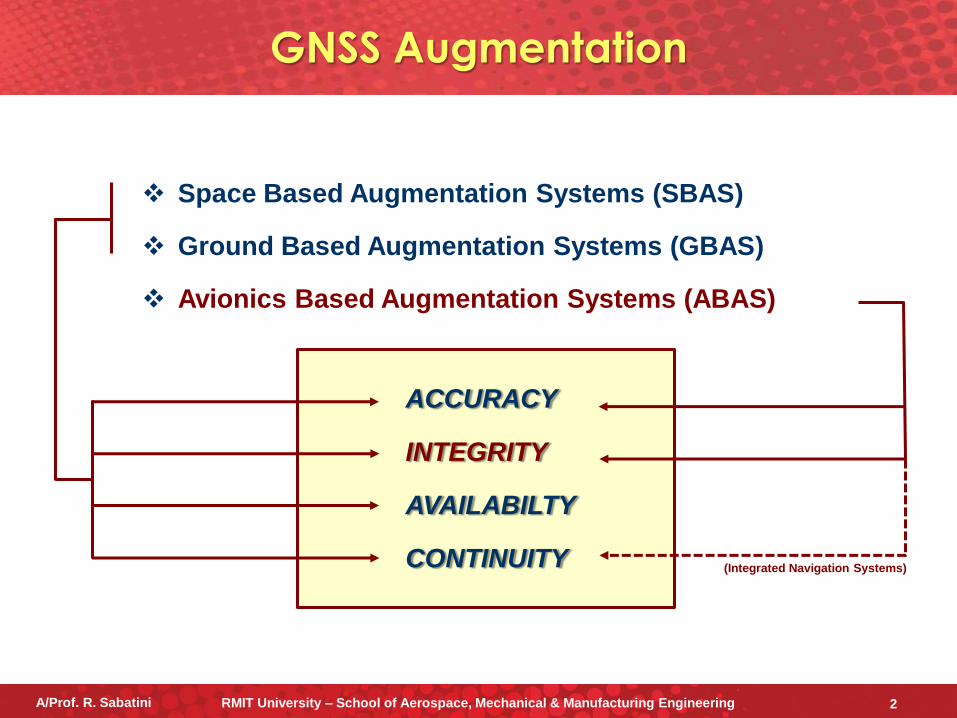
Space Based Augmentation Systems (SBAS)
Ground Based Augmentation Systems (GBAS)
Avionics Based Augmentation Systems (ABAS)
GNSS Augmentation
(Integrated Navigation Systems)
ACCURACY
INTEGRITY
AVAILABILTY
CONTINUITY
A/Prof. R. Sabatini RMIT University – School of Aerospace, Mechanical & Manufacturing Engineering 2
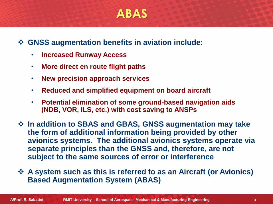
GNSS augmentation benefits in aviation include:
• Increased Runway Access
• More direct en route flight paths
• New precision approach services
• Reduced and simplified equipment on board aircraft
• Potential elimination of some ground-based navigation aids (NDB, VOR, ILS, etc.) with cost saving to ANSPs
In addition to SBAS and GBAS, GNSS augmentation may take the form of additional information being provided by other avionics systems. The additional avionics systems operate via separate principles than the GNSS and, therefore, are not subject to the same sources of error or interference
A system such as this is referred to as an Aircraft (or Avionics) Based Augmentation System (ABAS)
ABAS
A/Prof. R. Sabatini RMIT University – School of Aerospace, Mechanical & Manufacturing Engineering 3
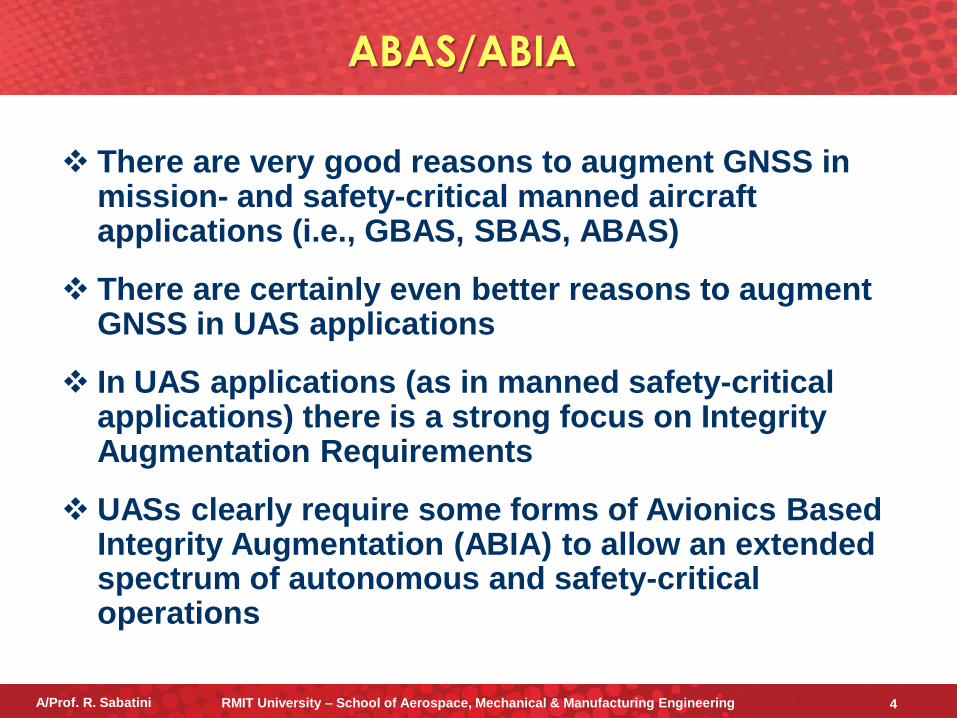
There are very good reasons to augment GNSS in mission- and safety-critical manned aircraft applications (i.e., GBAS, SBAS, ABAS)
There are certainly even better reasons to augment GNSS in UAS applications
In UAS applications (as in manned safety-critical applications) there is a strong focus on Integrity Augmentation Requirements
UASs clearly require some forms of Avionics Based Integrity Augmentation (ABIA) to allow an extended spectrum of autonomous and safety-critical operations
ABAS/ABIA
A/Prof. R. Sabatini RMIT University – School of Aerospace, Mechanical & Manufacturing Engineering 4
During flight test activities with GNSS TSPI and Integrated Position Reference Systems (PRS), it was observed that one or more of the following conditions was prone to cause TSPI data outages:
• The aircraft reaching Critical Attitude Angles (CAA)
• Bad satellite geometries and low satellite C/N0
• Aircraft Data Link (ADL) antennae coverage (real-time telemetry)
• Interference, at the airborne GPS antenna, caused by the Radio Systems or other Intentional/Unintentional RF signals
• Multipath caused by GNSS signals reflected by the Earth/Buildings or the aircraft body surfaces
It is evident that these limitations do not apply to TSPI GNSS systems only, but they hold true for other high integrity (and high accuracy) applications of GNSS, such as precision approach, landing, military weapon aiming, etc.
In our research, we developed a novel Avionics Based Integrity Augmentation (ABIA) system, specifically targeting GNSS Mission- and Safety-Critical Applications
GNSS TSPI Data
A/Prof. R. Sabatini RMIT University – School of Aerospace, Mechanical & Manufacturing Engineering 5
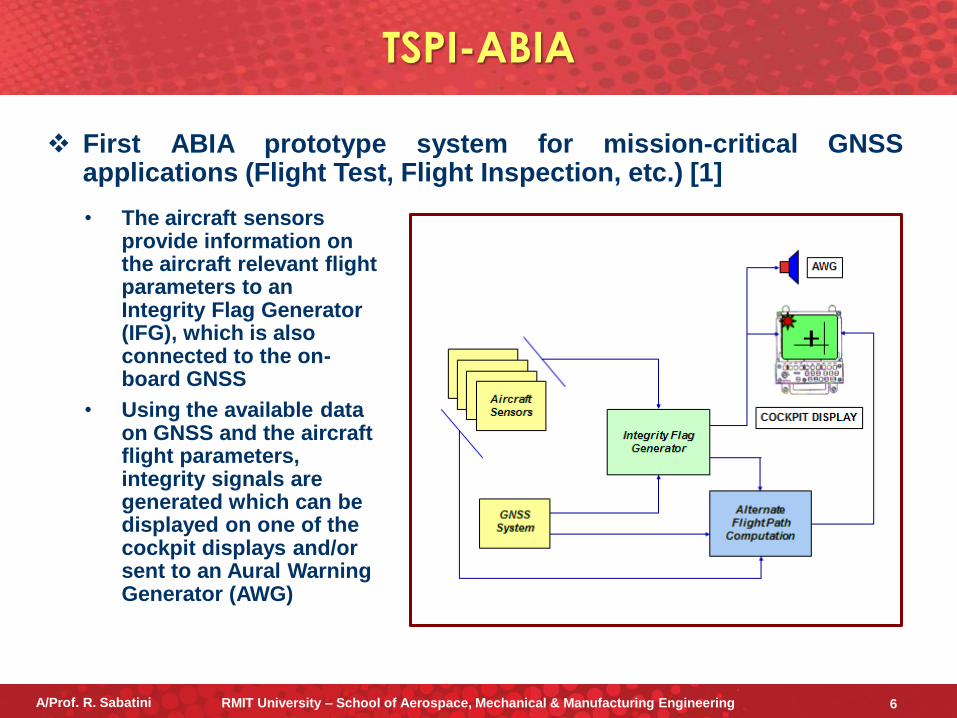
First ABIA prototype system for mission-critical GNSS applications (Flight Test, Flight Inspection, etc.) [1]
• The aircraft sensors provide information on the aircraft relevant flight parameters to an Integrity Flag Generator (IFG), which is also connected to the on-board GNSS
• Using the available data on GNSS and the aircraft flight parameters, integrity signals are generated which can be displayed on one of the cockpit displays and/or sent to an Aural Warning Generator (AWG)
TSPI-ABIA
A/Prof. R. Sabatini RMIT University – School of Aerospace, Mechanical & Manufacturing Engineering 6
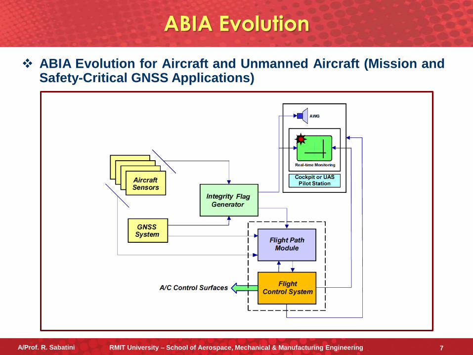
ABIA Evolution for Aircraft and Unmanned Aircraft (Mission and Safety-Critical GNSS Applications)
ABIA Evolution
A/Prof. R. Sabatini RMIT University – School of Aerospace, Mechanical & Manufacturing Engineering 7
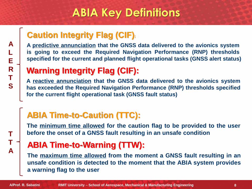
Caution Integrity Flag (CIF):
A predictive annunciation that the GNSS data delivered to the avionics system
is going to exceed the Required Navigation Performance (RNP) thresholds
specified for the current and planned flight operational tasks (GNSS alert status)
Warning Integrity Flag (CIF): A reactive annunciation that the GNSS data delivered to the avionics system
has exceeded the Required Navigation Performance (RNP) thresholds specified
for the current flight operational task (GNSS fault status)
ABIA Time-to-Caution (TTC): The minimum time allowed for the caution flag to be provided to the user
before the onset of a GNSS fault resulting in an unsafe condition
ABIA Time-to-Warning (TTW): The maximum time allowed from the moment a GNSS fault resulting in an
unsafe condition is detected to the moment that the ABIA system provides
a warning flag to the user
A
L
E
R
T
S
T
T
A
ABIA Key Definitions
A/Prof. R. Sabatini RMIT University – School of Aerospace, Mechanical & Manufacturing Engineering 8
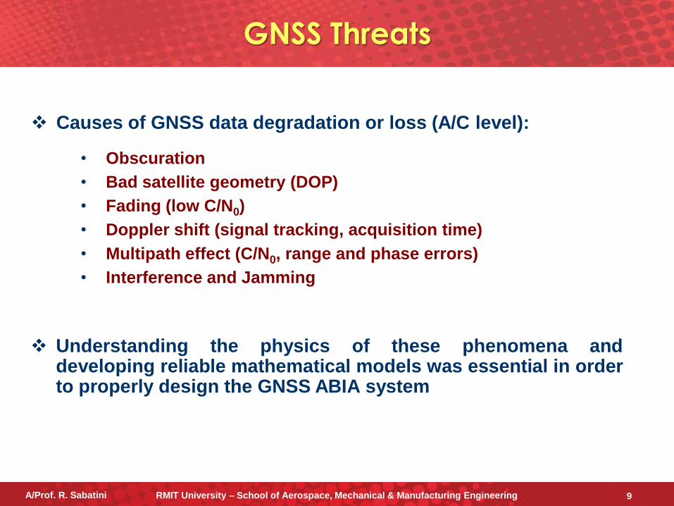
• Obscuration
• Bad satellite geometry (DOP)
• Fading (low C/N0)
• Doppler shift (signal tracking, acquisition time)
• Multipath effect (C/N0, range and phase errors)
• Interference and Jamming
Causes of GNSS data degradation or loss (A/C level):
Understanding the physics of these phenomena and developing reliable mathematical models was essential in order to properly design the GNSS ABIA system
GNSS Threats
A/Prof. R. Sabatini RMIT University – School of Aerospace, Mechanical & Manufacturing Engineering 9
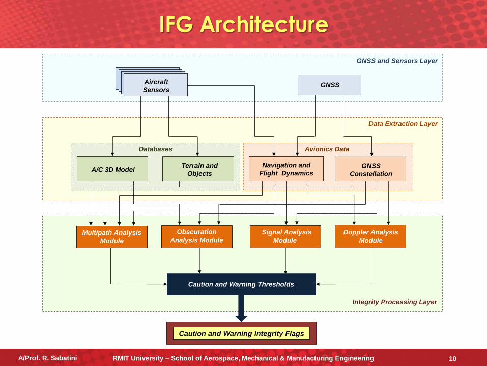
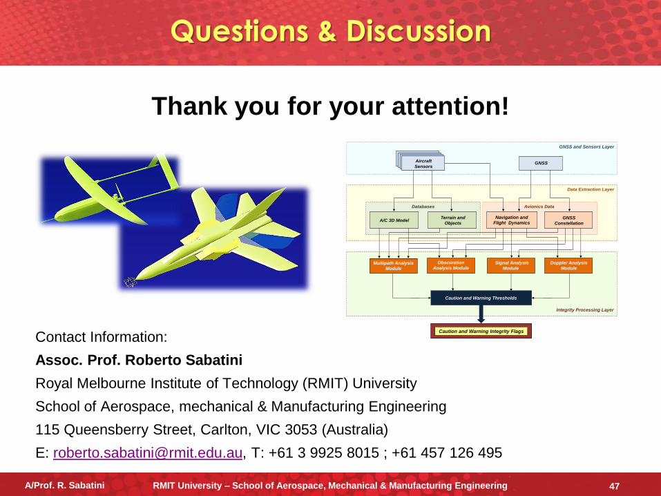
IFG Architecture
Integrity Processing Layer
Data Extraction Layer
GNSS and Sensors Layer
GNSSAircraft
Sensors
Caution and Warning Integrity Flags
A/C 3D Model Terrain and
Objects
Navigation and
Flight DynamicsGNSS
Constellation
Databases Avionics Data
Signal Analysis
Module
Doppler Analysis
Module
Obscuration
Analysis ModuleMultipath Analysis
Module
Caution and Warning Thresholds
A/Prof. R. Sabatini RMIT University – School of Aerospace, Mechanical & Manufacturing Engineering 10
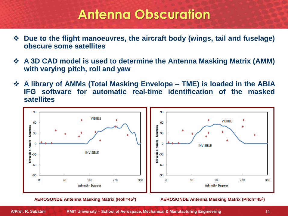
Due to the flight manoeuvres, the aircraft body (wings, tail and fuselage) obscure some satellites
A 3D CAD model is used to determine the Antenna Masking Matrix (AMM) with varying pitch, roll and yaw
A library of AMMs (Total Masking Envelope – TME) is loaded in the ABIA IFG software for automatic real-time identification of the masked satellites
AEROSONDE Antenna Masking Matrix (Roll=450) AEROSONDE Antenna Masking Matrix (Pitch=450)
Antenna Obscuration
A/Prof. R. Sabatini RMIT University – School of Aerospace, Mechanical & Manufacturing Engineering 11
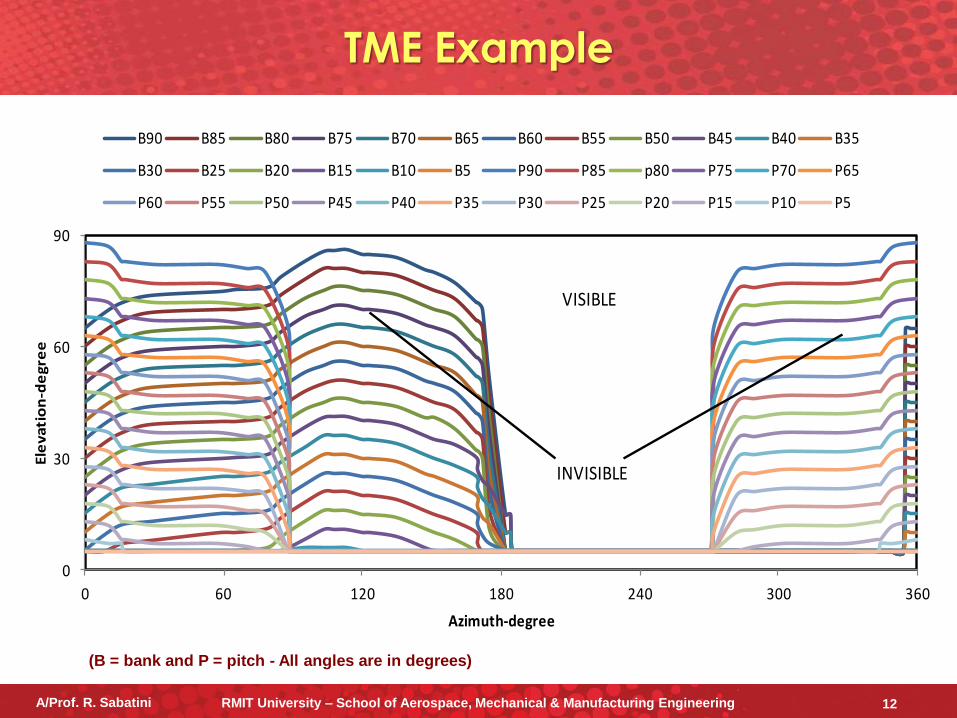
TME Example
0
30
60
90
0 60 120 180 240 300 360
Ele
va
tio
n-d
eg
ree
Azimuth-degree
B90 B85 B80 B75 B70 B65 B60 B55 B50 B45 B40 B35
B30 B25 B20 B15 B10 B5 P90 P85 p80 P75 P70 P65
P60 P55 P50 P45 P40 P35 P30 P25 P20 P15 P10 P5
INVISIBLE
VISIBLE
A/Prof. R. Sabatini RMIT University – School of Aerospace, Mechanical & Manufacturing Engineering 12
(B = bank and P = pitch - All angles are in degrees)
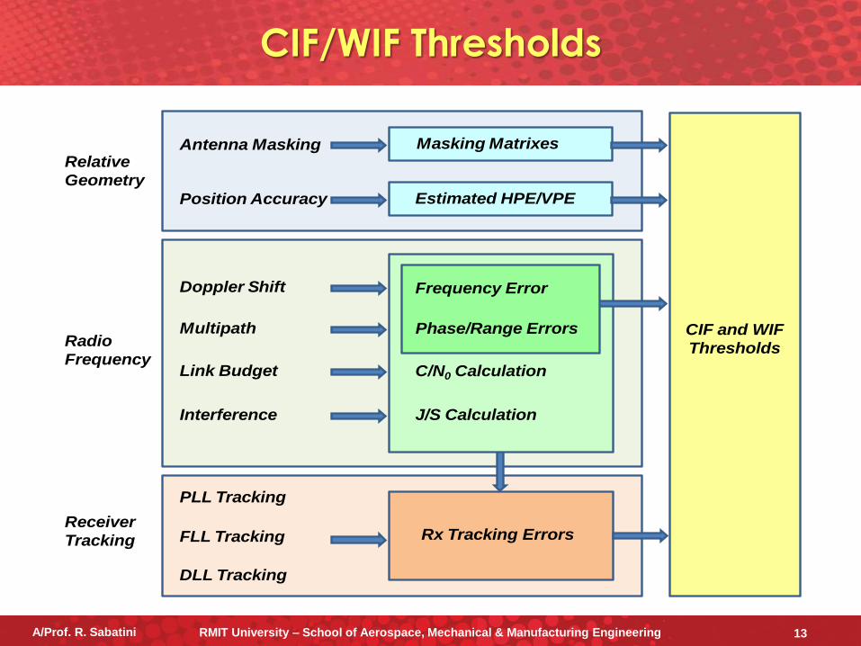
CIF/WIF Thresholds
CIF and WIF
Thresholds
Relative
Geometry
Radio
Frequency
Receiver
Tracking
Antenna Masking
Position Accuracy
PLL Tracking
FLL Tracking
Masking Matrixes
Estimated HPE/VPE
Rx Tracking Errors
DLL Tracking
Multipath
Link Budget
Interference
C/N0 Calculation
J/S Calculation
Doppler Shift
Phase/Range Errors
Frequency Error
A/Prof. R. Sabatini RMIT University – School of Aerospace, Mechanical & Manufacturing Engineering 13
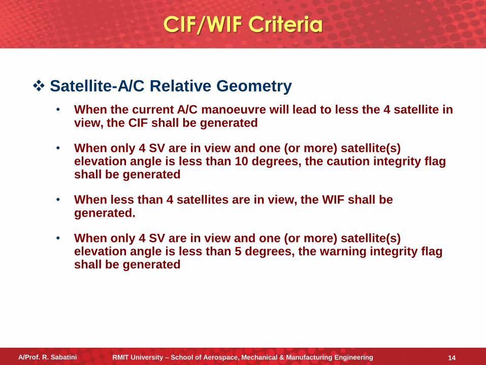
CIF/WIF Criteria
Satellite-A/C Relative Geometry
• When the current A/C manoeuvre will lead to less the 4 satellite in view, the CIF shall be generated
• When only 4 SV are in view and one (or more) satellite(s) elevation angle is less than 10 degrees, the caution integrity flag shall be generated
• When less than 4 satellites are in view, the WIF shall be generated.
• When only 4 SV are in view and one (or more) satellite(s) elevation angle is less than 5 degrees, the warning integrity flag shall be generated
A/Prof. R. Sabatini RMIT University – School of Aerospace, Mechanical & Manufacturing Engineering 14
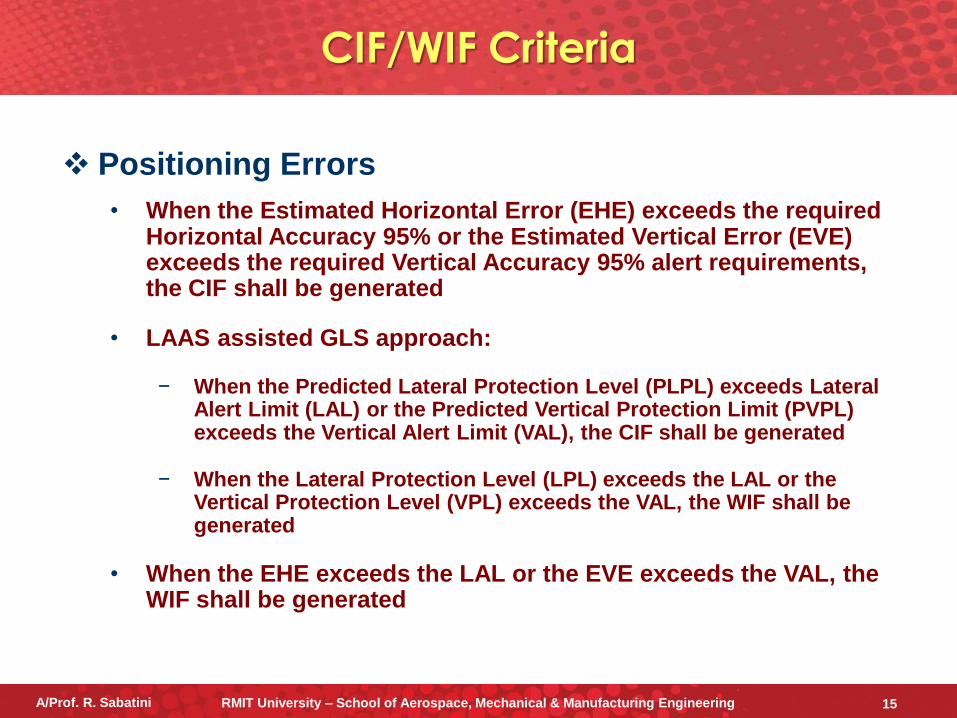
CIF/WIF Criteria
Positioning Errors
• When the Estimated Horizontal Error (EHE) exceeds the required Horizontal Accuracy 95% or the Estimated Vertical Error (EVE) exceeds the required Vertical Accuracy 95% alert requirements, the CIF shall be generated
• LAAS assisted GLS approach:
− When the Predicted Lateral Protection Level (PLPL) exceeds Lateral Alert Limit (LAL) or the Predicted Vertical Protection Limit (PVPL) exceeds the Vertical Alert Limit (VAL), the CIF shall be generated
− When the Lateral Protection Level (LPL) exceeds the LAL or the Vertical Protection Level (VPL) exceeds the VAL, the WIF shall be generated
• When the EHE exceeds the LAL or the EVE exceeds the VAL, the WIF shall be generated
A/Prof. R. Sabatini RMIT University – School of Aerospace, Mechanical & Manufacturing Engineering 15
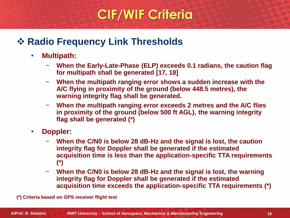
CIF/WIF Criteria
Radio Frequency Link Thresholds
• Multipath:
− When the Early-Late-Phase (ELP) exceeds 0.1 radians, the caution flag for multipath shall be generated [17, 18]
− When the multipath ranging error shows a sudden increase with the A/C flying in proximity of the ground (below 448.5 metres), the warning integrity flag shall be generated.
− When the multipath ranging error exceeds 2 metres and the A/C flies in proximity of the ground (below 500 ft AGL), the warning integrity flag shall be generated (*)
• Doppler:
− When the C/N0 is below 28 dB-Hz and the signal is lost, the caution integrity flag for Doppler shall be generated if the estimated acquisition time is less than the application-specific TTA requirements (*)
− When the C/N0 is below 28 dB-Hz and the signal is lost, the warning integrity flag for Doppler shall be generated if the estimated acquisition time exceeds the application-specific TTA requirements (*)
(*) Criteria based on GPS receiver flight test
A/Prof. R. Sabatini RMIT University – School of Aerospace, Mechanical & Manufacturing Engineering 16
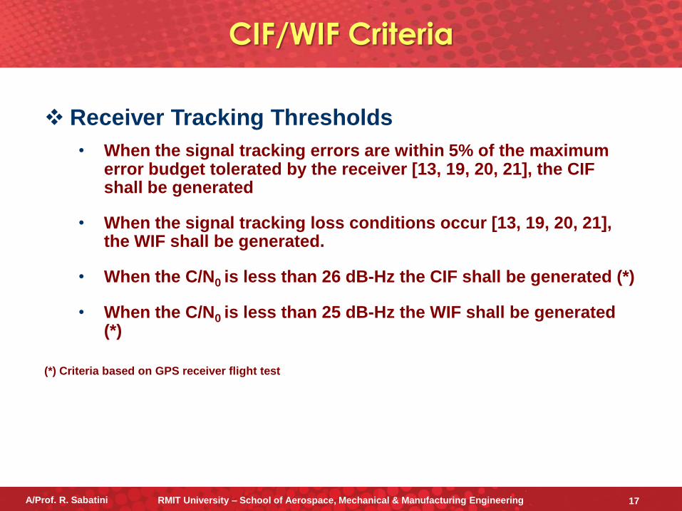
CIF/WIF Criteria
Receiver Tracking Thresholds
• When the signal tracking errors are within 5% of the maximum error budget tolerated by the receiver [13, 19, 20, 21], the CIF shall be generated
• When the signal tracking loss conditions occur [13, 19, 20, 21], the WIF shall be generated.
• When the C/N0 is less than 26 dB-Hz the CIF shall be generated (*)
• When the C/N0 is less than 25 dB-Hz the WIF shall be generated (*)
(*) Criteria based on GPS receiver flight test
A/Prof. R. Sabatini RMIT University – School of Aerospace, Mechanical & Manufacturing Engineering 17
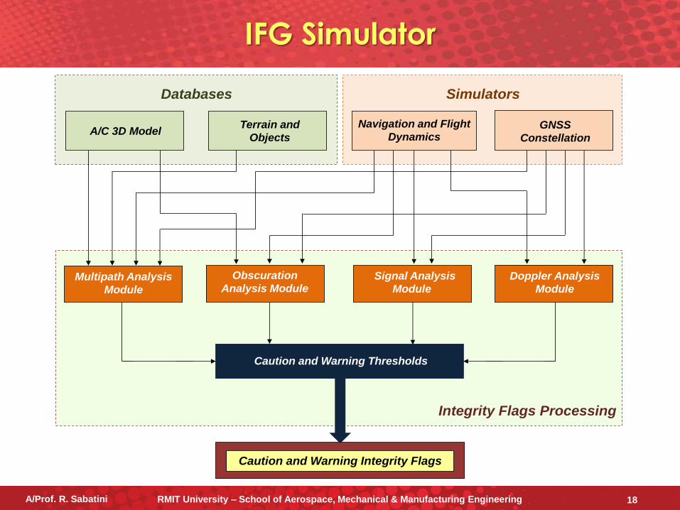
IFG Simulator
Integrity Flags Processing
A/C 3D Model Terrain and
Objects
Navigation and Flight
DynamicsGNSS
Constellation
Databases Simulators
Signal Analysis
Module
Doppler Analysis
Module
Obscuration
Analysis ModuleMultipath Analysis
Module
Caution and Warning Thresholds
Caution and Warning Integrity Flags
A/Prof. R. Sabatini RMIT University – School of Aerospace, Mechanical & Manufacturing Engineering 18
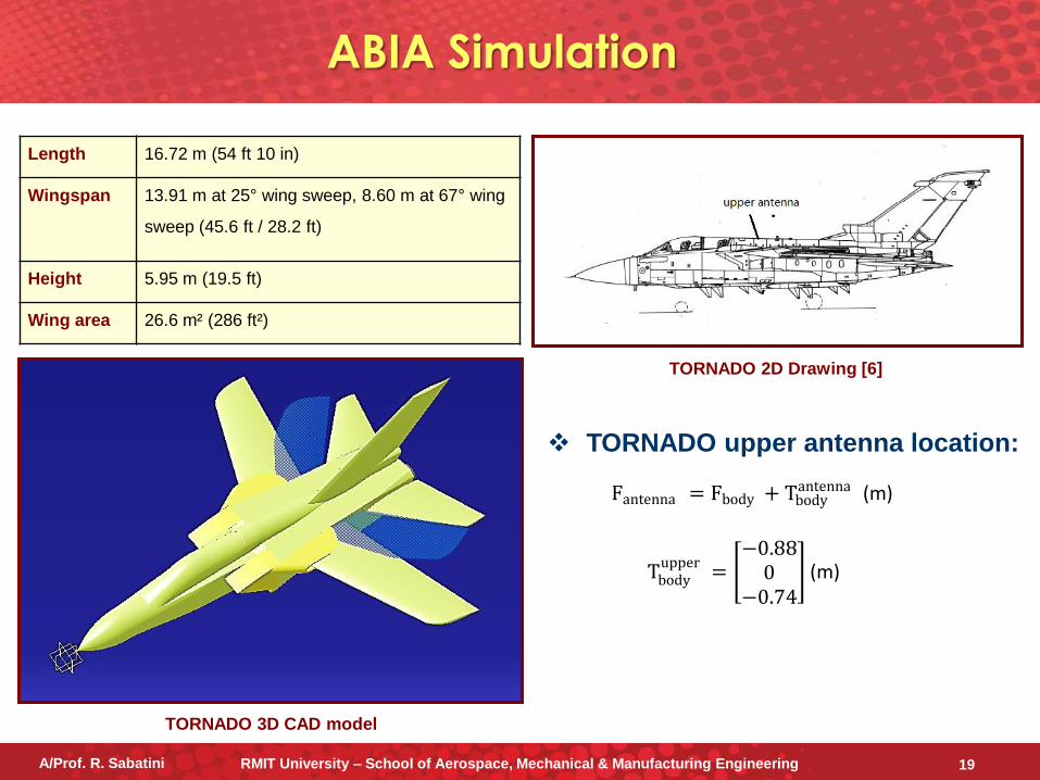
TORNADO upper antenna location:
TORNADO 2D Drawing [6]
TORNADO 3D CAD model
Fantenna = Fbody + Tbodyantenna (m)
Tbodyupper
= −0.88
0−0.74
(m)
Length 16.72 m (54 ft 10 in)
Wingspan 13.91 m at 25° wing sweep, 8.60 m at 67° wing
sweep (45.6 ft / 28.2 ft)
Height 5.95 m (19.5 ft)
Wing area 26.6 m² (286 ft²)
ABIA Simulation
A/Prof. R. Sabatini RMIT University – School of Aerospace, Mechanical & Manufacturing Engineering 19
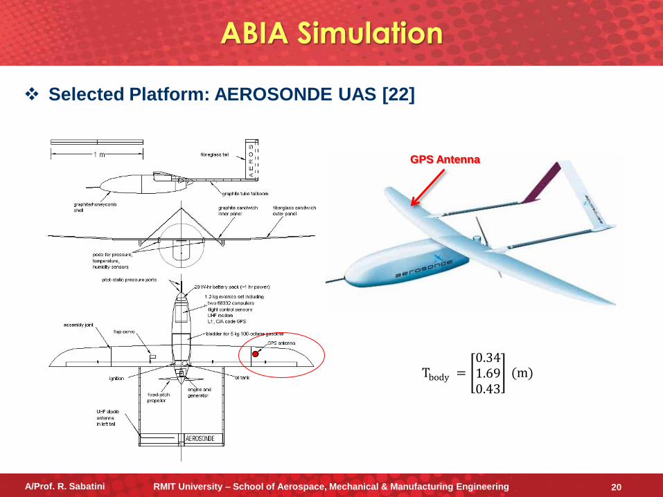
ABIA Simulation
Selected Platform: AEROSONDE UAS [22]
GPS Antenna
Tbody = 0.341.690.43
(m)
A/Prof. R. Sabatini RMIT University – School of Aerospace, Mechanical & Manufacturing Engineering 20
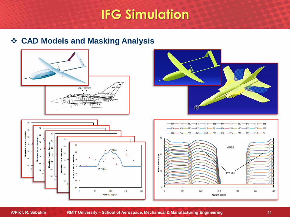
IFG Simulation
CAD Models and Masking Analysis
0
30
60
90
0 60 120 180 240 300 360
Ele
va
tio
n-d
eg
ree
Azimuth-degree
B90 B85 B80 B75 B70 B65 B60 B55 B50 B45 B40 B35
B30 B25 B20 B15 B10 B5 P90 P85 p80 P75 P70 P65
P60 P55 P50 P45 P40 P35 P30 P25 P20 P15 P10 P5
INVISIBLE
VISIBLE
A/Prof. R. Sabatini RMIT University – School of Aerospace, Mechanical & Manufacturing Engineering 21
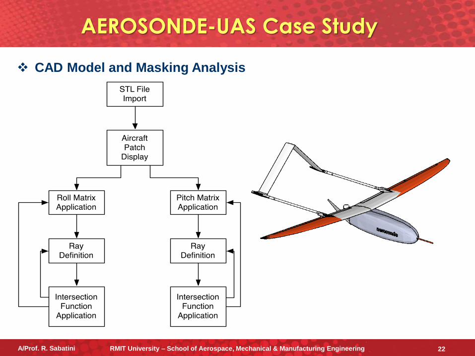
AEROSONDE-UAS Case Study
CAD Model and Masking Analysis
A/Prof. R. Sabatini RMIT University – School of Aerospace, Mechanical & Manufacturing Engineering 22
−1500
−1000
−500
0
500
1000
1500
−1500
−1000
−500
0
500
1000
−400
−200
0
200
400
600
−10000
10002000
3000
−2000
−1000
0
1000
2000
−500
0
500
1000
1500
2000
2500
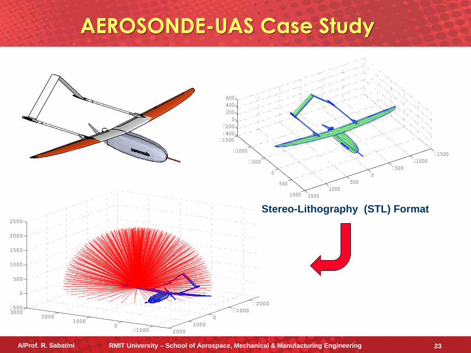
Stereo-Lithography (STL) Format
A/Prof. R. Sabatini RMIT University – School of Aerospace, Mechanical & Manufacturing Engineering 23
AEROSONDE-UAS Case Study
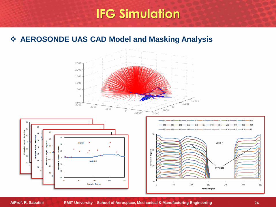
IFG Simulation
AEROSONDE UAS CAD Model and Masking Analysis
0
30
60
90
0 60 120 180 240 300 360
Ele
va
tio
n-d
eg
ree
Azimuth-degree
B90 B85 B80 B75 B70 B65 B60 B55 B50 B45 B40 B35
B30 B25 B20 B15 B10 B5 P90 P85 p80 P75 P70 P65
P60 P55 P50 P45 P40 P35 P30 P25 P20 P15 P10 P5
INVISIBLE
VISIBLE
−10000
10002000
3000
−2000
−1000
0
1000
2000
−500
0
500
1000
1500
2000
2500
A/Prof. R. Sabatini RMIT University – School of Aerospace, Mechanical & Manufacturing Engineering 24
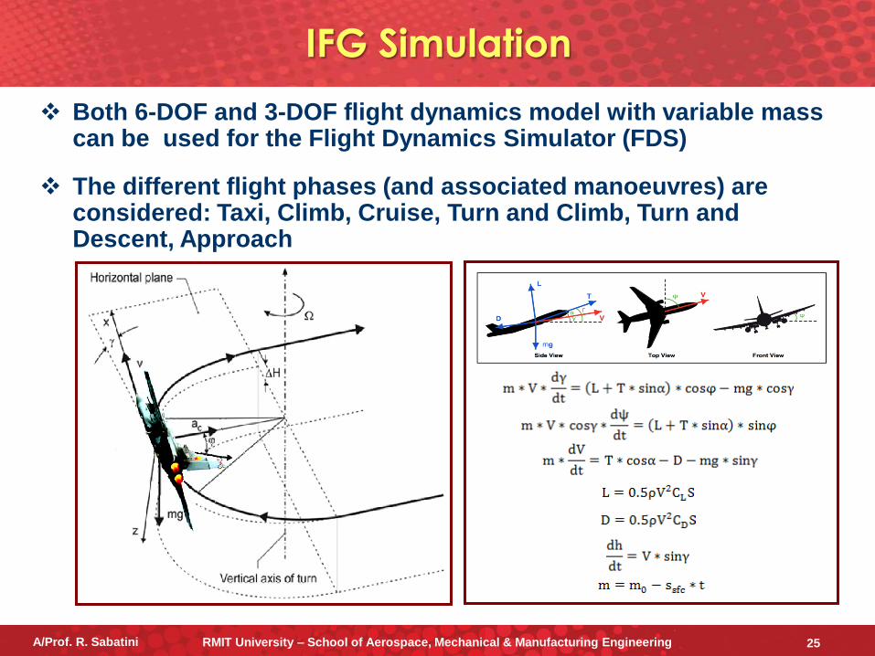
Both 6-DOF and 3-DOF flight dynamics model with variable mass can be used for the Flight Dynamics Simulator (FDS)
The different flight phases (and associated manoeuvres) are considered: Taxi, Climb, Cruise, Turn and Climb, Turn and Descent, Approach
IFG Simulation
A/Prof. R. Sabatini RMIT University – School of Aerospace, Mechanical & Manufacturing Engineering 25
TORNADO aircraft trajectory:
• Climb flight phase (0-5min)
• Cruise (straight-and-level) flight phase (5-10min)
• Turn and descend flight phase (10-5min)
• Cruise flight phase (15-20min)
• Approach (straight descent) flight phase (20-25min)
Initial point of the A/C trajectory located at LHR airport (WGS coordinates: 51° 28′ 39″ N, 0° 27′ 41″ W)
GPS constellation simulated using the YUMA almanac data
Flat terrain profile and free from man-made features
GLS in the presence of LAAS was simulated
TORNADO Case Study
A/Prof. R. Sabatini RMIT University – School of Aerospace, Mechanical & Manufacturing Engineering 26
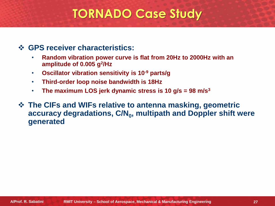
GPS receiver characteristics:
• Random vibration power curve is flat from 20Hz to 2000Hz with an amplitude of 0.005 g2/Hz
• Oscillator vibration sensitivity is 10-9 parts/g
• Third-order loop noise bandwidth is 18Hz
• The maximum LOS jerk dynamic stress is 10 g/s = 98 m/s3
The CIFs and WIFs relative to antenna masking, geometric accuracy degradations, C/N0, multipath and Doppler shift were generated
TORNADO Case Study
A/Prof. R. Sabatini RMIT University – School of Aerospace, Mechanical & Manufacturing Engineering 27
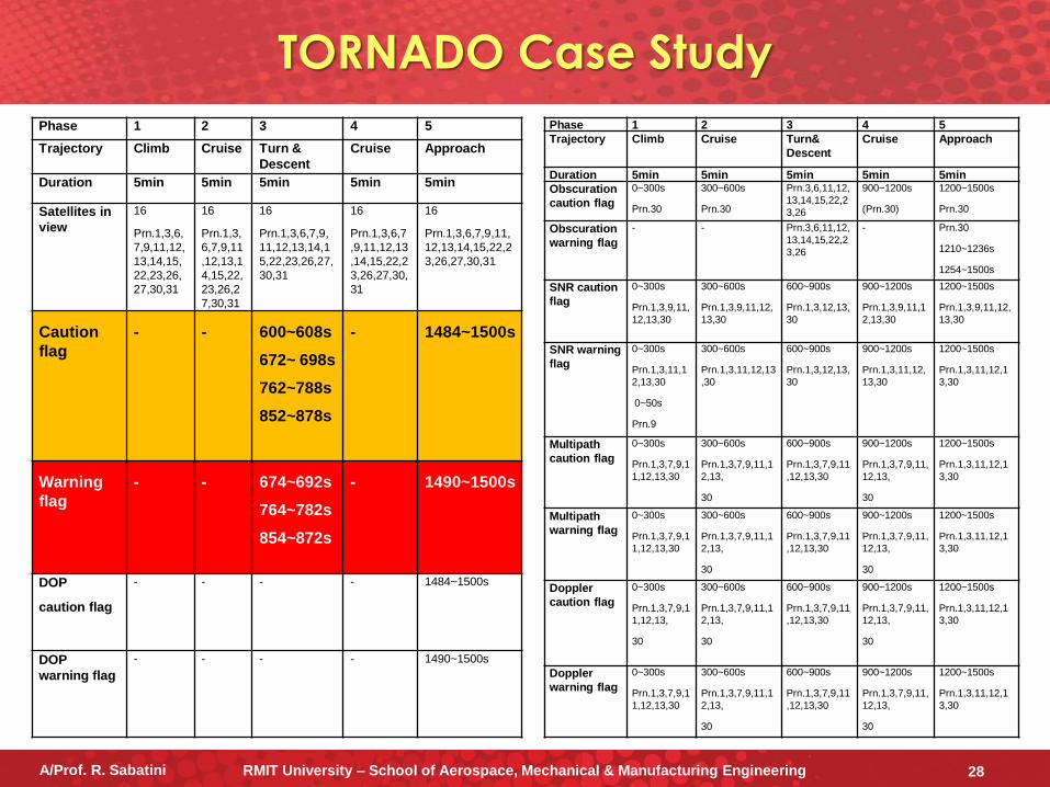
Phase 1 2 3 4 5
Trajectory Climb Cruise Turn &
Descent
Cruise Approach
Duration 5min 5min 5min 5min 5min
Satellites in
view
16
Prn.1,3,6,
7,9,11,12,
13,14,15,
22,23,26,
27,30,31
16
Prn.1,3,
6,7,9,11
,12,13,1
4,15,22,
23,26,2
7,30,31
16
Prn.1,3,6,7,9,
11,12,13,14,1
5,22,23,26,27,
30,31
16
Prn.1,3,6,7
,9,11,12,13
,14,15,22,2
3,26,27,30,
31
16
Prn.1,3,6,7,9,11,
12,13,14,15,22,2
3,26,27,30,31
Caution
flag
-
-
600~608s
672~ 698s
762~788s
852~878s
-
1484~1500s
Warning
flag
-
-
674~692s
764~782s
854~872s
-
1490~1500s
DOP
caution flag
- - - - 1484~1500s
DOP
warning flag
- - - - 1490~1500s
Phase 1 2 3 4 5
Trajectory Climb Cruise Turn&
Descent
Cruise Approach
Duration 5min 5min 5min 5min 5min
Obscuration
caution flag
0~300s
Prn.30
300~600s
Prn.30
Prn.3,6,11,12,
13,14,15,22,2
3,26
900~1200s
(Prn.30)
1200~1500s
Prn.30
Obscuration
warning flag
- - Prn.3,6,11,12,
13,14,15,22,2
3,26
- Prn.30
1210~1236s
1254~1500s
SNR caution
flag
0~300s
Prn.1,3,9,11,
12,13,30
300~600s
Prn.1,3,9,11,12,
13,30
600~900s
Prn.1,3,12,13,
30
900~1200s
Prn.1,3,9,11,1
2,13,30
1200~1500s
Prn.1,3,9,11,12,
13,30
SNR warning
flag
0~300s
Prn.1,3,11,1
2,13,30
0~50s
Prn.9
300~600s
Prn.1,3,11,12,13
,30
600~900s
Prn.1,3,12,13,
30
900~1200s
Prn.1,3,11,12,
13,30
1200~1500s
Prn.1,3,11,12,1
3,30
Multipath
caution flag
0~300s
Prn.1,3,7,9,1
1,12,13,30
300~600s
Prn.1,3,7,9,11,1
2,13,
30
600~900s
Prn.1,3,7,9,11
,12,13,30
900~1200s
Prn.1,3,7,9,11,
12,13,
30
1200~1500s
Prn.1,3,11,12,1
3,30
Multipath
warning flag
0~300s
Prn.1,3,7,9,1
1,12,13,30
300~600s
Prn.1,3,7,9,11,1
2,13,
30
600~900s
Prn.1,3,7,9,11
,12,13,30
900~1200s
Prn.1,3,7,9,11,
12,13,
30
1200~1500s
Prn.1,3,11,12,1
3,30
Doppler
caution flag
0~300s
Prn.1,3,7,9,1
1,12,13,
30
300~600s
Prn.1,3,7,9,11,1
2,13,
30
600~900s
Prn.1,3,7,9,11
,12,13,30
900~1200s
Prn.1,3,7,9,11,
12,13,
30
1200~1500s
Prn.1,3,11,12,1
3,30
Doppler
warning flag
0~300s
Prn.1,3,7,9,1
1,12,13,30
300~600s
Prn.1,3,7,9,11,1
2,13,
30
600~900s
Prn.1,3,7,9,11
,12,13,30
900~1200s
Prn.1,3,7,9,11,
12,13,
30
1200~1500s
Prn.1,3,11,12,1
3,30
TORNADO Case Study
A/Prof. R. Sabatini RMIT University – School of Aerospace, Mechanical & Manufacturing Engineering 28
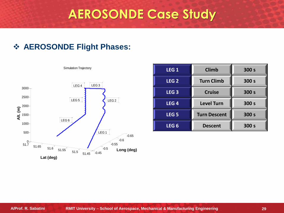
AEROSONDE Flight Phases:
AEROSONDE Case Study
LEG 1 Climb 300 s
LEG 2 Turn Climb 300 s
LEG 3 Cruise 300 s
LEG 4 Level Turn 300 s
LEG 5 Turn Descent 300 s
LEG 6 Descent 300 s
51.4551.5
51.5551.6
51.6551.7
-0.65
-0.6
-0.55
-0.5
-0.45
0
500
1000
1500
2000
2500
3000
Longitude:Degree
Simulation Trajectory
Latitude:Degree
Altitu
de
:Me
ter
LEG 5
LEG 6
LEG 1
LEG 2
LEG 4 LEG 3
Alt
. (m
)
Lat (deg)
Long (deg)
A/Prof. R. Sabatini RMIT University – School of Aerospace, Mechanical & Manufacturing Engineering 29
Initial point of the A/C trajectory located at WGS coordinates: 51° 28′ 39″ N, 0° 27′ 41″ W (London)
GPS constellation simulated using the YUMA almanac data
Fly over the sea (free from man-made features)
GLS in the presence of LAAS was simulated
IFG Simulation
PITCH (deg) BANK (deg) THRUST (rpm)
CLIMB 15 0 7000
TURNING CLIMB 15 +10 7000
CRUISE 0 0 4000
LEVEL TURN 0 +45 6000
TURNING DESCENT -5 -40 2000
DESCENT -5 0 100
Dynamics Model
Settings
A/Prof. R. Sabatini RMIT University – School of Aerospace, Mechanical & Manufacturing Engineering 30
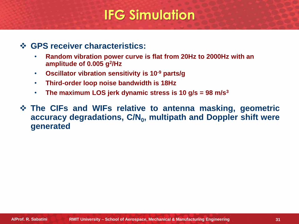
GPS receiver characteristics:
• Random vibration power curve is flat from 20Hz to 2000Hz with an amplitude of 0.005 g2/Hz
• Oscillator vibration sensitivity is 10-9 parts/g
• Third-order loop noise bandwidth is 18Hz
• The maximum LOS jerk dynamic stress is 10 g/s = 98 m/s3
The CIFs and WIFs relative to antenna masking, geometric accuracy degradations, C/N0, multipath and Doppler shift were generated
IFG Simulation
A/Prof. R. Sabatini RMIT University – School of Aerospace, Mechanical & Manufacturing Engineering 31
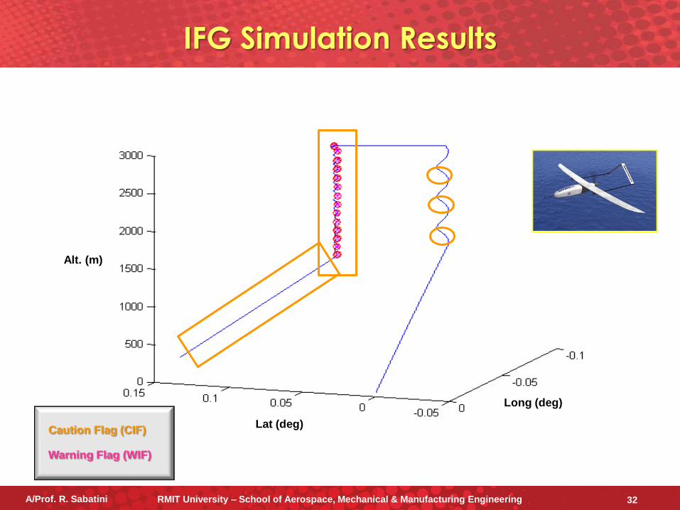
Long (deg)
Lat (deg)
Alt. (m)
Caution Flag (CIF)
Warning Flag (WIF)
IFG Simulation Results
A/Prof. R. Sabatini RMIT University – School of Aerospace, Mechanical & Manufacturing Engineering 32
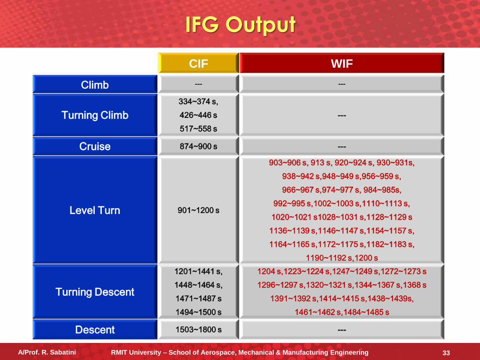
IFG Output
CIF WIF
Climb --- ---
Turning Climb
334~374 s,
426~446 s
517~558 s
---
Cruise 874~900 s ---
Level Turn 901~1200 s
903~906 s, 913 s, 920~924 s, 930~931s,
938~942 s,948~949 s,956~959 s,
966~967 s,974~977 s, 984~985s,
992~995 s,1002~1003 s,1110~1113 s,
1020~1021 s1028~1031 s,1128~1129 s
1136~1139 s,1146~1147 s,1154~1157 s,
1164~1165 s,1172~1175 s,1182~1183 s,
1190~1192 s,1200 s
Turning Descent
1201~1441 s,
1448~1464 s,
1471~1487 s
1494~1500 s
1204 s,1223~1224 s,1247~1249 s,1272~1273 s
1296~1297 s,1320~1321 s,1344~1367 s,1368 s
1391~1392 s,1414~1415 s,1438~1439s,
1461~1462 s,1484~1485 s
Descent 1503~1800 s ---
A/Prof. R. Sabatini RMIT University – School of Aerospace, Mechanical & Manufacturing Engineering 33
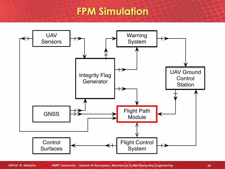
FPM Simulation
A/Prof. R. Sabatini RMIT University – School of Aerospace, Mechanical & Manufacturing Engineering 34
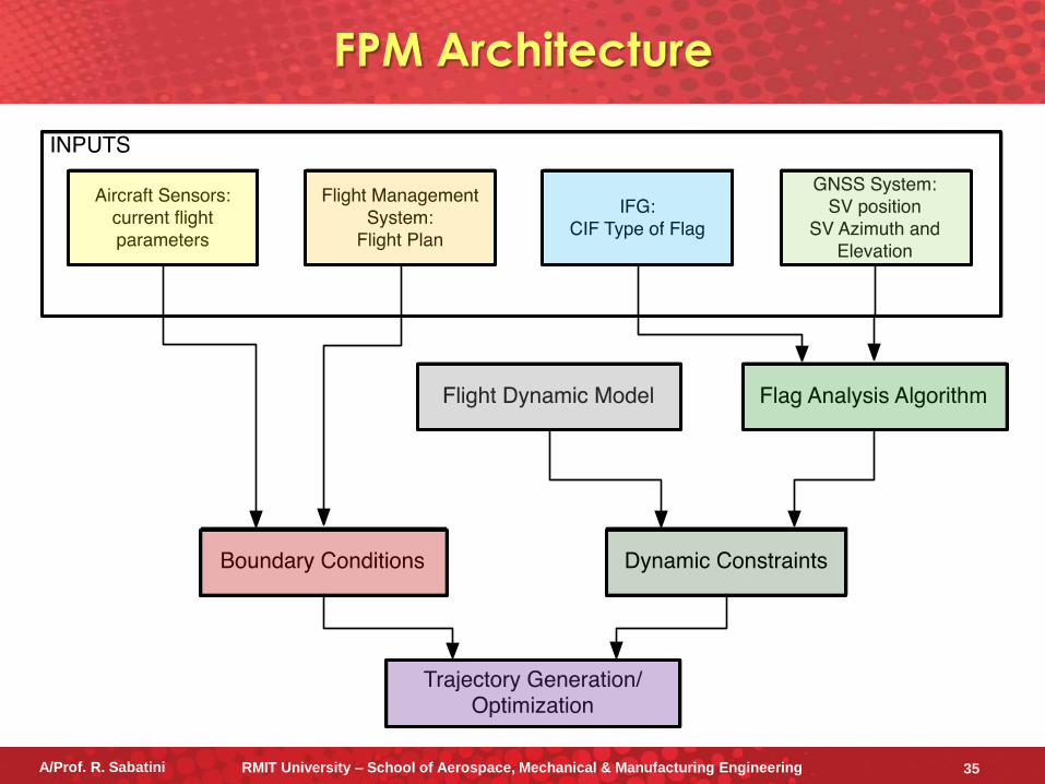
FPM Architecture
A/Prof. R. Sabatini RMIT University – School of Aerospace, Mechanical & Manufacturing Engineering 35
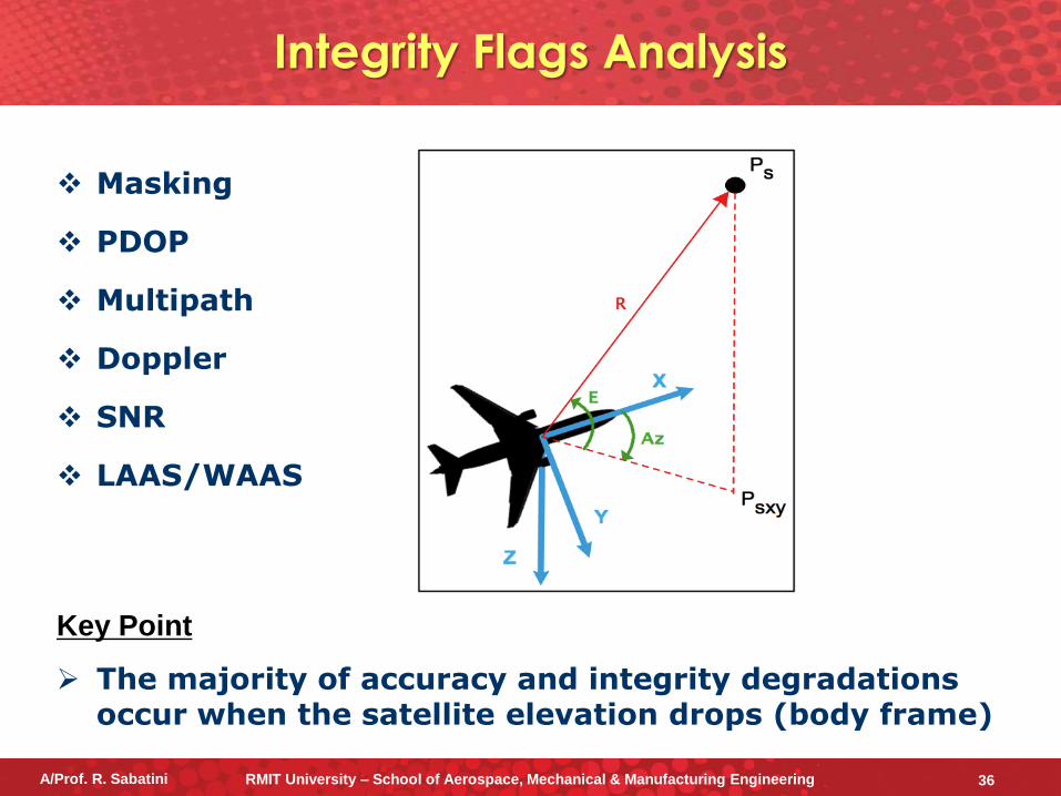
Integrity Flags Analysis
Masking
PDOP
Multipath
Doppler
SNR
LAAS/WAAS
Key Point
The majority of accuracy and integrity degradations occur when the satellite elevation drops (body frame)
A/Prof. R. Sabatini RMIT University – School of Aerospace, Mechanical & Manufacturing Engineering 36
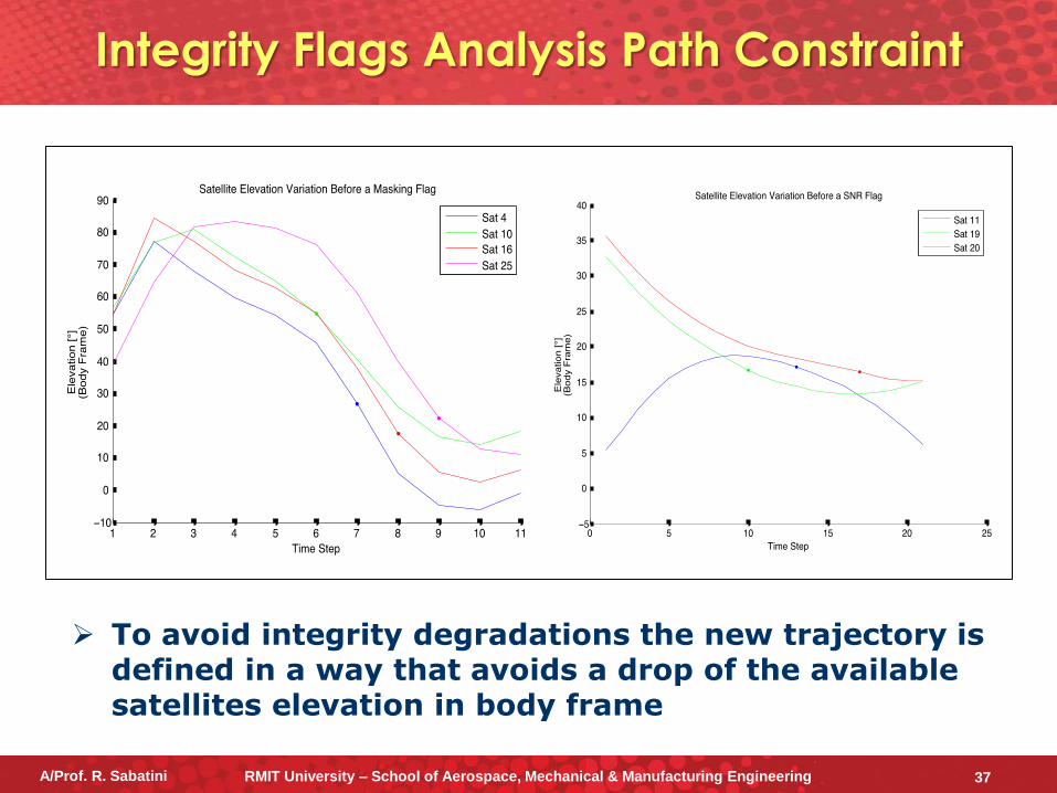
Integrity Flags Analysis Path Constraint
To avoid integrity degradations the new trajectory is defined in a way that avoids a drop of the available satellites elevation in body frame
A/Prof. R. Sabatini RMIT University – School of Aerospace, Mechanical & Manufacturing Engineering 37
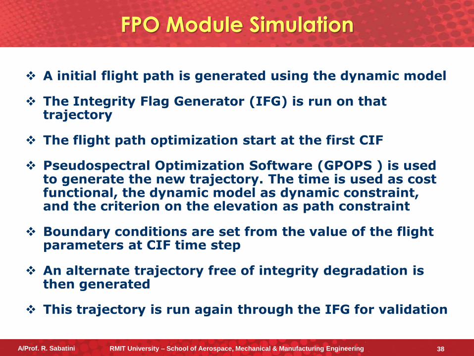
A initial flight path is generated using the dynamic model
The Integrity Flag Generator (IFG) is run on that trajectory
The flight path optimization start at the first CIF
Pseudospectral Optimization Software (GPOPS ) is used to generate the new trajectory. The time is used as cost functional, the dynamic model as dynamic constraint, and the criterion on the elevation as path constraint
Boundary conditions are set from the value of the flight parameters at CIF time step
An alternate trajectory free of integrity degradation is then generated
This trajectory is run again through the IFG for validation
FPO Module Simulation
A/Prof. R. Sabatini RMIT University – School of Aerospace, Mechanical & Manufacturing Engineering 38
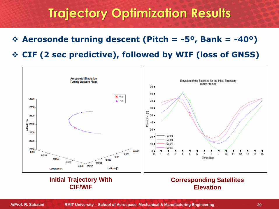
Aerosonde turning descent (Pitch = -5º, Bank = -40º)
CIF (2 sec predictive), followed by WIF (loss of GNSS)
Trajectory Optimization Results
Initial Trajectory With
CIF/WIF Corresponding Satellites
Elevation
A/Prof. R. Sabatini RMIT University – School of Aerospace, Mechanical & Manufacturing Engineering 39
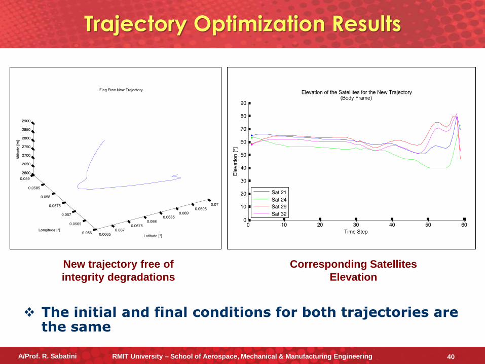
New trajectory free of
integrity degradations
Corresponding Satellites
Elevation
The initial and final conditions for both trajectories are the same
Trajectory Optimization Results
A/Prof. R. Sabatini RMIT University – School of Aerospace, Mechanical & Manufacturing Engineering 40
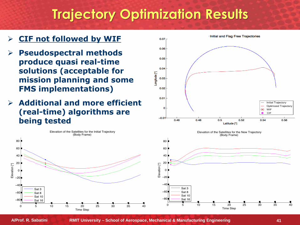
CIF not followed by WIF
Pseudospectral methods produce quasi real-time solutions (acceptable for mission planning and some FMS implementations)
Additional and more efficient (real-time) algorithms are being tested
Trajectory Optimization Results
A/Prof. R. Sabatini RMIT University – School of Aerospace, Mechanical & Manufacturing Engineering 41
Simulation Results
The ABIA Integrity Flag Generator (IFG) is capable of generating integrity flags to provide both caution and warning signals when GNSS signals are degraded or lost
After the integrity caution flag is generated, the time available for the pilot/autopilot to react (before the integrity event is detected and the warning flag is generated), is at least 2 seconds
This TTC can support safety-critical tasks including GLS curved/segmented precision approach and automatic landing applications
The trajectory optimization problem was mathematically formulated and the real-time capability of the FPO module (using pseudospectral and other methods) was verified
In the dynamic conditions explored, data analysis showed that the ABIA system can provided useful integrity signals for CAT-III precision approach and automatic landing (automated and real-time FPO is essential in this case)
A/Prof. R. Sabatini RMIT University – School of Aerospace, Mechanical & Manufacturing Engineering 42
Investigate and compare different types of avionics sensor technologies and their potential to support the design of robust ABAS/ABIA architectures for manned A/C and UAS
Analyse the synergies between ABAS/ABIA and UAS Sense-and-Avoid (SAA)
Extend the ABAS/ABIA concepts to the Aeronautical Data Link (ADL) application domain
Study possible applications of the ABAS/ABIA concepts to advanced mission planning and forensic (accident investigation) applications
Evaluate the potential of ABAS/ABIA to enhance the performance of next generation avionics and CNS/ATM systems for Performance/Intent Based Operations (PBO/IBO) and Four-Dimensional Trajectory (4DT) management
Future Work
A/Prof. R. Sabatini RMIT University – School of Aerospace, Mechanical & Manufacturing Engineering 43
[1] R. Sabatini and G. Palmerini. “Differential Global Positioning System (DGPS) for Flight Testing”. NATO Research
and Technology Organization (RTO) – Systems Concepts and Integration Panel (SCI). AGARDograph Series
RTO-AG-160 Vol. 21. Oct 2008.
[2] W.Y. Ochieng, K. Sauer, D. Walsh, G. Brodin, S. Griffin and Mark Denney. “GPS Integrity and Potential Impact
on Aviation Safety". The Journal of Navigation (The Royal Institute of Navigation), Vol. 56, pp. 51–65. 2003.
[3] YUMA GPS Almanacs. Available at: http://www.celestrak.com/GPS/almanac/Yuma/definition.asp.
[4] SEM GPS Almanacs. Available at: http://www.celestrak.com/GPS/almanac/SEM/definition.asp.
[5] Anonymous. “Aircraft Drawings”. available at http://www.aircraftdrawindsdownload.com.
[6] B.W. Parkinson and J.J. Spilker Jr. “Global Positioning System: Theory and Applications”. Volume I, AIAA -
Progress in Astronautics and Aeronautics. 1996.
[7] P. Gustavsson. “Development of a Matlab-based GPS-constellation simulation for navigation algorithm
developments”. MSc Thesis - Lulea University of Technology, 2005.
[8] W.B. Davenport and W.L. Root. "An Introduction to the Theory of Random Signals and Noise". IEEE Press (New
York). 1987
[9] H.T. Friis. "Noise Figures in Radio Receivers". Proceedings of the IRE, Vol. 32 (pp. 419-422). July 1944.
[10] A. Steingass. “The High Resolution Aeronautical Multipath Navigation Channel”. German Aerospace Center DLR.
2004. Available at http://www.kn-s.dlr.de/satnav.
[11] A. Steinggass, A. Lehner, “Aeronautical Channel Model”. German Aerospace Center DLR. 2004.
Available at http://www.kn-s.dlr.de/satnav.
[12] Michael S.Braasch. “On the characterization of multipath errors in satellite-based precision approach and landing
systems”. College of Engineering and Technology, Ohio University. June 1992.
References (1)
A/Prof. R. Sabatini RMIT University – School of Aerospace, Mechanical & Manufacturing Engineering 44
[13] E.D. Kaplan, C.J. Hegarty. “Understanding GPS: Principles and Applications”. Artech House. Second Edition.
2006.
[14] ICAO - Annex 10 to the Convention on International Civil Aviation. “Aeronautical Telecommunications”. Volume 1:
Radio Navigation Aids. Edition 6. July 2006.
[15] CAA Safety Regulation Group Paper 2003/09. “GPS Integrity and Potential Impact on Aviation Safety”. 2003.
[16] RTCA DO-245A. “Minimum Aviation System Performance Standards for Local Area Augmentation System
(LAAS)”. Dec 2004.
[17] Omer Mohsin Mubarak, Andrew G Dempster. “Analysis of early late phase in single and dual frequency GPS
receivers for multipath detection”. The University of New South Wales (Australia). 2010. Available at
http://www.gmat.unsw.edu.au/snap/staff/omer_mubarak.htm.
[18] Omer Mohsin Mubarak, Andrew G Dempster. “Statistical analysis of early late phase for multipath detection”.
IGNSS Symposium 2009. Gold Coast, Australia. December 2009.
[19] B.W. Parkinson and J.J. Spilker J.J. “Global Positioning System: Theory and Applications - Volume I. AIAA -
Progress in Astronautics and Aeronautics. 1996.
[20] Ward, P. “Using a GPS Receiver Monte Carlo Simulator to Predict RF Interference Performance”. Proc. of 10th
International Technical Meeting of The Satellite Division of The Institute of Navigation, Kansas City, MO
(pp.1473–1482). September 1997.
[21] Ward, P. W., "GPS Receiver RF Interference Monitoring, Mitigation, and Analysis Techniques." NAVIGATION,
Journal of the Institute of Navigation, Vol. 41, No. 4 (Winter), 1994-95, pp. 367-391.
[22] Maurer, J., “Polar Remote Sensing Using an Unpiloted Aerial Vehicle.” Seminar by Dr James Maslanik, Colorado
Center for Astrodynamics Research (CCAR), University of Colorado at Boulder, November 20, 2002. Available
online at: http://www2.hawaii.edu/~jmaurer/UAS/ (Visited in October 2013)
References (2)
A/Prof. R. Sabatini RMIT University – School of Aerospace, Mechanical & Manufacturing Engineering 45
[23] R. Sabatini, T. Moore, C. Hill. “A New Avionics Based GNSS Integrity Augmentation System: Part 2 – Integrity
Flags.” The Journal of Navigation (in print). 2013.
[24] R. Sabatini, T. Moore and C. Hill. “A New Avionics Based GNSS Integrity Augmentation System: Part 1 -
Fundamentals.” The Journal of Navigation. First published online: 21 March 2013 (final journal print planned for
Vol. 66, No. 3, May 2013). DOI: 10.1017/S0373463313000027.
[25] R. Sabatini, C. Bartel, A. Kaharkar and T. Shaid. "Low-cost Vision Sensors and Integrated Systems for
Unmanned Aerial Vehicle Navigation and Guidance." ARPN Journal of Systems and Software, ISSN: 2222-
9833, Vol. 2, Issue 11, pp. 323-349. December 2012.
[26] R. Sabatini, L. Rodríguez, A. Kaharkar, C. Bartel and T. Shaid." Carrier-phase GNSS Attitude Determination and
Control System for Unmanned Aerial Vehicle Applications." ARPN Journal of Systems and Software, ISSN:
2222-9833, Vol. 2, Issue 11, pp. 297-322. December 2012.
[27] R. Sabatini, T. Moore and C. Hill. “A Novel Avionics-Based GNSS Integrity Augmentation System for UAS
Applications.” Paper presented at the Royal Institute of Navigation (RIN) Conference on Unmanned Air Vehicles
- Sharing the Airspace. Teddington (UK), February 2013.
[28] R. Sabatini, T. Moore and C. Hill. “Avionics Based GNSS Integrity Augmentation for Mission- and Safety-Critical
Applications.” Paper presented at 25th International Technical Meeting of the Satellite Division of the Institute of
Navigation: ION GNSS-2012. Nashville (Tennessee), September 2012.
[29] R. Sabatini, Y. Liu, K. De Ridder, A. Gardi, S. Ramasamy, D. Zammit-Mangion, L. Rodriguez. “ENDEAVOUR
Project – Novel Avionics and ATM Systems for SESAR and NextGen.” Paper presented at the Conference
Avionics Europe 2013 – Tackling the Challenges in Avionics: Single Sky Many Platforms. Munich (Germany),
February 2013.
[30] R. Sabatini, C. Bartel, A. Kaharkar, T. Shaid, D. Zammit-Mangion and H. Jia. “Vision Based Sensors and
Multisensor Systems for Unmanned Aerial Vehicles Navigation and Guidance.” Paper presented at the European
Navigation Conference 2012 (ENC 2012). Gdansk (Poland), April 2012.
References (3)
A/Prof. R. Sabatini RMIT University – School of Aerospace, Mechanical & Manufacturing Engineering 46
Questions & Discussion
Thank you for your attention!
Contact Information:
Assoc. Prof. Roberto Sabatini
Royal Melbourne Institute of Technology (RMIT) University
School of Aerospace, mechanical & Manufacturing Engineering
115 Queensberry Street, Carlton, VIC 3053 (Australia)
E: [email protected], T: +61 3 9925 8015 ; +61 457 126 495
A/Prof. R. Sabatini RMIT University – School of Aerospace, Mechanical & Manufacturing Engineering 47
Integrity Processing Layer
Data Extraction Layer
GNSS and Sensors Layer
GNSSAircraft
Sensors
Caution and Warning Integrity Flags
A/C 3D Model Terrain and
Objects
Navigation and
Flight DynamicsGNSS
Constellation
Databases Avionics Data
Signal Analysis
Module
Doppler Analysis
Module
Obscuration
Analysis ModuleMultipath Analysis
Module
Caution and Warning Thresholds


