Embed Size (px)
Citation preview
A Pattern Based InstructionEncoding Technique for HighPerformance Architectures
Ricardo Santos*School of Computing,Federal University of Mato Grosso do Sul, Campo Grande, BrazilE-mail: [email protected]*Corresponding author
Rafael BatistellaRafael Fernandes BatistellaCPqD , Campinas, BrazilE-mail: [email protected]
Rodolfo AzevedoInstitute of Computing,University of Campinas - UNICAMP, Campinas, BrazilE-mail: [email protected]
Abstract: In this paper we propose a new technique to reduce the program footprintand the instruction fetch latency in high performance architectures adopting long in-structions in the memory. Our technique is based on an algorithm that factors longinstructions into instruction patterns and encoded instructions, which contains no re-dundant data and it is stored into an I-cache. The instruction patterns look like a mapto the decode logic to prepare the instruction to be executed in the execution stages.These patterns are stored into a new cache (P-cache). We evaluated this techniquein a high performance architecture called 2D-VLIW through trace-driven experimentswith MediaBench, and SPEC programs. We compared the 2D-VLIW execution timeperformance before and after the encoding, and also with other encoding techniquesimplemented in computer architectures. Experimental results reveal that our encodingstrategy provides a program execution time that is up to 69% better than EPIC.
Keywords: computer architecture; high performance; PBIW; pattern based instruc-tion encoding; instruction encoding; 2D-VLIW; EPIC; memory bottleneck, P-cache;pattern cache.
1 Introduction
It is well known that the rate of improvement in mi-croprocessor speed exceeds the rate of improvement inDRAM memory speed. Processor speed has been risingdramatically at approximately 80% per year, while DRAMspeed increases at 7% per year. However, the mainstreamcomputer architecture community is still largely focusedon increasing processor performance (McKee, 2004). Asa result, the difference between processor and memoryspeed has increased exponentially leading to a phenomenonknown as the Memory Wall (McKee, 2004). It is alreadywell known that the processor frequency will not raise as itused to. Even so, Memory Wall will still be a concern forthe computer architecture community since current proces-sor architectures are strongly based on many cores. Com-
puter architects are involved in how to provide data and in-structions to memory requests coming from multiple coressimultaneously.
A large number of techniques have addressed the Mem-ory Wall problem. Many of them have focused on codecompression techniques as an alternative to reduce theamount of data to be stored into the main memory. Specif-ically, compression techniques have focused architectureswhich fetch large instructions in memory and architecturestargeted to specific application domains like embedded sys-tems (Menon and Shankar, 2004; Prakash et al., 2004;Montserrat and Sutton, 2003; Ros and Sutton, 2004).
This paper proposes a new approach to deal with theoverhead of the instruction fetch latency and its impact onthe program performance. Specifically, the paper presentsa new instruction encoding technique targeted to architec-
tures that store long instructions in memory. The tech-nique is called PBIW (Pattern Based Instruction Words)and it is comprised of an encoding algorithm and a Pat-tern cache (P-cache) memory. The algorithm is named LIF(Large-Instruction Factorization algorithm) and is basedon the operand factorization technique (Araujo et al., 1998;Ernst et al., 1997; Franz and Thomas, 1997). After theinstruction scheduling and register allocation phases ofa back-end compiler, the algorithm extracts redundantoperands from long instructions, thus creating a new (en-coded) instruction with non-redundant operands. This en-coded instruction is stored into an I-cache. The algorithmkeeps track of the operands original position by creatingan instruction pattern that is stored into the P-cache. Thepattern is a data structure that looks like a map for prepar-ing the instruction to be executed.
A processor architecture adopting this technique fetchesshort encoded instructions from the I-cache and, at thedecode stage, it fetches an instruction pattern from the P-cache. It is important to notice that the fetch latencies ofthe I-cache and the P-cache will not be the same for everyfetch. Misses in the I-cache does not imply misses in the P-cache once patterns can be reused by different instructions,i.e., there is a surjection between the encoded instructionset and the pattern set (more than one instruction canbe mapped to the same pattern). After the decode stage,an instruction can execute its operations in the processingelements (or functional units) of the processor.
We have evaluated the impact of PBIW through a trace-driven simulation on I-caches and P-caches with Media-Bench, SPECint00, and SPECfp programs. The techniquehas been carried out on the top of two different architec-tures: 2D-VLIW Santos et al. (2006b,a); Santos (2007) andan instance of the EPIC architecture Schlansker and Rau(2000a,b). Our results Batistella et al. (2008) show that byadopting PBIW strategy the program is up to 81% smallerand up to 96% faster than a non-encoded 2D-VLIW in-struction strategy. Comparing to EPIC encoding, the pro-gram is up to 33% smaller and up to 69% faster.
This paper is organized as follows: We outline the re-lated work in Section 2. In Section 3 we present a gen-eral description of our encoding technique showing how itworks. The LIF algorithm is discussed in Section 4. An im-plementation of this encoding over a multiple-issue proces-sor architecture is presented in Section 5. Section 6 showsthe results of our technique through static and dynamicexperiments. Finally, Section 7 presents some concludingremarks.
2 Related Work
Previous work focusing on instruction size reduction haveused concepts and techniques from the code compressionarea. There are several proposals (Nam et al., 1999;Prakash et al., 2004; Ros and Sutton, 2004; Xie et al.,2001a,b, 2002) describing compression techniques for in-structions of VLIW (Very Long Instruction Word) archi-
tectures. However, some of these proposals try to improvethe program compression ratio at the expense of the de-compression overhead in the processor performance (Xieet al., 2001b).For example, in Nam et al. (1999) a dictionary-based
code compression using the instruction word isomorphismis presented. The authors attained a compression ratio of63% in SPECint95 programs. Their approach consists ofselecting the most frequent instructions and splitting upoperands and opcodes into two dictionaries. The decodelogic adds a new stage on the processor datapath. Ourapproach, on the other hand, allows the decode to takeplace in parallel to other datapath activities.In Saulsbury et al. (1996), the authors add several lev-
els of cache to the memory system to minimize the mem-ory latency. They combine latency hiding techniques suchas prefetching and memory speculation in a high perfor-mance processor in order to achieve reasonable efficiency.Conversely, our approach focuses on encoding long instruc-tions to reduce the memory latency. Prefetching and spec-ulation techniques are independent of our technique and allof them may be implemented by the target architecture.It is important to observe that our approach is differ-
ent from strategies that reduce the number of instructionsof a program, such as Instruction Collapsing (Jacobsonand Smith, 1999; Sassone and Wills, 2004; Sato and Chiy-onobu, 2006). In this strategy, the instruction dependencechains are analyzed and a set of dependent instructions areput together in only one collapsed instruction. In Sassoneand Wills (2004), the experiments show that by collapsingdependent instructions, we can reduce the need for fastissue, quick bypass, and large instruction windows. Ourencoding approach is focused on exploring the surjectionbetween instruction and its pattern in order to decreasethe instruction size in the memory.Similar to the approach used in Araujo et al. (1998),
the LIF algorithm factors long instructions into encodedinstructions and instruction patterns. However, our pro-posal differs from theirs in two key aspects. First, we storethe factored patterns into a cache memory that can be ac-cessed in parallel to other datapath activities. Second, ourbuilding strategy is simpler than traditional decompressionmechanisms since the encoded instruction in memory hasa tag which points to the P-cache line where its whole pat-tern is stored. At the decode stage, the encoded instructionand its pattern are used to prepare the instruction to beexecuted in the execution stages.
3 The Instruction Encoding Technique
Like traditional compression techniques based on operandfactorization (Araujo et al., 1998; Ernst et al., 1997; Franzand Thomas, 1997), our encoding strategy traverses pro-gram instructions factoring redundant operands and op-codes from these instructions into two elements: encodedinstructions and patterns. This strategy leads to a dra-matic instruction-size reduction since redundant data does
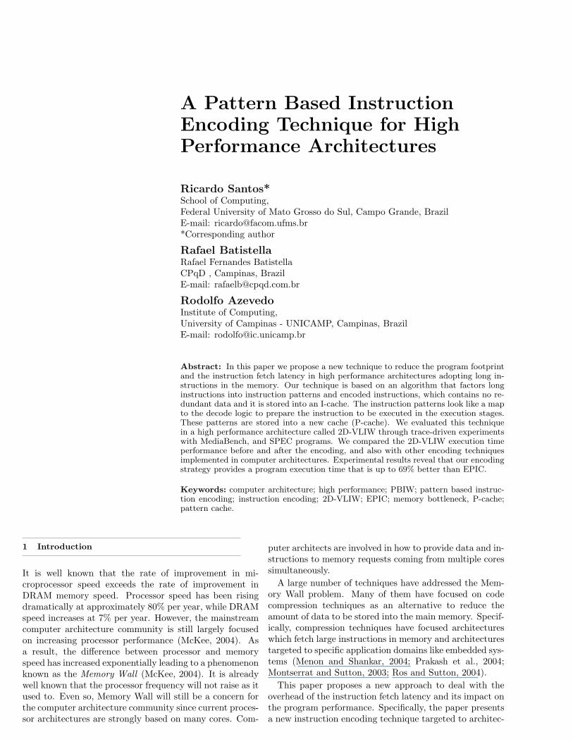
not appear in the instructions of the program anymore.An encoded instruction has no redundant data (registersor immediates) inside it and it is stored into the I-cacheas an usual program instruction. A pattern (or instruc-tion pattern) is a data structure that contains pointers tothe positions in the encoded instruction. These pointersare used as a map to prepare the instruction to be exe-cuted in the execution stages. A pattern is stored into anew cache called P-cache. Figure 1 illustrates the encodingflow of the technique to obtain an encoded instruction andthe pattern. The encoding can be done using the programbinaries after compilation or inside the compiler.
One could consider that this strategy impacts on the fi-nal performance since I-cache misses imply misses in the P-cache. However, previous work from Citron and Feitelson(2002), and Sodani and Sohi (1997) have already demon-strated that many distinct instructions reuse the same pat-tern all over again. Thus, an ideal P-cache organization hasan important feature: an I-cache miss should not imply aP-cache miss. This reuse can be modelled as a surjectionfunction between encoded instructions and their patterns,in such a way that there is a surjection from elements (in-structions) in an I-cache set SI to elements (instructionpatterns) in a P-cache set SP . Thus, as example:
a, b, c, d ∈ SI,
p ∈ SP,
∃ f such that f(a) = f(b) = f(c) = f(d) = p
This is the key aspect for factoring out patterns fromlong instructions. These patterns can be reused by dif-ferent encoded instructions. A large reuse of the patternsmake it possible to reduce the code region of a programsince the encoded instruction size is smaller, sometimesmuch smaller, than a non-encoded instruction and theamount of patterns should be smaller than the numberof encoded instructions.
In the encoding technique design the P-cache can be seenas an element of the processor datapath. Actually, the en-coded instruction format takes advantage of the P-cacheas another element of the existent datapath and allows thecontrol logic to perform other activities while a pattern isfetched. Moreover, the encoding technique does not re-strict the encoded instruction and the instruction patternto a specific size. The area of the encoded instructions andpatterns only depend on the architectural requirements.The technique arranges the data (operands and opcodes)in order to meet this requirement.
A PBIW encoded instruction is divided into four parts:input registers, output registers or immediates, P-cacheindex, and functional unit enable bits. A PBIW instruc-tion pattern contains C operations, where C is the numberof operations of an instruction. Each operation in the in-struction pattern is comprised of one opcode and a fixed setof pointers that point out to the operands in the encodedinstruction. Notice that the instruction operands remainin the encoded instruction.
4 The LIF Algorithm
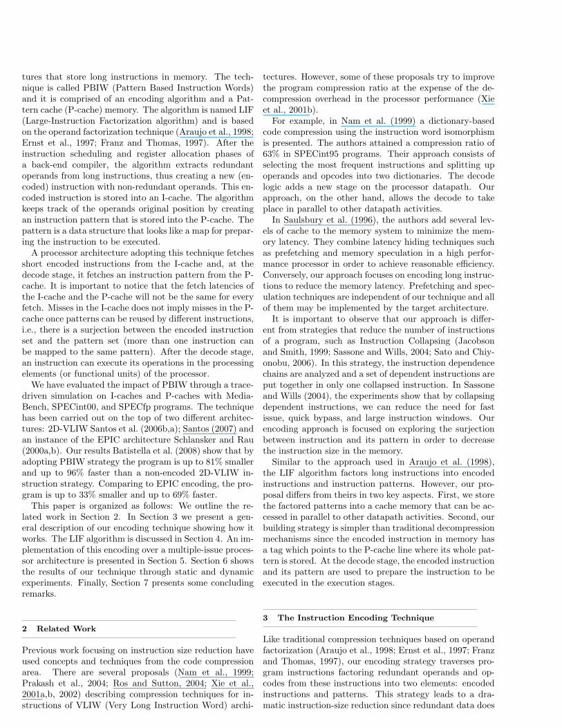
In order to perform other activities (e.g. read operandsfrom the register file) while an encoded instruction fetchesits pattern in the P-cache, the LIF algorithm splits upan encoded instruction into read register operands andwrite/immediate operands. For example, Figure 2(a)presents a code fragment composed of four operations in aMIPS-like assembly language. Figure 2(b) illustrates thecorresponding long instruction. We can notice that the in-struction looks like a common VLIW instruction word. Inthe example, an immediate is larger than a register anddue to this, an immediate uses two instruction fields.
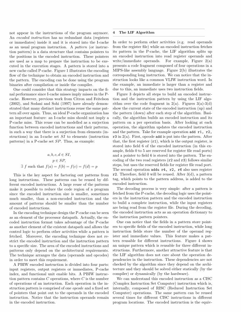
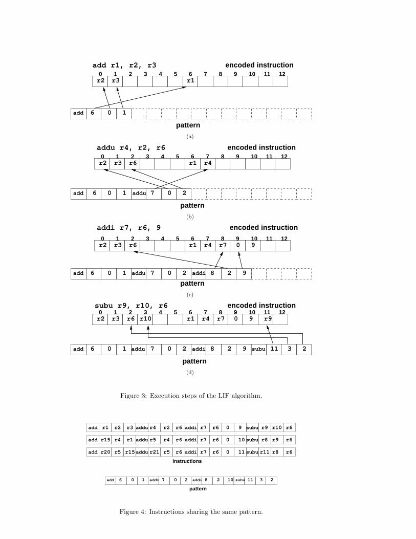
Figure 3 depicts all steps to build an encoded instruc-tion and the instruction pattern by using the LIF algo-rithm over the code fragment in 2(a). Figures 3(a)-3(d)show the current state of the encoded instruction (up) andthe pattern (down) after each step of the algorithm. Basi-cally, the algorithm builds an encoded instruction and itspattern on a per operation basis. After looking at eachoperation, the algorithm updates the encoded instructionand the pattern. Take for example operation add r1, r2,
r3 in 2(a). First, opcode add is put into the pattern. Afterthat, the first register (r1), which is the output register, isstored into field 6 of the encoded instruction (in this ex-ample, fields 0 to 5 are reserved for register file read ports)and a pointer to field 6 is stored into the pattern. The en-coding of the two read registers (r2 and r3) follows similarsteps, but uses the reserved fields for register file read port.The second operation addu r4, r2, r6 also uses registerr2. Therefore, field 0 will be reused. After 3(d), a patterntag, which points to the pattern address, is added to theencoded instruction.
The decoding process is very simple: after a pattern isfetched from the P-cache, the decoding logic uses the point-ers in the instruction pattern and the encoded instructionto build a complete instruction, while the input registersare being read from the register file. During the decoding,the encoded instruction acts as an operation dictionary tothe instruction pattern pointers.
One can notice that the fields in a pattern store point-ers to specific fields of the encoded instruction, while longinstruction fields store the number of the operand reg-ister and immediate values. This feature makes a pat-tern reusable for different instructions. Figure 4 showsan unique pattern which is reusable for three different in-structions. Furthermore, another attractive feature is thatthe LIF algorithm does not care about the operation de-pendencies in the instruction. These dependencies are notchecked by the algorithm since they depend on the archi-tecture and they should be solved either statically (by thecompiler) or dynamically (by the hardware).
We can understand this encoded instruction as a CISC(Complex Instruction Set Computer) instruction which is,internally, composed of RISC (Reduced Instruction SetComputer) operations. The same pattern can be reusedseveral times for different CISC instructions in differentprogram locations. The encoded instruction is the equiv-
Encoded Instruction Instruction Pattern
Program Instructions
TechniqueInstruction Encoding
Figure 1: Execution flow of the encoding technique.
add r1, r2, r3addu r4, r2, r6addi r7, r6, 9subu r9, r10, r6
(a) Code fragment.
addi r7 r6 0addu r4 r2 r6 9 subu r9 r10 r6add r1 r2 r3
(b) Instruction comprised of the operations from 2(a).
Figure 2: Code fragment and the long instruction.
alent of a CISC instruction. RISC operations are repre-sented by the operations stored in the pattern. The patterncan be seen as the microcode required to run the CISC in-struction. The microcode obtains its parameters from theCISC instruction fields.
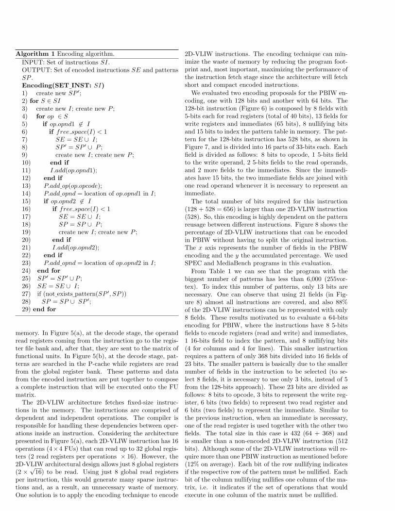
Algorithm 1 presents the main steps of the LIF algo-rithm. For simplicity, some parts of the algorithm such as:finding out similar patterns and adding write registers tothe pattern were left out. The input to this algorithm isa set of instructions (SI) with scheduling and register al-location already performed. Two sets are available on theoutput: the set of encoded instructions (SE) and the setof patterns (SP ).
For each instruction S in set SI (line 2), the algorithmanalyzes the instruction content (line 4) looking whetheroperands op.opnd1 and op.opnd2 of the current operationop are in the encoded instruction I (lines 5 and 15, respec-tively). If they are, pointers must be added to pattern P
in order to indicate which are the correct operands of op-eration op (lines 13, 14, and 23). If, due to some constraintof the architecture, operations cannot be encoded into thecurrent instruction I, these operations will be encoded intoa new instruction (lines 7-9, 17-19). The algorithm has twoimportant loops: the outer loop is used to obtain all theinstructions in the SI set; the inner loop verifies each op-eration in an instruction S selected in the outer loop. Asthe amount of operations in an instruction is constant, the
worst-case complexity of the algorithm is limited by thesize of the SI set and the search step to look for an exis-tent pattern into the SP set. Once the set of patterns canbe, at most, at the same size of SI, the final complexity isO(|SI|2).
5 A Case Study: The 2D-VLIW Architecture
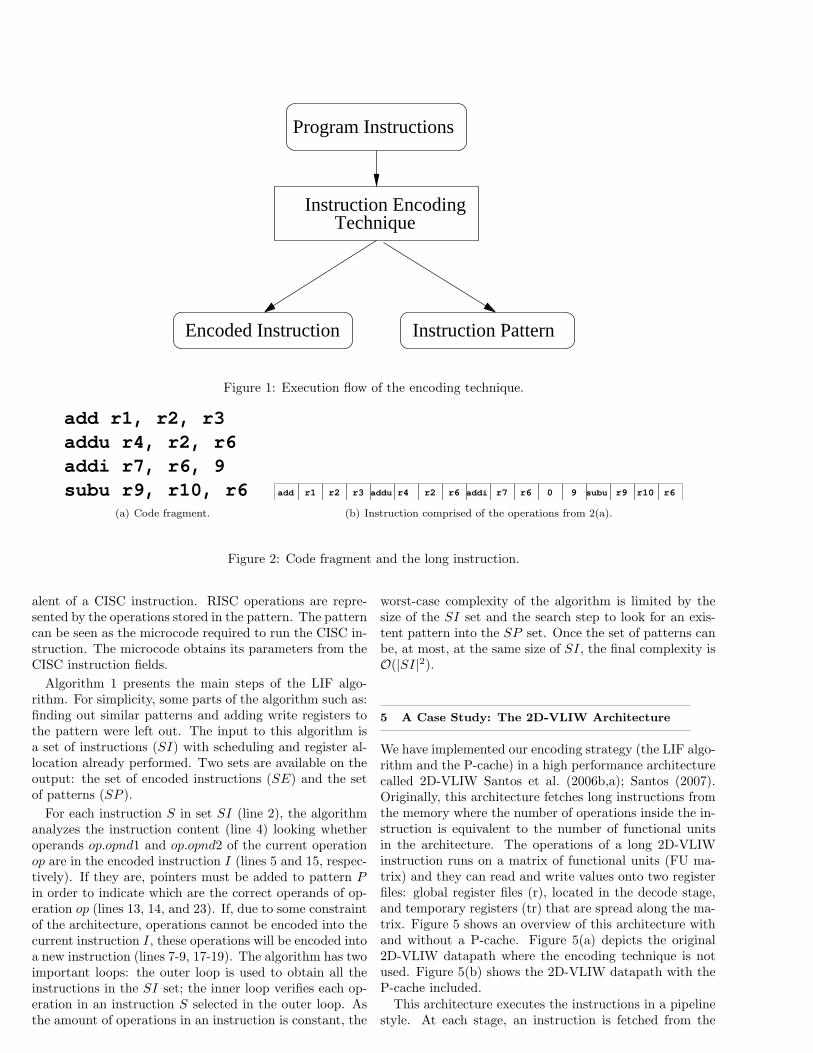
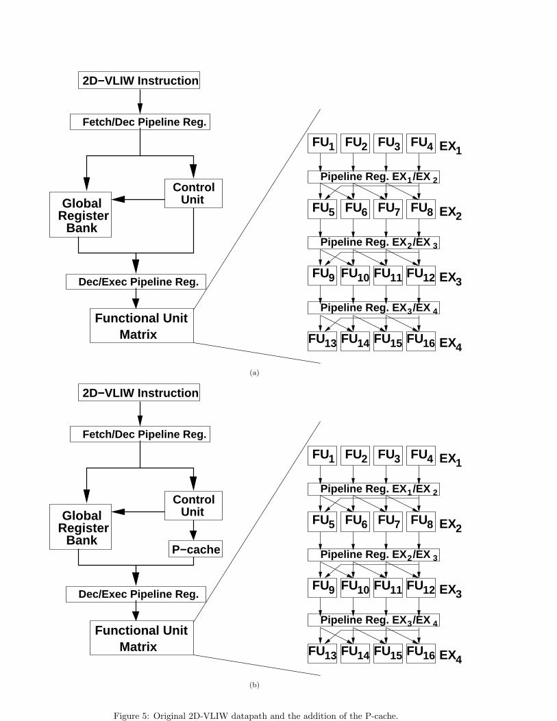
We have implemented our encoding strategy (the LIF algo-rithm and the P-cache) in a high performance architecturecalled 2D-VLIW Santos et al. (2006b,a); Santos (2007).Originally, this architecture fetches long instructions fromthe memory where the number of operations inside the in-struction is equivalent to the number of functional unitsin the architecture. The operations of a long 2D-VLIWinstruction runs on a matrix of functional units (FU ma-trix) and they can read and write values onto two registerfiles: global register files (r), located in the decode stage,and temporary registers (tr) that are spread along the ma-trix. Figure 5 shows an overview of this architecture withand without a P-cache. Figure 5(a) depicts the original2D-VLIW datapath where the encoding technique is notused. Figure 5(b) shows the 2D-VLIW datapath with theP-cache included.This architecture executes the instructions in a pipeline
style. At each stage, an instruction is fetched from the
add r1, r2, r3
r2 r30 1 2 3 4 5 6 7 8 9 10 11 12
r1
pattern
encoded instruction
6add 0 1
(a)
addu r4, r2, r6
r2 r3 r60 1 2 3 4 5 6 7 8 9 10 11 12
r1 r4
encoded instruction
pattern
7 0 2add 0 16 addu
(b)
addi r7, r6, 9
0 1 2 3 4 5 6 7 8 9 10 11 12
encoded instruction
6add 0 1 87 0 2
pattern
r2 r3 r6 r1 r4 90r7
2 9addu addi
(c)
subu r9, r10, r60 1 2 3 4 5 6 7 8 9 10 11 12r2 r3 r6 r1 r4 r7 0 9 r9
6 0 1 27 0 2 8 2
encoded instruction
pattern
9 11 3
r10
add subuaddu addi
(d)
Figure 3: Execution steps of the LIF algorithm.
addi r7 r6 0addu r4 r2 r6 9 subu r9 r10 r6add r1 r2 r3
addu r5 r4 r6 subu r8 r9 r6add r4 r1 addi r7 r6 0 10r15
addu r21 r5 r6 11 subu r8 r6add addi r7 r6 0r15r5r20 r11
instructions
6 0 1 11 3 2subu7 0 2 8 2 10addi
pattern
add addu
Figure 4: Instructions sharing the same pattern.
EX1
EX3
EX4
EX2
UnitControl
GlobalRegister
Bank
MatrixFunctional Unit
FU1 2 FU3 FU4
5 FU6 FU7 FU8
FU9 FU10 11 FU12
FU13 FU14 FU15 FU16
FU
FU
FU
2D−VLIW Instruction
Dec/Exec Pipeline Reg.
Fetch/Dec Pipeline Reg.
3
3 4
2
1 2
Pipeline Reg. EX /EX
Pipeline Reg. EX /EX
Pipeline Reg. EX /EX
(a)
EX1
EX3
EX4
EX2
UnitControl
GlobalRegister
Bank
MatrixFunctional Unit
FU1 2 FU3 FU4
5 FU6 FU7 FU8
FU9 FU10 11 FU12
FU13 FU14 FU15 FU16
FU
FU
FU
2D−VLIW Instruction
Dec/Exec Pipeline Reg.
Fetch/Dec Pipeline Reg.
3
3 4
2
1 2
Pipeline Reg. EX /EX
Pipeline Reg. EX /EX
Pipeline Reg. EX /EX
P−cache
(b)
Figure 5: Original 2D-VLIW datapath and the addition of the P-cache.
Algorithm 1 Encoding algorithm.
INPUT: Set of instructions SI.OUTPUT: Set of encoded instructions SE and patternsSP .Encoding(SET INST: SI)1) create new SP ′;2) for S ∈ SI
3) create new I; create new P ;4) for op ∈ S
5) if op.opnd1 6∈ I
6) if free space(I) < 17) SE = SE ∪ I;8) SP ′ = SP ′ ∪ P ;9) create new I; create new P ;10) end if11) I.add(op.opnd1);12) end if13) P.add op(op.opcode);14) P.add opnd = location of op.opnd1 in I;15) if op.opnd2 6∈ I
16) if free space(I) < 117) SE = SE ∪ I;18) SP = SP ∪ P ;19) create new I; create new P ;20) end if21) I.add(op.opnd2);22) end if23) P.add opnd = location of op.opnd2 in I;24) end for25) SP ′ = SP ′ ∪ P ;26) SE = SE ∪ I;27) if (not exists pattern(SP ′, SP ))28) SP = SP ∪ SP ′;29) end for
memory. In Figure 5(a), at the decode stage, the operandread registers coming from the instruction go to the regis-ter file bank and, after that, they are sent to the matrix offunctional units. In Figure 5(b), at the decode stage, pat-terns are searched in the P-cache while registers are readfrom the global register bank. These patterns and datafrom the encoded instruction are put together to composea complete instruction that will be executed onto the FUmatrix.
The 2D-VLIW architecture fetches fixed-size instruc-tions in the memory. The instructions are comprised ofdependent and independent operations. The compiler isresponsible for handling these dependencies between oper-ations inside an instruction. Considering the architecturepresented in Figure 5(a), each 2D-VLIW instruction has 16operations (4×4 FUs) that can read up to 32 global regis-ters (2 read registers per operations × 16). However, the2D-VLIW architectural design allows just 8 global registers(2 ×
√16) to be read. Using just 8 global read registers
per instruction, this would generate many sparse instruc-tions and, as a result, an unnecessary waste of memory.One solution is to apply the encoding technique to encode
2D-VLIW instructions. The encoding technique can min-imize the waste of memory by reducing the program foot-print and, most important, maximizing the performance ofthe instruction fetch stage since the architecture will fetchshort and compact encoded instructions.
We evaluated two encoding proposals for the PBIW en-coding, one with 128 bits and another with 64 bits. The128-bit instruction (Figure 6) is composed by 8 fields with5-bits each for read registers (total of 40 bits), 13 fields forwrite registers and immediates (65 bits), 8 nullifying bitsand 15 bits to index the pattern table in memory. The pat-tern for the 128-bits instruction has 528 bits, as shown inFigure 7, and is divided into 16 parts of 33-bits each. Eachfield is divided as follows: 8 bits to opcode, 1 5-bits fieldto the write operand, 2 5-bits fields to the read operands,and 2 more fields to the immediates. Since the immedi-ates have 15 bits, the two immediate fields are joined withone read operand whenever it is necessary to represent animmediate.
The total number of bits required for this instruction(128 + 528 = 656) is larger than one 2D-VLIW instruction(528). So, this encoding is highly dependent on the patternreusage between different instructions. Figure 8 shows thepercentage of 2D-VLIW instructions that can be encodedin PBIW without having to split the original instruction.The x axis represents the number of fields in the PBIWencoding and the y the accumulated percentage. We usedSPEC and MediaBench programs in this evaluation.
From Table 1 we can see that the program with thebiggest number of patterns has less than 6,000 (255vor-tex). To index this number of patterns, only 13 bits arenecessary. One can observe that using 21 fields (in Fig-ure 8) almost all instructions are covered, and also 88%of the 2D-VLIW instructions can be represented with only8 fields. These results motivated us to evaluate a 64-bitsencoding for PBIW, where the instructions have 8 5-bitsfields to encode registers (read and write) and immediates,1 16-bits field to index the pattern, and 8 nullifying bits(4 for columns and 4 for lines). This smaller instructionrequires a pattern of only 368 bits divided into 16 fields of23 bits. The smaller pattern is basically due to the smallernumber of fields in the instruction to be selected (to se-lect 8 fields, it is necessary to use only 3 bits, instead of 5from the 128-bits approach). These 23 bits are divided asfollows: 8 bits to opcode, 3 bits to represent the write reg-ister, 6 bits (two fields) to represent two read register and6 bits (two fields) to represent the immediate. Similar tothe previous instruction, when an immediate is necessary,one of the read register is used together with the other twofields. The total size in this case is 432 (64 + 368) andis smaller than a non-encoded 2D-VLIW instruction (512bits). Although some of the 2D-VLIW instructions will re-quire more than one PBIW instruction as mentioned before(12% on average). Each bit of the row nullifying indicatesif the respective row of the pattern must be nullified. Eachbit of the column nullifying nullifies one column of the ma-trix, i.e. it indicates if the set of operations that wouldexecute in one column of the matrix must be nullified.
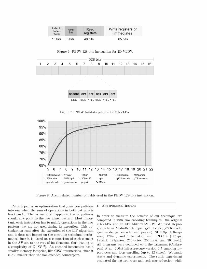
Figure 6: PBIW 128 bits instruction for 2D-VLIW.
Figure 7: PBIW 528-bits pattern for 2D-VLIW.
Figure 8: Accumulated number of fields used in the PBIW 128-bits instruction.
Pattern join is an optimization that joins two patternsinto one when the sum of operations in both patterns isless than 16. The instructions mapping to the old patternsshould now point to the new joined pattern. Most impor-tant, each instruction has to nullify operations in the newpattern that are not used during its execution. This op-timization runs after the execution of the LIF algorithmand it does not impact on the encoding technique perfor-mance since it is based on a comparison of each elementin the SP set to the rest of its elements, thus leading toa complexity of O(|SP |2). An encoded instruction has asmaller memory footprint, like CISC instructions, since itis 8× smaller than the non-encoded counterpart.
6 Experimental Results
In order to measure the benefits of our technique, wecompared it with two encoding techniques: the original2D-VLIW and an EPIC-like 2D-VLIW. We used 15 pro-grams from MediaBench (epic, g721decode, g721encode,gsmdecode, gsmencode, and pegwit), SPECfp (168wup-wise, 179art, and 183equake), and SPECint (175vpr,181mcf, 197parser, 255vortex, 256bzip2, and 300twolf).All programs were compiled with the Trimaran (Chakra-pani et al., 2004) infrastructure version 3.7 enabling hy-perblocks and loop unrolling (up to 32 times). We madestatic and dynamic experiments. The static experimentevaluated the pattern reuse and code size reduction, while
the dynamic evaluated the program performance. Perfor-mance was evaluated by creating and using an executiontrace together with Dinero cache simulator (Edler and Hill,1995). The 2D-VLIW model adopted was described in theHMDES, which is the architecture description languageused in Trimaran.
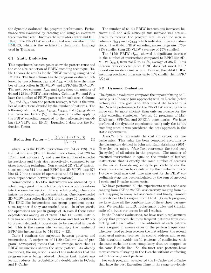
6.1 Static Evaluation
This experiment has two goals: show the pattern reuse andthe code size reduction of PBIW encoding technique. Ta-ble 1 shows the results for the PBIW encoding using 64 and128 bits. The first column has the programs evaluated, fol-lowed by two columns, I2d, and Ie2d, which have the num-ber of instruction in 2D-VLIW and EPIC-like 2D-VLIW.The next two columns, Ip64, and Ip128 show the number of64 and 128 bits PBIW instructions. Columns P64, and P128
have the number of PBIW patterns for each size. ColumnsR64, and R128 show the pattern reusage, which is the num-ber of instructions divided by the number of patterns. Thefollowing columns, F2d64, F2d128, Fe2d64, and Fe2d128 showsthe Reduction Factor (%) of the programs after applyingthe PBIW encoding compared to their alternative encod-ing (2D-VLIW and EPIC). Equation 1 describes the Re-duction Factor.
Reduction Factor = 1− ((Ip × α) + (P × β))
(Ix × γ)(1)
where: α is the PBIW instruction size (64 or 128). β isthe pattern size (368 for 64-bit instructions, and 528 for128-bit instructions). Ix and γ are the number of encodedinstructions and their size respectivelly, compared to an-other encoding technique. Non-encoded 2D-VLIW instruc-tions requires 512 bits and EPIC-like 2D-VLIW uses 576bits (512 bits to store 16 operations and 64 further bits tostore dependencies between the operations).
Non-encoded 2D-VLIW instructions are obtained by ascheduling algorithm which greedily tries to put operationsinto the same instruction. This scheduling algorithm max-imizes the occupation of one instruction. One non-encoded2D-VLIW instruction has 512 bits to store 16 operations.The EPIC-like instructions can group dependent opera-tions together if they are marked as so. In other words,the operations are put in groups of 16 even if there existsdependencies among all of them. One EPIC-like instruc-tion has 512 bits to store 16 operations and further 32 bitsto prevent dependent operations to be executed in paral-lel. This is the reason why we multiply the number ofEPIC-like instructions by 544 (512 + 32).
Table 1 confirms the surjection between patterns andinstructions. A surjection of 11.29 (Column R64 of pro-gram 168wupwise) means that, on average, more than 11PBIW instructions shares the same pattern. As alreadymentioned, the surjection is one of the indicators that theprogram size is being reduced. Besides that, higher sur-jection reduces the probability of a double miss in I-Cacheand P-Cache.
The number of 64-bit PBIW instructions increased be-tween 19% and 39% although this increase was not su-ficient to increase the program size, as can be seen incolumns F2d64 and Fe2d64 which indicates program reduc-tions. The 64-bit PBIW encoding makes programs 67%–81% smaller than 2D-VLIW (average of 75% smaller).The 64-bit PBIW (Ip64) showed a significant increase
in the number of instructions compared to EPIC-like 2D-VLIW (I32d), from 234% to 471%, average of 387%. Thisincrease was expected since EPIC does not insert NOPoperations inside an instruction. Even so, the 64-bit PBIWencoding produced programs up to 46% smaller than EPIC(Fe2d64).
6.2 Dynamic Evaluation
The dynamic evaluation compares the impact of using an I-cache plus a P-cache (our approach) with an I-cache (othertechniques). The goal is to determine if the I-cache plusthe P-cache performance for the 2D-VLIW encoding tech-nique can be more efficient than only an I-cache for theother encoding strategies. We use 10 programs of ME-DIABench, SPECint and SPECfp benchmarks. We haveperformed the dynamic experiments using only the 64-bitencoding since it was considered the best approach in thestatic experiments.MissPenalty represents the cost (in cycles) for one
cache miss. This value has been computed according tothe parameters defined in John and Radhakrishnan (2007)(5 cycles per miss). MissCost represents the total cost(in cycles) of all misses in the program. The number ofexecuted instructions is equal to the number of fetchedinstructions that is exactly the same number of accessesin the cache. Considering one cycle per cache access, theExecutionT ime can be calculated by the number of hits ×1 cycle + total miss cost. The miss cost for the PBIW en-coding strategy has been calculated by the sum of encodedI-cache and P-cache misses costs.We have performed all the experiments with cache size
ranging from 4KB to 256KB, associativity ranging from di-rect mapping to 4-way set associative and finally, numberof words per block ranging from 1 to 4. For each program,we have done all the combinations of these three parame-ters. We consider an LRU replacement policy and transferratio of 4 bytes per access for all I-caches.In the P-cache evaluations, we have used a replacement
policy that protects the most frequent patterns from con-flicting with each other. The addresses of each patternwere assigned in inverse order of the pattern frequencies.The most used pattern receives the first address, the secondmost used pattern receives the second address and so on.This algorithm avoids useful patterns of conflicting withthe same cache line since compulsory data are mapped tothe same P-cache line. So, the most used patterns havemore chances of staying in the P-cache without conflictingwith other very used patterns.For each program, we selected the P-Cache and I-Cache
that have the best Execution Time in the range previously
Program I2d Ie2d Ip64 Ip128 P64 P128 R64 R128 F2d64 F2d128 Fe2d64 Fe2d128
168wupwise 7.66 1.80 10.03 7.90 0.89 1.06 11.29 11.01 75 73 6 -3
175vpr 40.18 10.04 53.32 40.63 3.56 4.91 14.99 14.91 77 75 18 10
179art 9.07 2.05 11.71 9.32 1.00 1.22 11.67 11.47 76 73 5 -5
181mcf 5.85 1.53 7.69 5.90 0.80 0.98 9.57 9.46 74 70 11 -2
183equake 8.47 2.01 11.11 8.65 1.09 1.30 10.20 9.99 74 71 4 -7
197parser 41.69 11.39 55.55 41.95 3.93 5.36 4.15 14.08 77 74 24 16
255vortex 79.60 25.92 110.41 80.12 2.88 5.92 38.39 37.40 80 80 46 45
256bzip2 17.57 4.13 22.13 17.71 1.70 2.12 13.00 12.99 77 75 14 5
300twolf 66.20 15.34 78.47 66.35 4.14 5.52 18.95 18.92 81 79 26 19
epic 3.03 1.21 4.04 3.08 0.57 0.67 7.11 6.90 70 65 33 21
g721decode 1.64 0.53 2.19 1.64 0.37 0.39 5.91 5.94 67 63 9 -2
g721encode 1.65 0.53 2.20 1.65 0.37 0.39 6.02 6.02 67 63 10 -1
gsmdecode 9.91 2.65 11.80 9.91 0.75 0.93 15.75 15.32 80 78 33 26
gsmencode 13.01 3.20 15.56 13.02 1.07 1.30 14.48 14.21 79 77 25 18
pegwit 13.64 3.12 16.90 13.65 1.20 1.50 14.05 13.83 78 76 15 7
Average 21.28 5.70 27.54 21.43 1.62 2.24 13.70 13.50 75 73 19 10
Table 1: Number of instructions and patterns (×1000) and PBIW Reduction Factor (%).
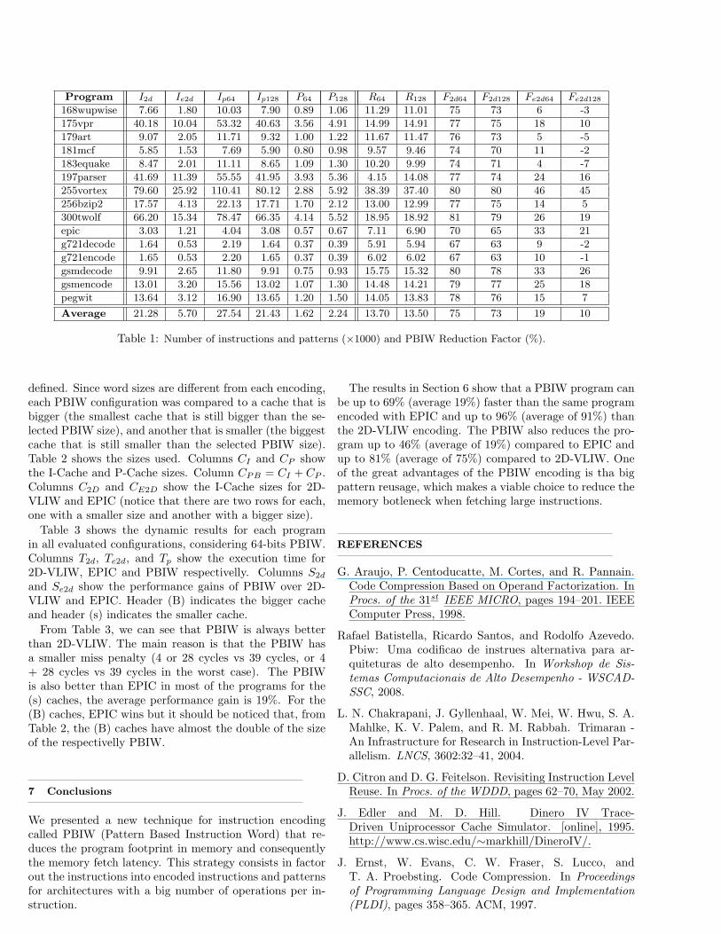
defined. Since word sizes are different from each encoding,each PBIW configuration was compared to a cache that isbigger (the smallest cache that is still bigger than the se-lected PBIW size), and another that is smaller (the biggestcache that is still smaller than the selected PBIW size).Table 2 shows the sizes used. Columns CI and CP showthe I-Cache and P-Cache sizes. Column CPB = CI + CP .Columns C2D and CE2D show the I-Cache sizes for 2D-VLIW and EPIC (notice that there are two rows for each,one with a smaller size and another with a bigger size).
Table 3 shows the dynamic results for each programin all evaluated configurations, considering 64-bits PBIW.Columns T2d, Te2d, and Tp show the execution time for2D-VLIW, EPIC and PBIW respectivelly. Columns S2d
and Se2d show the performance gains of PBIW over 2D-VLIW and EPIC. Header (B) indicates the bigger cacheand header (s) indicates the smaller cache.
From Table 3, we can see that PBIW is always betterthan 2D-VLIW. The main reason is that the PBIW hasa smaller miss penalty (4 or 28 cycles vs 39 cycles, or 4+ 28 cycles vs 39 cycles in the worst case). The PBIWis also better than EPIC in most of the programs for the(s) caches, the average performance gain is 19%. For the(B) caches, EPIC wins but it should be noticed that, fromTable 2, the (B) caches have almost the double of the sizeof the respectivelly PBIW.
7 Conclusions
We presented a new technique for instruction encodingcalled PBIW (Pattern Based Instruction Word) that re-duces the program footprint in memory and consequentlythe memory fetch latency. This strategy consists in factorout the instructions into encoded instructions and patternsfor architectures with a big number of operations per in-struction.
The results in Section 6 show that a PBIW program canbe up to 69% (average 19%) faster than the same programencoded with EPIC and up to 96% (average of 91%) thanthe 2D-VLIW encoding. The PBIW also reduces the pro-gram up to 46% (average of 19%) compared to EPIC andup to 81% (average of 75%) compared to 2D-VLIW. Oneof the great advantages of the PBIW encoding is tha bigpattern reusage, which makes a viable choice to reduce thememory botleneck when fetching large instructions.
REFERENCES
G. Araujo, P. Centoducatte, M. Cortes, and R. Pannain.Code Compression Based on Operand Factorization. InProcs. of the 31st IEEE MICRO, pages 194–201. IEEEComputer Press, 1998.
Rafael Batistella, Ricardo Santos, and Rodolfo Azevedo.Pbiw: Uma codificao de instrues alternativa para ar-quiteturas de alto desempenho. In Workshop de Sis-temas Computacionais de Alto Desempenho - WSCAD-SSC, 2008.
L. N. Chakrapani, J. Gyllenhaal, W. Mei, W. Hwu, S. A.Mahlke, K. V. Palem, and R. M. Rabbah. Trimaran -An Infrastructure for Research in Instruction-Level Par-allelism. LNCS, 3602:32–41, 2004.
D. Citron and D. G. Feitelson. Revisiting Instruction LevelReuse. In Procs. of the WDDD, pages 62–70, May 2002.
J. Edler and M. D. Hill. Dinero IV Trace-Driven Uniprocessor Cache Simulator. [online], 1995.http://www.cs.wisc.edu/∼markhill/DineroIV/.
J. Ernst, W. Evans, C. W. Fraser, S. Lucco, andT. A. Proebsting. Code Compression. In Proceedingsof Programming Language Design and Implementation(PLDI), pages 358–365. ACM, 1997.
Word Size CI CP CPB C2D CE2D
64 bits
8 5.8 13.88 916 18
8 2.9 10.98 916 18
32 2.9 34.932 1864 36
128 bits
8 4.1 12.18 916 18
16 4.1 20.116 1832 36
32 4.1 36.132 3664 72
Table 2: Cache sizes (in KB) considered.
Program T2d (s) T2d (B) Te2d (s) Te2d (B) Tp S2d (s) S2d (B) Se2d (s) Se2d (B)
168wupwise 18,124 18,124 5,122 3,443 3,484 81 81 32 -1
175vpr 97 50 9 6 9 90 81 -1 -46
179art 12,801 4,447 419 418 532 96 88 -27 -27
183equake 471 350 22 16 19 96 95 12 -22
197parser 1,546 861 261 205 280 82 68 -7 -36
256bzip2 56,735 45,523 2,180 1,878 2,253 96 95 -3 -20
g721decode 4,670 4,494 954 199 292 94 94 69 -47
g721encode 4,727 4,603 1,024 213 335 93 93 67 -58
gsmdecode 4,242 508 328 294 275 94 46 16 6
pegwit 1,641 1,116 188 133 129 92 88 31 3
Average 10,505 8,007 1,051 680 761 91 83 19 -25
Table 3: Execution time (×106 cycles) and performance gains (%) of 64-bit PBIW.
M. Franz and K. Thomas. Slim binaries. Communicationsof the ACM, 40(2):87–94, 1997.
Quinn Jacobson and James E. Smith. In-struction pre-processing in trace processors.In High Performance Computer Architec-ture (HPCA), pages 125–129, 1999. URLciteseer.ist.psu.edu/jacobson99instruction.html.
L. John and R. Radhakrishnan. A Selective Caching Tech-nique, 2007. http://citeseer.ist.psu.edu/115017.html.
S. A. McKee. Reflections on the Memory Wall. In Procs.of the 1st ACM Computing Frontiers, pages 162–167.ACM, April 2004.
S. K. Menon and P. Shankar. Space/Time Tradeoffsin Code Compression for the TMS320C62x Processor.Technical Report IISc-CSA-TR-2004-4, Indian Instituteof Science, India, 2004.
Ros Montserrat and Peter Sutton. Compiler Optimizationand Ordering Effects on VLIW Code Compression. InProceedings of the International Conference on Compil-ers, Architectures, and Synthesis for Embedded Systems,pages 95–103. ACM, November 2003.
S-J. Nam, I-C. Park, and C-H. Kyung. ImprovingDictionary-Based Code Compression in VLIW Archi-
tectures. IEICE Transactions on Fundamentals, E82-A(11):2318–2324, November 1999.
J. Prakash, C. Sandeep, P. Shankar, and Y. N. Srikant.Experiments with a New Dictionary Based Code-Compression Tool on a VLIW Processor. Technical Re-port IISc-CSA-TR-2004-5, Indian Institute of Science,India, 2004.
M. Ros and P. Sutton. Code Compression Based onOperand-Factorization for VLIW Processors. In Procs.of the CASES, pages 559–569. ACM Press, September2004.
R. Santos. 2D-VLIW: An Processor Architecture Based onthe Geometry of the Computation. PhD thesis, Unicamp,Brazil, Junho 2007.
R. Santos, R. Azevedo, and G. Araujo. Exploiting Dy-namic Reconfiguration Techniques: The 2D-VLIW Ap-proach. In Proceedings of the 13rd IEEE InternationalReconfigurable Architectures Workshop (RAW), RhodesIsland - Greece, 2006a. IEEE Computer Society.
R. Santos, R. Azevedo, and G. Araujo. 2D-VLIW: AnArchitecture Based on the Geometry of the Computa-tion. In Proceedings of the of the 17th IEEE Interna-tional Conference on Application-specific, Systems, Ar-
chitectures and Processors (ASAP), Steamboat Springs- Colorado, 2006b. IEEE Computer Society.
Peter G. Sassone and D. Scott Wills. Dynamic Strands:Collapsing Speculative Dependence Chains for Reduc-ing Pipeline Communication. In Procs. of the 37th
IEEE/ACM MICRO, pages 7–17, Washington, DC,USA, 2004. IEEE Computer Society. ISBN 0-7695-2126-6. doi: http://dx.doi.org/10.1109/MICRO.2004.16.
Toshinori Sato and Akihiro Chiyonobu. A preliminaryevaluation of timing-speculative instruction collapsing.In Proc. of 1st Workshop on Introspective Architectures,2006.
A. Saulsbury, F. Pong, and A. Nowatzyk. Missing theMemory Wall: The Case for Processor/Memory Inte-gration. In ISCA, pages 90–101, Philadelphia, October1996. ACM.
M. S. Schlansker and B. R. Rau. EPIC: An Architecturefor Instruction-Level Parallel Processors. Technical Re-port 99-111, Hewlett Packard Laboratories Palo Alto,February 2000a.
M. S. Schlansker and B. R. Rau. EPIC: Explicitly ParallelInstruction Computing. IEEE Computer, 33(2):37–45,February 2000b.
A. Sodani and G. S. Sohi. Dynamic Instruction Reuse. InISCA, pages 194–205. ACM, 1997.
Y. Xie, W. Wolf, and H. Lekatsas. A Code DecompressionArchitecture for VLIW Processors. In Proceedings of the34th IEEE/ACM International Symposium on Microar-chitecture, pages 66–75. IEEE Computer Press, 2001a.
Y. Xie, W. Wolf, and H. Lekatsas. Compression Ratioand Decompression Overhead Tradeoffs in Code Com-pression for VLIW Architectures. In Proceedings of the4th International Conference on ASIC, pages 337–341,October 2001b.
Y. Xie, W. Wolf, and H. Lekatsas. Code Compression forVLIW Processors Using Variable-to-Fixed Coding. InProceedings of the 15th IEEE/ACM International Sym-posium on System Synthesis, pages 138–143. IEEE Com-puter Press, 2002.


