Embed Size (px)
Citation preview
A RETINEX based Haze Removal MethodSudharsan Parthasarathy
Department of Electronics and Communication EngineeringNational Institute of Technology Calicut
Kerala, IndiaEmail:[email protected]
Praveen SankaranDepartment of Electronics and Communication Engineering
National Institute of Technology CalicutKerala, India
Email: [email protected]
Abstract—One of the most interesting problems in recent timesin image processing and computer vision is fog, haze and rainremoval from images. In this paper we shall consider the problemof haze removal. One of the latest haze removal algorithmsproposed by Kaiming et al. [1] uses a dark channel prior basedapproach for haze removal. Though this approach gives verygood results, this method is computationally complex. In thispaper we propose a RETINEX based approach that gives goodresults and is also computationally simpler.
I. INTRODUCTION
Images photographed in hazy or foggy conditions capturethe scene correctly as the observer sees it. But there areapplications like the landing system of aeroplanes or automaticcar driving systems where it is important to see the objectsthat are obscured in the haze or fog. Haze removal methodscan be divided into three broad categories viz. algorithmsthat use i) multiple images, ii) apriori information and iii)single image. Polarising filter based algorithm uses two ormore images for haze removal. The algorithm works on theprinciple that ‘airlight’ of the image is polarized [2]. Wewill see the term ‘airlight’ in Section II. Another algorithmby Narasimhan et al. [3] for haze removal uses multipleimages taken under different weather conditions. Haze removalalgorithms using apriori information needs either user supplieddepth information [4] or a 3D model [5]. Recently singleimage based haze removal models have been proposed. Thesemodels use the haze formation physical model that has beendeveloped by Koschmieder [6]. Narasimhan et al. [7] describein detail the physics behind the atmosphere optics and thehaze formation model. In 2008, Tarel proposed a single imagebased haze removal algorithm [8]. He observed that a hazefree image has higher local contrast than a hazy image. So hewas able to obtain haze free image by maximizing the localcontrast in the hazy image. The drawback of this approach isthat it is not based on haze formation physical model and hencethe haze free images appear unnatural due to over saturation ofcolours. Recently in 2011 Kaiming et al. [1] proposed a darkchannel prior based approach. This approach gives us goodresults but it is computationally complex.
In this paper we propose a retinex based approach for hazeremoval. This method uses the Koschmieder haze formationmethod and also reduces the computational time when com-pared to the dark channel prior method. In Section II we will
see the Koschmieder haze formation model. In Section III weshall see Kaiming et al.’s dark channel prior method. In SectionIV we shall describe the retinex model. In Section V we shalldiscuss the proposed retinex based haze removal approach. InSection VI we shall discuss the results in detail.
II. KOSCHMIEDER MODEL
The optical model used to describe the formation of hazeproposed by Koschmieder [6] is given as
Ic(x) = Jc(x)t(x) + (1− t(x))Ac (1)
where Ic(x) represents a hazy image. c represents Red,Green and Blue colour bands. Jc(x) represents a haze free im-age in the three colour bands. t(x) represents the transmissionmap. We assume the transmission remains constant across allthree color bands. Ac represents the global atmospheric lightin three colour bands. Ac is a constant that affects all pixelsin the image in the same manner. The challenge has been toobtain t(x) and Ac from the hazy image Ic(x) and hence findthe haze free image Jc(x).The term Jc(x)t(x) is called direct attenuation and it is amultiplicative distortion of the scene radiance Jc(x). The term(1− t(x))Ac is called airlight and it is an additive distortionof the scene radiance. In a homogeneous atmosphere, trans-mission t(x) can be expressed as
t(x) = exp (−βd(x)) (2)
where d(x) represents the depth of the scene and β representsthe scattering coefficient of the atmosphere.
III. DARK CHANNEL PRIOR METHOD
Dark channel prior method [1] is based on the principle thatin a haze free image the intensity of at least one of the threechannels is very low(dark) and close to zero. The dark channelcan be described as
Jdark(x) = minyεΩ(x)
( mincεr,g,b
Jc(y)) (3)
where J is any arbitrary image, x and y represents the pixelsof the image. Jc is a color band of J and Ω(x) is a localpatch area centered at pixel x of the image. A filter of sizeΩ(x)=15 is typically used.
978-1-4673-2605-6/12/$31.00 c© 2012 IEEE
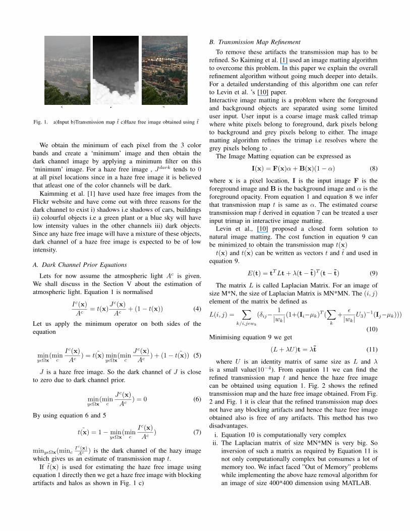
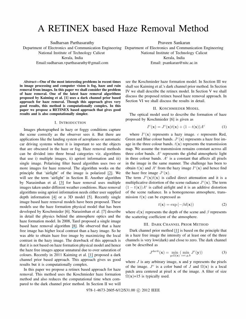
Fig. 1. a)Input b)Transmission map t c)Haze free image obtained using t
We obtain the minimum of each pixel from the 3 colorbands and create a ‘minimum’ image and then obtain thedark channel image by applying a minimum filter on this‘minimum’ image. For a haze free image , Jdark tends to 0at all pixel locations since in a haze free image it is believedthat atleast one of the color channels will be dark.
Kaimming et al. [1] have used haze free images from theFlickr website and have come out with three reasons for thedark channel to exist i) shadows i.e shadows of cars, buildingsii) colourful objects i.e a green plant or a blue sky will havelow intensity values in the other channels iii) dark objects.Since any haze free image will have a mixture of these objects,dark channel of a haze free image is expected to be of lowintensity.
A. Dark Channel Prior Equations
Lets for now assume the atmospheric light Ac is given.We shall discuss in the Section V about the estimation ofatmospheric light. Equation 1 is normalised
Ic(x)
Ac= t(x)
Jc(x)
Ac+ (1− t(x)) (4)
Let us apply the minimum operator on both sides of theequation
minyεΩx
(minc
Ic(x)
Ac) = ˜t(x) min
yεΩx(minc
Jc(x)
Ac) + (1− ˜t(x)) (5)
J is a haze free image. So the dark channel of J is closeto zero due to dark channel prior.
minyεΩx
(minc
Jc(x)
Ac) = 0 (6)
By using equation 6 and 5
˜t(x) = 1− minyεΩx
(minc
Ic(x)
Ac) (7)
minyεΩx(mincIc(x)Ac ) is the dark channel of the hazy image
which gives us an estimate of transmission map t.If t(x) is used for estimating the haze free image using
equation 1 directly then we get a haze free image with blockingartifacts and halos as shown in Fig. 1 c)
B. Transmission Map Refinement
To remove these artifacts the transmission map has to berefined. So Kaiming et al. [1] used an image matting algorithmto overcome this problem. In this paper we explain the overallrefinement algorithm without going much deeper into details.For a detailed understanding of this algorithm one can referto Levin et al. ’s [10] paper.Interactive image matting is a problem where the foregroundand background objects are separated using some limiteduser input. User input is a coarse image mask called trimapwhere white pixels belong to foreground, dark pixels belongto background and grey pixels belong to either. The imagematting algorithm refines the trimap i.e resolves where thegrey pixels belong to .
The Image Matting equation can be expressed as
I(x) = F(x)α+ B(x)(1− α) (8)
where x is a pixel location, I is the input image F is theforeground image and B is the background image and α is theforeground opacity. From equation 1 and equation 8 we inferthat transmission map t is same as α. The estimated coarsetransmission map t derived in equation 7 can be treated a userinput trimap in interactive image matting.
Levin et al., [10] proposed a closed form solution tonatural image matting. The cost function in equation 9 canbe minimized to obtain the transmission map t(x)t(x) and ˜t(x) can be written as vectors t and t and used in
equation 9.
E(t) = tTLt + λ(t− t)T (t− t) (9)
The matrix L is called Laplacian Matrix. For an image ofsize M*N, the size of Laplacian Matrix is MN*MN. The (i, j)element of the matrix be defined as
L(i, j) =∑
k/i,jεwk
(δij−1
|wk|(1+(Ii−µk)T (
∑k
+ε
|wk|U3)−1(Ij−µk)))
(10)Minimising equation 9 we get
(L+ λU)t = λt (11)
where U is an identity matrix of same size as L and λis a small value(10−4). From equation 11 we can find therefined transmission map t and hence the haze free imagecan be obtained using equation 1. Fig. 2 shows the refinedtransmission map and the haze free image obtained. From Fig.2 and Fig. 1 it is clear that the refined transmission map doesnot have any blocking artifacts and hence the haze free imageobtained also is free of any artifacts. This method has twodisadvantages.
i. Equation 10 is computationally very complexii. The Laplacian matrix of size MN*MN is very big. So
inversion of such a matrix as required by Equation 11 isnot only computationally complex but consumes a lot ofmemory too. We infact faced ”Out of Memory” problemswhile implementing the above haze removal algorithm foran image of size 400*400 dimension using MATLAB.
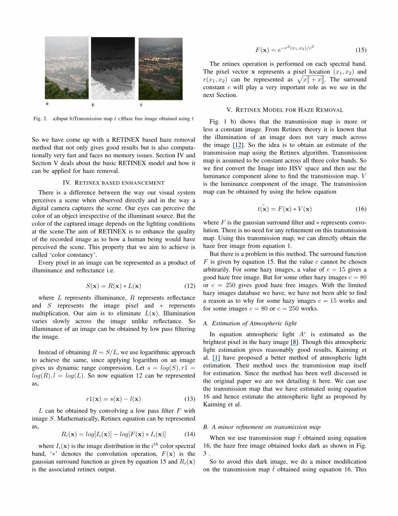
Fig. 2. a)Input b)Transmission map t c)Haze free image obtained using t
So we have come up with a RETINEX based haze removalmethod that not only gives good results but is also computa-tionally very fast and faces no memory issues. Section IV andSection V deals about the basic RETINEX model and how itcan be applied for haze removal.
IV. RETINEX BASED ENHANCEMENT
There is a difference between the way our visual systemperceives a scene when observed directly and in the way adigital camera captures the scene. Our eyes can perceive thecolor of an object irrespective of the illuminant source. But thecolor of the captured image depends on the lighting conditionsat the scene.The aim of RETINEX is to enhance the qualityof the recorded image as to how a human being would haveperceived the scene. This property that we aim to achieve iscalled ‘color constancy’.
Every pixel in an image can be represented as a product ofilluminance and reflectance i.e.
S(x) = R(x) ∗ L(x) (12)
where L represents illuminance, R represents reflectanceand S represents the image pixel and ∗ representsmultiplication. Our aim is to eliminate L(x). Illuminationvaries slowly across the image unlike reflectance. Soilluminance of an image can be obtained by low pass filteringthe image.
Instead of obtaining R = S/L, we use logarithmic approachto achieve the same, since applying logarithm on an imagegives us dynamic range compression. Let s = log(S), r1 =log(R), l = log(L). So now equation 12 can be representedas,
r1(x) = s(x)− l(x) (13)
L can be obtained by convolving a low pass filter F withimage S. Mathematically, Retinex equation can be representedas,
Ri(x) = log[Ii(x)]− log[F (x) ∗ Ii(x)] (14)
where Ii(x) is the image distribution in the ith color spectralband, ‘∗’ denotes the convolution operation, F (x) is thegaussian surround function as given by equation 15 and Ri(x)is the associated retinex output.
F (x) = e−r2(x1,x2)/c2 (15)
The retinex operation is performed on each spectral band.The pixel vector x represents a pixel location (x1, x2) andr(x1, x2) can be represented as
√x2
1 + x22. The surround
constant c will play a very important role as we see in thenext Section.
V. RETINEX MODEL FOR HAZE REMOVAL
Fig. 1 b) shows that the transmission map is more orless a constant image. From Retinex theory it is known thatthe illumination of an image does not vary much acrossthe image [12]. So the idea is to obtain an estimate of thetransmission map using the Retinex algorithm. Transmissionmap is assumed to be constant across all three color bands. Sowe first convert the Image into HSV space and then use theluminance component alone to find the transmission map. Vis the luminance component of the image. The transmissionmap can be obtained by using the below equation
˜t(x) = F (x) ∗ V (x) (16)
where F is the gaussian surround filter and ∗ represents convo-lution. There is no need for any refinement on this transmissionmap. Using this transmission map, we can directly obtain thehaze free image from equation 1.
But there is a problem in this method. The surround functionF is given by equation 15. But the value c cannot be chosenarbitrarily. For some hazy images, a value of c = 15 gives agood haze free image. But for some other hazy images c = 80or c = 250 gives good haze free images. With the limitedhazy images database we have, we have not been able to finda reason as to why for some hazy images c = 15 works andfor some images c = 80 or c = 250 works.
A. Estimation of Atmospheric light
In equation atmospheric light Ac is estimated as thebrightest pixel in the hazy image [8]. Though this atmosphericlight estimation gives reasonably good results, Kaiming etal. [1] have proposed a better method of atmospheric lightestimation. Their method uses the transmission map itselffor estimation. Since the method has been well discussed inthe original paper we are not detailing it here. We can usethe transmission map that we have estimated using equation16 and hence estimate the atmospheric light as proposed byKaiming et al.
B. A minor refinement on transmission map
When we use transmission map t obtained using equation16, the haze free image obtained looks dark as shown in Fig.3 .
So to avoid this dark image, we do a minor modificationon the transmission map t obtained using equation 16. This
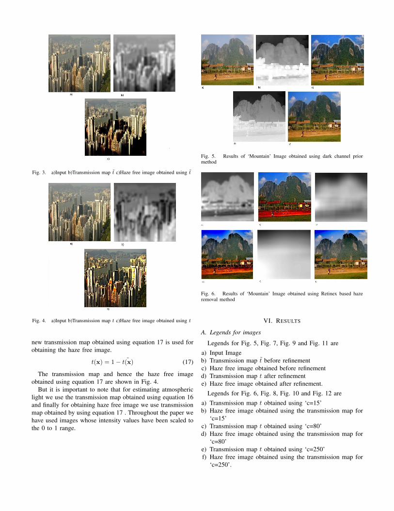
Fig. 3. a)Input b)Transmission map t c)Haze free image obtained using t
Fig. 4. a)Input b)Transmission map t c)Haze free image obtained using t
new transmission map obtained using equation 17 is used forobtaining the haze free image.
t(x) = 1− ˜t(x) (17)
The transmission map and hence the haze free imageobtained using equation 17 are shown in Fig. 4.
But it is important to note that for estimating atmosphericlight we use the transmission map obtained using equation 16and finally for obtaining haze free image we use transmissionmap obtained by using equation 17 . Throughout the paper wehave used images whose intensity values have been scaled tothe 0 to 1 range.
Fig. 5. Results of ‘Mountain’ Image obtained using dark channel priormethod
Fig. 6. Results of ‘Mountain’ Image obtained using Retinex based hazeremoval method
VI. RESULTS
A. Legends for images
Legends for Fig. 5, Fig. 7, Fig. 9 and Fig. 11 area) Input Imageb) Transmission map t before refinementc) Haze free image obtained before refinementd) Transmission map t after refinemente) Haze free image obtained after refinement.
Legends for Fig. 6, Fig. 8, Fig. 10 and Fig. 12 area) Transmission map t obtained using ‘c=15’b) Haze free image obtained using the transmission map for
‘c=15’c) Transmission map t obtained using ‘c=80’d) Haze free image obtained using the transmission map for
‘c=80’e) Transmission map t obtained using ‘c=250’f) Haze free image obtained using the transmission map for
‘c=250’.
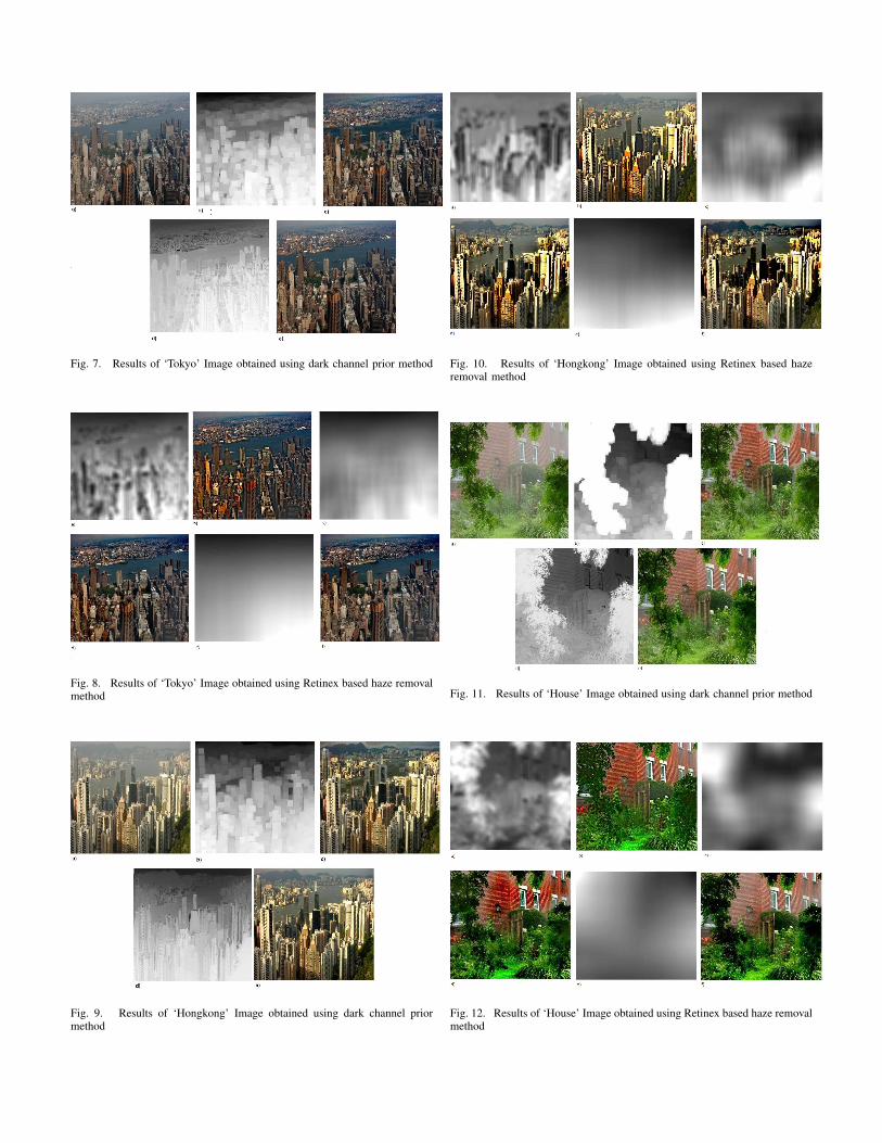
Fig. 7. Results of ‘Tokyo’ Image obtained using dark channel prior method
Fig. 8. Results of ‘Tokyo’ Image obtained using Retinex based haze removalmethod
Fig. 9. Results of ‘Hongkong’ Image obtained using dark channel priormethod
Fig. 10. Results of ‘Hongkong’ Image obtained using Retinex based hazeremoval method
Fig. 11. Results of ‘House’ Image obtained using dark channel prior method
Fig. 12. Results of ‘House’ Image obtained using Retinex based haze removalmethod
B. Discussion on Results
Fig. 5, Fig. 7, Fig. 9 and Fig. 11 gives the input imageand the associated transmission maps and haze free imagesobtained before and after matting(Kaiming et al.’s dark channelprior method). We observe that the haze free image obtainedbefore matting has blocking artifacts and the haze free imageobtained after matting is free of these artifacts. In Fig. 6, Fig.8, Fig. 10 and Fig. 12 the transmission maps and associatedhaze free images obtained for surround constant values of c =15, 80 and 250 are shown.i) ‘Mountain’ Image:From Fig. 5 and Fig. 6 we can infer that in retinex basedmethod a good haze free image is obtained for c=250 but thesurprising fact is that the transmission map obtained for c=250and the map obtained using dark channel prior do not appearsame. In this example for c= 15 or 80 we observe that thecolour of the soil is over saturated.
ii) ‘Tokyo’ Image:From Fig. 7 and Fig. 8 we can infer that in retinex basedmethod a good haze free image is obtained for c=80 or 250.For c=15, the colour of the building looks unnatural.
iii) ‘Hongkong’ Image: From Fig. 9 and Fig. 10 we caninfer that in retinex based method a good haze free image isobtained for c=15. For c=80 or 250, the colour of the blackbuilding looks more darker.
iv) ‘House’ Image: From Fig. 11 and Fig. 12 we caninfer that in retinex based method a good haze free imageis obtained for c=15.
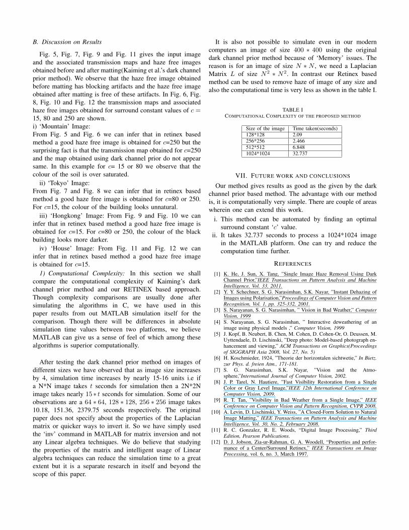
1) Computational Complexity: In this section we shallcompare the computational complexity of Kaiming’s darkchannel prior method and our RETINEX based approach.Though complexity comparisons are usually done aftersimulating the algorithms in C, we have used in thispaper results from out MATLAB simulation itself for thecomparison. Though there will be differences in absolutesimulation time values between two platforms, we believeMATLAB can give us a sense of feel of which among thesealgorithms is superior computationally.
After testing the dark channel prior method on images ofdifferent sizes we have observed that as image size increasesby 4, simulation time increases by nearly 15-16 units i.e ifa N*N image takes t seconds for simulation then a 2N*2Nimage takes nearly 15 ∗ t seconds for simulation. Some of ourobservations are a 64 ∗ 64, 128 ∗ 128, 256 ∗ 256 image takes10.18, 151.36, 2379.75 seconds respectively. The originalpaper does not specify about the properties of the Laplacianmatrix or quicker ways to invert it. So we have simply usedthe ‘inv’ command in MATLAB for matrix inversion and notany Linear algebra techniques. We do believe that studyingthe properties of the matrix and intelligent usage of Linearalgebra techniques can reduce the simulation time to a greatextent but it is a separate research in itself and beyond thescope of this paper.
It is also not possible to simulate even in our moderncomputers an image of size 400 ∗ 400 using the originaldark channel prior method because of ‘Memory’ issues. Thereason is for an image of size N ∗ N , we need a LaplacianMatrix L of size N2 ∗ N2. In contrast our Retinex basedmethod can be used to remove haze of image of any size andalso the computational time is very less as shown in the table I.
TABLE ICOMPUTATIONAL COMPLEXITY OF THE PROPOSED METHOD
Size of the image Time taken(seconds)128*128 2.09256*256 2.466512*512 6.8481024*1024 32.737
VII. FUTURE WORK AND CONCLUSIONS
Our method gives results as good as the given by the darkchannel prior based method. The advantage with our methodis, it is computationally very simple. There are couple of areaswherein one can extend this work.
i. This method can be automated by finding an optimalsurround constant ‘c’ value.
ii. It takes 32.737 seconds to process a 1024*1024 imagein the MATLAB platform. One can try and reduce thecomputation time further.
REFERENCES
[1] K. He, J. Sun, X. Tang, ”Single Image Haze Removal Using DarkChannel Prior,”IEEE Transactions on Pattern Analysis and MachineIntelligence, Vol. 33, 2011.
[2] Y. Y. Schechner, S. G. Narasimhan, S.K. Nayar, ”Instant Dehazing ofImages using Polarisation,”Proceedings of Computer Vision and PatternRecognition, Vol. 1, pp. 325-332, 2001.
[3] S. Narayanan, S. G. Narasimhan, ” Vision in Bad Weather,” ComputerVision, 1999
[4] S. Narayanan, S. G. Narasimhan, ” Interactive deweathering of animage using physical models ,” Computer Vision, 1999
[5] J. Kopf, B. Neubert, B. Chen, M. Cohen, D. Cohen-Or, O. Deussen, M.Uyttendaele, D. Lischinski, ”Deep photo: Model-based photograph en-hancement and viewing,” ACM Transactions on Graphics(Proceedingsof SIGGRAPH Asia 2008, Vol. 27, No. 5)
[6] H. Koschmieder, 1924, ”Theorie der horizontalen sichtwetie,” In Bietz.zur Phys. d. freien Atm., 171-181.
[7] S. G. Narasimhan, S.K. Nayar, ”Vision and the Atmo-sphere,”International Journal of Computer Vision, 2002.
[8] J. P. Tarel, N. Hautiere, ”Fast Visibility Restoration from a SingleColor or Gray Level Image,”IEEE 12th International Conference onComputer Vision, 2009.
[9] R. T. Tan, ”Visibility in Bad Weather from a Single Image,” IEEEConference on Computer Vision and Pattern Recognition, CVPR 2008.
[10] A. Levin, D. Lischinski, Y. Weiss, ”A Closed-Form Solution to NaturalImage Matting,” IEEE Transactions on Pattern Analysis and MachineIntelligence, Vol. 30, No. 2, February 2008.
[11] R. C. Gonzalez, R. E. Woods, “Digital Image Processing,” ThirdEdition, Pearson Publications.
[12] D. J. Jobson, Zia-ur-Rahman, G. A. Woodell, “Properties and perfor-mance of a Center/Surround Retinex,” IEEE Transactions on ImageProcessing, vol. 6, no. 3, March 1997.


