Embed Size (px)
Citation preview

Pergamon Energy Comers. Mgmt Vol. 38, No. I, pp. 83-99, 1997
Copyright © 1996 Elsevier Science Ltd Printed in Great Britain. All rights reserved
PII: S0196-8904(96)00011-8 0196-8904/97 $15.00 + 0.00
A REVIEW OF THE EFFECT OF PARTICULATE TRAPS ON THE EFFICIENCY OF VEHICLE DIESEL ENGINES
A. M . S T A M A T E L O S
Mechanical Engineering Department, Aristotle University, 540 06 Thessaloniki, Greece
(Received 21February 1995)
Abstrnct--Particulate traps are becoming more widely used on city buses, some delivery trucks and fork lift trucks. The possible use of diesel particulate traps will lead to a fuel consumption penalty imposed on the baseline engine that is due to the trap back pressure as well as to the energy requirements of the regeneration technique adopted to incinerate the collected soot at will. The combined effect of trap back pressure imposed on the engine and additional energy required for trap regeneration on the overall efficiency of the diesel power plant is examined in this paper. This effect varies according to engine type, trap type and size, regeneration system used, and the vehicle driving mode. Because of the strong interaction among the above parameters, optimization of trap systems on efficiency grounds is compli- cated. This complexity is even more pronounced in the case of diesel-powered passenger cars, where the full exploitation of their efficiency advantage over gasoline-powered cars is constrained by the necessity of an optimized solution of the particulate emission problem. The main diesel particulate trap regeneration philosophies existing today are reviewed in terms of their effect on the total efficiency of the diesel power plant. This is done by means of representative examples, concerning systems which may be suitable for large-scale application. The conclusions indicate that the price that must be paid for environmental protection, in the case of diesel particulate control systems, may be substantially reduced by system design optimization. Copyright © 1996 Elsevier Science Ltd
N O M E N C L A T U R E
A = Front vehicle surface (In 2) b e = Brake specific fuel consumption (g/kW. h)
b~ n = Additional bsfc during activation of regeneration device (g/kW. h) b~ -- Fuel pump supply per stroke (mm3/stroke) B e = Fuel consumption over specific driving cycle (g/kin) Br = Braking resistance (N) cp = Specific heat capacity (kJ/kg. K) cw - Drag coefficient
CO--Carbon monoxide emissions (g/km) E 0 = Exergy (available energy) (j) f - - Rolling friction coefficient F = Vehicle motive force (N)
F w -- Road load resistance (N) g = Acceleration due to gravity (m/s 2) h -- Enthalpy (kJ/kg. K)
H~ = Lower calorific value of fuel (kJ/kg) HC -- Unburned hydrocarbons emissions (g/km)
Jt = Turbocharger moment of inertia (kg.m 2) m = Mass flow rate (g/s) m ~ Vehicle mass (kg)
Md--Engine torque (N.m) rh~ t -- Engine fuel flow rate (kg/s)
n = Engine speed (min- t) NOx -- Nitrogen oxide emissions (g/kin)
p -- Pressure (Pa) p. -- Mean effective pressure (mep) (Pa) p~ = Exhaust throttling overpressure (Pa)
PM ~ Particulate emissions (g/kin) Qbu,~ ~ Burner power (kW)
S ~ Entropy (k J/K) t = Time (s)
T = Absolute temperature (K) U = Internal energy (k J) V = Volume (m 3)
83

84 STAMATELOS: EFFICIENCY OF VEHICLE DIESEL ENGINES
I'M--Engine displacement (m 3)
Greek letters
Qt
a p t Apf r = APse =
(ap)ox = E ~
t/ i =
0 = 2 =
U~.. P a i r ~
Pfuel ~'~ 0 ) =
t / u =
Subscripts eX
Vehicle acceleration (m/s 2) Pressure drop (Pa) Friction mep (Pa) Scavenging pressure drop (Pa) Exhaust pressure drop (Pa) Compression ratio Indicated engine efficiency Road gradient (rad) Equivalence ratio (air-to-fuel) Engine volumetric efficiency Vehicle speed (m/s) Air density (kg/m 3) Fuel density (kg/m 3) Turbocharger angular velocity (s -t ) Transmission efficiency of power train
Exhaust gas
1. I N T R O D U C T I O N
Four-stroke cycle spark ignition (SI) engines equip the majority of the world passenger car fleet. Application of the regulated three way catalytic converter technology rendered this type of engine very clean in terms of exhaust emissions. This fact is somewhat misleading, because a modern passenger car diesel engine is inherently more clean (Fig. 1), if one excludes particulate emissions.
Moreover, when one looks closer at the thermodynamics of the engine cycle, the superiority of the diesel is apparent. A typical situation for the SI engine is depicted in the available energy analysis of Fig. 2(a), where available energy, or exergy Eb is given by
Eb = ( U - Uo) + p o ( V - Vo) - T o ( S - So) (1)
as found in any modern thermodynamics text [1]. Exergy losses of a modern high-speed direct injection (DI) diesel engine are significantly lower (Fig. 2(b)), resulting in a thermodynamic efficiency higher than 40% that is not seriously deteriorated at low loads. Figure 3 compares brake specific fuel consumption (BSFC) maps of two comparable passenger car engines of the same manufacturer: a SI engine and a DI diesel engine [2, 3]. The main reasons for the superiority of
t o
100 --
80
60
4O
20 -
100% = HC -'- 0.25 glkm CO =2.11 g/km NO x = 0.62 g /km i / / / PM = 0.124 g/km [ " / / /
Statistical ~ ~ deviation
J range
HC n
C O N O x
Fig. 1. Exhaust emissions of a modern vehicle diesel engine (Audi 100 2.5 TDI), compared to the current SI engine emissions standards [2].

STAMATELOS" 85 EFFICIENCY OF VEHICLE DIESEL ENGINES
Exergy analysis 4 -s t roke SI engine, ¢--10:1
Cooling exergy lol
Exhaust exergy loss 20%
Comb. irreversibility 19%
2000 rpm, mep=3 bar (pin=0.5 bar)
ake work 25%
L Pumping work 4%
Comb. inefficiency 5%
tanical friction 7 %
Exergy analysis 4 -s t roke TDI engine, ~=20,5:1
Comb. irreversibilit work 33%
Cooling exergy loss 19%
Exhaust exergy loss 16%
g work I%
fficiency 3%
ion 8%
2000 rpm, mep=3 bar
Fig. 2. (a) Typical data for exergy analysis: four-stroke SI engine (~ ffi 10: I) at 2000 rpm. Inlet pressure 0.5 bar, ,~ -- 1, mep ffi 3 bar [2]. (b) Typical data for exergy analysis: four-stroke turbocharged, direct
injection diesel engine, ~ ffi 20.5 : 1, at 2000 rpm, mep ffi 3 bar.

86 STAMATELOS: EFFICIENCY OF VEHICLE DIESEL ENGINES
the diesel are the following:
• the combustion efficiency loss is reduced; • the amount of expansion stroke extracted is much greater, due to the higher compression ratio
(say 20:1 vs 10:1), and lean mixtures; • the heat losses are comparable; and • pumping work at light load is essentially eliminated.
Although diesel engines do exhibit clear efficiency advantages, on a worldwide basis, diesel vehicle emission standards are becoming increasingly stringent, especially regarding heavy-duty diesel engines.
The proposed NOx and particulate standards for heavy-duty diesel engines are shown in Fig. 4, transformed to g/kW. h and compared in Fig. 4(b) with future vehicle engines tested according to ECE 49 (directive 91/542/EEC) and EPA Transient test procedures [4-6]. Even in the case of different test procedures (13-mode vs U.S. Transient Test), reliable correlations already exist [7, 8]. The attainment of the 0.07 g/bhp, h U.S. limit for bus diesel engines will probably require the use of traps. In addition, the retrofitting of smoke traps is the best strategy to be followed in order to drastically reduce emissions of existing vehicle fleets at low cost.
14.
~ 1 0 -
!i E 2 .
0 0
brake specific fuel consumption [g/kWh]
I ' I I I I
1000 2000 3000 4000 5000 engine speed [rpm]
4.S
~ 3.8
2.4 E 1.2
0.0 4OO
brake specific fuel consumption [g/kWh]
,. lo.8 6 ~ " ~0 P~ 0
7.2 . ~ - ~ ' - - -
8.0 ~ ' ' - - , 2 s o < ~ ' ~ ' - - - ~ " > ~ . , . - . - - 290' , . . - , 300 '
~ ,..,,.- ~ ~ , , , , , ' " "
~_... ~ . . . . _ " ' - b.~ - - - = ' - '400'
1200 2000 2800 3600 4400 5200 6000 6BO0
e n g i n e s p e e d [ r p m ]
Fig. 3. Comparison of BSFC maps of two engines (one diesel, one otto cycle): five-cylinder. 2.46 turbocharged diesel engine. 85 kW at 4000 rpm, 265 Nm at 2250 rpm; 2.8 1, V-6 SI engine. 128 kW at
5500 rpm, 245 Nm at 3000 rpm [2, 5],

18.0 6000 ' -
14.4
,~ 4000 -
o
9.1] 8.0,1
2000 6 . 7
500 -
0,14 0.20.35 0.4
I I 5
ECE R 49 82
- 2 0 %
ECE R 49 89
- 5 0 %
UBA-Vorschlag Schweiz Sehweden 91
6 USA ss_l 1-
° /
I t ®
,~ ,~1,~ I~ ~ I -
I / I I / I 0.6 0.7 0.84 1.0 g /kWh
Part iculate
I I 50 130 250 mg / m 3 (5% 02)
STAMATELOS: EFFICIENCY OF VEHICLE DIESEL ENGINES 87
Fig. 4.
6OOO
4OOO
I= 2000
IS m
16
I • ~s I- ,~ . . .
5.7 6 •
4
2
I 0.14 0.2
I 50
5ool I I I I
0.4 0.6 0.8 1.0 g /kWh Part iculate
I I 130 250 m g / m 3 (5% 02)
(a) ECE R49 and EPA limits on NOx and particulates [6]. (b) The future status of development of heavy-duty diesel engines, based on recent research results [7].
The use of particulate traps has increased in certain applications, such as city buses, delivery trucks and fork lifts. Further work is needed to develop trap systems suitable for a wider application to commercial vehicles or passenger cars. Because of the probable higher future impact of the clean diesel for the above-mentioned and other reasons, it is important to study the effect of the trap on the thermodynamics of the total diesel power plant (including engine, trap and regeneration system) in order to assess and finally minimize the associated fuel consumption penalties. Such optimization could be even more important for the case of passenger cars Fig. 3, where attainment by the diesel powered vehicle of comparable emission values with its gasoline counterpart would enable a significant increase in the percentage of diesel cars in the world's fleet with very serious effects on reduction of the total traffic-consumed fuel and traffic-produced CO2.
2 . D I E S E L P A R T I C U L A T E T R A P S Y S T E M S
The particulate trap concept has focused intensive research and development activities around the world, and a variety of systems is offered by various manufacturers [9-16]. Any trap oxidizer system is based on a durable temperature-resistant filter, the trap, which removes particulate matter from the exhaust before it is emitted to the atmosphere. The volume of particulate is such that any reasonable filter would quickly become clogged. As a result, it is necessary to clean it periodically by burning off (oxidizing) the collected particulate. This process is known as regeneration [17]. Two parameters are important in investigating the effect of a trap system on the efficiency of the diesel power plant.
(i) The effect of trap back pressure---the pressure difference across the trap that is necessary to force the exhaust through it. The typical back pressure level is different with different types of traps and increases as the trap becomes loaded with particulates. High back pressure is undesirable, since it increases fuel consumption and reduces available power. An increase in exhaust back pressure is traced as an equivalent increase in the mean pressure of the high-pressure engine diagram [16, 18]. Minimizing back pressure levels while still maintain-

88 STAMATELOS: EFFICIENCY OF VEHICLE DIESEL ENGINES
(ii)
ing acceptable filtration efficiency and meeting other constraints is one of the major goals of trap oxidizer design. The necessity of regular trap regeneration. The filter soot is oxidized without catalytic aids at temperatures between 500 and 600°C, depending on the exhaust flow rate and oxygen content. Exhaust temperatures of that order start to be observed only at high load operation of the diesel engine. They are scarcely attained in the driving cycles of the official tests (ECE-15, FTP city, etc.). Thus, special regeneration techniques are employed [10]. Nearly all of them require the supply of additional energy to raise the exhaust temperatures.
In the following, the effect of these two major parameters on the efficiency of a trap-equipped diesel powered vehicle is going to be investigated.
For this reason, the fuel consumption of a given, trap-equipped vehicle, in a given driving cycle, may be computed (in g/km) by the following relation [19]:
l l fbe(n, md, Ap~[(mfgcosO+½c~Av2)+m(a+gsinO)+B~]vdt+f3(Ob~g(n, mo)dt
Be=o 0 (2) t
f vdt o
where 6 ( t )= l when the regeneration device is activated, and 6 ( t )= 0 otherwise. Thus, the effect of the installation of a specific type of trap system on a specific type of vehicle, driven in a specific driving cycle, may be taken into account in this computation
• by means of the effect of engine exhaust back pressure (increasing be(n, Md, Ap)), or • by means of the effect of additional fuel consumption required for regular regeneration of the
trap.
In the following, the above two contributions of a trap system to the fuel consumption increase of a given diesel-powered vehicle are going to be separately investigated in order to allow them to be introduced in a global model comprising interactions within the full diesel power plant (Fig. 5).
VEHICLE DIESEL ENGINE r- Vehicle Dr iver Therm°dynamic~'(")'/~M~F Vehicle L_. . . ._~)__~v=l/Fdt I speed
system: Yt-) Ii-lkinematics I - "
engine I 1 I R°adl°ad resistance ~ I Fw I [ Vehicle I. Engine speed (n)
~l I kinematics I
Trap backpressure ~-~Control ,]] TRAP SYSTEM~ ~ I
1 I " ~ " ~ - - C o m p r e s s o r [ : I ~' I - / in Fig. 5. Interactions within the full diesel engine power plant, comprising also a trap system.

STAMATELOS: EFFICIENCY OF VEHICLE DIESEL ENGINES
10 - 9 - Normal exhaust Smoke trap (loaded)
~ (Ap)ex=90 mbar (Ap)ex=490 mbar ~" 8 - ~ \ \ t ex:=431 C t ex=473 C
7 - \ ~ N b sp=61.2 mm31st b sp=64.6e=279 g/kWhmm31st
i, 4 RABMMAN e u g i a c l ~
r j 2 _
0 I ivo I I I I I I EVOI I 0.1 0.3 0.5 0.7 0.9 !.1 1.3 1.5 1.7 1.9
Cyl inder volume (din 3)
Fig. 6. Computed effect of exhaust back pressure on the four-stroke engine cycle (Raba/MAN, 10.31 engine, 2000 rpm, Pe = 4 bar).
89
3. TRAP BACK PRESSURE-INDUCED ADDITIONAL FUEL CONSUMPTION
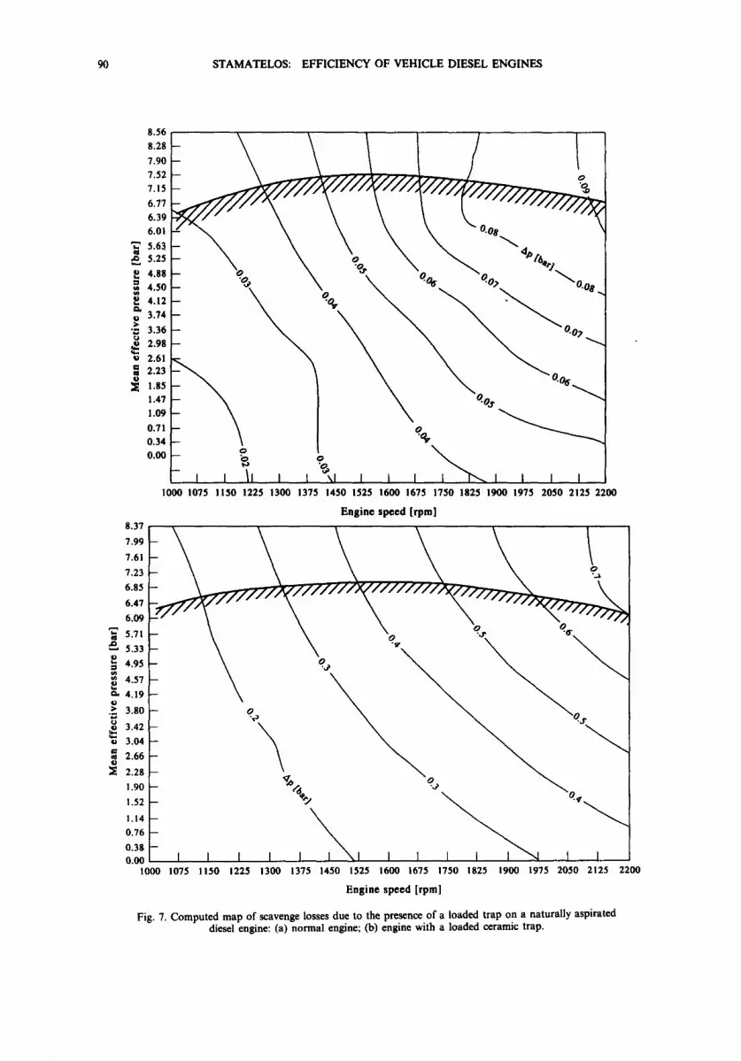
The engine fuel consumption map, be = be (n, M d) is affected by trap back pressure becoming be = be (n, Md, Ap). The effect of trap back pressure is spotted in augmentation of the gas exchange loop of the p-V diagram of the engine cycle [18, 20]. An example is shown in the computation depicted in Fig. 6, made by means of a filling and emptying type engine model for a single operating point of a 10.31 bus diesel engine. According to the computation, the additional back pressure induced by the presence of a trap (0.4 bar), causes a BSFC increase from 264 to 279 g/kW. h to produce a mean effective pressure of 4 bar at 2000 rpm with the specific engine. This computation may be done for the full engine map. Figure 7 presents a comparison between the back pressure maps of a normal 10.3 1 diesel engine and the same engine fitted with a typical trap size for a medium trap loading level.
The effect of back pressure increase, due to the presence of a trap, on the fuel consumption of a diesel engine may also be quickly computed, with an accuracy of the order of + 10%, by the following procedure.
Scavenge pressure losses (Ap~) are subtracted from engine output, measured as indicated mean effective pressure [20]. Thus, in order to produce the same output, the engine needs to consume additional fuel (Abe) per kW. h that may be computed based on the marginal efficiency of the engine at the specific operating point. This is approximately equal to the engine indicated efficiency:
{pdV (3) r/i = bsp Pfud Ha
(that is approximately constant over most of the engine map) times the mechanical efficiency at the specific point:
(Ap~ + Aptr) Abe oc (4)
Pe ~i H,
where APrr is the increase in friction mep due to load increase, and ~i may be taken as essentially constant over the useful part of the engine map (that may be significant only at high scavenge losses, like that occurring during regeneration by exhaust throttling; see Section 4.1). Based on the above simplified computation, and additional exhaust back pressure of 0.4 bar, induced by the presence of a loaded trap in the example of Fig. 6, would result in a BSFC increase from 264 to 282 g/kW.h, whereas the more detailed computation with the filling and emptying type model shown above gives an increase to 279 g/kW. h (Fig. 6). As referred to the overall effect in gf,,i/km, this depends, of course, on the driving mode, and a computation procedure will be described in Section 5.
90 STAMATELOS: EFFICIENCY OF VEHICLE DIESEL ENGINES
]
ID
U
8.37 7.99 7.61 7,23 6.85 6.47 6,119
~ 5.71 • ~. 5.33 ~ 4,95 ~ 4.57 ~. 4.19 o ~" 3.80
3.42 3.04 2.66 2.28 1.90
1.52
1.14 0.76 0.38 0.00
8.56
7.90 - / 7.52 7.15 /
6.016.396'77 ~ / ~ ~ ? i i ~ ~
5.6~ o ~ 4# :%: 5.25
4.50 4.12 3.74 3.36 2.98 2.61 2.23 1.85
1.47 1.09 0.71 0.34 0 . 0 0 - o
- , , 1 , i i ~ , , i , i " ~ , I , , 1000 1075 1150 1225 1300 1375 1450 1525 1600 1675 1750 1825 1900 1975 2050 2125 2200
Engine speed [rpm]
"2 o°;) i I I I I I ~ 1 I I I I ~ 1 I i
1000 1075 1150 1225 1300 1375 1450 1525 1600 1675 1750 1825 1900 1975 2050 2125 2200
Engine speed [rpm]
Fig. 7. Computed map of scavenge losses due to the presence of a loaded trap on a naturally aspirated diesel engine: (a) normal engine; (b) engine with a loaded ceramic trap.

STAMATELOS: EFFICIENCY OF VEHICLE DIESEL ENGINES 91
4. REGENERATION-INDUCED ADDITIONAL FUEL CONSUMPTION
Additional fuel (or equivalent energy) consumption may be necessary to support regeneration:
o'f( t )b~g(n, Md)dt (5)
where 6 ( t )= 1 when the regeneration device is activated, and 6 ( 0 = 0 otherwise (normal operation). The additional energy required, naturally, depends upon the specific trap and regeneration system used, along with its control settings.
As mentioned above, since the required high exhaust temperatures are not attained during the stop-and-go city driving modes, regeneration conditions are attained by special techniques, falling into three main categories:
(i) thermal regeneration by use of engine measures and engine modification; (ii) thermal regeneration with the aid of an external energy supply; and
(iii) catalytic regeneration.
In thermal regeneration techniques, the trap inlet temperature is raised to about 600°C by the implementation of engine measures (exhaust or inlet throttling, compressor bypassing etc.) or by direct supply of additional energy (i.e. burners, electrical igniters, etc.).
Catalytic regeneration is based on the use of catalysts to effect the onset of regeneration. The catalyst may impregnate the porous ceramic wall, or (more usually) may be added to the fuel as an additive, which, after combustion, is collected in the trap mixed with the emitted soot. Typical systems belonging to the above three categories are shown in Fig. 8.
4.1. Thermal regeneration by engine means
Figure 8(a) shows a system based on exhaust throttling for trap regeneration. With this system, when road conditions are favourable, the engine is exhaust throttled, resulting in a rise in the engine cycle pumping work and, consequently, a rise of the mean effective pressure and temperature of the high pressure loop [20]. The energy balance of the exhaust-throttled engine shows that an increased portion of the fuel energy per cycle is dissipated as exhaust gas enthalpy (Fig. 9). This causes the onset of regeneration. As already mentioned, the use of the engine itself to raise temporarily the exhaust enthalpy is a low-cost philosophy for the design of trap systems. The engine must be throttled for 0.3-3% of its total operation time, depending on the type of vehicle, the specific driving mode and the possible synergetic use of catalysts.
The exhaust-throttled engine shows an increased heat transfer rate during the exhaust blowdown period of the cycle because of the higher pressures and temperatures prevailing with the throttled engine [21].
Exhaust throttling by use of exhaust-type valves, results practically in a constant exhaust over pressure. In practice [22], constant pressure throttling is activated only over a certain temperature level, and trap bypassing is applied for trap protection from overheating during a trap failure scenario [23]. The control philosophy is as follows: if a peak of exhaust back pressure reaches a certain level during vehicle driving, the control is set to the regeneration mode. This means that, when road conditions are favourable, the engine will be exhaust throttled, resulting in a rise in engine exhaust temperature, and probably the onset of regeneration. As a general rule, a number of partial regenerations are effected during every day city driving, which are sometimes interrupted by trap bypassing (to protect the trap from overheating).
For a constant exhaust back pressure system [22, 23], additional fuel consumption due to the application of exhaust throttling can be assessed by the computation presented in Section 3, by substitution of the appropriate exhaust pressure levels (1.0-1.5 bar in usual practice [18, 22] and taking into account the fact that throttling is employed only between certain engine exhaust temperature (and, thus, mep) levels, (i.e. between 300°C or about 2-3 bar mep, and 500°C or about 6 bar mep). For a throttling pressure of 1.5 bar (typical in such trap systems for naturally aspirated engined buses), such a computation gives the results shown in Fig. 10.
As regards the effect on fuel consumption over a given driving cycle, this may be computed by assuming quasi-steady engine operation, as will be explained in Section 5.

92 STAMATELOS: EFFICIENCY OF VEHICLE DIESEL ENGINES
Here, it must be emphasized that the time percentage aUoted to trap regeneration by actuation of exhaust throttling varies in the range of 0.1-5% and is severely affected by the driving mode and the possible use of catalytic fuel additives to effect the onset of regeneration at low temperatures [11, 23, 24]. Thus, the overall effect on fuel consumption could be as high as 1.0% in the worst cases and without the use of catalysts.
Of course, all design efforts should be made to achieve trap regeneration conditions with a minimum level of exhaust throttling and a minimization of the percentage of driving with a throttled engine, not only on fuel consumption grounds but also on driveability ones [10] because exhaust throttling reduces available torque. The reduction may be approximated by subtracting the additional throttling pressure from the engine mep at the specific operation point.
4.2. Regeneration assistance by the supply of external energy
An advanced exhaust burner system is shown in Fig. 8(b). A reliable diesel burner of advanced design is used to incinerate the collected soot. The burner is using additional air, supplied by a special compressor, and can keep the full exhaust flow to a regeneration temperature of 600°C. This result is attained independently of the engine operation point. The burner is controlled by the engine control system already used for other tasks. Operating costs of the burner and, more
(a) ,t,ra p backpressure
Volvo THD I00 DC e n g i n e throttling bypass throttling
v i a I tmHt t m i*J'6m tmt ] t / m u
turbocharger
i (b)
Eng0ne Oil Temp~ En
Diesel Fuel
Exhaust Burner Air [1-"
Speed Exhaust Temp.
Control i ,, Trap
Compressor
T e m p . ~
:~ Exhaust out
Ign0t=on System
Fig. 8. Comparison of typical particulate trap systems: (a) exhaust throttling [18]; (b) exhaust-fed burner [19].

( c )
AIR FILTER
STAMATELOS: EFFICIENCY OF VEHICLE DIESEL ENGINES
EGR- LINE
, a r a b EXHAUST GAS OUTLET
93
AIR INLET
INTAKE
CRANKCASE VENTILATION VALVE ~ J~j/
CRANKCASE VENTILATION HOSE
BOOST PRESSURE LIMITER
PNEUMATIC PUMP
tAUST ' ~ . . . . . . . . . . , , FOLO ; . ::: f
800ST PRESSURE COMPENSATOR
~ / F U E L LINE
~1 INJECTION PUMP
ADDITIVE TANK
ADDITIVE INJECTION VALVE /
FROM FUEL TANK
' ~ ELECTRONIC CONTROL UNIT
I I ~ ina:C~l~ L[:0
Fig. 8. (c) Catalytic fuel additive system [20]; (d) electrical regeneration system [21].
generally, external energy supply systems are respectively higher: the specific conditions of a burner-assisted regeneration require a very low trap loading in order to ensure trap safety, obviously leading to significant increases in fuel consumption (of the order of 5%). The following paragraphs formulate, a computation procedure for the fuel consumption of an in-line, full-flow diesel fuel burner regeneration system, like that of Fig. 8(b) [25, 26]. Such systems may be used only in heavy duty vehicles, due to special cost, space and equipment requirements [10].

94 STAMATELOS: EFFICIENCY OF VEHICLE DIESEL ENGINES
Exhaust enthalpy
367
( a )
Cooling losses 340
Unthrottled
aft work 338
Friction losses
177
:tion Coolil ~ses
Iosse. ~ 77 372
Exhaust thrott led (p=l.9 bar)
0 M 615 engine - cycle computation computed heat transfer to cylinder head
full load/normal vs exhaust throttled 5 --
'~ (b) Unthrouled
- 5 ~ ~ / " Exhaust throttled ~=1.25
~ -10 - - ~ -15 -- ~ / Pu=l.9bar
~ -20 -- \ / I OM6lSengine [ -25 -- V pOOOrpm, k 1.25
-30 I I I I I I I I 0 90 180 270 380 450 540 630 720
Crank angle [deg] 4000 rpm, lambda-l.25 (pu=l.9 bar)
Fig. 9. Engine cycle calculation--normal vs exhaust-throttled OM 615 engine, at 4000 rpm. 2 = 1.25 [17]: (a) cycle energy balance; (b) computed heat flux to cylinder head as function of crank angle.
Starting from a usual DI diesel engine exhaust temperature map (Fig. 11), the minimum fuel mas flow rate required to maintain full exhaust flow at a temperature of, say 700°C, at a part loa, operation point (say 2000 rpm, 2 bar) may be computed:
• 700°C o Qb==r -- mexCpoxltex (700 C - t~x) (6
where cp,, is approximately equal to 1 kJ/(kg. K) for the diesel exhaust gas in the temperature rang, of interest, and
n /'l;lex = -~'~'1VH 10-6pair +/?/fuel" (7
In the computation, one must take into account that traps in burner-assisted systems are usuall: installed far from the exhaust manifold to facilitate and simplify installation. At such locations exhaust temperatures are much lower than that depicted on exhaust temperature maps like tha
8 -
7
6
5
g ~
o 4 ¢ J
3 o
2
I
0
m
B
B
i 0 5
• @. •
~ - b a ~ ~ • p = l . 0 bar p=l.5 bar p=2.0 bar
• p=l bar • p=l.5 bar m p=2 bar
I I l I I l I I I 10 15 20 25 30 35 40 45 50
BSFC increase [%] Fig. I0. Approximate computation of brake specific fuel consumption increase as function of mep, during exhaust throttling with different exhaust back pressure levels (Ikarus bus, 10.31 engine, 2000 rpm).

STAMATELOS: EFFICIENCY OF VEHICLE DIESEL ENGINES 95
8 -
6
~ 4
2 as
600°C
500°C 450°C 400°C
0 I I I I I 1200 1400 1600 1800 2000 2200
RPM
Fig, 1 I. Exhaust temperature map of the RABA/MAN engine.
of Fig. 11. For the case of a 10.3-1 bus engine at 1900 rpm, 150 N-m (tex = 300°C), mex ---- 0.167 kg/s and Qbu~ = 50 kW. This power will be needed even for much lower engine speeds due to the additional air supplied in such systems for trap protection [25].
The complete regeneration process in burner systems has a duration of about 5-10 min (6.5 min for the Deutz system). Thus, the maximum power of the burner, at 2200 rpm, no load, would be about 70 kW. This leads to a consumption of a maximum of 0.6 kg fuel per regeneration, or a mean value of about 0.3 kg per regeneration. When one takes into account that a regeneration will normally be needed every 50-100 km, a fuel consumption increase of the order of 1-2% due to the regeneration system is reached (with an Ikarus bus, with normal fuel consumption of 451 per 100 km in the driving conditions of the city of Athens). As seen in Fig. 12, based on the experience with various burner and electrical heating regeneration systems installed on Tokyo urban buses [27] there is an observable trade-off between regeneration frequency and pumping losses. Moreover, fuel consumption increase, in practice, could be significantly higher than in the computation.
As concerns application with electrical igniters, consideration of the efficiency of the diesel engine plus vehicle generator in the production of electricity (to be dissipated as heat) directly leads to the conclusion that on-line regeneration is not realistic with such techniques. This is seen also in practice (dual-trap systems), where two filters are arranged in parallel (Fig. 8(d)), so that they can be regenerated alternately by electric heaters when the particulate mass reaches a certain level. The heater elements are placed close to the inlet phase of the monolith and backed by a heat deflection plate. The electric heater output is of the order of I kW for a 5.66 x 6 inch filter (good for a 2000 cc passenger car) or of the order of 4 kW for a bus. This would require (for the bus case) an increase in battery capacity from 110 to 240 A h and an alternator current increase from 40 to 75 A [28].
8 --
6 .o
O
4
N
eL
~ P ' ~ Regeneration
-- D Pumping loss
m
I t A B C D
Fig. 12. Measured increase in fuel consumption of a I 1-1 engined bus equipped with different types of trap systems with external energy supply regeneration (bypass system): A, burner; B,C,D, various types of
electric heaters. Regeneration frequency vs pumping losses trade-off is apparent [27].
ECM 38/I--D
96 STAMATELOS- EFFICIENCY OF VEHICLE DIESEL ENGINES
Thus, for a total heating time of 15 min for each regeneration and a running distance between regenerations of the order of 50-100 km, the additional fuel consumption required would be computed as follows.
Efficiency: total 4.5% Diesel engine during city driving: 25% Generator with belt drive and fan: 30% Battery: 60%
Additional fuel required: 1200 k J/42 MJ/kg = 0.0275 kg or 0.03451 To produce the required heating energy: 54 kJ/0.045 = 1200 kJ, (3.6 kW x 15 min = 54 kJ)
Additional fuel consumption 0.03451/35 1 = 1%
4.3. Catalytic regeneration
The application of catalysts to lower soot ignition temperatures in the filter is very desirable in principle. In this respect, catalytic coatings on wall-flow filters have not proven very effective. It is well known that, even under the most favourable conditions, such as a low exhaust flow rate, high oxygen content and low trap loading, less than 100°C decrease in ignition temperatures is attained. A thermal regeneration system should be used in conjunction with the trap to keep a low trap loading. Also, there is a problem of sulphate emissions due to the oxidation of sulphur in the fuel across the catalysed filter at high loads [10].
Compared to the above, the application of catalytic fuel additives has proven to be quite effective. Soot ignition temperatures are reduced to under 250°C. Thus, continuous regeneration conditions may be set on the filter during city driving, if the fuel additive concentration is high enough and sufficient oxygen is present at the exhaust [29].
However, also in this class of systems, if the system lacks a backup regeneration and a trap protection device, a high trap loading produced by chance will lead to trap damage, owing to the significant degree of uncertainty that characterizes catalytic regeneration [30]. Thus, no purely fuel-additive-based system was able to succeed in attaining a long life-time for the filters. On the contrary, fuel-additive-based trap systems, with additional devices for emergency regeneration and filter protection devices, were shown to keep the advantages of pure fuel-additive-based systems and, at the same time, effect a long service life [11, 22]. A very low concentration of fuel additive is required with such systems in order to alleviate the tendency of systematic trap back pressure increase due to collection of the additive ash from the exhaust gas. A cleaning procedure is, nevertheless, needed in order to avoid the fuel consumption increase due to this fact [31].
5. FUEL CONSUMPTION C O M P U T A T I O N C O D E : OVERALL EFFECT OF THE TRAP SYSTEM
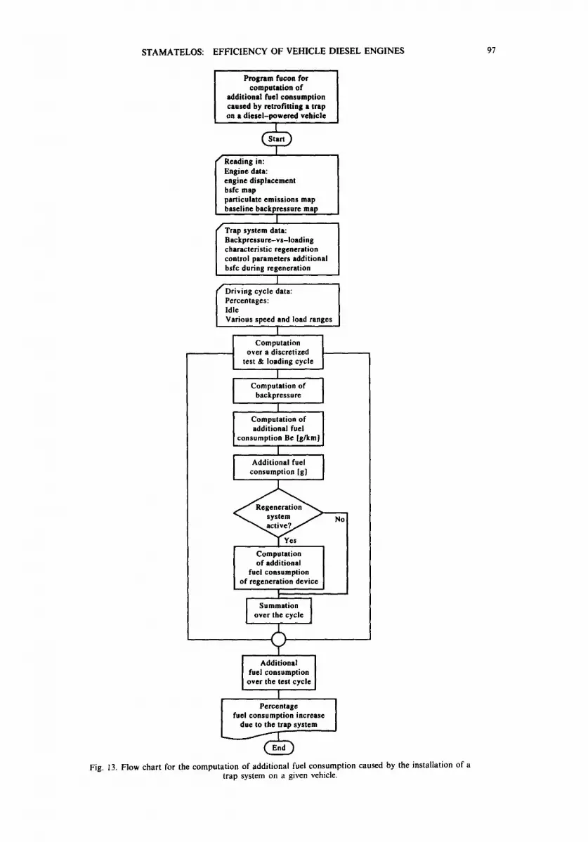
A simple computer code may be used to estimate the additional fuel consumption induced by a particulate trap system when installed on a diesel-engined vehicle. To this end, a good knowledge of the engine and vehicle characteristics, as well as filter type and regeneration device data, is needed. The flow chart of the above-mentioned code is given in Fig. 13. Essential for a good estimation of the additional fuel consumption is the driving cycle over which the computation will be made.
Driving patterns in cities all over the world show marked differences, and the same is true for the driving cycles used by legislation. Frequency distributions of mean vehicle speed, engine load and exhaust temperatures vary widely too [27].
Also, driving is seriously affected by the vehicle type. For comparison purposes among trap regeneration systems with wide differences in their principle of operation, and in order to take into account operation in the regeneration mode in this computation, a normalized cycle, such as the one proposed by the International Experts Meeting in Stockholm [32] could be used. This cycle covers systems with intermittent regeneration, as well as continuously regenerating systems.
Computations with this computer code for different system versions show that the fuel consumption increase of diesel particulate trap systems in heavy duty vehicles are normally under 5%. Systems using engine measures to induce regeneration are even more economical (only 2-3%
STAMATELOS: EFFICIENCY OF VEHICLE DIESEL ENGINES 97
Program fucon for computation of
additional fuel consumption caused by retrofitting a trap on a diesel-powered vehicle
f Reading in: Engine data: engine displacement bsfc map particulate emissions map baseline backpressure map
I
I Trap system data: Backpressure-vs-loading characteristic regeneration control parameters additional bsfc during regeneration
I
I Driving cycle data: Percentages: Idle Various speed and load ranges
I Computation ]
over a discretized test & loading cycle
I I Computation of backpressure I
I Computation of ] additional fuel
consumption Be [g/km]
I Additional fuel ]
consumption [g]
of additional fuel consumption
of regeneration device I
Summation } over the cycle
fuel consumption over the t©st cycle
I
~ s y s t e m [ I fuel conPs:rCe~:oang~ncrease
Fig. 13. Flow chart for the computation of additional fuel consumption caused by the installation of a trap system on a given vehicle.

98 STAMATELOS: EFFICIENCY OF VEHICLE DIESEL ENGINES
fuel consumpt ion increase). As explained in Section 4.3, the use o f catalysts to induce regeneration may diminish the fuel consumpt ion increase (order o f 1%).
6. C O N C L U S I O N S
Diesel engine fuel consumpt ion increase due to the installation of a trap system is produced by two main components :
(i) the effect o f trap back pressure on engine flow work; and (ii) the energy needed periodically to effect the onset o f regeneration.
A methodology for the computa t ion o f the contr ibution o f the above two parameters to diesel engine BSFC is presented in this paper, along with the results o f its application to real-world solutions. The basic principles o f a computer program that may be used to achieve system optimizat ion on efficiency grounds are also presented.
Based on the above methodology, the application o f thermal regeneration techniques based on temporary engine measures, studied in the example o f exhaust throttling, is shown to result in less than a 1% increase in fuel consumption. This is the result f rom both computa t ions and practical experience.
The application o f in-line, full-flow burner systems is shown to result in a consumpt ion increase o f the order o f 1-5%. This, along with inherent problems of exhaust-fed burners, has resulted in the adopt ion o f complicated bypass systems (i.e. dual-filter layouts, etc.) in order to reduce the additional energy supply. The same order is valid for electrical ignition systems.
The use o f fuel additives for regeneration assistance may result in a less than 0.5% fuel consumpt ion increase for regeneration purposes, due to the occasional need for operat ion o f the backup regeneration device.
Finally, the fuel consumpt ion penalty o f a trap system may be effectively minimized to insignificant values by systematic system optimization, a fact that has been proved, at least for heavy-duty vehicles. As explained in this paper, this happens to be true also for light-duty vehicles, a fact that could eventually lead to the full exploitation o f the DI diesel engine advantages as a prime mover for passenger cars.
R E F E R E N C E S
1. H. D. Baehr, Thermodynamik. Springer Verlag, Berlin (1973). 2. H. Demel, D. Stock and P. Bander, Audi Turbodieselmotor mit Direkteinspritzung. MTZ 52(9) s.420-429 (1991). 3. G. Faltermeier, P. Leitmer and X. Stemmer, The new Audi V-6 engine. MTZ 52 4, 172-181 (1991). 4. W. Carteilieri, W. Ospelt and K. Landfahrer, Erfuellung der Abgasgrenzwerte von Nutzfahrzeug-Dieselmotoren der
90er Jahre. Motortechnische Zeitschrift (MTZ) 50(9) 440-451 (1989). 5. F. X. Moser, Kriterien und Potential der Vier-Ventil-Technik bei Nutzfahrzeug-Dieselmotoren MTZ 50 6 (1989). 6. F. X. Moser, E. Haas, and H. Schloegl, Zur Partikelemission yon Nutzfahrzeug-Dieselmotoren. MTZ 51 5 (1990). 7. W. R. Dietrich, Gegenueberstellung des Schadstoffverhaltens moderner Verbrennungsmotoren in stationaeren wie in
Nutzfahrzeugbetriebs. MTZ 52 (6) 296-303 (1991). 8. R. Pischinger and M. Ankowitsch, Instationaere Erfassung der Emissionen von Lkw-Motoren im US-Transient Test
und Ihrer Vergleich mit Stationaermessungen. Vortag beim 11. Wiener Motorensymposium 26-27.4.1990. Wieu (1990). 9. E. Hoepke, Partikelfilter fuer Omnibusse und Kommunal-fahrzeuge. ATZ 91(12) 680 (1989).
10. A. M. Stamatelos, Impact of Environmental Legislation on the Design of Vehicle Diesel Engines: The Case of Diesel Particulate Traps. ASME/NTU Athens '91 International Conference on the Analysis and Optimization of Thermal Systems, Athens, June 1991.
11. K. N. Pattas, Z. Samaras, D. Sherwood, K. Umehara, C. Cantiani and J. Lemaire, Cordierite Filter Durability with Cerium Fuel Additive: 100,000 km of Revenue Service in Athens. SAE paper 920363 (1992).
12. D. L. McKinnon, D. A. Pavlich, T. Tadrous and D. Shepard, Results of North-American Field Trials Using Diesel Filters with a Copper Additive for Regeneration. SAE paper 940455 (1994).
13. V. D. N. Rao and H. A. Cicanek, Diesel Particulate Control System for Ford 1.8L Sierra Turbo-Diesel to Meet 1997-2003 Particulate Standards. SAE paper 940458. (1994).
14. R. R. Richards and J. E. Sibley, Diesel Engine Emissions Control for the 1990's. SAE paper 880346. (1988). 15. J. S. Howitt and M. R. Montierth, Cellular Ceramic Diesel Particulate Filter. SAE paper 810114 (1981). 16. R. W. Horrocks, Particulate Control Systems for Diesel Engines. Publication C349/87, IMechE (1987). 17. C. S. Weaver, Particulate Control Technology and Particulate Standards for Heavy Duty Diesel Engines. SAE paper
840174 (1984). 18. A. M. Stamatelos, Theoretical and Experimental Investigation of the Stationary and Transient Operation Character-
istics of the Exhaust Throttled Diesel Engine. Ph.D. Thesis, Mechanical Engineering Dept, Aristotle University of Thessaloniki, Thessaloniki (1988).

STAMATELOS: EFFICIENCY OF VEHICLE DIESEL ENGINES 99
19. R. Bosch, Kraftfahrtechnisches Taschenbuch. 20¢ Auflage (1990). 20. K. Pattas and A. Stamatelos, The Effect of Exhaust Throttling on the Diesel Engine Operation Characteristics and
Thermal Loading. SAE paper 890399 (1989). 21. K. Pattas, A. Stamatelos, N. Patsatzis, P. Kikides, J. Aidariuis and Z. Samaras, Forced Regeneration by Exhaust Gas
Throttling of the Ceramic Diesel Particulate Trap. SAE paper 860293 (1986). 22. K. Pattas, A. Stamatelos and J. Constantinidis, Exhaust Temperature Response of Trap Oxidizer Systems. SAE paper
900323 (1990). 23. K. Pattas, N. Patsatzis, C. Michalopoulou, A. Stamatelos and W. Sowul, Ceramic Trap Regeneration Rate Control
through Bypass Technique. SAE paper 880004 (1988). 24. W. Hueng and J. E. Sauerteig, The New DEUTZ Particulate Trap System for Trucks and Buses. SAE paper 892494
(1989). 25. K. N. Pattas and C. C. Michalopoulou, Catalytic Activity in the Regeneration of the Ceramic Diesel Particulate Trap.
SAE paper 920362 (1992). 26. K. Ha and J. E. Sauerteis, Performance Testing and Field Evaluation of an In-Line Full Flow Particulate Trap System
for the DDC 6V-92TA Two-Stroke Engine. SAE paper 920366 (1992). 27. H. Suto, T. Mikawi, H. Hira and M. Hori, Evaluation of Diesel Particulate Filter Systems for City Buses. SAE paper
910334 (1991). 28. V. Kumagai, Y. Kono and T. Ikeda, A Particulate Trap System Using Electric Heating Regeneration for Small Trucks.
SAE paper 920141 (1992). 29. E. Mudler and B. Wiedemann, Diesel Partikel-flltersystem mit additivgestuetzter Regeneration. Automobiltechnische
Zeitschrift (ATZ) 91 12 (1989). 30. K. Pattas, Z. Samaras, N. Patsatzis, C. Michalopoulou, O. Zogou, A. Stamatelos and M. Barkis, On-Road Experience
with Trap Oxidizer Systems Installed on 5 Urban Buses. SAE paper 900109 (1990). 31. K. N. Pattas and A. M. Stamatelos, Diesel Particulate Trap Systems as a Route to the Clean Diesel. XXIV Meeting
of Bus and Coach Experts, Budapest, 27-29 September 1993. 32. N. N.: International Experts' Meeting in Stockholm on Air Pollution by Motor Vehicles: Control of Air Pollution from
Motor Vehicles. Definition of LE-HDV:s. Exhaust and Noise Emissions Requirements and Test Procedures. Agreed Text, 1990-06-13. Stockholm (1990).