Embed Size (px)
Citation preview

Evaluates: MAX66300, MAX66242MAX66300-24x Evaluation Kit
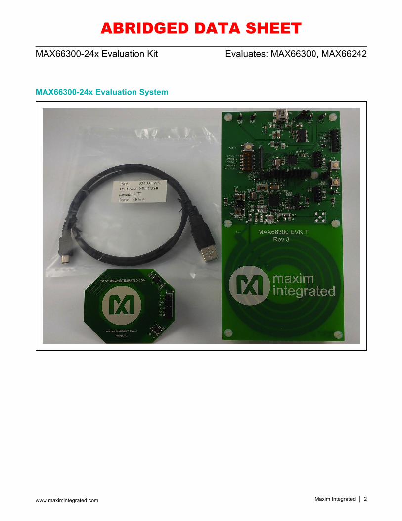
General DescriptionThe MAX66300-24x evaluation system (EV system) comprises a MAX66300 evaluation kit (EV kit) and a MAX66242 tag. The MAX66300 EV kit combines a RFID reader for contactless communication at 13.56MHz and a SHA-256 secure authenticator coprocessor. The RFID reader covers the ISO 15693 standard and the authenti-cator coprocessor is based on the FIPS 180-4 standard. The MAX66242 tag operates as a solution covering the ISO 15693 standard. By pairing the MAX66300 EV kit with the MAX66242 EV kit into an EV system, EV kit software can operate to show a secure challenge and response authentication and other part specific functionality.
Features A Secure, Contactless RFID Reader (MAX66300)
• 3.3V or 5V AFE Operation• UART and SPI Interface Support Through the
MAXQ610• Configuration for Lower Power Systems with Direct
Antenna Connections• On-Board 13.56MHz and 24MHz Oscillators• Symmetric Key-Based Secure Authentication
System• Pushbuttons for Board Reset and MAX66300
Reset• Port Select Switch Control • Jumpers for SPI, UART, and Control Signals
Protected Tag Solution with Peripheral Linking (MAX66242)• HF Interface at 13.56MHz• User EEPROM Authenticated Memory Page Read/
Write Transactions• User EEPROM Page or Block Read/Write
Transactions• Secure Transactions to Write Secret Keys and
Compute MACs• Energy Harvested VOUT Used to Power an LED
On/Off• I2C Communication with On-Board Temperature
Sensor IC, DS75S• Also Supports MAX66240 without I2C Interface
(Tag Not Included in EV Kit) MAX66300-24x EV System Software Available
219-0110; Rev 1; 8/16
Ordering Information appears at end of data sheet.
MAX66300-24x EV System Content ListPART QTY DESCRIPTION
MAX66300 EV Kit 1 MAX66300 evaluation kit
MAX66242 Tag 1 MAX66242 tag
3021003-03 1 Qualtek USB Type A to USB Mini-Type B cable
ABRIDGED DATA SHEET
Maxim Integrated 2www.maximintegrated.com
Evaluates: MAX66300, MAX66242MAX66300-24x Evaluation Kit
MAX66300-24x Evaluation System
ABRIDGED DATA SHEET
Maxim Integrated 3www.maximintegrated.com
Evaluates: MAX66300, MAX66242MAX66300-24x Evaluation Kit
Quick StartRequired Equipment
MAX66300 EV kit (included) MAX66242 tag (included) USB Type A to USB Mini Type B cable (included) PC with Windows® 8/8.1, Windows 7, or Windows
Vista® and a spare USB portNote: In the following sections, software-related items are identified by bolding. Text in bold only refers to items directly from the EV kit software. Text in bold and under-lined refers to items from the Windows OS.
Setup Procedure1) Perform the following to install the PL-2303HXD
prolific driver:a) Download the driver file called PL2303_Prolific_
DriverInstaller.zip from http://files.maximinte-grated.com/sia_bu/public/.
b) Unzip, Open and Run the file with the following name “PL2303_Prolific_DriverInstaller.exe”.
c) Follow the directions of the Install Wizard until Finish is reached for the PL-2303 USB-to-serial driver installation. Click the Finish button to close.
2) Proceed by setting up the MAX66300 EV kit hard-ware by doing the following:a) Configure the jumpers per Table 1 and Figure 46
for 3.3V operation.b) Set the switch SW3 per Table 2 and Figure 47
for UART operation when the MAX66300 pow-ers up.
c) Using the USB type A to USB type Mini B cable, connect the MAX66300 EV kit’s CN1 port into a spare USB port of a PC.
3) Set up the MAX66242 tag hardware by doing the following:a) Configure the jumpers per Table 3 and Figure
48.b) Position the MAX66242 tag over the MAX66300
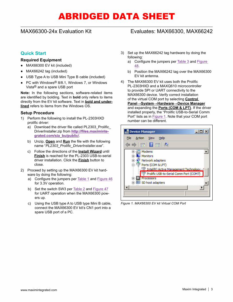
EV kit antenna.4) The MAX66300 EV kit uses both the Prolific
PL-2303HXD and a MAXQ610 microcontroller to provide SPI or UART connectivity to the MAX66300 device. Verify correct installation of the virtual COM port by selecting Control Panel→System→Hardware→Device Manager and expanding the Ports (COM & LPT). If the driver installed properly, the “Prolific USB-to-Serial Comm Port” lists as in Figure 1. Note that your COM port number can be different.
Figure 1. MAX66300 EV kit Virtual COM Port
ABRIDGED DATA SHEET
Maxim Integrated 4www.maximintegrated.com
Evaluates: MAX66300, MAX66242MAX66300-24x Evaluation Kit
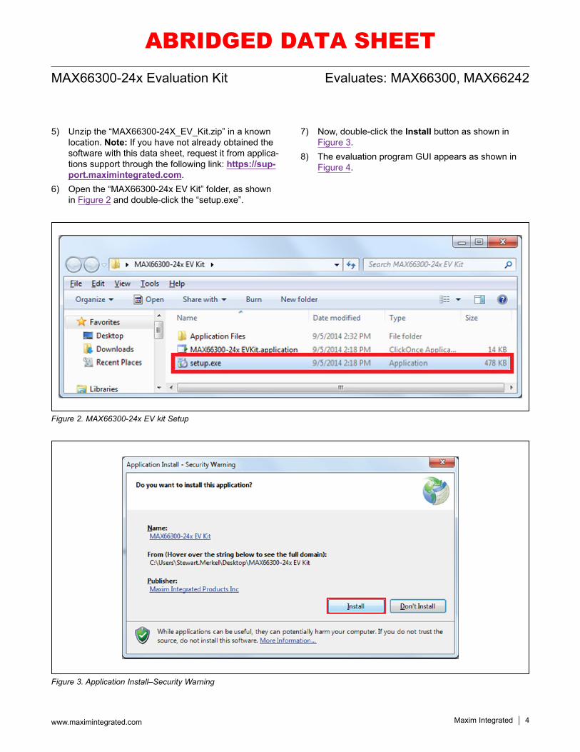
5) Unzip the “MAX66300-24X_EV_Kit.zip” in a known location. Note: If you have not already obtained the software with this data sheet, request it from applica-tions support through the following link: https://sup-port.maximintegrated.com.
6) Open the “MAX66300-24x EV Kit” folder, as shown in Figure 2 and double-click the “setup.exe”.
7) Now, double-click the Install button as shown in Figure 3.
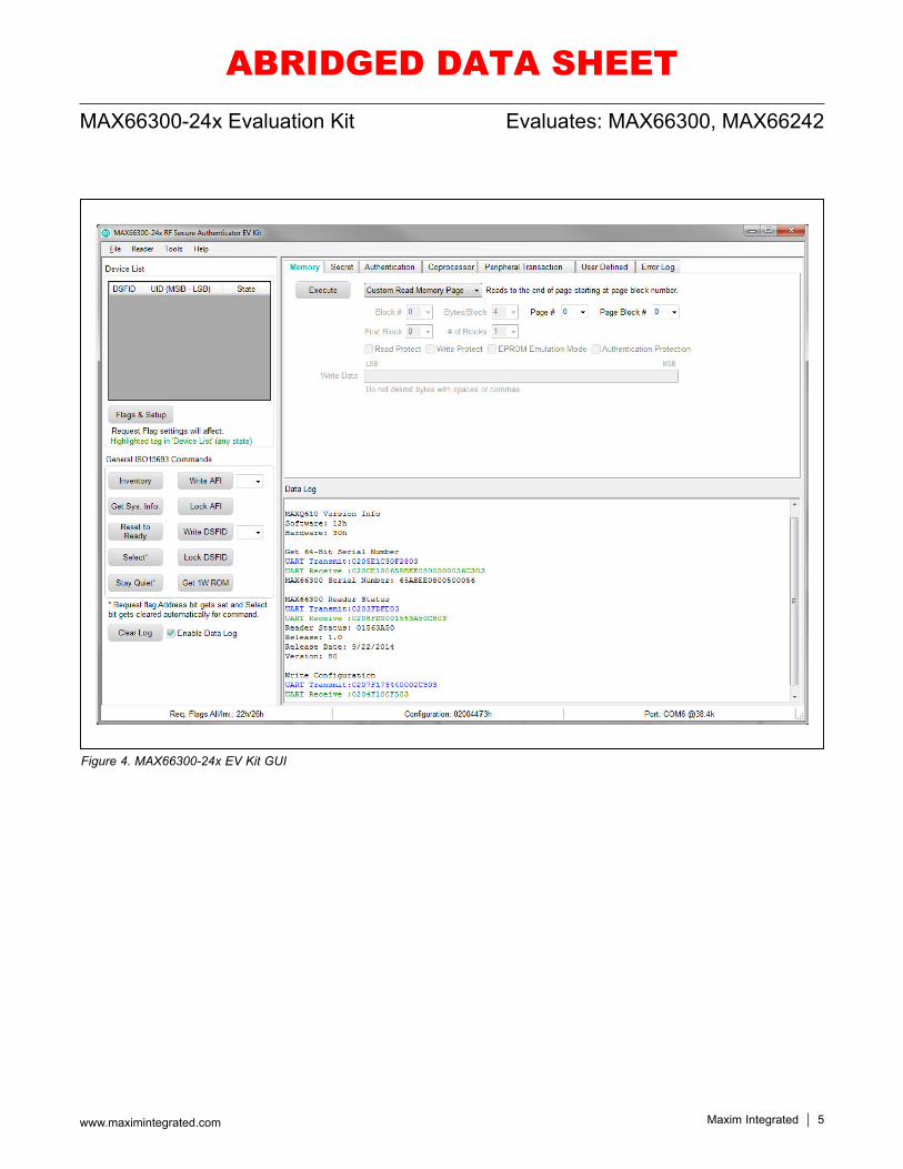
8) The evaluation program GUI appears as shown in Figure 4.
Figure 2. MAX66300-24x EV kit Setup
Figure 3. Application Install–Security Warning
ABRIDGED DATA SHEET
Maxim Integrated 5www.maximintegrated.com
Evaluates: MAX66300, MAX66242MAX66300-24x Evaluation Kit
Figure 4. MAX66300-24x EV Kit GUI
ABRIDGED DATA SHEET
Maxim Integrated 6www.maximintegrated.com
Evaluates: MAX66300, MAX66242MAX66300-24x Evaluation Kit
Peripheral Transaction and User-Defined TutorialThis tutorial involves the MAX66300 reader, the MAX66242 tag and the DS75S to show how to customize communi-cation. The first purpose is to show how to read tempera-ture from a DS75S I2C slave using the MAX66242 tag as the I2C master with the Peripheral Transaction tab. The second purpose is to show how to form a transmit packet using the User Defined tab.
Peripheral Transaction with DS75SThis section demonstrates how to perform I2C communi-cation to the DS75S device contained on the MAX66242 Tag with the MAX66300 EV kit. After completing the
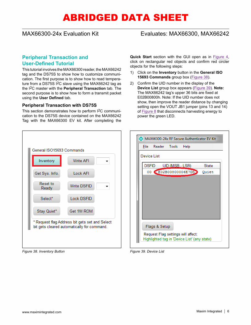
Quick Start section with the GUI open as in Figure 4, click on rectangular red objects and confirm red circler objects for the following steps:1) Click on the Inventory button in the General ISO
15693 Commands group box (Figure 38).2) Confirm the UID number in the display of the
Device List group box appears (Figure 39). Note: The MAX66242 tag’s upper 36 bits are fixed at E02B00800h. Note: If the UID number does not show, then improve the reader distance by changing setting open the VOUT JB1 jumper (pins 13 and 14) of Figure 8 that disconnects harvesting energy to power the green LED.
Figure 38. Inventory Button Figure 39. Device List
ABRIDGED DATA SHEET
Maxim Integrated 7www.maximintegrated.com
Evaluates: MAX66300, MAX66242MAX66300-24x Evaluation Kit
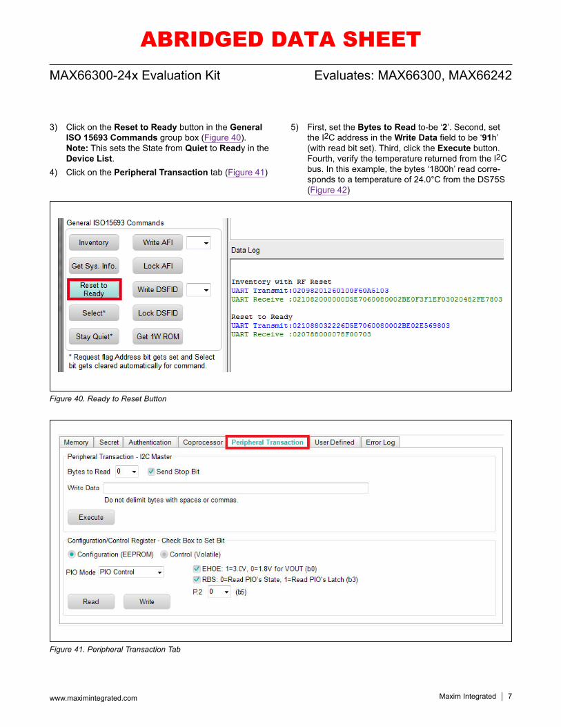
3) Click on the Reset to Ready button in the General ISO 15693 Commands group box (Figure 40). Note: This sets the State from Quiet to Ready in the Device List.
4) Click on the Peripheral Transaction tab (Figure 41)
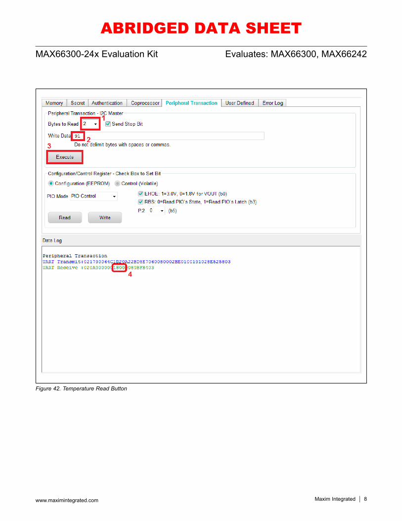
5) First, set the Bytes to Read to-be ‘2’. Second, set the I2C address in the Write Data field to be ‘91h’ (with read bit set). Third, click the Execute button. Fourth, verify the temperature returned from the I2C bus. In this example, the bytes ‘1800h’ read corre-sponds to a temperature of 24.0°C from the DS75S (Figure 42)
Figure 40. Ready to Reset Button
Figure 41. Peripheral Transaction Tab
ABRIDGED DATA SHEET
Maxim Integrated 8www.maximintegrated.com
Evaluates: MAX66300, MAX66242MAX66300-24x Evaluation Kit
Figure 42. Temperature Read Button
ABRIDGED DATA SHEET
Maxim Integrated 9www.maximintegrated.com
Evaluates: MAX66300, MAX66242MAX66300-24x Evaluation Kit
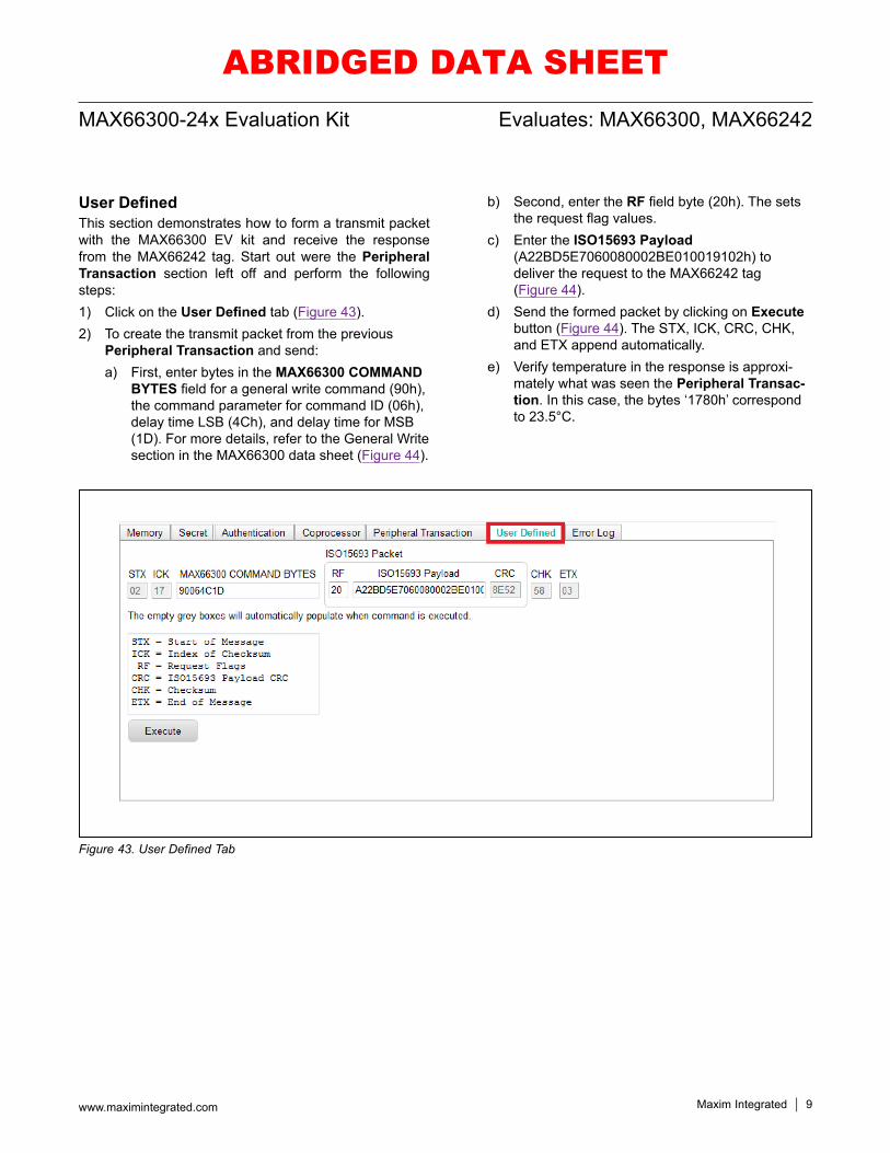
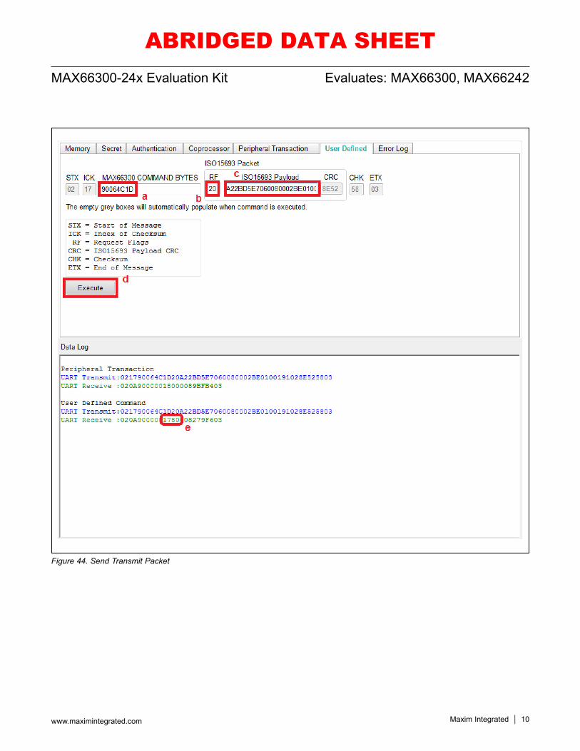
User DefinedThis section demonstrates how to form a transmit packet with the MAX66300 EV kit and receive the response from the MAX66242 tag. Start out were the Peripheral Transaction section left off and perform the following steps:1) Click on the User Defined tab (Figure 43).2) To create the transmit packet from the previous
Peripheral Transaction and send:a) First, enter bytes in the MAX66300 COMMAND
BYTES field for a general write command (90h), the command parameter for command ID (06h), delay time LSB (4Ch), and delay time for MSB (1D). For more details, refer to the General Write section in the MAX66300 data sheet (Figure 44).
b) Second, enter the RF field byte (20h). The sets the request flag values.
c) Enter the ISO15693 Payload (A22BD5E7060080002BE010019102h) to deliver the request to the MAX66242 tag (Figure 44).
d) Send the formed packet by clicking on Execute button (Figure 44). The STX, ICK, CRC, CHK, and ETX append automatically.
e) Verify temperature in the response is approxi-mately what was seen the Peripheral Transac-tion. In this case, the bytes ‘1780h’ correspond to 23.5°C.
Figure 43. User Defined Tab
ABRIDGED DATA SHEET
Maxim Integrated 10www.maximintegrated.com
Evaluates: MAX66300, MAX66242MAX66300-24x Evaluation Kit
Figure 44. Send Transmit Packet
ABRIDGED DATA SHEET
Maxim Integrated 11www.maximintegrated.com
Evaluates: MAX66300, MAX66242MAX66300-24x Evaluation Kit
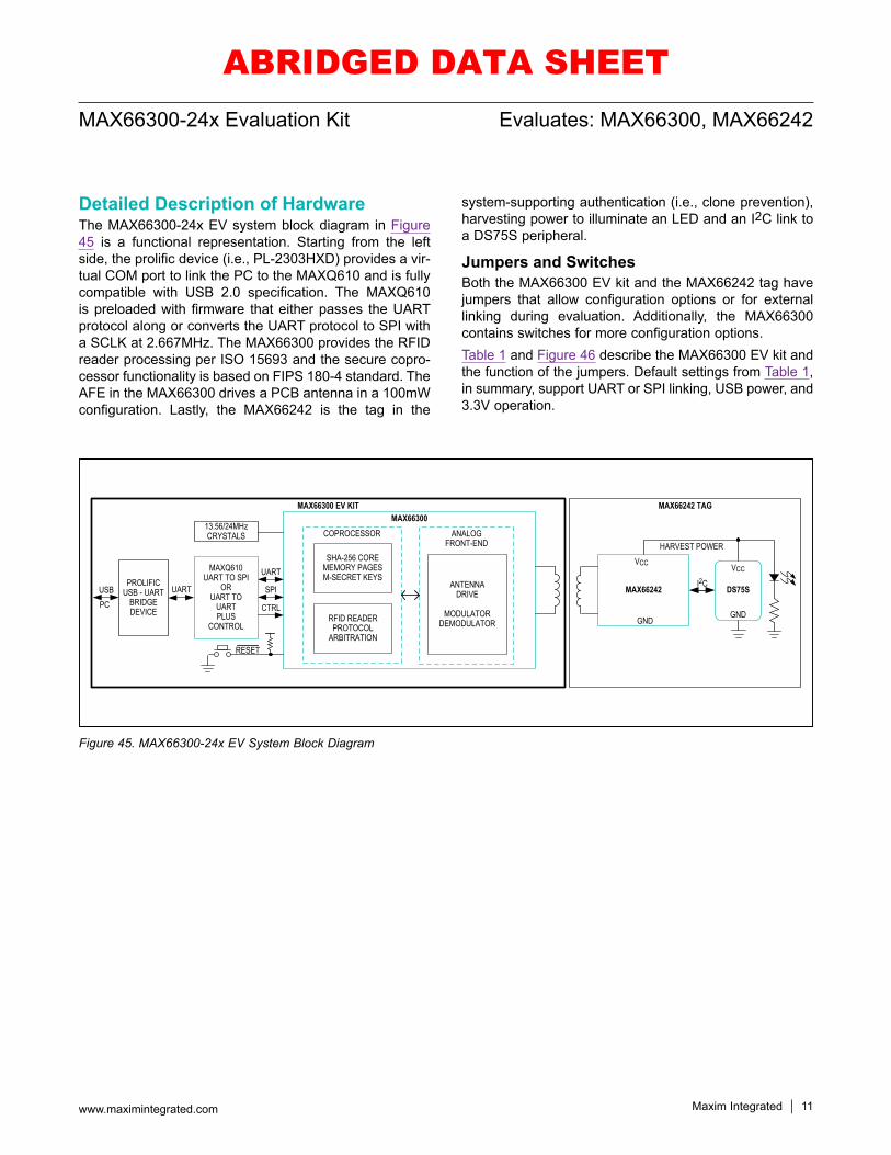
Detailed Description of HardwareThe MAX66300-24x EV system block diagram in Figure 45 is a functional representation. Starting from the left side, the prolific device (i.e., PL-2303HXD) provides a vir-tual COM port to link the PC to the MAXQ610 and is fully compatible with USB 2.0 specification. The MAXQ610 is preloaded with firmware that either passes the UART protocol along or converts the UART protocol to SPI with a SCLK at 2.667MHz. The MAX66300 provides the RFID reader processing per ISO 15693 and the secure copro-cessor functionality is based on FIPS 180-4 standard. The AFE in the MAX66300 drives a PCB antenna in a 100mW configuration. Lastly, the MAX66242 is the tag in the
system-supporting authentication (i.e., clone prevention), harvesting power to illuminate an LED and an I2C link to a DS75S peripheral.
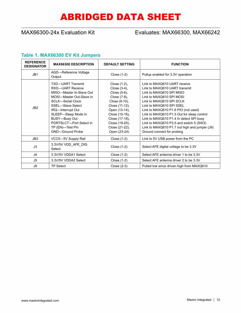
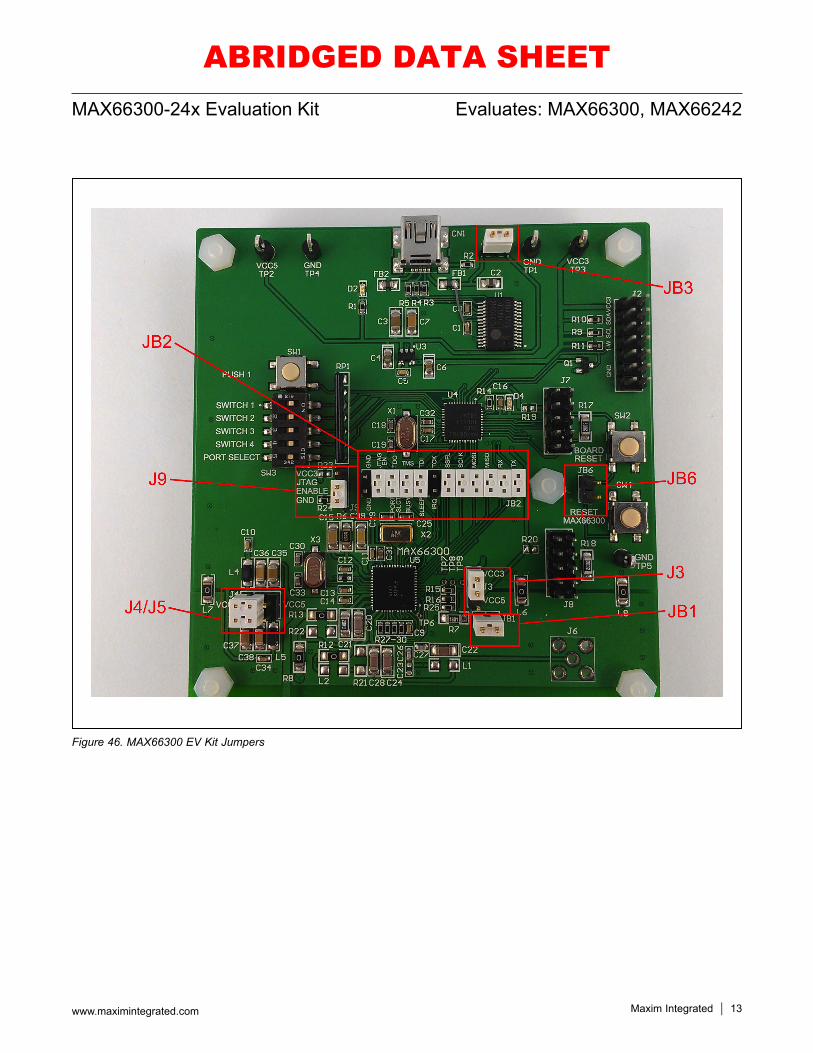
Jumpers and SwitchesBoth the MAX66300 EV kit and the MAX66242 tag have jumpers that allow configuration options or for external linking during evaluation. Additionally, the MAX66300 contains switches for more configuration options. Table 1 and Figure 46 describe the MAX66300 EV kit and the function of the jumpers. Default settings from Table 1, in summary, support UART or SPI linking, USB power, and 3.3V operation.
Figure 45. MAX66300-24x EV System Block Diagram
MAX66242 TAGMAX66300 EV KITMAX66300
COPROCESSOR ANALOGFRONT-END
SHA-256 COREMEMORY PAGESM-SECRET KEYS
RFID READERPROTOCOL
ARBITRATION
ANTENNADRIVE
MODULATORDEMODULATOR
MAX66242
MAXQ610UART TO SPI
ORUART TO
UARTPLUS
CONTROL
DS75SI2C
VCC VCC
HARVEST POWER
GNDGND
SPI
UART
CTRL
PROLIFICUSB - UART
BRIDGEDEVICE
UARTUSB
13.56/24MHzCRYSTALS
PC
RESET
ABRIDGED DATA SHEET
Maxim Integrated 12www.maximintegrated.com
Evaluates: MAX66300, MAX66242MAX66300-24x Evaluation Kit
Table 1. MAX66300 EV Kit JumpersREFERENCE DESIGNATOR MAX66300 DESCRIPTION DEFAULT SETTING FUNCTION
JB1 AGD—Reference Voltage Output Close (1-2) Pullup enabled for 3.3V operation
JB2
TXD—UART TransmitRXD—UART ReceiveMISO—Master In-Slave OutMOSI—Master Out-Slave InSCLK—Serial ClockSSEL—Slave SelectIRQ—Interrupt OutSLEEP—Sleep Mode InBUSY—Busy OutPORTSLCT—Port Select InTP (EN)—Test PinGND—Ground Probe
Close (1-2),Close (3-4),Close (5-6),Close (7-8),
Close (9-10),Close (11-12),Open (13-14),Close (15-16),Close (17-18),Close (19-20),Close (21-22),Open (23-24)
Link to MAXQ610 UART receiveLink to MAXQ610 UART transmitLink to MAXQ610 SPI MISOLink to MAXQ610 SPI MOSILink to MAXQ610 SPI SCLKLink to MAXQ610 SPI SSELLink to MAXQ610 P1.6 PIO (not used)Link to MAXQ610 P1.5 Out for sleep controlLink to MAXQ610 P1.4 In detect SPI busyLink to MAXQ610 P3.5 and switch 5 (SW3)Link to MAXQ610 P1.7 out high and jumper (J9)Ground connect for probing
JB3 VCC5—5V Supply Rail Close (1-2) Link to 5V USB power from the PC
J3 3.3V/5V VDD_AFE_DIG Select Close (1-2) Select AFE digital voltage to be 3.3V
J4 3.3V/5V VDDA1 Select Close (1-2) Select AFE antenna driver 1 to be 3.3V
J5 3.3V/5V VDDA2 Select Close (1-2) Select AFE antenna driver 2 to be 3.3V
J9 TP Select Close (2-3) Pulled low since driven high from MAXQ610
ABRIDGED DATA SHEET
Maxim Integrated 13www.maximintegrated.com
Evaluates: MAX66300, MAX66242MAX66300-24x Evaluation Kit
Figure 46. MAX66300 EV Kit Jumpers
ABRIDGED DATA SHEET
Maxim Integrated 14www.maximintegrated.com
Evaluates: MAX66300, MAX66242MAX66300-24x Evaluation Kit
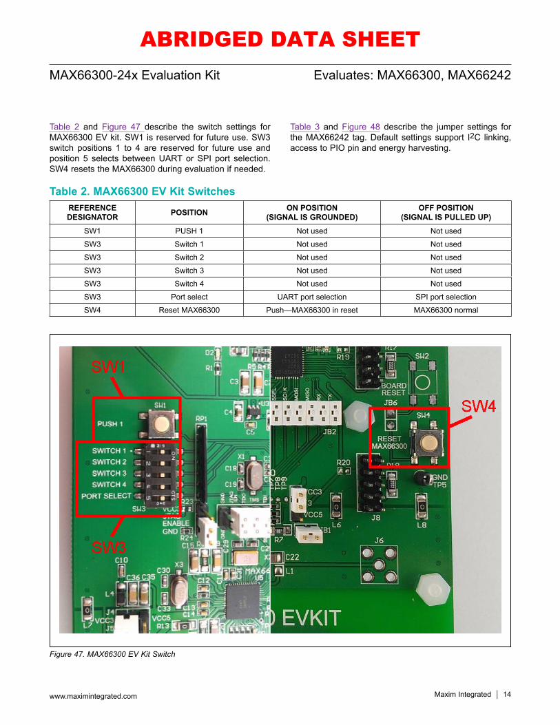
Table 2 and Figure 47 describe the switch settings for MAX66300 EV kit. SW1 is reserved for future use. SW3 switch positions 1 to 4 are reserved for future use and position 5 selects between UART or SPI port selection. SW4 resets the MAX66300 during evaluation if needed.
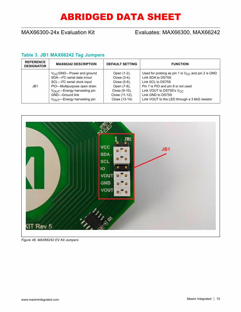
Table 3 and Figure 48 describe the jumper settings for the MAX66242 tag. Default settings support I2C linking, access to PIO pin and energy harvesting.
Table 2. MAX66300 EV Kit Switches
Figure 47. MAX66300 EV Kit Switch
REFERENCE DESIGNATOR POSITION ON POSITION
(SIGNAL IS GROUNDED)OFF POSITION
(SIGNAL IS PULLED UP)
SW1 PUSH 1 Not used Not used
SW3 Switch 1 Not used Not used
SW3 Switch 2 Not used Not used
SW3 Switch 3 Not used Not used
SW3 Switch 4 Not used Not used
SW3 Port select UART port selection SPI port selection
SW4 Reset MAX66300 Push—MAX66300 in reset MAX66300 normal
ABRIDGED DATA SHEET
Maxim Integrated 15www.maximintegrated.com
Evaluates: MAX66300, MAX66242MAX66300-24x Evaluation Kit
Table 3. JB1 MAX66242 Tag Jumpers
Figure 48. MAX66242 EV Kit Jumpers
REFERENCE DESIGNATOR MAX66242 DESCRIPTION DEFAULT SETTING FUNCTION
JB1
VCC/GND—Power and groundSDA—I2C serial data in/outSCL—I2C serial clock inputPIO—Multipurpose open drainVOUT—Energy harvesting pinGND—Ground linkVOUT—Energy harvesting pin
Open (1-2),Close (3-4),Close (5-6),Open (7-8),
Close (9-10),Close (11-12),Close (13-14)
Used for probing as pin 1 is VCC and pin 2 is GNDLink SDA to DS75SLink SCL to DS75SPin 7 is PIO and pin 8 is not usedLink VOUT to DS75S’s VCCLink GND to DS75SLink VOUT to the LED through a 3.6kΩ resistor
ABRIDGED DATA SHEET

Maxim Integrated 16www.maximintegrated.com
Evaluates: MAX66300, MAX66242MAX66300-24x Evaluation Kit
#Denotes RoHS compliant.
Ordering InformationPART TYPE
MAX66300-24xEVKIT# EV System
ABRIDGED DATA SHEET
Maxim Integrated 17www.maximintegrated.com
Evaluates: MAX66300, MAX66242MAX66300-24x Evaluation Kit
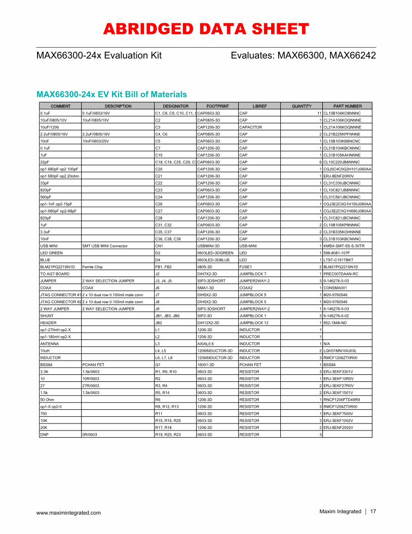
MAX66300-24x EV Kit Bill of MaterialsCOMMENT DESCRIPTION DESIGNATOR FOOTPRINT LIBREF QUANTITY PART NUMBER
0.1uF 0.1uF/0603/16V C1, C8, C9, C10, C11, C CAP0603-3D CAP 11 CL10B104KO8NNNC
10uF/0805/10V 10uF/0805/10V C2 CAP0805-3D CAP 1 CL21A106KOQNNNE
10uF/1206 C3 CAP1206-3D CAPACITOR 1 CL21A106KOQNNNE
2.2uF/0805/16V 2.2uF/0805/16V C4, C6 CAP0805-3D CAP 2 CL21B225KPFNNNE
10nF 10nF/0603/25V C5 CAP0603-3D CAP 1 CL10B103KB8NCNC
0.1uF C7 CAP1206-3D CAP 1 CL31B104KBCNNNC
1uF C15 CAP1206-3D CAP 1 CL31B105KAHNNNE
22pF C18, C19, C25, C29, C3 CAP0603-3D CAP 6 CL10C220JB8NNNC
op1 680pF op2 100pF C20 CAP1206-3D CAP 1 CGJ5C4C0G2H101J060AA
op1 680pF op2 20ohm C21 CAP1206-3D CAP 1 ERJ-8ENF20R0V
33pF C22 CAP1206-3D CAP 1 CL31C330JBCNNNC
820pF C23 CAP0603-3D CAP 1 CL10C821JB8NNNC
560pF C24 CAP1206-3D CAP 1 CL31C561JBCNNNC
op1-1nF op2-15pF C26 CAP0603-3D CAP 1 CGJ3E2C0G1H150J080AA
op1-680pF op2-68pF C27 CAP0603-3D CAP 1 CGJ3E2C0G1H680J080AA
820pF C28 CAP1206-3D CAP 1 CL31C821JBCNNNC
1uF C31, C32 CAP0603-3D CAP 2 CL10B105KP8NNNC
3.3uF C35, C37 CAP1206-3D CAP 2 CL31B335KOHNNNE
10nF C36, C38, C39 CAP1206-3D CAP 3 CL31B103KBCNNNC
USB MINI SMT USB MINI Connector CN1 USBMINI-3D USB-MINI 1 KMBX-SMT-5S-S-30TR
LED GREEN D2 0603LED-3DGREEN LED 1 598-8081-107F
BLUE D4 0603LED-3DBLUE LED 1 LTST-C191TBKT
BLM21PG221SN1D Ferrite Chip FB1, FB2 0805-3D FUSE1 2 BLM21PG221SN1D
TO AI27 BOARD J2 DIH7X2-3D JUMPBLOCK 7 1 PREC007DAAN-RC
JUMPER 2 WAY SELECTION JUMPER J3, J4, J5 SIP3-3DSHORT JUMPER2WAY-2 3 9-146276-0-03
COAX COAX J6 SMA1-3D COAX2 1 CONSMA001
JTAG CONNECTOR #1 2 x 10 dual row 0.100mil male conn J7 DIH5X2-3D JUMPBLOCK 5 1 M20-9760546
JTAG CONNECTOR #2 2 x 10 dual row 0.100mil male conn J8 DIH5X2-3D JUMPBLOCK 5 1 M20-9760546
2 WAY JUMPER 2 WAY SELECTION JUMPER J9 SIP3-3DSHORT JUMPER2WAY-2 1 9-146276-0-03
SHUNT JB1, JB3, JB6 SIP2-3D JUMPBLOCK 1 3 9-146276-0-02
HEADER JB2 DIH12X2-3D JUMPBLOCK 12 1 952-1848-ND
op1-270nH op2-X L1 1206-3D INDUCTOR 1
op1-180nH op2-X L2 1206-3D INDUCTOR 1
ANTENNA L3 AXIAL0.6 INDUCTOR 1 N/A
10uH L4, L5 1206INDUCTOR-3D INDUCTOR 2 LQH31MN100J03L
INDUCTOR L6, L7, L8 1206INDUCTOR-3D INDUCTOR 3 RMCF1206ZT0R00
BSS84 PCHAN FET Q1 16001-3D PCHAN FET 1 BSS84
3.3K 1.5k/0603 R1, R9, R10 0603-3D RESISTOR 3 ERJ-3EKF3301V
10 10R/0603 R2 0603-3D RESISTOR 1 ERJ-3EKF10R0V
27 27R/0603 R3, R4 0603-3D RESISTOR 2 ERJ-3EKF27R0V
1.5k 1.5k/0603 R5, R14 0603-3D RESISTOR 2 ERJ-3EKF1501V
50 Ohm R6 1206-3D RESISTOR 1 RNCP1206FTD49R9
op1-X op2-0 R8, R12, R13 1206-3D RESISTOR 3 RMCF1206ZT0R00
750 R11 0603-3D RESISTOR 1 ERJ-3EKF7500V
10K R15, R16, R25 0603-3D RESISTOR 3 ERJ-3EKF1002V
20K R17, R18 1206-3D RESISTOR 2 ERJ-8ENF2002V
DNP 0R/0603 R19, R20, R23 0603-3D RESISTOR 3
ABRIDGED DATA SHEET
Maxim Integrated 18www.maximintegrated.com
Evaluates: MAX66300, MAX66242MAX66300-24x Evaluation Kit
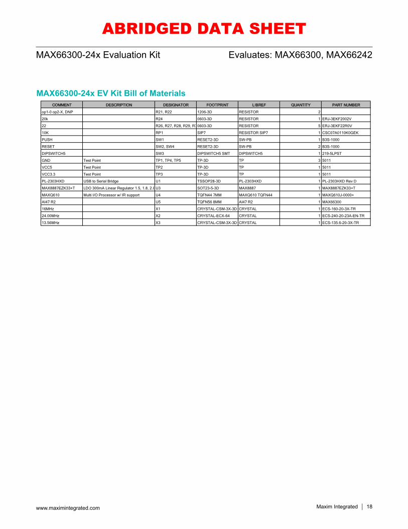
MAX66300-24x EV Kit Bill of MaterialsCOMMENT DESCRIPTION DESIGNATOR FOOTPRINT LIBREF QUANTITY PART NUMBER
op1-0 op2-X, DNP R21, R22 1206-3D RESISTOR 2
20k R24 0603-3D RESISTOR 1 ERJ-3EKF2002V
22 R26, R27, R28, R29, R30603-3D RESISTOR 5 ERJ-3EKF22R0V
10K RP1 SIP7 RESISTOR SIP7 1 CSC07A0110K0GEK
PUSH SW1 RESET2-3D SW-PB 1 B3S-1000
RESET SW2, SW4 RESET2-3D SW-PB 2 B3S-1000
DIPSWITCH5 SW3 DIPSWITCH5 SMT DIPSWITCH5 1 219-5LPST
GND Test Point TP1, TP4, TP5 TP-3D TP 3 5011
VCC5 Test Point TP2 TP-3D TP 1 5011
VCC3.3 Test Point TP3 TP-3D TP 1 5011
PL-2303HXD USB to Serial Bridge U1 TSSOP28-3D PL-2303HXD 1 PL-2303HXD Rev D
MAX8887EZK33+T LDO 300mA Linear Regulator 1.5, 1.8, 2.8 U3 SOT23-5-3D MAX8887 1 MAX8887EZK33+T
MAXQ610 Multi I/O Processor w/ IR support U4 TQFN44 7MM MAXQ610 TQFN44 1 MAXQ610J-0000+
AI47 R2 U5 TQFN56 8MM AI47 R2 1 MAX66300
16MHz X1 CRYSTAL-CSM-3X-3D CRYSTAL 1 ECS-160-20-3X-TR
24.00MHz X2 CRYSTAL-ECX-64 CRYSTAL 1 ECS-240-20-23A-EN-TR
13.56MHz X3 CRYSTAL-CSM-3X-3D CRYSTAL 1 ECS-135.6-20-3X-TR
ABRIDGED DATA SHEET
Maxim Integrated 19www.maximintegrated.com
Evaluates: MAX66300, MAX66242MAX66300-24x Evaluation Kit
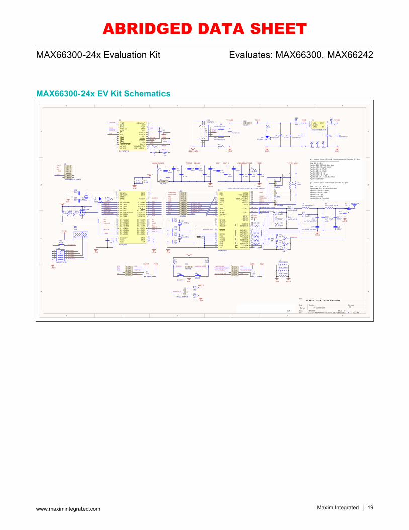
MAX66300-24x EV Kit Schematics
1
1
2
2
3
3
4
4
5
5
6
6
D D
C C
B B
A A
Title
Number RevisionSize
Tabloid
Date: 3/29/2016 Sheet ofFile: C:\Users\..\MAX66300EVKitRev4_1.SchDocDrawn By:
DMCN
GND
VO3.3
GNDVO3.3
DPCN
R51.5k
R327
R427
C10.1uF
C80.1uF
GND
TXD1
DTR2
RTS3
VDD-3254
RXD5
RI6
GND7
DSR9
DCD10
CTS11
SHUTDOWN12
GPIO-313
GPIO-214 USB PORT D+ 15USB PORT D- 16VO3.3 17GND 18RESET 19VDD5 20NC 21GPIO-0 22GPIO-1 23NC 24GND 25TEST 26NC 2712MHz Out* 28
NC8
U1
PL-2303HXD
P0.0/IRTXM1
P0.1/RX03
P0.2/TX05
P0.3/RX16
P0.4/TX17
P0.5/TBA0/TBA18
P0.6/TBB09
P0.7/TBB110
P1.0/INT0 11P1.1/INT1 12P1.2/INT2 13P1.3/INT3 14
VDD 41
P1.4/INT4 21P1.5/INT5 22P1.6/INT6 25
GND 17
P1.7/INT7 26
GND 20
P2.4/TCK 34P2.5/TDI 35P2.6/TMS 38P2.7/TDO 39
RESET 40IRTX43 IRRX44
HFXIN23
HFXOUT24 VDD 19
GND28 REGOUT18
EP EPGND42
P2.0/MOSI 27P2.1/MISO 29P2.2/SCLK 32P2.3/SSEL 33
P3.0/INT82 P3.1/INT94 P3.2/INT1015 P3.3/INT1116 P3.4/INT1230 P3.5/INT1331 P3.6/INT1436 P3.7/INT1537
U4
MAXQ610
L2op1-180nH op2-X
C23op1 820pFC26
op1-1nF op2-15pF
C27op1-680pF op2-68pF
ANTENNA
L3ANTENNA
C311uF
X224.00MHz
TXD2USBRXD2USB
X116MHz
C1822pF
C1922pF
GND
GND
R14
1.5k
GND
1 23 45 67 89 10
J7
TDO
TDI
TMS
TCK GND
RESET_IN
GND
VCC5VCC3.3
R19DNP
GND
TMSTDITCK
RESET_IN
C3022pF
C3322pF
C321uF
GND
X313.56MHz
C2522pF
C2922pF
GND
MAX66300_RESET
TDO
TP
MOSIMISO
SSELSCLK
TXDREADERRXDREADER
PORTSLCT
SLEEPBUSY
IRQ
TP
MOSIMISO
SSELSCLK
TXDREADERRXDREADER
1 23 45 67 89 1011 1213 1415 1617 1819 2021 2223 24
JB2
HEADER
VCC3.3 VCC5
C90.1uF
TXD2USB
RXD2USB
12
3
J3
JUMPER
12
3
J4
JUMPER
12
3
J5
JUMPER
C160.1uF
C170.1uF
GND
1 23 45 67 89 10
J8GND
GND
VCC5VCC3.3
R20DNP
1 23 45 67 89 1011 1213 14
J2
TO MAX66242 EVKIT
MAX66300_BUSY
MAX66300_IRQ
MAX66300_PORTSLCT
MAX66300_SLEEP
PORTSLCT SLEEPBUSY
IRQ
EVALUATION KIT FOR MAX66300
MAXIM
4.1
GND GND
RESET_IN
VCC3.3
VDDEMDIGVDDA1VDDA2
VDDEMDIGVDDA1 VDDA2
C110.1uF
C120.1uF
C130.1uF
C140.1uF
GND
C100.1uF
VCC3.3
MAX66300AGD
GND
6R
RP110K
SELECT1SELECT2SELECT3SELECT4PORTSLCT
SELECTPB
VCC3.3 SELECT1SELECT2SELECT3
SELECT4
SELECTPB
1-WIRE
SCLSDA
1-WIRESCLSDA
GND
VCC3.3
C21op1 680pF op2 20ohm
L1op1-270nH op2-X
C24560pF
C28820pF
C2233pFC20
op1 680pF op2 100pFR12
op1-X op2-0
VCCUSBRESET_IN
C151uF
VBAT
VBAT
R6
50 Ohm
VDDIO
VDDIO
VDDA1 AND VDDA2 MUST ALWAYS BE AT SAME VOLTAGE
VDDEMDIG
R15
10KR16
10K
MAX66300_RESET1 2
JB6
SHUNTMAX66300_RESET
R1720K
R1820K
VCC3.3
TP6TP TP7
TP
TP8TP
R71.8k
MAX66300AGD
12JB1
SHUNT
R13op1-X op2-0
R8op1-X op2-0
S
D
G
Q1BSS84
VCC3.3
R11750
1-WIRE SPU
R93.3K
R103.3K
J6COAX
12345
109876
SW3
DIPSWITCH5
2 1D4BLUE
RFIN1RFIN2
AT1
AT2
op1 - Antenna Option 1 External 50 ohm antenna (0=Zero ohm X=Open)-------------------------------------------------------Open R8, R12, R13Populate R21, R22 with Zero ohmPopulate C20, C21 with 680pFPopulate L1 with 270nH Populate L2 with 180nHPopulate C26 with 1nFPopulate C27 with 680pFPopulate L6, L7, L8 with Zero OhmPopulate C23 820pF
op2 - Antenna Option 2 internal (0=Zero ohm X=Open)-------------------------------------------------------Open C23, L1, L2, R21, R22Populate R8, R12, R13 with Zero ohmPopulate C21 with 22 ohmPopulate C20 with 120pFPopulate C26 15pFPopulate C27 68pFPopulate L6 with Zero Ohm
C340.1uF
R21
op1-0 op2-X
R22op1-0 op2-X
MAX66300_TP
12
3
J9
2 WAY JUMPER
R23
DNP
R24
20k
VCC3.3
GND
L510uH
L410uH
C353.3uF
C3810nF
C3610nF
C373.3uF
C3910nF
VCC5
GND AGND
L6INDUCTOR
AGND
AGND
AGND
L7INDUCTOR
L8INDUCTOR
R25
10K
TP9TP
R26 22
R29 22
R27 22
R28 22
R30 22
SW1PUSH
SW2
RESET
MAX66300_RESET
SW4
RESET
DPCNDMCN
GNDGND_EARTH
C210uF/0805/10V
R2
10
V+ 1
D- 2
D+ 34
V- 5
S6
S7
S8
S9
CN1USB MINI
VCC3.3
GND
C42.2uF/0805/16V
C62.2uF/0805/16V
C510nF
R13.3K
GND
D2LED GREEN
+C3
10uF/1206C7
0.1uF
VCC5
FB2BLM21PG221SN1D
FB1BLM21PG221SN1D
TP4
GND
TP5
GND
TP2
VCC5
TP3
VCC3.312
JB3
SHUNT
VCCUSB VCC5
VIN1
GND2 SHDN3
BP 4
OUT 5U3
MAX8887EZK33+T
TP1
GND
op2 x
MAX66300_BUSY
MAX66300_IRQMAX66300_PORTSLCT
MAX66300_SLEEP
MAX66300_TP
SYSAIN_1 56
SYSAIN_2 1
SYSAIN_3 3
RXD5
TXD6
SYSCIN 7
SYSBIN 8
GND9
MISO10
MOSI11
SCLK12
SSEL13
IRQ14
SLEEP15
BUSY16
PortSLCT17
RESET18
HFXIN20
HFXOUT21
VDDQ 22
GND23
REG1826
VDD_CORE 29
VDDIO 31
GND32
VDD_AFE_DIG 34
OSCIN35
OSCOUT36
VDDA1 37
ANT1 38
VSSA139
VDDA2 42
ANT2 41
VSSA240
RFIN2 44RFIN1 45
SYSBOUT 46
SYSCOUT 47
SYSAOUT 48
SYSDIN 54
VSS50
AGD 51
TP53
SYSDOUT 49EPEP
SYSEOUT 33SYSEIN 52
RFIN2 43
U5
MAX66300
/Devices/MAX66300_AI47/EV_Kit/EV_Kit_Schematics_PCBs/Rev4_1 SVN
89-66300#K00
ABRIDGED DATA SHEET
Maxim Integrated 20www.maximintegrated.com
Evaluates: MAX66300, MAX66242MAX66300-24x Evaluation Kit
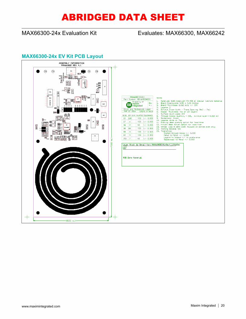
MAX66300-24x EV Kit PCB Layout
ABRIDGED DATA SHEET
Maxim Integrated 21www.maximintegrated.com
Evaluates: MAX66300, MAX66242MAX66300-24x Evaluation Kit
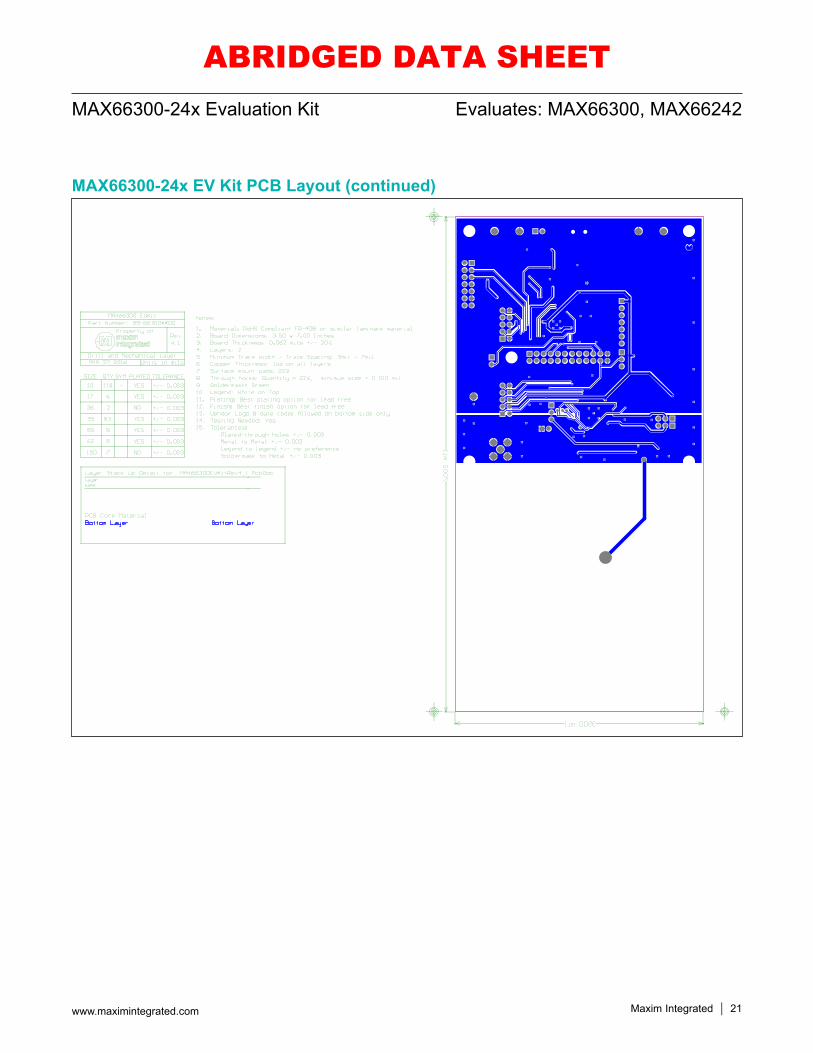
MAX66300-24x EV Kit PCB Layout (continued)
ABRIDGED DATA SHEET
Maxim Integrated 22www.maximintegrated.com
Evaluates: MAX66300, MAX66242MAX66300-24x Evaluation Kit
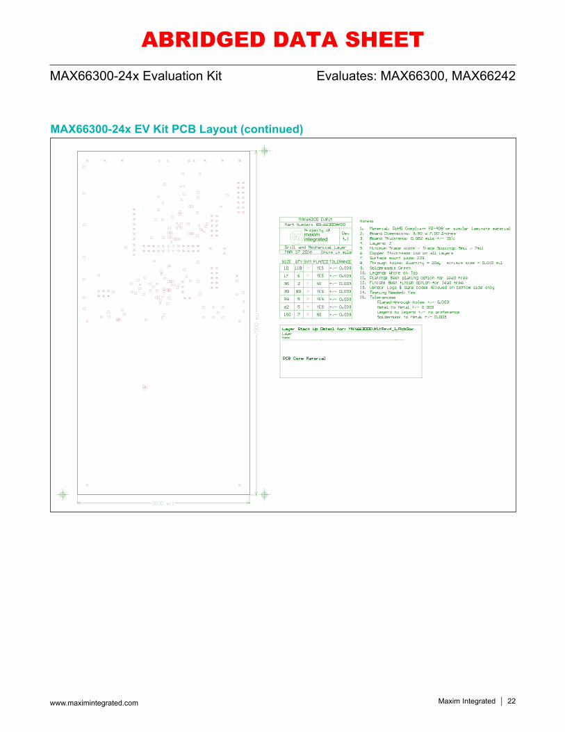
MAX66300-24x EV Kit PCB Layout (continued)
ABRIDGED DATA SHEET
Maxim Integrated 23www.maximintegrated.com
Evaluates: MAX66300, MAX66242MAX66300-24x Evaluation Kit
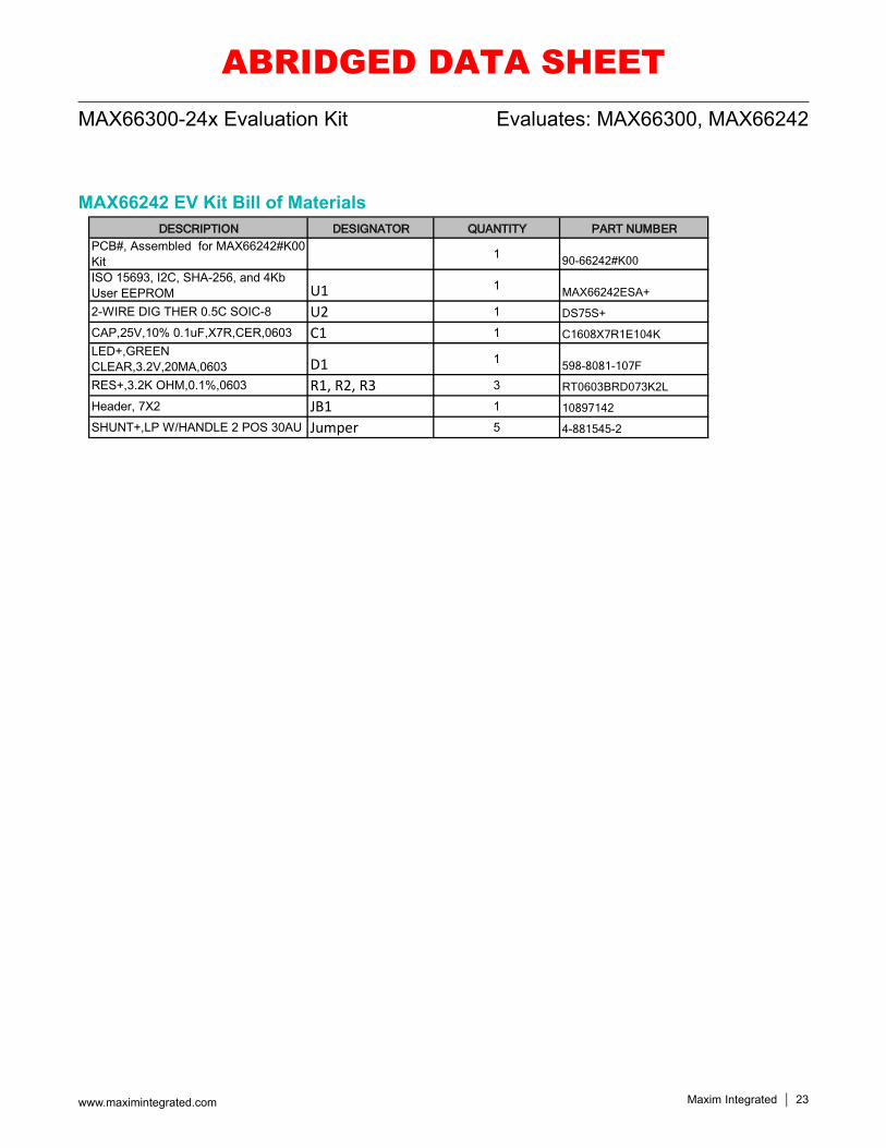
MAX66242 EV Kit Bill of MaterialsDESCRIPTION DESIGNATOR QUANTITY PART NUMBER
PCB#, Assembled for MAX66242#K00 Kit 1 90-66242#K00ISO 15693, I2C, SHA-256, and 4Kb User EEPROM U1 1 MAX66242ESA+
2-WIRE DIG THER 0.5C SOIC-8 U2 1 DS75S+
CAP,25V,10% 0.1uF,X7R,CER,0603 C1 1 C1608X7R1E104KLED+,GREEN CLEAR,3.2V,20MA,0603 D1 1 598-8081-107F
RES+,3.2K OHM,0.1%,0603 R1, R2, R3 3 RT0603BRD073K2L
Header, 7X2 JB1 1 10897142
SHUNT+,LP W/HANDLE 2 POS 30AU Jumper 5 4-881545-2
ABRIDGED DATA SHEET
Maxim Integrated 24www.maximintegrated.com
Evaluates: MAX66300, MAX66242MAX66300-24x Evaluation Kit
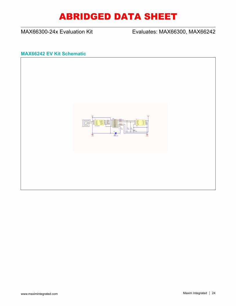
MAX66242 EV Kit Schematic
1
1
2
2
3
3
4
4
5
5
6
6
D D
C C
B B
A A
Title
Number RevisionSize
Tabloid
Date: 9/15/2014 Sheet ofFile: C:\rspencer\..\MAX662xxRev2.SchDoc Drawn By:
VCC1
AC12
AC23
GND4 VOUT 5P2/IO 6P0/SCL 7P1/SDA 8U1
MAX66242
SDA1
SCL2
OS3
GND4 A2 5A1 6A0 7VCC 8U2
DS75
1 23 45 67 89 1011 1213 14
JB1
JUMPBLOCK 7
GND
VCC
R13.6k
R23.6k
R33.6k
C10.1uFD1
Green LED
AN1SDASCLIOVOUT
MAXIM
GND2
GND
VCC2
SDA2SCL2
GND2
VCC2
MAX66242 EVKIT
5
MAXIM
ABRIDGED DATA SHEET
Maxim Integrated 25www.maximintegrated.com
Evaluates: MAX66300, MAX66242MAX66300-24x Evaluation Kit
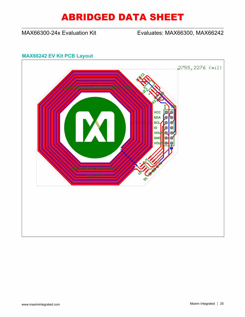
MAX66242 EV Kit PCB Layout
ABRIDGED DATA SHEET
Maxim Integrated cannot assume responsibility for use of any circuitry other than circuitry entirely embodied in a Maxim Integrated product. No circuit patent licenses are implied. Maxim Integrated reserves the right to change the circuitry and specifications without notice at any time.
Maxim Integrated and the Maxim Integrated logo are trademarks of Maxim Integrated Products, Inc. © 2016 Maxim Integrated Products, Inc. 26
Evaluates: MAX66300, MAX66242MAX66300-24x Evaluation Kit
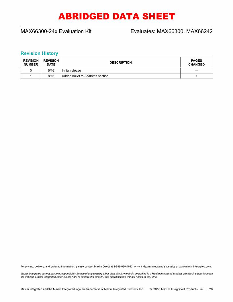
Revision HistoryREVISIONNUMBER
REVISIONDATE DESCRIPTION PAGES
CHANGED
0 5/16 Initial release —
1 8/16 Added bullet to Features section 1
For pricing, delivery, and ordering information, please contact Maxim Direct at 1-888-629-4642, or visit Maxim Integrated’s website at www.maximintegrated.com.
ABRIDGED DATA SHEET

Mouser Electronics
Authorized Distributor
Click to View Pricing, Inventory, Delivery & Lifecycle Information: Maxim Integrated:
MAX66300-24XEVKIT#


