Embed Size (px)
Citation preview
IEEE TRANSACTIONS ON SYSTEMS, MAN, AND CYBERNETICS—PART B: CYBERNETICS, VOL. 31, NO. 3, JUNE 2001 341
Adaptive Tracking Control of a Wheeled MobileRobot via an Uncalibrated Camera System
Warren E. Dixon, Member, IEEE, Darren M. Dawson, Senior Member, IEEE, Erkan Zergeroglu, Member, IEEE,and Aman Behal
Abstract—This paper considers the problem of position/orien-tation tracking control of wheeled mobile robots via visual ser-voing in the presence of parametric uncertainty associated with themechanical dynamics and the camera system. Specifically, we de-sign an adaptive controller that compensates for uncertain cameraand mechanical parameters and ensures global asymptotic posi-tion/orientation tracking. Simulation and experimental results areincluded to illustrate the performance of the control law.
Index Terms—Adaptive control, visual-servoing, wheeled mobilerobot.
I. INTRODUCTION
A S the demand increases for wheeled mobile robots(WMRs) in settings that range from shopping centers,
hospitals, warehouses, and nuclear waste facilities, the needfor precise control of WMRs is clearly evident; hence, aclosed-loop sensor-based controller is required. Unfortunately,due to the nonholonomic nature of the WMR and the standardencoder hardware configuration (e.g., optical encoders mountedon the actuators), the WMR Cartesian position is difficult toaccurately obtain. That is, the linear velocity of the WMRmust first be numerically differentiated from the position (i.e.,by the backward difference algorithm) and then the nonlinearkinematic model must be numerically integrated to obtain theWMR Cartesian position. Since numerical differentiation/inte-gration errors may accumulate over time, the accuracy of thenumerically calculated WMR Cartesian position may be com-promised. An interesting approach to overcome this positionmeasurement problem is to utilize a vision system to directlyobtain the Cartesian position information required by thecontroller (for an overview of the state-of-the-art in robot visualservoing, see [7] and [18]). Specifically, a ceiling-mounted
Manuscript received March 12, 2000; revised January 9, 2001. This workwas supported in part by a Eugene P. Wigner Fellow and Staff Member at theOak Ridge National Laboratory, managed by UT-Battelle, LLC, for the U.S.Department of Energy under Contract DE-AC05-00OR22725. Additional sup-port is provided by the U.S. National Science Foundation Grants DMI-9457967,CMS-9634796, ECS-9619785, DMI-9813213, and EPS-9630167, DOE GrantDE-FG07-96ER14728, a DOC Grant, and the Gebze Institute for AdvancedTechnology. This paper was recommended by Associate Editor R. A. Hess.
W. E. Dixon is with the Robotics and Process Systems Division, Oak RidgeNational Laboratory, Oak Ridge, TN 37831 USA (e-mail: [email protected]).
D. M. Dawson and A. Behal are with the Department of Electrical and Com-puter Engineering, Clemson University, Clemson, SC 29634 USA.
E. Zergeroglu was with the Department of Electrical and Computer Engi-neering, Clemson University, Clemson, SC 29634 USA. He is now with OpticalFiber Solutions, Bell Laboratory Innovations, Lucent Technologies, Sturbridge,MA 01566 USA.
Publisher Item Identifier S 1083-4419(01)05220-7.
camera system can be used to determine the WMR Cartesianposition without requiring numerical calculations. However, asemphasized by Bishopet al. in [1], when a vision system is uti-lized to extract information about a robot and the environment,adequate calibration of the vision system is required. That is,parametric uncertainty associated with the calibration of thecamera corrupts the WMR position/orientation information;hence, camera calibration errors can result in degraded controlperformance.
Despite the above motivation to incorporate visual informa-tion in the control loop, most of the WMR research available inliterature which incorporates visual information in the overallsystem seems to be concerned with vision-based navigation(i.e., using visual information for trajectory planning). It alsoseems that the state-of-the-art WMR research that specificallytargets incorporating visual information from an on-boardcamera into the closed-loop control strategy can be found in[5], [15], [21]. Specifically, in [15], Maet al. incorporates thedynamics of image curves obtained from a mobile camerasystem in the design of stabilizing control laws for trackingpiecewise analytic curves. In [1], Espiauet al. proposed avisual servoing framework and in [5], Samsonet al. addresscontrol issues in the image plane. For the most part, it seemsthat previous visual-servoing WMR work has assumed thatthe parametric uncertainty associated with the camera systemcan been neglected. In contrast, it seems that visual servoingresearch for robot manipulators has focused on the designof controllers that account for uncalibrated camera effects aswell as uncertainty associated with the mechanical dynamics.Specifically, in [10], Kelly designed a setpoint controller totake into account uncertainties in the camera orientation toachieve a local asymptotically stable result; however, thecontroller required exact knowledge of the robot gravitationalterm and restricted the difference between the estimated andactual camera orientation to the interval (90 , 90 ). In[1], Bishop and Spong developed an inverse dynamics-type,position tracking control scheme (i.e., exact model knowledgeof the mechanical dynamics) with on-line adaptive cameracalibration that guaranteed global asymptotic position tracking;however, convergence of the position tracking error requiredthe desired position trajectory to be persistently exciting. In[16], Maruyama and Fujita proposed setpoint controllers forthe camera-in-hand configuration; however, the proposedcontrollers required exact knowledge of the camera orientationand assumed the camera scaling factors to be the same valuefor both directions. In [11], Kellyet al. utilized a compositevelocity inner loop, image-based outer loop fixed-camera
1083–4419/01$10.00 © 2001 IEEE
342 IEEE TRANSACTIONS ON SYSTEMS, MAN, AND CYBERNETICS—PART B: CYBERNETICS, VOL. 31, NO. 3, JUNE 2001
tracking controller to obtain a local asymptotic stability result;however, exact model knowledge of the robot dynamics anda calibrated camera are required, and the difference betweenthe estimated and actual camera orientation is restricted tothe interval ( 90 , 90 ). Recently, in [23], Zergerogluet al.designed an adaptive tracking controller that accounted forparametric uncertainty throughout the entire robot-camerasystem; however, the controller required that the difference be-tween the estimated and actual camera orientation be restrictedto the interval ( 90 , 90 ). Moreover, in [24], Zergerogluetal. proposed a globally uniformly ultimately bounded (GUUB)tracking controller that is robust to uncertainty throughout theentire robot-camera system for a fixed-camera configuration,and a GUUB regulating controller for a camera-in-hand con-figuration. Note that in order to achieve the above results, [24]require that the camera orientation be within a certain range.
In this paper, we design a global asymptotic position/orienta-tion tracking controller for a WMR with a ceiling-mounted fixedcamera that adapts for uncertainty associated with the cameracalibration (e.g., magnification factors, focal length, and orien-tation) in addition to the uncertainty associated with the me-chanical parameters of the WMR dynamic model (e.g., mass,inertia, friction). We note that most of the vision-based naviga-tion approaches found in WMR literature can be utilized to gen-erate the camera-space reference trajectory for use in the pro-posed controller. However, if the camera is not assumed to beperfectly calibrated, then it is not obvious how to generate thereference trajectory in the task-space using the camera-system;hence, it seems that the reference trajectory must be generatedin the camera-space and the control loop must be closed inthe camera-space. Following this line of reasoning, we use acamera-space reference trajectory generator and the camera-space WMR kinematic model to formulate an open-loop errorsystem. This open-loop error system and the previous controlstructure given in [3] and [20] are then used to develop a kine-matic control to ensure tracking in the camera-space. We thenuse the standard pin-hole camera model and the WMR camera-space model to develop a transformation between the actualWMR velocity and the camera-space WMR velocity. This trans-formation is then used to transform the WMR dynamic modelinto a form that facilitates the design of a torque input adaptivecontroller that compensates for parametric uncertainty associ-ated with camera calibration effects as well as the WMR me-chanical dynamics. The proposed adaptive controller achievesglobal asymptotic tracking and requires the following signalsfor implementation:
1) WMR position/orientation in the camera-space;2) WMR linear and angular velocity in the camera-space;3) actual WMR orientation and angular velocity.
Note that the orientation and angular velocity of the WMR canbe obtained from the on-board optical encoders and the back-ward difference algorithm while the WMR linear and angularvelocity in the camera-space can be calculated from the WMRposition/orientation in the camera-space using the backward dif-ference algorithm; hence, the proposed controller does not re-quire integration of the nonlinear kinematic model for obtainingthe WMR Cartesian position.
This paper is organized as follows. In Section II, we describethe kinematic model of a WMR in the task-space and thecamera-space, and then we utilize the pin-hole camera modelto formulate a global invertible transformation between thetwo spaces. In Section III, the control objective of the paper isstated and then a kinematic tracking controller along with thecorresponding open-loop error system is developed. In SectionIV, we develop the dynamic model for the WMR that facilitatesthe subsequent closed-loop control development given in Sec-tion V and the corresponding stability analysis given in SectionVI. In Section VII, the controller’s performance is illustratedthrough simulation and experimental results. In Section VIII,we present some concluding remarks.
II. K INEMATIC MODEL
A. WMR Kinematic Model in the Task-Space
The kinematic model of a WMR in the task-space is assumedto be of the following form [17]:
(1)
where , are defined as
(2)
, , and denote the position and orientation,respectively, of the center of mass (COM) of the WMR (whichis assumed to coincide with the center of the axis of rotationof the WMR), , denote the Cartesian components ofthe linear velocity of the COM, denotes the angularvelocity of the COM, the matrix is defined asfollows:
(3)
and the velocity vector is defined as
(4)
with denoting the linear velocity of the COM of theWMR.
B. WMR Kinematic Model in the Camera-Space
Based on the task-space kinematic formulation given in (1)and the desire to craft a camera-space tracking controller, weassume that the representation of the WMR kinematic model inthe camera-space takes the following form
(5)
where was defined in (3),denotes the position and orientation of the WMR in the camera-space, and denotes the linear andangular velocity of the WMR in the camera-space. That is, weassume that the WMR in the camera-space must satisfy the samekinematic model as the WMR in the task-space. With regard tothe robot-camera system configuration, it is assumed that the
DIXON et al.: ADAPTIVE TRACKING CONTROL OF A WHEELED MOBILE ROBOT 343
camera is fixed above the robot workspace such that we havethe following.
1) Its image plane is parallel to the plane of motion of therobot.
2) The camera can capture images throughout the entirerobot workspace.
3) The camera system can determine the COM of the WMRby recognizing some physical characteristic (e.g., a lightemitting diode).
4) The camera can determine the orientation of the WMR,and hence, the direction that the WMR is traveling, byrecognizing an additional characteristic (e.g., an arrowpainted on the WMR, a second light emitting diode, etc).
C. Task-Space to Camera-Space Transformations
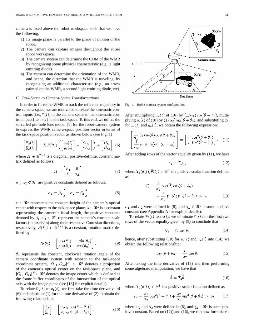
In order to force the WMR to track the reference trajectory inthe camera-space, we are motivated to relate the kinematic con-trol inputs [i.e., ] in the camera-space to the kinematic con-trol inputs [i.e., ] in the task-space. To this end, we utilize theso-called pin-hole lens model [1] for the robot-camera systemto express the WMR camera-space position vector in terms ofthe task-space position vector as shown below (see Fig. 1)
(6)
where is a diagonal, positive-definite, constant ma-trix defined as follows:
(7)
, are positive constants defined as follows:
(8)
represents the constant height of the camera’s opticalcenter with respect to the task-space plane, is a constantrepresenting the camera’s focal length, the positive constantsdenoted by , represent the camera’s constant scalefactors (in pixels/m) along their respective Cartesian directions,respectively, is a constant, rotation matrix de-fined by
(9)
represents the constant, clockwise rotation angle of thecamera coordinate system with respect to the task-spacecoordinate system, denotes a projectionof the camera’s optical center on the task-space plane, and
denotes the image center which is defined asthe frame buffer coordinates of the intersection of the opticalaxis with the image plane (see [13] for explicit details).
To relate to , we first take the time derivative of(6) and substitute (1) for the time derivative of (2) to obtain thefollowing relationship:
(10)
Fig. 1. Robot-camera system configuration.
After multiplying of (10) by , multi-plying of (10) by , and substituting (5)for and , we obtain the following expression:
(11)
After adding rows of the vector equality given by (11), we have
(12)
where is a positive scalar function definedas
(13)
and were defined in (8), and is some positiveconstant (see Appendix A for explicit details).
To relate to , we eliminate in the first tworows of the vector equality given by (5) to conclude that
(14)
hence, after substituting (10) for and into (14), weobtain the following relationship:
(15)
After taking the time derivative of (15) and then performingsome algebraic manipulation, we have that
(16)
where is a positive scalar function defined as
(17)
where and were defined in (8), and is some pos-itive constant. Based on (12)) and (16), we can now formulate a
344 IEEE TRANSACTIONS ON SYSTEMS, MAN, AND CYBERNETICS—PART B: CYBERNETICS, VOL. 31, NO. 3, JUNE 2001
global invertible transformation between the task-space WMRvelocities and the camera-space WMR velocities as follows:
(18)
where is defined as
(19)
and the positive scalar functions , , andwere defined in (13) and (17), respectively.
III. K INEMATIC CONTROL FORMULATION
A. Control Objective
The primary control objective is to force the representationof the WMR in the camera-space to track a trajectory generatedin the camera-space in the presence of parametric uncertainty(i.e., the camera calibration parameters and the mechanical pa-rameters associated with the dynamic model). Similar to pre-vious WMR research performed in the task-space (e.g., see [8]and [9]), the desired trajectory of the WMR is generated via areference robot which moves in the camera-space according tothe following dynamic trajectory:
(20)
where was defined in (3), =denotes the reference position and orientation trajectory
in the camera-space, and = de-notes the reference linear and angular velocity of the WMR inthe camera-space. With regard to (20), it is assumed that thesignal is obtained from a path planning algorithm and isconstructed to produce the desired motion in the camera-spaceand that , , , and are bounded for all time.
B. Open-Loop Error System Development
To facilitate the subsequent closed-loop error system devel-opment and stability analysis, we define an auxiliary error signaldenoted by = , that is related tothe difference between the reference position/orientation and thecamera-space position/orientation of the WMR through a globalinvertible transformation as follows [3], [20]:
(21)
where , , and are defined as
(22)
We can now formulate the open-loop error dynamics for bydifferentiating (21) to obtain the following expression:
(23)
where is an auxiliary signal de-fined in terms of the camera-space orientation/velocity, and thedesired trajectory as follows:
(24)
with the auxiliary variable beingdefined as follows:
(25)
To facilitate the kinematic closed-loop error system develop-ment, we inject the auxiliary control inputs, denoted by =
, into the open-loop dynamics of andby adding and subtracting and to the right-side of(23) to obtain the following expression:
(26)
where the kinematic tracking error signal, denoted by, is defined as follows:
(27)
C. Control Design and Closed-Loop Error SystemDevelopment
Based on (26) and the subsequent closed-loop error systemdevelopment, we design as shown below [3], [20]
(28)
where , denote positive constant control gains. Aftersubstituting (28) into (26), the resulting kinematic closed-looperror system for is given as follows:
(29)
IV. WMR DYNAMIC MODEL
Since the proposed control is designed to include the effectsof the dynamic model, we will assume that the task-space dy-namic model for the WMR can be expressed as follows:
(30)
where denotes the time derivative of defined in(4), represents the constant, diagonal inertia matrix,
represents the friction effects, repre-sents the torque input vector, and represents a di-agonal input matrix that governs torque transmission. To facil-itate the subsequent control design, we transform the dynamicmodel into a form that is consistent with the kinematic trans-formation given by (18) and (24). Specifically, we premultiply(30) by , substitute (18) for , and then substitute (24)
DIXON et al.: ADAPTIVE TRACKING CONTROL OF A WHEELED MOBILE ROBOT 345
for in the resulting expression to obtain the following con-venient dynamic model:
(31)
where
and , = . To facilitate the stability analysis,we note that the dynamic model given by (31) exhibits the fol-lowing properties [14].
Property 1: The transformed inertia matrix is sym-metric, positive definite, and satisfies the following inequalities:
(32)
where and are known positive constants, and denotesthe standard Euclidean norm.
Property 2:: A skew-symmetric relationship exists betweenthe transformed inertia matrix and the auxiliary matrixas follows:
(33)
where represents the time derivative of the transformedinertia matrix.
Property 3: The robot dynamics given in (31) can be linearlyparameterized as follows:
(34)
where contains the unknown constant mechanical pa-rameters (i.e., inertia, mass, and friction effects) and calibra-tion/camera constants (i.e., , , and ) and ,
denotes the known regression matrix. Furthermore, theglobal invertible matrix , defined in (19) is linearlyparameterizable as shown below in the following:
(35)
where , contain the unknown cameracalibration constants, and , ,
denote known regression vectors.Property 4: To avoid singularities in the subsequent control
law, we now define convex regions, in the same manner as [2]and [12], for the parameter vectors and defined in (35).Specifically, based on (13), (17), and (35), we define the spacespanned by the vector functions and asfollows:
(36)
In addition, we define the regions and as
(37)
where , were defined in (13) and (17), respectively, and wehave the following definitions concerning the regions and
and the subsequently designed parameter estimate vectorsand : int( ) is the interior of the
region , is the boundary for the region , isa unit vector normal to at the point of intersection of theboundary surface and where the positive direction for
is defined as pointing away from int() [note is onlydefined for ], is the component of the vector
that is tangential to at the point of intersectionof the boundary surface and the vector ,
is the component of the vector ,that is perpendicular to at the point of intersection of theboundary surface and the vector for .
Remark 1: Note that the subsequent control development re-lies heavily on the fact that the dynamic model is decoupled.It is not obvious how the controller can be extended to accountfor additional coupling terms that result from the COM of theWMR not corresponding to the center of the axis of rotation.Future research will target the development of a controller thatcan track a desired camera-space trajectory despite the use ofan uncalibrated vision system and parametric uncertainty in theWMR dynamic model which includes the additional couplingeffects.
V. DYNAMIC MODEL CONTROL FORMULATION
We now utilize the dynamic model given by (31) to design acontrol torque input that regulates the kinematic tracking errorsignal defined in (22). Motivated by the structure of (29), thekinematic tracking control objective can be obtained by regu-lating the auxiliary tracking signal defined in (27). To this end,we develop the closed-loop error system for by taking thetime derivative of (27) and multiplying both sides of the re-sulting expression by to obtain the following expression:
(38)
After substituting (31) for and then adding and subtractingterms to the right-side of the resulting expression, we arrangethe dynamics in the following advantageous form
(39)
where (27) was utilized, and regression matrix parametrizationis defined according to
(40)
where denotes the known desired regressionmatrix, and was defined in (34).
346 IEEE TRANSACTIONS ON SYSTEMS, MAN, AND CYBERNETICS—PART B: CYBERNETICS, VOL. 31, NO. 3, JUNE 2001
Based on the subsequent stability proof and the regulation of, we design the control torque input as follows:
(41)
where is an auxiliary control signaldesigned as shown in the following:
(42)
where , are positive constant control gains, and theparameter update laws for , , and are designedas follows:
(43)
if intif andif and
(44)
where int for , the auxiliary signalsand are defined as follows:
(45)
and
(46)
and , , are positive defi-nite gain matrices. If int , the above update law for
and defined in (44) ensures that and(See the definitions given in Property 4 and the ex-
planations given in [2] and [12]). After utilizing (35), (41), (42),and the definition of , given in (31) and then per-forming some algebraic manipulations, we can obtain the fol-lowing expression for the closed-loop error system for :
(47)
where the parameter error signals, denoted by ,, , are defined as follows:
(48)
VI. COMPOSITESTABILITY ANALYSIS
Theorem 1: The control torque input given in (28), (41)–(46)along with the closed-loop error system given in (29) and (47)
ensures global asymptotic position and orientation tracking con-trol in the sense that
(49)
provided
(50)
where , , and are defined in (22).Proof: To prove Theorem 1, we define a nonnegative,
scalar function denoted by , , , )as follows:
(51)
After taking the time derivative of (51) and making the appro-priate substitutions from (29) and (47), we can conclude that
(52)
where (33) and the fact that
(53)
has been utilized. After cancelling common terms and then uti-lizing (43)–(46) and Property 4, we obtain the following expres-sion (see Appendix C for explicit details)
(54)
Hence, utilizing (51) and (54), we can conclude that , ,, , and that , , .
Since , , , , , we can utilize
(43)–(46) and (48) to conclude that , , , ,
, , , . Furthermore, from the factthat , , , , , we can utilize Prop-erty 4 (i.e., , ) along with (27), (28), (41), (42),and Appendix A to conclude that , , , .Since , , we can utilize (21), (24), and (25) to ob-tain the fact that , ; hence, from (18) and (19), itis straightforward to show that , . From the factthat , , , , , and that , ,we can conclude that , (which is a sufficientcondition for and to be uniformly continuous). Basedon the boundedness of the aforementioned signals, we can takethe time derivative of and show that (see
DIXON et al.: ADAPTIVE TRACKING CONTROL OF A WHEELED MOBILE ROBOT 347
Appendix B for explicit details). Standard signal chasing argu-ments can now be used to show that all remaining signals arebounded.
From the fact that , , and are all uni-formly continuous, we can now employ a corollary to Barbalat’sLemma [22] to conclude that
Next, since , we know that is uniformly con-tinuous. Since we know that , and isuniformly continuous, we can use the following equality:
(55)
and Barbalat’s Lemma [22] to conclude thatwhere is a constant of integration. Based on the factthat , , , it is straightforward fromthe expression for given in (29) to see that
(56)
From (50), and the fact that
(57)
we can now conclude that . The globalasymptotic result given in (49) can now be directly obtainedfrom the inverse of the relationship given in (21). That is, from
(58)
it is clear that since , , that, , .
Remark 2: A physical interpretation of the reference trajec-tory restriction given in (50) is that the reference linear velocityof the WMR must be non zero in the limit, and hence, the WMRregulation problem is not solved as a special case of the adap-tive tracking controller (i.e., the WMR cannot be allowed tostop indefinitely at a desired position and orientation). This isa common problem endemic to many tracking controllers pre-sented in literature; however, we have recently developed con-trollers that overcome this restriction (see [4]) for WMRs thatdo not rely on visual-servoing. Future research will leverage offof our recent results (see [4]) to address the problem of elimi-nating the reference trajectory restriction given in (50) for thevisual-servoing problem.
VII. SIMULATION AND EXPERIMENTAL IMPLEMENTATION
In the following section, we provide simulation and experi-mental results to demonstrate the performance of the adaptivetracking controller given by (28) and (41)–(46). Due to somelimitations in the experimental testbed, we believe that the ex-perimental results do not adequately illustrate the performance
of the controller; hence, we elected to include simulation resultsto illustrate the theoretical validity of the proposed controller.
The proposed adaptive tracking controller was simulated andexperimentally implemented based on the camera model givenin (6)–(9) as follows:
(59)
and the dynamic model for a modified Pioneer II WMR manu-factured by ActivMedia given as follows:
sgnsgn
(60)
where (pixel/m) and (pixel/m) represent cameraparameters originally defined in (8), (rad) representsthe camera orientation originally defined in (9),(m) denotes the radius of the wheels, (m) denotesthe length of the axis between the wheels, (kg) de-notes the mass of the robot, and (kg m ) denotesthe inertia of the robot, and (Nm) and (Nm)denote static friction coefficients. The parameter values givenabove were required to simulate the proposed controller. The pa-rameter values for , , , and were selected based on ap-proximate measurements or calculations made from the experi-mental testbed, while parameter values for, , , , and
were selected for simplicity. To experimentally verify theproposed adaptive tracking controller we only require knowl-edge of the torque transmission parameters given byand ,due to the fact that the controller is constructed to adapt for un-certainty in the remaining camera and WMR parameters.
A. Simulation Results
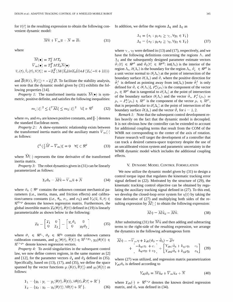
A path planning algorithm [4] was utilized to generate the si-nusoidal camera-space reference trajectory illustrated in Fig. 2.The output of this path planning algorithm were the referencecamera-space velocity signals and given as fol-lows:
(pixels/s)
(rad/s) (61)
where the initial conditions for the reference Cartesian camera-space positions and orientation were selected as follows:
(pixels) (pixels)
(rad). (62)
The initial conditions for the actual Cartesian camera-space po-sitions and orientation were selected as follows:
(pixels) (pixels)
(rad) (63)
348 IEEE TRANSACTIONS ON SYSTEMS, MAN, AND CYBERNETICS—PART B: CYBERNETICS, VOL. 31, NO. 3, JUNE 2001
Fig. 2. Desired trajectory.
Fig. 3. Camera-space position and orientation tracking errors.
and the initial task-space orientation was selected as follows:
(64)
The control gains were tuned until the best response was ob-tained and then recorded as follows:
(65)
diag
(66)
diag (67)
diag (68)
where each element of the estimate vector was initial-ized to 0.0, and each element of the estimate vectors ,
were initialized to 1.0 to ensure int ,int (see Property 4 and the discussions in [2] and [12]
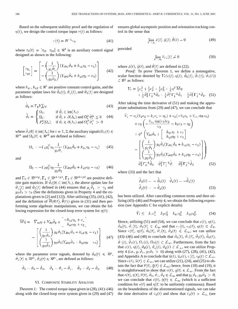
for further details). The camera-space position and orientationtracking errors are shown in Fig. 3 and the associated controltorque inputs are shown in Fig. 4.
B. Experimental Configuration
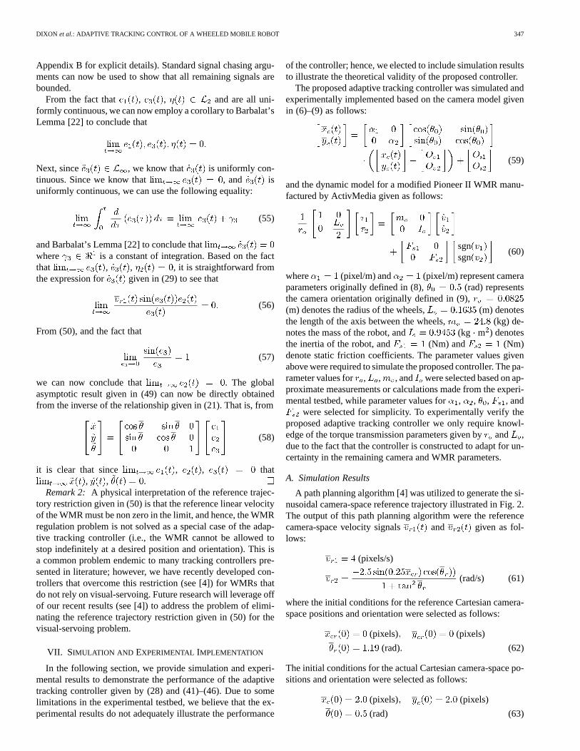
To illustrate the real-time performance of the proposed adap-tive tracking controller given in (28) and (42)–(46), an exper-imental testbed (see Fig. 5) was constructed consisting of thefollowing components:
1) modified Pioneer II WMR manufactured by ActivMedia,Inc.;
Fig. 4. Control torque inputs.
Fig. 5. Experimental testbed.
2) Dalsa CAD-6 camera that captures 955 frames/s with8-bit gray scale at a 260 260 resolution;
3) Road Runner Model 24 video capture board;4) two Pentium II-based personal computers (PCs) oper-
ating under the real-time operating system QNX.The WMR modifications include
1) replacement of all the existing computational hard-ware/software with an off-board Pentium 133 MHz PC;
2) replacement of the pulse-width modulated amplifiers andpower transmission circuitry with linear amplifiers andthe associated circuitry;
3) inclusion of two LEDs (with distinct brightness values)mounted on the top plate of the WMR (one LED wasmounted at the COM and the other LED was mountedat the front of the WMR).
The camera was equipped with a 6mm lens and mounted 2.87m above the robot workspace. The camera was connected tothe image processing PC to capture images of the WMR viathe video capture board and then determine the positions of theLEDs in the camera-space. The positions of the LEDs were cal-culated using a threshold based approach that compares bright-ness values of pixels within a specific range (the brightness ofeach LED was adjusted to yield a specific signature so that wecould distinguish each LED) and selects the brightest pixel in
DIXON et al.: ADAPTIVE TRACKING CONTROL OF A WHEELED MOBILE ROBOT 349
the two ranges to be the actual locations of the LEDs in thecamera-space. The image processing PC was connected to asecond off-board PC via a dedicated 100 Mb/s network connec-tion. The second off-board PC was utilized to
1) determine the position, orientation, and linear and angularvelocity of the WMR in the camera-space from the LEDpositions;
2) acquire the task-space orientation of the WMR;3) execute the control algorithm.
Since an LED was placed above the COM of the WMR, thecamera-space position of the WMR was directly given. Thecamera-space orientation of the WMR was calculated usingsimple geometric principles that relate the relative positionof the two LEDs. The time derivative of the camera-spaceposition and orientation was calculated via a standard backwarddifference/filtering algorithm while the linear and angularvelocities were calculated from (5). In order to determine thetask-space orientation of the WMR, we first measured the rotorposition of the wheel motors via encoders with a resolution of0.176/line (i.e., 2048 lines/rev). Based on the position of theleft and right wheels, denoted by and , respectively,we obtained the orientation of the WMR through the followingstatic relationship:
(69)
where denotes the known radius of the wheels, anddenotes the known distance between the wheels. The
data acquisition and control execution was performed at 700 Hzvia the Quanser MultiQ Server Board and in-house designedinterfacing circuitry. The control algorithms were implementedin C++ and executed using the real-time control environmentQmotor3.0 [19]. The computed torques were applied to perma-nent magnet dc motors attached to the left and right wheels viaa 19:1 gear coupling. For simplicity, the electrical dynamics ofthe system were ignored. That is, we assume that the computedtorque is statically related to the voltage input of the permanentmagnet dc motors by a constant.
C. Experimental Results
In order to limit the workspace to a reasonable size for thecamera system, we selected the reference linear and angular ve-locities as follows:
(pixels/s)
(rad/s) (70)
while reference camera-space position/orientation was initial-ized as follows:
(pixels) (pixels)
(rad) (71)
and the task-space orientation was initialized as follows:
(rad). (72)
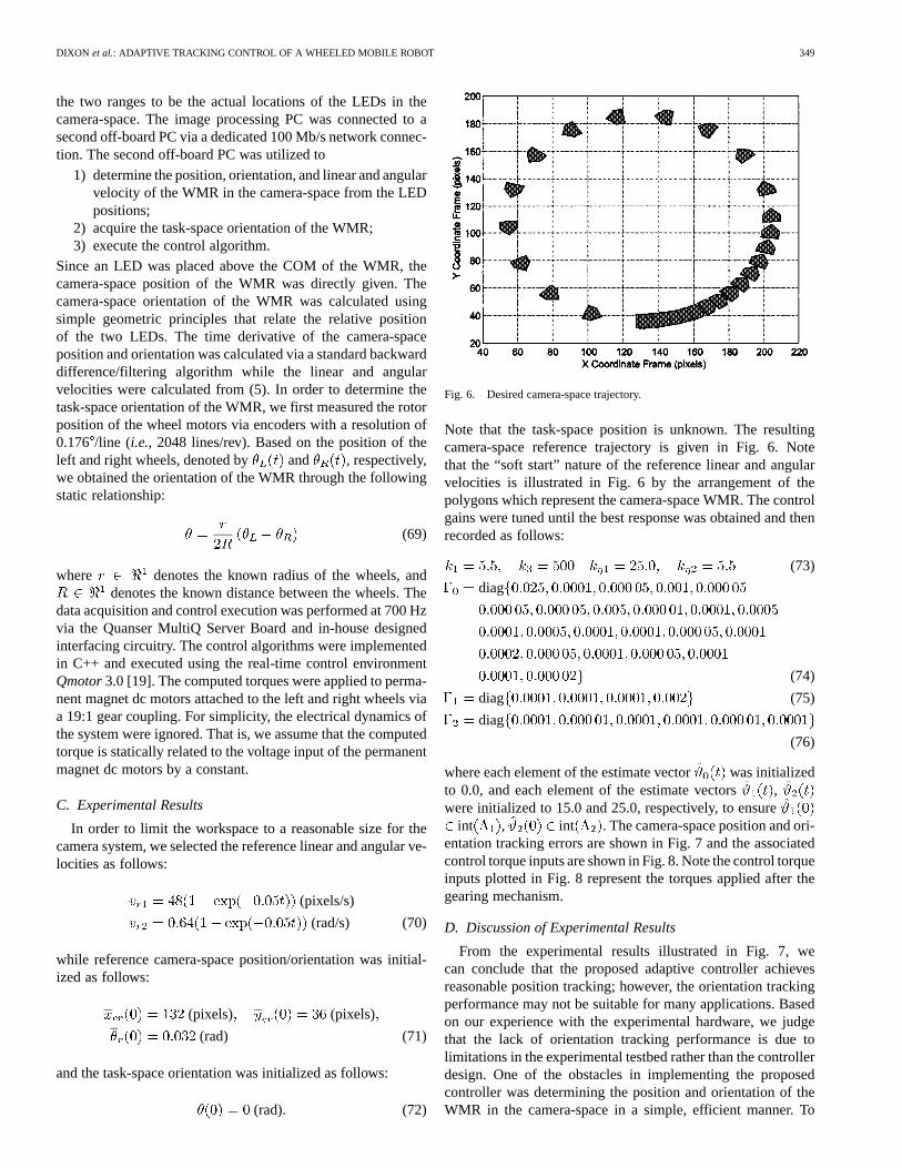
Fig. 6. Desired camera-space trajectory.
Note that the task-space position is unknown. The resultingcamera-space reference trajectory is given in Fig. 6. Notethat the “soft start” nature of the reference linear and angularvelocities is illustrated in Fig. 6 by the arrangement of thepolygons which represent the camera-space WMR. The controlgains were tuned until the best response was obtained and thenrecorded as follows:
(73)
diag
(74)
diag (75)
diag
(76)
where each element of the estimate vector was initializedto 0.0, and each element of the estimate vectors ,were initialized to 15.0 and 25.0, respectively, to ensure
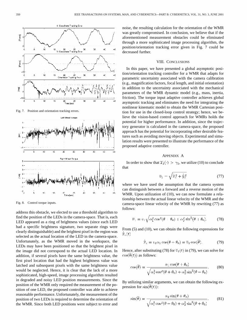
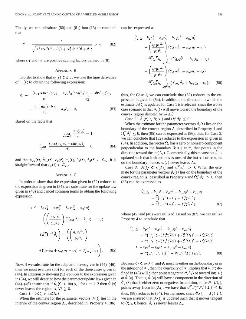
int , int . The camera-space position and ori-entation tracking errors are shown in Fig. 7 and the associatedcontrol torque inputs are shown in Fig. 8. Note the control torqueinputs plotted in Fig. 8 represent the torques applied after thegearing mechanism.
D. Discussion of Experimental Results
From the experimental results illustrated in Fig. 7, wecan conclude that the proposed adaptive controller achievesreasonable position tracking; however, the orientation trackingperformance may not be suitable for many applications. Basedon our experience with the experimental hardware, we judgethat the lack of orientation tracking performance is due tolimitations in the experimental testbed rather than the controllerdesign. One of the obstacles in implementing the proposedcontroller was determining the position and orientation of theWMR in the camera-space in a simple, efficient manner. To
350 IEEE TRANSACTIONS ON SYSTEMS, MAN, AND CYBERNETICS—PART B: CYBERNETICS, VOL. 31, NO. 3, JUNE 2001
Fig. 7. Position and orientation tracking errors.
Fig. 8. Control torque inputs.
address this obstacle, we elected to use a threshold algorithm tofind the position of the LEDs in the camera-space. That is, eachLED appeared as a ring of brightness values (since each LEDhad a specific brightness signature, two separate rings wereclearly distinguishable) and the brightest pixel in the region wasselected as the actual location of the LED in the camera-space.Unfortunately, as the WMR moved in the workspace, theLEDs may have been positioned so that the brightest pixel inthe image did not correspond to the actual LED location. Inaddition, if several pixels have the same brightness value, thefirst pixel location that had the highest brightness value waslatched and subsequent pixels with the same brightness valuewould be neglected. Hence, it is clear that the lack of a moresophisticated, high-speed, image processing algorithm resultedin degraded and noisy LED position measurements. Since theposition of the WMR only required the measurement of the po-sition of one LED, the proposed controller was able to achievereasonable performance. Unfortunately, the measurement of theposition of two LEDs is required to determine the orientation ofthe WMR. Since both LED positions were subject to error and
noise, the resulting calculation for the orientation of the WMRwas greatly compromised. In conclusion, we believe that if theaforementioned measurement obstacles could be eliminatedthrough a more sophisticated image processing algorithm, theposition/orientation tracking error given in Fig. 7 could bedecreased further.
VIII. C ONCLUSIONS
In this paper, we have presented a global asymptotic posi-tion/orientation tracking controller for a WMR that adapts forparametric uncertainty associated with the camera calibration(e.g., magnification factors, focal length, and initial orientation)in addition to the uncertainty associated with the mechanicalparameters of the WMR dynamic model (e.g., mass, inertia,friction). The torque input adaptive controller achieves globalasymptotic tracking and eliminates the need for integrating thenonlinear kinematic model to obtain the WMR Cartesian posi-tion for use in the closed-loop control strategy; hence, we be-lieve the vision-based control approach for WMRs holds thepotential for higher performance. In addition, since the trajec-tory generator is calculated in the camera-space, the proposedapproach has the potential for incorporating other desirable fea-tures such as avoiding moving objects. Experimental and simu-lation results were presented to illustrate the performance of theproposed adaptive controller.
APPENDIX A
In order to show that , we utilize (10) to concludethat
(77)
where we have used the assumption that the camera systemcan distinguish between a forward and a reverse motion of theWMR. Upon utilization of (10), we can now formulate a rela-tionship between the actual linear velocity of the WMR and thecamera-space linear velocity of the WMR by rewriting (77) asfollows:
(78)
From (5) and (10), we can obtain the following expressions for
(79)
Hence, after substituting (78) for in (79), we can solve foras follows:
(80)
By utilizing similar arguments, we can obtain the following ex-pression for :
(81)
DIXON et al.: ADAPTIVE TRACKING CONTROL OF A WHEELED MOBILE ROBOT 351
Finally, we can substitute (80) and (81) into (13) to concludethat
(82)
where and are positive scaling factors defined in (8).
APPENDIX B
In order to show that , we take the time derivativeof to obtain the following expression:
(83)
Based on the facts that
(84)
and that , , , , , , it isstraightforward that .
APPENDIX C
In order to show that the expression given in (52) reduces tothe expression in given in (54), we substitute for the update lawgiven in (43) and cancel common terms to obtain the followingexpression:
(85)
Now, if we substitute for the adaptation laws given in (44)–(46),then we must evaluate (85) for each of the three cases given in(44). In addition to showing (52) reduces to the expression givenin (54), we will describe how the parameter update laws given in(44)–(46) ensure that if int for thennever leaves the region, .
Case 1: intWhen the estimate for the parameter vectors lies in the
interior of the convex region , described in Property 4, (86)
can be expressed as
(86)
thus, for Case 1, we can conclude that (52) reduces to the ex-pression in given in (54). In addition, the direction in which theestimate is updated for Case 1 is irrelevant, since the worsecase scenario is that will move toward the boundary of theconvex region denoted by .
Case 2: andWhen the estimate for the parameter vectors lies on the
boundary of the convex region described in Property 4 and, then (85) can be expressed as (86); thus, for Case 2,
we can conclude that (52) reduces to the expression in given in(54). In addition, the vector has a zero or nonzero componentperpendicular to the boundary at that points in thedirection toward the int . Geometrically, this means that isupdated such that it either moves toward the int or remainson the boundary; hence, never leaves .
Case 3: and When the esti-mate for the parameter vectors lies on the boundary of theconvex region described in Property 4 and , then(85) can be expressed as
(87)
where (45) and (46) were utilized. Based on (87), we can utilizeProperty 4 to conclude that
(88)
Because , and must lie either on the boundary or inthe interior of , then the convexity of implies that de-fined in (48) will either point tangent to or toward intat . That is, will have a component in the direction of
that is either zero or negative. In addition, since ,points away from int , we have that ;
thus, (88) reduces to (54). Furthermore, since ,we are ensured that is updated such that it moves tangentto ; hence, never leaves .
352 IEEE TRANSACTIONS ON SYSTEMS, MAN, AND CYBERNETICS—PART B: CYBERNETICS, VOL. 31, NO. 3, JUNE 2001
REFERENCES
[1] B. E. Bishop and M. W. Spong, “Adaptive calibration and control of 2Dmonocular visual servo system,” inProc. IFAC Symp. Robot Control,Nantes, France, 1997, pp. 525–530.
[2] M. M. Bridges et al., “Control of rigid-link, flexible-joint robots: Asurvey of backstepping approaches,”J. Robot. Syst., vol. 12, no. 3, pp.199–216, 1995.
[3] C. Canudas de Witet al., “Nonlinear control for mobile robots,” inRe-cent Trends in Mobile Robots, Y. Zhenget al., Eds. New York: WorldScientific, 1993.
[4] W. E. Dixon et al., Nonlinear Control of Wheeled Mobile Robots, Lec-ture Notes in Control and Information Sciences. New York: Springer-Verlag, Jan. 2000.
[5] B. Espiauet al., “A new approach to visual servoing in robotics,”IEEETrans. Robot. Automat., vol. 8, pp. 313–326, June 1992.
[6] G. D. Hageret al., “Robot hand-eye coordination based on stereo vi-sion,” IEEE Control Syst. Mag., vol. 15, pp. 30–39, Feb. 1995.
[7] G. D. Hager and S. Hutchinson,Special Section Vision-Based ControlRobot Manipulators, IEEE Trans. Robot. Automat., vol. 12, pp.651–670, Oct. 1996.
[8] J. Nijmeijer and H. Nijmeijer, “Tracking control of mobile robots: Acase study in backstepping,”Automatica, vol. 33, no. 7, pp. 1393–1399,1997.
[9] Y. Kanayamaet al., “A stable tracking control method for an au-tonomous mobile robot,” inProc. IEEE Int. Conf. Robot. Automat.,1990, pp. 384–389.
[10] R. Kelly, “Robust asymptotically stable visual servoing of planarrobots,”IEEE Trans. Robot. Automat., vol. 12, pp. 759–766, Oct. 1996.
[11] R. Kelly et al., “A two-loops direct visual control of direct-drive planarrobots with moving target,” inProc. IEEE Int. Conf. Robot. Automat.,1999, pp. 599–604.
[12] R. Lozano and B. Brogliato, “Adaptive control of robot manipulatorswith flexible joints,” IEEE Trans. Automat. Contr., vol. 37, pp. 174–181,Feb. 1992.
[13] R. K. Lenz and R. Y. Tsai, “Techniques for calibration of the scale factorand image center for high accuracy 3-D machine vision metrology,”IEEE Trans. Pattern Anal. Machine Intell., vol. 10, pp. 713–720, Sept.1988.
[14] F. Lewiset al., Control of Robot Manipulators. New York: MacMillan,1993.
[15] Y. Ma et al., “Vision guided navigation for a nonholonomic mobilerobot,” IEEE Trans. Robot. Automat., vol. 15, pp. 521–596, June 1999.
[16] A. Maruyama and M. Fujita, “Robust visual servo control for planarmanipulators with eye-in-hand configurations,” inProc. Conf. DecisionContr., San Diego, CA, Dec. 1997, pp. 2551–2552.
[17] R. McCloskey and R. Murray, “Exponential stabilization of driftlessnonlinear control systems using homogeneous feedback,”IEEE Trans.Automat. Contr., vol. 42, pp. 614–628, May 1997.
[18] B. Nelson and N. Papanikolopoulos,Special Issue of Visual Servoing,IEEE Robot. Automat. Mag., vol. 5, pp. 521–536, Dec. 1998.
[19] N. P. Costescuet al., “QMotor 3.0 - An object oriented system for PCcontrol program implementation and tuning,” inProc. Amer. Contr.Conf., Arlington, VA, June 2001.
[20] C. Samson and K. Ait-Abderrahim, “Mobile robot control, part 1:Feedback control of a nonholonomic wheeled cart in Cartesian space,”INRIA, Sophia-Antipolis, France, Tech. Rep. 1990.
[21] C. Samson et al., Robot Control: The Task Function Ap-proach. Oxford, U.K.: Clarendon, 1991.
[22] S. Sastry and M. Bodson,Adaptive Control: Stability, Convergence, andRobustness. Englewood Cliffs, NJ: Prentice-Hall, 1989.
[23] E. Zergerogluet al., “Vision-based nonlinear tracking controllers withuncertain robot-camera parameters,” inProc. IEEE/ASME Int. Conf. Ad-vanced Intell. Mechatron., Atlanta, GA, Sept. 1999, pp. 854–859.
[24] E. Zergerogluet al., “Robust visual-servo control of robot manipulatorsin the presence of uncertainty,” inProc. IEEE Thirty Eighth Conf. De-cision Contr., Phoenix, AZ, Dec. 7–10, 1999, pp. 4137–4142.
Warren E. Dixon (S’94–M’00) was born in York,PA, in 1972. He received the B.S. and Ph.D. degreesin electrical engineering from Clemson University,Clemson, SC, in 1994 and 2000, respectively, and theM.E. degree in electrical engineering from the Uni-versity of South Carolina, Columbia, in 1997.
After completing his doctoral studies, he was se-lected as a Wigner Fellow with the Oak Ridge Na-tional Laboratory, Oak Ridge, TN, where he currentlyworks in the Robotics and Process Systems Division.His research interests include mobile robots, fault de-
tection, adaptive and robust control, amplitude limited control, output feedbackcontrol, visual-servoing, and the control of underactuated systems.
Darren M. Dawson (S’89–M’90–SM’94) was bornin Macon, GA, in 1962. He received the Associatedegree in mathematics from Macon Junior College in1982, and the B.S. and Ph.D. degrees in electrical en-gineering from the Georgia Institute of Technology,Atlanta, in 1984 and 1990, respectively.
From 1985 to 1987, he worked for Westinghouse,Pittsburgh, PA, as a Control Engineer. In July 1990,he joined the Electrical and Computer EngineeringDepartment, Clemson University, Clemson, SC,where he currently is a Professor. He leads the
Robotics and Manufacturing Automation Laboratory, which is jointly operatedby the Electrical and Mechanical Engineering Departments. His main researchinterests include nonlinear based robust, adaptive, and learning control withapplication to electromechanical systems including robot manipulators, motordrives, magnetic bearings, flexible cables, flexible beams, high-speed transportsystems, mobile robots, underactuated systems, and aerospace systems.
Erkan Zergeroglu (S’98–M’00) was born inArtvin-Yusufeli, Turkey, in 1970. He received theB.S. degree in electrical engineering from HacettepeUniversity, Ankara, Turkey, in 1992, the M.S.degree from the Middle East Technical University,Ankara, in 1996, and the Ph.D. degree from ClemsonUniversity, Clemson, SC, in 2000.
He is currently with Lucent Technologies, Stur-bridge, MA. His research interests include nonlinearcontrol of electromechanical systems with parametricuncertainty, robust and adaptive visual servo control
of robotic devices, mobile robotics, model-based control of underactuated me-chanical systems, and applied robotics.
Aman Behal received the M.Tech. degree in elec-trical engineering from the Indian Institute of Tech-nology, Bombay, in 1996. He is currently pursuingthe Ph.D. degree in controls and robotics at ClemsonUniversity, Clemson, SC.
His research interests include control of nonlinearsystems with special interest in motor control and un-deractuated systems.


