Embed Size (px)
Citation preview

AAS 07-078
1
AAS 07-078
INITIAL ARES I BENDING FILTER DESIGN
Jiann-Woei Jang, Nazareth Bedrossian, Robert Hall, H. Lee Norris
The Charles Stark Draper Laboratory, Inc.
Charles Hall, Mark Jackson NASA Marshall Space Flight Center
30th ANNUAL AAS GUIDANCE AND CONTROL CONFERENCE
February 3-7, 2007 Sponsored by Breckenridge, Colorado Rocky Mountain Section
AAS Publications Office, P.O. Box 28130 - San Diego, California 92198
AAS 07-078
2
INITIAL ARES I BENDING FILTER DESIGN
Jiann-Woei Jang1, Nazareth Bedrossian 2
The Charles Stark Draper Laboratory, Inc., Houston, TX 77058
Robert Hall3
The Charles Stark Draper Laboratory, Inc., Huntsville, AL 35812
H. Lee Norris4
The Charles Stark Draper Laboratory, Inc., Cambridge, MA 02139
Charles Hall5, Mark Jackson6
NASA Marshall Space Flight Center, Huntsville AL 35812
Abstract
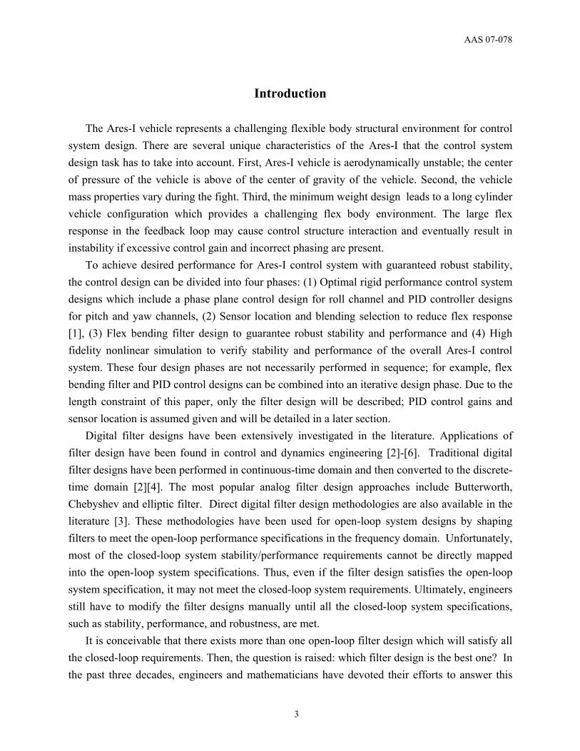
The Ares-I launch vehicle represents a challenging flex-body structural environment for control system design. Software filtering of the inertial sensor output will be required to ensure control system stability and adequate performance. This paper presents a design methodology employing numerical optimization to develop the Ares-I bending filters. The filter design methodology was based on a numerical constrained optimization approach to maximize stability margins while meeting performance requirements. The resulting bending filter designs achieved stability by adding lag to the first structural frequency and hence phase stabilizing the first Ares-I flex mode. To minimize rigid body performance impacts, a priority was placed via constraints in the optimization algorithm to minimize bandwidth decrease with the addition of the bending filters. The bending filters provided here have been demonstrated to provide a stable first stage control system in both the frequency domain and the MSFC MAVERIC time domain simulation.
1 Senior Member Technical Staff 2 Group Leader, Manned Space Systems 3 Principal Member Technical Staff 4 Group Leader, Aerospace Navigation 5 Senior Aerospace Engineer 6 Senior Aerospace Engineer
AAS 07-078
3
Introduction
The Ares-I vehicle represents a challenging flexible body structural environment for control
system design. There are several unique characteristics of the Ares-I that the control system design task has to take into account. First, Ares-I vehicle is aerodynamically unstable; the center of pressure of the vehicle is above of the center of gravity of the vehicle. Second, the vehicle mass properties vary during the fight. Third, the minimum weight design leads to a long cylinder vehicle configuration which provides a challenging flex body environment. The large flex response in the feedback loop may cause control structure interaction and eventually result in instability if excessive control gain and incorrect phasing are present.
To achieve desired performance for Ares-I control system with guaranteed robust stability, the control design can be divided into four phases: (1) Optimal rigid performance control system designs which include a phase plane control design for roll channel and PID controller designs for pitch and yaw channels, (2) Sensor location and blending selection to reduce flex response [1], (3) Flex bending filter design to guarantee robust stability and performance and (4) High fidelity nonlinear simulation to verify stability and performance of the overall Ares-I control system. These four design phases are not necessarily performed in sequence; for example, flex bending filter and PID control designs can be combined into an iterative design phase. Due to the length constraint of this paper, only the filter design will be described; PID control gains and sensor location is assumed given and will be detailed in a later section.
Digital filter designs have been extensively investigated in the literature. Applications of filter design have been found in control and dynamics engineering [2]-[6]. Traditional digital filter designs have been performed in continuous-time domain and then converted to the discrete-time domain [2][4]. The most popular analog filter design approaches include Butterworth, Chebyshev and elliptic filter. Direct digital filter design methodologies are also available in the literature [3]. These methodologies have been used for open-loop system designs by shaping filters to meet the open-loop performance specifications in the frequency domain. Unfortunately, most of the closed-loop system stability/performance requirements cannot be directly mapped into the open-loop system specifications. Thus, even if the filter design satisfies the open-loop system specification, it may not meet the closed-loop system requirements. Ultimately, engineers still have to modify the filter designs manually until all the closed-loop system specifications, such as stability, performance, and robustness, are met.
It is conceivable that there exists more than one open-loop filter design which will satisfy all the closed-loop requirements. Then, the question is raised: which filter design is the best one? In the past three decades, engineers and mathematicians have devoted their efforts to answer this
AAS 07-078
4
question by developing modern control theory. In general, modern control design methodologies utilize optimization processes to determine the filter/controller designs that provide the best closed-loop performance according to different system metrics. The H2 control method minimizes the 2-norm of the closed-loop system, which does not guarantee closed-loop stability margins. The H∞ control method generates the optimal filter based on the minimum of the maximum of the closed-loop singular value. However, it may still not meet the closed-loop stability margin requirements. The constrained H2 optimization method [5][6] expands the design space by including the closed-loop stability margin requirements. In order to preserve the convexity of the problem, the infinite-dimensional Youla parameterization is approximated by a finite number of orthogonal basis functions. Typical orthogonal basis functions include the FIR, Laguerre, and GOBF [7]. The orthogonality of these basis functions may limit its application space. For example, all the orthonormal basis functions either have no zeros or pole dependent zeros in their filter architecture. Recently, a robust controller design methodology was proposed using a numerical constrained optimization approach to maximize stability margins while meeting performance requirements [8]-[11]. This novel control design methodology has then successfully used to design a single robust CMG flex filter set for multiple International Space Station (ISS) stages [8] and robust flex filters and a PID controller for the entire time varying Orbiter Repair Maneuver operation [10]. The paper addresses the Ares-I control system/structural dynamic interaction problem, the use of constrained optimization for filter development, analytical model development based on Saturn heritage, stability and margin requirements definition, and time domain performance demonstration.
Ares I Control System
Ares-I uses a single five-segment solid rocket booster for the first stage, a derivative of the space shuttle's solid rocket booster. A liquid oxygen/liquid hydrogen J-2X engine derived from the J-2 engine used on Apollo's second stage will power second stage. First stage control is accommodated by Thrust Vector Control (TVC) for the pitch and yaw axes, and Reaction Control System (RCS) for the roll axis. Based on the fact that vehicle flexibility is significantly reduced for the 2nd stage and not much flexibility is present in the roll channel [12][13], only the pitch/yaw attitude control system in the 1st stage of the ascent flight is considered in this paper. Because of the symmetry of the vehicle and small cross coupling, pitch and yaw attitude control systems are assumed identical [12][13].
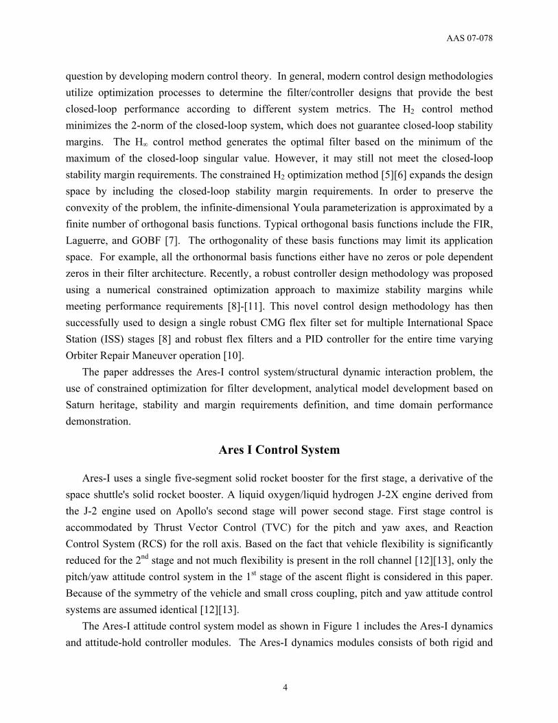
The Ares-I attitude control system model as shown in Figure 1 includes the Ares-I dynamics and attitude-hold controller modules. The Ares-I dynamics modules consists of both rigid and
AAS 07-078
5
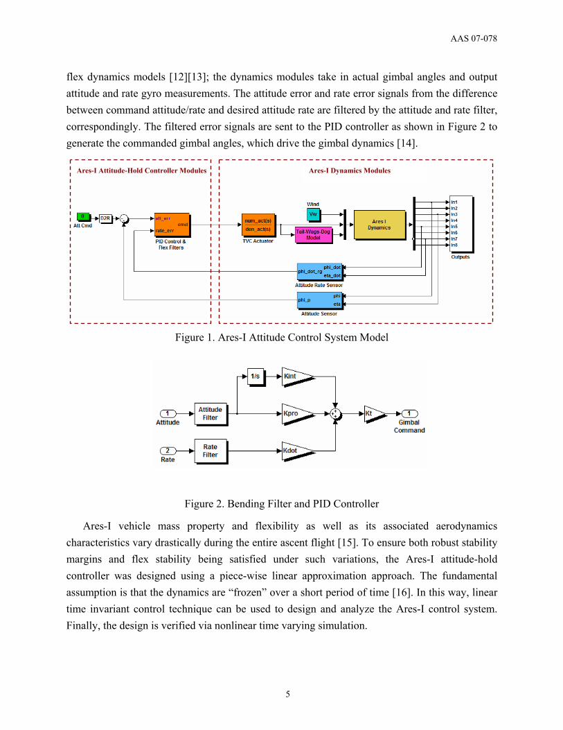
flex dynamics models [12][13]; the dynamics modules take in actual gimbal angles and output attitude and rate gyro measurements. The attitude error and rate error signals from the difference between command attitude/rate and desired attitude rate are filtered by the attitude and rate filter, correspondingly. The filtered error signals are sent to the PID controller as shown in Figure 2 to generate the commanded gimbal angles, which drive the gimbal dynamics [14].
Figure 1. Ares-I Attitude Control System Model
Figure 2. Bending Filter and PID Controller
Ares-I vehicle mass property and flexibility as well as its associated aerodynamics characteristics vary drastically during the entire ascent flight [15]. To ensure both robust stability margins and flex stability being satisfied under such variations, the Ares-I attitude-hold controller was designed using a piece-wise linear approximation approach. The fundamental assumption is that the dynamics are “frozen” over a short period of time [16]. In this way, linear time invariant control technique can be used to design and analyze the Ares-I control system. Finally, the design is verified via nonlinear time varying simulation.
Ares-I Attitude-Hold Controller Modules Ares-I Dynamics Modules
AAS 07-078
6
Both the PID gains and flex filters influence the Ares-I stability margin. With the assumption that the PID gains have been selected for rigid-body performance, the Ares I controller design task can be reduced to determining the bending filter parameters to meet rigid and flex stability margins. The bending filter design procedure is detailed in the next sections.
Constrained Optimization Filter Design
It has been previously demonstrated in multiple space applications [8]-[11] that bending filters can be designed numerically using a constrained optimization framework. The design parameters are the coefficients of bending filters. For example, if an nth order transfer function architecture is selected for both attitude and rate filter, the total number of design parameters is 4n. A set of feasible parameters must satisfy the following constraints:
(C1). The filter itself must be stable and minimal phase to guarantee stability and performance.
(C2). The bandwidth of the bending filter should be greater than that of the PID controller to avoid rigid performance degradation.
These constraints can be used to set the upper and lower bounds for the design parameters [8]. The primary objective of ARES-I control system design is to provide sufficient stability
margins in the presence of various uncertainties while maintaining adequate system response. The stability margin criteria from [13] are used in this paper:
(O1). The closed-loop Ares-I control system must be robustly stable under mass property, flexibility and atmosphere characteristics variation.
(O2). At least 6 dB gain margin and 30 degree phase margin for rigid only control system. (O3). At least 6 dB gain margin of the peak amplitude for gain stabilized bending modes. (O4). At least 45 degree phase margin for phase stabilized bending modes.
Gain stabilization of a flexible mode refers to a filter design where the flex mode amplitude is attenuated to an extent to not cause a stability concern. Phase stabilization of a flexible mode refers to a filter design where the phasing of the first mode does not cause a stability concern. In the latter case, the control system may actively damp the structure flexure.
Ares-I control systems must also ultimately demonstrate robustness to uncertainties in the plant. The goal is to design bending filters robust to structural frequency, mode shape, mass property and aerodynamics characteristics uncertainty. In this paper, only mass property variation and structural frequency uncertainty are considered; mass property variation is modeled using frozen time rigid dynamics for flight time at [1 10:10:120 129] seconds and structural uncertainty is modeled via bending mode frequency shift from nominal of +/-10% at a 5% increment. In all, a total of 70 frozen systems (G) are used to represent 1st stage flight.
AAS 07-078
7
Once design objectives and constraints are identified, the bending filter design task is ready to cast as the following constrained optimization problem
ul
GRx
xxxxg
ts
xfN
≤≤≤
∈
0)(..
)(min,4
The filter design criteria ((C1) and (C2)) can be formulated as inequality constraints; the design objective, can be cast either as an inequality constraint, g(x), or as an objective, f(x), in the above multi-objective constrained optimization problem. In general, these objectives are competing, for example, maximizing gain margins usually will diminish phase margins; therefore, there is no unique solution to this problem. Therefore, Pareto optimality [17] must be applied to characterize the objectives; a weighted sum strategy has been used to converts the multi-objective problem into a single objective optimization problem.
Ares-I Filter Design
Preliminary Ares-I filter designs will be presented in this section to demonstrate the
constrained optimization design methodology. There are three assumptions made for the bending filter design. First, the attitude control PID gains, designed to meet rigid body performance requirements, were not part of the design trade for flex body stability. Second, the structural model, defined at lift-off, was used throughout the entire 1st stage. Third, two sensor locations were considered: one in the instrumentation ring (Case 1) and another in the upper stage aft skirt (Case 2). Case 1 filter is designed for stability only; Case 2 filter is design for both stability and margins.
AAS 07-078
8
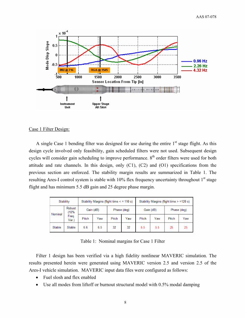
Case 1 Filter Design:
A single Case 1 bending filter was designed for use during the entire 1st stage flight. As this design cycle involved only feasibility, gain scheduled filters were not used. Subsequent design cycles will consider gain scheduling to improve performance. 8th order filters were used for both attitude and rate channels. In this design, only (C1), (C2) and (O1) specifications from the previous section are enforced. The stability margin results are summarized in Table 1. The resulting Ares-I control system is stable with 10% flex frequency uncertainty throughout 1st stage flight and has minimum 5.5 dB gain and 25 degree phase margin.
Table 1: Nominal margins for Case 1 Filter
Filter 1 design has been verified via a high fidelity nonlinear MAVERIC simulation. The
results presented herein were generated using MAVERIC version 2.5 and version 2.5 of the Ares-I vehicle simulation. MAVERIC input data files were configured as follows:
• Fuel slosh and flex enabled • Use all modes from liftoff or burnout structural model with 0.5% modal damping
AAS 07-078
9
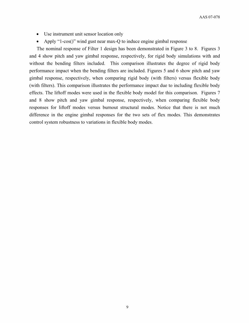
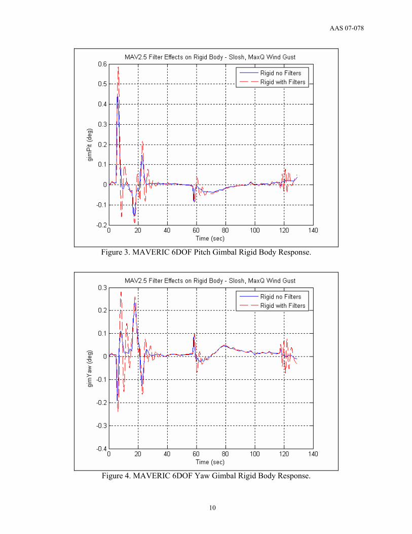
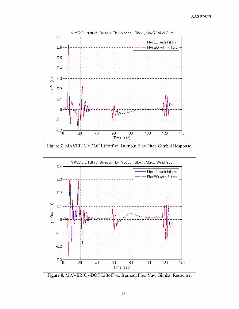
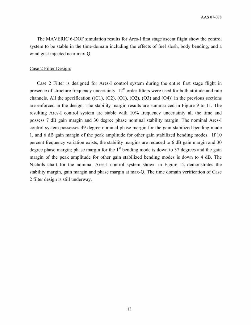
• Use instrument unit sensor location only • Apply “1-cos()” wind gust near max-Q to induce engine gimbal response The nominal response of Filter 1 design has been demonstrated in Figure 3 to 8. Figures 3
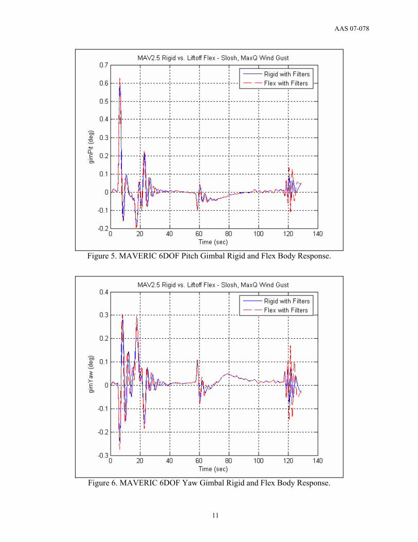
and 4 show pitch and yaw gimbal response, respectively, for rigid body simulations with and without the bending filters included. This comparison illustrates the degree of rigid body performance impact when the bending filters are included. Figures 5 and 6 show pitch and yaw gimbal response, respectively, when comparing rigid body (with filters) versus flexible body (with filters). This comparison illustrates the performance impact due to including flexible body effects. The liftoff modes were used in the flexible body model for this comparison. Figures 7 and 8 show pitch and yaw gimbal response, respectively, when comparing flexible body responses for liftoff modes versus burnout structural modes. Notice that there is not much difference in the engine gimbal responses for the two sets of flex modes. This demonstrates control system robustness to variations in flexible body modes.
AAS 07-078
10
Figure 3. MAVERIC 6DOF Pitch Gimbal Rigid Body Response.
Figure 4. MAVERIC 6DOF Yaw Gimbal Rigid Body Response.
AAS 07-078
11
Figure 5. MAVERIC 6DOF Pitch Gimbal Rigid and Flex Body Response.
Figure 6. MAVERIC 6DOF Yaw Gimbal Rigid and Flex Body Response.
AAS 07-078
12
Figure 7. MAVERIC 6DOF Liftoff vs. Burnout Flex Pitch Gimbal Response.
Figure 8. MAVERIC 6DOF Liftoff vs. Burnout Flex Yaw Gimbal Response.
AAS 07-078
13
The MAVERIC 6-DOF simulation results for Ares-I first stage ascent flight show the control system to be stable in the time-domain including the effects of fuel slosh, body bending, and a wind gust injected near max-Q. Case 2 Filter Design:
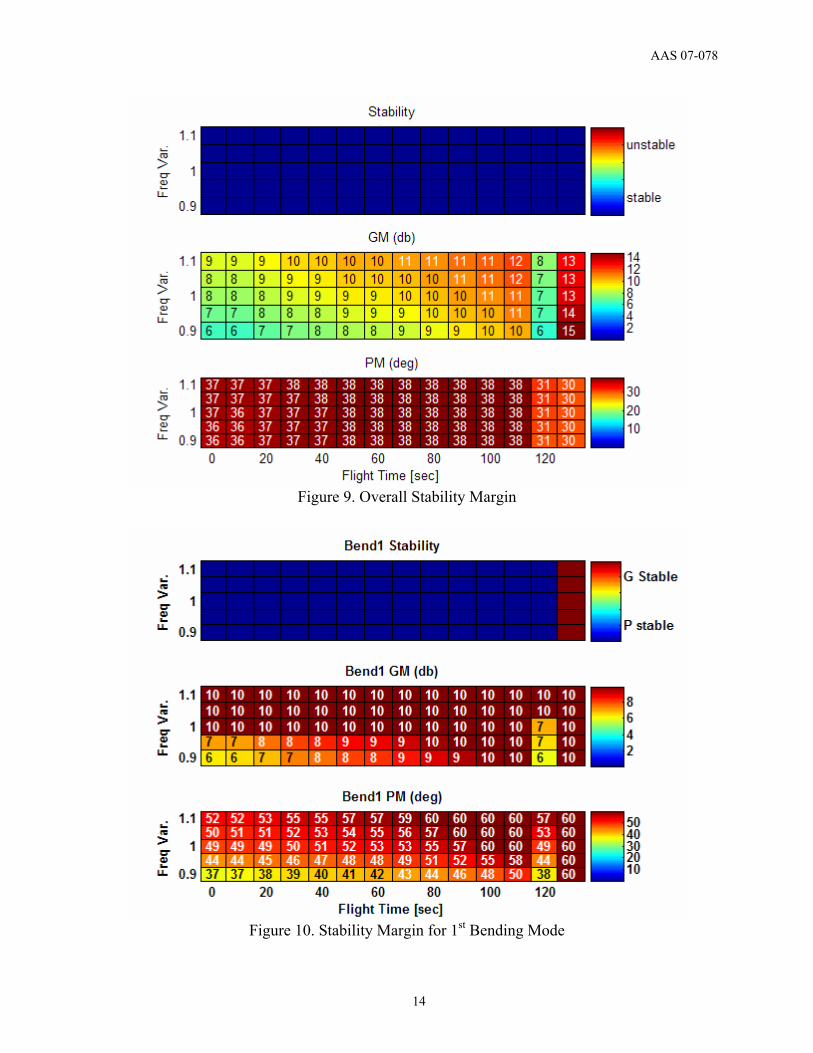
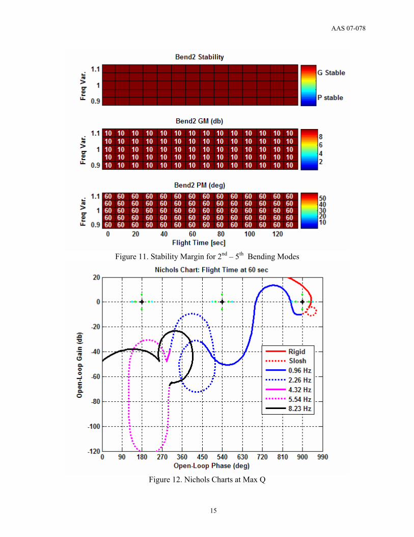
Case 2 Filter is designed for Ares-I control system during the entire first stage flight in presence of structure frequency uncertainty. 12th order filters were used for both attitude and rate channels. All the specification ((C1), (C2), (O1), (O2), (O3) and (O4)) in the previous sections are enforced in the design. The stability margin results are summarized in Figure 9 to 11. The resulting Ares-I control system are stable with 10% frequency uncertainty all the time and possess 7 dB gain margin and 30 degree phase nominal stability margin. The nominal Ares-I control system possesses 49 degree nominal phase margin for the gain stabilized bending mode 1, and 6 dB gain margin of the peak amplitude for other gain stabilized bending modes. If 10 percent frequency variation exists, the stability margins are reduced to 6 dB gain margin and 30 degree phase margin; phase margin for the 1st bending mode is down to 37 degrees and the gain margin of the peak amplitude for other gain stabilized bending modes is down to 4 dB. The Nichols chart for the nominal Ares-I control system shown in Figure 12 demonstrates the stability margin, gain margin and phase margin at max-Q. The time domain verification of Case 2 filter design is still underway.
AAS 07-078
14
Figure 9. Overall Stability Margin
Figure 10. Stability Margin for 1st Bending Mode
AAS 07-078
15
Figure 11. Stability Margin for 2nd – 5th Bending Modes
Figure 12. Nichols Charts at Max Q
AAS 07-078
16
Summary
The Ares-I launch vehicle represents a challenging flex-body structural environment for control system design. Software filtering is required to ensure control system stability and adequate performance. This paper presents a design methodology employing numerical optimization to develop the Ares-I bending filters. The filter design methodology was based on a numerical constrained optimization approach to maximize stability margins while meeting performance requirements. The resulting bending filter designs achieved stability by adding lag to the first structural frequency and hence phase stabilizing the first Ares-I flex mode. To minimize rigid body performance impacts, a priority was placed via constraints in the optimization algorithm to minimize bandwidth decrease with the addition of the bending filters. The bending filter designs provided here have been demonstrated to provide a stable 1st stage control system in both the frequency domain and time domain simulation.
Acknowledgements
This work was prepared by the Charles Stark Draper Laboratory, Inc., for the NASA Marshall Space Flight Center under subcontract to Jacobs Engineering (NNM05AB50C). The MAVERIC time domain results were generated by Jimmy Compton of DCI.
References [1] Hall, R., Jang, J., Bedrossian, N., Norris, H., Hall, C., Jackson, M., Hannan, M.,“ Stability
and Sensor Placement for Ares-I Control System,” to be submitted to 2007 AIAA GNC Conference.
[2] Oppenheim, A. V, and Schafer, R. W., Digital Signal Processing, Prentice-Hall Company, Inc., Englewood Cliffs, New Jersey, 1975.
[3] Friedlander, B., and Porat, B, “The Modified Yule-Walker Method of ARMA Spectral Estimation,” IEEE Transactions on Aerospace Electronic Systems, AES-20, No. 2, March 1984, pp. 158-173.
[4] Strum, R. D. and Kirk, D. E., First Principles of Discrete Systems and Digital Signal Processing, Addison-Wesley Publishing Company, Inc., New York, April 1989.
[5] McGovern, L. K., A Constrained Optimization Approach to Control with Application to Flexible Structures, Massachusetts Institute of Technology, Massachusetts, June 1996.
AAS 07-078
17
[6] Lintereur, B. V., Constrained H2 Design Via Convex Optimization with Applications, Master Thesis, Massachusetts Institute of Technology, Massachusetts, June 1998.
[7] Ninness, B. and Gustafsson, F., “A Unifying Construction of Orthonormal Bases for System Identification,” IEEE Transactions on Automatic Control, vol. 42, no. 4, pp. 515-521, April 1997.
[8] Jang, J., Bedrossian, N., Lee, A, Spanos, P., “A Constrained Optimization Approach for CMG Robust Flex Filter Design”, AIAA GN&C Conference, August 2002.
[9] Jang, J., Lee, A., Bedrossian, N., Spanos, P., “Design of Robust Nash Game Theoretic Controllers with Time Domain Constraints,” American Control Conference, 2003.
[10] Bedrossian, N., Jang, J., Alaniz, A., Johnson, M., Sebelius, K., Mesfin, Y., “International Space Station US GN&C Attitude Hold Controller Design for Orbiter Repair Maneuver,” AIAA GN&C Conference, August, 2005.
[11] Postma, B., Jang, J., Bedrossian, N., Spanos, P., “Robust Constrained Optimization Approach for International Space Station Centrifuge Rotor Auto-Balancing Controller,” AIAA GN&C Conference, August, 2005.
[12] Haussermann, W., Duncan, R.C, “Status of Guidance and Control Methods, Instrumentation, and Techniques as Applied to the Apollo Project”, Agardograph 92, NASA Code ATSS-AD, October 1964.
[13] Frosch, J.A., Vallely, D.P., “Saturn AS-501/S-IC Flight Control System Design”, Journal of Spacecraft, Vol. 4, No. 8, August 1967.
[14] Lominick, J., “SRB TVC System Design”, NASA MSFC memo EC25 (170-75), April 3, 1975.
[15] N. Bedrossian, R. Hall, J. Jang, R. Masterson, “CLV DAC 1 Analysis: First Stage Attitude Control System Bending Filter Design and Sensor Location Trade Studies”, Draper Lab memo CLV GNC-06-002, July 14, 2006.
[16] Greensite, A. L., Analysis and Design of Space Vehicle Flight Control Systems, Spartan Book, New York, 1970.
[17] Rao, S. S., “Game Theory Approach for Multi-objective Structural Optimization,” Computers & Structures, Vol. 24, No. 1, 1987, pp. 119-127.