Embed Size (px)
Citation preview

Dr. Haim Mazar (Madjar) [email protected] [email protected] Sami Shamoon College of Engineering, Advanced Wireless Communications
1
Advanced Wireless Communications, 2020
Academic course for 4th year engineering students
Radio Services identifier DOI 10.13140/RG.2.2.35017.90722More info in my Wiley book ’Radio Spectrum Management: Policies, Regulations and Techniques’ appears also in Amazon. The Book is already published in Chinese
1. Broadcasting1. Broadcasting Delivery and RF bands2. Broadcasting Video (TV)3. Broadcasting Audio (radio AM/FM)
2. Land Mobile3. Fixed4. Satellites5. Radar
6. Short Range Devices
Last updated on 24 January 2021
Sami Shamoon College of Engineering
Dr. Haim Mazar (Madjar), ITU & World-Bank expert; reelected vice-chair ITU-Radio Study Group 5 (terrestrial services)
Not all slides will be presented during the academic course
The source of slides is blue or is hyperlinked.
Sources are used for educational purposes, fair use.
'שימוש הוגן ביצירות לצרכי הוראה ומחקר'כל החומר בהרצאות הנו מקורי או

Dr. Haim Mazar (Madjar) [email protected] [email protected]
2Sami Shamoon College of Engineering Advanced Wireless Communications
Broadcasting: Video, Audio and Data

Dr. Haim Mazar (Madjar) [email protected] [email protected]
3Sami Shamoon College of Engineering Advanced Wireless Communications
Broadcasting
Studio
Terrestrial
Cable
Direct-Broadcast Satellite (DBS)
set-top box
set-top box
TV receiverEnd-User
Equipment
VHF or UHF TV, orAM, FM, digital…
Audio
Video + Audio
Internet Protocol TeleVision (IPTV)
Display
Web server
Return Channel
Return Channel
Off-air receiver
Handset using cellular infrastructure for
signaling
Return Channel
Video + Audio
IPTV is a protocol through which TV is delivered
Video & Audio delivery
& distribution; analog
or digital

Dr. Haim Mazar (Madjar) [email protected] [email protected]
4Sami Shamoon College of Engineering Advanced Wireless Communications
Audio AM- Medium Waves
MHz
Frequency Bands- Audio AM medium-waves
0.1 101 1000100 10000 100000
9 Khz
0.526 Mhz 1.602 Mhz
526.5-1 606.5 kHz

Dr. Haim Mazar (Madjar) [email protected] [email protected]
5Sami Shamoon College of Engineering Advanced Wireless Communications
MHz
0.1 101 1000100 10000 100000
10 Khz
Audio AM- HF
2.3 Mhz 26.1 Mhz
2 300 KHz-26.1 MHz
Frequency Bands- Audio AM HF

Dr. Haim Mazar (Madjar) [email protected] [email protected]
6Sami Shamoon College of Engineering Advanced Wireless Communications
MHz
0.1 101 1000100 10000 100000
0.3 Mhz
Audio FM
87.5 Mhz 108 Mhz
Tuning step 100 Khz88 MHz-108 MHz
Frequency Bands- Audio FM

Dr. Haim Mazar (Madjar) [email protected] [email protected]
7Sami Shamoon College of Engineering Advanced Wireless Communications
MHz
0.1 10.1 1000100 10000 100000
TV VHF Band III
ch8ch7ch6 ch10ch9 ch11ch5
174 Mhz 230 Mhz
ch12
7 Mhz
Frequency Bands- Video VHF; Region 1

Dr. Haim Mazar (Madjar) [email protected] [email protected]
8Sami Shamoon College of Engineering Advanced Wireless Communications
MHz
0.1 10.1 1000100 10000 100000
470 Mhz 790 Mhz
UHF TV Bands IV, V
630 Mhz
21 22 38 3937 40
8 Mhz
41 42 59 60
Frequency Bands- Video UHF; Region 1

Dr. Haim Mazar (Madjar) [email protected] [email protected]
9Sami Shamoon College of Engineering Advanced Wireless Communications
Designation of broadcasting bands mainly in Western Europe, Africa & Asian countries
Band RF (MHz) TV Channels’ number starting at (MHz) Ch.
Separation
Band I 47-68 2:47 (MHz), 3:54; 4:61 (MHz).
7 MHz
Band II 87.5-
108*
FM Channels; 100 kHz channel separation
Band III 174-230 5:174, 6:181; 7:188; 8:195; 9:202; 10:209;
11:216; 12:223 (MHz).
Band
IV
470-
582**
21:470; 22:478; 23:486; 24:494; 25:502;
26:510; 27:518; 28:526; 29:534: 30:542;
31:550; 32:558; 33:566; 34:574 (MHz).
8 MHz
Band V 582-862 35:582; 36:590; 37:598; 38:606; 39:614;
40:622; 41:630; 42:638; 43:646; 44:654;
45:662; 46:670; 47:678; 48:686; 49:694;
50:702; 51:710; 52:718; 53:726; 54:734;
55:742; 56:750; 57:758; 58:766; 59:774;
60:782; 61:790; 62:798; 63:806; 64:814;
65:822; 66:830; 67:838; 68:846; 69:854 (MHz)
* 87.5–108 MHz: FM radio broadcasting is known as Band II internationally;** UK defines Band IV 470 to 614 MHz, and Band V 614 toRF Broadcasting video & audio bands in Israel https://kanweb.blob.core.windows.net/download/files/tedarim1505.pdf

Dr. Haim Mazar (Madjar) [email protected] [email protected]
10Sami Shamoon College of Engineering Advanced Wireless Communications
Designation of Americans Broadcasting Bands
Band RF (MHz) TV Channels’ number starting at
(MHz)
Band I (VHF low) 54-88 2:54; 3:60; 4:66; 5*:76; 6**:82 (MHz)
Band II
(international)
87.5-108 FM Channels; 100 kHz channel
separation
Band III (VHF-high) 174-216 7:174; 8:180; 9:186; 10:192;11:198;
12:204; 13:210 (MHz)
UHF Bands 470-698 14:470; 15:476; 16:482; 17:488; 18:494;
19:500; 20:506; 21:512; 22:518; 23:524;
24: 530; 25:536; 26:542; 27:548;
28:554; 29:560; 30:566; 31:572; 32:578;
33:584; 34: 590; 35:596; 36:602;
37:608; 38:614; 39: 620; 40:626;
41:632; 42:638; 43:644; 44:650; 45:656;
46:662; 47:668; 48:674; 49:680; 50:686;
51:692 (MHz)
** Channel 5 starts at 76 MHz and not 72 MHz;** Channel 6: 82-88 MHz; the analog TV’s audio operates at 87.75 MHz, can be received as a normal 88.1-107.9 MHz FM radio.At 698-890 MHz, in Americas Region 2, Mobile is co-primary with Broadcasting. Taking into account Cognitive Radio Systems & White Spaces, the coexistence of Mobile and Broadcasting is difficult; so, TV channels 52-83 starting at 698 to 884 MHz are not active. Moreover, channel 51 is adjacent to cellular A-Block of the 700 MHz band; therefore, USA & Canada restrict broadcasting; see FCC Public Notice DA-11-1428A1 and Industry Canada Advisory Letter - Moratorium on the Use of Television Channel 51

Dr. Haim Mazar (Madjar) [email protected] [email protected]
11Sami Shamoon College of Engineering Advanced Wireless Communications
The three Analogue (or Analog) TV standards Lines per
frame
(visible
lines)
Fields per
second
Line Frequency (Hz) Video Bandwidth
(MHz)
Colour subcarrier
(MHz)
Subcarrier
Modulation
Year
implemented
NTSC 525
(480) 59.94 15,734.264 4.2 3.58 Quadrature
Amplitude (QAM)
1954
PAL 625
(576)
50 15,625. Only for PAL-M
15,734.264 5; 5.5; 6
4.43;
PAL-M 3.58, PAL-
N 3.58 1967 SECAM Frequency (FM)
The Three Digital TV Standards (Aware Channel Separation)
Reception speed Scanning Lines Image size
Pixels Modulation
ATSC Portable 1125 1920x1080 Single 8-VSB carrier codes
DVB-T > 90 km/h, for 8k
carriers;
<180 km/h, 2k
Flexible OFDM ISDB-T
See Mazar 2009 at http://eprints.mdx.ac.uk/133/2/MazarAug08.pdf p. 20
Band I III IV V
dB(mV/m) +48 +55 +65 +70
median field strength
Technical Parameters of the TV systems

Dr. Haim Mazar (Madjar) [email protected] [email protected]
12Sami Shamoon College of Engineering Advanced Wireless Communications
Digital television broadcasting systems Report ITU-R BT.2140
– ATSC DTV – Advanced Television Systems Committee – (System A)
– ATSC-M/H – Advanced Television Systems Committee Mobile &
Handheld
– DTMB – GB 20600-2006: “Framing structure, Channel coding and
modulation for digital TV terrestrial broadcasting system” (System D)
– DVB-H – Digital Video Broadcasting Handheld
– DVB-T – Digital Video Broadcasting Terrestrial – (System B)
– ISDB-T – Integrated Services Digital Broadcasting Terrestrial – (System
C)
– T-DMB compatible with T-DAB (Rec. ITU-R BT.1833, ETSI TS 102 427
and ETSI TS 102 428)
– ISDB-TSB – Integrated Services Digital Broadcasting-Terrestrial Sound
Broadcasting – (Rec. ITU-R BT.1833 Multimedia System F)
– FLO – Forward Link Only (Recommendation ITU-R BT.1833, Multimedia
System M, TIA-1099)

Dr. Haim Mazar (Madjar) [email protected] [email protected]
13Sami Shamoon College of Engineering Advanced Wireless Communications
Digital TV Standards; Report ITU-R BT.2140 Table 2
All systems operate at UHF/VHF bands; except T-DMB at VHF/1.5 GHz
Standard Channels Modulation Applicable standards
ATSC 6 MHz 8-VSB A/52, A/53, A/65, A/153
DTMB 6,7 and 8 MHz Single carrier
(QAM)/OFDM
GB 20600-2006
DVB-T 6, 7 and 8 MHz OFDM EN 300 744
DVB-H 5, 6, 7 and 8 MHz OFDM EN 302 304
ISDB-T 6, 7 and 8 MHz Segmented OFDM ARIB STD-B31
T-DMB 1.75 MHz OFDM ETSI TS 102 427 and ETSI TS 102 428
FLO 5, 6, 7 and 8 MHz OFDM TIA 1099
ISDB-TSB 0.43, 0.50, 0.57 MHz
1.29, 1.50, 1.71 MHz Segmented OFDM ARIB STD-B29

Dr. Haim Mazar (Madjar) [email protected] [email protected]
14Sami Shamoon College of Engineering Advanced Wireless Communications
TV Analog ch. 28 (526-534 MHz) adjacent to Digital ch. 29 (534-542 MHz) 19/09/06; measured by author; M1-an. Video,M4-an. synch,M3-an. sound, M2- dig. OFDM

Dr. Haim Mazar (Madjar) [email protected] [email protected]
15Sami Shamoon College of Engineering Advanced Wireless Communications
Digital Switchover and Digital Dividends1. Switchover requires homes to upgrade aerials & their direction
2. Regional & International http://www.itu.int/dms_pub/itu-d/ activities
3. Digital dividend (DD) releases RF at Switchover
4. RF used for broadcasting is freed-up for other wireless
services
5. Digital TV needs less spectrum than analog TV
1. Video compression transmits numerous digital subchannels, using the
same RF used to transmit one analog TV channel
2. Digital transmissions require less guard-band on either side, as less
prone to interference from adjacent channels
6. World Radio Conference (WRC)
1. (WRC)-07, 800 MHz band (790–862) DD 1
2. WRC-12, 700 MHz band (694/698–790) DD 2

Dr. Haim Mazar (Madjar) [email protected] [email protected]
16Sami Shamoon College of Engineering Advanced Wireless Communications
TV colours; analogue TV around the worldInfluence of language (English or French) and colonialism
See http://eprints.mdx.ac.uk/133/2/MazarAug08.pdf p. 184

Dr. Haim Mazar (Madjar) [email protected] [email protected]
17Sami Shamoon College of Engineering Advanced Wireless Communications
Digital Terrestrial Television Broadcasting (DTTB) system model DTTB Handbook
Video
Compresssion
Anc illary Data
Condit ional Access D ata
Control Data
Serv ice Multiplex
Source Coding
and Com pression
Audio
CompresssionAudio
Video
Serv ice Multiplex
Transport Modulat ion
Planning Fac tors
& Receiver C haracteris tics
Channel C oding
Dr. Haim Mazar (Madjar) [email protected] [email protected]
18Sami Shamoon College of Engineering Advanced Wireless Communications
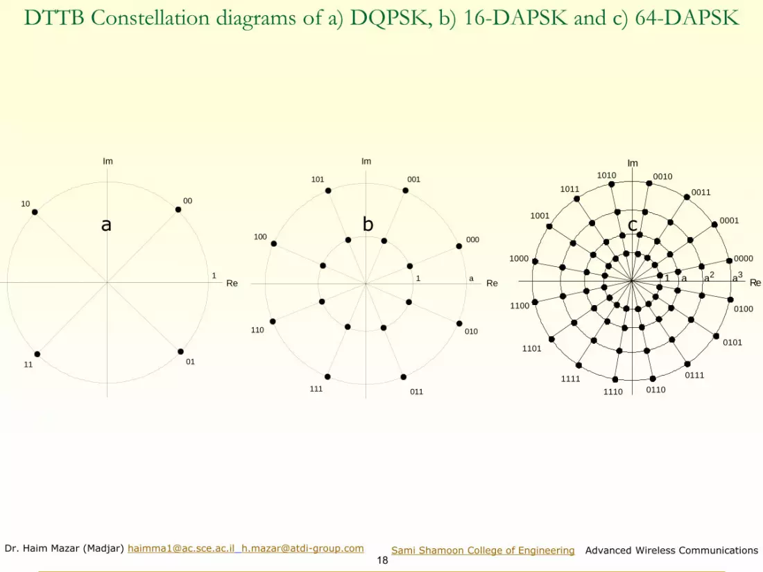
DTTB Constellation diagrams of a) DQPSK, b) 16-DAPSK and c) 64-DAPSK
a) b) c)
Im
Re
0010
11 01
1
Re
Im
1 a
000
001101
100
110
111 011
010
0000
0001
0011
00101010
1011
1001
1000
1100
1101
1111
1110 0110
0111
0101
0100
1 a a2 a3Re
Im
a b c

Dr. Haim Mazar (Madjar) [email protected] [email protected]
19Sami Shamoon College of Engineering Advanced Wireless Communications
media & means for Tx and Rx of information & interactive
services of sound, multimedia & TV broadcasting fig 1 in Rep ITU-R BT.2295
(
IBB systems
taking into account the peculiarities of countries and regionsSound, Multimedia, TV
broadcasting:
terrestrial, satellite, cable,
mobile networks, etc.
Info Communications:
WebTV, IPTV, OTT, etc.
Interactive communication terminals
Fixed:
TV, PC, ...
Video Information
Systems (VIS)
Mobile:
smartphones, tablet PC, ...
Those are the digital terrestrial broadcasting systems (TV and sound) : ATSC, DAB, DRM, DTMB, DVB-T, DVB-H, DVB-SH, DVB-T2, IBOC, ISDB-T family, RAVIS, T-DMB, AT-DMB.
Integrated Broadcast-Broadband (IBB) systems integrate both traditional broadcasting (terrestrial, satellite, cable) and broadcasting in mobile networks as well as other types of broadcasting
See also Recommendation ITU-R BT.2037 and Report ITU BT.2267

Dr. Haim Mazar (Madjar) [email protected] [email protected]
20Sami Shamoon College of Engineering Advanced Wireless Communications
Digital Terrestrial Television (DTT) broadcasting systems by country
See http://en.wikipedia.org/wiki/File:Digital_broadcast_standards.svg 1 Nov. 2020
Brazil

Dr. Haim Mazar (Madjar) [email protected] [email protected]
21Sami Shamoon College of Engineering Advanced Wireless Communications
DVB-T2 VHF/UHF min equivalent field strength (dB(µV/m))
VHF
FixedPortable
outdoor/urban
Portable
indoor/urbanMobile/rural
Handheld
portable
outdoor
moving
vehicle*UHF 1.54
MHz
BW
7.71
MHz
BW
Min. C/N 20.0 17.9 18.3 10.2 9.8 10.2 10.2Equivalent
noise band
width (MHz)
6.66 6.66 6.66 1.54 6.66 1.54 6.66
7.77 7.77 7.77 7.71 7.77 not
available7.71
Ant. Gain
relative to half
dipole (dBd)
7 -2.2 -2.2 -2.2 -17 -17 -17
11 0 0 0 -9.5-
-9.5
Man-made
noise (dB)2 8 8 5 0 0 0
0 1 1 0 0 - 0Penetration
loss (building
or vehicle) (dB)
0 0 9 0 0 8 8
0 0 11 0 0 - 8
Min. median
equivalent field
strength
(dB(µV/m))
41.3 52.4 62.4 39.5 51.1 57.8 64.1
48.2 54.1 66.8 49.5 54.2 - 67.5
* Handheld mobile Class H-D/ integrated antenna

Dr. Haim Mazar (Madjar) [email protected] [email protected]
22Sami Shamoon College of Engineering Advanced Wireless Communications
DVB-T1 and DVB-T2 protection ratios: C/N and C/I (dB) Rec. BT.1368 tables 1&15, BT.2033 tables 1&2 & EBU Technical Reports TR 022 & Tech 3348 (for DVBT-2)
Modulation Bit rate (Mbit/s) C/N (dB) C/I (dB)
DVBT-1 DVBT-2 DVBT-1 DVBT-2 DVBT-1 DVBT-2
QPSK 7 10* 6.9 3.1* 7 4.5
16-QAM 13 20* 13.1 8.9* 13 10.3
64-QAM 20 30* 18.7 13.6* 19 15.1
256-QAM no256QAM 40* - 18.1* (19.7) - 19.7
* from EBU report Tech 3348 Table 2.1; all other values are from BT.2033such as (19.7). The C/N DVBT-2 are calculated at BER=10-6 after BCH(Bose, Chaudhuri, Hocquenghem) code

Dr. Haim Mazar (Madjar) [email protected] [email protected]
23Sami Shamoon College of Engineering Advanced Wireless Communications
RF Digital Dividend in IsraelConfirmed on 9 Feb 2020 by Nisim Tal [email protected];
ל הנדסה"סמנכ,ניסים טל
1. 28 digital Transmitters, with two 8 UHF MHz channels
cover all Israel with 5 programs (1, 2, 10, 33, 99 )
2. Thus instead of
1. 45 analog UHF and additional VHF Transmitters covering only
one program - ch.1;
2. and 15 analog Transmitters at UHF covering only one program-
ch. 2.

Dr. Haim Mazar (Madjar) [email protected] [email protected]
24Sami Shamoon College of Engineering Advanced Wireless Communications
See http://www.rashut2.org.il/idan_map.asp 5 Feb 2020
2 digital 8 MHz UHF channels cover all Israel
Channel 26
Channel 29
Channel 29

Dr. Haim Mazar (Madjar) [email protected] [email protected]
25Sami Shamoon College of Engineering Advanced Wireless Communications
Questions to be asked about TV delivery
1. Except competition to satellites and cable, do we really need over-the-air terrestrial TV?
2. Which Standard: DVB-T, ISDB-T? ATSC? DMB-T? (check Channel Separation)
3. Free view or paid? Will HD be free also? HD or Ultra HD, 3D?
4. How many programs to transmit? Subsidiseset-top box?
5. Business model of DVB-H? Cellular Operators or Broadcasters transmit the DVB-H? Which Regulator?

Dr. Haim Mazar (Madjar) [email protected] [email protected]
26Sami Shamoon College of Engineering Advanced Wireless Communications
ETSI and3GPP band plan for Band Class 20
3GPP bandplan for
class 20
Downlink (DL) operating bandBS transmit UE receive
Uplink (UL) operating bandBS receive
UE transmit Duplex Mode
FDL_low – FDL_high FUL_low – FUL_high
20 791 MHz – 821 MHz 832 MHz – 862 MHz FDD
3GPP bandplanfor class 20
TX - RX carrier centre frequency
separation
20 41 MHz
Coexistence TV and Cellular (1)
LTE parameters in 800 MHz

Dr. Haim Mazar (Madjar) [email protected] [email protected]
27Sami Shamoon College of Engineering Advanced Wireless Communications
Coexistence TV and Cellular (see also specific slide in Land mobile )(1) Digital Dividend 790-862 MHz: Present 800/900 MHz Cellular, Trunking & TV allocations
System EGSM
800 890880870860850840830820 900810
UMTS850GSM
US standard
UHF TVstandard CH63 CH64 CH65 CH66 CH67 CH68 CH69
860 950940930920910900890880 960870
EGSM GSM
European standard
European and American
RF allocations
European
System
04 July 2010
RGSM
trunking trunking
UMTS850
EGSM GSMRGSM
Digital Dividend1 includes channels 61-69 (790-862 MHz)

Dr. Haim Mazar (Madjar) [email protected] [email protected]
28Sami Shamoon College of Engineering Advanced Wireless Communications
◼ Pn = F + 10 log (k T0 B)
◼ Ps min = C/N + Pn
◼ Aa = G + 10 log (1.642/4 )
◼ φmin = Ps min – Aa + Lf
◼ Emin = φmin + 120 + 10 log (120 )= φmin + 145.8
◼ Emed= Emin + Pmmn + Cl for roof top level fixed reception
◼ Emed= Emin + Pmmn + Cl + Lh for portable outdoor and mobile Rx
◼ Emed= Emin + Pmmn + Cl + Lh + Lb for portable indoor & mobile hand-held Rx
Cl = µ σt σt =
Calculation of minimum field strength (App1 to Ann 2 ITU-R BT 1368)
22
mb +

Dr. Haim Mazar (Madjar) [email protected] [email protected]
29Sami Shamoon College of Engineering Advanced Wireless Communications
◼ Pn : receiver noise input power (dBW) F :receiver noise figure (dB)
◼ k : Boltzmann’s constant (k = 1.38 10–23 (J/K)) T0 : absolute temperature (T0 = 290 (K))
◼ B : receiver noise bandwidth (B = 7.61 106 (Hz))
◼ Ps min : minimum receiver input power (dBW)
◼ C/N : RF S/N at the receiver input required by the system (dB)
◼ Aa : effective antenna aperture (dBm2)
◼ G : antenna gain related to half dipole (dBd)
◼ : wavelength of the signal (m)
◼ φmin : minimum pfd at receiving place (dB(W/m2))
◼ Lf : feeder loss (dB)
◼ Emin : equivalent minimum field strength at receiving place (dB(mV/m))
◼ Emed : minimum median equivalent field strength, planning value (dB(mV/m))
◼ Pmmn : allowance for man-made noise (dB)
◼ Lh : height loss (reception point at 1.5 m above ground level) (dB)
◼ Lb : building or vehicle entry loss (dB) Cl : location correction factor (dB)
◼ σ t : total strd deviation (dB) σ m strd deviation macro-scale (σ m = 5.5 (dB))
◼ σ b : strd deviation building entry loss (dB) ◼ µ : distribution factor being 0.52 for 70%, 1.28 for 90%, 1.64 for 95% and 2.33 for 99%.
Calculation of minimum field strength (Cont’d)

Dr. Haim Mazar (Madjar) [email protected] [email protected]
30Sami Shamoon College of Engineering Advanced Wireless Communications
Planning, Protection of land mobile and fixed systems from
terrestrial digital video and audio broadcasting systems
These two Recommendations were drafted by the author of this lecture
1.Rec. ITU-R M.1767: Protection of land mobile systems from terrestrial digital video and audio broadcasting systems in the VHF and UHF shared bands allocated on a primary basis
2. Rec. ITU-R F.1670: Protection of fixed wireless systems from terrestrial digital video and sound broadcasting systems in shared VHF and UHF bands

Dr. Haim Mazar (Madjar) [email protected] [email protected]
31Sami Shamoon College of Engineering Advanced Wireless Communications
Multipath Distortion in Broadcasting

Dr. Haim Mazar (Madjar) [email protected] [email protected]
32Sami Shamoon College of Engineering Advanced Wireless Communications
w
Multipath Distortion in FM and capture effect
U
t
DF kHz
50
25
0
-25
-50
t
FM
uin= Uin{cos [wot + Y(t)] +k cos [ ot -wot+y(t-t)]}
K = 0.25t = 50 ms
/2 3/2 2W t
DF = 2fm . Sin Wt
. Sin (Wt + Wt)2
Kg 15%
- deviation- modulation frequency- additional deviation
fm W DF

Dr. Haim Mazar (Madjar) [email protected] [email protected]
33Sami Shamoon College of Engineering Advanced Wireless Communications
Multipath Distortion in TV
t
TV

Dr. Haim Mazar (Madjar) [email protected] [email protected]
34Sami Shamoon College of Engineering Advanced Wireless Communications
HFIonosphere
Audio and Video Broadcasting

Dr. Haim Mazar (Madjar) [email protected] [email protected]
35Sami Shamoon College of Engineering Advanced Wireless Communications
AM transmitters in Israel Yosi Menashe, Bezeq1 December 2014

Dr. Haim Mazar (Madjar) [email protected] [email protected]
36Sami Shamoon College of Engineering Advanced Wireless Communications
f,kHz
Network FMTransmitters with the same RF
0 200 400
coverage
interference area
Dr. Haim Mazar (Madjar) [email protected] [email protected]
37Sami Shamoon College of Engineering Advanced Wireless Communications
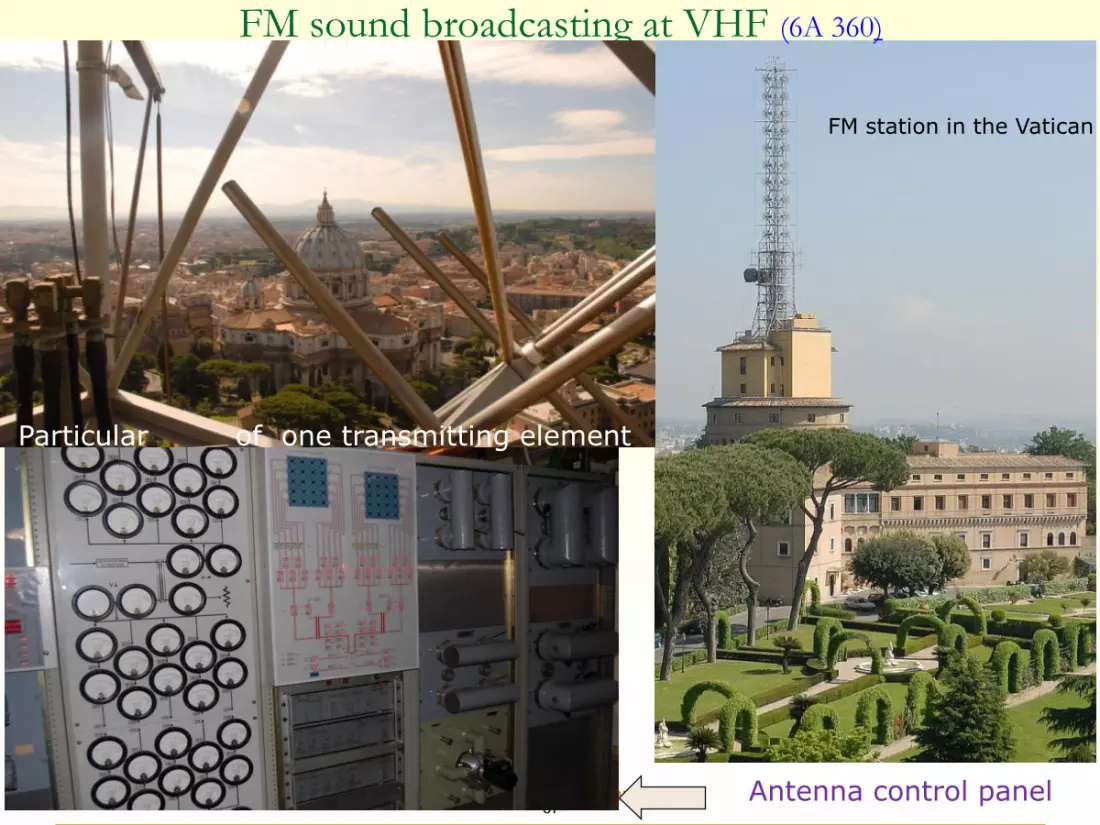
FM sound broadcasting at VHF (6A 360)
FM station in the Vatican
Particular of one transmitting element
Antenna control panel

Dr. Haim Mazar (Madjar) [email protected] [email protected]
38Sami Shamoon College of Engineering Advanced Wireless Communications
0 15 19 23 38 53 57
RDS/RBDS
Stereo Pilot
Mono AudioL+R
Modula
tion level
Frequency(kHz)
38 kHz suppressed carrier
Stereo Audio
L–R; lower sideband
L: left ; R: right; RDS: radio data system;
RBDS: radio broadcast data system
Stereo Audio
L–R; upper sideband
≈45 %
≈22.5 % ≈ 22.5%≈10 %
≈5%
FM Modulation
FM radio was first deployed in monaural in 1940; in 1960, FM stereo was introduced. The most prevalent wireless terrestrial sound in the world today is still the Frequency Modulation FM radio, operating worldwide 87.5-108 MHz. In the West European countries and the US, the max deviation is ± 75 kHz; in the ex-USSR and in some other European countries, it is ± 50 kHz; see Rec. ITU-R BS.450. the carrier frequencies, which define the nominal placement of the RF channels within the band, for both monophonic and stereophonic transmissions, are integral multiples 200 kHz in America, of 100 kHz in Europe and 50 kHz in Italy. So, some American FM radio receivers, with odd center frequency channel-spaced every 200 kHz, cannot operate in Europe.
Carson's bandwidth rule: bw =2(Δf+fm), where bw is the total significant (98%) bandwidth, Δf is the peak frequency deviation FM signal from the center frequency and fm is the highest modulating signal frequency. Defining the ratio Δf/fm as the modulation index β, Δf= β fm and bw =2(β fm +fm)= 2(1+ β)fm. The human ears are sensitive to audio signals 20 to 15,000 Hz; for β =5 and maximal modulating frequency of 15 kHz, the modulated (peak deviation) monaural signal swings to 5 x 15 kHz = 75 kHz above and below the RF carrier. For this common Δf =75 kHz and fm =15 kHz, bw= 2(Δf+fm)= 2(75+15)kHz=180kHz; it is close to the common 200 kHz channel bandwidth. Bessel Funtions
As the peak stereo modulating has 53 kHz information, using Carson's rule bw =2(1+ β)fm = 2(1+ β)53 kHz = (1+ β)106 kHz. In order to keep the total bw around 200 KHz, β is approximately 1. Depending on power, peak deviation and β, adjacent (in geography and frequency) FM stations need RF separation up to 400 kHz.
FM baseband

Dr. Haim Mazar (Madjar) [email protected] [email protected]
39Sami Shamoon College of Engineering Advanced Wireless Communications
FM Sound
Areas Monophonic dB(µV/m) Stereophonic dB(µV/m)
Rural 48 54
Urban 60 66
Large cities 70 74
Median field strength for satisfactory service (BS.412 Table 1)
50
f,kHz
dB
21
1-Mono
2-Streo40
20
10
0
-10
0
Protection Ratio
200 400
As the stereo signal is modulated on 38.0kHz suppressed carrier, the interference is most sensitive on that ‘out of band’ frequency

Dr. Haim Mazar (Madjar) [email protected] [email protected]
40Sami Shamoon College of Engineering Advanced Wireless Communications
Protection ratios of monophonic & stereo reception (Rec. BS.412 1998)
0412-02
400300200100– 20
– 10
0
10
20
30
40
50
60
0
S1
S2
M1
M2
FIGURE 2
Radio-frequency protection ratios required by broadcasting services
in band 8 (VHF) using a maximum frequency deviation of ± 50 kHz
Radio
-fre
qu
ency p
rote
ctio
n r
ati
os
(dB
)
Difference between carrier frequencies (kHz) of the unwanted and wanted signals
Curves M1: monophonic broadcasting; steady interference
M2: monophonic broadcasting; tropospheric interference
S1: stereophonic broadcasting; steady interference
S2: stereophonic broadcasting; tropospheric interference
channels are to be assigned in such a way that the carrier frequencies are integral multiples of 100 kHz; a uniform channel spacing of 100 kHz applies for both mono and stereo transmissions
For carrier frequency differences greater than 400 kHz, the protection ratio values should be substantially lower than –20 dB. The radio-frequency protection ratio value for the particular carrier frequency difference of 10.7 MHz (intermediate frequency) should be below –20 dB.

Dr. Haim Mazar (Madjar) [email protected] [email protected] Sami Shamoon College of Engineering, Advanced Wireless Communications
41
Advanced Wireless Communications, 2020
Academic course for 4th year engineering students
Land Mobile Services (mainly cellular)
http://mazar.atwebpages.com/

Dr. Haim Mazar (Madjar) [email protected] [email protected]
42Sami Shamoon College of Engineering Advanced Wireless Communications
3 sector tower site with 3 ant integrated radio 800 MHz units & three 2100 MHz ant
800 MHz
2100 MHz
Ericsson AIR 2 dipoles ant
two shot ant
one X-pol antenna consists of two dipole arrays (has 2 connectors)

Dr. Haim Mazar (Madjar) [email protected] [email protected]
43Sami Shamoon College of Engineering Advanced Wireless Communications
2.21
3.37
4.64
5.89
6.66
7.18
7.81
8.30
108.01
y = -0.3741x2 + 11.196x + 21.802R² = 0.9964
0
20
40
60
80
100
120
0.0
0.5
1.0
1.5
2.0
2.5
3.0
3.5
4.0
4.5
5.0
5.5
6.0
6.5
7.0
7.5
8.0
8.5
9.0
%
bil
lio
ns
Context: mobile-cellular telephone subscriptions (billions) &mobile-cellular telephone subscriptions per 100 inhabitants, 2005-2019
Mobile-cellular telephone subscriptions
Mobile-cellular telephone subscriptions per100 inhabitants (right axis)

Dr. Haim Mazar (Madjar) [email protected] [email protected]
44Sami Shamoon College of Engineering Advanced Wireless Communications
0
20
40
60
80
100
120
2011 2012 2013 2014 2015 2016 2017 2018 2019 2020
Highest growth forecast in M.2243
Lowest growth forecast in M.2243
Traf
fic in
crea
sing r
atio
com
pare
d to
201
0
Year
x80 (75% value of the estimated range)
x44 (25% value of the estimated range)
Estimated growth range
Extrapolated
Mobile traffic forecasts toward 2020 by extrapolation/M.2290-0 (2014) ‘Future spectrum requirements estimate for terrestrial IMT’ Fig. 5
IMT: International Mobile Telecommunications
25 to 100-fold growth ratio compared to 2010

Dr. Haim Mazar (Madjar) [email protected] [email protected]
45Sami Shamoon College of Engineering Advanced Wireless Communications
Ericsson Mobility Report Nov 2019 Subscription penetration Q3 2019 (percent of population)
1. 5G to cover up to 65 percent of the world’s population by the end of 2025 and handle 45 percent of global mobile data traffic
2. Smartphone users to consume a global average of 24 GB per month in 2025 from 7.2 GB currently, as video usage increases and new services become available
3. Total number of cellular IoT connections estimated at five billion by the end of 2025, from 1.3 billion by end of 2019

Dr. Haim Mazar (Madjar) [email protected] [email protected]
46Sami Shamoon College of Engineering Advanced Wireless Communications
Ericsson Mobility Report Nov 2019 Mobile subscriptions by technology (billion)

Dr. Haim Mazar (Madjar) [email protected] [email protected]
47Sami Shamoon College of Engineering Advanced Wireless Communications
Broadband
applications in the
mobile service
Enhancement of key capabilities from IMT-Advanced to IMT-2020

Dr. Haim Mazar (Madjar) [email protected] [email protected]
48Sami Shamoon College of Engineering Advanced Wireless Communications
Wireline access and wireless access comparison
Wireline Access
Wireless Access
Switch Digital line carrier (DLC)
or remote Distribution
Feeder/ Backhaul
Base radio and controller
Feeder/ Backhaul
Fibre Copper
Copper Coax
Fibre Copper
Point-to-point microwave
Switch
Distribution
Multiple access radio system
(400 MHz - 40 GHz)
ITU LM HB 2001 Fig 1

Dr. Haim Mazar (Madjar) [email protected] [email protected]
49Sami Shamoon College of Engineering Advanced Wireless Communications
Wireless access architecture
ITU LM HB 2001 Fig 5
➢Communication Types1. Traffic: Voice, video and data the user is transmitting2. Signaling: Additional data the system is transmitting per user to
control and monitor3. Control: Common data transmitted from BS to all users to
synchronize, page, pass information4. Random Access: Used by users mainly to request allocation.

Dr. Haim Mazar (Madjar) [email protected] [email protected]
50Sami Shamoon College of Engineering Advanced Wireless Communications
Access requirements: need a family of wireless access solutions to meet diverse requirements
ITU LM HB 2001 Fig 7
Suburban
Town
Village Rural 5 subs R = 1 km D = 2 subs / km
2 100 subs R = 2 km D = 10 subs / km
2
600 subs R = 3 km D = 20 subs / km
2
10,000 subs R = 4 km D = 200 subs / km
2 R
R
Urban / Industrial 25,000 subs R = 2 km D = 2000 subs / km
2

Dr. Haim Mazar (Madjar) [email protected] [email protected]
51Sami Shamoon College of Engineering Advanced Wireless Communications
IMT/5G Example deployment scenariosRecommendation ITU-R M.2101-0 (02/2017) Modelling and simulation of IMT networks and
systems for use in sharing and compatibility studies
M.2101 -01
Macro sell
Micro suburban
Micro urban Indoor
Small areacoverage
Macro rural Macro suburban Macro urban

Dr. Haim Mazar (Madjar) [email protected] [email protected]
52Sami Shamoon College of Engineering Advanced Wireless Communications
M.2101 2-0
A
B
IMT Macro cell geometry M.2101-0

Dr. Haim Mazar (Madjar) [email protected] [email protected]
53Sami Shamoon College of Engineering Advanced Wireless Communications
Macro cellular layout
(central cluster)M.2101-0
M.2101 3-0
11 10 9
11 10 911 10 9
12 3 2 812 3 2 8
12 3 2 813 4 0 1 7
13 4 0 1 713 4 0 1 7
14 5 6 18
14 5 6 18
15 16 1715 16 17
15 16 17
14 185 6
Dr. Haim Mazar (Madjar) [email protected] [email protected]
54Sami Shamoon College of Engineering Advanced Wireless Communications
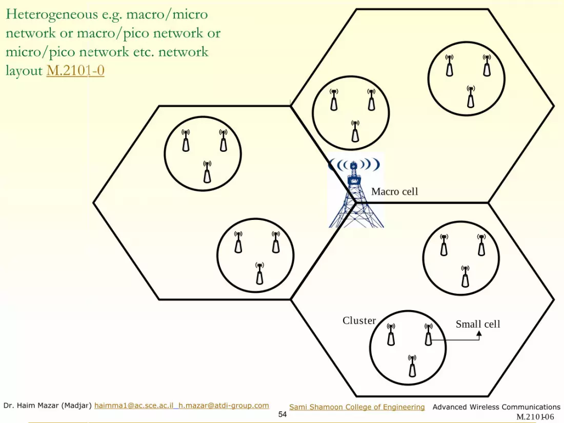
Heterogeneous e.g. macro/micro
network or macro/pico network or
micro/pico network etc. network
layout M.2101-0
M.2101 6-0
Macro cell
Small cellCluster

Dr. Haim Mazar (Madjar) [email protected] [email protected]
55Sami Shamoon College of Engineering Advanced Wireless Communications
Frequency Reuse; Dr. Arie Reichman
frequency reuse cluster

Dr. Haim Mazar (Madjar) [email protected] [email protected]
56Sami Shamoon College of Engineering Advanced Wireless Communications
MSC -- Mobile Switching Center; Dr. Arie Reichman
MSC PSTN
56
Handover. Moving from cell to cell or from sector to sector, the subscriber connectivity is changed accordingly

Dr. Haim Mazar (Madjar) [email protected] [email protected]
57Sami Shamoon College of Engineering Advanced Wireless Communications
Basic cellular mobile reference network
Tri-sector cells cluster of 7 cells; N (re-use)=7 network based on 7 cell reference network unit
A1
A2
A2
A3
A4
A6
A5
B
BB
A
A
C
D
C
C
D
D
B
D
Reuse
Network composed of 19 BTS (57 sectors), where the BTS are placed in the middle of 3 sectors.
In GSM re-use factor of 25%:each cell might use a quarter of the total BWIn UMTS, each cell has the same carrier frequency, with a re-use factor of 100%; N=1; easier planning
Cells with same letter use same RF

Dr. Haim Mazar (Madjar) [email protected] [email protected]
58Sami Shamoon College of Engineering Advanced Wireless Communications
Typical cell clusters and re-use
1
2 3
N = 3 R c
1
2 3
5
7 4
6
N = 7
1 N = 1 R c N = 4 1
2 4
R c
3
5
1 1 3
7
1 0 2
9
N = 1 2
6
1 2
4
1
8
N cell K = 19 reuse pattern, Lee W.C.Y.
3d k r= d reuse distancer cell radius
r is determined by exceeding the min c/i
Smaller N- greater capacity

Dr. Haim Mazar (Madjar) [email protected] [email protected]
59Sami Shamoon College of Engineering Advanced Wireless Communications
Land Mobile- Up and Down Links

Dr. Haim Mazar (Madjar) [email protected] [email protected]
60Sami Shamoon College of Engineering Advanced Wireless Communications
Femto cells used to expand capacity
ITU LM HB 2011Fig 3
BWA-03
Aggregate femto-cellcapacity far exceedsmacro-cell capacityfor same amountof spectrum
Femto-cellcoverage
Macro-cellcoverage

Dr. Haim Mazar (Madjar) [email protected] [email protected]
61Sami Shamoon College of Engineering Advanced Wireless Communications
Service types and their peak bit ratesTable 2 in Rec ITU-R M.1768-1 (2013)
Service type Peak bit rate
Very low rate data < 16 kbit/s
Low rate data and low multimedia < 144 kbit/s
Medium multimedia < 2 Mbit/s
High multimedia < 30 Mbit/s
Super-high multimedia 30 Mbit/s to 100 Mbit/s/1 Gbit/s

Dr. Haim Mazar (Madjar) [email protected] [email protected]
62Sami Shamoon College of Engineering Advanced Wireless Communications
Frequency/Code/Time Division Multiple Access
Dr. Haim Mazar (Madjar) [email protected] [email protected]
63Sami Shamoon College of Engineering Advanced Wireless Communications BWA-16
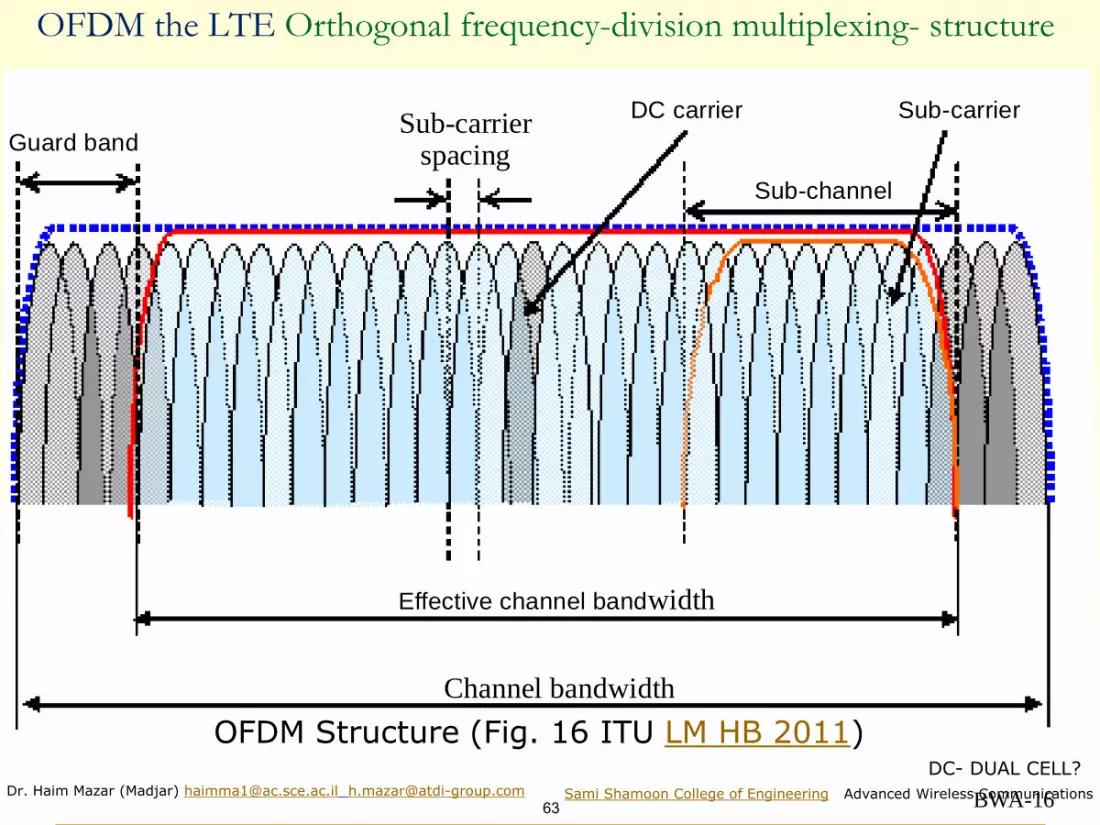
Channel bandwidth
Sub-channel
DC carrierSub-
spacingcarrier
Sub-carrier
Guard band
Effective channel bandwidth
OFDM the LTE Orthogonal frequency-division multiplexing- structure
OFDM Structure (Fig. 16 ITU LM HB 2011)DC- DUAL CELL?

Dr. Haim Mazar (Madjar) [email protected] [email protected]
64Sami Shamoon College of Engineering Advanced Wireless Communications
OFDM the LTE Orthogonal Frequency-Division MultiplexingOFDM (Orthogonal Frequency Division Multiplexing) is an FDM modulation technique that divides a communications channel into a small number of equally spaced frequency bands, each of which carry a portion or sub-signal of the radio signal. These sub-signals are then transmitted simultaneously at different frequencies to the receiver
OFDMA is the "multi-user" version of OFDM.Orthogonal Frequency Division Multiple Access (OFDMA) is a multiple access scheme for OFDM systems. It works by assigning a subset of subcarriers to individual users.
Spectrum of OFDM (Fig. 38 ITU LM HB 2011)
BWA-38
Am
pli
tud
e
Sub-carrier

Dr. Haim Mazar (Madjar) [email protected] [email protected]
65Sami Shamoon College of Engineering Advanced Wireless Communications
User 1 User 2 User 3 User ..
TDMA FDMA CDMA OFDMA
f f
f
t
f
t
f
f
t
f
t
f
• Time Division • Frequency Division • Code Division • Frequency Division
• Orthogonal subcarriers
Comparison of Domains Access
Source:Shalev
OFDMA: better immunity than CDMA to multipaththe part experiencing fading is avoided during allocation
Δf=15kHz

Dr. Haim Mazar (Madjar) [email protected] [email protected]
66Sami Shamoon College of Engineering Advanced Wireless Communications
OFDM/ OFDMA features
Rohde & Schwarz Seminar
OFDM allocates @ time domain OFDMA @ time & frequency domain

Dr. Haim Mazar (Madjar) [email protected] [email protected]
67Sami Shamoon College of Engineering Advanced Wireless Communications
OFDMA for Mobile; Dr. Arie Reichman
◼ ללא קו ראיה אפנון יעיל לתקשורת ניידת
User #1
Total Frequency band
User #69Contention pilots
Guard Band Guard Band
67

Dr. Haim Mazar (Madjar) [email protected] [email protected]
68Sami Shamoon College of Engineering Advanced Wireless Communications
Orthogonal frequency-division multiple access–OFDMA; Dr. Arie Reichman
User #1
Total Frequency band
User #69Contention pilots
Guard Band Guard Band

Dr. Haim Mazar (Madjar) [email protected] [email protected]
69Sami Shamoon College of Engineering Advanced Wireless Communications
טכנולוגית MIMO (Dr. Arie Reichman)
◼ הגדלת קצבים באותו רוחב סרט
◼ הגדלת קיבול
◼ נגד דעיכות
◼ נגד הפרעות
◼ Multiple In Multiple Out
◼ ריבוי אנטנות בשידור ובקליטה
◼ עיצוב אלומות
◼ קידוד מרחבי
◼ חלוקה מרחבית
◼ סיכום משוקלל

Dr. Haim Mazar (Madjar) [email protected] [email protected]
70Sami Shamoon College of Engineering Advanced Wireless Communications
Mobile has made a leap every ~10 years; Dr. Arie Reichman

Dr. Haim Mazar (Madjar) [email protected] [email protected]
71Sami Shamoon College of Engineering Advanced Wireless Communications
Extreme variation of requirements; Dr. Arie Reichman

Dr. Haim Mazar (Madjar) [email protected] [email protected]
72Sami Shamoon College of Engineering Advanced Wireless Communications
Source: Orange Poland
Development of the mobile cellular

Dr. Haim Mazar (Madjar) [email protected] [email protected]
73Sami Shamoon College of Engineering Advanced Wireless Communications
Source: Rec. ITU-R M.2083
M.2083-02
Gigabytes in a second
Smart home/building
Voice
Smart city
3D video, UHD screens
Work and play in the cloud
Augmented reality
Industry automation
Mission critical application
Self driving car
Massive machine type
communications
Ultra-reliable and low latency
communications
Enhanced mobile broadband
Future IMT

Dr. Haim Mazar (Madjar) [email protected] [email protected]
74Sami Shamoon College of Engineering Advanced Wireless Communications
Source: Rec. ITU-R M.2083
Importance of key capabilities in different usage scenarios
M.2083-04
User experienceddata rate
Spectrumefficiency
Mobility
LatencyConnection density
Networkenergy efficiency
Area trafficcapacity
Enhanced mobilebroadband
Peakdata rate
Massive machinetype communications
Ultra-reliableand low latency
communications
Low
Medium
High importance

Dr. Haim Mazar (Madjar) [email protected] [email protected]
75Sami Shamoon College of Engineering Advanced Wireless Communications
Source: Emf compliance assessments for 5G wireless networks ITU-T K Suppl 13 05/2019
Existing and new spectrum to be used for 5G mobile communication services

Dr. Haim Mazar (Madjar) [email protected] [email protected]
76Sami Shamoon College of Engineering Advanced Wireless Communications
Source: Emf compliance assessments for 5G wireless networks ITU-T K Suppl 13 05/2019
Schematic architecture for 5G mobile communication networks

Dr. Haim Mazar (Madjar) [email protected] [email protected]
77Sami Shamoon College of Engineering Advanced Wireless Communications
Source: Emf compliance assessments for 5G wireless networks ITU-T K Suppl 13 05/2019
5G networks initially integrated with existing 4G networks

Dr. Haim Mazar (Madjar) [email protected] [email protected]
78Sami Shamoon College of Engineering Advanced Wireless Communications
Source: Emf compliance assessments for 5G wireless networks ITU-T K Suppl 13 05/2019
Spectral Efficiency
Electromagnetic field compliance assessments for 5G wireless networks

Dr. Haim Mazar (Madjar) [email protected] [email protected]
79Sami Shamoon College of Engineering Advanced Wireless Communications
Source: Shalev
Trade off between Coverage and Capacity (1)The MCS (Modulation and Coding Scheme) defines the cell coverage & capacity
Coding rates (1/2, 2/3, ¾ and 5/6) reduce the system sensitivity
The code rate (or information rate) of a forward error correction (FER) code is the proportion of the data-stream that is useful (non-redundant): if the code rate is k/n for every k bits of useful information, the coder generates a total of n bits of data, of which n-k are redundantE.g, The code rate of a convolutional code will typically be 1/2, 2/3, 3/4, 5/6, 7/8, etc., corresponding to one redundant bit inserted after every single, second, third, etc., bit. The code rate of the octet oriented Reed Solomon block code denoted RS(204,188) is 188/204, meaning that 204-188=16 are redundant octets (or bytes), added to each block of 188 octets of useful informationNote that bit/s is a more widespread unit of measurement for the information rate, implying that it is synonymous with net bit rate or useful bit rate exclusive of error-correction codes.

Dr. Haim Mazar (Madjar) [email protected] [email protected]
80Sami Shamoon College of Engineering Advanced Wireless Communications
Trade off between Coverage and Capacity (2)
In OFDM Protection Ratio (PR), C/N and C/I are similar. Intra-protection ratios for co-channel interference are identical to therespective C/N values.The 64-QAM (see later)imposes higher PRs relative to 16-QAM: circa6 dB; 4 times higher PR (for the same CR) is a consequence of 4times more vector signal density at the I-Q plane.Balance: for the same range higher capacity 64QAM or 16QAM, vshigher Tx power.Min. distance between points in the constellation indicates the powerefficiency, number of points indicates the bandwidth efficiency.

Dr. Haim Mazar (Madjar) [email protected] [email protected]
81Sami Shamoon College of Engineering Advanced Wireless Communications
Source: Shalev
Trade off between Coverage and Capacity (3)
64QAM-5/6 64QAM-3/4 64QAM-2/3 16QAM-1/2 QPSK
Cell range
The MCS (Modulation and Coding Scheme) defines the cell coverage & capacity

Dr. Haim Mazar (Madjar) [email protected] [email protected]
82Sami Shamoon College of Engineering Advanced Wireless Communications
Sesia S., Toufik I. and Baker M. 2009 (2011 2th edition) LTE, the UMTS Long Term Evolution: from Theory to Practice, John Wiley & Sons
Reference sensitivity& coverage range

Dr. Haim Mazar (Madjar) [email protected] [email protected]
83Sami Shamoon College of Engineering Advanced Wireless Communications
LTE Downlink peak bit rates; Wiley 2009; LTE Technology
Throughput (Mbit/s) as function of SINR
Remark: true Shannon limit is:
( )2 1 /c b log s n= +

Dr. Haim Mazar (Madjar) [email protected] [email protected]
84Sami Shamoon College of Engineering Advanced Wireless Communications
◼ Static: KTBF(SNR)
◼ Dynamic : KTBF(SNR)+ Fade Margin
Sensitivity : Static and Dynamic
https://www.intechopen.com/

Dr. Haim Mazar (Madjar) [email protected] [email protected]
85Sami Shamoon College of Engineering Advanced Wireless Communications
GSM Reference Sensitivity (REFSENS)
◼ GSM 3GPP TS 05.05 (2005) 6.2 for UE & BTS BER 0.001
GSM 900Mhz -104dbm; GSM 1800Mhz UE -102dbm
GSM900 and GSM1800 (DCS 1 800) the normal
REFSENS BTS is - 104 dBm.
REFSENS is the minimum mean power received at the Base Tx Station (BTS) or User Equipment (UE) antenna port at which the Bit Error Ratio (BER) shall not exceed a specific value
◼ For B=0.2 MHz, F (Noise Figure) 8 & 10 dB
respectively and co-channel interference C/Ic 9dB the
UE, KTBF(C/N) equals: ◼ for GSM 900 MHz equals
-114+10*Log10(0.2)+ 8+9=-104dBm◼ for DCS 1800 MHz equals
-114+10*Log10(0.2)+10 +9 =-102dBm
Dr. Haim Mazar (Madjar) [email protected] [email protected]
86Sami Shamoon College of Engineering Advanced Wireless Communications
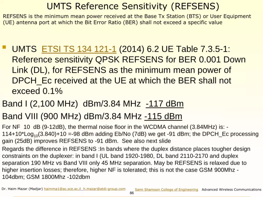
UMTS Reference Sensitivity (REFSENS)
◼ UMTS ETSI TS 134 121-1 (2014) 6.2 UE Table 7.3.5-1:
Reference sensitivity QPSK REFSENS for BER 0.001 Down
Link (DL), for REFSENS as the minimum mean power of
DPCH_Ec received at the UE at which the BER shall not
exceed 0.1%
Band I (2,100 MHz) dBm/3.84 MHz -117 dBm
Band VIII (900 MHz) dBm/3.84 MHz -115 dBm For NF 10 dB (9-12dB), the thermal noise floor in the WCDMA channel (3.84MHz) is: -
114+10*Log10(3.840)+10 =-98 dBm adding Eb/No (7dB) we get -91 dBm; the DPCH_Ec processing
gain (25dB) improves REFSENS to -91 dBm. See also next slide
Regards the difference in REFSENS :In bands where the duplex distance places tougher design
constraints on the duplexer: in band I (UL band 1920-1980, DL band 2110-2170 and duplex
separation 190 MHz vs Band VIII only 45 MHz separation. May be REFSENS is relaxed due to
higher insertion losses; therefore, higher NF is tolerated; this is not the case GSM 900Mhz -
104dbm; GSM 1800Mhz -102dbm
REFSENS is the minimum mean power received at the Base Tx Station (BTS) or User Equipment (UE) antenna port at which the Bit Error Ratio (BER) shall not exceed a specific value
Dr. Haim Mazar (Madjar) [email protected] [email protected]
87Sami Shamoon College of Engineering Advanced Wireless Communications
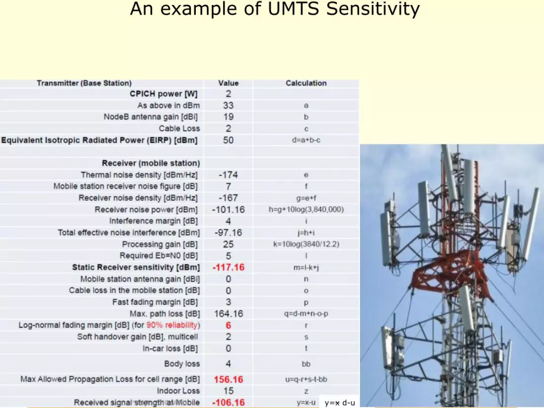
An example of UMTS Sensitivity
y=x d-u

Dr. Haim Mazar (Madjar) [email protected] [email protected]
88Sami Shamoon College of Engineering Advanced Wireless Communications
UMTS Reference Sensitivity (REFSENS) (Cont’)Copied from Wiley WCDMA for UMTS: HSPA Evolution and LTE: Harri Holma, Antti Toskala

Dr. Haim Mazar (Madjar) [email protected] [email protected]
89Sami Shamoon College of Engineering Advanced Wireless Communications
LTE Reference Sensitivity (REFSENS)
◼ ETSI TS 136 521-1 (2009) (see also LTE Acronyms) defines: REFerence SENSitivity power level. It is the minimum mean
received signal strength applied to both antenna ports at which there is
sufficient SINR for a given modulation scheme to meet 95% of the
maximum throughput of a reference measurement channel. It is given by
REFSENS = kTB + NF + SINR + IM − 3 (dBm), where kTB is the
thermal noise level in dBm in the bandwidth B, NF is the prescribed
maximum noise figure for the receiver, SINR is the requirement for the
chosen Modulation and Coding Scheme (MCS), IM is an implementation
margin and the -3 dB represents the diversity gain (only in the Up-Link
UL budget). See 3GPP TS36.101, Section 7.3
◼ LTE TS 136 521-1 Table 7.3.3-1, For throughput ≥
95% (as specified in Annexes A.2,2, A.2,3 and A.3..2)
the band 3 Down-Link DL (1,805 MHz to 1,880 MHz) 5
MHz channel bandwidth, QPSK REFSENS is
−97dBm; see next slide

Dr. Haim Mazar (Madjar) [email protected] [email protected]
90Sami Shamoon College of Engineering Advanced Wireless Communications
LTE Table 7.3.3-1ETSI TS 136 101 V12.5.0 (2014-11)

Dr. Haim Mazar (Madjar) [email protected] [email protected]
91Sami Shamoon College of Engineering Advanced Wireless Communications
Channel Bandwidth BW (MHz)
Band DL RF (MHz) BW 1.4 MHz BW 3 MHz BW 5 MHz BW 10 MHz BW 15MHz BW 20MHz
1 2,110-2,170 ------ -100 -97 -95.2 -94
2 1,930-1,990 -102.7 -99.7 -98 -95 -93.2-92
3 1,805-1,880 -101.7 -98.7 -97 -94 -92.2 -91
5 869 -894 -103.2 -100.2 -98 -95 ------
7 2,620-2,690 ------ -98 -95 -93.2 -92
8 925-960 -102.2 -99.2 -97 -94 ------
20 791-821 ------ -97 -94 -91.2 -90
LTE TS 136 521-1 Table 7.3.3-1: UE Reference sensitivity QPSK REFSENS (dBm)Down Link DL FDD RF bands retrieved from Table 5.5-1 of 3GPP TS 36.104 V12.3.0 (2014-03)
Dr. Haim Mazar (Madjar) [email protected] [email protected]
92Sami Shamoon College of Engineering Advanced Wireless Communications
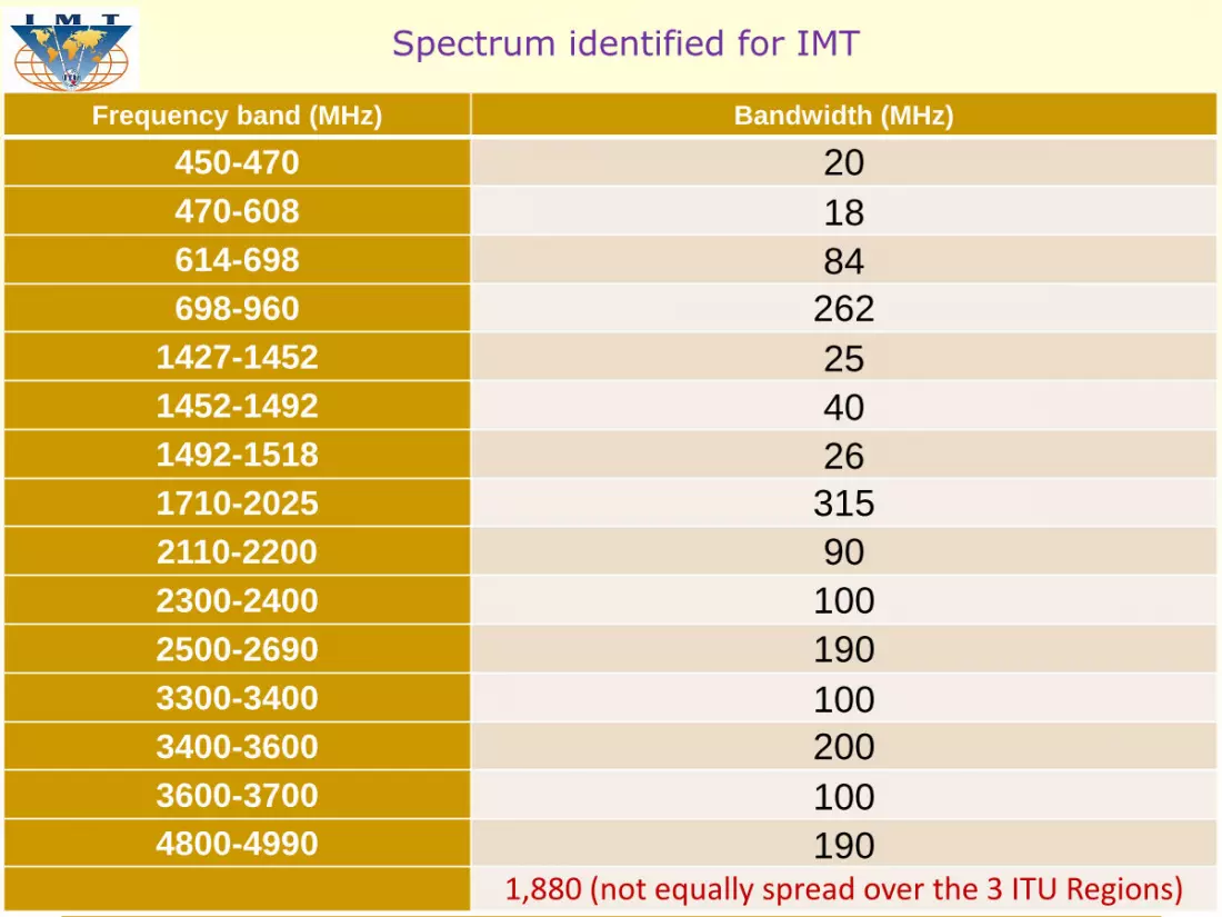
Spectrum identified for IMT
Frequency band (MHz) Bandwidth (MHz)
450-470 20
470-608 18
614-698 84
698-960 262
1427-1452 25
1452-1492 40
1492-1518 26
1710-2025 315
2110-2200 90
2300-2400 100
2500-2690 190
3300-3400 100
3400-3600 200
3600-3700 100
4800-4990 1901,880 (not equally spread over the 3 ITU Regions)

Dr. Haim Mazar (Madjar) [email protected] [email protected]
93Sami Shamoon College of Engineering Advanced Wireless Communications
ITU Radio Regulations (2020 edition), Footnotes identifying the band for IMT
* revised at WRC-19
Band Footnotes identifying the band for IMT
Region 1 Region 2 Region 3
450–470 MHz 5.286AA
470–698 MHz - 5.295, 5.308A 5.296A
694/698-960 MHz 5.317A 5.317A 5.313A, 5.317A
1 427–1 518 MHz 5.341A, 5.346 5.341B 5.341C, 5.346A
1 710-2 025 MHz 5.384A, 5.388
2 110–2 200 MHz 5.388
2 300–2 400 MHz 5.384A
2 500–2 690 MHz 5.384A
3 300–3 400 MHz 5.429B 5.429D 5.429F
3 400–3 600 MHz5.430A 5.431B 5.432A, 5.432B, 5.433A
3 600–3 700 MHz - 5.434 -
4 800–4 990 MHz 5.441B 5.441A, 5.441B 5.441B
24.25–27.5 GHz * 5.532AB
37–43.5 GHz* 5.550B
45.5–47 GHz* 5.553A 5.553A 5.553A
47.2–48.2 GHz* 5.553B 5.553B 5.553B
66–71 GHz* 5.559AA

Dr. Haim Mazar (Madjar) [email protected] [email protected]
94Sami Shamoon College of Engineering Advanced Wireless Communications
LAND Mobile Standards
Standard
179017801770176017501740173017201710 1820 1830 185018401810180018051785
Standard
1800 189018801870186018501840183018201810 1920 1930 1950194019101900
1805
DECT
B
1,700-2,200 MHz
Standard
197019601950194019301920191019001890 2000 2010 2030202019901980
MSS IMTIMTPCS-1900
UMTS TDD
(unused)UMTS FDD UMTS TDD
U.L.-PCSU.L.-PCS
216021502140213021202110210020902080 2200 2220221021802170
Standard
MSSIMT
UMTS FDD
2190
DCS-1800 or GSM 1800
DCS-1800 or GSM 1800
PCS-1900

Dr. Haim Mazar (Madjar) [email protected] [email protected]
95Sami Shamoon College of Engineering Advanced Wireless Communications
RF spacing in bands identified for IMT-2000.Based on Rec ITU-R M.10362020, parts of Fig. 3
Israel: A1 CDMA (Pelephone and Cellcom); A2 GSM (Partner)
A3 digital-dividend 800 MHz
A7 digital-dividend 700 MHz

Dr. Haim Mazar (Madjar) [email protected] [email protected]
96Sami Shamoon College of Engineering Advanced Wireless Communications
RF spacing in bands identified for IMT-2000.Based on Rec ITU-R M.1036 Fig 5
DCS B4 1710-1785 MHz & 1805-1880 MHz.
1885-2025 MHz UL, & 2110-2200 MHz DL; UMTS. Israel

Dr. Haim Mazar (Madjar) [email protected] [email protected]
97Sami Shamoon College of Engineering Advanced Wireless Communications
3GPP TS 36.101 V12.1.0 (2013-09) Table 5.5-1 E-UTRA LTE operating bands
Operating
Band
Uplink (UL) operating Downlink (DL) operating band Duplex
Mode
1 1920 MHz – 1980 MHz 2110 MHz – 2170 MHz FDD
2 1850 MHz – 1910 MHz 1930 MHz – 1990 MHz FDD
3 1710 MHz – 1785 MHz 1805 MHz – 1880 MHz FDD
4 1710 MHz – 1755 MHz 2110 MHz – 2155 MHz FDD
5 824 MHz – 849 MHz 869 MHz – 894MHz FDD
61 830 MHz – 840 MHz 875 MHz – 885 MHz FDD
7 2500 MHz – 2570 MHz 2620 MHz – 2690 MHz FDD
8 880 MHz – 915 MHz 925 MHz – 960 MHz FDD
9 1749.9 MHz– 1784.9M
Hz
1844.9
MHz
– 1879.9
MHz
FDD
10 1710 MHz – 1770 MHz 2110 MHz – 2170 MHz FDD
111427.9 MHz – 1447.9
MHz
1475.9
MHz
– 1495.9
MHz
FDD
12 699 MHz – 716 MHz 729 MHz – 746 MHz FDD
13 777 MHz – 787 MHz 746 MHz – 756 MHz FDD
14 788 MHz – 798 MHz 758 MHz – 768 MHz FDD
15 Reserved
FDD16
17 704 MHz – 716 MHz 734 MHz – 746 MHz FDD
18 815 MHz – 830 MHz 860 MHz – 875 MHz FDD
19 830 MHz – 845 MHz 875 MHz – 890 MHz FDD
20 832 MHz – 862 MHz 791 MHz – 821 MHz FDD
21 1447.9 MHz – 1462.9
MHz
1495.9
MHz
– 1510.9
MHz
FDD
NOTE 1: Band 6 is not applicable
Operating
Band
Uplink (UL) operating Downlink (DL) operating band Duplex
Mode
22 3410 MHz – 3490 MHz 3510 MHz – 3590 MHz FDD
23 2000 MHz – 2020 MHz 2180 MHz – 2200 MHz FDD
241626.5 MHz – 1660.5
MHz
1525 MHz – 1559 MHz FDD
25 1850 MHz – 1915 MHz 1930 MHz – 1995 MHz FDD
26 814 MHz – 849 MHz 859 MHz – 894 MHz FDD
27 807 MHz – 824 MHz 852 MHz – 869 MHz FDD
28 703 MHz – 748 MHz 758 MHz – 803 MHz FDD
29 N/A 717 MHz – 728 MHz FDD2
30 2305 MHz – 2315 MHz 2350 MHz – 2360 MHz FDD
31 452.5 MHz – 457.5
MHz
462.5
MHz
– 467.5
MHz
FDD
...
33 1900 MHz – 1920 MHz 1900 MHz – 1920 MHz TDD
34 2010 MHz – 2025 MHz 2010 MHz – 2025 MHz TDD
35 1850 MHz – 1910 MHz 1850 MHz – 1910 MHz TDD
36 1930 MHz – 1990 MHz 1930 MHz – 1990 MHz TDD
37 1910 MHz – 1930 MHz 1910 MHz – 1930 MHz TDD
38 2570 MHz – 2620 MHz 2570 MHz – 2620 MHz TDD
39 1880 MHz – 1920 MHz 1880 MHz – 1920 MHz TDD
40 2300 MHz – 2400 MHz 2300 MHz – 2400 MHz TDD
41 2496 MHz 2690 MHz 2496 MHz 2690 MHz TDD
42 3400 MHz – 3600 MHz 3400 MHz – 3600 MHz TDD
43 3600 MHz – 3800 MHz 3600 MHz – 3800 MHz TDD
44 703 MHz – 803 MHz 703 MHz – 803 MHz TDD

Dr. Haim Mazar (Madjar) [email protected] [email protected]
98Sami Shamoon College of Engineering Advanced Wireless Communications
Benefits resulting from technology choices, evolution to UMTS
ITU HB 2011 Migration to IMT-2000Table 3-1
Technology Benefits
GSM/GPRS with coding
schemes 1 to 2
IP packet data service delivers effective throughputs of up
to 40 kbit/s for four-slot devices
GSM/GPRS with coding
schemes 1 to 4
Includes an option for operators to boost speeds of GPRS
service by 33%
GSM/GPRS/EDGE Third-generation technology effectively triples GPRS data
rates and doubles spectral efficiency
IMT-2000 CDMA Direct
Spread
Supports flexible, integrated voice/data services with peak
rates of 2 Mbit/s
HSDPA An enhancement to UMTS and fully backwards compatible.
HSDPA will offer peak data rates of 14.2 Mbit/s
http://www.4gamericas.org/index.cfm?fuseaction=page§ionid=249

Dr. Haim Mazar (Madjar) [email protected] [email protected]
99Sami Shamoon College of Engineering Advanced Wireless Communications
Deplo-IMT-03-6
BTS
BSC
PDSN
MSC
PSTN
IP
backbone
WWW VPN
Enterprise network
New 1x channel card
New softwareNew 1xEV channel card
Softwareupgrade
Adding CDMA2000 1xEV
New terminal
(backwardcompatible)
New terminal(backward
compatible)
Software upgrade
IWF
Evolution path from cdmaOne to CDMA2000
ITU HB 2011 Migration to IMT-2000 systems Figure 3-6
This is the case of Pelephone evolution in Israel
Dr. Haim Mazar (Madjar) [email protected] [email protected]
100Sami Shamoon College of Engineering Advanced Wireless Communications
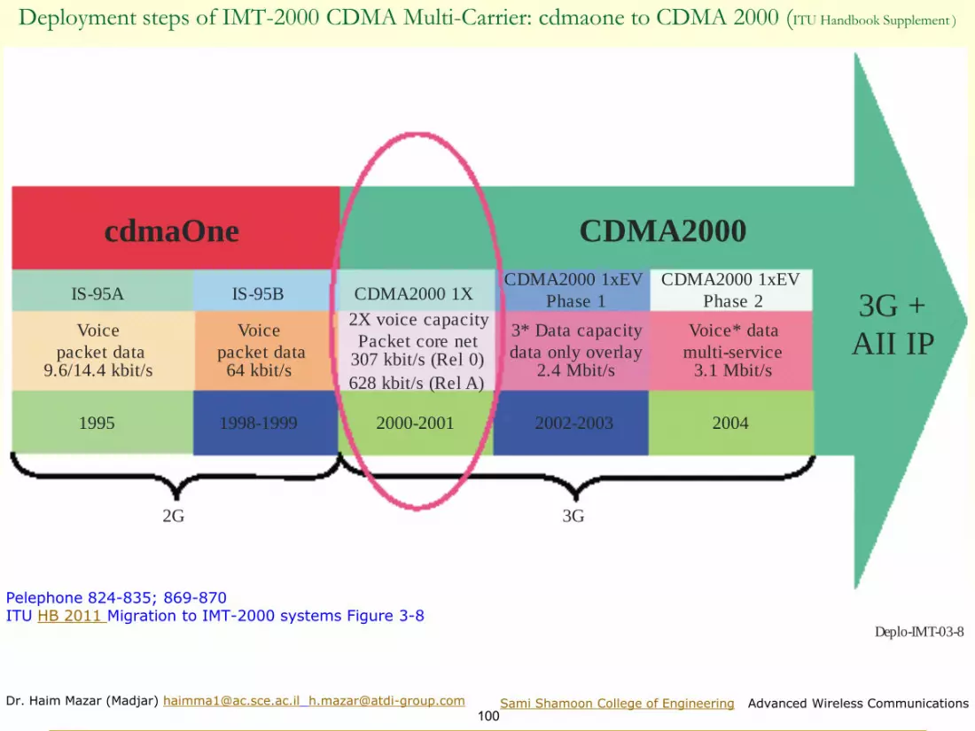
Deplo-IMT-03-8
cdmaOne CDMA2000
IS-95A IS-95B
Voice
packet data9.6/14.4 kbit/s
Voice
packet data64 kbit/s
1995 1998-1999
2X voice capacity
Packet core net307 kbit/s (Rel 0)
628 kbit/s (Rel A)
2000-2001
CDMA2000 1X
3* Data capacity
data only overlay2.4 Mbit/s
2002-2003
CDMA2000 1xEV
Phase 1
Voice* data
multi-service3.1 Mbit/s
2004
CDMA2000 1xEV
Phase 2 3G +
AII IP
2G 3G
Deployment steps of IMT-2000 CDMA Multi-Carrier: cdmaone to CDMA 2000 (ITU Handbook Supplement )
Pelephone 824-835; 869-870ITU HB 2011 Migration to IMT-2000 systems Figure 3-8

Dr. Haim Mazar (Madjar) [email protected] [email protected]
101Sami Shamoon College of Engineering Advanced Wireless Communications
CDMAIS-95A/B
1xRTTCDMA-2000
1xEV-DOIS-856
EV-DORev.A
GPRS: General Packet Radio Service
W-CDMA Wideband Code-Division Multiple Access
RTT: Radio Transmission Technology
EVDO: EVolution - Data Optimized (Data Only)
EDGE: Enhanced Data rates for Global Evolution
UMTS: Universal Mobile Telecommunications System
HSDPA: High-Speed Downlink Packet Access
HSUPA: High-Speed Uplink Packet Access
W-CDMA W-CDMA
An operator (Pelephone) evolution (Gidi)
CDMA
TDMA W-CDMA
GSMGPRS
EDGE
HSDPARelease5
W-CDMA
R.99
HSUPA
Release6
UMTS UMTS UMTS

Dr. Haim Mazar (Madjar) [email protected] [email protected]
102Sami Shamoon College of Engineering Advanced Wireless Communications
GSM 802.11b
<11Mbps
802.11a
<54 Mbps
802.11g
<54 Mbps
802.11n
<600 Mbps
802.11ac
<7 Gbps
802.11ad
cellula
r genera
tions a
nd I
ncre
asin
g d
ata
rate
s
2G
<20 k
bps
2.5
G<
100 K
bps
3G
<2.4
Mbps
3.5
G<
14.4
Mbps
3.9
<300 M
bps4
G/I
MT-
Advanced
<1 G
bps
IS-136
TDMAPDC
IS-95A
CDMA
HSCSD GPRS i-ModeIS-95B
CDMA
W-CDMA
FDD
W-CDMA
TDD
TD-
SCDMA
LCR-TDD
E-GPRS
EDGE
IS-95C
cdma2000
HSDPA/
HSUPA
FDD & TDD
EDGE
EVDO
Revisions
A & B
HSPA+ (MIMO,
Carrier Aggregation, etc.)
Release 7
LTE
FDD & TDD
Release 8
LTE-Advanced
Rel. 10 and beyond
Evolu
tion o
f W
i-Fi
802.11af
<600 Mbps
Dr. Haim Mazar (Madjar) [email protected] [email protected]
103Sami Shamoon College of Engineering Advanced Wireless Communications
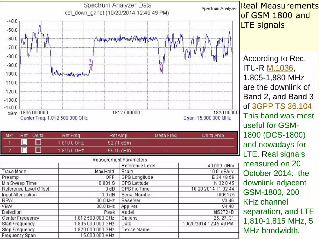
Real Measurements of GSM 1800 and LTE signals
According to Rec.
ITU-R M.1036,
1,805-1,880 MHz
are the downlink of
Band 2, and Band 3
of 3GPP TS 36.104.
This band was most
useful for GSM-
1800 (DCS-1800)
and nowadays for
LTE. Real signals
measured on 20
October 2014: the
downlink adjacent
GSM-1800, 200
KHz channel
separation, and LTE
1,810-1,815 MHz, 5
MHz bandwidth.
Dr. Haim Mazar (Madjar) [email protected] [email protected]
104Sami Shamoon College of Engineering Advanced Wireless Communications
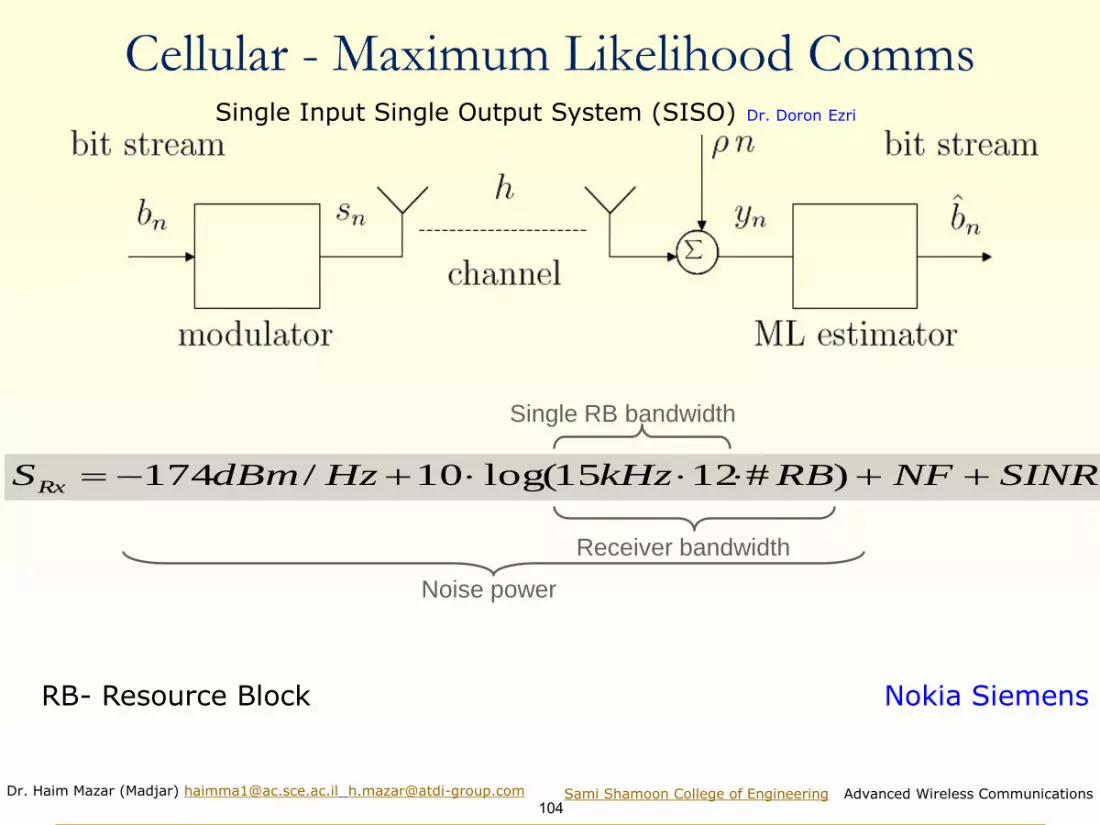
Cellular - Maximum Likelihood CommsSingle Input Single Output System (SISO) Dr. Doron Ezri
SINRNFRBkHzHzdBmSRx +++−= )#1215log(10/174
Single RB bandwidth
Receiver bandwidth
Noise power
RB- Resource Block Nokia Siemens

Dr. Haim Mazar (Madjar) [email protected] [email protected]
105Sami Shamoon College of Engineering Advanced Wireless Communications
LTE Coverage Criteria for Field Measurements & Network Planning:
Field measurement parameters❑ Terminals are measuring from serving cell:
◼ RSRP (Reference Signal Received Power)
◼ RSRQ (Reference Signal Received Quality)
❑ Scanners are measuring from all decoded cells:
◼ RSRP
◼ RSRQ
◼ Wideband channel power, RSSI (Received Signal Strength Indicator)
RSSI is common for all GSM family
◼ Primary & Secondary Synchronization Channels: P-SCH, S-SCH power
◼ Reference signal SINR
❑ System and link level simulations gives SINR thresholds for a certain
service level- MCS (Modulation and Coding Scheme) or throughput
❑ RSRP and RSRQ are more common measurements
Mapping from SINR thresholds to RSRP/RSRQ threshold needed
based on Nokia Siemens
int
signal
erference noise+

Dr. Haim Mazar (Madjar) [email protected] [email protected]
106Sami Shamoon College of Engineering Advanced Wireless Communications
RSRP & RSRQRSRP (only for LTE):
❑ RSRP is the power of a single
resource element
❑ UE measures the power of multiple
resource elements used to transfer the
reference signal but then takes an
average of them rather than summing
them.
❑ Reporting range -44…-140 dBm
◼ RSRQ:
❑ RSRQ = RSRP / (RSSI/N)
N is the number of resource blocks
over which the RSSI is measured
RSSI is wide band power, including
intracell power, interference and noise.
❑ Reporting range -3…-19.5dB
3GPP RSRP Definition: Reference signal received power (RSRP) is the linear average power over the power contributions of the resource elements that carry cell-specific reference signals within the considered measurement frequency bandwidth
3GPP RSRQ Definition:Reference Signal Received Quality (RSRQ) is the ratio N×RSRP/(E-UTRA carrier RSSI), where N is the number of RBs of the E-UTRA carrier RSSI measurement bandwidth. The measurements in the numerator and denominator shall be made over the same set of resource blocks.E-UTRA Carrier Received Signal Strength Indicator (RSSI) comprises the linear average power of the total received power observed only in OFDM symbols containing reference symbols for antenna port 0, in the measurement bandwidth, over N number of resource blocks by the UE from all sources, including co-channel serving and non-serving cells, adjacent channel interference, thermal noise etc
Nokia Siemens

Dr. Haim Mazar (Madjar) [email protected] [email protected]
107Sami Shamoon College of Engineering Advanced Wireless Communications
Mapping between RSRP, RSRQ & SINR (1/2)
RSRP vs. SNR
-15.00
-10.00
-5.00
0.00
5.00
10.00
15.00
20.00
25.00
30.00
35.00
40.00
-135 -130 -125 -120 -115 -110 -105 -100 -95 -90 -85 -80 -75 -70
RSRP (dBm)
SN
R (
dB
)SNR
_n RE
RSRPSNR
P=
• RSRP is measured for a single subcarrier
– noisepower_for_15KHz= -125.2dBm
▪ Including Noise figure UE = 7 dB
• Assumption: RSRP doesn’t contain noise power
SNR vs RSRP has a linear relation
_ 15 _ _n REP KHz noise power=
Curve gives upper limit to SINR with certain RSRP. SINR is always lower than SNR in in live network due to interference.If Interference considered the curve would move to the left -174+10*log15k+NF
RSRQ values higher than −9dB guarantee the best subscriber experience; the range between −9 and −12dB can be seen as neutral with a slight degradation of QoS; starting with RSRQ values of −13dB and lower, significant declines of throughput and a high risk of call drop; see Kreher R. and Gaenger K. 2011: p. 231
Based on Nokia Siemens

Dr. Haim Mazar (Madjar) [email protected] [email protected]
108Sami Shamoon College of Engineering Advanced Wireless Communications
Mapping between RSRP, RSRQ & SINR (2/2)
❑ RSRQ depends on own cell traffic load, but SINR doesn’t depend on own cell load
◼ Used Resource Elements per Resource Block (RE/RB) in serving cell is an input parameter for
RSRQ -> SINR mapping
◼ Assumption: RSRP doesn’t contain noise power
• Equation used:
• 2, RE/RB equals to empty cell. Only Reference Signal power is considered from serving cell.
• 12, RE/RB equals to fully loaded serving cell. All resource elements are carrying data.
1
–
2
1/
SINR
RSRQRE RB
=
RSRQ vs SINR
-10.00
-5.00
0.00
5.00
10.00
15.00
20.00
25.00
30.00
-20 -19 -18 -17 -16 -15 -14 -13 -12 -11 -10 -9 -8 -7 -6 -5 -4 -3
RSRQ (dB)
SIN
R (
dB
)
2 RE/RB
4 RE/RB
6 RE/RB
8 RE/RB
10 RE/RB
12 RE/RB
Based on Nokia Siemens

Dr. Haim Mazar (Madjar) [email protected] [email protected]
109Sami Shamoon College of Engineering Advanced Wireless Communications
Link Budget , RSSI and RSRP• LiBu provides the RSSI
◼ RSSI = wideband power= noise + serving cell power + interference power
◼ RSSI at the cell edge is the Rx Sensitivity
❑ RSSI=12*N*RSRP
◼ RSRP is the received power of 1 RE (3GPP definition) average of power levels received
across all Reference Signal symbols within the considered measurement frequency
bandwidth
◼ RSSI per resource block is measured over 12 resource elements (100% of the power is
considered i.e. 43dBm)
◼ N: number of RBs across the RSSI is measured and depends on the BW
❑ Based on the above under full load and high SNR (Note: In lab conditions it is possible to
know the load not in real networks.):
If we keep these other factors equal: RF, the same data rate, penetration loss: maxi
ranges of LTE and 3G are very similar
RSRP (dBm)= RSSI (dBm) -10*log (12*N)
Based on Nokia Siemens

Dr. Haim Mazar (Madjar) [email protected] [email protected]
110Sami Shamoon College of Engineering Advanced Wireless Communications
M.1073-01
EIR
MSC
AUC
HLR
BS
VLR
OMC
MSC
Fixed
networks
PDNSPSTNISDN
Interfacewith the fixed networks
AUC: BS:EIR: HLR:
MS: MSC: OMC:
VLR:
Radiointerface
Physical connection
Logical relationships
authentication centrebase stationequipment identity register
home location registermobile station
mobile services switching centreoperation and maintenance centrevisitor location register
MS
MS
Network architecture (Rec. ITU-R M.1073) (2012)
Basic system architecture for cellular systems. The communication protocols are specified according to the 7-layer OSI model, while the interfaces between mobile switching centres (MSCs) and the interfaces to the ISDN, PSTN and PDN are all specified according to ITU-T Recs. The numbering plan also follows ITU-T Recs

Dr. Haim Mazar (Madjar) [email protected] [email protected]
111Sami Shamoon College of Engineering Advanced Wireless Communications
ITU Handbook Supplement 1 (revision 1) Deployment of IMT-2000 Systems
IMT-2000 Terrestrial Radio Interfaces: External Organizations
Deplo-IMT-05
IMT-2000 terrestrialradio interfaces
IMT-2000CDMA
direct spread
IMT-2000CDMA
multi-carrier
IMT-2000CDMATDD
IMT-2000TDMA
single carrier
IMT-2000FDMA/TDMA
IMT-2000OFDMA TDD
WMAN
WCDMA(UMTS)
CDMA20001X and 3X
UTRA TDDand TD-SCDMA
UWC-136/EDGE
DECT WiMAX
Full Name Common Names External
Organizations
IMT-2000 CDMA Direct Spread UTRA FDD, WCDMA, UMTS 3GPP
IMT-2000 CDMA Multi-Carrier CDMA2000 1x and 3x, CDMA2000 EV-DO 3GPP2
IMT-2000 CDMA TDD (time-code) UTRA TDD 3.84 mchip/s high chip rate, UTRA TDD
1.28 mchip/s low chip rate, TD-SCDMA, UMTS
3GPP
IMT-2000 TDMA Single-Carrier UWC-136, EDGE, GERAN ATIS WTSC and
TIA
IMT-2000 FDMA/TDMA
(frequency-time)
DECT ETSI
IMT-2000 OFDMA TDD WMAN WiMAX, WirelessMAN-OFDMA IEEE

Dr. Haim Mazar (Madjar) [email protected] [email protected]
112Sami Shamoon College of Engineering Advanced Wireless Communications
internet
eNB
RB Control
Connection Mobility Cont.
eNB Measurement
Configuration & Provision
Dynamic Resource
Allocation (Scheduler)
PDCP
PHY
MME
S-GW
S1
MAC
Inter Cell RRM
Radio Admission Control
RLC
E-UTRAN EPC
RRC
Mobility
Anchoring
SAE Bearer Control
Idle State Mobility
Handling
NAS Security
P-GW
UE IP address
allocation
Packet Filtering
Overall architecture of the E-UTRAN radio access network (M.1457)
yellow boxes depict the logical nodes, white boxes depict the functional entities of the
control plane and blue boxes depict the radio protocol layers

Dr. Haim Mazar (Madjar) [email protected] [email protected]
113Sami Shamoon College of Engineering Advanced Wireless Communications
UMTS Radio Access Network architecture M.1457 2019
Cells are indicated by ellipses
Dr. Haim Mazar (Madjar) [email protected] [email protected]
114Sami Shamoon College of Engineering Advanced Wireless Communications
Shared
Channel
Elements
TRX
Op 2
TRX
Op 1
Shared PartsPower, Airco, Cabinet, Alarm,…
AT
M tr
ansm
.
PA
Op 2
PA
Op 1
XXXX
XXXX
Shared
RNC
Shared Iub
Shared
RNC
Iur
Node-BNode-B
Node-B
Core
Op 2
Core
Op 1
OMC-R
Shared
OMC-R
Op 1
OMC-R
Op 2
Node-B
Antenna Op 2
Antenna
Op1
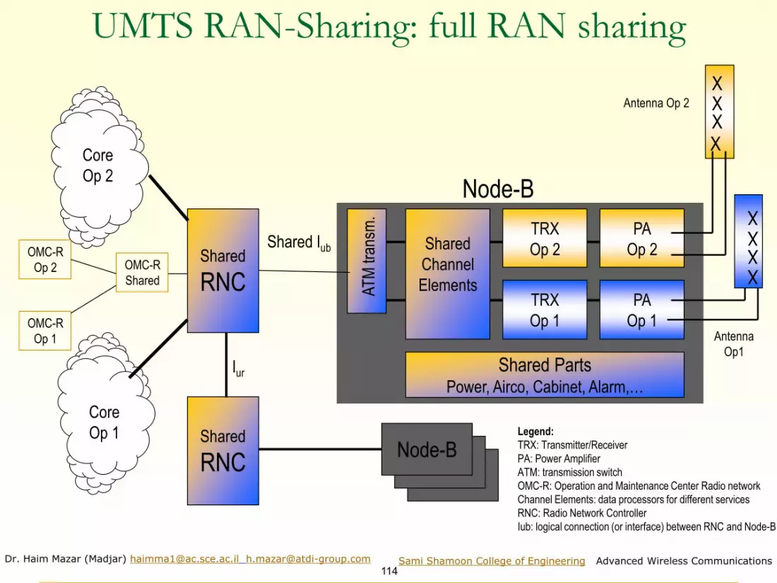
UMTS RAN-Sharing: full RAN sharing
Legend:
TRX: Transmitter/Receiver
PA: Power Amplifier
ATM: transmission switch
OMC-R: Operation and Maintenance Center Radio network
Channel Elements: data processors for different services
RNC: Radio Network Controller
Iub: logical connection (or interface) between RNC and Node-B

Dr. Haim Mazar (Madjar) [email protected] [email protected]
115Sami Shamoon College of Engineering Advanced Wireless Communications
BSCGSM
UMTSRNC
LTE
BSS& DBs
PSTN
Voice Core
OSS
MSC
HLRAuCEIR
STP/GMSC
Internet& SPs
Packet Core
GGSN
SGSN
Services&Service Control
MGW
-S
IMS
PCRF
/PDG
/MME
HSS
Billing
CRM, BI
Core Network
Access
3G-4G Cellular Architecture
Prepared by Partner

Dr. Haim Mazar (Madjar) [email protected] [email protected]
116Sami Shamoon College of Engineering Advanced Wireless Communications
Cellular subsystems
TerminalEquipment
Access
Aggregation
Core
ServicesEnablers
Internet& SPs
Content & Services PSTN
…
Backbone
Switching
Management
microwave
SMSC MPS IN, PP
StreamingServer
PhysicalInfra
Edge
BSS
MPLS CoreRouter
MSC
SGSN/MME
GGSN/PGw
IMS
GMSC
HLR/HSSIR
MGw
CUDB
Int’l
ATM Switch
RNC
IP/MPLSEdge Router
TDMx-connect
BSC
sharing
Prepared by Partner

Dr. Haim Mazar (Madjar) [email protected] [email protected]
117Sami Shamoon College of Engineering Advanced Wireless Communications
Active network Sharing,
MOCN (Multi-Operator Core Network)
SGSN/MME
GGSN/PGW
HLR/HSS
RF
Data
GGSN/PGW
HLR/HSS
RNC
UMTS
LTE
MGW
DataVoice
MGW
Voice
SGSN/MME
Data
Prepared by Partner

Dr. Haim Mazar (Madjar) [email protected] [email protected]
118Sami Shamoon College of Engineering Advanced Wireless Communications

Dr. Haim Mazar (Madjar) [email protected] [email protected]
119Sami Shamoon College of Engineering Advanced Wireless Communications

Dr. Haim Mazar (Madjar) [email protected] [email protected]
120Sami Shamoon College of Engineering Advanced Wireless Communications
100 Mbps
2010
2012
2013
20 MHz2x2 MIMO
150 Mbps
20 MHz2x2 MIMO
150 Mbps
10+10 MHz2x2 MIMO
LTE-Advanced Peak Data Rate Evolution
• Initial devices 100 Mbps (Cat 3) with contiguous 20 MHz
• Currently devices 150 Mbps (Cat 4) with contiguous 20 MHz
• 150 Mbps with 10 + 10 MHz carrier aggregation 2013
• 300 Mbps with 20 + 20 MHz starting 2014
• 3CA and 60 MHz combinations under work in 3GPP
2014
2015+
300 Mbps
20+20 MHz2x2 MIMO
>1 Gbps
40+ MHz4x4 / 8x8
MIMO
Source Shalev

Dr. Haim Mazar (Madjar) [email protected] [email protected]
121Sami Shamoon College of Engineering Advanced Wireless Communications
Authorized Shared Access (ASA) for dynamic use of
underutilized spectrum
Efficient use of fragmented spectrum by carrier-aggregation
More Capacity - more spectrum needed
Intra-band contiguous
Inter-band carrier aggregation
Intra-band non-contiguous
2.1
GH
z
2.3
GH
z
2.4
GH
z
2.6
GH
z
3.6
GH
z
3.8
GH
z
Unlicensed
ASA controller
ASA repository
ASA ASA
LicensedLicensedCarrier
aggregation across small and
large cell layer for mobility support
Source Shalev

Dr. Haim Mazar (Madjar) [email protected] [email protected]
122Sami Shamoon College of Engineering Advanced Wireless Communications
LTE- advanced: Radio-access network interfaces
Figure 1 ITU-R Rec. M.2012 (2019)

Dr. Haim Mazar (Madjar) [email protected] [email protected]
123Sami Shamoon College of Engineering Advanced Wireless Communications
LTE simplifies network architecture
LTE brings a new capability to mobility: Ofcom report November 2013
LTE networks are simpler and work with fewer components compared to 3G. This removes interactivity and also results in lower latencies.
Source: Ofcom

Dr. Haim Mazar (Madjar) [email protected] [email protected]
124Sami Shamoon College of Engineering Advanced Wireless Communications
Headline speed by technology generation
LTE brings a new capability to mobility: Ofcom report November 2013
Source: Ofcom

Dr. Haim Mazar (Madjar) [email protected] [email protected]
125Sami Shamoon College of Engineering Advanced Wireless Communications
◼ Network is responsible for all radio-related functions in one or
several cells
◼ LTE-Advanced radio-access network has a flat architecture with
a single type of node
◼ eNodeB is a conventional BS wirelessly backhauled to the
remaining part of the network
◼ eNodeB is connected to the serving gateway (S-GW) by means
of the S1 interface: to the user by S1-u, and to the Mobility
Management Entity (MME) by S1-c. To share load and for
redundancy, one eNodeB can interface with multiple MMEs/S-
GWs
◼ The X2 interface connects eNodeBs to each other, to support
active-mode mobility and multi-cell Radio Resource
Management (RRM) functions such as Inter-Cell Interference
Coordination (ICIC)
LTE- advanced: network architecture interfaces
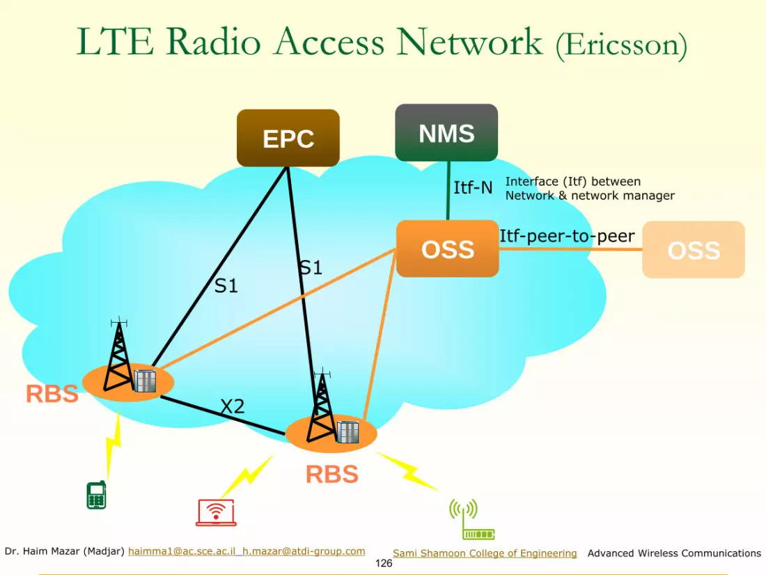
Dr. Haim Mazar (Madjar) [email protected] [email protected]
126Sami Shamoon College of Engineering Advanced Wireless Communications
LTE Radio Access Network (Ericsson)
OSS
EPC NMS
RBS
RBS
S1S1
Itf-N
X2
Itf-peer-to-peerOSS
Interface (Itf) between Network & network manager

Dr. Haim Mazar (Madjar) [email protected] [email protected]
127Sami Shamoon College of Engineering Advanced Wireless Communications
Key LTE radio access features (Ericsson, 2010)
Radio Access • Downlink: OFDM • Uplink: SC-FDMA
SC-FDMA
OFDMA
Advanced antenna solutions• Diversity• Multi-layer transmission (MIMO)• Beam-forming
TX TX
Spectrum flexibility• Flexible bandwidth• New and existing bands• Duplex flexibility: FDD and TDD
20 MHz1.4 MHz

Dr. Haim Mazar (Madjar) [email protected] [email protected]
128Sami Shamoon College of Engineering Advanced Wireless Communications
LTE parameters need to be dimensioned & optimized (CelPlan)
◼ WEBINAR 5 - PART 1 : What LTE parameters need to be Dimensioned and Optimized
◼ WEBINAR 5 - PART 2 : What LTE parameters need to be Dimensioned and Optimized
http://www.mpirical.com/courses
Additional courses
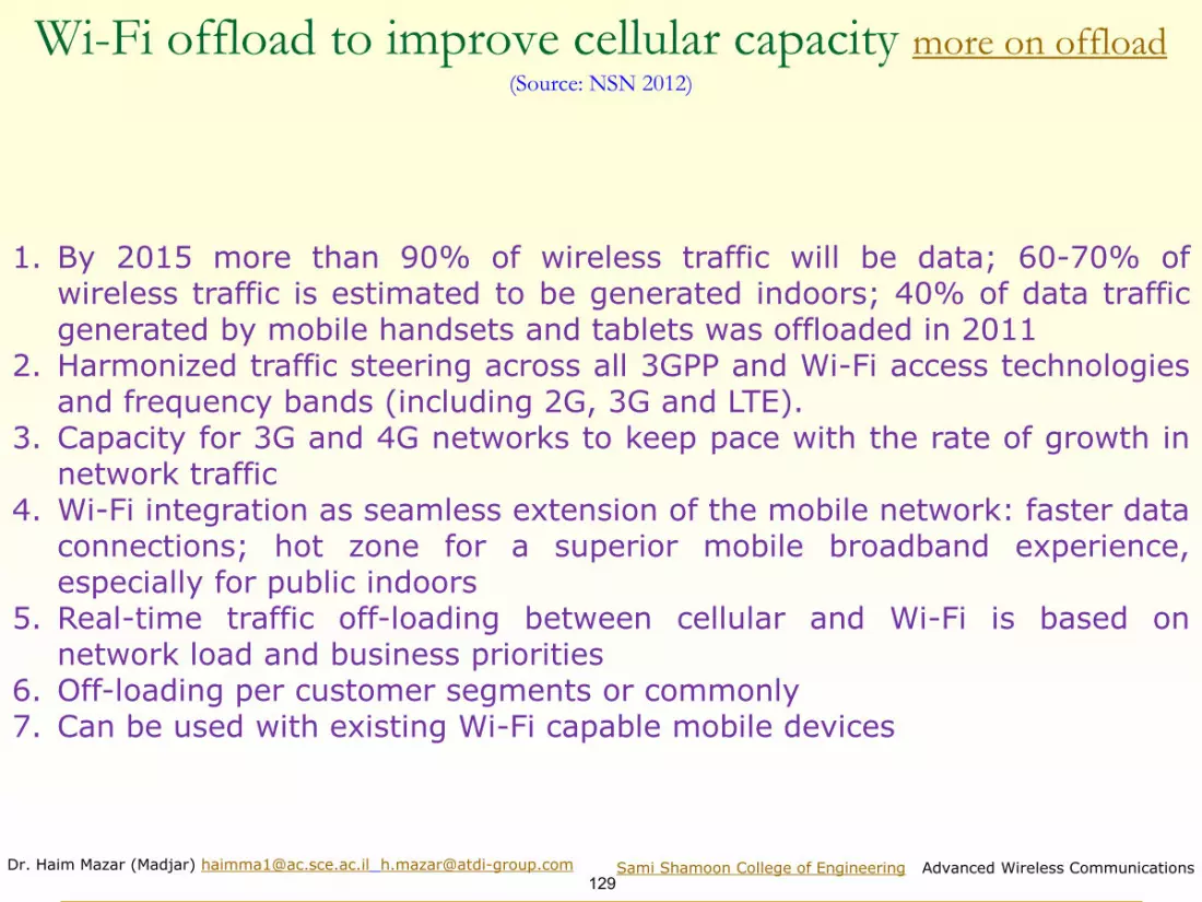
Dr. Haim Mazar (Madjar) [email protected] [email protected]
129Sami Shamoon College of Engineering Advanced Wireless Communications
Wi-Fi offload to improve cellular capacity more on offload (Source: NSN 2012)
1. By 2015 more than 90% of wireless traffic will be data; 60-70% ofwireless traffic is estimated to be generated indoors; 40% of data trafficgenerated by mobile handsets and tablets was offloaded in 2011
2. Harmonized traffic steering across all 3GPP and Wi-Fi access technologiesand frequency bands (including 2G, 3G and LTE).
3. Capacity for 3G and 4G networks to keep pace with the rate of growth innetwork traffic
4. Wi-Fi integration as seamless extension of the mobile network: faster dataconnections; hot zone for a superior mobile broadband experience,especially for public indoors
5. Real-time traffic off-loading between cellular and Wi-Fi is based onnetwork load and business priorities
6. Off-loading per customer segments or commonly7. Can be used with existing Wi-Fi capable mobile devices

Dr. Haim Mazar (Madjar) [email protected] [email protected]
130Sami Shamoon College of Engineering Advanced Wireless Communications
Example of sub network structure for BS access using sub-star & chains of FS links

Dr. Haim Mazar (Madjar) [email protected] [email protected]
131Sami Shamoon College of Engineering Advanced Wireless Communications
General overview of an IMT-2000 network

Dr. Haim Mazar (Madjar) [email protected] [email protected]
132Sami Shamoon College of Engineering Advanced Wireless Communications
ISDN integrated services digital network
MAP mobile application part
MGCF media gateway control function
MMS multimedia message service
MSC mobile switching centre
MT mobile terminal
MVNO mobile virtual network operator
NPV net present value
OPEX operational expenditure
PCF packet controller function
PDC personal digital cellular
PDSN packet data serving node
PDSN public data switched network
PS packet switching
PSTN public switched telephone network
RAN radio access network
RNS radio network system
SDMA space division multiple access
SDO standard development organization
SGSN serving GPRS support node
SIM subscriber identification module
SCDMA synchronous code-division multiple access
TD-
CDMA
time division-code division multiple access
TDD time division duplexing
TDMA time-division multiple access
TD-
SCDMA
time-division synchronous code-division multiple access
UIM user identity module
UMTS universal mobile telecommunication system
UTRA UMTS terrestrial radio access
UTRAN UMTS terrestrial radio access network
VNO virtual network operator
VoIP voice over IPWCDMA Wideband code division multiple access
WiMAX worldwide interoperability for microwave access.
1G first generation
2G second generation
3G third generation
3GPP third Generation Partnership Project
3GPP2 third Generation Partnership Project 2
ANSI American National Standard Institute
ARPU average revenue per user
ATM asynchronous transfer mode
CAPEX capital expenditure
CDMA code-division multiple access
CEPT European Conference of Postal and
Telecommunications Administrations
CITEL Comision Interamericana de Telecomunicaciones
CN core network
CS circuit switching
CSCF call session control function
DECT digitally enhanced cordless telecommunications
EBIT earnings before interest and taxes
EBITDA earnings before interest and taxes, depreciation and
amortization
EDGE enhanced data rates for global evolution
EDGE
DO
EDGE data only
ETSI European Telecommunication Standards Institute
FDD frequency division multiplexing
GERAN GSM EDGE radio access network
GGSN gateway GPRS support node
GPRS general packet radio service
GSM global system for mobile communications
HA home agent
HLR home location register
HSDPA high speed downlink packet access
IMS IP multimedia subsystem
IMT International mobile telecommunication
IP Internet protocol
Abbreviations

Dr. Haim Mazar (Madjar) [email protected] [email protected] Sami Shamoon College of Engineering, Advanced Wireless Communications
133
Advanced Wireless Communications, 2020
Academic course for 4th year engineering students
Fixed Service
Dr. Haim Mazar (Madjar), reelected vice-chair (VC) ITU-Radio Study Group 5(terrestrial services). Vice Chair Working Party 5C (Fixed Service)

Dr. Haim Mazar (Madjar) [email protected] [email protected]
134Sami Shamoon College of Engineering Advanced Wireless Communications
Evolution & current state of Fixed Services technology: Basics1. ITU Radio Regulations (RR 1.120) defines fixed service
as: ”A radiocommunication service between specified fixed points
2. Physical network supporting the end-to-end path is optical fibre, copper, radio relay or satellite
3. µwave remains (time to market, flexibility), fiber (capacity & distance) increases and copper (distance, availability) decreases
4. Nominal voice-grade bandwidth is limited to 4 kHz; sampled at 8 kHz (twice the highest frequency), quantization of 8 bits per sample, the fundamental standard for uncompressed digitized voice (narrow band channel) is 64 kbps (8 kHz x 8 bits)
5. Data rate of E1 is 2.048 M bits/second: 32 ch. of 64 Kbps6. Each byte of STM-1 (Synchronous Transport Module level-1)
corresponds to a 64kbit/s channel. STM-1 frame is the basic transmission format for SDH (Synchronous Digital Hierarchy)

Dr. Haim Mazar (Madjar) [email protected] [email protected]
135Sami Shamoon College of Engineering Advanced Wireless Communications
Evolution of Fixed Services technology (2)
1. Mobile Wireless Access implemented by IMT (LTE)2. Time-division multiplexing (TDM) migrates to packet- mode3. Increased capacity due to higher RF bandwidth and higher
modulation schemes with retained availability4. Adaptive and Agile: Modulation 4–1024QAM, Capacity,
Transport technology5. Multiple radios technique; 4X4 MIMO (Multiple-Input and
Multiple-Output)6. Today reuse of channels 80; tomorrow up to 150 (using
narrow beam class 4 antennas)7. Higher RF: 6L, 6U, 7, 8, 10, 11, 13, 15, 18, 23, 26, 28, 32,
38, 42, 60, 70/80 GHz (E band)8. Today: 7, 14, 28MHz, 56MHz ch. channels; tomorrow 112,
224…MHz ch.9. Increases capacity: today Bandwidth: up to 10 Gbps @
70/80 GHz band; tomorrow Bandwidth: up to 40 Gbps

Dr. Haim Mazar (Madjar) [email protected] [email protected]
136Sami Shamoon College of Engineering Advanced Wireless Communications
Rural, Urban and Suburban FS macro cells and small cells
Report ITU F.2086 (2010)P-MP system with anomnidirectional AccessPoint (AP) antenna ismainly deployed fordetached houses scatteringin a service area. Theservice area (last mile orfirst mile) radius isapproximately 1 km, whichdepends on serviceavailability objective andregional rain conditions. AP-MP system is also appliedto a multi-dwelling buildingwhich is not equipped withavailable wiring ducts inurban areas. A hornantenna is implemented insuch multi-dwellingbuildings. Multiple IP-baseduser terminals, such asPCs, can be accommodatedby Wireless Terminal (WT)

Dr. Haim Mazar (Madjar) [email protected] [email protected]
137Sami Shamoon College of Engineering Advanced Wireless Communications
Rep F.2086: Point to Point deployment topology
In P-P systems, traffic is transmitted directly from one station to another. Uses for P-P systems also include backhaul links for Local Area Network (LAN), Metropolitan Area Network (MAN), and cellular mobile networks

Dr. Haim Mazar (Madjar) [email protected] [email protected]
138Sami Shamoon College of Engineering Advanced Wireless Communications
Illustrating network deployment configuration based on P-MP configuration

Dr. Haim Mazar (Madjar) [email protected] [email protected]
139Sami Shamoon College of Engineering Advanced Wireless Communications
Fronthaul and backhaul operation to be used for mobile system networkRep. ITU-R F.2416 (2018) Fig. 3

Dr. Haim Mazar (Madjar) [email protected] [email protected]
140Sami Shamoon College of Engineering Advanced Wireless Communications
FS frequency bands for harmonised channel arrangement Source: ECC Newsletter May 2020 Fig 2 Quo Vadis?
Fixed Service evolves towards more efficient spectrum use

Dr. Haim Mazar (Madjar) [email protected] [email protected]
141Sami Shamoon College of Engineering Advanced Wireless Communications
Trends for the use of FS in the E-band (Source: ETSI White Paper No. 25, Microwave and
Millimetre-wave for 5G Transport; (Fig 5 Quo Vadis? Fixed Service evolves towards more efficient spectrum use)

Dr. Haim Mazar (Madjar) [email protected] [email protected]
142Sami Shamoon College of Engineering Advanced Wireless Communications
C/N versus bandwidth for signal transmissionRep. F.2416 (2018) Fig. 8

Dr. Haim Mazar (Madjar) [email protected] [email protected]
143Sami Shamoon College of Engineering Advanced Wireless Communications
C/N versus distance of 300-GHz wireless linkRep. F.2416 (2018) Fig. 9

Dr. Haim Mazar (Madjar) [email protected] [email protected]
144Sami Shamoon College of Engineering Advanced Wireless Communications
Acronyms and Abbreviations BRAN Broadband radio access network (ETSI)
BBU Base Band Unit
BS Base station
BWA Broadband wireless access
FDD Frequency division duplex
FWA Fixed wireless access
ISP Internet service providers
LAN Local area network
LoS Line-of-sight
MIMO Multiple input multiple output
MPEG4 Moving Picture Experts Group 4
MP-MP Multipoint-to-multipoint
NLOS Non-line-of-sight
P-P Point-to-point
P-MP Point-to-multipoint
QoS Quality of service
RLAN Radio local area network
RRH Remote radio head
SDH Synchronous digital hierarchy
SME Small medium enterprise
SOHO Small office home office
ST Subscriber terminal
SU Subscriber unit
TCP/IP Transmission control protocol/Internet protocol
TDD Time division duplex
VoIP Voice over Internet protocol
WAN Wide area network
WAS Wireless access systems

Dr. Haim Mazar (Madjar) [email protected] [email protected]
145Sami Shamoon College of Engineering Advanced Wireless Communications
Rep F.2086: Combination P-P, P-MP & MP-MP deployment topology
Enclosed a mix topology: the wireless network may have both P-MP and MP-MP links and the BS supporting its Subscriber Unit may be connected to the other networks via backbone network
Figure 5: Illustration of network deployment based on combination P-P, P-MP & MP-MP configuration

Dr. Haim Mazar (Madjar) [email protected] [email protected]
146Sami Shamoon College of Engineering Advanced Wireless Communications
3D terrain: left 1-way P2P, right P2MPSource: FMS program, 2013

Dr. Haim Mazar (Madjar) [email protected] [email protected]
147Sami Shamoon College of Engineering Advanced Wireless Communications
Microwave links 2-15 GHz around one Hungarian lake Source: FMS program, 2013
Central station is at top of the mountain
3D: the central station is the biggest red column
2-D
3-D

Dr. Haim Mazar (Madjar) [email protected] [email protected]
148Sami Shamoon College of Engineering Advanced Wireless Communications
LoS and NLoS FS links: RF, obstacles, attenuation by
atmospheric gases; distances
◼ Ionosphere, tropospheric, trans-horizon, diffraction and Line-of
–Sight paths
◼ If no topographical or man made obstacles (smooth earth), the
earth curvature is the limit of LoS links
◼ Fixed Wireless Systems (FWS) operating in lower RF profit
from the enhanced propagation range, relative to higher
frequencies deployment
◼ RF: below 6 GHz for NLoS; above 6 GHz for LoS
◼ Distance, obscuring buildings, attenuation by atmospheric
gases
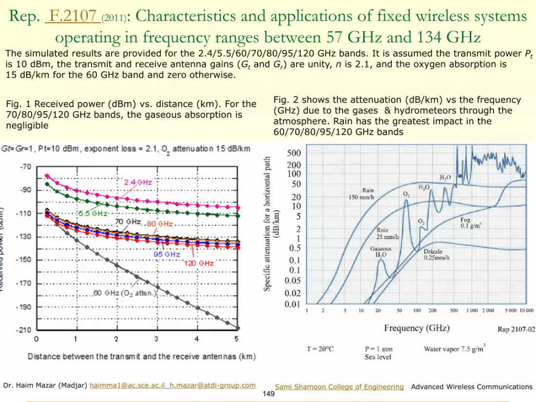
Dr. Haim Mazar (Madjar) [email protected] [email protected]
149Sami Shamoon College of Engineering Advanced Wireless Communications
Rep. F.2107 (2011): Characteristics and applications of fixed wireless systems
operating in frequency ranges between 57 GHz and 134 GHz
Fig. 1 Received power (dBm) vs. distance (km). For the 70/80/95/120 GHz bands, the gaseous absorption is negligible
Fig. 2 shows the attenuation (dB/km) vs the frequency (GHz) due to the gases & hydrometeors through the atmosphere. Rain has the greatest impact in the 60/70/80/95/120 GHz bands
The simulated results are provided for the 2.4/5.5/60/70/80/95/120 GHz bands. It is assumed the transmit power Pt
is 10 dBm, the transmit and receive antenna gains (Gt and Gr) are unity, n is 2.1, and the oxygen absorption is 15 dB/km for the 60 GHz band and zero otherwise.

Dr. Haim Mazar (Madjar) [email protected] [email protected]
150Sami Shamoon College of Engineering Advanced Wireless Communications
Lower RF→ higher range, less attenuation by obstacles & gases
PL=Propagation Loss; d=distance, λ=wavelength
Lower RF offers lower PL at free-space and non free-space prop.
The ability to cross obstacles is better at lower RF
Attenuation by obstacles depends on λ, relative to obstacle
PL= 20 log (4πd/ λ) ; f (MHz)= 300/ λ (m)
At f > 15 GHz λ <2 cm rain drops, dust & vapor attenuate the wireless signal
In general, above 6 GHz, if there is no optical Line of Sight, there is no electromagnetic propagation
Relevant meteorological information concerning the propagation mechanisms is given Recs ITU-R P.676 and P.834
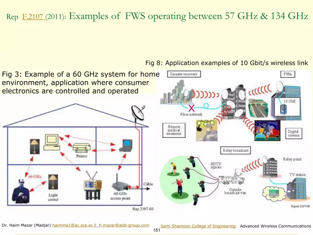
Dr. Haim Mazar (Madjar) [email protected] [email protected]
151Sami Shamoon College of Engineering Advanced Wireless Communications
Rep F.2107 (2011): Examples of FWS operating between 57 GHz & 134 GHz
Fig 3: Example of a 60 GHz system for home environment, application where consumer electronics are controlled and operated
Fig 8: Application examples of 10 Gbit/s wireless link

Dr. Haim Mazar (Madjar) [email protected] [email protected]
152Sami Shamoon College of Engineering Advanced Wireless Communications
ITU Report F.2416: Technical and operational characteristics and applications of the
point-to-point fixed service applications operating in the frequency band 275-450 GHz
(2018)
100 200 300 400 500 600 700 800 900 1000
Frequency (GHz)
10-1
1
10
102
103
104
105
106
Att
enu
atio
n c
oef
fici
ent
(dB
/km
)
Attenuation coefficient in the frequency range 100-1 000 GHz (dashed line indicates attenuation coefficient highest peak of 60 GHz band)

Dr. Haim Mazar (Madjar) [email protected] [email protected]
153Sami Shamoon College of Engineering Advanced Wireless Communications
ITU Report F.2416: Attenuation from atmospheric gases and rain
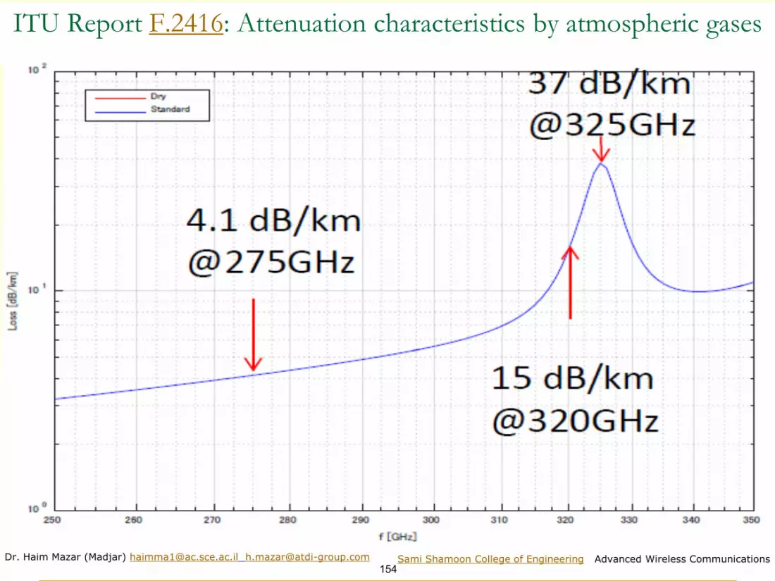
Dr. Haim Mazar (Madjar) [email protected] [email protected]
154Sami Shamoon College of Engineering Advanced Wireless Communications
ITU Report F.2416: Attenuation characteristics by atmospheric gases
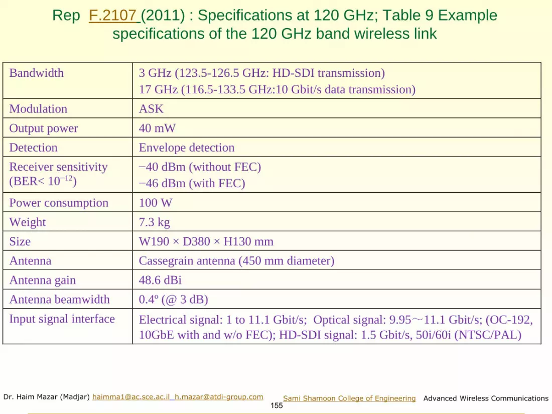
Dr. Haim Mazar (Madjar) [email protected] [email protected]
155Sami Shamoon College of Engineering Advanced Wireless Communications
Rep F.2107 (2011) : Specifications at 120 GHz; Table 9 Example
specifications of the 120 GHz band wireless link
Bandwidth 3 GHz (123.5-126.5 GHz: HD-SDI transmission)
17 GHz (116.5-133.5 GHz:10 Gbit/s data transmission)
Modulation ASK
Output power 40 mW
Detection Envelope detection
Receiver sensitivity
(BER< 10−12)
−40 dBm (without FEC)
−46 dBm (with FEC)
Power consumption 100 W
Weight 7.3 kg
Size W190 × D380 × H130 mm
Antenna Cassegrain antenna (450 mm diameter)
Antenna gain 48.6 dBi
Antenna beamwidth 0.4º (@ 3 dB)
Input signal interface Electrical signal: 1 to 11.1 Gbit/s; Optical signal: 9.95~11.1 Gbit/s; (OC-192,
10GbE with and w/o FEC); HD-SDI signal: 1.5 Gbit/s, 50i/60i (NTSC/PAL)

Dr. Haim Mazar (Madjar) [email protected] [email protected]
156Sami Shamoon College of Engineering Advanced Wireless Communications
Applications & examples; distance & bandwidth1. Ethernet capacities, up to 1 Gbps per Ethernet connection 2. TDM capacities: E1’s and STM-13. Up to 56MHz channels4. Modulation agile 4QAM- 1024QAM5. Link quality
1) Up to 50 km hop length with 99.999% availability2) Actual deployments of up to 80 km
Photograph of the P2P wireless equipment

Dr. Haim Mazar (Madjar) [email protected] [email protected]
157Sami Shamoon College of Engineering Advanced Wireless Communications
Report F.2060(2006) T.4: Capacity of fixed wireless links according to bandwidth & modulation
Bandwidth
(MHz)
Capacity (Mbit/s)
2 × 2 8 2 × 8 34 51 155 2 x 155
3.5 4 states 16 states
7 4 states 16
states
13.75, 14 4 states 16 states 32 states
27.5, 28, 29.65 4 states 16 states 128 states 128 states (CCDP)
40 64 states 64 states (CCDP)
55, 56 16 states 16 states (CCDP)
CCDP: Co-channel dual polarized
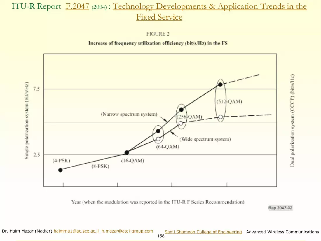
Dr. Haim Mazar (Madjar) [email protected] [email protected]
158Sami Shamoon College of Engineering Advanced Wireless Communications
ITU-R Report F.2047 (2004) : Technology Developments & Application Trends in the
Fixed Service

Dr. Haim Mazar (Madjar) [email protected] [email protected]
159Sami Shamoon College of Engineering Advanced Wireless Communications
Rec. ITU-R F.1610 2003 Planning, Design & Implementation, HF FS
Table 2: Desired take-off angles and best heights for layer 1F2
The height (in wavelengths) of the antenna above the ground generally determines the elevation angle of radiation. The optimum angle depends on the effective height of the ionosphere and the distance to the other stationHeight above ground (wavelengths) is related in some way reciprocally to the ‘antenna factor’
Distance
(km)
Take-off angle
(degrees)
Height above ground
(wavelengths)
200 60-75 0.28
400 45-65 0.33
800 30-45 0.42
1 200 20-35 0.55
1 600 15-25 0.72

Dr. Haim Mazar (Madjar) [email protected] [email protected]
160Sami Shamoon College of Engineering Advanced Wireless Communications
Channel Arrangements (CA) and BlocksRF Band Rec ITU-R RF Band Rec ITU-R
1 406.1-450 MHz F.1567 14 10.0-10.68 GHz F.747
2 1 350 -1 530 MHz F.1242 15 blocks at 10.15-10.3/10.5-10.65 GHz F.15683 1 350-2 690 MHz F.701 16 10.7-11.7 GHz F.3874 1 900-2 300 MHz F.1098 17 14.4-15.35 GHz F.636
5 2 290-2 670 MHz F.1243 18 17.7-19.7 GHz F.595
6 2 and 4 GHz F.382 19 21.2-23.6 GHz F.6377 blocks @ 3 400-3 800 MHz F.1488 20 25, 26 & 28 GHz F.7488 3 400-4 200 MHz F.635 21 31.8-33.4 GHz F.15209 4 400-5 000 MHz F.1099 22 36-40.5 GHz F.749
10 5 925 - 6 425 MHz F.383 23 CA & blocks at 40.5-43.5 GHz F.200511 6 425-7 125 MHz F.384 24 51.4-52.6 GHz F.149612 7 110-7 900 MHz F.385 25 CA & blocks @ 71-76 & 81-86 GHz F.2006
13 7 725-8 500 MHz F.386 26 92-95 GHz F.2004

Dr. Haim Mazar (Madjar) [email protected] [email protected]
161Sami Shamoon College of Engineering Advanced Wireless Communications
Report F.2060 (2006): Block Assignment Scenarios, with and without Guard Band
With guard band

Dr. Haim Mazar (Madjar) [email protected] [email protected]
162Sami Shamoon College of Engineering Advanced Wireless Communications
Interleaved assignment without guard band (cont.)
Report F.2060 (2006): Block Assignment Scenarios, with and without guard band

Dr. Haim Mazar (Madjar) [email protected] [email protected]
163Sami Shamoon College of Engineering Advanced Wireless Communications
Link budget point-to-point logarithmically and numerically
Inserting the free-space propagation loss d (km) and f (GHz) to the received signal:
Pr= Pt + Gt – Lt– Pl+ Gr- Lr= Pt+ Gt– Lt + Gr– Lr– 92.45– 20 log d (km) – 20 log f (GHz)
e.g., for a point-to-point system, distanced d 40 km, operating at 7,500 MHz (λ
wavelength 0.04 m), transmitting 2 Watts (33 dBm), 44.5 dBi (28,000) gains for
transmitting and receiving antennas, 1 dB (1.25) cable losses at transmitter and
receiver, assuming free-space loss (4πd/λ)2 , equivalent to 20 log (4πd/λ):
pr= = 6.35 10-6 Watts
In logarithmic expressions, for free-space loss:
Pr= 22+ 20log (40,000/0.04)= 22+ 120= 142 dB and Pr = 33+ 44.5– 1– 142+ 44.5– 1= –22 dBm
Multipath fading is taken into account to guarantee performance of fixed wireless systems
Fading countermeasure is usually expressed in terms of an improvement factor (IF). IF is the ratio
of the outage time observed for a system without the countermeasure, to that observed when the
countermeasure is operative Outage time indicates the time duration over which the system
exceeds a chosen bit-error ratio (BER) threshold
2
2 28,000 28,000
(4 40,000 0.04) 1.25 1.25

Dr. Haim Mazar (Madjar) [email protected] [email protected]
164Sami Shamoon College of Engineering Advanced Wireless Communications
Fade Margin
FM = Pr – Pr,min
or:
◼ FM = Ge + Gr + Pe – LT(p) – FL – Pr,min
◼ FM: fade margin
◼ Pe: input power at the emission (transmitter power) (dBm)
◼ LT(p): total loss (rain at p%, gas, diffraction) (dB)
◼ FL: feeder loss (total: at the emission and reception) (dB)
◼ Pr,min: min. level at the reception (usually for BER of 10–6) (dBm)
◼ Ge: antenna gain at the emission (transmitter) (dBi)
◼ Gr: antenna gain at the reception (receiver) (dBi).
If only P-P FS systems are considered, in the following calculation usually
Ge = Gr = G.

Dr. Haim Mazar (Madjar) [email protected] [email protected]
165Sami Shamoon College of Engineering Advanced Wireless Communications
Sharing Scenarios: ITU-R Reports F. 2059 (2005) & F.2108 (2007)
In most cases the interference from and to GSO satellites is through the antennas side lobes
F.2108 Fig. 2: FS system parameters for different freq. bands F. 2059 Fig. 1: Spectrum denial area “S”

Dr. Haim Mazar (Madjar) [email protected] [email protected] Sami Shamoon College of Engineering, Advanced Wireless Communications
166
Advanced Wireless Communications, 2020
Academic course for 4th year engineering students
http://mazar.atwebpages.com/
• Designations of Satellites RF bands & main RF bands • Orbits and Services
• GEO: FSS , BSS• MSS & LEO (incl. GPS); MEO; HEO
• Satellites’ Equipment
Satellite Communications
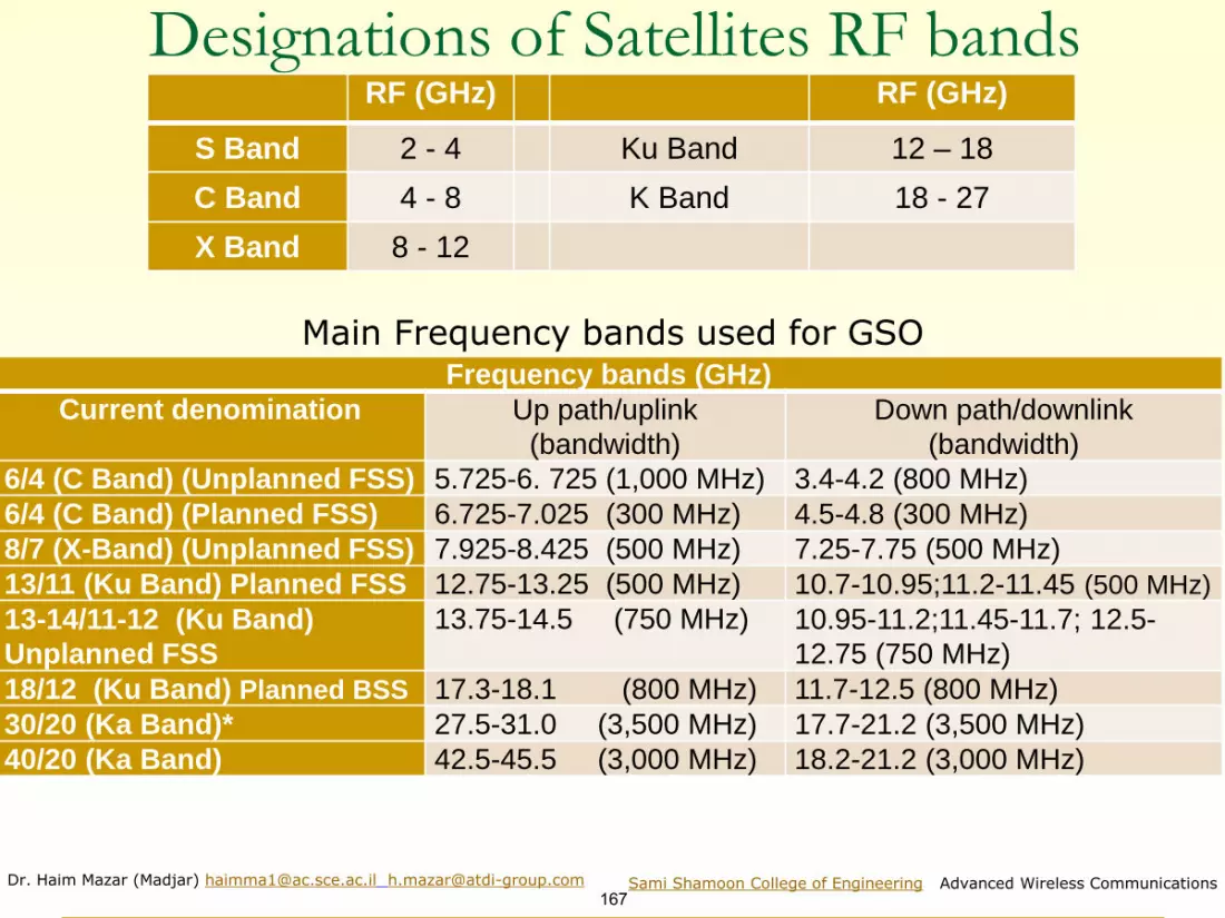
Dr. Haim Mazar (Madjar) [email protected] [email protected]
167Sami Shamoon College of Engineering Advanced Wireless Communications
Designations of Satellites RF bandsRF (GHz) RF (GHz)
S Band 2 - 4 Ku Band 12 – 18
C Band 4 - 8 K Band 18 - 27
X Band 8 - 12
Frequency bands (GHz)
Current denomination Up path/uplink
(bandwidth)
Down path/downlink
(bandwidth)
6/4 (C Band) (Unplanned FSS) 5.725-6. 725 (1,000 MHz) 3.4-4.2 (800 MHz)
6/4 (C Band) (Planned FSS) 6.725-7.025 (300 MHz) 4.5-4.8 (300 MHz)
8/7 (X-Band) (Unplanned FSS) 7.925-8.425 (500 MHz) 7.25-7.75 (500 MHz)
13/11 (Ku Band) Planned FSS 12.75-13.25 (500 MHz) 10.7-10.95;11.2-11.45 (500 MHz)
13-14/11-12 (Ku Band)
Unplanned FSS
13.75-14.5 (750 MHz) 10.95-11.2;11.45-11.7; 12.5-
12.75 (750 MHz)
18/12 (Ku Band) Planned BSS 17.3-18.1 (800 MHz) 11.7-12.5 (800 MHz)
30/20 (Ka Band)* 27.5-31.0 (3,500 MHz) 17.7-21.2 (3,500 MHz)
40/20 (Ka Band) 42.5-45.5 (3,000 MHz) 18.2-21.2 (3,000 MHz)
Main Frequency bands used for GSO

Dr. Haim Mazar (Madjar) [email protected] [email protected]
168Sami Shamoon College of Engineering Advanced Wireless Communications
The basic satellite link
Handbook on Satellite Communications ITU SAT HB 2002

Dr. Haim Mazar (Madjar) [email protected] [email protected]
169Sami Shamoon College of Engineering Advanced Wireless Communications
Satellites Orbits ITU Satellites HandbookORBITS LEO MEO HEO GEO
Environment constraints
Currently low (space debris: growing concern)
Low/medium Medium/high Low; short number of orbital slots; station keeping
Van Allen belts: 4 crossings/dayTypical orbital period 1.5-2 h 5-10 h 12 h 24 h
Altitude range 500-1,500 km 8,000-18,000 km Up to 40,000 km apogee (perigee ~ 1,000 km) 35,700 km
Visibility duration 15-20 mn/pass 2-8 h/pass 8-11 h/pass (apogee) Permanent
Elevation Rapid variations; high and low angles
Slow variations; high angles
No variations (apogee); high angles near Equator
No variation; low angles at high latitudes
Propagation delay Several milliseconds Tens of milliseconds Hundreds of milliseconds
(apogee) > 250 milliseconds
Link budget (distance)
Favorable; compatible with small satellites and handheld user terminals
Less favorableNot favorable for handheld or small terminals; requires large and powerful satellites
Not favorable for handheld or small terminals
Instantaneous ground coverage (diameter at 10°elevation)
6,000 km 12,000-15,000 km 16,000 km (apogee)16,000 km (~ 0.4 of earth circumference at Equator)
Examples of systems
Iridium, Globalstar, Skybridge, Orbcomm…
Odyssey, ICO-P ; O3B Molnya, Archimedes…Intelsat, Inmarsat, Meteosat, Milcom; Eutelsat, Amos…
Scientific missions
LEO: low-Earth orbits; MEO: medium-Earth orbits; HEO: highly-eccentric orbits; GEO: geostationary

Dr. Haim Mazar (Madjar) [email protected] [email protected]
170Sami Shamoon College of Engineering Advanced Wireless Communications
Generic illustration of BSS (ITU SAT Handbook)

Dr. Haim Mazar (Madjar) [email protected] [email protected]
171Sami Shamoon College of Engineering Advanced Wireless Communications
Geostationary Satellite
1. Circular orbits above the equator2. Angular separation less than 10 - allows more than 360
satellites3. Orbital height above the earth, about 23,000
miles/35,000km4. Round trip time to satellite about 0.24 seconds5. GEO satellites require more power for communications6. Signal to noise ratio for GEOs is worse due to distances7. 1 GEO covers about 40% of the world 8. Polar regions cannot be “seen” by GEOs9. As stationary, GEOs don’t require dynamic tracking10.GEOs are good for broadcasting to wide areas and FSS
36,000 2
300,000

Dr. Haim Mazar (Madjar) [email protected] [email protected]
172Sami Shamoon College of Engineering Advanced Wireless Communications
Example- geostationary satellite high-quality coverage

Dr. Haim Mazar (Madjar) [email protected] [email protected]
173Sami Shamoon College of Engineering Advanced Wireless Communications
FSS coverage

Dr. Haim Mazar (Madjar) [email protected] [email protected]
174Sami Shamoon College of Engineering Advanced Wireless Communications
Calculating Elevation and Azimuth to the Geostationary Satellite
Where:
θ is the elevation toward the GEO satellite,
Φ is the azimuth toward the GEO satellite
Geostationary Satellite Azimuth and Elevation Calculator
1. The principal limitation in coverage is the area above 75 degrees North or South
Latitude;
2. At the same longitude as the GEO sat, the elevation angle to the geostationary
satellite equals approximately 90 minus the absolute latitude; the latitude of the
Ground-Station defines the elevation angle to the satellite and thus limits the edge
of coverage.
3. The geographical latitude determines the elevation angle towards broadcasting
satellites; the longitude determines which of those satellites can be received

Dr. Haim Mazar (Madjar) [email protected] [email protected]
175Sami Shamoon College of Engineering Advanced Wireless Communications
Elevation to the Geostationary Satellite
]2
cos( 0.15 cos 0.15tan
sin1 cos(
) cos( )
) cos( )
sat obs obs
sat obs obs
long long lat
long long lat
−
−
− − =
−
Whereθ is the elevation toward the GEO satellite, 0.15 is the ratio of the earth radius to geo satellite orbital radius. α is the spherical separation angle observer to GEO, composed by the
separation in longitude (longsat- longobs ) &separation in latitude,which is exactly the latobs
cos α =cos (longsat- longobs) x cos (latobs)
To exemplify: longitude Amos= longsat= +4W0; observer in TelAviv, longitude 320 & TelAviv latitude 350;
cos α=cos(40-320) x cos(350 )= cos (280) x cos(350)=0.72
α=43.670 ; and θ equals 39.560 see Calculator, as
cos 0.15 0.72 0.150.83
sin 0.690anT
− − = =

Dr. Haim Mazar (Madjar) [email protected] [email protected]
176Sami Shamoon College of Engineering Advanced Wireless Communications
Azimuth to the Geostationary Satellite
Where A and Φ are the azimuths the GEO satellite, measured clockwise from North
To exemplify: longitude Amos= longsat= +4W0; observer in TelAviv, longitude 320
& TelAviv latitude 350; A=arc tan (40-320)/ sin (350 )= arc tan(-0.53/0.57)=
arc tan -0.927= -42.830 ±1800
The location of TelAviv is northern hemisphere & Amos +4W is West of TelAviv, so
Φ = A+180°= -42.830 ±1800. i.e.: -42.830 and -222.830; 317.170 and 137.170
The Calculator shows 222.83° = -(-180°-42.83°)
tan( )arctan
sin( )
sat obs
obs
longA
long
lat
−=
Provisional Azimuth angle A is modified according to location of the earth station (ES) on the Earth's surface: Φ = A+180° for ES located in the northern hemisphere & satellites located West of the earth stationΦ = 180°– A for ES in the northern hemisphere & satellites located East of the ESΦ = 360°– A for ES in the southern hemisphere & satellites located West of the ES Φ = A for ES in the southern hemisphere and satellites located East of the ES
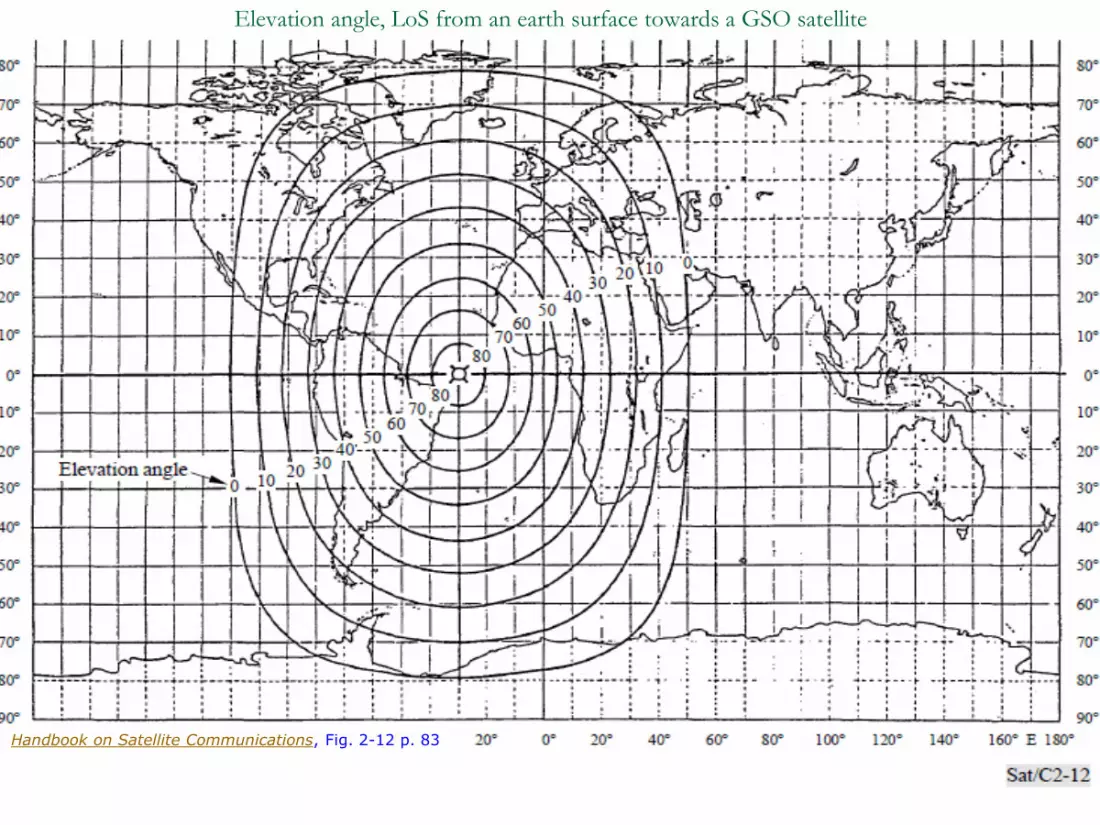
Dr. Haim Mazar (Madjar) [email protected] [email protected]
177Sami Shamoon College of Engineering Advanced Wireless Communications
Elevation angle, LoS from an earth surface towards a GSO satellite
Handbook on Satellite Communications, Fig. 2-12 p. 83

Dr. Haim Mazar (Madjar) [email protected] [email protected]
178Sami Shamoon College of Engineering Advanced Wireless Communications
GEO Main Problems, Rami Neudorfer
◼ Positioning in orbit: small rockets; fuel up to 10-15
Years
◼ Stability: solar panels and antennas
◼ Power: solar power is used to generate electricity
Batteries are needed as about half the time the LEOs
are behind the earth
◼ Communications: satellite to satellite communication
microwave or by optical laser
◼ Harsh environment: components need to be specially
“hardened’’, not only for temperature

Dr. Haim Mazar (Madjar) [email protected] [email protected]
179Sami Shamoon College of Engineering Advanced Wireless Communications Amos-3 global steerable changeable Ku & Ka footprints

Dr. Haim Mazar (Madjar) [email protected] [email protected]
180Sami Shamoon College of Engineering Advanced Wireless Communications
Service area of AMOS 2-B satellite network from 4W

Dr. Haim Mazar (Madjar) [email protected] [email protected]
181Sami Shamoon College of Engineering Advanced Wireless Communications
-30
-30
-25
-25
-20
-20
-15
-15
-10
-5
-3
LL
SA
TS
OF
T
50.00 60.00 70.00 80.00 90.00 100.00 110.00
East Longitude (Degrees)
-10.00
0.00
10.00
20.00
30.00
40.00
50.00
No
rth L
atitu
de
(De
gre
es)
Inmarsat ‘high capacity payload’ beam coverage

Dr. Haim Mazar (Madjar) [email protected] [email protected]
182Sami Shamoon College of Engineering Advanced Wireless Communications
ASTRA Coverage, Transfinite Visualise 7

Dr. Haim Mazar (Madjar) [email protected] [email protected]
183Sami Shamoon College of Engineering Advanced Wireless Communications
Typical Earth Station, Rami Neuderfer
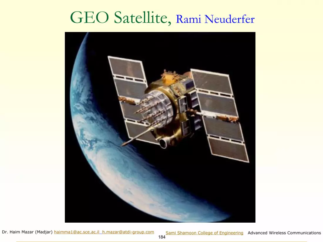
Dr. Haim Mazar (Madjar) [email protected] [email protected]
184Sami Shamoon College of Engineering Advanced Wireless Communications
GEO Satellite, Rami Neuderfer

Dr. Haim Mazar (Madjar) [email protected] [email protected]
185Sami Shamoon College of Engineering Advanced Wireless Communications
Amos Satellite, Rami Neuderfer

Dr. Haim Mazar (Madjar) [email protected] [email protected]
186Sami Shamoon College of Engineering Advanced Wireless Communications
Typical GEO Ku Band Link Budget & G/TParameter Downlink (DL) Values
Uplink (UL) Values Units
E.I.R.P. space to earth 52 dBW
E.I.R.P. earth to space 71 dBW
PL path loss 205 207 dB
G earth station 37.4 60 dBi
G space station 42 dBi
T earth station 10 log 100= 20 dB/K
T space station 10 log 500 = 27 dB/K
G/T earth station 37.4- 20= 17.4 dB/K
G/T space station 42-27= 15 dB/K
Normalised DL Thermal
C/N
93 dB
Normalised UL Thermal
C/N
107.6 dB
Signal Bandwidth 36x106 Hz; 10 log 36 x10
6=75.6 dB Hz
C/N 17.4 32 dB

Dr. Haim Mazar (Madjar) [email protected] [email protected]
187Sami Shamoon College of Engineering Advanced Wireless Communications
Orbit comparison- main coverage performances & link constraints SAT HB Table 6.1, revised
ORBITS LEO MEO HEO GEO
Environment constraints
Currently low (space debris: growing concern) Low/medium Medium/high Low; short number of
orbital slots; station keeping
Van Allen belts: 4 crossings/day
Typical orbital period 1.5-2 h 5-10 h 12 h 24 h
Altitude range 500-1,500 km 8,000-25,000 km Up to 40,000 km apogee (perigee ~ 1,000 km) 35,700 km
Visibility duration 15-20 mn/pass 2-8 h/pass 8-11 h/pass (apogee) Permanent
Elevation Rapid variations; high and low angles
Slow variations; high angles
No variations (apogee); high angles near Equator
No variation; low angles at high latitudes
Propagation delay Several milliseconds Tens of milliseconds Hundreds of milliseconds (apogee) > 250 milliseconds
Link budget (distance)Favorable; compatible with small satellites and handheld user terminals
Less favorable
Not favorable for handheld or small terminals; requires large and powerful satellites
Not favorable for handheld or small terminals
Instantaneous ground overage (diameter at 10° elevation)
6,000 km 12,000-15,000 km 16,000 km (apogee)16,000 km (~ 0.4 of earth circumference at Equator)
Examples of systems
Iridium,Globalstar, Skybridge, ORBCOMM, International Space Station (ISS)
Odyssey; O3B, GPS, GLONASS, Galileo, BeiDou
Molniya, ArchimedesIntelsat, Inmarsat, Meteosat, MILCOM; Eutelsat, AMOS
Scientific missions
LEO: low-Earth orbits; MEO: medium-Earth orbits; HEO: highly-eccentric orbits; GEO: geostationary orbits

Dr. Haim Mazar (Madjar) [email protected] [email protected]
188Sami Shamoon College of Engineering Advanced Wireless Communications
LEO vs GEO Orbits, Rami Neuderfer
◼ Low earth orbit satellites - between 100 - 1500 miles
◼ Signal to noise should be better with LEOs
◼ Shorter delays, between 1 - 10 ms typical
◼ LEOs move relative to the earth; they require dynamic tracking or non directive antennas (my addition)
◼ Circular orbits are simplest
◼ Inclined orbits are useful for coverage of equatorial regions
◼ Elliptical orbits can be used to give quasi stationary behaviour viewed from earth using 3 or 4 satellites
◼ Orbit changes extend the life of satellites

Dr. Haim Mazar (Madjar) [email protected] [email protected]
189Sami Shamoon College of Engineering Advanced Wireless Communications
Low Earth Orbit; Transfinite
SEE also shaded topo http://visibleearth.nasa.gov/view.php?id=57752

Dr. Haim Mazar (Madjar) [email protected] [email protected]
190Sami Shamoon College of Engineering Advanced Wireless Communications
Generic illustration of MSS
Handbook on Satellite Communications

Dr. Haim Mazar (Madjar) [email protected] [email protected]
191Sami Shamoon College of Engineering Advanced Wireless Communications
GPS: Global Positioning System, Struzak
21 satellites
>4 visibleX,Y,Z coordinates
(100m - 15m accuracy)
Time & frequency transfer
6 inclined orbit planes
20.000km
GPS receiver
strong signal

Dr. Haim Mazar (Madjar) [email protected] [email protected]
192Sami Shamoon College of Engineering Advanced Wireless Communications
GPS Principle, Ryszard Struzak
i-th satellite message: ”my time is Ti; my position is (Xi,Yi, Zi)”
R1
User (Xu,Yu, Zu)
R2 R3 R4
Pseudo-ranges: Ri = c(dTi).
Position: (Xi-Xu)2 + (Yi-Yu)
2 + (Zi-Zu)2 = (Ri- Cb)
2
c = light velocity Cb = clock bias i = 1...4.
The locus of points having a constant difference in distance to two points (here, two satellites) is a hyperboloid. Thus, from 4 or more measured reception times, the receiver can be placed at the intersection of the surfaces of three or more hyperboloids.

Dr. Haim Mazar (Madjar) [email protected] [email protected]
193Sami Shamoon College of Engineering Advanced Wireless Communications
Orbiting at an altitude of approximately 20,200 km (12,600 mi)example of a 24 sat GPS constellation in motion with the earth rotating. Notice how the number of satellites in view from a given point on the earth's surface, in this example
at 45°N, changes with time. Wiki http://en.wikipedia.org/wiki/File:ConstellationGPS.gif
ConstellationGPS.gif (240 × 192 pixels, file size: 485 KB, MIME type: image/gif, looped,
300 frames, 30 s)

Dr. Haim Mazar (Madjar) [email protected] [email protected]
194Sami Shamoon College of Engineering Advanced Wireless Communications
Comparison of Russian GLONASS and American GPSParameter GLONASS GPS
Ephemeris information presentation
method
Earth centred fixed coordinates + its
derivatives of first and second order
Modified Kepler elements of orbit
Geodesic coordinate system Parametry Zemli 1990; PZ-90.11 Geodetic Datum; WGS-84
Time corrections relative to the
Universal Time Coordinated (UTC)
UTC (SU)
SU is the Russian UTC
UTC (USNO); US Naval
Observatory master clock
Number of satellites (fully
operational)
GLONASS-M: 24 + 2 spares, +
2 GLONASS-K test
30 + 1 spare + 1 test
Number of orbital planes 3 6
Orbital inclination 64.8 55
Orbit altitude 19,100 km 20,180 km
Orbital period 11 h 15 min 12 h
Satellite signal division method FDMA CDMA
Frequency band L1 (MHz) (civilian) 1,597.5 515-1,605.886; center 1,602 1,575.42 ±1.023
Frequency band L2 (MHz) (+military) 1,242.4265-1,249.136; center 1,246 1,227.6 ±1.023
Duration of almanac transmission 2.5 min 12.5 min
Super frame capacity 7,500 bits (5 frames) 37,500 bits (25 frames)
Frame length 30 seconds
Synchro-code repetition period 2 s 6 s
Cross-talk between neighboring
channels
–48 dB –21 dB
Coarse/Acquisition (C/A); chips per sec 511 kHz 1,023 kHz
C/A-code length (symbols) 511 1,023C/A-code type; pseudorandom noise
(PRN)pseudo-random ranging code binary sequence: gold code
Modulation BPSK
Navigational message data rate 50 bit/s

Dr. Haim Mazar (Madjar) [email protected] [email protected]
195Sami Shamoon College of Engineering Advanced Wireless Communications
Wiki
Country/ies of origin European Union
Operator(s) GSA, ESA
Type Civilian, commercial
Status Initial services
Coverage Global
Accuracy 1 metre (public)
1 cm (encrypted)
Constellation size
Total satellites 30
Satellites in orbit 24 usable, 2 unavailable, and 2 retired
(12/2020)
First launch 2011
Total launches 28
Orbital characteristics
Regime(s) 3 × MEO planes
Orbital height 23,222 kilometres (14,429 mi)
Other details
Cost €10 billion
Galileo
(satellite
navigation)

Dr. Haim Mazar (Madjar) [email protected] [email protected]
196Sami Shamoon College of Engineering Advanced Wireless Communications
Wiki
Orbit size comparison of GPS, GLONASS, Galileo, BeiDou, & Iridium constellations, the International Space Station, the Hubble Space Telescope, & geostationary orbit (and its graveyard orbit), with the Van Allen radiation belts and the Earth to scale. The Moon's orbit is around 9 times as large as geostationary orbit.

Dr. Haim Mazar (Madjar) [email protected] [email protected]
197Sami Shamoon College of Engineering Advanced Wireless Communications
Satellites’ Equipment: Space Segment ◼ Solar arrays collect energy from the sun & stored in
batteries or used real-time;
◼ Thermal subsystem which controls & manages heat
creating and transfer in the satellite;
◼ Propulsion sub-system for the station keeping of the
satellite; and
◼ Radiocommunication payload which collects signals from
the Earth & retransmits these back down, or uses some
of them to control & monitor the spacecraft:
❑ Active repeaters- 1 demodulates the signal received & re-
modulates it before its transmission back to Earth; or
❑ Passive reflectors- one that acts as a pure bend-pipe system,
where the signal spectral components are reflected back to Earth
at a different carrier frequency.

Dr. Haim Mazar (Madjar) [email protected] [email protected]
198Sami Shamoon College of Engineering Advanced Wireless Communications
Satellites’ Equipment: Earth Stations▪ Earth station is the transmission, reception, relay & control terminal of a
telecommunication link via satellite;▪ General configuration of GEO earth station is not substantially different
from that of a radio-relay terminal, but the very large free-space attenuation (about 200 dB) undergone by the carrier radio waves, on their path between the station and satellite (approximately 36,000 km) usually requires the main subsystems of an earth station to have a much higher performance level, than those of a radio relay terminal:▪ High-gain (i.e. large diameter, high performance) antenna. Due to its
narrow beam, the receiver is less susceptible to noise and to interference;
▪ High-sensitivity receiver (i.e. with a very low internal noise); & powerful transmitter.
▪ The antenna of the earth station is used for both Rx & Tx transmission▪ GEO & MSS Earth stations consists of the following main subsystems:
▪ Antenna, Rx amplifiers (low-noise), Tx amplifiers (power);▪ Telecommunication equipment- RF converters & modems;▪ Multiplexers and demultiplexers;▪ Connection with the terrestrial network; and▪ Auxiliary equipment, power-supply & general infrastructure.
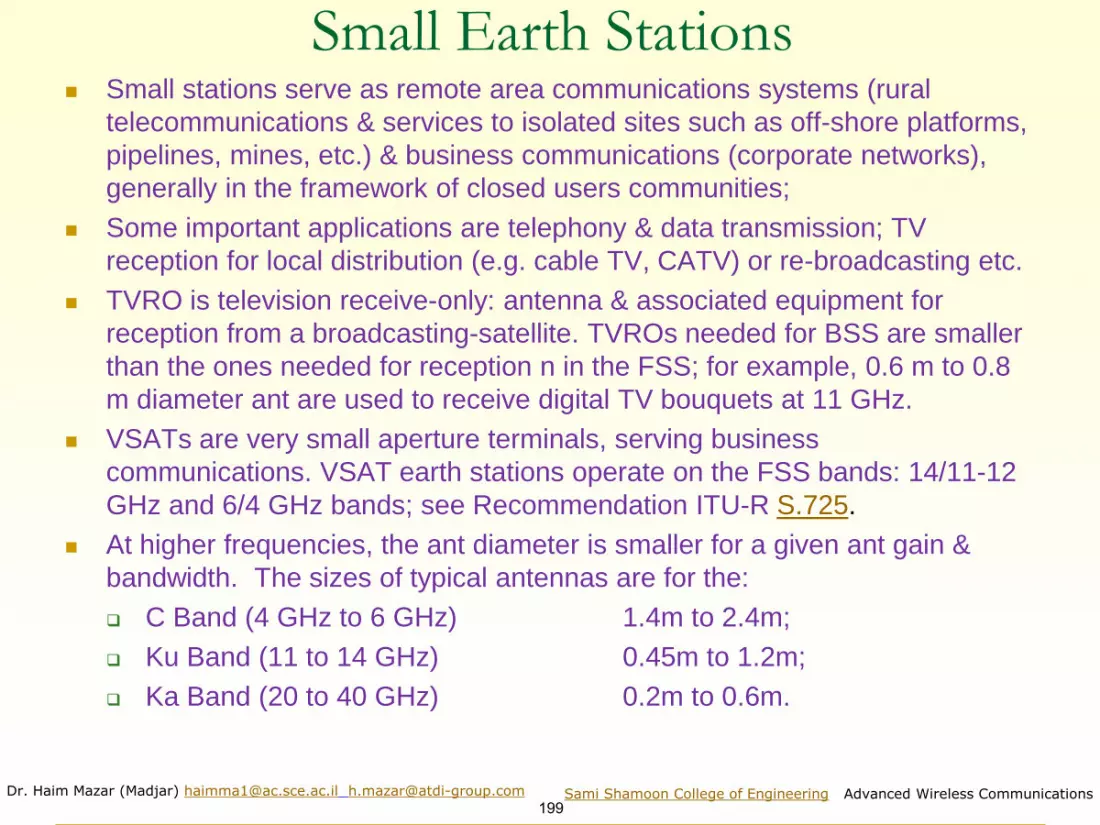
Dr. Haim Mazar (Madjar) [email protected] [email protected]
199Sami Shamoon College of Engineering Advanced Wireless Communications
Small Earth Stations◼ Small stations serve as remote area communications systems (rural
telecommunications & services to isolated sites such as off-shore platforms,
pipelines, mines, etc.) & business communications (corporate networks),
generally in the framework of closed users communities;
◼ Some important applications are telephony & data transmission; TV
reception for local distribution (e.g. cable TV, CATV) or re-broadcasting etc.
◼ TVRO is television receive-only: antenna & associated equipment for
reception from a broadcasting-satellite. TVROs needed for BSS are smaller
than the ones needed for reception n in the FSS; for example, 0.6 m to 0.8
m diameter ant are used to receive digital TV bouquets at 11 GHz.
◼ VSATs are very small aperture terminals, serving business
communications. VSAT earth stations operate on the FSS bands: 14/11-12
GHz and 6/4 GHz bands; see Recommendation ITU-R S.725.
◼ At higher frequencies, the ant diameter is smaller for a given ant gain &
bandwidth. The sizes of typical antennas are for the:
❑ C Band (4 GHz to 6 GHz) 1.4m to 2.4m;
❑ Ku Band (11 to 14 GHz) 0.45m to 1.2m;
❑ Ka Band (20 to 40 GHz) 0.2m to 0.6m.

Dr. Haim Mazar (Madjar) [email protected] [email protected] Sami Shamoon College of Engineering, Advanced Wireless Communications
200
Advanced Wireless Communications, 2020
Academic course for 4th year engineering students
Radar Systems
http://mazar.atwebpages.com/

Dr. Haim Mazar (Madjar) [email protected] [email protected]
201Sami Shamoon College of Engineering Advanced Wireless Communications
1. Radar is an object-detection system which uses mainly radio
waves to determine the range, altitude, direction, or speed of
both moving and fixed objects
2. Civil Applications: Air Traffic Control (including altimetry and
flight-control); Nautical Radars (landmarks and other ships);
a/c and cars anti-collision; ocean-surveillance; outer-space
surveillance and rendezvous; meteorology; ground-
penetrating radar (geological observations, coins), astronomy
3. Military Applications: air-defense and fire control -
Acquisition (bistatic, monostatic) (phased array antennas),
tracking (conical scan, monopulse), illumination, detonation;
antimissile; protection (a/c, tanks, fence)
Radar (Radio Detection And Ranging) Applications

Dr. Haim Mazar (Madjar) [email protected] [email protected]
202Sami Shamoon College of Engineering Advanced Wireless Communications
From M.A. Richards, Georgia TechRadar Frequency Bands c=λf

Dr. Haim Mazar (Madjar) [email protected] [email protected]
203Sami Shamoon College of Engineering Advanced Wireless Communications
12 pr c t=
range delay
velocity of propagation
2-way
Range Delay: radar range is measured by the time delay between pulse transmission & reception

Dr. Haim Mazar (Madjar) [email protected] [email protected]
204Sami Shamoon College of Engineering Advanced Wireless Communications
The Radar equation
r
24
tp g
r
24
tp g
r
( )
224
tp g
r
( )2
24
tr
p gp A
r
=
2
4
gA
=
( )
2 2
3 44
tr
p gp
r
=

Dr. Haim Mazar (Madjar) [email protected] [email protected]
205Sami Shamoon College of Engineering Advanced Wireless Communications
Radar Friis equation, Basic Transmission Loss
2
222
2 2 2
4
1 1
4 4 4 4 4
T T
T T T
TARGET e
received Transmit
g pP pfd a
r
g p gP P g
r r r
= =
= =
σ: radar target cross-section d: distance from the radar to the target λ: wave length
22
3 4(4 )received transmitp p g
r
=
Exercise: prove that for pulse width to and b= 1/ to the max detection range
depends on transmitted energy and not only transmitted power
P minimal discernable signal= kTbfs/n. For pulse radar b≈t
1
2 2 24 2 2 2
max 3 3 3
min(4 ) (4 ) (4 )Transmit Transmit Transmitd P g P g Energy g
P kTf Ktf
t
= = =

Dr. Haim Mazar (Madjar) [email protected] [email protected]
206Sami Shamoon College of Engineering Advanced Wireless Communications
0 1 2 3 4 5 6 7 80
0.1
0.2
0.3
0.4
0.5
0.6
0.7
r / noise STD
Pro
babili
tyTheoretical PDF, SNR = 8
signal+noise
noise
PD
threshold
single pulse, non-fluctuating
PFA
Pulse Detection Probability

Dr. Haim Mazar (Madjar) [email protected] [email protected]
207Sami Shamoon College of Engineering Advanced Wireless Communications
Search Pulse Radar: time versus frequency domain
time frequency

Dr. Haim Mazar (Madjar) [email protected] [email protected]
208Sami Shamoon College of Engineering Advanced Wireless Communications
tp
T
0 10 20 30 40 50 60 70 80 90 1000
1
2
3
4
5
6
Delay
Envelo
pe
detected targetmissed targetfalse alarm
threshold
Envelope detection
“A” Scope Display

Dr. Haim Mazar (Madjar) [email protected] [email protected]
209Sami Shamoon College of Engineering Advanced Wireless Communications
Measured search antenna plot;
amplitude vs. time (ITU-R M.1851)

Dr. Haim Mazar (Madjar) [email protected] [email protected]
210Sami Shamoon College of Engineering Advanced Wireless Communications
Acquisition Radar display
Plan Position Indicator (PPI)
Wiki

Dr. Haim Mazar (Madjar) [email protected] [email protected]
211Sami Shamoon College of Engineering Advanced Wireless Communications Radar Coverage 5.5Ghz around BG airport

Dr. Haim Mazar (Madjar) [email protected] [email protected]
212Sami Shamoon College of Engineering Advanced Wireless Communications
ray clearing
Line of Sight & detecting low flying A/C
Giraffe, surveillance radar

Dr. Haim Mazar (Madjar) [email protected] [email protected]
213Sami Shamoon College of Engineering Advanced Wireless Communications
Radars
SHORAD
Radar MEZ Limit
Radar
Detection
(red)
Radar
Interception
(turquoise)
Tactical aircraft
At 100 m AGL min

Dr. Haim Mazar (Madjar) [email protected] [email protected]
214Sami Shamoon College of Engineering Advanced Wireless Communications
Typical Pulse Search Radar Parameters
◼ transmitter power ……………………….. 1 MW
◼ pulse width ……………………….. 1 μsec
◼ mainbeam antenna gain…………. 43 dBi
◼ scan all directions (all sectors)
◼ frequency range ……………… 3300-3500 MHz
◼ first sidelobe antenna gain ………. 20 dBi
◼ backlobe antenna gain……………. 0 dBi
◼ 2nd harmonic output …………… 73 dB down
◼ 3rd and higher harmonics ……….. >80 dB down
◼ receiver sensitivity ……………… -90 dBm

Dr. Haim Mazar (Madjar) [email protected] [email protected]
215Sami Shamoon College of Engineering Advanced Wireless Communications
Radar Unambiguous Range
Interval Pulse Period (IPP)

Dr. Haim Mazar (Madjar) [email protected] [email protected]
216Sami Shamoon College of Engineering Advanced Wireless Communications
- complex dielectric constant of the surface
k - permittivity
- conductivity
0 - dielectric constant of free space
- signal wavelength
0' " / 60j k j = + −
2
2
cossin
cossin
−+
−−=H
2
2
cossin
cossinΓ
−+
−−=V
EH
EV V EV
H EH
Reflectance to analyse polarity influence

Dr. Haim Mazar (Madjar) [email protected] [email protected]
217Sami Shamoon College of Engineering Advanced Wireless Communications
0 10 20 30 40 50 60 70 80 900
0.1
0.2
0.3
0.4
0.5
0.6
0.7
0.8
0.9
1
grazing angle - degrees
refle
ctio
n co
effic
ient
- am
plitu
de
epsp=69 epspp=39
Vertical Polarizatio
Horizontal Polarization
0 10 20 30 40 50 60 70 80 900
0.5
1
1.5
2
2.5
3
3.5
4
grazing angle - degrees
refle
ctio
n co
effic
ient
- ph
ase
[rad]
epsp=69 epspp=39
Vertical Polarization
Horizontal Polarization
( ) j−= exp
ref_coef
Vertical vs Horizontal Polarity
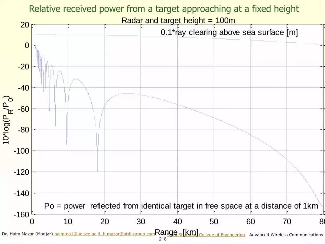
Dr. Haim Mazar (Madjar) [email protected] [email protected]
218Sami Shamoon College of Engineering Advanced Wireless Communications
0 10 20 30 40 50 60 70 80-160
-140
-120
-100
-80
-60
-40
-20
0
20
Range [km]
10*l
og(P
R/P
0)
0.1*ray clearing above sea surface [m]
Po = power reflected from identical target in free space at a distance of 1km
Radar and target height = 100m
Relative received power from a target approaching at a fixed height

Dr. Haim Mazar (Madjar) [email protected] [email protected]
219Sami Shamoon College of Engineering Advanced Wireless Communications
Cosecant squared beam coverage for search radar

Dr. Haim Mazar (Madjar) [email protected] [email protected]
220Sami Shamoon College of Engineering Advanced Wireless Communications
Cosecant squared beam equations
22
3 4(4 )received transmitp p g
r
=
( )2
2 2 4sink g = ( )2
2
2
4sin
kg
=
2222
cscsin
kg k
= =
( )1 21 1
22 2 4
4 4 4
sinreceived
k kk g k gP
r h h
= = =
2
1 3(4 )transmitk p
=
To get constant signal for a target flying at fixed altitude
radartutoria
l

Dr. Haim Mazar (Madjar) [email protected] [email protected]
221Sami Shamoon College of Engineering Advanced Wireless Communications
Cosecant squared beam- theory;
measured and in theorytheory: gain is
cosecant squared
π/2
radartutorial

Dr. Haim Mazar (Madjar) [email protected] [email protected]
222Sami Shamoon College of Engineering Advanced Wireless Communications
Ground Effects - multipath and clutter
Area contributingto multipath Area contributing
clutter at target’s range
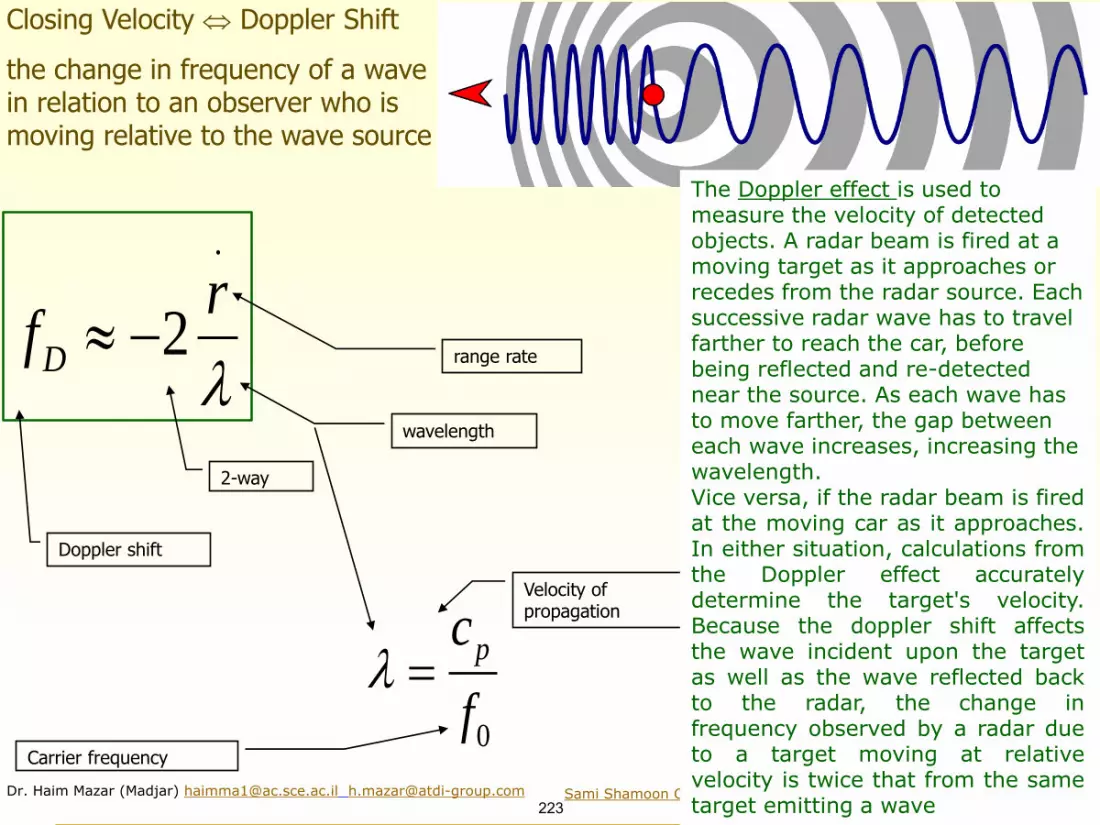
Dr. Haim Mazar (Madjar) [email protected] [email protected]
223Sami Shamoon College of Engineering Advanced Wireless Communications
.
2D
rf
− range rate
wavelength
Doppler shift
2-way
0
pc
f =
Velocity of propagation
Carrier frequency
Closing Velocity Doppler Shift
the change in frequency of a wave in relation to an observer who is moving relative to the wave source
The Doppler effect is used to measure the velocity of detected objects. A radar beam is fired at a moving target as it approaches or recedes from the radar source. Each successive radar wave has to travel farther to reach the car, before being reflected and re-detected near the source. As each wave has to move farther, the gap between each wave increases, increasing the wavelength. Vice versa, if the radar beam is firedat the moving car as it approaches.In either situation, calculations fromthe Doppler effect accuratelydetermine the target's velocity.Because the doppler shift affectsthe wave incident upon the targetas well as the wave reflected backto the radar, the change infrequency observed by a radar dueto a target moving at relativevelocity is twice that from the sametarget emitting a wave

Dr. Haim Mazar (Madjar) [email protected] [email protected]
224Sami Shamoon College of Engineering Advanced Wireless Communications
Because the doppler shift affects the waveincident upon the target as well as the wavereflected back to the radar, the change infrequency observed by a radar due to a targetmoving at relative velocity is twice that from thesame target emitting a wave
From Wiki

Dr. Haim Mazar (Madjar) [email protected] [email protected]
225Sami Shamoon College of Engineering Advanced Wireless Communications
From M.A. Richards, Georgia TechValues of Doppler Shift
Mach 2 a/c causes 4.4 kHz shift at L band

Dr. Haim Mazar (Madjar) [email protected] [email protected]
226Sami Shamoon College of Engineering Advanced Wireless Communications
Moving Target Indicator (MTI) or Doppler processing
• Involves coherent processing of a pulse train (plain or compressed)
• Purposes: separate weak returns of moving targets from large clutter returns
• Two basic approaches:
• Bank of filters (usually DFT)
• Pulse cancelers
From M.A. Richards, Georgia Tech

Dr. Haim Mazar (Madjar) [email protected] [email protected]
227Sami Shamoon College of Engineering Advanced Wireless Communications
From M.A. Richards, Georgia Tech
The concept of Moving Target Indication (MTI)

Dr. Haim Mazar (Madjar) [email protected] [email protected]
228Sami Shamoon College of Engineering Advanced Wireless Communications
From M.A. Richards, Georgia Tech
The concept of
Moving Target
Indication (MTI)

Dr. Haim Mazar (Madjar) [email protected] [email protected]
229Sami Shamoon College of Engineering Advanced Wireless Communications
From M.A. Richards, Georgia Tech
Blind speeds
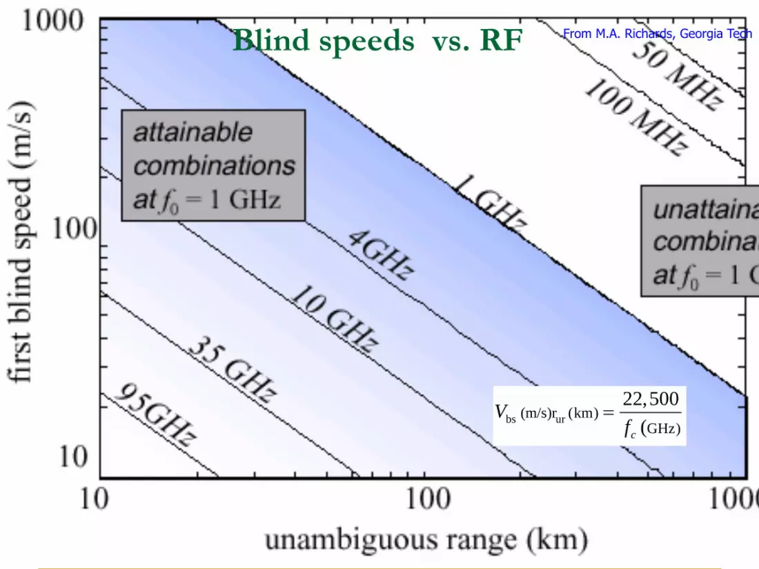
Dr. Haim Mazar (Madjar) [email protected] [email protected]
230Sami Shamoon College of Engineering Advanced Wireless Communications
bs ur(m/s)r (km)GHz)
22,500
(c
Vf
=
Blind speeds vs. RF From M.A. Richards, Georgia Tech
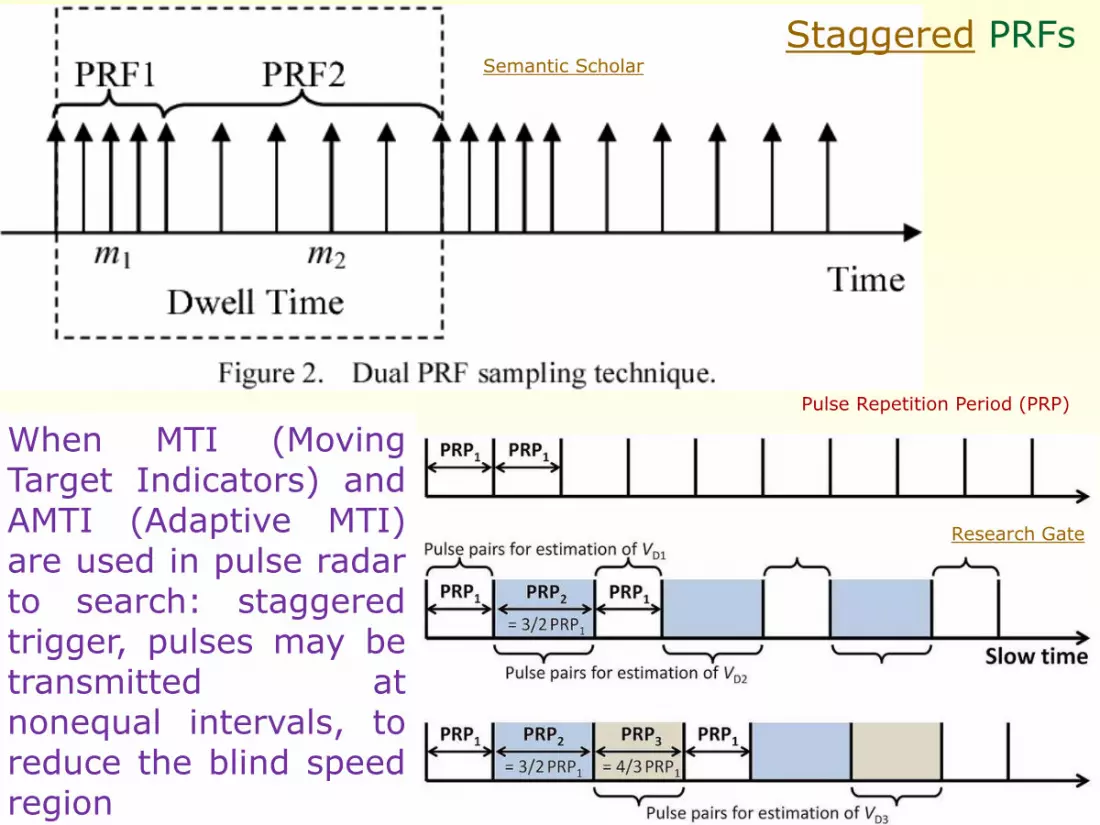
Dr. Haim Mazar (Madjar) [email protected] [email protected]
231Sami Shamoon College of Engineering Advanced Wireless Communications
Staggered PRFs
When MTI (MovingTarget Indicators) andAMTI (Adaptive MTI)are used in pulse radarto search: staggeredtrigger, pulses may betransmitted atnonequal intervals, toreduce the blind speedregion
Research Gate
Semantic Scholar
Pulse Repetition Period (PRP)

Dr. Haim Mazar (Madjar) [email protected] [email protected]
232Sami Shamoon College of Engineering Advanced Wireless Communications
2 2ur
c cr PRI
PRF= =
2 2bs bs cv v fPRF
c= =
2
4bs ur
c
cv r
f=
Unambiguous range (ur) vs. blind speeds (bs)
2 ur
cPRF
r=
2
2
bs cbs
ur
v fcDoppler
r c= =
From M.A. Richards, Georgia Tech
Pulse Repetition Frequency (PRF) Pulse Repetition Interval (PRI)

Dr. Haim Mazar (Madjar) [email protected] [email protected] Sami Shamoon College of Engineering, Advanced Wireless Communications
233
Advanced Wireless Communications, 2020
Academic course for 4th year engineering students
You may look at my presentation international, regional & national regulation of SRDs at ITU Workshop on SRDs, Geneva 3June14
Short Range Devices (SRDs)
http://mazar.atwebpages.com/

Dr. Haim Mazar (Madjar) [email protected] [email protected]
234Sami Shamoon College of Engineering Advanced Wireless Communications
Definitions◼ The regulatory framework for SRDs, such as the decision on frequency bands
for use by SRDs, is a national matter
◼ ITU RR 1.19 radiocommunication service: A service as defined in this Section
involving the transmission, emission and/or reception of radio waves for specific
telecommunication purposes
◼ SRDs are not a “Radio Service” under ITU Radio Regulations RR; thus they
cannot get primary or secondary allocation
◼ SRDs are emissions without a corresponding frequency allocation in the RR
◼ SRDs are not ISM applications, as defined in No. 1.15 of RR
◼ SRD covers radio transmitters, providing either unidirectional or bi-directional
communication, with low capability of causing interference to other radio
equipment
◼ For SRDs individual licenses are normally not required
◼ SRDs are permitted to operate on a non-interference and non-protected basis
◼ In general SRDs cannot claim protection from radio services, intentional or
unintentional radiator, by ISM equipment, or by an incidental radiator
◼ SRDs are deployed in both bands designated for ISM applications and bands
not designated for ISM applications

Dr. Haim Mazar (Madjar) [email protected] [email protected]
235Sami Shamoon College of Engineering Advanced Wireless Communications
ISM Bands: RR
6 765-6 795 kHz (centre frequency 6 780 kHz) FN 5.138
13 553-13 567 kHz (centre frequency 13 560 kHz), FN 5.150
26 957-27 283 kHz (centre frequency 27 120 kHz), FN 5.150
40.66-40.70 MHz (centre frequency 40.68 MHz), FN 5.150
433.05-434.79 MHz (centre frequency 433.92 MHz) in Region 1* FN 5.138
902-928 MHz in Region 2 (centre frequency 915 MHz), FN 5.150
2 400-2 500 MHz (centre frequency 2 450 MHz), FN 5.150
5 725-5 875 MHz (centre frequency 5 800 MHz), FN 5.150
24-24.25 GHz (centre frequency 24.125 GHz) FN 5.150
61-61.5 GHz (centre frequency 61.25 GHz) FN 5.138
122-123 GHz (centre frequency 122.5 GHz) FN 5.138
244-246 GHz (centre frequency 245 GHz) ` FN 5.138
Note: 6.780 MHz x2= 13.560 MHz ; 6.780 MHz x4= 27.120 MHz; 6.780x6= 40.680 MHz; 6.780 MHz x32=433.920 MHz.
61.25 GHz x2= 122.5 GHz; 61.25 GHz x4=234 GHz
SRDs are deployed in both bands designated for ISM applications and bands not designated for ISM
applications. ISM band is sufficient condition but not obligatory; SRD band is different than ISM
band
15.13§ 9 Administrations shall take all practicable and necessary steps to ensure that radiation from equipment used for
industrial, scientific and medical applications is minimal and that, outside the bands designated for use by this equipment, radiation from such equipment is at a level that does not cause harmful interference to a radiocommunication service and, in particular, to a radionavigation or any other safety service operating in accordance with the provisions of these Regulations.

Dr. Haim Mazar (Madjar) [email protected] [email protected]
236Sami Shamoon College of Engineering Advanced Wireless Communications
M
6,780 kHz; 13,560 kHz 27,120 kHz; 40.68 MHz
433.92 MHz915 MHz
2,450 MHz; 5,800 MHz24.125 GHz;61.25 GHz 122.5 GHz ;245 GHz
ISM bands
GlobalOnly in EuropeOnly in Americas
9-148.5 kHz; 3,155-3,400 kHz9 kHz- 47 MHz (specific SRDs)7,400-8,800 kHz138.20-138.45 MHz 169.4-216 MHz312-315MHz (non Europe)402-405 MHz medical devices470-489 MHz (normally individually licensed)
823-832 MHz and 1,785-1,805 MHz862-875 MHz in some Asian counties
862-876MHz Non-Specific SRDs 915-921 MHz5,150-5,350 & 5,470-5,725 MHz57-64GHz, 76-77GHz, 77-81GHz
non-ISM candidate bands for SRDs
Frequency Bands for SRDs
Haim Mazar

Dr. Haim Mazar (Madjar) [email protected] [email protected]
237Sami Shamoon College of Engineering Advanced Wireless Communications
Applications of ISM equipment, in and outside ISM bandsFrequency Applications
Below 1,000
kHz
Induction heating; ultrasonic cleaning and medical diagnostics; Domestic
induction cookers; metal melting; billet heating; tube welding; soldering and
brazing; component heating; spot welding; selective surface heat; treating of
metal parts; semiconductor crystal growing and refining; seam bonding of
autobody surfaces; package sealing; heating strip steel for galvanizing,
annealing and paint drying; electrical surgical units (ESU); hyperthermia
equipment
1-10 MHz Surgical diathermy (dampened wave oscillator); wood gluing and wood curing
(3.2 and 6.5 MHz); valve induction generators production of semi-conductor
material; RF arc stabilized welding; ESU
10-100 MHz Dielectric heating and material preheating. The majority operate in the ISM RF
bands at 13.56, 27.12 and 40.68 MHz, but many also operate on frequencies
outside the ISM bands): drying (textile, fiberglass, paper and paper coating,
veneer and lumber, foundry core, glue, film, solvent, food), ceramics, business
products (books, paper, gluing and drying), food (post baking, meat and fish
thawing), wood gluing, plastic heating (welding and moulding, die sealing and
plastic embossing), adhesive curing. Medical applications: medical diathermy
and hyperthermia equipment (27 MHz), MRI (10-100 MHz in large shielded
rooms)
100-915 MHz Medical applications (433 MHz), hyperthermia equipment (433 MHz and 915);
food processing (915 MHz); RF plasma generators; Rubber vulcanization (915
MHz); MRI
Above 915
MHz
Microwave ovens domestic and commercial (915 MHz and 2,450 MHz), food
tempering, thawing and cooking; RF excited ultra-violet paint and coating curing;
pharmaceutical processing; RF plasma generators; rubber vulcanization
(magnetrons at 915 and 2450 MHz)

Dr. Haim Mazar (Madjar) [email protected] [email protected]
238Sami Shamoon College of Engineering Advanced Wireless Communications
SRDs: new multiplexing, spreading & modulation techniques
for enhanced data-rate & to avoid interference
◼ Orthogonal frequency-division multiplexing (OFDM) is the modulation and
multiplexing of Wi-Fi 802.11a and g
◼ Coded Orthogonal Frequency-Division Multiple Access (COFDM) is used in
Wi-Fi 5GHz (IEEE802.11.a) as signal modulation technique; COFDM sends
a stream of data symbols in a parallel, with multiple subcarriers (i.e. small
slices of spectrum within the designated carrier RF band)
◼ Spread-spectrum techniques:
❑ Direct-sequence spread spectrum (DSSS) is used at Wi-Fi IEEE 802.11b and
ZigBee IEEE 802.15.4; ZigBee is basically a 10-meter range with transfer rate of
250 kbit/s
❑ Frequency-hopping spread spectrum (FHSS) is used for Bluetooth IEEE
802.15.1; Bluetooth enables exchanging data over short distances from fixed and
mobile devices
◼ Complementary Code Keying (CCK) is the modulation scheme used with
wireless networks (WLANs) that employ the IEEE 802.11b operating at
either 5.5 or 11 Mbit/s

Dr. Haim Mazar (Madjar) [email protected] [email protected]
239Sami Shamoon College of Engineering Advanced Wireless Communications
Typical Applications1. Wideband data transmission: RLAN/Wi-Fi, UWB, White Space Devices (in
the USA, white space devices are to operate on a non-protected, non-interference basis), Wideband
Low Activity Mode (WLAM), short range video
2. RF IDentification (RFID), active medical implants, health monitoring,
personal identification, inductive systems, proximity sensors
3. Car door openers, Transport and Traffic Telematics (TTT), road tolling,
Automatic Meter Reading (AMR), Street Lamp Monitoring and Control,
railway applications, car immobilisers
4. Logistics, livestock, Electronic Article Surveillance (EAS),
5. Radiodetermination: Automotive Short Range Radar (SRR), RF level
gauges, radar sensor, Level Probing Radar (LPR)
6. Near Field Communication (NFC) & voice like: walkie-talkie, baby
monitoring, remote control, radio microphone, cordless loudspeakers and
telephones, aids for the hearing impaired, voice enabled data collection
7. Telemetry, tracking, tracing and data acquisition, model control, home
automation, automotive industry, sensor monitoring
8. Alarm, social alarms, anti-theft

Dr. Haim Mazar (Madjar) [email protected] [email protected]
240Sami Shamoon College of Engineering Advanced Wireless Communications
RFID technology, as a typical SRD 1. RFID was developed by the British Air Force during World War
II to identify enemy aircrafts: identification, friend or foe (IFF)
2. RFID systems consist of transponders or tags, in objects to be
identified
3. Many kinds of RFID systems, depending on power source ,
operating frequency and functionality
4. 3 types: passive, semi active and active1) Passive: no internal power source, inductive coupling or backscattering short range,
unlimited life
2) Semi-passive: like passive but uses battery for electronic components
3) Active: battery powered incl. active transmitter; larger size, longer range, shorter life
5. Technological advances in RFID in recent years:
1. RTLS (Real Time Location Systems): addition of location functionality to
identification and data transfer, utilizing triangulation and other
techniques
2. 5.9GHz DSRC : “Wi-Fi for cars” for high data rate low latency V2V
(vehicle to vehicle) and V2I (vehicle to infrastructure) communication
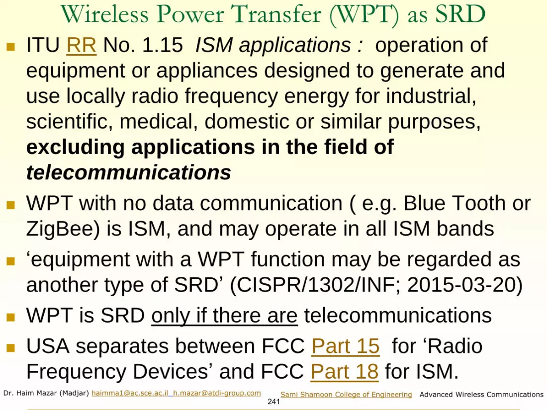
Dr. Haim Mazar (Madjar) [email protected] [email protected]
241Sami Shamoon College of Engineering Advanced Wireless Communications
Wireless Power Transfer (WPT) as SRD ◼ ITU RR No. 1.15 ISM applications : operation of
equipment or appliances designed to generate and
use locally radio frequency energy for industrial,
scientific, medical, domestic or similar purposes,
excluding applications in the field of
telecommunications
◼ WPT with no data communication ( e.g. Blue Tooth or
ZigBee) is ISM, and may operate in all ISM bands
◼ ‘equipment with a WPT function may be regarded as
another type of SRD’ (CISPR/1302/INF; 2015-03-20)
◼ WPT is SRD only if there are telecommunications
◼ USA separates between FCC Part 15 for ‘Radio
Frequency Devices’ and FCC Part 18 for ISM.

Dr. Haim Mazar (Madjar) [email protected] [email protected]
242Sami Shamoon College of Engineering Advanced Wireless Communications
Wave Impedance (z)of minute dipole & minute magnetic dipole 2
2
2( )
4
t t op g ePoyntingVector e h h z
d z= = = = relevant for far & near field
Source, Dipole Antenna -electric field is dominant
Normalized distance
Source, Loop Dipole-magnetic field is dominant

Dr. Haim Mazar (Madjar) [email protected] [email protected]
243Sami Shamoon College of Engineering Advanced Wireless Communications
Wave impedance
versus distanceSource: Ahn S.
(2017) Magnetic
Field Generation.
In: Suh N., Cho D.
(eds) The On-line
Electric Vehicle.
Springer, Cham.
https://doi.org/10.1
007/978-3-319-
51183-2_5; Fig 5.1

Dr. Haim Mazar (Madjar) [email protected] [email protected]
244Sami Shamoon College of Engineering Advanced Wireless Communications
UHF RFID: Americas versus Europe
RF band
(MHz)
Max e.i.r.p.
power (Watts)
Channels (kHz) Total RF BW
(MHz)
Approval process
Europe 865-868 up to 2 (e.r.p.)
x 1.64=3.2815 x 200 3 Radio Equipment Directive (RED)
Americas 902-928 4* 52 x 500 26 US tests every RFID
UWB emission masks in Europe and the USDifferences up to 49 dB@900-960MHz; Europe allowed UWB in 2005, US in 2001
244

Dr. Haim Mazar (Madjar) [email protected] [email protected]
245Sami Shamoon College of Engineering Advanced Wireless Communications
SRDs & smart sustainable world, cities, houses, cars; Internet of Things
Wireless networks provide vital infrastructure and connection of ICT’s that underpin the Smart Sustainable Cities
Source: ITU-T Report 2014 EMF Considerations in Smart Sustainable Cities

Dr. Haim Mazar (Madjar) [email protected] [email protected]
246Sami Shamoon College of Engineering Advanced Wireless Communications
Typical Emerging technology: Z-Wave, smart house
Z-Wave is designed mainly for
remote controls, smoke alarms and
security sensors
• Z-Wave uses a single frequency
FSK
• Data rate up to 100 Kbps; unlike
IEEE 802.11, designed primarily for
high-bandwidth data flow
• Range between controllers & slave
devices up to 100 ft
Country/Region Standard Z-Wave RF
Australia AS/NZS 4268 921.4 MHz
Brazil ANATEL Resolution 506 921.4 MHz
CEPT EN 300 220 868.4 MHz
Chile FCC CFR47 Part 15.249 908.4 MHz
China CNAS/EN 300 220 868.4 MHz
Hong Kong HKTA 1035 919.8 MHz
India CSR 564 (E) 865.2 MHz
Japan 950 (obsolete by end of 2015) ARIB T96 951-956 MHz
Japan 920 (since Feb 2012) ARIB STD-T108 922-926 MHz
Malaysia SKMM WTS SRD/EN 300 220 868.1 MHz
Mexico FCC CFR47 Part 15.249 908.4 MHz
New Zealand AS/NZS 4268 921.4 MHz
Russia GKRCh/EN 300 220 869.0 MHz
Singapore TS SRD/EN 300 220 868.4 MHz
South Africa ICASA/EN 300 220 868.4 MHz
Taiwan NCC/LP0002 922-926 MHz
UAE EN 300 220 868.4 MHz
USA/Canada FCC CFR47 Part 15.249 908.4 MHz
current sub-1GHz RF

Dr. Haim Mazar (Madjar) [email protected] [email protected]
247Sami Shamoon College of Engineering Advanced Wireless Communications
New Technologies, more immune to interference
Z-Wave
SRD, FSK signal, RF 916 MHz; 100 kbps; time domain
Same real SRD FSK signal, RF 916 MHz; RF domain

Dr. Haim Mazar (Madjar) [email protected] [email protected]
248Sami Shamoon College of Engineering Advanced Wireless Communications
UHF RFID Reader; real time analyzer: time & RF domains view
Tari 25 µs (40 kbps),
Phase-Reversal ASK (PR-ASK)
Siemens SIMATIC RF680R
power up phase, CW carrier & the modulation starting after about 10 ms
time domain
frequency domain
@ marker’s time
Phase-Reversal ASK (PR-ASK)

Dr. Haim Mazar (Madjar) [email protected] [email protected]
249Sami Shamoon College of Engineering Advanced Wireless Communications
SRD to track (& preserve) short-toed snake-eagle (regulated by the author)

Dr. Haim Mazar (Madjar) [email protected] [email protected]
250Sami Shamoon College of Engineering Advanced Wireless Communications
Rec. ITU-R SM.1896– RF ranges for global or regional harmonization
SRD applications are increasing, which result in
increasing spectrum demands
Water meter with built-in AMR radio module
Solar-powered wirelessrelay for AMR
Wireless wastewater & sewage level monitoring unit
with tilt sensors

Dr. Haim Mazar (Madjar) [email protected] [email protected]
251Sami Shamoon College of Engineering Advanced Wireless Communications
Rec. SM.1896 annex1: RF for global harmonization of SRDs
RF Range Remarks
9-148.5 kHz Inductive SRD applications
3 155-3 400 kHz Inductive SRD applications RR No. 5.116
6 765-6 795 kHz Inductive SRD applications ISM band (RR No. 5.138)
Centre frequency 6 780 kHz
13.553-
13.567 MHz
Inductive SRD applications; ISM band (RR No. 5.150);
Centre frequency 13.560 MHz; Level of side band
suppression is dependent on national regulations
26.957-
27.283 MHz
Inductive SRD applications/non-specific SRDs; ISM band
(RR No. 5.150); Centre frequency 27 120 kHz
40.66-40.7 MHz ISM band (RR No. 5.150); Centre frequency 40.68 MHz
2 400-2 500 MHz ISM band (RR No. 5.150); Centre frequency 2 450 MHz
5 725-5 875 MHz ISM band (RR No. 5.150); Centre frequency 5 800 MHz
24.00-24.25 GHz ISM band (RR No. 5.150); Centre frequency 24.125 GHz
61.0-61.5 GHz ISM band (RR No. 5.138); Centre frequency 61.25 GHz
122-123 GHz ISM band (RR No. 5.138); Centre frequency 122.5 GHz
244-246 GHz ISM band (RR No. 5.138); Centre frequency 245 GHz
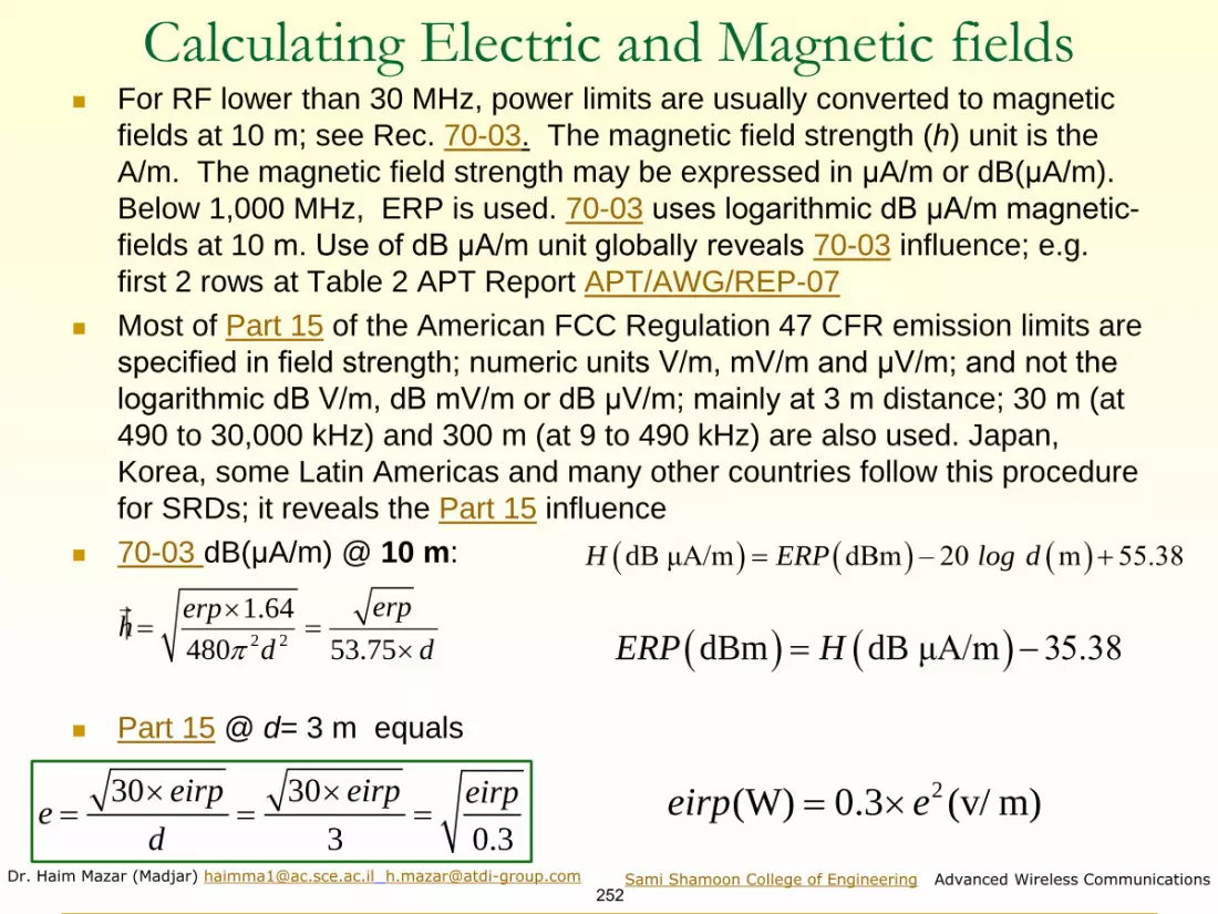
Dr. Haim Mazar (Madjar) [email protected] [email protected]
252Sami Shamoon College of Engineering Advanced Wireless Communications
Calculating Electric and Magnetic fields◼ For RF lower than 30 MHz, power limits are usually converted to magnetic
fields at 10 m; see Rec. 70-03. The magnetic field strength (h) unit is the
A/m. The magnetic field strength may be expressed in μA/m or dB(μA/m).
Below 1,000 MHz, ERP is used. 70-03 uses logarithmic dB µA/m magnetic-
fields at 10 m. Use of dB µA/m unit globally reveals 70-03 influence; e.g.
first 2 rows at Table 2 APT Report APT/AWG/REP-07
◼ Most of Part 15 of the American FCC Regulation 47 CFR emission limits are
specified in field strength; numeric units V/m, mV/m and µV/m; and not the
logarithmic dB V/m, dB mV/m or dB µV/m; mainly at 3 m distance; 30 m (at
490 to 30,000 kHz) and 300 m (at 9 to 490 kHz) are also used. Japan,
Korea, some Latin Americas and many other countries follow this procedure
for SRDs; it reveals the Part 15 influence
◼ 70-03 dB(μA/m) @ 10 m:
◼ Part 15 @ d= 3 m equals
2 2
1.64
480 53.75
erperph
d d
= =
( ) ( ) ( )dB μA/m dBm – 20 m 55.38H ERP log d= +
( ) ( )dBm dB μA/m 35.38ERP H= −
30 30
3 0.3
eirp eirp eirpe
d
= = =
2(W) 0.3 (v/ m)eirp e=
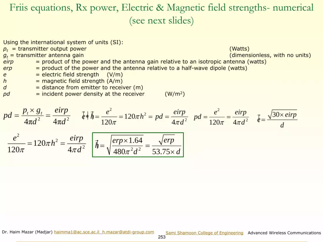
Dr. Haim Mazar (Madjar) [email protected] [email protected]
253Sami Shamoon College of Engineering Advanced Wireless Communications
Friis equations, Rx power, Electric & Magnetic field strengths- numerical
(see next slides)
Using the international system of units (SI):pt = transmitter output power (Watts)gt = transmitter antenna gain (dimensionless, with no units)eirp = product of the power and the antenna gain relative to an isotropic antenna (watts)erp = product of the power and the antenna relative to a half-wave dipole (watts)e = electric field strength (V/m) h = magnetic field strength (A/m) d = distance from emitter to receiver (m)pd = incident power density at the receiver (W/m2)
2 24π 4π
t tp g eirp
d dpd
==
22
2120
120 4
e eirpe h h pd
d
= = = =
2
2120 4pd
e eirp
d == 30 eirp
ed
=
22
2120
120 4
e eirph
d
= =
2 2
1.64
480 53.75
erperph
d d
= =

Dr. Haim Mazar (Madjar) [email protected] [email protected]
254Sami Shamoon College of Engineering Advanced Wireless Communications
Free Space loss, Electric Field-Strength(see next slides)
pt=tx power, g= antenna gain d=distance, pt x g- e.i.r.p. e=field strength h=magnetic field
2 2
. . . .30
e de i r p
=
Where e (V/m), h (A/m), the impedance the impedance Z0 (Ω) relates the magnitudes of electric and magnetic fields travelling through free space. Z0 ≡ |E|/|H|. From the plane wave solution to Maxwell’s equations , the impedance of free space equals the product of the vacuum permeability (or magnetic constant) μ0 and the speed of light c0 in a free space. The numerical equivalent isotropically radiated power is e.i.r.p. (W) and logarithmic E.I.R.P. (dBW)
00 0 0
0 0 0
1120 376.730 313 461 377Ohmz c
c
mm
= =
2
2( )
4
t t o
o
p g ePoyntingVector e h
d z= = =
0
0 0
1c
m
Ԧ𝑒 =30 × 𝑝𝑡 × 𝑔𝑡
𝑑=
30 × 𝑒. 𝑖. 𝑟. 𝑝.
𝑑𝑑 =
30 × 𝑒. 𝑖. 𝑟. 𝑝.
Ԧ𝑒

Dr. Haim Mazar (Madjar) [email protected] [email protected]
255Sami Shamoon College of Engineering Advanced Wireless Communications
Free Space loss, electric field-strength (numeric to log scale)See next similar slide, on magnetic field-strength
E (dBV/m) = E.I.R.P. (dB(W) - 20 log d (m) +14.8, and changing units,
E (dBµV/m)-120= E.I.R.P. (dB(W) - 20 log d (km ) - 60 + 14.8, thus
E (dBµV/m) = E.I.R.P. (dB(W) -20 log d (km) + 74.8 and
E.I.R.P. (dB(W)= E (dBµV/m) +20 log d (km) − 74.8
See, isotropically Pr received power for a given field strength; see Rec. ITU-R P.525 equation (7)
Received isotropically Pr (dB(W) = E (dBµV/m) - 20 log f (GHz) - 167.2; see P.525 equation (8)
Free-space basic transmission loss for a given isotropically transmitted power and field strength:
Lbf (dB) = Pt (dB(W) - E (dBµV/m) + 20 log f (GHz) + 167.2; see P.525 equation (9)
Power flux-density for a given field strength: S(dB(W/m2) = E (dBµV/m –145.8 P.525 equation (10)
Pt : isotropically transmitted power (dB(W))
Pr : isotropically received power (dB(W))
E : electric field strength (dB(mV/m))
f : frequency (GHz)
d : radio path length (km)
Lbf : free-space basic transmission loss (dB)
S : power flux-density (dB(W/m2))
Free-space E relative to half-wave dipole for 1 kW e.r.p. is : E dB(mV/m)= 106.9 – 20 log d (km)
30 . . . .e i r pe
d
= 20log 10log 30 . . . . 20 log 14.8 . . . . 20 loge E E I R P d E I R P d= = + − = + −

Dr. Haim Mazar (Madjar) [email protected] [email protected]
256Sami Shamoon College of Engineering Advanced Wireless Communications
Free Space loss, magnetic field-strength (numeric to log scale)
H (dBA/m) = E.I.R.P. (dB(W) - 20 log d (m) - 20 log (sqrt 480 x π)=
=E.I.R.P. (dB(W) - 20 log d (m) – 36.8, and changing units,
H (dBµA/m)-120= E.I.R.P. (dB(W) - 20 log d (km ) - 60 - 36.8, thus
H (dBµA/m) = E.I.R.P. (dB(W) - 20 log d (km) + 23.2 and
E.I.R.P. (dB(W) = H (dBµA/m) +2 0 log d (km) - 23.2
Pt : isotropically transmitted power (dB(W))
Pr : isotropically received power (dB(W))
H : electric field strength (dB(mA/m))
f : frequency (GHz)
d : radio path length (km)
Lbf : free-space basic transmission loss (dB)
30 . . . . . . . .
120 120 480
e i r p e i r peh
d d
= = =
and 𝑒. 𝑖. 𝑟. 𝑝. = 480𝜋2 × ℎ2 × 𝑑2
For example: assuming free-space loss, given H=68 dBµA/m @ 10 m, Pt dB(W) = H (dBµA/m) +20 log d (km) − 23.2= 68 (dBµA/m) +20 log 0.01 (km) − 23.2= 68-40-23.2=4.8 dB(W), equivalent to 3 W.
Interesting to compareE.I.R.P. (dB(W) = H (dBµA/m) +2 0 log d (km) - 23.2 and
E.I.R.P. (dB(W)= E (dBµV/m) +20 log d (km) − 74.8
As h=120πxe, 20log e/h= 20log(120π)=51.52 ~ (64.8-23.2)

Dr. Haim Mazar (Madjar) [email protected] [email protected]
257Sami Shamoon College of Engineering Advanced Wireless Communications
Regulating SRDs
Reducing interference:Indoor, Internal antenna, Duty Cycle and Activity Factor, Dynamic Frequency Selection (DFS), Adaptive Frequency Agility (AFA), Listen Before Talk (LBT), Aloha: Carrier Sensing (CS) and Collision Detection (CD), Transmitter Power Control (TPC), One-Time Programmable (OTP), Spread-spectrum techniques such as Frequency-Hopping Spread Spectrum (FHSS)
Administrations define: RF bands, power, channel spacing & mitigation requirements
Risk vs. Risk: reducing RF power & BW of SRD or UWB may preclude the entry of new technology. Benefit vs. Benefit: more RF resources available to the citizen & more RF power & BW for SRDs advance rapid growth of new technologies and services. More RF, less congestion and less ‘tragedy of commons’ in the RF ‘public park’
Will first responders use ‘unprotected’ RF bands?
No need to regulate non-active RFID: de minimis non curat lex
Regulators pay most attention to the RF bands cellular & SRD
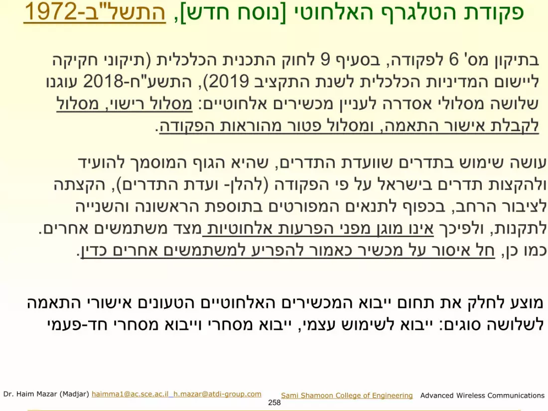
Dr. Haim Mazar (Madjar) [email protected] [email protected]
258Sami Shamoon College of Engineering Advanced Wireless Communications
1972-ב"התשל, [נוסח חדש]פקודת הטלגרף האלחוטי
תיקוני חקיקה (הכלכלית התכניתלחוק 9בסעיף , לפקודה6' בתיקון מס
עוגנו 2018-ח"התשע, )2019ליישום המדיניות הכלכלית לשנת התקציב
מסלול , מסלול רישוי: שלושה מסלולי אסדרה לעניין מכשירים אלחוטיים
.ומסלול פטור מהוראות הפקודה, לקבלת אישור התאמה
שהיא הגוף המוסמך להועיד , עושה שימוש בתדרים שוועדת התדרים
הקצתה , )ועדת התדרים-להלן(ולהקצות תדרים בישראל על פי הפקודה
בכפוף לתנאים המפורטים בתוספת הראשונה והשנייה , לציבור הרחב
. מצד משתמשים אחריםאינו מוגן מפני הפרעות אלחוטיות ולפיכך , לתקנות
.חל איסור על מכשיר כאמור להפריע למשתמשים אחרים כדין, כמו כן
מוצע לחלק את תחום ייבוא המכשירים האלחוטיים הטעונים אישורי התאמה
פעמי-ייבוא מסחרי וייבוא מסחרי חד, ייבוא לשימוש עצמי: לשלושה סוגים

Dr. Haim Mazar (Madjar) [email protected] [email protected]
259Sami Shamoon College of Engineering Advanced Wireless Communications
Interference of
SRDs to wireless
services: at low
RF no significant
degradation
Below 30 MHz, externalnoise is most influential atvictim receiver. Thus, asatmospheric, man-made,galactic noises & emissionsfrom atmospheric gasesand hydrometeors aredominant: they arestronger than the KTBFpower. Therefore, SRDsoperating below 30 MHz,interfere less than SRDs athigher frequencies.
Atmospheric and man-made noise, 10 kHz to 100 MHz (P.372, 2019)

Dr. Haim Mazar (Madjar) [email protected] [email protected]
260Sami Shamoon College of Engineering Advanced Wireless Communications
Four case-studies: WiFi; RFID, Citizen Band, IoT
1. Wi-Fi, RLAN, WLAN, U-NII (Unlicensed-National
Information Infrastructure) operating in 5.15-5.35 GHz
and 5.470–5.85 GHz)- including Recs ITU-R M.1454
2000 & RS.1632 2006)
2. RFID : Report ITU-R SM.2255 (2012) Characteristics,
standards and frequency bands for RFID and ETSI EN
302 208-2 (2011) RFID Equipment operating in the
band 865 MHz to 868 MHz with power levels up to 2W
3. ISM and Citizen Band 26.96–27.28 MHz: RR ISM,
applications, RR Article 5 allocations to radio services,
technical parameters of SRDs around the world
4. Internet of Things

Dr. Haim Mazar (Madjar) [email protected] [email protected]
261Sami Shamoon College of Engineering Advanced Wireless Communications
Wi-Fi Global: derived from ITU-R Rec. M.1450 (2014)
Characteristics
IEEE
Std
802.11-
2012
(Clause
17,
commo
nly
known
as
802.11
b)
IEEE Std
802.11-
2012
(Clause 18,
commonly
known
as
802.11a)
IEEE Std
802.11-2012
(Clause 19,
commonly
known as
802.11g)
IEEE Std
802.11-2012
(Clause 18,
Annex D and
Annex E,
commonly
known as
802.11j)
IEEE Std
802.11-2012
(Clause 20,
commonly
known as
802.11n)
IEEE
P802.11a
c
IEEE Std
802.11ad-
2012
ETSI
EN 300
328
ETSI
EN 301
893
ARIB
HiSWANa,
ETSI
EN
302
567
Frequency
band
2 400-
2 483.
5
MHz
5 150-
5 250 MHz
5 250-
5 350
MHz(4)
5 470-5
725 MHz
5 725-
5 825 MHz
2 400-2
483.5 MHz
4 940-4 990 MHz
5 030-5 091 MHz
5 150-5 250 MHz
5 250-5 350 MHz
5 470-5 725 MHz
5 725-5 825 MHz
2 400-2 483,5
MHz
5 150-5 250
MHz
5 250-5 350
MHz
5 470-5 725
MHz
5 725-5 825
MHz
5 150-5
250 MHz
5 250-5
350 MHz
5 470-5
725 MHz
5 725-5
825 MHz
57-66
GHz
2 400-2
483.5
MHz
5 150-
5 350
and
5 470-
5 725
MHz
4 900 to
5 000 MHz
5 150 to
5 250 MHz
57-
66
GHz
Interference
mitigation
LBT LBT/DFS/
TPC
LBT LBT LBT/DFS/T
PC
LBT/DFS
/TPC
LBT DAA/LBT,
DAA/non-
LBT, MU
LBT/DF
S/TPC
LBT
Channel
indexing
5 MHz 5 MHz in
2.4 GHz
20 MHz in 5
GHz
20 MHz 2 160
MHz
20 MHz 20 MHz
channel
spacing 4
channels
in 100 MHz
Characteristics associated with broadband RLAN standards

Dr. Haim Mazar (Madjar) [email protected] [email protected]
262Sami Shamoon College of Engineering Advanced Wireless Communications
WLAN: IEEE 802.11 Network bearer standards Source: also Radio-Electronics.com
Summary of major 802.11 Wi-Fi Standards
^ known also as µwave Wi-Fi; brand name WiGig operating in the 2.4, 5 and 60 GHz bands;* known also as Gigabit Wi-Fi, 5G Wi-Fi and 5G very high throughput (VHT);** known also as White-Fi and Super Wi-Fi;*** maximum data rate is 426.7 Mbit/s in 6 and 7 MHz channels, and 568.9 Mbit/s for 8 MHz channels.
802.11a 802.11b 802.11g 802.11n 802.11ad^ 802.11ac* 802.11af**
Date of standard
approval
(release)
Sept.
1999
Sept.
1999
June
2003
Oct.
2009
Dec. 2012Dec.
2013
February
2014
Maximum data
rate (Mbps)
54 11 54 < 600 <7 Gbps < 600***
Modulation OFDM CCK or
DSSS
CCK, DSSS, or
OFDM
SC and
OFDM
OFDM
RF Band (GHz) 5 2.4 2.4 or 5 60 5 TV bands
below 1 GHz
Number of
spatial streams
1 1 to 4 5 to 8 1,2,3,4 or
8
up to four
streams
Channel width
(MHz) nominal
20 20 or 40 80 or 160 20, 40,
80, 160
8 in Europe; 6
in N. America

Dr. Haim Mazar (Madjar) [email protected] [email protected]
263Sami Shamoon College of Engineering Advanced Wireless Communications
IEEE 802.11: IEEE Standard for Information technology--Telecommunications and
information exchange between systems - Local and metropolitan area networks--Specific
requirements - Part 11: Wireless LAN Medium Access Control (MAC) and Physical Layer
(PHY) Specifications:
◼ 802.11aq-2018 802.11aq-2018 - Amendment 5: Preassociation
Discovery
◼ 802.11ak-2018 802.11ak-2018 - Amendment 4: Enhancements
for Transit Links Within Bridged Networks
◼ 802.11aj-2018 802.11aj-2018 - Amendment 3: Enhancements
for Very High Throughput to Support Chinese Millimeter Wave
Frequency Bands (60 GHz and 45 GHz)
◼ 802.11ah-2016 802.11ah-2016 - Amendment 2: Sub 1 GHz
License Exempt Operation
◼ 802.11ai-20168 02.11ai-2016 - - 1: Fast Initial Link Setup
◼ 802.11-2016 802.11-2016 Specifications

264
Dr. Haim Mazar (Madjar) [email protected] Sami Shamoon College of Engineering Advanced Wireless Communications
Sub-carriers for High Throughput (HT) & wider channels (Source: Aruba 2013)
52 subcarriers (48 usable) for a 20 MHz non-
HT mode (legacy 802.11a/g) channel
fc+10MHz-10MHz
26 carriers 26 carriers
56 subcarriers (52 usable) for a 20 MHz
HT mode (802.11n) channel
fc+10MHz-10MHz
28 carriers 28 carriers
114 subcarriers (108 usable) for a 40 MHz HT mode (802.11n) channel
fc+10MHz-20MHz
57 carriers 57 carriers
+20MHz-10MHz
242 subcarriers (234 usable) for a 80 MHz Very HT mode (802.11ac) channel
An 80+80MHz or 16MHz channel is exactly two 80MHz channels, for 484 subcarriers (468 usable)
fc+10MHz-20MHz
121 carriers 121 carriers
+20MHz-10MHz-40MHz -30MHz +30MHz +40MHz
OFDM subcarriers used in 802.11a, 802.11n and 802.11ac

Dr. Haim Mazar (Madjar) [email protected] [email protected]
265Sami Shamoon College of Engineering Advanced Wireless Communications
Wi-Fi offload to improve cellular capacity (2) (more on offload)
(Sources: KDDI May 2013 and Alvarion October 2013)
• In congested areas (outdoors & indoors), the growing need of mobile data exceeds the available cellular capacity
• Main usage: city centers, big malls, airports, train station, stadiums
• WiFi is the most cost effective solution for data offloading
– RF Spectrum free of charge (at 2.4 GHz and 5 GHz)
– Embedded in all smartphones and tablets
Shibuya station of Tokyo Metro; 15 April 2013
~150 access points (APs) & more than 1800 stations (STAs) were observed in Ch1 in 2.4GHz band, in Shibuya Metro
In Seoul KTX train station, 351 APs and 1101 STAs were observed in 2.4 GHz band. In underground COEX mall, 277 APs and 917 STAs were observed in 2.4 GHz band

Dr. Haim Mazar (Madjar) [email protected] [email protected]
266Sami Shamoon College of Engineering Advanced Wireless Communications
Case Study: 2
RFID : Report SM.2255 (2012)Characteristics, standards and RF for RFID, ERC Rec
70-03 Relating to the Use of SRDs, ETSI EN 302 208-2 RFID operating at 865-868
MHz up to 2W, CFR 47 FCC Part 15—Radio Frequency Devices
Typical RFID application for safer & more efficient blood supply chain

Dr. Haim Mazar (Madjar) [email protected] [email protected]
267Sami Shamoon College of Engineering Advanced Wireless Communications
RFIDs - general
The pharmaceutical industry distributes regular pharmaceuticals through a complex supply chain involving
thousands of trading partners through multiple transaction levels. RFID assists to stem the influx of counterfeit
drugs. RFIDs "track and trace" a precision drug from the time pharmaceutical product leaves the factory to the
moment a patient receives it. Histories and authenticity are established. (Source : ALIEN)
EPC - Electronic Product Code is one of the standards for Global RFID developed by GS1; it’s
an eventual successor to the bar code, using RFID technology. EPC is a string of numbers & letters ,consisting
of a header and three sets of data: the first partition identifies the manufacturer; the second identifies the Product
type and the third the serial number unique to the item (source : RFID Journal)
Better Visibility: getting more in less time with reduce costs. RFID reduces manual and error-prone activity, by
automating product visibility (Source: Motorola)
RFID in the DOD supply chain: RFID allows military logisticians to synthesize and integrate end-to-end
information about assets . On July 2004 the DOD issued a policy requiring the implementation of RFID across
DOD (Source :Army Logistician)
Advantages over Barcode:
• Legible without visibility; enables reading of several labels simultaneously • Legible from great distance -active RFID up to 300 feet and more• No need for line of sight with the object• Able to read and write, can add data and identify individual items• Resistant to humidity and temperature; immune to dirt and dust
In general, passive and active tags can be differentiated by the existence of the battery in the tag. Active tags use
battery as power source to broadcast and communicate with the reader. The power and effective range of active
tags are significantly higher than passive tags and therefore may interfere farther.

Dr. Haim Mazar (Madjar) [email protected] [email protected]
268Sami Shamoon College of Engineering Advanced Wireless Communications
Some RFIDs Applications1. Asset Management: RFID marked assets combined with mobile scanners provide a way to identify and manage them
2. Inventory Systems: RFIDs enable control of movement and constant monitoring of stored items (such as spare parts)
and their inventory level
3. Product Tracking: Products are tracked through the manufacturing process from start to finished product ,finished
product store and further through supply chain to end customer
4. Transportation and Logistics: Yard management, shipping containers; freight control at distribution centers use RFID
tracking. Voice Directed Warehousing: workers wear a headset which tells the worker where to go and what to do using verbal prompts. Workers
confirm by predefined commands. The speech recognition software has to be taught the few commands; the communication is wireless. Pick To Light
Warehousing: The system includes lights above the bins or racks where the worker picks different items .The worker scans a barcode on the picking
container that represents the customer order .A light on the bin or rack illuminates with a quantity to pick .The worker presses a button to confirm that the
picking of definite item has been completed .The communication between the barcode reader and the TCP/ip controller is wireless
5. The communication between the controller and the ligts is performed by two alternative methods :
6. -Transmits and receives data and power using 4 wires
7. -Tansmits data using WIFI antennas
8. Animal Tracking and Identification: implantable tag is used for wild animals, pets and ear tags for cattle and sheep
9. Hospitals and Healthcare: RFID wristbands are used to identify patients and active tags are used to mark medical
equipment ,especially essential ,to locate them in the hospital area
10. Timing Races: racers wear tags and antennas in mats across the track
11. Toll Road Management: instead of toll boxes or gates ,transponders are mounted on the windshield and readers
installed above the road. As the vehicle passes the reader its transponder is read and data sent to be processed
12. Cutting Tools: modern machining produce expensive parts; RFIDs guarantee that a part is processed with the correct
tool. RFID tag is mounted on the tool carrier; tag is read by a reader on the machine CNC program can be verified
13. Waste Management: waste disposal trucks equipped with RFID readers pick up bins equipped with RFID tags. Tags
are read: bin number, collection place and time are recorded and sent (e.g. via cellular modem) for further processing

Dr. Haim Mazar (Madjar) [email protected] [email protected]
269Sami Shamoon College of Engineering Advanced Wireless Communications
RFID and RFID regulation in Israel ; see ttps://www.nevo.co.il/law_html/law01/164_008.htm
1982-ב"תשמ, (2' מס( )אי תחולת הפקודה)צו הטלגרף האלחוטי
◼ RF 915 -917 MHz. Evidence is needed about Out Of Band emissions.
Spectrum mask of interrogators: EiRP: 2 Watts
◼ Out of Band power density per 100 KHz, average per hour:
❑ Below 915 MHz -74 dBm;
❑ Above 917 MHz -57 dBm.
2012-ב"צו תשע2003-ג"צו תשס
:אלהבתנאיםץ"מה917עד915התדריםפסבתוךהפועלים(1י)
2012-ב"צו תשע
2עלעולהאינוהספקםאשר,ץ"מה916.3עד915.5שלמרכזיבתדר(1);e.i.r.pוואט
–שוואשידוריברמת(2)
2012-ג"צו תשע
,לשעהבממוצע,-71dBmעלעולהשאינה,ץ"מה915לתדרמתחת(א);ץ"קה200שלבתחום
2012-ג"צו תשע
;ץ"קה25שלבתחום,-63.6dBmעלעולהשאינה,ץ"מה917לתדרמעל(ב)

Dr. Haim Mazar (Madjar) [email protected] [email protected]
270Sami Shamoon College of Engineering Advanced Wireless Communications
Case Study: 3
ISM & Citizen Band (CB) 26.96-27.28 MHz
◼ Definitions
◼ RR Article 5 allocations
◼ technical parameters of SRDs around the
world

Dr. Haim Mazar (Madjar) [email protected] [email protected]
271Sami Shamoon College of Engineering Advanced Wireless Communications
ISM and Citizen Band 26.96-27.28 MHz: RR ISM & applications
◼ Used around the world also as Citizen
Band
◼ Applications: voice like walkie-talkie,
baby monitoring, remote control, model
control (in the air, on land or over or
under the water surface), telecommand,
anti-theft and car alarms

Dr. Haim Mazar (Madjar) [email protected] [email protected]
272Sami Shamoon College of Engineering Advanced Wireless Communications
Global technical parameters of SRDs at ISM Band 26.957-27.283 MHz, See also Report ITU-R SM.2153 (2012)
Region/Country Type of useSpecific Frequencies (MHz)
Emission limit Reference
CEPT and many
other countries
annex 1: non-specific
SRD
26.957-27.283 42 dB(mA/m) at
10 m; 10 mW e.r.p.
ERC
Recommendation
70-0326.995, 27.045, 27.095, 27.145, 27.195
100 mW e.r.p.
< 0.1 % duty cycle
annex 8: model control 100 mW e.r.p.
annex 9: inductive
applications
26.957-27.283 (as in annex 1) 42 dB(mA/m) at
10 m
Americas any 26.965, 26.975, 26.985, 27.005, 27.015, 27.025, 27.035,
27.055, 27.065, 27.075, 27.085, 27.105, 27.115, 27.125,
27.135, 27.155, 27.165, 27.175, 27.185, 27.205, 27.215,
27.225, 27.255, 27.235, 27.245, 27.265, 27.275, 27.285,
27.295, 27.305, 27.315, 27.325, 27.335, 27.345, 27.355,
27.365, 27.375, 27.385, 27.395, 27.405 : 40 channels
10 mV/m at 3 m
equiv. to 30 µW
(e.i.r.p.)
15.227 Operation
within 26.96-27.28
MHz § 95.407 On
what channels may I
operate?
China model & toy remote-
control devices
26.975, 26.995, 27.025, 27.045, 27.075,
27.095, 27.125, 27.145, 27.175, 27.195,
27.225, 27.255 max bandwidth: 8 kHz
750 mW (e.r.p.)
Report ITU-R
SM.2153other SRDs 26.957 to 27.283 42 dB(mA/m) at
10 m
Korea simplex See Americas 3 W
Report ITU-R
SM.2153Radio
controller
for
model
automobile
and ship craft
26.995, …, 27.195 MHz (5 channels,
50 kHz space 10 mV/m @10 m
Equiv to 333 µW
(e.i.r.p.)toy, security
alarm or
telecommand
26.958-27.282 MHz
Russia car alarm 26.939-26.951 MHz 2 W. Duty cycle < 10%.
Max ant gain 3 dBsecurity alarm 26.954-26.966 MHz
Belarus,
Kazakhstan, Russiaanti-theft alarm 26.945
2 W SM.2153alarm & distress 26.960

Dr. Haim Mazar (Madjar) [email protected] [email protected]
273Sami Shamoon College of Engineering Advanced Wireless Communications
Smart grids, homes, and cities; intelligent transportation & smart energy management
SRDs may connect IoT to wireless networking
M2M via cellular or WiFi infrastructure, & other SRDs means
Examples for M2M/IoT applications include:RFID; Home automation and Smart meters
273
Case Study: 4
SRDs and Internet of Things (IoTs)

Dr. Haim Mazar (Madjar) [email protected] [email protected]
274Sami Shamoon College of Engineering Advanced Wireless Communications
LoRa Gateway 43m AGL building; installed roof-top;Down Link: RF 920 MHz MHz; 500mW ERP
LoRaWAN™: Low Power Wide Area (LPWA) Network ATDI coverage predictions
Planning tool simulating IoT application (LoRa), to cover entire city

Dr. Haim Mazar (Madjar) [email protected] [email protected]
275Sami Shamoon College of Engineering Advanced Wireless Communications
List of Acronyms and Abbreviations
AFA Adaptive Frequency Agility
AMR Automatic Meter Reading
APT Asia Pacific Telecommunity
bps Bits per Second
CB Citizen Band
CEPT European Conference of Postal and
Telecommunications Administrations
CFR Code of Federal Regulations
DAA Detect and Avoid
DFS Dynamic Frequency Selection
ECC Electronic Communications Committee
EPC Electronic Product Code
ERC European Radiocommunications
Committee
ERM Electromagnetic Compatibility and Radio
Spectrum Matters
ETSI European Telecommunications Standard
Institute
EU European Union
FHSS Frequency Hopping Spread Spectrum
FSK Frequency Shift Keying
ISM Industrial, Scientific and Medical
applications
IoT
LBT
Internet of Things
Listen Before Talk
R&TTE Directive 1999/5/EC on radio equipment &
telecommunications terminal equipment
RF Radio Frequency
RR ITU Radio Regulations
RFID Radio Frequency Identification
RLAN Radio Local Area Network
SRD Short Range Devices
TPC Transmitter Power Control
UWB Ultra Wide Band
WLAN Wireless Local Area Network

Dr. Haim Mazar (Madjar) [email protected] [email protected]
276Sami Shamoon College of Engineering Advanced Wireless Communications
Some author’s presentations on SRDs1. UHF Global And Regional Ruling and Standardization - The Case
Of Different Allocations To Short Range Devices (SRDs) & Electronic Devices , Go Global Compliance Academy TM
Webinar, 19 Feb. 20132. International, Regional & National Regulation of SRDs ITU
Workshop on SRDs, Geneva 3 June 20143. Telecommunication Certification Body, Council; 15 April 2015,
Baltimore MD; USA TCB is accredited by FCC to approve electronic devices
4. http://mazar.atwebpages.com/Downloads/China_Beijing_SRMC%209July15_SRD.pdf
5. http://mazar.atwebpages.com/Downloads/January%202016_SRD_Mazar_SNG&SRTC&XHY&GDRTC.pdf
6. ITU Workshop on IoT IoT deployment in SRD networks Geneva
22 Nov. 2016; video includes Author’s my 16 minutes presentation 2:36:13 till 2:53:10
7. On-line English workshop 20th April to 1st May 20208. Atelier de renforcement des capacités sur la gestion moderne du
spectre 11-15 mai 2020

Dr. Haim Mazar (Madjar) [email protected] [email protected]
277Sami Shamoon College of Engineering Advanced Wireless Communications
First and third files of the course are found at
◼ Advanced_Wireless_Communications_Mazar1_Engine
ering_2020.pdf identifier DOI 10.13140/RG.2.2.11529.80488
◼ Advanced_Wireless_Communications_Mazar3_Regulat
ion_EMC_HumanHazards_2020.pdfidentifier DOI 10.13140/RG.2.2.29984.74247
Dr. Haim Mazar (Madjar) [email protected] [email protected]
More info in my Wiley book 2016 ‘Radio Spectrum Management: Policies, Regulations, Standards
and Techniques’ : policies, regulations, standards and techniques’
http://mazar.atwebpages.com/


