Embed Size (px)
Citation preview
ORIGINAL RESEARCH
An assessment of various process strategiesfor improving precision in single point incremental forming
Khamis Essa & Peter Hartley
Received: 8 July 2010 /Accepted: 10 October 2010 /Published online: 30 October 2010# Springer-Verlag France 2010
Abstract Single point incremental forming (SPIF) is aprocess with the capability to form complex geometriesusing a tool of very simple geometry, without the needfor a matching die. However, large elastic springbackresulting from the die-less nature of the process cancause problems if high levels of accuracy are required.The aim of this investigation is to use numericalmodelling to investigate different strategies to improvethe process precision. A finite-element (FE) model hasbeen used to investigate the effects of adding a backingplate, a supporting kinematic tool and modifying thefinal stage of the tool path. The results show that thebacking plate will minimise the sheet bending near to theinitial tool contact location; the additional kinematic toolwill reduce springback; and the extension of the toolpath across the base of the sheet will eliminate the pilloweffect. The cumulative effect of introducing thesefeatures to the process shows an improvement in theoverall accuracy of the profile and in the thicknessdistributions of the final product. The results contributeto a better understanding of springback in SPIF.
Keywords Single point incremental forming . Finiteelement analysis . Backing plate . Kinematic tool . Processaccuracy
Introduction
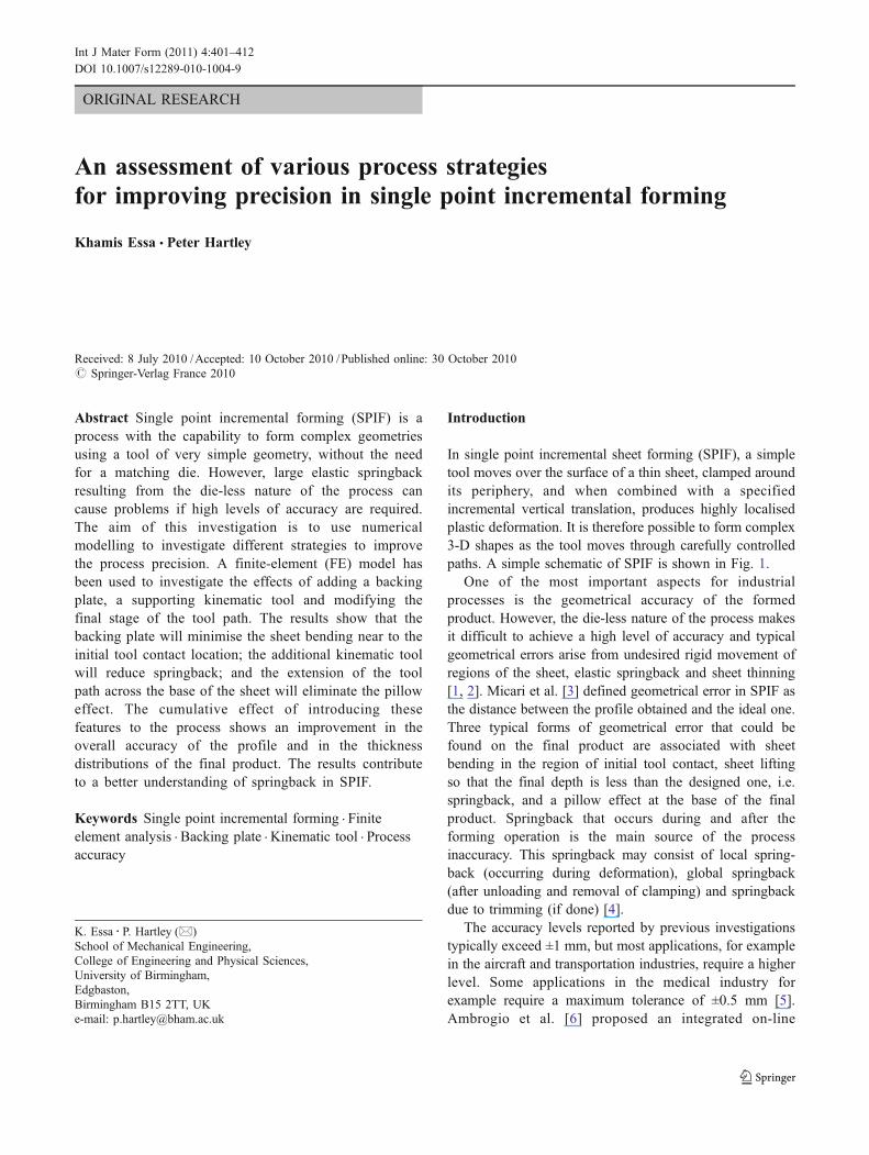
In single point incremental sheet forming (SPIF), a simpletool moves over the surface of a thin sheet, clamped aroundits periphery, and when combined with a specifiedincremental vertical translation, produces highly localisedplastic deformation. It is therefore possible to form complex3-D shapes as the tool moves through carefully controlledpaths. A simple schematic of SPIF is shown in Fig. 1.
One of the most important aspects for industrialprocesses is the geometrical accuracy of the formedproduct. However, the die-less nature of the process makesit difficult to achieve a high level of accuracy and typicalgeometrical errors arise from undesired rigid movement ofregions of the sheet, elastic springback and sheet thinning[1, 2]. Micari et al. [3] defined geometrical error in SPIF asthe distance between the profile obtained and the ideal one.Three typical forms of geometrical error that could befound on the final product are associated with sheetbending in the region of initial tool contact, sheet liftingso that the final depth is less than the designed one, i.e.springback, and a pillow effect at the base of the finalproduct. Springback that occurs during and after theforming operation is the main source of the processinaccuracy. This springback may consist of local spring-back (occurring during deformation), global springback(after unloading and removal of clamping) and springbackdue to trimming (if done) [4].
The accuracy levels reported by previous investigationstypically exceed ±1 mm, but most applications, for examplein the aircraft and transportation industries, require a higherlevel. Some applications in the medical industry forexample require a maximum tolerance of ±0.5 mm [5].Ambrogio et al. [6] proposed an integrated on-line
K. Essa : P. Hartley (*)School of Mechanical Engineering,College of Engineering and Physical Sciences,University of Birmingham,Edgbaston,Birmingham B15 2TT, UKe-mail: [email protected]
Int J Mater Form (2011) 4:401–412DOI 10.1007/s12289-010-1004-9
measuring system composed of a digital inspection andcomputer numerically controlled (CNC) open program tominimize profile errors. This system collected data on thegeometry in specific steps, and the subsequent tool pathwas modified to compensate for the geometrical errors.Ambrogio et al. [7] also used statistical analysis toinvestigate the effect of process variables on accuracy inSPIF. Based on a simple case study, process parameterssuch as tool diameter, step-down size, sheet thickness, wallangle and final depth were used to develop an analyticalmodel than can predict some of the geometrical errorsincluding springback and the pillow effect. Duflou et al. [8,9] used a laser beam through the forming tool to introducedynamic local heating, aimed at reducing the formingforces and improve springback behaviour to reduce thegeometrical errors. Attanasio et al. [10, 11] used twodifferent tool path strategies in which both a constant andvariable step-down (fixed scallop height) have beenintroduced. They concluded that the best dimensional andgeometrical accuracy was obtained by a fixed scallopheight. Franzen et al. [12] described the use of an additionalkinematic tool which moves on the bottom surface of thesheet in a synchronized motion with the forming tool.However, the effects of this arrangement on springbackwere not discussed. Bambach et al. [13] increased theaccuracy of SPIF by using a multi-stage forming process inwhich the final shape is obtained after stress reliefannealing between the forming stages. This retained ahigher level of accuracy after any trimming operation.
In SPIF, the complexity of the deformation is a result offactors such as the continually changing contact location,large plastic deformation and complex tool kinematics.Numerical methods, in particular FE modelling, permit adetailed study of the springback effect as experimentalmeasurements of this source of geometrical inaccuracy areextremely difficult. It allows a good prediction of thedeformation behaviour under a variety of working con-ditions. Previous work [4, 14, 15] has demonstrated thevalidity FE techniques in general for modelling SPIF. Also,Essa and Hartley [16] demonstrated the high level ofcorrelation between FE models and experimental data forthe forming of a truncated cone.
In this report, a 3D elastic-plastic FE model of theforming of a truncated cone using SPIF is used toinvestigate springback with various strategies to improvethe process accuracy. These involve the use of a backingplate, adding a supporting kinematic tool and modifying thetool path. The accumulated effect of these modifications onthe final geometrical precision is also investigated.
FE model for SPIF
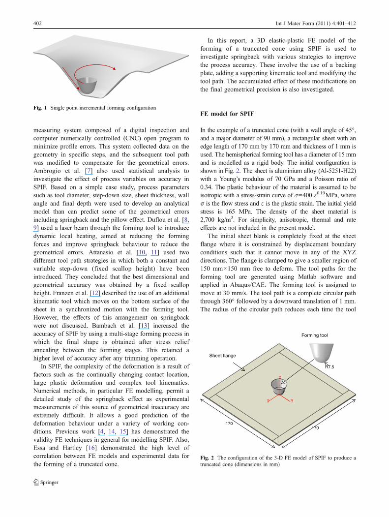
In the example of a truncated cone (with a wall angle of 45°,and a major diameter of 90 mm), a rectangular sheet with anedge length of 170 mm by 170 mm and thickness of 1 mm isused. The hemispherical forming tool has a diameter of 15 mmand is modelled as a rigid body. The initial configuration isshown in Fig. 2. The sheet is aluminium alloy (Al-5251-H22)with a Young’s modulus of 70 GPa and a Poisson ratio of0.34. The plastic behaviour of the material is assumed to beisotropic with a stress-strain curve of σ=400 ε0.19MPa, whereσ is the flow stress and ε is the plastic strain. The initial yieldstress is 165 MPa. The density of the sheet material is2,700 kg/m3. For simplicity, anisotropic, thermal and rateeffects are not included in the present model.
The initial sheet blank is completely fixed at the sheetflange where it is constrained by displacement boundaryconditions such that it cannot move in any of the XYZdirections. The flange is clamped to give a smaller region of150 mm×150 mm free to deform. The tool paths for theforming tool are generated using Matlab software andapplied in Abaqus/CAE. The forming tool is assigned tomove at 30 mm/s. The tool path is a complete circular paththrough 360° followed by a downward translation of 1 mm.The radius of the circular path reduces each time the tool
Sheet flange
170 170
Forming tool
R7.5
Fig. 2 The configuration of the 3-D FE model of SPIF to produce atruncated cone (dimensions in mm)
Fig. 1 Single point incremental forming configuration
402 Int J Mater Form (2011) 4:401–412
moves down by the step-down size, i.e. 1 mm. Surface tosurface contact between the forming tool and sheet surfaceis assumed and coulomb friction is set with a frictioncoefficient of 0.05 [16, 19]. The sheet was meshed with17,298 elements (8-node solid element with reducedintegration and hourglass control, C3D8R) with twoelements through the thickness. The simulations wereperformed using Abaqus/Implicit on an Intel® CoreTM
Dual computer with a 3 GHz CPU. The FE modelpresented above was used previously to explore through-thickness shear deformation [16, 17]. These reports de-scribe the performance of the solid elements chosen for thisanalysis and the development of a multi-level FE model[16], which could be combined with statistical techniques[17]; this required the extraction of a segment from the fullmodel with a highly refined mesh specifically to investigate
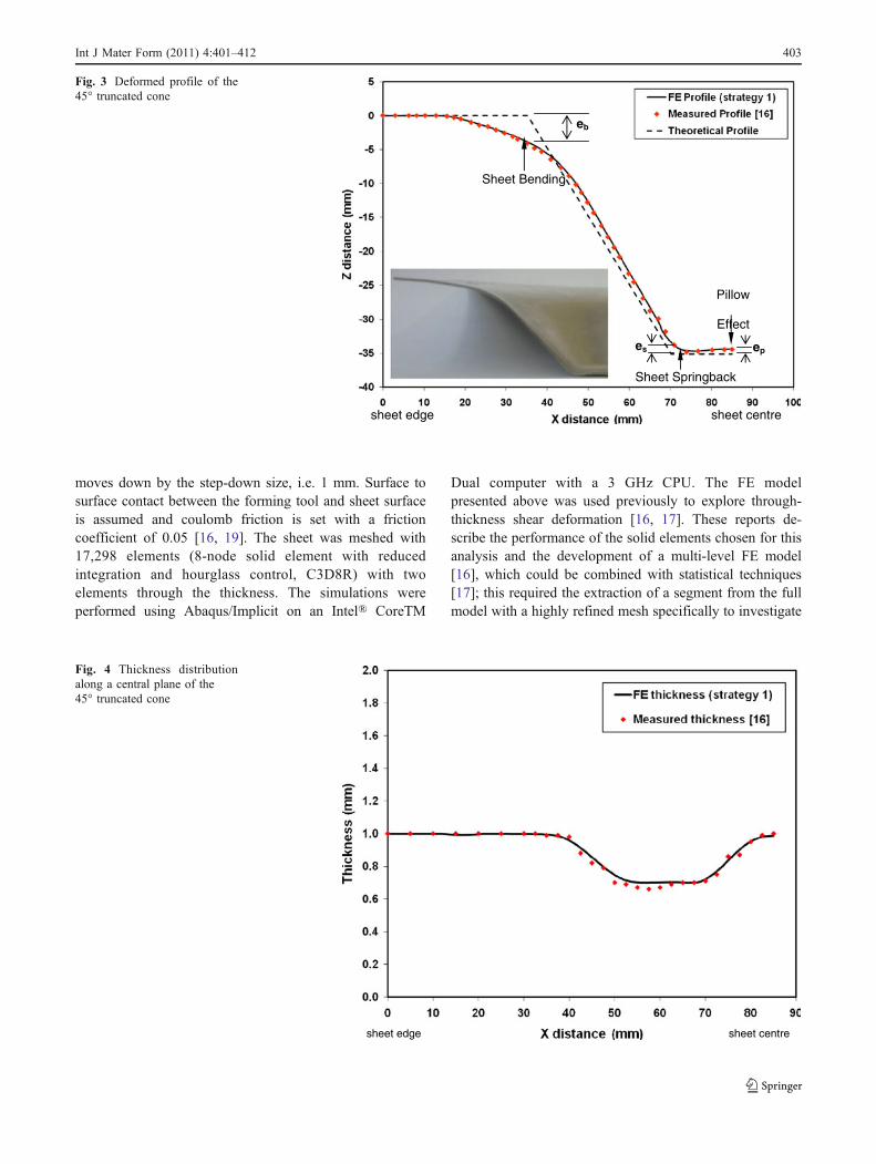
Sheet Springback
sheet edge sheet centre
eb
Sheet Bending
ep es
Pillow
Effect
Fig. 3 Deformed profile of the45° truncated cone
sheet edge sheet centre
Fig. 4 Thickness distributionalong a central plane of the45° truncated cone
Int J Mater Form (2011) 4:401–412 403
through-thickness shear strain. Experimental validation [16]has shown that two elements through the sheet thicknessare sufficient to deal with geometrical error, the focus of thecurrent paper, and therefore only a single level approach isnecessary. The more refined model is necessary if ananalysis of through thickness shear phenomena is required.
Four forming strategies are investigated.
1. This is based on the traditional method of SPIF and isprovided as a benchmark. The results have previouslybeen validated against experimental data [16].
2. This incorporates the use of an annular backing platelocated beneath the sheet.
3. In this strategy a supporting kinematic tool is used inaddition to the backing plate.
4. The final strategy is based on the same setup as strategy3 but incorporates modifications to the tool path so thatthe pillow effect at the sheet centre can be eliminated.
Strategy No 1
This strategy represents the traditional setup of SPIF with asingle forming tool that follows the contour of the partthrough a number of step-down levels. Figure 3 shows the
profile plots obtained by FE analysis and experimentalmeasurement from [16]. The experimental profile of thetruncated cone was obtained by measuring the profile on aco-ordinate measuring machine prior to any cutting to avoidany additional post-cutting springback. All the measure-ments were taken from the sheet edge to the centre of thepart. A theoretical profile of a 45° truncated cone is alsoplotted to show the geometrical errors. It can be seen thatthere is good agreement between the FE and experimentalprofiles. The FE model predicts the sheet bending close tothe major diameter of the cone, the springback at the conebase and the pillow effect at the centre of the cone, a featurealso observed by Micari et al. [3]. The sheet bending isexpected to be large since the deformation started at a largedistance, i.e. 35 mm, from the sheet flange.
The geometrical errors are evaluated as the distancebetween the theoretical and FE profiles [3]. According tothis definition, three measures eb, es and ep are used torepresent the different geometrical errors as shown inFig. 3. The deviation at the major diameter is given by ebwhich represents the geometrical error resulting from the
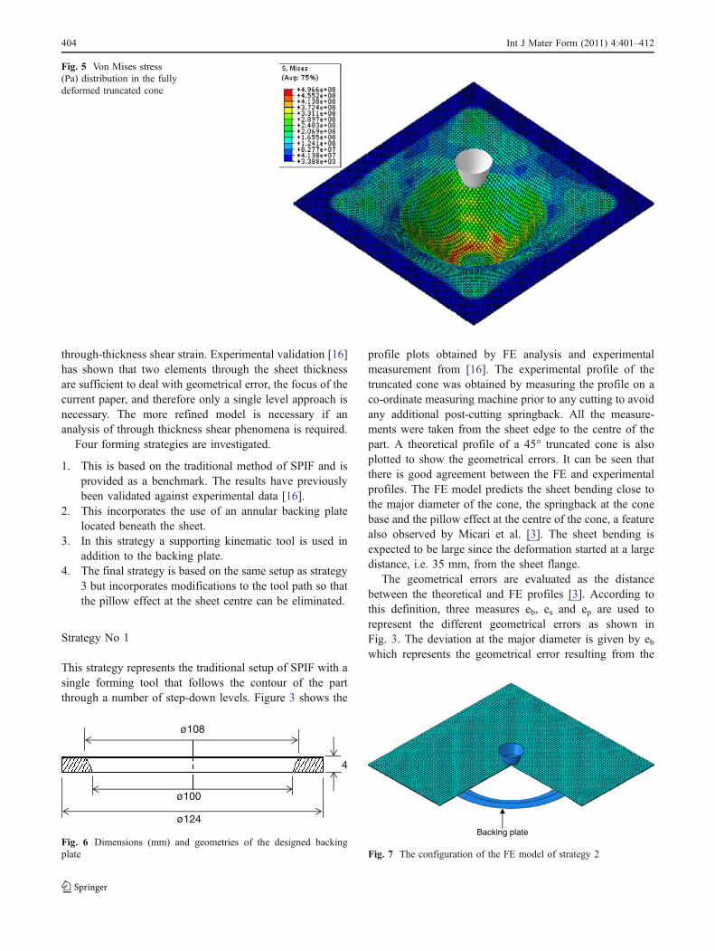
Fig. 5 Von Mises stress(Pa) distribution in the fullydeformed truncated cone
ø108
ø100
ø124
4
Fig. 6 Dimensions (mm) and geometries of the designed backingplate
Backing plate
Fig. 7 The configuration of the FE model of strategy 2
404 Int J Mater Form (2011) 4:401–412
sheet bending. The deviation at the minor base is shown byes which represents the sheet lifting resulting from spring-back. The deviation at the sheet centre is given by ep whichrepresents the geometrical error resulting from the pilloweffect. The values of eb, es and ep obtained from strategy 1are 3.99 mm, 1.52 and 0.63 mm respectively. The thicknessdistribution along the central plane of the deformed sheet isshown in Fig. 4. It can be seen that sheet thinning increasesas the cone depth increases. At a certain point near to thecone base, less thinning is apparent and the thickness isvery close to its original value. This would be expected instrategy 1 where the tool does not traverse the cone base.There is good agreement between the FE and measuredthickness variation. Figure 5 shows the von Mises stressdistribution in the deformed sheet at the end of the process.A largely uniform stress distribution develops along thecone wall with higher values around the last tool path as aresult of the materials reducing ability to unload at the endof deformation.
Strategies to improve the geometrical accuracy in SPIF
Although single point incremental forming can be per-formed using a simple forming tool without a dedicated die,
the process suffers from a lack in precision as a result ofminimal clamping, especially where the deformation startsat a large distance from the clamping frame, and due tosignificant springback. Strategies 2, 3 and 4 are investigatedto assess their potential for improving the geometricalaccuracy in SPIF processes. All FE models/strategies areperformed using Abaqus/Implicit code.
Strategy No 2
In the SPIF process, the distance between the forming areaand sheet flange is recommended to be as small as possibleto reduce the bending effect at the major diameter [3].Elastic springback will occur locally during deformationand globally after the forming process. Springback thatresults from post-processing such as trimming is notconsidered in the present model. The local springbackcould be reduced by using static dies [12]. These static diescould provide partial support or re-create the final productshape. The partial dies reduce springback in particular areasof deformation, while the full dies are much better but canbe used for specific products only and increase the toolingcost. The introduction of an annular backing plate instrategy 2, located beneath the sheet, extends the supportingstructure and minimises this distance. Strategy 2 thereforeaims to investigate the effect of the backing plate ongeometrical deviations, in particular the sheet bending atthe major diameter. Figure 6 shows the geometry anddimensions of the backing plate used for the truncated cone.The inner geometry of the plate is a circular profile that hasa fillet curvature of 4 mm radius in order to allow smoothcontact with the deformed material. The backing plate ismodelled as a rigid body and fixed concentrically under thesheet so that it cannot move in any direction. The FE modelfor strategy 2 is shown in Fig. 7.
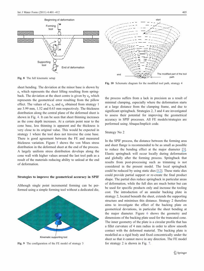
Beginning of deformation
End of deformation
Forming tool
Supporting tool
Fig. 8 The full kinematic setup
The modified part of the toolpath
start
end
Fig. 10 Schematic diagram for the modified tool path, strategy 4
Kinematic supporting tool
Fig. 9 The configuration of the FE model of strategy 3
Int J Mater Form (2011) 4:401–412 405
Strategy No 3
In this strategy a supporting kinematic tool is used inaddition to the backing plate as suggested in [12]. Althoughnot strictly SPIF, this could best be described as anenhanced SPIF process. The forming tool and the kinematicsupporting tool move in a synchronized motion andincrementally form the blank sheet into the required shapeas shown in the Fig. 8. The supporting tool has the same
dimensions and geometry of the forming tool. The new toolis modelled as a rigid body and its boundary condition isdefined so that it moves in a synchronized motion with theforming tool in the XY plane and is always in contact withthe bottom surface of the sheet. Surface to surface contactbetween the new tool and the bottom surface of the sheet isdefined and coulomb friction is set with a frictioncoefficient of 0.05. Figure 9 shows the FE model forstrategy 3.
sheet edge sheet centre
Fig. 11 Effect of the backingplate on the final profile
sheet edge sheet centre
Fig. 12 Effect of the kinematicsupporting tool on the finalprofile
406 Int J Mater Form (2011) 4:401–412
Strategy No 4
The final strategy is based on the same setup as strategy 3but incorporates modifications to the tool path so that thepillow effect at the sheet centre can be eliminated. Thepillow effect occurs when the final height at the sheet centreis less than that at the last tool position. If the requiredproduct geometry contains an area in which there is no
deformation imposed by the forming tool, such an effect isto be expected. In the example here the minor base of thetruncated cone represents such an area (see Fig. 5). It isclear that this defect, at the end of the forming process, is aresult of the product geometry, tool path and lack of supportat the sheet centre. The tool path is extended so that at theend of deformation, the forming tool and the kinematicsupporting tool continue circular paths on a horizontal
4mm
2mm
6mm
8mm10mm
sheet edge Sheet centre
Fig. 13 Deformation history us-ing strategy 1
4mm2mm
6mm 8mm
10mm
sheet edge sheet centre
Fig. 14 Deformation history us-ing strategy 3
Int J Mater Form (2011) 4:401–412 407
plane toward the sheet centre. This concept allows smallplastic deformation that leads to a flat surface instead of thecurved profile previously observed, so that the height at thesheet centre will be close to the desired height. Figure 10shows a schematic diagram for the modified tool path.
Results analysis and discussion
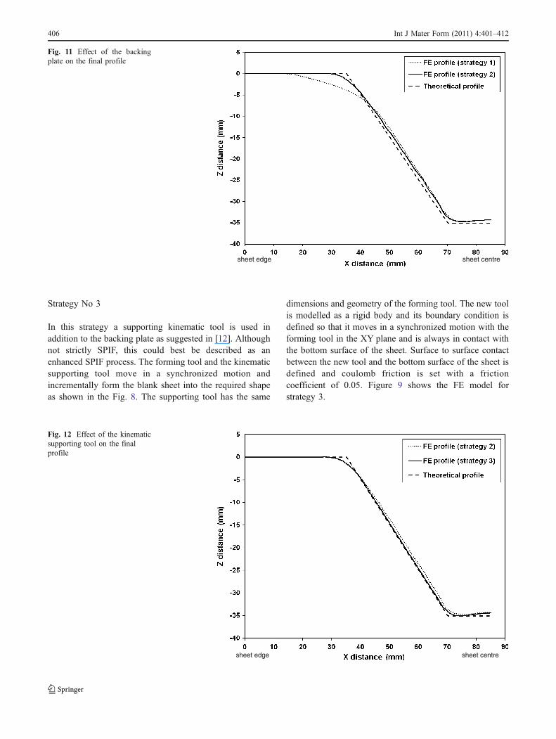
Figure 11 shows a comparison between strategy 1 and 2 toillustrate the effect of the backing plate on the final profile.
The theoretical profile is also plotted to show by how muchthe geometrical errors are reduced. Using strategy 2, asignificant reduction in the sheet bending at the majordiameter is achieved. The backing plate clearly increasesthe sheet rigidity by introducing additional support nearerto the deformation zone. However, there is no significantchange to the final profile either at the minor diameter or atthe cone centre. The results show that eb is reduced from3.99 mm to 1.62 mm while es and ep are found to be1.50 mm and 0.63 mm respectively. This suggests that thebacking plate could only reduce the deviation resulting
sheet edge sheet centre
Fig. 15 Effect of the modifiedtool path on the final profile
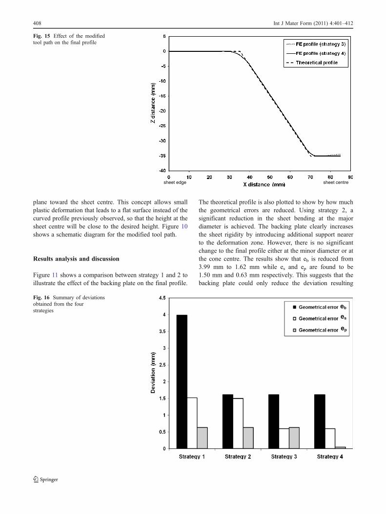
eb
es
ep
Fig. 16 Summary of deviationsobtained from the fourstrategies
408 Int J Mater Form (2011) 4:401–412
from the bending effect and it does not influence thedeviation resulting from the sheet springback and the pilloweffect.
In order to illustrate the effect of the kinematic supportingtool on the geometrical errors, a comparison between strategy2 and 3 is shown in Fig. 12. At the major diameter and sheetcentre of the truncated cone, there is no difference betweenstrategy 2 and 3 which means that the kinematic supporting
tool does not affect either the sheet bending or the pilloweffect. Along the cone wall until the minor diameter, there isa significant reduction in sheet springback as a result ofadding a new kinematic tool. The results show that only es isreduced from 1.50 mm by strategy 2–0.60 mm by strategy 3.The kinematic supporting tool leads to a greater localisationof the deformation underneath the forming tool and areduction of the local springback. Therefore, the cone wall
Higherlevel of
Von Misesstress (b) start mid-way base
(a) start mid-way base
Higherlevels of
Von Misesstress
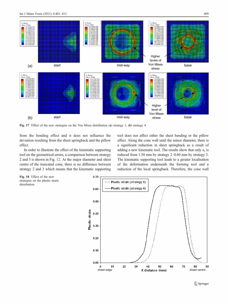
Fig. 17 Effect of the new strategies on the Von Mises distribution (a) strategy 1, (b) strategy 4
sheet edge sheet centre
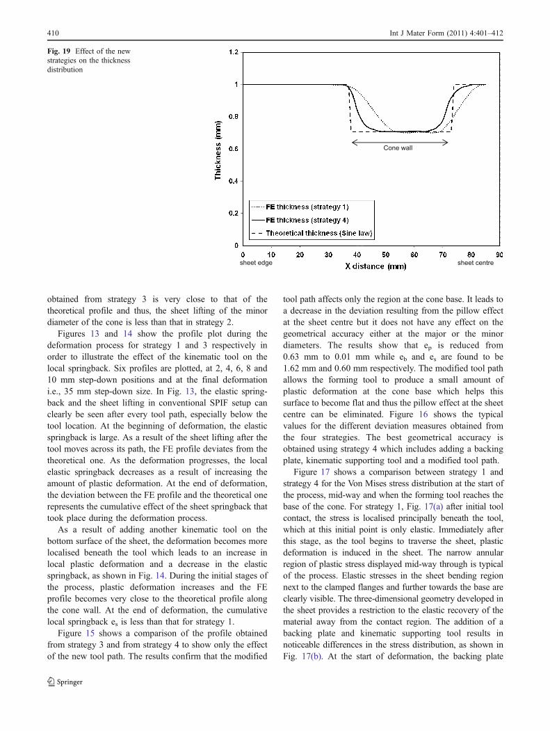
Fig. 18 Effect of the newstrategies on the plastic straindistribution
Int J Mater Form (2011) 4:401–412 409
obtained from strategy 3 is very close to that of thetheoretical profile and thus, the sheet lifting of the minordiameter of the cone is less than that in strategy 2.
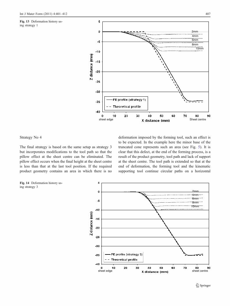
Figures 13 and 14 show the profile plot during thedeformation process for strategy 1 and 3 respectively inorder to illustrate the effect of the kinematic tool on thelocal springback. Six profiles are plotted, at 2, 4, 6, 8 and10 mm step-down positions and at the final deformationi.e., 35 mm step-down size. In Fig. 13, the elastic spring-back and the sheet lifting in conventional SPIF setup canclearly be seen after every tool path, especially below thetool location. At the beginning of deformation, the elasticspringback is large. As a result of the sheet lifting after thetool moves across its path, the FE profile deviates from thetheoretical one. As the deformation progresses, the localelastic springback decreases as a result of increasing theamount of plastic deformation. At the end of deformation,the deviation between the FE profile and the theoretical onerepresents the cumulative effect of the sheet springback thattook place during the deformation process.
As a result of adding another kinematic tool on thebottom surface of the sheet, the deformation becomes morelocalised beneath the tool which leads to an increase inlocal plastic deformation and a decrease in the elasticspringback, as shown in Fig. 14. During the initial stages ofthe process, plastic deformation increases and the FEprofile becomes very close to the theoretical profile alongthe cone wall. At the end of deformation, the cumulativelocal springback es is less than that for strategy 1.
Figure 15 shows a comparison of the profile obtainedfrom strategy 3 and from strategy 4 to show only the effectof the new tool path. The results confirm that the modified
tool path affects only the region at the cone base. It leads toa decrease in the deviation resulting from the pillow effectat the sheet centre but it does not have any effect on thegeometrical accuracy either at the major or the minordiameters. The results show that ep is reduced from0.63 mm to 0.01 mm while eb and es are found to be1.62 mm and 0.60 mm respectively. The modified tool pathallows the forming tool to produce a small amount ofplastic deformation at the cone base which helps thissurface to become flat and thus the pillow effect at the sheetcentre can be eliminated. Figure 16 shows the typicalvalues for the different deviation measures obtained fromthe four strategies. The best geometrical accuracy isobtained using strategy 4 which includes adding a backingplate, kinematic supporting tool and a modified tool path.
Figure 17 shows a comparison between strategy 1 andstrategy 4 for the Von Mises stress distribution at the start ofthe process, mid-way and when the forming tool reaches thebase of the cone. For strategy 1, Fig. 17(a) after initial toolcontact, the stress is localised principally beneath the tool,which at this initial point is only elastic. Immediately afterthis stage, as the tool begins to traverse the sheet, plasticdeformation is induced in the sheet. The narrow annularregion of plastic stress displayed mid-way through is typicalof the process. Elastic stresses in the sheet bending regionnext to the clamped flanges and further towards the base areclearly visible. The three-dimensional geometry developed inthe sheet provides a restriction to the elastic recovery of thematerial away from the contact region. The addition of abacking plate and kinematic supporting tool results innoticeable differences in the stress distribution, as shown inFig. 17(b). At the start of deformation, the backing plate
Cone wall
sheet edge sheet centre
Fig. 19 Effect of the newstrategies on the thicknessdistribution
410 Int J Mater Form (2011) 4:401–412
restricts the deformation area and hence the stress is morelocalised beneath the forming tool compared with that instrategy 1. As the deformation progresses, negligible stresscan be found in the region that surrounds the forming area asa result of using the backing plate and thus, the stresslocalises only in the area of deformation. The higher level ofVon Mises stress takes place underneath the forming tool i.e.,at the last tool position as a result of the kinematic supportingtool.
Figure 18 shows the plastic strain distribution obtainedfrom strategy 1 and strategy 4. For strategy 1, there can notbe any plastic strain at the sheet flange where the sheet iscompletely fixed. It then begins to increase at the start ofthe deformation area i.e., approximately 35 mm from thesheet edge. The maximum value of the plastic strain occurscorresponding to the location of maximum sheet thinningwhich takes place along the 45° wall angle. After this peak,the plastic deformation decreases towards the centre of thesheet. For strategy 4, the plastic strain starts earlier, near theinner edge of the backing plate. The maximum plastic strainis approximately uniform along the cone wall (between35 mm and 70 mm). It then decreases toward the sheetcentre. The plastic strain at the sheet centre is higher thanthat for strategy 1 as a result of the modified tool path andelimination of the pillow effect.
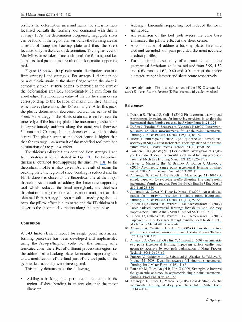
The thickness distributions obtained from strategy 1 andfrom strategy 4 are illustrated in Fig. 19. The theoreticalthickness obtained from applying the sine law [18] to thetheoretical profile is also given. As a result of using thebacking plate the region of sheet bending is reduced and theFE thickness is closer to the theoretical one at the majordiameter. As a result of adding the kinematic supportingtool which reduced the local springback, the thicknessdistribution along the cone wall is more uniform than thatobtained from strategy 1. As a result of modifying the toolpath, the pillow effect is eliminated and the FE thickness iscloser to the theoretical variation along the cone base.
Conclusion
A 3-D finite element model for single point incrementalforming processes has been developed and implementedusing the Abaqus/Implicit code. For the forming of atruncated cone, the effect of different process strategies, i.e.the addition of a backing plate, kinematic supporting tooland a modification of the final part of the tool path, on thegeometrical accuracy were investigated.
This study demonstrated the following,
& Adding a backing plate permitted a reduction in theregion of sheet bending in an area closer to the majordiameter.
& Adding a kinematic supporting tool reduced the localspringback.
& An extension of the tool path across the cone baseeliminated the pillow effect at the sheet centre.
& A combination of adding a backing plate, kinematictool and extended tool path provided the most accurateproduct profile.
& For the simple case study of a truncated cone, thegeometrical deviations could be reduced from 3.99, 1.52and 0.63 mm to 1.62, 0.60 and 0.01 mm at the majordiameter, minor diameter and sheet centre respectively.
Acknowledgments The financial support of the UK Overseas Re-search Students Awards Scheme (K Essa) is gratefully acknowledged.
References
1. Dejardin S, Thibaud S, Gelin J (2008) Finite element analysis andexperimental investigations for improving precision in single pointincremental sheet forming process. Int J Mater Form 1:121–124
2. Duflou J, Tunçkol Y, Szekeres A, Vanherck P (2007) Experimen-tal study on force measurements for single point incrementalforming. J Mater Process Technol 189(1–3):65–72
3. Micari F, Ambrogio G, Filice L (2007) Shape and dimensionalaccuracy in Single Point Incremental Forming: state of the art andfuture trends. J Mater Process Technol 191(1–3):390–395
4. Lasunon O, Knight W (2007) Comparative investigation of single-point and double-point incremental sheet metal forming processes.Proc Inst Mech Eng B: J Eng Manuf 221(12):1725–1732
5. Jeswiet J, Micari F, Hirt G, Bramley A, Duflou J, Allwood J(2005) Asymmetric single point incremental forming of sheetmetal. CIRP Ann - Manuf Technol 54(2):88–114
6. Ambrogio G, Filice L, De Napoli L, Muzzupappa M (2005) Asimple approach for reducing profile diverting in a single pointincremental forming process. Proc Inst Mech Eng B: J Eng Manuf219(11):823–830
7. Ambrogio G, Cozza V, Filice L, Micari F (2007) An analyticalmodel for improving precision in single point incrementalforming. J Mater Process Technol 191(1–3):92–95
8. Duflou JR, Callebaut B, Verbert J, De Baerdemaeker H (2007)Laser assisted incremental forming: formability and accuracyimprovement. CIRP Anna - Manuf Technol 56(1):273–276
9. Duflou JR, Callebaut B, Verbert J, De Baerdemaeker H (2008)Improved SPIF performance through dynamic local heating. Int JMach Tools Manuf 48(5):543–549
10. Attanasio A, Ceretti E, Giardini C (2006) Optimization of toolpath in two point incremental forming. J Mater Process Technol177(1–3):409–412
11. Attanasio A, Ceretti E, Giardini C, Mazzoni L (2008) Asymmetrictwo point incremental forming: improving surface quality andgeometric accuracy by tool path optimization. J Mater ProcessTechnol 197(1–3):59–67
12. Franzen V, Kwiatkowski L, Sebastiani G, Shankar R, Tekkaya E,Kleiner M (2008) Dyna-die: towards full kinematic incrementalforming. Int J Mater Form 1:1163–1166
13. Bambach M, Taleb Araghi B, Hirt G (2009) Strategies to improvethe geometric accuracy in asymmetric single point incrementalforming. Prod Eng 3(2):145–156
14. Ambrogio G, Filice L, Manco G (2008) Considerations on theincremental forming of deep geometries. Int J Mater Form1:1143–1146
Int J Mater Form (2011) 4:401–412 411

15. Ma LW, Mo JH (2008) Three-dimensional finite element methodsimulation of sheet metal single-point incremental forming and thedeformation pattern analysis. Proc Inst Mech Eng B: J Eng Manuf222(3):373–380
16. Essa K, Hartley P (2010) An evaluation of shear deformationmechanisms in single point incremental forming using a dual-levelfinite-element model. Submitted to CIRP Journal of Manufactur-ing Science and Technology, May
17. Essa K, Hartley P (2010) Investigation on the effects of processparameters on the through-thickness shear strain in single point
incremental forming using dual level FE modelling and statisticalanalysis. Accepted for publication in the Journal of ComputerMethods in Materials Science
18. Hussain G, Gao L (2007) A novel method to test the thinninglimits of sheet metals in negative incremental forming. Int J MachTools Manuf 47(3–4):419–435
19. Bambach M, Hirt G, Junk S (2003) Modelling and experimentalevaluation of the incremental CNC sheet metal forming process.In: Proceedings of the 7th International Conference on Computa-tional Plasticity. Barcelona, Spain, pp 1–17
412 Int J Mater Form (2011) 4:401–412


