Embed Size (px)
Citation preview

An Effective BIST Scheme for Carry-Save zyxwvutsrqponmlkjihgfedcbaZYXWVUTSRQPONMLKJIHGFEDCBAand Carry-Propagate Array Multipliers zyxwvutsrqponmlkjihgfedcbaZYXWVUTSRQPONMLKJIHGFEDCBA
Dimitris Gizopoulos Antonis Paschalis
I1 zyxwvutsrqponmlkjihgfedcbaZYXWVUTSRQPONMLKJIHGFEDCBA& T, NCSR ”Demokritos” Ag.Paraskevi, 15310 Athens, GREECE
Abstract zyxwvutsrqponmlkjihgfedcbaZYXWVUTSRQPONMLKJIHGFEDCBAArray multipliers, due zyxwvutsrqponmlkjihgfedcbaZYXWVUTSRQPONMLKJIHGFEDCBAto their high regularity, are
efficiently designed as zyxwvutsrqponmlkjihgfedcbaZYXWVUTSRQPONMLKJIHGFEDCBAparts of complex VZSI devices. Such embedded multipliers have low controllability and observability, making the use of appropriate BIST schemes a necessity. This paper introduces a very ef- fective BIST scheme zyxwvutsrqponmlkjihgfedcbaZYXWVUTSRQPONMLKJIHGFEDCBAfor carry-propagate and carry- save array multipliers. The deterministic BIST put- terns produced ly the Test Pattern Generator provide a jbult coverage larger than 99%. lRe required Test Pattern Generator consists of a simple binary counter m mazimum length LFSR of a jked size (8-bits), inde- pendent of the size of the multiplier. For Output Da- ta Evaluation a count-based scheme is adopted. The novel BIST scheme does not require any DFT in the multaplier design and is generic i e . independent of specific implementations of the multiplier cells.
1 Introduction Array multipliers are often critical parts of com-
plex digital circuits, and their speed greatly impacts the overall performance of the circuit. They can be ef- ficiently implemented in VLSI devices if they are built of regular two-dimensional Iterative Logic Arrays (I- LAs) [i], and not as tree-like multipliers [2]. The op- eration of an array multiplier zyxwvutsrqponmlkjihgfedcbaZYXWVUTSRQPONMLKJIHGFEDCBAcan be divided in two parts. The f ist is the formation zyxwvutsrqponmlkjihgfedcbaZYXWVUTSRQPONMLKJIHGFEDCBAof the partial product- s and the second is the summation of these products to form the final product of the multiplication.
Generally, the use of efficient BIST schemes for em- bedded array multipliers as well as for other embed- ded regular Structures, such as RAMS [3], ROMs [4], FIFOs [5], etc, allows at-speed testing, provides very high fault coverage and reduces the cost of testing for the overall circuit that contains the embedded regular structure. Therefore, with the increasing complexity of today’s ICs, BIST schemes for different types of regular structures are a necessity.
Taking advantage of the highly regular structure of array multipliers, efficient test sets can be obtained, in cases where the multiplier is either linear-testable, (i.e. tested with a number of test vectors increas- ing linearly with the multiplier size multiplier), or C- testable [6], (i.e. tested with a constant number of test vectors irrespective to the multiplier size The testability of Standard array multipliers has keen s tudied in [7]-[10] and efficient test sets of linear or constant size have been extracted and specific Design-
Yervant Zorian
AT&T Bell Laboratories PO Box 900, Princeton NJ 08540, USA
for-Testability techniques were proposed.
the considered fault model, the test set lengtt
iion af the basic array cell and the overhead introduced by each design, in terms of extra hardware, additional delay and extra primary inputs and outputs. The test sets of these approaches are meant to be externally stored and applied to the multiplier and their output response externally evaluated. Therefore small test sets axe required. These test sets have low regularity and they cannot be efFectively produced on-chip which Is necessity for effective BIST schemes. Also, to obtain the small test sets, DFT modifications were roposed. Such modifications cannot always be ,&Forte f i n speed and area optimized embedded array multipliers. A suitable BIST scheme for embedded array multiplier- s needs to give highly regular test vectors, efficiently produced on-chip, and require no DFT modifications.
In this paper we introduce a generic BIST scheme for carry-propagate and carry-save array multiplier- s which requires no DFT modifications. This nov- el BIST scheme compared to conventional pseudo- random BIST approach zyxwvutsrqponmlkjihgfedcbaZYXWVUTSRQPONMLKJIHGFEDCBAis superior in that it guaran- tees a very high fault coverage while requiring a very simple BIST hardware. Since in our scheme only reg- ular blocks (such as counter, multiplexers, accumula- tor) are used, the BIST synthesis process Is greatly simplified. BIST schemes for Iterative Logic Arrays have been proposed [14]-[16]. The approach proposed in [14] is given only for one-dimensional ILAs and re- quires the design of a custom random logic TPG. Its modification to two-dimensional ILAs re uires much additional hardware complexity. In [157 a well de- scribed methodology for test pattern generation and DFT for ILAs, based on graph labelling was given. Based on this, a procedure to design a BIST TPG using both re ular blocks and random logic was @v-
However, DFT modifications are required to apply this BIST scheme, imposing indesirable hardware and de- lay overheads. In [16] a specialized TPG is proposed for BIST of one-dimensional ILAs. Apart fiom the use of this TPG, the proposed approach requires modifi- cation of the multiplier hence imposing hardware and delay overheads. The BIST algorithm that we intro- duce provides a fault coverage greater than 99% and
Among the DFT approaches for array multipliers introduced in [7]-[io] there exist differences re
stant or linear), whether they modify or not
en and applie 3 to a carry-propagate array multiplier.
0-8186-7129-7/95 $4.00 0 1995 IEEE The Fourth Asian Test Symposium

is generated by a fixed-size test set, which does not depend on the size of the multiplier operands. Due to the fixed size zyxwvutsrqponmlkjihgfedcbaZYXWVUTSRQPONMLKJIHGFEDCBAof the test set, both the cost of the BIST TPG hardware, and the test application time are constants. zyxwvutsrqponmlkjihgfedcbaZYXWVUTSRQPONMLKJIHGFEDCBAA TPG block which simply consists of an &bit counter or a maximum length &bit LF- SR one with a primitive characteristic polynomial),
plier design. Considering that the test sets for array multipliers derived in P]-[lO] have very low regularity and thus they cannot be easily produced by small test pattern generators, we conclude that the use of just an &bit binary counter (or an &bit maximum length LFSR) as a BIST TPG is a very efficient solution.
Among the best known output data compaction schemes accumulator-based compaction [ll], [12] as well as signature analysis [13] provide excellent error coverage. These techniques seem to be more suitable for array multipliers, which are multiple-output cir- cuits and a fault may create a large number of erro- neous output bits. In the case that an accumulator al- ready exists at the multiplier outputs the count-based compaction scheme requires no extra hardware and hence it is more efficient. Note that a multiplier is ac- companied by an accumulator in the majority of gen- eral purpose computing structures based on datapath architectures, as well as DSP circuits. But even if not, the addition of an accumulator with area optimized adder cells, requires little design efFort due to its high modularity and imposes small hardware overhead.
During the application zyxwvutsrqponmlkjihgfedcbaZYXWVUTSRQPONMLKJIHGFEDCBAof the fixed-size test set of the proposed BIST scheme all the cells of the multi- plier are exhaustively tested with every possible input combination. The adopted fault model assumes that only one cell can be faulty and any combinational fault can happen inside the single faulty cell. The exhaus- tive testing of $1 the multi lier cells makes the pro-
mentations. The only exception to exhaustive testing is a small subset of adders. This exception is not able to reduce the fault coverage cif the scheme below 99%.
The paper is organized as follows. In Section 2, we briefly review the architecture of carry-propagate and carry-save array multipliers. In Section 3, the adopted fault model is described. In Section 4, the new BIST scheme is presented. First, we analyse the basic TPG and show it provides the sufficient test vectors for test- ing all the cells. Then a calculation of the hardware dedicated to our scheme is given. Finally, we discuss the effectiveness of the count-based output data com- paction. Section 5 concludes the paper.
2 Array Multiplier Operation The operation of an array multiplier is divided in
two parts. The first is the formation of the partial products and the second is their addition to form the final result of the multiplication.
For an zyxwvutsrqponmlkjihgfedcbaZYXWVUTSRQPONMLKJIHGFEDCBAN, zyxwvutsrqponmlkjihgfedcbaZYXWVUTSRQPONMLKJIHGFEDCBAx Ny array multiplier, N , partial prod- ucts, each one consisting of Ny bits are formed. The value of the j-th bit zyxwvutsrqponmlkjihgfedcbaZYXWVUTSRQPONMLKJIHGFEDCBA( j = 0, 1. . . Ny - 1) of the i-th par- tial product (i = 0 , l . . . N, - 1) is the AND function of bits zyxwvutsrqponmlkjihgfedcbaZYXWVUTSRQPONMLKJIHGFEDCBAX i and y j of the multiplier and multiplicant, respectively. We denote the partial product bits pp;,j.
can zyxwvutsrqponmlkjihgfedcbaZYXWVUTSRQPONMLKJIHGFEDCBAQ very easily synthesized with an existing multi-
posed test strategy indepen zyxwvutsrqponmlkjihgfedcbaZYXWVUTSRQPONMLKJIHGFEDCBAx ent of specific cell imple- zyxwvutsrqponmlkjihgfedcbaZYXWVUTSRQPONMLKJIHGFEDCBA
P15 PI4 PI3 PI2 PI7 Pi0 PS Pa j P7 P6 P5 P3 P2 PI PO
Figure 1: 8x8 Carry-Propagate Array Multiplier
P15 P14 P13 P12 Pi1 P10 P9 PQ P7 P6 P5 P4 P3 P2 P1 PO
Figure 2 8x8 Carry-Save Array Multiplier
The addition of the N , partial products is real- ized using either a carry-propagate or a carry-save array of adders. The corresponding multipliers are termed carry-propagate and carry-save array multi- pliers, respectively, and the 8 x 8 cases are shown in Figures 1 and 2. In both cases the array consists of N , . (Ny - 2) full adders and N , half adders. In carry- propagate configuration, carries ripple between adders at the same row while in carry-save configuration the addition of carries is realized in the next row. In the carry-save array a h a l stage cif carry-propagate ad- dition is required to form the correct h a 1 product. The rows of both arrays are numbered 0 , l . . . N , - 1 from top to bottom. The diagonals of full adders are numbered 0 , l . . . Ny - 3 from right to left.
3 Array Multiplier &ult Model Our testing strategy is based on exhaustive testing
of all the cells of the multiplier. We consider as the building cells of the multiplier, the %input AND gate and the two types of adders (half and full adders). We assume that only one cell can be faulty at a time and that only combinational faults can happen. Adopting this fault model we cover dl combinational faults (i.e. all faults that can change the function of the faulty cell to any other combinational one). The set of faults
287

Y zyxwvutsrqponmlkjihgfedcbaZYXWVUTSRQPONMLKJIHGFEDCBAIn ut Re ister
&bit counter or LFSR zyxwvutsrqponmlkjihgfedcbaZYXWVUTSRQPONMLKJIHGFEDCBA
- BIST
M u l t i l e x e r s
BIST
Carry-Propagate
or
Carry-Save
Array Multiplier + zyxwvutsrqponmlkjihgfedcbaZYXWVUTSRQPONMLKJIHGFEDCBANx + Ny
ODE zyxwvutsrqponmlkjihgfedcbaZYXWVUTSRQPONMLKJIHGFEDCBAFigure 3 BIST Architecture
included in the adopted fault model is a superset of the set of all single stuck-at faults. It also includes any other type of single or multiple fault, that can appear in the single faulty cell and can change its function to a different combinational one.
The exhaustive testing of each multiplier cell makes our testing strategy independent of specific cell imple- mentations. Any internal realization of the multiplier building cells can be used.
4 Proposed BIST Scheme Area and speed optimized multiplier designs are
essential parts of complex circuits since they signifi- cantly determine the overall performance of the cir- cuit. DFT modifications, if at all possible, either in the basic cells of the array multiplier or in the overall multiplier structure may lead to performance degrada- tion and add hardware overhead. Therefore, it 1s pre- ferrable to avoid such modifications whenever possible. The BIST scheme proposed in this paper does not re- quire modification of the multiplier structure since we use a Test Pattern Generator (TPG) and an Output Data Evaluator (ODE) to be augmented on the pe- riphery of the multiplier as shown in Figure 3. The input data registers for the two multiplier operands are dso shown. The two sets of multiplexers at the top and left sides of the multiplier array are used for the selection between normal and BIST inputs, based on the value of the extra primary input zyxwvutsrqponmlkjihgfedcbaZYXWVUTSRQPONMLKJIHGFEDCBABIST. 4.1 BIST Test Pattern Generation
Test pattern generation requirements for BIST and test pattern generation requirements for external test- ing have significant differences. Conventional external testing requires the number of test vectors to be as zyxwvutsrqponmlkjihgfedcbaZYXWVUTSRQPONMLKJIHGFEDCBAs mall as possible since they are stored in tester memory and are often applied at low speed. Therefore, larger number of test vectors means larger testing time and increases the cost of testing. BIST test vectors are zyxwvutsrqponmlkjihgfedcbaZYXWVUTSRQPONMLKJIHGFEDCBAap plied at the normal operating (system) speed and are produced (and not stored) on-chip. This means that test vectors need to have high re ularity zyxwvutsrqponmlkjihgfedcbaZYXWVUTSRQPONMLKJIHGFEDCBAso that small built-in machines can generate tiem.
The previously proposed testing strategies for ei- ther carry-propagate or carry-save array multipliers [7)[10] give small test sets which are very effective for external testing, but due to their low regularity they cannot be produced by tolerable size BIST TPGs. Ad- ditionally, DFT modifications to the structure of the multiplier are required which can lead to performance degradation of sophisticated laid-out designs.
The proposed Test Pattern Generator for an zyxwvutsrqponmlkjihgfedcbaZYXWVUTSRQPONMLKJIHGFEDCBAN , x Ny bits carry-propagate as well as for carry-save ar- ray multiplier is an %bit binary counter which goes through all its 256 cycles, or an %bit Linear Feed- back shift Register (LFSR) described by a primitive characteristic polynomial, which goes through dl its 255 cycles. During BIST, 4 of the test pattern gen- erator outputs are used as X inputs for the multi- plier, and the remaining 4 are used as Y inputs, as shown in Figure 3. Let us denote the counter outputs which are used as X inputs: X B I ~ T ~ . . . X B I ~ T ~ and the ones used as Y inputs: YBIST~ . . . YBI~T, . During BIST the multiplier receives for every 0 5 i 5 N, - 1, X, = XsrsT( , mod 4) and for every O 5 i 5 Ny - 1, Y, = YBIST(, zyxwvutsrqponmlkjihgfedcbaZYXWVUTSRQPONMLKJIHGFEDCBAmod 4) (this zyxwvutsrqponmlkjihgfedcbaZYXWVUTSRQPONMLKJIHGFEDCBAis accomplished by the mul- tiplexers shown in Figure 3, when the BIST input is set to "1"). During the application of the 256 test vec- tors produced by the counter (or the 255 test vectors produced by the LSFR) all the cells of the multiplier (AND gates and adders) are tested exhaustively with all their input combinations, except:
carry-propagate ?nu&$kr: The N, - 2 hst full adders of the leftmost diagonal which receive 7 of the 8 in- put combinations, and the up-right corner full adder which receives 6 of the 8 input combinations. carry-save multiplier: N, - 5 half adders of the half adders chain (the one at row 4 and the ones at rows 6 to N z - l ) which receive 3 of the 4 possible input com- binations, and the leftmost and rightmost full adders of the bottom row which receive 7 and 5 of the 8 possible input combinations, respectively.
This is valid for any multiplier operands lengths and comes fiom the fict that the input combinations of the three types of cells can be applied simultaneously in a repetitive manner (as will be shown below) to multiple cells of the same type in both the horizontal and verti- cal dimensions. The missing input combinations mini- mally affect the fault coverage of the proposed scheme for single stuck-at faults, since for the carry-propagate case it ranges from 99.48% for an 8 x 8 multiplier to 99.89% for a 32 x 32 one and for the carry-save case it ranges from 99.23% for an 8 x 8 multiplier to 99.75% for a 32 x 32 one, as will be shown later for example gate-level realizations of the adder cells.
In the following we assume that the 3 inputs of a full adder are named a, b, c (from left to right, as depicted in Figures 1, 2) and the 2 in uts of a half adder are named a , b @om left to rightf.
We give, in Tables 1-8 for the carry-save multipli- er, for each different input combination that an adder must receive, a set of test vectors that apply the input combination to all the adders of the array indepen- dently of the multiplier operands lengths. For d l the
288
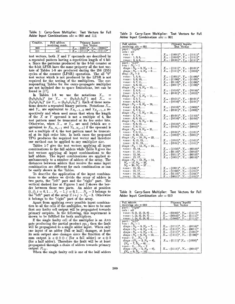
Table zyxwvutsrqponmlkjihgfedcbaZYXWVUTSRQPONMLKJIHGFEDCBA1: Carry-Save Multiplier: Test Vectors for zyxwvutsrqponmlkjihgfedcbaZYXWVUTSRQPONMLKJIHGFEDCBAFull Adder input Combinations zyxwvutsrqponmlkjihgfedcbaZYXWVUTSRQPONMLKJIHGFEDCBAabc = zyxwvutsrqponmlkjihgfedcbaZYXWVUTSRQPONMLKJIHGFEDCBA000 and zyxwvutsrqponmlkjihgfedcbaZYXWVUTSRQPONMLKJIHGFEDCBA111 zyxwvutsrqponmlkjihgfedcbaZYXWVUTSRQPONMLKJIHGFEDCBA
Comhn. Full add ers Primar puts receiving comb. Test zyxwvutsrqponmlkjihgfedcbaZYXWVUTSRQPONMLKJIHGFEDCBA$20, zyxwvutsrqponmlkjihgfedcbaZYXWVUTSRQPONMLKJIHGFEDCBA
000 all 11 1 alE
test vectors, both X and zyxwvutsrqponmlkjihgfedcbaZYXWVUTSRQPONMLKJIHGFEDCBAY operands are described by a repeated pattern havin a repetition length of 4 bit- s. Since the patterns pro8uced by the &bit counter or the %bit LFSR have the same property all the test vec- tors of lhbles 1-8 are roduced during the 256 zyxwvutsrqponmlkjihgfedcbaZYXWVUTSRQPONMLKJIHGFEDCBA(255) cycles of the counter &FSR) operation. The all "0" test vector which is not produced by the LFSR is not required for the testing of the multipliers. The cor- responding Tables for the carry-propagate multiplier are not included due to space limitations, but can be found zyxwvutsrqponmlkjihgfedcbaZYXWVUTSRQPONMLKJIHGFEDCBAin [17].
In Thbles 1-8 we use the notations X, = * (or Y, = (b3bzblbo)*) and X , = * (or Y, = (b3b2blbo)*). Each of these nota-
tions denote a repeated binary pattern. Notations X , and Y, are equivalent to XN=-~...O and YN,-~...o re- spectively and when used mean that when the length of the X or Y operand is not a multiple of 4, the test pattern must be truncated at its low order bits. Otherwise, when X , or Y, are used (which are e quivalent to X a . . ~ , - 1 and YQ..N,-i) if the operand is not a multiple of 4, the test pattern must be truncat- ed at its high order bits. In both cases the proposed TPG produces the required test vector and therefore our method can be applied to any multiplier size.
lhbles 1-7 give the test vectors applying all input combinations to the full adders while a b l e 8 gives the test vectors applying all input combinations to the half adders. The input combinations are applied si- multaneously to a number of adders of the array. The distances between adders that receive the same input combination are different for each combination as can be easily shown in the Tkbles.
To describe the application of the input combina- tions to the adders we divide the array of adders in two parts, the "left" part and the "right" part. The vertical dashed line at Figures 1 and 2 shows the bor- der between these two parts. An adder at position ( i , j ) , i = 0 , l . . . N, - 1, j = 0 , l . . . N - 3 belongs to the "left" part of the array if i+j > 4 -3. Otherwise it belongs to the "right" part of the array.
plying every possible input combina- tion to all the c z s of the multiplier, we have to be sure that any faulty cell output will be propagated towards primary outputs. In the followin this requirment is shown to be fulfilled for both mukipliers.
If the single faulty cell of the multiplier is an AND gate producing the partial product ppa,j then the fault will be propagated to a single adder input. When only one input of an adder (full or half) changes, at least its sum output also changes since the function of the sum output is a @ b c (for a full adder or a @ b
propagated through a chain of adders towards primary
When the single faulty cell is one of the half adders
Apart from
(for a half adder). Therefore the fault will b at least
output Pi+j *
Cols : all - rows :0, 1, 2 , 5 , 6 ... rows : 1, 2 , 3 , 6 , 7 . . . rows: 1, 4, 5 , 8,9 ...
part : "left"
Table 2 Carry-Save Multiplier: Test Vectors for Full Adder Input Combination abc = 001
x, : 0100 * , Y, : 1111
x, : 1000 , Y, : 1111 * x, : 0010 ;, Y, : 1111
Fi l adders receiving abc = 001 part : "right" cols : all row : 0 rows : 1, 3, 5, . . . rows : 2,4,6, . . .
vart : "left" +OW: NX-- 1 diags : Ny - 3, Ny - 5 . . . diags : Ny - 4, Ny - 6 . , .
dia.q : N, - 3 rovts : i , 5 , 9 , . . . rows : 2, 6, 10, . . . rows : 3,7, 11, . . . rows : 4, 8, 12, . . .
diags : Ny - 4, Ny - 10, . . . rows : 2,4,6, . . . rows : 3, 5,7, . . .
diags : Ny - 5, N, - 11,. , . rows : 3, 5,7, , . . rows : 4,6,8,. . .
diags : N, - 6, Ny - 18, . . . TOWS : 4,6,8, . . . rows : 5, 7,9, . , .
diags : Ny - 7, Ny - 19,, . . rows : 5, 7 9 , . . . rows : 6, 8, 10, . . .
diags : Ny - 8, Ny - 20, . . . rows : 6, 8, 10, . . . rows : 7, 9, 11, . . .
d iags :Ny-9 ,Ny-21, ... rows : 7, 9,11, . . . rows : 8, 10, 12, . . .
diags : N, - 10, Ny - 22, . . . rows : 8, 10, 12, . . . rows : 9,11,13, . . .
diags : Ny - 12, Ny - 24, , . . rows : 10,14, . . . rows : 11,15,. . . rows : 12,16,. . . rows : 13,17, . . .
diags : Ny - 13, Ny - 14,
4 - 26,d - 27'. . . rows : 12,16,. . . rows : 13,17, . . . rows : 14,18, . . . rows : 15,19,. . .
N - 15, N - 25
Yrimar puts Test $20,
x, . 1001 Y, : 1111
x,. 0101 * Y,. 1111 * x, ; 10101:; Y, ; 11111:
x, : 1111 Y , . 0101 *
x, : 1001 * , Y, : 1100 * x, : 1100 , Y , : 1100 *
x, : 0011 , Y, : 1100 *
Y,. 1010 *
x, : 11111):: Y, I [lolo]*
2 i [I%:]: : Y, I [lolo]*
x, : /olio/:, Y, : /lloo/*
x, : x, :
Y , Y,
x, : 1010 Y . 1000 * x, : [olol]:: YT 1 [lOOO]*
x, ; pol];; Y , : y o ] * x, i [olol]:: Y, I [OOlOj
x, ; pol];; Y, i y l l O l ] *
x, . 1010 Y, : 0100 *
x, 1010 Y, . 0010:
x, . 1010 Y, . 0001 *
x, : x, :
Y, Y,
x, : Y, ; /lolO/* x, : 0110 , Y, . 0010 * x, : 0011 x, : 1001 , Y, : 0010
, Y, : 0010 :
x, YOOlj*: Y, ; Ylolji x,. 1100 * Y,. 1101
x, : 0011 , Y, . 1101 * x, . 0110 ;, Y, : 1101
Table 3 Carry-Save Multiplier: Test Vectors for Full Adder Input Combination abc = 010
Fdl add ers receiving abc = 010 part : "right" I
r%E3e%;ts
row: N x - 1 diags : N, - 3, Ny - 7, . . . diags : Ny - 4, Ny - 8, . . . diags : Ny - 5, Ny - 9, . . . diags : N, - 6, N, - 10, . . rows: 0 . . . N x - 2 diags : (N, - 3, Ny - 4),
rows : 0...ks - 2 diags : (N - 5, Ny - 6),
(Ny - 7, N - 8) . . .
(Ny - 9, hu - 10) . . .
: 1111 * , Y, : 1111 * ( Y, : 1111 * , Y,
: (1111)* ,Y-
: (llll)*, Y,
: i l 1111 * ) Y,
: 0110 * : : jlOO1/* 0011 *
: 1100 *
: (1000)'
: (0010)*
289

Table zyxwvutsrqponmlkjihgfedcbaZYXWVUTSRQPONMLKJIHGFEDCBA4 Carry-Save Multiplier: Test Vectors zyxwvutsrqponmlkjihgfedcbaZYXWVUTSRQPONMLKJIHGFEDCBAfor Full Adder Input Combination zyxwvutsrqponmlkjihgfedcbaZYXWVUTSRQPONMLKJIHGFEDCBAabc = 011
Ed1 adders receiving abc = 011 p a r t : "right" rows: 0
rows: 1
rows : zyxwvutsrqponmlkjihgfedcbaZYXWVUTSRQPONMLKJIHGFEDCBA2, 14, zyxwvutsrqponmlkjihgfedcbaZYXWVUTSRQPONMLKJIHGFEDCBA26, . . .
cols : all
cols : all
cols : Ny - 3, Ny - 5, . , . cols : N y - 4, Ny - 6, . . .
rows:3.7.11. . . . I ,
cols : N y - zyxwvutsrqponmlkjihgfedcbaZYXWVUTSRQPONMLKJIHGFEDCBA3, N y - 5, . . . cols : Ny - 4, Ny - 6, . . . cols : Ny - 3, Ny - zyxwvutsrqponmlkjihgfedcbaZYXWVUTSRQPONMLKJIHGFEDCBA7, . . . cols : Ny - 4, Ny - 8, . . . cols : Ny - 5, Ny - 9, . . . cols : N y - 6, Ny - 10, . . . cols : Ny - 3, Ny - zyxwvutsrqponmlkjihgfedcbaZYXWVUTSRQPONMLKJIHGFEDCBA5, . . . cols : Ny - 4, Ng - 6, . . . cols : Ny - 3, Ny - 5, . . . cols : N y - 4, Ny - 6, . . . cols : N y - 3, N y - 7, . . . cols : Ny - 4, Ny - 8, . . . cols : Ny - 5, Ny - 9, . . . cols : Ny - 6, Ny - 10, . . . cols : Ny - 3, Ny - 7, . . . cols : Ny - 4, Ny - 8, . . . cols : Ny - 5, Ny - 9, . . . cols : Ny - 6, Ny - 10, . . . cols : Ny - 3, Ny - 7, . . . cols : Ny - 4, Ny - 8, . . . cols : Ny - 5, Ny - 9, . . . cols : N
cols : NJI - 3, Ny - 7, . . . cols : Ny - 4, Ny - 8, . . . cols : Ny - 5, Ng - 9, . . . cols : NU - 6, Nv - 10, . . .
rows : 4,8,12, . . .
rows : 5, 11, 17, . . .
rows : 6, 12, 18, , . .
rows : 9, 17, 25, , . .
TOWS : 10, 18, 26, . . .
rows : 9, 21, 33, . . .
- 6 Ny - 10, . . . rows : zyxwvutsrqponmlkjihgfedcbaZYXWVUTSRQPONMLKJIHGFEDCBA14 Z, zyxwvutsrqponmlkjihgfedcbaZYXWVUTSRQPONMLKJIHGFEDCBAki, . . .
par t : " l e f t " ~ O W S : ail d iags : Ny - 3, N y - 5, . . . diags : Nu - 4, Ny - 6, . . .
(except the first and last
at row j the fault is propagated either to primary out- put Pj+l which is the sum output of the half adder or to primary output Pj+z or both depending on whether the fault affects only one or both outputs of the half adder.
Finally, if the single faulty cell is a full adder at row i and column j , t,he fault will be propagated either to primary output Pi+j+a or to primary output Pi+j+s or both depending on whether the fault affects only one or both outputs of the full adder.
The advantage of the &bit TPG (either a counter or an LFSR) is that it consists of a very small block easily synthesized with an existing design. Additionally, we do not have to modify any cell of the multiplier or the overall multiplier structure and we just control the signals at the periphery of the array (X and zyxwvutsrqponmlkjihgfedcbaZYXWVUTSRQPONMLKJIHGFEDCBAY operands). Just an &bit counter or LFSR) module
fiom the counter outputs, and not fiom the normal primary inputs.
and a set of multiplexers are neede 6 to feed the array
4.2 Hardware Cost &timation A rough estimation of the hardware cost imposed
by our BIST scheme is given below in gate equiva- lents. In the following we assume that one full adder equals 10 gates, one half adder equals 5 gates, one 2- input AND gate equals two gates, one flip-flop equals 10 gates and one multiplexer equals 3 gates (we as- sume that 1 gate equivalent = %input NAND gate).
The original design of the multiplier consists of N,Ny AND gates, N, Ny -2) full adders and N, half
cuit in the original hardware size of the circuit we add N, +Ny full adders and an equal number of flip-flops.
The above give for the original design (assuming that the accumulator exists) a total number of gates: 5N, + 20N + 12N, Ny .
The BIS$ hardware for the basic %bit counter, con- sists of the &bit counter and a total of N, +Ny multi- plexers, giving a total number of gates: 3N, +3Ny +80.
adders. If an accumu ! ator is already part of the cir-
The hardware overhead is therefore: 3N, + 3Ny + 80
H O = 5N, + ZON, + 12N, Ny
The above formula gives for N, = Ny = 16,32,64, H O = 5.07%, 2.08%, 0.91%, respectively. 4.3 BIST Output Data Compaction
Count-based out ut data compaction is a well known technique [lly, [12]. Multiplier units are usual- ly accompanied by accumulators in datapath blocks, and thus this solution needs no extra hardware for response verification. If a dedicated accumulator is synthesized for output data compaction it does not require much design $fort, due to its inherent regu- larity.
It has been proved in [12] that when the accumu- lator consists of a carry rotate adder, it provides ex- cellent error coverage. We assume that such a carry rotate adder is used for output data compaction in OUT approach, as shown in Figure 3. An extra memo- ry element is to be added to the circuit to provide this operation during BIST mode. When the circuit op- erates in normal mode this memory element provides the carry-in input of the accumulator with logic "0".
We have exhaustively simulated the behavior of the proposed BIST scheme for 8 x 8 carry-propagate and carry-save array multipliers for all single stuck-at hults. The results are given in the following.
For the carry-propagate case no tested fault causes aliasing when the carry rotate adder is used. There- fore, fault coverage is only reduced by the untested faults of the N, -2 full adders. The calculation of the fault coverage is given in the next subsection.
For the carry-save case 3 sin le stuck-at faults in the N, - 5 half adders cause Zasing. Therefore in this case the fault coverage is slightly reduced due to the missing input combinations and due to the aliasing caused by the above faults. Fault coverage for this case is also given in the next subsection. 4.4 &ult Coverage Calculation
We calculate in the following the single stuck-at fault coverage of the proposed BIST strategy. We as- sume that a standard gate-level realization for the full adder cell k used as the one given in [18] and that the
290

Table 5 Carry-Save Multiplier: Test Vectors for zyxwvutsrqponmlkjihgfedcbaZYXWVUTSRQPONMLKJIHGFEDCBAFull Adder Input Combination zyxwvutsrqponmlkjihgfedcbaZYXWVUTSRQPONMLKJIHGFEDCBAabc = 100
Pi1 add ers receiving zyxwvutsrqponmlkjihgfedcbaZYXWVUTSRQPONMLKJIHGFEDCBAabc = 101
Pidl adders receiving abc = 100 p a r t : "right" zyxwvutsrqponmlkjihgfedcbaZYXWVUTSRQPONMLKJIHGFEDCBArows : zyxwvutsrqponmlkjihgfedcbaZYXWVUTSRQPONMLKJIHGFEDCBA0,4,8, . . . cols : Ny - 3, Ny - 7, . . . cols : N y - 4, N y - 8, . . . cols : N y - 5, N y - 9, . . . Cols : Ny - 6, Ny - 10, . . . cols : Ny - 3, Ny - zyxwvutsrqponmlkjihgfedcbaZYXWVUTSRQPONMLKJIHGFEDCBA5, . . . Cols : Ny - 4, N y - 6, . . . cols : Ny - 3, Ny - 5, . . . cols : Ny - 4, Ny - 6, . . . cols : N y - 3, Ny - 5, . . . Cols : Ny - 4, Ny - 6, . . . cols : Ny - 3, Ny - 7, . . . cols : Ny - 4, N y - 8, . . . CO19 : Ny - 5, N y - 9, . . . cols : N y - 6, N y - 10, . . . cols : Ny - 3, Ny - 7, . . , C O ~ S : N y - 4, N y - 8, . . . cols : Ny - 5, Ny - 9, . . . cols : Ny - 6, Ny - 10, . . . cols : Ny - 3, N y - 5, , . . cols : Ny - 4, N y - 6, . . . cols : Ny - 3, Ny - 5, . . . cols ; Ny - 4, N y - 6, . . . cols : Ny - 3, Ny - 7, . . . cols : N y - 4, N y - 8, . . . cols : N y - 5, N y - 9, . . . cols : Ny - 6, Ny - 10, . . . cols : Ny - 3, Ny - 7, . . . cols : N y - 4, Ny - 8, . . . cols : Ny - 5, Ny - 9, . . . cols : NV - 6, N V - 10, . . ,
rows : 1, 5,9, . . .
TOWS : 2,8,14, . . .
rows : 3, 9,15, . . .
rows : 6, 14, 22, . . . zyxwvutsrqponmlkjihgfedcbaZYXWVUTSRQPONMLKJIHGFEDCBAT O W S : 7,15, 23, . . .
rows : 6,18,30, . . .
rows : 7, 19, 31, . . .
rows : 6,10,14, . . .
rows : 7, 11, 15, . . .
p a r t : " l e t" rows: a 1 diags : Ny - 3, Ny - 5, . . . diags : NV - 4, Ny - 6, . . .
Primar puts Test zyxwvutsrqponmlkjihgfedcbaZYXWVUTSRQPONMLKJIHGFEDCBA$e!%x zyxwvutsrqponmlkjihgfedcbaZYXWVUTSRQPONMLKJIHGFEDCBA
x, : 1010 *, Y, : 0110 *
x, : 1010 , Y, : 1001 * x, : 1010 :, Y, : 1100 *
x, : zyxwvutsrqponmlkjihgfedcbaZYXWVUTSRQPONMLKJIHGFEDCBA/ I 1010 *, Y, : I I 0011 *
I ,
cols : ail rows : 4,8,12, . . . o a r t : " l e f t " cols : all
x, : 1001 Y, 1010; x, : [ l O O l ] ? Y, i [ O l O l ]
x, : [lolo]:: Y, : [lolo]*
x, : [olol];: Y, I [OlOl]*
x, : 1010 Y, : 0101 *
x, : 0101 Y, . 1010 *
x, : (1100)*, Y, : (1111)'
x, : (0110)*, Y, : (1111)'
x, : ( lOOOl* . Y- : 100011*
N y zyxwvutsrqponmlkjihgfedcbaZYXWVUTSRQPONMLKJIHGFEDCBA-7, ... Ny -8,... N y -9, . . . y3 - 10, . . .
x, : 1000 Y, : 0010 *
x, : 1000 Y, : 1000 * x, : I l O 0 O l i i Y, : [olool*
X , : X , : X + : x, :
x, : 0100 *, Y , : 0010 * x, : 0100 * ) Y, : 0100 * x, : 0100 *, Y, : 1000 :
Y, . 0101 ; x, : I t 0100 *, Y, : i i 0001
x, : jlOO0/ , Y, I x, [ /oloo]:i Y, : /ol1f
x,. 1000 x, I [looo]:: Y, I [lolo] x, i poo] : ~ Y, : (lolo]: x, . 0100 Y, : 0101
x, : 1000 *, Y, . 1101 *
x, : 1000 *, Y, : 1110 *
x, . 0100 * Y, : 1011
x, . 0100 x, . 0100 *, Y, : 1101
x, : 1000 :, Y, : 1011 *
, Y, : 1110 ;
- diags : Ny - 3, Ny - 7, . . . d iags : Ny - 4, Ny - 8, . . . diags : Ny - 5, Ny - 9, . . . diags : Nu - 6, Ny - 10, . . .
x, : 1111 *, Y, : 0101 * x, : 1111 *, Y, : 1010 *
X , : X , : X , : X , :
XOR gate of the half adder cells is implemented using 3 NAND gates and 2 inverters.
The total number of single stuck-at faults is: T =
The first term is the number of stuck-at faults of the AND gates, the second term is the number of stuck-at faults of the full adders and the third is the number of stuck-at faults of the half adders.
In the carry-propagate array multiplier each of the Nx - 2 full adders, that receive 7 of their 8 input com- binations, contains 2 untested faults and the top right corner full adder, which receives 6 of its 8 input com- binations, contains 4 untested faults. No faults are untested due to aliasing when a carry rotate adder is used at the accumulator ODE. Therefore, the to- tal number of untested faults in the carry-propagate multiplier is: U n t c p = 2(N, - 2) + 4.
In the carry-save array multiplier each of the N, - 5 half adders, that receive 3 of their 4 input combina- tions, contains 2 untested faults due to the missing
6N, Ny + 52NZ (Ny - 2) + 28N, = 58Nx Ny - 76Nx.
Table 6 Carry-Save Multiplier: Test Vectors for Full Adder Input Combination abc = 101
b w s : 0, (i, 2), (5, 6), . . . rows : 3. 7.11. . . . cols : all x, : (loll)*, Y, : (1111).
;ow: N,- 1 d iags : Ny - 3, diags : Ny - 4, diags : Ny - 5 , d iags : Ny - 6
rows : 0.. . N,'
Y, : Y, : Y, : Y, :
pi/: 0011 *
input combination and 3 untested faults due to alias- ing: Also the 2 full adders that receive 7 and 5 af their 8 input combinations contain 9 untested faults. Therefore, the total number of untested faults in the carry-save multiplier is: U n t c s = 5(Nx - 5) + 9.
The fault coverage for the carry-propagate case is:
T - U n t c p - 58Nx Ny - 78Nx - x 100
T 58Nx Ny - 76Nx FCcp =
while for the carry-save case is:
T - U n t c s - 58NxNy - 81Nx + 16 - x 100
58NxNy - 76Nx FCcs=
The above formulas give the results of lhble 9, for mme example sizes of both carry-propagate and carry- save array multipliers.
5 Conclusions An effective BIST scheme for the well known carry-
propagate and carry-save array multipliers has been introduced. An 8-bit counter or &bit LFSR TPG is used along with count-based Output Data Com- paction. The fault model adopted enables a BIST al- gorithm which is independent of specific implementa- tions of the multiplier cells. No DFT modifications to the original structures of the multipliers are required and the scheme is totally applied on the periphery d the multiplier structure therefore causing no internal performance degradation. In case of multiple multi- pliers in an ASIC more than one multiplier module can share the BIST hardware. The BIST scheme is generic and can be applied to any carry-propagate and carry-save array multiplier as well as other arithmetic regular structures.
References [l] K. HWANG, "Computer Arithmetic: Principles,
architecture and design", Wiley, New York, 1978.
291
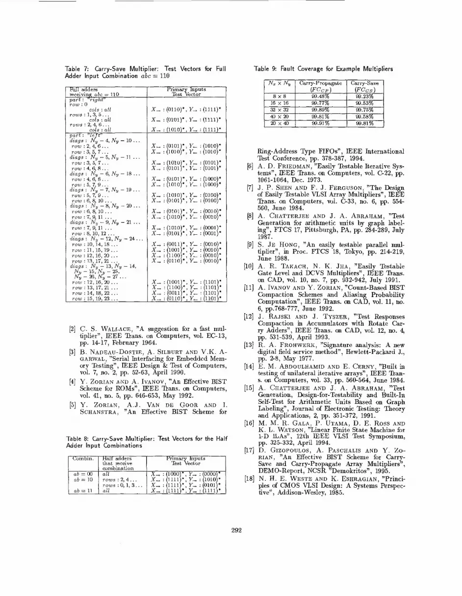
Table 7: Carry-Save Multiplier: Test Vectors for zyxwvutsrqponmlkjihgfedcbaZYXWVUTSRQPONMLKJIHGFEDCBAFull Adder Input Combination zyxwvutsrqponmlkjihgfedcbaZYXWVUTSRQPONMLKJIHGFEDCBAabc = zyxwvutsrqponmlkjihgfedcbaZYXWVUTSRQPONMLKJIHGFEDCBA110
C'ombin.
Full adders xceiving abc = 110 p a r t : "right"
Half zyxwvutsrqponmlkjihgfedcbaZYXWVUTSRQPONMLKJIHGFEDCBAadd ers Primar puts that rxeive Test b%or 1
T O W : 0
T O W S : 1, zyxwvutsrqponmlkjihgfedcbaZYXWVUTSRQPONMLKJIHGFEDCBA3, 5 . . . cols : all
cols : all rows : 2.4. 6 . . .
ab = zyxwvutsrqponmlkjihgfedcbaZYXWVUTSRQPONMLKJIHGFEDCBA00 ab = 10
Lois : p a r t : " l e t" d iags : zyxwvutsrqponmlkjihgfedcbaZYXWVUTSRQPONMLKJIHGFEDCBANi - 4, Ny row : 2, 4, 6.. . row : 3, 5, 7. . .
d iags : Ny - 5, Ny T O W : 3, 5. 7 . . .
all zyxwvutsrqponmlkjihgfedcbaZYXWVUTSRQPONMLKJIHGFEDCBAx, : 1000 * , Y, : 0000 * rows : 2.4.. . X , : 1111 * . Y- : 1010 *
- l o . . .
-11 ...
ab = 11
row : 4, 6, 8 . . .
row : 4, 6, 8 . . . diags : N , - 6, Nu - 18.
diags : Ny - 7, Ny - 19. row : 5, 7, 9 . . . row : 6,8 10. . .
diags : i$, - 8, Ny - 2 0 . row : 6.8. 1 0 . . .
T O W : 5, 7 g . . .
rows:0 ;1 ,3 . . . x,: I I I I * ; Y - : O I O I * all x, : 1111 * , Y, : 1111 *
, , row : 7,9, 11 . . . row : 7,9, 11 . . . T O W : 8, 10, 12 . . . TOW : 10, zyxwvutsrqponmlkjihgfedcbaZYXWVUTSRQPONMLKJIHGFEDCBA14, 18 . . .
d iags : NzI - 9, Ny - 21 . . .
diags : N, - 12, Ny - 2 4 . . . r o w : 1 1 , 1 5 , 1 9 ... row : 12, 16, 20 . . . TOW : 13, 17, 21 . . .
diags : Ny - 13, Ny - 14, N 15 N - 25 n?j 1 26: 4 - 27'. . .
T O W : 12, 16, 20 . . . row : 13, 17, 21 . . . T O W : 14, 18, 22 , . . row : 15,19, 2 3 . . .
Primar puts Test k%or
x, : (OllO)*, Y, : (1111)*
x, : (0101)*, Y , : (1111)'
x, : (lOlO)*
x, : 0101 * x, : [lolo]*
$1 ; [::::{I x, : r l o y , Y: ; I'Oooj:
x, ; ~o lo ] : : Y- : I"'OO]*
x, i p o l ] ; ; Y: ; r01oj:
x, : 1010 Y . 1000
x, . 0101 Y, : 0100 *
x, . 1010 Y . 0010
x, : 1010 * Y, . 0001 ; x, : [0101]*; Y+ I [OOOl]
x, : 0011 * , Y , : 0010 * x, : 1001
x, : 0110 * ) Y, : 0010 *
, Y, : 0010 ; x, : /lloo/:, Y, : /oolo/
x, : pool\:: ;: ; p101\* x, : 1100 1101 * x, : 0011 *; Y, : 1101 * x, : 0110 * , Y, : 1101 *
[2] C. S. WALLACE, "A suggestion for a fast mul- tiplier", IEEE Bans. on Computers, vol. EC-13, pp. 1417, February 1964.
[3] B. NADEAU-DOSTIE, A. SILBURT AND V.K. A- GARWAL, "Serial Interfacing for Embedded Mem- ory Testing", IEEE Design & Test of Computers, vol. 7, no. 2, pp. 52-63, April 1990.
[4] Y. ZORIAN AND A. IVANOV, "An Effective BIST Scheme for ROMs", IEEE Bans. on Computers, vol. 41, no. 5, pp. 646-653, May 1992. zyxwvutsrqponmlkjihgfedcbaZYXWVUTSRQPONMLKJIHGFEDCBA
[5] Y . Z O R I A N , A.J. VAN DE GOOR AND I. SCHANSTRA, "An Effective BIST Scheme for
Table 9 Fault Coverage for Example Multipliers
93.48% 93.23% 16 x 16
40x20 93.89% 93.75%
93.91% 93.81%
Ring-Address Type FIFOs", IEEE International Test Conference, pp. 378-387, 1994.
[6] A. D. FRIEDMAN, "Easily Testable Iterative Sys- tems", IEEE Bans. on Computers, vol. C22, pp.
[7] J. P. SHEN AND F. J . FERGUSON, "The Design of Easily Testable VLSI Array Multipliers", IEEE Bans. on Computers, vol. G33, no. 6, pp. 554- 560, June 1984.
[SI A. CHATTERJEE AND J. A. ABRAHAM, "Test Generation for asithmetic units by graph label- ing", FTCS 17, Pittsburgh, PA, pp. 284289, July 1987.
[9] S. JE HONG, "An easily testable parallel mul- tiplier", in Proc. FTCS 18, Tokyo, pp. 214219, June 1988.
[lo] A. R. TAKACH, N. K. JHA, "Easily Testable Gate Level and DCVS Multipliers", IEEE Bans. on CAD, vol. 10, no. 7, pp. 932-942, July 1991.
[ll] A. IVANOV AND Y . ZORIAN, "Count-Based BIST Compaction Schemes and Aliasing Probability Computation", IEEE Bans. on CAD, vol. 11, no. 6, pp.768-777, June 1992.
[12] J . RAJSKI AND J . TYSZER, "Test Responses Compaction in Accumulators with Rotate Car- ry Adders", IEEE Bans. on CAD, vol. 12, no. 4, pp. 531-539, April 1993.
[13] R. A. FROHWERK, "Signature analysis: A new digital field service method", Hewlett-Packard J., pp. 2-8, May 1977.
[14] E. M. ABDOULHAMID AND E. CERNY, "Built in testing of unilateral iterative arrays", IEEE %an- s. on Computers, vol. 33, pp. 560-564, June 1984.
[15] A. CHATTERJEE AND J . A. ABRAHAM, "Test Generation, Design-for-Testability and Built-In Self-Test for Arithmetic Units Based on Graph Labeling", Journal of Electronic Testing: Theory and Applications, 2, pp. 351-372, 1991.
[16] M. M. R. GALA, P. UTAMA, D. E. Ross AND K. L. WATSON, "Linear Finite State Machine for 1-D &As", 12th IEEE VLSI Test Symposium, pp. 325-332, April 1994.
[17] D. GIZOPOULOS, A. PASCHALIS AND Y . Zo- RIAN, "An ERective BIST Scheme for Carry- Save and Carry-Propagate Array Multipliers", DEMO-Report, NCSR "Demokritos", 1995.
[18] N. H. E. WESTE AND K. ESHRAGIAN, "Princi- ples of CMOS VLSI Design: A Systems Perspec- tive", Addison-Wesley, 1985.
1061-1064, Dec. 1973.
292