Embed Size (px)
Citation preview

AES-based BIST: self-test, test pattern generation and signature analysis
M. Doulcier, M.L. Flottes and B. Rouzeyre Laboratoire d’Informatique, de Robotique et de Microélectronique de Montpellier
LIRMM, Univ. Montpellier II / CNRS 161 rue Ada, 34932 Montpellier, France
{doulcier, flottes, rouzeyre}@lirmm.fr
Abstract
Re-using embedded resources for implementing built-in self test mechanisms allows test cost reduction. In this paper we demonstrate how to implement cost-efficient built-in self test functions from the AES cryptoalgorithm hardware implementation in a secure system. Self-test of the proposed implementation is also presented. A statistical test suite and fault-simulation are used for evaluating the efficiency of the corresponding cryptocore as pseudo-random test pattern generator; an analytical approach demonstrates the low probability of aliasing when used for test response compaction. Keywords: secure systems, AES core, BIST 1. Introduction
Nowadays, secure circuits are commonly used for applications such as e-banking, pay tv, cell phone... Because they hold personal data and must process secure operations, security requirements such as source/sink authentication, data integrity, confidentiality, or tamper resistance are maintained by means of several dedicated components. Confidentiality is ensured through cryptographic mechanisms generally implemented on co-processors. These mechanisms encode/decode plaintexts/cipher texts with the help of secret keys that must be preserved from compromise.
Testing a secure circuit requires a specific attention since any undetected malfunction may induce a vulnerability and any extra test mechanism may induce new security vulnerabilities. For instance, generation of deterministic test patterns and design for testability such as scan design provide very high fault coverage. This mechanism minimizes the probability to deliver a supposedly secure system, but actually faulty chip, which could fail to protect the secret data. However, the scan path itself may compromise the security of the
system since it provides facilities for controlling or observing sensitive data (scan based attacks have been demonstrated in [1] and [2]). Specific secure scan design methodologies such as the ones detailed in [3] and [4] can prevent abusive usage of the scan path but requires extra area and design effort.
Conversely, the Built-In Self Test (BIST) approach does not require visible scan chains. When the test mode is started, scan chains are fed from on-chip test resources and scanned-out test responses are compacted into a signature. The only test output is this compacted signature or the comparison result of this signature with a pre-computed “gold” one. The BIST strategy is considered as a good alternative if it provides acceptable fault coverage and low area overhead (apart from its recurrent cost, extra area for BIST implementation may in turn be subject to faults and, consequently, must be keep as low as possible).
Re-using a cryptographic core (“cryptocore”) as test pattern generator (TPG) or signature analyser (SA) for other cores in the system prevents the insertion of any other dedicated hardware. However efficiency in terms of pattern generation and response compaction must be evaluated.
In this paper we investigate a BIST solution based on a common “cryptoalgorithm” classically implemented on smart cards and other secure devices.
The cryptoalgorithm and its original implementation for supporting test pattern generation and response compaction are presented in section 2. The self-test of the corresponding implementation is discussed in section 3. The test sequences generated from the proposed cryptocore-based generator are evaluated in section 4. Section 5 discusses the usage of the cryptocore as signature analyser. Conclusions are given in section 6. 2. Cryptocore and implementations
The “Rijndael” cryptoalgorithm developed by Vincent Rijmen and Joan Daemen was officially
4th IEEE International Symposium on Electronic Design, Test & Application
0-7695-3110-5/08 $25.00 © 2008 IEEEDOI 10.1109/DELTA.2008.86
314
4th IEEE International Symposium on Electronic Design, Test & Applications
0-7695-3110-5/08 $25.00 © 2008 IEEEDOI 10.1109/DELTA.2008.86
314
4th IEEE International Symposium on Electronic Design, Test & Applications
0-7695-3110-5/08 $25.00 © 2008 IEEEDOI 10.1109/DELTA.2008.86
314
4th IEEE International Symposium on Electronic Design, Test & Applications
0-7695-3110-5/08 $25.00 © 2008 IEEEDOI 10.1109/DELTA.2008.86
314

approved as new Advanced Encryption Standard (AES) in December 2001 [5].
The AES ciphers a block of 128 bits plaintext into a 128 bits cipher text with the help of a 128, 192 or 256-bits secret key K.
The 128-bits plaintext is organized into a 4*4 matrix of 16 bytes. After a first XOR operation between K and the plaintext, the algorithm consists in several rounds: 10, 12 or 14 rounds according to the key length 128, 192 or 256 bits. Every round except the last one is composed of four operations: Subbytes is a substitution of text bytes with the help of substitution tables called Sboxes, ShiftRows consists in circular shifts on the matrix lines, MixColumns is a multiplication by a known matrix in the Galois field, and AddRoundKey is a XOR operation between the partially ciphered text and the round key RKi; RKi being derived from the initial secret key K. The last round does not execute the MixColumns operation. Without loss of generality, we assume hereafter 128-bits key and thus 10 rounds.
Figure 1 presents the base iterative implementation of the AES algorithm. It is mainly composed of a Key Generation module and a Round module. After 10 iterations of the Round module, the controller set the Encryption signal that loads the cipher text into the output register R2.
In this paper we investigate 1/ the self-testability of the AES cryptocore, and 2/ its use as TPG or SA. The three new behavioral modes (TPG/SA/SELF_TEST) entail the addition of extra control, and new operations in the datapath (AND, XOR) of the base implementation. Figure 2 depicts the introduced slight changes.
During the first round of the mission mode (encryption), self-test or TPG modes, the select signal is set to 0. The self-test of the core is further discussed in section 3.
In TPG mode, the select signal allows to load the seed of the generator. Next, the select signal is set to 1 while the SA is set to 0. Test patterns are issued from R2 at every clock cycle with the help of the Encryption signal that enables the R2 load operation after every round. Evaluation of the so-generated test vectors is presented in the section 4.
For test response compaction (SA mode), select and SA signals are set to 1. An XOR operation is performed between one response of the Core Under test (CUT) and the result of the previous round. The final signature obtain after compaction of all the test responses is loaded into the R2 register. Diagnostic facilities can be implemented using the Encryption signal for enabling the analysis of intermediate signatures. The quality of the AES as SA is studied in section 5.
The Key Generation module is also slightly modified in such a way that during self-test, TPG and SA modes, the 10th round key is used as the primary key for the next round keys generation. Usually, the original secret K is used as primary key at the beginning of every encryption, or, in other words, every ten rounds. This behavior is maintained for mission mode.
Table 1 reports the areas of original and modified AES cryptocores in terms of cell number. Both
Figure 1: AES base iterative implementation
Register R2
Cipher text
Key Generation
MUX
Secret Key K
Plaintext
RKi
Control
Select
Register R1
Sub Bytes
Shift Row
Mix Column
MUX
Start
Last-round
Encryption
Round
Key
0 1
Round
Register R2
Cipher text
Key Generation
MUX
Secret Key K
Plaintext
RKi
Control
Select
Register R1
Sub Bytes
Shift Row
Mix Column
MUX
Sub Bytes
Shift Row
Mix Column
MUX
Start
Last-round
Encryption
Round
Key
0 1
Round
Figure 2: AES TPG/SA implementation
Register R2
Cipher text
Key Generation
MUX
Secret Key K
Plaintext (AES, self-test, TPG modes)or CUT responses (SA mode)
RKi
Control
Select
Register R1
Sub Bytes
Shift Row
Mix Column
MUX
Start
Last-round
Encryption
Round
Key
0 1
Test
mode
SA (from Control)
Round
Register R2
Cipher text
Key Generation
MUX
Secret Key K
Plaintext (AES, self-test, TPG modes)or CUT responses (SA mode)
RKi
Control
Select
Register R1
Sub Bytes
Shift Row
Mix Column
MUX
Sub Bytes
Shift Row
Mix Column
MUX
Start
Last-round
Encryption
Round
Key
0 1
Test
mode
SA (from Control)
Round
315315315315
architectures have been described in VHDL and synthesized using a commercial design kit (library CMOS AMS 0.35µm).
As shown in Table 1, test facilities leads to an increase of 3.31% (507 cells) compared to the original implementation. For comparison, the implementation of a 128-bits BILBO register (Built-In Logic Block Observer, [6]), which provides also TPG and SA functions, requires 859 cells and eventual additional wiring for connection to cores under test. 3. AES Self-Test
This paragraph presents both theoretical results on the required test length for AES self-test and fault simulation results.
As discussed in [7], pseudo-random testing is an efficient technique for cryptocores. High fault coverage can be achieved with short pseudo-random test sequences because traditional cryptographic operations (XOR, substitution, modulo…) are easily tested with random data. Moreover, the inherent properties of these operations allow the propagation of random data through the circuit.
Because the AES core is mainly made up of Sboxes (83% of the AES area for implementing the SubByte operation), we first focused on the testability of these components.
The minimum deterministic test set for 100% fault coverage is 203 patterns long for one 8-input bits Sbox. An in-house fault simulator and a heuristic have been used for building up the fault dictionary and defining this minimal test set.
From this number, and in order to be conservative, we compute the minimal-length random sequence that would include these 203 patterns with a given confidence [8]:
[ ] ( )nk
1i
1i ip1ik
1)(1nXP −⎟⎟⎠
⎞⎜⎜⎝
⎛−−=≤ ∑
=
+ (1)
where P[X≤ n] is the confidence level, k is the number
of targeted patterns, p is the probability that every random pattern occurs (here p=1/28) and n is the number of random patterns that have to be sampled.
In our case, 203 patterns must be obtained after n random patterns with a confidence level of 99%, i.e.:
n
8
203
1i
1i21i1
i203
1)(10.99 ⎟⎠⎞
⎜⎝⎛ −⎟⎟⎠
⎞⎜⎜⎝
⎛−−= ∑
=
+ (2)
From this equation it comes that the minimal random sequence length is n = 2534 patterns. This result stands for the whole set of Sboxes in the AES core since they are tested in parallel.
The same experiment have been performed for various implementations of the Sboxes and thus for different minimal deterministic test sets. In any case, the theoretical minimal length of the random sequence for including the targeted deterministic patterns ranges from 2400 to 2600 patterns. The upper bound is thus set to 2600 random patterns to test the Sboxes whatever their implementation.
Concerning the other round operations: ShitRow function requires only wires for its implementation and is tested when every bit of this interconnection structure has been set to both “0” and “1” (under the assumption of stuck-at fault model). This should be easily achieved with the patterns issued from the Sboxes (bijective operations fed with 2600 random patterns). MixColumn and AddRoundKey operations are mainly xor trees and should be very easily tested too using random patterns issued from the Sboxes.
In order to confirm this hypothesis, we have performed a fault simulation on the proposed AES core sets in self-test mode. The test response (or signature) is only observed after simulation of the whole sequence, not at every round. The self-test structure is initialised with a randomly chosen plaintext and a secret key. This experiment has shown that all the faults have been tested after 2100 round cycles (to be compared with the 2534 random patterns theoretically required for 100% fault coverage on the first experimented Sboxes implementations). This experiment has been repeated with different plaintexts and secret keys as starting points: 2100 to 2500 patterns have been required for 100% fault coverage. We did the same experiments with two other AES logic implementations and obtained similar results.
From a practical point of view, 2600 round cycles in self-test mode should be sufficient to test the whole structure with a confidence level of 99%. 4. Test pattern generation
This section questions the randomness of the patterns issued from the proposed AES-based TPG, called “1-AES-round” TPG in the following.
Table 1: Area (# cells)
AES AES modified
Round SubBytes ShitRow MixColumn AddRoundKey
10192 0
301 423
10192 0
301 423
Control Unit 67 121Key generator 3409 3444AES logic 932 1351Total 15324 15832
316316316316

Inherent property of the basic operations involved during AES encryption and statistical analysis of the data issued from the base cryptoalgorithm demonstrate that the whole AES encryption process is a very good 128-bits random number generator [9]. It can be used for instance as random number generator for stream ciphering operations implemented in the same system.
The randomness properties of the 128 generated 1-bit streams and their usage as test sequences have been studied in [10]. However in this study, the whole AES mission mode was used to provide a new random word at every encryption cycle (i.e. every 10 rounds). The main drawback of this approach is that a test pattern is generated every ten clock cycles. Here, in the proposed TPG mode implementation, one pattern is issued at every round, or in other words at every clock cycle. This constraint allows a fair comparison with the usual LFSR-based TPGs that generate a new pseudo-random data at every clock cycle. 4.1 Randomness properties
Several empirical metrics can be used for evaluating the randomness of a sequence; we chose the NIST test battery composed of fifteen statistical tests [11]. The first one for instance determines whether the numbers of ones and zeros in the bit stream are approximately the same (Table 2, 1st column, line Freq.).
We set the parameters of the tool that execute these statistical tests in such away that if a result is greater than 0.01, then the bit stream under evaluation is considered as a random sequence with respect to this
statistical test with a confidence level of 99%. The level of uncertainty (1%) compensates the result of a statistical analysis performed on a finite length, and rather short, bit stream. In other words, a 1M bit stream can be considered as a random sequence with respect to the Freq. test for instance, if the number of 0 and 1 in the sequence are not exactly the same (i.e. 500,000), but only differ in few units (e.g. 505,000 “0” and 495,000 “1”).
The 2nd column in Table 2 reports the 15 statistical test results for a 1.5M bits stream issued from the rightmost bit of the output register (c.f R2 in figure 2). The AES core is in the 1-AES-round TPG mode (1.5M clock cycles for 1.5M bits). Since all the NIST test results are greater than 0.01, the corresponding bit stream can be considered as a random sequence with respect to the NIST statistical test suite.
In order to get a better idea of the randomness of this sequence, we also applied the NIST statistical test suite to 1.5M bit streams generated from two well known pseudo-random generators: - The bit stream issued from the rightmost output bit of the AES core executing its mission mode (i.e. 1 new bit is available every 10 rounds or 10 clock cycles), - The bit stream issued from the serial output (rightmost bit) of a modular 128-stages LFSR with the primitive polynomials p(x) = x128+x29+x27+x2+1.
LFSR seed, initial plaintexts and key for 1-AES-round and “classic AES” TPG have been randomly chosen.
Statistical test results are respectively reported in columns 2 and 3 (Table 2). While the AES basic implementation is well known for generating 128-bits random words, statistical results on the 1-bit stream issued from the rightmost output bit show that it does not perform better than the 1-AES-round (statistical test results are in favour of the 1-AES-round TPG for 10 tests over 15). Both AES-based TPGs pass all the tests. Conversely, the LFSR-based TPG passes only 11 tests out of 15. This can be explained by the fact that the bit stream under evaluation is extremely short compared to the total number of different states achieved by the LFSR before to come back to its initial state (1.5M bits under evaluation vs 2128-1 bits).
The random bit stream issued from the 1-AES-round rightmost bit can thus be used for feeding a single scan chain in a CUT. However, for multiple scan chain architectures (e.g. STUMP [12]); all the bit streams collected on the 1-AES-round output must be random enough. The randomness evaluation of the 128 possible bit streams issued from this structure is presented in Figure 3. The graphic shows the proportion of bit streams that pass a test i, i=1…15, (c.f Table 2). The two horizontal bold lines represent the confidence interval in which the whole 128-bit word
Table 2: Statistical randomness results on rightmost bit stream
1 AES round
AES LFSR
1: Freq 0.208017 0.110981 0.002560
2: BlkFreq 0.725004 0.267765 0.441504
3: CuSum 0.257467 0.103183 0.003262
4: Runs 0.247087 0.999049 0.143622
5: LongRuns 0.510618 0.079787 0.965931
6: Rank 0.321308 0.820208 0.526598
7: DFFT 0.25475 0.642256 0.810512
8: Univ 0.157055 0.845498 0.244026
9: Apen 0.983707 0.189886 0.637473
10: Serial1 0.164657 0.400669 0.572199
11: Serial2 0.271346 0.227037 0.855465
12: LinComp 0.981514 0.543506 0.000000
13: Aperiodic 0.533758 0.453813 0.499631
14: Periodic 0.379708 0.336229 0.393849
15: Random 0.570575 0.517951 0.000000
317317317317
streams can be considered as random enough. This confidence interval is calculated using a normal distribution as an approximation to the binomial distribution. This interval can be computed as:
( )m
p1p3p −×± (3)
where m is the number of bit streams (128 in the present case) and p is the confidence level (99%). This confidence interval is [0.9636164, 1] in the present case. If the proportion of bit streams that pass a test falls outside this interval, the data is non-random with respect to the corresponding test i.
Similarly, the statistical test suite has been applied on the 128 bit streams issued from the AES cryptocore in mission mode and the LFSR. As expected from the first one, the proportion of bit streams that pass any test i is included in the interval of confidence.
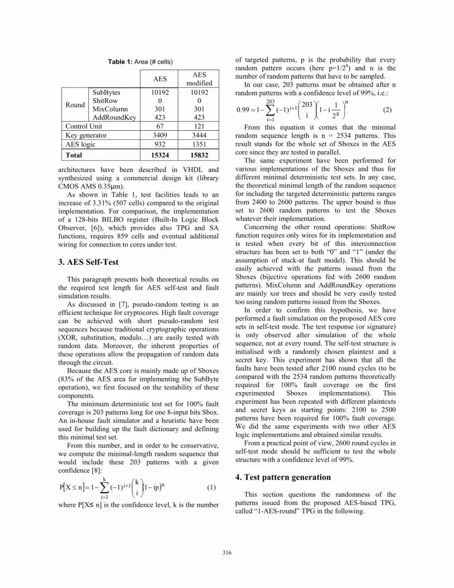
Conversely, the LFSR does not perform very well on several randomness tests. Figure 4 reports the figure of merits for the 128 bit streams issued from the LFSR. Randomness statistical analysis is again in favour of the 1-AES-round TPG.
As a conclusion of these experiments, the randomness properties of the bit streams issued from the 1-AES-round TPG are as good or even better than LFSR bit streams, and quite as good as those from the AES executing its mission mode, with the benefit of a faster pattern generation. Thus the 1-AES-round TPG can be considered as a candidate for pseudo-random test pattern generation when an AES core is already implemented in the device (secure circuits).
4.2 Fault simulation
Obviously, the randomness of a test sequence does not guaranty high fault coverage on every circuit. However, if the sequence is random enough, it should rapidly detect non resistant faults.
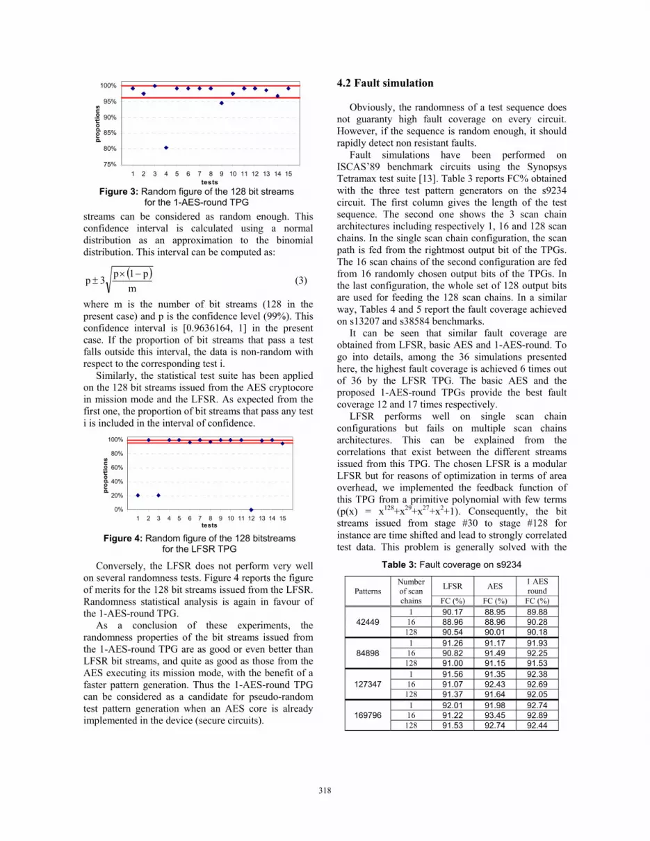
Fault simulations have been performed on ISCAS’89 benchmark circuits using the Synopsys Tetramax test suite [13]. Table 3 reports FC% obtained with the three test pattern generators on the s9234 circuit. The first column gives the length of the test sequence. The second one shows the 3 scan chain architectures including respectively 1, 16 and 128 scan chains. In the single scan chain configuration, the scan path is fed from the rightmost output bit of the TPGs. The 16 scan chains of the second configuration are fed from 16 randomly chosen output bits of the TPGs. In the last configuration, the whole set of 128 output bits are used for feeding the 128 scan chains. In a similar way, Tables 4 and 5 report the fault coverage achieved on s13207 and s38584 benchmarks.
It can be seen that similar fault coverage are obtained from LFSR, basic AES and 1-AES-round. To go into details, among the 36 simulations presented here, the highest fault coverage is achieved 6 times out of 36 by the LFSR TPG. The basic AES and the proposed 1-AES-round TPGs provide the best fault coverage 12 and 17 times respectively.
LFSR performs well on single scan chain configurations but fails on multiple scan chains architectures. This can be explained from the correlations that exist between the different streams issued from this TPG. The chosen LFSR is a modular LFSR but for reasons of optimization in terms of area overhead, we implemented the feedback function of this TPG from a primitive polynomial with few terms (p(x) = x128+x29+x27+x2+1). Consequently, the bit streams issued from stage #30 to stage #128 for instance are time shifted and lead to strongly correlated test data. This problem is generally solved with the
Figure 3: Random figure of the 128 bit streams for the 1-AES-round TPG
75%
80%
85%
90%
95%
100%
0 1 2 3 4 5 6 7 8 9 10 11 12 13 14 15 16tests
prop
ortio
ns
Figure 4: Random figure of the 128 bitstreams for the LFSR TPG
0%
20%
40%
60%
80%
100%
0 1 2 3 4 5 6 7 8 9 10 11 12 13 14 15 16tests
prop
ortio
ns
Table 3: Fault coverage on s9234
Patterns Number of scan chains
LFSR AES 1 AES round
FC (%) FC (%) FC (%)
42449 1 90.17 88.95 89.88
16 88.96 88.96 90.28 128 90.54 90.01 90.18
84898 1 91.26 91.17 91.93
16 90.82 91.49 92.25 128 91.00 91.15 91.53
127347 1 91.56 91.35 92.38
16 91.07 92.43 92.69 128 91.37 91.64 92.05
169796 1 92.01 91.98 92.74
16 91.22 93.45 92.89 128 91.53 92.74 92.44
318318318318

implementation of an extra network of XOR gates between the TPG and the scan chains (phase shifting).
In conclusion the 1-AES-round TPG appears as a good alternative for pseudo-random testing when the AES core is originally implemented in the system. 5. Signature analysis
In this section, we study the quality of the 1-AES-round as a signature analyser. The role of a signature analyser is to compact the sequence of test responses coming out from the CUT into a single word. The so-obtained signature is compared to the expected one. If they differ, this means that at least one erroneous response has been catch into the signature analyser during the test procedure.
However, two different test response sequences may lead to the same signature if the compaction process masks some erroneous responses (aliasing). For this reason, the quality of a signature analyser is evaluated in terms of probability of aliasing. This is the probability that the final signature corresponds to the expected one while some erroneous CUT test
responses have been compacted into the signature analyzer.
In the remaining, the expected state of the proposed SA is noted Sn, where n represents the number of test cycles performed until then. The last expected CUT test response is noted Rn. The terms Sn
* and Rn* denote
respectively the actual signature and current test response. The compaction function performed by the proposed signature analyser is noted Comp: Sn=Comp Sn-1,Rn . In the following, Comp is a short for Comp Sn-1,Rn and Comp* is a short for Comp Sn-1
* ,Rn* .
Aliasing may happen in one of the four following situations: - The current signature and test response are respectively equal to the expected ones, but an aliasing phenomenon has occurred during the n-1 first test cycles: Sn-1
* ,Rn* Sn-1,Rn .
- The current signature is different from the expected one and the test response is as expected but an aliasing phenomenon occurs at cycle n: Sn-1
* ≠ Sn-1 and Rn*= Rn.
- The current test response is different from the expected one and current signature is as expected but aliasing occurs at cycle n: Rn
* Rn and Sn-1* = Sn-1.
- The current signature and test response differ from the expected ones but aliasing occurs at cycle n: Sn-1
* ≠ Sn-1 and Rn* Rn.
We note the above conditions (Cdt) as: Cdt R: Rn= Rn
* and Cdt R: Rn≠ Rn* ,
Cdt S: Sn-1= Sn-1* and Cdt S: Sn-1≠ Sn-1
* . Thus the probability that the current signature
equals the expected one can be noted:
The term P comp=comp* S,R⁄ =1 since the signature and the responses are the expected ones.
An inherent property of the AES cryptographic core allows simplifying the computation of other terms. Round operations involved during the ciphering function are bijective. As a consequence, if a mismatch exists between the expected round input and the actual one, the mismatch also exists on the values obtained on the round output. Thus the aliasing probability for this AES-based SA implementation is equivalent to the masking probability of a xor operation. Thus:
P Sn= Sn* = P S∩R ·P comp=comp* S,R⁄
+ P S∩R ·P comp=comp* S,R+ P S∩R ·P comp=comp* S,R+ P S∩R ·P comp=comp* S,R
(4)
Table 5: Fault coverage on s38584
Patterns Number of scan chains
LFSR AES 1 AES round
FC (%) FC (%) FC (%)
7161 1 94.14 94.97 94.26 16 93.54 94.21 94.94
128 93.93 94.36 94.19
14322 1 95.31 95.59 95.21 16 94.90 94.99 95.77
128 94.97 95.60 95.60
21483 1 95.77 95.99 95.96 16 95.54 95.48 95.96
128 95.52 95.89 95.84
28644 1 95.93 96.15 96.09 16 95.81 96.19 96.12
128 96.05 96.20 96.14
Table 4: Fault coverage on s13207
Patterns Number of scan chains
LFSR AES 1 AES round
FC (%) FC (%) FC (%)
15000 1 99.37 96.00 95.83 16 94.62 95.37 96.02
128 86.48 94.93 95.42
30000 1 99.38 98.21 97.75 16 95.45 97.71 98.02
128 86.75 97.14 97.81
45000 1 99.38 98.59 98.54 16 95.83 98.57 98.69
128 86.81 98.32 98.27
60000 1 99.38 99.06 98.73 16 95.93 98.93 98.95
128 86.84 98.93 98.76
319319319319

Consequently, the terms P comp=comp* S,R and P comp=comp* S,R equal 0 since the xor output values cannot be equal when varying a single input.
The last term is: P comp=comp* S,R = 12m-1
(with m =128)
Thus the probability that the current signature equals the expected one can be noted:
P Sn= Sn* = P S∩R + P S∩R × 1
2m-1 (6)
Moreover, since the two events Sn-1= Sn-1* and
Rn= Rn* (or Sn-1≠ Sn-1
* and Rn≠ Rn*) are independent:
P Sn= Sn* = P S ×P R + P S ×P R × 1
2m-1 (7)
The probability that two test responses are identical is equal to 1/2m where m is the number of AES core outputs (m=128):
P Sn= Sn* = P S × 1
2m + P S × 1- 12m × 1
2m-1 (8)
The probability of aliasing is the probability that the current signature equals the expected one while at least one erroneous CUT response has been loaded into the signature analyser.
P aliasing =P Sn=Sn* -P R n=P Sn=Sn
* - 12m
n (9)
The aliasing probability is equal to 0 at the first test cycle. After n test cycle, the aliasing probability is:
P aliasing = 12m - 1
2m
n (10)
For large n, the fault masking probability tend towards 1/2m (≈ 0.29387×10-38 for m = 128).
If the number of CUT outputs is smaller than m, the free inputs of the AES-based SA are set to 0 and aliasing probability is unchanged.
Note that this aliasing probability is equivalent to the one obtain from a classical LFSR-based SA (e.g. MISR). The aliasing probability for a MISR is equal to:
P aliasing MISR⁄ = 2n-1-1
2m+n-1-1 (11)
With the assumption that all possible errors are equally likely and for large n, this probability tends also towards 1/2m [14]. 6. Conclusion
In the context of secure circuits, BIST approaches appear as good alternatives since they do not rely on visible scan chains. However they require extra-
hardware for implementing test pattern generation, signature analysis and corresponding control logic.
In this paper, a solution is presented that consists in using an AES-based cryptographic core commonly embedded in secure systems. Three additional modes are added to the current mission of the AES cryptocore, one for self-test, one for pseudo-random test pattern generation and one for signature analysis. Efficiency of these three modes has been demonstrated. Extra cost in terms of area is very low even compared to the implementation of a BILBO register.
Because only one AES core may be originally embedded in the system, it will be interesting to study concurrent test pattern generation and response compression. Furthermore, since secure systems requires very high quality testing strategies, it may be necessary to apply deterministic patterns to some systems cores due to their resistance to pseudo-random test sequences. Techniques such as TPG reseeding should be investigated in this case. 7. References [1] B. Yang, K. Wu, R. Karri, "Scan Based Side Channel Attack on Dedicated Hardware Implementations of Data Encryption Standard", Proc. International Test Conference, 2004, pp 339-344. [2] B. Yang, K. Wu, R. Karri, "Secure Scan: A Design-for-Test Architecture for Crypto Chips", IEEE Transactions on Computer-Aided Design of Integrated Circuits and Systems, Oct. 2006, pp 2287-2293. [3] D.Hély, F.Bancel, M-L.Flottes, B. Rouzeyre, "Securing Scan Control in Crypto Chips", Journal of Electronic Testing Theory and Applications, October 2007, Vol.23, n°5, pp 457-464. [4] D.Hély, F.Bancel, M-L.Flottes, B. Rouzeyre, "Secure Scan Techniques: a Comparison", Proc. International On-Line Testing Symposium, July 2006, pp 119-124. [5] FIPS 197, Advanced Encryption Standard (AES), November 2001. [6] B. Konemann, J. Mucha, G. Zwiehoff, "Built-In Logic Block Observation Technique", Proc. IEEE International Test Conference, 1979, pp. 37-41. [7] A. Schubert, W. Anheier, "On Random Pattern Testability of Cryptographic VLSI Cores", Journal of Electronic Testing: Theory and Applications archive, June 2000, Volume 16, Issue 3, pp 185–192. [8] S. Shioda, "Some upper and lower bounds on the coupon collector problem", Journal of Computational and Applied Mathematics, March 2007, Volume 200, Issue 1, pp 154-167.
P comp=comp* = P xoraliasing = P Rn Sn-1 = Rn
* Sn-1*
(5)
320320320320

[9] P. Hellekalek, S. Wegenkittl, "Empirical evidence concerning AES", ACM Transactions on Modeling and Computer Simulation, October 2003, Volume 13, Issue 4, pp 322-333. [10] M. Doulcier, M.-L. Flottes, B. Rouzeyre, "AES vs LFSR Based Test Pattern Generation: A Comparative Study", Latin-American Test Workshop, 2007. [11] NIST Special Publication 800-22, "A statistical test suite for random and pseudorandom number generators for cryptographic applications", (with revisions dated May 15, 2001). [12] P. H. Bardell, W. H. McAnney, "Self-Testing of Multichip Logic Modules", International Test Conference, November 1982, pp. 200-204. [13] www.synopsys.com/products/test/tetramax_ds.html [14] P. H Bardell, W. H. McAnney, J. Savir, "Built-In Test for VLSI: Pseudorandom Techniques", John Wiley & Sons, Inc., 1987.
321321321321