Embed Size (px)
Citation preview

This content has been downloaded from IOPscience. Please scroll down to see the full text.
Download details:
This content was downloaded by: jasonjin
IP Address: 219.220.212.96
This content was downloaded on 21/04/2014 at 07:26
Please note that terms and conditions apply.
An optimized ERP brain–computer interface based on facial expression changes
View the table of contents for this issue, or go to the journal homepage for more
2014 J. Neural Eng. 11 036004
(http://iopscience.iop.org/1741-2552/11/3/036004)
Home Search Collections Journals About Contact us My IOPscience

Journal of Neural Engineering
J. Neural Eng. 11 (2014) 036004 (11pp) doi:10.1088/1741-2560/11/3/036004
An optimized ERP brain–computer interfacebased on facial expression changes
Jing Jin1, Ian Daly2, Yu Zhang1, Xingyu Wang1 and Andrzej Cichocki3
1 Key Laboratory of Advanced Control and Optimization for Chemical Processes, Ministry of Education,East China University of Science and Technology, Shanghai, People’s Republic of China2 Brain Embodiment Lab, School of Systems Engineering, University of Reading, Reading, UK3 Laboratory for Advanced Brain Signal Processing, Brain Science Institute, RIKEN, Wako-shi, Japan
E-mail: [email protected]
Received 10 August 2013, revised 5 February 2014Accepted for publication 4 March 2014Published 17 April 2014
AbstractObjective. Interferences from spatially adjacent non-target stimuli are known to evokeevent-related potentials (ERPs) during non-target flashes and, therefore, lead to false positives.This phenomenon was commonly seen in visual attention-based brain–computer interfaces(BCIs) using conspicuous stimuli and is known to adversely affect the performance of BCIsystems. Although users try to focus on the target stimulus, they cannot help but be affected byconspicuous changes of the stimuli (such as flashes or presenting images) which were adjacentto the target stimulus. Furthermore, subjects have reported that conspicuous stimuli made themtired and annoyed. In view of this, the aim of this study was to reduce adjacent interference,annoyance and fatigue using a new stimulus presentation pattern based upon facial expressionchanges. Our goal was not to design a new pattern which could evoke larger ERPs than theface pattern, but to design a new pattern which could reduce adjacent interference, annoyanceand fatigue, and evoke ERPs as good as those observed during the face pattern. Approach.Positive facial expressions could be changed to negative facial expressions by minor changesto the original facial image. Although the changes are minor, the contrast is big enough toevoke strong ERPs. In this paper, a facial expression change pattern between positive andnegative facial expressions was used to attempt to minimize interference effects. This wascompared against two different conditions, a shuffled pattern containing the same shapes andcolours as the facial expression change pattern, but without the semantic content associatedwith a change in expression, and a face versus no face pattern. Comparisons were made interms of classification accuracy and information transfer rate as well as user suppliedsubjective measures. Main results. The results showed that interferences from adjacent stimuli,annoyance and the fatigue experienced by the subjects could be reduced significantly (p <
0.05) by using the facial expression change patterns in comparison with the face pattern. Theoffline results show that the classification accuracy of the facial expression change pattern wassignificantly better than that of the shuffled pattern (p < 0.05) and the face pattern (p < 0.05).Significance. The facial expression change pattern presented in this paper reduced interferencefrom adjacent stimuli and decreased the fatigue and annoyance experienced by BCI userssignificantly (p < 0.05) compared to the face pattern.
Keywords: event-related potentials, brain–computer interface, facial expression change
(Some figures may appear in colour only in the online journal)
1741-2560/14/036004+11$33.00 1 © 2014 IOP Publishing Ltd Printed in the UK

J. Neural Eng. 11 (2014) 036004 J Jin et al
1. Introduction
A brain–computer interface (BCI) is an emergingcommunication technology based on brain activity, which mayhave the potential to allow disabled patients to communicatewith the external world without any physical actions. Brain–computer interfacing is commonly based on EEG recordednoninvasively via electrodes placed on the surface of the head[1]. Motor imagery and visual evoked potentials are commonlyused in BCIs [2–9].
The P300 BCI is one example of a BCI system that canmake use of visual stimuli [10–13]. P300 ERPs (event-relatedpotentials) are evoked by asking users to focus their attentionon a target and count its appearances [14, 15]. The P300BCI was first used in speller applications and yielded goodperformance [10]. Currently, P300 BCIs have been tested notonly on healthy users, but also on patients [2, 6, 10, 11, 13–15].Additionally, P300-speller BCIs have already been applied ina ‘BrainPainting’ system, internet browser and environmentalcontrol [16–18].
Although many P300 BCI systems have been developed,most of them are still in the lab stage due to their low speedand unstable accuracy. A large amount of research has beendone to improve the P300 BCI system by using optimizedsignal processing and pattern recognition methods to improvethe classification accuracy [19–24], designing new ERPevoking paradigms (e.g. gaze independent BCIs) to expandthe applicability for ALS patients [25, 26] and optimizing thestimuli configuration to increase speed and reliability [27, 28].Enhancing the difference between attended and ignored eventsis one of the hot topics in the research of P300 BCIs.
Some groups adopted new stimulus presentationparadigms to increase other components of the ERP thatoccur before or after the P300. Guo et al (2008) introduceda novel way to elicit visual evoked potentials in a BCI: thestimuli briefly moved, instead of flashed, to evoke a motionvisual evoked potential (M-VEP). They reported that this BCIsystem might offer superior performance to a conventionalP300 BCI [29–31]. Jin et al (2012) combined the P300 andM-VEP by moving flash stimuli to improve the P300 BCIsystem [32]. Kaufmann et al (2011) introduced stimuli thatwere transparently overlaid with famous faces to improvethe classification accuracy by evoking a large N400 [33, 34].Zhang et al (2012) reported that N170 and vertex positivepotentials (VPP) also improve classification accuracy in a P300BCI with stimuli that change to faces [35].
However, while this research succeeded in increasing thereliability of identifying target flashes [28, 36], there is anotherway that could further improve the ERP-based BCI. If the falseevoked ERP in non-target flashes caused by the interferenceof spatially adjacent stimuli and the fatigue experienced byusers could both be decreased, then it would provide benefitsto BCI users in terms of accuracy and usability. Some studieshave tried to reduce the interference by decreasing the numberof adjacent flashes [27, 28, 37]. However, this increased thenumber of flashes in each trial, which reduced the speed ofthe BCI system. In this paper, a facial expression changepattern paradigm was designed to decrease the interference,
the annoyance and the fatigue experienced by users withoutdecreasing the speed of the BCI system.
The primary goal of this study was to verify theperformance of the facial expression change pattern inreducing the interference, annoyance and the fatigueexperienced by users. The key idea behind this work is thatminor changes to some types of images cause a big enoughcontrast to evoke strong ERPs, while not producing largeinterference effects. It has been proven that the use of aface pattern is superior to a ‘flash only’ pattern [33–35, 38]and, furthermore, that different facial expressions could evokestrong ERPs [39–41]. Human facial expression changes aresimulated by changing the orientation of a curve in a dummyface. In this way, the subjects would not be aware of thechanges of adjacent images when they are focusing on thetarget image. Because of all the previous reasons, a faceexpression change pattern was designed. This stimuli type wastested against two comparable conditions, a shuffled patternand a face pattern.
The face pattern serves to test whether the accuracies andbit rates observed with the facial expression change patternare due to the use of the expression change (as opposed to theuse of a human face). The shuffled face pattern serves to testwhether the particular semantic information attached to thefacial expression change pattern (positive or negative facialexpressions) leads to the observed accuracies and bit rates (asopposed to changes in the properties of the image, such ascolor, shape etc).
These patterns were compared with each other in termsof accuracy and information transfer rate to verify theperformance of the facial expression change pattern. Wehypothesized firstly that introducing small changes to the facewould improve classification rates as compared to the shuffledpatterns; secondly, small changes to the face would decreasethe interference and annoyance, and the fatigue as compared tothe face pattern. In this study, the system is a gaze-dependentBCI system using a small visual angle interface, which couldbe used by patients who did not completely lose their abilityto maintain eye gaze.
2. Materials and methods
2.1. Subjects
Ten healthy subjects (nine male and one female, aged22–27 years, mean 24 ± 1.6, all right handed) participated inthis study. All subjects signed a written consent form prior tothe experiment and were paid for their participation. The localethics committee approved the consent form and experimentalprocedure before any subjects participated. All subjects’ nativelanguage was Mandarin Chinese. Eight subjects had used aBCI before this study.
2.2. Stimuli and procedure
After being prepared for EEG recording, subjects were seatedabout 60 cm in front of a monitor that was 21.5 cm high(visual angle 19.7◦) and 38.5 cm wide (visual angle 32.7◦). Thestimuli were presented in the middle of the screen. During data
2

J. Neural Eng. 11 (2014) 036004 J Jin et al
Figure 1. The display during the online runs. The five-letter targetsequence is presented at the top of the screen, and the feedback ispresented below it. Please see the text for a description of thedifferent panels in this figure.
acquisition, subjects were asked to relax and avoid unnecessarymovement. Figure 1 shows the display presented to all subjects.It was a hexagon with six small circles at each of the sixcorners. The distance between two adjacent circles’ centrepoints was 4 cm (visual angle 3.8◦), the distance betweenthe centre point of the hexagon and the centre point of the circlewas 4 cm (visual angle 3.8◦) and the radius of the small circlewas 1 cm (visual angle: 0.95◦). There were three conditions inthe study, which differed only in the stimuli images.
The ‘facial expression change’ pattern proposed in thisstudy consists of as simple line drawing of a ‘happy face’. Thedrawing contains two eyes with eyebrows and a mouth, eachof which is represented by simple arcs and circles drawn inmonochrome. The target stimuli are generated by rotating thearc representing the mouth by 180◦ to produce a ‘sad face’.The ‘shuffled face’ condition contains all the same elementsas the ‘facial expression change’ condition (the same arcs andcircles), but randomly re-shuffled with orientations of all theelements randomly changed. Thus, the shuffled face conditionprovides the stimuli with identical image properties to the‘facial expression change’ pattern, but without the attachedsemantic information that one face is ‘happy’ and the otheris ‘sad’. Finally, the ‘face pattern’ consists of either a blankcircle or a neutral face (with a straight line representing themouth area).
The three conditions changed the stimuli in the purple boxof figure 1. The purple box was not shown in the real interface.
Figure 2. Configuration of electrode positions.
The stimulus off state (background state) can be seen in theleft column of figure 1 and the stimulus on state can be seen inthe right column of figure 1. The stimulus on time is 200 ms.
We used the term ‘flash’ throughout this paper to referto each individual event, such as a change in the shuffledface pattern. In each trial of each condition, each circle waschanged once. Hence, a single character flash pattern was usedhere [42], in which the single circle or facial image changedindividually. For simplicity, we use the term ‘flash’ throughoutthis paper to refer to these changes. In all three conditions, afterthe 200 ms flash, all circles or facial images reverted to theirusual background state for 100 ms before the next flash began.
2.3. Experiment setup, offline and online protocols
EEG signals were recorded with a g.USBamp and a g.EEGcap(Guger Technologies, Graz, Austria) with a sensitivity of100 μV, band pass filtered between 0.1 and 30 Hz, andsampled at 256 Hz. We recorded from 62 EEG electrodepositions based on the extended International 10-20 system(see figure 2). The electrodes with black boxes were selectedfor the online experiment based upon [33, 35, 43]. The rightmastoid electrode was used as the reference and the frontelectrode (FPz) was used as the ground. Active electrodeswere used and impedances of all the electrodes were less than30 k�, which is the smallest impedance that is shown on theg.tec active electrode device. Data were recorded and analysedusing the ECUST BCI platform software package developedthrough East China University of Science and Technology.
As noted, each flash reflected each time a stimuluschanged from a background stimulus, such as each changein the shuffled pattern. One trial (equal to one sequence)contained all flashes with each of the six flash patterns. Sinceall conditions had 200 ms flashes followed by a 100 ms delay,each trial lasted 1.8 s. A trial block referred to a group oftrials with the same target. During offline testing, there were16 trials per trial block and each run consisted of five trialblocks, each of which involved a different target. Subjects hada 5 min break after each offline run. During online testing, thenumber of trials per trial block was two. Subjects attempted
3

J. Neural Eng. 11 (2014) 036004 J Jin et al
Figure 3. One run of the experiment for online and offlineexperiments.
to identify 40 targets continuously during online testing (seefigure 3).
There were three conditions, which were presented to eachsubject in pseudorandom order. Double flashes were avoidedin this stimuli presentation pattern [44]. For each condition,each subject first participated in three offline runs. Subjectshad 5 min rest between each offline run. After all offline runsof the three conditions, subjects were tasked with attemptingto identify 40 targets (i.e. 40 trial blocks) continuously foreach condition in the online experiment. Feedback and targetselection time was 4 s before the beginning of each trial block(counting the ‘flashes’ in one of the six circles, see figure 1).Subjects had 5 min rest before starting the online task foreach condition. Before each trial, a white arrow cue was usedto show the target (face or circle) which the subjects shouldfocus on and count the flash numbers in both online and offlineexperiments. The feedback from an online experiment wasshown on the top of the screen. The feedback was shown byusing a white block around the target when the BCI systemidentified the target the subject was focused on. The feedbackon the top of the screen was used to record the result of oneonline experiment and the white block feedback was shown tosubjects.
2.4. Feature extraction procedure
A third-order Butterworth band pass filter was used to filter theEEG between 0.1 and 30 Hz. The EEG was then down-sampledfrom 256 to 64 Hz by selecting every fourth sample from the
filtered EEG. Single flashes lasting 800 ms were extractedfrom the data. For the offline data, windsorizing was used toremove the electrooculogram (EOG). The 10th percentile andthe 90th percentile were computed for the samples from eachelectrode. Amplitude values lying below the 10th percentileor above the 90th percentile were then replaced by the 10thpercentile or the 90th percentile, respectively [21].
2.5. Classification scheme
Bayesian linear discriminant analysis (BLDA) is an extensionof Fisher’s linear discriminant analysis (FLDA) that avoidsover fitting. The details of the algorithm can be found in [21].BLDA was selected because of its demonstrated classificationperformance in P300 BCI applications [21]. Data acquiredoffline were used to train the classifier using BLDA and obtainthe classifier model. This model was then used in the onlinesystem.
2.6. Practical bit rate
In this paper, we used two bit rate calculation methods calledpractical bit rate (PBR) and raw bit rate (RBR). The PBR isused to estimate the speed of the system in a real-world setting.The PBR incorporates the fact that every error requires twoadditional selections to correct the error (a backspace followedby selection of the correct character). The PBR is calculatedas RBR∗(1 – 2∗P), where RBR is the raw bit rate and P is theonline error rate of the system [27]. The PBR also incorporatesthe time between selections (4 s). RBR was calculated withoutselection time and is defined in [45].
2.7. Subjective report
After completing the last run, each subject was askedthree questions about each of the three conditions. Thesequestions could be answered on a 1–5 scale indicating strongdisagreement, moderate disagreement, neutrality, moderateagreement or strong agreement. The three questions were asfollows.
(1) Was this paradigm annoying?(2) Did this paradigm make you tired?(3) Was this paradigm hard? We asked subjects if they are
not able to catch the speed of the changes and count thenumber of the flashes. The question was asked in Chinese.
2.8. Statistical analysis
Before statistically comparing classification accuracy andPBR, data were statistically tested for normal distribution (one-sample Kolmogorov–Smirnov test) and sphericity (Mauchly’stest). Subsequently, repeated measure ANOVAs with stimulustype as factor were conducted. The p value was adjustedaccording to Bonferoni. Three levels of the factor were enteredinto the ANOVA. The condition (shuffled face pattern, facialexpression change pattern and face pattern) was used asindependent variable.
4

J. Neural Eng. 11 (2014) 036004 J Jin et al
Figure 4. Grand averaged ERPs of target across subjects 1–10 over 16 electrode sites (see figure 2, the electrodes with black boxes).
Table 1. Averaged peak values of N200 on P7, P300 on Pz and N400 on Fz. ‘S-P’ denotes the shuffled pattern, ‘FEC-P’ denotes the facialexpression change pattern and ‘F-P’ denotes the face pattern.
Amplitude (μV) Latency (ms)
ERP Electrodes S-P FEC-P F-P S-P FEC-P F-P
N200 P7 −1.7764 −1.9248 −2.7680 267.19 264.45 267.97P300 Pz 2.4068 1.8933 1.6849 355.86 358.20 360.55N400 Fz −1.8226 −2.3866 −1.7589 431.64 431.64 439.06
3. Result
3.1. Offline analysis
Figure 4 shows the grand averaged amplitude of target andnon-target flashes across subjects 1–10 over 16 sites usedin the online experiment. We measured the peak points ofN200 on electrode P7 (commonly chosen for measuring theN200 [31]), the peak points of P300 on Pz (commonly chosenfor measuring the P300) and peak points of N400 on Fz(commonly chosen for measuring the N400 [46]) for each
subject. A one-way ANOVA was used to show the differenceof ERPs among the patterns. It was shown that there are nosignificant difference on N200 (F(2, 27) = 0.51, p = 0.6,Eta2 = 0.364) on P300 (F(2, 27) = 0.66, p = 0.5, Eta2 =0.439) and on N400 (F(2, 27) = 0.46 P = 0.6, Eta2 = 0.404)between the patterns. The mean values of ERPs and latencyaveraged from ten subjects are shown in table 1. This showsthat the facial expression change pattern could evoke as largeERPs as the face pattern.
Figure 5 shows the grand averaged ERPs of non-targettrials across subjects 1–10. The adjacent non-target ‘flashes’
5

J. Neural Eng. 11 (2014) 036004 J Jin et al
Figure 5. Grand averaged ERPs of non-target flashes across subjects 1–10 over 16 electrode sites (see figure 2, the electrodes with blackboxes).
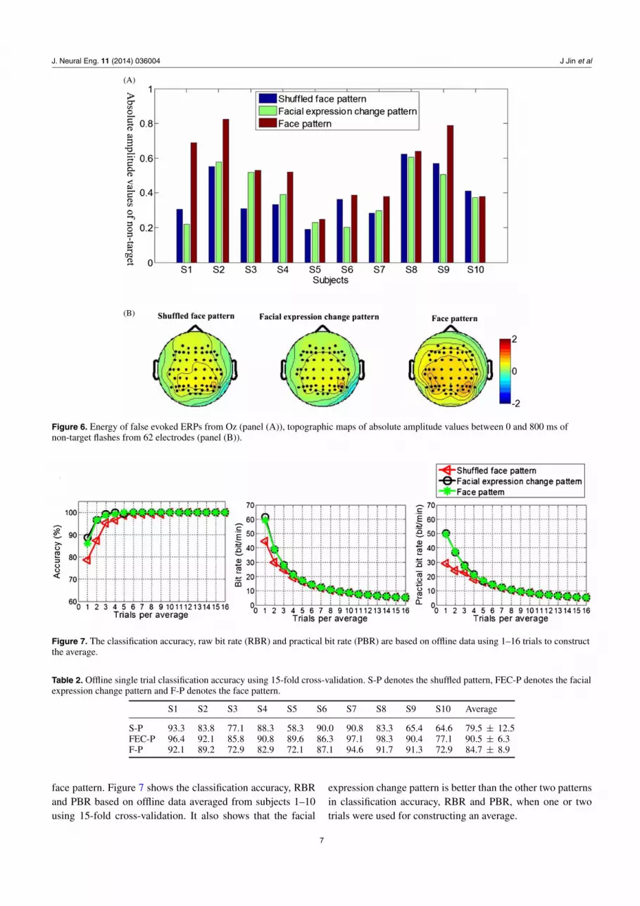
(interference) may evoke ERPs at any time, which will enlargethe non-target absolute amplitude values. We calculatedthe absolute amplitude value of non-targets averaged from0–800 ms on channel Oz (which was less affected by eyemovement than other electrodes in central and frontal areas)for each subject (see figure 6(A)).
A one-way repeated measures ANOVA was used to showthe absolute amplitude value difference of non-target flashesamong the three patterns (F(2, 18) = 8.37 p < 0.05, Eta2 =0.482). It was found that the non-target absolute amplitudevalues on Oz during the face pattern were significantly largerthan that of the face expression change pattern (p < 0.05). Here,absolute amplitude value of non-targets was used as dependentvalue. Three level factors were used. We used the repeatedmeasures defining factor function in SPSS to calculate theresults. Figure 6(B) shows the topographic maps of absoluteamplitude values of non-target flashes from 62 electrodes. Notethat the face pattern contains higher false evoked ERPs in non-target flashes than the other patterns. We also calculate the peakvalues of N200, P300 and N400 on Oz during target flashes.
This shows that there are no significant differences betweenthe facial expression change pattern and the face pattern onOz for N200 (F(2,27) = 0.34, p = 0.7, Eta2 = 0.276), P300(F(2,27) = 1.26, p = 0.3, Eta2 = 0.482) and N400 (F(2,27) =0, p = 0.9, Eta2 = 0.079). The face pattern contained largerinterference (false evoked potentials) in non-target flashes andevoked ERPs, which are not higher than the facial expressionchange pattern, which would make the classification accuracyof the face pattern lower than the facial expression pattern.
Table 2 shows the single trial classification accuracyusing 15-fold cross-validation. There are 240 trials for eachsubject. A one-way repeated measures ANOVA was used toshow the classification difference among the three patterns(F(2, 18) = 7.46, p < 0.05, Eta2 = 0.453). The result showsthat classification accuracy using single trials of the facialexpression change pattern (mean accuracy 90.5 ± 6.3) issignificantly higher than that of the shuffled face pattern (meanaccuracy 79.5 ± 12.5) (p < 0.05) and the face pattern (meanaccuracy 84.7 ± 8.9) (p < 0.05). In figure 7, it is also shownthat the facial expression change pattern is better than the
6
J. Neural Eng. 11 (2014) 036004 J Jin et al
(A)
(B)
Figure 6. Energy of false evoked ERPs from Oz (panel (A)), topographic maps of absolute amplitude values between 0 and 800 ms ofnon-target flashes from 62 electrodes (panel (B)).
Figure 7. The classification accuracy, raw bit rate (RBR) and practical bit rate (PBR) are based on offline data using 1–16 trials to constructthe average.
Table 2. Offline single trial classification accuracy using 15-fold cross-validation. S-P denotes the shuffled pattern, FEC-P denotes the facialexpression change pattern and F-P denotes the face pattern.
S1 S2 S3 S4 S5 S6 S7 S8 S9 S10 Average
S-P 93.3 83.8 77.1 88.3 58.3 90.0 90.8 83.3 65.4 64.6 79.5 ± 12.5FEC-P 96.4 92.1 85.8 90.8 89.6 86.3 97.1 98.3 90.4 77.1 90.5 ± 6.3F-P 92.1 89.2 72.9 82.9 72.1 87.1 94.6 91.7 91.3 72.9 84.7 ± 8.9
face pattern. Figure 7 shows the classification accuracy, RBRand PBR based on offline data averaged from subjects 1–10using 15-fold cross-validation. It also shows that the facial
expression change pattern is better than the other two patternsin classification accuracy, RBR and PBR, when one or twotrials were used for constructing an average.
7

J. Neural Eng. 11 (2014) 036004 J Jin et al
Table 3. Performance from online feedback runs using two trials to construct the average In this table, ‘Acc’ refers to classification accuracy,‘RBR’ to raw bit rate and ‘PBR’ to practical bit rate, measured in bits/min. ‘S-P’ denotes the shuffled pattern, ‘FEC-P’ denotes the facialexpression change pattern and ‘F-P’ denotes the face pattern.
S1 S2 S3 S4 S5 S6 S7 S8 S9 S10 Average
Acc (%) S-P 95.0 82.5 87.5 87.5 90.0 95.0 95.0 100 82.5 82.5 89.8 ± 6.2FEC-P 100 95.0 92.5 97.5 90.0 95.0 100 100 90.0 85.0 94.5 ± 5.1F-P 85.0 90.0 85.0 90.0 92.5 85.0 100 100 85.0 85.0 89.8 ± 6.1
RBR S-P 36.4 25.2 29.2 29.2 31.4 36.4 36.4 43.1 25.2 25.2 31.8 ± 6.1FEC-P 43.1 36.4 33.8 39.3 31.4 36.4 43.1 43.1 31.4 27.1 36.5 ± 5.6F-P 27.1 31.4 27.1 31.4 33.8 27.1 43.1 43.1 27.1 27.1 31.8 ± 6.4
PBR S-P 15.5 7.7 10.4 10.4 11.9 15.5 15.5 20.4 7.7 7.7 12.3 ± 4.3FEC-P 20.4 15.5 13.6 17.7 11.9 15.5 20.4 20.4 11.9 9.0 15.6 ± 4.1F-P 9.0 11.9 9.0 11.9 13.6 9.0 20.4 20.4 9.0 9.0 12.3 ± 4.6
3.2. Online analysis
Table 3 shows the online classification accuracy, bit rate andPBR using two trials to construct the average time series. Somesubjects failed to control the online BCI using single trialsin the pilot experiment. However, the performance improveswhen two trials were used for constructing the average.Therefore, two trials were used for constructing the average inthe online experiment. A one-way repeated measures ANOVAwas used to show the classification accuracy (F(2, 18) = 5.24,p < 0.05, Eta2 = 0.376) and PBR (F(2, 18) = 5.61, p <
0.05, Eta2 = 0.384) difference among the three patterns. Thisshows that the facial expression change pattern is significantlybetter than the shuffled pattern in terms of accuracy (p < 0.05)and PBR (p < 0.05). The mean classification accuracy of thefacial expression change pattern is 4.7% higher than that ofthe shuffled pattern and the face pattern, while the mean PBRof the facial expression change pattern is 3.3 bits min−1 higherthan that of the shuffled pattern and the face pattern.
3.3. Subjective report
Table 4 presents the subjects’ responses to the three questions.In order to show the difference between the face expressionpattern and the face pattern, a paired-samples t-test wasused. This shows that the facial expression change patternis significantly less annoying (t = −6.708, p < 0.05) andless tiring (t = −3.674, p < 0.05) than the face pattern. Nosignificant difference was found for difficulty (t = 0, p = 1).
4. Discussion
The goal of this study was to verify the facial expressionchange pattern’s validity in reducing the interference fromadjacent stimuli, and decreasing user annoyance and fatigue.Although both the shuffled pattern and the facial expressionchange pattern could decrease the interference and the fatigue,the offline and online results both indicated that the facialexpression change pattern could obtain significantly higherclassification accuracies and PBRs than the shuffled pattern(p < 0.05). The offline results show that the facial expressionchange pattern could obtain significantly higher classificationaccuracies than the face pattern (p < 0.05). The online results
also show a trend (p = 0.06) towards indicating that the facialexpression change pattern is better than the face pattern.
In the face pattern, the face picture was shown just likea flash (conspicuous changes of the stimuli) in the flashpattern, which could make the subject tired or feel annoyed.Additionally, such a pattern also causes the subject to beaffected by adjacent non-target flashes when trying to focus onthe target. In our paradigm, human facial expression changesare simulated by changing a curve in a dummy face. In thisway, subjects are not aware of the changes of adjacent imageswhen they are focusing on the target image. Since the stimulusof the expression change pattern is not as strong as the faceand the flash pattern, it was hypothesized that subjects wouldbe less fatigued using the expression change pattern than whenusing the face pattern or the flash pattern and that this patternwould result in fewer interference effects from neighbouringstimuli.
4.1. Reducing interference
In our study, our goal was not to evoke larger ERPs than thatevoked by the face pattern. The goal of this paper was to evokeas large ERPs as the face pattern by using the facial expressionchange pattern and, in so doing, decrease the interferencecaused by adjacent non-target flashes and produce less fatigueand annoyance for the subjects. Figure 4 and table 1 showthat there are no significant differences in N200, P300 andN400 between the face pattern and the facial expression changepattern in target flashes. Our results show that the interferenceof the facial expression change pattern realized by changing acurve in a dummy face (see figure 1) is reduced in comparisonwith the face pattern (see figure 5) and the offline classificationaccuracy was increased significantly (p < 0.05) in comparisonwith the shuffled pattern and the face pattern. The facialexpression change pattern could evoke as large ERPs as theface pattern (see figure 4 and table 1). We also calculate theabsolute amplitude value of non-target flashes (see figure 6)on channel Oz for each subject. This demonstrates that theabsolute amplitude value of non-target flashes produced duringuse of the face pattern is significantly higher than the facialexpression change pattern (p < 0.05), which indicated thatthe interference induced by the face pattern is higher than thefacial expression change pattern.
8

J. Neural Eng. 11 (2014) 036004 J Jin et al
Table 4. Subjects’ responses to three questions for each of the three patterns In this table, ‘S-P’ denotes the shuffled pattern, ‘FEC-P’ thefacial expression change pattern and ‘F-P’ the face pattern..
S1 S2 S3 S4 S5 S6 S7 S8 S9 S10
S-P(%) 1 1 1 1 2 2 2 2 1 3 1.6 ± 0.7Annoying FEC-P 1 2 1 1 1 2 2 2 1 3 1.6 ± 0.7
F-P 3 3 2 2 4 4 3 4 2 4 3.1 ± 0.9S-P(%) 3 1 1 1 2 2 3 4 4 3 2.4 ± 1.2
Tired FEC-P 1 1 1 2 2 3 2 3 2 2 1.9 ± 0.7F-P 2 2 2 2 3 4 2 4 2 2 2.5 ± 0.8S-P(%) 1 2 2 1 2 2 3 2 4 3 2.2 ± 0.9
Hard FEC-P 1 1 1 1 2 3 2 2 2 2 1.7 ± 0.7F-P 1 1 1 1 2 4 2 2 2 1 1.7 ± 0.9
4.2. Reducing fatigue
Conspicuous stimuli make subjects tired and annoyed. Table 4shows that the new stimuli presentation pattern we proposesignificantly decreases the fatigue and annoyance experiencedby the subjects compared to the face pattern. Thus, subjectsare more comfortable when using the proposed presentationpattern compared to the face pattern. This would be valuablefor long time use of the BCI. Additionally, the shuffled patternalso decreased user fatigue and annoyance (see table 4) andthe facial expression change pattern obtained a significantlyhigher classification accuracy (p < 0.05) in offline andonline experiments and a higher PBR (p < 0.05) in onlineexperiments.
4.3. Single trial classification
Subjects may lose their focus or be otherwise adverselyaffected by adjacent flashes (adjacent interference), whenusing the BCI. This kind of mistake happens in one or twotrials of one run and, hence, could not be found in the averagedamplitude of the ERPs. Therefore, the classification accuracyof single trials was used to test for this kind of mistake for eachof the different patterns (shuffled face pattern, facial expressionchange pattern, and face pattern). When the interference ofadjacent flashes was larger, the subject would be more likelyto be affected by adjacent non-target flashes. If the subject waseasily fatigued or annoyed when using one of the patterns,then they would be more prone to loss of attention. This wouldresult in a reduced single trial classification accuracy. In thispaper, our results show that the offline single trial classificationaccuracy of the facial expression change pattern is significantlyhigher than that of the face pattern (p < 0.05) and the shuffledface pattern (p < 0.05). This also illustrates that the facialexpression change pattern has an advantage in decreasinginterference and attracting the attention of subjects, whichreduces the amplitude of ERPs evoked by non-target flashes.
4.4. Potential advantage for patients and healthy users
The system is a gaze-dependent BCI system using a smallvisual angle interface, which could be used by patients whodid not completely lose their ability to maintain eye gaze.Furthermore, the proposed facial expression change patternwas found to be less tiring and annoying than the other patterns,which would be welcomed by patients and other BCI users.
4.5. Subjective reports
We asked subjects three questions relating to annoyance,tiredness and hardness of each of the three conditions.However, these questions only reflect subjective feelingsregarding the three patterns. BCI systems are developed forapplication to a wide range of user groups. Small samplesof subjective reports do not comprehensively demonstratedesirability of the systems. In future studies, a wide interviewof BCI users may be a necessary step before designing a newBCI system.
This sounds pretty negative. However, subjective reportsare essential and valuable if we wish to know about thesubjects’ perception of and satisfaction with a BCI controlledapplication. It is almost inherent in BCI studies that we haveto deal with low sample sizes. But, with time, reports fromsmall groups accumulate and we may, in the future, drawsome conclusions if we merge results.
5. Conclusions
A facial expression change pattern for visual attention-based BCIs was presented in this paper. It significantlyreduces the interference from neighbouring stimuli, improvingclassification accuracy and information transfer rate, whilereducing subject annoyance and fatigue. The key idea behindthis work is that minor changes to the image cause a largeenough contrast to evoke strong ERPs. The result obtained inour work shows a new direction for designing BCI paradigms.Increasing user interest and decreasing annoyance could bean effective way to improve the performance of BCI system,which would also be welcomed by BCI users.
Acknowledgments
This work was supported in part by the Grant National NaturalScience Foundation of China, under grant nos 61074113and 61203127 and in part by Shanghai Leading AcademicDiscipline Project, Project Number: B504. This work was alsosupported by the Fundamental Research Funds for the CentralUniversities (WH1114038 and WH1314023).
References
[1] Mason M F, Norton M I, Van Horn J D, Wegner D M,Graffton S and Neil Macrae C 2007 Wandering minds: thedefault network and stimulus-independent thought Science315 393–5
9

J. Neural Eng. 11 (2014) 036004 J Jin et al
[2] Kubler A, Kotchoubey B, Kaiser J, Wolpaw Jand Birbaumer N 2001 Brain–computer communication:unlocking the locked Psychol. Bull. 127 358–75
[3] Wolpaw J R, Birbaumer N, McFarland D J, Pfurtscheller Gand Vaughan T M 2002 Brain computer interfaces forcommunication and control Clin. Neurophysiol. 113 767–91
[4] Allison B Z, Wolpaw E W and Wolpaw J R 2007Brain–computer interface systems: progress and prospectsExpert Rev. Med. Devices 4 463–74
[5] Birbaumer N and Cohen L G 2007 Brain–computer interfaces:communication and restoration of movement in paralysis J.Physiol. 15 621–36
[6] Allison B Z, McFarland D J, Schalk G, Zheng S D,Jackson M M and Wolpaw J R 2008 Brain computerinterface systems: progress and prospects Clin.Neurophysiol. 119 399–408
[7] Mak J N and Wolpaw J R 2009 Clinical application ofbrain–computer interface: current state and future prospectsIEEE Rev. Biomed. Eng. 2 187–99
[8] Ortner R, Allison B Z, Korisek G, Gaqql Hand Pfurtscheller G 2011 An SSVEP BCI to control a handorthosis for persons with tetraplegia IEEE Trans. NeuralSyst. Rehabil. Eng. 19 1–5
[9] Daly I, Billinger M, Laparra-Hernndex J, Aloise F,Garca M L, Muller-Putz G R and Scherer R 2013 On thecontrol of brain–computer interfaces by users with cerebralpalsy Clin. Neurophysiol. 124 1787–97
[10] Farwell L A and Donchin E 1988 Talking off the top of yourhead: toward a mental prosthesis utilizing event-relatedbrain potentials Clin. Neurophysiol. 70 510–23
[11] Fazel-Rezai R 2007 Human error in P300 speller paradigm forbrain–computer interface 29th Conf. Proc. IEEEEngineering in Medicine and Biology Society (Lyon,France, 23–26 Aug.) pp 2516–9
[12] Mak J N, Arbel Y, Minett J W, McCane L M, Yuksel B,Ryan D, Thompson D, Bianchi L and Erdogmus D 2011Optimizing the P300-based brain–computer interface:current status, limitations and future directions J. NeuralEng. 8 025003
[13] Kleih S C, Riccio A, Mattia D, Schreuder M, Tangermann M,Zickler C, Neuper C and Kubler A 2011 Motivation affectsperformance in a P300 brain computer interface Int. J.Bioelectromagn. 13 46–47
[14] Johnson R Jr and Donchin E 1978 On how P300 amplitudevaries with utility of the eliciting stimuli Clin.Neurophysiol. 44 424–37
[15] Polich J 2007 Updating P300: an integrative theory of P3a andP3b Clin. Neurophysiol. 18 2128–48
[16] Mugler E, Bensch M, Halder S, Rosenstiel W, Bogdan M,Birbaumer N and Kubler A 2008 Control of an internetbrowser using the P300 event-related potential Int. J.Bioelectromagn. 10 56–63
[17] Munssinger J I, Halder S, Kleih S C, Furdea A, Raco V,Hoesle A and Kubler A 2010 Brain painting: first evaluationof a new brain–computer interface application withALS-patients and healthy volunteers Front. Neurosci. 4 182
[18] Aloise F, Schettini F, Arico P, Leotta F, Salinari S, Mattia D,Babiloni F and Cincotti F 2011 P300-based brain–computerinterface for environmental control: an asynchronousapproach J. Neural Eng. 8 025025
[19] Xu N, Gao X R, Hong B, Miao X B, Gao S K and Yang F S2004 BCI competition 2003-data set IIb: enhancing P300wave detection using ICA-based subspace projections forBCI applications IEEE Trans. Biomed. Eng. 51 1067–72
[20] Lotte F, Congedo M, Lecuyer A, Lamarche F and Arnaldi B2007 A review of classification algorithms for EEG-basedbrain–computer interfaces J. Neural Eng. 4 R1–13
[21] Hoffmann U, Vesin J M, Ebrahimi T and Diserens K 2008 Anempirical bayesian framework for brain computer interfaceJ. Neurosci. Methods 167 115–25
[22] Cichocki A, Washizawa N Y, Rutkowski T, Bakardjian H,Phan A H, Choi S, Lee H, Zhao Q, Zhang L and Li Y Q2008 Noninvasive BCIs: multiway signal-processing arraydecompositions IEEE Comput. 41 34–42
[23] Blankertz B, Lemm S, Treder M, Haufe S and Muller K R2011 Single-trial analysis and classification of ERPcomponents—a tutorial NeuroImage 56 814–25
[24] Zhang Y, Zhou G, Zhao Q, Jin J, Wang X and Andrzej C 2013Spatial-temporal discriminant analysis for ERP-basedbrain–computer interface IEEE Trans. Neural Syst. Rehabil.Eng. 21 233–43
[25] Liu Y, Zhou Z T and Hu D W 2010 Gaze independentbrain–computer speller with convert visual search tasksClin. Neurophysiol. 112 1127–36
[26] Treder M S, Schmidt N M and Blankertz B 2011Gaze-independent brain–computer interfaces based oncovert attention and feature attention J. Neural Eng.8 066003
[27] Townsend G, LaPallo B K, Boulay C B, Krusienski D J,Frye G E, Hauser C K, Schwartz N E,, Vaughan T M,Wolpaw J R and Sellers E W 2010 A novel P300-basedbrain–computer interface stimulus presentation paradigm:moving beyond rows and columns Clin. Neurophysiol.121 1109–20
[28] Jin J, Allison B Z, Sellers E W, Brunner C, Horki P, Wang Xand Neuper C 2011 Adaptive P300 based control system J.Neural Eng. 8 036006
[29] Guo F, Hong B, Gao X and Gao S 2008 A brain–computerinterface using motion-onset visual evoked potential J.Neural Eng. 5 011
[30] Liu T, Goldberg L, Gao S and Hong B 2010 An onlinebrain–computer interface using non-flashing visual evokedpotentials J. Neural Eng. 7 036003
[31] Hong B, Guo F, Liu T and Gao S 2009 N200-speller usingmotion-onset visual response Clin. Neurophysiol.120 1658–66
[32] Jin J, Allison B Z, Wang X and Neuper C 2012a A combinedbrain–computer interface based on P300 potentials andmotion-onset visual evoked potentials J. Neurosci. Methods205 265–76
[33] Kaufmann T, Schulz S M, Grunzinger C and Kubler A 2011Flashing characters with famous faces improves ERP-basedbrain–computer interface performance J. Neural Eng.8 056016
[34] Kaufmann T, Schulz S M, Koblitz A, Renner G, Wessig Cand Kubler A 2012 Face stimuli effectively preventbrain–computer interface inefficiency in patients withneurodegenerative disease Clin. Neurophysiol.124 893–900
[35] Zhang Y, Zhao Q, Jin J, Wang X and Cichocki A 2012 A novelBCI based on ERP components sensitive to configuralprocessing of human faces J. Neural Eng. 9 026018
[36] Townsend G, Shanahan J, Ryan D B and Sellers E W 2012 Ageneral P300 brain–computer interface presentationparadigm based on performance guided constraintsNeurosic. Lett. 531 63–68
[37] Frye G E, Hauser C K, Townsend G and Sellers E W 2011Suppressing flashes of items surrounding targets duringcalibration of a P300-based brain–computerinterface improves performance J. Neural Eng.8 025024
[38] Jin J, Allison B Z, Kaufmann T, Kubler A, Zhang Y,Wang X Y and Cichocki A 2012 The changing face of P300BCIs: a comparison of stimulus changes in a P300 BCIinvolving faces, emotion, and movement PLoS ONE7 e49688
10

J. Neural Eng. 11 (2014) 036004 J Jin et al
[39] Krombholz A, Schaefer F and Boucsein W 2007 Modificationof N170 by different emotional expression of schematicfaces Biol. Psychol. 76 156–62
[40] Bediou B, Eimer M, D’Amato T, Hauk O and Calder A J 2009In the eye of the beholder: individual differences inreward-drive modulate early frontocentral ERPs to angryfaces Neuropsychologia 47 825–34
[41] Calvo M G, Marrero H and Beltran D 2013 When does thebrain distinguish between genuine and ambiguous smiles?An ERP study Brain Cogn. 81 237–46
[42] Guger C, Daban S, Sellers E W, Holzner C, Krausz G,Carabalona R, Gramatica F and Edlinger G 2009 Howmany people are able to control a P300-basedbrain–computer interface (BCI) Neurosci. Lett. 462 94–8
[43] Jin J, Allison B Z, Kaufmann T, Kubler A, Zhang Y, Wang Xand Cichocki A 2012b The changing face of P300 BCIs: acomparison of stimulus changes in a P300 BCI involvingfaces, emotion, and movement PLoS One 7 e49688
[44] Jin J, Horki P, Brunner C, Wang X, Neuper Cand Pfurtscheller G 2010 A new P300 stimulus presentationpattern for EEG-based spelling systems Biomed. Tech.55 203–10
[45] Wolpaw J R, Birbaumer N, Pfurtscheller G and Vaughan T2002 Brain–computer interfaces for communication andcontrol Clin. Neurophysiol. 113 767–91
[46] Curran T and Hancock J 2007 The Fn400 indexesfamiliarity-based recognition of faces NeuroImage36 464–71
11