Embed Size (px)
Citation preview
International Research Journal of Engineering and Technology (IRJET) e-ISSN: 2395-0056
Volume: 08 Issue: 05 | May 2021 www.irjet.net p-ISSN: 2395-0072
© 2021, IRJET | Impact Factor value: 7.529 | ISO 9001:2008 Certified Journal |Page 4589
Analysis and Design of Commercial RCC Structure
Preethi M1, Aleena Baby2, Alok A Xavier3, Aswathy Madhu4, Ayana Stanly5
1Professor, Dept. of civil Engineering, FISAT, Angamaly, Kerala, India 2,3,4,5 Student, Dept. of civil Engineering, FISAT, Angamaly, Kerala, India
---------------------------------------------------------------------***---------------------------------------------------------------------
Abstract - Structural Analysis and design are important for finding out the significant threats to the integrity and stability of a structure. RCC structures are mostly used in the framing system for most of the building. They have the advantage of high compressive strength and stiffness. The principle objective of this project is to analyse and design a RCC framed structure using STAAD Pro. In this project, the plan of a G+2 commercial building, situated in Malayatoor is considered. RCC model for the structure is prepared using STAAD pro and the design involves load calculations and analysing the whole structure. The design methods used in STAAD-Pro analysis are Limit State Design following to the Indian Standard Code of Practice.
Key Words: STAAD Pro, Analysis, Design, Commercial building, RCC
1. INTRODUCTION Structures are constructed using different types of material. Studies are carried out to find the best alternative material that can be used for the construction of structures, which can satisfy both the strength and the intended purpose. In the olden days houses were constructed using native materials like rocks, timber, leaves, etc. They were constructed without following proper guidelines or ensuring if the building was safe. The quality and the type of material used were also a major constraint. Usage of inferior quality materials resulted in the collapse of structure when there was a sudden increase in the loading conditions. This happens when there is a sudden change in the wind pattern or can even be due to seismic activities. Structural stability and safety improved with the usage of concrete and steel. RCC framed structures are constructed widely in recent days.
Structural engineering is a part of engineering that deals with the safety and integrity of a structure. A structural engineer must ensure that a design is safe to various loading conditions that the structure can encounter during its useful life, while also keeping in mind the aesthetic aspect of the structure. As the population increased and the area of space available reduced the demand for high raised structures increased. Design of such structures manually is a time consuming process. Considering the effect of wind and seismic effect makes it an even harder process. The usage of softwares like STAAD Pro, ETABS, etc makes the analysis and design of such complex structures easier. This gives an even accurate result and can also eliminate the chance for human errors.
2. SOFTWARES USED
2.1 AutoCAD
AutoCAD is a commercial computer-aided design (CAD) and drafting software application. Developed and marketed by Auto desk, auto CAD is used in industry, by architects, project managers, engineers, graphic designers, city planners and other professionals. Due to the availability of a wide range of drawing tools and features this software has been used for plotting the plan and elevation of our structures.
2.2 STAAD.ProV8i
STAAD.Pro is one of the most widely used structural analysis and design software products worldwide. It supports over 90 international steel, concrete, timber and aluminium design codes. It can make use of various forms of analysis from the traditional static analysis to more recent analysis methods like p-delta analysis, geometric nonlinear analysis, pushover analysis or a buckling analysis. It can also make use of various forms of dynamic analysis methods from time history analysis to response spectrum analysis. Due to its versatility this software has been used for the analysis of the structures using limit state design.
3. METHODOLOGY
3.1. Analysis of the structure
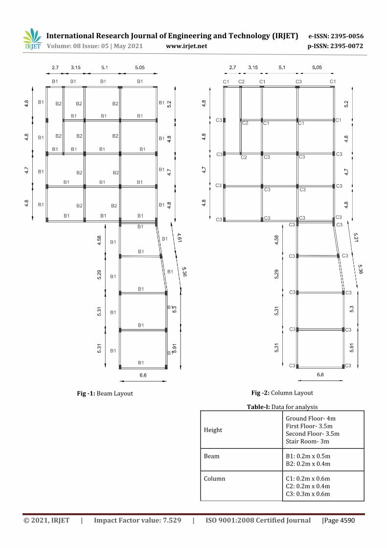
In this project, G+2 commercial building is considered for study. The beam and column layout of the building is shown in figure 1 and figure 2. The span between columns in RCC structures is limited. Increasing the span results in the increase of dimensions of columns and beams. This results in heavier structural members. For the RCC structure studied the maximum span is limited to less than 7m. Other relevant data is tabulated in table I:
International Research Journal of Engineering and Technology (IRJET) e-ISSN: 2395-0056
Volume: 08 Issue: 05 | May 2021 www.irjet.net p-ISSN: 2395-0072
© 2021, IRJET | Impact Factor value: 7.529 | ISO 9001:2008 Certified Journal |Page 4590
Fig -1: Beam Layout
Fig -2: Column Layout
Table-I: Data for analysis
Height
Ground Floor- 4m First Floor- 3.5m Second Floor- 3.5m Stair Room- 3m
Beam B1: 0.2m x 0.5m B2: 0.2m x 0.4m
Column C1: 0.2m x 0.6m C2: 0.2m x 0.4m C3: 0.3m x 0.6m
International Research Journal of Engineering and Technology (IRJET) e-ISSN: 2395-0056
Volume: 08 Issue: 05 | May 2021 www.irjet.net p-ISSN: 2395-0072
© 2021, IRJET | Impact Factor value: 7.529 | ISO 9001:2008 Certified Journal |Page 4591
Grade of concrete M25
Grade of steel FE415(rebar)
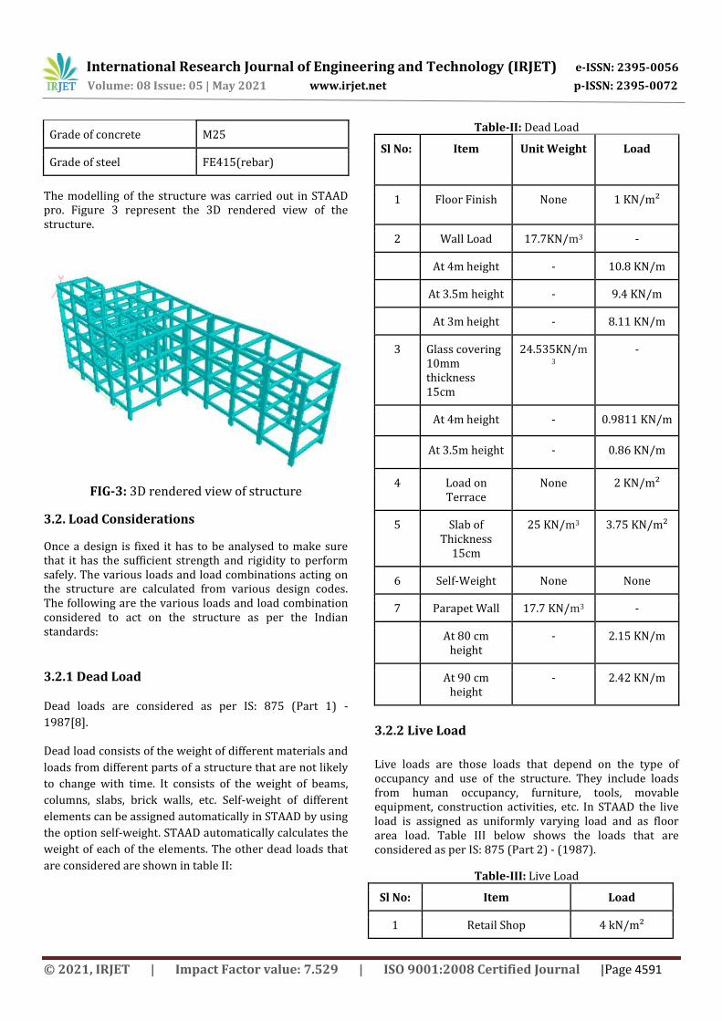
The modelling of the structure was carried out in STAAD pro. Figure 3 represent the 3D rendered view of the structure.
FIG-3: 3D rendered view of structure
3.2. Load Considerations
Once a design is fixed it has to be analysed to make sure that it has the sufficient strength and rigidity to perform safely. The various loads and load combinations acting on the structure are calculated from various design codes. The following are the various loads and load combination considered to act on the structure as per the Indian standards:
3.2.1 Dead Load
Dead loads are considered as per IS: 875 (Part 1) -
1987[8].
Dead load consists of the weight of different materials and
loads from different parts of a structure that are not likely
to change with time. It consists of the weight of beams,
columns, slabs, brick walls, etc. Self-weight of different
elements can be assigned automatically in STAAD by using
the option self-weight. STAAD automatically calculates the
weight of each of the elements. The other dead loads that
are considered are shown in table II:
Table-II: Dead Load
Sl No: Item Unit Weight Load
1 Floor Finish None 1 KN/m²
2 Wall Load 17.7KN/m3 -
At 4m height - 10.8 KN/m
At 3.5m height - 9.4 KN/m
At 3m height - 8.11 KN/m
3 Glass covering 10mm thickness 15cm
24.535KN/m3
-
At 4m height - 0.9811 KN/m
At 3.5m height - 0.86 KN/m
4 Load on Terrace
None 2 KN/m²
5 Slab of Thickness
15cm
25 KN/m3 3.75 KN/m²
6 Self-Weight None None
7 Parapet Wall 17.7 KN/m3 -
At 80 cm height
- 2.15 KN/m
At 90 cm height
- 2.42 KN/m
3.2.2 Live Load
Live loads are those loads that depend on the type of occupancy and use of the structure. They include loads from human occupancy, furniture, tools, movable equipment, construction activities, etc. In STAAD the live load is assigned as uniformly varying load and as floor area load. Table III below shows the loads that are considered as per IS: 875 (Part 2) - (1987).
Table-III: Live Load
Sl No: Item Load
1 Retail Shop 4 kN/m²
International Research Journal of Engineering and Technology (IRJET) e-ISSN: 2395-0056
Volume: 08 Issue: 05 | May 2021 www.irjet.net p-ISSN: 2395-0072
© 2021, IRJET | Impact Factor value: 7.529 | ISO 9001:2008 Certified Journal |Page 4592
2 Office Shop 2.5 KN/m²
3.2.3 Wind Load
Wind Load is used to refer to any pressure or force
that the wind exerts on a structure. Wind load acting on
the structure are calculated as per IS: 875 (Part 3) - 2015.
The calculation of wind load is as shown below:
a) Basic Wind Speed Vb is 39m/s from figure 1 of IS: 875
(Part 3) - 2015.
b) Design Wind Speed Vz is calculated as per clause 6.3,
IS: 875 (Part 3) – 2015. k1 is the probability factor which is
taken as 1 from table 1. k2 is terrain roughness and
height factor. The category is chosen as 2. The value of k2
is obtained from table 2. Up to 10m height k2 is taken as 1
and for height above 10m up to 14.8m k2 is taken as 1.05.
k3 is a topographic factor calculated as per clause 6.3.3.
The value is taken as 1. k4 is an important factor for the
cyclonic region (this value is neglected). Therefore, design
wind speed is calculated as Vz = Vb k1 k2 k3 k4. Up to 10m
height Vz = 39m/s, and for height above 10m up to 14.8m
Vz = 40.95m/s.
c) Design Wind Pressure pd is calculated as per clause
7.2, IS: 875 (Part 3) - 2015. Kd is the wind directionality
factor taken as 0.9 as per clause 7.2.1. Ka is an area
averaging factor which is approximately 0.85 obtained
from table 4. Kc is a combination factor taken as 0.9 as per
clause 7.3.3.13. From this pd = pz ka kc kd, where pz = 0.6
vz². As per the conditions given in clause 7.2, the value of
pd is 638.82N/m² up to 10m and 704.3N/m² above 10m
up to 14.8m.
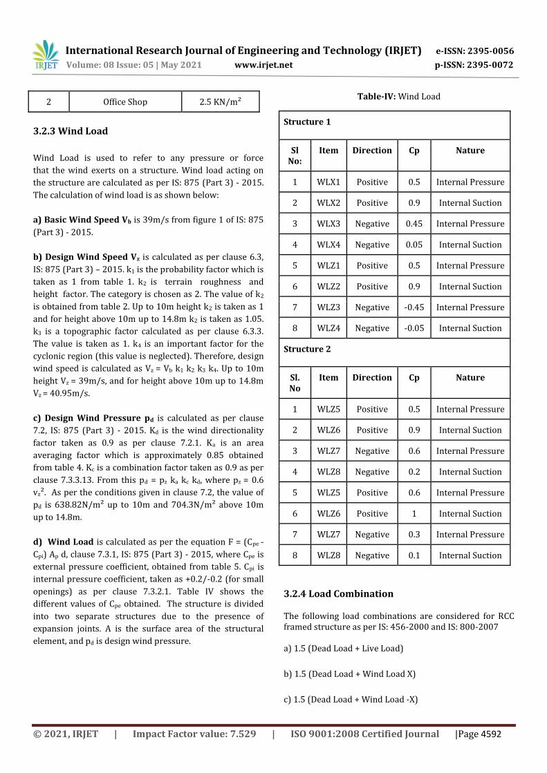
d) Wind Load is calculated as per the equation F = (Cpe -
Cpi) Ap d, clause 7.3.1, IS: 875 (Part 3) - 2015, where Cpe is
external pressure coefficient, obtained from table 5. Cpi is
internal pressure coefficient, taken as +0.2/-0.2 (for small
openings) as per clause 7.3.2.1. Table IV shows the
different values of Cpe obtained. The structure is divided
into two separate structures due to the presence of
expansion joints. A is the surface area of the structural
element, and pd is design wind pressure.
Table-IV: Wind Load
Structure 1
Sl No:
Item Direction Cp Nature
1 WLX1 Positive 0.5 Internal Pressure
2 WLX2 Positive 0.9 Internal Suction
3 WLX3 Negative 0.45 Internal Pressure
4 WLX4 Negative 0.05 Internal Suction
5 WLZ1 Positive 0.5 Internal Pressure
6 WLZ2 Positive 0.9 Internal Suction
7 WLZ3 Negative -0.45 Internal Pressure
8 WLZ4 Negative -0.05 Internal Suction
Structure 2
Sl. No
Item Direction Cp Nature
1 WLZ5 Positive 0.5 Internal Pressure
2 WLZ6 Positive 0.9 Internal Suction
3 WLZ7 Negative 0.6 Internal Pressure
4 WLZ8 Negative 0.2 Internal Suction
5 WLZ5 Positive 0.6 Internal Pressure
6 WLZ6 Positive 1 Internal Suction
7 WLZ7 Negative 0.3 Internal Pressure
8 WLZ8 Negative 0.1 Internal Suction
3.2.4 Load Combination
The following load combinations are considered for RCC framed structure as per IS: 456-2000 and IS: 800-2007 a) 1.5 (Dead Load + Live Load)
b) 1.5 (Dead Load + Wind Load X)
c) 1.5 (Dead Load + Wind Load -X)
International Research Journal of Engineering and Technology (IRJET) e-ISSN: 2395-0056
Volume: 08 Issue: 05 | May 2021 www.irjet.net p-ISSN: 2395-0072
© 2021, IRJET | Impact Factor value: 7.529 | ISO 9001:2008 Certified Journal |Page 4593
d) 1.5 (Dead Load + Wind Load Z)
e) 1.5 (Dead Load + Wind Load -Z)
f) 0.9 (Dead Load) + 1.5 (Wind Load X)
g) 0.9 (Dead Load) + 1.5 (Wind Load -X)
h) 0.9 (Dead Load) + 1.5 (Wind Load Z)
i) 0.9 (Dead Load) + 1.5 (Wind Load -Z)
j) 1.2 (Dead Load + Live Load + Wind Load X)
k) 1.2 (Dead Load + Live Load + Wind Load -X)
l) 1.2 (Dead Load + Live Load + Wind Load Z)
m) 1.2 (Dead Load + Live Load + Wind Load -Z)
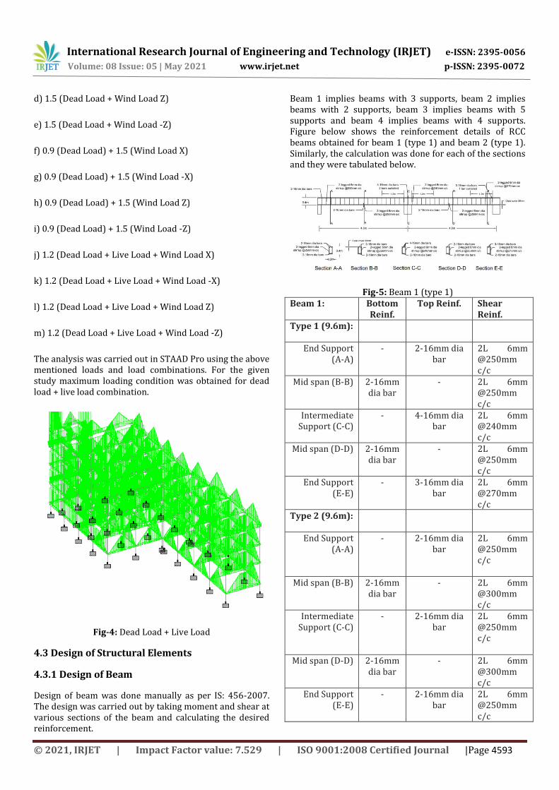
The analysis was carried out in STAAD Pro using the above mentioned loads and load combinations. For the given study maximum loading condition was obtained for dead load + live load combination.
Fig-4: Dead Load + Live Load
4.3 Design of Structural Elements
4.3.1 Design of Beam
Design of beam was done manually as per IS: 456-2007. The design was carried out by taking moment and shear at various sections of the beam and calculating the desired reinforcement.
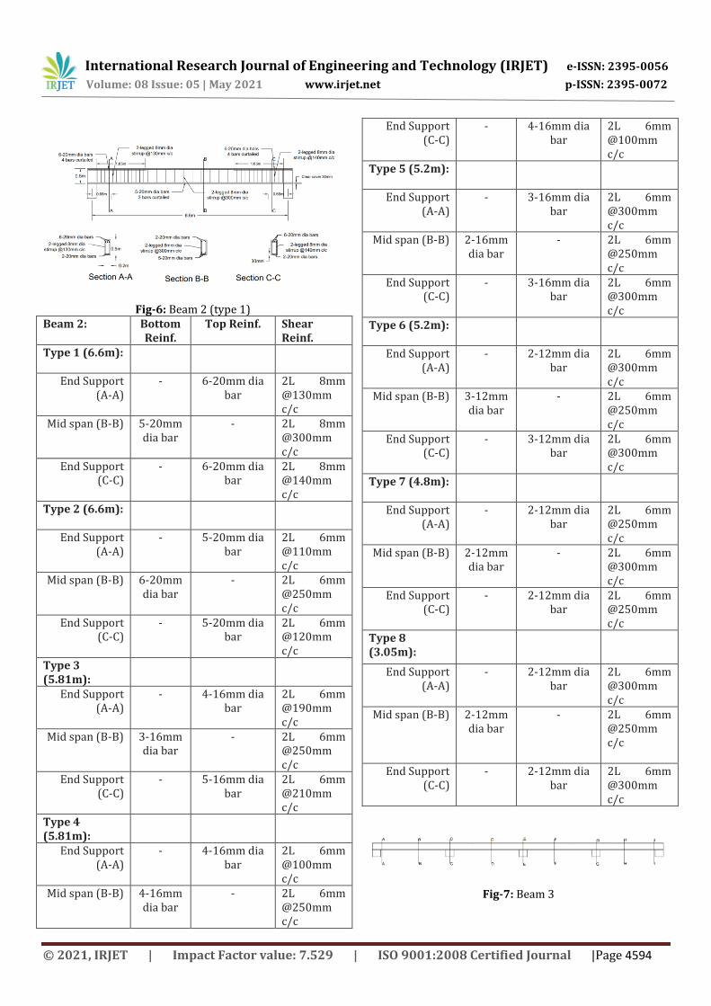
Beam 1 implies beams with 3 supports, beam 2 implies beams with 2 supports, beam 3 implies beams with 5 supports and beam 4 implies beams with 4 supports. Figure below shows the reinforcement details of RCC beams obtained for beam 1 (type 1) and beam 2 (type 1). Similarly, the calculation was done for each of the sections and they were tabulated below.
Fig-5: Beam 1 (type 1) Beam 1: Bottom
Reinf. Top Reinf. Shear
Reinf. Type 1 (9.6m):
End Support (A-A)
- 2-16mm dia bar
2L 6mm @250mm c/c
Mid span (B-B) 2-16mm dia bar
- 2L 6mm @250mm c/c
Intermediate Support (C-C)
- 4-16mm dia bar
2L 6mm @240mm c/c
Mid span (D-D) 2-16mm dia bar
- 2L 6mm @250mm c/c
End Support (E-E)
- 3-16mm dia bar
2L 6mm @270mm c/c
Type 2 (9.6m):
End Support (A-A)
- 2-16mm dia bar
2L 6mm @250mm c/c
Mid span (B-B) 2-16mm dia bar
- 2L 6mm @300mm c/c
Intermediate Support (C-C)
- 2-16mm dia bar
2L 6mm @250mm c/c
Mid span (D-D) 2-16mm dia bar
- 2L 6mm @300mm c/c
End Support (E-E)
- 2-16mm dia bar
2L 6mm @250mm c/c
International Research Journal of Engineering and Technology (IRJET) e-ISSN: 2395-0056
Volume: 08 Issue: 05 | May 2021 www.irjet.net p-ISSN: 2395-0072
© 2021, IRJET | Impact Factor value: 7.529 | ISO 9001:2008 Certified Journal |Page 4594
Fig-6: Beam 2 (type 1) Beam 2: Bottom
Reinf. Top Reinf. Shear
Reinf. Type 1 (6.6m):
End Support (A-A)
- 6-20mm dia bar
2L 8mm @130mm c/c
Mid span (B-B) 5-20mm dia bar
- 2L 8mm @300mm c/c
End Support (C-C)
- 6-20mm dia bar
2L 8mm @140mm c/c
Type 2 (6.6m):
End Support (A-A)
- 5-20mm dia bar
2L 6mm @110mm c/c
Mid span (B-B) 6-20mm dia bar
- 2L 6mm @250mm c/c
End Support (C-C)
- 5-20mm dia bar
2L 6mm @120mm c/c
Type 3 (5.81m):
End Support (A-A)
- 4-16mm dia bar
2L 6mm @190mm c/c
Mid span (B-B) 3-16mm dia bar
- 2L 6mm @250mm c/c
End Support (C-C)
- 5-16mm dia bar
2L 6mm @210mm c/c
Type 4 (5.81m):
End Support (A-A)
- 4-16mm dia bar
2L 6mm @100mm c/c
Mid span (B-B) 4-16mm dia bar
- 2L 6mm @250mm c/c
End Support (C-C)
- 4-16mm dia bar
2L 6mm @100mm c/c
Type 5 (5.2m):
End Support (A-A)
- 3-16mm dia bar
2L 6mm @300mm c/c
Mid span (B-B) 2-16mm dia bar
- 2L 6mm @250mm c/c
End Support (C-C)
- 3-16mm dia bar
2L 6mm @300mm c/c
Type 6 (5.2m):
End Support (A-A)
- 2-12mm dia bar
2L 6mm @300mm c/c
Mid span (B-B) 3-12mm dia bar
- 2L 6mm @250mm c/c
End Support (C-C)
- 3-12mm dia bar
2L 6mm @300mm c/c
Type 7 (4.8m):
End Support (A-A)
- 2-12mm dia bar
2L 6mm @250mm c/c
Mid span (B-B) 2-12mm dia bar
- 2L 6mm @300mm c/c
End Support (C-C)
- 2-12mm dia bar
2L 6mm @250mm c/c
Type 8 (3.05m):
End Support (A-A)
- 2-12mm dia bar
2L 6mm @300mm c/c
Mid span (B-B) 2-12mm dia bar
- 2L 6mm @250mm c/c
End Support (C-C)
- 2-12mm dia bar
2L 6mm @300mm c/c
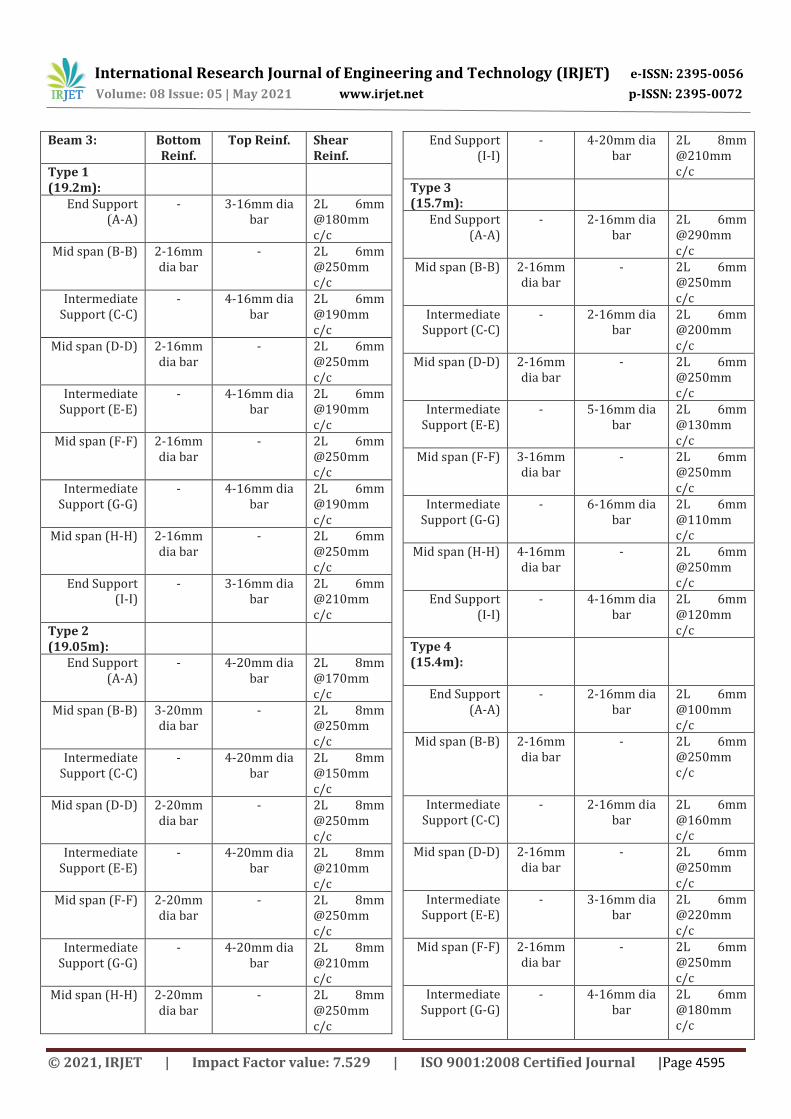
Fig-7: Beam 3
International Research Journal of Engineering and Technology (IRJET) e-ISSN: 2395-0056
Volume: 08 Issue: 05 | May 2021 www.irjet.net p-ISSN: 2395-0072
© 2021, IRJET | Impact Factor value: 7.529 | ISO 9001:2008 Certified Journal |Page 4595
Beam 3: Bottom Reinf.
Top Reinf. Shear Reinf.
Type 1 (19.2m):
End Support (A-A)
- 3-16mm dia bar
2L 6mm @180mm c/c
Mid span (B-B) 2-16mm dia bar
- 2L 6mm @250mm c/c
Intermediate Support (C-C)
- 4-16mm dia bar
2L 6mm @190mm c/c
Mid span (D-D) 2-16mm dia bar
- 2L 6mm @250mm c/c
Intermediate Support (E-E)
- 4-16mm dia bar
2L 6mm @190mm c/c
Mid span (F-F) 2-16mm dia bar
- 2L 6mm @250mm c/c
Intermediate Support (G-G)
- 4-16mm dia bar
2L 6mm @190mm c/c
Mid span (H-H) 2-16mm dia bar
- 2L 6mm @250mm c/c
End Support (I-I)
- 3-16mm dia bar
2L 6mm @210mm c/c
Type 2 (19.05m):
End Support (A-A)
- 4-20mm dia bar
2L 8mm @170mm c/c
Mid span (B-B) 3-20mm dia bar
- 2L 8mm @250mm c/c
Intermediate Support (C-C)
- 4-20mm dia bar
2L 8mm @150mm c/c
Mid span (D-D) 2-20mm dia bar
- 2L 8mm @250mm c/c
Intermediate Support (E-E)
- 4-20mm dia bar
2L 8mm @210mm c/c
Mid span (F-F) 2-20mm dia bar
- 2L 8mm @250mm c/c
Intermediate Support (G-G)
- 4-20mm dia bar
2L 8mm @210mm c/c
Mid span (H-H) 2-20mm dia bar
- 2L 8mm @250mm c/c
End Support (I-I)
- 4-20mm dia bar
2L 8mm @210mm c/c
Type 3 (15.7m):
End Support (A-A)
- 2-16mm dia bar
2L 6mm @290mm c/c
Mid span (B-B) 2-16mm dia bar
- 2L 6mm @250mm c/c
Intermediate Support (C-C)
- 2-16mm dia bar
2L 6mm @200mm c/c
Mid span (D-D) 2-16mm dia bar
- 2L 6mm @250mm c/c
Intermediate Support (E-E)
- 5-16mm dia bar
2L 6mm @130mm c/c
Mid span (F-F) 3-16mm dia bar
- 2L 6mm @250mm c/c
Intermediate Support (G-G)
- 6-16mm dia bar
2L 6mm @110mm c/c
Mid span (H-H) 4-16mm dia bar
- 2L 6mm @250mm c/c
End Support (I-I)
- 4-16mm dia bar
2L 6mm @120mm c/c
Type 4 (15.4m):
End Support (A-A)
- 2-16mm dia bar
2L 6mm @100mm c/c
Mid span (B-B) 2-16mm dia bar
- 2L 6mm @250mm c/c
Intermediate Support (C-C)
- 2-16mm dia bar
2L 6mm @160mm c/c
Mid span (D-D) 2-16mm dia bar
- 2L 6mm @250mm c/c
Intermediate Support (E-E)
- 3-16mm dia bar
2L 6mm @220mm c/c
Mid span (F-F) 2-16mm dia bar
- 2L 6mm @250mm c/c
Intermediate Support (G-G)
- 4-16mm dia bar
2L 6mm @180mm c/c
International Research Journal of Engineering and Technology (IRJET) e-ISSN: 2395-0056
Volume: 08 Issue: 05 | May 2021 www.irjet.net p-ISSN: 2395-0072
© 2021, IRJET | Impact Factor value: 7.529 | ISO 9001:2008 Certified Journal |Page 4596
Mid span (H-H) 3-16mm dia bar
- 2L 6mm @250mm c/c
End Support (I-I)
- 3-16mm dia bar
2L 6mm @190mm c/c
Type 5 (20.59m):
End Support (A-A)
- 3-16mm dia bar
2L 6mm @300mm c/c
Mid span (B-B) 2-16mm dia bar
- 2L 6mm @250mm c/c
Intermediate Support (C-C)
- 4-16mm dia bar
2L 6mm @220mm c/c
Mid span (D-D) 2-16mm dia bar
- 2L 6mm @250mm c/c
Intermediate Support (E-E)
- 4-16mm dia bar
2L 6mm @300mm c/c
Mid span (F-F) 2-16mm dia bar
- 2L 6mm @250mm c/c
Intermediate Support (G-G)
- 4-16mm dia bar
2L 6mm @300mm c/c
Mid span (H-H) 2-16mm dia bar
- 2L 6mm @250mm c/c
End Support (I-I)
- 3-16mm dia bar
2L 6mm @300mm c/c
Type 6 (20.49m):
End Support (A-A)
- 3-16mm dia bar
2L 6mm @300mm c/c
Mid span (B-B) 2-16mm dia bar
- 2L 6mm @250mm c/c
Intermediate Support (C-C)
- 3-16mm dia bar
2L 6mm @290mm c/c
Mid span (D-D) 2-16mm dia bar
- 2L 6mm @250mm c/c
Intermediate Support (E-E)
- 4-16mm dia bar
2L 6mm @250mm c/c
Mid span (F-F) 2-16mm dia bar
- 2L 6mm @250mm c/c
Intermediate - 4-16mm dia 2L 6mm
Support (G-G) bar @260mm c/c
Mid span (H-H) 2-16mm dia bar
- 2L 6mm @250mm c/c
End Support (I-I)
- 2-16mm dia bar
2L 6mm @300mm c/c
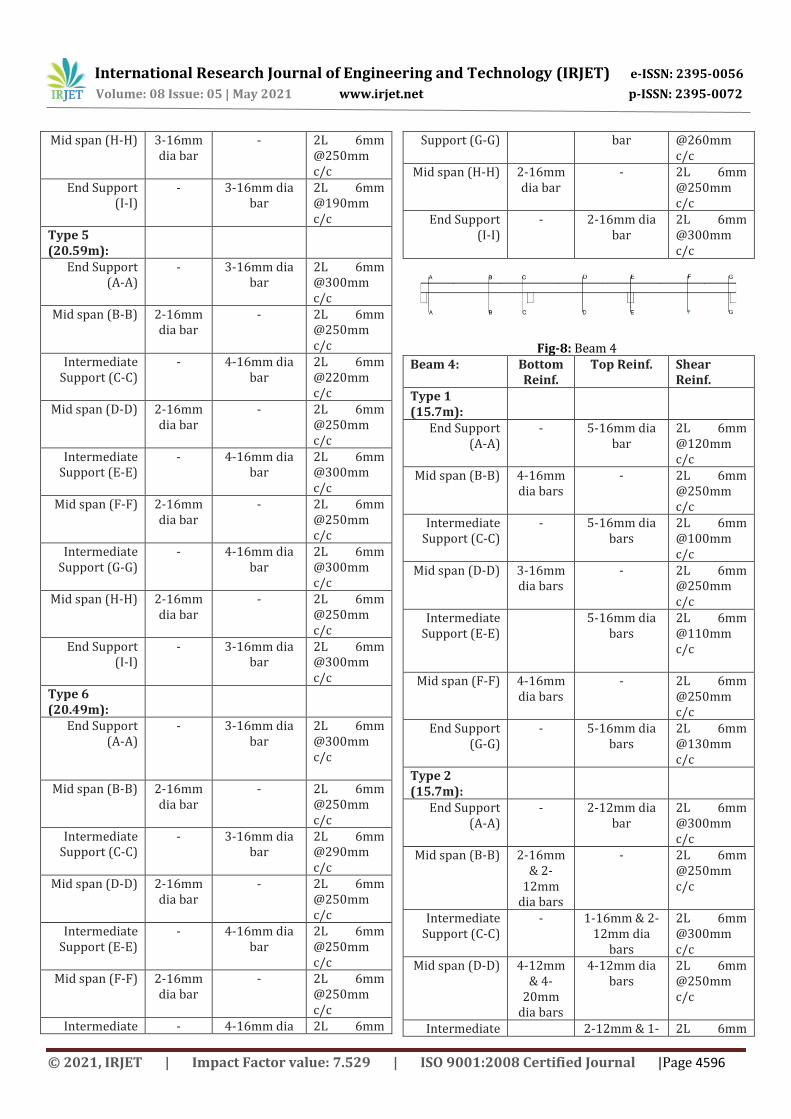
Fig-8: Beam 4 Beam 4: Bottom
Reinf. Top Reinf. Shear
Reinf. Type 1 (15.7m):
End Support (A-A)
- 5-16mm dia bar
2L 6mm @120mm c/c
Mid span (B-B) 4-16mm dia bars
- 2L 6mm @250mm c/c
Intermediate Support (C-C)
- 5-16mm dia bars
2L 6mm @100mm c/c
Mid span (D-D) 3-16mm dia bars
- 2L 6mm @250mm c/c
Intermediate Support (E-E)
5-16mm dia bars
2L 6mm @110mm c/c
Mid span (F-F) 4-16mm dia bars
- 2L 6mm @250mm c/c
End Support (G-G)
- 5-16mm dia bars
2L 6mm @130mm c/c
Type 2 (15.7m):
End Support (A-A)
- 2-12mm dia bar
2L 6mm @300mm c/c
Mid span (B-B) 2-16mm & 2-
12mm dia bars
- 2L 6mm @250mm c/c
Intermediate Support (C-C)
- 1-16mm & 2-12mm dia
bars
2L 6mm @300mm c/c
Mid span (D-D) 4-12mm & 4-
20mm dia bars
4-12mm dia bars
2L 6mm @250mm c/c
Intermediate 2-12mm & 1- 2L 6mm
International Research Journal of Engineering and Technology (IRJET) e-ISSN: 2395-0056
Volume: 08 Issue: 05 | May 2021 www.irjet.net p-ISSN: 2395-0072
© 2021, IRJET | Impact Factor value: 7.529 | ISO 9001:2008 Certified Journal |Page 4597
Support (E-E) 20mm dia bars
@300mm c/c
Mid span (F-F) 3-12mm dia bar -
- 2L 6mm @300mm c/c
End Support (G-G)
- 3-12mm dia bar -
2L 6mm @300mm c/c
Type 3 (15.7m)
End Support (A-A)
- 2-16mm dia bar
2L 6mm @300mm c/c
Mid span (B-B) 2-16mm dia bars
- 2L 6mm @250mm c/c
Intermediate Support (C-C)
- 3-16mm dia bars
2L 6mm @300mm c/c
Mid span (D-D) 2-16mm dia bars
- 2L 6mm @250mm c/c
Intermediate Support (E-E)
4-16mm dia bars
2L 6mm @300mm c/c
Mid span (F-F) 2-16mm dia bars
- 2L 6mm @250mm c/c
End Support (G-G)
- 2-16mm dia bars
2L 6mm @260mm c/c
Type 4 (15.7m):
End Support (A-A)
- 4-16mm dia bar
2L 6mm @200mm c/c
Mid span (B-B) 3-16mm dia bars
- 2L 6mm @250mm c/c
Intermediate Support (C-C)
- 5-16mm dia bars
2L 6mm @170mm c/c
Mid span (D-D) 2-16mm dia bars
- 2L 6mm @250mm c/c
Intermediate Support (E-E)
4-16mm dia bars
2L 6mm @180mm c/c
Mid span (F-F) 3-16mm dia bars
- 2L 6mm @250mm c/c
End Support (G-G)
- 4-16mm dia bars
2L 6mm @210mm c/c
Type 5 (13.35m)
End Support (A-A)
- 2-12mm dia bar
2L 8mm @300mm c/c
Mid span (B-B) 2-12mm dia bars
- 2L 8mm @300mm c/c
Intermediate Support (C-C)
- 3-12mm & 2-16mm dia
bars
2L 8mm @300mm c/c
Mid span (D-D) 4-12mm dia bars
- 2L 8mm @300mm c/c
Intermediate Support (E-E)
3-12mm & 3-20mm dia
bars
2L 8mm @150mm c/c
Mid span (F-F) 3-12mm & 2-
16mm dia bars
- 2L 8mm @300mm c/c
End Support (G-G)
- 2-12mm & 3-20mm dia
bars
2L 8mm @170mm c/c
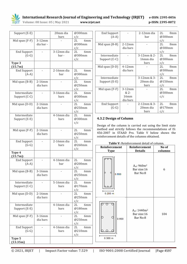
4.3.2 Design of Column
Design of the column is carried out using the limit state method and strictly follows the recommendations of IS: 456-2007 in STAAD Pro. Table V below shows the reinforcement details of the columns obtained.
Table V: Reinforcement detail of column. Reinforcement
Type Reinforcement
Details No of
columns
Ast: 960m2 Bar size:16
Bar No:8
6
Ast: 1440m2 Bar size:16
Bar No:8
104
International Research Journal of Engineering and Technology (IRJET) e-ISSN: 2395-0056
Volume: 08 Issue: 05 | May 2021 www.irjet.net p-ISSN: 2395-0072
© 2021, IRJET | Impact Factor value: 7.529 | ISO 9001:2008 Certified Journal |Page 4598
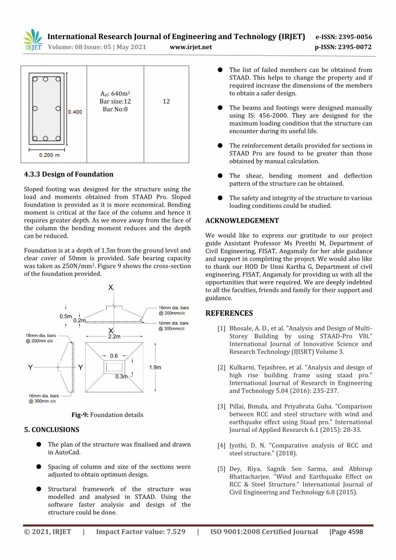
Ast: 640m2 Bar size:12
Bar No:8
12
4.3.3 Design of Foundation
Sloped footing was designed for the structure using the load and moments obtained from STAAD Pro. Sloped foundation is provided as it is more economical. Bending moment is critical at the face of the column and hence it requires greater depth. As we move away from the face of the column the bending moment reduces and the depth can be reduced.
Foundation is at a depth of 1.5m from the ground level and clear cover of 50mm is provided. Safe bearing capacity was taken as 250N/mm2. Figure 9 shows the cross-section of the foundation provided.
Fig-9: Foundation details
5. CONCLUSIONS
● The plan of the structure was finalised and drawn in AutoCad.
● Spacing of column and size of the sections were adjusted to obtain optimum design.
● Structural framework of the structure was modelled and analysed in STAAD. Using the software faster analysis and design of the structure could be done.
● The list of failed members can be obtained from STAAD. This helps to change the property and if required increase the dimensions of the members to obtain a safer design.
● The beams and footings were designed manually using IS: 456-2000. They are designed for the maximum loading condition that the structure can encounter during its useful life.
● The reinforcement details provided for sections in STAAD Pro are found to be greater than those obtained by manual calculation.
● The shear, bending moment and deflection pattern of the structure can be obtained.
● The safety and integrity of the structure to various loading conditions could be studied.
ACKNOWLEDGEMENT
We would like to express our gratitude to our project guide Assistant Professor Ms Preethi M, Department of Civil Engineering, FISAT, Angamaly for her able guidance and support in completing the project. We would also like to thank our HOD Dr Unni Kartha G, Department of civil engineering, FISAT, Angamaly for providing us with all the opportunities that were required. We are deeply indebted to all the faculties, friends and family for their support and guidance.
REFERENCES
[1] Bhosale, A. D., et al. "Analysis and Design of Multi-Storey Building by using STAAD-Pro V8i." International Journal of Innovative Science and Research Technology (IJISRT) Volume 3.
[2] Kulkarni, Tejashree, et al. "Analysis and design of
high rise building frame using staad pro." International Journal of Research in Engineering and Technology 5.04 (2016): 235-237.
[3] Pillai, Bimala, and Priyabrata Guha. "Comparison
between RCC and steel structure with wind and earthquake effect using Staad pro." International Journal of Applied Research 6.1 (2015): 28-33.
[4] Jyothi, D. N. "Comparative analysis of RCC and
steel structure." (2018).
[5] Dey, Riya, Sagnik Sen Sarma, and Abhirup Bhattacharjee. "Wind and Earthquake Effect on RCC & Steel Structure." International Journal of Civil Engineering and Technology 6.8 (2015).
International Research Journal of Engineering and Technology (IRJET) e-ISSN: 2395-0056
Volume: 08 Issue: 05 | May 2021 www.irjet.net p-ISSN: 2395-0072
© 2021, IRJET | Impact Factor value: 7.529 | ISO 9001:2008 Certified Journal |Page 4599
[6] IS: 456, Code of practice for plain and reinforced concrete code of practice, Bureau of Indian Standards, New Delhi, 2000.
[7] IS: 800, Code of practice for general construction
in steel, Bureau of Indian Standards, New Delhi, 2007.
[8] IS: 875, code of practice for design load (other
than earthquake) for buildings and structures Bureau of Indian Standards, New Delhi, 2002.


