Embed Size (px)
Citation preview
International Research Journal of Engineering and Technology (IRJET) e-ISSN: 2395-0056
Volume: 07 Issue: 05 | May 2020 www.irjet.net p-ISSN: 2395-0072
© 2020, IRJET | Impact Factor value: 7.529 | ISO 9001:2008 Certified Journal | Page 7771
Quick Experiments Description Manual for Radiowave Absorption
Measurements
Mohamed A. El-morsy1, Mohamed Edries1, Hesham A. Mohamed2, Sherif S. Hekal3 and Hala A.
Mansour3
1 Department of Electronics and Communication, Higher Institute of Engineering El Shorouk City, Cairo, Egypt 2 Department of Microstrip circuits, Electronics Research institute, Dokky, Cairo, Egypt
3 Department of Electronics and Communication, Banha University, Cairo, Egypt
---------------------------------------------------------------------***---------------------------------------------------------------------
Abstract - In this article we introduce a quick manual for radiowave absorption measurement techniques. Researchers, developers, manufactures and end users of radiowave absorber material need parameters and performance evaluation. This manual is aimed to help research beginners as well as experts to select a suitable performance test method that can be adopted with minimum costs. A set of experiments each suit a form of absorbers used in the field of radiowave absorption. We described experiments in brief. Technical terms definitions, can be found in open literatures and equipment descriptions.
Key Words: Microwaves, Antenna, Absorption, FSS, Metamaterial, Measurements
1. INTRODUCTION
Microwave and antenna measurements are basic organs
in the electromagnetic science and technology body.
Radiowave absorption material (RAM) also called Radar
Absorbing Material are increasingly used in both military
and civilian sectors. Research, manufacturing, development
of RAM requires performance measurements to assure
compliance with applications targeted. In this manual we
classified measurement techniques according material forms
(sheets – solid blocks – paints – printed patches). RAM types
such as dielectric sheets – frequency selective surfaces (FSS)
– Metamaterial can be tested using the adequate
experiments. Dielectric sheets are made of a polymer loaded
with absorbing material as carbon or ferrite additives to
increase the losses of radiowaves passing through them.
They can be formed as flexible sheets or foam. FSS is a
periodic surface with identical 2-D arrays of elements
arranged on a dielectric substrate. It is designed to be
transparent in some frequency bands while reflective,
absorbing or redirecting to others [1]. There is no commonly
definition for metamaterial; however, all common
descriptions of metamaterial are artificial materials that gain
their properties from the structure rather than from the
composition which can provide unusual electromagnetic
effects that are difficult to be accomplished by natural
materials [2]. Metamaterials are designed through different
forms of split rings or periodic structures fabricated from
highly conductivity materials like gold, silver, or copper. Two
parameters define the response of a material; electric
permittivity ε, and magnetic permeability µ, so the
propagation of the electromagnetic wave inside any material
depends on the sign of µ and ε. We can conveniently describe
most electromagnetic materials by the quadrant where they
lie in the permittivity ε and permeability µ plane. The
artificial materials or as defined metamaterials lie in the
quadrant where µ < 0 and ε < 0, this region can be called
Double Negative Medium (DNM). The electromagnetic wave
in this region will obey Left Hand Medium (LHM) where the
wave will propagate in the opposite direction of propagation.
We introduce in this paper measurements for dielectric
absorbers and metamaterial. There are two types of
measurements, waveguide and free space measurements.
Therefore, samples to be have prepared for measurements.
In case of waveguide tests, it should be possible to insert the
sample into the waveguide or the coaxial line sample holder.
Sample dimensions should match the waveguide in the
operating bands or the coaxial line dimensions. For free
space tests, samples of dimensions 25 × 25 cm2 to
30 × 30 cm2 may be quite suitable. The ground plane should
be at the same sample dimensions [3]. A quick test selection
table is listed below in table 1.
These experiments listed in table 1 help for quick selection of a suitable performance test method. In this paper, a quick experiments description manual for radiowave absorption measurements are presented. The paper is constructed in five sections. Introduction is set in Section 1. Section 2 describes the measurements types for dielectric absorbers and FSS. The absorption calculations are presented in Section 3. Section 4 describes various measurements laboratories that can be used in measurements. Finally, a conclusion is set in Section 5.

International Research Journal of Engineering and Technology (IRJET) e-ISSN: 2395-0056
Volume: 07 Issue: 05 | May 2020 www.irjet.net p-ISSN: 2395-0072
© 2020, IRJET | Impact Factor value: 7.529 | ISO 9001:2008 Certified Journal | Page 7772
Table -1: Test selection table Experiment No. Test Form
Experiment (1), (2) Waveguide samples (Special material forms)
Experiment (3), (4), (5)
Free space ungrounded dielectric sheets and FSS for, normal incidence, oblique incidence, transmission measurement, and reflection measurement
Experiment (6), (7), (8)
Free space, grounded dielectric sheets and metamaterial for, normal incidence – single feed, normal incidence – double feeds, and oblique incidence – double feeds
2. ABSORBERS and FSS In this section the measurements of dielectric absorbers and
FSS are described in details. There are two types of
measurements, waveguide and free space measurements.
These measurement are suitable for transmission and
reflection measurements. Also the absorption (loss) can be
calculated.
Note, notations: input and output shown in experiments
setups are the two ports of the Vector Network Analyzer
(VNA).
1.1 Waveguide Measurements
1.1.1 Experiment (1): Ground Free Dielectric
Sample
Figure -1: Waveguide sample test (without ground plane)
-- Instruments: A Vector Network Analyzer (VNA) – waveguide sample
holder or a coaxial cable sample holder. --Sample:
Is formed to fill a portion of the waveguide or a coaxial cable sample holder. --Procedures:
- Set the arrangement of figure 1.
- Record the reflection coefficient S11 and the transmission coefficient (S21) with the sample inserted.
- Normalize the results to the case of removed sample to eliminate the wave guide or the coaxial holder losses. -- Formulas: The absorption (L) in sample can be calculated as [4]:
L = 1-| S11|2-| S21|2 (1) Note: S11, S21 and L are normalized ratios of field magnitudes.
Loss in decibels: L = 10log(L) (2)
1.1.2 Experiment (2): With Ground
Figure 2. Waveguide sample test (with ground plane)
--Instruments: A Vector Network Analyzer (VNA) – waveguide sample
holder or a coaxial cable sample holder. --Sample: Is formed to fill a portion of the waveguide or a coaxial cable sample holder. --Procedures:
- Set the arrangement of figure 2. - Record the reflection coefficient (S11) with and without
the sample. - Normalize the results to the case of removed sample to
eliminate the wave guide or the coaxial holder losses. -- Formulas:
The absorption (L) in sample can be calculated as [4]: L = 1-| S11|2 (3)
Vector Network
Analyzer (VNA)
Waveguide
sample
holder
Sample
Output Input
Waveguide
sample holder
Vector Network
Analyzer (VNA)
Sample
Output
Short circuit
International Research Journal of Engineering and Technology (IRJET) e-ISSN: 2395-0056
Volume: 07 Issue: 05 | May 2020 www.irjet.net p-ISSN: 2395-0072
© 2020, IRJET | Impact Factor value: 7.529 | ISO 9001:2008 Certified Journal | Page 7773
1.2 Free Space Measurements
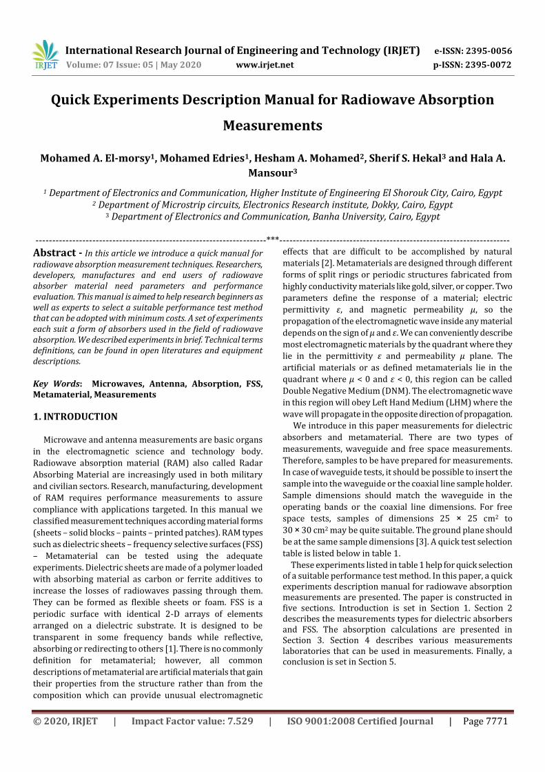
1.2.1 Experiment (3): Unground Sheets: Normal
Incidence
Figure -3: Transmission – Reflection measurement
--Instruments: A Vector Network Analyzer (VNA) – two feeds.
--Sample: A sheet of a dielectric material (ungrounded).
--Procedures: - Set the arrangement of figure 3. - For transmission coefficient / insertion loss: - Measure S21 with and without sample. - Normalize S21 - For reflection coefficient: - Set the arrangement of figure. 3. - Measure S11 with the metal sheet placed between the two
feeds. - Repeat measuring S11 with the absorber placed instead of
the metal sheet (at the same location). - Normalize S11
-- Formulas: The absorption (L) in sample can be calculated as [4]:
L = 1-| S11|2-| S21|2 (4)
- Repeat this measurement for various polarizations.
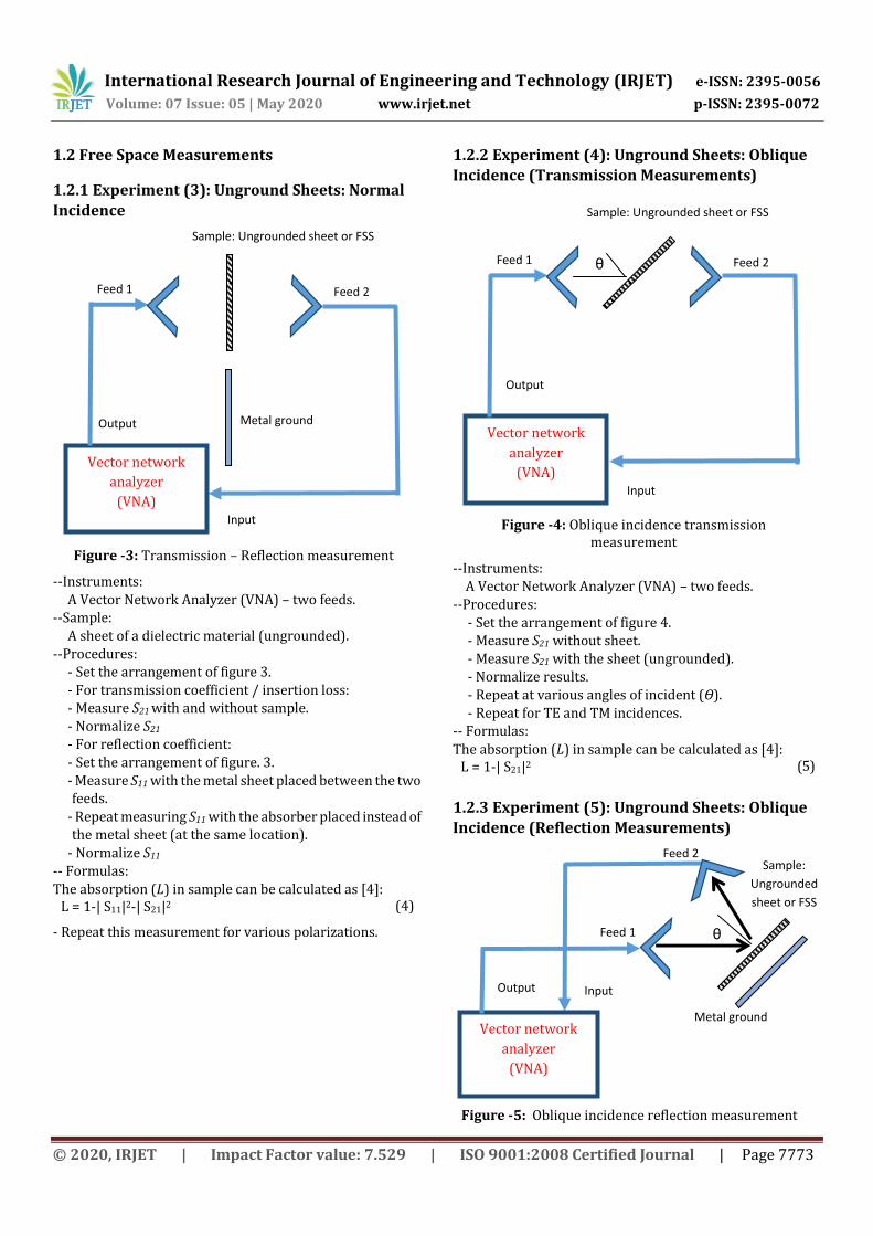
1.2.2 Experiment (4): Unground Sheets: Oblique
Incidence (Transmission Measurements)
Figure -4: Oblique incidence transmission measurement
--Instruments: A Vector Network Analyzer (VNA) – two feeds. --Procedures:
- Set the arrangement of figure 4. - Measure S21 without sheet. - Measure S21 with the sheet (ungrounded). - Normalize results. - Repeat at various angles of incident (Ɵ). - Repeat for TE and TM incidences.
-- Formulas:
The absorption (L) in sample can be calculated as [4]: L = 1-| S21|2 (5)
1.2.3 Experiment (5): Unground Sheets: Oblique Incidence (Reflection Measurements)
Figure -5: Oblique incidence reflection measurement
Feed 2 Feed 1
Metal ground
sheet
Sample: Ungrounded sheet or FSS
Output
Vector network
analyzer
(VNA) Input
θ Feed 2 Feed 1
Sample: Ungrounded sheet or FSS
Output
Vector network
analyzer
(VNA) Input
θ
Metal ground
sheet
Feed 2
Feed 1
Vector network
analyzer
(VNA)
Output Input
Sample:
Ungrounded
sheet or FSS
International Research Journal of Engineering and Technology (IRJET) e-ISSN: 2395-0056
Volume: 07 Issue: 05 | May 2020 www.irjet.net p-ISSN: 2395-0072
© 2020, IRJET | Impact Factor value: 7.529 | ISO 9001:2008 Certified Journal | Page 7774
--Instruments: A Vector Network Analyzer (VNA) – two feeds. --Procedures:
- Set the arrangement of figure. 5. - Measure S21 in case of ground mounted (select S21 on
VNA). - Measure S21 in case of sheet without ground (select S21
on VNA). - Normalize results. - Repeat at various angles of incident (Ɵ). - Repeat for TE and TM incidences.
-- Formulas:
The absorption (L) in sample can be calculated as [4]: L = 1-| S21|2 (6)
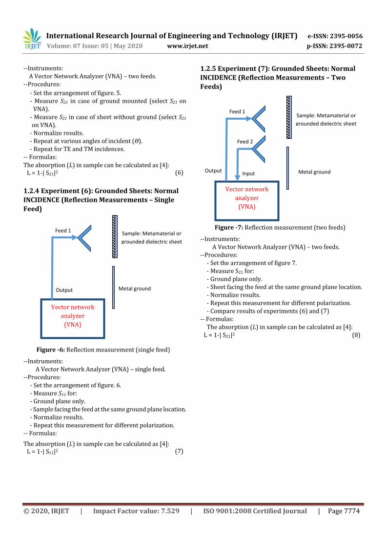
1.2.4 Experiment (6): Grounded Sheets: Normal
INCIDENCE (Reflection Measurements – Single
Feed)
Figure -6: Reflection measurement (single feed)
--Instruments: A Vector Network Analyzer (VNA) – single feed.
--Procedures: - Set the arrangement of figure. 6. - Measure S11 for: - Ground plane only. - Sample facing the feed at the same ground plane location. - Normalize results. - Repeat this measurement for different polarization.
-- Formulas:
The absorption (L) in sample can be calculated as [4]: L = 1-| S11|2 (7)
1.2.5 Experiment (7): Grounded Sheets: Normal
INCIDENCE (Reflection Measurements – Two
Feeds)
Figure -7: Reflection measurement (two feeds)
--Instruments: A Vector Network Analyzer (VNA) – two feeds.
--Procedures: - Set the arrangement of figure 7. - Measure S21 for: - Ground plane only. - Sheet facing the feed at the same ground plane location. - Normalize results. - Repeat this measurement for different polarization. - Compare results of experiments (6) and (7)
-- Formulas: The absorption (L) in sample can be calculated as [4]:
L = 1-| S21|2 (8)
Feed 1
Metal ground
sheet Output
Vector network
analyzer
(VNA)
Sample: Metamaterial or
grounded dielectric sheet
Feed 2
Feed 1
Input Metal ground
sheet
Sample: Metamaterial or
grounded dielectric sheet
Output
Vector network
analyzer
(VNA)
International Research Journal of Engineering and Technology (IRJET) e-ISSN: 2395-0056
Volume: 07 Issue: 05 | May 2020 www.irjet.net p-ISSN: 2395-0072
© 2020, IRJET | Impact Factor value: 7.529 | ISO 9001:2008 Certified Journal | Page 7775
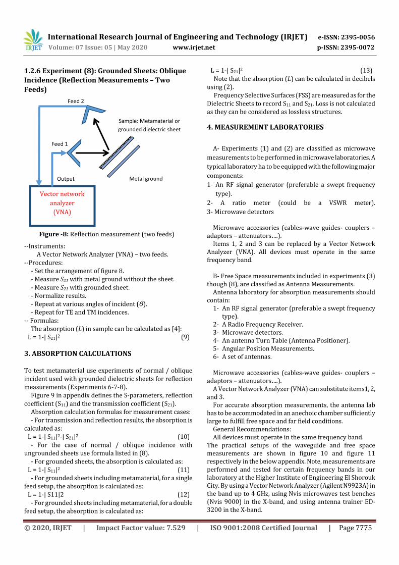
1.2.6 Experiment (8): Grounded Sheets: Oblique
Incidence (Reflection Measurements – Two
Feeds)
Figure -8: Reflection measurement (two feeds)
--Instruments: A Vector Network Analyzer (VNA) – two feeds.
--Procedures: - Set the arrangement of figure 8. - Measure S21 with metal ground without the sheet. - Measure S21 with grounded sheet. - Normalize results. - Repeat at various angles of incident (Ɵ). - Repeat for TE and TM incidences.
-- Formulas: The absorption (L) in sample can be calculated as [4]:
L = 1-| S21|2 (9)
3. ABSORPTION CALCULATIONS To test metamaterial use experiments of normal / oblique incident used with grounded dielectric sheets for reflection measurements (Experiments 6-7-8).
Figure 9 in appendix defines the S-parameters, reflection coefficient (S11) and the transmission coefficient (S21).
Absorption calculation formulas for measurement cases: - For transmission and reflection results, the absorption is
calculated as: L = 1-| S11|2-| S21|2 (10)
- For the case of normal / oblique incidence with ungrounded sheets use formula listed in (8).
- For grounded sheets, the absorption is calculated as: L = 1-| S11|2 (11)
- For grounded sheets including metamaterial, for a single feed setup, the absorption is calculated as:
L = 1-| S11|2 (12) - For grounded sheets including metamaterial, for a double
feed setup, the absorption is calculated as:
L = 1-| S21|2 (13) Note that the absorption (L) can be calculated in decibels
using (2). Frequency Selective Surfaces (FSS) are measured as for the
Dielectric Sheets to record S11 and S21. Loss is not calculated as they can be considered as lossless structures.
4. MEASUREMENT LABORATORIES
A- Experiments (1) and (2) are classified as microwave
measurements to be performed in microwave laboratories. A
typical laboratory ha to be equipped with the following major
components:
1- An RF signal generator (preferable a swept frequency
type).
2- A ratio meter (could be a VSWR meter).
3- Microwave detectors
Microwave accessories (cables-wave guides- couplers – adaptors – attenuators….).
Items 1, 2 and 3 can be replaced by a Vector Network Analyzer (VNA). All devices must operate in the same frequency band.
B- Free Space measurements included in experiments (3)
though (8), are classified as Antenna Measurements. Antenna laboratory for absorption measurements should
contain: 1- An RF signal generator (preferable a swept frequency
type). 2- A Radio Frequency Receiver. 3- Microwave detectors. 4- An antenna Turn Table (Antenna Positioner). 5- Angular Position Measurements. 6- A set of antennas.
Microwave accessories (cables-wave guides- couplers –
adaptors – attenuators….). A Vector Network Analyzer (VNA) can substitute items1, 2,
and 3. For accurate absorption measurements, the antenna lab
has to be accommodated in an anechoic chamber sufficiently large to fulfill free space and far field conditions.
General Recommendations: All devices must operate in the same frequency band.
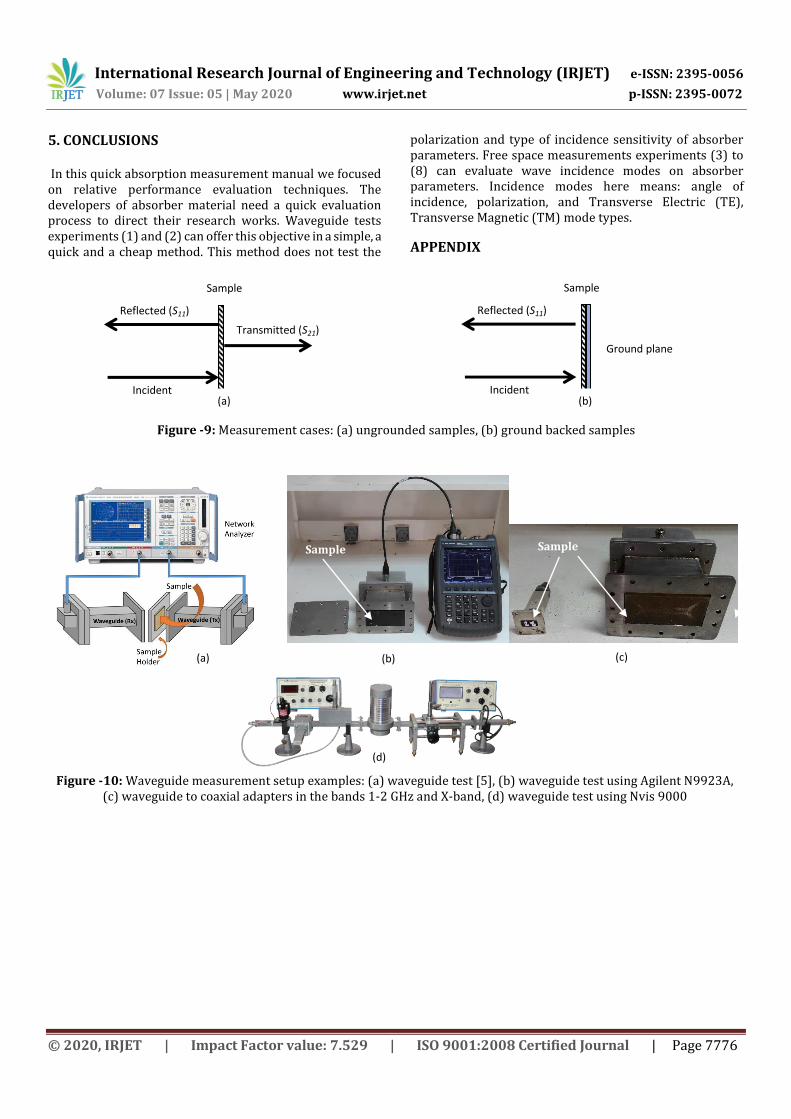
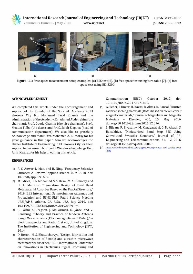
The practical setups of the waveguide and free space measurements are shown in figure 10 and figure 11 respectively in the below appendix. Note, measurements are performed and tested for certain frequency bands in our laboratory at the Higher Institute of Engineering El Shorouk City. By using a Vector Network Analyzer (Agilent N9923A) in the band up to 4 GHz, using Nvis microwaves test benches (Nvis 9000) in the X-band, and using antenna trainer ED-3200 in the X-band.
Output Metal ground
sheet
Sample: Metamaterial or
grounded dielectric sheet
Vector network
analyzer
(VNA)
Feed 1
Feed 2
International Research Journal of Engineering and Technology (IRJET) e-ISSN: 2395-0056
Volume: 07 Issue: 05 | May 2020 www.irjet.net p-ISSN: 2395-0072
© 2020, IRJET | Impact Factor value: 7.529 | ISO 9001:2008 Certified Journal | Page 7776
5. CONCLUSIONS In this quick absorption measurement manual we focused on relative performance evaluation techniques. The developers of absorber material need a quick evaluation process to direct their research works. Waveguide tests experiments (1) and (2) can offer this objective in a simple, a quick and a cheap method. This method does not test the
polarization and type of incidence sensitivity of absorber parameters. Free space measurements experiments (3) to (8) can evaluate wave incidence modes on absorber parameters. Incidence modes here means: angle of incidence, polarization, and Transverse Electric (TE), Transverse Magnetic (TM) mode types.
APPENDIX
Figure -9: Measurement cases: (a) ungrounded samples, (b) ground backed samples
Figure -10: Waveguide measurement setup examples: (a) waveguide test [5], (b) waveguide test using Agilent N9923A, (c) waveguide to coaxial adapters in the bands 1-2 GHz and X-band, (d) waveguide test using Nvis 9000
Sample
Incident
Reflected (S11)
Transmitted (S21)
Sample
Incident
Reflected (S11)
Ground plane
(a) (b)
(a) (b) (c)
(d)
Sample Sample
(c)
Sample
International Research Journal of Engineering and Technology (IRJET) e-ISSN: 2395-0056
Volume: 07 Issue: 05 | May 2020 www.irjet.net p-ISSN: 2395-0072
© 2020, IRJET | Impact Factor value: 7.529 | ISO 9001:2008 Certified Journal | Page 7777
Figure -11: Free space measurement setup examples: (a) FSS test [6], (b) free space test using turn table [7], (c) free space test using ED-3200
ACKNOWLEDGEMENT We completed this article under the encouragement and
support of the founder of the Shorouk Academy in El
Shorouk City Mr. Mohamed Farid Khamis and the
administration of the Academy, Dr. Ahmed Abdelrehim (the
chairman), Prof., Gouda Ghanim (the vise chairman), Prof.,
Moataz Tolba (the dean), and Prof., Salah Elagooz (head of
communication department). We also like to gratefully
acknowledge and thank Prof. Mohamed A. El-morsy for his
great guidance in this paper. Also we acknowledges the
Higher Institute of Engineering in El Shorouk City for their
support to our research projects. We also acknowledge Eng.
Amir Khairat for his help in editing this article.
REFERENCES [1] R. S. Anwar, L. Mao, and H. Ning, “Frequency Selective
Surfaces: A Review,” applied science, 8, 9, 2018, doi:
10.3390/app8091689.
[2] M. Edries, H. A. Mohamed, S. S. Hekal, M. A. El-morsy, and
H. A. Mansour, “Simulation Design of Dual Band
Metamaterial Absorber Based on the Fractal Structure,”
2019 IEEE International Symposium on Antennas and
Propagation and USNC-URSI Radio Science Meeting
URSI/AP-S, Atlanta, GA, USA, USA, July 2019, doi:
10.1109/APUSNCURSINRSM.2019.8889195.
[3] C. Parini, S. Gregson, J. McCormick, D. Janse, and V.
Rensburg, ”Theory and Practice of Modern Antenna
Range Measurements (Electromagnetics and Radar),” in
Electromagnetics and Radar, 1 st ed., United Kingdom:
The Institution of Engineering and Technology (IET),
2014.
[4] D. Borah, N. S. Bhattacharyya, “Design, fabrication and
characterization of flexible and ultrathin microwave
metamaterial absorber,” IEEE International Conference
on Innovations in Electronics, Signal Processing and
Communication (IESC), October 2017, doi:
10.1109/IESPC.2017.8071890.
[5] A. Teber, I. Unver, H. Kavas, B. Aktas, R. Bansal, ”Knitted
radar absorbing materials (RAM) based on nickel–cobalt
magnetic materials,” Journal of Magnetism and Magnetic
Materials – Elsevier, 406, 15, May 2016,
doi.org/10.1016/j.jmmm.2015.12.056.
[6] S. Bilvam, R. Sivasamy, M. Kanagasabai, G. N. Alsath, S.
Baisakhiya, “Miniaturized Band Stop FSS Using
Convoluted Swastika Structure,” Journal of RF-
Engineering and Telecommunications, 71, 1-2, 2016,
doi.org/10.1515/freq-2016-0049. [7] http://www.davidemicheli.com/page%20htm/projects_and_studies_page
.htm
(a) (b) (c)
Sample


