Embed Size (px)
Citation preview
Citation: Kian, A.; Widanapathirana,
G.; Joseph, A.M.; Lai, D.T.H.; Begg, R.
Application of Wearable Sensors in
Actuation and Control of Powered
Ankle Exoskeletons: A
Comprehensive Review. Sensors 2022,
22, 2244. https://doi.org/10.3390/
s22062244
Academic Editor: Roozbeh Ghaffari
Received: 28 January 2022
Accepted: 8 March 2022
Published: 14 March 2022
Publisher’s Note: MDPI stays neutral
with regard to jurisdictional claims in
published maps and institutional affil-
iations.
Copyright: © 2022 by the authors.
Licensee MDPI, Basel, Switzerland.
This article is an open access article
distributed under the terms and
conditions of the Creative Commons
Attribution (CC BY) license (https://
creativecommons.org/licenses/by/
4.0/).
sensors
Review
Application of Wearable Sensors in Actuation and Control ofPowered Ankle Exoskeletons: A Comprehensive ReviewAzadeh Kian 1,* , Giwantha Widanapathirana 1 , Anna M. Joseph 1 , Daniel T. H. Lai 1,2 and Rezaul Begg 1
1 Institute for Health and Sport, Victoria University, Melbourne, VIC 3000, Australia;[email protected] (G.W.); [email protected] (A.M.J.);[email protected] (D.T.H.L.); [email protected] (R.B.)
2 College of Engineering and Science, Victoria University, Melbourne, VIC 3000, Australia* Correspondence: [email protected]
Abstract: Powered ankle exoskeletons (PAEs) are robotic devices developed for gait assistance,rehabilitation, and augmentation. To fulfil their purposes, PAEs vastly rely heavily on their sensorsystems. Human–machine interface sensors collect the biomechanical signals from the human user toinform the higher level of the control hierarchy about the user’s locomotion intention and requirement,whereas machine–machine interface sensors monitor the output of the actuation unit to ensure precisetracking of the high-level control commands via the low-level control scheme. The current articleaims to provide a comprehensive review of how wearable sensor technology has contributed to theactuation and control of the PAEs developed over the past two decades. The control schemes andactuation principles employed in the reviewed PAEs, as well as their interaction with the integratedsensor systems, are investigated in this review. Further, the role of wearable sensors in overcomingthe main challenges in developing fully autonomous portable PAEs is discussed. Finally, a briefdiscussion on how the recent technology advancements in wearable sensors, including environment—machine interface sensors, could promote the future generation of fully autonomous portable PAEsis provided.
Keywords: powered; ankle exoskeleton; orthosis; robot; wearable; human–machine; sensor; actua-tion; control
1. Introduction
Powered ankle exoskeletons (PAEs) are robotic devices developed for gait rehabilita-tion, locomotion assistance, and strength augmentation purposes [1]. Traditionally, whendeveloped for assisting with pathological conditions, PAEs may also be referred to asactive ankle–foot orthoses (AAFOs) or powered ankle–foot orthoses (PAFOs) [2]. The PAEsdeveloped for rehabilitation purposes are usually wearable robots utilized in rehabilitationfacilities that enable repeated walking training rounds on a treadmill or over ground toimprove the recovery of the lower-limb motor function in patients suffering from neurolog-ical disorders such as stroke, cerebral palsy, and spinal cord injuries. Assistive PAEs, onthe other hand, aim to help people with gait disorders affecting the ankle joint caused byageing, trauma, or neurological conditions to overcome their movement limitations andretrieve a normal and safe gait pattern during their locomotion in daily life. As reportedby the World Health Organization [3], about 15% of the total population across the globeexperience some form of disability such as muscle weakness, partial or full paralysis ormobility limitation in the lower limb. Therefore, a majority of the currently availablePAEs have been developed to address the increasing demand for ankle rehabilitation andassistive devices. However, the application of PAEs is not limited to gait rehabilitation andassistance. Strength augmentation ankle exoskeletons have been developed for poweringthe ankle joint in healthy users to enhance their performance and reduce the risk of injuriesduring normal walking, running, or manual handling activities [1,4,5].
Sensors 2022, 22, 2244. https://doi.org/10.3390/s22062244 https://www.mdpi.com/journal/sensors
Sensors 2022, 22, 2244 2 of 39
The concept of robotic exoskeletons as we know them today goes back to the 1950swhen Zaroodny of the U.S. Army Exterior Ballistic Research Laboratory initiated a projecton a ‘powered orthopedic supplement’, publishing a report in 1963 [6]. This exoskeletondevice was intended to augment the load-carrying abilities of an able-bodied wearersuch as a soldier. In the late 1960s, General Electric Research (Schenectady, NY, USA) incollaboration with Cornell University constructed a full-body (680 kg, 30 DoFs) poweredexoskeleton prototype funded by the U.S. Office of Naval Research [7]. However, the firstpowered exoskeleton explicitly developed for the ankle joint might be the early activeankle orthosis presented in 1981 by Jaukovic at the University of Titograd in the formerYugoslavia [8]. This orthosis was actuated using a DC motor placed in front of the wearer’sshin that assisted in dorsi/plantar flexion of the ankle. The footswitches in the solesprovided the data required for controlling the device [9]. Long after Jaukovic, in the early2000s, significant efforts aimed at developing PAEs were initiated by Blaya and Herr atMIT [10], Ferris et al. at the University of Michigan [11], Hollander et al. the ArizonaState University [12], and Agrawal et al. at the University of Delaware [13]. Since then,numerous studies have been conducted by many researchers around the globe aimed atdeveloping fully autonomous PAEs.
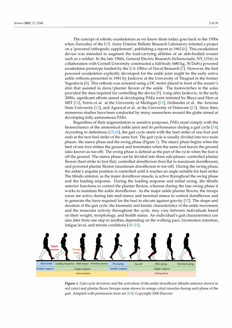
Regardless of their augmentation or assistive purposes, PAEs must comply with thebiomechanics of the anatomical ankle joint and its performance during a gait cycle [14].According to definitions [15,16], the gait cycle starts with the heel strike of one foot andends at the next heel strike of the same foot. The gait cycle is usually divided into two mainphases: the stance phase and the swing phase (Figure 1). The stance phase begins when theheel of one foot strikes the ground and terminates when the same foot leaves the ground(also known as toe-off). The swing phase is defined as the part of the cycle when the foot isoff the ground. The stance phase can be divided into three sub-phases: controlled plantarflexion (heel strike to foot flat), controlled dorsiflexion (foot flat to maximum dorsiflexion),and powered plantar flexion (maximum dorsiflexion to toe-off). During the swing phase,the ankle’s angular position is controlled until it reaches an angle suitable for heel strike.The tibialis anterior, as the major dorsiflexor muscle, is active throughout the swing phaseand the loading response. During the loading response and initial swing, the tibialisanterior functions to control the plantar flexion, whereas during the late swing phase itworks to maintain the ankle dorsiflexion. As the major ankle plantar flexors, the tricepssurae are active during late mid-stance and terminal stance to control dorsiflexion andto generate the force required for the heel to elevate against gravity [17]. The shape andduration of the gait cycle, the kinematic and kinetic characteristics of the ankle movement,and the muscular activity throughout the cycle, may vary between individuals basedon their weight, morphology, and health status. An individual’s gait characteristics canalso alter from one step to another, depending on the walking pace, locomotion intention,fatigue level, and terrain conditions [18–21].
Sensors 2022, 22, x FOR PEER REVIEW 2 of 42
reduce the risk of injuries during normal walking, running, or manual handling activities [1, 4, 5].
The concept of robotic exoskeletons as we know them today goes back to the 1950s when Zaroodny of the U.S. Army Exterior Ballistic Research Laboratory initiated a project on a ‘powered orthopedic supplement’, publishing a report in 1963 [6]. This exoskeleton device was intended to augment the load-carrying abilities of an able-bodied wearer such as a soldier. In the late 1960s, General Electric Research (Schenectady, NY, USA) in collab-oration with Cornell University constructed a full-body (680 kg, 30 DoFs) powered exo-skeleton prototype funded by the U.S. Office of Naval Research [7]. However, the first powered exoskeleton explicitly developed for the ankle joint might be the early active ankle orthosis presented in 1981 by Jaukovic at the University of Titograd in the former Yugoslavia [8]. This orthosis was actuated using a DC motor placed in front of the wearer’s shin that assisted in dorsi/plantar flexion of the ankle. The footswitches in the soles provided the data required for controlling the device [9]. Long after Jaukovic, in the early 2000s, significant efforts aimed at developing PAEs were initiated by Blaya and Herr at MIT [10], Ferris et al. at the University of Michigan [11], Hollander et al. the Arizona State University [12], and Agrawal et al. at the University of Delaware [13]. Since then, numerous studies have been conducted by many researchers around the globe aimed at developing fully autonomous PAEs.
Regardless of their augmentation or assistive purposes, PAEs must comply with the biomechanics of the anatomical ankle joint and its performance during a gait cycle [14]. According to definitions [15, 16], the gait cycle starts with the heel strike of one foot and ends at the next heel strike of the same foot. The gait cycle is usually divided into two main phases: the stance phase and the swing phase (Figure 1). The stance phase begins when the heel of one foot strikes the ground and terminates when the same foot leaves the ground (also known as toe-off). The swing phase is defined as the part of the cycle when the foot is off the ground. The stance phase can be divided into three sub-phases: controlled plantar flexion (heel strike to foot flat), controlled dorsiflexion (foot flat to max-imum dorsiflexion), and powered plantar flexion (maximum dorsiflexion to toe-off). Dur-ing the swing phase, the ankle’s angular position is controlled until it reaches an angle suitable for heel strike. The tibialis anterior, as the major dorsiflexor muscle, is active throughout the swing phase and the loading response. During the loading response and initial swing, the tibialis anterior functions to control the plantar flexion, whereas during the late swing phase it works to maintain the ankle dorsiflexion. As the major ankle plan-tar flexors, the triceps surae are active during late mid-stance and terminal stance to con-trol dorsiflexion and to generate the force required for the heel to elevate against gravity [17]. The shape and duration of the gait cycle, the kinematic and kinetic characteristics of the ankle movement, and the muscular activity throughout the cycle, may vary between individuals based on their weight, morphology, and health status. An individual’s gait characteristics can also alter from one step to another, depending on the walking pace, locomotion intention, fatigue level, and terrain conditions [18-21].
Figure 1. Gait cycle divisions and the activation of the ankle dorsiflexor (tibialis anterior shown in red color) and plantar flexor (triceps surae shown in orange color) muscles during each phase of the gait. Adapted from Best et al., 2006 [16] .
Figure 1. Gait cycle divisions and the activation of the ankle dorsiflexor (tibialis anterior shown inred color) and plantar flexor (triceps surae shown in orange color) muscles during each phase of thegait. Adapted with permission from ref. [16]. Copyright 2006 Elsevier.
Sensors 2022, 22, 2244 3 of 39
Laboratory gait analysis equipment such as force plates, instrumented treadmills,and motion capture systems are the gold standard settings traditionally used for preciselymeasuring the gait biomechanics and characteristics [16]. However, the growing demandfor the light, portable, and wireless measurement tools necessary for conducting field eval-uations, as well as the development of portable smart devices, has led to the developmentof wearable untethered sensors and measurement tools [22,23]. Nowadays, technologyinnovations in sensor hardware fabrication along with advancements in signal processingand sensor fusion techniques have improved the measurement techniques for bio-signalsthat describe an individual’s gait biomechanics [24–29]. Like many other intelligent wear-able devices, PAEs have significantly benefitted from such advancements. It is noteworthythat what makes the PAEs remarkably superior to passive ankle exoskeletons and AFOsis the controllability of the delivered assistance in such intelligent devices. The controlhierarchy of a PAE is, therefore, the most critical and complicated component of the device,as it needs to detect the human user’s instantaneous locomotion requirement and ensurethe performance of the device is compliant with the user’s intention, while delivering thedesired assistance to the user in an optimal fashion [9]. Fulfilling such a complex purposeis not conceivable without the use of an effective integrated sensor system that gathers therequired information from the human user and different parts of the exoskeleton in realtime. A PAE relies heavily on its sensor system to not only communicate with the humanuser but also to continuously monitor its performance.
To date, several excellent review papers have been published on lower-limb orthosesand exoskeletons, discussing the design, actuation, and control principles of these de-vices [14,30,31]. Alqahtani et al., 2021 [1] provided a discussion on different applicationsof lower-limb robotic exoskeletons. Kalita et al., 2020 [32] systematically reviewed lower-limb robotic-based orthoses and exoskeletons with a section briefly discussing a selectednumber of PAEs. While Kubasad et al., 2021 [2] has reviewed the design of a number ofactive and passive orthoses developed for treating drop foot, Jiang et al., 2018 [33] andShi et al., 2019 [34] focused on the application of these devices in the recovery of strokepatients. Alvarez-Perez, et al., 2019 [35] delivered a review on a selection of seated andwalking robots used for ankle rehabilitation. However, in the mentioned reviews, multi-joint exoskeletons and rehabilitation suits have been generally favored over single-jointexoskeletons. Moltedo et al., 2018 [36] provided an exceptional review of studies thatinvestigated the effect of the assistance delivered by PAFOs on healthy and impaired usersduring walking trials. However, a comprehensive review of the broad range of availablePAEs is still missing. Furthermore, the sensor system as a critical component in PAEs andits interaction with the actuation unit and the control hierarchy of the device have not beenproperly investigated so far. Hence, the current article aims to provide a comprehensivereview of how wearable sensors have contributed to the actuation and control of the PAEsdeveloped over the past two decades. Articles concerning seated rehabilitation ankle robotsand multi-joint exoskeletons are not included in this review article. For a more detailedexplanation of the search and review process, please see the Supplementary Materials(Figure S1).
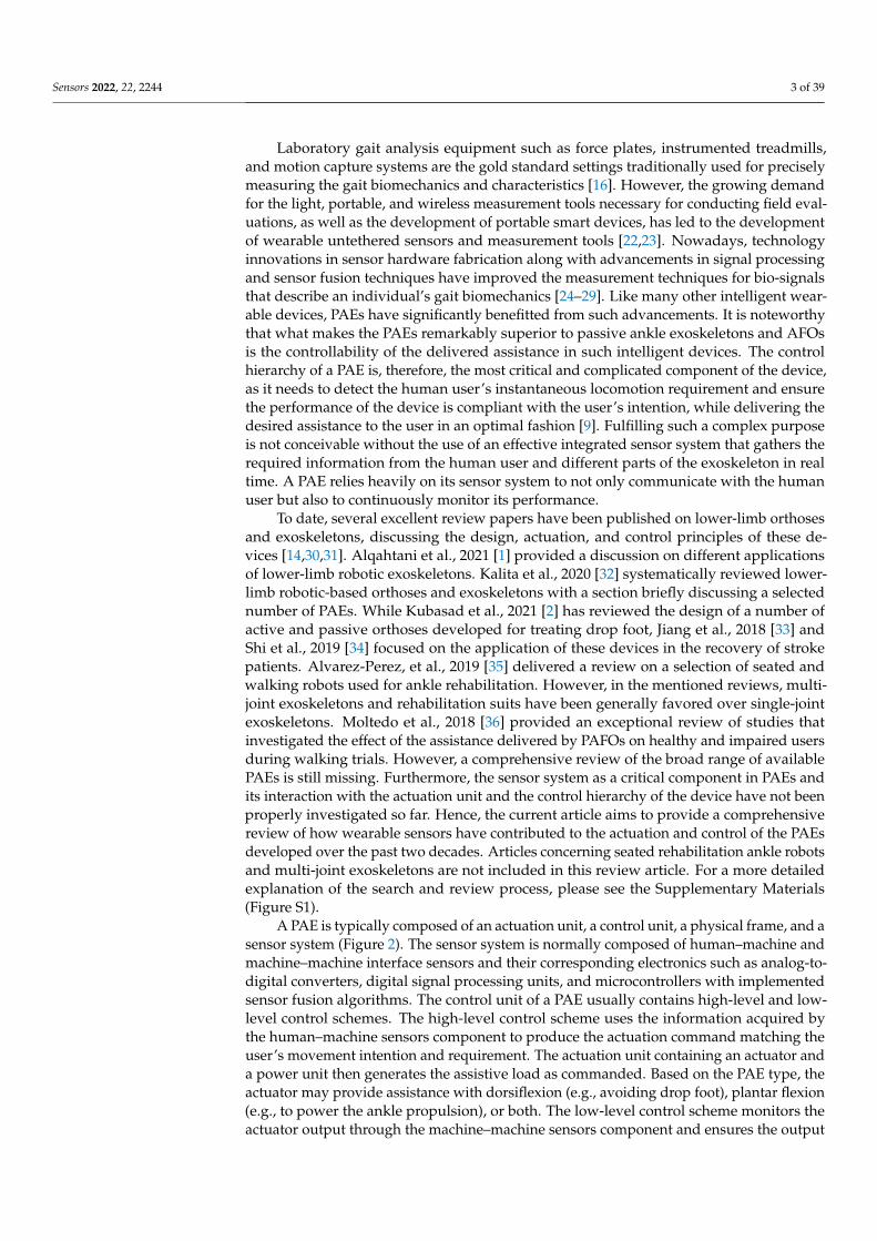
A PAE is typically composed of an actuation unit, a control unit, a physical frame, and asensor system (Figure 2). The sensor system is normally composed of human–machine andmachine–machine interface sensors and their corresponding electronics such as analog-to-digital converters, digital signal processing units, and microcontrollers with implementedsensor fusion algorithms. The control unit of a PAE usually contains high-level and low-level control schemes. The high-level control scheme uses the information acquired bythe human–machine sensors component to produce the actuation command matching theuser’s movement intention and requirement. The actuation unit containing an actuator anda power unit then generates the assistive load as commanded. Based on the PAE type, theactuator may provide assistance with dorsiflexion (e.g., avoiding drop foot), plantar flexion(e.g., to power the ankle propulsion), or both. The low-level control scheme monitors theactuator output through the machine–machine sensors component and ensures the output
Sensors 2022, 22, 2244 4 of 39
matches with the value commanded by the high-level control algorithm. The physicalframe transfers the generated load to the user’s anatomical ankle, while it may or may notallow for a passive movement in the eversion/inversion degree of freedom. The physicalframe is required to be light, comfortable to wear, and yet sturdy and durable. Furthermore,the physical frame of a PAE is normally used for housing the actuation, sensors, and controlcomponents.
To comprehensively review the selected articles, the following information was ex-tracted from the grouped papers:
• General information including the exoskeleton purpose and target population, targetlimb side (bilateral or unilateral), degree of freedom (DoF), and assistance direction(dorsiflexion or plantar flexion or both), portability, and the total weight.
• Actuation principle and actuator type.• Control hierarchy including high-level and low-level control schemes.• Sensor system including human–machine and machine–machine sensors
The general information extracted from all 172 reviewed articles is available in TableS1 in the Supplementary Materials. A selection of recently developed state-of-the-art PAEsand a summary of their key features are provided in Table 1 for illustration purposes. Theselected devices are examples of well-developed PAEs with advanced control algorithms,innovative sensor systems, functional actuation units, and practical wearable physicalframes.
Sensors 2022, 22, x FOR PEER REVIEW 4 of 42
and ensures the output matches with the value commanded by the high-level control al-gorithm. The physical frame transfers the generated load to the user’s anatomical ankle, while it may or may not allow for a passive movement in the eversion/inversion degree of freedom. The physical frame is required to be light, comfortable to wear, and yet sturdy and durable. Furthermore, the physical frame of a PAE is normally used for housing the actuation, sensors, and control components.
To comprehensively review the selected articles, the following information was ex-tracted from the grouped papers: • General information including the exoskeleton purpose and target population, target
limb side (bilateral or unilateral), degree of freedom (DoF), and assistance direction (dorsiflexion or plantar flexion or both), portability, and the total weight.
• Actuation principle and actuator type. • Control hierarchy including high-level and low-level control schemes. • Sensor system including human–machine and machine–machine sensors
The general information extracted from all 172 reviewed articles is available in Table S1 in the Supplementary Materials. A selection of recently developed state-of-the-art PAEs and a summary of their key features are provided in Table 1 for illustration purposes. The selected devices are examples of well-developed PAEs with advanced control algorithms, innovative sensor systems, functional actuation units, and practical wearable physical frames.
Figure 2. Schematic block diagram of the interaction between the main components of the PAEs. The list of different technologies and methods used in the reviewed literature for developing each component is provided in the corresponding block.
Figure 2. Schematic block diagram of the interaction between the main components of the PAEs.The list of different technologies and methods used in the reviewed literature for developing eachcomponent is provided in the corresponding block.
Sensors 2022, 22, 2244 5 of 39
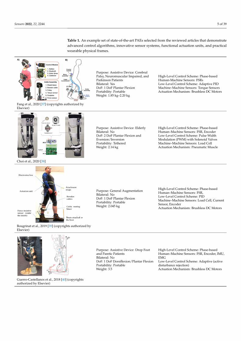
Table 1. An example set of state-of-the-art PAEs selected from the reviewed articles that demonstrateadvanced control algorithms, innovative sensor systems, functional actuation units, and practicalwearable physical frames.
Sensors 2022, 22, x FOR PEER REVIEW 5 of 42
Table 1. An example set of state-of-the-art PAEs selected from the reviewed articles that demon-strate advanced control algorithms, innovative sensor systems, functional actuation units, and prac-tical wearable physical frames.
Fang et al., 2020 [37] (copyrights authorized by Elsevier)
Purpose: Assistive Device: Cer-ebral Palsy, Neuromuscular Im-paired, and Parkinson Patients Bilateral: Yes DoF: 1 DoF Plantar Flexion Portability: Portable Weight: 1.85 kg–2.20 kg
High-Level Control Scheme: Phase-based Human-Machine Sensors: FSRs Low-Level Control Scheme: Adap-tive PID Machine–Machine Sensors: Torque Sensors Actuation Mechanism: Brushless DC Motors
Choi et al., 2020 [38]
Purpose: Assistive Device: El-derly Bilateral: No DoF: 2 DoF Plantar Flexion and Eversion/Inversion Portability: Tethered Weight: 2.14 kg
High-Level Control Scheme: Phase-based Human–Machine Sensors: FSR, En-coder Low-Level Control Scheme: Pulse Width Modulation (PWM) with So-lenoid Valves Machine–Machine Sensors: Load Cell Actuation Mechanism: Pneumatic Muscle
Bougrinat et al., 2019 [39] (copyrights authorized by Elsevier)
Purpose: General Augmenta-tion Bilateral: No DoF: 1 DoF Plantar Flexion Portability: Portable Weight: 2.045 kg
High-Level Control Scheme: Phase-based Human–Machine Sensors: FSR, Low-Level Control Scheme: PID Machine–Machine Sensors: Load Cell, Current Sensor, Encoder Actuation Mechanism: Brushless DC Motors
Guerro-Castellanos et al., 2018 [40] (copyrights authorized by Elsevier)
Purpose: Assistive Device: Drop Foot and Paretic Patients Bilateral: No DoF: 1 DoF Dorsiflexion/Plan-tar Flexion Portability: Portable Weight: 3.5
High-Level Control Scheme: Phase-based Human–Machine Sensors: FSR, En-coder, IMU, EMG Low-Level Control Scheme: Adap-tive (active disturbance rejection) Actuation Mechanism: Brushless DC Motors
Fang et al., 2020 [37] (copyrights authorized byElsevier)
Purpose: Assistive Device: CerebralPalsy, Neuromuscular Impaired, andParkinson PatientsBilateral: YesDoF: 1 DoF Plantar FlexionPortability: PortableWeight: 1.85 kg–2.20 kg
High-Level Control Scheme: Phase-basedHuman-Machine Sensors: FSRsLow-Level Control Scheme: Adaptive PIDMachine–Machine Sensors: Torque SensorsActuation Mechanism: Brushless DC Motors
Sensors 2022, 22, x FOR PEER REVIEW 5 of 42
Table 1. An example set of state-of-the-art PAEs selected from the reviewed articles that demon-strate advanced control algorithms, innovative sensor systems, functional actuation units, and prac-tical wearable physical frames.
Fang et al., 2020 [37] (copyrights authorized by Elsevier)
Purpose: Assistive Device: Cer-ebral Palsy, Neuromuscular Im-paired, and Parkinson Patients Bilateral: Yes DoF: 1 DoF Plantar Flexion Portability: Portable Weight: 1.85 kg–2.20 kg
High-Level Control Scheme: Phase-based Human-Machine Sensors: FSRs Low-Level Control Scheme: Adap-tive PID Machine–Machine Sensors: Torque Sensors Actuation Mechanism: Brushless DC Motors
Choi et al., 2020 [38]
Purpose: Assistive Device: El-derly Bilateral: No DoF: 2 DoF Plantar Flexion and Eversion/Inversion Portability: Tethered Weight: 2.14 kg
High-Level Control Scheme: Phase-based Human–Machine Sensors: FSR, En-coder Low-Level Control Scheme: Pulse Width Modulation (PWM) with So-lenoid Valves Machine–Machine Sensors: Load Cell Actuation Mechanism: Pneumatic Muscle
Bougrinat et al., 2019 [39] (copyrights authorized by Elsevier)
Purpose: General Augmenta-tion Bilateral: No DoF: 1 DoF Plantar Flexion Portability: Portable Weight: 2.045 kg
High-Level Control Scheme: Phase-based Human–Machine Sensors: FSR, Low-Level Control Scheme: PID Machine–Machine Sensors: Load Cell, Current Sensor, Encoder Actuation Mechanism: Brushless DC Motors
Guerro-Castellanos et al., 2018 [40] (copyrights authorized by Elsevier)
Purpose: Assistive Device: Drop Foot and Paretic Patients Bilateral: No DoF: 1 DoF Dorsiflexion/Plan-tar Flexion Portability: Portable Weight: 3.5
High-Level Control Scheme: Phase-based Human–Machine Sensors: FSR, En-coder, IMU, EMG Low-Level Control Scheme: Adap-tive (active disturbance rejection) Actuation Mechanism: Brushless DC Motors
Choi et al., 2020 [38]
Purpose: Assistive Device: ElderlyBilateral: NoDoF: 2 DoF Plantar Flexion andEversion/InversionPortability: TetheredWeight: 2.14 kg
High-Level Control Scheme: Phase-basedHuman–Machine Sensors: FSR, EncoderLow-Level Control Scheme: Pulse WidthModulation (PWM) with Solenoid ValvesMachine–Machine Sensors: Load CellActuation Mechanism: Pneumatic Muscle
Sensors 2022, 22, x FOR PEER REVIEW 5 of 42
Table 1. An example set of state-of-the-art PAEs selected from the reviewed articles that demon-strate advanced control algorithms, innovative sensor systems, functional actuation units, and prac-tical wearable physical frames.
Fang et al., 2020 [37] (copyrights authorized by Elsevier)
Purpose: Assistive Device: Cer-ebral Palsy, Neuromuscular Im-paired, and Parkinson Patients Bilateral: Yes DoF: 1 DoF Plantar Flexion Portability: Portable Weight: 1.85 kg–2.20 kg
High-Level Control Scheme: Phase-based Human-Machine Sensors: FSRs Low-Level Control Scheme: Adap-tive PID Machine–Machine Sensors: Torque Sensors Actuation Mechanism: Brushless DC Motors
Choi et al., 2020 [38]
Purpose: Assistive Device: El-derly Bilateral: No DoF: 2 DoF Plantar Flexion and Eversion/Inversion Portability: Tethered Weight: 2.14 kg
High-Level Control Scheme: Phase-based Human–Machine Sensors: FSR, En-coder Low-Level Control Scheme: Pulse Width Modulation (PWM) with So-lenoid Valves Machine–Machine Sensors: Load Cell Actuation Mechanism: Pneumatic Muscle
Purpose: General Augmenta-tion Bilateral: No DoF: 1 DoF Plantar Flexion Portability: Portable Weight: 2.045 kg
High-Level Control Scheme: Phase-based Human–Machine Sensors: FSR, Low-Level Control Scheme: PID Machine–Machine Sensors: Load Cell, Current Sensor, Encoder Actuation Mechanism: Brushless DC Motors
Purpose: Assistive Device: Drop Foot and Paretic Patients Bilateral: No DoF: 1 DoF Dorsiflexion/Plan-tar Flexion Portability: Portable Weight: 3.5
High-Level Control Scheme: Phase-based Human–Machine Sensors: FSR, En-coder, IMU, EMG Low-Level Control Scheme: Adap-tive (active disturbance rejection) Actuation Mechanism: Brushless DC Motors
Bougrinat et al., 2019 [39] (copyrights authorized byElsevier)
Purpose: General AugmentationBilateral: NoDoF: 1 DoF Plantar FlexionPortability: PortableWeight: 2.045 kg
High-Level Control Scheme: Phase-basedHuman–Machine Sensors: FSR,Low-Level Control Scheme: PIDMachine–Machine Sensors: Load Cell, CurrentSensor, EncoderActuation Mechanism: Brushless DC Motors
Sensors 2022, 22, x FOR PEER REVIEW 5 of 42
Table 1. An example set of state-of-the-art PAEs selected from the reviewed articles that demon-strate advanced control algorithms, innovative sensor systems, functional actuation units, and prac-tical wearable physical frames.
Fang et al., 2020 [37] (copyrights authorized by Elsevier)
Purpose: Assistive Device: Cer-ebral Palsy, Neuromuscular Im-paired, and Parkinson Patients Bilateral: Yes DoF: 1 DoF Plantar Flexion Portability: Portable Weight: 1.85 kg–2.20 kg
High-Level Control Scheme: Phase-based Human-Machine Sensors: FSRs Low-Level Control Scheme: Adap-tive PID Machine–Machine Sensors: Torque Sensors Actuation Mechanism: Brushless DC Motors
Choi et al., 2020 [38]
Purpose: Assistive Device: El-derly Bilateral: No DoF: 2 DoF Plantar Flexion and Eversion/Inversion Portability: Tethered Weight: 2.14 kg
High-Level Control Scheme: Phase-based Human–Machine Sensors: FSR, En-coder Low-Level Control Scheme: Pulse Width Modulation (PWM) with So-lenoid Valves Machine–Machine Sensors: Load Cell Actuation Mechanism: Pneumatic Muscle
Purpose: General Augmenta-tion Bilateral: No DoF: 1 DoF Plantar Flexion Portability: Portable Weight: 2.045 kg
High-Level Control Scheme: Phase-based Human–Machine Sensors: FSR, Low-Level Control Scheme: PID Machine–Machine Sensors: Load Cell, Current Sensor, Encoder Actuation Mechanism: Brushless DC Motors
Purpose: Assistive Device: Drop Foot and Paretic Patients Bilateral: No DoF: 1 DoF Dorsiflexion/Plan-tar Flexion Portability: Portable Weight: 3.5
High-Level Control Scheme: Phase-based Human–Machine Sensors: FSR, En-coder, IMU, EMG Low-Level Control Scheme: Adap-tive (active disturbance rejection) Actuation Mechanism: Brushless DC Motors Guerro-Castellanos et al., 2018 [40] (copyrights
authorized by Elsevier)
Purpose: Assistive Device: Drop Footand Paretic PatientsBilateral: NoDoF: 1 DoF Dorsiflexion/Plantar FlexionPortability: PortableWeight: 3.5
High-Level Control Scheme: Phase-basedHuman–Machine Sensors: FSR, Encoder, IMU,EMGLow-Level Control Scheme: Adaptive (activedisturbance rejection)Actuation Mechanism: Brushless DC Motors
Sensors 2022, 22, 2244 6 of 39
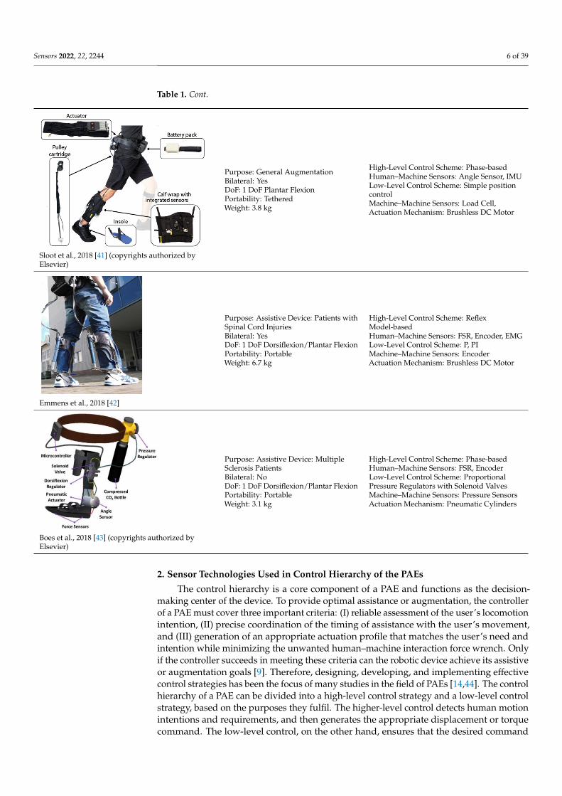
Table 1. Cont.
Sensors 2022, 22, x FOR PEER REVIEW 6 of 42
Guerro-Castellanos et al., 2018 [40] (copyrights authorized by Elsevier)
Sloot et al., 2018 [41] (copyrights authorized by Elsevier)
Purpose: General Augmenta-tion Bilateral: Yes DoF: 1 DoF Plantar Flexion Portability: Tethered Weight: 3.8 kg
High-Level Control Scheme: Phase-based Human–Machine Sensors: Angle Sensor, IMU Low-Level Control Scheme: Simple position control Machine–Machine Sensors: Load Cell, Actuation Mechanism: Brushless DC Motor
Emmens et al., 2018 [42]
Purpose: Assistive Device: Pa-tients with Spinal Cord Injuries Bilateral: Yes DoF: 1 DoF Dorsiflexion/Plan-tar Flexion Portability: Portable Weight: 6.7 kg
High-Level Control Scheme: Reflex Model-based Human–Machine Sensors: FSR, En-coder, EMG Low-Level Control Scheme: P, PI Machine–Machine Sensors: Encoder Actuation Mechanism: Brushless DC Motor
Boes et al., 2018 [43] (copyrights authorized by Elsevier)
Purpose: Assistive Device: Mul-tiple Sclerosis Patients Bilateral: No DoF: 1 DoF Dorsiflexion/Plan-tar Flexion Portability: Portable Weight: 3.1 kg
High-Level Control Scheme: Phase-based Human–Machine Sensors: FSR, En-coder Low-Level Control Scheme: Propor-tional Pressure Regulators with So-lenoid Valves Machine–Machine Sensors: Pressure Sensors Actuation Mechanism: Pneumatic Cylinders
2. Sensor Technologies Used in Control Hierarchy of the PAEs The control hierarchy is a core component of a PAE and functions as the decision-
making center of the device. To provide optimal assistance or augmentation, the controller of a PAE must cover three important criteria: (I) reliable assessment of the user’s locomo-tion intention, (II) precise coordination of the timing of assistance with the user’s move-ment, and (III) generation of an appropriate actuation profile that matches the user’s need and intention while minimizing the unwanted human–machine interaction force wrench. Only if the controller succeeds in meeting these criteria can the robotic device achieve its
Sloot et al., 2018 [41] (copyrights authorized byElsevier)
Purpose: General AugmentationBilateral: YesDoF: 1 DoF Plantar FlexionPortability: TetheredWeight: 3.8 kg
High-Level Control Scheme: Phase-basedHuman–Machine Sensors: Angle Sensor, IMULow-Level Control Scheme: Simple positioncontrolMachine–Machine Sensors: Load Cell,Actuation Mechanism: Brushless DC Motor
Sensors 2022, 22, x FOR PEER REVIEW 6 of 42
Guerro-Castellanos et al., 2018 [40] (copyrights authorized by Elsevier)
Sloot et al., 2018 [41] (copyrights authorized by Elsevier)
Purpose: General Augmenta-tion Bilateral: Yes DoF: 1 DoF Plantar Flexion Portability: Tethered Weight: 3.8 kg
High-Level Control Scheme: Phase-based Human–Machine Sensors: Angle Sensor, IMU Low-Level Control Scheme: Simple position control Machine–Machine Sensors: Load Cell, Actuation Mechanism: Brushless DC Motor
Emmens et al., 2018 [42]
Purpose: Assistive Device: Pa-tients with Spinal Cord Injuries Bilateral: Yes DoF: 1 DoF Dorsiflexion/Plan-tar Flexion Portability: Portable Weight: 6.7 kg
High-Level Control Scheme: Reflex Model-based Human–Machine Sensors: FSR, En-coder, EMG Low-Level Control Scheme: P, PI Machine–Machine Sensors: Encoder Actuation Mechanism: Brushless DC Motor
Boes et al., 2018 [43] (copyrights authorized by Elsevier)
Purpose: Assistive Device: Mul-tiple Sclerosis Patients Bilateral: No DoF: 1 DoF Dorsiflexion/Plan-tar Flexion Portability: Portable Weight: 3.1 kg
High-Level Control Scheme: Phase-based Human–Machine Sensors: FSR, En-coder Low-Level Control Scheme: Propor-tional Pressure Regulators with So-lenoid Valves Machine–Machine Sensors: Pressure Sensors Actuation Mechanism: Pneumatic Cylinders
2. Sensor Technologies Used in Control Hierarchy of the PAEs The control hierarchy is a core component of a PAE and functions as the decision-
making center of the device. To provide optimal assistance or augmentation, the controller of a PAE must cover three important criteria: (I) reliable assessment of the user’s locomo-tion intention, (II) precise coordination of the timing of assistance with the user’s move-ment, and (III) generation of an appropriate actuation profile that matches the user’s need and intention while minimizing the unwanted human–machine interaction force wrench. Only if the controller succeeds in meeting these criteria can the robotic device achieve its
Emmens et al., 2018 [42]
Purpose: Assistive Device: Patients withSpinal Cord InjuriesBilateral: YesDoF: 1 DoF Dorsiflexion/Plantar FlexionPortability: PortableWeight: 6.7 kg
High-Level Control Scheme: ReflexModel-basedHuman–Machine Sensors: FSR, Encoder, EMGLow-Level Control Scheme: P, PIMachine–Machine Sensors: EncoderActuation Mechanism: Brushless DC Motor
Sensors 2022, 22, x FOR PEER REVIEW 6 of 42
Guerro-Castellanos et al., 2018 [40] (copyrights authorized by Elsevier)
Sloot et al., 2018 [41] (copyrights authorized by Elsevier)
Purpose: General Augmenta-tion Bilateral: Yes DoF: 1 DoF Plantar Flexion Portability: Tethered Weight: 3.8 kg
High-Level Control Scheme: Phase-based Human–Machine Sensors: Angle Sensor, IMU Low-Level Control Scheme: Simple position control Machine–Machine Sensors: Load Cell, Actuation Mechanism: Brushless DC Motor
Emmens et al., 2018 [42]
Purpose: Assistive Device: Pa-tients with Spinal Cord Injuries Bilateral: Yes DoF: 1 DoF Dorsiflexion/Plan-tar Flexion Portability: Portable Weight: 6.7 kg
High-Level Control Scheme: Reflex Model-based Human–Machine Sensors: FSR, En-coder, EMG Low-Level Control Scheme: P, PI Machine–Machine Sensors: Encoder Actuation Mechanism: Brushless DC Motor
Boes et al., 2018 [43] (copyrights authorized by Elsevier)
Purpose: Assistive Device: Mul-tiple Sclerosis Patients Bilateral: No DoF: 1 DoF Dorsiflexion/Plan-tar Flexion Portability: Portable Weight: 3.1 kg
High-Level Control Scheme: Phase-based Human–Machine Sensors: FSR, En-coder Low-Level Control Scheme: Propor-tional Pressure Regulators with So-lenoid Valves Machine–Machine Sensors: Pressure Sensors Actuation Mechanism: Pneumatic Cylinders
2. Sensor Technologies Used in Control Hierarchy of the PAEs The control hierarchy is a core component of a PAE and functions as the decision-
making center of the device. To provide optimal assistance or augmentation, the controller of a PAE must cover three important criteria: (I) reliable assessment of the user’s locomo-tion intention, (II) precise coordination of the timing of assistance with the user’s move-ment, and (III) generation of an appropriate actuation profile that matches the user’s need and intention while minimizing the unwanted human–machine interaction force wrench. Only if the controller succeeds in meeting these criteria can the robotic device achieve its
Boes et al., 2018 [43] (copyrights authorized byElsevier)
Purpose: Assistive Device: MultipleSclerosis PatientsBilateral: NoDoF: 1 DoF Dorsiflexion/Plantar FlexionPortability: PortableWeight: 3.1 kg
High-Level Control Scheme: Phase-basedHuman–Machine Sensors: FSR, EncoderLow-Level Control Scheme: ProportionalPressure Regulators with Solenoid ValvesMachine–Machine Sensors: Pressure SensorsActuation Mechanism: Pneumatic Cylinders
2. Sensor Technologies Used in Control Hierarchy of the PAEs
The control hierarchy is a core component of a PAE and functions as the decision-making center of the device. To provide optimal assistance or augmentation, the controllerof a PAE must cover three important criteria: (I) reliable assessment of the user’s locomotionintention, (II) precise coordination of the timing of assistance with the user’s movement,and (III) generation of an appropriate actuation profile that matches the user’s need andintention while minimizing the unwanted human–machine interaction force wrench. Onlyif the controller succeeds in meeting these criteria can the robotic device achieve its assistiveor augmentation goals [9]. Therefore, designing, developing, and implementing effectivecontrol strategies has been the focus of many studies in the field of PAEs [14,44]. The controlhierarchy of a PAE can be divided into a high-level control strategy and a low-level controlstrategy, based on the purposes they fulfil. The higher-level control detects human motionintentions and requirements, and then generates the appropriate displacement or torquecommand. The low-level control, on the other hand, ensures that the desired command
Sensors 2022, 22, 2244 7 of 39
is tracked by the exoskeleton precisely and that the actuator’s output does not cause aninteraction force wrench [45].
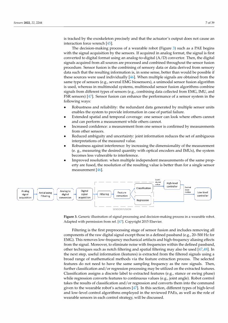
The decision-making process of a wearable robot (Figure 3) such as a PAE beginswith the signal acquisition by the sensors. If acquired in analog format, the signal is firstconverted to digital format using an analog-to-digital (A/D) convertor. Then, the digitalsignals acquired from all sources are processed and combined throughout the sensor fusionprocedure. Sensor fusion is the combining of sensory data or data derived from sensorydata such that the resulting information is, in some sense, better than would be possible ifthese sources were used individually [46]. When multiple signals are obtained from thesame type of sensors (e.g., several EMG biosensors), a unimodal sensor fusion algorithmis used, whereas in multimodal systems, multimodal sensor fusion algorithms combinesignals from different types of sensors (e.g., combining data collected from EMG, IMU, andFSR sensors) [47]. Sensor fusion can enhance the performance of a sensor system in thefollowing ways:
• Robustness and reliability: the redundant data generated by multiple sensor unitsenables the system to provide information in case of partial failure.
• Extended spatial and temporal coverage: one sensor can look where others cannotand can perform a measurement while others cannot.
• Increased confidence: a measurement from one sensor is confirmed by measurementsfrom other sensors.
• Reduced ambiguity and uncertainty: joint information reduces the set of ambiguousinterpretations of the measured value.
• Robustness against interference: by increasing the dimensionality of the measurement(e. g., measuring the desired quantity with optical encoders and IMUs), the systembecomes less vulnerable to interference.
• Improved resolution: when multiple independent measurements of the same prop-erty are fused, the resolution of the resulting value is better than for a single sensormeasurement [46].
Sensors 2022, 22, x FOR PEER REVIEW 7 of 42
The decision-making process of a wearable robot (Figure 3) such as a PAE begins with the signal acquisition by the sensors. If acquired in analog format, the signal is first converted to digital format using an analog-to-digital (A/D) convertor. Then, the digital signals acquired from all sources are processed and combined throughout the sensor fu-sion procedure. Sensor fusion is the combining of sensory data or data derived from sen-sory data such that the resulting information is, in some sense, better than would be pos-sible if these sources were used individually [46]. When multiple signals are obtained from the same type of sensors (e.g., several EMG biosensors), a unimodal sensor fusion algorithm is used, whereas in multimodal systems, multimodal sensor fusion algorithms combine signals from different types of sensors (e.g., combining data collected from EMG, IMU, and FSR sensors) [47]. Sensor fusion can enhance the performance of a sensor system in the following ways: • Robustness and reliability: the redundant data generated by multiple sensor units
enables the system to provide information in case of partial failure. • Extended spatial and temporal coverage: one sensor can look where others cannot
and can perform a measurement while others cannot. • Increased confidence: a measurement from one sensor is confirmed by measurements
from other sensors. • Reduced ambiguity and uncertainty: joint information reduces the set of ambiguous
interpretations of the measured value. • Robustness against interference: by increasing the dimensionality of the measure-
ment (e. g., measuring the desired quantity with optical encoders and IMUs), the sys-tem becomes less vulnerable to interference.
• Improved resolution: when multiple independent measurements of the same prop-erty are fused, the resolution of the resulting value is better than for a single sensor measurement [46].
Figure 3. Generic illustration of signal processing and decision-making process in a wearable robot. Adapted from Novak et al., 2015 [47].
Filtering is the first preprocessing stage of sensor fusion and includes removing all components of the raw digital signal except those in a defined passband (e.g., 20–500 Hz for EMG). This removes low-frequency mechanical artifacts and high-frequency aliasing effects from the signal. Moreover, to eliminate noise with frequencies within the defined passband, other techniques such as notch filtering and spatial filtering may also be used [47, 48]. In the next step, useful information (features) is extracted from the filtered signals using a broad range of mathematical methods via the feature extraction process. The se-lected features do not need to have the same sampling frequency as the raw signals. Then, further classification and/or regression processing may be utilized on the extracted fea-tures. Classification assigns a discrete label to extracted features (e.g., stance or swing phase) while regression converts features to continuous values (e.g., joint angle). Robot control takes the results of classification and/or regression and converts them into the command given to the wearable robot’s actuators [47]. In this section, different types of high-level and low-level control algorithms employed in the reviewed PAEs, as well as the role of wearable sensors in each control strategy, will be discussed.
Figure 3. Generic illustration of signal processing and decision-making process in a wearable robot.Adapted with permission from ref. [47]. Copyright 2015 Elsevier.
Filtering is the first preprocessing stage of sensor fusion and includes removing allcomponents of the raw digital signal except those in a defined passband (e.g., 20–500 Hz forEMG). This removes low-frequency mechanical artifacts and high-frequency aliasing effectsfrom the signal. Moreover, to eliminate noise with frequencies within the defined passband,other techniques such as notch filtering and spatial filtering may also be used [47,48]. Inthe next step, useful information (features) is extracted from the filtered signals using abroad range of mathematical methods via the feature extraction process. The selectedfeatures do not need to have the same sampling frequency as the raw signals. Then,further classification and/or regression processing may be utilized on the extracted features.Classification assigns a discrete label to extracted features (e.g., stance or swing phase)while regression converts features to continuous values (e.g., joint angle). Robot controltakes the results of classification and/or regression and converts them into the commandgiven to the wearable robot’s actuators [47]. In this section, different types of high-leveland low-level control algorithms employed in the reviewed PAEs, as well as the role ofwearable sensors in each control strategy, will be discussed.
Sensors 2022, 22, 2244 8 of 39
2.1. High-Level Control and Human–Machine Sensors
Apart from Sawicki et al., 2005 [49] and 2006 [50], who investigated the option ofcontrolling the device using a manual push-button held by the user or their therapist, allother reviewed articles had developed a form of automatic control. Implementing controlstrategies is not possible without the use of sensors. The exoskeleton needs to functionas an extension of the human body, to power it, and more importantly, support and har-moniously synchronize with it. Bio-inspired high-level controllers, which play a criticalrole in this regard, rely heavily on biosensors and physical sensors for precisely trackinghuman motion intentions, in turn leading to human-in-the-loop (HIL) optimization andassist-as-needed (AAN) strategies [51,52]. The high-level control strategies utilized in PAEscan generally be classified into two main trends based on their sensor systems: phase-based controllers and myoelectric-based controllers. Phase-based control schemes relyon physical sensors such as force sensitive resistors (FSRs), encoders, and inertial-basedsensors, whereas myoelectric-based control algorithms use biosensors, i.e., electromyo-graphy (EMG) electrodes for collecting the necessary information from the human user.Basic phase-based and myoelectric-based controls comprised the majority of the controloptions in early robot ankle exoskeletons, though in more advanced prototypes, the basiccontrol schemes were usually combined with a secondary control strategy to enhancethe performance of the system (Table 2). Different research groups have taken differentapproaches to resolving control problems by exploiting the advantages of either of thesetwo main schemes while compensating for the shortcomings via adding other controlstrategies to their control algorithm. Such remarkable efforts have led to the creation andimplementation of novel control algorithms. The section below provides a discussion ofthese advancements.
Table 2. High-level control strategies used in PAEs.
High-Level Control Scheme Reference
Phase-based [10,37–41,43,49,53–179]
Impedance-based [74,75,102,136,161–165,180]
Metabolic-rate-based [70,96,132,181,182]
Reflex-model-based [68,183–188]
Proportional-myoelectric-based [11,49,68,89,189–201]
Adaptive gain proportional-myoelectric-based [133–135,202–205]
Myoelectric neuromechanical-model-based [206,207]
Push-button [49,50]
2.1.1. Phase-Based Control and Physical Sensors
Phase-based control algorithms aim to track a desired ankle joint torque or angularmovement based on the user’s gait phase and kinematic states, measured by a varietyof mechanically intrinsic wearable sensors [10,37–41,43,49,53–179]. Phase-based controlschemes are the most frequently utilized high-level algorithms in the reviewed literaturedue to the simplicity of the algorithms, though when used in their basic form they arenot adaptive to individual needs and variations, or even gait mode alternations in thesame individual. Phase-based control algorithms, therefore, have been combined withother bio-inspired control strategies to form hybrid high-level control hierarchies thatallow for further adaptation and compliance with the user’s biomechanics and locomotionneeds [37,54,80,83,86,117,118,141].
Impedance-based controllers are an example of such complementary schemes [74,75,136,161–165]. Lopes et al., 2020 [102] developed an adaptive impedance control algorithmthat adapts the human–robot interaction stiffness based on the user’s gait phase and state toallow for an assist-as-needed strategy. Nuckols and Sawicki, 2020 [180] used an impedance-
Sensors 2022, 22, 2244 9 of 39
based controller to determine the desired exoskeleton torque. The impedance controller wasdesigned to emulate a physical passive elastic element capable of providing plantar flexiontorque (rotational stiffness). The desired torque was calculated based on a predefinedrotational stiffness and the real-time ankle joint angle.
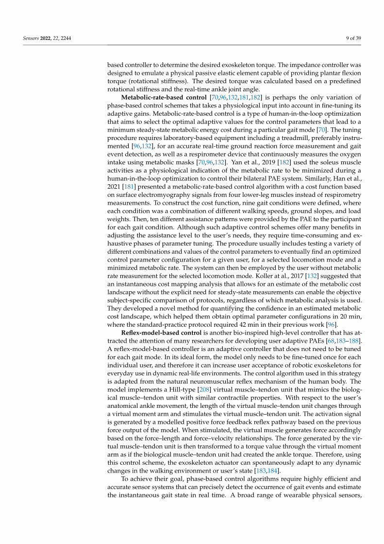
Metabolic-rate-based control [70,96,132,181,182] is perhaps the only variation ofphase-based control schemes that takes a physiological input into account in fine-tuning itsadaptive gains. Metabolic-rate-based control is a type of human-in-the-loop optimizationthat aims to select the optimal adaptive values for the control parameters that lead to aminimum steady-state metabolic energy cost during a particular gait mode [70]. The tuningprocedure requires laboratory-based equipment including a treadmill, preferably instru-mented [96,132], for an accurate real-time ground reaction force measurement and gaitevent detection, as well as a respirometer device that continuously measures the oxygenintake using metabolic masks [70,96,132]. Yan et al., 2019 [182] used the soleus muscleactivities as a physiological indication of the metabolic rate to be minimized during ahuman-in-the-loop optimization to control their bilateral PAE system. Similarly, Han et al.,2021 [181] presented a metabolic-rate-based control algorithm with a cost function basedon surface electromyography signals from four lower-leg muscles instead of respirometrymeasurements. To construct the cost function, nine gait conditions were defined, whereeach condition was a combination of different walking speeds, ground slopes, and loadweights. Then, ten different assistance patterns were provided by the PAE to the participantfor each gait condition. Although such adaptive control schemes offer many benefits inadjusting the assistance level to the user’s needs, they require time-consuming and ex-haustive phases of parameter tuning. The procedure usually includes testing a variety ofdifferent combinations and values of the control parameters to eventually find an optimizedcontrol parameter configuration for a given user, for a selected locomotion mode and aminimized metabolic rate. The system can then be employed by the user without metabolicrate measurement for the selected locomotion mode. Koller at al., 2017 [132] suggested thatan instantaneous cost mapping analysis that allows for an estimate of the metabolic costlandscape without the explicit need for steady-state measurements can enable the objectivesubject-specific comparison of protocols, regardless of which metabolic analysis is used.They developed a novel method for quantifying the confidence in an estimated metaboliccost landscape, which helped them obtain optimal parameter configurations in 20 min,where the standard-practice protocol required 42 min in their previous work [96].
Reflex-model-based control is another bio-inspired high-level controller that has at-tracted the attention of many researchers for developing user adaptive PAEs [68,183–188].A reflex-model-based controller is an adaptive controller that does not need to be tunedfor each gait mode. In its ideal form, the model only needs to be fine-tuned once for eachindividual user, and therefore it can increase user acceptance of robotic exoskeletons foreveryday use in dynamic real-life environments. The control algorithm used in this strategyis adapted from the natural neuromuscular reflex mechanism of the human body. Themodel implements a Hill-type [208] virtual muscle–tendon unit that mimics the biolog-ical muscle–tendon unit with similar contractile properties. With respect to the user’sanatomical ankle movement, the length of the virtual muscle–tendon unit changes througha virtual moment arm and stimulates the virtual muscle–tendon unit. The activation signalis generated by a modelled positive force feedback reflex pathway based on the previousforce output of the model. When stimulated, the virtual muscle generates force accordinglybased on the force–length and force–velocity relationships. The force generated by the vir-tual muscle–tendon unit is then transformed to a torque value through the virtual momentarm as if the biological muscle–tendon unit had created the ankle torque. Therefore, usingthis control scheme, the exoskeleton actuator can spontaneously adapt to any dynamicchanges in the walking environment or user’s state [183,184].
To achieve their goal, phase-based control algorithms require highly efficient andaccurate sensor systems that can precisely detect the occurrence of gait events and estimatethe instantaneous gait state in real time. A broad range of wearable physical sensors,
Sensors 2022, 22, 2244 10 of 39
also known as mechanically intrinsic sensors, have been used in developing intelligentankle exoskeletons to fulfil this necessity (Tables 3 and 4). Force sensitive resistors (FSR),foot-pressure insoles, and footswitches are the most commonly used physical sensorsfor detecting gait events in PAEs (Table 3). Their application in ankle robot technologydevelopment dates back to the initial PAEs [147–149]. Kim et al., 2007 [60] and 2011 [61]detected the gait cycle from foot contact signals recorded by FSR sensors that acted ason/off switches and indicated gait events by measuring the voltage drop. Similarly, Hwanget al., 2006 [59] used four FSR sensors and a rotary potentiometer to detect gait phases.Gurney et al., 2008 [209] integrated a set of FSR sensors into shoe insoles to measure theplantar pressure from the main pressure distribution regions of the foot sole: forefoot,toe, and heel, to identify gait events based on the pressure profile of these regions duringdifferent states of a normal gait cycle.
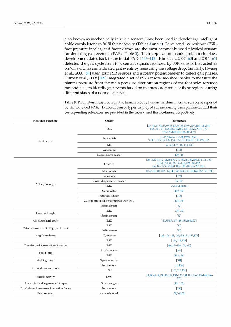
Table 3. Parameters measured from the human user by human–machine interface sensors as reportedby the reviewed PAEs. Different sensor types employed for measuring each parameter and theircorresponding references are provided in the second and third columns, respectively.
Measured Parameter Sensor References
Gait events
FSR[37–40,43,56,57,59–65,67,76–85,87,94,107,116–120,141–
143,145,147–153,156,159,160,166–168,170,171,173–175,177,178,184,186,187,189]
Footswitch [10,49,58,69,72,73,88,89,91–93,97–99,111,113,122,139,154,155,163–165,181,198,199,202]
IMU [57,66,74,75,102,158,170]
Gyroscope [112]
Piezoresistive sensor [109,110]
Ankle joint angle
Encoder[38,40,42,58,62–64,68,69,72,73,85,86,100,103,104,106,108–
110,117,118,138,139,142,149–151,159–162,165,173,178,181,185–188,202,206,207,210],
Potentiometer [10,43,59,101,102,114,143,147,148,154,155,166,167,170,171]
Gyroscope [172]
Linear displacement sensor [97–99]
IMU [64,127,152,211]
Goniometer [180,183]
Attitude sensor [116]
Custom strain sensor combined with IMU [174,175]
Strain sensor [87]
Knee joint angleIMU [206,207]
Strain sensor [87]
Absolute shank angle IMU [40,85,87,117,118,159,160,177]
Orientation of shank, thigh, and trunkIMU [42]
Inclinometer [82]
Angular velocity Gyroscope [123–126,128,129,150,151,157,172]
IMU [114,119,120]
Translational acceleration of wearer IMU [40,117–120,159,160]
Foot tiltingAccelerometer [141]
IMU [119,120]
Walking speed Speed encoder [204]
Ground reaction forceForce sensor [10,136]
FSR [101,117,131]
Muscle activity EMG [11,40,49,68,89,116,117,133–135,181,185,186,190–194,196–207]
Anatomical ankle generated torque Strain gauges [101,102]
Exoskeleton frame–user interaction forces Force sensor [136]
Respirometry Metabolic mask [70,96,132]
Sensors 2022, 22, 2244 11 of 39
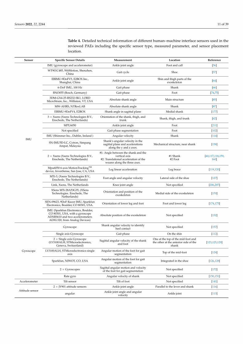
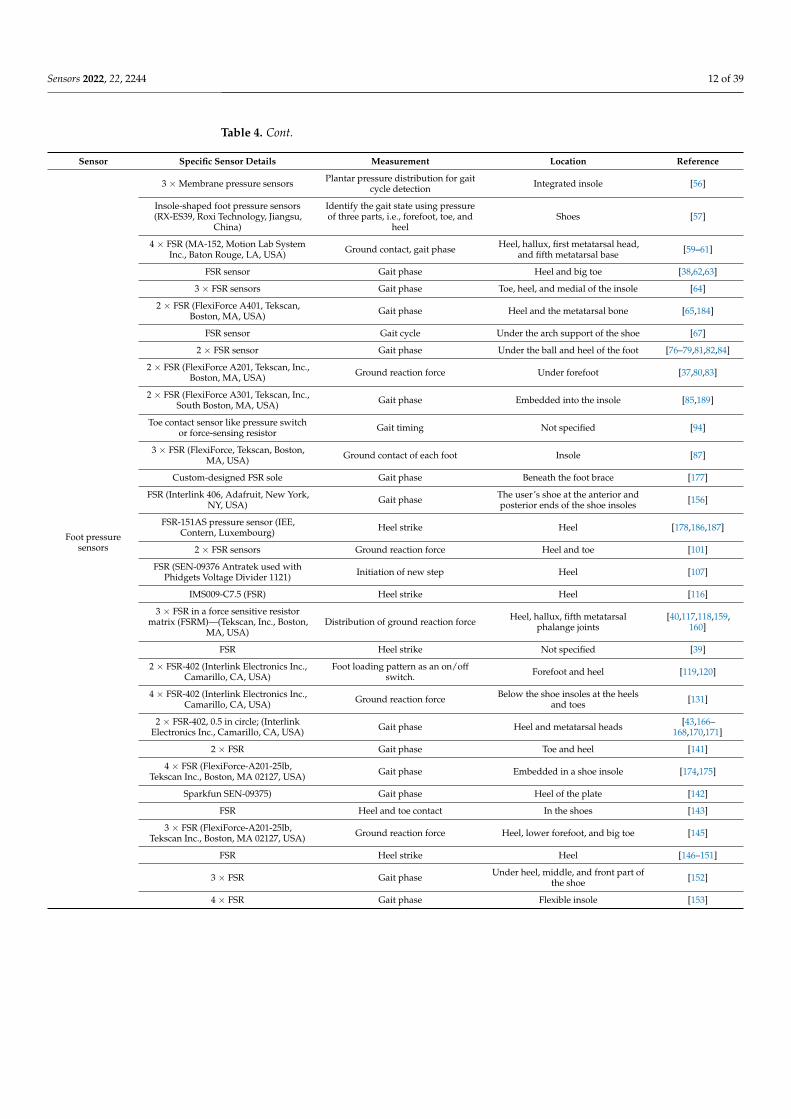
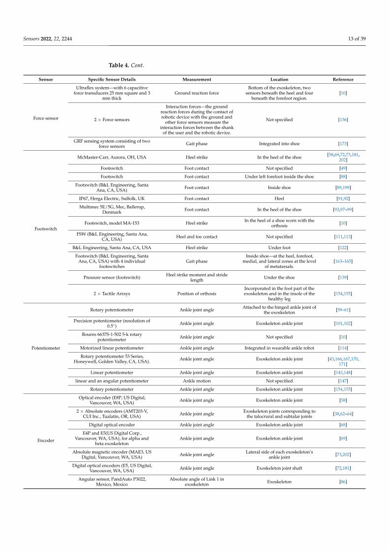
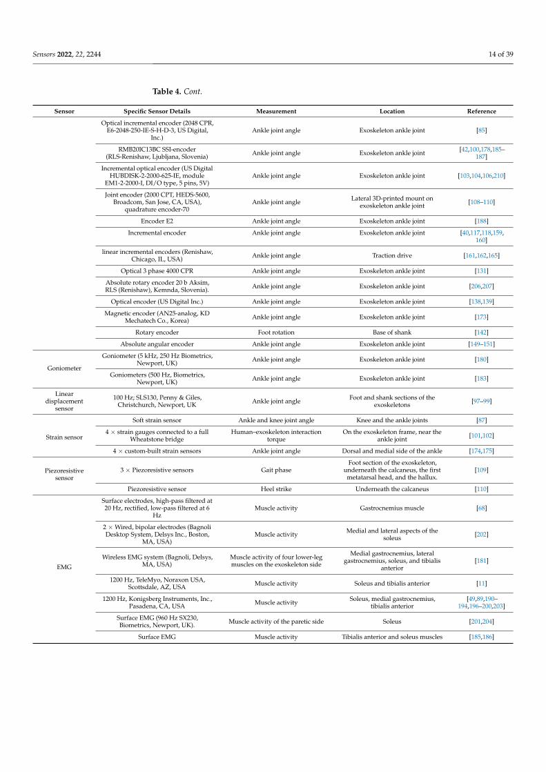
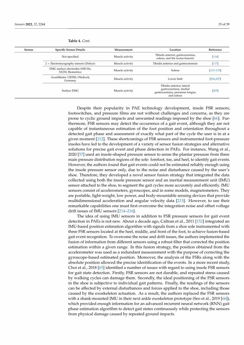
Table 4. Detailed technical information of different human–machine interface sensors used in thereviewed PAEs including the specific sensor type, measured parameter, and sensor placementlocation.
Sensor Specific Sensor Details Measurement Location Reference
IMU
IMU (gyroscope and accelerometer) Ankle joint angle Foot and calf [56]
WT901C485, WitMotion, Shenzhen,China Gait cycle Shoe [57]
EBIMU-9DoFV5, E2BOX Inc.,Shanghai, China Ankle joint angle Shin and thigh parts of the
exoskeleton [64]
6-DoF IMU, 100 Hz Gait phase Shank [66]
BNO055 (Bosch, Germany) Gait phase Foot [74,75]
3DM-GX4-25-RS232-SK1, LORDMicroStrain, Inc., Williston, VT, USA Absolute shank angle Main structure [85]
MW-AHRS, NTRexLAB Absolute shank angle Shank [87]
EBIMU-9DoFV4, E2BOX Shank angle in sagittal plane Medial shank [177]
3 × Xsens (Xsens Technologies B.V.,Enschede, The Netherlands)
Orientation of the shank, thigh, andtrunk Shank, thigh, and trunk [42]
MPU6050 Ankle joint angle Foot [211]
Not specified Gait phase segmentation Foot [102]
IMU (Shimmer Inc., Dublin, Ireland ) Angular velocity Shank [114]
SN-IMU5D-LC, Cytron, SimpangAmpat, Malaysia
Shank’s angular velocity in thesagittal plane and accelerations
along the y and z axes.Mechanical structure, near shank [158]
2 × Xsens (Xsens Technologies B.V.,Enschede, The Netherlands)
#1: Angle between the shank and thevertical axis
#2: Translational acceleration of thewearer along the three axes.
#1 Shank#2 Foot
[40,117,118,159,160]
Mpu6050 6-axis MotionTrackingTM
device, InvenSense, San Jose, CA, USA Leg linear acceleration Leg brace [119,120]
MTi-3, (Xsens Technologies B.V.,Enschede, The Netherlands) Foot angle and angular velocity Lateral side of the shoe [127]
Link, Xsens, The Netherlands Knee joint angle Not specified [206,207]
XSens MTi-28A53G35, (XSensTechnologies. Enschede, The
Netherlands)
Orientation and position of theexoskeleton Medial side of the exoskeleton [170]
SEN-09623, 9DoF Razor IMU, SparkfunElectronics, Boulder, CO 80301, USA. Orientation of lower leg and foot Foot and lower leg [174,175]
IMU (Sparkfun Electronics, Boulder,CO 80301, USA, with a gyroscope
ADXRS610 and two accelerometersADXL320, from Analog Devices)
Absolute position of the exoskeleton Not specified [152]
Gyroscope
Gyroscope Shank angular velocity to identifyheel contact Not specified [157]
Single axis Gyroscope Gait phase On the shin [112]
2 × Single axis Gyroscope(LY3100ALH, STMicroelectronics,
Geneva, Switzerland)
Sagittal angular velocity of the shankand foot
One at the top of the mid-foot andthe other at the anterior side of the
shank[123,125,129]
LY3100ALH, STMicroelectronics-singleaxis
Angular motion of the foot for gaitsegmentation Top of the mid-foot [124]
Sparkfun, NIWOT, CO, USA Angular motion of the foot for gaitsegmentation Integrated in the shoe [126,128]
2 × Gyroscopes Sagittal angular motion and velocityof the foot for gait segmentation Not specified [172]
Rate gyro Angular velocity of shank Not specified [150,151]
Accelerometer Tilt sensor Tilt of foot Not specified [141]
Attitude sensor2 × JY901 attitude sensors Ankle joint angle Parallel to the lever and shank [116]
angular Ankle joint angle and angularvelocity Ankle joint [113]
Sensors 2022, 22, 2244 12 of 39
Table 4. Cont.
Sensor Specific Sensor Details Measurement Location Reference
Foot pressuresensors
3 × Membrane pressure sensors Plantar pressure distribution for gaitcycle detection Integrated insole [56]
Insole-shaped foot pressure sensors(RX-ES39, Roxi Technology, Jiangsu,
China)
Identify the gait state using pressureof three parts, i.e., forefoot, toe, and
heelShoes [57]
4 × FSR (MA-152, Motion Lab SystemInc., Baton Rouge, LA, USA) Ground contact, gait phase Heel, hallux, first metatarsal head,
and fifth metatarsal base [59–61]
FSR sensor Gait phase Heel and big toe [38,62,63]
3 × FSR sensors Gait phase Toe, heel, and medial of the insole [64]
2 × FSR (FlexiForce A401, Tekscan,Boston, MA, USA) Gait phase Heel and the metatarsal bone [65,184]
FSR sensor Gait cycle Under the arch support of the shoe [67]
2 × FSR sensor Gait phase Under the ball and heel of the foot [76–79,81,82,84]
2 × FSR (FlexiForce A201, Tekscan, Inc.,Boston, MA, USA) Ground reaction force Under forefoot [37,80,83]
2 × FSR (FlexiForce A301, Tekscan, Inc.,South Boston, MA, USA) Gait phase Embedded into the insole [85,189]
Toe contact sensor like pressure switchor force-sensing resistor Gait timing Not specified [94]
3 × FSR (FlexiForce, Tekscan, Boston,MA, USA) Ground contact of each foot Insole [87]
Custom-designed FSR sole Gait phase Beneath the foot brace [177]
FSR (Interlink 406, Adafruit, New York,NY, USA) Gait phase The user’s shoe at the anterior and
posterior ends of the shoe insoles [156]
FSR-151AS pressure sensor (IEE,Contern, Luxembourg) Heel strike Heel [178,186,187]
2 × FSR sensors Ground reaction force Heel and toe [101]
FSR (SEN-09376 Antratek used withPhidgets Voltage Divider 1121) Initiation of new step Heel [107]
IMS009-C7.5 (FSR) Heel strike Heel [116]
3 × FSR in a force sensitive resistormatrix (FSRM)—(Tekscan, Inc., Boston,
MA, USA)Distribution of ground reaction force Heel, hallux, fifth metatarsal
phalange joints[40,117,118,159,
160]
FSR Heel strike Not specified [39]
2 × FSR-402 (Interlink Electronics Inc.,Camarillo, CA, USA)
Foot loading pattern as an on/offswitch. Forefoot and heel [119,120]
4 × FSR-402 (Interlink Electronics Inc.,Camarillo, CA, USA) Ground reaction force Below the shoe insoles at the heels
and toes [131]
2 × FSR-402, 0.5 in circle; (InterlinkElectronics Inc., Camarillo, CA, USA) Gait phase Heel and metatarsal heads [43,166–
168,170,171]
2 × FSR Gait phase Toe and heel [141]
4 × FSR (FlexiForce-A201-25lb,Tekscan Inc., Boston, MA 02127, USA) Gait phase Embedded in a shoe insole [174,175]
Sparkfun SEN-09375) Gait phase Heel of the plate [142]
FSR Heel and toe contact In the shoes [143]
3 × FSR (FlexiForce-A201-25lb,Tekscan Inc., Boston, MA 02127, USA) Ground reaction force Heel, lower forefoot, and big toe [145]
FSR Heel strike Heel [146–151]
3 × FSR Gait phase Under heel, middle, and front part ofthe shoe [152]
4 × FSR Gait phase Flexible insole [153]
Sensors 2022, 22, 2244 13 of 39
Table 4. Cont.
Sensor Specific Sensor Details Measurement Location Reference
Force sensor
Ultraflex system—with 6 capacitiveforce transducers 25 mm square and 3
mm thickGround reaction force
Bottom of the exoskeleton, twosensors beneath the heel and four
beneath the forefoot region.[10]
2 × Force sensors
Interaction forces—the groundreaction forces during the contact ofrobotic device with the ground and
other force sensors measure theinteraction forces between the shank
of the user and the robotic device.
Not specified [136]
GRF sensing system consisting of twoforce sensors Gait phase Integrated into shoe [173]
Footswitch
McMaster-Carr, Aurora, OH, USA Heel strike In the heel of the shoe [58,69,72,73,181,202]
Footswitch Foot contact Not specified [49]
Footswitch Foot contact Under left forefoot inside the shoe [88]
Footswitch (B&L Engineering, SantaAna, CA, USA) Foot contact Inside shoe [89,199]
IP67, Herga Electric, Suffolk, UK Foot contact Heel [91,92]
Multimec 5E/5G, Mec, Ballerup,Denmark Foot contact In the heel of the shoe [93,97–99]
Footswitch, model MA-153 Heel strike In the heel of a shoe worn with theorthosis [10]
FSW (B&L Engineering, Santa Ana,CA, USA) Heel and toe contact Not specified [111,113]
B&L Engineering, Santa Ana, CA, USA Heel strike Under foot [122]
Footswitch (B&L Engineering, SantaAna, CA, USA) with 4 individual
footswitchesGait phase
Inside shoe—at the heel, forefoot,medial, and lateral zones at the level
of metatarsals.[163–165]
Pressure sensor (footswitch) Heel strike moment and stridelength Under the shoe [139]
2 × Tactile Arrays Position of orthosisIncorporated in the foot part of theexoskeleton and in the insole of the
healthy leg[154,155]
Potentiometer
Rotary potentiometer Ankle joint angle Attached to the hinged ankle joint ofthe exoskeleton [59–61]
Precision potentiometer (resolution of0.5) Ankle joint angle Exoskeleton ankle joint [101,102]
Bourns 6637S-1-502 5-k rotarypotentiometer Ankle joint angle Not specified [10]
Motorized linear potentiometer Ankle joint angle Integrated in wearable ankle robot [114]
Rotary potentiometer 53 Series,Honeywell, Golden Valley, CA, USA). Ankle joint angle Exoskeleton ankle joint [43,166,167,170,
171]
Linear potentiometer Ankle joint angle Exoskeleton ankle joint [143,148]
linear and an angular potentiometer Ankle motion Not specified [147]
Rotary potentiometer Ankle joint angle Exoskeleton ankle joint [154,155]
Encoder
Optical encoder (E8P; US Digital,Vancouver, WA, USA) Ankle joint angle Exoskeleton ankle joint [58]
2 × Absolute encoders (AMT203-V,CUI Inc., Tualatin, OR, USA) Ankle joint angle Exoskeleton joints corresponding to
the talocrural and subtalar joints [38,62–64]
Digital optical encoder Ankle joint angle Exoskeleton ankle joint [68]
E4P and E5(US Digital Corp.,Vancouver, WA, USA), for alpha and
beta exoskeletonAnkle joint angle Exoskeleton ankle joint [69]
Absolute magnetic encoder (MAE3, USDigital, Vancouver, WA, USA) Ankle joint angle Lateral side of each exoskeleton’s
ankle joint [73,202]
Digital optical encoders (E5, US Digital,Vancouver, WA, USA) Ankle joint angle Exoskeleton joint shaft [72,181]
Angular sensor, PandAuto P3022,Mexico, Mexico
Absolute angle of Link 1 inexoskeleton Exoskeleton [86]
Sensors 2022, 22, 2244 14 of 39
Table 4. Cont.
Sensor Specific Sensor Details Measurement Location Reference
Optical incremental encoder (2048 CPR,E6-2048-250-IE-S-H-D-3, US Digital,
Inc.)Ankle joint angle Exoskeleton ankle joint [85]
RMB20IC13BC SSI-encoder(RLS-Renishaw, Ljubljana, Slovenia) Ankle joint angle Exoskeleton ankle joint [42,100,178,185–
187]
Incremental optical encoder (US DigitalHUBDISK-2-2000-625-IE, module
EM1-2-2000-I, DI/O type, 5 pins, 5V)Ankle joint angle Exoskeleton ankle joint [103,104,106,210]
Joint encoder (2000 CPT, HEDS-5600,Broadcom, San Jose, CA, USA),
quadrature encoder-70Ankle joint angle Lateral 3D-printed mount on
exoskeleton ankle joint [108–110]
Encoder E2 Ankle joint angle Exoskeleton ankle joint [188]
Incremental encoder Ankle joint angle Exoskeleton ankle joint [40,117,118,159,160]
linear incremental encoders (Renishaw,Chicago, IL, USA) Ankle joint angle Traction drive [161,162,165]
Optical 3 phase 4000 CPR Ankle joint angle Exoskeleton ankle joint [131]
Absolute rotary encoder 20 b Aksim,RLS (Renishaw), Kemnda, Slovenia). Ankle joint angle Exoskeleton ankle joint [206,207]
Optical encoder (US Digital Inc.) Ankle joint angle Exoskeleton ankle joint [138,139]
Magnetic encoder (AN25-analog, KDMechatech Co., Korea) Ankle joint angle Exoskeleton ankle joint [173]
Rotary encoder Foot rotation Base of shank [142]
Absolute angular encoder Ankle joint angle Exoskeleton ankle joint [149–151]
Goniometer
Goniometer (5 kHz, 250 Hz Biometrics,Newport, UK) Ankle joint angle Exoskeleton ankle joint [180]
Goniometers (500 Hz, Biometrics,Newport, UK) Ankle joint angle Exoskeleton ankle joint [183]
Lineardisplacement
sensor
100 Hz; SLS130, Penny & Giles,Christchurch, Newport, UK Ankle joint angle Foot and shank sections of the
exoskeletons [97–99]
Strain sensor
Soft strain sensor Ankle and knee joint angle Knee and the ankle joints [87]
4 × strain gauges connected to a fullWheatstone bridge
Human–exoskeleton interactiontorque
On the exoskeleton frame, near theankle joint [101,102]
4 × custom-built strain sensors Ankle joint angle Dorsal and medial side of the ankle [174,175]
Piezoresistivesensor
3 × Piezoresistive sensors Gait phaseFoot section of the exoskeleton,
underneath the calcaneus, the firstmetatarsal head, and the hallux.
[109]
Piezoresistive sensor Heel strike Underneath the calcaneus [110]
EMG
Surface electrodes, high-pass filtered at20 Hz, rectified, low-pass filtered at 6
HzMuscle activity Gastrocnemius muscle [68]
2 × Wired, bipolar electrodes (BagnoliDesktop System, Delsys Inc., Boston,
MA, USA)Muscle activity Medial and lateral aspects of the
soleus [202]
Wireless EMG system (Bagnoli, Delsys,MA, USA)
Muscle activity of four lower-legmuscles on the exoskeleton side
Medial gastrocnemius, lateralgastrocnemius, soleus, and tibialis
anterior[181]
1200 Hz, TeleMyo, Noraxon USA,Scottsdale, AZ, USA Muscle activity Soleus and tibialis anterior [11]
1200 Hz, Konigsberg Instruments, Inc.,Pasadena, CA, USA Muscle activity Soleus, medial gastrocnemius,
tibialis anterior[49,89,190–
194,196–200,203]
Surface EMG (960 Hz SX230,Biometrics, Newport, UK). Muscle activity of the paretic side Soleus [201,204]
Surface EMG Muscle activity Tibialis anterior and soleus muscles [185,186]
Sensors 2022, 22, 2244 15 of 39
Table 4. Cont.
Sensor Specific Sensor Details Measurement Location Reference
Not specified Muscle activity Tibialis anterior, gastrocnemius,soleus, and the rectus femoris [116]
2 × Electromyography sensors (Delsys) Muscle activity Tibialis anterior and gastrocnemius [117]
EMG surface electrodes-1000 Hz;SX230, Biometrics Muscle activity Soleus [133–135]
AxonMaster 13E500, Ottobock,Germany Muscle activity Lower limb [206,207]
Surface EMG Muscle activity
Tibialis anterior, lateralgastrocnemius, medial
gastrocnemius, peroneus longus,and soleus
[205]
Despite their popularity in PAE technology development, insole FSR sensors,footswitches, and pressure films are not without challenges and concerns, as they areprone to cyclic ground impacts and unwanted readings imposed by the shoe [66]. Fur-thermore, FSR sensors may detect the occurrence of a gait event, although they are notcapable of instantaneous estimation of the foot position and orientation throughout adetected gait phase and assessment of exactly what part of the cycle the user is in at agiven moment [212]. These shortcomings of FSR sensors and instrumented foot-pressureinsoles have led to the development of a variety of sensor fusion strategies and alternativesolutions for precise gait event and phase detection in PAEs. For instance, Wang et al.,2020 [57] used an insole-shaped pressure sensor to sense the plantar pressure from threemain pressure distribution regions of the sole: forefoot, toe, and heel, to identify gait events.However, the authors found that gait events could not be estimated reliably enough usingthe insole pressure sensor only, due to the noise and disturbance caused by the user’sshoe. Therefore, they developed a novel sensor fusion strategy that integrated the datacollected using both the insole pressure sensor and an inertial measurement unit (IMU)sensor attached to the shoe, to segment the gait cycles more accurately and efficiently. IMUsensors consist of accelerometers, gyroscopes, and in some models, magnetometers. Theyare portable, light-weight, low power, and body-mountable sensing devices that providemultidimensional acceleration and angular velocity data [213]. However, to use theirremarkable capabilities one must first overcome the integration noise and offset voltagedrift issues of IMU sensors [214–216].
The idea of using IMU sensors in addition to FSR pressure sensors for gait eventdetection in PAEs is not new. About a decade ago, Caltran et al., 2011 [152] integrated anIMU-based position estimation algorithm with signals from a shoe sole instrumented withthree FSR sensors located at the heel, middle, and front of the foot, to achieve fusion-basedgait event recognition. To overcome the noise and drift issues, the authors implemented thefusion of information from different sensors using a robust filter that corrected the positionestimation within a given range. In this fusion strategy, the position obtained from theaccelerometer was used as a redundant measurement with the purpose of correcting thegyroscope-based estimated position. Moreover, the analysis of the FSRs along with theabsolute position allowed the precise identification of the events. In a more recent study,Choi et al., 2018 [65] identified a number of issues with regard to using insole FSR sensorsfor gait state detection. Firstly, FSR sensors are not durable, and repeated stress causedby walking cycles can damage them. Secondly, the ideal positioning of the FSR sensorsin the shoe is subjective to individual gait patterns. Finally, the readings of the sensorscan be affected by external disturbances and forces applied to the shoe, including thosecaused by the exoskeleton actuation. As a result, the authors replaced the FSR sensorswith a shank-mounted IMU in their next ankle exoskeleton prototype (Seo et al., 2019 [66]),which provided enough information for an advanced recurrent neural network (RNN) gaitphase estimation algorithm to detect gait states continuously while protecting the sensorsfrom physical damage caused by repeated ground impacts.
Sensors 2022, 22, 2244 16 of 39
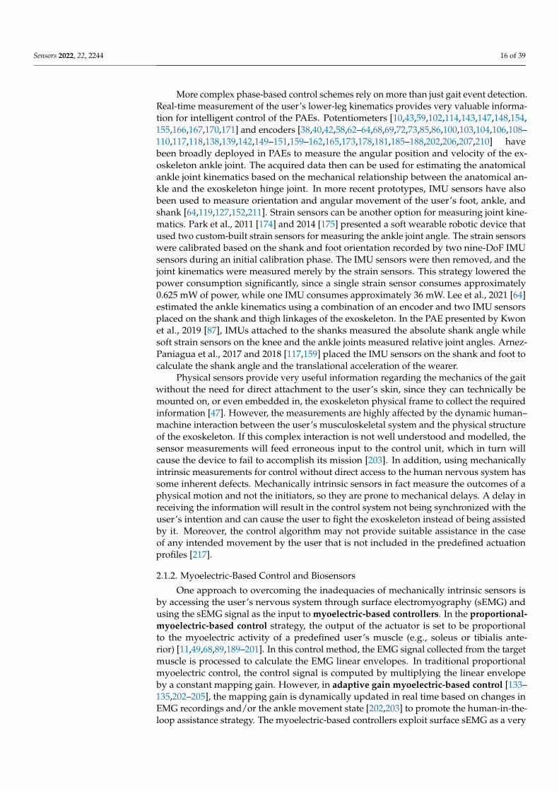
More complex phase-based control schemes rely on more than just gait event detection.Real-time measurement of the user’s lower-leg kinematics provides very valuable informa-tion for intelligent control of the PAEs. Potentiometers [10,43,59,102,114,143,147,148,154,155,166,167,170,171] and encoders [38,40,42,58,62–64,68,69,72,73,85,86,100,103,104,106,108–110,117,118,138,139,142,149–151,159–162,165,173,178,181,185–188,202,206,207,210] havebeen broadly deployed in PAEs to measure the angular position and velocity of the ex-oskeleton ankle joint. The acquired data then can be used for estimating the anatomicalankle joint kinematics based on the mechanical relationship between the anatomical an-kle and the exoskeleton hinge joint. In more recent prototypes, IMU sensors have alsobeen used to measure orientation and angular movement of the user’s foot, ankle, andshank [64,119,127,152,211]. Strain sensors can be another option for measuring joint kine-matics. Park et al., 2011 [174] and 2014 [175] presented a soft wearable robotic device thatused two custom-built strain sensors for measuring the ankle joint angle. The strain sensorswere calibrated based on the shank and foot orientation recorded by two nine-DoF IMUsensors during an initial calibration phase. The IMU sensors were then removed, and thejoint kinematics were measured merely by the strain sensors. This strategy lowered thepower consumption significantly, since a single strain sensor consumes approximately0.625 mW of power, while one IMU consumes approximately 36 mW. Lee et al., 2021 [64]estimated the ankle kinematics using a combination of an encoder and two IMU sensorsplaced on the shank and thigh linkages of the exoskeleton. In the PAE presented by Kwonet al., 2019 [87], IMUs attached to the shanks measured the absolute shank angle whilesoft strain sensors on the knee and the ankle joints measured relative joint angles. Arnez-Paniagua et al., 2017 and 2018 [117,159] placed the IMU sensors on the shank and foot tocalculate the shank angle and the translational acceleration of the wearer.
Physical sensors provide very useful information regarding the mechanics of the gaitwithout the need for direct attachment to the user’s skin, since they can technically bemounted on, or even embedded in, the exoskeleton physical frame to collect the requiredinformation [47]. However, the measurements are highly affected by the dynamic human–machine interaction between the user’s musculoskeletal system and the physical structureof the exoskeleton. If this complex interaction is not well understood and modelled, thesensor measurements will feed erroneous input to the control unit, which in turn willcause the device to fail to accomplish its mission [203]. In addition, using mechanicallyintrinsic measurements for control without direct access to the human nervous system hassome inherent defects. Mechanically intrinsic sensors in fact measure the outcomes of aphysical motion and not the initiators, so they are prone to mechanical delays. A delay inreceiving the information will result in the control system not being synchronized with theuser’s intention and can cause the user to fight the exoskeleton instead of being assistedby it. Moreover, the control algorithm may not provide suitable assistance in the caseof any intended movement by the user that is not included in the predefined actuationprofiles [217].
2.1.2. Myoelectric-Based Control and Biosensors
One approach to overcoming the inadequacies of mechanically intrinsic sensors isby accessing the user’s nervous system through surface electromyography (sEMG) andusing the sEMG signal as the input to myoelectric-based controllers. In the proportional-myoelectric-based control strategy, the output of the actuator is set to be proportionalto the myoelectric activity of a predefined user’s muscle (e.g., soleus or tibialis ante-rior) [11,49,68,89,189–201]. In this control method, the EMG signal collected from the targetmuscle is processed to calculate the EMG linear envelopes. In traditional proportionalmyoelectric control, the control signal is computed by multiplying the linear envelopeby a constant mapping gain. However, in adaptive gain myoelectric-based control [133–135,202–205], the mapping gain is dynamically updated in real time based on changes inEMG recordings and/or the ankle movement state [202,203] to promote the human-in-the-loop assistance strategy. The myoelectric-based controllers exploit surface sEMG as a very
Sensors 2022, 22, 2244 17 of 39
effective method to directly and yet non-invasively connect to the user’s nervous system.They are shown to be better synchronized with the user’s physiology compared to thephase-based controllers, since the user has direct control over the timing and magnitude ofthe actuation. Myoelectric-based control allows the exoskeleton wearer to actively initiate,modify, and stop the actuation, and therefore may promote the user’s neuroplasticity. Thistype of control does not require a reference value and therefore can potentially be more ro-bust to environmental changes. This advantage makes myoelectric-based control a suitableoption for controlling autonomous wearable devices. Nevertheless, the standard sEMGprotocols must be in place when EMG biosensors are used as the main human–machineinterface measurement tool. A typical sEMG procedure usually begins with preparingthe electrode attachment site on the skin to reduce the skin impedance to less than 5 kΩ,locating the target muscle, and correctly placing the electrode on top of the target musclebelly [218]. The process then continues with acquiring EMG signals at a sample rate of noless than 2000 Hz, and applying several signal amplification and filtering steps to the ac-quired data to finally achieve a high signal-to-noise ratio (SNR), indicating that the acquireddata is suitable for use in controlling an exoskeleton [219]. Recent technology advancementshave led to the development of wireless sEMG sensors with integrated amplification andfiltering circuits that facilitate their deployment in wearable technologies [220].
Despite the valuable benefits of traditional EMG-based controllers mentioned above,it is important to note that proportional-myoelectric-based and adaptive gain myoelectric-based control algorithms produce control commands directly from electromyographyreadings, while neglecting the highly nonlinear transformations that occur between neuralexcitation of a muscle (EMG onsets) and the resultant mechanical joint torque generation.Such algorithms do not take into account the nonlinear behavior of an individual muscle–tendon unit or the complex dynamic co-activity of multiple muscles acting on the ankle joint.Accurate estimates of the anatomical ankle joint torque using EMG signals requires datato be acquired from at least the major, if not all, muscles spanning the joint, and requiresexplicit modelling of the EMG-to-joint torque transformation. Employing a person-specificEMG-driven neuromusculoskeletal modelling approach that estimates muscle forces fromelectromyography signals through excitation–activation and activation–contraction dynam-ics in recently developed control schemes has overcome the shortcomings of the traditionalmyoelectric-based control algorithms. This type of control is known as neuromechanical-model-based control [206,207] or myoelectric neuromuscular-model-based control andcontains a comprehensive sensor fusion procedure that effectively integrates the datafrom a large set of wearable physical (angular kinematics) and physiological (EMG) sen-sors to precisely estimate the person’s specific ankle dorsiflexion/plantar flexion torque.Neuromechanical-model-based control can potentially revolutionize the communicationbetween the human and the machine and eventually meet the ultimate goals of PAEs asintelligent user-adaptive robotic devices. However, it is important to note that developingwell-performing subject-specific neuromechanical-model-based control for driving a PAEis not a trivial task. EMG-driven models not only inherit the typical electromyographychallenges (e.g., noise, crosstalk, skin and movement artifacts, etc.) but also rely on severalpre-measurements, parameter tuning, and calibration stages [221–223]. For instance, astandard set of isometric tasks would be required for measuring maximum voluntarycontraction (MVC) values of the muscles included in model to be used in the EMG normal-ization procedure. In addition, the absolute MVC value may vary for the same individualfrom one day to another, due to alternations in environmental or physiological condi-tions [224]. Furthermore, obtaining MVC values in patients with pathological conditionscan be very challenging and requires the development of condition-specific testing proto-cols [225]. The neuromechanical modelling procedure also requires the development of amusculoskeletal model of the user’s lower limb which is scaled to the user’s anthropometryusing static motion capture data. Then, a set of pre-defined effective calibration tasks mustbe conducted for person-specific optimization of the activation dynamics coefficients andmuscle–tendon unit parameters [226,227], which in turn necessitates obtaining high-quality
Sensors 2022, 22, 2244 18 of 39
electromyography, motion analysis, and ground reaction force data during the calibrationprocedure.
Parameters measured using a variety of human–machine interface sensors used in thereviewed PAEs are shown in Table 3. Different sensor types employed for measuring eachparameter are grouped and listed together to demonstrate available sensor technologies formeasuring a particular parameter. To investigate the sensor types and their implementationin PAEs for detecting the user’s locomotion intention and requirement more deeply, detailedtechnical information including sensor specifications, measured parameters, and sensorattachment locations is extracted from the reviewed publications and collated in Table 4.
2.2. Low-Level Control and Machine–Machine Sensors
The main purpose of a low-level controller in a PAE is to ensure that the commandgenerated by the high-level controller is precisely tracked by the actuation component.The selection of the low-level control scheme is dependent on the actuation principle andactuation mechanism. Choosing the proper actuator for a PAE can be very challengingdue to the specific requirements of these devices. PAEs demand high torques and speedsto be able to provide the essential assistance at the ankle joint, given that the joint torqueat the anatomical ankle can reach up to 1.5 N·m/kg during normal walking [228]. Themain criteria to consider when choosing a suitable actuator for a PAE include: torque-to-mass ratio, power-to-weight ratio, back-drivability, force bandwidth, efficiency, and forcedensity [229,230]. When development of a portable PAE is desired, portability, total weight,and total size of the actuator and its corresponding power source would take a high priorityin selecting the actuator type, whereas a powerful and reliable actuation and power sourceunit might be a better option for tethered rehabilitation PAEs. A further discussion on thechallenges in developing portable PAEs is provided in Section 3. Actuators used in PAEs(Table 5) can be classified based on the employed actuation principle [231].
Pneumatic actuators are made of pneumatic cylinders or cylinder-like elements withenclosed pistons that can be powered and driven using external air compressors. Four typesof pneumatic actuators were used in the reviewed PAEs: pneumatic artificial muscles [11,38,49,50,62,63,88–93,95–99,131–135,146,174–176,179,190–201,203], pneumatic cylinders [43,166–171], soft fabric actuators [156,232], and soft fiber braided bending actuators [211].Pneumatic actuators are cheap and can provide high specific power. Nonetheless, thenonlinearities associated with the compressibility factor of air make the pneumatic actuatorsvery difficult to model and control. Moreover, pneumatic actuators are not ideal choicesfor portable devices due to the need for external air compressors which are usually veryheavy and bulky [233]. Portable air compressors have been used to actuate a number ofPAEs [43,131,146,166–171,174–176], though they do not last long enough to qualify as aneveryday usage option.
Electric actuators were the most popular actuators deployed in the reviewed PAEs.They were powered by on-board battery packs [37,41,56,57,61,65–67,76–84,86,87,94,100–102,112,113,115,118–120,126,127,130,144,145,156–160,172–175,177,184,187,189,234,235], DCoff-board power supply units [10,39,109,116,121,122,128,136,147–149], and AC off-boardpower supply units [72,181]. Eight different types of electric actuation elements wereused in the reviewed articles: brushed DC motors [86,115,121,172], brushless DC mo-tors [37,39,40,42,57,64–66,76–84,100–113,116–118,122–125,127,129,143,147–151,157–165,178,184–187,210], servo DC motors [74,75,87,119,120,141,144,145,177], servo AC motors [53,58,68–73,180–183,202,204], stepper motors [189], permanent magnetic synchronous mo-tors [85], DC voice coil actuators [154,155], and hybrid drive systems [138–140,173]. Hybriddrive systems, in fact, are a combination of both hydraulic and electric actuation mecha-nisms and are often recognized as electrohydraulic actuators. Electrohydraulic actuatorseliminate the necessity for dedicated hydraulic pumps by replacing the pumps with anelectrical motor. In general, electric actuators can provide high speeds, high torques, highforce bandwidths, and fast response times. Conversely, they are heavy and suffer from arather low torque-to-mass ratio [158].
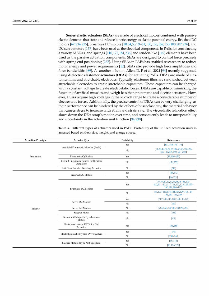
Sensors 2022, 22, 2244 19 of 39
Series elastic actuators (SEAs) are made of electrical motors combined with passiveelastic elements that store and release kinetic energy as elastic potential energy. Brushed DCmotors [67,234,235], brushless DC motors [10,54,55,59–61,130,136,152,153,188,207,236], andDC servo motors [137] have been used as the electrical components in PAEs for constructinga variety of SEAs, and springs [110,172,181,236] and tendon-like [149] elements have beenused as the passive actuation components. SEAs are designed to control force preciselywith spring end positioning [237]. Using SEAs in PAEs has enabled researchers to reducemotor energy and power requirements [12]. SEAs also provide high force amplitudes andforce bandwidths [69]. As another solution, Allen, D. P. et al., 2021 [94] recently suggestedusing dielectric elastomer actuators (DEAs) for actuating PAEs. DEAs are made of elas-tomer films and stretchable electrodes. Typically, elastomer films are sandwiched betweenstretchable electrodes to create stretchable capacitors. These capacitors can be chargedwith a constant voltage to create electrostatic forces. DEAs are capable of mimicking thefunction of artificial muscles and weigh less than pneumatic and electric actuators. How-ever, DEAs require high voltages in the kilovolt range to create a considerable number ofelectrostatic forces. Additionally, the precise control of DEAs can be very challenging, astheir performance can be hindered by the effects of viscoelasticity, the material behaviorthat causes stress to increase with strain and strain rate. The viscoelastic relaxation effectslows down the DEA strap’s motion over time, and consequently leads to unrepeatabilityand uncertainty in the actuation unit function [94,238].
Table 5. Different types of actuators used in PAEs. Portability of the utilized actuation units isassessed based on their size, weight, and energy source.
Actuation Principle Actuator Type Portability References
Pneumatic
Artificial Pneumatic Muscles (PAM)Yes [131,146,174–176]
No [11,38,49,50,62,63,88–93,95–99,132–135,142,179,190–201,203]
Pneumatic Cylinders Yes [43,166–171]
Exosuit Pneumatic Source (Soft FabricActuator) No [156,232]
Soft Fiber Braided Bending Actuator No [211]
Electric
Brushed DC MotorsYes [115,172]
No [86,121]
Brushless DC Motors
Yes[37,39,40,42,57,65,66,76–84,100–
102,111–113,117,118,122,123,127,157–160,178,184–187]
No [64,103–110,116,124,125,129,143,147–151,161–165,210]
Servo DC MotorsYes [74,75,87,119,120,144,145,177]
No [141]
Servo AC Motors No [53,58,68–73,180–183,202,204]
Stepper Motor No [189]
Permanent Magnetic SynchronousMotors No [85]
Electromechanical DC Voice CoilActuator No [154,155]
Electrohydraulic Hybrid Drive SystemYes [173]
No [138–140]
Electric Motors (Type Not Specified)Yes [56,114]
No [41,126,128]
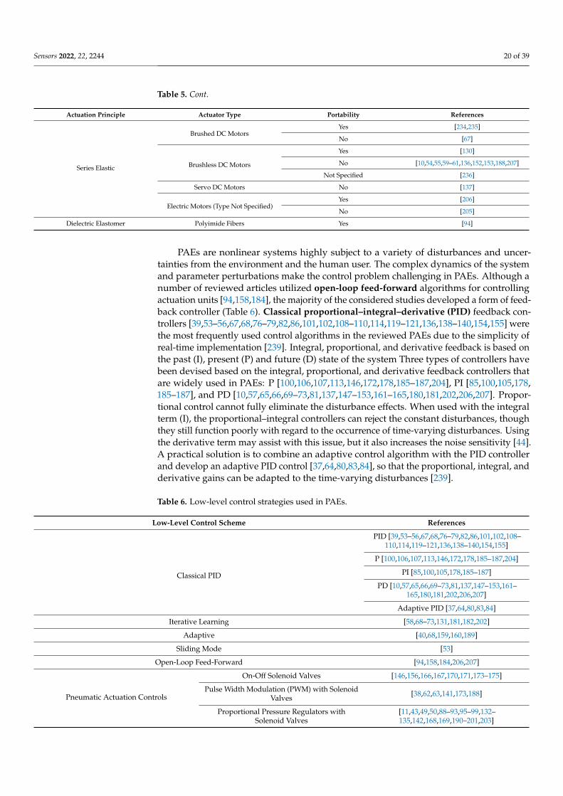
Sensors 2022, 22, 2244 20 of 39
Table 5. Cont.
Actuation Principle Actuator Type Portability References
Series Elastic
Brushed DC MotorsYes [234,235]
No [67]
Brushless DC Motors
Yes [130]
No [10,54,55,59–61,136,152,153,188,207]
Not Specified [236]
Servo DC Motors No [137]
Electric Motors (Type Not Specified)Yes [206]
No [205]
Dielectric Elastomer Polyimide Fibers Yes [94]
PAEs are nonlinear systems highly subject to a variety of disturbances and uncer-tainties from the environment and the human user. The complex dynamics of the systemand parameter perturbations make the control problem challenging in PAEs. Although anumber of reviewed articles utilized open-loop feed-forward algorithms for controllingactuation units [94,158,184], the majority of the considered studies developed a form of feed-back controller (Table 6). Classical proportional–integral–derivative (PID) feedback con-trollers [39,53–56,67,68,76–79,82,86,101,102,108–110,114,119–121,136,138–140,154,155] werethe most frequently used control algorithms in the reviewed PAEs due to the simplicity ofreal-time implementation [239]. Integral, proportional, and derivative feedback is based onthe past (I), present (P) and future (D) state of the system Three types of controllers havebeen devised based on the integral, proportional, and derivative feedback controllers thatare widely used in PAEs: P [100,106,107,113,146,172,178,185–187,204], PI [85,100,105,178,185–187], and PD [10,57,65,66,69–73,81,137,147–153,161–165,180,181,202,206,207]. Propor-tional control cannot fully eliminate the disturbance effects. When used with the integralterm (I), the proportional–integral controllers can reject the constant disturbances, thoughthey still function poorly with regard to the occurrence of time-varying disturbances. Usingthe derivative term may assist with this issue, but it also increases the noise sensitivity [44].A practical solution is to combine an adaptive control algorithm with the PID controllerand develop an adaptive PID control [37,64,80,83,84], so that the proportional, integral, andderivative gains can be adapted to the time-varying disturbances [239].
Table 6. Low-level control strategies used in PAEs.
Low-Level Control Scheme References
Classical PID
PID [39,53–56,67,68,76–79,82,86,101,102,108–110,114,119–121,136,138–140,154,155]
P [100,106,107,113,146,172,178,185–187,204]
PI [85,100,105,178,185–187]
PD [10,57,65,66,69–73,81,137,147–153,161–165,180,181,202,206,207]
Adaptive PID [37,64,80,83,84]
Iterative Learning [58,68–73,131,181,182,202]
Adaptive [40,68,159,160,189]
Sliding Mode [53]
Open-Loop Feed-Forward [94,158,184,206,207]
Pneumatic Actuation Controls
On-Off Solenoid Valves [146,156,166,167,170,171,173–175]
Pulse Width Modulation (PWM) with SolenoidValves [38,62,63,141,173,188]
Proportional Pressure Regulators withSolenoid Valves
[11,43,49,50,88–93,95–99,132–135,142,168,169,190–201,203]
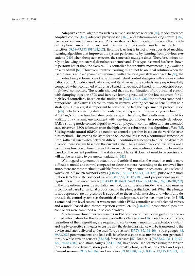
Sensors 2022, 22, 2244 21 of 39
Adaptive control algorithms such as active disturbance rejection [40], model referenceadaptive control [159], adaptive proxy-based [160], and extremum-seeking control [189]have also been used in more recent PAEs. An iterative learning algorithm is another practi-cal option since it does not require an accurate model in order tofunction [58,68–73,131,181,182,202]. Iterative learning is in fact an unsupervised machinelearning algorithm that improves the system performance by learning from previous exe-cutions [240] when the system executes the same task multiple times. Therefore, it does notrely on knowing the external disturbances beforehand. This type of control has been shownto perform better than the classical PID controller for repetitive movements, e.g., walkingon a treadmill [68]. However, iterative learning might not be an ideal solution when theuser interacts with a dynamic environment with a varying gait style and pace. In [68], thetorque-tracking performances of nine different hybrid control strategies with various combi-nations of PID, model-based, adaptive, and iterative learning controls were experimentallycompared when combined with phase-based, reflex-model-based, or myoelectric-basedhigh-level controllers. The results showed that the combination of proportional controlwith damping injection (PD) and iterative learning resulted in the lowest errors for allhigh-level controllers. Based on this finding, in [69,71–73,181,202] the authors combined aproportional–derivative (PD) control with an iterative learning scheme to benefit from bothstrategies. However, it is important to consider the fact the experimental protocol usedin [68] included collecting data from only one participant, during walking on a treadmillat 1.25 m/s for one hundred steady-state steps. Therefore, the results may not hold forwalking in a dynamic environment with varying gait modes. In a recently developedPAE, a sliding mode control algorithm was employed in combination with an extendedstate observer (ESO) to benefit from the high level of robustness this algorithm offers [53].Sliding mode control (SMC) is a nonlinear control algorithm based on the variable struc-ture method. This means the state-feedback control law is not a continuous function oftime, rather it can switch between different continuous functions to alter the dynamicsof a nonlinear system based on the current state. The state-feedback control law is not acontinuous function of time. Instead, it can switch from one continuous structure to anotherbased on the current position in the state space. Hence, it does not need to be precise andwill not be sensitive to parameter variations [241].
With regard to pneumatic actuators and artificial muscles, the actuation unit is moredifficult to model and control compared to electric motors. According to the reviewed liter-ature, there are three methods available for controlling pneumatic actuators using solenoidvalves: on–off switch solenoid valves [146,156,166,167,170,171,173–175], pulse width mod-ulation (PWM) of the solenoid valves [38,62,63,141,173,188], and proportional pressureregulators with solenoid valves [11,43,49,50,88–93,95–99,132–135,142,168,169,190–201,203].In the proportional pressure regulation method, the air pressure inside the artificial musclesis controlled based on a signal proportional to the plunger displacement. When the plungeris not depressed, no air pressure is supplied to the artificial muscles, and when fully de-pressed, the control system sets the artificial muscle pressure at the maximum level. In [175],a combined low-level controller was created with a PWM controller, on/off solenoid valves,and a model-based disturbance rejection controller. In [146,176], proportional positioncontrollers were combined with solenoid valves.
Machine–machine interface sensors in PAEs play a critical role in gathering the re-quired information for the low-level controllers (Tables 7 and 8). Feedback controllers,regardless of their algorithm, are required to continuously monitor the actuator’s outputand apply corrective strategies to ensure that the desired assistance will be transferred to thedevice, and later delivered to the user. Torque sensors [37,76–85,104–106], strain gauges [68,69,73,202], potentiometers, and load cells have been used to measure the actuator-generatedtorque, while tension sensors [53,182], force sensors [57], load cells [39,58,69,108–110,122–129,180,183,204], and strain gauges [72,113,181] have been used for measuring the tensionforce in the force transmission parts of the exoskeletons, such as the cables and ropes.Current sensors [39,85,161,162] and encoders [39,103,104,106,108,110–113,115,116,121,131,
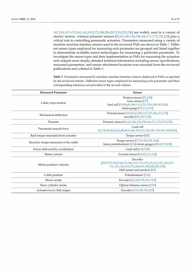
Sensors 2022, 22, 2244 22 of 39
141,143,147–151,161,162,165,172,188,206,207,210,235,236] are widely used in a variety ofelectric motors, whereas pressure sensors [62,63,146,156,158,166,171,173,176,232] play acritical role in controlling pneumatic actuators. Parameters measured using a variety ofmachine–machine interface sensors used in the reviewed PAEs are shown in Table 7. Differ-ent sensor types employed for measuring each parameter are grouped and listed togetherto demonstrate available sensor technologies for measuring a particular parameter. Toinvestigate the sensor types and their implementation in PAEs for measuring the actuationunit outputs more deeply, detailed technical information including sensor specifications,measured parameters, and sensor attachment locations was extracted from the reviewedpublications and collated in Table 8.
Table 7. Parameters measured by machine–machine interface sensors deployed in PAEs as reportedby the reviewed articles. Different sensor types employed for measuring each parameter and theircorresponding references are provided in the second column.
Measured Parameter Sensor
Cable/rope tension
Tension sensor [53,182]force sensor [57]
load cell [39,58,69,108–110,122–129,180,183,204]strain gauge [72,113,181]
Mechanical deflection Potentiometer [10,55,67,108,110,137,146,153,176]encoder [206,207,236]
Pressure Pressure sensor [62,63,146,156,158,166,171,173,176,232]
Pneumatic muscle force Load cell[11,38,49,50,62,63,88,89,91,96–99,131,134,190–194,196–200,203]
Real torque measured from actuator Torque sensor [85]
Reaction torque measured at the ankle Torque sensor [37,76–84,104–106]linear potentiometer [234] strain gauges [68,69,73,202]
Forces delivered by exoskeleton Load cell [138,139]
Motor current Current sensor [39,85,161,162]
Motor position/velocity
Encoder[39,55,57,59,67,68,72,108,110–113,115,116,121,141,143,147–
151,161,162,165,172,180,181,188,206,207,235]Hall sensor and resolver [85]
Cable position Potentiometer [126]
Motor stroke Encoder [42,100,178,185–187]
Slave cylinder stroke Optical distance sensor [158]
Actuator lever/link angles Encoder [103,104,106,210]
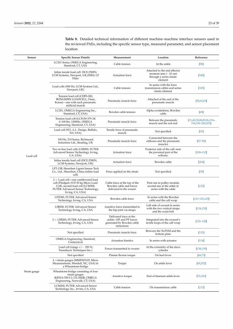
Sensors 2022, 22, 2244 23 of 39
Table 8. Detailed technical information of different machine–machine interface sensors used inthe reviewed PAEs, including the specific sensor type, measured parameter, and sensor placementlocation.
Sensor Specific Sensor Details Measurement Location Reference
Load cell
LC201 Series; OMEGA Engineering,Stamford, CT, USA Cable tension At the ankle [58]
Inline tensile load cell: DCE-2500N,LCM Systems, Newport, UK,250Hz LP
FilterActuation force
Attached to the end effectormoment arm (~ 10 cm)through a series elastic
element
[180]
Load cells (500 Hz, LCM Systems Ltd.,Newport, UK) Cable tension
In series with the forcetransmission cables and series
elastic element[183]
Tension load cell (CDFS-200,BONGSHIN LOADCELL, Osan,
Korea)—one with each pneumaticartificial muscle
Pneumatic muscle force Attached at the end of thepneumatic muscle [38,62,63]
LC201, OMEGA Engineering Inc.,Stamford, CT, USA) Bowden cable tension Alpha exoskeleton, Bowden
cable [69]
Tension load cell-(LC8150-375-1K0–100 lbs, 1200Hz, OMEGA
Engineering, Stamford, CT, USA)Pneumatic muscle force Between the pneumatic
muscle and the rod end[11,49,50,88,89,96,190–
194,196–200,203]
Load cell (W2, A.L. Design, Buffalo,NY, USA)
Tensile force of pneumaticmuscle Not specified [91]
100 Hz; 210 Series, RichmondIndustries Ltd., Reading, UK Pneumatic muscle force
Connected between theorthoses and the pneumatic
muscles[97–99]
Two in-line load cells (LSB200, FUTEKAdvanced Sensor Technology, Irving,
CA, USA)Actuation force
Posterior side of the calf, nearthe proximal part of the
orthosis.[108–110]
Inline tensile load cell (DCE-2500N,LCM Systems, Newport, UK) Actuation force Bowden cable [204]
LFT-13B, Shenzhen Ligent Sensor TechCo., Ltd., Shenzhen, China (inline load
cell)Force applied on the struts Not specified [39]
2 × Load cell—one cantilevered loadcell (Phidgets 3135 50 kg Micro Load
Cell), second load cell (LCM300,FUTEK Advanced Sensor Technology,
Irving, CA, USA)
Cable force at the top of theBowden cable and forcesdelivered to the wearer
First one in pulley module,second one at the ankle in
series with the cable[122]
LTH300, FUTEK Advanced SensorTechnology, Irving, CA, USA Bowden cable force In series with the Bowden
cable and the calf wrap [123–125,129]
LSB200, FUTEK Advanced SensorTechnology Irving, CA, USA
Assistive force transmitted tothe hip joint via straps
Left side of exosuit in serieswith the two vertical straps
and the waist belt[124,129]
2 × LSB200, FUTEK Advanced SensorTechnology, Irving, CA, USA
Delivered force at theankle—DF and PF forces
generated by Bowden cableretractions
Integrated into the exosuit’stextile loops of the calf wrap [126–128]
Not specified Pneumatic muscle force Between the NcPAM and thebottom plate [131]
OMEGA Engineering, Stamford,Connecticut Actuation kinetics In series with actuator [134]
Load cell (range +/− 220 N;Transducer Techniques Inc.) Forces transmitted to wearer At the extremity of the slave
cylinder [138,139]
Strain gauge
Not specified Plantar flexion torque On heel lever [68,73]
4 ×strain gauges (MMF003129, MicroMeasurements, Wendell, NC, USA) in
a Wheatstone-bridgeTorque On ankle lever [69,202]
Wheatstone bridge consisting of fourstrain gauges
(KFH-6-350-C1-11L1M2R, OMEGAEngineering, Norwalk, CT, USA)
Assistive torque End of titanium ankle lever [72,181]
LCM200, FUTEK Advanced SensorTechnology, Inc., Irvine, CA, USA Cable tension On transmission cable [113]
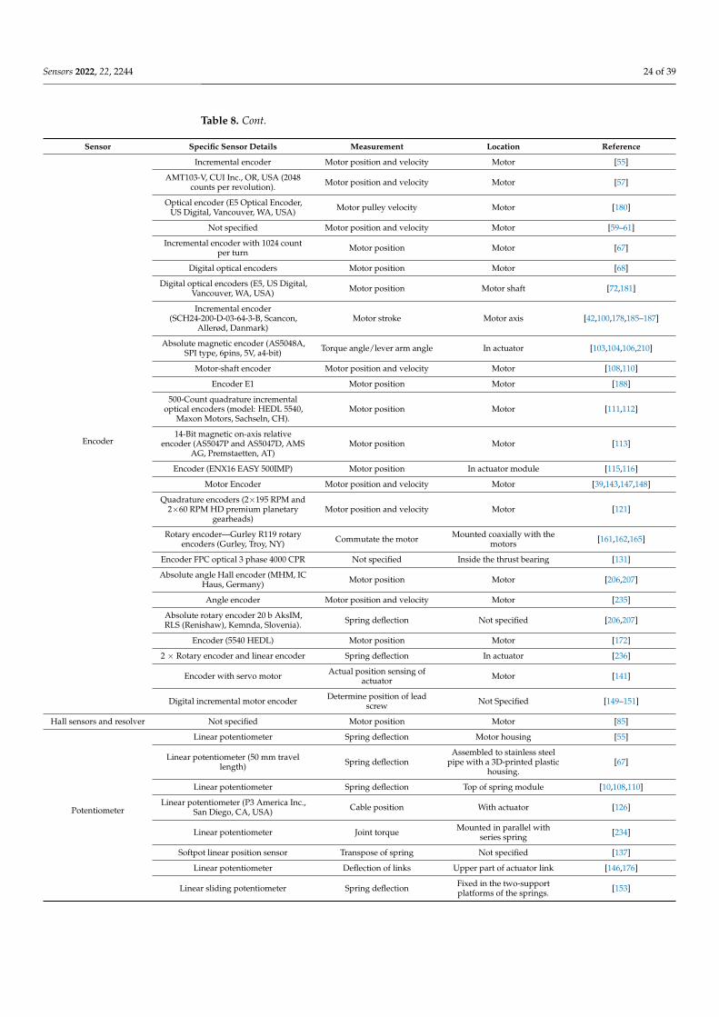
Sensors 2022, 22, 2244 24 of 39
Table 8. Cont.
Sensor Specific Sensor Details Measurement Location Reference
Encoder
Incremental encoder Motor position and velocity Motor [55]
AMT103-V, CUI Inc., OR, USA (2048counts per revolution). Motor position and velocity Motor [57]
Optical encoder (E5 Optical Encoder,US Digital, Vancouver, WA, USA) Motor pulley velocity Motor [180]
Not specified Motor position and velocity Motor [59–61]
Incremental encoder with 1024 countper turn Motor position Motor [67]
Digital optical encoders Motor position Motor [68]
Digital optical encoders (E5, US Digital,Vancouver, WA, USA) Motor position Motor shaft [72,181]
Incremental encoder(SCH24-200-D-03-64-3-B, Scancon,
Allerød, Danmark)Motor stroke Motor axis [42,100,178,185–187]
Absolute magnetic encoder (AS5048A,SPI type, 6pins, 5V, a4-bit) Torque angle/lever arm angle In actuator [103,104,106,210]
Motor-shaft encoder Motor position and velocity Motor [108,110]
Encoder E1 Motor position Motor [188]
500-Count quadrature incrementaloptical encoders (model: HEDL 5540,
Maxon Motors, Sachseln, CH).Motor position Motor [111,112]
14-Bit magnetic on-axis relativeencoder (AS5047P and AS5047D, AMS
AG, Premstaetten, AT)Motor position Motor [113]
Encoder (ENX16 EASY 500IMP) Motor position In actuator module [115,116]
Motor Encoder Motor position and velocity Motor [39,143,147,148]
Quadrature encoders (2×195 RPM and2×60 RPM HD premium planetary
gearheads)Motor position and velocity Motor [121]
Rotary encoder—Gurley R119 rotaryencoders (Gurley, Troy, NY) Commutate the motor Mounted coaxially with the
motors [161,162,165]
Encoder FPC optical 3 phase 4000 CPR Not specified Inside the thrust bearing [131]
Absolute angle Hall encoder (MHM, ICHaus, Germany) Motor position Motor [206,207]
Angle encoder Motor position and velocity Motor [235]
Absolute rotary encoder 20 b AksIM,RLS (Renishaw), Kemnda, Slovenia). Spring deflection Not specified [206,207]
Encoder (5540 HEDL) Motor position Motor [172]
2 × Rotary encoder and linear encoder Spring deflection In actuator [236]
Encoder with servo motor Actual position sensing ofactuator Motor [141]
Digital incremental motor encoder Determine position of leadscrew Not Specified [149–151]
Hall sensors and resolver Not specified Motor position Motor [85]
Potentiometer
Linear potentiometer Spring deflection Motor housing [55]
Linear potentiometer (50 mm travellength) Spring deflection
Assembled to stainless steelpipe with a 3D-printed plastic
housing.[67]
Linear potentiometer Spring deflection Top of spring module [10,108,110]
Linear potentiometer (P3 America Inc.,San Diego, CA, USA) Cable position With actuator [126]
Linear potentiometer Joint torque Mounted in parallel withseries spring [234]
Softpot linear position sensor Transpose of spring Not specified [137]
Linear potentiometer Deflection of links Upper part of actuator link [146,176]
Linear sliding potentiometer Spring deflection Fixed in the two-supportplatforms of the springs. [153]
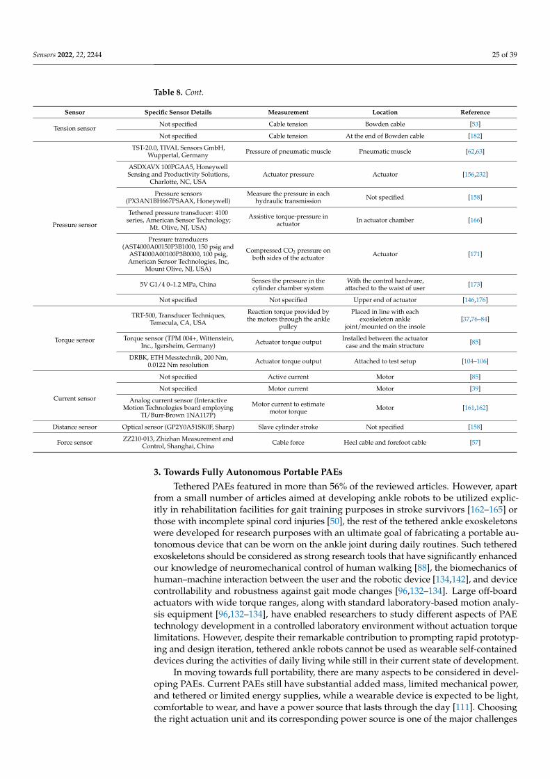
Sensors 2022, 22, 2244 25 of 39
Table 8. Cont.
Sensor Specific Sensor Details Measurement Location Reference
Tension sensorNot specified Cable tension Bowden cable [53]
Not specified Cable tension At the end of Bowden cable [182]
Pressure sensor
TST-20.0, TIVAL Sensors GmbH,Wuppertal, Germany Pressure of pneumatic muscle Pneumatic muscle [62,63]
ASDXAVX 100PGAA5, HoneywellSensing and Productivity Solutions,
Charlotte, NC, USAActuator pressure Actuator [156,232]
Pressure sensors(PX3AN1BH667PSAAX, Honeywell)
Measure the pressure in eachhydraulic transmission Not specified [158]
Tethered pressure transducer: 4100series, American Sensor Technology;
Mt. Olive, NJ, USA)
Assistive torque-pressure inactuator In actuator chamber [166]
Pressure transducers(AST4000A00150P3B1000, 150 psig and
AST4000A00100P3B0000, 100 psig,American Sensor Technologies, Inc,
Mount Olive, NJ, USA)
Compressed CO2 pressure onboth sides of the actuator Actuator [171]
5V G1/4 0–1.2 MPa, China Senses the pressure in thecylinder chamber system
With the control hardware,attached to the waist of user [173]
Not specified Not specified Upper end of actuator [146,176]
Torque sensor
TRT-500, Transducer Techniques,Temecula, CA, USA
Reaction torque provided bythe motors through the ankle
pulley
Placed in line with eachexoskeleton ankle
joint/mounted on the insole[37,76–84]
Torque sensor (TPM 004+, Wittenstein,Inc., Igersheim, Germany) Actuator torque output Installed between the actuator
case and the main structure [85]
DRBK, ETH Messtechnik, 200 Nm,0.0122 Nm resolution Actuator torque output Attached to test setup [104–106]
Current sensor
Not specified Active current Motor [85]
Not specified Motor current Motor [39]
Analog current sensor (InteractiveMotion Technologies board employing
TI/Burr-Brown 1NA117P)
Motor current to estimatemotor torque Motor [161,162]
Distance sensor Optical sensor (GP2Y0A51SK0F, Sharp) Slave cylinder stroke Not specified [158]
Force sensor ZZ210-013, Zhizhan Measurement andControl, Shanghai, China Cable force Heel cable and forefoot cable [57]
3. Towards Fully Autonomous Portable PAEs
Tethered PAEs featured in more than 56% of the reviewed articles. However, apartfrom a small number of articles aimed at developing ankle robots to be utilized explic-itly in rehabilitation facilities for gait training purposes in stroke survivors [162–165] orthose with incomplete spinal cord injuries [50], the rest of the tethered ankle exoskeletonswere developed for research purposes with an ultimate goal of fabricating a portable au-tonomous device that can be worn on the ankle joint during daily routines. Such tetheredexoskeletons should be considered as strong research tools that have significantly enhancedour knowledge of neuromechanical control of human walking [88], the biomechanics ofhuman–machine interaction between the user and the robotic device [134,142], and devicecontrollability and robustness against gait mode changes [96,132–134]. Large off-boardactuators with wide torque ranges, along with standard laboratory-based motion analy-sis equipment [96,132–134], have enabled researchers to study different aspects of PAEtechnology development in a controlled laboratory environment without actuation torquelimitations. However, despite their remarkable contribution to prompting rapid prototyp-ing and design iteration, tethered ankle robots cannot be used as wearable self-containeddevices during the activities of daily living while still in their current state of development.
In moving towards full portability, there are many aspects to be considered in devel-oping PAEs. Current PAEs still have substantial added mass, limited mechanical power,and tethered or limited energy supplies, while a wearable device is expected to be light,comfortable to wear, and have a power source that lasts through the day [111]. Choosingthe right actuation unit and its corresponding power source is one of the major challenges
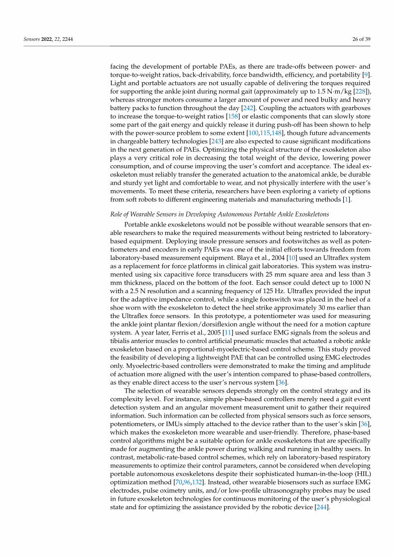
Sensors 2022, 22, 2244 26 of 39
facing the development of portable PAEs, as there are trade-offs between power- andtorque-to-weight ratios, back-drivability, force bandwidth, efficiency, and portability [9].Light and portable actuators are not usually capable of delivering the torques requiredfor supporting the ankle joint during normal gait (approximately up to 1.5 N·m/kg [228]),whereas stronger motors consume a larger amount of power and need bulky and heavybattery packs to function throughout the day [242]. Coupling the actuators with gearboxesto increase the torque-to-weight ratios [158] or elastic components that can slowly storesome part of the gait energy and quickly release it during push-off has been shown to helpwith the power-source problem to some extent [100,115,148], though future advancementsin chargeable battery technologies [243] are also expected to cause significant modificationsin the next generation of PAEs. Optimizing the physical structure of the exoskeleton alsoplays a very critical role in decreasing the total weight of the device, lowering powerconsumption, and of course improving the user’s comfort and acceptance. The ideal ex-oskeleton must reliably transfer the generated actuation to the anatomical ankle, be durableand sturdy yet light and comfortable to wear, and not physically interfere with the user’smovements. To meet these criteria, researchers have been exploring a variety of optionsfrom soft robots to different engineering materials and manufacturing methods [1].
Role of Wearable Sensors in Developing Autonomous Portable Ankle Exoskeletons
Portable ankle exoskeletons would not be possible without wearable sensors that en-able researchers to make the required measurements without being restricted to laboratory-based equipment. Deploying insole pressure sensors and footswitches as well as poten-tiometers and encoders in early PAEs was one of the initial efforts towards freedom fromlaboratory-based measurement equipment. Blaya et al., 2004 [10] used an Ultraflex systemas a replacement for force platforms in clinical gait laboratories. This system was instru-mented using six capacitive force transducers with 25 mm square area and less than 3mm thickness, placed on the bottom of the foot. Each sensor could detect up to 1000 Nwith a 2.5 N resolution and a scanning frequency of 125 Hz. Ultraflex provided the inputfor the adaptive impedance control, while a single footswitch was placed in the heel of ashoe worn with the exoskeleton to detect the heel strike approximately 30 ms earlier thanthe Ultraflex force sensors. In this prototype, a potentiometer was used for measuringthe ankle joint plantar flexion/dorsiflexion angle without the need for a motion capturesystem. A year later, Ferris et al., 2005 [11] used surface EMG signals from the soleus andtibialis anterior muscles to control artificial pneumatic muscles that actuated a robotic ankleexoskeleton based on a proportional-myoelectric-based control scheme. This study provedthe feasibility of developing a lightweight PAE that can be controlled using EMG electrodesonly. Myoelectric-based controllers were demonstrated to make the timing and amplitudeof actuation more aligned with the user’s intention compared to phase-based controllers,as they enable direct access to the user’s nervous system [36].
The selection of wearable sensors depends strongly on the control strategy and itscomplexity level. For instance, simple phase-based controllers merely need a gait eventdetection system and an angular movement measurement unit to gather their requiredinformation. Such information can be collected from physical sensors such as force sensors,potentiometers, or IMUs simply attached to the device rather than to the user’s skin [36],which makes the exoskeleton more wearable and user-friendly. Therefore, phase-basedcontrol algorithms might be a suitable option for ankle exoskeletons that are specificallymade for augmenting the ankle power during walking and running in healthy users. Incontrast, metabolic-rate-based control schemes, which rely on laboratory-based respiratorymeasurements to optimize their control parameters, cannot be considered when developingportable autonomous exoskeletons despite their sophisticated human-in-the-loop (HIL)optimization method [70,96,132]. Instead, other wearable biosensors such as surface EMGelectrodes, pulse oximetry units, and/or low-profile ultrasonography probes may be usedin future exoskeleton technologies for continuous monitoring of the user’s physiologicalstate and for optimizing the assistance provided by the robotic device [244].
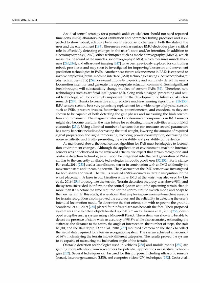
Sensors 2022, 22, 2244 27 of 39
An ideal control strategy for a portable ankle exoskeleton should not need repeatedtime-consuming laboratory-based calibration and parameter tuning processes and is ex-pected to show robust, adaptive behavior in response to changes in both the state of theuser and the environment [183]. Biosensors such as surface EMG electrodes play a criticalrole in effectively detecting changes in the user’s state and/or intention. In addition toelectromyography (EMG), other techniques such as mechanomyography (MMG), whichmeasures the sound of the muscles, sonomyography (SMG), which measures muscle thick-ness [245,246], and ultrasound imaging [247] have been previously explored for controllingrobotic prostheses and may soon be investigated for improving biosensors and movementprediction technologies in PAEs. Another near-future advancement in PAEs is expected toinvolve employing brain–machine interface (BMI) technologies using electroencephalogra-phy techniques (EEG) [248] or neural implants to quickly and accurately detect the user’slocomotion intention and generate the appropriate actuation command. Such significantbreakthroughs will substantially change the face of current PAEs [52]. Therefore, newtechnologies such as artificial intelligence (AI), along with biosignal processing and neu-ral technology, will be extremely important for the development of future exoskeletonresearch [249]. Thanks to corrective and predictive machine learning algorithms [216,250],IMU sensors seem to be a very promising replacement for a wide range of physical sensorssuch as FSRs, pressure insoles, footswitches, potentiometers, and encoders, as they areshown to be capable of both detecting the gait phases and measuring the limb orienta-tion and movement. The magnetometer and accelerometer components in IMU sensorsmight also become useful in the near future for evaluating muscle activities without EMGelectrodes [251]. Using a limited number of sensors that can measure several parametershas many benefits including decreasing the total weight, lowering the amount of requiredsignal preparation and signal processing, reducing power consumption, decreasing thenoise sensitivity, and finally promoting the wearability and portability of the device.
As mentioned above, the ideal control algorithm for PAE must be adaptive to locomo-tion environment changes. Although the application of environment–machine interfacesensors was not observed in the reviewed articles, we expect that terrain recognition andobstacle detection technologies will soon be integrated into the next generation of PAEs,similar to the currently available technologies in robotic prostheses [52,252]. For instance,Fan et al., 2011 [253] used a laser distance sensor in combination with an IMU to identify themovement state and upcoming terrain. The placement of the IMU sensor was investigatedfor both shank and waist. The results revealed a 98% accuracy in terrain recognition for thewaist placement. A laser in combination with an IMU at the waist was also used by Liuet al., 2016 [254] to recognize the terrain. Terrain detection accuracy was above 98%, andthe system succeeded in informing the control system about the upcoming terrain changemore than 0.5 s before the time required for the control unit to switch mode and adapt tothe new terrain. In this study, it was shown that employing environment–machine sensorsfor terrain recognition also improved the accuracy and the reliability in detecting the user’sintended locomotion mode. To determine the foot orientation with respect to the ground,Scandaroli et al., 2009 [255] placed four infrared sensors beneath the foot. Their proposedsystem was able to detect objects located up to 0.3 m away. Krausz et al., 2015 [256] devel-oped a depth-sensing system using a Microsoft Kinect. The system was shown to be able todetect the presence of stairs with an accuracy of 98.8% while also accurately estimating thestaircase, the distance to the stairs, the angle of intersection, the number of steps, the stairheight, and the stair depth. Diaz et al., 2018 [257] mounted a camera on the shank to collectthe visual data required for a terrain recognition system. The system achieved an accuracyof 86% in classifying the terrain into six different categories. The results proved the systemto be capable of measuring the inclination angle of the terrain.
Obstacle detection technologies used in vehicles [258] and mobile robots [259] aregaining more attention from researchers for potential applications in assistive technolo-gies [252]. Several techniques can be used for this purpose, including ultrasonic sensors(sonar), laser range scanners (LRS), and computer vision (CV) techniques [252]. Costa et al.,
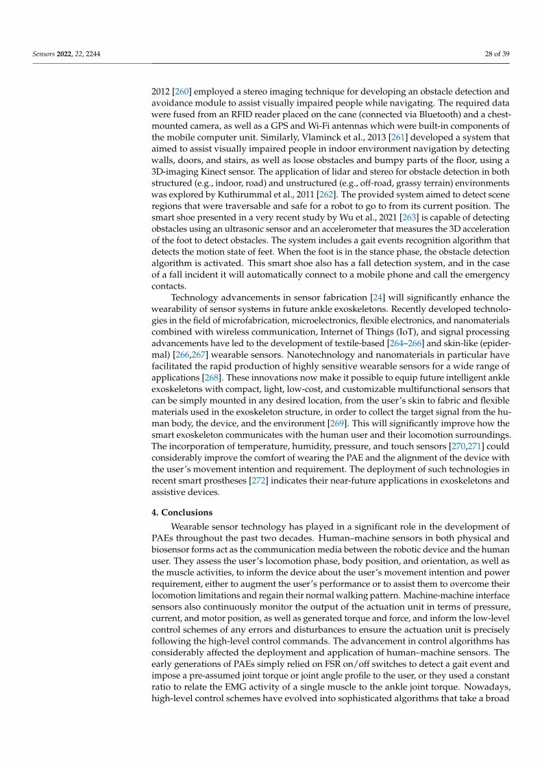
Sensors 2022, 22, 2244 28 of 39
2012 [260] employed a stereo imaging technique for developing an obstacle detection andavoidance module to assist visually impaired people while navigating. The required datawere fused from an RFID reader placed on the cane (connected via Bluetooth) and a chest-mounted camera, as well as a GPS and Wi-Fi antennas which were built-in components ofthe mobile computer unit. Similarly, Vlaminck et al., 2013 [261] developed a system thataimed to assist visually impaired people in indoor environment navigation by detectingwalls, doors, and stairs, as well as loose obstacles and bumpy parts of the floor, using a3D-imaging Kinect sensor. The application of lidar and stereo for obstacle detection in bothstructured (e.g., indoor, road) and unstructured (e.g., off-road, grassy terrain) environmentswas explored by Kuthirummal et al., 2011 [262]. The provided system aimed to detect sceneregions that were traversable and safe for a robot to go to from its current position. Thesmart shoe presented in a very recent study by Wu et al., 2021 [263] is capable of detectingobstacles using an ultrasonic sensor and an accelerometer that measures the 3D accelerationof the foot to detect obstacles. The system includes a gait events recognition algorithm thatdetects the motion state of feet. When the foot is in the stance phase, the obstacle detectionalgorithm is activated. This smart shoe also has a fall detection system, and in the caseof a fall incident it will automatically connect to a mobile phone and call the emergencycontacts.
Technology advancements in sensor fabrication [24] will significantly enhance thewearability of sensor systems in future ankle exoskeletons. Recently developed technolo-gies in the field of microfabrication, microelectronics, flexible electronics, and nanomaterialscombined with wireless communication, Internet of Things (IoT), and signal processingadvancements have led to the development of textile-based [264–266] and skin-like (epider-mal) [266,267] wearable sensors. Nanotechnology and nanomaterials in particular havefacilitated the rapid production of highly sensitive wearable sensors for a wide range ofapplications [268]. These innovations now make it possible to equip future intelligent ankleexoskeletons with compact, light, low-cost, and customizable multifunctional sensors thatcan be simply mounted in any desired location, from the user’s skin to fabric and flexiblematerials used in the exoskeleton structure, in order to collect the target signal from the hu-man body, the device, and the environment [269]. This will significantly improve how thesmart exoskeleton communicates with the human user and their locomotion surroundings.The incorporation of temperature, humidity, pressure, and touch sensors [270,271] couldconsiderably improve the comfort of wearing the PAE and the alignment of the device withthe user’s movement intention and requirement. The deployment of such technologies inrecent smart prostheses [272] indicates their near-future applications in exoskeletons andassistive devices.
4. Conclusions
Wearable sensor technology has played in a significant role in the development ofPAEs throughout the past two decades. Human–machine sensors in both physical andbiosensor forms act as the communication media between the robotic device and the humanuser. They assess the user’s locomotion phase, body position, and orientation, as well asthe muscle activities, to inform the device about the user’s movement intention and powerrequirement, either to augment the user’s performance or to assist them to overcome theirlocomotion limitations and regain their normal walking pattern. Machine-machine interfacesensors also continuously monitor the output of the actuation unit in terms of pressure,current, and motor position, as well as generated torque and force, and inform the low-levelcontrol schemes of any errors and disturbances to ensure the actuation unit is preciselyfollowing the high-level control commands. The advancement in control algorithms hasconsiderably affected the deployment and application of human–machine sensors. Theearly generations of PAEs simply relied on FSR on/off switches to detect a gait event andimpose a pre-assumed joint torque or joint angle profile to the user, or they used a constantratio to relate the EMG activity of a single muscle to the ankle joint torque. Nowadays,high-level control schemes have evolved into sophisticated algorithms that take a broad
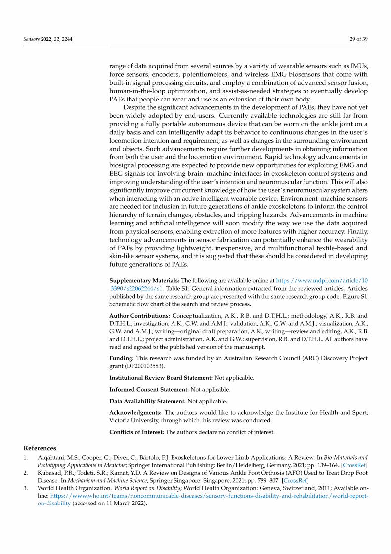
Sensors 2022, 22, 2244 29 of 39
range of data acquired from several sources by a variety of wearable sensors such as IMUs,force sensors, encoders, potentiometers, and wireless EMG biosensors that come withbuilt-in signal processing circuits, and employ a combination of advanced sensor fusion,human-in-the-loop optimization, and assist-as-needed strategies to eventually developPAEs that people can wear and use as an extension of their own body.
Despite the significant advancements in the development of PAEs, they have not yetbeen widely adopted by end users. Currently available technologies are still far fromproviding a fully portable autonomous device that can be worn on the ankle joint on adaily basis and can intelligently adapt its behavior to continuous changes in the user’slocomotion intention and requirement, as well as changes in the surrounding environmentand objects. Such advancements require further developments in obtaining informationfrom both the user and the locomotion environment. Rapid technology advancements inbiosignal processing are expected to provide new opportunities for exploiting EMG andEEG signals for involving brain–machine interfaces in exoskeleton control systems andimproving understanding of the user’s intention and neuromuscular function. This will alsosignificantly improve our current knowledge of how the user’s neuromuscular system alterswhen interacting with an active intelligent wearable device. Environment–machine sensorsare needed for inclusion in future generations of ankle exoskeletons to inform the controlhierarchy of terrain changes, obstacles, and tripping hazards. Advancements in machinelearning and artificial intelligence will soon modify the way we use the data acquiredfrom physical sensors, enabling extraction of more features with higher accuracy. Finally,technology advancements in sensor fabrication can potentially enhance the wearabilityof PAEs by providing lightweight, inexpensive, and multifunctional textile-based andskin-like sensor systems, and it is suggested that these should be considered in developingfuture generations of PAEs.
Supplementary Materials: The following are available online at https://www.mdpi.com/article/10.3390/s22062244/s1. Table S1: General information extracted from the reviewed articles. Articlespublished by the same research group are presented with the same research group code. Figure S1.Schematic flow chart of the search and review process.
Author Contributions: Conceptualization, A.K., R.B. and D.T.H.L.; methodology, A.K., R.B. andD.T.H.L.; investigation, A.K., G.W. and A.M.J.; validation, A.K., G.W. and A.M.J.; visualization, A.K.,G.W. and A.M.J.; writing—original draft preparation, A.K.; writing—review and editing, A.K., R.B.and D.T.H.L.; project administration, A.K. and G.W.; supervision, R.B. and D.T.H.L. All authors haveread and agreed to the published version of the manuscript.
Funding: This research was funded by an Australian Research Council (ARC) Discovery Projectgrant (DP200103583).
Institutional Review Board Statement: Not applicable.
Informed Consent Statement: Not applicable.
Data Availability Statement: Not applicable.
Acknowledgments: The authors would like to acknowledge the Institute for Health and Sport,Victoria University, through which this review was conducted.
Conflicts of Interest: The authors declare no conflict of interest.
References1. Alqahtani, M.S.; Cooper, G.; Diver, C.; Bártolo, P.J. Exoskeletons for Lower Limb Applications: A Review. In Bio-Materials and
Prototyping Applications in Medicine; Springer International Publishing: Berlin/Heidelberg, Germany, 2021; pp. 139–164. [CrossRef]2. Kubasad, P.R.; Todeti, S.R.; Kamat, Y.D. A Review on Designs of Various Ankle Foot Orthosis (AFO) Used to Treat Drop Foot
Disease. In Mechanism and Machine Science; Springer Singapore: Singapore, 2021; pp. 789–807. [CrossRef]3. World Health Organization. World Report on Disability; World Health Organization: Geneva, Switzerland, 2011; Available on-
line: https://www.who.int/teams/noncommunicable-diseases/sensory-functions-disability-and-rehabilitation/world-report-on-disability (accessed on 11 March 2022).
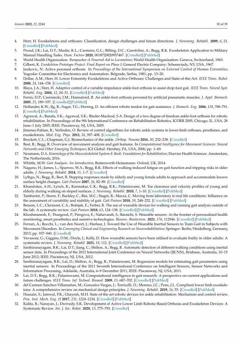
Sensors 2022, 22, 2244 30 of 39
4. Herr, H. Exoskeletons and orthoses: Classification, design challenges and future directions. J. Neuroeng. Rehabil. 2009, 6, 21.[CrossRef] [PubMed]
5. Proud, J.K.; Lai, D.T.; Mudie, K.L.; Carstairs, G.L.; Billing, D.C.; Garofolini, A.; Begg, R.K. Exoskeleton Application to MilitaryManual Handling Tasks. Hum. Factors 2020, 0018720820957467. [CrossRef] [PubMed]
6. World Health Organization. Bumpusher-A Powered Aid to Locomotion; World Health Organization: Geneva, Switzerland, 1963.7. Gilbert, K. Exoskeleton Prototype Project: Final Report on Phase I; General Electric Company: Schenectady, NY, USA, 1967.8. Jaukovic, N. Active peroneal orthosis. In Proceedings of the International Symposium on External Control of Human Extremities;
Yugoslav Committee for Electronics and Automation: Belgrade, Serbia, 1981; pp. 13–20.9. Dollar, A.M.; Herr, H. Lower Extremity Exoskeletons and Active Orthoses: Challenges and State-of-the-Art. IEEE Trans. Robot.
2008, 24, 144–158. [CrossRef]10. Blaya, J.A.; Herr, H. Adaptive control of a variable-impedance ankle-foot orthosis to assist drop-foot gait. IEEE Trans. Neural Syst.
Rehabil. Eng. 2004, 12, 24–31. [CrossRef] [PubMed]11. Ferris, D.P.; Czerniecki, J.M.; Hannaford, B. An ankle-foot orthosis powered by artificial pneumatic muscles. J. Appl. Biomech.
2005, 21, 189–197. [CrossRef] [PubMed]12. Hollander, K.W.; Ilg, R.; Sugar, T.G.; Herring, D. An efficient robotic tendon for gait assistance. J. Biomech. Eng. 2006, 128, 788–791.
[CrossRef] [PubMed]13. Agrawal, A.; Banala, S.K.; Agrawal, S.K.; Binder-Macleod, S.A. Design of a two degree-of-freedom ankle-foot orthosis for robotic
rehabilitation. In Proceedings of the 9th International Conference on Rehabilitation Robotics, ICORR 2005, Chicago, IL, USA, 28June–1 July 2005; IEEE: Piscataway, NJ, USA, 2005.
14. Jimenez-Fabian, R.; Verlinden, O. Review of control algorithms for robotic ankle systems in lower-limb orthoses, prostheses, andexoskeletons. Med. Eng. Phys. 2012, 34, 397–408. [CrossRef]
15. Brockett, C.L.; Chapman, G.J. Biomechanics of the ankle. Orthop. Trauma 2016, 30, 232–238. [CrossRef]16. Best, R.; Begg, R. Overview of movement analysis and gait features. In Computational Intelligence for Movement Sciences: Neural
Networks and Other Emerging Techniques; IGI Global: Hershey, PA, USA, 2006; pp. 1–69.17. Neumann, D.A. Kinesiology of the Musculoskeletal System-E-Book: Foundations for Rehabilitation; Elsevier Health Sciences: Amsterdam,
The Netherlands, 2016.18. Whittle, M.W. Gait Analysis: An Introduction; Butterworth-Heinemann: Oxford, UK, 2014.19. Nagano, H.; James, L.; Sparrow, W.A.; Begg, R.K. Effects of walking-induced fatigue on gait function and tripping risks in older
adults. J. Neuroeng. Rehabil. 2014, 11, 1–7. [CrossRef]20. Lythgo, N.; Begg, R.; Best, R. Stepping responses made by elderly and young female adults to approach and accommodate known
surface height changes. Gait Posture 2007, 26, 82–89. [CrossRef]21. Khandoker, A.H.; Lynch, K.; Karmakar, C.K.; Begg, R.K.; Palaniswami, M. Toe clearance and velocity profiles of young and
elderly during walking on sloped surfaces. J. Neuroeng. Rehabil. 2010, 7, 1–10. [CrossRef] [PubMed]22. Tamburini, P.; Storm, F.; Buckley, C.; Bisi, M.C.; Stagni, R.; Mazzà, C. Moving from laboratory to real life conditions: Influence on
the assessment of variability and stability of gait. Gait Posture 2018, 59, 248–252. [CrossRef] [PubMed]23. Benson, L.C.; Clermont, C.A.; Bošnjak, E.; Ferber, R. The use of wearable devices for walking and running gait analysis outside of
the lab: A systematic review. Gait Posture 2018, 63, 124–138. [CrossRef] [PubMed]24. Khoshmanesh, F.; Thurgood, P.; Pirogova, E.; Nahavandi, S.; Baratchi, S. Wearable sensors: At the frontier of personalised health
monitoring, smart prosthetics and assistive technologies. Biosens. Bioelectron. 2021, 176, 112946. [CrossRef] [PubMed]25. Ferrari, A.; Rocchi, L.; van den Noort, J.; Harlaar, J. Toward the Use of Wearable Inertial Sensors to Train Gait in Subjects with
Movement Disorders. In Converging Clinical and Engineering Research on Neurorehabilitation; Springer: Berlin/Heidelberg, Germany,2013; pp. 937–940. [CrossRef]
26. Vavasour, G.; Giggins, O.M.; Doyle, J.; Kelly, D. How wearable sensors have been utilised to evaluate frailty in older adults: Asystematic review. J. Neuroeng. Rehabil. 2021, 18, 112. [CrossRef] [PubMed]
27. Santhiranayagam, B.K.; Lai, D.T.; Jiang, C.; Shilton, A.; Begg, R. Automatic detection of different walking conditions using inertialsensor data. In Proceedings of the 2012 International Joint Conference on Neural Networks (IJCNN), Brisbane, Australia, 10–15June 2012; IEEE: Piscataway, NJ, USA, 2012.
28. Santhiranayagam, B.K.; Lai, D.; Shilton, A.; Begg, R.; Palaniswami, M. Regression models for estimating gait parameters usinginertial sensors. In Proceedings of the 2011 Seventh International Conference on Intelligent Sensors, Sensor Networks andInformation Processing, Adelaide, Australia, 6–9 December 2011; IEEE: Piscataway, NJ, USA, 2011.
29. Lai, D.T.; Begg, R.K.; Palaniswami, M. Computational intelligence in gait research: A perspective on current applications andfuture challenges. IEEE Trans. Inf. Technol. Biomed. 2009, 13, 687–702. [CrossRef] [PubMed]
30. del Carmen Sanchez-Villamañan, M.; Gonzalez-Vargas, J.; Torricelli, D.; Moreno, J.C.; Pons, J.L. Compliant lower limb exoskele-tons: A comprehensive review on mechanical design principles. J. Neuroeng. Rehabil. 2019, 16, 55. [CrossRef] [PubMed]
31. Hussain, S.; Jamwal, P.K.; Ghayesh, M.H. State-of-the-art robotic devices for ankle rehabilitation: Mechanism and control review.Proc. Inst. Mech. Eng. H 2017, 231, 1224–1234. [CrossRef] [PubMed]
32. Kalita, B.; Narayan, J.; Dwivedy, S.K. Development of Active Lower Limb Robotic-Based Orthosis and Exoskeleton Devices: ASystematic Review. Int. J. Soc. Robot. 2020, 13, 775–793. [CrossRef]
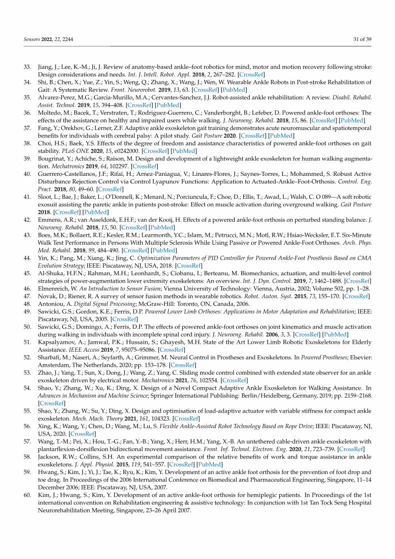
Sensors 2022, 22, 2244 31 of 39
33. Jiang, J.; Lee, K.-M.; Ji, J. Review of anatomy-based ankle–foot robotics for mind, motor and motion recovery following stroke:Design considerations and needs. Int. J. Intell. Robot. Appl. 2018, 2, 267–282. [CrossRef]
34. Shi, B.; Chen, X.; Yue, Z.; Yin, S.; Weng, Q.; Zhang, X.; Wang, J.; Wen, W. Wearable Ankle Robots in Post-stroke Rehabilitation ofGait: A Systematic Review. Front. Neurorobot. 2019, 13, 63. [CrossRef] [PubMed]
35. Alvarez-Perez, M.G.; Garcia-Murillo, M.A.; Cervantes-Sanchez, J.J. Robot-assisted ankle rehabilitation: A review. Disabil. Rehabil.Assist. Technol. 2019, 15, 394–408. [CrossRef] [PubMed]
36. Moltedo, M.; Bacek, T.; Verstraten, T.; Rodriguez-Guerrero, C.; Vanderborght, B.; Lefeber, D. Powered ankle-foot orthoses: Theeffects of the assistance on healthy and impaired users while walking. J. Neuroeng. Rehabil. 2018, 15, 86. [CrossRef] [PubMed]
37. Fang, Y.; Orekhov, G.; Lerner, Z.F. Adaptive ankle exoskeleton gait training demonstrates acute neuromuscular and spatiotemporalbenefits for individuals with cerebral palsy: A pilot study. Gait Posture 2020. [CrossRef] [PubMed]
38. Choi, H.S.; Baek, Y.S. Effects of the degree of freedom and assistance characteristics of powered ankle-foot orthoses on gaitstability. PLoS ONE 2020, 15, e0242000. [CrossRef] [PubMed]
39. Bougrinat, Y.; Achiche, S.; Raison, M. Design and development of a lightweight ankle exoskeleton for human walking augmenta-tion. Mechatronics 2019, 64, 102297. [CrossRef]
40. Guerrero-Castellanos, J.F.; Rifaï, H.; Arnez-Paniagua, V.; Linares-Flores, J.; Saynes-Torres, L.; Mohammed, S. Robust ActiveDisturbance Rejection Control via Control Lyapunov Functions: Application to Actuated-Ankle–Foot-Orthosis. Control. Eng.Pract. 2018, 80, 49–60. [CrossRef]
41. Sloot, L.; Bae, J.; Baker, L.; O’Donnell, K.; Menard, N.; Porciuncula, F.; Choe, D.; Ellis, T.; Awad, L.; Walsh, C. O 089—A soft roboticexosuit assisting the paretic ankle in patients post-stroke: Effect on muscle activation during overground walking. Gait Posture2018. [CrossRef] [PubMed]
42. Emmens, A.R.; van Asseldonk, E.H.F.; van der Kooij, H. Effects of a powered ankle-foot orthosis on perturbed standing balance. J.Neuroeng. Rehabil. 2018, 15, 50. [CrossRef] [PubMed]
43. Boes, M.K.; Bollaert, R.E.; Kesler, R.M.; Learmonth, Y.C.; Islam, M.; Petrucci, M.N.; Motl, R.W.; Hsiao-Wecksler, E.T. Six-MinuteWalk Test Performance in Persons With Multiple Sclerosis While Using Passive or Powered Ankle-Foot Orthoses. Arch. Phys.Med. Rehabil. 2018, 99, 484–490. [CrossRef] [PubMed]
44. Yin, K.; Pang, M.; Xiang, K.; Jing, C. Optimization Parameters of PID Controller for Powered Ankle-Foot Prosthesis Based on CMAEvolution Strategy; IEEE: Piscataway, NJ, USA, 2018. [CrossRef]
45. Al-Shuka, H.F.N.; Rahman, M.H.; Leonhardt, S.; Ciobanu, I.; Berteanu, M. Biomechanics, actuation, and multi-level controlstrategies of power-augmentation lower extremity exoskeletons: An overview. Int. J. Dyn. Control. 2019, 7, 1462–1488. [CrossRef]
46. Elmenreich, W. An Introduction to Sensor Fusion; Vienna University of Technology: Vienna, Austria, 2002; Volume 502, pp. 1–28.47. Novak, D.; Riener, R. A survey of sensor fusion methods in wearable robotics. Robot. Auton. Syst. 2015, 73, 155–170. [CrossRef]48. Antoniou, A. Digital Signal Processing; McGraw-Hill: Toronto, ON, Canada, 2006.49. Sawicki, G.S.; Gordon, K.E.; Ferris, D.P. Powered Lower Limb Orthoses: Applications in Motor Adaptation and Rehabilitation; IEEE:
Piscataway, NJ, USA, 2005. [CrossRef]50. Sawicki, G.S.; Domingo, A.; Ferris, D.P. The effects of powered ankle-foot orthoses on joint kinematics and muscle activation
during walking in individuals with incomplete spinal cord injury. J. Neuroeng. Rehabil. 2006, 3, 3. [CrossRef] [PubMed]51. Kapsalyamov, A.; Jamwal, P.K.; Hussain, S.; Ghayesh, M.H. State of the Art Lower Limb Robotic Exoskeletons for Elderly
Assistance. IEEE Access 2019, 7, 95075–95086. [CrossRef]52. Sharbafi, M.; Naseri, A.; Seyfarth, A.; Grimmer, M. Neural Control in Prostheses and Exoskeletons. In Powered Prostheses; Elsevier:
Amsterdam, The Netherlands, 2020; pp. 153–178. [CrossRef]53. Zhao, J.; Yang, T.; Sun, X.; Dong, J.; Wang, Z.; Yang, C. Sliding mode control combined with extended state observer for an ankle
exoskeleton driven by electrical motor. Mechatronics 2021, 76, 102554. [CrossRef]54. Shao, Y.; Zhang, W.; Xu, K.; Ding, X. Design of a Novel Compact Adaptive Ankle Exoskeleton for Walking Assistance. In
Advances in Mechanism and Machine Science; Springer International Publishing: Berlin/Heidelberg, Germany, 2019; pp. 2159–2168.[CrossRef]
55. Shao, Y.; Zhang, W.; Su, Y.; Ding, X. Design and optimisation of load-adaptive actuator with variable stiffness for compact ankleexoskeleton. Mech. Mach. Theory 2021, 161, 104323. [CrossRef]
56. Xing, K.; Wang, Y.; Chen, D.; Wang, M.; Lu, S. Flexible Ankle-Assisted Robot Technology Based on Rope Drive; IEEE: Piscataway, NJ,USA, 2020. [CrossRef]
57. Wang, T.-M.; Pei, X.; Hou, T.-G.; Fan, Y.-B.; Yang, X.; Herr, H.M.; Yang, X.-B. An untethered cable-driven ankle exoskeleton withplantarflexion-dorsiflexion bidirectional movement assistance. Front. Inf. Technol. Electron. Eng. 2020, 21, 723–739. [CrossRef]
58. Jackson, R.W.; Collins, S.H. An experimental comparison of the relative benefits of work and torque assistance in ankleexoskeletons. J. Appl. Physiol. 2015, 119, 541–557. [CrossRef] [PubMed]
59. Hwang, S.; Kim, J.; Yi, J.; Tae, K.; Ryu, K.; Kim, Y. Development of an active ankle foot orthosis for the prevention of foot drop andtoe drag. In Proceedings of the 2006 International Conference on Biomedical and Pharmaceutical Engineering, Singapore, 11–14December 2006; IEEE: Piscataway, NJ, USA, 2007.
60. Kim, J.; Hwang, S.; Kim, Y. Development of an active ankle-foot orthosis for hemiplegic patients. In Proceedings of the 1stinternational convention on Rehabilitation engineering & assistive technology: In conjunction with 1st Tan Tock Seng HospitalNeurorehabilitation Meeting, Singapore, 23–26 April 2007.
Sensors 2022, 22, 2244 32 of 39
61. Kim, J.; Hwang, S.; Sohn, R.; Lee, Y.; Kim, Y. Development of an active ankle foot orthosis to prevent foot drop and toe drag inhemiplegic patients: A preliminary study. Appl. Bionics Biomech. 2011, 8, 377–384. [CrossRef]
62. Choi, H.S.; Lee, C.H.; Baek, Y.S. Design and Validation of a Two-Degree-of-Freedom Powered Ankle-Foot Orthosis with TwoPneumatic Artificial Muscles. Mechatronics 2020, 72, 102469. [CrossRef]
63. Choi, H.S.; Lee, C.H.; Baek, Y.S. Design of a Pneumatic Actuated Ankle-Foot Orthosis which Has Talocrural and Subtalar Joint; IEEE:Piscataway, NJ, USA, 2019. [CrossRef]
64. Lee, T.; Kim, I.; Baek, Y.S. Design of a 2DoF Ankle Exoskeleton with a Polycentric Structure and a Bi-Directional Tendon-DrivenActuator Controlled Using a PID Neural Network. Actuators 2021, 10, 9. [CrossRef]
65. Choi, H.; Park, Y.J.; Seo, K.; Lee, J.; Lee, S.-E.; Shim, Y. A Multifunctional Ankle Exoskeleton for Mobility Enhancement ofGait-Impaired Individuals and Seniors. IEEE Robot. Autom. Lett. 2018, 3, 411–418. [CrossRef]
66. Seo, K.; Park, Y.J.; Lee, J.; Hyung, S.; Lee, M.; Kim, J.; Choi, H.; Shim, Y. RNN-Based on-Line Continuous Gait Phase Estimation fromShank-Mounted IMUs to Control Ankle Exoskeletons; IEEE: Piscataway, NJ, USA, 2019. [CrossRef]
67. Kirtas, O.; Savas, Y.; Bayraker, M.; Baskaya, F.; Basturk, H.; Samur, E. Design, implementation, and evaluation of a backsteppingcontrol algorithm for an active ankle–foot orthosis. Control. Eng. Pract. 2021, 106, 104667. [CrossRef]
68. Zhang, J.; Cheah, C.C.; Collins, S.H. Experimental Comparison of Torque Control Methods on an Ankle Exoskeleton during HumanWalking; IEEE: Piscataway, NJ, USA, 2015. [CrossRef]
69. Witte, K.A.; Zhang, J.; Jackson, R.W.; Collins, S.H. Design of two lightweight, high-bandwidth torque-controlled ankle exoskele-tons. In Proceedings of the 2015 IEEE International Conference on Robotics and Automation (ICRA), Seattle, WA, USA, 26–30May 2015; IEEE: Piscataway, NJ, USA.
70. Zhang, J.; Fiers, P.; Witte, K.A.; Jackson, R.W.; Poggensee, K.L.; Atkeson, C.G.; Collins, S.H. Human-in-the-loop optimization ofexoskeleton assistance during walking. Science 2017, 356, 1280–1284. [CrossRef] [PubMed]
71. Steele, K.M.; Jackson, R.W.; Shuman, B.R.; Collins, S.H. Muscle recruitment and coordination with an ankle exoskeleton. J.Biomech. 2017, 59, 50–58. [CrossRef] [PubMed]
72. Wang, W.; Chen, J.; Ji, Y.; Jin, W.; Liu, J.; Zhang, J. Evaluation of Lower Leg Muscle Activities During Human Walking Assisted byan Ankle Exoskeleton. IEEE Trans. Ind. Inform. 2020, 16, 7168–7176. [CrossRef]
73. Witte, K.A.; Fiers, P.; Sheets-Singer, A.L.; Collins, S.H. Improving the energy economy of human running with powered andunpowered ankle exoskeleton assistance. Sci. Robot. 2020, 5, eaay9108. [CrossRef] [PubMed]
74. Manchola, M.; Serrano, D.; Gómez, D.; Ballen, F.; Casas, D.; Munera, M.; Cifuentes, C.A. T-FLEX: Variable stiffness ankle-footorthosis for gait assistance. In International Symposium on Wearable Robotics; Springer: Berlin/Heidelberg, Germany, 2018.
75. Gomez-Vargas, D.; Ballen-Moreno, F.; Barria, P.; Aguilar, R.; Azorin, J.M.; Munera, M.; Cifuentes, C.A. The Actuation Systemof the Ankle Exoskeleton T-FLEX: First Use Experimental Validation in People with Stroke. Brain Sci. 2021, 11, 412. [CrossRef][PubMed]
76. Lerner, Z.F.; Gasparri, G.M.; Bair, M.O.; Lawson, J.L.; Luque, J.; Harvey, T.A.; Lerner, A.T. An Untethered Ankle ExoskeletonImproves Walking Economy in a Pilot Study of Individuals with Cerebral Palsy. IEEE Trans. Neural Syst. Rehabil. Eng. 2018, 26,1985–1993. [CrossRef] [PubMed]
77. Gasparri, G.M.; Bair, M.O.; Libby, R.P.; Lerner, Z.F. Verification of a Robotic Ankle Exoskeleton Control Scheme for Gait Assistance inIndividuals with Cerebral Palsy; IEEE: Piscataway, NJ, USA, 2018. [CrossRef]
78. Lerner, Z.F.; Harvey, T.A.; Lawson, J.L. A Battery-Powered Ankle Exoskeleton Improves Gait Mechanics in a Feasibility Study ofIndividuals with Cerebral Palsy. Ann. Biomed. Eng. 2019, 47, 1345–1356. [CrossRef] [PubMed]
79. Lerner, Z.F.; Conner, B.C.; Remec, N.M. Adaptation of Gait Energetics to Ankle Exoskeleton Assistance within and across Visits: AClinical Case Series; IEEE: Piscataway, NJ, USA, 2019. [CrossRef]
80. Gasparri, G.M.; Luque, J.; Lerner, Z.F. Proportional Joint-Moment Control for Instantaneously Adaptive Ankle ExoskeletonAssistance. IEEE Trans. Neural Syst. Rehabil. Eng. 2019, 27, 751–759. [CrossRef] [PubMed]
81. Orekhov, G.; Fang, Y.; Luque, J.; Lerner, Z.F. Ankle Exoskeleton Assistance Can Improve Over-Ground Walking Economy inIndividuals with Cerebral Palsy. IEEE Trans. Neural Syst. Rehabil. Eng. 2020, 28, 461–467. [CrossRef]
82. Jain, T.K.; Carter, V.; Lerner, Z.F. Effects of Lightweight Wearable Ankle Exoskeleton in an Individual With Parkinson Disease. Top.Geriatr. Rehabil. 2020, 36, 146–151. [CrossRef]
83. Conner, B.C.; Luque, J.; Lerner, Z.F. Adaptive Ankle Resistance from a Wearable Robotic Device to Improve Muscle Recruitmentin Cerebral Palsy. Ann. Biomed. Eng. 2020, 48, 1309–1321. [CrossRef] [PubMed]
84. Fang, Y.; Lerner, Z.F. Feasibility of Augmenting Ankle Exoskeleton Walking Performance with Step Length Biofeedback inIndividuals With Cerebral Palsy. IEEE Trans. Neural Syst. Rehabil. Eng. 2021, 29, 442–449. [CrossRef]
85. Lv, G.; Zhu, H.; Elery, T.; Li, L.; Gregg, R.D. Experimental implementation of underactuated potential energy shaping on apowered ankle-foot orthosis. In Proceedings of the 2016 IEEE International Conference on Robotics and Automation (ICRA),Stockholm, Sweden, 16–21 May 2016; IEEE: Piscataway, NJ, USA, 2016.
86. Zhou, Y.; Lu, L. Development and Testing of a User-Adaptive Ankle Foot Orthosis; IEEE: Piscataway, NJ, USA, 2020. [CrossRef]87. Kwon, J.; Park, J.-H.; Ku, S.; Jeong, Y.; Paik, N.-J.; Park, Y.-L. A Soft Wearable Robotic Ankle-Foot-Orthosis for Post-Stroke Patients.
IEEE Robot. Autom. Lett. 2019, 4, 2547–2552. [CrossRef]88. Gordon, K.E.; Sawicki, G.S.; Ferris, D.P. Mechanical performance of artificial pneumatic muscles to power an ankle-foot orthosis.
J. Biomech. 2006, 39, 1832–1841. [CrossRef] [PubMed]
Sensors 2022, 22, 2244 33 of 39
89. Cain, S.M.; Gordon, K.E.; Ferris, D.P. Locomotor adaptation to a powered ankle-foot orthosis depends on control method. J.Neuroeng. Rehabil. 2007, 4, 48. [CrossRef]
90. Malcolm, P.; Fiers, P.; Segers, V.; van Caekenberghe, I.; Lenoir, M.; De Clercq, D. Experimental study on the role of the ankle pushoff in the walk-to-run transition by means of a powered ankle-foot-exoskeleton. Gait Posture 2009, 30, 322–327. [CrossRef]
91. Malcolm, P.; Derave, W.; Galle, S.; de Clercq, D. A simple exoskeleton that assists plantarflexion can reduce the metabolic cost ofhuman walking. PLoS ONE 2013, 8, e56137. [CrossRef]
92. Galle, S.; Malcolm, P.; Derave, W.; De Clercq, D. Adaptation to walking with an exoskeleton that assists ankle extension. GaitPosture 2013, 38, 495–499. [CrossRef] [PubMed]
93. Galle, S.; Malcolm, P.; Derave, W.; De Clercq, D. Enhancing performance during inclined loaded walking with a poweredankle-foot exoskeleton. Eur. J. Appl. Physiol. 2014, 114, 2341–2351. [CrossRef] [PubMed]
94. Allen, D.P.; Little, R.; Laube, J.; Warren, J.; Voit, W.; Gregg, R.D. Towards an ankle-foot orthosis powered by a dielectric elastomeractuator. Mechatronics 2021, 76, 102551. [CrossRef]
95. Galle, S.; Malcolm, P.; Derave, W.; de Clercq, D. Uphill walking with a simple exoskeleton: Plantarflexion assistance leads toproximal adaptations. Gait Posture 2015, 41, 246–251. [CrossRef] [PubMed]
96. Koller, J.R.; Gates, D.H.; Ferris, D.P.; Remy, C.D. ‘Body-in-the-Loop’Optimization of Assistive Robotic Devices: A ValidationStudy. In Robotics: Science and Systems; MIT Press: Cambridge, MA, USA, 2016. [CrossRef]
97. Galle, S.; Malcolm, P.; Collins, S.H.; De Clercq, D. Reducing the metabolic cost of walking with an ankle exoskeleton: Interactionbetween actuation timing and power. J. Neuroeng. Rehabil. 2017, 14, 35. [CrossRef] [PubMed]
98. Galle, S.; Derave, W.; Bossuyt, F.; Calders, P.; Malcolm, P.; De Clercq, D. Exoskeleton plantarflexion assistance for elderly. GaitPosture 2017, 52, 183–188. [CrossRef] [PubMed]
99. Antonellis, P.; Galle, S.; de Clercq, D.; Malcolm, P. Altering gait variability with an ankle exoskeleton. PLoS ONE 2018, 13,e0205088. [CrossRef] [PubMed]
100. Meijneke, C.; van Dijk, W.; van der Kooij, H. Achilles: An Autonomous Lightweight Ankle Exoskeleton to Provide Push-off Power; IEEE:Piscataway, NJ, USA, 2014. [CrossRef]
101. Pinheiro, C.; Figueiredo, J.; Magalhaes, N.; Santos, C.P. Wearable Biofeedback Improves Human-Robot Compliance duringAnkle-Foot Exoskeleton-Assisted Gait Training: A Pre-Post Controlled Study in Healthy Participants. Sensors 2020, 20, 5876.[CrossRef] [PubMed]
102. Lopes, J.; Pinheiro, C.; Figueiredo, J.; Reis, L.P.; Santos, C.P. Assist-as-Needed Impedance Control Strategy for a Wearable Ankle RoboticOrthosis; IEEE: Piscataway, NJ, USA, 2020. [CrossRef]
103. Moltedo, M.; Bacek, T.; Junius, K.; Vanderborght, B.; Lefeber, D. Mechanical Design of a Lightweight Compliant and Adaptable ActiveAnkle Foot Orthosis; IEEE: Piscataway, NJ, USA, 2016. [CrossRef]
104. Moltedo, M.; Bacek, T.; Langlois, K.; Junius, K.; Vanderborght, B.; Lefeber, D. Design and Experimental Evaluation of a Lightweight,High-Torque and Compliant Actuator for an Active Ankle Foot Orthosis; IEEE: Piscataway, NJ, USA, 2017. [CrossRef]
105. Moltedo, M.; Bacek, T.; Langlois, K.; Junius, K.; Vanderborght, B.; Lefeber, D. A Compliant Lightweight and Adaptable ActiveAnkle Foot Orthosis for Robotic Rehabilitation. In Wearable Robotics: Challenges and Trends; Springer International Publishing:Berlin/Heidelberg, Germany, 2017; pp. 45–49. [CrossRef]
106. Moltedo, M.; Cavallo, G.; Bacek, T.; Lataire, J.; Vanderborght, B.; Lefeber, D.; Rodriguez-Guerrero, C. Variable stiffness ankleactuator for use in robotic-assisted walking: Control strategy and experimental characterization. Mech. Mach. Theory 2019, 134,604–624. [CrossRef]
107. Moltedo, M.; Bacek, T.; Serrien, B.; Langlois, K.; Vanderborght, B.; Lefeber, D.; Rodriguez-Guerrero, C. Walking with a poweredankle-foot orthosis: The effects of actuation timing and stiffness level on healthy users. J. Neuroeng. Rehabil. 2020, 17, 98. [CrossRef][PubMed]
108. Zhang, Y.; Kleinmann, R.J.; Nolan, K.J.; Zanotto, D. Design and Evaluation of an Active/Semiactive Ankle-Foot Orthosis for GaitTraining; IEEE: Piscataway, NJ, USA, 2018. [CrossRef]
109. Zhang, Y.; Nolan, K.J.; Zanotto, D. Oscillator-Based Transparent Control of an Active/Semiactive Ankle-Foot Orthosis. IEEERobot. Autom. Lett. 2019, 4, 247–253. [CrossRef]
110. Zhang, Y.; Kleinmann, R.J.; Nolan, K.J.; Zanotto, D. Preliminary Validation of a Cable-Driven Powered Ankle–Foot Orthosis withDual Actuation Mode. IEEE Trans. Med. Robot. Bionics 2019, 1, 30–37. [CrossRef]
111. Mooney, L.M.; Rouse, E.J.; Herr, H.M. Autonomous exoskeleton reduces metabolic cost of human walking during load carriage. J.Neuroeng. Rehabil. 2014, 11, 80. [CrossRef] [PubMed]
112. Mooney, L.M.; Herr, H.M. Biomechanical walking mechanisms underlying the metabolic reduction caused by an autonomousexoskeleton. J. Neuroeng. Rehabil. 2016, 13, 4. [CrossRef] [PubMed]
113. Wu, A.; Yang, X.; Kuan, J.-Y.; Herr, H.M. An Autonomous Exoskeleton for Ankle Plantarflexion Assistance; IEEE: Piscataway, NJ, USA,2019. [CrossRef]
114. Martinez-Hernandez, U.; Rubio-Solis, A.; Cedeno-Campos, V.; Dehghani-Sanij, A.A. Towards an Intelligent Wearable Ankle Robot forAssistance to Foot Drop; IEEE: Piscataway, NJ, USA, 2019. [CrossRef]
115. Fu, C.; Xiong, C.; Liu, J. An Ankle Exoskeleton Using a Lightweight Motor to Create High Power Assistance for Push-Off. J. Mech.Robot. 2019, 11, 041001. [CrossRef]
Sensors 2022, 22, 2244 34 of 39
116. Dong, W.; Liu, C.; Zhang, Q.; Xiong, C. Design and Evaluation of an Active Ankle Exoskeleton in Gait Assistance; IEEE: Piscataway, NJ,USA, 2019. [CrossRef]
117. Arnez-Paniagua, V.; Rifai, H.; Mohammed, S.; Amirat, Y. Adaptive Control of an Actuated Ankle Foot Orthosis for Foot-DropCorrection. IFAC-PapersOnLine 2017, 50, 1384–1389. [CrossRef]
118. Arnez-Paniagua, V.; Rifaï, H.; Amirat, Y.; Ghedira, M.; Gracies, J.M.; Mohammed, S. Adaptive control of an actuated ankle footorthosis for paretic patients. Control. Eng. Pract. 2019, 90, 207–220. [CrossRef]
119. Yeung, L.F.; Ockenfeld, C.; Pang, M.K.; Wai, H.W.; Soo, O.Y.; Li, S.W.; Tong, K.Y. Design of an Exoskeleton Ankle Robot forRobot-assisted Gait Training of Stroke Patients; IEEE: Piscataway, NJ, USA, 2017. [CrossRef]
120. Yeung, L.F.; Ockenfeld, C.; Pang, M.K.; Wai, H.W.; Soo, O.Y.; Li, S.W.; Tong, K.Y. Randomized controlled trial of robot-assistedgait training with dorsiflexion assistance on chronic stroke patients wearing ankle-foot-orthosis. J. Neuroeng. Rehabil. 2018, 15, 51.[CrossRef] [PubMed]
121. Weerasingha, A.; Pragnathilaka, A.; Withanage, W.; Ranaweera, R.; Gopura, R. C-JAE: 3 DOF Robotic Ankle Exoskeleton withCompatible Joint Axes; IEEE: Piscataway, NJ, USA, 2018. [CrossRef]
122. Asbeck, A.T.; De Rossi, S.M.M.; Holt, K.G.; Walsh, C.J. A biologically inspired soft exosuit for walking assistance. Int. J. Robot. Res.2015, 34, 744–762. [CrossRef]
123. Lee, S.; Crea, S.; Malcolm, P.; Galiana, I.; Asbeck, A.; Walsh, C. Controlling Negative and Positive Power at the Ankle with a Soft Exosuit;IEEE: Piscataway, NJ, USA, 2016. [CrossRef]
124. Quinlivan, B.T.; Lee, S.; Malcolm, P.; Rossi, D.M.; Grimmer, M.; Siviy, C.; Karavas, N.; Wagner, D.; Asbeck, A.; Galiana, I.; et al.Assistance magnitude versus metabolic cost reductions for a tethered multiarticular soft exosuit. Sci. Robot. 2017, 2, eaah4416.[CrossRef] [PubMed]
125. Malcolm, P.; Lee, S.; Crea, S.; Siviy, C.; Saucedo, F.; Galiana, I.; Panizzolo, F.A.; Holt, K.G.; Walsh, C.J. Varying negative workassistance at the ankle with a soft exosuit during loaded walking. J. Neuroeng. Rehabil. 2017, 14, 62. [CrossRef] [PubMed]
126. Awad, L.N.; Bae, J.; O’Donnell, K.; de Rossi, S.M.M.; Hendron, K.; Sloot, L.H.; Kudzia, P.; Allen, S.; Holt, K.G.; Ellis, T.D.; et al. Asoft robotic exosuit improves walking in patients after stroke. Sci. Transl. Med. 2017, 9, eaai9084. [CrossRef] [PubMed]
127. Bae, J.; Siviy, C.; Rouleau, M.; Menard, N.; O’Donnell, K.; Geliana, I.; Athanassiu, M.; Ryan, D.; Bibeau, C.; Sloot, L.; et al. ALightweight and Efficient Portable Soft Exosuit for Paretic Ankle Assistance in Walking after Stroke; IEEE: Piscataway, NJ, USA, 2018.[CrossRef]
128. Bae, J.; Awad, L.N.; Long, A.; O’Donnell, K.; Hendron, K.; Holt, K.G.; Ellis, T.D.; Walsh, C.J. Biomechanical mechanismsunderlying exosuit-induced improvements in walking economy after stroke. J. Exp. Biol. 2018, 221, jeb168815. [CrossRef][PubMed]
129. Grimmer, M.; Quinlivan, B.T.; Lee, S.; Malcolm, P.; Rossi, D.M.; Siviy, C.; Walsh, C.J. Comparison of the human-exosuit interactionusing ankle moment and ankle positive power inspired walking assistance. J. Biomech. 2019, 83, 76–84. [CrossRef] [PubMed]
130. Esposito, E.R.; Schmidtbauer, K.A.; Wilken, J.M. Experimental comparisons of passive and powered ankle-foot orthoses inindividuals with limb reconstruction. J. Neuroeng. Rehabil. 2018, 15, 111. [CrossRef] [PubMed]
131. Noda, T.; Takai, A.; Teramae, T.; Hirookai, E.; Hase, K.; Morimoto, J. Robotizing Double-Bar Ankle-Foot Orthosis; IEEE: Piscataway,NJ, USA, 2018. [CrossRef]
132. Koller, J.R.; Gates, D.H.; Ferris, D.P.; Remy, C.D. Confidence in the curve: Establishing instantaneous cost mapping techniquesusing bilateral ankle exoskeletons. J. Appl. Physiol. 2017, 122, 242–252. [CrossRef] [PubMed]
133. Koller, J.R.; Remy, C.D.; Ferris, D.P. Comparing Neural Control and Mechanically Intrinsic Control of Powered Ankle Exoskeletons; IEEE:Piscataway, NJ, USA, 2017. [CrossRef]
134. Koller, J.R.; Remy, C.D.; Ferris, D.P. Biomechanics and energetics of walking in powered ankle exoskeletons using myoelectriccontrol versus mechanically intrinsic control. J. Neuroeng. Rehabil. 2018, 15, 42. [CrossRef] [PubMed]
135. Jacobs, D.A.; Koller, J.R.; Steele, K.M.; Ferris, D.P. Motor modules during adaptation to walking in a powered ankle exoskeleton. J.Neuroeng. Rehabil. 2018, 15, 2. [CrossRef] [PubMed]
136. Baser, O.; Kizilhan, H. Mechanical design and preliminary tests of VS-AnkleExo. J. Braz. Soc. Mech. Sci. Eng. 2018, 40. [CrossRef]137. Chinh, N.D.; Tan, P.N.; Long, C.B.; Tien, N.T. Design of Force Support Device for Human Ankle Joint; IEEE: Piscataway, NJ, USA, 2017.
[CrossRef]138. Noel, M.; Cantin, B.; Lambert, S.; Gosselin, C.M.; Bouyer, L.J. An electrohydraulic actuated ankle foot orthosis to generate
force fields and to test proprioceptive reflexes during human walking. IEEE Trans. Neural Syst. Rehabil. Eng. 2008, 16, 390–399.[CrossRef]
139. Noel, M.; Fortin, K.; Bouyer, L.J. Using an electrohydraulic ankle foot orthosis to study modifications in feedforward controlduring locomotor adaptation to force fields applied in stance. J. Neuroeng. Rehabil. 2009, 6, 16. [CrossRef] [PubMed]
140. Belley, A.F.; Bouffard, J.; Brochu, K.; Mercier, C.; Roy, J.-S.; Bouyer, L. Development and reliability of a measure evaluatingdynamic proprioception during walking with a robotized ankle-foot orthosis, and its relation to dynamic postural control. GaitPosture 2016, 49, 213–218. [CrossRef] [PubMed]
141. Dhule, S.V.; Shete, V.V.; Somani, S.B. Implementation of Adaptive Dorsiflexion and Plantar Flexion in Active Ankle Foot Orthosis; IEEE:Piscataway, NJ, USA, 2015. [CrossRef]
142. Murphy, P.; Adolf, G.; Daly, S.; Bolton, M.; Maurice, O.; Bonia, T.; Mavroidis, C.; Yen, S.-C. Test of a Customized Compliant AnkleRehabilitation Device in Unpowered Mode; IEEE: Piscataway, NJ, USA, 2014. [CrossRef]
Sensors 2022, 22, 2244 35 of 39
143. Polinkovsky, A.; Bachmann, R.J.; Kern, N.I.; Quinn, R.D. An Ankle Foot Orthosis with Insertion Point Eccentricity Control; IEEE:Piscataway, NJ, USA, 2012. [CrossRef]
144. Patar, A.; Jamlus, N.; Makhtar, K.; Mahmud, J.; Komeda, T. Development of Dynamic Ankle Foot Orthosis for TherapeuticApplication. Procedia Eng. 2012, 41, 1432–1440. [CrossRef]
145. Hamid, A.; Patar, M.N.A.A.; Ayub, M.A. Force Sensor Detection and Performance Evaluation of New Active System Ankle FootOrthosis. Procedia Eng. 2012, 41, 510–515. [CrossRef]
146. Bharadwaj, K.; Sugar, T.G.; Koeneman, J.B.; Koeneman, E.J. Design of a robotic gait trainer using spring over muscle actuators forankle stroke rehabilitation. J. Biomech. Eng. 2005, 127, 1009–1013. [CrossRef] [PubMed]
147. Oymagil, A.M.; Hitt, J.K.; Sugar, T.; Fleeger, J. Control of a Regenerative Braking Powered Ankle Foot Orthosis; IEEE: Piscataway, NJ,USA, 2007. [CrossRef]
148. Hitt, J.; Oymagil, A.; Sugar, T.; Hollander, K.; Boehler, A.; Fleeger, J. Dynamically Controlled Ankle-Foot Orthosis (DCO) withRegenerative Kinetics: Incrementally Attaining User Portability; IEEE: Piscataway, NJ, USA, 2007. [CrossRef]
149. Boehler, A.W.; Hollander, K.W.; Sugar, T.G.; Shin, D. Design, Implementation and Test Results of a Robust Control Method for a PoweredAnkle Foot Orthosis (AFO); IEEE: Piscataway, NJ, USA, 2008. [CrossRef]
150. Ward, J.; Sugar, T.; Standeven, J.; Engsberg, J.R. Stroke Survivor Gait Adaptation and Performance after Training on a Powered AnkleFoot Orthosis; IEEE: Piscataway, NJ, USA, 2010. [CrossRef]
151. Ward, J.; Sugar, T.; Boehler, A.; Standeven, J.; Engsberg, J.R. Stroke Survivors’ Gait Adaptations to a Powered Ankle Foot Orthosis.Adv. Robot. 2011, 25, 1879–1901. [CrossRef] [PubMed]
152. Caltran, C.; Siqueira, A.A.G.; Inoue, R.S.; Terra, M.H. Robust Filtering Applied to Position Estimation of an Active Ankle-FootOrthosis. IFAC Proc. Vol. 2011, 44, 9391–9396. [CrossRef]
153. Jardim, B.; Siqueira, A.A.G. Development and analysis of series elastic actuators for impedance control of an active ankle–footorthosis. J. Braz. Soc. Mech. Sci. Eng. 2013, 36, 501–510. [CrossRef]
154. Boiadjiev, G.V.; Veneva, I.P. Control System for Data Acquisition and Processing of Ankle-Foot Orthosis. IFAC Proc. Vol. 2009, 42,597–602. [CrossRef]
155. Veneva, I. Intelligent device for control of active ankle-foot orthosis. In Proceedings of the 7th IASTED International Conferenceon Biomedical Engineering, Innsbruck, Austria, 17–19 February 2010; Acta Press: Calgary, AB, Canada, 2010.
156. Thalman, C.M.; Hertzell, T.; Lee, H. Toward a Soft Robotic Ankle-Foot Orthosis (SR-AFO) Exosuit for Human Locomotion: PreliminaryResults in Late Stance Plantarflexion Assistance; IEEE: Piscataway, NJ, USA, 2020. [CrossRef]
157. Ingraham, K.A.; Remy, C.D.; Rouse, E.J. User Preference of Applied Torque Characteristics for Bilateral Powered Ankle Exoskeletons;IEEE: Piscataway, NJ, USA, 2020. [CrossRef]
158. Khazoom, C.; Veronneau, C.; Bigue, J.-P.L.; Grenier, J.; Girard, A.; Plante, J.-S. Design and Control of a Multifunctional AnkleExoskeleton Powered by Magnetorheological Actuators to Assist Walking, Jumping, and Landing. IEEE Robot. Autom. Lett. 2019,4, 3083–3090. [CrossRef]
159. Arnez-Paniagua, V.; Rifai, H.; Amirat, Y.; Mohammed, S.; Ghedira, M.; Gracies, J.M. Modified Adaptive Control of an Actuated AnkleFoot Orthosis to Assist Paretic Patients; IEEE: Piscataway, NJ, USA, 2018. [CrossRef]
160. Huo, W.; Arnez-Paniagua, V.; Ding, G.; Amirat, Y.; Mohammed, S. Adaptive Proxy-Based Controller of an Active Ankle FootOrthosis to Assist Lower Limb Movements of Paretic Patients. Robotica 2019, 37, 2147–2164. [CrossRef]
161. Roy, A.; Krebs, H.I.; Patterson, S.L.; Judkins, T.N.; Khanna, I.; Forrester, L.W.; Macko, R.M.; Hogan, N. Measurement of HumanAnkle Stiffness Using the Anklebot; IEEE: Piscataway, NJ, USA, 2007. [CrossRef]
162. Roy, A.; Krebs, H.I.; Williams, D.J.; Bever, C.T.; Forrester, L.W.; Macko, R.M.; Hogan, N. Robot-Aided Neurorehabilitation: ANovel Robot for Ankle Rehabilitation. IEEE Trans. Robot. 2009, 25, 569–582. [CrossRef]
163. Roy, A.; Krebs, H.I.; Barton, J.E.; Macko, R.F.; Forrester, L.W. Anklebot-Assisted Locomotor Training after Stroke: A novel Deficit-AdjustedControl Approach; IEEE: Piscataway, NJ, USA, 2013. [CrossRef]
164. Roy, A.; Krebs, H.I.; Iqbal, K.; Macko, N.R.; Macko, R.F.; Forrester, L.W. Facilitating Push-off Propulsion: A Biomechanical Model ofAnkle Robotics Assistance for Plantarflexion Gait Training in Stroke; IEEE: Piscataway, NJ, USA, 2014. [CrossRef]
165. Roy, A.; Chornay, C.; Forrester, L.W.; Hafer-Macko, C.E.; Macko, R.F. Quantifying Human Autonomy Recovery during AnkleRobot-Assisted Reversal of Foot Drop after Stroke; IEEE: Piscataway, NJ, USA, 2018. [CrossRef]
166. Shorter, K.A.; Kogler, G.F.; Loth, E.; Durfee, W.K.; Hsiao-Wecksler, E.T. A portable powered ankle-foot orthosis for rehabilitation.J. Rehabil. Res. Dev. 2011, 48, 459–472. [CrossRef] [PubMed]
167. Li, D.Y.; Becker, A.; Shorter, K.A.; Bretl, T.; Hsiao-Wecksler, E. Estimating system state during human walking with a poweredankle-foot orthosis. Mechatronics 2011, 16, 835–844. [CrossRef]
168. Shorter, K.A.; Li, Y.; Morris, E.A.; Kogler, G.F.; Hsiao-Wecksler, E.T. Experimental Evaluation of a Portable Powered Ankle-Foot Orthosis;IEEE: Piscataway, NJ, USA, 2011. [CrossRef]
169. Petrucci, M.N.; MacKinnon, C.D.; Hsiao-Wecksler, E.T. Modulation of Anticipatory Postural Adjustments of Gait Using a PortablePowered Ankle-Foot Orthosis; IEEE: Piscataway, NJ, USA, 2013. [CrossRef]
170. Li, Y.D.; Hsiaowecksler, E.T. Gait Mode Recognition and Control for a Portable-Powered Ankle-Foot Orthosis; IEEE: Piscataway, NJ,USA, 2013. [CrossRef]
171. Boes, M.K.; Islam, M.; Li, Y.D.; Hsiao-Wecksler, E.T. Fuel Efficiency of a Portable Powered Ankle-Foot Orthosis; IEEE: Piscataway, NJ,USA, 2013. [CrossRef]
Sensors 2022, 22, 2244 36 of 39
172. Xu, K.; Li, J.; Li, W.; Cai, X.; Xia, Z. A Hybrid Powered Ankle Exoskeleton for Walking; IEEE: Piscataway, NJ, USA, 2017. [CrossRef]173. Gu, G.M.; Kyeong, S.; Park, D.-S.; Kim, J. SMAFO: Stiffness Modulated Ankle Foot Orthosis for a Patient with Foot Drop; IEEE:
Piscataway, NJ, USA, 2015. [CrossRef]174. Park, Y.-L.; Chen, B.-R.; Young, D.; Stirling, L.; Wood, R.J.; Goldfield, E.; Nagpal, R. Bio-Inspired Active Soft Orthotic Device for Ankle
Foot Pathologies; IEEE: Piscataway, NJ, USA, 2011. [CrossRef]175. Park, Y.L.; Chen, B.R.; Perez-Arancibia, N.O.; Young, D.; Stirling, L.; Wood, R.J.; Goldfield, E.C.; Nagpal, R. Design and control of
a bio-inspired soft wearable robotic device for ankle-foot rehabilitation. Bioinspir. Biomim. 2014, 9, 016007. [CrossRef] [PubMed]176. Ward, J.A.; Balasubramanian, S.; Sugar, T.; He, J. Robotic Gait Trainer Reliability and Stroke Patient Case Study. In Proceedings of
the 2007 IEEE 10th International Conference on Rehabilitation Robotics, Noordwijk, The Netherlands, 13–15 June 2007. [CrossRef]177. Xia, H.; Kwon, J.; Pathak, P.; Ahn, J.; Shull, P.B.; Park, Y.-L. Design of A Multi-Functional Soft Ankle Exoskeleton for Foot-Drop
Prevention, Propulsion Assistance, and Inversion/Eversion Stabilization; IEEE: Piscataway, NJ, USA, 2020. [CrossRef]178. van Dijk, W.; Meijneke, C.; van der Kooij, H. Evaluation of the Achilles Ankle Exoskeleton. IEEE Trans. Neural Syst. Rehabil. Eng.
2017, 25, 151–160. [CrossRef] [PubMed]179. Norris, J.A.; Granata, K.P.; Mitros, M.R.; Byrne, E.M.; Marsh, A.P. Effect of augmented plantarflexion power on preferred walking
speed and economy in young and older adults. Gait Posture 2007, 25, 620–627. [CrossRef] [PubMed]180. Nuckols, R.W.; Sawicki, G.S. Impact of elastic ankle exoskeleton stiffness on neuromechanics and energetics of human walking
across multiple speeds. J. Neuroeng. Rehabil. 2020, 17, 75. [CrossRef] [PubMed]181. Han, H.; Wang, W.; Zhang, F.; Li, X.; Chen, J.; Han, J.; Zhang, J. Selection of Muscle-Activity-Based Cost Function in Human-
in-the-Loop Optimization of Multi-Gait Ankle Exoskeleton Assistance. IEEE Trans. Neural Syst. Rehabil. Eng. 2021, 29, 944–952.[CrossRef] [PubMed]
182. Yan, H.; Tang, B.; Xiang, K.; Pang, M. Human-in-the-Loop Optimization Control for the Ankle Exoskeleton during Walking Based onIterative Learning and Particle Swarm Optimization Algorithm; IEEE: Piscataway, NJ, USA, 2019. [CrossRef]
183. Shafer, B.A.; Philius, S.A.; Nuckols, R.W.; McCall, J.; Young, A.J.; Sawicki, G.S. Neuromechanics and energetics of walking withan ankle exoskeleton using neuromuscular-model based control: A parameter study. Front. Bioeng. Biotechnol. 2021, 9, 615358.[CrossRef] [PubMed]
184. Lee, M.; Kim, J.; Hyung, S.; Lee, J.; Seo, K.; Park, Y.J.; Cho, J.; Choi, B.-k.; Shim, Y.; Choi, H. A Compact Ankle Exoskeleton with aMultiaxis Parallel Linkage Mechanism. IEEE/ASME Trans. Mechatron. 2021, 26, 191–202. [CrossRef]
185. Dzeladini, F.; Wu, A.R.; Renjewski, D.; Arami, A.; Burdet, E.; van Asseldonk, E.; van der Kooij, H.; Ijspeert, A.J. Effects of aNeuromuscular Controller on a Powered Ankle Exoskeleton during Human Walking; IEEE: Piscataway, NJ, USA, 2016. [CrossRef]
186. Tamburella, F.; Tagliamonte, N.L.; Pisotta, I.; Masciullo, M.; Arquilla, M.; van Asseldonk, E.H.F.; van der Kooij, H.; Wu, A.R.;Dzeladini, F.; Ijspeert, A.J.; et al. Neuromuscular Controller Embedded in a Powered Ankle Exoskeleton: Effects on Gait, ClinicalFeatures and Subjective Perspective of Incomplete Spinal Cord Injured Subjects. IEEE Trans. Neural Syst. Rehabil. Eng. 2020, 28,1157–1167. [CrossRef] [PubMed]
187. Tamburella, F.; Tagliamonte, N.L.; Masciullo, M.; Pisotta, I.; Arquilla, M.; van Asseldonk, E.H.F.; van der Kooij, H.; Wu,A.R.; Dzeladini, F.; Ijspeert, A.J.; et al. Gait training with Achilles ankle exoskeleton in chronic incomplete spinal cord injurysubjects. J. Biol. Regul. Homeost. Agents 2020, 34 (5 Suppl. 3), 147–164, Technology in Medicine. Available online: https://www.ncbi.nlm.nih.gov/pubmed/33386045 (accessed on 11 March 2022). [PubMed]
188. Li, M.; Pang, M.; Xiang, K.; Ju, Z.; Zhou, S. Design and Reflex Control for a Series Elastic Actuator Based Ankle Joint Emulator; IEEE:Piscataway, NJ, USA, 2018. [CrossRef]
189. Kumar, S.; Zwall, M.; Bolivar-Nieto, E.; Gregg, R.D.; Gans, N. Extremum Seeking Control for Stiffness Auto-Tuning of aQuasi-Passive Ankle Exoskeleton. IEEE Robot. Autom. Lett. 2020, 5, 4604–4611. [CrossRef]
190. Ferris, D.P.; Gordon, K.E.; Sawicki, G.S.; Peethambaran, A. An improved powered ankle-foot orthosis using proportionalmyoelectric control. Gait Posture 2006, 23, 425–428. [CrossRef] [PubMed]
191. Gordon, K.E.; Ferris, D.P. Learning to walk with a robotic ankle exoskeleton. J. Biomech. 2007, 40, 2636–2644. [CrossRef] [PubMed]192. Sawicki, G.S.; Ferris, D.P. Mechanics and energetics of level walking with powered ankle exoskeletons. J. Exp. Biol. 2008, 211,
1402–1413. [CrossRef] [PubMed]193. Sawicki, G.S.; Ferris, D.P. Powered ankle exoskeletons reveal the metabolic cost of plantar flexor mechanical work during walking
with longer steps at constant step frequency. J. Exp. Biol. 2009, 212, 21–31. [CrossRef] [PubMed]194. Sawicki, G.S.; Ferris, D.P. Mechanics and energetics of incline walking with robotic ankle exoskeletons. J. Exp. Biol. 2009, 212,
32–41. [CrossRef] [PubMed]195. Malcolm, P.; Segers, V.; Van Caekenberghe, I.; De Clercq, D. Experimental study of the influence of the m. tibialis anterior on the
walk-to-run transition by means of a powered ankle-foot exoskeleton. Gait Posture 2009, 29, 6–10. [CrossRef] [PubMed]196. Kinnaird, C.R.; Ferris, D.P. Medial gastrocnemius myoelectric control of a robotic ankle exoskeleton. IEEE Trans. Neural Syst.
Rehabil. Eng. 2009, 17, 31–37. [CrossRef] [PubMed]197. Kao, C.; Ferris, D.P. Motor adaptation during dorsiflexion-assisted walking with a powered orthosis. Gait Posture 2009, 29,
230–236. [CrossRef] [PubMed]198. Kao, C.; Lewis, C.L.; Ferris, D.P. Short-term locomotor adaptation to a robotic ankle exoskeleton does not alter soleus Hoffmann
reflex amplitude. J. Neuroeng. Rehabil. 2010, 7, 33. [CrossRef] [PubMed]
Sensors 2022, 22, 2244 37 of 39
199. Kao, C.; Lewis, C.L.; Ferris, D.P. Joint kinetic response during unexpectedly reduced plantar flexor torque provided by a roboticankle exoskeleton during walking. J. Biomech. 2010, 43, 1401–1407. [CrossRef] [PubMed]
200. Kao, C.; Lewis, C.L.; Ferris, D.P. Invariant ankle moment patterns when walking with and without a robotic ankle exoskeleton. J.Biomech. 2010, 43, 203–209. [CrossRef] [PubMed]
201. Takahashi, K.Z.; Lewek, M.D.; Sawicki, G.S. A neuromechanics-based powered ankle exoskeleton to assist walking post-stroke: Afeasibility study. J. Neuroeng. Rehabil. 2015, 12, 23. [CrossRef] [PubMed]
202. Jackson, R.W.; Collins, S.H. Heuristic-Based Ankle Exoskeleton Control for Co-Adaptive Assistance of Human Locomotion. IEEETrans. Neural Syst. Rehabil. Eng. 2019, 27, 2059–2069. [CrossRef] [PubMed]
203. Koller, J.R.; Jacobs, D.A.; Ferris, D.P.; Remy, C.D. Learning to walk with an adaptive gain proportional myoelectric controller for arobotic ankle exoskeleton. J. Neuroeng. Rehabil. 2015, 12, 97. [CrossRef] [PubMed]
204. McCain, E.M.; Dick, T.J.M.; Giest, T.N.; Nuckols, R.W.; Lewek, M.D.; Saul, K.R.; Sawicki, G.S. Mechanics and energetics ofpost-stroke walking aided by a powered ankle exoskeleton with speed-adaptive myoelectric control. J. Neuroeng. Rehabil. 2019, 16,57. [CrossRef]
205. Zhang, Z.; Wang, Z.; Jiang, J.-X.; Qian, J.-W. Control method for exoskeleton ankle with surface electromyography signals. J.Shanghai Univ. 2009, 13, 270–273. [CrossRef]
206. Durandau, G.; Rampeltshammer, W.F.; van der Kooij, H.; Sartori, M. Myoelectric model-based control of a bi-lateral roboticankle exoskeleton during even ground locomotion. In Proceedings of the 2020 8th IEEE RAS/EMBS International Conference forBiomedical Robotics and Biomechatronics (BioRob), New York, NY, USA, 29 November–1 December 2020; IEEE: Piscataway, NJ,USA, 2020.
207. Durandau, G.; Rampeltshammer, W.; van der Kooij, H.; Sartori, M.J.A.P.A. Neuromechanical Model-Based Control of Bi-Lateral Ankle Exoskeletons: Biological Joint Torque and Electromyogram Reduction across Walking Conditions. arXiv 2021,arXiv:2108.00980.
208. Zajac, F.E. Muscle and tendon: Properties, models, scaling, and application to biomechanics and motor control. Crit. Rev.Biomed. Eng. 1989, 17, 359–411. Available online: https://www.ncbi.nlm.nih.gov/pubmed/2676342 (accessed on 11 March 2022).[PubMed]
209. Gurney, J.K.; Kersting, U.G.; Rosenbaum, D. Between-day reliability of repeated plantar pressure distribution measurements in anormal population. Gait Posture 2008, 27, 706–709. [CrossRef] [PubMed]
210. Langlois, K.; Moltedo, M.; Bacek, T.; Rodriguez-Guerrero, C.; Vanderborght, B.; Lefeber, D. Design and Development of CustomizedPhysical Interfaces to Reduce Relative Motion Between the User and a Powered Ankle Foot Exoskeleton; IEEE: Piscataway, NJ, USA, 2018.[CrossRef]
211. Kamarudin, N.E.M. Soft Actuated Foot Exoskeleton for Ankle Rehabilitation. Int. J. Adv. Trends Comput. Sci. Eng. 2020, 9, 367–373.[CrossRef]
212. Pérez-Ibarra, J.C.; Williams, H.; Siqueira, A.A.; Krebs, H.I. Real-time identification of impaired gait phases using a singlefoot-mounted inertial sensor: Review and feasibility study. In Proceedings of the 2018 7th IEEE International Conference onBiomedical Robotics and Biomechatronics (Biorob), Enschede, The Netherlands, 26–29 August 2018; IEEE: Piscataway, NJ,USA, 2018.
213. Arganaras, J.G.; Wong, Y.T.; Begg, R.; Karmakar, N.C. State-of-the-Art Wearable Sensors and Possibilities for Radar in FallPrevention. Sensors 2021, 21, 6836. [CrossRef] [PubMed]
214. Zhao, J. A Review of Wearable IMU (Inertial-Measurement-Unit)-based Pose Estimation and Drift Reduction Technologies. InJournal of Physics: Conference Series; IOP Publishing: Bristol, UK, 2018.
215. Charry, E.; Lai, D.T.; Begg, R.K.; Palaniswami, M. A study on band-pass filtering for calculating foot displacements fromaccelerometer and gyroscope sensors. In Proceedings of the 2009 Annual International Conference of the IEEE Engineering inMedicine and Biology Society, Minneapolis, MN, USA, 3–6 September 2009; pp. 4826–4827. [CrossRef]
216. Santhiranayagam, B.K.; Lai, D.T.; Sparrow, W.A.; Begg, R.K. A machine learning approach to estimate minimum toe clearanceusing inertial measurement units. J. Biomech. 2015, 48, 4309–4316. [CrossRef] [PubMed]
217. Ferris, D.P.; Sawicki, G.S.; Daley, M.A. A Physiologist’s Perspective on Robotic Exoskeletons for Human Locomotion. Int. J.Humanoid Robot. 2007, 4, 507–528. [CrossRef] [PubMed]
218. De Luca, C.J. The use of surface electromyography in biomechanics. J. Appl. Biomech. 1997, 13, 135–163. [CrossRef]219. Wang, J.; Tang, L.; Bronlund, J.E. Surface EMG signal amplification and filtering. Int. J. Comput. Appl. 2013, 82, 15–22. [CrossRef]220. Wu, Y.-D.; Ruan, S.-J.; Lee, Y.-H. An Ultra-Low Power Surface EMG Sensor for Wearable Biometric and Medical Applications.
Biosensors 2021, 11, 411. [CrossRef] [PubMed]221. Manal, K.; Gravare-Silbernagel, K.; Buchanan, T.S. A Real-Time EMG-Driven Musculoskeletal Model of the Ankle. Multibody Syst.
Dyn. 2012, 28, 169–180.222. Lloyd, D.G.; Besier, T.F. An EMG-driven musculoskeletal model to estimate muscle forces and knee joint moments in vivo. J.
Biomech. 2003, 36, 765–776. [CrossRef]223. Kian, A.; Pizzolato, C.; Halaki, M.; Ginn, K.; Lloyd, D.; Reed, D.; Ackland, D. Static optimization underestimates antagonist
muscle activity at the glenohumeral joint: A musculoskeletal modeling study. J. Biomech. 2019, 97, 109348. [CrossRef] [PubMed]224. Albertus-Kajee, Y.; Tucker, R.; Derman, W.; Lamberts, R.P.; Lambert, M.I. Alternative methods of normalising EMG during
running. J. Electromyogr. Kinesiol. 2011, 21, 579–586. [CrossRef] [PubMed]
Sensors 2022, 22, 2244 38 of 39
225. Zellers, J.A.; Parker, S.; Marmon, A.; Silbernagel, K.G. Muscle activation during maximum voluntary contraction and m-waverelated in healthy but not in injured conditions: Implications when normalizing electromyography. Clin. Biomech. 2019, 69,104–108. [CrossRef] [PubMed]
226. Sartori, M.; Reggiani, M.; Farina, D.; Lloyd, D.G. EMG-driven forward-dynamic estimation of muscle force and joint momentabout multiple degrees of freedom in the human lower extremity. PLoS ONE 2012, 7, e52618. [CrossRef] [PubMed]
227. Kian, A.; Pizzolato, C.; Halaki, M.; Ginn, K.; Lloyd, D.; Reed, D.; Ackland, D. The effectiveness of EMG-driven neuromuscu-loskeletal model calibration is task dependent. J. Biomech. 2021, 129, 110698. [CrossRef] [PubMed]
228. Sloot, L.H.; van der Krogt, M.M. Interpreting Joint Moments and Powers in Gait. In Handbook of Human Motion; SpringerInternational Publishing: Berlin/Heidelberg, Germany, 2016; pp. 1–19. [CrossRef]
229. Onen, U.; Botsali, F.M.; Kalyoncu, M.; Tinkir, M.; Yilmaz, N.; Sahin, Y. Design and actuator selection of a lower extremityexoskeleton. IEEE/ASME Trans. Mechatron. 2013, 19, 623–632. [CrossRef]
230. Véronneau, C.; Bigué, J.-P.L.; Lussier-Desbiens, A.; Plante, J.-S.J.I.R.; Letters, A. A high-bandwidth back-drivable hydrostaticpower distribution system for exoskeletons based on magnetorheological clutches. IEEE Robot. Autom. Lett. 2018, 3, 2592–2599.[CrossRef]
231. Gopura, R.; Bandara, D.; Kiguchi, K.; Mann, G.K.J.R.; Systems, A. Developments in hardware systems of active upper-limbexoskeleton robots: A review. Robot. Auton. Syst. 2016, 75, 203–220. [CrossRef]
232. Thalman, C.M.; Lee, H. Design and Validation of a Soft Robotic Ankle-Foot Orthosis (SR-AFO) Exosuit for Inversion and Eversion AnkleSupport; IEEE: Piscataway, NJ, USA, 2020. [CrossRef]
233. Hunter, I.W.; Hollerbach, J.M.; Ballantyne, J.J.R.R. A comparative analysis of actuator technologies for robotics. Robot. Rev. 1991,2, 299–342.
234. Zhu, J.; She, H.; Sun, W.; Li, X.; Zhang, X.; Huang, Q. Design of Compliant Joints and Human-Robot Connection in an Ankle-FootExoskeleton; IEEE: Piscataway, NJ, USA, 2017. [CrossRef]
235. Zhu, J.; Wang, Q.; Huang, Y.; Wang, L. Adding compliant joints and segmented foot to bio-inspired below-knee exoskeleton. InProceedings of the 2011 IEEE International Conference on Robotics and Automation, Shanghai, China, 9–13 May 2011; IEEE:Piscataway, NJ, USA, 2011.
236. Rahman, S.M.M.; Ikeura, R. A Novel Variable Impedance Compact Compliant Ankle Robot for Overground Gait Rehabilitationand Assistance. Procedia Eng. 2012, 41, 522–531. [CrossRef]
237. Oh, S.; Kong, K. High-precision robust force control of a series elastic actuator. IEEE/ASME Trans. Mechatron. 2016, 22, 71–80.[CrossRef]
238. Allen, D.P. Design Principles for Using Dielectric Elastomer Transducers Applied to Powered Prosthetics and Orthotics; The University ofTexas at Dallas: Richardson, TX, USA, 2020.
239. Lee, C.-H. A survey of PID controller design based on gain and phase margins. Int. J. Comput. Cogn. 2004, 2, 63–100.240. Bristow, D.A.; Tharayil, M.; Alleyne, A.G. A survey of iterative learning control. IEEE Control. Syst. 2006, 26, 96–114. [CrossRef]241. Young, K.D.; Utkin, V.I.; Ozguner, U. A control engineer’s guide to sliding mode control. IEEE Trans. Control. Syst. Technol. 1999,
7, 328–342. [CrossRef]242. Grimmer, M.; Eslamy, M.; Seyfarth, A. Energetic and Peak Power Advantages of Series Elastic Actuators in an Actuated Prosthetic
Leg for Walking and Running. Actuators 2014, 3, 1–19. [CrossRef]243. Liang, Y.; Zhao, C.Z.; Yuan, H.; Chen, Y.; Zhang, W.; Huang, J.Q.; Yu, D.; Liu, Y.; Titirici, M.M.; Chueh, Y.L.; et al. A review of
rechargeable batteries for portable electronic devices. InfoMat 2019, 1, 6–32. [CrossRef]244. Sawicki, G.S.; Beck, O.N.; Kang, I.; Young, A.J. The exoskeleton expansion: Improving walking and running economy. J. Neuroeng.
Rehabil. 2020, 17, 25. [CrossRef] [PubMed]245. Guo, J.Y.; Zheng, Y.P.; Xie, H.B.; Chen, X. Continuous monitoring of electromyography (EMG), mechanomyography (MMG),
sonomyography (SMG) and torque output during ramp and step isometric contractions. Med. Eng. Phys. 2010, 32, 1032–1042.[CrossRef] [PubMed]
246. Smith, C.M.; Housh, T.J.; Hill, E.C.; Keller, J.L.; Johnson, G.O.; Schmidt, R.J. A biosignal analysis for reducing prosthetic controldurations: A proposed method using electromyographic and mechanomyographic control theory. J. Musculoskelet. NeuronalInteract. 2019, 19, 142. [PubMed]
247. Ribeiro, J.; Mota, F.; Cavalcante, T.; Nogueira, I.; Gondim, V.; Albuquerque, V.; Alexandria, A. Analysis of man-machine interfacesin upper-limb prosthesis: A review. Robotics 2019, 8, 16. [CrossRef]
248. Contreras-Vidal, J.L.; Grossman, R.G. NeuroRex: A Clinical Neural Interface Roadmap for EEG-Based Brain Machine Interfaces to aLower Body Robotic Exoskeleton; IEEE: Piscataway, NJ, USA, 2013. [CrossRef]
249. Young, A.J.; Ferris, D.P. State of the Art and Future Directions for Lower Limb Robotic Exoskeletons. IEEE Trans. Neural Syst.Rehabil. Eng. 2017, 25, 171–182. [CrossRef] [PubMed]
250. Zaroug, A.; Garofolini, A.; Lai, D.T.; Mudie, K.; Begg, R. Prediction of gait trajectories based on the Long Short Term Memoryneural networks. PLoS ONE 2021, 16, e0255597. [CrossRef] [PubMed]
251. Khushaba, R.N.; Krasoulis, A.; Al-Jumaily, A.; Nazarpour, K. Spatio-Temporal Inertial Measurements Feature Extraction ImprovesHand Movement Pattern Recognition without Electromyography; IEEE: Piscataway, NJ, USA, 2018. [CrossRef]
252. Al-dabbagh, A.H.A.; Ronsse, R. A review of terrain detection systems for applications in locomotion assistance. Robot. Auton.Syst. 2020, 133, 103628. [CrossRef]
Sensors 2022, 22, 2244 39 of 39
253. Fan, Z.; Zheng, F.; Ming, L.; He, H. Preliminary Design of a Terrain Recognition System; IEEE: Piscataway, NJ, USA, 2011. [CrossRef]254. Liu, M.; Wang, D.; Huang, H.H. Development of an Environment-Aware Locomotion Mode Recognition System for Powered
Lower Limb Prostheses. IEEE Trans. Neural Syst. Rehabil. Eng. 2016, 24, 434–443. [CrossRef] [PubMed]255. Scandaroli, G.G.; Borges, G.A.; Ishihara, J.Y.; Terra, M.H.; da Rocha, A.F.; Nascimento, F.A.D.O. Estimation of Foot Orientation with
Respect to Ground for an above Knee Robotic Prosthesis; IEEE: Piscataway, NJ, USA, 2009. [CrossRef]256. Krausz, N.E.; Lenzi, T.; Hargrove, L.J. Depth Sensing for Improved Control of Lower Limb Prostheses. IEEE Trans. Biomed. Eng.
2015, 62, 2576–2587. [CrossRef] [PubMed]257. Diaz, J.P.; Da Silva, R.L.; Zhong, B.; Huang, H.H.; Lobaton, E. Visual Terrain Identification and Surface Inclination Estimation for
Improving Human Locomotion with a Lower-Limb Prosthetic; IEEE: Piscataway, NJ, USA, 2018. [CrossRef]258. Manduchi, R.; Castano, A.; Talukder, A.; Matthies, L. Obstacle detection and terrain classification for autonomous off-road
navigation. Auton. Robot. 2005, 18, 81–102. [CrossRef]259. Yue, H.; Chen, W.; Wu, X.; Zhang, J. Kinect based real time obstacle detection for legged robots in complex environments. In
Proceedings of the 2013 IEEE 8th Conference on Industrial Electronics and Applications (ICIEA), Melbourne, Australia, 19–21June 2013; IEEE: Piscataway, NJ, USA, 2013.
260. Costa, P.; Fernandes, H.; Martins, P.; Barroso, J.; Hadjileontiadis, L.J. Obstacle Detection using Stereo Imaging to Assist theNavigation of Visually Impaired People. Procedia Comput. Sci. 2012, 14, 83–93. [CrossRef]
261. Vlaminck, M.; Jovanov, L.; van Hese; Goossens, B.; Philips, W.; Pizurica, A. Obstacle Detection for Pedestrians with a Visual ImpairmentBased on 3D Imaging; IEEE: Piscataway, NJ, USA, 2013. [CrossRef]
262. Kuthirummal, S.; Das, A.; Samarasekera, S. A Graph Traversal Based Algorithm for Obstacle Detection Using Lidar or Stereo; IEEE:Piscataway, NJ, USA, 2011. [CrossRef]
263. Wu, W.; Lei, N.; Tang, J. Smart Shoes for Obstacle Detection. In The 10th International Conference on Computer Engineering andNetworks; Springer Singapore: Singapore, 2021; pp. 1319–1326. [CrossRef]
264. Castano, L.M.; Flatau, A.B. Smart fabric sensors and e-textile technologies: A review. Smart Mater. Struct. 2014, 23, 053001.[CrossRef]
265. Custodio, V.; Herrera, F.J.; Lopez, G.; Moreno, J.I. A review on architectures and communications technologies for wearablehealth-monitoring systems. Sensors 2012, 12, 13907–13946. [CrossRef] [PubMed]
266. Heo, J.S.; Eom, J.; Kim, Y.H.; Park, S.K. Recent Progress of Textile-Based Wearable Electronics: A Comprehensive Review ofMaterials, Devices, and Applications. Small 2018, 14, 1703034. [CrossRef] [PubMed]
267. Kim, J.; Lee, M.; Shim, H.J.; Ghaffari, R.; Cho, H.R.; Son, D.; Jung, Y.H.; Soh, M.; Choi, C.; Jung, S.; et al. Stretchable siliconnanoribbon electronics for skin prosthesis. Nat. Commun. 2014, 5, 5747. [CrossRef] [PubMed]
268. Peng, B.; Zhao, F.; Ping, J.; Ying, Y. Recent Advances in Nanomaterial-Enabled Wearable Sensors: Material Synthesis, SensorDesign, and Personal Health Monitoring. Small 2020, 16, e2002681. [CrossRef] [PubMed]
269. Yu, Y.; Nassar, J.; Xu, C.; Min, J.; Yang, Y.; Dai, A.; Doshi, R.; Huang, A.; Song, Y.; Gehlhar, R.; et al. Biofuel-powered soft electronicskin with multiplexed and wireless sensing for human-machine interfaces. Sci. Robot. 2020, 5. [CrossRef] [PubMed]
270. Rahman, M.A.; Walia, S.; Naznee, S.; Taha, M.; Nirantar, S.; Rahman, F.; Bhaskaran, M.; Sriram, S. Artificial Somatosensors:Feedback Receptors for Electronic Skins. Adv. Intell. Syst. 2020, 2, 2000094. [CrossRef]
271. Hua, Q.; Sun, J.; Liu, H.; Bao, R.; Yu, R.; Zhai, J.; Pan, C.; Wang, Z.L. Skin-inspired highly stretchable and conformable matrixnetworks for multifunctional sensing. Nat. Commun. 2018, 9, 244. [CrossRef] [PubMed]
272. Wu, Y.; Liu, Y.; Zhou, Y.; Man, Q.; Hu, C.; Asghar, W.; Li, F.; Yu, Z.; Shang, J.; Liu, G.; et al. A skin-inspired tactile sensor for smartprosthetics. Sci. Robot. 2018, 3, eaat0429. [CrossRef] [PubMed]