Embed Size (px)
Citation preview
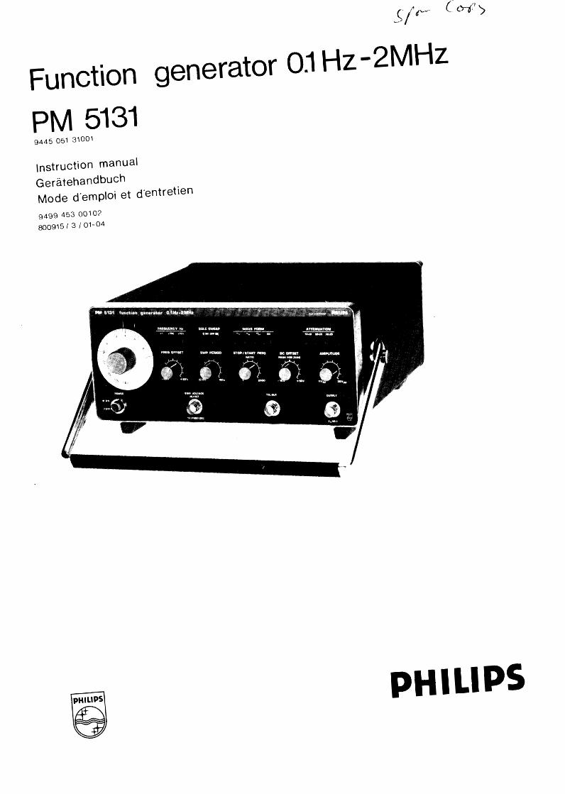
Function generator 0:\ Hz-2MHz
PM 5131 9445 051 31001
\nstruction manual
Gerateha ndbuch Mode d'emp\oi et d'entretien
9499 453 00102
800915 I 3 I 01-04
PHILIPS
2
Please note
1 n correspondence concerning this instrument, please quote the type number and serial number as given on the type plate.
Bitte beachten
Bei Schriftwechsel uber dieses Gerat wird gebeten, die Typennummer und die Geratenummer anzugeben. Diese befinden sich auf dem Typenschild an der Ruckseite des Gerates ..
Noter s. v. p.
Dans votre correspondance et dans vos reclamations se rapportant a cet appareil, veuillez toujours indiquer le numero de type et le numero de serie qui sont marques sur Ia plaquette de caracteristiques.
Important
As the instrument is an electrical apparatus, it may be operated only by trained personnel. Maintenance and repairs may also be carried out only by qualified personnel.
Wichtig
Da das Gerat ein elektrisches Betriebsmittel ist, dart die Bedienung nur durch eingewiesenes Personal erfolgen. Wartung und Reparatur durfen nur von geschultem, tach- und sachkundigem Personal durchgeflihrt werden.
Important
Comme !'instrument est un equipement electrique, le service doit etre assure par du personnel qualifie. De meme, l'entretien et les reparations sont a confier aux personnes suffisement qualifies.
® Philips GmbH - Hamburg - Germany - 1980
All rights are strictly reserved.
Reproduction or divulgation in any form whatsoever is not permitt<ed without written authority from the copyright owner.
Issued by Philips GmbH -Unternehmensbereich Elektronik fur Wissenschaft und Industria- Werk fur MeBtechnik
Printed in Germany
3
CONTENTS
1. GENERAL 5
1. 1. Introduction 5
1.2. Technical data 5
1.3. Accessories 7
1.4. Operating principle 8
2. INSTALLATION 9 2.1. Safety regulations 9 2.2. Mounting 10 2.3. Earthing 10 2.4. Dismantling the instrument 10 2.5. Mains connection
10
3. OPERATING INSTRUCTIONS 11 3.1. Control and sockets 11 3.2. Operation
12
4. SERVICE PART 4.1. 4.2. Access to parts 4.3. Check and adjustment 4.4. Check after repair and maintenance 4.5. Parts I ist
5. FIGURES
1. Block diagram 2. Front view 3. Front view, mechanical parts 4. Bottom view 5. Unit 1, component lay-out 6. Overall circuit diagram
6. CODING SYSTEM OF FAILURE REPORTING FOR QUALITY
7. ADDRESSES FOR SALES AND SERVICE
4
INHAL TSVERZEICHNIS TABLE DES MATIERES
ALLGEMEINES 15
1 . GENE RALITES 25 1. 1 . 1. Einleitung 15 1.1. Introduction 25 1.2. Technische Daten 15 1.2. Caracteristiques techniques 25 1.3. Zubehor 17 1.3. Accessoires 27 1.4. Funktionspri nzip 18 1.4. Principe de fonctionnement 28
2. VORBEREITUNGSANWEISUNGEN 19 2. INSTALLATION 29
2.1. Sicherheitstechnische Hinweise 19 2.1. Consignes de securite 29 2.2. Aufstellen 20 2.2. Montage 30 2.3. Erden 20 2.3. Mise a Ia terre 30 2.4. Offnen des Gehauses 20 2.4. Demontage de l'appareil 30 2.5. Netzanschluss 20 2.5. Branchement de l'appareil 30
3. BETRI EBSANLEITUNG 21 3. MISE EN SERVICE 31 3.1. Bedienelemente und Anschlusse 21 3.1. Commandes et douilles 31 3.2. Bedienung 22 3.2. Fonctionnement 32
5. 81 LDVERZEICHNIS 5. RAPPEL DES FIGURES
1. Blockschaltbild 1. Schema synoptique 2. Frontansicht 2. Face avant
1. GENERAL
1.1. INTRODUCTION
The PM 5131 function generator is an instrument designed for applications extending from the educational to the general purpose area.
5
It produces sinewave, triangular and squarewave output signals, the frequencies of which are adjustable in three
logarithmical sub-ranges from 0.1 Hz to 2 MHz. The frequency vernier allows the frequency setting to be varied from -20 % to +20 %.
The output voltage is continuously adjustable up to 30 Vpp and can be attenuated in steps of 10 dB down to 60 dB. A continuously adjustable output voltage can be selected separately or whenever used as d.c. offset voltage added to the selected output signal.
The generator provides a more than 3 decade sweep facility with adjustable sweep range and a variable sweep time from 10 to 150 secondes. For instance it is possible to cover the audio frequency range of 20 Hz to 20kHz in one continuous sweep. Moreover external sweep and frequency modulation can be performed.
For TTL applications a separate output is available.
The ergonomic design of the controls and sockets serves for convenient operating the instrument.
1.2. TECHNICAL DATA
General information:
On delivery from the factory, the instrument complies with the safety regulations of measuring and control
equipment. The information and warnings contained in this instruction manual must be followed by the user
to ensure safe operation and to maintain the instrument in a safe condition.
Only data with indicated tolerances or limits are guaranteed; data without tolerances are given only for guidance.
All specifications will be met after a warm-up time of 30 min. when keeping the instrument in a constant mounting position.
Inaccuracies (absolute or in %) relate to the indicated reference value.
1.2.1. Frequency
Frequency range
Selected ranges I
II Ill
Characteristic
Adjustments
Frequency indication
Setting error
Vernier frequency adjustment
Temperature coefficient
Short-term drift
Long-term drift
0.1 Hz- 2 MHz
0.1 Hz - 200 Hz 10 Hz- 20kHz
1 kHz- 2 MHz
logarithmic
three range pushbuttons
dial with logarithmic scale fine control knob
logarithmic scale on the dial
<± 10%
-20% ... +20% of the dial setting
< 0,5 %/K
< 0,5% within 15 min.
< 0,7% within 7 h.
6
1.2.2. Output
Connection
Impedance
Load capability
Wave forms
Open circuit voltage
- setting range - maximum value
DC (offset) voltage
button PUSH FOR ZERO pulled, open circuit voltage button PUSH FOR ZERO or WAVE FORM button DC pressed
Attenuation
- continuous - fixed
Distortion (sinewave)
Linearity (triangular wave)
Rise time, fall time (squarewave)
Overshoot and ringing (squarewave)
Amplitude response (sinewave; reference value 1 kHz)
1.2.3. TTL output
Connection
Duty cycle
Fan out
1.2.4. Frequency control
1.2.4. 1. Internal sweep
Sweep mode
Sweep characteristic
Sweep range (ratio f STOP/f START)
Sweep period (sweep time)
SWEEP VOLTAGE output (frequency analogue voltage)
connection - scale factor
1.2.4.2. External sweep or frequency modulation
Connection
Voltage vs. frequency characteristic
Max. sweep range
Sensitivity
BNC socket
5on short-circuit proof
SinewavH, triangular-, squarewave; all time-symmetrical; with or without d.c. offset. d.c. voltage without a.c.
3 Vpp ... 30 Vpp. continuously adjustable ± 15 v
-10 V ... +10 V, continuously adjustable
<50mV
0 ... 20 dB (see open circuit voltage 3 Vpp- 30 Vpp) 0 to 60 dB in steps of 1 0 dB
< 0,5% in ranges 1,11 < 3 %in range Ill
better than 99,5% in ranges I, II
< 75 ns
<2%
< 0,1 dB in ranges I, II
< 0,3 dB in range 111 < 1 MHz < 1 dB in range Ill ~ 2 MHz
(output voltage 3 ... 30 Vpp. load 50 n, attenuation 0 dB).
BNC soc:ket
50%
~ 20 TTL inputs
single sweep
logarithmic
1 ... 2000 ( 1 ... 2·1 o3), continuously adjustable
~ 10 ... 150 s,continuously adjustable.
BNC soc:ket 1 V /frequency decade
BNC socket SWEEP VOLTAGE IN/OUT
logarithmic
total sub-range I, II or Ill
1 V /frequency decade
Input impedance
Max. modulation frequency
1.2.5. Power supply
Reference value
Nominal values Nominal operating range Operating limits Nominal frequency range Limit range of operation Power consumption
1.2.6. Environmental conditions
Ambient temperature
Reference value
Nominal working range
Limits for storage and transport
Relative humidity
Reference range
Nominal working range
Air pressure
Reference value
Nominal working range
Air speed
Reference value
Nominal working range
Operating position
Warm-up time
1.2.7. Cabinet
Protection type (see DIN 40 050)
Protection class (see I EC 348)
Overall dimensions
height
- width
- depth
Weight
1.3. ACCESSORIES
1.3.1. Standard
1.3.2. Optional
1 kS1
ca. 5kHz
AC mains
230 v 115 V /230 V selectable by solder links
±15% of selected nominal value ±15% of selected nominal value 50-100Hz 47.5- 105Hz 21 w
+23 °C ± 1 °C
+5 °C ... +40 °C
-40 °C ... +70 °C
45 ... 75%
20 ... 80%
1013 mbar (= 760 mm Hg)
800 ... 1066 mbar (up to 2200 m height)
0 ... 0.2 m/s
0 ... 0.5 m/s
normally upright on feet or with handle fold down
30 min.
IP 20
class I, protective conductor
140 mm
310 mm
330mm
approx. 4.5 kg
Instruction manual Fuse 500 rnA delayed
PM 9585: 50 S1 termination 1 W
PM 9581: 50 S1 termination 3 W
PM 9075: Coaxial connection cable BNC-BNC
7
8
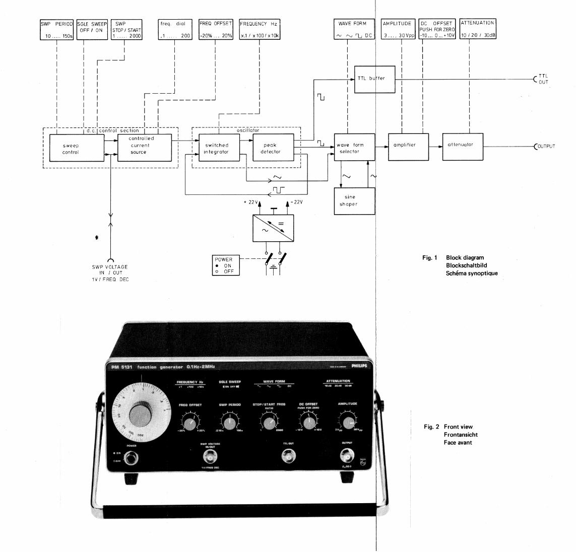
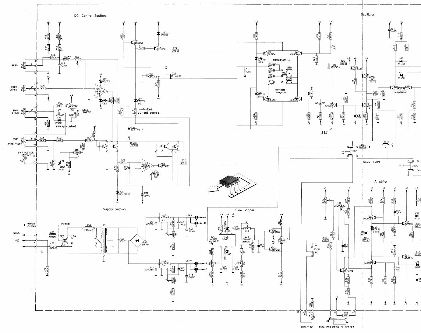
1.4. OPERATING PRINCIPLE (see Fig. 1., block diagram)
The oscillator of the function generator comprises the switched integrator and the Reak detector (comparator).
The controlled current source of the d.c. control section generates the charging current for the integrator. At
the integrator output a linear voltage ramp is fed to the peak detector. When reaching the reference voltage the
detector reverses the charging current of the integrator resulting in integration in the opposite direction.
Integration down is performed until reaching the negative reference level of the peak detector, which again
reverses the current of the switched integrator. As both reference levels are symmetrical with respect to earth,
a zero symmetrical triangular wave is generated at the output of the integrator. The duty cycle of this wave
is 1 : 1.
The output current of the controlled current source depends on the positions of the frequency dial and the
FREQUENCY OFFSET control. The resulting frequency of the oscillator is determined by this current and
- in addition - by the integrating capacitor in the switched integrator. Different capacitors are switched in by
the FREQUENCY Hz pushbuttons. Internal frequency control of the main oscillator for single sweep is effected
by the sweeQ control, started by the SGLE SWEEP pushbutton. The sweep range can be adjusted by the
SWP STOP/START control. The SWP PERIOD turn-knob adjusts the sweep time.
The instantaneous (sweep) voltage corresponding to a distinct frequency of the oscillator is available at the
SWP VOLTAGE IN/OUT socket. Via this socket external sweep or frequency modulation can be performed.
The voltage to frequency relationship is logarithmical, corresponding to the transfer characteristic of the
controlled current source.
The WAVE FORM switch allows the following wave forms to be selected: a triangular wave from the integrator,
a squarewave fro.m the peak detector or a sinewave formed by the sine shaper circuitry. The signal is fed to the
OUTPUT socket via AMPLITUDE potentiometer, amQiifi1~ and attenuator.
By means of the DC OFFSET control a d.c. voltage can be added to the signal, activated by pulling the
PUSH FOR ZERO switch/turn-knob. If d.c. voltage only is requested, the a.c. part of the output signal can be
switched off by pressing the DC pushbutton of the wave form selector.
A squarewave signal of the peak detector is fed via the TTL buffer to the TTL OUT socket.
The stabilized power supply provides the d.c. voltages for the circuitries.
9
2. INSTALLATION
2.1. SAFETY REGULATIONS
2.1.1.
2.1.2.
Upon delivery, the instrument complies with the required safety regulations. To maintain this condition and to ensure safe operation, it is recommended to follow the instructions below.
Before connecting
Mains voltage
Check whether the instrument is adapted to the nominal mains voltage.
Protection
This instrument is protected according to class I (protective earth) of the I EC 348 or VDE 0411. The mains cable provides earth connection. Outside specially protected rooms, the mains plug must be connected only to sockets with earthed contact.
It is not allowed to interrupt the earth connection inside or outside the instrument.
Maintenance and repair
Failure and excessive stress
If the instrument is suspected of being unsafe, take it out of operation permanently.
This is the case when the instrument
shows physical damage
does not function anymore
is stressed beyond the tolerable limits (e. g. during storage and transportation)
Dismantling the instrument
When removing covers or other parts by means of tools, live parts or terminals could be exposed. Before opening the instrument, disconnect it from all power sources.
If the open live instrument needs calibration, maintenance or repair, it must be performed only by trained personnel being aware of the risks. After disconnection from all power sources, the capacitors in the instrument may remain charged for some seconds.
Fuses
Only use the specified fuses.
Repair, replacing parts
Repairs must be made by trained personnel. Ensure that the construction of the instrument is not altered to the detriment of safety. Above all, leakage paths, air gaps and insulation layers must not be reduced.
When replacing, use only original parts. Other spare parts are only acceptable when the safety precautions for the instrument are not impaired.
10
2.2. MOUNTING
The instrument may be used in any desired position. With the handle fold down, the instrument may be used in sloping position; for this purpose press the buttons of the handle (Fig. 2). Do not position the instrument on any surface which produces or radiates heat, or in direct sunlight.
2.3. EARTHING
Before switching on, the instrument must be earthed in conformity with the local safety regulations. The mains cable fixed to the instrument includes a protective conductor, which is connected to the earth contacts of the plug. Thus, when connected to an earthed mains socket, the cabinet of the instrument is consequently connected to the protective earth.
WARNING: Connect the mains cable plug only to a socket with protective earth contacts. This protection must not be made ineffective, e. g. by using an extension cable without earth protection!
The circuit earth potential applied to the external contacts of BNC sockets is connected to the cabinet by means of a parallel-connected capacitor and resistor. So correct H F-earthing of the circuit is obtained. The external contacts of the BNC sockets must not be used to connect a protective conductor.
2.4. DISMANTLING THE INSTRUMENT
Unplug the mains connector Fold up the handle to the top. For this push the buttons of the handle Loosen the central screw at the rear Remove the lead-through of the mains cable from the cabinet Dismantle the cabinet
2.5. MAINS CONNECTION
The instrument must be connected only to an AC supply. On delivery the instrument is set to 230 V. Before mains connection, ensure that the local mains voltage ranges within the set mains voltage range indicated on the plate at the rear of the instrument.
If the instrument is to be used on 115 V supply, proceed as follows:
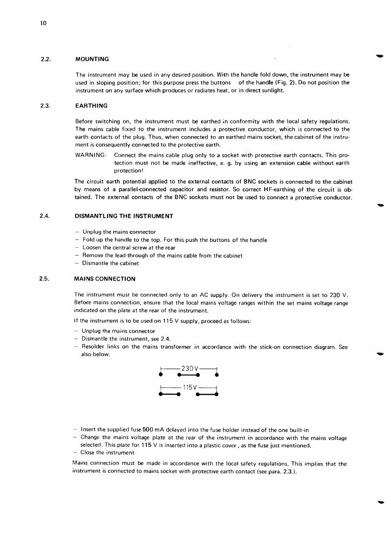
Unplug the mains connector Dismantle the instrument, see 2.4. Resolder links on the mains transformer in accordance with the stick-on connection diagram. See also below.
f--230V-1 • • • !- 115V-j
··~--·· ··~------
Insert the supplied fuse 500 rnA delayed into the fuse holder instead of the one built-in Change the mains voltage plate at the rear of the instrument in accordance with the mains voltage selected. This plate for 115 V is inserted into a plastic cover, as the fuse just mentioned. Close the instrument
Mains connection must be made in accordance with the local safety regulations. This implies that the instrument is connected to mains socket with protective earth contact (see para. 2.3.).
-
3. OPERATING INSTRUCTIONS
3.1. CONTROLS AND SOCKETS (FIG. 2)
Legend
POWER
oON
• OFF
WAVEFORM
\.., ~ ru FREQUENCY Hz
x1 x100 x 10k
Position
251
252/5 to
252/7
252/1 to
252/3
Function
mains switch:
white dot for ON position
push buttons for the required waveform:
sinewave, triangular or square wave.
pushbuttons for selecting the frequency range
0.1-200 Hz, 10Hz-20kHz, 1 kHz-2 MHz
650 dial for continuous coarse frequency adjustment
.1 ..... 200
(logarithmical scale)
FREO OFFSET
-20 %, ........ +20%
ATTENUATION
10dB 20dB 30dB
AMPLITUDE
3 Vpp ....... 30 Vpp
DC
DC OFFSET
-10 v .... +10 v
PUSH FOR ZERO
OUTPUT
TTL OUTput
SGLE SWEEP
I( ON OFF.
SWP STOP/START
1 ....... 2000
SWP VOLTAGE
IN/OUT
1 V/ FREQ DEC
SWP PERIOD
!5:10s ....... 150s
651
252/9 to
252/11
821
252/8
822
822
200
201
252/4
653
202
652
knob for continuous fine frequency adjustment
pushbuttons for setting the fixed attenuation;
40-60 dB by combination of pushbuttons.
knob for continuous amplitude
adjustment of the output signal
push buttons for switching off the a.c. portion of the
signal
knob for continuous d.c. voltage adjustment
pull-switch for adding the d.c. voltage to the output
signal
B NC output socket for the signal
B NC output socket for the TTL signal
pushbutton for starting a single sweep period
knob for adjusting the stop frequency (ratio stop/start
frequency)
BCN input/output socket for the frequency analogue
voltage
knob for setting the sweep time
11
12
3.2. OPERATION
3.2.1. Setting the voltage at socket OUTPUT
By means of the control AMPLITUDE, the amplitude of the output signal is continuously variable. Released button DC and pulled button PUSH FOR ZERO enables a continuously adjustable positive or negative d.c. voltage to be added to the output signal. When pressing the button DC, the a.c. part of the output signal is switched off and the d.c. voltage only is fed to the output. With step attenuator ATTENUATION, the output signal and the DC offset can be attenuated in steps of 10 dB up to 60 dB. For 10 dB to 30 dB separate push buttons an:J available. Attenuations of 40 and 50 dB are selected by combined pushbutton actions. For 60 dB all three buttons have to be pressed.
Note: The output amplifier could be overdriven due to adding signal and DC offset voltage. To avoid limiting, the peak value of the open-circuit output voltage must not exceed± 15 V (step attenuator set to 0 dB).
3.2.2. Setting the frequency
Three controls are provided for setting the frequency
dial with logarithmical scale range selector"'F R EQUENCY Hz vernier FREQ OFFSET control.
The scale reading, multiplied by the factor of the range selector, represents the frequency. In addition the frequency deviation set by means of the FREQ OFFSET control must be accounted for.
The set frequency represents:
the output signal frequency
the signal frequency with 0 V control voltage at socket SWP VOLTAGE IN/OUT
the start frequency
3.2.3. Internal single sweep
when button SG LE SWEEP released
when button SGLE SWEEP pressed
of the single sweep mode.
Internal single sweep from the start-to the stop-frequency is started by pressing the button SGLE SWEEP. The characteristic is expontential following the relation
to= fSTART. 10 Uc/V
where f0 =instantaneous signal frequency at the output
fsTART =frequency at the beginning of the sweep represented by the frequency setting, see 3.2.2. Uc = voltage at the socket SWP VOLTAGE IN/OUT.
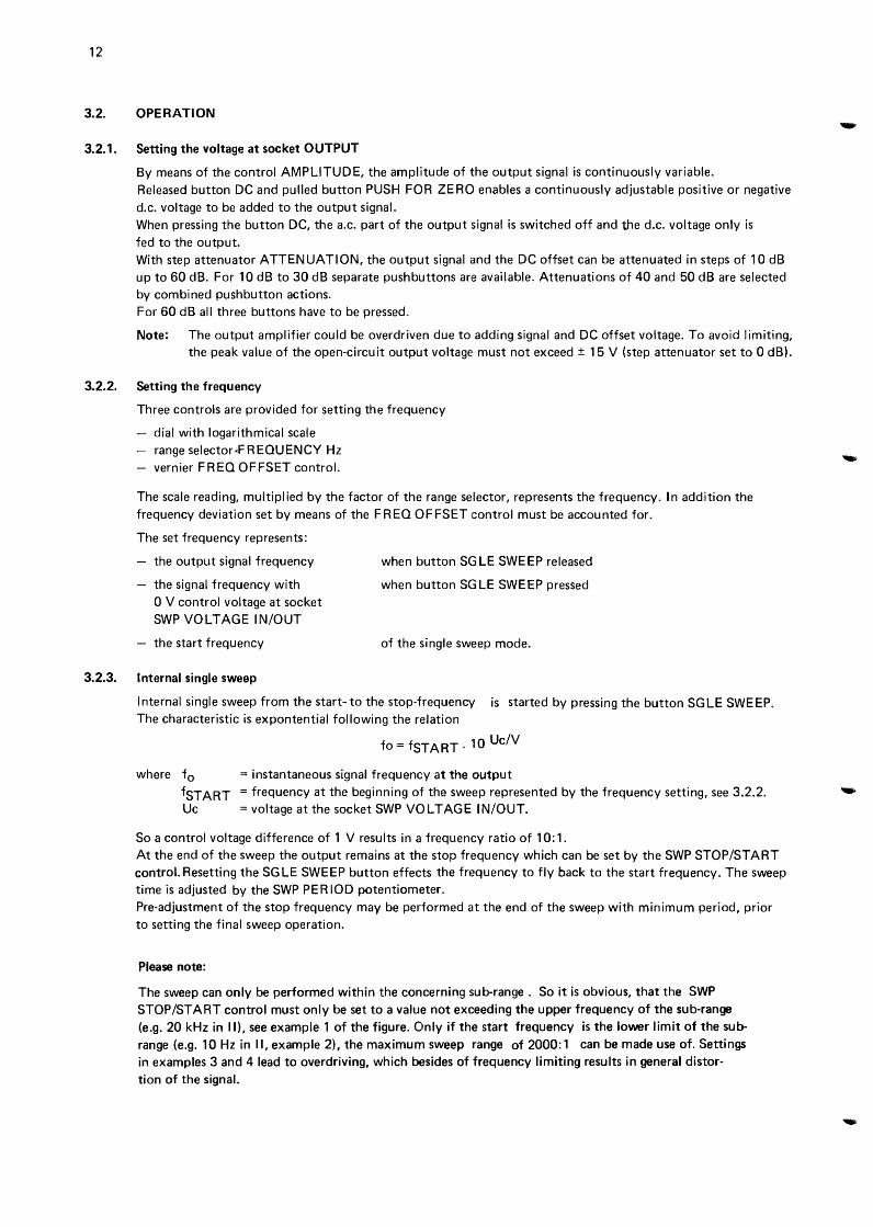
So a control voltage difference of 1 V results in a frequency ratio of 10:1. At the end of the sweep the output remains at the stop frequency which can be set by the SWP STOP/START control. Resetting the SGLE SWEEP button effects the frequency to fly back to the start frequency. The sweep time is adjusted by the SWP PERIOD potentiometer. Pre-adjustment of the stop frequency may be performed at the end of the sweep with minimum period, prior to setting the final sweep operation.
Please note:
The sweep can only be performed within the concerning sub-range. So it is obvious, that the SWP STOP/START control must only be set to a value not exceeding the upper frequency of the sub-range (e.g. 20kHz in II), see example 1 of the figure. Only if the start frequency is the lower limit of the subrange (e.g. 10Hz in II, example 2), the maximum sweep range of 2000:1 can be made use of. Settings in examples 3 and 4 lead to overdriving, which besides of frequency limiting results in general distor
tion of the signal.
log f
f STOP T-sweep range
f START
sweep time
(PERIOD)
l Hz
fSTART
I
100
1 k
10 k
20 k
SWP STOP/ START
I I
Example for the sub-range II (x1 00);
10 k
Hz
100
10
the other two ranges to be regarded similarly.
13
3.2.4. External sweep and frequency modulation
The SGLE SWEEP button must be released.
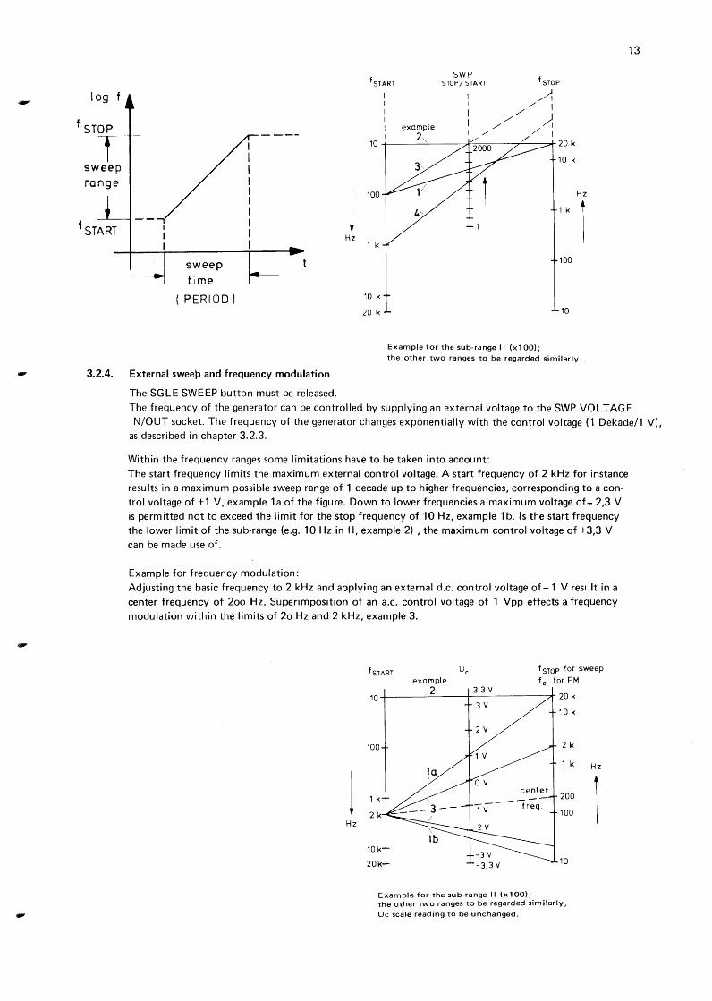
The frequency of the generator can be controlled by supplying an external voltage to the SWP VOLTAGE IN/OUT socket. The frequency of the generator changes exponentially with the control voltage (1 Dekade/1 V), as described in chapter 3. 2. 3.
Within the frequency ranges some limitations have to be taken into account: The start frequency limits the maximum external control voltage. A start frequency of 2 kHz for instance results in a maximum possible sweep range of 1 decade up to higher frequencies, corresponding to a con
trol voltage of +1 V, example 1 a of the figure. Down to lower frequencies a maximum voltage of- 2,3 V is permitted not to exceed the limit for the stop frequency of 10 Hz, example 1 b. Is the start frequency
the lower limit of the sub-range (e.g. 10Hz in II, example 2) , the maximum control voltage of +3,3 V can be made use of.
Example for frequency modulation:
Adjusting the basic frequency to 2 kHz and applying an external d.c. control voltage of-1 V result in a
center frequency of 2oo Hz. Superimposition of an a.c. control voltage of 1 Vpp effects a frequency
modulation within the limits of 2o Hz and 2 kHz, example 3.
j Hz
fsTART Uc f STOP for sweep example f 0 forFM
2 3,3 v 10~----~~----~----------~* 20 k
100
1 k
2 k
10k
20k
Example for the sub-range II (x100);
10 k
2 k
1 k
200
100
10
the other two ranges to be regarded similarly,
Uc scale reading to be unchanged.
Hz
1
15
1. ALLGEMEINES
1.1. EINLEITUNG
Der Funktionsgenerator PM 5131 wurde fur Schulungsaufgaben und allgemeine Anwendungen entwickelt.
Er erzeugt sinus-, dreieck- und rechteckformige Ausgangssignale, deren Frequenzen in drei logarithmischen
Bereichen von 0,1 Hz bis 2 MHz eingestellt werden konnen. Die Feineinstellung lasst Verstellung der Frequenz im Bereich von -20% bis +20% zu.
Die Ausgangsspannung ist bis 30 Vss stetig einstellbar und kann in Stufen von 10 dB bis 60 dB abgeschwacht
werden.
Dem Ausgangssignal kann eine von -10 V bis +1 0 V stetig einstellbare Gleichspannung hinzugefi.igt werden.
Sie kann auch separat an den Ausgang gefuhrt werden.
Es ist moglich, die Frequenz des Generators in den 3 Bereichen jeweils i.iber mehr als 3 Dekaden ZU steuern (interner Einzelsweep). So ist es moglich, den gesamten Audio-Bereich von 20Hz bis 20kHz mit einem
kontinuierlichen Sweep zu durchfahren. Die Sweepzeit reicht von etwa 10 bis 150 Sekunden.
Weiterhin ist externer Sweep und Frequenzmodulation moglich.
Fur Anwendungen auf den TTL-Gebiet steht ein weiterer Signalausgang zur Verfugung.
Die ubersichtliche Anordnung der Bedienelemente und Anschlusse gewahrleistet eine bequeme Handhabung des
Gerates.
1.2. TECHNISCHE DATEN
Allgemeine Hinweise:
Dieses Gerat entspricht den Sicherheitsbestimmungen fur elektrische Mess- und Regeleinrichtungen und hat
das Werk in sicherheitstechnisch einwandfreiem Zustand verlassen. Urn diesen Zustand zu erhalten und einen
gefahrlosen Betrieb sicherzustellen, muss der Anwender die Hinweise und Warnvermerke beachten, die in dem
vorliegenden Geratehandbuch enthalten sind.
- Nur Angaben mit Toleranzen oder Grenzwerten konnen als garantierte Daten angesehen werden. Daten
ohne Toleranzen, d.h. ohne Fehlergrenzen, sind informative Daten und werden nicht garantiert. Fehlerangaben gelten nach einer Anwarmzeit von 30 Minuten nach dem Einschalten bei konstanter
Betriebslage. Prozentuale und absolute Fehler sind auf den jeweils angegebenen Referenzwert bezogen.
1.2.1. Frequenz
F requenzbere ich
Teilbereiche II
Ill
Charakteristik
Ei nstell elemente
Frequenzanzeige
Einstellfehlergrenzen
Frequenz- Fei neinstellu ng
Temperatu rkoeffizient
Kurzzeitdrift
Langze itdrift
0,1 Hz- 2 MHz
0,1 Hz- 200Hz
10Hz-20kHz 1 kHz- 2 MHz
logarithmisch
3 Bereichstasten
- Kreisskale mit logarithmischer Teilung - Feineinsteller
logarithmische Skale der Kreisscheibe
± 10%
-20% ... +20% der Kreisskalen-Einstellung
< 0,5 %/K
< 0,5% innerhalb von 15 Minuten
< 0,7% innerhalb von 7 Stunden
16
1.2.2. OUTPUT-Signalausgang
Anschluss
lnnenwiderstand
Belastbarkeit
Signalformen
Leerlaufampl itude
- Einstellbereich - Grenzwert
DC Gleichspannung (Offset)
Drucktaste PUSH FOR ZERO gezogen; Leer I aufspan nu ng Drucktaste PUSH FOR ZERO oder Signalformtaster DC gedruckt
Abschwacher
- stetig - fest (Stufenabschwacher)
BNC-Buchse
50ft
ku rzsch I u B fest
Sinus, Dreieck oder Rechteck; aile zeitsymmetrisch; mit oder ohne Gleichspannungsoffset. Gleichspannung ohne Wechselspannungsanteil.
3 Vss ... 30 Vss, stetig einstellbar ± 15 v
-10 V ... +10 V, stetig einstellbar
<50mV
0 ... 20 dB (siehe Leerlaufamplitude 3 Vss ... 30 Vss) 0 bis 60 dB in Stufen von 10 dB
Klirrfaktor (Sinus) < 0,5% in den Teilbereichen I, II < 3 % imTeilbereich Ill
Linearitat (Dreieck) besser als 99,5% in den Teilbereichen I, II
Anstiegs- und Abfallzeit ( Rechteck) < 75 ns
Uberschwingen und Welligkeit ( Rechteck) < 2%
Amplitudengang (Sinus; Referenzwert 1 kHz) < 0,1 dB in den Teilbereichen I, II
1.2.3. TTL OUT-Ausgang
Anschluss
Tastgrad (duty cycle)
Grenzlast (fan-out)
1.2.4. Frequenzsteuerung
1.2.4. 1. lnterner Sweep
Betriebsart
Sweep-Charakteristik
Sweepbereich (Verhaltnis f STOP/START)
Sweepperiode (Sweepzeit)
SWEEP VOLTAGE Ausgang (Frequenzanaloge Spannung)
Anschluss - Skalenfaktor
1.2.4.2. Externer Sweep oder Frequenzmodulation
Anschluss
Spannungs-Frequenz Charakteristik
Maximaler Steuerbereich
< 0,3 dB imTeilbereich Ill < 1 MHz < 1 dB imTeilbereich Ill ~ 2 MHz (Ausgan!JSSpannung 3 ... 30 Vss, Belastung 50 n, Abschwacher 0 dB).
BNC-Buchse
50%
~ 20 TTL-Eingange
Einzelsweep
logarithmisch
1 ... 2000 (1 ... 2-103), stetig einstellbar
~ 10 ... 150 s, stetig einstellbar
BNC-Buchse 1 V/Frequenzdekade
BNC-Buchse SWEEP VOLTAGE IN/OUT
logarithmisch
den ganzen Teilbereich I, II oder Ill
Empfindlichkeit
Eingangswiderstand
Maximale Modulationsfrequenz
1.2.5. Versorgungsspannung
Referenzwert
Nennwerte
Nennbetriebsbereich
Grenzbetriebsbereich
Frequenznennbereich F requenztoleranzbereich Lei stu ngsaufnah me
1.2.6. Umgebungsbedingungen
Umgebungstemperatu r
Referenzwert
Nenngebrauchsberelch
Grenzbereich fur Lagerung und Transport
Relative Luftfeuch te
Referenzbereich
Nenngebrauchsbereich
Luftdruck
Referenzwert
Nenngebrauchsbereich
Geschwindigkeit der umgebenden Luft
Referenzbereich
Nen ngebrauchsbereich
Betriebslage
Anwarmzeit
1.2.7. Gehause
Schutzart nach Dl N 40 050
Schutzart nach I EC 348
Abmessungen uber alles Hohe
- Breite - Tiefe
. Gewicht
1.3. ZUBEHOR
1.3.1. Normalzubehor
1.3.2. Sonderzubehor
1 V/Frequenzdekade
1 krl
etwa 5kHz
Netzwechselspannu ng
230 v 115 v /230 vI durch Lotbrucken wahlbar
± 15% vom eingestellten Nennwert
± 15% vom eingestellten Nennwert
50- 100Hz 47,5- 105Hz 21 w
+23 °C ± 1 °C
+5 °C ... +40 °C
-40 °C ... +70 °C
45% ... 75%
20% ... 80%
1013 mbar (= 760 mm Hg)
800 mbar ... 1066 mbar (bis 2200 m Hohe)
0 m/s ... 0,2 m/s
0 m/s ... 0,5 m/s
17
auf den Fussen stehend (Normallage) oder auf Tragbugel gestellt
30 min.
IP 20
Klasse I, Schutzleiter
140mm 310mm 330mm
ca. 4,5 kg
Geratehandbuch Sicherung 500 mAT
PM 9585: 50 !1-AbschluB 1 W
PM 9581: 50 !1-AbschluB 3 W
PM 9075: Koaxialkabel BNC-BNC
18
1.4. FUNKTIONSPRINZIP (siehe Abb. 1, Blockschaltbild)
Der Oszillator des Funktionsgenerators umfasst den geschalteten Integrator (switched integrator) und den Komparator (peak detector). Die gesteuerte Stromquelle (controlled current source) des Gleichstromteils erzeugt den Ladestrom fUr den Integrator. Am I ntegratorausgang wird eine lineare Spannungsrampe dem Komparator zugefuhrt. Beim Erreichen eines vorgegebenen Schwellwertes spricht der Komparator an und steuert die Stromrichtung im Integrator urn. Der lntegrationsvorgang verlauft nun in der entgegengesetzten Richtung. Erreicht die Spannungsrampe den anderen Schwellenwert des Komparators, so kehrt dieser die Stromrichtung im Integrator wieder urn. Da die beiden Schwellenwerte entgegengesetzt gleich gross sind, entsteht so am lntegratorausgang eine periodische, nullsymmetrische Dreieckspannung. Das Zeitverhaltnis der ansteigenden zur abfallenden Dreieckflanke ist 1:1.
Der Ausgangsstrom der gesteuerten Stromquelle hangt von den Einstellungen der Kreisskale und dem Feineinsteller F REO OFFSET a b. Die resultierende Frequenz des Oszillators wird von diesem Strom und zusatzlich vom Wert des Kondensators im Integrator bestimmt. Verschiedene Kapazitatswerte werden mit den Drucktasten F R EOU ENZY Hz eingeschaltet.
Interne Frequenzsteuerung des Oszillators fur Einzelsweep erfolgt mit dem Sweep-Steuerteil (sweep control). Die Auslosung erfolgt durch Betatigen der Taste SG LE SWEEP. Der Sweepbereich wird stetig mit dem Steller SWP STOP/START eingestellt. Die Einstellung der Sweepzeit erfolgt mit dem Potentiometer SWEEP PERIOD. Die momentane (Sweep-) Spannung, die einer bestimmten Frequenz des Oszillators entspricht, steht an der Buchse SWP VOLT AGE IN/OUT zur Verfugung. Das Verhaltnis von Spannung zu Frequenz ist, entsprechend der Charakteristik der gesteuerten Stromquelle, logarithmisch.
Mit dem Signalformschalter WAVE FORM konnen drei Signalformen gewahlt werden: die Dreieickspannung vom Integrator, die Rechteckspannung vom Komparator oder die Sinusspannung, die mit dem Sinusformer (sine shaper) aus der Dreieckspannung erzeugt wird.
Das Signal wird uber den Amplitudensteller, den Verstarker (amplifier) und Abschwacher (attenuator) an den Ausgang gefuhrt.
Mit Hilfe des Stellers DC OFFSET kann dem Signal eine Gleichspannung unterlegt werden, zugeschaltet durch Ziehen des Schalters PUSH FOR ZERO. Wenn nur die Gleichspannung allein gewunscht wird, kann der Wechselspannungsanteil des Ausgangssignals abgeschaltet werden. Dazu ist die Drucktaste DC des Signalformwahlers zu betatigen.
Ein Rechtecksignal des Komparators wird uber einen Trennverstarker (TTL buffer) zur TTL OUT Buchse gefuhrt.
Das stabilisierte Netzteil liefert die Gleichspannungen fur die Schaltkreise.
-
19
2. VORBEREITUNGSANWEISUNGEN
2.1. SICHERHEITSTECHNISCHE HINWEISE
2.1.1.
2.1.2.
Dieses Gerat hat das Werk in sicherheitstechnisch einwandfreiem Zustand verlassen. Zur Erhaltung dieses Zustands und seines gefahrlosen Betriebs empfehlen wir, die nachfolgenden Hinweise sorgfaltig zu beachten.
Vor dem AnschlieBen
Netzspannung
Es ist sicherzustellen, daB die eingestellte Betriebsspannung des Gerats und die Nenn-Netzspannung i.ibereinstimmen.
Schutzklasse
Dieses Gerat ist ein Gerat der Schutzklasse I (SchutzleiteranschluB) gemaB I EC 348 oder VDE 0411. Die mitgelieferte Netzzuleitung enthalt einen Schutzleiter. AuBer in besonders zugelassenen Raumen dart der Netzstecker nur in Schutzkontaktsteckdosen eingefi.ihrt werden.
Jede Unterbrechung des Schutzleiters, innerhalb oder auBerhalb des Gerats, ist unzulassig.
Reparatur und Wartung
Fehler und auBergewohnliche Beanspruchungen
Wenn anzunehmen ist, daB ein gefahrloser Betrieb nicht mehr moglich ist, so ist das Gerat auBer Betrieb zu setzen und gegen unabsichtlichen Betrieb zu sichern. Dieser Fall tritt ein,
wenn das Gerat sichtbare Beschadigungen aufweist,
wenn das Gerat nicht mehr arbeitet,
nach Oberbeanspruchungen jeglicher Art (z. B. Lagerung, Transport), die die zulassigen Grenzen i.iberschreiten.
Offnen des Gerats
Beim Offnen von Abdeckungen oder Entfernen von Teilen mit Werkzeug konnen spannungsfi.ihrende Teile freigelegt werden. Auch konnen AnschluBstellen spannungsfi.ihrend sein.
Vor dem Offnen des Gerats muB das Gerat von allen Spannungsquellen getrennt sein.
Wenn danach eine Kalibrierung, Wartung oder Reparatur am geoffneten Gerat unter Spannung unvermeidlich ist, so dart das r:'Ur durch eine Fachkraft geschehen, welche die damit verbundenen Gefahren kennt.
Kondensatoren im Gerat konnen noch geladen sein, selbst wenn das Gerat von allen Spannungsquellen getrennt wurde, die Schaltbilder sind zu beachten.
Sicherungen
Es di.irfen nur die vorgeschriebenen Sicherungen verwendet werden.
Reparatur, Ersatz von Teilen
Reparaturen sind fachgerecht durchzufi.ihren. Dabei ist besonders darauf zu achten, daB die konstruktiven Merkmale des Gerats nicht sicherheitsmindernd verandert werden. Insbesondere di.irten die Kriech- und Luftstrecken und die Abstande durch die lsolierung hindurch nK:ht verkleinert werden.
Zum Ersatz nur Originalteile verwenden. Andere Ersatzteile sind nur zulassig, wenn dadurch die sicherheitstechnischen Eigenschaften des Gerats nicht verschlechtert werden.
20
2.2. AUFSTELLEN
Das Gerat darf in beliebiger Lage aufgestellt und betrieben werden. Bei heruntergeklapptem Tragbi.igel
kann das Gerat in schrager Lage aufgestellt werden; hierzu sind die beiden Verriegelungsknopfe
des Tragbi.igels zu dri.icken (Fig. 2). Es ist darauf zu achten, daB das Gerat nicht auf andere Warme
quellen gestellt oder i.ibermaBiger Warmeeinstrahlung ausgesetzt wird.
2.3. ERDEN
Das Gerat muB den ortlichen Vorschriften entsprechend geerdet werden. Die Netzzuleitung enthalt einen Schutzleiter und ist mit einem Schutzkontaktstecker versehen. Hierdurch wird beim AnschluB
an eine Schutzkontaktsteckdose das Gehause des Gerats zwangslaufig mit Schutzerde verbunden.
ACHTUNG: Der NetzanschluBstecker dart nur in eine Schutzkontaktsteckdose eingefi.ihrt werden. Diese SchutzmaBnahme darf nicht unwirksam gemacht werden, z. B. durch eine unvoll
kommene Verlangerungsleitung!
Die AuBenkontakte der BNC-Buchsen fi.ihren das Schaltungsnullpunkt-Potential und sind mit dem Ge
hause i.iber die Parallelschaltung eines Kondensators und eines Widerstandes verbunden. Dadurch wird eine
eindeutige H F-Erdung der Schaltung bewirkt.
Eine Schutzerdung i.iber AuBenkontakte der BNC-Buchsen ist unzulassig!
2.4. OFFNEN DES GEHAUSES
Netzstecker herausziehen Handgriff von der Frontseite wegschwenken; dazu sind die beiden Verriegelungsknopfe (Fig. 2)
zu dri.icken Zentralbefestigung an der Ri.ickseite Ibsen
Netzkabeldurchfi.ihrung aus dem Durchbruch des Mantels ziehen
Mantel abziehen
2.5. N ETZANSCH LUSS
Dieses Gerat darf nur an Wechselspannung betrieben werden. Es ist bei Auslieferung auf einen Netz
spannungsbereich von 230 V eingestellt. Vor dem AnschlieBen an das Netz ist zu pri.ifen, ob der ein
gestellte Netzspannungsbereich die ortliche Netzspannung umfaBt. Die eingestellte Spannung kann
auf dem Netzspannungsschild an der Gehauseri.ickwand abgelesen werden.
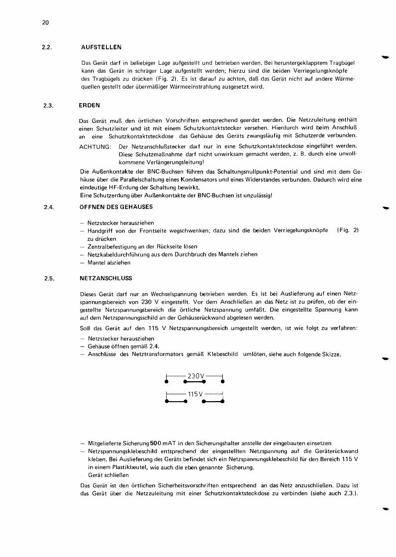
Soli das Gerat auf den 115 V Netzspannungsbereich umgestellt werden, ist wie folgt zu verfahren:
Netzstecker herausziehen Gehause offnen gemaB 2.4.
Anschli.isse des Netztransformators gemaB Klebeschild umloten, siehe auch folgende Skizze.
r-- 2 3 0 v ----1 • • • • ~115V.=j
Mitgelieferte Sicherung 500 mAT in den Sicherungshalter anstelle der eingebauten einsetzen
Netzspannungsklebeschild entsprechend der eingestellten Netzspannung auf die Gerateri.ickwand
kleben. Bei Auslieferung des Geri.its befindet sich ein Netzspannungsklebeschild fi.ir den Bereich 115 V
in einem Plastikbeutel, wie auch die eben genannte Sicherung. Gerat schlieBen
Das Gerat ist den ortlichen Sicherheitsvorschriften entsprechend an das Netz anzuschlieBen. Dazu ist
das Gerat i.iber die Netzzuleitung mit einer Schutzkontaktsteckdose zu verbinden (siehe auch 2.3.).
3. BETRIEBSANLEITUNG
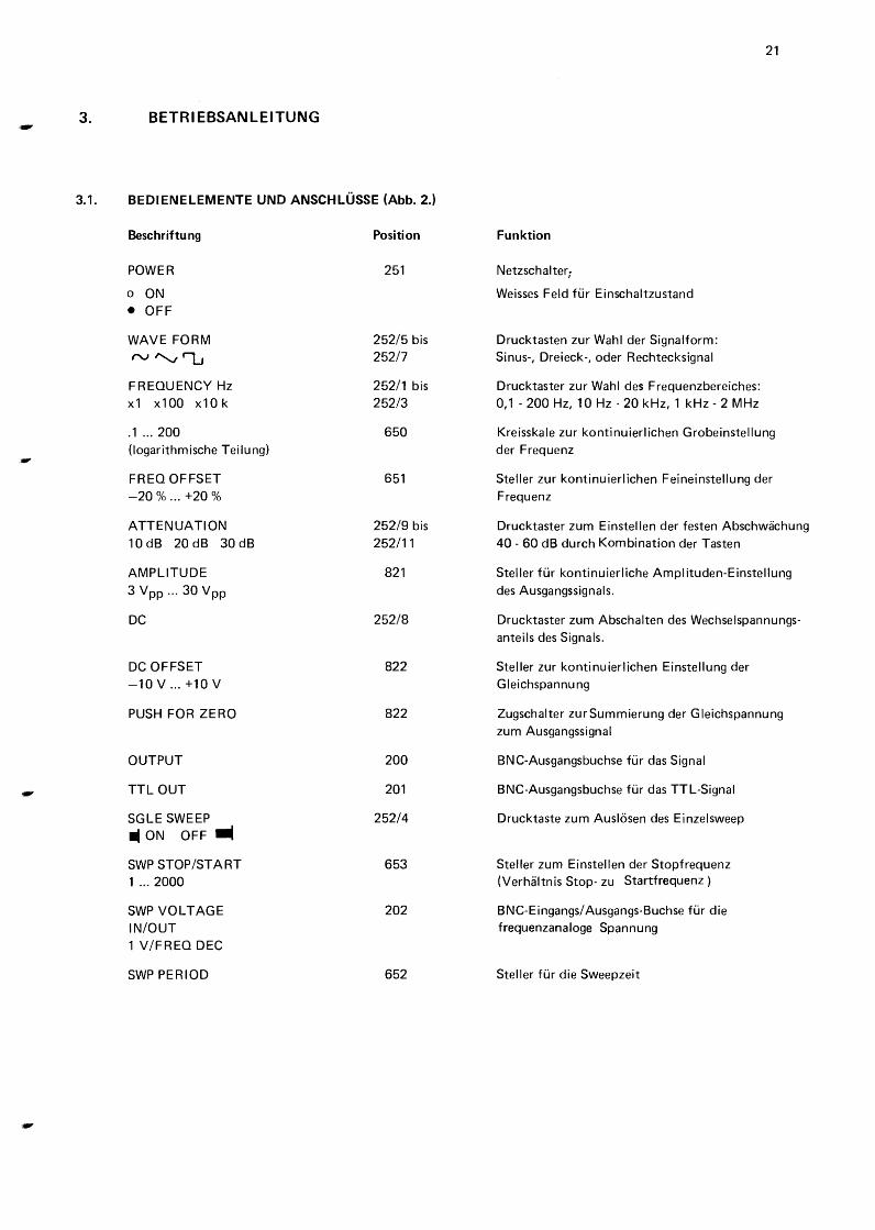
3.1. BEDIENELEMENTE UNO ANSCHLUSSE (Abb. 2.)
Beschriftung
POWER
o ON
• OFF
WAVEFORM
rv "v 'l...J
FREQUENCY Hz x1 x1 00 x1 0 k
.1 ... 200 (logarithmische Teilung)
FREO OFFSET -20% ... +20%
ATTENUATION 10 dB 20 dB 30 dB
AMPLITUDE
3 Vpp ... 30 Vpp
DC
DC OFFSET -10V ... +10V
PUSH FOR ZERO
OUTPUT
TTL OUT
SGLE SWEEP • ON OFF.
SWP STOP/START 1 ... 2000
SWP VOLTAGE IN/OUT 1 V/FREO DEC
SWP PERIOD
Position
251
252/5 bis 252/7
252/1 bis 252/3
650
651
252/9 bis 252/11
821
252/8
822
822
200
201
252/4
653
202
652
Funktion
Netzschalter;
Weisses Feld fur Einschaltzustand
Drucktasten zur Wahl der Signalform: Sinus-, Dreieck-, oder Rechtecksignal
Drucktaster zur Wahl des Frequenzbereiches: 0,1-200 Hz, 10Hz-20kHz, 1 kHz- 2 MHz
21
Kreisskale zur kontinuierlichen Grobeinstellung der Frequenz
Steller zur kontinuierlichen Feineinstellung der Frequenz
Drucktaster zum Einstellen der festen Abschwachung 40- 60 dB durch Kombination der Tasten
Steller fur kontinuierliche Amplituden-Einstellung des Ausgangssignals.
Drucktaster zum Abschalten des Wechselspannungsanteils des Signals.
Steller zur kontinuierlichen Einstellung der G leichspannu ng
Zugschalter zurSummierung der Gleichspannung zum Ausgangssignal
BNC-Ausgangsbuchse fur das Signal
BNC-Ausgangsbuchse fur das TTL-Signal
Drucktaste zum Auslosen des Einzelsweep
Steller zum Einstellen der Stopfrequenz (Verhaltnis Stop- zu Startfrequenz)
BNC-Eingangs/ Ausgangs-Buchse fur die frequenzanaloge Spannung
Steller fur die Sweepzeit
22
3.2. BEDI ENUNG
3.2.1. Einsteller der Ausgangsspannung (OUTPUT)
Mit dem Steller AMPLITUDE ist die Amplitude des Ausgangssignals stetig einstellbar. Bei entriegeltem Drucktaster DC und gezogenem Knopf PUSH FOR ZERO kann dem Ausgangssignal eine stetig einstellbare positive oder negative Gleichspannung unterlegt werden. Wird der Drucktaster DC gedruckt, ist der Wechselspannungsanteil des Signals abgeschaltet, und es wird nur die Gleichspannung an den Ausgang gefuhrt.
Mit dem Stufenabschwacher ATTENUATION kann das Ausgangssignal einschliesslich DC-Offset in Stufen von 10 dB bis 60 dB abgeschwacht werden. Fur 10 bis 30 dB stehen einzelne Drucktasten zur Verfugung.
40 und 50 dB sind durch Kombination zweier Tasten wahlbar.
Fi..ir 60 dB mi..issen aile 3 Tasten gedruckt sein.
Hinweis: Der Ausgangsverstarker ist durch gleichzeitige Aussteuerung mit Signal und DC-Offsetspannung
ubersteuerbar. Zur Vermeidung von Begrenzungseffekten dart der Scheitelwert der Leerlaufaus
gangsspannung ± 15 V nicht Liberschreiten (Stufenabschwacher auf 0 dB).
3.2.2. Einstellen der Frequenz
Zum Einstellen der Frequenz stehen drei Bedienungselemente zur Verfugung:
Kreisskale mit logarithmischer Teilung
- Bereichschalter FREQUENCY Hz
- Feineinsteller FREO OFFSET
Die resultierende Frequenz entspricht dem Produkt aus dem angezeigten Zahlenwert auf der Kreisskale und
dem Einstellwert des Bereichschalters FREQUENCY Hz. Zusatzlich ist die durch den Feineinsteller
F REO OFFSET festgelegte Frequenzabweichung zu berucksichtigen.
Die eingestellte Frequenz entspricht
der Signalfrequenz der Signalfrequenz, mit 0 V
Steuerspannung an der Buchse
SWEEP VOLTAGE IN/OUT der Startfrequenz
3.2.3. lnterner Einzelsweep
bei entriegelter Taste SGLE SWEEP
bei gedruckten Taste SG LE SWEEP
des Einzelsweep
lnterner Einzelsweep von der Start- zur Stopfrequenz wird durch Drucken der Taste SGLE SWEEP ausgelost. Die Charakteristik ist exponentiell, gemass der Beziehung
fo = fSTART ·10Uc/V
wobei f0 = momentane Signalfrequenz am Ausgang
fSTART= Frequenz zu Beginn des Sweep, eingestellt durch die Grundfrequenz gem~ss 3.2.2. Uc = Spannung an der Buchse SWP VOLTAGE IN/OUT.
Somit andert sich die Frequenz um eine Dekade bei einer Steuerspannungsdifferenz von 1 V. Am Ende der
Sweepperiode verweilt der Ausgang an der oberen Frequenz des Sweepbereiches, die mit dem Steller
SWP STOP/START eingestellt werden kann. Rucksetzen der Taste SGLE SWEEP lasst den Ausgang zur Startfrequenz zuruckspringen.
Die Sweepzeit wird mit dem Potentiometer SWP PERIOD eingestellt. Vor-Einstellung der Stopfrequenz sollte am Ende des Sweep bei kleiner Pe'riodenzeit vorgenommen werden, bevor der endgultige Sweep ausgefuhrt wird.
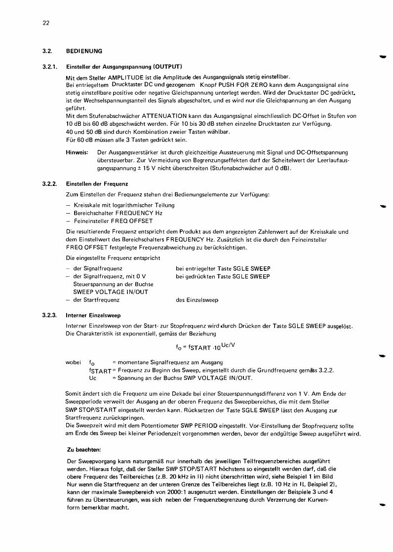
Zu beachten:
Der Sweepvorgang kann naturgemaB nur innerhalb des jeweiligen Teilfrequenzbereiches ausgefuhrt werden. Hieraus folgt, daB der Steller SWP STOP/START hochstens so eingestellt werden darf, daB die obere Frequenz des Teilbereiches (z.B. 20kHz in II) nicht uberschritten wird, siehe Beispiel 1 im Bild Nur wenn die Startfrequenz an der unteren Grenze des Teilbereiches liegt (z.B. 10Hz in ll. Beispiel 2), kann der maxi male Sweepbereich von 2000:1 ausgenutzt werden. Einstellungen der Beispiele 3 und 4 fuhren zu Obersteuerungen, was sich neben der Frequenzbegrenzung durch Verzerrung der Kurvenform bemerkbar macht.
f STOP
T sweep range
-3.2.4.
.,
23
fsTART SWP
STOP/ START
I I I
----example
10 2" 20 k
10 k
1 100 Hz
1 k
1 Hz sweep 1 k
time 100
(PERIOD) 10 k
20 k 10
Beispiel fur den Teilbereich II (xlOO);
die beiden anderen Bereiche ergeben
sich ahnlich.
Externer Sweep und Frequenzmodulation
Die Taste SGLE SWEEP muss entriegelt sein.
Die Signalfrequenz des Generators kann durch Zufuhren einer Spannung uber die Buchse SWP VOLTAGE
IN/OUT gesteuert Werden. Die Frequenz andert sich dabei exponentiell mit der Steuerspannung ( 1 Dekade/1 V) I
wie in Kapitel 3.2.3. beschrieben.
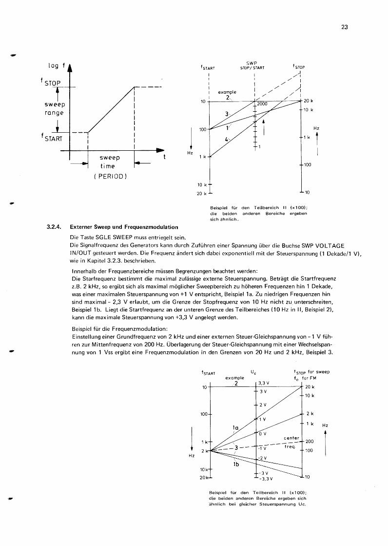
I nnerhalb der Frequenzbereiche mussen Begrenzungen beachtet werden: Die Starfrequenz bestimmt die maximal zulassige externe Steuerspannung. Betragt die Startfrequenz
z.B. 2 kHz, so ergibt sich als maximal moglicher Sweepbereich zu hoheren Frequenzen hin 1 Dekade,
was einer maxima len Steuerspannung von +1 V entspricht, Beispiel 1 a. Zu niedrigen Frequenzen hin
sind maximal- 2,3 V erlaubt, urn die Grenze der Stopfrequenz von 10 Hz nicht zu_ unterschreiten, Beispiel 1 b. Liegt die Startfrequenz an der unteren Grenze des Teilbereiches ( 10 Hz in II, Beispiel 2),
kann die maximale Steuerspannung von +3,3 V angelegt werden.
Beispiel fur die Frequenzmodulation:
Einstellung einer Grundfrequenz von 2 kHz und einer externen Steuer-Gieichspannung von -1 V fuh
ren zur Mittenfrequenz von 200 Hz. Oberlagerung der Steuer-Gieichspannung mit einer Wechselspan
nung von 1 Vss ergibt eine Frequenzmodulation in den Grenzen von 20 Hz und 2 kHz, Beispiel 3.
fsTART uc t STOP for sweep example f 0 for FM
/2 3,3 v 10 20 k
3V 10 k
100 2 k
1 k Hz
1 1 k 200
1 2 k 100 Hz
10k
20k 10
Beispiel fur den Teilbereich II (xlOO);
die beiden anderen Bereiche ergeben sich
ahnlich bei gleicher Steuerspannung Uc.
1. GENERALITES
1.1. INTRODUCTION
Le generateur de fonctions PM 5131 est un appareil con<;u pour des applications allant du secteur educatif
au secteur general.
II delivre des signaux de sortie sinuso'ldaux, triangulaires et rectangulaires, dont Ia frequence est reglable en trois gammes logarithmiques de 0,1 Hz a 2 MHz. Le vernier de frequence permet de faire varier Ia frequence
de -20 % a +20 %.
25
La tension de sortie est reglable de fac;:on continue jusqu'a 30 Vee et peut etre attenuee en echelons de 10 dB a 60 dB.
Une tension de sortie continument reglable peut etre selectionnee separement, ou le cas echeant, utilisee comme
tension continue d'offset additionnee au signal de sortie selectionne.
Le generateur permet le balayage sur plus de 3 decades (gamme reglable) et un temps de balayage variable entre 10 et 150 secondes. II sera done possible de couvrier Ia gamme de frequence audio de 20 Hz a 20kHz en un balayage continu. De plus, le balayage externe et Ia modulation en frequence sont possibles.
Pour des applications TTL une sortie separee est disponible.
La structure ergonomic des commandes et des douilles permet de manipuler l'appareil d'une fac;:on commode.
1.2. CARACTERISTIOUES TECHNIQUES
A Ia livraison, cet appareil repond aux consignes de securite pour les appareils de mesure et de controle. Les instructions et avertissements contenus dans ce mode d'emploi doivent etre observes par l'utilisateur afin
d'assurer le fonctionnement de l'appareil dans les conditions de securite et de le maintenir conforme a Ia norme.
Seules les valeurs indiquees avec une tolerance ou une limite sont garanties; les caracteristiques sans
tolerance sont donnees a titre indicatif.
Toutes les specifications sont valables apres un temps de chauffe de 30 min. en tenant l'appareil dans une position de montage constante.
Les precisions (absolues ou en %) se rapportent a Ia valeur de reference indiquee.
1.2.1. Fn!quence
Gamme de frequence
Gammes selectionnees I II Ill
Caracteristique
Reglages
Indication de frequence
Erreur de reglage
Reglage de frequence par vernier
Coefficient de temperature
Derive a court terme
Derive a long terme
0,1 Hz- 2 MHz
0,1 Hz - 200 Hz 10Hz-20kHz 1 kHz- 2 MHz
Logarithmique
trois boutons-poussoirs de gamme - cadran a echelle logarithmique - commande de reglage fin
Echelle logarithmique sur l'ecran
<± 10%
-20% a +20% du reglage sur l'ecran
< 0,5 %/K
< 0,5% en 15 minutes
< 0,7% en 7 heures
26
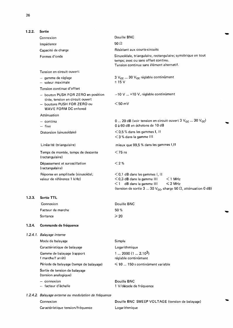
1.2.2. Sortie
Connexion
Impedance
Capacite de charge
Formes d'onde
Tension en circuit ouvert:
- gamme de reglage - valeur maximale
Tension continue d'offset
bouton PUSH FOR ZERO en position tiree, tension en circuit ouvert boutons PUSH FOR ZERO ou WAVE FORM DC enfonce
Attenuation
- continu - fixe
Distorsion (sinuso'idale)
Linearite (triangulaire)
Temps de montee, temps de descente (rectangulaire)
Depassement et suroscillation (rectangulaire)
Reponse en amplitude (sinuso"idal; valeur de reference 1 kHz)
1.2.3. Sortie TTL
Connexion
Facteur de marche
Sortance
1.2.4. Commande de frequence
1.2.4. 1. Balayage interne
Mode de balayage
Caracteristique de balayage
Gamme de balayage (rapport f marche/f arret)
Periode de balayage (temps de balayage)
Sortie de tension de balayage (tension analogique)
connexion - facteur d'echelle
1.2.4.2. Balayage externe au modulation de fniquence
Connexion
Caracteristique tension/frequence
Douille BNC
5on
Resistant aux courts-circuits
Sinuso"idale, triangulaire, rectangulaire; symetrique en tout temps; avec ou sans offset continu. Tension continue sans element alternatif.
3 Vee ... 30 Vee reglable continument ± 15 v
-10 V ... +10 V, reglable continument
<50mV
0 ... 20 dB (voir tension en circuit ouvert 3 V cc ... 30 V eel 0 a 60 dB en echelons de 10 dB
< 0,5% dans les gammes I, II < 3% dans Ia gamme Ill
mieux que 99,5% dans les gammes I ,II
< 75 ns
<2%
< 0,1 dB dans les gammes I, II < 0,3 dB dans Ia gamme Ill < 1 MHz < 1 dB dans Ia gamme Ill ~ 2 MHz (tension de sortie 3 ... 30 V CC• charge 50 n, attenuation 0 dB)
Douille BNC
50%
~20
Simple
Logarithmique
1 .. . 2ooo ( 1 .. . 2. 1 o3) reglable continument
~ 10 ... 150 s continument variable
Douille BNC 1 V /decade de frequence
Douille BNC SWEEP VOLTAGE (tension de balayage)
Logarithmique
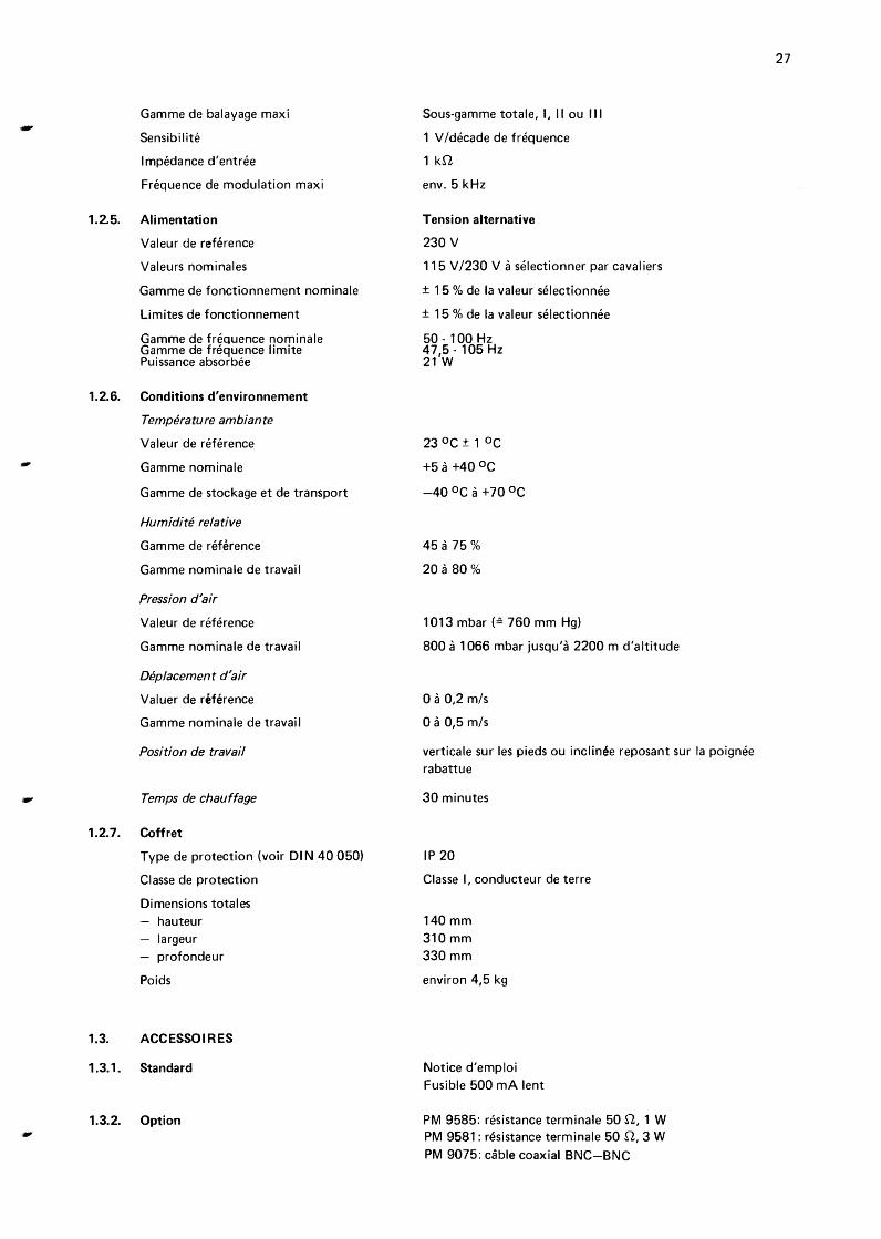
Gamme de balayage maxi
Sensibilite
Impedance d'entree
Frequence de modulation maxi
1.2.5. Alimentation
Valeur de reference
Valeurs nominales
Gamme de fonctionnement nominale
Limites de fonctionnement
Gamme de frequence nominale Gamme de frequence limite Puissance absorbee
1.2.6. Conditions d'environnement
Temperature ambiante
Valeur de reference
Gamme nominale
Gamme de stockage et de transport
Humidite relative
Gamme de reference
Gamme nominale de travail
Pression d'air
Valeur de reference
Gamme nominale de travail
Dep/acement d'air
Valuer de reference
Gamme nominale de travail
Position de travail
Temps de chauffage
1.2.7. Coffret
Type de protection (voir Dl N 40 050)
Classe de protection
Dimensions totales hauteur
- largeur - profondeur
Po ids
1.3. ACCESSOIRES
1.3.1. Standard
1.3.2. Option
Sous-gamme totale, I, II ou Ill
1 V /decade de frequence
1 kn
env. 5kHz
Tension alternative
230 v 115 v /230 v a selectionner par cavaliers
± 15 % de Ia valeur selectionnee
± 15% de Ia valeur selectionnee
50-100Hz 47,5- 105Hz 21 w
23 °C ± 1 °C
+5 a +40 oc
-40 oc a +70 oc
45 a 75%
20 a 80%
1013 mbar (~ 760 mm Hg)
800 a 1066 mbar jusqu'a 2200 m d'altitude
0 a 0,2 m/s
0 a 0,5 m/s
verticale sur les pieds ou inclinee reposant sur Ia poignee rabattue
30 minutes
IP 20
Classe I, conducteur de terre
140 mm 310 mm 330mm
environ 4,5 kg
Notice d'emploi Fusible 500 rnA lent
PM 9585: resistance terminale 50 n, 1 W PM 9581: resistance terminale 50 n, 3 W
PM 9075: cable coaxial BNC-BNC
27
28
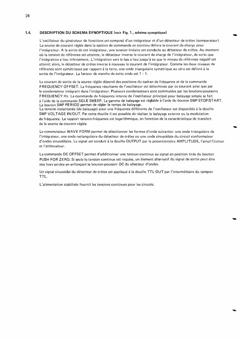
1.4. DESCRIPTION DU SCHEMA SYNOPTIOUE (voir Fig. 1., schema synoptique)
L'oscillateur du generateur de fonctions est compose d'un integrateur et d'un detecteur de cretes (comparateur).
La source de courant reglee dans Ia section de commande en continu delivre le courant de charge pour l'integrateur. A Ia sortie de cet integrateur, une tension lineaire est conduite au detecteur de cretes. Au moment ou Ia tension de reference est atteinte, le detecteur inverse le courant de charge de l'integrateur, de sorte que
!'integration a lieu infersement. L'integration vers le bas a lieu jusqu'a ce que le niveau de reference negatif est atteint; alors, le detecteur de cretes inverse a nouveau le courant de l'integrateur. Comme les deux niveaux de
reference sont symetriques par rapport a Ia terre, une onde triangulaire symetrique au zero est delivre a Ia sortie de l'integrateur. La facteur de marche de cette onde est 1 : 1.
Le courant de sortie de Ia source reglee depend des positions du cadran de frequence et de Ia commande FREQUENCY OFFSET. La frequence resultante de l'oscillateur est determinee par ce courant ainsi que par le condensateur integrant dans l'integrateur. Plusieurs condensateurs sont commutees par les boutons-poussoirs
FREQUENCY Hz. La commande de frequence interne de l'oscillateur principal pour balayage simple se fait a !'aide de Ia commande SGLE SWEEP. Le gamme de halayage est reglable a l'aide du bouton SWP STOP/START. Le bouton SWP PERIOD permet de regler le temps de balayage. La tension instantanee (de balayage) pour une frequence differente de l'oscillateur est disponible a Ia douille
SWP VOLTAGE IN/OUT. Par cette douille il est possible de realiser le balayage externe ou Ia modulation
de frequence. Le rapport tension-frequence est logarithmique, en fonction de Ia caracteristique de transfert
de Ia source de courant reglee.
Le commutateur WAVE FORM permet de selectionner les formes d'onde suivantes: une onde triangulaire de
l'integrateur, une onde rectangulaire du detecteur de cretes ou une onde sinuso'idale du circuit conformateur
d'ondes sinuso'idales. Le signal est conduit a Ia douille OUTPUT par le potentiometre AMPLITUDE, l'amp!ificateur
et l'attenuateur.
La commande DC OFFSET permet d'additionner une tension continue au signal en position tiree du bouton
PUSH FOR ZERO. Si seule Ia tension continue est requise, un element alternatif du signal de sortie peut etre
mis hors service en enfon<;ant le bouton-poussoir DC du selecteur d'ondes.
Un signal sinuso'ldal du detecteur de cretes est applique a Ia douille TTL OUT par l'intermediaire du tampon TTL.
L'alimentation stabilisee fournit les tensions continues pour les circuits.
29
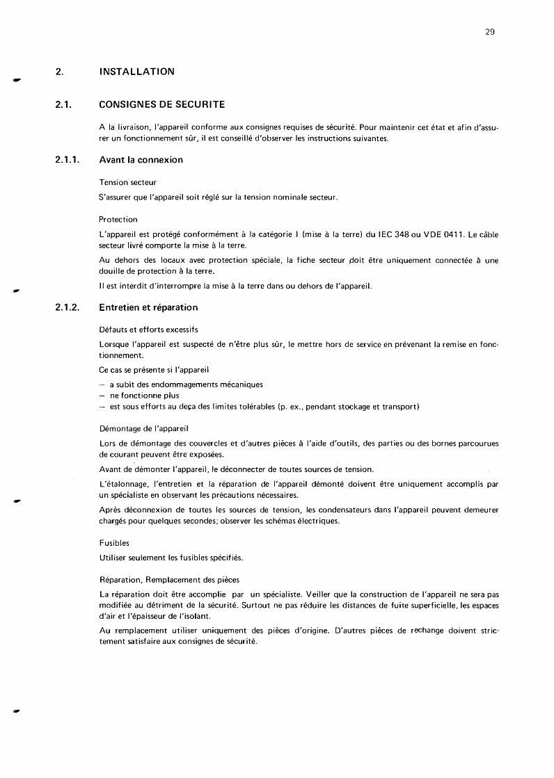
2. INSTALLATION
2.1. CONSIGNES DE SECURITE
2.1.1.
2.1.2.
A Ia livraison, l'appareil conforme aux consignes requises de securite. Pour maintenir cet etat et afin d'assurer un fonctionnement sur, il est conseille d'observer les instructions suivantes.
Avant Ia connexion
Tension secteur
S'assurer que l'appareil soit regie sur Ia tension nominale secteur.
Protection
L'appareil est protege conformement a Ia categorie I (mise a Ia terre) du I EC 348 ou VDE 0411. Le cable secteur livre comporte Ia mise a Ia terre.
Au dehors des locaux avec protection speciale, Ia fiche secteur ~oit etre uniquement connectee a une douille de protection a Ia terre.
II est interdit d'interrompre Ia mise a Ia terre dans ou dehors de l'appareil.
Entretien et reparation
Defauts et efforts excessifs
Lorsque l'appareil est suspecte de n'etre plus sur, le mettre hors de service en prevenant Ia remise en fonctionnement.
Ce cas se presente si l'appareil
a subit des endommagements mecaniques ne fonctionne plus est sous efforts au de~a des limites tolerables (p. ex., pendant stockage et transport)
Demontage de l'appareil
Lors de demontage des couvercles et d'autres pieces a l'aide d'outils, des parties ou des bornes parcourues de courant peuvent etre exposees.
Avant de demonter l'appareil, le deconnecter de toutes sources de tension.
L'etalonnage, l'entretien et Ia reparation de l'appareil demonte doivent etre uniquement accomplis par un specialiste en observant les precautions necessaires.
Apres deconnexion de toutes les sources de tension, les condensateurs dans l'appareil peuvent demeurer charges pour quelques secondes; observer les schemas electriques.
Fusibles
Utiliser seulement les fusibles specifies.
Reparation, Remplacement des pieces
La reparation doit etre accomplie par un specialiste. Veiller que Ia construction de l'appareil ne sera pas modifiee au detriment de Ia securite. Surtout ne pas reduire les distances de fuite superficielle, les espaces d'air et l'epaisseur de l'isolant.
Au remplacement utiliser uniquement des pieces d'origine. D'autres pieces de rechange doivent strictement satisfaire aux consignes de securite.
30
2.2. MONTAGE
L'appareil peut etre utilise dans toute position. Avec poignee rabattue, l'appareil peut etre utilise en position inclinee; a cette fin, enfoncer les boutons de Ia poignee (fig. 2). II est recommande de ne pas placer l'appareil sur une surface produisant de Ia chaleur ou en plein soleil.
2.3. MISE A LA TERRE
Avant toute mise sous tension, l'appareil doit etre connecte a Ia terre conformement aux consignes de securite locales. Le cable secteur fixe a l'appareil comporte un conducteur de terre brache sur les contacts protecteurs de Ia fiche. Ainsi, avec le coffret de l'appareil connecte sur une prise a contacts protecteurs, il est, par consequent, mis a Ia terre.
ATTENTION: La fiche secteur ne ·doit etre introduite que dans une prise a contact de terre. La mise a Ia terre ne doit pas etre eliminee par l'emploi, par exemple, d'un cable prolongateur sans conducteur de terre.
Le potentiel zero du circuit sur les contacts externes des douilles BNC est branche au coffret par l'intermediaire d'un circuit paraiiE~Ie RC. Une mise a Ia terre HF correcte est ainsi obtenue. Les contacts externes des douilles BNC ne doivent pas etre utilises pour brancher un conducteur de terre.
2.4. DEMONTAGE DE l'APPAREIL
Debrancher Ia fiche secteur Placer Ia poignee en haut sur l'appareil; a cette fin, enfoncer les boutons de Ia poignee Desserrer Ia vis centrale a l'arriere de l'appareil Enlever le tuyau de protection du cable secteur fixe sur le boitier Demonter le boitier
2.5. BRANCHEMENT DE l'APPAREIL
L'appareil ne peut etre branche que sur une alimentation en alternatif. A Ia livraison, l'appareil est regie sur 230 V. Avant le branchement au secteur, s'assurer que Ia gam me choisie de tension secteur comporte Ia tension secteur locale indiquee a l'arriere de l'appareil sur une plaquette. Au cas ou l'appareil doit etre alimente sur 115 V, proceder comme suit:
Debrancher Ia fiche secteur Demonter l'appareil, voir Ia para. 2.4. Ressouder les pontets sur le transformateur secteur selon le schema de connexion collant; voir aussi ci-dessous:
• 230 V-----1 • • • 1t---115 v ---It ··----·· ··----··
I nserer le fusible fourni de 500 rnA, retarde, dans le porte-fusible au lieu de celui prevu Changer Ia plaquette de tension secteur a l'arriere de l'appareil conformement a Ia selection. La plaquette de 115 V est contenue dans une enveloppe en plastique, comme Ia fusible fourni. Fermer l'appareil
le branchement secteur doit etre conforme aux consignes de securite locales; il implique que l'appareil soit branche sur une douille secteur avec conducteur de terre (voir le para. 2.3.).
3. MISE EN SERVICE
3.1. COMMANDES ET DOUILLES
Legende
POWER o ON
• OFF
WAVEFOPM
~~l.J
FREQUENCY Hz x 1 x1 00 x1 Ok
.1 ... 200 (echelle logarithmique)
FREO. OFFSET -20% ... +20%
ATTENUATION 10 dB 20 dB 30 dB
AMPLITUDE
3 Vpp ... 30 Vpp
DC
DC OFFSET -10V ... +10V
PUSH FOR ZERO
OUTPUT
TTL OUTPUT
SGLE SWEEP ON OFF
SWP VOLTAGE 1 ... 2000
SWP VOLTAGE IN/OUT 1 V/FREO DEC
SWP PERIOD ~ 10 s ... 150 s
Repere
251
252/5 a 252/7
252/1 a 252/3
650
651
252/9 a 252/11
821
252/8
822
822
200
201
252/4
653
202
652
Fonction
Commutateur secteur, point blanc indiquant Ia position enclenchee
Boutons-poussoirs pour forme d'onde requise:
sinuso"ldale, triangulaire ou rectangulaire
Selecteurs de Ia gamme de frequence 0,1-200 Hz, 10Hz-20kHz, 1kHz- 2 MHz
Cadran pour reglage de frequence gros continu
Cadran pour reglage de frequence fin continu
Boutons-poussoirs pour reglage de !'attenuation fixe; 40- 60 dB par combinaison de boutonspoussoirs
31
Bouton pour reglage d'amplitude continu du signal de sortie-
Bouton-poussoir pour declenchement de Ia portion alternative du signal
Bouton pour reglage continu de tension continue
Tirette pour addition de Ia tension continue au signal de sortie
Douille de sortie BNC pour signal
Douille de sortie BNC pour le signal TTL
Bouton-poussoir pour demarrage d'une periode de balayage simple
Bouton pour reglage de Ia frequence d'arret (rapport frequence arret/marche)
Douille d'entree/sortie BNC pour tension analogique de frequence
Bouton pour reglage du temps de balayage
32
3.2. FONCTIONNEMENT
3.2.1. Reglage de Ia tension sur Ia douille OUTPUT
L'amplitude du signal de sortie est reglable en continu par Ia commande AMPLITUDE.
Avec bouton DC rei ache et bouton PUSH FOR ZERO tire, une tension continue positive ou negative,
continument reglable peut etre additionnee au signal de sortie. En position enfoncee du bouton DC, Ia portion
alternative du signal de sortie est eliminee et seule Ia tension continue appliquee a Ia sortie.
Le signal de sortie et !'offset en continu peuvent etre attenues en echelons de 10 a 60 dB. Pour 10 a 30 dB,
des boutons-poussoirs separes sont disponibles. Des attenuations de 40 at 50 dB sont selectionnees par
l'actionnement de plusieurs poutons-poussoirs. Pour 60 dB les trois boutons doivent etre enfonces.
Remarque: L'amplificateur de sortie pourrait etre surcharge a Ia suite de !'addition du signal et de I' offset en
tension continue. Afin d'eviter Ia limitation, Ia valeur de crete de Ia tension sortie en circuit ouvert
ne doit pas depasser de +15 V (attenuateur par echelons regie sur 0 dB).
3.2.2. Reglage de Ia frequence
Trois commandes sont disponibles pour regler Ia frequence de base:
cadran a echelle logarithmique
- selecteur de gamme F R EOU ENCY Hz
- commande vernier FREO OFFSET
L'affichage multiplie par le facteur choisi sur le selecteur de gamme represente Ia frequence. De plus, il taut tenir compte de l'ecart de frequence regie a l'aide de Ia commande F REO OFFSET.
La frequence selectionnee represente:
Ia frequence du signal de sortie
Ia frequence du signal avec OV
a Ia douille SWP VOLTAGE
IN/OUT
Ia frequence de demarrage
3.2.3. Balayage simple interne
bouton SG LE SWEEP relache
bouton SGLE SWEEP enfonce
du mode de balayage simple
La balayage simple interne de Ia frequence marche-arnh est demarre en enfon<;:ant le bouton SG LE SWEEP.
La caracteristique est exponentielle selon Ia formule
fo = fSTART. 10 Uc/V
f0 etant Ia frequence instantanee a Ia sortie,
fSTART Ia freqllence au debut du balayage, representee par le reglage de Ia frequence; voir 3.2.2. Uc Ia tension a Ia douille SWP VOLTAGE IN/OUT
De Ia sorte, une difference de tension de commande de 1 V resulte en un rapport de frequence 10 : 1.
A Ia fin du balayage Ia sortie reste a Ia frequence d'ardh, laquelle est reglable a l'aide de Ia commande
SWP STOP/START. Lorsque le bouton SG LE SWEEP est rel«khe, Ia frequence est retournee a Ia frequence
de demarrage. Le temps de balayage est regie a l'aide du potentiometre SWP PERIOD. Le pre-reglage de Ia
frequence d'arret peut etre realisee a Ia fin du balayage pendant un temps minimal avant de proceder au reglage du balayage final.
Veuillez noter:
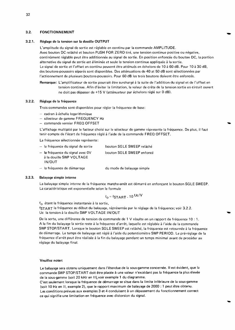
Le balayage sera obtenu uniquement dans l'etendue de Ia sous-gamme concernee. II est evident, que Ia
commande SWP STOP/START doit etre placee a une valeur n'excedant pas Ia frequence Ia plus elevee
de Ia sous-gamme (soit 20 kHz en II), voir exemple 1 du diagramme. C'est seulement lorsque Ia frequence de demarrage se situe dans Ia limite interieure de Ia sous-gamme (soit 10Hz en II, exemple 2), que le rapport maximum de balayage de 2000: 1 peut etre obtenu. Les conditions prevues aux exemples 3 et 4 conduisent a un depassement du fonctionnement correct
ce qui signifie une limitation en frequence avec distorsion du signal.
log f
f STOP ---r--+-
sweep range
3.2.4.
sweep time
(PERIOD)
l Hz
Balayage externe et modulation de frequence
Le bouton SGLE SWEEP doit etre relikhe.
fSTART
I
example
SWP STOP/ START
I I
2" 10~---~---~~~----~--~~20k
100
1 k
10 k
20 k
10 k
Hz
1 k
1 100
10
Exemple pour Ia sous-gamme II (x 100)
les deux autres gammes seront considerees
de facon similaire.
33
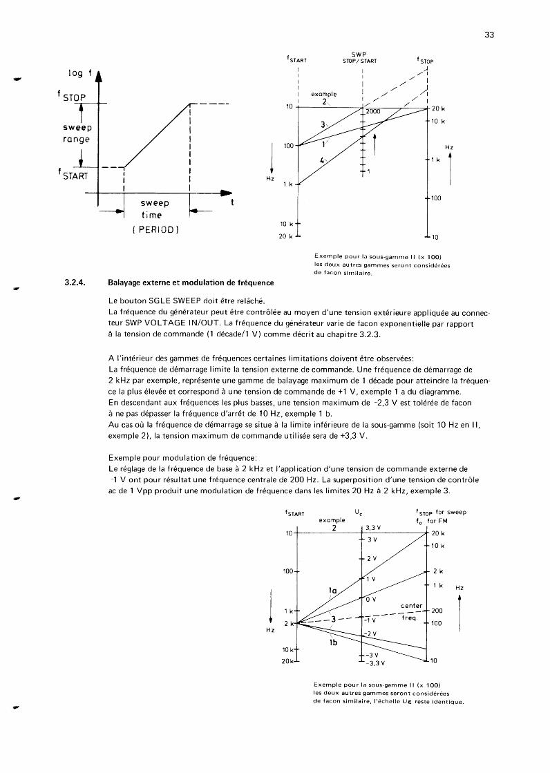
La frequence du generateur peut etre controlee au moyen d'une tension exterieure appliquee au connec
teur SWP VOLTAGE IN/OUT. La frequence du generateur varie de facon exponentielle par rapport a Ia tension de commande (1 decade/1 V) comme decrit au chapitre 3.2.3.
A l'interieur des gammes de frequences certaines limitations doivent etre observees:
La frequence de demarrage limite Ia tension externe de commande. Une frequence de demarrage de
2 kHz par exemple, represente une gamme de balayage maximum de 1 decade pour atteindre Ia frequen
ce Ia plus elevee et correspond a une tension de commande de +1 V, exemple 1 a du diagramme.
En descendant aux frequences les plus basses, une tension maximum de -2,3 V est toleree de facon
a ne pas depasser Ia frequence d'arret de 10 Hz, exemple 1 b.
Au cas ou Ia frequence de demarrage se situe a Ia limite inferieure de Ia sous-gamme (soit 10Hz en II,
exemple 2), Ia tension maximum de commande utilisee sera de +3,3 V.
Exemple pour modulation de frequence:
Le reglage de Ia frequence de base a 2kHz et !'application d'une tension de commande externe de
-1 V ont pour resultat une frequence centrale de 200Hz. La superposition d'une tension de controle
ac de 1 Vpp produit une modulation de frequence dans les limites 20Hz a 2 kHz, exemple 3.
1 Hz
fsTART f STOP for sweep example f
0 for FM
2 3,3 v 10 -+--------+----------+ 20 k
100
1 k
2 k
10 k
20k
3V 10k
2 k
1 k
200
100
10
Exemple pour Ia sous-gamme II (x 1 00)
les deux autres gammes seront considerees
Hz
r
de facon similaire, l'echelle Uc: reste identique.

4.2. ACCESS TO PARTS
4.2.1.
4.2.2.
4.2.3.
4.2.4.
Before dismantling the instrument, the safety regulations in accordance with para. 2.1. must be strictly
observed.
Cabinet, see 2.4.
Knobs
Remove the cap from the knob. Unscrew the nut and remove the knob. When replacing the knob, ensure that the white mark is correctly aligned with the text plate markings.
Text plate
Remove the cabinet, see 2.4. Remove the turn-knobs, see 4.2.2. Remove the dial. Remove the plastic cover of the mains switch. The text plate can now be removed.
Be careful: The textplate is fitted to the frontplate by double sided adhesive tape.
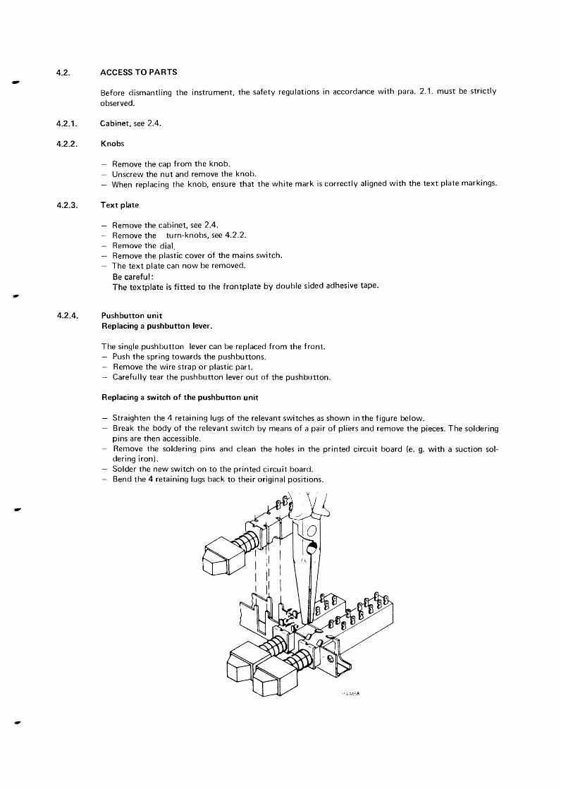
Pushbutton unit Replacing a pushbutton lever.
The single pushbutton lever can be replaced from the front. Push the spring towards the pushbuttons. Remove the wire strap or plastic part. Carefully tear the pushbutton lever out of the pushbutton.
Replacing a switch of the pushbutton unit
Straighten the 4 retaining lugs of the relevant switches as shown in the figure below. Break the body of the relevant switch by means of a pair of pliers and remove the pieces. The soldering pins are then accessible. Remove the soldering pins and clean the holes in the printed circuit board (e. g. with a suction soldering iron). Solder the new switch on to the printed circuit board. Bend the 4 retaining lugs back to their original positions.
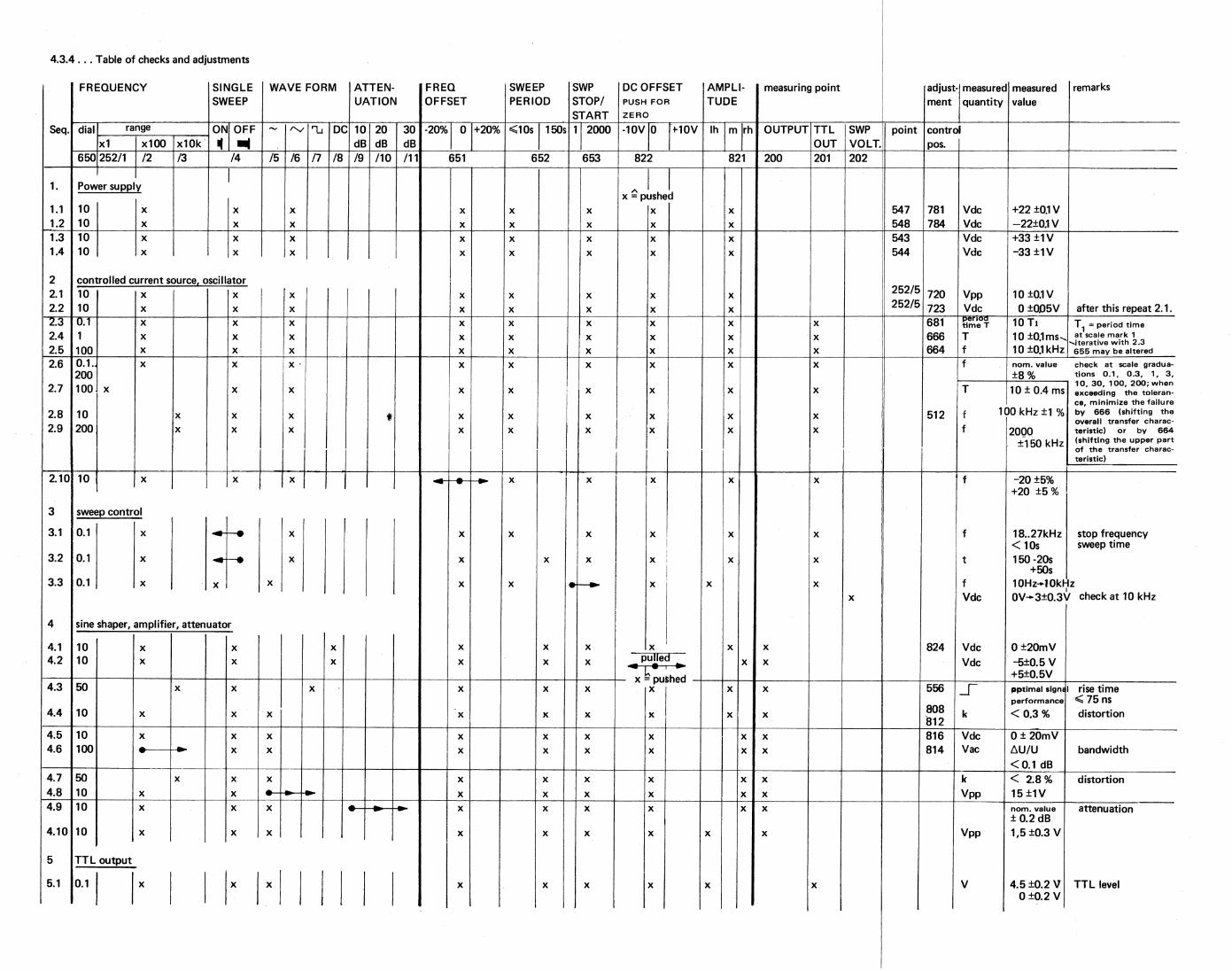
4.3. CHECK AND ADJUSTMENT
4.3.1. General
The limits mentioned in this paragraph are valid only for a newly adjusted instrument and therefore might
deviate from the values as stated in paragraph 1.2. "Technical Data".
Adjustment of the instrument is only permitted after a warm-up hme of at least 30 minutes at an ambient
temperature of (+23 ± 3) °C and when connected to a mains voltage of 230 V ± 5 %. The cabinet must
be closed.
The printed circuit board is mounted overhead. Nevertheless all trimming potentiometers and capacitors are
accessible from the top. For adequate temperature stability during adjustment, the cabinet should be
removed only for a short time and so far that the required adjusting element is just accessible.
If not explicitely stated otherwise, the voltage potentials refer to the relevant contact measured against
circuit earth ( j_ 0 ).
The following abbreviations are used for setting and measuring instruments:
X
0
rh
lh
m ml D.V.M. (d.c.}
osc. c Fg
DA
OM
50S1
4.3.2. Preparations
= Button pressed
= Button not pressed/unlocked = Button only tipped = extreme right-hand position
=extreme lift-hand position
= mid-position = position in the middle between m and lh = Digital voltmeter for DC measurements e.g. PM 2441 =Oscilloscope e.g. PM 3240, PM 3260 = Counter e.g. PM 6630 = Function generator e.g. PM 5127 = Distortion analyzer e.g HP 333 A
= Digital multimeter e.g. PM 2424 = 50 S1 terminating resistor e.g. PM 9585
All trimming potentiometers and capacitors in mid-position; (only for completely new adjustment).
Turn dial potentiometer to extreme counter clockwise position.
Position dial such that the 0.1 graduation on the dial is positioned 8 mm left to the text plate mark.
- Solder joints A, B, C, D must be closed. To be opened for failure detection only.
Terminate the OUTPUT by a 50 Ohm resistor.
4.3.3. General functional test
Actuate all buttons one after the other for rough functional test of the generator by means of an
oscilloscope connected to the OUTPUT socket.
Control the TTL output.
Roughly control the output voltage at the SWP VOLTAGE socket during the internal sweep.
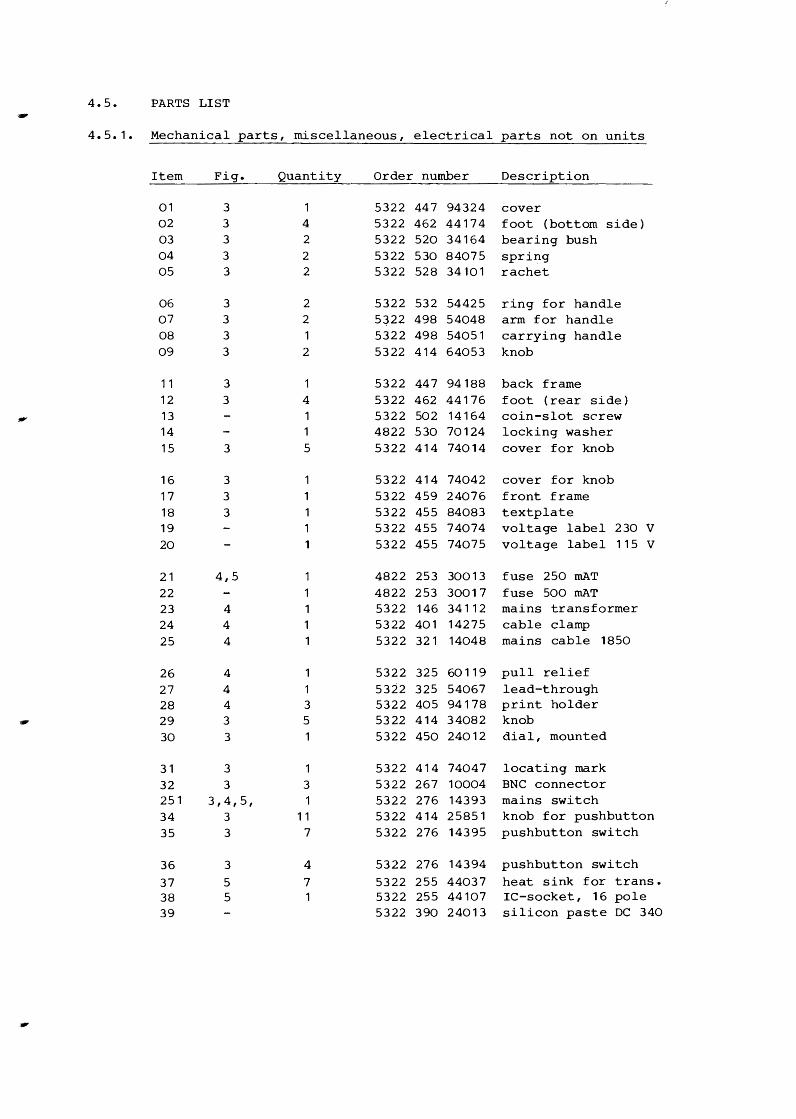
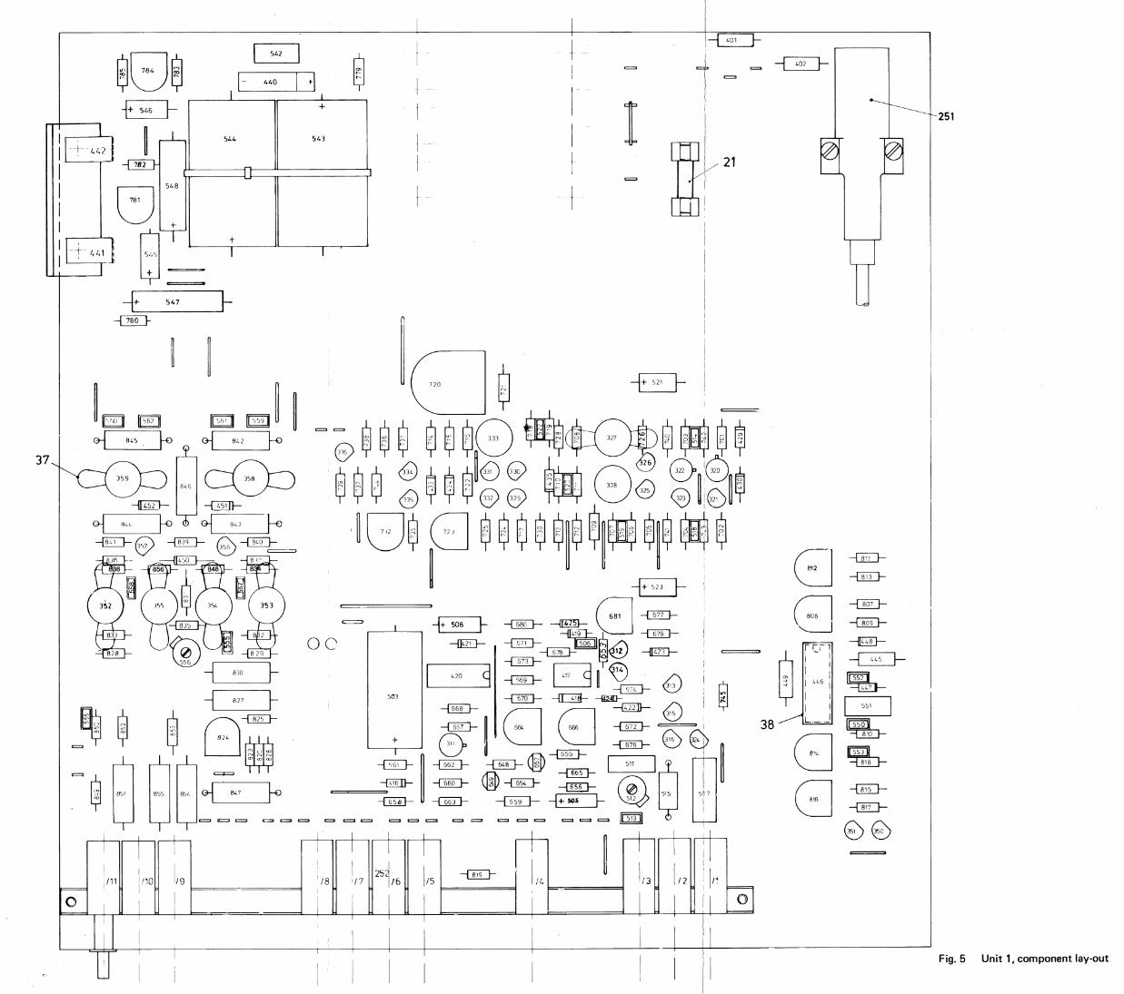
4.5. PARTS LIST
4.5.1. Mechanical parts, miscellaneous, electrical parts not on units
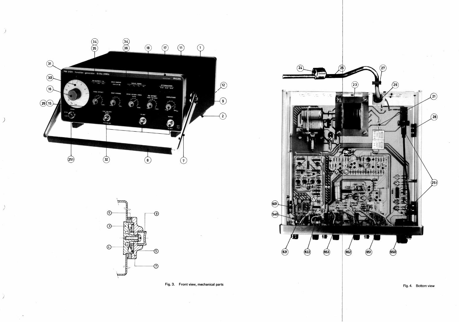
Item Fig. Quantity Order number Description
01 3 5322 447 94324 cover 02 3 4 5322 462 44174 foot (bottom side) 03 3 2 5322 520 34164 bearing bush 04 3 2 5322 530 84075 spring 05 3 2 5322 528 34101 rachet
06 3 2 5322 532 54425 ring for handle 07 3 2 5~22 498 54048 arm for handle 08 3 5322 498 54051 carrying handle 09 3 2 5322 414 64053 knob
11 3 5322 447 94188 back frame 12 3 4 5322 462 44176 foot (rear side) 13 5322 502 14164 coin-slot screw 14 1 4822 530 70124 locking washer 15 3 5 5322 414 74014 cover for knob
16 3 5322 414 74042 cover for knob 17 3 5322 459 24076 front frame 18 3 5322 455 84083 textplate 19 5322 455 74074 voltage label 230 v 20 5322 455 74075 voltage label 115 v
21 4,5 1 4822 253 30013 fuse 250 mAT 22 1 4822 253 30017 fuse 500 mAT 23 4 5322 146 34112 mains transformer 24 4 1 5322 401 14275 cable clamp 25 4 1 5322 321 14048 mains cable 1850
26 4 5322 325 60119 pull relief 27 4 5322 325 54067 lead-through 28 4 3 5322 405 94178 print holder 29 3 5 5322 414 34082 knob 30 3 5322 450 24012 dial, mounted
31 3 5322 414 74047 locating mark 32 3 3 5322 267 10004 BNC connector 251 3,4,5, 5322 276 14393 mains switch 34 3 11 5322 414 25851 knob for pushbutton 35 3 7 5322 276 14395 pushbutton switch
36 3 4 5322 276 14394 pushbutton switch
37 5 7 5322 255 44037 heat sink for trans. 38 5 5322 255 44107 IC-socket, 16 pole 39 5322 390 24013 silicon paste DC 340
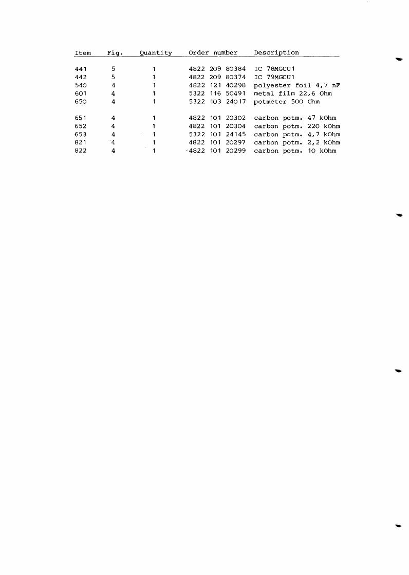
Item Fig. Quantity Order number Description ... 441 5 4822 209 80384 IC 78MGCU1 442 5 4822 209 80374 IC 79MGCU1 540 4 4822 121 40298 polyester foil 4,7 nF 601 4 1 5322 116 50491 metal film 22,6 Ohm 650 4 1 5322 103 24017 potmeter 500 Ohm
651 4 4822 101 20302 carbon potm. 47 kOhm 652 4 4822 101 20304 carbon potm. 220 kOhm 653 4 5322 101 24145 carbon potm. 4,7 kOhm 821 4 4822 101 20297 carbon potm. 2,2 kOhm 822 4 ·4822 101 20299 carbon potm. 10 kOhm
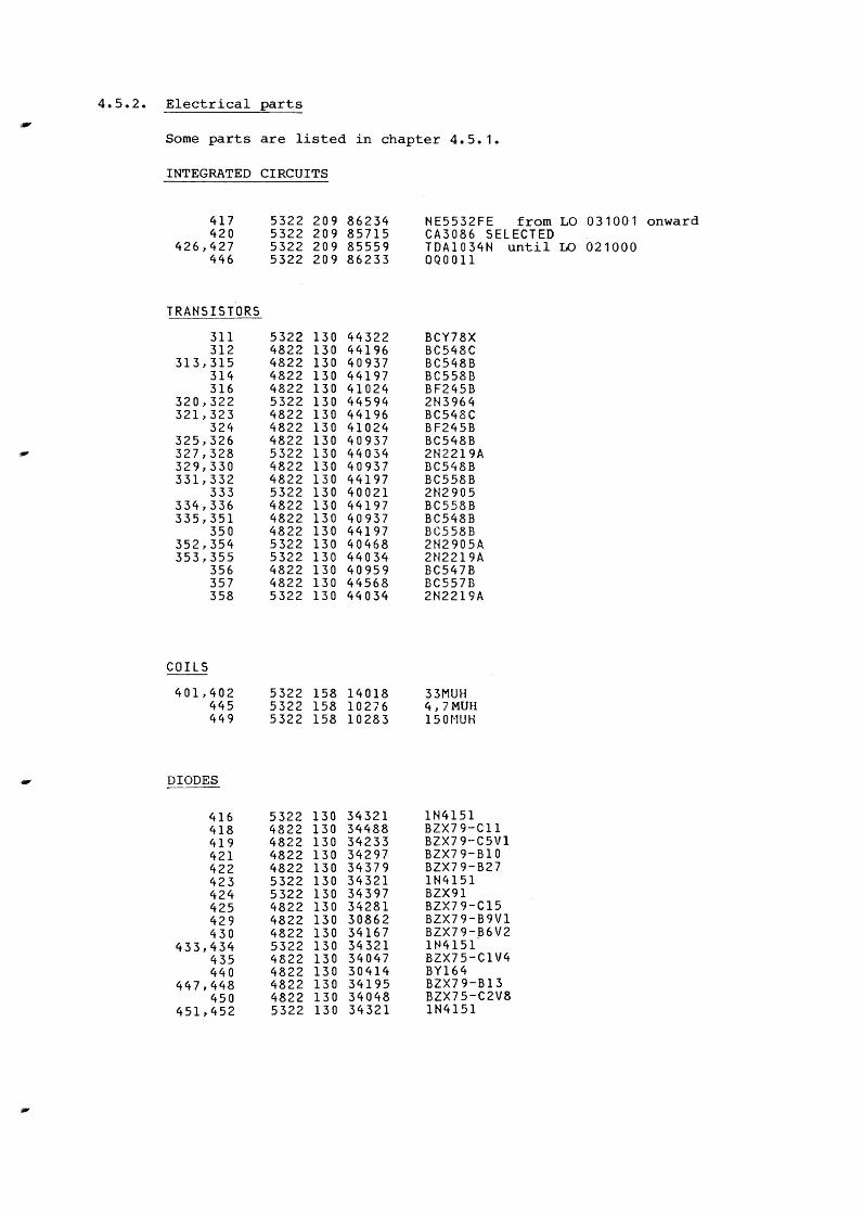
4.5.2. Electrical
Some parts
INTEGRATED
417 420
426,427 446
TRANSISTORS
311 312
313,315 314 316
320,322 321,323
324 325,326 327,328 329,330 331,332
333 334,336 335,351
350 352,354 353,355
356 357 358
COILS
401,402 445 449
DIODES
416 418 419 421 422 423 424 425 429 430
433,434 435 440
447,448 450
451,452
parts
are listed in chapter 4.5.1.
CIRCUITS
5322 209 86234 5322 209 85715 5322 209 85559 5322 209 86233
5322 130 44322 4822 130 44196 4822 130 40937 4822 130 44197 4822 130 41024 5322 130 44594 4822 130 44196 4822 130 41024 4822 130 40937 5322 130 44034 4822 130 40937 4822 130 44197 5322 130 40021 4822 130 44197 4822 130 40937 4822 130 44197 5322 130 40468 5322 130 44034 4822 130 40959 4822 130 44568 5322 130 44034
5322 158 14018 5322 158 10276 5322 158 10283
5322 130 34321 4822 130 34488 4822 130 34233 4822 130 34297 4822 130 34379 5322 130 34321 5322 130 34397 4822 130 34281 4822 130 30862 4822 130 34167 5322 130 34321 4822 130 34047 4822 130 30414 4822 130 34195 4822 130 34048 5322 130 34321
NE5532FE from LO CA3086 SELECTED TDA1034N OQ0011
BCY78X BC548C BC548B BC558B BF245B 2N3964 BC548C BF245B BC548B 2N2219A BC548B BC558B 2N2905 BC558B BC548B BC558B 2N2905A 2N2219A BC547B BC557B 2N2219A
33MUH 4, 7 MUH 15 0~1UH
1N4151 BZX79-C11
until LO
BZX79-C5V1 BZX79-B10 BZX79-B27 1N4151 BZX91 BZX79-C15 BZX79-B9Vl BZX79-J36V2 1N4151 BZX75-C1V4 BY164 BZX79-B13 BZX75-C2V8 1N4151
031001 onward
021000
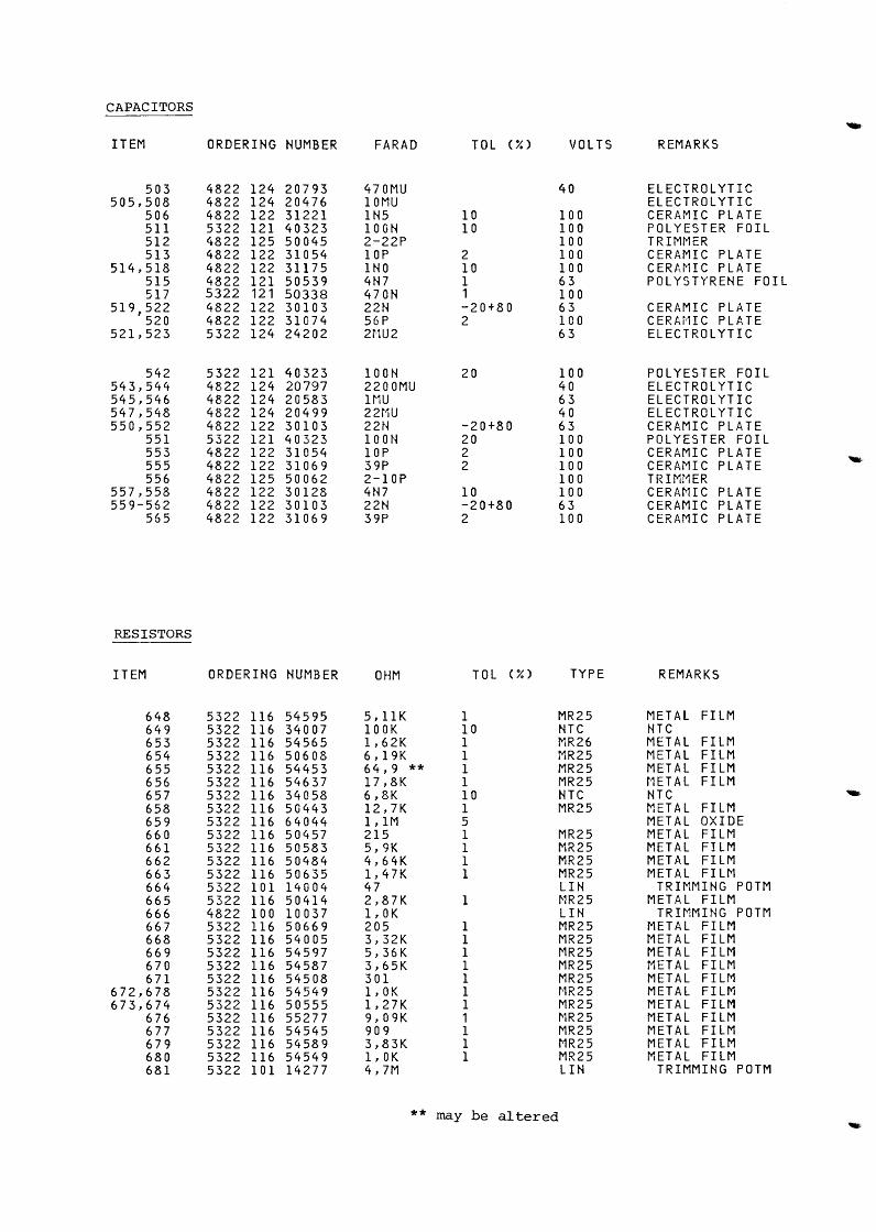
CAPACITORS
ITEM ORDERING NUMBER FARAD TOL (%) VOLTS REMARKS
503 4822 124 20793 4 7 Of'1U 40 ELECTROLYTIC 505,508 4822 124 20476 lOMU ELECTROLYTIC
506 4822 122 31221 INS 10 100 CERAMIC PLATE 511 5322 121 40323 lOON 10 100 POLYESTER FOIL 512 4822 125 50045 2-22P 100 TRIMt'lER 513 4822 122 31054 lOP 2 100 CERAMIC PLATE
514,518 4822 122 31175 1NO 10 100 CERt\~1IC PLATE 515 4822 121 50539 4N7 1 63 POLYSTYRENE FOIL 517 5322 121 50338 470N 1 100
519,522 4822 122 30103 22N -20+80 63 CERAMIC PLATE 520 4822 122 31074 56P 2 100 C ERA i•H C P L AT E
521,523 5322 124 24202 2i-1U2 63 ELECTROLYTIC
542 5322 121 40323 lOON 20 100 POLYESTER FOIL 543,544 4822 124 20797 2200MU 40 ELECTROLYTIC 545,546 4822 124 20583 1MU 63 ELECTROLYTIC 547,548 4822 124 20499 22t1U 40 ELECTROLYTIC 550,552 4822 122 30103 22N -20+80 63 CERAMIC PLATE
551 5322 121 40323 lOON 20 100 POLYESTER FOIL 553 4822 122 31054 lOP 2 100 CERAMIC PLATE 555 4822 122 31069 39P 2 100 CERAMIC PLATE 556 4822 125 50062 2-10P 100 TRIMi1ER
557,558 4822 122 30128 4N7 10 100 CERAt'ii C PLATE 559-562 4822 122 30103 22N -20+80 63 CERAMIC PLATE
565 4822 122 31069 39P 2 100 CERAMIC PLATE
RESISTORS
ITEM ORDERING NUMBER OHM TOL 00 TYPE REMARKS
648 5322 116 54595 5,11K 1 MR25 METAL FILM 649 5322 116 34007 lOOK 10 NTC NTC 653 5322 116 54565 1,62K 1 MR26 METAL FILM 654 5322 116 50608 6,19K 1 MR25 METAL FILM 655 5322 116 54453 64,9 ** 1 MR25 METAL FILM 656 5322 116 54637 l7,8K 1 MR25 t·1ETAL FILM 657 5322 116 34058 6,8K 10 NTC NTC 658 5322 116 50443 12,7K 1 MR25 METAL FILM 659 5322 116 64044 1,1M 5 METAL OXIDE 660 5322 116 50457 215 1 MR25 METAL FILM 661 5322 116 50583 5,9K 1 MR25 METAL FILM 662 5322 116 50484 4,64K 1 MR25 METAL FILM 663 5322 116 50635 1,47K 1 MR25 METAL FILt-1 664 5322 101 14004 47 LIN T R I ~1M IN G P 0 TM 665 5322 116 50414 2,87K 1 ~1R25 METAL FILM 666 4822 100 10037 l,OK LIN TRIMMING POTM 667 5322 116 50669 205 1 MR25 METAL FILM 668 5322 116 54005 3,32K 1 MR25 METAL FILM 669 5322 116 54597 5,36K l f'1R25 METAL FILM 670 5322 116 54587 3,65K l MR25 METAL FILM 671 5322 116 54508 301 1 MR25 METAL FILM
672,678 5322 116 54549 1,0K 1 ~1R25 METAL FILM 673,674 5322 116 50555 1,27K 1 MR25 METAL FILM
676 5322 116 55277 9,09K 1 MR25 METAL FILM 677 5322 116 54545 909 1 MR25 METAL FILM 679 5322 116 54589 3,83K 1 MR25 METAL FILM 680 5322 116 54549 1,0K 1 MR25 METAL FILM 681 5322 101 14277 4,7M LIN TRIMMING POTM
** may be altered
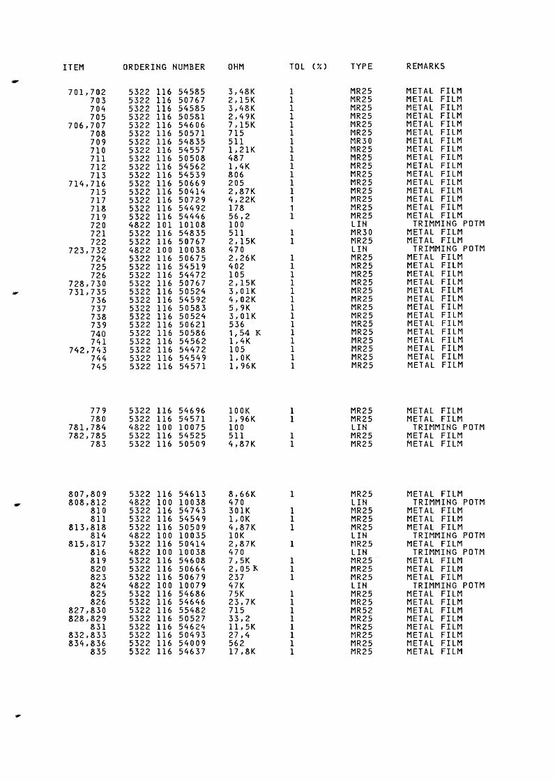
ITEM
701,702 703 704 705
706,707 708 709 710 711 712 713
714,716 715 717 718 719 720 721 722
723,732 724 725 726
728,730 731,735
736 737 738 739 740 741
742,743 744 745
779 780
781,784 782,785
783
807,809 808,812
810 811
813,818 814
815,817 816 819 820 823 824 825 826
827,830 828,829
831 832,833 834,836
835
ORDERING HUMBER
5322 116 54585 5322 116 50767 5322 116 54585 5322 116 50581 5322 116 54606 5322 116 50571 5322 116 54835 5322 116 54557 5322 116 50508 5322 116 54562 5322 116 54539 5322 116 50669 5322 116 50414 5322 116 50729 5322 116 54492 5322 116 54446 4822 101 10108 5322 116 54835 5322 116 50767 4822 100 10038 5322 116 50675 5322 116 54519 5322 116 54472 5322 116 50767 5322 116 50524 5322 116 54592 5322 116 50583 5322 116 50524 5322 116 50621 5322 116 50586 5322 116 54562 5322 116 54472 5322 116 54549 5322 116 54571
5322 116 54696 5322 116 54571 4822 100 10075 5322 116 54525 5322 116 50509
5322 116 54613 4822 100 10038 5322 116 54743 5322 116 54549 5322 116 50509 4822 100 10035 5322 116 50414 4822 100 10038 5322 116 54608 5322 116 50664 5322 116 50679 4822 100 10079 5322 116 54686 5322 116 54646 5322 116 55482 5322 116 50527 5322 116 54624 5322 116 50493 5322 116 54009 5322 116 54637
OHM
3,48K 2,15K 3,48K 2,49K 7,15K 715 511 1,21K 487 1,4K 806 205 2,87K 4,22K 178 56,2 100 511 2,15K 470 2,26K 402 105 2,15K 3,01K 4,02K 5,9K 3,01K 536 1,54 K 1,4K 105 !,OK 1,96K
lOOK 1,96K 100 511 4,87K
8,66K 470 301K !,OK 4,87K 10K 2,87K 470 7,5K 2, 05 K 237 47K 75K 23,7K 715 33,2 ll,5K 27,4 562 17,8K
TOL
1 1 1 1 1 1 1 1 1 1 1 1 1 1 1 1
1 1
1 1 1 1 1 1 1 1 1 1 1 1 1 1
1 1
1 1
1
1 1 1
1
1 1 1
1 1 1 1 1 1 1 1
(%) TYPE
MR25 MR25 MR25 MR25 MR25 MR25 MR30 MR25 MR25 MR25 MR25 MR25 MR25 MR25 MR25 MR25 LIN MR30 MR25 LIN MR25 MR25 MR25 MR25 MR25 MR25 MR25 MR25 MR25 MR25 MR25 MR25 MR25 MR25
MR25 MR25 LIN MR25 MR25
MR25 LIN ~1R25 MR25 MR25 LIN MR25 LIN MR25 MR25 MR25 LIN MR25 MR25 MR52 MR25 MR25 ~1R25 MR25 MR25
REMARKS
METAL FILM METAL FILM METAL FILM METAL FILM METAL FILM METAL FILM METAL FILM METAL FILM METAL FILM METAL FILM METAL FILM METAL FILM METAL FI L~1 METAL FILM METAL FILM METAL FILM
TRIMMING POTM METAL FILM METAL FILM
TRIMMING POTM METAL FILM METAL FILM METAL FILM METAL FILM METAL FILM METAL FILM METAL FILM METAL FILM METAL FILM METAL FILM METAL FILM METAL FILM METAL FILM METAL FILM
METAL FILM METAL FILM
TRIMMING POTM METAL FILM METAL FILM
METAL FILM TRIMMING POTM
METAL FILM METAL FILM METAL FILM
TRIMMING POTM METAL FILM
TRIMMING POTM METAL FILM METAL FILM METAL FILM
TRIMMING POTM METAL FILM METAL FILM METAL FILM METAL FILM METAL FILM METAL FILM METAL FILM METAL FILM
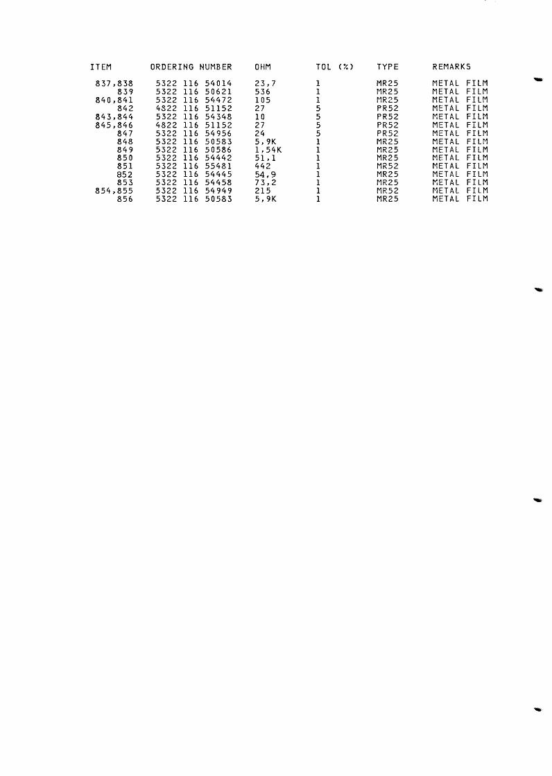
ITEM ORDERING NUMBER OHM TOL (iO TYPE REMARKS
837,838 5322 116 54014 23,7 1 MR25 METAL FILM 839 5322 116 50621 536 1 ~1R25 METAL FILM
840,841 5322 116 54472 105 1 MR25 METAL FILM 842 4822 116 51152 27 5 PR52 METAL FILM
843,844 5322 116 54348 10 5 PR52 METAL FILM 845,846 4822 116 51152 27 5 PR52 METAL FILM
847 5322 116 54956 24 5 PR52 METAL FILM 848 5322 116 50583 5,9K 1 MR25 METAL FILM 849 5322 116 50586 1,54K 1 MR25 METAL FILM 850 5322 116 54442 51,1 1 MR25 METAL FILM 851 5322 116 55481 442 1 MR52 METAL FILM 852 5322 116 54445 54,9 1 MR25 METAL FILM 853 5322 116 54458 73,2 1 MR25 METAL FILM
854,855 5322 116 54949 215 1 MR52 t-1ETAL FILM 856 5322 116 50583 5,9K 1 MR25 METAL FILM