Embed Size (px)
Citation preview
Applied SOA
Service-Oriented Architectureand Design Strategies
Mike RosenBoris LublinskyKevin T. Smith
Marc J. Balcer
Wiley Publishing, Inc.

Applied SOA


Applied SOA
Service-Oriented Architectureand Design Strategies
Mike RosenBoris LublinskyKevin T. Smith
Marc J. Balcer
Wiley Publishing, Inc.
Applied SOA: Service-Oriented Architecture and Design Strategies
Published byWiley Publishing, Inc.10475 Crosspoint BoulevardIndianapolis, IN 46256www.wiley.com
Copyright 2008 by Wiley Publishing, Inc., Indianapolis, Indiana
Published simultaneously in Canada
ISBN: 978-0-470-22365-9
Manufactured in the United States of America
10 9 8 7 6 5 4 3 2 1
No part of this publication may be reproduced, stored in a retrieval system or transmitted in any formor by any means, electronic, mechanical, photocopying, recording, scanning or otherwise, except aspermitted under Sections 107 or 108 of the 1976 United States Copyright Act, without either the priorwritten permission of the Publisher, or authorization through payment of the appropriate per-copy feeto the Copyright Clearance Center, 222 Rosewood Drive, Danvers, MA 01923, (978) 750-8400, fax (978)646-8600. Requests to the Publisher for permission should be addressed to the Legal Department, WileyPublishing, Inc., 10475 Crosspoint Blvd., Indianapolis, IN 46256, (317) 572-3447, fax (317) 572-4355, oronline at http://www.wiley.com/go/permissions.
Limit of Liability/Disclaimer of Warranty: The publisher and the author make no representations orwarranties with respect to the accuracy or completeness of the contents of this work and specificallydisclaim all warranties, including without limitation warranties of fitness for a particular purpose. Nowarranty may be created or extended by sales or promotional materials. The advice and strategiescontained herein may not be suitable for every situation. This work is sold with the understandingthat the publisher is not engaged in rendering legal, accounting, or other professional services. Ifprofessional assistance is required, the services of a competent professional person should be sought.Neither the publisher nor the author shall be liable for damages arising herefrom. The fact that anorganization or Website is referred to in this work as a citation and/or a potential source of furtherinformation does not mean that the author or the publisher endorses the information the organizationor Website may provide or recommendations it may make. Further, readers should be aware thatInternet Websites listed in this work may have changed or disappeared between when this work waswritten and when it is read.
For general information on our other products and services or to obtain technical support, pleasecontact our Customer Care Department within the U.S. at (800) 762-2974, outside the U.S. at (317)572-3993 or fax (317) 572-4002.
Library of Congress Cataloging-in-Publication Data:
Applied SOA : service-oriented architecture and design strategies / MikeRosen . . . [et al.].
p. cm.Includes index.ISBN 978-0-470-22365-9 (paper/website)
1. Web services. 2. Software architecture. 3. Computer networkarchitecture. 4. Information resources management. I. Rosen, Michael,1956-
TK5105.88813.A69 2008006.7′8 — dc22
2008015109
Trademarks: Wiley, the Wiley logo, and related trade dress are trademarks or registered trademarksof John Wiley & Sons, Inc. and/or its affiliates, in the United States and other countries, and may notbe used without written permission. All other trademarks are the property of their respective owners.Wiley Publishing, Inc., is not associated with any product or vendor mentioned in this book.
Wiley also publishes its books in a variety of electronic formats. Some content that appears in printmay not be available in electronic books.
About the Authors
Mike Rosen is chief scientist at Wilton Consulting Group, which providesexpert consulting on software architecture, SOA, and enterprise architecture.He is also director of enterprise architecture for the Cutter Consortium andeditorial director of the SOA Institute. He frequently speaks at industrysymposia and contributes to industry journals.
Boris Lublinsky is lead architect at Navteq, where he is responsible forSOA and BPM implementations. He is a frequent contributor to technologymagazines and a speaker at industry conferences. Boris is also an SOA newseditor for InfoQ.
Kevin T. Smith is a technical director at ManTech MBI (formally McDonaldBradley, Inc.), where he builds highly secure and data-driven SOA solutionsfor the U.S. government. He is the author of many SOA technology articlesin industry magazines, such as the SOA/Web Services Journal, and hascoauthored several technology books, including The Semantic Web (Wiley,2003), Professional Portal Development with Open Source Tools (Wrox, 2004), MoreJava Pitfalls (Wiley, 2003), and Essential XUL Programming (Wiley, 2001), inaddition to the books where he has written chapters as a contributing author.Kevin has led SOA workshops and has presented at numerous industryconferences, such as the RSA Security Conference, JavaOne, the SemanticTechnology Conference, the Apache Open Source Conference, Net-CentricWarfare, the Object Management Group, and the Association for EnterpriseIntegration.
Marc J. Balcer is the founder of ModelCompilers.com, a provider oftools and services for realizing the power of model-based development,and the coauthor of Executable UML: A Foundation for Model-Driven Archi-tecture (Addison-Wesley, 2002). He has over 15 years of experience in
v
vi About the Authors
developing, deploying, and managing projects based upon executable modelsand model-driven development techniques.
As a party to many enterprise development projects, Marc has witnessedfirsthand how the precision of application and architecture models can makethe difference between spectacular success and miserable failure. He hasapplied Executable UML to projects in such diverse areas as medical instru-mentation, transportation logistics, telecommunications, and financial services.
Credits
Executive EditorRobert Elliott
Development EditorSydney Jones
Technical EditorJim Amsden
Production EditorLaurel Ibey
Copy EditorFoxxe Editorial Services
Editorial ManagerMary Beth Wakefield
Production ManagerTim Tate
Vice President and ExecutiveGroup PublisherRichard Swadley
Vice President and ExecutivePublisherJoseph B. Wikert
Project Coordinator, CoverLynsey Stanford
ProofreadersNancy Carrasco, Kathryn Duggan
IndexerJack Lewis
Cover ImagePaul Cooklin/JupiterimagesCorporation
vii

Acknowledgments
Well, who to thank for all the help? First, thanks to all the people who supportedme throughout this process. There were many, but a few stand out for specialmention: all my friends and clients who cut me a little slack when I mighthave been slightly unresponsive during the final push to finish everything;my friends in the travel industry who inspired the case study; everyone atCutter Consortium for constant encouragement; SOAInstitute for providing aforum to teach and discuss all things SOA; Robert Elliott at Wiley, who hadthe uncanny timing to call me during a lull in my consulting practice and ask ifI wanted to be involved in an SOA book; and Sydney Jones, our project editor,for putting up with our changes and delays. I hope she wasn’t just being nicewhen she said we weren’t the worst group of authors ever. Thanks to JimAmsden, a friend and colleague, who also turned out to be the best technicaleditor you could imagine; Jeroen van Tyn and Laura O’Brian for the greatBusiness Use Cases in Chapters 6 and 7 and Appendix A; my good friend KenOrr for teaching me about business architecture, processes, and semantics overthe years; my coauthors, for contributing to a collaborative project where weall learned from each other and everyone’s chapters, and the book, benefited;and most importantly, to my awesome wife, Tamar Krichevsky, who not onlyput up with it all, but who also read every single chapter of the book andcompiled and wrote the fantastic Evaluating SOA Services appendix. Thanks.
— Mike Rosen
I would like to thank Mike for calling me out of the blue and asking whether Iwould like to participate in this exciting project. I really enjoyed collaboratingwith Mike, Kevin, and Marc. It allowed me to learn more about SOA andsignificantly improved the quality of my chapters. Many thanks to the peoplewhom I used to work with over the years, especially Didier Le Tien, Dmitry
ix
x Acknowledgments
Tyomkin, and Deborah Shaddon, for always challenging me with tough archi-tecture questions and pointing at deficiencies in my solutions; Jay Davidsonand Edward Kuffert for explaining to me the importance of business architec-ture and the way the insurance industry works; and Jerry Daus, Matt O’Neal,and Maria Mernandez for helping me to understand how IBM software worksand the best ways to use it. I am also thankful for all of the failed and successfulprojects that I worked on, which taught me what is important and what is not,and why things fail or succeed. Most importantly, to my wonderful wife, Lilia,for patiently putting up with me spending more time with my computer thanwith her. Thanks.
— Boris Lublinsky
I would like to thank my three talented coauthors, Mike, Boris, and Marc — ithas been a pleasure working with you on this exciting and challenging project.Mike, you did a great job of guiding us in this process, and I would especiallylike to thank Boris for his additions to the chapters on Composing Services(Chapter 8) and SOA Governance (Chapter 12). I would like to thank VaughnBullard for his suggestions on Chapter 12 and Layer7’s Toufic Boubez for hissupport of my discussion on dynamic policy adaptation (‘‘Policy ApplicationPoints’’) in Chapters 11 and 12. Special thanks to Ken and Myrtle RuthStockman for allowing me to use their nicknames in one of my examples, andthanks to my ‘‘readability editors,’’ Helen G. Smith and Lois G. Schermerhorn.
I would like to thank my company, ManTech MBI (formerly McDonaldBradley, Inc.) in Herndon, VA, with special and sincere thanks to those whoencouraged my writing of this book on my own time — specifically, thanks toDanny Proko, Bill Pulsipher, Waymond Edwards, John Sutton, Gail Rissler,Mark Day, and Ken Bartee. I would like to give my thanks (and apologies)to my wonderful wife, Gwen, and my sweet daughters, Isabella and Emma!Thank you for putting up with me as I went into isolation for countless nightsand weekends while writing this book. I would like to thank Ashland Coffeeand Tea, who once again didn’t kick me out when I camped out there for daysat a time for writing, research, and of course, caffeine.
Thanks to the Washington Redskins, who thoughtfully did not have agood enough football season that it would distract me from writing onSundays. Thanks to other people, places, and things that most likely affectedmy writing in a positive way (in no particular order): Gavin Sutcliffe; EricMonk; Nick Duan; Sue Lee; Joanie Barr; John Medlock; Kyle Hendrickson;Tom Diepenbrock; Scooby-Doo; Jeff Phelps; Ruben Wise; Kim Gumabay; MikeHoops, the AMC Pacer, Ralph Perko, Kathleen Ferris, Brad Giaccio, KevinMoran; Mike Daconta; Leo Obrst; Fox; my community group (Russ and DebiGarber, Ed and Lori Buchanan, Steve and Ani Tetrault, Ed Hoppe); KyleRice; Thai Gourmet in Kings Charter; the Apostle Paul; Sean, Jen, Garrett, andParker Cullinan; Daniel Buckley; Ken Pratt; Adam Dean; Mike Rohan; Carl and

Acknowledgments xi
Sharon Smith, Emma when she sleeps past 4:00 a.m., Bill, Farron, Casey, andWill Smith, New Hanover Church, Grace Community Presbyterian Church,Mungo, and T3. Finally, all glory, laud, and honor to the one who was, who is,and who is to come.
— Kevin T. Smith
Many ideas emerge from the everyday work of developing real solutions.In addition to my coauthors, I would like to acknowledge the contributions,criticism, and insights from current and former colleagues, including SteveDowse of International Asset Systems, and Brian Itow, Gary Marcos, JulioRoque, and Matt Samsonoff of AZORA Technologies. Most importantly, Iwould like to thank my partner, Canares (‘‘Chicho’’) Aban, for his dedicationand support during this project.
— Marc J. Balcer

Contents at a Glance
Part One Understanding SOA
Chapter 1 Realizing the Promise of SOA 3
Chapter 2 SOA — Architecture Fundamentals 27
Chapter 3 Getting Started with SOA 77
Part Two Designing SOA
Chapter 4 Starting with the Business 119
Chapter 5 Service Context and Common Semantics 159
Chapter 6 Designing Service Interfaces 203
Chapter 7 Designing Service Implementations 253
Chapter 8 Composing Services 273
Chapter 9 Using Services to Build Enterprise Solutions 311
Chapter 10 Designing and Using Integration in SOA Solutions 353
Chapter 11 SOA Security 391
Chapter 12 SOA Governance 449
Part Three Case Studies
Chapter 13 Case Study — Travel Insurance 495
Chapter 14 Case Study — Service-Based Integration in Insurance 541
xiii

xiv Contents at a Glance
Appendix A Business Use Cases 579
Appendix B Evaluating SOA Services 589
Appendix C Additional Reading 621
Index 631
Contents
Acknowledgments ix
Introduction xxvii
Part One Understanding SOA
Chapter 1 Realizing the Promise of SOA 3Once Upon a Time . . . 4Learning from History 7
What Went Wrong? 8What Went Right? 9What Can You Learn? 10
The Promise of SOA 10The Challenges of SOA 11
Reuse 11Efficiency in Development 14Integration of Applications and Data 15Agility, Flexibility, and Alignment 16Meeting the Challenge 18
Reference Architecture 19Common Semantics 19Governance 20Business Process Modeling 22Design-Time Service Discovery 22Model-Based Development 23
Best Practices in SOA Analysis and Design 24Summary 25
Chapter 2 SOA — Architecture Fundamentals 27What Is Architecture? 28
xv
xvi Contents
Architectural Styles 29Architectural Principles and Practices 30
What Is Service-Oriented Architecture? 331. Defining a Service 372. Defining How Services Are Built and Used 383. Integrating Packaged and Legacy Systems into the Service
Environment 394. Combining Services into Enterprise Processes 395. Specifying the Technology Infrastructure 39
Specifying the Technology Infrastructure 39Specifying the Application Infrastructure Required to
Support Services 406. Defining Common Semantics and Data 407. Aligning Services with the Business 408. Determining How to Use the Architecture 41
Determining the Development Environment, Frameworks,Infrastructure, and Tools 41
Defining Metrics for Measuring Success 41Business-Driven SOA 41SOA and Other Architectures 44
Enterprise Architecture 44Software Architecture 46EA, 4+1, and Services 49
What Is a Service? 50A Word about Information Architecture 52Service Characteristics 53
Service Granularity 56Service Dimensions 60
Loose Coupling Is King 64Location Transparency 65Interface and Implementation 66Data 66Versioning 67Interoperability and Platform Independence 67Usage, Assumptions, and Knowledge 68
Common Service Patterns 68Service Types and Purpose 70
SOA Reference Architecture 73Summary 75
Chapter 3 Getting Started with SOA 77Overview of SOA Implementation Methodology 78SOA Reference Architecture 82
Minimum Architecture 839-Month Checkpoint 8418-Month Checkpoint 84Long Term 85
Contents xvii
Business Architecture 85Business Processes 86Information Design 88Service Identification 90Service Specification 94
Service Expectations 96Interaction Model 97Service Constraints 97Service Location 98
Services Realization 98Buying Services 99Outsourcing Services 99Building Services 102Summary of Service Identification and Realization Concerns 102
Service Life Cycle 104The Service Design Process 106
Top-Down Approaches 106Enterprise System Analysis 107Business Process Model 107
Bottom-Up Approaches 108Utility Services 108Service Enabling 108
Middle-Out: The Best of Both 109Process Summary 109
Activities 110Artifacts 111Repositories 111Governance 111
Process Phases 111Architectural Context 111Business 112Design 112Implementation 112Test 112
Practical steps 113Summary 115
Part Two Designing SOA
Chapter 4 Starting with the Business 119Business Architecture 121
Enterprise Business Architecture 124Project Business Architecture 124Value Chain 125Business Context 126
Understanding the Business Motivation Model 132Ends 134
xviii Contents
Vision 134Desired Results 134
Means 134Mission 134Course of Action 135Directives 135
Influencers 136Alignment and Traceability 136
Business Process Management and Modeling 137Basic Business Process Model Components 139Executable Models 140Business Process Models in an SOA World 142
How to Create Business Process Models 143Use Cases 143
Use Cases and Business Process Models 144One Use Case, Multiple Scenarios 144Step Reuse 146
Documents 146Conditional Business Process Models 148
Conditional Flows 148Conditional Operation Outputs 148
Recap: Processes and Services 149Organizing Services 151
Domains 152Types of Domains 154
The Service Inventory 155Summary 156
Chapter 5 Service Context and Common Semantics 159The Importance of Semantics in SOA 160Core Information Modeling 163
Objects and Attributes 163Classes, Attributes, and Instances 164Attributes and Instances 165Associations 166Association Multiplicities 166Finding Classes 167
Defining Types 167Simple Types 168
Numeric Types 168Symbolic Types 169Enumeration Types 169
Composite Types 170Implementing Types 170
Beyond the Basics 170Identifiers and Uniqueness Constraints 170
Identifier and Identity 171
Contents xix
Contrived Identifiers 171Multiple Population Identifiers 171Subpopulation Identifiers 172
Specializations 172Derived Attributes 174Value Constraints 176
Structuring Information Models 176Documents 177
Defining Documents 178Adapting the Information Model 179Multiple Documents 180
Documents and XML 181XML Schema 184Types in Schemas 185Document Variations in Schemas 187Designing for Change 188
XML Patterns 190Derivation Using Abstract Classes 192Derivation by Extension 193Derivation by Restriction 194Disallowing Derivations 195
Russian Doll 195Salami Slice 196Venetian Blind 197
Best Practices for the SOA Architect 198Using Abstraction to Avoid ‘‘SOA Stovepipes’’ 199Reuse Standards to Avoid Reinventing the Wheel 200Develop Information Models Based on Use Cases 201With Change, Crawl, Walk, Then Run 201
Summary 202
Chapter 6 Designing Service Interfaces 203Services Revisited 204
Service Characteristics 204Granularity 205Scope 205Visibility 206
Interaction Styles 207Parameter Passing 208Document Passing 208Data Passing 209Request/Reply 210Events 211Mixed Style 212
Design Guidelines 213Isolating Responsibilities 213Understanding Overall Context 215
xx Contents
Identifying Granularity 217Stateless Interfaces 218Exceptions 220Designing Documents 221
Interface Design Illustrated 222Overview of Models and Diagrams 223ACME Insurance Example 224Conceptual Architecture 225Problem Space Model 227
Use Case Diagrams 227Actors 228Initial Scenario Diagrams 229Purchase Insurance Scenario 230Enterprise Service Context and Inventory 232Detailed Scenario Diagrams 234Information Model 239Service Specification 239
Solution Model 241Service Model 241
Service Definition Diagrams 243Operations Procedures 246More Information Model 246Document Model 248
Summary 249
Chapter 7 Designing Service Implementations 253Basic Service Architecture 254
Layer Responsibilities 256Using Activity Diagrams for Modeling Operational Logic 257Implementation Components 259
Implementing the Interface Layer 260Document Receipt 261
Syntactic Validation 261Transformations 262
Implementing the Business Layer 263Semantic Input Validation 263Performing the Business Logic of the Operation 264Computing and Returning Results 267
Implementing the Resource Layer 267Implementation Design Illustrated 268
Business Layer 268Create Quote Operation (Quoting Service — Request
Quote Scenario) 269Price for Quote Operation (Automobile LOB Pricing) 269
Summary 272
Contents xxi
Chapter 8 Composing Services 273Understanding Service Composition 274
Separation into Service Layers 275Orchestration and Choreography 276The Relationship between BPM and Composition 278
Architectural Models in Service Composition 279Hierarchical and Conversational Composition 279Conductor-Based and Peer-to-Peer Composition 280
Service Composition Implementation 281Programmatic Composition 281Service Component Architecture Composition 282Event-Based Composition 285Orchestration Engine–Based Composition 286Centralized and Decentralized Orchestration Approaches 290
Service Composition and Business Rules 292Service Composition and Transactions 295Incorporating Human Activities into Service Composition 297Orchestration with BPEL 299Composition Example — Case Study 301
The Problem 301High-Level Design Decisions 302Process Modeling 303
Dos and Don’ts in Service Composition 307Avoid Static, Programmatic Orchestration 307Use a Layered Service Approach 308When Using BPEL, Use Abstract Processes 308
Summary 309
Chapter 9 Using Services to Build Enterprise Solutions 311Enterprise Solutions versus Applications 312Service-Based Enterprise Solutions 313Layered SOA Architecture and Multitiered Application
Architecture 317Locating Services 321
Example: Implementing Service Access for Policy Issuance 325Versioning: Dealing with Service Changes 325
Version Deployment and Access Approaches 327Example: Coping with Changes in Policy Issuance Solutions 329
Architecting Security for Service-Based Solutions 330Using a Security Gateway 330Using an Interceptor in Security Implementations 331Example: Architecting Security for Policy Issuance Solutions 333
Exception Handling and Logging in Enterprise Solutions 333Monitoring and Managing Enterprise Solutions 337
xxii Contents
Business Activity Monitoring 338Technical Monitoring and Management of SOA Solutions 340
Enterprise Service Bus-Unified Infrastructure for EnterpriseSolutions 343
Defining ESB 344ESB Architecture 346
Stand-alone ESB 348ESB as a Service Container 348ESB as a Framework 349
Choosing an ESB 350Summary 351
Chapter 10 Designing and Using Integration in SOA Solutions 353Challenges of Integration in SOA 354
Characteristics of Islands of Data 354Characteristics of Islands of Automation 355Characteristics of Islands of Security 355
Integration in SOA Defined 358Integration Services 360Integration Access Implementations 364
Using Messaging Infrastructure to Implement IntegrationAccess 365
Using a Message Broker to Implement Integration 367Using Existing Web Services to Implement Integration 369Using JCA/J2C Adapters to Implement Integration 372Using Web Service Wrappers to Implement Integration 374Using Direct Database Access to Implement Integration 375Using an Enterprise Service Bus to Implement Integration 376
Special Considerations for Implementing of Integration 377Data Mapping in Integration 378Security Support for Integration 380Transactional Support in Integration 381Versioning Integration 383Dealing with Large Messages 384
Data Virtualization and Enterprise Data Bus 386Summary 389
Chapter 11 SOA Security 391SOA Security Goals and Fundamentals 392
Authentication 392Authorization and Access Control 395Two Types of Access Control — DAC and MAC 396Federated Identity and Cross-Enterprise Access 397Confidentiality 400Integrity 401Non-Repudiation 404
Contents xxiii
Web Service Security Standards and Specifications 405WS-Security SOAP Messaging 405WS-Trust 406WS-Federation 409WS-SecureConversation 410WS-SecurityPolicy and the WS-Policy Framework 410SAML 411XACML 413XML Signature 415XML Encryption 415
SOA Security Blueprints 416Separation of Security into Components and Services 416Authentication and Identity Blueprints 419
Identity Propagation for SSO Solutions 420Point-to-Point Authentication 425
Access Control Blueprints 427Controlling Access to Data, Not Just Services 427Access Control Policy Enforcement Approaches 428
Auditing and Troubleshooting 435Flexibility with Dynamic WS-SecurityPolicy Adaptation 436Complete Architecture Analysis 437
Applying Concepts from This Chapter — A Simple CaseStudy 437
Establishing Enterprise Security Services 440Defining Identity Propagation and Access Control 441
The Security Game Plan for the SOA Architect 443Plan from the Beginning, Focusing on Requirements 443Crawl and Walk before Running 444Use Accepted Standards (in a Standard Way) 444Understand the Details of the Standards 445Understand the Impact of Security on Performance 446Try to Keep It Simple 446
Summary 447
Chapter 12 SOA Governance 449SOA Management and Governance Defined 450The Case for SOA Governance 453
The Reality of Change in Real-World Deployments 453The Need for an Enterprise Big Picture 455The Need for Explicit Run-Time Service Policies 456The Need to Separate Policy Logic from Business Logic 457
SOA Governance and the Service Life Cycle 459Design-Time Governance 462
The Service Identification Process 464The Service Design and Specification Process 465The Service Implementation Process 467
xxiv Contents
Deploy-Time Governance 469Run-Time Governance 471
Practical SOA Governance 475Structuring Your Organization for Governance 475Developing Enterprise Policy 477Using the Service Repository 481
Cataloging and Discovery 483Validation 483Dependency Management 484Service Evolution and Versioning 484Artifacts Publishing Governance 484Support for Multiple Artifact Types 484
Developing and Registering Run-Time Policies 486Run-Time Policy Enforcement and Adaptation 488
Summary 490
Part Three Case Studies
Chapter 13 Case Study — Travel Insurance 495Travel Insurance 496
The Scenario 496Conceptual Architecture 497Business Concerns 498
Business Value Chain 499Business Motivation 500
Brief Review 502Business Analysis 506Business Process Model 509Service Conceptual Architecture 510Use Cases 512Enterprise Context 517
Solutions Architecture 518Authentication 519Authorization 521Confidentiality 522Integrity and Non-Repudiation 522The Big Security Picture 523Service Inventory 524Entity Diagram 525
Information Model 527Document Model 529
Service Interface Design 530Service Interactions 532
Document Design 533Service Implementation Design 534
Contents xxv
Service Specification 534Implementation Layers 535Operation Procedure 536
Summary 538
Chapter 14 Case Study — Service-Based Integration in Insurance 541ACME Insurance 542High-Level Integration Design 547
Establishing Policy Submission 548Rate Insurance Policy 551Assess Insured Location 552Get Driver’s Information 553Generate Policy Notice Documents 554Collect Policy Financials 555Work with Documents 556Integration Requirements for the ACME Implementation 556
Integration with Existing CICS Transactions 557Integration Approaches 558ACME’s Implementation of a CICS-Based Integration 562
Integration with the Existing COM Components 565ACME’s Implementation of Integration with COM
Components 567Integration Based on the Existing Java APIs 568
ACME’s Implementation of Integration Based on Java APIs 569Integration with the Existing J2EE Applications 570
ACME’s Implementation of Integration for J2EE-BasedApplications 572
Integration with Existing Databases 573ACME’s Implementation of Database Integrations 575
Integration Based on the Vendor’s Web Services 576ACME’s Implementation of Integration Using the Vendor’s
Web Services 577Summary 578
Appendix A Business Use Cases 579Business Use Case BU01 — Quote Insurance 579
Basic Workflow 580Alternative Workflow: Unacceptable Risk 582Performance Goals 582
Business Use Case BU02 — Process Application 582Basic Workflow 583Alternative Workflow: Unacceptable Risk 585Performance Goals 585
xxvi Contents
Business Use Case BU03 — Change Policy 585Basic Workflow 585Alternative Workflow: Unacceptable Risk 587Extension Points 588
Appendix B Evaluating SOA Services 589How Do I Assess Services? 590
Alignment Characteristics 597Business Alignment 598Specification 599Fit for Purpose 601Security 602Semantic Alignment 603
Design Characteristics 605Isolation of Responsibilities 605Abstraction 606Coupling 607Granularity 609Stateless 610Composable 611Governance 612
Technical Characteristics 613Specification 613Service Level Agreement 615Extensibility 616Variability and Configurability 617Autonomy 618
Housekeeping Characteristics 619
Appendix C Additional Reading 621
Index 631
Introduction
Welcome to Applied SOA: Service-Oriented Architecture and Design Strategies.This book is designed to fill a gap that we see in available SOA information.The current collection of SOA books and articles is rich on high-level theorybut light on practical advice. At the other end of the spectrum are the WebServices books that concentrate on APIs and programming, but gloss over thearchitecture. This book focuses on an area that most other books ignore, offeringthe reader a practical guide for applying design strategies to service-orientedsolutions. It targets the practical application of SOA and appeals to architects,analysts, designers, and CTO/CIOs, as they roll out concrete strategies anddesigns for their organizations and projects.
The book starts by discussing the expected benefits of SOA and the archi-tectural principles needed to realize them, which lead to successful solutions.Then, it provides an overview of the process for designing services andservice-oriented solutions. Each major step of the process is followed by achapter that describes the detailed practices and principles for that step, withhandy tips and techniques for applying them. Of course, no SOA solutionwould be complete without integrating legacy systems and applications, pro-viding security, or having appropriate governance, so these topics are alsocovered in depth. Throughout the book, the principles are demonstrated withrelevant examples. Finally, the book concludes with two different extensivecase studies that illustrate the architecture and design strategies.
Why This Book Was Written
Service-Oriented Architecture (SOA) is the current state of the art in ITapplication architecture. As a result, platforms and tools that support SOA are
xxvii
xxviii Introduction
hitting the market every week. Every major software vendor, including IBM,Microsoft, Oracle, and SAP has embraced SOA and is investing billions ofdollars to service-enable their product sets. SOA is here to stay, and it is likelyto be the predominant architectural style for the next decade.
Most SOA implementations are based on Web Service technologies, whichhave matured to the point where there are many mission-critical implemen-tations in production. In addition, the training industry has ramped up toprovide considerable variety and opportunity for education in SOA and WebServices. Yet, real service-oriented applications have not followed suit andthe promised benefits of SOA have not been realized for most organizations.Generally, the available literature and education fall short of providing whatcompanies really need to be successful.
As we work with companies that are starting with SOA, or struggling withtheir current approach, we see several common areas of confusion:
First, what is SOA? In particular, what are the architectural aspects ofSOA compared to just Web Services or other distributed technologies?And beyond that, how should the architecture influence design?
Second, what is the relationship between business and SOA? What ishype and what is real? How does functional decomposition at the busi-ness process level translate into requirements and design for businessservices?
Third, how do you design a good service? This seems to be the mostmisunderstood aspect of SOA. A meeting rarely goes by where someonedoesn’t ask, ‘‘How big should a service be?’’
Fourth, how do you effectively integrate existing applications and re-sources into a service-oriented solution? How can this be done whileavoiding the pitfalls of traditional EAI approaches? What does a goodintegration service look like?
And finally, how do services fit into overall enterprise solutions? Whatis the layered and tiered structure of an SOA application architecture?Where do security, transactions, naming, and the other aspects of dis-tributed enterprise solutions fit in?
Anybody can build a service; that’s not the challenge facing IT professionalstoday. In fact, the tools make it incredibly easy (often too easy) to build services,especially poorly designed ones. The first challenge is to build a good service,based on solid design principles. But still this is not enough. The servicesmust also fit into an overall architecture that results in services that can becombined into larger business processes within the enterprise. In other words,the architecture and the design process must provide an enterprise contextthat influences the design and implementation of services.
Introduction xxix
The next decade will be filled with winners and also-rans. Those companieson top will have learned how to use IT as a strategic differentiator thatprovides them with a sustainable competitive advantage. This will be built ona foundation of SOA that exposes the fundamental business capabilities andinformation as flexible, reusable services. These services will support a layerof business processes that can be easily changed to provide new products andservices to keep ahead of the competition. But this is easier to show in a Visiodiagram than to actually achieve. The good news is that this book starts toshow you how. The bad news is that it’s still hard.
The goal of Applied SOA: Service-Oriented Architecture and Design Strategiesis to provide the architecture and design principles and methodology thataddress these challenges and empower the reader to develop successfulimplementations that deliver the expected benefits of SOA.
Who This Book Is For
This is primarily a technical book, focused on architects, designers, businessanalysts, IT managers, and executives. It is not a book about writing code; infact, there is no code in the book. It is about architecture and design, what theimportant principles of SOA are, and how they should be applied. It delves intoeach of the important aspects of architecture, including business, information,application, and technology, as they relate to service-oriented solutions:
Architects will learn the relationships between architectural concerns,enterprise context, and the SOA design process. This is particularlyimportant in making architecture actionable. As architects, you shouldalways remember that creating architecture itself provides little value.The value comes from using the architecture to help projects meet imme-diate needs, but in a way that also meets the needs and longer-term goalsof the overall enterprise. This is critical to realizing the promise of SOA.
Designers will learn a step-by-step process for the analysis and designof services, and what the different types and styles of services are. Theywill come to understand what information is required from the businessfor complete service design, how that relates to process and informationmodels, and how it shows up in the different design artifacts. But mostimportantly, they will learn how to start thinking in terms of SOA; inother words, how to shift their design paradigm.
Business analysts will learn the relationship between business strate-gies, goals, and objectives, and the capabilities and information that areused to achieve them. The direct link between capabilities, business ser-vices, and business processes will be illustrated. Analysts will learn how
xxx Introduction
to use business process models as the link between business architectureand IT design, specifically SOA.
Managers and executives will get an understanding of the SOA archi-tecture and design process that will enable them to understand, govern,plan, and manage SOA projects that deliver value to both their immedi-ate project and to the enterprise.
What This Book Covers
This book provides architects, designers, and analysts with the principles andtechniques necessary to create superior-quality service-oriented architecturesand solutions. It enables them to go beyond building services to actuallydeliver on SOA’s promises of agility and flexibility by providing practical andactionable advice that leads directly to better architecture and design.
Thus, the book is about the architecture and design of service-orientedsolutions and systems. It is not a high-level overview of the benefits ofSOA, nor is it a user’s manual for the technologies and standards of SOAimplementation (i.e., Web Services). Instead, it focuses on the difficult areain between, to provide a methodology for designing not only simple servicesbut also service-oriented solutions that incorporate legacy integration andsecurity.
The book is technical in that it provides detailed, step-by-step proceduresand examples of architecture and design. However, it generally does not delveinto APIs and code, except to illustrate the design implications of certaintechnologies and standards. In addition, this book contains two detailed casestudies that illustrate the concepts and techniques presented throughout.
How This Book Is Structured
This book is structured in three sections: an overview of the architecture,service and solution design, and case studies:
Part I: Understanding SOA — This section provides the motivation forSOA and the architectural requirements needed to meet them, then describesSOA architecture structure and principles, and finally describes the processfor getting started with SOA in the enterprise.
Chapter 1: ‘‘Realizing the Promise of SOA’’ describes the primary moti-vations for SOA in the industry, such as improved flexibility, reducedcosts, and competitive advantage. Given these motivations and expec-tations, what is really required from IT to deliver on that promise? This
Introduction xxxi
question is explored in depth and the answer presented as the require-ments that SOA architecture must meet to achieve the promise.
Chapter 2: ‘‘SOA — Architecture Fundamentals’’ describes the SOA ref-erence architecture and how that meets the challenges and requirementslaid out in Chapter 1. It describes the overall enterprise context, thearchitectural layers and tiers, the domain-specific concepts and abstrac-tions, and specifically what a service is and the important architecturalcharacteristics of a service.
Chapter 3: ‘‘Getting Started with SOA’’ describes the overall process forinitiation of SOA activities, aligning SOA with the business, identifyingand specifying services, designing service interfaces and implementa-tions, and creating solutions
Part II: Designing SOA — This section explores the details of each step inthe design process. It is roughly divided into two main areas: Chapters 4–7cover the design of services and Chapters 8–12 focus on building enterpriseSOA solutions.
Chapter 4: ‘‘Starting with the Business’’ describes a business architec-ture approach for SOA and how to use business architecture and busi-ness process modeling to define services.
Chapter 5: ‘‘Service Context and Common Semantics’’ focuses on theoverall enterprise context for SOA, specifically the common semanticmodel and the service inventory. It describes how to discover the com-mon semantic model, tips and techniques for developing it, how to cre-ate and use a service inventory, and how it fits with the semantic model.
Chapter 6: ‘‘Designing Service Interfaces’’ digs into the details of ser-vice interface design. It shows how to use the business and enterprisecontexts established in Chapters 4 and 5 in the service interface designand discusses issues of interaction and usage style in terms of design.Then, it presents an in-depth example of the design of an interface for anautomobile insurance solution.
Chapter 7: ‘‘Designing Service Implementations’’ continues with detailson the design of the service implementation. It describes the techniquesfor defining the technology independent design of service operationsand the specification of schema for the documents that are the inputs andoutputs for those operations. It extends the example from Chapter 6 toillustrate the design of the service operations.
Chapter 8: ‘‘Composing Services’’ goes into detail about the importanttechniques of service composition. It describes the tradeoffs and advan-tages of a variety of different approaches, addresses the role of Business
xxxii Introduction
Process Execution Languages (BPEL) and Service Component Archi-tecture (SCA) in composition, provides some useful do’s and don’ts,and finishes with an example of a service composition using BPEL.
Chapter 9: ‘‘Using Services to Build Enterprise Solutions’’ describesthe role services play in an overall enterprise solution. It describes howservices fit into the classical n-tier architecture, discusses issues of servicelocation and discovery, exception handling, management and monitor-ing, service evolution, and the use of Enterprise Service Buses (ESBs) toimplement SOA solutions.
Chapter 10: ‘‘Designing and Using Integration in SOA Solutions’’focuses on the difficult problem of creating services that integrate exist-ing applications and data. It starts with the architectural issues of service-based integration and then goes into details about the design and imple-mentation of integration services, providing a toolbag of techniques andtradeoffs for different integration scenarios.
Chapter 11: ‘‘SOA Security’’ addresses the thorny questions of security.Again, it starts with an architectural overview of the different types ofsecurity and the type of threats and challenges they address. Then, itprovides an overview of the most common security standards in SOA.Next, it presents a set of ‘‘security blueprints’’ or guidelines for deter-mining the right security solution, and the patterns for applying them.The chapter finishes with suggestions and a game plan for the securityarchitect.
Chapter 12: ‘‘SOA Governance’’ takes up the issues of keeping yourSOA solutions and architecture running and on track. It describes thelife cycle of services, and the issues of management and governancethroughout the different phases of the life cycle. This includes tips andtechniques for practical SOA governance.
Part III: Case Studies — This section illustrates architecture and designprinciples and strategies by exploring two different case studies in depth. Thefirst focuses on designing business services to support business processes.The second focuses on integrating existing applications into a service-orientedsolution.
Chapter 13: ‘‘Case Study — Travel Insurance’’ provides a case study ofan SOA implementation from the travel industry. The case study startswith the business architecture and works through to the design of theservice interface and implementation, highlighting the architectural con-cerns and design strategies presented in Part II.
Chapter 14: ‘‘Case Study — Service-Based Integration in Insurance’’provides a case study of the implementation of integration services in
Introduction xxxiii
the insurance industry. The example illustrates the design and imple-mentation of multiple different integration services based on existingcustomer information control (CICS), commercial off-the-shelf (COTS),Java, database, and other systems and shows how they can be used in anenterprise solution.
Appendix A: ‘‘Business Use Cases’’ provides the detailed use cases forthe example used in Chapters 6 and 7.
Appendix B: ‘‘Evaluating SOA Services’’ provides a handy list for eval-uating services against the important architectural and design criteriapresented in this book.
Appendix C: ‘‘Additional Reading’’ provides a list of resources onSOA and all of the references used while researching the book.
What You Need to Use This Book
Beyond a basic desire to learn about architecture and design, there are no otherrequirements for the book. Many of the design and implementation examplesuse UML models, so a basic ability to read these models will help, but it is notnecessary. We have tried to steer clear of complex models.
Final Thoughts
This book is meant to lay out the important aspects and strategies of architec-ture and design for SOA solutions. Our challenge was not deciding what toput into the book but deciding what to cut out. As it is, we went way over ouroriginal estimate for length. It is not possible to cover every possible aspect ofdesign and architecture for SOA solutions in a single text. We have provideda lengthy list of references and other readings in Appendix C to supplementthe material here.
But we do think that we’ve covered material that is not well served by mostother SOA books, and that is critical to SOA success. We sincerely hope thatyou find it useful and are able to incorporate it into your SOA solutions.

P a r t
IUnderstanding SOA
In This Part
Chapter 1: Realizing the Promise of SOAChapter 2: SOA — Architecture FundamentalsChapter 3: Getting Started with SOA

C H A P T E R
1
Realizing the Promise of SOAThose who do not remember the past are condemned to repeat it.
— George Santayana
Everyone has heard the many promises and benefits of Service-Oriented Archi-tecture (SOA), and you’ve all probably heard a dozen different definitions ofwhat SOA is or isn’t. We’re going to take a different approach. We wantto paint a picture of what SOA can deliver and the promise of SOA, andthen describe the challenges that organizations face in realizing that promise.Together, the vision and the challenges provide a set of requirements thatthe architecture must meet to make your implementation of SOA successfulat delivering the promised benefits. Throughout the book, we’ll describe thedetailed architecture, design principles, and techniques that meet those archi-tectural requirements, make the architecture actionable, and deliver results. Inthis chapter, you look at:
What did and didn’t work in the past
The promise of SOA to the enterprise
The challenges of delivering on that promise
How to meet the challenge (the subject of this book)
But first, let’s start with a little story. The scenario is true although the nameshave been changed.
3
4 Part I ■ Understanding SOA
Once Upon a Time . . .
Back in 1994, a major U.S. bank was trying to resolve a problem with customerservice. Like pretty much every bank at that time, all of the different products(i.e., different types of accounts) were implemented on different mainframesystems. When you telephoned the customer service representative, you spoketo a beleaguered person with numerous green screen terminals on his or herdesktop.
If you wanted information about your checking account, the customer ser-vice representative went to one terminal and entered your account number. Ifyou wanted information about your savings account, the representative had toget a different account number from you and enter that in a different terminal.Each account system had a different interface. Together, they provided a con-fusing mix of commands and interaction that necessitated expensive trainingand was error prone. Customer satisfaction with problem resolution was low,employee satisfaction was low, and retention of both was problematic.
So what’s a bank to do? First, they set about rationalizing the interface toall of the systems into a consistent interface, on a single terminal. Solutionssuch as 3270 emulators and PCs were tossed around but discarded becausethey only reduced the number of terminals, not the complexity of multipleinterfaces. Instead, the bank took a gamble on a relatively new, distributedtechnology, Common Object Request Broker Architecture (CORBA).
The specific technology they chose is less important than the approach. Thefirst thing they did was to create distributed objects to represent the differenttypes of accounts. These objects provided an abstraction layer between the userinterface and the mainframe systems that actually implemented the accounts.Next, they wrote a new user interface, using Visual Basic (VB), that providedaccount information to the customer service representatives by accessing thedifferent systems via the CORBA objects.
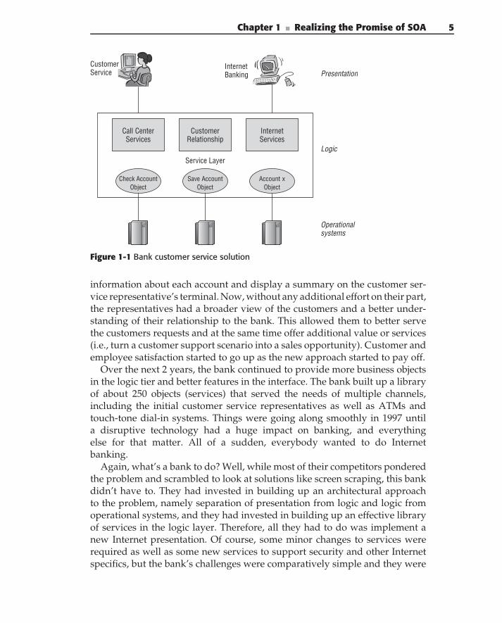
It took about 6 months to get the basic functions in place — a new userinterface, VB/CORBA bridging, and simple account objects — and then theywere able to start replacing some of the green screen terminals. At this point,they began to understand the potential of the approach. They had essentiallyimplemented the beginnings of a 3-tiered application architecture by separat-ing the presentation, business logic, and operational systems. Figure 1-1 showsa simplified view of their solutions.
The next enhancement was to implement a customer relationship object inthe logic tier. What this did was to take any account number or customer name,find all of the accounts that belonged to that customer, and provide that infor-mation to the customer service representative. Now, the customers didn’t needto keep track of all their different account numbers in order to do business withthe bank. The next incremental improvement was to automatically look up
Chapter 1 ■ Realizing the Promise of SOA 5
Service Layer
Check Account Object
Account x Object
Save Account Object
Customer Relationship
Call Center Services
InternetServices
Presentation
Logic
Operational systems
Customer Service
Internet Banking
Figure 1-1 Bank customer service solution
information about each account and display a summary on the customer ser-vice representative’s terminal. Now, without any additional effort on their part,the representatives had a broader view of the customers and a better under-standing of their relationship to the bank. This allowed them to better servethe customers requests and at the same time offer additional value or services(i.e., turn a customer support scenario into a sales opportunity). Customer andemployee satisfaction started to go up as the new approach started to pay off.
Over the next 2 years, the bank continued to provide more business objectsin the logic tier and better features in the interface. The bank built up a libraryof about 250 objects (services) that served the needs of multiple channels,including the initial customer service representatives as well as ATMs andtouch-tone dial-in systems. Things were going along smoothly in 1997 untila disruptive technology had a huge impact on banking, and everythingelse for that matter. All of a sudden, everybody wanted to do Internetbanking.
Again, what’s a bank to do? Well, while most of their competitors ponderedthe problem and scrambled to look at solutions like screen scraping, this bankdidn’t have to. They had invested in building up an architectural approachto the problem, namely separation of presentation from logic and logic fromoperational systems, and they had invested in building up an effective libraryof services in the logic layer. Therefore, all they had to do was implement anew Internet presentation. Of course, some minor changes to services wererequired as well as some new services to support security and other Internetspecifics, but the bank’s challenges were comparatively simple and they were
6 Part I ■ Understanding SOA
up on the Internet in less than 6 months. This was a full 6–12 months fasterthan their competitors, who struggled to catch up. And it was a real imple-mentation that built toward the future, not a quick-and-dirty hack that neededto be replaced later. Many of the bank’s competitors have never caught up.
Two years later, the bank merged with another major bank. This time theproblem was how to integrate the new bank’s systems into the other bank’sInternet operations. Imagine the challenges involved, and imagine the surprisewhen 100% of the combined customers were able to access their accounts viathe Internet on the first official day of merged operations! Okay, in reality, afew months were spent making this possible before the official opening day,but again the architectural investment paid off. Instead of adding a new pre-sentation, the bank added new systems to the operational layer and enhancedthe logic layer so that it was possible to access the new types of accounts andsystems. Only very minor changes were required in the presentation layer.
Since the initial introduction of their Internet banking capability, the imple-mentation and infrastructure has been enhanced to support tens of millionsof transactions per day. And, since the merger, hundreds of other banks havebeen acquired and merged into the architecture. They were the competitorsthat never caught up, that never invested in architecturally sound IT solutions.
But of course, all of this didn’t just happen by accident. The bank was for-tunate to have a perceptive, skilled, and forward-thinking architect involvedin the project. The architect quickly realized both the potential and the chal-lenges and set about making changes to address them. First and foremost wasthe adoption of an architecture that distributed responsibilities across layersand tiers.
Second, the bank understood the challenge of creating the right kind ofservices in the logic tier and of having developers reuse them. To accomplishthis, the bank created a new position, a reuse manager, for fostering andmanaging reuse. This person was responsible for helping developers createthe right services with the right interfaces, helping presentation applicationsfind and reuse services, and setting out an overall vision and roadmap of whatservices would be needed over time.
Finally, the bank realized that the existing organizational structure was notconducive to creating or using services. Instead of having monolithic applica-tion groups, they divided IT into groups that built the business services, andinto other groups that used the services in their presentations and applications.After some obvious learning curves and attitude adjustments, the bank wasable to drop the time to enhance or develop new user applications from 6months under the monolithic model to 4–6 weeks under the service model.And, the more services that were added to the service library, under the carefuldirection of the reuse manager, the shorter this timeframe became.
So, with a successful implementation of SOA, the bank was able to improvecustomer retention and satisfaction, reduce costs and time to market, take
Chapter 1 ■ Realizing the Promise of SOA 7
advantage of disruptive technologies, quickly absorb acquisitions, and keepahead of their competitors. No wonder businesses are interested in SOA.From a more technical point of view, the bank was able to integrate multiplesystems, support multiple channels and devices, scale horizontally to supportvery large-scale and highly reliable requirements, incrementally add newfunctionality, manage reuse, and converge on a common service infrastructure.
The moral of the story is this: SOA isn’t about technology, and SOAdoesn’t just happen. SOA is an architectural approach to building systems thatrequires an investment in architecture and IT, a strategic and business vision,engineering discipline and governance, and a supporting organizational struc-ture. Ignore these things and you end up with another broken promise. Putthem together well, and you can deliver the promise and potential of agility,flexibility, and competitive advantage.
Learning from History
As can be seen from this story, SOA is not new. It has been around for years,well before the term was coined, by most accounts, in 1996. Forward-thinkingcompanies like the bank whose story was told earlier, and many other financeand telecom companies were able to implement service layers using a varietyof distributed technologies, including CORBA and the Distributed CommonObject Model (DCOM). Other technologies, like Tuxedo, were inherentlyservice-oriented and stateless, and formed the basis of some of the largest,high-performance, distributed applications of their day.
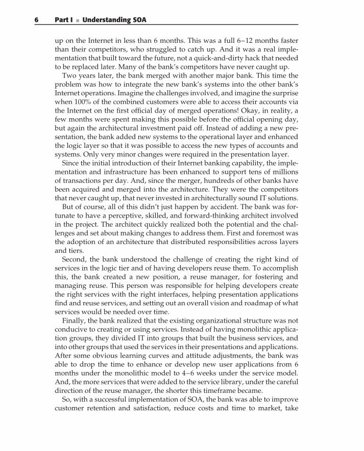
So while it is not difficult to find companies that were successful in imple-menting SOA, it’s much easier to find companies that failed in their SOA.IT graveyards are filled with failed projects and sometimes the vendors ofthe technologies that promised the elusive, and ultimately ineffective, silverbullet. Figure 1-2 shows a brief timeline of SOA activity.
1990
Tuxedo Apps
Distributed Objects
(CORBA/COM)
1996
Term SOA Coined Web Services
2002 2008
Tech
nolo
gy C
ompl
exity
SOA
Succ
ess
Rate
Figure 1-2 SOA timeline
8 Part I ■ Understanding SOA
What Went Wrong?You might ask why some projects succeeded while others failed. Luckily, youhave the opportunity to look back and examine both the successes and failuresto discover patterns, and to then plan a path forward that avoids the failedbehavior and embraces the successful activities.
Looking at the failures uncovers two main patterns. First, the technologiesthat we mentioned were too difficult for the average programmer to master.Distributed computing with CORBA or DCOM was just too difficult for themasses. Sophisticated IT departments had the system programmers and archi-tects to manage these technologies, but most organizations did not. Visual Basic(VB) programmers and other client/server Rapid Application Development(RAD) application programmers didn’t cut it, and the underlying platforms didnot have enough of the complexities of distributed applications built into them.
The other problem was that, as an industry, we had not yet figured out whata good service was. No one knew what the right characteristics of a service orits interface or interaction style were. And if you could figure these things out,you then had to describe them in a service abstraction, and finally implementthe service abstraction on top of the object abstraction naturally providedby the distributed technology. Again, some sophisticated people figured allthis out, but most didn’t. The hurdles to create any service were so great thatmost attempts failed well before the developers had to worry about whetherthey were building good services or what SOA meant, how to build it, or howto use it.
The situation today is much better. Web Services are much easier to usethan previous technologies. This is not because the technologies are really anysimpler (see the sidebar ‘‘It’s Not So Simple’’), but mostly because the toolsand environments have advanced greatly. It is now possible to developservices without really knowing what a service is or anything much aboutdistributed technologies (we can debate whether this is good or bad later . . . ).
Instead, the implicit knowledge of distribution and services is built into theplatform, whether it is based on Java, .NET, or something else. And the serviceabstraction layer is built into the Web Service technologies.
IT’S NOT SO SIMPLE
Distributed technologies have had a long history, a history that tends to repeatitself. In the early days, we came up with the Distributed ComputingEnvironment (DCE). Originally, this was a Remote Procedure Call (RPC)mechanism aimed at allowing different UNIX systems to communicate. Oncethe basics were worked out, people tried to use it for real enterpriseapplications and realized that it needed more capabilities such as security,transactions, reliability, and so on.
Chapter 1 ■ Realizing the Promise of SOA 9
Next was CORBA, a mechanism for distributing objects. Initially, it was prettysimple, until people tried to use it to create real enterprise applications. Soonthey realized that it needed security, transactions, reliable delivery, and so on,and it became complicated.
So a simpler technology was invented, Java. And all was well and good untilpeople tried to use it to build real enterprise applications. All of a sudden itneeded to have security, transactions, messaging, and so on.
Finally, Web Services came along, invented by developers so ignorant ofhistory that they actually had the audacity to call the protocol SOAP, SimpleObject Access Protocol. And all was fine until people tried to build realapplications with it and discovered that they needed security, transactions,reliable messaging, and so on. You know the rest.
Hmm. What will be next?
What Went Right?If you look at what worked, you get a broader picture. Not every companythat mastered the technology managed to succeed with SOA. As has alwaysbeen true with IT, technology alone is not enough to solve business problems.
The first thing that successful companies had was an understanding of notonly how to use the technology but also what to do with it. These companieshad an architectural vision that described the construction of applications interms of a logical distribution of responsibility across tiers. The architecturewent on to describe how services fit into that mix, what services were, how tobuild them, and how to use them.
The next, and equally important, aspect shared by successful companieswas a business vision that described what business the company was in, whatinformation and processes were necessary to run the business, what capabilitieswere needed to support those processes, and what services were needed toprovide those capabilities. In addition, the vision included a roadmap thatallowed for a prioritization and ordering of service implementations.
The vision and roadmap were combined with processes that helped theorganization implement them. Two major aspects of this were: first, to helpapplications use existing services and, second, to help service providers createthe right services, ones that didn’t overlap with existing services or leave gapsin the roadmap.
Another aspect of successful SOA implementations was a structure thatsupported the consumer-and-provider nature of services. In addition to anorganizational structure that separated these roles, the underlying architec-ture and infrastructure supported the discovery and publishing functions ofconsumers and providers.
10 Part I ■ Understanding SOA
Finally, the architecture and process were tied into an implementationmethodology that supported the use and creation of services within applica-tions and was informed by the overall enterprise context, business vision, androadmap.
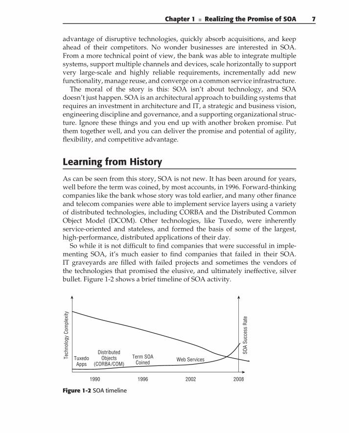
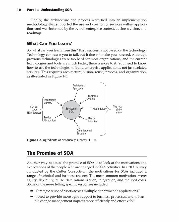
What Can You Learn?So, what can you learn from this? First, success is not based on the technology.Technology can cause you to fail, but it doesn’t make you succeed. Althoughprevious technologies were too hard for most organizations, and the currenttechnologies and tools are much better, there is more to it. You need to knowhow to use the technologies to build enterprise applications, not just isolatedservices. This requires architecture, vision, reuse, process, and organization,as illustrated in Figure 1-3.
Successful SOA
Technology Mastery
Service Abstraction
Architectural Approach
Business Vision
Reuse Initiative
Organizational Structure
MethodologyCan get
from Web Services
The restof thestory
Figure 1-3 Ingredients of historically successful SOA
The Promise of SOA
Another way to assess the promise of SOA is to look at the motivations andexpectations of the people who are engaged in SOA activities. In a 2006 surveyconducted by the Cutter Consortium, the motivations for SOA included arange of technical and business reasons. The most common motivations were:agility, flexibility, reuse, data rationalization, integration, and reduced costs.Some of the more telling specific responses included:
‘‘Strategic reuse of assets across multiple department’s applications’’
‘‘Need to provide more agile support to business processes, and to han-dle change management impacts more efficiently and effectively’’
Chapter 1 ■ Realizing the Promise of SOA 11
‘‘Master Data Management’’
‘‘Speed and ease of project deployment, concerns with duplication ofwork between projects’’
‘‘Support external collaborators’’
‘‘Efficiency in terms of time to market and development cost’’
‘‘Bring together diverse lines of business across many geographies withfaster speed to market’’
‘‘Integrate legacy systems’’
Not surprisingly, the motivations for adopting SOA echo the concerns thatmost enterprise IT organizations are struggling with.
The Challenges of SOA
If we examine the history and look at the goals or motivations for SOA, we candetermine the challenges that organizations face in delivering on its promise.Let’s restate the expectations, history, and goals in terms of four questionsand then look at the issues they raise and the corresponding architecturalrequirements.
What is required to provide agility, flexibility, and the strategic reuse ofassets across multiple departments?
What is required to bring more efficiency in terms of time to market anddevelopment costs, while delivering new capabilities to the organization?
How will the integration of existing applications or enterprise data helpto bring together diverse lines of business across geographies with fastertime to market?
How will SOA’s agility and flexibility improve relationships and providebetter alignment of business and IT?
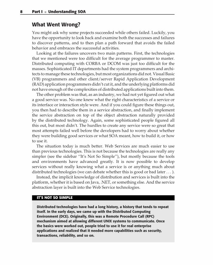
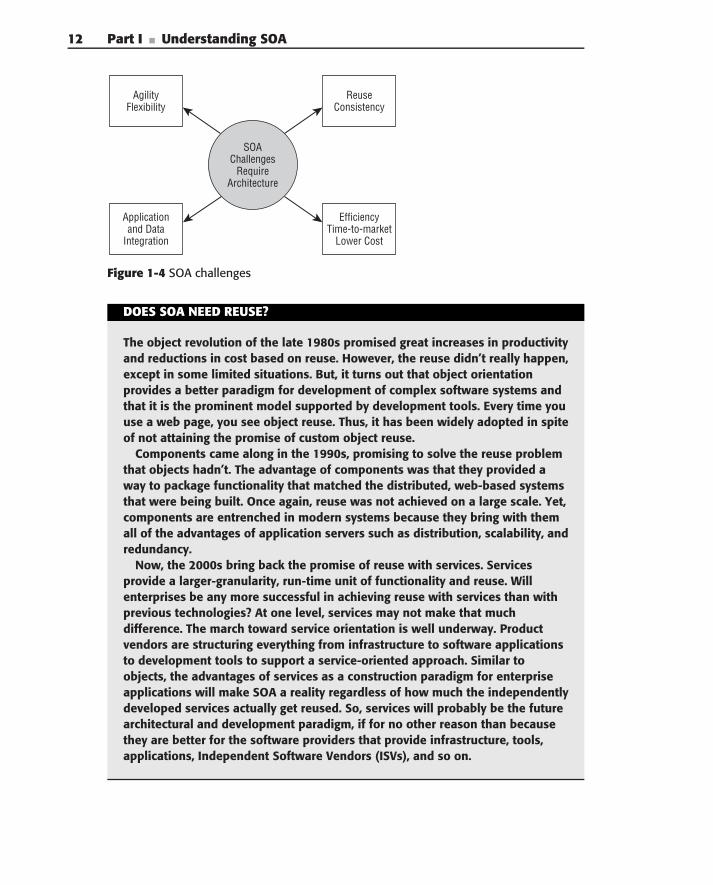
Figure 1-4 illustrates the four major challenges facing SOA adoption today.
ReuseReuse seems to have been the holy grail of software for decades. But theobjects and components failed to live up to the promise of the marketeers.Now, services are the next great hope for reuse. If we’re smart enough to learnfrom the past, we can be more successful with services. SOA will march oneither way (see the sidebar ‘‘Does SOA Need Reuse?’’).
12 Part I ■ Understanding SOA
SOA Challenges
Require Architecture
Reuse Consistency
Efficiency Time-to-market
Lower Cost
Agility Flexibility
Application and Data
Integration
Figure 1-4 SOA challenges
DOES SOA NEED REUSE?
The object revolution of the late 1980s promised great increases in productivityand reductions in cost based on reuse. However, the reuse didn’t really happen,except in some limited situations. But, it turns out that object orientationprovides a better paradigm for development of complex software systems andthat it is the prominent model supported by development tools. Every time youuse a web page, you see object reuse. Thus, it has been widely adopted in spiteof not attaining the promise of custom object reuse.
Components came along in the 1990s, promising to solve the reuse problemthat objects hadn’t. The advantage of components was that they provided away to package functionality that matched the distributed, web-based systemsthat were being built. Once again, reuse was not achieved on a large scale. Yet,components are entrenched in modern systems because they bring with themall of the advantages of application servers such as distribution, scalability, andredundancy.
Now, the 2000s bring back the promise of reuse with services. Servicesprovide a larger-granularity, run-time unit of functionality and reuse. Willenterprises be any more successful in achieving reuse with services than withprevious technologies? At one level, services may not make that muchdifference. The march toward service orientation is well underway. Productvendors are structuring everything from infrastructure to software applicationsto development tools to support a service-oriented approach. Similar toobjects, the advantages of services as a construction paradigm for enterpriseapplications will make SOA a reality regardless of how much the independentlydeveloped services actually get reused. So, services will probably be the futurearchitectural and development paradigm, if for no other reason than becausethey are better for the software providers that provide infrastructure, tools,applications, Independent Software Vendors (ISVs), and so on.
Chapter 1 ■ Realizing the Promise of SOA 13
However, many of the benefits that organizations hope to achieve with SOArequire that services be reused within their environment. Those enterprisesthat achieve reuse will reap more of the benefits, be more agile, and be morecompetitive. Therefore, it behooves us to look at what did and didn’t workin terms of reuse, and apply those lessons to services. Guess what? In everyinstance, technology was not the issue when it came to reuse. It’s true thatservices have some technical features that make them better for reuse thancomponents, just as components had technical features that were superior tothose of objects. But the main roadblocks to reuse have, and will continue tobe, organizational, methodological, and political.
Let’s look at these issues from the perspective of the service consumer.When an application or process wants to use a service, it first needs a way tofind and evaluate candidate services. Then, once it decides to use the service,it has dependencies on that service. Therefore, the service consumer needs tobe guaranteed that the service will operate reliably, that bugs will be fixed ina timely manner, that requests for enhancements will be considered, that itwill continue to operate and be supported for a reasonable amount of time,and, most importantly, that new versions of a service won’t cause existingconsumer applications to stop working. To make things more complicated, inan enterprise, the service consumer often needs to rely on another organizationfor that guarantee.
The following list discusses the architectural requirements for effectivereuse:
The ability to publish, search for, evaluate, and register as a consumer ofa service
Sufficient variability in service function to meet consumers’ needs
Capabilities for managing and maintaining a service life cycle acrossorganizational boundaries
The ability to guarantee the availability and lifetime of a service version
Mechanisms for decoupling the consumer’s life cycle from the provider’s
CONSISTENCY, CONSISTENCY, CONSISTENCY
We often promote reuse as a way to reduce development costs or time tomarket. Although you can achieve improvements in both these areas, often it isconsistency that is the most important value of reuse. SOA allows you toseparate access to functions or data such that every application that needs tomake use of the function or data can use the same service to get it.
(continued)
14 Part I ■ Understanding SOA
CONSISTENCY, CONSISTENCY, CONSISTENCY (continued)
How many enterprises suffer from redundant data or applications? (All ofthem, probably.) What is the result? Users get different results depending onhow they go about doing something. When the users are customers, this resultsin dissatisfaction and lost customers. You’ve all heard of problems such as acustomer having to call multiple different departments to correctly change hisor her address, or an item being available through one system, but not another.
Imagine an enterprise-wide customer service that manages the sharedcustomer information (such as addresses) for all systems and only needs to bechanged once. Or, a single inventory service used by all order-managementprocesses where they get consistent results about availability. SOA provides anapproach for consistency of processes and data for both internal and externalcustomers. This is something that the business sponsors understand and areoften more willing to pay for than the promise of reduced costs and reuse.
Efficiency in DevelopmentMaking development more efficient means building more functionality, in lesstime, at less cost. Doing so depends on a variety of factors, including the reuseof services and the ability to quickly compose applications from those services.This in turn requires a different approach to service and solution developmentthan the approach that was used in the past.
Developers of services can no longer create services in isolation, but rather,the services must fit into the overall architecture and conform to the enterprisebusiness and information models. However, the initial version of a servicecannot be expected to meet the requirements of all possible, future users.There has to be a managed process for deciding on, funding, and implement-ing enhancements to accommodate those additional users. But at the sametime, enhancements to services need to be done in a controlled fashion thatmaintains the integrity of the service architecture and design, and conforms toversioning and compatibility requirements.
Developers of solutions that will consume services need to be able toeasily find existing services and to evaluate them, determine what theydo, and request enhancements. Furthermore, methods and tools for modelingand composing business processes from existing services need to be estab-lished. When projects are implementing business processes, a system designmethodology is needed that focuses on composing business processes from
Chapter 1 ■ Realizing the Promise of SOA 15
the existing services. And, there has to be a variety of different kinds of servicesavailable, at different levels of organizational scope and granularity, to fullysupport the composition of business processes.
There also has to be an analysis and design methodology for the servicesthemselves that describes the characteristics of the different types of servicesand explains the interaction, interface, and implementation design decisions.
Finally, there have to be organizational changes to support service devel-opment and use across the enterprise that match the consumer and providernature of services.
The following architectural requirements are necessary for effective devel-opment productivity:
Have a reference architecture that guides the development of services.
Use Business Process Management (BPM) to define business processes,based on service composition and a layered set of services. Use BPM todrive the discovery and design of required services.
Have efficient processes that manage the integrity of the total set of ser-vices for both providers and consumers in accordance with the overallvision and the business and information models.
Integration of Applications and DataThe integration of existing applications and data is perhaps the most perplexingchallenge facing enterprise IT organizations. Billions have been spent over thepast decades on enterprise application integration (EAI) to implement applica-tion integration, but results are mixed. Too often, fragile and unmaintainablesolutions have been put in place that created a rat’s nest of point-to-pointconnections over a variety of different technologies and protocols.
SOA, based on Web Services, promises to simplify integration by providinguniversal connectivity to existing systems and data. But, as with everythingelse, technology is only a small part of the solution. Again, you can look atwhat did and didn’t work with EAI to craft a strategy for moving forward. Andwhen you do, you see that an overall, enterprise-wide, architectural solution isrequired. You should no longer be connecting individual applications directlywith point-to-point connections, but rather, providing services that connectindividual applications into the overall enterprise.
The really hard part, however, is getting the new interfaces to the existingsystem right. Here, the tools are often our own worst enemy. The vendors
16 Part I ■ Understanding SOA
trumpet their wiz-bang Web Services Description Language (WSDL)generators that can take an existing schema or application programminginterface (API) and generate a service interface. Although this is seductive, itis wrong. You should not be exposing the data models or APIs of 20-year-oldapplications directly as services. The chances that these old APIs representwhat your enterprise needs today are slim at best. Instead, you should trans-form them into new interfaces that meet the strategy, goals, and requirementsof the enterprise today and in the future.
A similar situation exists for data integration. How many millions werespent on failed projects to implement a global enterprise data model? Toooften, applications could not be retrofitted to the model, the cost of changewas too high, or business units wouldn’t go along with the changes. Yet, forservices to fit together into a business process or to be composed together ina meaningful way, they have to share a common data model and semantics.Here’s the difference, however: They do not have to agree on every single itemand field of data. They have to agree only on what the shared, enterprise-widedata should be. Then, each application can translate between its own, internalversion of the data and the shared, enterprise (external) representation ofthe data.
The following architectural requirements are necessary for integration:
Have an enterprise, common semantic model for the shared information.
Have a reference architecture that differentiates between business ser-vices and integration services.
Have a reference architecture that describes common patterns forintegration.
Have infrastructure capabilities that enable semantic transformationbetween existing systems and the enterprise model.
Agility, Flexibility, and AlignmentAgility and flexibility occur when new processes can quickly and efficientlybe created from the existing set of services. Achieving agility and flexibilityrequires an easily searchable catalog that lists the functions and data providedby the available services. In addition, an efficient way to assemble the businessprocesses from the services needs to be available.
The services that compose the catalog must support a variety of differentprocesses, at a variety of different levels, and have minimal gaps or overlapsin functionality. At the same time, the services must share and conform to a
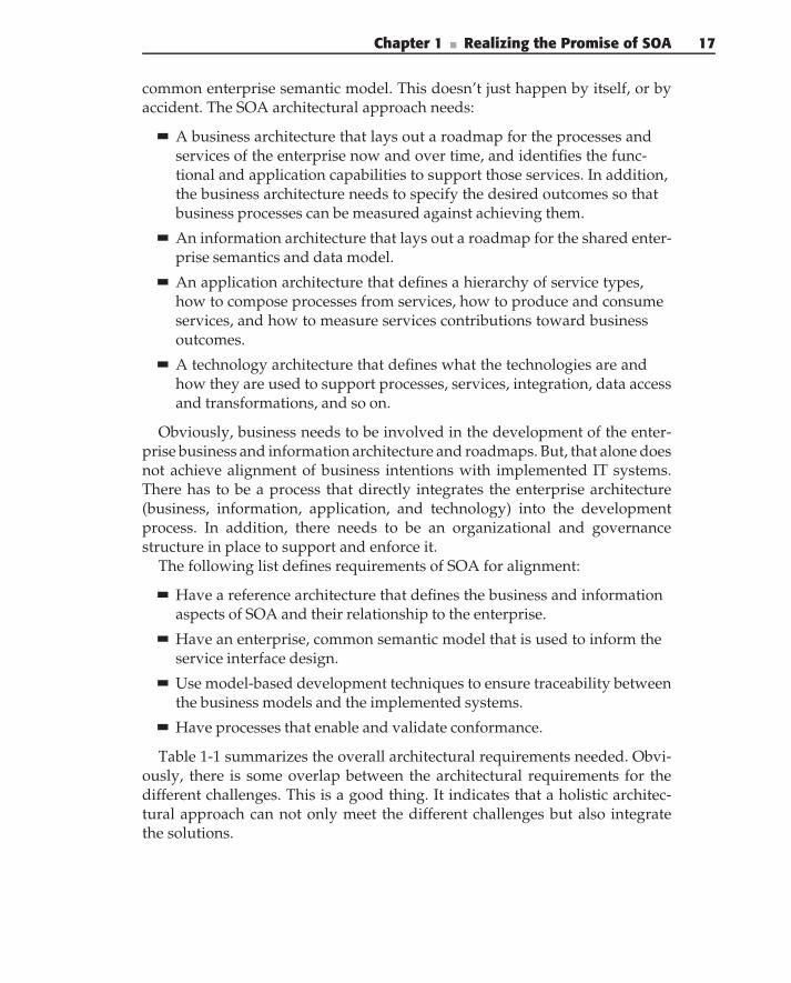
Chapter 1 ■ Realizing the Promise of SOA 17
common enterprise semantic model. This doesn’t just happen by itself, or byaccident. The SOA architectural approach needs:
A business architecture that lays out a roadmap for the processes andservices of the enterprise now and over time, and identifies the func-tional and application capabilities to support those services. In addition,the business architecture needs to specify the desired outcomes so thatbusiness processes can be measured against achieving them.
An information architecture that lays out a roadmap for the shared enter-prise semantics and data model.
An application architecture that defines a hierarchy of service types,how to compose processes from services, how to produce and consumeservices, and how to measure services contributions toward businessoutcomes.
A technology architecture that defines what the technologies are andhow they are used to support processes, services, integration, data accessand transformations, and so on.
Obviously, business needs to be involved in the development of the enter-prise business and information architecture and roadmaps. But, that alone doesnot achieve alignment of business intentions with implemented IT systems.There has to be a process that directly integrates the enterprise architecture(business, information, application, and technology) into the developmentprocess. In addition, there needs to be an organizational and governancestructure in place to support and enforce it.
The following list defines requirements of SOA for alignment:
Have a reference architecture that defines the business and informationaspects of SOA and their relationship to the enterprise.
Have an enterprise, common semantic model that is used to inform theservice interface design.
Use model-based development techniques to ensure traceability betweenthe business models and the implemented systems.
Have processes that enable and validate conformance.
Table 1-1 summarizes the overall architectural requirements needed. Obvi-ously, there is some overlap between the architectural requirements for thedifferent challenges. This is a good thing. It indicates that a holistic architec-tural approach can not only meet the different challenges but also integratethe solutions.
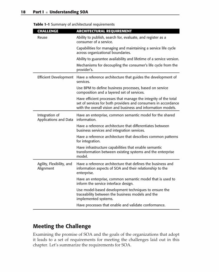
18 Part I ■ Understanding SOA
Table 1-1 Summary of architectural requirements
CHALLENGE ARCHITECTURAL REQUIREMENT
Reuse Ability to publish, search for, evaluate, and register as aconsumer of a service.
Capabilities for managing and maintaining a service life cycleacross organizational boundaries.
Ability to guarantee availability and lifetime of a service version.
Mechanisms for decoupling the consumer’s life cycle from theprovider’s.
Efficient Development Have a reference architecture that guides the development ofservices.
Use BPM to define business processes, based on servicecomposition and a layered set of services.
Have efficient processes that manage the integrity of the totalset of services for both providers and consumers in accordancewith the overall vision and business and information models.
Integration ofApplications and Data
Have an enterprise, common semantic model for the sharedinformation.
Have a reference architecture that differentiates betweenbusiness services and integration services.
Have a reference architecture that describes common patternsfor integration.
Have infrastructure capabilities that enable semantictransformation between existing systems and the enterprisemodel.
Agility, Flexibility, andAlignment
Have a reference architecture that defines the business andinformation aspects of SOA and their relationship to theenterprise.
Have an enterprise, common semantic model that is used toinform the service interface design.
Use model-based development techniques to ensure thetraceability between the business models and theimplemented systems.
Have processes that enable and validate conformance.
Meeting the ChallengeExamining the promise of SOA and the goals of the organizations that adoptit leads to a set of requirements for meeting the challenges laid out in thischapter. Let’s summarize the requirements for SOA.
Chapter 1 ■ Realizing the Promise of SOA 19
Reference Architecture
Creating and maintaining a reference architecture is one of the more importantbut difficult best practices for SOA and is an important critical success factorin achieving SOA goals. Yet, often, organizations will have only an informalarchitecture, or none at all. Figure 1-5 shows the major components of anSOA reference architecture. The reference architecture represents a moreformal architectural definition, one that can be used for objective validation ofservices and applications. For SOA, the reference architecture should:
Support enterprise concepts, particularly the subarchitectures of busi-ness, information, application, and technology
Specify a hierarchy and taxonomy of services and service types
Define how services fit into an overall enterprise application, such as aportal
Provide a separation between business, application, and technologyconcepts
Be integrated into the development process
Chapter 2 covers the reference architecture in detail.
ServiceTaxonomy
ServiceDesign
Methodology
Service-OrientedSolutions
Technology
SOA Reference Architecture
Business
Domain
Utility
IntegrationEnterpriseConcerns
Technology
Application
Information
Business
Figure 1-5 Aspects of an enterprise SOA reference architecture
Common Semantics
Defining a common, enterprise semantic and information model is key toachieving agility and flexibility. Without it services cannot be easily combinedto form meaningful business processes. For example, imagine a process thatcombines different travel activities, such as air, hotel, and rental car into a tripbased on a customer and their companions. The customer wants to see all of therelated activities and only wants to provide the information once. The airlines
20 Part I ■ Understanding SOA
require the names of all passengers; the rental car agency needs to knowif additional travelers are over age 25 and their relationship to the primarytraveler; and the hotel needs a different set of information. If the servicesdon’t have some common understanding of what a customer is, and what atravel companion is, it won’t be very easy to automate the combined processesor provide a single view or interface to the customer. Without commonunderstanding, rather than agility and flexibility, each process requires specialcase code to combine the data. The common semantics should:
Identify information that must be shared across the enterprise andbetween services
Define the meaning and context of that information
Identify techniques for mapping enterprise semantics to existing applica-tion data models
Chapter 5 describes the development of the common semantic model, andChapter 6 shows how it is used in the design of service interfaces.
Governance
Governance has been defined as the art and discipline of managingoutcomes through structured relationships, procedures, and policies. Gov-ernance enforces compliance with the architecture and common semanticsand facilitates managing the enterprise-wide development, use, and evolutionof services. Governance consists of a set of policies that service providers andconsumers (and their developers) must conform to, a set of practices for imple-menting those policies, and a set of processes for ensuring that the policiesare implemented correctly. There is typically an organizational structure inplace to define and implement governance policies and often a repository toautomate and enforce them. Governance of SOA should include:
Policies regulating service definition and enhancements, including own-ership, roles, criteria, review guidelines, and so on.
Identification of roles, responsibilities, and owners.
Policy enforcement that is integrated directly into the service repository(where appropriate).
Guidelines, templates, checklists, and examples that make it easy to con-form to governance requirements.
Review of service interface definitions for new services and enhance-ments to existing services. The review ensures that the service definitionconforms to standards and aligns with the business and information
Chapter 1 ■ Realizing the Promise of SOA 21
models. The review is typically done by a service review board or theunit responsible for the service.
Architectural review of solutions and services to ensure that they con-form to the SOA and enterprise architecture. This review is typicallydone by an architecture review board.
Warning! Governance should not be primarily a review activity. If architec-ture is nothing more than extra steps in the process or a burden to developers,they will just ignore it. Effective governance follows a carrot-and-stickapproach with an emphasis on enabling developers to build conformingapplications (the carrot) and automating governance activities and policies.Reviews (the stick) should be a final check where process is minimal andexceptions are actually the exception.
We’ve seen countless articles and presentations (surprisingly by vendors)that talk about governance as a required activity from day 1. But we don’tagree. There are enough challenges and barriers to get over for SOA to work,that you don’t need another one to start with. When you have only a fewservices, you don’t need a lot of processes to govern them. Figure out howto build and use services first, and then add governance. If you have to goback and correct things, fine. Certainly make sure that you have governancebefore you have 100 services, but don’t put it in place when you have only oneservice. Chapter 12 discusses governance.
TYPES OF GOVERNANCE
We often discuss governance in terms of four different aspects of a service’slife cycle:
◆ Design-time governance — Policies and procedures to ensure that the rightservices are built and used
◆ Deploy-time governance — Policies that affect the deployment of servicesinto production
◆ Run-time governance — Policies that affect the binding of consumers andproviders
◆ Change-time governance — Policies and procedures that affect thedesign, versioning, and provisioning of service enhancements
We have primarily discussed design-time and change-time governance asarchitectural requirements. Obviously, deploy-time governance is important foroperational quality. Although automated run-time governance functions canprovide benefits and sophistication to a SOA implementation, we don’t thinkthat it is a critical factor in achieving overall SOA success and value. Of course,it is important to specify policies regarding security and the authorization of
(continued)
22 Part I ■ Understanding SOA
TYPES OF GOVERNANCE (continued)
service consumers and providers. However, many successful SOAimplementations today use very simple mechanisms to implement this ratherthan a sophisticated registry to automatically apply the policies during binding.On the other hand, governance of service interface design is necessary toachieve a consistent overall set of services, which is critical to achieving SOAsuccess.
Business Process Modeling
Business processes need to change relatively frequently yet be based on stableunderlying capabilities. The flexibility to do this comes from being able toquickly construct new business processes from business services, which arerelatively stable. Business processes should:
Be specified using Business Process Models and executed in a businessprocess management system
Be composed of activities that are implemented by business services(provided by the SOA)
Pass information into, out of, and within the processes in the form ofdocuments, which are built on top of the common information model
Chapter 4 describes the use of BPM in addressing business requirementsand influencing service design.
Design-Time Service Discovery
To reuse services, you have to be able to find the services that exist, andyou have to be able to examine them to see if they perform the functionsrequired, provide the appropriate qualities of service, are reliable, and so on.It is important to understand the distinction between a run-time registry anda design-time repository, even though both functions may be implemented bythe same software. A registry is used at run time to identify a service endpointfor a requested service interface. This is where run-time governance policiesmay be enforced. A repository is used at design time to find existing servicesfor inclusion in processes during the design of that process. This is critical toenabling service reuse. Service discovery does not necessarily have to be basedon a repository (although repositories do a good job of it) but should providethe following functions:
Chapter 1 ■ Realizing the Promise of SOA 23
A catalog of available services.
Sophisticated search capabilities for identifying potential services.
Capabilities for examining a service, its interface and implementation,and design and testing to determine if it is appropriate for the desiredusage. This will often be through links to documents, models, code,reports, and the like that are stored in other systems.
Metrics on service usage.
Notification to interested parties about upgrades to services or otherevents.
Automation of certain governance policies.
Direct integration into the development environment.
In subsequent chapters, we provide methods for describing and categorizingservices to assist you in locating them during development. Chapter 5 describesthe creation and use of the service inventory in the discovery and design ofservice interfaces.
Model-Based Development
Model-based development is a best practice in software engineering in generaland in SOA as well. Models provide a way to conceptualize and describe asystem without getting bogged down in details, and to describe the major partsof a system and their relationships. A model-based development approach forSOA should incorporate the following:
A higher level of abstraction for software development and the ability tovisualize software and service designs
Support for a domain-specific language (DSL) for the implementationof SOA
Automatic integration of SOA reference architecture into the designenvironment and DSL
Separation of business, services, and technology concerns
The design methodologies throughout this book use a model-based approachto SOA design, based on a set of SOA domain concepts and abstractions thatmake up a domain-specific language for SOA. Although it is helpful to beable to generate development artifacts directly from design models, and infact many tools do exactly that, it is not strictly required. The proper designof services is critical to achieving SOA goals, and models are the linguafranca of design. What is required is the design of service interfaces and
24 Part I ■ Understanding SOA
implementations, and a way to pass those design models to development asspecifications for construction. Of course, the more you can generate, theeasier and less error prone that hand-off will be. Chapter 7 focuses on thetechnology-independent design of service implementations that lead to amodel-based approach.
Best Practices in SOA Analysis and Design
There’s a clever saying that goes ‘‘In theory, there’s no difference betweentheory and practice, but in practice there is.’’ This difference is most often seenin the clash between architecture and development.
The architecture team is responsible for understanding the big picture.They must answer questions such as: How will SOA support the overallenterprise goals? How will it fit with other initiatives such as Single Sign-On(SSO)? What standards and technologies are important? How do they fit inwith the enterprise technology roadmap? What strategy and tactics should beemployed to introduce and phase in SOA? How will it be sold to managementand the business? All of these are important and difficult questions that mustbe answered, and the architecture team or steering committee is the right placefor this. We often call this a top-down approach.
The development team is responsible for implementing and deployingindividual services. They have a different set of questions to answer: How willan individual service be implemented? How will the master data definition betranslated to the individual systems of record that contain the data? How willthe service be deployed? How will the service be managed? How will newversions be implemented and deployed? How will services be registered anddiscovered at run time? How will services be discovered and reused at designtime? How will dependencies be minimized and managed? Again, these arevery important and difficult questions that must be answered. We might callthis a bottom-up approach.
With these questions and concerns, the architecture team is trying to max-imize the value that SOA can provide in the delivery of enterprise solutions.Value comes from enabling and creating an enterprise service layer thatsupports the flexible creation of business processes. Value comes from beingable to quickly modify these business processes without having to make diffi-cult and expensive modifications to existing operational systems. Value comesfrom having consistent behavior across the enterprise for the same businessfunction (i.e., having the business function implemented in a single service).Value comes from having modular business capabilities that can be outsourced
Chapter 1 ■ Realizing the Promise of SOA 25
or sold as a service. To support this, the SOA has to describe how the differentorganizations in the enterprise can contribute to the overall SOA, and at thesame time, meet their immediate business requirements.
Meanwhile, the technical team is trying to provide value by implementingspecific business functionality in the best, most efficient, and most cost-effectivemanner — not just in the short term, but with an eye toward the total cost ofownership of IT systems. The manager of a technical team we worked withput it best. He sees SOA as a way to minimize and manage the collateraldamage caused by changes. We’ve all heard the horror stories, such as the caseof adding two digits to a part number that required $25 million and 1 yearto implement (but added no business value), because it touched on almostevery system in the enterprise. By applying a separation of concerns, having aMaster Data Schema, and a set of services to manage the fundamental businessentities, the required changes could have been isolated and minimized.
The theory naturally leads toward a top-down approach in which processesand services are driven by an overall enterprise model. These projects are oftenstarted with a high-level business process model or an overall enterprise systemanalysis activity. The practice leads us to a bottom-up approach in whichservices are implemented to meet a specific, immediate business requirementor project. These projects often start by service-enabling legacy systems orincorporating simple external services. Yet neither of these approaches is veryeffective. In order to meet both the enterprise goals and the immediate projectgoals, these organizations and concerns have to meet in the middle. Chapter3 describes the overall process of initiating SOA and designing services basedon a middle-out approach.
Summary
Effective SOA (and architecture in general) is the careful balance and blendingof the big picture and the immediate requirements. It is the practical applica-tion of theory to meet a set of goals, now and in the future. In this middle-outapproach, the architecture team provides an overall SOA that offers the guid-ance and context necessary to support the implementation and reuse of ser-vices. This is provided as a set of guidelines, patterns, frameworks, examples,and reference implementations. The technical teams use these to incorporatethe requirements (business and information context) into their designs so thatthe services they implement provide the necessary business functions that areneeded immediately, but can easily be extended to support other processes
26 Part I ■ Understanding SOA
and services in the future. These are the roles of the reference architecture,the architecture-driven design process, and the domain-specific modelingapproach.
Chapter 2 describes the SOA reference architecture and how it meetsthe challenges and requirements introduced in this chapter. It describes theoverall enterprise context, the architectural layers and tiers, the domain-specificconcepts and abstractions, and specifically what a service is and the importantarchitectural characteristics of a service.
C H A P T E R
2SOA — Architecture
FundamentalsAny problem in computer science can be solved by another layer of abstraction.
— Butler Lampson
Chapter 1 discussed the expectations for Service-Oriented Architecture (SOA)and the requirements for delivering on those expectations. At one level, theextent to which expectations are met will depend on how successful anorganization is at creating and reusing services. To be more specific, successwill not depend on any individual service, but on the overall collection ofservices and how well they support the ability to modify existing solutionsand build new ones faster to meet changing requirements. We went on todescribe the SOA reference architecture as the foundation that allows reusableand composable services to be created with a scope that is larger than anysingle project. So, just what is architecture, and what are the components ofthe SOA reference architecture? This chapter describes:
The general principles of architecture
The basics of SOA
Business-driven SOA
The relationship of SOA to other architectures
What a service is and the characteristics of a service
Service types and purposes
The SOA reference architecture
27
28 Part I ■ Understanding SOA
What Is Architecture?
Software architecture is a description of a software system in terms of its majorcomponents, their relationships, and the information that passes among them.In essence, architecture is a plan for building systems that meet well-definedrequirements and, by extension, systems that possess the characteristics neededto meet those requirements now and in the future.
A fundamental purpose of software architecture is to help manage thecomplexity of software systems and the modifications that systems inevitablyundergo in response to external changes in the business, organizational, andtechnical environments.
There is no single, industry-wide definition of software architecture. TheSoftware Engineering Institute (SEI) web site includes a long list of defini-tions for the term ‘‘software architecture’’ at www.sei.cmu.edu/architecture/definitions.html. Some definitions provide details and context to the abs-tract definition given above, and expand on the notions of a systemdescription, requirement specification, and planning. Others are just as abstractbut provide a different viewpoint for thinking about architecture. It is instruc-tive to read them all, if only on the chance that one of them will make youthink ‘‘Aha!’’
Here is a definition of software architecture from The Rational UnifiedProcess — An Introduction by Booch and Kruchten (1999).
Software Architecture encompasses the significant decisions about:
The organization of a software system,
the selection of the structural elements and their interfaces by which the systemis composed, together with their behavior as specified in the collaboration amongthose elements,
the composition of these elements into progressively larger subsystems,
the architectural style that guides this organization, these elements and theirinterfaces, their collaborations, and their composition.
Software architecture is not only concerned with structure and behavior butalso with usage, functionality, performance, resilience, reuse, comprehensibility,economic and technological constraints and tradeoffs, and aesthetics.
Most definitions agree that software architecture describes the compositionof systems, but differ in the perspective of what a system is and whatcomposition implies. We like this definition because it is detailed but broadenough to cover many perspectives and scopes.
While traditional software architecture is focused on the construction ofsoftware applications, SOA is focused on the construction of solutions with
Chapter 2 ■ SOA — Architecture Fundamentals 29
an enterprise or cross-organizational scope, based on the interactions betweenconsumers with needs (often business processes) and providers with capabili-ties (services).
We like to describe architecture as having to answer three main questions:
1. What are the important concepts?
2. What are the relationships among them? How do these relationshipsdescribe the behavior of the system?
3. How do the concepts and relationships provide value higher up? Howdo they serve the purpose of the overall system rather than the pur-pose of the individual parts?
So, a typical software architecture might describe the structure of classes (akey concept) or components, their relationships, and their value in the softwareproduct. Similarly, SOA describes the structure of services (a key concept),their relationships, and the value they bring to enterprise-wide processes andsolutions.
Architectural Styles
Most products, applications, and enterprises have unique architectures,although many of them may be very similar. For example, the architec-ture for an e-commerce application at one company probably resembles thatof an e-commerce application at another company of like size and businessfunction. This implies that there is a difference between a specific architectureand the type of solution it defines. The common industry term for the latter isarchitectural style.
In terms of the architectural questions presented previously, the architecturalstyle is the vocabulary of concepts and relationships, and a set of constraintson how they can be combined to meet the higher-level goals and to forma particular architecture. An architectural style is a family of architecturesrelated by common principles and attributes. In other words, an architecturalstyle contains a well-defined set of patterns that constitute a common wayfor enterprise solution components to interact with one another. For example,we consider client/server, 3-tier, n-tier, and enterprise application integration(EAI) approaches all to be architectural styles.
A useful metaphor to describe styles is the construction of a cathedral. Allcathedrals have certain underlying construction principles. For example, thebasic floor plan is that of a cross. And while there is also wide variation amongcathedrals, a few common characteristics emerge such as Romanesque andGothic. These two architectural styles define a specific set of patterns thattransform the basic cathedral into an easily identifiable style.
30 Part I ■ Understanding SOA
The choice of an architectural style for enterprise solutions is typicallymade as a result of engineering tradeoffs in response to a specific setof requirements. For example, an n-tier architectural style is designed tomeet requirements of distribution, scalability, interface flexibility, deviceindependence, business service reuse, application integration, and so on.Specifically, the n-tier architecture is designed to provide web-based andother types of client access to information and services that reside within theenterprise, which might in fact be implemented in a legacy application.
SOA can be defined as an architectural style promoting the concept ofa business-aligned enterprise service as the fundamental unit of designing,building, and composing enterprise business solutions. Multiple patternsdescribing definitions, implementations, and deployment of the SOA solu-tions complete this style. Throughout this chapter, we define the concepts,relationships, constraints, and patterns that make up the SOA architecturalstyle.
Architectural Principles and PracticesBefore diving into the specifics of SOA, let’s review some important architec-tural principles and practices that we apply throughout the chapter:
Separation of concerns
Architectural views
Accommodation of change
Abstraction
Consistency
Business derivation
Patterns
Facilitation
Communications
The separation of concerns is the most fundamental principle of archi-tecture. Concerns are kept separate so that independent elements remainindependent. The benefit is that a change in one part of the system doesnot adversely affect other parts. In other words, they can change indepen-dently. A familiar example of this principle is the separation of interface fromimplementation.
Architectural views provide another important separation of concerns by theinclusion or exclusion of specific details and the presentation of informationto different stakeholders. Architectural views or perspectives are designed toaddress specific concerns of software development or the important enterprise
Chapter 2 ■ SOA — Architecture Fundamentals 31
groups and organizations that play a part in the full life cycle of enter-prise solutions. Typical software views are logical, deployment, process, andnetwork. Typical enterprise architectural views (concerns) are business, infor-mation, application, technology, and implementation. Coincidentally, SOAimplementation and design map well to these sets of architectural concerns.
Accommodation of change refers to the fact that the architecture should provideflexibility, so that future application requirements can be more easily satisfied.A flexible architecture identifies both future application requirements andareas that are likely to change. Tracking industry trends helps identify someareas of potential change. These areas must be addressed explicitly in architec-ture. If the specifics of flexibility and independence are not included in the orig-inal design it is very likely that the architecture will contain implicit couplings,which are much more difficult to deal with when change inevitably occurs.
Abstraction is a key architectural tool used in decoupling, accommodatingchange, and separating concerns. There is a saying in the industry that ‘‘anyproblem in computer science can be solved by adding a layer of abstraction.’’An abstraction layer provides indirection between two layers, allowing forincreased flexibility. Typically, the abstraction also provides a higher level ofinteraction. For example, rather than writing directly to a database, you writeSQL, which provides a higher-level interaction model, as well as an abstractionand indirection layer above the lower-level database interfaces. The abstractionprovides higher productivity (in the sense that one SQL statement correspondsto many invocations of the lower-level database interfaces) and also supportsmultiple different datastores.
One of the main goals of architecture is the promotion of consistency andreuse. Thus, one difference between software architecture and Service-OrientedArchitecture is that of scope. SOA is concerned with providing consistent ser-vices throughout the entire enterprise, so that they can be used by manydifferent families of solutions. SOA must promote the development of busi-ness capabilities in such a way that they are easily reused by the differentbusiness processes.
Business derivation is perhaps the most important architectural principle,which acknowledges that an architecture’s raison d’etre (and that of IT itself)is to support the enterprise’s business — that is, the strategies and goals of theorganization.
A pattern is a template for a solution to a specific set of requirements,and as such it is a tool for describing architecture. The father of the patternmovement is generally acknowledged to be Christopher Alexander, a professorof architecture (as in buildings, not software) at Berkeley. He put it this way‘‘Each pattern describes a problem which occurs over and over again in ourenvironment, and then describes the core of the solution to that problem, insuch a way that you can use the same solution a million times over, withoutever doing it the same way twice.’’
32 Part I ■ Understanding SOA
Facilitation means that an architecture should make it easy to build solutionsthat conform to the architecture. Thus architecture is not only about describingwhat the system does; it must also provide the means to construct the systemand its components.
Communications has to do with the fact that an architecture provides themechanism for people to communicate about, and reach a common under-standing of, IT systems. These architectural principles allow you to describearchitecture unambiguously, at different levels of abstraction, and in a contextunderstandable to each stakeholder.
DEATH BY ARCHITECTURE
Perhaps nothing is more drawn out and aggravating for an IT organization thanwhat we call death by architecture. This classic story happens all too often. Thehigh priests and architects depart for the ivory tower and return some monthsor years later with ‘‘The Revealed Truth’’ in the form of 1000 pages ofarchitecture documents. In the meantime, new applications have beendeveloped and requirements have changed, and the architecture is out of dateon delivery. Other reasons may contribute to its being dead on arrival. It may beirrelevant to the development organization or might not have enough buy-in tobe accepted. It may be hard to understand its value or how it achieves businessgoals, or dozens of other reasons.
Obviously, we believe in the value and importance of architecture, and wehope to convince you as well. But don’t confuse belief in the importance ofarchitecture with support for ivory-tower architecture projects. There are rightways and wrong ways to do everything, and SOA architecture has more than itsshare of wrong ways. So don’t give up on the idea of architecture, even if yourexperience with architecture thus far has been painful. We have seen verysuccessful architecture projects, and they are a joy to behold. The world’s mostsuccessful applications are based on solid architectures and solidimplementations.
However, architecture is hard to do well. It fails most frequently because ITdoes not have the will to implement the associated organizational changesrequired to make it work. Other common reasons are poor projectmanagement, changes in leadership or sponsorship, and changes in priorities.Sometimes, the architecture group itself is to blame. But there is no doubt thatit is a primary responsibility of the chief architect to avoid death byarchitecture. Here are some suggestions:
◆ Quickly create an architectural vision and strategy. It should take about1 month to develop this ‘‘high-level architecture.’’ Use this to prioritize andguide the implementation of the architecture.
Chapter 2 ■ SOA — Architecture Fundamentals 33
◆ Pick an appropriate project to start implementing the first pieces of archi-tecture, one that is important enough to get noticed, but not so criticalthat outside pressures will make it impossible to do the right thing.
◆ Implement a small portion of the architecture at one time, as part of aproject that is delivering real business value to the organization. Use yourarchitectural vision to help pick areas that demonstrate architectural val-ues, such as reuse and consistency. Services and frameworks are oftengood candidates. Continue to incrementally implement more of the archi-tecture as part of subsequent projects.
◆ After every project, integrate the lessons learned into the next iteration ofthe architecture. Keep it current. Constantly solicit feedback from develop-ment. Get their buy-in by demonstrating that architecture makes their jobeasier.
◆ Implement, collect, and report metrics to prove the value in terms of cost,time, and quality.
◆ Know the difference between great and good enough. It will never be per-fect. A good-enough project delivered on time beats a late-but-great oneevery time.
◆ Don’t try a big bang approach. It never works. SOA should be businessdriven and based on a vision of what processes, capabilities, and servicesyou’ll need over time. However, you don’t have to have the entire enter-prise business model complete before you can get started on the first fewservices.
What Is Service-Oriented Architecture?
SOA is an architectural style for building enterprise solutions based onservices. More specifically, SOA is concerned with the independent con-struction of business-aligned services that can be combined into meaningful,higher-level business processes and solutions within the context of the enter-prise. Anybody can create a service; that is not the challenge of SOA. Thereal value of SOA comes when reusable services are combined to create agile,flexible, business processes. Unfortunately, that does not just happen by itself.Achieving it might be easier to manage if a single organization is creating allof the services, but that is not the case at most large organizations. So, part ofthe architecture of SOA is responsible for creating the environment necessaryto create and use composable services across the enterprise.
In other words, architecture enables different organizations to indepen-dently implement services that meet their immediate needs, yet can also be
34 Part I ■ Understanding SOA
combined into higher-level business processes and enterprise solutions. Thisrequires that services:
Have similar size, shape, form, function, and other characteristics
Conform to enterprise standards
Communicate at a technical level
Communicate at a semantic level
Don’t have gaps and overlaps in responsibilities
As mentioned earlier, architecture has to answer these three questions: Whatare the important parts? What is the relationship among the parts? How dothey combine to provide value to the level above them?
In terms of SOA, the important parts are:
Processes — High-level business functions, often spanning applicationsor LOBs
Services — Modular units of business functionality
Integration — Connection to and exposure of existing applicationsand/or data as services
Existing systems — Existing legacy systems, commercial off-the-shelf(COTS) applications, and data that the enterprise wants to leverage
Documents — High-level units of business information, such as a pur-chase order, or an EDI document
Semantics — The underlying meaning of information that is exchangedin processes
Transformation — The conversion of information from one format orsemantic to another
Communications — The ability of services to communicate with eachother
Figure 2-1 illustrates a layered SOA architecture, including two importantconcepts for each layer. On the left are the functional concepts that youuse to construct systems and processes. On the right are the informationalconcepts that you use to pass, describe, or manipulate data at those differentfunctional levels. In other words, you are explicitly recognizing the factthat enterprises are a combination of process and information. Each layerneeds both abstractions. Yet, too often, SOA only focuses on the functionalaspects, ignoring the important data concepts. Instead, you should presentthe functional and data abstractions together. The connections between layersrepresent the relationships between the functions.
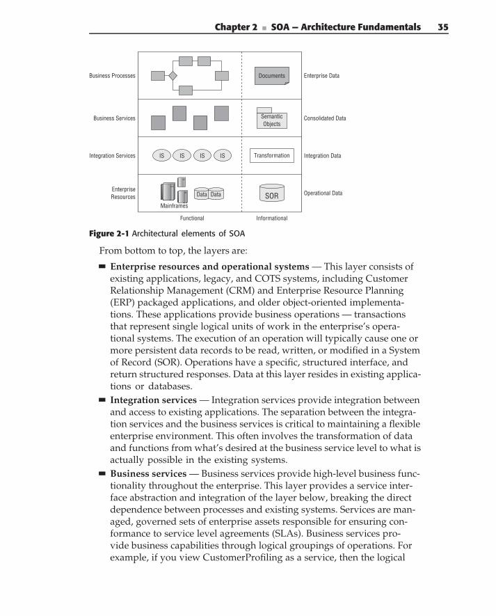
Chapter 2 ■ SOA — Architecture Fundamentals 35
Operational Data
Functional Informational
Integration Services
Business Services
Business Processes
EnterpriseResources SORSOR
Semantic Objects
Documents
TransformationIS IS IS ISIS IS IS IS
Data Data
Mainframes
Enterprise Data
Consolidated Data
Integration Data
Figure 2-1 Architectural elements of SOA
From bottom to top, the layers are:
Enterprise resources and operational systems — This layer consists ofexisting applications, legacy, and COTS systems, including CustomerRelationship Management (CRM) and Enterprise Resource Planning(ERP) packaged applications, and older object-oriented implementa-tions. These applications provide business operations — transactionsthat represent single logical units of work in the enterprise’s opera-tional systems. The execution of an operation will typically cause one ormore persistent data records to be read, written, or modified in a Systemof Record (SOR). Operations have a specific, structured interface, andreturn structured responses. Data at this layer resides in existing applica-tions or databases.Integration services — Integration services provide integration betweenand access to existing applications. The separation between the integra-tion services and the business services is critical to maintaining a flexibleenterprise environment. This often involves the transformation of dataand functions from what’s desired at the business service level to what isactually possible in the existing systems.Business services — Business services provide high-level business func-tionality throughout the enterprise. This layer provides a service inter-face abstraction and integration of the layer below, breaking the directdependence between processes and existing systems. Services are man-aged, governed sets of enterprise assets responsible for ensuring con-formance to service level agreements (SLAs). Business services pro-vide business capabilities through logical groupings of operations. Forexample, if you view CustomerProfiling as a service, then the logical
36 Part I ■ Understanding SOA
group of operations it contains might be: Lookup Customer by Tele-phone Number, List Customers by Name, and Save New CustomerData. Note that all operations will not necessarily come from the sameoperational systems, or in some cases, the operations will be replicatedacross multiple similar systems. Thus, the business services provide avirtual implementation of related business operations. Business servicesoperate on semantic data objects, virtual data that describes the informa-tion that must be shared or passed between services. It is often aggre-gated from multiple existing systems. Note that the business servicelayer will be composed of many different types of services, discussedlater in the chapter.
Business processes — A business process consists of a series ofoperations that are executed in an ordered sequence according to a setof business rules. Often, the business process is described in a BusinessProcess Model, such as those conforming to Business Process ModelingNotation (BPMN), and executed by a specialized businessprocess management system (BPMS). The sequencing, selection, andexecution of operations is termed orchestration. Business processes pro-vide long-running sets of actions or activities. They are composed ofbusiness services and typically encompass multiple service invocations.Business processes operate on business documents. The processes anddocuments are composed from the services and objects of the layerbelow, according to a Business Process Model and a common seman-tic data model. The scope of these processes is often the entire enterprise.Examples of business processes are: Initiate New Employee, Sell Prod-ucts or Services, and Fulfill Order.
Completing the answer to the third architectural question, these conceptsand relationships provide value to the enterprise by:
Providing a single, consistent place to access data or perform businessfunctions
Isolating and exposing existing application data and functions
Creating reusable, combinable building blocks for the construction ofbusiness processes
Figure 2-1 shows a typical layered perspective of SOA that addresses thecomposition and integration requirements of SOA and business processes,but not so much the run-time, governance, organizational, or enterpriserequirements. We will expand on these layers in Chapters 9 and 10 when wediscuss implementing enterprise solutions. Figure 2-2 illustrates a differentperspective on SOA.
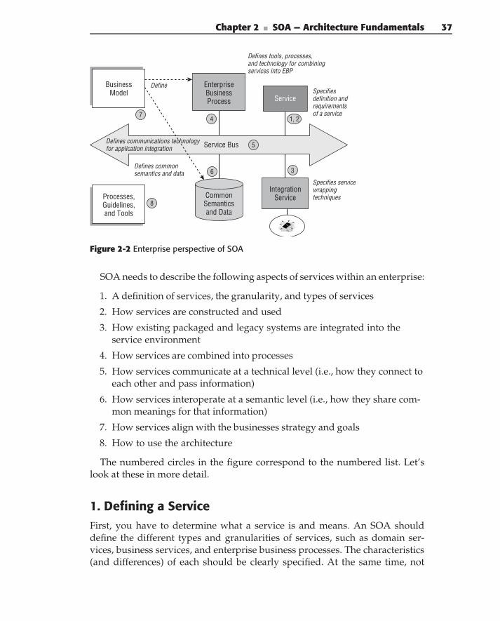
Chapter 2 ■ SOA — Architecture Fundamentals 37
Integration Service
Business Model
Define
Service Bus
Processes, Guidelines, and Tools
Specifiesdefinition andrequirements of a service
Defines communications technology for application integration
Specifies servicewrapping techniques
Defines common semantics and data
Defines tools, processes, and technology for combining services into EBP
Service
1, 2
3
5
8
7
Common Semantics and Data
Enterprise Business Process
4
6
Figure 2-2 Enterprise perspective of SOA
SOA needs to describe the following aspects of services within an enterprise:
1. A definition of services, the granularity, and types of services
2. How services are constructed and used
3. How existing packaged and legacy systems are integrated into theservice environment
4. How services are combined into processes
5. How services communicate at a technical level (i.e., how they connect toeach other and pass information)
6. How services interoperate at a semantic level (i.e., how they share com-mon meanings for that information)
7. How services align with the businesses strategy and goals
8. How to use the architecture
The numbered circles in the figure correspond to the numbered list. Let’slook at these in more detail.
1. Defining a ServiceFirst, you have to determine what a service is and means. An SOA shoulddefine the different types and granularities of services, such as domain ser-vices, business services, and enterprise business processes. The characteristics(and differences) of each should be clearly specified. At the same time, not
38 Part I ■ Understanding SOA
everything should be a service. The SOA should also specify what kinds ofsoftware constructs should not be services. For example, the logic that dis-plays data on a web page based on a user’s profile should not be a service,whereas the logic that retrieves the user’s profile and authorization informationshould be.
2. Defining How Services Are Built and UsedServices are intended to operate within the larger enterprise context (semanticand behavioral environment). The SOA must be clear about how servicesshould be used in an enterprise solution (e.g., what standard features theyhave, what required interactions there are, how they support managementcapabilities, etc.).
The architecture must define the structure of a service and how to build one.We will discuss the details of different types of services in the next section. Foreach type of service, the architecture should specify:
Granularity — The appropriate size of the service.
Type or style of interface — Guidelines for interface design. Forexample, business services should be large-grained services that passdata through documents, whereas utility services provide discrete com-mon functions where the input is often a single simple parameter.
Configuration mechanisms — Standard mechanisms for configuringservices should be defined. This allows for the use of a common configu-ration service, and more importantly, for common configuration data tobe shared between services. For example, several different services mayrequire the specification of a customer authorization file. Rather thanrepeating that information for each service, a better approach would beto allow the services to share the information. SOA enables the mecha-nisms required for sharing.
Other artifacts — The set of artifacts that are required to support a ser-vice, such as design models and specifications, documentation, testplans, and so on.
Associated information — Additional information that should be partof a service to support run-time and design-time inspection, such asthe version, author, date, keywords, and so on. Note the two differentand important types of service information: design time and run time.Although these have some overlap, they are largely different. Design-time information is used to search for and locate services, to determine ifthey are appropriate for the desired usage, and to describe what they doand how they are used. Run-time information is used more for manage-ment operations to track what is running at any give time.
Chapter 2 ■ SOA — Architecture Fundamentals 39
Dependency management and other patterns — Specific design pat-terns that should be followed to keep services independent and reusable.
In addition, the architecture must describe the complete life cycle of services,including maintenance, evolution, versioning, and backward-compatibilityrequirements.
3. Integrating Packaged and Legacy Systemsinto the Service EnvironmentThe reality is that much of the business functionality in an enterprise today isnot in the form of a service. An essential part of an SOA is how this functionalitycan be exposed as services and connected to the service bus. The SOA mustspecify the general mechanism for defining these services, wrapping them,and connecting them to the bus, with specific implementations for the mostcommon type of system.
4. Combining Services into Enterprise ProcessesAn important goal of an SOA is to enable the reuse of services throughoutthe enterprise to support a variety of different applications. The SOA mustdescribe the methods, tools, and infrastructure for combining services intolarger business processes.
5. Specifying the Technology InfrastructureA technical infrastructure must be in place to enable integration, servicecomposition, and communication among services. However, there are manydifferent types of infrastructures, and even within the same type, there aremany different options. For example, if the infrastructure is Web Services, thenthe architecture might specify that WS-I Basic Profile v1.1 and Security Profilev1.0 be used. All aspects of interaction with the technical infrastructure suchas protocol versions, security, and application utilities must be addressed toensure integration at the business process level.
Specifying the Technology Infrastructure
The technical infrastructure to enable services to communicate must be com-pletely specified, along with the guidelines for using that infrastructure. Thisincludes:
The communications mechanism — How messages, requests, and dataare transported
40 Part I ■ Understanding SOA
Failover mechanisms — How communication failures are handled,including failover and recovery
Discovery and location transparency — How services are advertisedand discovered in a location-transparent manner
Note that the architecture does not imply any specific technology for thisbus. It could be implemented by Web Services, an Enterprise Service Bus, anapplication server platform, or other middleware. However, it is importantthat the architecture specifies a solution for communications issues, and thatthe chosen solution addresses these issues.
Specifying the Application Infrastructure Requiredto Support Services
A service is less valuable in isolation. Rather, its value lies in its abilityto be combined with other services to create an agile enterprise. To dothis, it must be designed to fit into a specific environment. In addition to thecommunications infrastructure, this solution environment (infrastructure) andthe services it provides must be described by the architecture. For example,how do services cooperate in a Single Sign-On (SSO) security framework?What are the defined security policies required between consumers andproducers (security messaging, access control policies, etc.)? In addition, if allservices support specific management interfaces, logging, or configuration, theinfrastructure should define services to utilize and manipulate the informationprovided through them.
6. Defining Common Semantics and DataThe SOA must define the common semantic environment in which the servicesoperate. For example: What data schema must be common throughout theenterprise for consistency and interoperability? What must be common toachieve enterprise goals and enable consistent business processes?
Note that the common enterprise information model is not trying to defineevery detail of every piece of data in the enterprise. Rather, it is trying todefine the subset of information that is passed between services, and that musthave a common meaning within an enterprise process.
7. Aligning Services with the BusinessA business model is key to understanding the requirements for a commonenvironment and creating information and services to support it. The businessmodel should answer certain basic questions: What business is the enterprisein? What outcomes are required to meet the enterprise goals? What processes
Chapter 2 ■ SOA — Architecture Fundamentals 41
and services are necessary to achieve those outcomes? What capabilities areneeded to implement the processes, and what services will be used to exposethose capabilities? The SOA does not necessarily define the business model,but it must define how the business model is used to design domain, business,and enterprise business processes, and how it drives SOA requirements.
8. Determining How to Use the ArchitectureFinally, the cleverest architecture in the world will not be successful if it can’tbe used. An architecture is not complete until it defines how it will be usedto support the development of solutions that conform to it. The followingsections discuss the elements of this process.
Determining the Development Environment, Frameworks,Infrastructure, and Tools
These are all required to support the SOA program. It is not enough todescribe what services are; the architecture must enable the easy and efficientcreation of those services. Even more, it must specify how the architecturefits with and supports the development process to add value rather thanoverhead. We are not proposing that SOA should mandate any particulardevelopment environment at an enterprise level. Our experience is that thatkind of centralization is not effective. What is important, however, is that thearchitecture understands the aspects of services that must be consistent acrossthe range of development environments, and creates standards, guidelines,examples, frameworks, plug-ins, or the like that support these developmentenvironments and processes. This ensures that architecture becomes a normalconsideration during design and development, rather than an additional stepin the process.
Defining Metrics for Measuring Success
An SOA is only effective if it meets the business goals that drive the SOAprogram. The architecture must choose metrics to demonstrate those goalsand a method for collecting and reporting the metrics.
Business-Driven SOASOA is not new. There are prominent examples of enterprises that havesuccessfully implemented them and have realized numerous advantages,including reduced costs and improved competitiveness. Unfortunately, theseexamples are few and far between because implementing a successful SOA ishard. In the past, few organizations had the skill to overcome the architectural,
42 Part I ■ Understanding SOA
technical, business, and organizational challenges required for successfulimplementations. And while many of those challenges still exist, severaltechnologies are converging to make SOA more obtainable to enterprisesstaffed by mere mortals.
Web Services provide a convenient technology for the infrastructure ofservices. However, the nature of distributed systems dictates that those ser-vices be defined at a higher level. Business services designed to exchangebusiness documents written in Extensible Markup Language (XML) take thisinto account, but present new challenges in terms of creating business com-positions and processing business documents. Business Process Management(BPM) provides a perfect solution and complement to the implementation ofservices and SOA. BPM provides the development and execution environ-ment for combining services into larger enterprise processes. Business ProcessExecution Language (BPEL) is designed to work explicitly with Web Servicesand provide coordination and integration of Web Services into higher-levelbusiness services.
Of course, if we have learned anything from the IT industry, we should havelearned that technology alone doesn’t solve business problems; at best it canact as an enabler. Some combination of technology, business, and organizationis always required to meet business goals. This is even truer with SOA. An SOAcan enable an agile enterprise, where higher-level processes are quickly andinexpensively composed from an inventory of more fundamental businessservices. But alone, it is not enough. It must be accompanied by businessdesign (i.e., a business model). The business model is critical to creating aset of services that can actually work together to provide higher-level value.You can implement an SOA without an overall business model, but you willend up with only a pile of incompatible services, rather than an inventory ofservices that lead to an agile, flexible enterprise.
The business principle behind SOA is to build up a collection of independentservices that can be quickly and easily combined in a variety of ways intodifferent, higher-level business services and business processes. Chapter 8addresses service composition. This is what gives an enterprise the agility tooffer new capabilities and respond to competitive pressures. Businesses wantto use SOA to create value and help achieve a business strategy. Doing this,however, requires an understanding of what the strategy is and making surethat the right processes and services (building blocks) are being created toachieve that strategy.
The ‘‘LEGO’’ analogy is often used to describe the service-oriented enter-prise. Imagine that the LEGO blocks represent different services. You can eventhink of the different sized and shaped blocks as different types of servicesin the enterprise. Using a combination of blocks, you can assemble manydifferent things like houses, hotels, and garages. This is fine if you want tocreate buildings, but what if you want to assemble a car or a plane? Then,
Chapter 2 ■ SOA — Architecture Fundamentals 43
you need a set of LEGOs that includes wheels, nose cones, and so on. In otherwords, you need to plan ahead and know what kind of things you’re trying toconstruct in order to have the necessary building blocks on hand. In businessterms, you need to know what business you’re in and where you’re headed inorder to have the right services in the inventory to meet business needs. Themore you know about your strategy and requirements, the more capable youare of creating the right services to get you where you want to go.
Furthermore, it is not enough to simply have services; you need the rightkind of service to meet your needs now and in the future. For example, asecurity service that provides authentication may be enough for a simpleapplication, but it wouldn’t suffice enterprise-wide. However, enterprisesecurity services that provide authentication, authorization, security policyretrieval, security policy enforcement, security credential discovery, andauditing would work for all applications in the enterprise, including the smallones. In other words, you need to know enough about where your business isheaded, and how services might be used in multiple environments, to accom-modate present and future scenarios. Without this knowledge, many of theservices that are built will be headed in the wrong direction, causing eitherunnecessary rework, or worse yet, replication of services and inconsistenciesin business processing.
A business model is the place where you define these things. At a highlevel, the business architecture describes the goals and value chain of theenterprise and the processes required to support them. At a more detailedlevel, it describes the business services, workers, policies, rules, activities, andinformation necessary to implement the business processes. Enterprises thathave taken the steps to create a business model will vouch for its value, andyou won’t find a really successful example of an SOA that doesn’t includesome form of business-driven planning. In summary, the business architecturedefines the business processes that drive what capabilities and services areneeded, and then BPM can be used to exploit these capabilities to create agilebusiness solutions. The key is to not forget architecture and go directly frombusiness processes to BPM solutions. Although this is not a book on businessarchitecture, Chapter 4 addresses some of the important aspects of the businessdomain with respect to services.
EASY DOES IT
We’ve discussed the necessity of having a vision of the future enterprise needs,and creating the right kind of services. But don’t confuse that for a waterfallapproach. For SOA to work, you need to balance two different forcessimultaneously. One is the need to think ahead, and the other is the need to
(continued)
44 Part I ■ Understanding SOA
EASY DOES IT (continued)
deliver things. Luckily, SOA supports both goals with an incremental approach.Let’s look at the security service example again. Do you provide a simpleservice that only does authentication, or do you provide a moreenterprise-strength service that supports authentication, policy, authorization,and auditing? The answer is yes. You do both. You plan for a service that willsupport the enterprise, but you implement only the authentication part first.However, because you have planned ahead, the structure of the service willenable it to be easily extended, and the authentication capabilities willnaturally integrate with the policy, authorization, and auditing functions whenyou implement those features in future versions of the service.
SOA and Other ArchitecturesTo put SOA into perspective, let’s see how it compares to two other importantand related architectural disciplines: Enterprise Architecture and softwarearchitecture.
Enterprise Architecture
Enterprise Architecture (EA) is another area of IT that is experiencingrapid adoption and development. EA is supported by a conceptual frame-work that subdivides the overall subject of Enterprise Architecture intomanageable, digestible pieces. These divisions are called architectural per-spectives, views, domains, or subarchitectures. Common approaches breakEA into business architecture, information architecture, application architec-ture, and technology architecture. Let’s use these same perspectives to lookat SOA.
To achieve reuse of services by multiple business processes, the SOA mustalso describe how the different services fit together within the context ofbusiness processes. This requires a business architecture that defines the overallservice landscape. The business model is often divided into service groups, andperhaps individual services within those groups. For each group, it defines theroles and responsibilities of the services or groups, their relationships to eachother, and their place in the overall enterprise. Chapter 4 describes businessarchitecture in more detail.
Services must also share a common set of semantics. This requires anenterprise information architecture that defines what information must becommon and shared among services in order to use them together in ameaningful way. Chapter 5 describes the common information model in moredetail.
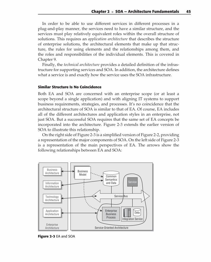
Chapter 2 ■ SOA — Architecture Fundamentals 45
In order to be able to use different services in different processes in aplug-and-play manner, the services need to have a similar structure, and theservices must play relatively equivalent roles within the overall structure ofsolutions. This requires an application architecture that describes the structureof enterprise solutions, the architectural elements that make up that struc-ture, the rules for using elements and the relationships among them, andthe roles and responsibilities of the individual elements. This is covered inChapter 9.
Finally, the technical architecture provides a detailed definition of the infras-tructure for supporting services and SOA. In addition, the architecture defineswhat a service is and exactly how the service uses the SOA infrastructure.
Similar Structure Is No Coincidence
Both EA and SOA are concerned with an enterprise scope (or at least ascope beyond a single application) and with aligning IT systems to supportbusiness requirements, strategies, and processes. It’s no coincidence that thearchitectural structure of SOA is similar to that of EA. Of course, EA includesall of the different architectures and application styles in an enterprise, notjust SOA. But a successful SOA requires that the same set of EA concepts beincorporated into the architecture. Figure 2-3 extends the earlier version ofSOA to illustrate this relationship.
On the right side of Figure 2-3 is a simplified version of Figure 2-2, providinga representation of the major components of SOA. On the left side of Figure 2-3is a representation of the main perspectives of EA. The arrows show thefollowing relationships between EA and SOA:
EnterpriseArchitecture
TechnologyArchitecture
Service
Enterprise Business Process
Service Bus
ApplicationArchitecture
BusinessArchitecture
Common Semantics and DataInformation
Architecture
Integration Service
BusinessModel
Data
Service-Oriented Architecture
Figure 2-3 EA and SOA
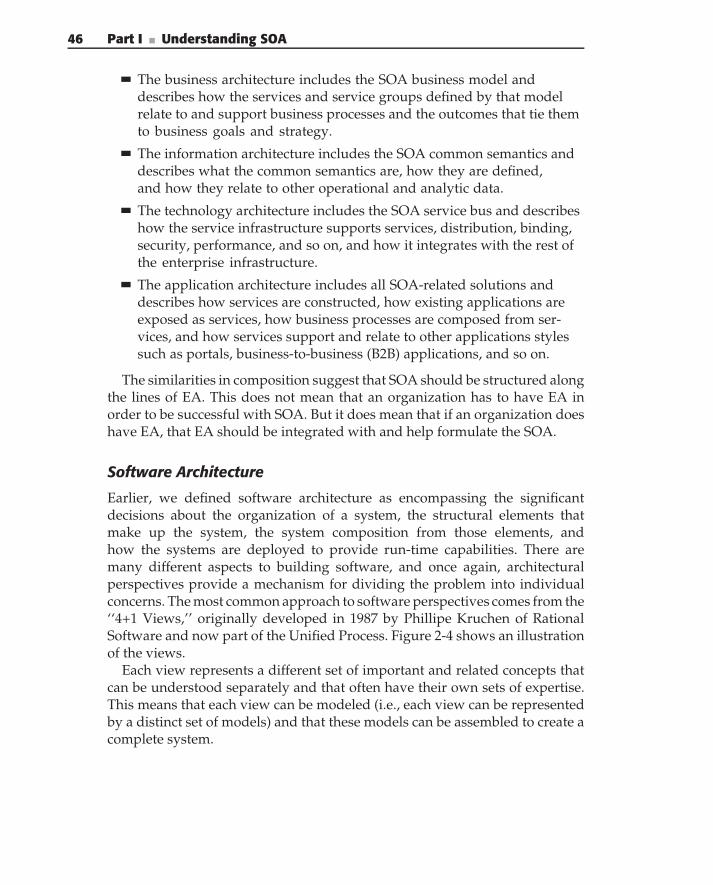
46 Part I ■ Understanding SOA
The business architecture includes the SOA business model anddescribes how the services and service groups defined by that modelrelate to and support business processes and the outcomes that tie themto business goals and strategy.
The information architecture includes the SOA common semantics anddescribes what the common semantics are, how they are defined,and how they relate to other operational and analytic data.
The technology architecture includes the SOA service bus and describeshow the service infrastructure supports services, distribution, binding,security, performance, and so on, and how it integrates with the rest ofthe enterprise infrastructure.
The application architecture includes all SOA-related solutions anddescribes how services are constructed, how existing applications areexposed as services, how business processes are composed from ser-vices, and how services support and relate to other applications stylessuch as portals, business-to-business (B2B) applications, and so on.
The similarities in composition suggest that SOA should be structured alongthe lines of EA. This does not mean that an organization has to have EA inorder to be successful with SOA. But it does mean that if an organization doeshave EA, that EA should be integrated with and help formulate the SOA.
Software Architecture
Earlier, we defined software architecture as encompassing the significantdecisions about the organization of a system, the structural elements thatmake up the system, the system composition from those elements, andhow the systems are deployed to provide run-time capabilities. There aremany different aspects to building software, and once again, architecturalperspectives provide a mechanism for dividing the problem into individualconcerns. The most common approach to software perspectives comes from the‘‘4+1 Views,’’ originally developed in 1987 by Phillipe Kruchen of RationalSoftware and now part of the Unified Process. Figure 2-4 shows an illustrationof the views.
Each view represents a different set of important and related concepts thatcan be understood separately and that often have their own sets of expertise.This means that each view can be modeled (i.e., each view can be representedby a distinct set of models) and that these models can be assembled to create acomplete system.
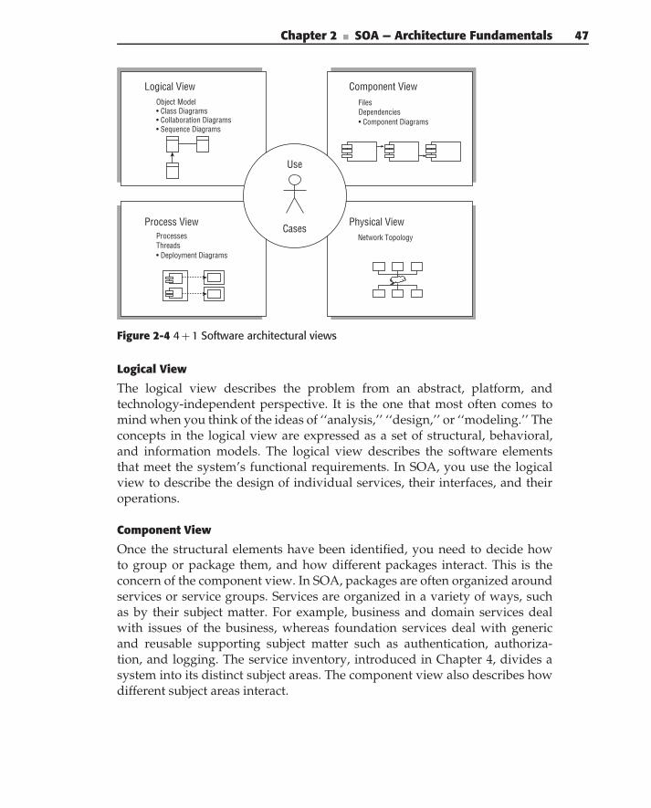
Chapter 2 ■ SOA — Architecture Fundamentals 47
Logical ViewObject Model
• Collaboration Diagrams• Class Diagrams
• Sequence Diagrams
Process ViewProcessesThreads• Deployment Diagrams
Component ViewFilesDependencies• Component Diagrams
Physical ViewNetwork Topology
Use
Cases
Figure 2-4 4 + 1 Software architectural views
Logical View
The logical view describes the problem from an abstract, platform, andtechnology-independent perspective. It is the one that most often comes tomind when you think of the ideas of ‘‘analysis,’’ ‘‘design,’’ or ‘‘modeling.’’ Theconcepts in the logical view are expressed as a set of structural, behavioral,and information models. The logical view describes the software elementsthat meet the system’s functional requirements. In SOA, you use the logicalview to describe the design of individual services, their interfaces, and theiroperations.
Component View
Once the structural elements have been identified, you need to decide howto group or package them, and how different packages interact. This is theconcern of the component view. In SOA, packages are often organized aroundservices or service groups. Services are organized in a variety of ways, suchas by their subject matter. For example, business and domain services dealwith issues of the business, whereas foundation services deal with genericand reusable supporting subject matter such as authentication, authoriza-tion, and logging. The service inventory, introduced in Chapter 4, divides asystem into its distinct subject areas. The component view also describes howdifferent subject areas interact.
48 Part I ■ Understanding SOA
Process View
The process view describes the kinds of components — code and other exe-cutable artifacts — that need to be built in order to realize a system, andhow those artifacts are assigned to executable processes. While the logicalview is about the problem, the process view is about the implementation. Butit is not an elaboration of the logical view; it is a completely independent(but related) view that describes a specific implementation. There can be morethan one process view to support a given logical view. In SOA, the processview describes the executable artifacts needed to support services and howthey are organized into processes. These implementation-specific aspects arenot covered in this book.
Physical View
The physical view defines the different real and logical systems (machines,programs, network nodes, hosts, etc.) that compose and are necessary to realizea solution. In a very simple system, there may be only one machine containingthe services, their logic, and their data.
More complex solutions will generally contain separate and redundantmachines and nodes for the services, databases, existing systems, and soon. Additionally, the different services may be supported by different sys-tems, and these systems may exist inside and outside corporate and divisionalboundaries. In SOA, the physical view describes the configuration and systemsthat host the consumers and providers of services to meet specific nonfunc-tional and quality of service (QoS) requirements. Again, these implementationspecific aspects are not covered in this book.
Use Case View
The use case (or scenario view) presents the system as the capabilities areenvisioned by the end consumer. It models a system in terms of businessscenarios, organized by use cases. This view is shown as overlapping theothers, because the contents of these models generally incorporate elementsof each other’s views. For example, a use case contains not only the functionalrequirements (the logical view) but may also include utility-level issues suchas authorization and logging, and nonfunctional requirements that lead toplatform design decisions and system organization decisions. In addition, theuse case view is what ties all of the other views together to provide traceabilityacross the views in relation to specific use cases.
In SOA, the use case view describes use cases and scenarios. A single usecase will often involve several different services, and a single service will oftenbe used by many different use cases. Chapter 6 shows you how to look acrossmultiple use cases to provide a broader perspective during service design.
Chapter 2 ■ SOA — Architecture Fundamentals 49
A WORD ABOUT TECHNOLOGY INDEPENDENCE
Another important separation of concern (yes, there are many) is the differencebetween the logical design and the technology implementation. The concept oftechnology independence means that you want to completely design the logicof your system without introducing technology-specific details. Then, you makean explicit mapping step to translate the technology-independent logic to atechnology-specific implementation.
For example, Web Services are a popular technology for the implementationof SOA solutions. But, Web Services are not required to implement SOA. So, atthe analysis and design level (the logical view), you work with generic,technology-independent concepts such as services, interfaces, and documentsrather than specific concepts such as WSDL and SOAP. Then, when youimplement a service interface, you map it to WSDL (hopefully, with a nice tool).
But perhaps you say: ‘‘I’ve already selected Web Services, so why do I care?’’A perfectly good question, with a perfectly good answer. Web Services are arapidly evolving technology. Suppose that you design your service interfacesexplicitly with WSDL v1.1. What happens when you need to upgrade to WSDL2.0? You will have to change both your design and your implementation. Thechanges will be more or less extensive depending on the extent that youassumed WSDL v1.1 specifics in your design. If, however, your design followsgood SOA architecture and design principles, independent of WSDL, and thenyour implementation process does a mapping to WSDL, the upgrade to WSDL2.0 (or SOAP or UDDI or XSD) will not require any design changes. Experiencehas shown that platform-independent designs provide more flexibility, betterextensibility, and better longevity, and can reduce the cost of upgrading by asmuch as 90%. We follow a platform-independent approach in this book.
EA, 4+1, and Services
Both EA and software architecture use the concepts of views. And, in fact theviews have reasonable overlap. Primarily, the difference is a matter of scopeand intent. EA is intended to span all the solutions and applications in anenterprise, and to tie business and IT concerns together. Software architectureis intended to describe the implementation of a single solution and to tiedesign to implementation to deployment.
The primary areas of overlap are in the application and technology viewsof EA. The EA application view describes how solutions are constructed ofservices and the types of services that exist. The 4+1 logical view describesthe design of individual services, and the 4+1 component view describes theinteraction between them. The EA technology view describes how solu-tions are implemented on specific technologies to provide commonalityacross technologies, implementations, and infrastructures. The 4+1 process
50 Part I ■ Understanding SOA
and physical views show how service designs are implemented on specifictechnologies and deployed on specific infrastructures.
Conveniently, all of these different architectural concepts and techniquesare consistent and complementary. Architecture uses a variety of approaches,concepts, techniques, and tools to solve any given problem. Good architectureties all of these together according to fundamental principles and commonunderlying concepts and abstractions. So, let’s get back to the importantconcepts of SOA.
What Is a Service?
The fundamental concept in SOA is a service, so what exactly is a service?We define a service as a discrete unit of business functionality that is madeavailable through a service contract.
The service contract specifies all interactions between the service consumerand service provider. This includes:
Service interface
Interface documents
Service policies
Quality of service (QoS)
Performance
One of the main differences between a service and other software constructs(such as components or objects) is that a service is explicitly managed. The QoSand performance are managed through a service level agreement (SLA). Inaddition, the entire service life cycle is managed — from design, to deployment,to enhancements, to maintenance.
Figure 2-5 shows the major parts of a service.There are two main aspects to the service itself. In the diagram, the top
part of the service is the service interface, and the bottom of the service isthe service implementation. A service specifically separates the interface fromthe implementation.
The service interface specifies the service operations, that is, what the servicedoes, the parameters that are passed into and out of the operation, and theprotocols for how those capabilities are used and provided. A service typicallycontains several different, but related, operations. The service implementationis how the service provides the capabilities of its interface. The implementationmay be based on existing applications, on orchestrating other services tocombine their capabilities, on code written specifically for the service, or allof the above. What is important here is that consumers of the service should
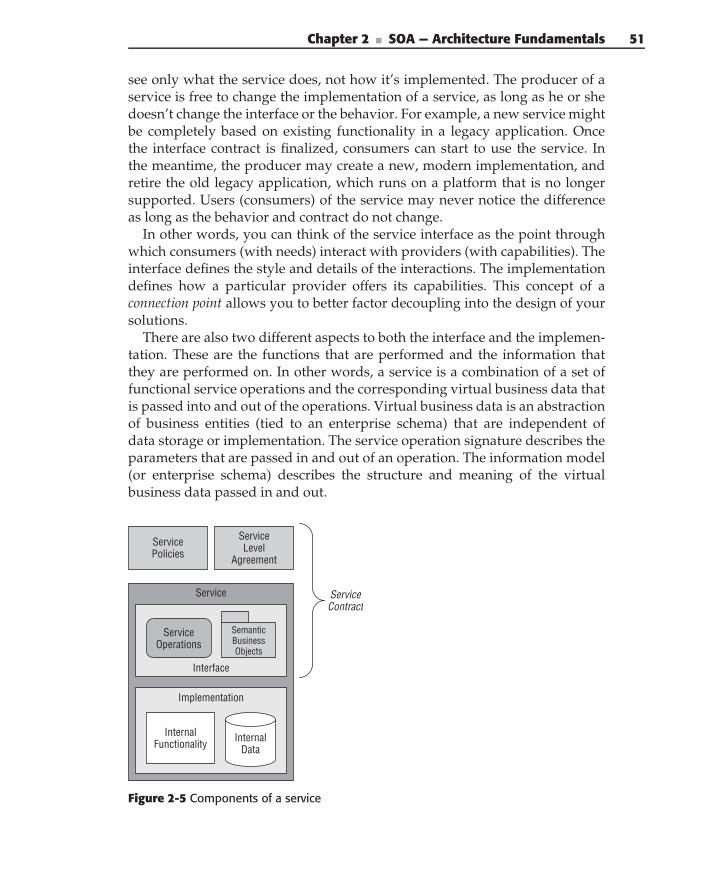
Chapter 2 ■ SOA — Architecture Fundamentals 51
see only what the service does, not how it’s implemented. The producer of aservice is free to change the implementation of a service, as long as he or shedoesn’t change the interface or the behavior. For example, a new service mightbe completely based on existing functionality in a legacy application. Oncethe interface contract is finalized, consumers can start to use the service. Inthe meantime, the producer may create a new, modern implementation, andretire the old legacy application, which runs on a platform that is no longersupported. Users (consumers) of the service may never notice the differenceas long as the behavior and contract do not change.
In other words, you can think of the service interface as the point throughwhich consumers (with needs) interact with providers (with capabilities). Theinterface defines the style and details of the interactions. The implementationdefines how a particular provider offers its capabilities. This concept of aconnection point allows you to better factor decoupling into the design of yoursolutions.
There are also two different aspects to both the interface and the implemen-tation. These are the functions that are performed and the information thatthey are performed on. In other words, a service is a combination of a set offunctional service operations and the corresponding virtual business data thatis passed into and out of the operations. Virtual business data is an abstractionof business entities (tied to an enterprise schema) that are independent ofdata storage or implementation. The service operation signature describes theparameters that are passed in and out of an operation. The information model(or enterprise schema) describes the structure and meaning of the virtualbusiness data passed in and out.
Service Level
Agreement
Service
Interface
Implementation
Internal Data
Internal Functionality
SemanticBusinessObjects
Service Operations
ServiceContract
Service Policies
Figure 2-5 Components of a service
52 Part I ■ Understanding SOA
The distinction between the virtual information in the service interface andthe logical and physical data in the service implementation is critical. Atthe service interface level, what is important is the information that must bepassed between services to enable and complete the business process. Thisis information that must be agreed to and must be common to all theservices that participate in the process. However, internally, many of theseservices have a different superset of the information, potentially in a differentformat. Luckily, you do not have to know or agree on all of the differentdetails of the internal data models of all the services involved (which would beimpractical if not impossible). Instead, the separation of the interface from theimplementation (with regard to the information model) allows you to easilytranslate between the common (virtual) definition and the internal (physical)implementation.
A Word about Information ArchitectureNow is a good time to clarify an important aspect of information architecture asit relates to services. You can describe the different types of information in termsof three layers: physical data (sources), domain (service) data, and semanticdata. Physical data is the persistent enterprise data, usually preexisting.Domain data is the classes that encapsulate information needed to implementservices. This uses the classic object/relational mapping. Semantic data isthe information exchanged between service consumers and providers and isoften a non-normalized view on domain data or data sources. The mappingsbetween these three represent the mining of data for different purposes. Theseparation of concerns isolates the service consumers, service providers, andpersistent sources to provide more reusable, maintainable, agile solutions.
Figure 2-6 shows these relationships among the various types of data.
Physical data — This is the data that is actually stored on disk. Thedetails of how it is stored are described in a database schema. Theschema is optimized for the performance characteristics and require-ments of the particular datastore.
Domain data — This is the data that is used in the service implemen-tation. It is described in a standard data model and describes all of theinformation that is used in the implementation of a service. It representsthe private knowledge of the data. A subset of the data is the service’sview of the common information. Service data is a view of the phys-ical data and may come from one or more physical datastores.
Semantic data — This is the data that describes the common under-standing of business entities and information that must be sharedbetween services. It is described in the shared information model andis closely aligned to the business model. It is used to describe informa-tion that is exchanged through service interfaces. Semantic data is anormalized view of the common data from all the different services.
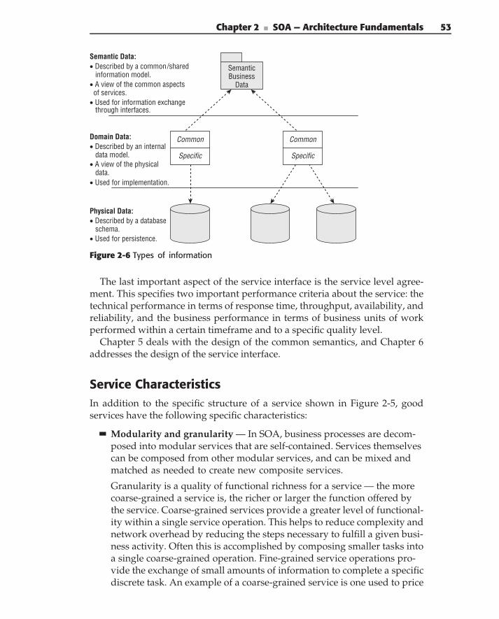
Chapter 2 ■ SOA — Architecture Fundamentals 53
Semantic Business
Data
Physical Data:• Described by a database schema.• Used for persistence.
Domain Data:• Described by an internal data model.• A view of the physical data.• Used for implementation.
Semantic Data:• Described by a common/shared information model.• A view of the common aspects of services.• Used for information exchange through interfaces.
Common
Specific
Common
Specific
Figure 2-6 Types of information
The last important aspect of the service interface is the service level agree-ment. This specifies two important performance criteria about the service: thetechnical performance in terms of response time, throughput, availability, andreliability, and the business performance in terms of business units of workperformed within a certain timeframe and to a specific quality level.
Chapter 5 deals with the design of the common semantics, and Chapter 6addresses the design of the service interface.
Service CharacteristicsIn addition to the specific structure of a service shown in Figure 2-5, goodservices have the following specific characteristics:
Modularity and granularity — In SOA, business processes are decom-posed into modular services that are self-contained. Services themselvescan be composed from other modular services, and can be mixed andmatched as needed to create new composite services.
Granularity is a quality of functional richness for a service — the morecoarse-grained a service is, the richer or larger the function offered bythe service. Coarse-grained services provide a greater level of functional-ity within a single service operation. This helps to reduce complexity andnetwork overhead by reducing the steps necessary to fulfill a given busi-ness activity. Often this is accomplished by composing smaller tasks intoa single coarse-grained operation. Fine-grained service operations pro-vide the exchange of small amounts of information to complete a specificdiscrete task. An example of a coarse-grained service is one used to price
54 Part I ■ Understanding SOA
an insurance quote. A fine-grained service (which would be used by thepricing service, among others) might return risk information based onthe zip code of the applicant.
Encapsulation — Services exhibit a strict separation of the service inter-face (what a service does) from the service implementation (how it isdone). Encapsulation hides the service’s internal implementation detailsand data structures from the published interface operations and seman-tic model.
Loose coupling — Coupling describes the number of dependenciesbetween a service consumer and provider. Loosely coupled serviceshave few, well-known and -managed dependencies. Tightly coupledservices have many known and, more importantly, unknown dependen-cies. The degree of coupling directly affects the flexibility and extensi-bility of a system. We discuss coupling in detail later in the chapter.
Isolation of responsibilities — Services are responsible for discretetasks or the management of specific resources. A key characteristic ofservice design is the isolation of responsibility for specific functions orinformation into a single service. This provides one (and only one) placefor each function to be performed, providing consistency and reducingredundancy.
Autonomy — Autonomy is the characteristic that allows services to bedeployed, modified, and maintained independently from each other andthe solutions that use them. An autonomous service’s life cycle is inde-pendent of other services.
Reuse — Together, modularity, encapsulation, loose coupling, isolationof responsibilities, and autonomy enable services to be combined intomultiple business processes or accessed by multiple service consumersfrom multiple locations and in multiple contexts. In other words, ser-vices are shared and reused as building blocks in the construction of pro-cesses or composite services.
Dynamic discovery and binding — Services can be discovered atdesign time through the use of a design-time service repository.Although it is theoretically possible to dynamically discover servicesat run time, we have yet to see this work in practice. See the sidebar‘‘Dynamic Discovery and Binding.’’
However, service consumers can be dynamically bound to providersduring run time. In this scenario, the consumer asks the registry for aspecific service and is routed and bound dynamically to the appropriateservice provider. The dynamic binding of a service consumer to the ser-vice provider enhances loose coupling and enables additional capabili-ties such as mediation.
Chapter 2 ■ SOA — Architecture Fundamentals 55
Stateless — Service operations are stateless. This means that they neitherremember the last thing they were asked to do nor care what the next is.Services are not dependent on the context or state of other services —only on their functionality. Stateless services provide better flexibility,scalability, and reliability.
Note that this is typically a design goal, but it isn’t always practical (forlong-running service interactions, for example).
Self-describing — The service contract provides a complete descriptionof the service interface, its operations, the input and output parameters,and schema. The contract may also contain pre- and postconditions andconstraints about the operations.
Composable — Services can be composed from other services and, inturn, can be combined with other services to compose new services orbusiness processes.
Governed by policy — Relationships between service consumers andproviders (and between services and service domains) are governedby policies and service level agreements (SLAs). Policies describe howdifferent consumers are allowed to interact with the service — in otherwords, what they are allowed to do.
Independent of location, language, and protocol — Services aredesigned to be location-transparent and protocol/platform-independent.In other words, they are accessible to any authorized user, on any plat-form, from any location (within reason).
DYNAMIC DISCOVERY AND BINDING
One of the overpromised characteristics of services is the concept of dynamicdiscovery and binding. Let’s take a look at each of these.
Dynamic discovery means that a consumer of a service can go to some cent-ral location to discover that a service exists and get all the information necess-ary to start using the service. This is a useful concept at development time. Thestory goes like this: You know that you need a service that does such and such,so you go some place and look for services that might do what you need. Onceyou find one, then you can figure out how to use it. In most enterprises, this isdone through some combination of a service repository and word of mouth.
Now think of the way a computer program is structured. You know that youhave to accomplish specific goals by doing certain things with certaininformation. So, your program goes about collecting the information and thenapplying the algorithms to it to achieve the desired result. But you don’t writeprograms that don’t know what they’re trying to accomplish and that go out
(continued)
56 Part I ■ Understanding SOA
DYNAMIC DISCOVERY AND BINDING (continued)
looking for random functionality that they can somehow utilize to accomplishunknown goals. The idea that a program would dynamically discover services atrun time, figure out how to use them, and reconstruct itself flies in the face ofhow you build, test, or deploy systems. Although it might be theoreticallypossible (only after the semantic web is a reality), we don’t see it affectingenterprise SOA for a while.
Let’s look at another touted aspect — dynamic binding. Here, the idea is thata program is going to read the description of a service interface anddynamically construct the request and response handling in order to use theservice. If the user of the service is going to be a person interacting though auser interface, it would be possible to write a program that dynamicallyconstructs a form to ask the user for the service’s inputs, constructs and sendsthe requests, and then displays the results. However, if the user of a service isanother program, which is often the case with SOA, then this doesn’t makesense. If you’re writing a program to use a service, then you need to know whatparameters to pass to the service request and how to process the serviceresponse. Generally, you do not want or need this to be dynamic, nor can youjustify the cost of writing a program smart enough to do it. So, while it istheoretically possible, and there may be a few examples where dynamicinterface discovery makes sense, in our experience it is not practical. However,the other aspects of dynamic binding, and the dynamic connection of theconsumer to the provider endpoint, are useful.
Service Granularity
Granularity describes the size of a service. This doesn’t mean size in terms ofkilobytes of code. It means the amount of business function that is performedin a single request/response exchange of messages.
One of the most common questions asked about SOA is: ‘‘How big shoulda service be?’’ We’re often told that services should be coarse-grained, butof course it’s not that simple. There is no, single, correct granularity for aservice. Rather, the right granularity depends on a variety of factors such as:Who are the intended users of the service (partners, business processes, otherservices)? What are the topology and performance requirements (LAN, WAN,etc.)? What is the intended scope of the service?
In any complex system or environment, you should expect to see a widerange of service granularities. Figure 2-7 shows a hierarchy of the followingservice types and granularity:
Enterprise business processes — These business processes span theentire enterprise and can make use of the underlying services.
Chapter 2 ■ SOA — Architecture Fundamentals 57
Business services — Business services are the most coarse-grained ser-vices. Business services expose high-level, composite business functionsto the enterprise. The functions and information match closely to thesemantics and syntax required of business processes. Data integrationservices at this level support the consolidated data required by enter-prise processes. Business services can be either of the following:
Line-of-business services — Specific LOB functionality that is exposedexternally to the rest of the enterprise
Common business services — Allow all applications to share basicbusiness functionality and exhibit common behavior (e.g., StructuredInformation Management)
Domain services — Domain services are medium-grained. They pro-vide business-related services that are specific to a business domain andare used by many different business services in that domain (e.g., mem-bership validation) but may not be exposed outside of the domain.
Utility services — Utility services are the least coarse-grained. They pro-vide lower-level services that provide common functionality across theenterprise (e.g., address book or part number validation).
Integration services — These expose existing applications as servicesfor use by the rest of the enterprise, and provide consistent consoli-dated access to enterprise data that is spread across many different datasources. The granularity of integration services will be partially depen-dent on the existing systems that they expose. Integration services typi-cally involve a transformation between the enterprise model and appli-cation model, both at a functional and informational level.
External services — These provide access to systems and applicationsprovided by suppliers or partners external to the enterprise (e.g., creditcard validation or shipment tracking). The granularity of external ser-vices will depend on the particular service provider. Although tradi-tionally these were relatively fine-grained, new software-as-a-serviceproviders are creating a wide variety of services in all areas.
Foundation services — These provide fine-grained capabilities that areused in the construction of higher-level services, independent of anybusiness domain (e.g., security, logging, and orchestration). These arethe capabilities traditionally called services that supported infrastruc-tures such as CORBA or COM. Unfortunately, we can’t just stop callingthem services, but we do need to distinguish between them and thebusiness-related services listed here. These are sometimes also calledtechnical or infrastructure services.
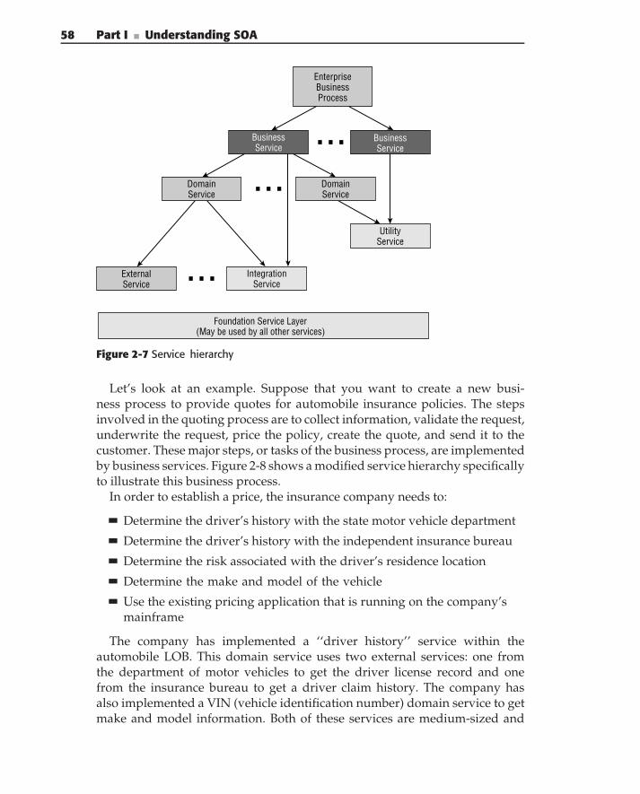
58 Part I ■ Understanding SOA
Foundation Service Layer(May be used by all other services)
DomainService
ExternalService
IntegrationService
UtilityService
EnterpriseBusinessProcess
BusinessService
BusinessService
DomainService
Figure 2-7 Service hierarchy
Let’s look at an example. Suppose that you want to create a new busi-ness process to provide quotes for automobile insurance policies. The stepsinvolved in the quoting process are to collect information, validate the request,underwrite the request, price the policy, create the quote, and send it to thecustomer. These major steps, or tasks of the business process, are implementedby business services. Figure 2-8 shows a modified service hierarchy specificallyto illustrate this business process.
In order to establish a price, the insurance company needs to:
Determine the driver’s history with the state motor vehicle department
Determine the driver’s history with the independent insurance bureau
Determine the risk associated with the driver’s residence location
Determine the make and model of the vehicle
Use the existing pricing application that is running on the company’smainframe
The company has implemented a ‘‘driver history’’ service within theautomobile LOB. This domain service uses two external services: one fromthe department of motor vehicles to get the driver license record and onefrom the insurance bureau to get a driver claim history. The company hasalso implemented a VIN (vehicle identification number) domain service to getmake and model information. Both of these services are medium-sized and
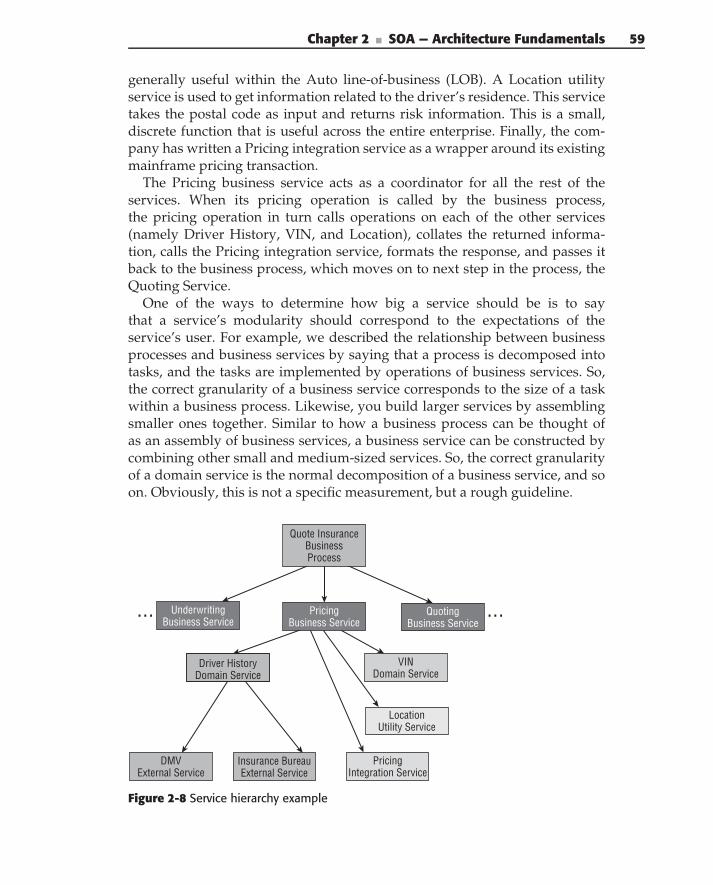
Chapter 2 ■ SOA — Architecture Fundamentals 59
generally useful within the Auto line-of-business (LOB). A Location utilityservice is used to get information related to the driver’s residence. This servicetakes the postal code as input and returns risk information. This is a small,discrete function that is useful across the entire enterprise. Finally, the com-pany has written a Pricing integration service as a wrapper around its existingmainframe pricing transaction.
The Pricing business service acts as a coordinator for all the rest of theservices. When its pricing operation is called by the business process,the pricing operation in turn calls operations on each of the other services(namely Driver History, VIN, and Location), collates the returned informa-tion, calls the Pricing integration service, formats the response, and passes itback to the business process, which moves on to next step in the process, theQuoting Service.
One of the ways to determine how big a service should be is to saythat a service’s modularity should correspond to the expectations of theservice’s user. For example, we described the relationship between businessprocesses and business services by saying that a process is decomposed intotasks, and the tasks are implemented by operations of business services. So,the correct granularity of a business service corresponds to the size of a taskwithin a business process. Likewise, you build larger services by assemblingsmaller ones together. Similar to how a business process can be thought ofas an assembly of business services, a business service can be constructed bycombining other small and medium-sized services. So, the correct granularityof a domain service is the normal decomposition of a business service, and soon. Obviously, this is not a specific measurement, but a rough guideline.
VIN Domain Service
Driver History Domain Service
DMV External Service
Pricing Integration Service
Location Utility Service
Quoting Business Service
Underwriting Business Service
Insurance Bureau External Service
Pricing Business Service
Quote Insurance Business Process
Figure 2-8 Service hierarchy example
60 Part I ■ Understanding SOA
Service Dimensions
As the previous discussion suggests, size is not the only important anddistinguishing characteristic that determines how a service is used. Figure2-9 shows four dimensions of a service: Scope, Ownership, Granularity, andConstruction. Every service has some aspect of each dimension.
Scope — Scope defines the organizational boundaries that a service isexpected to operate in. For example, a service with an enterprise scopeis expected to be used by processes or other services across the entireenterprise (i.e., other LOBs). At the opposite end of the scale is a servicethat is used by only a single application or organizational group. ‘‘So,who cares?’’ you might ask. Shouldn’t all services be available across theentire enterprise? It turns out that there is a direct correlation betweenthe scope of a service and the responsibilities and costs of managing,maintaining, and enhancing it. On a simple level, this seems fairly obvi-ous. The larger the user base, the more the support costs. So, for practicalreasons, you may want to limit the scope of services in order to limit theliability of particular service providers and encourage participation inthe overall enterprise SOA.
Ownership — Ownership defines the organizational unit that is respon-sible for support of a service. In an SOA, this extends well beyond simplemaintenance and operations to the overall life cycle of the service. Someof the thorny ownership questions are: How are the different requests fornew enhancements managed and prioritized across the many differentusers? How many versions of the service will be supported simultane-ously? What kind of backward compatibility will be required? How longwill previous versions be supported?
A common organizational approach is to have a central service groupthat is responsible for ownership of shared services across the enterprise.In addition, each LOB (or smaller organizational unit) may have someservices that they individually own. Any of the possible combinationsof ownership and scope could exist for services within a given organiza-tion.
Note that services are often used to cross ownership boundaries andestablish value exchange across corporations.
Granularity — Granularity describes the size of a service in terms of theamount of business function that is performed in a single request/res-ponse exchange of messages. This was covered extensively in theprevious section. Note that a service designer runs into the issue of gran-ularity very quickly (well before he or she understands the other dimen-sions), which is why it is usually the first question asked about services.
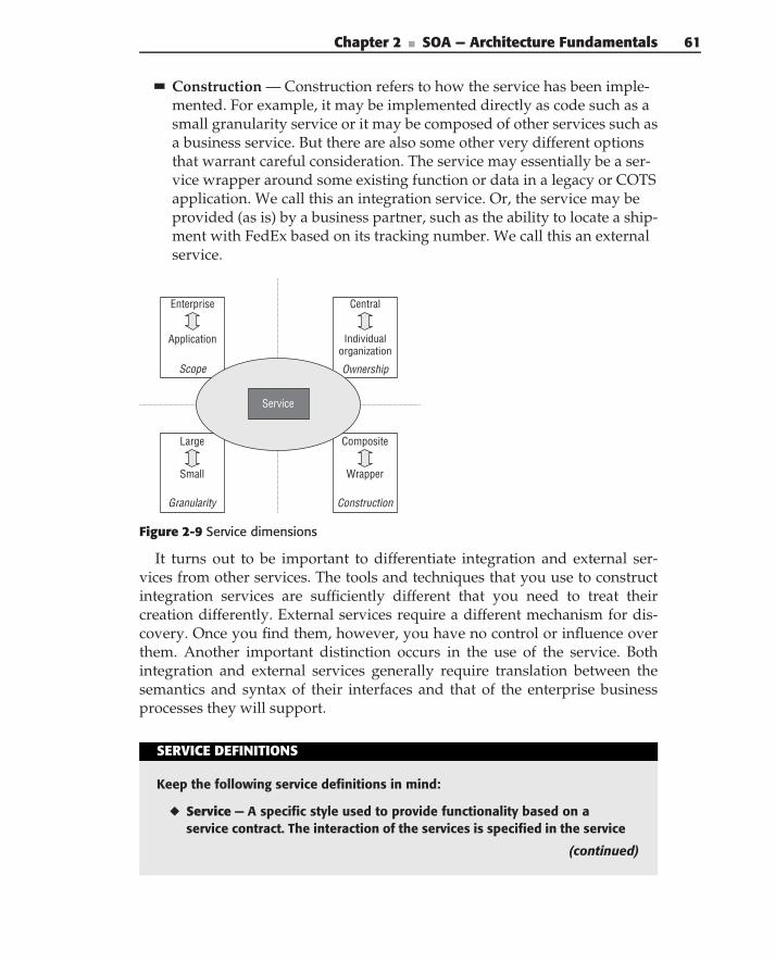
Chapter 2 ■ SOA — Architecture Fundamentals 61
Construction — Construction refers to how the service has been imple-mented. For example, it may be implemented directly as code such as asmall granularity service or it may be composed of other services such asa business service. But there are also some other very different optionsthat warrant careful consideration. The service may essentially be a ser-vice wrapper around some existing function or data in a legacy or COTSapplication. We call this an integration service. Or, the service may beprovided (as is) by a business partner, such as the ability to locate a ship-ment with FedEx based on its tracking number. We call this an externalservice.
Granularity
Large
Small
Ownership
Central
Individual organization
Scope
Enterprise
Application
Construction
Composite
Wrapper
Service
Figure 2-9 Service dimensions
It turns out to be important to differentiate integration and external ser-vices from other services. The tools and techniques that you use to constructintegration services are sufficiently different that you need to treat theircreation differently. External services require a different mechanism for dis-covery. Once you find them, however, you have no control or influence overthem. Another important distinction occurs in the use of the service. Bothintegration and external services generally require translation between thesemantics and syntax of their interfaces and that of the enterprise businessprocesses they will support.
SERVICE DEFINITIONS
Keep the following service definitions in mind:
◆ Service — A specific style used to provide functionality based on aservice contract. The interaction of the services is specified in the service
(continued)
62 Part I ■ Understanding SOA
SERVICE DEFINITIONS (continued)
interface. The service acts as a connection for consumers who need to inter-act with providers with specific capabilities. Normally, a service is furthercharacterized by loose coupling and offers a process-centric rather thandata-centric interaction style.
◆ Interface — An interface defines the interaction with a service. It groupsrelated capabilities via a set of related operations. The interface definesthe inputs and outputs of the service operations and any preconditions,postconditions, and constraints of those operations. The interface may bespecified in terms of an interface definition language (such as WSDL orCOM IDL), or as an interface class (as in Java).
◆ Process — A business process is a set of coordinated tasks and activitiesthat lead to accomplishing a specific organizational goal. In terms of SOA, aprocess can be used to coordinate business services.
◆ Granularity — Refers to the size or amount of functionality in a given inter-action. For example, a very fine-grained interaction would be to set or get asingle attribute value of an object. A very coarse-grained interaction wouldbe to get all of the values of a collection of objects in a single interaction.These are examples of interface granularity. Granularity also refers to thevalue of a given interaction. For example, Add Member is a higher-grainedservice than Validate Address. The appropriate granularity of a service andinterface is based on the intended usage and applies to the type of service.
◆ Composite service — A service with an implementation that is a compositeof other services.
◆ Atomic service — A service with an implementation that does not requireor use any other services. This is the lowest level of service composition.
◆ Foundation service — A foundation service is a utility that aids in the con-struction of other services, such as a business rules engine, data-routingservice, or workflow system. These services do not provide any specificbusiness functionality but instead provide higher-level technical capabil-ities for the construction of services. (The terms infrastructure service andfoundation service are used synonymously.)
◆ Business service — A business service is a specific kind of service thatoffers a higher granularity of business value (such as Evaluate Escrow, orRecalculate Payments). It is typically composed of several lower-levelor finer-grained services.
◆ Domain service — A domain service is a lower-level service that providesbusiness functionality within a specific business domain. It provides impor-tant, shared capabilities within a domain, but it is not intended to beexposed outside of the domain. For example, validating the correctness of
Chapter 2 ■ SOA — Architecture Fundamentals 63
payee data is a function (service) that is shared by severaldifferent aspects of claims processing but is not intended to be used byother domains. Domain services provide common functionality that is usedin the composition of business services.
◆ Utility service — Utility services are the smallest, or least coarse-grained. They provide lower-level services that provide common function-ality across the enterprise (e.g., address book functionality or part numbervalidation).
◆ Integration service — An integration service exposes existing applicationsas services for use by the rest of the enterprise, and providesconsistent consolidated access to enterprise data that is spread acrossmany different data sources. The granularity of integration services will bepartially dependent on the existing systems that they expose. Integrationservices typically involve transformation between the enterprise model andapplication model.
◆ External service — An external service provides access to systems andapplications provided by suppliers or partners external to the enterprise(e.g., credit card validation or shipment tracking). The granularity of exter-nal services will depend on the particular service provider. Although tra-ditionally these were relatively fine-grained, new software-as-a-serviceproviders are creating a wide variety of services in all areas.
◆ Enterprise business process — An enterprise business process is aspecific kind of business process that spans business domains within (oroutside) the enterprise.
◆ Workflow — Workflow is a style of computing in which a process isdecomposed into a series of steps, activities, conditions, and the like. Workactivities flow from one step to the next based on conditional evaluation.Workflow is typically executed by a workflow management system thatsupports developing workflows, dispatching work to queues, process man-agement, and so on. Frequently, workflow systems include activities thatare carried out by humans, where the work items are placed in a person’sinbox and completed items are placed in his or her outbox.
◆ Orchestration — Orchestration is a specific type of workflow that isgenerally applied to the construction of business processes from busi-ness services or of composite services from smaller services, and does notinclude human-performed activities. Orchestration often includes aconductor or controller that is managing, controlling, or directing the inter-action between other parts so that they do not have direct dependencies oneach other.
(continued)
64 Part I ■ Understanding SOA
SERVICE DEFINITIONS (continued)
◆ Business Process Management (BPM) — Wikipedia defines this as ‘‘anemerging field of knowledge and research at the intersection betweenmanagement and information technology, encompassing methods, tech-niques and tools to design, enact, control, and analyze operationalbusiness processes involving humans, organizations, applications, docu-ments and other sources of information.’’ You can think of it as a type ofprocess construction that emphasizes the management of business pro-cesses in addition to the technology of orchestration. A key function of BPMsystems is monitoring to ensure processes are meeting the intended busi-ness objectives. In addition, they may include auditing, reporting, and otherfunctions.
◆ Business Process Model — A model used to define the execution andcomposition of higher-level processes from lower-level services. Processmodels are executed by orchestration or BPM tools. Both business servicesand enterprise business processes can be defined by Business ProcessModels.
Loose Coupling Is KingA principle characteristic of a service is loose coupling. Coupling refers tothe extent of dependency between modules, components, or services con-sumers and providers. Loosely coupled services (it’s actually the consumerand provider that are loosely coupled) have few well-known dependencies,whereas tightly coupled services have many known and, more importantly,unknown dependencies. A system’s degree of coupling directly affects itsoverall flexibility. The more tightly coupled a system, the more a change inone service will require changes in other services or service consumers.
There are many dimensions to coupling. In distributed systems, tradition-ally coupling was thought of with respect to time, and discussion about it wasframed in terms of synchronous versus asynchronous communications mech-anisms. However, in service-based systems, the more important dimension ofcoupling is the �used� and �used by� relationship between consumers(those with needs, who use capabilities) and providers (those with capabilitiesthat are used by consumers).
SOA is about organizing functional capabilities into services and limitingthe coupling between consumers and providers to specific service interfaces.That way, changes to a function only effect the consumers connected to theservice providing that function. All other consumers who are interacting withthe same provider, but through different service interfaces, are unaffected.
Chapter 2 ■ SOA — Architecture Fundamentals 65
Object-based analysis and design are concerned with low coupling and highcohesion. In other words, you want to design the responsibility of a classor subsystem so that it’s as independent as possible from other classes (lowcoupling), giving it the highest potential for reuse in multiple scenarios. At thesame time, however, you want to group related responsibilities in the sameclass (high cohesion) to centralize related business rules and access to commondata, and to minimize unnecessary messaging or interactions.
These principles of coupling and cohesion apply to services, but a service-oriented architecture takes loose coupling much further. This is important forseveral reasons. In an enterprise, the producer and consumer of services arefrequently decoupled in terms of organization, schedules, and priorities. Inother words, the application that is consuming a service has a different lifecycle than the service itself. What happens when the group that developsand maintains the service decides to upgrade? One option is to demandthat consumers of the service upgrade at the same time. Although that maysound reasonable to some (producers mostly), it is not reasonable to serviceconsumers. The ultimate result of such a policy is that other groups will notuse the service and instead will develop something themselves that they havecontrol over. If service providers want to promote use of their services, theymust understand that the users of the service will be different organizationalunits, with different schedules, priorities, and business drivers. Given this, itis important to enable the independent evolution of both the service consumerand provider (for example, loose coupling). This is done through a variety oftechniques, technologies, and policies.
In an SOA, you want to achieve loose coupling in terms of the following:
Location transparency
Interface and implementation
Data
Versioning
Interoperability and platform independence
Usage, assumptions, and knowledge
These are discussed in the following sections.
Location Transparency
Location transparency relieves the service consumer of the need to knowanything about the location of the service. Instead, the consumer goes toa well-known service registry to dynamically look up location information.The service registry (as an intermediary) can provide many other importantsystem attributes in terms of availability and performance. For example, a
66 Part I ■ Understanding SOA
load-balancing mechanism can be used to distribute requests across multipleservice instances for increased availability. New service instances can be addedto increase throughput without any change (or knowledge) to the client. Servicelocations can be moved as systems are migrated, or for redundancy and failoverpurposes.
Location transparency is not new. It has been used since the early implemen-tations of DCE (Distributed Computing Environment, from the Open SoftwareFoundation) in the mid-1980s. However, SOA extends the service directory(the fundamental building block of location transparency) to a service registry,where not only the location of the service is determined, but also the serviceinterface contract. A service consumer can locate an appropriate service atrun time by providing a set of selection criteria to the registry. The registrywill then return a pointer to the most appropriate service based on both theconsumer’s and system’s criteria. The use of the registry in enterprise solutionsis discussed in Chapter 9.
Interface and Implementation
Another fundamental concept of distributed applications is the decouplingof the interface from the implementation (also known as encapsulation inobject-based systems, or information hiding in data systems). This allows aservice implementation to change (such as changing internal data represen-tation, or migrating from a legacy system to a new implementation) withoutrequiring changes of the service consumers. SOA reduces coupling and depen-dency between service providers and consumers by ensuring that the interfacecontract is their only means of interaction. Chapter 6 describes loose couplingin service interface design.
Data
You can also think of decoupling in terms of the definition of data. The conceptof information hiding directs you to define a public view of the data (thesemantic data) and then map it to the internal view (the domain data) orimplementation. A service should never expose its internal data structures.Even the smallest amount of internal information that is exposed outsidethe service will result in unnecessary dependencies. Only the informationavailable in the semantic model is exposed through the interface. In theservice implementation, that information is transformed between the semanticinformation model and the internal schema to isolate the two. In other words,the internal data definitions are mapped into the semantics of the externalcontract. The contract depends only on the service’s problem domain, not onthe internal implementation details.
Chapter 2 ■ SOA — Architecture Fundamentals 67
This allows the internal view to evolve without affecting clients, and pre-vents clients from making assumptions about the implementation. Chapter 7describes the transformation between semantic and domain data in the serviceimplementation.
Versioning
Services will inevitably evolve to meet new requirements. However, as servicesare used beyond organizational or enterprise boundaries, the producer of aservice cannot control when the consumer of a service will update his orher implementation. Additionally, as more and more consumers come todepend on a specific service, it becomes more difficult logistically to manage aforced version migration. At a business level, if the service consumers cannotmaintain control of their own application life cycle and release schedules,they are unlikely to make use of that service. An SOA must take theseissues into account through a combination of infrastructure, interface design,data definition, dynamic binding, and versioning policy. For example, theinfrastructure for the service definition, lookup, and invocation must supportversion numbers and multiple simultaneous versions.
Service providers must conform to a versioning policy. A typical policywould describe two classes of upgrade: minor enhancements and majorenhancements. Minor enhancements are bug fixes and other small changes thatdo not change behavior or interfaces (although they may enhance capabilitiesin simple ways). Major enhancements change interfaces and/or behavior. Atypical policy would require backward compatibility between minor versionupdates. In addition, it would require two major versions to be supportedcontinuously, or a minimum period (1 to 2 years) for a previous version to besupported. Versioning is discussed in more detail in Chapter 9.
Interoperability and Platform Independence
The requirement for services to support multiple consumers has implicationsin terms of communications, interoperability, and platform independence.You cannot assume that all of the consumers of a service will be using thesame platform. This is especially true for large enterprises or consumers thatare outside the enterprise boundaries. Therefore, you need a communicationsmechanism that is compatible across platforms. This allows any client tobe able to access a service, and gives service providers flexibility in terms ofplatform implementation. (For example, because of acquisition, they may needto implement services now on an existing platform, while planning to migrateto the different, enterprise-standard platform over time.)
Web Services can help provide this interoperability, but it is not so simple.As mentioned earlier, Web Services are rapidly evolving. Consumers and
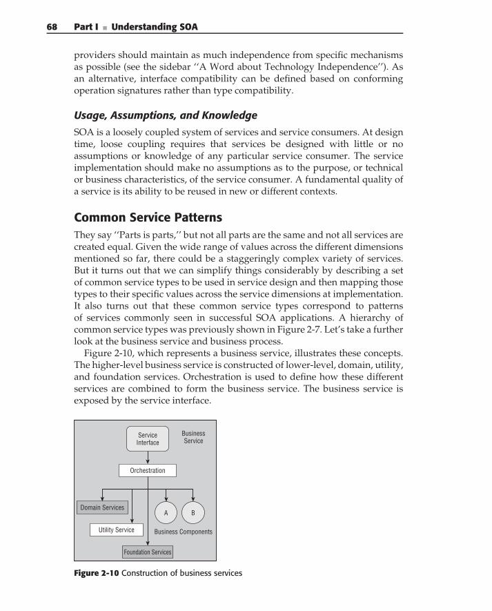
68 Part I ■ Understanding SOA
providers should maintain as much independence from specific mechanismsas possible (see the sidebar ‘‘A Word about Technology Independence’’). Asan alternative, interface compatibility can be defined based on conformingoperation signatures rather than type compatibility.
Usage, Assumptions, and Knowledge
SOA is a loosely coupled system of services and service consumers. At designtime, loose coupling requires that services be designed with little or noassumptions or knowledge of any particular service consumer. The serviceimplementation should make no assumptions as to the purpose, or technicalor business characteristics, of the service consumer. A fundamental quality ofa service is its ability to be reused in new or different contexts.
Common Service PatternsThey say ‘‘Parts is parts,’’ but not all parts are the same and not all services arecreated equal. Given the wide range of values across the different dimensionsmentioned so far, there could be a staggeringly complex variety of services.But it turns out that we can simplify things considerably by describing a setof common service types to be used in service design and then mapping thosetypes to their specific values across the service dimensions at implementation.It also turns out that these common service types correspond to patternsof services commonly seen in successful SOA applications. A hierarchy ofcommon service types was previously shown in Figure 2-7. Let’s take a furtherlook at the business service and business process.
Figure 2-10, which represents a business service, illustrates these concepts.The higher-level business service is constructed of lower-level, domain, utility,and foundation services. Orchestration is used to define how these differentservices are combined to form the business service. The business service isexposed by the service interface.
BA
Business Components
Service Interface
Utility Service
Domain Services
Business Service
Orchestration
Foundation Services
Figure 2-10 Construction of business services
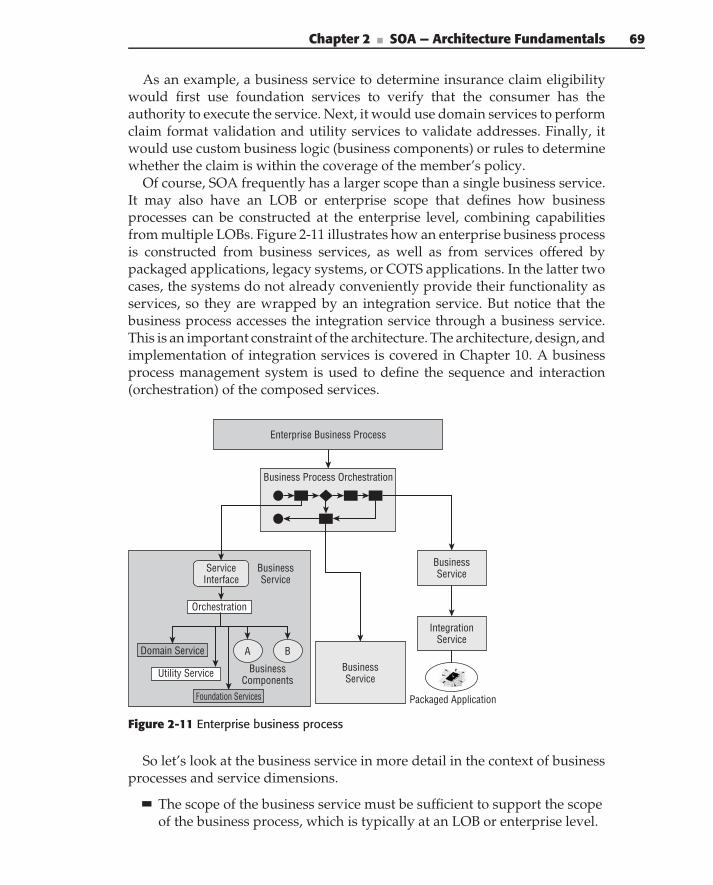
Chapter 2 ■ SOA — Architecture Fundamentals 69
As an example, a business service to determine insurance claim eligibilitywould first use foundation services to verify that the consumer has theauthority to execute the service. Next, it would use domain services to performclaim format validation and utility services to validate addresses. Finally, itwould use custom business logic (business components) or rules to determinewhether the claim is within the coverage of the member’s policy.
Of course, SOA frequently has a larger scope than a single business service.It may also have an LOB or enterprise scope that defines how businessprocesses can be constructed at the enterprise level, combining capabilitiesfrom multiple LOBs. Figure 2-11 illustrates how an enterprise business processis constructed from business services, as well as from services offered bypackaged applications, legacy systems, or COTS applications. In the latter twocases, the systems do not already conveniently provide their functionality asservices, so they are wrapped by an integration service. But notice that thebusiness process accesses the integration service through a business service.This is an important constraint of the architecture. The architecture, design, andimplementation of integration services is covered in Chapter 10. A businessprocess management system is used to define the sequence and interaction(orchestration) of the composed services.
Enterprise Business Process
Business Process Orchestration
IntegrationService
Packaged Application
BA
ServiceInterface
Utility Service
Orchestration
Domain Service
Foundation Services
BusinessService
BusinessService
BusinessService
BusinessComponents
Figure 2-11 Enterprise business process
So let’s look at the business service in more detail in the context of businessprocesses and service dimensions.
The scope of the business service must be sufficient to support the scopeof the business process, which is typically at an LOB or enterprise level.
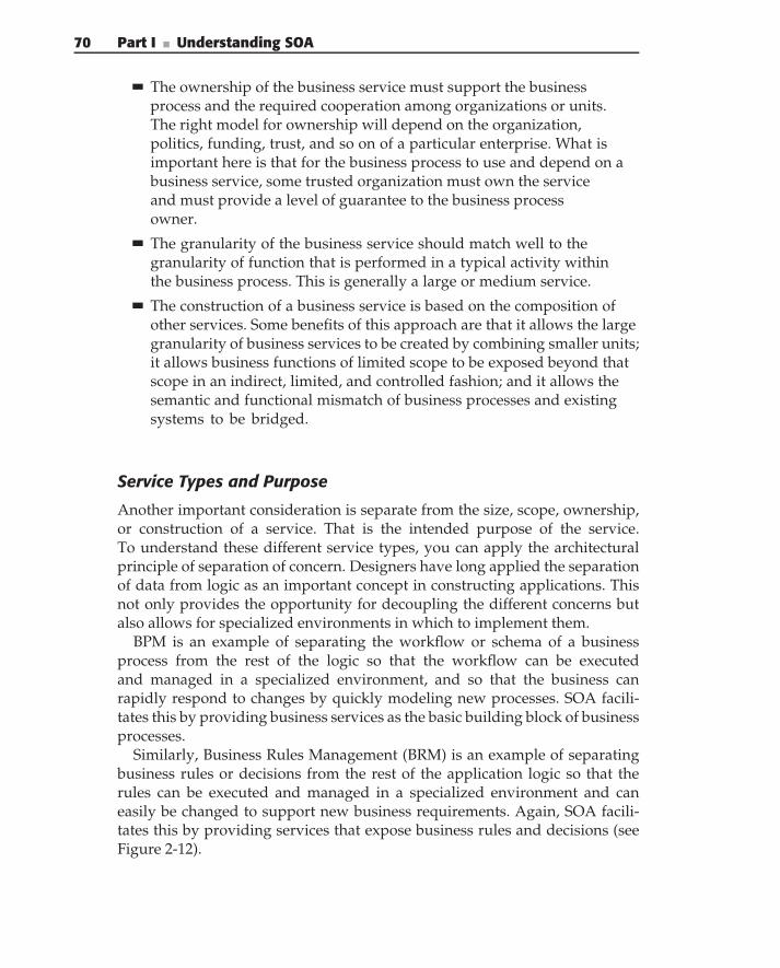
70 Part I ■ Understanding SOA
The ownership of the business service must support the businessprocess and the required cooperation among organizations or units.The right model for ownership will depend on the organization,politics, funding, trust, and so on of a particular enterprise. What isimportant here is that for the business process to use and depend on abusiness service, some trusted organization must own the serviceand must provide a level of guarantee to the business processowner.
The granularity of the business service should match well to thegranularity of function that is performed in a typical activity withinthe business process. This is generally a large or medium service.
The construction of a business service is based on the composition ofother services. Some benefits of this approach are that it allows the largegranularity of business services to be created by combining smaller units;it allows business functions of limited scope to be exposed beyond thatscope in an indirect, limited, and controlled fashion; and it allows thesemantic and functional mismatch of business processes and existingsystems to be bridged.
Service Types and Purpose
Another important consideration is separate from the size, scope, ownership,or construction of a service. That is the intended purpose of the service.To understand these different service types, you can apply the architecturalprinciple of separation of concern. Designers have long applied the separationof data from logic as an important concept in constructing applications. Thisnot only provides the opportunity for decoupling the different concerns butalso allows for specialized environments in which to implement them.
BPM is an example of separating the workflow or schema of a businessprocess from the rest of the logic so that the workflow can be executedand managed in a specialized environment, and so that the business canrapidly respond to changes by quickly modeling new processes. SOA facili-tates this by providing business services as the basic building block of businessprocesses.
Similarly, Business Rules Management (BRM) is an example of separatingbusiness rules or decisions from the rest of the application logic so that therules can be executed and managed in a specialized environment and caneasily be changed to support new business requirements. Again, SOA facili-tates this by providing services that expose business rules and decisions (seeFigure 2-12).
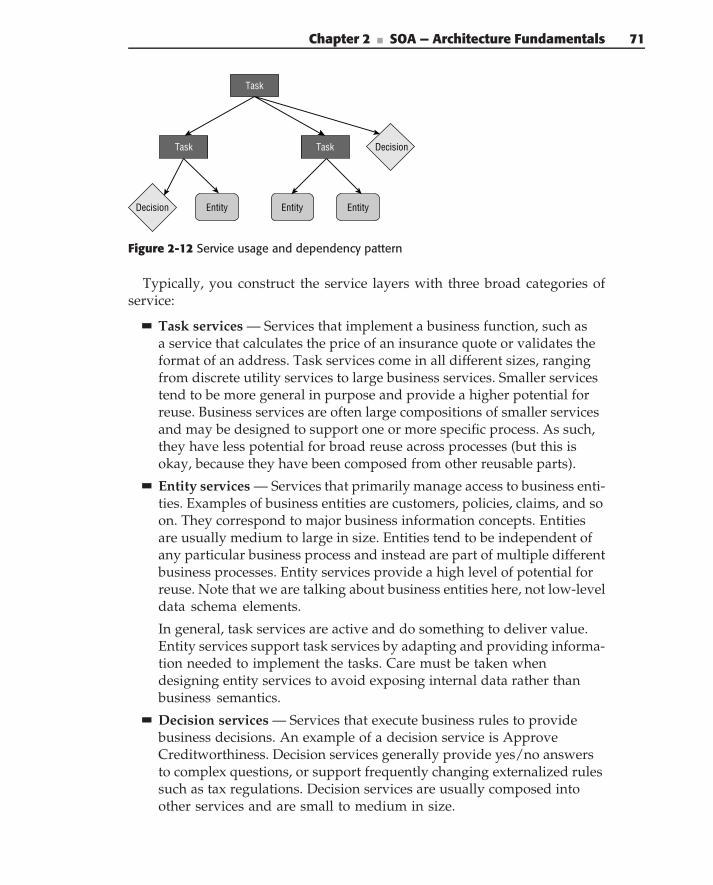
Chapter 2 ■ SOA — Architecture Fundamentals 71
Task
EntityDecision
Task Task Decision
Entity Entity
Figure 2-12 Service usage and dependency pattern
Typically, you construct the service layers with three broad categories ofservice:
Task services — Services that implement a business function, such asa service that calculates the price of an insurance quote or validates theformat of an address. Task services come in all different sizes, rangingfrom discrete utility services to large business services. Smaller servicestend to be more general in purpose and provide a higher potential forreuse. Business services are often large compositions of smaller servicesand may be designed to support one or more specific process. As such,they have less potential for broad reuse across processes (but this isokay, because they have been composed from other reusable parts).
Entity services — Services that primarily manage access to business enti-ties. Examples of business entities are customers, policies, claims, and soon. They correspond to major business information concepts. Entitiesare usually medium to large in size. Entities tend to be independent ofany particular business process and instead are part of multiple differentbusiness processes. Entity services provide a high level of potential forreuse. Note that we are talking about business entities here, not low-leveldata schema elements.
In general, task services are active and do something to deliver value.Entity services support task services by adapting and providing informa-tion needed to implement the tasks. Care must be taken whendesigning entity services to avoid exposing internal data rather thanbusiness semantics.
Decision services — Services that execute business rules to providebusiness decisions. An example of a decision service is ApproveCreditworthiness. Decision services generally provide yes/no answersto complex questions, or support frequently changing externalized rulessuch as tax regulations. Decision services are usually composed intoother services and are small to medium in size.
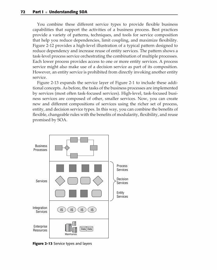
72 Part I ■ Understanding SOA
You combine these different service types to provide flexible businesscapabilities that support the activities of a business process. Best practicesprovide a variety of patterns, techniques, and tools for service compositionthat help you reduce dependencies, limit coupling, and maximize flexibility.Figure 2-12 provides a high-level illustration of a typical pattern designed toreduce dependency and increase reuse of entity services. The pattern shows atask-level process service orchestrating the combination of multiple processes.Each lower process provides access to one or more entity services. A processservice might also make use of a decision service as part of its composition.However, an entity service is prohibited from directly invoking another entityservice.
Figure 2-13 expands the service layer of Figure 2-1 to include these addi-tional concepts. As before, the tasks of the business processes are implementedby services (most often task-focused services). High-level, task-focused busi-ness services are composed of other, smaller services. Now, you can createnew and different compositions of services using the richer set of process,entity, and decision service types. In this way, you can combine the benefits offlexible, changeable rules with the benefits of modularity, flexibility, and reusepromised by SOA.
EnterpriseResources Data Data
Mainframes
BusinessProcesses
Services
IntegrationServices
EntityServices
ProcessServices
DecisionServices
IS IS IS IS
Figure 2-13 Service types and layers
Chapter 2 ■ SOA — Architecture Fundamentals 73
SOA Reference Architecture
In Chapter 1, we described the requirements of SOA and introduced itsreference architecture. Throughout this chapter, we have described the overallarchitecture of SOA. The reference architecture is the formal representation ofthese concepts.
The term reference architecture has as many different meanings as it hasuses and thus can be a great source of confusion. Wikipedia says, ‘‘A referencearchitecture provides a proven template solution for an architecture for aparticular domain. It also provides a common vocabulary with which todiscuss implementations, often with the aim to stress commonality.’’
SOA reference architecture goes beyond this definition to support thefollowing goals:
Provide a common language for services and SOA
Provide consistency of implementation, business purpose, and semanticsacross services
Provide an architectural-based design methodology
Support SOA governance
Support EA
Define how the reference architecture is used
Figure 2-14 illustrates the conceptual contents of the SOA reference archi-tecture, including:
Service Metamodel — This defines the concepts, characteristics, anddetails of a service and how services relate to other parts of the architec-ture. Specifically, this defines the service types (business, domain, utility,integration, external, and foundation), the service dimensions, and howthese concepts are represented and manifest themselves in a service defi-nition.
EA Perspectives — Comprise the following standard EA domains:
Business Metamodel — This defines the concepts used to describethe business architecture. Defines the relationship of traditional busi-ness architecture concepts (strategy, goals, outcomes, organization,value chain, contexts, and processes) to service-oriented systems.
Information Metamodel — This defines the concepts used to char-acterize the information architecture such as semantic, domain, andphysical data. It defines the relationship between traditional informa-tion architecture concepts and service-oriented systems.
74 Part I ■ Understanding SOA
Application Metamodel — This defines the concepts used to charac-terize the application architecture. It defines the relationship betweentraditional application architecture concepts and service-orientedsystems. For example, it describes how services are used in an n-tierarchitecture.
Technology Metamodel — This defines the concepts used to charac-terize the technical architecture. It defines the relationship betweentechnical architecture concepts and service-oriented systems. Forexample, how specific platforms and networks support service SLAsfor quality of service.
MBD Perspectives — These support model-based developmentapproaches with specific profiles. MBD profiles are related to architec-tural metamodels, but provide a mechanism to embed the metamodelinto a standard modeling and generation tool.
Business Profile — This defines the concepts used to describe thebusiness problem in nontechnical terms. Furthermore, it definesthe relationships among concepts, rules, and constraints.
Application Profile — This defines the logical structure of applica-tions, typically in terms of layers, tiers, and architectural elements. Itdefines where and how services fit into the overall applicationstructure.
Platform Profiles — A platform profile defines the details of the tech-nology platform that will be used for implementation. There will typ-ically be multiple different platform metamodels to support differenttechnologies, such as .NET, Java, ESB, and so on.
Transformations — This defines how concepts in one model are trans-formed into concepts in another model and the traceabilitybetween model elements.
Process Metamodel — This defines a process for the design and imple-mentation of services, starting at the business level, moving throughservice design, to platform-specific implementation. It defines the overallworkflow, the goals and concerns of each step in the process, the inputs,the metamodel elements involved in each step, the work products pro-duced, and the metrics.
Governance Metamodel — This defines the fundamental concepts ofgovernance, what metamodel elements they apply to, relationships andconstraints, and the interaction of governance with the rest of the refer-ence architecture at design and run time.
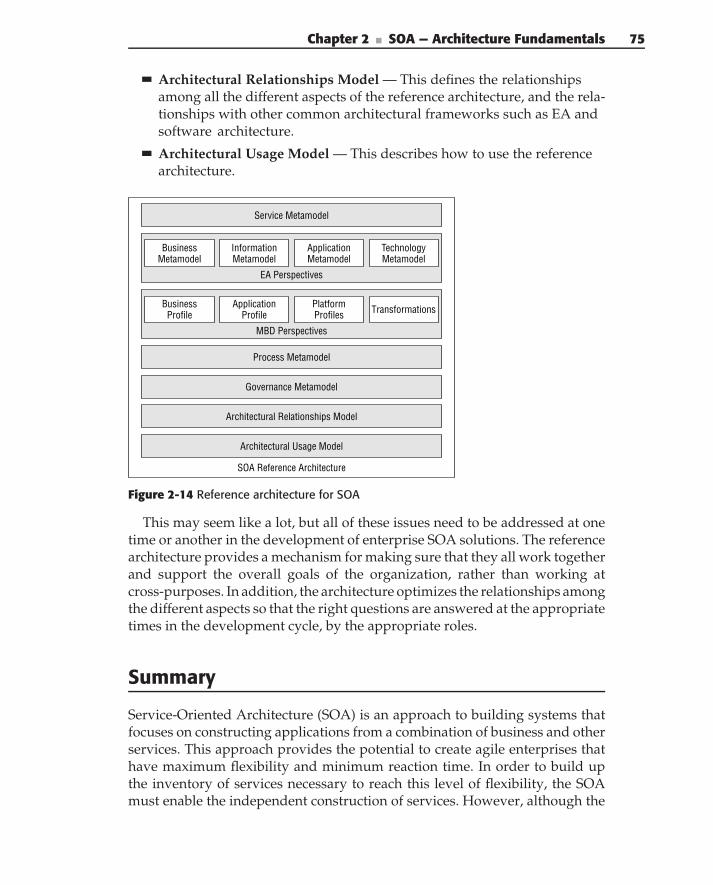
Chapter 2 ■ SOA — Architecture Fundamentals 75
Architectural Relationships Model — This defines the relationshipsamong all the different aspects of the reference architecture, and the rela-tionships with other common architectural frameworks such as EA andsoftware architecture.
Architectural Usage Model — This describes how to use the referencearchitecture.
Process Metamodel
Architectural Relationships Model
SOA Reference Architecture
Governance Metamodel
Architectural Usage Model
EA Perspectives
BusinessMetamodel
InformationMetamodel
ApplicationMetamodel
TechnologyMetamodel
MBD Perspectives
BusinessProfile
ApplicationProfile
PlatformProfiles Transformations
Service Metamodel
Figure 2-14 Reference architecture for SOA
This may seem like a lot, but all of these issues need to be addressed at onetime or another in the development of enterprise SOA solutions. The referencearchitecture provides a mechanism for making sure that they all work togetherand support the overall goals of the organization, rather than working atcross-purposes. In addition, the architecture optimizes the relationships amongthe different aspects so that the right questions are answered at the appropriatetimes in the development cycle, by the appropriate roles.
Summary
Service-Oriented Architecture (SOA) is an approach to building systems thatfocuses on constructing applications from a combination of business and otherservices. This approach provides the potential to create agile enterprises thathave maximum flexibility and minimum reaction time. In order to build upthe inventory of services necessary to reach this level of flexibility, the SOAmust enable the independent construction of services. However, although the
76 Part I ■ Understanding SOA
services need to be developed independently in response to specific businessrequirements, they cannot be developed in a vacuum. They must be developedwithin the context and shared semantics of the enterprise.
In addition, care must be taken to limit the coupling between services oreven well-designed, business-driven services will not provide the expectedflexibility. Thus, you can think about SOA as defining:
The capabilities necessary to meet business needs
How those capabilities are organized (into interfaces)
What participants provide and consume the capabilities
How the consumers and providers connect via interfaces
As more and more solutions make use of services, managing dependenciesbetween consumers and providers becomes a major concern. Therefore, oneof the fundamental principles of SOA is loose coupling, which manifestsitself in many forms, including the communications mechanism, separation ofimplementation and interface, data design, and versioning.
Achieving these difficult goals cannot be left to chance. A well-definedarchitecture provides the guidance, principles, and practices for achievingenterprise, business, and technical requirements. At the enterprise level, SOAcorresponds to the principles and practices of EA. At the design level, under-standing the relationship of BPM and SOA and applying the principles ofcohesion and coupling lead to reusable, flexible services. At the implementa-tion level, software architecture allows you to provide technology-independentdesigns and then to map them to specific technologies and configurations.
The remainder of the book is about applying the architecture to the analysis,design, and implementation of services and service-based solutions. In thenext chapter, we provide an overview of the process that is elaborated onthroughout the book.
C H A P T E R
3
Getting Started with SOAThe secret of getting ahead is getting started. The secret of getting started is
breaking your complex overwhelming tasks into small manageable tasks,and then starting on the first one.
— Mark Twain
We defined SOA as an architectural style promoting the concept of business-aligned enterprise services as the fundamental unit of designing, building, andcomposing enterprise business solutions. So how do you go about designingand building solutions and the services that support them? This chapter coversthe role of the SOA methodology in the creation of enterprise SOA solutionsand the methodology’s major steps. For each step, a high level overview of itsgoals, requirements, and activities is provided.
The details of these steps are the topic of the rest of the book. In general,each major step in service design is covered in a chapter later on. Specifically,in this chapter, we cover:
An overview of SOA methodology
Defining the reference architecture
Defining the business architecture
Information design
Identifying services
Specifying services
77
78 Part I ■ Understanding SOA
Implementing services
Service design process
Finally, we end with some practical suggestions for getting started.
Overview of SOA Implementation Methodology
Enterprise SOA defines a set of business-aligned IT services (available to par-ticipants throughout the enterprise across multiple lines of business or evenoutside of the enterprise) that collectively address an organization’s businessprocesses and goals. These services can be combined in a variety of differ-ent ways to support enterprise business processes and business solutions.By ensuring that there is a business focus of its main constituents (businessservices and business processes), the SOA architectural style promotes align-ment of business requirements and technology solutions. Both processes andservices are driven by the business architecture and can be traced back to thebusiness outcomes that they help to realize. The major forces shaping the SOAarchitecture and its major elements are shown in Figure 3-1 and discussed inthe following list:
The forces that drive the business and SOA — the enterprise businessdrivers — are at the top. These are things like strategy, competition,market forces, regulatory forces, and so on. They all combine to drive thebusiness architecture (model) and to shape the measurement and feed-back for enterprise-wide performance management.
The business model is the representation of the business resources andprocesses that are required to meet enterprise operational, tactical,and strategic business goals. Having a business model is critical to thesuccessful alignment of services with business goals and objectives,and consequently to the overall SOA implementation’s success.
The semantic information model defines the common business informa-tion for a given enterprise (such as customer, agreement, etc.). Theseobjects effectively create an ontology of the enterprise data by defin-ing common concepts (and their content) that describe the operationsof the enterprise. Using the semantic information model to define busi-ness service interfaces leads to the creation of semantically interoperableservices — a semantic SOA.
Other aspects that enable SOA to provide value are: key performanceindicators (KPIs) and portfolio rationalization. The KPIs enable quantita-tive assessment of the impact of SOA and allow business processes andservices to be measured and optimized. Portfolio rationalization enables
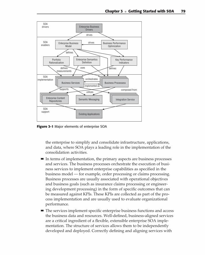
Chapter 3 ■ Getting Started with SOA 79
drives
drives
SOAdrivers
SOAenablers
Enterprise Business Model
Business PerformanceOptimization
defines
PortfolioRationalization
Enterprise SemanticsDefinition
Key PerformanceIndicators
definesmeasurements
uses defines
SOAimplementation
Business Services Business Processess
Integration Service
orchestrates
implemented ascomposed fromsupports
utilizes
Semantic Messaging
Existing Applications
SOAsupport
Enterprise BusinessDrivers
Enterprise ContentRepositories
Figure 3-1 Major elements of enterprise SOA
the enterprise to simplify and consolidate infrastructure, applications,and data, where SOA plays a leading role in the implementation of theconsolidation activities.
In terms of implementation, the primary aspects are business processesand services. The business processes orchestrate the execution of busi-ness services to implement enterprise capabilities as specified in thebusiness model — for example, order processing or claims processing.Business processes are usually associated with operational objectivesand business goals (such as insurance claims processing or engineer-ing development processing) in the form of specific outcomes that canbe measured against KPIs. These KPIs are collected as part of the pro-cess implementation and are usually used to evaluate organizationalperformance.
The services implement specific enterprise business functions and accessthe business data and resources. Well-defined, business-aligned servicesare a critical ingredient of a flexible, extensible enterprise SOA imple-mentation. The structure of services allows them to be independentlydeveloped and deployed. Correctly defining and aligning services with
80 Part I ■ Understanding SOA
the business and semantic models results in plug-and-play implemen-tations that can effectively be combined into different enterprise-widebusiness processes and/or solutions.
Information represents the data resources of the organization. Dataresides in a variety of different stores, applications, and formats. Dif-ferent levels of data are used by different levels of SOA constructs. Thesemantic information model defines the data for business processes andservices. The information passed in business processes in the form ofdocuments is based on the semantic information model. The documentsprovide a form of semantic message between processes and services. TheSOA defines the mechanisms for transforming data from its native oper-ational format to the semantic data required for the business processes.
Documents can represent legal entities (such as financial documents,insurance policies and claims, and government regulations) that definethe obligations of the enterprise and its partners. Documents are a vitalpart of modern enterprises and have to be included in the SOA imple-mentations (along with the rest of the enterprise information) as first-class citizens.
Information from existing systems and applications is made available toprocesses and services through a data virtualization layer.
Functions from existing systems and applications are made available toservices through integration services that expose the existing functional-ity through new service interfaces.
The effective implementation of service-oriented solutions is a complexundertaking that must take all of these different aspects into account. Thisrequires cooperation among many groups within an enterprise, includingmanagement, business leaders, architecture, development organization, oper-ations, and so forth. At an enterprise level, this would not be possible withouta well-defined methodology, describing the major steps and work products,and the roles and responsibilities of each participating group. In the remain-der of this chapter, we lay out a high-level methodology for enterprise SOAsolutions. This methodology is shown in Figure 3-2.
The methodology consists of the following major activities:
SOA reference architecture — Define the important aspects of the SOAreference architecture, in particular what a service is, the types of ser-vices and their relationships, design and implementation concepts andprocesses, and relationships to other architectures and communications.
Business architecture definition — The first step is to define the enter-prise business architecture. This influences the processes, services,information, and enterprise solutions that will be built.
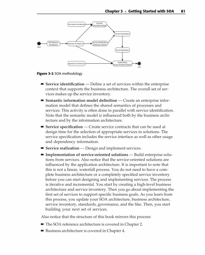
Chapter 3 ■ Getting Started with SOA 81
Business Architecture Service Identification(Enterprise Context)
Service Specification
Service Realization
ImplementingService-Oriented SolutionsApplication Architecture
Information Architecture SemanticInformation Design
Start
End
SOA ReferenceArchitecture
Figure 3-2 SOA methodology
Service identification — Define a set of services within the enterprisecontext that supports the business architecture. The overall set of ser-vices makes up the service inventory.
Semantic information model definition — Create an enterprise infor-mation model that defines the shared semantics of processes andservices. This activity is often done in parallel with service identification.Note that the semantic model is influenced both by the business archi-tecture and by the information architecture.
Service specification — Create service contracts that can be used atdesign time for the selection of appropriate services in solutions. Theservice specification includes the service interface as well as other usageand dependency information.
Service realization — Design and implement services.
Implementation of service-oriented solutions — Build enterprise solu-tions from services. Also notice that the service-oriented solutions areinfluenced by the application architecture. It is important to note thatthis is not a linear, waterfall process. You do not need to have a com-plete business architecture or a completely specified service inventorybefore you can start designing and implementing services. The processis iterative and incremental. You start by creating a high-level businessarchitecture and service inventory. Then you go about implementing thefirst set of services to support specific business goals. As you learn fromthis process, you update your SOA architecture, business architecture,service inventory, standards, governance, and the like. Then, you startbuilding your next set of services.
Also notice that the structure of this book mirrors this process:
The SOA reference architecture is covered in Chapter 2.
Business architecture is covered in Chapter 4.
82 Part I ■ Understanding SOA
Service identification is covered in Chapters 4 and 5.
The semantic information model is covered in Chapter 5.
Service specification and interface design are covered in Chapter 6.
Service realization is covered in Chapters 7 and 8. Chapter 7 describesservice implementation design, and Chapter 8 covers servicecomposition.
Service-oriented solutions are covered in chapters 9–12. Chapter 9 cov-ers the overall issues and architecture related to enterprise solutions.Chapter 10 covers integration. Chapter 11 is on security, and Chapter 12is on governance.
SOA Reference Architecture
One of the first things that needs to be done before embarking on enterpriseSOA solutions is to initiate the SOA reference architecture as described inChapter 2 and detailed in Figure 2-14. In reality, it takes some time to completethe reference architecture (if architecture is ever really finished). That is to beexpected. It is not important to have everything worked out before you start orto have complete models, documentations, standards, and governance in placebefore allowing the first service to be designed and built. But, it is important tohave an idea of what you’re doing. It is important to have a high-level vision ofthe architecture and the context that the architecture provides in terms of theservice hierarchy, service inventory, and semantic information model, beforeyou create very many services.
We recommend creating what we call a minimum architecture. The mini-mum architecture determines the few things that absolutely must be standard-ized in order to meet the enterprise goals and clearly specifies them. Then,it puts an architectural vision in place for how the rest of the architecturemight be defined, and a process for continual, incremental enhancement andimprovement of the architecture. For enterprise SOA, those crucial things arethe service definitions, service inventory, and semantic information model.We provided our vision of the SOA reference architecture in the previouschapter. It is based on our extensive experience with proven implementa-tions, and we encourage you to adopt it. It is up to you to define the inventoryand information models for your particular business, but we do explain thetechniques for creating them.
In the next few sections, we describe a sample architectural roadmap. Yourparticular roadmap depends on your own requirements and circumstances,but this example illustrates the basic concepts and contents of a roadmap foran SOA architecture.
Chapter 3 ■ Getting Started with SOA 83
Minimum Architecture
The minimum architecture should specify:
What a service is — The types and granularities of services. Forexample, business, domain, utility, integration, external, and foundationservices.
Required interfaces and functions — Interfaces or other functions thatservices are required to use or support. For example, all services mustsupport the management interface and use the logging service.
Technical infrastructure — What technology services use to commu-nicate. For example, Web Services conforming to the WS-I Basic Profilev1.1 and Security Profile v1.0.
High-level semantic information model — Identify the major enter-prise business entities and documents. What information do they need incommon to meet enterprise goals? What information needs to be sharedbetween services? For example, a consolidated customer entity supportsthe business goal of having a single customer view. The high-level modelshould identify 20–40 business entities and documents.
Initial service inventory — Identify the major service groups and ser-vices needed to support enterprise goals and processes. Determine anorganizational structure (such as line-of-business or functional domain).Integrate appropriate industry standards or patterns. The initial inven-tory should identify 30–50 services and service groups.
High-level business model — Identify the major enterprise businessprocesses and the common processes that occur across enterprisedomains. Identify the underlying capabilities needed to supportthose processes. The high-level business model should identify 10–20major processes and 20–40 capabilities.
Service identification, specification, and design process — This de-scribes how the architecture and enterprise context fit into and supportthe development process.
Architecture life cycle process — This is a feedback mechanism for theconstant updating and enhancement of the architecture.
Roadmap — The roadmap addresses at least two areas. The first is arough priority order of service implementation based on dependencies,commonality, and usefulness. This doesn’t specify a timeline, nor takeinto account other business drivers, but it provides an initial vision forbuilding out the service inventory. The second is a high-level plan forbuilding out the architecture.
84 Part I ■ Understanding SOA
The minimum architecture should take between 4 and 8 weeks to produce,depending on the size and complexity of the enterprise, and the experience,capability and number of architects.
9-Month CheckpointOnce the architectural vision (minimum architecture) is in place, you can startto implement services and use them in enterprise solutions. Often, this beginswith a small-scale or pilot project to really figure out how to do it, and thenexpand from there. The architecture and process needs to be updated basedon the knowledge gained from this process. After 6–9 months, the followingadditional architecture aspects should have been developed:
Governance — Processes for design-time and deploy-time governanceare put in place.
Metrics — Measurements to demonstrate the usage and value of SOAare defined. Implementation of metrics is started.
Services metamodel — A formalized service definition is created in theform of a metamodel.
Integration services — Patterns and techniques for how to implementintegration services are in place.
Updated business and information models — The models are updatedto include prior implementations.
Updated service inventory and roadmap — The service inventory androadmap are updated to include existing services and to factor in newbusiness models and other forces.
18-Month CheckpointTypically around the next checkpoint, the architecture and the organization areready for a larger-scale rollout of SOA. For this to be effective, the architectureand processes need to be complete and clear enough for a broader audience ofdevelopers. At this point, the following aspects should have been introduced:
Updated architecture — The architecture is updated based on past expe-rience and projects. It is also documented more completely.
Formalized process — Governance and development processes areenhanced, formalized, documented, and measured.
Design-time repository — A design-time repository is introduced andintegrated with the service inventory.
Versioning — Versioning policies, procedures, and infrastructure arein place.
Chapter 3 ■ Getting Started with SOA 85
BPM — Business processes are constructed using services to implementprocess tasks. The rules and constraints are clearly defined.
SaaS — Services provided by external vendors or software-as-a-serviceproviders make up a portion of the overall service inventory. Integrationtechniques, rules, and constraints are clearly defined.
Reporting — Information from metrics is collected and reported on. Pro-cess and architectural improvements can be identified and measured.The SOA’s value can be measured and demonstrated.
Integration with enterprise architecture — SOA and EA activities arewell coordinated.
Updated business and information models — The models are updatedto include prior implementations.
Updated service inventory and roadmap — The service inventory androadmap are updated to include existing services and to factor in newbusiness models and other forces.
Long TermLong term, there are many things you can do to continue to enhance the valueof the architecture and improve organizational effectiveness and businessagility. These are the more advanced aspects of the reference architecture. Theability to implement them and benefit from them depends on the maturity andcapability of business and IT. Many organizations do not get as far as this withtheir architecture program, but we have seen the benefits of these activitieswhen they are implemented and believe it is important to at least mention thepossibilities:
Model-based development (MBD) — Integrate the architecture into amodel-based development process and tool.
Formal metamodels and perspectives — Formalize the architecture interms of metamodels and perspectives that support both MBDand EA.
Tool and framework integration — Create tools and frameworks toautomate compliance and implementation.
Business Architecture
The foundation of a business-aligned SOA implementation is an enter-prise business model, containing the primary representation of the resources(business, IT, data, etc.) and processes involved in meeting the enterprise’s
86 Part I ■ Understanding SOA
operational, tactical, and strategic business goals. Business architecture (BA)is an essential component of a successful service-oriented implementation,providing consistency and flexibility of services across the enterprise.
We go into some length to define business architecture in the next chapter, sowe’re not going to try to define it here. Instead, we’ll describe what aspects ofBA we’re concerned with when implementing an SOA or enterprise solution.BA must answer the following questions:
What business are you in?
What are the goals and objectives of this particular business?
What outcomes are needed to achieve those goals?
What is the strategy for achieving them?
How will they be measured?
What capabilities and information are needed to achieve those outcomes?
What processes, services, entities, and rules are needed to implementthose capabilities?
What existing applications provide basic capabilities and information?
How are the applications, processes, and so on, aligned with the businessstrategies and goals?
All very good questions. Business architecture helps you to understand andanswer these questions, and it describes how to provide traceability, fromthe operational concepts of processes and services, through to the concepts oftactics and objectives, all the way up to business goals and strategy.
Business Processes
Business tactics and objectives are typically defined for particular businessprocesses. A business process is a group of logically related (and typicallysequenced) activities that use the resources of the organization to providedefined results. Business processes deliver value in the form of products orservices, often to an external party such as a customer or partner.
In order to accommodate the needs of both executive management andbusiness process owners, business processes are typically defined at twolevels of detail: ‘‘One model, for the executives, contains a set of high-levelbusiness scenarios that show the intent and purpose of the organization.The other model, for the business process owners, contains a detailed set ofuse cases that define how the organization needs to function internally. Foreach high-level business scenario, you could define one, or several, detailedbusiness use cases representing the same activities in the organization. . . .’’
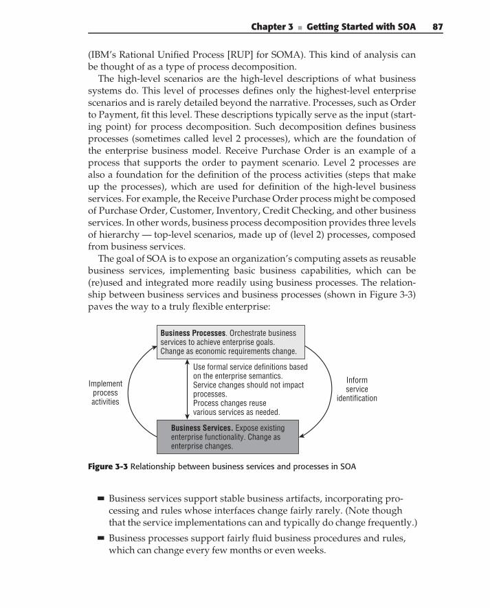
Chapter 3 ■ Getting Started with SOA 87
(IBM’s Rational Unified Process [RUP] for SOMA). This kind of analysis canbe thought of as a type of process decomposition.
The high-level scenarios are the high-level descriptions of what businesssystems do. This level of processes defines only the highest-level enterprisescenarios and is rarely detailed beyond the narrative. Processes, such as Orderto Payment, fit this level. These descriptions typically serve as the input (start-ing point) for process decomposition. Such decomposition defines businessprocesses (sometimes called level 2 processes), which are the foundation ofthe enterprise business model. Receive Purchase Order is an example of aprocess that supports the order to payment scenario. Level 2 processes arealso a foundation for the definition of the process activities (steps that makeup the processes), which are used for definition of the high-level businessservices. For example, the Receive Purchase Order process might be composedof Purchase Order, Customer, Inventory, Credit Checking, and other businessservices. In other words, business process decomposition provides three levelsof hierarchy — top-level scenarios, made up of (level 2) processes, composedfrom business services.
The goal of SOA is to expose an organization’s computing assets as reusablebusiness services, implementing basic business capabilities, which can be(re)used and integrated more readily using business processes. The relation-ship between business services and business processes (shown in Figure 3-3)paves the way to a truly flexible enterprise:
Implementprocessactivities
Informservice
identification
Use formal service definitions based on the enterprise semantics.Service changes should not impactprocesses.Process changes reusevarious services as needed.
Business Processes. Orchestrate businessservices to achieve enterprise goals.Change as economic requirements change.
Business Services. Expose existingenterprise functionality. Change asenterprise changes.
Figure 3-3 Relationship between business services and processes in SOA
Business services support stable business artifacts, incorporating pro-cessing and rules whose interfaces change fairly rarely. (Note thoughthat the service implementations can and typically do change frequently.)
Business processes support fairly fluid business procedures and rules,which can change every few months or even weeks.
88 Part I ■ Understanding SOA
The interaction between business processes and business services isbased on the enterprise semantics, which minimizes the impact of ser-vice changes on the business processes and simplifies building processesfrom business services.
This separation of responsibilities enables business analysts and IT architectsto reuse IT capabilities, encapsulated in business services, through the compo-sition of business processes. This simplifies the creation of new processes andoptimization of the existing ones. More importantly, once designed, processescan be quickly modified in response to market conditions. All this translatesinto increased business flexibility and competitiveness, while reducing theincremental costs of making frequent process changes.
Information Design
The next step in the process definition is creation of the enterprise semantics(semantic information model) — a definition of the standard business entitiesfor the enterprise; for example, insurance policy, claim, and so on. A commonsemantic definition ensures that:
Each term throughout the enterprise has a clear and concise definition.
All enterprise terms are used consistently (mean the same thing and usethe same definitions) throughout the enterprise.
Each term is used in at least one process/activity definition.
Only terms defined in the enterprise semantic information model areused by process/activity definitions.
The semantic information model is influenced by both the business architec-ture and the information architecture. The business architecture identifies theprocesses required to support the business goals and objectives. The seman-tic information model defines the information, concepts, and meanings thatmust be common throughout those processes to effectively pass informationbetween the process steps. This corresponds to the information architectureconcepts of semantic data as illustrated in Figure 2-6.
The semantic data is not the same as the domain data. It does not defineall of the details of the information needed within each step of a process.Rather, it defines the information that must be common between then. Eachindividual process’s step (implemented by a business service) provides anytransformation required between the semantic information model and its owninternal domain model.
Chapter 3 ■ Getting Started with SOA 89
N O T E In this context, objects and entities refer to business ‘‘things.’’ We areusing these terms without the connotations associated with object-oriented orentity-relationship modeling. In other words, business semantics described hereare used only as a foundation for service interactions (messaging model), not forservice implementation.
Although the semantic information model seems similar to a standardizedenterprise data model, the two are radically different and should not be con-fused with each other. The semantic information model defines the messagesexchanged by services. The messages implement interservice communication.Thus, they are transient and do not reside in a data store (at least not explic-itly). In contrast, the enterprise data model defines the data structure and therelationships between data in the database. Because in practice implementa-tion of the SOA involves service enabling of existing enterprise applications,changing the underlying data model is an extremely expensive propositionthat often requires the complete rewriting of applications. In other words, it’sprobably not happening, so a system that provides interoperability withoutchanging existing models is going to be better.
An SOA implemented, based on the semantic information model, providesa semantically interoperable SOA. Such an implementation offers enhancedinteroperability between services. At the interface level, all of them work withthe same objects. In effect, this eliminates the need for message transformationsbetween services. Because service interfaces are created according to thestandard enterprise semantic information model, it is guaranteed that everyservice can understand and correctly interpret any message, regardless of whothe service consumer is.
THE FUTURE OF THE SEMANTIC INTERFACES
The introduction of semantic data for service contracts also allows forrethinking the design of service interfaces. It is no longer necessary to sendspecific request/response message pairs between the consumer and providerfor each service operation. Because the interface data models for all servicesare driven by the same semantics, it is possible to introduce the notion ofpassing the service execution context around as part of the service invocation‘‘thread.’’ In this case, the service interface operations are massivelypolymorphic and expressed as:
Service.method (XML context in, XML context out)
The context in this case is a service execution context, expressed as an XMLdocument supporting enterprise semantics. In this implementation, anyparticular service can extract data that it is interested in from the context.
This solution reverses responsibilities: Instead of the service consumerbuilding a specific interface for a participating service, the service itself is
(continued)
90 Part I ■ Understanding SOA
THE FUTURE OF THE SEMANTIC INTERFACES (continued)
responsible for accessing the required information from the execution contextand updating the context with the results of its execution. Such an approachminimizes the impact of service interface changes, as long as the required putsdata is available in the execution context. This approach, of course, puts anadditional burden on the service implementations, but it may be negligiblecompared to the expenses of realigning of the service consumers with theservices interface changes.
This approach, however, can lead to significant control and data couplingbetween consumers and providers where the semantics of the service arehidden in the interpretation of data. This can make services more difficult toreuse, compromises encapsulation, and can make change management moredifficult. (A provider interprets the data differently, changing the service, andconsumers don’t see this as a change in the service interface.)
There are plenty of industry (and cross-industry) consortiums today, defin-ing data semantics for a particular industry, such as ACORD for insurance,or HL7 for healthcare. Their semantic dictionaries (if they exist) should beconsidered a starting point for the creation of enterprise semantic informationmodels.
Service Identification
One of the most important tasks during implementation of a solution basedon service-oriented principles is the proper definition of business services,based on the decomposition of the problem domain (see the sidebar ‘‘SOA andDecomposition’’).
SOA AND DECOMPOSITION
Decomposition is a well-known (and widely adopted) technique for dealingwith complexity. The first software decomposition approach (introduced in theearly 1960s) was splitting applications into separate jobs, each implemented bya separate program. Later, as more insight into program internals was gained,each program itself was split into modules or subroutines, according to itsvarious functions.
The object-oriented (OO) paradigm introduced by Simula and Smalltalk in the1970s strengthened the adoption of decomposition by introducing objects:modules of code, each of which implemented a model of a real thing. The idea
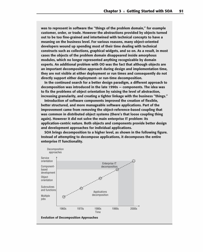
Chapter 3 ■ Getting Started with SOA 91
was to represent in software the ‘‘things of the problem domain,’’ for examplecustomer, order, or trade. However the abstractions provided by objects turnedout to be too fine-grained and intertwined with technical concepts to have ameaning on the business level. For various reasons, many object-orienteddevelopers wound up spending most of their time dealing with technicalconstructs such as collections, graphical widgets, and so on. As a result, in mostcases the objects of the problem domain disappeared inside amorphousmodules, which no longer represented anything recognizable by domainexperts. An additional problem with OO was the fact that although objects arean important decomposition approach during design and implementation time,they are not visible at either deployment or run times and consequently do notdirectly support either deployment- or run-time decomposition.
In the continued search for a better design paradigm, a different approach todecomposition was introduced in the late 1990s — components. The idea wasto fix the problems of object orientation by raising the level of abstraction,increasing granularity, and creating a tighter linkage with the business ‘‘things.’’
Introduction of software components improved the creation of flexible,better structured, and more manageable software applications. Part of theimprovement came from removing the object-reference-based coupling thatwas common in distributed object systems (there’s that loose coupling thingagain). However it did not solve the main enterprise IT problem: itsapplication-centric nature. Both objects and components provide better designand development approaches for individual applications.
SOA brings decomposition to a higher level, as shown in the following figure.Instead of attempting to decompose applications, it decomposes the entireenterprise IT functionality.
1960s 1970s 1980s 1990s 2000sTime
Serviceorientation
Component-baseddevelopment
Objectorientation
Subroutinesand functions
Multiplejobs
Decompositionapproaches
Enterprise ITdecomposition
Applicationsdecomposition
Evolution of Decomposition Approaches
92 Part I ■ Understanding SOA
It seems like the simplest approach to decomposition (and consequentlyservice definition), is to directly expose the existing application’s function-ality as a set of services (decomposition based on the existing applicationportfolio) — similar to the traditional enterprise application integration (EAI)practice. Unfortunately, such an approach rarely works. It ‘‘is in essencetechnology first approach and is a recipe for disaster and/or serious over-engineering’’ (Gary Booch, ‘‘SOA Best Practices,’’ Software architecture, soft-ware engineering, and Renaissance Jazz blog [March 11, 2006]). A betterdecomposition approach is based on the decomposition of the enterprise-widebusiness model: designing a set of services that define the enterprise archi-tecture blueprint supporting the current business goals of the enterprise andproviding capabilities for future changes. It requires you ‘‘to start with thescenarios/business needs, play those out against the existing/new systems,zero in on the points of tangency, and there plant a flag for harvesting ameaningful service’’ (ibid.).
Such an approach leads to the creation of a set of business-aligned ITservices (available to participants throughout the enterprise across multiplelines-of-business or even outside of the enterprise) that collectively fulfill anorganization’s business processes and goals. The resulting business servicesare independent from the current enterprise application portfolio and supportthe ‘‘ideal’’ enterprise architecture.
Hierarchical decomposition, based on the enterprise business model istypically not sufficient for proper service identification. Although it providesan alignment between business and IT, it does not guarantee that resultingservices will adhere to the basic service tenets. The service characteristicsdefined in Chapter 2 need to be considered in the design process.
But still this is not enough. The services need to be defined within the contextof the overall enterprise. To do this, you need two things. First, you needto think about the way you design systems and decomposition differently.To overuse a phrase, you need a paradigm shift in design practice. Then, tosupport the new paradigm, you need an easy way to find the existing services.
For example, a typical approach to SOA design might incorporate thissequence:
For each business domain, identify and analyze the processes.
Break the processes down into tasks that are implemented by services.
Look for existing services that perform the specified tasks.
Use existing services when possible.
Design and implement new services.
Chapter 3 ■ Getting Started with SOA 93
This probably seems like a pretty reasonable approach, but let’s look at anSOA-focused sequence and compare:
For each business domain, identify and analyze the processes.
Understand what services currently exist (or are planned) and theirresponsibilities.
Use existing services to frame the design, and break the process downinto tasks that are implemented by services.
Use existing services when possible.
Design and implement new services where necessary.
The difference comes at the breakdown of processes into tasks and services.The difference may seem subtle, but the effect is huge. In the first approach,you are free to come up with almost any reasonable sequence of tasks toimplement your process. There could be dozens of possibilities. Then, youlook for existing services that do things your way, but probably don’t findvery many. Instead, you implement new services, but ones that overlap withexisting services. In the SOA approach, you factor in the existing services firstand then design around them. They provide a design constraint that limits thepossible solutions to a few, instead of dozens. Now, when you use existingservices, they’ve already been designed in, and they work with your newsolutions and support your enterprise. Instead of promoting new services, youfacilitated reusing existing ones.
The crux is this. You are not designing a solution or process from scratch.Instead, you are starting with an existing base and building your solutionon top of it. You are extending and reusing, adding value to what exists, notduplicating responsibilities and adding inconsistencies. But to make this work,you need to be able to find the existing services. This requires an easy wayto search for and find services at design time, and an organization of servicesthat makes it easy to understand the overall set of services. We call the overallset of services the service inventory.
The service inventory lays out the overall set of services and their rela-tionships to each other and the overall enterprise goals. You can think of theservice inventory as a responsibility map of service interfaces. It should clearlydescribe the overall set of services, and what responsibilities the differentservice groups perform, and don’t perform. The service inventory helps youin two important service design activities.
First, the inventory allows you to quickly scan the overall set of services at ahigh level and then to dig deeper into groups of services within a given area.This helps you to locate the services to support your look-first, design-laterapproach.
94 Part I ■ Understanding SOA
But at least as important, the inventory helps you to make decisions aboutwhat functions to include within your service implementations, and whatfunctions you should expect to be performed by another service. If you needto implement a new service, you have to make sure that it doesn’t duplicatefunctions that are already (or plan to be) implemented by other services. Thisis where the responsibility map aspect of the inventory is important. It mustclearly define the boundaries of responsibility for services and service groups.
Service Specification
Once services and their corresponding semantic models are identified, theyneed to be described (specified) correctly. The complexity of proper servicespecification stems from the fact that there are two very distinct groups ofservice users that require information about services: business users (businessanalysts), who need to decide whether a particular service can be used in thesolution that they are designing, and technical users (developers), who needto know how to write the code, invoking a particular service.
Business users need to understand what a service does in business terms,which requires answers to the following questions:
What does the service provide for prospective clients? This includes adescription of what is accomplished by the service, limitations on serviceapplicability and quality of service (QoS), and requirements that the ser-vice requester must satisfy to use the service successfully.
How is the service used? This includes a detailed definition of the con-tent of service requests and responses, the conditions under which par-ticular outcomes occur, and, when necessary, a step-by-step descriptionof processes leading to those outcomes.
Technical users need to know how to implement service operations thatrequire answering the following questions:
How to interact with services? This specifies a communication protocol,message formats, including serialization techniques and service loca-tions, for example, the service endpoint URL.
What are the service invocation policies? This defines specific require-ments for service invocation, for example, security requirements,required SOAP headers, and so on.
What are service QoS guarantees? This specifies the quality-of-servicecharacteristics that the service provides, including response time,throughput, availability, planned maintenance, and the like.
Chapter 3 ■ Getting Started with SOA 95
CURRENT PRACTICES FOR SERVICE SPECIFICATIONS
The notion of the service specification is widely recognized as one of theprerequisites for successful service usage. The problem is usually not the factthat a specification does not exist, but rather what the specification contains.Based on experience with object-oriented and component-based development,many architects and developers consider the service interface to be equivalentto the service contract. In the best cases, the service interface is supplementedby a free-form text document that captures some additional serviceinformation. Although this approach can significantly help, free-formdocuments are imprecise, hard to validate for completeness, and virtuallyimpossible to process automatically.
For example, the popular web site www.webservicex.net provides aLloydsRiskCodeService service1 with the following contract:
Textual description of the functionality — ‘‘This service returns Lloyds riskcode details for a given risk code or description.’’
Textual definition — ‘‘The following operations are supported:
■ GetLloydsRiskCodeDetailsByRiskCode— This method returnsLloyds Risk Code details for a given risk code.
■ GetLloydsRiskCodeDetailByRiskCodeDescription— Thismethod returns Lloyds Risk Code details for a given risk codedescription.’’
The formal definition is in the form of the service WSDL and sample XMLpayloads (not shown here for brevity).
At first glance, the information seems sufficient to successfully use theservice. However, let’s take a closer look at how this contract can be used bydifferent people.
On the business side, in order to decide whether the service is appropriatefor solving a problem, the following questions must be answered:
◆ What functionality does the service provide? In our example, the informa-tion is supposed to be provided by the textual description of the functional-ity, but unless the user is acquainted with risk codes’ definitions(www.lloyds.com/Lloyds Market/Tools and reference/Risk
codes.htm) and can figure out which ones are really supported by the ser-vice, he or she can’t decide whether it is appropriate.
◆ What are the limitations of the service? The textual definition does not pro-vide any information about this. Examination of the service WSDL answersthis question to some degree, but it’s rare that business users ever lookat it.
◆ Which SLAs does the service support? This is not specified in the servicedefinition.
(continued)
96 Part I ■ Understanding SOA
CURRENT PRACTICES FOR SERVICE SPECIFICATIONS (continued)
◆ What are the requirements that the service requester must satisfy to invokethe service successfully? The service definition does not specify any require-ments on the input parameters.
◆ What are the detailed definitions of the content of service requests andresponses? Some of this information is provided by the formal definition inthe form of WSDL and XML samples. This definition assumes that the busi-ness analyst can understand XML, and that WSDL correctly represents thedata semantics.
Similarly, on the technical side, the following questions must be answered:
◆ What are the communication protocols, message formats, including seri-alization techniques, and service location? This information is provided bythe formal definition in the WSDL.
◆ What are the errors that service invocation can produce? This information isprovided by the formal definition in the WSDL.
◆ What are the service invocation policies such as security requirements,required SOAP headers, and so on? Some of this information (SOAP head-ers) is provided by the formal definition in the WSDL. Other characteris-tics such as invocation policies theoretically could be added to WSDL, butthey rarely are.
◆ Which SLAs does the service support? This is not specified in the definitionabove.
So, you can see from this example (which is comparatively good) that muchinformation needs to be provided in security specifications.
The service specification should define all of the relevant aspects of a servicerequired by potential service consumers, including the service expectations,interaction model, service constraints, and the service location.
Service ExpectationsThe expectations define the result desired by the consumer who is usingthe service. This is also known as the real-world effect of using a service.For example, invoking the claims-processing service allows customers to getinsurance payments. When potential customers invoke the service, they arenot interested in a response indicating that their insurance company hasmerely recorded an application. Rather, they are interested in whether it willreimburse their losses.
Of course, the service provides encapsulation: The insurance company’sinternal systems record the claim without exposing this fact to the consumer.However, minimizing the client’s assumptions about how the insurance com-pany processes their claim increases the potential for smooth interaction.
Chapter 3 ■ Getting Started with SOA 97
Expectations associated with a service interaction are usually described interms of the message traffic exchanged with the service. In some sense, similarto a service interface, it is possible to define expectations in terms of the kindof information that is provided by a service, as opposed to the informationthat is required for a current interaction.
Interaction ModelThe interaction model defines the interaction between service consumer andprovider through the service interface. Three key concepts are important inunderstanding what it is involved in interacting with services: informationmodel, process model, and execution context.
The information model defines the information that is exchanged withservice consumers. This model should conform to the enterprise seman-tic information model. The scope of the information model includes themessage semantics and their format (encoding). The message formatdefines the structure of the messages used for service invocation andresponse.
The process (behavioral) model of the service defines the actions thatconsumers can execute on a service, the responses to these actions, andtemporal dependencies between them. Temporal dependencies aremostly applicable to a conversational composite service, where inter-actions between the service consumer and provider can involve multipleservice invocations.
The service execution model defines the behavior resulting from inter-actions with the service. Some of this behavior can be private, and somepublic. The publicly visible portion of the service behavior is defined bythe service execution model. The private behavior should never be madevisible to service consumers.
Service ConstraintsService constraints describe rules, limitations, and facts about a service andits operations. Service constraints are usually expressed as policies. A policyis a statement of the obligations, constraints, or other conditions that eitherdefine service characteristics or have to be fulfilled by service consumers wheninvoking the service. There are two major types of policies that can be definedfor a service:
Business-oriented policies such as hours of operation, return poli-cies, and so on — Business-oriented policies usually apply to the serviceoperations, regardless of where and how these operations are deployed.For example, in order to invoke the claim processing service, a consumermust have a valid insurance policy.
98 Part I ■ Understanding SOA
Infrastructure-oriented policies such as security, privacy, manage-ability, performance, and the like — These policies are defined for aparticular service endpoint address. This means that there can be mul-tiple service deployments, adhering to different infrastructure policies.For example, an appraisal service can be exposed through two differentURIs. One guarantees a two-business-day appraisal response time, whilethe second guarantees fulfillment in five business days. Typically, theservice provider charges differently for using these different endpoints.
Service LocationInvocation of a service requires its location, that is, the endpoint address.The same service can have several endpoint addresses. Multiple endpointaddresses may be employed for several reasons. As in the dual-URI appraisalservice example, each endpoint address could support different policies. Often,multiple endpoint addresses are also required for different service methods.For example, withdrawal and inquiry methods on a bank account serviceexpose completely different QoS requirements. On the one hand, the with-drawal operation requires guaranteed (once and only once) service delivery,reliability, and transactionality. These involve fairly expensive infrastructuresupport. On the other hand, the inquiry operation has less strict requirements.In case of failure, its execution can be retried. Since the frequency of inquiry is,on average, 5–10 times higher than that of withdrawal, it is not cost-effectiveto use the same expensive infrastructure for both methods. Such situationsrequire that the service specification support different endpoint addresses fordifferent service methods. Additionally multiple endpoint addresses can beused to support multiple versions and different infrastructure constraints thata given service can have.
To summarize, a service specification should provide information aboutthe service’s behavior, interface, and policies. This information covers serviceexpectations, the interaction model, service constraints, and the service loca-tion. It provides the basis for implementing service consumers, as well as fordynamically binding consumers to the service provider(s).
Services Realization
Once services are identified and their specifications are created, it is necessaryto decide on the service realization. SOA solutions provide several options forrealizing (implementing) services.
Buy — Purchase a complete implementation of a service that may bedeployed and hosted internally.
Chapter 3 ■ Getting Started with SOA 99
Outsource (rent) — Use a service provided by an external vendor. AsWeb Services and business-to-business integration become more preva-lent, this option will be considered by more enterprises.
Build — Provide an internal implementation of a service. With a builddecision, there are multiple options:
New implementation — An implementation of a service is createdfrom scratch. Of course, the new service can be a composition of otherexisting services. Not all of it is necessarily from scratch.
Integrate or wrap legacy applications (systems) to expose therequired service functionality — This approach uses the existingcapabilities directly but exposes them through new service interfaces.
Modernization — the repurposing of existing applications. This usesa combination of techniques. One common technique for services isbusiness rules/processes extraction to pull out a segment of capabilityso that it can be used independently and exposed as a service.
Buying ServicesBuying services might seem very similar to traditional buying decisions forsoftware, but there is a big difference. Unlike a stand-alone application, aservice has to fit seamlessly into the enterprise service infrastructure, whichmeans that it has to support the following:
Functional alignment with the overall business model, service decompo-sition, and service inventory.
Usage of the enterprise semantic information model for service interfacedefinitions.
Support for the enterprise service infrastructure, including security, log-ging, exception handling, and so on.
These requirements are rarely met unless a service is custom designedand built for a given enterprise. As a result, services themselves are rarelybought. A more common scenario is buying packaged applications that pro-vide the required capabilities and then doing an in-house service-wrappingimplementation, exposing it as an integration service.
Outsourcing ServicesOutsourcing assumes that an enterprise wants to concentrate only on the corebusiness capabilities, while outsourcing (partially) other business functions.Such an approach allows the enterprise to focus its energy, money, andpeople on only the areas that are critical for a particular business or providecompetitive advantage.
100 Part I ■ Understanding SOA
Outsourced services, or on-demand services, also called software as aservice (SaaS), is an application delivery model in which a serviceprovider hosts and operates a software application for use by its customersover the Internet. Customers use the application through an API accessibleover the web. On-demand services provide a low-cost way for businessesto obtain the same benefits of commercially licensed software without theassociated complexity and costs of development, ownership, or operations.The key characteristics of on-demand services include:
Designed for use by customers through the Internet
Hosted off-premises, not on the customer’s premises
Governed by a service contract
The service contract consists of a publicly availably interface, API, anda run-time service policy, which may include an SLA. At a basic level,the on-demand service is a software construct that happens to be hostedoff-premise and that encapsulates a unit of work, which is made availablethrough a service contract. Like any business contract, there is someonewho provides the service and someone who consumes the service, only here,the provider and consumer are computer systems accessible over the Internet.The service has a public view, which is available to the consumer of the servicevia the contract, and a private implementation view, which is available onlyto the service provider.
When it comes to incorporating outsourced services, the range of issuesis very similar to the issues an enterprise has to deal with when buying aservice — the service has to seamlessly fit into the enterprise service infra-structure, which means it has to support functional alignment with the overallbusiness model and support enterprise semantics. However, since the serviceis hosted off-site, there are a different set of issue concerning the enterpriseservice infrastructure, including security, logging, exception handling, and thelike. Figure 3-4 shows two common approaches to incorporating SaaS into anoverall SOA.
The first approach (left) uses the on-demand service directly. In this case,the interface API and semantic model defined by the service provider are useddirectly by the enterprise. The ability of an enterprise to use this approachdepends on a variety of factors, including the flexibility and customizationof the service (particularly its data model), the need and complexity ofintegration with other services, and the extent and flexibility of the existingSOA infrastructure.
The second approach delegates only the implementation to the on-demandservice. In this case, the interface and semantics are defined by the enterprise,and the service implementation does whatever translation is necessary beforeinvoking the on-demand service through its standard API. This approach
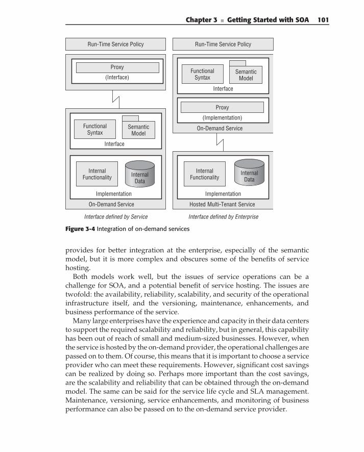
Chapter 3 ■ Getting Started with SOA 101
Hosted Multi-Tenant Service
On-Demand Service
Interface
Implementation
Internal Functionality
Semantic Model
(Implementation)
Proxy
Functional Syntax
Interface defined by Enterprise
Internal Data
On-Demand Service
Run-Time Service Policy Run-Time Service Policy
Implementation
Internal Functionality
Interface
Semantic Model
Functional Syntax
Interface defined by Service
Proxy
Internal Data
(Interface)
Figure 3-4 Integration of on-demand services
provides for better integration at the enterprise, especially of the semanticmodel, but it is more complex and obscures some of the benefits of servicehosting.
Both models work well, but the issues of service operations can be achallenge for SOA, and a potential benefit of service hosting. The issues aretwofold: the availability, reliability, scalability, and security of the operationalinfrastructure itself, and the versioning, maintenance, enhancements, andbusiness performance of the service.
Many large enterprises have the experience and capacity in their data centersto support the required scalability and reliability, but in general, this capabilityhas been out of reach of small and medium-sized businesses. However, whenthe service is hosted by the on-demand provider, the operational challenges arepassed on to them. Of course, this means that it is important to choose a serviceprovider who can meet these requirements. However, significant cost savingscan be realized by doing so. Perhaps more important than the cost savings,are the scalability and reliability that can be obtained through the on-demandmodel. The same can be said for the service life cycle and SLA management.Maintenance, versioning, service enhancements, and monitoring of businessperformance can also be passed on to the on-demand service provider.
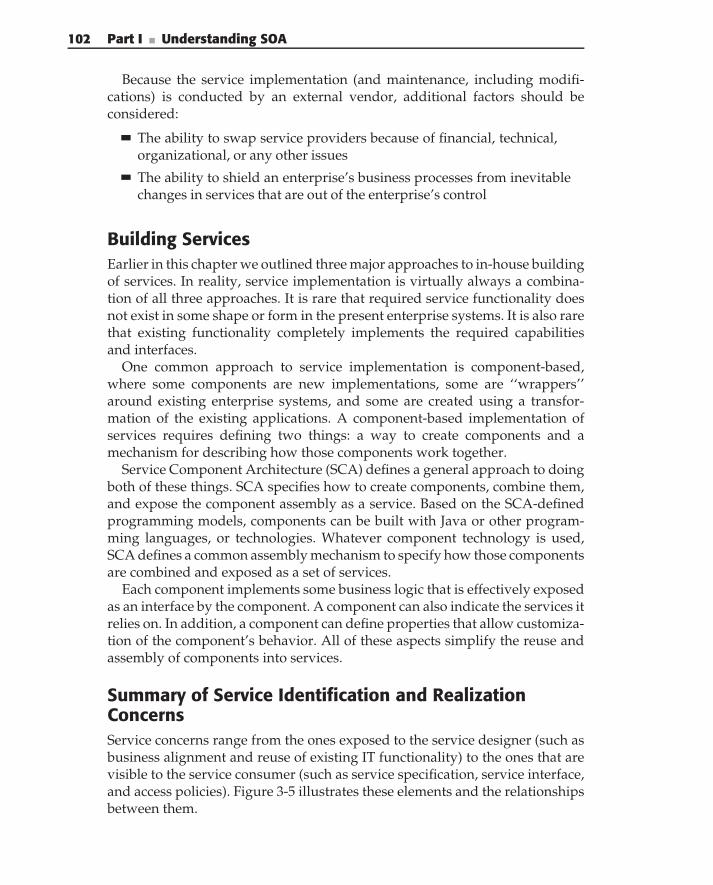
102 Part I ■ Understanding SOA
Because the service implementation (and maintenance, including modifi-cations) is conducted by an external vendor, additional factors should beconsidered:
The ability to swap service providers because of financial, technical,organizational, or any other issues
The ability to shield an enterprise’s business processes from inevitablechanges in services that are out of the enterprise’s control
Building ServicesEarlier in this chapter we outlined three major approaches to in-house buildingof services. In reality, service implementation is virtually always a combina-tion of all three approaches. It is rare that required service functionality doesnot exist in some shape or form in the present enterprise systems. It is also rarethat existing functionality completely implements the required capabilitiesand interfaces.
One common approach to service implementation is component-based,where some components are new implementations, some are ‘‘wrappers’’around existing enterprise systems, and some are created using a transfor-mation of the existing applications. A component-based implementation ofservices requires defining two things: a way to create components and amechanism for describing how those components work together.
Service Component Architecture (SCA) defines a general approach to doingboth of these things. SCA specifies how to create components, combine them,and expose the component assembly as a service. Based on the SCA-definedprogramming models, components can be built with Java or other program-ming languages, or technologies. Whatever component technology is used,SCA defines a common assembly mechanism to specify how those componentsare combined and exposed as a set of services.
Each component implements some business logic that is effectively exposedas an interface by the component. A component can also indicate the services itrelies on. In addition, a component can define properties that allow customiza-tion of the component’s behavior. All of these aspects simplify the reuse andassembly of components into services.
Summary of Service Identification and RealizationConcernsService concerns range from the ones exposed to the service designer (such asbusiness alignment and reuse of existing IT functionality) to the ones that arevisible to the service consumer (such as service specification, service interface,and access policies). Figure 3-5 illustrates these elements and the relationshipsbetween them.
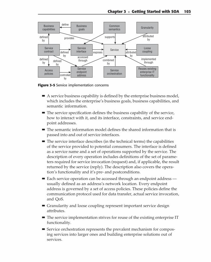
Chapter 3 ■ Getting Started with SOA 103
Service
Businesscapabilities
Businessgoals
Serviceorchestration
Reuses existingenterprise IT functionality
Service interface
Granularity
provides supports
implementedthrough
attributed by
accessed through combined
by
Servicecontract exposesdefined
by
Accesspolicies controlled
by
Loosecouplingattributed
bydefined
by
defined by
define
definedby
Common semantics
Service endpoint address
Figure 3-5 Service implementation concerns
A service business capability is defined by the enterprise business model,which includes the enterprise’s business goals, business capabilities, andsemantic information.
The service specification defines the business capability of the service,how to interact with it, and its interface, constraints, and service end-point addresses.
The semantic information model defines the shared information that ispassed into and out of service interfaces.
The service interface describes (in the technical terms) the capabilitiesof the service provided to potential consumers. The interface is definedas a service name and a set of operations supported by the service. Thedescription of every operation includes definitions of the set of parame-ters required for service invocation (request) and, if applicable, the resultreturned by the service (reply). The description also covers the opera-tion’s functionality and it’s pre- and postconditions.
Each service operation can be accessed through an endpoint address —usually defined as an address’s network location. Every endpointaddress is governed by a set of access policies. These policies define thecommunication protocol used for data transfer, actual service invocation,and QoS.
Granularity and loose coupling represent important service designattributes.
The service implementation strives for reuse of the existing enterprise ITfunctionality.
Service orchestration represents the prevalent mechanism for compos-ing services into larger ones and building enterprise solutions out ofservices.
104 Part I ■ Understanding SOA
Service Life Cycle
Of course, a service is just beginning its life after it has been implemented.Then, it must go into production, be updated, and so on, until eventually it isretired (like that ever happens). Figure 3-6 illustrates the high-level service lifecycle.
1. Service identification — Service identification is the first major step inthe life of a service. It is driven off of the business model, process def-inition, and semantic information model. This results in the proposalfor a new service.
2. Service design and specification — These are the steps where the ser-vice proposal is designed and specified, again in accordance with thefunctional business model and the semantic information model. Othernonfunctional requirements are also taken into account. After both theidentification and specification phases, the functional and semanticmodels should be updated.
3. Service implementation — Next, the service is implemented using oneof the techniques described earlier. Again, the implementation is inaccordance with enterprise standards, security requirements, opera-tional requirements, and so on.
4. Service deployment — After validation and testing of the implementedservice, it is ready to be deployed — again, in accordance with policyand procedure for putting software into production.
5. Service usage and enhancement — Once the service is in use, it willinevitably requires enhancements and modifications. New users mayrequire a more generalized or flexible implementation. New and existingusers will have requests for new features. All of this has to be managed.A new version of the service has to go through the design and imple-mentation phase again, with all that entails.
6. Service retirement — Eventually, the service will be retired. Perhapsthis will only be the retirement of older versions of the service, or itcould eventually be the entire service. Again, processes and proceduresshould be in place to manage this.
All of these steps of the service life cycle have constraints, processes,and procedures that need to be followed. It is the role of SOA governanceto ensure that they are followed. Governance has been defined as: ‘‘theart and discipline of managing outcomes through structured relationships,procedures and policies.’’ Infravio, ‘‘The Definitive Guide to SOA Gover-nance and Lifecycle Management’’ (2006). Governance enforces compliancewith the architecture and common semantics, and facilitates managing the
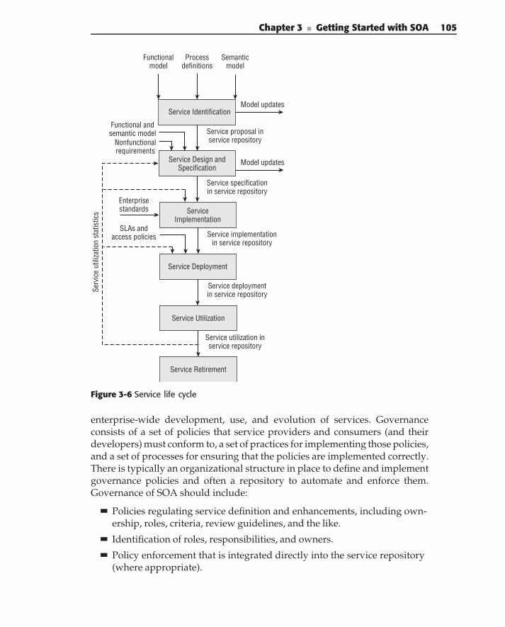
Chapter 3 ■ Getting Started with SOA 105
Functionalmodel
Processdefinitions
Semanticmodel
Service IdentificationModel updates
Model updates
Service proposal inservice repository
Service specificationin service repository
Service implementationin service repository
Service deploymentin service repository
Functional andsemantic model
Nonfunctionalrequirements
Service Design andSpecification
ServiceImplementation
Service Deployment
Service Utilization
Service utilization inservice repository
Service Retirement
SLAs andaccess policies
Enterprisestandards
Serv
ice
utili
zatio
n st
atis
tics
Figure 3-6 Service life cycle
enterprise-wide development, use, and evolution of services. Governanceconsists of a set of policies that service providers and consumers (and theirdevelopers) must conform to, a set of practices for implementing those policies,and a set of processes for ensuring that the policies are implemented correctly.There is typically an organizational structure in place to define and implementgovernance policies and often a repository to automate and enforce them.Governance of SOA should include:
Policies regulating service definition and enhancements, including own-ership, roles, criteria, review guidelines, and the like.
Identification of roles, responsibilities, and owners.
Policy enforcement that is integrated directly into the service repository(where appropriate).
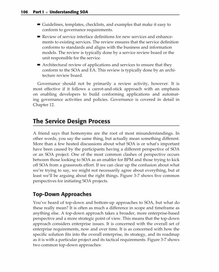
106 Part I ■ Understanding SOA
Guidelines, templates, checklists, and examples that make it easy toconform to governance requirements.
Review of service interface definitions for new services and enhance-ments to existing services. The review ensures that the service definitionconforms to standards and aligns with the business and informationmodels. The review is typically done by a service review board or theunit responsible for the service.
Architectural review of applications and services to ensure that theyconform to the SOA and EA. This review is typically done by an archi-tecture review board.
Governance should not be primarily a review activity, however. It ismost effective if it follows a carrot-and-stick approach with an emphasison enabling developers to build conforming applications and automat-ing governance activities and policies. Governance is covered in detail inChapter 12.
The Service Design Process
A friend says that homonyms are the root of most misunderstandings. Inother words, you say the same thing, but actually mean something different.More than a few heated discussions about what SOA is or what’s importanthave been caused by the participants having a different perspective of SOAor an SOA project. One of the most common clashes of perspective occursbetween those looking to SOA as an enabler for BPM and those trying to kickoff SOA from a grassroots effort. If we can clear up the confusion about whatwe’re trying to say, we might not necessarily agree about everything, but atleast we’ll be arguing about the right things. Figure 3-7 shows five commonperspectives for initiating SOA projects.
Top-Down ApproachesYou’ve heard of top-down and bottom-up approaches to SOA, but what dothese really mean? It is often as much a difference in scope and timeframe asanything else. A top-down approach takes a broader, more enterprise-basedperspective and a more strategic point of view. This means that the top-downapproach considers enterprise issues. It is concerned with the overall set ofenterprise requirements, now and over time. It is as concerned with how thespecific solution fits into the overall enterprise, its strategy, and its roadmapas it is with a particular project and its tactical requirements. Figure 3-7 showstwo common top-down approaches:
Chapter 3 ■ Getting Started with SOA 107
Business Process Model
Service Enabling
Legacy Systems
Discover Existing or
External Services
Enterprise System Analysis
Botto
m U
p
Project
Create Services with SOA
Reference Architecture
Top Down
Enterprise
Middle Out
Figure 3-7 SOA project approaches
Enterprise System Analysis
Enterprise System Analysis strives to understand and account for the overallenterprise requirements. Typically starting with business goals and drivers,the analysis looks at the overall business architecture and information model.This sets the context for a service inventory and roadmap that identifythe major entities, services, and service groups that are necessary to sup-port the business goals over the next few years. The roadmap should alsoprioritize an order for implementing services so that the most important orwidely usable ones are addressed first. The enterprise analysis should takeinto account a standard SOA platform, technologies, and standards. It shouldcreate a roadmap for their introduction concurrently with the business serviceroadmap, while maintaining the separation of concerns between the businessdesign and technology.
Business Process Model
Another starting point for SOA is to develop business process models asa set of detailed business requirements (top-right box of Figure 3-7). Inthis approach, the tasks of the business process model are implemented bybusiness services. The business process model may be an extension of the over-all Enterprise System Analysis approach, providing the next level of detail(level 2) of the business architecture (which is, of course, better from an archi-tectural perspective). But often, it is done on a project basis that is being drivenby BPM-oriented project sponsors. To the extent that the enterprise context isignored, the project misses opportunities to improve reuse, integration, andflexibility. In this case, it behooves the SOA team to understand the enterprisecontext on behalf of the business sponsor.
108 Part I ■ Understanding SOA
The crux of the top-down approach is an understanding of the enterprise con-text and roadmap, and integration of that into a project-based service design.This is often in contrast to the pressure to create immediate deliverables feltby project teams and their lack of understanding of enterprise requirements.The result is a conflict between enterprise architects or designers, who areconcerned with understanding common semantics and creating extensible ser-vices; and technicians, who just want to do the most expedient thing. It shouldbe pointed out that many times, architects are their own worst enemy in thesediscussions because they get hung up on the long term and fail to demonstratehow it can be achieved with minimal impact to immediate deliverables.
Bottom-Up ApproachesBottom-up SOA starts from a perspective of existing systems, technology, orcommon services. The scope of bottom-up approaches is typically a specificproject with immediate requirements. Generally, the project team doesn’t feelthat it has the luxury to consider a broader enterprise scope or longer-termtimeframe, or it doesn’t understand the value of that approach. Again,Figure 3-7 shows two common bottom-up approaches to SOA:
Utility Services
SOA is often introduced into an organization as a grassroots effort by atechnology team that thinks it is the right technology and/or wants to be onthe leading edge. When this occurs, there is no real business driver motivatingSOA, only the ethereal benefits of reuse, lower cost, better quality, and fastertime-to-market (all of which are achievable with SOA, if done right, but whichare technology drivers, not business drivers). The team struggles to look forthings that make sense as services and comes up with a set of commonenterprise utilities (such as address checking or part number validation, etc.).These indeed make good utility services, but without projects identified to usethem, and without business sponsors to fund them, they can go awry. And,because there is no organizational infrastructure to support them, they areundiscovered and underutilized.
Service Enabling
SOA has been touted as a replacement for EAI and the next best way to dointegration. As such, SOA is often embarked on as a way to integrate dataor functions from legacy systems. Here, the technology vendors are actuallythe worst enemy of the enterprise because they promote (and provide toolsfor) a simple-minded approach to service wrapping that exposes the existingdata or function directly as a service interface. In fact, this is almost never the
Chapter 3 ■ Getting Started with SOA 109
right interface to meet enterprise requirements, be flexible, or be extensible,but it is the easiest and fastest. Even when the designers are not taking shortcuts, they are often thinking in a limited, point-to-point integration view ofservices, instead of exposing the existing system in the granularity, syntax,and semantics to meet the needs of the current and future enterprise.
The problem with a bottom-up approach is the narrow scope and lack ofconsideration of a broader context. History has repeatedly shown that projectsdone this way create long-term costs rather than provide long-term value.This is often not a conscience tradeoff, but rather a failure to understandthe complete requirements. As often as not, it takes no more time and effortto design and implement good services than it does to design bad ones. But,convincing team members of this under a time pressure is a challenge. Conflictsarise when an architect tries to discuss enterprise processes, business models,semantics, and so on, with a developer, who has never even considered theseaspects of services, can’t understand their importance, and only sees them asa distraction.
Middle-Out: The Best of Both
There is general acceptance that a compromise approach is needed. Thetop-down approach is perceived as impractical, unnecessary, or not providingvalue. The bottom-up approach creates isolated services that aren’t reusedacross the enterprise and don’t deliver the benefits of SOA. A middle-outapproach is frequently cited as being better, but what does it mean, and whatis the key ingredient that actually makes it work?
What it means is that when a project team is engaged in an SOA design, ithas to both push up into the enterprise scope and, at the same time, push downinto immediate deliverables. In other words, the approach produces both ahigher-level business and information architecture and design artifacts, andworking and deployed services. And the secret sauce that makes this actuallywork is the SOA reference architecture. The reference architecture ensuresthat the enterprise context is present in the concerns, activities, and artifacts ofeveryday project development.
Process SummaryFigure 3-8 shows an overall middle-out process and its constituent partsfor designing and implementing services. The process is structured aroundthe activities, artifacts, roles, and repository required for each major area.Although the drawing is divided into discrete rows, in practice, they are alltightly related to each other. Note that this is only a representative drawing.The specific process and artifacts that you need for your organization may
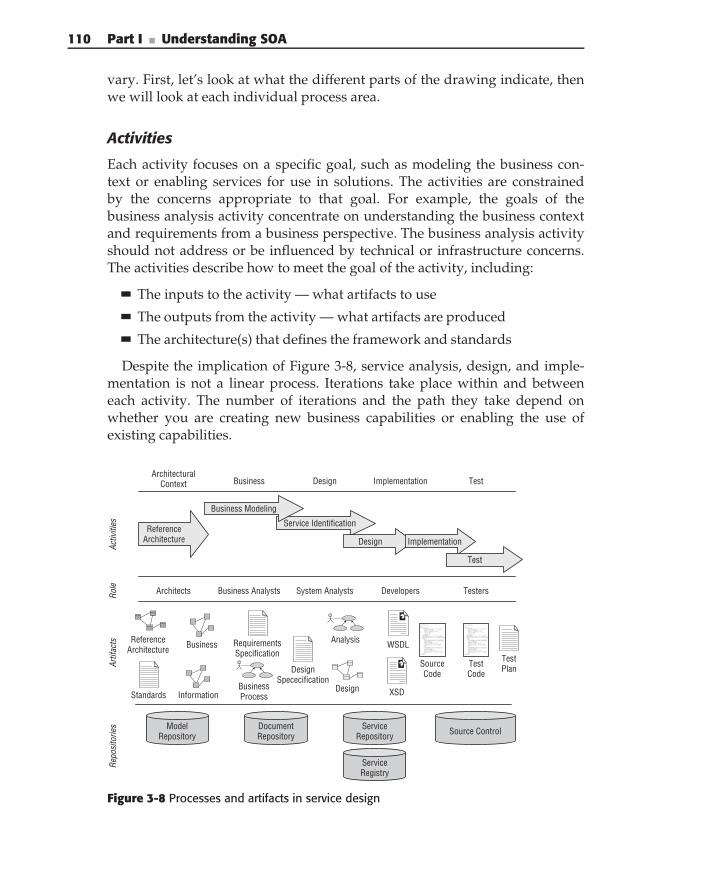
110 Part I ■ Understanding SOA
vary. First, let’s look at what the different parts of the drawing indicate, thenwe will look at each individual process area.
Activities
Each activity focuses on a specific goal, such as modeling the business con-text or enabling services for use in solutions. The activities are constrainedby the concerns appropriate to that goal. For example, the goals of thebusiness analysis activity concentrate on understanding the business contextand requirements from a business perspective. The business analysis activityshould not address or be influenced by technical or infrastructure concerns.The activities describe how to meet the goal of the activity, including:
The inputs to the activity — what artifacts to use
The outputs from the activity — what artifacts are produced
The architecture(s) that defines the framework and standards
Despite the implication of Figure 3-8, service analysis, design, and imple-mentation is not a linear process. Iterations take place within and betweeneach activity. The number of iterations and the path they take depend onwhether you are creating new business capabilities or enabling the use ofexisting capabilities.
ServiceRepository
ServiceRegistry
Business
ModelRepository
DocumentRepository Source Control
Implementation TestDesign
Repo
sito
ries
Artif
acts
Activ
ities
ArchitecturalContext
Business
Standards
ReferenceArchitecture
Information
RequirementsSpecification
Analysis
Design
WSDL
XSD
DesignSpececification
TestPlanSource
CodeTestCode
Role
Service Identification
Design Implementation
Test
Business Modeling
ReferenceArchitecture
Architects Business Analysts System Analysts TestersDevelopers
BusinessProcess
Figure 3-8 Processes and artifacts in service design
Chapter 3 ■ Getting Started with SOA 111
Artifacts
Every activity has inputs and outputs, whether it is a manufacturing process,a business process, or a software development activity. The general term forinputs to and outputs from the activity is artifacts. Artifacts may take manyforms from specifications to models to executable code or test plans. Thearchitecture, guidelines, and governance specify which artifact to use as inputfor a particular step of the process, and what artifact is produced or modifiedas an output from the step.
Repositories
The repositories indicate where specific artifacts are stored and managed. Noticethat the overall process requires a variety of different repository technologies.Integration of these repositories represents a challenge to most tools andorganizations.
Governance
Governance is an important aspect of the management of the overall process.The governance policies and procedures determine what artifacts are requiredat what point in the process. Governance also provides mechanisms to comparespecific artifacts against standards to determine if a project is ready to enterthe next phase. In each phase, the governance consists of a set of guidelines,examples, and standards to encourage compliance, and a review process tovalidate it.
Process PhasesThe top of Figure 3-8 lists the high-level process phases involved in the overalldevelopment of services and SOA solutions.
Architectural Context
This is the early stage of SOA, where the organization is developing thereference architecture. Typically, this is done by the architecture team, whois responsible for producing a variety of architectural artifacts, including:the reference architecture, standards, business model, and semantic informa-tion model. The artifacts produced during this phase are at an enterprisescope and not limited to a specific project. Typically, this phase is done oncefor the enterprise, while subsequent phases of the process are done once foreach project. There is however a feedback loop that continually updates thearchitecture and keeps it current. A model repository may be used to store andcoordinate all the models.
112 Part I ■ Understanding SOA
Business
This is where you do the bulk of the business analysis and business processdesign. Typically, the activities of this phase are performed by a businessanalyst. The design phase overlaps with the architecture phase around thedevelopment of the business and information models. Often the architectscreate the initial, high-level models, and the business analysts fill them out withthe next level of detail while working on a specific project. The primary artifactof this phase is business process models. In addition, some organizations mayproduce requirement specifications. The business phase provides the initialinput for service identification.
Design
During design, you complete the service identification and service specifica-tion. These activities are usually carried out by a system analyst, who createsanalysis and design models that describe the details of the service interfaceand implementation design, including the documents that are part of theirinterfaces. A design document or service specification document may option-ally be produced. Service interfaces may be described in WSDL, and interfacedocument schemas may be described in XSDs. A design-time service reposi-tory may be used to support searching for services according to informationfrom their specifications.
Implementation
This is where the actual service implementation is done. Developers writesource code to implement the service. This may include business components,integration access, SCA, and BPEL. A source code repository should be usedto manage the source code. The run-time registry may also begin to be used toregister the executable instance of the services.
Test
You should not forget testing and other preparations before a service can beput into production. This stage is usually carried out by test developers or alldevelopers (depending on the testing strategy). Often, a test plan is written toguide the testing activities, or an agile approach may be followed. Artifactsproduced are tests that are managed from a testing framework and stored ina source code repository.
No lines have been drawn between phases because the boundary betweenactivities, and what role produces what artifacts, is naturally fuzzy. Theimportant thing is to come up with a process that works for your organizationand meets your goals. Experience has shown that the process at more matureorganizations contains most of the elements of Figure 3-8.
Chapter 3 ■ Getting Started with SOA 113
Practical steps
As we have described in this chapter, there are a lot things that need to be con-sidered for practical SOA implementations, including business, organizational,and technical changes. So when you decide to embark on an SOA implemen-tation, the typical question is where to start. On the one hand, the linkage ofSOA to the enterprise business model implies that an enterprise-wide SOAimplementation is the most beneficial, providing the majority of SOA benefits.On the other hand, the sheer complexity of such an approach typically makesit impractical; it requires a lot of things to be in place and creates too muchrisk.
A common approach, advocated by many authors, is to start small and thenorganically grow SOA. Although it seems very attractive from the point ofview of containing the risks and providing a good learning experience forthe enterprise, such an undertaking too often provides very few benefits. Theissue here is not that the choice is always wrong, but the fact that the projectsare more concerned with the delivery speed than with setting up a foundationfor future SOA growth. In fact, many of these projects are more concernedwith creating Web Services, than SOA experience. They are often treated astechnology, not the first steps in establishing SOA. Typical mistakes that occurin technology-driven implementations are:
No attempt is made to align the implementation to the enterprise busi-ness model. This usually manifests itself where analysis is only con-cerned with the scope of the project, not the broader enterprise. (Thisis exactly the same as the good old application-centric approach, usinga new technology: Web Services.) As a result, service definitions andimplementation are application-specific, and their use (and reuse) on theenterprise level is extremely limited.
As a result of skipping the business-model-based design, and the limitedscope of analysis, business semantics are rarely introduced.
Service definitions become significantly less important. Implementa-tion involves a limited set of developers and business analysts, who dealwith ambiguities through day-to-day discussions. Moreover, becauseservices are limited in scope to a particular application, precise servicecontract definitions are not considered important. The absence of preciseservice definitions often leads to the absence of service registries. On thissmaller scale, a repository is often considered as a waste of money andresources.
Buy versus build versus outsource issues are rarely discussed. Becausethey are often not based on the enterprise business strategy, they typi-cally come as predetermined requirements to the project implementation.
114 Part I ■ Understanding SOA
Because of the limited scope of the project, which is often run by oneor two project managers, the role of service governance is often viewedas an unnecessary overhead — a smaller scope requires significantly lesscoordination.
This does not necessarily mean that an approach that starts enterprise SOAimplementations from small contained projects is wrong. In fact, we think itcan be a practical approach. But, it only works when an enterprise SOA contextand vision (the minimum architecture described earlier) is established first.In addition, common pitfalls just described should be avoided, and commonfactors in the following list considered, when choosing and planning a project:
SOA is an architecture. It is a set of best practices, not a technology.
SOA is not a panacea. It’s especially useful for increasing asset reuse,providing better business visibility, and most importantly, increasingbusiness agility in an environment of heterogeneity. But if your problemisn’t one of these, SOA may not be the right approach.
The biggest challenges with SOA are organizational, cultural, and polit-ical. People are resistant to change, to sharing assets, and to fundingeach other’s projects. Compared to these challenges, technology is theeasy part.
The core SOA challenges are governance, quality, and management.Without governance, SOA is limited to project scope. Enterprise SOAefforts are doomed to failure. Quality in the SOA context becomes anongoing, full life-cycle battle.
The business side of the house doesn’t want SOA. They want solutionsto business problems. The most successful SOA initiatives aren’t calledSOA, but are closely tied to the problem they are looking tosolve. SOA is more of the secret weapon IT brings to bear to solve busi-ness problems.
Based on these lists and the methodology presented in this chapter, werecommend that the initial SOA project decision and implementation considerthe following:
SOA implementations are not optimal for organizations with anill-defined business architecture. Make sure that business architectureis defined, at least on the level of enterprise business processes and busi-ness semantics.
Do not try to sell SOA to business leaders, but make sure that you choosea project that is sufficiently important to them. The project’s success canensure traction for SOA’s adoption and business leaders’ support.
Chapter 3 ■ Getting Started with SOA 115
Ensure proper SOA organizational support. Ensure that governanceincludes both the organizational structure and technical support,and includes a service repository.
Continue enhancing the enterprise business model. Make sure that:
Service identification directly supports (traceable to) the businessmodel and is not derived directly from existing applications’functionality.
Service interfaces are based on the enterprise semantics informationmodel.
Business processes allow for direct support and measurements of out-comes and KPIs.
Set up standards and practices for the definition and description of ser-vice contracts.
Ensure that attention is paid to the SOA infrastructure and appropriatefoundation services are designed and put in place to support implemen-tation and operations.
Use existing application capabilities in your service implementationthrough proper componentization and integration services.
Read the rest of the book for more details.
Summary
This chapter has defined the basic activities that an enterprise must engagein to create SOA solutions. First, the SOA reference architecture is the formalspecification of services, their types and characteristics, how they supportbusiness processes, and how they relate to architecture and developmentprocesses. Put a minimum architecture in place to establish the SOA visionbefore doing anything else, then continue to build it out over time.
Business architecture is key to creating flexible, reusable services, and toaligning processes and services with enterprise strategy and goals. Commonsemantics are key to enabling services to work together. Both of these need tobe created and continually updated.
Service identification uses the business and information models to driveservice design. In addition, the overall enterprise context, as described inthe service inventory, helps in identification of existing services, and in theallocation of responsibilities to new services. Service specifications describewhat a service does and how to use it. They support discovery of servicesduring service identification and business process design, and the specificationof service details for implementation.
116 Part I ■ Understanding SOA
Service realization provides the implementation of services. We describedthree major approaches to implementing services: buy, outsource, and build.When building services, we described a middle-out approach to service designthat has been proven to be more practical and effective than the traditionaltop-down and bottom-up approaches.
All of these aspects are part of an overall SOA life cycle. The life cycle issupported by the SOA methodology and enforced by SOA governance.
P a r t
IIDesigning SOA
In This Part
Chapter 4: Starting with the BusinessChapter 5: Service Context and Common SemanticsChapter 6: Designing Service InterfacesChapter 7: Designing Service ImplementationsChapter 8: Composing ServicesChapter 9: Using Services to Build Enterprise SolutionsChapter 10: Designing and Using Integration in SOA SolutionsChapter 11: SOA SecurityChapter 12: SOA Governance

C H A P T E R
4
Starting with the BusinessThe measure of success is not whether you have a tough problem to deal with, but
whether it’s the same problem you had last year.
— John Foster Dulles
The ever-elusive goal of corporations, large or small, East or West, is to align thebusiness with IT. The burden often falls on IT to demonstrate how technologyand systems provide value and help move the business forward. But what isit that IT is supposed to align with? How is it determined and specified? Andwho is responsible for it? All too often, business strategy and goals are too high-level, vague, or not well articulated. So, how can IT demonstrate alignment?
Business architecture (BA) is the key to achieving alignment. First, it pro-vides a way to clearly determine and specify a business strategy, goals, andobjectives. Then, it provides a way to measure outcomes against those objec-tives, and finally, it provides a way to specify business processes that achievethose outcomes. An effective architecture also provides traceability from theprocesses to the outcomes to the objectives to the strategy. It is this traceabilitythat demonstrates alignment.
There are two different, but important, sets of questions that must beanswered by business architecture. One set of questions applies at the enter-prise level. What are the goals and strategies of the business? How will they bemeasured? This is the domain of enterprise business architecture. A differentset of questions applies to individual projects. What are the processes, activi-ties, services, and information needed for a specific project or solution? This isthe domain of project business architecture.
In this chapter, we introduce both areas of business architecture. Theenterprise business architecture determines the overall context that individual
119
120 Part II ■ Designing SOA
projects must work within, so this is addressed first. The project business archi-tecture determines the business details of individual projects, in particular, thedesign of business processes, and this is addressed second.
Business processes need to change relatively frequently, yet be based onstable underlying capabilities. The flexibility to do this comes from beingable to quickly construct business processes from stable and precise businessbuilding blocks. These building blocks need to be expressed in businessterms, be usable without detailed knowledge of their implementation, andbe sufficiently interoperable and variable so that they can be combined andrecombined as the needs of the business change.
The promise of SOA to the businessperson is this very ability to createand modify business processes from business services — software componentsthat are realizations of the basic business building blocks. It is essentially amanufacturing paradigm in which you create new systems by assemblingexisting components.
SOA may be a relatively recent phenomenon, but the concept of buildingnew systems using existing components is as old as engineering itself. Thechallenge in successful component-based engineering (and SOA) is twofold:creating the right components (services) and having a foundation for reliablyusing those components. Unfortunately, too many IT efforts focus on thefoundation, without paying adequate attention to the former, the businessaspects of SOA. Without the right building blocks, even the best foundation isnot that useful.
So, to effectively deliver business agility with SOA, you need to find andcreate the right business services. To do that, you need to find the businesscapabilities (operations and data) that form the basis for the services. Youcan approach this by business process modeling, a classic way of identifyingbusiness activities and the role of the project business architecture. But,for those services to be flexible and reusable across processes, to deliver onthe promise of SOA, they also have to be identified within the context of theenterprise. This is the role of enterprise business architecture in SOA design.
This chapter introduces the basics of business architecture and businessprocess modeling — not a detailed course, just enough to show how to under-stand the business motivation and to derive good business services fromreal-world business processes. It provides techniques for getting started withthe models, explains the individual elements, and relates them to their realiza-tion as services. Finally, we introduce techniques for organizing these servicesby business organization, structure, and subject matter. We call this approachstarting from the business, including:
Business architecture
Value chains and context diagrams
Business Motivation Model (BMM)
Chapter 4 ■ Starting with the Business 121
Business Process Models (BPMs)
BPM and SOA
Organizing services
Business Architecture
What is business architecture? Although there are many available definitions,here are a few that we found useful:
A rather wordy, but descriptive definition comes from the USDA:
The business architecture represents the functions and processes that support thebusiness, the organizations that perform the business, the locations where thebusiness is performed, and the factors that could cause the business to change.In other words, the business architecture addresses how the mission-criticalfunctions of the organization are accomplished. It is a portrayal of how the orga-nization actually accomplishes its mission rather than how it is organizationallystructured to manage its mission. The business architecture also encompassesa strategic direction that an organization strives to attain. Major influences onthe business architecture are laws and regulations, external and internal poli-cies, organizational structures, organizational culture, business change, people,budgets, and technology drivers. This layer ignores any physical constraints andcontains no element of system design.
The Open Group describes the business architecture view as:
Addressing the concerns of the users including consideration of the following:
People — the human resource aspects of the system. It examines the humanactors involved in the system.
Process — deals with the user processes involved in the system.
Function — deals with the functions required to support the processes.
Business Information — deals with the information required to flow in sup-port of the processes.
Usability — considers the usability aspects of the system and itsenvironment.
Performance — considers the performance aspects of the system and its envi-ronment.
The business architecture view is derived from business scenarios, whereeach scenario is defined by describing the problem, environment, objective,human actors, system actors, and roles and responsibilities.
Finally, for a more succinct definition, you can turn to the recent article‘‘Business Architecture: Aligning Strategy and Deployment’’ by William Ulrich
122 Part II ■ Designing SOA
(BPMInstitute, June 2, 2006), which describes business architecture as‘‘Conceptual views & physical instantiations of business strategy, governancestructures, and processes — across the extended value chain.’’
What all of these definitions have in common are the concepts of strategy,organization, and business processes. In other words, the business architecturetranslates the business strategy into actionable processes. When you look intosome details of this, you see that it involves people and systems (the actors andtheir organizations), information and information flow, and business processesand activities.
Not surprisingly, you see these same elements if you examine some of thestandard ways of representing business architecture. For example, a businesscontext diagram (see Figure 4-3) illustrates users, organizations, boundariesand information flows between them. A value chain diagram (see Figure 4-2)shows organizations and the chain of processes and information that providebusiness value. A business process diagram (see Figure 4-6) shows the sequenceof processes executed by different organizational units, and the informationflow between them.
Business architecture allows an organization to envision and articulate theessence of their organization while creating tangible ways to align businessarchitecture with IT architecture. Business architecture enables a business tovisualize, analyze, redefine, and reengineer the way it functions and commu-nicates internally, with business partners, and with IT.
In other words, business architecture focuses on aligning business strategywith IT implementation, by:
Identifying goals and strategy
Identifying organizational structures and governance and their impacton strategy
Applying the strategy across the entire enterprise
Aligning with external entities
Identifying quantifiable outcomes to measure the strategy
Identifying the processes, rules, and information necessary to supportthe outcomes
Managing and synchronizing the process model, business rules model,and information models:
Applying business architecture context to individual projects
Acting as a bridge between enterprise context and individual projectrequirements
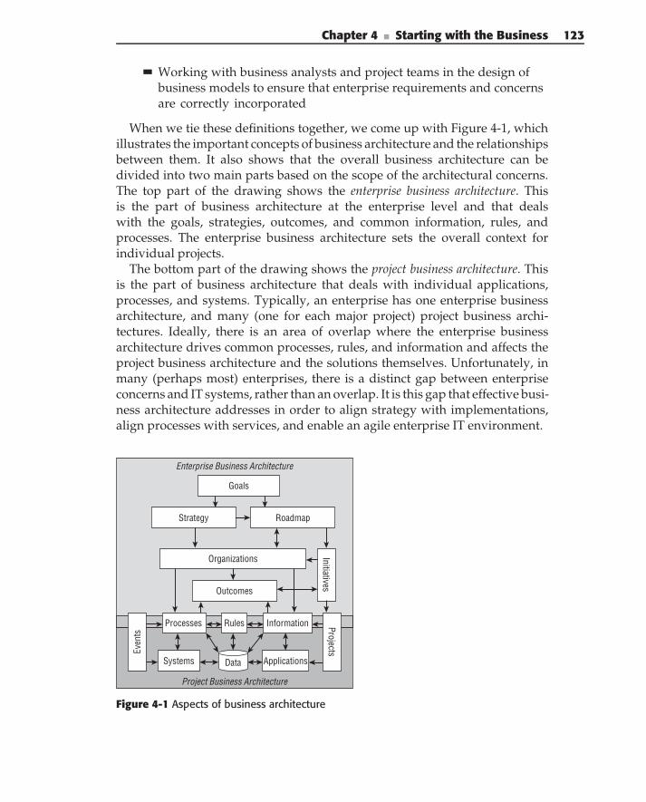
Chapter 4 ■ Starting with the Business 123
Working with business analysts and project teams in the design ofbusiness models to ensure that enterprise requirements and concernsare correctly incorporated
When we tie these definitions together, we come up with Figure 4-1, whichillustrates the important concepts of business architecture and the relationshipsbetween them. It also shows that the overall business architecture can bedivided into two main parts based on the scope of the architectural concerns.The top part of the drawing shows the enterprise business architecture. Thisis the part of business architecture at the enterprise level and that dealswith the goals, strategies, outcomes, and common information, rules, andprocesses. The enterprise business architecture sets the overall context forindividual projects.
The bottom part of the drawing shows the project business architecture. Thisis the part of business architecture that deals with individual applications,processes, and systems. Typically, an enterprise has one enterprise businessarchitecture, and many (one for each major project) project business archi-tectures. Ideally, there is an area of overlap where the enterprise businessarchitecture drives common processes, rules, and information and affects theproject business architecture and the solutions themselves. Unfortunately, inmany (perhaps most) enterprises, there is a distinct gap between enterpriseconcerns and IT systems, rather than an overlap. It is this gap that effective busi-ness architecture addresses in order to align strategy with implementations,align processes with services, and enable an agile enterprise IT environment.
Project Business Architecture
Enterprise Business Architecture
Systems ApplicationsData
Outcomes
Strategy Roadmap
Initiatives
Goals
Organizations
InformationProcesses
Even
ts
Rules Projects
Figure 4-1 Aspects of business architecture
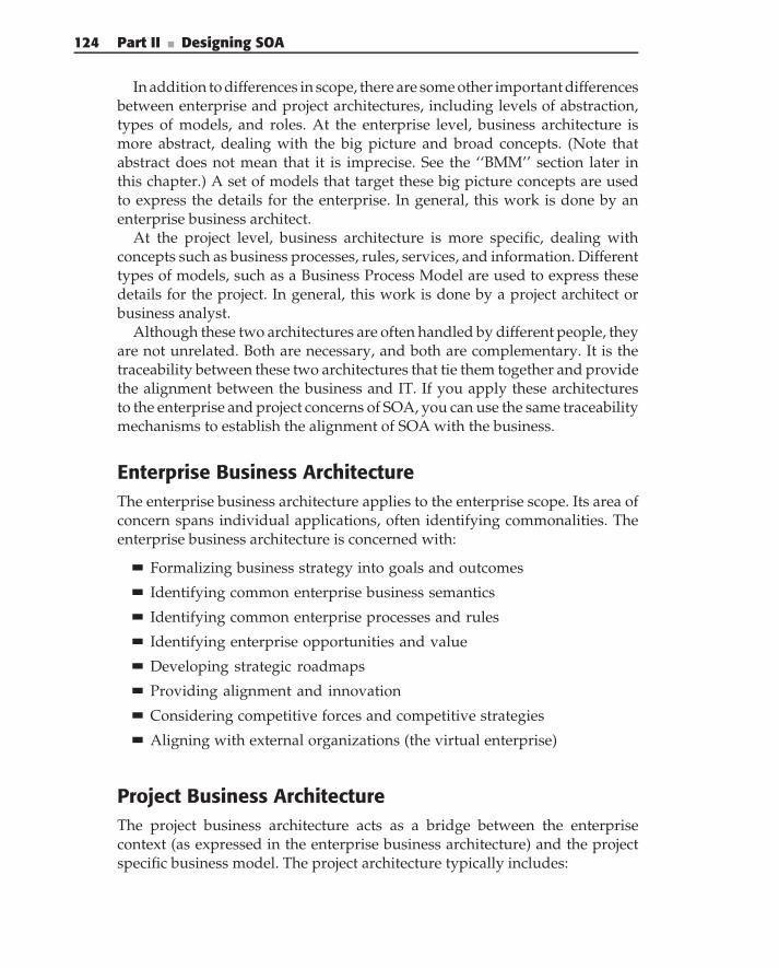
124 Part II ■ Designing SOA
In addition to differences in scope, there are some other important differencesbetween enterprise and project architectures, including levels of abstraction,types of models, and roles. At the enterprise level, business architecture ismore abstract, dealing with the big picture and broad concepts. (Note thatabstract does not mean that it is imprecise. See the ‘‘BMM’’ section later inthis chapter.) A set of models that target these big picture concepts are usedto express the details for the enterprise. In general, this work is done by anenterprise business architect.
At the project level, business architecture is more specific, dealing withconcepts such as business processes, rules, services, and information. Differenttypes of models, such as a Business Process Model are used to express thesedetails for the project. In general, this work is done by a project architect orbusiness analyst.
Although these two architectures are often handled by different people, theyare not unrelated. Both are necessary, and both are complementary. It is thetraceability between these two architectures that tie them together and providethe alignment between the business and IT. If you apply these architecturesto the enterprise and project concerns of SOA, you can use the same traceabilitymechanisms to establish the alignment of SOA with the business.
Enterprise Business ArchitectureThe enterprise business architecture applies to the enterprise scope. Its area ofconcern spans individual applications, often identifying commonalities. Theenterprise business architecture is concerned with:
Formalizing business strategy into goals and outcomes
Identifying common enterprise business semantics
Identifying common enterprise processes and rules
Identifying enterprise opportunities and value
Developing strategic roadmaps
Providing alignment and innovation
Considering competitive forces and competitive strategies
Aligning with external organizations (the virtual enterprise)
Project Business ArchitectureThe project business architecture acts as a bridge between the enterprisecontext (as expressed in the enterprise business architecture) and the projectspecific business model. The project architecture typically includes:
Chapter 4 ■ Starting with the Business 125
Context diagrams
Process models
Information models
Integration of enterprise semantics into project models
Integration of enterprise semantics, common processes, and services intothe project design
Value ChainOne way to get started with the business is to create a business value chain.The value chain was first developed by Michael Porter and described inhis 1985 book Competitive Advantage. Figure 4-2 illustrates a sample extendedvalue chain. (Note that this format of the value chain has evolved from Porter’soriginal. The format we use is called an extended value chain.)
The value chain is divided into two main sets of activities. The activitieson the bottom are called supporting activities. These are things like HR andfinance that must be in place to keep the company operating, but that do notadd value to the products or services. (Note that in Porter’s version of thevalue chain, he lists the supporting activities on the top. We have moved themto the bottom because they are not the focus of the corporation.)
Project/Process Management
Channels
Shopping and
Content
Inventory Management
Add-On Marketing and Sales
Pricing and Yield
OptimizationReservations
Primary Activities
Core Business Process
Process Management
Payment Management
Product Information
“. . . to provide premium travel content and reservation services”
Planning andReservations
Goal
Supporting (Financial, HR, IT, . . .) Assets
HR Management
Financial Management
IT Management
Administration Management
SupportingActivities
Support Asset Info
Supporting Processes
Billing and Payment
Figure 4-2 Extended value chain
126 Part II ■ Designing SOA
The top part of the diagram describes the primary activities. The mainbusiness that our example company is involved in is Trip Planning andReservations. This is composed of five main value adding activities: Shoppingand Content, Inventory Management, Add-on Marketing and Sales, Price andYield Optimization, and Reservations. These make up the primary activity, asidentified by the arrow which connects the steps and ties them to the goals.(This is the traditional value chain.)
In addition, the primary activities consist of management functions such asProcess/Project Management, Channel Management, Billing and Payments,and Information Management. These are all necessary to keep the primary valuechain going, but do not provide specific value added services to the product.
We find that the value chain is useful for identifying the different functionalareas of the company and focusing attention on the most important of them.It is a good mechanism for bringing out the goals and objectives. As well,it starts to identify areas of services. For example, each different step orprimary activity in the value chain is likely to have one or more service groupsassociated with it. This provides a first step in creating a service inventory.
Business ContextThe value chain provides one enterprise-level perspective on the operationsof the business. You also know that business operations inside and outside ofthe enterprise are made up of interactions and exchanges of informationbetween parties. To describe the overall set of interactions, you use a businesscontext diagram, as illustrated in Figure 4-3. The context diagram includes themajor parties, represented by the rounded rectangles, and the messages thatthey exchange, represented by the arrows. You create the context diagram bytalking with the business analysts and walking through all of the differentinteractions required for end-to-end capabilities.
The context diagram is made up of the following semantic elements:
Actors — The main parties of the interactions, (the rounded rectangles).Typical actors are people, organizations, or systems.
Messages — Information exchanged between actors (the arrows). Mes-sages are typically documents, packages, electronic communications,and the like.
Subjects — The business matters that the messages are about. The sub-jects are not explicit in the drawing, but are implied by the interactionsand messages. Subjects are typically things like products and services.
You can think of a shipping package (such as a box from a bookseller) as ametaphor for these elements of the context model. The package has a shippinglabel with From and To addresses. These are the actors. The package box itself(to which the labels are attached) is like the message. It moves between the
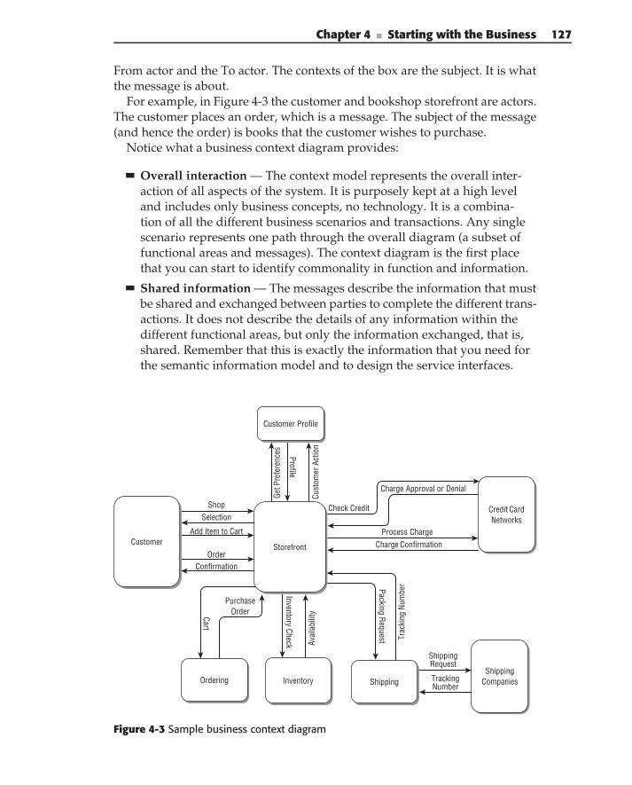
Chapter 4 ■ Starting with the Business 127
From actor and the To actor. The contexts of the box are the subject. It is whatthe message is about.
For example, in Figure 4-3 the customer and bookshop storefront are actors.The customer places an order, which is a message. The subject of the message(and hence the order) is books that the customer wishes to purchase.
Notice what a business context diagram provides:
Overall interaction — The context model represents the overall inter-action of all aspects of the system. It is purposely kept at a high leveland includes only business concepts, no technology. It is a combina-tion of all the different business scenarios and transactions. Any singlescenario represents one path through the overall diagram (a subset offunctional areas and messages). The context diagram is the first placethat you can start to identify commonality in function and information.
Shared information — The messages describe the information that mustbe shared and exchanged between parties to complete the different trans-actions. It does not describe the details of any information within thedifferent functional areas, but only the information exchanged, that is,shared. Remember that this is exactly the information that you need forthe semantic information model and to design the service interfaces.
ShopSelection
ConfirmationOrder
Add Item to Cart
Check Credit
Charge Approval or Denial
ShippingRequest
TrackingNumber
Get P
refe
renc
es Profile
Cust
omer
Act
ion
Cart
Purchase Order
Inventory Check Avai
labi
lity
Process ChargeCharge Confirmation
Packing Request Trac
king
Num
ber
Customer
Credit Card Networks
Shipping CompaniesOrdering
Storefront
Inventory Shipping
Customer Profile
Figure 4-3 Sample business context diagram
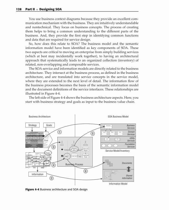
128 Part II ■ Designing SOA
You use business context diagrams because they provide an excellent com-munication mechanism with the business. They are intuitively understandableand nontechnical. They focus on business concepts. The process of creatingthem helps to bring a common understanding to the different parts of thebusiness. And, they provide the first step in identifying common functionsand data that are required for service design.
So, how does this relate to SOA? The business model and the semanticinformation model have been identified as key components of SOA. Thesetwo aspects are critical to moving an enterprise from simply building services(which at best may incidentally work together), to having an architecturalapproach that systematically leads to an organized collection (inventory) ofrelated, non-overlapping and composable services.
The SOA service and information models are directly related to the businessarchitecture. They intersect at the business process, as defined in the businessarchitecture, and are translated into service concepts in the service model,where they are extended to the next level of detail. The information flow ofthe business processes becomes the basis of the semantic information modeland the document definitions of the service interfaces. These relationships areillustrated in Figure 4-4.
The left side of Figure 4-4 shows the business architecture aspects. Here, youstart with business strategy and goals as input to the business value chain.
Business Architecture SOA Business Model
GoalsStrategy
Information
Business Process
Customer Quoting Underwriting
QuoteRequest
RiskQuote
UW Requtes
DomainServices
UtilityServices
FoundationServices
Service Model/Inventory
Information Model
BusinessServices
Documents
SharedInformation
Quote
Business Service
DomainnDomain2Domain1
Utility1 Utilityn
Quote
Quote
Customer Usage & Quality
Project/Process Management
Network Research & Quality
Network Infrastructure Assets
ForecastingNetwork/ProductPlanning
CapitalEquipmentAcquisition
ConstructioNetwork
Monitoring
CustomerOrder
ServiceProvisionin
CustomerService
CustomerBilling
Real-timeOperations
“…to provide apremiumcommunicationsnetwork andcustomer services”
telecomnetworkcustomerservice
Goal
Supporting (Financial, HR, IT, . . .) Assets
HR ManagementFinancial Management
IT ManagementAdministration Management
1
2
4
3
6
5
RequestQuote
UnderwriteRequest
Create RiskProfile
Create Quote
Insured PartyName: StringPrimaryAddress: AHomePhone:WorkPhoneMobilePhone: Phone...DoB: Date: Phone...MaritalStatus: Marit..Gender
DriverIdentification
State: StringLicenseNumber: String
CoInsured
Relationship: Relation...
Product
ProductIdentifier: Prod…
ProductType: Product:
InsuredItem
VehicleVIN: VINMake: StringModel: StringYear: StringStyle: VehicleStyleCode
VehicleUsage
Usage: VehicleUsageCO...YearlyMiles: IntBusiness: Boolean
CoverageCoverage: CoverageT...Detail: CoverageDesc...Name: String
Limit
LimitAmount: C...
Deductable
Deductable: A...
R11 1
R110
related by
R1
0..*
Product
0..*
0..*
R1
1
1..*
R1
1
1
R1
1
1. . *
R1
1
1R1
1
1
R1
1
1
PrimaryDriver
Customer
BillingAddres: Addre...CustomerID: Custom...
Figure 4-4 Business architecture and SOA design
Chapter 4 ■ Starting with the Business 129
The value chain helps you to identify the major areas of business activities,and to prioritize them in terms of importance and value creation. For each ofthese major areas, you need to specify the next level of details.
You use the business context model to identify the major parties, major areasof business capability, and the interactions between them. The context modelleads directly to identification of the information model and specific BusinessProcess Models.
The steps are fairly straightforward. (The numbers in the following listcorrespond to the numbers in Figure 4-4.) First, you establish the overallcontext:
1. The overall set of processes, as identified by the value chain, and the setof all context models provides the enterprise SOA context that is repre-sented in the service inventory.
2. The enterprise information model describes the superset of informationthat is needed to be shared between services. This becomes the basis forthe more detailed semantic information model.
Next, you refine context models into process models or scenarios:
3. Parties or functional areas in the context model become actors in theBusiness Process Models.
4. Messages in the context model become data that is passed into and outof the business processes.
Finally, you focus on the specific business processes:
5. Activities in the business processes are implemented by operations onservices. The services fit within an overall service hierarchy, but at thislevel you are primarily identifying business services.
6. Inputs and outputs of the business processes become documents that arepassed through service interfaces. The documents are derived from thesemantic information model.
Note that the business architecture is purposely devoid of IT specifics, andthat the business services are the realization of those business requirements inIT terms. Clearly, these are related (they better be), but they are not exactly thesame.
We have described the relationship for a single process, but of course thebusiness architecture and the service model are concerned with the totality ofprocesses, services and information. They are concerned with the present, thenear term, and the long term. Thus, the business model must identify all ofthe processes and information that exist today, those that are currentlyplanned or being implemented, and the processes and information that areneeded over time to realize the business strategy and goals.
130 Part II ■ Designing SOA
Likewise, the SOA business model must describe today’s services, doc-uments, and information (those currently being implemented) and futureservices and information (those that provide the business capabilities requiredof the future business processes). In other words, the SOA service modelis directly influenced by the business strategy and must identify services toprovide all the capabilities required of that strategy. And, the SOA informationmodel is directly influenced by the business information and must identify allof the information required for the future processes.
Of course, the level of detail, in which current processes, services, andinformation are described, is much greater than for the future. In your mod-els, you do not need to (nor can you) identify every detail of the future.But, you must identify enough about your future needs to set the rightdirection now.
The SOA business model has some other important goals. It has to managethe sharing of services and information across processes. In other words, itneeds to eliminate redundancy, overlap, and gaps between services. Thatensures that each business capability is implemented once, by the organiza-tional unit that is responsible for that capability, and that those services areused by all the different processes needing those capabilities. In addition, allof the information shared between services must be identified in the semanticinformation model. In other words, all services that are related to the samebusiness concepts must use the same information to describe the same con-cepts. Finally, the SOA business model must ensure that all of the informationpassed into and out of the business services (mostly in the form of documents)is defined in the semantic information model.
You have looked at several different definitions of business architectureand identified some common components of strategy, processes, and infor-mation. Then, you looked at how these aspects of the business architectureare related to SOA. At the business architecture level, you need to ensurethat your business architecture is internally consistent. That strategy, goals,organization, and so on are realized as processes and information. Then, youneed to make sure that the business architecture is consistent externally withthe SOA model, that it drives the long-term vision, and that you have completeand consistent traceability from strategy to process to task to implementationas a business service. For this, you use a Business Motivation Model.
THE TECHNOLOGY OF BUSINESS ARCHITECTURE
Okay . . . hold on . . . what the heck are they talking about now, you ask? Well,it’s not exactly technology, but we want to talk about the formal architecturalunderpinnings of BA.
Chapter 4 ■ Starting with the Business 131
We say that service design should be driven by the business, or to be moreprecise, we say that BA must answer the following questions: What businessare you in? What are the goals and objectives of this particular business? Whatoutcomes are needed to achieve those goals? What is the strategy for achievingthem? How will they be measured? What capabilities and information areneeded to achieve those outcomes? What processes, services, entities, andrules are needed to implement those capabilities? What existing applicationsprovide basic capabilities and information? Although this is where we usuallystop, others might add: What organizational structure do you need to supportthem? What initiative, programs, and projects do you need to create, enhanceand maintain them?
All good questions, so, how do you describe all of these things? Architectureshould have two complementary views: a conceptual view, usually as a Visiodiagram, designed to communicate concepts to a particular audience; and aformal view, usually as a formal model, designed to be a precise specificationof the architecture that can be implemented and validated. If you use astandard notation, the formal model will use standard definitions andnomenclature that allow for common/shared understanding among architectswho are conversant in the notation. For example, if the modeling notationformally defines what strategy means, then you have removed ambiguity aboutthe meaning of strategy. Rather than debate what strategy means, you caninstead focus on the contents of a particular strategy.
The Business Motivation Model (BMM) specification, published by the ObjectManagement Group (OMG) provides the underlying architectural metamodelfor describing much of the concepts mentioned previously. Tying it to ourexample, the BMM explicitly defines the following concepts: goals, objectives,strategy, tactics, policies, rules, and assessments.
You might ask why bother with the value chain at all? Can’t you do everythingit does in the BMM? Well yes, but there’s a catch. Business people and execu-tives are familiar with the value chain. It is easily recognizable and intuitive tothe business. And who is the audience for this part of the business architecture?Although the BMM is more precise, often, it is considered too technical by theintended audience and simply dismissed. Is it fair? No. Is it reality? Yes. Anyonewho has tried to show a UML model to a businessperson knows what I’mtalking about.
The next question is how do you define the business processes? There arelots of proprietary versions of Business Process Models, and you could useone of them if you’ve already invested in a tool set, or you could use theemerging standard, Business Process Modeling Notation (BPMN). The notationitself is a standard way to represent and diagram business processes in visualmodels. It is based on an underlying metamodel called the Business Process
(continued)
132 Part II ■ Designing SOA
THE TECHNOLOGY OF BUSINESS ARCHITECTURE (continued)
Definition Metamodel (BPDM). (Both BPMN and BPDM are described on theOMG page listed previously.) So, why have two separate specifications? Toquote the OMG:
BPDM provides the capability to represent and model business processesindependent of notation or methodology, thus bringing these differentapproaches together into a cohesive capability. This is done using a metamodel — a model of how to describe business processes — a kind of sharedvocabulary of process with well defined connections between terms andconcepts. This meta model captures the meaning behind the notations andtechnologies in a way that can help integrate them and leverage existingassets and new designs.
Earlier, it was stated that architecture must answer three importantquestions: 1) What are the important concepts? 2) What are the relationshipsbetween them, and how do those relationships describe the behavior of thesystem? 3) How does the system provide value (beyond the value of any singlepart)? This is essentially what these modeling specifications do. They define theimportant concepts, and they define the relationships between them. But, theydo it in a standard way, so that people don’t have to reinvent those concepts.Thus, the meaning is clear to everyone who knows the notation, and tools canimplement and exchange standard models.
Just one word of advice, when talking to the business about businessarchitecture, it’s probably best to leave all these metamodel details out of theconversation.
Understanding the Business Motivation Model
The Business Motivation Model (BMM), published by the Business RulesGroup and the Object Management Group (OMG) provides the underly-ing architectural metamodel for describing many of the concepts mentionedearlier. Version 1.3, the current version of the specification, was released inSeptember 2007 (www.omg.org/technology/documents/br pm spec catalog
.htm). (Note: Some of the description of the model’s concepts in this sectionare paraphrased from the specification.)
There are two major areas of the BMM:
The Ends and Means of business plans — Among the Ends are thingsthat the enterprise wishes to achieve — for example, Goals and Objec-tives. Among the Means are things the enterprise uses to achieve thoseEnds — for example, Strategies and Tactics.
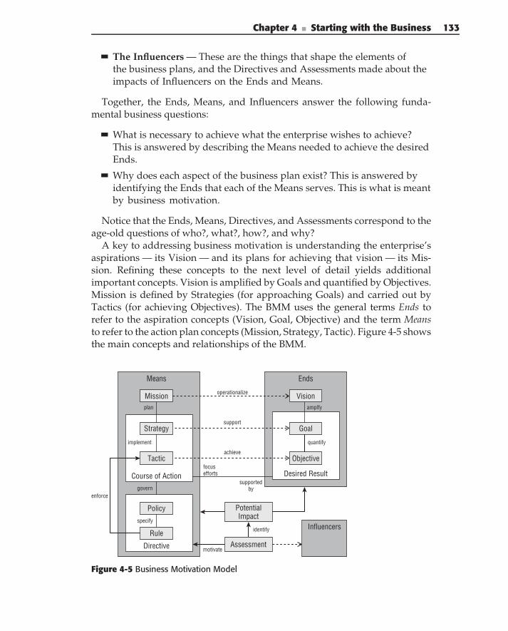
Chapter 4 ■ Starting with the Business 133
The Influencers — These are the things that shape the elements ofthe business plans, and the Directives and Assessments made about theimpacts of Influencers on the Ends and Means.
Together, the Ends, Means, and Influencers answer the following funda-mental business questions:
What is necessary to achieve what the enterprise wishes to achieve?This is answered by describing the Means needed to achieve the desiredEnds.
Why does each aspect of the business plan exist? This is answered byidentifying the Ends that each of the Means serves. This is what is meantby business motivation.
Notice that the Ends, Means, Directives, and Assessments correspond to theage-old questions of who?, what?, how?, and why?
A key to addressing business motivation is understanding the enterprise’saspirations — its Vision — and its plans for achieving that vision — its Mis-sion. Refining these concepts to the next level of detail yields additionalimportant concepts. Vision is amplified by Goals and quantified by Objectives.Mission is defined by Strategies (for approaching Goals) and carried out byTactics (for achieving Objectives). The BMM uses the general terms Ends torefer to the aspiration concepts (Vision, Goal, Objective) and the term Meansto refer to the action plan concepts (Mission, Strategy, Tactic). Figure 4-5 showsthe main concepts and relationships of the BMM.
Means Ends
Course of Action
Directive
Desired Result
Strategy
Tactic Objective
Goal
Rule
Policy
VisionMission
supportedby
focusefforts
implement quantify
plan
govern
specify
operationalize
enforce
amplfy
support
achieve
Influencers
Assessmentmotivate
PotentialImpact
identify
Figure 4-5 Business Motivation Model
134 Part II ■ Designing SOA
EndsAn End is something the enterprise desires to accomplish. Note that an Enddescribes what will be accomplished, but not how. A Means is any device,capability, technique, restriction, agency, or method that may be called upon,activated, or enforced to achieve the Ends.
Vision
Vision is an overall image of what the organization wants to be or become. Itusually encompasses the entire organization and is long term in perspective.A Vision describes the future state of the enterprise, without regard to howit is to be achieved. A Vision is amplified by Goals. A Vision is supported oroperationalized by Missions.
Desired Results
There are two types of Desired Results that the enterprise intends to achievein order to meet its Vision: Goals and Objectives.
A Goal is a statement about a state or condition of the enterprise to bebrought about or sustained through appropriate Means. A Goal amplifies aVision — that is, it indicates what must be satisfied on a continuing basis toeffectively attain the Vision.
An Objective is a statement of an attainable, time-specific, and measurabletarget that the enterprise seeks to achieve its Goals. An Objective quanti-fies a Goal. Objectives should be SMART — specific, measurable, achievable,realistic, and time-bound.
Goals and Objectives are somewhat fuzzy concepts, but you can generallysay that a Goal tends to be longer term, qualitative (rather than quantitative),general (rather than specific), and ongoing. An Objective tends to be shortterm, quantitative, and specific, and does not continue beyond its timeframe.
Desired Results (the specific Ends) are supported by Courses of Action(specific Means), which can be either Strategies or Tactics. Generally, Goalsare supported by Strategies, and Objectives are achieved by Tactics.
MeansThe Means are the operational part of the BMM. They provide a mechanismto specify how the Vision is realized in terms of operational concepts.
Mission
A Mission indicates the ongoing operational activity of the enterprise. TheMission describes what the business is or will be doing on a day-to-day basis.A Mission is planned by Strategies.
Chapter 4 ■ Starting with the Business 135
Course of Action
A Course of Action is an approach or plan for configuring some aspect of theenterprise involving things, processes, locations, people, timing, or motivation,undertaken to achieve Desired Results. In other words, a Course of Actionfocuses efforts towards Desired Results. There are two types of Courses of Action:Strategies and Tactics.
A Strategy is one major aspect of the plan for the Mission. A Strat-egy represents the essential courses of action to achieve Ends — Goals inparticular. A Strategy usually focuses efforts toward those Goals. A Strategyis more than a resource, skill, or competency that the enterprise can use. AStrategy is accepted by the enterprise as the right approach to achieve itsGoals given the constraints and risks that the enterprise operates with. ATactic represents the detailing of Strategies. In other words, Tactics implementStrategies.
Again, Strategies and Tactics are somewhat fuzzy, but generally you cansay that Strategies tend to be longer term and broader than Tactics. Strategiesare implemented by Tactics. Strategies usually support Goals and focus efforts onObjectives. Compared to a Strategy, a Tactic tends to be shorter term andnarrower; they are Courses of Action that generally achieve Objectives.
In and of themselves, however, Courses of Action tend to be limited. Theyrequire Directives to be successfully applied in the business.
Directives
Directives describe the Policies and Rules for applying the Strategies andObjectives. In other words, Directives govern Courses of Action. Specifically, aDirective defines or constrains some aspect of an enterprise. It is intended toassert business structure or to control or influence the behavior of the business.
A Directive always has to do with constraints, governance or guidance. ACourse of Action, in contrast, identifies an active approach in moving towardthe Ends.
A Business Policy is a non-actionable Directive whose purpose is to governor guide the enterprise. Policies sharpen Tactics because they make Coursesof Action concrete at the operational level. In general, Business Policies existto govern — that is, control, guide, and shape — Strategies and Tactics. ABusiness Policy provides the basis for Business Rules.
A Business Rule is a Directive, intended to guide or influence businessbehavior, in support of Business Policy. In other words, Rules specify thePolicies. Business Rules sharpen the Business Tactics because they makeCourses of Action concrete at the operational level. Business Rules enforceTactics.
To compare the two Directives, a Business Policy tends to be less structured,less discrete, and usually not atomic — that is, not focused on a single aspect
136 Part II ■ Designing SOA
of governance or guidance. Also, a Business Policy tends to be less compliantwith standard business vocabulary, and less formally articulated. In contrast,a Business Rule is highly structured and is carefully expressed in terms ofstandard vocabulary. A Business Rule should be discrete and atomic (that is,represent only a single aspect of governance or guidance).
InfluencersOf course, the enterprise does not exist in a vacuum. You can go merrily on yourway toward implementing your objectives, but if you ignore the other forces(Influencers), you’re in for a disappointment. An Influencer can be anythingthat has the ability to affect the business, often without direct exercise ofcommand, deliberate effort, or intent. Influencers can be external or internal tothe enterprise. Typical examples of Influencers are: a competitor, a customer, asupplier, a regulation, technology, corporate infrastructure, and managementinitiatives. Specifically, the business is concerned with the Influencers that canimpact the employment of Means or achievement of Ends.
So, what are you to do about these Influencers? How do you differentiatebetween important ones and trivial ones? This impact of an Influencer isjudged in an Assessment. Influencers, the ‘‘who’’ in business requirements, areneutral — they are more or less just there until someone makes an assessmentof them as they relate to Ends and/or Means. An assessment indicates whichInfluencers are relevant to which Ends and/or Means and identifies thePotential Impact that they can have. Potential impact can be either a riskor a reward; it provides the ‘‘why’’ of business requirements — quantifyingthe value proposition. Assessments often take the form of a SWOT analysis:strength, weakness, opportunity, and threat.
Armed with this information, the enterprise can take action to address thepotential impact. Often, a Directive is specifically motivated by the potentialimpact of an Influencer.
Alignment and TraceabilityOne of the key expectations of business architecture is that it helps toalign IT with the business. You’ve all heard this statement so much that it isoften treated as little more than a cliche. But, it need not be. The BMMprovides a formal way to trace the tactics back to goals and objectives. Now,you need to take it one step further and tie IT systems to the tactics thatthey implement. For example, in SOA, business processes and services arethe IT constructs that should implement tactics. So, you can create formaltraceability between the services (IT) and the business by modeling a for-mal relationship between a service and the tactic it is intended to implement.
Chapter 4 ■ Starting with the Business 137
But why go to all of this trouble? Isn’t it the business’s job? Well yes, but itis our job as well. The business should have an idea of their strategy, goals,objectives, and tactics, but in general they will not be clear or precise enoughto trace back to. As architects, you are equipped to help the business expressthe enterprise context in terms of a formal model, which will then enable IT toboth achieve and demonstrate alignment.
N O T E There are many different ways to create and represent a businessarchitecture. What we have (very) briefly described here is only one of manypossible approaches. We find it works particularly well for determining thebusiness information necessary for SOA. Hopefully, this glimpse into businessarchitecture illustrates the value it can bring and encourages you to learn moreabout it from one of the books in our references section.
So far we have looked at the enterprise business architecture as a wayto establish and specify the overall enterprise context. Now, we turn to theproject business architecture, and specifically business processes, which usethe enterprise context and other requirements to drive to the next level of detail.
Business Process Management and Modeling
Business Process Management (BPM) empowers a business analyst to alignIT systems with strategic goals by creating well-defined enterprise businessprocesses, monitoring their performance, and optimizing them for greateroperational efficiencies. Each business process is modeled as a set of individualprocessing tasks. These tasks are typically implemented as business serviceswithin the enterprise. The BPM system provides a tool set that allows thebusiness analyst to create process models using a notation system, such asBPMN, and then performs the business process automation, or execution ofthe model, by invoking the services.
BPM provides a wonderful abstraction for building business systems. Butall too often in the past, it was used to build higher-level, more efficient, butnonetheless siloed applications, rather than contributing to an overall flexible,agile enterprise. This is where SOA comes in. SOA provides the platform ofunderlying capabilities that bridge between the business processes and theoperational resources (as shown in Chapter 2, Figure 2-1). At the businessprocess level, SOA provides interfaces that directly support executing processtasks. But it defines those interfaces within an enterprise context to supportconsistency and reuse. At the operational resource level, SOA exposes existingcapabilities as integration services.
Together, BPM and SOA provide a perfect combination for enterprisecomputing. BPM provides the higher-level abstraction for defining business
138 Part II ■ Designing SOA
processes, as well as other important capabilities for monitoring and managingthose processes. Services provide the functions that support those processes.SOA provides the capabilities for services to be combined and to support andcreate an agile, flexible enterprise. BPM without SOA is useful for buildingapplications, but it is difficult to extend to the enterprise. SOA without BPM isuseful for creating reusable and consistent services, but it lacks the ability toturn those services into an agile, competitive enterprise.
BUSINESS PROCESS MANAGEMENT OR BUSINESS PROCESS MODELING?
Wikipedia defines BPM as:
an emerging field of knowledge and research at the intersection betweenmanagement and information technology, encompassing methods, tech-niques and tools to design, enact, control, and analyze operational businessprocesses involving humans, organizations, applications, documents andother sources of information.
You can think of it as a type of process construction that emphasizes themanagement of business processes in addition to their execution. In otherwords, the focus of BPM is twofold: design and execute business processes,and manage and monitor those processes. A key benefit of BPM systems ismonitoring to ensure processes are meeting the intended business objectivesand performing auditing, reporting, and other functions.
First, a BPM system must provide for the creation of business processes. Thisis typically done through the use of a graphical tool that enables the drawing ofthe process. In other words, to create a Business Process Model. To completethe story, BPM provides a means to execute the process, as described by themodel.
Sometimes the acronym BPM is confused with that for Business ProcessModel or modeling (the act of creating the model). We have tried to consis-tently mean management when we use the BPM acronym, and to spell outmodeling.
Business process modeling is a technique for formalizing the steps of abusiness process, the people, organizations, or systems responsible for thosesteps, and the data associated with each step. BPM is particularly interestingin the context of SOA because it provides a language for utilizing reusablebusiness services. This section of the chapter focuses on business processmodeling.
Figure 4-6 shows a simple Business Process Model (using Business ProcessModeling Notation (BPMN)) of the process by which a customer orders booksfrom an online bookstore.
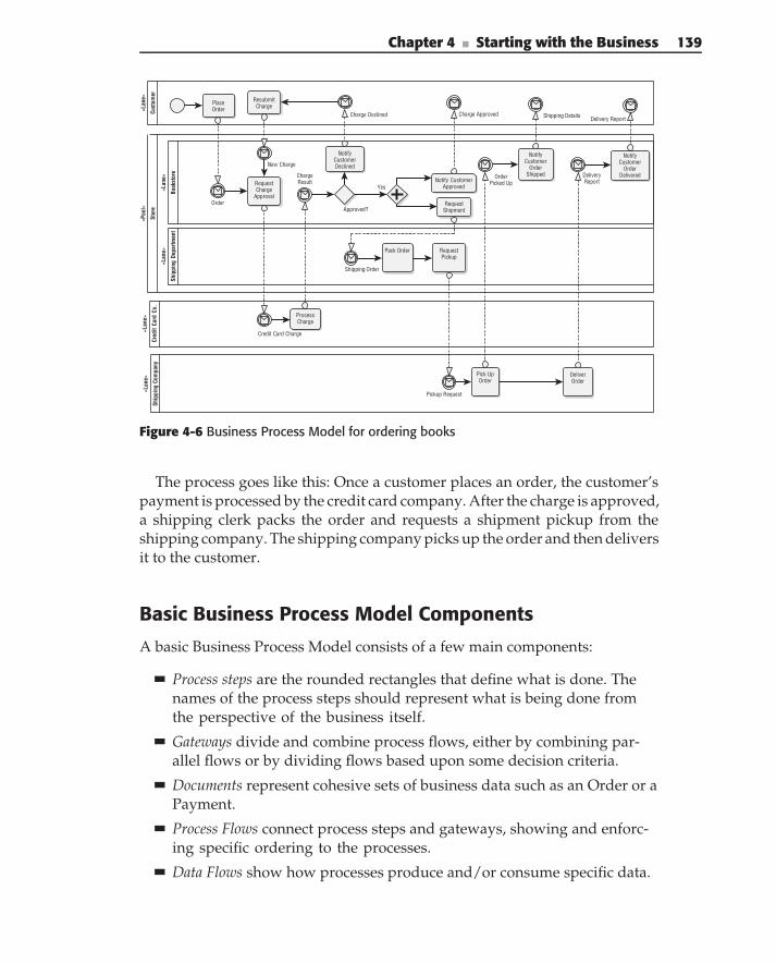
Chapter 4 ■ Starting with the Business 139
Stor
e
«Poo
l»
Book
stor
e
«Lan
e»Sh
ippi
ng C
ompa
ny
«Lan
e»
Ship
ping
Dep
artm
ent
«Lan
e»
Cred
it Ca
rd C
o.
«Lan
e»Cu
stom
er
«Lan
e»
PlaceOrder
ProcessCharge
Charge Approved
Pack Order
Pickup Request
OrderPicked Up
Shipping Details
DeliveryReport
Pick UpOrder
Order
RequestCharge
Approval
Credit Card Charge
ChargeResult
NotifyCustomer
OrderShipped
Notify CustomerApproved
RequestPickup
DeliverOrder
NotifyCustomer
OrderDelivered
Delivery Report
RequestShipmentApproved?
Shipping Order
NotifyCustomerDeclined
Charge Declined
ResubmitCharge
New Charge
Yes
Figure 4-6 Business Process Model for ordering books
The process goes like this: Once a customer places an order, the customer’spayment is processed by the credit card company. After the charge is approved,a shipping clerk packs the order and requests a shipment pickup from theshipping company. The shipping company picks up the order and then deliversit to the customer.
Basic Business Process Model Components
A basic Business Process Model consists of a few main components:
Process steps are the rounded rectangles that define what is done. Thenames of the process steps should represent what is being done fromthe perspective of the business itself.
Gateways divide and combine process flows, either by combining par-allel flows or by dividing flows based upon some decision criteria.
Documents represent cohesive sets of business data such as an Order or aPayment.
Process Flows connect process steps and gateways, showing and enforc-ing specific ordering to the processes.
Data Flows show how processes produce and/or consume specific data.
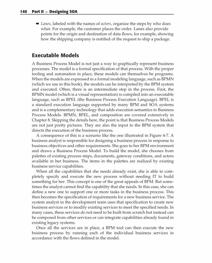
140 Part II ■ Designing SOA
Lanes, labeled with the names of actors, organize the steps by who doeswhat. For example, the customer places the order. Lanes also providepoints for the origin and destination of data flows, for example, showinghow the shipping company is notified of the request to ship a package.
Executable ModelsA Business Process Model is not just a way to graphically represent businessprocesses. The model is a formal specification of that process. With the propertooling and automation in place, these models can themselves be programs.When the models are expressed in a formal modeling language, such as BPMN(which we use in this book), the models can be interpreted by the BPM systemand executed. Often, there is an intermediate step in the process. First, theBPMN model (which is a visual representation) is compiled into an executablelanguage, such as BPEL (the Business Process Execution Language). BPEL isa standard execution language supported by many BPM and SOA systemsand is a complementary technology that adds execution semantics to BusinessProcess Models. BPMN, BPEL, and composition are covered extensively inChapter 8. Skipping the details here, the point is that Business Process Modelsare not just pretty pictures. They are also the input to the BPM system thatdirects the execution of the business process.
A consequence of this is a scenario like the one illustrated in Figure 4-7. Abusiness analyst is responsible for designing a business process in response tobusiness objectives and other requirements. She goes to her BPM environmentand draws a Business Process Model. To build the model, she chooses frompalettes of existing process steps, documents, gateway conditions, and actorsavailable in her business. The items in the palettes are realized by existingbusiness service capabilities.
When all the capabilities that she needs already exist, she is able to com-pletely specify and execute the new process without needing IT to buildsomething for her. This concept is one of the great appeals of BPM. But some-times the analyst cannot find the capability that she needs. In this case, she candefine a new one to support one or more tasks in the business process. Thisthen becomes the specification of requirements for a new business service. Thesystem analyst in the development team uses that specification to create newbusiness services or to modify existing services to meet the specified needs. Inmany cases, these services do not need to be built from scratch but instead canbe composed from other services or can integrate capabilities already found inexisting legacy systems.
Once all the services are in place, a BPM tool can then execute the newbusiness process by running each of the individual business services inaccordance with the flows defined in the model.
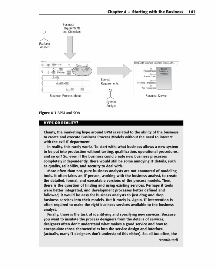
Chapter 4 ■ Starting with the Business 141
Business Analyst
System Analyst
BPMN Order Books
Book
stor
e«L
ane»
Ship
ping
Com
pany
«Lan
e»Sh
ippi
ng D
epar
tmen
t«L
ane»
Cred
it Ca
rd C
o.«L
ane»
Cust
omer
«Lan
e» Place Order
ProcessCharge
Charge Approve
Pack and Ship Order
Pickup Request
OrderPicked Up
Shipping Details
DeliveryReport
Pick Up Order
Order
RequestCharge
Approval
Credit Card Charge
Charge Result
Notify Customer
Order Shipped
Notify Customer Approved
Request Pickup
Deliver Order
Notify Customer
Order Delivered
Delivery Report
Request ShipmentApproved?
Shipping Order
Notify Customer Declined
Charge Declined
ResubmitCharge
New Charge
Yes
composite structure Business Process M. . .
«domain» Credit Card Processing
Process Charge
Process Credit
Reconcile Transactions
Void Transactions
Service Requirements
Business Process Model
Business Requirements and Objectives
Business Service
Figure 4-7 BPM and SOA
HYPE OR REALITY?
Clearly, the marketing hype around BPM is related to the ability of the businessto create and execute Business Process Models without the need to interactwith the evil IT department.
In reality, this rarely works. To start with, what business allows a new systemto be put into production without testing, qualification, operational procedures,and so on? So, even if the business could create new business processescompletely independently, there would still be some annoying IT details, suchas quality, reliability, and security to deal with.
More often than not, pure business analysts are not enamored of modelingtools. It often takes an IT person, working with the business analyst, to createthe detailed, formal, and executable versions of the process models. Then,there is the question of finding and using existing services. Perhaps if toolswere better integrated, and development processes better defined andfollowed, it would be easy for business analysts to just drag and dropbusiness services into their models. But it rarely is. Again, IT intervention isoften required to make the right business services available to the businessanalyst.
Finally, there is the task of identifying and specifying new services. Becauseyou want to insulate the process designers from the details of services,designers often don’t understand what makes a good service and how toencapsulate those characteristics into the service design and interface(actually, many IT designers don’t understand this either). So, all too often, the
(continued)
142 Part II ■ Designing SOA
HYPE OR REALITY? (continued)
services specified by business analysts are the wrong granularity, too tightlycoupled, have too many dependencies, and you name it, to be good services.
So, is all this BPM stuff a pile of bunk? Absolutely not! The benefits ofBPM in the design of flexible business processes, and the ability to provide abusiness focused execution environment that complements SOA, are real. But,it’s not quite as simple as drag and drop. There still needs to be a partnershipbetween the business and IT. And, that partnership is enabled by BusinessProcess Models, which provide a good common vocabulary for both sidesto use.
Want to know what we think (in case you couldn’t tell already)? It’s not thatsimple, as explained in this chapter. . . . Read on.
Business Process Models in an SOA WorldPlain business process modeling does not define where the processes, ordocuments, or gateway criteria come from; it just assumes that the businessanalyst will create these elements as necessary in order to properly define thebusiness processes. Following a traditional software development paradigm,each of these elements becomes the specification of some component thatwill be built and then woven together following the structure of the BusinessProcess Model.
But when used in an SOA context, the steps that make up the modelshould be implemented by well-designed business services. New businessprocesses should use existing services as much as possible, balanced withthe opportunities for identifying new services, as needed, to create the newprocesses. Here, governance plays an important role by setting up proceduresto help find the appropriate services and to verify that new services areidentified in accordance with enterprise goals and policies. Approaches togovernance are explored in Chapter 12.
Furthermore, the Business Process Models should uniformly represent theproblem and not a specific implementation of that problem. This ensures thatthe models, and the definitions of the business services that emerge from thesemodels, are independent of particular technology and software architecturechoices.
There are other concerns as well. The functional decomposition of processesinto services can lead to tight coupling between processes and businessservices. This is often the case when processes are designed in isolation. Manybusiness processes are quite goal-oriented; they are the steps to get a specificthing done. They are often more observed or anticipated scenarios, rather than
Chapter 4 ■ Starting with the Business 143
reusable solutions made of reusable parts. Services come from looking acrossmany processes to find commonality variability, reuse, separation of concerns,overlapping capabilities, and common information. Business analysts don’toften do this, and many BPM tools don’t have the capability to easily supportit. This is where business architecture comes in for SOA and where the systemanalyst has the responsibility to understand the enterprise context whendesigning services to meet business process requirements.
How to Create Business Process Models
SOA presents several interesting challenges in creating Business ProcessModels and the business services that result from those models. How do youget the right level of processes? How do you avoid repeating the same thingover and over again while exploiting opportunities for reuse? How do youdefine steps that will ultimately lead to good business service design?
Business Process Models are formalizations of the required function, control,and data in a set of business processes. Properly designed, a business’s set ofactivities can be completely described in Business Process Models. However,as with any design activity, you need criteria for grouping related BusinessProcess Models, and criteria for ensuring uniformity among models createdby different people at different times within the same organization.
This section introduces Business Process Models and the Business ProcessModeling Notation in only enough detail to show how Business ProcessModels are a useful foundation for identifying business services. It is notintended as a detailed tutorial; there are lots of other resources availablefor that.
Use CasesMany software design efforts begin by identifying use cases — the differentcapabilities to be provided to users of a system.
A use case diagram, such as that shown in Figure 4-8, can be thought ofas a table of contents that says, ‘‘here’s who is going to be doing what in ourproblem.’’ The stick figures represent actors — the entities that can initiate andparticipate in the use cases. The ovals represent the use cases that the actorscan participate in.
In some practice, the term use case is little more than modern software-speakfor ‘‘informal requirements document.’’ But they should be more than that.The techniques presented in this section help to create use cases and scenariosthat are conducive to producing good and useful models, and that lead togood service design.
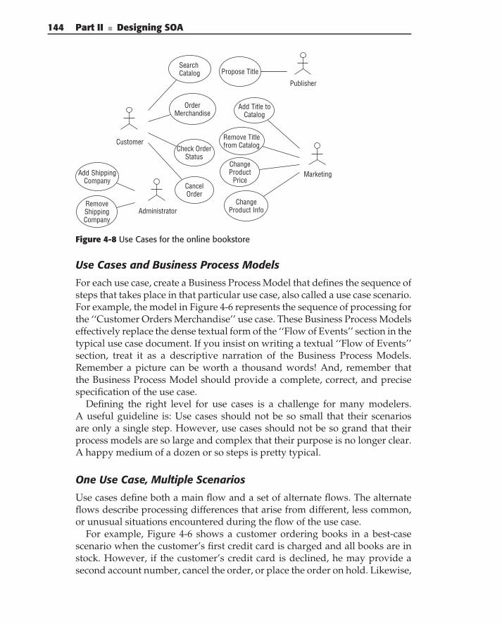
144 Part II ■ Designing SOA
Customer
OrderMerchandise
SearchCatalog
Check OrderStatus
Cancel Order
Publisher
Propose Title
Marketing
Add Title toCatalog
Remove Titlefrom Catalog
ChangeProduct
Price
ChangeProduct InfoAdministrator
Add Shipping Company
RemoveShippingCompany
Figure 4-8 Use Cases for the online bookstore
Use Cases and Business Process Models
For each use case, create a Business Process Model that defines the sequence ofsteps that takes place in that particular use case, also called a use case scenario.For example, the model in Figure 4-6 represents the sequence of processing forthe ‘‘Customer Orders Merchandise’’ use case. These Business Process Modelseffectively replace the dense textual form of the ‘‘Flow of Events’’ section in thetypical use case document. If you insist on writing a textual ‘‘Flow of Events’’section, treat it as a descriptive narration of the Business Process Models.Remember a picture can be worth a thousand words! And, remember thatthe Business Process Model should provide a complete, correct, and precisespecification of the use case.
Defining the right level for use cases is a challenge for many modelers.A useful guideline is: Use cases should not be so small that their scenariosare only a single step. However, use cases should not be so grand that theirprocess models are so large and complex that their purpose is no longer clear.A happy medium of a dozen or so steps is pretty typical.
One Use Case, Multiple Scenarios
Use cases define both a main flow and a set of alternate flows. The alternateflows describe processing differences that arise from different, less common,or unusual situations encountered during the flow of the use case.
For example, Figure 4-6 shows a customer ordering books in a best-casescenario when the customer’s first credit card is charged and all books are instock. However, if the customer’s credit card is declined, he may provide asecond account number, cancel the order, or place the order on hold. Likewise,
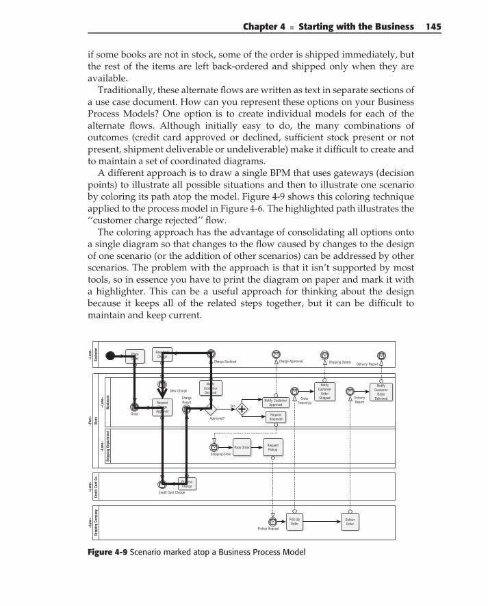
Chapter 4 ■ Starting with the Business 145
if some books are not in stock, some of the order is shipped immediately, butthe rest of the items are left back-ordered and shipped only when they areavailable.
Traditionally, these alternate flows are written as text in separate sections ofa use case document. How can you represent these options on your BusinessProcess Models? One option is to create individual models for each of thealternate flows. Although initially easy to do, the many combinations ofoutcomes (credit card approved or declined, sufficient stock present or notpresent, shipment deliverable or undeliverable) make it difficult to create andto maintain a set of coordinated diagrams.
A different approach is to draw a single BPM that uses gateways (decisionpoints) to illustrate all possible situations and then to illustrate one scenarioby coloring its path atop the model. Figure 4-9 shows this coloring techniqueapplied to the process model in Figure 4-6. The highlighted path illustrates the‘‘customer charge rejected’’ flow.
The coloring approach has the advantage of consolidating all options ontoa single diagram so that changes to the flow caused by changes to the designof one scenario (or the addition of other scenarios) can be addressed by otherscenarios. The problem with the approach is that it isn’t supported by mosttools, so in essence you have to print the diagram on paper and mark it witha highlighter. This can be a useful approach for thinking about the designbecause it keeps all of the related steps together, but it can be difficult tomaintain and keep current.
Stor
e
«Poo
l»
Book
stor
e
«Lan
e»
Ship
ping
Com
pany
«Lan
e»
Ship
ping
Dep
artm
ent
«Lan
e»
Cred
it Ca
rd C
o.
«Lan
e»
Cust
omer
«Lan
e»
PlaceOrder
ProcessCharge
Charge Approved
Pack Order
Pickup Request
OrderPicked Up
Shipping Details
DeliveryReport
Pick UpOrder
Order
RequestCharge
Approval
Credit Card Charge
ChargeResult
NotifyCustomer
OrderShipped
Notify CustomerApproved
RequestPickup
DeliverOrder
NotifyCustomer
OrderDelivered
Delivery Report
RequestShipmentApproved?
Shipping Order
NotifyCustomerDeclined
Charge Declined
ResubmitCharge
New Charge
Yes
Figure 4-9 Scenario marked atop a Business Process Model
146 Part II ■ Designing SOA
Regardless of how you address creating the model, it is important tounderstand that a given use case can have many scenarios, that those scenariosshare common steps, and that they can affect each other.
Step Reuse
Scenario coloring consolidates a number of distinct use case flows onto asingle diagram, thus ensuring greater consistency and reuse of steps across thedifferent flows. Additionally, several models may share common processingsteps, gateways, states, and documents. For example, the step of canceling anorder is both part of a Cancel Order use case and the Order Merchandise usecase.
The modeling environment used to create Business Process Models shouldprovide palettes of existing process elements, preferably tied directly to repos-itories of existing business services, in order to facilitate this reuse. If this isnot possible, manual processes should be implemented to facilitate discoveryof reusable processing elements.
If not done properly, reuse can have a dark side: If a service is not sufficientlyflexible, it will be largely reinvented in a slightly different form each time thecapability is needed. When a business process modeler finds a service that’ssimilar to what he needs, but it does not match it exactly, there is an opportunityto either extend the existing service or to create a new service. The defaultmindset should be to reuse and extend first, and to create new as a last resort.Service governance policies should address how extensions to a service arerequested, designed, implemented, and deployed.
DocumentsDocuments are the means by which information is passed between steps ina process. They represent cohesive sets of business data, such as an Orderor a Payment. This is the data that has to be shared (and have a commonsemantic definition) across multiple steps of the process. Documents areused as the inputs and outputs of business process steps. For example, inFigure 4-6, Request Charge Approval accepts an Order document. Often,the same document is used in multiple steps of the process. For example,the Request Shipment step produces a Shipping Order. This same shipmentdocument is then the input to and the output of the Process Shipping Orderand Pack Order steps, as illustrated in the model segment in Figure 4-10.
Identification of documents is an important aspect of tying BPM to SOA. Thedocuments identified in the process model are used to specify the documentspassed in service interfaces. In business processes, the documents shouldrelate to real-world documents whenever they exist (things like purchaseorder, shipping manifest, binder, etc.). In services, the document schema must
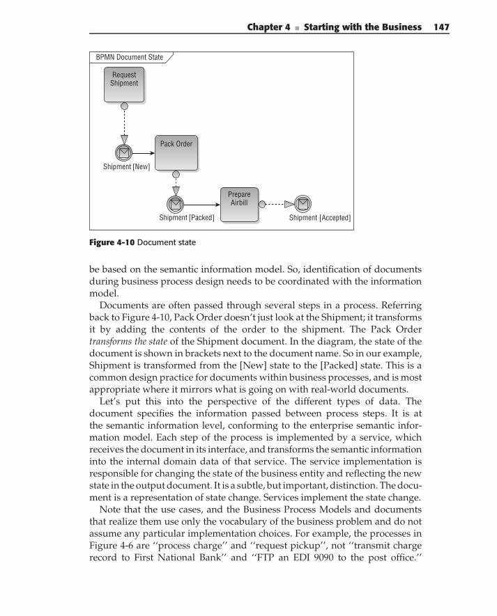
Chapter 4 ■ Starting with the Business 147
BPMN Document State
Request Shipment
Shipment [New]
Pack Order
Shipment [Packed]
Prepare Airbill
Shipment [Accepted]
Figure 4-10 Document state
be based on the semantic information model. So, identification of documentsduring business process design needs to be coordinated with the informationmodel.
Documents are often passed through several steps in a process. Referringback to Figure 4-10, Pack Order doesn’t just look at the Shipment; it transformsit by adding the contents of the order to the shipment. The Pack Ordertransforms the state of the Shipment document. In the diagram, the state of thedocument is shown in brackets next to the document name. So in our example,Shipment is transformed from the [New] state to the [Packed] state. This is acommon design practice for documents within business processes, and is mostappropriate where it mirrors what is going on with real-world documents.
Let’s put this into the perspective of the different types of data. Thedocument specifies the information passed between process steps. It is atthe semantic information level, conforming to the enterprise semantic infor-mation model. Each step of the process is implemented by a service, whichreceives the document in its interface, and transforms the semantic informationinto the internal domain data of that service. The service implementation isresponsible for changing the state of the business entity and reflecting the newstate in the output document. It is a subtle, but important, distinction. The docu-ment is a representation of state change. Services implement the state change.
Note that the use cases, and the Business Process Models and documentsthat realize them use only the vocabulary of the business problem and do notassume any particular implementation choices. For example, the processes inFigure 4-6 are ‘‘process charge’’ and ‘‘request pickup’’, not ‘‘transmit chargerecord to First National Bank’’ and ‘‘FTP an EDI 9090 to the post office.’’
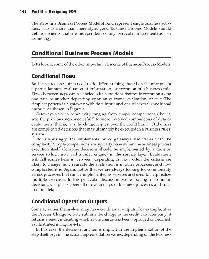
148 Part II ■ Designing SOA
The steps in a Business Process Model should represent single business activ-ities. This is more than mere style; good Business Process Models shoulddefine elements that are independent of any particular implementation ortechnology.
Conditional Business Process Models
Let’s look at some of the other important elements of Business Process Models.
Conditional FlowsBusiness processes often need to do different things based on the outcome ofa particular step, evaluation of information, or execution of a business rule.Flows between steps can be labeled with conditions that route execution alongone path or another depending upon an outcome, evaluation, or rule. Thesimplest pattern is a gateway with data input and one of several conditionaloutputs, as shown in Figure 4-11.
Gateways vary in complexity ranging from simple comparisons (that is,was the previous step successful?) to more involved comparisons of data orevaluations (that is, was the charge request over the credit limit?). Still othersare complicated decisions that may ultimately be executed in a business rules’system.
Not surprisingly, the implementation of gateways also varies with thecomplexity. Simple comparisons are typically done within the business processexecution itself. Complex decisions should be implemented by a decisionservice (which may call a rules engine) in the service layer. Evaluationswill fall somewhere in between, depending on how often the criteria arelikely to change, how reusable the evaluation is in other processes, and howcomplicated it is. Again, notice that we are always looking for commonalityacross processes that can be implemented as services and used to help realizemultiple use cases. In this particular discussion, we’re looking for commondecisions. Chapter 8 covers the relationships of business processes and rulesin more detail.
Conditional Operation OutputsSome activities themselves may have conditional outputs. For example, afterthe Process Charge activity submits the charge to the credit card company, itreturns a result indicating whether the charge has been approved or declined,as illustrated in Figure 4-12.
In this case, the decision function is implicit in the implementation of thestep itself. Again, the actual implementation varies, depending on the business
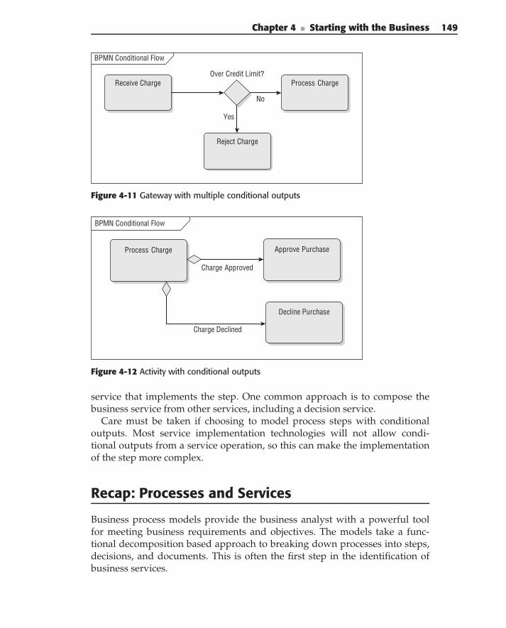
Chapter 4 ■ Starting with the Business 149
BPMN Conditional Flow
Receive ChargeOver Credit Limit?
Process Charge
Reject Charge
No
Yes
Figure 4-11 Gateway with multiple conditional outputs
BPMN Conditional Flow
Process Charge Approve Purchase
Decline Purchase
Charge Approved
Charge Declined
Figure 4-12 Activity with conditional outputs
service that implements the step. One common approach is to compose thebusiness service from other services, including a decision service.
Care must be taken if choosing to model process steps with conditionaloutputs. Most service implementation technologies will not allow condi-tional outputs from a service operation, so this can make the implementationof the step more complex.
Recap: Processes and Services
Business process models provide the business analyst with a powerful toolfor meeting business requirements and objectives. The models take a func-tional decomposition based approach to breaking down processes into steps,decisions, and documents. This is often the first step in the identification ofbusiness services.
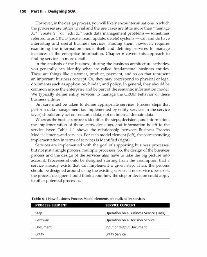
150 Part II ■ Designing SOA
However, in the design process, you will likely encounter situations in whichthe processes are rather trivial and the use cases are little more than ‘‘manageX,’’ ‘‘create Y,’’ or ‘‘edit Z.’’ Such data management problems — sometimesreferred to as CRUD (create, read, update, delete) systems — can and do haveinteresting and useful business services. Finding them, however, requiresexamining the information model itself and defining services to manageinstances of the enterprise information. Chapter 6 covers this approach tofinding services in more detail.
In the analysis of the business, during the business architecture activities,you generally can identify what are called fundamental business entities.These are things like customer, product, payment, and so on that representan important business concept. Or, they may correspond to physical or legaldocuments such as application, binder, and policy. In general, they should becommon across the enterprise and be part of the semantic information model.We typically define entity services to manage the CRUD behavior of thesebusiness entities.
But care must be taken to define appropriate services. Process steps thatperform data management (as implemented by entity services in the servicelayer) should only act on semantic data, not on internal domain data.
Whereas the business process identifies the steps, decisions, and information,the implementation of these steps, decisions, and information is left to theservice layer. Table 4-1 shows the relationship between Business ProcessModel elements and services. For each model element (left), the correspondingimplementation in terms of services is identified (right).
Services are implemented with the goal of supporting business processes,but not just a single process, multiple processes. So, the design of the businessprocess and the design of the services also have to take the big picture intoaccount. Processes should be designed starting from the assumption that aservice already exists that can implement a given step. Then, the processshould be designed around using the existing service. If no service does exist,the process designer should think about how the step or decision could applyto other potential processes.
Table 4-1 How Business Process Model elements are realized by services
PROCESS ELEMENT SERVICE CONCEPT
Step Operation on a Business Service (Task)
Gateway Operation on a Decision Service
Document Input or Output Document
Entity Entity Service
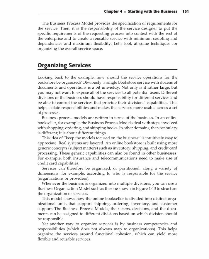
Chapter 4 ■ Starting with the Business 151
The Business Process Model provides the specification of requirements forthe service. Then, it is the responsibility of the service designer to put thespecific requirements of the requesting process into context with the rest ofthe enterprise and to create a reusable service with minimum coupling anddependencies and maximum flexibility. Let’s look at some techniques fororganizing the overall service space.
Organizing Services
Looking back to the example, how should the service operations for thebookstore be organized? Obviously, a single Bookstore service with dozens ofdocuments and operations is a bit unwieldy. Not only is it rather large, butyou may not want to expose all of the services to all potential users. Differentdivisions of the business should have responsibility for different services andbe able to control the services that provide their divisions’ capabilities. Thishelps isolate responsibilities and makes the services more usable across a setof processes.
Business process models are written in terms of the business. In an onlinebookseller, for example, the Business Process Models deal with steps involvedwith shopping, ordering, and shipping books. In other domains, the vocabularyis different; it is about different things.
This idea of ‘‘keep the models focused on the business’’ is intuitively easy toappreciate. Real systems are layered. An online bookstore is built using moregeneric concepts (subject matters) such as inventory, shipping, and credit cardprocessing. These generic capabilities can also be found in other businesses:For example, both insurance and telecommunications need to make use ofcredit card capabilities.
Services can therefore be organized, or partitioned, along a variety ofdimensions, for example, according to who is responsible for the service(organizations or providers).
Whenever the business is organized into multiple divisions, you can use aBusiness Organization Model such as the one shown in Figure 4-13 to structurethe organization of services.
This model shows how the online bookseller is divided into distinct orga-nizational units that support shipping, ordering, inventory, and customersupport. The Business Process Models, their steps, decisions, and the docu-ments can be assigned to different divisions based on which division shouldbe responsible.
Yet another way to organize services is by business competencies andresponsibilities (which does not always map to organizations). This helpsorganize the services around functional cohesion, which can yield moreflexible and reusable services.
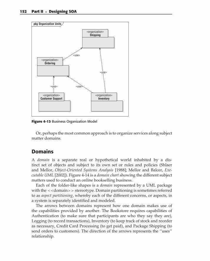
152 Part II ■ Designing SOA
pkg Organization Units
«organization» Shipping
«organization» Ordering
«organization» Customer Support
«organization» Inventory
«use»
«use»
«use»
«use»
Figure 4-13 Business Organization Model
Or, perhaps the most common approach is to organize services along subjectmatter domains.
DomainsA domain is a separate real or hypothetical world inhabited by a dis-tinct set of objects and subject to its own set or rules and policies (Shlaerand Mellor, Object-Oriented Systems Analysis [1988]; Mellor and Balcer, Exe-cutable UML [2002]). Figure 4-14 is a domain chart showing the different subjectmatters used to conduct an online bookselling business.
Each of the folder-like shapes is a domain represented by a UML packagewith the <<domain>> stereotype. Domain partitioning is sometimes referredto as aspect partitioning, whereby each of the different concerns, or aspects, ina system is separately identified and modeled.
The arrows between domains represent how one domain makes use ofthe capabilities provided by another. The Bookstore requires capabilities ofAuthentication (to make sure that participants are who they say they are),Logging (to record transactions), Inventory (to keep track of stock and reorderas necessary, Credit Card Processing (to get paid), and Package Shipping (tosend orders to customers). The direction of the arrows represents the ‘‘uses’’relationship.
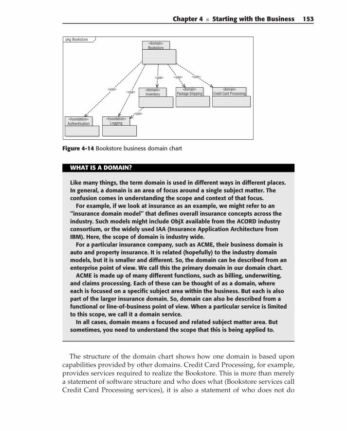
Chapter 4 ■ Starting with the Business 153
pkg Bookstore«domain» Bookstore
«use»
«use»«use»
«use» «use»
«use»
«domain» Inventory
«domain» Package Shipping
«domain» Credit Card Processing
«foundation» Authentication
«foundation» Logging
Figure 4-14 Bookstore business domain chart
WHAT IS A DOMAIN?
Like many things, the term domain is used in different ways in different places.In general, a domain is an area of focus around a single subject matter. Theconfusion comes in understanding the scope and context of that focus.
For example, if we look at insurance as an example, we might refer to an‘‘insurance domain model’’ that defines overall insurance concepts across theindustry. Such models might include ObjX available from the ACORD industryconsortium, or the widely used IAA (Insurance Application Architecture fromIBM). Here, the scope of domain is industry wide.
For a particular insurance company, such as ACME, their business domain isauto and property insurance. It is related (hopefully) to the industry domainmodels, but it is smaller and different. So, the domain can be described from anenterprise point of view. We call this the primary domain in our domain chart.
ACME is made up of many different functions, such as billing, underwriting,and claims processing. Each of these can be thought of as a domain, whereeach is focused on a specific subject area within the business. But each is alsopart of the larger insurance domain. So, domain can also be described from afunctional or line-of-business point of view. When a particular service is limitedto this scope, we call it a domain service.
In all cases, domain means a focused and related subject matter area. Butsometimes, you need to understand the scope that this is being applied to.
The structure of the domain chart shows how one domain is based uponcapabilities provided by other domains. Credit Card Processing, for example,provides services required to realize the Bookstore. This is more than merelya statement of software structure and who does what (Bookstore services callCredit Card Processing services), it is also a statement of who does not do
154 Part II ■ Designing SOA
something, that the Bookstore services do not directly process payments andinstead assume that some other domain will carry out the payment processing.
Such organization provides two distinct advantages: First, higher-levelservices can be constructed without regard for the details of how more genericbusiness and utility capabilities are provided. Second, the capabilities requiredof the lower-level domains can be discerned from the requirements placed onthem by the higher-level domains.
Note that the domain chart is different from the business organizationdiagram. The packages in the domain chart are not divisions of the business;they are distinct subject matters that can be understood independently ofone other. For example, the problem of maintaining and tracking inventoryis generic and, by implication, reusable in contexts other than the onlinebookstore.
Many businesses also share common industry standards. The domain chartcan be extended to show how two different booksellers make use of somecommon industry standard items, such as ISBN numbering. Each companycan start with a common base and then specialize it to meet its own particularneeds.
Types of Domains
A domain chart is drawn with respect to the business being modeled. Thepackage at the top of the chart — and there is always only one — is theprincipal domain representing the subject matter of the business itself. Otherdomains provide capabilities that are used to realize the principal domain.Generic domains are generic business subject matters, such as Billing, Inventory,and Shipping. Foundation domains, in contrast, provide computer-technology-related capabilities such as Authentication and Messaging.
A domain’s capabilities are abstracted as service interfaces. Consider theCredit Card Processing domain. It provides a capability to process a chargethat accepts a credit card number, expiration date, the account holder’s name,and the amount of the charge. This capability returns a code either approvingor declining the charge. The capability is made available as an operation ona service interface. In other words, domains interact with each other throughservices. The interface provides the connection points between the capabilitiesoffered by the domain (the provider) and the needs of the consumer. Soundfamiliar?
The complete definition of the domain’s capabilities is expressed in theservice specifications. These define the provided and required capabilities andthe rules or protocol for using them. However, they do not specify (or evenprovide the least little clue to) the implementation of the service. The servicespecification does tell providers what they must do to implement the service.
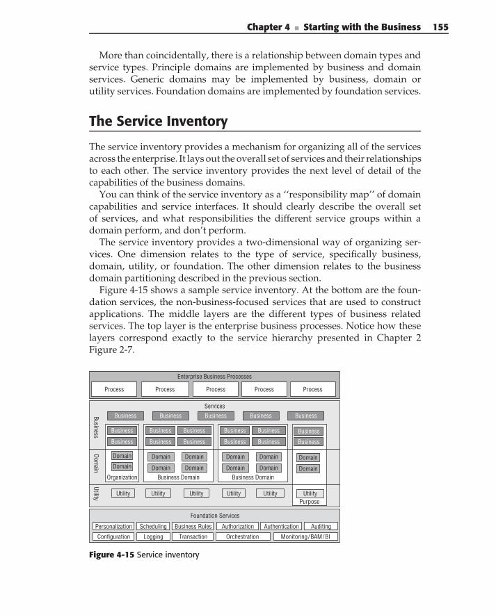
Chapter 4 ■ Starting with the Business 155
More than coincidentally, there is a relationship between domain types andservice types. Principle domains are implemented by business and domainservices. Generic domains may be implemented by business, domain orutility services. Foundation domains are implemented by foundation services.
The Service Inventory
The service inventory provides a mechanism for organizing all of the servicesacross the enterprise. It lays out the overall set of services and their relationshipsto each other. The service inventory provides the next level of detail of thecapabilities of the business domains.
You can think of the service inventory as a ‘‘responsibility map’’ of domaincapabilities and service interfaces. It should clearly describe the overall setof services, and what responsibilities the different service groups within adomain perform, and don’t perform.
The service inventory provides a two-dimensional way of organizing ser-vices. One dimension relates to the type of service, specifically business,domain, utility, or foundation. The other dimension relates to the businessdomain partitioning described in the previous section.
Figure 4-15 shows a sample service inventory. At the bottom are the foun-dation services, the non-business-focused services that are used to constructapplications. The middle layers are the different types of business relatedservices. The top layer is the enterprise business processes. Notice how theselayers correspond exactly to the service hierarchy presented in Chapter 2Figure 2-7.
Services
Enterprise Business Processes
PurposeUtility Utility
Foundation Services
Business Rules Authorization
Orchestration Logging
Scheduling
Configuration
Personalization Authentication
Transaction
Auditing
Monitoring/BAM/BI
BusinessDom
ainProcess ProcessProcessProcessProcess
Utility Utility Utility Utility
Organization
Domain
Business Domain
Business
Business BusinessBusinessBusiness
Domain
Business
Business
Business Business
Business
Business
BusinessBusiness
Business DomainDomain
Domain Domain Domain
Domain
Domain
Domain
Domain
Business Business
BusinessBusiness
Domain Domain
Utility
Figure 4-15 Service inventory
156 Part II ■ Designing SOA
The middle layers are really the main focus of the service inventory. Theyare made up (from bottom to top) of utility services, domain services, andbusiness services. Going from bottom to top of the drawing describes theservice type dimension.
Going from left to right is the business domain dimension. Services,particularly the business and domain services, are organized according todifferent domains. As we mentioned earlier, there are a variety of approachesto domain partitioning, and any or all of them can be used to organize theservice inventory.
Notice that some services are enterprise-wide, both at the business serviceand utility service layers. These apply to the principle domain and are notincluded in an individual subdomain.
The inventory helps answer two important questions:
What services exist? At design time, you need to know what servicesexist, what they do, and how they relate to other services. The inventoryprovides a convenient structure and visualization for taking the first stepin locating and qualifying services.
What should a new service do? This is perhaps the more importantfunction. When a requirement for a service has been identified, you needto determine how that service fits into the overall set of services. Specif-ically, what capabilities are the responsibility of the new service, andwhat capabilities should you expect to be performed by another service.The answers to this question are crucial in eliminating gaps and overlapsin service functions.
Of course, there are many ways to organize the service inventory. The bestway for any given enterprise is related to its own goals, structure, organization,maturity, and so on. The specific structure of the inventory is not importantas long as it provides a mechanism to easily answer the two questions above.Ideally, the service inventory is integrated directly with the service repositoryand the overall governance approach.
Summary
A fundamental requirement for technology is to align the business with IT.This is perhaps even truer for SOA-based solutions, but just wishing it doesn’tmake it so. Business architecture is the key to the alignment.
First, you must define what ‘‘the business’’ means. What are the goalsand objectives of the business? What are its primary value adding activities?How do they relate and interact with each other, the customers, and partners.You use a variety of techniques including value chains and business context
Chapter 4 ■ Starting with the Business 157
diagrams to answer these questions. In addition, you can use a formal BusinessMotivation Model to precisely define the goals, objectives, and strategies andtactics for meeting them. This is business architecture at the enterprise level.
Next, you turn to business architecture at the project level. Here, the primaryactivity is the creation of Business Process Models. Business process modelingis a useful analysis technique enabling you to find and create business ser-vices by enumerating business capabilities and information. Business ProcessModels describe the steps, decisions, information, and flow of the businessprocesses. The steps and decisions are implemented by business servicesprovided by SOA. The information is passed in documents.
But process design done in isolation does not lead to good services. You alsoneed a way to understand and organize the big picture. Domain partitioningorganizes a problem space by subject matter in order to break the probleminto manageable chunks and to identify cohesive sets of responsibilities andminimize coupling. The service inventory provides another important wayof organizing and categorizing the overall set of services to aid in serviceidentification and implementation. Ultimately, the capabilities of each domainwill be implemented by services, well organized in the inventory, and that canbe traced back to specific tactics in the business model and provide the link toaligning business objectives with IT systems.

C H A P T E R
5Service Context and Common
SemanticsSOA is useless without good data.
— Joe McIndrick
Chapter 4 showed how to use techniques of business process modeling andsubject matter partitioning to identify business services that conform to auniform business architecture. In this architecture, individual services do notexist in isolation — they should be usable in multiple contexts. In other words,these services should be interoperable. Uniform messaging semantics is oneof the most important requirements for service interoperability. This ensuresthat service consumers and providers exchange data in a consistent way thatenables their mutual understanding of the information they are intended toprocess.
This chapter starts by revisiting the importance of uniform messagingsemantics and a semantic information model, and then introduces modelingtechniques for creating that model based upon information modeling andobject-oriented analysis principles. You learn how to synthesize a model byexposing details about a problem based upon the things in the domain. Thistechnique has been shown, in practice, to provide a cohesive foundation forensuring common semantics.
In constructing an information model, you learn how to model the worldof a domain in terms of objects, attributes, and associations and extend thesebasics by using techniques of specialization and constraint modeling to achievebetter model accuracy. We also show you how to partition large models, bothto manage the modeling problem and to reflect the real complexities in largeenterprises. Finally, the chapter covers usage of XML for representing thesemodels.
159
160 Part II ■ Designing SOA
In this chapter, you learn:
The importance of semantics in SOA
Components of core information modeling
Information-modeling techniques beyond simple data modeling
How to structure information models to fit and to reveal a serviceorganization
How to define documents based on the information model
How to apply the common information model to define XML and to mapdata into existing services
Best practices and pitfalls to avoid
The Importance of Semantics in SOA
Achieving real service interoperability can be harder than some SOA evange-lists would have you believe. This is because a majority of SOA publicationsfocus almost exclusively on the mechanics of constructing and combiningservices. Such syntactic coupling certainly achieves much, but it solves just onepart of the problem. Many Web Service standards revolve around rules foraddressing and binding to services, and they focus on the clear definition ofsyntactic contracts for service interfaces. Minimizing coupling at the syntacticlevel is critical, and SOA (especially with the help of the OASIS and W3 Cstandards bodies and the WS-I organization) has made enormous progress.
Unfortunately, syntactic interoperability alone is not sufficient. For areal-world example, consider telephone systems; they are syntactically inter-operable worldwide. Someone in the United States can use a phone to callsomeone in Mexico, and the other person can pick up the phone, hear thecaller, and begin talking. However, just because they are connected does notnecessarily mean that the two parties can successfully communicate or under-stand each other. If the caller only speaks and understands English, and theperson on the other end of the phone only speaks and understands Spanish,the fact that they are connected does not help them communicate. In the sameway, service consumers and service providers need to be able to ‘‘speak thesame language’’ in order to effectively communicate.
There is more to semantic interoperability than just speaking the samelanguage, however. In Web Services, Extensible Markup Language (XML)is used for carrying the payload of messages because it is an agreed-uponformat and therefore an interoperability mechanism, but just knowing thatdata is marked up in XML isn’t enough to have an understanding of whatthe XML-marked data means. Continuing the same telephone analogy, evenif the two parties on the phone speak the same language, they still need acommon understanding of the words of the language they are speaking. If an
Chapter 5 ■ Service Context and Common Semantics 161
astronomer and a Hollywood socialite are talking, the phrase ‘‘star sighting’’has a different meaning for both of them; both have a different understanding ofthe word ‘‘star.’’ So their conversation is going to be confused at best. Semanticinteroperability, therefore, involves having a common understanding of whatthe data actually means.
Semantic interoperability is an essential aspect of SOA because serviceconsumers and service providers need to exchange information that bothunderstand and that can be used to achieve a specific capability. Data thatis not understandable is obviously not useful, and without semantics, datawould simply consist of garbage strings of zeroes and ones that have nomeaning. Without understanding the meaning of the data, service consumersand providers could misinterpret the data and ultimately bring undesirableeffects to the business. Semantic interoperability between services and for yourparticular business domain increases your chances for success.
There are many levels of maturity for semantic interoperability, from thevery simple to the very complex. Michael C. Daconta, Leo Obrst, and KevinT. Smith, in their book The Semantic Web, (2003), refer to levels of datainteroperability as the ‘‘smart data continuum,’’ where data at the low-est level of interoperability has relevance to only certain applications, andwhere data at the highest level of interoperability can be discoverableand understandable between applications in different business domains. Youcan apply this concept to SOA by looking at three levels of interoperabilitymaturity:
Project-specific interoperability — The lowest level of interoperabilityinvolves creating data formats specific to a particular SOA project. Inthis case, schemas are typically created by looking at the functionalityof specific services. Because the data in these projects is only relevant tothe specific services in the project, interoperability with other projectsis usually only achieved by transformations between similar messagesfrom services and consumers in different projects (once other projectsunderstand the meaning of your data formats). This interoperabilityapproach is therefore doable, but is often short-sighted if existing datastandards are not used.
Business domain-specific interoperability — A higher level of interop-erability revolves around the reuse of data standards within a businessdomain. By using accepted standard schemas for such a domain, dataused in SOA projects can reuse message formats and can, therefore,interoperate with other services and consumers within that businessdomain. An example is services that utilize XML standards within thehealthcare, insurance, or the military industries. As businesses havegrasped the importance of semantic interoperability, many consortiumsand industries have collaborated to build standard data formats, datamodels, and taxonomies related to their domains. Therefore, using such
162 Part II ■ Designing SOA
standards is good practice, as similar projects may need to interoperatewith other systems in the same domain.
Business domain-independent interoperability — In the highest levelof interoperability, data formats use standards from multiple businessdomains. In this approach, service messages may include elements fromschemas from several business domains, they may reference taxonomicclassifications from different domains, and elements of the data mayrefer to elements in an ontology. By using semantic web technologies,services and clients from different domains can consume the data, andin many cases, they can use rule-based systems to infer new knowl-edge by the analysis of data. The bottom line is that the highest level ofinteroperability includes the maximum reuse of data standards and datadefinitions.
As you can see, semantics are important and dictate how interoperable yourSOA will be. Without semantics, the network connectivity between consumersand services mean nothing. The more mature your project is on the maturityscale, the more flexible and interoperable your services are. For example, ifyour SOA revolves around data formats that you explicitly defined only foryour project, then future interoperability between other applications may bedifficult because you would have to explain to someone what ‘‘your’’ datastandard means, and you have to understand the data standards of the otherapplication. Therefore, the more you reuse accepted semantic data standards,the better off you are.
At the same time, if you are new to data standards, we’re not advising you tojump into the highest level of interoperability maturity, focusing on ontologydesign and expert systems. A little semantics can go a long way. Your SOAgovernance should define guidance, policies, best practices, and proceduresrelated to how you define your data formats for SOA. We talk more about thisin Chapter 12.
HOW DOES THE SEMANTIC WEB RELATE TO SOA?
Tim Berners-Lee, James Hendler, and Ora Lassila, in their May 2001 ScientificAmerican article ‘‘The Semantic Web,’’ which coined the phrase with the samename, unveiled a vision of the future web. ‘‘The Semantic Web’’, they wrote,‘‘is an extension of the current Web in which information is given well-definedmeaning, better enabling computers and people to work in cooperation’’.The Semantic Web is a vision, and much progress has been made in semantictechnologies since that initial vision was proposed. The Semantic Web, like WebServices, builds on XML as a foundation. Languages such as XML Schema, theWeb Ontology Language (OWL), and the Resource Description Framework (RDF)have come a long way in making the vision of the Semantic Web seem attainable.
Chapter 5 ■ Service Context and Common Semantics 163
SOA relates to the Semantic Web in that it needs to be data-centric in itsmessaging. The use of XML as an interchange format, the use of schemas todefine and reference common vocabularies, the use of ontologies, and the useof registries for associating services with taxonomic classification is probablyjust putting us on the cusp of the Semantic Web vision.
So, is the Semantic Web ‘‘there yet’’ for SOA? Not quite — there is ‘‘SemanticWeb’’ the utopian vision that we strive for, and there are useful semantictechnologies that are currently reaching for the vision. Much progress is beingmade in academia, government, and the commercial space in semantictechnologies. We expect that further developments in these semantic tech-nologies will have a positive impact on SOA. For more information about thevision and how it relates to SOA, we recommend the book The Semantic Web:A Guide to the Future of XML, Web Services, and Knowledge Management(2003) by Daconta, Obrst, and Smith.
Core Information Modeling
The foundation of semantic interoperability is core information modeling. Theinformation model defines the data and domain concepts that must be sharedbetween services. Similar to domain partitioning (see Chapter 4) for identify-ing business services, core information modeling partitions the informationdomain to define information objects used for service communications.
To understand a domain, you need to understand the things in the domain(the objects) and their semantics (their meaning, rules, and policies). Informa-tion modeling provides the foundations for this understanding. In constructingan information model, you learn how to model the world of a domain in termsof objects, attributes, and associations.
Objects and AttributesIn order to understand a world — a domain — you begin by characterizingthe things in it. This process is called abstraction. It involves sorting theunimportant things from the important things (e.g., fire hydrants are part of adog’s world, but they’re not relevant to the problem of issuing and trackingdog licenses) and categorizing those important things according to conceptsand perceptions of ‘‘likeness’’ and ‘‘difference.’’
Our notion of an object is based upon this notion of likeness. An object isdefined as an abstraction of a set of things in a domain such that:
All the things in the set — the instances — have the samecharacteristics
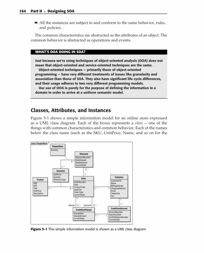
164 Part II ■ Designing SOA
All the instances are subject to and conform to the same behavior, rules,and policies.
The common characteristics are abstracted as the attributes of an object. Thecommon behavior is abstracted as operations and events.
WHAT’S OOA DOING IN SOA?
Just because we’re using techniques of object-oriented analysis (OOA) does notmean that object-oriented and service-oriented techniques are the same.
Object-oriented techniques — primarily those of object-orientedprogramming — have very different treatments of issues like granularity andassociation than those of SOA. They also have significant life cycle differences,and their usage adheres to two very different programming models.
Our use of OOA is purely for the purpose of defining the information in adomain in order to arrive at a uniform semantic model.
Classes, Attributes, and InstancesFigure 5-1 shows a simple information model for an online store expressedas a UML class diagram. Each of the boxes represents a class — one of thethings with common characteristics and common behavior. Each of the namesbelow the class name (such as the SKU, UnitPrice, Name, and so on for the
Product
SKUUPCTitleUnitPriceDescription
Order
OrderNumberDateProductTotalSalesTaxOrderTotalCurrentState
CreditCardCharge
ChargeDateChargeAmountCurrentState
Customer
CustomerIDNameBillingAddressShippingAddressEmailTelephoneFax
Shipment
ShipmentNumberDateShippedDateDeliveredCurrentState
CreditCardAccount
AccountNumberExpirationDateCardValidationNumberCurrentState
Selection
UnitPriceQuantitySelectionTotal
ShippedItem
Quantity
payment 0..1
1
0..*
11..*
1..*
0..*
1
attempt 0..*
11..*
1
1..*
1..* 0..*
class SimpleStore
Figure 5-1 This simple information model is shown as a UML class diagram
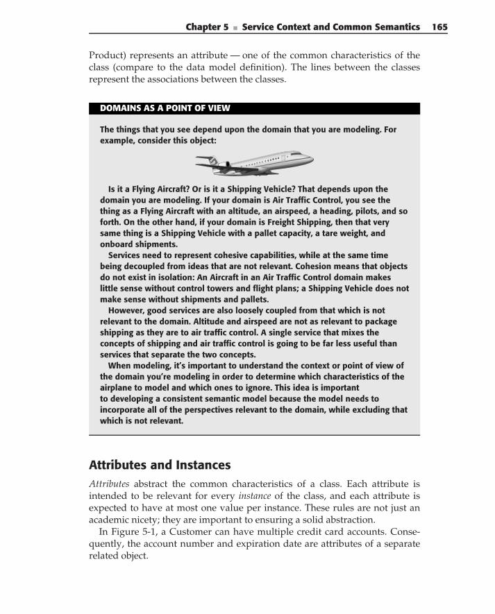
Chapter 5 ■ Service Context and Common Semantics 165
Product) represents an attribute — one of the common characteristics of theclass (compare to the data model definition). The lines between the classesrepresent the associations between the classes.
DOMAINS AS A POINT OF VIEW
The things that you see depend upon the domain that you are modeling. Forexample, consider this object:
Is it a Flying Aircraft? Or is it a Shipping Vehicle? That depends upon thedomain you are modeling. If your domain is Air Traffic Control, you see thething as a Flying Aircraft with an altitude, an airspeed, a heading, pilots, and soforth. On the other hand, if your domain is Freight Shipping, then that verysame thing is a Shipping Vehicle with a pallet capacity, a tare weight, andonboard shipments.
Services need to represent cohesive capabilities, while at the same timebeing decoupled from ideas that are not relevant. Cohesion means that objectsdo not exist in isolation: An Aircraft in an Air Traffic Control domain makeslittle sense without control towers and flight plans; a Shipping Vehicle does notmake sense without shipments and pallets.
However, good services are also loosely coupled from that which is notrelevant to the domain. Altitude and airspeed are not as relevant to packageshipping as they are to air traffic control. A single service that mixes theconcepts of shipping and air traffic control is going to be far less useful thanservices that separate the two concepts.
When modeling, it’s important to understand the context or point of view ofthe domain you’re modeling in order to determine which characteristics of theairplane to model and which ones to ignore. This idea is importantto developing a consistent semantic model because the model needs toincorporate all of the perspectives relevant to the domain, while excluding thatwhich is not relevant.
Attributes and InstancesAttributes abstract the common characteristics of a class. Each attribute isintended to be relevant for every instance of the class, and each attribute isexpected to have at most one value per instance. These rules are not just anacademic nicety; they are important to ensuring a solid abstraction.
In Figure 5-1, a Customer can have multiple credit card accounts. Conse-quently, the account number and expiration date are attributes of a separaterelated object.
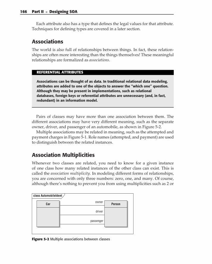
166 Part II ■ Designing SOA
Each attribute also has a type that defines the legal values for that attribute.Techniques for defining types are covered in a later section.
AssociationsThe world is also full of relationships between things. In fact, these relation-ships are often more interesting than the things themselves! These meaningfulrelationships are formalized as associations.
REFERENTIAL ATTRIBUTES
Associations can be thought of as data. In traditional relational data modeling,attributes are added to one of the objects to answer the ‘‘which one’’ question.Although they may be present in implementations, such as relationaldatabases, foreign keys or referential attributes are unnecessary (and, in fact,redundant) in an information model.
Pairs of classes may have more than one association between them. Thedifferent associations may have very different meaning, such as the separateowner, driver, and passenger of an automobile, as shown in Figure 5-2.
Multiple associations may be related in meaning, such as the attempted andpayment charges in Figure 5-1. Role names (attempted, and payment) are usedto distinguish between the related instances.
Association MultiplicitiesWhenever two classes are related, you need to know for a given instanceof one class how many related instances of the other class can exist. This iscalled the association multiplicity. In modeling different forms of relationships,you are concerned with only three numbers: zero, one, and many. Of course,although there’s nothing to prevent you from using multiplicities such as 2 or
Personowner
driver
passenger
class AutomobileIdent
Car
Figure 5-2 Multiple associations between classes
Chapter 5 ■ Service Context and Common Semantics 167
1.8, in practice, such fixed multiplicities can either hide real abstractions, suchas the difference between the owner and driver of a car, or they can representless-relevant implementation limitations.
The multiplicity of an association carries substantial meaning. Consider therelationship between the Order and the Customer in Figure 5-1. The fact thatan Order requires one Customer, and a Customer has one or more Orders,means that a Customer does not exist until there is a corresponding Order.
Finding ClassesClasses do not represent just tangible things such as cars, airplanes, and books.Although these kinds of things provide a good starting point for informationmodeling, they are not the only classes that can be modeled. Classes canalso represent roles played by people or things, interactions between things,incidents that happen at a point in time, and specifications.
Defining Types
Every value produced or consumed by a service — whether as an operationparameter or as part of a document — has a set of legal values. These setsof legal values are formalized as data types (and sometimes values validfor a particular data type). By formally defining data types, you ensurethe overall accuracy and consistency of the information model. Data typestypically represent core concepts of a particular domain and as such areoften called domain-specific data types. Their names, their semantics, and theirimplementations are meaningful to the problem domain. Two data typesdefined for two different domains might have the same name, but they aredifferent data types. For example, in a shipping domain, a customer definitionhas to include its shipping address and can omit any other attributes, whilein the billing domain, a customer’s billing information is the most importantcharacteristic of the customer.
Domain-specific types are generally representable across several differenttechnologies. Their value may be represented as an XML document (messag-ing), Java or C# class (processing), and/or a relational database (persistence).
Using domain-specific types helps you to be able to define one name for atype and then to have as many different implementations as necessary for thedifferent technologies. Many kinds of subtle errors can be detected if yourimplementation technologies support strong typing (enforcement of rulesdefining which kinds of values are acceptable function inputs and outputs).
The domain-specific types provide a coordinated, platform-agnostic way toname each of the different kinds of data that will be input to, processed by,and output from each service.
168 Part II ■ Designing SOA
Domain-specific types fall into three basic categories: simple types thatrepresent only a single value, composite types that represent a single valuethat can be meaningfully subdivided into component values, and documenttypes that represent sophisticated business data, built by combining simpleand composite types, typically into a hierarchical organization.
Simple TypesSimple data types that represent single atomic values can be classified as eithernumeric, symbolic, or enumeration, depending upon the kind of informationrepresented by the type.
Numeric Types
Numeric types represent quantities and measurements. Generally, these canbe expressed in terms of a range and a precision. Some examples are:
Type A is 10..20 by 1
Type B is 0..max by 1
Type C is 32..212 by 0.01
Type D is -100..100 by 10
Numeric types may also be defined in terms of a unit of measure. Suchdimensioned numbers are not just for physical quantities (feet, inches, meters)but can be used for money/currency values as well. Dimensioned numbersconsist of both the dimension (length, money) and the unit in which thenumber is represented.
A numeric type does not only have to be represented as a traditional numericvalue. Times and dates are also instances of numeric values, even though theirdisplay representations (10:35 p.m.) are more complex than simple integernumbers.
All numeric types share one basic characteristic: Arithmetic operations makesense. Two measurements can be added to form another measurement; a clocktime can be subtracted from another clock time to yield a duration, and so forth.
The definition of a type includes both the structure of the type and thesets of operations that are permitted between values of that type and othertypes. As an example, consider services for managing intermodal shippingcontainers. Weight, linear dimensions, and volume dimensions are key prop-erties of a shipping container. Weights can be added and subtracted; linearmeasurements can be added and subtracted, but a weight cannot be added to alinear measurement. Dimensioning also allows you to deal with both imperial(feet, pounds) and metric measurements: You know that your service needs tosupport operations to convert between different units.
Chapter 5 ■ Service Context and Common Semantics 169
Symbolic Types
While numeric types represent physical quantities and counts and supporta wide variety of arithmetic operations, symbolic types represent labels,monikers, and other similar kinds of descriptive text. Like numeric types, theyare defined in terms of their sets of legal values. But in the case of symbolictypes, these values are described in terms of patterns of legal values.
These patterns can be very simple, specified in terms of a length, or specifiedin terms of a pattern (shown here as a regular expression):
// Very simple type
NameString is any text
// Symbolic types specified as a length
ZipCode is exactly 5 characters
PostalCode is between 3 and 12 characters
Password is at least 10 characters
ContainerCode is up to 6 characters
CommentString is up to 200 characters and can be null
// Symbolic type as a pattern
["+" digit+] ["(" digit+ ")"] digit+ [space digit+]*
Typical operations supported for symbolic types include combining (con-catenation), splitting (substring), and parsing (splitting according to patternsor grammars).
Enumeration Types
Enumerations represent discrete values taken from some defined set. Someexamples are:
ContainerCondition is (Clean, Dirty, Damaged)
OrderState is (New, Unpaid, Paid, Packed, Shipped, Delivered)
Enumerations are a third kind of type because they are not really numbers(even though they may be represented by discrete integer values behind thescenes) and are not really symbolic types either. A ContainerCondition cannotbe concatenated to an OrderState.
Not every programming language and few database technologies sup-port strongly typed enumerations. (XML, the .NET languages, and Java dosupport them.) However, enumerations provide a much more accurate andsatisfying way to represent discrete values where the value is truly distinctfrom its implementation representations.
170 Part II ■ Designing SOA
Composite TypesMany values encountered in real business problems have a dual personality:In some contexts, they are single atomic values. At the same time, they containseveral individual components that can be meaningful on their own. Theubiquitous ‘‘Address’’ is an outstanding example of such a composite type:
Type Address is
Street: string
City: string
State: UNSubdivisionCode
PostalCode: PostalCode
Country: ISOCountryCode
End Type
Composite types may themselves consist of other composite types.
Implementing TypesIn reading this rather detailed definition of types, you’re likely to be thinking,‘‘but my language or database or middleware doesn’t support this concept.’’And that’s exactly the purpose of this extensive section. SOA generally requiresyou to represent the same real-world values in several different technologies;therefore, it is important that you start with a complete but platform-agnosticdefinition.
Beyond the Basics
The last section presented a basic introduction to information modeling. Inorder to create models that expose detail and help you to create a completesemantic model of a domain, you need to apply several more sophisticatedtechniques.
Identifiers and Uniqueness ConstraintsTo use the objects defined in the information model, you need to be ableto refer to individual and collective instances of those objects. An identifieris a collection of attributes that by themselves, or in the context of someassociation, uniquely identifies an instance of an object (similar to the primarykeys, defined in the entity/relational modeling).
The real world is full of identifiers. This book, for example, has an ISBN(International Standard Book Number) and a UPC (Universal Product Code). Itis likely that the store from which you bought it gave it an SKU (Stock Keeping
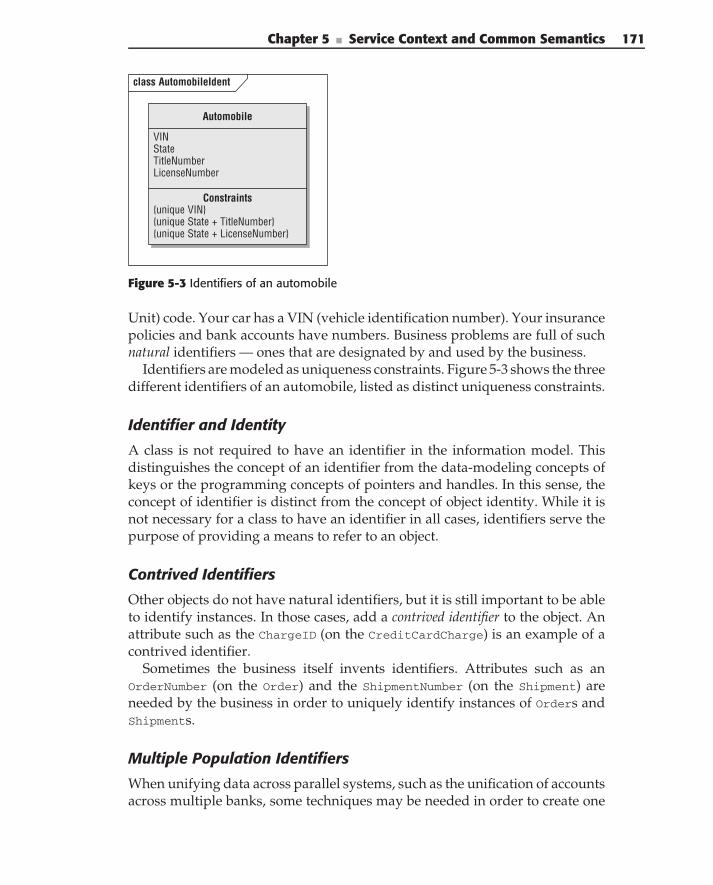
Chapter 5 ■ Service Context and Common Semantics 171
class AutomobileIdent
Automobile
VINStateTitleNumberLicenseNumber
Constraints{unique VIN}{unique State + TitleNumber}{unique State + LicenseNumber}
Figure 5-3 Identifiers of an automobile
Unit) code. Your car has a VIN (vehicle identification number). Your insurancepolicies and bank accounts have numbers. Business problems are full of suchnatural identifiers — ones that are designated by and used by the business.
Identifiers are modeled as uniqueness constraints. Figure 5-3 shows the threedifferent identifiers of an automobile, listed as distinct uniqueness constraints.
Identifier and Identity
A class is not required to have an identifier in the information model. Thisdistinguishes the concept of an identifier from the data-modeling concepts ofkeys or the programming concepts of pointers and handles. In this sense, theconcept of identifier is distinct from the concept of object identity. While it isnot necessary for a class to have an identifier in all cases, identifiers serve thepurpose of providing a means to refer to an object.
Contrived Identifiers
Other objects do not have natural identifiers, but it is still important to be ableto identify instances. In those cases, add a contrived identifier to the object. Anattribute such as the ChargeID (on the CreditCardCharge) is an example of acontrived identifier.
Sometimes the business itself invents identifiers. Attributes such as anOrderNumber (on the Order) and the ShipmentNumber (on the Shipment) areneeded by the business in order to uniquely identify instances of Orders andShipments.
Multiple Population Identifiers
When unifying data across parallel systems, such as the unification of accountsacross multiple banks, some techniques may be needed in order to create one
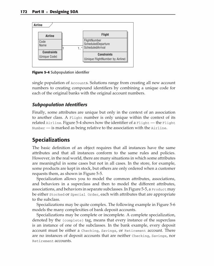
172 Part II ■ Designing SOA
Airline
Airline
CodeName
Constraints{Unique Code}
Flight
FlightNumberScheduledDepartureScheduledArrival
Constraints{Unique FlightNumber by Airline}
1 1..*
Figure 5-4 Subpopulation identifier
single population of Accounts. Solutions range from creating all new accountnumbers to creating compound identifiers by combining a unique code foreach of the original banks with the original account numbers.
Subpopulation Identifiers
Finally, some attributes are unique but only in the context of an associationto another class. A Flight number is only unique within the context of itsrelated Airline. Figure 5-4 shows how the identifier of a Flight — the Flight
Number — is marked as being relative to the association with the Airline.
SpecializationsThe basic definition of an object requires that all instances have the sameattributes and that all instances conform to the same rules and policies.However, in the real world, there are many situations in which some attributesare meaningful in some cases but not in all cases. In the store, for example,some products are kept in stock, but others are only ordered when a customerrequests them, as shown in Figure 5-5.
Specialization allows you to model the common attributes, associations,and behaviors in a superclass and then to model the different attributes,associations, and behaviors in separate subclasses. In Figure 5-5, a Productmaybe either Stocked or Special Order, each with attributes that are appropriateto the subclass.
Specializations may be quite complex. The following example in Figure 5-6models the many complexities of bank deposit accounts.
Specializations may be complete or incomplete. A complete specialization,denoted by the {complete} tag, means that every instance of the superclassis an instance of one of the subclasses. In the bank example, every depositaccount must be either a Checking, Savings, or Retirement account. Thereare no instances of deposit accounts that are neither Checking, Savings, norRetirement accounts.
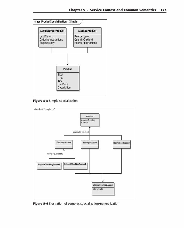
Chapter 5 ■ Service Context and Common Semantics 173
class ProductSpecialization - Simple
SKUUPCTitleUnitPriceDescription
ReorderLevelQuantityOnHandReorderInstructions
LeadTime OrderingInstructionsShipsDirectly
SpecialOrderProduct StockedProduct
Product
Figure 5-5 Simple specialization
class BankExample
Account
AccountNumberBalance
CheckingAccount SavingsAccount RetirementAccount
RegularCheckingAccount InterestCheckingAccount
InterestBearingAccount
InterestRate
{complete, disjoint}
{complete, disjoint}
Figure 5-6 Illustration of complex specialization/generalization
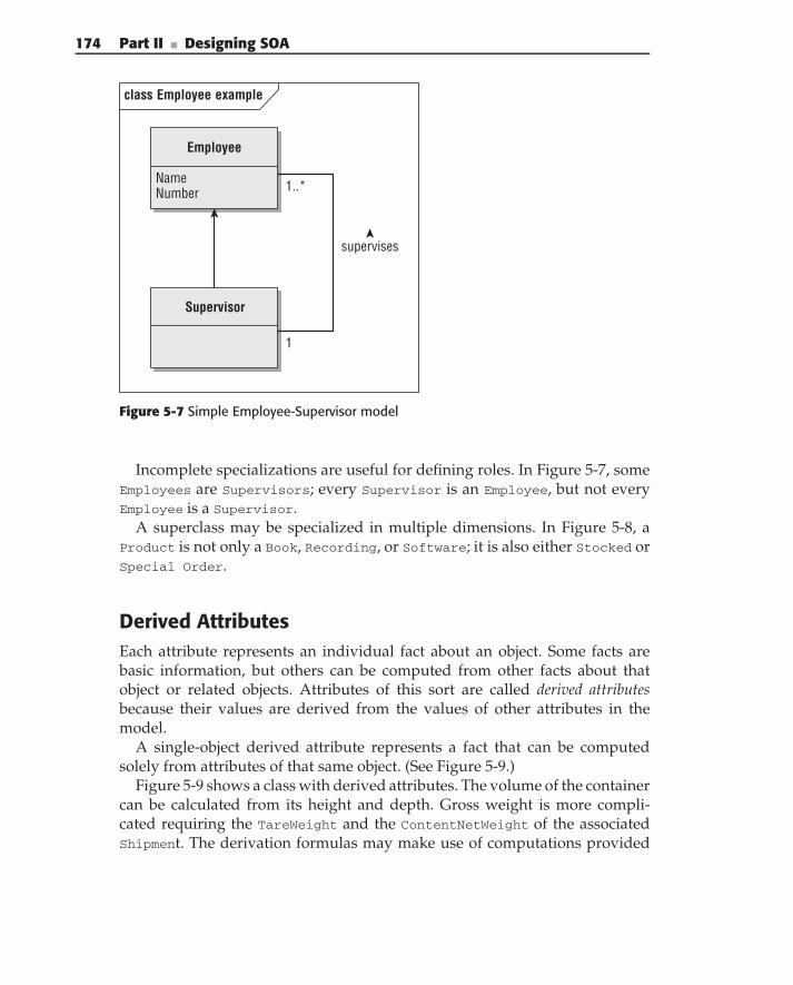
174 Part II ■ Designing SOA
class Employee example
Employee
NameNumber
supervises
1
1..*
Supervisor
Figure 5-7 Simple Employee-Supervisor model
Incomplete specializations are useful for defining roles. In Figure 5-7, someEmployees are Supervisors; every Supervisor is an Employee, but not everyEmployee is a Supervisor.
A superclass may be specialized in multiple dimensions. In Figure 5-8, aProduct is not only a Book, Recording, or Software; it is also either Stocked orSpecial Order.
Derived AttributesEach attribute represents an individual fact about an object. Some facts arebasic information, but others can be computed from other facts about thatobject or related objects. Attributes of this sort are called derived attributesbecause their values are derived from the values of other attributes in themodel.
A single-object derived attribute represents a fact that can be computedsolely from attributes of that same object. (See Figure 5-9.)
Figure 5-9 shows a class with derived attributes. The volume of the containercan be calculated from its height and depth. Gross weight is more compli-cated requiring the TareWeight and the ContentNetWeight of the associatedShipment. The derivation formulas may make use of computations provided
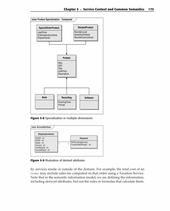
Chapter 5 ■ Service Context and Common Semantics 175
class Product Specialization - Compound
SpecialOrderProduct
LeadTimeOrderingInstructionsShipsDirectly
StockedProduct
ReorderLevelQuantityOnHandReorderInstructions
Product
SKUUPCTitleUnitPriceDescription
Book Recording
RunningTimeFormat
Software
Figure 5-8 Specialization in multiple dimensions
class DerivedAttribute
ShippingContainer
Height: intWidth: intDepth: intVolume: intTareWeight: intGrossWeight: int
Shipment
BillOfLadingNumber ContentsNetWeight: int1 1
Figure 5-9 Illustration of derived attributes
by services inside or outside of the domain. For example, the total cost of anOrder may include sales tax computed on that order using a Taxation Service.Note that in the semantic information model, we are defining the information,including derived attributes, but not the rules or formulas that calculate them.
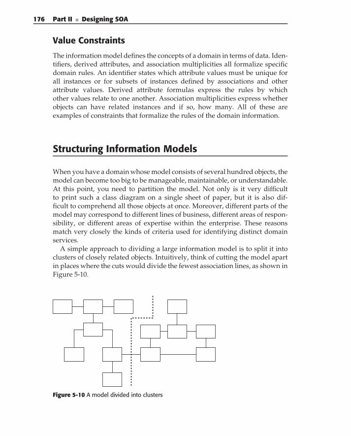
176 Part II ■ Designing SOA
Value Constraints
The information model defines the concepts of a domain in terms of data. Iden-tifiers, derived attributes, and association multiplicities all formalize specificdomain rules. An identifier states which attribute values must be unique forall instances or for subsets of instances defined by associations and otherattribute values. Derived attribute formulas express the rules by whichother values relate to one another. Association multiplicities express whetherobjects can have related instances and if so, how many. All of these areexamples of constraints that formalize the rules of the domain information.
Structuring Information Models
When you have a domain whose model consists of several hundred objects, themodel can become too big to be manageable, maintainable, or understandable.At this point, you need to partition the model. Not only is it very difficultto print such a class diagram on a single sheet of paper, but it is also dif-ficult to comprehend all those objects at once. Moreover, different parts of themodel may correspond to different lines of business, different areas of respon-sibility, or different areas of expertise within the enterprise. These reasonsmatch very closely the kinds of criteria used for identifying distinct domainservices.
A simple approach to dividing a large information model is to split it intoclusters of closely related objects. Intuitively, think of cutting the model apartin places where the cuts would divide the fewest association lines, as shown inFigure 5-10.
Figure 5-10 A model divided into clusters
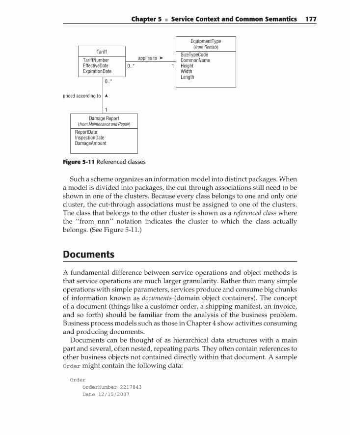
Chapter 5 ■ Service Context and Common Semantics 177
Damage Report(from Maintenance and Repair)
ReportDateInspectionDateDamageAmount
EquipmentType(from Rentals)
SizeTypeCodeCommonNameHeightWidthLength
Tariff
TariffNumberEffectiveDateExpirationDate
0..* 1
applies to
priced according to
1
0..*
Figure 5-11 Referenced classes
Such a scheme organizes an information model into distinct packages. Whena model is divided into packages, the cut-through associations still need to beshown in one of the clusters. Because every class belongs to one and only onecluster, the cut-through associations must be assigned to one of the clusters.The class that belongs to the other cluster is shown as a referenced class wherethe ‘‘from nnn’’ notation indicates the cluster to which the class actuallybelongs. (See Figure 5-11.)
Documents
A fundamental difference between service operations and object methods isthat service operations are much larger granularity. Rather than many simpleoperations with simple parameters, services produce and consume big chunksof information known as documents (domain object containers). The conceptof a document (things like a customer order, a shipping manifest, an invoice,and so forth) should be familiar from the analysis of the business problem.Business process models such as those in Chapter 4 show activities consumingand producing documents.
Documents can be thought of as hierarchical data structures with a mainpart and several, often nested, repeating parts. They often contain references toother business objects not contained directly within that document. A sampleOrder might contain the following data:
Order
OrderNumber 2217843
Date 12/15/2007
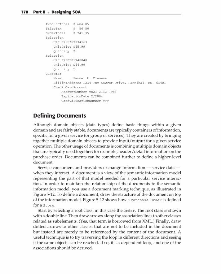
178 Part II ■ Designing SOA
ProductTotal $ 684.85
SalesTax $ 56.50
OrderTotal $ 741.35
Selection
UPC 0785357834163
UnitPrice $45.99
Quantity 2
Selection
UPC 9780201748048
UnitPrice $44.99
Quantity 5
Customer
Name Samuel L. Clemens
BillingAddress 1234 Tom Sawyer Drive, Hannibal, MO, 63401
CreditCardAccount
AccountNumber 9823-2132-7983
ExpirationDate 2/2004
CardValidationNumber 999
Defining Documents
Although domain objects (data types) define basic things within a givendomain and are fairly stable, documents are typically containers of information,specific for a given service (or group of services). They are created by bringingtogether multiple domain objects to provide input/output for a given serviceoperation. The other usage of documents is combining multiple domain objectsthat are typically used together; for example, header/detail information on thepurchase order. Documents can be combined further to define a higher-leveldocument.
Service consumers and providers exchange information — service data —when they interact. A document is a view of the semantic information modelrepresenting the part of that model needed for a particular service interac-tion. In order to maintain the relationship of the documents to the semanticinformation model, you use a document marking technique, as illustrated inFigure 5-12. To define a document, draw the structure of the document on topof the information model. Figure 5-12 shows how a Purchase Order is definedfor a Store.
Start by selecting a root class, in this case the Order. The root class is shownwith a double line. Then draw arrows along the association lines to other classesrelated as subelements. (Yes, that term is borrowed from XML.) Finally, drawdotted arrows to other classes that are not to be included in the documentbut instead are merely to be referenced by the content of the document. Auseful technique is to try traversing the loop in different directions and seeingif the same objects can be reached. If so, it’s a dependent loop, and one of theassociations should be derived.
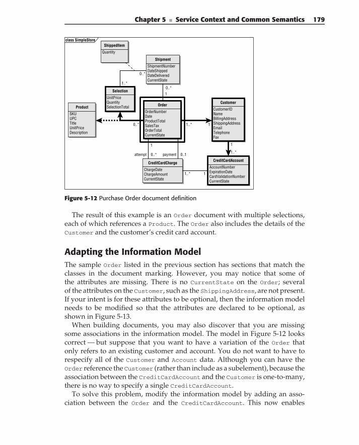
Chapter 5 ■ Service Context and Common Semantics 179
Product
SKUUPCTitleUnitPriceDescription
Order
OrderNumberDateProductTotalSalesTaxOrderTotalCurrentState
CreditCardCharge
ChargeDateChargeAmountCurrentState
Customer
CustomerIDNameBillingAddressShippingAddressEmailTelephoneFax
Shipment
ShipmentNumberDateShippedDateDeliveredCurrentState
CreditCardAccount
AccountNumberExpirationDateCardValidationNumberCurrentState
Selection
UnitPriceQuantitySelectionTotal
ShippedItem
Quantity
payment 0..1
10..*
11..*
1..*
0..*
1
attempt 0..*
11..*
1
1..*
0..*
class SimpleStore
Figure 5-12 Purchase Order document definition
The result of this example is an Order document with multiple selections,each of which references a Product. The Order also includes the details of theCustomer and the customer’s credit card account.
Adapting the Information ModelThe sample Order listed in the previous section has sections that match theclasses in the document marking. However, you may notice that some ofthe attributes are missing. There is no CurrentState on the Order; severalof the attributes on the Customer, such as the ShippingAddress, are not present.If your intent is for these attributes to be optional, then the information modelneeds to be modified so that the attributes are declared to be optional, asshown in Figure 5-13.
When building documents, you may also discover that you are missingsome associations in the information model. The model in Figure 5-12 lookscorrect — but suppose that you want to have a variation of the Order thatonly refers to an existing customer and account. You do not want to have torespecify all of the Customer and Account data. Although you can have theOrder reference the Customer (rather than include as a subelement), because theassociation between the CreditCardAccount and the Customer is one-to-many,there is no way to specify a single CreditCardAccount.
To solve this problem, modify the information model by adding an asso-ciation between the Order and the CreditCardAccount. This now enables
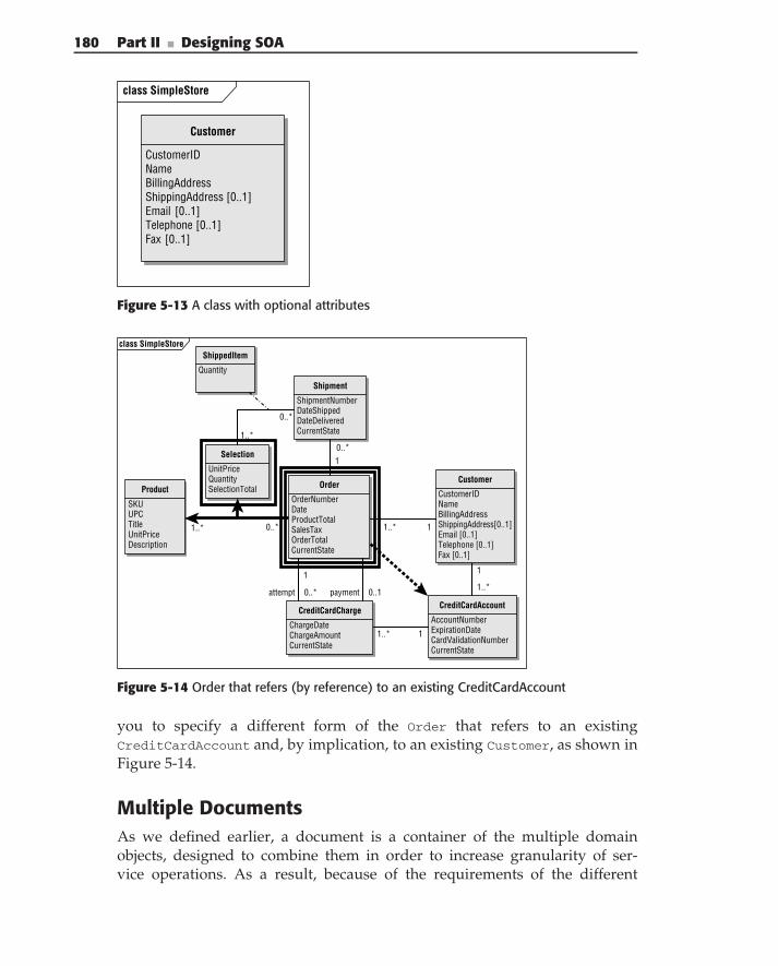
180 Part II ■ Designing SOA
class SimpleStore
Customer
CustomerIDNameBillingAddressShippingAddress [0..1]Email [0..1]Telephone [0..1]Fax [0..1]
Figure 5-13 A class with optional attributes
Product
SKUUPCTitleUnitPriceDescription
Order
OrderNumberDateProductTotalSalesTaxOrderTotalCurrentState
CreditCardCharge
ChargeDateChargeAmountCurrentState
Customer
CustomerIDNameBillingAddressShippingAddress[0..1]Email [0..1]Telephone [0..1]Fax [0..1]
Shipment
ShipmentNumberDateShippedDateDeliveredCurrentState
CreditCardAccount
AccountNumberExpirationDateCardValidationNumberCurrentState
Selection
UnitPriceQuantitySelectionTotal
ShippedItem
Quantity
payment 0..1
10..*
11..*
1..*
0..*
1
attempt 0..*
11..*
1
1..*
1..* 0..*
class SimpleStore
Figure 5-14 Order that refers (by reference) to an existing CreditCardAccount
you to specify a different form of the Order that refers to an existingCreditCardAccount and, by implication, to an existing Customer, as shown inFigure 5-14.
Multiple DocumentsAs we defined earlier, a document is a container of the multiple domainobjects, designed to combine them in order to increase granularity of ser-vice operations. As a result, because of the requirements of the different
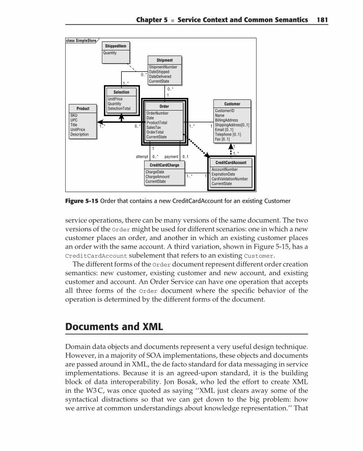
Chapter 5 ■ Service Context and Common Semantics 181
Product
SKUUPCTitleUnitPriceDescription
Order
OrderNumberDateProductTotalSalesTaxOrderTotalCurrentState
CreditCardCharge
ChargeDateChargeAmountCurrentState
Shipment
ShipmentNumberDateShippedDateDeliveredCurrentState
CreditCardAccount
AccountNumberExpirationDateCardValidationNumberCurrentState
Selection
UnitPriceQuantitySelectionTotal
ShippedItem
Quantity
payment 0..1
10..*
11..*
1..*
0..*
1
attempt 0..*
11..*
1
1..*
1..* 0..*
class SimpleStore
Customer
CustomerIDNameBillingAddressShippingAddress[0..1]Email [0..1]Telephone [0..1]Fax [0..1]
Figure 5-15 Order that contains a new CreditCardAccount for an existing Customer
service operations, there can be many versions of the same document. The twoversions of the Order might be used for different scenarios: one in which a newcustomer places an order, and another in which an existing customer placesan order with the same account. A third variation, shown in Figure 5-15, has aCreditCardAccount subelement that refers to an existing Customer.
The different forms of the Orderdocument represent different order creationsemantics: new customer, existing customer and new account, and existingcustomer and account. An Order Service can have one operation that acceptsall three forms of the Order document where the specific behavior of theoperation is determined by the different forms of the document.
Documents and XML
Domain data objects and documents represent a very useful design technique.However, in a majority of SOA implementations, these objects and documentsare passed around in XML, the de facto standard for data messaging in serviceimplementations. Because it is an agreed-upon standard, it is the buildingblock of data interoperability. Jon Bosak, who led the effort to create XMLin the W3 C, was once quoted as saying ‘‘XML just clears away some of thesyntactical distractions so that we can get down to the big problem: howwe arrive at common understandings about knowledge representation.’’ That
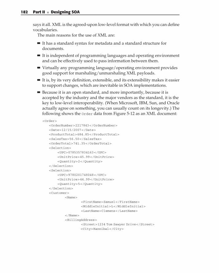
182 Part II ■ Designing SOA
says it all. XML is the agreed-upon low-level format with which you can definevocabularies.
The main reasons for the use of XML are:
It has a standard syntax for metadata and a standard structure fordocuments.
It is independent of programming languages and operating environmentand can be effectively used to pass information between them.
Virtually any programming language/operating environment providesgood support for marshaling/unmarshaling XML payloads.
It is, by its very definition, extensible, and its extensibility makes it easierto support changes, which are inevitable in SOA implementations.
Because it is an open standard, and more importantly, because it isaccepted by the industry and the major vendors as the standard, it is thekey to low-level interoperability. (When Microsoft, IBM, Sun, and Oracleactually agree on something, you can usually count on its longevity.) Thefollowing shows the Order data from Figure 5-12 as an XML document:
<Order>
<OrderNumber>2217843</OrderNumber>
<Date>12/15/2007</Date>
<ProductTotal>684.85</ProductTotal>
<SalesTax>56.50</SalesTax>
<OrderTotal>741.35</OrderTotal>
<Selection>
<UPC>0785357834163</UPC>
<UnitPrice>45.99</UnitPrice>
<Quantity>2</Quantity>
</Selection>
<Selection>
<UPC>9780201748048</UPC>
<UnitPrice>44.99</UnitPrice>
<Quantity>5</Quantity>
</Selection>
<Customer>
<Name>
<FirstName>Samuel</FirstName>
<MiddleInitial>L</MiddleInitial>
<LastName>Clemens</LastName>
</Name>
<BillingAddress>
<Street>1234 Tom Sawyer Drive</Street>
<City>Hannibal</City>
Chapter 5 ■ Service Context and Common Semantics 183
<State>MO</State>
<Zip>63401</Zip>
</BillingAddress>
<CreditCardAccount>
<AccountNumber>9823-2132-7983</AccountNumber>
<ExpirationDate>2/2004</ExpirationDate>
<CardValidationNumber>999</CardValidationNumber>
</CreditCardAccount>
</Customer>
</Order>
Note how the structure of the order is immediately evident in the textof the document. The tags follow the structure of the document: elements,subelements, references, and attributes. However, there are some significantissues in the relationship of the model and the XML document that describesit. When designing XML documents, the following should be considered:
XML uses a hierarchical data model. The hierarchical model differs sig-nificantly from OO representations and data models used in traditionaldatabases, like the normalized relational data model, which aims for fastupdates and retrievals; or the dimensional data model which aims toslice information in various dimensions; or pointers, which provide fastdata traversal. As a result, common database design techniques (e.g.,normalization, joins, foreign keys, etc.) or OO design (described in thepreceding sections on classes, attributes, etc.) are rarely applicable toXML. They usually lead to an overly complex XML implementation.XML design typically requires significant denormalization of data tominimize cross-references between XML objects.
As XML payloads are subject to marshaling/unmarshaling whencrossing each service boundary, the use of ‘‘small’’ types in XML incurssignificant serialization overhead, which in turn has a negative impacton performance. Every XML type is marshaled/unmarshaled into a sep-arate object. This means that usage of ‘‘small’’ XML types leads to thecreation and deletion of a large number of objects during execution.Therefore, it is recommended that you increase the size of XML objectsduring semantic information model design.
Excessive nesting of XML types can lead to a significantly more complexXML processing of the payloads. It usually leads to creation of additionallanguage objects during marshaling/unmarshaling and requires a morecomplex notation to access the data. Therefore, it is advantageous tominimize the amount of nesting in the XML payload’s definition.
We talk more about best practices later in this chapter.
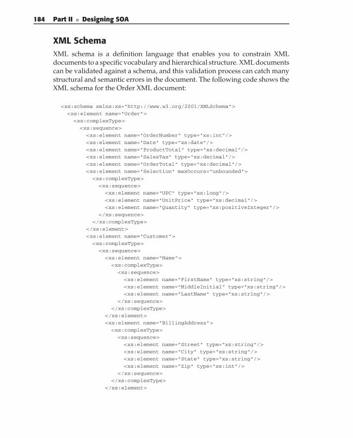
184 Part II ■ Designing SOA
XML SchemaXML schema is a definition language that enables you to constrain XMLdocuments to a specific vocabulary and hierarchical structure. XML documentscan be validated against a schema, and this validation process can catch manystructural and semantic errors in the document. The following code shows theXML schema for the Order XML document:
<xs:schema xmlns:xs="http://www.w3.org/2001/XMLSchema">
<xs:element name="Order">
<xs:complexType>
<xs:sequence>
<xs:element name="OrderNumber" type="xs:int"/>
<xs:element name="Date" type="xs:date"/>
<xs:element name="ProductTotal" type="xs:decimal"/>
<xs:element name="SalesTax" type="xs:decimal"/>
<xs:element name="OrderTotal" type="xs:decimal"/>
<xs:element name="Selection" maxOccurs="unbounded">
<xs:complexType>
<xs:sequence>
<xs:element name="UPC" type="xs:long"/>
<xs:element name="UnitPrice" type="xs:decimal"/>
<xs:element name="Quantity" type="xs:positiveInteger"/>
</xs:sequence>
</xs:complexType>
</xs:element>
<xs:element name="Customer">
<xs:complexType>
<xs:sequence>
<xs:element name="Name">
<xs:complexType>
<xs:sequence>
<xs:element name="FirstName" type="xs:string"/>
<xs:element name="MiddleInitial" type="xs:string"/>
<xs:element name="LastName" type="xs:string"/>
</xs:sequence>
</xs:complexType>
</xs:element>
<xs:element name="BillingAddress">
<xs:complexType>
<xs:sequence>
<xs:element name="Street" type="xs:string"/>
<xs:element name="City" type="xs:string"/>
<xs:element name="State" type="xs:string"/>
<xs:element name="Zip" type="xs:int"/>
</xs:sequence>
</xs:complexType>
</xs:element>
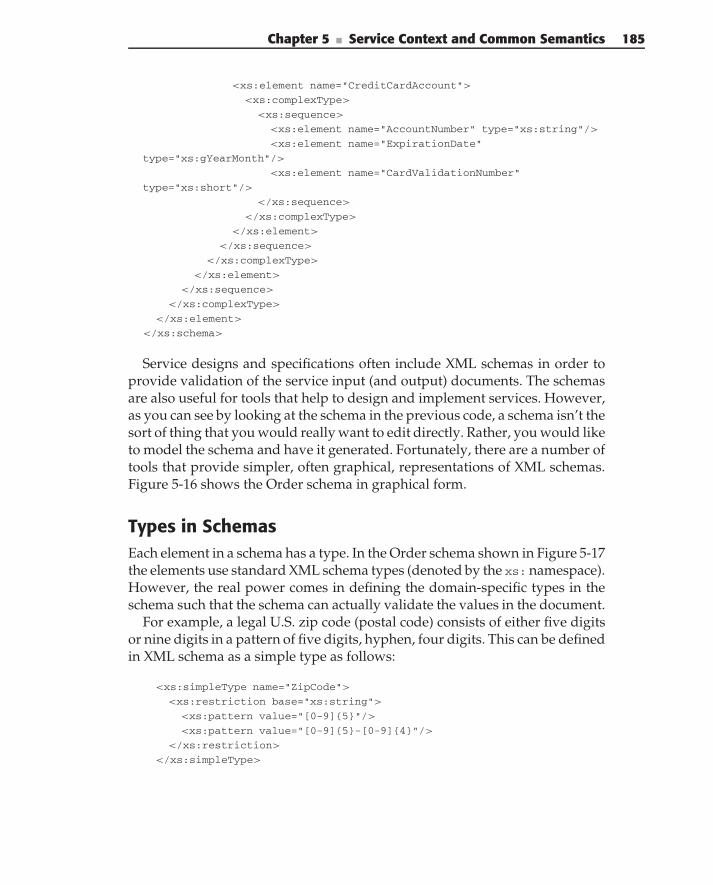
Chapter 5 ■ Service Context and Common Semantics 185
<xs:element name="CreditCardAccount">
<xs:complexType>
<xs:sequence>
<xs:element name="AccountNumber" type="xs:string"/>
<xs:element name="ExpirationDate"
type="xs:gYearMonth"/>
<xs:element name="CardValidationNumber"
type="xs:short"/>
</xs:sequence>
</xs:complexType>
</xs:element>
</xs:sequence>
</xs:complexType>
</xs:element>
</xs:sequence>
</xs:complexType>
</xs:element>
</xs:schema>
Service designs and specifications often include XML schemas in order toprovide validation of the service input (and output) documents. The schemasare also useful for tools that help to design and implement services. However,as you can see by looking at the schema in the previous code, a schema isn’t thesort of thing that you would really want to edit directly. Rather, you would liketo model the schema and have it generated. Fortunately, there are a number oftools that provide simpler, often graphical, representations of XML schemas.Figure 5-16 shows the Order schema in graphical form.
Types in SchemasEach element in a schema has a type. In the Order schema shown in Figure 5-17the elements use standard XML schema types (denoted by the xs: namespace).However, the real power comes in defining the domain-specific types in theschema such that the schema can actually validate the values in the document.
For example, a legal U.S. zip code (postal code) consists of either five digitsor nine digits in a pattern of five digits, hyphen, four digits. This can be definedin XML schema as a simple type as follows:
<xs:simpleType name="ZipCode">
<xs:restriction base="xs:string">
<xs:pattern value="[0-9]{5}"/>
<xs:pattern value="[0-9]{5}-[0-9]{4}"/>
</xs:restriction>
</xs:simpleType>
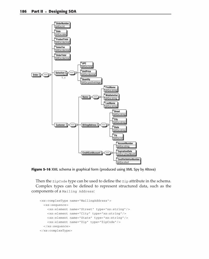
186 Part II ■ Designing SOA
OrderNumbertype xs:int
Datetype xs:date
SalesTaxtype xs:decimal
OrderTotal
OrderSelection
type xs:decimal
1..∞
UPCtype xs:long
UnitPricetype xs:decimal
Quantitytype xs:positiveInteger
FirstNametype xs:string
MiddleInitialName
Customer BillingAddress
CreditCardAccount
type xs:string
LastNametype xs:string
Streettype xs:string
Citytype xs:string
Statetype xs:string
Ziptype xs:int
AccountNumbertype xs:string
ExpirationDatetype xs:gYearMonth
CardValidationNumbertype xs:short
ProductTotaltype xs:decimal
Figure 5-16 XML schema in graphical form (produced using XML Spy by Altova)
Then the ZipCode type can be used to define the Zip attribute in the schema.Complex types can be defined to represent structured data, such as the
components of a Mailing Address:
<xs:complexType name="MailingAddress">
<xs:sequence>
<xs:element name="Street" type="xs:string"/>
<xs:element name="City" type="xs:string"/>
<xs:element name="State" type="xs:string"/>
<xs:element name="Zip" type="ZipCode"/>
</xs:sequence>
</xs:complexType>
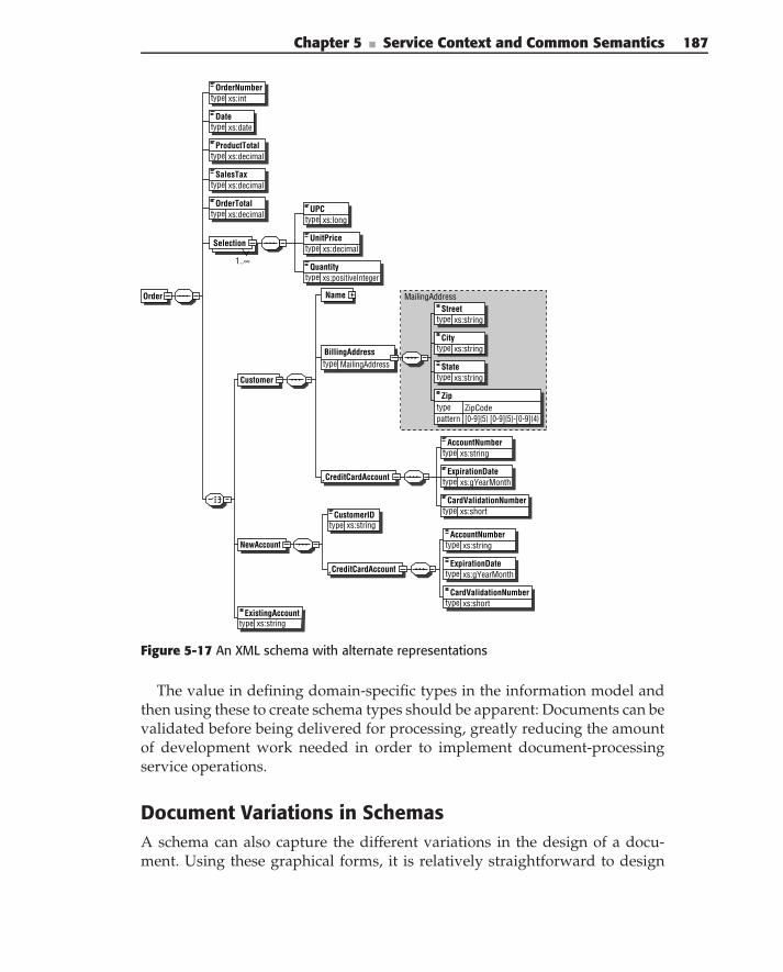
Chapter 5 ■ Service Context and Common Semantics 187
OrderNumbertype xs:int
Datetype xs:date
SalesTaxtype xs:decimal
OrderTotal
Order
Selection
type xs:decimal
1..∞
UPCtype xs:long
UnitPricetype xs:decimal
Quantitytype xs:positiveInteger
Name
Customer
CreditCardAccount
NewAccount
Streettype xs:string
CustomerIDtype xs:string
ExistingAccounttype xs:string
BillingAddresstype MailingAddress
Citytype xs:string
Statetype xs:string
Zip
pattern [0-9]{5} [0-9]{5}-[0-9]{4}type ZipCode
AccountNumbertype xs:string
ExpirationDatetype xs:gYearMonth
CardValidationNumbertype xs:short
CreditCardAccount
AccountNumbertype xs:string
ExpirationDatetype xs:gYearMonth
CardValidationNumbertype xs:short
ProductTotaltype xs:decimal
MailingAddress
Figure 5-17 An XML schema with alternate representations
The value in defining domain-specific types in the information model andthen using these to create schema types should be apparent: Documents can bevalidated before being delivered for processing, greatly reducing the amountof development work needed in order to implement document-processingservice operations.
Document Variations in SchemasA schema can also capture the different variations in the design of a docu-ment. Using these graphical forms, it is relatively straightforward to design
188 Part II ■ Designing SOA
documents with variations such as the several forms of the Order mentionedearlier and shown in Figure 5-17.
Designing for Change
One of the important requirements for designing an XML document for ser-vice interfaces is support for versioning (see Chapter 9 for more on the serviceversioning). Using XML schemas to define potential document changes allowsan alignment with XML schema-versioning techniques (see the ‘‘VersioningSupport in XML Schemas’’ sidebar), thus allowing for direct representation ofversioning in the documents. Changes in schemas can be broadly divided intothree major categories:
Revisions represent document changes with no semantic meaning. Forexample, a change in white space, formatting, non-normative documen-tation, comments, and so on. A revision of an already published versionmust not affect the functionality of either service implementations orconsumers.
Additionally, the initial incremental revisions during development ofa semantic schema, before it is published for production, can also betreated as revisions of the same version.
Minor changes are backward-compatible changes to the documentschema. Examples of minor changes to the schema include:
Changing the optionality of a local element or element reference fromrequired to optional.
Adding a global element or type.
Adding optional elements to the existing type.
Changing the type of a global or local element to the type derivedfrom the original type, by adding/restricting optional elements.
Major changes are non-backward-compatible changes to the documentschema.
Examples of major changes to the schema include:
Changing the type of a local or global element by adding requiredelements or attributes.
Changing the optionality of a local element or element reference fromoptional to required.
Adding or removing an enumeration value.
Removing or renaming a global type or element.
Chapter 5 ■ Service Context and Common Semantics 189
VERSIONING SUPPORT IN XML SCHEMAS
The simplest way to denote versions in XML Schema is to use an (optional)attribute at the xs:schema element — version. The content model permitsDewey notation of major.minor version numbers.
Bacause XML parsers are not required to validate instances using version, itis possible to implement a custom representation of version, enabling theparser to include it in the validation process. Using this technique typicallyrequires introduction of a versioning attribute as a fixed, required value foridentifying a specific schema version. Although theoretically this is a goodapproach for schema versioning, it is not very practical. There are severaldisadvantages to this approach:
◆ An XML instance is unable to use multiple versions of a schema representa-tion because versioning occurs at the schema’s root.
◆ XML schema validation tools are not required to validate instances usingthe version attribute. The attribute is provided purely for documentationpurposes and is not enforceable by XML parsers.
◆ Because XML parsers are not required to validate the use of the versionattribute, additional custom processing (over and above parsing and valida-tion) is required to ensure that the expected schema version(s) is being ref-erenced by the instance.
◆ Marshaling/unmarshaling of XML documents is very rarely done usingdirect manipulation of the Document Object Model (DOM) tree. The mostprevalent approach to marshaling is the generation of classes that support‘‘automatic’’ marshaling, using tools like WSDL2Java, Castor, Eclipse Model-ing Framework (EMF), Service Data Objects (SDO), XML Schema Definition(XSD), XSDObjectGenerator, and the like. In this case, classes are gener-ated in the packages in Java or namespaces in C#, based on the schemanamespaces, not the schema version.
Another option for denoting the schema version is XML namespaces. Inthis approach a new XML namespace is used for all major version releases. Thisapproach is well aligned with the generation of marshaling/unmarshaling code.It allows code to be generated in different packages (namespaces), thusenabling a single-service consumer to work with several major releases ofschema simultaneously.
The final option is to keep XML namespace values constant and add a specialelement for grouping custom extensions. This approach wraps extensions tothe underlying vocabulary within a special extension element. This technique isfavored by several industry-standard schemas. For example, the OpenApplication Group’s Business Object Documents (OAG BODs) include a<userarea> element defining custom information that may not be part of thebase vocabulary. This approach provides maximum extensibility of the schema
(continued)
190 Part II ■ Designing SOA
VERSIONING SUPPORT IN XML SCHEMAS (continued)
constructs (schemas can be both forward and backward compatible) withoutthe introduction of new namespaces. There are two disadvantages to thisapproach:
◆ It introduces significantly higher levels of complexity into the schema.
◆ It does not allow the implementation of multiple extensions across differ-ent portions of the XML instance, because all extensions must be groupedwithin the extension ‘‘wrapper.’’
◆ The most scalable approach to versioning of schemas is:
■ Componentization of the overall schema into logical partitions, usingmultiple namespaces, thus allowing each to contain changes.
■ Defining a new namespace (reflecting the major version information) forevery major version of each schema.
■ Denoting every minor version as a schema version in a major versionnamespace. Because minor versions are backward-compatible, gener-ated marshaling/unmarshaling code is backward-compatible as well.
XML Patterns
With the multiplicity of tools that allow for the generation of XML documents,creation of documents might seem very straightforward. Once a UML modelof semantic information is created, the appropriate tooling can be used togenerate both the schema and XML instances. This approach does not requireknowledge or a good understanding of XML and seems so simple that a lot ofpeople have rushed into using it without thinking about the consequences. Asa result, many implementations are stuck with ‘‘bad,’’ hard-to-maintain XMLschemas. We have seen a lot of cases where this approach leads to significantperformance degradation, requirements for massive implementation changes,and so on. Here, we discuss some approaches that allow you to producebetter, more maintainable XML documents. Some of the recommendationsdescribed here can be achieved through modification of the models, whereasothers may require tweaking an XML schema produced as a result of thegeneration.
One of the things to keep in mind is that XML uses a hierarchical data model,which differs significantly from OO representations. This model is very wellsuited for implementing containment relationships, but the implementation ofreferences (although possible through usage of IDs/IDREFs XML support) canlead to significant performance degradation during XML processing. The usage
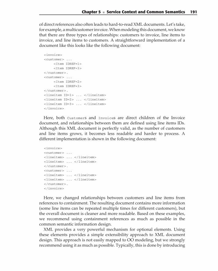
Chapter 5 ■ Service Context and Common Semantics 191
of direct references also often leads to hard-to-read XML documents. Let’s take,for example, a multicustomer invoice. When modeling this document, we knowthat there are three types of relationships: customers to invoice, line items toinvoice, and line items to customers. A straightforward implementation of adocument like this looks like the following document:
<invoice>
<customer> ...
<Item IDREF=1>
<Item IDREF=3>
</customer>.
<customer> ...
<Item IDREF=2>
<Item IDREF=3>
</customer>.
<lineitem ID=1> ... </lineitem>
<lineitem ID=2> ... </lineitem>
<lineitem ID=3> ... </lineitem>
</invoice>
Here, both Customers and Invoices are direct children of the Invoicedocument, and relationships between them are defined using line items IDs.Although this XML document is perfectly valid, as the number of customersand line items grows, it becomes less readable and harder to process. Adifferent implementation is shown in the following document:
<invoice>
<customer> ...
<lineitem> ... </lineitem>
<lineitem> ... </lineitem>
</customer>.
<customer> ...
<lineitem> ... </lineitem>
<lineitem> ... </lineitem>
</customer>.
</invoice>
Here, we changed relationships between customers and line items fromreferences to containment. The resulting document contains more information(some line items can be repeated multiple times for different customers), butthe overall document is cleaner and more readable. Based on these examples,we recommend using containment references as much as possible in thecommon semantic information design.
XML provides a very powerful mechanism for optional elements. Usingthese elements provides a simple extensibility approach to XML documentdesign. This approach is not easily mapped to OO modeling, but we stronglyrecommend using it as much as possible. Typically, this is done by introducing
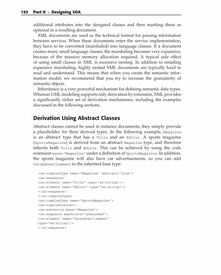
192 Part II ■ Designing SOA
additional attributes into the designed classes and then marking them asoptional in a resulting document.
XML documents are used as the technical format for passing informationbetween services. When these documents enter the service implementation,they have to be converted (marshaled) into language classes. If a documentcreates many small language classes, the marshaling becomes very expensive,because of the massive memory allocation required. A typical side effectof using small classes in XML is excessive nesting. In addition to entailingexpensive marshaling, highly nested XML documents are typically hard toread and understand. This means that when you create the semantic infor-mation model, we recommend that you try to increase the granularity ofsemantic objects.
Inheritance is a very powerful mechanism for defining semantic data types.Whereas UML modeling supports only derivation by extension, XML providesa significantly richer set of derivation mechanisms, including the examplesdiscussed in the following sections.
Derivation Using Abstract ClassesAbstract classes cannot be used in instance documents; they simply providea placeholder for their derived types. In the following example, Magazineis an abstract type that has a Title and an Editor. A sports magazine(SportsMagazine) is derived from an abstract Magazine type, and thereforeinherits both Title and Editor. This can be achieved by using the codeextension base="Magazine"under a definition of SportsMagazine. In addition,the sports magazine will also have car advertisements, so you can addCarsAdvertizement to the inherited base type:
<xs:complexType name="Magazine" abstract="true">
<xs:sequence>
<xs:element name="Title" type="xs:string"/>
<xs:element name="Editor" type="xs:string"/>
</xs:sequence>
</xs:complexType>
<xs:complexType name="SportsMagazine">
<xs:complexContent>
<xs:extension base="Magazine">
<xs:sequence maxOccurs="unbounded">
<xs:element name="CarsAdvertizement"
type="xs:string"/>
</xs:sequence>
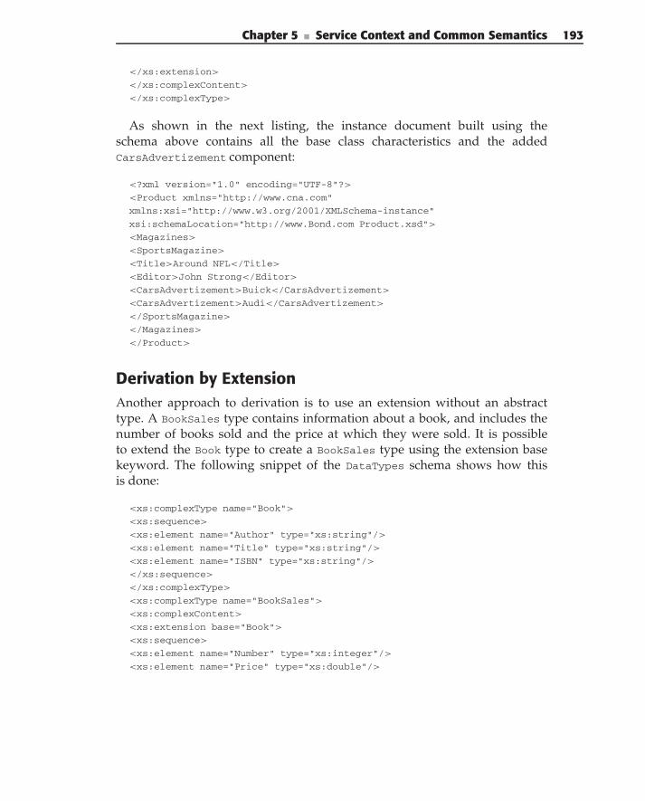
Chapter 5 ■ Service Context and Common Semantics 193
</xs:extension>
</xs:complexContent>
</xs:complexType>
As shown in the next listing, the instance document built using theschema above contains all the base class characteristics and the addedCarsAdvertizement component:
<?xml version="1.0" encoding="UTF-8"?>
<Product xmlns="http://www.cna.com"
xmlns:xsi="http://www.w3.org/2001/XMLSchema-instance"
xsi:schemaLocation="http://www.Bond.com Product.xsd">
<Magazines>
<SportsMagazine>
<Title>Around NFL</Title>
<Editor>John Strong</Editor>
<CarsAdvertizement>Buick</CarsAdvertizement>
<CarsAdvertizement>Audi</CarsAdvertizement>
</SportsMagazine>
</Magazines>
</Product>
Derivation by ExtensionAnother approach to derivation is to use an extension without an abstracttype. A BookSales type contains information about a book, and includes thenumber of books sold and the price at which they were sold. It is possibleto extend the Book type to create a BookSales type using the extension basekeyword. The following snippet of the DataTypes schema shows how thisis done:
<xs:complexType name="Book">
<xs:sequence>
<xs:element name="Author" type="xs:string"/>
<xs:element name="Title" type="xs:string"/>
<xs:element name="ISBN" type="xs:string"/>
</xs:sequence>
</xs:complexType>
<xs:complexType name="BookSales">
<xs:complexContent>
<xs:extension base="Book">
<xs:sequence>
<xs:element name="Number" type="xs:integer"/>
<xs:element name="Price" type="xs:double"/>
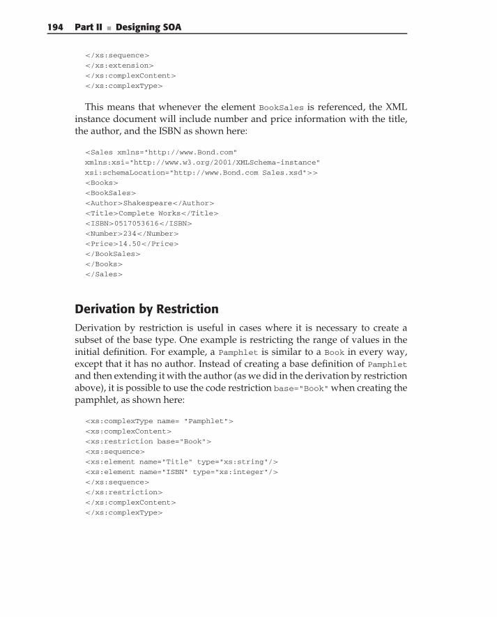
194 Part II ■ Designing SOA
</xs:sequence>
</xs:extension>
</xs:complexContent>
</xs:complexType>
This means that whenever the element BookSales is referenced, the XMLinstance document will include number and price information with the title,the author, and the ISBN as shown here:
<Sales xmlns="http://www.Bond.com"
xmlns:xsi="http://www.w3.org/2001/XMLSchema-instance"
xsi:schemaLocation="http://www.Bond.com Sales.xsd">>
<Books>
<BookSales>
<Author>Shakespeare</Author>
<Title>Complete Works</Title>
<ISBN>0517053616</ISBN>
<Number>234</Number>
<Price>14.50</Price>
</BookSales>
</Books>
</Sales>
Derivation by RestrictionDerivation by restriction is useful in cases where it is necessary to create asubset of the base type. One example is restricting the range of values in theinitial definition. For example, a Pamphlet is similar to a Book in every way,except that it has no author. Instead of creating a base definition of Pamphletand then extending it with the author (as we did in the derivation by restrictionabove), it is possible to use the code restriction base="Book" when creating thepamphlet, as shown here:
<xs:complexType name= "Pamphlet">
<xs:complexContent>
<xs:restriction base="Book">
<xs:sequence>
<xs:element name="Title" type="xs:string"/>
<xs:element name="ISBN" type="xs:integer"/>
</xs:sequence>
</xs:restriction>
</xs:complexContent>
</xs:complexType>
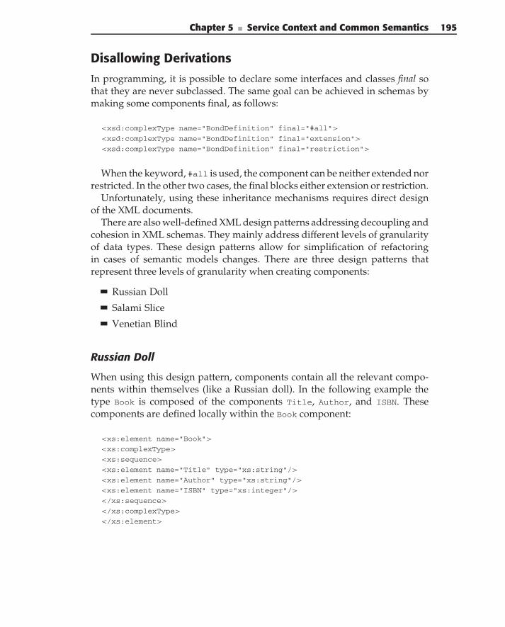
Chapter 5 ■ Service Context and Common Semantics 195
Disallowing Derivations
In programming, it is possible to declare some interfaces and classes final sothat they are never subclassed. The same goal can be achieved in schemas bymaking some components final, as follows:
<xsd:complexType name="BondDefinition" final="#all">
<xsd:complexType name="BondDefinition" final="extension">
<xsd:complexType name="BondDefinition" final="restriction">
When the keyword, #all is used, the component can be neither extended norrestricted. In the other two cases, the final blocks either extension or restriction.
Unfortunately, using these inheritance mechanisms requires direct designof the XML documents.
There are also well-defined XML design patterns addressing decoupling andcohesion in XML schemas. They mainly address different levels of granularityof data types. These design patterns allow for simplification of refactoringin cases of semantic models changes. There are three design patterns thatrepresent three levels of granularity when creating components:
Russian Doll
Salami Slice
Venetian Blind
Russian Doll
When using this design pattern, components contain all the relevant compo-nents within themselves (like a Russian doll). In the following example thetype Book is composed of the components Title, Author, and ISBN. Thesecomponents are defined locally within the Book component:
<xs:element name="Book">
<xs:complexType>
<xs:sequence>
<xs:element name="Title" type="xs:string"/>
<xs:element name="Author" type="xs:string"/>
<xs:element name="ISBN" type="xs:integer"/>
</xs:sequence>
</xs:complexType>
</xs:element>
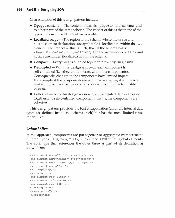
196 Part II ■ Designing SOA
Characteristics of this design pattern include:
Opaque content — The content of Book is opaque to other schemas andto other parts of the same schema. The impact of this is that none of thetypes or elements within Book are reusable.
Localized scope — The region of the schema where the Title andAuthor element declarations are applicable is localized to within the Bookelement. The impact of this is such, that, if the schema has setelementFormDefault="unqualified", then the namespaces of Title andAuthor are hidden (localized) within the schema.
Compact — Everything is bundled together into a tidy, single unit.
Decoupled — With this design approach, each component isself-contained (i.e., they don’t interact with other components).Consequently, changes to the components have limited impact.For example, if the components are within Book change, it will have alimited impact because they are not coupled to components outsideof Book.
Cohesive — With this design approach, all the related data is groupedtogether into self-contained components, that is, the components arecohesive.
This design pattern provides the best encapsulation (all of the internal datatypes are defined inside the schema itself) but has the most limited reusecapabilities.
Salami Slice
In this approach, components are put together or aggregated by referencingdifferent types. Thus, Book, Title, Author, and ISBN are all global elements.The Book type then references the other three as part of its definition asshown here:
<xs:element name="Title" type="string"/>
<xs:element name="Author" type="string"/>
<xs:element name="ISBN" type="integer"/>
<xs:element name="Book">
<xs:complexType>
<xs:sequence>
<xs:element ref="Title"/>
<xs:element ref="Author"/>
<xs:element ref="ISBN"/>
</xs:sequence>
</xs:complexType>
</xs:element>
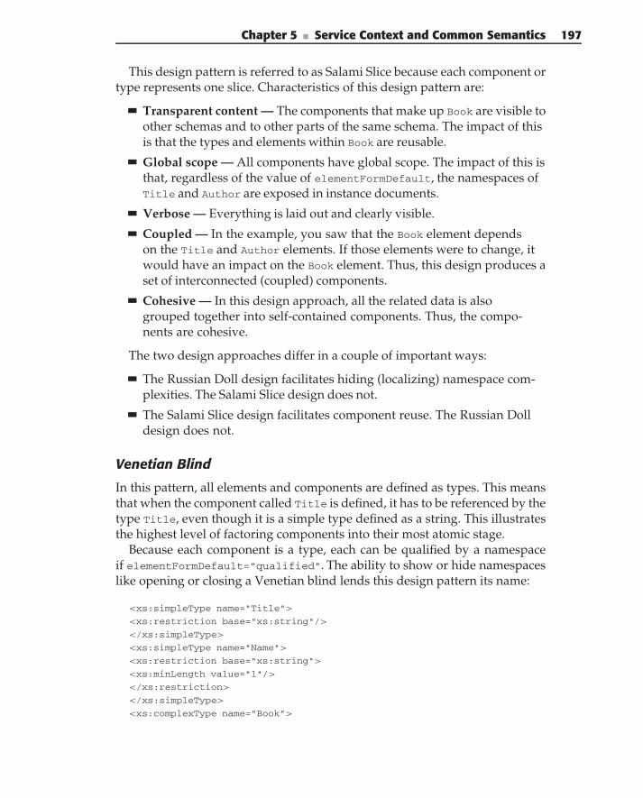
Chapter 5 ■ Service Context and Common Semantics 197
This design pattern is referred to as Salami Slice because each component ortype represents one slice. Characteristics of this design pattern are:
Transparent content — The components that make up Book are visible toother schemas and to other parts of the same schema. The impact of thisis that the types and elements within Book are reusable.
Global scope — All components have global scope. The impact of this isthat, regardless of the value of elementFormDefault, the namespaces ofTitle and Author are exposed in instance documents.
Verbose — Everything is laid out and clearly visible.
Coupled — In the example, you saw that the Book element dependson the Title and Author elements. If those elements were to change, itwould have an impact on the Book element. Thus, this design produces aset of interconnected (coupled) components.
Cohesive — In this design approach, all the related data is alsogrouped together into self-contained components. Thus, the compo-nents are cohesive.
The two design approaches differ in a couple of important ways:
The Russian Doll design facilitates hiding (localizing) namespace com-plexities. The Salami Slice design does not.
The Salami Slice design facilitates component reuse. The Russian Dolldesign does not.
Venetian Blind
In this pattern, all elements and components are defined as types. This meansthat when the component called Title is defined, it has to be referenced by thetype Title, even though it is a simple type defined as a string. This illustratesthe highest level of factoring components into their most atomic stage.
Because each component is a type, each can be qualified by a namespaceif elementFormDefault="qualified". The ability to show or hide namespaceslike opening or closing a Venetian blind lends this design pattern its name:
<xs:simpleType name="Title">
<xs:restriction base="xs:string"/>
</xs:simpleType>
<xs:simpleType name="Name">
<xs:restriction base="xs:string">
<xs:minLength value="1"/>
</xs:restriction>
</xs:simpleType>
<xs:complexType name="Book">
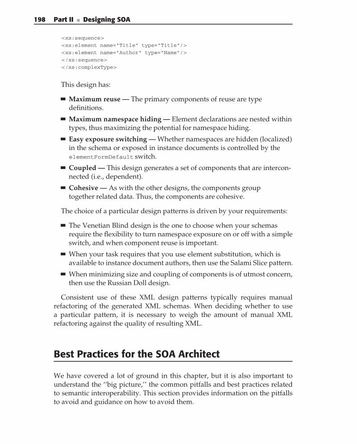
198 Part II ■ Designing SOA
<xs:sequence>
<xs:element name="Title" type="Title"/>
<xs:element name="Author" type="Name"/>
</xs:sequence>
</xs:complexType>
This design has:
Maximum reuse — The primary components of reuse are typedefinitions.
Maximum namespace hiding — Element declarations are nested withintypes, thus maximizing the potential for namespace hiding.
Easy exposure switching — Whether namespaces are hidden (localized)in the schema or exposed in instance documents is controlled by theelementFormDefault switch.
Coupled — This design generates a set of components that are intercon-nected (i.e., dependent).
Cohesive — As with the other designs, the components grouptogether related data. Thus, the components are cohesive.
The choice of a particular design patterns is driven by your requirements:
The Venetian Blind design is the one to choose when your schemasrequire the flexibility to turn namespace exposure on or off with a simpleswitch, and when component reuse is important.
When your task requires that you use element substitution, which isavailable to instance document authors, then use the Salami Slice pattern.
When minimizing size and coupling of components is of utmost concern,then use the Russian Doll design.
Consistent use of these XML design patterns typically requires manualrefactoring of the generated XML schemas. When deciding whether to usea particular pattern, it is necessary to weigh the amount of manual XMLrefactoring against the quality of resulting XML.
Best Practices for the SOA Architect
We have covered a lot of ground in this chapter, but it is also important tounderstand the ‘‘big picture,’’ the common pitfalls and best practices relatedto semantic interoperability. This section provides information on the pitfallsto avoid and guidance on how to avoid them.
Chapter 5 ■ Service Context and Common Semantics 199
Using Abstraction to Avoid ‘‘SOA Stovepipes’’Earlier in this chapter, we talked about the basic level of semantic interop-erability, which is developing data definitions and schemas that are specificto your project. Unfortunately, adopting such a methodology is sometimesshort-sighted. When you do this, the data is tightly coupled to each service orapplication. This short-sighted technique is commonly referred to as buildingan ‘‘SOA stovepipe!’’ A service that communicates using messages that areonly understood by the people who built it is not very interoperable at all.Unfortunately, this is a trap that is very easy to fall into, because of thefollowing:
Point-and-click object–to–WSDL generation — Many enterprise devel-opment tools allow automatic Web Service Description Language(WSDL) generation, where objects from previously developed programscan turn into services with the click of a button. Certainly, this is tempt-ing when time is a factor in the development schedule (as it usually is),but have you ever looked at the WSDL results? The parameter objectsthat are passed into each service do not translate to intuitive messages,and the result is that understanding the XML payloads is dependenton understanding the initial application API. The resulting data is verytightly coupled to the application, and therefore, changes in the appli-cation result in having to change the WSDL, leading to chaos in oper-ational deployments.
Database-to-schema conversion — Sometimes developers create a one-to-one translation of database tables to XML schemas, either becausethere are ‘‘database-to-ML’’ tools that easily allow this to happen orbecause they are very familiar with the database. What happens isthat the understanding of the resulting XML revolves around under-standing the implementation of the underlying database, which meansthat your messages are tightly coupled to your database. If you everchange your database schema, you most likely have to change your XMLmessages, resulting in chaos.
Direct API–to–service bindings — Similar to point-and-click WSDLgeneration, this pitfall happens when a developer creates a one-to-onerelationship to the original API (whether it be new or legacy) to theservice interface, disregarding the definition of data standards forthe payloads being passed in service messages. Once again, the one-to-one relationship leads to tight coupling and chaos.
It is important to avoid these traps at all costs. All of these roads lead tosemantic chaos. Mergers and acquisitions, regulation, market competition, andcustomer demands bring constant changes that are difficult enough without
200 Part II ■ Designing SOA
worrying about the constant changes that you have to make to keep up withservices that are tightly coupled and inflexible. If you start with services thatare too tightly coupled to your applications, you have no chance of keepingup.
The key to avoiding this trap is abstraction. Your SOA governance (seeChapter 12) should define processes and procedures for service design, and youshould spend time on abstracting the underlying details of legacy applicationsand your databases.
TIP FOR THE ‘‘TOO LATE’’ SOA FIREFIGHTER
If you are brought in to try to solve the chaos related to SOA stovepipes, youcan use a centralized, or hub-and-spoke, approach to data transformation withmessage brokers, where each service’s proprietary semantic meaning ismapped to a logical data model. Semantic interoperability is achieved via ahub-and-spoke topology, which reduces the redundancy and maintenance costof point-to-point integration. For more information, see the article, ‘‘Achievesemantic interoperability in a SOA’’ by Mei Selvage, Dan Wolfson, Bob Zurek,and Ed Kahan (June 2006).
Reuse Standards to Avoid Reinventing the WheelIt is easy to invent your own data standards. You are in a time crunch; youneed to develop something fast, and so you do, at the cost of reinventingwhat already exists. The result is that your shortcut is a barrier to futureinteroperability. Imagine, for example, that each doctor’s office and hospitalin the United States have a different schema for ‘‘Patient Record.’’ Imaginehow difficult it could be when a patient transfers from doctor’s office todoctor’s office, or from hospital to hospital. In the same way, even if you arenot planning on initially integrating with other organizations, such situationsalways happen.
Make sure to look for standards that your SOA governance recommends.Certain approaches may include all or some of the following:
Using enterprise semantics — In many successful SOA implementa-tions, all of the services communicate based on the enterprisesemantics. These semantics usually include a common vocabulary,a semantic information model, and common schemas. What is helpful isthat such an approach does not require data transformations throughoutthe enterprise. Rather it is the responsibility of service consumers andproviders to implement the abstractions from their internal data modelsto enterprise semantics.
Chapter 5 ■ Service Context and Common Semantics 201
Using business-domain semantics — Look for industry standards thatyou can reuse that are relevant to your business domain. In order toencourage interoperability within industries, many vertical industrystandardization groups develop industry-specific information models,which often include XML messages and message schemas. For instance,the Association of Retail Technology Standards (ARTS) develops suchstandards for the retail industry, and the Agency Company Organiza-tion for Research and Development (ACORD) develops standards forthe insurance industry. These models provide a greater level of seman-tic interoperability and encourage asset reuse. Some organizations evenadopt the industry standard models as their internal enterprise logicalmodels and semantic message models.
Typically, SOA governance initially looks for standards that apply to thebusiness domain. Where those standards are not relevant, a team can focuson creating enterprise data standards. In many cases, a successful solutionconsists of the combination of the above.
Develop Information Models Based on Use Cases
A common pitfall involves ‘‘analysis paralysis’’ for data modeling. Here’s atip: Don’t model the universe down to the level of DNA when you alreadyhave an idea of what your messages will be, and what your use cases are foryour services. The last thing you need is for another data-modeling team tospend a year developing another schema or ontology starting with ‘‘person,’’‘‘place,’’ and ‘‘thing.’’ Use cases are driven by your project’s requirementsand, therefore, must have a good requirements analysis phase. Based on thatphase, look only at the entities required in the messaging of your SOA. Startfrom there. If no other enterprise standards or industry standards for thoseentities exist, start modeling for those entities and those entities only.
With Change, Crawl, Walk, Then Run
Many overzealous architects attempt to take on too much of the data problemat once. Especially when services are already deployed, they try to changesemantics in all enterprise applications simultaneously. This requires too manychanges in too many applications, it is unrealistically complex, it is expensive,and it becomes chaotic. An SOA team needs to provide initial guidance.Once you have that guidance (or if you don’t have that team), take a look atthe big picture, and see what changes will be the most important. Take aniterative approach with such changes. For more information on what a maturegovernance life cycle looks like that accommodates change, see Chapter 12.
202 Part II ■ Designing SOA
Summary
Good service design should yield cohesive, interoperable services that areloosely coupled in their implementation and use. The process needs to beprecise and detailed — after all, the goal is real working services — but mustbe agile enough to accommodate changes as the business and understandingof the business evolves over time.
A common semantic information model is a key tool for ensuring consistentshared information across services. Rather than approaching a domain from theperspective of business processes, it uses the business data to define semantics.Information models can be structured along the lines of the business in orderto partition concepts specific to certain parts of the business, while capturingcommon elements, such as the concept of a Customer, for consistent use acrossthe entire enterprise.
The common information model also provides the foundation for definingall of the documents that make up the inputs and outputs of services. Docu-ment definition using an information model can expose multiple reasonablevariations on the business data, while ensuring consistency with a commonmodel. These practices also make the process of designing documents, usingtechnologies such as XML, far more straightforward and consistent thanmerely creating isolated schemas.
However, simple approaches to XML generation can result in overly sim-plistic schemas that result in tightly coupled data, maintenance issues, andperformance problems. Understanding the issues related to creating XMLschemas from information models is important to developing successful SOAsolutions. Common design patterns help to address the issue and create betterschemas and solutions.
C H A P T E R
6
Designing Service InterfacesParts Is Parts
— Wendy’s
In previous chapters, we discussed the architectural implications of SOA, theissues related to composing larger services from a collection of smaller ones,and the issues involved in designing common information and semantics tospan many different service interfaces. In this chapter, we tie these conceptstogether around the design of service interfaces. First, we review some of theimportant service concepts and look at the important characteristics of serviceinterfaces. Then, we introduce a process for interface design and illustrate itwith a detailed example. In this chapter, we cover:
The service characteristics of granularity, scope, and visibility
Service interaction styles, including parameter passing, documentpassing, and data passing
Service invocation styles, including request/response, events, andmixed
Service design guidelines
The interface design process
Sample problem space models
Sample solution models
203
204 Part II ■ Designing SOA
Services Revisited
Let’s review the important aspects of services. A service provides capabilitiesthat are accessed through its interface. The interface describes how thosecapabilities are presented and the rules and protocols for using them. Theservice is implemented through a variety of mechanisms, such as components,composition, and integration. So, we think of a service as a combination ofits interface — the public view of the service, and its implementation — theprivate view of the service. In addition, both the interface and the implemen-tation are a combination of functional and informational aspects. Figure 6-1highlights these aspects of a service.
In terms of service interface design, this means:
The service interface hides the details of the implementation.
The service interface expresses the service’s functions. This is donethrough the operations that the service interface provides.
The service operates on information. The schema of the information isdescribed in the parameters of the service operations. The schema isderived from a common semantic model.
This last observation leads to a very important point about services in anSOA. There is a difference between building services and having an SOA. It isnot enough to simply build random services. Instead, an SOA demands thatthe services be part of an overall collection (or inventory) of services that aredesigned to work together and to be composed into business processes. Forthis to happen, you need to understand two critical aspects of the overall SOAcontext in order to design an effective service interface. These are:
The specific responsibilities of the service operations and how theseresponsibilities relate to other services, that is, the relationship of the ser-vice to others
The information that must be common and shared between this serviceand other services to enable those relationships and service composition
We cover these two points more extensively later in this chapter. In additionto the anatomy of the service, there are several different sizes, types, and otheraspects that are important to interface design. We review these as well.
Service Characteristics
Three characteristics of services are particularly important in the design ofservice interfaces. These are: granularity, scope, and visibility.
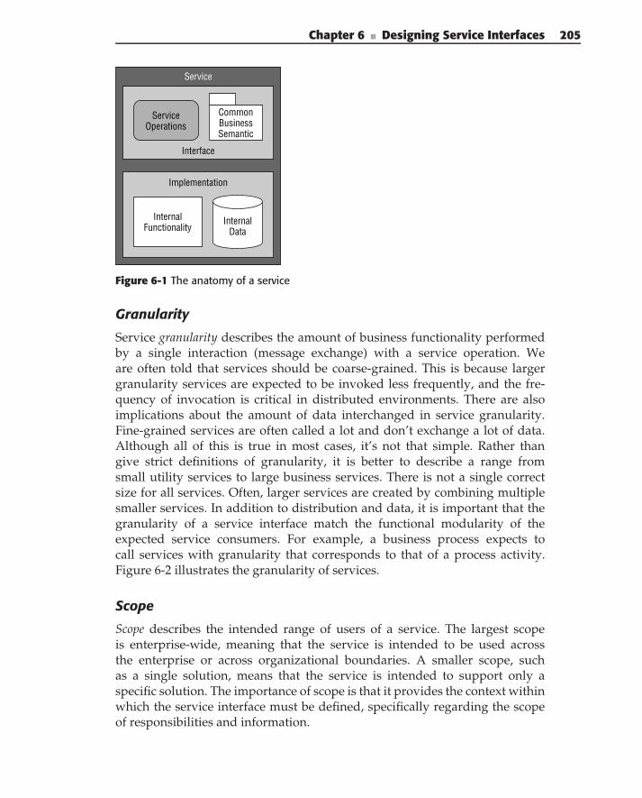
Chapter 6 ■ Designing Service Interfaces 205
Service
Interface
Implementation
InternalData
InternalFunctionality
CommonBusinessSemantic
ServiceOperations
Figure 6-1 The anatomy of a service
Granularity
Service granularity describes the amount of business functionality performedby a single interaction (message exchange) with a service operation. Weare often told that services should be coarse-grained. This is because largergranularity services are expected to be invoked less frequently, and the fre-quency of invocation is critical in distributed environments. There are alsoimplications about the amount of data interchanged in service granularity.Fine-grained services are often called a lot and don’t exchange a lot of data.Although all of this is true in most cases, it’s not that simple. Rather thangive strict definitions of granularity, it is better to describe a range fromsmall utility services to large business services. There is not a single correctsize for all services. Often, larger services are created by combining multiplesmaller services. In addition to distribution and data, it is important that thegranularity of a service interface match the functional modularity of theexpected service consumers. For example, a business process expects tocall services with granularity that corresponds to that of a process activity.Figure 6-2 illustrates the granularity of services.
Scope
Scope describes the intended range of users of a service. The largest scopeis enterprise-wide, meaning that the service is intended to be used acrossthe enterprise or across organizational boundaries. A smaller scope, suchas a single solution, means that the service is intended to support only aspecific solution. The importance of scope is that it provides the context withinwhich the service interface must be defined, specifically regarding the scopeof responsibilities and information.
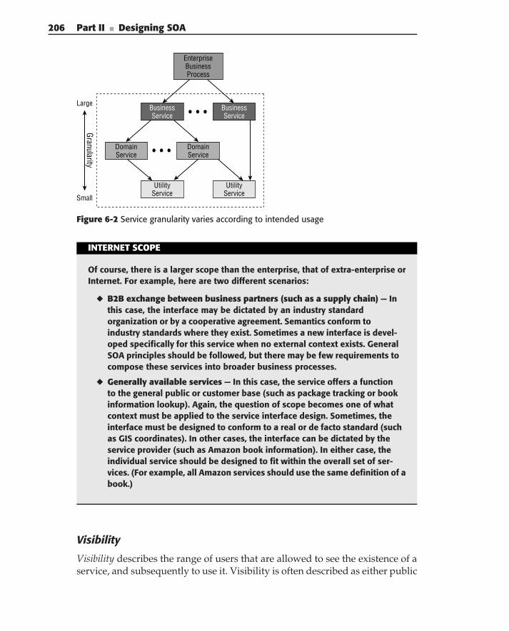
206 Part II ■ Designing SOA
EnterpriseBusinessProcess
Granularity
Small
Large ...BusinessService
BusinessService
DomainService
UtilityService
UtilityService
DomainService
...
Figure 6-2 Service granularity varies according to intended usage
INTERNET SCOPE
Of course, there is a larger scope than the enterprise, that of extra-enterprise orInternet. For example, here are two different scenarios:
◆ B2B exchange between business partners (such as a supply chain) — Inthis case, the interface may be dictated by an industry standardorganization or by a cooperative agreement. Semantics conform toindustry standards where they exist. Sometimes a new interface is devel-oped specifically for this service when no external context exists. GeneralSOA principles should be followed, but there may be few requirements tocompose these services into broader business processes.
◆ Generally available services — In this case, the service offers a functionto the general public or customer base (such as package tracking or bookinformation lookup). Again, the question of scope becomes one of whatcontext must be applied to the service interface design. Sometimes, theinterface must be designed to conform to a real or de facto standard (suchas GIS coordinates). In other cases, the interface can be dictated by theservice provider (such as Amazon book information). In either case, theindividual service should be designed to fit within the overall set of ser-vices. (For example, all Amazon services should use the same definition of abook.)
Visibility
Visibility describes the range of users that are allowed to see the existence of aservice, and subsequently to use it. Visibility is often described as either public
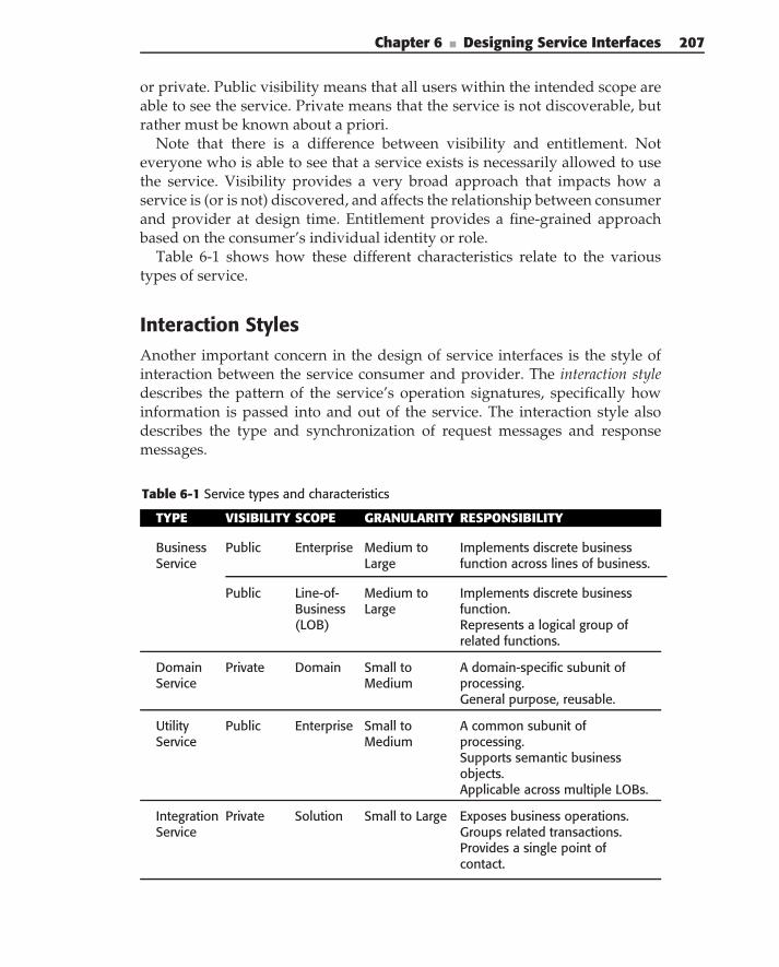
Chapter 6 ■ Designing Service Interfaces 207
or private. Public visibility means that all users within the intended scope areable to see the service. Private means that the service is not discoverable, butrather must be known about a priori.
Note that there is a difference between visibility and entitlement. Noteveryone who is able to see that a service exists is necessarily allowed to usethe service. Visibility provides a very broad approach that impacts how aservice is (or is not) discovered, and affects the relationship between consumerand provider at design time. Entitlement provides a fine-grained approachbased on the consumer’s individual identity or role.
Table 6-1 shows how these different characteristics relate to the varioustypes of service.
Interaction StylesAnother important concern in the design of service interfaces is the style ofinteraction between the service consumer and provider. The interaction styledescribes the pattern of the service’s operation signatures, specifically howinformation is passed into and out of the service. The interaction style alsodescribes the type and synchronization of request messages and responsemessages.
Table 6-1 Service types and characteristics
TYPE VISIBILITY SCOPE GRANULARITY RESPONSIBILITY
BusinessService
Public Enterprise Medium toLarge
Implements discrete businessfunction across lines of business.
Public Line-of-Business(LOB)
Medium toLarge
Implements discrete businessfunction.Represents a logical group ofrelated functions.
DomainService
Private Domain Small toMedium
A domain-specific subunit ofprocessing.General purpose, reusable.
UtilityService
Public Enterprise Small toMedium
A common subunit ofprocessing.Supports semantic businessobjects.Applicable across multiple LOBs.
IntegrationService
Private Solution Small to Large Exposes business operations.Groups related transactions.Provides a single point ofcontact.
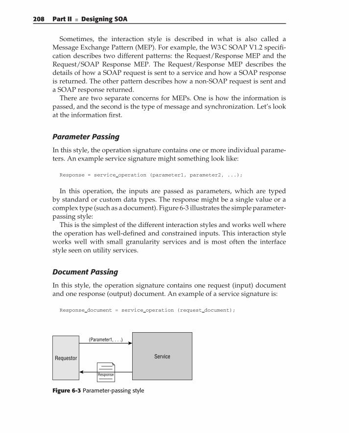
208 Part II ■ Designing SOA
Sometimes, the interaction style is described in what is also called aMessage Exchange Pattern (MEP). For example, the W3 C SOAP V1.2 specifi-cation describes two different patterns: the Request/Response MEP and theRequest/SOAP Response MEP. The Request/Response MEP describes thedetails of how a SOAP request is sent to a service and how a SOAP responseis returned. The other pattern describes how a non-SOAP request is sent anda SOAP response returned.
There are two separate concerns for MEPs. One is how the information ispassed, and the second is the type of message and synchronization. Let’s lookat the information first.
Parameter Passing
In this style, the operation signature contains one or more individual parame-ters. An example service signature might something look like:
Response = service operation (parameter1, parameter2, ...);
In this operation, the inputs are passed as parameters, which are typedby standard or custom data types. The response might be a single value or acomplex type (such as a document). Figure 6-3 illustrates the simple parameter-passing style:
This is the simplest of the different interaction styles and works well wherethe operation has well-defined and constrained inputs. This interaction styleworks well with small granularity services and is most often the interfacestyle seen on utility services.
Document Passing
In this style, the operation signature contains one request (input) documentand one response (output) document. An example of a service signature is:
Response document = service operation (request document);
Requestor Service
Response
(Parameter1, . . .)
Figure 6-3 Parameter-passing style
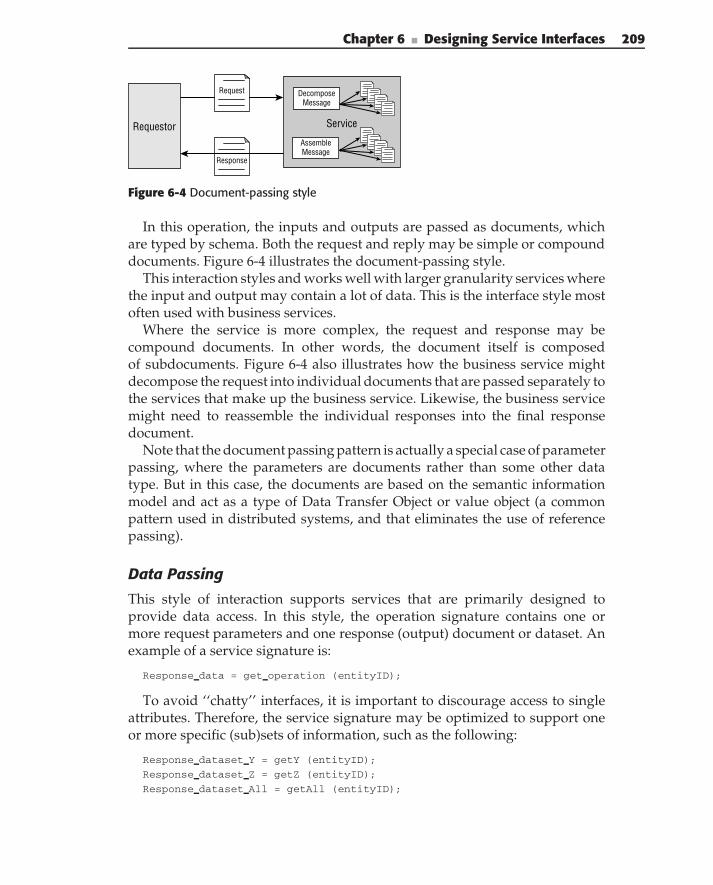
Chapter 6 ■ Designing Service Interfaces 209
Requestor Service
Response
Request DecomposeMessage
AssembleMessage
Figure 6-4 Document-passing style
In this operation, the inputs and outputs are passed as documents, whichare typed by schema. Both the request and reply may be simple or compounddocuments. Figure 6-4 illustrates the document-passing style.
This interaction styles and works well with larger granularity services wherethe input and output may contain a lot of data. This is the interface style mostoften used with business services.
Where the service is more complex, the request and response may becompound documents. In other words, the document itself is composedof subdocuments. Figure 6-4 also illustrates how the business service mightdecompose the request into individual documents that are passed separately tothe services that make up the business service. Likewise, the business servicemight need to reassemble the individual responses into the final responsedocument.
Note that the document passing pattern is actually a special case of parameterpassing, where the parameters are documents rather than some other datatype. But in this case, the documents are based on the semantic informationmodel and act as a type of Data Transfer Object or value object (a commonpattern used in distributed systems, and that eliminates the use of referencepassing).
Data Passing
This style of interaction supports services that are primarily designed toprovide data access. In this style, the operation signature contains one ormore request parameters and one response (output) document or dataset. Anexample of a service signature is:
Response data = get operation (entityID);
To avoid ‘‘chatty’’ interfaces, it is important to discourage access to singleattributes. Therefore, the service signature may be optimized to support oneor more specific (sub)sets of information, such as the following:
Response dataset Y = getY (entityID);
Response dataset Z = getZ (entityID);
Response dataset All = getAll (entityID);
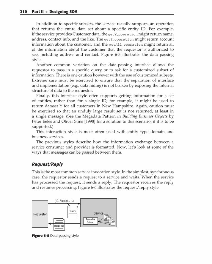
210 Part II ■ Designing SOA
In addition to specific subsets, the service usually supports an operationthat returns the entire data set about a specific entity ID. For example,if the service provides Customer data, the getY operation might return name,address, contact info, and the like. The getZ operation might return accountinformation about the customer, and the getAll operation might return allof the information about the customer that the requestor is authorized tosee, including address and contact. Figure 6-5 illustrates the data passingstyle.
Another common variation on the data-passing interface allows therequestor to pass in a specific query or to ask for a customized subset ofinformation. There is one caution however with the use of customized subsets.Extreme care must be exercised to ensure that the separation of interfaceand implementation (e.g., data hiding) is not broken by exposing the internalstructure of data to the requestor.
Finally, this interface style often supports getting information for a setof entities, rather than for a single ID; for example, it might be used toreturn dataset Y for all customers in New Hampshire. Again, caution mustbe exercised so that an unduly large result set is not returned, at least ina single message. (See the Megadata Pattern in Building Business Objects byPeter Eeles and Oliver Sims [1998] for a solution to this scenario, if it is to besupported.)
This interaction style is most often used with entity type domain andbusiness services.
The previous styles describe how the information exchange between aservice consumer and provider is formatted. Now, let’s look at some of theways that messages can be passed between them.
Request/Reply
This is the most common service invocation style. In the simplest, synchronouscase, the requestor sends a request to a service and waits. When the servicehas processed the request, it sends a reply. The requestor receives the replyand resumes processing. Figure 6-6 illustrates the request/reply style.
Requestor Service
Response
(ID, Subset, . . .)
AssembleDataset
Query
Figure 6-5 Data-passing style
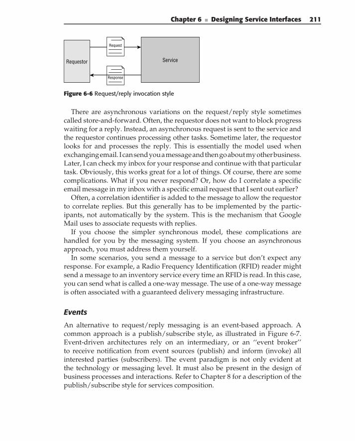
Chapter 6 ■ Designing Service Interfaces 211
Requestor Service
Response
Request
Figure 6-6 Request/reply invocation style
There are asynchronous variations on the request/reply style sometimescalled store-and-forward. Often, the requestor does not want to block progresswaiting for a reply. Instead, an asynchronous request is sent to the service andthe requestor continues processing other tasks. Sometime later, the requestorlooks for and processes the reply. This is essentially the model used whenexchangingemail. Icansendyouamessageandthengoaboutmyotherbusiness.Later, I can check my inbox for your response and continue with that particulartask. Obviously, this works great for a lot of things. Of course, there are somecomplications. What if you never respond? Or, how do I correlate a specificemail message in my inbox with a specific email request that I sent out earlier?
Often, a correlation identifier is added to the message to allow the requestorto correlate replies. But this generally has to be implemented by the partic-ipants, not automatically by the system. This is the mechanism that GoogleMail uses to associate requests with replies.
If you choose the simpler synchronous model, these complications arehandled for you by the messaging system. If you choose an asynchronousapproach, you must address them yourself.
In some scenarios, you send a message to a service but don’t expect anyresponse. For example, a Radio Frequency Identification (RFID) reader mightsend a message to an inventory service every time an RFID is read. In this case,you can send what is called a one-way message. The use of a one-way messageis often associated with a guaranteed delivery messaging infrastructure.
Events
An alternative to request/reply messaging is an event-based approach. Acommon approach is a publish/subscribe style, as illustrated in Figure 6-7.Event-driven architectures rely on an intermediary, or an ‘‘event broker’’to receive notification from event sources (publish) and inform (invoke) allinterested parties (subscribers). The event paradigm is not only evident atthe technology or messaging level. It must also be present in the design ofbusiness processes and interactions. Refer to Chapter 8 for a description of thepublish/subscribe style for services composition.
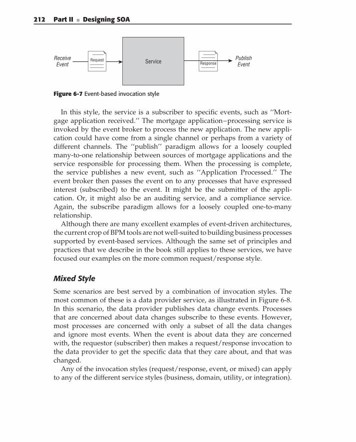
212 Part II ■ Designing SOA
Service ResponseRequestReceive
EventPublishEvent
Figure 6-7 Event-based invocation style
In this style, the service is a subscriber to specific events, such as ‘‘Mort-gage application received.’’ The mortgage application–processing service isinvoked by the event broker to process the new application. The new appli-cation could have come from a single channel or perhaps from a variety ofdifferent channels. The ‘‘publish’’ paradigm allows for a loosely coupledmany-to-one relationship between sources of mortgage applications and theservice responsible for processing them. When the processing is complete,the service publishes a new event, such as ‘‘Application Processed.’’ Theevent broker then passes the event on to any processes that have expressedinterest (subscribed) to the event. It might be the submitter of the appli-cation. Or, it might also be an auditing service, and a compliance service.Again, the subscribe paradigm allows for a loosely coupled one-to-manyrelationship.
Although there are many excellent examples of event-driven architectures,the current crop of BPM tools are not well-suited to building business processessupported by event-based services. Although the same set of principles andpractices that we describe in the book still applies to these services, we havefocused our examples on the more common request/response style.
Mixed Style
Some scenarios are best served by a combination of invocation styles. Themost common of these is a data provider service, as illustrated in Figure 6-8.In this scenario, the data provider publishes data change events. Processesthat are concerned about data changes subscribe to these events. However,most processes are concerned with only a subset of all the data changesand ignore most events. When the event is about data they are concernedwith, the requestor (subscriber) then makes a request/response invocation tothe data provider to get the specific data that they care about, and that waschanged.
Any of the invocation styles (request/response, event, or mixed) can applyto any of the different service styles (business, domain, utility, or integration).
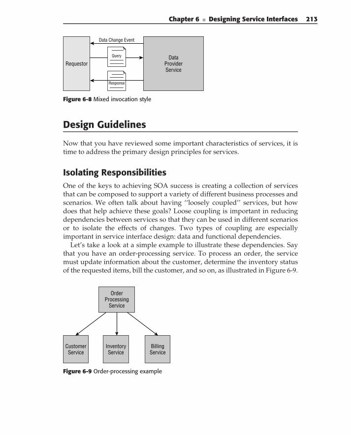
Chapter 6 ■ Designing Service Interfaces 213
RequestorData
ProviderService
Response
Query
Data Change Event
Figure 6-8 Mixed invocation style
Design Guidelines
Now that you have reviewed some important characteristics of services, it istime to address the primary design principles for services.
Isolating ResponsibilitiesOne of the keys to achieving SOA success is creating a collection of servicesthat can be composed to support a variety of different business processes andscenarios. We often talk about having ‘‘loosely coupled’’ services, but howdoes that help achieve these goals? Loose coupling is important in reducingdependencies between services so that they can be used in different scenariosor to isolate the effects of changes. Two types of coupling are especiallyimportant in service interface design: data and functional dependencies.
Let’s take a look at a simple example to illustrate these dependencies. Saythat you have an order-processing service. To process an order, the servicemust update information about the customer, determine the inventory statusof the requested items, bill the customer, and so on, as illustrated in Figure 6-9.
OrderProcessing
Service
CustomerService
InventoryService
BillingService
Figure 6-9 Order-processing example
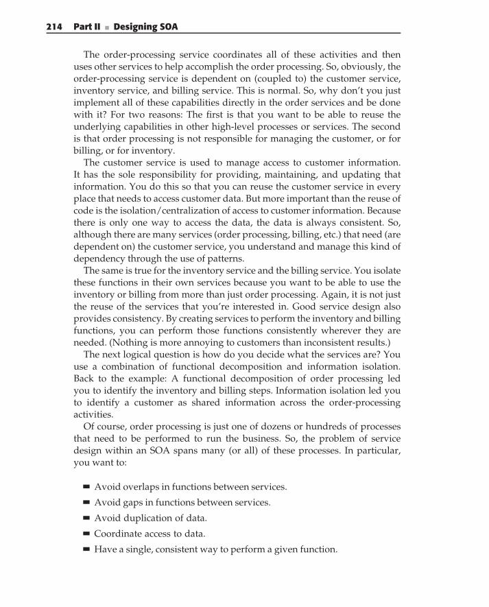
214 Part II ■ Designing SOA
The order-processing service coordinates all of these activities and thenuses other services to help accomplish the order processing. So, obviously, theorder-processing service is dependent on (coupled to) the customer service,inventory service, and billing service. This is normal. So, why don’t you justimplement all of these capabilities directly in the order services and be donewith it? For two reasons: The first is that you want to be able to reuse theunderlying capabilities in other high-level processes or services. The secondis that order processing is not responsible for managing the customer, or forbilling, or for inventory.
The customer service is used to manage access to customer information.It has the sole responsibility for providing, maintaining, and updating thatinformation. You do this so that you can reuse the customer service in everyplace that needs to access customer data. But more important than the reuse ofcode is the isolation/centralization of access to customer information. Becausethere is only one way to access the data, the data is always consistent. So,although there are many services (order processing, billing, etc.) that need (aredependent on) the customer service, you understand and manage this kind ofdependency through the use of patterns.
The same is true for the inventory service and the billing service. You isolatethese functions in their own services because you want to be able to use theinventory or billing from more than just order processing. Again, it is not justthe reuse of the services that you’re interested in. Good service design alsoprovides consistency. By creating services to perform the inventory and billingfunctions, you can perform those functions consistently wherever they areneeded. (Nothing is more annoying to customers than inconsistent results.)
The next logical question is how do you decide what the services are? Youuse a combination of functional decomposition and information isolation.Back to the example: A functional decomposition of order processing ledyou to identify the inventory and billing steps. Information isolation led youto identify a customer as shared information across the order-processingactivities.
Of course, order processing is just one of dozens or hundreds of processesthat need to be performed to run the business. So, the problem of servicedesign within an SOA spans many (or all) of these processes. In particular,you want to:
Avoid overlaps in functions between services.
Avoid gaps in functions between services.
Avoid duplication of data.
Coordinate access to data.
Have a single, consistent way to perform a given function.
Chapter 6 ■ Designing Service Interfaces 215
A key to achieving these goals is to keep the following questions in mindduring the design of a service:
Who is responsible for a given function? Where is that function used?
Who is responsible for management of specific data?
Who is responsible for defining and implementing specific rules?
What step in the process owns the specific knowledge needed to performa given task?
The answer to these questions helps to identify what the service should doand is responsible for. Just as importantly, it identifies what the service shouldnot do, but rather what it should depend on other services for.
Understanding Overall ContextTo achieve these goals within the intended scope of the SOA you mustunderstand more than a single process, scenario, or use case. You must under-stand the overall context to which the SOA applies. The overall set of serviceswithin this context is referred to as the service inventory. This is where thebusiness and domain model come into play.
The SOA business model asks and answers the following questions:
What business are you in (e.g., what is the domain model)?
What are the goals and objectives of this particular business?
What outcomes are needed to achieve those goals?
How will they be measured?
What capabilities and information are needed to achieve thoseoutcomes?
What processes, services, entities, and rules are needed to implementthose capabilities?
What existing applications provide basic capabilities and informationthat can support these?
The first four questions describe the businesses requirements, while the restdescribe the overall SOA context and provide the requirements for the serviceinventory. In other words, the service inventory describes the overall set ofservices necessary to support SOA within a context. In doing so, the inventorymust identify:
The overall scope
Areas of service responsibilities
Groupings of related services
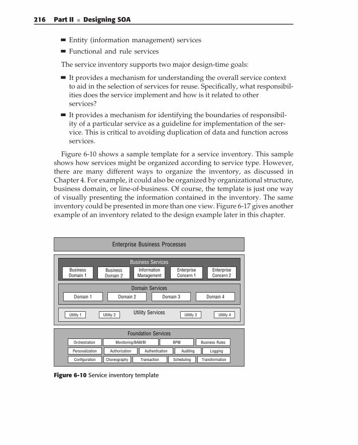
216 Part II ■ Designing SOA
Entity (information management) services
Functional and rule services
The service inventory supports two major design-time goals:
It provides a mechanism for understanding the overall service contextto aid in the selection of services for reuse. Specifically, what responsibil-ities does the service implement and how is it related to otherservices?
It provides a mechanism for identifying the boundaries of responsibil-ity of a particular service as a guideline for implementation of the ser-vice. This is critical to avoiding duplication of data and function acrossservices.
Figure 6-10 shows a sample template for a service inventory. This sampleshows how services might be organized according to service type. However,there are many different ways to organize the inventory, as discussed inChapter 4. For example, it could also be organized by organizational structure,business domain, or line-of-business. Of course, the template is just one wayof visually presenting the information contained in the inventory. The sameinventory could be presented in more than one view. Figure 6-17 gives anotherexample of an inventory related to the design example later in this chapter.
Enterprise Business Processes
Utility ServicesUtility 1 Utility 2 Utility 3
Business ServicesBusinessDomain 1
BusinessDomain 2
InformationManagement
EnterpriseConcern 1
EnterpriseConcern 2
Domain Services
Domain 1 Domain 3Domain 2 Domain 4
Utility 4
Foundation Services
Business Rules
Authorization
Orchestration
Choreography SchedulingConfiguration
Personalization Authentication
Transaction
Auditing
Monitoring/BAM/BI BPM
Transformation
Logging
Figure 6-10 Service inventory template
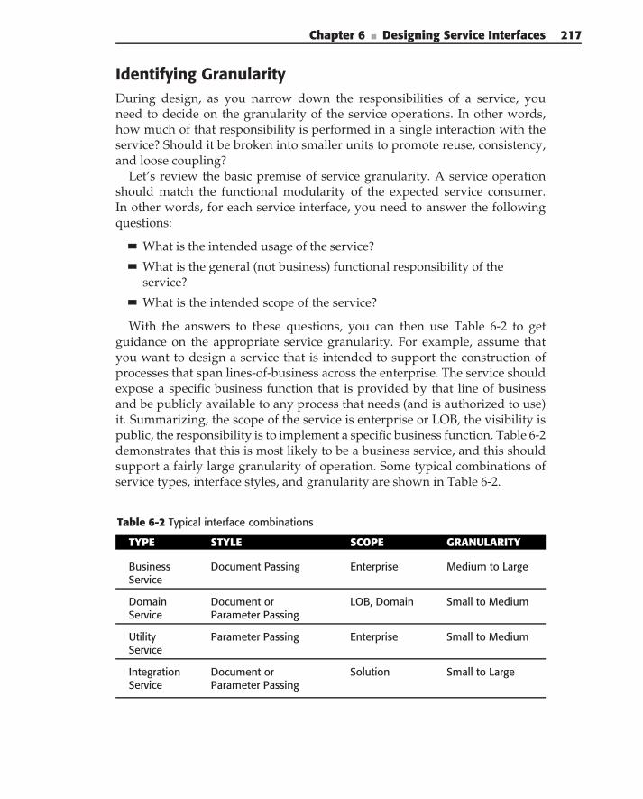
Chapter 6 ■ Designing Service Interfaces 217
Identifying GranularityDuring design, as you narrow down the responsibilities of a service, youneed to decide on the granularity of the service operations. In other words,how much of that responsibility is performed in a single interaction with theservice? Should it be broken into smaller units to promote reuse, consistency,and loose coupling?
Let’s review the basic premise of service granularity. A service operationshould match the functional modularity of the expected service consumer.In other words, for each service interface, you need to answer the followingquestions:
What is the intended usage of the service?
What is the general (not business) functional responsibility of theservice?
What is the intended scope of the service?
With the answers to these questions, you can then use Table 6-2 to getguidance on the appropriate service granularity. For example, assume thatyou want to design a service that is intended to support the construction ofprocesses that span lines-of-business across the enterprise. The service shouldexpose a specific business function that is provided by that line of businessand be publicly available to any process that needs (and is authorized to use)it. Summarizing, the scope of the service is enterprise or LOB, the visibility ispublic, the responsibility is to implement a specific business function. Table 6-2demonstrates that this is most likely to be a business service, and this shouldsupport a fairly large granularity of operation. Some typical combinations ofservice types, interface styles, and granularity are shown in Table 6-2.
Table 6-2 Typical interface combinations
TYPE STYLE SCOPE GRANULARITY
BusinessService
Document Passing Enterprise Medium to Large
DomainService
Document orParameter Passing
LOB, Domain Small to Medium
UtilityService
Parameter Passing Enterprise Small to Medium
IntegrationService
Document orParameter Passing
Solution Small to Large
218 Part II ■ Designing SOA
Stateless InterfacesAn important characteristic of service interfaces is to be as stateless as possible.This means that a service does not maintain state on behalf of its consumerbetween requests. Any given request can act on the state of particular infor-mation, but a subsequent request does not rely on the service maintaining thestate from a previous request.
EXECUTION STATE VERSUS INVOCATION STATE
There is a profound difference between the notions of execution andinvocation state: Execution state represents the state of the service during itsexecution. It always exists and includes internal variables created duringservice execution. It is used for keeping track of which part of the serviceexecution has been completed, storing the results of partial service execution,and passing parameters between multiple components of a service implemen-tation. This state is typically encapsulated in the service implementation and isinvisible to the service consumers.
Invocation state is a shared context between the service consumer andservice provider in a particular conversation. In this case, a consumer invokesdifferent operations of the same service, assuming that the information thatwas passed to the service during an earlier operation invocation is available tothe service during all consecutive invocations.
A service may participate in multiple conversations with different consumersand must keep track of each conversation separately. The notion of invocationstate is used, for example in the session variables, or stateful session beans inJ2EE. A better term describing this type of state is ‘‘conversation state.’’
Throughout this book when we talk about stateful versus stateless invocationof services, we are referring only to the invocation state.
Why is this important? Stateless interactions are important in terms ofscalability, reliability, failover, and so on. For example, consider the followingtwo pseudo-code segments below for checking the balance of your savingsaccount:
myAccount = account service.getAccount (myD);
myBalance = myAccount.getBalance ();
myTransactionHistory = myAccount.getTransactionHistory ();
myBalance = account service.getAccountBalance (myID);
myTransactionHistory = account service.getTransactionHistory (myID);
The first example is the classical object-oriented approach to the problem.Create an account object and then perform operations on the account. Whatthis means is that the account service creates an instance of myAccount, and
Chapter 6 ■ Designing Service Interfaces 219
each subsequent call to the account object must go to the exact same instanceof the account service. In other words, the first call to get an account createsthe account instance. The second and third calls (to the account object) getinformation about the account, namely the balance and transaction history.Because the account object is maintained by the first service, it does not haveto be created for each call.
The second example is the stateless service approach. The first call getsthe balance. The second call gets the transaction history. Each time theaccount service is called, it needs to retrieve the requested information,which may require some duplicated access to the database. However, thereis no dependency between the caller and any particular service instance.The first request can go to server 1 while the second request could go toserver 19. The tradeoff is one of flexibility and reliability versus processingoverhead.
But what happens in the first scenario if the server fails for some reasonbetween retrieving the balance and the history? The server state is lost, andthe client needs to find a new server, recreate the account instance, and thenrequest the transaction history. This is a much more complicated failover sce-nario than the stateless case. In that case, because no state is being maintainedby the server, the history request can be sent to any available server. Hence,nothing different is required to handle the failover.
What happens when the processing of account information becomes abottleneck? In the stateless example, you can simply add more servers andrequests automatically get routed to them. But in the stateful example, eventhough you add new servers, all existing requests are still restricted to thealready overloaded servers because that is where the state is being maintained.Only new accounts’ conversations are routed to the new servers.
There are many other scenarios where stateless services provide betternonfunctional characteristics. However, not all service interactions lend them-selves to stateless interfaces. Sometimes, the added complexity of makingsomething stateless is not worth the effort. For example, if accessing the infor-mation is very complex, you might want to do it once and get on with otherthings. Consider that getting the account balance might require accessingfive or more different systems to collect information, which then has to beaggregated. In that case, the added flexibility of stateless services might wellbe outweighed by the overhead of accessing multiple systems to assemble theaccount information.
From another perspective, it’s not so much that the service’s interactionsare stateless as it is how that state is handled. For example, a service couldbe implemented by saving all its state in a persistent data source betweenconsumer invocations and reconstruct the state on the next service request;or the service could hand all the state information back to the consumer in
220 Part II ■ Designing SOA
message data and expect the consumer to return it on the next invocation.These are stateless services from the standpoint of the implementation of theservice provider, but the service’s interactions are stateful.
Ultimately, it is a design choice that needs to be made by weighing thevarious tradeoffs. However, the overwhelming preference should be forthe creation of stateless service interfaces.
Exceptions
Unfortunately, not everything always goes right (oh darn). This is undoubtedlytrue with computers, and even more so with service-oriented solutions. In hisclassic text on distributed computing, Professor Andrew Tannenbaum saidsomething like ‘‘a distributed system is one where a problem that occurs ona computer you didn’t even know existed can cause your computer to fail.’’Computer Networks (1985).
Exceptions are an integral part of service interface design. We’ll discussthree key aspects of exception design here. First, all exceptions have to bedefined at the interface level. Second, like data, common exceptions shouldbe defined the same across all services. And third, exceptions need to reportcorrelation information.
To explain these first two points, we need to mention the two main types ofexceptions: application exceptions, and system exceptions. Application excep-tions are application-specific errors that occur, such as ‘‘insufficient funds’’when a customer tries to withdraw more money than they have in theiraccount. Each operation has a set of application errors. The interface needs tocollect and declare the complete set of possible application exceptions for alloperations.
System exceptions are those that occur because of system issues such as‘‘access denied’’, ‘‘system unavailable’’, or a communications error. In general,these errors are common across most services and operations. They shouldbe defined once in a common format. Then, every service should use thesame exception definition for the same event. Usually there is a central systemexception file that is used by all services.
When an exception occurs, it is reported to two important stakeholders.Obviously, the consumer of a service needs to have exception informationabout their request reported to them so that they can act appropriately.In addition, exception information needs to be logged for future analysis,either to address a specific problem or to analyze trends. Typically, in additionto the application or system error information, this includes informationidentifying the server where the exception occurred and a value that identifiesthe end-to-end transaction that is involved. Chapter 9 describes a loggingarchitecture for collecting these errors in a central location.
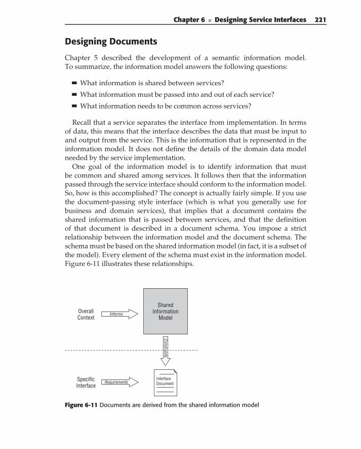
Chapter 6 ■ Designing Service Interfaces 221
Designing Documents
Chapter 5 described the development of a semantic information model.To summarize, the information model answers the following questions:
What information is shared between services?
What information must be passed into and out of each service?
What information needs to be common across services?
Recall that a service separates the interface from implementation. In termsof data, this means that the interface describes the data that must be input toand output from the service. This is the information that is represented in theinformation model. It does not define the details of the domain data modelneeded by the service implementation.
One goal of the information model is to identify information that mustbe common and shared among services. It follows then that the informationpassed through the service interface should conform to the information model.So, how is this accomplished? The concept is actually fairly simple. If you usethe document-passing style interface (which is what you generally use forbusiness and domain services), that implies that a document contains theshared information that is passed between services, and that the definitionof that document is described in a document schema. You impose a strictrelationship between the information model and the document schema. Theschema must be based on the shared information model (in fact, it is a subset ofthe model). Every element of the schema must exist in the information model.Figure 6-11 illustrates these relationships.
Shared Information
Model
Interface Document
Constraints
Overall Context
Informs
Specific Interface
Requirements
Figure 6-11 Documents are derived from the shared information model
222 Part II ■ Designing SOA
The overall context of the SOA environment identifies the information thatmust be shared and common between services. This information informs thecreation of the shared information model. The input and output of a specificservice provide the requirements for the contents of the interface document,as described by the schema. The requirement for consistency between theinformation model and the document constrains the schema to contain onlythe elements that exist in the shared information model.
In fact, the same relationships and constraints should apply to data passed inoperation parameters for the parameter-passing interface style. The primaryrequirement is that the data that is passed through the service interface issemantic data, or data defined by the semantic information model.
This requirement introduces a corollary requirement for the service designprocess. As you work through the design process, you inevitably discover moreand more data that is required. How do you evolve the interface documentto support this discovery, while also meeting the previous requirement? Theanswer is that you don’t modify the document; you evolve the informationmodel first and then redraw the schema and document based on the newinformation model. Later in this chapter, Figure 6-23 illustrates how to derivea schema from the information model.
Interface Design Illustrated
In this section, we describe the interface design process by using an exampleof an automobile insurance–quoting process. First, you’ll look at the overallprocess and the models that can be created, as illustrated in Figure 6-12. Youdivide the overall process into two distinct parts: the problem model, whichdescribes the problem in detail in business terms, independent of the potentialIT systems, and the solution model, which describes the design of the solutionin terms of SOA concepts. Each model consists of a set of related drawings,with traceability between the business model and the solution model.
IT’S OUR PROCESS . . . WHICH IS OURS . . .
There’s more than one way to skin a cat, and more than one way to designservices. The method that we present here is the way we have found to be themost effective with our clients. It’s not the only way. What is important is to getthe fundamental service design concepts from our approach so that you canapply whatever makes the most sense in your own environment. Sochill . . . this example illustrates our approach. We hope you find it useful andadopt and adapt it to fit your needs. In any case, please look past anymethodology specifics that you disagree with and get to the heart of the designdecisions. Or, adopt it all. It works great for us.
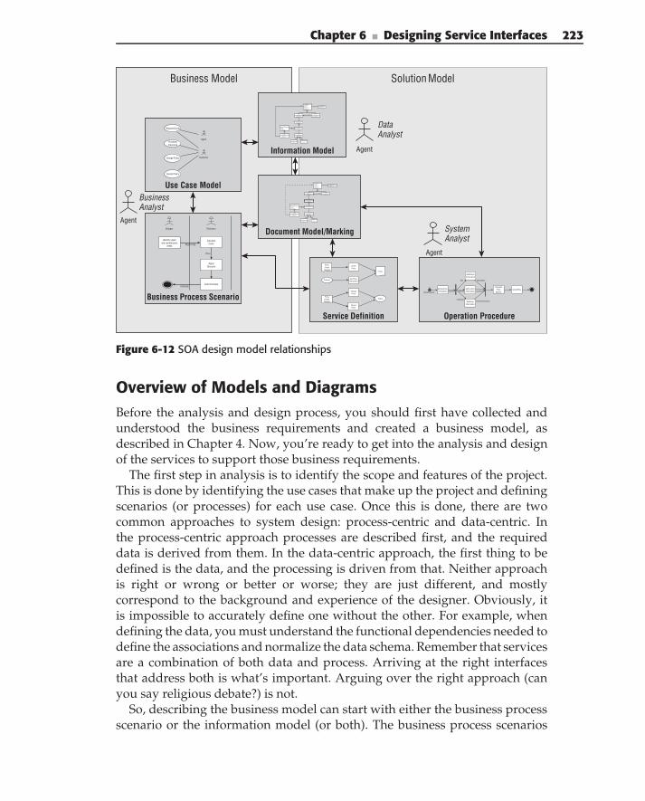
Chapter 6 ■ Designing Service Interfaces 223
Solution ModelBusiness Model
Business Process Scenario
Shipper Estimator
Identify repairand maintenance
needs
CalculateCosts
Apply Discount
Send Estimate
Repair Slip
Price
Estimate w St
GetCustomer Information
GetVehicle Information
GetLocation Information
GetDriver Information
Calculate Price
OptionsCreatePrice
QuoteRequestCustomer
VehicalInfo
LocationInfo
DriverInformation
VIN
Address
Customer
Operation Procedure
Document Model/MarkingAgent
Business Analyst
Data Analyst
Agent
Agent
System Analyst
Information Model
Request Quote
PurchaseInsurance
Change Policy
Cancel Policy
Customer
Agent
Use Case Model
Service Definition
Status
PolicyId
Policy
PolicyChangeRequest
PolicyCreate
Request
CreatePolicy
Change Policy
CancelPolicy
Get Policy Information
Insured Party
Name: StringPrimaryAddress: AHomePhone:WorkPhoneMobilePhone: Phone...DoB: Date: Phone...MaritalStatus: Marit..Gender
DriverIdentification
State: StringLicenseNumber: String
Customer
BillingAddres: Addre...CustomerID: Custom...
CoInsured
Relationship: Relation...
Product
ProductIdentifier: Prod…
ProductType: Product:
InsuredItem
Vehicle
VIN: VINMake: StringModel: StringYear: StringStyle: VehicleStyleCode
VehicleUsage
Usage: VehicleUsageCO...YearlyMiles: IntBusiness: Boolean
Coverage
Coverage: CoverageT...Detail: CoverageDesc...Name: String
Limit
LimitAmount: C...
Deductable
Deductable: A...
R11 1
R110
related by
R1
0..*
Product
0..*
0..*
R1
1
1..*
R1
1
1
R1
1
1. . *
R1
1
1R1
1
1
R1
1
1
PrimaryDriver
Figure 6-12 SOA design model relationships
Overview of Models and DiagramsBefore the analysis and design process, you should first have collected andunderstood the business requirements and created a business model, asdescribed in Chapter 4. Now, you’re ready to get into the analysis and designof the services to support those business requirements.
The first step in analysis is to identify the scope and features of the project.This is done by identifying the use cases that make up the project and definingscenarios (or processes) for each use case. Once this is done, there are twocommon approaches to system design: process-centric and data-centric. Inthe process-centric approach processes are described first, and the requireddata is derived from them. In the data-centric approach, the first thing to bedefined is the data, and the processing is driven from that. Neither approachis right or wrong or better or worse; they are just different, and mostlycorrespond to the background and experience of the designer. Obviously, itis impossible to accurately define one without the other. For example, whendefining the data, you must understand the functional dependencies needed todefine the associations and normalize the data schema. Remember that servicesare a combination of both data and process. Arriving at the right interfacesthat address both is what’s important. Arguing over the right approach (canyou say religious debate?) is not.
So, describing the business model can start with either the business processscenario or the information model (or both). The business process scenarios
224 Part II ■ Designing SOA
describe the activities that constitute the use cases and the information flowwithin scenarios in terms of business documents. The information modeldescribes the main information that is part of the business problem domainspace. In the example, later in the chapter, we take a process-centric approach,using scenarios to dig out the information requirements.
Together, the use case diagrams, scenario diagrams, information model,and document model make up the problem space model. As you developthe solution and continue to identify more detail, this detail will be addedto the information model and document markings; thus, these two modelsspan both the problem and solution models of your SOA design process.
The solution model follows from the problem model. Again, the solutionmodel can start from either a process or data perspective, with either the infor-mation model or the definition of services. In one approach, you perform a func-tional decomposition of the processes and then identify the information neededto support the functions. In the other approach, you identify the informationneeds and then assign services to process the information. Neither approachis necessarily better than the other, and in reality, you generally identify boththe information and functions together in an iterative fashion. One differencemight be that a process-(or behavior-) centered approach is more goal-oriented,providing a better link to the business requirements and processes. Again, inthe example later in the chapter, we take the process (functional) approach.
Each activity that is identified in a use case scenario is a candidate for a serviceoperation. Each service is described by an interface and an implementation.The interface is described in the service definition diagram, which showsthe collection of service operations and their inputs and outputs in terms ofdocuments and parameters.
Finally, the implementation of each service operation is described in anoperation procedure diagram (discussed in Chapter 7),which defines theinternal steps of the operation, the data flow, and the data transformation ofeach step. Each step in the procedure may in turn invoke another service toimplement that step. The overall procedure must match the input and outputdefined in the service definition.
Now, let’s look at developing these models based on an example from theinsurance industry, using the fictitious ‘‘ACME Insurance Company,’’ whichhas recently acquired another company in order to add automobile insuranceto their existing lines-of-business, such as property and casualty, life, and theirunique line of roadrunner-confounding products.
ACME Insurance ExampleIntroduction — ACME Insurance Company sells multiple types of insuranceto individuals and businesses (e.g. auto, homeowners, life, etc.). Like manycompanies, its internal IT landscape is a hodge-podge of existing applicationsand systems, many of which provide redundant or overlapping functions and
Chapter 6 ■ Designing Service Interfaces 225
that don’t integrate with each other effectively. To stay competitive, ACMEmust upgrade its systems. A driving factor is to provide a single customerview across multiple lines of business. In order to achieve its immediate andlonger term business goals, ACME is looking to Service-Oriented Architecture(SOA) to provide the agility, flexibility, and speed that it needs.
Business problem — Implement new insurance-quoting and -issuing pro-cesses that improve the customer experience. A customer’s initial contact withACME is through its own or independent insurance agents. Both web-basedinteractive sessions with the agents and automated Single Entry MultipleCarrier Interface (SEMCI) quote requests must be supported. After a policyhas been issued, a customer can interact directly with ACME via self-serviceweb applications to make policy changes and pay bills.
Enterprise context — This is the first of many initiatives that can be aimedat modernizing ACME so that it becomes a service-oriented enterprise. Thedevelopment process must consider the overall enterprise context, which, ofcourse, is just emerging. An initial version of the application architecturedescribes the high-level concepts for building an SOA, and the technicalarchitecture describes the platform details on which it will be implemented.Together, these answer many of the typical ‘‘system requirement’’ questions.
Project context — For this project, we create services to support four usecases: Create a Quote (BU01), Purchase Insurance (BU02), Change Policy(BU03), and Cancel Policy (BU04).
PROCESS DOCUMENTATION STRUCTURE
Each step in the process is described in detail and then followed with asummary of the process that includes:
Goals — The goals of this stage of the process and associated set of activi-ties
Concerns — The enterprise concerns that are introduced at this stage of theprocess
Concepts — The SOA concepts that are used to express the analysis ordesign during this stage
In addition, occasional ‘‘Notes’’ provide tips and techniques for carrying outthe step.
Conceptual ArchitectureOften, the first step in a project is to create a conceptual architecture. This isan informal architecture overview with the purpose of conveying the overallproject concept, goals, and approach to a nontechnical audience.
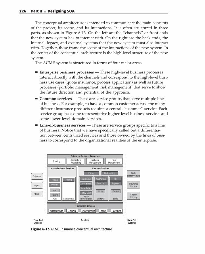
226 Part II ■ Designing SOA
The conceptual architecture is intended to communicate the main conceptsof the project, its scope, and its interactions. It is often structured in threeparts, as shown in Figure 6-13. On the left are the ‘‘channels’’ or front endsthat the new system has to interact with. On the right are the back ends, theinternal, legacy, and external systems that the new system must also interactwith. Together, these frame the scope of the interactions of the new system. Inthe center of the conceptual architecture is the high-level structure of the newsystem.
The ACME system is structured in terms of four major areas:
Enterprise business processes — These high-level business processesinteract directly with the channels and correspond to the high-level busi-ness use cases (quote insurance, process application) as well as futureprocesses (portfolio management, risk management) that serve to showthe future direction and potential of the approach.
Common services — These are service groups that serve multiple linesof business. For example, to have a common customer across the manydifferent insurance products requires a central ‘‘customer’’ service. Eachservice group has some representative higher-level business services andsome lower-level domain services.
Line-of-business services — These are service groups specific to a lineof business. Notice that we have specifically called out a differentia-tion between centralized services and those owned by the lines of busi-ness to correspond to the organizational realities of the enterprise.
Common ServicesLine-of-Business Services
Billing
Product
Auto
VIN
Customer
Party
AddMember Bill
Payment
Pricing
Pricing
Cust. Info
PolicyAdministration
Issue Binder
Issue Policy
Policy Maint
Application
Record
Portfolio
Underwriting
Enterprise Business Processes
ApplicationProcessing
Risk Management
PortfolioManagementQuoting
Homeowners
Pricing
Front-EndChannels
Back-End Systems
Customer
Agent
SEMCI
StateMotor Vehicle
LegacyPricing
Insurance Bureau
Foundation Services
Services
SecurityAuthentication Audit LoggingManagement
Figure 6-13 ACME Insurance conceptual architecture
Chapter 6 ■ Designing Service Interfaces 227
Foundation services — These services support the overall constructionof the system (but do not implement business functionality). Because thistype of service has been common in enterprise systems for a long time,we include the foundation services in the conceptual architecture to dif-ferentiate them from the business related services.
Goal — Convey the overall concept, structure, and direction of theproject to sponsors and nontechnical viewers.
Concerns — Scope of the project, internal, and external interactions,and the structure of the system.
Concepts — Channels, external systems, processes, service groups,and services.
Problem Space ModelWith the overall concepts laid out, it is time to start describing the problem inbusiness terms to verify that all the requirements are understood and framedin the appropriate context.
Use Case Diagrams
The problem model is derived from the use cases and knowledge about theproblem domain. For this example, we are using four business use cases:request a quote for insurance (BU01), purchase an insurance policy (BU02),change the coverage on a policy (BU03), and cancel insurance (BU04). Thedetailed use cases are included in Appendix A. Figure 6-14 shows the usecases and primary actors.
Each business use case becomes a use case in our use case diagram. Inaddition, we include the actors that have been identified from the businessuse cases. Often, we find that use cases are overdone and can result inanalysis paralysis. We try to use the use case diagram as a ‘‘table of con-tents’’ of the overall set of use cases, and to help identify any relationshipsbetween them. But, we try not to make then too complicated and tend toavoid using <<extends>> and <<includes>> relationships. Instead, weprefer to specify the use case details in scenario diagrams or business pro-cess models.
Goals — Provide a table of contents of the major functions and users of thesystem.
Concerns — Interaction of business use cases with each other and externalusers and systems.
Concepts — Use cases, actors.
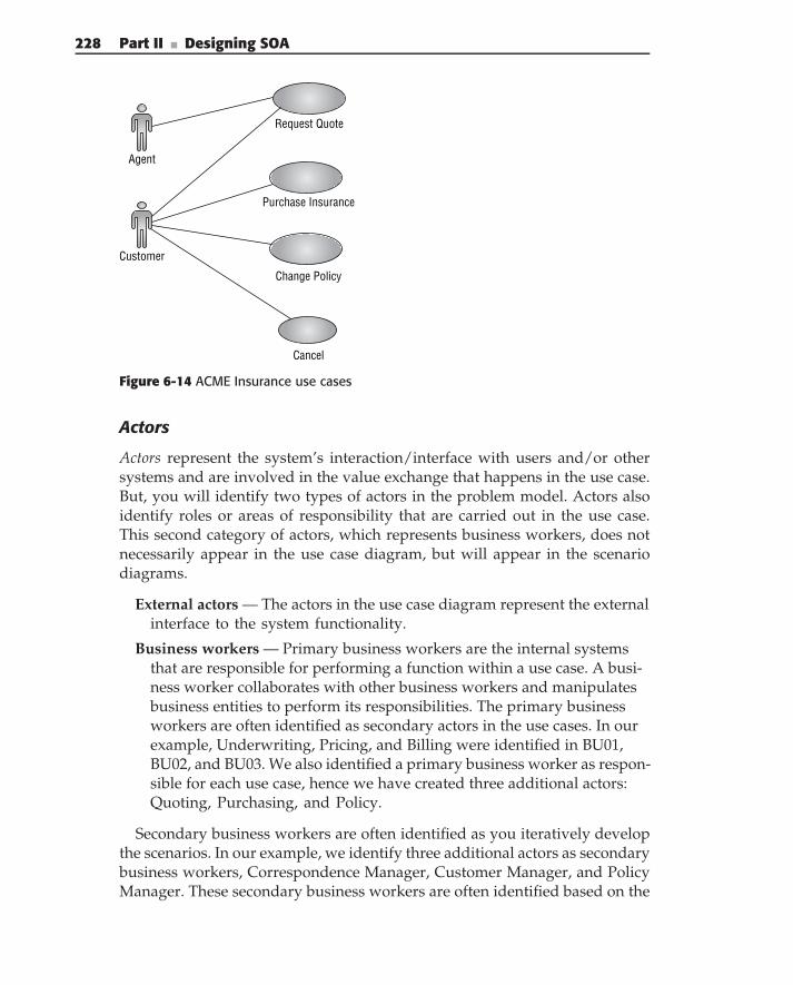
228 Part II ■ Designing SOA
Request Quote
Purchase Insurance
Change Policy
Cancel
Customer
Agent
Figure 6-14 ACME Insurance use cases
Actors
Actors represent the system’s interaction/interface with users and/or othersystems and are involved in the value exchange that happens in the use case.But, you will identify two types of actors in the problem model. Actors alsoidentify roles or areas of responsibility that are carried out in the use case.This second category of actors, which represents business workers, does notnecessarily appear in the use case diagram, but will appear in the scenariodiagrams.
External actors — The actors in the use case diagram represent the externalinterface to the system functionality.
Business workers — Primary business workers are the internal systemsthat are responsible for performing a function within a use case. A busi-ness worker collaborates with other business workers and manipulatesbusiness entities to perform its responsibilities. The primary businessworkers are often identified as secondary actors in the use cases. In ourexample, Underwriting, Pricing, and Billing were identified in BU01,BU02, and BU03. We also identified a primary business worker as respon-sible for each use case, hence we have created three additional actors:Quoting, Purchasing, and Policy.
Secondary business workers are often identified as you iteratively developthe scenarios. In our example, we identify three additional actors as secondarybusiness workers, Correspondence Manager, Customer Manager, and PolicyManager. These secondary business workers are often identified based on the
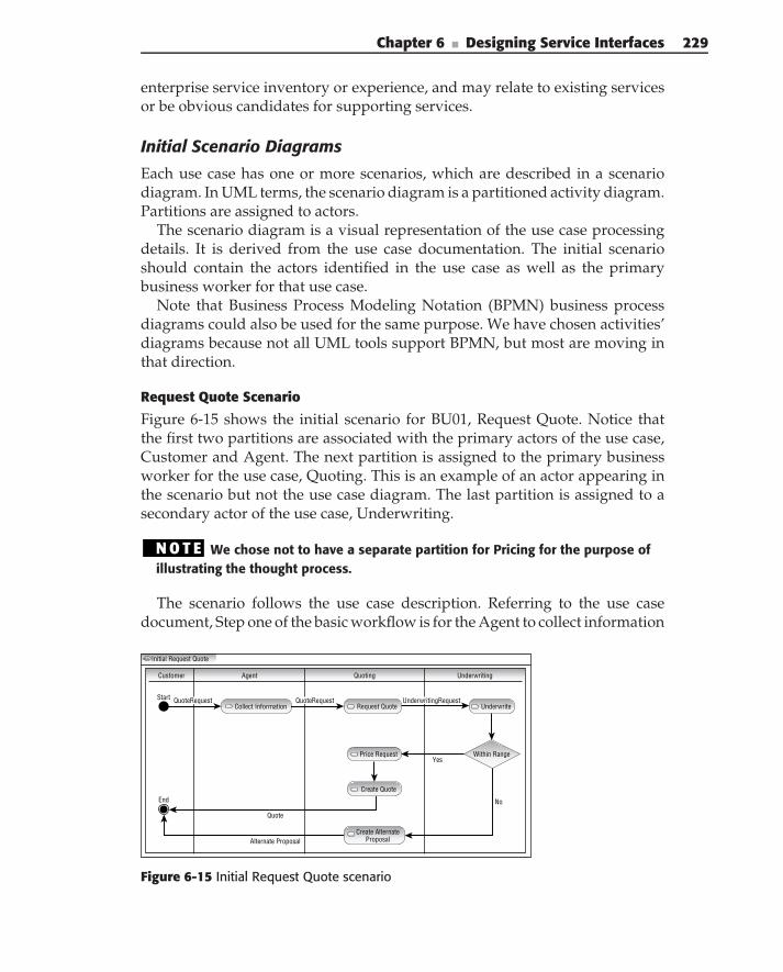
Chapter 6 ■ Designing Service Interfaces 229
enterprise service inventory or experience, and may relate to existing servicesor be obvious candidates for supporting services.
Initial Scenario Diagrams
Each use case has one or more scenarios, which are described in a scenariodiagram. In UML terms, the scenario diagram is a partitioned activity diagram.Partitions are assigned to actors.
The scenario diagram is a visual representation of the use case processingdetails. It is derived from the use case documentation. The initial scenarioshould contain the actors identified in the use case as well as the primarybusiness worker for that use case.
Note that Business Process Modeling Notation (BPMN) business processdiagrams could also be used for the same purpose. We have chosen activities’diagrams because not all UML tools support BPMN, but most are moving inthat direction.
Request Quote Scenario
Figure 6-15 shows the initial scenario for BU01, Request Quote. Notice thatthe first two partitions are associated with the primary actors of the use case,Customer and Agent. The next partition is assigned to the primary businessworker for the use case, Quoting. This is an example of an actor appearing inthe scenario but not the use case diagram. The last partition is assigned to asecondary actor of the use case, Underwriting.
N O T E We chose not to have a separate partition for Pricing for the purpose ofillustrating the thought process.
The scenario follows the use case description. Referring to the use casedocument, Step one of the basic workflow is for the Agent to collect information
Initial Request Quote
Customer
Quote
Alternate Proposal
Agent Quoting Underwriting
Within Range
Request Quote
Yes
No
Price Request
Create Quote
UnderwriteCollect InformationStart
End
Create AlternateProposal
QuoteRequest QuoteRequest UnderwritingRequest
Figure 6-15 Initial Request Quote scenario
230 Part II ■ Designing SOA
from the Customer about the requested insurance. Notice that this stepwill probably not become automated. But, at this level of design, you mustspecify the scenario independently of technology concerns. Obviously, later onin the process you need to be able to distinguish between automated andnon-automated steps. Step 2 in the business use case is to underwrite thequote. From experience, you know that requests need to be validated forcorrection, so you insert that as the next step of the scenario, performed bythe Quoting business worker even though it is not explicitly called out in thedocument. Next, the quote is underwritten. Because of its simplicity, we havechosen to incorporate the alternate flow into the initial scenario and indicatethat a decision is made during the underwriting step to determine whetherthe quote is within acceptable risk limits. If so, the basic workflow continues,if not, the alternate workflow is followed, and an alternate proposal is madeand presented to the Customer.
Back to the basic flow, Step 3 is to price the quote request, so we add aprice request activity to the scenario. Step 4 of the business use case is topresent the quote to the Customer. Obviously, you need to create it first, soyou add an activity to create the quote and return the quote to the Customerfor evaluation.
The last task in outlining the scenario is to identify the information flowbetween activities in the scenario. Each flow line can be adorned with one ormore documents that facilitate the information flow. Some of the documentsmay have already been identified in the document model, but probably not allof them. For example, in Figure 6-15 we identified a QuoteRequest documentthat is passed to the agent, who collects additional information and sends theQuote Request on to the next step. An Underwriting Request document isused to pass the necessary information to Underwriting. This document wasnot identified in the use case, but you know you will need to pass somethingalong, so you create the document definition as you’re developing the scenario.Finally, either a quote or an alternate proposal is returned to the customer, asdescribed in the use case document.
N O T E Remember that this is an iterative process. Don’t worry about gettingeverything right the first time. You can go back to correct and improve the actors,scenarios, documents, and so on, several times during analysis as you workthrough other use cases. The important thing is to get the information down first.At this point, it’s more important to be clear than it is to be correct. Reviewers willtell you if it’s wrong, as long as they can understand it.
Purchase Insurance ScenarioFigure 6-16 shows the scenario diagram for the Purchase Insurance scenariobased on business use case BU02. The process of creating this scenario is prettymuch the same as for the Request Quote scenario, so we won’t repeat all of thedescriptions. However, we describe some aspects that are different.
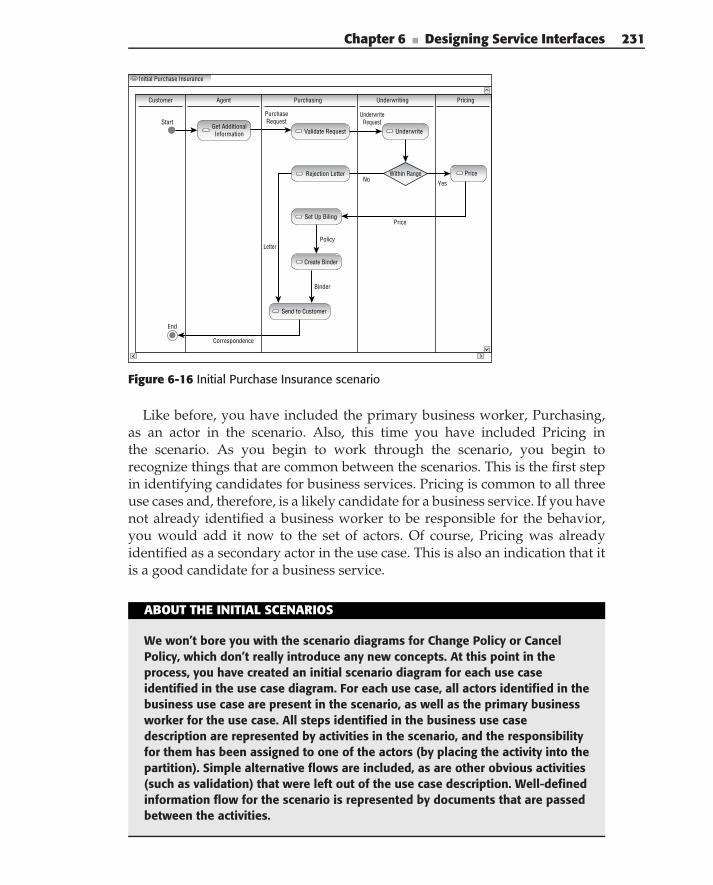
Chapter 6 ■ Designing Service Interfaces 231
Initial Purchase Insurance
Customer Agent Purchasing Underwriting Pricing
StartGet AdditionalInformation Validate Request
PurchaseRequest
UnderwriteRequest
Rejection Letter
Set Up Biling
Create Binder
Send to Customer
Binder
Correspondence
End
Letter
Price
NoYes
Policy
Price
Underwrite
Within Range
Figure 6-16 Initial Purchase Insurance scenario
Like before, you have included the primary business worker, Purchasing,as an actor in the scenario. Also, this time you have included Pricing inthe scenario. As you begin to work through the scenario, you begin torecognize things that are common between the scenarios. This is the first stepin identifying candidates for business services. Pricing is common to all threeuse cases and, therefore, is a likely candidate for a business service. If you havenot already identified a business worker to be responsible for the behavior,you would add it now to the set of actors. Of course, Pricing was alreadyidentified as a secondary actor in the use case. This is also an indication that itis a good candidate for a business service.
ABOUT THE INITIAL SCENARIOS
We won’t bore you with the scenario diagrams for Change Policy or CancelPolicy, which don’t really introduce any new concepts. At this point in theprocess, you have created an initial scenario diagram for each use caseidentified in the use case diagram. For each use case, all actors identified in thebusiness use case are present in the scenario, as well as the primary businessworker for the use case. All steps identified in the business use casedescription are represented by activities in the scenario, and the responsibilityfor them has been assigned to one of the actors (by placing the activity into thepartition). Simple alternative flows are included, as are other obvious activities(such as validation) that were left out of the use case description. Well-definedinformation flow for the scenario is represented by documents that are passedbetween the activities.
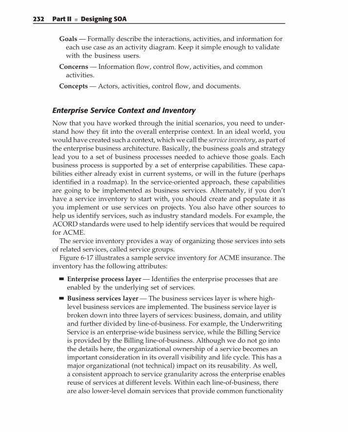
232 Part II ■ Designing SOA
Goals — Formally describe the interactions, activities, and information foreach use case as an activity diagram. Keep it simple enough to validatewith the business users.
Concerns — Information flow, control flow, activities, and commonactivities.
Concepts — Actors, activities, control flow, and documents.
Enterprise Service Context and Inventory
Now that you have worked through the initial scenarios, you need to under-stand how they fit into the overall enterprise context. In an ideal world, youwould have created such a context, which we call the service inventory, as part ofthe enterprise business architecture. Basically, the business goals and strategylead you to a set of business processes needed to achieve those goals. Eachbusiness process is supported by a set of enterprise capabilities. These capa-bilities either already exist in current systems, or will in the future (perhapsidentified in a roadmap). In the service-oriented approach, these capabilitiesare going to be implemented as business services. Alternately, if you don’thave a service inventory to start with, you should create and populate it asyou implement or use services on projects. You also have other sources tohelp us identify services, such as industry standard models. For example, theACORD standards were used to help identify services that would be requiredfor ACME.
The service inventory provides a way of organizing those services into setsof related services, called service groups.
Figure 6-17 illustrates a sample service inventory for ACME insurance. Theinventory has the following attributes:
Enterprise process layer — Identifies the enterprise processes that areenabled by the underlying set of services.
Business services layer — The business services layer is where high-level business services are implemented. The business service layer isbroken down into three layers of services: business, domain, and utilityand further divided by line-of-business. For example, the UnderwritingService is an enterprise-wide business service, while the Billing Serviceis provided by the Billing line-of-business. Although we do not go intothe details here, the organizational ownership of a service becomes animportant consideration in its overall visibility and life cycle. This has amajor organizational (not technical) impact on its reusability. As well,a consistent approach to service granularity across the enterprise enablesreuse of services at different levels. Within each line-of-business, thereare also lower-level domain services that provide common functionality
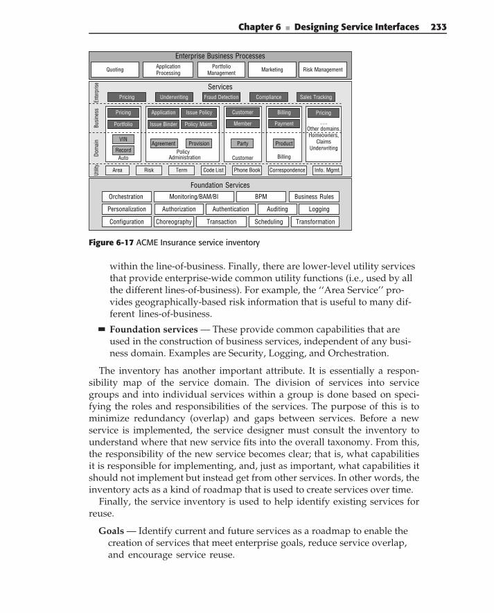
Chapter 6 ■ Designing Service Interfaces 233
Services
Enterprise Business Processes
Billing
Phone Book Info. Mgmt.
Ente
rpris
eBu
sine
ss
Dom
ain
Utilit
y
ApplicationProcessing Risk ManagementMarketingPortfolio
ManagementQuoting
Area
Product
Risk Term Code List
Auto
VIN
Customer
Party
Customer
PolicyAdministration
Issue Binder
Issue Policy Billing
Payment ….Other domains.Homeowners,
ClaimsUnderwriting
Pricing
Pricing
Policy Maint.
Agreement Provision
Member
Application
Sales TrackingComplianceFraud Detection
Record
Portfolio
Underwriting
Pricing
Correspondence
Foundation ServicesBusiness Rules
Authorization
Orchestration
Choreography SchedulingConfiguration
Personalization Authentication
Transaction
Auditing
Monitoring/BAM/BI BPM
Transformation
Logging
Figure 6-17 ACME Insurance service inventory
within the line-of-business. Finally, there are lower-level utility servicesthat provide enterprise-wide common utility functions (i.e., used by allthe different lines-of-business). For example, the ‘‘Area Service’’ pro-vides geographically-based risk information that is useful to many dif-ferent lines-of-business.
Foundation services — These provide common capabilities that areused in the construction of business services, independent of any busi-ness domain. Examples are Security, Logging, and Orchestration.
The inventory has another important attribute. It is essentially a respon-sibility map of the service domain. The division of services into servicegroups and into individual services within a group is done based on speci-fying the roles and responsibilities of the services. The purpose of this is tominimize redundancy (overlap) and gaps between services. Before a newservice is implemented, the service designer must consult the inventory tounderstand where that new service fits into the overall taxonomy. From this,the responsibility of the new service becomes clear; that is, what capabilitiesit is responsible for implementing, and, just as important, what capabilities itshould not implement but instead get from other services. In other words, theinventory acts as a kind of roadmap that is used to create services over time.
Finally, the service inventory is used to help identify existing services forreuse.
Goals — Identify current and future services as a roadmap to enable thecreation of services that meet enterprise goals, reduce service overlap,and encourage service reuse.
234 Part II ■ Designing SOA
Concerns — Role, responsibilities, organization, scope, and visibility.
Concepts — Processes, business services, domain services, utility service,and foundation service.
Detailed Scenario Diagrams
Now that you have worked through the initial scenarios and put them intothe overall enterprise SOA context, you want to go back and refine them withmore detail. You will create a second, ‘‘detailed scenario’’ for each of the usecases. In the detailed scenarios, you factor in some additional informationfrom the use cases and the service inventory. In addition, you apply commonpatterns, and assign responsibility for shared information and fundamentalbusiness entities identified in the information model.
Entity Managers
During the design process, you identify certain types of information in twoways. First, in the information model, you identify fundamental businessentities, such as Customer or Policy. Second, you identify information that isshared across scenarios, or by multiple activities in a scenario, such as a Quote.The management of shared information needs to be coordinated, and you cancreate entity manager actors with that responsibility.
Request Quote Detailed Scenario
Figure 6-18 shows the detailed scenario for Request Quote. In the discussion,we compare the detailed scenario to the initial scenario in Figure 6-15. First,let’s examine the actors. Because the customer had no participation in thescenario other than to initiate the request, we have omitted the customer actorfrom the detailed scenario. Next, we added pricing into the scenario becausewe earlier identified it as a shared responsibility. Also, we added the secondarybusiness worker, Customer Manager, to the scenario.
The first few steps of the detailed scenario are the same as in the initialscenario, namely Collect Information and Validate Request. The next activity,Create Quote, is also taken from the initial scenario. However, as you definethe service interface and implementation, you must take into account the moredetailed scenario.
BU01 contains some important text. ‘‘ACME also offers a multi-policydiscount of 5% for Customers already holding another policy with ACME,assuming the quoted policy would not replace an existing policy.’’ Thisimplies that you need to know if the requestor is an existing Customer ornot. So, the next activity in the scenario is to ask the Customer Manager toreturn information about the Customer, including whether or not they alreadyexist. Notice that the input to the Get Customer Info activities is a Customer
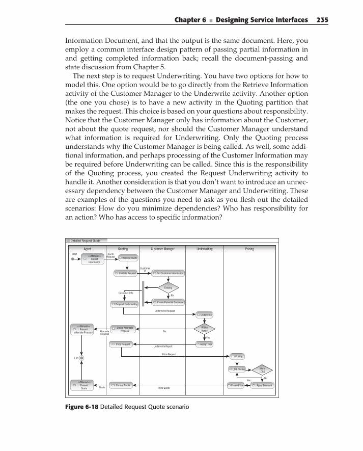
Chapter 6 ■ Designing Service Interfaces 235
Information Document, and that the output is the same document. Here, youemploy a common interface design pattern of passing partial information inand getting completed information back; recall the document-passing andstate discussion from Chapter 5.
The next step is to request Underwriting. You have two options for how tomodel this. One option would be to go directly from the Retrieve Informationactivity of the Customer Manager to the Underwrite activity. Another option(the one you chose) is to have a new activity in the Quoting partition thatmakes the request. This choice is based on your questions about responsibility.Notice that the Customer Manager only has information about the Customer,not about the quote request, nor should the Customer Manager understandwhat information is required for Underwriting. Only the Quoting processunderstands why the Customer Manager is being called. As well, some addi-tional information, and perhaps processing of the Customer Information maybe required before Underwriting can be called. Since this is the responsibilityof the Quoting process, you created the Request Underwriting activity tohandle it. Another consideration is that you don’t want to introduce an unnec-essary dependency between the Customer Manager and Underwriting. Theseare examples of the questions you need to ask as you flesh out the detailedscenarios: How do you minimize dependencies? Who has responsibility foran action? Who has access to specific information?
Detailed Request Quote
Agent Quoting Customer Manager Underwriting PricingStart
Price Quote
YesNo
Price Request
Underwrite Report
MoreLOBS
Existing
WithinRange
<<Manual>>Collect
Information
Get Customer Information
CustomerId
Create Potential Customer
Request QuoteQuote
Request
Validate Request
<<Manual>>Present
Alternate Proposal
<<Manual>>PresentQuote Quote
Request Underwriting
Price Request
Format Quote Create Price
Create AlternateProposal
End
Apply Discount
LOB Pricing
Assign Risk
Underwrite
Pricing
AlternateProposal
No
Underwrite Request
No
Yes
Customer Info
Figure 6-18 Detailed Request Quote scenario
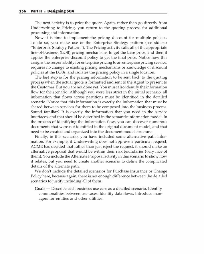
236 Part II ■ Designing SOA
The next activity is to price the quote. Again, rather than go directly fromUnderwriting to Pricing, you return to the quoting process for additionalprocessing and information.
Now it is time to implement the pricing discount for multiple policies.To do so, you make use of the Enterprise Strategy pattern (see sidebar‘‘Enterprise Strategy Pattern’’). The Pricing activity calls all of the appropriateline-of-business (LOB) pricing mechanisms to get the base price, and then itapplies the enterprise discount policy to get the final price. Notice how thisassigns the responsibility for enterprise pricing to an enterprise pricing service,requires no change to existing pricing mechanisms or knowledge of discountpolicies at the LOBs, and isolates the pricing policy in a single location.
The last step is for the pricing information to be sent back to the quotingprocess when the actual quote is formatted and sent to the Agent to present tothe Customer. But you are not done yet. You must also identify the informationflow for the scenario. Although you were less strict in the initial scenario, allinformation that flows across partitions must be identified in the detailedscenario. Notice that this information is exactly the information that must beshared between services for them to be composed into the business process.Sound familiar? It is exactly the information that you need in the serviceinterfaces, and that should be described in the semantic information model. Inthe process of identifying the information flow, you can discover numerousdocuments that were not identified in the original document model, and thatneed to be created and organized into the document model structure.
Finally, in this scenario, you have included some alternative path infor-mation. For example, if Underwriting does not approve a particular request,ACME has decided that rather than just reject the request, it should make analternative proposal that would be within their risk boundaries (very nice ofthem). You include the Alternate Proposal activity in this scenario to show howit relates, but you need to create another scenario to define the complicateddetails of the alternate path.
We don’t include the detailed scenarios for Purchase Insurance or ChangePolicy here, because again, there is not enough difference between the detailedscenarios to justify including all of them.
Goals — Describe each business use case as a detailed scenario. Identifycommonalities between use cases. Identify data flows. Introduce man-agers for entities and other utilities.
Chapter 6 ■ Designing Service Interfaces 237
Concerns — Information flow, control flow, activities, common activities,and entities.
Concepts — Actors, activities, control flow, and documents.
ENTERPRISE STRATEGY PATTERN
Name — Enterprise Strategy.
Intent — To provide an enterprise-wide solution that is based on both line-of-business policies and enterprise policies.
Problem — Policies need to be applied depending on scope. Only processeswithin a scope are aware of that scope’s policies. In addition, processesare not aware of policies outside their own scope.
Forces:
■ Enterprise policies are defined at the enterprise level, based oncommon (cross line-of-business) information and enterprisesemantics.
■ Enterprise polices require information from multiple lines-of-business.
■ Individual line-of-business policies are defined within the lines ofbusiness.
■ Different lines-of-business have different implementations, platforms,and data.
Solution — The enterprise strategy solution provides a mediator betweenthe different lines of business. Each line of business is invoked to applyits own policy. Then, the enterprise policy is applied to the results.
Implementation —
1. Define the input and output, based on the common enterprise seman-tics.
2. Determine the context. This provides information on:
Which lines-of-business to call.
What enterprise policy to apply.
(continued)
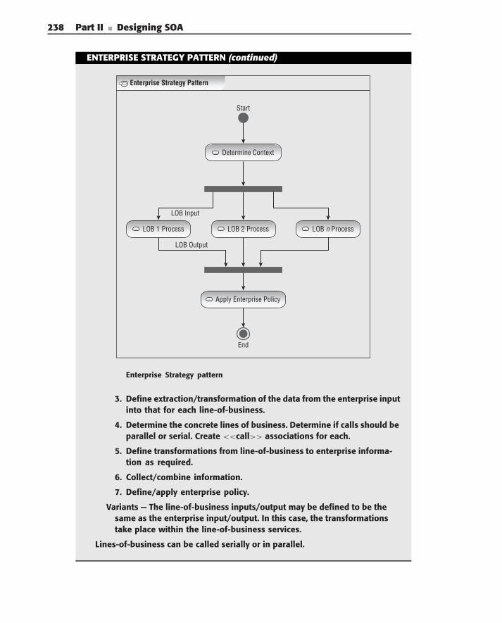
238 Part II ■ Designing SOA
ENTERPRISE STRATEGY PATTERN (continued)
Start
End
LOB Input
LOB Output
Apply Enterprise Policy
LOB 2 Process
Determine Context
LOB 1 Process LOB n Process
Enterprise Strategy Pattern
Enterprise Strategy pattern
3. Define extraction/transformation of the data from the enterprise inputinto that for each line-of-business.
4. Determine the concrete lines of business. Determine if calls should beparallel or serial. Create <<call>> associations for each.
5. Define transformations from line-of-business to enterprise informa-tion as required.
6. Collect/combine information.
7. Define/apply enterprise policy.
Variants — The line-of-business inputs/output may be defined to be thesame as the enterprise input/output. In this case, the transformationstake place within the line-of-business services.
Lines-of-business can be called serially or in parallel.
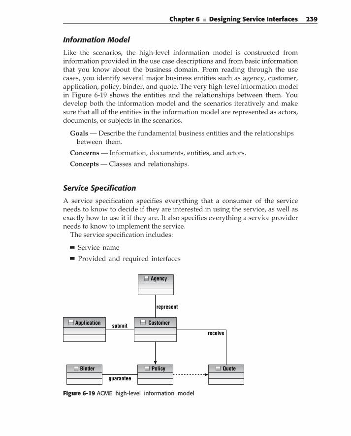
Chapter 6 ■ Designing Service Interfaces 239
Information Model
Like the scenarios, the high-level information model is constructed frominformation provided in the use case descriptions and from basic informationthat you know about the business domain. From reading through the usecases, you identify several major business entities such as agency, customer,application, policy, binder, and quote. The very high-level information modelin Figure 6-19 shows the entities and the relationships between them. Youdevelop both the information model and the scenarios iteratively and makesure that all of the entities in the information model are represented as actors,documents, or subjects in the scenarios.
Goals — Describe the fundamental business entities and the relationshipsbetween them.
Concerns — Information, documents, entities, and actors.
Concepts — Classes and relationships.
Service Specification
A service specification specifies everything that a consumer of the serviceneeds to know to decide if they are interested in using the service, as well asexactly how to use it if they are. It also specifies everything a service providerneeds to know to implement the service.
The service specification includes:
Service name
Provided and required interfaces
Agency
Policy QuoteBinder
CustomerApplication
represent
receive
guarantee
submit
Figure 6-19 ACME high-level information model
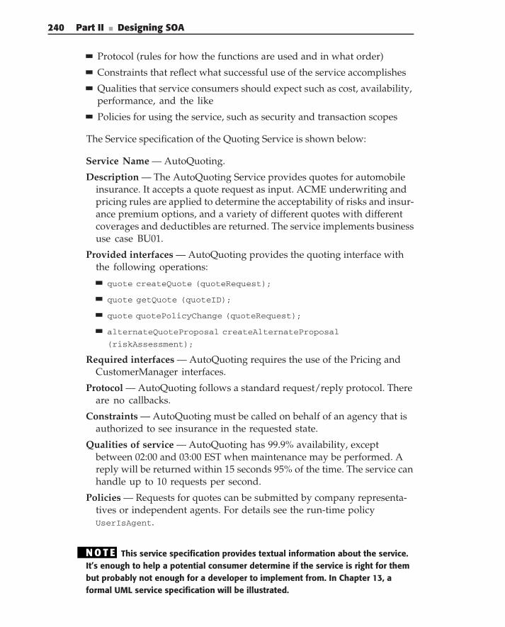
240 Part II ■ Designing SOA
Protocol (rules for how the functions are used and in what order)
Constraints that reflect what successful use of the service accomplishes
Qualities that service consumers should expect such as cost, availability,performance, and the like
Policies for using the service, such as security and transaction scopes
The Service specification of the Quoting Service is shown below:
Service Name — AutoQuoting.
Description — The AutoQuoting Service provides quotes for automobileinsurance. It accepts a quote request as input. ACME underwriting andpricing rules are applied to determine the acceptability of risks and insur-ance premium options, and a variety of different quotes with differentcoverages and deductibles are returned. The service implements businessuse case BU01.
Provided interfaces — AutoQuoting provides the quoting interface withthe following operations:
quote createQuote (quoteRequest);
quote getQuote (quoteID);
quote quotePolicyChange (quoteRequest);
alternateQuoteProposal createAlternateProposal
(riskAssessment);
Required interfaces — AutoQuoting requires the use of the Pricing andCustomerManager interfaces.
Protocol — AutoQuoting follows a standard request/reply protocol. Thereare no callbacks.
Constraints — AutoQuoting must be called on behalf of an agency that isauthorized to see insurance in the requested state.
Qualities of service — AutoQuoting has 99.9% availability, exceptbetween 02:00 and 03:00 EST when maintenance may be performed. Areply will be returned within 15 seconds 95% of the time. The service canhandle up to 10 requests per second.
Policies — Requests for quotes can be submitted by company representa-tives or independent agents. For details see the run-time policyUserIsAgent.
N O T E This service specification provides textual information about the service.It’s enough to help a potential consumer determine if the service is right for thembut probably not enough for a developer to implement from. In Chapter 13, aformal UML service specification will be illustrated.
Chapter 6 ■ Designing Service Interfaces 241
FORMAL VERSUS INFORMAL SPECIFICATIONS
To be or not to be formal? That is the question. Like many things inarchitecture, the answer is ‘‘that depends.’’ There is a place for both informalspecifications that are meant to communicate to a nontechnical audience, andformal specifications, which are intended to be complete and precise. Ourposition is that you need both to be effective architects.
One of the primary responsibilities of an architect is to communicate. If thecommunication medium is impenetrable, then it doesn’t matter how correct itis, because some percentage of the audience won’t touch it, and the architecthas failed.
In this chapter, we present an informal software specification. In our casestudy example, we use a formal UML specification. You decide what you’d usewith business process designers, and what you’d use with system analysts. Weknow what we’d do.
Solution Model
The solution model picks up where the problem model leaves off. It refinesthe business concepts (processes, activities, entities, and documents) intoSOA technology concepts of services, interfaces, operations, documents, andinformation. Note however, that it does this in a way that is independent ofthe underlying platform (such as an ESB or .NET).
In this section, we look at the development of the service model that specifiesthe overall set of service, and for each service, the service interface definition,and how it relates to the enterprise context and semantics.
Service ModelThe first part of the solution model is the service model. It contains a collectionof related services, and shows the services and their relationships. Servicemodels act as an organizing mechanism for grouping related services. Inthe problem model, we identified service candidates by looking for commonbehavior and shared information. The service inventory provided a roadmapfor new and existing services and their responsibilities. Common behaviorswere identified as scenario activities. We also identified some shared infor-mation and resources that are controlled by manager actors (and hence entityservice). Now, we refine these into services.
The basic process is to work through each of the detailed business scenariosand evaluate every activity in the scenario as being implemented by a service.For each activity, there are three possible options:
Define it as a manual task.
Assign it to a service operation. This is done either by creating a new ser-vice for it, or assigning it to an existing service.
242 Part II ■ Designing SOA
Defer it as an internal task of another service. This often represents alower-level service that is part of the composition of the business service.
For example, we address the Request Quote scenario as follows:
Collect Information: This is a manual process.
Validate Request: This is internal to another service.
Underwrite for Quote: For this, we create the Underwriting Service.
Price Request: For this, we create the Pricing Service.
Create Quote: For this, we create the Quoting Service.
Create Alternate Proposal: This is done by the Quoting Service.
WOULDN’T IT BE NICE . . .
Wouldn’t it be nice if the information that the business provided to use is niceand uniform? Okay, pinch yourself and wake up to reality. This is rarely thecase. More likely, you’re happy to get any level of detail at all. And, when youdo translate that business detail into something more IT-like, you need to verifythat you did it accurately.
So, a scenario diagram has to accurately reflect the information providedby your business partners, and communicate to them that you have accuratelyaccounted for all requirements. That’s one of the most important aspects of ascenario diagram (especially the initial diagrams). So, the facts of life are thatthe details that are specified to you are at differing levels. Some are serviceoperations; others are implementation details . . . hey, deal with it!
At this stage in the process, you need to deal with these different levels.Sorry if reality is messy. That’s why they pay you the big bucks.
At the beginning of this task (assigning activities to services), you oftenneed to create new services for the activities. Near the end of the task, manyservices have already been created, and you are adding new operations tothem. As you create new services, you want to think about how to orga-nize them into service groups (or packages) and make sure that those ser-vices align with the service taxonomy. You have chosen to group the Quot-ing and Pricing related services together into the Pricing group because offunctional cohesion.
Another common principle is to group services by organizational unitor scope. For example, you might have groupings for each line-of-businessor application group. The goal is to group cohesive services in the same servicemodel so that it is easy to understand the responsibilities associated with thoseservices.
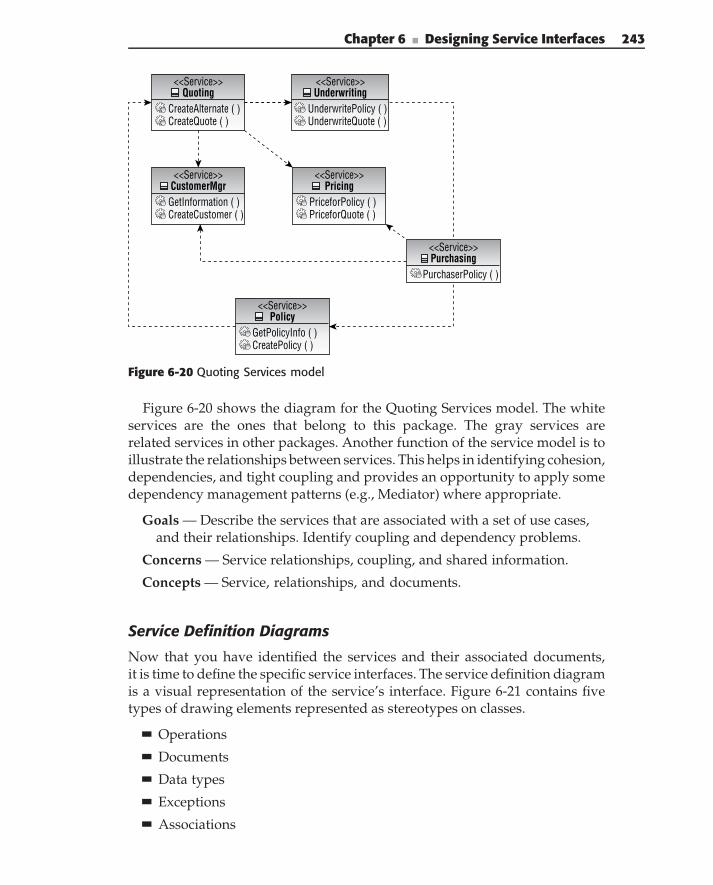
Chapter 6 ■ Designing Service Interfaces 243
<<Service>>Quoting
CreateAlternate ( )CreateQuote ( )
<<Service>>CustomerMgrGetInformation ( )CreateCustomer ( )
<<Service>>Underwriting
UnderwritePolicy ( )UnderwriteQuote ( )
<<Service>>Pricing
PriceforPolicy ( )PriceforQuote ( )
<<Service>>Purchasing
PurchaserPolicy ( )
<<Service>>Policy
GetPolicyInfo ( )CreatePolicy ( )
Figure 6-20 Quoting Services model
Figure 6-20 shows the diagram for the Quoting Services model. The whiteservices are the ones that belong to this package. The gray services arerelated services in other packages. Another function of the service model is toillustrate the relationships between services. This helps in identifying cohesion,dependencies, and tight coupling and provides an opportunity to apply somedependency management patterns (e.g., Mediator) where appropriate.
Goals — Describe the services that are associated with a set of use cases,and their relationships. Identify coupling and dependency problems.
Concerns — Service relationships, coupling, and shared information.
Concepts — Service, relationships, and documents.
Service Definition Diagrams
Now that you have identified the services and their associated documents,it is time to define the specific service interfaces. The service definition diagramis a visual representation of the service’s interface. Figure 6-21 contains fivetypes of drawing elements represented as stereotypes on classes.
Operations
Documents
Data types
Exceptions
Associations
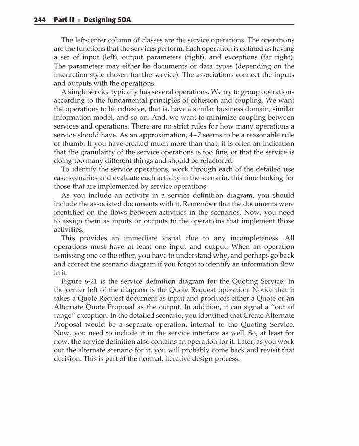
244 Part II ■ Designing SOA
The left-center column of classes are the service operations. The operationsare the functions that the services perform. Each operation is defined as havinga set of input (left), output parameters (right), and exceptions (far right).The parameters may either be documents or data types (depending on theinteraction style chosen for the service). The associations connect the inputsand outputs with the operations.
A single service typically has several operations. We try to group operationsaccording to the fundamental principles of cohesion and coupling. We wantthe operations to be cohesive, that is, have a similar business domain, similarinformation model, and so on. And, we want to minimize coupling betweenservices and operations. There are no strict rules for how many operations aservice should have. As an approximation, 4–7 seems to be a reasonable ruleof thumb. If you have created much more than that, it is often an indicationthat the granularity of the service operations is too fine, or that the service isdoing too many different things and should be refactored.
To identify the service operations, work through each of the detailed usecase scenarios and evaluate each activity in the scenario, this time looking forthose that are implemented by service operations.
As you include an activity in a service definition diagram, you shouldinclude the associated documents with it. Remember that the documents wereidentified on the flows between activities in the scenarios. Now, you needto assign them as inputs or outputs to the operations that implement thoseactivities.
This provides an immediate visual clue to any incompleteness. Alloperations must have at least one input and output. When an operationis missing one or the other, you have to understand why, and perhaps go backand correct the scenario diagram if you forgot to identify an information flowin it.
Figure 6-21 is the service definition diagram for the Quoting Service. Inthe center left of the diagram is the Quote Request operation. Notice that ittakes a Quote Request document as input and produces either a Quote or anAlternate Quote Proposal as the output. In addition, it can signal a ‘‘out ofrange’’ exception. In the detailed scenario, you identified that Create AlternateProposal would be a separate operation, internal to the Quoting Service.Now, you need to include it in the service interface as well. So, at least fornow, the service definition also contains an operation for it. Later, as you workout the alternate scenario for it, you will probably come back and revisit thatdecision. This is part of the normal, iterative design process.
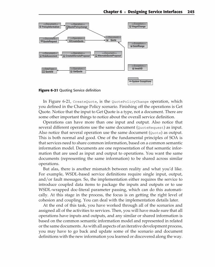
Chapter 6 ■ Designing Service Interfaces 245
<<Document>>PolicyInformation
<<Operation>>QuotePolicychange
<<Operation>>CreateQuote
<<Document>>QuoteRequest
<<Document>>RiskAssesment
<<DataType>>QuoteId<D>
<<Operation>>GetQuote
<<Operation>>CreateAlternateProposal
<<Document>>Quote
<<Document>>AlternateQuoteProposal
<<Exception>>IllegalChange
<<Exception>>OutofRange
<<Exception>>InvaliID
System Exceptiions
Figure 6-21 Quoting Service definition
In Figure 6-21, CreateQuote, is the QuotePolicyChange operation, whichyou defined in the Change Policy scenario. Finishing off the operations is GetQuote. Notice that the input to Get Quote is a type, not a document. There aresome other important things to notice about the overall service definition.
Operations can have more than one input and output. Also notice thatseveral different operations use the same document (QuoteRequest) as input.Also notice that several operation use the same document (Quote) as output.This is both normal and good. One of the fundamental principles of SOA isthat services need to share common information, based on a common semanticinformation model. Documents are one representation of that semantic infor-mation that are used as input and output to operations. You want the samedocuments (representing the same information) to be shared across similaroperations.
But alas, there is another mismatch between reality and what you’d like.For example, WSDL-based service definitions require single input, output,and/or fault messages. So, the implementation either requires the service tointroduce coupled data items to package the inputs and outputs or to useWSDL-wrapped doc-literal parameter passing, which can do this automati-cally. At this stage in the process, the focus is on getting the right level ofcohesion and coupling. You can deal with the implementation details later.
At the end of this task, you have worked through all of the scenarios andassigned all of the activities to services. Then, you will have made sure that alloperations have inputs and outputs, and any similar or shared information isbased on the common semantic information model and represented in relatedor the same documents. As with all aspects of an iterative development process,you may have to go back and update some of the scenario and documentdefinitions with the new information you learned or discovered along the way.
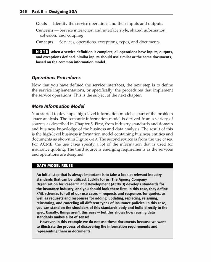
246 Part II ■ Designing SOA
Goals — Identify the service operations and their inputs and outputs.
Concerns — Service interaction and interface style, shared information,cohesion, and coupling.
Concepts — Services, operations, exceptions, types, and documents.
N O T E When a service definition is complete, all operations have inputs, outputs,and exceptions defined. Similar inputs should use similar or the same documents,based on the common information model.
Operations Procedures
Now that you have defined the service interfaces, the next step is to definethe service implementations, or specifically, the procedures that implementthe service operations. This is the subject of the next chapter.
More Information Model
You started to develop a high-level information model as part of the problemspace analysis. The semantic information model is derived from a variety ofsources as described in Chapter 5. First, from industry standards and domainand business knowledge of the business and data analysis. The result of thisis the high-level business information model containing business entities anddocuments as shown in Figure 6-19. The second source is from the use cases.For ACME, the use cases specify a lot of the information that is used forinsurance quoting. The third source is emerging requirements as the servicesand operations are designed.
DATA MODEL REUSE
An initial step that is always important is to take a look at relevant industrystandards that can be utilized. Luckily for us, The Agency CompanyOrganization for Research and Development (ACORD) develops standards forthe insurance industry, and you should look there first. In this case, they defineXML schemas for all of our use cases — requests and responses for quotes, aswell as requests and responses for adding, updating, replacing, reissuing,reinstating, and canceling all different types of insurance policies. In this case,you can stand on the shoulders of this standards body and build directly to thespec. Usually, things aren’t this easy — but this shows how reusing datastandards makes a lot of sense!
However, in this example we do not use these documents because we wantto illustrate the process of discovering the information requirements andrepresenting them in documents.
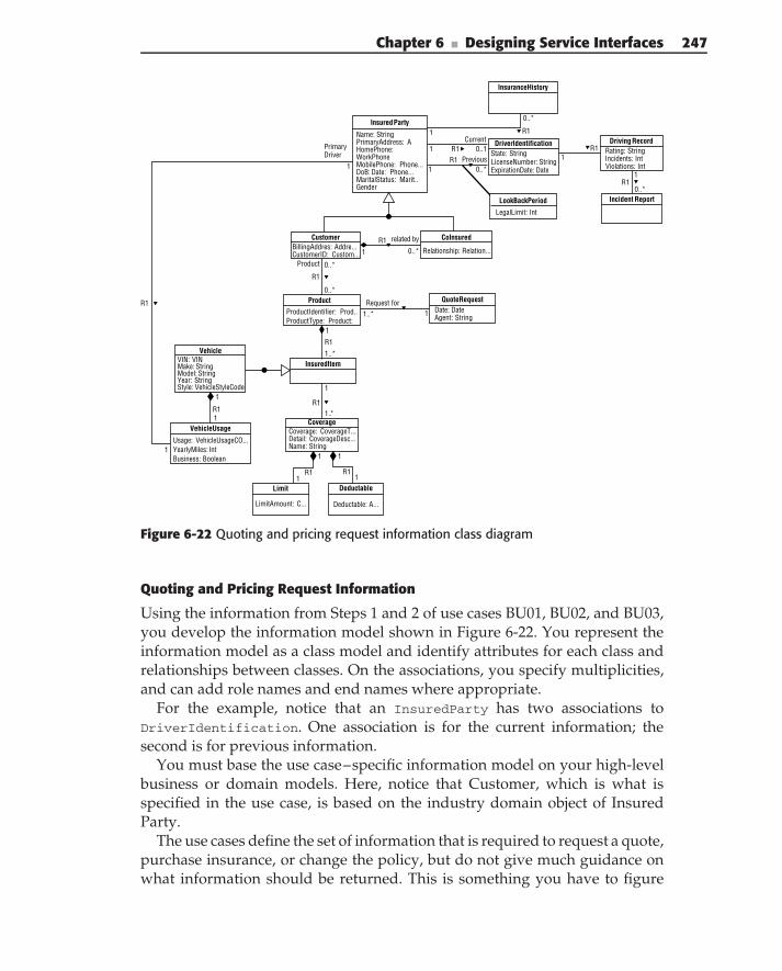
Chapter 6 ■ Designing Service Interfaces 247
Driving RecordRating: StringIncidents: IntViolations: Int
Incident ReportLookBackPeriod
LegalLimit: Int
InsuranceHistory
QuoteRequestDate: DateAgent: String
R1 0..1
0..*
CurrentR1
1Previous
R11
0..*
R11
1
0..*
Request for11..*
Insured Party
Name: StringPrimaryAddress: AHomePhone:WorkPhoneMobilePhone: Phone...DoB: Date: Phone...MaritalStatus: Marit..Gender
DriverIdentificationState: StringLicenseNumber: StringExpirationDate: Date
CustomerBillingAddres: Addre...CustomerID: Custom...
CoInsured
Relationship: Relation...
Product
ProductIdentifier: Prod..ProductType: Product:
InsuredItem
VehicleVIN: VINMake: StringModel: StringYear: StringStyle: VehicleStyleCode
YearlyMiles: IntBusiness: Boolean
VehicleUsage
Usage: VehicleUsageCO...
CoverageCoverage: CoverageT...Detail: CoverageDesc...Name: String
Limit
LimitAmount: C...
Deductable
Deductable: A...
1
R1
1
related by
R1
0..*
Product
0..*
0..*
R1
1
1..*
R1
1
1
R1
1
1.*.
R1
1
1R1
1
1
R1
1
1
PrimaryDriver
R1
Figure 6-22 Quoting and pricing request information class diagram
Quoting and Pricing Request Information
Using the information from Steps 1 and 2 of use cases BU01, BU02, and BU03,you develop the information model shown in Figure 6-22. You represent theinformation model as a class model and identify attributes for each class andrelationships between classes. On the associations, you specify multiplicities,and can add role names and end names where appropriate.
For the example, notice that an InsuredParty has two associations toDriverIdentification. One association is for the current information; thesecond is for previous information.
You must base the use case–specific information model on your high-levelbusiness or domain models. Here, notice that Customer, which is what isspecified in the use case, is based on the industry domain object of InsuredParty.
The use cases define the set of information that is required to request a quote,purchase insurance, or change the policy, but do not give much guidance onwhat information should be returned. This is something you have to figure
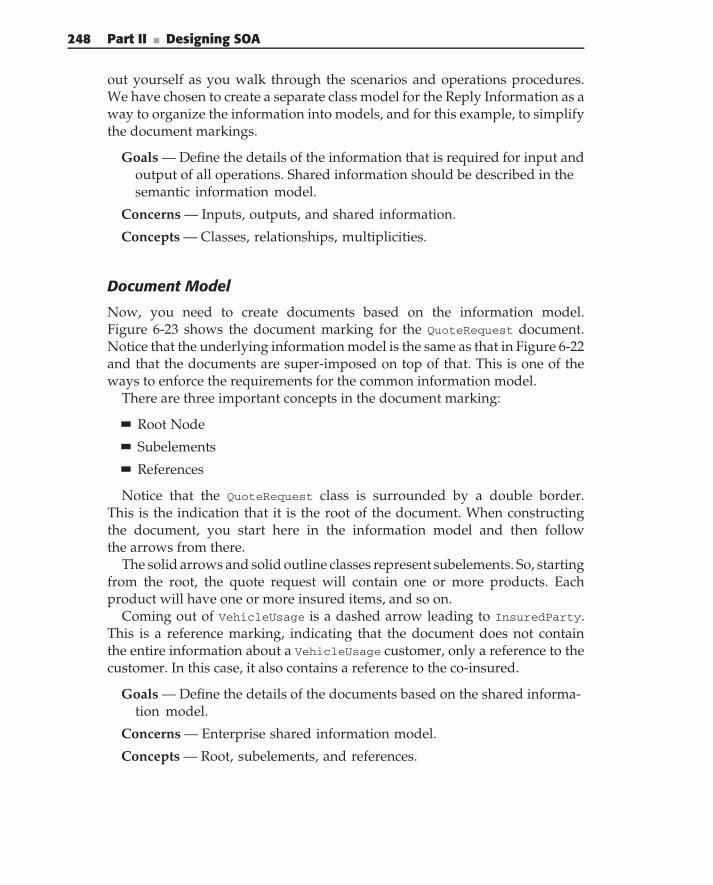
248 Part II ■ Designing SOA
out yourself as you walk through the scenarios and operations procedures.We have chosen to create a separate class model for the Reply Information as away to organize the information into models, and for this example, to simplifythe document markings.
Goals — Define the details of the information that is required for input andoutput of all operations. Shared information should be described in thesemantic information model.
Concerns — Inputs, outputs, and shared information.
Concepts — Classes, relationships, multiplicities.
Document Model
Now, you need to create documents based on the information model.Figure 6-23 shows the document marking for the QuoteRequest document.Notice that the underlying information model is the same as that in Figure 6-22and that the documents are super-imposed on top of that. This is one of theways to enforce the requirements for the common information model.
There are three important concepts in the document marking:
Root Node
Subelements
References
Notice that the QuoteRequest class is surrounded by a double border.This is the indication that it is the root of the document. When constructingthe document, you start here in the information model and then followthe arrows from there.
The solid arrows and solid outline classes represent subelements. So, startingfrom the root, the quote request will contain one or more products. Eachproduct will have one or more insured items, and so on.
Coming out of VehicleUsage is a dashed arrow leading to InsuredParty.This is a reference marking, indicating that the document does not containthe entire information about a VehicleUsage customer, only a reference to thecustomer. In this case, it also contains a reference to the co-insured.
Goals — Define the details of the documents based on the shared informa-tion model.
Concerns — Enterprise shared information model.
Concepts — Root, subelements, and references.
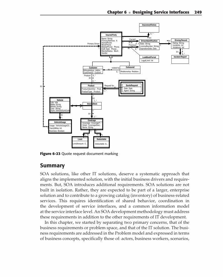
Chapter 6 ■ Designing Service Interfaces 249
Driving RecordRating: StringIncidents: IntViolations: Int
Incident ReportLookBackPeriod
LegalLimit: Int
InsuranceHistory
QuoteRequestDate: DateAgent: String
R1 0..1
CurrentR1
1Previous
R11
0..*
R11
1
0..*
Request for
11..*
Insured Party
Name: StringPrimaryAddress: AHomePhone:WorkPhoneMobilePhone: Phone...DoB: Date: Phone...MaritalStatus: Marit..Gender
DriverIdentificationState: StringLicenseNumber: StringExpirationDate: Date
CustomerBillingAddres: Addre...CustomerID: Custom...
CoInsured
Relationship: Relation...
Product
ProductIdentifier: Prod..ProductType: Product:
InsuredItem
VehicleVIN: VINMake: StringModel: StringYear: StringStyle: VehicleStyleCode
YearlyMiles: IntBusiness: Boolean
VehicleUsage
Usage: VehicleUsageCO...
CoverageCoverage: CoverageT...Detail: CoverageDesc...Name: String
Limit
LimitAmount: C...
Deductable
Deductable: A...
1
R1related by
R1
0..*
Product
0..*
0..*
R11
1..*
R11
1
R11
1.*.
R1
1
1 R1
1
1
R1
1
1
Primary Driver
R1 0..*
Figure 6-23 Quote request document marking
SummarySOA solutions, like other IT solutions, deserve a systematic approach thataligns the implemented solution, with the initial business drivers and require-ments. But, SOA introduces additional requirements. SOA solutions are notbuilt in isolation. Rather, they are expected to be part of a larger, enterprisesolution and to contribute to a growing catalog (inventory) of business-relatedservices. This requires identification of shared behavior, coordination inthe development of service interfaces, and a common information modelat the service interface level. An SOA development methodology must addressthese requirements in addition to the other requirements of IT development.
In this chapter, we started by separating two primary concerns, that of thebusiness requirements or problem space, and that of the IT solution. The busi-ness requirements are addressed in the Problem model and expressed in termsof business concepts, specifically those of: actors, business workers, scenarios,
250 Part II ■ Designing SOA
activities, documents, and information entities. Use cases are used to collectand organize requirements, and then to provide a high-level organization forthe problem model itself.
The solution model addresses how the business requirements can beimplemented in IT systems. It expresses the solution in terms of platformindependent IT application concepts, specifically those of services, operations,procedures, interfaces, implementations, transformations, information, anddocuments.
Services are the fundamental concept in an SOA. A service is made up ofits interface, which specifies the operations, inputs and outputs; and its imple-mentation, which specifies how the operations are performed. A document is afundamental concept in the specification of a service interface. It is a structuredcollection of information. In SOA, it is critical that the same information beused to represent the same concepts, across different services. The semanticinformation model is used to facilitate this, and the documents are constructedas collections of information from the semantic model.
The implementations of service operations are specified in terms of proce-dure definitions, which define a set of steps and transformations that togetherimplement the operation. Services are often constructed, or composed, of otherservices, which may themselves be composed from other services, and so on.In other words, the procedures that implement a service operation invokeother services as part of the operation’s implementation.
The design methodology is iterative and incremental. You do not completeone step for the entire model and then go on to the next step for the entiremodel, and so on. Rather, you divide the solution space into small increments,such as the definition and implementation of a specific service, and workthrough all of the steps for that service. Then, you incorporate what youlearned back into the high-level design and start with another increment.
Within each increment, you work iteratively to do some information model-ing, some interface design, some procedure specification, and so forth. In eachstep, you learn additional information that has to be folded back into the otherareas of the design.
You start at a high-level, addressing the main steps outlined in the usecases and cover a set of related use cases. At this level, you are trying toidentify behavior that is common across use cases and factor it out intoshared behavior. These are the first candidates for business services. You alsoidentify information that is shared across these use cases and include thatin our information model. Fundamental business entities and other sharedinformation may also be candidates for entity or resource manager services.
Next, you dig into the use cases in more detail, using what you’ve identifiedas common from the high-level scenario analysis along with additional detailsfrom the use cases themselves, your service inventory, and domain knowl-edge and experience. This identifies additional areas of responsibility and
Chapter 6 ■ Designing Service Interfaces 251
activities. You also specify the flow of information between the activitiesin terms of documents. Now, you have effectively represented the businessrequirements in terms of the Problem model.
The solution model translates these business concepts into SOA applica-tion concepts. One primary translation is from the activities in the businessscenarios. Activities are either done manually, or, if automated, become oper-ations on business services, or internal steps (composed services) within theimplementation of an operation procedure. You work through the model,addressing each activity to determine its likely outcome and begin to definethe services and their operations. The service model organizes services intocohesive collections of services. In addition to providing a table of contentsfor the services, the models illustrate the relationships between services. Here,you examine the relationships between services to reduce dependencies andcoupling and to increase cohesion. This may result in a refactoring of some ofthe service definitions.
Next, you work out the details of the service interfaces. Initially, activitiesfrom the business scenarios can identify the service operations and data flowsbetween those activities, and can define the documents that are used asinputs and output. As you elaborate on the operations, you identify additionalinternal operations that may become part of the service definition, as well asadditional information that is needed in the interfaces.
For each operation, you define the procedure that implements the operation.Again, this is accomplished by iteratively working through the input andoutputs, internal information requirements, and internal processing steps. Asyou work through these details, you also identify changes or additions to theservice interfaces and information.
Whenever you identify additional information requirements at the interfacelevel, you incorporate that new information into the semantic informationmodel. As you create the detailed specifications of the documents, based onthe information model, you will likely discover and implement more changesto the information model as well. Finally, when a service definition is complete,all operations will have inputs and outputs defined, and all document schemawill be defined. Similar inputs should use similar, or the same, documentsbased on the common information model.
This chapter has focused on the design of the service interface. The nextchapter goes into detail on the design of the service implementation.

C H A P T E R
7Designing ServiceImplementations
Out of intense complexities, intense simplicities emerge.
— Winston Churchill
In the last three chapters we focused on identifying business services(Chapter 4), defining the business data using information models (Chapter 5),and defining service interfaces (Chapter 6). Therefore, most of our focus hasbeen external — how to define services based on high-level goals and require-ments, and their interfaces based on semantically rich data resulting frominformation modeling. Information modeling is a key aspect, as it placesservice behavior in the context of the life cycles of enterprise information,providing a more complete view that is sometimes left out by simple func-tional analysis and decomposition alone. This is useful for the creation of alltypes of services (business services, domain services, utility services, and soon), and once you have gone through that process and have defined yourinterfaces and messaging, you have reduced complexity to the point whereyou can now focus on the internals, or the implementation design of yourservices. In this chapter, you learn how to define what is inside each ser-vice in order to create the service implementations. This is more than just adevelopment or programming task, and it is more than just elaborating on adesign. Good service implementation design ensures that the overall archi-tecture is maintained by following the principles established in the enterprisearchitecture.
253
254 Part II ■ Designing SOA
This chapter presents a strategy for constructing services that divides theproblem into several key parts:
Designing the implementation of a service interface
Designing the implementation of the business logic (the logic of thedomain itself)
Designing the resource access layer of a service
The strategy presented in this chapter does not presume any particularimplementation or platform technology. The approach is platform-indepen-dent, although a few examples are illustrated with particular technologies. Thechapter presents the following information:
Basic service architecture
Using activity diagrams to describe operations
Implementing the interface layer
Implementing the business logic layer
Implementing the resource access layer
Example of implementation design
Basic Service Architecture
Before we get started with the service design, it is important to address somecommon misconceptions about the implementations of services. Althoughthere is an abundance of ‘‘Hello World’’ example services in many program-ming languages, a service is not one simple class that implements a serviceinterface. Certainly, a service could consist of one class (although this is typi-cally a very bad design), but it is important to understand that a service shouldbe looked at as an application with all the characteristics thereof. Therefore, itmust include architectural focus for its implementation. Service design shoulduse a layered architecture just like application design. The basic service archi-tecture, presented in Figure 7-1, is composed of the following major layers: aservice interface layer, a service business layer, and a resource access layer. Thisthree-layered architecture is often referred to as a service implementation model.
The service interface layer implements the service contract (or interface) — theoperations provided by the service (interaction patterns supported by theseoperations), the documents associated with each operation, and the datatypes composing these documents. The service business layer is responsiblefor implementing the business logic, rules, and state transitions. The resourceaccess layer contains the logic necessary to access enterprise resources, whichare utilized by the service’s implementation. The resources used by the servicemay include data (databases used directly by a service), existing enterprise
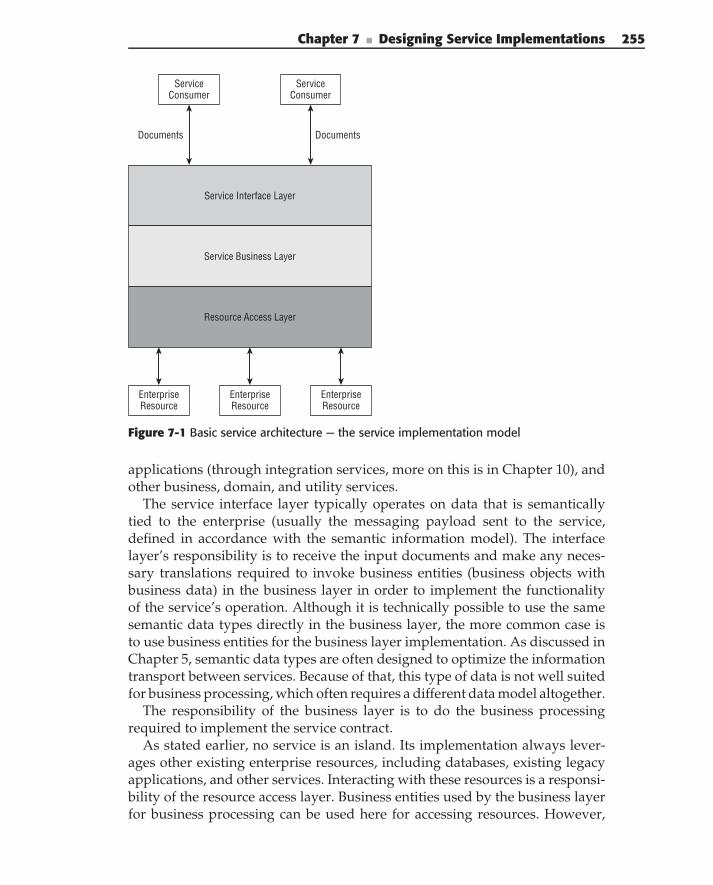
Chapter 7 ■ Designing Service Implementations 255
Service Interface Layer
ServiceConsumer
ServiceConsumer
DocumentsDocuments
Service Business Layer
Resource Access Layer
EnterpriseResource
EnterpriseResource
EnterpriseResource
Figure 7-1 Basic service architecture — the service implementation model
applications (through integration services, more on this is in Chapter 10), andother business, domain, and utility services.
The service interface layer typically operates on data that is semanticallytied to the enterprise (usually the messaging payload sent to the service,defined in accordance with the semantic information model). The interfacelayer’s responsibility is to receive the input documents and make any neces-sary translations required to invoke business entities (business objects withbusiness data) in the business layer in order to implement the functionalityof the service’s operation. Although it is technically possible to use the samesemantic data types directly in the business layer, the more common case isto use business entities for the business layer implementation. As discussed inChapter 5, semantic data types are often designed to optimize the informationtransport between services. Because of that, this type of data is not well suitedfor business processing, which often requires a different data model altogether.
The responsibility of the business layer is to do the business processingrequired to implement the service contract.
As stated earlier, no service is an island. Its implementation always lever-ages other existing enterprise resources, including databases, existing legacyapplications, and other services. Interacting with these resources is a responsi-bility of the resource access layer. Business entities used by the business layerfor business processing can be used here for accessing resources. However,
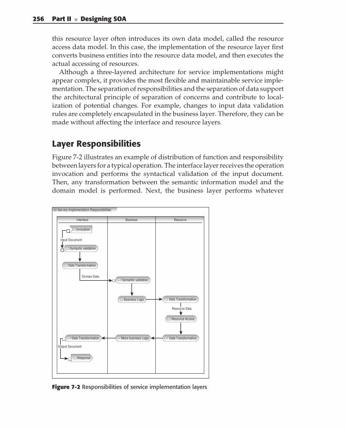
256 Part II ■ Designing SOA
this resource layer often introduces its own data model, called the resourceaccess data model. In this case, the implementation of the resource layer firstconverts business entities into the resource data model, and then executes theactual accessing of resources.
Although a three-layered architecture for service implementations mightappear complex, it provides the most flexible and maintainable service imple-mentation. The separation of responsibilities and the separation of data supportthe architectural principle of separation of concerns and contribute to local-ization of potential changes. For example, changes to input data validationrules are completely encapsulated in the business layer. Therefore, they can bemade without affecting the interface and resource layers.
Layer ResponsibilitiesFigure 7-2 illustrates an example of distribution of function and responsibilitybetween layers for a typical operation. The interface layer receives the operationinvocation and performs the syntactical validation of the input document.Then, any transformation between the semantic information model and thedomain model is performed. Next, the business layer performs whatever
Service Implementation Responsibilities
Interface
Invocation
Domain Data
Business Resource
Response
Syntactic validation
Data Transformation
Semantic validation
Business Logic Data Transformation
Resource Access
Data TransformationMore business LogicData Transformation
Resource Data
Input Document
Output Document
Figure 7-2 Responsibilities of service implementation layers
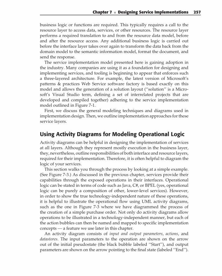
Chapter 7 ■ Designing Service Implementations 257
business logic or functions are required. This typically requires a call to theresource layer to access data, services, or other resources. The resource layerperforms a required translation to and from the resource data model, beforeand after the resource access. Any additional business logic is carried outbefore the interface layer takes over again to transform the data back from thedomain model to the semantic information model, format the document, andsend the response.
The service implementation model presented here is gaining adoption inthe industry. Many companies are using it as a foundation for designing andimplementing services, and tooling is beginning to appear that enforces sucha three-layered architecture. For example, the latest version of Microsoft’spatterns & practices Web Service software factory is based exactly on thismodel and allows the generation of a solution layout (‘‘solution’’ is a Micro-soft’s Visual Studio term, defining a set of interrelated projects that aredeveloped and compiled together) adhering to the service implementationmodel outlined in Figure 7-1.
First, we discuss the general modeling techniques and diagrams used inimplementation design. Then, we outline implementation approaches for theseservice layers.
Using Activity Diagrams for Modeling Operational LogicActivity diagrams can be helpful in designing the implementation of servicesat all layers. Although they represent mostly execution in the business layer,they, nevertheless, outline responsibilities of both interface and resource layers,required for their implementation. Therefore, it is often helpful to diagram thelogic of your services.
This section walks you through the process by looking at a simple example.(See Figure 7-3.) As discussed in the previous chapter, services provide theircapabilities through the exposed operations in their interfaces. Operationallogic can be stated in terms of code such as Java, C#, or BPEL (yes, operationallogic can be purely a composition of other, lower-level services). However,in order to show the true technology-independent nature of these operations,it is helpful to illustrate the operational flow using UML activity diagrams,such as the one in Figure 7-3 where we have diagrammed the process ofthe creation of a simple purchase order. Not only do activity diagrams allowoperations to be illustrated in a technology-independent manner, but each ofthe action bubbles can then be named and mapped to specific implementationconcepts — a feature we use later in this chapter.
An activity diagram consists of input and output parameters, actions, anddatastores. The input parameters to the operation are shown on the arrowout of the initial pseudostate (the black bubble labeled ‘‘Start’’), and outputparameters are shown on the arrow pointing to the final state (labeled ‘‘End’’).
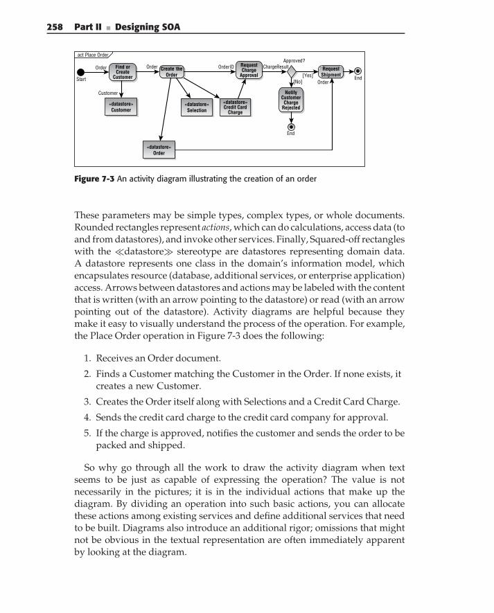
258 Part II ■ Designing SOA
act Place Order
Start
Create theOrder
«datastore»Order
«datastore»Selection
Find orCreate
Customer
«datastore»Customer
RequestCharge
Approval
«datastore»Credit Card
Charge
Approved?
RequestShipment
NotifyCustomer
ChargeRejected
End
End
OrderID
Customer
Order ChargeResult
[Yes][No]
Order
Order
Figure 7-3 An activity diagram illustrating the creation of an order
These parameters may be simple types, complex types, or whole documents.Rounded rectangles represent actions, which can do calculations, access data (toand from datastores), and invoke other services. Finally, Squared-off rectangleswith the �datastore� stereotype are datastores representing domain data.A datastore represents one class in the domain’s information model, whichencapsulates resource (database, additional services, or enterprise application)access. Arrows between datastores and actions may be labeled with the contentthat is written (with an arrow pointing to the datastore) or read (with an arrowpointing out of the datastore). Activity diagrams are helpful because theymake it easy to visually understand the process of the operation. For example,the Place Order operation in Figure 7-3 does the following:
1. Receives an Order document.
2. Finds a Customer matching the Customer in the Order. If none exists, itcreates a new Customer.
3. Creates the Order itself along with Selections and a Credit Card Charge.
4. Sends the credit card charge to the credit card company for approval.
5. If the charge is approved, notifies the customer and sends the order to bepacked and shipped.
So why go through all the work to draw the activity diagram when textseems to be just as capable of expressing the operation? The value is notnecessarily in the pictures; it is in the individual actions that make up thediagram. By dividing an operation into such basic actions, you can allocatethese actions among existing services and define additional services that needto be built. Diagrams also introduce an additional rigor; omissions that mightnot be obvious in the textual representation are often immediately apparentby looking at the diagram.
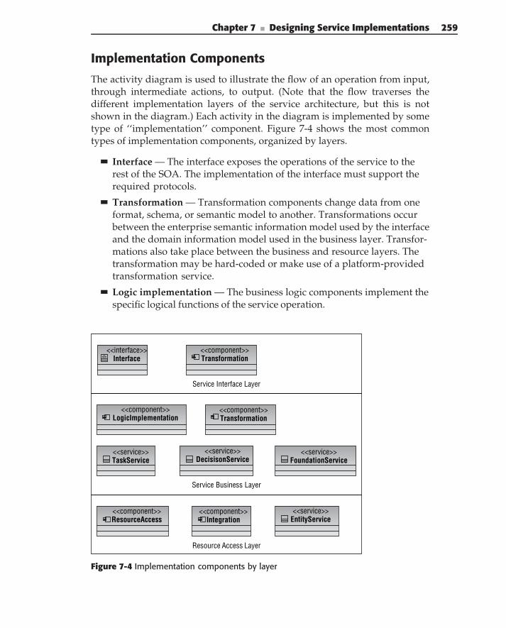
Chapter 7 ■ Designing Service Implementations 259
Implementation Components
The activity diagram is used to illustrate the flow of an operation from input,through intermediate actions, to output. (Note that the flow traverses thedifferent implementation layers of the service architecture, but this is notshown in the diagram.) Each activity in the diagram is implemented by sometype of ‘‘implementation’’ component. Figure 7-4 shows the most commontypes of implementation components, organized by layers.
Interface — The interface exposes the operations of the service to therest of the SOA. The implementation of the interface must support therequired protocols.
Transformation — Transformation components change data from oneformat, schema, or semantic model to another. Transformations occurbetween the enterprise semantic information model used by the interfaceand the domain information model used in the business layer. Transfor-mations also take place between the business and resource layers. Thetransformation may be hard-coded or make use of a platform-providedtransformation service.
Logic implementation — The business logic components implement thespecific logical functions of the service operation.
Resource Access Layer
Service Interface Layer
Service Business Layer
<<component>>Transformation
<<component>>Transformation
<<component>>ResourceAccess
<<component>>Integration
<<component>>LogicImplementation
<<interface>>Interface<I>
<<service>>TaskService
<<service>>DecisisonService
<<service>>FoundationService
<<service>>EntityService
Figure 7-4 Implementation components by layer
260 Part II ■ Designing SOA
Task Service — Services may be composed of other services. Taskservices implement business or logical tasks, such as common domainfunctions or business utilities.
Decision Service — Decision services implement (complex) businessrules and provide an external mechanism for specifying and maintain-ing the rules.
Foundation Service — Foundation services provide traditional plat-form distributed services such as authentication, logging, configura-tion, and the like.
Integration Component — Integration components expose integra-tion services and make their legacy functions and data available to theservice operation.
Resource Access Component — Resource access components encapsu-late the access to resources, such as datastores.
Entity Service — Entity services provide common service-based accessto common business entities.
Implementing the Interface Layer
The service interface layer provides the interaction point between externalservice consumers and the capabilities provided by the service implementation.The main responsibilities of a service interface layer are to:
Implement the service contract — This layer exposes the service opera-tions to the outside world. In many cases, it is necessary to expose theseoperations via multiple transports (in order to provide different quali-ties of service or just support for many different consumer types), whichmeans that one responsibility of the interface layer is to act as a listeneron several required transports.
Support interactions with the business layer responsible for the exe-cution of the service functionality — The business layer often operateson domain entities, which are different from the semantic data objectspassed into/out of the interface layer. The interface layer is also respon-sible for data transformation between these two information models.
Perform syntactic data validation — It must perform this validation toensure that the service input parameters are of the required type andconform to a set of legal values defined by the enterprise semantic infor-mation model. Some may argue that this function belongs in the businesslayer, but our take is that it does not complicate the implementation
Chapter 7 ■ Designing Service Implementations 261
and is required anyway for data transformation in the interface layer.This is why we recommend keeping syntactic data validation here.
Implementation of the interface layer is typically based on a programmaticimplementation of semantic data objects and documents.
Document ReceiptImplementation of a service interface starts with receiving an inputdocument — the service request. The basic semantics of receiving a documentare, ‘‘Make the contents of the objects (semantic data type implementations)match what’s in the document.’’ This means that the whole document andevery subelement in the document needs a way to be identified so that inprocessing the document you can correctly populate appropriate semanticdata types. With XML becoming a de facto standard of the ‘‘on-the-wire’’representation of the document, this operation is typically carried out by XMLparsers. In many cases, this operation is delegated to the underlying WebService technologies, implementing both the actual document receipt andpopulation of the semantic data types based on the WSDL definitions of thedocument. This works well when the structure of the documents is not verycomplex. As the complexity of the documents grows, especially if the docu-ment is using a lot of cross-references, leveraging these technologies becomesmore problematic.
For example, the ACORD specification (defining very complex schemasfor semantic messaging in insurance) does not rely on these technologiesand passes XML documents as attachments, forcing users to process inputdocuments programmatically. Newer XML implementations, for example,JAX-B, can be used for processing the input XML documents in these cases.
Syntactic Validation
Any operation that accepts input parameter data needs to be sure that thevalues are meaningful and correct for the operation. Such input validation isof two forms: syntactic validation, which determines whether the parametersare correctly formed, and semantic validation, which determines if the valuesthemselves are correct and meaningful. Syntactic validation is the responsi-bility of the interface layer, whereas the responsibility for semantic validationfalls on the business layer.
For simple parameters, syntactic validation generally answers the questions:Does the actual parameter meet the requirements of the type? Are numberscomposed of numeric values, and do they fit within the ranges defined for thetype? Do symbolic values fit the patterns defined for them? Do enumerationvalues fit the set of values for their type?
262 Part II ■ Designing SOA
Document parameter validations need to look at the overall structure of thedocument as well as the individual attribute values. Is the document formedcorrectly? Do elements have the right attributes (required and optional)? Doelements have the right number and types of subelements? Are attribute valuescorrect for their type?
Again, technologies such as Web Services make structural validations rela-tively straightforward to implement: The parameter structures can be specifieddirectly in the schema files. The Web Service run times reject actual parame-ters that do not meet the structural requirements. Although this seems like aviable approach, many of the real-world implementations are trying to avoidit. The issue here (as with any distributed strongly typed implementation)is that validations are done by the run time before reaching implementa-tion code. As a result, there is no place for the service implementation toexecute any processing logic in the event of failures. The service consumerstill receives an error reply, but this reply is produced by the run time, notthe service itself. These exceptions can vary significantly from very explicitand easy to understand in some run times to very cumbersome in others.Our recommendation is to avoid run-time validation (easily done by pass-ing all parameters as strings) and do syntactic validation in code. In thiscase, all validation errors can be collected and properly reported to a serviceconsumer. As we have discussed, syntactic validations, depending on theircomplexity, can be implemented either in an interface layer or a businesslayer.
TransformationsFinally, it is the responsibility of the interface layer to transform semantic datatypes to business entities for use in the business layer. Typically, semanticdata types and business entities are well aligned through design; these trans-formations are fairly straightforward and can be directly implemented usinggeneral-purpose programming languages. We recommend that you separatethese transformations into specialized classes or components to improve theoverall maintainability of the code.
In the case where transformation is more complex, the use of specializedtransformation (foundation) services can be used. Typically, these are providedby the underlying SOA or Web Service platform. The transformation serviceconsists of a design-time editor to define the transformation map betweenschemas, and a run-time component that executes the transformation on thespecified input data.
Chapter 7 ■ Designing Service Implementations 263
Implementing the Business Layer
The business layer is the foundation of the service implementation, containingthe implementation of the service’s business logic and business entities thatare used by the business logic. This can include the following:
Semantic validation of incoming parameters.
Sequence calls to other business logic, data access logic, other services orexisting enterprise applications.
Transaction initiation and control. All of the two-phase transactions areencapsulated in service implementations (see Chapters 8 and 10 for moreinformation on transactions between services). The business layer isresponsible for transaction demarcation.
Conditional logic and business rule implementation.
Greatly simplified, the business implementation of an operation consists ofthree parts:
1. Semantic validation of the input parameters
2. Performing the business logic of the operation
3. Returning a result
This section covers each of these steps.
Semantic Input Validation
Operation logic needs to be sure that the input values are meaningful andcorrect. Semantic validation, the determination of correctness of specific inputvalues (according to business rules) occurs here in the business logic layer.
Semantic validation differs from syntactic validation in that it requiresinformation beyond just the type declaration. Generally, semantic validationsrequire examining the data in the context of the service’s overall environment,ensuring that all of the information for the service invocation is complete. Forexample, validation can ensure that the account used in the service invocationexists. In most development scenarios, semantic validations need to be coded,not just declared.
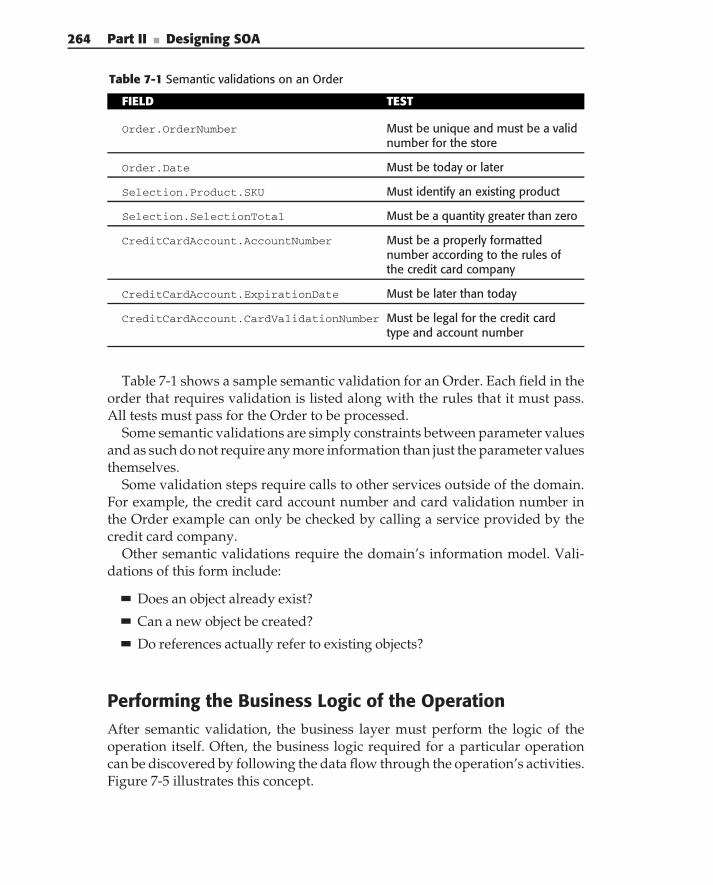
264 Part II ■ Designing SOA
Table 7-1 Semantic validations on an Order
FIELD TEST
Order.OrderNumber Must be unique and must be a validnumber for the store
Order.Date Must be today or later
Selection.Product.SKU Must identify an existing product
Selection.SelectionTotal Must be a quantity greater than zero
CreditCardAccount.AccountNumber Must be a properly formattednumber according to the rules ofthe credit card company
CreditCardAccount.ExpirationDate Must be later than today
CreditCardAccount.CardValidationNumber Must be legal for the credit cardtype and account number
Table 7-1 shows a sample semantic validation for an Order. Each field in theorder that requires validation is listed along with the rules that it must pass.All tests must pass for the Order to be processed.
Some semantic validations are simply constraints between parameter valuesand as such do not require any more information than just the parameter valuesthemselves.
Some validation steps require calls to other services outside of the domain.For example, the credit card account number and card validation number inthe Order example can only be checked by calling a service provided by thecredit card company.
Other semantic validations require the domain’s information model. Vali-dations of this form include:
Does an object already exist?
Can a new object be created?
Do references actually refer to existing objects?
Performing the Business Logic of the OperationAfter semantic validation, the business layer must perform the logic of theoperation itself. Often, the business logic required for a particular operationcan be discovered by following the data flow through the operation’s activities.Figure 7-5 illustrates this concept.
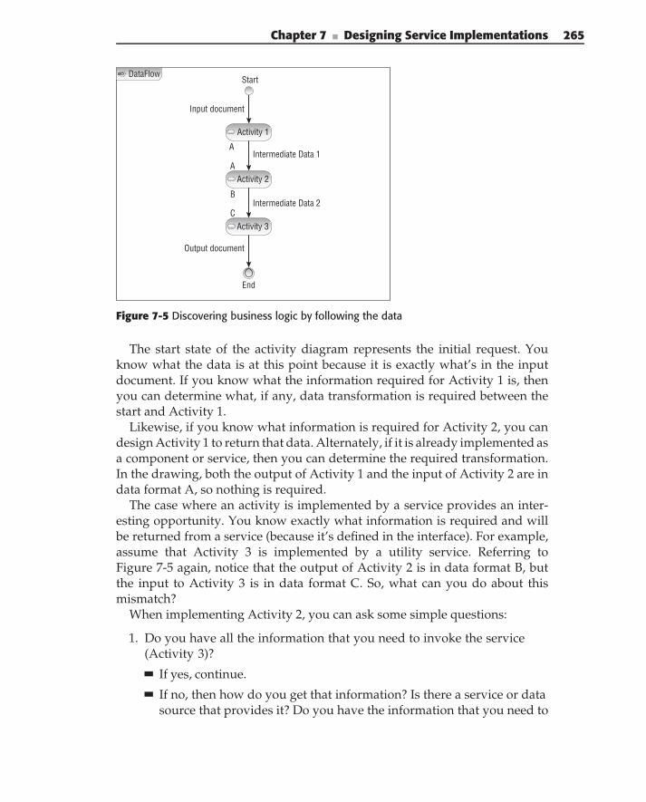
Chapter 7 ■ Designing Service Implementations 265
DataFlowStart
End
Output document
Intermediate Data 1
Intermediate Data 2
Input document
A
A
B
C
Activity 1
Activity 2
Activity 3
Figure 7-5 Discovering business logic by following the data
The start state of the activity diagram represents the initial request. Youknow what the data is at this point because it is exactly what’s in the inputdocument. If you know what the information required for Activity 1 is, thenyou can determine what, if any, data transformation is required between thestart and Activity 1.
Likewise, if you know what information is required for Activity 2, you candesign Activity 1 to return that data. Alternately, if it is already implemented asa component or service, then you can determine the required transformation.In the drawing, both the output of Activity 1 and the input of Activity 2 are indata format A, so nothing is required.
The case where an activity is implemented by a service provides an inter-esting opportunity. You know exactly what information is required and willbe returned from a service (because it’s defined in the interface). For example,assume that Activity 3 is implemented by a utility service. Referring toFigure 7-5 again, notice that the output of Activity 2 is in data format B, butthe input to Activity 3 is in data format C. So, what can you do about thismismatch?
When implementing Activity 2, you can ask some simple questions:
1. Do you have all the information that you need to invoke the service(Activity 3)?
If yes, continue.
If no, then how do you get that information? Is there a service or datasource that provides it? Do you have the information that you need to
266 Part II ■ Designing SOA
call that service? Or, do you have to change the operation’s inputdocument definition to get the required information?
2. Does the output of Activity 2 match the input of Activity 3? (Note that itdoesn’t have to match exactly, but all the information required for Activ-ity 3 must be present.)
If yes, continue.
If no, then what transformation is required?
As you can see, you can follow the data flow from activity to activity in thediagram determining what, if any, additional information or transformationsare required and implementing them through a combination of components,services, and transformations, until the final return document is completed.Alternatively, you can start with the output document and work backwardthrough the service to the input determining the implementation design.
In following the data flow of your activity diagram, you may determine thatyou are actually building a composite service, where the logic of your servicemay be simply to combine services based on a logical business process. If thisis the case, your business layer contains the process for orchestrating services.In this case, we refer you to Chapter 8, where we focus on various service com-position strategies ranging from BPEL-based orchestration, and compositionusing such frameworks as Service Component Architecture (SCA).
Finally, as you prepare to build the implementation of the service, you mustdevelop or adhere to a strategy for exception handling, typically establishedby your SOA governance policies (see Chapter 12). In Chapter 6, we discussedexceptions as part of the service interface definition, but the actual handlingof these exceptions is typically implemented in the business layer, and theirresults are then propagated to the interface layer to report them to the serviceconsumers. The typical implementation is based on the ability of applicationdesigners and developers to anticipate the possible exception conditions,appropriately instrument them in the code, and handle them at run time.From this point of view, exception handling in service implementations is nodifferent from the exception handling in ordinary applications.
What makes exception handling different in SOA is the dynamic nature ofservices, which can be combined in a multitude of different ways (throughchoreography and service composition). It is necessary to propagate all ofthe exceptions to the interface layer to report the exceptions to the serviceconsumer. This is usually done by executing all of the business logic in asingle try/catch block defined in the interface layer. Such an approach allowsthe interface layer to catch, appropriately map, and report all of the serviceexecution exceptions. Centralized error-handling techniques, as described in
Chapter 7 ■ Designing Service Implementations 267
Chapter 9, allow all of the service exceptions to be intercepted and deliveredto the centralized location for complete system analysis.
Computing and Returning ResultsOften the business logic requires the computation of specific results based onthe input data. Computations can be implemented by custom code, compo-nents, or by invoking other existing services.
Depending on the type of computation, typically either task-oriented ordecision services would be used to perform the calculation. When a serviceis constructed primarily from other services, service orchestration may be theappropriate implementation technique.
Returning results is almost the opposite of receiving the initial input docu-ment, except that no validation needs to occur. The activity involves collectingthe data, calculations, and so on, from the business logic, doing any necessarytranslations, and formatting the return document.
As with the request document, with XML becoming a standard for docu-ments, this activity is typically carried out by XML parsers or Web Servicetechnologies.
Implementing the Resource Layer
The resource access layer is the layer between the business layer and adatabase, external services, or enterprise applications. The data access logicis responsible for persisting business entities to a database and retrievingindividual business entities or sets of business entities on behalf of the businesslayer. The resource access layer may also contain invocation of other services(business, domain, utility, or integration) to retrieve resources, required forbusiness logic implementation. This layer should encapsulate all the code thatdeals with external resources (such as databases or other services), withoutexposing any of these implementation details to higher layers. This includestransformation between business services and data required for resourceinvocation and the actual invocation of resources.
As mentioned in the previous section, many times, your service imple-mentation may actually be a composite service, where business logic dictatesthe use of several other services combined with additional logical processto provide the functionality of your service. In this case, the business layerincludes the definition of that process, and orchestrates the calling of the other
268 Part II ■ Designing SOA
services by invoking components in the resource layer. The business logic fororchestration occurs in the business layer, and the resource layer typicallyinvolves the utilization of frameworks such as SCA. We refer you to Chapter8, which covers design techniques for composing services.
A typical implementation of resource access is through integration/resourcecomponents (see Chapter 10 for more details). Each component exposesan interface expressed in terms of business entities and is responsible forimplementation of the access to a particular resource. From the point of viewof the rest of service implementation, resource functionality is implementedby a resource component, hiding the details of integration and resource access.Invocation of these resource components is orchestrated by the businesslogic layer.
Implementation Design Illustrated
In this section of the chapter, we illustrate the implementation design processby continuing the automobile insurance–quoting example from Chapter 6. Inthat part of the example, the process of service interface design was illustrated.As a brief review, use cases to describe the problem space were identifiedalong with detailed scenarios for the use cases and an information model tosupport them. The steps in the scenarios (specifically, the actions in activitydiagrams used to specify them) were assigned to operations on businessservices and were organized into service interfaces based on cohesion andcoupling principles. The information passing into and out of service interfaceswas defined in terms of documents, which were based on the semanticinformation model. Now, it is time to define the specific service operations.This part of the example focuses on the implementation business layer.
Business LayerWith so many service operations, where should you start? We like to start withthe ‘‘primary use cases operations’’ first. For example, for the Create QuoteScenario, the Create Quote operation corresponds to the primary use case.
The reason to start with the primary use case operations is to finish workingthrough all the use case scenario actions. You can now make your final passthrough the scenarios. Recall that for each scenario action, you have threepossible assignments: Define it as a manual task, assign it to a service, orinclude it as an internal step of a service operation (possibly implemented bya lower-level service).
You should have completed the first two already. The remaining scenarioactivities (those still unassigned) should become internal steps within an
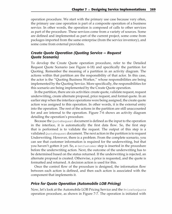
Chapter 7 ■ Designing Service Implementations 269
operation procedure. We start with the primary use case because very often,the primary use case operation is part of a composite operation of a businessservice. In other words, the operation is composed of calls to other servicesas part of the procedure. These services come from a variety of sources. Someare defined and implemented as part of the current project, some come frompackages imported from the same enterprise (from the service inventory), andsome come from external providers.
Create Quote Operation (Quoting Service — RequestQuote Scenario)
To develop the Create Quote operation procedure, refer to the DetailedRequest Quote Scenario (see Figure 6-18) and specifically the partition forQuoting. Remember the meaning of a partition in an activity diagram. Theactions within that partition are the responsibility of that actor. In this case,the actor is the ‘‘Quoting Business Worker,’’ whose responsibilities are beingimplemented by the Quoting Service. More specifically, the responsibilities forthis scenario are being implemented by the Create Quote operation.
In the partition, there are six activities: create quote, validate request, requestunderwriting, create alternate proposal, price request, and format quote. In anearlier step when the interface operations were being assigned, the create quoteaction was assigned to this operation. In other words, it is the external entryinto the operation. The rest of the actions in the partition are still unaccountedfor and are internal to the operation. Figure 7-6 shows an activity diagramdetailing the operation’s procedure.
Because the QuoteRequest document is defined as the input to the operationin the interface, it is automatically the first data flow. So, the first stepthat is performed is to validate the request. The output of this step is avalidated QuoteRequestdocument. The next action in the partition is to requestUnderwriting. However, there is a problem. From the complete scenario, youcan see that customer information is required for the underwriting, but thatyou haven’t gotten it yet. So, a GetCustomer step is inserted in the procedurebefore the underwriting action. Next, the outcome of the underwriting has tobe determined based on the status returned. If the underwriting is rejected, analternate proposal is created. Otherwise, a price is requested, and the quote isformatted and returned. A decision action is used for this.
Once the control flow of the procedure is designed, the information flowbetween each action is defined, and then each action is associated with thecomponent that implements it.
Price for Quote Operation (Automobile LOB Pricing)
Now, let’s look at the Automobile LOB Pricing Service and the PriceforQuote
operation procedure, as shown in Figure 7-7. The operation is initiated with
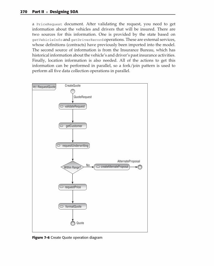
270 Part II ■ Designing SOA
a PriceRequest document. After validating the request, you need to getinformation about the vehicles and drivers that will be insured. There aretwo sources for this information. One is provided by the state based ongetVehicleInfo and getDriverRecord operations. These are external services,whose definitions (contracts) have previously been imported into the model.The second source of information is from the Insurance Bureau, which hashistorical information about the vehicle’s and driver’s past insurance activities.Finally, location information is also needed. All of the actions to get thisinformation can be performed in parallel, so a fork/join pattern is used toperform all five data collection operations in parallel.
CreateQuote
QuoteRequest
validateRequest
getCustomer
requestUnderwriting
createAlternateProposal
AlternateProposal
Within Range?No
formatQuote
Quote
RequestQuote
requestPrice
Figure 7-6 Create Quote operation diagram
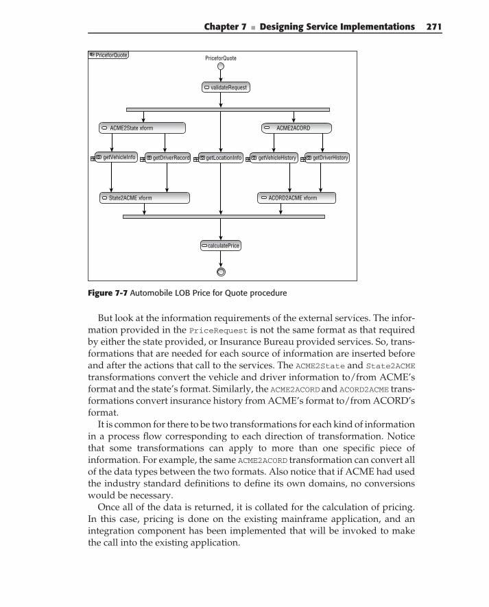
Chapter 7 ■ Designing Service Implementations 271
PriceforQuote PriceforQuote
validateRequest
ACME2State xform
getVehicleInfo getDriverRecord getLocationInfo getVehicleHistory getDriverHistory
ACORD2ACME xform
calculatePrice
State2ACME xform
ACME2ACORD
Figure 7-7 Automobile LOB Price for Quote procedure
But look at the information requirements of the external services. The infor-mation provided in the PriceRequest is not the same format as that requiredby either the state provided, or Insurance Bureau provided services. So, trans-formations that are needed for each source of information are inserted beforeand after the actions that call to the services. The ACME2State and State2ACME
transformations convert the vehicle and driver information to/from ACME’sformat and the state’s format. Similarly, the ACME2ACORD and ACORD2ACME trans-formations convert insurance history from ACME’s format to/from ACORD’sformat.
It is common for there to be two transformations for each kind of informationin a process flow corresponding to each direction of transformation. Noticethat some transformations can apply to more than one specific piece ofinformation. For example, the same ACME2ACORD transformation can convert allof the data types between the two formats. Also notice that if ACME had usedthe industry standard definitions to define its own domains, no conversionswould be necessary.
Once all of the data is returned, it is collated for the calculation of pricing.In this case, pricing is done on the existing mainframe application, and anintegration component has been implemented that will be invoked to makethe call into the existing application.
272 Part II ■ Designing SOA
All of the data collection actions are performed by other services, so wehave modeled them as ‘‘call actions’’ in the activity diagram. But notice thatwe have purposely kept the activity diagram simple for illustration purposesof the example. We could have included the data flow and other details inthe model (and in a real model we would have), but that would start to makethings busy and difficult to illustrate. There are tradeoffs in everything, andthis is not a book on UML, so we have chosen to keep the models moreillustrative and less complete in order to get the design principles across.
Goals — Define the control and data flow of implementation details foreach service operation.
Concerns — Inputs, outputs, control flow, and data flow.
Concepts — Documents, procedures, actions, transformations, and otherservices.
Summary
This chapter has continued with the design issues of services, specificallythe design of the service implementation. A basic service architecture wasintroduced that separates the responsibilities of a service implementation intothree layers.
The interface layer is responsible for receiving the service requests. Theinterface layer operates at the enterprise semantic level (regarding data), so itis responsible for transformation between the input documents that conformto the semantic information model and the internal domain objects.
The business layer is responsible for the logic that provides the servicecapabilities. This may be custom code, reusable business components, or callsto existing services.
When resources are required, the final layer, the resource access layer, isused to access the resources and insulate the business logic from the vagariesof data access.
The use of activity diagrams as a way to illustrate the control and data flowin operation was introduced as well as a technique for discovering the logicrequirements by following the data through the actions of the activity.
C H A P T E R
8
Composing ServicesOne LEGO block by itself is no fun at all.
— Jason Bloomberg
The return on investment (ROI) of SOA is achieved by providing businessvalue and solving real-world problems, and you can solve these problems onlyif your business processes drive the technology — not the other way around.As discussed in Chapter 4, BPM provides the business process workflow thatdrives how you define business-level services and how you can composeexisting services to form new applications and services. Services are reusablecomponents and are meant to be combined to meet business needs for enter-prise applications. Service composition is the practice of how this objective isachieved.
Good service composition is an art form, building on sound architecturalprinciples and successful design patterns. Certain strategies are successful,other strategies are flawed from the beginning, and the success of manystrategies depends on specific use cases and a number of different factors.This chapter provides a practical guide for composing services, applyingconcepts addressed in previous chapters. Earlier in this book, in Chapter 2,we introduced you to SOA fundamentals, and in Chapter 4, we provided anin-depth discussion on Business Process Management (BPM). This chapterbuilds on those two chapters, and it focuses on the following:
Service layer interaction, orchestration, choreography, the role of busi-ness rules, and business processes in composition
273
274 Part II ■ Designing SOA
Business composition and transactions, human activities, andorchestration languages, including the Business Process ExecutionLanguage (BPEL)
Strategies in service composition, providing the pros and cons of eachstrategy
A case study that you can use as a reference guide
Understanding Service Composition
A funny quote heard at a recent technology conference was ‘‘the most looselycoupled service is one that doesn’t communicate with anything.’’ This isan interesting statement — obviously, a service that doesn’t talk to anythingelse doesn’t provide any business value, but the statement is a good onein that it identifies that when services begin to interact, there can certainlybe collaboration dependencies between them. Conversation rules betweenservices, semantics, and business-processing rules regarding how these ser-vices are used can certainly affect coupling. It is our goal to minimize suchdependencies.
In keeping with the LEGO analogy of SOA from Chapter 2, when youstart combining LEGO pieces to form other things, the toys begin to take ondifferent properties and become, quite literally, tightly coupled to the newcreation. Tight coupling in SOA composition is not the goal, but unfortunatelyit could certainly happen if service composition is not done correctly. Servicecomposition builds on the use of loosely coupled services, but it also involvesa focus on having loosely coupled interaction processes between services. Youdo this initially by separating services into a service hierarchy based onfunctionality, by abstracting the layers, and by defining business processesthat can be separated from the makeup of the services themselves.
In service composition, the result of combining services is referred to as acomposite service. When you use services together to achieve new functionalityin a business process, the composition process itself that dictates that the orderand interactions between the lower-level services is exposed as this compositeservice. This section discusses service composition, focusing on some of thefundamental prerequisites that are best practices — separation of services intolayers and separating the business processes from the services. It also definesand discusses orchestration and choreography, two different approaches toservice composition.
IS THIS CHAPTER ABOUT ‘‘MASHUPS’’?
A Web 2.0 buzzword that is prevalent in software industry literature today isthe ‘‘mashup,’’ which refers to combining sources of various data into one
Chapter 8 ■ Composing Services 275
application. From that high-level definition, you could certainly say that thischapter is all about service-based mashups.
Usually, when the term is used, however, a mashup is a more user-facing anduser-directed process, where an end user directs an application to combine andaggregate data from various sources (RSS feeds, Atom feeds, web pages, etc.)and combines the data with a presentation to provide a comprehensive view ofthe aggregation. Such a mashup provides great value to the end user —however, it is a little different from what we call service composition because ittypically combines presentation and content. Because the web mashupcombines presentation and content, the mashup itself is hard to reuse inanother application.
SOA compositions, on the other hand, are not user-facing. Like user-facingmashups, they aggregate other components. They combine lower-level serviceswith business processes to provide a higher level of functionality, and thecompositions themselves are exposed as services that can be called and reusedwith other higher-level services. So in that sense, they could be called service‘‘mashups.’’ User-facing mashups could certainly call these composite servicesin order to aggregate content for the end user, but we prefer the term ‘‘SOAcomposition’’ to the term ‘‘mashup,’’ because mashup is not really awell-defined term.
Separation into Service Layers
In Chapter 2, we defined a service hierarchy that shows how enterprisebusiness processes can make use of underlying services in SOA. This hierar-chy is again shown in Figure 8-1. The higher-level services make use of theunderlying services to perform business functionality in the enterprise. Asa review, business services abstract high-level business functionality that aredriven by enterprise business processes. This gives the benefits of SOA (decou-pling, separation of concerns, dependency and complexity management, etc.)to the business as well as the service domains. It allows a single architecturalstyle to be used at all levels of abstraction as well as across domains. Domainservices provide mid-level business functionality specific to a certain domain,utility services provide low-level business functionality across the enterprise,integration services abstract existing applications with a service layer, exter-nal services are services provided by third-party providers, and foundationalservices provide infrastructure-type functionality for the entire enterprise. Eachhigher-level service aggregates lower-level services, according to the businessprocess. As Chapter 2 defines this hierarchy and service types in depth, wewill refer you to that chapter, as we will be referencing this hierarchy with thetypes of services throughout this chapter.
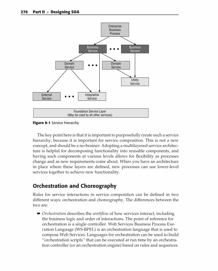
276 Part II ■ Designing SOA
Foundation Service Layer(May be used by all other services)
DomainService
ExternalService
IntegrationService
UtilityService
EnterpriseBusinessProcess
BusinessService
BusinessService
DomainService
Figure 8-1 Service hierarchy
The key point here is that it is important to purposefully create such a servicehierarchy, because it is important for service composition. This is not a newconcept, and should be a no-brainer: Adopting a multilayered service architec-ture is helpful for decomposing functionality into reusable components, andhaving such components at various levels allows for flexibility as processeschange and as new requirements come about. When you have an architecturein place where these layers are defined, new processes can use lower-levelservices together to achieve new functionality.
Orchestration and ChoreographyRules for service interactions in service composition can be defined in twodifferent ways: orchestration and choreography. The differences between thetwo are:
Orchestration describes the workflow of how services interact, includingthe business logic and order of interactions. The point of reference fororchestration is a single controller. Web Services Business Process Exe-cution Language (WS-BPEL) is an orchestration language that is used tocompose Web Services. Languages for orchestration can be used to build‘‘orchestration scripts’’ that can be executed at run time by an orchestra-tion controller (or an orchestration engine) based on rules and sequences.
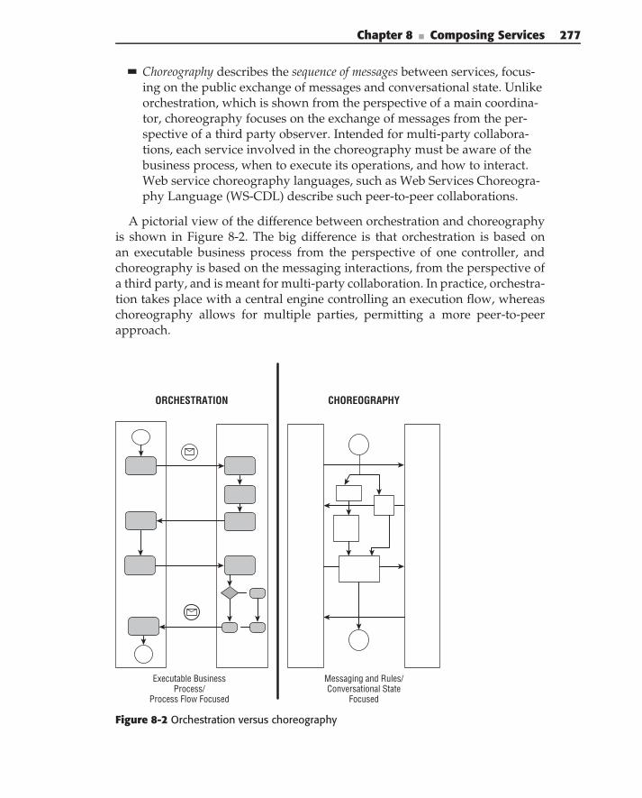
Chapter 8 ■ Composing Services 277
Choreography describes the sequence of messages between services, focus-ing on the public exchange of messages and conversational state. Unlikeorchestration, which is shown from the perspective of a main coordina-tor, choreography focuses on the exchange of messages from the per-spective of a third party observer. Intended for multi-party collabora-tions, each service involved in the choreography must be aware of thebusiness process, when to execute its operations, and how to interact.Web service choreography languages, such as Web Services Choreogra-phy Language (WS-CDL) describe such peer-to-peer collaborations.
A pictorial view of the difference between orchestration and choreographyis shown in Figure 8-2. The big difference is that orchestration is based onan executable business process from the perspective of one controller, andchoreography is based on the messaging interactions, from the perspective ofa third party, and is meant for multi-party collaboration. In practice, orchestra-tion takes place with a central engine controlling an execution flow, whereaschoreography allows for multiple parties, permitting a more peer-to-peerapproach.
Messaging and Rules/ Conversational State
Focused
Executable Business Process/
Process Flow Focused
ORCHESTRATION CHOREOGRAPHY
Figure 8-2 Orchestration versus choreography
278 Part II ■ Designing SOA
As you can see, orchestration and choreography approach two differentmethodologies of service composition. There are passionate debates betweenthese two camps, and there are many strong opinions on both sides. Itseems that at this point, the orchestration community has the most tractionin the standards bodies and in technology adoption. WS-BPEL is a unifyingorchestration standard from OASIS; it was adopted in 2007 and has beenin the standards process since 2003. WS-BPEL evolved from the BPEL4WSspecification (2003), which had roots in Microsoft’s XLang (2000) and IBM’sWSFL (2001). WS-CDL, a choreography language, has been a W3 C workingdraft since 2004. Because WS-BPEL is a standard with widespread adoption,we focus primarily on that orchestration standard later in this chapter.
The Relationship between BPM and CompositionBusiness processes and good service design come together in composition.Business services are process-oriented, orchestrating lower-level servicesaccording to business processes. Because business processes change often, itis important when creating a composite service to separate the business pro-cesses and rules for combining them from the implementation of the service.Many frameworks for building composite services (for example, orchestra-tion servers and service composition with SCA) provide the means to haveconfigurable compositions that can change as the business processes change.This is an important aspect of composing services. If you hard-code rules andbusiness process logic into the logic of services that aggregate other services,changes in requirements involve code changes. Real business processes areseldom simple, so separating them from your service logic allows you to endup with a simpler implementation of services.
One common area of confusion with service composition revolves aroundBPM. Obviously, business goals drive all aspects of a Service-Oriented Archi-tecture, and one way of composing business services is based on the modeledbusiness processes. Chapter 4 discussed how businesses can use a BPM-focusedapproach to take a more service-oriented approach to business analysis, andone typical way to express modeled business processes is by using BusinessProcess Modeling Notation (BPMN). Obviously, modeling business processesis different from the actual service composition. The confusion lies in composi-tion software tools, which commonly use BPMN-like graphical user interfacesfor composing services, creating new services directly based on the businessprocesses.
Certainly, the modeling done by business analysts can lead to the logicthat is used in the composition phase for developing business-oriented com-posite services. Software developers and integrators can use the modelscreated in that modeling phase in creating the composite services. We feelthat it is important, however, to distinguish the difference between modeling
Chapter 8 ■ Composing Services 279
and business process-oriented composition. Typically, those with the func-tional business knowledge, who create the models, are not the same peoplewho develop and integrate composite services. This certainly is the visionpresented to us by the tool vendors, but it is not quite reality! The importantthing to understand here is that modeling of the business processes occursearlier in the life cycle than composition does. Much as implementation alwaysfollows analysis and design in the waterfall model of software development,composition can be based on the business process model, but it occurs laterand requires another skill set.
N O T E Composition can be based on BPM, but composition is not BPM.
Architectural Models in Service Composition
This section provides an overview of a few common architectural models usedfor service composition. Later in the chapter, we refer to these approaches asthey are implemented in SOA.
Hierarchical and Conversational CompositionFigure 8-3 shows a diagram illustrating two common approaches to buildinga service composition that abstracts the details from lower-level services. Thetwo most common design approaches are called hierarchical and conversationalcomposition. In the case of hierarchical composition, the implementation of thecomposition is completely hidden from its consumer. Thus, it is sometimescalled ‘‘black box’’ composition. A consumer who invokes this type of solutionwaits until its execution is completed and uses the results (either directly or inthe form of side effects) of its execution.
Although the hierarchical composition approach is a very powerful wayof dealing with the complexities, sometimes a consumer needs to control theexecution of the solution based on the intermediate results of its execution.Such implementations are supported by conversational composition, as shownin Figure 8-3. In this case, the implementation of the composite service is alsocompletely hidden from the service consumer, but selected intermediateexecution results are exposed. Thus, conversational composition is sometimescalled ‘‘gray box’’ composition.
The hierarchical composition approach is a natural fit for implementingsolutions that do not require human or any other interaction from the solutioninvoker. Such an example might be a Truck Engine Manufacturing Service. Ifthe service receives a message that says ‘‘Build me a Chevrolet 350 V8 Engine,’’no further communication with the requester is usually necessary. The Truck
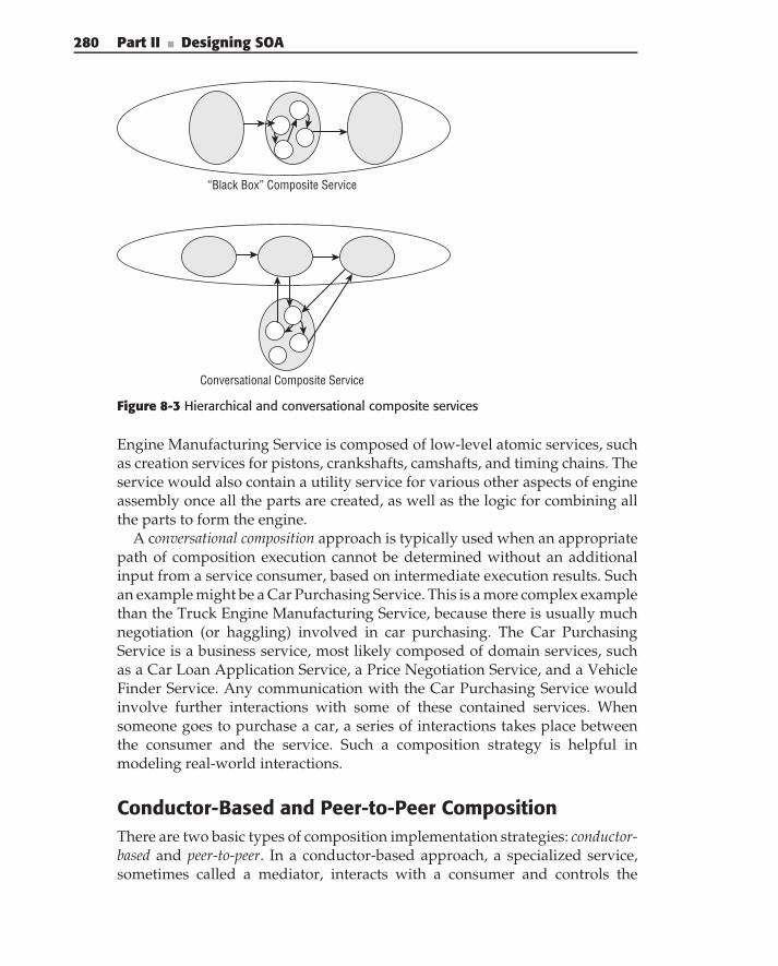
280 Part II ■ Designing SOA
“Black Box” Composite Service
Conversational Composite Service
Figure 8-3 Hierarchical and conversational composite services
Engine Manufacturing Service is composed of low-level atomic services, suchas creation services for pistons, crankshafts, camshafts, and timing chains. Theservice would also contain a utility service for various other aspects of engineassembly once all the parts are created, as well as the logic for combining allthe parts to form the engine.
A conversational composition approach is typically used when an appropriatepath of composition execution cannot be determined without an additionalinput from a service consumer, based on intermediate execution results. Suchan example might be a Car Purchasing Service. This is a more complex examplethan the Truck Engine Manufacturing Service, because there is usually muchnegotiation (or haggling) involved in car purchasing. The Car PurchasingService is a business service, most likely composed of domain services, suchas a Car Loan Application Service, a Price Negotiation Service, and a VehicleFinder Service. Any communication with the Car Purchasing Service wouldinvolve further interactions with some of these contained services. Whensomeone goes to purchase a car, a series of interactions takes place betweenthe consumer and the service. Such a composition strategy is helpful inmodeling real-world interactions.
Conductor-Based and Peer-to-Peer CompositionThere are two basic types of composition implementation strategies: conductor-based and peer-to-peer. In a conductor-based approach, a specialized service,sometimes called a mediator, interacts with a consumer and controls the
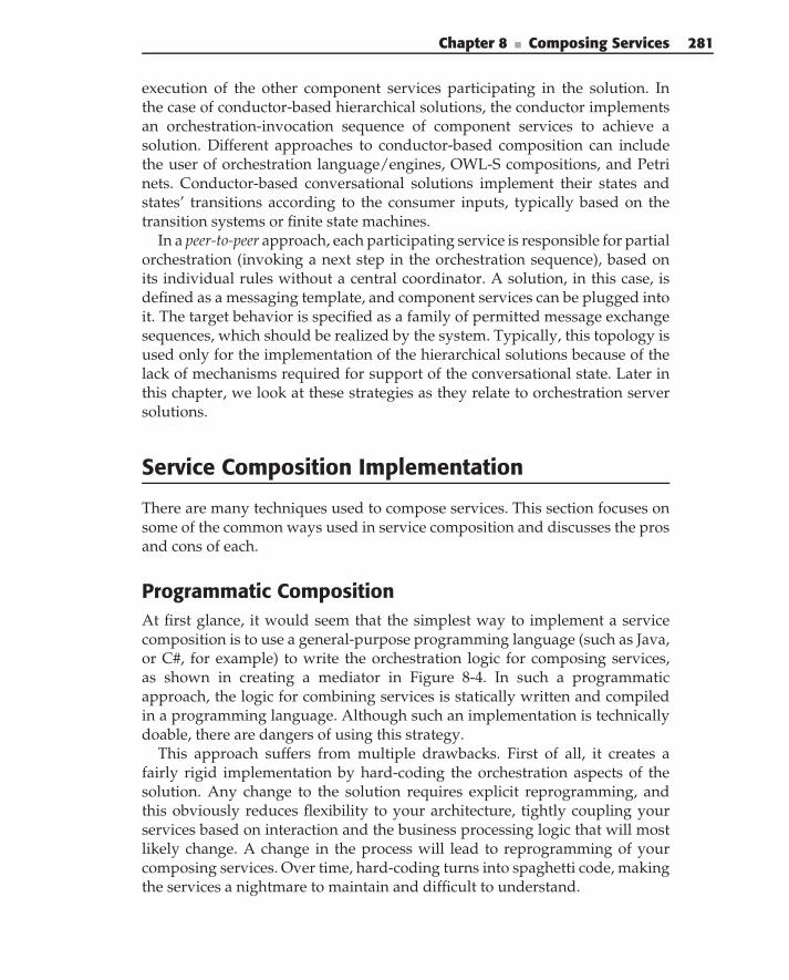
Chapter 8 ■ Composing Services 281
execution of the other component services participating in the solution. Inthe case of conductor-based hierarchical solutions, the conductor implementsan orchestration-invocation sequence of component services to achieve asolution. Different approaches to conductor-based composition can includethe user of orchestration language/engines, OWL-S compositions, and Petrinets. Conductor-based conversational solutions implement their states andstates’ transitions according to the consumer inputs, typically based on thetransition systems or finite state machines.
In a peer-to-peer approach, each participating service is responsible for partialorchestration (invoking a next step in the orchestration sequence), based onits individual rules without a central coordinator. A solution, in this case, isdefined as a messaging template, and component services can be plugged intoit. The target behavior is specified as a family of permitted message exchangesequences, which should be realized by the system. Typically, this topology isused only for the implementation of the hierarchical solutions because of thelack of mechanisms required for support of the conversational state. Later inthis chapter, we look at these strategies as they relate to orchestration serversolutions.
Service Composition Implementation
There are many techniques used to compose services. This section focuses onsome of the common ways used in service composition and discusses the prosand cons of each.
Programmatic CompositionAt first glance, it would seem that the simplest way to implement a servicecomposition is to use a general-purpose programming language (such as Java,or C#, for example) to write the orchestration logic for composing services,as shown in creating a mediator in Figure 8-4. In such a programmaticapproach, the logic for combining services is statically written and compiledin a programming language. Although such an implementation is technicallydoable, there are dangers of using this strategy.
This approach suffers from multiple drawbacks. First of all, it creates afairly rigid implementation by hard-coding the orchestration aspects of thesolution. Any change to the solution requires explicit reprogramming, andthis obviously reduces flexibility to your architecture, tightly coupling yourservices based on interaction and the business processing logic that will mostlikely change. A change in the process will lead to reprogramming of yourcomposing services. Over time, hard-coding turns into spaghetti code, makingthe services a nightmare to maintain and difficult to understand.
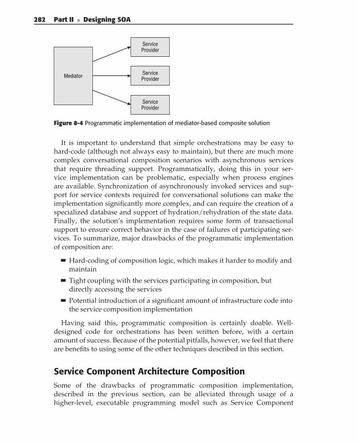
282 Part II ■ Designing SOA
Mediator
ServiceProvider
ServiceProvider
ServiceProvider
Figure 8-4 Programmatic implementation of mediator-based composite solution
It is important to understand that simple orchestrations may be easy tohard-code (although not always easy to maintain), but there are much morecomplex conversational composition scenarios with asynchronous servicesthat require threading support. Programmatically, doing this in your ser-vice implementation can be problematic, especially when process enginesare available. Synchronization of asynchronously invoked services and sup-port for service contexts required for conversational solutions can make theimplementation significantly more complex, and can require the creation of aspecialized database and support of hydration/rehydration of the state data.Finally, the solution’s implementation requires some form of transactionalsupport to ensure correct behavior in the case of failures of participating ser-vices. To summarize, major drawbacks of the programmatic implementationof composition are:
Hard-coding of composition logic, which makes it harder to modify andmaintain
Tight coupling with the services participating in composition, butdirectly accessing the services
Potential introduction of a significant amount of infrastructure code intothe service composition implementation
Having said this, programmatic composition is certainly doable. Well-designed code for orchestrations has been written before, with a certainamount of success. Because of the potential pitfalls, however, we feel that thereare benefits to using some of the other techniques described in this section.
Service Component Architecture CompositionSome of the drawbacks of programmatic composition implementation,described in the previous section, can be alleviated through usage of ahigher-level, executable programming model such as Service Component
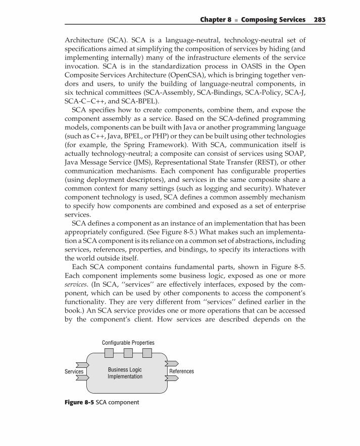
Chapter 8 ■ Composing Services 283
Architecture (SCA). SCA is a language-neutral, technology-neutral set ofspecifications aimed at simplifying the composition of services by hiding (andimplementing internally) many of the infrastructure elements of the serviceinvocation. SCA is in the standardization process in OASIS in the OpenComposite Services Architecture (OpenCSA), which is bringing together ven-dors and users, to unify the building of language-neutral components, insix technical committees (SCA-Assembly, SCA-Bindings, SCA-Policy, SCA-J,SCA-C–C++, and SCA-BPEL).
SCA specifies how to create components, combine them, and expose thecomponent assembly as a service. Based on the SCA-defined programmingmodels, components can be built with Java or another programming language(such as C++, Java, BPEL, or PHP) or they can be built using other technologies(for example, the Spring Framework). With SCA, communication itself isactually technology-neutral; a composite can consist of services using SOAP,Java Message Service (JMS), Representational State Transfer (REST), or othercommunication mechanisms. Each component has configurable properties(using deployment descriptors), and services in the same composite share acommon context for many settings (such as logging and security). Whatevercomponent technology is used, SCA defines a common assembly mechanismto specify how components are combined and exposed as a set of enterpriseservices.
SCA defines a component as an instance of an implementation that has beenappropriately configured. (See Figure 8-5.) What makes such an implementa-tion a SCA component is its reliance on a common set of abstractions, includingservices, references, properties, and bindings, to specify its interactions withthe world outside itself.
Each SCA component contains fundamental parts, shown in Figure 8-5.Each component implements some business logic, exposed as one or moreservices. (In SCA, ‘‘services’’ are effectively interfaces, exposed by the com-ponent, which can be used by other components to access the component’sfunctionality. They are very different from ‘‘services’’ defined earlier in thebook.) An SCA service provides one or more operations that can be accessedby the component’s client. How services are described depends on the
Business LogicImplementation
Configurable Properties
Services References
Figure 8-5 SCA component
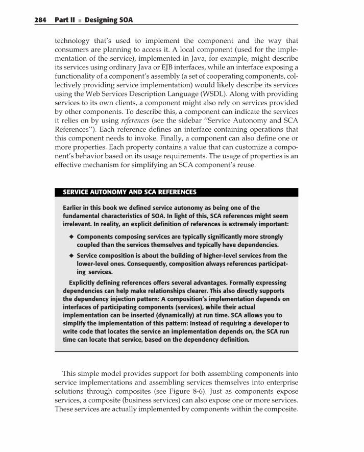
284 Part II ■ Designing SOA
technology that’s used to implement the component and the way thatconsumers are planning to access it. A local component (used for the imple-mentation of the service), implemented in Java, for example, might describeits services using ordinary Java or EJB interfaces, while an interface exposing afunctionality of a component’s assembly (a set of cooperating components, col-lectively providing service implementation) would likely describe its servicesusing the Web Services Description Language (WSDL). Along with providingservices to its own clients, a component might also rely on services providedby other components. To describe this, a component can indicate the servicesit relies on by using references (see the sidebar ‘‘Service Autonomy and SCAReferences’’). Each reference defines an interface containing operations thatthis component needs to invoke. Finally, a component can also define one ormore properties. Each property contains a value that can customize a compo-nent’s behavior based on its usage requirements. The usage of properties is aneffective mechanism for simplifying an SCA component’s reuse.
SERVICE AUTONOMY AND SCA REFERENCES
Earlier in this book we defined service autonomy as being one of thefundamental characteristics of SOA. In light of this, SCA references might seemirrelevant. In reality, an explicit definition of references is extremely important:
◆ Components composing services are typically significantly more stronglycoupled than the services themselves and typically have dependencies.
◆ Service composition is about the building of higher-level services from thelower-level ones. Consequently, composition always references participat-ing services.
Explicitly defining references offers several advantages. Formally expressingdependencies can help make relationships clearer. This also directly supportsthe dependency injection pattern: A composition’s implementation depends oninterfaces of participating components (services), while their actualimplementation can be inserted (dynamically) at run time. SCA allows you tosimplify the implementation of this pattern: Instead of requiring a developer towrite code that locates the service an implementation depends on, the SCA runtime can locate that service, based on the dependency definition.
This simple model provides support for both assembling components intoservice implementations and assembling services themselves into enterprisesolutions through composites (see Figure 8-6). Just as components exposeservices, a composite (business services) can also expose one or more services.These services are actually implemented by components within the composite.
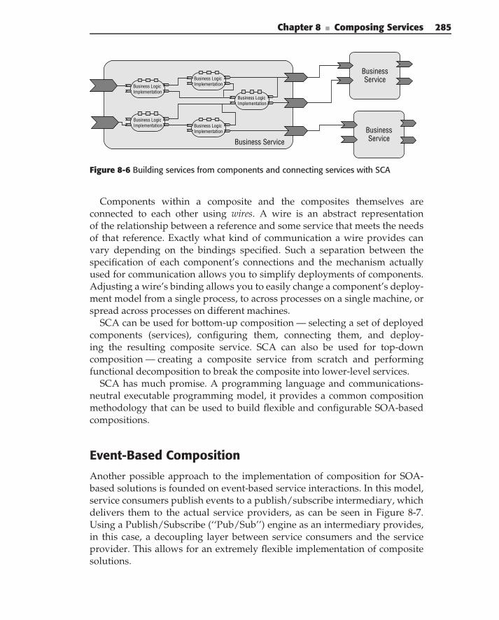
Chapter 8 ■ Composing Services 285
Business LogicImplementation
Business LogicImplementation
Business LogicImplementation
Business LogicImplementation
Business LogicImplementation
BusinessService
Business Service
BusinessService
Figure 8-6 Building services from components and connecting services with SCA
Components within a composite and the composites themselves areconnected to each other using wires. A wire is an abstract representationof the relationship between a reference and some service that meets the needsof that reference. Exactly what kind of communication a wire provides canvary depending on the bindings specified. Such a separation between thespecification of each component’s connections and the mechanism actuallyused for communication allows you to simplify deployments of components.Adjusting a wire’s binding allows you to easily change a component’s deploy-ment model from a single process, to across processes on a single machine, orspread across processes on different machines.
SCA can be used for bottom-up composition — selecting a set of deployedcomponents (services), configuring them, connecting them, and deploy-ing the resulting composite service. SCA can also be used for top-downcomposition — creating a composite service from scratch and performingfunctional decomposition to break the composite into lower-level services.
SCA has much promise. A programming language and communications-neutral executable programming model, it provides a common compositionmethodology that can be used to build flexible and configurable SOA-basedcompositions.
Event-Based Composition
Another possible approach to the implementation of composition for SOA-based solutions is founded on event-based service interactions. In this model,service consumers publish events to a publish/subscribe intermediary, whichdelivers them to the actual service providers, as can be seen in Figure 8-7.Using a Publish/Subscribe (‘‘Pub/Sub’’) engine as an intermediary provides,in this case, a decoupling layer between service consumers and the serviceprovider. This allows for an extremely flexible implementation of compositesolutions.
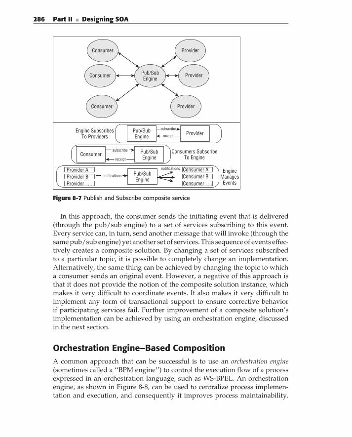
286 Part II ■ Designing SOA
Consumer Pub/SubEngine
Provider
Provider
Provider
Consumer
Consumer
Pub/SubEngine
subscribeProviderreceipt
Pub/SubEngine
Consumersubscribe
receipt
Pub/SubEngine
Consumer AProvider AProvider BProvider . . .
Consumer BConsumer . . .
notifications
notifications
Engine SubscribesTo Providers
Consumers SubscribeTo Engine
EngineManagesEvents
Figure 8-7 Publish and Subscribe composite service
In this approach, the consumer sends the initiating event that is delivered(through the pub/sub engine) to a set of services subscribing to this event.Every service can, in turn, send another message that will invoke (through thesame pub/sub engine) yet another set of services. This sequence of events effec-tively creates a composite solution. By changing a set of services subscribedto a particular topic, it is possible to completely change an implementation.Alternatively, the same thing can be achieved by changing the topic to whicha consumer sends an original event. However, a negative of this approach isthat it does not provide the notion of the composite solution instance, whichmakes it very difficult to coordinate events. It also makes it very difficult toimplement any form of transactional support to ensure corrective behaviorif participating services fail. Further improvement of a composite solution’simplementation can be achieved by using an orchestration engine, discussedin the next section.
Orchestration Engine–Based CompositionA common approach that can be successful is to use an orchestration engine(sometimes called a ‘‘BPM engine’’) to control the execution flow of a processexpressed in an orchestration language, such as WS-BPEL. An orchestrationengine, as shown in Figure 8-8, can be used to centralize process implemen-tation and execution, and consequently it improves process maintainability.
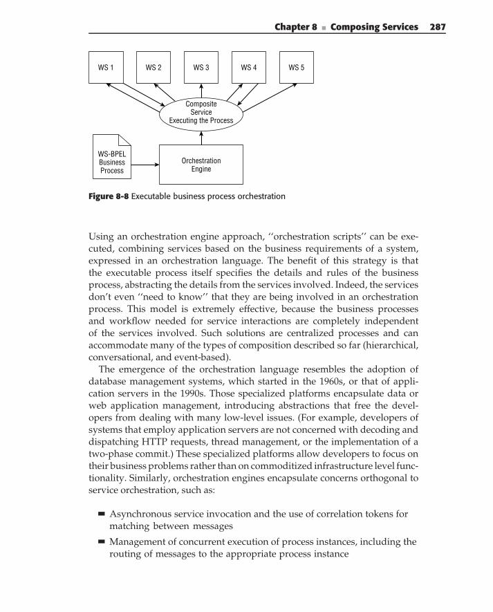
Chapter 8 ■ Composing Services 287
OrchestrationEngine
WS 1 WS 2 WS 3
WS-BPELBusinessProcess
CompositeService
Executing the Process
WS 5WS 4
Figure 8-8 Executable business process orchestration
Using an orchestration engine approach, ‘‘orchestration scripts’’ can be exe-cuted, combining services based on the business requirements of a system,expressed in an orchestration language. The benefit of this strategy is thatthe executable process itself specifies the details and rules of the businessprocess, abstracting the details from the services involved. Indeed, the servicesdon’t even ‘‘need to know’’ that they are being involved in an orchestrationprocess. This model is extremely effective, because the business processesand workflow needed for service interactions are completely independentof the services involved. Such solutions are centralized processes and canaccommodate many of the types of composition described so far (hierarchical,conversational, and event-based).
The emergence of the orchestration language resembles the adoption ofdatabase management systems, which started in the 1960s, or that of appli-cation servers in the 1990s. Those specialized platforms encapsulate data orweb application management, introducing abstractions that free the devel-opers from dealing with many low-level issues. (For example, developers ofsystems that employ application servers are not concerned with decoding anddispatching HTTP requests, thread management, or the implementation of atwo-phase commit.) These specialized platforms allow developers to focus ontheir business problems rather than on commoditized infrastructure level func-tionality. Similarly, orchestration engines encapsulate concerns orthogonal toservice orchestration, such as:
Asynchronous service invocation and the use of correlation tokens formatching between messages
Management of concurrent execution of process instances, including therouting of messages to the appropriate process instance
288 Part II ■ Designing SOA
Management of the execution context containing the information thatdetermines the state of the business process: what activities have com-pleted and what activity is currently executing
Management of the data flow, including data flowing into services (i.e.,invocation arguments), as well as out of services (i.e., return values)
Management of the long-running actions, transactions, and semanticcompensation
Support for manual activities
Collection and processing of business events and key performance indi-cators (KPIs), defining both the health of the engine itself and that of theprocesses it executes
Support for achieving critical enterprise architecture goals such as scala-bility and availability
In engine-based orchestration, a business process server engine processesan orchestration script, and generates a composite service for executing inter-actions between the Web Services involved in the business process, as shownin Figure 8-6. Orchestration engines provide recursive aggregation, meaningthat a composite service can be created to compose a new process involvinginteractions with services, and the resulting composite service can itself beused by other processes to create new composite services. Composite servicescan even instantiate and call themselves.
Further simplification of the use of orchestration engines is achievedthrough the use of orchestration languages — domain-specific languages(DSLs) — specialized for expressing and supporting concepts required forimplementation of service compositions (see the sidebar ‘‘About Domain-Specific Languages’’). Using such a language, supported by an orchestra-tion engine (instead of using a general programming language) improves andsimplifies an orchestration’s implementation. It allows you to programand maintain composition logic using visual editors, allowing you to defineall the major aspects of orchestration graphically.
ABOUT DOMAIN-SPECIFIC LANGUAGES
A common strategy for building executable processes for orchestrationsinvolves the use of domain-specific languages (DSLs). DSLs are specialized forexpressing and supporting domain-specific concepts. A DSL precisely capturesa domain’s semantics — a vertical DSL is industry-specific, whereas a horizontalDSL is meant for a specific problem domain. DSLs are helpful for buildingscripts that run in orchestration engines.
Chapter 8 ■ Composing Services 289
DSLs are highly declarative and describe what needs to happen, rather thenthe specifics of how the functionality is done. Because of this, DSLs areconsidered specifications (executable) and not programming languages. Thekey advantages of specific DSLs are that they are domain-specific abstractionsand notations, and have more expressive power, focused on the specificdomain involved. Orchestration languages, such as WS-BPEL, Microsoft’s ODX(Orchestration Designer XML), and XLang are DSLs, languages focused on thespecific domain of orchestration.
There are several reasons that DSLs are more attractive than general-purposelanguages (GPLs) for some classes of applications:
◆ Easier programming — Abstractions and notations aligned with the partic-ular domain and coupled with declarative formulations make a DSL pro-gram more concise and readable than its GPL counterpart. It allows closerinteractions between developers and domain experts, that can understand,validate, modify, and often develop DSL programs. They also allow short-ened development and improved maintenance of a DSL-based implemen-tation.
◆ Systematic reuse — By capturing domain expertise, a DSL program pro-motes reuse either implicitly by hiding common program patterns in theDSL implementation, or explicitly by exposing appropriate parameteriza-tion to the DSL programmer.
◆ Easier verification — With advances in software engineering, formal codeverification is playing an important role in successful development. In thecase of GPLs, such verification only ensures that the code will execute.However, in the case of DSLs, because of their compactness and domainalignment, validation can often ensure that the code will produce correctresults.
◆ Increased cooperation — The use of the same business-related semanticsacross the organization facilitates the sharing of information and reducesthe risk of a mismatch between the actual implementation of the businesslogic and the business users’ expectations.
Orchestration languages are DSLs because they apply to the problem set(domain) of business orchestration. At the same time, DSLs that apply tospecific business domains can also be used for generating orchestration scriptswritten in orchestration languages. (For example, a higher-level tax-domainprocess language could be used to generate the BPEL that is interpreted by theorchestration engine.) Regardless, DSLs provide a level of abstraction thatmakes building composite services simple.
In addition to simplifying the composition process, the use of an orches-tration language also allows you to leverage the inherent benefits of the
290 Part II ■ Designing SOA
orchestration engines, which provide built-in functionality that includescapabilities such as asynchronous invocations, state management, and com-pensation support. The use of orchestration engines for composite solutionimplementation provides the following advantages:
Orchestration languages directly support the majority of orchestrationconcepts, which usually simplifies composite service implementation.
Additional programming can be simplified through use of a visualeditor.
The orchestration engine natively supports orchestration instances andcontexts that are required for implementing of SOA-based solutions.
Compensation support, implemented in the orchestration languages,makes transactional support implementation significantly simpler.
Orchestration languages, such as WS-BPEL, are portable from any pro-gramming language platform, and they can be run on an orchestration serverregardless of whether it is J2EE-based, .NET-based, or any other implemen-tation. This is important because different business partners use differentplatforms. WS-BPEL separates interaction and business process functionalityfrom the services themselves, and orchestration servers process the executableprocesses. This separation makes the implementation of your business servicesvery straightforward.
Centralized and Decentralized Orchestration ApproachesUsing an orchestration engine has a major advantage over creating hard-codedbusiness routing decisions at design time or even routing decisions at compiletime. It provides abstraction between services and the way that services areused. This increases the reusability of your services and the agility of yourarchitecture. Later in this chapter, we discuss WS-BPEL, the executable processlanguage used to describe Web Service compositions in these engines.
The most common approach to an orchestration server is to use a centralizedserver (sometimes called a ‘‘BPM server’’) for an enterprise or a business unit.This approach is effective because it is simple for management and eventauditing, and it is sometimes easier to store your business processes in oneplace. In practice, however, centralized composition can scale only so far,because there is a danger of creating a processing bottleneck, leading to issueswith performance and availability, and a potential for a single point of failure.
Distributed strategies (such as using multiple orchestration servers) promisescalability. Because of scalability concerns related to centralized orchestration,many organizations are investigating a deployment architecture in which aninitial orchestration engine breaks up tasks into other composite service parti-tions and passes these on to other orchestration engines to process. (For more
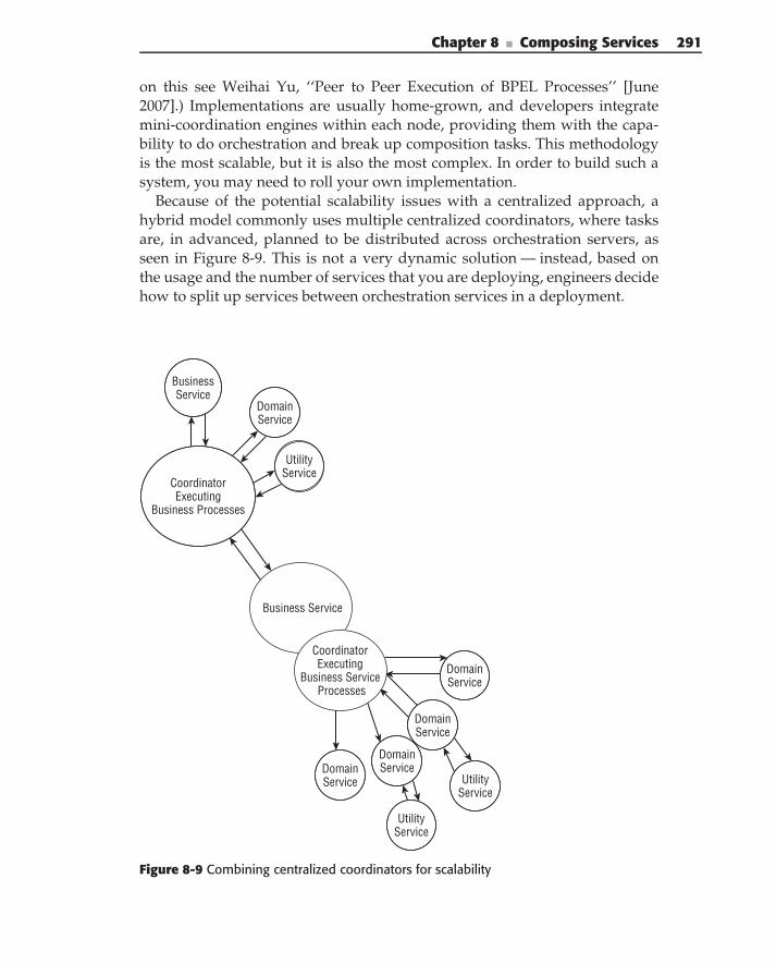
Chapter 8 ■ Composing Services 291
on this see Weihai Yu, ‘‘Peer to Peer Execution of BPEL Processes’’ [June2007].) Implementations are usually home-grown, and developers integratemini-coordination engines within each node, providing them with the capa-bility to do orchestration and break up composition tasks. This methodologyis the most scalable, but it is also the most complex. In order to build such asystem, you may need to roll your own implementation.
Because of the potential scalability issues with a centralized approach, ahybrid model commonly uses multiple centralized coordinators, where tasksare, in advanced, planned to be distributed across orchestration servers, asseen in Figure 8-9. This is not a very dynamic solution — instead, based onthe usage and the number of services that you are deploying, engineers decidehow to split up services between orchestration services in a deployment.
Business Service
CoordinatorExecuting
Business Processes
BusinessService
DomainService
UtilityService
UtilityService
DomainService
DomainService
DomainServiceDomain
Service
UtilityService
CoordinatorExecuting
Business Service Processes
Figure 8-9 Combining centralized coordinators for scalability
292 Part II ■ Designing SOA
As an architect, it is important that you treat a centralized orchestrationsolution like you would any central server — make certain that you under-stand the load and performance requirements, and investigate replication andduplication solutions that meet the demands of your enterprise. BPM serversthat offer central orchestration based on executable processes all approachscalability differently, so if you are considering using them, you will want toask the vendor how they approach enterprise scalability.
Service Composition and Business Rules
As mentioned throughout this chapter, service composition is drivenby business rules, defining an invocation sequence of particular servicesparticipating in a process. This leads many practitioners to consider businessrules as part of the broader BPM picture and consider business rules andbusiness processes together. As a result, many consider business rules enginesand business process engines as two competing technologies for business pro-cesses/business rules implementation. This is based on the following popularmisconceptions:
Business rules and business processes share the same design andimplementation model.
Business rules and business processes deliver the same artifacts and canbe used the same way.
In reality, business rules and business processes are quite different. Accord-ing to Wikipedia, ‘‘Business rules describe the operations, definitions andconstraints that apply to an organization in achieving its goals. These rulesare used to help the organization to better achieve goals, communicate amongprincipals and agents, communicate between the organization and interestedthird parties, demonstrate fulfillment of legal obligations, operate more effi-ciently, automate operations, perform analysis on current practices, etc.’’ Busi-ness rules can be viewed as a collection of business practices, defining theactual implementations or business logic. The implementation of such logic canoften be simplified through the use of specialized tools — business rule lan-guages and business rule engines. Declarative programming (i.e., prescribingthe what) represents the paradigm of choice for rules: Something is triggered(i.e., an action) based on whether a rule evaluates to true or false. The controlflow (i.e., the sequencing of these invocations) is implicit and emerges as therules fire.
A business process definition, on the other hand, can be viewed as a recipefor achieving a specific goal. Imperative programming (i.e., prescribing the how)represents the paradigm of choice for business processes implementation:
Chapter 8 ■ Composing Services 293
Something is invoked after something else because the business processdefinition prescribes their sequence. The control flow is explicit.
Determining the right technology becomes critical when it comes to bestsupporting business requirements and achieving the optimal architecturalqualities. At the end of the day, assuming that the appropriate DSL and engineare used, the implementation choice between business rules and businessprocess paradigms depends on the two major factors: the capabilities of theengine and decomposition of the overall system.
When it comes to the capabilities of the rules versus business processengines, the following should be considered:
Synchronicity — Rule evaluation is synchronous, and rules engines aredesigned to evaluate business rules as quickly as possible. Processes, onanother hand, are typically long running and asynchronous in nature.The strength of a process engine is the ability to support long-runningprocesses, where actions can take a long time to complete. As a result,they provide the mechanism required to deal with asynchronous invoca-tions, such as request/response correlation, compensations, and so on.
Statefulness — Rules engines are stateless — when a rule fires, anengine typically pulls its inputs either from the input parameters or theknowledge base. It evaluates it, and then it either updates the knowledgebase or propagates results to output. Business process engines are specif-ically designed to hold the state of each active process instance, hydrateand store it between activities invocations, and rehydrate it for the exe-cution of the next activity.
Determinism — The rules engine fires rules whose conditions evaluatesimultaneously. However, their ordering is nondeterministic. Businessprocesses are, for the most part, deterministic (with the exception of par-allel activities), and people typically add checks and balances to ensuredeterminism.
Granularity — Although the business rules themselves can be usedat the company level, they are usually considered to be components.As such, they provide a smaller granularity and offer a higher level offlexibility from maintenance and deployment perspectives. Businessprocesses, on the other hand, can be viewed more as stable assets that areless likely to go through drastic changes over time.
Based on the previous comparison of business processes/business rulesengines’ capabilities and SOA decomposition (described in Chapters 2,3, and 4), the following recommendations can be made for choosing a technol-ogy that supports business rules:
Service orchestration — Service orchestration typically deals with long-running and asynchronous invocation of external activities/services.
294 Part II ■ Designing SOA
Today’s business rules engines do not support these capabilities. Busi-ness process language/engines, designed specifically to define and exe-cute long-running coordinations with asynchronous invocations are themost appropriate paradigm for the service orchestration.
Business service implementations — Business service implementa-tions are typically short-lived transactional implementations with onlysynchronous interactions. In this case, the line between business rulesand business processes becomes blurry. Often the same problem can bedefined, and consequently solved, with either technology. As a result,based on the design-time paradigm, one might consider using either arule set or a business process approach for solving the same problem.
The advantage of using a business process approach, in this case, issimplified support for invocation of external activities (services).
The advantages of using a business rules approach, in this case, arethe ability to change rules without recompiling and redeploying thebusiness rule components, and the ability to reuse the implementedbusiness logic at the component level (as opposed to the service levelwhen dealing with business processes).
Implementation of business rules controlling business processexecution — When rules define the execution of the business processitself, it is necessary to consider their complexity and change frequency.Modern business process engines usually provide capabilities for eval-uating simple rules, either built into the business process language oravailable by invocation of general-purpose languages. Thus, it is entirelyfeasible to implement ‘‘simple’’ business rules in the business processengine. In this case, however, any change in the rules requires a full test-ing and deployment of the business process. As for complex businessrules, they typically need to be extracted from the process and imple-mented as a separate service, using a rules engine.
Rules engines fit in at the service layer in the implementation of decisionservices, while business process (BPM) engines are better for the larger processimplementations of service orchestration capabilities. Figure 8-10 shows thistypical usage of business process and rules engines in the SOA implementation.In cases where rules control activities whose coordination is very complex (orthat change much faster the process itself so that they require usage of the rulesengines), these rules are usually externalized as a special rules service, invokedby the business process engine. Because this type of service invocation can bepotentially expensive (network calls), some of the business process engines,for example, Biztalk from Microsoft, WebSphere Process Server from IBM,Smart BPM Suite from PegaSystems, and others, incorporate both a businessprocess engine and a rules engine in a single application.
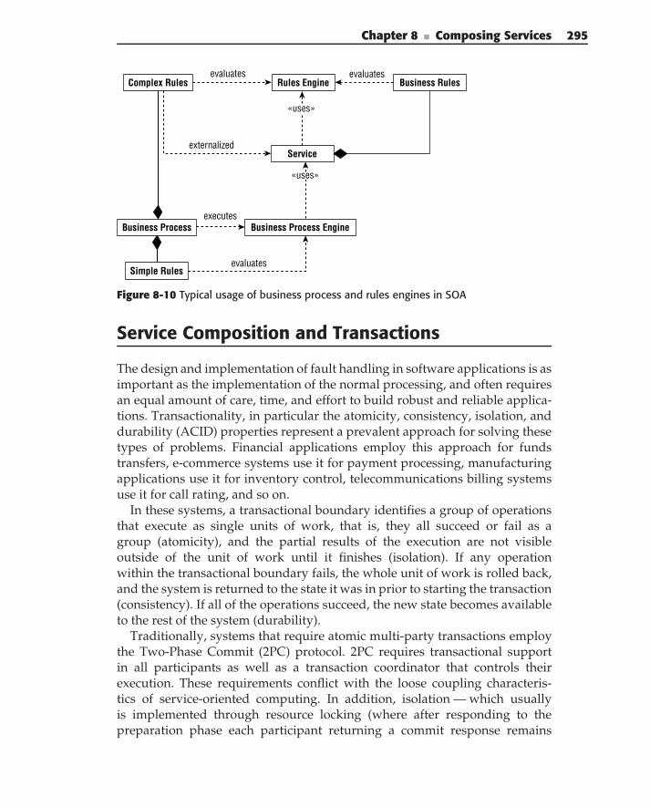
Chapter 8 ■ Composing Services 295
Business Process EngineBusiness Process
Rules EngineComplex Rulesevaluates
executes
Simple Rules
Service
Business Rules
externalized
evaluates
evaluates
«uses»
«uses»
Figure 8-10 Typical usage of business process and rules engines in SOA
Service Composition and Transactions
The design and implementation of fault handling in software applications is asimportant as the implementation of the normal processing, and often requiresan equal amount of care, time, and effort to build robust and reliable applica-tions. Transactionality, in particular the atomicity, consistency, isolation, anddurability (ACID) properties represent a prevalent approach for solving thesetypes of problems. Financial applications employ this approach for fundstransfers, e-commerce systems use it for payment processing, manufacturingapplications use it for inventory control, telecommunications billing systemsuse it for call rating, and so on.
In these systems, a transactional boundary identifies a group of operationsthat execute as single units of work, that is, they all succeed or fail as agroup (atomicity), and the partial results of the execution are not visibleoutside of the unit of work until it finishes (isolation). If any operationwithin the transactional boundary fails, the whole unit of work is rolled back,and the system is returned to the state it was in prior to starting the transaction(consistency). If all of the operations succeed, the new state becomes availableto the rest of the system (durability).
Traditionally, systems that require atomic multi-party transactions employthe Two-Phase Commit (2PC) protocol. 2PC requires transactional supportin all participants as well as a transaction coordinator that controls theirexecution. These requirements conflict with the loose coupling characteris-tics of service-oriented computing. In addition, isolation — which usuallyis implemented through resource locking (where after responding to thepreparation phase each participant returning a commit response remains
296 Part II ■ Designing SOA
locked until it receives the coordinator’s commit) — is particularly problematicwith long-running business processes. In general, the traditional transac-tional architectures are not a good fit for long-running processes coordinatingautonomous services for the following reasons:
The requirements of the 2PC protocol conflict with the loosely couplednature services. First, the participating services do not always supporttransactional behavior. Second, the introduction of a single transactionalcoordinator supporting transactional semantics of service execution isnot always feasible, especially when service location crosses organiza-tional boundaries. Finally, the locking nature of isolation makes it a poorchoice for long-running processes.
Silent rollback implemented by 2PC is not always applicable to SOAimplementations, especially in the cases of economic transactions, whereboth commit and rollback imply agreement. In these situations, bothtransaction commitment and transaction aborting have to be explicitlyconfirmed by all participating parties.
Well-designed services provide large-grained functionality, implemen-ted as a business process or as collaboration between applicationsand/or business components. A single undo action (as in the Com-mand pattern) is likely too fined-grained to cancel the effects of serviceinvocation.
Undo actions often depend not only on the results of the last serviceinvocation but also on the overall state of the (process) execution.Loosely coupled services do not share state, which means that they arenot always capable of ‘‘undoing’’ each other’s actions.
An alternative to a true 2PC, supported by the majority of BPM engines,is compensation — invocation of business logic that can be called in case of afailure. Service compensation uses a set of compensating activities (i.e., serviceinvocations) that, when executed, cancel out the effects of the ‘‘forward’’execution. Although compensation does not provide the ACID properties ofthe 2PC protocol, it suffices in many practical situations.
The use of compensation instead of the true 2PC removes the requirementsthat make 2PC unsuitable for SOA — most notably temporal coupling througha transaction coordinator and resource locking for isolation. In addition, ser-vice compensation works well with both transactional and nontransactionalservice implementations. In both cases, the results of the ‘‘forward’’ invoca-tion(s) can be rolled back through an additional invocation(s) that reversestheir effects. Since there is no waiting for commit or rollback commands, noresource locking is required in this case. The tradeoff of this approach is anabsence of isolation.
Chapter 8 ■ Composing Services 297
In effect, compensation extends the process definition. Defining anorchestration goes beyond composing the services participating in thebusiness process (‘‘happy path’’). It must incorporate additional elements,namely the definitions of the compensation scopes (i.e., fault detectionboundaries), the mechanisms for signaling faults, and definitions of thecompensating actions.
Using orchestrations/processes as a mechanism for both invoking andimplementing compensations has an additional advantage. Service compen-sation (unlike normal transactions) may depend on the state of the processand be stateful by itself. Because the orchestration engine implements servicecompensation as part of the orchestration, any state information required forcompensation is available from the execution context, supported by an BPMserver.
Incorporating Human Activities into ServiceComposition
In many cases business processes implemented through a service orchestrationinvolve human activities. This typically happens when particular activities ofthe process are too expensive (not cost-effective) or too complex to automate.
Dealing with human activities poses the following problems:
Humans interact with computers through interfaces very different thanthe ones of software systems. Their implementation requires dealingwith presentation, a typical aspect of human-computer interaction.
Besides working exclusively in an asynchronous manner, human work-ers also have slow response times, low throughput, and poor availabil-ity. Many organizations deal with the low availability by defining roles(rather than a specific individual) for each activity and defining severalworkers for each role. Roles address the low availability issues throughdelaying the binding of human workers to the activity until run time.However, they introduce an additional problem that doesn’t exist in thecontext of automated activities — definition and synchronization of cre-dentials.
Orchestration execution environments are well equipped to handle asyn-chronous interactions and long-running activities. However, the othercharacteristics of human interactions, including long response times, pooravailability, and specialized interaction mechanisms make their executionradically different from automated process activities.
A typical approach to support human activities is the introduction ofa specialized component human activities manager, collaborating with theorchestration engine to support human interactions, as shown in Figure 8-11.
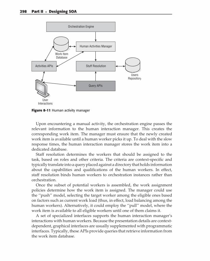
298 Part II ■ Designing SOA
Orchestration Engine
Human Activities Manager
Work ItemDatabase
Query APIs
Activities APIs Stuff Resolution
UsersRepository
UserInteractions
Figure 8-11 Human activity manager
Upon encountering a manual activity, the orchestration engine passes therelevant information to the human interaction manager. This creates thecorresponding work item. The manager must ensure that the newly createdwork item is available until a human worker picks it up. To deal with the slowresponse times, the human interaction manager stores the work item into adedicated database.
Staff resolution determines the workers that should be assigned to thetask, based on roles and other criteria. The criteria are context-specific andtypically translate into a query placed against a directory that holds informationabout the capabilities and qualifications of the human workers. In effect,staff resolution binds human workers to orchestration instances rather thanorchestration.
Once the subset of potential workers is assembled, the work assignmentpolicies determine how the work item is assigned. The manager could usethe ‘‘push’’ model, selecting the target worker among the eligible ones basedon factors such as current work load (thus, in effect, load balancing among thehuman workers). Alternatively, it could employ the ‘‘pull’’ model, where thework item is available to all eligible workers until one of them claims it.
A set of specialized interfaces supports the human interaction manager’sinteractions with human workers. Because the presentation details are context-dependent, graphical interfaces are usually supplemented with programmaticinterfaces. Typically, these APIs provide queries that retrieve information fromthe work item database.
Chapter 8 ■ Composing Services 299
Orchestration with BPEL
BPEL stands for Business Process Execution Language and is the common termused to denote the WS-BPEL business process execution language that hasevolved over the last seven years under different names. As mentioned earlier,the latest OASIS standard released in 2007 is WS-BPEL 2.0, an XML-basedgrammar used to describe logic to orchestrate the interaction between WebServices in a business process. WS-BPEL 2.0 evolved from BPEL4WS 1.0, whichwas a 2003 specification from OASIS that converged WSFL and XLANG.Although WS-BPEL is the standard, people still call it BPEL (and manypeople even pronounce it differently). Whether you pronounce it ‘‘Bipple’’ or‘‘Bee-pell,’’ architects agree, it is an important standard for use in an SOA.Because it provides a very expressive grammar for defining real-world businessprocesses, and because it is a standard that has matured over the course ofmany years, and because there is so much vendor acceptance and support, itis a language that every service-oriented enterprise should consider using.It is also a very detailed standard. For this reason, this section provides only abird’s-eye view, not focusing on syntax, but on the big picture.
WHAT ABOUT A WS-BPEL REFERENCE GUIDE?
As mentioned at the beginning of this book, we want to make sure that you, asan architect, understand how to apply technologies, but we are not going toprovide a primer on every standard we discuss. This is not that type of book,and frankly, such a book would be too heavy for you to carry around (it’s heavyenough as it is!). We do, however, give you a big picture of what WS-BPELprovides, and we give you an overview of how architects use design tools thatwrite WS-BPEL for use on orchestration engines and servers. Later, we providea case study that applies these concepts.
There are many books that act as reference guides on all aspects of WS-BPELand its earlier variant, BPEL4WS. At the point of writing, we noticed that manyof these books were out of date already! We recommend, therefore, that you goto the web page for the OASIS WSBPEL Technical Committee(oasis-open.org/committees/wsbpel). This page provides the latestversions of the standard and links to reference guides and detailed examples.
BPEL grew out of the need to model and execute complex interactionsbetween Web Services. WSDL-defined Web Services have a stateless interactionmodel, but real-world processes are usually very complex and require arobust interaction model. BPEL provides the means for expressing stateful,long-running interactions between services. As we have described in thelast section, processes written in WS-BPEL allow you to separate business
300 Part II ■ Designing SOA
process interaction from the services themselves, providing independence andflexibility.
BPEL revolves around the definitions of two types of processes:
An executable process, which contains internal process business logicthat can be executed as a composite service on an orchestration server
An abstract process, which is used to describe observable messageexchange behavior between services, but cannot be executed as acomposite service
Executable business processes are simple to understand, as we covered inthe previous section. The concept of an abstract process is new and, therefore,requires more explanation. Abstract processes are useful for a number ofreasons:
First of all, they can provide a ‘‘public’’ view of an internal business pro-cess. This is helpful for interaction with business partners who don’tneed to know (and shouldn’t know) internal decision-making processesbut still need to know how to interact (semantically and syntactically).Abstract profiles specify constraints on message exchange, specifyingthe order in which messages need to be consumed and produced.
Second, abstract processes allow you the freedom to change internaldecision-making processes (in executable processes) without affectingobservable behavior.
Finally, an abstract process is useful because it can define a processtemplate for domain-specific best practices. They can serve as a guidefor creating the detailed executable processes. Common activities, datastructure, and high-level control flow can be done at the beginning of theproject, as a guide.
WS-BPEL is layered on top of and extends WSDL. WSDL defines the opera-tions allowed, and WS-BPEL defines how WSDL operations are orchestratedin order to satisfy a business process. WS-BPEL also extends WSDL to supportlong-running asynchronous business processes. As a business process lan-guage, it is a very expressive and rich XML-based language, with constructsvery similar to those of high-level programming languages. For executableprocesses you can declare and modify variables, define fault handlers andthrow exceptions, invoke services, and use case statements, while statements,and loops. XPath and XSLT provide support for data manipulation in BPEL.You can specify actions to occur in a synchronous sequence or in an asyn-chronous parallel flow. The result is that this language can express almostany business process, the process can be executed on a server to composeservices, and the executable process itself becomes a composite service thatcan be called and reused by other services. Finally, because it is a standardXML-based language, it is portable and can be run in any orchestration server.
Chapter 8 ■ Composing Services 301
In practice, constructing processes is done visually with various designtools, and many are free, including the BPEL Visual Designer for Eclipse,and the BPEL plug-in for NetBeans. There are also commercial BPEL designertools from companies such as Oracle, IBM, Active Endpoints, and BEA. Thesetools allow you to create visual flows and generate BPEL that can be executedon an orchestration server. Most tools have their own look and feel, and are‘‘BPMN-like’’ in their visual notations, but they all export to BPEL. Once adesign tool exports the model to BPEL, an orchestration engine is able toexecute the process.
BPEL-based solutions, like those of other orchestration languages, followwhat Martin Fowler, in his book Patterns of Enterprise Application Architecture,(2002), calls ‘‘the transaction script’’ pattern. Solutions using this patternorganize business logic into procedural ‘‘transaction scripts.’’ Much like otherimplementations of the transaction script pattern, BPEL solutions are powerfuland are easy to use. However, it should be mentioned that they are not a ‘‘silverbullet’’ for composition — they have the potential to suffer certain drawbacksrelated to code complexity, sometimes leading to ‘‘procedural code spaghetti,’’which affects maintainability. However, as many tools progress to the pointof allowing the designer to work purely with the user interface that generatesBPEL, there is certainly the promise of the user interface providing that bufferbetween visual composition and the generated code, making maintainabilityeasier. In the next section, we walk you through a composition example, andthrough the construction of a simple BPEL process.
Composition Example — Case Study
This section illustrates a simple example of composing services based on acompany’s business processes, applying the techniques of this chapter. Here,we are focused on identification of services and interactions for a businessprocess. Based on modeling the process, we can create executable compositeservices.
The Problem
The scenario revolves around an auto body shop with a technology head-ache. This body shop often needs to order parts from suppliers. They workwith many suppliers of vehicle parts, and for the longest time, all of theirorders for automobile parts were done by negotiating over the phone withmany vendors. The industry recently moved to a Web Service environment,and all purchasing can now be done electronically between businesses. Foreach type of vehicle, there is a different business process, where the body
302 Part II ■ Designing SOA
shop requests quotes for parts from a variety of different partners, choosesthe cheapest quote, and orders the part. There are four separate businessprocesses for cars, trucks, buses, and construction vehicles. Each process isdifferent enough to be separated, but each process has many things in common;they request price quotes from partners, and they choose the lowest price.
The company made a bad decision. They hired a summer intern whowas not a software architect or a seasoned developer, and the intern builta stand-alone application to manage all of these processes, with all of thisprocess logic hard-coded in a single application. This worked great for a while(while the intern was employed during the summer). When the processeschanged, nobody could understand the spaghetti code in the program. Theapplication was full of complex, nested if-then-else statements correspondingto the logic of all of the processes. Now, the company has abandoned thestand-alone application, reverting to the old business style, using the telephone.Unfortunately, the company is having a hard time doing business now. Theycan’t get the parts vendors on the phone, because most of the transactions forthose vendors are done electronically (with little phone support!).
This auto shop company badly needs help. They need a solution that meetstoday’s requirements and business processes, but more importantly, theyneed a solution that is flexible enough to accommodate changing businessprocesses.
High-Level Design DecisionsYou know from the problem statement that there are complex and differentprocesses for ordering different types of vehicle parts. By applying the conceptsfrom earlier in this chapter, you can look at those processes involved (car partsbuying, truck parts buying, bus parts buying, and construction parts buying)as composite services that could be used together to build the main systemprocess for ordering vehicle parts.
Following that logic, you would break up the task into a hierarchy of services.You can define a high-level business process for auto parts purchasing thatuses domain-level services that correspond to the different processes involvedin purchasing parts for different vehicle types. The solution shown here definesthe business processes for Truck Parts Ordering, Car Parts Ordering, Bus PartsOrdering, and Construction Vehicle Parts Ordering, and those are executablecomposite services that the main process can use.
You want to create domain-level services that abstract the purchasingprocesses for each type of vehicle, and the higher-level business servicecan abstract these. An overview of the composition, shown in Figure 8-12,uses black box composition. Based on the type of vehicle, The Vehicle PartsOrdering Process simply propagates the request to the lower-level processes,and returns the purchase response to its consumer. The front-end application’s
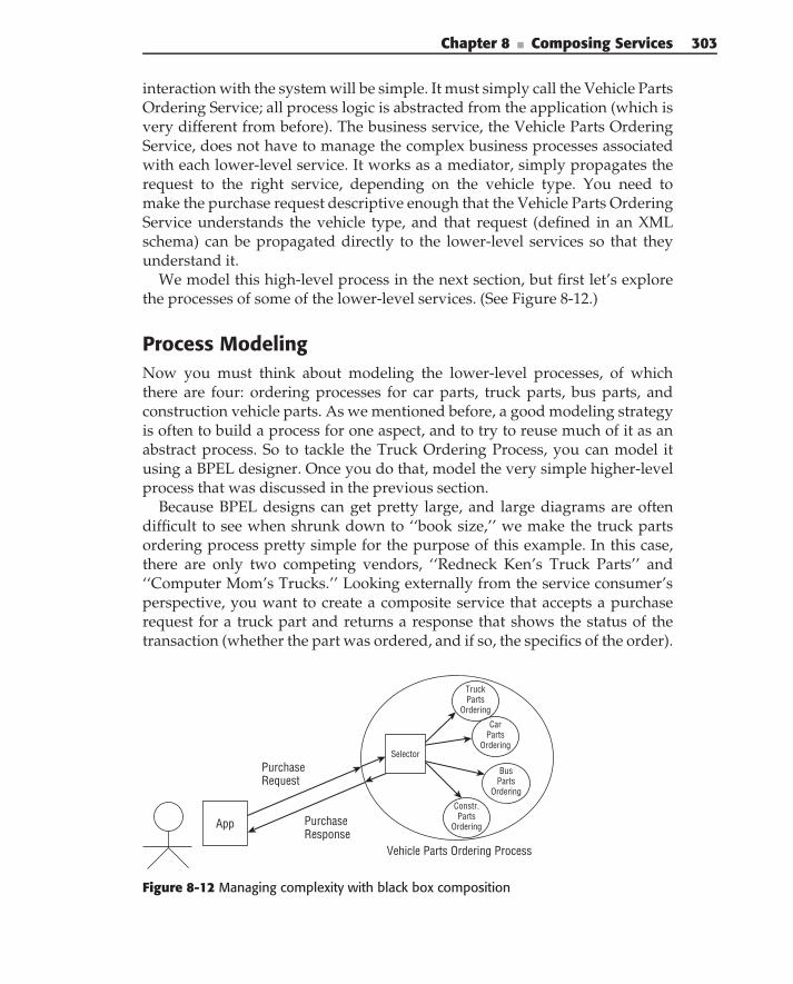
Chapter 8 ■ Composing Services 303
interaction with the system will be simple. It must simply call the Vehicle PartsOrdering Service; all process logic is abstracted from the application (which isvery different from before). The business service, the Vehicle Parts OrderingService, does not have to manage the complex business processes associatedwith each lower-level service. It works as a mediator, simply propagates therequest to the right service, depending on the vehicle type. You need tomake the purchase request descriptive enough that the Vehicle Parts OrderingService understands the vehicle type, and that request (defined in an XMLschema) can be propagated directly to the lower-level services so that theyunderstand it.
We model this high-level process in the next section, but first let’s explorethe processes of some of the lower-level services. (See Figure 8-12.)
Process ModelingNow you must think about modeling the lower-level processes, of whichthere are four: ordering processes for car parts, truck parts, bus parts, andconstruction vehicle parts. As we mentioned before, a good modeling strategyis often to build a process for one aspect, and to try to reuse much of it as anabstract process. So to tackle the Truck Ordering Process, you can model itusing a BPEL designer. Once you do that, model the very simple higher-levelprocess that was discussed in the previous section.
Because BPEL designs can get pretty large, and large diagrams are oftendifficult to see when shrunk down to ‘‘book size,’’ we make the truck partsordering process pretty simple for the purpose of this example. In this case,there are only two competing vendors, ‘‘Redneck Ken’s Truck Parts’’ and‘‘Computer Mom’s Trucks.’’ Looking externally from the service consumer’sperspective, you want to create a composite service that accepts a purchaserequest for a truck part and returns a response that shows the status of thetransaction (whether the part was ordered, and if so, the specifics of the order).
App
PurchaseRequest
Vehicle Parts Ordering Process
TruckParts
Ordering
PurchaseResponse
CarParts
Ordering
BusParts
Ordering
Constr.Parts
Ordering
Selector
Figure 8-12 Managing complexity with black box composition
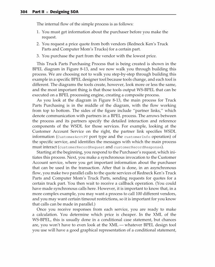
304 Part II ■ Designing SOA
The internal flow of the simple process is as follows:
1. You must get information about the purchaser before you make therequest.
2. You request a price quote from both vendors (Redneck Ken’s TruckParts and Computer Mom’s Trucks) for a certain part.
3. You purchase the part from the vendor with the lowest price.
This Truck Parts Purchasing Process that is being created is shown in theBPEL diagram in Figure 8-13, and we now walk you through building thisprocess. We are choosing not to walk you step-by-step through building thisexample in a specific BPEL designer tool because tools change, and each tool isdifferent. The diagrams the tools create, however, look more or less the same,and the most important thing is that those tools output WS-BPEL that can beexecuted on a BPEL processing engine, creating a composite process.
As you look at the diagram in Figure 8-13, the main process for TruckParts Purchasing is in the middle of the diagram, with the flow workingfrom top to bottom. The sides of the figure include ‘‘partner links,’’ whichdenote communication with partners in a BPEL process. The arrows betweenthe process and its partners specify the detailed interaction and referencecomponents of the WSDL for those services. For example, looking at theCustomer Account Service on the right, the partner link specifies WSDLinformation (CustomerAcctPT port type and the customerInfo operation) ofthe specific service, and identifies the messages with which the main processmust interact (customerRecordRequest and customerRecordResponse).
Starting at the beginning, you respond to the Purchaser’s request, which ini-tiates this process. Next, you make a synchronous invocation to the CustomerAccount service, where you get important information about the purchaserthat can be used in the transaction. After that is done, in an asynchronousflow, you make two parallel calls to the quote services of Redneck Ken’s TruckParts and Computer Mom’s Truck Parts, sending requests for quotes for acertain truck part. You then wait to receive a callback operation. (You couldhave made synchronous calls here. However, it is important to know that, in amore complex example, you may want a process to call 100 different vendors,and you may want certain timeout restrictions, so it is important for you knowthat calls can be made in parallel.)
Once you receive responses from each service, you are ready to makea calculation. You determine which price is cheaper. In the XML of theWS-BPEL, this is usually done in a conditional case statement, but chancesare, you won’t have to even look at the XML — whatever BPEL design toolyou use will have a good graphical representation of a conditional statement,
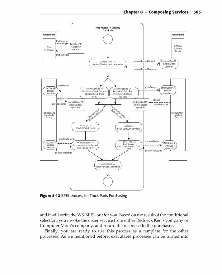
Chapter 8 ■ Composing Services 305
<<invoke (sync) >> Retrieve Client Account Information
<<invoke (async) >> Get price for Truck Part from
Redneck Ken’s’ TruckParts
<<invoke (async) >> Get price for Truck Part from ComputerMom’s
Truck Parts
Redneck Ken’sTruck Parts
Service
Client (Purchaser)
Redneck.pric
e <
ComputerMom.pric
e
ComputerMom.price <=
Redneck.price
<<assign>> Select Redneck Quote
<<assign>>Select Computrmom Quote
<<invoke (sync) >> Purchase part from Redneck
Ken’s Truck Parts
<<invoke (sync) >>Purchase part
from ComputerMom’s TruckParts
<<reply (sync) >> Return Purchase Confirmation
TruckPartPT: requestPartoperation
BPEL Process for OrderingTruck Parts
QuoteCallbackPT: QuoteCallback
operation
callBack
quoteRequest
quoteResponse
CustomerAccountService
ComputerMom’sTruck Parts
Service
purchaseRequest
purchaseResponse
QuoteCallbackPT: QuoteCallback
operation
rDadQuotePT getQuote operation
rDadOrderPT purchase operation
Partner Links Partner Links
cMomQuotePTgetQuoteoperation
CustomerAcctPT:customerInfo
Operation
cMomOrderPTpurchaseoperation
PartResponse
PartRequest
callBack
quoteResponse
purchaseResponse
purchaseRequest
customerRecordRequest
customerRecordResponse
quoteRequest
Figure 8-13 BPEL process for Truck Parts Purchasing
and it will write the WS-BPEL out for you. Based on the result of the conditionalselection, you invoke the order service from either Redneck Ken’s company orComputer Mom’s company, and return the response to the purchaser.
Finally, you are ready to use this process as a template for the otherprocesses. As we mentioned before, executable processes can be turned into
306 Part II ■ Designing SOA
abstract processes by hiding some internal process logic. Before this is done,however, it is important to look at the external interfaces and interactions of thisprocess to make sure that it is indeed reusable. Conversational compositionscan get more complex, but this one is more straightforward because you usedblack box composition — the external view of the process from the consumeris really the initial call to the service, focused on the interfaces and messagetypes for request and response. Originally, when authoring this process,we used incoming and outgoing messages such as TruckPartRequest andTruckPartResponse between the purchaser and the truck parts service. Oncewe saw that we could use this as a template, where executable purchasingprocesses for other parts types could be created, we made sure to modifythe message types to be more generic, using the messages PartRequest andPartResponse that could be used by other similar parts ordering services. Indoing so, the payload of those messages would be more descriptive, definingthe vehicle type. Using such a strategy makes it easier to define abstractprocesses that can be reusable by other services (for example, ‘‘car partsordering,’’ ‘‘bus parts ordering,’’ and so on). By doing that, the interfaces tothe services for all parts ordering can be the same, but the payload is moredescriptive, allowing each implementation to process the incoming messagedifferently.
We skip the modeling of the domain-level services, however, and insteadwe model the higher-level process that uses them all together. Figure 8-14is a good example of how composite services can be used in new com-positions. In this example, we used the abstract process we created as atemplate for the other vehicle purchasing services. In this case, this trans-lates to all of the services in this example using the same incoming andoutgoing messages. We used the PartRequest and PartResponse messagescoming into each service, including the higher-level Vehicle Parts OrderingService.
As you can see, the logic of the higher-level service was pretty simple. Theprocess must inspect the payload of the PartRequest message, and dependingon the vehicle type, simply passes the request through to the correct orderingservice. The higher-level business service is a BPEL-based composite service,as are the domain-level services for ordering from vendors from the vehicletaxonomy.
Obviously, this was a high-level example that didn’t actually expose anyWS-BPEL or WSDL, but the point is this: BPEL design tools allow you to focuson the processes, not the technology. As an architect, it is important to beable to define these processes, where you focus on the interactions betweenpartners and services in order to create an executable process.
Chapter 8 ■ Composing Services 307
Client(Purchaser)
Vehi
cleTy
pe=T
ruck
?
Vehi
cleT
ype=
Car?
<<invoke(sync)>> Call
BusPartOrderService
<<invoke (sync) >>Call
TruckPartOrderService
<<reply (sync) >> Return Purchase Confirmation
VehiclePartPT:requestPartoperation
BPEL Process for OrderingVehicle Parts
Partner Links Partner Links
VehicleType=Bus?<<invoke (sync) >>
CallCarPartOrderService
<<invoke(sync)>> Call
ConstPartOrderService
TruckPartOrder
Service(Composite)
CarPart Order
Service (Composite)
PartRequest
PartResponse
PartRequest
PartResponse
PartRequest
TruckPartPT: requestPartoperation
CarPartPT:requestPartoperation
BusPartPT: requestPartoperation
constPartPT:requestPartoperation
ConstPartOrder
Service(Composite)
BusPartOrder
Service(Composite)
PartRequest
PartResponse
PartResponse
PartRequest
PartResponse
VehicleType=Construction?
Figure 8-14 Using the BPEL process as a composite service in another process
Dos and Don’ts in Service Composition
This section brings together key factors in service composition, placing theminto actionable items for you to use on your software architecture and designteams.
Avoid Static, Programmatic OrchestrationSince you have read this far in the chapter, it should be no surprise whenwe tell you that a pitfall for service composition is hard-coded, programmatic
308 Part II ■ Designing SOA
composition, where you use a programming language like Java, Perl, or C#to statically write your orchestration logic. As we mentioned earlier in thischapter, your orchestration logic will probably change over time. Using aconfigurable framework (such as SCA) or by using an orchestration enginethat uses an orchestration language, you can provide more flexibility.
Use a Layered Service ApproachAs we have already discussed at length in this book, services should beseparated into layers that run the gamut from high-level, coarse-grainedbusiness processes to low-level fine-grained atomic services. This is not a newidea that came with Web Services. The ‘‘Gang of Four’’ Mediator design patternand the Session Facade J2EE design pattern are two design solutions used toallow higher-level business services to centralize, control, and coordinatecomplex interactions with lower-level services.
You can also organize your team of designers and developers according tothis layered approach. We recommend this, because sometimes teams simplyfocus on end-to-end functionality, with team members duplicating efforts.Once you establish your service hierarchy, you can assign designers anddevelopers to services at each layer. The services they design and developmay be fine-grained utility services or higher-level business services. Businessprocess engineers and architects can do process modeling and the designing ofhigh-level business services and domain services during the service definitionstage of the project in a ‘‘top-down’’ approach. Developers who focus more ondiscrete functionality can focus on building utility services.
When Using BPEL, Use Abstract ProcessesIn the last section, we gave reasons for BPEL-based abstract processes — theyprovide the ‘‘interaction process contract’’ to partners without giving them toomuch information, and they are useful to use as templates for other services inyour enterprise. Abstract processes may also be useful for describing protocolsfor services that involve more than one operation; callbacks are a simpleexample, but there are many more. You can use abstract processes in eithera top-down approach, where you first build the abstract process before yourefine the executable process; or in a bottom-up approach, where you createthe executable process first. Much like designing interfaces in object-orienteddesign, make sure that the abstract process is final and won’t be changedbefore you give it to a partner.
In the example in this chapter, we created the executable process (for TruckParts Purchasing) before we created the abstract process that was used forbuilding the other processes. That approach has advantages, because it forcesus to work through a concrete scenario before thinking about how the process
Chapter 8 ■ Composing Services 309
would be used in related scenarios — this allows the architect to refine the pro-cess before he distributes the template. Fred Brooks in the Mythical Man-Month(1995) mentioned that a good software construction technique is ‘‘build oneto throw away,’’ because when you work through the process of designingand then developing a piece of software, you are most likely to understandthe problem better after you have finished. In the case of business processmodeling, building a process and changing it is remarkably easy. Once youwork your way through building an executable process and think about howit may be used as a template, throwing it away or even ‘‘massively refining it’’isn’t difficult — the good thing is that you don’t have to change and compilecode. Instead, you use a BPEL designer, you press a button, and you create anew executable process.
Summary
Service composition is one of the great benefits of using SOA. This chapterfocused on service composition, providing a detailed look at differentapproaches, fundamental issues, and best practices. We provided a casestudy and a simple example of composing services using a BPEL designer.Finally, we provided a list of best practices in service composition.

C H A P T E R
9Using Services to Build
Enterprise SolutionsWhile it’s easy to grasp the theory of SOA, implementing well-designed, practical
SOA systems can be a difficult challenge.
— Arnon Rotem-Gal-Oz
So far in this book, we have been concentrating on the approaches to design-ing and building individual services. Although each individual service isimportant, its functionality is limited to supporting a very specific capability.Building enterprise solutions typically requires leveraging existing enterpriseapplications for service implementations and combining multiple existingservices into enterprise solutions.
This chapter discusses practical approaches to building enterprise solutionsusing existing enterprise business services (leveraging existing enterpriseapplications for building business services are covered in the next chapter).We start by defining the overall architecture of the service-based enterprisesolutions and a discussion of its constituent parts. We then describe approachesto resolving issues arising during building service-based solutions, includinglocating and versioning services, and service security, monitoring, and man-agement. We end this chapter with the description of the enterprise servicebus — an SOA infrastructure pattern — simplifying the implementation ofsolutions to the previously mentioned concerns.
This chapter covers the following topic:
Differences between typical applications and SOA-based enterprisesolutions
Overall high-level architecture for service-based enterprise solutions
311
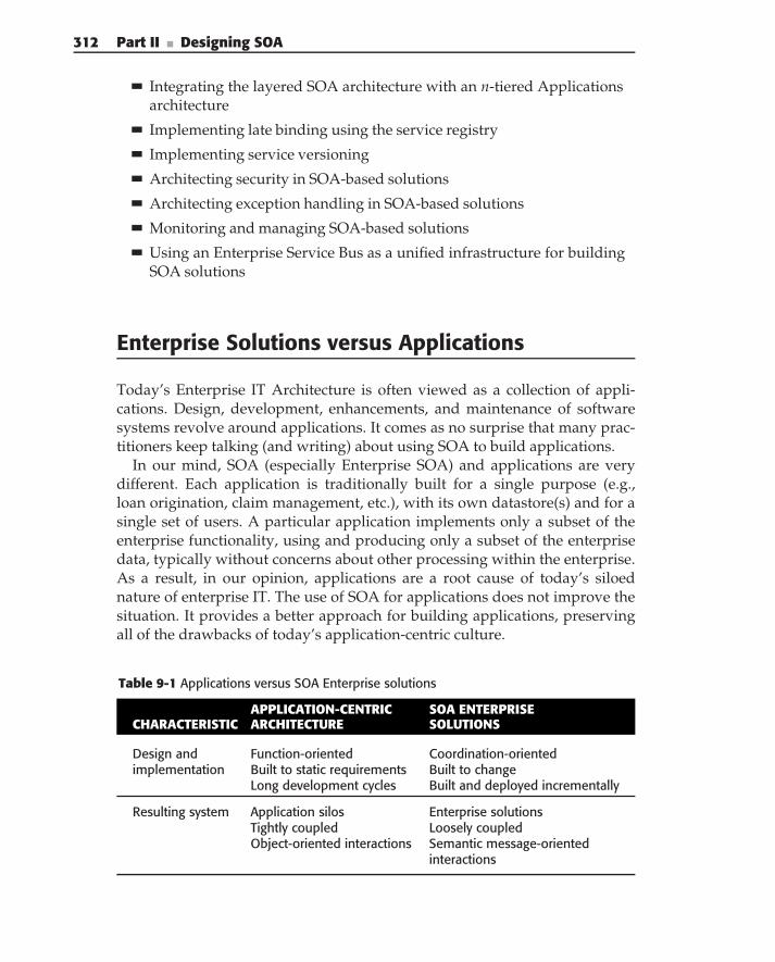
312 Part II ■ Designing SOA
Integrating the layered SOA architecture with an n-tiered Applicationsarchitecture
Implementing late binding using the service registry
Implementing service versioning
Architecting security in SOA-based solutions
Architecting exception handling in SOA-based solutions
Monitoring and managing SOA-based solutions
Using an Enterprise Service Bus as a unified infrastructure for buildingSOA solutions
Enterprise Solutions versus Applications
Today’s Enterprise IT Architecture is often viewed as a collection of appli-cations. Design, development, enhancements, and maintenance of softwaresystems revolve around applications. It comes as no surprise that many prac-titioners keep talking (and writing) about using SOA to build applications.
In our mind, SOA (especially Enterprise SOA) and applications are verydifferent. Each application is traditionally built for a single purpose (e.g.,loan origination, claim management, etc.), with its own datastore(s) and for asingle set of users. A particular application implements only a subset of theenterprise functionality, using and producing only a subset of the enterprisedata, typically without concerns about other processing within the enterprise.As a result, in our opinion, applications are a root cause of today’s siloednature of enterprise IT. The use of SOA for applications does not improve thesituation. It provides a better approach for building applications, preservingall of the drawbacks of today’s application-centric culture.
Table 9-1 Applications versus SOA Enterprise solutions
APPLICATION-CENTRIC SOA ENTERPRISECHARACTERISTIC ARCHITECTURE SOLUTIONS
Design andimplementation
Function-orientedBuilt to static requirementsLong development cycles
Coordination-orientedBuilt to changeBuilt and deployed incrementally
Resulting system Application silosTightly coupledObject-oriented interactions
Enterprise solutionsLoosely coupledSemantic message-orientedinteractions
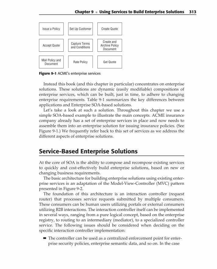
Chapter 9 ■ Using Services to Build Enterprise Solutions 313
Get QuoteRate PolicyMail Policy andDocument
Create QuoteSet Up CustomerIssue a Policy
Create andArchive Policy
Document
Capture Termsand ConditionsAccept Quote
Figure 9-1 ACME’s enterprise services
Instead this book (and this chapter in particular) concentrates on enterprisesolutions. These solutions are dynamic (easily modifiable) compositions ofenterprise services, which can be built, just in time, to adhere to changingenterprise requirements. Table 9-1 summarizes the key differences betweenapplications and Enterprise SOA-based solutions.
Let’s take a look at such a solution. Throughout this chapter we use asimple SOA-based example to illustrate the main concepts. ACME insurancecompany already has a set of enterprise services in place and now needs toassemble them into an enterprise solution for issuing insurance policies. (SeeFigure 9-1.) We frequently refer back to this set of services as we address thedifferent aspects of enterprise solutions.
Service-Based Enterprise Solutions
At the core of SOA is the ability to compose and recompose existing servicesto quickly and cost-effectively build enterprise solutions, based on new orchanging business requirements.
The basic architecture for building enterprise solutions using existing enter-prise services is an adaptation of the Model-View-Controller (MVC) patternpresented in Figure 9-2.
The foundation of this architecture is an interaction controller (requestrouter) that processes service requests submitted by multiple consumers.These consumers can be human users utilizing portals or external consumersutilizing B2B interactions. The interaction controller itself can be implementedin several ways, ranging from a pure logical concept, based on the enterpriseregistry, to routing to an intermediary (mediator), to a specialized controllerservice. The following issues should be considered when deciding on thespecific interaction controller implementation:
The controller can be used as a centralized enforcement point for enter-prise security policies, enterprise semantic data, and so on. In the case
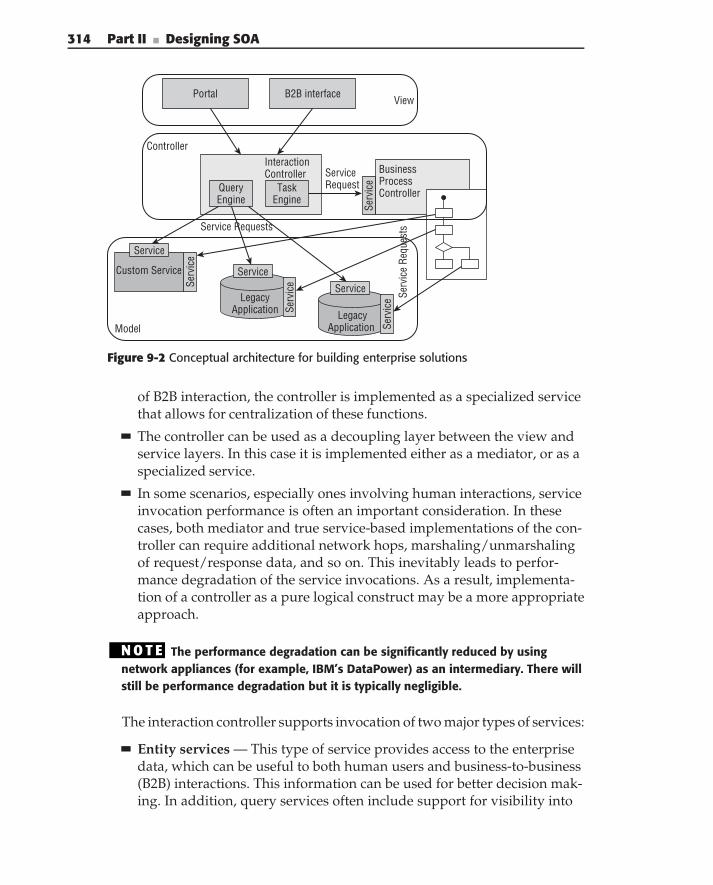
314 Part II ■ Designing SOA
Model
Portal
QueryEngine
Task Engine
InteractionController Business
ProcessController
Serv
ice
Custom Service
Serv
ice
Service
Legacy Application
Service
Serv
ice
ServiceRequest
Service Requests
Serv
ice
Requ
ests
B2B interfaceView
Controller
LegacyApplication
ServiceSe
rvic
e
Figure 9-2 Conceptual architecture for building enterprise solutions
of B2B interaction, the controller is implemented as a specialized servicethat allows for centralization of these functions.
The controller can be used as a decoupling layer between the view andservice layers. In this case it is implemented either as a mediator, or as aspecialized service.
In some scenarios, especially ones involving human interactions, serviceinvocation performance is often an important consideration. In thesecases, both mediator and true service-based implementations of the con-troller can require additional network hops, marshaling/unmarshalingof request/response data, and so on. This inevitably leads to perfor-mance degradation of the service invocations. As a result, implementa-tion of a controller as a pure logical construct may be a more appropriateapproach.
N O T E The performance degradation can be significantly reduced by usingnetwork appliances (for example, IBM’s DataPower) as an intermediary. There willstill be performance degradation but it is typically negligible.
The interaction controller supports invocation of two major types of services:
Entity services — This type of service provides access to the enterprisedata, which can be useful to both human users and business-to-business(B2B) interactions. This information can be used for better decision mak-ing. In addition, query services often include support for visibility into
Chapter 9 ■ Using Services to Build Enterprise Solutions 315
operations of the enterprise — for example, results of business activitymonitoring, service usage statistics, and the like. In the ACME case, anexample of a data service is the Get Quote Service. A customer can usethis service to get the content of the current quote to decide whether hewants to accept it.
Task services — This type of service allows you to start business pro-cesses (service compositions) and interact with those processes (humanactivity tasks). In the case of ACME insurance, Capture Terms and Con-ditions and Accept Quote are examples of such services. Capture Termsand Conditions allows customers to (re)enter insurance information,which causes regeneration of the quote, whereas Accept Quote signalsthe solution implementation to issue the policy.
N O T E As defined in Chapter 2, there are other types of services, but these twoare the ones used by the interaction controller. Other service types are typicallyused for implementation of entity and task services.
Another core component of this architecture is a business process controller(typically a process engine), that orchestrates the execution of services par-ticipating in a given solution. This solution effectively brings together two oftoday’s mainstream technologies — SOA and Business Process Management(BPM). Business services and business processes provide an ideal combinationfor implementing flexible enterprise solutions:
Business services provide a foundation for the creation of business pro-cesses by supporting stable business artifacts, which incorporate busi-ness capabilities and rules that change relatively infrequently.
Business processes support a quick time to market for enterprise solu-tions through easy implementation of fairly fluid business processingand rules, which can change every few months or even weeks.
N O T E For approaches to business process composition, refer to Chapter 8.
Finally, portals and B2B interfaces support the use of these solutions insideand outside the enterprise by human users and automated systems.
Human interaction with the SOA solutions is typically based on portals,providing ‘‘on-the-glass’’ integration of data from many disparate sources(services in this case). Using portals in SOA implementations allows forsimultaneous execution of multiple enterprise solutions (and/or multipleservices from the given solution). For example, a portal allows for simultaneousviewing of the process state, contents of the human task, and additionalsolution-specific data provided through data services. Combining all of this
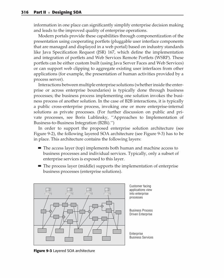
316 Part II ■ Designing SOA
information in one place can significantly simplify enterprise decision makingand leads to the improved quality of enterprise operations.
Modern portals provide these capabilities through componentization of thepresentation using cooperating portlets (pluggable user interface componentsthat are managed and displayed in a web portal) based on industry standardslike Java Specification Request (JSR) 167, which define the implementationand integration of portlets and Web Services Remote Portlets (WSRP). Theseportlets can be either custom built (using Java Server Faces and Web Services)or can support web clipping to aggregate existing user interfaces from otherapplications (for example, the presentation of human activities provided by aprocess server).
Interactions between multiple enterprise solutions (whether inside the enter-prise or across enterprise boundaries) is typically done through businessprocesses; the business process implementing one solution invokes the busi-ness process of another solution. In the case of B2B interactions, it is typicallya public cross-enterprise process, invoking one or more enterprise-internalsolutions as private processes. (For further discussion on public and pri-vate processes, see Boris Lublinsky, ‘‘Approaches to Implementation ofBusiness-to-Business Integration (B2Bi).’’)
In order to support the proposed enterprise solution architecture (seeFigure 9-2), the following layered SOA architecture (see Figure 9-3) has to bein place. This architecture contains the following layers:
The access layer (top) implements both human and machine access tobusiness processes and individual services. Typically, only a subset ofenterprise services is exposed to this layer.
The process layer (middle) supports the implementation of enterprisebusiness processes (enterprise solutions).
Customer facingapplications viewinto enterpriseprocesses
Business ProcessDriven Enterprise
EnterpriseBusiness Services
Figure 9-3 Layered SOA architecture
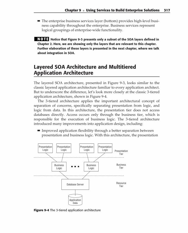
Chapter 9 ■ Using Services to Build Enterprise Solutions 317
The enterprise business services layer (bottom) provides high-level busi-ness capability throughout the enterprise. Business services representlogical groupings of enterprise-wide functionality.
N O T E Notice that Figure 9-3 presents only a subset of the SOA layers defined inChapter 2. Here, we are showing only the layers that are relevant to this chapter.Further elaboration of these layers is presented in the next chapter, where we talkabout integration in SOA.
Layered SOA Architecture and MultitieredApplication Architecture
The layered SOA architecture, presented in Figure 9-3, looks similar to theclassic layered application architecture familiar to every application architect.But to underscore the difference, let’s look more closely at the classic 3-tieredapplication architecture, shown in Figure 9-4.
The 3-tiered architecture applies the important architectural concept ofseparation of concerns, specifically separating presentation from logic, andlogic from data. In this architecture, the presentation tier does not accessdatabases directly. Access occurs only through the business tier, which isresponsible for the execution of business logic. The 3-tiered architectureintroduced many improvements into application design, including:
Improved application flexibility through a better separation betweenpresentation and business logic. With this architecture, the presentation
ApplicationData
Database Server
BusinessLogic
BusinessLogic
PresentationLogic
PresentationLogic
PresentationLogic
PresentationLogic
ResourceTier
BusinessTier
PresentationTier
Figure 9-4 The 3-tiered application architecture
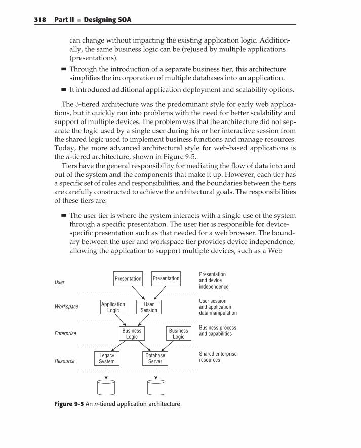
318 Part II ■ Designing SOA
can change without impacting the existing application logic. Addition-ally, the same business logic can be (re)used by multiple applications(presentations).
Through the introduction of a separate business tier, this architecturesimplifies the incorporation of multiple databases into an application.
It introduced additional application deployment and scalability options.
The 3-tiered architecture was the predominant style for early web applica-tions, but it quickly ran into problems with the need for better scalability andsupport of multiple devices. The problem was that the architecture did not sep-arate the logic used by a single user during his or her interactive session fromthe shared logic used to implement business functions and manage resources.Today, the more advanced architectural style for web-based applications isthe n-tiered architecture, shown in Figure 9-5.
Tiers have the general responsibility for mediating the flow of data into andout of the system and the components that make it up. However, each tier hasa specific set of roles and responsibilities, and the boundaries between the tiersare carefully constructed to achieve the architectural goals. The responsibilitiesof these tiers are:
The user tier is where the system interacts with a single use of the systemthrough a specific presentation. The user tier is responsible for device-specific presentation such as that needed for a web browser. The bound-ary between the user and workspace tier provides device independence,allowing the application to support multiple devices, such as a Web
User
Workspace
Enterprise
Resource
Presentation Presentation
User Session
Application Logic
Business Logic
Business Logic
Database Server
Legacy System
Presentation and device independence
User session and application data manipulation
Business process and capabilities
Shared enterpriseresources
Figure 9-5 An n-tiered application architecture
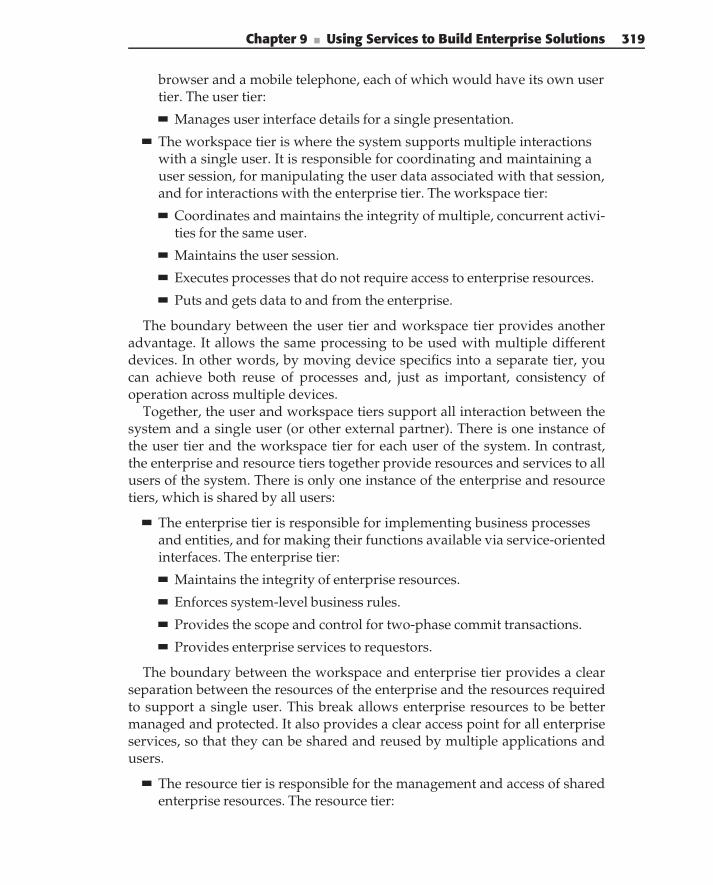
Chapter 9 ■ Using Services to Build Enterprise Solutions 319
browser and a mobile telephone, each of which would have its own usertier. The user tier:
Manages user interface details for a single presentation.
The workspace tier is where the system supports multiple interactionswith a single user. It is responsible for coordinating and maintaining auser session, for manipulating the user data associated with that session,and for interactions with the enterprise tier. The workspace tier:
Coordinates and maintains the integrity of multiple, concurrent activi-ties for the same user.
Maintains the user session.
Executes processes that do not require access to enterprise resources.
Puts and gets data to and from the enterprise.
The boundary between the user tier and workspace tier provides anotheradvantage. It allows the same processing to be used with multiple differentdevices. In other words, by moving device specifics into a separate tier, youcan achieve both reuse of processes and, just as important, consistency ofoperation across multiple devices.
Together, the user and workspace tiers support all interaction between thesystem and a single user (or other external partner). There is one instance ofthe user tier and the workspace tier for each user of the system. In contrast,the enterprise and resource tiers together provide resources and services to allusers of the system. There is only one instance of the enterprise and resourcetiers, which is shared by all users:
The enterprise tier is responsible for implementing business processesand entities, and for making their functions available via service-orientedinterfaces. The enterprise tier:
Maintains the integrity of enterprise resources.
Enforces system-level business rules.
Provides the scope and control for two-phase commit transactions.
Provides enterprise services to requestors.
The boundary between the workspace and enterprise tier provides a clearseparation between the resources of the enterprise and the resources requiredto support a single user. This break allows enterprise resources to be bettermanaged and protected. It also provides a clear access point for all enterpriseservices, so that they can be shared and reused by multiple applications andusers.
The resource tier is responsible for the management and access of sharedenterprise resources. The resource tier:
320 Part II ■ Designing SOA
Provides access to shared resources of the enterprise.
Provides access to enterprise data and databases.
Provides access to legacy systems.
The boundary between the resource and enterprise tier provides a separationbetween the technology specifics of the resources and the enterprise’s use (aswell as the service’s representation) of them. This allows changes in theresource or enterprise tiers to occur independently, without disruption to theother.
Services can be present in most of the tiers of the n-tier architecture (otherthan presentation). However, a common mistake is to misunderstand therelationship between service type and the roles and responsibilities of thetiers; the result is much like the 3-tier architecture that did not separatethe responsibilities of different types of logic. Figure 9-6 illustrates how thedifferent types of services line up with the tiers of an n-tiered architecture.
Let’s look at each tier, its responsibility, and the types of services thatare used to implement them. Starting at the top, the presentation tier is notimplemented with services. Next is the workspace tier. This tier is responsiblefor coordinating and maintaining all activities for a single user, and beingthe intermediary between the presentation channel and the enterprise. Inother words, the tier is responsible for coordinating and presenting businesscapabilities though a delivery channel. It fulfills a user request in the mosteffective manner based on presentation device, user role, user context, anduser preferences. This requires a variety of different functions, many of whichcan be implemented as services. Some typical services at this tier are profile,
User
Workspace
Enterprise
Resource
Presentation
Domain Service
Business Service
Presentation
Coordinate andpresent business capabilities through a delivery channel using presentation services
Implement business process andcapabilities composedfrom business, domain,and utility services
Expose shared enterprise resources as integration services
Distribution Service
Application Service
Utility Service
Presentation Service
Integration Service
Integration Service
Integration Service
Utility Service
Business Process
Presentation
Figure 9-6 Service types and tiers
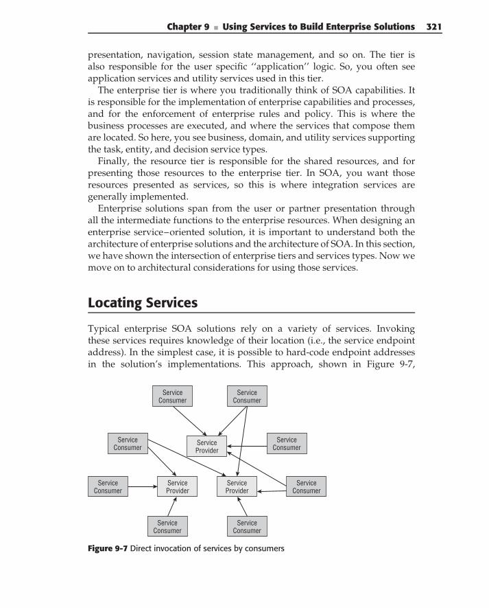
Chapter 9 ■ Using Services to Build Enterprise Solutions 321
presentation, navigation, session state management, and so on. The tier isalso responsible for the user specific ‘‘application’’ logic. So, you often seeapplication services and utility services used in this tier.
The enterprise tier is where you traditionally think of SOA capabilities. Itis responsible for the implementation of enterprise capabilities and processes,and for the enforcement of enterprise rules and policy. This is where thebusiness processes are executed, and where the services that compose themare located. So here, you see business, domain, and utility services supportingthe task, entity, and decision service types.
Finally, the resource tier is responsible for the shared resources, and forpresenting those resources to the enterprise tier. In SOA, you want thoseresources presented as services, so this is where integration services aregenerally implemented.
Enterprise solutions span from the user or partner presentation throughall the intermediate functions to the enterprise resources. When designing anenterprise service–oriented solution, it is important to understand both thearchitecture of enterprise solutions and the architecture of SOA. In this section,we have shown the intersection of enterprise tiers and services types. Now wemove on to architectural considerations for using those services.
Locating Services
Typical enterprise SOA solutions rely on a variety of services. Invokingthese services requires knowledge of their location (i.e., the service endpointaddress). In the simplest case, it is possible to hard-code endpoint addressesin the solution’s implementations. This approach, shown in Figure 9-7,
ServiceConsumer
ServiceConsumer
ServiceConsumer
ServiceConsumer
ServiceConsumer
ServiceConsumer
ServiceConsumer
ServiceConsumer
ServiceProvider
ServiceProvider
ServiceProvider
Figure 9-7 Direct invocation of services by consumers
322 Part II ■ Designing SOA
introduces tight coupling between the solution’s implementations and theservice’s location (location coupling).
N O T E Both Java and .NET tooling generate Web Service consumers withendpoint addresses encoded directly in the implementation. As a result, it comesas no surprise that many current systems resemble Figure 9-7.
Accommodating service endpoint address changes in the implementationrequires modifications to the solution’s implementations. This process isprone to error and scales poorly as the number of services and solutionsgrows. Accounting for multiple deployment environments (e.g., development,testing, quality assurance, production) only compounds the problem.
Externalizing the endpoint addresses into configuration files offers a poten-tial improvement. This approach is more flexible because it removes endpointaddresses from the solution’s code and externalizes them in configurationfiles. This allows the solution to accommodate address changes without anycode modifications. However, this option also runs into scalability problemsas the numbers of consumers and services (and consequently of configurationfiles) grow.
Using an intermediary that dynamically resolves service queries into end-point addresses and invocation policies — a service registry — provides themost flexible and maintainable solution for this problem. The service registrycontains all the information about service deployments, their locations, andthe policies associated with invocation at each location.
ROLE OF THE SERVICE REGISTRY
Steve Vinoski, in his article ‘‘The social side of services,’’ (January 2006), pointsout that the usefulness of the service registry increases with the number ofservices:
‘‘The technical line of reasoning for reaching and managing this critical masstypically goes like this:
1. For services to operate as a collective, they have to know about each other.
2. For services to know about each other, they must either be hardwiredtogether or be able to dynamically find one another.
3. Hardwiring would be bad, as it implies high coupling and potential diffi-culties in replacing one service implementation with another somewheredown the line.
4. To facilitate dynamic discovery, then, services need a place that they canadvertise themselves and meet other services.
5. Of course, a registry!’’
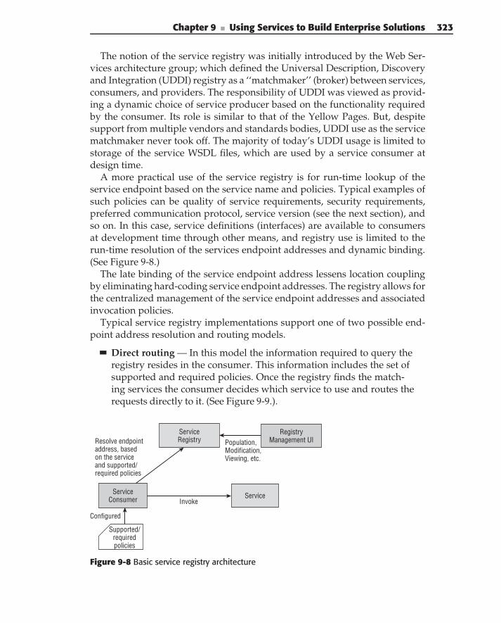
Chapter 9 ■ Using Services to Build Enterprise Solutions 323
The notion of the service registry was initially introduced by the Web Ser-vices architecture group; which defined the Universal Description, Discoveryand Integration (UDDI) registry as a ‘‘matchmaker’’ (broker) between services,consumers, and providers. The responsibility of UDDI was viewed as provid-ing a dynamic choice of service producer based on the functionality requiredby the consumer. Its role is similar to that of the Yellow Pages. But, despitesupport from multiple vendors and standards bodies, UDDI use as the servicematchmaker never took off. The majority of today’s UDDI usage is limited tostorage of the service WSDL files, which are used by a service consumer atdesign time.
A more practical use of the service registry is for run-time lookup of theservice endpoint based on the service name and policies. Typical examples ofsuch policies can be quality of service requirements, security requirements,preferred communication protocol, service version (see the next section), andso on. In this case, service definitions (interfaces) are available to consumersat development time through other means, and registry use is limited to therun-time resolution of the services endpoint addresses and dynamic binding.(See Figure 9-8.)
The late binding of the service endpoint address lessens location couplingby eliminating hard-coding service endpoint addresses. The registry allows forthe centralized management of the service endpoint addresses and associatedinvocation policies.
Typical service registry implementations support one of two possible end-point address resolution and routing models.
Direct routing — In this model the information required to query theregistry resides in the consumer. This information includes the set ofsupported and required policies. Once the registry finds the match-ing services the consumer decides which service to use and routes therequests directly to it. (See Figure 9-9.).
ServiceRegistry Population,
Modification,Viewing, etc.
RegistryManagement UI
ServiceInvoke
Configured
ServiceConsumer
Supported/requiredpolicies
Resolve endpointaddress, basedon the serviceand supported/required policies
Figure 9-8 Basic service registry architecture
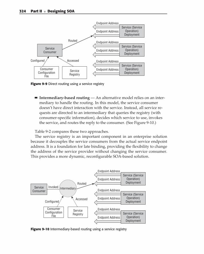
324 Part II ■ Designing SOA
ServiceConsumer
ConsumerConfiguration
File
Configured Accessed
Routed
Endpoint Address
Endpoint Address
ServiceRegistry
Service (ServiceOperation)
Deployment
Endpoint Address
Endpoint AddressService (Service
Operation)Deployment
Endpoint Address
Endpoint AddressService (Service
Operation)Deployment
Figure 9-9 Direct routing using a service registry
Intermediary-based routing — An alternative model relies on an inter-mediary to handle the routing. In this model, the service consumerdoesn’t have direct interaction with the service. Instead, all service re-quests are directed to an intermediary that queries the registry (withconsumer-specific information), decides which service to use, invokesthe service, and routes the reply to the consumer. (See Figure 9-10.)
Table 9-2 compares these two approaches.The service registry is an important component in an enterprise solution
because it decouples the service consumers from the actual service endpointaddress. It is a foundation for late binding, providing the flexibility to changethe address of the service provider without changing the service consumer.This provides a more dynamic, reconfigurable SOA-based solution.
ServiceConsumer
ConsumerConfiguration
File
ServiceRegistry
ConfiguredAccessed
RoutedInvoked Intermediary
Endpoint Address
Endpoint AddressService (Service
Operation)Deployment
Endpoint Address
Endpoint AddressService (Service
Operation)Deployment
Endpoint Address
Endpoint AddressService (Service
Operation)Deployment
Figure 9-10 Intermediary-based routing using a service registry
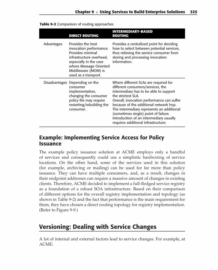
Chapter 9 ■ Using Services to Build Enterprise Solutions 325
Table 9-2 Comparison of routing approaches
INTERMEDIARY-BASEDDIRECT ROUTING ROUTING
Advantages Provides the bestinvocation performance.Provides minimalinfrastructure overhead,especially in the casewhere Message OrientedMiddleware (MOM) isused as a transport.
Provides a centralized point for decidinghow to select between potential services,thus relieving the service consumer fromstoring and processing invocationinformation.
Disadvantages Depending on theconsumerimplementation,changing the consumerpolicy file may requirerestarting/rebuilding theconsumer.
Where different SLAs are required fordifferent consumers/services, theintermediary has to be able to supportthe strictest SLA.Overall, invocation performance can sufferbecause of the additional network hop.The intermediary represents an additional(sometimes single) point of failure.Introduction of an intermediary usuallyrequires additional infrastructure.
Example: Implementing Service Access for PolicyIssuanceThe example policy issuance solution at ACME employs only a handfulof services and consequently could use a simplistic hardwiring of servicelocations. On the other hand, some of the services used in this solution(for example, archiving or mailing) can be used for far more than policyissuance. They can have multiple consumers, and, as a result, changes intheir endpoint addresses can require a massive amount of changes in existingclients. Therefore, ACME decided to implement a full-fledged service registryas a foundation of a robust SOA infrastructure. Based on their comparisonof different options for the overall registry implementation and topology (asshown in Table 9-2) and the fact that performance is the main requirement forthem, they have chosen a direct routing topology for registry implementation.(Refer to Figure 9-9.)
Versioning: Dealing with Service Changes
A lot of internal and external factors lead to service changes. For example, atACME:
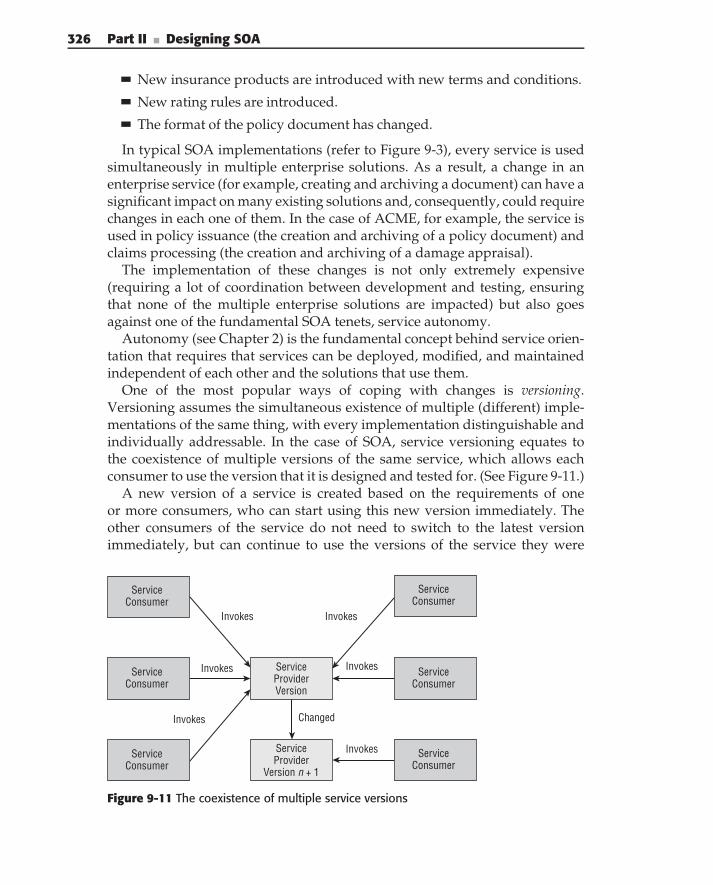
326 Part II ■ Designing SOA
New insurance products are introduced with new terms and conditions.
New rating rules are introduced.
The format of the policy document has changed.
In typical SOA implementations (refer to Figure 9-3), every service is usedsimultaneously in multiple enterprise solutions. As a result, a change in anenterprise service (for example, creating and archiving a document) can have asignificant impact on many existing solutions and, consequently, could requirechanges in each one of them. In the case of ACME, for example, the service isused in policy issuance (the creation and archiving of a policy document) andclaims processing (the creation and archiving of a damage appraisal).
The implementation of these changes is not only extremely expensive(requiring a lot of coordination between development and testing, ensuringthat none of the multiple enterprise solutions are impacted) but also goesagainst one of the fundamental SOA tenets, service autonomy.
Autonomy (see Chapter 2) is the fundamental concept behind service orien-tation that requires that services can be deployed, modified, and maintainedindependent of each other and the solutions that use them.
One of the most popular ways of coping with changes is versioning.Versioning assumes the simultaneous existence of multiple (different) imple-mentations of the same thing, with every implementation distinguishable andindividually addressable. In the case of SOA, service versioning equates tothe coexistence of multiple versions of the same service, which allows eachconsumer to use the version that it is designed and tested for. (See Figure 9-11.)
A new version of a service is created based on the requirements of oneor more consumers, who can start using this new version immediately. Theother consumers of the service do not need to switch to the latest versionimmediately, but can continue to use the versions of the service they were
ServiceProviderVersion
ServiceProvider
Version n + 1
Invokes Invokes
Invokes
Invokes
Invokes
Invokes
Changed
ServiceConsumer
ServiceConsumer
ServiceConsumer
ServiceConsumer
ServiceConsumer
ServiceConsumer
Figure 9-11 The coexistence of multiple service versions
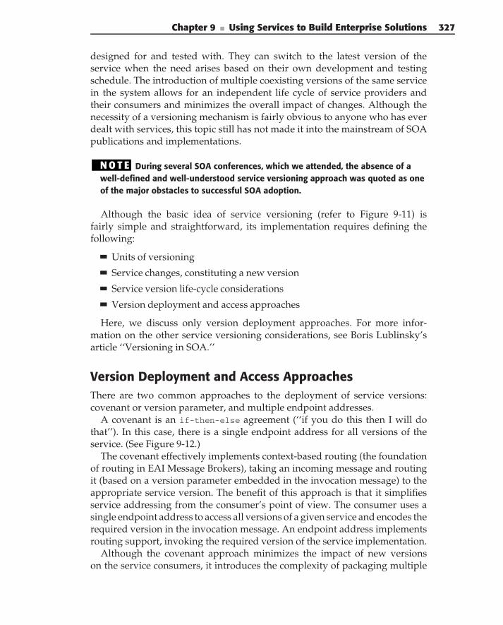
Chapter 9 ■ Using Services to Build Enterprise Solutions 327
designed for and tested with. They can switch to the latest version of theservice when the need arises based on their own development and testingschedule. The introduction of multiple coexisting versions of the same servicein the system allows for an independent life cycle of service providers andtheir consumers and minimizes the overall impact of changes. Although thenecessity of a versioning mechanism is fairly obvious to anyone who has everdealt with services, this topic still has not made it into the mainstream of SOApublications and implementations.
N O T E During several SOA conferences, which we attended, the absence of awell-defined and well-understood service versioning approach was quoted as oneof the major obstacles to successful SOA adoption.
Although the basic idea of service versioning (refer to Figure 9-11) isfairly simple and straightforward, its implementation requires defining thefollowing:
Units of versioning
Service changes, constituting a new version
Service version life-cycle considerations
Version deployment and access approaches
Here, we discuss only version deployment approaches. For more infor-mation on the other service versioning considerations, see Boris Lublinsky’sarticle ‘‘Versioning in SOA.’’
Version Deployment and Access ApproachesThere are two common approaches to the deployment of service versions:covenant or version parameter, and multiple endpoint addresses.
A covenant is an if-then-else agreement (‘‘if you do this then I will dothat’’). In this case, there is a single endpoint address for all versions of theservice. (See Figure 9-12.)
The covenant effectively implements context-based routing (the foundationof routing in EAI Message Brokers), taking an incoming message and routingit (based on a version parameter embedded in the invocation message) to theappropriate service version. The benefit of this approach is that it simplifiesservice addressing from the consumer’s point of view. The consumer uses asingle endpoint address to access all versions of a given service and encodes therequired version in the invocation message. An endpoint address implementsrouting support, invoking the required version of the service implementation.
Although the covenant approach minimizes the impact of new versionson the service consumers, it introduces the complexity of packaging multiple
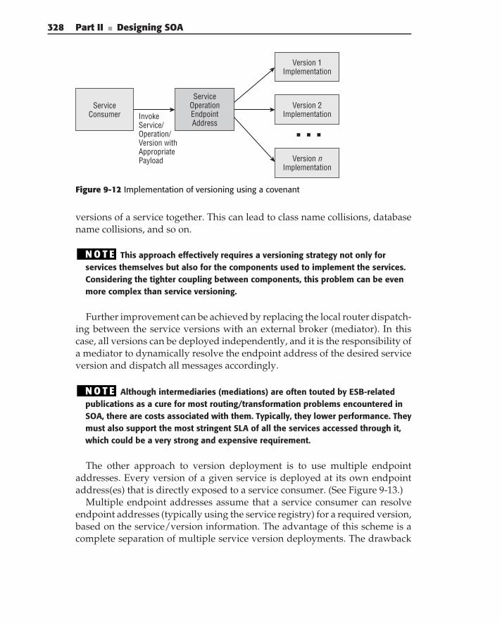
328 Part II ■ Designing SOA
InvokeService/Operation/Version withAppropriatePayload Version n
Implementation
ServiceConsumer
ServiceOperationEndpointAddress
Version 1 Implementation
Version 2 Implementation
Figure 9-12 Implementation of versioning using a covenant
versions of a service together. This can lead to class name collisions, databasename collisions, and so on.
N O T E This approach effectively requires a versioning strategy not only forservices themselves but also for the components used to implement the services.Considering the tighter coupling between components, this problem can be evenmore complex than service versioning.
Further improvement can be achieved by replacing the local router dispatch-ing between the service versions with an external broker (mediator). In thiscase, all versions can be deployed independently, and it is the responsibility ofa mediator to dynamically resolve the endpoint address of the desired serviceversion and dispatch all messages accordingly.
N O T E Although intermediaries (mediations) are often touted by ESB-relatedpublications as a cure for most routing/transformation problems encountered inSOA, there are costs associated with them. Typically, they lower performance. Theymust also support the most stringent SLA of all the services accessed through it,which could be a very strong and expensive requirement.
The other approach to version deployment is to use multiple endpointaddresses. Every version of a given service is deployed at its own endpointaddress(es) that is directly exposed to a service consumer. (See Figure 9-13.)
Multiple endpoint addresses assume that a service consumer can resolveendpoint addresses (typically using the service registry) for a required version,based on the service/version information. The advantage of this scheme is acomplete separation of multiple service version deployments. The drawback
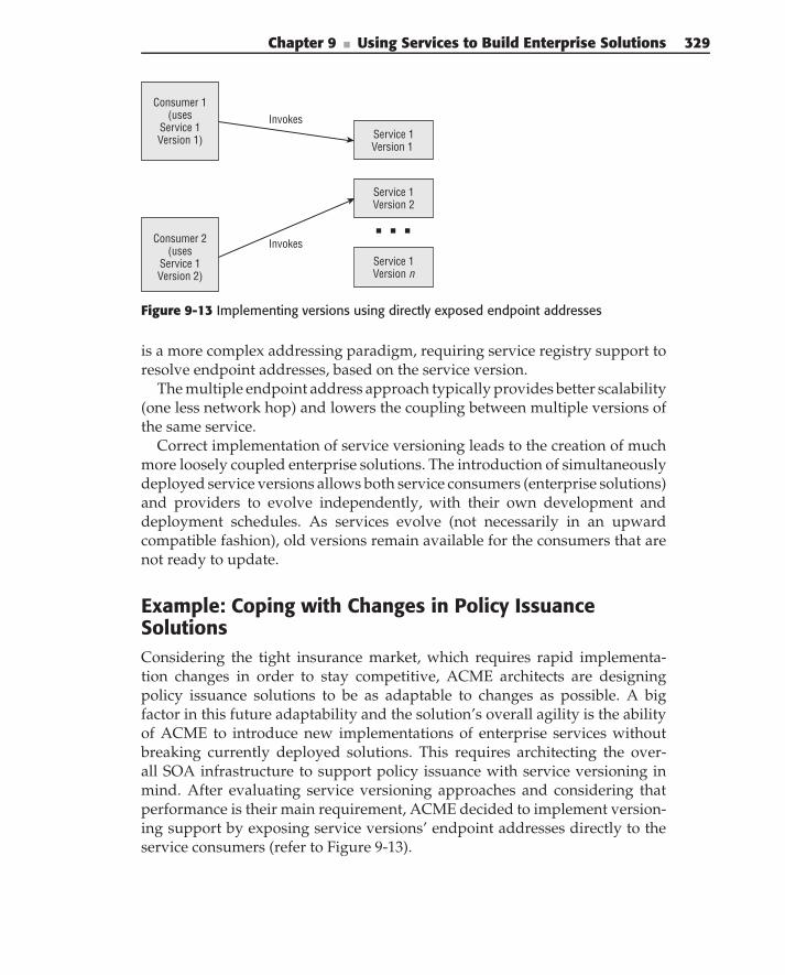
Chapter 9 ■ Using Services to Build Enterprise Solutions 329
Consumer 1 (uses
Service 1Version 1)
Consumer 2 (uses
Service 1 Version 2)
Invokes
Invokes
Service 1 Version 1
Service 1 Version 2
Service 1 Version n
Figure 9-13 Implementing versions using directly exposed endpoint addresses
is a more complex addressing paradigm, requiring service registry support toresolve endpoint addresses, based on the service version.
The multiple endpoint address approach typically provides better scalability(one less network hop) and lowers the coupling between multiple versions ofthe same service.
Correct implementation of service versioning leads to the creation of muchmore loosely coupled enterprise solutions. The introduction of simultaneouslydeployed service versions allows both service consumers (enterprise solutions)and providers to evolve independently, with their own development anddeployment schedules. As services evolve (not necessarily in an upwardcompatible fashion), old versions remain available for the consumers that arenot ready to update.
Example: Coping with Changes in Policy IssuanceSolutionsConsidering the tight insurance market, which requires rapid implementa-tion changes in order to stay competitive, ACME architects are designingpolicy issuance solutions to be as adaptable to changes as possible. A bigfactor in this future adaptability and the solution’s overall agility is the abilityof ACME to introduce new implementations of enterprise services withoutbreaking currently deployed solutions. This requires architecting the over-all SOA infrastructure to support policy issuance with service versioning inmind. After evaluating service versioning approaches and considering thatperformance is their main requirement, ACME decided to implement version-ing support by exposing service versions’ endpoint addresses directly to theservice consumers (refer to Figure 9-13).
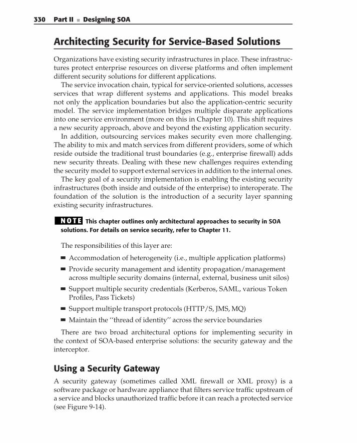
330 Part II ■ Designing SOA
Architecting Security for Service-Based Solutions
Organizations have existing security infrastructures in place. These infrastruc-tures protect enterprise resources on diverse platforms and often implementdifferent security solutions for different applications.
The service invocation chain, typical for service-oriented solutions, accessesservices that wrap different systems and applications. This model breaksnot only the application boundaries but also the application-centric securitymodel. The service implementation bridges multiple disparate applicationsinto one service environment (more on this in Chapter 10). This shift requiresa new security approach, above and beyond the existing application security.
In addition, outsourcing services makes security even more challenging.The ability to mix and match services from different providers, some of whichreside outside the traditional trust boundaries (e.g., enterprise firewall) addsnew security threats. Dealing with these new challenges requires extendingthe security model to support external services in addition to the internal ones.
The key goal of a security implementation is enabling the existing securityinfrastructures (both inside and outside of the enterprise) to interoperate. Thefoundation of the solution is the introduction of a security layer spanningexisting security infrastructures.
N O T E This chapter outlines only architectural approaches to security in SOAsolutions. For details on service security, refer to Chapter 11.
The responsibilities of this layer are:
Accommodation of heterogeneity (i.e., multiple application platforms)
Provide security management and identity propagation/managementacross multiple security domains (internal, external, business unit silos)
Support multiple security credentials (Kerberos, SAML, various TokenProfiles, Pass Tickets)
Support multiple transport protocols (HTTP/S, JMS, MQ)
Maintain the ‘‘thread of identity’’ across the service boundaries
There are two broad architectural options for implementing security inthe context of SOA-based enterprise solutions: the security gateway and theinterceptor.
Using a Security GatewayA security gateway (sometimes called XML firewall or XML proxy) is asoftware package or hardware appliance that filters service traffic upstream ofa service and blocks unauthorized traffic before it can reach a protected service(see Figure 9-14).
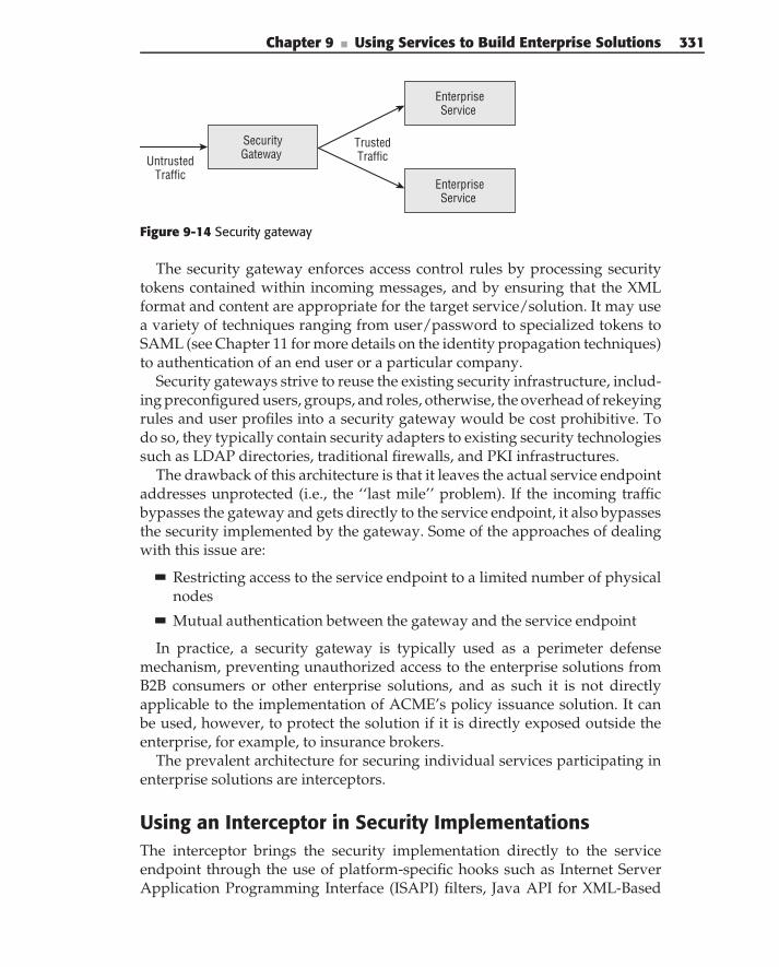
Chapter 9 ■ Using Services to Build Enterprise Solutions 331
Security Gateway
Enterprise Service
Enterprise Service
Trusted TrafficUntrusted
Traffic
Figure 9-14 Security gateway
The security gateway enforces access control rules by processing securitytokens contained within incoming messages, and by ensuring that the XMLformat and content are appropriate for the target service/solution. It may usea variety of techniques ranging from user/password to specialized tokens toSAML (see Chapter 11 for more details on the identity propagation techniques)to authentication of an end user or a particular company.
Security gateways strive to reuse the existing security infrastructure, includ-ing preconfigured users, groups, and roles, otherwise, the overhead of rekeyingrules and user profiles into a security gateway would be cost prohibitive. Todo so, they typically contain security adapters to existing security technologiessuch as LDAP directories, traditional firewalls, and PKI infrastructures.
The drawback of this architecture is that it leaves the actual service endpointaddresses unprotected (i.e., the ‘‘last mile’’ problem). If the incoming trafficbypasses the gateway and gets directly to the service endpoint, it also bypassesthe security implemented by the gateway. Some of the approaches of dealingwith this issue are:
Restricting access to the service endpoint to a limited number of physicalnodes
Mutual authentication between the gateway and the service endpoint
In practice, a security gateway is typically used as a perimeter defensemechanism, preventing unauthorized access to the enterprise solutions fromB2B consumers or other enterprise solutions, and as such it is not directlyapplicable to the implementation of ACME’s policy issuance solution. It canbe used, however, to protect the solution if it is directly exposed outside theenterprise, for example, to insurance brokers.
The prevalent architecture for securing individual services participating inenterprise solutions are interceptors.
Using an Interceptor in Security ImplementationsThe interceptor brings the security implementation directly to the serviceendpoint through the use of platform-specific hooks such as Internet ServerApplication Programming Interface (ISAPI) filters, Java API for XML-Based
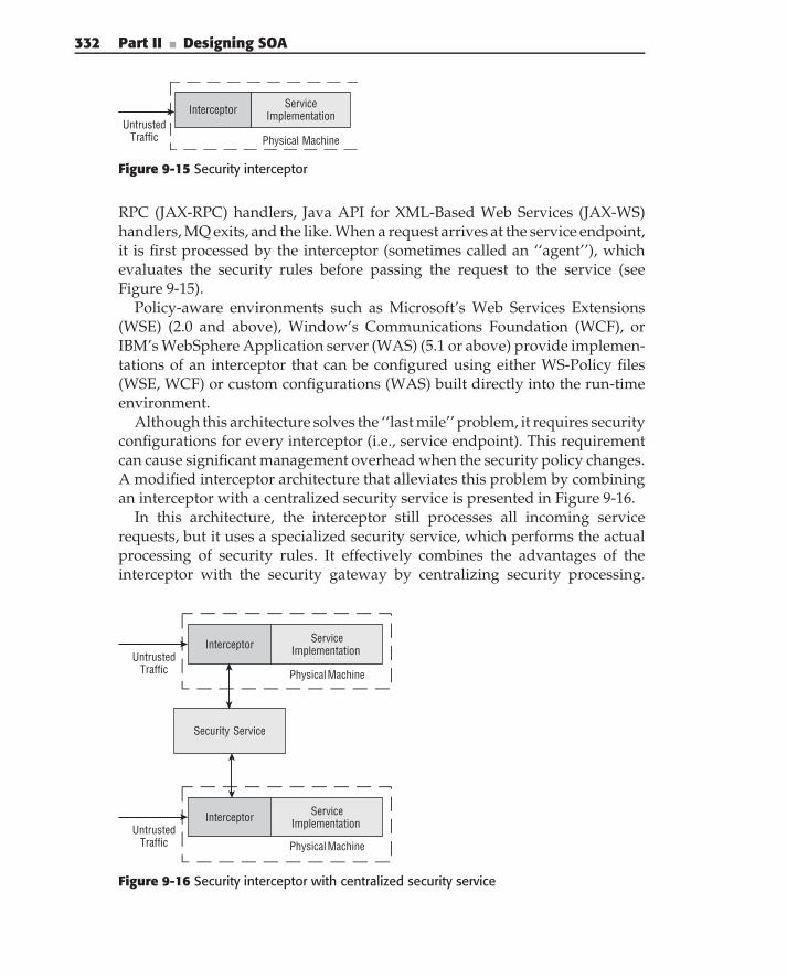
332 Part II ■ Designing SOA
ServiceImplementationInterceptor
Untrusted Traffic Physical Machine
Figure 9-15 Security interceptor
RPC (JAX-RPC) handlers, Java API for XML-Based Web Services (JAX-WS)handlers, MQ exits, and the like. When a request arrives at the service endpoint,it is first processed by the interceptor (sometimes called an ‘‘agent’’), whichevaluates the security rules before passing the request to the service (seeFigure 9-15).
Policy-aware environments such as Microsoft’s Web Services Extensions(WSE) (2.0 and above), Window’s Communications Foundation (WCF), orIBM’s WebSphere Application server (WAS) (5.1 or above) provide implemen-tations of an interceptor that can be configured using either WS-Policy files(WSE, WCF) or custom configurations (WAS) built directly into the run-timeenvironment.
Although this architecture solves the ‘‘last mile’’ problem, it requires securityconfigurations for every interceptor (i.e., service endpoint). This requirementcan cause significant management overhead when the security policy changes.A modified interceptor architecture that alleviates this problem by combiningan interceptor with a centralized security service is presented in Figure 9-16.
In this architecture, the interceptor still processes all incoming servicerequests, but it uses a specialized security service, which performs the actualprocessing of security rules. It effectively combines the advantages of theinterceptor with the security gateway by centralizing security processing.
Security Service
Service Implementation Interceptor
Untrusted Traffic
Service Implementation Interceptor
Untrusted Traffic
Physical Machine
Physical Machine
Figure 9-16 Security interceptor with centralized security service
Chapter 9 ■ Using Services to Build Enterprise Solutions 333
Centralization allows the computationally intensive functions such as cryptog-raphy to be implemented in dedicated hosts (appliances). This minimizes theimpact on invocation performance and provides a central point of managementand reporting for service security processing.
Example: Architecting Security for Policy IssuanceSolutionsServices participating in a policy issuance solution exchange a significantamount of sensitive information. As a result, a proper security implementationis paramount for this solution.
Using an interceptor is the most appropriate approach for the securityimplementation of the policy issuance solution. Every participating service(refer to Figure 9-1) should contain an interceptor supporting (and enforcing)the service’s security policy. For more on policy enforcement, see Chapters 11and 12.
For ACME’s services implemented in Java, this interceptor can be imple-mented as a JAX-WS handler, invoked as part of the service invocation. Forservices implemented using WCF, programmatic WCF security can be used asa security interceptor.
Exception Handling and Logging in EnterpriseSolutions
In the ideal world nothing ever fails, service invocations always completesuccessfully and return the required results. Unfortunately, in reality, servicesand solutions built using services may and do fail.
Let’s consider a rate policy service, for example. A wide variety of problemscan cause the execution of this service to fail, including failures of the serviceitself; for example, because of the validation of the incoming parameters, orjust an implementation bug, or a communication problem, where the servicecannot be reached, or the implementation cannot reach an underlying database.
A widely adopted mechanism for dealing with failures is exception han-dling, encompassing capturing and logging errors and choosing an alternativeexecution path in case of failures. It has become a standard mechanism inapplication development, where it is typically based on the ability of applica-tion designers and developers to anticipate the possible exception conditionsand appropriately instrument code to handle them at run time.
N O T E The implementation of exceptions is usually based on try/catch blocks(supported by the majority of today’s programming languages, for example, Java orC#), allowing you to determine the exception and use logging mechanisms to storeexceptions for follow-up analysis.
334 Part II ■ Designing SOA
This approach relies on the following assumptions:
The application is designed as a whole in all of its completeness, includ-ing all of the possible exception situations. This means that all of theexecution paths of applications can be fully defined and, as a result, com-pletely tested by an application team.
The application is executed on a single machine (limited set of machines)and reports all of the exceptions in the local log files using standardizedexceptions reporting schemas.
Changes in the application are administered centrally, thus providinga single application development team with complete control over allchanges.
Implementing these exception-handling approaches becomes significantlymore complex in the case of distributed systems due to the following:
Exceptions can be caused not only by the application code itself but alsoby the infrastructure malfunctioning, which makes it harder to analyzeall possible exception scenarios.
Exception logs are spread between multiple physical machines, whichmake their reconciliation significantly more complex.
In the context of SOA, characteristics like loose coupling (both organizationaland technological), autonomy, and reliance on existing applications for theimplementation of the business capabilities complicate exception handlingeven more.
Every service is designed, implemented, and maintained by itself and canbe used in multiple enterprise solutions, which might not be known at thetime of the service design. As a result, the exception-handling implementationfor a given service usually revolves around processing and logging exceptionsthat are local to the service implementation and, when they cannot be resolvedlocally, reporting them to the service consumer. If special measures are nottaken, this results in ‘‘islands of exception handling’’ (see Figure 9-17).
As defined in Sean Fitts’s September 2005 article ‘‘When exceptions arethe rule: Achieving reliable and traceable service oriented architectures,’’exception processing in SOA introduces the following unique challenges:
The distributed and heterogeneous nature of SOA makes it particularlyprone to failures, causing exceptions at multiple levels. System-levelexceptions result from the messaging, communications, and other infra-structure failures. Application-level exceptions result from incorrectmessage semantics or logical errors within the application. Business-levelexceptions result in violation of best practices, compliance laws, regula-tions, or business policies mandated by business managers.
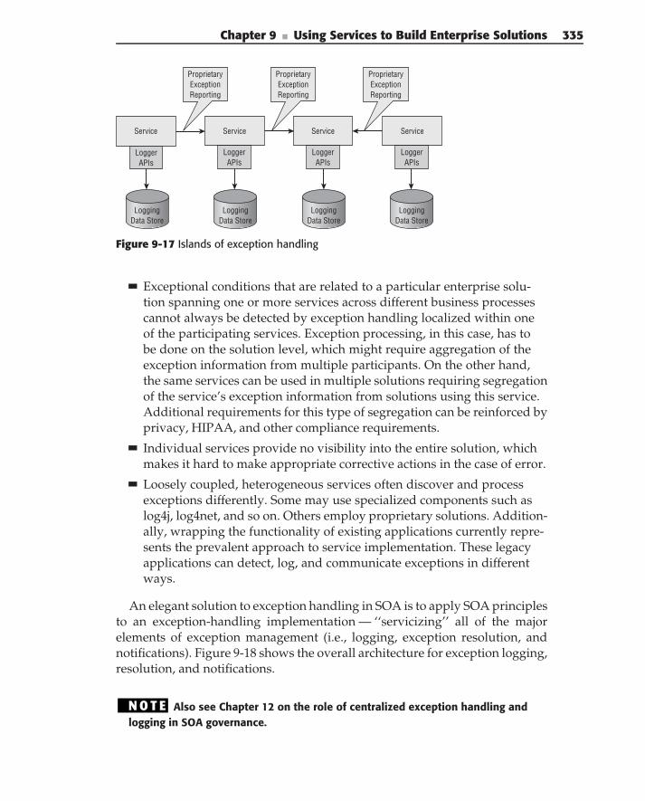
Chapter 9 ■ Using Services to Build Enterprise Solutions 335
Service Service Service Service
LoggingData Store
LoggingData Store
LoggingData Store
LoggingData Store
ProprietaryExceptionReporting
ProprietaryExceptionReporting
ProprietaryExceptionReporting
Logger APIs
Logger APIs
Logger APIs
Logger APIs
Figure 9-17 Islands of exception handling
Exceptional conditions that are related to a particular enterprise solu-tion spanning one or more services across different business processescannot always be detected by exception handling localized within oneof the participating services. Exception processing, in this case, has tobe done on the solution level, which might require aggregation of theexception information from multiple participants. On the other hand,the same services can be used in multiple solutions requiring segregationof the service’s exception information from solutions using this service.Additional requirements for this type of segregation can be reinforced byprivacy, HIPAA, and other compliance requirements.
Individual services provide no visibility into the entire solution, whichmakes it hard to make appropriate corrective actions in the case of error.
Loosely coupled, heterogeneous services often discover and processexceptions differently. Some may use specialized components such aslog4j, log4net, and so on. Others employ proprietary solutions. Addition-ally, wrapping the functionality of existing applications currently repre-sents the prevalent approach to service implementation. These legacyapplications can detect, log, and communicate exceptions in differentways.
An elegant solution to exception handling in SOA is to apply SOA principlesto an exception-handling implementation — ‘‘servicizing’’ all of the majorelements of exception management (i.e., logging, exception resolution, andnotifications). Figure 9-18 shows the overall architecture for exception logging,resolution, and notifications.
N O T E Also see Chapter 12 on the role of centralized exception handling andlogging in SOA governance.
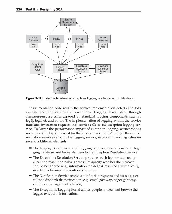
336 Part II ■ Designing SOA
ServiceManagement
Solution
ExceptionsNotification
Service
ExceptionsResolution
Service
LoggingService
Exceptions/LoggingPortal
ServiceConsumer
ServiceConsumer
Service Service
LoggerAPIs
LoggerAPIs
LoggerAPIs
LoggerAPIs
LoggingData Store
Figure 9-18 Unified architecture for exceptions logging, resolution, and notifications
Instrumentation code within the service implementation detects and logssystem- and application-level exceptions. Logging takes place throughcommon-purpose APIs exposed by standard logging components such aslog4j, log4net, and so on. The implementation of logging within the servicetranslates invocation requests into service calls to the exception-logging ser-vice. To lower the performance impact of exception logging, asynchronousinvocations are typically used for the service invocation. Although this imple-mentation revolves around the logging service, exception handling relies onseveral additional elements:
The Logging Service accepts all logging requests, stores them in the log-ging database, and forwards them to the Exception Resolution Service.
The Exceptions Resolution Service processes each log message usingexception resolution rules. These rules specify whether the messageshould be ignored (e.g., information messages), resolved automatically,or whether human intervention is required.
The Notification Service receives notification requests and uses a set ofrules to dispatch the notification (e.g., email gateway, pager gateway,enterprise management solution).
The Exceptions/Logging Portal allows people to view and browse thelogged exception information.
Chapter 9 ■ Using Services to Build Enterprise Solutions 337
Service Management monitors service traffic to determine business-levelexceptions and reports them to the logging service, which treats them thesame way as any other exceptions in the system.
This partitioning of responsibility ensures that exception logging and resolu-tion take place in a consistent fashion. This allows you to formalize enterprisebest practices (‘‘common knowledge’’) and improves auditing, monitoring,and the control of exceptions. This represents a big step toward regulatorycompliance.
The centralized exception resolution service allows for faster implementa-tion of changes in the handling of specific exception types. The most commonapproaches to exception resolution are:
Automatic resolution that resolves the problem without the need forhuman intervention
Semi-automatic resolution that evaluates a rule set and suggests possibleresolutions
Fallback to humans for manual resolution
The solution presented in Figure 9-18 has the following prerequisites:
All logging and messages, including information, warning, exceptions,and so on must follow a standard format, for example, Common BaseEvents (see www.ibm.com/developerworks/autonomic/books/fpy0mst
.htm#HDRAPPA for more information).
All participants (i.e., service consumers and providers, logging, excep-tions resolution, and notification services) should be able to interpret theexceptions/logging information, which should conform to the enterprisesemantic model (refer to service exceptions definitions in Chapter 6).
Analyzing and understanding failure entails linking log messages acrossservice boundaries. This requires a unique correlation ID, spanning thescope of business transactions.
The logging and exception-handling architecture described here appliesSOA principles to provide the foundation for the effective management ofexceptions. It promotes the use of specialized infrastructure services to buildflexible, extensible exception-handling solutions, which are easily integratableinto SOA-based enterprise solutions.
Monitoring and Managing Enterprise Solutions
To compete in today’s economic climate, it is not sufficient to automate asolution itself. Business intelligence, especially when it is actionable, provides
338 Part II ■ Designing SOA
the foundation of business competitiveness. Tuning the enterprise operationrequires knowledge about customers, products, processes, sales, expenses, andso on. For example, in the case of policy issuance, it is important to know thefollowing:
The number of setup customers, rated quotes, and issued policies —This measures the attractiveness of ACME’s offerings and the effective-ness of their advertising campaigns.
The ratio of rated quotes and issued policies, most common terms andconditions used by customers and premium amounts — This addi-tionally quantifies the effectiveness of the current offerings, providinginsight into their improvement.
The average and peak processing times for policy issuance — In addi-tion to indicating the turnaround time of the process, these metrics canalso drive increasing capacity of the IT systems.
While many SOA practitioners are trying to rush SOA solutions to themarket, considering solutions monitoring and management as nice to have,in our opinion it is an integral part of the solution itself. There are two majoraspects to monitoring and management of enterprise solutions — businessactivity monitoring and technical service monitoring. Although both of themare about monitoring, they cater to two very different audiences:
Business activity monitoring supports evaluation of the business impactof the enterprise solution by business people and consequently is con-cerned with collecting and calculating the solution’s key performanceindicators (KPI), business measures, including historical trends, andso on.
Technical monitoring of SOA solutions aids IT personnel in day-to-daysupport of SOA-based solutions, including service utilization statistics,service level agreement (SLA) evaluation, resource and capacity plan-ning, problem resolutions, and so on.
The rest of this section covers details of both business activity and tech-nical monitoring of service-based enterprise solutions and outlines the mainconsiderations of their implementation.
Business Activity MonitoringAn ideal BAM solution intercepts any significant business events in theenterprise, examines the content of the event’s information, and decides howthis information has to be interpreted and ultimately processed. The outcomeof the BAM solution can range from simple reporting to personnel notificationto real-time changes to the solution execution.
Chapter 9 ■ Using Services to Build Enterprise Solutions 339
John Medicke, Feng-Wei Chen, and Margie Mago, in their article ‘‘Creatingan intelligent and flexible solution with BPM, Business Rules, and BusinessIntelligence,’’ (October 2003), define BAM in terms of the ‘‘Five Rs’’ of businessactivity monitoring and decision making:
Recognition of particular situations
Response to particular situations
Resolution of a particular situation
Review of the resolution actions
Delivering return on investment (ROI)
At the foundation of BAM are several key business improvement concepts,which are becoming increasingly important to business executives. Inciden-tally, these concepts are in close alignment with the principles of the SOA-basedsolutions architecture (refer to Figure 9-2).
Putting business process management at the core of business solutions.The explicit implementation of business processes provides the ability toquickly adapt to changes in the business environment. The introductionof the business process controller as one of the key components of enter-prise solutions fully supports this concept.
Driving business processes by actionable intelligence and improvingthem through analysis of key performance indicators captured duringtheir execution. The use of semantic messaging models in SOA-basedsolutions simplifies the acquisition of business intelligence.
Replacing thousands of pages of business intelligence reports with asmaller number of KPIs that reveal the critical characteristics of opera-tional success. The introduction of specialized services dedicated to cal-culations of KPI promotes centralized, flexible KPI calculations.
Driving business process execution by real-time actionable businessevents representing the current state of the enterprise. This requires busi-ness events to be produced and evaluated not after the completion of thebusiness process but rather during its execution. The usage of servicesaligned with real business activities makes SOA-based solutions ideallysuited for such implementations.
From the solution design point of view, at least the following need to bedetermined:
What business measures and KPIs are applicable for a given solution?Typically, those are derived from the enterprise’s business vision, goals,and objectives (see Chapter 4 for more details). For example, the numberof policy ratings and issuances, the ratio of ratings to issuances, and theaverage and overall premium amounts, in the ACME example.
340 Part II ■ Designing SOA
How can these measures and KPI be calculated, based on the data con-tained in the solution? For example, the amounts of ratings and issuancescan be measured through direct capturing of corresponding events; aratio of ratings to issuances can be calculated by dividing two values;premiums amounts can be calculated based on the issuance informationand so on.
Which parts of the solution (including the solution’s business process,participating services, UI, etc.) should be instrumented with businessevents, emitting the data required for business measures and KPI calcu-lations? For example, the BAM implementation for the issuance examplerequires instrumentation of the issuance process with the events reflect-ing current terms and quote calculation, rating, and issuance. Theseevents should contain enough information for the calculation of businessmeasures.
How should these business events be correlated (for example, solution-wise, solution-instance-wise, etc.) to provide a full picture of solutionexecution? For example, correlation in the case of issuance should be per-formed on the issuance process instance level.
Additional considerations can include such topics as alarming, in caseswhen KPIs are going out of the predefined range, alarm notifications, andso on.
Technical Monitoring and Management of SOA SolutionsBAM provides enough information to business personnel for the man-agement and monitoring enterprise solutions. However, its informationtypically does not address requirements of the IT support personnel whouse enterprise-monitoring tools that report on the health of hardware, oper-ating systems, applications servers, and applications. These tools also do notsolve the problem, because they provide information about the underlyingapplications, not services using these applications’ capabilities. The properfunctioning of all of the participating applications does not ensure supportfor required SLAs by the services utilizing these applications (for example, aproblem in the integration service would not be noticed by monitoring theunderlying application). Additionally, due to the potential sharing of appli-cation capabilities by multiple services, a single faulty application can impactseveral services simultaneously.
In the policy issuance example, different stakeholders within ACME areinterested in various pieces of information about service execution. SOAgovernance and portfolio architects need to know which services are inplace and how they are utilized, so they can improve the accuracy of theinformation about the enterprise services’ asset repository and adjust service
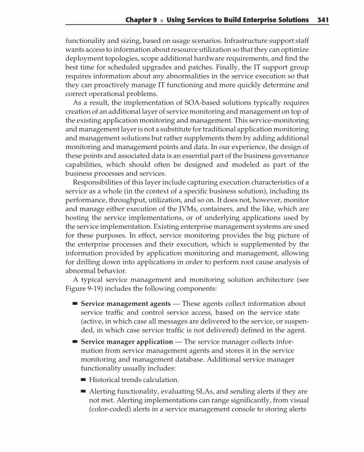
Chapter 9 ■ Using Services to Build Enterprise Solutions 341
functionality and sizing, based on usage scenarios. Infrastructure support staffwants access to information about resource utilization so that they can optimizedeployment topologies, scope additional hardware requirements, and find thebest time for scheduled upgrades and patches. Finally, the IT support grouprequires information about any abnormalities in the service execution so thatthey can proactively manage IT functioning and more quickly determine andcorrect operational problems.
As a result, the implementation of SOA-based solutions typically requirescreation of an additional layer of service monitoring and management on top ofthe existing application monitoring and management. This service-monitoringand management layer is not a substitute for traditional application monitoringand management solutions but rather supplements them by adding additionalmonitoring and management points and data. In our experience, the design ofthese points and associated data is an essential part of the business governancecapabilities, which should often be designed and modeled as part of thebusiness processes and services.
Responsibilities of this layer include capturing execution characteristics of aservice as a whole (in the context of a specific business solution), including itsperformance, throughput, utilization, and so on. It does not, however, monitorand manage either execution of the JVMs, containers, and the like, which arehosting the service implementations, or of underlying applications used bythe service implementation. Existing enterprise management systems are usedfor these purposes. In effect, service monitoring provides the big picture ofthe enterprise processes and their execution, which is supplemented by theinformation provided by application monitoring and management, allowingfor drilling down into applications in order to perform root cause analysis ofabnormal behavior.
A typical service management and monitoring solution architecture (seeFigure 9-19) includes the following components:
Service management agents — These agents collect information aboutservice traffic and control service access, based on the service state(active, in which case all messages are delivered to the service, or suspen-ded, in which case service traffic is not delivered) defined in the agent.
Service manager application — The service manager collects infor-mation from service management agents and stores it in the servicemonitoring and management database. Additional service managerfunctionality usually includes:
Historical trends calculation.
Alerting functionality, evaluating SLAs, and sending alerts if they arenot met. Alerting implementations can range significantly, from visual(color-coded) alerts in a service management console to storing alerts
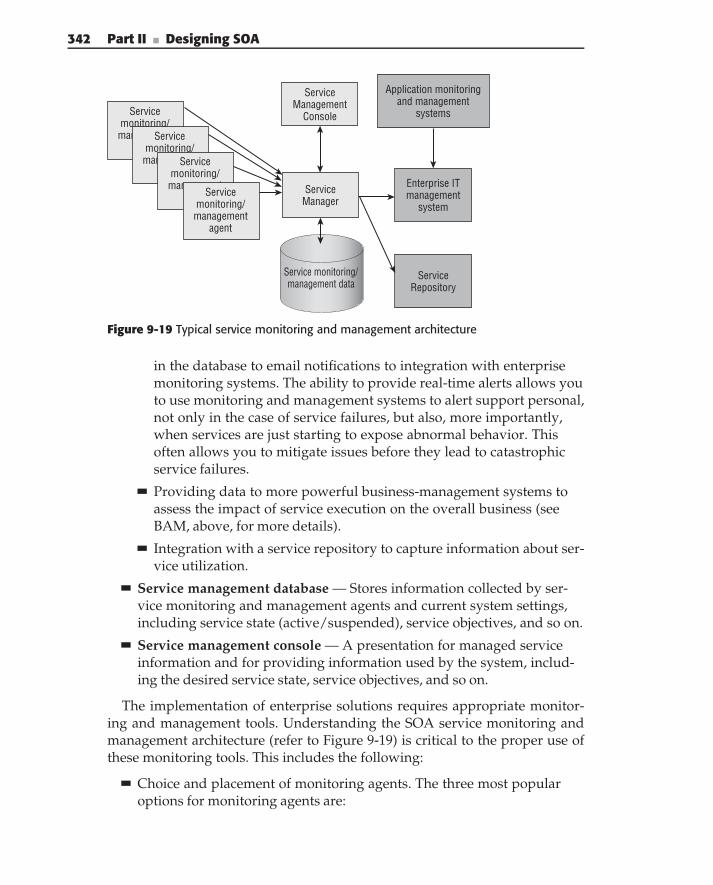
342 Part II ■ Designing SOA
Servicemonitoring/
managementagent
Servicemonitoring/management
agentService
monitoring/management
agentServicemonitoring/management
agent
Service monitoring/management data
ServiceManagement
Console
Application monitoringand management
systems
Enterprise IT management
system
ServiceRepository
ServiceManager
Figure 9-19 Typical service monitoring and management architecture
in the database to email notifications to integration with enterprisemonitoring systems. The ability to provide real-time alerts allows youto use monitoring and management systems to alert support personal,not only in the case of service failures, but also, more importantly,when services are just starting to expose abnormal behavior. Thisoften allows you to mitigate issues before they lead to catastrophicservice failures.
Providing data to more powerful business-management systems toassess the impact of service execution on the overall business (seeBAM, above, for more details).
Integration with a service repository to capture information about ser-vice utilization.
Service management database — Stores information collected by ser-vice monitoring and management agents and current system settings,including service state (active/suspended), service objectives, and so on.
Service management console — A presentation for managed serviceinformation and for providing information used by the system, includ-ing the desired service state, service objectives, and so on.
The implementation of enterprise solutions requires appropriate monitor-ing and management tools. Understanding the SOA service monitoring andmanagement architecture (refer to Figure 9-19) is critical to the proper use ofthese monitoring tools. This includes the following:
Choice and placement of monitoring agents. The three most popularoptions for monitoring agents are:
Chapter 9 ■ Using Services to Build Enterprise Solutions 343
Proxy agent — An agent, injected in the service traffic. The serviceconsumer, talks to the agent, which passes the request to the serviceimplementation. This is the least invasive approach to monitoring andmanagement, requiring no changes to the existing service consumerand provider. On the other hand, this type of agent can lead to signifi-cant performance degradation, especially in the case of large messagesand the use of SSL.
Interceptor agent — An agent is deployed in the same process spaceas either the service consumer or provider (HTTP handler or JAX-RPChandler are the prevalent deployment options in this case). Thisoption alleviates some of the problems of a proxy agent — for exam-ple, performance degradation. On the other hand, this option usuallyrequires a significantly larger number of agents (one for every ser-vice provider and often for every consumer), which makes the overallsolution implementation more expensive.
Callable agent — An agent is outside of the service traffic, with accessfrom the service consumer and provider. This architecture requiresmodification to both service consumer and provider. An advantageof this type of agent is a fixed size of communications between serviceconsumer and provider, which eliminates performance degradation inthe case of large service requests.
Design of the service SLAs (objectives). The choices for the SLA defi-nitions supported by different monitoring solutions vary significantlyranging from predefined SLA options to sophisticated SLA designtoolkits.
Design and implementation of integration and alerting options.
Implementation of service monitoring and management provides visibilityinto service traffic and consequently service deployment and utilization. Itis a required element of an SOA implementation, allowing for proactivemanagement of service resources.
Enterprise Service Bus-Unified Infrastructurefor Enterprise Solutions
As we have shown in the previous sections of this chapter, there is a largeand ever-growing number of techniques for delivering flexibility and agilityto SOA-based solutions in a realistic and incrementally realizable manner. Themajority of these techniques are based on intercepting service communicationstraffic and inserting additional processing of the service messages transpar-ently to the service consumers and providers (compare this to the service
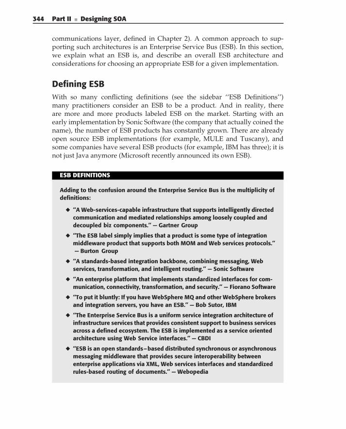
344 Part II ■ Designing SOA
communications layer, defined in Chapter 2). A common approach to sup-porting such architectures is an Enterprise Service Bus (ESB). In this section,we explain what an ESB is, and describe an overall ESB architecture andconsiderations for choosing an appropriate ESB for a given implementation.
Defining ESBWith so many conflicting definitions (see the sidebar ‘‘ESB Definitions’’)many practitioners consider an ESB to be a product. And in reality, thereare more and more products labeled ESB on the market. Starting with anearly implementation by Sonic Software (the company that actually coined thename), the number of ESB products has constantly grown. There are alreadyopen source ESB implementations (for example, MULE and Tuscany), andsome companies have several ESB products (for example, IBM has three); it isnot just Java anymore (Microsoft recently announced its own ESB).
ESB DEFINITIONS
Adding to the confusion around the Enterprise Service Bus is the multiplicity ofdefinitions:
◆ ‘‘A Web-services-capable infrastructure that supports intelligently directedcommunication and mediated relationships among loosely coupled anddecoupled biz components.’’ — Gartner Group
◆ ‘‘The ESB label simply implies that a product is some type of integrationmiddleware product that supports both MOM and Web services protocols.’’— Burton Group
◆ ‘‘A standards-based integration backbone, combining messaging, Webservices, transformation, and intelligent routing.’’ — Sonic Software
◆ ‘‘An enterprise platform that implements standardized interfaces for com-munication, connectivity, transformation, and security.’’ — Fiorano Software
◆ ‘‘To put it bluntly: If you have WebSphere MQ and other WebSphere brokersand integration servers, you have an ESB.’’ — Bob Sutor, IBM
◆ ‘‘The Enterprise Service Bus is a uniform service integration architecture ofinfrastructure services that provides consistent support to business servicesacross a defined ecosystem. The ESB is implemented as a service orientedarchitecture using Web Service interfaces.’’ — CBDI
◆ ‘‘ESB is an open standards–based distributed synchronous or asynchronousmessaging middleware that provides secure interoperability betweenenterprise applications via XML, Web services interfaces and standardizedrules-based routing of documents.’’ — Webopedia
Chapter 9 ■ Using Services to Build Enterprise Solutions 345
◆ ‘‘An ESB refers to a software architecture construct, implemented by tech-nologies found in a category of middleware infrastructure products usuallybased on standards, that provides foundational services for more complexarchitectures via an event-driven and standards-based messaging engine(the bus).’’ — Wikipedia
Other practitioners consider ESB to be an architectural pattern and exist-ing products to be implementations of this pattern. We belong to this lattercamp. In our mind, an ESB is an enterprise-wide extendable middlewareinfrastructure providing virtualization and management of service interac-tions, including support for the communication, mediation, transformation,and integration technologies required by services. The foundation of the ESBpattern is a universal intermediary. (This intermediary does not have to beremote. We consider any abstraction layer, whether local or remote, used as anintermediary to be a service bus.) Rather than interacting directly, participantsin a service interaction communicate through a bus, which can be implementedusing a variety of middleware technologies and programming models.
VIRTUALIZATION
Virtualization is a commonly used approach for simplification of the ITinfrastructure through unification of access to resources and the managementof those resources. According to Wikipedia:
Virtualization is the process of presenting a logical grouping or subset ofcomputing resources so that they can be accessed in ways that give bene-fits over the original configuration. This new virtual view of the resourcesis not restricted by the implementation, geographic location or the physicalconfiguration of underlying resources.
Resource virtualization enables hiding many proprietary infrastructurecomponents that are required for the proper functioning of particularresources, and minimizes the impact of IT infrastructure changes on theresource consumers.
A service implementation is a type of virtualization of IT resources hiddenbehind the service interface. An ESB adds an additional level of virtualization tothe service through vitalizing the service infrastructure (access). In effect, SOAwith ESB is virtualization squared.
The roots of the ESB can be traced to a common approach used in applicationintegration architectures — hub and spoke (Message Broker), which support
346 Part II ■ Designing SOA
virtualization and decoupling in EAI implementations. In this architecture,invocations and routing rules are separated from implementations. The draw-back of this architecture is the fact that a central hub becomes both a singlepoint of failure and a potential bottleneck for communications.
In order to avoid these drawbacks, hubs can be joined together to form whatis logically a single entity — bus — that provides a single point of controlbut is implemented as a collection of physically distributed components. Abus lowers coupling between service consumers and providers by serving asa communication intermediary supporting mediation between required andprovided capabilities. This provides a clean separation between the businessaspects of the solution supported by the service consumers and providers, andthe technical aspects (for example, security, or dynamic routing) supported bythe bus. Furthermore, in a bus architecture, the implementation of this technicalaspect can change transparently to the service consumers and providers. Forexample, the introduction of a new security approach could be limited tochanges in the bus mediation.
The ability of a bus to support communications between consumers andproviders is based on the explicit declaration of capabilities and requirementsof interactions — metadata describing domain models (set of services) and a setof policies governing access to these services. This metadata allows the bus tovalidate the request, map it to the location of the actual service implementation(supporting the required invocation policies), and invoke services on behalf ofconsumers.
ESB ArchitectureThe basic architecture of an ESB is presented in Figure 9-20 and usuallycontains the following:
Distributed ESB engine, (run-time engine) responsible for communica-tions between service consumers and providers. This engine is usuallymulti-transport and supports message delivery and service invocation,along with quality of service support for these operations. It often sup-ports events and the publish/subscribe paradigm.
Distributed ESB infrastructure services, including:
Service location/routing directory — Service registry containingservice endpoint addresses and policies governing access to the end-points.
Transactional support — An ESB usually implements multiple trans-actional models — business transactions, required for businessservice interactions and variations of two-phase commit transactionsfor integration services.
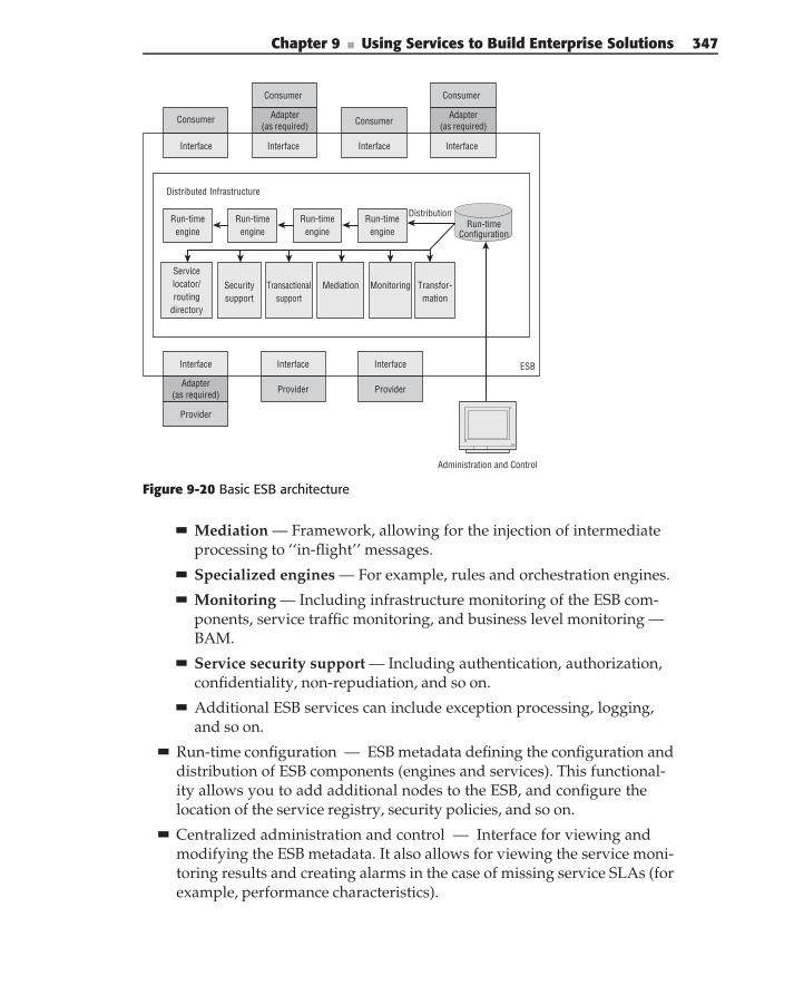
Chapter 9 ■ Using Services to Build Enterprise Solutions 347
Provider
Interface
Provider
Interface
Provider
Interface
Consumer
Interface
Consumer
Interface
Consumer
Interface
Consumer
Interface
Service locator/ routing
directory
Security support
Mediation Transfor-mation
Distributed Infrastructure
Run-timeengine
Run-time Configuration
Administration and Control
ESB
Distribution
Transactionalsupport
Adapter (as required)
Adapter (as required)
Adapter (as required)
Monitoring
Run-time engine
Run-time engine
Run-time engine
Figure 9-20 Basic ESB architecture
Mediation — Framework, allowing for the injection of intermediateprocessing to ‘‘in-flight’’ messages.
Specialized engines — For example, rules and orchestration engines.
Monitoring — Including infrastructure monitoring of the ESB com-ponents, service traffic monitoring, and business level monitoring —BAM.
Service security support — Including authentication, authorization,confidentiality, non-repudiation, and so on.
Additional ESB services can include exception processing, logging,and so on.
Run-time configuration — ESB metadata defining the configuration anddistribution of ESB components (engines and services). This functional-ity allows you to add additional nodes to the ESB, and configure thelocation of the service registry, security policies, and so on.
Centralized administration and control — Interface for viewing andmodifying the ESB metadata. It also allows for viewing the service moni-toring results and creating alarms in the case of missing service SLAs (forexample, performance characteristics).
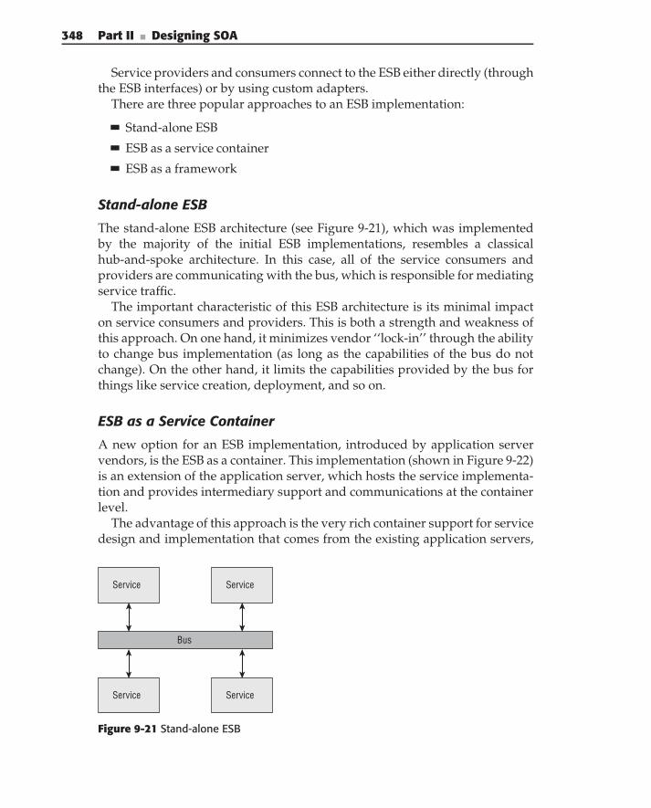
348 Part II ■ Designing SOA
Service providers and consumers connect to the ESB either directly (throughthe ESB interfaces) or by using custom adapters.
There are three popular approaches to an ESB implementation:
Stand-alone ESB
ESB as a service container
ESB as a framework
Stand-alone ESB
The stand-alone ESB architecture (see Figure 9-21), which was implementedby the majority of the initial ESB implementations, resembles a classicalhub-and-spoke architecture. In this case, all of the service consumers andproviders are communicating with the bus, which is responsible for mediatingservice traffic.
The important characteristic of this ESB architecture is its minimal impacton service consumers and providers. This is both a strength and weakness ofthis approach. On one hand, it minimizes vendor ‘‘lock-in’’ through the abilityto change bus implementation (as long as the capabilities of the bus do notchange). On the other hand, it limits the capabilities provided by the bus forthings like service creation, deployment, and so on.
ESB as a Service Container
A new option for an ESB implementation, introduced by application servervendors, is the ESB as a container. This implementation (shown in Figure 9-22)is an extension of the application server, which hosts the service implementa-tion and provides intermediary support and communications at the containerlevel.
The advantage of this approach is the very rich container support for servicedesign and implementation that comes from the existing application servers,
Service
Bus
Service Service
Service
Figure 9-21 Stand-alone ESB
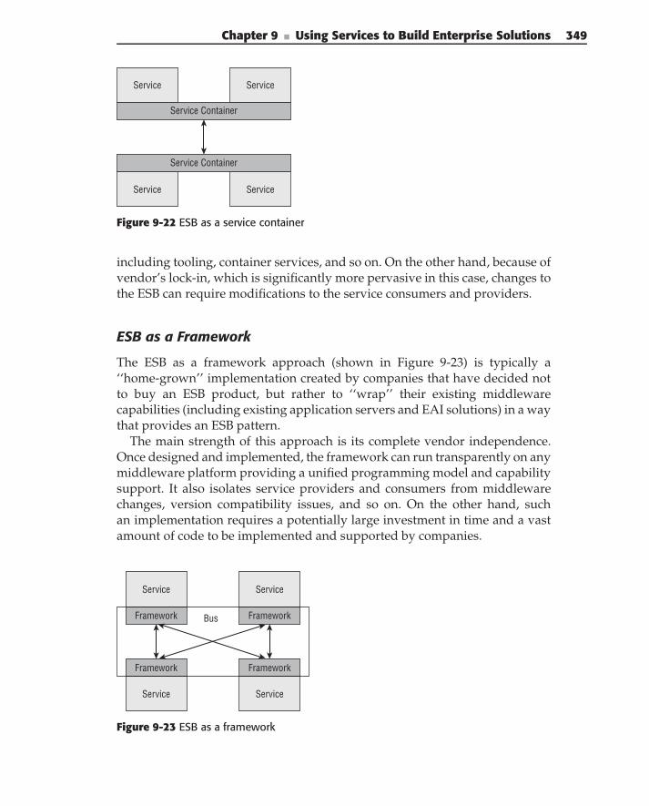
Chapter 9 ■ Using Services to Build Enterprise Solutions 349
Service
Service Container
Service Service
Service
Service Container
Figure 9-22 ESB as a service container
including tooling, container services, and so on. On the other hand, because ofvendor’s lock-in, which is significantly more pervasive in this case, changes tothe ESB can require modifications to the service consumers and providers.
ESB as a Framework
The ESB as a framework approach (shown in Figure 9-23) is typically a‘‘home-grown’’ implementation created by companies that have decided notto buy an ESB product, but rather to ‘‘wrap’’ their existing middlewarecapabilities (including existing application servers and EAI solutions) in a waythat provides an ESB pattern.
The main strength of this approach is its complete vendor independence.Once designed and implemented, the framework can run transparently on anymiddleware platform providing a unified programming model and capabilitysupport. It also isolates service providers and consumers from middlewarechanges, version compatibility issues, and so on. On the other hand, suchan implementation requires a potentially large investment in time and a vastamount of code to be implemented and supported by companies.
Service Service
Framework Framework
Service Service
Framework FrameworkBus
Figure 9-23 ESB as a framework
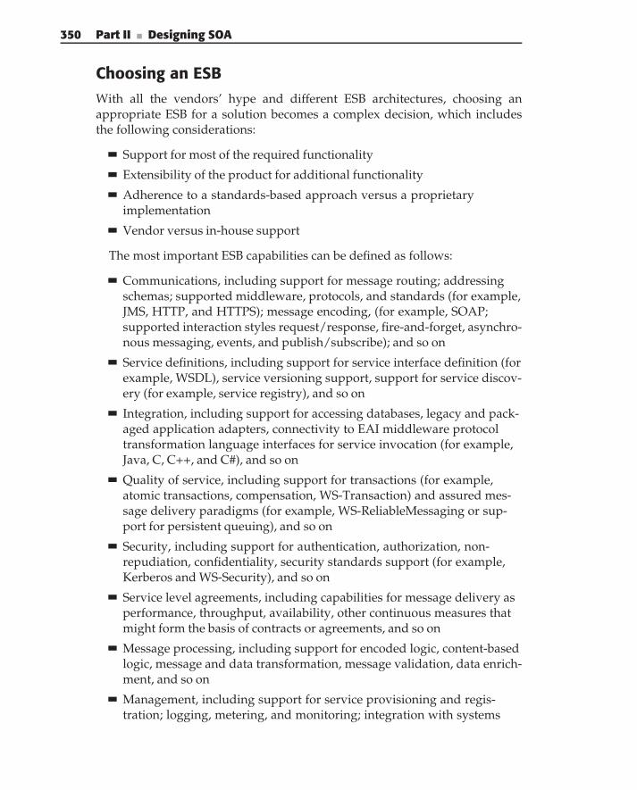
350 Part II ■ Designing SOA
Choosing an ESBWith all the vendors’ hype and different ESB architectures, choosing anappropriate ESB for a solution becomes a complex decision, which includesthe following considerations:
Support for most of the required functionality
Extensibility of the product for additional functionality
Adherence to a standards-based approach versus a proprietaryimplementation
Vendor versus in-house support
The most important ESB capabilities can be defined as follows:
Communications, including support for message routing; addressingschemas; supported middleware, protocols, and standards (for example,JMS, HTTP, and HTTPS); message encoding, (for example, SOAP;supported interaction styles request/response, fire-and-forget, asynchro-nous messaging, events, and publish/subscribe); and so on
Service definitions, including support for service interface definition (forexample, WSDL), service versioning support, support for service discov-ery (for example, service registry), and so on
Integration, including support for accessing databases, legacy and pack-aged application adapters, connectivity to EAI middleware protocoltransformation language interfaces for service invocation (for example,Java, C, C++, and C#), and so on
Quality of service, including support for transactions (for example,atomic transactions, compensation, WS-Transaction) and assured mes-sage delivery paradigms (for example, WS-ReliableMessaging or sup-port for persistent queuing), and so on
Security, including support for authentication, authorization, non-repudiation, confidentiality, security standards support (for example,Kerberos and WS-Security), and so on
Service level agreements, including capabilities for message delivery asperformance, throughput, availability, other continuous measures thatmight form the basis of contracts or agreements, and so on
Message processing, including support for encoded logic, content-basedlogic, message and data transformation, message validation, data enrich-ment, and so on
Management, including support for service provisioning and regis-tration; logging, metering, and monitoring; integration with systems
Chapter 9 ■ Using Services to Build Enterprise Solutions 351
management and administration tooling; self-monitoring and self-management; alerting; and so on
Modeling, including support for common business objects models, dataformat libraries, development and deployment tooling; and so on
Infrastructure intelligence, including support for business rules; policy-driven behavior, particularly for service level, security, and quality ofservice capabilities (for example, WS-Policy); service orchestration; pat-tern recognition; and so on
N O T E For a full list of ESB capabilities, refer to the series of articles by RickRobinson, ‘‘Understand enterprise service bus scenarios and solutions inservice-oriented architecture, Part 1–3,’’ (June 2004).
Although some of these capabilities are quite basic, others, such as intelligentrouting capabilities, are quite advanced. It is important to recognize that aparticular SOA implementation requires only a subset of the capabilities withina subset of these categories.
An ESB provides a unified service support infrastructure, supporting bothbusiness-focused and integration services (refer to Figure 9-3). This infra-structure supports service invocations over multiple transports with differentQoS, usually governed by policies. An ESB also provides built-in supportfor the majority of the service’s run-time patterns, including the serviceregistry, service management and monitoring, and facilities for the centralizedmanagement of deployed services.
Although many practitioners, especially software vendors, would like youto believe that the use of an ESB product is a prerequisite for a successful SOAimplementation, this is not true. We have seen and successfully implementedSOA solutions without them. On the other hand, an ESB (at least on thepattern level) is very powerful middleware, which often simplifies SOA-basedimplementations.
Summary
This chapter has defined a layered architecture for SOA-based enterprisesolutions. It then discussed some of the key components that have to be takeninto consideration when building solutions including:
Service locations — Defining the ways to make endpoint addresses ofservices available throughout the enterprise, based on the service reg-istry, which can be used as a universal service locator
352 Part II ■ Designing SOA
Service versioning — Defining the ways to evolve services and service-based solutions independently with minimal or no impact on each other
Service security — Defining architectural approaches to securingservice-based enterprise solutions
Exception handling and logging in the SOA world — Defining the roleof basic exception and logging architecture, which can be easily incorpo-rated in any SOA-based implementation
Service monitoring and management — Defining the role, place, andtwo important types of monitoring and management: BAM and techni-cal management
Finally, we introduced the Enterprise Service Bus pattern, which providesvirtualization of service communications and serves as a foundation for theimplementation of the majority of the architectural components described inthis chapter.
C H A P T E R
10Designing and Using Integration
in SOA SolutionsExisting software assets are essential to your business. Application systems contain
a reservoir of business rules vital to operational continuity, yet remainundocumented outside the source code. These software assets and the
accompanying business data are difficult to decipher and almost impossible toreplicate using ‘‘green-field’’ approaches.
–William Ulrich
With all the advances in SOA that provide the best hope for efficient, flexible,and cost-effective implementations, the bulk of the business processing todayis still carried out by legacy systems and packaged applications, like EnterpriseResource Planning (ERP), Customer Relationship Management (CRM), and soon. If there is a big bang conversion from existing applications to new systems,architecture will not work. Instead, IT organizations should bridge the gapvia a carefully planned transition and migration process. This means thatSOA solutions cannot be built in a vacuum — the only cost-effective approachis to base new solutions on the existing application portfolio and leverageintegration as a mechanism for accessing the existing capabilities. But, it is notas simple as just Web- Service-enabling existing applications and data. Instead,the existing functions and data need to be transformed into new capabilitiesand information that can move the enterprise forward toward its current goalsand strategies, and not keep it tied to the 20-year-old strategies associated withthe 20-year-old systems.
This chapter discusses the role that integration plays in SOA and introducesmore specific definitions of integration services and their implementationchallenges.
353
354 Part II ■ Designing SOA
The chapter covers the following topics:
The role of integration and what makes its implementation complex
The history of attempts to bridge SOA and integration
Choosing integration implementation approaches
Cross-cutting concerns for implementing integration, including datamapping, security, transactional support, versioning and support forlarge messages
Supporting data access in SOA
The Enterprise Data Bus as a pattern for virtualization of data access toservices throughout the enterprise
Challenges of Integration in SOA
Integration is not new. It has been around for at least 10-15 years and iswell understood and widely adopted. In today’s reality, integration projectsconsume a lion’s share of the IT budget, often impeding new developments.The need for integration is caused by the siloed nature of existing enterpriseapplications, which manifest themselves as islands of data, automation, andsecurity.
Characteristics of Islands of DataEach island of data has its own meaning and/or definition of enterprise objects.For example, in one application ‘‘insured party’’ defines an insured individual;in another application, the same term might refer to a company. Even if anobject, for example, ‘‘address’’ has the same meaning in two applications, oneapplication can define it as a set of address lines, while another might treatit as street address, city, state, zip, and country. Both cases create semanticdissonance between applications.
Each island of data has information that overlaps with the contents of anotherisland. For example, applications dealing with the management of healthand dental claims also store the demographics information for the insured.At the same time the CRM application contains both insured addresses anddemographics. This duplication creates integrity issues.
No one can provide a complete picture of the enterprise data. For example, apersonal auto Policy and Product Administration application doesn’t containinformation about the insured policies from other lines of business. Creatinga unified view of the enterprise data requires integrating information frommultiple sources.
Chapter 10 ■ Designing and Using Integration in SOA Solutions 355
Characteristics of Islands of AutomationEach island of automation focuses on a limited set of activities within theenterprise. For example, a health claim management application deals onlywith the processing of health claims without considering the role and place ofthese activities in the overall enterprise business process. This requires usersto engage in ‘‘application hopping’’ to perform their work, thus affecting theirproductivity.
There is a duplication of functionality between multiple applications. Forexample, multiple applications that process insurance applications for differentlines of business all implement address cleansing functionality. As a result,when changing address cleansing rules, these changes have to be coordinatedbetween all applications.
There is duplication of business processes contained within different islands.For example, as a result of a merger or acquisition an insurance companycan have several claim-processing systems. This requires synchronization ofchanges among multiple applications, ensuring consistency of the processesand business rules that support these processes.
Characteristics of Islands of SecurityDifferent enterprise applications often use different authentication mechanisms.This makes it difficult to propagate user identity among multiple applica-tions. For example, existing solutions such as Single Sign-On (SSO) cater toweb-facing applications and employ browser sessions and cookies associatedwith them. Therefore, they are usually not applicable to application inte-gration. Various applications also use application-specific identities, not tiedinto the global enterprise, which creates further integration difficulties. Addi-tionally, different authorization mechanisms (roles versus security attributesversus individual authorization) employed by different applications often relyon incompatible representations for user identity. Complicating the matterfurther, individual enterprise applications may use application-specific autho-rization credentials and tightly coupled, deeply embedded security logic,making security integration very difficult.
Requirements for the implementation of invocation privacy can vary signifi-cantly between enterprise applications. Popular choices include implementingprivacy at the transport level (e.g., HTTPS or SSL) or at the message level (e.g.,S/MIME, WS-Security).
Different applications can provide radically different mechanisms and locationsfor security audit trails. Bringing together and correlating these trails for multipleintegration activities can be a difficult task. In addition, the heterogeneity ofstorage mechanisms and formats often makes them virtually unusable. Thenecessity to create maintainable and manageable IT infrastructure positioned to
356 Part II ■ Designing SOA
better respond to the business needs requires a massive amount of integrationwork, aimed at bridging these islands.
Despite the fact that integration has been around for many years, a largeportion of integration projects fail. The major reasons for these failures are:
Although many integration vendors try to convince you otherwise, thecomplexity and cost of integration is not due to the complexity and costof a particular tool but rather due to the complexity and cost of architect-ing interactions between heterogeneous applications that often were notdesigned to work together.
In many of today’s enterprises, each business unit is autonomous andhas its own set of technologies, applications, and budgets. Cross-unitintegration requires both technical (infrastructure and applications) andfinancial (sharing integration costs) cooperation between business units,which typically requires centralized IT governance.
Defining the overall integration approach and implementation archi-tecture is still as much art (based on the experience of the integrationteams) as science. There is no well-established methodology for topicssuch as how to analyze overall data and process flow, when to choosesimple data synchronization versus service-oriented architecture, andhow to determine data and service interfaces. Standardized architecturesshould be in place when defining applicable EAI topologies, includ-ing the choice of the integration transports, definitions of routing rules,placement of the data transformation, security, failover, and load balanc-ing. Considerations for each are important.
Integration spans multiple existing applications and usually involvescomparatively little development work but a lot of research and designactivity. This requires teams, project management, and implementationapproaches that differ significantly from those of traditional applicationdevelopment.
As the size of the integration grows, so does the complexity. Unfor-tunately, unlike traditional applications, this growth is not linear, butrather exponential.
Integration is considered by many companies to be a technical, ratherthan a business undertaking. This leads to the business impact of inte-gration being ignored until deployment to production, at which time it isalready too late.
Data model mismatches between applications severely complicate inte-gration. (This topic is covered in more detail later in the ‘‘Data Mappingin Integration’’ section of this chapter.)
Chapter 10 ■ Designing and Using Integration in SOA Solutions 357
Implementing integration as part of SOA makes integration even morecomplex. First, SOA is often an enterprise-wide undertaking, which makes therequirement for business unit cooperation and centralized governance evenmore stringent. Second, there is an architectural design mismatch betweenSOA and existing enterprise applications. SOA design defines business servicesbased on the decomposition of the enterprise business model with the interfacesdefined according to the enterprise semantic model. In contrast, existingenterprise applications have been created and/or acquired over time in orderto fulfill specific tasks. The differences between these two approaches makeit challenging to use existing applications to implement business services.In SOA, the role of integration is not only to bridge the islands describedpreviously, but also to deal with the following:
Information fidelity — The redundancy of business data between appli-cations creates an inaccurate representation of enterprise data, evenwhen periodic synchronization occurs. The representations themselvesare difficult to reconcile, or at worst contradictory. As the individualapplications evolve independently, the complexity of the problemincreases. The role of integration in SOA is to rationalize data from mul-tiple existing applications in order to provide accurate information tothe business services. Furthermore, it requires data updates, executed onthe business service level to be correctly propagated to all participatingenterprise applications.
Business processes fragmentation — Individual applications providea limited, often duplicated, piece of enterprise functionality. The roleof integration in SOA is not only to pick the most appropriate imple-mentation of the existing functionality but also to ensure that it won’tbreak existing applications.
Security fragmentation — Different enterprise applications rely onusers’ identity/group membership for programmatic/declarativeauthorization implementation. These applications often use differentauthentication approaches, which can be based on different users’ repre-sentations located in different users’ identity stores. Therefore,integration in SOA is required to correctly convert a user’s identity rep-resentation in order to satisfy each of the enterprise applications used.
All of the previous points require careful architecture and implementationof integration in SOA environments. In the rest of this chapter, we discussdifferent integration approaches and show how these problems can be solved.Also refer to Chapter 14 for a case study of building an integration solutionfor a fictitious insurance company.
358 Part II ■ Designing SOA
Integration in SOA Defined
The first attempt to extend SOA to standardize integration implementation —Service-Oriented Integration (SOI) — was suggested by several authors inthe early 2000s. SOI is defined by Anna Liu and Ian Gorton in their paper,‘‘Process and Criteria for Evaluating Services-Based Integration Technologies,’’(July 2005):
The services-based approach to doing integration is about integrating computingentities using service interactions. The services-based approach to integrationaddresses problems with integrating legacy and inflexible heterogeneous sys-tems by enabling IT organizations to offer the functionality locked in existingapplications as reusable services.
In contrast to traditional enterprise application, integration (EAI), the significantcharacteristics of the services-based approach to integration are:
Well-defined, standardized interfaces — Consumers are provided with eas-ily understood and consistent access to the underlying service.
Opaqueness — The technology and location of the application providing thefunctionality are hidden behind the service interface. In fact, there is no need fora fixed services provider.
Flexibility — Both the providers of services and consumers of services canchange — the service description is the only constant. As long as both theprovider and consumer continue to adhere to the service description, the applica-tions will continue to work.
The original SOI approach was to simply replace any proprietary mid-dleware with SOAP over HTTP as a ubiquitous middleware platform guar-anteeing interoperability between service consumers and providers (see thesidebar ‘‘Service-Oriented Integration,’’ which follows the approach describedin ‘‘Integration Patterns’’ by David Trowbridge, et al. [June 2004]).
SERVICE-ORIENTED INTEGRATION
It is necessary to integrate information systems that were not originallydesigned to work together. These systems are built using differenttechnologies, languages, and architecture.
Problem
How do you integrate applications at the business logic layer?
Chapter 10 ■ Designing and Using Integration in SOA Solutions 359
Forces
Integrating systems at the business logic layer involves balancing the followingforces:
Explicit Machine BoundariesAttempt to minimize coupling to improve interoperability.
Solution
Integrate applications at the business logic layer, through the use of WebServices Description Language (WSDL) contracts to describe the interfaces tothese systems. Ensure interoperability by making the implementationcompliant with the Web Services family of specifications (including WebServices Interoperability [WS-I]).
Note: The term service is used in many different ways in the context ofsoftware engineering. In this pattern, the term service is used to mean XMLWeb Services.
Resolving the ForcesBasing service invocation (messages) on XML and XML Schema Definitionlanguage (XSD) results in a highly portable type system that dramaticallyreduces type-system coupling, which is a major impediment to cross-platformintegration.
BenefitsThe key benefit of using Service-Oriented Integration is interoperabilitybetween disparate technical architectures, which helps to decouple anenterprise’s business architecture from its information technology. Thisdecoupling gives an enterprise a great deal of flexibility in terms of how itimplements specific business capabilities.
LiabilitiesThe key liability of using Service-Oriented Integration is the use of XMLfor marshaling data. Not only can marshaling/unmarshaling be very expensive,but it also leads to increased message size, which increases networktraffic.
360 Part II ■ Designing SOA
Although, using SOI provides for bringing SOA and integration together,it is a simplistic and not very practical approach because it treats integrationthe same way as business services. As a result, business services created usingthe SOI approach are aligned not with the enterprise business model, butrather with the existing functionality of a particular application, with all of thedrawbacks of that approach:
This approach goes against one of the most important SOA principles —services are the rationalization layer, hiding existing application portfo-lios and supporting the ideal enterprise business model.
Services built using the SOI approach expose existing applicationfunctionality rather than the functionality defined by the enterprisemodel, and this might complicate reuse later on.
The SOI approach creates a tight coupling between the existing appli-cation portfolio and the service interfaces. If one or more enterpriseapplications change, an undesirable ripple effect may be created inthe existing service model.
Services in SOI expose the underlying application’s data model, ratherthan the enterprise semantic information model (detailed in Chapter 5),and this typically complicates interoperability.
The granularity of a service is aligned with the existing application,resulting in a potential increase in network traffic.
Integration ServicesThis book takes a different approach. We treat integration as a specializedtype of service — an integration service. The role of integration services is toprovide access to the existing enterprise applications and data, so that they canbe utilized by business and utility. Scott Simmons in his article ‘‘Introducingthe WebSphere Integration Reference Architecture,’’ (August 2005), definesintegration services as ‘‘the bridging capabilities between legacy applications,pre-packaged applications, enterprise data stores (including relational, hier-archical, and nontraditional, unstructured sources, such as XML, text andcontent management systems), and the business services implementation.’’
With such integration services in place, a typical implementation of abusiness/utility service is an assembly of business components, the majorityof which are implemented as wrappers using integration access to the exist-ing legacy applications. See Figure 10-1. An integration service, as defined inChapter 2, is represented here as a combination of integration access (a mech-anism used to expose existing legacy functionality and business components)and an abstraction layer hiding details of the interaction with the integrationaccess.
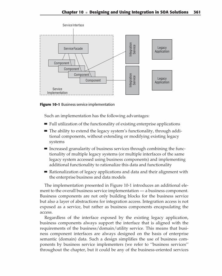
Chapter 10 ■ Designing and Using Integration in SOA Solutions 361
Service Facade
Component
Component
Component
Component
Service Implementation
Inte
grat
ion
Serv
ice
Inte
grat
ion
Serv
ice
Legacy Application
Legacy Application
Service Interface
Figure 10-1 Business service implementation
Such an implementation has the following advantages:
Full utilization of the functionality of existing enterprise applications
The ability to extend the legacy system’s functionality, through addi-tional components, without extending or modifying existing legacysystems
Increased granularity of business services through combining the func-tionality of multiple legacy systems (or multiple interfaces of the samelegacy system accessed using business components) and implementingadditional functionality to rationalize this data and functionality
Rationalization of legacy applications and data and their alignment withthe enterprise business and data models
The implementation presented in Figure 10-1 introduces an additional ele-ment to the overall business service implementation — a business component.Business components are not only building blocks for the business servicebut also a layer of abstractions for integration access. Integration access is notexposed as a service, but rather as business components encapsulating theaccess.
Regardless of the interface exposed by the existing legacy application,business components always support the interface that is aligned with therequirements of the business/domain/utility service. This means that busi-ness component interfaces are always designed on the basis of enterprisesemantic (domain) data. Such a design simplifies the use of business com-ponents by business service implementers (we refer to ‘‘business services’’throughout the chapter, but it could be any of the business-oriented services
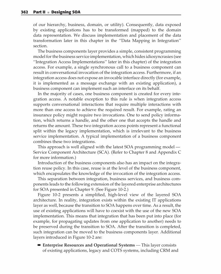
362 Part II ■ Designing SOA
of our hierarchy, business, domain, or utility). Consequently, data exposedby existing applications has to be transformed (mapped) to the domaindata representation. We discuss implementation and placement of the datatransformation later in this chapter in the ‘‘Data Mapping in Integration’’section.
The business components layer provides a simple, consistent programmingmodel for the business service implementation, which hides idiosyncrasies (see‘‘Integration Access Implementations’’ later in this chapter) of the integrationaccess. For example, a single synchronous call to a business component canresult in conversational invocation of the integration access. Furthermore, if anintegration access does not expose an invocable interface directly (for example,it is implemented as a message exchange with an existing application), abusiness component can implement such an interface on its behalf.
In the majority of cases, one business component is created for every inte-gration access. A notable exception to this rule is when integration accesssupports conversational interactions that require multiple interactions withmore than one access to achieve the required result. For example, rating aninsurance policy might require two invocations. One to send policy informa-tion, which returns a handle, and the other one that accepts the handle andreturns the amount. These two integration access points represent a functionalsplit within the legacy implementation, which is irrelevant to the businessservice implementation. A typical implementation of a business componentcombines these two integrations.
This approach is well aligned with the latest SOA programming model —Service Component Architecture (SCA). (Refer to Chapter 8 and Appendix Cfor more information.)
Introduction of the business components also has an impact on the integra-tion reuse policy. In this case, reuse is at the level of the business component,which encapsulates the knowledge of the invocation of the integration access.
This separation between integration, business services, and business com-ponents leads to the following extension of the layered enterprise architecturesfor SOA presented in Chapter 9. (See Figure 10-2.)
Figure 10-2 presents a simplified, high-level view of the layered SOAarchitecture. In reality, integration exists within the existing IT applicationslayer as well, because the transition to SOA happens over time. As a result, theuse of existing applications will have to coexist with the use of the new SOAimplementation. This means that integration that has been put into place (forexample, for propagating updates from one application to another) needs tobe preserved during the transition to SOA. After the transition is completed,such integration can be moved to the business components layer. Additionallayers introduced in Figure 10-2 are:
Enterprise Resources and Operational Systems — This layer consistsof existing applications, legacy and COTS systems, including CRM and
Chapter 10 ■ Designing and Using Integration in SOA Solutions 363
DataData DataServers Servers
WorkstationsMainframe Mainframe
Customer-Facing Applications’ View into Enterprise Processes
Business Process Driven Enterprise
Services- Rationalization of Enterprise Systems Against Business Meaningful Services
Business Components Encapsulation of Integration and Additional Functionality
Integration Exposing Existing Enterprise Systems
Existing IT Hardware/Software Topology
Figure 10-2 Layered Enterprise Architecture for service implementation
ERP packaged applications, and older object-oriented implementations.These applications provide business operation: transactions that repre-sent single logical units of work in the enterprise’s operational systems.Execution of an operation typically causes one or more persistent datarecords to be read, written, or modified in a System of Record (SOR).Operations have a specific, structured interface, and return structuredresponses.
Integration Access — Integration access provides access to an exist-ing application’s functionality. This separation between the businessservices and integration is critical to maintaining a flexible enterpriseenvironment. Although integration directly exposes the functionalityof existing applications and is tightly coupled with the existing appli-cation, business services expose functionality that is aligned with theenterprise business model and, therefore, is completely decoupled fromthe existing application’s portfolio.
Business components — Business components are deployable unitsof software that provide the (integration) functionality required by the
364 Part II ■ Designing SOA
business services. Components can either be implemented directly orwrap existing operational systems using integration services. Compo-nent implementations usually use container-based technologies suchas application servers to provide workload management, availability,and load balancing. The components, acting as integration service con-sumers, provide a single point of access to the integration services. Thisprevents a proliferation of hard-to-manage cut-and-paste code for access-ing the integration services.
This layering promotes architectural differences between integration ser-vices and business services:
Unlike business services, integration services don’t have to be coarse-grained. The granularity of the integration is defined by the granularityof the existing functionality, exposed by the application. It is generallyadvantageous to increase this granularity when possible.
Synchronous invocations are a prevalent invocation pattern for integra-tion services (with some exceptions for the data integration).
ACID transactions are often a required property of the integration ser-vices, especially when their functionality is to update application data.
Legacy integration often requires conversational interactions;consequently, integration services often have to be implemented asconversational.
Defining integration services as an implementation technique for businessservices is also well aligned with the service design approach described inChapter 3.
Integration Access ImplementationsGiven the broad definition of integration access as a way to expose existinglegacy functionality and data to business services, a wide variety of integra-tion access implementations are possible. Specific implementation approachesdepend on the following major factors:
Enterprise maturity in the EAI/integration space — If a companyalready has either a robust EAI implementation (Message Broker) or awidely used messaging infrastructure that supports integration of themajor enterprise applications, existing middleware can be leveraged forimplementing integration services.
Composition of the existing application portfolio — If the majority ofthe existing application portfolio is composed of packaged applicationsfrom major software vendors, and these applications are kept relatively
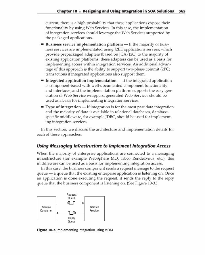
Chapter 10 ■ Designing and Using Integration in SOA Solutions 365
current, there is a high probability that these applications expose theirfunctionality by using Web Services. In this case, the implementationof integration services should leverage the Web Services supported bythe packaged applications.
Business service implementation platform — If the majority of busi-ness services are implementated using J2EE applications servers, whichprovide prepackaged adapters (based on JCA/J2C) to the majority ofexisting application platforms, these adapters can be used as a basis forimplementing access within integration services. An additional advan-tage of this approach is the ability to support two-phase commit (2PC)transactions if integrated applications also support them.
Integrated application implementation — If the integrated applicationis component-based with well-documented component functionalityand interfaces, and the implementation platform supports the easy gen-eration of Web Service wrappers, generated Web Services should beused as a basis for implementing integration services.
Type of integration — If integration is for the most part data integrationand the majority of data is available in relational databases, database-specific middleware, for example JDBC, should be used for implement-ing integration services.
In this section, we discuss the architecture and implementation details foreach of these approaches.
Using Messaging Infrastructure to Implement Integration Access
When the majority of enterprise applications are connected to a messaginginfrastructure (for example WebSphere MQ, Tibco Rendezvous, etc.), thismiddleware can be used as a basis for implementing integration access.
In this case, the business component sends a request message to the requestqueue — a queue that the existing enterprise application is listening on. Oncean application is done executing the request, it sends the reply to the replyqueue that the business component is listening on. (See Figure 10-3.)
ServiceProvider
ServiceConsumer
RequestQueue
ReplyQueue
Figure 10-3 Implementing integration using MOM
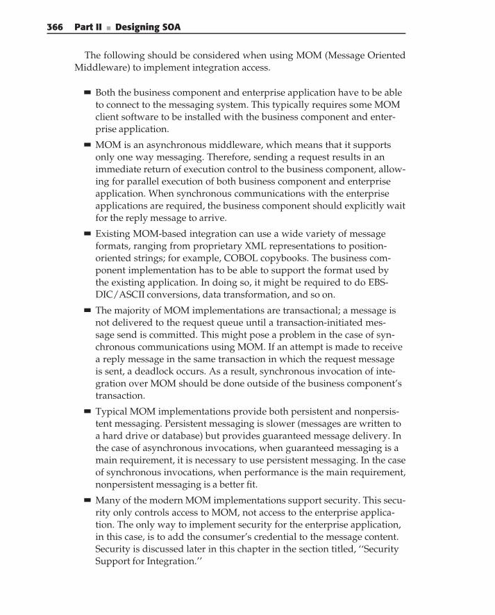
366 Part II ■ Designing SOA
The following should be considered when using MOM (Message OrientedMiddleware) to implement integration access.
Both the business component and enterprise application have to be ableto connect to the messaging system. This typically requires some MOMclient software to be installed with the business component and enter-prise application.
MOM is an asynchronous middleware, which means that it supportsonly one way messaging. Therefore, sending a request results in animmediate return of execution control to the business component, allow-ing for parallel execution of both business component and enterpriseapplication. When synchronous communications with the enterpriseapplications are required, the business component should explicitly waitfor the reply message to arrive.
Existing MOM-based integration can use a wide variety of messageformats, ranging from proprietary XML representations to position-oriented strings; for example, COBOL copybooks. The business com-ponent implementation has to be able to support the format used bythe existing application. In doing so, it might be required to do EBS-DIC/ASCII conversions, data transformation, and so on.
The majority of MOM implementations are transactional; a message isnot delivered to the request queue until a transaction-initiated mes-sage send is committed. This might pose a problem in the case of syn-chronous communications using MOM. If an attempt is made to receivea reply message in the same transaction in which the request messageis sent, a deadlock occurs. As a result, synchronous invocation of inte-gration over MOM should be done outside of the business component’stransaction.
Typical MOM implementations provide both persistent and nonpersis-tent messaging. Persistent messaging is slower (messages are written toa hard drive or database) but provides guaranteed message delivery. Inthe case of asynchronous invocations, when guaranteed messaging is amain requirement, it is necessary to use persistent messaging. In the caseof synchronous invocations, when performance is the main requirement,nonpersistent messaging is a better fit.
Many of the modern MOM implementations support security. This secu-rity only controls access to MOM, not access to the enterprise applica-tion. The only way to implement security for the enterprise application,in this case, is to add the consumer’s credential to the message content.Security is discussed later in this chapter in the section titled, ‘‘SecuritySupport for Integration.’’
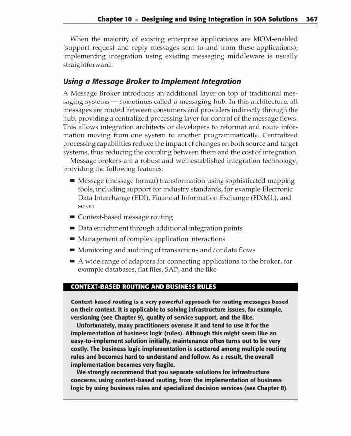
Chapter 10 ■ Designing and Using Integration in SOA Solutions 367
When the majority of existing enterprise applications are MOM-enabled(support request and reply messages sent to and from these applications),implementing integration using existing messaging middleware is usuallystraightforward.
Using a Message Broker to Implement IntegrationA Message Broker introduces an additional layer on top of traditional mes-saging systems — sometimes called a messaging hub. In this architecture, allmessages are routed between consumers and providers indirectly through thehub, providing a centralized processing layer for control of the message flows.This allows integration architects or developers to reformat and route infor-mation moving from one system to another programmatically. Centralizedprocessing capabilities reduce the impact of changes on both source and targetsystems, thus reducing the coupling between them and the cost of integration.
Message brokers are a robust and well-established integration technology,providing the following features:
Message (message format) transformation using sophisticated mappingtools, including support for industry standards, for example ElectronicData Interchange (EDI), Financial Information Exchange (FIXML), andso on
Context-based message routing
Data enrichment through additional integration points
Management of complex application interactions
Monitoring and auditing of transactions and/or data flows
A wide range of adapters for connecting applications to the broker, forexample databases, flat files, SAP, and the like
CONTEXT-BASED ROUTING AND BUSINESS RULES
Context-based routing is a very powerful approach for routing messages basedon their context. It is applicable to solving infrastructure issues, for example,versioning (see Chapter 9), quality of service support, and the like.
Unfortunately, many practitioners overuse it and tend to use it for theimplementation of business logic (rules). Although this might seem like aneasy-to-implement solution initially, maintenance often turns out to be verycostly. The business logic implementation is scattered among multiple routingrules and becomes hard to understand and follow. As a result, the overallimplementation becomes very fragile.
We strongly recommend that you separate solutions for infrastructureconcerns, using context-based routing, from the implementation of businesslogic by using business rules and specialized decision services (see Chapter 8).
368 Part II ■ Designing SOA
Existing Enterprise Application
Existing Enterprise Application
Existing Enterprise Application
Existing Enterprise Application
Message Broker
Integration Service
Consumer
Figure 10-4 Implementing an integration service using a message broker
Implementation of integration access based on existing, message-broker-based integration, as shown in Figure 10-4, is fairly straightforward. Thebusiness component connects to the broker, allowing the reuse of integrationaccess that is already in place.
The following should be considered when using Message Brokers to imple-ment integration:
All of the Message Brokers support some form of MOM connectionto the broker, allowing for a MOM-based implementation of the busi-ness component. See the considerations for such an implementationin the previous section. In addition, many Message Broker implemen-tations (for example, WebSphere Message Broker) provide Web Ser-vice support, which can also be leveraged to access existing integration.The choice of the particular access mechanism depends on the imple-mentation platform and integration requirements. Although Web Ser-vice access typically does not require any additional software to imple-ment connectivity, it lacks support for guaranteed delivery and asyn-chronous invocations. MOM-based access, on the other hand, requiresadditional software on the client side, but provides richer communica-tion options.
Because the Message Broker comes with built-in support for format anddata transformation, its facilities should be used for transforming databetween the formats used by the business component and the existingapplications. A canonical data format, widely adopted by Message Bro-ker implementations, is a good starting point for such transformations.
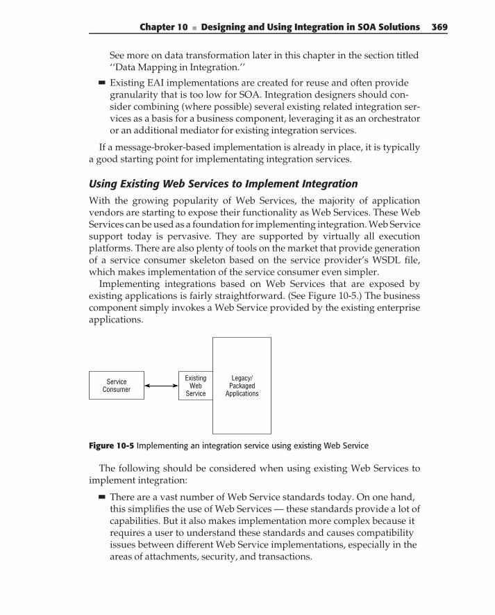
Chapter 10 ■ Designing and Using Integration in SOA Solutions 369
See more on data transformation later in this chapter in the section titled‘‘Data Mapping in Integration.’’
Existing EAI implementations are created for reuse and often providegranularity that is too low for SOA. Integration designers should con-sider combining (where possible) several existing related integration ser-vices as a basis for a business component, leveraging it as an orchestratoror an additional mediator for existing integration services.
If a message-broker-based implementation is already in place, it is typicallya good starting point for implementating integration services.
Using Existing Web Services to Implement Integration
With the growing popularity of Web Services, the majority of applicationvendors are starting to expose their functionality as Web Services. These WebServices can be used as a foundation for implementing integration. Web Servicesupport today is pervasive. They are supported by virtually all executionplatforms. There are also plenty of tools on the market that provide generationof a service consumer skeleton based on the service provider’s WSDL file,which makes implementation of the service consumer even simpler.
Implementing integrations based on Web Services that are exposed byexisting applications is fairly straightforward. (See Figure 10-5.) The businesscomponent simply invokes a Web Service provided by the existing enterpriseapplications.
ServiceConsumer
Legacy/Packaged
Applications
ExistingWeb
Service
Figure 10-5 Implementing an integration service using existing Web Service
The following should be considered when using existing Web Services toimplement integration:
There are a vast number of Web Service standards today. On one hand,this simplifies the use of Web Services — these standards provide a lot ofcapabilities. But it also makes implementation more complex because itrequires a user to understand these standards and causes compatibilityissues between different Web Service implementations, especially in theareas of attachments, security, and transactions.
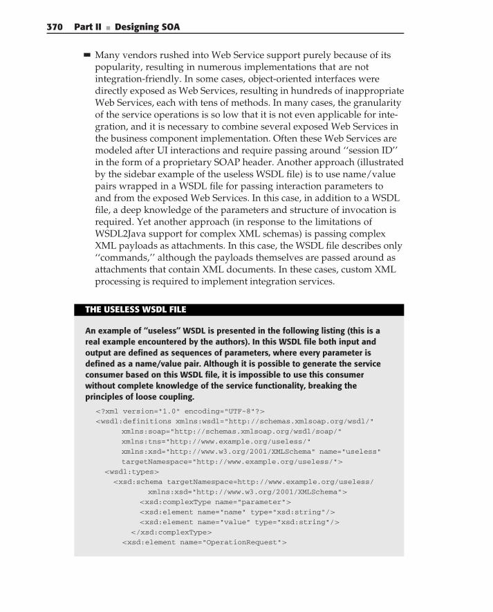
370 Part II ■ Designing SOA
Many vendors rushed into Web Service support purely because of itspopularity, resulting in numerous implementations that are notintegration-friendly. In some cases, object-oriented interfaces weredirectly exposed as Web Services, resulting in hundreds of inappropriateWeb Services, each with tens of methods. In many cases, the granularityof the service operations is so low that it is not even applicable for inte-gration, and it is necessary to combine several exposed Web Services inthe business component implementation. Often these Web Services aremodeled after UI interactions and require passing around ‘‘session ID’’in the form of a proprietary SOAP header. Another approach (illustratedby the sidebar example of the useless WSDL file) is to use name/valuepairs wrapped in a WSDL file for passing interaction parameters toand from the exposed Web Services. In this case, in addition to a WSDLfile, a deep knowledge of the parameters and structure of invocation isrequired. Yet another approach (in response to the limitations ofWSDL2Java support for complex XML schemas) is passing complexXML payloads as attachments. In this case, the WSDL file describes only‘‘commands,’’ although the payloads themselves are passed around asattachments that contain XML documents. In these cases, custom XMLprocessing is required to implement integration services.
THE USELESS WSDL FILE
An example of ‘‘useless’’ WSDL is presented in the following listing (this is areal example encountered by the authors). In this WSDL file both input andoutput are defined as sequences of parameters, where every parameter isdefined as a name/value pair. Although it is possible to generate the serviceconsumer based on this WSDL file, it is impossible to use this consumerwithout complete knowledge of the service functionality, breaking theprinciples of loose coupling.
<?xml version="1.0" encoding="UTF-8"?>
<wsdl:definitions xmlns:wsdl="http://schemas.xmlsoap.org/wsdl/"
xmlns:soap="http://schemas.xmlsoap.org/wsdl/soap/"
xmlns:tns="http://www.example.org/useless/"
xmlns:xsd="http://www.w3.org/2001/XMLSchema" name="useless"
targetNamespace="http://www.example.org/useless/">
<wsdl:types>
<xsd:schema targetNamespace=http://www.example.org/useless/
xmlns:xsd="http://www.w3.org/2001/XMLSchema">
<xsd:complexType name="parameter">
<xsd:element name="name" type="xsd:string"/>
<xsd:element name="value" type="xsd:string"/>
</xsd:complexType>
<xsd:element name="OperationRequest">
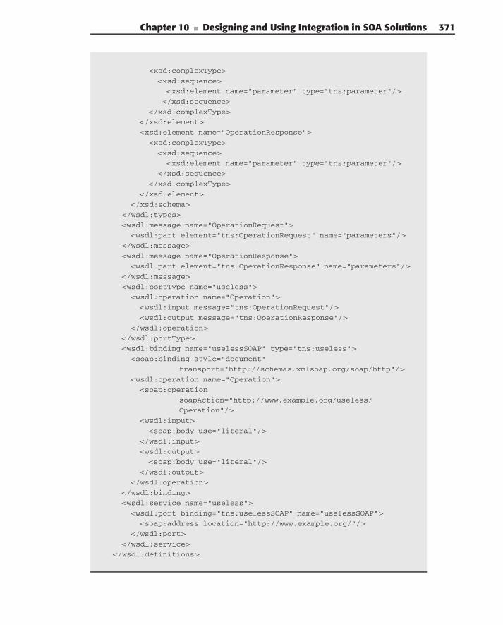
Chapter 10 ■ Designing and Using Integration in SOA Solutions 371
<xsd:complexType>
<xsd:sequence>
<xsd:element name="parameter" type="tns:parameter"/>
</xsd:sequence>
</xsd:complexType>
</xsd:element>
<xsd:element name="OperationResponse">
<xsd:complexType>
<xsd:sequence>
<xsd:element name="parameter" type="tns:parameter"/>
</xsd:sequence>
</xsd:complexType>
</xsd:element>
</xsd:schema>
</wsdl:types>
<wsdl:message name="OperationRequest">
<wsdl:part element="tns:OperationRequest" name="parameters"/>
</wsdl:message>
<wsdl:message name="OperationResponse">
<wsdl:part element="tns:OperationResponse" name="parameters"/>
</wsdl:message>
<wsdl:portType name="useless">
<wsdl:operation name="Operation">
<wsdl:input message="tns:OperationRequest"/>
<wsdl:output message="tns:OperationResponse"/>
</wsdl:operation>
</wsdl:portType>
<wsdl:binding name="uselessSOAP" type="tns:useless">
<soap:binding style="document"
transport="http://schemas.xmlsoap.org/soap/http"/>
<wsdl:operation name="Operation">
<soap:operation
soapAction="http://www.example.org/useless/
Operation"/>
<wsdl:input>
<soap:body use="literal"/>
</wsdl:input>
<wsdl:output>
<soap:body use="literal"/>
</wsdl:output>
</wsdl:operation>
</wsdl:binding>
<wsdl:service name="useless">
<wsdl:port binding="tns:uselessSOAP" name="uselessSOAP">
<soap:address location="http://www.example.org/"/>
</wsdl:port>
</wsdl:service>
</wsdl:definitions>
372 Part II ■ Designing SOA
Using JCA/J2C Adapters to Implement Integration
J2EE Connector Architecture (J2C), formally Java Connector Architecture(JCA), is a standardized Java-based solution for integration. (For more infor-mation see ‘‘J2EE Connector Architecture’’ at http://java.sun.com/j2ee/
connector.) The J2C specification defines three key functions: the CommonClient Interface (CCI), which provides a uniform client API across multipleenterprise information systems; the Service Provider Interface (SPI), whichdefines system-level contracts for connection management, transaction man-agement, and security between an application server and the adapter for aspecific enterprise application; and a deployment and packaging protocol. Theadvantages of J2C are:
It provides a uniform client programming model for accessing any appli-cation supported by the adapter.
It tightly integrates with the application server in terms of security,transaction management, and connection pooling. The J2C SPI stan-dardizes the following:
Connection management, standardizing the way that applicationservers establish and manage connections to an enterprise system,including support for connection pooling
Transaction management, specifying the way the application server’stransaction manager can manage transactions across applicationsthrough connected applications
Security management allowing, J2C adapters to either propagatethe current user, or impersonate another one for the applicationinvocation
It increases the number of adapters on the market and lowers their priceby standardizing on implementations.
Enterprise systems for which J2C adapters are available today include Enter-prise Resource Planning Systems (PeopleSoft, Baan, JD Edwards, and SAP),Transactions Monitors (CICS), Database Management Systems (Oracle, DB2,SQL server), and messaging systems (WebSphere MQ, Tibco Rendezvous).
Because a majority of J2EE application servers support J2C, it appears to bea very powerful mechanism for implementing integration when the businessservice implementation is based on a J2EE application server. In Figure 10-6,an adapter implements access to a legacy application, messaging middleware,or database. The business component is implemented as a set of the adapterAPI calls.
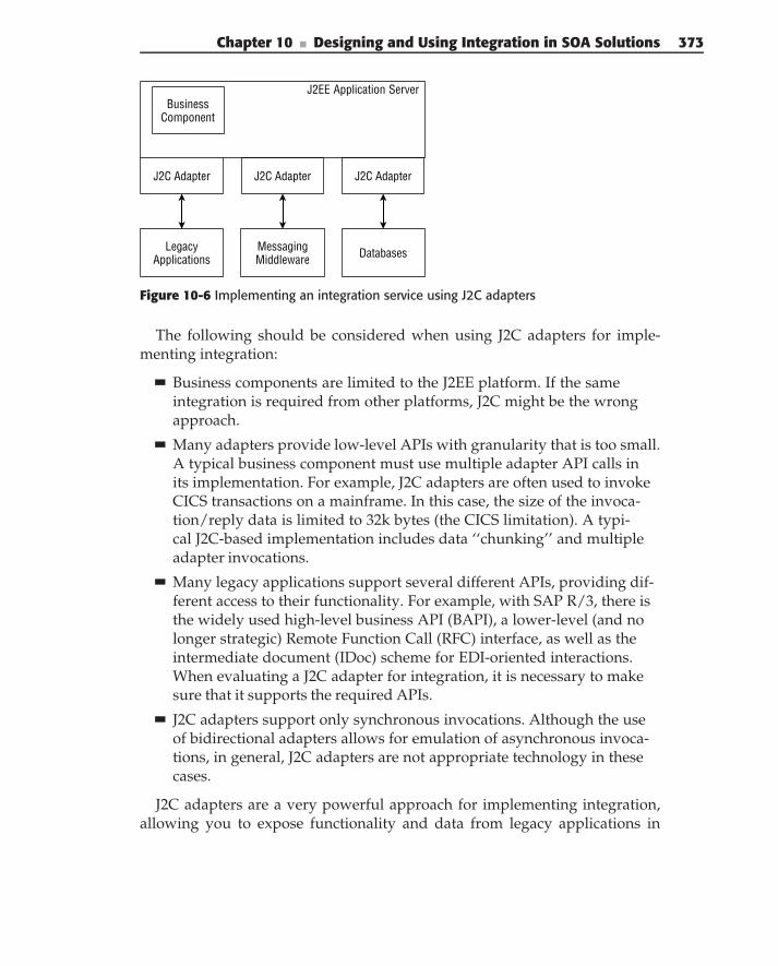
Chapter 10 ■ Designing and Using Integration in SOA Solutions 373
J2C Adapter J2C Adapter J2C Adapter
MessagingMiddleware Databases
J2EE Application ServerBusiness
Component
LegacyApplications
Figure 10-6 Implementing an integration service using J2C adapters
The following should be considered when using J2C adapters for imple-menting integration:
Business components are limited to the J2EE platform. If the sameintegration is required from other platforms, J2C might be the wrongapproach.
Many adapters provide low-level APIs with granularity that is too small.A typical business component must use multiple adapter API calls inits implementation. For example, J2C adapters are often used to invokeCICS transactions on a mainframe. In this case, the size of the invoca-tion/reply data is limited to 32k bytes (the CICS limitation). A typi-cal J2C-based implementation includes data ‘‘chunking’’ and multipleadapter invocations.
Many legacy applications support several different APIs, providing dif-ferent access to their functionality. For example, with SAP R/3, there isthe widely used high-level business API (BAPI), a lower-level (and nolonger strategic) Remote Function Call (RFC) interface, as well as theintermediate document (IDoc) scheme for EDI-oriented interactions.When evaluating a J2C adapter for integration, it is necessary to makesure that it supports the required APIs.
J2C adapters support only synchronous invocations. Although the useof bidirectional adapters allows for emulation of asynchronous invoca-tions, in general, J2C adapters are not appropriate technology in thesecases.
J2C adapters are a very powerful approach for implementing integration,allowing you to expose functionality and data from legacy applications in
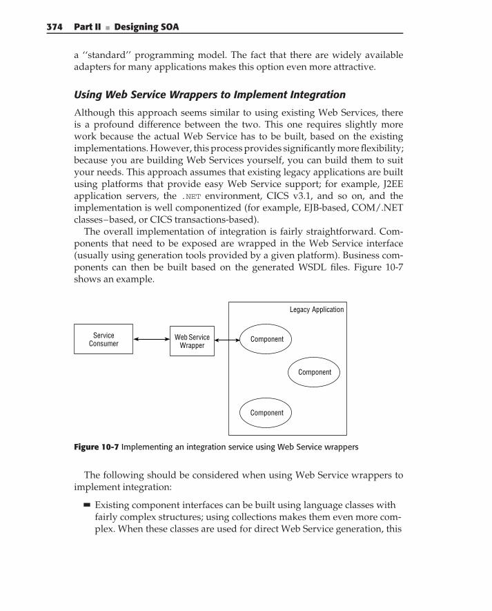
374 Part II ■ Designing SOA
a ‘‘standard’’ programming model. The fact that there are widely availableadapters for many applications makes this option even more attractive.
Using Web Service Wrappers to Implement Integration
Although this approach seems similar to using existing Web Services, thereis a profound difference between the two. This one requires slightly morework because the actual Web Service has to be built, based on the existingimplementations. However, this process provides significantly more flexibility;because you are building Web Services yourself, you can build them to suityour needs. This approach assumes that existing legacy applications are builtusing platforms that provide easy Web Service support; for example, J2EEapplication servers, the .NET environment, CICS v3.1, and so on, and theimplementation is well componentized (for example, EJB-based, COM/.NETclasses–based, or CICS transactions-based).
The overall implementation of integration is fairly straightforward. Com-ponents that need to be exposed are wrapped in the Web Service interface(usually using generation tools provided by a given platform). Business com-ponents can then be built based on the generated WSDL files. Figure 10-7shows an example.
Legacy Application
Component
Component
Component
Web ServiceWrapper
ServiceConsumer
Figure 10-7 Implementing an integration service using Web Service wrappers
The following should be considered when using Web Service wrappers toimplement integration:
Existing component interfaces can be built using language classes withfairly complex structures; using collections makes them even more com-plex. When these classes are used for direct Web Service generation, this
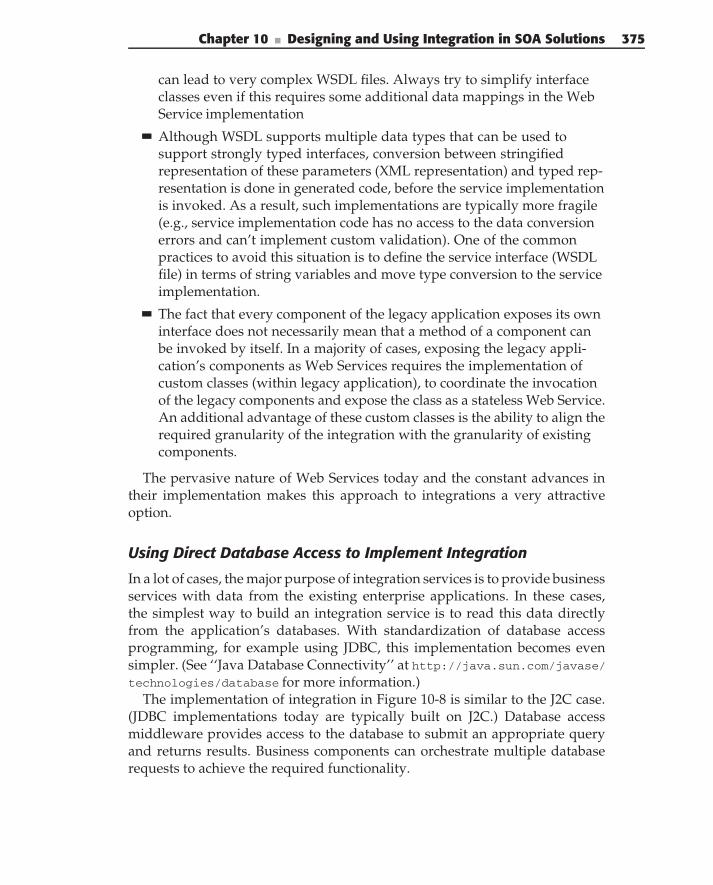
Chapter 10 ■ Designing and Using Integration in SOA Solutions 375
can lead to very complex WSDL files. Always try to simplify interfaceclasses even if this requires some additional data mappings in the WebService implementation
Although WSDL supports multiple data types that can be used tosupport strongly typed interfaces, conversion between stringifiedrepresentation of these parameters (XML representation) and typed rep-resentation is done in generated code, before the service implementationis invoked. As a result, such implementations are typically more fragile(e.g., service implementation code has no access to the data conversionerrors and can’t implement custom validation). One of the commonpractices to avoid this situation is to define the service interface (WSDLfile) in terms of string variables and move type conversion to the serviceimplementation.
The fact that every component of the legacy application exposes its owninterface does not necessarily mean that a method of a component canbe invoked by itself. In a majority of cases, exposing the legacy appli-cation’s components as Web Services requires the implementation ofcustom classes (within legacy application), to coordinate the invocationof the legacy components and expose the class as a stateless Web Service.An additional advantage of these custom classes is the ability to align therequired granularity of the integration with the granularity of existingcomponents.
The pervasive nature of Web Services today and the constant advances intheir implementation makes this approach to integrations a very attractiveoption.
Using Direct Database Access to Implement Integration
In a lot of cases, the major purpose of integration services is to provide businessservices with data from the existing enterprise applications. In these cases,the simplest way to build an integration service is to read this data directlyfrom the application’s databases. With standardization of database accessprogramming, for example using JDBC, this implementation becomes evensimpler. (See ‘‘Java Database Connectivity’’ at http://java.sun.com/javase/technologies/database for more information.)
The implementation of integration in Figure 10-8 is similar to the J2C case.(JDBC implementations today are typically built on J2C.) Database accessmiddleware provides access to the database to submit an appropriate queryand returns results. Business components can orchestrate multiple databaserequests to achieve the required functionality.
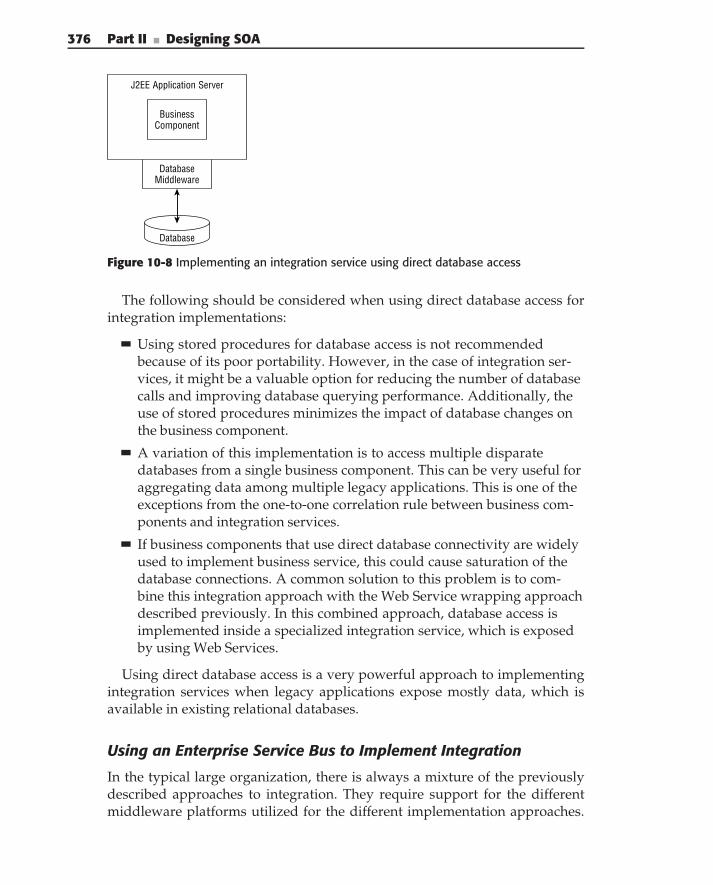
376 Part II ■ Designing SOA
J2EE Application Server
BusinessComponent
DatabaseMiddleware
Database
Figure 10-8 Implementing an integration service using direct database access
The following should be considered when using direct database access forintegration implementations:
Using stored procedures for database access is not recommendedbecause of its poor portability. However, in the case of integration ser-vices, it might be a valuable option for reducing the number of databasecalls and improving database querying performance. Additionally, theuse of stored procedures minimizes the impact of database changes onthe business component.
A variation of this implementation is to access multiple disparatedatabases from a single business component. This can be very useful foraggregating data among multiple legacy applications. This is one of theexceptions from the one-to-one correlation rule between business com-ponents and integration services.
If business components that use direct database connectivity are widelyused to implement business service, this could cause saturation of thedatabase connections. A common solution to this problem is to com-bine this integration approach with the Web Service wrapping approachdescribed previously. In this combined approach, database access isimplemented inside a specialized integration service, which is exposedby using Web Services.
Using direct database access is a very powerful approach to implementingintegration services when legacy applications expose mostly data, which isavailable in existing relational databases.
Using an Enterprise Service Bus to Implement Integration
In the typical large organization, there is always a mixture of the previouslydescribed approaches to integration. They require support for the differentmiddleware platforms utilized for the different implementation approaches.
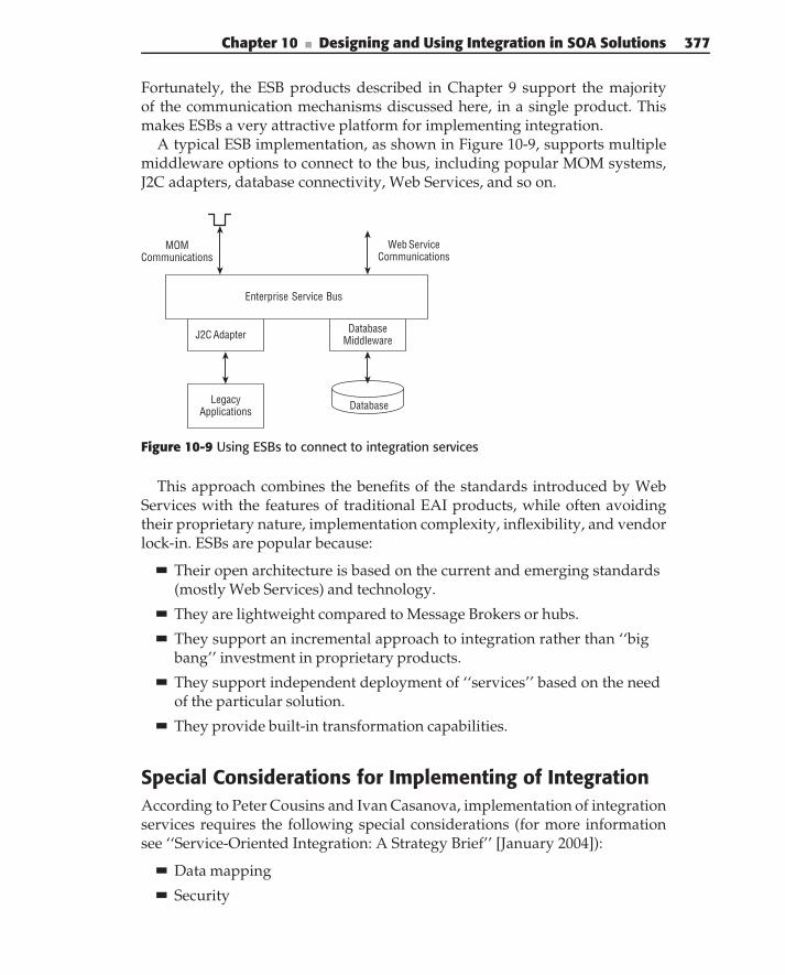
Chapter 10 ■ Designing and Using Integration in SOA Solutions 377
Fortunately, the ESB products described in Chapter 9 support the majorityof the communication mechanisms discussed here, in a single product. Thismakes ESBs a very attractive platform for implementing integration.
A typical ESB implementation, as shown in Figure 10-9, supports multiplemiddleware options to connect to the bus, including popular MOM systems,J2C adapters, database connectivity, Web Services, and so on.
Enterprise Service Bus
J2C Adapter
LegacyApplications
DatabaseMiddleware
Database
MOMCommunications
Web ServiceCommunications
Figure 10-9 Using ESBs to connect to integration services
This approach combines the benefits of the standards introduced by WebServices with the features of traditional EAI products, while often avoidingtheir proprietary nature, implementation complexity, inflexibility, and vendorlock-in. ESBs are popular because:
Their open architecture is based on the current and emerging standards(mostly Web Services) and technology.
They are lightweight compared to Message Brokers or hubs.
They support an incremental approach to integration rather than ‘‘bigbang’’ investment in proprietary products.
They support independent deployment of ‘‘services’’ based on the needof the particular solution.
They provide built-in transformation capabilities.
Special Considerations for Implementing of IntegrationAccording to Peter Cousins and Ivan Casanova, implementation of integrationservices requires the following special considerations (for more informationsee ‘‘Service-Oriented Integration: A Strategy Brief’’ [January 2004]):
Data mapping
Security
378 Part II ■ Designing SOA
Transactional support
Versioning
Large messages
We discuss these concerns and their typical implementation architec-tures here. Keep in mind that these concerns are common to all of theintegration implementation approaches described in this chapter. Althoughsolutions might be slightly different, depending on the implementation, theseapproaches have enough in common to describe them together.
Data Mapping in Integration
Because of the data fidelity issues in existing enterprise applications, datamapping was traditionally one of the main concerns of EAI implementations.This problem is still relevant for implementations of integration in SOA.Although enterprise business services are based on the enterprise semanticmodel (see Chapter 6 for more details), each legacy system is based on its owndata model, which is typically different from the enterprise data model andfrom other data models. At some point, these proprietary data models have tobe mapped to the enterprise data model.
Picking the appropriate place for this transformation is one of the mainissues during integration service design and implementation. Based on thearchitecture of the business service implementation (refer to Figure 10-1),the following solutions are possible:
Implementing data mapping as part of the integration accessimplementation — This solution works well when the Message Bro-ker is used to implement the integration access. The Message Broker’sdata-mapping capabilities typically provide good support for theseimplementations. It also might be an option when using Web Servicewrappers or direct database access (when it is implemented using storedprocedures). In other integration access approaches, such a solutionrequires changes to the existing legacy implementation, which is never adesirable option.
Implementing data mapping as part of the message delivery — Thissolution is possible for all of the integration service implementationapproaches except J2C and direct database access (there is no messagedelivery per se in this case). A variation of this solution, especially in thecase of an Enterprise Service Bus, is to use mediation for the data trans-formation, as shown in Figure 10-10.
Implementing data mapping as part of a business componentthat wraps the integration service invocation — This is the most generic
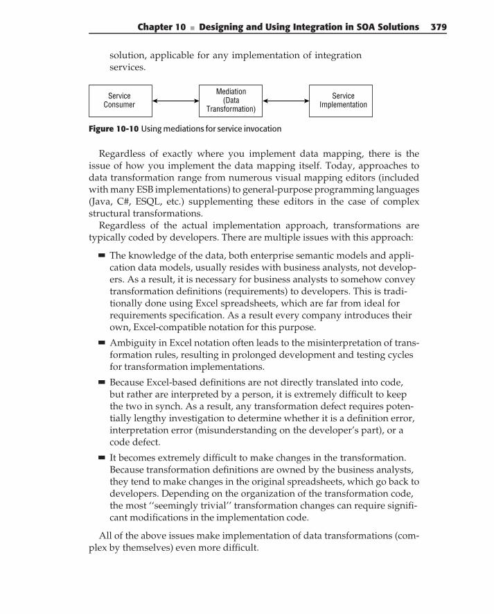
Chapter 10 ■ Designing and Using Integration in SOA Solutions 379
solution, applicable for any implementation of integrationservices.
ServiceConsumer
Mediation(Data
Transformation)
ServiceImplementation
Figure 10-10 Using mediations for service invocation
Regardless of exactly where you implement data mapping, there is theissue of how you implement the data mapping itself. Today, approaches todata transformation range from numerous visual mapping editors (includedwith many ESB implementations) to general-purpose programming languages(Java, C#, ESQL, etc.) supplementing these editors in the case of complexstructural transformations.
Regardless of the actual implementation approach, transformations aretypically coded by developers. There are multiple issues with this approach:
The knowledge of the data, both enterprise semantic models and appli-cation data models, usually resides with business analysts, not develop-ers. As a result, it is necessary for business analysts to somehow conveytransformation definitions (requirements) to developers. This is tradi-tionally done using Excel spreadsheets, which are far from ideal forrequirements specification. As a result every company introduces theirown, Excel-compatible notation for this purpose.
Ambiguity in Excel notation often leads to the misinterpretation of trans-formation rules, resulting in prolonged development and testing cyclesfor transformation implementations.
Because Excel-based definitions are not directly translated into code,but rather are interpreted by a person, it is extremely difficult to keepthe two in synch. As a result, any transformation defect requires poten-tially lengthy investigation to determine whether it is a definition error,interpretation error (misunderstanding on the developer’s part), or acode defect.
It becomes extremely difficult to make changes in the transformation.Because transformation definitions are owned by the business analysts,they tend to make changes in the original spreadsheets, which go back todevelopers. Depending on the organization of the transformation code,the most ‘‘seemingly trivial’’ transformation changes can require signifi-cant modifications in the implementation code.
All of the above issues make implementation of data transformations (com-plex by themselves) even more difficult.
380 Part II ■ Designing SOA
A better approach for implementing data transformation is to use aspecialized tool that provides a clear separation between transformation design(that can be done directly by business analysts) and run-time execution (thatis implemented as a standard library, available on the majority of executionplatforms). In this case, the majority of data transformation/mapping changescan be made (and tested) directly in the transformation tool with minimalor no impact on the execution code. Additionally, such an approach pro-vides maximum deployment flexibility. The integration architect can pick anappropriate place to run the transformation based on the overall architecturalrequirements.
Security Support for Integration
One of the characteristics of current enterprise application portfolios in themajority of enterprises is islands of security. The key goal of security forintegration is to enable existing security infrastructures to interoperate. Thesolution to this problem lies in introducing a security layer that spans existingsecurity infrastructures. Not surprisingly, this resembles the introduction ofservices as a rationalization layer on top of existing applications, to create a‘‘standardized’’ enterprise business model. To achieve this goal, the enterpriseneeds a single identity management (federated identity management) andsecurity policy infrastructure that governs the access to all participating enter-prise applications. This means that security support for integration servicesshould include the following:
N O T E This chapter covers only a thin slice of services security. For an overallapproach to SOA security refer to Chapter 11.
Accommodate heterogeneity (i.e., multiple application platforms)
Provide security management and identity propagation/managementacross multiple security domains (internal, external, and business unitsilos)
Support multiple security credentials that can identify subjects (andoptionally, their authorization credentials [for example, Kerberos, SAML,etc.])
Support multiple transport protocols (HTTP/S, JMS, MQ)
Provide a mechanism for maintaining the ‘‘thread of identity’’ acrossthe integration services invocations
Implementation of security support for integration typically consists of twomain parts:
Propagating the user identity as a part of the invocation of integrationservices
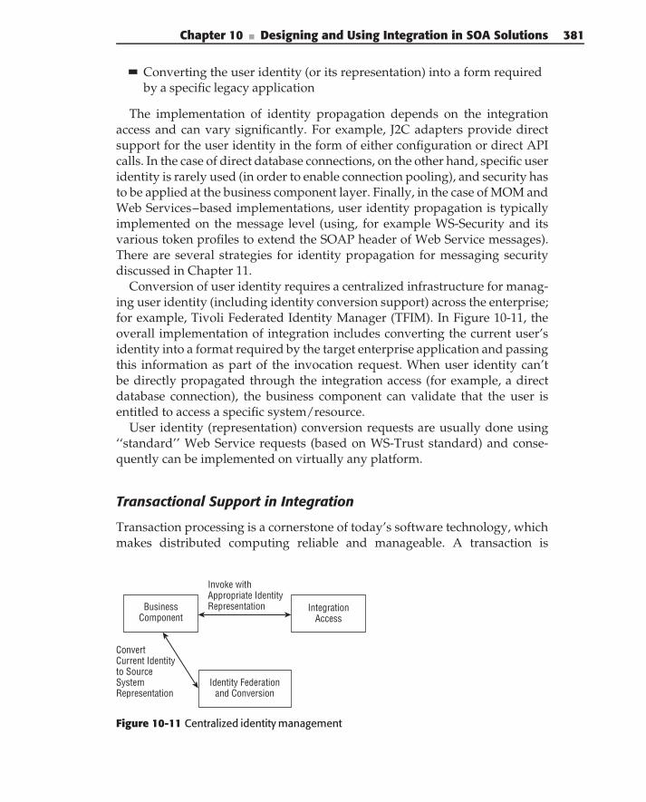
Chapter 10 ■ Designing and Using Integration in SOA Solutions 381
Converting the user identity (or its representation) into a form requiredby a specific legacy application
The implementation of identity propagation depends on the integrationaccess and can vary significantly. For example, J2C adapters provide directsupport for the user identity in the form of either configuration or direct APIcalls. In the case of direct database connections, on the other hand, specific useridentity is rarely used (in order to enable connection pooling), and security hasto be applied at the business component layer. Finally, in the case of MOM andWeb Services–based implementations, user identity propagation is typicallyimplemented on the message level (using, for example WS-Security and itsvarious token profiles to extend the SOAP header of Web Service messages).There are several strategies for identity propagation for messaging securitydiscussed in Chapter 11.
Conversion of user identity requires a centralized infrastructure for manag-ing user identity (including identity conversion support) across the enterprise;for example, Tivoli Federated Identity Manager (TFIM). In Figure 10-11, theoverall implementation of integration includes converting the current user’sidentity into a format required by the target enterprise application and passingthis information as part of the invocation request. When user identity can’tbe directly propagated through the integration access (for example, a directdatabase connection), the business component can validate that the user isentitled to access a specific system/resource.
User identity (representation) conversion requests are usually done using‘‘standard’’ Web Service requests (based on WS-Trust standard) and conse-quently can be implemented on virtually any platform.
Transactional Support in Integration
Transaction processing is a cornerstone of today’s software technology, whichmakes distributed computing reliable and manageable. A transaction is
BusinessComponent
ConvertCurrent Identityto SourceSystemRepresentation
Identity Federationand Conversion
IntegrationAccess
Invoke withAppropriate IdentityRepresentation
Figure 10-11 Centralized identity management
382 Part II ■ Designing SOA
a consistent change of application(s) state that is governed by ACID (atomic,consistent, isolated, and durable) properties:
Atomic — The transaction executes completely or not at all. Atomicity oftransaction ensures that either all of the updates are performed or noneis performed. Atomicity also ensures that underlying data returns to aknown valid state following the failure, thus reducing the requirementsfor manual intervention during failures and restarts.
Consistent — The transaction preserves the internal consistency ofunderlying data. This means that if a transaction is executed by itself onthe underlying resources, which are initially consistent, at the end of thetransaction these resources will be consistent again.
Isolated — The transaction executes as if it were running alone, with noother transactions. An execution is isolated if its effect is the same as run-ning transactions serially, one after another, with no overlap of executionof any of them.
Durable — The transaction results are not lost in the case of softwareor hardware failures. So once a transaction is committed, its results aredurably stored and can be used for automatic system recovery.
ACID transactions are usually implemented using transaction monitors(for example, Tuxedo, CICS, or Encina) or component platforms (for example,a J2EE application server or MTS). This means that support for ACID transac-tions requires coupling through the transactional environment, thus limitinginteroperability and flexibility. In addition, some of the legacy applicationsdo not support transactions at all. Finally, a requirement for ACID transac-tion implementations is resource locking for the duration of the transaction,which requires a guaranteed short execution time of services. Longer trans-action times usually lead to worsening overall throughput of transactionalresources.
ACID transactions, although perfectly appropriate for objects and compo-nents, are usually too restrictive for services.
In an attempt to overcome the limitations of the traditional two-phasecommit protocol, several standards defining business transactions have beenproposed and implemented.
Unfortunately, business transactions are supported only for WebServices and require SOAP enveloping, which is not always possible for inte-gration and often requires specific support from the existing enterpriseapplications (which is also not a simple sell).
The most generic approach to the implementation of transactional supportfor integration is to use compensations, also called compensating transactions.This means creating appropriate ‘‘undo’’ methods as part of integration
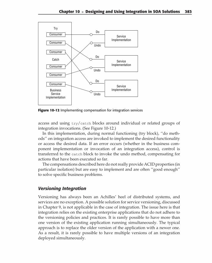
Chapter 10 ■ Designing and Using Integration in SOA Solutions 383
ServiceImplementation
ServiceImplementation
ServiceImplementation
Undo
Do
Undo
Do
Undo
Do
BusinessService
Implementation
Try
Catch
Consumer
Consumer
Consumer
Consumer
Consumer
Consumer
Figure 10-12 Implementing compensation for integration services
access and using try/catch blocks around individual or related groups ofintegration invocations. (See Figure 10-12.)
In this implementation, during normal functioning (try block), ‘‘do meth-ods’’ on integration access are invoked to implement the desired functionalityor access the desired data. If an error occurs (whether in the business com-ponent implementation or invocation of an integration access), control istransferred to the catch block to invoke the undo method, compensating foractions that have been executed so far.
The compensations described here do not really provide ACID properties (inparticular isolation) but are easy to implement and are often ‘‘good enough’’to solve specific business problems.
Versioning Integration
Versioning has always been an Achilles’ heel of distributed systems, andservices are no exception. A possible solution for service versioning, discussedin Chapter 9, is not applicable in the case of integration. The issue here is thatintegration relies on the existing enterprise applications that do not adhere tothe versioning policies and practices. It is rarely possible to have more thanone version of the existing application running simultaneously. The typicalapproach is to replace the older version of the application with a newer one.As a result, it is rarely possible to have multiple versions of an integrationdeployed simultaneously.
384 Part II ■ Designing SOA
Because the implementation of a business service never uses the integrationaccess directly, but rather does so through the business component, thisbusiness component is a natural unit of versioning. If the integration accesschanges, these changes can be encapsulated within the implementation of thebusiness component, assuming that its interface and characteristics do notchange.
Dealing with Large Messages
When integration is based on Web Services or MOM middleware, the sizeof the invocation payload can have a significant impact on both invocationperformance and the scalability of the business service implementation. Theissue here is twofold:
N O T E When we say large we mean several megabytes. For example, we haveseen an integration service retrieve an insurance policy from the legacy system,which can return up to 20 megabytes of data.
Large size messages create additional strain on the network and under-lying middleware. For example, in the case of MQ, the limit of thesupported message size must be increased explicitly, which increases thetoll on the resources used by the MQ infrastructure. In the case of HTTPtransport, middleware splits messages into 4 Kb ‘‘chunks’’ for delivery,with the ‘‘Ack’’ message, accompanying every ‘‘chunk.’’ As a result,there is severe (nonlinear) degradation in the message delivery perfor-mance as the message size grows. Message encryption can worsen thesituation by adding additional CPU load and performance degradationdue to encryption/decryption operations.
Large message size is also one of the reasons for peak memoryutilization on the service consumer. There are typically severalrepresentations of the same payload, for example, XML string, OOrepresentation, and so on, which have to be present in memory simul-taneously. As the size of the message grows, the load on the garbagecollector (Java and/or C#) and memory paging increases, thus slowingdown the implementations.
One of the possible solutions to this problem is ‘‘chunking’’ of the servicepayload, replacing, for example, a single inquiry method that returns the wholeinsurance policy with the multiple partial inquiry methods each returningparts of the policy. Although this solution seems like a good one, it does notalways work. It can contradict the way the enterprise system that providesthis functionality works.
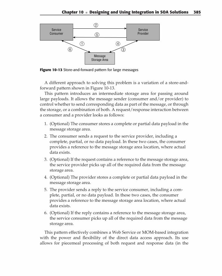
Chapter 10 ■ Designing and Using Integration in SOA Solutions 385
ServiceConsumer
MessageStorage Area
ServiceProvider
1
2
3
4
5
6
Figure 10-13 Store-and-forward pattern for large messages
A different approach to solving this problem is a variation of a store-and-forward pattern shown in Figure 10-13.
This pattern introduces an intermediate storage area for passing aroundlarge payloads. It allows the message sender (consumer and/or provider) tocontrol whether to send corresponding data as part of the message, or throughthe storage, or a combination of both. A request/response interaction betweena consumer and a provider looks as follows:
1. (Optional) The consumer stores a complete or partial data payload in themessage storage area.
2. The consumer sends a request to the service provider, including acomplete, partial, or no data payload. In these two cases, the consumerprovides a reference to the message storage area location, where actualdata exists.
3. (Optional) If the request contains a reference to the message storage area,the service provider picks up all of the required data from the messagestorage area.
4. (Optional) The provider stores a complete or partial data payload in themessage storage area.
5. The provider sends a reply to the service consumer, including a com-plete, partial, or no data payload. In these two cases, the consumerprovides a reference to the message storage area location, where actualdata exists.
6. (Optional) If the reply contains a reference to the message storage area,the service consumer picks up all of the required data from the messagestorage area.
This pattern effectively combines a Web Service or MOM-based integrationwith the power and flexibility of the direct data access approach. Its useallows for piecemeal processing of both request and response data (in the
386 Part II ■ Designing SOA
message storage area), combined with the existing services’ granularity, andtypically requires significantly fewer changes in the existing legacy applica-tions compared to chunking.
Data Virtualization and Enterprise Data BusIn typical SOA implementations, a large portion of the integration supportsaccess to existing enterprise data. Aligning this data integration with thebusiness services is often a challenge for large-scale SOA implementations.
Although typical SOA implementations hide enterprise data behind serviceinterfaces, the following data access issues must still be resolved:
Consolidation of data among multiple applications — Today’s enter-prise data is typically scattered across multiple siloed applications. Thismeans that enterprise data access from business services requires theinvocation of multiple data integration services, and then the correctalignment and consolidation of data from them. It is also necessary toensure the propagation of data changes to all applications that rely onthis data.
Ownership of enterprise data by services — The foundation of themodern service definition technique — functional decomposition — isnot easily mapped to enterprise data. For example, the notion of thecustomer (and corresponding data) is usually shared between multiplefunctional services. The problem is that functional and data decomposi-tions are driven by completely different rules. Functional decompositionis defined based on enterprise business processes, whereas data decom-position is defined based on the enterprise domain data taxonomy. Asa result, aligning the enterprise data with enterprise services becomes adaunting task.
Business service interface definitions — Because business service invo-cations are always remote, their design strives toward large-granularityinterfaces, aiming at minimizing the amount of network traffic. Dataaccess, on the other side, can require both high and fine granularity ofinterfaces, depending on the data access requirements. Finally, dataaccess typically implements pure CRUD (create, read, update, delete),whereas enterprise services implement meaningful business interfaces,such as rate policy, and so on.
N O T E Although this is true in general, there are plenty of exceptions. There aresituations where CRUD-type business services are well aligned with the businessfunctionality; for example, GetPoliciesForACustomer(customer), is an exampleof a business meaningful CRUD service.
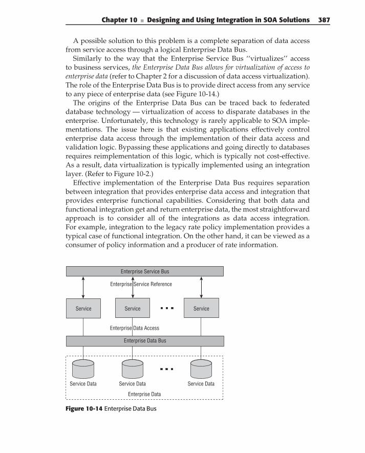
Chapter 10 ■ Designing and Using Integration in SOA Solutions 387
A possible solution to this problem is a complete separation of data accessfrom service access through a logical Enterprise Data Bus.
Similarly to the way that the Enterprise Service Bus ‘‘virtualizes’’ accessto business services, the Enterprise Data Bus allows for virtualization of access toenterprise data (refer to Chapter 2 for a discussion of data access virtualization).The role of the Enterprise Data Bus is to provide direct access from any serviceto any piece of enterprise data (see Figure 10-14.)
The origins of the Enterprise Data Bus can be traced back to federateddatabase technology — virtualization of access to disparate databases in theenterprise. Unfortunately, this technology is rarely applicable to SOA imple-mentations. The issue here is that existing applications effectively controlenterprise data access through the implementation of their data access andvalidation logic. Bypassing these applications and going directly to databasesrequires reimplementation of this logic, which is typically not cost-effective.As a result, data virtualization is typically implemented using an integrationlayer. (Refer to Figure 10-2.)
Effective implementation of the Enterprise Data Bus requires separationbetween integration that provides enterprise data access and integration thatprovides enterprise functional capabilities. Considering that both data andfunctional integration get and return enterprise data, the most straightforwardapproach is to consider all of the integrations as data access integration.For example, integration to the legacy rate policy implementation provides atypical case of functional integration. On the other hand, it can be viewed as aconsumer of policy information and a producer of rate information.
Service Data
Service Service Service
Service Data Service Data
Enterprise Data
Enterprise Data Bus
Enterprise Data Access
Enterprise Service Reference
Enterprise Service Bus
Figure 10-14 Enterprise Data Bus
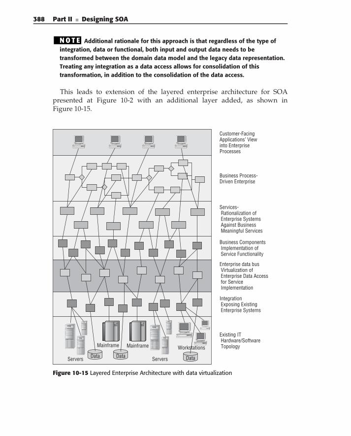
388 Part II ■ Designing SOA
N O T E Additional rationale for this approach is that regardless of the type ofintegration, data or functional, both input and output data needs to betransformed between the domain data model and the legacy data representation.Treating any integration as a data access allows for consolidation of thistransformation, in addition to the consolidation of the data access.
This leads to extension of the layered enterprise architecture for SOApresented at Figure 10-2 with an additional layer added, as shown inFigure 10-15.
DataData DataServers Servers
WorkstationsMainframe Mainframe
Customer-FacingApplications’ Viewinto EnterpriseProcesses
Business Process-Driven Enterprise
Services- Rationalization of Enterprise Systems Against Business Meaningful Services
Business Components Implementation of Service Functionality
Enterprise data bus Virtualization of Enterprise Data Access for Service Implementation
Integration Exposing Existing Enterprise Systems
Existing IT Hardware/Software Topology
Figure 10-15 Layered Enterprise Architecture with data virtualization
Chapter 10 ■ Designing and Using Integration in SOA Solutions 389
The additional layer — data virtualization — provides access to theenterprise data contained in either enterprise applications or their subor-dinated databases. It also modifies implementation of the business componentlayer; in this implementation, it no longer contains ‘‘wrapper’’ components.Business components are composed only of the components that implementservice functionality based on existing application functionality, and data thatis accessible through the Enterprise Data Bus. The advantages of such anarchitecture are:
Explicit separation of concerns between implementation of the businessservice functionality (business logic) and enterprise data support logiceffectively creates an abstraction layer, shielding the business functional-ity from details of enterprise data/functionality access.
By encapsulating all of the access to enterprise data/functionality, theEnterprise Data Bus provides a single place for all of the transforma-tions between the domain data model and the data models of enterpriseapplications.
Because any service implementation can have access to any of the enter-prise data it requires, you can significantly reduce coupling betweenservices — service invocations contain only data references (key), whichchange extremely rarely, while the actual data access is implemented bythe service itself. This means that if the service implementation requiresadditional data for its processing, it can access it directly without affect-ing its consumers.
Two possible approaches to the Enterprise Data Bus implementations are:
Specialized servers, for example, the IBM Information Server
Providing support for both direct database access and integration, anddistributed data caching, for example IBM’s Object Grid
Summary
This chapter defined integration as a foundation of successful SOA imple-mentation. It described general integration challenges and showed differentapproaches for bringing integration and SOA together.
It then introduced a precise definition of integration, the relationship tobusiness services, and the role in business service implementation, includ-ing different approaches to implementing integration, among them: MOM,
390 Part II ■ Designing SOA
Message Broker, J2C, data access, and two different Web Service solutions.It also discussed the main implementation considerations for each approach.It highlighted the role of the ESB as a universal connectivity middlewaresolution, which simplifies the implementation of integration.
Next, it discussed major architectural concerns for implementing integrationservices, including data mapping, security, transactional support, versioning,and large message impact, and presented possible solutions for each problem.
Finally, it introduced the concept of the Enterprise Data Bus, to unify andencapsulate different approaches to implementing integration.
C H A P T E R
11
SOA SecurityIf you think technology can solve your security problems, then you don’t understand
the problems, and you don’t understand the technology.
— Bruce Schneier
In the very brief history of SOA architecture and design, security is one aspectthat is sometimes overlooked. A vital piece of the SOA puzzle, security consistsof a series of requirements that demands a well-thought-out plan, design, andimplementation. No specific technology is a silver bullet — a successful SOAsecurity solution can only be accomplished by understanding the foundationalprinciples of information security and mastering SOA architecture and design.Anyone who has such knowledge can understand that it is essential toadopt a security strategy for SOA and a security architecture roadmap earlyon. A smart SOA security strategy allows business applications to meetthe needs of organizations and their business partners by incorporating theclassic security goals of authentication, authorization, integrity, confidentiality,non-repudiation, auditing, and availability.
The security challenges in SOA are complicated by the state of today’sbusiness practices. This is the age of dynamic business partners, wherebyorganizations share information on a short- and long-term basis with otherenterprises, and as a result, networks have become porous, blurring the linesof the definition between ‘‘internal’’ and ‘‘external’’ networks. Gone are thedays of monolithic applications protected only by corporate firewalls. Instead,organizations are moving toward a policy-centric SOA model enforced at theapplication and service levels, providing security between clients and servicesin a multi-domain environment. As a result, an organization must adopt
391
392 Part II ■ Designing SOA
an agile SOA security strategy that fits this model, and architectures must beadaptable enough to change as policies and relationships change.
This chapter is aimed at the SOA architect and designer; it provides a focuson security fundamentals and key standards, and offers practical strategiesand blueprints for securing the components of an enterprise SOA. It is dividedinto five sections, and each section builds on the foundation of the precedingones to provide a clear understanding of SOA security principles, standards,and practical tips:
Key security terminology, common security goals found in SOA-basedprojects, and the security challenges related to achieving these goals
Major standards that can help you achieve SOA security goals
Guidance for using standards and different security methodologies invarious SOA security scenarios
A case study providing an example of how to use the concepts in thisbook
A roadmap and common-sense practical advice for achieving success inSOA-based projects
SOA Security Goals and Fundamentals
To plan a sound SOA security strategy, SOA architects must have an under-standing of information security fundamentals and how they can be appliedto build SOA solutions. Many security goals require some explanation, andunderstanding SOA security standards and best practices is dependent onunderstanding security terminology. This section defines an information secu-rity vocabulary, giving examples, scenarios, and challenges from real-worldSOA deployments. Because there are entire books dedicated to these concepts,this section is simply meant to be a ‘‘bird’s-eye view’’ introduction, focusing onthe scope of what the SOA architect needs to know. The terms defined in thissection are important for the discussions of SOA security in the subsequentsections of this chapter.
AuthenticationAuthentication means validating the identity of a subject. A subject can be a user,a Web Service, a computer, or an application. Authentication is the first step inaccess control. To enforce an access control policy, a system needs to initiallyidentify the subject with some level of assurance. Mutual authentication istwo-way authentication, and proves the identity of both parties involved incommunication, providing both sides with identity assurance.
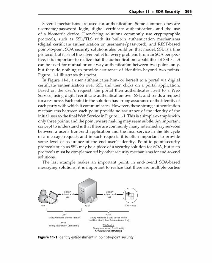
Chapter 11 ■ SOA Security 393
Several mechanisms are used for authentication: Some common ones areusername/password login, digital certificate authentication, and the useof a biometric device. User-facing solutions commonly use cryptographicprotocols, such as SSL/TLS with its built-in authentication mechanisms(digital certificate authentication or username/password), and REST-basedpoint-to-point SOA security solutions also build on that model. SSL is a fineprotocol, but it is not the silver bullet for every problem. From an SOA perspec-tive, it is important to realize that the authentication capabilities of SSL/TLScan be used for mutual or one-way authentication between two points only,but they do nothing to provide assurance of identities beyond two points.Figure 11-1 illustrates this point.
In Figure 11-1, a user authenticates him- or herself to a portal via digitalcertificate authentication over SSL and then clicks on a portal application.Based on the user’s request, the portal then authenticates itself to a WebService, using digital certificate authentication over SSL, and sends a requestfor a resource. Each point in the solution has strong assurance of the identity ofeach party with which it communicates. However, these strong authenticationmechanisms between each point provide no assurance of the identity of theinitial user to the final Web Service in Figure 11-1. This is a simple example withonly three points, and the point we are making may seem subtle. An importantconcept to understand is that there are commonly many intermediary servicesbetween a user’s front-end application and the final service in the life cycleof a message request, and in such requests it is often important to providesome level of assurance of the end user’s identity. Point-to-point securityprotocols such as SSL may be a piece of a security solution for SOA, but suchprotocols must be complemented by other security mechanisms for end-to-endsolutions.
The last example makes an important point: in end-to-end SOA-basedmessaging solutions, it is important to realize that there are multiple parties
User Portal
Mutually Authenticated
SSL
Web Service
User:Strong Assurance of Portal Identity
Portal:Strong Assurance of User Identity
Portal:Strong Assurance of Web Service Identity
(and User Identity from Previous Connection)
Web Service:Strong Assurance of Portal Identity
No Assurance of User Identity
Mutually Authenticated
SSL
Figure 11-1 Identity establishment in point-to-point security
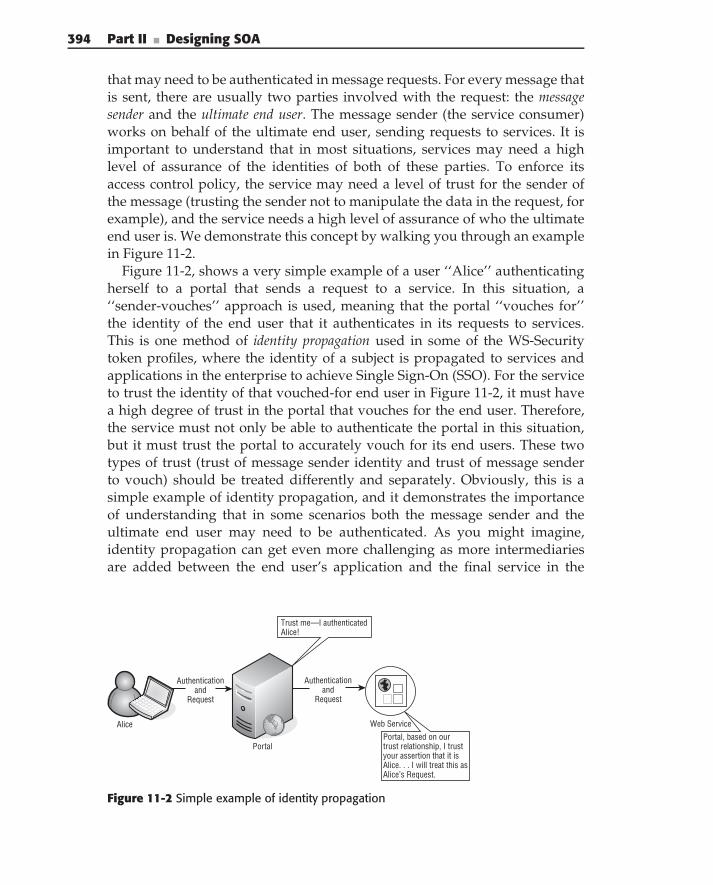
394 Part II ■ Designing SOA
that may need to be authenticated in message requests. For every message thatis sent, there are usually two parties involved with the request: the messagesender and the ultimate end user. The message sender (the service consumer)works on behalf of the ultimate end user, sending requests to services. It isimportant to understand that in most situations, services may need a highlevel of assurance of the identities of both of these parties. To enforce itsaccess control policy, the service may need a level of trust for the sender ofthe message (trusting the sender not to manipulate the data in the request, forexample), and the service needs a high level of assurance of who the ultimateend user is. We demonstrate this concept by walking you through an examplein Figure 11-2.
Figure 11-2, shows a very simple example of a user ‘‘Alice’’ authenticatingherself to a portal that sends a request to a service. In this situation, a‘‘sender-vouches’’ approach is used, meaning that the portal ‘‘vouches for’’the identity of the end user that it authenticates in its requests to services.This is one method of identity propagation used in some of the WS-Securitytoken profiles, where the identity of a subject is propagated to services andapplications in the enterprise to achieve Single Sign-On (SSO). For the serviceto trust the identity of that vouched-for end user in Figure 11-2, it must havea high degree of trust in the portal that vouches for the end user. Therefore,the service must not only be able to authenticate the portal in this situation,but it must trust the portal to accurately vouch for its end users. These twotypes of trust (trust of message sender identity and trust of message senderto vouch) should be treated differently and separately. Obviously, this is asimple example of identity propagation, and it demonstrates the importanceof understanding that in some scenarios both the message sender and theultimate end user may need to be authenticated. As you might imagine,identity propagation can get even more challenging as more intermediariesare added between the end user’s application and the final service in the
Trust me—I authenticated Alice!
Portal, based on ourtrust relationship, I trust your assertion that it isAlice. . . I will treat this asAlice’s Request.
Alice
Portal
Portal
Authenticationand
Request
Web Service
Authenticationand
Request
Figure 11-2 Simple example of identity propagation
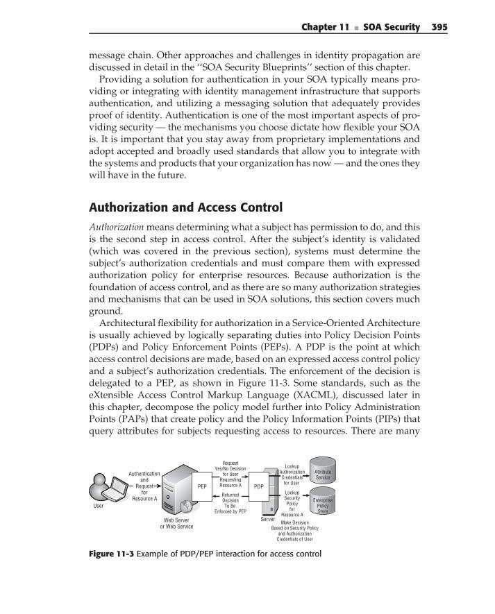
Chapter 11 ■ SOA Security 395
message chain. Other approaches and challenges in identity propagation arediscussed in detail in the ‘‘SOA Security Blueprints’’ section of this chapter.
Providing a solution for authentication in your SOA typically means pro-viding or integrating with identity management infrastructure that supportsauthentication, and utilizing a messaging solution that adequately providesproof of identity. Authentication is one of the most important aspects of pro-viding security — the mechanisms you choose dictate how flexible your SOAis. It is important that you stay away from proprietary implementations andadopt accepted and broadly used standards that allow you to integrate withthe systems and products that your organization has now — and the ones theywill have in the future.
Authorization and Access ControlAuthorization means determining what a subject has permission to do, and thisis the second step in access control. After the subject’s identity is validated(which was covered in the previous section), systems must determine thesubject’s authorization credentials and must compare them with expressedauthorization policy for enterprise resources. Because authorization is thefoundation of access control, and as there are so many authorization strategiesand mechanisms that can be used in SOA solutions, this section covers muchground.
Architectural flexibility for authorization in a Service-Oriented Architectureis usually achieved by logically separating duties into Policy Decision Points(PDPs) and Policy Enforcement Points (PEPs). A PDP is the point at whichaccess control decisions are made, based on an expressed access control policyand a subject’s authorization credentials. The enforcement of the decision isdelegated to a PEP, as shown in Figure 11-3. Some standards, such as theeXtensible Access Control Markup Language (XACML), discussed later inthis chapter, decompose the policy model further into Policy AdministrationPoints (PAPs) that create policy and the Policy Information Points (PIPs) thatquery attributes for subjects requesting access to resources. There are many
Attribute Service
EnterprisePolicyStore
ServerMake Decision
Based on Security Policyand Authorization
Credentials of User
User
Web Serveror Web Service
Authenticationand
Requestfor
Resource A
PDPPEP
Request Yes/No Decision
for UserRequestingResource A
Returned DecisionTo Be
Enforced by PEP
Lookup Authorization Credentials for User
Lookup SecurityPolicy
forResource A
Figure 11-3 Example of PDP/PEP interaction for access control
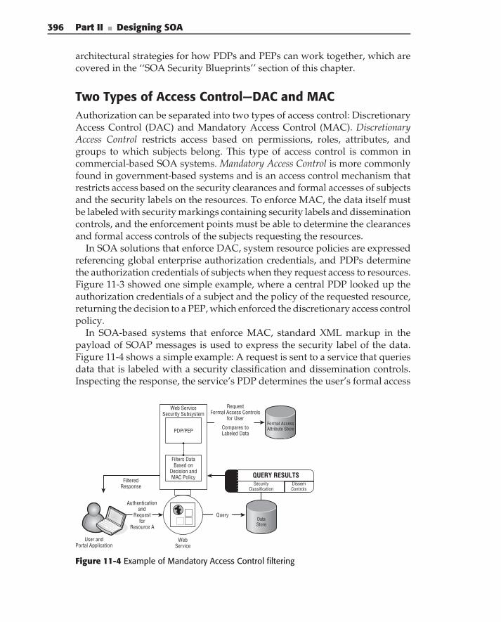
396 Part II ■ Designing SOA
architectural strategies for how PDPs and PEPs can work together, which arecovered in the ‘‘SOA Security Blueprints’’ section of this chapter.
Two Types of Access Control—DAC and MACAuthorization can be separated into two types of access control: DiscretionaryAccess Control (DAC) and Mandatory Access Control (MAC). DiscretionaryAccess Control restricts access based on permissions, roles, attributes, andgroups to which subjects belong. This type of access control is common incommercial-based SOA systems. Mandatory Access Control is more commonlyfound in government-based systems and is an access control mechanism thatrestricts access based on the security clearances and formal accesses of subjectsand the security labels on the resources. To enforce MAC, the data itself mustbe labeled with security markings containing security labels and disseminationcontrols, and the enforcement points must be able to determine the clearancesand formal access controls of the subjects requesting the resources.
In SOA solutions that enforce DAC, system resource policies are expressedreferencing global enterprise authorization credentials, and PDPs determinethe authorization credentials of subjects when they request access to resources.Figure 11-3 showed one simple example, where a central PDP looked up theauthorization credentials of a subject and the policy of the requested resource,returning the decision to a PEP, which enforced the discretionary access controlpolicy.
In SOA-based systems that enforce MAC, standard XML markup in thepayload of SOAP messages is used to express the security label of the data.Figure 11-4 shows a simple example: A request is sent to a service that queriesdata that is labeled with a security classification and dissemination controls.Inspecting the response, the service’s PDP determines the user’s formal access
DataStore
Request Formal Access Controls
for User
Compares to Labeled Data
Filters Data Based on
Decision andMAC Policy
PDP/PEP
Web Service Security Subsystem
SecurityClassification
Dissem Controls
QUERY RESULTSFiltered
Response
Web Service
Authenticationand
Requestfor
Resource A
Query
User andPortal Application
Formal AccessAttribute Store
Figure 11-4 Example of Mandatory Access Control filtering
Chapter 11 ■ SOA Security 397
authorization credentials, compares it to data’s security label, and the PDPthen makes an authorization decision, resulting in the PEP filtering the resultsinto data that only the end user has permission to see.
Role-Based Access Control (RBAC) is a common credentialing strategy usedin DAC enforcement. Using RBAC, security roles are defined and assignedto subjects, resource access control policies are expressed using security roles,and PDPs make decisions based on the roles of subjects and the policies ofresources.
Attribute-Based Access Control (ABAC) is a strategy similar to RBAC, butit utilizes security attributes rather than security roles. Many systems havemoved to the ABAC model because of the desire to separate a user’s duties(roles) from other types of credentials that could be used in access controlsystems. An ABAC credentialing strategy enables both Mandatory and Discre-tionary Access Control in SOA. In such a solution, a trusted enterprise attributeservice may store and expose subject authorization credentials such as role,group, security clearance, and citizenship as attributes. In many ABAC-basedSOA systems, RBAC roles are included as authorization attributes.
Predetermined Authorization Decision-Based Access Control (PADBAC) isan access control strategy defined in this book where access control policy(either DAC or MAC) is used in making an authorization decision for a subjectaccessing a resource, and where those digitally signed authorization decisionsare distributed to the subjects as ‘‘tickets’’ for future access. For example, alaundry service may issue an authorization decision to a user when the userdrops off his or her laundry; for instance, ‘‘Parker Cullinan is authorizedto pick up his laundry (bin #228).’’ Later, that signed authorization decisionwould be presented by Parker Cullinan to the laundry service in order to pickup his laundry. PADBAC can be used to model such real-world situations andis discussed later in this chapter (in ‘‘SOA Security Blueprints’’).
Many service security standards revolve around authorization — SecurityAssertion Markup Language (SAML), XACML, and WS-Trust are just a fewexamples of standards that provide many of the fundamentals of authorizationin an SOA. Both standards and authorization strategies are discussed at lengththroughout this chapter.
Federated Identity and Cross-Enterprise AccessFederated identity is a security goal where a policy arrangement is made amongmultiple security domains that allows users to use the same identificationdata to access resources in partner security domains. The collection of part-ner enterprises is called a federation, and this security goal provides users ofthis federation the capability of SSO to applications throughout the feder-ation. In an effective federated identity solution, partners share an explicitmutual trust pertaining to the way the identity of users is validated and
398 Part II ■ Designing SOA
how authorization of resources occur. A key point is that in such solutions,a resource provider in a partner enterprise relies on an externally managedidentity, rather than creating another locally managed identity for the subjectrequesting access. This reliance relieves the burden of cost and managementcomplexity.
The success of federated identity is dependent upon the ability to share arich and commonly understood set of claims between an identity provider (theorganization vouching for the identity) and a relying party (the organizationproviding access to resources). The notion of identity federation is broadand evolving, and as a result, there are certain situations where informationbesides identity is federated. In practice, access control in a federation canoccur in multiple ways: Partners can grant certain accesses to users from oneenterprise, based on their identity in their host organization (true identityfederation); partners can assign everyone from a host organization certainauthorization credentials (enterprise-based policy and not really federatedidentity); or access can be granted based on authorization credentials of theuser, and the federation arrangement can include a translation of mappings ofauthorization credentials between the two organizations (federated authoriza-tion). In practice, there are protocols for both browser-based SSO, where browserclients and web applications use standard HTTP extensions and redirectionsfor identity federation, and service-based SSO, intended for identity federationbetween services.
One important concept for the SOA architect to understand is the dynamicnature of relationships in a federation. Although it is common for federatedidentity partnerships to be long-lived, it is important to realize that the newage of dynamic business partners requires a more fluid model. The wayorganizations do business is complex, and if you are going to be able toshare information successfully, your architecture must adapt to these businessprocesses. In sharing information in these partnerships, it is vital that eachorganization protects its information assets. A flexible SOA, therefore, canutilize federated identity technology to allow dynamic communities of interestto share data. Figure 11-5 shows such a model, where enterprises may joinmultiple federations at any given time. To meet the authentication and autho-rization needs of partners in this dynamic environment, organizations mustadapt cross-enterprise access policies, and they must adopt a policy-centricmodel for enforcing access control, utilizing open standards that maximizeinteroperability.
Standards related to federated identity have been evolving. There arecurrently two specifications in OASIS revolving around federated identity.In 2005, OASIS finalized the SAML 2.0 standard, which unified previousspecifications of identity federation, such as Shibboleth and the Liberty AllianceIdentity Federation Framework (ID-FF). The Liberty Alliance also releasedthe Identity Web Services Framework (ID-WSF), which relies heavily on
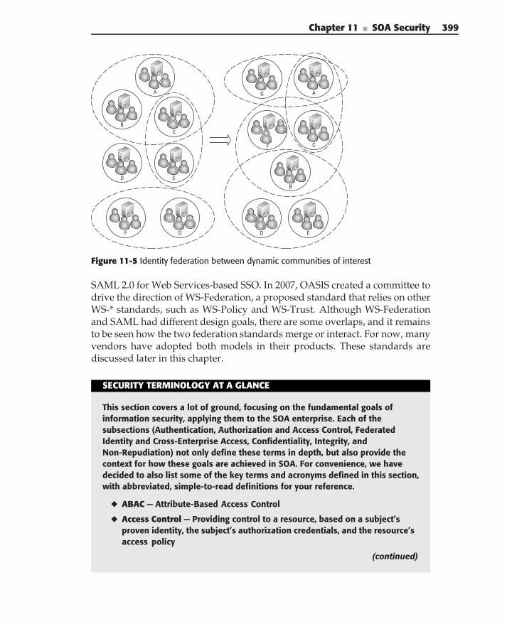
Chapter 11 ■ SOA Security 399
A
BC
ED
F G
G A
CF
ED
B
Figure 11-5 Identity federation between dynamic communities of interest
SAML 2.0 for Web Services-based SSO. In 2007, OASIS created a committee todrive the direction of WS-Federation, a proposed standard that relies on otherWS-* standards, such as WS-Policy and WS-Trust. Although WS-Federationand SAML had different design goals, there are some overlaps, and it remainsto be seen how the two federation standards merge or interact. For now, manyvendors have adopted both models in their products. These standards arediscussed later in this chapter.
SECURITY TERMINOLOGY AT A GLANCE
This section covers a lot of ground, focusing on the fundamental goals ofinformation security, applying them to the SOA enterprise. Each of thesubsections (Authentication, Authorization and Access Control, FederatedIdentity and Cross-Enterprise Access, Confidentiality, Integrity, andNon-Repudiation) not only define these terms in depth, but also provide thecontext for how these goals are achieved in SOA. For convenience, we havedecided to also list some of the key terms and acronyms defined in this section,with abbreviated, simple-to-read definitions for your reference.
◆ ABAC — Attribute-Based Access Control
◆ Access Control — Providing control to a resource, based on a subject’sproven identity, the subject’s authorization credentials, and the resource’saccess policy
(continued)
400 Part II ■ Designing SOA
SECURITY TERMINOLOGY AT A GLANCE (continued)
◆ Authentication — Validating the identity of a subject
◆ Authorization — Determining if a subject has permission to do something
◆ Confidentiality — The security goal aimed at hiding sensitive information,done with encryption
◆ DAC — Discretionary Access Control
◆ Federated identity — A security goal where a policy arrangement is madeamong multiple security domains that allows users to use the same identifi-cation data to access resources in partner security domains.
◆ Integrity — The assurance that data has not been altered in transit or atrest, usually achieved by message digests, hash codes, or as a side effect ofa digital signature.
◆ MAC — Mandatory Access Control
◆ Non-repudiation — Strong assurance that a subject signed a message (legalproof that can be validated by a third party) achieved through a digitalsignature.
◆ PADBAC — Predetermined Authorization Decision-Based Access Control
◆ RBAC — Role-Based Access Control
ConfidentialityWhen sensitive information is transmitted between authorized parties, it isimportant that this information not be seen in transit by eavesdroppers.Confidentiality is the security goal aimed at hiding sensitive information, andthis is done with encryption. In the encryption process, a plaintext message isscrambled with a cryptographic algorithm to produce a ciphertext message.Using a key (or shared secret), the intended recipient can decrypt the data.There are many different cryptographic algorithms, symmetric (secret key)and asymmetric (public key) algorithms that can be used to provide differentlevels of protection for data.
In an enterprise SOA solution, there may be certain elements of messagesthat are confidential and require a level of encryption. Many higher-levelprotocols, such as SSL/TLS, provide bulk encryption (and data integrity)between two points. If bulk encryption satisfies your security requirements,this may be sufficient. However, there are scenarios in SOA solutions wherebulk encryption protocols do not offer the correct solution, as shown inFigure 11-6.
In Figure 11-6, the bulk encryption protocol provides confidentiality betweenevery point in the solution. However, if there is one element of the original
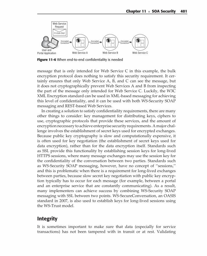
Chapter 11 ■ SOA Security 401
Encrypted Connection
Web Service A
C’s Eyes Only!
Web ServiceRequest
User and Portal Application
Encrypted Connection
Web Service B
Encrypted Connection
Web Service C
Figure 11-6 When end-to-end confidentiality is needed
message that is only intended for Web Service C in this example, the bulkencryption protocol does nothing to satisfy this security requirement. It cer-tainly ensures that only Web Service A, B, and C can see the message, butit does not cryptographically prevent Web Services A and B from inspectingthe part of the message only intended for Web Service C. Luckily, the W3CXML Encryption standard can be used in XML-based messaging for achievingthis level of confidentiality, and it can be used with both WS-Security SOAPmessaging and REST-based Web Services.
In creating a solution to satisfy confidentiality requirements, there are manyother things to consider: key management for distributing keys, ciphers touse, cryptographic protocols that provide these services, and the amount ofencryption necessary to achieve enterprise security requirements. A major chal-lenge involves the establishment of secret keys used for encrypted exchanges.Because public key cryptography is slow and computationally expensive, itis often used for key negotiation (the establishment of secret keys used fordata encryption), rather than for the data encryption itself. Standards suchas SSL provide this functionality by establishing session keys for long-livedHTTPS sessions, where many message exchanges may use the session key forthe confidentiality of the conversation between two parties. Standards suchas WS-Security SOAP messaging, however, have no concept of ‘‘sessions,’’and this is problematic when there is a requirement for long-lived exchangesbetween parties, because slow secret key negotiation with public key encryp-tion typically has to occur for each message (for example, between a portaland an enterprise service that are constantly communicating). As a result,many implementers can achieve success by combining WS-Security SOAPmessaging with SSL between two points. WS-SecureConversation, an OASISstandard in 2007, is also used to establish keys for long-lived sessions usingthe WS-Trust model.
IntegrityIt is sometimes important to make sure that data (especially for servicetransactions) has not been tampered with in transit or at rest. Validating
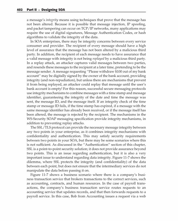
402 Part II ■ Designing SOA
a message’s integrity means using techniques that prove that the message hasnot been altered. Because it is possible that message injection, IP spoofing,and packet tampering can occur on TCP/IP networks, many applications mayrequire the use of digital signatures, Message Authentication Codes, or hashalgorithms to validate the integrity of the data.
In SOA enterprises, there may be integrity concerns between every serviceconsumer and provider. The recipient of every message should have a highlevel of assurance that the message has not been altered by a malicious thirdparty. In addition, the recipient of each message needs to have assurance thata valid message with integrity is not being replayed by a malicious third party.In a replay attack, an attacker captures valid messages between two parties,and resends these messages to the recipient at a later time, pretending to be themessage sender. A message requesting ‘‘Please withdraw $100 out of my bankaccount’’ may be digitally signed by the owner of the bank account, providingintegrity (and non-repudiation), but unless there are mechanisms that preventit from being replayed, an attacker could replay that message until the user’sbank account is empty! For this reason, successful secure messaging protocolsuse integrity mechanisms to combine messages with a time stamp and messageidentifier, guaranteeing the integrity of the date and time the message wassent, the message ID, and the message itself. If an integrity check of the timestamp or message ID fails, if the time stamp has expired, if a message with thesame message identifier has already been received, or if the message itself hasbeen altered, the message is rejected by the recipient. The mechanisms in theWS-Security SOAP messaging specification provide integrity mechanisms, inaddition to preventing replay attacks.
The SSL/TLS protocol can provide the necessary message integrity betweenany two points in your enterprise, as it combines integrity mechanisms withconfidentiality and authentication. This may satisfy security requirementsbetween two points in your SOA, but there may be some scenarios where thisis not sufficient. As discussed in the ‘‘Authentication’’ section of this chapter,SSL is a point-to-point security solution; it does not provide assurance beyondtwo points. This is an issue regarding authentication, but it is also a veryimportant issue to understand regarding data integrity. Figure 11-7 shows thedilemma, where SSL protects the integrity (and confidentiality) of the databetween each point, but does not ensure that the intermediary services do notmanipulate the data before passing it on.
Figure 11-7 shows a business scenario where there is a company’s busi-ness transaction service that brokers transactions to the correct services, suchas accounting, contracts, and human resources. In the case of payroll trans-actions, the company’s business transaction service routes requests to anaccounting service that updates records, and that then forwards requests to apayroll service. In this case, Bob from Accounting issues a request via a web
Chapter 11 ■ SOA Security 403
SSL Connection
BusinessTransaction
Service
Web ServiceRequest
"Bob says deposit$100 into Bill
Lumberg's Acct"
AlteredRequest
"Bob says deposit$100 into MiltonWaddum's Acct"
BobFrom Accounting
SSL Connection
PayrollService
SSL Connection
AccountingService
Figure 11-7 When end-to-end integrity is needed
portal to deposit $100 into the account of an employee, Bill Lumberg. Betweenthe user’s client application and the business transaction service is a mutuallyauthenticated SSL connection, ensuring confidentiality, data integrity, andidentification of the identities of each party. In fact, between every point inFigure 11-7 there are mutually authenticated SSL connections, ensuring thislevel of security between each point. As you can see from Figure 11-7, however,the security provided by SSL doesn’t prevent one of the Web Services fromaltering the user’s original request — even though SSL protects datafrom being altered in transit, it does not prevent one of the nodes in thesolution from modifying the request before propagating the request on tothe next service. Indeed, Figure 11-7 shows that the compromised businesstransaction service alters the user’s original request, resulting in the wrongemployee getting a payroll deposit.
The W3C XML Signature standard can be used as part of the data integritysolution for solving the problem demonstrated in Figure 11-7, because aby-product of a digital signature is a hash code used to validate integrity.If the user’s original request is digitally signed, and that signed request ispropagated to all of the nodes in the solution, this ensures the integrity of theoriginal request. If any Web Service attempts to alter the message, it fails anintegrity check. At the same time, mechanisms must also be used with XMLSignature to prevent the replay of the request, and there are some potentialpitfalls with signatures that are covered in the next section. XML Signaturecan be used in XML-based messaging, and can therefore be used with bothWS-Security SOAP messaging and REST-based Web Services.
Much about providing integrity is straightforward, but some of the casesaddressed in this section (related to message replay and integrity in end-to-endsolutions) are more subtle. It is important, therefore, for architects to look atSOA usage scenarios and security requirements ahead of time in order toprevent these attacks.
Integrity is usually a key requirement in business, commercial, and govern-ment SOA initiatives, and is therefore very important to understand.
404 Part II ■ Designing SOA
Non-RepudiationNon-repudiation is the side effect of digitally signing a message, and it is legalproof that a subject signed a message. A digital signature cryptographicallyties the identity of the signer to the contents of the data being signed, whichis an important concept in SOA-based messaging. Because digital signaturesare based on public key cryptography, the sender of the signed message cannot successfully deny the fact that he signed the message. Using public keycryptography, the signature can be mathematically proven to be done by thesigner of the message, because of the nature of the cryptographic operationperformed with the sender’s private key. Because of the size of the keysinvolved, digital signature validation produces a very high level of assurancethat a message signer indeed signed the message.
The W3C XML Signature standard is a W3C standard used for providingintegrity and non-repudiation, and it is used to sign XML documents andelements of XML documents. It can be used in REST-based Web Services aswell as WS-Security SOAP Messaging. Often, digital signatures are used inestablishing trust in challenge-response scenarios for authenticating serviceconsumers for Web Service requests. A message sender may send a digitallysigned message to a service, providing strong assurance of the sender’sidentity, strong assurance that the data was not altered in transit (dataintegrity), and cryptographically tying the sender to the data.
Due to the strong level of assurance provided by digital signatures, it isimportant that anyone implementing SOA messaging solutions realize thepotential dangers in the way that signatures can be applied and used. Ifan XML element is signed without stating its conditions of use or withoutbeing bound to a specific request, this could be very dangerous. For example, avoting authority could sign an assertion that says ‘‘This is Joey Bush’’ for a usernamed Joey Bush to use for voting purposes in the 2008 election. If, however,the authority doesn’t include an expiration date on that assertion (2008) and anexplicit condition of use (voting), anyone could use that signed assertion in away for which it was not intended. Without specific constraints, the assertionin this example meant to be used in a voting application could be used to emptyJoey’s bank account or run up Joey’s credit card purchases. For this reason,it is common practice in SOA messaging to explicitly state constraints andconditions of use in signed data, and when identity assertions are involved,the constrained assertion should be cryptographically bound with the requestby a digital signature, making sure that the assertion is not used for anotherpurpose. It is important, therefore, to use digital signatures wisely.
There are many other subtleties and potential pitfalls related to the use ofdigital signatures in SOA environments. SOAP-based messaging standards,such as WS-Security SOAP Messaging, SAML, and others, document these riskareas well and provide a framework for avoiding such issues, but it is often easy
Chapter 11 ■ SOA Security 405
for the errant software developer to introduce something potentially harmful.Obviously, developers creating XML messaging solutions for REST-based ser-vices need to be extremely careful with digital signatures, and should carefullylook at warnings and trouble areas documented in SOAP-based messagingprotocols such as the OASIS WS-Security SOAP Messaging standard.
Web Service Security Standards and Specifications
There are a large number of Web Service security standards, and we havechosen to focus on the major standards that we feel are most important forthe SOA architect to understand. Most of the specifications in this section areaccepted and well-established standards that are used throughout industry. Afew other specifications were included because they are well on their way tostandardization and are already being adopted by major SOA vendors. Thissection is intended to provide enough background to prepare SOA architectsfor the ‘‘SOA Security Blueprints’’ section of this chapter; thus, we do not spendthis section regurgitating the specs. Instead, this chapter briefly describes whatthe standards are, why they are important, where the full specifications are,and a little about the architecture(s) involved, if applicable. Although manyof these standards are based on SOAP messaging, many of these (specificallySAML, XML Signature, XML Encryption, and XACML) can also apply toREST-based security solutions.
WS-Security SOAP MessagingWS-Security SOAP messaging is a widely used and accepted OASIS standard,and it provides the capability to supply integrity, non-repudiation, confi-dentiality, and token passing in Web Service–focused SOA environments.WS-Security provides much flexibility, marrying SOAP messaging with mul-tiple security standards and technologies: The standard extends the SOAPHeader to provide security information for secure messaging, it leverageslower-level standards such as XML Signature and XML Encryption, it isextensible to support multiple token formats for identity and authorization,and it supports multiple trust models for sharing security contexts. By itself,WS-Security does not provide a complete security solution for SOAP-basedWeb Services. It is a building block for secure messaging, accommodatingmany technologies and messaging models, and it can be used with higher-levelcomplementary standards and other protocols to build a solid SOA securitysolution.
Many standards build on the foundation of WS-Security SOAP messaging.WS-Trust and WS-SecureConversation, discussed later in this chapter, can be
406 Part II ■ Designing SOA
used together to create security contexts used in WS-Security SOAP messag-ing. There are other related standards, such as the WS-Security SOAP withAttachments Specification, and there are notable higher-level OASIS standardsfor passing tokens for identity, authorization, and rights using WS-SecuritySOAP messaging:
The WS-Security Security Assertion Markup Language (SAML) TokenProfile specifies how SAML tokens can be used in WS-Security SOAPmessaging for identifying subjects, identifying authorization credentialsof subjects, propagating identity and attributes in end-to-end solutions,and expressing authorization decisions.
The WS-Security X.509 Certificate Token Profile specifies how X.509 Cer-tificates representing a subject’s identity can be passed in WS-SecuritySOAP messaging.
The WS-Security Kerberos Token Profile utilizes Kerberos tickets withWS-Security SOAP Messaging, accommodating enterprises that useKerberos for authentication and trust.
The WS-Security Username Token Profile shows how usernames, and,optionally, passwords, can be passed in WS-Security SOAP Messaging.
WS-Security REL (Rights Expression Language) Token Profile specifieshow the Rights Expression Language can be used to achieve authoriza-tion in an SOA by using attribute licenses and authorization tokens.
Every one of the WS-Security token profile standards comes with differentstrategies, guidance, and scenarios for their use in SOA environments. The useof some of these token profiles are referenced in the ‘‘SOA Security Blueprints’’section of this chapter.
WS-Security is the standard to use in any SOAP-based SOA, and mostproducts support it. Because it is independent of security infrastructure, andbecause it can be used with so many other standards and token formats, itprovides a flexible mechanism for secure messaging in any SOA solution.The OASIS WS-Security SOAP Messaging family of standards is available atOASIS at http://oasis-open.org/committees/wss.
WS-TrustThe OASIS WS-Trust standard, a part of the WS-Security family of specifica-tions, defines a Security Token Service (STS), and a protocol for requestingand issuing security tokens used by WS-Security SOAP Messaging for estab-lishing trust. Figure 11-8 illustrates the WS-Trust STS model. In the figure,the STS is a trusted identity provider, providing claims about requestorsof services. Providers of resources rely on tokens issued by the STS for
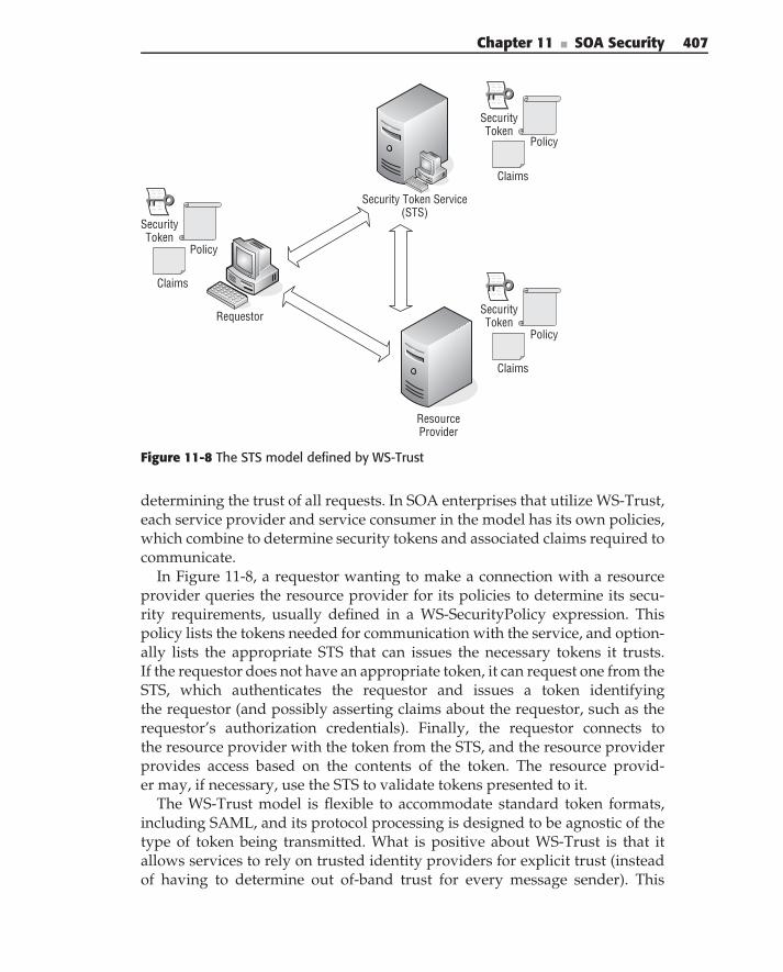
Chapter 11 ■ SOA Security 407
Requestor
ResourceProvider
Policy
SecurityToken
Claims
Policy
SecurityToken
Claims
Policy
SecurityToken
Claims
Security Token Service(STS)
Figure 11-8 The STS model defined by WS-Trust
determining the trust of all requests. In SOA enterprises that utilize WS-Trust,each service provider and service consumer in the model has its own policies,which combine to determine security tokens and associated claims required tocommunicate.
In Figure 11-8, a requestor wanting to make a connection with a resourceprovider queries the resource provider for its policies to determine its secu-rity requirements, usually defined in a WS-SecurityPolicy expression. Thispolicy lists the tokens needed for communication with the service, and option-ally lists the appropriate STS that can issues the necessary tokens it trusts.If the requestor does not have an appropriate token, it can request one from theSTS, which authenticates the requestor and issues a token identifyingthe requestor (and possibly asserting claims about the requestor, such as therequestor’s authorization credentials). Finally, the requestor connects tothe resource provider with the token from the STS, and the resource providerprovides access based on the contents of the token. The resource provid-er may, if necessary, use the STS to validate tokens presented to it.
The WS-Trust model is flexible to accommodate standard token formats,including SAML, and its protocol processing is designed to be agnostic of thetype of token being transmitted. What is positive about WS-Trust is that itallows services to rely on trusted identity providers for explicit trust (insteadof having to determine out of-band trust for every message sender). This
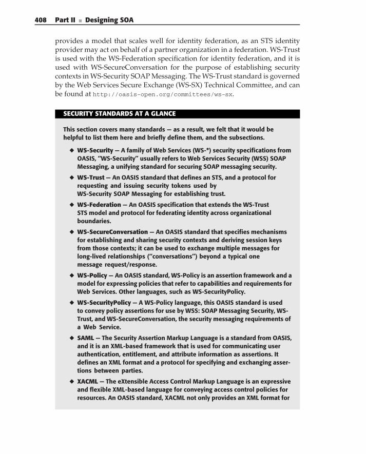
408 Part II ■ Designing SOA
provides a model that scales well for identity federation, as an STS identityprovider may act on behalf of a partner organization in a federation. WS-Trustis used with the WS-Federation specification for identity federation, and it isused with WS-SecureConversation for the purpose of establishing securitycontexts in WS-Security SOAP Messaging. The WS-Trust standard is governedby the Web Services Secure Exchange (WS-SX) Technical Committee, and canbe found at http://oasis-open.org/committees/ws-sx.
SECURITY STANDARDS AT A GLANCE
This section covers many standards — as a result, we felt that it would behelpful to list them here and briefly define them, and the subsections.
◆ WS-Security — A family of Web Services (WS-*) security specifications fromOASIS, ‘‘WS-Security’’ usually refers to Web Services Security (WSS) SOAPMessaging, a unifying standard for securing SOAP messaging security.
◆ WS-Trust — An OASIS standard that defines an STS, and a protocol forrequesting and issuing security tokens used byWS-Security SOAP Messaging for establishing trust.
◆ WS-Federation — An OASIS specification that extends the WS-TrustSTS model and protocol for federating identity across organizationalboundaries.
◆ WS-SecureConversation — An OASIS standard that specifies mechanismsfor establishing and sharing security contexts and deriving session keysfrom those contexts; it can be used to exchange multiple messages forlong-lived relationships (‘‘conversations’’) beyond a typical onemessage request/response.
◆ WS-Policy — An OASIS standard, WS-Policy is an assertion framework and amodel for expressing policies that refer to capabilities and requirements forWeb Services. Other languages, such as WS-SecurityPolicy.
◆ WS-SecurityPolicy — A WS-Policy language, this OASIS standard is usedto convey policy assertions for use by WSS: SOAP Messaging Security, WS-Trust, and WS-SecureConversation, the security messaging requirements ofa Web Service.
◆ SAML — The Security Assertion Markup Language is a standard from OASIS,and it is an XML-based framework that is used for communicating userauthentication, entitlement, and attribute information as assertions. Itdefines an XML format and a protocol for specifying and exchanging asser-tions between parties.
◆ XACML — The eXtensible Access Control Markup Language is an expressiveand flexible XML-based language for conveying access control policies forresources. An OASIS standard, XACML not only provides an XML format for
Chapter 11 ■ SOA Security 409
conveying access control policy but includes a request/response protocolfor querying for policy decisions to be made.
◆ XML Signature — A W3C Standard, it is used for digitally signing elementsof XML documents. It is a lower-level standard used in both SOAP and RESTimplementations for providing non-repudiation and message integrity forXML-based messaging.
◆ XML Encryption — A W3C Standard, it is used for encrypting elements ofXML documents. It is a lower-level standard used in both SOAP and RESTimplementations to provide confidentiality and information hiding inXML-based messaging.
WS-FederationWS-Federation, a specification introduced into OASIS in 2007, is in theWS-Security family of specifications, and utilizes and extends the WS-TrustSTS model and protocol for federating identity across organizational bound-aries. By defining a variety of federation services, including authentication,authorization, attribute, and pseudonym services, for the purpose of federat-ing access across multiple domains, and by providing a federation metadatamodel describing such services, participants in a federation can discoverhow to access and use services for the purpose of cross-domain Web Servicecommunication.
WS-Federation offers the capability of a new STS called an authorizationservice which provides decision brokering services (PDP/PEPs) for partici-pants in a federation. WS-Federation also defines a model for parties to accessattribute services based upon the security token service concept and relianton the token issuance protocol defined in WS-Trust. Pseudonym services areprovided in that a Resource Provider can describe the set of attributes requiredto access a resource, and an Identity Provider (an STS) can assert that a partic-ular subject possesses those attributes, without divulging the actual identityof the subject. WS-Federation also includes extensions to the Security TokenRequest protocol of WS-Trust to allow a requestor to list privacy require-ments, ensuring that sensitive and confidential data is not conveyed in tokentransmission.
WS-Federation can be used in both browser-based and Web Service–basedidentity federation, and as such, there is some overlap between SAML 2.0browser HTTP federation capabilities and the capabilities of WS-Federation.As WS-Federation is now moving to standardization in OASIS, hopefullyWS-Federation and SAML 2.0 can complement (and not compete with) eachother. The WS-Federation documentation is at the OASIS Web Services
410 Part II ■ Designing SOA
Federation Technical Committee at the following URL: oasis-open.org/
committees/wsfed.
WS-SecureConversationWS-SecureConversation is built on top of WS-Security to provide securecommunication between services. An OASIS standard that specifies mecha-nisms for establishing and sharing security contexts and deriving session keysfrom those contexts, WS-SecureConversation can be used to exchange multi-ple messages for long-lived relationships (‘‘conversations’’) beyond a typicalone message request/response. In situations where constant communicationbetween services is expected (between a portal and an enterprise Web Service,for example), this is helpful in that performance greatly increases by utilizingderived session keys for encryption communications, instead of having to doslow key negotiation with each message.
The WS-SecureConversation standard complements WS-Security SOAPmessaging. WS-SecureConversation defines a new WS-Security token typethat is a security context obtained by using a binding of WS-Trust. Thissecurity context can be used to derive a ‘‘shared secret’’ for encrypted commu-nications. In the WS-SecureConversation standard, a security context tokenmay be created by an STS, it may be created by one of the communicatingparties and propagated with a message, or it may be created by negotiationbetween parties. WS-Security alone has no capability of deriving this context,so WS-SecureConversation provides needed functionality for WS-SecuritySOAP Messaging.
An OASIS standard since 2007, WS-SecureConversation is beginning tobe adopted by many vendors and toolkits. For more information, visitthe OASIS Web Services Secure Exchange (WS-SX) Technical Committee athttp://oasis-open.org/committees/ws-sx.
WS-SecurityPolicy and the WS-Policy FrameworkWS-Policy (or Web Services Policy Framework) is an XML language thatis used to represent the capabilities, constraints, and requirements of WebServices, and these capabilities and requirements are expressed as policy asser-tions. Because the Web Service Definition Language (WSDL) is not expressiveenough to define Web Service capabilities and requirements such as quality ofservice (QoS) and messaging security, WS-Policy complements WSDL, and isused for many aspects of SOA governance that are discussed in Chapter 12.WS-SecurityPolicy is a subset of WS-Policy, and provides a set of WS-Policysecurity policy assertions describing the messaging security policy require-ments involved in communicating with Web Services, and these are used withWS-Security SOAP Messaging, WS-Trust, and WS-SecureConversation.
Chapter 11 ■ SOA Security 411
The WS-Policy Framework has been a W3C recommendation since Septem-ber 2007, and WS-SecurityPolicy is an OASIS committee standard, which hasseen acceptance and is being used by major SOA vendors. Used for expressingmessaging security requirements, WS-SecurityPolicy describes the granulardetails required for secure messaging for SOAP messages. For example, if aWeb Service requires a WS-Security Header containing a signed BinarySe-curityToken (WS-Security X.509 Certificate Token Profile), WS-SecurityPolicywould be used to express that policy. If certain elements in a Web Serviceoperation are required to be signed or encrypted, WS-SecurityPolicy is usedto express this policy. WS-SecurityPolicy supports a wide variety of tokentypes used to provide authentication and authorization information, and isvery helpful in a dynamic SOA environment, where interactions and securitypolicies of business partners are dynamic, and where a complement to WSDLis needed to achieve this security collaboration.
The use of WS-SecurityPolicy is discussed more in the Blueprints sectionof this chapter and is also discussed in Chapter 12. The WS-Policy proposedrecommendation is found at the W3C at w3.org/TR/ws-policy, and the OASISWS-SecurityPolicy specification is found at http://docs.oasis-open.org/
ws-sx/ws-securitypolicy.
SAMLThe Security Assertion Markup Language (SAML) is an XML-based frame-work that is used for communicating subject authentication, entitlement, andattribute information. There are many uses of SAML, and it is commonly usedwith many other standards and specifications, including WS-Security SOAPMessaging, WS-Trust, WS-Federation, XACML, and the Liberty Identity WebServices Framework (ID-WSF). An OASIS standard since 2002, SAML revolvesaround the concept of an assertion, which is simply a declaration about a sub-ject. An assertion may be a declaration about a subject’s authentication (andtherefore its identity), a list of a subject’s authorization credentials, or anexpression of an authorization decision granting a subject to access a resource.The trust of a SAML assertion is based upon the trust of the entity issuing anassertion, usually referred to as an Asserting Party or a SAML authority. Sincethe specification was adopted in 2002, it has gained significant momentumand its 2.0 version includes federated identity capabilities, in addition to itsuse as an XML-based token and a protocol for exchanging assertions.
Figure 11-9 provides a snapshot of a few of the many capabilities of SAML.The figure provides a high-level view of the format of a SAML assertion. Thefigure shows an example of SAML being used as a request/response protocolfor requesting assertions for access control decisions; it shows the use of SAMLtokens in WS-Security and shows a conceptual use case of SAML assertionsbeing utilized in browser-based SSO.
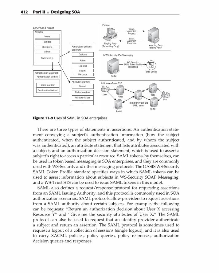
412 Part II ■ Designing SOA
Relying Party(Requesting Party) Asserting Party
(Issuing Party)
SAMLAssertionRequest
UserPortal
Portal
Identity Provider andSAML Issuer
Portal
Portal
Issuer
Conditions
Attribute Statement
Attribute–Values
Statement(s)
Subject
Attribute–Values
Authentication Statement
Authentication Method
Name Identifier
Confirmation Method
. . .
Authorization DecisionStatement
Action
Decision
Evidence
Subject
Subject
Advice
Resource
Assertion
Assertion FormatProtocol
In Browser-Based SSO
SAMLAssertionResponse
User
Portal
In WS-Security SOAP Messaging
Web Service
WS-SecuritySAML Token Profile
Messaging
Figure 11-9 Uses of SAML in SOA enterprises
There are three types of statements in assertions: An authentication state-ment conveying a subject’s authentication information (how the subjectauthenticated, when the subject authenticated, and by whom the subjectwas authenticated), an attribute statement that lists attributes associated witha subject, and an authorization decision statement, which is used to assert asubject’s right to access a particular resource. SAML tokens, by themselves, canbe used in token based messaging in SOA enterprises, and they are commonlyused with WS-Security and other messaging protocols. The OASIS WS-SecuritySAML Token Profile standard specifies ways in which SAML tokens can beused to assert information about subjects in WS-Security SOAP Messaging,and a WS-Trust STS can be used to issue SAML tokens in this model.
SAML also defines a request/response protocol for requesting assertionsfrom an SAML Issuing Authority, and this protocol is commonly used in SOAauthorization scenarios. SAML protocols allow providers to request assertionsfrom a SAML authority about certain subjects. For example, the followingcan be requests: ‘‘Return an authorization decision about User X accessingResource Y’’ and ‘‘Give me the security attributes of User X.’’ The SAMLprotocol can also be used to request that an identity provider authenticatea subject and return an assertion. The SAML protocol is sometimes used torequest a logout of a collection of sessions (single logout), and it is also usedto carry XACML policies, policy queries, policy responses, authorizationdecision queries and responses.
Chapter 11 ■ SOA Security 413
SAML 2.0 provides support for SSO. Some of the types of SSO supportedare: Identity SSO, where the user identity is registered in both securitydomains, and Attribute SSO, where access control to resources in a domainis controlled by authorization attributes. Anonymous SSO can be accom-plished by only passing SAML attribute statements, and SAML also hasthe capability for using pseudonym-based SSO for privacy concerns. TheSAML Web browser SSO profile specifies how SAML authentication asser-tions are communicated between an identity provider and a service providerto enable SSO for a browser user, and this is significant because this modelbrokers trust relationships between the user’s browser and services in theenterprise.
SAML is used as one of the ‘‘building blocks’’ for federated identity. TheSAML profiles lend themselves to federation beyond the host organization.The Liberty Alliance, a consortium focused on federated identity and SSO, wasinstrumental in adding federation capabilities (from ID-FF) into SAML 2.0 forbrowser-based SSO, and now utilizes SAML 2.0 in the ID-WSF (the IdentityWeb Services Framework), a framework focused on Web Service SSO.
As there is some overlap between SAML and WS-Federation in the federatedidentity arena, it remains to be seen how the identity federation capabilitiesof SAML and WS-Federation play together in the future. As noted earlier,WS-Federation is able to use SAML tokens in its architecture, but uses theWS-Trust STS architecture and protocols for exchanging information.
SAML has been widely adopted as a token format for conveying authentica-tion and authorization information, and many products (such as policy serversand federated identity management systems) have adopted the SAML proto-col and federation capabilities of SAML. Documents on SAML are at the OASISSecurity Services Technical Committee online at http://oasis-open.org/
committees/security.
XACML
The eXtensible Access Control Markup Language (XACML) is an expressiveand flexible XML-based language for conveying access control policies forresources. An OASIS standard since 2003, XACML provides not only an XMLformat for conveying access control policy, but includes a request/responseprotocol for querying for policy decisions to be made. XACML as an XMLpolicy language is used to describe general access control requirements, andis extensible in that you can define new functions, data types, and combinglogic. The request/response language allows components to form a queryto ask whether or not a given action should be allowed, and interprets theresult.
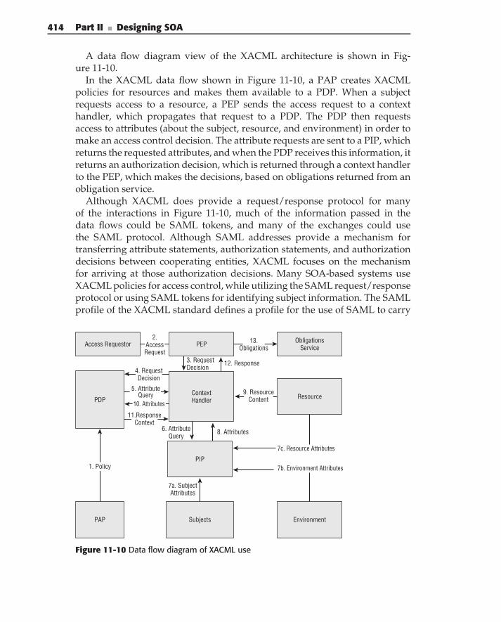
414 Part II ■ Designing SOA
A data flow diagram view of the XACML architecture is shown in Fig-ure 11-10.
In the XACML data flow shown in Figure 11-10, a PAP creates XACMLpolicies for resources and makes them available to a PDP. When a subjectrequests access to a resource, a PEP sends the access request to a contexthandler, which propagates that request to a PDP. The PDP then requestsaccess to attributes (about the subject, resource, and environment) in order tomake an access control decision. The attribute requests are sent to a PIP, whichreturns the requested attributes, and when the PDP receives this information, itreturns an authorization decision, which is returned through a context handlerto the PEP, which makes the decisions, based on obligations returned from anobligation service.
Although XACML does provide a request/response protocol for manyof the interactions in Figure 11-10, much of the information passed in thedata flows could be SAML tokens, and many of the exchanges could usethe SAML protocol. Although SAML addresses provide a mechanism fortransferring attribute statements, authorization statements, and authorizationdecisions between cooperating entities, XACML focuses on the mechanismfor arriving at those authorization decisions. Many SOA-based systems useXACML policies for access control, while utilizing the SAML request/responseprotocol or using SAML tokens for identifying subject information. The SAMLprofile of the XACML standard defines a profile for the use of SAML to carry
Access Requestor PEP ObligationsService
ContextHandler ResourcePDP
PIP
Subjects EnvironmentPAP
1. Policy
3. RequestDecision
6. AttributeQuery
7a. SubjectAttributes
7b. Environment Attributes
8. Attributes
7c. Resource Attributes
10. Attributes
11.ResponseContext
12. Response
2.AccessRequest
4. RequestDecision
5. AttributeQuery 9. Resource
Content
13.Obligations
Figure 11-10 Data flow diagram of XACML use
Chapter 11 ■ SOA Security 415
XACML policies, policy queries and responses, and authorization decisionsand responses.
In practice, XACML is used primarily for its expression language, and policyservers use XACML for the expression and storage of policies in the enterprise.The future of the success of the XACML protocol remains to be seen.
XACML is a platform-independent policy language and continues to berefined in the OASIS XACML Technical Committee. Documents, news, andcurrent progress can be found at http://oasis-open.org/committees/xacml.
XML SignatureXML Signature is a W3C standard that is a way to provide message integrityand non-repudiation of XML documents and elements of XML documents.XML Signature, sometimes called XML-SIG or XML-DSIG, relies on public keytechnology in which the hash (or message digest) of an element or a set of XMLelements is signed by the signer’s private key and, therefore, can be validatedby third parties by performing a cryptographic operation on the hash of thedata with the sender’s public key.
A message may have elements that are digitally signed by many differentparties, and a signature of a message may cryptographically tie elementstogether. For example, identity, authorization, and time information from theWS-Security header and the SOAP request in the SOAP body are often cryp-tographically bound together by the digital signature, preventing an attackerfrom reusing security information with other requests, providing proof thatthe message was not altered in transit, and providing proof that the signersent the message. XML Signature is heavily utilized by WS-Security SOAP mes-saging for providing integrity and non-repudiation, but it can be used in anyXML messaging solution where those security goals need to be met. The XMLSignature standard can be found online at http://w3.org/TR/xmldsig-core.
XML EncryptionXML encryption is a W3C standard that provides confidentiality of XMLdocuments and elements of XML documents. XML encryption is used withvarious encryption ciphers to encrypt data to different parties. As discussedin an earlier section on confidentiality in this chapter, XML encryption canbe used at the element level, providing confidentiality of sensitive XMLelements intended for only certain parties, safely protecting encrypted datathrough intermediary Web Services, until the intended recipient is able todecrypt the element. Like the XML Signature standard, XML encryption isheavily utilized by WS-Security SOAP Messaging, as well as other XML-based
416 Part II ■ Designing SOA
messaging protocols. The XML encryption standard can be found online athttp://w3.org/TR/xmlenc-core.
SOA Security Blueprints
This section of the chapter builds on the first two. Now that you have an un-derstanding of the classical information security goals, and a high-levelunderstanding of some of the most important SOA security standards, thissection provides practical advice, tips, and methodologies to use in differentscenarios used to satisfy security requirements in your SOA.
As you read this section, please note that the Web Service security landscape(relating to standards) is continuing to mature and evolve. For this reason, wefocus more on architectural principles than on the usage of the key standardsin the last section. Where applicable and where it is deemed necessary, werefer to the standards, but most of the concepts and strategies discussed inthis section for achieving your security goals can be implementation- andstandard-agnostic. It is our goal in this section to have these blueprints be inuse as standards evolve and change, regardless of the technologies used.
Separation of Security into Components and ServicesSome of the fundamental architectural principles, as we have discussed inChapter 2 and throughout this book, revolve around abstraction and accommo-dation of change. To accommodate change, it is important for your architectureto be loosely coupled. For this reason, it is important to separate security fromthe business logic of your service consumers and providers As architecturesmoved to client/server in the 1990s, many adopted a more loosely coupledmodel with the Model-View-Controller (MVC) design pattern, separating pre-sentation, business logic, and data into three components. In SOA, we separatefunctionality even further, and one of the ways that we do this for security isby abstracting enterprise security into a service layer and into local securitycomponents for service consumers and producers. Such an abstraction is nec-essary because it is otherwise easy for the presentation, data, and business logicto be tightly coupled to security, which provides performance and manage-ment problems — in the case study section of this chapter, we show you suchan example.
It is important that you realize that creating a security service layer is nottantamount to creating a set of ‘‘central’’ security processing services that actas performance bottlenecks and single point of failures in your enterprise. Aswe address later in the ‘‘Access Control Blueprints’’ section, there are manystrategies for using enterprise services for access control, addressed by the
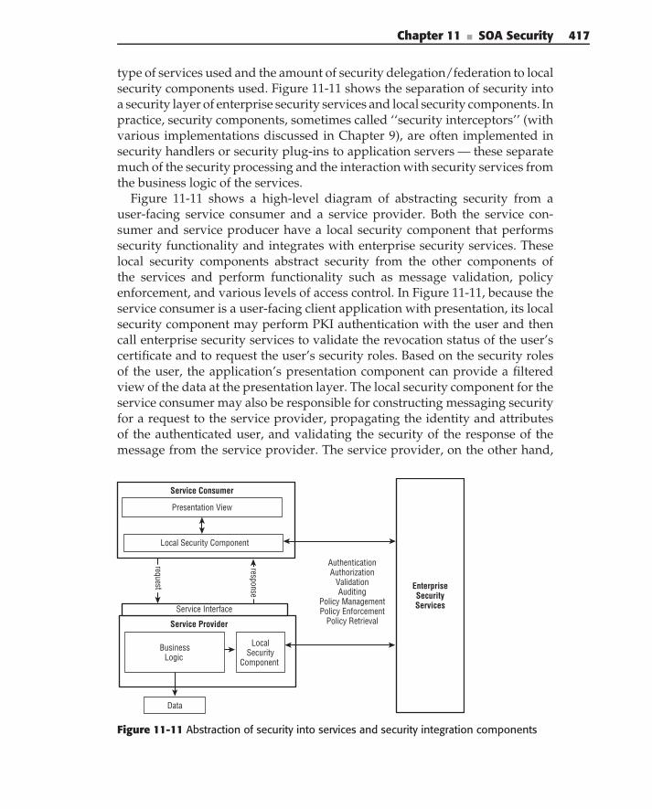
Chapter 11 ■ SOA Security 417
type of services used and the amount of security delegation/federation to localsecurity components used. Figure 11-11 shows the separation of security intoa security layer of enterprise security services and local security components. Inpractice, security components, sometimes called ‘‘security interceptors’’ (withvarious implementations discussed in Chapter 9), are often implemented insecurity handlers or security plug-ins to application servers — these separatemuch of the security processing and the interaction with security services fromthe business logic of the services.
Figure 11-11 shows a high-level diagram of abstracting security from auser-facing service consumer and a service provider. Both the service con-sumer and service producer have a local security component that performssecurity functionality and integrates with enterprise security services. Theselocal security components abstract security from the other components ofthe services and perform functionality such as message validation, policyenforcement, and various levels of access control. In Figure 11-11, because theservice consumer is a user-facing client application with presentation, its localsecurity component may perform PKI authentication with the user and thencall enterprise security services to validate the revocation status of the user’scertificate and to request the user’s security roles. Based on the security rolesof the user, the application’s presentation component can provide a filteredview of the data at the presentation layer. The local security component for theservice consumer may also be responsible for constructing messaging securityfor a request to the service provider, propagating the identity and attributesof the authenticated user, and validating the security of the response of themessage from the service provider. The service provider, on the other hand,
Business Logic
Presentation View
Data
Local Security
Component
request
Local Security Component
Service Interface
response
Authentication Authorization
Validation Auditing
Policy Management Policy Enforcement
Policy Retrieval
Service Consumer
Service Provider
EnterpriseSecurityServices
Figure 11-11 Abstraction of security into services and security integration components
418 Part II ■ Designing SOA
has a local security component that may validate the security of the incomingmessage, and may act as a PEP, calling enterprise security services to makeaccess control decisions.
To accommodate flexibility in your security architecture, it is important toestablish an array of security services that meet the current and future securityneeds of your enterprise. Many common services are the following:
Identification and Authentication Services — These types of servicesare used for identification of subjects in the enterprise. Depending on thetype of authentication used, a specific ‘‘authentication service’’ may notbe needed, but other services, such as certificate validation and certificaterevocation status verification services, would certainly fall under thiscategory.
Attribute Service — This service is typically used for retrieving attributecredentials (security roles and other credentials used for authorization)for subjects in the enterprise.
Access Control Policy Management Service — This service is typicallyused for storing the access control policy for resources in the enterprise.
Policy Retrieval Service — This service is used for retrieving the storedpolicy for resources in the enterprise, for the purpose of making accesscontrol decisions.
Authorization Decision Service — This service is usually used to makeauthorization decisions about a subject’s request for a resource, actingas a PDP based on access control policy and attributes about subjects.
Identity Transformation Services — Although such services would notexist in a ‘‘perfect world’’ network, where each subject has one identitycredential, it is sometimes helpful to provide services that aid in trans-formation of identities between multiple enterprise applications andsupport different authentication credentials for the same user. Such aservice can be helpful with identity propagation.
Security Token Service (STS) — This service is used for issuing trustedassertions of identity, security attributes, and authorization decisions inthe enterprise.
Auditing Services — These types of services are used for providing acentralized view of logs and alerts in the enterprise.
Providing all of these services allows options and flexibility for security,especially for access control. Later on in this section, you can see severalblueprints for various mechanisms of access control that use a combinationof these enterprise security services and local security components in theenterprise.
Chapter 11 ■ SOA Security 419
SELECTING PRODUCTS FOR ENTERPRISE SECURITY SERVICES
It is sometimes a temptation to pick a vendor’s commercial off-the-shelf (COTS)product that supplies all of your security services and components, thinkingthat this can solve all of the problems for your enterprise. The key to selectingproducts revolves around standards compliance. Look for supported standardsthat we discussed in the ‘‘Web Service Security Standards and Specifications’’section of this chapter. Make sure to do your research. If you hear or readphrases like ‘‘Our supported messaging is based on WS-Security,’’ or ‘‘Oursecurity tokens are SAML-like,’’ this should throw up a few red flags. Eitherproducts are standards-compliant or they are not.
In the same way, be warned that many vendors attempt to lock you in totheir product by both supporting standard security mechanisms and supportingvery easy-to-use proprietary mechanisms for security. (For example, someapplication servers support JAX-WS or JAX-RPC security handlers but urge youto only use their proprietary plug-ins for security.) It is easy for thewell-intentioned developer to go down the proprietary road, because theproprietary road usually offers very easy integration. As the security architect,make certain that you warn your developers not to do this.
If you use a product and make sure to only use services that use standardprotocols and standard security components, you can reduce your dependenceon that vendor. This way, if the product becomes unsupported in the future orbecomes unreliable or unusable, you can have a much easier time replacing itwith another product!
Separating security functionality into enterprise security services and localsecurity components is essential. The next few sections of blueprints showvarious options that the SOA architect has when using these enterprisesecurity components. Later in this chapter, we provide a simple case study,where enterprise security services and local security components are used inan example enterprise.
Authentication and Identity BlueprintsThis section contains blueprints and best practices related to authenticationand identity. As we discussed in the first section of this chapter, there isusually a requirement to identify both the message sender and the identity of theend user in each service request. Initially, the message sender and the end userare the same when the user authenticates to a front-end application. Beyondthat, the architect has options related to identifying users. Every SOA securityarchitect should understand the issues related to SSO, trust propagation, andauthentication in an SOA, and this section focuses on these issues and offerspractical solutions based on security policy and infrastructure.
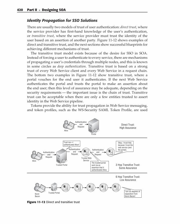
420 Part II ■ Designing SOA
Identity Propagation for SSO Solutions
There are usually two models of trust of user authentication: direct trust, wherethe service provider has first-hand knowledge of the user’s authentication,or transitive trust, where the service provider must trust the identity of theuser based on an assertion of another party. Figure 11-12 shows examples ofdirect and transitive trust, and the next sections show successful blueprints forachieving different mechanisms of trust.
The transitive trust model exists because of the desire for SSO in SOA.Instead of forcing a user to authenticate to every service, there are mechanismsof propagating a user’s credentials through multiple nodes, and this is knownin some circles as deep authentication. Transitive trust is based on a strongtrust of every Web Service client and every Web Service in a request chain.The bottom two examples in Figure 11-12 show transitive trust, where aportal vouches for the end user it authenticates. If the next Web Serviceauthenticates the portal and trusts the portal to make an assertion aboutthe end user; then this level of assurance may be adequate, depending on thesecurity requirements — the important issue is the chain of trust. Transitivetrust can be acceptable when there are only a few entities trusted to assertidentity in the Web Service pipeline.
Tokens provide the ability for trust propagation in Web Service messaging,and token profiles, such as the WS-Security SAML Token Profile, are used
Trust me—I authenticated Alice!
Alice
Trusted Portal
Trusted Web Service
The trusted portal sent me an assertion that it authenticated Alice.
Okay, I trust that, because I trust the web service (and the portal).
3 Hop Transitive Trust: Some Assurance
Kevin Bacon
Trusted PortalI am six degrees of separation from Kevin Bacon!
6 Hop Transitive Trust: Low Assurance
Alice
Portal
Direct Trust: High Assurance
Authentication and
Request
Authentication and
RequestAuthentication
and Request
Authentication and
Request
Figure 11-12 Direct and transitive trust
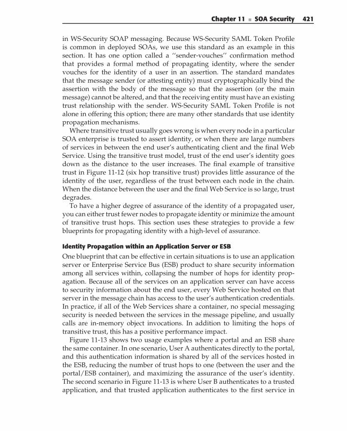
Chapter 11 ■ SOA Security 421
in WS-Security SOAP messaging. Because WS-Security SAML Token Profileis common in deployed SOAs, we use this standard as an example in thissection. It has one option called a ‘‘sender-vouches’’ confirmation methodthat provides a formal method of propagating identity, where the sendervouches for the identity of a user in an assertion. The standard mandatesthat the message sender (or attesting entity) must cryptographically bind theassertion with the body of the message so that the assertion (or the mainmessage) cannot be altered, and that the receiving entity must have an existingtrust relationship with the sender. WS-Security SAML Token Profile is notalone in offering this option; there are many other standards that use identitypropagation mechanisms.
Where transitive trust usually goes wrong is when every node in a particularSOA enterprise is trusted to assert identity, or when there are large numbersof services in between the end user’s authenticating client and the final WebService. Using the transitive trust model, trust of the end user’s identity goesdown as the distance to the user increases. The final example of transitivetrust in Figure 11-12 (six hop transitive trust) provides little assurance of theidentity of the user, regardless of the trust between each node in the chain.When the distance between the user and the final Web Service is so large, trustdegrades.
To have a higher degree of assurance of the identity of a propagated user,you can either trust fewer nodes to propagate identity or minimize the amountof transitive trust hops. This section uses these strategies to provide a fewblueprints for propagating identity with a high-level of assurance.
Identity Propagation within an Application Server or ESB
One blueprint that can be effective in certain situations is to use an applicationserver or Enterprise Service Bus (ESB) product to share security informationamong all services within, collapsing the number of hops for identity prop-agation. Because all of the services on an application server can have accessto security information about the end user, every Web Service hosted on thatserver in the message chain has access to the user’s authentication credentials.In practice, if all of the Web Services share a container, no special messagingsecurity is needed between the services in the message pipeline, and usuallycalls are in-memory object invocations. In addition to limiting the hops oftransitive trust, this has a positive performance impact.
Figure 11-13 shows two usage examples where a portal and an ESB sharethe same container. In one scenario, User A authenticates directly to the portal,and this authentication information is shared by all of the services hosted inthe ESB, reducing the number of trust hops to one (between the user and theportal/ESB container), and maximizing the assurance of the user’s identity.The second scenario in Figure 11-13 is where User B authenticates to a trustedapplication, and that trusted application authenticates to the first service in
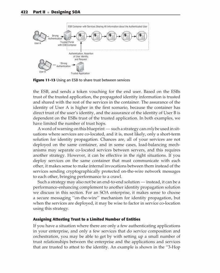
422 Part II ■ Designing SOA
User A Trusted Portal with ESB Container
User BTrusted Application
Strong Authentication
Authentication, Assertion of User Identity,
and Request
ESB Container with Services Sharing All Information about the Authenticated User
Strong Authentication
Figure 11-13 Using an ESB to share trust between services
the ESB, and sends a token vouching for the end user. Based on the ESBstrust of the trusted application, the propagated identity information is trustedand shared with the rest of the services in the container. The assurance of theidentity of User A is higher in the first scenario, because the container hasdirect trust of the user’s identity, and the assurance of the identity of User B isdependent on the ESBs trust of the trusted application. In both examples, wehave limited the number of trust hops.
A word of warning on this blueprint — such a strategy can only be used in sit-uations where services are co-located, and it is, most likely, only a short-termsolution for identity propagation. Chances are, all of your services are notdeployed on the same container, and in some cases, load-balancing mech-anisms may separate co-located services between servers, and this requiresanother strategy. However, it can be effective in the right situations. If youdeploy services on the same container that must communicate with eachother, it makes sense to make internal invocations between them instead of theservices sending cryptographically protected on-the-wire network messagesto each other, bringing performance to a crawl.
Such a strategy may also not be an end-to-end solution — instead, it can be aperformance-enhancing complement to another identity propagation solutionwe discuss in this section. For an SOA enterprise, it makes sense to choosea secure messaging ‘‘on-the-wire’’ mechanism for identity propagation, butwhen the services are deployed, it may be wise to factor in service co-locationusing this strategy.
Assigning Attesting Trust to a Limited Number of Entities
If you have a situation where there are only a few authenticating applicationsin your enterprise, and only a few services that do service composition andorchestration, you may be able to get by with setting up a small number oftrust relationships between the enterprise and the applications and servicesthat are trusted to attest to the identity. An example is shown in the ‘‘3-Hop
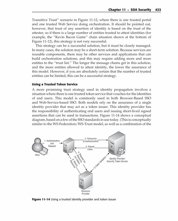
Chapter 11 ■ SOA Security 423
Transitive Trust’’ scenario in Figure 11-12, where there is one trusted portaland one trusted Web Service doing orchestration. It should be pointed out,however, that trust of any assertion of identity is based on the trust of theattester, so if there is a large number of entities trusted to attest identities (forexample, the ‘‘Kevin Bacon Game’’ chain situation shown at the bottom ofFigure 11-12), this strategy is not very successful.
This strategy can be a successful solution, but it must be closely managed.In many cases, the solution may be a short-term solution. Because services arereusable components, there may be other services and applications that canbuild orchestration solutions, and this may require adding more and moreentities to the ‘‘trust list.’’ The longer the message chains get in this solution,and the more entities allowed to attest identity, the lower the assurance ofthis model. However, if you are absolutely certain that the number of trustedentities can be limited, this can be a successful strategy.
Using a Trusted Token Service
A more promising trust strategy used in identity propagation involves asituation where there is one trusted token service that vouches for the identitiesof end users. This model is commonly used in both Browser-Based SSOand Web-Service-based SSO. Both models rely on the assurance of a singleidentity provider that may act as a token issuer. This identity provider hasthe responsibility of authenticating end users and issuing short-lived signedassertions that can be used in transactions. Figure 11-14 shows a conceptualdiagram, based on a few of the SSO standards in use today. (This is conceptuallysimilar to the WS-Federation/WS-Trust model, as well as a combination of the
ResourceProvider
Alice
Identity Provider/ Security Token Service
2. Outsource of Authentication
3. Signed Token
5.Tok
en Valid
ation6. Return
Resource
1. Authentication and
Request
4. Request for
Resource
(w/ token)
Figure 11-14 Using a trusted identity provider and token issuer
424 Part II ■ Designing SOA
SAML Browser SSO Profile and the Liberty ID-WSF model.) In the example,a user authenticates to a portal, which has a strong trust relationship withan identity provider. The portal ‘‘outsources’’ or redirects authentication to theidentity provider, so that it directly authenticates the user. Based on a user’svalid authentication, the identity provider returns a signed SAML assertion,which is returned to the user’s browser for subsequent portal interactions, butthis can also be used by the portal to propagate identity to other Web Servicesin the enterprise.
The trust of the identity of the user in this model is based on the trust of theidentity provider issuing the token, with a bit of trust placed on the portal thatis integrated with the identity provider/token service. This limits the amountof trusted entities (eliminating the ‘‘Kevin Bacon Game’’ problem), providinga high degree of assurance.
Identity Propagation with REST Using Browser SSO
The introduction of the SAML Browser SSO Profile in 2005 makes identitypropagation for Representational State Transfer (REST) possible. BecauseREST does not differentiate between a service call and a click from theuser’s browser, distance is minimized between the user’s browser and theWeb Services using browser-specific profiles, such as the SAML BrowserSSO Profile, and we anticipate that when WS-Federation is standardized, itsBrowser SSO capabilities can bring similar success to REST-based services.
Figure 11-15 shows a high-level sequence diagram of the Browser SSO modelprovided by the Profiles for OASIS SAML Standard. Each service providerredirects authentication to an identity provider that issues tokens (similar tothe browser-portal interaction in the last section). For an initial browser-basedrequest, HTTP redirections or other mechanisms initiate a login sequence withan identity provider, and the identity provider’s response (in the form of aSAML token) is returned to the user’s browser, which is delivered to theservice provider, which then grants access based on the token and the trust ofthe identity provider. If the service provider makes a call to another serviceprovider on behalf of the user, the same sequence can be used.
The beauty of this approach compared to the previous one is that onestandard is used, instead of multiple standards. Because the user’s browseris able to have token information, standard HTTP redirects allow directconnection between the user’s browser and each service. Because each servicetrusts one identity provider that issues assertions to the user’s browser, thereis trust of one entity, not several. It not only works in an organizational SSOmodel, but it is used in federation scenarios as well.
Because this model embraces HTTP and open standards, implementers usingREST-based services should consider using this standard when organizationalSSO or service federation to multiple enterprises is needed.
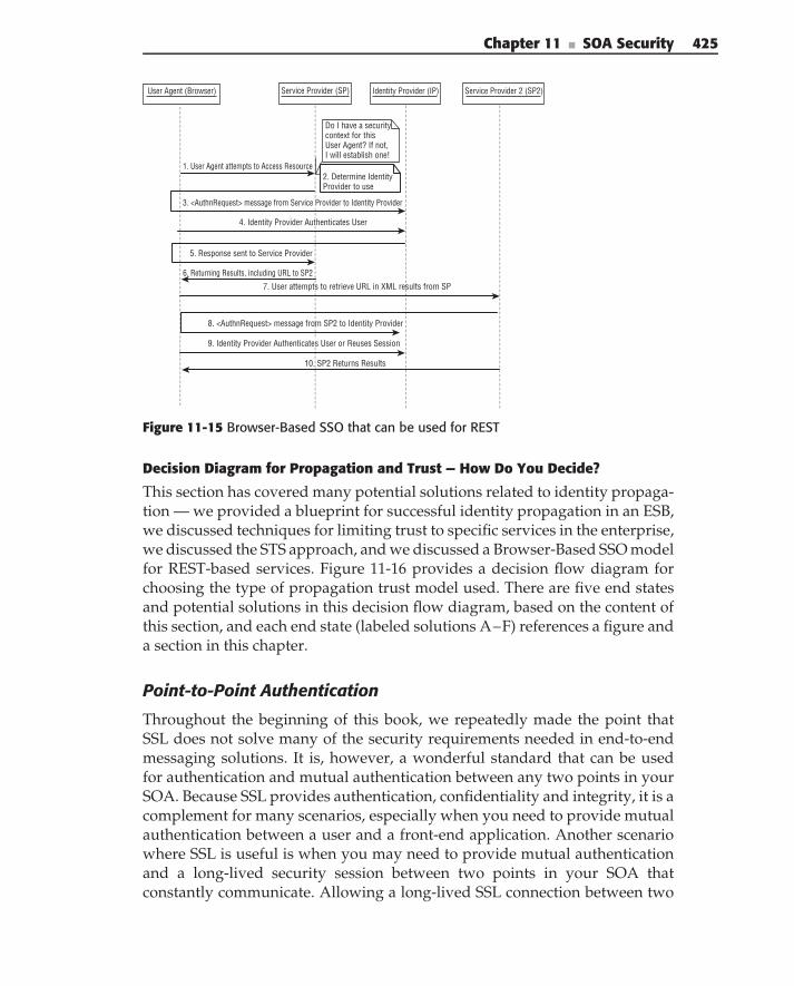
Chapter 11 ■ SOA Security 425
User Agent (Browser) Service Provider (SP) Identity Provider (IP) Service Provider 2 (SP2)
1. User Agent attempts to Access Resource
Do I have a security context for this User Agent? If not,I will establish one!
2. Determine IdentityProvider to use
5. Response sent to Service Provider
6. Returning Results, including URL to SP2
8. <AuthnRequest> message from SP2 to Identity Provider
10. SP2 Returns Results
3. <AuthnRequest> message from Service Provider to Identity Provider
4. Identity Provider Authenticates User
9. Identity Provider Authenticates User or Reuses Session
7. User attempts to retrieve URL in XML results from SP
Figure 11-15 Browser-Based SSO that can be used for REST
Decision Diagram for Propagation and Trust — How Do You Decide?
This section has covered many potential solutions related to identity propaga-tion — we provided a blueprint for successful identity propagation in an ESB,we discussed techniques for limiting trust to specific services in the enterprise,we discussed the STS approach, and we discussed a Browser-Based SSO modelfor REST-based services. Figure 11-16 provides a decision flow diagram forchoosing the type of propagation trust model used. There are five end statesand potential solutions in this decision flow diagram, based on the content ofthis section, and each end state (labeled solutions A–F) references a figure anda section in this chapter.
Point-to-Point Authentication
Throughout the beginning of this book, we repeatedly made the point thatSSL does not solve many of the security requirements needed in end-to-endmessaging solutions. It is, however, a wonderful standard that can be usedfor authentication and mutual authentication between any two points in yourSOA. Because SSL provides authentication, confidentiality and integrity, it is acomplement for many scenarios, especially when you need to provide mutualauthentication between a user and a front-end application. Another scenariowhere SSL is useful is when you may need to provide mutual authenticationand a long-lived security session between two points in your SOA thatconstantly communicate. Allowing a long-lived SSL connection between two
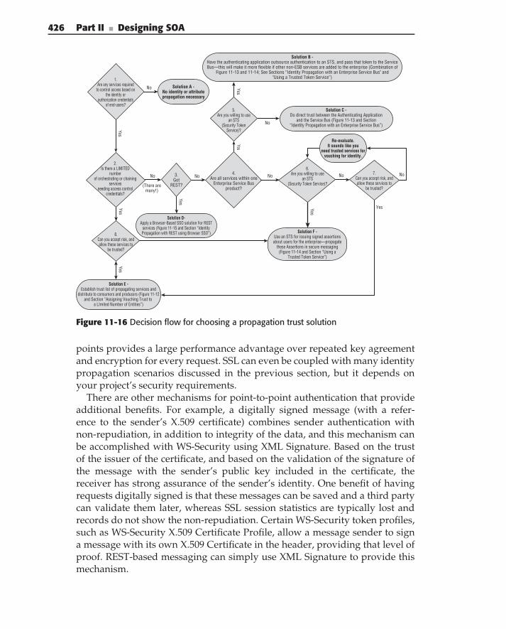
426 Part II ■ Designing SOA
No
1.Are any services required
to control access based onthe identity or
authorization credentialsof end-users?
Solution A -No identity or attributepropagation necessary
Solution B - Have the authenticating application outsource authentication to an STS, and pass that token to the ServiceBus—this will make it more flexible if other non-ESB services are added to the enterprise (Combination of
Figure 11-13 and 11-14; See Sections “Identity Propagation with an Enterprise Service Bus" and"Using a Trusted Token Service”)
No
No
YesYes
NoNo
YesYes
Yes
Yes
No
Yes
Solution C -Do direct trust between the Authenticating Application
and the Service Bus (Figure 11-13 and Section“Identity Propagation with an Enterprise Service Bus”)
5. Are you willing to use
an STS(Security Token
Service)?
4.Are all services within one
Enterprise Service Busproduct?
3.Got
REST?(There aremany!)
2.Is there a LIMITED
numberof orchestrating or chaining
services needing access control
credentials?
6. Are you willing to use
an STS(Security Token Service)?
Re-evaluate.It sounds like you
need trusted services forvouching for identity.
Solution F -Use an STS for issuing signed assertionsabout users for the enterprise—propagate
these Assertions in secure messaging(Figure 11-14 and Section “Using a
Trusted Token Service”)
Solution D-Apply a Browser-Based SSO solution For REST
services (Figure 11-15 and Section “IdentityPropagation with REST using Browser SSO”)8.
Can you accept risk, andallow these services to
be trusted?
Solution E -Establish trust list of propagating services and
distribute to consumers and producers (Figure 11-12and Section “Assigning Vouching Trust to
a LImited Number of Entities”)
Yes
7. Can you accept risk, andallow these services to
be trusted?
No
Figure 11-16 Decision flow for choosing a propagation trust solution
points provides a large performance advantage over repeated key agreementand encryption for every request. SSL can even be coupled with many identitypropagation scenarios discussed in the previous section, but it depends onyour project’s security requirements.
There are other mechanisms for point-to-point authentication that provideadditional benefits. For example, a digitally signed message (with a refer-ence to the sender’s X.509 certificate) combines sender authentication withnon-repudiation, in addition to integrity of the data, and this mechanism canbe accomplished with WS-Security using XML Signature. Based on the trustof the issuer of the certificate, and based on the validation of the signature ofthe message with the sender’s public key included in the certificate, thereceiver has strong assurance of the sender’s identity. One benefit of havingrequests digitally signed is that these messages can be saved and a third partycan validate them later, whereas SSL session statistics are typically lost andrecords do not show the non-repudiation. Certain WS-Security token profiles,such as WS-Security X.509 Certificate Profile, allow a message sender to signa message with its own X.509 Certificate in the header, providing that level ofproof. REST-based messaging can simply use XML Signature to provide thismechanism.
Chapter 11 ■ SOA Security 427
Access Control BlueprintsBuilding on the authentication-based blueprints of the last section, this sectionfocuses on practical solutions for access control. Once a user is identified,it is important to determine what that user can do (authorization). Accesscontrol can be done by expressing and enforcing access control policy basedon the identity of the user and the user’s authorization credentials. This sectionfocuses on key aspects of access control in SOA-based solutions, providingapproaches and best practices.
Controlling Access to Data, Not Just Services
One important thing to remember when providing access control to serviceresources is that, although you can provide authorization at the service level forincoming requests, you can also secure access to the data itself by labeling thedata itself with access control policy information and allowing your PDP/PEPto enforce authorization policy based on the label of your data. This is oftenused in both commercial and government systems where data may be labeledwith sensitivity levels, such as ‘‘FOR INTERNAL USE ONLY.’’ A securityclassification example dealing with Mandatory Access Control was shown inFigure 11-4.
In providing access control to data, security handlers or security componentsare most likely to constrain requests based on the data labels, or they can filterservice results before they are returned to the user (sometimes called ‘‘responsefiltering’’ or ‘‘response pipeline filtering’’). For those enterprises that need thislevel of security, security metadata tagging on messages is quite important forcontrolling access to the data. Some approaches involved security metadatatagging at the message level, where each message is labeled with securitymetadata — this is helpful, because the label of the entire message can beplaced in the SOAP header with other security information. Other approachesinvolve tagging at the XML element level directly (right along with the data).The positive aspect of that particular approach is that, in the message responsepipeline, the response message would actually be filtered on the way backfrom the service, whereas providing response security using the message-levellabeling alternative simply would either accept or drop the response. Thebenefit of labeling at the element level is that potentially more informationwould be returned to the user. On the other hand, the benefit of labeling at themessage level is that the security data (in the header) can be separated fromthe business data (in the body).
Certainly, there are other database-centric solutions that do not necessarilyuse security tagging. In such approaches, a service queries a database withconstraints of access (for example, ‘‘give me these search results, except forrecords labeled ‘FOR INTERNAL USE ONLY’’’), and the database does the
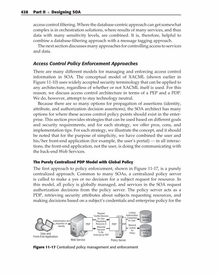
428 Part II ■ Designing SOA
access control filtering. Where the database-centric approach can get somewhatcomplex is in orchestration solutions, where results of many services, and thusdata with many sensitivity levels, are combined. It is, therefore, helpful tocombine a database-filtering approach with a message tagging approach.
The next section discusses many approaches for controlling access to servicesand data.
Access Control Policy Enforcement Approaches
There are many different models for managing and enforcing access controlinformation in SOA. The conceptual model of XACML (shown earlier inFigure 11-10) uses widely accepted security terminology that can be applied toany architecture, regardless of whether or not XACML itself is used. For thisreason, we discuss access control architecture in terms of a PEP and a PDP.We do, however, attempt to stay technology neutral.
Because there are so many options for propagation of assertions (identity,attribute, and authorization decision assertions), the SOA architect has manyoptions for where these access control policy points should exist in the enter-prise. This section provides strategies that can be used based on different goalsand security requirements, and for each strategy, we offer pros, cons, andimplementation tips. For each strategy, we illustrate the concept, and it shouldbe noted that for the purpose of simplicity, we have combined the user andhis/her front-end application (for example, the user’s portal) — in all interac-tions, the front-end application, not the user, is doing the communicating withthe back-end Web Services.
The Purely Centralized PDP Model with Global Policy
The first approach to policy enforcement, shown in Figure 11-17, is a purelycentralized approach. Common to many SOAs, a centralized policy serveris called to make a yes or no decision for a subject request for resource. Inthis model, all policy is globally managed, and services in the SOA requestauthorization decisions from the policy server. The policy server acts as aPDP, retrieving security attributes about subjects requesting resources, andmaking decisions based on a subject’s credentials and enterprise policy for the
Attribute Service
EnterprisePolicyStore
Policy Server
User andFront-End Application
Web Service
Portal
Authentication andAssertion of
IdentityPDPPEP
Request Yes/No Decision
for UserRequestingResource AReturned DecisionTo Be
Enforced by PEP
Lookup Authorization Credentials for User
NetworkLookup
forPolicy
PIP
Figure 11-17 Centralized policy management and enforcement
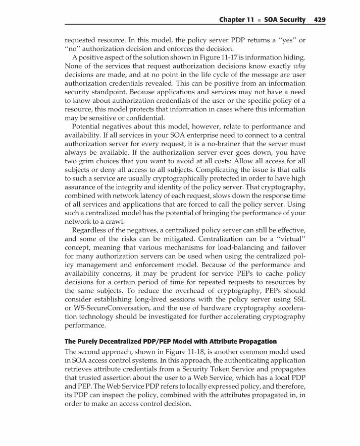
Chapter 11 ■ SOA Security 429
requested resource. In this model, the policy server PDP returns a ‘‘yes’’ or‘‘no’’ authorization decision and enforces the decision.
A positive aspect of the solution shown in Figure 11-17 is information hiding.None of the services that request authorization decisions know exactly whydecisions are made, and at no point in the life cycle of the message are userauthorization credentials revealed. This can be positive from an informationsecurity standpoint. Because applications and services may not have a needto know about authorization credentials of the user or the specific policy of aresource, this model protects that information in cases where this informationmay be sensitive or confidential.
Potential negatives about this model, however, relate to performance andavailability. If all services in your SOA enterprise need to connect to a centralauthorization server for every request, it is a no-brainer that the server mustalways be available. If the authorization server ever goes down, you havetwo grim choices that you want to avoid at all costs: Allow all access for allsubjects or deny all access to all subjects. Complicating the issue is that callsto such a service are usually cryptographically protected in order to have highassurance of the integrity and identity of the policy server. That cryptography,combined with network latency of each request, slows down the response timeof all services and applications that are forced to call the policy server. Usingsuch a centralized model has the potential of bringing the performance of yournetwork to a crawl.
Regardless of the negatives, a centralized policy server can still be effective,and some of the risks can be mitigated. Centralization can be a ‘‘virtual’’concept, meaning that various mechanisms for load-balancing and failoverfor many authorization servers can be used when using the centralized pol-icy management and enforcement model. Because of the performance andavailability concerns, it may be prudent for service PEPs to cache policydecisions for a certain period of time for repeated requests to resources bythe same subjects. To reduce the overhead of cryptography, PEPs shouldconsider establishing long-lived sessions with the policy server using SSLor WS-SecureConversation, and the use of hardware cryptography accelera-tion technology should be investigated for further accelerating cryptographyperformance.
The Purely Decentralized PDP/PEP Model with Attribute Propagation
The second approach, shown in Figure 11-18, is another common model usedin SOA access control systems. In this approach, the authenticating applicationretrieves attribute credentials from a Security Token Service and propagatesthat trusted assertion about the user to a Web Service, which has a local PDPand PEP. The Web Service PDP refers to locally expressed policy, and therefore,its PDP can inspect the policy, combined with the attributes propagated in, inorder to make an access control decision.
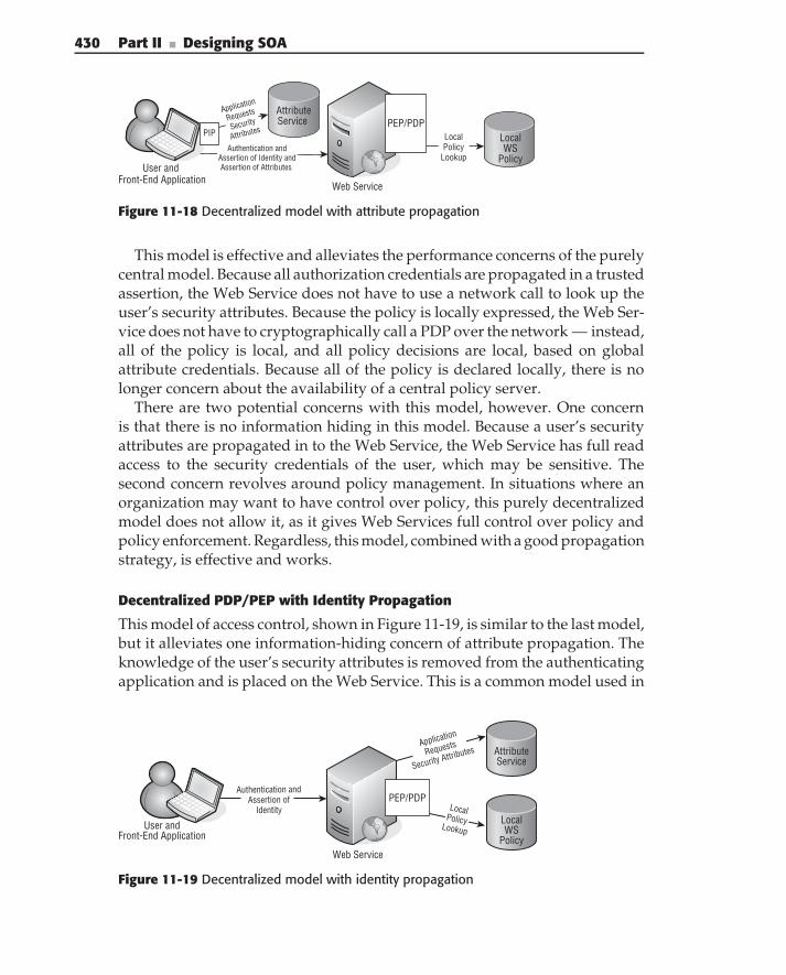
430 Part II ■ Designing SOA
Web Service
Application
Requests
Security
Attributes
AttributeService
Local WS
Policy
PIPPEP/PDP
User and Front-End Application
Local Policy
LookupAuthentication and
Assertion of Identity and Assertion of Attributes
Figure 11-18 Decentralized model with attribute propagation
This model is effective and alleviates the performance concerns of the purelycentral model. Because all authorization credentials are propagated in a trustedassertion, the Web Service does not have to use a network call to look up theuser’s security attributes. Because the policy is locally expressed, the Web Ser-vice does not have to cryptographically call a PDP over the network — instead,all of the policy is local, and all policy decisions are local, based on globalattribute credentials. Because all of the policy is declared locally, there is nolonger concern about the availability of a central policy server.
There are two potential concerns with this model, however. One concernis that there is no information hiding in this model. Because a user’s securityattributes are propagated in to the Web Service, the Web Service has full readaccess to the security credentials of the user, which may be sensitive. Thesecond concern revolves around policy management. In situations where anorganization may want to have control over policy, this purely decentralizedmodel does not allow it, as it gives Web Services full control over policy andpolicy enforcement. Regardless, this model, combined with a good propagationstrategy, is effective and works.
Decentralized PDP/PEP with Identity Propagation
This model of access control, shown in Figure 11-19, is similar to the last model,but it alleviates one information-hiding concern of attribute propagation. Theknowledge of the user’s security attributes is removed from the authenticatingapplication and is placed on the Web Service. This is a common model used in
User andFront-End Application
Authentication andAssertion of
Identity
Web Service
Portal
PEP/PDP
Attribute Service
LocalWS
Policy
Application
Requests
Security Attributes
Local Policy Lookup
Figure 11-19 Decentralized model with identity propagation
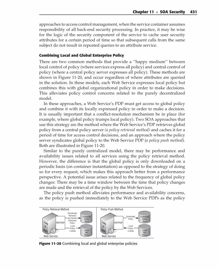
Chapter 11 ■ SOA Security 431
approaches to access control management, when the service container assumesresponsibility of all back-end security processing. In practice, it may be wisefor the logic of the security component of the service to cache user securityattributes for a certain period of time so that subsequent calls from the samesubject do not result in repeated queries to an attribute service.
Combining Local and Global Enterprise Policy
There are two common methods that provide a ‘‘happy medium’’ betweenlocal control of policy (where services express all policy) and central control ofpolicy (where a central policy server expresses all policy). These methods areshown in Figure 11-20, and occur regardless of where attributes are queriedin the solution. In these models, each Web Service expresses local policy butcombines this with global organizational policy in order to make decisions.This alleviates policy control concerns related to the purely decentralizedmodel.
In these approaches, a Web Service’s PDP must get access to global policyand combine it with its locally expressed policy in order to make a decision.It is usually important that a conflict-resolution mechanism be in place (forexample, where global policy trumps local policy). Two SOA approaches thatuse this strategy are the method where the Web Service’s PDP retrieves globalpolicy from a central policy server (a policy retrieval method) and caches it for aperiod of time for access control decisions, and an approach where the policyserver syndicates global policy to the Web Service PDP (a policy push method).Both are illustrated in Figure 11-20.
Similar to the purely centralized model, there may be performance andavailability issues related to all services using the policy retrieval method.However, the difference is that the global policy is only downloaded on aperiodic basis (on container instantiation) as opposed to the strategy of doingso for every request, which makes this approach better from a performanceperspective. A potential issue arises related to the frequency of global policychanges: There may be a time window between the time that policy changesare made and the retrieval of the policy by the Web Services.
The policy push method alleviates performance and availability concerns,as the policy is pushed immediately to the Web Service PDPs as the policy
Policy Retrieval Method
Web Service
Local WS
Policy
EnterprisePolicyStorePEP/PDP
Local Policy
Lookup
PeriodicallyRetrieves
and CachesEnterprise
Policy
Policy Push Method
Web Service
Local WS
Policy
EnterprisePolicyStorePEP/PDP
Local Policy
Lookup
SyndicatedPolicy
Figure 11-20 Combining local and global enterprise policies
432 Part II ■ Designing SOA
changes are created. This alleviates the time window concern, because as thepolicy is changed, it is immediately sent to the Web Service PDPs. The securityof syndication in this model does need to be addressed. The security modelneeds to protect against entities ‘‘spoofing’’ the syndication server, replayingsyndication policy update messages, tampering with messages in transit, anddenial of service attacks that would prevent syndicated policy messages frombeing received by all PDPs.
Both methods discussed in this section are effective for access controlin an SOA. Which you choose depends on your security and performancerequirements.
Predetermined Decision-Based Models
One unique approach to access control is a methodology that we call PADBAC(Predetermined Authorization Decision-Based Access Control). Such a modelof access control revolves around services issuing authorization decisions forresource access in advance, before these resources are requested. In this model,the services issue authorization decisions to the appropriate subjects, who lateruse them to gain authorized access to resources. These decisions are digitallysigned by the service and tied to the identity of the subject who can laterrequest access. When it is time for the subject to request access, the subjectsigns a request for the resource, including the previously issued assertion inthe message.
Such solutions model real-world, day-to-day scenarios. When you dropyour clothes off at a dry cleaner, the clerk typically gives you a receipt witha number, listing the day that you can pick them up. Later, you bring thatreceipt back and the cleaner finds your dry-cleaned clothes and gives themback to you. This process is simple; you don’t have to pull out your ID card,or show the cleaner any authorization credentials in order to get your drycleaning. In the same way, a PADBAC-based approach requires no identity orattribute propagation in the service transaction. Once a subject gets a signedauthorization decision to do something, the subject simply signs the requestto do it, attaching the signed authorization decision along with the request.
A service-based example of using the PADBAC model can be demon-strated in an example implementation of an airline ticket service, illustratedin Figure 11-21. An airline ticket booking Web Service needs to provide accesscontrol to allow only the ticket-booking agents of the airline to book tickets forairline flights. Instead of using one of the access control policy models we havediscussed before, the SOA architect has chosen to use a model that utilizespre-issued authorization decisions for access control. In the example, Gwen,Emma, and Isabella are agents who book flights for customers, so the airlineticket booking service issues signed authorization decision assertions to Gwen,Emma, and Isabella, expressing the purpose of the privilege (booking seats onflights) and a timeframe of validity. When one of the agents needs to later book
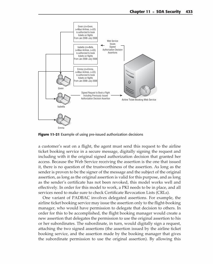
Chapter 11 ■ SOA Security 433
Gwen
Airline Ticket Booking Web Service
Isabella
Emma
Gwen (cn=Gwen,o=Maui Airlines, c=US)is authorized to book
tickets on flightsFrom Jan 2008–July 2008
Isabella (cn=Bella,o=Maui Airlines, c=US)is authorized to book
tickets on flightsFrom Jan 2008–July 2008
Emma (cn=Emma,o=Maui Airlines, c=US)is authorized to book
tickets on flightsFrom Jan 2008–July 2008
Signed Request to Book a FlightIncluding Previously Issued
Authorization Decision Assertion
Web ServiceIssuesSigned
Authorization DecisionAssertions
Figure 11-21 Example of using pre-issued authorization decisions
a customer’s seat on a flight, the agent must send this request to the airlineticket booking service in a secure message, digitally signing the request andincluding with it the original signed authorization decision that granted heraccess. Because the Web Service receiving the assertion is the one that issuedit, there is no question of the trustworthiness of the assertion. As long as thesender is proven to be the signer of the message and the subject of the originalassertion, as long as the original assertion is valid for this purpose, and as longas the sender’s certificate has not been revoked, this model works well andeffectively. In order for this model to work, a PKI needs to be in place, and allservices need to make sure to check Certificate Revocation Lists (CRLs).
One variant of PADBAC involves delegated assertions. For example, theairline ticket booking service may issue the assertion only to the flight-bookingmanager, who would have permission to delegate that decision to others. Inorder for this to be accomplished, the flight booking manager would create anew assertion that delegates the permission to use the original assertion to hisor her subordinates. The subordinate, in turn, would digitally sign a request,attaching the two signed assertions (the assertion issued by the airline ticketbooking service, and the assertion made by the booking manager that givesthe subordinate permission to use the original assertion). By allowing this
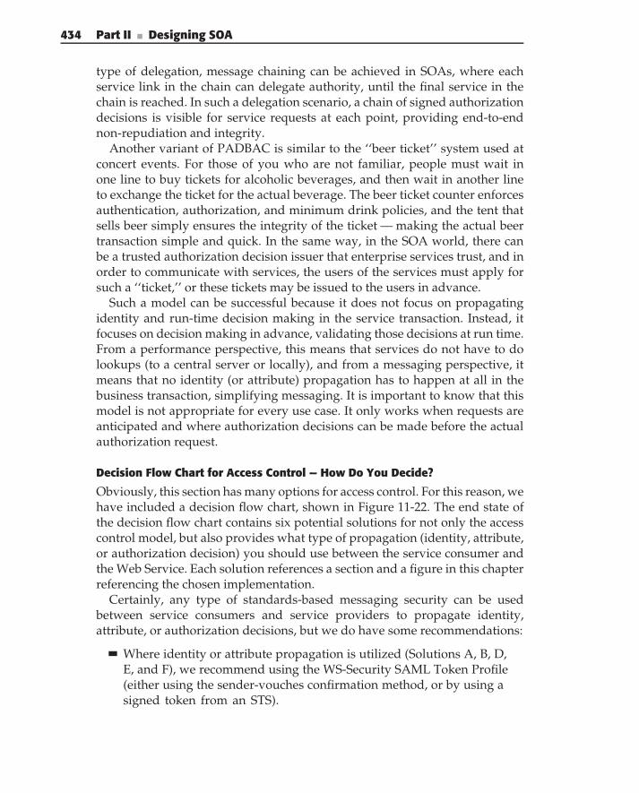
434 Part II ■ Designing SOA
type of delegation, message chaining can be achieved in SOAs, where eachservice link in the chain can delegate authority, until the final service in thechain is reached. In such a delegation scenario, a chain of signed authorizationdecisions is visible for service requests at each point, providing end-to-endnon-repudiation and integrity.
Another variant of PADBAC is similar to the ‘‘beer ticket’’ system used atconcert events. For those of you who are not familiar, people must wait inone line to buy tickets for alcoholic beverages, and then wait in another lineto exchange the ticket for the actual beverage. The beer ticket counter enforcesauthentication, authorization, and minimum drink policies, and the tent thatsells beer simply ensures the integrity of the ticket — making the actual beertransaction simple and quick. In the same way, in the SOA world, there canbe a trusted authorization decision issuer that enterprise services trust, and inorder to communicate with services, the users of the services must apply forsuch a ‘‘ticket,’’ or these tickets may be issued to the users in advance.
Such a model can be successful because it does not focus on propagatingidentity and run-time decision making in the service transaction. Instead, itfocuses on decision making in advance, validating those decisions at run time.From a performance perspective, this means that services do not have to dolookups (to a central server or locally), and from a messaging perspective, itmeans that no identity (or attribute) propagation has to happen at all in thebusiness transaction, simplifying messaging. It is important to know that thismodel is not appropriate for every use case. It only works when requests areanticipated and where authorization decisions can be made before the actualauthorization request.
Decision Flow Chart for Access Control — How Do You Decide?
Obviously, this section has many options for access control. For this reason, wehave included a decision flow chart, shown in Figure 11-22. The end state ofthe decision flow chart contains six potential solutions for not only the accesscontrol model, but also provides what type of propagation (identity, attribute,or authorization decision) you should use between the service consumer andthe Web Service. Each solution references a section and a figure in this chapterreferencing the chosen implementation.
Certainly, any type of standards-based messaging security can be usedbetween service consumers and service providers to propagate identity,attribute, or authorization decisions, but we do have some recommendations:
Where identity or attribute propagation is utilized (Solutions A, B, D,E, and F), we recommend using the WS-Security SAML Token Profile(either using the sender-vouches confirmation method, or by using asigned token from an STS).
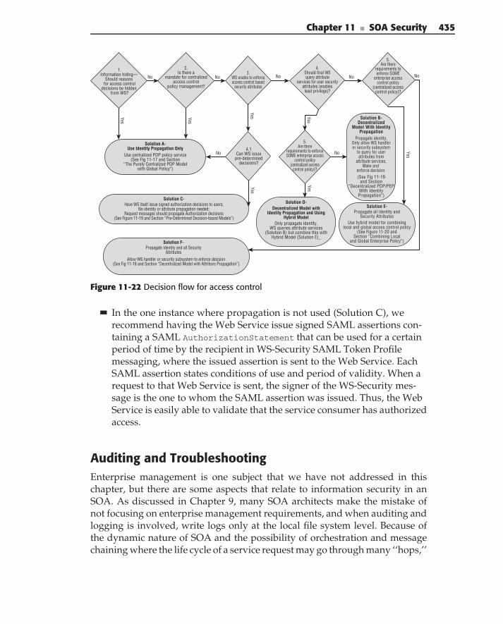
Chapter 11 ■ SOA Security 435
1.Information hiding—
Should reasons for access control
decisions be hidden from WS?
Solution A-Use Identity Propagation Only
Solution C-
Solution F-
2.Is there a
mandate for centralizedaccess control
policy management?
Use centralized PDP policy service(See FIg 11-17 and Section
“The Purely Centralized PDP Modelwith Global Policy”)
Have WS itself issue signed authorization decisions to users;No identity or attribute propagation needed;
Request messages should propagate Authorization decisions(See Figure 11-19 and Section “Pre-Determined Decision-based Models”)
Allow WS handler or security subsystem to enforce decision(See Fig 11-18 and Section “Decentralized Model with Attribure Propagation”)
Propagate Identity and all SecurityAttributes
Solution D-Decentralized Model with
Identity Propagation and UsingHybrid Model
Only propagate identity,WS queries attribute services
(Solution B) but combine this withHybrid Model (Solution E)_
Solution E-Propagate all Identity and
Security AttributesUse hybrid model for combining
local and global access control policy(See Figure 11-20 and
Section “Combining Localand Global Enterprise Policy”)
Solution B-Decentralized
Model With IdentityPropagation
Propagate identity,Only allow WS handleror security subsystem
to query for userattributes from
attribute services,Make and
enforce decision.(See Fig 11-19
and Section“Decentralized PDP/PEP
With IdentityPropagation”)
4.1Can WS issue
pre-determineddecisions?
5.Are there
requirements to enforceSOME enterprise access
control policy(centralized access
control policy)?
3.WS unable to enforceaccess control based
security attributes
4.Should final WSquery attribute
services for user securityattributes (enables
least privilege)?
5.Are there
requirements toenforce SOME
enterprise accesscontrol policy
(centralized accesscontrol policy)?
No No No No
Yes
Yes
Yes
YesYes
Yes
Yes
No No
No
Figure 11-22 Decision flow for access control
In the one instance where propagation is not used (Solution C), werecommend having the Web Service issue signed SAML assertions con-taining a SAML AuthorizationStatement that can be used for a certainperiod of time by the recipient in WS-Security SAML Token Profilemessaging, where the issued assertion is sent to the Web Service. EachSAML assertion states conditions of use and period of validity. When arequest to that Web Service is sent, the signer of the WS-Security mes-sage is the one to whom the SAML assertion was issued. Thus, the WebService is easily able to validate that the service consumer has authorizedaccess.
Auditing and TroubleshootingEnterprise management is one subject that we have not addressed in thischapter, but there are some aspects that relate to information security in anSOA. As discussed in Chapter 9, many SOA architects make the mistake ofnot focusing on enterprise management requirements, and when auditing andlogging is involved, write logs only at the local file system level. Because ofthe dynamic nature of SOA and the possibility of orchestration and messagechaining where the life cycle of a service request may go through many ‘‘hops,’’
436 Part II ■ Designing SOA
it is often difficult to troubleshoot security incidents and errors if every servicelogs information to its local machine. It is prudent, therefore, to use eithera centralized logging capability or an SOA enterprise management COTSpackage, which integrates with your Web Service consumers and producers,providing not only ‘‘the big picture’’ of your SOA but also the big securitypicture. Chapter 9, the section ‘‘Exception Handling and Logging in EnterpriseSolutions’’ provides detailed strategies for auditing and logging that apply toboth security and enterprise management.
Flexibility with Dynamic WS-SecurityPolicy AdaptationThe introduction of WS-SecurityPolicy allows SOA security solutions to usedynamic run-time mechanisms for discovering and adhering to security policy.Similar to the way that applications can download WSDL and dynamicallycreate stubs to access services, Web Service consumers and producers can nowdynamically discover messaging security requirements and adapt at run time.
The following is a good example: Suppose that a Web Service that oncerequired a token of a user’s authentication (an Authentication Assertion) inWS-Security SOAP messaging now requires a token of the user’s attributes (anAttribute Assertion). If that Web Service modifies its expressed WS-Security-Policy, which can be referred to in the service’s WSDL, the calling applicationinitially calls the Web Service. When it receives an error notification that thesecurity policy is changed, it can download the new policy, discover thatchanges have been made, and adapt by retrieving a new type of assertion froman Asserting Provider or an STS in its enterprise. It can then call the servicecorrectly.
Expressing the security messaging requirements in a discoverable way usingWS-SecurityPolicy gives service consumers the capability to be more looselycoupled to the security messaging of services. If the security messaging ishard-coded in your service’s clients, any change in security messaging wouldbreak the client’s interactions with the service. Dynamic policy adaption,therefore, provides a very flexible model. Although developers can writesoftware to accomplish this in security interceptors and security handlers, itshould be mentioned that many COTS vendors are building these dynamicpolicy adaptation capabilities (sometimes called ‘‘Policy Application Points’’)into their products, supporting many messaging formats and token formatsin order to support SOA security flexibility in enterprise deployments. Thisapproach is also used beyond WS-SecurityPolicy to adapt to other WS-Policyrequirements of services in the enterprise.
N O T E This strategy is discussed in more depth in Chapter 12, in a section called‘‘Run-Time Policy Enforcement and Adaptation.’’ There we discuss how a serviceclient’s ‘‘Policy Application Point’’ can be used to adapt to adhere to many types of
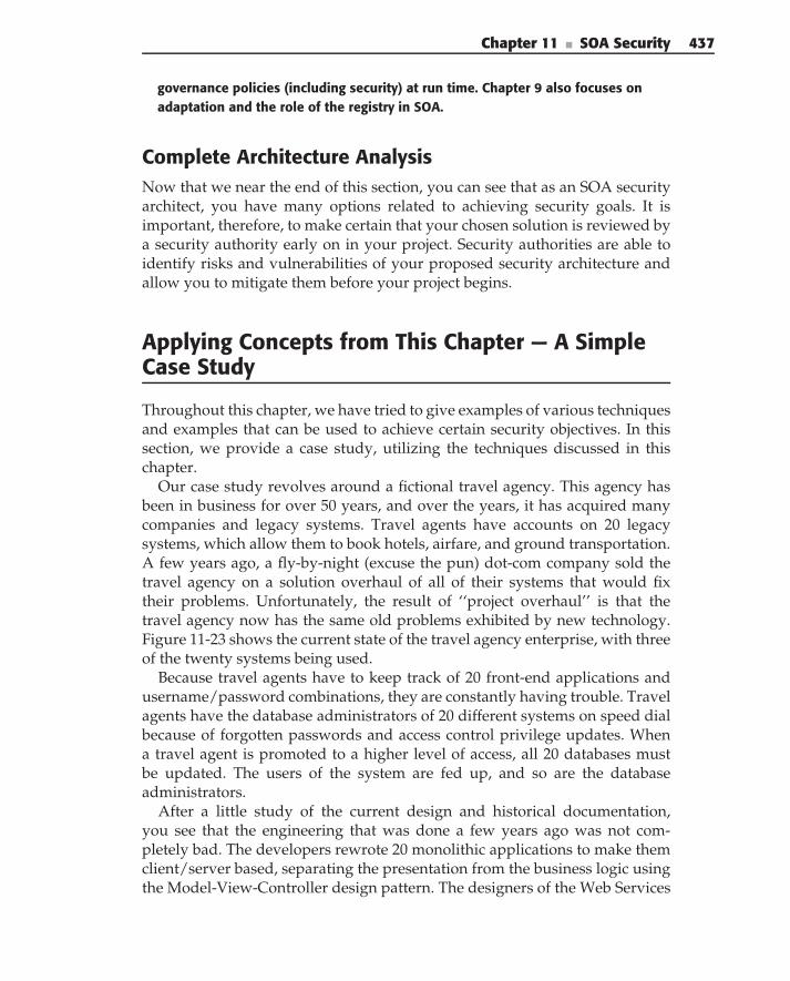
Chapter 11 ■ SOA Security 437
governance policies (including security) at run time. Chapter 9 also focuses onadaptation and the role of the registry in SOA.
Complete Architecture AnalysisNow that we near the end of this section, you can see that as an SOA securityarchitect, you have many options related to achieving security goals. It isimportant, therefore, to make certain that your chosen solution is reviewed bya security authority early on in your project. Security authorities are able toidentify risks and vulnerabilities of your proposed security architecture andallow you to mitigate them before your project begins.
Applying Concepts from This Chapter — A SimpleCase Study
Throughout this chapter, we have tried to give examples of various techniquesand examples that can be used to achieve certain security objectives. In thissection, we provide a case study, utilizing the techniques discussed in thischapter.
Our case study revolves around a fictional travel agency. This agency hasbeen in business for over 50 years, and over the years, it has acquired manycompanies and legacy systems. Travel agents have accounts on 20 legacysystems, which allow them to book hotels, airfare, and ground transportation.A few years ago, a fly-by-night (excuse the pun) dot-com company sold thetravel agency on a solution overhaul of all of their systems that would fixtheir problems. Unfortunately, the result of ‘‘project overhaul’’ is that thetravel agency now has the same old problems exhibited by new technology.Figure 11-23 shows the current state of the travel agency enterprise, with threeof the twenty systems being used.
Because travel agents have to keep track of 20 front-end applications andusername/password combinations, they are constantly having trouble. Travelagents have the database administrators of 20 different systems on speed dialbecause of forgotten passwords and access control privilege updates. Whena travel agent is promoted to a higher level of access, all 20 databases mustbe updated. The users of the system are fed up, and so are the databaseadministrators.
After a little study of the current design and historical documentation,you see that the engineering that was done a few years ago was not com-pletely bad. The developers rewrote 20 monolithic applications to make themclient/server based, separating the presentation from the business logic usingthe Model-View-Controller design pattern. The designers of the Web Services
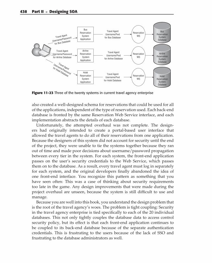
438 Part II ■ Designing SOA
BusReservation
System Application
AirlineReservation
System Application
Hotel Reservation
System Application
Reservation WS
Reservation WS
Reservation WS
Travel Agent Username/Password for Airline Database
Travel Agent
Username/Password
for Hotel Database
BusReservation
SystemDatabase
AirlineReservation
System Database
HotelReservation
System Database
Travel Agent
Username/Password
for Bus Database
Travel AgentUsername/Pwd
for Bus Database
Travel AgentUsername/Pwd
for Airline Database
Travel AgentUsername/Pwd
for Hotel Database
Figure 11-23 Three of the twenty systems in current travel agency enterprise
also created a well-designed schema for reservations that could be used for allof the applications, independent of the type of reservation used. Each back-enddatabase is fronted by the same Reservation Web Service interface, and eachimplementation abstracts the details of each database.
Unfortunately, the attempted overhaul was not complete. The design-ers had originally intended to create a portal-based user interface thatallowed the travel agents to do all of their reservations from one application.Because the designers of this system did not account for security until the endof the project, they were unable to tie the systems together because they ranout of time and made poor decisions about username/password propagationbetween every tier in the system. For each system, the front-end applicationpasses on the user’s security credentials to the Web Service, which passesthem on to the database. As a result, every travel agent must log in separatelyfor each system, and the original developers finally abandoned the idea ofone front-end interface. You recognize this pattern as something that youhave seen often: This was a case of thinking about security requirementstoo late in the game. Any design improvements that were made during theproject overhaul are unseen, because the system is still difficult to use andmanage.
Because you are well into this book, you understand the design problem thatis the root of the travel agency’s woes. The problem is tight coupling: Securityin the travel agency enterprise is tied specifically to each of the 20 individualdatabases. This not only tightly couples the database data to access controlsecurity policy, but its effect is that each front-end application continues tobe coupled to its back-end database because of the separate authenticationcredentials. This is frustrating to the users because of the lack of SSO andfrustrating to the database administrators as well.
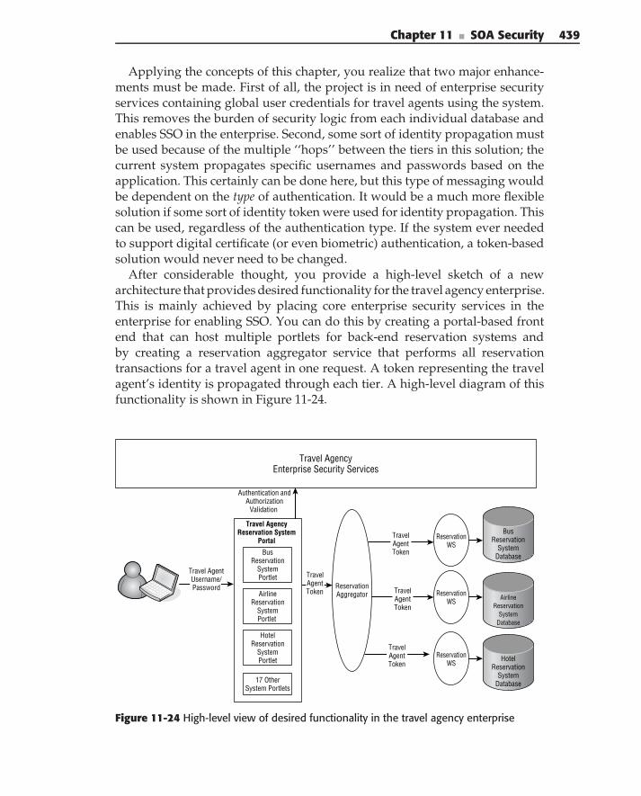
Chapter 11 ■ SOA Security 439
Applying the concepts of this chapter, you realize that two major enhance-ments must be made. First of all, the project is in need of enterprise securityservices containing global user credentials for travel agents using the system.This removes the burden of security logic from each individual database andenables SSO in the enterprise. Second, some sort of identity propagation mustbe used because of the multiple ‘‘hops’’ between the tiers in this solution; thecurrent system propagates specific usernames and passwords based on theapplication. This certainly can be done here, but this type of messaging wouldbe dependent on the type of authentication. It would be a much more flexiblesolution if some sort of identity token were used for identity propagation. Thiscan be used, regardless of the authentication type. If the system ever neededto support digital certificate (or even biometric) authentication, a token-basedsolution would never need to be changed.
After considerable thought, you provide a high-level sketch of a newarchitecture that provides desired functionality for the travel agency enterprise.This is mainly achieved by placing core enterprise security services in theenterprise for enabling SSO. You can do this by creating a portal-based frontend that can host multiple portlets for back-end reservation systems andby creating a reservation aggregator service that performs all reservationtransactions for a travel agent in one request. A token representing the travelagent’s identity is propagated through each tier. A high-level diagram of thisfunctionality is shown in Figure 11-24.
BusReservation
SystemPortlet
AirlineReservation
SystemPortlet
AirlineReservation
SystemDatabase
HotelReservation
SystemPortlet Hotel
ReservationSystem
Database
ReservationWS
ReservationWS
ReservationWS
17 OtherSystem Portlets
ReservationAggregator
Travel AgencyEnterprise Security Services
Authentication andAuthorization
Validation
Travel AgencyReservation System
Portal
TravelAgentToken
TravelAgentToken
TravelAgentToken
TravelAgentToken
BusReservation
SystemDatabase
Travel AgentUsername/Password
Figure 11-24 High-level view of desired functionality in the travel agency enterprise
440 Part II ■ Designing SOA
Figure 11-24 shows that a travel agent logs in to the portal, and each portalhas portlets associated with each back-end system. Once the travel agent entersall travel requirements and reservation information for the customer, the portalsystem sends a bulk request, along with the user’s token. The enterprise reusesthe well-designed abstract Reservation Web Service interfaces that abstract thedetails of each system.
Establishing Enterprise Security ServicesAt this point in the case study, more decisions need to be made. Specifically,it is important to define the enterprise security services. After having readthe concepts and security solution blueprints in this chapter, you know thatthere are many options for access control, depending on the security servicesavailable. Architectural flexibility is provided when you provide the securityservices needed for all of the alternatives for access control policy enforce-ment. This allows different future applications with different requirements theability to use multiple options. For this reason, you create the following:
An Authentication Service, which identifies the user (and/or applica-tions in the enterprise).
An Attribute Service, which exposes authorization credentials of usersin the enterprise. In the travel agency, the current security roles arereservation approver, travel reserver, and purchasing approver.Such an attribute service accommodates those roles and also accommo-dates growth and flexibility.
A Policy Management Service, which is used by policy administrators tocreate, update, and manage security policy.
A Policy Retrieval Service, which exposes the policies of resources inthe enterprise. Policies can be expressed in XACML for resources in theenterprise, regardless of the resource. In the travel agency enterprise,policy logic can be taken out of each individual database and instead beexpressed by these policies.
An Authorization Decision Service, which acts as the service that makesaccess control decisions based on enterprise policy for a subject’s accessto a resource. In order for the Authorization Decision Service to make adecision, it must know the identity of the subject requesting the resource(via an identity token), the authorization credentials of the user (viathe Attribute Service), and the policy of the resource and the enterprisepolicy (via the Policy Retrieval Service).
An STS, which issues tokens related to the identity and securityattributes of users, as well as authorization decisions. This token serviceidentifies users, and in doing so, communicates with the other services.
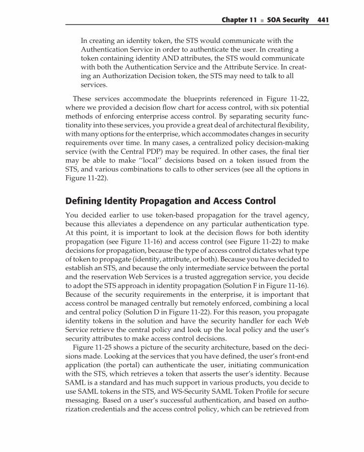
Chapter 11 ■ SOA Security 441
In creating an identity token, the STS would communicate with theAuthentication Service in order to authenticate the user. In creating atoken containing identity AND attributes, the STS would communicatewith both the Authentication Service and the Attribute Service. In creat-ing an Authorization Decision token, the STS may need to talk to allservices.
These services accommodate the blueprints referenced in Figure 11-22,where we provided a decision flow chart for access control, with six potentialmethods of enforcing enterprise access control. By separating security func-tionality into these services, you provide a great deal of architectural flexibility,with many options for the enterprise, which accommodates changes in securityrequirements over time. In many cases, a centralized policy decision-makingservice (with the Central PDP) may be required. In other cases, the final tiermay be able to make ‘‘local’’ decisions based on a token issued from theSTS, and various combinations to calls to other services (see all the options inFigure 11-22).
Defining Identity Propagation and Access ControlYou decided earlier to use token-based propagation for the travel agency,because this alleviates a dependence on any particular authentication type.At this point, it is important to look at the decision flows for both identitypropagation (see Figure 11-16) and access control (see Figure 11-22) to makedecisions for propagation, because the type of access control dictates what typeof token to propagate (identity, attribute, or both). Because you have decided toestablish an STS, and because the only intermediate service between the portaland the reservation Web Services is a trusted aggregation service, you decideto adopt the STS approach in identity propagation (Solution F in Figure 11-16).Because of the security requirements in the enterprise, it is important thataccess control be managed centrally but remotely enforced, combining a localand central policy (Solution D in Figure 11-22). For this reason, you propagateidentity tokens in the solution and have the security handler for each WebService retrieve the central policy and look up the local policy and the user’ssecurity attributes to make access control decisions.
Figure 11-25 shows a picture of the security architecture, based on the deci-sions made. Looking at the services that you have defined, the user’s front-endapplication (the portal) can authenticate the user, initiating communicationwith the STS, which retrieves a token that asserts the user’s identity. BecauseSAML is a standard and has much support in various products, you decide touse SAML tokens in the STS, and WS-Security SAML Token Profile for securemessaging. Based on a user’s successful authentication, and based on autho-rization credentials and the access control policy, which can be retrieved from
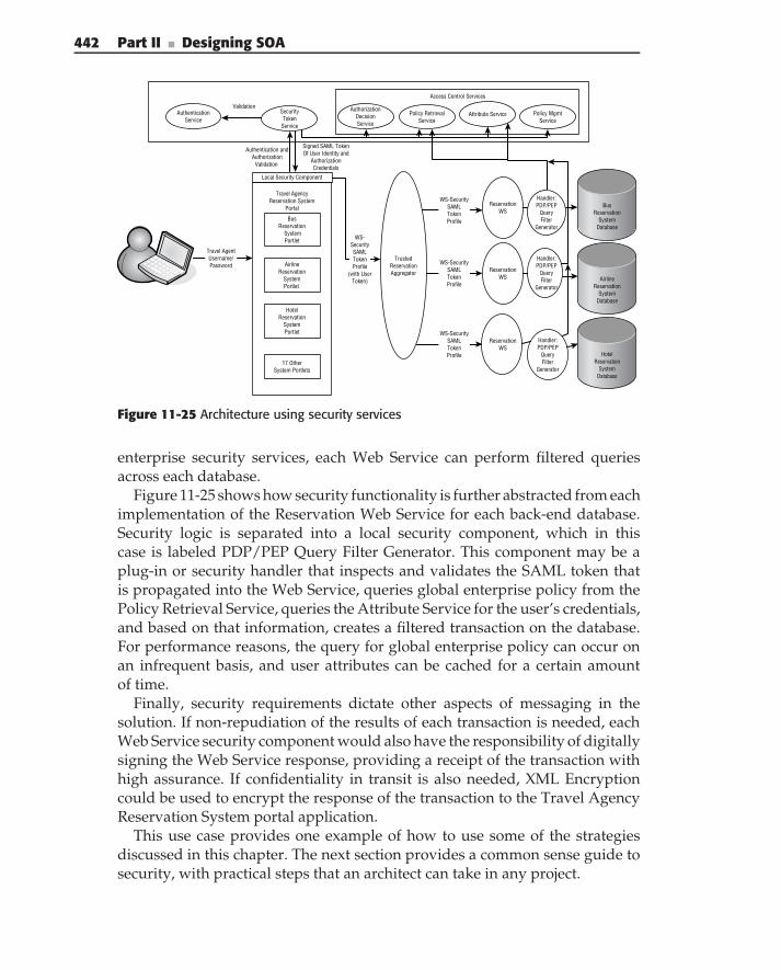
442 Part II ■ Designing SOA
WS-SecuritySAMLTokenProfile
WS-SecuritySAMLTokenProfile
WS-SecuritySAMLTokenProfile
Travel AgentUsername/Password
BusReservation
SystemPortlet
Travel AgencyReservation System
Portal BusReservation
SystemDatabase
AirlineReservation
SystemPortlet
AirlineReservation
SystemDatabase
HotelReservation
SystemPortlet
HotelReservation
SystemDatabase
ReservationWS
ReservationWS
ReservationWS
17 OtherSystem Portlets
TrustedReservationAggregator
WS-SecuritySAMLTokenProfile
(with UserToken)
Authentication andAuthorization
Validation
AuthenticationService
Access Control Services
AuthorizationDecisionService
Attribute Service Policy MgmtService
SecurityToken
Service
Validation
Signed SAML TokenOf User Identity and
AuthorizationCredentials
Handler:PDP/PEP
QueryFilter
Generator
Handler:PDP/PEP
QueryFilter
Generator
Handler:PDP/PEP
QueryFilter
Generator
Policy RetrievalService
Local Security Component
Figure 11-25 Architecture using security services
enterprise security services, each Web Service can perform filtered queriesacross each database.
Figure 11-25 shows how security functionality is further abstracted from eachimplementation of the Reservation Web Service for each back-end database.Security logic is separated into a local security component, which in thiscase is labeled PDP/PEP Query Filter Generator. This component may be aplug-in or security handler that inspects and validates the SAML token thatis propagated into the Web Service, queries global enterprise policy from thePolicy Retrieval Service, queries the Attribute Service for the user’s credentials,and based on that information, creates a filtered transaction on the database.For performance reasons, the query for global enterprise policy can occur onan infrequent basis, and user attributes can be cached for a certain amountof time.
Finally, security requirements dictate other aspects of messaging in thesolution. If non-repudiation of the results of each transaction is needed, eachWeb Service security component would also have the responsibility of digitallysigning the Web Service response, providing a receipt of the transaction withhigh assurance. If confidentiality in transit is also needed, XML Encryptioncould be used to encrypt the response of the transaction to the Travel AgencyReservation System portal application.
This use case provides one example of how to use some of the strategiesdiscussed in this chapter. The next section provides a common sense guide tosecurity, with practical steps that an architect can take in any project.
Chapter 11 ■ SOA Security 443
The Security Game Plan for the SOA Architect
If you are new to information security principles or to some of the standardsdiscussed in this chapter, you may be overwhelmed at this point. The learningcurve related to understanding the security fundamentals alone is quite steep,and there is quite an ‘‘alphabet soup’’ of security standards that overlapor compete with each other in many areas. Because each of the securitystandards has multiple options, it is easy to see that there is not one clear usagescenario — there are many! It is also important to note that there is never ‘‘oneanswer’’ for every SOA security solution. Every SOA is unique and, therefore,has its own individual security requirements. Providing all of this securitybackground information necessitated going ‘‘into the weeds’’ in some areasof this chapter. Now, however, we would like you to sit back and focus onthe ‘‘big picture.’’ This section provides a high-level game plan for providingSOA security solutions in your projects.
Plan from the Beginning, Focusing on RequirementsThe big picture is that focusing on security from the beginning is essential, andthe plan needs to be based on the requirements of the organization(s) involved.When SOA architects wait until the last minute to plan for security, disasterawaits. In too many projects, the initial emphasis is solely on developing thecore functionality of services, and adding security is postponed until the end ofprojects. As you can imagine, adding the security capabilities discussed earlierin this chapter not only requires a steep learning curve, but also retrofittingsecurity at the last minute leads to a brittle architecture and probably leads toburned-out developers! For this reason, security architecture planning needsto be at the beginning of your roadmap.
In order to plan for security, however, it is important to understand yoursecurity requirements. Regardless of the technologies used, you cannot achieveyour goals if you do not understand what your goals are. A requirementsanalysis phase is critical for this understanding. Because most customers arefocused on functionality, they may not think about security until right beforedeployment when their security officer mandates certain requirements. Whenasked, most stakeholders say ‘‘Yes, I would like you to make everythingsecure. Thanks!’’ At the beginning of each project, you need to determinewhat requirements exist for authentication, authorization, confidentiality,integrity, non-repudiation, auditing, and availability. Find out who is levyingsecurity requirements, ask them specific questions, and determine the truerequirements together. Once you discover the true requirements of your SOA,you can then begin planning and you can determine the approaches that youcan take in order to satisfy your security goals.
444 Part II ■ Designing SOA
In doing requirements analysis, it is also important that you understand thecurrent enterprise architecture with which your SOA needs to interoperate.Your SOA may need to integrate with LDAP directories, policy servers,Attribute Services, and a PKI. It is important that your planning includes thisinfrastructure so that you don’t architect in a vacuum.
Crawl and Walk before RunningIt is certainly a temptation at the beginning of SOA-based projects to attemptto achieve too much and ‘‘boil the ocean’’ in an unrealistic period of time.To satisfy security requirements, it is paramount that methods of achievingsecurity goals be rigorously tested against your requirements and againstpotential threats and vulnerabilities. If the security requirements for your SOArequire much to be achieved, it is preferable to create a phased approachto separate complexity and to make certain that each individual goal issuccessfully achieved. Moving from an SOA with no security to an SOAwith high-levels of access control and dynamic, federated access to partnerscan be done over time, but stampeding toward this goal too quickly causesdisappointment and could cause disaster. A phased, incremental approach,where additional security requirements can be rigorously tested in each phase,is more likely to succeed.
Use Accepted Standards (in a Standard Way)The second part of this chapter focused on accepted standards and specifi-cations used in SOA security solutions. They were chosen to be included inthis chapter because they are produced by standards bodies, and they areaccepted and used by major vendors. It is certainly possible to use proprietarytechnologies to achieve your security goals, but doing so flies in the face ofinteroperability, one of the main reasons for using SOA in the first place. Trustus, tying yourself to a proprietary solution is painful in the long run, and maynecessitate a total rewrite or redesign in order to be interoperable with othersystems, tools, and technologies. It is therefore important to use standards.
It is also important to use standards in a standard way. In the early days ofSOA, when standards such as WS-Security and SAML were in their infancy,security architects had to create XML-based messaging security themselves,acting as ‘‘amateur cryptographers.’’ Even when WS-Security SOAP Messag-ing became a higher-level standard that combined lower-level standards suchas XML, SOAP, XML Encryption, and XML Signature, it alone did not specifyhow it would be used with security tokens such as SAML, X.509 Certificates,or Kerberos Tickets. Security architects had to meet security requirementsby determining how to use the standards together in a secure way. Theresults during this period of time introduced security vulnerabilities, as SOA
Chapter 11 ■ SOA Security 445
architects aren’t expected to be cryptographers. Just as important, the resultswere standards-based but proprietary, non-interoperable messaging solutionsthat used standards in a nonstandard way.
Thankfully, over the years, the standards have evolved, and higher-levelstandards specify how to use standards together (such as the various WS-Security Token Profiles). As a result, there is no reason to create new messagingprotocols! Instead, it is important to choose those standards that achieve yourrequirements, looking to standards that are accepted and adopted by manycommercial vendors, so that your SOA is interoperable with other systems asyour enterprise evolves in the future.
Understand the Details of the StandardsUnfortunately, understanding the standards at a high level are not enoughwhen you are creating security solutions for your SOA enterprise. Thesestandards provide many options and each option can be used in different waysin order to achieve different security requirements. The standards thereforeneed to be fully understood by the security architects involved in your SOAprojects, which means you need to read the specifications involved.
Each standard lists security considerations related to their use in operationalSOA deployments, and they need to be fully understood. For many of thestandards, advice is given related to the threat of message replay, denial ofservice attacks, and other attacks and countermeasures. In each standard, theremay be options that provide different security capabilities that are importantto understand. For example, WS-Security SAML Token Profile has multipleconfirmation methods — holder of key and sender-vouches; understandingthe requirements and security goals of each method could have an impacton the trust models (and the infrastructure) of your SOA. This is just oneexample, but the key point here is that the security architect needs to under-stand the ramifications of the use of all options in your standards.
Finally, it is important (and probably fairly obvious at this point) thatmost standards in SOA security do not stand alone. Many have depen-dencies and other interactions with standards and infrastructure provided byother standards. For example, WS-SecureConversation and WS-Federation relyon the specifications and infrastructure (the STS) of WS-Trust. WS-Securityand various token profiles are used together, and these interactions aredocumented in the various WS-Security Token Profile standards. SAMLand XACML can be used together, and as a result, there is a standardcalled ‘‘The SAML 2.0 Profile of the XACML 2.0 Standard.’’ The list goeson. In most cases, the interactions and dependencies of standards are docu-mented in each standard but refer to other standards.
Vendor toolkits and containers sometimes provide default capabilities forusing specific standards, but these default capabilities may not be sufficient.
446 Part II ■ Designing SOA
In order to satisfy your security requirements, you need to understand thedetails of the security mechanisms of your SOA. The bottom line? Spend sometime reading the standards! If you don’t understand them, you should hire anSOA security architect on your project who does.
Understand the Impact of Security on PerformanceWhen developing the security architecture for your SOA, remember thatsecurity always has an impact on the performance of service consumers andproviders in your enterprise. Network calls made to authenticate subjects,retrieve authorization credentials, and obtain policy information have aneffect on bandwidth as well as performance. The file I/O and bandwidthassociated with auditing to local and remote file systems can have an impact onsystem performance. When cryptography is used in secure messaging, there isalways an impact on performance, because cryptography uses computationallyexpensive operations.
Cryptography is a ‘‘double-edged sword,’’ meaning that cryptography cancertainly be used to achieve security goals, but it always has a negative impacton performance. It is important for the SOA architect to realize that morecryptography does not mean more security. It is indeed possible to create avery slow solution that does not achieve your security goals. For this reason,it is important to understand the security requirements for SOA. If encryptionis not needed, then don’t use it! If there is no requirement for integrity ornon-repudiation, don’t use digital signatures! Be intentional in your use ofcryptography and understand its potential performance impact.
From a performance perspective, it is important to look at technologysolutions and architectural solutions focused on maximizing performance andavailability, and some strategies related to access control were discussed inthe ‘‘SOA Security Blueprints’’ section of this chapter. Finally, dependingon your performance requirements, it may be wise to investigate XML andsecurity appliances that offload XML processing and cryptographic operationsto hardware. If you do this, determine the impact at the beginning of yourprojects, just in case a large amount of integration needs to be written.
Try to Keep It SimpleThe most elegant and secure solutions are usually the most simple. The morecomplex a solution is, the greater the possibility of introducing bugs andvulnerabilities. Therefore, try not to over-engineer your solution, and try touse standard practices and blueprints for securing your SOA. Try to applysecurity mechanisms to all of your clients and services in the same way,reusing security components. Treat services as ‘‘black boxes,’’ and make surethat all inputs, outputs, and side effects of calling them are documented,
Chapter 11 ■ SOA Security 447
intuitive, and well understood. Finally, try to anticipate use cases in your SOA,and always expect and plan for message-chaining scenarios and Web Serviceorchestration in your security design.
Summary
This chapter has provided a brief but in-depth look at SOA security. Buildingon a security vocabulary and discussing SOA security goals in the first section,we provided a look at the major standards in Web Services that are acceptedand are being adopted by industry in the second section. In the third sectionof this chapter, we focused on SOA Security ‘‘blueprints’’ that can be usedfor you to make practical decisions about your security architecture. In thefourth section, we provided an example case study putting the blueprintsand concepts of this chapter into action. Finally, in the last section, we haveprovided some common-sense guidance and a game plan for achieving yourSOA security goals. Use this guidance and blueprints to achieve success inyour SOA-based projects.

C H A P T E R
12
SOA GovernanceWith the widespread adoption of SOA, the challenges associated with SOA projectsare emerging. SOA governance isn’t optional — it’s imperative. Without it, return oninvestment will be low and every SOA project out of the pilot phase will be at risk.
–Paolo Malinverno
SOA governance is essential to a successful SOA. Without it, well-intendedSOA pilot projects spiral into chaos when they go operational. We have seenit before — an organization spends a lot of money developing services, itdeclares success when everything works well in the lab, but because theydidn’t plan ahead for every aspect of the project for real-time operations, thereis constant pain at all levels of the organization when the project goes ‘‘live.’’ Incases like these, where governance is largely ignored, the isolated technologybenefits of SOA adoption are outweighed by the hassle of managing chaos.Managers, architects, and developers get burnt out as they make necessarymassive ‘‘Band-Aid’’ solutions to real-time deployed systems. There are manypeople (like us) who have the battle scars from the early days of SOA, andby reading this chapter, you can benefit from the lessons we have learned.This chapter provides an introduction to SOA governance. It defines anddescribes the SOA governance life cycle, and it provides a practical guide forimplementing it in your organization.
Specifically, this chapter covers the following topics:
Important terminology, principles, and goals related to SOA governance
The case for SOA governance, where we explain why every organizationneeds to focus on these processes
449
450 Part II ■ Designing SOA
The SOA governance life cycle as it applies to the life cycle of services,with each process and the roles of stakeholders explained at every step
Practical actionable steps and key processes that can be used in settingup SOA governance in your organization
SOA Management and Governance Defined
The terms SOA management and SOA governance are terms whose definitionsintersect with each other. For this reason, we feel that it is important to formallydefine them in this section.
SOA governance is the creation, communication, enforcement, and adaptationof policies used to direct and control the creation and implementation of the lifecycle of services. It is a run-time and design-time administrative capability thatno organization should be without. Jean Jacques Dubray, in his October 2007InfoQ article ‘‘Establishing a Service Governance Organization,’’ provides awell-written objective of service governance:
The main objective of Service governance is to achieve the benefits of a ServiceOriented Architecture by fostering the creation of reusable, enterprise classservices. As a cross functional organization, service governance ensures thetimely resolution of issues and conflicts due to the necessary tradeoffs that aremade when shared requirements are defined.
An organization’s governance process is policy-centric, and these policiesinvolve enterprise standards, capabilities, and constraints for use of specificservices in run-time service policies and best practices. Simply put, governancesets policies in place, and provides the mechanism to enforce them. Governanceitself is not a process that is unique to SOA — it can be applied to anybusiness domain used to accomplish business objectives. SOA governance doeshave some unique characteristics, different from those of general governance,as it applies to the service life cycle, and this chapter focuses on thesecharacteristics. SOA management establishes control of the Service-OrientedEnterprise (SOE) — first, by creating a holistic view of the entire enterprise,and then by providing the capabilities to control, monitor, and measureinformation about services and other enterprise components. By having accessto a ‘‘big picture’’ view of your SOA, you are able to understand real-timerequirements by comprehending how the services are being used, and youare able to make changes in order to accommodate those requirements.Sometimes called Enterprise Service Management (ESM), SOA management
Chapter 12 ■ SOA Governance 451
involves the real-time control and collection of data about services in theenterprise.
While SOA management provides the big picture, its definition collideswith governance when it involves measuring and monitoring the adherenceto SOA governance policies. Information collected in the SOA managementprocess may directly affect governance. For example, response time guaranteesfor service level agreements (SLAs) may be refined over time, based on themetrics collected as the services are used. The SOA governance life cycle iscommonly referred to in four different phases — design time, deploy time,run time, and change time:
Design-Time Governance refers to the defining and controlling ofenterprise services to be created in the enterprise, and the creation ofpolicies used to direct and control the implementation of the enterpriseservice life cycle. Key aspects of design-time governance are thecreation of enterprise policies used to direct and control the implementationof the life cycle of enterprise services, and the creation of run-time servicepolicies that specify constraints and capabilities for specific enterpriseservices. In this phase, an SOA architect is responsible for defining andauthoring policies for standards compliance, privacy requirements,access control, reliability, performance, messaging, and develop-ing SLAs.
Deploy-Time Governance involves the process of testing and controllingcompliance to enterprise policies in order for services to be deployed inan SOA. It involves deployment options and topologies, and adherenceto policy should dictate whether or not a service can be deployed on anetwork.
Run-Time Governance refers to the process of enforcing the adherence torun-time service policies at run time. In addition to policy enforcement, thisterm is often used to include aspects of SOA management as it relatesto these policies and to include real-time policy compliance monitoring,auditing, and measuring and collecting result statistics.
Change-Time Governance involves managing services through the cycleof change. In a service life cycle, interfaces, service policies, and agree-ments may be modified many times. Change-time governance focuseson such issues as service versioning, deprecation, and run-time policyadaptation. Governance tools can be used to achieve such strategies asadding service intermediaries to intercept messages and route them tothe appropriate previous versions of services.
452 Part II ■ Designing SOA
As you can see, governance revolves around policy. Policies are created,edited, and refined throughout the life cycle of a project. The following arecommon types of policies used in SOA governance:
Messaging Security — What are the policies related to confidentiality,integrity, and non-repudiation for each service? What kind of authen-tication is used? Are tokens, such as Kerberos, username/password, orSAML used to convey the identity of the end user? What standards tosupport these mechanisms are used?
Access Control Policy — What are the access control policies used forthe services?
Conformance to Enterprise Vocabulary and Schema — What schemasneed to be supported for a service to deploy? Is there a common enter-prise vocabulary that needs to be used? Is there a reference data model?
Conformance to Technical Standards (WS-I, WSDL, WS-Security,WS-ReliableMessaging) — What are the standards to which a servicemust conform in order to deploy?
Deployment Process — What is the process for deploying new services?Related to standards conformance, are there run-time tests that enable aservice to be deployed on the network?
Versioning Policies — What are the policies related to service version-ing and deprecation of existing services?
Discovery Policy — What is the process of discovering a service anddetermining its access policies?
Privacy Regulations — What privacy regulations must be enforced,and how can they be enforced?
Quality of Service (QoS) — Are there guaranteed response times foreach service? Are there levels of service responsiveness and prioritiesfor each classification of user? (For example, employees, customers, andpartners may each get a different guarantee of responsiveness and be putin a priority queue for the same service implementation.) Are there ser-vice levels (for example, gold, silver, bronze) for each type of customer,or are they individualized? Can service levels be negotiated at run timeaccording to the requestor’s requirements?
Reliability — Are there policies related to in-order delivery, at least oncedelivery, and at most once delivery?
Auditing and Reporting Requirements — What type of auditing andreporting needs to be supported by each service?
Service Level Agreements (SLAs) — Are there formal agreementsbetween service consumers and providers related to QoS response times,
Chapter 12 ■ SOA Governance 453
business units of work, and action guarantees based on met conditions?Are there service load conditions related to guarantees?
Certainly, this is not an exhaustive list. These examples of governancepolicies involve standards conformance for service deployment, changingservice interfaces, agreements between parties, domain-specific requirementsand regulations, and enterprise best practices. SOA governance policies forstandards compliance can usually be run in automated service testing scripts,determining whether or not a service can be deployed. SOA governancepolicies used at run time should be easily discoverable and be written ina declarative, configurable, and machine-understandable language (such asWS-Policy), allowing services and clients to adapt to changing policies atrun time.
All of the types of policies mentioned in this section do not apply to everySOA; each enterprise may have different requirements. It is also importantto know that SOA governance policies do not have to be exhaustive andoverwhelming — a little bit of policy and guidance often goes a long way. Thekey thing to understand is that there needs to be some level of governance;enterprise requirements dictate exactly how much.
SOA governance is necessary for providing guidance and keeping thingsin order, increasing the chance of success. Policies developed for servicesgovern how services and their consumers interoperate, providing a contractmore expressive and descriptive than interface bindings. In many cases, SOAgovernance solutions are legally necessary; there are costly penalties for notconforming to laws such as Sarbanes-Oxley (SOX), HIPAA (Health InsurancePortability and Accountability Act), and other domain-specific regulationswhich include the management, control, monitoring, and auditing of events.Finally, adopting a successful SOA governance strategy means that yourenterprise architecture can evolve by design, not by accident!
The Case for SOA Governance
Many engineers new to SOA (or those who have not had to be involved inan operational SOA) question the need for governance. They design, develop,and deploy their services, and they feel that this is enough. In this section, wedemonstrate to you why SOA governance is indeed important.
The Reality of Change in Real-World DeploymentsThe stories of ill-fated SOA pilot projects are not always the same. Certainly, inmany cases, projects fail because of a poor architecture or poor service designs,when architects and designers ignore much of what we’ve talked about in
454 Part II ■ Designing SOA
this book. Sadly, however, the most unfortunate projects are those with goodarchitectures and elegant designs that fail because of a lack of planning forchange and what goes on in real-world operations.
The stories of these cases are often the same. The designs were initially solid,everything went well in the development lab, and services were rigorouslytested. There may have been some inherent governance involved related tothe architectural process. When they were initially deployed in operations,everything went okay until something needed to be changed. Because there wasno process for service versioning and deprecation, changes temporarily brokethe connections between clients and services, requiring changes in clientapplications. And that was only the beginning.
In this true story, lack of governance had a downward spiral effect onthe project. Security changes broke connections, requiring client upgrades.When services needed to support specific functionality for different classifica-tions of users, service code got larger. As requirements changed, overworkeddevelopers quickly modified the service interfaces to support the require-ments. The larger the enterprise and customer base, the more intense thechaos. To keep up with the constant change and the deadlines, enterpriseschemas were abandoned or hastily changed without thinking. Over time, theBand-Aid fixes evolved into spaghetti code and spaghetti WSDL written byoverworked developers trying to keep up with constant change. With everychange, there were irate customers who needed to understand and rebind tothe new service interface. Sadly, such a project with initially nicely designedand adequately developed services became an operations and maintenancenightmare. Finally, because it took too much time, money, and effort for thesystem to adapt to the changing requirements, the project was abandoned,or the scope of the project was reduced to the point where it was effecti-vely ‘‘dead.’’
If that story is familiar to you, we feel your pain. Change is inevitable. If youhave an organization focused on governance that defines processes in yourservice life cycle, you are ready for change. Service governance mechanismsallow you to plan for change, putting run-time service policies in place, andallowing you to adapt to these policies at design time and run time. Certainenterprise policies, as simple as service versioning and service deprecation,can happen at design time (or policy authoring time). Policies related to SLAsand messaging security should not have to change the service interfaces. Ifthe run-time service policies are written in a declarative, software-readableformat (WS-Policy, for example), client applications can dynamically adjust tosuch agreements at run time. The result of good service governance is a projectand an organization that is prepared for change, increasing its chances forsuccess.
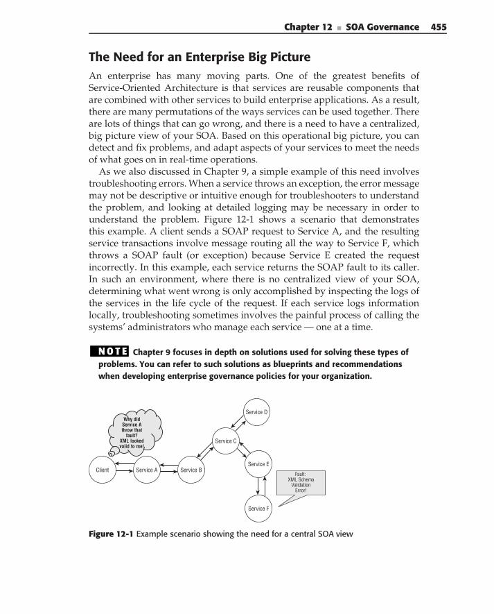
Chapter 12 ■ SOA Governance 455
The Need for an Enterprise Big PictureAn enterprise has many moving parts. One of the greatest benefits ofService-Oriented Architecture is that services are reusable components thatare combined with other services to build enterprise applications. As a result,there are many permutations of the ways services can be used together. Thereare lots of things that can go wrong, and there is a need to have a centralized,big picture view of your SOA. Based on this operational big picture, you candetect and fix problems, and adapt aspects of your services to meet the needsof what goes on in real-time operations.
As we also discussed in Chapter 9, a simple example of this need involvestroubleshooting errors. When a service throws an exception, the error messagemay not be descriptive or intuitive enough for troubleshooters to understandthe problem, and looking at detailed logging may be necessary in order tounderstand the problem. Figure 12-1 shows a scenario that demonstratesthis example. A client sends a SOAP request to Service A, and the resultingservice transactions involve message routing all the way to Service F, whichthrows a SOAP fault (or exception) because Service E created the requestincorrectly. In this example, each service returns the SOAP fault to its caller.In such an environment, where there is no centralized view of your SOA,determining what went wrong is only accomplished by inspecting the logs ofthe services in the life cycle of the request. If each service logs informationlocally, troubleshooting sometimes involves the painful process of calling thesystems’ administrators who manage each service — one at a time.
N O T E Chapter 9 focuses in depth on solutions used for solving these types ofproblems. You can refer to such solutions as blueprints and recommendationswhen developing enterprise governance policies for your organization.
Client Service A Service B
Service C
Service E
Service D
Service F
Fault: XML Schema
Validation Error!
Why did Service A throw that
fault? XML looked valid to me!
Figure 12-1 Example scenario showing the need for a central SOA view

456 Part II ■ Designing SOA
Certainly, such an example underscores the need for SOA governance. Indesign-time governance, architects provide enterprise policy guidance relatedto detailed messaging and error handling. This example also demonstrates theneed for SOA management, where software tools can provide monitoring, acentralized view of audit logs, and the mechanisms necessary to have the bigpicture of the enterprise. Based on analysis of statistics gathered in servicemonitoring, governance policies may be edited and refined over time, anddecisions related to availability and performance may be made. Having ahigh-level, operational view of how clients and services interact increases theprobability of success in real-time operations.
The Need for Explicit Run-Time Service PoliciesEver since the advent of Web Services, books and magazine articles have showna picture similar to Figure 12-2. This famous ‘‘publish-find-bind’’ triangle hasbeen used in literature to show how Web Services can dynamically work withUDDI and other service registries. In practice, the service provider usuallyregisters its WSDL with a service broker, who stores the service provider’sinformation in a registry. A service consumer registers with the broker todiscover the Web Service, and finally, the service consumer downloads theservice’s WSDL and dynamically binds to the Web Service. As we discussedin Chapter 2 (see sidebar ‘‘Dynamic Discovery and Binding’’), the ‘‘publishWSDL, find, and bind’’ model is a fallacy because it is woefully incomplete inpractice.
Conceptually, this abstract publish-find-bind model is solid. The typicalWSDL use case, however, is sufficient for your operational SOA only if youare still living in the Garden of Eden. In the real world, there is a lot more toconnecting with a service than just knowing the syntax of its interface. In anoperational environment, you are more than likely to have different policiesfor security, transport, authorization, and service level guarantees based ondifferent customers, partners, suppliers, and employees that interact with your
Service Provider
ServiceBroker
Service Consumer
3. Bind
2. Find
1. Pu
blish
Figure 12-2 The famous publish-find-bind triangle
Chapter 12 ■ SOA Governance 457
services. Service clients (or agents or intermediaries who work on behalf of theclients) have to understand these policies, and they also have to understandthe semantics of what is in the payload of the services. The service providershave to enforce these policies at run time. Due to certain legal requirements(for example, SOX, HIPAA, and other similar policies), service providers haveto monitor and audit interactions, policy enforcement, and compliance atrun time.
What does this all mean? First, it means that in order for services tooperate in the real world, there must be policies in place that account for allof these requirements (capabilities and constraints) beyond interface binding.Services have to enforce these policies, and both service consumers and serviceproviders have to adapt to policy change. Second, it means that projects withoutdesign-time governance evolve into chaotic systems that never scale. Third, itmeans that projects without run-time and change-time governance are neverable to adapt to the rigors of policy compliance and change. Finally, ourexperience is that a huge percentage of pilot projects that did not begin withSOA governance ended up failing.
Applying design-time governance with discoverable run-time service poli-cies that express the constraints and capabilities of services can help realizethe vision of the conceptual publish-find-bind triangle. In a policy-drivenenterprise, expressed and exposed policies provide more information in dis-covery of services for how clients can connect. We talk about this later in thischapter.
The Need to Separate Policy Logic from Business Logic
Some who are new to SOA agree with governance in principle. They believethat certain policies need to be in place (design-time governance), but theyargue that run-time and change-time governance can be accomplished byhard-coding compliance logic in the business logic of the services involved.This assumption is another example of theory versus practice. It sounds doablein theory but becomes quite complicated and unmanageable in practice.
First of all, policies change over time, and although changing service codeto adapt to the policy changes is theoretically doable, it introduces verytight coupling. It is laborious for anyone to change the code of their servicesfor every policy change, and every service change may require changes toservice clients. Complicating the matter is the fact that real-world servicesundoubtedly have different policies in place for every partner. Figure 12-3shows an example of how a simple service may have different policies,depending on the types of consumers using the service. In the figure, a bookstore has a service called the Book Ordering Service, which allows customers,business partners, and employees to order books.
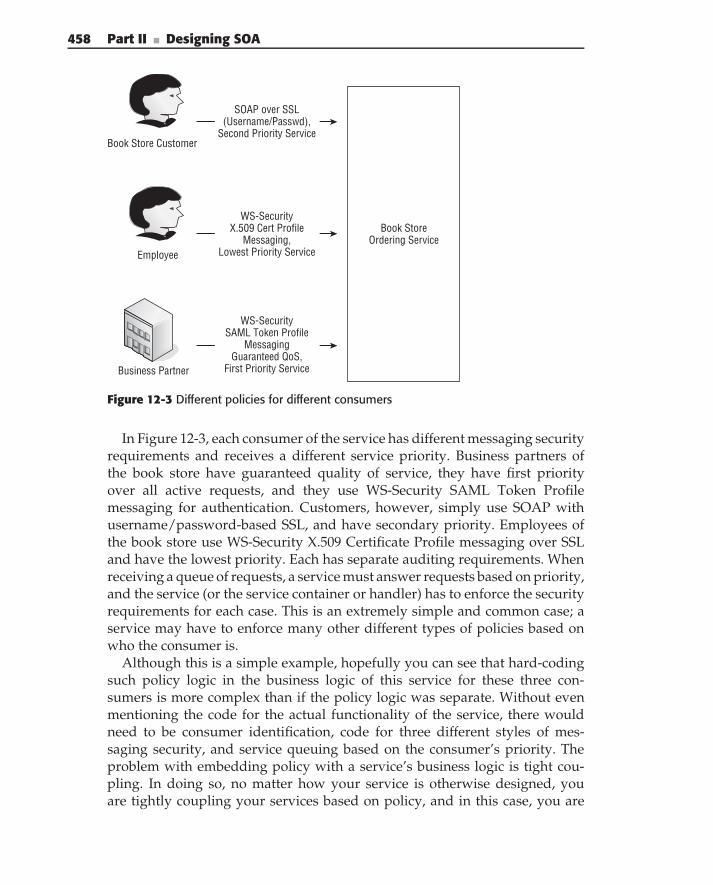
458 Part II ■ Designing SOA
Book Store Ordering Service
Book Store Customer
Employee
Business Partner
SOAP over SSL (Username/Passwd),
Second Priority Service
WS-Security X.509 Cert Profile
Messaging, Lowest Priority Service
WS-Security SAML Token Profile
Messaging Guaranteed QoS,
First Priority Service
Figure 12-3 Different policies for different consumers
In Figure 12-3, each consumer of the service has different messaging securityrequirements and receives a different service priority. Business partners ofthe book store have guaranteed quality of service, they have first priorityover all active requests, and they use WS-Security SAML Token Profilemessaging for authentication. Customers, however, simply use SOAP withusername/password-based SSL, and have secondary priority. Employees ofthe book store use WS-Security X.509 Certificate Profile messaging over SSLand have the lowest priority. Each has separate auditing requirements. Whenreceiving a queue of requests, a service must answer requests based on priority,and the service (or the service container or handler) has to enforce the securityrequirements for each case. This is an extremely simple and common case; aservice may have to enforce many other different types of policies based onwho the consumer is.
Although this is a simple example, hopefully you can see that hard-codingsuch policy logic in the business logic of this service for these three con-sumers is more complex than if the policy logic was separate. Without evenmentioning the code for the actual functionality of the service, there wouldneed to be consumer identification, code for three different styles of mes-saging security, and service queuing based on the consumer’s priority. Theproblem with embedding policy with a service’s business logic is tight cou-pling. In doing so, no matter how your service is otherwise designed, youare tightly coupling your services based on policy, and in this case, you are
Chapter 12 ■ SOA Governance 459
tightly coupling your service’s business logic to your service consumers. Moreimportantly, your service client has to understand this policy and may have towrite different code for the different messaging mechanisms required. If anyof these policies ever change, you have to rewrite your service (or the code inyour interceptor or handler if you componentize this policy logic), and chang-ing this messaging implementation breaks the interactions with your clients.Your clients, in turn, have to rewrite the interaction with the service if themessaging security implementation changes. In practice, adapting to policychanges without run-time governance involves pandemonium, weeping, andgnashing of teeth. Unfortunately, this a common problem.
An effective way to avoid this predicament is by explicitly declaring yourpolicies in a discoverable and software-readable format, by using run-timegovernance mechanisms to enforce the policies on the service side, and bydiscovering and adhering to the policies on the client side. In the ‘‘PracticalSOA Governance’’ section later in this chapter, we explore how this can beachieved.
SOA Governance and the Service Life Cycle
The SOA governance life cycle, as we define it, is shown in Figure 12-4. Wehave overlaid it with the Service Life Cycle from Chapter 3 in order to providecontext, since the governance drives all aspects of the service life cycle, fromcradle to grave. This section walks you through every phase of the servicelife cycle, focusing on the processes that occur in each phase, as well as thestakeholders involved.
An organization’s SOA governance team dictates the processes that occurthroughout the service life cycle, as well as the roles and responsibilities ofthe stakeholders. Therefore, processes and stakeholders may be different fromorganization to organization. However, this section defines typical successfulprocesses, as well as stakeholders and their roles and responsibilities. SOAgovernance affects the entire organization, and one person often fills multipleroles. Throughout the following sections, we refer to the following stakeholderroles:
Solution Lead — A business architect tasked with solving a particu-lar business problem. This stakeholder’s responsibilities mostly revolvearound the translation of business requirements into a service proposal.
Functional Architect — An architect who maintains and enhances anenterprise functional model. He or she maintains a messaging dictionary(semantic messaging) that ensures interoperability between enterpriseservices, and he or she ensures service alignment with the functionalmodel.
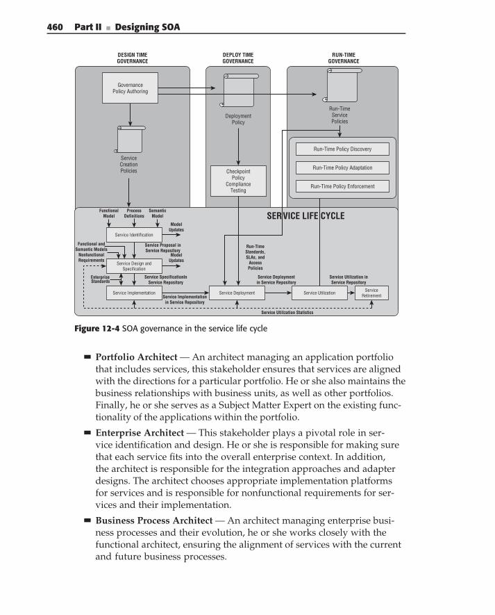
460 Part II ■ Designing SOA
DESIGN TIMEGOVERNANCE
DEPLOY TIMEGOVERNANCE
RUN-TIMEGOVERNANCE
ServiceCreationPolicies
Service Identification
Service Design andSpecification
FunctionalModel
ProcessDefinitions
SemanticModel
ModelUpdates
ModelUpdates
Functional andSemantic Models
NonfunctionalRequirements
Service Proposal inService Repository
Service SpecificationInService Repository
Service Implementation Service DeploymentService Implementation
in Service Repository
Service Utilization ServiceRetirement
Service Deploymentin Service Repository
Service Utilization inService Repository
Service Utilization Statistics
CheckpointPolicy
ComplianceTesting
GovernancePolicy Authoring
DeploymentPolicy
Run-TimeServicePolicies
Run-Time Policy Discovery
Run-Time Policy Adaptation
Run-Time Policy Enforcement
Run-TimeStandards,SLAs, and
AccessPolicies
SERVICE LIFE CYCLE
Enterprise Standards
Figure 12-4 SOA governance in the service life cycle
Portfolio Architect — An architect managing an application portfoliothat includes services, this stakeholder ensures that services are alignedwith the directions for a particular portfolio. He or she also maintains thebusiness relationships with business units, as well as other portfolios.Finally, he or she serves as a Subject Matter Expert on the existing func-tionality of the applications within the portfolio.
Enterprise Architect — This stakeholder plays a pivotal role in ser-vice identification and design. He or she is responsible for making surethat each service fits into the overall enterprise context. In addition,the architect is responsible for the integration approaches and adapterdesigns. The architect chooses appropriate implementation platformsfor services and is responsible for nonfunctional requirements for ser-vices and their implementation.
Business Process Architect — An architect managing enterprise busi-ness processes and their evolution, he or she works closely with thefunctional architect, ensuring the alignment of services with the currentand future business processes.
Chapter 12 ■ SOA Governance 461
Services Librarian — A person responsible for maintenance of the ser-vice registry, a backbone of service governance. This stakeholder worksto ensure that all of the service information is in a standardized form,accurate, up-to-date, and properly classified.
SOA Run-Time Architect — An architect responsible for maintenanceof and enhancements to the service run time, including standardizationof service APIs, and service run-time support — registry, monitoring,and so on.
Application Developer — This stakeholder is a developer building andmaintaining business functionality for base services.
Service Assembler — The developer building and maintaining businessfunctionality for composite service (business processes).
Service Tester — A quality assurance (QA) representative responsiblefor testing of the services.
Service Infrastructure Specialist — An infrastructure engineer respon-sible for the creation of the service deployment diagrams and topologies,and maintenance of the service registry and service management solu-tion. He or she also monitors service usage and SLA adherence.
SOA governance directly affects people from different parts of organization.The policies, processes, and procedures that are developed in SOA governanceneed to be comprehensive, and must cover all of these stages of the servicelife cycle. The next sections of this chapter provide an overview of each aspectof governance, focusing on design time, deploy time, and run time. Eachsection refers to the life cycle in Figure 12-4. Although we don’t specificallycall out ‘‘change-time governance’’ as an explicit phase, accommodation ofchange is built-in based on service utilization statistics and metrics collected inrun-time governance and, therefore, is addressed in that section. This sectionfocuses on all phases of governance and walks you through the service lifecycle.
N O T E Remember as you go through the next few sections that the SOAgovernance activities throughout the service life cycle can vary from organizationto organization, and they depend on many things, including the makeup andculture of your organization. It is important to know that this section covers the‘‘whole nine yards’’ of SOA governance, and its elements are representative ofthe processes, roles, and stakeholders of a very mature organization. If yourorganization is new to SOA (or new to governance processes), you probably wantto start small, evolving to the mature process that we discuss (see the‘‘Governance from Day 3’’ sidebar later in this chapter). Finally, the matureprocesses and activities that we define serve as a model that should be tailored tofit your organization.
462 Part II ■ Designing SOA
Design-Time Governance
Design-time governance involves legislation (policy creation) that affectsprocesses throughout the service life cycle. Initial policies are typicallyenterprise-wide policies focused on technical standards compliance, adherenceto an enterprise vocabulary, and service creation policies. In an organizationwith a mature process, such policies already exist, and new projects usuallyinherit or customize the policies, according to their requirements.
It is important that clear ownership of SOA issues be established, providingefficient resolution of SOA-specific issues, defining SOA funding approaches,enabling maturity tracking, aligning the organization’s SOA strategy withother enterprise strategies, ensuring infrastructure readiness, creating policiesand processes, and ensuring adherence to them. This is typically done byestablishing a team responsible for SOA governance in an organization. Atthe beginning of SOA projects, service creation policies dictate the serviceproposal, design, and implementation processes. Adherence to compliancepolicies is regulated by the SOA governance group, and this group determineswhether or not the services can be deployed (deploy-time governance).
Run-time service policies defining capabilities and constraints of spe-cific services are also defined during the design-time governance phasein the service life cycle. Unlike enterprise-wide policies, these policies arerelated to the services themselves and are based on business requirements,domain-specific rules, and specific regulations. These run-time policies revolvearound constraints and capabilities (security, reliability, and quality of ser-vice), and are policies that act as contracts between the service and the serviceconsumer.
SLAs are typically part of the run-time service policy. An SLA relatesto guarantees of benchmarks related to performance and availability, andincludes acceptable performance parameters, the duration of the agreement,procedures for monitoring the service levels, exceptions to the agreement, andproblem resolution procedures. Metrics such as messages per hour, serviceresponse time, uptime, throughput, number of errors, units of business workcompleted, different roles for the parties involved, and other factors are usedwhen creating SLAs. Classes of customers may have different SLAs for thesame service — a ‘‘Gold’’ customer may be promised a better priority of servicethan a ‘‘Silver’’ or ‘‘Bronze’’ customer, and each may have different connectionrequirements.
Run-time policies are authored in the design-time phase and are typicallydefined by a declarative language such as WS-Policy. Typically, run-timeservice policies are refined over time, based on the collection of metrics anduse cases in the operational environment.
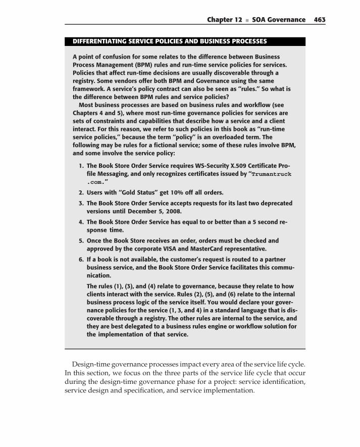
Chapter 12 ■ SOA Governance 463
DIFFERENTIATING SERVICE POLICIES AND BUSINESS PROCESSES
A point of confusion for some relates to the difference between BusinessProcess Management (BPM) rules and run-time service policies for services.Policies that affect run-time decisions are usually discoverable through aregistry. Some vendors offer both BPM and Governance using the sameframework. A service’s policy contract can also be seen as ‘‘rules.’’ So what isthe difference between BPM rules and service policies?
Most business processes are based on business rules and workflow (seeChapters 4 and 5), where most run-time governance policies for services aresets of constraints and capabilities that describe how a service and a clientinteract. For this reason, we refer to such policies in this book as ‘‘run-timeservice policies,’’ because the term ‘‘policy’’ is an overloaded term. Thefollowing may be rules for a fictional service; some of these rules involve BPM,and some involve the service policy:
1. The Book Store Order Service requires WS-Security X.509 Certificate Pro-file Messaging, and only recognizes certificates issued by ‘‘Trumantruck.com.’’
2. Users with ‘‘Gold Status’’ get 10% off all orders.
3. The Book Store Order Service accepts requests for its last two deprecatedversions until December 5, 2008.
4. The Book Store Order Service has equal to or better than a 5 second re-sponse time.
5. Once the Book Store receives an order, orders must be checked andapproved by the corporate VISA and MasterCard representative.
6. If a book is not available, the customer’s request is routed to a partnerbusiness service, and the Book Store Order Service facilitates this commu-nication.
The rules (1), (3), and (4) relate to governance, because they relate to howclients interact with the service. Rules (2), (5), and (6) relate to the internalbusiness process logic of the service itself. You would declare your gover-nance policies for the service (1, 3, and 4) in a standard language that is dis-coverable through a registry. The other rules are internal to the service, andthey are best delegated to a business rules engine or workflow solution forthe implementation of that service.
Design-time governance processes impact every area of the service life cycle.In this section, we focus on the three parts of the service life cycle that occurduring the design-time governance phase for a project: service identification,service design and specification, and service implementation.
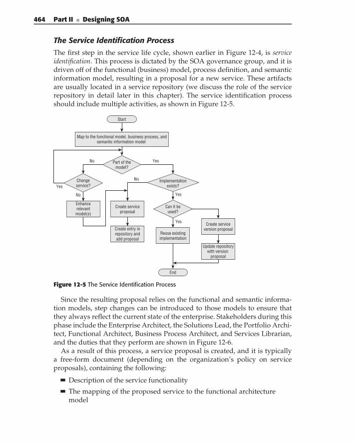
464 Part II ■ Designing SOA
The Service Identification Process
The first step in the service life cycle, shown earlier in Figure 12-4, is serviceidentification. This process is dictated by the SOA governance group, and it isdriven off of the functional (business) model, process definition, and semanticinformation model, resulting in a proposal for a new service. These artifactsare usually located in a service repository (we discuss the role of the servicerepository in detail later in this chapter). The service identification processshould include multiple activities, as shown in Figure 12-5.
Part of themodel?
Map to the functional model, business process, andsemantic information model
Yes
Implementationexists?
No
Changeservice?Yes
Enhancerelevantmodel(s)
Can it beused?
Yes
Yes
Create serviceproposal
No
Create serviceversion proposal
End
Start
No
Create entry inrepository andadd proposal
Reuse existingimplementation
Update repositorywith version
proposal
Figure 12-5 The Service Identification Process
Since the resulting proposal relies on the functional and semantic informa-tion models, step changes can be introduced to those models to ensure thatthey always reflect the current state of the enterprise. Stakeholders during thisphase include the Enterprise Architect, the Solutions Lead, the Portfolio Archi-tect, Functional Architect, Business Process Architect, and Services Librarian,and the duties that they perform are shown in Figure 12-6.
As a result of this process, a service proposal is created, and it is typicallya free-form document (depending on the organization’s policy on serviceproposals), containing the following:
Description of the service functionality
The mapping of the proposed service to the functional architecturemodel
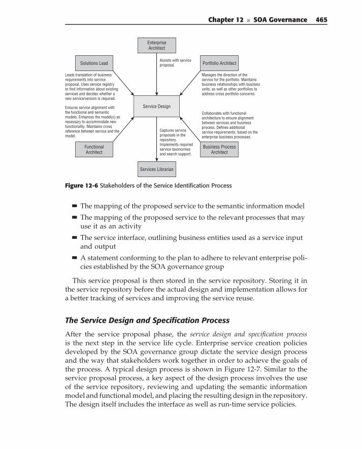
Chapter 12 ■ SOA Governance 465
Service Design
Solutions Lead Portfolio Architect
EnterpriseArchitect
FunctionalArchitect
Business ProcessArchitect
Leads translation of businessrequirements into serviceproposal. Uses service registryto find information about existingservices and decides whether anew service/version is required.
Manages the direction of theservice for the portfolio. Maintainsbusiness relationships with businessunits, as well as other portfolios toaddress cross portfolio concerns.
Services Librarian
Captures serviceproposals in therepository.Implements requiredservice taxonomiesand search support.
Assists with serviceproposal.
Ensures service alignment withthe functional and semanticmodels. Enhances the model(s) asnecessary to accommodate newfunctionality. Maintains crossreference between service and themodel.
Collaborates with functionalarchitecture to ensure alignmentbetween services and businessprocess. Defines additionalservice requirements, based on theenterprise business processes.
Figure 12-6 Stakeholders of the Service Identification Process
The mapping of the proposed service to the semantic information model
The mapping of the proposed service to the relevant processes that mayuse it as an activity
The service interface, outlining business entities used as a service inputand output
A statement conforming to the plan to adhere to relevant enterprise poli-cies established by the SOA governance group
This service proposal is then stored in the service repository. Storing it inthe service repository before the actual design and implementation allows fora better tracking of services and improving the service reuse.
The Service Design and Specification Process
After the service proposal phase, the service design and specification processis the next step in the service life cycle. Enterprise service creation policiesdeveloped by the SOA governance group dictate the service design processand the way that stakeholders work together in order to achieve the goals ofthe process. A typical design process is shown in Figure 12-7. Similar to theservice proposal process, a key aspect of the design process involves the useof the service repository, reviewing and updating the semantic informationmodel and functional model, and placing the resulting design in the repository.The design itself includes the interface as well as run-time service policies.
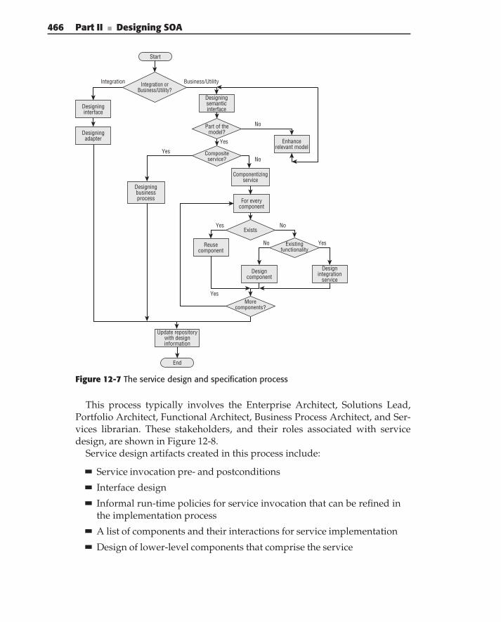
466 Part II ■ Designing SOA
Start
Designingadapter
Integration orBusiness/Utility?
Designingsemanticinterface
Business/UtilityIntegration
Designinginterface
End
Update repositorywith designinformation
Compositeservice?
Yes
Componentizingservice
Reusecomponent
No
No
Designintegration
service
Yes
Yes
For everycomponent
Designcomponent
Morecomponents?
YesNo
Designingbusinessprocess
Part of themodel?
Enhancerelevant model
Yes
No
Existingfunctionality
Exists
Figure 12-7 The service design and specification process
This process typically involves the Enterprise Architect, Solutions Lead,Portfolio Architect, Functional Architect, Business Process Architect, and Ser-vices librarian. These stakeholders, and their roles associated with servicedesign, are shown in Figure 12-8.
Service design artifacts created in this process include:
Service invocation pre- and postconditions
Interface design
Informal run-time policies for service invocation that can be refined inthe implementation process
A list of components and their interactions for service implementation
Design of lower-level components that comprise the service
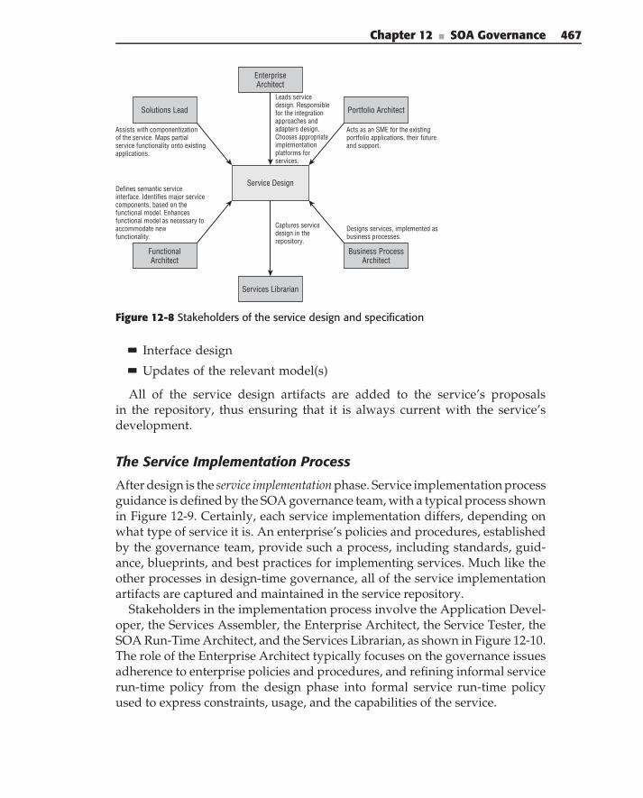
Chapter 12 ■ SOA Governance 467
Service Design
Solutions Lead Portfolio Architect
EnterpriseArchitect
FunctionalArchitect
Business ProcessArchitect
Assists with componentizationof the service. Maps partialservice functionality onto existingapplications.
Acts as an SME for the existingportfolio applications, their futureand support.
Services Librarian
Captures servicedesign in therepository.
Leads servicedesign. Responsiblefor the integrationapproaches andadapters design.Chooses appropriateimplementationplatforms forservices.
Defines semantic serviceinterface. Identifies major servicecomponents, based on thefunctional model. Enhancesfunctional model as necessary toaccommodate newfunctionality.
Designs services, implemented asbusiness processes.
Figure 12-8 Stakeholders of the service design and specification
Interface design
Updates of the relevant model(s)
All of the service design artifacts are added to the service’s proposalsin the repository, thus ensuring that it is always current with the service’sdevelopment.
The Service Implementation Process
After design is the service implementation phase. Service implementation processguidance is defined by the SOA governance team, with a typical process shownin Figure 12-9. Certainly, each service implementation differs, depending onwhat type of service it is. An enterprise’s policies and procedures, establishedby the governance team, provide such a process, including standards, guid-ance, blueprints, and best practices for implementing services. Much like theother processes in design-time governance, all of the service implementationartifacts are captured and maintained in the service repository.
Stakeholders in the implementation process involve the Application Devel-oper, the Services Assembler, the Enterprise Architect, the Service Tester, theSOA Run-Time Architect, and the Services Librarian, as shown in Figure 12-10.The role of the Enterprise Architect typically focuses on the governance issuesadherence to enterprise policies and procedures, and refining informal servicerun-time policy from the design phase into formal service run-time policyused to express constraints, usage, and the capabilities of the service.
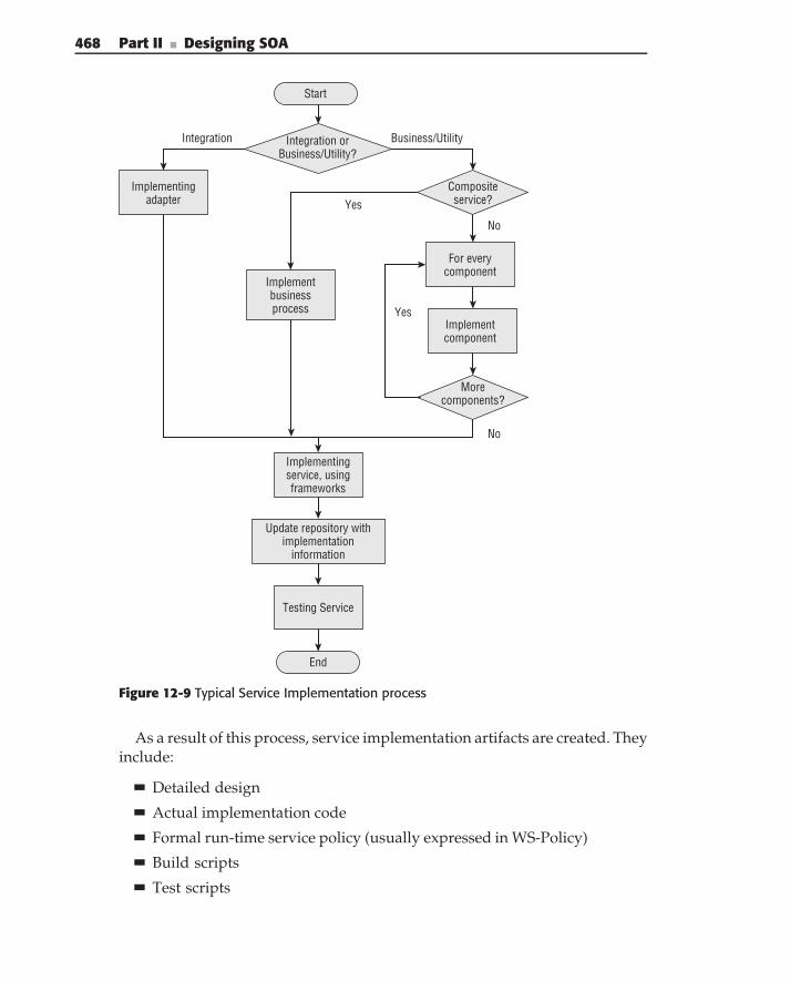
468 Part II ■ Designing SOA
Start
Integration orBusiness/Utility?
Business/UtilityIntegration
Implementingadapter
Yes
Compositeservice?
Implementingservice, usingframeworks
End
Testing Service
For everycomponent
Implementcomponent
Morecomponents?
No
Yes
No
Implementbusinessprocess
Update repository withimplementation
information
Figure 12-9 Typical Service Implementation process
As a result of this process, service implementation artifacts are created. Theyinclude:
Detailed design
Actual implementation code
Formal run-time service policy (usually expressed in WS-Policy)
Build scripts
Test scripts
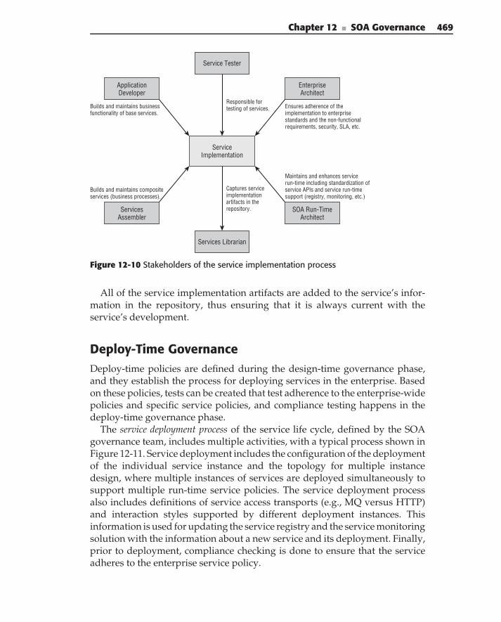
Chapter 12 ■ SOA Governance 469
ServiceImplementation
ApplicationDeveloper
EnterpriseArchitect
Service Tester
ServicesAssembler
SOA Run-TimeArchitect
Builds and maintains businessfunctionality of base services.
Ensures adherence of theimplementation to enterprisestandards and the non-functionalrequirements, security, SLA, etc.
Services Librarian
Captures serviceimplementationartifacts in therepository.
Responsible fortesting of services.
Builds and maintains compositeservices (business processes).
Maintains and enhances servicerun-time including standardization ofservice APIs and service run-timesupport (registry, monitoring, etc.)
Figure 12-10 Stakeholders of the service implementation process
All of the service implementation artifacts are added to the service’s infor-mation in the repository, thus ensuring that it is always current with theservice’s development.
Deploy-Time GovernanceDeploy-time policies are defined during the design-time governance phase,and they establish the process for deploying services in the enterprise. Basedon these policies, tests can be created that test adherence to the enterprise-widepolicies and specific service policies, and compliance testing happens in thedeploy-time governance phase.
The service deployment process of the service life cycle, defined by the SOAgovernance team, includes multiple activities, with a typical process shown inFigure 12-11. Service deployment includes the configuration of the deploymentof the individual service instance and the topology for multiple instancedesign, where multiple instances of services are deployed simultaneously tosupport multiple run-time service policies. The service deployment processalso includes definitions of service access transports (e.g., MQ versus HTTP)and interaction styles supported by different deployment instances. Thisinformation is used for updating the service registry and the service monitoringsolution with the information about a new service and its deployment. Finally,prior to deployment, compliance checking is done to ensure that the serviceadheres to the enterprise service policy.
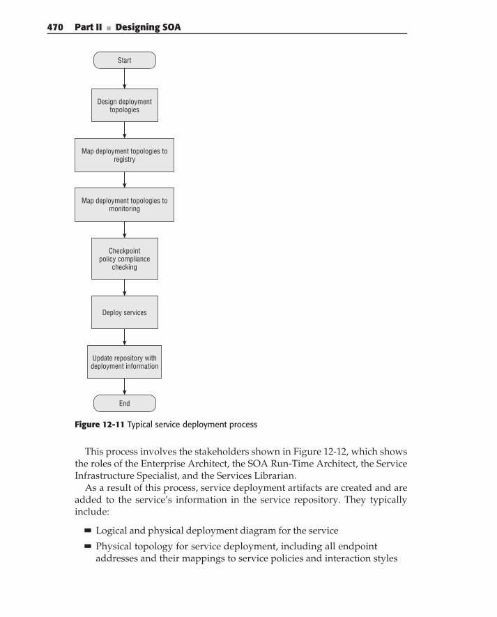
470 Part II ■ Designing SOA
Start
Design deploymenttopologies
Map deployment topologies toregistry
Map deployment topologies tomonitoring
Deploy services
End
Update repository withdeployment information
Checkpointpolicy compliance
checking
Figure 12-11 Typical service deployment process
This process involves the stakeholders shown in Figure 12-12, which showsthe roles of the Enterprise Architect, the SOA Run-Time Architect, the ServiceInfrastructure Specialist, and the Services Librarian.
As a result of this process, service deployment artifacts are created and areadded to the service’s information in the service repository. They typicallyinclude:
Logical and physical deployment diagram for the service
Physical topology for service deployment, including all endpointaddresses and their mappings to service policies and interaction styles
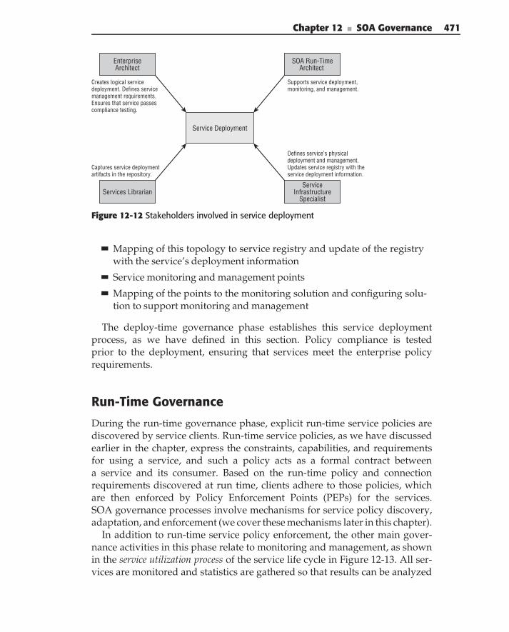
Chapter 12 ■ SOA Governance 471
SOA Run-TimeArchitect
Service Deployment
EnterpriseArchitect
ServiceInfrastructure
SpecialistServices Librarian
Creates logical servicedeployment. Defines servicemanagement requirements.Ensures that service passescompliance testing.
Supports service deployment,monitoring, and management.
Captures service deploymentartifacts in the repository.
Defines service’s physicaldeployment and management.Updates service registry with theservice deployment information.
Figure 12-12 Stakeholders involved in service deployment
Mapping of this topology to service registry and update of the registrywith the service’s deployment information
Service monitoring and management points
Mapping of the points to the monitoring solution and configuring solu-tion to support monitoring and management
The deploy-time governance phase establishes this service deploymentprocess, as we have defined in this section. Policy compliance is testedprior to the deployment, ensuring that services meet the enterprise policyrequirements.
Run-Time Governance
During the run-time governance phase, explicit run-time service policies arediscovered by service clients. Run-time service policies, as we have discussedearlier in the chapter, express the constraints, capabilities, and requirementsfor using a service, and such a policy acts as a formal contract betweena service and its consumer. Based on the run-time policy and connectionrequirements discovered at run time, clients adhere to those policies, whichare then enforced by Policy Enforcement Points (PEPs) for the services.SOA governance processes involve mechanisms for service policy discovery,adaptation, and enforcement (we cover these mechanisms later in this chapter).
In addition to run-time service policy enforcement, the other main gover-nance activities in this phase relate to monitoring and management, as shownin the service utilization process of the service life cycle in Figure 12-13. All ser-vices are monitored and statistics are gathered so that results can be analyzed
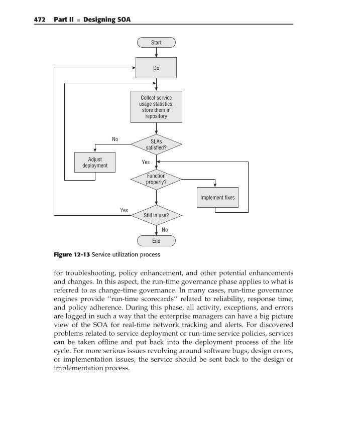
472 Part II ■ Designing SOA
Collect serviceusage statistics,
store them inrepository
Start
Do
End
Functionproperly?
Implement fixes
Still in use?
No
Yes
SLAssatisfied?
Adjustdeployment
No
Yes
Figure 12-13 Service utilization process
for troubleshooting, policy enhancement, and other potential enhancementsand changes. In this aspect, the run-time governance phase applies to what isreferred to as change-time governance. In many cases, run-time governanceengines provide ‘‘run-time scorecards’’ related to reliability, response time,and policy adherence. During this phase, all activity, exceptions, and errorsare logged in such a way that the enterprise managers can have a big pictureview of the SOA for real-time network tracking and alerts. For discoveredproblems related to service deployment or run-time service policies, servicescan be taken offline and put back into the deployment process of the lifecycle. For more serious issues revolving around software bugs, design errors,or implementation issues, the service should be sent back to the design orimplementation process.
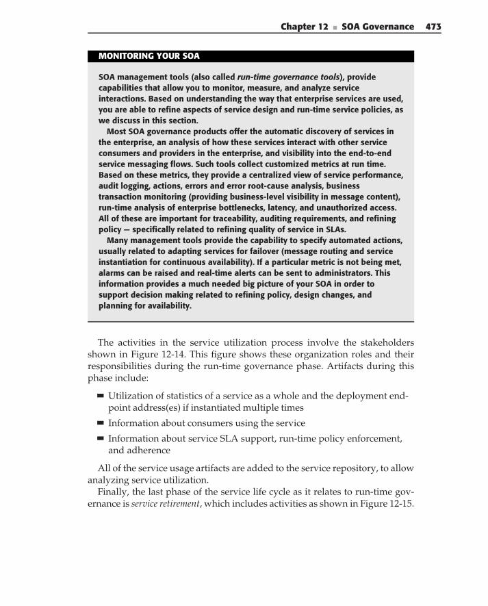
Chapter 12 ■ SOA Governance 473
MONITORING YOUR SOA
SOA management tools (also called run-time governance tools), providecapabilities that allow you to monitor, measure, and analyze serviceinteractions. Based on understanding the way that enterprise services are used,you are able to refine aspects of service design and run-time service policies, aswe discuss in this section.
Most SOA governance products offer the automatic discovery of services inthe enterprise, an analysis of how these services interact with other serviceconsumers and providers in the enterprise, and visibility into the end-to-endservice messaging flows. Such tools collect customized metrics at run time.Based on these metrics, they provide a centralized view of service performance,audit logging, actions, errors and error root-cause analysis, businesstransaction monitoring (providing business-level visibility in message content),run-time analysis of enterprise bottlenecks, latency, and unauthorized access.All of these are important for traceability, auditing requirements, and refiningpolicy — specifically related to refining quality of service in SLAs.
Many management tools provide the capability to specify automated actions,usually related to adapting services for failover (message routing and serviceinstantiation for continuous availability). If a particular metric is not being met,alarms can be raised and real-time alerts can be sent to administrators. Thisinformation provides a much needed big picture of your SOA in order tosupport decision making related to refining policy, design changes, andplanning for availability.
The activities in the service utilization process involve the stakeholdersshown in Figure 12-14. This figure shows these organization roles and theirresponsibilities during the run-time governance phase. Artifacts during thisphase include:
Utilization of statistics of a service as a whole and the deployment end-point address(es) if instantiated multiple times
Information about consumers using the service
Information about service SLA support, run-time policy enforcement,and adherence
All of the service usage artifacts are added to the service repository, to allowanalyzing service utilization.
Finally, the last phase of the service life cycle as it relates to run-time gov-ernance is service retirement, which includes activities as shown in Figure 12-15.
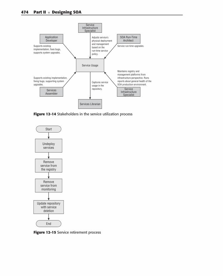
474 Part II ■ Designing SOA
Supports existingimplementation, fixes bugs,supports system upgrades.
Service run-time upgrades.
Captures serviceusage in therepository.
Adjusts service’sphysical deploymentand managementbased on therun-time servicepolicy.
Supports existing implementation,fixing bugs, supporting systemupgrades.
Maintains registry andmanagement platforms frominfrastructure perspective. Runsreports about general health of theSOA production environment.
Service Usage
ApplicationDeveloper
SOA Run-TimeArchitect
ServicesAssembler
ServiceInfrastructure
Specialist
ServiceInfrastructure
Specialist
Services Librarian
Figure 12-14 Stakeholders in the service utilization process
Start
Undeployservices
Removeservice fromthe registry
Removeservice frommonitoring
Update repositorywith service
deletion
End
Figure 12-15 Service retirement process
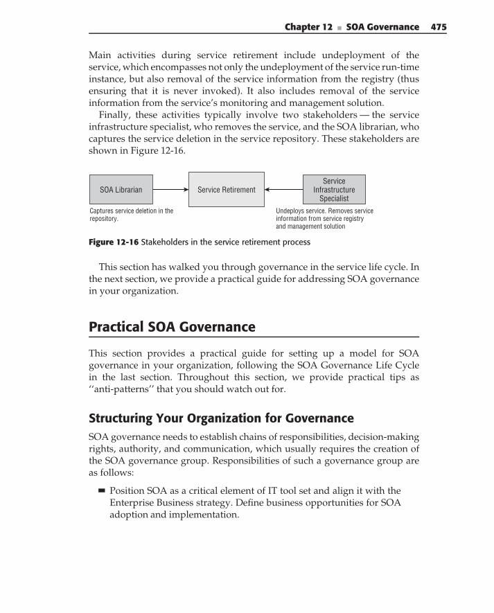
Chapter 12 ■ SOA Governance 475
Main activities during service retirement include undeployment of theservice, which encompasses not only the undeployment of the service run-timeinstance, but also removal of the service information from the registry (thusensuring that it is never invoked). It also includes removal of the serviceinformation from the service’s monitoring and management solution.
Finally, these activities typically involve two stakeholders — the serviceinfrastructure specialist, who removes the service, and the SOA librarian, whocaptures the service deletion in the service repository. These stakeholders areshown in Figure 12-16.
Service RetirementSOA LibrarianService
InfrastructureSpecialist
Captures service deletion in therepository.
Undeploys service. Removes serviceinformation from service registryand management solution
Figure 12-16 Stakeholders in the service retirement process
This section has walked you through governance in the service life cycle. Inthe next section, we provide a practical guide for addressing SOA governancein your organization.
Practical SOA Governance
This section provides a practical guide for setting up a model for SOAgovernance in your organization, following the SOA Governance Life Cyclein the last section. Throughout this section, we provide practical tips as‘‘anti-patterns’’ that you should watch out for.
Structuring Your Organization for GovernanceSOA governance needs to establish chains of responsibilities, decision-makingrights, authority, and communication, which usually requires the creation ofthe SOA governance group. Responsibilities of such a governance group areas follows:
Position SOA as a critical element of IT tool set and align it with theEnterprise Business strategy. Define business opportunities for SOAadoption and implementation.
476 Part II ■ Designing SOA
Create clear ownership, supervision, and escalation of SOA specificissues, thus providing quick and efficient resolution of SOA-relatedissues.
Define SOA funding approaches, including reuse charge backs, and soon.
Enable SOA maturity tracking and its controlled evolution based on themetrics for SOA adoption benefits, services reuse,and so on.
Align SOA strategy with other enterprise strategies, including security,presentation, portfolio management, and so on.
Ensure adherence to service definition and implementation policiesand processes.
Ensure infrastructure readiness for SOA (see Chapter 10 for an expandeddiscussion of this).
Maintain and advertise major SOA artifacts — services, business pro-cesses, and so on.
Out of all these tasks, establishing processes and procedures is the mostimportant functions of the SOA group. These policies, processes and proce-dures have to be comprehensive and need to cover all of the stages of theservice life cycle, as we discussed in the last section.
There are a few different ways to establish authority for adherence to policy.One of the best ways is to establish a team-based policy authoring model, wherethe team is led by an energetic and persuasive leader, and where everyonefeels that they have a ‘‘say’’ in the process. In such a collaborative approach,the team feels ownership in the process, leaders step up, and it increasesthe likelihood of success. It is important that governance has managementsupport — adherence to policy needs to be mandated from the top. For thisreason, a centralized SOA group reporting to the CTO, CIO, or chief architectof the organization with ‘‘built-in’’ management support is usually the bestoption. Because SOA impacts business as much as IT, this group must alsohave representation from the business staff as well as the technology staff.Although it is theoretically possible to create a decentralized SOA groupcomprised of the representatives from multiple departments, in reality itrarely works. It is important that the group govern effectively without beingtoo heavy-handed. A few anti-patterns in governance discipline are illustratedin the ‘‘The Powerless Committee and the Ivory Tower Dictator’’ sidebar.
Chapter 12 ■ SOA Governance 477
THE POWERLESS COMMITTEE AND THE IVORY TOWER DICTATOR
There are two extremes of the SOA governance discipline that are common butare also ineffective. The first extreme is the establishment of a powerlesscommittee, where a committee is appointed to develop policies for the SOAproject, but it is set up to have no control because management does notmandate the control. The second extreme is an anti-pattern we call the ivorytower dictator. The ivory tower dictator is the architect who has the power,authors all the policies from on high, and shoves it in the designers’ anddevelopers’ faces without their input. The ivory tower dictator rules with aniron fist and is despised. As a result, the rest of the team can find ways aroundthe policies or can rebel and try to sabotage the process. Both of these modelsare well intentioned but wrong. Neither the powerless committee nor the ivorytower dictator is ever successful. One model has no power to discipline, andthe other has all the power but the dictator lords it over the project. Theeffective alternative is a collaborative, team-based approach, led by apersuasive leader who has management support.
As you can see from the SOA stakeholders and their roles in the lastsection, SOA governance brings together people from different parts of theorganization. It does not mean, however, that all of the participants haveto be administratively in the SOA group that establishes the policies for theorganization. The SOA governance group usually employs:
The group leader (the SOA group ‘‘champion’’)
A Services Librarian
An SOA Run-Time Architect and development group
A Functional Architect (optional)
A Service Infrastructure Specialist (optional)
This group also maintains the service repository and best practices fordifferent steps in the SOA process. It facilitates conversations during differentsteps of the SOA process and ensures quality of deliverables on every step. Therest of the participants supplement the SOA group during specific projects.
Developing Enterprise PolicyAfter the SOA governance group is formed for an organization, the firststep in governance involves the establishment of enterprise-wide policies forbuilding services. Policies developed in this stage revolve around compliance
478 Part II ■ Designing SOA
with technical standards, the use of common vocabularies, service versioningpolicies, common namespaces for services, and guidance for best practices andreuse. Such enterprise policies affect the entire organization, applying to allservices and their consumers.
In our experience, it is best to start small, borrowing experiences fromother projects. Although too little governance is an unacceptable extreme,going overboard, and setting up too many rules, checklists, and policies fromthe beginning can be overwhelming. Enterprise policies should be sufficientto provide order but should not be stifling. The following are some basicguidelines that are usually effective in most projects but obviously should betailored to your organization:
Standards compliance — It is important to use accepted standards inorder to ensure both current and future interoperability. Organizationsthat create their own standards for SOA, instead of using accepted stan-dards, are essentially creating ‘‘SOA stove pipes’’ that lead to inflexibil-ity and integration difficulties. At the bare minimum, common best prac-tices for messaging for SOAP-based services involve compliance relatedto WS-I and WS-Security. Every organization is different and may sup-port other standards.
Common vocabulary — As we have discussed throughout this book(specifically, in Chapters 2, 3, and 6), it is a best practice for your servicesto adopt a common vocabulary. Policies for using a common vocabularyinvolve the reuse of existing organizational schemas, a data referencemodel, or referencing an organizational ontology. The reuse of commonvocabularies is key to semantic interoperability.
Naming conventions — Certain fundamental standards, such as defin-ing the organizational namespaces, are determined at this stage.
Error handling and auditing — Much of this involves your choice ofauditing tools, but common best practices involve the standardizationof SOAP fault message descriptions to include the IP address and theService Name where the fault occurred, as well as streaming audit logsto a centralized location. Many times, the implementation of this pol-icy involves the integration of run-time governance software. For moreinformation, see the ‘‘Exception handling and logging in enterprise solu-tions’’ section in Chapter 9.
Run-time service policy authoring — A typical best practice involvesthe establishment of how a service policy is described (usually inWS-Policy) and stored in a central registry. If a project has chosen a pol-icy authoring tool, this is stated at this point.
General best practices and blueprints — It is good at this stage toestablish a repository of best practices for the SOA project. They should
Chapter 12 ■ SOA Governance 479
include coding guidelines, design patterns, and typical use cases forachieving repeatable solutions.
Service versioning — Enterprise policy should be written that dictateshow the versioning and deprecation process works, and the commu-nication plan associated with changing versions. The implementationof this policy should be addressed and may depend on the run-timegovernance and management software tools that are available for man-aging this process. A simple policy for service versioning may be: ‘‘Afterdeployment of a new version of a service, the earlier version of the ser-vice can be supported and available for six months, and users of theoriginal service are notified. The corporate registry is updated with thenew version of the service.’’ For an in-depth look at service version-ing, see the ‘‘Dealing with service changes’’ section in Chapter 9.
For most development organizations, many of these policies (especiallyrelated to standards and best practices) were already in place before anyonestarted using the word governance. Governance brings a little more formalityto the mix, because it involves making sure that all services are compliant. Itis important that adherence to these policies is checked before deploying newservices on the network (deploy-time governance). Many SOA governancetools have automated compliance testing software that allows you to testadherence to these policies.
One potential pitfall that you can run into during this process is ‘‘analysisparalysis’’ on authoring specific policies. For example, Data Architects could(and will if you let them) spend three years building a huge data model thatwould be used in the common vocabulary of all services. As admirable as thatis, it is better to start small and build for ‘‘evolveability.’’ Remember that theSOA governance life cycle is a continuing spiral, where policies can be refinedover time. Start small and simple so that projects can get started quicklywith some policies and guidance in place. Build for today, while planning forincremental change tomorrow.
GOVERNANCE FROM DAY 3
We’ve seen many articles that espouse ‘‘Governance from Day 1.’’ Depending onyour organization, this may or may not be the right step for you. It all dependson the maturity of the organization and the type of project that you’re doing.
If you have an established architecture or SOA program, and you don’t havegovernance, that’s a big problem. Many times, however, the scenario with SOAis that you’re trying to introduce architecture to an organization. This mayinvolve a change to processes, techniques, tools, technologies, ororganizational structure. To have a fighting chance, you need to remove every
(continued)
480 Part II ■ Designing SOA
GOVERNANCE FROM DAY 3 (continued)
unnecessary obstacle from the path of the transition. At this phase of the game,architecture needs to demonstrate value, not add additional steps.
Let’s look at an SOA introduction as an example. First, you need to introducethe concepts of service orientation and demonstrate where they are useful. Thisis often done by implementing a single service as a proof point. But, at thesame time, you want to make sure that the service follows architecturalprinciples, patterns, standards, and so on. The problem is that you don’t havethose well articulated yet, nor have you really figured out what processes andtools work for implementing services in the organization. One approach to thisdilemma is to assemble an initial service team, staffed from the architecturegroup, to assist the project in implementing and deploying the service. Theteam has several goals. First and foremost is to implement a service that meetsthe requirements of the project and provides value to the business. The secondgoal is to demonstrate how the architectural approach provided a better servicethan you would have gotten if you had just followed the same old process. Andthe third goal is to figure out what process, patterns, techniques, and standardscan work in this particular organization for implementing SOA within thecontext of the architecture.
The next step of the initiative is to take what was learned on the first projectand expand that to a few more projects. The original service team can bebroken up and each member assigned to lead an additional project team, soinstead of a single service being implemented, four or five services can bedeveloped in the second round. Again, the primary goal is to implementservices that meet project requirements and provide value to the business. Thesecond goal is to implement services that can work together to start todemonstrate the power of service composition, and also to find a project thatcan reuse the initial service. This allows the team to learn how to accomplishthe important requirements of reuse and versioning. The third goal is to refinethe process and architecture so that it is well articulated and mature enough tobe rolled out to teams throughout the organization.
By this point, the SOA initiative should have delivered value by helpingprojects to create services that meet their need and at the same time,demonstrated some of the values of an SOA approach. It should have, a fairlywell defined architecture and process, and a good understanding of what canand won’t work in this organization (every organization is different). Thereshould also be a small handful of services. Now is the time to flesh outgovernance. If you think about it, you really don’t need much governance yet,especially development governance, when you only have a few services, andit’s too early to introduce it before you really understand the processes,organization, and architecture.
Chapter 12 ■ SOA Governance 481
It’s true that you might have to go back and update some of the initialservices once you get the governance model in place, but that’s okay. That’swhat versioning is all about. But at least architecture will have gotten afoothold and gained momentum before governance can be perceived to slow itdown. Remember that architecture is a delicate balance. It must specify enoughcontext and process to achieve important enterprise goals. If it specifies toolittle, then the goals cannot be achieved. If it specifies too much, it will just beignored (and the goals won’t be achieved either). Getting it just right is aconstant challenge for architecture.
One point to remember: Do not confuse ‘‘Governance from Day 3’’ with theprocrastination slogan ‘‘Governance Tomorrow,’’ where you never end upadding governance, and it only becomes important when you experience thingsgoing wrong in an operational SOA. This is not what we are advocating — oncethings go wrong, it is probably too late! Going operational without anygovernance is just stupid. By the time you are operational, the cost of having toretrofit governance once things go wrong is so much higher than if you startedfrom the beginning.
But, if you’re in a situation where you need to introduce architecture to theorganization, the Day 3 approach often works. Introduce architectural ideasand apply them to a small selection of projects on Day 1. On Day 2, refine whatworks, prove value, and expand your scope. If you are successful, you actuallyget the chance to get to Day 3, where you can finally add governance. This canbe a successful model for new adopters of SOA.
Using the Service RepositoryImplementation of the processes and procedures established by SOA gover-nance is based on a service repository providing a foundation for collaborationbetween people involved in service design and implementation. Such a ser-vice repository integrates all of the sources of service related information,including design artifacts, run-time topologies, information collected by yourservice monitoring and management solution, and more. It provides a unifiedrepresentation of all of this information allowing all of the SOA stakeholdersto centrally access it, based on their job functions, as shown in Figure 12-17.
A service repository provides information required to support the completeservice life cycle starting from its inception, through design, implementation,deployment, usage, and maintenance.
During service identification, business analysts identify the requirementsfor new services. These requirements are evaluated against the functionality
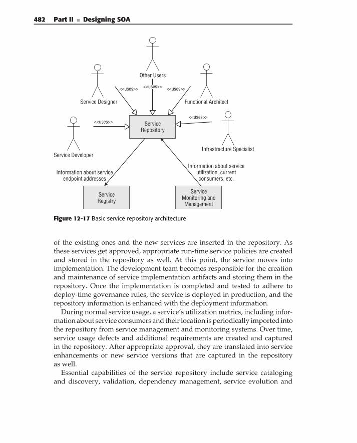
482 Part II ■ Designing SOA
ServiceRegistry
Service Designer
<<uses>>
<<uses>> <<uses>>
<<uses>>
Service Developer
Other Users
Functional Architect
Infrastracture Specialist
Information about serviceutilization, currentconsumers, etc.
Information about serviceendpoint addresses
ServiceMonitoring andManagement
ServiceRepository
<<uses>>
Figure 12-17 Basic service repository architecture
of the existing ones and the new services are inserted in the repository. Asthese services get approved, appropriate run-time service policies are createdand stored in the repository as well. At this point, the service moves intoimplementation. The development team becomes responsible for the creationand maintenance of service implementation artifacts and storing them in therepository. Once the implementation is completed and tested to adhere todeploy-time governance rules, the service is deployed in production, and therepository information is enhanced with the deployment information.
During normal service usage, a service’s utilization metrics, including infor-mation about service consumers and their location is periodically imported intothe repository from service management and monitoring systems. Over time,service usage defects and additional requirements are created and capturedin the repository. After appropriate approval, they are translated into serviceenhancements or new service versions that are captured in the repositoryas well.
Essential capabilities of the service repository include service catalogingand discovery, validation, dependency management, service evolution and
Chapter 12 ■ SOA Governance 483
versioning, artifact publishing governance, and support for multiple artifacttypes. The next sections address these capabilities.
Cataloging and Discovery
The main purpose of the service repository is to provide the ability to findartifacts, based on the artifact-specific metadata. This metadata is typicallycontained in the artifacts themselves. Consequently, the service repositoryshould automatically extract this metadata (based on the cataloging policies)whenever new artifacts are published to the repository. An example of sucha policy can be the automatic generation of the following information duringservice definition cataloging:
Links to the auxiliary documents imported by the service definitiondocument, such as XML schema documents, messaging semantics def-initions, and so on
The XML namespaces used by the service contract documents
The name and description of the interfaces, and the XML types used bythe service contract
Links to the policies governing service invocation and execution
The implementation of cataloging requires defining the metadata for everyartifact placed in the repository. The metadata must be rich and flexible enoughto support different types of service artifacts stored in the repository, as wellas their evolution.
The collection of the metadata stored in the service repository encompassesthe information that business analysts and service designers can use to discoverexisting services and decide on their applicability for a given solution. Thus,the repository should provide discovery capabilities that are extensible andcan accommodate a wide range of domain-specific discovery queries. Thisrequirement typically translates into the repository’s ability to support multiplebusiness-related taxonomies.
Validation
Finding artifacts that are not valid does not do the enterprise any good. As thepoint of access to service-related information, the service repository shouldenforce organizational and domain-specific business rules, ensuring confor-mance of these artifacts to the enterprise policies and standards. This ability toenforce validation rules makes the repository a focal part of Service-OrientedArchitecture governance.
484 Part II ■ Designing SOA
Dependency Management
Service-related information typically includes multiple interrelated artifacts,such as service interfaces, message schemas, implementation code, usageprofiles, and so on. Because the services themselves can be reused by otherservices or business processes, understanding the relationships and depen-dencies between services is quite important. As the number of services grows,tracking all these dependencies and evaluating the impacts of changes becomesa difficult task.
The service repository can simplify this task by supporting the managementof relationships between service artifacts. The repository should providestandard relationship types. It should also allow the organization to extendthese types with additional ones based on their additional requirements.
Service Evolution and Versioning
Once created, services typically evolve over time. This evolution can be causedby changes in the service functionality, semantic messaging, implementation,and so on. Many of these changes require creation and deployment of a newversion of the service. In order to track all of this versioning information,the service repository should provide versioning capabilities for all serviceartifacts, regardless of their type.
Additionally, the service repository should provide change/versioning noti-fication capabilities, allowing interested parties to be notified about upcomingand current changes. This allows you to provide change information to allinterested parties such as the service consumer’s development teams. Such asubscription mechanism should allow specifying the types of events that areof interest, thus preventing the flooding of the subscriber with notifications.
Artifacts Publishing Governance
As the service repository becomes a centralized collection of all of the infor-mation about service-related assets, it requires the same governance as anyother enterprise assets repository. This type of governance typically includespermissions for publishing service-related artifacts and an artifacts-publishingapproval process.
Support for Multiple Artifact Types
One of the main challenges in the creation of a service repository is the greatdiversity of service-related artifacts, which run the gamut of XML documents,
Chapter 12 ■ SOA Governance 485
service interfaces, messaging schemas, implementation code, UML diagrams,and text documents. The use of a generic representation for the differentasset types can significantly simplify the repository implementation (see the‘‘Reusable Asset Specification’’ sidebar.)
REUSABLE ASSET SPECIFICATION
OMG’s Reusable Assets Specification (RAS) covers the generalizedrepresentation of different asset types. RAS defines an asset as a collection ofrelated artifacts that provide a solution to a problem.
An asset may represent a complete solution, including requirements, usecases, design models, component specifications, components, test cases, testdrivers, and test data, or it may be just a set of use cases and their models andthe rules for extending the use cases.
A good asset has the following characteristics:
◆ It should be easy to use, customize, and apply to another context.
◆ It should possess the characteristics of good software engineering: tightcohesion, loose coupling, and sufficient capabilities.
◆ Its purpose and intent should be easy to understand.
◆ It should be easy to conduct fit analysis on, to determine the asset’s matchto a particular context.
To achieve these goals, an asset needs to be more than just a collection ofrun-time artifacts (e.g., code and components). It should also include artifactsthat explain goals, purpose, motivation, and assumptions. In many cases, theseare best captured as subsets of the original requirements and the vision-relatedartifacts used in the creation of the asset’s run-time elements.
RAS describes assets using metadata captured in a form of XML manifestprovided as part of the asset’s packaging, as shown in the following RASMetadata Format figure. The manifest contains at least the asset specification,including attributes such as name, version, and description. An assetspecification can be extended through classifications expressed as a set ofsimple name and value descriptors and through the declaration of contextssuch as a specific development or deployment context. The asset’s payload iscomposed of a collection of artifacts addressing a particular problem. Theusage section provides guidance on applying and customizing the asset. Finally,the related assets’ section defines the asset’s relationships to other assets andhelps to create collections or families of assets to form larger-grainedsolutions.
(continued)
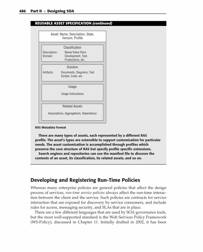
486 Part II ■ Designing SOA
REUSABLE ASSET SPECIFICATION (continued)
Asset: Name, Description, State,Version, Profile
ClassificationDescriptors: Name/Value PairsDomain: Development, Test,
Productions, etc.
SolutionArtifacts: Documents, Diagrams, Test
Scripts, Code, etc.
Usage
Usage Instructions
Related Assets
Associations, Aggregations, Dependency
RAS Metadata Format
There are many types of assets, each represented by a different RASprofile. The asset’s types are extensible to support customization for particularneeds. The asset customization is accomplished through profiles whichpreserve the core structure of RAS but specify profile specific extensions.
Search engines and repositories can use the manifest file to discover thecontents of an asset, its classification, its related assets, and so on.
Developing and Registering Run-Time PoliciesWhereas many enterprise policies are general policies that affect the designprocess of services, run-time service policies always affect the run-time interac-tion between the client and the service. Such policies are contracts for serviceinteraction that are exposed for discovery by service consumers, and includerules for access, messaging security, and SLAs that are in place.
There are a few different languages that are used by SOA governance tools,but the most well-supported standard is the Web Services Policy Framework(WS-Policy), discussed in Chapter 11. Initially drafted in 2002, it has been
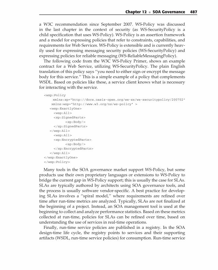
Chapter 12 ■ SOA Governance 487
a W3C recommendation since September 2007. WS-Policy was discussedin the last chapter in the context of security (as WS-SecurityPolicy is achild specification that uses WS-Policy). WS-Policy is an assertion frameworkand a model for expressing policies that refer to constraints, capabilities, andrequirements for Web Services. WS-Policy is extensible and is currently heav-ily used for expressing messaging security policies (WS-SecurityPolicy) andexpressing policies for reliable messaging (WS-ReliableMessagingPolicy).
The following code from the W3C WS-Policy Primer, shows an examplecontract for a Web Service, utilizing WS-SecurityPolicy. The plain Englishtranslation of this policy says ‘‘you need to either sign or encrypt the messagebody for this service.’’ This is a simple example of a policy that complementsWSDL. Based on policies like these, a service client knows what is necessaryfor interacting with the service.
<wsp:Policy
xmlns:sp="http://docs.oasis-open.org/ws-sx/ws-securitypolicy/200702"
xmlns:wsp="http://www.w3.org/ns/ws-policy" >
<wsp:ExactlyOne>
<wsp:All>
<sp:SignedParts>
<sp:Body/>
</sp:SignedParts>
</wsp:All>
<wsp:All>
<sp:EncryptedParts>
<sp:Body/>
</sp:EncryptedParts>
</wsp:All>
</wsp:ExactlyOne>
</wsp:Policy>
Many tools in the SOA governance market support WS-Policy, but someproducts use their own proprietary languages or extensions to WS-Policy tobridge the current gap in WS-Policy support; this is usually the case for SLAs.SLAs are typically authored by architects using SOA governance tools, andthe process is usually software vendor-specific. A best practice for develop-ing SLAs involves a ‘‘spiral model,’’ where requirements are refined overtime after run-time metrics are analyzed. Typically, SLAs are not finalized atthe beginning of a project. Instead, an SOA management tool is used at thebeginning to collect and analyze performance statistics. Based on these metricscollected at run-time, policies for SLAs can be refined over time, based onunderstanding the use of services in real-time operations.
Finally, run-time service policies are published in a registry. In the SOAdesign-time life cycle, the registry points to services and their supportingartifacts (WSDL, run-time service policies) for consumption. Run-time service
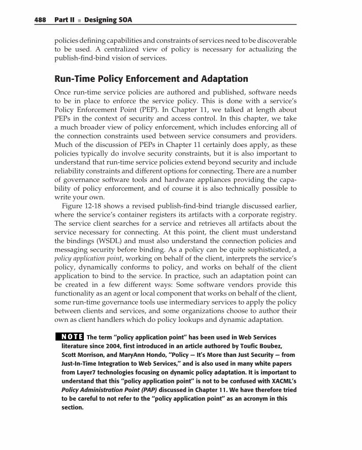
488 Part II ■ Designing SOA
policies defining capabilities and constraints of services need to be discoverableto be used. A centralized view of policy is necessary for actualizing thepublish-find-bind vision of services.
Run-Time Policy Enforcement and AdaptationOnce run-time service policies are authored and published, software needsto be in place to enforce the service policy. This is done with a service’sPolicy Enforcement Point (PEP). In Chapter 11, we talked at length aboutPEPs in the context of security and access control. In this chapter, we takea much broader view of policy enforcement, which includes enforcing all ofthe connection constraints used between service consumers and providers.Much of the discussion of PEPs in Chapter 11 certainly does apply, as thesepolicies typically do involve security constraints, but it is also important tounderstand that run-time service policies extend beyond security and includereliability constraints and different options for connecting. There are a numberof governance software tools and hardware appliances providing the capa-bility of policy enforcement, and of course it is also technically possible towrite your own.
Figure 12-18 shows a revised publish-find-bind triangle discussed earlier,where the service’s container registers its artifacts with a corporate registry.The service client searches for a service and retrieves all artifacts about theservice necessary for connecting. At this point, the client must understandthe bindings (WSDL) and must also understand the connection policies andmessaging security before binding. As a policy can be quite sophisticated, apolicy application point, working on behalf of the client, interprets the service’spolicy, dynamically conforms to policy, and works on behalf of the clientapplication to bind to the service. In practice, such an adaptation point canbe created in a few different ways: Some software vendors provide thisfunctionality as an agent or local component that works on behalf of the client,some run-time governance tools use intermediary services to apply the policybetween clients and services, and some organizations choose to author theirown as client handlers which do policy lookups and dynamic adaptation.
N O T E The term ‘‘policy application point’’ has been used in Web Servicesliterature since 2004, first introduced in an article authored by Toufic Boubez,Scott Morrison, and MaryAnn Hondo, ‘‘Policy — It’s More than Just Security — fromJust-In-Time Integration to Web Services,’’ and is also used in many white papersfrom Layer7 technologies focusing on dynamic policy adaptation. It is important tounderstand that this ‘‘policy application point’’ is not to be confused with XACML’sPolicy Administration Point (PAP) discussed in Chapter 11. We have therefore triedto be careful to not refer to the ‘‘policy application point’’ as an acronym in thissection.
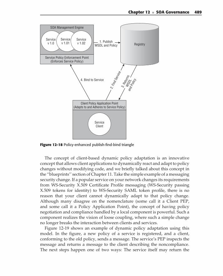
Chapter 12 ■ SOA Governance 489
Service v 1.0
Service v 1.01
Service v 1.02
Service Policy Enforcement Point (Enforces Service Policy)
SOA Management Engine
1. Publish WSDL and Policy Registry
Client Policy Application Point (Adapts to and Adheres to Service Policy)
Service Client
2. Fi
nd S
ervic
e3.
Ret
urns
W
SDL
and
Polic
y4. Bind to Service
Figure 12-18 Policy-enhanced publish-find-bind triangle
The concept of client-based dynamic policy adaptation is an innovativeconcept that allows client applications to dynamically react and adapt to policychanges without modifying code, and we briefly talked about this concept inthe ‘‘blueprints’’ section of Chapter 11. Take the simple example of a messagingsecurity change. If a popular service on your network changes its requirementsfrom WS-Security X.509 Certificate Profile messaging (WS-Security passingX.509 tokens for identity) to WS-Security SAML token profile, there is noreason that your client cannot dynamically adapt to that policy change.Although many disagree on the nomenclature (some call it a Client PEP,and some call it a Policy Application Point), the concept of having policynegotiation and compliance handled by a local component is powerful. Such acomponent realizes the vision of loose coupling, where such a simple changeno longer breaks the interaction between clients and services.
Figure 12-19 shows an example of dynamic policy adaptation using thismodel. In the figure, a new policy of a service is registered, and a client,conforming to the old policy, sends a message. The service’s PEP inspects themessage and returns a message to the client describing the noncompliance.The next steps happen one of two ways: The service itself may return the
490 Part II ■ Designing SOA
Service v 1.0
Service v 1.01
Service v 1.02
Service Policy Enforcement Point (Enforces Policy)
SOA Management Engine
1. Publish NEW WSDL and Policy Registry
Client Policy Application Point (Adheres to and Adapts to Service Policy)
Service Client
4. R
eque
st P
olicy
5. R
etur
ns P
olicy
2. Bind to Service
3. Policy Exception
(New Policy)
6. Rebind After Policy
Adaptation
Figure 12-19 Dynamic policy adaptation using a policy application point
signed new policy in the response, or the client’s policy application point canquery the registry for the new policy, dynamically adapt to the new policy,and resend the message. Because policy is meant to be descriptive enough,clients can adapt to changing policies.
Utilizing a process that allows you to dynamically adapt to run-time servicepolicies provides the great benefit of flexibility. Most of the pain associated withdeployments revolves around change. If your policies and the enforcement ofyour policy logic can be decoupled from your services and consumers, and ifyou utilize a flexible architecture where run-time policies can be discoveredand dynamically adhered to, this makes SOA change management easier asrun-time policies inevitably change.
Summary
This chapter has provided an introduction to SOA governance, and it hasprovided a comprehensive and practical guide for setting up these processesin your organization and managing your SOA. Specifically, this chapter

Chapter 12 ■ SOA Governance 491
has provided insight into structuring your organization for governance;establishing enterprise policies and procedures; defining the process for thephases in a service life cycle; and using solutions that express, dynamicallyadapt to, and enforce run-time service policies. Following the processes andexamples in this chapter as a model can provide you with a methodology thatyou can use to effectively govern your enterprise.

P a r t
IIICase Studies
In This Part
Chapter 13: Case Study — Travel InsuranceChapter 14: Case Study — Service-Based Integration in Insurance

C H A P T E R
13
Case Study — Travel InsuranceA journey of a thousand miles begins with a single step.
— Loa Tzu
In the previous chapters, we presented the general architecture of SOAand an overall process for approaching SOA projects. We then presented achapter for each major step of the process, including business/domain analysis,information modeling, service interface design, service implementation design,service composition, security, and solution design. In this chapter, we providea case study that incorporates all of these aspects.
In the example, we cover:
Case study scenario
Conceptual architecture
Solution architecture
Security design
Business concerns
Analysis and design review
Business analysis
Process and service models
Use cases
Information model
Service interface design
Document design
Service implementation design
495
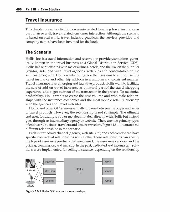
496 Part III ■ Case Studies
Travel Insurance
This chapter presents a fictitious scenario related to selling travel insurance aspart of an overall, travel-related, customer interaction. Although the scenariois based on real-world travel industry practices, the services provided andcompany names have been invented for the book.
The ScenarioHollis, Inc. is a travel information and reservation provider, sometimes gener-ically known in the travel business as a Global Distribution Service (GDS).Hollis has relationships with major airlines, hotels, and the like on the supplier(vendor) side, and with travel agencies, web sites and consolidators on thesell (customer) side. Hollis wants to upgrade their systems to support sellingtravel insurance and other trip add-ons in a uniform and consistent manner.Travel insurance is an emerging and lucrative product. Hollis want to facilitatethe sale of add-on travel insurance as a natural part of the travel shoppingexperience, and to get their cut of the transaction in the process. To maximizeprofitability, Hollis wants to create the best volume and wholesale relation-ships with the insurance companies and the most flexible retail relationshipwith the agencies and travel web sites.
Hollis, and other GDSs, are essentially brokers between the buyer and sellerof travel products. However, the relationship is not so simple. The ultimateend user, for example you or me, does not deal directly with Hollis but insteadgoes through an intermediary agency or web site. There are two primary typesof end users, business travelers and leisure travelers. Figure 13-1 illustrates thedifferent relationships in the scenario.
Each intermediary channel (agency, web site, etc.) and each vendor can havespecific contractual relationships with Hollis. These relationships can specifythe type of insurance products that are offered, the insurance vendors, and thepricing, commission, and markup. In the past, dedicated and inconsistent solu-tions were implemented for selling insurance, depending on the relationship
Hollis GDS
Business
Leisure
Vendor
Vendor
Vendor
Agencies
Web Sites
Custom
Figure 13-1 Hollis GDS insurance relationships
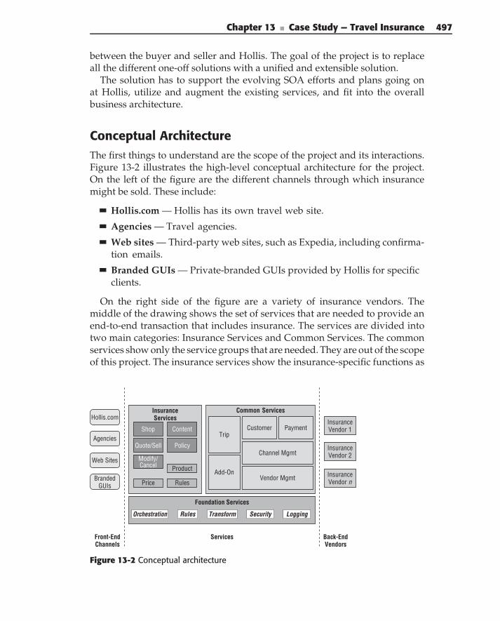
Chapter 13 ■ Case Study — Travel Insurance 497
between the buyer and seller and Hollis. The goal of the project is to replaceall the different one-off solutions with a unified and extensible solution.
The solution has to support the evolving SOA efforts and plans going onat Hollis, utilize and augment the existing services, and fit into the overallbusiness architecture.
Conceptual ArchitectureThe first things to understand are the scope of the project and its interactions.Figure 13-2 illustrates the high-level conceptual architecture for the project.On the left of the figure are the different channels through which insurancemight be sold. These include:
Hollis.com — Hollis has its own travel web site.
Agencies — Travel agencies.
Web sites — Third-party web sites, such as Expedia, including confirma-tion emails.
Branded GUIs — Private-branded GUIs provided by Hollis for specificclients.
On the right side of the figure are a variety of insurance vendors. Themiddle of the drawing shows the set of services that are needed to provide anend-to-end transaction that includes insurance. The services are divided intotwo main categories: Insurance Services and Common Services. The commonservices show only the service groups that are needed. They are out of the scopeof this project. The insurance services show the insurance-specific functions as
Common Services
Front-EndChannels
Back-End Vendors
Web Sites
Branded GUIs
Insurance Vendor 1
Agencies
Insurance Vendor n
Insurance Vendor 2
Foundation Services
TransformRules SecurityOrchestration Logging
Insurance Services
Product
Shop
Price
Quote/Sell
Services
Hollis.com
Modify/ Cancel
CustomerTrip
Payment
Add-On
Content
Policy
Vendor Mgmt
Channel Mgmt
Rules
Figure 13-2 Conceptual architecture
498 Part III ■ Case Studies
either business or domain services. This set of services comprises the scope ofthe project.
Insurance services include:
Shop — Supports shopping for different insurance products and options
Quote and Sell — Supports validating a request and providing a pricequote; also supports purchasing insurance based on the quote
Modify — Supports changing an insurance policy or trip, including can-cellation
Content — Supports vendors providing insurance products and othercontent
Policy — Supports insurance policy creation and modification withvendors
Common services include:
Trip — The set of services associated with the creation and maintenanceof a trip; a trip is the primary entity in travel that all other transactionsinteract with.
Add-on — Suggest and sell trip add-ons such as ground transportation,tickets, events, and so on.
Customer — Manage customers and partners, including itineraries, his-tories, and preferences.
Payment — Manage payments to and from channels and vendors,including commission and markups.
Channel Management — Manage the relationship and rules for the dif-ferent channels.
Vendor Management — Manage the relationships, rules, and contractsfor the different insurance vendors.
Business ConcernsNow that you have the high-level service-oriented vision, it is time to takea look at the business issues. It is always a goal, and a challenge for ITorganizations, to build systems that ‘‘align with the business.’’ You’ve heardthis refrain so often that it is hard to consider it more than a cliche. But at thesame time, it is an important aspect of an SOA project. If the services don’talign with the business, they don’t stand much of a chance of being usableacross a variety of applications.
More often than not, the business hasn’t really thought about how thebusiness is structured, what is important, or what the goals and strategy are.
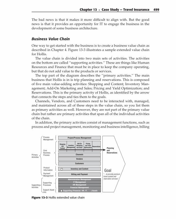
Chapter 13 ■ Case Study — Travel Insurance 499
The bad news is that it makes it more difficult to align with. But the goodnews is that it provides an opportunity for IT to engage the business in thedevelopment of some business architecture.
Business Value Chain
One way to get started with the business is to create a business value chain asdescribed in Chapter 4. Figure 13-3 illustrates a sample extended value chainfor Hollis.
The value chain is divided into two main sets of activities. The activitieson the bottom are called ‘‘supporting activities.’’ These are things like HumanResources and Finance that must be in place to keep the company operating,but that do not add value to the products or services.
The top part of the diagram describes the ‘‘primary activities.’’ The mainbusiness that Hollis is in is trip planning and reservations. This is composedof five main value-adding activities: Shopping and Content; Inventory Man-agement; Add-On Marketing and Sales; Pricing and Yield Optimization; andReservations. This is the primary activity of Hollis, as identified by the arrowthat connects the steps and ties them to the goals.
Channels, Vendors, and Customers need to be interacted with, managed,and maintained across all of these steps in the value chain, so you list themas primary activities as well. However, they are not part of the primary valuechain but rather are primary activities that span all of the individual activitiesof the chain.
In addition, the primary activities consist of management functions, such asprocess and project management, monitoring and business intelligence, billing
Billing and Payment
Project/Process Management
Customers
Inventory and Content
Shopping and
Content
Inventory Management
Add-On Marketing and Sales
Pricing and Yield
Optimization Reservations
Primary Activities
Core Business Process
Process Management
Payment Management
Product Information
“…to provide premium travel content and reservation services”
Planning andReservations
Goal
Supporting (Financial, HR, IT, . . .) Assets
HR ManagementFinancial Management
IT ManagementAdministration Management
SupportingActivities
Support Asset Info
Supporting Processes
Vendors
Channels
Figure 13-3 Hollis extended value chain
500 Part III ■ Case Studies
and payments, and information management. These are all necessary to keepthe primary value chain going.
The value chain is useful for identifying the different functional areas of thecompany and focusing attention on the most important. It is a good mechanismfor bringing out the goals and objectives. As well, it starts to identify areas ofservices. For example, each different step or primary activity is likely to haveone or more service groups associated with it. This provides a first step increating a service inventory.
The primary business goal of Hollis is ‘‘to provide premium travel contentand reservation services.’’ Some secondary goals are shown in the followinglist:
Be the primary travel content provider in the industry.
Provide integration with all types of travel content.
Support a customer-centric approach to travel reservations (to optimizecustomer experience) and product marketing and sales, across multiplechannels where possible.
Provide the best price and inventory optimization and management onbehalf of partner providers.
Business Motivation
So, if the objective is to align your SOA solution with the business goals, howdo you go about doing that? First, you need to ask the right questions. ForSOA, you must answer the following questions:
What business are you in?
What are the goals and objectives of this particular business?
What outcomes are needed to achieve those goals?
What is the strategy for achieving them?
How will they be measured?
What capabilities and information are needed to achieve those out-comes?
What processes, services, entities, and rules are needed to implementthose capabilities?
What existing applications provide basic capabilities and information?
How are the applications, processes, and so on aligned with the businessstrategies and goals?
Business architecture helps you understand and answer these questions,but how do you describe all the different concepts? And how do you tie the
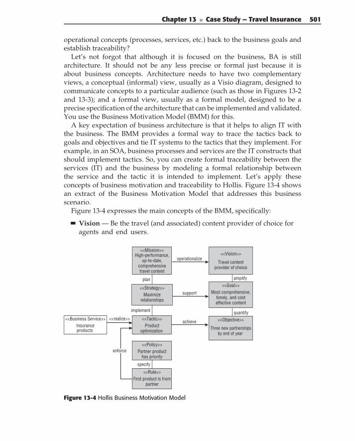
Chapter 13 ■ Case Study — Travel Insurance 501
operational concepts (processes, services, etc.) back to the business goals andestablish traceability?
Let’s not forgot that although it is focused on the business, BA is stillarchitecture. It should not be any less precise or formal just because it isabout business concepts. Architecture needs to have two complementaryviews, a conceptual (informal) view, usually as a Visio diagram, designed tocommunicate concepts to a particular audience (such as those in Figures 13-2and 13-3); and a formal view, usually as a formal model, designed to be aprecise specification of the architecture that can be implemented and validated.You use the Business Motivation Model (BMM) for this.
A key expectation of business architecture is that it helps to align IT withthe business. The BMM provides a formal way to trace the tactics back togoals and objectives and tie IT systems to the tactics that they implement. Forexample, in an SOA, business processes and services are the IT constructs thatshould implement tactics. So, you can create formal traceability between theservices (IT) and the business by modeling a formal relationship betweenthe service and the tactic it is intended to implement. Let’s apply theseconcepts of business motivation and traceability to Hollis. Figure 13-4 showsan extract of the Business Motivation Model that addresses this businessscenario.
Figure 13-4 expresses the main concepts of the BMM, specifically:
Vision — Be the travel (and associated) content provider of choice foragents and end users.
<<Strategy>>
<<Tactic>>
<<Rule>>
<<Policy>>
<<Mission>>
implement
plan
specify
support
High-performance,up-to-date,
comprehensivetravel content
Maximize relationships
quantify
amplify
<<Vision>>
Travel contentprovider of choice
<<Goal>>Most comprehensive,
timely, and costeffective content
<<Objective>>
Three new partnershipsby end of year
Product optimization
Partner product has priority
First product is frompartner
<<Business Service>>Insuranceproducts
<<realize>>
operationalize
achieve
enforce
Figure 13-4 Hollis Business Motivation Model
502 Part III ■ Case Studies
Goals — Provide the best, most comprehensive, timely, and cost-effective travel content (including insurance) in the industry. Rememberthat goals are long term and more broadly defined.
Objectives — Create three new partnerships with insurance providersby end of year. Objectives are specific, actionable, measurable, and time-bound.
Mission — Provide high-performance, up-to-date, and comprehensivetravel related content to travel consumers.
Strategy — Maximize relationships with travel insurance providers.Remember that strategy is broad and typically supports goals.
Tactics — Provide product optimization capabilities to partnered insur-ance providers. Tactics are the more specific realization of strategy,directed at achieving specific objectives.
Policies — Partnered insurance is given priority over other products.Policies provide a set of directives.
Rules — The first product offered in any given request comes from apartnered provider. Rules specify actions to achieve policies in supportof enforcing tactics.
The vision of being the travel content provider of choice for agents and endusers is operationalized by the mission, which is to provide high-performance,up-to-date, and comprehensive content. The vision is amplified by the goalof providing the best and most comprehensive insurance content, and thegoal is quantified by the objective of signing three new insurance partnersthis year. The goal is supported by the strategy of maximizing relationshipswith travel insurance providers. The objective is achieved by the tactic ofproviding product optimization capabilities for partners as an enticement toget new partners to sign. The strategy and tactics are governed by the policyof providing priority to partners’ insurance products, which are enforced bythe rule of offering the partners’ products first.
Finally, the business service InsProduct realizes the tactic, providing trace-ability from the service to the tactic that it implements and to the objective thatthe tactic achieves.
Brief ReviewBefore you dive into the case study any further, let’s review the analysis anddesign steps (from Chapter 4) that are followed in the example. These are:
Identify business goals, objectives and requirements.
Understand business context and interactions.
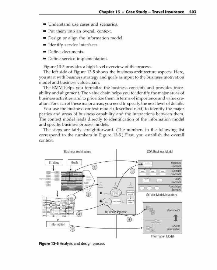
Chapter 13 ■ Case Study — Travel Insurance 503
Understand use cases and scenarios.
Put them into an overall context.
Design or align the information model.
Identify service interfaces.
Define documents.
Define service implementation.
Figure 13-5 provides a high-level overview of the process.The left side of Figure 13-5 shows the business architecture aspects. Here,
you start with business strategy and goals as input to the business motivationmodel and business value chain.
The BMM helps you formalize the business concepts and provides trace-ability and alignment. The value chain helps you to identify the major areas ofbusiness activities, and to prioritize them in terms of importance and value cre-ation. For each of these major areas, you need to specify the next level of details.
You use the business context model (described next) to identify the majorparties and areas of business capability and the interactions between them.The context model leads directly to identification of the information modeland specific business process models.
The steps are fairly straightforward. (The numbers in the following listcorrespond to the numbers in Figure 13-5.) First, you establish the overallcontext.
Business Architecture SOA Business Model
GoalsStrategy
Information
Business Process
Customer Quoting Underwriting
QuoteRequest
RiskQuote
UW Requtes
DomainServices
UtilityServices
FoundationServices
Service Model /Inventory
Information Model
BusinessServices
Documents
SharedInformation
Quote
Business Service
DomainnDomain2Domain1
Utility1 Utilityn
Quote
Quote
Customer Usage & Quality
Project/Process Management
Network Research & Quality
Network Infrastructure Assets
ForecastingNetwork/ProductPlanning
CapitalEquipmentAcquisition
ConstructioNetwork
Monitoring
CustomerOrder
ServiceProvisionin
CustomerService
CustomerBilling
Real-timeOperations
“…to provide a premiumcommunicationsnetwork andcustomer services”
telecomnetworkcustomerservice
Goal
Supporting (Financial, HR, IT, …) Assets
HR ManagementFinancial Management
IT ManagementAdministration Management
1
2
4
3
6
5
RequestQuote
Underwriterequest
Create RiskProfile
Create Quote
Insured PartyName: StringPrimaryAddress: AHomePhone:WorkPhoneMobilePhone: Phone...DoB: Date: Phone...MaritalStatus: Marit..Gender
DriverIdentification
State: StringLicenseNumber: String
CoInsured
Relationship: Relation...
Product
ProductIdentifier: Prod…ProductType: Product:
InsuredItem
VehicleVIN: VINMake: StringModel: StringYear: StringStyle: VehicleStyleCode
VehicleUsage
Usage: VehicleUsageCO...YearlyMiles: IntBusiness: Boolean
CoverageCoverage: CoverageT...Detail: CoverageDesc...Name: String
Limit
LimitAmount: C...
Deductable
Deductable: A...
R11 1
R110
related by
R1
0..*
Product
0..*
0..*
R1
1
1..*
R1
1
1
R1
1
1. . *
R1
1
1R1
1
1
R1
1
1
PrimaryDriver
Customer
BillingAddres: Addre...CustomerID: Custom...
<<Strategy>>
<<Tactic>>
<<Rule>>
<<Policy>>
<<Mission>>
implement
plan
specify
support
High-performance,up-to-date,
comprehensivetravel content
Maximize relationships
quantify
amplify
<<Vision>>
Travel contentprovider of choice
<<Goal>>Most comprehensive
timely, and costeffective content
<<Objective>>
Three new partnershipsby end of year
Product optimization
Partner product have priority
First product is frompartner
<<Business Service>>Insuranceproducts
<<realize>>
operationalize
achieve
enforce
Figure 13-5 Analysis and design process
504 Part III ■ Case Studies
1. The overall set of processes, as identified by the value chain and the setof all context models provides the enterprise SOA with a context that canbe represented in the service inventory.
2. The enterprise information model describes the superset of informationthat is needed to be shared between services. This becomes the basis forthe more detailed service information model.
Next, you refine context models into process models or scenarios.
3. Parties or functional areas in the context model become actors in thebusiness process models.
4. Messages in the context model become data that are passed into and outof the business processes.
Finally, you focus on the specific business processes.
5. Activities in the business processes become operations on services. Theservices fit within an overall service hierarchy, but at this level you areprimarily identifying business services.
6. Inputs and outputs of the business processes become documents that arepassed through service interfaces. The documents are derived from theinformation model.
Figure 13-5 shows the relationship between the business and SOA in termsof models and transformations. Figure 13-6 provides a more detailed view ofthe service design and implementation aspects.
EVERYTHING IS CONNECTED
In an SOA solution, you are not designing an application or process fromscratch. Instead, you are starting with an existing context, based on yourbusiness and information architectures, and building on top of it. You areextending and reusing, adding value to what exists, not duplicatingresponsibilities and adding inconsistencies.
But to make this actually work, you need to make sure that the architectureand design processes support each other. The artifacts that you produce withbusiness architecture have to directly support the design of processes andservices. The mechanisms for business processes need to produce artifacts thatdirectly lead to the development of appropriate services. Any time that theoutput of one step is not the input to the next step, you introduce anopportunity for errors and disconnect. More importantly, however,an additional step in the process encourages developers to ignore the outputsof the previous step, creating extra work rather than providing value.
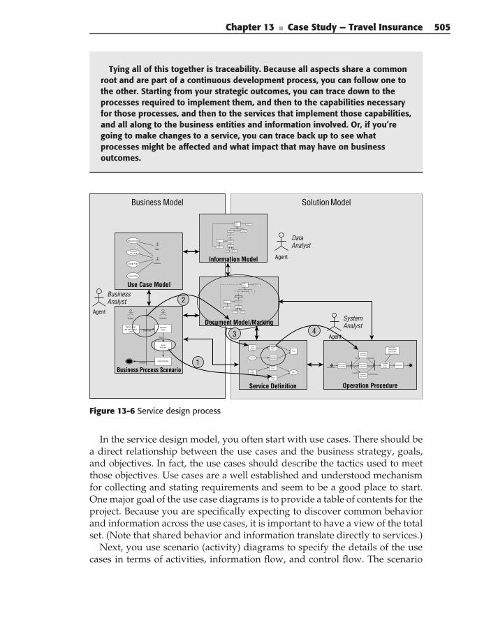
Chapter 13 ■ Case Study — Travel Insurance 505
Tying all of this together is traceability. Because all aspects share a commonroot and are part of a continuous development process, you can follow one tothe other. Starting from your strategic outcomes, you can trace down to theprocesses required to implement them, and then to the capabilities necessaryfor those processes, and then to the services that implement those capabilities,and all along to the business entities and information involved. Or, if you’regoing to make changes to a service, you can trace back up to see whatprocesses might be affected and what impact that may have on businessoutcomes.
Solution ModelBusiness Model
Business Process Scenario
Shipper Estimator
Identify repairand maintenance
needs
CalculateCosts
ApplyDiscount
Send Estimate
Repair Slip
Price
Estimate
Should be a branch here toloop through
list of vehicles
w St
GetCustomerInformation
GetVehicleInformation
GetLocationInformation
GetDriverInformation
CalculatePrice
OptionsCreatePrice
QuoteRequestCustomer
VehicalInfo
LocationInfo
DriverInformation
VIN
Address
Customer
Operation Procedure
Document Model/Marking
Agent
BusinessAnalyst
DataAnalyst
Agent
Agent
SystemAnalyst
Information Model
Request Quote
PurchaseInsurance
Change Policy
Cancel Policy
Customer
Agent
Use Case Model
Service Definition
Status
PolicyId
Policy
PolicyChangeRequest
PolicyCreate
Request
CreatePolicy
ChangePolicy
CancelPolicy
Get PolicyInformation
1
2
43
Insured Party
Name: StringPrimaryAddress: AHomePhone:WorkPhoneMobilePhone: Phone...DoB: Date: Phone...MaritalStatus: Marit..Gender
DriverIdentification
State: StringLicenseNumber: String
Customer
BillingAddres: Addre...CustomerID: Custom...
CoInsured
Relationship: Relation...
Product
ProductIdentifier: Prod…
ProductType: Product:
InsuredItem
Vehicle
VIN: VINMake: StringModel: StringYear: StringStyle: VehicleStyleCode
VehicleUsage
Usage: VehicleUsageCO...YearlyMiles: IntBusiness: Boolean
Coverage
Coverage: CoverageT...Detail: CoverageDesc...Name: String
Limit
LimitAmount: C...
Deductable
Deductable: A...
R11 1
R110
related by
R1
0..*
Product
0..*
0..*
R1
1
1..*
R1
1
1
R1
1
1. . *
R1
1
1R1
1
1
R1
1
1
PrimaryDriver
Figure 13-6 Service design process
In the service design model, you often start with use cases. There should bea direct relationship between the use cases and the business strategy, goals,and objectives. In fact, the use cases should describe the tactics used to meetthose objectives. Use cases are a well established and understood mechanismfor collecting and stating requirements and seem to be a good place to start.One major goal of the use case diagrams is to provide a table of contents for theproject. Because you are specifically expecting to discover common behaviorand information across the use cases, it is important to have a view of the totalset. (Note that shared behavior and information translate directly to services.)
Next, you use scenario (activity) diagrams to specify the details of the usecases in terms of activities, information flow, and control flow. The scenario
506 Part III ■ Case Studies
diagrams serve the same purpose as the Business Process Models. The maindifference is that they are the type of model supported by UML tools, which iswhat you use for the design process.
The information model is derived from the overall enterprise model andadditional details from the use case models. Once the scenarios and use casesare in place, you’re ready to start with service interface design. Again, thenumbers in the following list correspond to the numbers in Figure 13-6.
1. Activities in a scenario diagram become operations on a service inter-face. You include the operations in a service interface diagram.
2. The information passed into and out of operations become documents.The documents are defined by deriving the specific information for eachoperation from the overall information model.
3. You also include the documents in the service diagram. This gives youan overall view of the service from which you can evaluate the cohesion,coupling, and complexity.
4. The implementation of each operation is described in procedure dia-grams, including activity and class models.
Of course, this is an iterative process. You constantly discover new oper-ations and new information as you work through the details of the servicedesign. In addition, you constantly need to refactor the models to accommo-date shared behavior, shared information, and variability. This may requireyou to go back and update use case scenarios, information models, serviceinventory, and so on. It is best to keep things up-to-date as you go.
At the same time, you don’t want to get bogged down in analysis paralysis.An agile approach to development is often best. You first want to get a bigpicture view in place; for example, an overall service inventory or an overallunderstanding of the service interface. But this should not take too long anddoes not require a complete model. Then, you can completely implementand test one operation at a time and one service at a time. As you build theservices, you continue to evolve the models and to refactor them based onwhat you learned and new or changed requirements.
Now, let’s get back to the business analysis of the case study.
Business AnalysisThe first step in the business analysis is to understand the overall businessinteractions that take place regarding insurance. The conceptual architecturehas identified the main parties in this interaction, namely the channels, theinsurance and common services, and the vendors. Now, you want to under-stand exactly what interactions these parties have and what information theyneed to exchange. For this, you use a business context diagram, as illustrated in
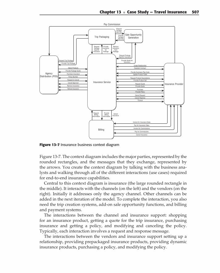
Chapter 13 ■ Case Study — Travel Insurance 507
Create RelationshipEstablish Contract
Provide Summary Plan Code
Request Product DescriptionsProvide Product Set
Update Product Table
Request QuoteProvide Quote
PurchaseProvide Policy
Cancel RequestCancel Reponse
TCancel
Pay Commission
Request Trip Package
Provide Trip Package
Provide Insurance
forPackage
Remove Insurance
from Package
Request Package Add-Ons
Provide Package Add-Ons
Request Package Specific Insurance
Provide Quote for Insurance
Select Products
Provide Package Quote
Purchase Insurance
Policy Number
Request to Cancel
Remove Insurance
Cancel Approval
Refund Insurance
Invoice for Commissions
Invoice for Insurance Sales
Provide Billing
Information
Request Billing
Information
Pay for Commissions
Pay for Insurance Sales
Cancel Insurance
Cancel Insurance
Agency Distribution (POS)
Sale Opportunity GenerationTrip Packaging
Insurance Service
Billing
Insurance Provider
Request Package Specific
Insurance
Figure 13-7 Insurance business context diagram
Figure 13-7. The context diagram includes the major parties, represented by therounded rectangles, and the messages that they exchange, represented bythe arrows. You create the context diagram by talking with the business ana-lysts and walking through all of the different interactions (use cases) requiredfor end-to-end insurance capabilities.
Central to this context diagram is insurance (the large rounded rectangle inthe middle). It interacts with the channels (on the left) and the vendors (on theright). Initially it addresses only the agency channel. Other channels can beadded in the next iteration of the model. To complete the interaction, you alsoneed the trip creation systems, add-on sale opportunity functions, and billingand payment systems.
The interactions between the channel and insurance support: shoppingfor an insurance product, getting a quote for the trip insurance, purchasinginsurance and getting a policy, and modifying and canceling the policy.Typically, each interaction involves a request and response message.
The interactions between the vendors and insurance support setting up arelationship, providing prepackaged insurance products, providing dynamicinsurance products, purchasing a policy, and modifying the policy.
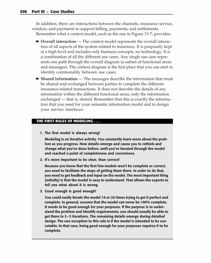
508 Part III ■ Case Studies
In addition, there are interactions between the channels, insurance service,vendors, and payments to support billing, payments, and settlements.
Remember what a context model, such as the one in Figure 13-7, provides:
Overall interaction — The context model represents the overall interac-tion of all aspects of the system related to insurance. It is purposely keptat a high level and includes only business concepts, no technology. It isa combination of all the different use cases. Any single use case repre-sents one path through the overall diagram (a subset of functional areasand messages). The context diagram is the first place that you can start toidentify commonality between use cases.
Shared information — The messages describe the information that mustbe shared and exchanged between parties to complete the differentinsurance-related transactions. It does not describe the details of anyinformation within the different functional areas, only the informationexchanged — that is, shared. Remember that this is exactly the informa-tion that you need for your semantic information model and to designyour service interfaces.
THE FIRST RULES OF MODELING . . .
1. The first model is always wrong!
Modeling is an iterative activity. You constantly learn more about the prob-lem as you progress. New details emerge and cause you to rethink andchange what you’ve done before, until you’ve iterated through the modeland reached a point of completeness and correctness.
2. It’s more important to be clear, than correct!
Because you know that the first few models won’t be complete or correct,you need to facilitate the steps of getting them there. In order to do that,you need to get feedback and input on the model. The most important thing(initially) is that the model is easy to understand. That allows the experts totell you what about it is wrong.
3. Good enough is good enough!
You could easily iterate the model 10 or 20 times trying to get it perfect andcomplete. In general, assume that the model can never be 100% complete.It needs to be good enough for your purposes. If the purpose is to under-stand the problem and identify requirements, you should usually be able toget there in 3–5 iterations. The remaining details emerge during detaileddesign. The one exception to this rule is if the model is intended to be exe-cutable. In that case, being good enough for your purposes requires it to becomplete.
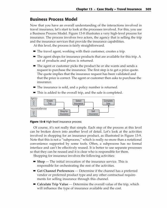
Chapter 13 ■ Case Study — Travel Insurance 509
Business Process ModelNow that you have an overall understanding of the interactions involved intravel insurance, let’s start to look at the processes involved. For this, you usea Business Process Model. Figure 13-8 illustrates a very high-level process forinsurance. The process involves two actors, the agency that is selling the tripand the insurance services that provide the insurance capabilities.
At this level, the process is fairly straightforward.
The travel agent, working with their customer, creates a trip.
The agent shops for insurance products that are available for this trip. Aset of products and prices is returned.
The agent or customer picks the product he or she wants and sends arequest to purchase the insurance. The first step is to get a price quote.The quote implies that the insurance request has been validated andthat the price is correct. The agent or customer then asks to purchase theinsurance.
The insurance is sold, and a policy number is returned.
This is added to the overall trip, and the sale is completed.
InsuranceService
Agency
Shop forInsurance
Select Insurance
Sell Insurance
Complete Sale
CreateTrip
Figure 13-8 High-level insurance process
Of course, it’s not really that simple. Each step of the process at this levelcan be broken down into another level of detail. Let’s look at the activitiesinvolved in shopping for an insurance product, as illustrated in Figure 13-9.Note that this is not a ‘‘subprocess,’’ which is really no more than a notationalconvenience supported by some tools. Often, a subprocess has no formalinterface and can’t be effectively reused. It is better to use separate processesso that they can be reused and it is clear who is responsible for them.
Shopping for insurance involves the following activities:
Shop — The initial invocation of the insurance service. This isresponsible for orchestrating the rest of the activities.
Get Channel Preferences — Determine if the channel has a preferredvendor or preferred product type and any other contractual require-ments for selling insurance through this channel.
Calculate Trip Value — Determine the overall value of the trip, whichwill influence the type of insurance available and the cost.
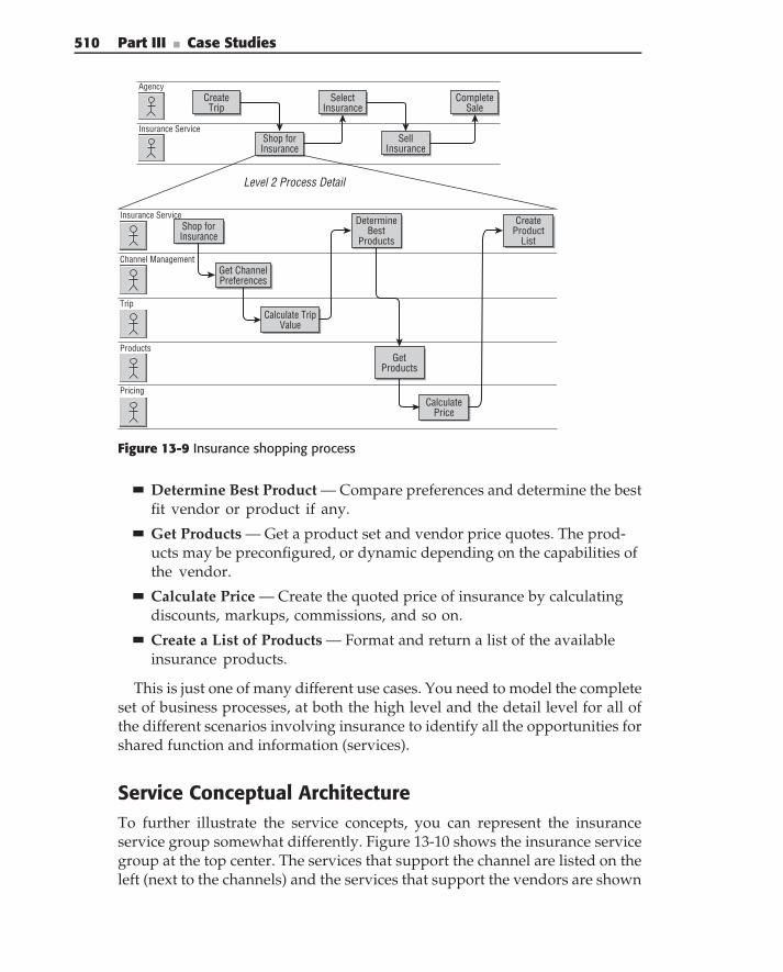
510 Part III ■ Case Studies
Insurance Service
Agency
Shop forInsurance
Select Insurance
Sell Insurance
Complete Sale
CreateTrip
Level 2 Process Detail
Insurance Service
Products
Pricing
Trip
Channel Management
Shop forInsurance
Calculate TripValue
Determine Best
Products
GetProducts
CalculatePrice
Create Product
List
Get Channel Preferences
Figure 13-9 Insurance shopping process
Determine Best Product — Compare preferences and determine the bestfit vendor or product if any.
Get Products — Get a product set and vendor price quotes. The prod-ucts may be preconfigured, or dynamic depending on the capabilities ofthe vendor.
Calculate Price — Create the quoted price of insurance by calculatingdiscounts, markups, commissions, and so on.
Create a List of Products — Format and return a list of the availableinsurance products.
This is just one of many different use cases. You need to model the completeset of business processes, at both the high level and the detail level for all ofthe different scenarios involving insurance to identify all the opportunities forshared function and information (services).
Service Conceptual ArchitectureTo further illustrate the service concepts, you can represent the insuranceservice group somewhat differently. Figure 13-10 shows the insurance servicegroup at the top center. The services that support the channel are listed on theleft (next to the channels) and the services that support the vendors are shown
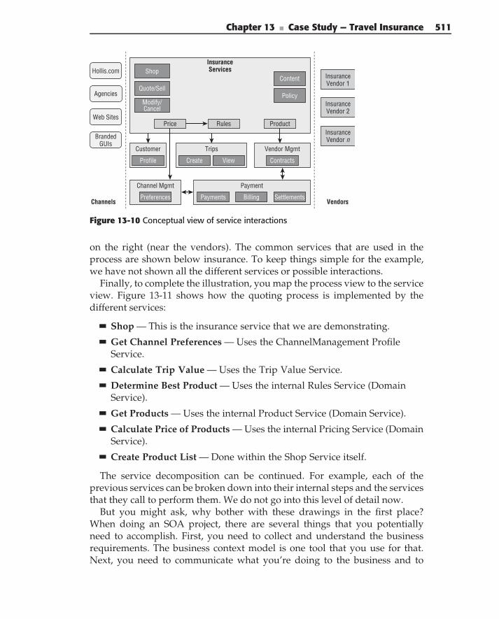
Chapter 13 ■ Case Study — Travel Insurance 511
Channels Vendors
Web Sites
BrandedGUIs
InsuranceVendor 1
Agencies
InsuranceVendor n
InsuranceVendor 2
InsuranceServices
Product
Shop
Price
Quote/Sell
Hollis.com
Modify/Cancel
Customer Trips
Payment
Content
Policy
Vendor Mgmt
Channel Mgmt
Rules
Profile
Preferences
Contracts
Payments Billing Settlements
Create View
Figure 13-10 Conceptual view of service interactions
on the right (near the vendors). The common services that are used in theprocess are shown below insurance. To keep things simple for the example,we have not shown all the different services or possible interactions.
Finally, to complete the illustration, you map the process view to the serviceview. Figure 13-11 shows how the quoting process is implemented by thedifferent services:
Shop — This is the insurance service that we are demonstrating.
Get Channel Preferences — Uses the ChannelManagement ProfileService.
Calculate Trip Value — Uses the Trip Value Service.
Determine Best Product — Uses the internal Rules Service (DomainService).
Get Products — Uses the internal Product Service (Domain Service).
Calculate Price of Products — Uses the internal Pricing Service (DomainService).
Create Product List — Done within the Shop Service itself.
The service decomposition can be continued. For example, each of theprevious services can be broken down into their internal steps and the servicesthat they call to perform them. We do not go into this level of detail now.
But you might ask, why bother with these drawings in the first place?When doing an SOA project, there are several things that you potentiallyneed to accomplish. First, you need to collect and understand the businessrequirements. The business context model is one tool that you use for that.Next, you need to communicate what you’re doing to the business and to
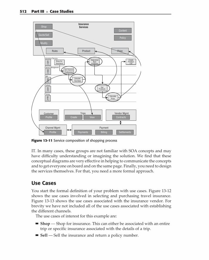
512 Part III ■ Case Studies
Insurance Services
Price
Shop
Rules
Quote/Sell
Content
Policy
Product
Insurance Service
Product
Pricing
Trips
Channel Management
Shop for Insurance
CalculateTrip Value
Determine Best
Products
GetProducts
CalculatePrice
Create Product
List
Get Channel Preferences
Trips
Payments Settlements
Create View
Channel Mgmt Payment
Vendor MgmtProfile Contracts
Profile Billing
Customer
Modify
Figure 13-11 Service composition of shopping process
IT. In many cases, these groups are not familiar with SOA concepts and mayhave difficulty understanding or imagining the solution. We find that theseconceptual diagrams are very effective in helping to communicate the conceptsand to get everyone on board and on the same page. Finally, you need to designthe services themselves. For that, you need a more formal approach.
Use CasesYou start the formal definition of your problem with use cases. Figure 13-12shows the use cases involved in selecting and purchasing travel insurance.Figure 13-13 shows the use cases associated with the insurance vendor. Forbrevity we have not included all of the use cases associated with establishingthe different channels.
The use cases of interest for this example are:
Shop — Shop for insurance. This can either be associated with an entiretrip or specific insurance associated with the details of a trip.
Sell — Sell the insurance and return a policy number.
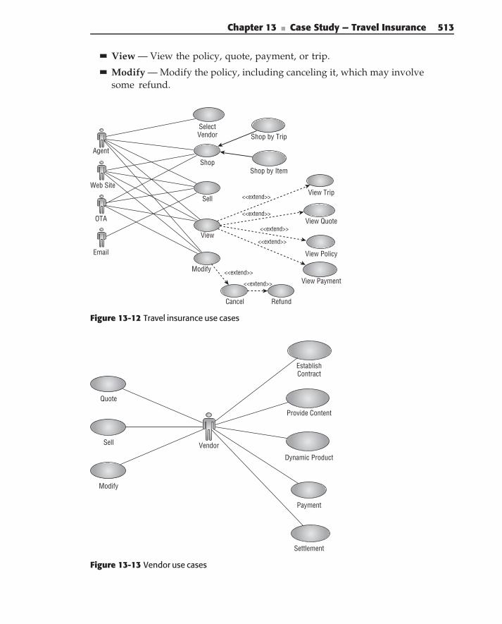
Chapter 13 ■ Case Study — Travel Insurance 513
View — View the policy, quote, payment, or trip.
Modify — Modify the policy, including canceling it, which may involvesome refund.
Agent
Web Site
OTA
SelectVendor
Shop
Sell
View
Modify
Cancel Refund
View Payment
View Quote
View Trip
View Policy
Shop by Trip
Shop by Item
<<extend>>
<<extend>>
<<extend>>
<<extend>>
<<extend>>
<<extend>>
Figure 13-12 Travel insurance use cases
Quote
Sell
Modify
EstablishContract
Provide Content
Dynamic Product
Payment
Settlement
Vendor
Figure 13-13 Vendor use cases
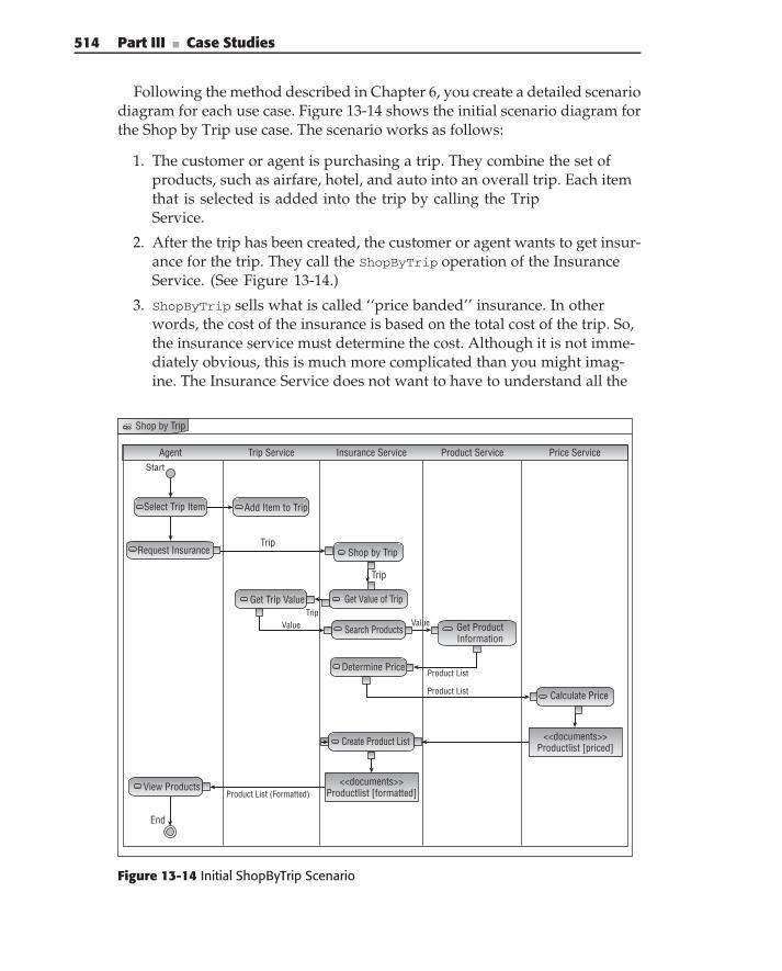
514 Part III ■ Case Studies
Following the method described in Chapter 6, you create a detailed scenariodiagram for each use case. Figure 13-14 shows the initial scenario diagram forthe Shop by Trip use case. The scenario works as follows:
1. The customer or agent is purchasing a trip. They combine the set ofproducts, such as airfare, hotel, and auto into an overall trip. Each itemthat is selected is added into the trip by calling the TripService.
2. After the trip has been created, the customer or agent wants to get insur-ance for the trip. They call the ShopByTrip operation of the InsuranceService. (See Figure 13-14.)
3. ShopByTrip sells what is called ‘‘price banded’’ insurance. In otherwords, the cost of the insurance is based on the total cost of the trip. So,the insurance service must determine the cost. Although it is not imme-diately obvious, this is much more complicated than you might imag-ine. The Insurance Service does not want to have to understand all the
Shop by Trip
Agent Trip Service Insurance Service Product Service Price ServiceStart
Select Trip Item Add Item to Trip
Request Insurance
Get Trip Value
Trip
Trip
Trip
Shop by Trip
Get Value of Trip
Value ValueSearch Products
Determine Price
Get ProductInformation
Product List
Product List Calculate Price
<<documents>>Productlist [formatted]Product List (Formatted)
Create Product List
View Products
End
<<documents>>Productlist [priced]
Figure 13-14 Initial ShopByTrip Scenario
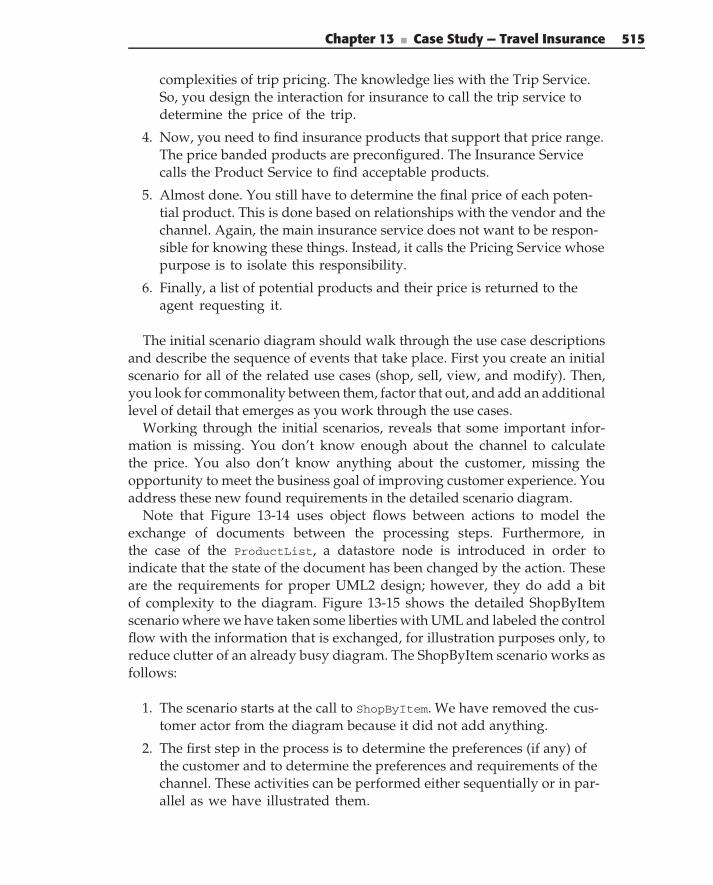
Chapter 13 ■ Case Study — Travel Insurance 515
complexities of trip pricing. The knowledge lies with the Trip Service.So, you design the interaction for insurance to call the trip service todetermine the price of the trip.
4. Now, you need to find insurance products that support that price range.The price banded products are preconfigured. The Insurance Servicecalls the Product Service to find acceptable products.
5. Almost done. You still have to determine the final price of each poten-tial product. This is done based on relationships with the vendor and thechannel. Again, the main insurance service does not want to be respon-sible for knowing these things. Instead, it calls the Pricing Service whosepurpose is to isolate this responsibility.
6. Finally, a list of potential products and their price is returned to theagent requesting it.
The initial scenario diagram should walk through the use case descriptionsand describe the sequence of events that take place. First you create an initialscenario for all of the related use cases (shop, sell, view, and modify). Then,you look for commonality between them, factor that out, and add an additionallevel of detail that emerges as you work through the use cases.
Working through the initial scenarios, reveals that some important infor-mation is missing. You don’t know enough about the channel to calculatethe price. You also don’t know anything about the customer, missing theopportunity to meet the business goal of improving customer experience. Youaddress these new found requirements in the detailed scenario diagram.
Note that Figure 13-14 uses object flows between actions to model theexchange of documents between the processing steps. Furthermore, inthe case of the ProductList, a datastore node is introduced in order toindicate that the state of the document has been changed by the action. Theseare the requirements for proper UML2 design; however, they do add a bitof complexity to the diagram. Figure 13-15 shows the detailed ShopByItemscenario where we have taken some liberties with UML and labeled the controlflow with the information that is exchanged, for illustration purposes only, toreduce clutter of an already busy diagram. The ShopByItem scenario works asfollows:
1. The scenario starts at the call to ShopByItem. We have removed the cus-tomer actor from the diagram because it did not add anything.
2. The first step in the process is to determine the preferences (if any) ofthe customer and to determine the preferences and requirements of thechannel. These activities can be performed either sequentially or in par-allel as we have illustrated them.
516 Part III ■ Case Studies
Customer Profile
Channel Profile
Channel ID
Shop by Item
Shop by Item
Trip
Determine preferences
Insurance Service Customer Service Channel Management Product Service Price ServiceVendor
Process Trip
Get Products
ExistsYes
No
Yes
Add to Insurance
Insurance Item List
Price Items
Describe Product
End
Start
Get Profile
Get Profile
Get Profile
Calculate Price
No
YesTrip Item
Trip ItemInsurance product
Insurance product
Insurable?
Exists? Get Profile
CustomerID
Insurance Item List
Insurance Item List (priced)
Figure 13-15 Detailed ShopByItem scenario
3. Now, the insurance service processes the trip. A trip is a collection ofrelated trip items. For each item, such as airfare, hotel, and so on, theservice determines whether the item is subject to additional insurance.If not, you move on to the next item in the trip. If it is, you go to thenext step.
N O T E There is an important design decision made in Step 3. We allowed theinsurance service to understand the format of a trip object and to be able to divideit into individual items. Because a trip is a fundamental entity of the business, wedecided to allow this. The other alternative would have been to call the trip serviceand have it return a list of items.
4. For each insurable item, you first go to the insurance product service tosee if there are any preconfigured products that support it. If not, you goto the next step.
Chapter 13 ■ Case Study — Travel Insurance 517
5. If there are no preconfigured items, you make a call directly to the insur-ance vendors and see if they want to offer insurance for a particularitem. For example, to a traveler who is going to Florida in June, they maychoose to offer special ‘‘Hurricane Insurance.’’
N O T E The insurance service is responsible for deciding if an item is insurable.This is a tradeoff between performance and flexibility. Calling out to an insurancevendor for every item in a trip has performance implications. We reduced thenumber of calls by filtering out items that we know can’t be insured, such as rentalcars (which have a different kind of insurance) or theatre tickets. The tradeoff isthat when a new kind of insurance is added (or deleted), the insurance servicemust be updated by the vendor. In an ideal world, only the insurance vendorswould know what products they offer at any given time, and the insurance servicewould call them to get the latest product information. The vendors could add orremove products at any time. But the cost of this flexibility is performance, whichis a critical requirement for the travel industry. Because insurance products don’tchange very often, we chose a less dynamic method that has less overhead.
6. If a product exists, you add it to your list of potential insurance items.
7. If a product exists, you need to apply the pricing policy to it. Again, youcall the Pricing Service to do this.
N O T E Here is another design decision. You could call the Pricing Service aftereach product is discovered, and then add the priced items to the list. Instead, webuilt the list of unpriced items and passed the entire list to the Pricing Service in asingle method call. This is a common pattern for reducing service invocationoverhead.
8. Finally, a list of potential products and their price is returned to theagent or customer. They can select from the list of items and purchasethose that they are interested in.
Enterprise ContextBefore you get much further in the design, you need to understand theenterprise context that the SOA architecture fits into. This context influencesthe design of your solution, services, and documents. First, you need to lookat the overall solution in order to define service policies. Then, you need tolook at the context in terms of service responsibilities and the information thatis passed through service interfaces.
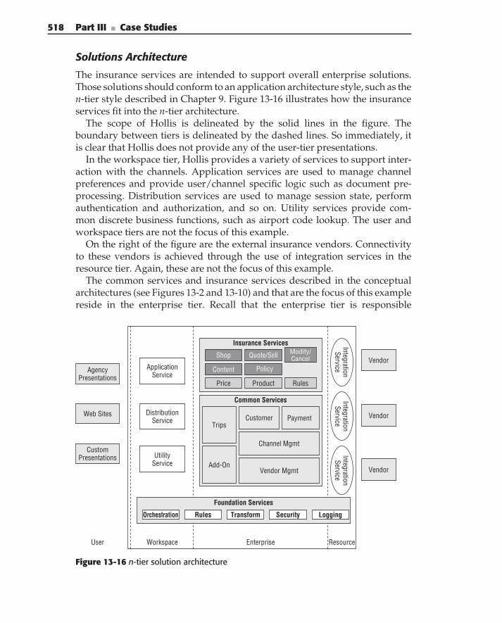
518 Part III ■ Case Studies
Solutions Architecture
The insurance services are intended to support overall enterprise solutions.Those solutions should conform to an application architecture style, such as then-tier style described in Chapter 9. Figure 13-16 illustrates how the insuranceservices fit into the n-tier architecture.
The scope of Hollis is delineated by the solid lines in the figure. Theboundary between tiers is delineated by the dashed lines. So immediately, itis clear that Hollis does not provide any of the user-tier presentations.
In the workspace tier, Hollis provides a variety of services to support inter-action with the channels. Application services are used to manage channelpreferences and provide user/channel specific logic such as document pre-processing. Distribution services are used to manage session state, performauthentication and authorization, and so on. Utility services provide com-mon discrete business functions, such as airport code lookup. The user andworkspace tiers are not the focus of this example.
On the right of the figure are the external insurance vendors. Connectivityto these vendors is achieved through the use of integration services in theresource tier. Again, these are not the focus of this example.
The common services and insurance services described in the conceptualarchitectures (see Figures 13-2 and 13-10) and that are the focus of this examplereside in the enterprise tier. Recall that the enterprise tier is responsible
Vendor
Vendor
Vendor
AgencyPresentations
Web Sites
CustomPresentations
User Workspace Enterprise Resource
DistributionService
ApplicationService
UtilityService
IntegrationService
Common Services
CustomerTrips
Payment
Add-OnVendor Mgmt
Channel Mgmt
Foundation Services
Insurance Services
Product
Shop
Price
Content Policy
Quote/Sell Modify/Cancel
Rules
IntegrationService
IntegrationService
Transform SecurityOrchestration LoggingRules
Figure 13-16 n-tier solution architecture
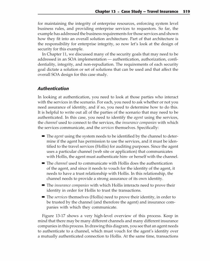
Chapter 13 ■ Case Study — Travel Insurance 519
for maintaining the integrity of enterprise resources, enforcing system levelbusiness rules, and providing enterprise services to requestors. So far, theexample has addressed the business requirements for those services and shownhow they fit into an overall solution architecture. Part of that architecture isthe responsibility for enterprise integrity, so now let’s look at the design ofsecurity for this example.
In Chapter 11, we discussed many of the security goals that may need to beaddressed in an SOA implementation — authentication, authorization, confi-dentiality, integrity, and non-repudiation. The requirements of each securitygoal dictate a solution or set of solutions that can be used and that affect theoverall SOA design for this case study.
Authentication
In looking at authentication, you need to look at those parties who interactwith the services in the scenario. For each, you need to ask whether or not youneed assurance of identity, and if so, you need to determine how to do this.It is helpful to write out all of the parties of the scenario that may need to beauthenticated. In this case, you need to identify the agent using the services,the channel used to connect to the services, the insurance companies with whichthe services communicate, and the services themselves. Specifically:
The agent using the system needs to be identified by the channel to deter-mine if the agent has permission to use the services, and it must be iden-tified to the travel services (Hollis) for auditing purposes. Since the agentuses a particular channel (web site or application) that communicateswith Hollis, the agent must authenticate him- or herself with the channel.
The channel used to communicate with Hollis does the authenticationof the agent, and since it needs to vouch for the identity of the agent, itneeds to have a trust relationship with Hollis. In this relationship, thechannel needs to provide a strong assurance of its own identity.
The insurance companies with which Hollis interacts need to prove theiridentity in order for Hollis to trust the transactions.
The services themselves (Hollis) need to prove their identity, in order tobe trusted by the channel (and therefore the agent) and insurance com-panies with which they communicate.
Figure 13-17 shows a very high-level overview of this process. Keep inmind that there may be many different channels and many different insurancecompanies in this process. In drawing this diagram, you see that an agent needsto authenticate to a channel, which must vouch for the agent’s identity overa mutually authenticated connection to Hollis. At the same time, transactions
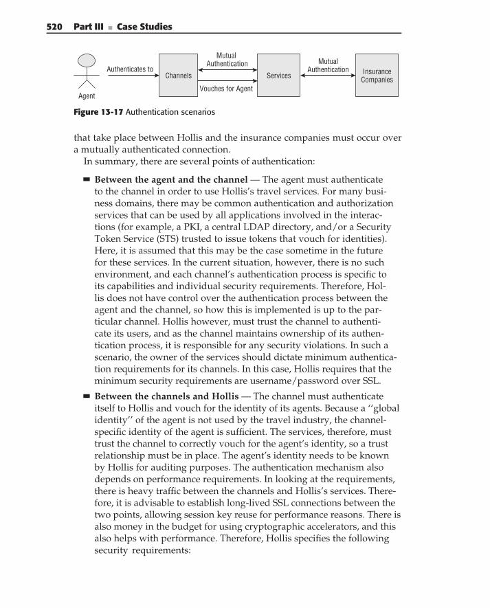
520 Part III ■ Case Studies
ChannelsAuthenticates to
Agent
Services
Mutual Authentication
Vouches for Agent
InsuranceCompanies
MutualAuthentication
Figure 13-17 Authentication scenarios
that take place between Hollis and the insurance companies must occur overa mutually authenticated connection.
In summary, there are several points of authentication:
Between the agent and the channel — The agent must authenticateto the channel in order to use Hollis’s travel services. For many busi-ness domains, there may be common authentication and authorizationservices that can be used by all applications involved in the interac-tions (for example, a PKI, a central LDAP directory, and/or a SecurityToken Service (STS) trusted to issue tokens that vouch for identities).Here, it is assumed that this may be the case sometime in the futurefor these services. In the current situation, however, there is no suchenvironment, and each channel’s authentication process is specific toits capabilities and individual security requirements. Therefore, Hol-lis does not have control over the authentication process between theagent and the channel, so how this is implemented is up to the par-ticular channel. Hollis however, must trust the channel to authenti-cate its users, and as the channel maintains ownership of its authen-tication process, it is responsible for any security violations. In such ascenario, the owner of the services should dictate minimum authentica-tion requirements for its channels. In this case, Hollis requires that theminimum security requirements are username/password over SSL.
Between the channels and Hollis — The channel must authenticateitself to Hollis and vouch for the identity of its agents. Because a ‘‘globalidentity’’ of the agent is not used by the travel industry, the channel-specific identity of the agent is sufficient. The services, therefore, musttrust the channel to correctly vouch for the agent’s identity, so a trustrelationship must be in place. The agent’s identity needs to be knownby Hollis for auditing purposes. The authentication mechanism alsodepends on performance requirements. In looking at the requirements,there is heavy traffic between the channels and Hollis’s services. There-fore, it is advisable to establish long-lived SSL connections between thetwo points, allowing session key reuse for performance reasons. There isalso money in the budget for using cryptographic accelerators, and thisalso helps with performance. Therefore, Hollis specifies the followingsecurity requirements:
Chapter 13 ■ Case Study — Travel Insurance 521
Mutual authentication — All transactions must occur over a mutu-ally authenticated SSL connection. This means that the channel’sdigital certificate must be trusted by the services, and vice versa. Inorder for a new channel to use the services, that channel must obtaina digital certificate and enter a process to put a trust relationship inplace with the services.
Vouching for agent identity — Because Hollis does not have controlover the method of authentication performed by the channel, a stan-dard such as the Security Assertion Markup Language (SAML) canbe used, as it is authentication technology ‘‘agnostic.’’ Hollis, there-fore, specifies that all messaging between the channel and the ser-vices must be WS-Security SAML Token Profile Messaging (with thesender-vouches confirmation method), since the services have explicittrust of the channels involved. The SAML token propagated conveysauthentication and identity information about the user. Although youmay think that using this style of messaging (for mere auditing pur-poses in the services) is overkill, such a strategy can better accommo-date change when the insurance industry eventually provides globalauthentication and authorization services. At that time, the channelswill use those services to identify agents, and Hollis’s services willperform authorization checks on the agent.
Between Hollis and the insurance companies — Hollis must prove itsown identity to the companies, and vice versa. In this case, you can usethe same methodology that is used between the channels and Hollis:mutually authenticated SSL. All transactions must occur over a mutuallyauthenticated SSL connection. This means that the insurance company’sdigital certificate must be trusted by Hollis, and vice versa. In order fora new insurance company partner to participate in this process, it mustobtain a digital certificate and enter a process to put a trust relationshipin place with Hollis.
Authorization
For authorization, you follow similar steps to flesh out the requirements.For example, you may need to know if the parties in the scenario haveauthorization requirements. Specifically, do agents, channels, or insurancecompanies have special privileges or security roles that allow them to docertain things? In such a scenario, if this were the case, Hollis would typicallyhave an entitlement service containing attributes of subjects, or a policy serveror database conveying access control policies.
Some state governments require agents to be licensed to sell insurance, soonly certain agents are permitted to do so. Agencies typically have supervisors
522 Part III ■ Case Studies
who can see everything, whereas individual agents are limited to their ownsets of transactions or customers. It may be possible, in the next generation ofservices, to create a security infrastructure for both authentication and autho-rization, providing security services that allow the travel industry (channelsand service providers) to have a common methodology for authentication andauthorization, checking global identity, and licenses. In the current scenario,however, this is the responsibility of the channel authenticating the agents.Because each channel controls its own authentication methodology, it alsomust validate the licenses of agents, according to the state’s laws.
Confidentiality
Because sensitive information is transferred between all points in the scenario,it is important that some of the information be encrypted. In looking atthe requirements, you can see that the travel business is very data- andtransaction-intensive, with requirements for high transaction rates. For thisreason, the solution needs to be very performance conscious, so whateverwould be adequate for security with minimal impact on performance is thebest choice.
Since you are using mutually authenticated SSL between all of the pointsin this solution, this covers confidentiality, but it is important to note thatthere is a performance impact. As mentioned in the authentication section,you can establish long-lived SSL connections between the nodes in the solu-tion, eliminating the need for repeated computationally expensive public keycryptography for session key negotiation each time. In addition, the budgetallows you to invest in cryptographic accelerators that offload the performanceburden.
Integrity and Non-Repudiation
It is important that there be assurance of integrity (that data has not been alteredin transit). Luckily, this is accomplished by the SSL connections between thechannels, Hollis, and the insurance companies. In addition, it is important thatyou have a high level of assurance of the transactions, binding the messagesenders to the transaction requests and responses. As discussed in Chapter 11,non-repudiation, using digital signatures, accomplishes this goal of providinglegal proof of such a binding.
In this case, receipts of purchase requests need to be long-lived and digitallysigned, providing legal proof that can be validated by a third party. This meansthat the insurance companies must digitally sign the responses to requests,providing such a proof. These signed documents may be stored for archiveby Hollis, providing legal proof, and can be returned in the responses ofmessages to the channels. In doing so, WS-Security SOAP Messaging is used
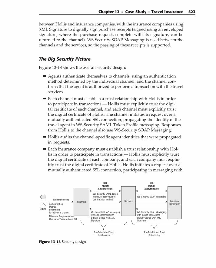
Chapter 13 ■ Case Study — Travel Insurance 523
between Hollis and insurance companies, with the insurance companies usingXML Signature to digitally sign purchase receipts (signed using an envelopedsignature, where the purchase request, complete with its signature, can bereturned to the channel). WS-Security SOAP Messaging is used between thechannels and the services, so the passing of these receipts is supported.
The Big Security Picture
Figure 13-18 shows the overall security design:
Agents authenticate themselves to channels, using an authenticationmethod determined by the individual channel, and the channel con-firms that the agent is authorized to perform a transaction with the travelservices.
Each channel must establish a trust relationship with Hollis in orderto participate in transactions — Hollis must explicitly trust the digi-tal certificate of each channel, and each channel must explicitly trustthe digital certificate of Hollis. The channel initiates a request over amutually authenticated SSL connection, propagating the identity of thetravel agent in WS-Security SAML Token Profile messaging. Responsesfrom Hollis to the channel also use WS-Security SOAP Messaging.
Hollis audits the channel-specific agent identities that were propagatedin requests.
Each insurance company must establish a trust relationship with Hol-lis in order to participate in transactions — Hollis must explicitly trustthe digital certificate of each company, and each company must explic-itly trust the digital certificate of Hollis. Hollis initiates a request over amutually authenticated SSL connection, participating in messaging with
ChannelsAuthenticates to
Agent
Services
SSLMutual
Authentication
SSLMutual
Authentication
WS-Security SAML TokenProfile, sender-vouchesconfirmation method
InsuranceCompaniesAuthentication
Methoddeterminedby individual channel
Minimum Requirement—Username/Passward over SSL
WS-Security SOAP Messaging
WS-Security SOAP Messagingwith signed transactionsdigitally signed with XMLSignature
WS-Security SOAP Messagingwith signed transactionsdigitally signed with XMLSignature
Pre-Established TrustRelationship
Pre-Established TrustRelationship
Figure 13-18 Security design
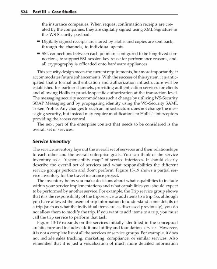
524 Part III ■ Case Studies
the insurance companies. When request confirmation receipts are cre-ated by the companies, they are digitally signed using XML Signature inthe WS-Security payload.
Digitally signed receipts are stored by Hollis and copies are sent back,through the channels, to individual agents.
SSL connections between each point are configured to be long-lived con-nections, to support SSL session key reuse for performance reasons, andall cryptography is offloaded onto hardware appliances.
This security design meets the current requirements, but more importantly, itaccommodates future enhancements. With the success of this system, it is antic-ipated that a formal authentication and authorization infrastructure will beestablished for partner channels, providing authentication services for clientsand allowing Hollis to provide specific authorization at the transaction level.The messaging security accommodates such a change by utilizing WS-SecuritySOAP Messaging and by propagating identity using the WS-Security SAMLToken Profile. Any changes to such an infrastructure does not change the mes-saging security, but instead may require modifications to Hollis’s interceptorsproviding the access control.
The next part of the enterprise context that needs to be considered is theoverall set of services.
Service Inventory
The service inventory lays out the overall set of services and their relationshipsto each other and the overall enterprise goals. You can think of the serviceinventory as a ‘‘responsibility map’’ of service interfaces. It should clearlydescribe the overall set of services and what responsibilities the differentservice groups perform and don’t perform. Figure 13-19 shows a partial ser-vice inventory for the travel insurance project.
The inventory helps you make decisions about what capabilities to includewithin your service implementations and what capabilities you should expectto be performed by another service. For example, the Trip service group showsthat it is the responsibility of the trip service to add items to a trip. So, althoughyou have allowed the users of trip information to understand some details ofa trip (such as what the individual items are as discussed previously), you donot allow them to modify the trip. If you want to add items to a trip, you mustcall the trip service to perform that task.
Figure 13-19 expands on the services initially identified in the conceptualarchitecture and includes additional utility and foundation services. However,it is not a complete list of all the services or service groups. For example, it doesnot include sales tracking, marketing, compliance, or similar services. Alsoremember that it is just a visualization of much more detailed information
Chapter 13 ■ Case Study — Travel Insurance 525
Common Services
Foundation Services
InsuranceServices
Product
Shop
Price
Quote/Sell
Modify
Customer
Party
AddMember
Cust. Info
Profile
Trips
Add to Trip
Price
Trip Maint.
Shop
CRUD
Payment
Billing
Payment
Settlement
Invoice
Add-On
Suggest
Sell
Modify
Product
PriceContent
Policy
Vendor Mgmt
Regulation
Content
Contract
Accounting
Channel Mgmt
Agency
ProfileContract
Accounting
Web
Commission
Rules
Utility Services
Phone Book Info. Mgmt.Area Currency PCC Code List
Authentication Management AuditSecurity Logging
Transform ScheduleOrchestration Rules Configuration
Figure 13-19 Service inventory
about each service, as contained in the service specification and stored in therepository.
Entity Diagram
The other important part of enterprise context is the information that isshared between services. Here, you describe the main entities involved in thebusiness domain and their relationships. The model keeps things at a highlevel and generally does not describe the details of each individual entity. Themodel is constructed through a combination of internal domain knowledge,reverse engineering of existing systems, and industry standards. For example,standards from the Open Travel Alliance (OTA) define specific schema forinformation exchange between travel-related companies. Entities identified inthose schema are factored into the information model. Figure 13-20 shows asegment of the information model for Hollis.
Primarily, the model shows the relationship between the Trip, Traveler, andInsurance Policy. For example, you can see that an InsurancePolicy is related
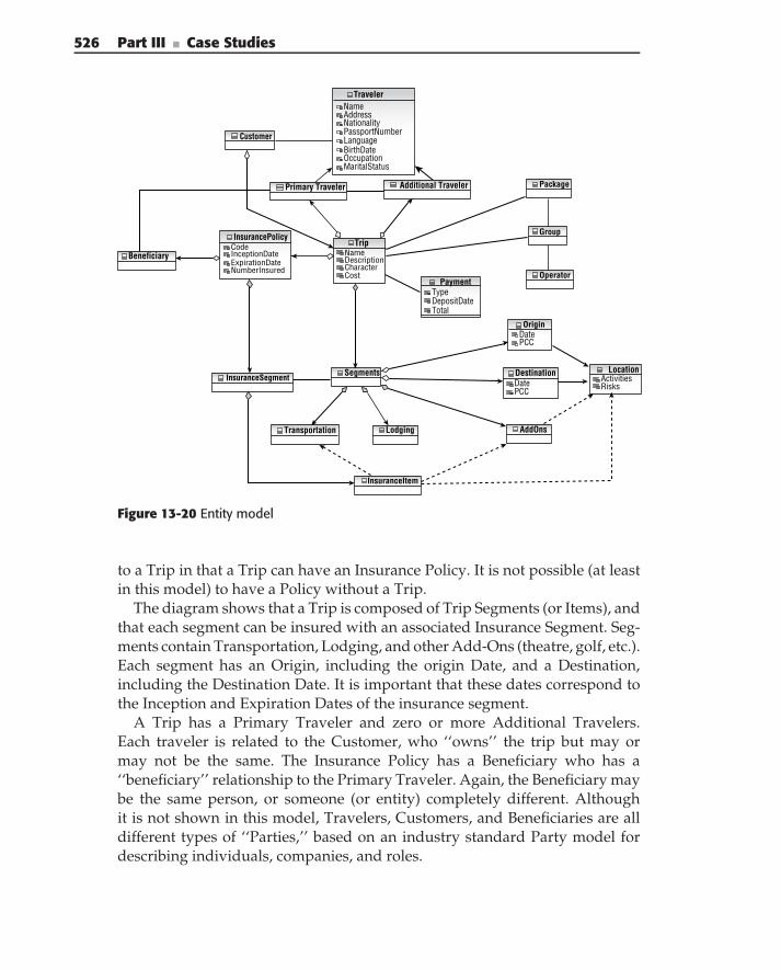
526 Part III ■ Case Studies
NameAddressNationalityPassportNumberLanguageBirthDateOccupationMaritalStatus
Additional TravelerPrimary Traveler
Customer
Package
Traveler
NameDescriptionCharacterCost
Trip
TypeDepositDateTotal
Payment
DatePCC
Origin
ActivitiesRisks
Location
DatePCC
Destination
Operator
Beneficiary
InsuranceSegment
InsuranceItem
Transportation
Segments
Lodging AddOns
Group
CodeInceptionDateExpirationDateNumberInsured
InsurancePolicy
Figure 13-20 Entity model
to a Trip in that a Trip can have an Insurance Policy. It is not possible (at leastin this model) to have a Policy without a Trip.
The diagram shows that a Trip is composed of Trip Segments (or Items), andthat each segment can be insured with an associated Insurance Segment. Seg-ments contain Transportation, Lodging, and other Add-Ons (theatre, golf, etc.).Each segment has an Origin, including the origin Date, and a Destination,including the Destination Date. It is important that these dates correspond tothe Inception and Expiration Dates of the insurance segment.
A Trip has a Primary Traveler and zero or more Additional Travelers.Each traveler is related to the Customer, who ‘‘owns’’ the trip but may ormay not be the same. The Insurance Policy has a Beneficiary who has a‘‘beneficiary’’ relationship to the Primary Traveler. Again, the Beneficiary maybe the same person, or someone (or entity) completely different. Althoughit is not shown in this model, Travelers, Customers, and Beneficiaries are alldifferent types of ‘‘Parties,’’ based on an industry standard Party model fordescribing individuals, companies, and roles.
Chapter 13 ■ Case Study — Travel Insurance 527
Information ModelThe semantic information model provides the next level of detail after theentity model. In a sense, it is a refinement of the entity model. The modelcan often be broken up into many different diagrams designed to focus ona specific aspect of the information, as described in Chapter 5. It is mainly amatter of style, but we like to keep the diagrams to about one or two pages.When they get much larger that that, it is difficult to comprehend all thedifferent aspects (much less display or print it).
MODEL, DIAGRAM, METADATA
What is the difference between a model, a diagram, and metadata?
◆ Model — A model is a representation of a system. There are many differentkinds of models, for example Business Models, Business Process Models,and Service Design Models. Each model describes some specific aspect orset of aspects about a system or subsystem.
■ A Conceptual Model is an informal visualization intended to communi-cate concepts. It is often rendered as a Visio diagram. It is important asa means of communication to a variety of audiences, but it is not meantto (nor is it detailed or precise enough) specify an architecture, design, orimplementation. Figure 13-2 (Conceptual architecture) is such a model.
■ A Specification Model is a formal model that is intended to preciselydefine the system to the point that it can unambiguously be imple-mented. A formal model is based on precise semantics, such as BPMN orUML. A formal model is created in a modeling tool, such as Rational Soft-ware Modeler. Figures 13-12 through 13-15, and 13-20 through 13-29 areexamples of formal models.
◆ Diagram — A diagram is a specific visualization of some aspect of a model.A model usually contains many diagrams. For example, all the formal dia-grams shown in this chapter are part of the same model. The model for theinsurance project contains about 50 different diagrams. One thing you maynotice is that the same model elements (such as Trip) often occur in morethan one diagram. This does not mean that the model element occurs mul-tiple times in the model. Instead, it points out the important distinctionbetween model diagrams and model metadata.
◆ Metadata — The model is a combination of its metadata and its diagrams.Metadata describes the general modeling concepts, rules, and relationshipsbut not the specific contents of a particular model. Metadata is an externaldescription of a resource. Common usages for metadata include providingthe context of a data resource, managing its life cycle, and extending it tonew uses.
(continued)
528 Part III ■ Case Studies
MODEL, DIAGRAM, METADATA (continued)
The specific details about every model element are stored in a repositoryaccording to the specification of the modeling language. For example, Trip isstored as a UML Class and all the information that is associated with it. Thediagrams are structured visualizations of the model elements and theirmetadata. The same model elements can appear in many different diagrams.For example, the same service often appears in a class diagram, a collaborationdiagram, and a sequence diagram. This is because the modeling language hasestablished certain relationships between these types of diagrams andmaintains those relationships (and traceability) for us.
People often refer to conceptual drawings, formal diagrams, and formalmodels all as ‘‘models.’’ Perhaps trying to correct this would be an exercise infrustration. But it is important to know the difference and be able to distinguishamong them when it really matters.
You create the information model from several sources.
Domain information — Detailed information from industry domainsources (such as OTA).
Use case descriptions — Often the use cases describe specific detailsabout information that is collected, passed, or displayed.
Use cases scenarios — As you create the use case scenarios, you specifythe information that is passed into and out of the service interfaces. Alldata that is passed in a scenario needs to be contained in the informationmodel.
Service design — Finally, as you work out the details of the serviceinterfaces, and especially the implementations, you discover manydetails about the information that is needed. You follow an iterativeprocess in development, adding detail to the information model as youdiscover it.
Figure 13-21 is an example from the information model showing the detailsof the insurance policy. Remember that at this level you are still describingthe information that is passed between services and described in the serviceinterfaces, that is, the semantic information model. You are not yet identifyingthe details of the internal implementation information.
In this diagram, you can see that an InsurancePolicy has Benefits,Exclusions, and a Premium. The Premium is associated with a Payment, whichalso includes Tax and Commission and can be paid by CreditCard or Voucher.The policy is associated with a ProductPlan (remember that it is an instance ofa type of Product). The policy is offered by a specific Vendor. The Vendor might
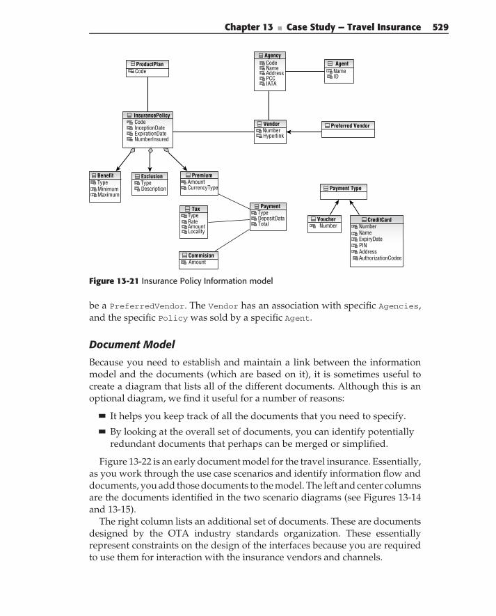
Chapter 13 ■ Case Study — Travel Insurance 529
CodeCodeName NameAddressPCC IDIATA
ProductPlan
Agency
NumberNameExpiryDatePINAddressAuthorizationCodee
CreditCard
CodeInceptionDateExpirationDateNumberInsured
InsurancePolicy
Agent
NumberHyperlink
Vendor
TypeDescription
ExclusionAmountCurrencyType
Premium
TypeRateAmountLocality
Tax
TypeMinimumMaximum
Benefit
NumberVoucher
AmountCommision
Preferred Vendor
Payment Type
TypeDepositDataTotal
Payment
Figure 13-21 Insurance Policy Information model
be a PreferredVendor. The Vendor has an association with specific Agencies,and the specific Policy was sold by a specific Agent.
Document Model
Because you need to establish and maintain a link between the informationmodel and the documents (which are based on it), it is sometimes useful tocreate a diagram that lists all of the different documents. Although this is anoptional diagram, we find it useful for a number of reasons:
It helps you keep track of all the documents that you need to specify.
By looking at the overall set of documents, you can identify potentiallyredundant documents that perhaps can be merged or simplified.
Figure 13-22 is an early document model for the travel insurance. Essentially,as you work through the use case scenarios and identify information flow anddocuments, you add those documents to the model. The left and center columnsare the documents identified in the two scenario diagrams (see Figures 13-14and 13-15).
The right column lists an additional set of documents. These are documentsdesigned by the OTA industry standards organization. These essentiallyrepresent constraints on the design of the interfaces because you are requiredto use them for interaction with the insurance vendors and channels.
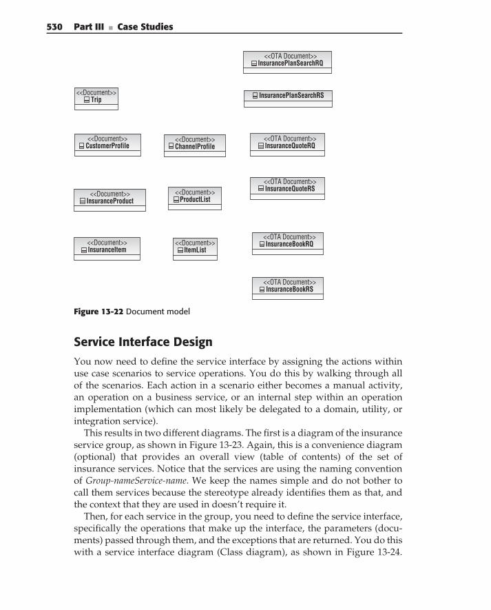
530 Part III ■ Case Studies
<<Document>> Trip
<<Document>> CustomerProfile
<<OTA Document>> InsurancePlanSearchRQ
<<OTA Document>> InsuranceQuoteRQ
<<OTA Document>> InsuranceBookRQ
<<OTA Document>> InsuranceQuoteRS
InsurancePlanSearchRS
<<Document>> ChannelProfile
<<Document>> ProductList
<<Document>> ItemList
<<Document>> InsuranceItem
<<Document>> InsuranceProduct
<<OTA Document>> InsuranceBookRS
Figure 13-22 Document model
Service Interface DesignYou now need to define the service interface by assigning the actions withinuse case scenarios to service operations. You do this by walking through allof the scenarios. Each action in a scenario either becomes a manual activity,an operation on a business service, or an internal step within an operationimplementation (which can most likely be delegated to a domain, utility, orintegration service).
This results in two different diagrams. The first is a diagram of the insuranceservice group, as shown in Figure 13-23. Again, this is a convenience diagram(optional) that provides an overall view (table of contents) of the set ofinsurance services. Notice that the services are using the naming conventionof Group-nameService-name. We keep the names simple and do not bother tocall them services because the stereotype already identifies them as that, andthe context that they are used in doesn’t require it.
Then, for each service in the group, you need to define the service interface,specifically the operations that make up the interface, the parameters (docu-ments) passed through them, and the exceptions that are returned. You do thiswith a service interface diagram (Class diagram), as shown in Figure 13-24.
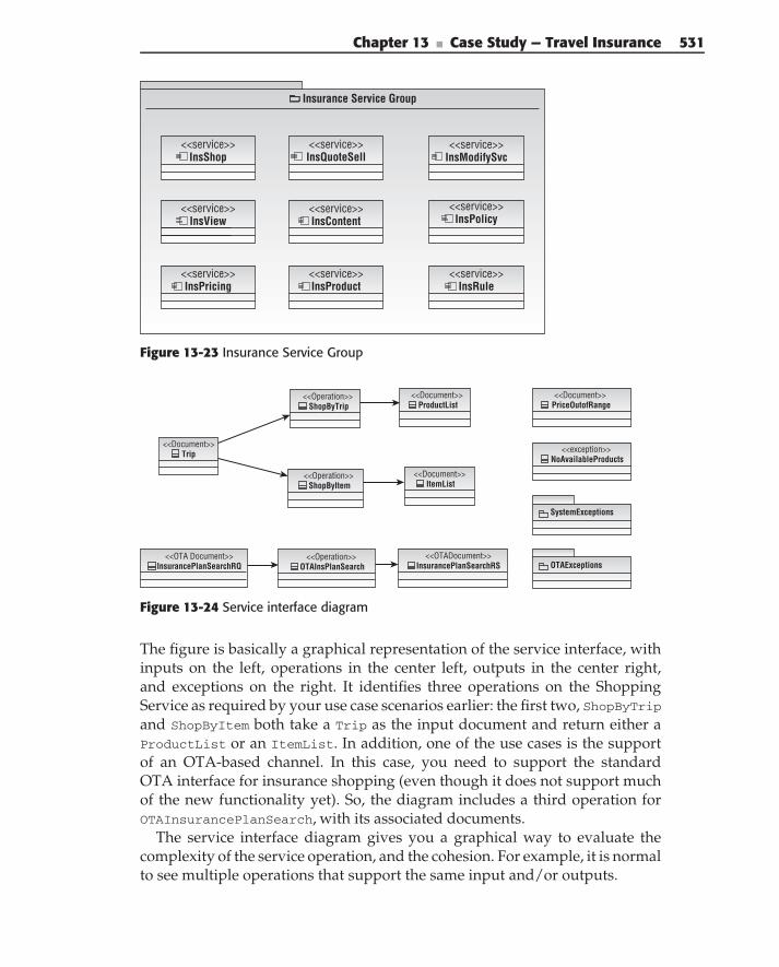
Chapter 13 ■ Case Study — Travel Insurance 531
<<service>>InsShop
<<service>>InsView
<<service>>InsPricing
<<service>>InsPolicy
<<service>>InsRule
<<service>>InsProduct
<<service>>InsQuoteSell
<<service>>InsContent
<<service>>InsModifySvc
Insurance Service Group
Figure 13-23 Insurance Service Group
<<Document>> Trip
<<OTA Document>> InsurancePlanSearchRQ
<<Operation>> ShopByTrip
<<Document>> ProductList
SystemExceptions
<<Document>> ItemList
<<Operation>> ShopByItem
<<Operation>> OTAInsPlanSearch
<<OTADocument>> InsurancePlanSearchRS
<<Document>> PriceOutofRange
<<exception>> NoAvailableProducts
OTAExceptions
Figure 13-24 Service interface diagram
The figure is basically a graphical representation of the service interface, withinputs on the left, operations in the center left, outputs in the center right,and exceptions on the right. It identifies three operations on the ShoppingService as required by your use case scenarios earlier: the first two, ShopByTripand ShopByItem both take a Trip as the input document and return either aProductList or an ItemList. In addition, one of the use cases is the supportof an OTA-based channel. In this case, you need to support the standardOTA interface for insurance shopping (even though it does not support muchof the new functionality yet). So, the diagram includes a third operation forOTAInsurancePlanSearch, with its associated documents.
The service interface diagram gives you a graphical way to evaluate thecomplexity of the service operation, and the cohesion. For example, it is normalto see multiple operations that support the same input and/or outputs.
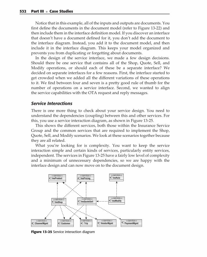
532 Part III ■ Case Studies
Notice that in this example, all of the inputs and outputs are documents. Youfirst define the documents in the document model (refer to Figure 13-22) andthen include them in the interface definition model. If you discover an interfacethat doesn’t have a document defined for it, you don’t add the document tothe interface diagram. Instead, you add it to the document model, and theninclude it in the interface diagram. This keeps your model organized andprevents you from duplicating or forgetting about documents.
In the design of the service interface, we made a few design decisions.Should there be one service that contains all of the Shop, Quote, Sell, andModify operations, or should each of these be a separate interface? Wedecided on separate interfaces for a few reasons. First, the interface started toget crowded when we added all the different variations of these operationsto it. We find between four and seven is a pretty good rule of thumb for thenumber of operations on a service interface. Second, we wanted to alignthe service capabilities with the OTA request and reply messages.
Service Interactions
There is one more thing to check about your service design. You need tounderstand the dependencies (coupling) between this and other services. Forthis, you use a service interaction diagram, as shown in Figure 13-25.
This shows the different services, both those within the Insurance ServiceGroup and the common services that are required to implement the Shop,Quote, Sell, and Modify scenarios. We look at these scenarios together becausethey are all related.
What you’re looking for is complexity. You want to keep the serviceinteraction simple and certain kinds of services, particularly entity services,independent. The services in Figure 13-25 have a fairly low level of complexityand a minimum of unnecessary dependencies, so we are happy with theinterface design and can now move on to the document design.
<<service>>InsRule
<<service>>InsProduct
<<service>>InsShop
<<service>>Customer
<<service>>Trip
<<service>>ChannelMgmt
<<service>>InsQuoteSell
<<service>>InsModify
<<service>>VendorMgmt
<<service>>PaymentMgmt
<<service>>InsPricing
Figure 13-25 Service interaction diagram
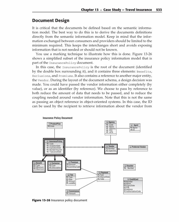
Chapter 13 ■ Case Study — Travel Insurance 533
Document Design
It is critical that the documents be defined based on the semantic informa-tion model. The best way to do this is to derive the documents definitionsdirectly from the semantic information model. Keep in mind that the infor-mation exchanged between consumers and providers should be limited to theminimum required. This keeps the interchanges short and avoids exposinginformation that is not needed or should not be known.
You use a marking technique to illustrate how this is done. Figure 13-26shows a simplified subset of the insurance policy information model that ispart of the InsurancePolicy document.
In this case, the InsurancePolicy is the root of the document (identifiedby the double box surrounding it), and it contains three elements: Benefits,Exclusions, and Premiums. It also contains a reference to another major entity,the Vendor. During the layout of the document schema, a design decision wasmade. You could have passed the vendor information either completely (byvalue), or as an identifier (by reference). We choose to pass by reference toboth reduce the amount of data that needs to be passed, and to reduce thecoupling needed around vendor information. Note that this is not the sameas passing an object reference in object-oriented systems. In this case, the IDcan be used by the recipient to retrieve information about the vendor from
Insurance Policy Document
CodeCodeName NameAddressPCC IDIATA
ProductPlanAgency
NumberNameExpiryDatePINAddressAuthorizationCode
CreditCard
CodeInceptionDateExpirationDateNumberInsuredTripCancelDate
InsurancePolicy
Agent
NumberHyperlink
Vendor
TypeDescription
ExclusionAmountCurrencyType
Premium
TypeDepositDataTotal
Payment
TypeRateAmountLocality
Tax
TypeMinimumMaximum
Benefit
NumberVoucher
AmountCommission
Preferred Vendor
Figure 13-26 Insurance policy document
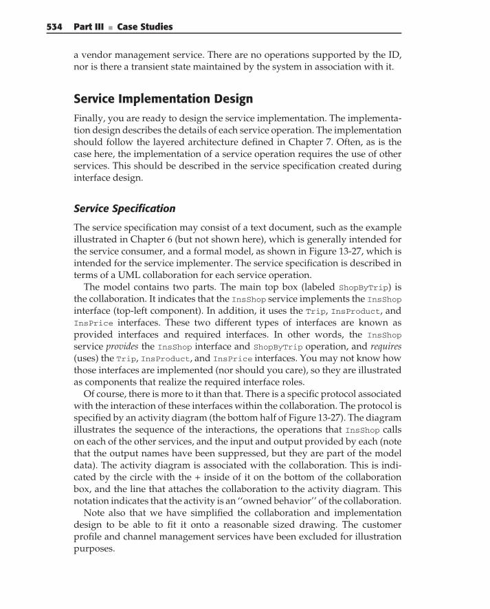
534 Part III ■ Case Studies
a vendor management service. There are no operations supported by the ID,nor is there a transient state maintained by the system in association with it.
Service Implementation DesignFinally, you are ready to design the service implementation. The implementa-tion design describes the details of each service operation. The implementationshould follow the layered architecture defined in Chapter 7. Often, as is thecase here, the implementation of a service operation requires the use of otherservices. This should be described in the service specification created duringinterface design.
Service Specification
The service specification may consist of a text document, such as the exampleillustrated in Chapter 6 (but not shown here), which is generally intended forthe service consumer, and a formal model, as shown in Figure 13-27, which isintended for the service implementer. The service specification is described interms of a UML collaboration for each service operation.
The model contains two parts. The main top box (labeled ShopByTrip) isthe collaboration. It indicates that the InsShop service implements the InsShopinterface (top-left component). In addition, it uses the Trip, InsProduct, andInsPrice interfaces. These two different types of interfaces are known asprovided interfaces and required interfaces. In other words, the InsShop
service provides the InsShop interface and ShopByTrip operation, and requires(uses) the Trip, InsProduct, and InsPrice interfaces. You may not know howthose interfaces are implemented (nor should you care), so they are illustratedas components that realize the required interface roles.
Of course, there is more to it than that. There is a specific protocol associatedwith the interaction of these interfaces within the collaboration. The protocol isspecified by an activity diagram (the bottom half of Figure 13-27). The diagramillustrates the sequence of the interactions, the operations that InsShop callson each of the other services, and the input and output provided by each (notethat the output names have been suppressed, but they are part of the modeldata). The activity diagram is associated with the collaboration. This is indi-cated by the circle with the + inside of it on the bottom of the collaborationbox, and the line that attaches the collaboration to the activity diagram. Thisnotation indicates that the activity is an ‘‘owned behavior’’ of the collaboration.
Note also that we have simplified the collaboration and implementationdesign to be able to fit it onto a reasonable sized drawing. The customerprofile and channel management services have been excluded for illustrationpurposes.
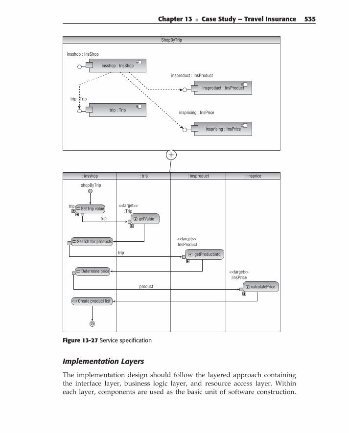
Chapter 13 ■ Case Study — Travel Insurance 535
: insshop : trip : insproduct
ShopByTrip
insshop : InsShop
insshop : InsShop
: insprice
shopByTrip
trip Get trip value
Determine price
Search for products
Create product list
getValue
<<target>>:Trip
trip
trip
product
<<target>>:InsProduct
getProductinfo
<<target>>:InsPrice
calculatePrice
trip : Trip
trip : Trip
insproduct : InsProduct
insproduct : InsProduct
inspricing : InsPrice
inspricing : InsPrice
Figure 13-27 Service specification
Implementation Layers
The implementation design should follow the layered approach containingthe interface layer, business logic layer, and resource access layer. Withineach layer, components are used as the basic unit of software construction.
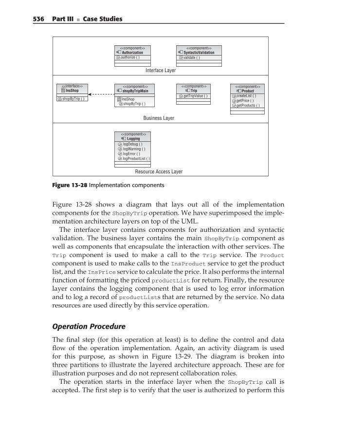
536 Part III ■ Case Studies
<<component>>Authorization
<<component>>SyntacticValidation
authorize ( ) validate ( )
<<component>>shopByTripMain
<<component>>Logging
<<component>>Trip
<<component>>Product
<<interface>>InsShop
InsShopgetTripValue ( ) createList ( )
getPrice ( )getProducts ( )shopByTrip ( )
shopByTrip ( )
logDebug ( )logWarning ( )logError ( )logProductList ( )
<I>
<I>
Interface Layer
Business Layer
Resource Access Layer
Figure 13-28 Implementation components
Figure 13-28 shows a diagram that lays out all of the implementationcomponents for the ShopByTrip operation. We have superimposed the imple-mentation architecture layers on top of the UML.
The interface layer contains components for authorization and syntacticvalidation. The business layer contains the main ShopByTrip component aswell as components that encapsulate the interaction with other services. TheTrip component is used to make a call to the Trip service. The Product
component is used to make calls to the InsProduct service to get the productlist, and the InsPrice service to calculate the price. It also performs the internalfunction of formatting the priced productList for return. Finally, the resourcelayer contains the logging component that is used to log error informationand to log a record of productLists that are returned by the service. No dataresources are used directly by this service operation.
Operation Procedure
The final step (for this operation at least) is to define the control and dataflow of the operation implementation. Again, an activity diagram is usedfor this purpose, as shown in Figure 13-29. The diagram is broken intothree partitions to illustrate the layered architecture approach. These are forillustration purposes and do not represent collaboration roles.
The operation starts in the interface layer when the ShopByTrip call isaccepted. The first step is to verify that the user is authorized to perform this
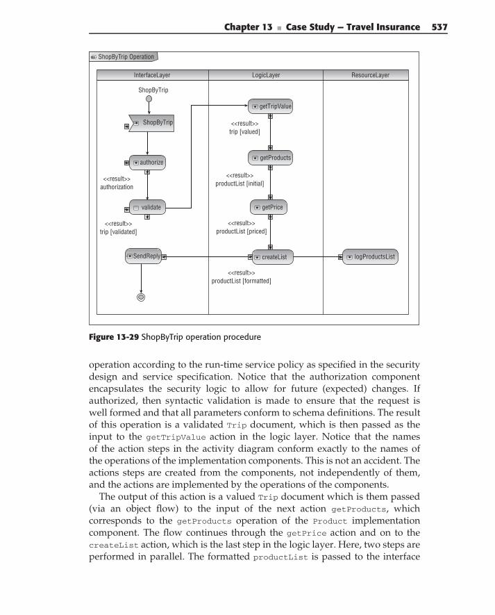
Chapter 13 ■ Case Study — Travel Insurance 537
ShopByTrip Operation
InterfaceLayer LogicLayer ResourceLayer
ShopByTrip
ShopByTrip
authorize
getTripValue
getProducts
logProductsListcreateList
getPricevalidate
SendReply
<<result>>authorization
<<result>>trip [validated]
<<result>>trip [valued]
<<result>>productList [initial]
<<result>>productList [priced]
<<result>>productList [formatted]
Figure 13-29 ShopByTrip operation procedure
operation according to the run-time service policy as specified in the securitydesign and service specification. Notice that the authorization componentencapsulates the security logic to allow for future (expected) changes. Ifauthorized, then syntactic validation is made to ensure that the request iswell formed and that all parameters conform to schema definitions. The resultof this operation is a validated Trip document, which is then passed as theinput to the getTripValue action in the logic layer. Notice that the namesof the action steps in the activity diagram conform exactly to the names ofthe operations of the implementation components. This is not an accident. Theactions steps are created from the components, not independently of them,and the actions are implemented by the operations of the components.
The output of this action is a valued Trip document which is them passed(via an object flow) to the input of the next action getProducts, whichcorresponds to the getProducts operation of the Product implementationcomponent. The flow continues through the getPrice action and on to thecreateList action, which is the last step in the logic layer. Here, two steps areperformed in parallel. The formatted productList is passed to the interface
538 Part III ■ Case Studies
layer for return to the requestor (via the SendReply reply action). At the sametime, the productList is passed on to the logging component in the resourcelayer for auditing purposes.
What remains is to define the operations’ procedures for the rest of theInsShop service interface, and then to define the interface, documents, andimplementation for the rest of the insurance services. We leave that foranother day.
Summary
In this chapter, you looked at an actual service scenario from the travel industryto illustrate the design concepts of the book. First, you start with the business.In this case, we used several different business architecture artifacts, includinga value chain, a context diagram, and a business motivation model.
Next, you refine the business model into business process scenarios. Youlooked at several related scenarios to maximize the opportunity for sharedbehavior and information, which are first-class candidates for services.
But, services don’t exist in isolation. They are part of an overall solution andmust be seen within the larger enterprise context of all services. You use anestablished architectural style, such as n-tier, to describe the overall solutionand to position the insurance services where they belong in the enterprisetier. Then, you analyze the interaction between the parties to determinethe security implementation and policies for the application. Next, you use theservice inventory as a way to map responsibilities of services and servicegroups and get an overall picture of all the enterprise services and theirrelationships. You also use the common semantic information model as a wayto formally define the common information shared across these services.
Then you are ready to define individual service interfaces. Here, you rely onuse cases to express the requirements, and elaborate the use cases in scenarios.First, for each use case, you create a high-level scenario, and in the processof looking at all the use cases together, you identify additional requirements,and common behavior and information. You factor this new information intoa more detailed set of scenarios.
Each of the actions in the detailed scenarios is implemented as an operationon a service. The information flowing into and out of the actions is implementedas documents. You set about organizing the operations and documents.You combine operations into interfaces in accordance with cohesion andcoupling principles. Documents are the parameters passed into or out of thoseinterfaces.
Chapter 13 ■ Case Study — Travel Insurance 539
Finally, you provide the design for the implementation of each service oper-ation in a technology-independent fashion that conforms to a three-layeredimplementation architecture. The specification is created in terms of a collab-oration showing provided and required interfaces and protocols, a diagramshowing the main implementation components, and activity diagrams describ-ing the control and data flow of each operation. This should be clear, complete,and specific enough to be the software specification given to the developmentorganization that is responsible for implementing the service. Now that’sanother book in itself.

C H A P T E R
14Case Study — Service-Based
Integration in InsuranceStart where you are. Use what you have. Do what you can.
— Arthur Ashe
SOA has defined a new approach to the design and implementation ofenterprise IT systems. But using SOA does not, by any stretch of the imagi-nation, mean that you should abandon the existing applications that are thebackbone of today’s enterprises or the best integration approaches developedover the last 15–20 years. Furthermore, SOA does not mean automatically andblindly turning everything into a service. It means defining and implementingenterprise business services to support the primary enterprise capabilities.When it comes to implementing these services using existing enterprise appli-cations, integration approaches can vary widely. There is no hard and fast rulethat all integration has to be implemented as services. On the contrary, eachspecific integration scenario has to be analyzed carefully and an appropriateimplementation chosen, based on the requirements of the higher-level businessservices.
This chapter provides an example that demonstrates the implementation ofservice-based integration in the insurance industry. It illustrates the approachesdefined in Chapter 10 as applied to a fictitious insurance company — ACMEInsurance — and its current IT applications. Then, it illustrates the implemen-tation of enterprise services, focusing on the integration architecture aspectsof the implementation. Although the example in this chapter is fictitious, it isbased on real projects done by the authors.
541
542 Part III ■ Case Studies
The chapter and example are structured as follows:
An overview of ACME’s existing IT systems
A description of the new enterprise business service interfaces
For each interface, an examination of design approaches for mappingexisting capabilities to new interface operations
A summary of the different integration approaches required to supportthese mappings
For each integration approach we provide:
Analysis of the integration approach and discussion of pros and cons
Details of how ACME implemented the particular approach
Additional enterprise concerns of location and the registry, security,exception handling, and monitoring
ACME Insurance
ACME Insurance is an insurance company specializing in two lines-of-business: commercial auto and commercial property. ACME deals with allthe issues associated with the full insurance life cycle, including rating, under-writing, and servicing insurance policies. All of these capabilities currentlywork fine and are implemented on existing but separate systems. Unfortu-nately, it is difficult to share the capabilities across products, to add newproducts, or to take advantage of marketing and sales opportunities acrosslines-of-business. In order to improve flexibility and stay competitive, ACMEmust improve the integration of and synergy between these legacy applicationsand enable new, cross-line-of-business, and cross-product business processes.To accomplish this, an SOA approach has been chosen. The strategy is toexpose existing business capabilities from the legacy systems as new businessservices that can then be used in the business processes.
ACME’s architects and business analysts have been hard at work definingthe company’s goals, objectives, and outcomes and then designing businessprocesses to meet them. This has been taken to the next level of detail,the specification of new business services (based on the enterprise analysisand decomposition) that can support the requirements of the current andfuture business processes. Now comes the tricky part: how to map the newenterprise business service interfaces to the capabilities of the existing systemsand how to provide the technical connections to those systems. Answeringthese questions is where we begin our case study.
To keep the complexity under control in the example, we are limiting thescope and focus of the solution to a handful of enterprise underwriting services
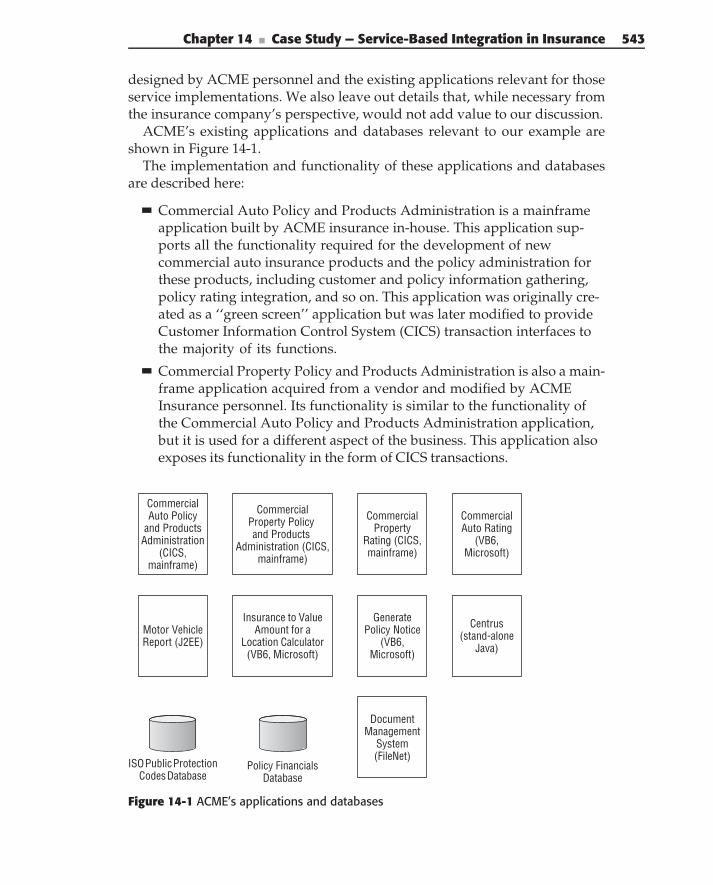
Chapter 14 ■ Case Study — Service-Based Integration in Insurance 543
designed by ACME personnel and the existing applications relevant for thoseservice implementations. We also leave out details that, while necessary fromthe insurance company’s perspective, would not add value to our discussion.
ACME’s existing applications and databases relevant to our example areshown in Figure 14-1.
The implementation and functionality of these applications and databasesare described here:
Commercial Auto Policy and Products Administration is a mainframeapplication built by ACME insurance in-house. This application sup-ports all the functionality required for the development of newcommercial auto insurance products and the policy administration forthese products, including customer and policy information gathering,policy rating integration, and so on. This application was originally cre-ated as a ‘‘green screen’’ application but was later modified to provideCustomer Information Control System (CICS) transaction interfaces tothe majority of its functions.
Commercial Property Policy and Products Administration is also a main-frame application acquired from a vendor and modified by ACMEInsurance personnel. Its functionality is similar to the functionality ofthe Commercial Auto Policy and Products Administration application,but it is used for a different aspect of the business. This application alsoexposes its functionality in the form of CICS transactions.
CommercialAuto Policy
and ProductsAdministration
(CICS,mainframe)
Commercial
Property Policy and Products
Administration (CICS,mainframe)
Motor VehicleReport (J2EE)
CommercialAuto Rating
(VB6,Microsoft)
CommercialProperty
Rating (CICS,mainframe)
Centrus(stand-alone
Java)
ISO Public ProtectionCodes Database
Insurance to ValueAmount for a
Location Calculator(VB6, Microsoft)
GeneratePolicy Notice
(VB6,Microsoft)
Policy FinancialsDatabase
DocumentManagement
System(FileNet)
Figure 14-1 ACME’s applications and databases
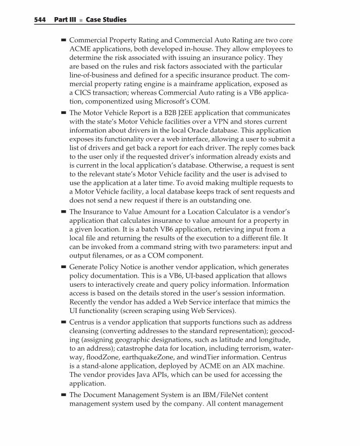
544 Part III ■ Case Studies
Commercial Property Rating and Commercial Auto Rating are two coreACME applications, both developed in-house. They allow employees todetermine the risk associated with issuing an insurance policy. Theyare based on the rules and risk factors associated with the particularline-of-business and defined for a specific insurance product. The com-mercial property rating engine is a mainframe application, exposed asa CICS transaction; whereas Commercial Auto rating is a VB6 applica-tion, componentized using Microsoft’s COM.
The Motor Vehicle Report is a B2B J2EE application that communicateswith the state’s Motor Vehicle facilities over a VPN and stores currentinformation about drivers in the local Oracle database. This applicationexposes its functionality over a web interface, allowing a user to submit alist of drivers and get back a report for each driver. The reply comes backto the user only if the requested driver’s information already exists andis current in the local application’s database. Otherwise, a request is sentto the relevant state’s Motor Vehicle facility and the user is advised touse the application at a later time. To avoid making multiple requests toa Motor Vehicle facility, a local database keeps track of sent requests anddoes not send a new request if there is an outstanding one.
The Insurance to Value Amount for a Location Calculator is a vendor’sapplication that calculates insurance to value amount for a property ina given location. It is a batch VB6 application, retrieving input from alocal file and returning the results of the execution to a different file. Itcan be invoked from a command string with two parameters: input andoutput filenames, or as a COM component.
Generate Policy Notice is another vendor application, which generatespolicy documentation. This is a VB6, UI-based application that allowsusers to interactively create and query policy information. Informationaccess is based on the details stored in the user’s session information.Recently the vendor has added a Web Service interface that mimics theUI functionality (screen scraping using Web Services).
Centrus is a vendor application that supports functions such as addresscleansing (converting addresses to the standard representation); geocod-ing (assigning geographic designations, such as latitude and longitude,to an address); catastrophe data for location, including terrorism, water-way, floodZone, earthquakeZone, and windTier information. Centrusis a stand-alone application, deployed by ACME on an AIX machine.The vendor provides Java APIs, which can be used for accessing theapplication.
The Document Management System is an IBM/FileNet contentmanagement system used by the company. All content management
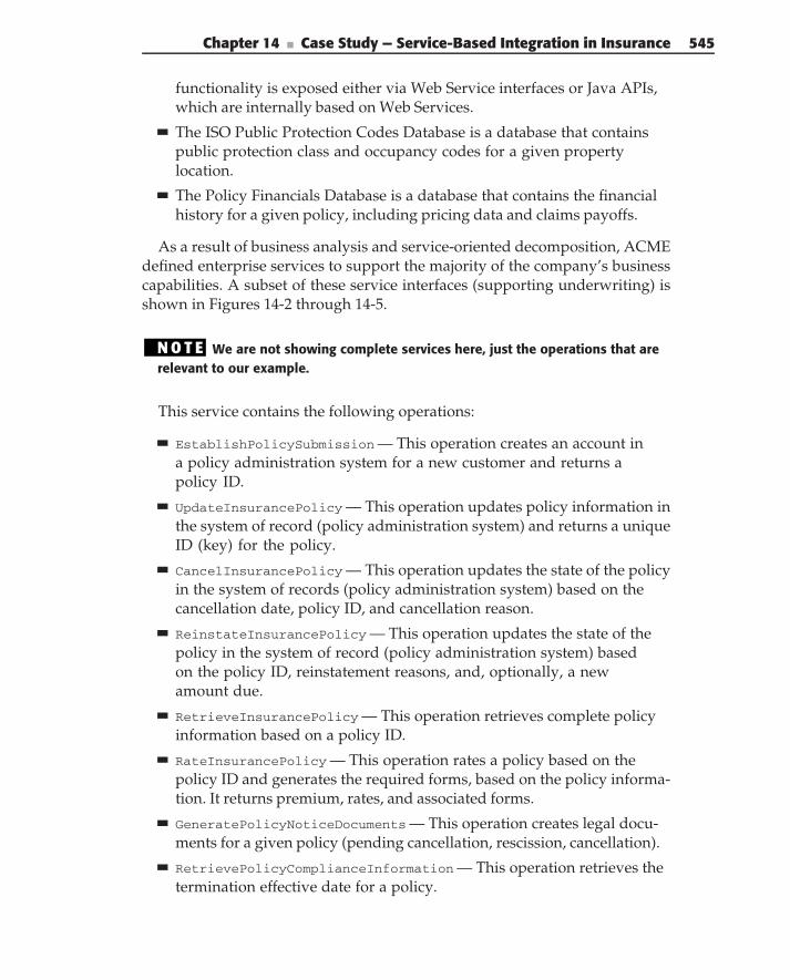
Chapter 14 ■ Case Study — Service-Based Integration in Insurance 545
functionality is exposed either via Web Service interfaces or Java APIs,which are internally based on Web Services.
The ISO Public Protection Codes Database is a database that containspublic protection class and occupancy codes for a given propertylocation.
The Policy Financials Database is a database that contains the financialhistory for a given policy, including pricing data and claims payoffs.
As a result of business analysis and service-oriented decomposition, ACMEdefined enterprise services to support the majority of the company’s businesscapabilities. A subset of these service interfaces (supporting underwriting) isshown in Figures 14-2 through 14-5.
N O T E We are not showing complete services here, just the operations that arerelevant to our example.
This service contains the following operations:
EstablishPolicySubmission — This operation creates an account ina policy administration system for a new customer and returns apolicy ID.
UpdateInsurancePolicy — This operation updates policy information inthe system of record (policy administration system) and returns a uniqueID (key) for the policy.
CancelInsurancePolicy — This operation updates the state of the policyin the system of records (policy administration system) based on thecancellation date, policy ID, and cancellation reason.
ReinstateInsurancePolicy — This operation updates the state of thepolicy in the system of record (policy administration system) basedon the policy ID, reinstatement reasons, and, optionally, a newamount due.
RetrieveInsurancePolicy — This operation retrieves complete policyinformation based on a policy ID.
RateInsurancePolicy — This operation rates a policy based on thepolicy ID and generates the required forms, based on the policy informa-tion. It returns premium, rates, and associated forms.
GeneratePolicyNoticeDocuments — This operation creates legal docu-ments for a given policy (pending cancellation, rescission, cancellation).
RetrievePolicyComplianceInformation — This operation retrieves thetermination effective date for a policy.
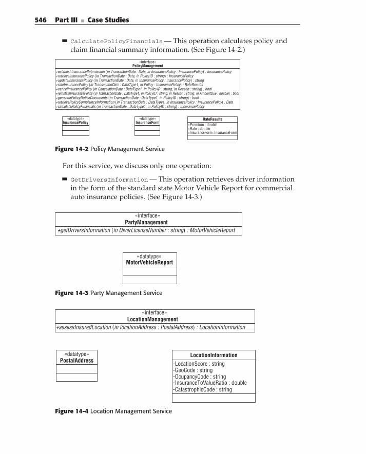
546 Part III ■ Case Studies
CalculatePolicyFinancials — This operation calculates policy andclaim financial summary information. (See Figure 14-2.)
«datatype»InsurancePolicy
+establishInsuranceSubmission (in TransactionDate : Date, in InsurancePolicy : InsurancePolicy) : InsurancePolicy+retrieveInsurancePolicy (in TransactionDate : Date, in PolicyID : string) : InsurancePolicy+updateInsurancePolicy (in TransactionDate : Date, in InsurancePolicy : InsurancePolicy) : string+rateInsurancePolicy (in TransactionDate : DataType1, in Policy : InsurancePolicy) : RateResults+cancelInsurancePolicy (in CancelationDate : DataType1, in PolicyID : string, in Reason : string) : bool+reinstateInsurancePolicy (in TransactionDate : DataType1, in PolicyID : string, in Reason : string, in AmountDue : double) : bool+generatePolicyNoticeDocuments (in TransactionDate : DataType1, in PolicyID : string) : bool+retrievePolicyComplainceInformation (in TransactionDate : DataType1, in InsurancePolicy : InsurancePolicy) : Date+calculatePolicyFinancials (in TransactionDate : DataType1, in PolicyID : string) : InsurancePolicy
«interface»PolicyManagement
«datatype»InsuranceForm +Premium : double
+Rate : double+InsuranceForm :InsuranceForm
RateResults
Figure 14-2 Policy Management Service
For this service, we discuss only one operation:
GetDriversInformation — This operation retrieves driver informationin the form of the standard state Motor Vehicle Report for commercialauto insurance policies. (See Figure 14-3.)
+getDriversInformation (in DiverLicenseNumber : string) : MotorVehicleReport
«interface»PartyManagement
«datatype»MotorVehicleReport
Figure 14-3 Party Management Service
+assessInsuredLocation (in locationAddress : PostalAddress) : LocationInformation
«interface»LocationManagement
«datatype»PostalAddress -LocationScore : string
-GeoCode : string-OcupancyCode : string-InsuranceToValueRatio : double-CatastrophicCode : string
LocationInformation
Figure 14-4 Location Management Service
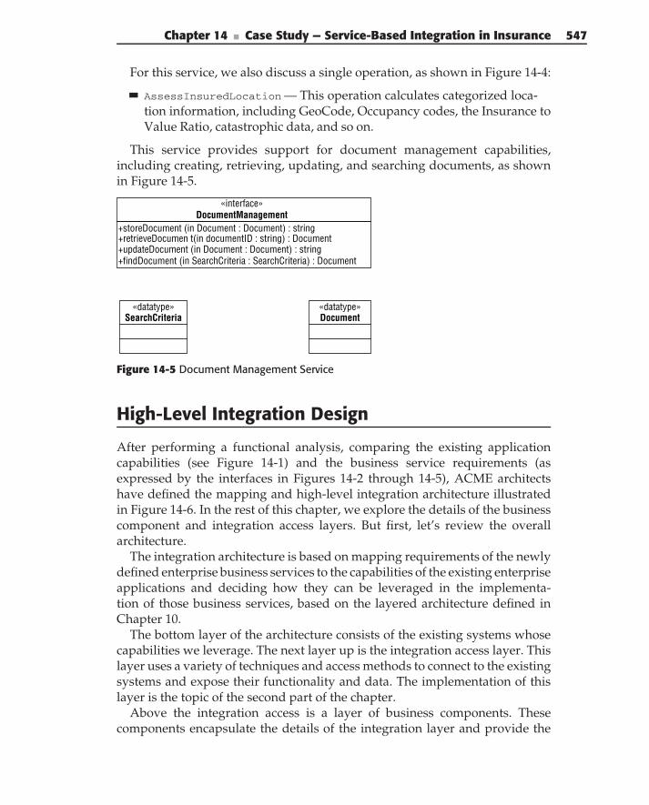
Chapter 14 ■ Case Study — Service-Based Integration in Insurance 547
For this service, we also discuss a single operation, as shown in Figure 14-4:
AssessInsuredLocation — This operation calculates categorized loca-tion information, including GeoCode, Occupancy codes, the Insurance toValue Ratio, catastrophic data, and so on.
This service provides support for document management capabilities,including creating, retrieving, updating, and searching documents, as shownin Figure 14-5.
+storeDocument (in Document : Document) : string+retrieveDocumen t(in documentID : string) : Document+updateDocument (in Document : Document) : string+findDocument (in SearchCriteria : SearchCriteria) : Document
«interface»DocumentManagement
«datatype»Document
«datatype»SearchCriteria
Figure 14-5 Document Management Service
High-Level Integration Design
After performing a functional analysis, comparing the existing applicationcapabilities (see Figure 14-1) and the business service requirements (asexpressed by the interfaces in Figures 14-2 through 14-5), ACME architectshave defined the mapping and high-level integration architecture illustratedin Figure 14-6. In the rest of this chapter, we explore the details of the businesscomponent and integration access layers. But first, let’s review the overallarchitecture.
The integration architecture is based on mapping requirements of the newlydefined enterprise business services to the capabilities of the existing enterpriseapplications and deciding how they can be leveraged in the implementa-tion of those business services, based on the layered architecture defined inChapter 10.
The bottom layer of the architecture consists of the existing systems whosecapabilities we leverage. The next layer up is the integration access layer. Thislayer uses a variety of techniques and access methods to connect to the existingsystems and expose their functionality and data. The implementation of thislayer is the topic of the second part of the chapter.
Above the integration access is a layer of business components. Thesecomponents encapsulate the details of the integration layer and provide the
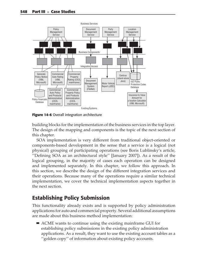
548 Part III ■ Case Studies
PartyManagement
Service
DocumentManagement
Service
Motor VehicleReport (J2EE)
DocumentManagement
System(FileNet)
PolicyManagement
Service
LocationManagement
Service
CommercialAuto Policy
and ProductsAdministration
(CICS,mainframe)
CommercialProperty Policyand Products
Administration(CICS,
mainframe)
CommercialProperty
Rating (CICS,mainframe)
Centrus(stand-alone
Java)
Insurance to ValueAmount for
a location Calculator(VB6, Microsoft)
Policy FinancialsDatabase
Existing Systems
Business Services
CommercialAuto Rating
(VB6,Microsoft)
GeneratePolicy Notice
(VB6,Microsoft)
Integration Access
Business Components
ISO PublicProtection CodesDatabase
Figure 14-6 Overall integration architecture
building blocks for the implementation of the business services in the top layer.The design of the mapping and components is the topic of the next section ofthis chapter.
SOA implementation is very different from traditional object-oriented orcomponents-based development in the sense that a service is a logical (notphysical) grouping of participating operations (see Boris Lublinsky’s article,‘‘Defining SOA as an architectural style’’ [January 2007]). As a result of thelogical grouping, in the majority of cases each operation can be designedand implemented separately. In this chapter, we follow this approach. Inthis section, we describe the design of the different integration services andtheir operations. Because many of the operations require a similar technicalimplementation, we cover the technical implementation aspects together inthe next section.
Establishing Policy SubmissionThis functionality already exists and is supported by policy administrationapplications for auto and commercial property. Several additional assumptionsare made about this business method implementation:
ACME wants to continue using the existing mainframe GUI forestablishing policy submissions in the existing policy administrationapplications. As a result, they want to use the existing account tables as a‘‘golden copy’’ of information about existing policy accounts.
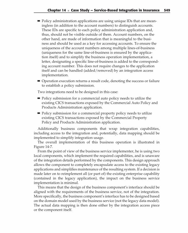
Chapter 14 ■ Case Study — Service-Based Integration in Insurance 549
Policy administration applications are using unique IDs that are mean-ingless (in addition to the account numbers) to distinguish accounts.These IDs are specific to each policy administration application and,thus, should not be visible outside of them. Account numbers, on theother hand, are made of information that is meaningful to the busi-ness and should be used as a key for accessing accounts. To ensure theuniqueness of the account numbers among multiple lines-of-business(uniqueness for the same line-of-business is ensured by the applica-tion itself) and to simplify the business operation implementation, aletter, designating a specific line-of-business is added to the correspond-ing account number. This does not require changes to the applicationitself and can be handled (added/removed) by an integration accessimplementation.
Operation execution returns a result code, denoting the success or failureto establish a policy submission.
Two integrations need to be designed in this case:
Policy submission for a commercial auto policy needs to utilize theexisting CICS transactions exposed by the Commercial Auto Policy andProducts Administration application.
Policy submission for a commercial property policy needs to utilizeexisting CICS transactions exposed by the Commercial PropertyPolicy and Products Administration application.
Additionally business components that wrap integration capabilities,including access to the integration and, potentially, data mapping should beimplemented to simplify integration usage.
The overall implementation of this business operation is illustrated inFigure 14-7.
From the point of view of the business service implementer, he is using twolocal components, which implement the required capabilities, and is unawareof the integration details performed by the components. This design approachallows the component to completely encapsulate access to the existing legacyapplications and simplifies maintenance of the resulting system. If a decision ismade later on to reimplement all (or part of) the existing enterprise capability(contained in the legacy application), the impact on the business serviceimplementation is minimal.
This means that the design of the business component’s interface should bealigned with the requirements of the business service, not of the integration.More specifically, the business component’s interface has to be designed basedon the domain model used by the business service (not the legacy data model).The actual data mapping is then done either by the integration access pieceor the component itself.
550 Part III ■ Case Studies
Receive request
Property or Auto?
Component: Establish PolicySubmission for Commercial
Auto
Component: Establish PolicySubmission for Commercial
Property
Service: Establish PolicySubmission for Commercial
Auto. Access CICSTransaction
Service: Establish PolicySubmission for Commercial
Property. Access CICSTransaction
Return result
AutoProperty
Figure 14-7 EstablishPolicySubmission operation
Both integrations for this operation are implemented through the access tothe CICS transactions on the mainframe. The technical implementation of theintegration is covered later in this chapter.
A similar design applies to several other operations that were identifiedas part of ACME’s business analysis and service decomposition. Theseoperations are:
UpdateInsurancePolicy can be implemented based on two integrationsutilizing existing CICS transactions — update commercial auto policyand update commercial property services. ACME has made a decisionto use existing policy administration applications as a ‘‘golden copy’’ ofthe policy data. As a result this operation requires the complete insur-ance policy, along with the policy identification information — policynumber and effective data — as its input. To ensure uniqueness of policynumbers between lines-of-business and to simplify request routing, a let-ter specifying a line-of-business is appended to the policy number. Theoverall business operation implementation is similar to that depicted inFigure 14-7. This operation returns back an ID for an updated policy.
CancelInsurancePolicy can be implemented based on two integra-tions utilizing existing CICS transactions — cancel commercial auto
Chapter 14 ■ Case Study — Service-Based Integration in Insurance 551
policy and cancel commercial property services. Cancellation is doneusing policy identification information as its input. The overall businessservice implementation is similar to the one, depicted in Figure 14-7.The status returned by the operation defines the success or failure ofexecution.
ReinstateInsurancePolicy can be implemented based on two integra-tions utilizing existing CICS transactions — reinstate commercial autopolicy and reinstate commercial property services. Reinstatement usespolicy identification information as its input. The overall business ser-vice implementation is similar to the one, depicted in Figure 14-7. Thestatus returned by the operation defines the success or failure of serviceexecution.
RetrieveInsurancePolicy can be implemented based on two integra-tions utilizing existing CICS transactions — retrieve commercial autopolicy and retrieve commercial property services. The policy is retrievedbased on the service identification information. The overall businessservice implementation is similar to the one depicted in Figure 14-7.The operation returns a complete insurance policy.
Rate Insurance PolicyThe capability for this operation already exists in two applications —commercial property rating and commercial auto rating. This operation ispurely a calculation; it executes a set of rules (that are different for differentlines-of-business and are contained in existing applications). The rules areused for calculating premiums, rates, and forms. RateInsurancePolicy takesan insurance policy, including the account information, terms and conditions,as input and returns calculated premiums.
Two integrations have to be designed to support this operation:
The RateCommercialProperty integration can utilize existing CICS trans-actions exposed by the Commercial property rating application.
The RateAutoPolicy integration can utilize existing COM componentsexposed by the Auto policy rating application.
Business components that wrap the integration access further simplifythe business operation implementation. The overall implementation of thisbusiness operation is presented in Figure 14-8.
We describe the technical implementation of integration with CICS transac-tions and COM components later in this chapter.
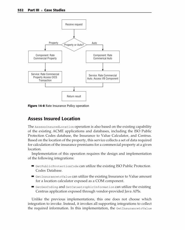
552 Part III ■ Case Studies
Receive request
Property or Auto?
Component: RateCommerical Auto
Component: RateCommercial Property
Service: Rate CommercialAuto. Access VB Component
Service: Rate CommercialProperty Access CICS
Transaction
Return result
AutoProperty
Figure 14-8 Rate Insurance Policy operation
Assess Insured Location
The AssessInsuredLocation operation is also based on the existing capabilityof the existing ACME applications and databases, including the ISO PublicProtection Codes database, the Insurance to Value Calculator, and Centrus.Based on the location of the property, this service collects a set of data requiredfor calculation of the insurance premiums for a commercial property at a givenlocation.
Implementation of this operation requires the design and implementationof the following integrations:
GetPublicProtectionCode can utilize the existing ISO Public ProtectionCodes Database.
GetInsurancetoValue can utilize the existing Insurance to Value amountfor a location calculator exposed as a COM component.
GetGeoCoding and GetCatastrophicInformation can utilize the existingCentrus application exposed through vendor-provided Java APIs.
Unlike the previous implementations, this one does not choose whichintegration to invoke. Instead, it invokes all supporting integrations to collectthe required information. In this implementation, the GetInsurancetoValue
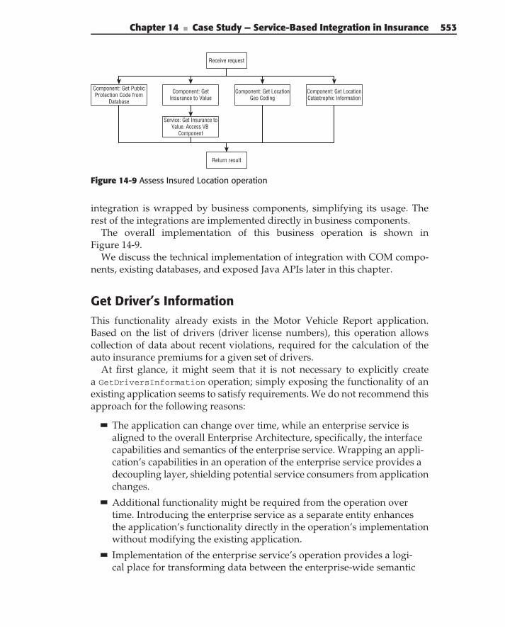
Chapter 14 ■ Case Study — Service-Based Integration in Insurance 553
Receive request
Return result
Component: Get Insurance to Value
Component: Get PublicProtection Code from
Database
Service: Get Insurance toValue. Access VB
Component
Component: Get LocationGeo Coding
Component: Get LocationCatastrophic Information
Figure 14-9 Assess Insured Location operation
integration is wrapped by business components, simplifying its usage. Therest of the integrations are implemented directly in business components.
The overall implementation of this business operation is shown inFigure 14-9.
We discuss the technical implementation of integration with COM compo-nents, existing databases, and exposed Java APIs later in this chapter.
Get Driver’s InformationThis functionality already exists in the Motor Vehicle Report application.Based on the list of drivers (driver license numbers), this operation allowscollection of data about recent violations, required for the calculation of theauto insurance premiums for a given set of drivers.
At first glance, it might seem that it is not necessary to explicitly createa GetDriversInformation operation; simply exposing the functionality of anexisting application seems to satisfy requirements. We do not recommend thisapproach for the following reasons:
The application can change over time, while an enterprise service isaligned to the overall Enterprise Architecture, specifically, the interfacecapabilities and semantics of the enterprise service. Wrapping an appli-cation’s capabilities in an operation of the enterprise service provides adecoupling layer, shielding potential service consumers from applicationchanges.
Additional functionality might be required from the operation overtime. Introducing the enterprise service as a separate entity enhancesthe application’s functionality directly in the operation’s implementationwithout modifying the existing application.
Implementation of the enterprise service’s operation provides a logi-cal place for transforming data between the enterprise-wide semantic
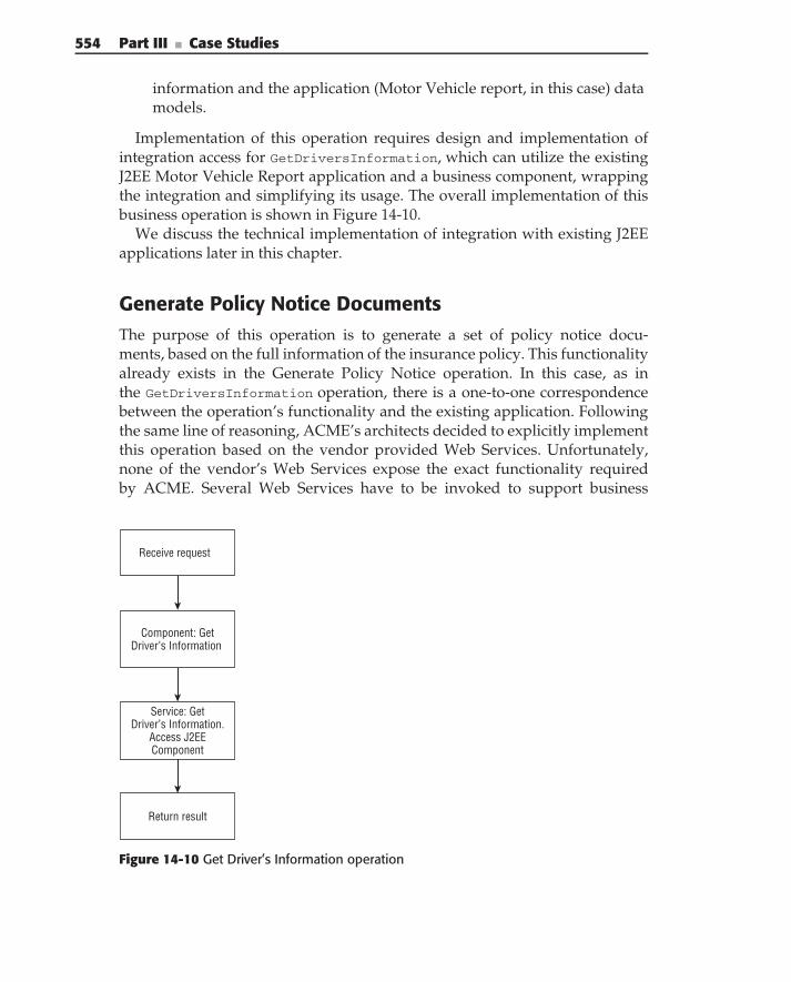
554 Part III ■ Case Studies
information and the application (Motor Vehicle report, in this case) datamodels.
Implementation of this operation requires design and implementation ofintegration access for GetDriversInformation, which can utilize the existingJ2EE Motor Vehicle Report application and a business component, wrappingthe integration and simplifying its usage. The overall implementation of thisbusiness operation is shown in Figure 14-10.
We discuss the technical implementation of integration with existing J2EEapplications later in this chapter.
Generate Policy Notice DocumentsThe purpose of this operation is to generate a set of policy notice docu-ments, based on the full information of the insurance policy. This functionalityalready exists in the Generate Policy Notice operation. In this case, as inthe GetDriversInformation operation, there is a one-to-one correspondencebetween the operation’s functionality and the existing application. Followingthe same line of reasoning, ACME’s architects decided to explicitly implementthis operation based on the vendor provided Web Services. Unfortunately,none of the vendor’s Web Services expose the exact functionality requiredby ACME. Several Web Services have to be invoked to support business
Receive request
Return result
Component: GetDriver’s Information
Service: GetDriver’s Information.
Access J2EEComponent
Figure 14-10 Get Driver’s Information operation
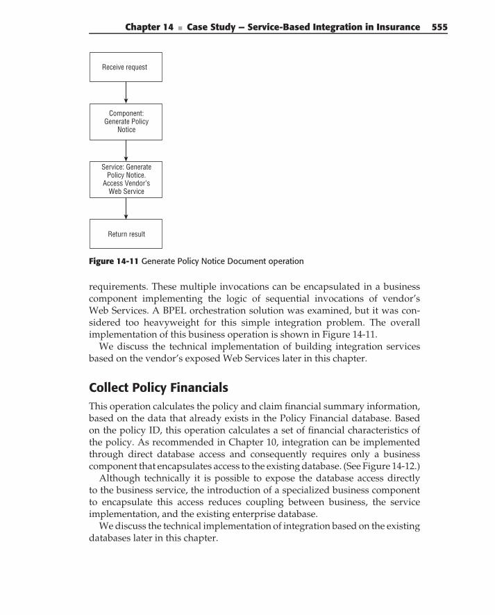
Chapter 14 ■ Case Study — Service-Based Integration in Insurance 555
Receive request
Return result
Component:Generate Policy
Notice
Service: GeneratePolicy Notice.
Access Vendor’sWeb Service
Figure 14-11 Generate Policy Notice Document operation
requirements. These multiple invocations can be encapsulated in a businesscomponent implementing the logic of sequential invocations of vendor’sWeb Services. A BPEL orchestration solution was examined, but it was con-sidered too heavyweight for this simple integration problem. The overallimplementation of this business operation is shown in Figure 14-11.
We discuss the technical implementation of building integration servicesbased on the vendor’s exposed Web Services later in this chapter.
Collect Policy FinancialsThis operation calculates the policy and claim financial summary information,based on the data that already exists in the Policy Financial database. Basedon the policy ID, this operation calculates a set of financial characteristics ofthe policy. As recommended in Chapter 10, integration can be implementedthrough direct database access and consequently requires only a businesscomponent that encapsulates access to the existing database. (See Figure 14-12.)
Although technically it is possible to expose the database access directlyto the business service, the introduction of a specialized business componentto encapsulate this access reduces coupling between business, the serviceimplementation, and the existing enterprise database.
We discuss the technical implementation of integration based on the existingdatabases later in this chapter.
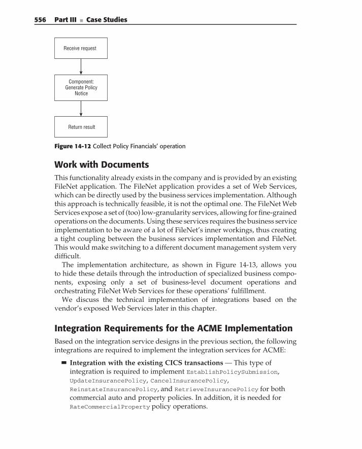
556 Part III ■ Case Studies
Receive request
Return result
Component:Generate Policy
Notice
Figure 14-12 Collect Policy Financials’ operation
Work with DocumentsThis functionality already exists in the company and is provided by an existingFileNet application. The FileNet application provides a set of Web Services,which can be directly used by the business services implementation. Althoughthis approach is technically feasible, it is not the optimal one. The FileNet WebServices expose a set of (too) low-granularity services, allowing for fine-grainedoperations on the documents. Using these services requires the business serviceimplementation to be aware of a lot of FileNet’s inner workings, thus creatinga tight coupling between the business services implementation and FileNet.This would make switching to a different document management system verydifficult.
The implementation architecture, as shown in Figure 14-13, allows youto hide these details through the introduction of specialized business compo-nents, exposing only a set of business-level document operations andorchestrating FileNet Web Services for these operations’ fulfillment.
We discuss the technical implementation of integrations based on thevendor’s exposed Web Services later in this chapter.
Integration Requirements for the ACME ImplementationBased on the integration service designs in the previous section, the followingintegrations are required to implement the integration services for ACME:
Integration with the existing CICS transactions — This type ofintegration is required to implement EstablishPolicySubmission,UpdateInsurancePolicy, CancelInsurancePolicy,ReinstateInsurancePolicy, and RetrieveInsurancePolicy for bothcommercial auto and property policies. In addition, it is needed forRateCommercialProperty policy operations.
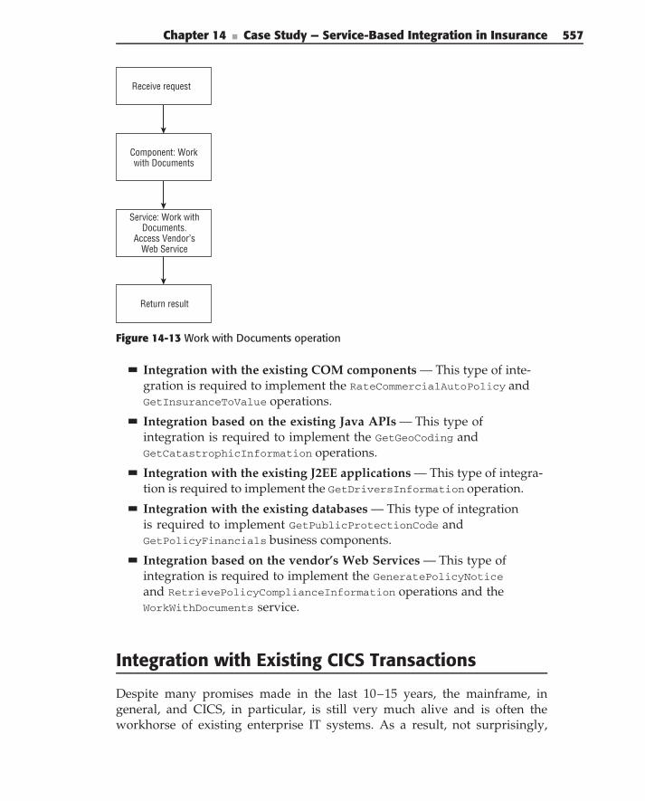
Chapter 14 ■ Case Study — Service-Based Integration in Insurance 557
Receive request
Return result
Component: Workwith Documents
Service: Work withDocuments.
Access Vendor’sWeb Service
Figure 14-13 Work with Documents operation
Integration with the existing COM components — This type of inte-gration is required to implement the RateCommercialAutoPolicy andGetInsuranceToValue operations.
Integration based on the existing Java APIs — This type ofintegration is required to implement the GetGeoCoding andGetCatastrophicInformation operations.
Integration with the existing J2EE applications — This type of integra-tion is required to implement the GetDriversInformation operation.
Integration with the existing databases — This type of integrationis required to implement GetPublicProtectionCode andGetPolicyFinancials business components.
Integration based on the vendor’s Web Services — This type ofintegration is required to implement the GeneratePolicyNotice
and RetrievePolicyComplianceInformation operations and theWorkWithDocuments service.
Integration with Existing CICS Transactions
Despite many promises made in the last 10–15 years, the mainframe, ingeneral, and CICS, in particular, is still very much alive and is often theworkhorse of existing enterprise IT systems. As a result, not surprisingly,
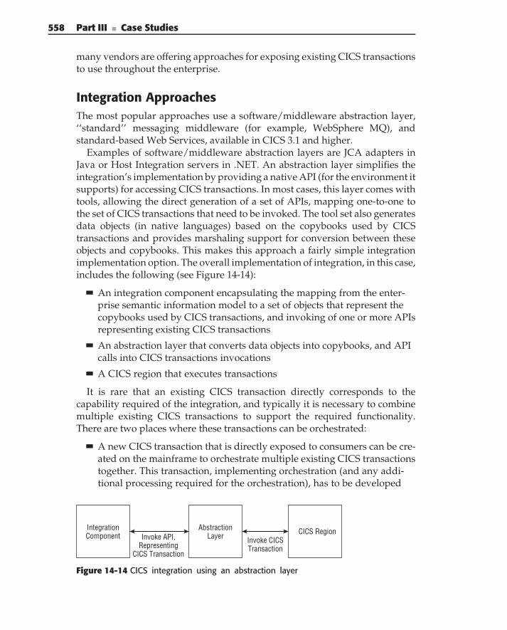
558 Part III ■ Case Studies
many vendors are offering approaches for exposing existing CICS transactionsto use throughout the enterprise.
Integration ApproachesThe most popular approaches use a software/middleware abstraction layer,‘‘standard’’ messaging middleware (for example, WebSphere MQ), andstandard-based Web Services, available in CICS 3.1 and higher.
Examples of software/middleware abstraction layers are JCA adapters inJava or Host Integration servers in .NET. An abstraction layer simplifies theintegration’s implementation by providing a native API (for the environment itsupports) for accessing CICS transactions. In most cases, this layer comes withtools, allowing the direct generation of a set of APIs, mapping one-to-one tothe set of CICS transactions that need to be invoked. The tool set also generatesdata objects (in native languages) based on the copybooks used by CICStransactions and provides marshaling support for conversion between theseobjects and copybooks. This makes this approach a fairly simple integrationimplementation option. The overall implementation of integration, in this case,includes the following (see Figure 14-14):
An integration component encapsulating the mapping from the enter-prise semantic information model to a set of objects that represent thecopybooks used by CICS transactions, and invoking of one or more APIsrepresenting existing CICS transactions
An abstraction layer that converts data objects into copybooks, and APIcalls into CICS transactions invocations
A CICS region that executes transactions
It is rare that an existing CICS transaction directly corresponds to thecapability required of the integration, and typically it is necessary to combinemultiple existing CICS transactions to support the required functionality.There are two places where these transactions can be orchestrated:
A new CICS transaction that is directly exposed to consumers can be cre-ated on the mainframe to orchestrate multiple existing CICS transactionstogether. This transaction, implementing orchestration (and any addi-tional processing required for the orchestration), has to be developed
IntegrationComponent
AbstractionLayer CICS Region
Invoke API,Representing
CICS Transaction
Invoke CICSTransaction
Figure 14-14 CICS integration using an abstraction layer
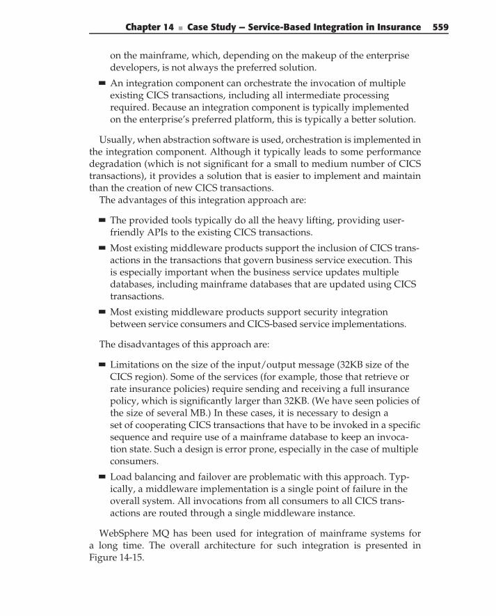
Chapter 14 ■ Case Study — Service-Based Integration in Insurance 559
on the mainframe, which, depending on the makeup of the enterprisedevelopers, is not always the preferred solution.
An integration component can orchestrate the invocation of multipleexisting CICS transactions, including all intermediate processingrequired. Because an integration component is typically implementedon the enterprise’s preferred platform, this is typically a better solution.
Usually, when abstraction software is used, orchestration is implemented inthe integration component. Although it typically leads to some performancedegradation (which is not significant for a small to medium number of CICStransactions), it provides a solution that is easier to implement and maintainthan the creation of new CICS transactions.
The advantages of this integration approach are:
The provided tools typically do all the heavy lifting, providing user-friendly APIs to the existing CICS transactions.
Most existing middleware products support the inclusion of CICS trans-actions in the transactions that govern business service execution. Thisis especially important when the business service updates multipledatabases, including mainframe databases that are updated using CICStransactions.
Most existing middleware products support security integrationbetween service consumers and CICS-based service implementations.
The disadvantages of this approach are:
Limitations on the size of the input/output message (32KB size of theCICS region). Some of the services (for example, those that retrieve orrate insurance policies) require sending and receiving a full insurancepolicy, which is significantly larger than 32KB. (We have seen policies ofthe size of several MB.) In these cases, it is necessary to design aset of cooperating CICS transactions that have to be invoked in a specificsequence and require use of a mainframe database to keep an invoca-tion state. Such a design is error prone, especially in the case of multipleconsumers.
Load balancing and failover are problematic with this approach. Typ-ically, a middleware implementation is a single point of failure in theoverall system. All invocations from all consumers to all CICS trans-actions are routed through a single middleware instance.
WebSphere MQ has been used for integration of mainframe systems fora long time. The overall architecture for such integration is presented inFigure 14-15.
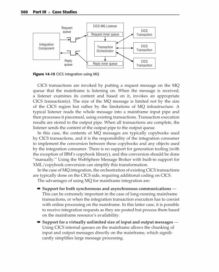
560 Part III ■ Case Studies
IntegrationComponent
Request queue
Reply queue
CICS MQ Listener
Transaction Orchestrator
CICS Transaction
CICS Transaction
CICS Transaction
Request inner queue
Reply inner queue
Figure 14-15 CICS integration using MQ
CICS transactions are invoked by putting a request message on the MQqueue that the mainframe is listening on. When the message is received,a listener examines its content and based on it, invokes an appropriateCICS transaction(s). The size of the MQ message is limited not by the sizeof the CICS region but rather by the limitations of MQ infrastructure. Atypical listener reads the whole message into a mainframe input pipe andthen processes it piecemeal, using existing transactions. Transaction executionresults are stored to the output pipe. When all transactions are complete, thelistener sends the content of the output pipe to the output queue.
In this case, the contents of MQ messages are typically copybooks usedby CICS transactions, and it is the responsibility of the integration consumerto implement the conversion between these copybooks and any objects usedby the integration consumer. There is no support for generation tooling (withthe exception of IBM’s copybook library), and this conversion should be done‘‘manually.’’ Using the WebSphere Message Broker with built-in support forXML/copybook conversion can simplify this transformation.
In the case of MQ integration, the orchestration of existing CICS transactionsare typically done on the CICS side, requiring additional coding on CICS.
The advantages of using MQ for mainframe integration are:
Support for both synchronous and asynchronous communications —This can be extremely important in the case of long-running mainframetransactions, or when the integration transaction execution has to coexistwith online processing on the mainframe. In this latter case, it is possibleto receive integration requests as they are posted but process them basedon the mainframe resource’s availability.
Support for a virtually unlimited size of input and output messages —Using CICS internal queues on the mainframe allows the chunking ofinput and output messages directly on the mainframe, which signifi-cantly simplifies large message processing.
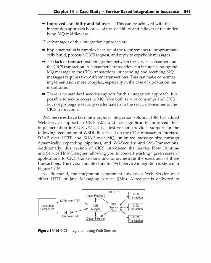
Chapter 14 ■ Case Study — Service-Based Integration in Insurance 561
Improved scalability and failover — This can be achieved with thisintegration approach because of the scalability and failover of the under-lying MQ middleware.
Disadvantages of this integration approach are:
Implementation is complex because of the requirements to programmati-cally build, process a CICS request, and reply to copybook messages.
The lack of transactional integration between the service consumer andthe CICS transaction. A consumer’s transaction can include sending theMQ message to the CICS transactions, but sending and receiving MQmessages requires two different transactions. This can make consumerimplementation more complex, especially in the case of updates on themainframe.
There is no standard security support for this integration approach. It ispossible to secure access to MQ from both service consumer and CICSbut not propagate security credentials from the service consumer to theCICS transaction.
Web Services have become a popular integration solution. IBM has addedWeb Service support in CICS v2.1, and has significantly improved theirimplementation in CICS v3.1. This latest version provides support for thefollowing: generation of WSDL files based on the CICS transaction interface,SOAP over HTTP and SOAP over MQ, unlimited message size throughdynamically expanding pipelines, and WS-Security and WS-Transactions.Additionally, this version of CICS introduced the Service Flow Runtimeand Service Flow Designer, allowing you to convert existing ‘‘green screen’’applications to CICS transactions and to orchestrate the execution of thesetransactions. The overall architecture for Web Service integration is shown inFigure 14-16.
As illustrated, the integration component invokes a Web Service overeither HTTP or Java Messaging Service (JMS). A request is delivered to
Integration Component
SOAP over HTTP
SOAP over JMS
CICS Transaction
CICS Transaction
CICS Transaction
URI Mapper
Output Pipeline
CICS v3.1Input Pipeline
CICS Service
Flow
Figure 14-16 CICS integration using Web Services
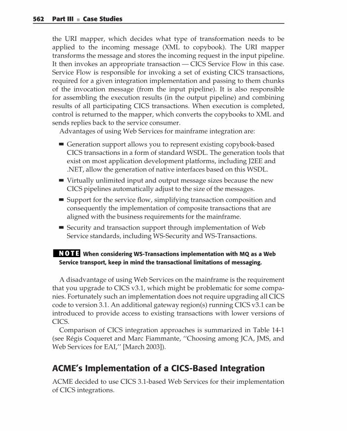
562 Part III ■ Case Studies
the URI mapper, which decides what type of transformation needs to beapplied to the incoming message (XML to copybook). The URI mappertransforms the message and stores the incoming request in the input pipeline.It then invokes an appropriate transaction — CICS Service Flow in this case.Service Flow is responsible for invoking a set of existing CICS transactions,required for a given integration implementation and passing to them chunksof the invocation message (from the input pipeline). It is also responsiblefor assembling the execution results (in the output pipeline) and combiningresults of all participating CICS transactions. When execution is completed,control is returned to the mapper, which converts the copybooks to XML andsends replies back to the service consumer.
Advantages of using Web Services for mainframe integration are:
Generation support allows you to represent existing copybook-basedCICS transactions in a form of standard WSDL. The generation tools thatexist on most application development platforms, including J2EE and.NET, allow the generation of native interfaces based on this WSDL.
Virtually unlimited input and output message sizes because the newCICS pipelines automatically adjust to the size of the messages.
Support for the service flow, simplifying transaction composition andconsequently the implementation of composite transactions that arealigned with the business requirements for the mainframe.
Security and transaction support through implementation of WebService standards, including WS-Security and WS-Transactions.
N O T E When considering WS-Transactions implementation with MQ as a WebService transport, keep in mind the transactional limitations of messaging.
A disadvantage of using Web Services on the mainframe is the requirementthat you upgrade to CICS v3.1, which might be problematic for some compa-nies. Fortunately such an implementation does not require upgrading all CICScode to version 3.1. An additional gateway region(s) running CICS v3.1 can beintroduced to provide access to existing transactions with lower versions ofCICS.
Comparison of CICS integration approaches is summarized in Table 14-1(see Regis Coqueret and Marc Fiammante, ‘‘Choosing among JCA, JMS, andWeb Services for EAI,’’ [March 2003]).
ACME’s Implementation of a CICS-Based IntegrationACME decided to use CICS 3.1-based Web Services for their implementationof CICS integrations.
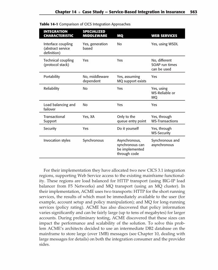
Chapter 14 ■ Case Study — Service-Based Integration in Insurance 563
Table 14-1 Comparison of CICS Integration Approaches
INTEGRATION SPECIALIZEDCHARACTERISTIC MIDDLEWARE MQ WEB SERVICES
Interface coupling(abstract servicedefinition)
Yes, generationbased
No Yes, using WSDL
Technical coupling(protocol stack)
Yes Yes No, differentSOAP run timescan be used
Portability No, middlewaredependent
Yes, assumingMQ support exists
Yes
Reliability No Yes Yes, usingWS-Reliable orMQ
Load balancing andfailover
No Yes Yes
TransactionalSupport
Yes, XA Only to thequeue entry point
Yes, throughWS-Transactions
Security Yes Do it yourself Yes, throughWS-Security
Invocation styles Synchronous Asynchronous,synchronous canbe implementedthrough code
Synchronous andasynchronous
For their implementation they have allocated two new CICS 3.1 integrationregions, supporting Web Service access to the existing mainframe functional-ity. These regions are load balanced for HTTP transport (using BIG-IP loadbalancer from F5 Networks) and MQ transport (using an MQ cluster). Intheir implementation, ACME uses two transports: HTTP for the short runningservices, the results of which must be immediately available to the user (forexample, account setup and policy manipulation); and MQ for long-runningservices (policy rating). ACME has also discovered that policy informationvaries significantly and can be fairly large (up to tens of megabytes) for largeraccounts. During preliminary testing, ACME discovered that these sizes canimpact the performance and scalability of the solution. To solve this prob-lem ACME’s architects decided to use an intermediate DB2 database on themainframe to store large (over 1MB) messages (see Chapter 10, dealing withlarge messages for details) on both the integration consumer and the providersides.
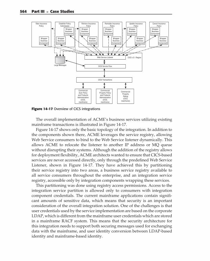
564 Part III ■ Case Studies
CICS v3.1 Region
CommercialAuto Policy
and ProductsAdministration
(CICS,mainframe)
CommercialProperty Policyand Products
Administration(CICS,
mainframe)
CommercialPropertyRating(CICS,
mainframe)
CICS Transactions
CICS Service Flow
Establish PolicySubmission
Large Messages
Retrieve InsurancePolicy
Reinstate InsurancePolicy
Update InsurancePolicy
Cancel InsurancePolicy
Rate InsurancePolicy
WrapperBusiness
Component
WrapperBusiness
Component
WrapperBusiness
Component
WrapperBusiness
Component
WrapperBusiness
Component
WrapperBusiness
Component
WrapperBusiness
Component
WrapperBusiness
Component
WrapperBusiness
Component
WrapperBusiness
Component
WrapperBusiness
Component
Web Service Listener
Figure 14-17 Overview of CICS integrations
The overall implementation of ACME’s business services utilizing existingmainframe transactions is illustrated in Figure 14-17.
Figure 14-17 shows only the basic topology of the integration. In addition tothe components shown there, ACME leverages the service registry, allowingWeb Service consumers to bind to the Web Service listener dynamically. Thisallows ACME to relocate the listener to another IP address or MQ queuewithout disrupting their systems. Although the addition of the registry allowsfor deployment flexibility, ACME architects wanted to ensure that CICS-basedservices are never accessed directly, only through the predefined Web ServiceListener, shown in Figure 14-17. They have achieved this by partitioningtheir service registry into two areas, a business service registry available toall service consumers throughout the enterprise, and an integration serviceregistry, accessible only by integration components wrapping these services.
This partitioning was done using registry access permissions. Access to theintegration service partition is allowed only to consumers with integrationcomponent credentials. The current mainframe applications contain signifi-cant amounts of sensitive data, which means that security is an importantconsideration of the overall integration solution. One of the challenges is thatuser credentials used by the service implementation are based on the corporateLDAP, which is different from the mainframe user credentials which are storedin a mainframe RACF system. This means that the security architecture forthis integration needs to support both securing messages used for exchangingdata with the mainframe, and user identity conversion between LDAP-basedidentity and mainframe-based identity.
Chapter 14 ■ Case Study — Service-Based Integration in Insurance 565
Based on the SOA security techniques, described in Chapter 11, ACMEarchitects decided to use WS-Security support (provided by IBM’s Web Serviceimplementation for CICS) to do both message encryption and identity tokenpropagation. They also used Tivoli Federated Identity Manager (TFIM) toimplement identity conversion between Kerberos tokens (standardized byACME as an identity token) and the Passtickets used by the mainframe.
One of the biggest challenges for any integration implementation is errorhandling and logging. In order to implement an overall exception-loggingarchitecture, described in Chapter 9, ACME architects did the following:
Designed integration service interfaces in a way that allowed them toreturn any exception information to the Web Service consumers.
Designed and implemented a daemon (for the mainframe environment)that periodically scans existing mainframe logs and submits their infor-mation (appropriately converted) to a centralized logging service. Suchan approach allows them to keep the existing logging mechanism inCICS transactions (minimize required changes), while centralizing theirprocessing through a centralized service.
Typically, integration services do not participate in the overall BAM solu-tions, and the mainframe integrations designed by ACME are no exception.Technical monitoring, on the other hand, is required for all services. Follow-ing the overall architecture, described in Chapter 9, the decision was madeto instrument integration components with service monitoring/managementagents.
Integration with the Existing COM Components
The most popular approach for integration with COM components today isto use a Web Service facade for the legacy applications. The basic designguidelines and implementation considerations for this approach are outlinedin ‘‘Web Service Facade for Legacy Applications,’’ Microsoft Patterns andPractice, June 2003.
The overall architecture for this integration type (which is shown inFigure 14-18) relies heavily on two technologies from Microsoft. The .NET/COM bridge, allowing automatic wrapper creation for existing COM compo-nents (which results in the ability to treat them like an ordinary .NET class,for example C# class), and Visual Studio with its ability to easily expose thelanguage (for example C#) class as a Web Service.
When implementing this type of integration, it is important to correctly mapexisting COM components to the integration Web Services. Considering thatCOM interfaces are local and create very little communications latency, while
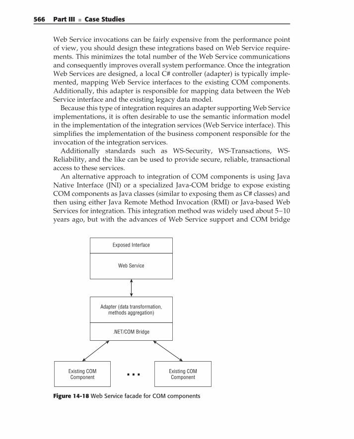
566 Part III ■ Case Studies
Web Service invocations can be fairly expensive from the performance pointof view, you should design these integrations based on Web Service require-ments. This minimizes the total number of the Web Service communicationsand consequently improves overall system performance. Once the integrationWeb Services are designed, a local C# controller (adapter) is typically imple-mented, mapping Web Service interfaces to the existing COM components.Additionally, this adapter is responsible for mapping data between the WebService interface and the existing legacy data model.
Because this type of integration requires an adapter supporting Web Serviceimplementations, it is often desirable to use the semantic information modelin the implementation of the integration services (Web Service interface). Thissimplifies the implementation of the business component responsible for theinvocation of the integration services.
Additionally standards such as WS-Security, WS-Transactions, WS-Reliability, and the like can be used to provide secure, reliable, transactionalaccess to these services.
An alternative approach to integration of COM components is using JavaNative Interface (JNI) or a specialized Java-COM bridge to expose existingCOM components as Java classes (similar to exposing them as C# classes) andthen using either Java Remote Method Invocation (RMI) or Java-based WebServices for integration. This integration method was widely used about 5–10years ago, but with the advances of Web Service support and COM bridge
Web Service
Exposed Interface
Adapter (data transformation,methods aggregation)
.NET/COM Bridge
Existing COMComponent
Existing COMComponent
Figure 14-18 Web Service facade for COM components
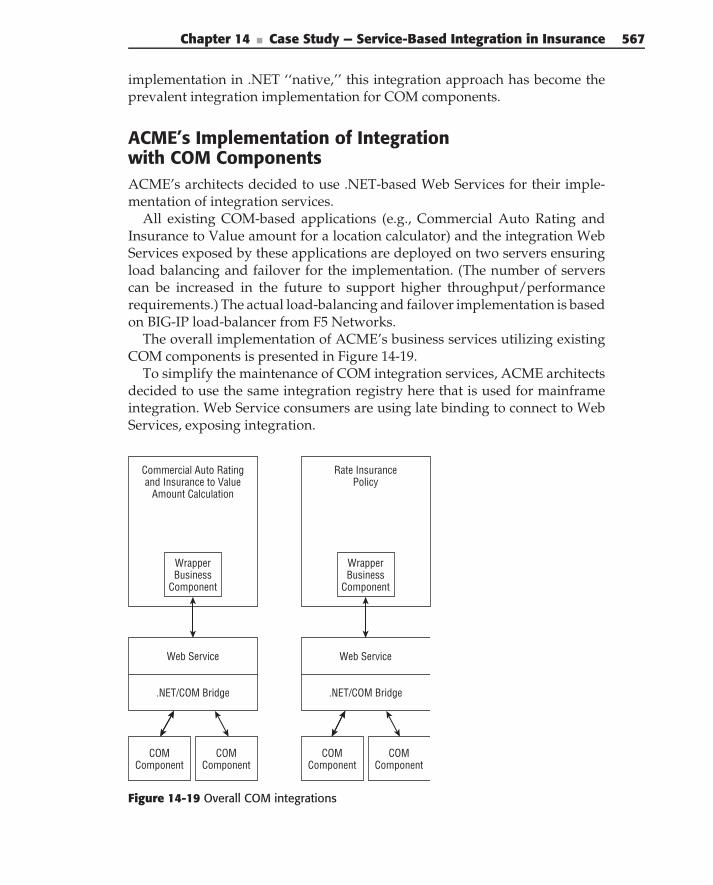
Chapter 14 ■ Case Study — Service-Based Integration in Insurance 567
implementation in .NET ‘‘native,’’ this integration approach has become theprevalent integration implementation for COM components.
ACME’s Implementation of Integrationwith COM ComponentsACME’s architects decided to use .NET-based Web Services for their imple-mentation of integration services.
All existing COM-based applications (e.g., Commercial Auto Rating andInsurance to Value amount for a location calculator) and the integration WebServices exposed by these applications are deployed on two servers ensuringload balancing and failover for the implementation. (The number of serverscan be increased in the future to support higher throughput/performancerequirements.) The actual load-balancing and failover implementation is basedon BIG-IP load-balancer from F5 Networks.
The overall implementation of ACME’s business services utilizing existingCOM components is presented in Figure 14-19.
To simplify the maintenance of COM integration services, ACME architectsdecided to use the same integration registry here that is used for mainframeintegration. Web Service consumers are using late binding to connect to WebServices, exposing integration.
Commercial Auto Ratingand Insurance to Value
Amount Calculation
WrapperBusiness
Component
WrapperBusiness
Component
Rate InsurancePolicy
Web Service
.NET/COM Bridge
COMComponent
COMComponent
Web Service
.NET/COM Bridge
COMComponent
COMComponent
Figure 14-19 Overall COM integrations
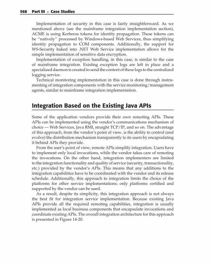
568 Part III ■ Case Studies
Implementation of security in this case is fairly straightforward. As wementioned above (see the mainframe integration implementation section),ACME is using Kerberos tokens for identity propagation. These tokens canbe ‘‘natively’’ processed by Windows-based Web Services, thus simplifyingidentity propagation to COM components. Additionally, the support forWS-Security baked into .NET Web Service implementation allows for thesimple implementation of sensitive data encryption.
Implementation of exception handling, in this case, is similar to the caseof mainframe integration. Existing exception logs are left in place and aspecialized daemon is created to send the content of these logs to the centralizedlogging service.
Technical monitoring implementation in this case is done through instru-menting of integration components with the service monitoring/managementagents, similar to mainframe integration implementation.
Integration Based on the Existing Java APIs
Some of the application vendors provide their own remoting APIs. TheseAPIs can be implemented using the vendor’s communications mechanism ofchoice — Web Services, Java RMI, straight TCP/IP, and so on. The advantageof this approach, from the vendor’s point of view, is the ability to control (andevolve) the distribution mechanism transparently to its users by encapsulatingit behind APIs they provide.
From the user’s point of view, remote APIs simplify integration. Users haveto implement only local invocations, while the vendor takes care of remotingthe invocations. On the other hand, integration implementers are limitedto the integration functionality and quality of service (security, transactionality,etc.) provided by the vendor’s APIs. This means that any additions to theintegration capabilities have to be coordinated with the vendor and its releaseschedule. Additionally, this approach to integration limits the choice of theplatforms for other service implementations; only platforms certified andsupported by the vendor can be used.
As a result, despite its simplicity, this integration approach is not alwaysthe best fit for integration service implementation. Because existing JavaAPIs provide all the required remoting capabilities, integration is usuallyimplemented as local business components that encapsulate invocations andcoordinate existing APIs. The overall integration architecture for this approachis presented in Figure 14-20.
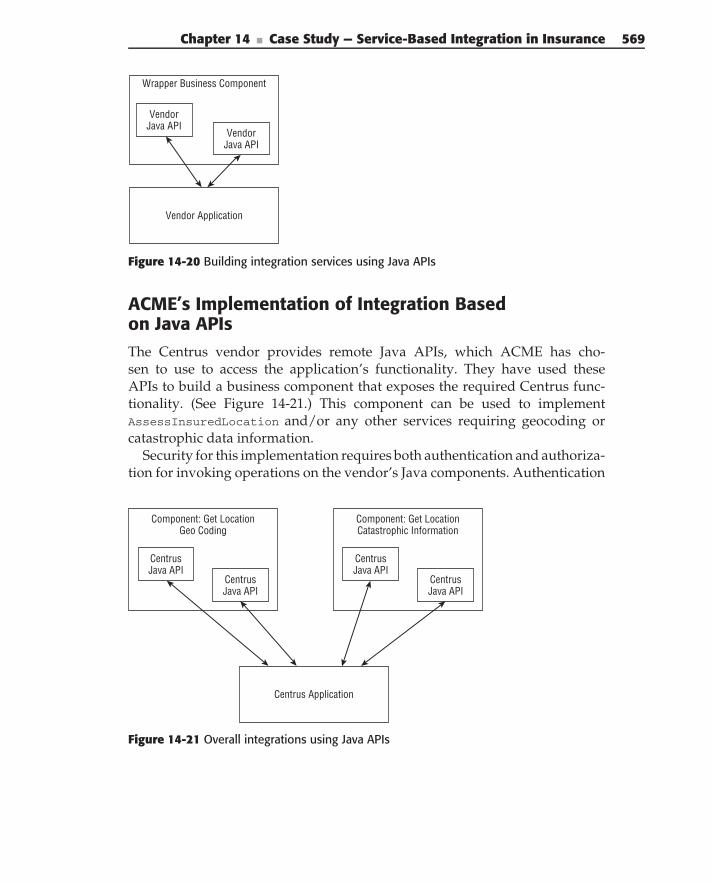
Chapter 14 ■ Case Study — Service-Based Integration in Insurance 569
Wrapper Business Component
VendorJava API
VendorJava API
Vendor Application
Figure 14-20 Building integration services using Java APIs
ACME’s Implementation of Integration Basedon Java APIsThe Centrus vendor provides remote Java APIs, which ACME has cho-sen to use to access the application’s functionality. They have used theseAPIs to build a business component that exposes the required Centrus func-tionality. (See Figure 14-21.) This component can be used to implementAssessInsuredLocation and/or any other services requiring geocoding orcatastrophic data information.
Security for this implementation requires both authentication and authoriza-tion for invoking operations on the vendor’s Java components. Authentication
Component: Get LocationGeo Coding
Component: Get LocationCatastrophic Information
CentrusJava API
CentrusJava API
CentrusJava API
CentrusJava API
Centrus Application
Figure 14-21 Overall integrations using Java APIs
570 Part III ■ Case Studies
requires mapping the enterprise user’s identity to the identity understood bythe application (typically username and password), much like the mainframeintegration approach. ACME architects decided to use TFIM to support thissecurity goal. Authorization is achieved by implementing authorization atthe boundary of an integration component, allowing only users with spe-cific roles to execute certain components. This authorization can be easilyimplemented using the standard Java security model, where you configureRole-Based Access Control (RBAC) security on operations of Java components,and as such, this functionality does not require any approaches specific to WebServices.
Exception handling is typically limited to the exception handling of remoteJava APIs. Although implementation of a specialized daemon pushing theapplication’s log to the centralized logging service is possible, it’s rarely donebecause of changes that can be introduced by the vendor in newer versions.
Technical monitoring for this implementation is done through instrumentingthe integration components with service monitoring/management agents,similar to approaches described earlier.
Integration with the Existing J2EE Applications
The majority of J2EE application servers provide three basic mechanismsfor exposing server-based applications: JMS, Java RMI and Web Services.Theoretically, all three mechanisms can be used for building integrationservices that expose the capabilities of existing J2EE-based applications.
When building integration services, RMI seems like the most straightforwardapproach due to its simplicity and other advantages. Java objects can beexposed over RMI, and a different quality of services (transactionality, security,etc.) is supported. However, it suffers from the following drawbacks:
RMI-based implementations are applicable only if the business com-ponent that wraps the integration is implemented in Java. Access toRMI-based services from non-Java implementations is possible but verycomplex.
Although RMI is highly standardized, numerous interoperability issuesarise with RMI when the consumer and provider use Java virtualmachines (JVM) from different vendors or even different versions of aJVM from the same vendor.
An RMI service exposes Java-based interfaces, which makes it verysensitive to changes, thus increasing the coupling between service con-sumers and providers.
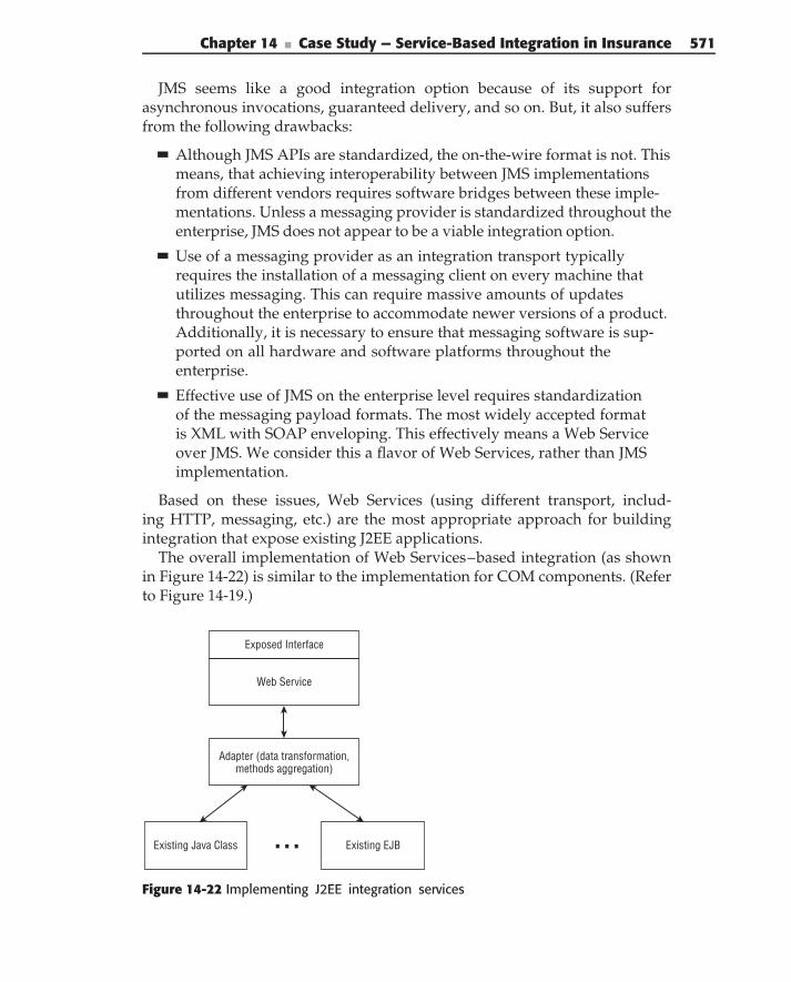
Chapter 14 ■ Case Study — Service-Based Integration in Insurance 571
JMS seems like a good integration option because of its support forasynchronous invocations, guaranteed delivery, and so on. But, it also suffersfrom the following drawbacks:
Although JMS APIs are standardized, the on-the-wire format is not. Thismeans, that achieving interoperability between JMS implementationsfrom different vendors requires software bridges between these imple-mentations. Unless a messaging provider is standardized throughout theenterprise, JMS does not appear to be a viable integration option.
Use of a messaging provider as an integration transport typicallyrequires the installation of a messaging client on every machine thatutilizes messaging. This can require massive amounts of updatesthroughout the enterprise to accommodate newer versions of a product.Additionally, it is necessary to ensure that messaging software is sup-ported on all hardware and software platforms throughout theenterprise.
Effective use of JMS on the enterprise level requires standardizationof the messaging payload formats. The most widely accepted formatis XML with SOAP enveloping. This effectively means a Web Serviceover JMS. We consider this a flavor of Web Services, rather than JMSimplementation.
Based on these issues, Web Services (using different transport, includ-ing HTTP, messaging, etc.) are the most appropriate approach for buildingintegration that expose existing J2EE applications.
The overall implementation of Web Services–based integration (as shownin Figure 14-22) is similar to the implementation for COM components. (Referto Figure 14-19.)
Web Service
Exposed Interface
Adapter (data transformation,methods aggregation)
Existing Java Class Existing EJB
Figure 14-22 Implementing J2EE integration services
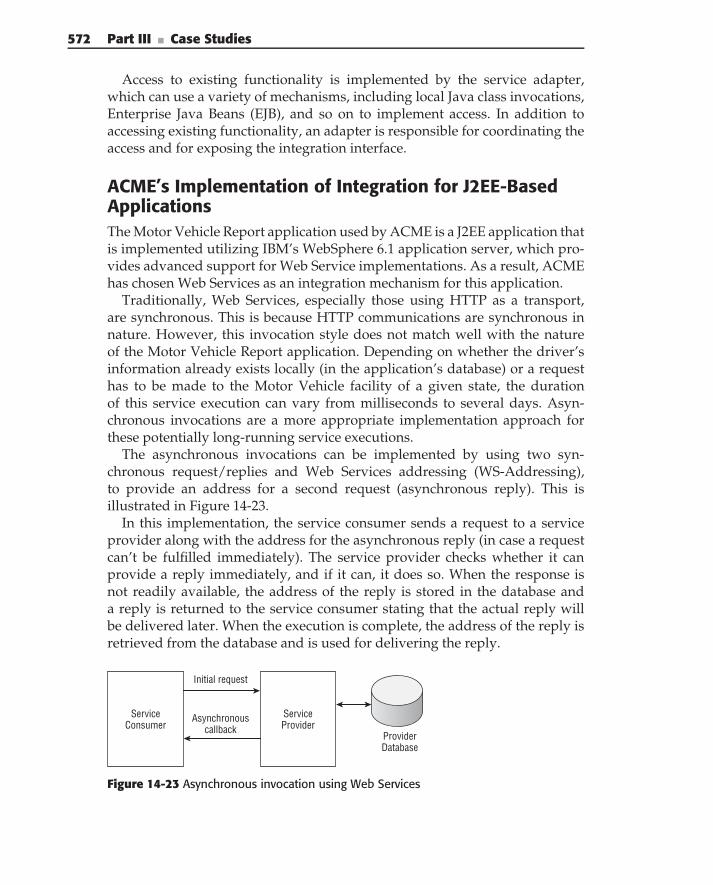
572 Part III ■ Case Studies
Access to existing functionality is implemented by the service adapter,which can use a variety of mechanisms, including local Java class invocations,Enterprise Java Beans (EJB), and so on to implement access. In addition toaccessing existing functionality, an adapter is responsible for coordinating theaccess and for exposing the integration interface.
ACME’s Implementation of Integration for J2EE-BasedApplicationsThe Motor Vehicle Report application used by ACME is a J2EE application thatis implemented utilizing IBM’s WebSphere 6.1 application server, which pro-vides advanced support for Web Service implementations. As a result, ACMEhas chosen Web Services as an integration mechanism for this application.
Traditionally, Web Services, especially those using HTTP as a transport,are synchronous. This is because HTTP communications are synchronous innature. However, this invocation style does not match well with the natureof the Motor Vehicle Report application. Depending on whether the driver’sinformation already exists locally (in the application’s database) or a requesthas to be made to the Motor Vehicle facility of a given state, the durationof this service execution can vary from milliseconds to several days. Asyn-chronous invocations are a more appropriate implementation approach forthese potentially long-running service executions.
The asynchronous invocations can be implemented by using two syn-chronous request/replies and Web Services addressing (WS-Addressing),to provide an address for a second request (asynchronous reply). This isillustrated in Figure 14-23.
In this implementation, the service consumer sends a request to a serviceprovider along with the address for the asynchronous reply (in case a requestcan’t be fulfilled immediately). The service provider checks whether it canprovide a reply immediately, and if it can, it does so. When the response isnot readily available, the address of the reply is stored in the database anda reply is returned to the service consumer stating that the actual reply willbe delivered later. When the execution is complete, the address of the reply isretrieved from the database and is used for delivering the reply.
ServiceConsumer
ServiceProvider
ProviderDatabase
Initial request
Asynchronouscallback
Figure 14-23 Asynchronous invocation using Web Services
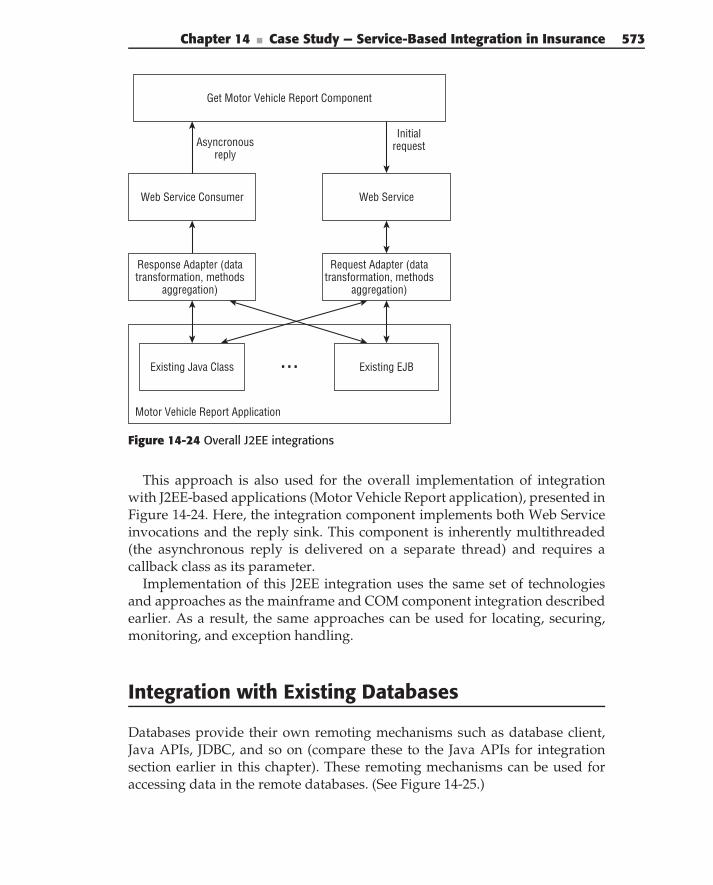
Chapter 14 ■ Case Study — Service-Based Integration in Insurance 573
Web Service
Motor Vehicle Report Application
Web Service Consumer
Get Motor Vehicle Report Component
InitialrequestAsyncronous
reply
Request Adapter (datatransformation, methods
aggregation)
Response Adapter (datatransformation, methods
aggregation)
Existing Java Class Existing EJB
Figure 14-24 Overall J2EE integrations
This approach is also used for the overall implementation of integrationwith J2EE-based applications (Motor Vehicle Report application), presented inFigure 14-24. Here, the integration component implements both Web Serviceinvocations and the reply sink. This component is inherently multithreaded(the asynchronous reply is delivered on a separate thread) and requires acallback class as its parameter.
Implementation of this J2EE integration uses the same set of technologiesand approaches as the mainframe and COM component integration describedearlier. As a result, the same approaches can be used for locating, securing,monitoring, and exception handling.
Integration with Existing Databases
Databases provide their own remoting mechanisms such as database client,Java APIs, JDBC, and so on (compare these to the Java APIs for integrationsection earlier in this chapter). These remoting mechanisms can be used foraccessing data in the remote databases. (See Figure 14-25.)
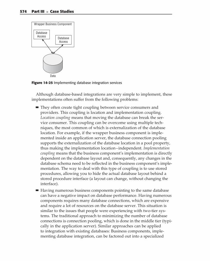
574 Part III ■ Case Studies
Wrapper Business Component
DatabaseAccess Database
Access
Data
Figure 14-25 Implementing database integration services
Although database-based integrations are very simple to implement, theseimplementations often suffer from the following problems:
They often create tight coupling between service consumers andproviders. This coupling is location and implementation coupling.Location coupling means that moving the database can break the ser-vice consumer. This coupling can be overcome using multiple tech-niques, the most common of which is externalization of the databaselocation. For example, if the wrapper business component is imple-mented inside an application server, the database connection poolingsupports the externalization of the database location in a pool property,thus making the implementation location–independent. Implementationcoupling means that the business component’s implementation is directlydependent on the database layout and, consequently, any changes in thedatabase schema need to be reflected in the business component’s imple-mentation. The way to deal with this type of coupling is to use storedprocedures, allowing you to hide the actual database layout behind astored procedure interface (a layout can change, without changing theinterface).
Having numerous business components pointing to the same databasecan have a negative impact on database performance. Having numerouscomponents requires many database connections, which are expensiveand require a lot of resources on the database server. This situation issimilar to the issues that people were experiencing with two-tier sys-tems. The traditional approach to minimizing the number of databaseconnections is connection pooling, which is done in the middle tier (typi-cally in the application server). Similar approaches can be appliedto integration with existing databases: Business components, imple-menting database integration, can be factored out into a specialized
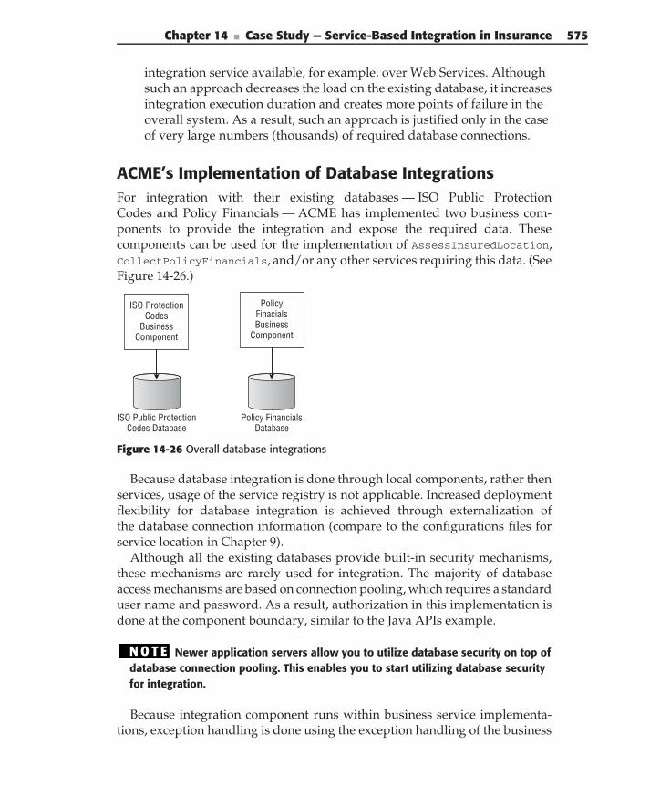
Chapter 14 ■ Case Study — Service-Based Integration in Insurance 575
integration service available, for example, over Web Services. Althoughsuch an approach decreases the load on the existing database, it increasesintegration execution duration and creates more points of failure in theoverall system. As a result, such an approach is justified only in the caseof very large numbers (thousands) of required database connections.
ACME’s Implementation of Database IntegrationsFor integration with their existing databases — ISO Public ProtectionCodes and Policy Financials — ACME has implemented two business com-ponents to provide the integration and expose the required data. Thesecomponents can be used for the implementation of AssessInsuredLocation,CollectPolicyFinancials, and/or any other services requiring this data. (SeeFigure 14-26.)
ISO Public ProtectionCodes Database
Policy FinancialsDatabase
ISO ProtectionCodes
BusinessComponent
PolicyFinacials Business
Component
Figure 14-26 Overall database integrations
Because database integration is done through local components, rather thenservices, usage of the service registry is not applicable. Increased deploymentflexibility for database integration is achieved through externalization ofthe database connection information (compare to the configurations files forservice location in Chapter 9).
Although all the existing databases provide built-in security mechanisms,these mechanisms are rarely used for integration. The majority of databaseaccess mechanisms are based on connection pooling, which requires a standarduser name and password. As a result, authorization in this implementation isdone at the component boundary, similar to the Java APIs example.
N O T E Newer application servers allow you to utilize database security on top ofdatabase connection pooling. This enables you to start utilizing database securityfor integration.
Because integration component runs within business service implementa-tions, exception handling is done using the exception handling of the business
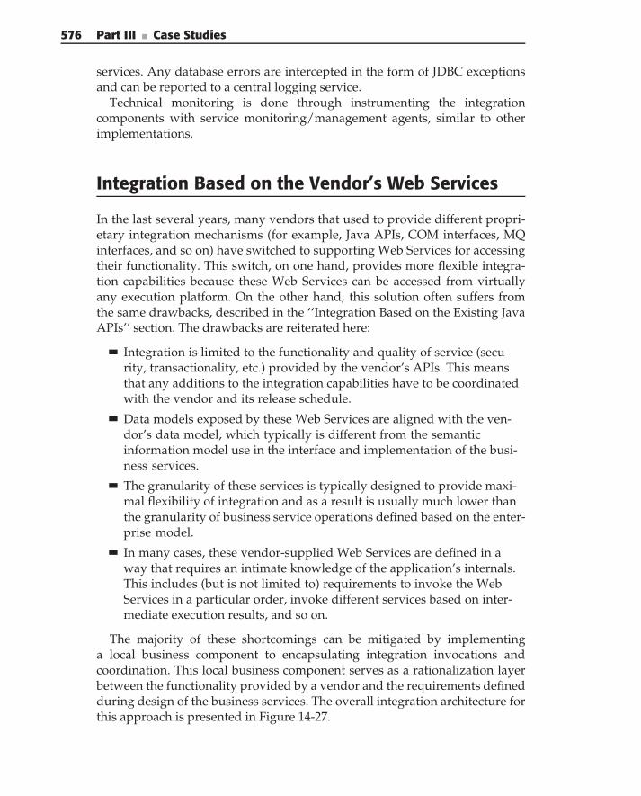
576 Part III ■ Case Studies
services. Any database errors are intercepted in the form of JDBC exceptionsand can be reported to a central logging service.
Technical monitoring is done through instrumenting the integrationcomponents with service monitoring/management agents, similar to otherimplementations.
Integration Based on the Vendor’s Web Services
In the last several years, many vendors that used to provide different propri-etary integration mechanisms (for example, Java APIs, COM interfaces, MQinterfaces, and so on) have switched to supporting Web Services for accessingtheir functionality. This switch, on one hand, provides more flexible integra-tion capabilities because these Web Services can be accessed from virtuallyany execution platform. On the other hand, this solution often suffers fromthe same drawbacks, described in the ‘‘Integration Based on the Existing JavaAPIs’’ section. The drawbacks are reiterated here:
Integration is limited to the functionality and quality of service (secu-rity, transactionality, etc.) provided by the vendor’s APIs. This meansthat any additions to the integration capabilities have to be coordinatedwith the vendor and its release schedule.
Data models exposed by these Web Services are aligned with the ven-dor’s data model, which typically is different from the semanticinformation model use in the interface and implementation of the busi-ness services.
The granularity of these services is typically designed to provide maxi-mal flexibility of integration and as a result is usually much lower thanthe granularity of business service operations defined based on the enter-prise model.
In many cases, these vendor-supplied Web Services are defined in away that requires an intimate knowledge of the application’s internals.This includes (but is not limited to) requirements to invoke the WebServices in a particular order, invoke different services based on inter-mediate execution results, and so on.
The majority of these shortcomings can be mitigated by implementinga local business component to encapsulating integration invocations andcoordination. This local business component serves as a rationalization layerbetween the functionality provided by a vendor and the requirements definedduring design of the business services. The overall integration architecture forthis approach is presented in Figure 14-27.
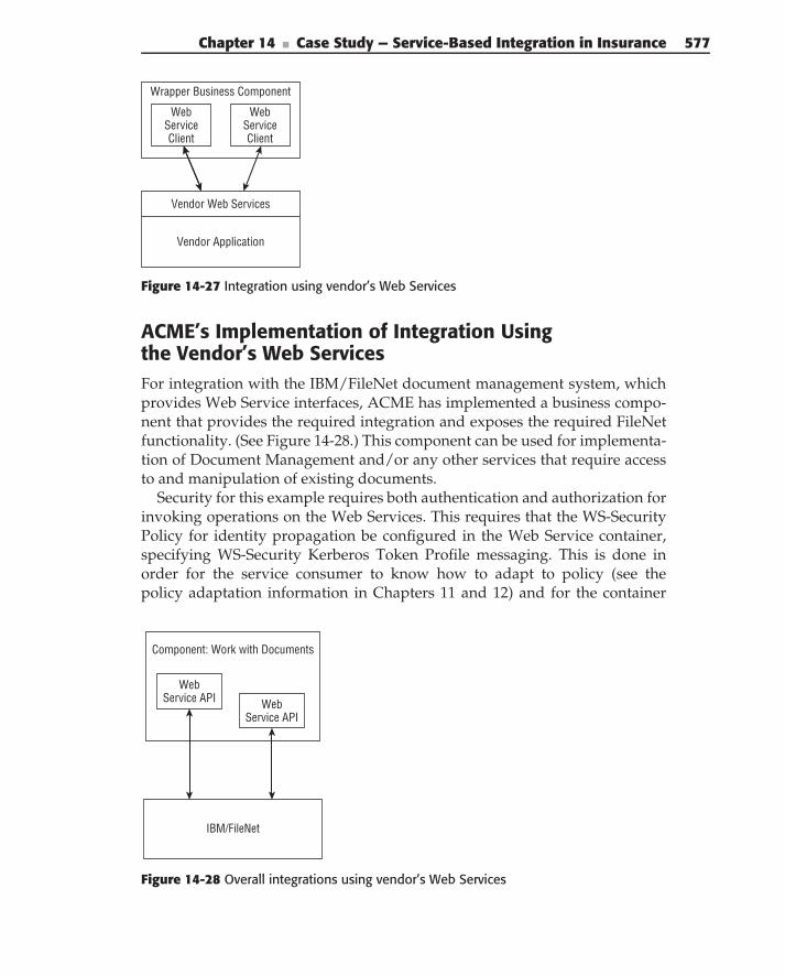
Chapter 14 ■ Case Study — Service-Based Integration in Insurance 577
Vendor Application
Vendor Web Services
Wrapper Business Component
WebServiceClient
WebServiceClient
Figure 14-27 Integration using vendor’s Web Services
ACME’s Implementation of Integration Usingthe Vendor’s Web ServicesFor integration with the IBM/FileNet document management system, whichprovides Web Service interfaces, ACME has implemented a business compo-nent that provides the required integration and exposes the required FileNetfunctionality. (See Figure 14-28.) This component can be used for implementa-tion of Document Management and/or any other services that require accessto and manipulation of existing documents.
Security for this example requires both authentication and authorization forinvoking operations on the Web Services. This requires that the WS-SecurityPolicy for identity propagation be configured in the Web Service container,specifying WS-Security Kerberos Token Profile messaging. This is done inorder for the service consumer to know how to adapt to policy (see thepolicy adaptation information in Chapters 11 and 12) and for the container
IBM/FileNet
Component: Work with Documents
WebService API Web
Service API
Figure 14-28 Overall integrations using vendor’s Web Services
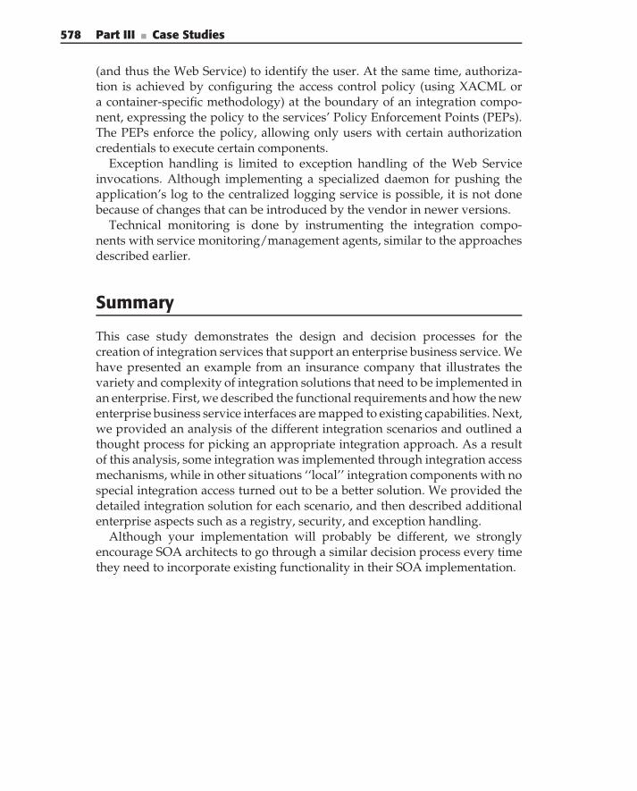
578 Part III ■ Case Studies
(and thus the Web Service) to identify the user. At the same time, authoriza-tion is achieved by configuring the access control policy (using XACML ora container-specific methodology) at the boundary of an integration compo-nent, expressing the policy to the services’ Policy Enforcement Points (PEPs).The PEPs enforce the policy, allowing only users with certain authorizationcredentials to execute certain components.
Exception handling is limited to exception handling of the Web Serviceinvocations. Although implementing a specialized daemon for pushing theapplication’s log to the centralized logging service is possible, it is not donebecause of changes that can be introduced by the vendor in newer versions.
Technical monitoring is done by instrumenting the integration compo-nents with service monitoring/management agents, similar to the approachesdescribed earlier.
Summary
This case study demonstrates the design and decision processes for thecreation of integration services that support an enterprise business service. Wehave presented an example from an insurance company that illustrates thevariety and complexity of integration solutions that need to be implemented inan enterprise. First, we described the functional requirements and how the newenterprise business service interfaces are mapped to existing capabilities. Next,we provided an analysis of the different integration scenarios and outlined athought process for picking an appropriate integration approach. As a resultof this analysis, some integration was implemented through integration accessmechanisms, while in other situations ‘‘local’’ integration components with nospecial integration access turned out to be a better solution. We provided thedetailed integration solution for each scenario, and then described additionalenterprise aspects such as a registry, security, and exception handling.
Although your implementation will probably be different, we stronglyencourage SOA architects to go through a similar decision process every timethey need to incorporate existing functionality in their SOA implementation.
A P P E N D I X
A
Business Use Cases
This appendix contains the business use cases for the examples describedin Chapters 6 and 7 on service interface design and service implementationdesign.
Business Use Case BU01 — Quote Insurance
This section provides an overview of the use case, goals, and actors.Description — This is the process by which a quote for insurance is pro-
duced and presented to a Customer in response to a Customer request. ACME’sunderwriting and pricing rules are applied to determine the acceptability ofrisks and insurance premium options.
Actors —
Primary Actors — Customer, Agency
Secondary Actors — Underwriting, Pricing
Business goal — To obtain new business by providing competitive insur-ance offerings
Triggers — Customer requests an insurance quote
579
580 Appendix A ■ Business Use Cases
Basic Workflow
1. Gather information for quote — The Agency gets information from theCustomer about the insurance desired:
Customer information
Customer contact information: phone, address, and email address
Whether this is a new Customer
Auto insurance
Auto information
• Make, model, year, and body type
• VIN
• General condition
Customer information
• Driving record
• Age
• Gender
• Information on other drivers (same as above)
Auto usage
• Expected yearly commuter miles and total miles
• Whether the auto is used for business purposes
Coverage desired
• Liability
• Collision
• Comprehensive
• Towing
• Auto glass
Homeowner’s insurance
Property information
• Location (physical address)
• Year built
• Dwelling type (single family, duplex, condo, etc.)
• Type of construction (stick frame, balloon frame, stone, brick,etc.)
• Whether located in a flood plain
Appendix A ■ Business Use Cases 581
• Whether smoke alarms are present
• The value of the property
Occupancy (owner-occupied, rental, or unoccupied)
Coverage desired
Liability
Replacement value versus actual value
Personal property
Property item information
• Type
• Value
• Serial number (if applicable)
Whether the item is used for business
Coverage desired
• Replacement versus actual value
• Damage
2. Underwrite the quote — Underwriting examines the information on thequote to determine which risks can be accepted and which cannot, basedon the company’s underwriting guidelines. A risk factor score between1 and 100 is assigned for each coverage on each covered item. Covereditems include:
Auto insurance
Liability
Physical damage to the auto from collisions
Physical damage to the auto that is not the result of collisions
Physical damage to other autos from a collision
Physical damage to other property from a collision
Injuries, from collisions, sustained by covered persons
Injuries, from collisions, sustained by other persons
Towing services
Auto glass replacement
Homeowner’s insurance
Personal property
3. Price the quote — For each quoted coverage, the Agency creates a setof options to present to the Customer. Each option includes a coverage
582 Appendix A ■ Business Use Cases
limit, a deductible, and a premium. The premium is based on ACME’spricing rules, and is based on the coverage limit, deductible, and riskfactor.
ACME also offers a multipolicy discount of 5% for Customers alreadyholding another policy with ACME, assuming the quoted policy doesnot replace an existing policy. ACME also offers a 7% employee discountfor all policies.
4. Present quote — The Agency presents the quote to the Customer.
Alternative Workflow: Unacceptable RiskIf in Step 2 above, Underwriting determines that the coverage requested bythe Customer falls outside of ACME’s underwriting guidelines, one of thefollowing actions may be taken:
The Agency suggests to the Customer alternative coverage options,which are then quoted.
The Customer decides not to pursue further quoting.
Performance GoalsQuick quote turnaround — ACME has determined that a quick response toa request for a quote plays a significant role in a Customer’s decision as towhether to purchase insurance. For this reason, ACME has a goal of producingquotes in 1 hour’s time, with an ultimate goal of producing quotes during anactual Customer interaction.
Business Use Case BU02 — Process Application
Overview — This section provides an overview of the use case, goals, andactors.
Description — This is the process by which a Customer obtains insurancecoverage. Based on a preexisting quote, the Customer submits an applicationfor insurance. The insurance is underwritten and priced to take into accountadditional coverage details and information about the Customer and/orcovered items that were not included in the quoting process. Billing is set up,and the Customer receives an insurance binder.
Actors —
Primary Actors — Customer, Agency
Secondary Actors — Underwriting, Pricing
Business goal — Agency goal: to book new businessTriggers — Customer asks to apply for insurance
Appendix A ■ Business Use Cases 583
Basic Workflow1. Complete application — The Agency works with the Customer to fill
out an insurance application, based upon the Customer’s selection ofcoverage options presented on a preexisting quote. The Agency workswith the Customer to obtain additional required information and/orto update any information that may be different from what was on theoriginal quote. Additional information includes:
Driver’s license number, state, and expiration date for all drivers.
Similar information for prior driver’s licenses held within the‘‘look-back’’ period allowed by state regulations for the state in whichthe Customer resides. The look-back period is the number of yearsback that a person’s driving record may be considered when under-writing insurance.
2. Gather additional information for policy processing — The Agencyobtains additional information required for completing and underwrit-ing the application. Some of this information is immediately available,such as VIN verification, police reports, insurance history, and so on.Some information takes longer to obtain, such as that derived from anon-site dwelling inspection. The intent is that the information be as com-plete as possible, while still processing the application within the statedperformance goal guidelines (see below under ‘‘Performance Goals’’).
Auto insurance
Auto information
• From Kelley Blue Book — Verification that the VIN numbermatches the vehicle; incident history
• From local and state police — Verification that the vehicle is notstolen
• From local and state police — Police reports involving thevehicle
Customer information
• From state driver’s license bureaus — driving record(s) fromstate(s) of previous residence (all drivers)
Insurance information
• From insurance industry consortium — Claim history
• From insurance industry consortium — History of denied orcanceled auto insurance
Homeowner’s insurance
584 Appendix A ■ Business Use Cases
Property information
• From on-site inspection — Condition of the property, existenceof smoke alarms
• From appraisal — Value of the property
• From state department of natural resources — Verification offlood plain status
Personal property insurance
Property item information
• From appraisals or purchase receipts supplied by theCustomer — Item value
• From local and state police — For items that have a serial num-ber and a stated value of over $5000, verification that the itemwasn’t stolen
All insurance lines — Fraud detection
From internal ACME information — Was the Customer a claimantas an uninsured person on multiple claims against insurance poli-cies underwritten by ACME?
3. Underwrite the policy — Based on information on the application,underwriting performs the same process of evaluating and scoring risksas is done in BU01 Quote Insurance.
4. Price the policy — The Agency sets the premium for each coverage,with its Customer-selected limit(s) and deductible, in the policy. As inBU01 Quote Insurance, each coverage premium is based on ACME pric-ing rules and is based on the coverage limit, deductible, and riskfactor.
Also, as in BU01 Quote Insurance, multipolicy and employee discountsapply.
5. Set up billing and payment method — Billing is notified of the new pol-icy application.
6. Send insurance binder — The Agency creates an insurance binder,which is effective when the Agency receives the completed applica-tion. Continued coverage is contingent upon the Customer making aninitial payment within 5 business days of acceptance of the applica-tion. The Agency also mails the Customer a hard copy of the insurancebinder.
Appendix A ■ Business Use Cases 585
Alternative Workflow: Unacceptable RiskIf in Step 2 above, Underwriting determines that the coverage requested by theCustomer falls outside of ACME’s underwriting guidelines, the application isdeclined.
Performance GoalsQuick application processing — As part of its overall customer service strat-egy, ACME has a goal of completing underwriting and final pricing within 10business days of receipt of an insurance application. However, ACME has acorporate policy of maintaining an open underwriting period of 20 businessdays after receipt of an insurance application. This means that a policy may becanceled because of underwriting activities even after the insurance binder orthe policy itself is sent out.
Business Use Case BU03 — Change Policy
Overview — This section provides an overview of the use case, goals, andactors.
Description — This is the process by which an existing insurance policy ischanged per the Customer’s request. The changes are underwritten, priced,and quoted. The policy is updated accordingly, necessary changes are madeto billing, and the Customer is sent an updated copy of the policy.
Actors —
Primary Actors — Customer, Agency
Secondary Actors — Underwriting, Pricing, Billing
Business goals — To meet the Customer’s needs by modifying an existingpolicy, thereby retaining the Customer’s business
Triggers — Customer requests that the agency make one or more changesto an existing policy
Basic Workflow1. Gather information regarding requested changes — The Agency
obtains information from the Customer about the changes that theCustomer wishes to make to the policy. Changes may include:
Auto insurance
Auto information
• Add or drop an auto
586 Appendix A ■ Business Use Cases
• Add or drop coverage
• Change deductible
Customer information
• Contact information change (other than address)
• Address change
• Add or drop a driver
Homeowner’s insurance
Property information
• Add or drop coverage
• Change deductible
• Value of property changes
Personal property insurance
Property item information
• Add or drop an item
• Value of an item changes
• Change deductible
• Add or drop coverage
2. Gather additional information for processing policy changes — Asapplicable, the Agency obtains additional information required for pro-cessing and underwriting the policy changes. Some of this informationis immediately available, such as VIN verification, police reports, insur-ance history, and so on. Some information takes longer to obtain, suchas that derived from an on-site dwelling inspection. The intent is that theinformation be as complete as possible, while still processing the appli-cation within the stated performance goal guidelines (see below under‘‘Performance Goals’’).
Auto insurance
Auto information (for autos added)
• From Kelley Blue Book — Verification that the VIN numbermatches the vehicle; incident history
• From local and state police — Verification that the vehicle is notstolen
• From local and state police — Police reports involving thevehicle
Customer information (for drivers added)
Appendix A ■ Business Use Cases 587
• From state driver’s license bureaus — Driving record(s) fromstate(s) of previous residence (all drivers)
Insurance information (for drivers added)
• From insurance industry consortium — Claims history
• From insurance industry consortium — History of denied orcancelled auto insurance
Homeowner’s insurance
Property information (for property value change)
• From appraisal — Value of the property
Personal property insurance
Property item information (for added items or for items whosevalue has changed)
• From appraisals or purchase receipts supplied by theCustomer — Item value
• From local and state police — For items that have a serial num-ber and a stated value of over $5000, verification of whether theitem was stolen
3. Underwrite the policy — The policy changes are underwritten using thesame process of evaluating and scoring risks as in BU01 QuoteInsurance.
4. Price the policy — The Agency reprices the policy based on therequested changes, generates a new quote, and presents it to the Cus-tomer, as in BU01 Quote Insurance.
5. Update billing — The Agency notifies Billing of any premium changes.
6. Update policy package — Document Processing makes necessarychanges to the hard-copy policy package.
7. Send copy of policy package to the Customer — Document Process-ing sends a copy of the updated policy package to the Customer via sur-face mail.
Alternative Workflow: Unacceptable RiskIn Step 2 above, if Underwriting determines that the requested policy change(s)presents an unacceptable risk, the changes are denied and one of the followingmay happen:
The Customer modifies the requested changes, and the Agency requotesthe policy.
588 Appendix A ■ Business Use Cases
The Customer retains the policy as is.
The Customer cancels the policy.
Extension PointsThis section describes any extension points.
Billing change — Step 4 above may activate BU05 Adjust Premium.Customer cancellation — Alternative Flow Underwriting Required may
activate BU04 Cancel Policy.
A P P E N D I X
B
Evaluating SOA Services
This book discusses the fundamentals of Service-Oriented Architecture,including the design and technical concerns of building SOA services. Asstated in Chapter 2, simply having services is not enough; you need the rightkind of services, and you need well-designed and properly built services. Howdo you know if you have the right kind of services or if the services will satisfythe current or future requirements? Is there an objective way to assess servicesand their alignment with business needs?
This appendix contains an evaluation matrix for assessing the design ofSOA services. It consists of four categories: Alignment Characteristics, DesignCharacteristics, Technical Characteristics, and Housekeeping Characteristics. Withineach category, there are several characteristics pertaining to the category andquestions to ask about how well the service satisfies that characteristic. Thecollected answers to the questions in the matrix indicate how well a servicefits into an SOA solution.
Categories group together service characteristics that address specificarchitectural principles and practices.
Characteristics are the service dimensions that you evaluate. The goalof the evaluation is to determine how well the service follows the SOAprinciple or practices. Each characteristic has a brief description and isfollowed by a list of the outcomes of the evaluation.
589
590 Appendix B ■ Evaluating SOA Services
Questions help you evaluate each characteristic. The matrix providesa set of questions to use while assessing the service. For example, howwell the service aligns with the business drivers or the composability ofthe service. Each question is followed by a list of possible answers.
We have tried to keep the table brief and manageable. Following the tableis a detailed explanation of each characteristic, the meanings of the associatedoutcomes, motivation and elaboration of each question, and the meanings ofthe associated answers.
You use the evaluation matrix throughout the process of service designand implementation. The evaluation criteria allow you to rate the service inan objective manner. The results provide insight into how well the servicesatisfies the key requirements, such as reusability or alignment with businessgoals and needs.
Throughout the design and implementation process, each perspective (role)checks the services against the evaluation criteria that fit within their concern.For example, there is no need for the business analyst to evaluate the Autonomycharacteristic or the interface style. In general:
The Business Perspective is concerned with the Alignment Character-istics.
The Design Perspective is concerned with Alignment and Service Char-acteristics, along with a selection of Technical and HousekeepingCharacteristics.
The Implementation Perspective is concerned with Alignment, Service,Technical, and Housekeeping Characteristics — basically, the entirematrix.
How Do I Assess Services?
The service evaluation matrix asks questions designed to help you evaluateservices both qualitatively and quantitatively. You use the matrix through-out the service design and implementation process. Depending on yourperspective within the process — Business, Design, or Implementation — youask the questions in the categories that are appropriate for your concerns.Once your answers are collected, you identify gaps in the service’s design orimplementation.
For the first three categories in the matrix, the assessments ask multiple-choice questions. The list starts with the most desirable answers and ends withthe less desirable answers.
The fourth category of the matrix — Housekeeping Characteristics — isdifferent from the rest. Instead of assessing the quality of the service, itfocuses on the quantitative aspects of the services in your enterprise. The
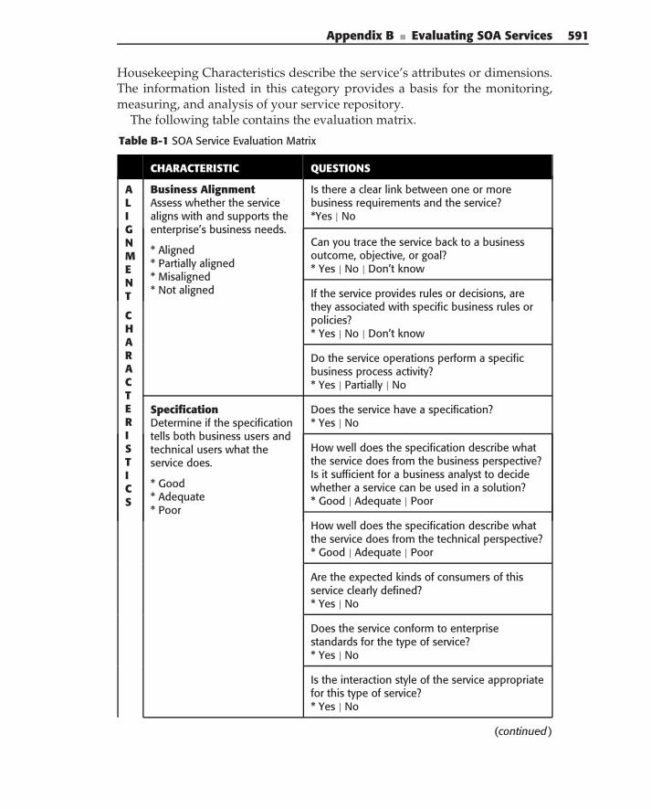
Appendix B ■ Evaluating SOA Services 591
Housekeeping Characteristics describe the service’s attributes or dimensions.The information listed in this category provides a basis for the monitoring,measuring, and analysis of your service repository.
The following table contains the evaluation matrix.
Table B-1 SOA Service Evaluation Matrix
CHARACTERISTIC QUESTIONS
ALIGNMENT
CHARACTERISTICS
Business AlignmentAssess whether the servicealigns with and supports theenterprise’s business needs.
* Aligned* Partially aligned* Misaligned* Not aligned
Is there a clear link between one or morebusiness requirements and the service?*Yes | No
Can you trace the service back to a businessoutcome, objective, or goal?* Yes | No | Don’t know
If the service provides rules or decisions, arethey associated with specific business rules orpolicies?* Yes | No | Don’t know
Do the service operations perform a specificbusiness process activity?* Yes | Partially | No
SpecificationDetermine if the specificationtells both business users andtechnical users what theservice does.
* Good* Adequate* Poor
Does the service have a specification?* Yes | No
How well does the specification describe whatthe service does from the business perspective?Is it sufficient for a business analyst to decidewhether a service can be used in a solution?* Good | Adequate | Poor
How well does the specification describe whatthe service does from the technical perspective?* Good | Adequate | Poor
Are the expected kinds of consumers of thisservice clearly defined?* Yes | No
Does the service conform to enterprisestandards for the type of service?* Yes | No
Is the interaction style of the service appropriatefor this type of service?* Yes | No
(continued)
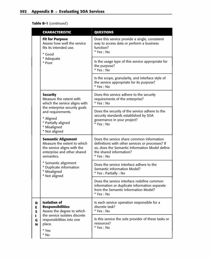
592 Appendix B ■ Evaluating SOA Services
Table B-1 (continued)
CHARACTERISTIC QUESTIONS
Fit for PurposeAssess how well the servicefits its intended use.
* Good* Adequate* Poor
Does this service provide a single, consistentway to access data or perform a businessfunction?* Yes | No
Is the usage type of this service appropriate forthe purpose?* Yes | No
Is the scope, granularity, and interface style ofthe service appropriate for its purpose?* Yes | No
SecurityMeasure the extent withwhich the service aligns withthe enterprise security goalsand requirements.
* Aligned* Partially aligned* Misaligned* Not aligned
Does this service adhere to the securityrequirements of the enterprise?* Yes | No
Does the security of the service adhere to thesecurity standards established by SOAgovernance in your project?* Yes | No
Semantic AlignmentMeasure the extent to whichthe service aligns with theenterprise and other sharedsemantics.
* Semantic alignment* Duplicate information* Misaligned* Not aligned
Does the service share common informationdefinitions with other services or processes? Ifso, does the Semantic Information Model definethe shared information?* Yes | No
Does the service interface adhere to theSemantic Information Model?* Yes | Partially | No
Does the service interface redefine commoninformation or duplicate information separatefrom the Semantic Information Model?* Yes | No
DESIGN
Isolation ofResponsibilitiesAssess the degree to whichthe service isolates discreteresponsibilities into oneplace.
* Yes* No
Is each service operation responsible for adiscrete task?* Yes | No
Is this service the sole provider of these tasks orresources?* Yes | No
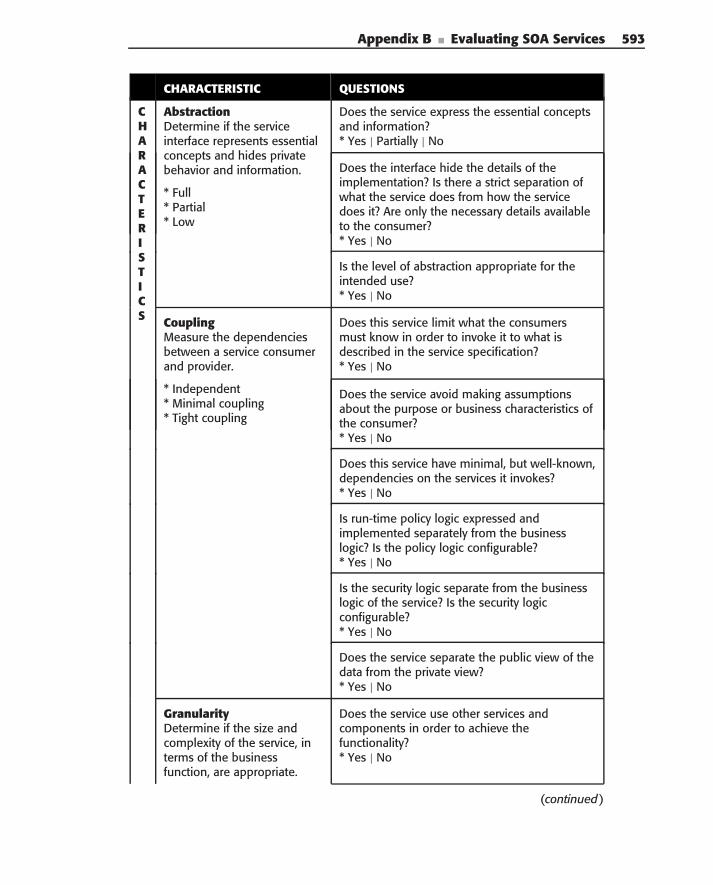
Appendix B ■ Evaluating SOA Services 593
CHARACTERISTIC QUESTIONS
CHARACTERISTICS
AbstractionDetermine if the serviceinterface represents essentialconcepts and hides privatebehavior and information.
* Full* Partial* Low
Does the service express the essential conceptsand information?* Yes | Partially | No
Does the interface hide the details of theimplementation? Is there a strict separation ofwhat the service does from how the servicedoes it? Are only the necessary details availableto the consumer?* Yes | No
Is the level of abstraction appropriate for theintended use?* Yes | No
CouplingMeasure the dependenciesbetween a service consumerand provider.
* Independent* Minimal coupling* Tight coupling
Does this service limit what the consumersmust know in order to invoke it to what isdescribed in the service specification?* Yes | No
Does the service avoid making assumptionsabout the purpose or business characteristics ofthe consumer?* Yes | No
Does this service have minimal, but well-known,dependencies on the services it invokes?* Yes | No
Is run-time policy logic expressed andimplemented separately from the businesslogic? Is the policy logic configurable?* Yes | No
Is the security logic separate from the businesslogic of the service? Is the security logicconfigurable?* Yes | No
Does the service separate the public view of thedata from the private view?* Yes | No
GranularityDetermine if the size andcomplexity of the service, interms of the businessfunction, are appropriate.
Does the service use other services andcomponents in order to achieve thefunctionality?* Yes | No
(continued)
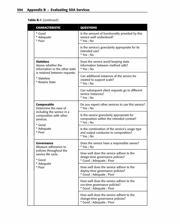
594 Appendix B ■ Evaluating SOA Services
Table B-1 (continued)
CHARACTERISTIC QUESTIONS
* Good* Adequate* Poor
Is the amount of functionality provided by thisservice well understood?* Yes | No
Is the service’s granularity appropriate for itsintended use?* Yes | No
StatelessAssess whether theinformation or the other stateis retained between requests.
* Stateless* Retains State
Does the service avoid keeping stateinformation between method calls?* Yes | No
Can additional instances of the service becreated to support scale?* Yes | No
Can subsequent client requests go to differentservice instances?* Yes | No
ComposableDetermine the ease ofincluding the service in acomposition with otherservices.
* Good* Adequate* Poor
Do you expect other services to use this service?* Yes | No
Is the service granularity appropriate forcomposition within the intended context?* Yes | No
Is the combination of the service’s usage typeand output conducive to composition?* Yes | No
GovernanceMeasure adherence topolicies throughout theservice life cycle.
* Good* Adequate* Poor
Does the service have a responsible owner?* Yes | No
How well does the service adhere to thedesign-time governance policies?* Good | Adequate | Poor
How well does the service adhere to thedeploy-time governance policies?* Good | Adequate | Poor
How well does the service adhere to therun-time governance policies?* Good | Adequate | Poor
How well does the service adhere to thechange-time governance policies?* Good | Adequate | Poor
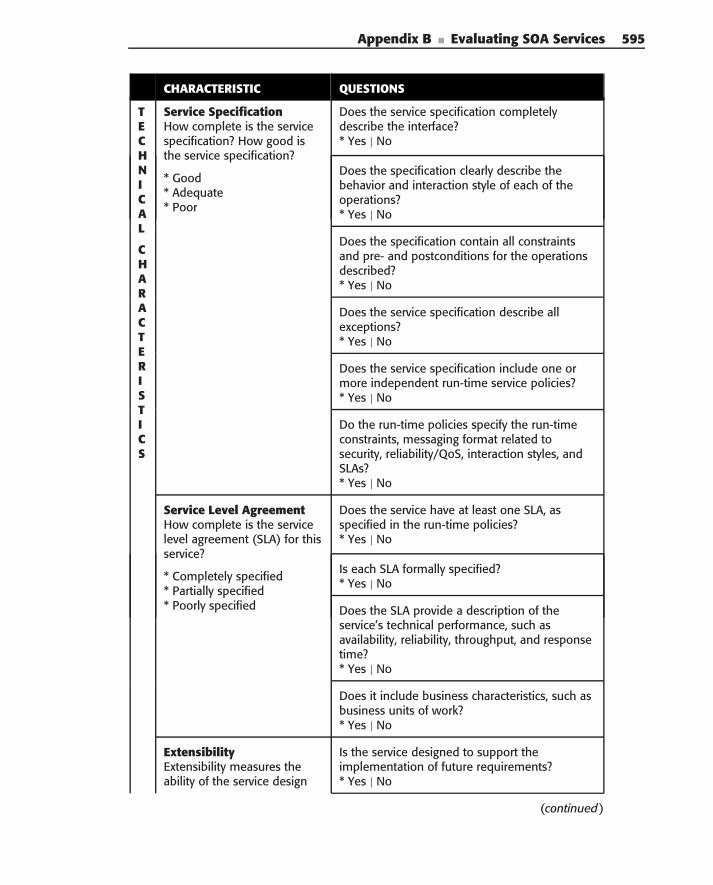
Appendix B ■ Evaluating SOA Services 595
CHARACTERISTIC QUESTIONS
TECHNICAL
CHARACTERISTICS
Service SpecificationHow complete is the servicespecification? How good isthe service specification?
* Good* Adequate* Poor
Does the service specification completelydescribe the interface?* Yes | No
Does the specification clearly describe thebehavior and interaction style of each of theoperations?* Yes | No
Does the specification contain all constraintsand pre- and postconditions for the operationsdescribed?* Yes | No
Does the service specification describe allexceptions?* Yes | No
Does the service specification include one ormore independent run-time service policies?* Yes | No
Do the run-time policies specify the run-timeconstraints, messaging format related tosecurity, reliability/QoS, interaction styles, andSLAs?* Yes | No
Service Level AgreementHow complete is the servicelevel agreement (SLA) for thisservice?
* Completely specified* Partially specified* Poorly specified
Does the service have at least one SLA, asspecified in the run-time policies?* Yes | No
Is each SLA formally specified?* Yes | No
Does the SLA provide a description of theservice’s technical performance, such asavailability, reliability, throughput, and responsetime?* Yes | No
Does it include business characteristics, such asbusiness units of work?* Yes | No
ExtensibilityExtensibility measures theability of the service design
Is the service designed to support theimplementation of future requirements?* Yes | No
(continued)
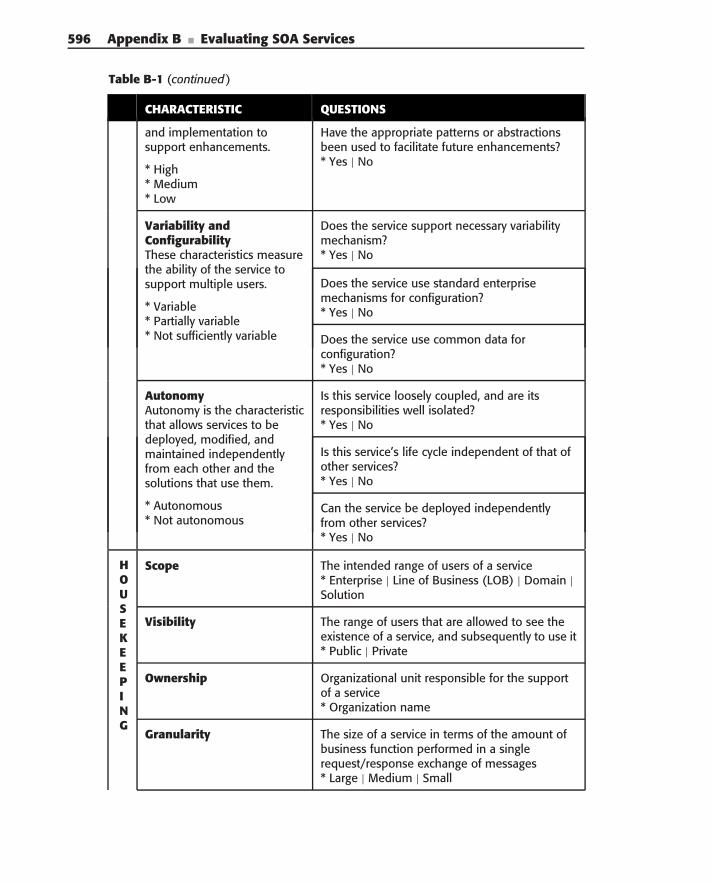
596 Appendix B ■ Evaluating SOA Services
Table B-1 (continued)
CHARACTERISTIC QUESTIONS
and implementation tosupport enhancements.
* High* Medium* Low
Have the appropriate patterns or abstractionsbeen used to facilitate future enhancements?* Yes | No
Variability andConfigurabilityThese characteristics measurethe ability of the service tosupport multiple users.
* Variable* Partially variable* Not sufficiently variable
Does the service support necessary variabilitymechanism?* Yes | No
Does the service use standard enterprisemechanisms for configuration?* Yes | No
Does the service use common data forconfiguration?* Yes | No
AutonomyAutonomy is the characteristicthat allows services to bedeployed, modified, andmaintained independentlyfrom each other and thesolutions that use them.
* Autonomous* Not autonomous
Is this service loosely coupled, and are itsresponsibilities well isolated?* Yes | No
Is this service’s life cycle independent of that ofother services?* Yes | No
Can the service be deployed independentlyfrom other services?* Yes | No
HOUSEKEEPING
Scope The intended range of users of a service* Enterprise | Line of Business (LOB) | Domain |Solution
Visibility The range of users that are allowed to see theexistence of a service, and subsequently to use it* Public | Private
Ownership Organizational unit responsible for the supportof a service* Organization name
Granularity The size of a service in terms of the amount ofbusiness function performed in a singlerequest/response exchange of messages* Large | Medium | Small
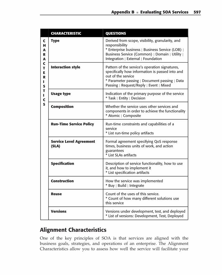
Appendix B ■ Evaluating SOA Services 597
CHARACTERISTIC QUESTIONS
CHARACTERISTICS
Type Derived from scope, visibility, granularity, andresponsibility* Enterprise business | Business Service (LOB) |Business Service (Common) | Domain | Utility |Integration | External | Foundation
Interaction style Pattern of the service’s operation signatures,specifically how information is passed into andout of the service* Parameter passing | Document passing | DataPassing | Request/Reply | Event | Mixed
Usage type Indication of the primary purpose of the service* Task | Entity | Decision
Composition Whether the service uses other services andcomponents in order to achieve the functionality* Atomic | Composite
Run-Time Service Policy Run-time constraints and capabilities of aservice* List run-time policy artifacts
Service Level Agreement(SLA)
Formal agreement specifying QoS responsetimes, business units of work, and actionguarantees* List SLAs artifacts
Specification Description of service functionality, how to useit, and how to implement it* List specification artifacts
Construction How the service was implemented* Buy | Build | Integrate
Reuse Count of the uses of this service.* Count of how many different solutions usethis service
Versions Versions under development, test, and deployed* List of versions: Development, Test, Deployed
Alignment CharacteristicsOne of the key principles of SOA is that services are aligned with thebusiness goals, strategies, and operations of an enterprise. The AlignmentCharacteristics allow you to assess how well the service will facilitate your
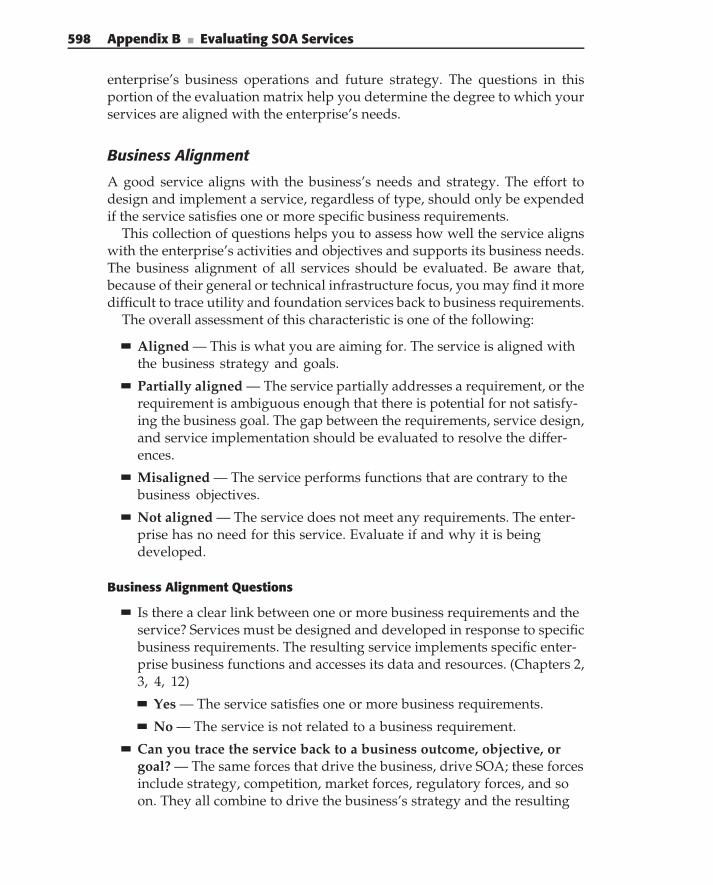
598 Appendix B ■ Evaluating SOA Services
enterprise’s business operations and future strategy. The questions in thisportion of the evaluation matrix help you determine the degree to which yourservices are aligned with the enterprise’s needs.
Business Alignment
A good service aligns with the business’s needs and strategy. The effort todesign and implement a service, regardless of type, should only be expendedif the service satisfies one or more specific business requirements.
This collection of questions helps you to assess how well the service alignswith the enterprise’s activities and objectives and supports its business needs.The business alignment of all services should be evaluated. Be aware that,because of their general or technical infrastructure focus, you may find it moredifficult to trace utility and foundation services back to business requirements.
The overall assessment of this characteristic is one of the following:
Aligned — This is what you are aiming for. The service is aligned withthe business strategy and goals.
Partially aligned — The service partially addresses a requirement, or therequirement is ambiguous enough that there is potential for not satisfy-ing the business goal. The gap between the requirements, service design,and service implementation should be evaluated to resolve the differ-ences.
Misaligned — The service performs functions that are contrary to thebusiness objectives.
Not aligned — The service does not meet any requirements. The enter-prise has no need for this service. Evaluate if and why it is beingdeveloped.
Business Alignment Questions
Is there a clear link between one or more business requirements and theservice? Services must be designed and developed in response to specificbusiness requirements. The resulting service implements specific enter-prise business functions and accesses its data and resources. (Chapters 2,3, 4, 12)
Yes — The service satisfies one or more business requirements.
No — The service is not related to a business requirement.
Can you trace the service back to a business outcome, objective, orgoal? — The same forces that drive the business, drive SOA; these forcesinclude strategy, competition, market forces, regulatory forces, and soon. They all combine to drive the business’s strategy and the resulting
Appendix B ■ Evaluating SOA Services 599
business architecture (model). Because services are created in responseto business needs, you should be able to trace the purpose of the serviceback to a specific business driver. (Chapters 2, 3, 4)
Yes — One or more business outcomes, objectives, or goals issatisfied.
No — The service is not related to a business need.
Don’t know — It is not clear if the service is related to a businessneed.
If the service provides rules or decisions, are they associated withspecific business rules or policies? — Services must support specificbusiness rules and decisions. Their behavior must be consistent withthe business operations. (Chapters 2, 3, 12)
Yes — The service is associated with a specific business policy or rule.
No — The service is not associated with any business policy or rule.
Don’t know — It is not clear whether the service is associated with aspecific business policy or rule.
Do the service operations perform a specific business process activ-ity? — Now you are looking in more detail at the service. Specifically,you want to determine if the service’s operations address activities of aspecific business process. The operations of business and domain ser-vices should be traceable back to specific business activities. (Chapters 2,4, 6, 12)
Yes — All of the operations within a service are associated with aspecific business activity.
Partially — Some of the operations execute specific business activities.
No — None of the operations is associated with a specific businessactivity.
SpecificationThese questions help you ensure that the stakeholders, such as businessusers and technical users, have an unambiguous description of the service, itsbehavior and information, how to interact with it, usage constraints, and so on.As stated in Chapter 3, business analysts need to decide whether a particularservice can be used in the solution that they are designing, and technical users,or developers, need to know how to invoke the service.
This section has a different focus than the ‘‘Specification’’ section under‘‘Technical Characteristics.’’ Here, we are assessing how well the specifi-cation conveys the necessary information to its audiences. The ‘‘TechnicalCharacteristics’’ section focuses on the technical aspects of the specificationcontents.
600 Appendix B ■ Evaluating SOA Services
The overall assessment of how well a service’s specification communicateswith its intended audience is one of the following:
Good — The specification clearly describes what the service does andhow to use it.
Adequate — The specification describes the service, but there may beslight ambiguities or minor missing information.
Poor — The specification is nonexistent or insufficient to understandwhat the service does and how to interact with it.
Specification Questions
Does the service have a specification? — A specification is requiredfor others to assess whether to use the service and how to use it.(Chapter 3, 12)
Yes — A specification exists.
No — A specification does not exist.
How well does the specification clearly describe what the service doesfrom the business perspective? — Is it sufficient for a business analystto decide whether a service can be used in a solution? Does it include adescription of what the service accomplishes, appropriate use, limita-tions of use, quality of service (QoS), and requirements for use? Is there adetailed description of how the service is used? Is there at least one ser-vice level agreement (SLA)? (Chapter 3)
Good — The service’s behavior is clearly described in business terms.
Adequate — The service’s behavior is described in business terms butcould use improvement.
Poor — The description of the service’s behavior is not sufficient tocommunicate with the business analyst.
How well does the specification clearly describe what the service doesfrom the technical perspective? — Is it sufficient for an architect to doadequate resource planning? Can the developer implement the ser-vice? Does the specification describe how to use the service (invocation,protocols, etc.), invocation policies, and quality of service guarantees?(Chapter 3)
Good — The service’s behavior is clearly described in technical terms.
Adequate — The service’s behavior is described in technical terms,but could use improvement.
Poor — The description of the service’s behavior is not sufficient tocommunicate to the technical audience.
Appendix B ■ Evaluating SOA Services 601
Are the expected kinds of consumers of this service clear? Just as withany other customer relationship, the service must know what kinds ofconsumers it is serving. Even though loose coupling dictates that ser-vices be designed with little or no assumptions or knowledge of anyparticular service consumer, the design must take into considerationwhat types of consumers will use it. This is because the consumers’expectations influence granularity and interaction style. A consumercould be a business process, enterprise, line-of-business, other service,and so on. (Chapter 2, 3)
Yes — It is clear what kinds of consumer would use this service.
No — It is not clear what kinds of consumer would use this service.
Does the service conform to enterprise standards for the type ofservice? — In any complex system or environment, you would expectto see a range of service types. Given the common service patterns, doesthis service meet the enterprise standards? If the service varies fromthe standards, determine if the exception is acceptable. (Chapter 6)
Yes — The service is in conformance.
Partially — The service varies in some aspect from the standards.
No — The service does not conform to the standards.
Is the interaction style of the service appropriate for this type ofservice? — An important concern in the design of service interfacesis the style of interaction between the service consumer and provider.Chapter 6 provides guidance on the typical kinds of interaction stylesfor different service types and their appropriate use. See ‘‘HousekeepingCharacteristics’’ for a list of valid interaction types. (Chapters 2, 3, 6)
Yes — Each operation’s interaction is appropriate for this type ofservice.
No — The interaction style is not appropriate.
Fit for Purpose
As stated in Chapter 2, the business principle behind SOA is to build up acollection of independent services that can be quickly and easily combined ina variety of ways into different, higher-level business services and businessprocesses. Because each service provides a discrete unit of business function-ality, you want to be sure that the functionality is appropriate for its intendedpurpose, according to its service type (Business, Domain, Utility, etc.) and itsusage style (task, entity, etc.).
The overall assessment of how well a service fits its purpose is one of thefollowing:
602 Appendix B ■ Evaluating SOA Services
Good — The service clearly fits its purpose without extraneousfunctions.
Adequate — The service does a good job of accessing information orperforming a business function, but there is room for improvement.
Poor — The service is a poor fit for its intended purpose.
Fit for Purpose Questions
Does this service provide a single, consistent way to access data orperform a business function? — When a service provides a single, con-sistent way to access information or perform a business function, it isclear what its responsibilities are. When the responsibilities are clear,business analysts and technical users can easily combine the service withothers. (Chapters 2, 6)
Yes — There is a single, consistent way to access information orperform tasks.
No — There are multiple ways to access information or perform tasks.
Is the usage type of this service appropriate for the purpose? — Thismay seem like an obvious question, but you want to be sure that theservice focuses on its primary purpose and that a little extra process-ing has not crept in at some point. For example, a decision service doesnot do a task based on the results of the decision. The usage typeindicates, in a broad sense, the primary purpose of the service. See‘‘Housekeeping Characteristics’’ for the list of usage types. (Chapter 2, 4)
Yes — The usage type is appropriate.
No — The usage type is not appropriate.
Is the scope, granularity, and interface style of the service appropriatefor its purpose? — Does this service do too much or do too little for theservice layer? The combination of scope, granularity, and interface styleindicate the enterprise context in which the service interface is expectedto operate. See ‘‘Housekeeping Characteristics’’ for valid measures ofscope and granularity. (Chapters 2, 6)
Yes — The scope, granularity, and interface are appropriate.
No — The scope, granularity, and the interface do not match theservice’s purpose.
Security
As we discussed in Chapter 11, a service’s security is dictated by the enterprise’ssecurity goals and requirements. From a business alignment perspective, it isimportant that a service satisfies these goals and requirements; otherwise, they
Appendix B ■ Evaluating SOA Services 603
are not achieving what is required. It is important that the security require-ments’ analysis at the beginning of a project determine such requirements. Inaddition, security standards and practices established in SOA governance alsodrive the mechanisms of service security.
This section of the evaluation matrix focuses on how a service adheres tothese requirements and standards. The overall assessment of this characteristicis one of the following:
Aligned — This is what you are aiming for. The service is aligned withthe enterprise security requirements and goals.
Partially aligned — The service partially addresses the enterprise secu-rity requirements and goals. The gap between the security requirementsand the service’s security capabilities should be evaluated to resolve thedifferences.
Misaligned — The service’s security capabilities are contrary to theenterprise’s goals and strategy.
Not aligned — The service does not meet any security requirements.
Security Questions
Does this service adhere to the security requirements of the enter-prise? — Specifically, you want to know if the service aligns with secu-rity goals such as authentication, authorization, confidentiality, integrity,and non-repudiation. (Chapter 11)
Yes — The service does adhere to the security requirements.
No — The service does not adhere to the security requirements.
Does the security of your service adhere to the security standardsestablished by SOA governance in your project? — Does the serviceprovide security using the standard mechanisms? If not, is the varianceacceptable? (Chapter 11)
Yes — The service does adhere to the security governance standards.
No — The service does not adhere to the security governance stan-dards.
Semantic Alignment
The Semantic Alignment characteristic is concerned with the extent to whichthe service aligns with the Semantic Information Model. The information modelcontains the common understanding of business entities and informationshared between services, and provides the definitive source for the messagesexchanged by services.
604 Appendix B ■ Evaluating SOA Services
The overall assessment of this alignment is one of the following:
Semantic Alignment — The service relies solely on the Semantic Infor-mation Model to define the information exchanged between it and otherservices.
Duplicate Information — The service duplicates information from theSemantic Information Model, which may lead to ambiguity or differingsets of information passed between services.
Partial alignment — The service relies on the Semantic InformationModel but defines some information on its own.
No Alignment — There is no alignment between the service and theSemantic Information Model. The service does its own thing about infor-mation.
Semantic Information Model Questions
Does the service share common information definitions with otherservices or processes? If so, does the Semantic Information Model definethe shared information? The Semantic Information Model provides thedefinitive source for the messages exchanged by services. Therefore, allshared information should be contained in the model. If the informationis in the model, then the service must use it. If it is not in the model, thenit should be added. If the service does not share information with otherservices, then it may not be a candidate for being a service. (Chapter 2)
Yes — The service shares information and its information is in theSemantic Information Model.
No — The service does not share information or its information is notin the Semantic Information Model.
Does the service interface adhere to the Semantic InformationModel? — Using the Semantic Information Model to define businessservice interfaces leads to the creation of semantically interoperableservices. If a service interface varies from the semantic model, inter-operability and composability may be at risk. (Chapter 3, 4, 5, 6)
Yes — The service adheres to the Semantic Information Model.
Partially — The service partially adheres to the Semantic InformationModel.
No — The service departs altogether from the Semantic InformationModel.
Does the service interface redefine common information or duplicateinformation separate from the Semantic Information Model? — Bestpractices for SOA state that the service interface uses the Semantic
Appendix B ■ Evaluating SOA Services 605
Information Model as the source for shared information. The serviceshould not define a one-off variation or duplicate the information.(Chapters 2, 3, 4, 5, 6)
Yes — The service interface has redefined or duplicated informationfrom the Semantic Information Model.
No — The service interface does not redefine or duplicate informationfrom the Semantic Information Model.
Design CharacteristicsOne of the keys to achieving SOA success is creating a collection of servicesthat support a variety of different business processes and scenarios. Thecharacteristics and questions in this section of the evaluation matrix help youto understand how well services adhere to the key design principles of SOA.
Isolation of Responsibilities
A key characteristic of service design is ensuring that the responsibility fordiscrete tasks or the management of specific resources is the responsibility ofa single service. When responsibilities are isolated, there is one, and only one,place for each function, providing consistency and reducing redundancy.
This collection of questions help you assess how well the service providesconsistency and reduces redundancy by isolating responsibilities.
The overall assessment of this characteristic is one of the following:
Yes — This service is the sole source of its responsibilities.
No — This service is not the sole source of its responsibilities.
Isolation of Responsibilities Questions
Is each service operation within this service responsible for a discretetask? — Although a well-designed service is responsible for a cohesiveset of operations relating to the same resource, each operation withinthat service performs a discrete task to manage the resource. If an oper-ation provides functions for more than one discrete task or resource,the operations may need to be separated into additional services.(Chapters 2, 6)
Yes — Each service operation is responsible for a discrete task.
No — One or more service operations does too much.
Is this service the sole provider of these tasks or resources? — If morethan one service provides functions for specific tasks or resources, thenyou have duplication and the potential for divergent behavior or infor-mation. (Chapters 2, 6)
606 Appendix B ■ Evaluating SOA Services
Yes — This service is the sole provider for these tasks or resources.
No — Duplication of responsibility exists.
Abstraction
When designing and building services, good abstraction reduces coupling,accommodates change, and facilitates separation of concerns. The abstractioncharacteristic measures the extent to which the service interface and informa-tion represent essential concepts and information separate from the internalbehavior and information.
The overall assessment of this characteristic is one of the following:
Full — The service is fully abstracted. It cleanly hides private implemen-tation and information.
Partial — The service is partially abstracted. It could do a better job ofhiding private implementation and information.
Low — The service exposes its private implementation or information.
Abstraction Questions
Does the service express the essential functions and information? —To determine whether the service expresses the essential functions andinformation, you evaluate the service interface. This is where you findwhat the service does and what information is involved. (Chapters 3, 6)
Yes — Only the necessary details are available to the consumers.
Partially — The service interface could do a better job of hiding theservice’s private implementation and information.
No — Internal implementation or information is made public.
Does the interface hide the details of the implementation? — Is therea strict separation of what the service does from how the service does it?Are only the necessary details available to the consumer? Well-designedservices keep their internal working opaque to the consumers. Theyexhibit a strict separation of the service interface from the service imple-mentation. (Chapters 2, 4, 6)
Yes — The service interface cleanly hides the service’s private imple-mentation and information.
No — The private implementation or information is not hidden.
Is the level of abstraction appropriate for the intended use? — Abstrac-tion is the suppression of irrelevant detail. Each layer of the servicehierarchy provides an abstraction and integration of the layer below,breaking the direct dependence between processes and existing
Appendix B ■ Evaluating SOA Services 607
systems. Higher-level services hide all the complexity and details of theunderlying implementation behind a consistent business focused inter-face that is appropriate for a business process. Lower-level services haveless abstract interfaces that expose smaller modularity of capabilitiesand information. Therefore, the level of abstraction of a service shouldsupport the intended use as related to the service type. (Chapters 2, 6)
Yes — The level of abstraction is appropriate for the service’sintended use.
No — The level of abstraction is inappropriate for the service’sintended use.
Coupling
Coupling describes the amount of dependencies between a service consumerand service provider. The degree of coupling between services directly affectsthe flexibility and extensibility of a system. The looser the coupling, the moreflexible the service. Loosely coupled services have few, but well-known andwell-managed, dependencies. Tightly coupled services have many known,and more importantly unknown, dependencies. From the service’s perspective,coupling is twofold. First, as a provider, the service is concerned with thedegree of coupling it requires of its consumers. How much beyond the serviceinterface should the consumer know to use the service? The less that theconsumer must know, the looser the coupling. Second, the service is concernedwith its dependencies on other required services (when it is a consumer ofother services).
The assessment of a service’s coupling with its consumers and providers is:
Independent — The service has no dependencies.
Minimal coupling — The service has a few, but well-known and well-managed, dependencies.
Tightly coupled — The service’s dependencies are onerous or unknown.
Coupling Questions
Does this service limit what the consumers must know in order toinvoke it to what is described in the service specification? — It isimportant to enable the independent evolution of both the service con-sumer and provider. This is done through a variety of techniques,technologies, and policies. A service increases the coupling when theconsumer must know details of internal things such as communicationsprotocols or location. (Chapter 2, 3, 9)
Yes — Nothing beyond the service interface is required of consumers.
608 Appendix B ■ Evaluating SOA Services
No — Consumers must know more than what is in the serviceinterface.
Does the service avoid making assumptions about the purpose or busi-ness characteristics of the consumer? — The service implementationshould make no assumptions as to the purpose, technical, or businesscharacteristics of the service consumer. (Chapter 2)
Yes — The service makes no assumptions, or only necessary assump-tions are made, about its typical consumers.
No — The service makes unnecessary assumptions about theconsumers.
Does this service have minimal, but well-known dependencies on theservices it invokes? — In this case, you are looking at the service as aconsumer of other services. You need to determine how tightly coupledthis service is to the services it invokes. (Chapter 2, 6)
Yes — The dependencies are few, well-known, and well-managed.
No — The dependencies are numerous or unknown. This directlyimpacts flexibility and extensibility.
Is run-time policy logic separately expressed and implemented fromthe business logic? — Is the policy logic configurable? Separating therun-time policy logic from business logic makes your service moreloosely coupled. When service policies are separated from business logicand are expressed in a discoverable way, the consumer can dynamicallyadapt to future service policy changes. (Chapters 9, 12)
Yes — The service has decoupled its policy logic and business logic,as well as its expression of run-time service policy.
No — The service’s run-time policy logic is implemented directly inthe service and/or run-time policies are not expressed.
Is the security logic separate from the business logic of the service? —Is the security policy logic configurable? Best practices recommend loosecoupling between the implementation of security logic and the imple-mentation of business logic. Standard security interceptor mechanismscan be used, either embedded as functionality in your application serveror written with security handlers. (Chapters 9, 12)
Yes — The service has decoupled its security logic and business logic.
No — The service’s business layer implements security logic.
Does the service separate the public view of its data from its privateview? A service should never expose its internal data structures. Onlythe information described in the semantic model should be exposedthrough the interface. Even the smallest amount of internal information
Appendix B ■ Evaluating SOA Services 609
that is exposed outside the service will result in unnecessary dependen-cies. (Chapters 2, 3, 4, 6, 7)
Yes — The only information exposed is from the Semantic Informa-tion Model.
No — Private, internal data is exposed.
Granularity
In SOA, business processes are decomposed into modular ‘‘services’’ thatare self-contained. Services themselves can be composed from other modularservices, and can be mixed and matched as needed to create new composite ser-vices. Granularity is a quality of functional richness for a service — the morecoarse-grained a service is, the richer the function offered by the service.
This characteristic measures whether the service’s granularity is well under-stood. The possible assessments are:
Good — The granularity of the service is appropriate for its type andpurpose.
Adequate — The granularity may need refinement.
Poor — The granularity is inappropriate for its type and purpose.
Granularity Questions
Does the service use other services in order to achieve its function-ality? — A composite service’s implementation invokes other services.The implementation of an atomic service does not require or use anyother services. Atomic services are the lowest level of service compo-sition. Whether a service is atomic or composite will affect its granu-larity. Coarse-grained services provide a greater level of functional-ity within a single service operation. Fine-grained service operationsprovide the exchange of smaller amounts of information to complete aspecific discrete task. In general, the finest-grained services are morelikely to be atomic and the coarser-grained services will be composite.(Chapter 2, 6)
Yes — The service is composite.
No — The service is atomic.
Is the amount of business functionality provided by this service wellunderstood? — Services may be course-grained (have lots of functional-ity), medium-grained, or fine-grained (have little functionality). There isnot a single, correct size for all services. What is important is that thefunctionality provided be consistent, modular, and understandable.(Chapter 6)
610 Appendix B ■ Evaluating SOA Services
Yes — The amount of business functionality is well understood.
No — It is not clear how much business functionality is provided.
Is the service’s granularity appropriate for its intended use? — A ser-vice’s granularity should match the functional modularity of its typicalconsumer. For example, a business process expects to call services withgranularity that corresponds to that of a process activity. (Chapter 6)
Yes — The service’s granularity is appropriate for its use.
No — The service’s granularity is not appropriate for its use.
Stateless
An important characteristic of a service is to be as stateless as possible. Thismeans that services neither remember the last thing they were asked to do norcare what the next is. More specifically, the service does not maintain stateon behalf of its consumer between requests. Any given request can act on thestate of particular information, but a subsequent request does not rely onthe service maintaining the state from a previous request. Stateless interactionsare important in terms of scalability, reliability, failover, and so on.
Assessment outcomes:
Stateless — The service is sufficiently stateless.
Retains state — The service retains too much state.
Stateless Questions
Does the service avoid keeping state information between methodcalls? — If the service maintains a session, context, or data across invoca-tions, then it retains state. This affects the ability to scale, load balance, orfail over. (Chapters 2, 6)
Yes — State is not maintained between calls.
No — State is maintained between calls.
Can additional instances of the service be created to support scale? —Adding services to improve performance or support scale is much easierwhen those services do not maintain state. Maintaining state ties a ser-vice instance to a particular datastore. (Chapters 2, 6)
Yes — Additional services may be added with predictable results.
No — State is maintained in a store tied directly to a service instance.
Can subsequent client requests go to different service instances? —Relocating or duplicating services is much easier when those services donot maintain state. (Chapters 2, 6)
Appendix B ■ Evaluating SOA Services 611
Yes — Client requests are not tied to a specific instance of a service.They may be directed to different instances of the service.
No — The client is limited to a specific server instance.
Composable
SOA promotes the concept of a business-aligned enterprise service as thefundamental unit for designing, building, and composing enterprise businesssolutions. This means that services can be composed from other services — and,in turn, they can be combined with other services to compose new servicesor business processes. Several of the characteristics found throughout theevaluation matrix, such as semantic alignment, isolation of responsibilities,and coupling, are essential for creating services that lend themselves tocomposability.
Assessment outcomes for composability are:
Good — The service is a good candidate for composition.
Adequate — The service is a candidate for composition, with limitations.
Poor — The service is not a candidate for composition.
Composable Questions
Do you expect other services to use this service? — Services are oftenconstructed, or composed, of other services, which may themselves becomposed from other services, and so on. If this service is expected to beused in the construction of another service, it must adhere to the Seman-tic Information Model, have loose coupling, and other characteristicsthat increase composability. (Chapters 2, 3, 6)
Yes — This service expects to be part of a composition.
No — This service does not expect to be part of a composition.
Is the service granularity appropriate for composition within theintended context? — Service granularity describes the amount of busi-ness functionality performed by a single interaction with a serviceoperation. It is important that the granularity of a service interface matchthe functional modularity of the expected service consumers. Otherwise,the consumers are limited in how they can use the service in a composi-tion. (Chapters 2, 6)
Yes — The granularity is appropriate for using this service in a com-position.
No — The granularity is inappropriate.
Is the combination of the service’s usage type and output conducive tocomposition? — The questions to ask here start with the usage type: If
612 Appendix B ■ Evaluating SOA Services
the service is an entity service, is the information it provides indepen-dent of other entities? If the service is a task service, does it providediscrete, reusable functions? If the service is a decision service, are thedecisions and rules adaptable to different contexts? (Chapters 2, 6)
Yes — The usage type and output are conducive to composition.
No — There is a mismatch between the usage type, output, andintended use.
Governance
SOA governance is essential to a successful SOA. Governance enforces compli-ance with the architecture and common semantics, and facilitates managing theenterprise-wide development, use, and evolution of services. The questionsin this section determine the extent to which a service conforms to gover-nance policies and guidelines. They are not intended to evaluate the gover-nance policies.
Assessment outcomes for governance are:
Good — The service adheres well to governance policies.
Adequate — The service adheres to governance policies with exceptions.
Poor — The service does not sufficiently adhere to governance policies.
Governance Questions
Does the service have a responsible owner? — An owner may be agroup or an individual. Ownership defines which organizational unitis responsible for the support of a service. In an SOA, this extends wellbeyond simple maintenance and operations, to the overall life cycle ofthe service. (Chapter 2)
Yes — An organization is identified as the owner of the service.
No — The service has no responsible owner.
How well does the service adhere to the design-time governancepolicies? — Governance at design-time consists of a set of policies andpractices that developers use to ensure that the services are designed andimplemented correctly. (Chapters 3, 12)
Good — The service adheres to design-time governance policies with-out exceptions.
Adequate — The service adheres to design-time governance policieswith necessary exceptions.
Poor — There are many exceptions to policies or no adherence.
Appendix B ■ Evaluating SOA Services 613
How well does the service adhere to the deploy-time governancepolicies? — Deploy-time governance involves deployment options andtopologies, and adherence to policy should dictate whether a service canbe deployed on a network. (Chapter 12)
Good — The service adheres to deploy-time governance policies with-out exceptions.
Adequate — The service adheres to deploy-time governance policieswith exceptions.
Poor — There are many exceptions to policies or no adherence.
How well does the service adhere to the run-time governance policies?Run-time governance enforces adherence to run-time service policies.(Chapter 12)
Good — The service adheres to run-time governance policies withoutexceptions.
Adequate — The service adheres to run-time governance policieswith exceptions.
Poor — There are many exceptions to policies or no adherence.
How well does the service adhere to the change-time governancepolicies? Change-time governance involves managing services throughthe cycle of change. It focuses on such issues as service versioning, dep-recation, and run-time policy adaptation. (Chapter 12)
Good — The service adheres to change-time governance policieswithout exceptions.
Adequate — The service adheres to change-time governance policieswith exceptions.
Poor — There are many exceptions to policies or no adherence.
Technical CharacteristicsThe technical characteristics address the implementation concerns for a service.
Specification
The notion of the service specification is widely recognized as one of theprerequisites for successful service use. Usually, the problem is not whethera specification exists — it most likely does — but what it contains. A goodservice specification clearly describes everything that a consumer of the serviceneeds to know to decide if they are interested in using the service, as well asexactly how to use it if they are. It also specifies everything a service providerneeds to know to implement the service.
614 Appendix B ■ Evaluating SOA Services
This section has a different focus from the ‘‘Specification’’ section under‘‘Alignment Characteristics.’’ Here, you are assessing the quality of the servicespecification itself, as opposed to how well the specification conveys thenecessary information to its audience.
The overall assessment of the service specification is one of the following:
Good — The specification clearly describes what the service does, howto use it, and who uses it.
Adequate — The specification describes the service, but there may beslight ambiguities or minor missing information.
Poor — The specification is nonexistent or insufficient to understandwhat the service does and how to interact with it.
Specification Questions
Does the service specification completely describe the interface? — Theservice specification should include:
Service name
Provided and required interfaces
Exceptions
Protocol (rules for how the functions are used and in what order)
Pre- and postconditions
Constraints that reflect what successful use of the service accom-plishes
Run-Time Service Policies for using the service (one or more) and thatcontain each of (one or more) SLAs, QoS, and run-time constraints
Portions of Chapters 3, 6, and 12 describe the contents of a good servicespecification,
Good — The specification is complete and easily understandable.
Adequate — The specification is complete.
Poor — The specification is lacking in some manner.
Does the specification clearly describe the behavior and interactionstyle of each of the operations? — The service interface specifies the ser-vice operations — that is, what the service does, the parameters that arepassed into and out of the operation, and the protocols for how thosecapabilities are used and provided. A service typically contains severaldifferent, but related, operations. (Chapters 2, 6)
Yes — The interaction styles are clearly defined for each operation.
Appendix B ■ Evaluating SOA Services 615
No — The interaction style is either not defined or is unclear for oneor more operations.
Does the specification contain all constraints and pre- and postcondi-tions for the service operations? Along with the inputs and outputs ofthe service operations, the service interface defines any preconditions,postconditions, and constraints of those operations. Service constraintsdescribe rules, limitations, and facts about a service and its operations.(Chapters 2, 3, 6, 12)
Yes — All constraints and conditions are specified.
No — Some constraints or conditions are not specified.
Does the specification describe all exceptions? Exceptions are an inte-gral part of service interface design. All exceptions have to be defined inthe interface. (Chapters 6, 9, 12)
Yes — All exceptions are described.
No — Some exceptions are not described or are poorly described.
Does the service specification include one or more independent run-time service policies? — One important aspect of the service interface isthe run-time service policy. A run-time service policy defines the charac-teristics, constraints, and capabilities of a service that consumers of theservice can discover and use at run time. (Chapter 12)
Yes — Run-time service policies are included.
No — There are no run-time service policies in the service specifi-cation.
Does each of the run-time policies specify the run-time constraints,messaging format related to security, reliability/QoS, and SLAs? Aservice policy contains one or more of the following: SLA, QoS state-ments, messaging formats, and run-time constraints. (Chapters 3, 12)
Yes — The run-time service policies contain the necessary informa-tion.
No — Information is missing from the run-time service policies.
Service Level Agreement
The service level agreement (SLA) specifies two important performance criteriaabout the service: the technical performance and the business performance interms of business units of work. An SLA is a formal agreement between serviceconsumers and service providers related to QoS response times, business unitsof work, and action guarantees.
616 Appendix B ■ Evaluating SOA Services
The overall assessment of the SLA is one of the following:
Good — The SLA clearly describes the technical and business perfor-mance.
Adequate — The SLA describes the technical and business performance,but there may be slight ambiguities or minor missing information.
Poor — The SLA is nonexistent or insufficient to measure or monitor theservice performance.
Service Level Agreement Questions
Does the service have at least one SLA, as specified in the run-timepolicies? — In an SOA, services are a managed, governed set of enter-prise assets responsible for ensuring conformance to SLAs. Thus, aservice is required to have at least one SLA. (Chapter 2, 12)
Yes — At least one SLA is provided.
No — There are no SLAs in the run-time service policy.
Is each SLA formally specified? — An SLA is a formal agreementbetween service consumers and service providers related to QoS busi-ness units of work, and action guarantees. (Chapter 12)
Yes — The SLA is formally specified.
No — The SLA is informally specified or unspecified.
Does the SLA provide a description of the service’s technical per-formance, such as availability, reliability, throughput, and responsetime? — Technical users need to know what to expect from the service,including response time, throughput, availability, planned maintenance,and so on. (Chapter 2, 3, 12)
Yes — The technical performance is specified.
No — The technical performance is not specified or it is lacking keyaspects.
Does the SLA include business characteristics, such as business unitsof work? Business users need to understand what a service does in busi-ness terms, such as business units of work. (Chapter 2, 3)
Yes — The SLA contains business characteristics.
No — Business characteristics are not sufficiently specified.
Extensibility
Services will inevitably evolve to support broader user requirements and newbusiness requirements. A well-designed service can handle these changes
Appendix B ■ Evaluating SOA Services 617
gracefully because extensibility is designed in from the beginning. ‘‘Flexpoints’’ in the design support likely areas of change.
The overall assessment of the extensibility is one of the following:
Good — The service can easily be extended in the future.
Adequate — The service can accept some changes for future require-ments but not without a moderate amount of impact on its consumers.
Poor — Future extensions to the service are expected to be painfulaffairs.
Extensibility Questions
Is the service designed to support the implementation of future re-quirements? — Well-defined, business-aligned services are a criticalingredient of a flexible, extensible enterprise SOA implementation. Thestructure of services allows them to be independently developed andextended. Adhering to the principles of loose coupling, encapsulation,isolation of responsibilities, and autonomy, and following extensibledesign patterns allow for extensible services. (Chapters 2, 3)
Yes — The service design supports future enhancements.
No — The service design does not accommodate future enhance-ments.
Have the appropriate patterns or abstractions been used to facilitatefuture enhancements? — Best practices provide patterns, techniques,and tools for service composition that help reduce dependencies, limitcoupling, and maximize flexibility, all of which promote extensibility.Specific design patterns should be followed to keep services indepen-dent, extensible, and reusable.
Yes — Best practices for accommodating enhancements were used.
No — Best practices for accommodating enhancements were not used.
Variability and Configurability
Standard mechanisms for variation and configuring services should be definedas part of the SOA. These mechanisms facilitate the use of a common,technology-independent configuration service, and more importantly, com-mon configuration data to be shared between services.
The overall assessment of the variability is one of the following:
Variable — The service supports sufficient variability mechanisms andcan easily be configured in a standard way when deployed.
Partially variable — The service varies from the standard mechanismsin an acceptable way.
618 Appendix B ■ Evaluating SOA Services
Not sufficiently variable — The service cannot be configured or usesnonstandard mechanisms that do not scale, are location-specific, requiretight coupling, or have similar drawbacks.
Variability and Configurability Questions
Does the service support a necessary variability mechanism? In orderto support a wide range of clients, services need the ability to vary cer-tain aspects of their operations, such as rules, locations, datastores, QoS,and the like, at run time or deployment time. The specific type of vari-ability mechanism used depends on the requirements for that service.
Yes — The service supports sufficient variability.
No — The service does not support sufficient variability.
Does the service adhere to enterprise standards for configuration? —When services use common configuration capabilities, the configura-bility of the entire solution is greatly enhanced. It is important that theconfiguration standards and practices established in SOA governancedrive the mechanisms of service configuration. If the service does varyfrom the standards, then is the variance acceptable? (Chapter 2)
Yes — The service uses the standard mechanisms.
No — The service does not use the standard mechanisms.
Does the service use common data for configuration? — In addition tousing standard configuration mechanisms, the service should leveragecommon configuration information. Externally modifiable configura-tion parameters support common configuration needs. (Chapter 2)
Yes — Common configuration information is used.
No — Private configuration information is used.
Autonomy
Autonomy relates to the entire service life cycle, including deployment, runtime, and change time. An autonomous service’s life cycle is independent ofother services. It can be deployed, modified, and maintained independentlyfrom other services and the solutions that use it. Loose coupling and isolationof responsibilities help facilitate autonomy.
The overall assessment of the autonomy is one of the following:
Autonomous — The service can easily be deployed, modified, and main-tained independently.
Not Autonomous — The service cannot be deployed, modified, andmaintained independently.
Appendix B ■ Evaluating SOA Services 619
Autonomy Questions
Is this service loosely coupled, and are its responsibilities wellisolated? — The tighter the coupling and the less isolated the respon-sibilities of a service, the weaker the autonomy. (Chapter 2, 12)
Yes — The service is loosely coupled and responsibilities are isolated.
No — The service’s coupling is tight or responsibilities are notisolated.
Is this service’s life cycle independent of other services? — If this ser-vice is required to change because of a change in another service, or thisservice requires other services to be updated when it changes, then it isnot autonomous. (Chapter 2, 12)
Yes — The service’s life cycle is independent of other services.
No — Dependencies based on versions exist between services.
Can the service be deployed independently of other services? — Ifdeploying this service requires other services to be deployed at thesame time, in the same configuration, then it is not autonomous.(Chapter 2, 12)
Yes — The service’s deployment is independent of other services.
No — Deployment dependencies exist with services.
Housekeeping CharacteristicsThe Housekeeping Characteristics allow for the management and reportingof services and provide a place to collect additional information that may beuseful in analysis. These characteristics are not meant to evaluate the qualityof the service. Instead, they provide a baseline for certain management andmetrics, such as the number of outsourced services or how many utilityand foundation services you have.

A P P E N D I X
C
Additional Reading
It is virtually impossible to cover all of the facets of designing and buildingSOA solutions in one book. We encourage additional reading on the topics wehave covered. As a starting point, you can use the following list of referencesthat we have found useful:
ACORD. www.acord.org/home/home.aspx.
Arsanjani, Ali. ”Principles of Advanced Software Engineering: Vari-ation Oriented Analysis, Design and Implementation.’’ January 2000.cs.mum.edu/cs525/Refs/VOD-12-27-99.PDF.
. ‘‘Service-oriented modeling and architecture.’’ IBM developer-Works, November 2004. ibm.com/developerworks/library/ws-soa-design1.
. ‘‘Towards a Pattern Language for Service-Oriented Architectureand Integration, Part 2: Service Composition.’’ IBM developerWorks,December 2005. www-128.ibm.com/developerworks/webservices/library/ws-soa-soi2.
Arsanjani, Ali, Liang-Jie Zhang, Michael Ellis, Abdul Allam, and KishoreChannabasavaiah. ‘‘Design an SOA solution using a reference architec-ture.’’ IBM developerWorks, March 2007. www-128.ibm.com/developerworks/library/ar-archtemp/index.html.
621
622 Appendix C ■ Additional Reading
Baeyens, Tom. ‘‘Process Component Models: The Next Generation inWorkflow?’’ InfoQ, February 2008. infoq.com/articles/process-component-models.
Balcer, Marc J. ‘‘BPM Implementation with SOA and MDA.’’ OMG SOA,BPM, and MDA Workshop, Burlingame, CA, October 2006. omg.org/news/meetings/workshops/soa-bpm-mda-2006/06-1 Balcer Revised
.pdf.
Baresi, Luciano, Andrea Maurino, and Stefano Modafferi. ‘‘TowardsDistributed BPEL Orchestrations.’’ Proceedings of the Third Workshop onSoftware Evolution through Transformations (SeTra). Rio Grande de Norte,Brazil, 2006.
Berners-Lee, Tim, James Hendler, and Ora Lassila. ‘‘The Semantic Web.’’Scientific American, May 2001. www.sciam.com/article.cfm?id = the-semantic-web.
Bloomberg, Jason. ‘‘The LEGO Model of SOA.’’ ZapThink, December 11,2006. www.zapthink.com/report.html?id = zapflash-20061212.
Booch, Gary. ‘‘SOA Best Practices.’’ Software architecture, software engi-neering, and Renaissance Jazz blog, March 11, 2006. www-03.ibm.com/developerworks/blogs/page/gradybooch?entry = soa best
practices.
Booch and Kruchten. The Rational Unified Process — An Introduction.Addison-Wesley, 1999.
Brooks, Jr., Fred P. The Mythical Man-Month: Essays on Software Engineer-ing, 20th Anniversary Edition. Reading, MA: Addison-WesleyProfessional, 1995.
Byrne, Brian, and Brian Yarow. ‘‘Building SOA solutions with IndustryModels and the IBM Rational Software Development Platform.’’ IBMdeveloperWorks, July 2006. www-128.ibm.com/developerworks/rational/library/jul06/byrne yarow.
Cousins, Peter, and Ivan Casanova, ‘‘Service-Oriented Integration: AStrategy Brief.’’ IONA Technologies, January 2004. http://microsites.cmp.com/documents/s=9077/int1077662028640.
Daconta, Michael C. Information as Product. Outskirts Press, 2007.
Daconta, Michael C., Leo Obrst, and Kevin T. Smith. The Semantic Web:A Guide to the Future of XML, Web Services, and Knowledge Management.Hoboken, NJ: Wiley, 2003.
Dubray, Jean-Jacques. ‘‘Composite Software Construction — Under-standing SOA in the Context of a Programming Model.’’ C4Media, 2007.infoq.com/minibooks/composite-software-construction.
Appendix C ■ Additional Reading 623
. ‘‘Establishing a Service Governance Organization.’’ InfoQ,October 2007. infoq.com/articles/soa-governance-organization.
Duermeyer, Karin. ‘‘Bridging Business Value to SOA: SOA BestPractices.’’ May 24, 2005. websphere.org/docs/presentations/Duermeyer-SOA Executive Event Muenchen.pdf.
Eeles, Peter, and Oliver Sims. Building Business Objects. New York:Wiley, 1998.
Erl, Thomas. SOA: Principles of Service Design. Upper Saddle River, NJ:Prentice Hall, 2007.
Evdemon, John. ‘‘Principles of service design: Service patterns and anti-patterns.’’ MSDN, August 2005. http://msdn2.microsoft.com/en-us/library/ms954638.aspx
. ‘‘The four tenets of service orientation.’’ BPMInstitute, May 2005.bpminstitute.org/articles/article/article/the-four-tenets-of-
service-orientation.html.
Fitts, Sean. ‘‘When exceptions are the rule: Achieving reliable and trace-able service oriented architectures.’’ SOA/WebServices Journal, Septem-ber 2005. http://webservices.sys-con.com/read/121945.htm.
Fowler, Martin. Patterns of Enterprise Architecture. Reading, MA:Addison-Wesley, 2002.
Fuller, Tom. ‘‘A Foundation for the Pillars of Software Factories.’’ TheArchitecture Journal, no. 9, 2006. architecturejournal.net/2006/issue9/F4 Foundation.
Hay, David C. Data Model Patterns: Conventions of Thought. New York:Dorset House, 1995.
Heffner, Randy. ‘‘A strategic SOA platform vision.’’ SOA World, January2006. soa-world.com/FeatureRO.asp?Featureid=188.
Helland, Pat. ‘‘Data on the Outside vs. Data on the Inside: An Exami-nation of the Impact of Service Oriented Architectures on Data.’’ 2008.http://msdn.microsoft.com/library/default.asp?url = /library/
en-us/dnbda/html/dataoutsideinside.asp.
High, Jr., Rob, Stephen Kinder, and Steve Graham. ‘‘IBM’s SOA Foun-dation: An Architectural Introduction and Overview.’’ IBM developer-Works, November 2005. http://download.boulder.ibm.com/ibmdl/pub/software/dw/webservices/ws-soa-whitepaper.pdf.
Hofmeister, Christine, Robert Nord, and Dilip Soni. Applied SoftwareArchitecture. Reading, MA: Addison-Wesley, 2000.
Hohpe, Gregor, and Bobby Woolf. Enterprise Integration Patterns:Designing, Building, and Deploying Messaging Solutions. Boston: Addison-Wesley, 2004.
624 Appendix C ■ Additional Reading
Hubert, Richard. Convergent Architecture: Building Model Driven J2EESystems with UML. Hoboken, NJ: Wiley, 2001.
Hutchison, B., M.T. Schmidt, P. Lambros, and R. Phippen. ‘‘SOAprogramming model for implementing web services, Part 4: An intro-duction to the IBM enterprise service bus.’’ IBM developerWorks, July2005. www-128.ibm.com/developerworks/library/ws-soa-progmodel4.
Infravio. ‘‘The Definitive Guide to SOA Governance and Lifecycle Man-agement.’’ 2006. infravio.com
‘‘Insurance Application Architecture.’’ www-1.ibm.com/industries/financialservices/doc/content/solution/278918103.html.
‘‘J2EE Connector Architecture.’’ http://java.sun.com/j2ee/connector.
‘‘Java Database Connectivity.’’ http://java.sun.com/javase/technologies/database.
Keen, Martin, Oscar Adinolfi, Sarah Hemmings, Andrew Humphreys,Kanthi Hanumanth, and Alasdair Nottingham. ‘‘Patterns: Implement-ing an SOA using an Enterprise Service Bus in WebSphere ApplicationServer V6.’’ IBM Redbooks, 2005. redbooks.ibm.com/abstracts/sg246494.html?Open.
Krafzig, Dirk, Karl Ganke, and Dirk Slama. Enterprise SOA: Service Ori-ented Best Practices. Upper Saddle River, NJ: Prentice Hall, 2005.
Kruchten, Philippe. ‘‘The 4+1 View Model of Architecture.’’ IEEE Soft-ware, vol. 12, no. 6:42–50, November 1995.
Lhotka, Rocky. ‘‘A SOA Version Covenant.’’ April 2005. theserverside.net/articles/showarticle.tss?id=SOAVersioningCovenant.
Liu, Anna, and Ian Gorton. ‘‘Process and Criteria for EvaluatingServices-Based Integration Technologies.’’ The Architecture Journal, July2005. http://msdn2.microsoft.com/en-us/arcjournal/aa480046.aspx.
Lublinsky, Boris.‘‘Achieving the Ultimate EAI Implementation.’’ EAIJournal, 2001. eaijournal.com/Article.asp?ArticleID=303&DepartmentId=7.
. ‘‘Approaches to Implementation of Business-to-Business Integra-tion (B2Bi).’’ EAI Journal, vol. 4, no. 2:38–47. eaijournal.com/PDF/B2BLublinsky.pdf.
. ‘‘Data transformation in SOA using WebSphere TransformationExtender (TX).’’ IBM developerWorks, August 2007. www.ibm.com/developerworks/library/ar-datatrans.
.‘‘Defining SOA as an architectural style.’’ IBM developerWorks,January 2007. www-128.ibm.com/developerworks/architecture/library/ar-soastyle.
Appendix C ■ Additional Reading 625
.‘‘Explore the role of service repositories and registries in Service-Oriented Architecture (SOA).’’ IBM developerWorks, May 2007. www-128.ibm.com/developerworks/architecture/library/ar-servrepos/
?S TACT=105AGX78&S CMP=HP.
.‘‘Implement WS Notification in WebSphere Application ServerV6.1.’’ IBM developerWorks, December 2006. www-128.ibm.com/developerworks/architecture/library/ar-wasnot.
. ‘‘Implementing Exceptions in SOA.’’ InfoQ, May 2007. infoq.com/articles/lublinsky-soa-exception.
. ‘‘Service Composition.’’ InfoQ, July 2007. infoq.com/articles/lublinsky-soa-composition.
. ‘‘SOA Design: Meet in the Middle.’’ JavaPro, Fawcette TechnicalPress FTP site, August 2004. ftponline.com/javapro/2004 10/
magazine/features/blublinsky/default.aspx?CP=true
. ‘‘SOA Programming Models,’’ InfoQ, October 2006. infoq.com/articles/SOA-programming-models.
. ‘‘Supporting policies in Service-Oriented Architecture.’’ IBMdeveloperWorks, 2004. www-128.ibm.com/developerworks/webservices/library/ws-support-soa.
. ‘‘Transactions and Web Services.’’ EAI Journal, January 2003.bijonline.com/PDF/TWSLublinsky.pdf.
. ‘‘Unifying Data, Documents and Processes.’’ Enterprise Architect,vol. 2, no. 2, 2004. ftponline.com/ea/magazine/summer2004/features/blublinsky.
. ‘‘Versioning in SOA.’’ The Architecture Journal, no. 11:36-41.http://msdn2.microsoft.com/en-us/arcjournal/bb491124.aspx.
Lublinsky, Boris and M. Farrell. ‘‘Top ten reasons why EAI implementa-tions fail.’’ EAI Journal, December 2002, 41–42. bijonline.com/PDF/LublinskyEAIFails.pdf.
Lublinsky, Boris and Michael Rosen. ‘‘Enterprise Integration Architec-ture and Web Services.’’ Cutter Executive Report, vol. 5, no. 11, November2002. cutter.com/architecture/abstracts.html#2002.
Lublinsky, Boris and D. Tyomkyn. ‘‘SOA & BPM: Living Happily EverAfter?’’ Business Integration Journal, March/April 2006, 22–24. bijonline.com/index.cfm?section=article&aid=239.
Maldonado, Martin F. ‘‘Virtualization in a nutshell: A pattern point ofview.’’ IBM developerWorks, June 2006. www-128.ibm.com/developerworks/grid/library/gr-virt.
626 Appendix C ■ Additional Reading
Malinverno, Paul. ‘‘Service-Oriented Architecture Craves Governance.’’Gartner, January 20, 2006. http://www.gartner.com/DisplayDocument?id=488180.
McGovern, James, Oliver Sims, Ashish Jain, and Mark Little. EnterpriseService Oriented Architectures: Concepts, Challenges, Recommendations.Dordrecht, The Netherlands: Springer, 2006.
Medicke, John, Feng-Wei Chen, and Margie Mago. ‘‘Creating an intel-ligent and flexible solution with BPM, Business Rules, and BusinessIntelligence.’’ IBM developerWorks, October 2003. www-128.ibm.com/developerworks/db2/library/techarticle/0310medicke/
0310medicke.html.
Mellor, Stephen J. and Marc J. Balcer. Executable UML: A Foundation forModel-Driven Architecture. Boston: Addison-Wesley, 2002.
‘‘Oasis SOA reference model.’’ April 2006. oasis-open.org/committees/tc home.php?wg abbrev=soa-rm.
Oasis SOA rm wiki: Architecture/governance. http://wiki.oasis-open.org/soa-rm/TheArchitecture/Governance.
O’Neill, Mark. ‘‘Architecting security for web services.’’ JavaPro, August2003. ftponline.com/channels/security/javapro/2003 08/magazine/
features/moneill.
Open Group, The. ‘‘Part IV: Resource Base: Developing ArchitectureViews.’’ The Open Group Architecture Framework 8.1.1, August 2006.www.opengroup
.org/architecture/togaf8-doc/arch/chap31.html.
Orr, Ken. ‘‘BPM Project Perspectives.’’ BPTrends, April 2007. bptrends.com/publicationfiles/04-07-COL-BPMandSOA-Rosen-final.pdf.
. ‘‘Business Architecture — Linking Business, Data, and Technol-ogy.’’ Cutter Consortium Enterprise Architecture Executive Report, vol. 10,no. 2, February 2007.
. ‘‘Business Process Modeling Fundamentals.’’ Cutter ConsortiumBusiness-IT Strategies Executive Report, vol. 10, no. 7, 2007.
. ‘‘Business Reference Modeling — The New Rosetta Stone forManagers.’’ Cutter Consortium Enterprise Architecture Executive Report,vol. 9, no. 12, December 2006.
. ‘‘Business Semantics.’’ Cutter Consortium Business IntelligenceExecutive Report, vol. 5, no. 7, 2005.
. ‘‘Information Integration in the Real World.’’ Cutter ConsortiumEnterprise Architecture Executive Report, vol. 6, no. 4, 2003.
Appendix C ■ Additional Reading 627
Pereira, Jude. ‘‘Enterprise Application Integration: Approaches to Inte-gration.’’ MindTree white paper, 2006. mindtree.com/white paper/
EAI-integration-approaches.pdf.
Porter, Michael E. Competitive Advantage: Creating and Sustaining SuperiorPerformance. New York: Free Press, 1985.
Ranganathan, Ramesh. ‘‘Managing exceptions in a SOA world.’’ IT Tool-box: Emerging Technologies. September 2005. http://hosteddocs.ittoolbox.com/RR091605.pdf.
Robinson, Rick. ‘‘Understand enterprise service bus scenarios and solu-tions in service-oriented architecture, Part 1.’’ IBM developerWorks,June 2004. www-106.ibm.com/developerworks/webservices/library/ws-esbscen.
. ‘‘Understand enterprise service bus scenarios and solutions inservice-oriented architecture, Part 2.’’ IBM developerWorks, June 2004.www-106.ibm.com/developerworks/webservices/library/
ws-esbscen2.html.
. ‘‘Understand enterprise service bus scenarios and solutions inservice-oriented architecture, Part 3.’’ IBM developerWorks, June 2004.ibm.com/developerworks/webservices/library/ws-esbscen3.
Rosen, Michael. ‘‘5 Key Requirements for SOA.’’ BPTrends, May 2006.bptrends.com/publicationfiles/05-06COL-5KeyReqforSOA-
Rosen.pdf.
. ‘‘Adoption of Best Practices in SOA Development.’’ Cutter Bench-mark Review, vol. 6, no. 10, October 2006.
. ‘‘Business Architecture and SOA.’’ SOAInstitute, August2006. soainstitute.org/articles/article/article/business-architecture-and-soa.html.
. ‘‘Business Driven SOA.’’ SOAInstitute, February 2007. http://www.soainstitute.org/articles/article/article/
business-driven-soa.html.
. ‘‘Designing Service Oriented Applications — Part I: Architectureand Methodology.’’ Cutter Consortium Enterprise Architecture ExecutiveReport, vol. 9, no. 10, October 2006.
. ‘‘Designing Service Oriented Applications — Part II: Analysis andDesign.’’ Cutter Consortium Enterprise Architecture Executive Report, vol. 9,no. 11, November 2006.
. ‘‘Implementing an SOA with common technologies.’’ Cutter Enter-prise Architecture Executive Report, 7. The Cutter Consortium, July 2004.cutter.com/content/architecture/fulltext/reports/2004/
07/index.html.
628 Appendix C ■ Additional Reading
. ‘‘Key Components of SOA.’’ SOAInstitute, July 2006.soainstitute.org/articles/article/article/
key-components-of-soa.html.
.‘‘Making Sense of SOA Standards Activities.’’ SOAInstitute,December 2006. soainstitute.org/articles/article/article/making-sense-of-soa-standards-activities-part-i.html
.cutter.com/architecture/abstracts.html#2005.
. ‘‘Service Usage Types.’’ BPTrends, December 2007. bptrends.com/publicationfiles/12-07 SOA Service Usage Types-Rosen-final
.pdf.
. ‘‘Services and Versioning.’’ SOAInstitute, November 2007.soainstitute.org/articles/article/article/
services-and-versioning.html.
. ‘‘SOA, EA, and Tools: Part I.’’ BPTrends, November 2006.bptrends.com/publicationfiles/11-06-COL-SOAEATools-Rosen.pdf.
. ‘‘SOA, EA, and Tools: Part II.’’ BPTrends, January 2007.bptrends.com/publicationfiles/01-07-COL-BPM-SOA-Rosen-Final
.pdf.
. ‘‘SOA Governance: Adoption and Best Practices.’’ SOAInstitute,January 2007. soainstitute.org/articles/article/article/soa-governance-adoption-and-best-practices.html.
. ‘‘What Kind of Service Does a Business Process Need?’’ BPTrends.July 2006. bptrends.com/publicationfiles/07-06COL-WhatServiceDoesABPNeed-Rosen.pdf.
Rosen, Michael, and Boris Lublinsky. ‘‘Service-Oriented Integration:Aligning SOA with enterprise integration.’’ Cutter Executive Report,vol. 8, no. 1, January 2005.
Rosenbloom, Scott. ‘‘An Introduction to Service-oriented Integration.’’April 2003. wrq.com/info/newsletters/03/april/soi vision.html.
Rummler, Geary A., and Alan P. Brache. Improving Performance: Howto Manage the White Space in the Organization Chart. San Francisco, CA:Jossey-Bass Wiley, 1990.
Selvage, Mei, Dan Wolfson, Bob Zurek, and Ed Kahan. ‘‘Achieve seman-tic interoperability in a SOA.’’ IBM developerWorks, June 2006. www-128.ibm.com/developerworks/webservices/library/
ws-soa-seminterop.html.
Shlaer, Sally and Stephen J. Mellor. Object Lifecycles: Modeling the World inStates. Englewood Cliffs, NJ: Yourdon Press, 1992.
Appendix C ■ Additional Reading 629
. Object-Oriented Systems Analysis: Modeling the World in Data.Englewood Cliffs, NJ: Yourdon Press, 1988.
Simmons, Scott. ‘‘Introducing the WebSphere Integration ReferenceArchitecture.’’ IBM WebSphere Developer Technical Journal, August 2005.www-ibm.com/developerworks/websphere/techjournal/0508 simmons/
0508 simmon.
Smith, Kevin T. ‘‘Creating Secure Web Service Sessions.’’ SOA/Web Ser-vices Journal, July 2006.
. ‘‘Six Basic Rules for Securing SOA-Based Projects: Common SenseSOA Security.’’ SOA/Web Services Journal, October 2006.
. ‘‘SOA Access Control Policy Management — Approaches, Com-mon Pitfalls, and Best Practices.’’ SOA/Web Services Journal, September2006.
Specifications: Service Component Architecture (SCA) and Service DataObjects (SDO). www-128.ibm.com/developerworks/webservices/library/specification/ws-scasdosumm.
Taylor, D. A. Business Engineering with Object Technology. New York:Wiley, 1995.
Tilkov, Stefan. ‘‘10 Principles of SOA.’’ InfoQ, 2007. infoq.com/articles/tilkov-10-soa-principles.
Topinski, Jan, Bartosz Kiepuszewsky, and Borys Stokalski. ‘‘Service Ori-ented Integration: A Report from the Trenches.’’ Cutter ConsortiumEnterprise Architecture Executive Report, vol. 9, no. 5, May 2006.
Trowbridge, David, Ulrich Roxburgh, Gregor Hohpe, DragosManolescu, and E. G. Nadhan. ’’Integration Patterns.’’ MicrosoftCorporation, June 2004. http://msdn2.microsoft.com/en-us/library/ms978729.aspx.
Ulrich, William. ‘‘Business Architecture: Aligning Strategy & Deploy-ment.’’ BPMInstitute, June 2, 2006. www.bpminstitute.org/articles/article/article/business-architecture-moving.html.
US Department of Agriculture (USDA). Working paper. USDA, 2003.www.usda.gov/da/property/RealProp.pdf.
Vinoski, Steve. ‘‘The social side of services.’’ IEEE Internet Computing,January 2006. iona.com/hyplan/vinoski/pdfs/IEEE-The Social
Side of Services.pdf.
‘‘Web Service Facade for Legacy Applications.’’ Microsoft patterns &practices Developer Center, June 2003. http://msdn.microsoft.com/en-us/library/ms979218.aspx.
630 Appendix C ■ Additional Reading
‘‘Web Services Architecture.’’ W3C Working Group Note 11 February2004. w3.org/TR/ws-arch.
‘‘Web Services Composite Application Framework (WS-CAF).’’ August2006. oasis-open.org/committees/tc home.php?wg abbrev=ws-caf.
Whittle, Ralph and Conrad B. Myrick. Enterprise Business Architecture:The Formal Link Between Strategy and Results. Boca Raton, FL: CRCPress, 2004.
Wikipedia. http://en.wikipedia.org/wiki/Virtualization.
XFire User Guide. ‘‘Versioning best practices.’’ http://docs.codehaus.org/display/XFIRE/Versioning.
Yu, Weihai. ‘‘Peer to Peer Execution of BPEL Processes.’’ Proceedings ofthe CAiSE 2007 Forum at the 19th International Conference on Advanced Sys-tems Engineering, Trondheim, Norway, 11-15 June 2007.
Index
AABAC (Attribute-Based Access
Control), 397, 399abstract classes, in derivation, 192–193abstract processes
process modeling with, 303turning executable processes into,
305–306, 308using BPEL with, 300, 308–309
abstractionas architectural principle, 31avoiding SOA stovepipes by using,
199–200evaluating Design Characteristics for,
593, 606–607overview of, 163–164
abstraction layerCICS integration using, 558–559integration service using, 360–361as service bus, 345
access controlauthentication, 392–395authorization, 395–396case study example, 441–442DAC and MAC, 396–397for data, not just services, 427–428defined, 399enforcing policy. See policy
enforcement approaches
federated identity andcross-enterprise, 397–400
security gateway rules, 331Access Control Policy Management
Service, 418AccessInsuredLocation operation,
547, 552–553accommodation of change, 31ACID (atomicity, consistency,
isolation, and durability)transactions, 295, 382–383
ACME Insurancedomains, 153service implementation design,
268–272ACME Insurance, service interface
designconceptual architecture, 225–227overview of, 224–225problem space model. See problem
space modelsolution model, 241–249use cases. See business use cases
ACME Insurance, service-basedintegration, 541–578
AccessInsuredLocation, 552–553ACME Insurance, 542–547based on existing Java APIs,
568–570
631
632 Index ■ A
ACME Insurance, service-basedintegration (continued)
based on vendor’s Web Services,576–578
CollectPolicyFinancials, 555–556establishing policy submission,
548–551with existing CICS transactions,
557–565with existing COM components,
565–568with existing databases, 573–576with existing J2EE applications,
570–573GeneratePolicyNoticeDocuments,
554–555GetDriversInformation, 553–554high-level integration design,
547–548rate insurance policy, 551–552requirements for ACME
implementation, 556–557work with documents, 556
ACORD (The Agency CompanyOrganization for Research andDevelopment)
Create Quote operation, 271document receipt and, 261overview of, 246
actions, activity diagram, 257–258activities
with conditional outputs, 148–149islands of automation focusing on
limited set of, 355middle-out process design, 110service composition using human,
297–298value chain, 125–126, 499–500
activity diagrams, 257–258actors, 126, 228–229administration, ESB, 347The Agency Company Organization
for Research and Development. SeeACORD (The Agency CompanyOrganization for Research andDevelopment)
agility, 16–18alignment
Business Motivation Model, 136–137overview of, 17–18of services with business, 40–41
Alignment Characteristics, evaluatingSOA, 597–605
business alignment, 598–599defined, 597–598fit for purpose, 601–602security, 602–603Semantic Alignment, 603–605service evaluation matrix overview,
591–592specification, 599–601
#all keyword, 195Anonymous SSO, 413APIs (application programming
interfaces)building SOA stovepipes, 100integration based on existing Java,
557, 568–570logger, 335–336transforming into new service
interfaces, 16application architecture
3-tiered, 317–321Enterprise Architecture, 45–46n-tiered, 318–321SOA enterprise solutions vs., 312–313
application developers, 461application exceptions, service
interface design, 220application metamodel, 74–75application profile, 74–75application programming interfaces.
See APIs (application programminginterfaces)
application servers, 421–422applications
agility, flexibility and alignmentarchitecture, 17
insurance case study of existing IT,543–545
integration requirements, 15–16SOA enterprise solutions vs., 312–313
Index ■ A 633
architectural modelsoverview of, 74–75service composition, 279–281
architectural views, 30–31architecture. See also SOA
(Service-Oriented Architecture),promise of
avoiding death by, 32–33business. See BA (business
architecture)case study of overall integration,
547–548complete analysis for security, 437conceptual, 226–227, 497–498defining, 28–29enterprise solution, 313–317life cycle process, 83principles and practices of, 30–32styles, 29–30
architecture fundamentals, 33–50architecture defined, 28–29business-driven, 41–44common semantics and data, 40determining how to use, 41elements of, 33–38Enterprise Architecture vs., 44–46,
49–50integrating packaged and legacy
systems, 39principles, 30–33reference architecture, 73–75services. See servicessoftware architecture, 46–50styles, 29–30technology infrastructure, 39–40
artifactsdependency management, 484finding with service repository,
483–485middle-out process design, 111Reusable Asset Specification, 485–486service, 38
aspect partitioning, 152assertions, SAML, 411–412, 435Assessments, Business Motivation
Model, 133
associationsdefined in information model, 166modeling using specializations,
172–174multiplicity of, 166–167
atomic service, 62atomicity, consistency, isolation, and
durability (ACID) transactions, 295,382–383
attesting trust, 422–423Attribute Service, 418, 440Attribute SSO, 413attribute statements, SAML assertions,
412Attribute-Based Access Control
(ABAC), 397, 399attributes
decentralized policy management,429–430
derived, 174–175identifiers as, 163–167information model, 163–167modeling using specializations and,
172–174auditing
developing enterprise policy, 478security and, 355–356troubleshooting and, 435–436
Auditing Services, 418authentication
best practices, 419case study example, 437–442defined, 400of enterprise applications, 355–357identity propagation for SSO,
420–425overview of, 392–395point-to-point, 425–426SAML assertions, 412SSL. See SSL authenticationSSL/TLS protocols, 393, 400–403travel insurance case study, 519–521
authorization. See also access controlfor access control, 395–396defined, 395enforcing DAC and MAC, 396–397
634 Index ■ A–B
authorization. See also access control(continued)
enterprise applications, 355–357overview of, 400travel insurance case study, 521–522
Authorization Decision Service, 418,440
authorization decision statements,SAML, 412
automation, islands of, 355Automobile LOB Pricing service,
269–271autonomy, service
dealing with service changes, 326evaluating SOA, 596, 618–619overview of, 54SCA references and, 284
BB2B interactions, 206, 313–317BA (business architecture). See also
BMM (Business Motivation Model)basing SOA project on, 114creating semantic information model,
88–90defining, 121–122designing, 121–124enterprise, 124Enterprise Architecture and, 44, 46getting started, 85–86implementing, 78methodology, 80–81, 85–86project, 124–125service and information models,
127–130service design process, 502–505SOA driven by, 41–44technology of, 130–132
BAM (business activity monitoring),338–340
banking, customer service solution,4–7
behaviors, modeling, 172–174binding, dynamic, 54–55, 56biometrics, and authentication, 393BMM (Business Motivation Model),
132–137
alignment and traceability, 136–137defining, 131Ends, 134Influencers, 136Means, 134–136overview of, 132–133service design process, 503travel insurance case study, 501–502
bottom-up SOA, service design,108–113
BPDM (Business Process DefinitionMetamodel), 132
BPEL (Business Process ExecutionManagement), 42, 140
BPM (Business Process Management).See also Business Process Models
benefits, limitations of, 141–142creating reference architecture using,
85defining, 64differentiating service policies with,
463engines, 286, 294–296implementing services and SOA with,
42–43marketing hype or reality of, 141–142modeling and, 137–138purposes of, 70–72server, centralized orchestration,
290–292service composition and, 278–279
BPMN (Business Process ModelingNotation)
defined, 131–132example of, 138–139executable models and, 140–141problem model scenario diagrams
using, 229service composition and, 278–279
BRM (Business Rules Management),70–72
Browser-Based SSOfederated identity and, 398identity propagation with REST
using, 424–425using trusted token service, 423–424
Index ■ B 635
BU01- quote insurance (business usecase)
actors, 228alternative workflow, 582basic workflow, 580–582detailed scenario diagrams,
234–238document model, 248–249information model, 246–248initial scenario diagrams, 229–232overview of, 579performance goals, 582problem space model, 227–228
BU02- process application (businessuse case)
actors, 228alternative workflow, 585basic workflow, 583–584detailed scenario diagrams, 234–238document model, 248–249information model, 246–248initial scenario diagrams, 229–232overview of, 582performance goals, 585problem space model, 227–228
BU03- change policy (business usecase)
actors, 228alternative workflow, 587–588basic workflow, 585–587detailed scenario diagrams, 234–238document model, 248–249extension points, 588information model, 246–248initial scenario diagrams, 229–232overview of, 585problem space model, 227–228use cases, business, 585–588
BU04- cancel insurance (business usecase)
actors, 228detailed scenario diagrams, 234–238document model, 248–249information model, 246–248initial scenario diagrams, 229–232
bus, ESB, 346
business, starting with, 119–157. Seealso BA (business architecture)
business architecture, 121–124business architecture technology,
130–132business context, 126–130Business Motivation Model, 132–137Business Process Management,
137–138Business Process Models. See
Business Process Modelsenterprise business architecture, 124organizing services, 151–155overview of, 119–120project business architecture, 124–125service inventory, 155–156travel insurance case study, 498–502,
506–508value chain, 125–126
business activity monitoring (BAM),338–340
business alignment, 40–41, 591,598–599
business architecture. See BA (businessarchitecture)
business componentsimplementing data mapping, 378–379implementing database-based
integration, 574–576implementing integration with direct
database access, 376implementing integration with J2C,
373implementing MOM-based
integration, 366integration access with, 361–362integration based on vendor’s Web
Services, 577–578layer, 363–364
business context diagramdefined, 122overview of, 126–130service design process, 503travel insurance case study,
506–508business derivation, 31
636 Index ■ B
business domain-independentinteroperability, 162
business domain-specificinteroperability, 161–162
business layer. See service businesslayer
business logic, 264–267business metamodel, reference
architecture, 73, 75business model, 78, 83–85, 222–224Business Motivation Model. See BMM
(Business Motivation Model)Business Perspective, 590–597business process architect, 460business process controller, 315–317,
341Business Process Definition Metamodel
(BPDM), 132Business Process Execution
Management (BPEL), 42, 140Business Process Management. See
BPM (Business ProcessManagement)
Business Process Modeling Notation.See BPMN (Business ProcessModeling Notation)
Business Process Models, 138–155analysis and design, 24–25Business Process Management vs.,
138–139Business Process Modeling Notation,
131–132components, 139–140conditional flows, 148conditional operation outputs,
148–149creating, 143–148defined, 36, 64executable, 140–141overview of, 22processes and services, 149–150service design using, 107–108in SOA world, 142–143travel insurance case study, 509–510
business processesbusiness rules vs., 292–295
defined, 62, 86describing business model scenario,
223–224diagram, 122getting started, 86–88implementing, 79implementing with business rules,
294integration of, 357islands of automation duplicating,
355methodology, 86–88overview of, 36service design process, 504service granularity for, 56service policies vs., 463travel insurance case study, 509–510
business profile, reference architecture,74–75
business rulesBusiness Motivation Model, 502Business Rules Management, 70–72context-based routing and, 366directives governing, 135–136service composition and, 292–295
Business Rules Group, 132Business Rules Management (BRM),
70–72business services
Business Process Models defining, 64characteristics of, 207common patterns of, 68–70creating business processes from, 120defined, 62as foundation for business processes,
315granularity of, 57implementing business processes,
87–88implementing with business rules,
294integration of, 360–364integration services vs., 364interface design requirements,
216–217organizing service inventory, 232–233
Index ■ B–C 637
overview of, 35–36service hierarchy, 58–59, 275–276specifications, 95–96types and purpose of, 70–72typical interface combinations, 217
business use cases, 579–588BU01- quote insurance, 579–582BU02- process application, 582–585BU03- change policy, 585–588
business value chain. See value chaindiagram
business workers, 228business-domain semantics, 201
CCalculatePolicyFinancials ope-
ration, 546callable agent, 343CancelInsurancePolicy operation,
545, 550–551, 556canonical data format, Message
Brokers, 368–369case studies
service-based integration. See ACMEInsurance, service-basedintegration
travel insurance, 493–540cataloging, 483CCI (Common Client Interface), J2C,
372centralized orchestration, 290–292centralized policy management,
428–429Certificate Revocation Lists (CRLs), 433change
designing XML schemas for, 188service repository for, 484
change-time governance, 20, 451,453–454
choreography, of service interactions,277–278
chunking, service payload, 384CICS-based integrations, 557–565
ACME’s implementation of, 562–565approaches, 558–562comparison of approaches, 563
defined, 556classes, information model, 163–167classes, referenced, 177clusters, information model, 176–177coarse-grained services
business services, 57overview of, 53–54service interface design, 205–206
COM components, integration with,557, 565–568
Common Client Interface (CCI), J2C,372
Common Object Request BrokerArchitecture (CORBA), 4–5, 7–10
common semanticscreating semantic information model,
88–90defining, 40in enterprise policy, 478importance of in SOA, 160–162overview of, 19–20semantic data information type,
52–53communications
as architectural principle, 32ESB capabilities, 350specifying service infrastructure, 39
compensationimplementing for integration
services, 382–383service, 296–297
Competitive Advantage (Porter), 125component view, 47, 49components
building services with, 102Business Process Model, 139–140reuse using, 12separating security into services and,
416–419services vs., 50–51
composite services. See also servicecomposition
defined, 62evaluating Design Characteristics,
594, 611–612as result of combining services, 274
638 Index ■ C–D
composite typesanalyzing, 597defined, 170
computations, business logic, 267conceptual architecture
creating project, 226–227travel insurance case study, 497–498,
510–512concerns, separation of, 30conditional flows, 148conditional operation outputs, 148–149conductor-based composition, 280–281confidentiality
case study examples, 442, 522defined, 400security and, 400–401
configurationdefining service, 38evaluating, 596, 617–618
connection point, 51consistency, 13–14, 31consistency property, transactions, 382constraints, 97–98, 404construction
analyzing, 597business service, 70service, 61
context-based routing, 366contrived identifiers, 171conversation state, 218conversational composition services,
279–280CORBA (Common Object Request
Broker Architecture), 4–5, 7–10core information modeling. See
information modelingcorrelation identifier, 211costs, implementing integration, 356coupling. See also loose coupling
database-based integration and,574
defined, 64drawbacks of integration using SOI,
360evaluating Design Characteristics,
593, 607–609
Russian doll design pattern for,195–196, 198
service interface design, 213–215Course of Action, Business Motivation
Model, 135–136covenants, version deployment,
327–328create, read, update, delete (CRUD)
services, 386Create Quote operation, 269–272CRLs (Certificate Revocation Lists), 433cross-enterprise access, 397–400CRUD (create, read, update, delete)
services, 386cryptography
confidentiality and, 400–401digital signatures based on, 404performance impacted by, 446XML Signature relying on, 415
customer service, example scenario,4–7
DDAC (Discretionary Access Control),
396–397, 400data
access control for, 427–428creating semantic information model,
88–90decoupling, 66–67encryption. See encryptionintegration requirements, 15–16islands of, 354–355
data access virtualization, EnterpriseData Bus, 386–389
data flows, Business Process Models,139
data mapping, 356, 362, 378–380data model reuse, 246data types
composite, 170implementing, 170overview of, 167–168simple, 168–169
Database Management Systems, J2Cadapters for, 372
Index ■ D 639
databasesavoiding SOA stovepipes, 199–200Enterprise Data Bus originating in,
387implementing integration, 375–376,
557, 573–576insurance case study of existing IT,
543–545service management, 342
data-centric approach processes, 223data-passing invocation style, 209–210datastores, activity diagram, 257–258DCE (Distributed Computing
Environment), 8, 66DCOM (Distributed Common Object
Model), 7–10death by architecture, 32–33decentralized orchestration, 290–292decentralized policy management
with attribute propagation, 429–430with identity propagation, 430–431
decision services, 71–72, 260decomposition, 90–94deep authentication, 420dependencies
defining building and use of services,39
loosely vs. tightly coupled, 64managing between service artifacts,
484of security standards, 445
deploy-time governancedefined, 20, 451overview of, 469–471service life cycle, 105
derivationsdisallowing, 195–198by extension, 193–194by restriction, 194using abstract classes, 192–193
derived attributes, 174–175design
high-level integration, 547–548service discovery during, 22–23SOA best practices, 24–25travel insurance case study, 502–506
Design Characteristics, evaluatingSOA, 605–613
abstraction, 606–607composable, 611–612coupling, 607–609governance, 612–613granularity, 609–610isolation of responsibilities, 605–606service evaluation matrix overview,
592–594stateless, 610–611
Design Perspective, 590–597design-time
defining building and use of servicesat, 38
developing repository for, 84middle-out process phase of, 112service discovery during, 22–23,
54–55design-time governance, 462–469
defined, 20, 451overview of, 462–463service design and specification,
465–467service identification, 464–465service implementation, 467–469service policies and business
processes, 463Desired Results, Business Motivation
Model, 134, 135determinism, business rules vs.
processes, 293development
determining environment for, 41efficiency in, 14–15, 18model-based, 23–24
diagrams, defining, 527–528digital certificate authentication, 393,
521digital signatures, 404, 426dimensioned numbers, 168dimensions, service, 60–61direct database access, integration,
375–376direct routing, using service registry,
323–325
640 Index ■ D–E
direct trust, 420Directives, Business Motivation Model,
133, 135–136discovery, service
during design-time, 22–23dynamic, 54, 55–56specifying service infrastructure, 40using service repository, 483
Discretionary Access Control (DAC),396–397, 400
Distributed Common Object Model(DCOM), 7–10
Distributed Computing Environment(DCE), 8, 66
document model, 248–249, 529–530document-passing invocation style,
208–209, 217documents
adapting information model, 179–180Business Process Model, 139, 146–148case study designing, 533–534case study of integration services,
556–557defining, 178–179implementing, 80multiple, 180–181overview of, 177–178service interface design, 221–222,
261–262documents, and XML, 181–190
designing for change, 188overview of, 181–183types in schemas, 185–187variations in schemas, 187–188versioning support in schemas,
189–190XML patterns. See XML patternsXML schema, 184–185
domain data, as information type,52–53
domain object containers. Seedocuments
domain servicescharacteristics of, 207defining, 62–63granularity of, 57
service hierarchy, 58–59, 275–276typical interface combinations, 217
domainscreating information model from,
163–167, 528defined, 153interoperability levels, 161–162organizing services into, 152–154as point of view, 165service inventory, 156types of, 154–155
domain-specific data typescomposite, 170implementing, 170overview of, 167–168simple, 168–169
DSLs (domain-specific languages), 23,288–289
durable property, transactions, 382dynamic binding, 54–55, 56dynamic discovery, 54, 55–56dynamic WS-SecurityPolicy,
436–437
EEA (Enterprise Architecture)
4+1, services and, 49–50defined, 44reference architecture for SOA,
73–75, 85SOA vs., 44–46
EAI (enterprise applicationintegration), 15
Eclipse, BPEL Visual Designer for, 301efficiency in development, 14–15, 18element substitution, 196–198encapsulation
decoupling interface fromimplementation, 66
with Russian doll design pattern, 196of services, 54
encryptionconfidentiality and, 400–401large messages and, 384XML Encryption standard, 415–416
Index ■ E 641
endpoint addresseslocating services, 98, 321–325security gateway enforcing, 331version deployment using, 328–329
Ends, Business Motivation Model,132–133, 134
enterprise architect, 460Enterprise Architecture. See EA
(Enterprise Architecture)enterprise business architecture,
119–120, 123–124enterprise business model, 115enterprise business processes
Business Process Models defining, 64combining services into, 39common patterns of, 69conceptual architecture for, 226defined, 63need for governance, 455–456service granularity for, 56service hierarchy, 58–59
enterprise business services. Seeenterprise solutions, building
Enterprise Data Bus, 386–389enterprise perspective, of SOA, 37Enterprise Resource Planning Systems,
372Enterprise Resources and Operational
Systems layer, 363enterprise resources, as architectural
element, 35enterprise semantics, 200Enterprise Service Bus. See ESB
(Enterprise Service Bus)enterprise service context and
inventory, problem model, 232–234Enterprise Service Management (ESM),
450–451enterprise solutions, building, 311–352
applications vs., 312–313architecting security for, 330–333Enterprise Service Bus. See ESB
(Enterprise Service Bus)example of, 325exception handling and logging,
333–337
layered SOA/multitiered applicationarchitectures, 317–321
locating services, 321–325monitoring and managing, 337–343overview of, 311–312service-based, 313–317versioning, 325–329
enterprise strategy pattern, 237–238Enterprise System Analysis, 107enterprise tier, 319, 321entitlement, visibility vs., 207entity diagram, 525–527entity managers, 234entity services
business logic implementation, 260constructing as service layer, 71–72interaction controller supporting,
314–315enumeration data types, 169error handling
CICS integration, 565enterprise policies for, 478integration with COM components,
568ESB (Enterprise Service Bus), 344–351
architecture, 346–348choosing, 350–351defining, 344–346engine, 346as framework, 349identity propagation within, 421–422implementing integration access,
377–378as service container, 348–349stand-alone, 348
ESM (Enterprise Service Management),450–451
‘‘Establishing a Service GovernanceOrganization’’ (Dubray), 450
EstablishPolicySubmission
operation, 545, 548–551, 556event-based composition, 285–286event-based invocation style, 211–212evolution, service repository and, 484Excel notation, and data mapping,
379
642 Index ■ E–G
exception handlingbuilding enterprise solutions,
333–337implementing, 266–267service interface design, 220
Exception Resolution Service, 336Exceptions/Logging Portal, 336executable Business Process Models,
140–141executable processes
BPEL using, 300building with domain-specific
languages, 288–289central orchestration with, 292orchestration engine-based
composition with, 287turning into abstract processes, 306
execution state, 218extended value chain, 125–126extensibility, evaluating, 595–596,
616–617eXtensible Access Control Markup
Language. See XACML (eXtensibleAccess Control Markup Language)
Extensible Markup Language. See XML(Extensible Markup Language)
extensionsderivation by, 193–194versioning schemas with, 189–190
external actors, problem model, 228external services
construction of, 61defining, 63granularity of, 57service hierarchy, 58–59, 275–276
Ffacilitation, as architectural principle,
32failover, 40, 559federated database technology, 387federated identity, 397–400, 413FileNet application, 556, 577–578fine-grained services, 53–54, 205–206fit for purpose, evaluating alignment,
592, 601–602
flexibilityaccommodating change, 31architectural requirements, 18overview of, 16–18security services for, 418of WS-SecurityPolicy, 436–437
foundation domains, 154foundation services
business logic, 260conceptual architecture, 227defining, 62granularity, 57–58problem model design, 233service hierarchy, 275–276
4+1 Views, 46–50framework, development, 41framework, ESB as, 349functional architect, 459functionality
of integration services, 361islands of automation duplicating,
355
GGang of Four Mediator design pattern,
308gateways, 139, 148–149general-purpose languages (GPLs), 289GeneratePolicyNotice operation,
557GeneratePolicyNoticeDocuments
operation, 546, 554–555GetCatastrophicInformation
operation, 552–553, 557getDriverRecord operation, 270–271GetDriversInformation operation,
546GetGeoCoding operation, 552–553, 557GetInsurancetoValue operation,
552–553GetInsuranceToValue operation, 557GetPolicyFinancials operation, 557GetPublicProtectionCode
operation, 552–553, 557getVehicleInfo operation, 270–271global policy, 428–429, 431–432
Index ■ G–I 643
goalsBusiness Motivation Model, 134, 135,
502service interface design, 216–217
Google Mail, 211governance, 449–491
defining, 450–452enterprise policy, 477–481evaluating, 594, 612–613metamodel, 74–75middle-out process design, 111need for, 453–459overview of, 20–21reference architecture, 84run-time policies, 486–490of services by policy, 55SOA management and, 450SOA project based on, 115structuring organization for, 475–477types of, 20–21using service repository, 481–486
GPLs (general-purpose languages), 289granularity
analyzing, 596business rules vs. processes, 293for business services, 70defined, 53–54defining, 62drawbacks of integration using SOI,
360evaluating, 593–594, 609–610hierarchy of service types and, 56–59integration based on vendor’s Web
Services, 576integration services and, 361integration using J2C, 373integration with Web Services, 370interface design, 205–207overview of, 60–61specifying size, 38typical interface combinations, 217
Hheterogeneity, and integration, 380hierarchical composition services,
279–280
hierarchical data model, XML, 183, 190high-level integration design,
547–548history, learning from, 7–10Housekeeping Characteristics,
evaluating SOA services, 590–591,619
HTTP transport, 384, 563hubs and spokes, ESB, 345–346human activities
building enterprise solutions,313–317
manager of, 297–298in service composition, 297–298
IIdentification and Authentication
Services, 418identifiers, 170–172identity
authentication and, 394best practices, 419–426federated, 397–400identifiers and, 171travel insurance case study
authentication, 521WS-Trust/WS-Federation used for,
408Identity Federation Framework
(ID-FF), 398, 413identity propagation
within application server or ESB,421–422
assigning attesting trust for, 422–423case study example, 439, 441–442choosing solution, 425–426decentralized policy management
with, 430–431example of, 394–395with REST using Browser-Based SSO,
424–425for Single Sign-On solutions, 420with trusted token service, 423–424
identity provider, 398Identity SSO, 413Identity Transformation Services, 418
644 Index ■ I
ID-FF (Identity FederationFramework), 398, 413
ID-WSF (Identity Web ServicesFramework), 398–399, 413
implementation. See also SOA(Service-Oriented Architecture),getting started
coupling, 574layers, 535–536
Implementation Perspective, 590–597Influencers, Business Motivation
Model, 133, 136information
islands of automation, 355islands of data, 354islands of security, 355–357role of integration in SOA, 357
information architectureagility, flexibility, alignment for, 17common semantics for, 19–20creating semantic information model,
88–90designing, 80Enterprise Architecture vs. SOA, 44,
46governance of, 20for services, 52–53
information hiding, 66, 429information metamodel, 73, 75, 84–85information modeling
association multiplicities, 166–167associations, 166attributes and instances, 165–166business context diagram for, 127–130business model, 223–224classes, attributes and instances,
164–165data types, 167–170derived attributes, 174–175developing from use cases, 201documents, building, 179–180documents, designing, 221–222finding classes, 167identifiers, 170–172objects and attributes, 163–164problem model, 239
semantic interoperability using, 163service design process, 506service expectations, 97solution model, 246–248specializations, 172–174structuring, 176–177travel insurance case study,
527–530uniqueness constraints, 170–172value constraints, 176
initial scenarios, problem model,229–232
input parameters, activity diagram,257–258
instances, information model, 164–165integration, of applications and data,
15–16, 18integration access implementation,
365–378data mapping, 378direct database access, 375–376Enterprise Service Bus, 377–378existing Web Services, 369–371JCA/J2C adapters, 372–374Message Broker, 367–369messaging (MOM) infrastructure,
365–367Web Service wrappers, 374–375
Integration Access layer, 363integration components, 260integration services, 353–390
advantages of, 360–362as architectural layer, 35case study. See ACME Insurance,
service-based integrationchallenges of, 354–357characteristics of, 207construction of, 61data mapping for, 378–380data virtualization and Enterprise
Data Bus in, 386–389defined, 63Enterprise Service Bus and, 350granularity of, 57interface combinations, 217large messages and, 384–386
Index ■ I–L 645
layered enterprise architecture for,363–364
on-demand, 100–102overview of, 358–360reference architecture for, 84security for, 380–381service hierarchy and,
58–59, 275–276transactional support, 381–383versioning, 383–384
integritydefined, 400security and, 401–403travel insurance case study,
522–523interaction controller, 313–315interaction model
business context diagram, 127, 508service expectations, 97
interaction style, 207–213analyzing, 597data passing, 209–210document passing, 208–209events, 211–212mixed styles, 212–213overview of, 207–208parameter passing, 208request/reply, 210–211
interactions, service, 530interceptor, 331–333interceptor agent, 343intermediary-based routing, 324–325,
328Internet banking example, 5–6Internet scope, service interface, 206interoperability, 67–68invocation
implementing privacy, 355of services by consumers, 321–325state, 218
islands of automation, 355islands of data, 354–355islands of security, 355–357isolated property, transactions, 382isolation of responsibilities
evaluating, 592, 605–606
services and, 54Two-Phase Commit protocol,
295–296ivory tower dictator, 477
JJ2C (J2EE Connector Architecture),
372–374, 381J2EE applications, integration with,
557, 570–573Java
integration with existing APIs, 557,568–570
limitations for enterpriseapplications, 9
Java-COM bridge, 566–567JCA (Java Connector Architecture)
adapters, 372–374, 558JMS (Java Message Service), 570–571JNI (Java Native Interface), 566–567JSR (Java Specification Request), 316
KKerberos
Enterprise Service Bus support for,350
governance policy, 452identity propagation to COM
components, 568integration implementation, 380, 565security architecture supporting, 330WS-Security Token Profile, 406, 577
knowledge, loose couplingrequirements, 68
KPIs (key performance indicators), 78,341–342
Llanes, Business Process Models, 140languages
domain-specific, 23, 288–289general-purpose, 289orchestration, 276Rights Expression Language, 406SAML. See SAML (Security Assertion
Markup Language)
646 Index ■ L–M
languages (continued)Web Ontology Language, 162Web service, 277Web Services Choreography
Language, 277–278, 286–290WS-BPEL. See WS-BPEL (Web
Services Business ProcessExecution Language)
WSDL. See WSDL (Web ServicesDescription Language)
XACML. See XACML (eXtensibleAccess Control MarkupLanguage)
XML. See XML (Extensible MarkupLanguage)
large size messages, 384–385layered SOA architecture,
316–321learning from history, 7–10legacy systems
building services from, 99functionality of integration services,
361integrating into service environment,
39integration using J2C, 373integration using Web Services
wrappers, 375integration with COM components,
565–568legal values, 165legalities, SOA governance, 453LEGO analogy, 42–43Liberty Alliance, 398, 413life cycle, service, 104–106line-of-business services. See LOB
(line-of-business) servicesload balancing, CICS integration, 559,
563LOB (line-of-business) services
conceptual architecture for, 226granularity, 57service hierarchy, 58–59
local policies, combining global and,431–432
locating services, 98, 321–325
location coupling, 574location transparency
loose coupling for, 65–66services designed for, 55specifying service infrastructure, 40
logging, exceptionCICS integration using, 565integration with COM components,
568overview of, 336–337
Logging Service, 336logic implementation, 259–260logical view, 47, 49login, username/password, 393loose coupling, 64–68
assumptions and, 68data and, 66–67between interface and
implementation, 66between interoperability and
platform independence, 67–68knowledge and, 68location transparency and, 65–66overview of, 64–65separating security into
services/components, 416–419service interface design using,
213–215between services, 54, 274Two-Phase Commit protocol and, 296usage and, 68versioning and, 67
MMAC (Mandatory Access Control),
396–397, 400major changes, XML schemas, 188management, 337–343
business activity, 338–340Enterprise Service Bus, 350–351overview of, 337–338SOA governance vs. SOA, 450–451SOA tools for, 473technical, 340–343
Mandatory Access Control (MAC),396–397, 400
Index ■ M–N 647
mashups, 274–275maturity levels, semantic
interoperability, 161MBD (model-based development),
74–75, 85Means, Business Motivation Model,
132–136mediator
conductor-based composition using,280–281
data transformation using, 378–379ESB support for, 347routing/transformation problems
using, 328medium-grained services, 57memory utilization, 384MEPs (Message Exchange Patterns),
208Message Brokers, 367–369Message Exchange Patterns (MEPs),
208message sender
best practices, 419defined, 394integrity and, 402non-repudiation, 402WS-Trust, 407–408
messagesbusiness context diagram, 126ESB processing capabilities, 350implementing data mapping as part
of delivery, 378large size, 384–386
Message Oriented Middleware (MOM)infrastructure, 365–368
messaging systems, J2C adapters for,372
metadata, 527–528metrics
creating reference architecture, 84–85measuring success with, 41
middle-out process, service design,109–112
middleware abstraction layers, CICSintegrations, 558–559
minimum architecture, 82–84
minor changes, XML schemas, 188Mission, Business Motivation Model,
133, 502model-based development (MBD),
74–75, 85modeling. See also information
modelingbusiness context diagram, 506–508Business Process Models. See
Business Process Modelsbusiness processing, 22defining, 527–528development based on, 23–24ESB capabilities, 351first rules of, 508interaction model, 508shared information model, 508
modernization, of existingapplications, 99
modularity of services, 53–54MOM (Message Oriented Middleware)
infrastructure, 365–368monitoring, of enterprise solutions
business activity, 338–340ESB support for, 347overview of, 337–338technical monitoring of SOA
solutions, 340–343monitoring agents, types of, 342–343motivation, business. See BMM
(Business Motivation Model)MQ infrastracture
CICS integration, 559–561, 563dealing with large messages, 384
multiple population identifiers,171–172
multitiered application architecture,317–321
MVC (Model-View-Controller) designpattern, 313–314, 416–419
Nnamespaces, XML, 189–190, 197–198naming conventions, 478, 530NetBeans, 301.NET/COM bridge, 565–568
648 Index ■ N–P
nonpersistent messaging, 366non-repudiation
case study examples, 442, 522–523defined, 400security and, 404–405
Notification Service, 336n-tier solution architecture, 318–321,
518–519numeric data types, 168
OObject Management Group (OMG), 132Objectives, Business Motivation Model
applying via Directives, 135–136case study, 502overview of, 134
objectsachieving reuse through, 12derived attributes from, 174–175identifiers and uniqueness constraints
of, 170–172information model defining,
163–167modeling using specializations,
172–174services vs., 50
OMG (Object Management Group),132
on-demand services, 100–102OO (object-oriented) design
overview of, 90–91use of, 164XML hierarchical data model vs., 183,
190OpenCSA (Open Composite Services
Architecture), 283operation procedures
case study, 536–538implementation of services, 224service definition diagrams, 244–245within solution model, 246
operational logic, modeling, 257–258operational systems, as architectural
element, 35(optional) attribute, XML schemas, 189
orchestrationwith BPEL, 299–301centralized and decentralized,
290–292defined, 36, 63engine-based composition, 286–290human activities incorporated into,
297–298overview of, 276–278pitfalls of service composition,
307–308supporting business rules, 293–294
output parameters, activity diagram,257–258
outsourced (rented) services,99–102
OWL (Web Ontology Language), 162ownership
analyzing, 596business service, 70service, 60–61structuring for SOA governance, 476
Ppackaged systems, integrating, 39PADBAC (Predetermined
Authorization Decision-BasedAccess Control), 397, 400,432–434
PAPs (Policy Administration Points)authorization for access control using,
395policy application points vs., 486XACML architecture, 414
parameter-passing invocation style,208, 217
partitioning, domain, 152passwords
authentication, 393case study, 437–439WS-Security Username Token Profile,
406pattern, as architectural principle, 31Patterns of Enterprise Application
Architecture (Fowler), 301
Index ■ P 649
PDPs (Policy Decision Points)authorization for access control using,
395–396centralized policy management
using, 428–429combining global and local policies,
431–432decentralized policy management
using, 429–431Mandatory Access Control using,
396WS-Federation using, 409XACML architecture using, 395
peer-to-peer based composition,280–281
PEPs (Policy Enforcement Points)authorization for access control using,
395–396centralized policy management and,
429decentralized policy management
with attribute propagation,429–430
decentralized policy managementwith identity propagation,430–431
enforcing service policies at run-time,471
integration based on vendor’s WebServices, 578
Mandatory Access Control using, 396run-time policy enforcement using,
486–488WS-Federation using, 409XACML architecture, 395
performancebuilding enterprise solutions, 314centralized policy management and,
429combining global and local policies,
431–432database-based integrations and,
574–575impact of security on, 446
persistent messaging, MOMimplementations, 366
phases, implementing security in, 444physical data, as information type,
52–53physical view, 48PIPs (Policy Information Points),
395planning, for security, 443–444platform independence, 67–68platform profiles, reference
architecture, 74–75point-and-click WSDL generation,
199–200point-to-point authentication, 425–426policies
Business Motivation Model, 502defined, 55design-time governance. See
design-time governancedeveloping and registering run-time,
486–488developing enterprise, 477–481directives governing business,
135–136enforcing and adapting run-time,
488–490governance of, 20, 105–106, 450–454,
477–481integration services case study,
548–551, 555–556middle-out process design, 111monitoring enterprise solutions, 338need for explicit run-time service
policies, 456–457run-time enforcement and
adaptation, 488–490separating business logic from,
457–458separating business processes from
service, 463service constraints, 97–98versioning, 66
Policy Administration Points. See PAPs(Policy Administration Points)
policy application points, 486–488Policy Decision Points. See PDPs
(Policy Decision Points)
650 Index ■ P–R
policy enforcement approaches,428–435
choosing solution, 434–435combining local and global enterprise
policy, 431–432decentralized PDP/PEP, 430–431predetermined decision-based
models, 432–434purely centralized PDP, 428–429purely decentralized PDP/PEP,
429–430Policy Information Points (PIPs), 395Policy Management Service, case
study, 440policy push method, 431–432policy retrieval method, 431Policy Retrieval Service, 418, 440portals, 315–316portfolio architect, 460portfolio rationalization, 78–79Potential impact, 136powerless committee, 477Predetermined Authorization
Decision-Based Access Control(PADBAC), 397, 400, 432–434
PriceForQuote operation, 269–270PriceRequest document, 270–271primary activities, extended value
chain, 125–126principal domains, 154principles, architectural, 30–33privacy, pseudonym SSO for, 413private processes, 316problem space model, 227–241
actors, 228–229describing, 224detailed scenario diagrams, 234–238enterprise service context and
inventory, 232–234information model, 239initial scenario diagrams, 229–232service specifications, 239–241use case diagrams, 227–228
process (behavior) model, 97process documentation structure, 225process flows, Business Process
Models, 139
process metamodel, referencearchitecture, 74–75
process steps, Business ProcessModels, 139
process view, 48–50process-centric approach processes, 223processes
business. See business processesBusiness Process Models and,
149–150modeling in service composition,
303–307organizing service inventory for
enterprise, 232programmatic composition, 281–282programming, DSLs vs. GPLs, 289project business architecture
defined, 120enterprise business architecture vs.,
123–124features of, 124–125
project-specific interoperability, 161proxy agent, 343pseudonym SSO, 413public key cryptography, 404, 415publish-find-bind triangle, 456–457,
486–487Publish/Subscribe (Pub/Sub)
composite service, 285–286pull model, 298push model, 298
QQoS (quality of service)
ESB and, 350service specifications and, 94
QuoteRequest document, 269
RRadio Frequency Identification (RFID)
reader, 211RAS (Reusable Asset Specification),
485–486RateAutoPolicy integration, 551RateCommercialAutoProperty
operation, 557RateCommercialProperty operation,
551, 556
Index ■ R 651
RateInsurancePolicy operation, 546,551–552
The Rational Unified Process — AnIntroduction (Booch and Krutchen),28
RBAC (Role-Based Access Control),397, 400
RDF (Resource DescriptionFramework), 162
recursive aggregation, of orchestrationengines, 288
reference architecturecontents of, 73–75getting started, 82–85goals of, 73methodology, 80–81, 82–85middle-out process phase, 111overview of, 19
referenced classes, 177references, document marking, 248registry. See service registryReinstateInsurancePolicy
operation, 545, 551, 556REL (Rights Expression Language), 406relying party, 398Remote Method Invocation (RMI),
566–567, 570Remote Procedure Call (RPC), 8reporting, reference architecture, 85repositories, middle-out process
design, 111Representational State Transfer. See
REST (Representational StateTransfer)-based Web services
request/reply invocation style,210–211
request/response protocolSAML, 412XACML, 413–414
requirements, security, 443–444research, integration and, 356Reservation Web Service, 442resource access layer
business logic implementation, 260implementation components,
259–260implementing, 267–268
overview of, 254–256responsibilities, 256–257
Resource Description Framework(RDF), 162
resource tier, 319–320, 321REST (Representational State
Transfer)-based Web servicesconfidentiality, 401identity propagation, 424–425integrity, 403non-repudiation, 404
restriction, derivations by, 194retirement, service, 105, 473–475RetrieveInsurancePolicy
operation, 546, 551, 556RetrievePolicyComplianceInfor
mation operation, 546, 557return on investment (ROI), of SOA,
273Reusable Asset Specification (RAS),
485–486reuse
analyzing, 597architectural requirements, 13–14, 18challenges of, 11–13data model, 246DSLs vs. GPLs, 289example scenario, 6integration policy for, 362motivations for, 10–11need for governance, 455promoting consistency, 31Reusable Asset Specification, 485–486of services, 54
revisions, XML schemas, 188RFID (Radio Frequency Identification)
reader, 211Rights Expression Language (REL), 406RMI (Remote Method Invocation),
566–567, 570roadmap, reference architecture, 83–85ROI (return on investment), of SOA,
273Role-Based Access Control (RBAC),
397, 400root class, selecting for document, 178root node, document marking, 248
652 Index ■ R–S
RPC (Remote Procedure Call), 8rules. See business rulesrules engines, 294–295run-time
design-time registry vs., 22ESB configuration at, 347governance, 451, 471–475tracking what is running at, 38
run-time service policyanalyzing, 597authoring, 478creating, 451design phase, 462developing and registering, 486–488enforcement and adaptation, 488–490need for explicit, 456–457run-time phase, 471–475
Russian doll, XML design pattern,195–196
SSaaS (software-as-a-service), 85,
100–102Salami Slice, XML design, 196–197SAML (Security Assertion Markup
Language)Browser-Based SSO for REST,
424–425case studies using, 441–442, 521defined, 408overview of, 411–413Token Profile standard, WS-Security,
406, 420, 441–442using federated identity, 398–399WS-Federation using, 409WS-Trust accommodating, 407–408XACML policies carried by, 414–415
SAML Issuing Authority, 412SCA (Service Component Architecture)
building services using, 102composition, 282–285implementing business components,
362scalability, centralized orchestration
and, 290–292scenarios, use case
Business Process Models, 144case studies, 496–497, 514–517creating information model, 528implementing business layer,
268–272multiple, 144–146problem model diagrams, 229–232,
234–238service design, 505–506service interface design, 223–224service model, 241–243step reuse, 146
scopeanalyzing, 596business service, 69service, 60–61service interface design, 205–207software architecture vs. SOA, 31typical interface combinations, 217
security, 391–447access control, 395–397, 427–435auditing, 435–436authentication, 392–395, 419–426authorization, 395–396case study examples, 437–442,
523–524CICS integration, 564–565complete architecture analysis of, 437components. See componentsconfidentiality, 400–401credentials, 380cross-enterprise access, 397–400database-based integrations,
575–576ESB support for, 347, 350evaluating Alignment Characteristics,
592, 602–603federated identity, 397–400flexibility with WS-SecurityPolicy,
436–437gateway, 330–331high-level game plan for, 443–447identity, 419–426integration role, 357integration support, 380–381integration using J2C, 372
Index ■ S 653
integration using vendor’s WebServices, 577–578
integration with COM components,566, 568
integration with MOM, 366integrity, 401–403interceptors, 331–333islands of, 355–357non-repudiation, 404–405overview of, 330selecting enterprise service products,
416–419tagging, 427–428terminology, 400–401troubleshooting, 435–436Web Services. See Web Services,
standards and specificationsSecurity Assertion Markup Language.
See SAML (Security AssertionMarkup Language)
Security Token Service. See STS(Security Token Service)
SEI (Software Engineering Institute),28
self-describing, service contracts, 55Semantic Alignment, evaluating, 592,
603–605semantic data information type,
52–53semantic information model
creating, 88–90implementation of, 78reference architecture, 83SOA methodology, 81
semantic input validations, 263–264semantic interoperability
avoiding SOA stovepipes, 199–200core information modeling,
163–167importance of, 160–162
The Semantic Web: A Guide to the Futureof XML, Web Services, and KnowledgeManagement (Daconta, Obrst, andSmith), 161, 163
‘‘The Semantic Web’’, ScientificAmerica, 162–163
semantics, common. See also servicecontext and common semantics
creating semantic information model,88–90
defining, 40in enterprise policy, 478importance of, 160–162overview of, 19–20semantic data information type,
52–53SEMCI (Single Entry Multiple Carrier
Interface), 225sender-voucher confirmation method,
421separation of concern
applying to service types, 70–72as architectural principle, 30logical design vs. technology
implementation, 49servers, centralized, 290–292service architecture, basic, 254–260
activity diagrams, 257–258implementation components,
259–260layer responsibilities, 256–257overview of, 254–256
service autonomy. See autonomy,service
service business layerimplementation components,
259–260implementing, 263–267implementing, example of, 268–272implementing interface layer, 260overview of, 254–256responsibilities, 256–257
Service Component Architecture. SeeSCA (Service ComponentArchitecture)
service composition, 273–309. See alsocomposite services
architectural models in, 279–281avoiding static, programmatic
orchestration, 307–308BPM-composition relationship,
278–279
654 Index ■ S
service composition, 273–309. See alsocomposite services (continued)
business rules and, 292–295case study example, 301–307incorporating human activities into,
297–298orchestration and choreography,
276–278orchestration with BPEL, 299–301,
308–309separation into service layers,
275–276transactions and, 295–297understanding, 274–275using layered service approach,
308service composition, implementing,
281–292centralized/decentralized
approaches, 290–292event-based approach, 285–286orchestration engine-based approach,
286–290programmatic approach, 281–282Service Component Architecture
approach, 282–285service container, ESB as, 348–349service context and common
semantics, 159–202best practices, and pitfalls, 199–201core information modeling, 163–167defining types, 167–170derived attributes, 174–176documents, 177–181documents and XML. See documents,
and XMLidentifiers and uniqueness
constraints, 170–172importance of semantics, 160–163specializations, 172–174structuring information models,
176–177value constraints, 176XML patterns. See XML patterns
service contracts, 55, 260service definitions, 243–246, 350
service deployment, governance,469–471
service design, 106–109bottom-up approaches, 108–109design-time governance, 465–467overview of, 106service life cycle, 105top-down approaches, 106–108
service endpoint addressesinterceptors enforcing, 332locating services, 98, 321–325security gateway enforcing, 331version deployment using, 328–329
service execution model, 97service hierarchy, 56–59, 275–276, 308service identification
design-time governance, 464–465overview of, 90–94service life cycle, 105summary of, 102–103
service implementation design,253–271. See also business use cases
basic service architecture, 254–260business layer, 263–267business layer, example, 268–272case study, 534–538governance, 467–469interface layer, 260–262overview of, 253–254resource layer, 267–268
service infrastructure specialist, 461service interface
building, 38creating reference architecture, 83decoupling from implementation, 66defined, 62future of semantic, 89–90governance of, 22implementation components,
259–260implementing, 260–262integration of applications/data with,
15–16overview of, 50–52, 254–256responsibilities, 256–257service level agreement and, 53
Index ■ S 655
service interface design, 203–252business use cases. See business use
casescase study, 530–532document design, 221–222example of. See ACME Insurance,
service interface designexceptions, 220identifying granularity, 217interaction styles, 207–213isolating responsibilities, 213–215service characteristics and, 204–207SOA context and, 204stateless interfaces, 218–220summary of, 249–251understanding overall context,
215–216service inventory
designing problem model, 232–234designing SOA, 155–156service identification, 93–94service interface design, 216–217travel insurance case study, 524–525
service level agreements. See SLAs(service level agreements)
service life cycle, SOA governance,459–475
deploy-time, 469–471design-time, 462–469overview of, 104–106, 459–461phases of, 451–452run-time, 471–475
service managementarchitecture, 341–342exception logging, 337
service metamodel, referencearchitecture, 73, 75
service model, 6–7, 241–243Service Provider Interface (SPI), J2C,
372service registry
CICS integration using, 564ESB support for, 346implementing location transparency,
65–66overview of, 323–324
publishing run-time policies in,487–488
role of, 322service repository
artifacts, 484–485basic architecture, 481–483cataloging and discovery, 483dependency management, 484governance using, 481–486Reusable Asset Specification, 485–486service evolution and versioning, 484validation, 483
service retirement, 105, 473–475service specifications
constraints, 97–98current practices, 95–96evaluating, 595expectations, 96–97formal vs. informal, 241interaction model of, 97location of, 98overview of, 94problem model of, 239–240service life cycle and, 105travel insurance case study, 534–535
service tester, 461service utilization process, run-time
governance, 471–474service-based enterprise solutions,
313–317service-based integration case study.
See ACME Insurance, service-basedintegration
Service-Oriented Architecturegetting started. See SOA
(Service-Oriented Architecture),getting started
promise of. See SOA(Service-Oriented Architecture),promise of
Service-Oriented Enterprise (SOE), 450Service-Oriented Integration (SOI),
358–360services
analysis and design, 24–25business. See business services
656 Index ■ S
services (continued)Business Process Models and,
149–151buying, 98–99conceptual architecture, 497–498design process, 505–506design-time discovery, 22–23efficiency in developing, 15enterprise solutions. See enterprise
solutions, buildinggovernance of, 20, 22granularity. See granularityimplementation of, 79–81integration. See integration servicesorganizing, 151–155reference architecture, 83–85reuse of. See reusesecurity, 416–419
services, characteristics ofcommon patterns, 68–70dimensions, 60–64granularity, 56–59loose coupling, 64–68overview of, 53–56types and purpose, 70–72
services, evaluating SOA, 589–619Alignment Characteristics, 597–605Design Characteristics, 605–613evaluation matrix, 590–597Housekeeping Characteristics, 619overview of, 589–590Technical Characteristics, 613–619
services, SOA architecturefundamentals, 37–72
aligning to business, 40–41aligning with business, 40–41building and using, 38–39characteristics of. See services,
characteristics ofcombining into enterprise processes,
39defining, 37–38, 50–52defining common semantics and data,
40definitions, 61–64enterprise architecture for, 44–46
information architecture relating to,52–53
integrating packaged and legacysystems, 39
specifying technology infrastructure,39–40
services assembler, 461services librarian, 461services metamodel, 84services realization, 98–104
building, 102–103buying, 99outsourcing, 99–102overview of, 98–99summary of, 103–104
Session Facade J2EE design pattern,308
shared information modelbusiness context providing, 127–130,
508deriving documents from, 221–222
silent rollback, of 2PC, 296simple data types, 168–169Single Entry Multiple Carrier Interface
(SEMCI), 225Single Sign-On. See SSO (Single
Sign-On)size, large message, 384–386SLAs (service level agreements)
analyzing, 597defined, 53designing, 343design-time governance, 462ESB capabilities, 350evaluating Technical Characteristics,
595, 615–616service managers evaluating, 341–342
smart data continuum, 161SOA (Service-Oriented Architecture),
getting startedbusiness architecture, 85–86business processes, 86–88compromise approach, 109–112identifying services, 90–94, 102–103information design, 88–90methodology overview, 78–82
Index ■ S 657
practical steps, 113–115realizing services, 98–103reference architecture, 82–85service design process, 106–109service life cycle, 104–106specifying services, 94–98
SOA (Service-Oriented Architecture),promise of
agility and flexibility, 16–18alignment, 17–18analysis and design, 24–25business processing modeling, 22common semantics, 19–20design-time service discovery, 22–23efficient development, 14–15, 18example scenario, 4–7governance, 20–22integration of applications and data,
15, 18learning from history, 7–10model-based development, 23–24motivations for using, 10–11reference architecture, 19reuse, 11–14, 18
SOA run-time architect, 461SOA stovepipes, 199‘‘The social side of services’’, IEEE
Internet Computing (Vinoski), 322SOE (Service-Oriented Enterprise), 450software abstraction layers, CICS
integrations, 558–559software architecture
comparing SOA to, 46–48defining, 28–29principles and practices of, 30–33SOA vs., 31styles, 29–30
Software Engineering Institute (SEI), 28software-as-a-service (SaaS), 85,
100–102SOI (Service-Oriented Integration),
358–360solution lead, 459solution model, service interface
design, 241–249describing, 224
document model, 248–249information model, 246–248operations procedures, 246overview of, 222–223service definition diagrams, 243–246service model, 241–243
specializations, 172–174specifications
analyzing, 597evaluating Alignment Characteristics,
591, 599–601evaluating Technical Characteristics,
613–615SPI (Service Provider Interface), J2C,
372SSL authentication
confidentiality and, 522integrity and, 522point-to-point authentication using,
425–426travel insurance case study, 521
SSL/TLS authentication protocols, 393,400–403
SSO (Single Sign-On)browser-based vs. service-based, 398case study, 438–439defined, 355SAML 2.0 support for, 413using federated identity for, 397–398
SSO (Single Sign-On), identitypropagation for, 420–426
within application server or ESB,421–422
assigning attesting trust, 422–423Browser-Based SSO for REST,
424–425choosing solution, 425–426defined, 394–395overview of, 420–421using trusted token service, 423–424
staff resolution, 297–298stakeholders
role in SOA governance, 459–460service deployment, 469–471service design and specification,
465–467
658 Index ■ S–T
stakeholders (continued)service identification, 464–465service implementation, 467–469service retirement, 475service utilization, 473–474
stand-alone ESB architecture, 348standards
developing enterprise policy, 478fully understanding details of, 445reusing, 200–201selecting products for enterprises
based on, 419using accepted, 444–445
statefulness, 293stateless
evaluating, 594, 610–611service operations, 55
stateless service interfaces, 218–220step reuse, 146store-and-forward pattern, 385–386stored procedures, 376Strategy, Business Motivation Model
applying via Directives, 135–136defined, 134implementing Goals through, 135travel insurance case study, 502
structuring organization, forgovernance, 475–477
STS (Security Token Service)as authorization service for
WS-Federation, 409case study, 440–442defined, 418defined by WS-Trust, 406–408WS-SecureConversation, 410
styles, architectural, 29–30subelements, document marking, 248subjects, business context diagram, 126subpopulation identifiers, 172supporting activities, extended value
chain, 125–126symbolic data types, 169synchronicity, business rules vs.
processes, 293synchronous invocations, 373syntactic coupling, 160
syntactic data validations, 260–263system exceptions, service interface
design, 220
TTactics, Business Motivation Model,
135, 502task services
business logic implementation, 260constructing as service layer, 71–72interaction controller supporting, 315
Technical Characteristics, 613–619autonomy, 618–619extensibility, 616–617service evaluation matrix overview,
595–596service level agreement, 615–616services, evaluating SOA, 613–619specification, 613–615variability and configurability,
617–618technology
agility, flexibility and alignment of, 17analysis and design of, 24business architecture, 122–123,
130–132EA and SOA architecture, 45–46implementing integration and, 356logical design vs. implementation of,
49monitoring SOA solutions, 340–343reference architecture for SOA, 74–75service specifications, 96specifying service infrastructure,
39–40testing, middle-out process phase, 112TFIM (Tivoli Federated Identity
Manager), 381, 5653-tiered application architecture
n-tiered vs., 318–321overview of, 317–318
Tivoli Federated Identity Manager(TFIM), 381, 565
Token Profile standards, WS-Security,406, 412, 420
tokens, SAML, 412
Index ■ T–U 659
tokens, trust propagation using, 420top-down SOA, service design,
106–107, 109–113traceability, Business Motivation
Model, 136–137Transaction Monitors, J2C adapters for,
372transactions
ESB support for, 346integration using J2C, 372MOM-based integration, 366service composition and, 295–297support in integration, 381–383
transformationscomponents of, 259implementing data, 379–380implementing interface layer, 262reference architecture for SOA, 74–75
transitive trust, 420–423transport protocols, 380travel insurance case study, 493–540
analysis and design review, 502–506authentication, 519–521authorization, 521–522business analysis, 506–508business concerns, 498–502business process model, 509–510conceptual architecture, 497–498confidentiality, 522document design, 533–534entity diagram, 525–527information model, 527–530integrity and non-repudiation,
522–523scenario, 496–497security design, 523–524service conceptual architecture,
510–512service implementation design,
534–538service interface design, 530–532service inventory, 524–525solution architecture, 518–519use cases, 512–517
troubleshooting, auditing and,435–436
trust, 425–426. See also identitypropagation
trusted token service, 423–424try/catch blocks, exception
handling, 266, 333–337Tuxedo, 7–102PC (Two-Phase Commit) protocol,
295–296type, analyzing, 597
UUDDI (Universal Description,
Discovery and Integration) registry,323
undo actions, of 2PC, 296uniqueness constraints, 170–172Universal Description, Discovery and
Integration (UDDI) registry, 323UpdateInsurancePolicy operation,
545, 550, 556URI mapper, 561–562usage
analyzing, 597loose coupling for, 68loose coupling requirements, 68service life cycle, 105service pattern, 71
use cases. See also business use casesBusiness Process Models and,
144–146creating information model from, 528designing initial scenarios, 229–232developing information models based
on, 201identifying for service interface
design, 223–224, 225overview of, 48, 143–144problem model, 227–228service design process, 506step reuse, 146travel insurance case study, 512–517
<<used>> and <<used by>>
relationship, coupling, 64user identity, 380–381, 413user tier, 318–319, 320user-facing mashups, 275
660 Index ■ U–W
usernamesauthentication, 393case study, 437–439WS-Security Username Token Profile,
406utility services
as bottom-up approach, 108characteristics of, 207defined, 63granularity of, 57–59service hierarchy and, 275–276typical interface combinations, 217
Vvalidations
semantic input, 263–264syntactic data, 260–262using service repository, 483
value chain diagramcase study, 499–500defined, 122overview of, 125–126reasons to use, 131service design process, 503–504
value constraints, informationmodeling, 176
variability, evaluating, 596,617–618
VB (Visual Basic), 4–5, 8–10vehicle identification number (VIN),
171vendors, integration using Web
Services of, 576–578Venetian Blind, XML design pattern,
197–198verification, DSLs vs. GPLs, 289versioning
analyzing, 597creating reference architecture, 84dealing with service changes, 325–327deployment and access approaches,
327–329designing XML documents for,
188–189developing enterprise policy, 479example of, 329
integration, 383–384overview of, 67service repository and, 484support in XML schemas, 189–190
viewsarchitectural, 30–31software architectural, 46–48
VIN (vehicle identification number),171
virtualization, 345, 386–389visibility
analyzing, 596defined, 206–207service interface design, 207
Vision, Business Motivation Model,133–134, 501
Visual Basic (VB), 4–5, 8–10Visual Studio, 565–566
WWeb Ontology Language (OWL), 162Web Services, 562
infrastructure of services using, 42integration based on, 369–371integration based on CICS, 561–565integration based on vendor’s, 557,
576–578integration using wrappers, 374–375integration with COM components,
557, 565–568integration with existing J2EE
applications, 570–573limitations in enterprise applications,
9technology independence and, 49user identity conversion requests
implemented, 381Web Services Business Process
Execution Language. See WS-BPEL(Web Services Business ProcessExecution Language)
Web Services Choreography Language(WS-CDL), 277–278, 286–290
Web Services Description Language.See WSDL (Web ServicesDescription Language)
Index ■ W 661
Web Services Remote Portlets (WSRP),316
Web Services Secure Exchange(WS-SX) Technical Committee, 408,410
Web Services, standards andspecifications, 405–416
SAML, 411–413types of, 408–409WS-Federation, 409–410WS-SecureConversation, 410WS-Security SOAP messaging,
405–406WS-SecurityPolicy and WS-Policy
Framework, 410–411WS-Trust, 406–408XACML, 413–415XML encryption, 415–416XML Signature, 415
Web-Service-based SSO, 398, 423–424WebSphere MQ integration, 559–561,
563wires, SCA, 285workflow
BU01- quote insurance, 580–582BU02- process application, 583–585BU03- change policy, 585–588defining, 63orchestration of service composition,
276–278workspace tier, 319, 320–321WorkWithDocuments operation,
556–557WS-BPEL (Web Services Business
Process Execution Language)abstract processes for, 308–309defining, 278orchestration with, 276, 299–301reference guide for, 299service composition using, 303–307
WS-CDL (Web Services ChoreographyLanguage), 277–278, 286–290
WSDL (Web Services DescriptionLanguage)
avoiding SOA stovepipes, 199–200
CICS integration using Web Services,562
fallacy of publish-find-bind triangle,456–457
generating service interface with, 16integration using Web Services
wrappers, 375useless, 370–371WS-BPEL extending, 300WS-Policy complementing, 410
WS-Federationdefined, 408origins of, 399overview of, 409–410WS-Trust used with, 408
WS-Policydefined, 408overview of, 410–411WS-SecurityPolicy as subset of, 410
WS-Policy framework, 486–488WSRP (Web Services Remote Portlets),
316WS-SecureConversation
achieving confidentiality with, 401confidentiality of, 405defined, 408overview of, 410WS-Trust used with, 408
WS-Security, defined, 408WS-Security SOAP messaging
confidentiality of, 401integrity, 403non-repudiation, 404overview of, 405–406point-to-point authentication, 426WS-Federation, 408–409WS-SecureConversation, 410WS-Trust, 406–408XML Encryption utilized by, 415–416XML Signature utilized by, 415
WS-SecurityPolicydefined, 408developing and registering run-time
policies, 487flexibility with, 436–437
662 Index ■ W–X
WS-SecurityPolicy (continued)integration based on vendor’s Web
Services, 577–578overview of, 410–411
WS-SX (Web Services SecureExchange) Technical Committee,408, 410
WS-Trustbuilt on WS-Security SOAP
messaging, 405confidentiality of, 401defined, 408overview of, 406–408WS-Federation using and extending,
409
XX.509 Certificates, WS-Security Token
Profile, 406, 426XACML (eXtensible Access Control
Markup Language)authorization for access control, 395defined, 408–409overview of, 413–415
XML (Extensible Markup Language)integration with Web Services and,
370semantic interoperability and,
160–162WS-BPEL based on, 300XACML, 413–414
XML documentsdesigning for change, 188overview of, 181–183
schemas, 184–185signing with XML Signature, 404types in schemas, 185–187variations in schemas, 187–188versioning support in schemas,
189–190XML Encryption standard, 401, 409,
415–416XML namespaces, 189XML parsers, 189XML patterns, 190–198
derivation by extension, 193–194derivation by restriction, 194derivation using abstract classes,
192–193disallowing derivations, 195–198overview of, 190–192
XML schemasavoiding SOA stovepipes,
199–200overview of, 184–185as semantic technology, 162types in, 185–187variations in, 187–188versioning support in, 189–190
XML Signaturedefined, 409overview of, 415point-to-point authentication using,
426providing integrity, 403providing non-repudiation, 404
XML-DSIG. See XML SignatureXML-SIG. See XML Signature


