Embed Size (px)
Citation preview

International Journal of VLSI design & Communication Systems (VLSICS) Vol.2, No.1, March 2011
DOI : 10.5121/vlsic.2011.2110 116
AREA EFFICIENT 3.3GHZ PHASE LOCKED LOOP
WITH FOUR MULTIPLE OUTPUT USING 45NM VLSI
TECHNOLOGY
Ms. Ujwala A. Belorkar 1 and Dr. S.A.Ladhake
2
1Department of electronics & telecommunication ,Hanuman Vyayam Prasarak Mandal’s
College of Engineering & Technology, Amravati. Maharashtra. [email protected]
2 Sipana’s College of Engineering & Technology, Amravati, Maharashtra.
Abstract
This paper present area efficient layout designs for 3.3GigaHertz (GHz) Phase Locked loop (PLL) with
four multiple output. Effort has been taken to design Low Power Phase locked loop with multiple output,
using VLSI technology. VLSI Technology includes process design, trends, chip fabrication, real circuit
parameters, circuit design, electrical characteristics, configuration building blocks, switching circuitry,
translation onto silicon, CAD and practical experience in layout design. The proposed PLL is designed
using 45 nm CMOS/VLSI technology with microwind 3.1. This software allows designing and simulating
an integrated circuit at physical description level. The main novelties related to the 45 nm technology are
the high-k gate oxide, metal gate and very low-k interconnect dielectric. The effective gate length
required for 45 nm technology is 25nm. Low Power (0.211miliwatt) phase locked loop with four multiple
outputs as PLL8x, PLL4x, PLL2x, & PLL1x of 3.3 GHz, 1.65 GHz, 0.825 GHz, and 0.412 GHz
respectively is obtained using 45 nm VLSI technology.
Index Terms : phase-locked loop (PLL), high performance voltage-controlled oscillator (VCO), 45nm
technology, multiple outputs, low power.
1. INTRODUCTION
Power has become one of the most important paradigms of design convergence for
multi gigahertz communication systems such as optical data links, wireless products,
microprocessor & ASIC/SOC designs. The current leading-edge technologies (such as
low bit-rate video and cellular communications) already provide the end-users a certain
amount of processing power and portability. This trend is expected to continue, with
very important implications on VLSI and systems design. One of the most important
characteristics of information services is their increasing need for very high processing
power and bandwidth (in order to handle real-time video, for example). The other
important characteristic is that the information services tend to become more and more
personalized (as opposed to collective services such as broadcasting), which means that
the devices must be more intelligent to answer individual demands, and at the same time
they must be portable to allow more flexibility/mobility.
Since the multiple outputs Phase Locked Loop (PLL) provides multiple clock
generation, it is to be needed to design PLL with multiple output for modern
communication Engineering applications with low power, high stability and low jitter.

International Journal of VLSI design & Communication Systems (VLSICS) Vol.2, No.1, March 2011
117
This paper introduces a design aspect for layout design of low power PLL with four
multiple output using VLSI technology.
PLL is widely applied for different purposes in various domains such as communication
and instrumentation. Phase locked loop can be used to maintain a well-defined phase,
and hence frequency relation between two independent signal sources [2].
The proposed PLL is a feed back system composed of three elements: a phase detector,
a loop filter and a high performance voltage controlled oscillator (VCO).
Reported work describes the use of VLSI technology to design optimum layout for Low
Power, High performance phase locked loop with multiple output. The design process,
at various levels, is usually evolutionary in nature. It starts with a given set of
requirement. When the requirements are not met, the design has to be improved. More
simplified view of the VLSI technology consists of various representations, abstractions
of design, logic circuits, CMOS circuits and physical layout.
Here for the design, microwind 3.1 VLSI Backend software is used. This software
allows designing and simulating an integrated circuit at physical description level. The
proposed PLL is designed using 45 mm CMOS/VLSI technology in microwind
3.1software, which in turn offers high speed performance at low power [1].
The main novelties related to the 45 nm technology are the high-k gate oxide, metal gate
and very low-k interconnect dielectric [1]. The effective gate length required for 45 nm
technology is 25nm. Some of the key features of 45 nm technologies from various
providers like TSMC, Fujitsu, and Intel are as given in table-I below.
TABLE I
KEY FEATURES OF 45 NM TECHNOLOGY
Parameter Value
VDD (V) 0.85-1.2 V.
Ioff N (nA/um) 5-100
Ioff P (nA/um) 5-100
Gate dielectric SiON, HfO2
No. of metal layers 6-10
Compared to 65-nm technology, 45 nm technology must offer:
1) 30% increases in switching performance
2) 30 % reduction in Power consumption
3) 2 times higher density

International Journal of VLSI design & Communication Systems (VLSICS) Vol.2, No.1, March 2011
118
4) 2 times reduction of the leakage between source and drain and through the
gate oxide [1].
Considering the advantage of 45 nm technologies over 90 nm & 65 nm technologies,
the proposed work is done with 45 nm technologies. Power consumption is a limiting
factor in VLSI integration for portable applications. The resulting heat dissipation also
limits the feasible packaging and performance of the VLSI chip. Since the dynamic
power dissipation in synchronous digital integrated circuit is determined by CV2f,
reducing the supply voltage is an effective way to reduce power consumption of the
modern electronic systems [2]. As the supply voltage scales down with the technology,
any power supply noise on power and ground level affects the analog circuit
performance more than before. This power supply noise has a direct effect on the
voltage controller oscillator (VCO) output frequency of PLL which is proportional to
the control voltage from the charge pump.
Following steps are involved to obtain the proposed design. Every step of design
follows the design flow of microwind 3.1 software.
2. PROPOSED PHASE LOCKED LOOP DESIGN
Until DSP technology is capable of directly processing and generating the RF signals
used to transmit wireless data, raditional RF engineering will remain a fundamental part
of wireless communication systems design. As it stands, wireless transceivers must still
be able to generate a wide range of frequencies in order to upconvert the outgoing data
for transmission and downconvert the received signal for processing. Monolithic phase
locked loops have been used for clock-&-data recovery in communication system, clock
generation and distribution in microprocessor and frequency synthesis in wireless
application. [3].
A proposed PLL is a feedback system composed of three elements: a phase detector, a
loop filter and a high performance voltage controlled oscillator (VCO). To obtain the
layout of proposed PLL, CMOS circuit of each element of proposed PLL is converted
into physical layout using lamda based rules of microwind 3.1 software. After cascading
the layout of each element, final layout is obtained. This paper particularly focuses on
analysis and design of phase-locked loop with low power consumption using VLSI
technology.
3. DESIGN OF PHASE DETECTOR & FILTER
The phase detector of the PLL is the XOR gate [3]. The XOR gate output produces a
regular square oscillation VPD when the clock input circuit and signal input clkIn have
one quarter of period shift (900 or π /2).

International Journal of VLSI design & Communication Systems (VLSICS) Vol.2, No.1, March 2011
119
Average value Of VPD
(c) πφ =∆
VDD (b)Ideal position
Phase difference
VDD/2
(a) 0=∆φ
0 clkIn-ClkDiv
0 π /2 π 3 π /2 2 π
Fig.2.2.1 The XOR Phase detector at work
For other angles, the output is no more regular. As shown in fig-1, at initialization, the
average value of XOR output VPD is close to 0. When the phase between clkDiv and
ClkIn is aroundπ /2, PDV is VDD/2, then it increases to VDD.
The gain of the phase detector is the ratio between PDV and φ∆ . When the phase
between clkDiv and ClkIn is aroundπ /2, PDV is VDD/2, then it increases to VDD. The
gain of the phase detector is the ratio between PDV and φ∆ . When the phase difference
is larger thanπ , the slope sign is negative until 2π . When locked, the phase difference
should be close to π /2.
The XOR gate output produces a regulator square oscillation VPD when the clkIn and
the signal clkdiv have one quarter of period shift (90 or Π/2). For other angles output is
not regular. Fallowing fig - 2 shows CMOS circuit for XOR gate.
Fig. 2 CMOS circuit for XOR Gate
International Journal of VLSI design & Communication Systems (VLSICS) Vol.2, No.1, March 2011
120
The low-pass filter smooth out the abrupt control inputs from the charge pump. Since
initially the oscillator may be far from the reference frequency, practical phase detectors
may also respond to frequency differences, so as to increase the lock-in range of
allowable inputs. The low pass filter for proposed PLL is designed using virtual
resistance of 1000 ohm with capacitor of 2 Pico farad.
4. DESIGN OF THE VOLTAGE CONTROLLED OSCILLATOR AND MULTIPLE
OUTPUT UNIT
The VCO is the most important functional unit in the PLL. Its output frequency
determines the effectiveness of PLL. In addition to operating at highest frequency, this
unit consumes the most of the power in the system.
Obviously, this unit is of particular focus to reduce power consumption. PLL with
multiple outputs means to VCO with multiple output. Voltage Controlled Oscillator
required for PLL should posses following characteristics.
1) The oscillating frequency should be restricted to the required bandwidth. For
example, in European mobile phone applications, the VCO frequency should be
varying between flow= 1700 MHz and High=1800 MHz [3].
2) Due to process variations, the VCO frequency range should be extended to fmin,
fmax, typically 10% higher and lower than the request range.
3) When the control voltage Vc is equal to VDD/2, the clock should be centered in
the middle of the desired frequency range.
4) The duty cycle of VCO clock output should be as close as possible to 50%. If
this is not the case, the PLL would have problems locking, or would not produce
a stable output clock [3].
A. High Performance VCO
The proposed PLL uses high performance VCO as shown in fig-3. It provides very
good linearity. The principle of this VCO is a delay cell with linear delay dependence
on the control voltage. The delay cell consists of a p-channel MOS (pmos) in series,
controlled by Vcontrol, and a pull-down n-channel MOS (nmos) controlled by Vplage.
The delay dependence on Vcontrol is almost linear for the fall edge. The key point is to
design an inverter just after the delay-cell with a very low commutation point Vc. The
rise edge is almost unchanged [3].
The delay cells are connected, to delay both rise and fall edge of the oscillator as shown
in following figure-3.

International Journal of VLSI design & Communication Systems (VLSICS) Vol.2, No.1, March 2011
121
Fig. 3 High performance VCO
B. Multiple Outputs PLL
For multiple output PLL, 1x is the basic output of PLL, the 900 phase shifted output is
generated using delay circuits or using logic circuits which in turn offers his speed
performance at low power. It have multiple outputs 1x, 2x, 4x and 8x, which can be
utilized in multiphase clocking circuits.
Figure-5 shows the block schematic of multiple output (four output) PLL with high
performance VCO.
To achieve the proposed target fallowing steps are include in the design and analysis of
proposed PLL.
Data in
DregisterDFF
Q
Q
Fig. 4 Block of Dregister ( DFF )
1) Schematic design of each block of proposed PLL using CMOS transistors.
2) Performance verification of the above for different parameters.
3) CMOS layout for the proposed PLL using Lamda defined rules of VLSI
backend3.1 software.

International Journal of VLSI design & Communication Systems (VLSICS) Vol.2, No.1, March 2011
122
4) Verification of CMOS layout and parameter testing.
5) If the goal is achieved for all proposed parameter including detail verification, sing
off for the design analysis and design will be ready for IC making.
6) If detail verification of parameters would not completed then again fallow the first
step with different methodology.
Fig. 5 Block schematic of PLL with four outputs
As a result of technology scaling, there are increased process variations of circuit
parameters such as the transistor channel length and transistor threshold voltage. The
increased process variations can have a significant effect on circuit performance and
power variations also have an impact on how exactly a parallel system should be
designed [4]. BSIM4 model of the transistor nmos and pmos is having the
specifications as fallows:
N-MOS BSIM4:
low leakage
MODEL N1 NMOS LEVEL=14 VTHO=0.19
U0=0.020 TOXE= 3.5E-9 LINT=0.000U

International Journal of VLSI design & Communication Systems (VLSICS) Vol.2, No.1, March 2011
123
Fig. 6 Layout Design of PLL with four output
K1 =0.750 K2=0.100 DVT0=2.300
DVT1=0.540 LPE0=2.200e-9 ETA0=0.080
NFACTOR= 0.1 U0=0.020 UA=6.300e-15
WINT=0.020U LPE0=2.200e-9
KT1=-0.060 UTE=-1.800 VOFF=0.000
XJ=0.150U NDEP=170.000e15 PCLM=1.100
CGSO=100.0p CGDO=100.0p
CGBO= 60.0p
P-MOS BSIM4:
Low leakage
MODEL P1 PMOS LEVEL=14 VTHO=-0.15 U0=0.018 TOXE= 3.5E-9 LINT=0.000U
K1 =0.650 K2=0.100 DVT0=2.300
DVT1=0.540 LPE0=2.200e-9 ETA0=0.080
NFACTOR= 0.1 U0=0.018 UA=9.500e-15
WINT=0.020U LPE0=2.200e-9
KT1=-0.060 UTE=-1.800 VOFF=0.000
XJ=0.150U NDEP=170.000e15 PCLM=0.700
CGSO=100.0p CGDO=100.0p
CGBO= 60.0p
International Journal of VLSI design & Communication Systems (VLSICS) Vol.2, No.1, March 2011
124
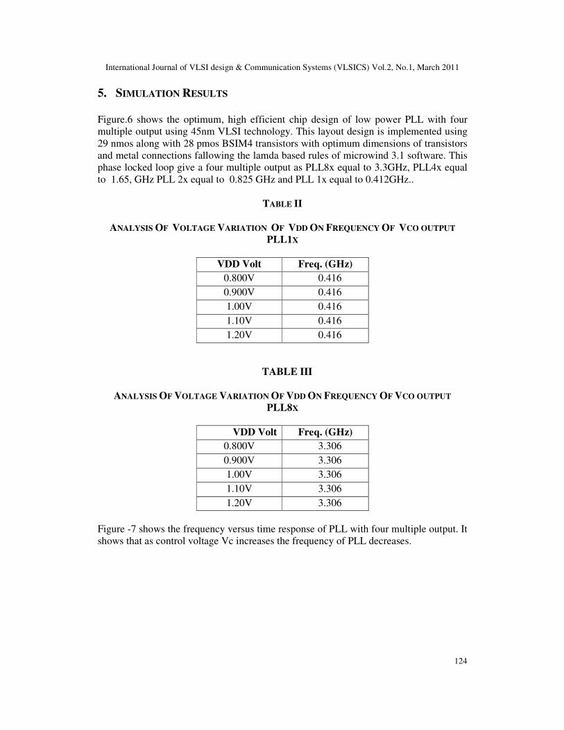
5. SIMULATION RESULTS
Figure.6 shows the optimum, high efficient chip design of low power PLL with four
multiple output using 45nm VLSI technology. This layout design is implemented using
29 nmos along with 28 pmos BSIM4 transistors with optimum dimensions of transistors
and metal connections fallowing the lamda based rules of microwind 3.1 software. This
phase locked loop give a four multiple output as PLL8x equal to 3.3GHz, PLL4x equal
to 1.65, GHz PLL 2x equal to 0.825 GHz and PLL 1x equal to 0.412GHz..
TABLE II
ANALYSIS OF VOLTAGE VARIATION OF VDD ON FREQUENCY OF VCO OUTPUT
PLL1X
VDD Volt Freq. (GHz)
0.800V 0.416
0.900V 0.416
1.00V 0.416
1.10V 0.416
1.20V 0.416
TABLE III
ANALYSIS OF VOLTAGE VARIATION OF VDD ON FREQUENCY OF VCO OUTPUT
PLL8X
VDD Volt Freq. (GHz)
0.800V 3.306
0.900V 3.306
1.00V 3.306
1.10V 3.306
1.20V 3.306
Figure -7 shows the frequency versus time response of PLL with four multiple output. It
shows that as control voltage Vc increases the frequency of PLL decreases.

International Journal of VLSI design & Communication Systems (VLSICS) Vol.2, No.1, March 2011
125
Fig. 7 Frequencies vs. time response of proposed PLL
Fig. 8 Voltage vs. time wave forms of PLL with four multiple output
The PLL is locked at 3.3 GHz frequency. Figure-8 shows voltage verses time
waveforms of PLL’s outputs and inputs. When control voltage is reaches to 0.415 volt,
PLL is locked to the frequency of 3.3 GHz. Multiple output of the PLL gives multiple
frequencies of amplitude 1volt.
Above table II & III shows that, though there is variation of supply VDD from 0.8V to
1.2V, the output of PLL remained stable which proved the high stability of the PLL.
From the parametric analysis of designed PLL the power dissipation measured by VDD
at 1V is found to be 0.211mw, which shows that power consumption is very low (Low
power).
International Journal of VLSI design & Communication Systems (VLSICS) Vol.2, No.1, March 2011
126
Thus the effort has been taken to design high efficient, optimum area chip for PLL with
four outputs.
6. CONCLUSION
The proposed PLL is designed using 45 nm CMOS/VLSI technology with microwind
3.1. This PLL gives a four multiple outputs as PLL8x, PLL4x, PLL2x and PLL1x
simultaneously. This can be used for multichanneling communication system which in
turn provides a very fast multitasking communication. This layout design is
implemented using 29 nmos along with 28 pmos BSIM4 transistors. Though there is the
variation of supply voltage VDD from 0.8V to 1.2V, all the output of proposed PLL is
found stable which proves the high stability of the PLL. From the parametric analysis of
design tool, the power dissipation measured by VDD at 1Volt is found 0.211miliwatt,
which shows that power consumption is very low. In this way very high efficient, low
power optimum area chip is designed for phase locked loop with four multiple outputs
as PLL8x, PLL4x, and PLL2x & PLL1x of 3.3 GHz 1.65 GHz, 0.825 GHz, and 0.412
GHz respectively.
ACKNOWLEDGEMENT
The authors wish to thank Vinay Sharma, Director, Ni2 logic design Pvt. Ltd., for
simulating discussions
REFERENCES
[1] E. Sicard, Syed Mahfuzul Aziz, “introducing 45 nm technology in Microwind3,” microwind
application note.
[2] Navid Azizi, Student Member, IEEE, Muhammad M. Khellah, Member, IEEE, Vivek K. De,
Senior Member, IEEE,and Farid N. Najm, Fellow, IEEE,”Aware Low-Power Design and
Block.” IEEE transactions on very large scale integration (vlsi) systems, vol. 15, no. 7, july 2007
[3] E. Sicard, S. Delman- Bendhia, “Deep submicron CMOS Design”.
[4] S. Borkar, T. Karnik, S. Narendra, T. Tschanz, A. Keshavarzi, and V. De, “Parameter variations
and impact on circuits and microarchitecture,” in Proc. Design Autom. Conf., 2003, pp. 338–342.
[5] Fernando Rangel De Sousa, “A reconfigurable high frequency phase-locked loop” IEEE
transactions on instrumentation & measurement Vol. 53 No. 4 Aug. 2004.
[6] Recardo Gonzalez, “Supply and threshold voltage scaling for low power CMOS” IEEE journal
of solid state circuits Vol. 32 No. 8 April 1997.
[7] Zuoding Wang, “An Analysis of Charge-Pump Phase-Locked Loops” IE EE transactions on
circuits and systemsi: regular papers, vol. 52, no. 10, October 2005.
[8] Oscal T. – C. Chen “A power efficient wide range phase locked loop” IEEE journal of solid
state circuits vol. 37 No. 1 January 2002.
[9] R. E. Best, “Phase locked loops design, simulation and application”, Mc Graw Hill 2003,
ISBMO-07-14/20/8.
[10] Y. Eken and J. Uyemura, “A 5.9GHz Voltage Controlled Ring in 0.18- µm CMOS,” IEEE
Journal of Solid State Circuits, vol. 39, no. 1, Jan. 1997, pp. 230-233.


