Embed Size (px)
Citation preview
(This is a sample cover image for this issue. The actual cover is not yet available at this time.)
This article appeared in a journal published by Elsevier. The attachedcopy is furnished to the author for internal non-commercial researchand education use, including for instruction at the authors institution
and sharing with colleagues.
Other uses, including reproduction and distribution, or selling orlicensing copies, or posting to personal, institutional or third party
websites are prohibited.
In most cases authors are permitted to post their version of thearticle (e.g. in Word or Tex form) to their personal website orinstitutional repository. Authors requiring further information
regarding Elsevier’s archiving and manuscript policies areencouraged to visit:
http://www.elsevier.com/copyright
Author's personal copy
Catastrophic caldera-forming eruptions: Thermomechanics and implications foreruption triggering and maximum caldera dimensions on Earth
P.M. Gregg a,⁎, S.L. de Silva a, E.B. Grosfils b, J.P. Parmigiani c
a College of Earth, Oceanic, and Atmospheric Sciences, 104 CEOAS Admin Bldg., Oregon State University, Corvallis, OR, 97331, United Statesb Geology Department, 185 E. Sixth Street, Pomona College, Claremont, CA, 91711, United Statesc Dept. of Mechanical, Industrial and Manufacturing Engineering, Oregon State University, Corvallis, OR, 97331, United States
a b s t r a c ta r t i c l e i n f o
Article history:Received 5 April 2012Accepted 4 June 2012Available online 13 June 2012
Keywords:Caldera collapseFinite-element modelMohr–Coulomb failureGeodynamic modelMagma chamber ruptureSurface displacementTumescenceResurgenceThermomechanics
Approximately every 100,000 years the Earth experiences catastrophic caldera-forming “supereruptions” that areconsidered to be one of the most hazardous natural events on Earth. Utilizing new temperature-dependent,viscoelastic numerical models that incorporate a Mohr-Coulomb failure criterion, we find that eruptive failureof the largest magma chambers is a function of the geometry of the overlying roof and the location of thebrittle-ductile transition. In particular, the ductile halo created around the hotmagma chamber buffers increasingoverpressures and prevents pressure relief via magmatic injection from the magma chamber. The numericalresults indicate that as chamber volume increases, the higher temperatures in the host rock and the decrease inthe roof aspect ratio cause a shift from reservoir-triggered eruption to an external roof-triggered mechanism.Specifically, as overpressure increases within the largest magma chambers, extensive uplift in the overlyingroof promotes the development of through-going faults that may trigger eruption and caldera collapse fromabove.We find that formagma chamber volumes>103 km3, and roof aspect ratios (depth/width)b0.3,moderatemagma chamber overpressures (b30 MPa) will cause extensive through-going fault development in the overly-ing roof. This result indicates an externalmechanism, caused by fault propagation in the roof, is a likely trigger forthe largest caldera forming eruptions. The thermomechanical models also provide an estimate of the maximumsize of magma chamber growth in a pristine host material and, thus, an estimate of the maximum size ofthe resultant caldera. We find a maximum reservoir volume range of 104–105 km3 for shallow crustal magmachambers emplaced at depths to the top of the magma chamber of 3–7 km. These volumes produce maximumcaldera areas of 103–104 km2, comparable to the largest calderas observed on Earth (e.g., Toba). Thesethermomechanical models offer critical new insight into the mechanics of catastrophic caldera collapse andprovide a numerical construct for predicting how eruption is triggered in the largest crustal magma chambers.
© 2012 Elsevier B.V. All rights reserved.
1. Introduction
Catastrophic caldera-forming eruptions that emplace 1000s of cubickilometers of ignimbrites are amongst the most devastating of geologicphenomena. The calderas left in the wake of these explosive events are10s of kilometers in diameter (e.g., Smith and Bailey, 1968; Lipman,1984) and the magma bodies that supply these events are thoughtto be as much as an order of magnitude larger in volume (Smithand Shaw, 1979). Growing an eruptible magma reservoir of this sizerequires tens of thousands to hundreds of thousands of years ofmaterialand thermal fluxes well in excess of average mantle to crust flows(de Silva and Gosnold, 2007; Annen, 2009). Over that time period, re-peated intrusions from below heat the host rock in the vicinity of themagma reservoir and enhance its ductility (Annen and Sparks, 2002;Jellinek and DePaolo, 2003; de Silva et al., 2006; de Silva and Gosnold,
2007; Annen et al., 2008; Karlstrom et al., 2010), allowing the reservoirto growwithout triggeringmagma evacuation through intrusion and/oreruption (Jellinek and DePaolo, 2003; Annen et al., 2006). Nevertheless,since a preliminary plinian eruption is a common feature of manycatastrophic caldera-forming eruptions (e.g., Druitt and Sparks, 1984),a common mechanism invoked for the onset of caldera collapse is therelief of overpressure through an initial eruption from the magmachamber (Roche et al., 2000; Roche and Druitt, 2001). The resultantunderpressurization will rapidly deflate the magma chamber andpromote reverse ring faulting through the roof, leading to calderacollapse (Roche et al., 2000; Kennedy et al., 2004; Acocella, 2006; Geyeret al., 2006; Scandone and Acocella, 2007; Simakin and Ghassemi,2010). However, if the ductile region around a magma chamber inhibitsdike and sill formation (Jellinek and DePaolo, 2003), it is difficult to citea pre-cursor dike injection as the optimal trigger for caldera-formingeruptions in large systems. Furthermore, analog models indicate thatprecursor eruptions must drain a significant portion of themagma reser-voir (10–60%; Geyer et al., 2006) for caldera onset. Finally, many of thelargest calderas do not record evidence of an initial plinian eruption
Journal of Volcanology and Geothermal Research 241–242 (2012) 1–12
⁎ Corresponding author. Tel.: +1 541 737 4915.E-mail address: [email protected] (PM. Gregg).
0377-0273/$ – see front matter © 2012 Elsevier B.V. All rights reserved.doi:10.1016/j.jvolgeores.2012.06.009
Contents lists available at SciVerse ScienceDirect
Journal of Volcanology and Geothermal Research
j ourna l homepage: www.e lsev ie r .com/ locate / jvo lgeores
Author's personal copy
that would underpressurize the magma chamber and catalyze calderacollapse (Druitt and Sparks, 1984; Sparks et al., 1985; de Silva et al.,2006; Chesner, 2012). Thus, critical gaps in our knowledge of themechanics of triggering the largest silicic eruptions remain.
Numerical models have been utilized extensively to investigate theformation of collapse calderas at a variety of size scales (Gudmundsson,1988; Gudmundsson, 1998; Burov and Guillou-Frottier, 1999; Guillou-Frottier et al., 2000; Folch and Marti, 2004; Hardy, 2008; Kinvig et al.,2009; Simakin and Ghassemi, 2010; Karlstrom et al., 2012). Some ofthese efforts have focused on the elastic problem (e.g., Gudmundsson,1998), and almost all have focused on rapidly underpressurizing themagma chamber via a precursor eruption to trigger caldera formation(e.g., Kinvig et al., 2009). The thermomechanical models of Burov andGuillou-Frottier (1999) provide an examination of fault developmentdue to uplift in the crust above a pressurized magma chamber prior torapid underpressurization triggered by a central vent eruption, and aresome of the first to illustrate fault formation. However, these numericalexperiments did not explore the implications of developing weaknessesin the roof overlying a magma chamber in triggering eruption (Burovand Guillou-Frottier, 1999; Guillou-Frottier et al., 2000). Subsequentinvestigations by Simakin and Ghassemi (2010) impose pre-existingzones of weakness in the roof and explore the role of pre-existing faultsin the eruption behavior of a volcanic system. While these numericalmodeling studies greatly advanced our understanding of catastrophiccaldera formation, none have focused on the mechanism(s) triggeringcaldera eruptions or the mechanical size limitations of building largemagmatic systems.
Although large caldera forming eruptions have a potentiallydevastating impact on the local and global environment, little is knownabout the maximum size and frequency of these events (Mason et al.,2004). Of particular interest is whether there is an absolute limit to thepotential size of eruptions on Earth andhow themagmabody accumulat-ing in the crustmay govern this size limit. The accretion of large bodies ofmagma in the crust has been the topic of several previous investigations(Annen and Sparks, 2002; Jellinek and DePaolo, 2003; de Silva et al.,2006; de Silva and Gosnold, 2007; Annen et al., 2008; Karlstrom et al.,2010). Of particular note are the models of magma chamber growthdeveloped by Jellinek and DePaolo (2003), which reveal that the ductileshell generated around a very large magma reservoir will prevent dikeinitiation and allow the reservoir to grow indefinitely without eruption.This finding led Jellinek and DePaolo (2003) to pose two critical ques-tions: (1) what mechanics limit the maximum size of magma chambergrowth; and (2) what ultimately triggers eruption of the largest magmachambers? The primary field constraints available to provide limits onthe largest eruptions are the resultant collapse caldera areas and theextrusive lava volumes. While these surface expressions provide crucialinformation about the magmatic plumbing systems that feed theseeruptions, there are no detailed mechanical models which link calderasize and erupted volume to the size of the reservoir beneath. In thispaper, we investigate both the eruption trigger in the largest systemsand the mechanics limiting their size.
To investigate the pre-collapse evolution of large silicic magmachambers and the maximum size of magma chamber growth, wedevelop a new viscoelastic model that incorporates a temperature-dependent formulation for viscosity and a Mohr–Coulomb failurecriterion. This paper is organized as follows:first, elastic and viscoelasticnumerical modeling advancements are benchmarked against ana-lytical solutions for a pressurized spherical magma chamber. Second,the effects of incorporating a temperature-dependent viscosity andtemperature-dependent material parameters into the viscoelasticrheology are investigated. Third, the numerical models are applied toa spectrum of magma chamber geometries. The incorporation of aMohr–Coulomb failure criterion in the numerical model allows forcritical investigation of fault formation in the overlying roof and itsrole in triggering eruption as the system evolves. Finally, we compareour numerical results to the global database of collapse calderas.
2. Analytical solution
The analytical solution for the surface deformation in response toa pressurized point source at depth in an elastic half space (Mogi,1958) is widely utilized to describe the pressurization of a sphericalmagma chamber at depth within the crust. In this solution, the Earth'scrust is considered to be an ideal semi-infinite elastic body and theradius of the source, a, is assumed to be much less than the depthto the center of the source, d. It follows that the horizontal and verticaldisplacements at the surface, Ux and Uz respectively, are functions ofsource location and the elastic properties of the crust:
Ux ¼ΔPa3xr3
3K þ 4G2G 3K þ Gð Þ ; ð1Þ
Uz ¼ΔPa3dr3
3K þ 4G2G 3K þ Gð Þ ; ð2Þ
where ΔP is the change in pressure of the sphere, r is the radial distanceto the mid-point of the source, K is the bulk modulus, and G is the shearmodulus.
While the elastic model has proven to be effective for describingsurface displacement in small reservoir systems (McTigue, 1987;Grosfils, 2007), when a/d≪1 or the material properties are not purelyelastic, the Mogi model may not be effective (Newman et al., 2001;Newman et al., 2006). As such, to calculate the predicted deformationin large magmatic systems with long thermal histories it is necessaryto also consider the viscous and temperature-dependent responses ofthe crust to changes in magma chamber pressurization. To this end,we first consider the analytical solution for a linear viscoelasticmaterial,which will be used to benchmark our numerical solutions.
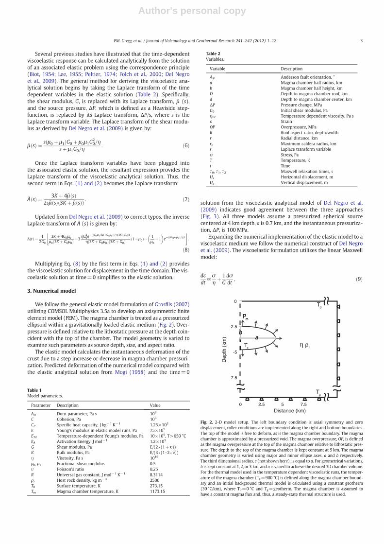
A simple description of a viscoelastic material is a linear Maxwellmodel in which the instantaneous elastic response of the material isgiven by a spring with a stiffness, given by G, while the time-dependentviscous response is defined by a dashpot with viscosity, η. The deforma-tion response of a viscoelastic material is further defined in the general-ized Maxwell model (Fig. 1), which utilizes j linear Maxwell series inparallel with each other. The viscoelastic response is dependent on thecharacteristic relaxation times given by:
τ0 ¼ ηG0μ1
ð3Þ
τ1 ¼ 3K þ G0
3K þ G0μ0τ0 ð4Þ
τ2 ¼ τ0μ0
ð5Þ
where μ0 and μ1 are the fractional moduli.
Fig. 1. Generalized Maxwell model.
2 PM. Gregg et al. / Journal of Volcanology and Geothermal Research 241–242 (2012) 1–12
Author's personal copy
Several previous studies have illustrated that the time-dependentviscoelastic response can be calculated analytically from the solutionof an associated elastic problem using the correspondence principle(Biot, 1954; Lee, 1955; Peltier, 1974; Folch et al., 2000; Del Negroet al., 2009). The general method for deriving the viscoelastic ana-lytical solution begins by taking the Laplace transform of the timedependent variables in the elastic solution (Table 2). Specifically,the shear modulus, G, is replaced with its Laplace transform, ~μ (s),and the source pressure, ΔP, which is defined as a Heaviside step-function, is replaced by its Laplace transform, ΔP/s, where s is theLaplace transform variable. The Laplace transform of the shear modu-lus as derived by Del Negro et al. (2009) is given by:
~μ sð Þ ¼ s μ0 þ μ1ð ÞG0 þ μ0μ1G20=η
sþ μ1G0=η: ð6Þ
Once the Laplace transform variables have been plugged intothe associated elastic solution, the resultant expression provides theLaplace transform of the viscoelastic analytical solution. Thus, thesecond term in Eqs. (1) and (2) becomes the Laplace transform:
~A sð Þ ¼ 3K þ 4~μ sð Þ2s~μ sð Þ 3K þ ~μ sð Þð Þ : ð7Þ
Updated from Del Negro et al. (2009) to correct typos, the inverseLaplace transform of à (s) is given by:
A tð Þ ¼ 12G0
3K þ 4G0μ0
μ0 3K þ G0μ0ð Þ−3ηG2
0e− G0μ1 3KþG0μ0ð Þð Þ=η 3KþG0ð Þð Þt
η 3K þ G0μ0ð Þ 3K þ G0ð Þ 1−μ0ð Þ− 1μ0
−1� �
e− G0μ0μ1ð Þ=ηð Þt$ %
:
ð8Þ
Multiplying Eq. (8) by the first term in Eqs. (1) and (2) providesthe viscoelastic solution for displacement in the time domain. The vis-coelastic solution at time=0 simplifies to the elastic solution.
3. Numerical model
We follow the general elastic model formulation of Grosfils (2007)utilizing COMSOL Multiphysics 3.5a to develop an axisymmetric finiteelement model (FEM). The magma chamber is treated as a pressurizedellipsoid within a gravitationally loaded elastic medium (Fig. 2). Over-pressure is defined relative to the lithostatic pressure at the depth coin-cident with the top of the chamber. The model geometry is varied toexamine such parameters as source depth, size, and aspect ratio.
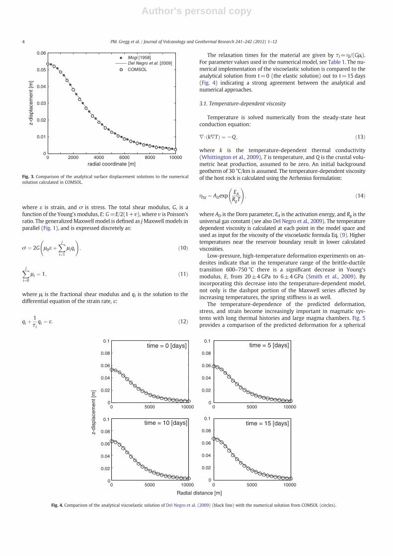
The elastic model calculates the instantaneous deformation of thecrust due to a step increase or decrease in magma chamber pressuri-zation. Predicted deformation of the numerical model compared withthe elastic analytical solution from Mogi (1958) and the time=0
solution from the viscoelastic analytical model of Del Negro et al.(2009) indicates good agreement between the three approaches(Fig. 3). All three models assume a pressurized spherical sourcecentered at 4 km depth, a is 0.7 km, and the instantaneous pressuriza-tion, ΔP, is 100 MPa.
Expanding the numerical implementation of the elastic model to aviscoelastic medium we follow the numerical construct of Del Negroet al. (2009). The viscoelastic formulation utilizes the linear Maxwellmodel:
dεdt
∝σηþ 1Gdσdt
; ð9Þ
Table 1Model parameters.
Parameter Description Value
AD Dorn parameter, Pa s 109
C Cohesion, Pa 106
CP Specific heat capacity, J kg−1 K−1 1.25×10³
E Young's modulus in elastic model runs, Pa 75×109
ETd Temperature-dependent Young's modulus, Pa 10×109, T>650 °CEA Activation Energy, J mol−1 1.2×10⁵
G Shear modulus, Pa E/(2*(1+υ))K Bulk modulus, Pa E/(3*(1–2*υ))η Viscosity, Pa s 1016
μ0, μ1 Fractional shear modulus 0.5υ Poisson's ratio 0.25R Universal gas constant, J mol−1 K−1 8.3114ρr Host rock density, kg m−3 2500T0 Surface temperature, K 273.15Tm Magma chamber temperature, K 1173.15
Table 2Variables.
Variable Description
AΨ Anderson fault orientation, °a Magma chamber half radius, kmb Magma chamber half height, kmD Depth to magma chamber roof, kmd Depth to magma chamber center, kmΔP Pressure change, MPaG0 Initial shear modulus, PaηTd Temperature dependent viscosity, Pa sε StrainOP Overpressure, MPaR Roof aspect ratio, depth/widthr Radial distance, kmrc Maximum caldera radius, kms Laplace transform variableσ Stress, PaT Temperature, Kt Timeτ0, τ1, τ2 Maxwell relaxation times, sUx Horizontal displacement, mUz Vertical displacement, m
-5
-2.5
-7.5
0
Dep
th (
km)
52.5 7.50Distance (km)
bbbaaa
PPmmPm
Tc
T0
η ρr
Tg
Fig. 2. 2-D model setup. The left boundary condition is axial symmetry and zerodisplacement, roller conditions are implemented along the right and bottom boundaries.The top of the model is free to deform, as is the magma chamber boundary. The magmachamber is approximated by a pressurized void. The magma overpressure, OP, is definedas the magma overpressure at the top of the magma chamber relative to lithostatic pres-sure. The depth to the top of the magma chamber is kept constant at 5 km. The magmachamber geometry is varied using major and minor ellipse axes, a and b respectively.The third dimensional radius, c (not shown here), is equal to a. For geometrical variations,b is kept constant at 1, 2, or 3 km, and a is varied to achieve the desired 3D chamber volume.For the thermal model used in the temperature dependent viscoelastic runs, the temper-ature of the magma chamber (Tc=900 °C) is defined along the magma chamber bound-ary and an initial background thermal model is calculated using a constant geotherm(30 °C/km), where T0=0 °C and Tg=geotherm. The magma chamber is assumed tohave a constant magma flux and, thus, a steady-state thermal structure is used.
3PM. Gregg et al. / Journal of Volcanology and Geothermal Research 241–242 (2012) 1–12
Author's personal copy
where ε is strain, and σ is stress. The total shear modulus, G, is afunction of the Young's modulus, E: G=E/2(1+υ), where υ is Poisson'sratio. The generalizedMaxwell model is defined as jMaxwell models inparallel (Fig. 1), and is expressed discretely as:
σ ¼ 2G μ0ε þXji¼1
μ iqi
!; ð10Þ
Xji¼0
μ i ¼ 1; ð11Þ
where μi is the fractional shear modulus and qi is the solution to thedifferential equation of the strain rate, ε:
qi þ1τiqi ¼ ε: ð12Þ
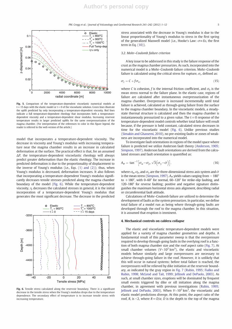
The relaxation times for the material are given by τI=ηi/(Gμi).For parameter values used in the numerical model, see Table 1. The nu-merical implementation of the viscoelastic solution is compared to theanalytical solution from t=0 (the elastic solution) out to t=15 days(Fig. 4) indicating a strong agreement between the analytical andnumerical approaches.
3.1. Temperature-dependent viscosity
Temperature is solved numerically from the steady-state heatconduction equation:
∇⋅ k∇Tð Þ ¼ −Q ; ð13Þ
where k is the temperature-dependent thermal conductivity(Whittington et al., 2009), T is temperature, and Q is the crustal volu-metric heat production, assumed to be zero. An initial backgroundgeotherm of 30 °C/km is assumed. The temperature-dependent viscosityof the host rock is calculated using the Arrhenius formulation:
ηTd ¼ ADexpEARgT
!; ð14Þ
where AD is the Dorn parameter, EA is the activation energy, and Rg is theuniversal gas constant (see also Del Negro et al., 2009). The temperaturedependent viscosity is calculated at each point in the model space andused as input for the viscosity of the viscoelastic formula Eq. (9). Highertemperatures near the reservoir boundary result in lower calculatedviscosities.
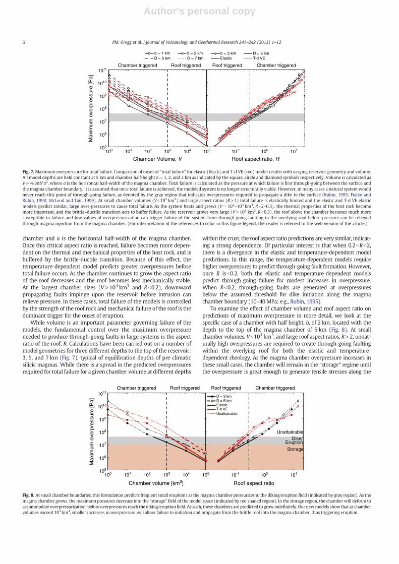
Low-pressure, high-temperature deformation experiments on an-desites indicate that in the temperature range of the brittle-ductiletransition 600–750 °C there is a significant decrease in Young'smodulus, E, from 20±4 GPa to 6±4 GPa (Smith et al., 2009). Byincorporating this decrease into the temperature-dependent model,not only is the dashpot portion of the Maxwell series affected byincreasing temperatures, the spring stiffness is as well.
The temperature-dependence of the predicted deformation,stress, and strain become increasingly important in magmatic sys-tems with long thermal histories and large magma chambers. Fig. 5provides a comparison of the predicted deformation for a spherical
0 2000 4000 6000 8000 100000
0.01
0.02
0.03
0.04
0.05
0.06
radial coordinate [m]
z-di
spla
cem
ent [
m]
Mogi [1958]Del Negro et al. [2009]COMSOL
Fig. 3. Comparison of the analytical surface displacement solutions to the numericalsolution calculated in COMSOL.
0 5000 10000 0 5000 100000
0.02
0.04
0.06
0.08
0.1
0
0.02
0.04
0.06
0.08
0.1
0
0.02
0.04
0.06
0.08
0.1
0
0.02
0.04
0.06
0.08
0.1
time = 0 [days]
z-di
spla
cem
ent [
m]
time = 5 [days]
0 5000 10000 0 5000 10000
time = 10 [days]
Radial distance [m]
time = 15 [days]
Fig. 4. Comparison of the analytical viscoelastic solution of Del Negro et al. (2009) (black line) with the numerical solution from COMSOL (circles).
4 PM. Gregg et al. / Journal of Volcanology and Geothermal Research 241–242 (2012) 1–12
Author's personal copy
model that incorporates a temperature-dependent viscosity. Thedecrease in viscosity and Young's modulus with increasing tempera-ture near the magma chamber results in an increase in calculateddeformation at the surface. The practical effect is that, for an assumedΔP, the temperature-dependent viscoelastic rheology will alwayspredict greater deformation than the elastic rheology. The increase inpredicted deformation is due to the proportionality of displacement tothe inverse of Young's modulus (i.e., Eqs. (1) and (2)); thus, whenYoung's modulus is decreased, deformation increases. It also followsthat incorporating a temperature-dependent Young's modulus signifi-cantly decreases tensile stresses predicted along the magma chamberboundary of the model (Fig. 6). While the temperature-dependentviscosity, η, decreases the calculated stresses in general, it is the initialincorporation of a temperature-dependent Young's modulus thatgenerates the most significant decrease. The decrease in the predicted
stress associated with the decrease in Young's modulus is due to thelinear proportionality of Young's modulus to stress in the first springof the generalized Maxwell model (i.e., Hooke's Law: σ∝Eε, the firstterm in Eq. (10)).
3.2. Mohr–Coulomb failure criterion
A key issue to be addressed in this study is the failure response of thecrust as themagma chamber pressurizes. As such, incorporated into thenumerical model is a Mohr–Coulomb failure criterion. Mohr–Coulombfailure is calculated using the critical stress for rupture, σc, defined as:
σ c ¼ C þ fσn; ð15Þ
where C is cohesion, f is the internal friction coefficient, and σn is themean stress normal to the failure plane. In the elastic case, regions offailure are calculated after instantaneous overpressurization of themagma chamber. Overpressure is increased incrementally until totalfailure is achieved, calculated as through-going failure from the surfaceto the magma chamber boundary. In the viscoelastic models, a steady-state thermal structure is calculated and then the magma chamber isinstantaneously pressurized to a given value. The t=0 response of thetemperature-dependent model controls whether total failure will resultbecause, if the pressure is held constant, calculated stress decreases intime for the viscoelastic model (Fig. 6). Unlike previous studies(Simakin and Ghassemi, 2010), no pre-existing faults or zones of weak-ness are incorporated into the numerical model.
To investigate fault orientations in regions of themodel spacewherefailure is predicted we utilize Anderson fault theory (Anderson, 1905;Simpson, 1997). Anderson fault orientations are derived from the calcu-lated stresses and fault orientation is quantified as:
AΨ ¼ tan−1 σα−σβ ;ffiffiffi3
pσγ− �σ� �h i
; ð16Þ
where σα, σβ, and σγ are the three-dimensional stress axis system and �σis themean stress (Simpson, 1997). AΨ yields values ranging from−180°to +180°, with 0–60° for normal, 60–120° for strike-slip faulting, and120–180° for reverse faulting; positive and negative signature distin-guishes the maximum horizontal stress axis alignment, describing radialor circumferential fault attitude.
Calculations of Mohr–Coulomb failure are utilized to determine thedevelopment of faults as the systempressurizes. In particular, we definetotal failure of a model run as being where through-going faults aredeveloped through the roof to the magma chamber. In this situation,it is assumed that eruption is imminent.
4. Mechanical controls on caldera collapse
The elastic and viscoelastic temperature-dependent models wereapplied for a variety of magma chamber geometries and depths. Afundamental result of this parameter sweep is that the overpressurerequired to develop through-going faults in the overlying roof is a func-tion of both magma chamber size and the roof aspect ratio (Fig. 7). Atsmall chamber volumes (Vb102 km3), the elastic and viscoelasticmodels behave similarly and large overpressures are necessary toachieve through-going failure in the roof. However, it is unlikely thatthis will occur in natural systems; before total failure is reached, theoverpressures will be relieved by dike initiation at the reservoir bound-ary, as indicated by the gray region in Fig. 7 (Rubin, 1995; Fialko andRubin, 1998; McLeod and Tait, 1999; Jellinek and DePaolo, 2003). Assuch, at small chamber sizes, eruptions will be dominated by frequentsmall events triggered by dike or sill initiation along the magmachamber, in agreement with previous investigations (Rubin, 1995;Jellinek and DePaolo, 2003). When V~102 km3, the viscoelastic andelastic model predictions diverge. At this point, the aspect ratio of theroof, R, is b2, where R=D/a; D is the depth to the top of the magma
0 2000 4000 6000 8000 100000
0.02
0.04
0.06
0.08
0.1
radial coordinate [m]
z-di
spla
cem
ent [
m]
ElasticT
c = 800oC
Tc = 900oC
Tc = 1000oC
Full Temp-dep ηTd only
Fig. 5. Comparison of the temperature-dependent viscoelastic numerical models att=15 days with the elastic model or t=0 of the viscoelastic solution. Green lines illustratethe uplift predicted by only incorporating a temperature-dependent viscosity. Red linesindicate a full temperature-dependent rheology that incorporates both a temperature-dependent viscosity and a temperature-dependent shear modulus. Increasing reservoirtemperature results in larger predicted uplifts for the same overpressurization of themagma chamber. (For interpretation of the references to color in this figure legend, thereader is referred to the web version of the article.)
-40 -20 0 20 40 60-4800
-4400
-4000
-3600
-3200
Tensile stress [MPa]
Dep
th [m
]
t = 0 t = 15 days
ElasticT
c = 900oC T
c = 1000oC
Tc = 800oC
Fig. 6. Tensile stress calculated along the reservoir boundary. There is a significantdecrease in the tensile stress when the Young's modulus drops due to the temperaturedependence. The secondary effect of temperature is to increase tensile stress withincreasing temperature.
5PM. Gregg et al. / Journal of Volcanology and Geothermal Research 241–242 (2012) 1–12
Author's personal copy
chamber and a is the horizontal half-width of the magma chamber.Once this critical aspect ratio is reached, failure becomes more depen-dent on the thermal and mechanical properties of the host rock, and isbuffered by the brittle-ductile transition. Because of this effect, thetemperature-dependent model predicts greater overpressures beforetotal failure occurs. As the chamber continues to grow the aspect ratioof the roof decreases and the roof becomes less mechanically stable.At the largest chamber sizes (V>104 km3 and Rb0.2), downwardpropagating faults impinge upon the reservoir before intrusion canrelieve pressure. In these cases, total failure of the models is controlledby the strength of the roof rock and mechanical failure of the roof is thedominant trigger for the onset of eruption.
While volume is an important parameter governing failure of themodels, the fundamental control over the maximum overpressureneeded to produce through-going faults in large systems is the aspectratio of the roof, R. Calculations have been carried out on a number ofmodel geometries for three different depths to the top of the reservoir:3, 5, and 7 km (Fig. 7), typical of equilibration depths of pre-climaticsilicic magmas. While there is a spread in the predicted overpressuresrequired for total failure for a given chamber volume at different depths
within the crust, the roof aspect ratio predictions are very similar, indicat-ing a strong dependence. Of particular interest is that when 0.2bRb2,there is a divergence in the elastic and temperature-dependent modelpredictions. In this range, the temperature-dependent models requirehigher overpressures to predict through-going fault formation. However,once R isb0.2, both the elastic and temperature-dependent modelspredict through-going failure for modest increases in overpressure.When Rb0.2, through-going faults are generated at overpressuresbelow the assumed threshold for dike initiation along the magmachamber boundary (10–40MPa; e.g., Rubin, 1995).
To examine the effect of chamber volume and roof aspect ratio onpredictions of maximum overpressure in more detail, we look at thespecific case of a chamber with half height, b, of 2 km, located with thedepth to the top of the magma chamber of 5 km (Fig. 8). At smallchamber volumes, Vb103 km3, and large roof aspect ratios, R>2, unnat-urally high overpressures are required to create through-going faultingwithin the overlying roof for both the elastic and temperature-dependent rheology. As the magma chamber overpressure increases inthese small cases, the chamber will remain in the “storage” regime untilthe overpressure is great enough to generate tensile stresses along the
Roof aspect ratio, R
105
100 102 103 104 105 10-1 101100101
106
107
108
109
1010
1011
Chamber Volume, V
Max
imum
ove
rpre
ssur
e [P
a]
D = 3 kmD = 5 km D = 7 km
b = 2 km b = 3 kmb = 1 kmElastic T-d VE
Chamber triggered Roof triggered Chamber triggeredRoof triggered
Fig. 7.Maximum overpressure for total failure. Comparison of onset of “total failure” for elastic (black) and T-d VE (red) model results with varying reservoir geometry and volume.All model depths are held constant at 5 km and chamber half-height b=1, 2, and 3 km as indicated by the square, circle and diamond symbols respectively. Volume is calculated asV=4/3πb*a2, where a is the horizontal half-width of the magma chamber. Total failure is calculated as the pressure at which failure is first through-going between the surface andthe magma chamber boundary. It is assumed that once total failure is achieved, the modeled system is no longer structurally viable. However, in many cases a natural system wouldnever reach this point of through-going failure, as denoted by the gray region that indicates overpressures required to propagate a dike to the surface (Rubin, 1995; Fialko andRubin, 1998; McLeod and Tait, 1999). At small chamber volumes (Vb102 km3) and large aspect ratios (R>1) total failure is elastically limited and the elastic and T-d VE elasticmodels predict similar, large over-pressures to cause total failure. As the system heats and grows (V=102–103 km3, R~2–0.3), the thermal properties of the host rock becomemore important, and the brittle–ductile transition acts to buffer failure. As the reservoir grows very large (V>103 km3, Rb0.3), the roof above the chamber becomes much moresusceptible to failure and low values of overpressurization can trigger failure of the system from through-going faulting in the overlying roof before pressure can be relievedthrough magma injection from the magma chamber. (For interpretation of the references to color in this figure legend, the reader is referred to the web version of the article.)
Roof aspect ratio
1011
1010
109
108
107
106
105
100 101 102 103 104 105 10-1 100 101
Chamber volume [km3]
Max
imum
ove
rpre
ssur
e [P
a]
D = 3 kmD = 5 kmElasticT-d VE
Chamber triggered Roof triggered Chamber triggeredRoof triggered
Dike/Eruption
Storage
Unattainable
Unattainable
Fig. 8. At small chamber boundaries, this formulation predicts frequent small eruptions as themagma chamber pressurizes to the diking/eruption field (indicated by gray region). As themagma chamber grows, the maximum pressures decrease into the “storage” field of the model space (indicated by red shaded region). In the storage region, the chamber will deform toaccommodate overpressurization, before overpressures reach the diking/eruptionfield. As such, these chambers are predicted to grow indefinitely. Our newmodels show that as chambervolumes exceed 103 km3, smaller increases in overpressure will allow failure to initiation and propagate from the brittle roof into the magma chamber, thus triggering eruption.
6 PM. Gregg et al. / Journal of Volcanology and Geothermal Research 241–242 (2012) 1–12
Author's personal copy
chamber boundary that are in excess of the tensile strength of the hostrock, at which point a dike or sill will rupture to relieve the overpressure.As such, in this size range, the predominant eruption triggeringmechanism will be from the magma chamber via dike or sill initiation.When V>102 km3 and Rb2, the thermal effect on the mechanicalproperties of the roof comes into play and the temperature-dependentmodels predict higher maximum overpressures to promote through-going faults. If an elastic model is used, when V>103 km3 and Rb0.5maximum overpressure predictions fall within the range which alsomay produce dike injection from the chamber boundary. Elastic modelswith these geometries predict triggering of eruptions from both faultgeneration in the roof as well as dike injection from the reservoir.Temperature-dependent models in this range predict overpressuresabove the expected dike initiation range, thus indicating that eruptionswill still be triggered from the chamber. When V>104 km3 and Rb0.2,both the elastic and temperature-dependent rheologies predict maxi-mum overpressures that fall within or below the range for dike and sillinitiation. Once this size range is reached, a predominant eruptiontriggering mechanism is predicted to be the mechanical failure of theroof.
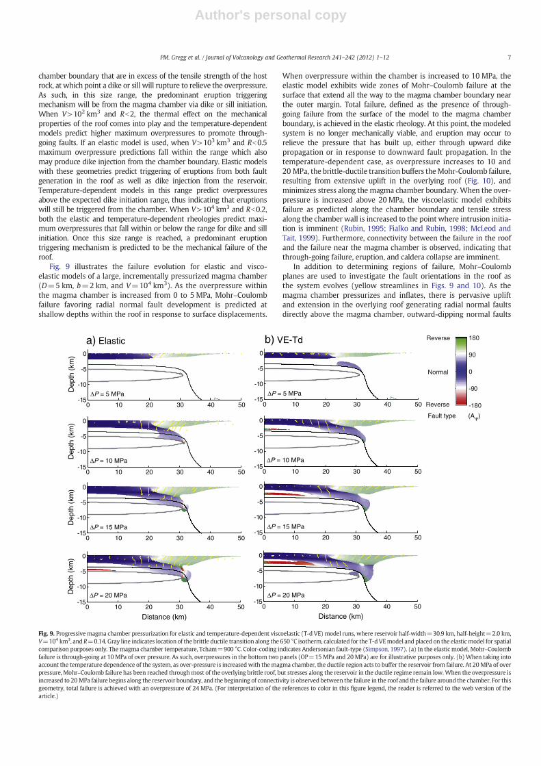
Fig. 9 illustrates the failure evolution for elastic and visco-elastic models of a large, incrementally pressurized magma chamber(D=5 km, b=2 km, and V=104 km3). As the overpressure withinthe magma chamber is increased from 0 to 5 MPa, Mohr–Coulombfailure favoring radial normal fault development is predicted atshallow depths within the roof in response to surface displacements.
When overpressure within the chamber is increased to 10 MPa, theelastic model exhibits wide zones of Mohr–Coulomb failure at thesurface that extend all the way to the magma chamber boundary nearthe outer margin. Total failure, defined as the presence of through-going failure from the surface of the model to the magma chamberboundary, is achieved in the elastic rheology. At this point, the modeledsystem is no longer mechanically viable, and eruption may occur torelieve the pressure that has built up, either through upward dikepropagation or in response to downward fault propagation. In thetemperature-dependent case, as overpressure increases to 10 and20 MPa, the brittle-ductile transition buffers theMohr-Coulomb failure,resulting from extensive uplift in the overlying roof (Fig. 10), andminimizes stress along the magma chamber boundary. When the over-pressure is increased above 20 MPa, the viscoelastic model exhibitsfailure as predicted along the chamber boundary and tensile stressalong the chamber wall is increased to the point where intrusion initia-tion is imminent (Rubin, 1995; Fialko and Rubin, 1998; McLeod andTait, 1999). Furthermore, connectivity between the failure in the roofand the failure near the magma chamber is observed, indicating thatthrough-going failure, eruption, and caldera collapse are imminent.
In addition to determining regions of failure, Mohr–Coulombplanes are used to investigate the fault orientations in the roof asthe system evolves (yellow streamlines in Figs. 9 and 10). As themagma chamber pressurizes and inflates, there is pervasive upliftand extension in the overlying roof generating radial normal faultsdirectly above the magma chamber, outward-dipping normal faults
0 10 20 30 40 50-15
-10
-5
0
ΔP = 5 MPa
Dep
th (
km)
0 10 20 30 40 50-15
-10
-5
0
ΔP = 10 MPaDep
th (
km)
0 10 20 30 40 50-15
-10
-5
0
ΔP = 15 MPa
Dep
th (
km)
0 10 20 30 40 50-15
-10
-5
0
Distance (km)
ΔP = 20 MPaDep
th (
km)
0 10 20 30 40 50-15
-10
-5
0
ΔP = 5 MPa
0 10 20 30 40 50-15
-10
-5
0
ΔP = 10 MPa
0 10 20 30 40 50-15
-10
-5
0
ΔP = 15 MPa
0 10 20 30 40 50-15
-10
-5
0
ΔP = 20 MPa
Distance (km)
a) Elastic b) VE-Td
-180
-90
0
90
180
Normal
Reverse
Reverse
Fault type (AΨ)
Fig. 9. Progressive magma chamber pressurization for elastic and temperature-dependent viscoelastic (T-d VE) model runs, where reservoir half-width=30.9 km, half-height=2.0 km,V=104 km3, and R=0.14. Gray line indicates location of the brittle ductile transition along the 650 °C isotherm, calculated for the T-d VEmodel and placed on the elasticmodel for spatialcomparison purposes only. Themagma chamber temperature, Tcham=900 °C. Color-coding indicates Andersonian fault-type (Simpson, 1997). (a) In the elastic model, Mohr–Coulombfailure is through-going at 10 MPa of over pressure. As such, overpressures in the bottom two panels (OP=15MPa and 20MPa) are for illustrative purposes only. (b) When taking intoaccount the temperature dependence of the system, as over-pressure is increased with the magma chamber, the ductile region acts to buffer the reservoir from failure. At 20 MPa of overpressure, Mohr–Coulomb failure has been reached throughmost of the overlying brittle roof, but stresses along the reservoir in the ductile regime remain low.When the overpressure isincreased to 20 MPa failure begins along the reservoir boundary, and the beginning of connectivity is observed between the failure in the roof and the failure around the chamber. For thisgeometry, total failure is achieved with an overpressure of 24 MPa. (For interpretation of the references to color in this figure legend, the reader is referred to the web version of thearticle.)
7PM. Gregg et al. / Journal of Volcanology and Geothermal Research 241–242 (2012) 1–12
Author's personal copy
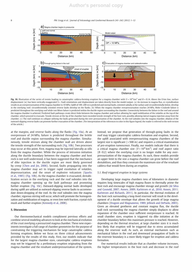
at the margins, and reverse faults along the flanks (Fig. 10a). At anoverpressure of 24 MPa, failure is predicted throughout the brittleroof and ductile region surrounding the magma chamber. Simulta-neously, tensile stresses along the chamber wall are driven abovethe tensile strength of the surrounding rock (Fig. 10b). Two processesmay occur at this point. First, magma may be injected laterally as sillsfrom the magma chamber. While the process of intrusion initiationalong the ductile boundary between the magma chamber and hostrock is not well understood, it has been suggested that the mechanicsof dike injection in the ductile region are most likely governedby creep (Chen and Jin, 2006). Second, faults propagating into themagma chamber may act to trigger rapid exsolution of volatiles,depressurization, and the onset of explosive volcanism (Sparkset al., 1985) (Fig. 10b). As the magma chamber is evacuated, destabi-lization occurs in the overlying rock and the roof subsides into themagma chamber opening up the fault pathways and promotingfurther eruption (Fig. 10c). Outward-dipping normal faults developedduring uplift are utilized as outward-dipping reverse faults to accommo-date down-dropping of the roof. As the roof subsides into the magmachamber, vigorous stirringwill occur, whichwill promote the homogeni-zation andmobilization of magma, or even lowmelt fraction, crystal-richmush and further eruption (Kennedy et al., 2008).
5. Discussion
Our thermomechanical models compliment previous efforts andcombine severalmodeling advances to look at themechanical evolutionof the crust overlying a pressurizedmagma chamber. These new exper-iments investigate a full range of chamber geometries for the purpose ofconstraining the triggering mechanism for large catastrophic calderaforming eruptions. Below we focus on three critical advancementsprovided by the results of this study. First, our models indicate thatfor the largest magma chamber sizes, catastrophic caldera eruptionsmay not be triggered by a preliminary eruption originating from themagma chamber and the resultant underpressurization of the system.
Instead, we propose that generation of through-going faults in theroof may trigger catastrophic caldera formation and eruption. Second,the uplift associated with overpressurizing magma chambers of thelargest size is significant (>500 m) and requires a critical examinationof pre-eruption tumescence. Finally, our models indicate that there isa critical magma chamber size (V>104 km3) and roof aspect ratio(Rb0.2) where the overlying crust is no longer stable for any over-pressurization of the magma chamber. As such, these models providean upper limit to the size a magma chamber can grow before the roofdestabilizes, and thus they constrain themaximum size of the resultantcaldera that would form during an eruption.
5.1. Roof-triggered eruption in large systems
Developing large magma chambers tens of kilometers in diameterrequires long timescales of high magma fluxes to thermally prime thehost rock and encourage magma chamber storage and growth (de Silvaand Gosnold, 2007; Annen, 2009; Karlstrom et al., 2010; Annen, 2011;Karlstrom and Richards, 2011). In particular, the thermal evolution ofthe host rock surrounding a long-lived reservoir will result in the devel-opment of a ductile envelope that allows the growth of large magmachambers (Dragoni and Magnanensi, 1989; Jellinek and DePaolo, 2003).Given an elevated geotherm and constant magma flux, the ductilewall rock surrounding the magma chamber simply displaces to allowexpansion of the chamber once sufficient overpressure is reached. Atsmall chamber sizes, eruption is triggered via dike initiation at thechamber boundary before this maximum pressure is reached. However,depending on the thermal structure, at large chamber sizes it is muchless likely that eruption will be triggered due to stress accumulatedalong the reservoir wall. As such, an external mechanism such asmechanical failure in the roof and downward propagation of faults tothe reservoir boundary is a more likely trigger for eruption and calderaformation.
Our numerical results indicate that as chamber volume increases,the higher temperatures in the host rock and decrease in the roof
0 10 20 30 40 50-15
-10
-5
0
Distance (km)0 10 20 30 40 50
Distance (km)
0 10 20 30 40 50
Distance (km)0 10 20 30 40 50
Distance (km)
Dep
th (
km)
1
w [k
m]
-15
-10
-5
0
Dep
th (
km)
1
w [k
m]
-15
-10
-5
0
Dep
th (
km)
1
w [k
m]
OP = 10 MPa
uplift and normalfaulting
OP = 24 MPa
reverse faulting
a) Magma chamber begins to pressurize
b)Through-going failure in the roof
-15
-10
-5
0
Dep
th (
km)
OP = 10 MPa
magma magma magma injectioninjecinjectiontionmagma injection
c) Evacuation of magma chamber and calderaformation
reversereversreversefaultfaultfaultreversefault
normalnormalnormalfaultfaultfaultnormalfault
roof collapseonset of eruption
Model output
Fig. 10. Illustration of the series of events leading to catastrophic caldera-forming eruption for a magma chamber with V=104 km3 and R=0.14. Above the 0 km line, surfacedisplacement (w) has been vertically exaggerated 5×. Fault orientations and displacement are taken directly from the model output. (a) An increase in magma flux, or crystallizationresults in anoverpressurization of themagma chamber to 10 MPa. Uplift of 100–200 m is predicted and normal faults, oriented radially at the surface and circumferentially below, developin the overlying roof; circumferentially oriented reverse faults develop on the flanks. (b) When the magma chamber overpressurization reaches 24 MPa, Mohr–Coulomb failure ispredicted throughout the overlying roof while vonMises failure is predicted within the ductile region surrounding the chamber. Connectivity between the failure in the roof and aroundthe magma chamber is achieved. Predicted fault pathways create direct links between the magma chamber and surface allowing for rapid mobilization of the volatiles at the top of thechamber, which proceed to evacuate. Tensile stresses at the tip of the chamber have exceeded tensile strength of the host rock, possibly allowing lateral magma injection away from thechamber. (c) The roof continues to collapse utilizing the faults generated during the over-pressurization of the chamber. As the roof subsides into the magma chamber, dilation of theoutward-dipping reverse faults can promote further evacuation of the chamber. (For interpretation of the references to color in this figure legend, the reader is referred to theweb versionof the article.)
8 PM. Gregg et al. / Journal of Volcanology and Geothermal Research 241–242 (2012) 1–12
Author's personal copy
aspect ratio cause a shift from reservoir-triggered eruption to anexternal roof-triggered mechanism with overpressurization of themagma chamber. Fault formation in the overriding roof is commonlyobserved in experimental analog models of caldera formation, but isprimarily investigated assuming underpressurization of the magmachamber prior to the onset of a catastrophic caldera forming eruption(Roche et al., 2000; Kennedy et al., 2004; Acocella, 2006; Geyeret al., 2006). These analog experiments focus on the roof aspectratio and magma chamber deflation necessary for the formation ofstructures in the overlying roof leading to a collapse caldera. Whileunderpressurization of the magma chamber is generally acceptedas the primary driving mechanism for caldera collapse it requires aprecursor eruption to begin magma chamber evacuation. However,requiring a precursor eruption triggered by dike initiation at themagma chamber brings us back to the predicament presentedabove in which the ductile halo developed around a thermallymature magma chamber may inhibit dike initiation (Jellinek andDePaolo, 2003; Karlstrom and Richards, 2011). Furthermore, analogmodels indicate that a large percentage of evacuation is necessary inthe precursor eruption in order to achieve a runaway eruption state lead-ing to caldera collapse. In particular, experiments by Geyer et al. (2006)require a precursor eruption to evacuate 10–60% of themagma chamberbefore triggering the onset of caldera formation. If an initial evacuation isrequired to trigger caldera collapse eruptions, a precursor eruption thatempties volumes of this magnitude should be a common feature in thestratigraphy of caldera systems.
In the scheme of Druitt and Sparks (1984), a precursory eruptiontypically produces a basal fall deposit seen in most small to mediumvolume ignimbrites (b100 km3) and some large ignimbrites suchas the Huckleberry Ridge (Yellowstone, WY) and Bishop Tuff (LongValley, CA). These imply convecting eruption columns associatedwith low mass eruption rates, high eruption velocities and narrowvents. However, many of the largest eruptions lack initial fall depositsin their stratigraphic records (Sparks et al., 1985; de Silva, 1989a;de Silva, 1989b; Chesner, 1998; Lindsay et al., 2001b; Maughanet al., 2002; de Silva et al., 2006; Cas et al., 2011; Folkes et al.,2011). Although one could argue that the absence of evidence is notevidence of absence, it requires a special coincidence that fall depositsare not observed for these eruptions and it is likely that the lack of aprecursor eruption is a characteristic of the largest eruptions, and isjust part of the spectrum of explosive eruptions. It is generally acceptedthat pyroclastic flows are associated with high mass eruption rates andwide vents that accompany the onset of caldera collapse (e.g., Druittand Sparks, 1984). As such, when through-going failure is predictedby our numerical models, the mechanical instability of the roof shouldtrigger a rapid evacuation of the magma chamber and lead to earlycaldera collapse and large pyroclastic eruptions that produce dominantlyignimbrites. That said, our model does not deal with eruption dynamicsand is not meant to preclude plinian fall or other precursory eruptions,but the immediate onset of roof failure does predict large cumulativevent cross sections, high mass eruption rates, and sustained collapsingcolumns that produce pyroclastic flows (Sparks et al., 1985; Maughanet al., 2002; de Silva et al., 2006). It is also important to note that thepredictions of the numerical model, roof collapse on outward dippingfaults as the eruption trigger, were first proposed by Sparks et al.(1985) for the Cerro Galan caldera in Argentina and have been reiteratedby subsequent volcanological investigations of large caldera systems(e.g., de Silva et al., 2006).
A critical observation from the numerical results is that, forthe largest chamber sizes, caldera formation may have an externalroof-triggered mechanism with an overpressurized condition. It there-fore follows that underpressurization, due to a precursor dike eruptioninitiated from the magma chamber, is not required to trigger cata-strophic caldera formation. This chamber size-dependent result isconsistent with observations from numerous locales, such as the largecalderas in the Central Andes where at least ten supereruptions have
occurred between 10 and 2 Ma (de Silva and Gosnold, 2007; Salisburyet al., 2010), the Great Basin of Nevada (Best and Christiansen, 1991;Maughan et al., 2002), the Southern Rocky Mountain Volcanic Field ofColorado (Lipman, 1984), and Toba (Chesner and Rose, 1991; Chesner,2012). These calderas are large complex structures that have beendescribed as volcano-tectonic depressions. The ignimbrites associatedwith these calderas lack precursory plinian fall deposits and weredeposited at very high temperatures, characteristics that have allbeen used to propose an external triggering mechanism such as faultpropagation from the roof (Sparks et al., 1985; de Silva, 1989a;de Silva, 1989b; Christiansen, 2001; Lindsay et al., 2001b; Maughanet al., 2002; Schmitt et al., 2003; Chesner, 2012). This general familyresemblance between the largest caldera forming eruptions aroundthe world implies that our models successfully characterize the condi-tions leading to mechanically triggered eruption from the roof in largesilicic systems.
5.2. Pre-eruption tumescence
The plutonic build up leading to catastrophic caldera formation ishypothesized to result in widespread regional tumescence and thegeneration of ring faults (Smith and Bailey, 1968). This classic evolu-tionary stage in the life of a resurgent caldera provides importantcontext for viewing the numerical predictions of vertical displace-ment. In our numerical experiments, as overpressure is increased,vertical displacement (uplift) is predicted to increase along the surfaceof the model above the magma chamber. For the elastic case, thepredicted uplift is linearly proportional to the pressure increase andthe source radius, a, cubed (Eq. (2)). For small magma chambers(ab1 km), predicted uplift is on the order of millimeters given modestincreases in overpressure. However, for end-member models of largemagma chambers (a>25 km), predicted uplift is orders of magnitudelarger, up to hundreds of meters (Fig. 11). The predicted uplift andextension in the overlying roof is accommodated by the generation ofring faults in the shallow crust directly above the chamber and outwardfacing normal faults on the flanks. These findings agree with the resultsof previous thermomechanical models for large silicic systems, whichhave shown that the growth of large magma chambers should beassociated with significant uplift and extension in the overlying crust(Guillou-Frottier et al., 2000).
The effect of incorporating temperature-dependence into thenumerical model is two fold. On one hand, temperature-dependenceresults in larger vertical displacements due to the decrease in Young'smodulus and the decrease in viscosity near the magma chamber. Onthe other hand, the temperature-dependent model results in loweroverall calculated stress, and therefore can accommodate largedisplacementswithout generating through-going faults. Fig. 11 comparesthe vertical displacement predicted by the elastic and temperature-dependent models for the pressurized magma chamber illustratedin Fig. 9 (V=104 km3, a=34.54 km, D=5 km). Total failure, given by
0 10 20 30 40 500
200
400
600
800
1000
1200
Distance [km]
Dis
plac
emen
t [m
]
5 MPa10 MPa15 MPa20 MPaElasticT-d VE
Fig. 11. Surface displacement for model runs illustrated in Fig. 9. Temperature-dependentviscoelastic (Td VE, shown in red) predict surface displacements up to three times as highas the elastic models for the same pressurization. (For interpretation of the references tocolor in this figure legend, the reader is referred to the web version of the article.)
9PM. Gregg et al. / Journal of Volcanology and Geothermal Research 241–242 (2012) 1–12
Author's personal copy
through-going fault generation, is predicted in the elastic case at ~10 MPaafter only 200 m of uplift. In the temperature dependent case, the crust isable to accommodate >1100 m of uplift before through-going failure iscalculated (~24 MPa).
While the prediction of upwards of a kilometer of uplift is significant,it is over a long wavelength larger than the dimensions of the calderaitself. This is supported by the observations that most large calderasare collapses within broader positive topographic anomalies (domes);i.e., they are surrounded by gentle dipping flanks that result in a distinctradial drainage. For example, Toba is located on a much larger topo-graphic anomaly known as the Batak Tumor that is thought to reflectan underlying batholith (Van Bemmelen, 1939; Chesner, 2012). More-over, domical uplifts of 100s of square kilometers and over a kilometerhigh are the typical expression of post-caldera resurgence and uplift atlarge calderas (Van Bemmelen, 1939; Smith and Bailey, 1968; Lipman,1984; Marsh, 1984; Sparks et al., 1985; Lindsay et al., 2001a; Folkeset al., 2011).
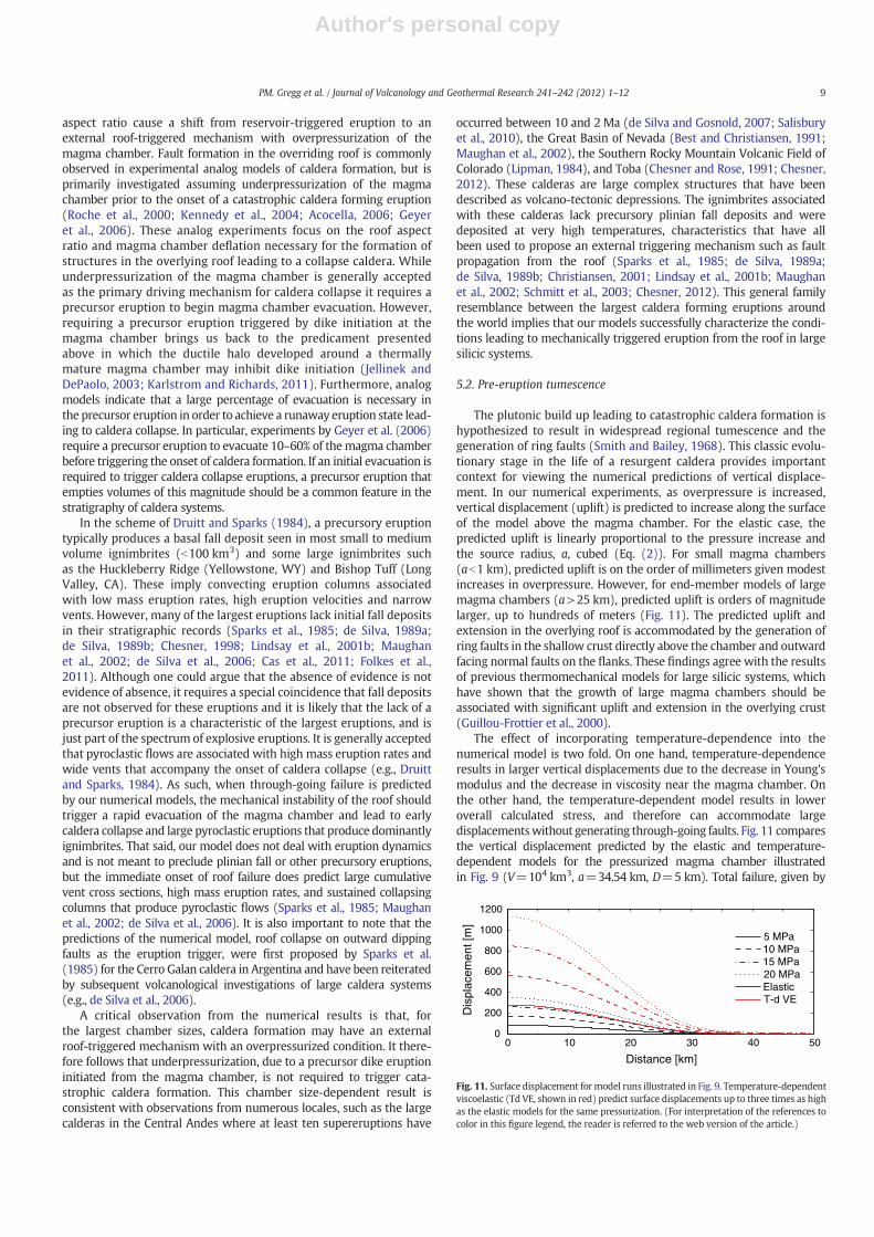
5.3. Maximum chamber and caldera size
For a given set of model parameters there is a maximum sizeat which a magma chamber is mechanically stable in the modelspace prior to any applied magma chamber overpressurization. Suchmaterial properties as density and temperature impact whether anumerical experiment is stable, but the most important constraint isthe roof aspect ratio. As is indicated in Fig. 7, after the roof aspectratio decreases below 0.1 significantly lower overpressure is requiredto generate faulting throughout the overlying roof. In the case of roofaspect ratios b0.02, the numerical mode runs were unstable and didnot provide meaningful estimates for maximum overpressure. Thesenumerical findings are complimentary to previous investigations,which indicate that aspect ratio provides a primary control on thestyle and timing of caldera collapse (Roche et al., 2000; Roche andDruitt, 2001; Geyer et al., 2006; Scandone and Acocella, 2007; Stixand Kobayashi, 2008).
Given the material properties assumed, our results indicate that itis unlikely that shallow magma chambers (depth to the top of the
chamber, D=3–7 km), with full reservoir thicknesses≤6 km, willreach volume V>105 km3. Furthermore, given the low overpressuresthat canbe accommodated bymagma chambers of this size, amaximumsize range of V=104–105 km3 is indicated. It is important to note thatthese models assume a pristine host material with no prior faulting orweaknesses or any far-field tectonic stresses. As such, we expect thatthe numerical results provide a limit to upper crustal magma chambersize.
Another important outcome of these numerical models is that theyprovide predictions of the maximum caldera size initially generatedgiven a particularmagma chamber geometry. Maximum caldera radius,rc, is calculated for models where total failure has been achieved byfinding the location of the most-distal normal fault in the overlyingroof. In a practical sense, this location is where the calculated fault-type switches from normal to strike-slip as indicated by AΨ=60°(Fig. 9). It is assumed that the outward-dipping normal faults generatedduring uplift are utilized during the subsequent collapse of the caldera.Therefore, the maximum caldera size should be constrained by thenormal faults that are furthest out. The maximum caldera radius iscalculated for every model run where the roof aspect ratio is b1.0.For models where the aspect ratio is >1.0, through-going failure ispredicted directly above the center of the reservoir and, therefore,does not provide a useful assessment of maximum caldera size. Fig. 12provides a comparison of the model-predicted maximum caldera areawith the global data set for large collapse calderas (Spera and Crisp,1981; Scandone, 1990; Geyer andMarti, 2008). Caldera area is calculat-ed from themaximumpredicted caldera radius asπ·rc2. Erupted volumeis calculated assuming 10% or 25% evacuation of the magma chamber.
Using mechanical predictions for failure and the extent of ringfracture formation allows for a self-consistent method of linking thechamber volume and geometry to the resultant surface expression ofcaldera area and erupted lava volumes. While recent investigationshave discussed the dynamics of erupting material from a large magmareservoir, and compared estimations of caldera collapse size to theCaldera Collapse Database (Karlstrom et al., 2012), they do not fullytake into account the interplay between chamber geometry and calderasize nor do they provide predictions for the volumes of eruptedmaterial.
104
103
102
101
100
10-1
101 102 103 104 105100
Caldera Area (km2)
Eru
pted
Vol
ume
(km
3 )
b = 2kmb = 4kmb = 6km10% Vchamber
25% Vchamber
Chamber triggered Roof triggered
Fig. 12. Model predicted caldera area versus erupted volume compared to caldera area and erupted volume data from Spera and Crisp (1981) and Geyer and Marti (2008), squaresand circles respectively. Dashed gray line indicates transition from a chamber-triggered eruption mechanism to a roof-triggered mechanism.
10 PM. Gregg et al. / Journal of Volcanology and Geothermal Research 241–242 (2012) 1–12
Author's personal copy
Another intriguing outcome of our viscoelastic temperature-dependentmodel is a calculation of the percentage of volume that is erupted fromthemagma chamber to reproduceboth the calderas anderupted volumesobserved in natural systems given a particular chamber geometry. As thethickness of the magma body is increased, a lower percent evacuation isnecessary to reproduce the relationship observed between caldera areaand erupted volume. For example, a 6 km thickmagma chamber requiresonly 10% evacuation to produce the same caldera and eruptive volumesas a 2 km thick magma chamber expelling 25% of its chamber volume.These findings have implications for future investigations on eruptiondynamics including how the magma chamber is mobilized and whatportions of the magma chamber are erupted.
6. Conclusions
Our new thermomechanical models of an overpressurized magmachamber provide critical insight into the eruption triggeringmechanismsof volcanic systems. For the smallestmagma chambers (Vb102 km3), ournumerical models predict frequent, small eruptions controlled by theinitiation of dikes at the magma chamber boundary once the tensilestrength of the host rock has been exceeded. In the mid-range ofmagma chamber sizes (102bVb104 km3), results indicate that thetemperature-dependence of the viscoelastic host rock becomes impor-tant for buffering failure at themagma chamber boundary and inhibitingdike formation. At the largest magma chamber sizes (V>103 km3),eruption is likely controlled by the mechanical properties of the hostrock. In this size range, modest overpressures result in significant pre-eruption uplift that leads to through-going faults within the crust,which may trigger eruption by breaching the magma chamberboundary. As such, we suggest that, for the largest cases, an externalroof-strength controlled triggering mechanismwill dictate the onsetof catastrophic caldera formation.
Roof aspect ratio is a primary parameter that controls mechanicalfailure of the roof for the shallow crustal magma chambers investigatedherein. At high roof aspect ratios (R>2), failure is confined to theshallow crust for overpressures b40 MPa, and thus, eruption is likelytriggered from the magma chamber boundary. In other words, at highR, the roof block is sufficiently thick and remains stable up to largeapplied overpressures. As R decreases, the mechanical stability of theoverlyingmaterial becomes critical and through-going faults are gener-ated for modest overpressures. In particular, when Rb0.2, overpres-sures b40 MPa are able to generate through-going failure in the roof.When Rb0.1, overpressures b10 MPa generate through-going failure.This shift suggests that large volume, low aspect ratio systems aremost likely triggered due to fault propagation in the overlying roof.
This new physical insight into catastrophic ignimbrite eruptionsenhances and informs ongoing studies of large silicic systems signifi-cantly. Nevertheless, given the inherent complexity of these dynamicmagmatic systems, several additional factors need to be exploredin future modeling efforts, including: the effect of the rheologicalproperties within the magma chamber; the dynamics of the roofcollapse and chamber evacuation once faults have ruptured the reservoirboundary; the effect of varying magma chamber temperature; the effectof regional tectonic stresses and pre-existing faults and zones ofweakness; the temporal evolution of magma chamber growth;and, the mechanics of failure in the ductile region surrounding themagmatic source.
Acknowledgments
We thank the APVC Research Group and the Volcano IgneousPetrology Economic Research (VIPER) Group at OSU for insightfuldiscussions that contributed to this work. We thank G. Currentifor aid in double-checking the viscoelastic analytical and numericalsolutions. We also thank R. Scandone and an anonymous reviewerfor helpful comments, which added to the final manuscript. This
research was funded by a National Science Foundation PostdoctoralFellowship (Gregg, EAR 0815101). Work on supereruptions in theCentral Andes is funded by the National Science Foundation (de Silva,EAR 0908324). Initial formulation and analysis of the elastic caldera me-chanics problem commenced during research funded by a Fulbright NewZealand Award (Grosfils).
References
Acocella, V., 2006. Caldera types: how end-members relate to evolutionary stages ofcollapse. Geophysical Research Letters 33 (L18314), http://dx.doi.org/10.1029/2006GL027434.
Anderson, E.M., 1905. The dynamics of faulting. Transactions of the Edinburgh GeologicalSociety 8 (3), 387–402.
Annen, C., 2009. From plutons to magma chambers: thermal constraints on theaccumulation of eruptible silicic magma in the upper crust. Earth and PlanetaryScience Letters 284 (3–4), 409–416.
Annen, C., 2011. Implications of incremental emplacement of magma bodies for magmadifferentiation, thermal aureole dimensions and plutonism–volcanism relationships.Tectonophysics 500 (1–4), 3–10.
Annen, C., Sparks, R.S.J., 2002. Effects of repetitive emplacement of basaltic intrusionson thermal evolution and melt generation in the crust. Earth and Planetary ScienceLetters 203 (3–4), 937–955.
Annen, C., Blundy, J.D., Sparks, R.S.J., 2006. The genesis of intermediate and silicicmagmas in deep crustal hot zones. Journal of Petrology 47 (3), 505–539.
Annen, C., Pichavant, M., Bachmann, O., Burgisser, A., 2008. Conditions for the growth of along-lived shallow crustal magma chamber belowMount Pelee volcano (Martinique,Lesser Antilles Arc). Journal of Geophysical Research-Solid Earth 113 (B7).
Best, M.G., Christiansen, E.H., 1991. Limited extension during peak tertiary volcanism,Great-Basin of Nevada and Utah. Journal of Geophysical Research-Solid Earth andPlanets 96 (B8), 13509–13528.
Biot, M.A., 1954. Theory of stress–strain relations in anisotropic viscoelasticity andrelaxation phenomena. Journal of Applied Physics 25 (11), 1385–1391.
Burov, E.B., Guillou-Frottier, L., 1999. Thermomechanical behavior of large ash flowcalderas. Journal of Geophysical Research 104 (B10), 23,081–23,109.
Cas, R.A.F., Wright, H.M.N., Folkes, C.B., Lesti, C., Porreca, M., Giordano, G., Viramonte,J.G., 2011. The flow dynamics of an extremely large volume pyroclastic flow, the2.08-Ma Cerro Galan Ignimbrite, NW Argentina, and comparison with other flowtypes. Bulletin of Volcanology 73 (10), 1583–1609.
Chen, Z., Jin, Z.H., 2006. Magma-driven subcritical crack growth and implications fordike initiation from a magma chamber. Geophysical Research Letters 33 (19).
Chesner, C.A., 1998. Petrogenesis of the Toba Tuffs, Sumatra, Indonesia. Journal ofPetrology 39 (3), 397–438.
Chesner, C.A., 2012. The Toba Caldera complex. Quaternary International 258, 5–18.Chesner, C.A., Rose, W.I., 1991. Stratigraphy of the Toba-Tuffs and the evolution of the
Toba-Caldera Complex, Sumatra Indonesia. Bulletin of Volcanology 53 (5), 343–356.Christiansen, R.L., 2001. The Quaternary and Pliocene Yellowstone Plateau Volcanic
Field of Wyoming, Idaho, and Montana: U.S. Geol. Surv. Prof. Pap., 729, pp. 1–146.de Silva, S.L., 1989a. Altiplano–Puna volcanic complex of the Central Andes. Geology 17 (12),
1102–1106.de Silva, S.L., 1989b. Geochronology and stratigraphy of the ignimbrites from the 21 30′
S to 23 30′S portion of the Central Andes of Northern Chile. Journal of Volcanologyand Geothermal Research 37 (2), 93–131.
de Silva, S.L., Gosnold, W.D., 2007. Episodic construction of batholiths: insights fromthe spatiotemporal development of an ignimbrite flare-up. Journal of Volcanologyand Geothermal Research 167 (1–4), 320–335.
de Silva, S.L., Zandt, G., Trumbull, R., Viramonte, J.G., Salas, G., Jimenez, N., 2006. Largeignimbrite eruptions and volcano-tectonic depressions in the Central Andes: athermomechanical perspective. In: RTroise, C., De Natale, G., Kilburn, C.R.J. (Eds.),Mechanics of Activity and Unrest at Large Calderas. Geological Society of London,London, pp. 47–63.
Del Negro, C., Currenti, G., Scandura, D., 2009. Temperature-dependent viscoelasticmodeling of ground deformation: application to Etna volcano during the 1993–1997inflation period. Physics of the Earth and Planetary Interiors 172, 299–309.
Dragoni, M., Magnanensi, C., 1989. Displacement and stress produced by a pressurized,spherical magma chamber, surrounded by a viscoelastic shell. Physics of the Earthand Planetary Interiors 56 (3–4), 316–328.
Druitt, T.H., Sparks, R.S.J., 1984. On the formation of calderas during ignimbriteeruptions. Nature 310 (5979), 679–681.
Fialko, Y.A., Rubin, A.M., 1998. Thermodynamics of lateral dike propagation: Implicationsfor crustal accretion at slow spreading mid-ocean ridges. Journal of GeophysicalResearch-Solid Earth 103 (B2), 2501–2514.
Folch, A., Marti, J., 2004. Geometrical and mechanical constraints on the formation ofring-fault calderas. Earth and Planetary Science Letters 221 (1–4), 215–255.
Folch, A., Fernandez, J., Rundle, J.B., Marti, J., 2000. Ground deformation in a viscoelasticmedium composed of a layer overlying a half-space: a comparison between pointand extended sources. Geophysical Journal International 140, 37–50.
Folkes, C.B., Wright, H.M., Cas, R.A.F., de Silva, S.L., Lesti, C., Viramonte, J.G., 2011.A re-appraisal of the stratigraphy and volcanology of the Cerro Galan volcanicsystem, NW Argentina. Bulletin of Volcanology 73 (10), 1427–1454.
Geyer, A., Marti, J., 2008. The new worldwide collapse caldera database (CCDB): a toolfor studying and understanding caldera processes. Journal of Volcanology andGeothermal Research 175, 334–354.
11PM. Gregg et al. / Journal of Volcanology and Geothermal Research 241–242 (2012) 1–12

Author's personal copy
Geyer, A., Folch, A., Marti, J., 2006. Relationship between caldera collapse and magmachamber withdrawal: an experimental approach. Journal of Volcanology andGeothermal Research 2006 (157), 375–386.
Grosfils, E.B., 2007. Magma reservoir failure on the terrestrial planets: assessing theimportance of gravitational loading in simple elastic models. Journal of Volcanologyand Geothermal Research 166 (2), 47–75.
Gudmundsson, A., 1988. Formation of collapse calderas. Geology 6 (9), 808–810.Gudmundsson, A., 1998. Formation and development of normal-fault calderas and the
initiation of large explosive eruptions. Bulletin of Volcanology 60, 160–171.Guillou-Frottier, L., Burov, E.B., Milesi, J.-P., 2000. Genitic links between ash-flow
calderas and associated ore deposits as revealed by large-scale thermomechanicalmodeling. Journal of Volcanology and Geothermal Research 102, 339–361.
Hardy, S., 2008. Structural evolution of calderas: insights from two-dimensionaldiscrete element simulations. Geology 36 (12), 927–930.
Jellinek, A.M., DePaolo, D.J., 2003. A model for the origin of large silicic magma chambers:precursors of caldera-forming eruptions. Bulletin of Volcanology 65 (5), 363–381.
Karlstrom, L., Richards, M., 2011. On the evolution of large ultramafic magma chambersand timescales for flood basalt eruptions. Journal of Geophysical Research 116(B08216), http://dx.doi.org/10.1029/2010JB008159.
Karlstrom, L., Dufek, J., Manga, M., 2010. Magma chamber stability in arc and continentalcrust. Journal of Volcanology and Geothermal Research 190 (3–4), 249–270.
Karlstrom, L., Rudolph, M.L., Manga, M., 2012. Caldera size modulated by the yieldstress within a crystal-rich magma reservoir. Nature Geoscience, http://dx.doi.org/10.1038/NGEO1453.
Kennedy, B.M., Stix, J., Vallance, J.W., Lavallee, Y., Longpre, M.-A., 2004. Controls oncaldera structure: results from analogue sandbox modeling. Geological Society ofAmerica Bulletin 116 (5/6), 515–524.
Kennedy, B.M., Jellinek, A.M., Stix, J., 2008. Coupled caldera subsidence and stirringinferred from analogue models. Nature Geoscience 1 (6), 385–389.
Kinvig, H.S., Geyer, A., Gottsmann, J., 2009. On the effect of crustal layering on ring-faultinitiation and the formation of collapse calderas. Journal of Volcanology andGeothermalResearch 186, 293–304.
Lee, E.H., 1955. Stress analysis in visco-elastic bodies. Quarterly of AppliedMathematics 13(2), 183–190.
Lindsay, J.M., de Silva, S., Trumbull, R., Emmermann, R., Wemmer, K., 2001a. La Pacanacaldera, N. Chile: a re-evaluation of the stratigraphy and volcanology of one ofthe world's largest resurgent calderas. Journal of Volcanology and GeothermalResearch 106 (1–2), 145–173.
Lindsay, J.M., Schmitt, A.K., Trumbull, R.B., De Silva, S.L., Siebel, W., Emmermann, R.,2001b. Magmatic evolution of the La Pacana caldera system, Central Andes,Chile: compositional variation of two cogenetic, large-volume felsic ignimbrites.Journal of Petrology 42 (3), 459–486.
Lipman, P.W., 1984. The roots of ash flow calderas in western North America: windows intothe tops of granitic batholiths. Journal of Geophysical Research 89 (B10), 8801–8841.
Marsh, B.D., 1984. On the mechanics of caldera resurgence. Journal of GeophysicalResearch 89 (B10), 8245–8251.
Mason, B.G., Pyle, D.M., Oppenheimer, C., 2004. The size and frequency of the largestexplosive eruptions on Earth. Bulletin of Volcanology 66 (8), 735–748.
Maughan, L.L., Christiansen, E.H., Best, M.G., Gromme, C.S., Deino, A.L., Tingey, D.G.,2002. The Oligocene Lund Tuff, Great Basin, USA: a very large volume monotonousintermediate. Journal of Volcanology and Geothermal Research 113, 129–157.
McLeod, P., Tait, S., 1999. The growth of dykes from magma chambers. Journal ofVolcanology and Geothermal Research 92 (3–4), 231–246.
McTigue, D.F., 1987. Elastic stress and deformation near a finite spherical magmabody: resolution of a point source paradox. Journal of Geophysical Research 92,15977–15990.
Mogi, K., 1958. Relations of the eruptions of various volcanoes and the deformations ofthe ground surface around them. Bull. Earthq. Res. Inst., University of Tokyo 36,99–134.
Newman, A.V., Dixon, T.H., Ofoegbu, G.I., Dixon, J.E., 2001. Geodetic and seismicconstraints on recent activity at Long Valley Caldera, California: evidence for viscoelasticrheology. Journal of Volcanology and Geothermal Research 105, 183–206.
Newman, A.V., Dixon, T.H., Gourmelen, N., 2006. A four-dimensional viscoelasticdeformation model for Long Valley Caldera, California, between 1995 and 2000.Journal of Volcanology and Geothermal Research 150, 244–269.
Peltier, W.R., 1974. The impulse response of a Maxwell Earth. Reviews of Geophysicsand Space Physics 12 (4), 649–668.
Roche, O., Druitt, T.H., 2001. Onset of caldera collapse during ignimbrite eruptions.Earth and Planetary Science Letters 191 (3–4), 191–202.
Roche, O., Druitt, T.H., Merle, O., 2000. Experimental study of caldera formation. Journalof Geophysical Research-Solid Earth 105 (B1), 395–416.
Rubin, A.M., 1995. Propagation of magma-filled cracks. Annual Review of Earth andPlanetary Sciences 23, 287–336.
Salisbury, M.J., Jicha, B.R., de Silva, S.L., Singer, B.S., Jimenes, N.C., Ort, M.H., 2010. 40Ar/39Archronostratigraphy of Altiplano–Puna volcanic complex ignimbrites reveals thedevelopment of a major magmatic province. GSA Bulletin 123 (5–6), 821–840.
Scandone, R., 1990. Chaotic collapse of calderas. Journal of Volcanology and GeothermalResearch 42, 285–302.
Scandone, R., Acocella, V., 2007. Control of the aspect ratio of the chamber roof oncaldera fomation during solicic eruption. Geophysical Research Letters 34 (L22307),http://dx.doi.org/10.1029/2007GL032059.
Schmitt, A.K., Lindsay, J.M., de Silva, S., Trumbull, R.B., 2003. U–Pb zirconchronostratigraphy of early-Pliocene ignimbrites from La Pacana, north Chile: implica-tions for the formation of stratified magma chambers. Journal of Volcanology andGeothermal Research 120 (1–2), 43–53.
Simakin, A.G., Ghassemi, A., 2010. The role of magma chamber–fault interaction incaldera forming eruptions. Bulletin of Volcanology 72 (1), 85–101.
Simpson, R.W., 1997. Quantifying Anderson's fault types. Journal of GeophysicalResearch 102 (B8), 17909–17919.
Smith, R.L., Bailey, R.A., 1968. Resurgent cauldrons. Geological Society of AmericaMemoirs 116, 613–662.
Smith, R.L., Shaw, H.R., 1979. Igneous related geothermal systems. Assessment ofgeothermal resources of the United States. In: White, D.E., Williams, D.L. (Eds.),United States Geological Survey Circular, pp. 58–83.
Smith, R., Sammonds, P.R., Kilburn, C.R.J., 2009. Fracturing of volcanic systems: experimentalinsights into pre-eruptive conditions. Earth and Planetary Science Letters 280, 211–219.
Sparks, R.S.J., Francis, P.W., Hamer, R.D., Pankhurst, R.J., O'Callaghan, L.O., Thorpe, R.S.,Page, R., 1985. Ignimbrites of the Cerro Galan Caldera, NW Argentina. Journal ofVolcanology and Geothermal Research 24, 205–248.
Spera, F.J., Crisp, J.A., 1981. Eruption volume, periodicity, and caldera area: relationshipsand inferences on development of compositional zonation in silicicmagma chambers.Journal of Volcanology and Geothermal Research 11, 169–187.
Stix, J., Kobayashi, T., 2008. Magma dynamics and collapse mechanisms during fourhistoric caldera-forming events. Journal of Geophysical Research 113, B09205.
Van Bemmelen, R.W., 1939. The volcano-tectonic origin of Lake Toba (North Sumatra).De Ingenieur in Nederlandsch Indie 6–9, 126–140.
Whittington, A.G., Hofmeister, A.M., Nabelek, P.I., 2009. Temperature-dependentthermal diffusivity of the Earth's crust and implications for magmatism. Nature458, http://dx.doi.org/10.1038/nature07818.
12 PM. Gregg et al. / Journal of Volcanology and Geothermal Research 241–242 (2012) 1–12


