Embed Size (px)
Citation preview
NASA-CR-195521
AUTONOMOUS SPACE PROCESSOR FORORBITAL DEBRIS (ASPOD)
(1991-92) ///
University of ArizonaAerospace and Mechanical Engineering Department
Tucson, Arizona
Principal Investigator. Dr. Kumar Ramohalli
Graduate Research Assistants:
Dominique Mitchell,Brett Tai_
Robotic Arm Team:
Paul Chinnock,Curt Bradley,
George Williams,Peter Wegner
End Effector Team:Bjoern Kutz,
Todd Jacobson,David Lyle,
Matt McCutchen
Universities Space Research AssociationAdvanced Design Program
8th Annlml ConferenceWashington D. C.June 15-19, 1992
N,,0 ,,0
P,,j f_ P,,jI _ ,.$"
,,.* U 00", CZ _ 0
u.J_J
Q.. CL
o
Z d_ .
t--- ...J ,-_ ¢-
u" C
I
_.3 _.n_-,I v-_ C5
col,,-i
i,-+;
0
AUTONOMOUS SPACE PROCESSOR FOR ORBITAL DEBRIS
ADVANCED DESIGN PROJECT IN SUPPORT OF
SOLAR SYSTEM EXPLORATION
University of ArizonaAerospace and Mec.b-n_r_._,l "_n,+_--ing Department
Tucson, Arizona
Dr. Kumar RamohalliDominique MiW..hell, Brett Taft,
Paul Chinnock, Bjoern Kutz
Abstract
This paper is regarding a project in the Advanced Design Program at theUniversity of Arizona. The project is named the Autonomous Space Processor for
Orbital Debris (ASPOD) and is a Universities Space Research Association (USRA)sponsored design project. The development of ASPOD and the students abilities
in designing and building a prototype spacecraft are the ultimate goals of thisproject. This year's focus entailed the development of a secondary robotic armand end-effector to work in tandem with an existent arm in the removal of orbital
debris. The new arm features the introduction of composite materials and alinear drive system, thus producing a light-weight and more accurate prototype.The main characteristic of the end-effector design is that it incorporates all of themotors and gearing internally, thus not subjecting them to the harsh space
environment. Furthermore, the arm and the end-effector are automated by acontrol system with positional feedback. This system is composed of magneticand optical encoders connected to a 486 PC via two servo-motor controller cards.Programming a series of basic routines and sub-routines has allowed the ASPOD
prototype to become more autonomous. The new system is expected to performspecified tasks with a positional accuracy of 0.5 cm.
Introduction
The subject of orbital debris has been reaching the spotlight since SkyLab'sdegenerating orbit put the world on alert as to where the debris that survived
reentry would touch down on Earth. These problems have not gone away and arecurrently affecting today's space missions, as was demonstrated whenDiscovery's crew in September of 1991 and Atlantis's crew in November of 1991
had to alter their orbits in order to avoid a piece of space junk that was on a
trajectory thatcould possibly place the crew in danger. These events are a goodindication of the growing trouble caused by orbital debris. Table 1 is a shortoutline of the types of problems caused by orbital debris [1].
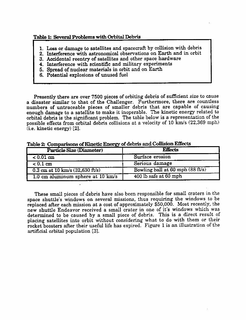
Table 1: Several Problems with Orbital Debris
I. Loss or damage to satellitesand spacecrai_by collisionwith debris2. Interferencewith astronomical observations on Earth and in orbit
3. Accidental reentry of satellitesand other space hardware4. Interference with scientificand military experiments
5. Spread of nuclear materials in orbitand on Earth
6. Potential explosions of unused fuel
Presently there are over 7500 pieces of orbitingdebris of sufficientsizeto causea disaster similar to that of the Challenger. Furthermore, there are countless
numbers of untraceable pieces of smaller debris that are capable of causingenough damage to a satelliteto make itinoperable. The kinetic energy related toorbitaldebris isthe significantproblem. The table below is a representation of the
possible effectsfrom orbitaldebris collisionsat a velocityof 10 km/s (22,369 mph)(i.e.kineticenergy) [2].
Table 2: Comparisons of 1_metic Energy of debrisParticleSize (Diameter)
and CollisionEffects
Zlfects
Surface erosion< 0.01 cm
< 0.1 cm Serious damage
0.3 cm at 10 km/s (32,630 ft/s) Bowling ball at 60 mph (88 ft/s)
1.0 cm aluminum sphere at 10 km/s 400 lb safe at 60 mph
These small pieces of debris have also been responsible for small craters in thespace shuttle's windows on several missions, thus requiring the windows to bereplaced after each mission at a cost of approximately $50,000. Most recently, thenew shuttle Endeavor received a small crater in one of it's windows which was
determined to be caused by a small piece of debris. This is a direct result of
placing satellites into orbit without considering what to do with them or theirrocket boosters after their useful life has expired. Figure 1 is an illustration of the
artificial orbital population [3].
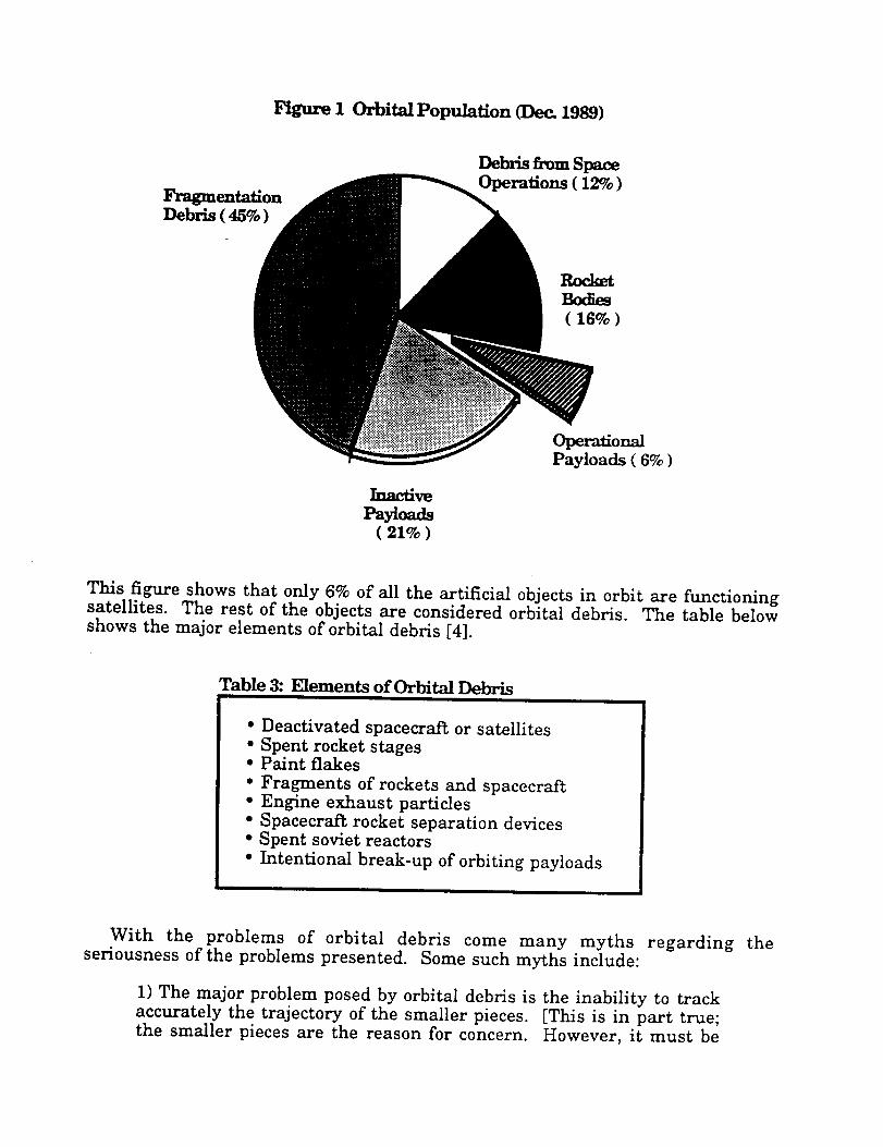
Figure I Orbital Population (Dec_ 1989)
FragmentationDebris ( 45% )
Debris from SpaceOperations (12%)
RocketBodies( 16% )
In,z_ve
Payloads( 21% )
OperationalPayloads ( 6% )
This figure shows that only 6% of all the artificial objects in orbit are functioningsatellites. The rest of the objects are considered orbital debris. The table belowshows the major elements of orbital debris [4].
Table 3: Elements of Orbital Debris
• Deactivated spacecraft or satellites
• Spent rocket stages• Paint flakes
• Fragments of rockets and spacecraft• Engine exhaust particles
• Spacecra_ rocket separation devices• Spent soviet reactors
• Intentional break-up of orbiting payloads
With the problems of orbital debris come many myths regardingseriousness of the problems presented. Some such myths include:
1) The major problem posed by orbital debris is the inability to track
accurately the trajectory of the smaller pieces. [This is in part true;the smaller pieces are the reason for concern. However, it must be
the
realized that the larger pieces through orbital collisions and
explosions of excess propellant are the cause of the smaller pieces ofdebris.]
2) The problem of space debris will not be significantuntil the year2000. [Why wait untilthe problem becomes seriousin order to search
for viable solutions? Furthermore, it can takes about 10 years todevelop a space craftfrom conception to production, thus there is nobetter time to startthan the present.]
3) The body of knowledge about orbital debris is not well defined; andthus more studies are needed to learn more about the problem. [This
is an unfounded rumor. In fact, the majority of the larger pieces ofdebris are currently being tracked by the Space Surveillance Network(SSN) which is operated by Department of Defense. Also there aredatabases that have information about the large debris (i.e.trajectories, velocities, mass, geometry, etc.).]
Fortunately, students at the University of Arizona under the guidance of Dr.Kumar Ramohalli have been able to see through these myths and are now
concerning themselves with a means to solve this problem. The concept of anAutonomous Space Processor for Orbital Debris is the answer to sweep up theproblem of orbital debris. The two major goals of the ASPOD spacecrai_ are to dealwith the orbital debris problem (by processing the trackable large pieces of debrisbefore they have a chance of becoming small, untraceable projectiles thatpotentially could cause a lot of damage) and to utilize the resource (i.e. the debris)that is already in orbit (by using the materials from the debris to produce or buildnew device that will serve a propose). The goal of ASPOD is to process large piecesof debris. The following table shows the approximate number of objects and theirtotalmasses (see table 4) [5].
Table 4: Approximate Number and Size ofArtitqcislly-Msde Orbit.__ 1 DebrisOt ect
> I0 cm
I- 10cm
< Icm
Number of
Objects7,000
P_mge ofObjects, %
0.2
17,500 0.5
3,500,000 99.3
Total Mass
3,000,00 kg
1,000 k_
P_tage byMass, %
99.970.03
Although objects over 10 cm in size constitute less than 1% of the number of
objects in orbit, they contribute to over 99% of the total mass of orbiting objects.
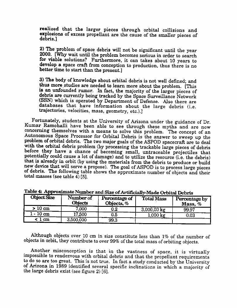
Another misconception is that in the vastness of space, it is virtuallyimpossible to rendezvous with orbital debris and that the propellant requirementsto do so are too great. This is not true. In fact a study conducted by the Universityof Arizona in 1989 identified several specific inclinations in which a majority ofthe large debris exist (see figure 2) [6].
Figure 2: Distribution of Orbital Tn_l;n_tions
NUMBER OF TARGETS VS. INCLINATION
140
130
110
1009O8)
z Ill10
0
! _tui|i|t|_i|_iJ|_j_le_|_j|i||_H_|"_|_I_lt|_i_j_|m_"j_||_j_tI_1|_
. sA'rmJLrnm wtr_ __ YB.AN l_am ir.G
! bJl_.J J . tJ_ . ._ _.............................. I
0 10 20 30 40 50 60 70 80 90 100 11,
mC_U_ATZON (d_
Mission feasibility studies have shown that one of the envisioned spacecrat_ could
process at least five of the large pieces of debris with reasonable propellant
requirements . This is accomplished by taking advantage of nodal regressiondifferences and the use of classic Hohmann transfer [7].
ASPOD's Basic Mission Profile
The following is the overall mission scenario:
1. Launch from booster or Space Shuttle.
2. Use propulsion and programming to enter orbit and rendezvous withtarget debris.
3. Rendezvous with debris and use programming and one of twocomputer-controlled robotic arms to retrieve debris.
4. Programming selects the proper placement of second robotic arm togrip the piece to be cut off.
5. Both arms then move debris into the focal point of solar cutting device(solar cutter is an array of mirrors and Fresnel lenses).
6. After piece has been cut, the second arm places the piece in storage
bin. The process (from 4 to 6) is repeated until whole debris is placedin storage bin.
7. Programming instructs ASPOD to rendezvous with next targetdebris (steps 3 to 7 are repeated until all target debris has beenprocessed).
8. ASPOD has then three o_tions dep_ndin_ on retrieved payload (i.e.orbital debris):
a) rendezvous
b)
c)
with Space Shuttle where debris will bedownloaded and return to earth. ASPOD will then be
refueled and given new instructionsand new target debrisrendezvous with future Space Station where debris will bedownloaded and remanufactured for other uses
burnup on reentry into atmosphere:
This project was initiated in 1987 and has become an integral part of theAdvanced Design Program at the University of Arizona over the past severalyears due in part to an increased interestin the problem of orbitaldebris and the
continued funding of NASA/USRA. Moreover, the ASPOD project has been metwith great support over the years from both the University of Arizona and thesurrounding community, resulting in numerous appearances in both local andnational newspapers and news broadcasts.
Progress
Since 1987, the ASPOD project has maintained a steady level of progress, each
year enhancing the former years design along with incorporating necessaryadditional systems into the satellite to ensure that it will be truly be autonomouswhen completed. In this respect, the prototype (test-bed) has excelled from thebasic concept of a debris retriever to that of an integrated machine capable ofmaneuvering a piece of debris with a robotic arm through a focal point of a solararray that has utilized a solar tracker to align itself with the sun in order tomaximize its cutting potential.
Consistent with the USRA philosophy, a new group of undergraduates wasinvolved with the ASPOD project this year. This years team eonsisted of 14undergraduates and 2 graduate students with varying majors and interests. A
complete list of these and past students can be found in the Appendix 1.
Arm
The ASPOD design group was tasked with designing a second robotic arm forthe ASPOD satellite. Improvements that were required included a greaterincrease in reliability, a lighter structure, higher stiffness, drive systemsimplification, and a high degree of controllability. The arm's improvementsmust be accomplished while maintaining the original arm's degrees of freedomand rough link lengths.
The design group that undertook this project included Paul Chinnock, GeorgeWilliams, Peter Wegner, and Curt Bradley. Paul Chinnock was responsible forthe design of a light, rigid structure of high reliability, ease to manufacture.George Williams was charged with drive system design. The drive system wasrequired to be light, consume low energy, be very reliable, and fulfill motivationneeds for the loading conditions specified. Peter Wegner needed to engineer thecontrol system with a closed loop feed-back control using encoders. In addition
the system needed to be light,very accurate, and to work in close conjunction with
a remote computer for precise position control. Curt Bradley needed to design asupport frame on which to mount the arm and straddle the mirror frame. Within
the support frame design area, the arm's base needed to be positioned tomaximize its usefulness.
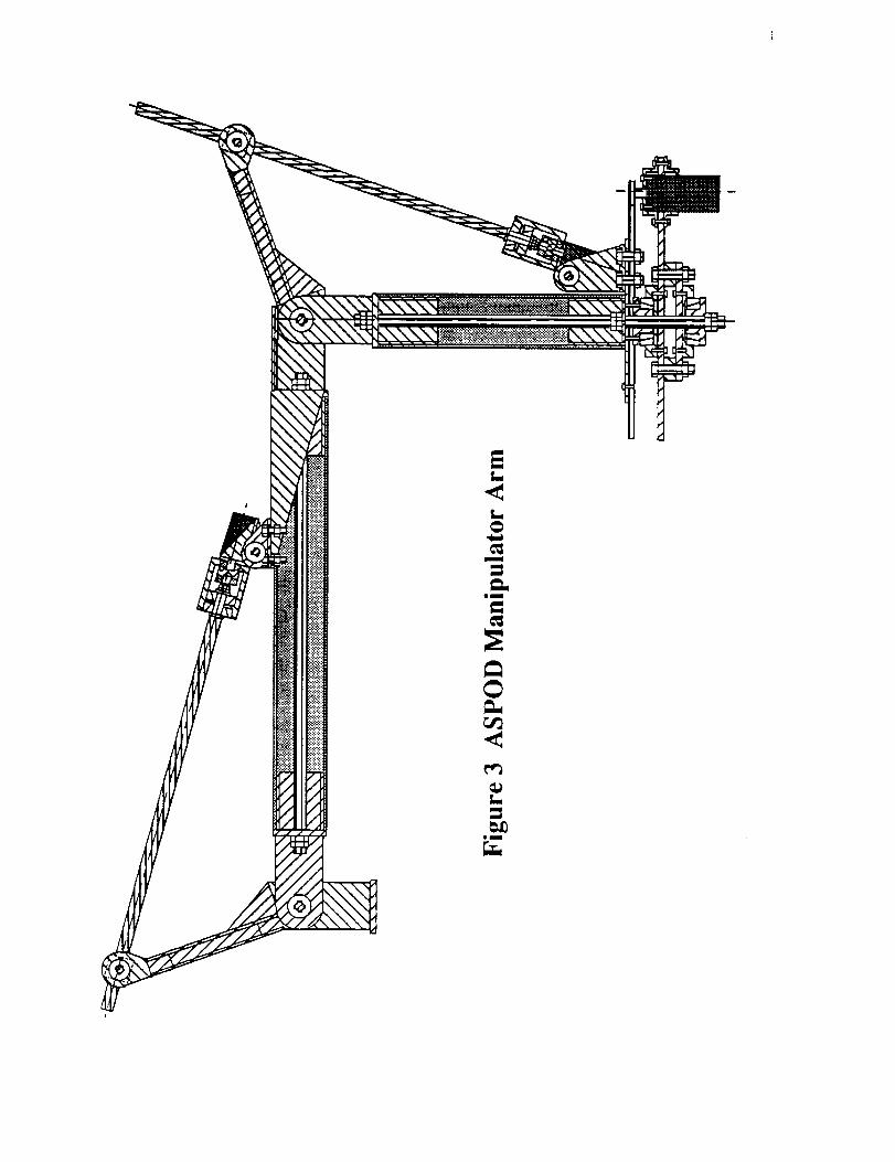
The first semester consisted of brain storming and iterative paper-baseddesign. The design (see figure 3 next page) was finalizedand parts were orderedfor manufacturing and assembling in the Spring semester. Throughout themanufacturing process, further simplifications were made to the individual
pleces to shorten machining time. The entire two-semester project was packedwith educationally rewarding experiences.
The arm is designed with linear ball screw-to-ball-nut drives for highefficiency,reduced stresses at the axles, simplicity,and lightness. The arm's
structure isbuilt of composite links and aluminum joints. The base is designed totravel a full360 degrees of rotation and therefore uses a gear and chain assembly.Links are preloaded toincrease stiffness. The arm's end has been designed toaccept the arm end-effector.
The linear drives have preloaded ball nuts that eliminate play induced by wearand tear on the arm. The ball screw-ball nut linear actuator exceeds the first
arm's drive system in reliability,reduced play, simplification,lightness, and
reduced stresses. The arm's drive motors are DC brushless and offer torque foracceleration and deceleration for placement speed of 90 degrees per minute. Thearm has been demonstrated at much higher speeds. Lagrangian dynamics wasused to determine the torques required for allconditions. All three motors are thesame and have 195 oz.of continuous torque.
The control system uses optical encoders to position the arm to an accuracy of 1centimeter loaded with a 1 pound load and unloaded. A 486 computer with twothree-channel control boards is used for control. The controller boards convert the
computer's digital signals to analog signals for the motors. The boards' outputsignals are amplified to the DC motor's requirements for input by two amplifiers.The controller cards in addition to translating signals have built-in stabilityprogramming for set bandwidths. The channels on the boards each have
position, velocity, and acceleration registers. The optical encoders offer 270,000pulses for a joint's entire range of motion exceeding accuracy requirements.
The Base Support Frame has carbon-graphite composite links preloaded with
centered bolts and joints made of aluminum. The structure exceeds strengthrequirements and stiffness specifications. The deflection under double the load
requirement (2.2 lbs) and worst torque position is 6.35 mm including arm andbase structure linked.
om
r_
e_
1.1
oU
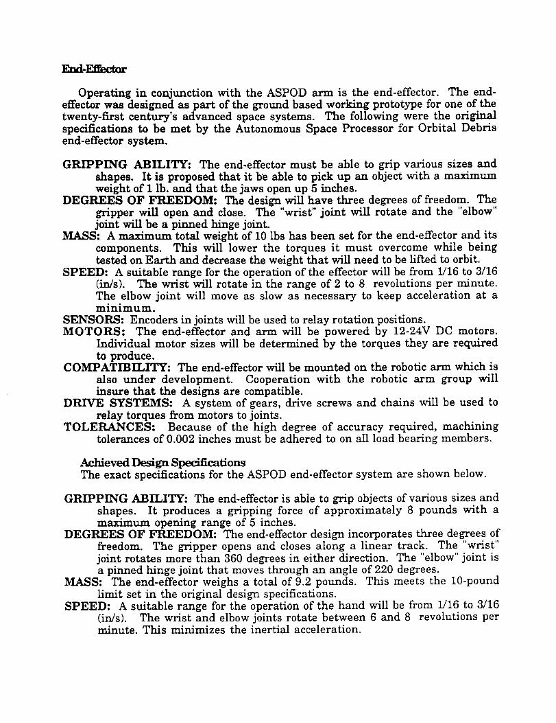
End-Effec_
Operating in conjunction with the ASPOD arm is the end-effector. The end-effectorwas designed as part of the ground based working prototype for one of thetwenty-firstcentury's advanced space systems. The following were the originalspecificationsto be met by the Autonomous Space Processor for Orbital Debrisend-effectorsystem.
GRIPPING ABILITY: The end-effectormust be able to grip various sizes and
shapes. Itis proposed that it be able to pick up an object with a maximumweight of I lb.and that the jaws open up 5 inches.
DEGREES OF FREEDOM: The design will have three degrees of freedom. Thegripper will open and close. The "wrist"joint will rotate and the "elbow"jointwillbe a pinned hinge joint.
MASS: A maximum totalweight of 10 Ibs has been set for the end-effectorand itscomponents. This will lower the torques it must overcome while beingtested on Earth and decrease the weight that willneed to be lii_edto orbit.
SPEED: A suitable range for the operation of the effectorwillbe from 1/16 to 3/16(in/s). The wrist willrotate in the range of 2 to 8 revolutions per minute.The elbow joint will move as slow as necessary to keep acceleration at aminimum.
SENSORS: Encoders in jointswillbe used to relay rotationpositions.MOTORS: The end-effector and arm will be powered by 12-24V DC motors.
Individual motor sizes will be determined by the torques they are required
to produce.COMPATIBILITY: The end-effectorwillbe mounted on the roboticarm which is
also under development. Cooperation with the robotic arm group willinsure that the designs are compatible.
DRIVE SYSTEMS: A system of gears, drive screws and chains will be used torelay torques from motors to joints.
TOLERANCES: Because of the high degree of accuracy required, machiningtolerances of 0.002 inches must be adhered to on allload bearing members.
Achieved Design SpecificationsThe exact specifications for the ASPOD end-effector system are shown below.
GRIPPING ABILITY: The end-effector is able to grip objects of various sizes and
shapes. It produces a gripping force of approximately 8 pounds with amaximum opening range of 5 inches.
DEGREES OF FREEDOM: The end-effector design incorporates three degrees offreedom. The gripper opens and closes along a linear track. The "wrist"
joint rotates more than 360 degrees in either direction. The "elbow" joint isa pinned hinge joint that moves through an angle of 220 degrees.
MASS: The end-effector weighs a total of 9.2 pounds. This meets the 10-pound
limit set in the original design specifications.SPEED: A suitable range for the operation of the hand will be from 1/16 to 3/16
(in/s). The wrist and elbow joints rotate between 6 and 8 revolutions perminute. This minimizes the inertial acceleration.
SENSORS: Magnetic encoders attached to the end of the motors are used to relayrotation positions.
MOTORS: The end-efrectoris powered by three motors. A 360 oz-in 12-V DC
motor powers the elbow joint. The rotationaljointis run by a 670 oz-in 12-VDC motor. And a 200 oz-in 24-V DC motor powers the gripper.
COMPATIBILITY: The end-efrector is attachable to the parent robotic arm,which in turn works with the rest ofthe systems on the ASPOD vehicle.
DRIVE SYSTEMS: For allthree degrees of freedom, power is transferred from
the gear motor through shaft couplers and drive shafts. For the gripperand bending joints, a series of gears is used to relay power. But therotationalmotor transfers torque by directdrive.
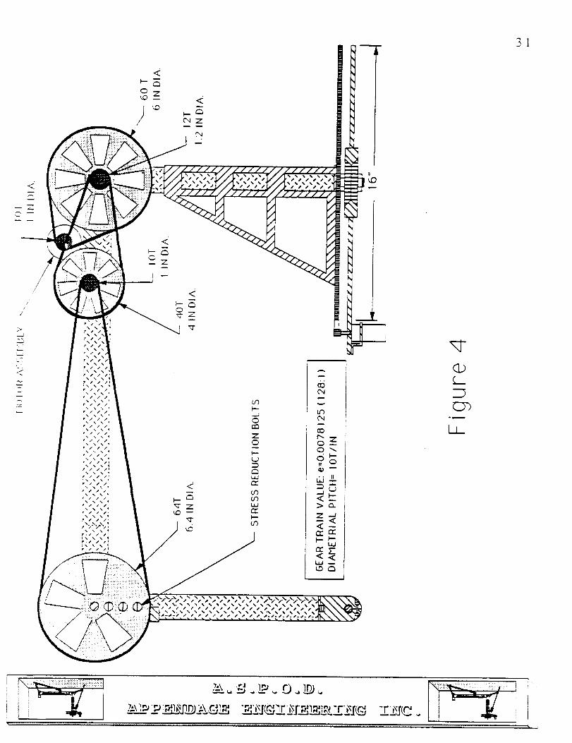
Beyond the basic quantitative constraints,the design team also followed a set of
qualitative constraints or goals. The main concepts adhered to the design areeffidency,reliabilityand flexibility.To make the design "efficient"the prototype isrepresentative of an uncluttered "common sense" assembly. The reliabilityof theend-effector components implies protection from failure and accidents, but also
easy repair ifan accident should occur. Finally, since the ASPOD system is stillin the optimization stage of development, the end-effectoris designed to be flexible
with respect to changing performance needs. The result of careful design andanalysis is shown in Figure 4 on the following page. From this figure severalgeneral design features are can be seen as examples of efficiency,reliability,andflexibility.
Notice the efficient layout of the components of the design. The twisting joint issituated before the bending joint. This arrangement better utilizes the capabilitiesof the bending joint. If the position of the joints were reversed, the bending jointwould be redundant with the rest of the arm joints. Also the selection of compact,high torque gear motors manufactured by "Micro Mo" allowed the designers toplace the motors at each joint inside the aluminum support tubing. The internalmotors are protected from the environment, while the short distance to the
applied joint eliminated the need for complex drive systems. Along with themotors, all of the gearing and most of the wiring are enclosed for protection. Theresult is an efficient, uncluttered design.
The design layout also contributes to high reliability. High precision fits andinternal mountings reduce gear wear while protecting parts. Since the motors
are mounted to the joints in assemblies of simple parts, the joints and parts areeasily disassembled and repaired in case of a problem.
The design of the assemblies also allows for easy redesign or configurationchanges. This flexibility reduces the need for major redesign iterations. The
linear gripper utilizes removable fingers on the jaws. This allows jaw redesignand implementation in a matter of minutes rather than longer, more costlyperiods of time. In addition, since the motors are in single assemblies with theirdriven joints, switching from the twisting joint first, bending joint secondconfiguration to the opposite arrangement is accomplished in half an hour.
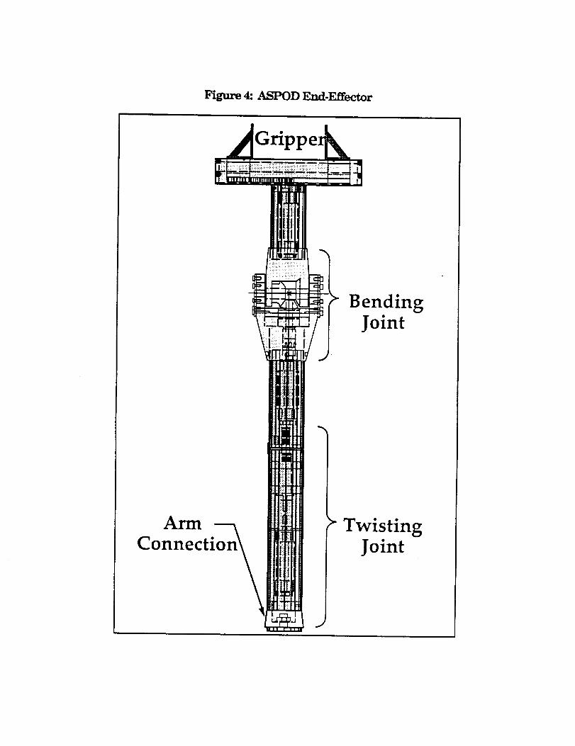
Figure 4: ASPOD End-Effector
IlUl IFIIIII Ilmi iU I
AI*UT
Connectit
BendingJoint
TwistingJoint
One of the most dramatic aspects of the flexible design is the control system.The control system allows the operator to program a desired output into the
terminal. The computer-based control system then calculates the specific systemrequirements, provides the system commands, and moves the system to thedesired state while checking for errors. This process starts at the computer
terminal. The user specifies a move using one of the programming methodsavailable. The controller card inside the computer converts the logical commandto a voltage command and sends the command to the appropriate axis via theconnection card. The power amplifier converts the output signal to anappropriate motor input command signal. While the motor is in a control mode,the controller card reads the encoder output, comparing the output to the desired
position. The controller card will move the motor to the desired position and keepit there until another command is given. The major components used in thecontrol system axe the actuators, the feedback sensors, the interface hardware,the controller card, and the computer-based instructions.
The actuators used for the arm and end-effector are Pittman and Micro Mo
high torque gear motors. The motors used for the bending and the twisting jointrequire a twelve volt power output, while the gripper and arm motors requiretwenty four volts. The controller card offers a convenient method for adjusting theoutput signal. Gain and offset potentiometers are supplied for each axis and canbe adjusted for a desired output.
In the ASPOD Arm-Effector design, the actuators are all DC motors requiringan analog output from the controller card. Attached to the motors are the
feedback sensors. In the case of the three Micro Mo motors, the feedback sensorsare magnetic encoders. Magnetic encoders were chosen because they werecheaper and more readily available as an integral package from the
manufacturer. The Pittman motors utilize BEI optical encoders reading off theoutput shafL The encoders provide two square wave signals 180 degrees out of
phase which are decoded in to a number of counts per motor revolution. Theposition of each joint is then determined from a reference. This information isthen used to command the motor.
In the control system the encoders and the motors do not interface directly tothe controller card. First, the controller connects to a wiring interface card whichin turn connects to the power amplifiers and the encoders. The interface card
was supplied by Servo Systems with the controller card. The power amplifiercircuits were constructed by the design team.
The power amplifier circuits were designed around a National SemiconductorLM12C operational amplifier. The circuit involves two power supplies powering acommon bus. Each power amplifier circuit draws power off the bus to distributeto the appropriate motor. Each power amplifier circuit is interfaced between amotor and a control axis on the controller card.
The controller card is the main processor of the control system. The OmnitechRobotics MC-3000 card is a 3-axis controller card designed around three Hewlett
Packard HCTL-1000 motion controllerIC chips. Two MC-3000's are sufficientforthe six axes of control required for the arm and end-effector.Although several
control modes are available, the trapezoidal profile mode is being used.Trapezoidal mode is ideal for robotic applications because it offers reasonable
velocity and acceleration control with positioning control. An acceleration /
deceleration and a m_dmllm velocity are specified by the user. When the card
receives a position command, it accelerates the motor until maximum velocityisreached or until the motor is halfway to the desired position. Then the motor isdecelerated at the programmed deceleration. After the motor is decelerated, thecard checks for position,and adjusts to the programmed value.
Although a decoding program was provided by Servo Systems, a better userinterface was desired. A goal was to have a program that fulfilledthreeobjectives.The program should be easy to use, powerful, and, of course, should be
able to run the robot arm through fixed routines. Originally the "C++"programming language was chosen for the program. However, it was laterdecided to use "Turbo Pascal 6.0". Turbo Pascal is easier to learn and compilesmore quickly significantly lessening development time. Turbo Pascal also cameequipped with extra libraries for windows and mouse interface programming.These libraries were not included with C++.
To make the control program easier to learn and use, the program wasdesigned to be menu; windows; and mouse-driven. A windows-based menu-
driven program arranges methods and commands in a logical system. This
interface allows new users with little or no computer experience to learn programbasics in less than an hour. In the case of the menu commands, pressing the"Alt" key and the highlighted letter will open that sub-menu. Once the sub-menu
is open, a command in that sub-menu may be executed by pressing the keycorresponding to the highlighted letter. An alternate, easier method for choosingcommands is by using the mouse. With this method, the mouse is used to movethe cursor to the desired sub-menu, the right mouse button is _clicked" (
depressed and released ) opening the sub-menu. Then the right mouse button isclicked while the cursor is over the desired menu item. This procedure willexecute the desired menu command. Some commands offer yet an additionalmethod for their use. When each sub-menu is open, some of the commands have
key sequences adjacent to them against the right hand side of the box. These keysequences are known as _Hot-Keys ". By executing the Hot-Key sequence on thekeyboard, the desired command can be effected without having to use the menus.Within this structure, three general control methods are available to adapt to thevarying needs of the operator. These methods are a menu-executed trapezoidalcommand, a programmed set of routines, and direct keyboard or "hand " control.
By using the mouse or keyboard commands to go through the menus the
operator can executed trapezoidal command. Trapezoidal command implies thatthe maximum velocity and the acceleration / deceleration are specified by theuser. When this method is used the position versus time profile is in the shape ofa trapezoid. The menu-executed trapezoidal command is advantageous when
testing moves in order to build a routine. To see what will happen when acommand is executed, enter the test values and execute. If the effect is not
desired, return the arm to the original position and try again. By testingcommands like this the user can come up with a programmed routine.
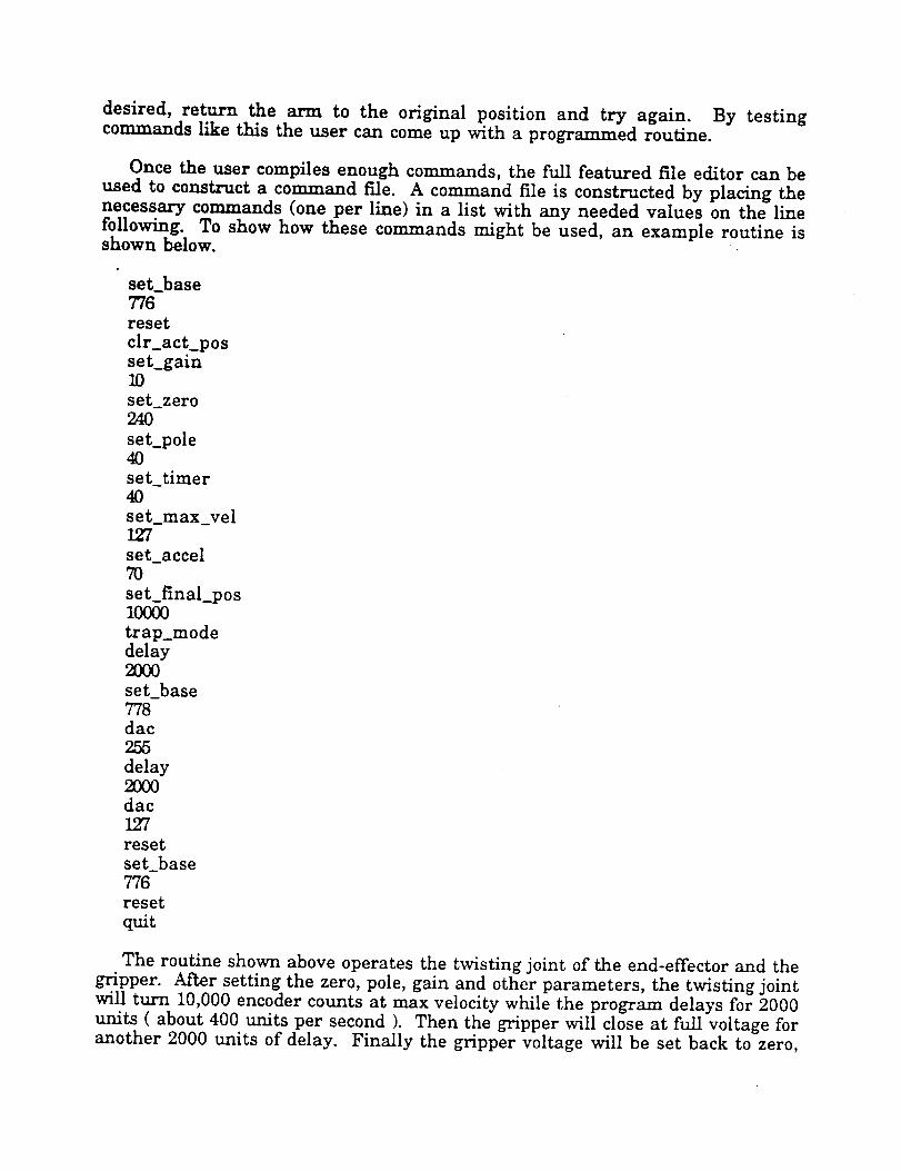
Once the user compiles enough commands, the full featured file editor can be
used to construct a command file. A command file is constructed by placing thenecessary commands (one per line) in a list with any needed values on the line
following. To show how these commands might be used, an example routine isshown below.
set_base776
reset
clr_act_posset_gain10
set_zero24O
set_pole40
settimer40
set_max_vel127
set_accel70
set final pos10000
trap_modedelay2000
set_base778dac255
delay2OO0dac127
reset
setbase776reset
quit
The routine shown above operates the twisting joint of the end-effector and the
gripper. After setting the zero, pole, gain and other parameters, the twisting jointwill turn 10,000 encoder counts at max velocity while the program delays for 2000units ( about 400 units per second ). Then the gripper will close at full voltage foranother 2000 units of delay. Finally the gripper voltage will be set back to zero,
and both axes willreceive a hard reset. Routines like this are easy to design andtest using the fileeditorinside the controllerprogram.
A final alternate to trapezoidal commands and command routines are the
straight keyboard commands. Occasionally, the trapezoidal command mode isnot the most convenient method formoving the arm. For this reason a set of _rIot-Keys" has been assigned to positive,negative, and zero voltage out commands foreach axis. A listof these commands is located under the _ menu. Tomove an axis,the user hits the _escape_ key until the _A]I axes have been reset_
message is displayed. Then the Hot-Key sequence corresponding to the desiredmotion is hit. The joint should move. Once the axis has moved to the desired
point, the user hits the home key to stop the motion. The home key will only stopthe last axis to be activatedby a voltage out command.
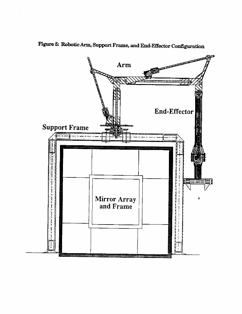
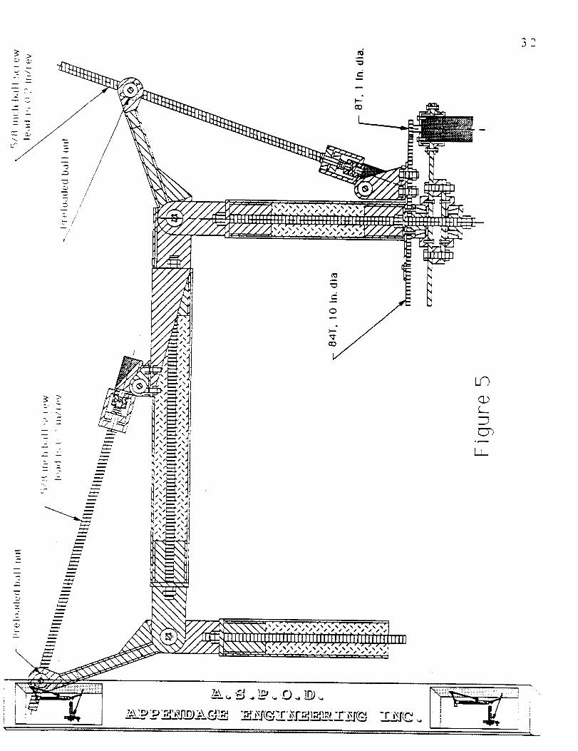
F_gttre 5: Robotic Arm, Support Frame, and End-Effector Configuration
Arm
End-Effector
Support Frame
Mirror Arrayand Frame
Conclusion
The progress of ASPOD is highly encouraging with several large steps madein both the integrated system and the overall design approach. One majoradvancement in the development is an additional robotic arm which is capable ofworking with the existing arm in order to accomplish the tasks that are needed inthe removal of orbital debris. This arm is built with a more stable linear drivesystem and the use of composites as an effort to decrease weight of arm itself. Themain characteristic of the end-effector design was that it incorporated all of the
motors and gearing internally, thus not subjecting them to the harsh spaceenvironment. Furthermore, a control system was developed in order to control
the arm and end-effector. The total configuration of the arm, support frame, andend-effector are on the previous page (see Figure 5). More detail information onthe arm configuration and the end-effector configuration can be found inappendix 2 and 3 respectively.
The future plans are to control both arms in tandem from a computer in orderto move the debris into the focal point of the solar cutter. In this respect, acomputer code is being written such to tell the arms to perform certain functionswith a single command from comm-linked operator.

Ref_
1. Orbitin_ Debris. A Space Environmental Problem. Office of TechnologyAssessment, September 1990, p3.
2. SDace Debris a Potential Threat to St)ace Station and Shuttle. GeneralAccounting Office Report, April 1990, pl0.
3. Orbitin_ Debris. A St)ace Environmental Problem, Office of TechnologyAssessment, September 1990, p2.
4. Orbitin_ Debris. A Space Environmental Problem, Office of TechnologyAssessment, September 1990, p2.
5. Space Debris a Potential Threat to St)ace Station and Shuttle. General
Accounting Office Report, April 1990, p9.
,
Ramohalli, Kumar, et al., Advanced Desk, n For Orbital Debris Removal in
Support of Solar System Exploration USRA Summer Conference, June 1991,p2.
.
Ramohalli, Kumar, et al., Advanced Design For Orbital Debris Removal in
Sut)t)ort of Solar System Exploration, USRA Summer Conference, June 1991,p2.

Appendix 1

From Sept. 1987 to June 1992
> 60 - students, ranging from high school to graduate students haveparticipated in the ASPOD progrmn at University of Arizona.
Student Participation:1987. 1988
Graduate Students: David Campbell, Scott Reid
Undergraduate Students: Donald Barnett, Bryan Cindrich, Steve DiVarco,
Catherine Dodd, Velda Dykehouse, Robert Flori,
Reid Greenberg, Joseph Manning, Jim Matison,Ruzila Mohkhirhadi, James Poon, andZenophen Xenophontos.
1988 ° 1989
Graduate Student: David Campbell
Undergraduate Students: Jeff Brockman, Bruce Carter, Leslie Donelson,
Lawrence John, Micky Marine, Dan Rodina.
1989- 1990
Graduate Student: David Campbell
Undergraduate Students: Dan Bertles, Micky Marine, Ramon Gutierrez,
Joseph Huppenthal, David Nichols,Mohamed Saad, Carlos Valenzuela.
1990. 1991
Graduate Student: Micky Marine
Undergraduate Students: James Bartos, James Colvin, Richard Crockett,
Kirby Hnat, David Ngo, Jennifer Putz,James Shattuck, Lee Sword, Sheri Woelfe.
Pre-University Students: Angela Mcfadden, Jennifer Hamilton,Brenda Lundt.
1991 - 1992
Graduate Students: Dominique Mitchell, Brett Tai_
Undergraduate Students: Curt Bardley, Sheila Caoile, Paul Chinnock,
Greg Hart, Todd Jacobson, Bjoern Kutz, Dave Lye,
Matt McCutchen, Angela Mcfadden, Ted Parvu,
Mohamed Saad, Glen Sonnenberg, Peter Weginer,George Williams.
Pre-University Student: William Dalby.


Appendix 2
ASPOD MANIPULATOR ARMFINAL DESIGN REPORT
For
The Autonomous Space Processor for Orbital Debris (ASPOD)
Submitted To:
Prof. Kumar Ramohalli
Prof. Karl Ousterhout
AME 412 Faculty and Senior Advisors
May 5th, 1992
Group Members
Project Leader: Paul Chinnock
Curt Bradley
George Williams
Peter Wegner
[,,
m
\\
i :
;i
'i
oll
Table qf Contents
IN_'RODUC'IION 1
PROBLEM DEFINITION 4
TECHNICAL SUBPROBLEMS 5
MILESTONE CHART, CPM DIAGRAM, WORK PLAN 7
GEOMETRY AND STRUCTURAL DESIGN 1 1
DRIVE SYSTEMS 2 3
CONTROL SYSTEMS 3 7
MOUNTING AND POSITIONING OF MANIPULATOR ARM 5 5
REFER._CES 6 4
APPENDIX A (ARM STRUCTURE, ITEM LIST, SUPPLIERS) 6 5
APPENDIX B (DRIVE SYSTEM ANALYSIS) 9 5
APPENDIX C (CONTROL SYSTEM ANALYSIS) 1 1 3
APPENDIX D (FRAME DIAGRAMS AND ANALYSIS) 1 2 0
; :.:::: ::- . ::.
INTRODUCTION
Space debris has been increasing in quantity throughout the
decades of space travel and has now begun to threaten future space
development. According to a report by the General Accounting Office
[2], space debris imposes a great threat to the future space station
and continued space shuttle flights. The University of Arizona in
1989 found that there were 386 objects in Earth orbit that were
1500 Kilograms or larger in mass. The objects identified will
maintain their orbits past the year 2000. Space debris includes dead
satellites, rocket boosters, shielding and even human waste. These
large pieces of debris will eventually fall to earth, but they will
maintain their orbits for a long of time. If the orbital debris does
fall, many pieces will not burn up upon reentry into the earth's
atmosphere and will cause significant damage if they strike land.
Because of the tremendous velocities involved, orbital debris of a
small mass can cause catastrophic damage. A 25 gram object in orbit
will have the kinetic energy of a 3000 lb automobile travelling at 60
mph [1]. The larger pieces of debris can be tracked by. ground based
sensors, but if two larger objects strike each other, the smaller debris
resulting from the collision would be untrackable and therefore
much more dangerous. The large pieces of debris that exist now
must be processed soon, before the problem makes orbital flight too
dangerous.
The Autonomous Space Processor for Orbital Debris (ASPOD) is
designed to economically remove debris from orbit [3]. The robot arm
this group has designed will grapple orbital debris and in conjunction
with another arm will maneuver the object into the focal point of a solar
powered cutting be-am. The beam will cut the debris to more
manageable sizes for possible use on the ASPOD satellite for additional
light gathering capability or for such needs as increased power
generation. Unrecycleable processed debris will be dealt with in one of
three different manners; it will either be placed in a storage bin, sent
into the atmosphere for safe burn up, or be placed into a ocean splash-
down trajectory if the material will not burn up upon reentry.
The problems the design group solved include the challenge to make
an arm with the same dimensions and degrees of freedom as that of the
existing arm, to make the structure lighter, more reliable, maximize its
usefulness by optimal base placement, meet all the specifications placed
on the existing arm, and provide the capability to control the arm using
computer software.
Reductions in the weight of the arm will increase the payload
capacity for other desired hardware on the satellite. The position
sensors will allow for remote operation or in the future, artificial
intelligence control. Reliability will prevent the ASPOD from
becoming another broken and dead satellite to avoid. The
?
number of degrees of freedom and the general geometry of the new
arm must stay the same or be similar to the old arm so that the
amount of work needed for generating the control software is
minimized and there is redundancy between the two arms so that
the old arm can be replaced by the new if desired.
A successful solution to the orbital debris problem will greatly
reduce the chances of orbital debris inhibiting space travel in the
future.
....,,._:: i!;i ;i_i;i;::i!i!:_:_i_!iiil _;: :r ,,. r.
PROBLEM DEFINITION
4
The ASPOD Manipulator Arm Design Group has designed a
robot arm that maintains the original arm's general linkage lengths
and degrees of freedom while engineering in controllability,
reliability, a lighter structure and optimal placement.
TE CI-{]NqCALSUBPROBLEM$
An efficient solution to the problem defined in this paper was
addressed in the following technical areas;
1. Manipulator Arm Structure
2. Mounting and Positioning of Manipulator Arm
3. Control and Sensor Interface
4. Power System and Drive Mechanisms.
Each person from the group was responsible for one of these specific
areas in developing the second manipulator arm for the ASPOD
project.
The development of the manipulator arm structure was the
responsibility of Paul Chinnock. The problem in this area was to
design a strong and rigid arm structure that was as light as possible.
This design included all the bearings, braces, and connections
required to complete the manipulator arm. The ',,,'eight was
optimized to reduce the cost of orbital placement, because the launch
cost for an object in orbit increases dramatically as the object's
weight increases. Research was done in the area of material selection
where the factors of weight, cost, reliability, and ease of manufacture
were very important.
Curt Bradley concentrated on the problem of mounting and
positioning of the arm. The arm is rigidly mounted to the ASPOD
satellite in a position that will optimize the capabilities of the arm.
The arm has to be able to reach out and grab a moving object and
maneuver that object into the focal point of the mirrors. The arm is
placed in such a manner that it will be able to attach a prespecified
---- =. ...... -.,...... Z ,.Eft.-,. !
piece of material onto the ASPOD satellite in order to improve it's
own performance or it will place that object in a specified location for
disposal. The mount or foundation frame is strong and reliable. The
mount was optimized for light weight thereby reducing the overall
weight of the satellite.
The design of the drive and power system was directed by
George Williams. The problem was to design a system to drive the
manipulator arm. The drive system had to be light weight. The
drive system had to have a fairly low power requirement. The drive
system must manipulate a 1500 kg satellite, at full scale operation.
The drive system had to move at a rate that did not cause
unacceptable stresses on the arm.
The control system of the manipulator arm is the responsibility
of Peter Wegner. A closed loop servo system is used as the basis for
stable control of the arm. This system uses digital control provided
by motion control cards. Encoders are mounted as dictated bv the
control system requirements. These encoders are light weight and
accurate. The control system enables the robot arm to be
manipulated from computer without direct human intervention. This
system moves the arm with smooth, precise movements.
:_i!_i_ii,¸¸ '̧_:_i:i_ili!iiiiii!!i!!i!iiiii!iiiiiiii_:ii!!!iiiiii!!!i!i_i
U j==k_._
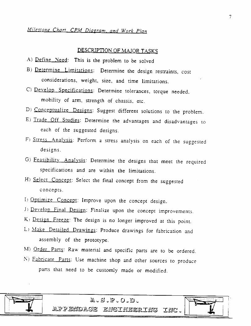
Milestone Chart. CPM Diaeram, and Work Plan
DESCRIPTION OF MAJOR TASKS
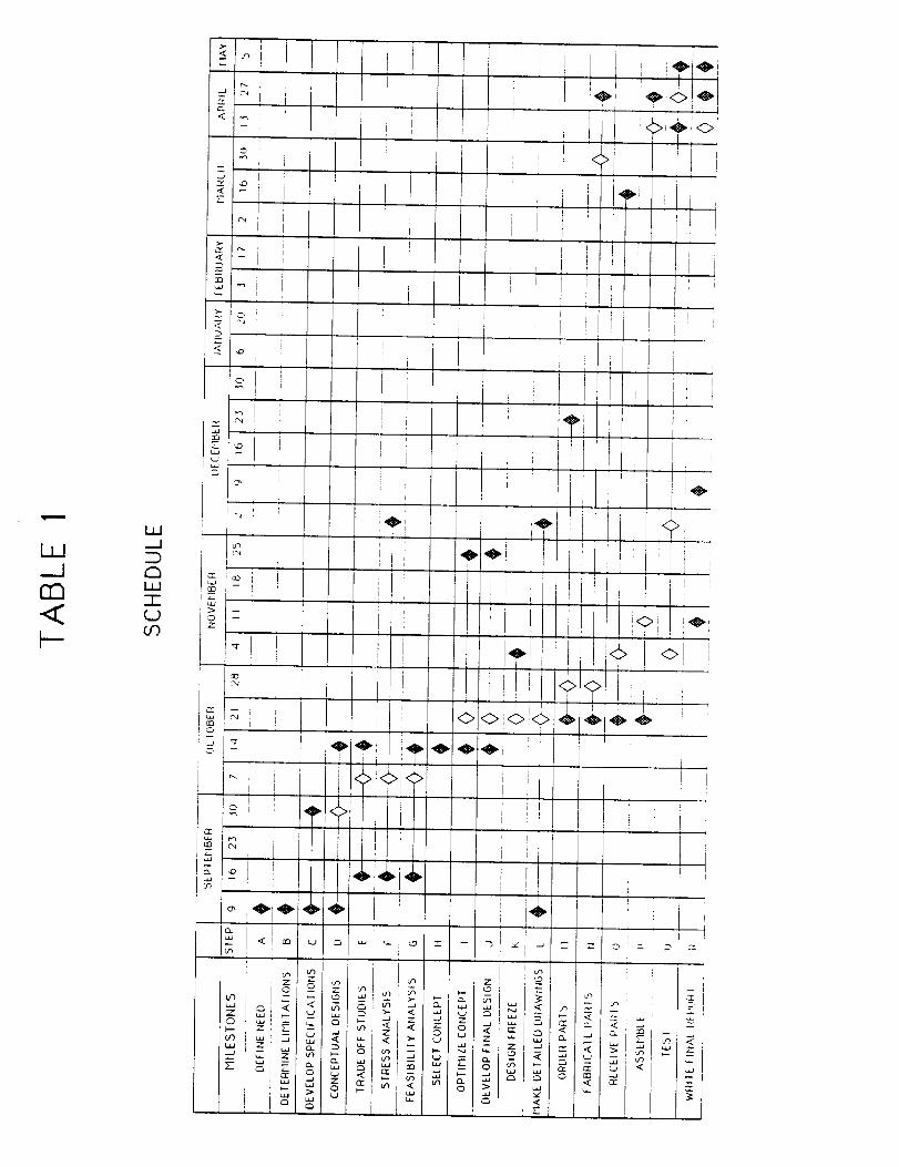
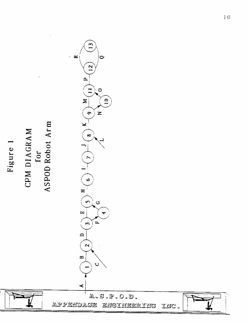
A) Define Need: This is the problem to be solved
B) Determine Limitations: Determine the design restraints, cost
considerations, weight, size, and time limitations.
C) Develop Specifications: Determine tolerances, torque needed,
mobility of arm, strength of chassis, etc.
D) Conceptualize Designs: Suggest different solutions to the problem.
E) Trade Off Studies: Determine the advantages and disadvantages to
each of the suggested designs.
F) Stress Analysis: Perform a stress analysis on each of the suggested
designs.
G) Feasibility Analysis: Determine the designs that meet the required
specifications and are within the limitations.
H) Select Concept: Select the final concept from the suggested
concepts.
I) Optimize Concept: Improve upon the concept design.
J) Develop Final Design: Finalize upon the concept improvements.
K) Design Freeze: The design is no longer improved at this point.
L) Make Detailed Drawings: Produce drawings for fabrication and
assembly of the prototype.
M) Order Parts: Raw material and specific parts are to be ordered.
N) Fabricate Parts: Use machine shop and other sources to produce
parts that need to be customly made or modified.
O) Receive Parts
P) Assemble: Begin assembly of the prototype.
Q) _ Perform tests on the assembled prototype to determine if it
meets all required specifications and functions.
R) Write Final Report: Write up final designs and prototypes report.
In the 2nd semester write up final report and prepare oral and
visual presentation.
Ill--_Jr_<
Iii-.1
1.1_1-r-(..2or')
I
II
II
I
I
I
ItIt
]0

I1
GEOMETRY AND
STRUCTURAL DESIGN
by
Paul Chinnock
"x
1 ")
ENTRODUCTION
The ASPOD arm structure needed to be both strong and light.
The existing prototype arm made by last year's senior design team is
a very heavy arm that has unduly high stresses at many joints. This
arm has stripped one of its axles, because the entire weight of the
arm and its coinciding torque was supported at a very small radius
bolt. The arm configuration designed and built during the last two
semesters has been engineered to rid the joints of moments and
reduce the stresses that exist at the pivot points. The design has
resulted in a highly' reliable, clean in appearance and light arm
structure.
13
PROBLEM DEFINITIQN
The structure of the ASPOD arm had to be designed to be as
light as possible, highly reliable, deflect less than 1 cm when under
full load, be nearly identical in link dimensions, have the same
degrees of freedom as the existing arm, and interface correctly with
the end effector.
14
LIMITATIONS AND CONSTRAINT_
The arm was restricted by dimensions and degrees of freedom
to be nearly identical to last year's design. The completed arm has
link lengths very near the first arm's, with the first link being 14
inches from base to the first pivot point and the second link being 25
inches long. It was expressed by our graduate student managers
that exact link lengths were not important constants, but degrees of
freedom were. The third link was modified due to the length of the
end effector to be only as long as a good transition joint required.
The end effector is mounted directly to the third link elbow joint to
keep the overall arm length as close as possible to the existing arm
and to reduce the torque arm. The arm had to be lighter than last
year's design and the arm is currently competitive in weight.
Modifications to the arm are being carried out that will drastically
reduce the weight while not reducing its structural integrity. The
third linkage's design provided a very simple end for integration of
the end effector.
i"
15
SPECIFICATIONS
The arm's structure allows it to work in unison with the drive
system and control system to move to any given location with an
accuracy of 1 centimeter carrying the end effector and over two
pounds of load. The arm designed provides a reliable platform while
bein_,_, liahter_ and more rigid than the previous arm. The arm had to
be manufacturable and in the final design individual pieces were
made as easy to machine as possible. In the manufacturing stage,
further simplifications were made to the design to accelerate the
assembly.

16
ARM DESIGN AND CONFIGURATION DETAILS
The design and configuration of the arm became an ever
changing iterative process during the first semester. At the start, the
design was built around a gear drive motivation scheme that became
extremely bulky because of the many gear reductions required to
obtain reasonable motor sizes and velocities needed. This
configuration would have resulted in tremendous difficulties in
control due to the backlash problems incurred by numerous gears.
In addition, difficulties would have appeared in reliability. The
design was also not very asthetically pleasing. After expressing our
concerns to our class and faculty advisors, we decided that a linear
drive motivated design would solve many of the previous design's
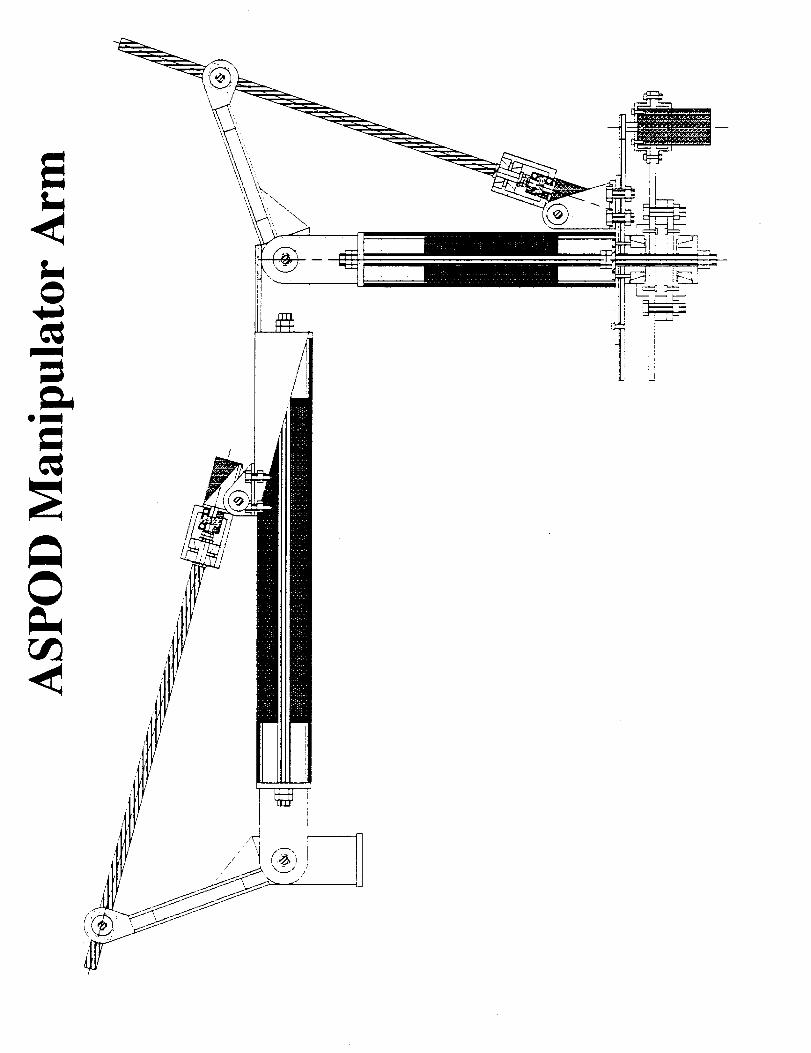
problems. The linear driven design ( see Figure 1 in Appendix A.1
provides the capability to rid the axles of torsion and load them with
shear only. The design has become very clean and simplified.
A. CONFIGURATION MATERIALS
Each link is built around a composite tube of carbon graphite
construction. The composite tubing has a good strength to weight
ratio, high stiffness and relatively good abrasion resistance. Through
each link is located a 1/2" threaded rod that provides pretoading in
the each link and holds the ends together for each link in the
prototype phase. If the links did not require dissassembly the 1/2"
rods could be removed for all, but the base to reduce weight. The
rest of the structure is made of aluminum. Aluminum provides easy
_!!!!!i_iii!!!!i!iiiiii!!i 1
machining, a fairly good strength to weight ratio, weldability and a
fairly low cost. The base bearing sleeves (see Figure 2 in Appendix
A.2) required steel to be used to provide good strength between the
1/2" rod and the bearing. The materials chosen provide a structure
that is lighter than last year's design when combined with the
simplicity of the drive system.
17
B. STRUCTLT, E DETAILS
Throughout the design, individual pieces (see Figures Appendix
A.2) were kept as simple as possible to minimize the amount of
machine work. The joints were made identical to make machining as
easy as possible and to reduce the work needed for motivation
analysis. The aluminum joints are standardized into male and female
parts that will be relatively easy to machine. In the female joints
machine screw's were used to reduce milling time. The male joints
were greatly simplified to two pieces welded together that proved to
be strong enough without additional strengthening pieces. The
height of the first joint above the base allowed room for only an
eight inch torque arm to be used, because of the space restrictions of
placing a motor, transition section and torque arm at full pivot
within the length of the link. The first torque arm's length was
further reduced due to the angle limitations introduced by a large
motor. The torque arm is angled 20 degrees above the horizontal
when the connected arm is horizontal. The reason this was done was
to provide the capability to move the arm from in line with the
previous link to 140 degrees counter-clockwise from there and still
provide a minimum torque arm for the linear drive of 2.73 inches
18
corresponding to an eight inch torque arm. The second link is still
easily movable under all load conditions due to above requirement
motors used. Motor position on the second link had to be far enough
out to provide clearance from the drive screw driving that link.
-Each link has an aluminum plug fitting snugly internal to the
composite. The tubing is connected to the male joint pieces by welds
that the composite unevenly fit against. Collars were machined to
straddle these welds and provide a uniform surface to compress the
composite onto. The plugs provide shear strength and moment
resistance. The plugs form the connection point to each joint base.
Motor mounts and motor to linear drive screw transition
sections are made from aluminum. The transition from the motor to
screw is done with a flexible coupling to make up for any
innacuracies in the center of rotation locations. The joint axles and
motor mount axles are supported by standard ball bearings while the
linear drive screws and the base are supported by tapered roller
bearings.
All the individual pieces were drawn and configured for
machining (see Figures, Appendix A.2). Even though the drawings
were done with the utmost effort in trying to ease machining
requirements, during the machining process further simplifications
were carried out. One such simplification resulted in reducing the
amount of milling time required by a single complex piece bv
producing many simple pieces machine screwed together.
The entire arm is supported by a 1/4 inch plate of aluminum
that is flanked top and bottom by the arm supporting tapered roller
bearings. The bearings are held between their brackets and sheaths
by preloaded al/2 inch bolt that runs through the center of the link
and the base. The first link's motor is mounted on the base gear that
acts as a rotating foundation.
All bolts were chosen to be as large as possible within reason
and space limitations. This was done to make sure that our design
would not fail due to fastener failure.
19
C. ANALYSIS
Some simple analysis was done (See Appendix A.5) on parts
where concern about failure or large deflections was focused. The I-
Beam that was a large part of the torque arm for each joint was
analyzed as if it was the only moment supporting member in the
joint. The simple analysis that was done revealed that the torque
arm's deflection at maximum load conditions would result in end of
manipulator arm deflection well within tolerances. The maximum
stress would result in a safety factor near two for 2011 Aluminum
alloy. The highest stress area in the base was in the top bearing
sheath. The steel sheath was analyzed with assumptions made that
would make the situation far worse than in actuality. The mounting
bolts could easily carry the loads induced with factors of safety
above three. If the center 1/2 inch bolt were preloaded the tensile
and shear forces in bearing sheath's bolts were further reduced. An
analysis was done on the maximum shear force that could be
imparted on the base if only three of the sheath bolts were resisting
the force and without the center bolt. The force calculated with very
low shear strengths used in each bolt and very lov, friction
coefficients between the sheath and the base gear assumed, resulted
\
2O
in over 500 pounds. In conclusion, areas of concern were analyzed
and they easily met max load conditions.
:k_
21
PARTS AND SUPPLIER INFORMATION
An item list (see Appendix A.3) was made and was very
helpfull in ordering parts. Suppliers of bearings and couplings are
identified in Appendix A.4.
PROJECT RESULTS AND MODIFICATIONS
,-)._
The arm's assembly was a long drawn out process were
simplifications to the orriginal drawings were done at every chance
to allow us to complete the project on time. Simplifications included,
as discussed earlier, using machine screws were possible to assemble
complex pieces from a few simple ones. George became very adept
at drilling and tapping #8 and #10 machine screws. In the summer
further weight reduction to the arm, that was not allowed due to
time restrictions, will be carried out. The structure met all
specifications required of it. The arm has shown a very high degree
of reliability by being transported and banged numerous times and
being operated at speeds well in excess of its design velocities. The
arm has shown a deflection with gripper attached and a 2.2 pound
load of less than 6.5 millimeters. The result of our labor has turned
out to be a very clean design with a minimum of complexity. The
arm proved be tough to manufacture, but we completed it with man','
long hours of work. Most important of all, our graduate managers
have said that we have met all their requirements for the arm. The
USRA budget was not known by the team member's, but our arm
was relatively cheap compared to the controlling computer. The
linear drives and composite tubing was by far the most expensive
with a cost of approximately $600 for both types of hardware.
Second most expensive where the bearings and where close to $150
The motors were 525 dollars apiece and raw materials and bolts
were quite innexpensive also.
23
DRIVE SYSTEMS
by
George Williams
_¢,a._ ,_ _ .,_
2-¢
BACKGROUND:
The drive systems of the robotic were a subproblem of this
project simply because the previous design was unsatisfactory in the
areas of weight, precision movement and reliability. Therefore, this
design was to optimize the previous design in these areas while
fulfilling performance specifications.
PROBLEM DEFINITION:
To design a drive system for the robotic arm that will
manipulate the arm through all 3 degrees of motion with fluid,
precise, controllable movements.
PROJECT LIMITATIONS/CONSTRAINTS:
The following are limitations and constraints on the ASPOD ROBOT
ARM project (1/5 scale). Each limitation and constraint must be met in
accordance with the previous teams specifications but will hopefu]l,, be
surpassed through optimization of the design. Following the list is a
brief summary of what each limitation/constraint means.
1) Time
2) Weight
Working prototype by May 1, 1992.
Arm must weigh less than current arm,
25
3) Deflection - Must be less than 1 cm between the
loaded and unloaded conditions.
4) Degrees of freedom - Arm must have 6 D.O.F.
5) Earth based design Related problems
6) Loading conditions - Arm must be able to handle
and move a specified mass.
7) Arm span The arm must extend 4.0 feet in
any given direction.
Descriptions
1)
2)
3)
The time given to design and develop a prototype is
only one semester. The following semester will be
spent on further optimization and construction of thedesign.
The goal of the project is to minimize the weight of the
robotic arm (thereby decreasing the overall weight of
the satellite) through optimization of the existing arm.
The design of the arm should be should be such that
there be less than 1 cm deflection between the loaded
and unloaded condition. This is in consideration of the
dynamic loading effects on the arm and the material itis made of.
4)
5)
The arm must be able to translate as well as rotate in
the x-y-z spatial coordinates in order to handle the
precise positioning of debris required for the cutting
procedure.
The design of this robotic arm takes place on earth
where gravity exists while it is to function in space
where gravity does not exist. On earth, the predominate
acceleration is gravity while in space the predominate
acceleration will be angular acceleration. It is this
26
unavoidable fact that makes using the LangrangianEquation for torque difficult.
6) The mass of the load, for application in space, will be
1500 kg or greater. The mass the 1/5 scale prototypemust handle is 2 lb.
7) The length of the robotic arm is to be 4.0 feet in
extended length.
i
===X_,

SOLUTION:
w
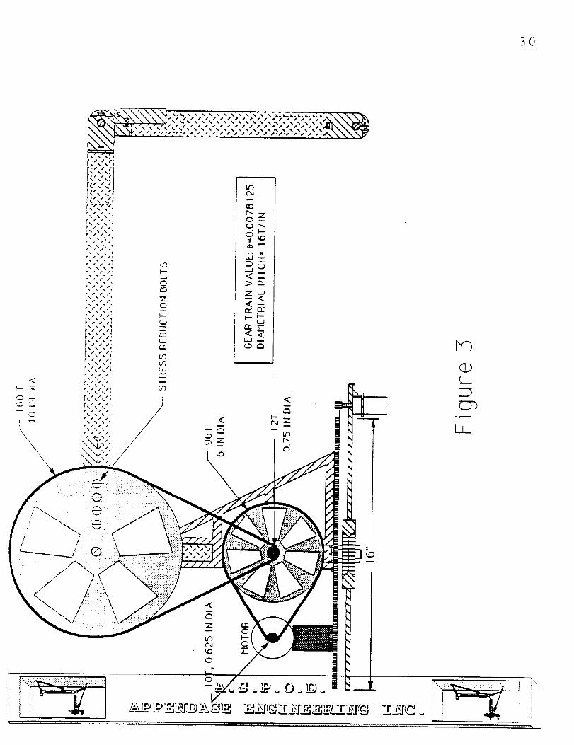
The first proposed solution for the robot arm drive systems is
shown in Figures 2, 3 and 4. The robot arm was to be driven with
sprocket-chain assemblies with specific gear train values designed to
meet both torque and speed requirements. This proved to be a very
simple design and it met all of the operating conditions. However,
this design was eventually discarded for several reasons. First, this
design introduced high localized stress concentrations at all of the
axis of rotation. Second, these types of systems are inherently
difficult to control due to the inherent "play" characteristics that exist
within them. Finally, this design was deemed to be unappealing to
the eye due to its bulky appearance. For these reasons a new design
was proposed and is shown in Figure 5.
The introduction of the ball screw-ball nut linear actuator
proved to be a much better design when compared to the sprocket-
chain assembly due to three major improvements. First, the linear
actuator is a very efficient device, on the order of 95%, in power
transmission. Second, the ball nut of this system can be preloaded so
as to negate any effects of play that may exist within the system.
Finally, this design is much more appealing to the eye due the
streamlined appearance the linear actuators create. However, it
must be noted that a modified version of the sprocket-chain
assembly has been retained as the drive system for the base for the
following reason. The motion requirement for the base is that it
must be able to rotate through 360 degrees, a condition that is best
met with the application of the sprocket-chain assembly system. The
-x
28
problems previously mentioned with using this type of system have
been compensated for by applying a preload to the chain so that an,,'
detrimental effects will be minimized.
Due the improvements that have been noted, the design shown
in Figure 5 was chosen as the final design to be implemented as the
mechanical drive system for the robotic arm.
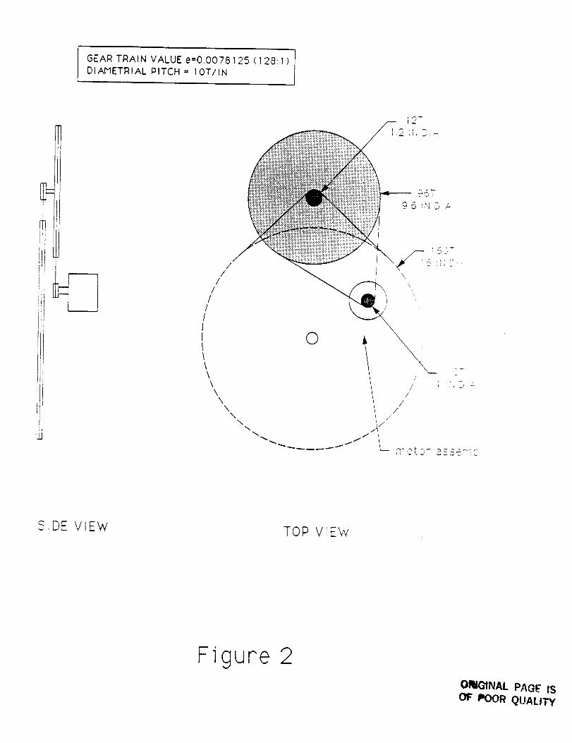
GEAR TRAIN VALUE e=0.0078125 ( 1281 )DIAMETRIAL PITCH = 10T/IN
//
//
///II
\\\\\
NN
\
O
\
///
//
Y_- _ ",* -., 30. _,_.-,..,_
, _ i _, i_ _
SiDE VIEW TOP VIEW
Figure 2O_iG1NAL PAGE IS
OF POOR QUALITY
30
_i_-,._\\\\\"4,,, ........ ,,,,,,, .... R
/zIIPPI_PfCP¢SSSSSS_JSSSSJ_
j,j#-*2s2s2_,2s s # i J _* * # s # ¢ # **-p2_,2P2s2s2s2_
(D
Lx_
<
O Z,.D _
<
0
<
0n_
Z©
L_
o_Cxl
• . II
<_.
_, _
<-
(19
31
!i:ii:i i_ill i!:i i!
_t_s_sJ_SS_Ss_SS_Sss_
° J/_
_ _-_.,__.__-_-__-_ _2.T_Z_.___.Z22_.
35
ANALYSIS:
The analysis of the arm was subject to several parameters.
First, the analysis was performed with the assumption that the
applied load is twice as heavy as the actual load so that all
calculations would meet the required factor of safety of 1.5. Second,
the angular velocity of each link was specified to be 90
degrees/minute (0.25 rev./min), defined by the desire for uniform
velocities between links and also from the knowledge that fast
operating speeds are neither required nor desired. Third, the
angular acceleration of each link was specified to be 0.0436
radians/sec^2, defined by accelerating to the specified angular
velocity in 2 seconds while traveling through 5 degrees. This value
of acceleration was chosen because a greater acceleration would
require greater torque from the motors, while a slower acceleration
would make demonstration practices time consuming. Therefore this
acceleration is a middle ground and is uniform for all links. Finallx.
an analysis using Lagrangian dynamics was performed so that the
motors would be accurately sized for the condition of all links being
in motion at the same time.
L t
!
34
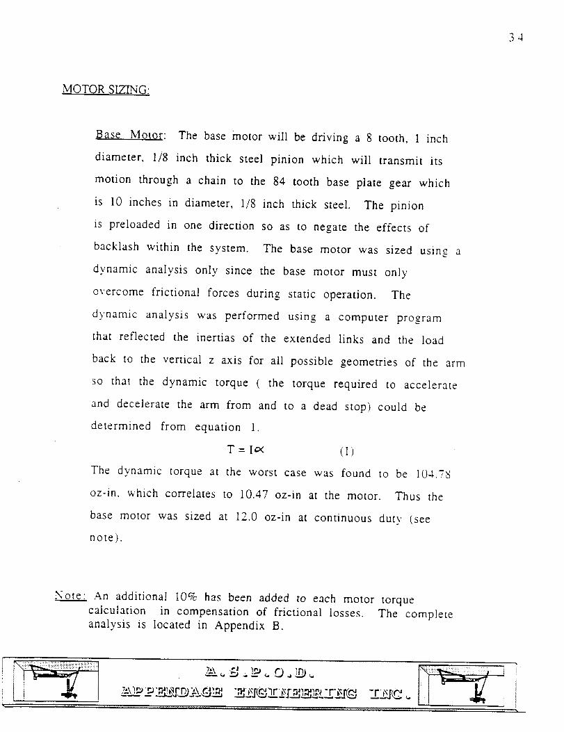
MOTOR SIZING:
Base Motor: The base motor will be driving a 8 tooth, 1 inch
diameter, 1/8 inch thick steel pinion which will transmit its
motion through a chain to the 84 tooth base plate gear which
is 10 inches in diameter, 1/8 inch thick steel. The pinion
is preloaded in one direction so as to negate the effects of
backlash within the system. The base motor was sized using a
dynamic analysis only since the base motor must only
overcome frictional forces during static operation. The
dynamic analysis was performed using a computer program
that reflected the inertias of the extended links and the load
back to the vertical z axis for all possible geometries of the arm
so that the dynamic torque ( the torque required to accelerate
and decelerate the arm from and to a dead stop) could be
determined from equation 1.
T = Io< (1)
The dynamic torque at the worst case was found to be 104.78
oz-in, which correlates to 10.47 oz-in at the motor. Thus the
base motor was sized at 12.0 oz-in at continuous duty (see
note).
Note An additional 10% has been added to each motor torque
calculation in compensation of frictional losses. The complete
analysis is located in Appendix B.
,_rrj_(_. ,., _!iilJiiii!i!::::
35
Second Link Motor: The second link motor will be driving a
5/8 inch stainless steel ball screw through a compatible pre-
loaded stainless steel ball nut. The ball nut is to be pre-loaded
so as to negate the effects of backlash within the system. A
static analysis was performed on an Excel spreadsheet for all
possible arm geometries so that the worst case could be easily
obtained. The worst case was found to be when the arm is
fully, extended and 50 degrees below horizontal. The static
torque at worst case was found to be 242 oz-in. A dynamic
analysis was then performed and it was predetermined that
the worst case would not be dependant on the angle of the arm
relative to the horizontal, only that it was dependant on the
degree of extension of the arm. The worst case was found to be
at full extension and the dynamic torque was found to be 78.17
oz-in. Thus, in order to accurately size the motor the motor
must provide both the static and dynamic torque at the same
time. Therefore, the second link motor must provide 360 oz-
in at continuous duty.
"b
36
Third Link Motor: The third link motor will be driving a 5/8
inch stainless steel ball screw through a compatible pre-
loaded stainless steel ball nut. The ball nut is to be pre-loaded
so as to negate the effects of backlash within the system. A
static analysis was performed on an Excel spreadsheet for all
possible arm geometries so that the worst case could be easily
obtained. The worst case was found to be when the arm and
the load are fully extended relative to one-another. The static
torque at worst case was found to be 102.7 oz-in. A dynamic
analysis was then performed. It was predetermined that
the worst case would not be dependant on the angle of the arm
relative to the horizontal, rather that it was dependant only on
the degree of extension of the arm. The worst case was found
to be at full extension and the dynamic torque was found to be
71.9 oz-in. Thus, the second link motor must provide 192 oz-
in at continuous duty.
_!:i!: izliii_'----] _
i
!
37
CONTROL SYSTEM
by
Peter Wegner
!iiI _
INTRODUCTION
A. Background
The goal of the US RA funded research project for the 1991-
92 school year has been to develop a second robotic arm for the
debris collecting satellite. This arm, in conjunction with the
arm developed by the previous years design team, will serve as a
proof of concept for the Autonomous SpaceProcessor for Orbital
Debris. The arm must demonstrate that autonomous retrieval of
space debris is possible and feasible.
38
B. PROBLEM DEFINITION
A control system for the manipulator arm must be designed so
that the arm can demonstrate autonomous movements. The control
system must provide reliable, stable, and simultaneous movements
for all six degrees of freedom on the arm. This movement must be
repeatable and alterable.
C. LIMITATIONS AND CONSTRAINTS
The control system must meet the above criteria in such a
way that cost is minimized. The weight of the arm must be
reduced below that of last years design. The control system
should have an accuracy of +/-2.5 cm at the full extension of the
arm. The control system must be designed so that the end
affector and the first 3 degrees of freedom (DOF) of the arm can
be combined into one system. The arm must be capable of varying
velocities and accelerations so that the arm can perform a
reasonable demonstration. In order to do this the arm must be
capable of moving a 2# load as slow as 2.5 cm/min and fast enough
that the arm will move through a 90 degree rotation in 1 minute.
39
FINAL DESIGN
A. OVER-VIEW
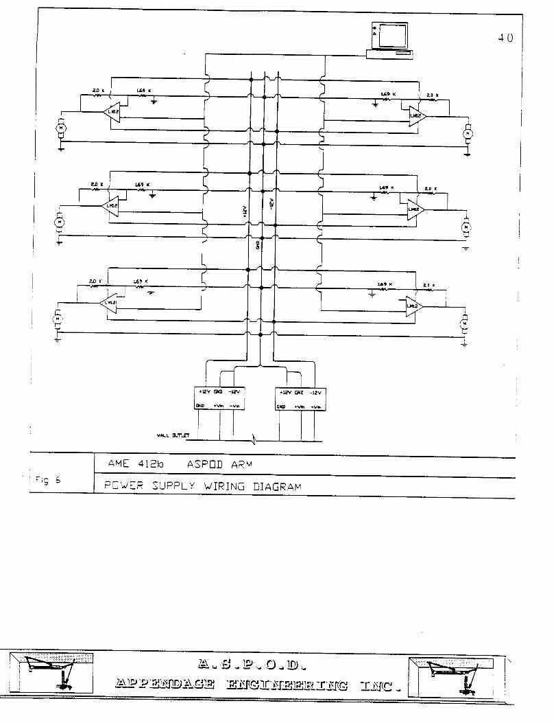
The system used to control the arm is shown in figure 6. A
personal computer with a 486 micro processor is used to power the
control software and provide processing power. Two control cards
installed in the computer are used to convert the digital motor
commands required for proper positioning commands to analog
signals that are used by the motors. These cards perform the
time intensive tasks of motion profiling, compensation filtering,
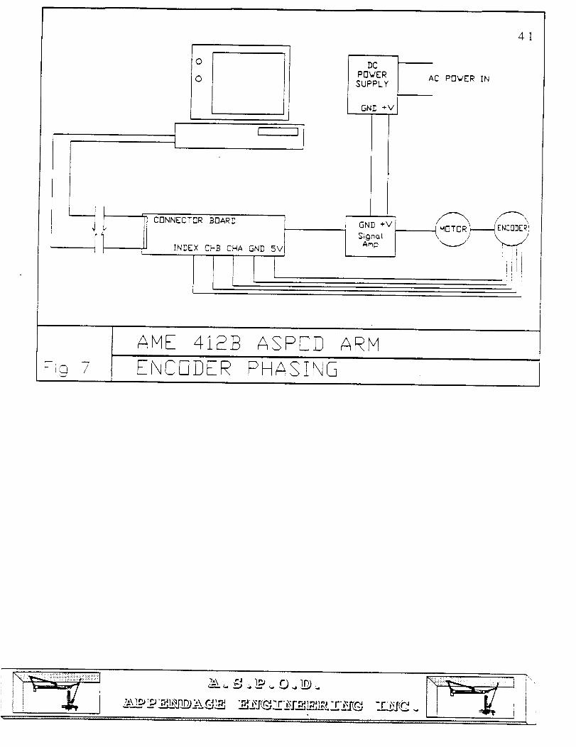
and encoder decoding. Connector boards as shown in figure 7 are
used to connect amplifier, encoder, motor, and computer wiring
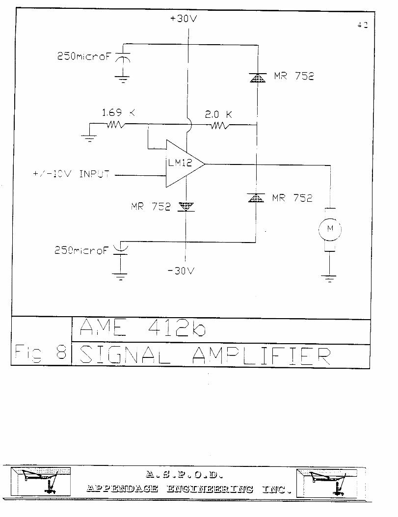
in a simple manner. Signal amplifiers as shown in figure 8 are
used to amplify the motor signals coming from the computer at +/-
10VDC to +/-24VDC as required by the motors. Power supplies
shown in figure 6 are used to supply current to the motors as
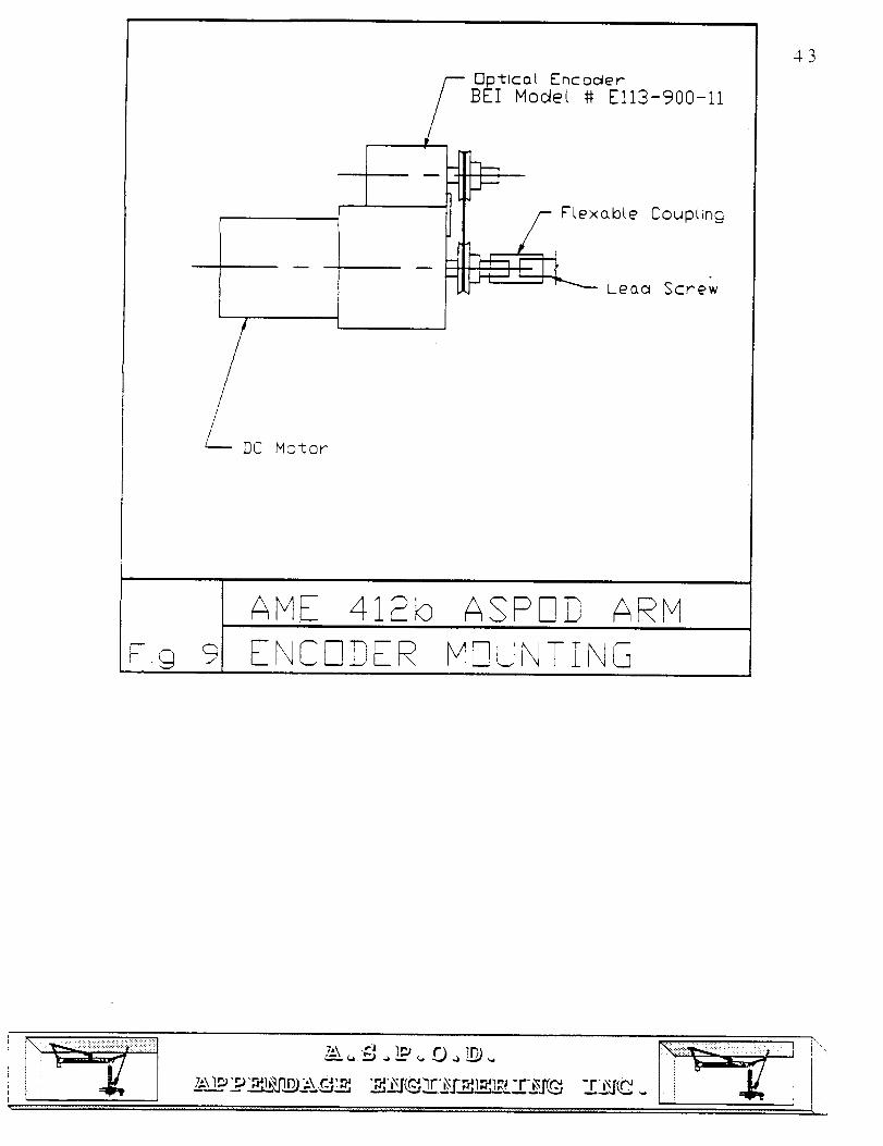
required to move the applied loads. Optical encoders mounted as
in figure 9 are used to provide position feedback to the
computer. The control cards are programmable so that the arm can
autonomously move through a given motion. This programming is
accomplished using a series of supplied functions provided with
the control cards.
-¢--
/ _...J
• __/ %
"h f..f_
I
i-]
I
i
40
ANE 412b ASPrq]D ARH
F_9POWER SUPPLY WIRING DIASRAH
_'m 0 __J___
"_'_X [(-t2_,_r _I'_I_I#_ -r_
0
0
0clPOVERSUPPLY
GN]) ÷V
AC PrIVER IN
GND ÷V IS_gna_ /
Amp I
4!
\\
ENCO_ERI/
lii!,
A_IE 4123 ASPSI} A£P1
_-_9 7 ENCODER PHASING
?,,t.'\ "J !_
::=L_
+30V4.2
£50micr'oF 7 L.-,,,
1,69 K
+/-I@V
£,0 K
INPUT
M_ 752
£SOmicroF LJjI
-3OV
i
i
H£ 758
M_ 758
!
_,i,I,_j//'
FiQ 8,,d
A_vIz _-12b
S_G\A_ Av'PLZFTf -
/I DC Ho<or
/I
-i-_ Flexable
_Lea
]_±lco I Encoc_er] Hodel # Ell3-900-11
Coupting
cl Screw
AME 41Sb ASPND ARM
ENCNDER HNUNTIN69
43
_.\ ._ imp. 0 _. ['\_ ",
44
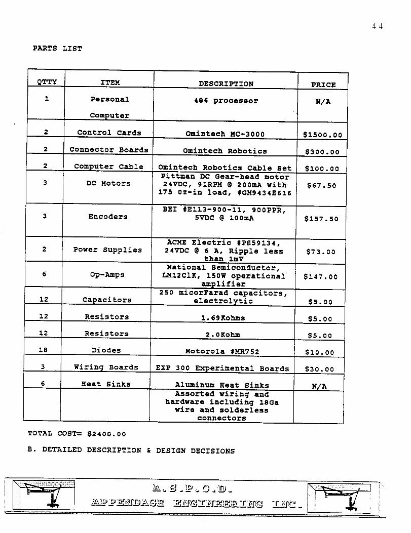
PARTS LIST
QTTY
1
ITEM
Personal
Computer
Control Cards2
2 Connector Boards
2
3
6
12
12
12
18
3
6
Computer Cable
DC Motors
Encoders
Power Supplies
Op-Amps
Capacitors
Resistors
DESCRIPTION PRICE
486 processor
Omintech MC-3000
Omintech Robotics
Omintech Robotics Cable Set
Pittman DC Gear-head motor
24VDC, 91RPH @ 200mA with
175 0z-in load, #GM9434E616
BEI #EI13-900-II, 900PPR,5VDC @ 100mA
ACME Electric #PS59134,
24VDC @ 6 A, Ripple lessthan imV
National Semiconductor,
LMI2CIK, 150W operational
amplifier
250 micorFarad capacitors,
electrolytic
Motorola #MR752
1.69 Kohms
Resistors 2.0Kohm
Diodes
EXP 300 Experimental Boards
Aluminum Heat Sinks
NIA
$1500.00
$300.00
$i00.00
$67,50
$157.50
$73.00
$147.00
$5.00
Ss.oo
$s.oo
$I0.00
$30.00Wirin_ Boards
Rear Sinks
Assorted wiring and
hardware including ISGa
wire and solderless
connectors
NIA
TOTAL COST=- $2400.00
B. DETAILED DESCRIPTION & DESIGN DECISIONS
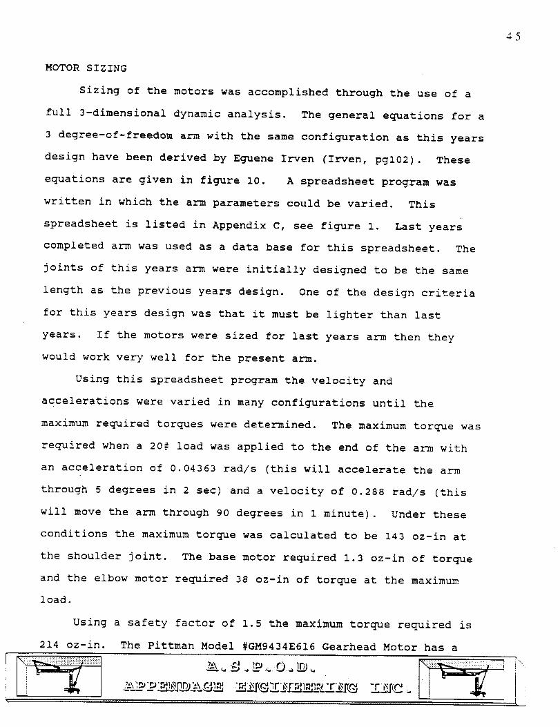
MOTOR SIZING
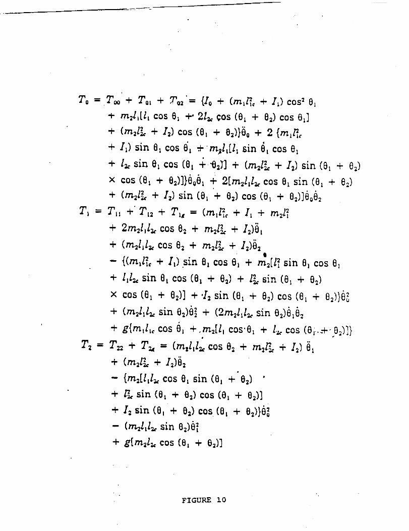
Sizing of the motors was accomplished through the use of a
full 3-dimensional dynamic analysis. The general equations for a
3 degree-of-freedom arm with the same configuration as this years
design have been derived by Equene Irven (Irven, pgl02). These
equations are given in figure I0. A spreadsheet program was
written in which the arm parameters could be varied. This
spreadsheet is listed in Appendix C, see figure I. Last years
completed arm was used as a data base for this spreadsheet. The
joints of this years arm were initially designed to be the same
length as the previous years design. One of the design criteria
for this years design was that it must be lighter than last
years. If the motors were sized for last years arm then they
would work very well for the present arm.
Using this spreadsheet program the velocity and
accelerations were varied in many configurations until the
maximum required torques were determined. The maximum torque was
required when a 20# load was applied to the end of the arm with
an acceleration of 0.04363 rad/s (this will accelerate the arm
through 5 degrees in 2 sec) and a velocity of 0.288 rad/s (this
will move the arm through 90 degrees in 1 minute). Under these
conditions the maximum torque was calculated to be 143 oz-in at
the shoulder joint. The base motor required 1.3 oz-in of torque
and the elbow motor required 38 oz-in of torque at the maximum
load.
Using a safety factor of 1.5 the maximum torque required is
214 oz-in. The Pittman Model #GM9434E616 Gearhead Motor has a
45
To :T_'+ ToL + To2'= {/o + (rn_/_, + I_)cos 20_
÷ m21,[l: cos 0_ +' 2I_. Cos (0_ + 82) cos 8_]
+ (m2lL + I=)cos (0_ + 02)}0o + 2 {rn:_
+ I_) sin Oxcos 0'_ .+m_l,[l_ sin O_cos O_e
+ lu sin O_cos (O_ + "02>] + (m,l_, + 12) sin (0_ + 0_)
× cos (0_ + 02)]}6o0_ + 2[m,l,l_ cos O_sin (Ox + 0:)
+ (m21_, + 12)sin (0_ + 0=)cos (0_ + 0_)]6o0_
Tl = Tll ÷" Tl2 + Ylx = (mzl_, + Ii + m21_
+ 2m_l_I_ cos 02 + m_l_ + I_)01
+ (m2l_l_ cos 82 + m21L + I_)0_
- {(m_l_, + I_) sin 8_ cos O_ + m_[l_ sin O_cos O,
+ l_l_, sin O_ cos (0_ + 0_) + l_ sin (0_ + 0_)
× cos (0_ + 0_)] + 'I_ sin (O_ + 0_)cos (0_ + 0_.))_
+ (m_l_l_ sin 0_)0_ + (2m=l_lu sin 0_)0_0_
+ g{m_l_, cos O_ +.m_[l, cos'O, + lz. cos (Oi-.-+'O_)]t
T= = Y_ + Y_ = (m:l_l_ cos O_ + m_l_ + I_) [_
+ (m=l_ + I_)§=
- {m=[l,l_, cos O, sin (0, + 0=) "
+ F_ sin (0_ + 0_)cos (0, + O_)]
+ I= sin (0_ + 0=) cos (0_ + 0_)}0_
- (rr_l,l_ sin 0,)0_
+ g[m,lz, cos (0_ + 0,)]
FIGURE i0
continuous rating of 195 oz-in. This is slightly less than the
calculated torque required. However, after considering the
affects of counterbalancing achieved by the torque arm and lead
screw design ( a total weight of 3# was used as a counterbalance)
the maximum torque required was determined to be only 183 oz-in.
This motor was used in all three joints of the arm for ease of
manufacturing. This motor has operating characteristics as shown
in appendix C, figure 2. The motor is available from Servo
Systems Inc. for $22.50 each.
CONTROL CARDS
The control cards solve the differential equations of
motion for each motor on a real time basis. They also decode
the encoder feedback and determine the compensation filtering to
provide system stability. This frees the PC for higher level
applications. Using this motor control card the components
required to build a servo control system are the DC motor, an
incremental encoder, and a power amplifier (see figure 7). The
control card that will be used for this system is the MC-3000
motor control card from Servo Systems Inc. This is a three axis
control card, i.e. one that can simultaneously control three
motors. The controller card has 32-bit position, velocity, and
acceleration registers. The control card contains a full PID
controller which will stabilize the system within a given
bandwidth. It can be shown through classical control methods
that a system can be stabilized within a certain operating range
by the proper choice of feedback gain parameters in a PID
controller [Grantham & Vincent, 1991, pp 6.1-6.60].
47
48
POWER SUPPLY SELECTION
At maximum load these motors will draw about 900 mA. The
end affector group selected motors that would draw less than 1
amp at the maximum load. The power supplies were sized so that 6
amps of current is available. This means that all 6 motors can
be operating at the maximum loading case simultaneously with
available current left over if a stall condition should occur.
The power supplies are wired as in figure 6. This was done
because the power supplies output +24VDC. With this wiring
configuration the system is supplied with +24VDC as well as -24
VDC at 6 amps. The power supplies were purchased from Servo
Systems Inc. for $36.50 each.
SIGNAL AMPLIFIERS
The signal amplifiers are built around an LMI2CLK op-amp
from National Semiconductor. These were purchased from Anthem
Electronics for $25.40 each. The op-amps were wired with
protection circuits as shown in figure 8. The capacitors smooth
ripples in the power supply. The diodes keep current from going
back into the op-amp and destroying the op-amp. The resistors
provide a gain factor for the amplifier of 1.18. These circuits
are wired to bread boards as shown in figure ii.
The op-amps were mounted to heat sinks as shown in figure 6.
The heat sinks must be able to dissipate 80 Watts of power from
the op-amp and keep the center of the op-amp from exceeding 70
degrees Celsius. Initially a heat transfer analysis was
performed for a fin dissipating this energy (Reynolds, p 568).
The calculations are shown in Appendix C. These calculations
iiiiii i"

250microF
1.69K
_ "'
"ML.n
_q_-_ --F250m;crog
\
\'\
._ I-L
m
:! zz i-4. 1
I
zE£
i-- I
÷30V
--- -3OV
>
Horizontal sectors (ire connectedin a common buss
Common GND buss
49
AME 418b ASP_I) AR_I7i9 i1 ;READ Sf3ARD _I£!NG D!A_£A_
; u -r_;_
'\
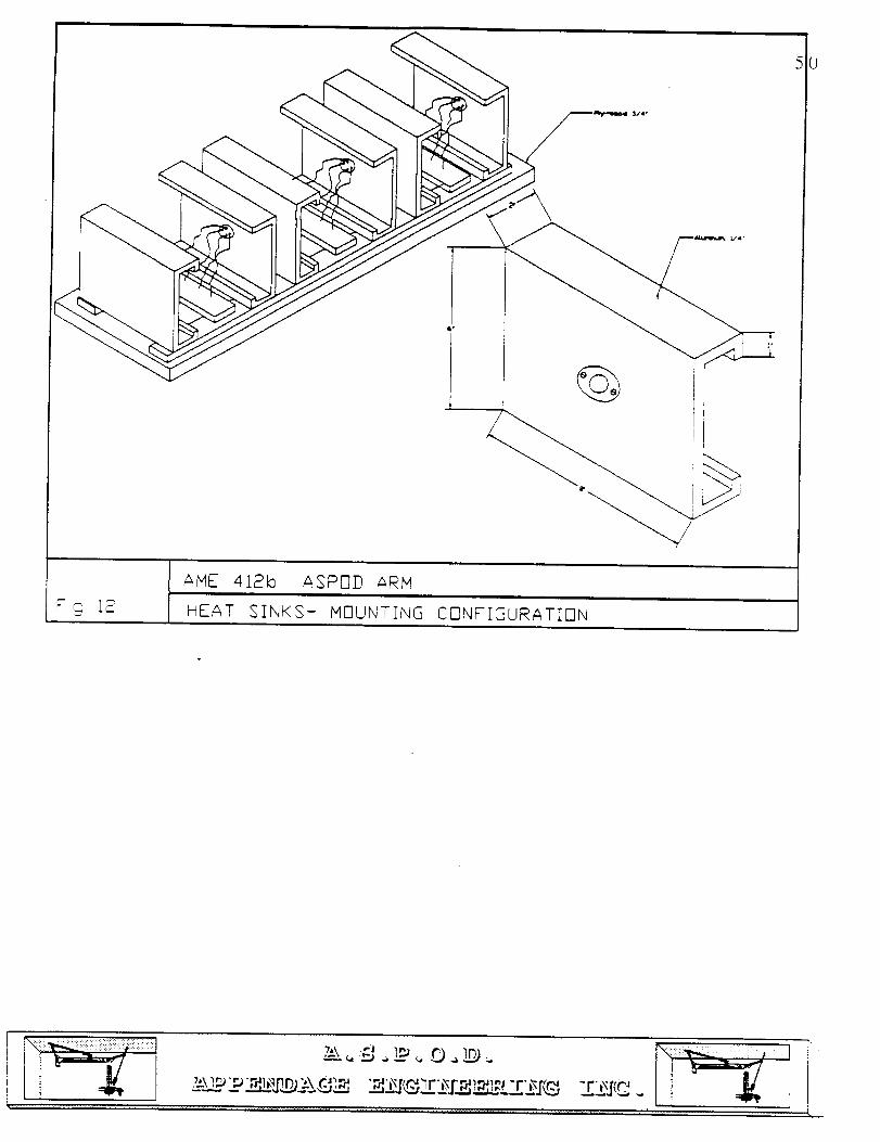
AME 418b ASPOD ARM
S;r,_ 18 HEAT SINKS- MOUNTIN6 CONFIGURATION
"0
:_,\lm'_ _j_@ _x_._ -r4_xr(_sr_r_,m_ r, _ .n, -r_.[_.
were written into a spreadsheet as shown in Appendix C, figure 3.
This analysis showed that each op-amp would require a fin 20cm x
15 cm x 2.5 cm. To check these calculations the heat sinks were
sized using procedures given in a Thermalloy Catalogue. This
analysis determined that a plate 13cm x 13cm x 2cm would
adequately cool the op-amps. Finally, a chart provided by
National Semiconductor was consulted. This chart showed that
each op-amp would require 50 square inches for adequate cooling.
ENCODERS
As previously noted, in order to complete the servo-system
design the controller card must be supplemented by an optical
encoder. An optical encoder is a device capable of counting the
angular distance that a given shaft is rotated. The encoder used
in this design is the BEI Model #EI13-900-II. This encoder
operates on 5VDC at 100mA. The output is on 2 channels in
quadrature with an index channel. This means that the encoder
indicates direction of rotation as well as absolute position of
the arm.
The resolution is increased substantially by the control card.
The control card has the capability of reading the encoder output
in quadrature. The controller counts every time the encoder
signal changes direction, which happens four times for every
pulse. Essentially the controller card increases the resolution
of the encoder by a factor of four.
It was determined that if the encoder emits 360 pulses
during the entire range of motion of the arm the position of the
end affector could be determined to within +/- 2 centimeters.
51
The encoder selected emits 900 pulses per revolution, which is
equivalent to 3600 PPR in quadrature. The encoder will be
directly driven at a l:l ratio by the motor shaft using a small
pulley and belt as shown in figure 9. This configuration will
keep backlash between the arm joints from entering the controller
and creating a cyclic affect. Mounting the encoders in this
manner will also increase the length of travel of the torque arm
on the lead screw.
It was determined that the maximum change in length for
either of the lead screws was 15 inches, the lead screws selected
have a lead of 0.2 inches per revolution. The motor must turn 75
times to obtain this change in length. This means that the
encoder will emit 270,000 pulses during the full range of motion
of either joint. The base motor will turn i0 times during one
revolution of the manipulator base. The encoder attached to this
motor will emit 36,000 pulses during this motion. Thus it is
apparent that in the absence of backlash in the system this
encoder would easily meet the accuracy requirements.
The controller card that will be used has a 32 bit position
register. This means that the card can store 2.1xi0"9 pulses on
each channel. This is far more than are required for the
complete range of motion of the arm.
The encoder selected operates at 100KHz. If the motor turns
at 63 RPM, which will cause the arm to move 90 degrees per
minute, the encoder will be sending 3.8 x 10"3 pulses per second.
This speed is well within the operating resolution of the
encoder. This will ensure that the encoder does not miss any
52
_ii!!i!!_ i"_
i
L
counts during operation. The controller cards selected will
operate with an encoder of up to 750 Khz. Thus, there is a good
match between the controller cards and the encoders to ensure
that this combination accurately measures the arms position.
CONTROLLER PROGRAM
The controller program is written in a text file in which
pre-programmed commands are recalled and used from the controller
card's memory. These commands tell each axis how many encoder
counts to rotate through as well as the speed and acceleration
requirements. The manipulator arm initially is programmed with
only one trajectory. The program tells the arm how many
revolutions of each motor are needed as well as the velocity and
acceleration required for each motor. This initial program
completes a good demonstration of the arm. It moves each joint
individually, then proceeds through a series of simultaneous
movements. This program is listed in Appendix C, figure C.4.
A spreadsheet program was developed that calculates the
number of turns of each encoder required for a one degree turn of
the corresponding joint, see Appendix C figure c.5. A 3-D
AutoCad drawing of the arm was used to visualize the proper
angles to rotate each joint, this drawing is shown in Appendix C,
figure c.6.
55
54
C. CONCLUSION
The design presented in this report has been completed and
tested. The system is able to place a 2# object with an accuracy
of 2.5 Cm, this has been tested by measuring the repeatability of
the arm motions with a 2# object.
This project has been a very valuable lesson to the people
involved. The knowledge gained from this experience is far
superior to that obtained in any previous courses. The author's
knowledge of control systems, electricity, and electronics, as
well as team work and the design process have been increased
tremendously. The author is very grateful to the people who made
this project possible through their advice and guidance.
o m
D3
MOUNTING AND POSITIONING
OF MANIPULATOR ARM
By
Curt Bradley

56
INTRODUCTION
One of the functions of ASPOD is to dissect large pieces of debris into
smaller more manageable parts. These smaller pieces, if useful, can then
be stored on the ASPOD craft itself. Or, if the piece is unwanted junk, it can
be sent into a lower orbit that will speed it's reentry into the earth's
atmosphere. It is during the cutting operation ° that two robotic arms are
necessary. One of the arms will be used to position the debris in front of
the solar cutter, the other will be needed to prevent the material from
swinging forward into the solar mirror array or any other vital
instruments on the craft. Also, a second arm placed at an optimal distance
from the first, will offer a larger area of accessibility. What this means is
that if a desirable piece of material is separated from its parent satellite.
there will be a need to store this piece somewhere on the craft. The
second arm, positioned correctly, could place this useful part, possibly near
the solar mirror array. If the useful part happened to be reflective in
nature it could be positioned in such a way to increase the effectiveness of
the solar mirror array.
It is my specific task to position the second robotic arm and design a
frame to hold it in place. The second arm needs to be placed near enough
to the first so that both arms can grab the same object, but it also needs to
be placed close to the solar mirror array so that it has access to the rear of
the craft. The frame that supports the second arm must be connected to
the frame of the spacecraft itself and not any external members, such as
the frame of the solar mirror array. This constraint was created to allo_v
flexibility in the design of the solar mirror setup. If the design for the
solar mirrors were to change, the frame for the second arm would not need
to be. Because of this uncertainty, there must be sufficient clearance
between the robotic arm frame and the flame for the mirrors. The frame
must be made of a material strong enough to be able to support the weight
of the robotic arm and any moments it will encounter. It should be made
of a material stiff enough to keep the total deflection of a fully extended
arm loaded with a two pound weight tO less than 1.0 cm. Also, the frame
placement must be such that it doesn't interfere with the functioning of
the first robotic arm or the solar cutter. Weight must be taken into
consideration because of the high cost of sending any mass into orbit.
57
FINAL DESIGN
My proposed frame design is shown in Appendices D.1, D.2. D.3, and D.a.
Appendix D.I shows the three views of the assembled frame and its
dimensions.
Appendix D.2 is a side view of the frame with the robot arm assembly,
mirror frame, and the base of the ASPOD satellite. The dashed semicircle
represents the area of accessibility of the fully extended robot arm
positioned perpendicular to the mirror frame. This arc does not include
the length of the end effector. The directions foreword and aft are used to
describe positions on the satellite. When looking at the figure, foreword or
front refers to the left part of the diagram, rearward or aft refers to the
right. The focal point of the solar cutter lies along the horizontal dashed
line that crosses through the center of the mirror frame. This is the point
where the sun's rays will be concentrated in a similar manner as the',' are
when they pass through a magnifying glass. From the figure it appears
that the robot arm is not long enough to reach the focal point, but with the
end effector attached, giving it an extra thirty inches, it is able to do so.
One of the purposes of our designed arm is to hold objects in front of the
_!iiii_!iiiiii!i!i!!iiii!i!!!!_iii!:+:_i;i!!;iii!i!i!!!_!
_t..NqU_,,, _[ii!ii!i_!ii
58
solar cutter in conjunction with the primary arm. The primary arm will be
the same as the secondary arm except that it is mounted to a base that
rotates about a point in the center of the base of the satellite. This point is
represented by the vertical dashed line. When as object is to be cut, the
piece will be held in position by the primary arm with the assistance of the
secondary arm. If the cut part is then to be stored, the secondary arm will
have access to any storage areas near the rear of the craft. As indicated on
the drawing, the front mirror frame is two inches aft of the front of the
robot arm frame. The frame was positioned here because it is the furthest
aft it can be placed without the bottom brackets extending beyond the
ASPOD base boundary. The frame can be moved slightly forward but is
limited by the support track for the primary arm base. Clearance was
given between the arm frame and mirror frame to allow for design
changes in the latter.
Appendix D.3 is a front view of the frame and arm assembly
surrounding the mirror frame. The dashed semicircle is the area swept out
by the fully extended arm (excluding end effector) when it is positioned
parallel with the front of the mirror frame. The crosshatch represents the
focal point of the solar cutter.
Appendix D.4 is a top view of the arm frame with the satellite base and
the mirror frame assembly. This figure includes the boundaries for the
satellite and position of the support track for the primary arm base.
Appendices D.5, D.6, D.7, and D.8 are drawings of the individual parts of
the support frame. When designing the brackets I kept three criteria in
mind: strength and stiffness of the bracket, cost of the material, and ease
of assembly. Because of these factors I chose to fabricate all three
brackets out of aluminum, which is relatively cheap, has a high stiffness to..............................................................7._\ 1.e.,,. 0. ............. "1 r',,
- i' ...... • .................. [I ,
weight ratio (aluminum has a modulus af elasticity of 10.3 Mpsi and a unit
weight of .098 Ib/cu.in compared to gray cast iron with a modulus of
elasticity of 14.4 Mpsi and a unit weight of .260 lb/cu.in), and is easy to
machine. The only problem with using aluminum is that it required the
use of a TIG type welder.
The bottom brackets (figure D.5) were designed to fit in the space
provided. The base of the satellite extends only 8.25" outward and 8.25"
aft from the front corners of the mirror frame (see Appendix D.4). The
brackets are made from 1" x 1" x .25" angle stock. On top of this are
welded a .25" x 2.5" x 7.5" plate. On top of this plate are welded two
cylinders with outer and inner diameters of 2.25" and 2.0" respectively.
The outer parts of the plate have holes drilled for the bolts that will
connect the bracket to the ASPOD frame.
The edge brackets (Appendix D.6) were designed to withstand the
moments that they will encounter from the actions of the top composite
crossmembers and the counter moments from the side composites. I used
2.5" x 2.5" x .25" thick angle stock, similar to that used in the bottom
bracket, reinforced on either end with triangular pieces of aluminum, also
.25" thick. These pieces will ensure that the faces of the angle stock
remain perpendicular to each other. Two aluminum cylinders, with the
same I.D. and O.D. as the ones used in the bottom bracket, are welded to
either face of the angle stock. The bottom and edge brackets are designed
to allow for wrench access to the nuts that will be placed at the end of the
rods.
The purpose of the center brackets (Appendix D.7) is to connect the
ASPOD arm base to the support frame. Originally, the arm base was to be
tilted at an angle so that it would be parallel to the upper mirror (see
59
............... ....::_.....
60
figure D.2). This would give the robot arm greater accessibility to points
closer to the front mirror frame. But this tilt of sixteen degrees to the
horizontal created a torque demand that was too large for the base motor,
so the bracket design was changed to the present horizontal configuration.
This bracket is made from 4" x 4" x .25" angle stock cut to the proper size.
Through the stock two cylinders are attached using a compound called J.B.
Weld. The two cylinders are machined so that they slide over the upper
composite crossmembers. Presently, the center brackets are not fixed to
the crossmembers, but can be by using epoxy. The arm base is connected
to the center brackets by four bolts and mating nuts (not drawn).
Appendix D.8 is a drawing of the composite tubing and thread rods that
are used. The composites are carbon graphite with a HMS 6 ply (the same
as used for the arm). The frame is held together by the thread rods that
compress the brackets into the composites. This is done to allow the frame
to be disassembled and adjusted. To lower the weight of the frame the
thread rods can be removed and the composites can be epoxied to the
brackets. For this reason, concentric grooves were cu't in the tube surface,,
of the edge and bottom brackets. This was done to provide the epoxy v,ith
a larger surface area to bond to.
Aluminum rings are place around the tubes of the bottom and edge
brackets to compensate for the weld bead that is present. Appendix D.9 is
a drawing showing the placement of these rings with respect to the
composite tubes. The rings slide over the aluminum tubes and butt up
against the weld. This gives the composites a flat surface to compress
upon. If the rings were not present the tubes would press up against the
welds and cause stress concentrations and possible failure at their ends.
............................................. ii i,
i
Before the frame was constructed a static analysis of the frame was
performed. This was done to see if the designed frame was stiff enough to
support the moments and weights of the arm, and to find the optimal
placement of the thread rods. A finite-elements modeling program called
GIFTS was used to do this. By modeling the frame in different
configurations, the best frame design was chosen.
Appendix D.10 is an isometric view of the modeled frame without the
thread rods. Appendix D.11 is a front view of the same. Six models of the
frame were made, each with different thread rod positions. The frames
were modeled with all aluminum components because the exact
characteristics of the composites were not known at the time. The frames
were then loaded at four points corresponding to the loads and moments
that these points would encounter if an arm were attached that was
extended in a horizontal position with a ten pound weight at its end.
Because these loads would change if the arm position were changed,
several load cases were placed on each model. The symmetry of the arm
gave deflection results that were similar but opposite in sign when
compared to the opposite arm condition. For this reason the 270, 315, and
0 degree cases were the ones repeated for each load condition. When
looking at Appendix D.4 (top view), the 270 degree case is where the arm
is extended directly in front of the frame towards the center crosshair.
This case is represented graphically in Appendix D.12. The 0 degree case
is where the arm is extended towards the right mirror. Because of the
unknown stiffness of the composites, all parts of the frame were modeled
as aluminum.
61
62
Appendix D.13 contains the model results. The first column describes
the model. 'Standaxd' represents the model with the thread rods centered.
'Opposite Offset' represents the model with parallel rods in the same plane
offset to s to each other. In other words the vertical rods in the fore
members were offset to the inside and the vertical rods in the aft
members were offset to the outside (inside refers to the center of the
mirror frame). The fore horizontal member is offset to the bottom and the
aft horizontal member is offset to the top. Column three to six contain the
deflections and rotations of the point where the arm attaches to the frame.
This point is labeled 'X' in Appendix D.10. From the rotations and
deflections at this point, the total deflection of a fully extended arm can be
calculated. This information is contained under column seven.
From this information, the standard orientation was chosen because of
the small difference between the different models and the fact that this
placement would be easier to fabricate.
_iiii_ii!!!!!!iiiiii!!!! l
PARTS LIST
63
ALUMINUM TUBING
41" of 2" O.D. x .125" wall thickness
6" of 2" I.D. of .125" wall thickness (fabricated
ALUMINUM .%NGLE STOCK:
30" of 1" x 1" x .25"
18" of 2.5" x 2.5" x .25"
20" of 4" x 4" x .25"
ALUMINUM PLATE:
20"x 20"x .25"
COMPOSITE TUBING"
4 x 34" x 2.0" I.D. x .050" wall thickness
2 x 36.5" x 2.0" I.D. x .050" wall thickness
STEEL THREAd) ROD:
4 x 37" x .5" Dia.
2 x 40" x .5" Dia.
STEEL BOLTS:
12 x 3/8" x 1"
NUTS
24 x 1/2" coarse
12 x 3/8" coarse
WASHERS.
24 x 1/2" flat
12 x 3/8" fiat
12 x 3/8" lock
2__=,__ L-.x._ "re,xrce,_r,xr_,_ -r_ .re.i
64
[11
[2]
Beard, Jonathan. Verdens Forste Flyvende $kraldemand, Danish
Science, December 1988, p46.
Brady, Michael, Robot Motion: Planning and Control, (Cambridge,Mass., MIT Press, 1982)
[3]
[4]
Coiffet, Philippe, Modelling and Control, (Neuilly, France, HermesPublishing, 1981)
Elector-Craft Corp., DC Motors, Speed Controls, Servo Systems,(New York, Pergamon Press, 1972)
[5] General Accounting Office Report, April 1989.
[6J Ramohalli, Dr. Kumar. Advanced Design For Orbital Debris
Removal In Support Of Solar System Exploration, University of
Arizona, Aerospace and Mechanical Engineering Department.
Tucson, Arizona, 1991, p2.
[7] Reynolds, W.C., and Perkins, H.C., Engineering
Thermodynamics, (New York, McGraw Hill, 1977.)
[8]
[9]
[i0]
[11]
Riven, Eugen I., Mechanical Design of Robots, (New York,
McGraw-Hill Book Company, 1988)
SRI International, Robotic Design Handbook, (New York, McGra_-
Hill Book Company, 1988)
Taylor, P.M., Robotic Control, (London, Macmillan Education
LTD, 1990)
Warwick, K., and Pugh, A., Robot Control Theory and
Application, (London, Peregrinus Lmtd, 1988)
[12] Vincent, Thomas L., and Grantham, Walter J., Modern Control
Systems Analysis and Design, (University of Arizona, 1991)
_!i_;_i;i!iii!i;i!i!iii: i
65
APPENDIX A.1
OVERALL SCHEMATIC
66
6?
APPENDIX A.2
INDIVIDUAL PIECE SCHEMATICS
_.._ .,L_.r.O__ _
_\!._._-£_j_rj_ _,_.l'_'_r___,1_L_r;_.r_-
FEMALE JOINT SCHEMATIC
X
i
Ii
2
1
_-- Symetrlca
J 1/4"I
Y
2x
Dia inset
around this line
gap
3/16" roach',he screw
6S
51 18" racllcS ,noie
All pieces machine
together using threemachine screws
screwed
#10
nchesI_
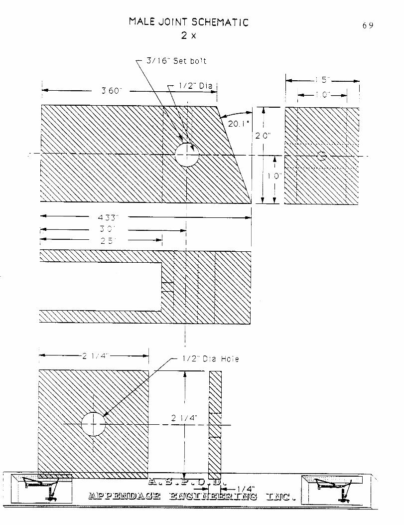
MALE JOINT SCHEMATIC
2x69
3/]6" Set bolt
I/2" Diai
433"
i .
I
:_ _ 5' _ii -- I
I
I
i
2.0"
--T
' ]._"
J__L
_ 15"
--- 1 0 ----_ I
i
J
C_t
tt,<
_:_,\\\\\\\\\\\\\\ ,
1/2" Dia Hole
"Z,_. _---=,_
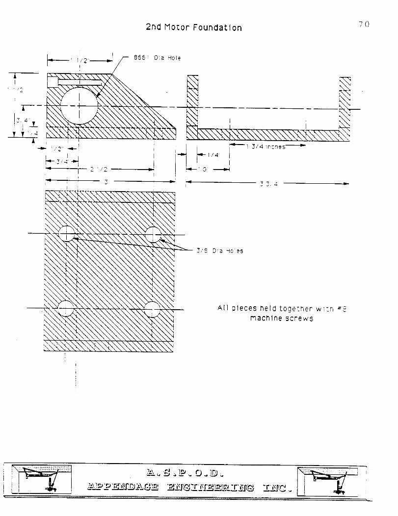
702ndMotor Foundation
A
["7 _
V 1/_ir
"Z i_,8 Dla -ioles
All !pieces held togetr, er wl-n #=
machine screws
n l ii , .......................
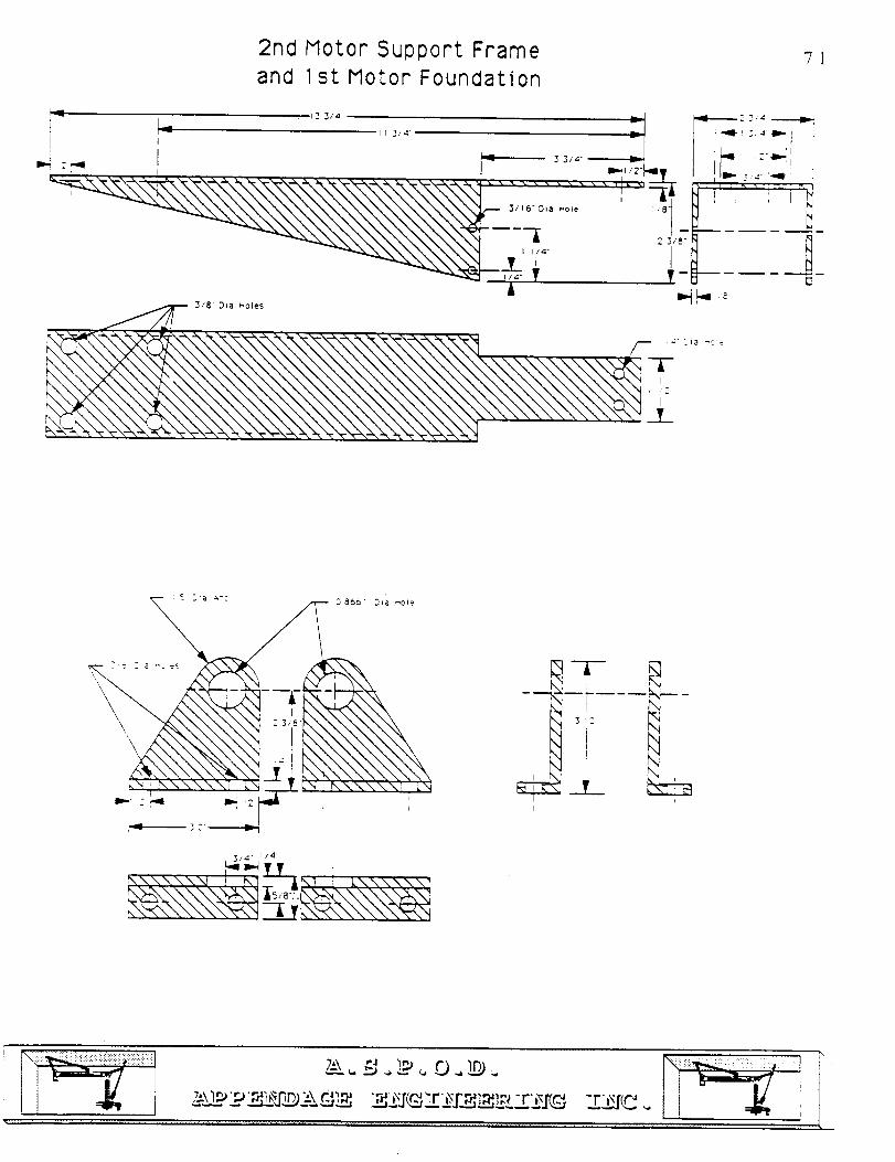
2nd Motor Support Frame
and 1st Motor Foundation71
L_ Zii_ I r 3tdI
L..,,,I
I
li,,,' ,_II
3/8" Dla _OI_'s
9866' .%,a ,_ole
I.,gl lil,-I 1I II
v.-,\\\\\_ i ,_7_7 ! k\\\\\\7
I
_td
T _
_'iiiii_ii!iliiiii!!!i!ilil
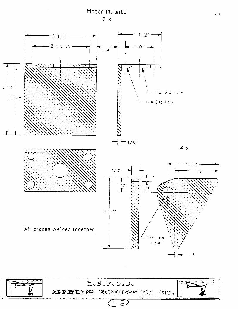
Motor Mounts
2x72
Ai Tri
i
? ?
2 1/2" =
2 inches =
I t
_ ! _\\\\'q F k\\\\\_ I P_l
All pieces welded together
1 1/2"-i_
i ir _-q 1 k_', N
/2' Dia Hoie
1 4" Dia Hole
4X
I ,t2
// 2"
_- 3/8 DlaHole
t
L=
r I
-,_ ,..,-- I _¸
\
\
'v
_;!ii_i!!!!!!!ili!!!!!!_ &\2._._L_-_m_CL_..DL-'___L_L_ __r2J'.._,_$Lr_IL_,_
i!_!i!_ / i i
TORQUE ARM SCHEMATIC
2x73
Tt/2'
I
3"2" ---ID-
2"
£
;I
_IO 8661
i/4"
D18 r'Gie
h.N\'_'._N\".,I
L\\\ ...... ,\"
[\\\.,'. , .\.
,\\\\\\\\\\_\\ \_
• -.. \\_N.,_._,.\\I
Shoulder Torque Arm 2" Shorter
_i!i!i_:: ......_ t _
\
\
\
165"
\
\
\\
,\
Motor to Screw Transition
2x
tA
0 395
A1
2295"
2 112"
I
I
74
i/4' holes
!
[65 ¸, =,
\\\\
\\
\\
\\
\ \
\\
\\
\\
\\
\\
\\
\\
\\
\\
\\
• k'/,/X,/_ ,
v. "/AY/ _4
7;\l_ _r__dL_,.,F_2Ard_ _J_ __rE.F__2L_rE__, -_r2j_..
JOINT ALUMINUM TUBING 7 5
4x
m
heslon
3 Inches
2 OD
_, I 1/8 wall
4"JD
X
Composite
and SteelTubingBolts
1/2
T
!2 ¸
i
t
76
!
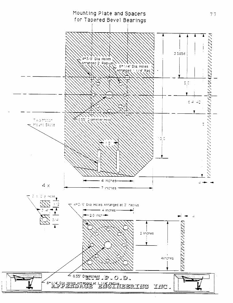
Mounting Plate and Spacers
for Tapered Bevel Bearings
77
4 X
4 lncr_es
7 Iqcne5
8"I/4" Dla. Holes1 I 14" RaG.
.i: _ -iII
I_ "91 ¸
'4N
-r .l'tC
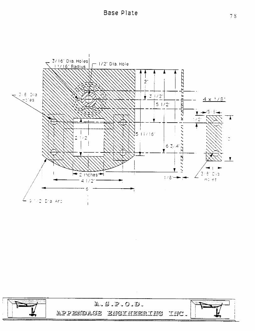
Base Plate 7
I
3/16' Dia. Holes,
11/16" Radius
I
2 inchesL.I-- 4 1/2'"
, _ D;a ArC
1/2" Dia. Hole
I
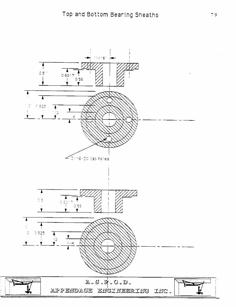
Top and Bottom Bearing Sheaths 79
AI
08:
IT
060_I?
ii:
3 !6-20 tad holes
A
? 055V
i.ELbj_-
li'"
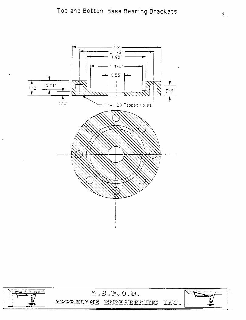
Top and Bottom Base Bearing Brackets 8O
A1/2T
T031 .¸
A
_.0"
2 1/2"198" =
1 3/4"'
0'5i 5" _
I
3/8'
I
20 Tapped Holes

81
APPENDIX A.3
ITEM LIST
.'-\_,_p_.p.__) z\ _ "r_,M(._,_r_rr_,'_,;_ -r-i_r(_ X2.I_- ..
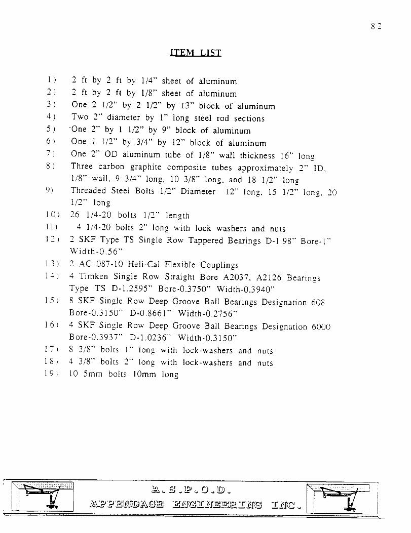
82
I.T.E.N....I,I,2I
1)
2)
3)
4)
5)6)
7)
8>
9)
10)
11)
12)
13
14}
15
16
"Ti'
18
19
2 ft by 2 ft by 1/4" sheet of aluminum
2 ft by 2 ft by 1/8" sheet of aluminum
One 2 1/2" by 2 1/2" by 13" block of aluminum
Two 2" diameter by 1" long steel rod sections
One 2" by 1 1/2" by 9" block of aluminum
One 1 1/2" by 3/4" by 12" block of aluminum
One 2" OD aluminum tube of 1/8" wall thickness 16" long
Three carbon graphite composite tubes approximately 2" ID,
1/8" wall, 9 3/4" long, l0 3/8" long, and 18 1/2" long
Threaded Steel Bolts 1/2" Diameter 12" long, 15 1/2" long. 20
1/2" long
26 1/4-20 bolts 1/2" length
4 1/4-20 bolts 2" long with lock washers and nuts
2 SKF Type TS Single Row Yappered Bearings D-1.98" Bore-l-
Width-0.56"
2 AC 087-10 Heli-Cal Flexible Couplings
4 Timken Single Row Straight Bore A2037, A2126 Bearings
Type TS D-1.2595" Bore-0.3750" Width-0.3940"
8 SKF Single Row Deep Groove Ball Bearings Designation 608
Bore-0.3150" D-0.8661" Width-0.2756"
4 SKF Single Row Deep Groove Ball Bearings Designation 6000
Bore-0.3937" D-1.0236" Width-0.3150"
8 3/8" bolts 1" long with lock-washers and nuts
4 3/8" bolts 2" long with lock-washers and nuts
10 5mm bolts 10mm long
83
APPENDIX A.4
SUPPLIERS
i!ii_i__ i¸¸
i
Atlantic _ ]'racy,b_"orings & I:_wer tronvt'dssion equity, no.hi
44 THIRD AVENUE
SOMERVILLE, MA 02143
e_z.ee6.3_so/,/t,
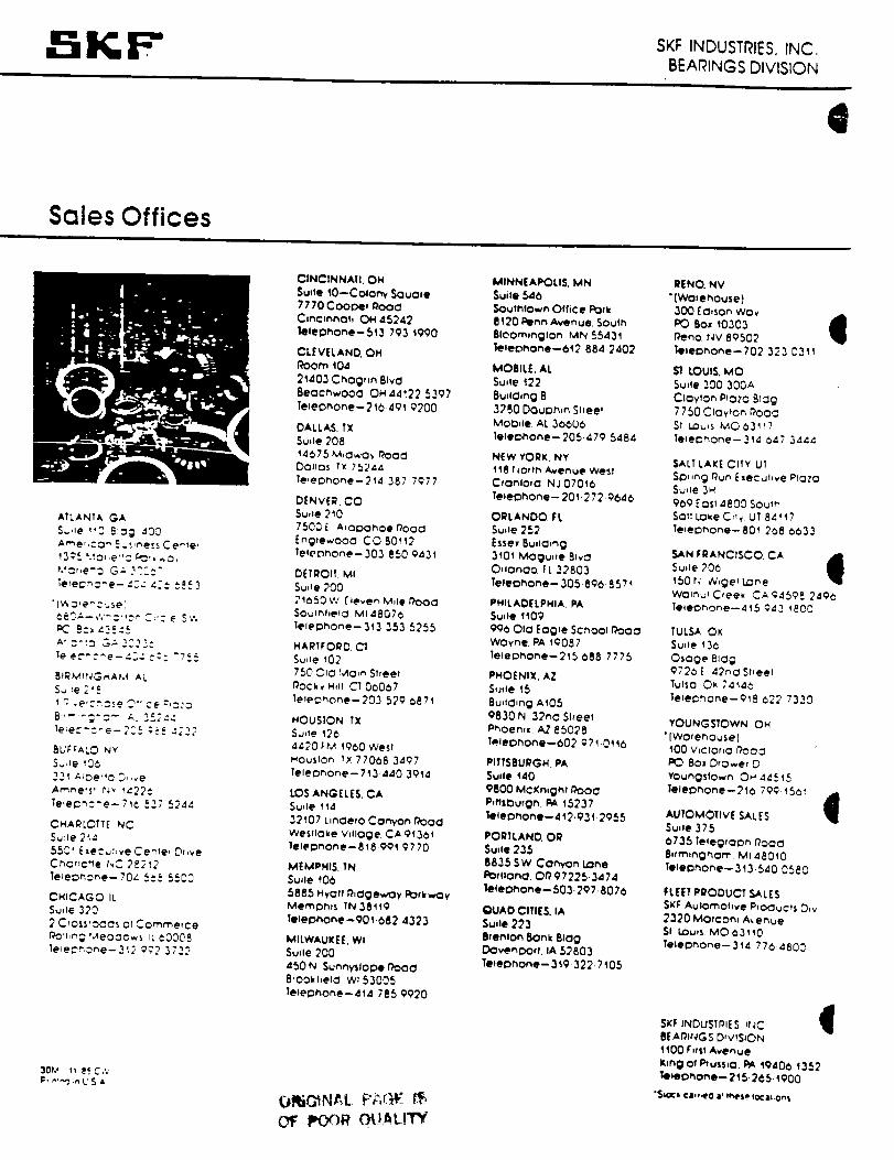
SKI =- SKI: INDUSTRIES. INC.BEARINGS DIVISION
e
Sales Offices
ATLANTA GA
S..He 113 8'.:g 43_
13_I '.'o,,e"o ¢'_', ...0,
Teteu,_e- 4._- 4:: :.".:3
"(_,:,e_ :-.sel
(:8-_--¢,'_:": _ C;'.-e Sv.
PC 8:_45:':5
_":':o G-" ._222:
le e.---._-e-43: c:: "7_.5
t r:; .e,c_:se _-.ce :d_:3
8 .... ;':- _. 352::
BUFFALO N¥
33_ ;-_De'_c D,,,e
Ar,_.ne,sl Nv I_22C
Te_el::hc-.e-71¢ 537 5244
CXA_LOTT[ NC
S_:le 2'I/!
55C_ E,e=,_hve Cease, ?,,re
Cho,c.e NC 2._2_2
Te_eDnone-70_ 5= _,5500
CHICAGO It
Su,_e 320
2 C,ossroOCs of Comme,ce
r_mrg Meoc_o..s _L ¢0008
le_e_one- 3:_ 9;'2 3722
3Oh* _ _._ C.'.
ClNCINNAII. OH
Su,te 10-Colony Souo_e
7770 Coooe, fh3OCl
Cinc,nnoh OH 45242
leleD_one--513 793 t990
CLEVELAND. OH
l_oom 104
2_403 Chog,,n Bird
Becchwooo OH 44_22 5397
Teleohone-210 401 9200
DALLAS. TX
Su.e 208
14_75 M,OwO,, _OOCl
Dorcas TX 75244
le_el:)hone--214 387 7977
DENVER. CO
Su,_e 210
750_ [ A_Ol:3OhOe r_ooa
[nglewooO CO 80112
Tel('Dhone-303 850 0431
D£TRO_L MI
S_,_e 200
21050 W ['_even M,_e Pooa
SOufht,e_o MI48076
Telephone--343 353 5255
HART_ORr)_ CT
SuHe 102
750 OIc t..4a,n Sheet
r_OCk v H,II C] 00037
le_ec, hone- 203 529 _871
HOUSTON TX
Su,te 12(5
4420 I:P,I 1900 west
_ouslon _× 77068 3407
Teleo_one-- 713-440 3914
LOS ANGELES. CA
5u,le 114
32_07 L.nOe,o Canyon I'_OO
Weslloke V_lloge CA 91361
le_epnone- 818 991 9770
MEMPHIS. TN
Sude 40b
5885 Hyoft I_,clgewoy POrkwOy
Meml:3r.s TN 38119
leie_hone-_Ot _82 4323
MILWAUKEE. WI
Su.e 200
450 N Sunrw_loiDe 19000
8'OOkf.elcI W153005
Te_eDnone--414 785 9020
o_NAL r ,-,.,..OF POOR OU_LITY
MINNEAPOLIS, MN
$uile 546
SOuthlown Office I:lot k
811)0 Penn Avenue. South
81Com,nglOn MN 55431
le_eot_one--_2 884 2402
MOBIL£. AL
Su,_e 122
8u,lCl,ng B
3280 DoulDh,n Sl,eel
MoD,Ie AL 30600
Teteohone-- 205.479 5484
NEW YORK. NY
118 HOrth Avenue West
Cronloto NJ0701(_
TeteDhone -- 20 I-272-9640
ORLANDO, EL
Su.e 252
Esse. 8u.o,ng
3101 Mogu,,e 81vO
O, Ionoo FL 32803
Te_eohone-- 305-890- 8571
PHILADELPHIA, PA
Sude 1t09
996 OIo Eogle SChoOl i_O0
WOyne PA 10087
lelecmone--21_ 688 7775
PHOENIX. AZ
S,Jde 15
8u,tChng AI05
9830 N 32n0 St,eet
P_oen,x AZ 85028
T.eleohone--602 971.0_ 16
PITTSBURGH. PA
Sude 140
9800 McKn_ght r'_OCl
P, tlsburgn. PA 15237
leleDhone--412.93 t 2955
PORTLAND. OR
Suile 235
88.15 SW Canyon Lone
Po,lona. O_ 97225.3474
telephone- 503.207.8076
_JAD CITIES, IA
Sui,e 223
8,enton _Onk 8100
DOvenlDOrt, IA 52803
leteonone-- 3 t9- 322 7 I05
REND. NV
"{Warehouse)
300 EO,son wov
PO 8o* 10303 J
Peno Nv 80502
leteohone--702 323 0311
Sl LOUIS, MO
Su,le 300 300A
Cloyton Plato 8_og7750 C_oyto,', Pooc
St LOu,s M0031_7
le_eDnone--314 047 3444
SALT LAKE CITY UT
SDl,ng OUn ExeCuhve mOtO
Su,_e 3H
909 Sos, 4800 Sou_h
Sol| Lo_,e C_I t UT 84,17
TePee)none-801 268 0033
SAN FRANCISCO CA
Su,_e 200 I'150 r_ _,ge_ Lone
wo_n_C,ee_ CA94598 249_
1e_e_ho_e--415 043 _800
TULSA OK
Su,_e 130
Osoge 81og
072_E 42noSttee_
TutsO O_, 7414_
Te_ec_hone--918 022 7330
YOUNGSTOWN OH
• [Wo_enouse}
100 V_clOr,O 19OO_
PC) 8o* D,o_er D
Youngsfown OH 44515
lele13none--21_ 799 1501
AUTOMOTIVE SALES I
Su,le 375
0735 lelegroon _OOC
8*frn_nghom MI48010
Telephone-- 313.540 0580
FLEET PRODUCT SALES
SKF Aulomohve P'O_uC*S _,v
_320 Morton, A_.enue
St LOu,s MO631'_0
TeleDnone-- 3'14 7764800
SKF INDUSTP_ES It,_C IBEAP|NGS D,wS_ON
1100 _r,t$1Avenue
K|ng Of P_uI$,O. PA Ig406 1352
telephone-- 215- 2 <_51900
"51_(i ¢_l_t,_, O l' II"4PSP 10C81,0.$
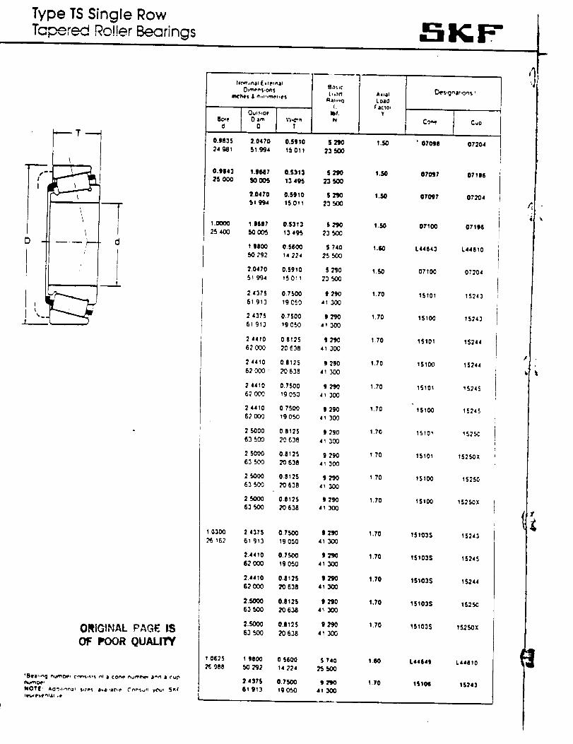
Type TS Single RowTa _''_ Roller _rings
II
D _
t%.
F----_- cl
/ l
/ I
!
ORIGINAL PAGE IS
OF POOR QUALITY
humoer
NOT|: &o'l,t,,_a_ $,..e_ lwt,lar_;e (','_s_. !rOy, SKI'
Iq$# p_f e_l_l o(=
-':;KF"
1.0000
25 400
1030(i)
162
t0625
2£988
2 4375 0.7500 1290 1.70 151035 15_4361 913 19050 4_:)0(:)
2.4410 0.7_ )_ 1.70 151025 IS245_2000 Ig_O 41_00
2.4410 0.1125 S_J)O 1.70 1S1035 IS24462000 20638 413_0
2.S000 0.|125 | 290 1.70 1S103S 1S2SO63500 _063_ 4_ 300
2..r_ooo 0J125 9 290 1.70 151035 15250X63 500 20638 41 30_
19800 0 S600 S 740 1+_0 L4464S L44810SO?g) 14 224 21SO0
2 437S 0.7,500 1790 1.70 1510S !S24361 g13 Igor30 41_0
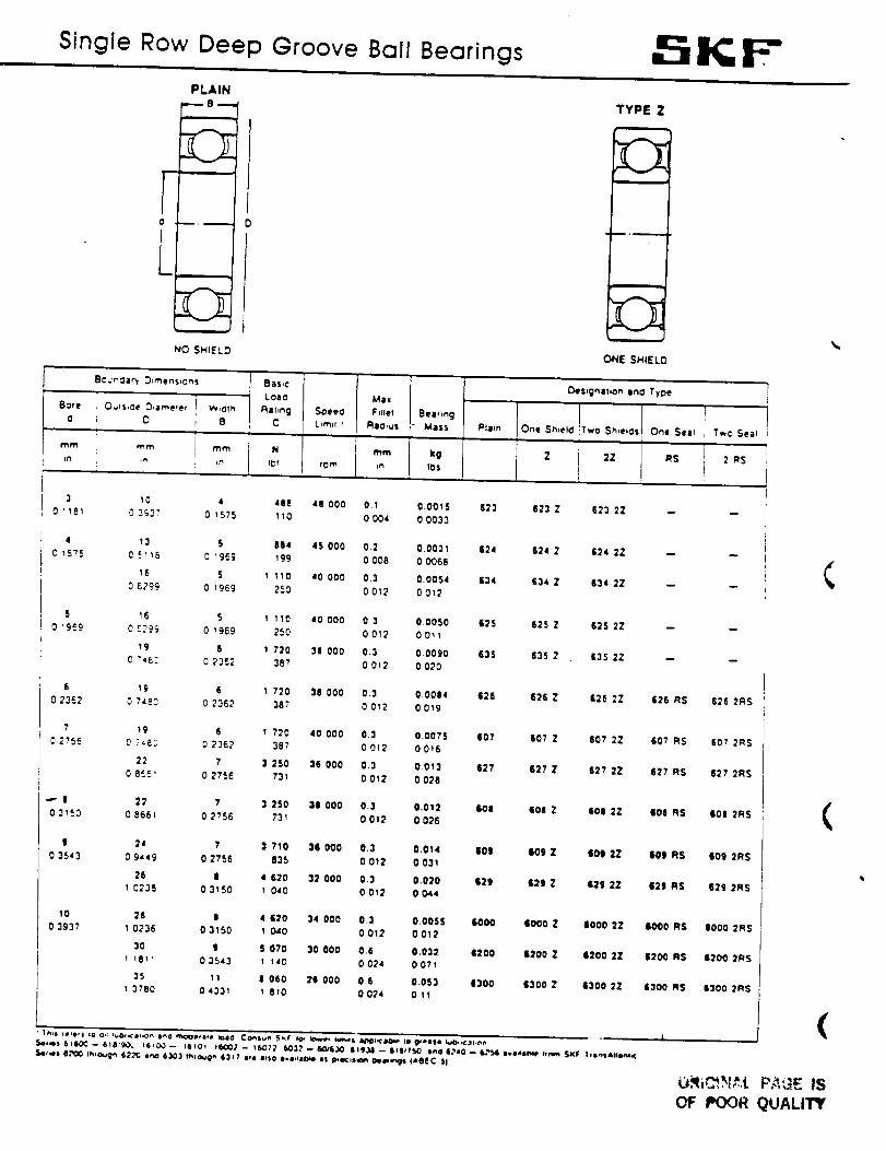
Single Row Deep Groove Ball Bearings . IK; F"PLAIN
F-'-
i
..,,--,,,_
i
NO SHIELD
Bc._n'_ary O:rnens_ons Ba$,¢
Loacl
Rare O_,Is,oe D_ameter W,Olh Rahng Spee(:
C D R C L,m,¢ '
1
I'_m mm mm N
Max
Fdlel Bea,,ngRIO,us Mass
mm kgJn IDS
TYPE Z
r
ONE SMIELD
_s=gnahon Ina Type
Pli,n One Sh,el_ Two Sh,eIas One Sear Two Seal
Z 2Z RS 2 RS
3 10 4 488 48 000 0.1 0.0015 623 623 Z 623 2Z --0 1181 0 3_37 0 1575 110 0004 00033
4 13 S 064 4S 000 0.2 0.0031 624 624 Z 624 2Z --0 157S O _116 0 196g 199 0008 00068
16 5 1 110 40 000 0.3 0.0054 634 $34 Z $34 22 --0 6299 0 1969 260 0 012 0 012
5 16 5 I 110 40 000 0.3 00000 $25 625 Z 625 2Zco0 19.. OC_ 0 1969 250 0012 00_1
19 S 1 720 31 000 0.3 0.0090 $35 $35 2 $35 22 --C ?=E: 0 2362 387 0 012 0 020
6 19 6 1 720 38 000 0.3 00064 $26 626 Z 626 2Z 626 RS0.2362 _ 7483 0 2362 38_ 0 012 0 019
7 _9 6 _ 720 40 000 0.3 0.0075 $07 $07 Z 607 2Z $07 RS0 2_56 0 _¢E_ 0 2362 387 0012 0016
22 7 3 250 36 000 0.3 0.013 627 $27 Z $2? 2Z $27 RS0 8£_' 0 2756 731 0 012 0 020
_" I 22 7 3 250 31 000 0.3 0.012 601 $06 Z $00 2Z $06 RS031£0 0 8661 0 2756 731 0012 0026
| 24 7 3 710 36000 0.3 0.014 |01 109 Z 101 2Z 109 RS0 3543 0 9649 0 2756 035 0 012 0 031
26 I 4 $20 32 000 0.3 0.020 629 $21 Z $21 2Z 621 RS0_36 0 3160 1 040 0 012 0044
10 26 6 4 620 34 000 0.3 0.0065 $000 6000 Z IO00 22 IO00 RS0 393? 1 0236 0 3150 1 040 0 012 0 012
30 g 6 070 30 000 0.8 0.032 $200 6200 Z 1200 2Z $200 R$1 1811 0 3543 1 140 0 024 0 071
35 It I 060 2$ 000 06 0.063 1300 $300 Z 6300 22 $300 RSI 3780 04331 I 810 0024 0 11
626 2RS
607 2RS
627 2RS
$0| 2R$
$09 2RS
629 2RS
IO00 2RS
$2D0 2R$
$300 2R$
(
(
(
OF POOR QUALITY
||C, ISTEREDTRADEMARK
TAPERED ROLLER BEARINGS
m
BEARINGSELECTIONHANDBOOK
REVISED- 1986
TH E TIM t-(EN COMPANY
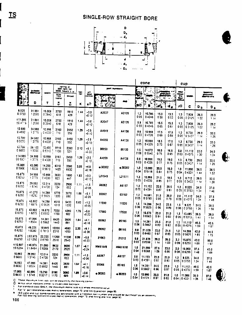
T_.SSINGLE-ROW STRAIGHT BORE
D !
F . o, _l-d= "1 _,
o I
|d
- 4 k
- D, ...... J
10.0080 -%_0
10.0060 3_40
10.9980 4330
10.998
0 4330
10.9980 432
14.250 561
10.99
0 433012.0140_73
14.28;
0 562_
15.670'0 6553
14.3110 5662
19.1145
0 7813
22.7250 8750
21.0000 8268
12.0140 4730
14.3810 5662
13.2S0}5217
00050
A4059
e30302
L_1549
A50_2
03063
11§90
17SI0
050_2
_0_2
210(3
NM8164|
A60_7
05066
• _203
v ,'r-_._, ""
A2037 A2125
A2047 A2125
A4049 A4131
A4050 A4130
00150
A4138
• 30302
l,.21511
A6157
03162
11S20
17520
05185
21212
HMII$10
A6157
05115
e_o_3
I
0 43;
1.71:
0 342
9.S2!
0 375
11.11:0 4371
S.525375{
13.41_) 531:
_I,fI_)4375
4.28156_S
S.I7S8250
i.O006299
.5253750
.112_375
1331
D_ D a
26.0 29.01 02 t 14
25.0 29.01 02 I14
32.0
32.0
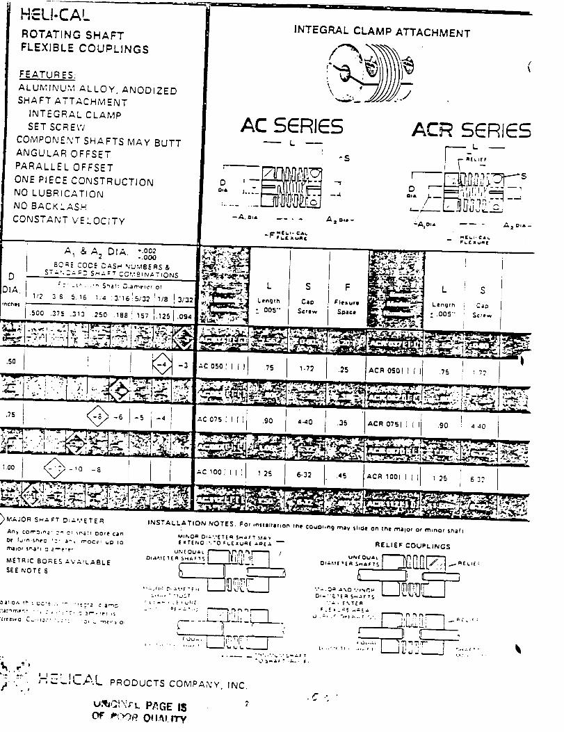
H'ELI-CALROTATING SHAFT
FLEXIBLE COUPLINGS
FEATURES:
ALUMINU,M ALLOY, ANODIZED
SHAFT ATTACHMENT
INTEGRAL CLAMP
SET SCREW
COMPONEN'T SHAFTS MAY BUTT
ANGULAR OFFSET
PARALLEL OFFSET
ONE PIECE CONSTRUCTION
NO LUBRfCATION
NO BACKLASH
CONSTANT VELOCITY
INTEGF:LAL CLAMP ATTACHMENT

92
APPENDIX A.5
STRESS ANALYSIS
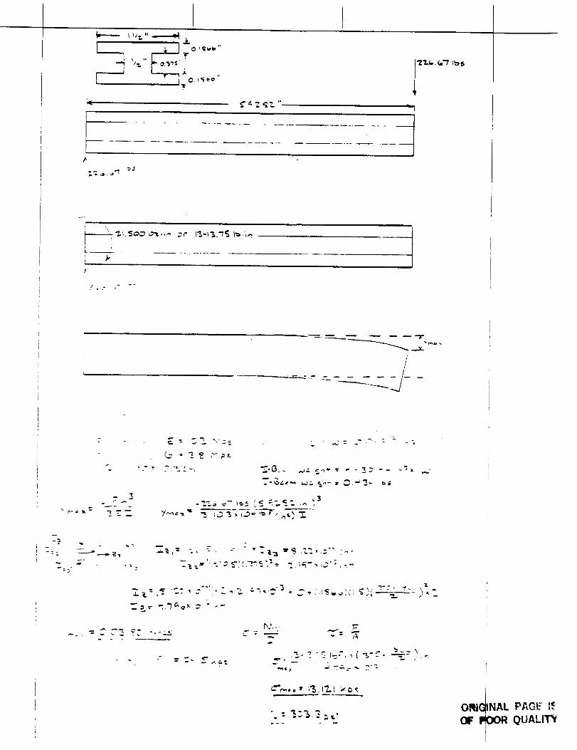
"_ _"t.
I .++.
_,_o.._ _.,n _r I'$_%.'/_l_.',mI +'
J
t
f
-jr
/
_J
q,
+=2
_-C).- ._+_._ --- - ___'--m_
,3
,_-., ". "'-- 1--', -, i "%':"-'- -'_-- ,"
.. _--_ _ .
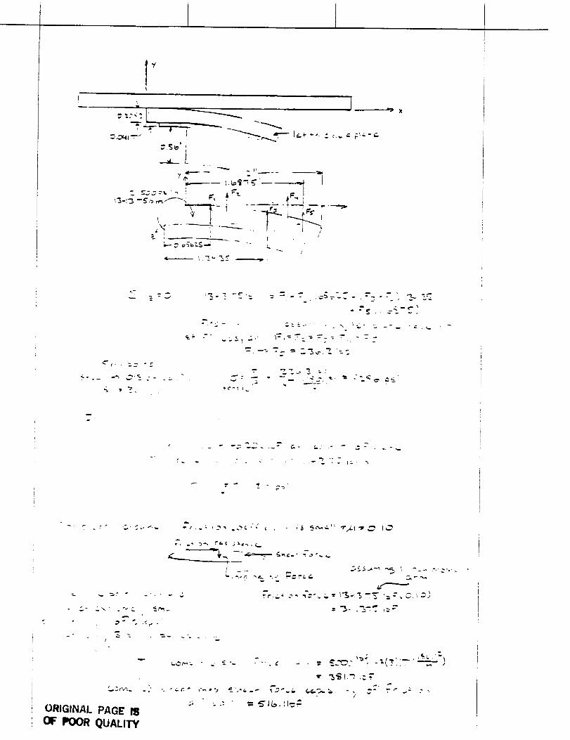
c-
"" ... _
_ _"- = _."c_ _ ,-.._
• "r'a
!
e" --'-
• "_" _ '_C" "
_, ._ ,__'_ ._/._ c _ _ _c_.-_" _/_,_,._ I_.._
/
ORIGIi_,O,I. I:)A(3E ISOF POOR QUALITY
95
APPENDIX B
DRIVE SYSTEMS ANALYSIS
iii:_i!i!i!i!ii!!i!iii]
96
BASE MOTOR ANALYSIS
* EQUATION DERIVATION
* MATLAB PROGRAM
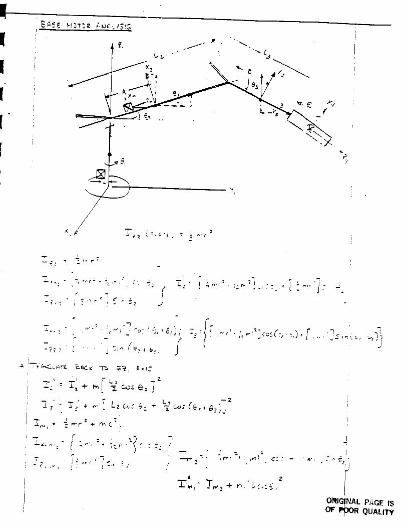
PY
I
--.[,: = .
T
"?T ._
-.;,-" " + _ "_ ¢0.,.',_= j,
.... _ ,9-_ "2', _ ,,- . /zU.: +o
_.. I 2 =,_ -- _ _r_l" ÷ r_ c. ,
• - 4 m '
- J ie"
"[ '-_; (ez, e,._j
r?
":' D',f _ ] "1 u . _ C _. -
•_l_]co_C:, • '-,)_ [ -_• ,, _ ,_ I _, ",.,;,
o_OFP
INAL PAGE IS
31OR QUALITY
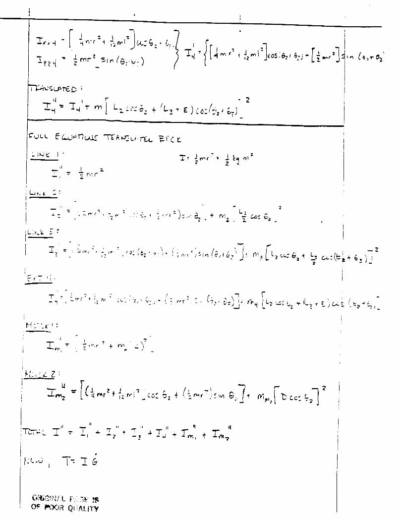
' I.L
II j 1"
+ IL_ • E ) -_=i:,z j _,...j
2
LI_ I "_', ..,_' : J. I:<I ,_
Z -
i
1 ? I "
i
'_1'_,, "--"' T ?''r
. P - {
--- __I( _..L_ - r_r z { ' (" "' 7+ z r,'l'; LC_ _z ar • -v_r :._,_n _,. -i
-FDT_,,:,L _" " "
)
Or _YJR Ot!_!.rl_f
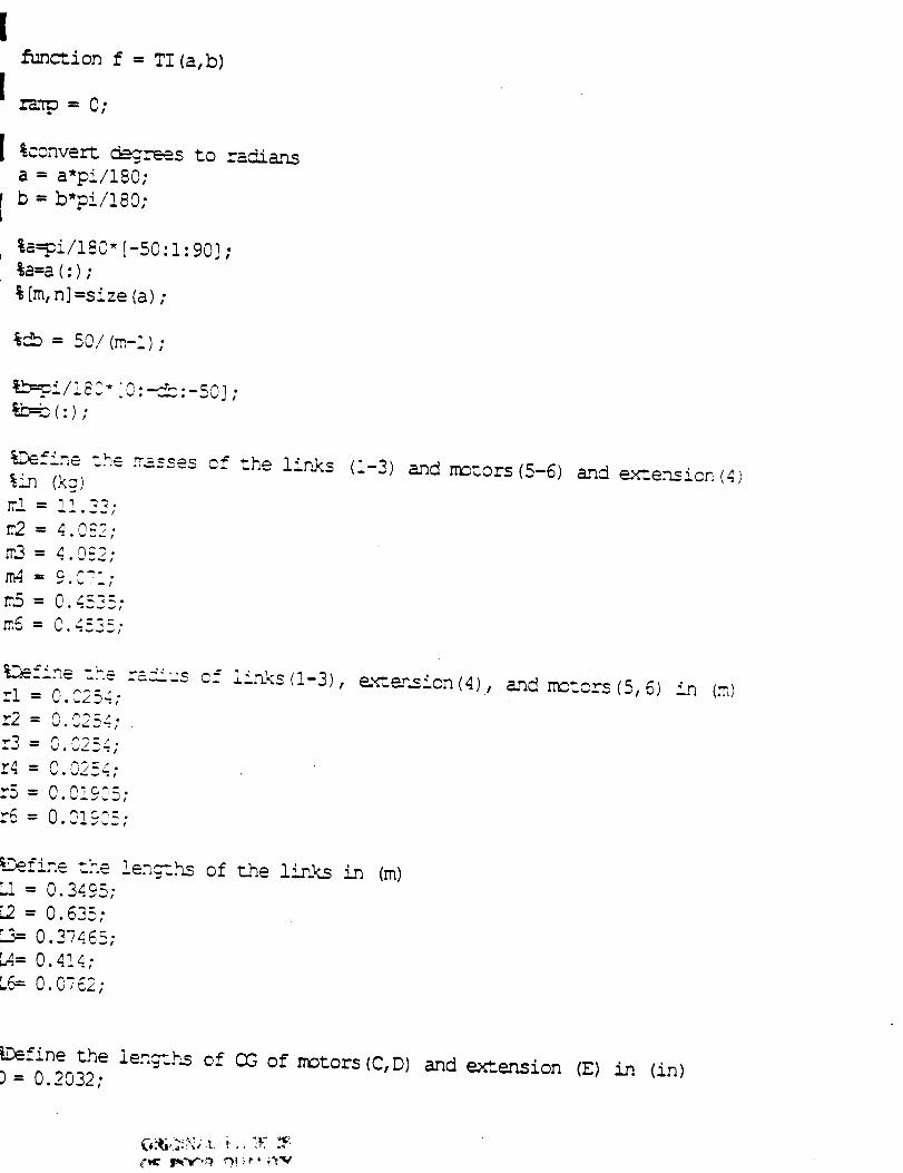
function f = TI (a,b)
rz_p = 0;
[ %convert _--_-.__ee_s:o radia.ns
a = a'pi/i80;
[ b = b*pi/!80;
, %a=9i/180"[-50:1:90] ;%a=a (:);
% [m,n] =size (a);
%cb = 50/(m-i) ;
%-b=91/!_3" '0:_:-50] ;_=b(:) ;
%Define the -asses of the !i_As (1-3) and rr_%ors (5-6) and ex_..ension (4)%Cq (k_)
_.2 = 4.0__
• _0.m3 = 4 0..,
m4- 2 _--.
m5 = 0.4_25;
m5 O. _.52 =.
%Defin_-'--- =<'us c __ru<.(!-3), e-_z_.sion(4), and nm_ors(5,6) in (m)rl = 0.C254;
r2 = 0 _?'_"
r4 = 0.0254;
r5 = 0 O! _'-• .4 %. _W !
"6 = 00l:"="
_.Define the !en_.hs of the links in (m)L! = 0.3495;
L2 = 0.635:
0.37465;
b4.=0.4!4;
L6= 0.0762;
_Define the ie.n_-'.hscf OG of motors (C,D) and extension (E) in (in)) = 0.2032:
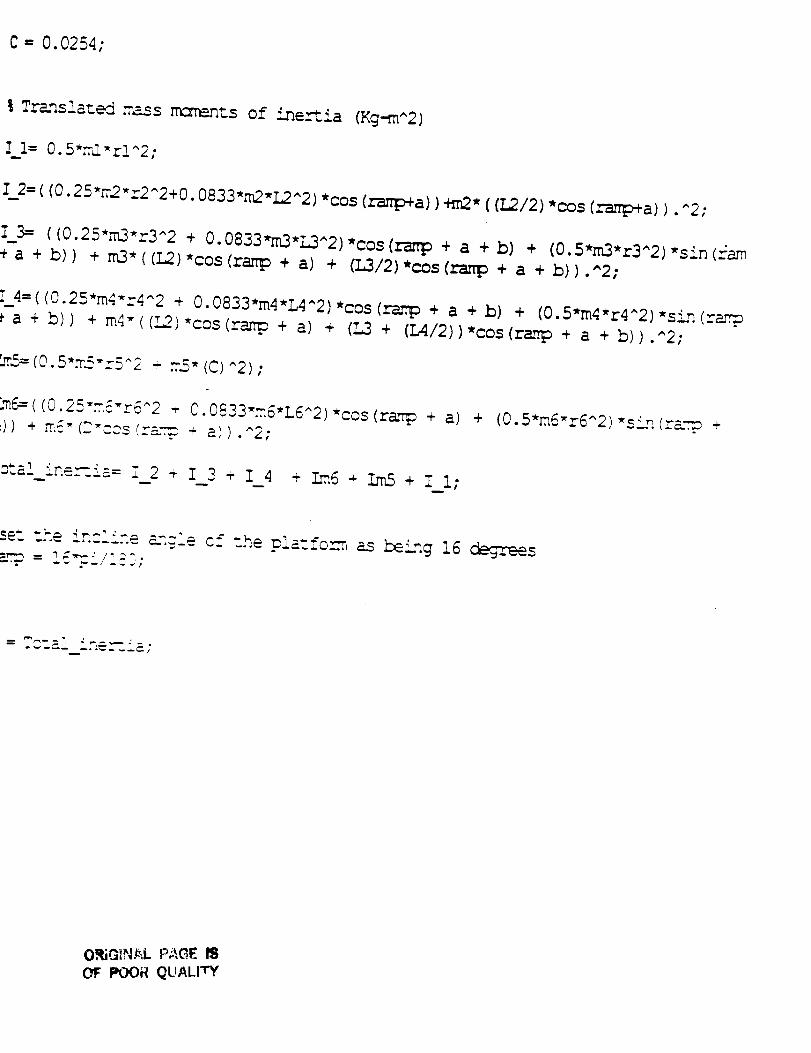
C - 0.0254;
%Tr_lazed _ass nmmenzs of ine,--_ia (Kg-m^2)
Z l= 0.5_rl-rl^2;
Z_2= ((0.25_m2-r2^2+0. 0833,m2,L2^2) *cos (ranp+a))+m2* ((L2/2) *cos (_a)). ^2;
I 3= ( (0.25,m3_r3^2 + 0.0833,m3,L3^2 ),cOs (ranlD + a + b) + (0.5*m3,r3^2) ,sin (.::am
+ a + b)) + m3*((L2),cos(ramp + a) + (L3/2)*c_s(r-_iD + a + b)).^2;
[_4=( (0.25*m4,r4^2 + 0.0833,m4,L4^2) _cos (rmtp + a + b) + (0.5*m4,r4^2) _sin (rarp
a + b)) + m4-((!2)*cos(ramp + a) + (L3 + (L4/2))*cos(ramp + a + b)).^2;
_5= (0.5-_5-r5^_ + _£_ (C)^2) ;
im_:=((0.2_=--{-r6^2 ÷ O.0833,m6,L6^2) "cos (ramp + a) + (0.5*m6-r6^2) "sLn (rm.-cm,+_)) + m{- (-''cos(r=_-m__ a)) .^2;
_=__i -_.i-= i 2 + I 3 _ I 4+ Ira6 + I2_ + I I;
- -.......- a,n{ie the p!a',fon_,_as being 16 _s-_ r'-J-_-_';
. -a!_i.-e_ _i- •
O.,IjGINAL PAGE ISOF POOR QUALITY
i01
SECOND AND THIRD LINK MOTORANALYSIS
* EQUATION DERIVATION
* TABLE OF RESULTS
* GRAPHS
%)ii_::_::_!!i:_::ii!::_:::::iiii!ii::_::ei_::_::_::_!i::i::ii:i!::iiii_ii::_::_::_i_::
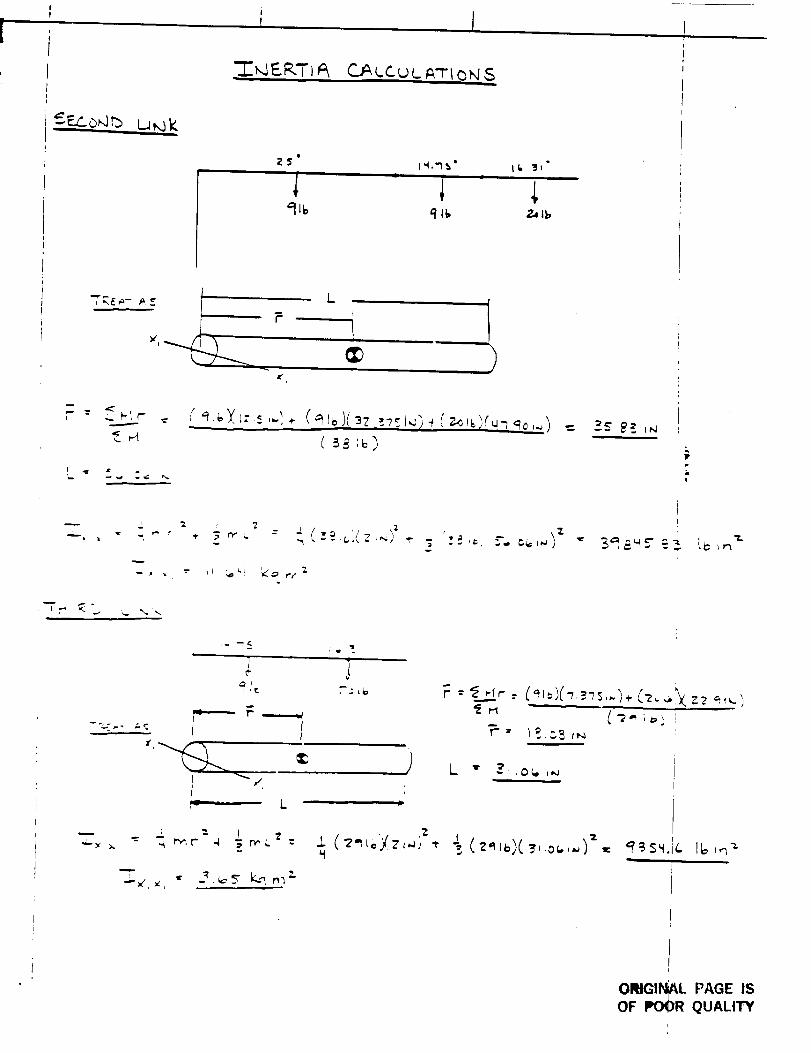
C._.L.C _ c.__-r_ <bP4S
_ E.L_<.b,'4'b
23
'91_,
t "I."I _"i
J,Z.+I_
_q
+.-'_ r" _
<.,4
,f
+" y.
__ . _. +
+
w _.. o[ _ r •
L
C+t_,IC+z,.;.-,+_+.+_.+Cmt+l!_-+++,..+l__
7 p ,,2
'_" _, r',- 7.
, 2.
IP
iiii
I_ _ r"X .'t-
7
,.+,
r,,--_, --'I
; ,ip "_o
/,
--- .= _ _ I_x :,.. +.., r',,".r" 4 _ t'_L
i.. .It
,'ZJ..( +" _o+;,Cz,,.+++.,t
:'_ "--.-[<""- +'_+/+,-_++,,-+.,-(-z°+,_z+_ --+.,,..'
I
ORIGINAL PAGE ISOF POOR QUALITY
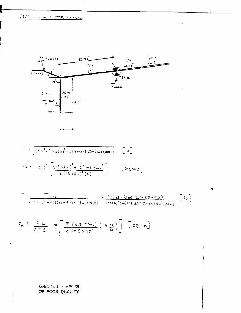
p
m
'11
CI_ IIIOOR QUALITY
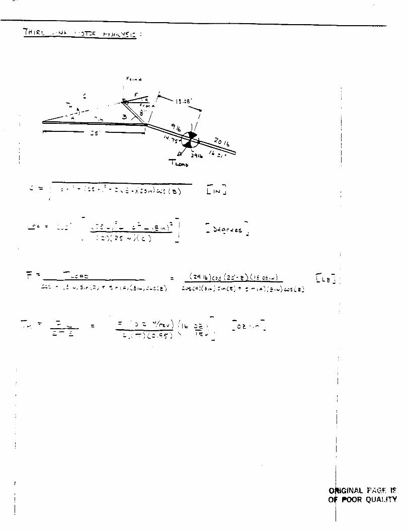
"]-I,,/_
--,_-_,o;_: I_ _'_
i -
01
Ol
_JGINAL F_._E
POOR QUALITY
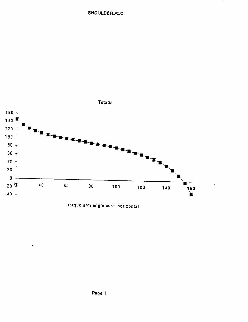
$HOULDER.XLC
160 -r
14o _,: •
1_0 -
100 -
80 -r
60 -r
40-
2o -
0
-zo ?.o
-d0 -
Tstatic
4O 6O 8O
= i i
100 120 140
torque arm angle w.r.t, horizontal
\
\
_eoI
Page I
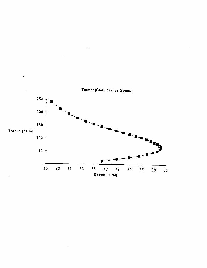
Torque [oz-ln]
250 -J
r
ZOO "-[
lO0 -
50 "
i
15
\I.
20
Tmotor [Shoulder] vs Speed
;'5 3O 35 40 45 50 55 60
Speed [RPM]
4
65
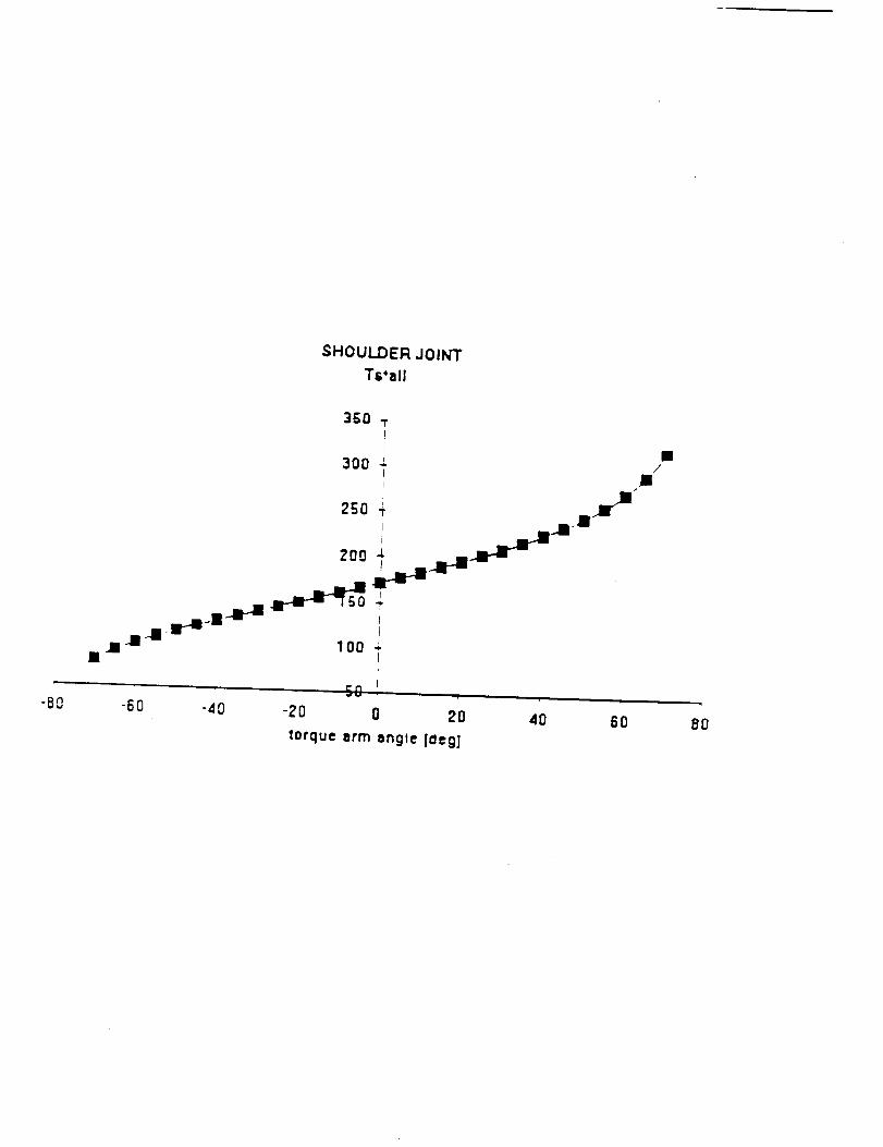
SHOULDER, JOINT
Ts'all
I
3_0 "rPI
300 J. 1i /I .ffi
l "
..m-m lOO .J.
-8o -6o -4o-Zo o 2o
torque arm angte |aeg]40 60 80
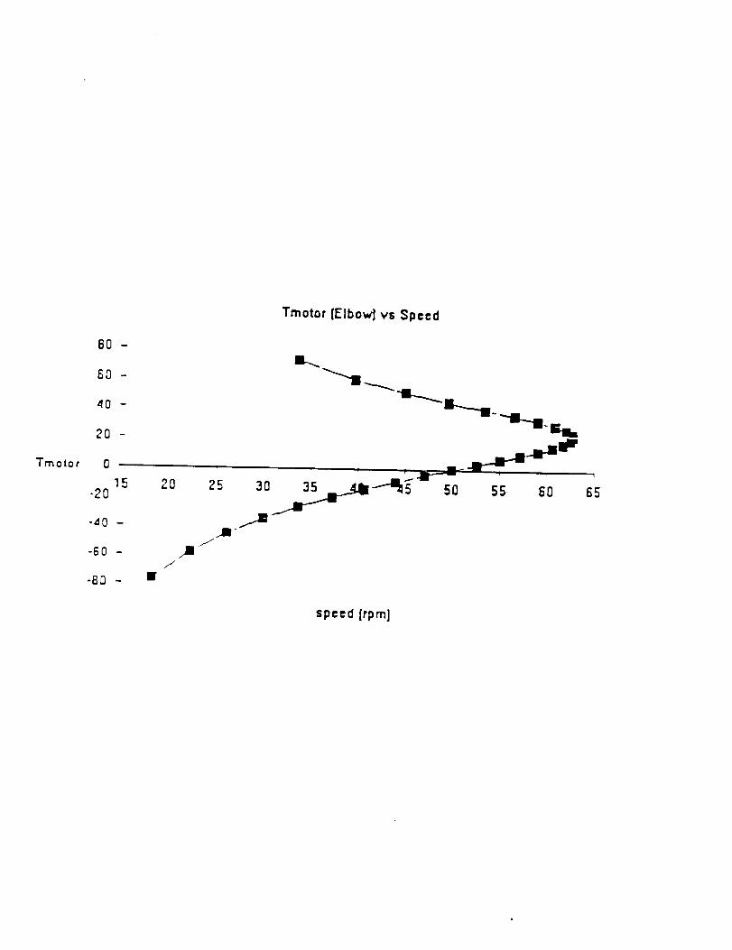
"J'motor
80-
60-
_0 -
20 -
n
15-20
-40 -
-60 -
-8_3 -
Tmotor [Elbow'] vs $p=cd
mL_ -Br
/
/
50 55 50
i
_5
spced[rpmJ
110
PRODUCT VENDOR
* BALL S CREW
* PRELOADED BALL NUT
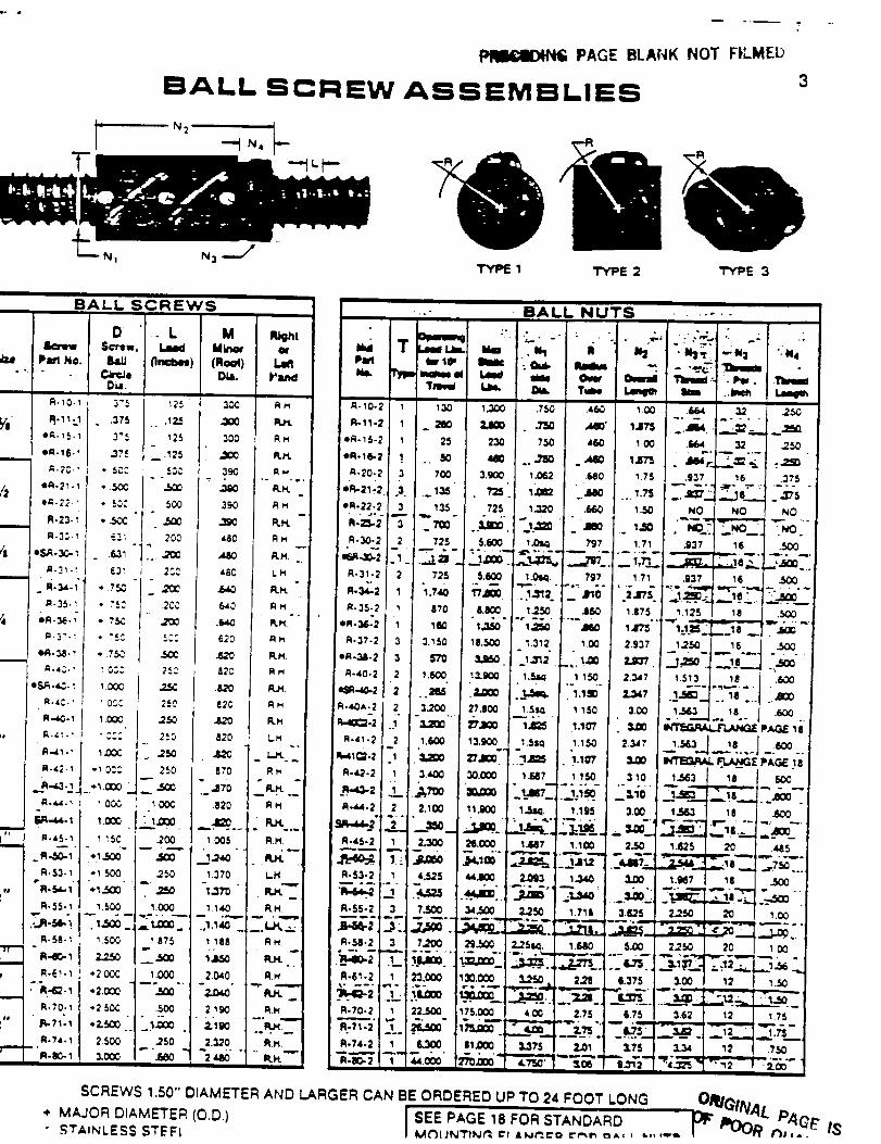
T
PAGE BLANK NOT FI,LMEb
BALL SCREW ASSEMBLIES3
NI
TYPE 1 TYPE 2 TYPE 3
BALL SCREWS -.- BALL NUTS
* MAJOR DIAMETER (O.D)" STaiNLESS STEFL
SCREWS 1.50" DIAMETER AND LARGER CAN BE ORDERED UP TO 24 FOOT LONG
I SEE PAGE 18 FOR STANDARD I_F_'O__ P,q(,E ,_
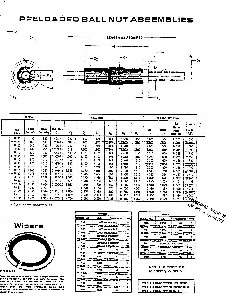
PRELOADED BALL NUT ASSEMBLIES
-- L3
C3
• -_ C4
LENGTH AS REOUIRED
66
/-CI
ro,¢ /
--D1
$C_£,_
K'B$Illm_
A; ;,_oRP.31
RFM
• AI=-41
RP-43
1_50
• FW.56
RP.?_
R_-&?II
• Le_
lira II_
-o_ _-h
4_: i 630643 ?_5
.6,_ t ,7'._8:: _ 003
8% _010
1 2#: 1.536
1 375 [ 1510
? ,c: 2 .5.cO
2 4_ I 2.g_
h_nd assemblies
|ALL NUT
Wipers
Th(I. _d21
Cl Cz C3 C4, : % 61 ' C?J
,33&_6 _000 sc 800 870 440 3 500 i _SO
._38-_61.000 _ ".BOO -.ITS- _4,A_ " "..,_ .1._ "1I ;2_.I_ I 250 910 g30 _40 4 :).40 1370I._16 1.312 ].Ol_ "._ _0 L_ "I._
563 _6 _ 500 s_ _ _50 1 _00 440 _ 050 1 6501.563-10 1.,500$(_ 1.150 1.100 ..440 " "'4_:W3 .I.J3,_563._8 _ 567 i 100 _ 100 _0 6940 I8_0
1.r',R_'161.6,07 1.100 1.100 ".6_,0 . _.940 "I.]10625-23 _ 667 1 lO0 1 270 .f_50 5 750 1 810
2.546-18 2.625 1.870 .l.6aO _ 12.130. 2.8101 _7-I_. _ 0_3 1 340 1 460 560 6 500 2 3101._7-18 2.093 1._40 1.460 ..'_. ".(L_ Z.3102 750.20 2 52_. _ 640 _ 700 _40 " 8 190 2 8102.2_-20 2.62=_ 1.5443 1.700 "..4,dK) |.1_ 2.8103 _37-_2( 3 375 2270 2560 125 142_ 40003&2_-121 4 0(30 2.570 2.4_0 .l_ 14.7'30 4.2S03 625 _2, 4 000 2 670 2 480 880 14320 4 2504 1_?_ 4 7_ 3050 3:2-r.r.r.r.Se"I_ I_._ S.O00
m
I_15 NOT AVJJ_O, c _
..":_,_--.___-..:am_.vaa.aam.c"_."__R-_ C20_dJl, t ; AG'_O_I' --
:.- . -.-___ _j._:.1t5 .t40 A
R-3_ 11_6 _40
= 1_'--" _j _ _.._,_:
_,,,='_ 1.,_ .$40 •
l,um 140 C
FI,,,_NG( (oIIrflONALI
--L1 L_ _ DI. '"l_t "=
2 600 530 4.266 20gO"_ L_ 4.._
2 600 530 4.266 2 0£0.?.J_ " ..'.._e 4-.:_ ". _::F'_'
3 250 630 4.266 ? 7_
3 250 630 4- 266 2 750
._ '_ _.._3.200 500 4-266 2 702
.. 4.9,40 :.7_ a-.S3_ ._1_.4 380 .530 4- 397 3 _04._ .._._D 4.._7" _74 940 _ 020 4. _31 _ _2_
4._ L.0?0 4-.s3_ _'4'..__5 380 _ 580 6-656 4 375
""_.0[)0 1.7_ |.._:_66 000 I 780 8- 556 _
7.380 2.0"2'0 I_ "/_1 %'_....
_ _ c
"__ ""I,__E::
Iq41 CONS_q.T I_ ACT'O_Y
_ ".2 _t_::
AcIcI -4 to Model No
tO specify W,per K=I
1_3
APPENDIX C
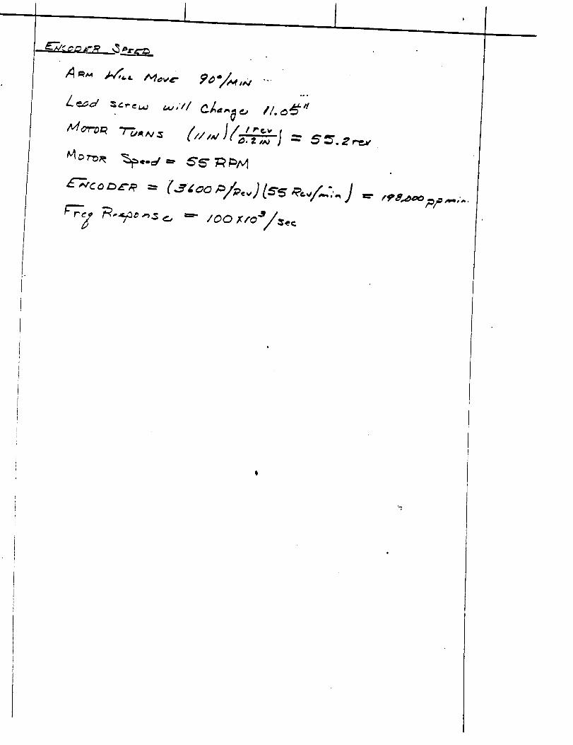
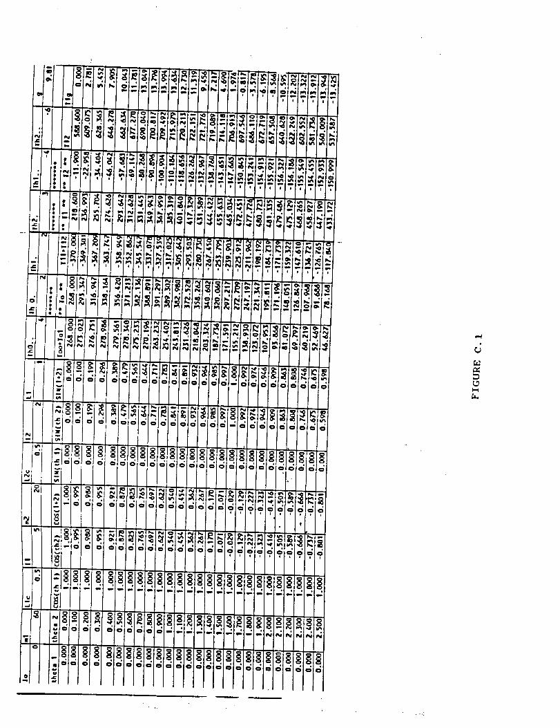
i '
d
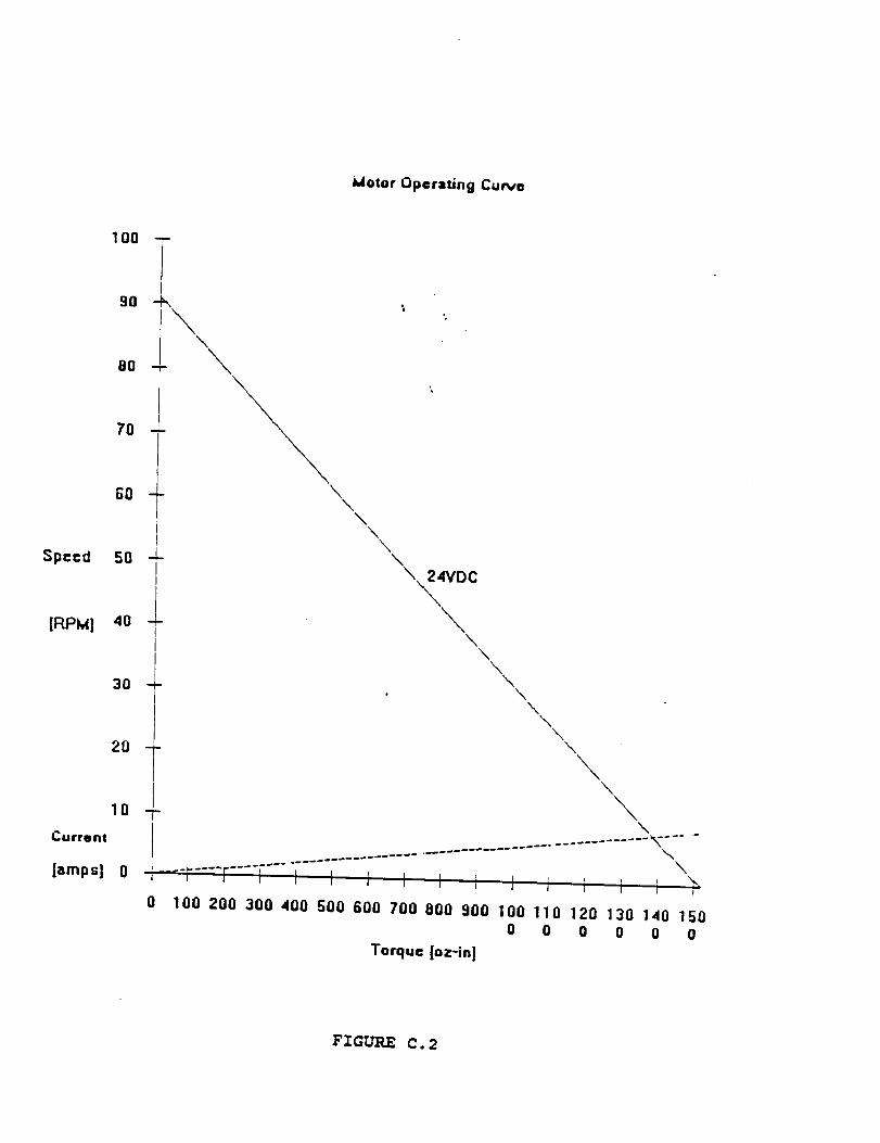
blotor Operating CuNe
100 --
80 -
80 -
70 -
80 -
Speed 50 -LII
[RPM] 40
3o
Curront
2O
1Q
[amps] 0
\\
\
\\
\\
\\
%\
,,_4VDC
\%
%\
%• %
%%
%%
\
-_-r....r....r..................... \
0 100 200 300 400 500 600 70Q 8OO 900 100 110 120 130 140 1500 0 0 0 0 0
Torque [oz-in]
FIGURE C.2
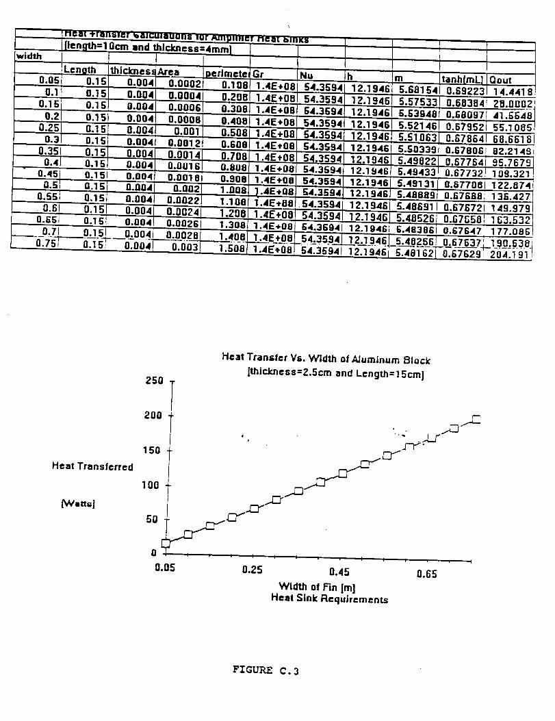
width
0.0!
0.1O.
0.20.3
0.40.45
0.50.55
0.6O.G_
0.710.751
and _lcJr.ness=4r
Area
0.1 0.000 0.1080.1 0.000_
0.00, 0.0006 0.3060,1! 0.0008 0.4000.1! 0.00_ 0.5080.1! 0.004 0.0012
0.15 0.00' 0.0011 0.8010.15t 0.004 0.001 0.9010.1 0.00a 0.002 1.0080.1 0.004 0.0022 1.1 080.1_ 0.00,
0.1 G 0.004 Q.O02G i 1.30!0.1 0.00, 1.4010.I 0.00_ 0.003 1.508
Gr Nu h
1.4E+08 t 12.19411.4E+00 54.3594 12.19461.4E+08; 12.19461.4E+08 12.1946
.4E+08 12.1941.4E,01 54.3554] 12.1941
1.4E+01 54.3594 12.19461.4E+00 54.359a 12.1946
.4E÷08 54.369_ 12.1941.4E,08 54.3594 12.1941
12.1941.4E+08 64.36941 12.1941
54=359, 2.1 9461 54.3594 12.1946
m Qout5.681 54 0.6922: 14.4418
5.57! _ 20.0002G.539,4 0.680971 41._405.521a 0.6795_ 55.1 005
0.67864 68.66185.50339 0.67e061 82.2148
0.6776,: 95.7679
5.4943: _ 109.3215.491 31 0.677001 122.074s.4aaa9 a.a7aaai 136.4275.48691 0.67872i 1 49.9-_
3.532t
5.481 G-2-j'-_07-6-29-_2-04. i gllj
250
Heat Transfer Vs. Width of AJumlnum Block
[thickness=Z.5cm and Length=l 5cm]
Heat Transferred
_vVattsJ
200
i,
150
100 f
0 'i I l J I l J I I
0.05 0.25 0.45
Width of Fin [m]Heat Sink Requirements
_ ......-_
0.65
FIGURE C. 3
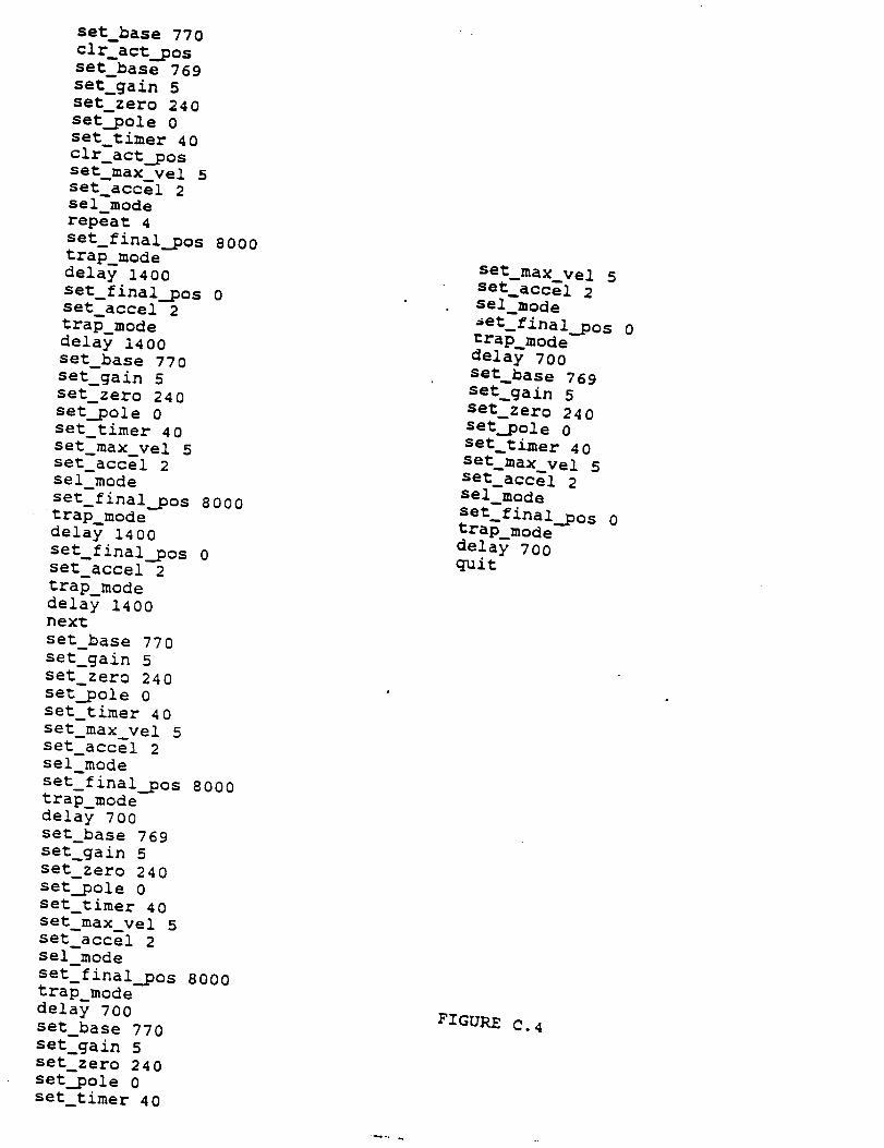
set_base 770
clr_act pos
set_base 769
set_gain 5
set_zero 240
set_pole 0
set_timer 40
clr_act pos
set_max_vel 5set_accel 2
sel_mode
repeat 4
set_final pos 8000
trap_mode
delay 1400
set_final_pos 0
set_accel 2
trap_mode
delay 1400
set_base 770
set_gain 5
set zero 240 set gain 5
set,pole 0 set,zero 240
set timer 405 setpoleset_max_vel set_timer040
set_accel 2
sel_mode
set_final_Dos 8000
trap_mode
delay 1400
set_final_pos 0
set_accel 2
trap_mode
delay 1400
next
set_base 770
set_gain 5
set_zero 240
set_pole 0
set_timer 40
set_max_vel 5
set_accel 2
sel_mode
set_final pos 8000
trap mode-
delay 700
set_base 769
set_gain 5
set zero 240
setpole 0
set_timer 40
set_max_vel 5
set_accel 2
sel_mode
set_final_Dos 8000
trap_mode
delay 700
set_base 770
set_gain 5
set_zero 240
setpole 0
set_timer 40
set_max_vel 5
set_accel 2selmode
_et_final Pos 0urapmode
delay 700
set_base 769
FIGURE C.4
set_max_vel 5
set_accel 2
sel_mode
set_final pos 0trap_mode
delay 700
quit
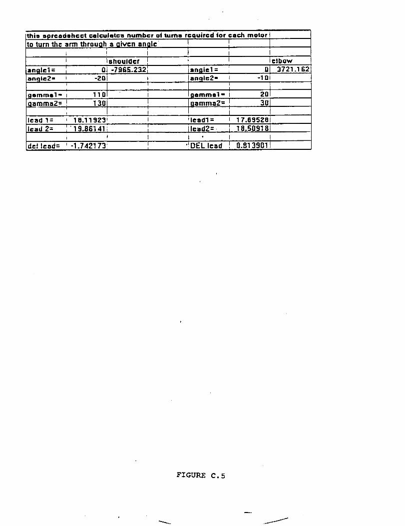
thio aprcadahcct c=Icuiatca number of turns required for
to turn the arm through a given angle 1I
i Isnoulocr i i
i Q] -7965.232 l angi-'l :angle1: [
each motor I
' I[I I
Iclbow
.lnn 3721.162
angle2- 1 -2Q( I angle2=i 0 i1 t
gamma1" I 11 I 19emma1 =
qammaZ= ;ll 1301 ,11 gamma2=
lead 1: , 18.11923i t !lead1 =I
Icad 2= _ " ' I lcad2=.I 19.86141 l
t i i t 'del lead= _,-1.742173 _ '!DEL.lead'
I, I201
I 3OLI= 17.6=JSZOi
' 8I 18.5091
! 0.813901
FIGURE C. 5
/
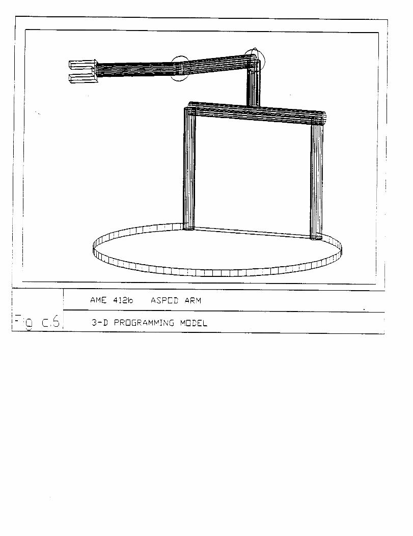
_ME _!2_ _POD ARM
FiQ C,6, 3-]] PROGRAMMING MODEL
17..c_
APPENDIX D
FRAME STRUCTURE DIAGRAMS
,£ZI_..
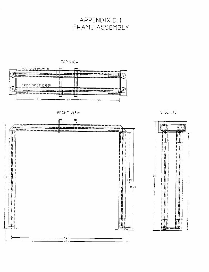
APPENDIX D. 1FRAME ASSEMBLY
TOP vIEW
FRONT VIE'w
, . %
....................._,,i]i."_';_., "T-":_ "_==_ _'i_ -+' ................. ""##-"'-'_='=:
II_S :I
;: _
i: e-,,'__
ii I_ ,,
I
l J9 '2
| i.,_ ,i
II i-i Ii
I _ i I
i ii _ ,
i P', hl
_5 25
/_
J
SIDE v _E ,.,
-r- ............. ,
, ,.,',foql
'--1. ," .?'--I: ". i,;"-"1, I_ ,I II _
i i I ,-_
8
II
1t I,_ i
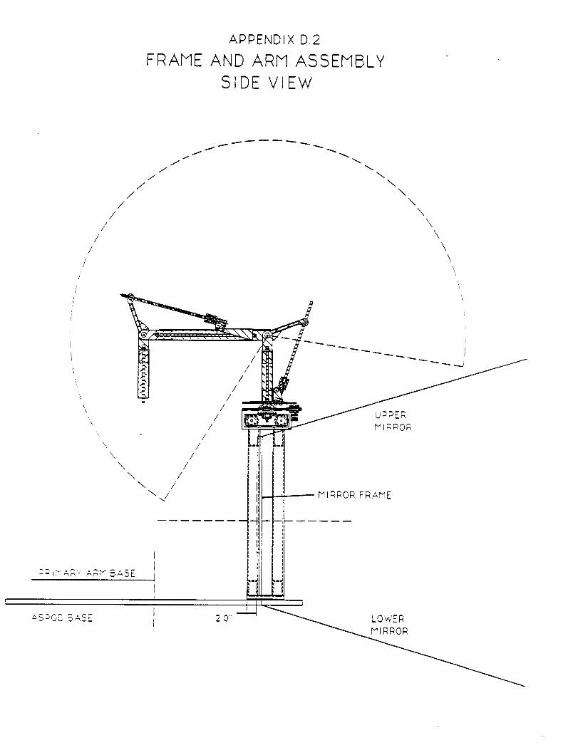
FRAME
APPENDIX D.2
AND ARM ASSEMBLY
SIDE VIEW
//
//
/
/
//
J/
JJ
f
J
f
X
\\
\\
\X
\
,* S-sO'D B_2E
\\
\\
\\,
iI
IIII
-I',I
'iI II II tI nI II II II II II II
J
-- I"IlRRC, R FRAME
I
2.0
/p
/ _j/
/ I/ I
/ t/ I;
\ \/ 1!
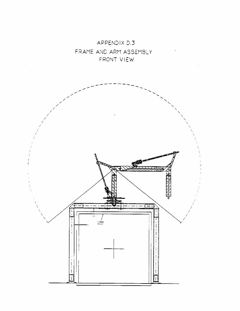
FRAME
APPENDIX D.3
AND ARM ASSEMBLY
FRONT VIEW
///
/
/
/
J
'ii
\
//
//
\
\\
\
J
/
/
/
/
J
J
p i t
i i ii q
:ll
:11i
i ti
iJ i
Ii
I!i !t J_ili _
\
\
\
\
\
\\
\
\
\
//
/
\L
/
/
/
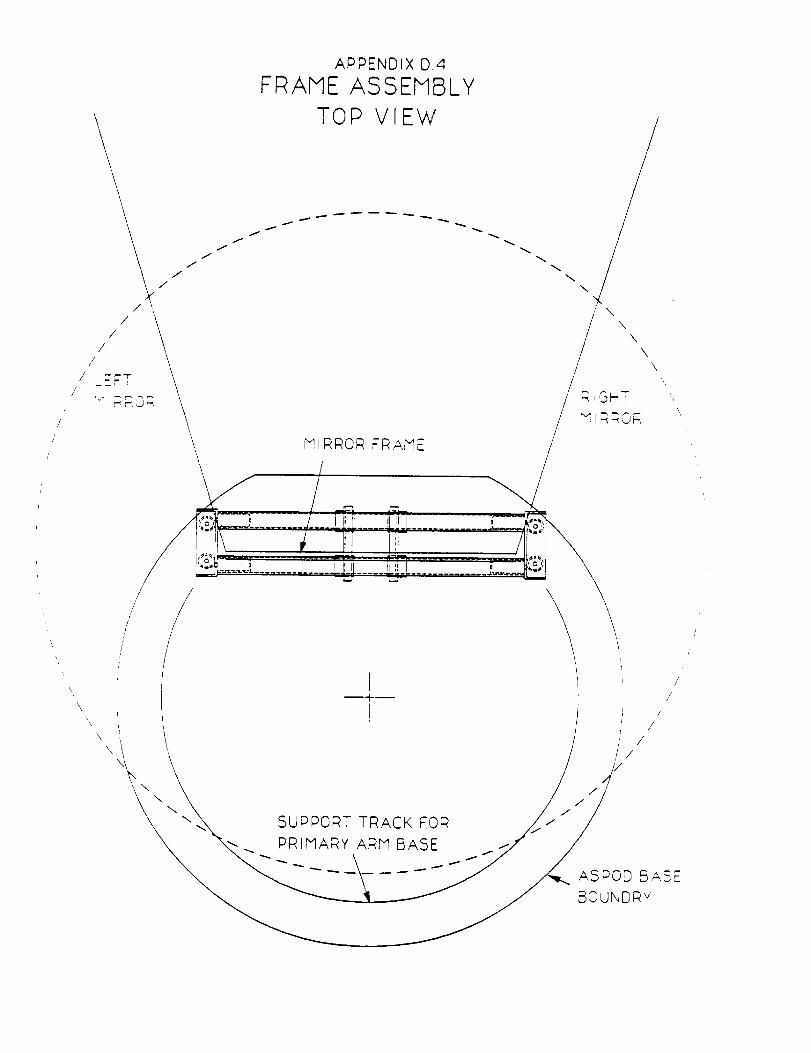
///
/
\
/J
//
//
/ _E; I
G i
\
\
\
APPENDIX O.4
FRAME ASSEMBLY
TOP VIEW
J
f
i
MIRROR FRAME
/ r_:-_C2.,;.............._-i.... i.=............_....
t
I
\\
_ ,., _ \\',,
/ MI RRO_,
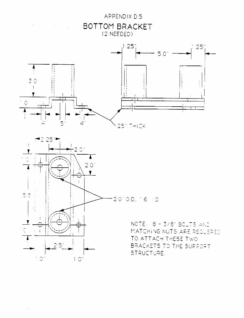
APPENDIX D,5
BOTTOM BRACKET(2 NEEDED)
.0"
25
L_...... -I
'_ 2 215" _ I
, I ; I Ai I i I
' " ' C
, ,I ii I
I II I
1
r
iii
......__'
2 0"
__00D,
=-_-,__lr
t..2s C_., I,O
NOTE 8 - 3/8" BOLT_ ,.:,,XZ
MATCHING NUTS ARE REO_.,E-CEZ
TO ATTACH THESE TWO
BRACKETS TO THE SUPPORT
STRUCTURE
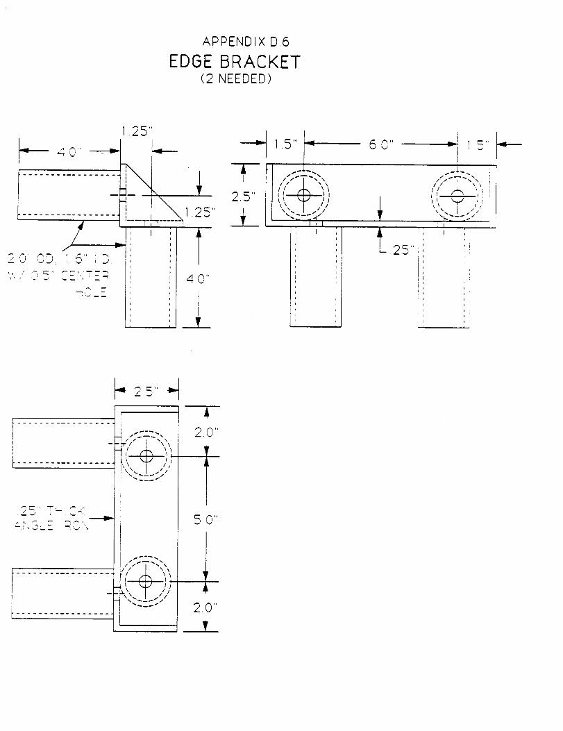
APPENDIX D.6
EDGE BRACKET(2 NEEDED)
,25"I
................_× ,
................../ t,_:O_OD, i5" ;D I: /
,'.... : _E:._TE_, 1 40"I
, , .___L
_._ 1.5" _
_L, "-:-,?,,t
i
i
p
i
i
Ii
i
i
i
p
i
0 qg
,
I
I
n
i
I
I
i
/;.---... i'_l _, i
_\_,1 /
\\ x. I i/;/,
ii rI
25"
t
I ;:j -:,,
t ................. , "1"4/
,._ _., , X/,_
.................. ( ',
2.0"
I50"
2.0"
V
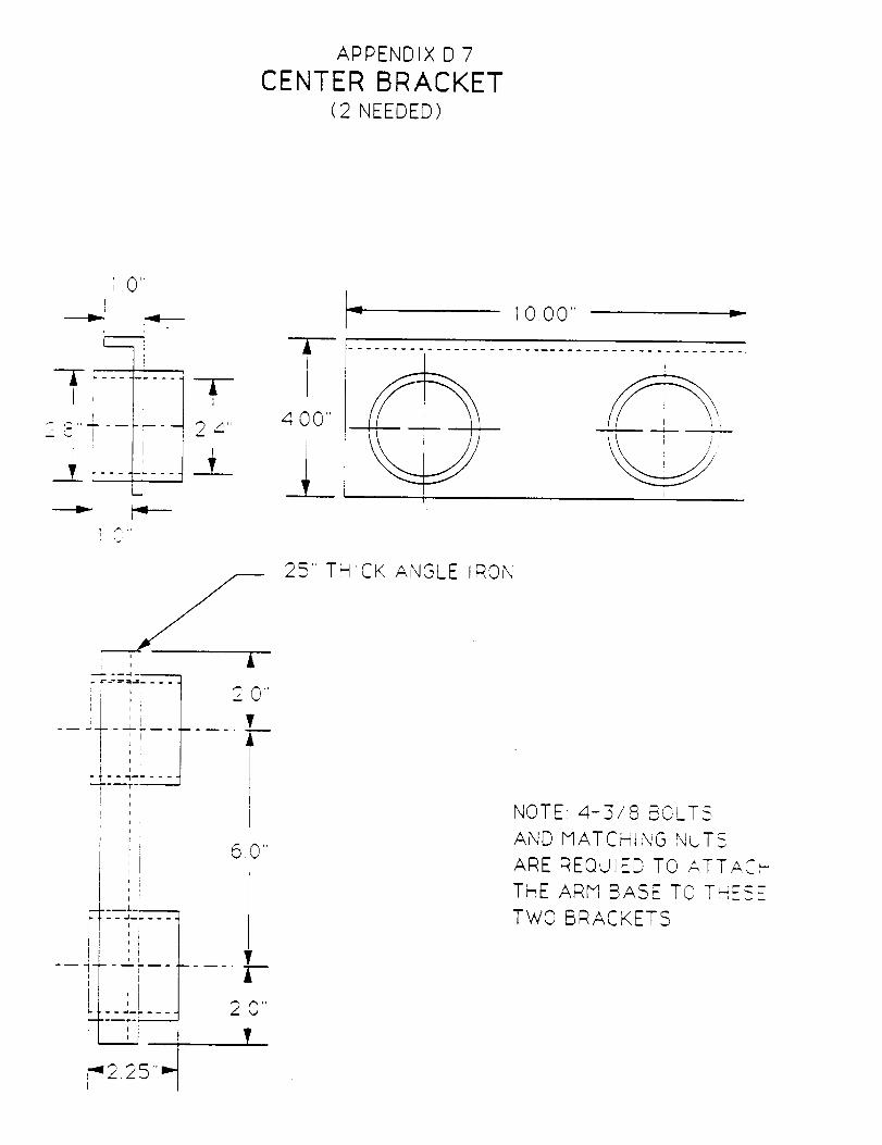
APPENDIX D7
CENTER BRACKET(2 NEEDED)
1 0 I'
ri
1- q_ ,, i
." ,.,.-, !
t
T i---
--p- ....
i
--- - - - -4
i! II
T24"
i
.... 4 -- _i..--i,I
,ii i
' I
I i
20"
6 0"
L
i
--I,L--
-I-_---I
i
1
i
1000" =:
400"
225" THrCK ANGLE RON
NOTE 4-3/8 BOLT c-
AND MATCHING NUT5
ARE REQUIED TO ATT ""r', k_ ,-
THE ARM BASE TO T'--:E_E
TWO BRACKETS
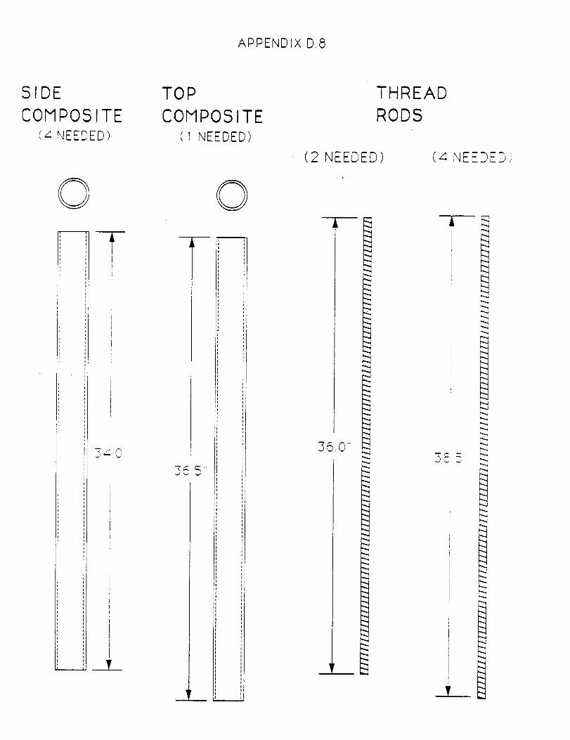
APPENDIX D.8
SIDE
COMPOSITE4 NEEDED)
---i-
i
ii
!:!,
:r
._ v _'I" 0
;it
:lpr
:I:1:1
iiil
:l
:1
_J,i
li
_L
TOP
COMPOSITE( 1 NEEDED)
O)
I
IIii
q_
_P
_E,i
355"',liI
:1II
',l_k
iiiiii
'l_',1',l
IIt
,,iii
t_
'llIii
I
i,i,I
,,I
(2 NEEDED)
360"
.,..d
THREAD
RODS
(4 NEEDED },
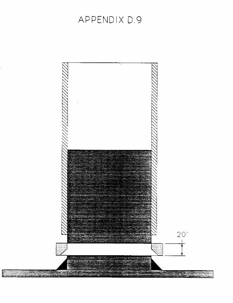
AP PENDIX D.9
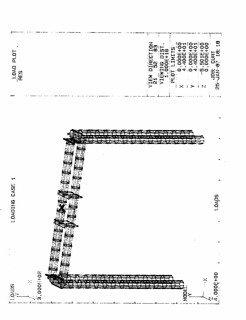
I--0__I
_i Lurr
X
b ......................................... _____
LM
C}
r__.._0...J
,"M0+
•., ,°,
w.,, 0_.?- 0o 0
I-....... I
oo
>< 4-LU'-
O,
_ __.___-L...__ ¸L ........ .-.I.......... 41- j
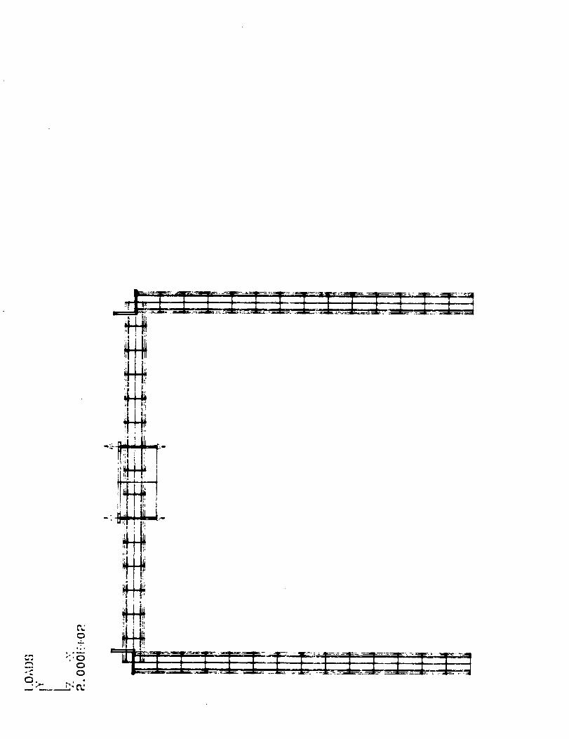
0.
O
,°.
C_0
,F
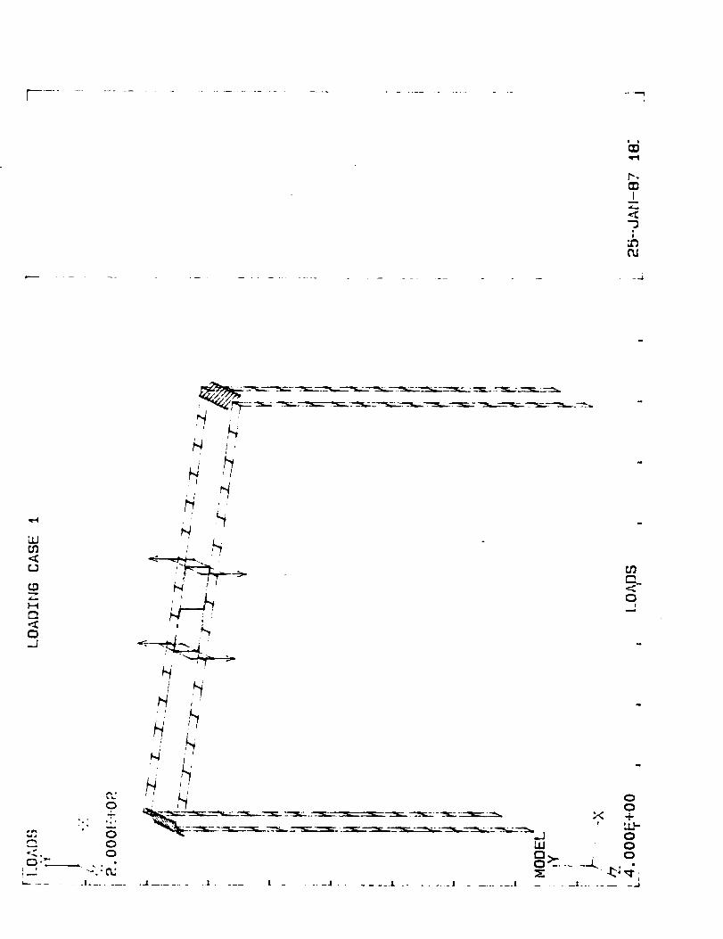
r ..............................................
;N
"3
_.j
qr4
LU{n
rJ
(34.,.
F_
r_
{:3_J
¢3
Qo
x +t ,j.]-
oL_ 0
Q
1 .... J ...................................... 1 ...... ..I
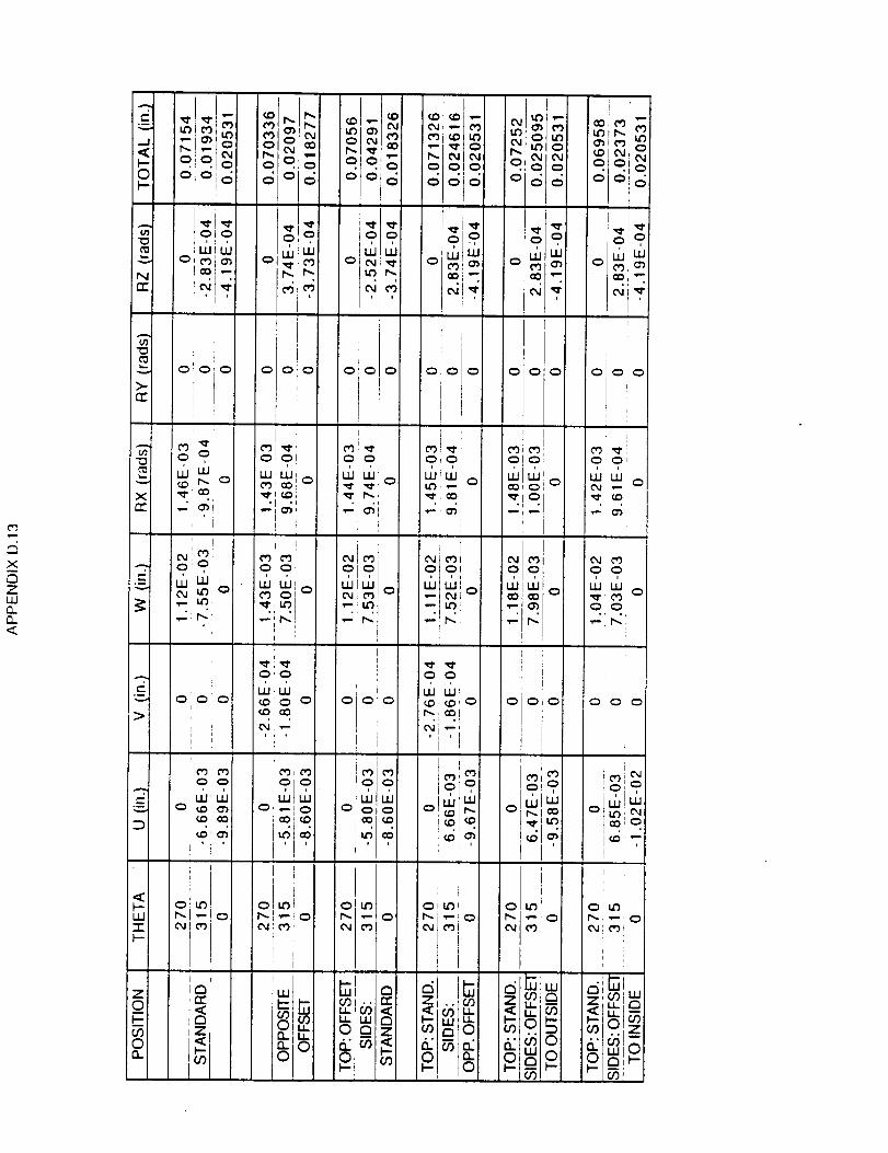


Appendix 3
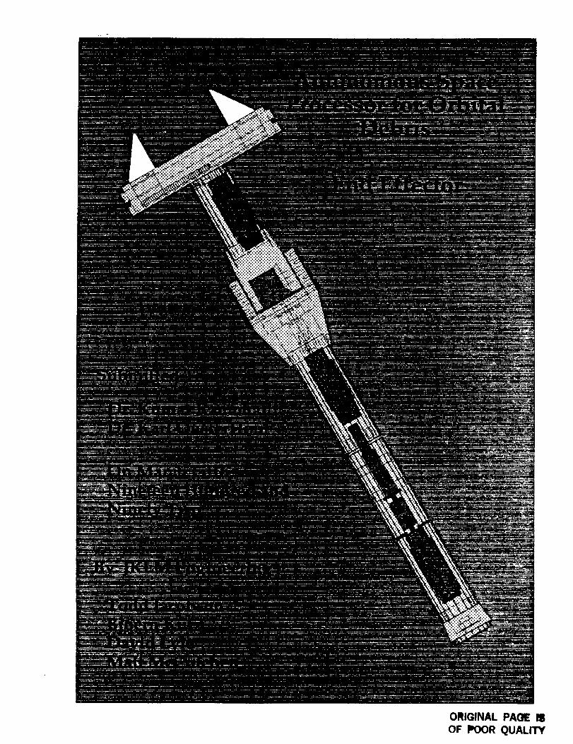
ORIGINAL PA(_ IS
OF POOR QUALITY

ABSTRACT (McCutchen)
The Autonomous Space Processor for Orbital Debris (ASPOD) project is
funded by NASA. Over four million tons of man-made debris is in low earth
orbit. This debris is traveling at an average of six miles a second. This project
is necessary because the debris is dangerous to spacecraft and satellites. The
development of a satellite that removes this debris from its low earth orbit is
the major problem. The proposed solution for this problem is the
Autonomous Space Processor for Orbital Debris (ASPOD). The overall
concept of this project is that a computer controlled television camera will
spot the debris, then the satellite will position itself so that t.he debris can be
picked up using a robotic arm in conjunction with the end-effector. Next the
object will be split into smaller pieces using concentrated solar power. These
pieces will then be moved by the arm and end-effector into a storage bin so
that they can be disposed of at a later time. A small part of the overall project
is the end-effector that will grip the objects to be disposed of. Successful
completion of this project will show that there is a low cost and light weight
way to clean up space debris. It will also make space safer for spacecraft and
satellites. The end-effector is an integral component of the overall concept
TABLE OF CONTENTS
L
IL
HI.
IV.
V.
VI.
VII.
VIII.
IX.
Introduction (Jacobson)
Initial Design Specifications
Achieved Design Specifications
Materials (Jacobson)
Connection to Arm (lacobson)
Rotational Joint (McCutchen)
A. Materials (Jacobson)
B. Motors (Lyle)
Elbow Joint (Lyle)
A. Drive Gears
B. Axial Bearings
C.. Pinion Bracket
D. Pinion Shaft
E. Axial Shaft
F. Motor Mount
G. Materials
H. Adjustability
I. Motor Selection
J. Improvements
Gripper (Kutz)
A. Constraints
B. Design
C. Motor
Control System (Kutz)
A. Encoders
ii

X.
XI.
XII.
XIIL
B. Controller Card
C. Programming
Cost Analysis (Lyle, Jacobson)
Milestone Chart (Kutz)
Conclusion (Jacobson)
Appendices
A.
B.
C.
D.
E.
F.
G.
Materials (Jacobson)
Connection to Arm (J'acobson)
Rotational Joint (McCutchen)
Elbow Joint (Lyle)
Gripper (Kutz)
Encoders (Kutz)
Program
iii
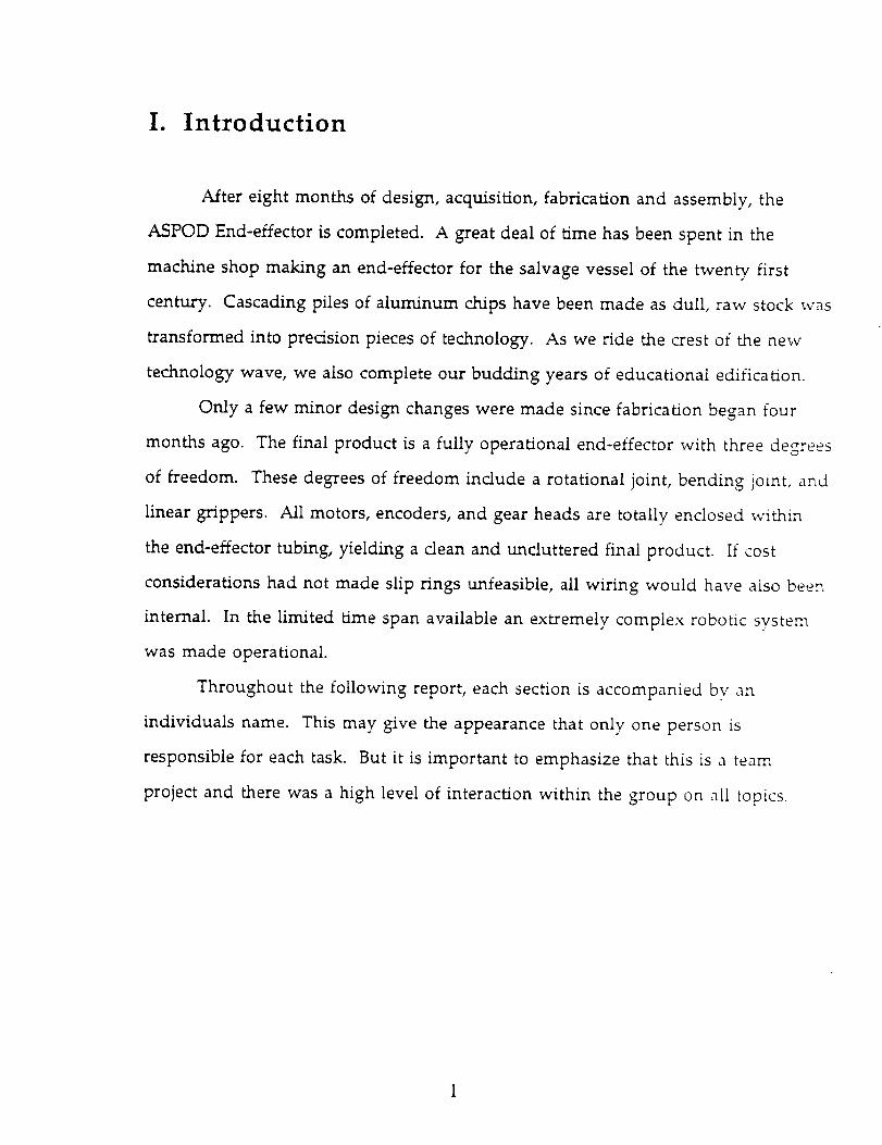
I. Introduction
After eight months of design, acquisition, fabrication and assembly, the
ASPOD End-effector is completed. A great deal of time has been spent in the
machine shop making an end-effector for the salvage vessel of the twenty first
century. Cascading piles of aluminum chips have been made as dull, raw stock was
transformed into precision pieces of technology. As we ride the crest of the new
technology wave, we also complete our budding years of educational edification.
Only a few minor design changes were made since fabrication began four
months ago. The final product is a fully operational end-effector with three degrees
of freedom. These degrees of freedom include a rotational joint, bending joint, and
linear grippers. All motors, encoders, and gear heads are totally enclosed within
the end-effector tubing, yielding a clean and uncluttered final product. If cost
considerations had not made slip rings unfeasible, all wiring would have also been
internal. In the limited time span available an extremely complex robotic system
was made operational.
Throughout the following report, each section is accompanied bv an
individuals name. This may give the appearance that only one person is
responsible for each task. But it is important to emphasize that this is a team
project and there was a high level of interaction within the group on all topics.
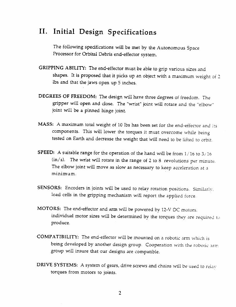
II. Initial Design Specifications
The following specifications will be met by the Autonomous Space
Processor for Orbital Debris end-effector system.
GRIPPING ABILITY: The end-effector must be able to grip various si7es and
shapes. It is proposed that it picks up an object with a maximum weight of 2
lbs and that the jaws open up 5 inches.
DEGREES OF FREEDOM: The design will have three degrees of freedom. The
gripper will open and close. The "wrist" joint will rotate and the "elbow"
joint will be a pinned hinge joint.
MASS: A maximum total weight of 10 lbs has been set for the end-effector and its
components. This will lower the torques it must overcome while being
tested on Earth and decrease the weight that Will need to be lifted to orbit.
SPEED: A suitable range for the operation of the hand will be from 1/16 to 3/16
(in/s). The wrist will rotate in the range of 2 to 8 revolutions per minute.
The elbow joint will move as slow as necessary to keep acceleration at a
minimum.
SENSORS: Encoders in joints will be used to relay rotation positions. Similarly,
load ceils in the gripping mechanism will report the applied force.
MOTORS: The end-effector and arm will be powered by 12-V DC motors.
individual motor sizes will be determined by the torques thev are required to
produce.
COMPATIBILITY: The end-effector will be mounted on a robotic arm which is
being developed by another design group. Cooperation with the robotic arm
group will insure that our designs are compatible.
DRIVE SYSTEMS: A system of gears, drive screws and chains will be used to relay
torques from motors to joints.

TOLERANCES: Becauseof the high degree of accuracy required, tolerances of 0.002
inches must be adhered eo on all load bearing members.
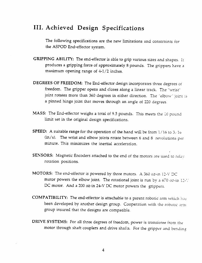
"i
III. Achieved Design Specifications
The following specifications are the new limitations and constraints for
the ASPOD End-effector system.
GRIPPING ABILITY: The end-effector is able to grip various sizes and shapes. It
produces a gripping force of approximately 8 pounds. The grippers have a
maximum opening range of 4-1/2 inches.
DEGREES OF FREEDOM: The End-effector design incorporates three degrees of
freedom. The gripper opens and closes along a linear track. The "wrist"
joint rotates more than 360 degrees in either direction. The "elbow _' joint is
a pinned hinge joint that moves through an angle of 220 degrees.
MASS: The End-effector weighs a total of 9.5 pounds. This meets the 10 pound
limit set in the original design specifications.
SPEED: A suitable range for the operation of the hand will be from 1/16 to 3/lo
(in/s). The wrist and elbow joints rotate between 6 and 8 revolutions per
minute. This minimizes the inertial acceleration.
SENSORS: Magnetic Encoders attached to the end of the motors are used to relay
rotation positions.
MOTORS: The end-effector is powered by three motors. A 360 oz-in 12-V DC
motor powers the elbow joint. The rotational joint is run bv a 070 oz-in I2-_,
DC motor. And a 200 oz-in 24-V DC motor powers the grippers.
COMPATIBILITY: The end-effector is attachable to a parent robotic arm which ha_
been developed by another design group. Cooperation with the robotic arn_
group insured that the designs are compatible.
DRIVE SYSTEMS: For all three degrees of freedom, power is transferee from the
motor through shaft couplers and drive shafts. For the gripper and bending
4

joints, a series of gears is used to relay power. But the rotational motor
transfers torque by direct drive.
5
IV. Materials
Proper materials selection is an essential part of the design process. The
material selected for each component depends upon the stresses and maximum
allowable deflections that each individual part can have. In some cases, the size of
the part is limited, thus restricting the selection of possible materials. Some
components, gears for example, are only available in certain mater{als, such as
steel. Also the mass of each component should be kept to a minimum to reduce
bending moments and forces produced from the weight.
The total weight of the end-effector is an extremely important design
consideration. A light final product is desired not only to reduce the forces
experienced by the end-effector joints, but also because the composite arm must
operate with the end-effector attached. Reducing the mass of the final design can be
accomplished by "shaving" nonessential material from individual components.
There are numerous parts containing material that could be removed without
threatening the integrity of the part. If care is taken to ensure only nonessential
parts are shaved, the reduction in mass would be of great benefit.
The totalnumber of components for the entire end-effector is quite large
Fortunately most of these parts are not subjected to large stresses and a careful
strength analysis isnot necessary. But there are some components that are
subjected to large stress values, like shafts, gears and the cylindrical housing. These
type of components must be analyzed to ensure that they have the strength needed
to avoid failure or unacceptable deflection.
The material selection process can be divided into two categories. The first
category contains components that are common throughout the end-effector
design, such as the cylindrical housing. The other category contains parts that are
unique to individual joints of the end-effector, such as the grippers in the jaw
6

mechanism. Components from this second category will be discussed in the
section dealing with that particular joint.
One component that requires important material selection is the cylindrical
housing. Since the housing needs to be 2 inches in diameter an approximately 20
inches in length, a light weight material is needed. But because of the length
involved, deflection is a potential problem. Two stiff, light-weight materials that
could be used include a graphite composite or a low mass metallic alloy. Since the
housing will have numerous openings and drilled holes, a graphite composite may
be structurally weakened and is not a good material choice. Although aluminum
is heavier than a graphite composite it is easier to machine and keeps its
mechanical strength. A hollow aluminum tube with an outside diameter of 2
inches and 0.065 inch wall thickness will provide a stiff, lightweight housing. S_e
Appendix B for weight and deflection calculations.
?
V. Connection to Arm
The end-effector currently being designe d will be mounted on a robotic arm
which is being designed by another engineering team. Although the connection
between the arm and end-effector is not an actual joint with moving parts, it is an
important component. The connection must securely hold the end-effector to the
arm while allowing simple attachment and detachment of the end-efiector. The
shapes and sizes of the tubing to be joined dictates the design of the connection.
The composite arm tubing will have an outside diameter of 2.15 inches and a _vaii
thickness of 0.075 inches. A fiat aluminum plate will be attached to the end of the
composite arm, compliments of the arm design team. The aluminum end-effector
tubing will have an outside diameter of 2.00 inches and a wall thickness of 0.005
inches.
These specifications were used to design the end-effector connection. The
component that will connect the arm and end-effector was machined from a solidi
cylindrical block of aluminum. The initial dimensions of the block included _
length of 1.75 inches and a diameter of 2.25 inches. The aluminum block was
machined to the desired shape for the connection using a lathe and drill press, se_
Figure 5.1 for connection schematic. The outside diameter sits flush with the 2._,_
inch diameter of the end-effector tubing.
Once the initial shape of the connection is set, it must be attached to the
tubing on both sides. At the aluminum tubing end of the connection, the diL_meter
was decreased by 0.065 inches to allow the tubing to slide onto the connection. The
reduction in diameter must produce a snug fit to properly transmit bending
moments without allowing play in the connection. The end-effector tubing was
then attached to the connection by six 4-40 countersunk cap screws. The screws sit
8
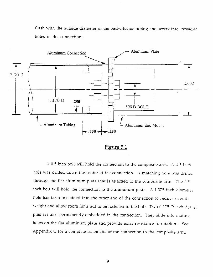
flush with the outside diameter of the end-effector tubing and screw into threaded
holes in the connection.
T(--.'_0 [D
Aluminum_ Aluminum Plate
• _ i .500 D BOLT
,// /
,./ T
--i-
Figure 5.1
A 0.5 inch bolt will hold the connection to the composite arm..4 0.3 inch
hole was drilled down the center of the connection. A matching hole was drilled
through the flat aluminum plate that is attached to the composite arm. The 0 -_
inch bolt will hold the connection to the aluminum plate. A 1.373 inch diameter
hole has been machined into the other end of the connection to reduce overall
weight and allow room for a nut to be fastened to the bolt. Two 0.125 D inch dow,i
pins are also permanently embedded in the connection. Thev slide into mating
holes on the flat aluminum plate and provide extra resistance to rotation. See
Appendix C for a complete schematic of the connection to the composite arm.
9
VI. Rotational Joint
The design of this joint has involved many steps and modifications. In the
design of this joint the amount of rotation has been the main design criteria. There
are two ways to approach this problem, one way is to design it for unlimited
rotations, and the second is to limit the rotations. For an unlimited rotation the
joint would utilize a slip ring, which would allow the wires to be enclosed within
the arm. The slip ring was then checked for price and availability and it was found
that the slip ring would cost $2316 if purchased from Fabricast Inc. It would not be
available for 12-14 weeks. Therefore, the use of a slip ring is not practical due to
the cost and lack of availability. This then lead to a design with a limited rotation.
The computer program itself would prevent the wires from twisting and breaking.
Once the basic configuration was determined the design of the joint itself
could begin. The final design of this joint is shown in Figure 6.1. The maximum
torque for the rotational joint was determined to be 40 in-lbs. A motor capable of
producing this torque was then found. The specifications for this motor (part ;3}
can be found in Appendix C. It was then necessary to support the motor within the
tube. This was done by machining a front and back motor support. Part #4 and
part #1 respectively. These supports were connected to the motor using the
preexisting holes that are designed to help mount the motor. The 4 mounting
holes on the front of the motor are 3 millimeters in diameter and the 2 holes on
the back of the motor are 2 millimeters in diameter. This should be noted because
the rest of the Allen head screws used are in English units. The motor supports
prevent the motor from rotating within the tube because the supports are
connected to the tube using Allen head screws. There are 4 screws holding each
motor support in place.
10
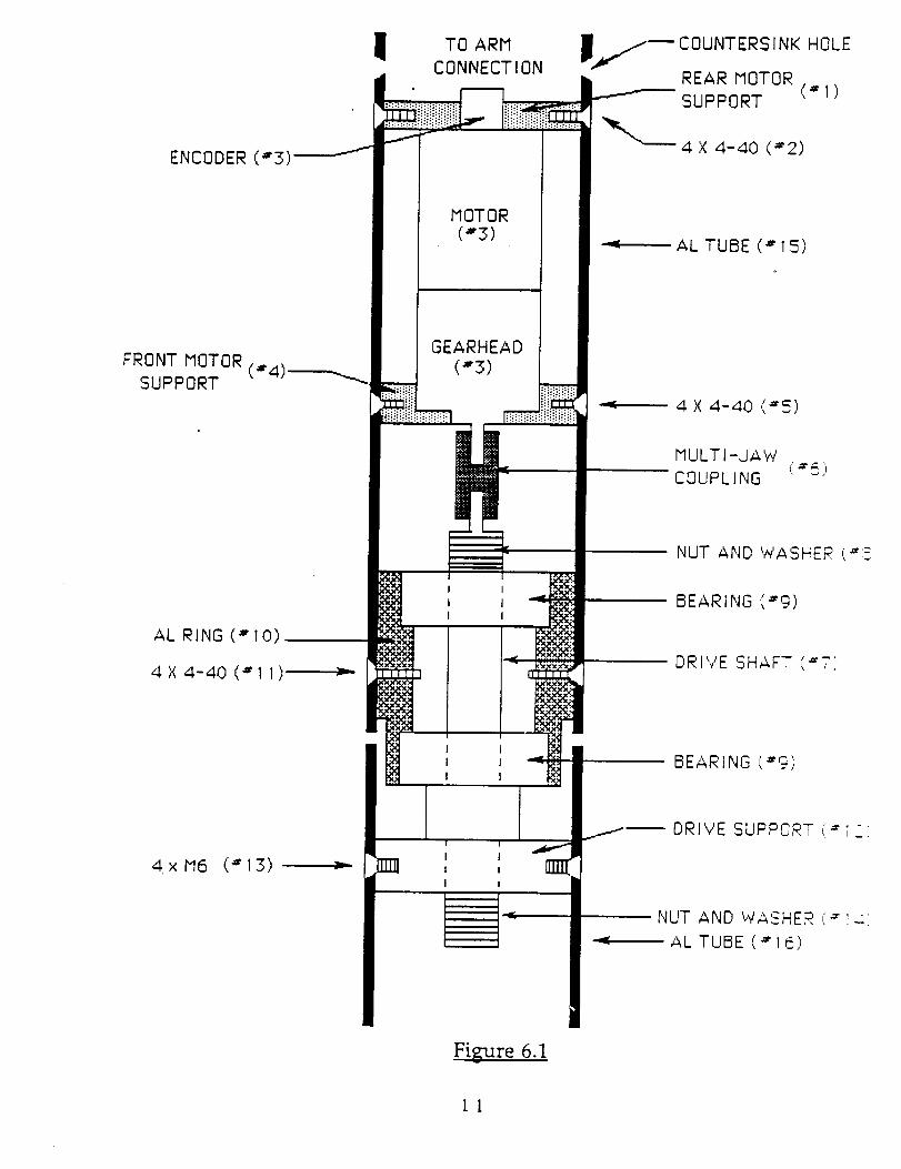
!
ENCODER (#3)_
TO ARM
CONNECTION
I
I
MOTOR
(#3)
COUNTERSINK HOLE
REAR MOTOR
SUPPORT (# I)
4 X 4-40 (#2)
AL TUBE (# 15)
FRONT MOTOR(#4',
SUPPORT
GEARHEAD
(#3)
4 X 4-40 (*5)
MULTI-JAW
COUPLING ('6)
AL RING (# I0)
4X 4-40 (#I I)
4 x M6 (# 13)
I I
I I
I I
I
I
I
n
I I
I I
[] i ,I I
I
I
JI
i
NUT AND WASHER (_:_
BEARING (#9)
DRIVE SHAFT (_'71'
BEARING ('9)
NUT AND WASHER (#',_,
AL TUBE (*16)
Figure 6.1
I!
The Allen head screws are parts #2 and #5 and they are 4-40 size Allen head screws.
The motor supports also insure that the motor is lined up in the center of the tube.
These motor supports can be seen in Appendix C. The next design decision was on
how to transmit the torque from the motor to the arm. A drive shaft connected by
a mull:i-jaw coupling to the motor was the solution. This drive shaft turns at a
maximum of 18.9 revolutions per minute. The minimum diameter of the drive
shaft was also calculated and it was found to be .455 inches in diameter. To perrni_
the drive shaft to rotate in the fixed end of the aluminum tube a set of bearings was
used. These bearings were press fit in to the tube and separated bv a 0.52 inch thick
aluminum ring. These bearings will reduce the load on the motor shaft and by
placing the bearings 1 inch apart the deflection will also be reduced. The outside
end of the aluminum ring was machined down to allow the aluminum tube to
rotate freely. The aluminum ring is held in place by four Allen head screws these
Allen head screws kept the ring and the bearings from rotating or moving. The
bearings will be held in place by a Nylock nut and washer (part _8). The
specifications and designs of the shaft coupling (part #6), the drive shaft (part _7_,
the aluminum ring (part #10), and the bearings (part #9) is in Appendix C.
Once the drive shaft is past the bearings it will be connected to the rotationai
part of the end-effector. The end of the drive shaft will be threaded in order to
connect it to the rotational end of the end-effector. The threads are 1/2-13 threads
On the end of the drive shaft will be the drive support. The drive support is how
the torque of the motor is translated to the end-effector. A 0.5 inch hole will be
drilled in the drive support and be threaded this will allow the drive support to be
screwed on to the drive shaft. The drive shaft and the threads must be perfectly fla:
and straight so that the arm rotates straight. The drive support is held in place by
four Allen head screws. These screws are 6 millimeters in size. A self-locking nut
and washer will be placed on the drive shaft after the drive support to insure that it
12
does not back off or loosen. See Appendix C for the specifications and drawings of
the drive shaft, nut and washer (part #14), and drive support (part #12). The
screws that will be used to hold all pieces will be Allen head countersink screws
because of their high strength.
The design of the joint has been extensive and has lead to this final product.
The production phase of the project went well with very few problems or changes
The only real change occurs in the design of the aluminum ring. The outside
diameter of one end was machined down to allow the tube to rotate freelv. This
was the only production change.
The finished product is of high quality it works very well and meets all
specifications. The overall cost of the rotational joint was $537.85. The motor for
the rotational joint cost $435.65, and the labor was free. The rotational joint has
exceeded expectations.
A. Materials
A critical component that must be carefully designed is the shaft that
connects the two separate sides of the rotational joint. This shaft will experience
alternating bending moments, shear forces, and torques as it rotates. The shaft als,;
experiences stress concentrations were the diameter changes. It is critical that the
shaft be adequately designed to prevent fatigue failure. The deflection of the shaft
must also be kept to a minimum. Any deflection in the shaft would be amplified
along the remaining length of the end-effector, creating a much larger deflection at
the gripping surface.
There are two major variables that can be adjusted in the shaft design, the
material selected and the minimum shaft diameter. Although steel is much
heavier than aluminum, it is also considerably stronger. Do to the high strength
13
required and space considerations, steel was the material selected. For the analvsis
of the shaft, 1030 steel was used. Fatigue analysis was preformed to find an
appropriate minimum shaft diameter. Then the minimum shaft diameter was
checked for a possible unacceptable deflection. See Appendix C for calculations.
Based on a factor of safety of 2.5, the minimum shaft diameter was found to be 0.45
inches.
B. Motor
The motor selected for the rotational joint is a 12 volt 2842s Micro Mo. motor with
a 30/1 gear head and a 415:1 reduction ratio. The maximum stall torque for this
motor gear head combination is 772.70z-in. The torque required to rotate the wri__:
with the elbow bent through the horizontal plane is 672 Oz-in. See Appendix C tor
calculations. The maximum output power of the motor is 9.4 Watts The
maximum RPM this rotational joint can experience is 18.9 RPM.
14
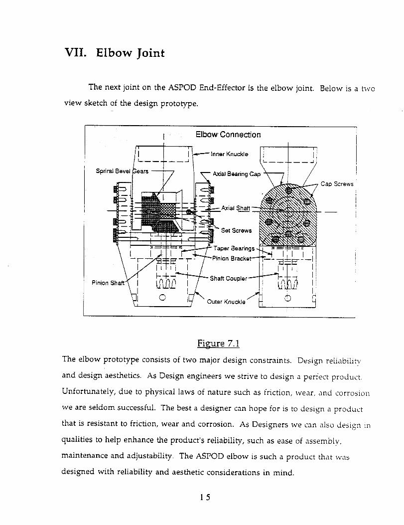
VII. Elbow Joint
The next joint on the ASPOD End-Effector is the elbow joint. Below is a two
view sketch of the design prototype.
J
I
-17_ --'l_'-7--
e iEI
Elbow Connection
Inner Knuckle
.._AxialBearingCap
I
Outer Knuckle _ [_i
Cap Screws
Figure 7.1
The elbow prototype consists of two major design constraints. Design reliability
and design aesthetics. As Design engineers we strive to design a perfect product.
Unfortunately, due to physical laws of nature such as friction, wear, and corrosio_
we are seldom successful. The best a designer can hope for is to design a product
that is resistant to friction, wear and corrosion. As Designers we can also design in
qualities to help enhance the product's reliability, such as ease of assembly,
maintenance and adjustability. The ASPOD elbow is such a product that was
designed with reliability and aesthetic considerations in mind.
15
A. Drive Gears
The ASPOD elbow is driven by a set of spiral bevel gears. Spiral bevel gears
have overlapping tooth action which results in a smoother gear action, lower
noise, and higher load capacity than a straight bevel of equal size. The duty load of
the bevel gears is, at most four hours per week and their rotation will never exceed
25 revolutions per minute. Therefore, little or no lubrication is required for these
gears. However, a light Teflon coating on each gear is recommended to prevent
any wear that might occur during operation. The bevel gears are made of
hardened steel to help prevent against chipping of the teeth during operation. One
of the design considerations was to find gears which could handle the stress on the
gear teeth under normal and extreme operating conditions.
must be made of hardened steel or they may chip or fatigue.
stress on gear teeth calculations.
The gears for this join:
See Appendix E for
B. Axial Bearings
Another design problem that must not be over looked is movement of tl_e
inner knuckle along the axis of rotation. If this happens then the bevel gears will
not mesh properly resulting in unnecessary play and extensive wear on the teeth.
To prevent this axial movement from occuring, taper bearings are preloaded in the
outer knuckle in an opposing manner. Taper bearings from Timkin corporanon
are able to operate under radial and axial force. A series of cap screws on each side
of the outer knuckle hold the axial cap to the bearings and regulates the preload
force. The preload force on the axial caps was determined experimentally during
the testing phase of the project. Nine to twelve foot-pounds of torque is required
16

on the axial cap screws to lock the position of the large bevel gear and to provide
enough resisting force to the gripper moment, arm which helps to stabilize the
gripper in a horizon plane without a voltage input to the motor.
C. Pinion Bracket
The pinion Bracket is designed as a single unit. Its unique shape will mate
snugly inside cut out of the outer knuckle. Four bolts, two below each axial bearin_
help to hold the assembly in place. This single unit design feature helps to aid the
operator in the assembly process. The nut at the base of the pinion shaft would be
nearly impossible to access inside of the Outer Knuckle if the Pinion Bracket were
connected to the Outer Knuckle. SeeFigure 7.1. Therefore the Bracket was
designed to be removed from the top end of the Outer Knuckle to allow access to
the nut, washer, and shaft coupler. Another benefit of the removable Pinion
Bracket is that it allows for future modifications. If upon final assemblv a flaw in
the gear alignment is found due to the positioning of the pinion gear. The flaw c_:_
be repaired by reconstructing the Pinion Bracket rather than reconstructing the
entire Outer Knuckle. Therefore, since the Pinion Bracket allows for ease of
accessibility and freedom for future modifications it will serve as an effective
component in the overall bending joint design.
D. Pinion Shaft
The pinion shaft is a 0.3750 in diameter steel shaft turned down to 0.3175 in
on one end and 0.3125 in on the other end. A set screw will be tapped in the piniol_
gear and tightened against a ground flat surface on the pinion shaft. This allows
adjustability of the pinion with respect to the gear. The pinion shaft is supported in
17

a similar manner to the axial shaft by two opposing taper bearings, loaded into the
pinion bracket and held firm by a 3/8 - 16washer and nut. The nut preloads the
bearings to prevent lateral movement in the pinion gear. The preload torque was
experimentally determined in the testing stage. Twelve to Fourteen foot-pounds of
torque is required on the nut in order to provide enough resistive force to help
stabilize the gripper moment arm in the horizontal plane under gravi .ty. Finallv a
shaft coupler will be added to the base of the pinion shaft. It's purpose is to create a
dividing point between the motor and the pinion shaft. The Pinion Bracket will be
accessedfrom the top of the Outer Knuckle and the motor will be accessedfrom
below. With the motor and the Pinion shaft in place no tools can be used to
assemble or disassemble the Pinion shaft and Motor shaft connection therefore a
multi-jaw coupler is used.
E. Axial Shaft
The axial shaft is a is a 0.6250 in diameter steel shaft turned down to 0.3750 i,,_
on both sides with a standard 1/8 " X 1/16 " key way rooted through the length of
the large diameter. See Figure E.1. The Outer knuckle will be connected to the
Inner Knuckle with the Axial shaft. Washers will be placed on each end of the
axial shaft to maintain the 1/16 in clearance between the outer Knuckle and the
Inner Knuckle. Since the gear rests against the Inner Knuckle and the pinion is
connected to the Outer Knuckle the washers also serve to maintain 0.004 in
clearance between the gears. This is another example of adjustabilitv. The washers
can be machined and replaced to maintain proper gear clearance more easily than
machining new Outer and Inner Knuckles.
18
F. Motor Mount
The motor will be mounted to the outer knuckle with the motor mount
bracket in Figure E.2. Four, three millimeter cap screws will hold the motor to the
mounting bracket. A single machine screw will support the mounting bracket to
the sleeve. This screw will keep the connecting holes on the mounting bracket
lined up with the connecting holes on the sleeve while an assembler aligns the
connecting holes with the corresponding connecting holes on the outer knuckle.
With everything assembled correctly the shaft couplers will be in perfect alignment
with each other.
G. Materials
Now that all of the major failure points have been carefully considered tt_e
design aesthetics can be improved on. The Outer knuckle, Inner knuckie, and
pinion shaft bracket are machined out of stock Aluminum. The bevel gears are
hardened steel and black in color. The Axial bearing cover on both sides of the
outer knuckle are made from polished brass to complement the machine finishe_i
aluminum that it rests against. To offset the brass color, all cap screws in the axlai
bearing cover are black Allen head in shape and symmetric about the center line
axis. One subtle aspect that the drawings do not show is the fact that all sharp edge_-
rounded in the final product. Smooth transitions from the round two inch
diameter sleeves to the rectangular mid section are also incorporated in the final
product. With contrasting metals, colors, symmetry and smooth transitions the
End effector elbow should give the appeal of a solid state product.
19
H. Adjustability
When machining a complex component such as the End-effector bending
joint, a machinist can spend days even weeks setting up a job, checking the
precisions and machining the part. The last thing the machinist wants to do is to
re-machine a part because of a subtle design flaw. This is why it is important to
have adjustabihty designed into the part. For example the a pinion's ability to slide
vertically along the pinion shaft to help make up the vertical clearance between the
gears. The pinion bracket, unattached to the Outer Knuckle, gave the flexibility to
replace the pinion bracket if upon completion of the elbow the pinion shaft was is
not parallel to the center-line of the arm; the bracket can be re-machined more
easily than the Outer knuckle. These adjustability considerations help aid to the
products reliability. If the product fails there is room to improve.
L Motor Selection
The motor chosen for the elbow is a 12 volt Micro Mo 2842s with a 30,1 oe,L,__.
head of 134:1 reduction ratio. This motor and gear head combination offers o03 @z-
in of stall torque. Calculations for torque on the elbow show that onlv 340 Oz-in are
required to operate the elbow and forearm at a horizontal position. This will allow
for a large margin of safety. The recommended max continuous RPM is 22.4 in d_e
motor and the forearm will rotate at 10 RPM due to the 2:1 reduction of the bevel
gears. The power required by the motor assuming that the forearm rotates at 10
RPM is approx 5 watts, and the motor efficiency is 72%. For motor mounting
considerations ,it is not that important to be concerned about heat dissipation from
the motor since the 5 watts of power output from the motor will be converted into
useable energy. However some thermal dissipation will occur. The motor chart in
2O
Appendix E shows that 16degrees per watt will dissipate from the case to the
surroundings, assuming that the motor is suspended in mid air. Since the motor
will be attached to a gear head the gear head will act Like a heat sink and draw the
heat away from the motor.
]. Improvements
Upon testing the elbow connection intolerable amounts of play began to
propagate in each axial connection of the elbow due to the slipping of shaft couplers
on the rotational shafts. The sources of play were: motor shaft/shaft coupler
connection, pinion shaft/shaft coupler connection, pinion shaft/pinion gear
connection and the axial shaft key way. The play in the key way was removed by
milling a flat surface on the axial shaft and inserting a set screw through the inner
knuckle and perpendicular to the flat surface. The play on the shaft couplers and
their mating shafts was removed by drilling a shallow hole in the shaft for the set
screw to sit into and securing the set screws with lock tight. Other modifications
include removing excess material from the Inner Knuckle and the Pinion Bracket
All modifications are noted in their respective drawings. See Inner knuckb
drawing, Main axial drawing, and Pinion bracket drawing.
21

VIII. Gripper
A. Constraints:
1. The gripper is to be able to hold an object of one pound, and up 5
inches in diameter with a factor of safety of two while subject to
accelerations and conditions it will incur during normal working
conditions in land based service.
2. The gripper ( not the entire arm ) will maintain accurate jaw
placement to a 1/32" error during normal working conditions in
land based service.
3. The gripper will be controllable by a computer program based
instruction set, as opposed to manual control bv a human
operator.
4. The gripper shall be no larger than 10 inches by 5 inches bv 5
inches.
5. The gripper will be maintainable ( Disassemblv will be possible, and
will not require any structural modifications to the individual parts _
6. The gripper will interface with the rest of the effector and in turn
the rest of the arm.
22
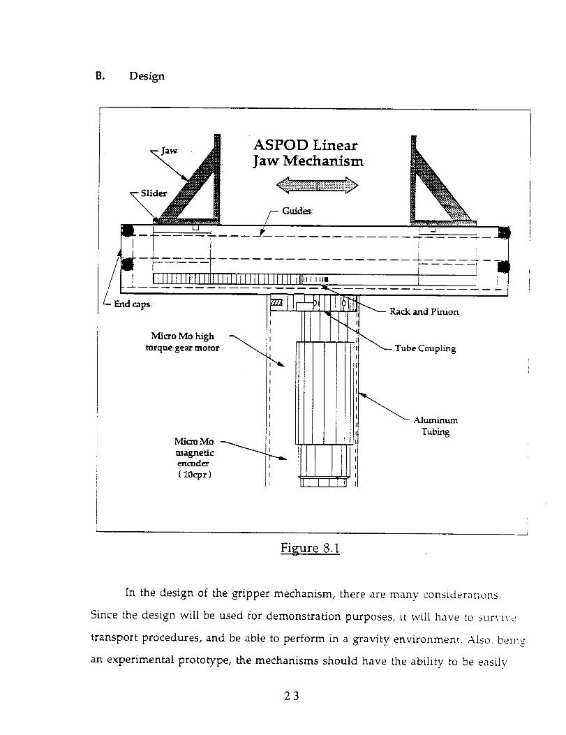
B. Design
Rack and Pinion
Micro Mo high
torque gear motor Tube Coupling
Micro¸ Mo
magneticencoder
( IOcpr )
Aluminum
Tubing
Figure 8.1
In the design of the gripper mechanism, there are many considerations.
Since the design will be used for demonstration purposes, it will have to survive
transport procedures, and be able to perform in a gravity environment. Also, being
an experimental prototype, the mechanisms should have the ability to be easilv
23
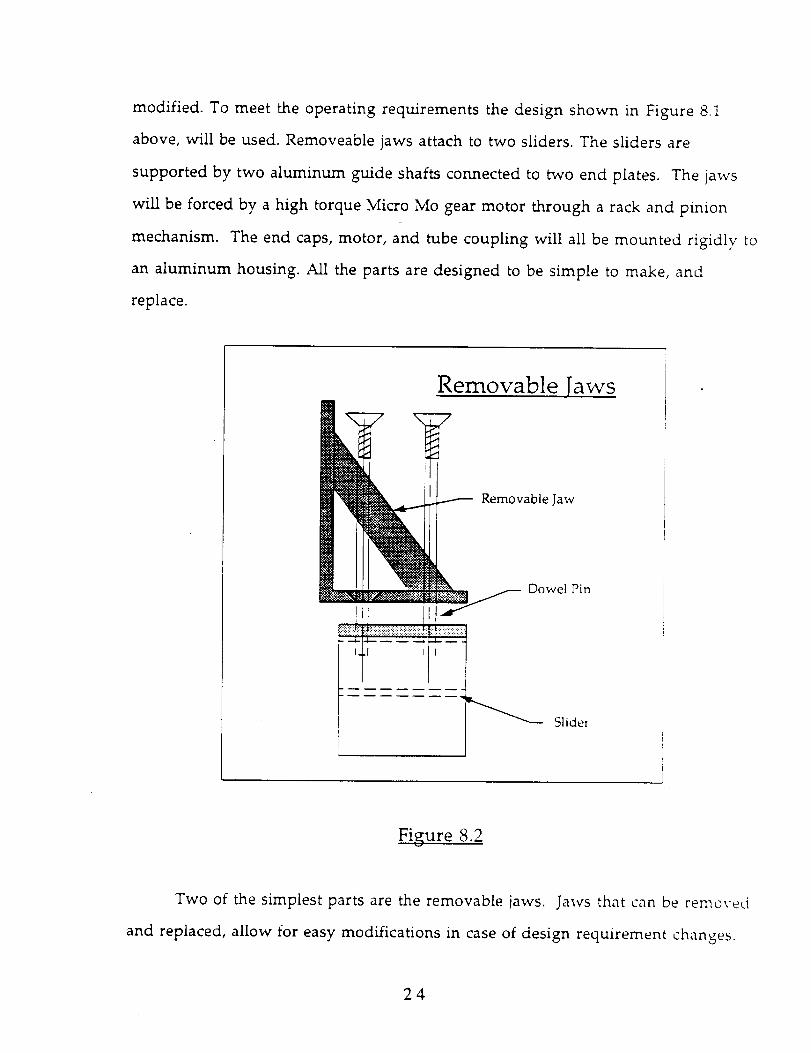
modified. To meet the operating requirements the design shown in Figure 8.1
above, will be used. Removeable jaws attach to two sliders.The sliders are
supported by two aluminum guide shafts connected to two end plates. The jaws
will be forced by a high torque Micro Mo gear motor through a rack and pinion
mechanism. The end caps, motor, and tube coupling will allbe mounted rigidly to
an aluminum housing. All the parts are designed to be simple to make, and
replace.
Removable laws
Removable Jaw
Dowel Pin
Slider
Figure 8.2
Two of the simplest parts are the removable jaws. Jaws that can be removed
and replaced, allow for easy modifications in case of design requirement changes.
24

For the initial design each jaw will be machined out of a single piece of Plexiglass.
The connection to the slider will consist of two screws to secure the jaw to the
slider ( seeFigure 8.2 above ). To hold the an object at maximum specifications, the
jaws must supply 7.5 lbs of force. At these parameters, the screws must support
fatigue loading with a maximum normal load of 11.25 lb, and a maximum shear
load of 7.5 lbs. A 10-32screw with a 0.02in2 stress area requires a preload of 8.245 lb
The Hencky-Mises equation was used along with an approximation of the
Goodman criteria to find that a minimum of 0.02623screws would be needed ¢o
hold the jaw securely in place. Complete calculations are contained in appendix E.
The jaws above will be mounted to two aluminum sliders located inside the
housing. The sliders are supported by two aluminum guide rods, and driven bv a
steel rack. At the 7.5 ib holding force the slider transmits a moment of 24.375 in-[bs
to the aluminum guide rods. During a maximum holding condition the guide rod_
will deflect a maximum of 4.22e-5 inches over its length. The guide rods are
supported by two end caps.To check for safety, it was assumed that all the force was
transferred to one end cap. 0.22265 6-32 screws are required to support this [oadh_;
At 4 screws per support, the screws will not fail due to fatigue.
25
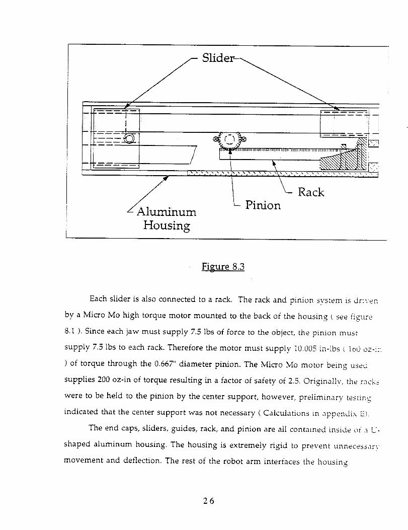
m
Al num
SHder-
Rack
L_ Pinion
Housing
Figure 8.3
Each slider is also connected to a rack. The rack and pinion system is driven
by a Micro Mo high torque motor mounted to the back of the housing _ see figure
8.1 ). Since each jaw must supply 7.5 lbs of force to the object, the pinion must
supply 7.5 lbs to each rack. Therefore the motor must supply 10.005 in-[bs ( lo0 oz-i:_
) of torque through the 0.66Y" diameter pinion. The Micro Mo motor being used
supplies 200 oz-in of torque resulting in a factor of safety of 2.5. Originally, the rack_
were to be held to the pinion by the center support, however, preliminary testing
indicated that the center support was not necessary ( Calculations in appendix E).
The end caps, sliders, guides, rack, and pinion are all contained inside or a U-
shaped aluminum housing. The housing is extremely rigid to prevent unnecessary
movement and deflection. The rest of the robot arm interfaces the housing
26
through a tube coupling. The tube coupling is basically a large aluminum washer
sandwiched between the front of the motor and the front of the housing ( See
figure 8.1).Six screws secure the support tube to the coupling. Accounting for the
weight of the gripper and the maximum load, the tube coupling requires 0.027584
screws (Appendix E).
Six A/fen head cap screws secure the aluminum tubing to the tube coupling.
This aluminum tubing provides a supporting structure from the elbow to the
gripper. The original design called for an aluminum heat sink to be mounted
around the motor. Preliminary testing determined that a heat sink was not
necessary. However, ifduring more rigorous testing the motor is in danger of
overheating, a heat sink can easily be added. Ifthe motor is stillin danger of over
heating, other corrective measures will be considered.
C. Motor
The motor must supply 160 oz-in of torque to meet with a factor of safety or
two holding requirement. The motor being used for this is a Micro Mo 2133-U024s
high torque gear motor. This motor operates through a 750:1 gear reduction to
supply 200 oz-in of torque. The Micro Mo motor was chosen for its high torque,
small size, and low cost ( Micro Mo supplied a free product sample. ). Originally a
Pittman high torque motor was specified, but when Pittman announced shipping
delays, Micro Mo was recontacted. After some discussion it was determined that a
product sample could be obtained.
Although the sample Micro Mo gear motor has a gear head with an offset
output shaft, very little adjustment was needed. With the motor skewed to one
side inside the connecting tube, the pinion remained centered between the two
27

sliders. Since the twisting axis rotates at a relatively low speed, the any imbalance
caused by the skewed mounting is negligible.
The gripper design is currently being machined and built. In the evaluation
of the design, great care was taken to find a simple but durable design. On of the
tools used was the Hencky-Mises equation with the Goodman criteria. These
techniques were used to construct a spreadsheet for evaluating the fatigue life of
the many small screws in the gripper structure. Preventive measures like this will
make redesign more rare and easier.
D. Materials
The material used to make the actual grippers must be carefully selected.
Since the end-effector is a linear jaw design, the slightest deflection of the gripper
will significantly reduce the gripping force. Also the gripping surface must have a
high coefficient of friction to reduce the possibility of the object slipping between
the grippers.
Three materials considered for the grippers include: steel, aluminum, and
plastic. After analysis to find the size and weight of each material to insure a
minimum deflection, plastic was chosen as the optimum material. Also, instead _
square sided grippers, a triangular design was chosen. The triangular grippers wiil
provide better support while keeping the total size to a minimum. See Appendix F
for calculations. The calculated minimum width of the gripper base is 023 inches
To reduce the possibility of the object slipping between the grippers, the
inside of the plastic grippers may be covered with a material having a high friction
coefficient such as rubber. The current grippers are coated with a 0.125 in. thick
sheet of foam rubber. This surface seems to be a good overall choice, but different
materials could be used depending upon specific applications.
28ORIGINAL PAGEOF POOR QUALITY
As the grippers open and dose, they are supported by two linear guides.
These linear guides could be subjected to a large bending stressas the grippers apply
a force on an object. For this reason, stress and deflection analysis are done to find
the best material selection for the guide shafts. See Appendix F for calculations.
A/though steel guides would have a smaller minimum diameter, they would be
heavier than aluminum guides of comparable strength. Therefore aluminum
guides with a 0.5 inch diameter were chosen.
29
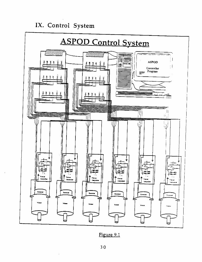
IX. Control System
ASPOD Control _ ystem
ASPOD
Controller
_: Program
,i!!
Figure 9.1
3O
In the current design, one of the major upgrades from last years arm is the
control system. The control system ( A general block diagram is shown above in
figure 9.1. ) allows the operator to program a desired output into the terminal. The
computer based control system then calculates the specific system requirements,
provides the system commands, and moves the system to the desired state while
checking for errors. This process starts at the computer terminal. The user specifi¢_-
a move using one of the programming methods available. The controller card
inside the computer converts the logical command to a voltage command and
sends the command to the appropriate axis via the connection card ( Shown in
Figure 9.1 ). The power amplifier converts the output signal to an appropriate
motor input command signal. While the motor is in a control mode the controller
card reads the encoder output, comparing the output to the desired position. The
controller card will move the motor to the deserted position and keep it there unti!
another command is given. The major components used in the control svstem ar_
the actuators, the feedback sensors, the interface hardware, the controller card. a_d
the computer based instructions.
A. Actuators
The actuators used for the end effector are all Micro Mo high torque gear-
motors with integrally mounted magnetic encoders. The motors used for the
bending and the twisting joint require a twelve volt power output, while the
gripper motor requires twenty four volts. The controller card offers a convenien_
method for adjusting the output signal. Gain and offset potentiometers are
supplied for each axis and can be adjusted for a desired output. The details
concerning each motor are contained in the section associated with each joint.
31

B. Encoders
In the ASPOD end effector design, the actuators are all DC motors requiring
an analog output from the controller card. Attached to the back of the motors are
the feedback sensors. In the case of the three Micro Mo motors the feedback sensors
are magnetic encoders. Magnetic encoders were chosen because thev were cheaper
and more readily available as an integral package from the manufacturer.
Although, the output is similar to that of an optical encoder, the interface hardware
is having trouble interpreting the feedback signal. Testing is currentlv being
conducted using an oscilloscope to determine possible sources of error.
Gripper Encoder
A Micro Mo motor drives the rack and pinion mechanism on the gripper
The racks each travel 2.095 inches for one revolution of the pinion. However, _i_
optical encoder on the back of the motor travels 750 revolutions for each pinion
revolution. At
10 counts per revolution, the encoder has reads 0.000069833 inches per count wit!_
quadrature decoding. This is well under the 1/32 inch resolution specified in the
gripper constraints ( see encoder calculations in appendix F ).
Elbow Encoder
The motor for the elbow joint is to be controlled to within 1/32" at the tip of
the jaws ( neglecting backlash ). The length of the end effector from the bending t
elbow ) joint to the tip of the jaws is about 10 inches. At this length, the elbow goes
32

through an angular displacement of 0.179014° / count. The encoder resolution
available from Micro Mo is type HE with a resolution of 15 counts per revolution.
With a quadrature decoding and a gear reduction of 268:1 this encoder is accurate to
0.02238806 ° / count. Therefore the 03b was selected ( Appendix F ).
Wrist Encoder
The motor for the wrist joint is to be controlled to within 1/32" at the tip of
the jaws ( neglecting backlash ). The length of the end effector from the bending (
elbow ) joint to the tip of the jaws is about 10 inches. At this length, the elbow goes
through an angular displacement of 0.179014 ° / count. The lowest encoder
resolution available from Micro Mo is type HE with a resolution of 15 counts per
revolution. With a quadrature decoding and a gear reduction of 159:1 this encode:
is accurate to 0.03773585 ° / count. Therefore the 03b was selected CAppendix F
C. Interface Hardware
In the control system the controller card does not interface directly to the
encoders and the motors. First the controller connects to a "a'iring interface card
which in turn connects to the power amplifiers and the encoders ( See Figure 4 l
The interface card was supplied by Servo Systems with the controller card. The
power amplifier circuits were constructed by Peter Wagner of the arm design tea_
Power Amplifiers
The power amplifier circuits were designed around a National
Semiconductor LM12C operational amplifier. The circuit involves two power
33
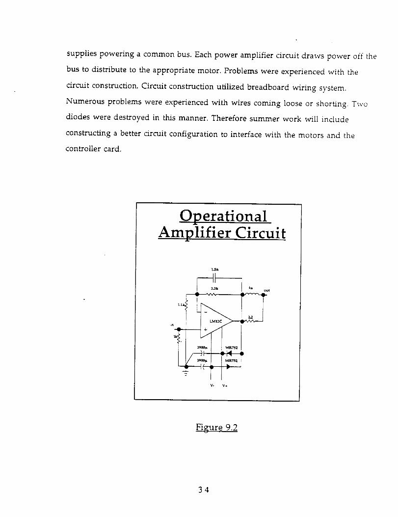
supplies powering a common bus. Each power amplifier circuit draws power off the
bus to distribute to the appropriate motor. Problems were experienced with the
circuit construction. Circuit construction utilized breadboard wiring system.
Numerous problems were experienced with wires coming loose or shorting. Two
diodes were destroyed in this manner. Therefore summer work will include
constructing a better circuit configuration to interface with the motors and the
controller card.
O__12erationalAmplifier Circuit
l,.Sa
4¼ out
! _RTszI\ _W r
V- V.*.
Figure 9.2
34
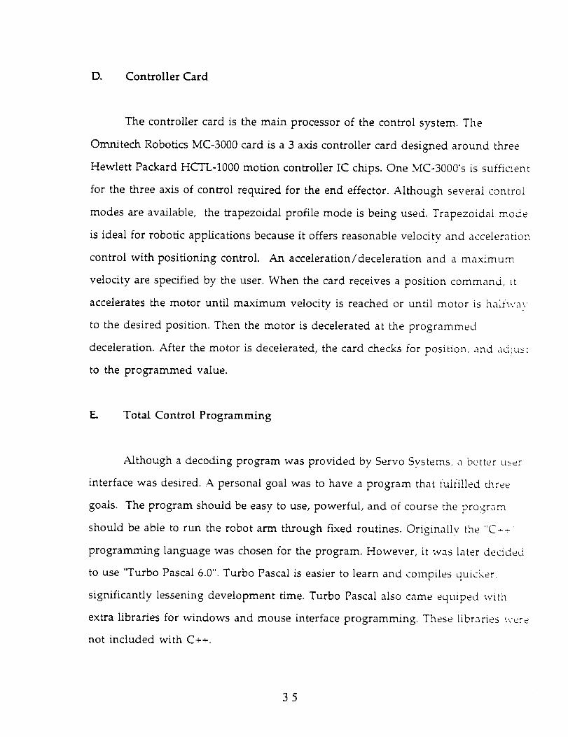
D. Controller Card
The controller card is the main processor of the control system. The
Omnitech Robotics MC-3000 card is a 3 axis controller card designed around three
F'Iewlett Packard HCTL-1000 motion controller IC chips. One MC-3000's is sufficient
for the three axis of control required for the end effector. Although several control
modes are available, the trapezoidal profile mode is being used. Trapezoidal mode
is ideal for robotic applications because it offers reasonable velocity and acceleration
control with positioning control. An acceleration/deceleration and a maximum
velocity are specified by the user. When the card receives a position command, it
accelerates the motor until maximum velocity is reached or until motor is halfway
to the desired position. Then the motor is decelerated at the programmed
deceleration. After the motor is decelerated, the card checks for position, and adju__t
to the programmed value.
E. Total Control Programming
Although a decoding program was provided by Servo Systems, a better use:
interface was desired. A personal goal was to have a program that fulfilled three
goals. The program should be easy to use, powerful, and of course the program
should be able to run the robot arm through fixed routines. Originally the "C--
programming language was chosen for the program. However, it was later decided
to use "Turbo Pascal 6.0". Turbo Pascal is easier to learn and compiles quicker,
significantly lessening development time. Turbo Pascal also came equiped with
extra libraries for windows and mouse interface programming. These libraries were
not included with C++.
35
The libraries for the mouse and for windows were necessary to construct a
menu and mouse driven program. The ease of use associated with a menu driven
program puts the commands in "pull down" menus allowing a new user to learn
commands quicker. The windows display the output in a more ascetically pleasing
manner. This type of graphical user interface did pose some problems to the
programmer. A new programming method was needed. The program is based on
events and objects. Every procedure, variable or other object is controlled
or utilized by events. Every action taken by the program or the user is an event
requiring an event handler to identify actions with reactions. In this manner the
supporting procedures or objects in the program occupy nearly sixteen hundred
lines of code while the actual program only requires six. The menu diagram shown
below gives a general idea of the layout of the command structure.
36
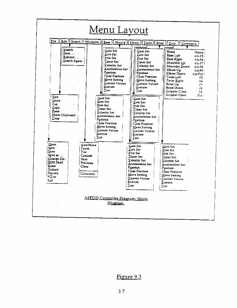
]_dit
_ndo
Cat
CopyEaste
Show ClipboardClear
!_oen
New
_ave
Save a_...
_'hange Dir.DOS Shell
Reset
Default
Decode
Exit
N[enu Layout
_arch
Emd...
Replace...
Search A gam
tGain Set
Zero Set
Pole Set
limer Set
Velocity SetAcceleration Set
Position
Clear Position
Move SettingCurrent Values
_te
Test
! _._.edM ore
Zoom
Tile
Cascade
Next
Previous
Close
Calculator
Gain Set
Zero Set
Pole Set
Timer Set
Velocity SetAcceleration Set
Position
Clear Position
Move SettingCurrent Values
Execute
Test
Set
Zero Set
gole Set
Timer Set
Velocity SetAcceleration Set
Position
Clear Position
Move SettingCurrent Values
_ute
Test
Gain Set
Zero Set
Eole Set
Timer Set
Velocity SetAcceleration Set
Position
Clear Position
Move SettingCurrent Values
Execute
_est
t
Gain Set
Zero Set
Pole Set
Timer Set
Velocity SetAcceleration Set
Position
Clear Position
Move SettingCurrent Values
_gk_ute
j Test
Command
Reset Home
Base L_ft AIt-F5
Base Right AIr-F6
Shoulder _ AIr-F7
Shoulder Down A lt-F8
Elbow U R AIt-F9
Elbow Down AIt-F'10
Twist Left F5
Twist Right F6
Bend Up F7
Bend Down F8
Gripper Close F9
Gripper Open F10
Gain Set
Zero Set
Pole Set
Timer Set
Velocity Set
Acceleration Set
Position
Clear Position
Move SettingCurrent Values
_XOCU I:e
_St
ASPOD Controller Program; M¢nu
Di_agra
Figure 9.3
37
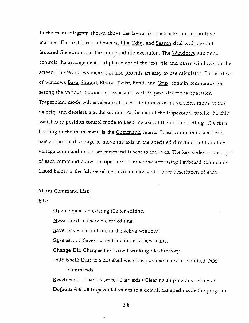
In the menu diagram shown above the layout is constructed in an intuitive
manner. The first three submenus, File, Edit, and Search deal with the full
featured file editor and the command file execution. The Windows submenu
controls the arrangement and placement of the text, file and other windows on the
screen. The Windows menu can also provide an easy to use calculator. The next set
of windows Base, Should, Elbow Twist, Bend, and _ contain commands for
setting the various parameters associated with trapezoidal mode operation.
Trapezoidal mode will accelerate at a set rate to maximum velocity, move at this
velocity and decelerate at the set rate. At the end of the trapezoidal profile the chip
switches to position control mode to keep the axis at the desired setting. The final
heading in the main menu is the Command menu. These commands send each
axis a command voltage to move the axis in the specified direction until another
voltage command or a reset command is sent to that axis. The key codes at the r_;_:
of each command allow the operator to move the arm using keyboard commands.
Listed below is the full set of menu commands and a brief description of each.
Menu Command List:
Fil___ie:
Open: Opens an existing file for editing.
New: Creates a new file for editing.
Save: Saves current file in the active window.
Save as.,. : Saves current file under a new name.
Change Dir: Changes the current working file directory.
DOS Shell: Exits to a dos shell were it is possible to execute limited DOS
commands.
Reset- Sends a hard reset to all six axis ( Clearing all previous settings I
Default" Sets all trapezoidal values to a default assigned inside the program.
38

Edi_.__tt:
._how
Clear:.
Search:
D_code: Executes a routine program, decoding commands and values.
NTest: Used to test a decoding procedure inside the program ( For
debugging ).
Exit: Exits the ASPOD Controller program.
Undo: Cancels the last change made in the file editor.
Cut: Removes a block of selected text from the current window and saves i:
to the clipboard.
Copy: Copies a block of selected text from the current window to the
clipboard.
paste: Pastes a block of text to the current file window at the current cursor
position.
Clipboard: Shows the contents of the clipboard.
Removes a block of text from the current window.
Find...: Searches the current window for a defined string of text.
Replace...: Replaces the defined string of text with another string of text _:_
the current window.
Search Again: Re-executes the last search command.
Windows:
Size/Move: Resizes or moves the current window.
Zoom: Makes the the current window the size of the entire screen.
Tile: Tiles visible windows on the screen.
Cascade: Layers the visible windows on the screen with the current
window on top.
Next: Moves the next window to the current status:
Previous: Moves the previous window to the current position.
39
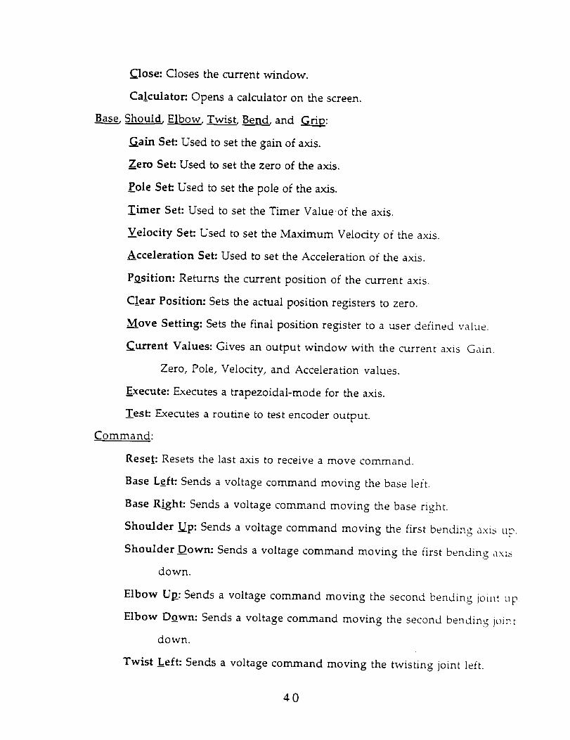
Close: Closes the current window.
Calculator: Opens a calculator on the screen.
Should, ElbLb_p__ow_ _ and r_O.X_:
Gain Set: Used to set the gain of axis.
Zero Set: Used to set the zero of the axis.
Pole Set: Used to set the pole of the axis.
Timer Set: Used to set the Timer Valueof the axis.
Velocity Set: Used to set the Maximum Velocity of the axis.
Acceleration Set: Used to set the Acceleration of the axis.
Position: Returns the current position of the current axis.
Clear Position: Sets the actual position registers to zero.
Move Setting: Sets the final position register to a user defined value.
Current Values: Gives an output window with the current axis' Gain,
Zero, Pole, Velocity, and Acceleration values.
Execute: Executes a trapezoidal-mode for the axis.
Test: Executes a routine to test encoder output.
Command:
Reset: Resets the last axis to receive a move command.
Base Left: Sends a voltage command moving the base left.
Base Right: Sends a voltage command moving the base right.
Shoulder --Up: Sends a voltage command moving the first bending axis up.
Shoulder Down: Sends a voltage command moving the first bending axis
down.
Elbow Up_: Sends a voltage command moving the second bending joint up
Elbow Down: Sends a voltage command moving the second bending joint
down.
Twist Left: Sends a voltage command moving the twisting joint left.
¢0
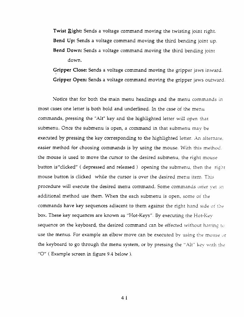
Twist Right: Sends a voltage command moving the twisting joint right.
Bend Up: Sends a voltage command moving the third bending joint up.
Bend Down: Sends a voltage command moving the third bending joint
down.
Gripper Close: Sends a voltage command moving the gripper jaws inward.
Gripper Open: Sends a voltage command moving the gripper jaws outward.
Notice that for both the main menu headings and the menu commands in
most cases one letter is both bold and underlined. In the case Of the menu
commands, pressing the "Alt" key and the highlighted letter will open that
submenu. Once the submenu is open, a command in that submenu may be
executed by pressing the key corresponding to the highlighted letter. An alternate,
easier method for choosing commands is by using the mouse. With this method,
the mouse is used to move the cursor to the desired submenu, the right mouse
button is"clicked" ( depressed and released ) opening the submenu, then the right
mouse button is clicked while the cursor is over the desired menu item. This
procedure will execute the desired menu command. Some commands offer vet ac_
additional method use them. When the each submenu is open, some of the
commands have key sequences adiacent to them against the right hand side of the
box. These key sequences are known as "Hot-Keys". By executing the Hot-Key
sequence on the keyboard, the desired command can be effected without having to
use the menus. For example an elbow move can be executed bv using the mouse _,r
the keyboard to go through the menu system, or by pressing the "Alt" key with the
"O" ( Example screen in figure 9.4 below ).
41
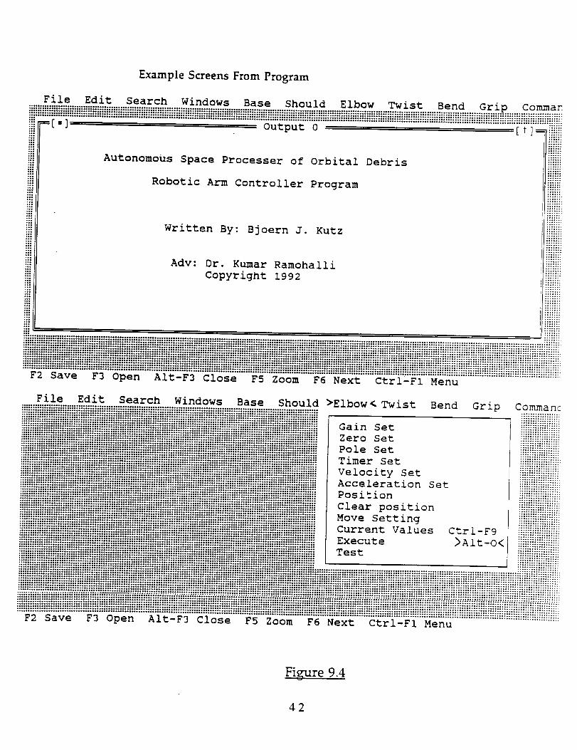
Example Screens From Program
File Edit Search
,]
Windows Base She id
Output 0
Dw Twist
Autonomous Space Processer of Orbital Debris
Robotic Arm Controller Program
Written By: Bjoern J. Kutz
Adv: Dr. Kumar Ramohalli
Copyright 1992
Be d :ip Comma_
ii!!ii!ZZ_!!ii!!i
i iii iiii iiiiiiii ii iiiiiiiiiiiii iii iii iHiiiiHiiii iiiiiiiii ii!iiiiiiiiiiii!iiiiiiiii!iiiiiiiiii iiiiiiiiiiiiiiiiiiiiiiiiiiiii ii iii i ii!i i ii i iiii iiiiJiiiiiiiiiiiiJiiiiiiiiiiiiEJi!iiiii iiiJJiii¸File Edit Search Windows Base Should >Elbow < Twist Bend Grip Commanc
i!i_iiiiii_iiii_iiiii!iiii!iiii_iiiiiiiiiiiiii!_iiii!Hiii_iiiiiiiiii!ii!_iiiii_iiiiiiiii_iiii_iiii_ii_iiiiiii_iii!_ii_i_iiiiii_ _._ I_i_
iiii{{iiiiii_iiii_iiii_ii_ii_ii_ii_ii_ii{_i_ii_iii_ii_iiiii_iii_ii_iiiii_ii_iiiiiiii!_!i_!iii_ii!_i{_ii_i_iiiI Timer Set _ iiiiiiiiii{!{iii{
iiiiii{!iiiiii!iiii_!i{i_ii_iiiiiiiii_i_ii_{_i_!ii_iii{i_iiii_{{i{_{iii_!iii_iii{!iiii_i_ii!_i_!!iiiiiiiii_iiiii_ii[ Acce lerat ion S e t iiiiiiiiiiiii_iii:-
_ii_iii_i_iiiiiii{iii_ii_i!iiii_ii_ii_iii!i_iiii_iiiiiiii_iiiiiiiiii_ii!ii_ii_iiiiiiiii_iii_ii_ii_ii{ii{iiii_iiiiiiiiiiiiiiI c_ear pos_t_on I iiiiiiii{iiiiiiiiiiiii_iiii_iiii!_iii!!iiii_i{ii_iiii_iii_!iiii_iiiii_iii_i!iiiiiiii_ii_iiiii_iii!i_iii_iii$iii_iii_i!!iiiiiiii_iiii_iiiiiI Mo v e Setting i iiiii!_iiiii_iiiil
_i!iiiii!_iiiii_!!iii!!_i_!_i_iiii!iii_{_iiiii_!ii_!iii!iiii_!iiii_iii_ii_i{i_iiiii!i_iiiiiiiii_!ii_!_iiii!_ii_i_iiiiI Current Va I ues Ctr i - F9 !iiiiiiiiiiiiiiii
ii_iiiiiiiiiiiiii!i_iiiiii_ii_i_i!ii_iiii_ii_i_ii_ii_iiii_iiii_ii_i_iiii_ii!i_ii_iiii_ii_iii_iiii_iiiiH!iii_iiiii_e_ iiiiiii!iiiiii_
'"_'_'"'_'a'v'e......F_'"5"_'e'n......i'['£'"'_'_'"'6T_'s'e......"_'_'"'_'gGm......"_'_'"'_'e'x_......"6"£'r'G'_'{'"_'&'_'u'"':.....::::::::::::::::::::::::::::::::::::
Figure 9.4
42
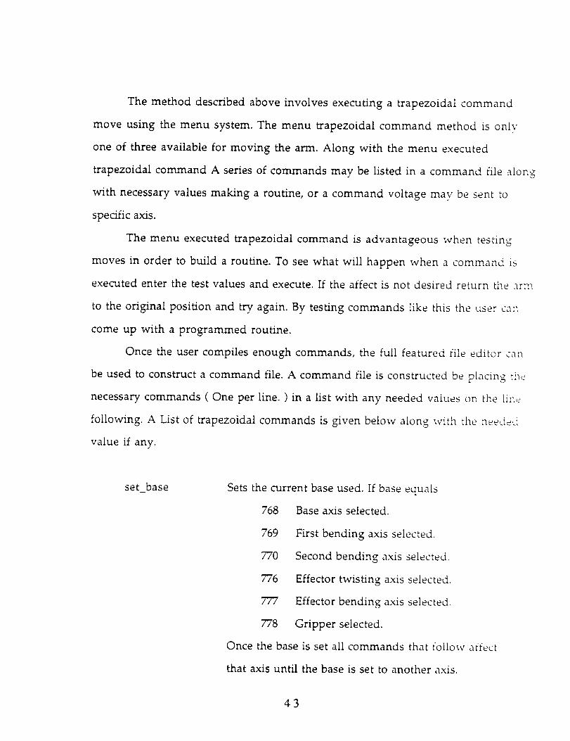
The method described above involves executing a trapezoidal command
move using the menu system. The menu trapezoidal command method is only
one of three available for moving the arm. Along with the menu executed
trapezoidal command A series of commands may be listed in a command file along
with necessary values making a routine, or a command voltage may be sent to
specific axis.
The menu executed trapezoidal command is advantageous when testing
moves in order to build a routine. To see what will happen when a command is
executed enter the test values and execute. If the affect is not desired return the arm
to the original position and try again. By testing commands like this the user can
come up with a programmed routine.
Once the user compiles enough commands, the full featured file editor ca:_
be used to construct a command file. A command file is constructed be placing the
necessary commands ( One per line. ) in a list with any needed values on the line
following. A List of trapezoidal commands is given below along with the needed
value if any.
set_base Sets the current base used. If base equals
768 Base axis selected.
769 First bending axis selected.
770 Second bending axis selected.
776 Effector twisting axis selected.
777 Effector bending axis selected,
778 Gripper selected.
Once the base is set all commands that follow affect
that axis until the base is set to another axis.
43
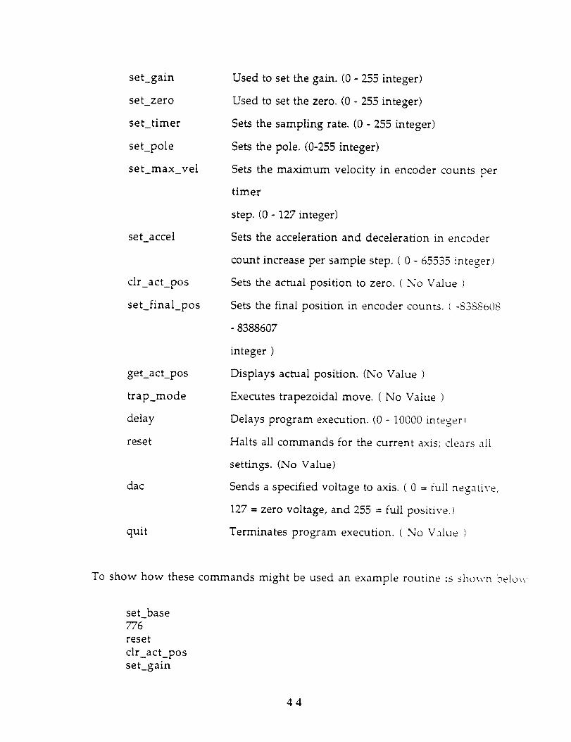
set_gain
set_zero
set_timer
set_pole
set max_vel
set_accel
clr_act_pos
set_final_pos
get_act_pos
trapmode
delay
reset
dac
quit
Used to set the gain. (0 - 255 integer)
Used to set the zero. (0 - 255 integer)
Sets the sampling rate. (0 - 255 integer)
Sets the pole. (0-255 integer)
Sets the maximum velocity in encoder counts per
timer
step. (0 - 127 integer)
Sets the acceleration and deceleration in encoder
count increase per sample step. ( 0 - 65535 integer)
Sets the actual position to zero. ( No Value )
Sets the final position in encoder counts. ( -8355_08
- 8388607
integer )
Displays actual position. (No Value )
Executes trapezoidal move. ( No Value )
Delays program execution. (0 - 10000 integer l
Halts all commands for the current axis; clears all
settings. (No Value)
Sends a specified voltage to axis. ( 0 = full negative,
127 = zero voltage, and 255 = full positive.)
Terminates program execution. ( No Value t
To show how these commands might be used an example routine is shown below
set_base7"76
reset
clr_act_pos
set_gain
44
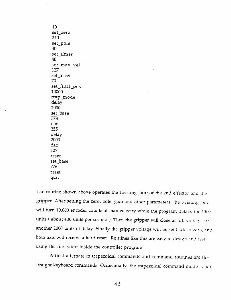
10set_zero
240
set_pole
40
set_timer
4O
set_max_vel
127
set_accel70
set_final_pos10000
trap_mode
delay2000
set_base778
dac
255
delay2000
dac
127
reset
set_base776
reset
quit
The routine shown above operates the twisting joint of the end effector and the
gripper. After setting the zero, pole, gain and other parameters, the twisting joint
will turn 10,000 encoder counts at max velocity while the program delavs for 200@
units ( about 400 units per second ). Then the gripper will close at full voltage for
another 2000 units of delay. Finally the gripper voltage will be set back to zero, an,_
both axis will receive a hard reset. Routines like this are easy to design and test
using the file editor inside the controller program.
A final alternate to trapezoidal commands and command routines are the
straight keyboard commands. Occasionally, the trapezoidal command mode is not
45

the most convenient method for moving the arm. For this reason a set of "Hot-
Keys" have been assigned to positive, negative and zero voltage out commands for
each axis. A list of these commands is located under the Commands menu. To
move an axis the user hits the "escape" key until the "All axis have been reset."
message is displayed. Then the Hot-Key sequence corresponding to the desired
motion is hit. The joint should move. Once the axis has moved to the desired
point, the user hits the home key to stop the motion. The home key will onlv stop
the last axis to be activated by a voltage out command.
Although the current program is easy to use and powerful, several
improvements are still possible. To make programming even easier the trapezoidal
menu commands and the Hot-Key output commands could be tied to a file writing
utility. In this scheme, commands could be tested using the menu or the Hot-Key
commands. Then if desired the commands could be written to an routine file. Thi_
type of routine will make programming easier and faster.
46
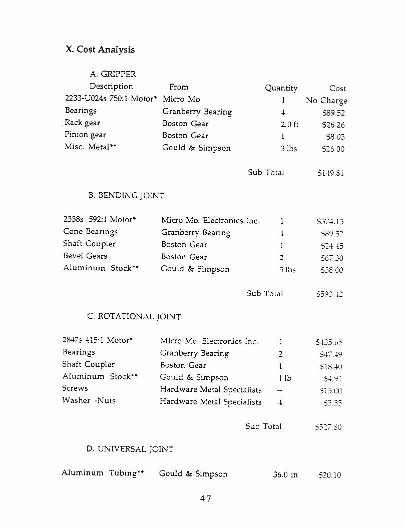
X. Cost Analysis
A. GRIPPER
Description
2233-U024s 750:1 Motor*
Bearings
. Rack gear
Pinion gear
Misc. Metal**
From
Micro Mo
Granberry Bearing
Boston Gear
Boston Gear
Gould & Simpson
Quantity
I
4
2.0 ft
1
3 lbs
Cost
No Charge
$89.52
$26.26
$8.03
$26.00
Sub Total $149.81
B. BENDING JOINT
2338s 592:1 Motor*
Cone Bearings
Shaft Coupler
Bevel Gears
Aluminum Stock**
Micro Mo. Electronics Inc.
Granberry Bearing
Boston Gear
Boston Gear
Gould & Simpson
1
4
1
5 lbs
$374. I5
$89.52
$24.45
$67.30
S38.00
Sub Total _a9._ .4_.
C. ROTATIONAL JOINT
2842s 415:1 Motor*
Bearings
Shaft Coupler
Aluminum Stock**
Screws
Washer -Nuts
Micro Mo. Electronics Inc.
Granberry Bearing
Boston Gear
Gould & Simpson
Hardware Metal Specialists
Hardware Metal Specialists
1
m
1
1 lb
4
$435.05
S47.49
$18.40
$4.91
$15.00
$5.35
Sub Total
D. UNIVERSAL JOINT
Aluminum Tubing** Gould & Simpson 36.0 in $20.10
47
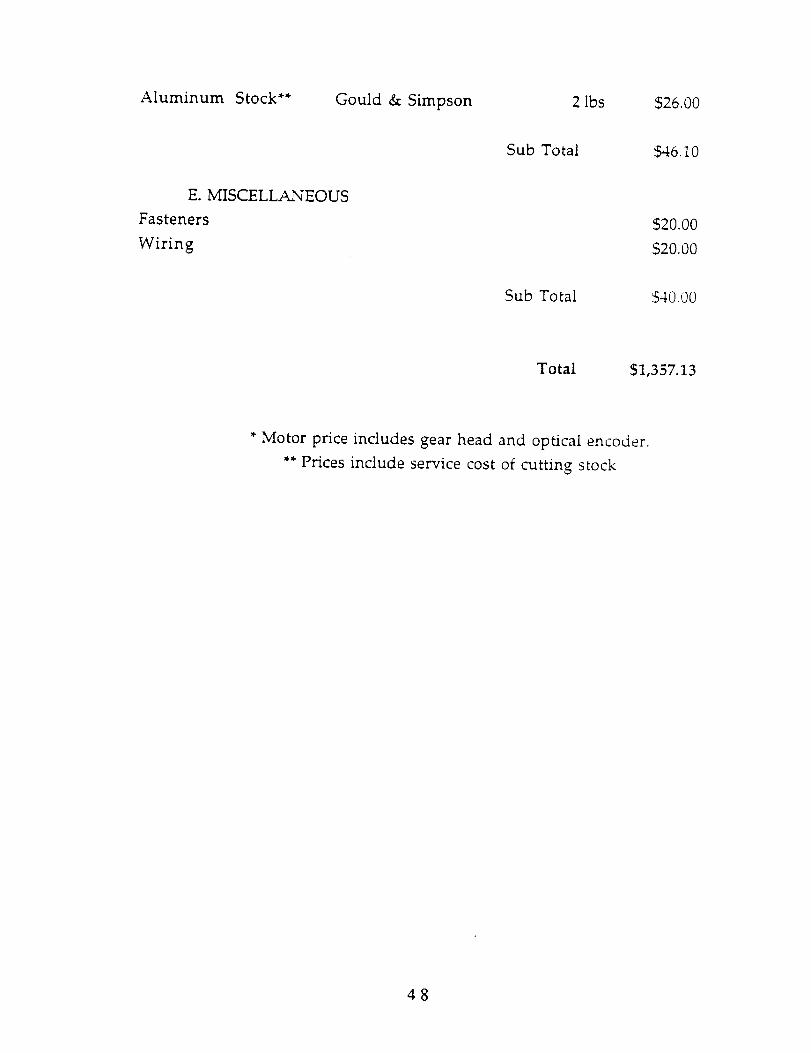
Aluminum Stock** Gould & Simpson 2 lbs $26.00
Sub Total $46.10
E. MISCELLANEOUS
Fasteners
Wiring$20.00
$20.00
Sub Total 540.00
Total $1,357.13
* Motor price includes gear head and optical encoder.
** Prices include service cost of cutting stock
48
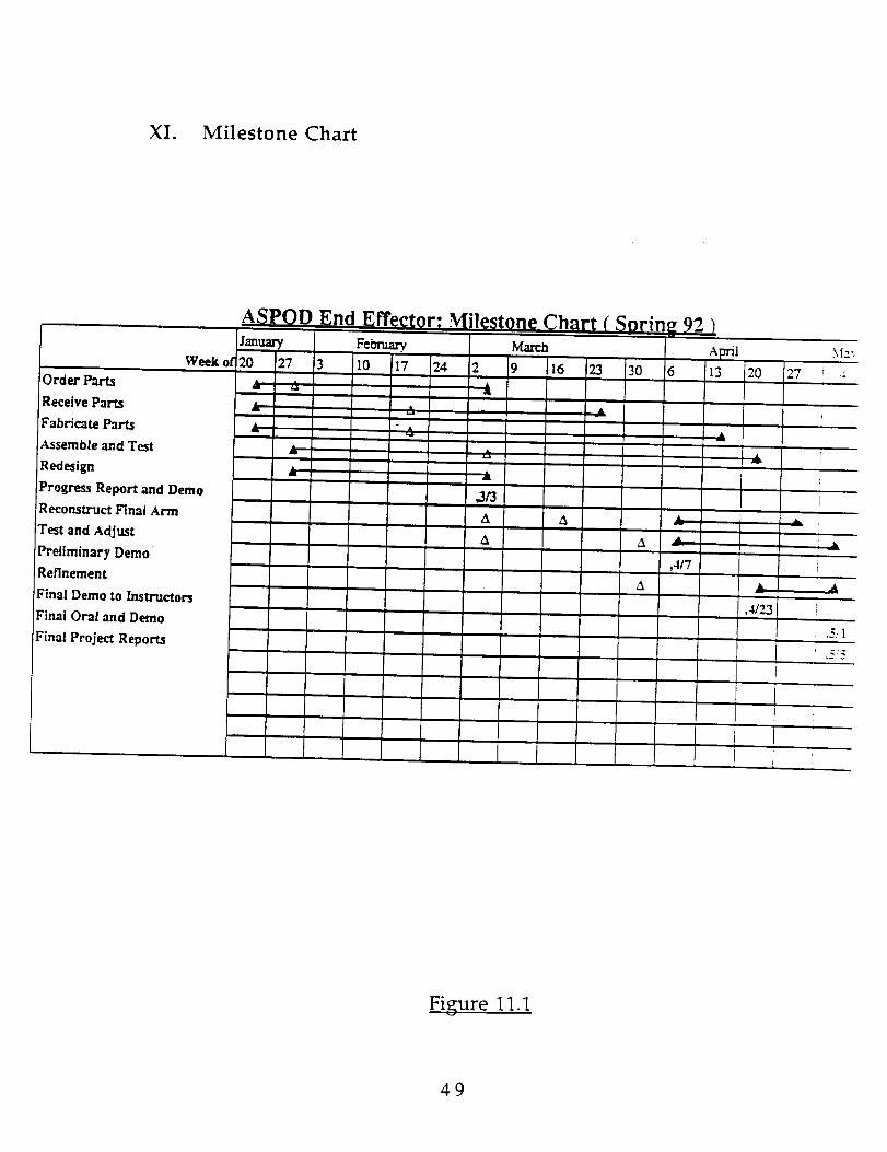
XI. Milestone Chart
Week of
Order Parts
Receive Parts
Fabricate Parts
Assemble and Test
Redesign
Progress Report and Demo
Reconstruct Hnai Arm
Test and Adjust
Preliminary Demo
Refinement
Final Demo to Instructors
Final Oral and Demo
Final Project Reports
A_
2o___27 3_.___0___7 ____ _ .9___
_" --A------.-
&
,3/3A
A
23 3O
A A
,4/7
13 20
4/23
r27
J
I
± 1
i l
f
J
m
.5/1
Figure 11.1
49

XII. CONCLUSION
The final design of the ASPOD End-effector has come a long way since the
project began. Drawings along with a detailed analysis of each part were first
completed. The process of drawing the individual parts uncovered design flaws
that were not otherwise easily detected. This early modification of the design has
resulted in very few changes to the design during machining.
The design process was originally divided up into technical subproblems
such as materials, motors and controls. But as the design progressed, it became
apparent that the tasks should be divided by end-effector section. The design
sections were the gripper, rotational joint, bending joint, and the universal
connection.
This change in task assignment made the design process smother and more
efficient.
It is difficult at best to relate the amount of time and effort required to
produce a quality product like the end-effector. Half of the entire project time was
spent designing, modifying, and redesigning the end-effector subsvstems. Then
countless hours were spent in the machine shop and at the computer terminal
producing the hardware and the software needed to make the end-effector a reaiitv
The excessive amount of time and effort that went into this project is evident in
the quality of the final product.
5O

APPENDIX A
MATERIALS
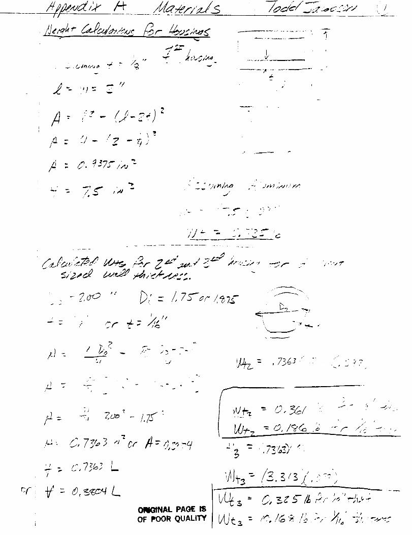
/b/a,/er/.j_s /
c£
#e_._ d&Pad_,.:,.._/_,-,14,.,.,,_c
, IP , i
fi " C. q37_/,_,
d-
, I!
d
: . - ?.o_ "" 7),(- /, 7_,,_- t+._
; I II
- " 4-/,.£" _r .-
7'- i -!
• _"->
# -_ --_, 7o: -- 17_.
J
,+
ORI_NAL PAI3tE ISOF POOR QUALITY
,.-.:., ?"
./
i/
i/ '+
, / , /
z> _ Z"5- ,--',,-.,,, ,',-.
- ,'_.Id_'_'..._--,- r:....'--."
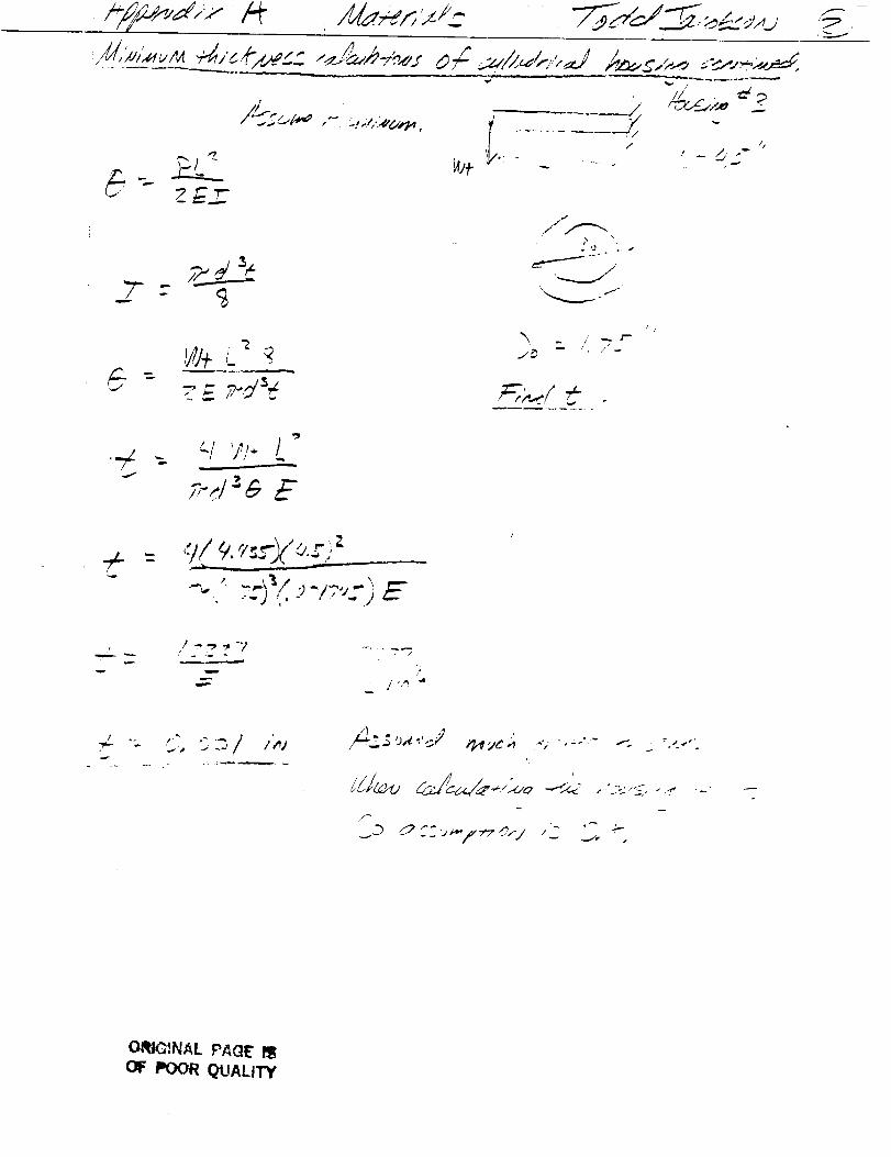
L , __ _
, ,, //' ,
/1
/ t # .
r_d_-
z__._
,"/
-f v,.,. t "
_ t "-' _ -_ "7 -, .
, t ,,,,,.,.,_.. "_. ,f'_ ._ ._ j
_~ -- ;- +.
j •( +.l..O_ ---+"/_.<' .... .._ -.
OffI,OINAL P,4(IE' I1!I
OF POOR QtJALIT7
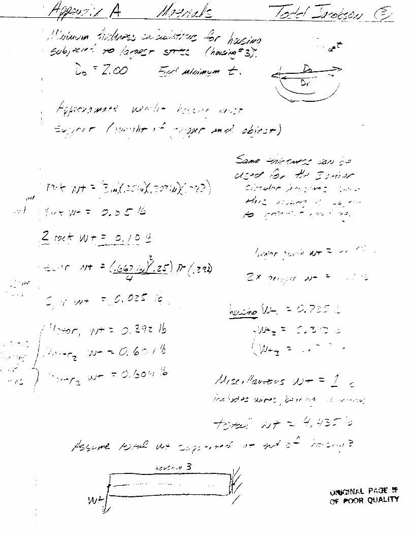
I • i" : ., ,
,L?/_ " ,': :;"C_.9A,4## d b6P'" ,'i+" :,'t:,_"...." ,'U..."?
_ </'.'...'r'/
k i _..
• '/vl
., )#
,"):'e" W"_ - .,o _ ..- ':_
C/',-':_,/,,r ,",.,.,:.,.v_- :,,,,..
,v
?_
.-.. , ," ¢.1)
:.,/
/
" 'i)
' I'D/ :?_r, .'M÷" ,'__'?Z
7, ,',.,..... w--- O,f=:':/'/-/ "'_
t
_O.A.,7._,J.,--, <.i.<
, I
'y'.l: ,
: .._,._.I:_c ',_l._ _ '_1_ 2 G"_' r/
"'. " '.,_ " " , ". 0 "
, ..: /:j_- ., .,.,.
1, !
;1 ,,". T_,.,j:i _" i',?' " , <. ,' .
I001,! QUALITY

APPENDIX B
CONNECTION TO ARM
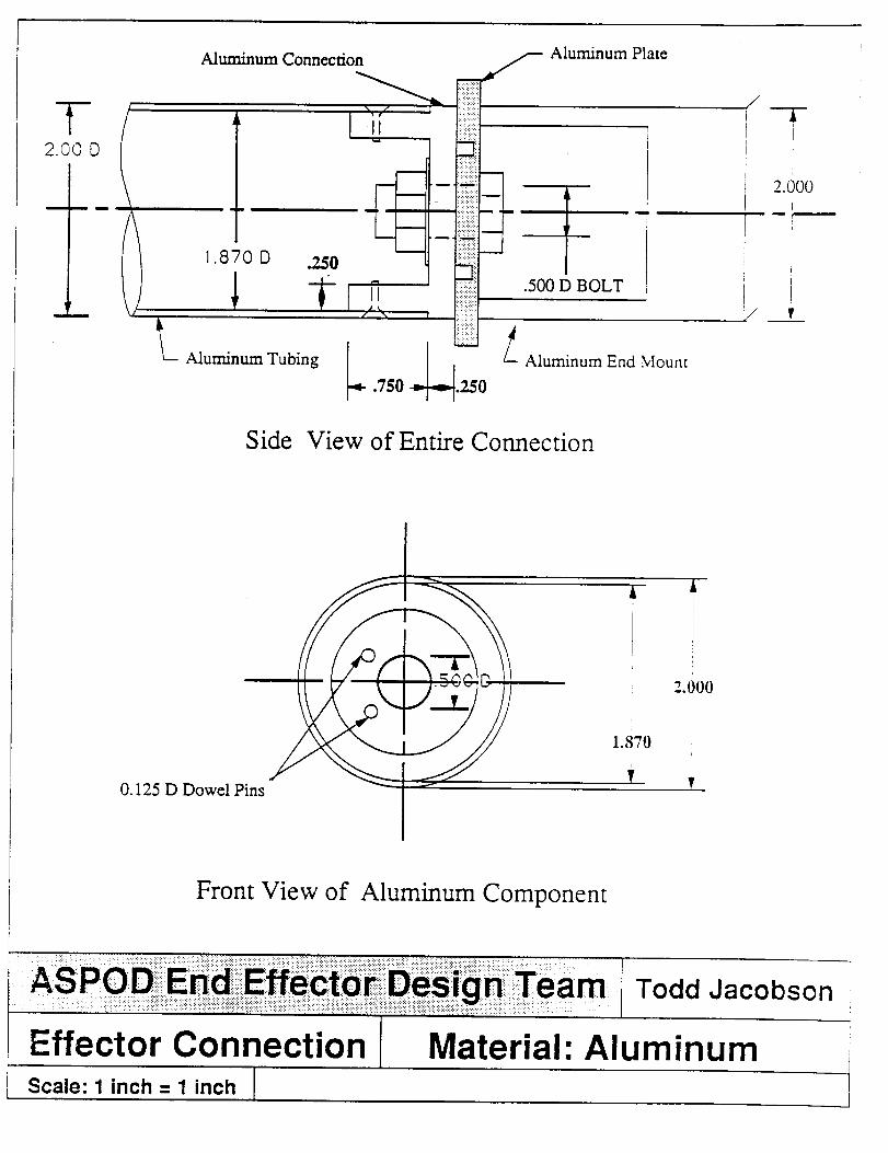
T(2.00 O
Aluminum Connection
L Aluminum Tubing
S Aluminum Plate
/m
Aluminum End Mount
!!
J2.000
Side View of Entire Connection
0.125 D Dowel Pins
A
I
i
2.000
1.870i
T ,
Front View of Aluminum Component
Effector ConnectionScale: 1 inch = 1 inch I
i Todd Jacobsen
Material: Aluminum

APPENDIX C
ROTATIONAL JOINT
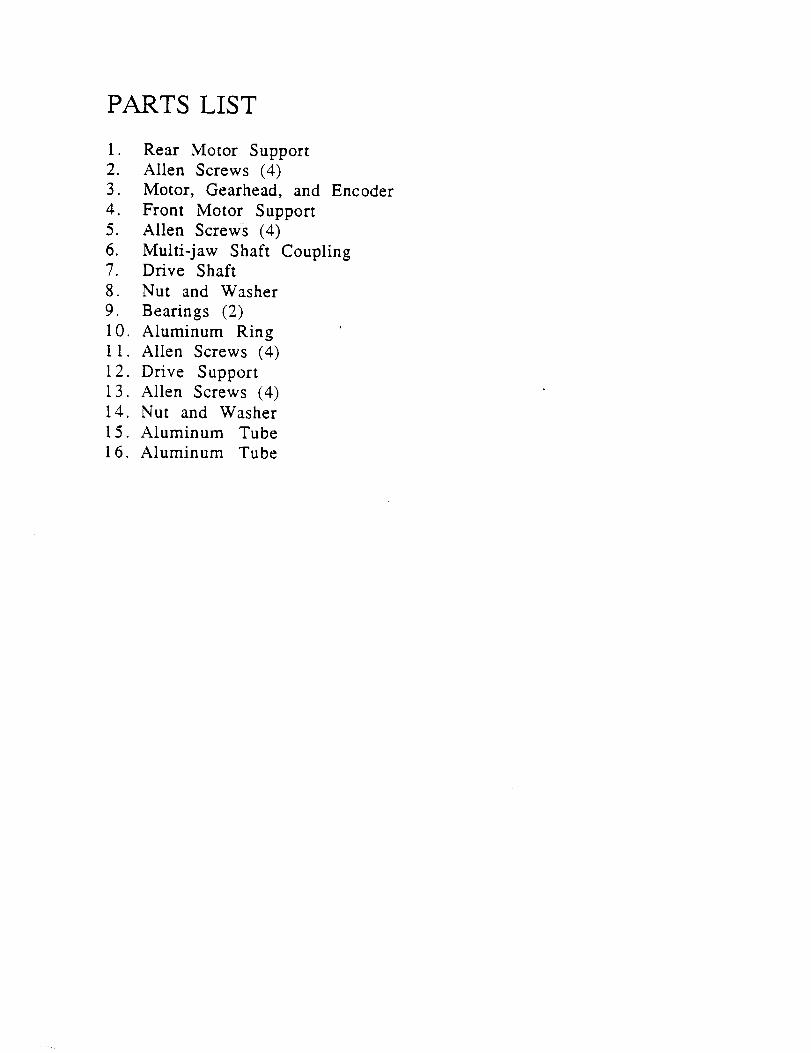
PARTS LIST
1. Rear Motor Support
2. Alien Screws (4)
3. Motor, Gearhead, and Encoder
4. Front Motor Support
5. Allen Screws (4)
6. Multi-jaw Shaft Coupling7. Drive Shaft
8. Nut and Washer
9. Bearings (2)
10. Aluminum Ring
1 1. Allen Screws (4)
12. Drive Support
13. Alien Screws (4)
14. Nut and Washer
15. Aluminum Tube
16. Aluminum Tube
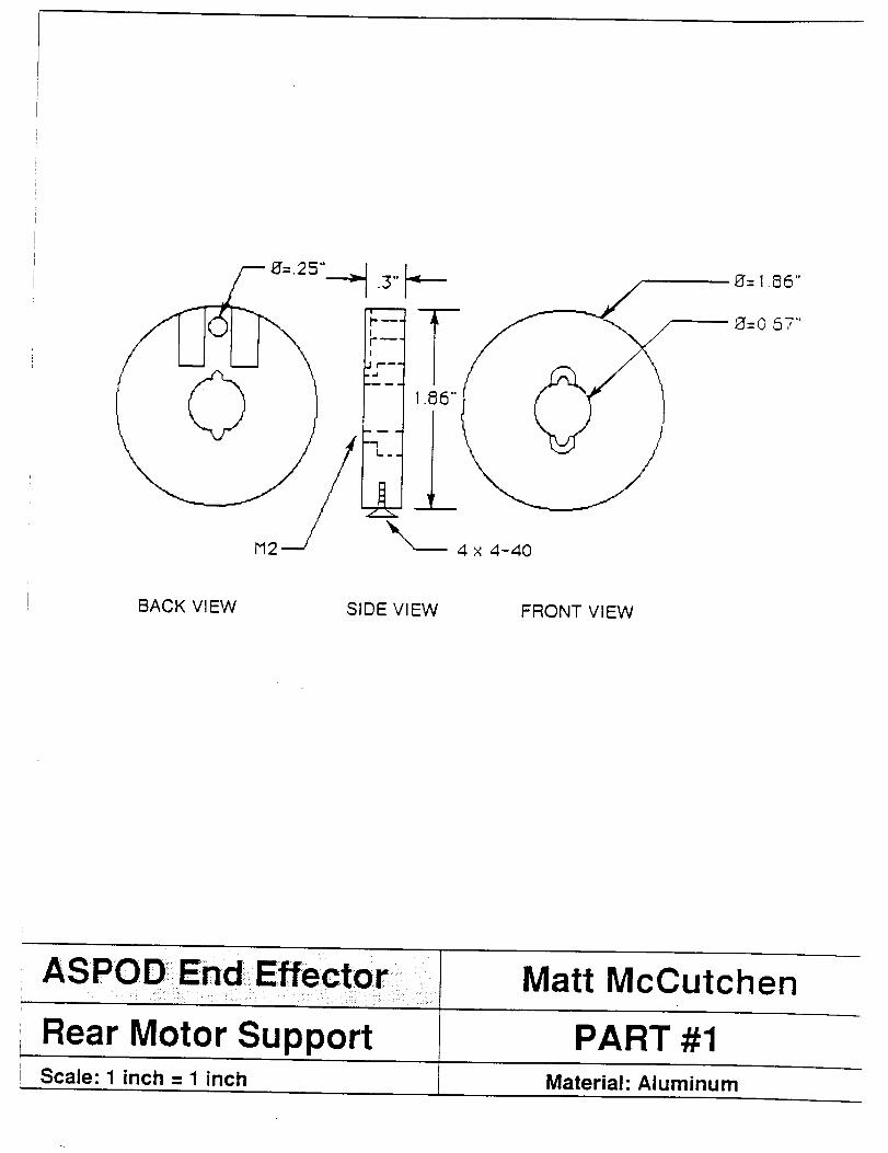
BACK VIEW SIDE VIEW FRONT VIEW
ASPOD _End Effector
Rear Motor Support
Matt McCutchen
PART #1I
Scale" 1 inch = 1 inch Material: Aluminum
SPECIFICATIONS
PART #2
Allen Screws
Head: Countersink
Size: 4 - 4 0
Quantity" 4
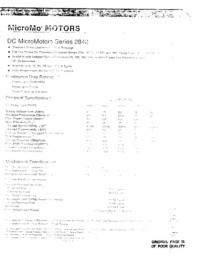
;icroMo" ! OTORS
DC MicroMotors Series 2842m ql,"lr'ld,lr,I P/_'!r)r (;or'_lni,l": [- , r, +!i R_,,qrlnq.m
m Fil_; C),fr .c;,'+'rp,,,v-(-)npT,.q.I+I,,I,..I_,,t'._:Ith¢-,..lr t Sr',rie_ 2q/t+ ,_."r .; ] t Pr'; 3r,,t +.P_+ f' l,,f;fl _';_-. t" ' '_
w Avnil."+t,ln wilh Inlporal c').I_;_ r__ r-t_r'r:+lnr_ (15, 10t'). 1R(1 c_'_ ,_, lr_,,_ r'rllqr,,- ['_,i Mn,/,,l_,,;,,,,, r.,,+
[)_ lh r: hr>m r.h'+ r._
• ' ,¢,.'mlnhl_. ir_ 6 12, 24 ,";q ml,_ ,': ',./,!f F_pe,q
_1 I liqh [_'rlpP"lfllr_' V_.'+f't4,H , ' T .... t'} _'"_nrl:]rd
,"',,r_linuou,q [)_Jty R;ttit_r;.<: ""r '''+''t' ,_{' ',, r, nnO RPM
r'r},..,nr _,.°r',lf till 'm _q ¢/n'l'"
Fr,,,':trical Si_nc, iricntir+r_+-
r-,,, _t.l_,l_._r [,,r'_', ?':_,I71
S_pr'ly Vnlta(_,-. n<rn (Volls)
+ ,'_r,nnh_r_ Pr+_;_"4.1nnce (Ohm) _ 1;" ':
P13,, rnwnr r hdp, d {W.'tff_)'"
LI;;', t=ffic:i_r'r'v I"_,)' "
"_ I oad S()n,-,4 _RPM) r 12'''_
, !n I r%"4tl C',frr_tq _mA) _5Onh
+",q:.,r'l '[}',tq,l_ .' .. tlQ Loa_'l "._., ..... _'-,z ,_,t
q!'!1 l;')rq_l,_ (,,:, ,I,Y '
'"'_ ','if',' Cr._-I'+rq :F_PM/V_qtlp :_1. FP.fF C"_'"_t:llll (rftV, IRp ' :'1
''llt# (+"rl':!,ql+f I'_" fII/l'_lfl['l
f,
ft,,'_
!
r ,_
fi' I
I
l+_,q,
.1 R_}()
t-(" I
-r;
• _ t 7
,,_ F _ "'" r')
2.1
£" _,+
.-+
1 .P..t 1( )
t o
r,,
°,
1
I.
_r
ff; ,'ll i,:,,',':
+', Air I r,,,,:
I 7 /"11 [ I ....
''r',', llr'_t'_ r_ r,, I+.llr,_t} ,,.. Ro' ,_r'_.l! ,. 4 r t,,, _+,,,r_t_ ,g_ "-',,*,rl f, _ z', ,It r-,+,p if [1+_,+ 1 ,,', I ,,+ c- • ,, , : ,. • ,
:1 'n I _f,_ ' ,, , ; r'_, + 11+,_ |hit,, I i+t ' , - I I P_r,, , tl H"+,J" rll+' ( _,'_'1 , ' .... ",' I',.. '',_t'" b ' _''+''''_'_ ' + r ,'
_ _C '+'_ll'e`'_ ,"I + P t_I+I_.31 qltlH_Iy "+_ll,_,',. ' ,.+ +ii fl_ _ _ , l.lrtf ¢,. _ if,_, I , }
r,++ _f , ,
4 ,
ORIGINAL PAGE ISOF POOR QUALITY
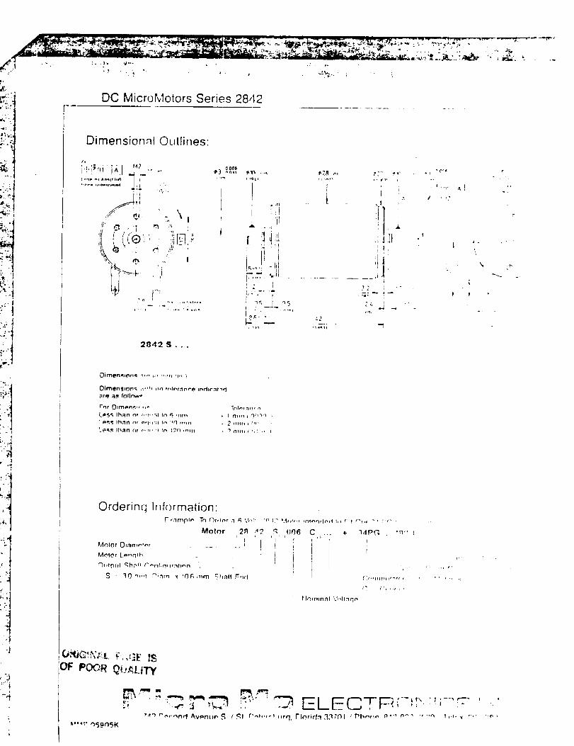
DC MicroMotors Series 2842
Dimensionnl Outlines:
'" IA2i i_riikl'(. I ,, o,
!
2842 $...
0 00't'
ir'i --
; !!i iU!
I , i
.,'__, .L 22
_n _.i_ r_'3
# _,' ",, t,.2
?,
! i •
!-2c __ _...
I
I
I
,r
Oirll@rl41tln_l ;_,_ H, r','_l Ilu }
Oim@n_lor_l .v"!, _n l_It, l'.-Int'p _ndlr.'It,_d
arq ;l.q IoIh"_
Lms_ lhRn o,r ,,,!"hi _ _ rlllll i I ]"TIIII I _ ll_r_
I _,!I Ih;'ln n_ _¢1_1:11 _'_ 3dl i1t111 & 2 illlll J tit, ,
Le_._ lh;_n or _,.-, ,i _n l.'2f) H"IITI _ "l (1%lli ( I'r:.,
Orderinq I_,formation:
Motor 2_t "_ q 006
= I ' '''' = :
MnlOr O_art,n_nr ..... I I .;
Mr_IO r L _,,q_h : iI
t')lll_31ll qh, _II t"'_l'_l_q, lr:'%llnn
S - '30 r,,,n ,m_nrn _ lOG mm _hnll r:_d
C, ... + "I,IPG
I r
rInm_nrllVHIInqn
(', I", I'f,'
l ¸¸
'' '" ,r
_",,.._E ISOF POOR _tJ,_LI'Fy
_,_,':,')59¢)5 K
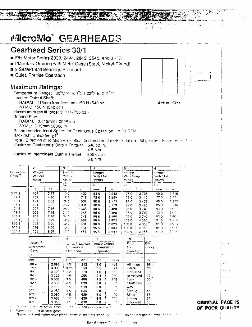
t,3icro,"V](£ E EARHEADGGearhead Series 30/1• Fits Motor Series 2338, 24,14. 2842, 3540, and 35"7
• Planetary Gearing with Metal Case (Steel, Nickel Plnlnd).
m 2 Sealed Ball Bearings Stnndard.
m Quiet, Precise Operation
Maximurn Ratings:Terrlpernh_re flange: -30_C in 100_C (-22°F Io 212_F!Load on Outp, ff Shaft:
RADIAL: (15mmfromb,_ming) 150 N (540 oz.)AXIAl.: 150 N (540 oz.)
Maximum nress fit force: 20n _J (%'0 oz.)Rearing Pt_y:
rlADI/_L: 0.015ram (.00n_q in )AXIAL; 0 15mm(.0060;n)
rlqcommendpd Inpul Spored for Continuous C,peralion; _r'n0 RPMBacklash Unloaded _1 °
_lote: Directinn of rolation in identical to direction of molr, r rotation
M3_imtvm Continuous Outp"t rnrqtjP.; 640 ozin.4.5 Nm
Maximv=m lnt_rmilfent Oulp, d Torque: 850 oz in.6.0 Nm
R_,,_ct_on W,,ght t I ,,rlrlrh Length n p n,gth
R-'ltI_' II _i_Vl{hotJl '.*,';thqtlt With Mntnr I Wllh ,_._ntor
Motor M,_e,_r 2338S 2444S
1.2 -'1"
lO;' I 3.;'7 4o_139 I 4 gO 716
1;'1 03 I ?3 2 1 031
!T_ , 103 J 2_r_ 2 I 03120.q .'.16 I 34 2 1.346
_03 7 16 I 34 _ 1 346
203 n 7 16 I q4 2 I 346
235 1.29 I ,12.;.' 1 661
2_ ,29 I 4,"2 , _.61_L_ . 129. I _ 12 2 1 661
3.71:1
_4I
,13 1
n6 1
I"9,I
246 1
415 1592:1
a_9.1
,_2A I
7
V_/Hh _Aotor
LI
nlrn !tl
64 6 2.5.13
72 6 2 85q
806 3 _ ."'_
806 3 17'3
88 6 348R
8g 6 3 488
a8 6 3 4n8
96 6 3 9'03
96 6 3803
96 6 3 n0:]
96 6 3 gOq
I.I
rn_q In
68 4 J 2.693
76 4 J 3 OO8
_4 .t 3 323
84 4 I 3 323
92 ': J 3 63892 4 3 638
i
1_ i I 3 953
Ilr._ 4, 3.953I('9 4 3 953
;'1
_-
_r?l Iltln
r!tll OZ _n
21250170255496638
6386_638
' _ ;" .., _ ¢.¢,c.lin
[._ qu___.HPut __Int_rrtllftnt_t
...__e r atlon
3 0 J 42505 I 71
2.4 I 3,t9_
4.5 I 638
I_ 0 I [: 50
R (1 I _rr_
6 0 I P"_
6.0. I r',)
60 I n"'1
¢, 0 I _'_ '_
LI
710 I 2.795790 I 3 11087 0 I 3 42587 0 I 3.425
95 0 I 3740
95 0 I 3 140
" 95 0 I 3 7,t0
103 0 I 4 055
103.0 J 4055 "_
103 0 I 4 055
in'30 I 4055
tO ]11
IR_rn
IIOH
[]urerhon
• [_ 'i,J ' ..," ,,,_,h k.*et_r .'1:r__ tr c'_h.m, 7
{: , :(afin ? , I I ,s ;111 _tnol gn.'lr':
_nti_e 14 1 m,d h,,']hpt h.tv= p'_ .... '_,,."11" in thn {np, lt ,_tnrl,", (A
All ratvos
rot#to
as ',,mewed
from
•_,hnfl' End
w_th
D,,v,,,g_._Motor
ttrrninq
c!_ckwnso
ACHml S I;,r_
All gearl},-,n('l,_ are rn, nr'-,; ',,
t! ,_ j- .....
Elf,
clnncyi
8
I ,,,_qth
W,,h ]_,lnln r
2#42S
L_
f11fl_ [rl
6g.0 2.7_6
#5 ( 3 3.m
85 ( _ _tc_
93.( 3 '. 1
93 ( ,3 ".:_
n_t( q n;I
I01.( _1,_-.q
I0_16 3 ,:..;101 ( 3 a "_
Inl ( 3 q, ,-
I88.8070
70
60
60
55555'_55
' _' ' ' 'dh rill_tn('I gOm't -_n."':" ' %':
r
ORt_NAL PAGE ISOF POOR QUALITY
-- Spnmlic_ho,,_ ": : i" ' T" r'!;nn(;_ ..
. ,. ,2 1
•' • i
°-j
_'_- :1
q:" ,u
2_;• j
r
J
-. q
:
y. ,
1
Gearhead Series 30/1
Dimensionnl Outlines:
J I d ' ,_,.
;A ,,, ;
2_
t
Front View 30/1 with Molor 2338, 2,1,! t or 2_42 3nll ,.,tllv :'._,,:or 1-'-",! +t
LffS_I [hAlt _ ,'o,'I_1 r_ I ?I'_mm
?.,,,. ( nn ;,c_ )
, _,'_m ( 011R"I
00 POOR _l_,, _'_,
,-'-'
_12c_, _.... a^,,,,_,_¢_q /SI PPc'_htro r',,;._:37_I/Phone QI'_,_:_'_'_q/ ,;t .... -_'n? "........
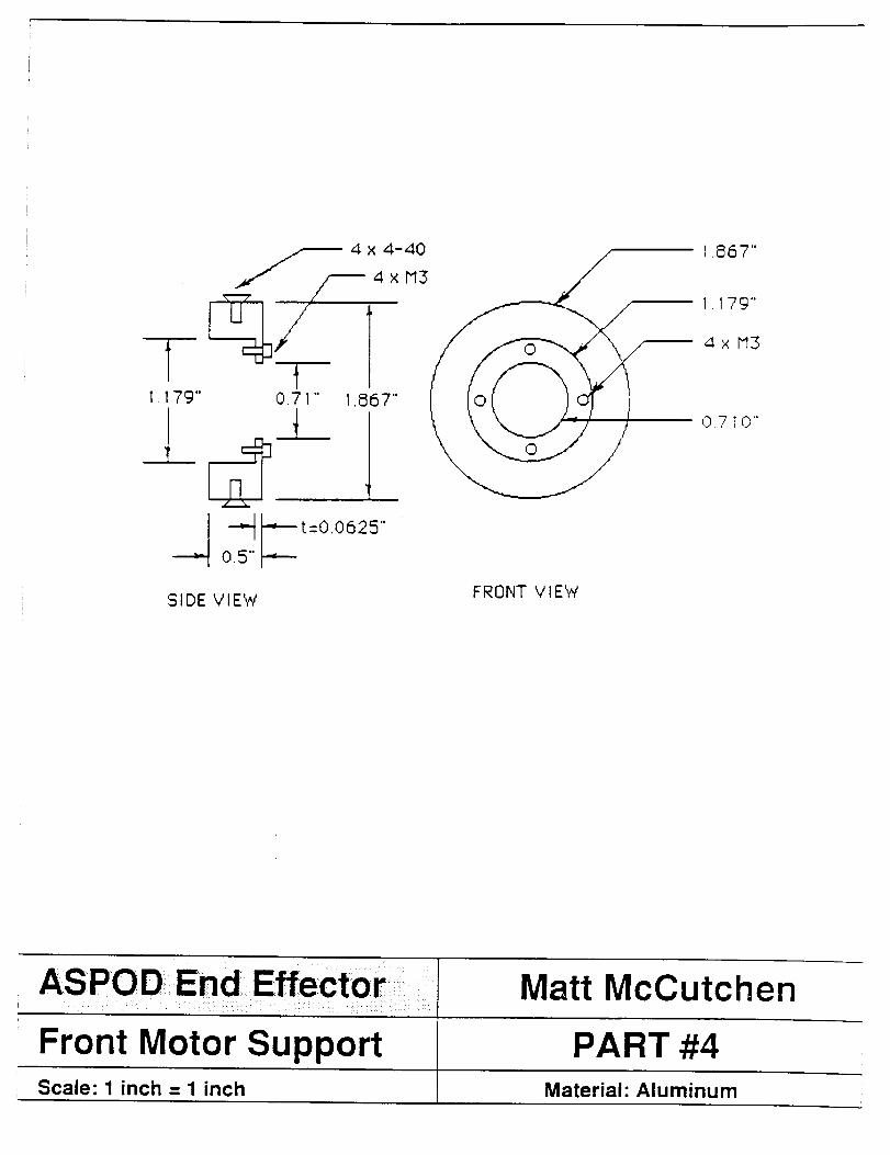
I . 79"
q/0.71" 1.867"
I.867"
L_ 0 710'"
SIDE VIEW
I
FRONT VIEW
ASPODEnd::Effector: I Matt McCutchen
Front Motor Support PART #4Scale: 1 inch = 1 inch Material" Aluminum
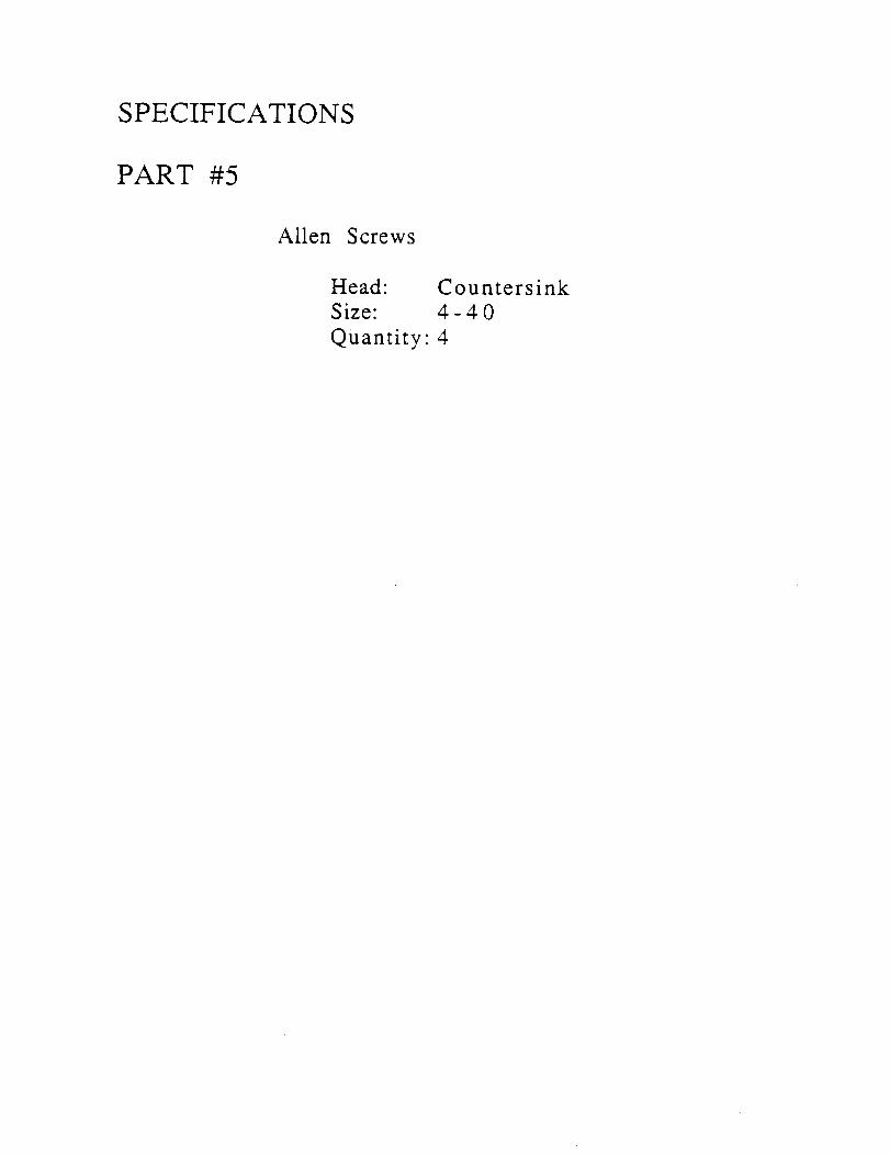
SPECIFICATIONS
PART #5
Allen Screws
Head"
Size:
Quantity:
Countersink
4-40
4
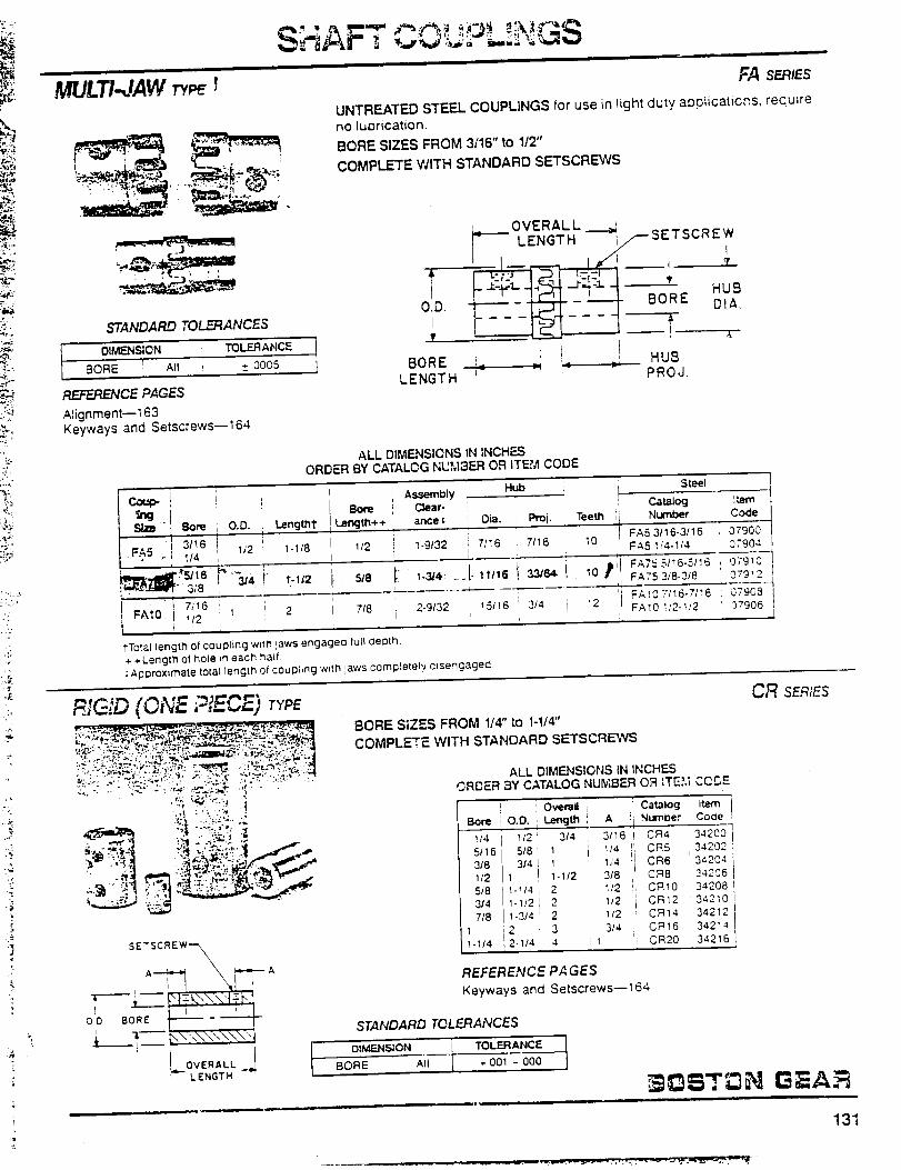
MULTI JAW ',
STANDARD TOL_ANCES
I OlMF_NSION TOLERANCE IBORE i All ', _ 0005
REFERENCE PAGES
Alignment--163Keyways and Setscrews--164
FA SERIES
UNTREATED STEEL COUPL]NGS for use in light duty applicaticp, s, requLre
no luDrication.
BORE SIZES FROM 3/16" to 1/2"
COMPLETE WITH STANDARD SETSCREWS
O.D.
T
BORE
LENGTH
OVERALL __,_LENGTH I SETSCREWy__
__-
i i I HUB
L I PROJ.
ALL DIMENSIONS IN INCHESORDER BY CATALOG NUMBER OR ITEM CODE
,i S teei
_g ! i Length1"
Size Bore I O.D. ;3/16
F.&5- I/4 I 112 i 1.1/8
__ 3;8 314 T-112
' I! FA;.O ;1e11 i 2i +!_2 I i
HubI 'b Assembly !
! Bore _ C$ear- I ! !i
i i._ncjffi++ ! ance= Dia. Pml. !Teeth
I I 1-9/32 , 7/16 i 10 ,,i ,iI
.... --4
7/8 i 2-9/32 1 15t16' 3/4 !
i"TO_.al length ot coupling wTtn )aws engaged full deoth.
+ -,-Lengm of hote _n each half
;Approximate to_al length of couphng wttn jaws comptetely d_sengaged.
rR G:D (ONE ? ECE') TYPE
-... - -_..._ : .,,_-_-:.,,._,,*. ,_ ....
'_"_ :.s -,I ..._-_, ,:_,i_f_._fj_ -"
BORE SIZES FROM 114" to I-1/4"
COMPLETE WITH STANDARD SETSCREWS
Catalog Item
Number Code
FA5 3116-3/16 07900
FA5 I/4-1/4 07904
FATS 5/_ 6-5/I 5 !)79_0
FA75 3/8-3/8 079_2
'I FA10 7/_6-7/_6 07908
I! FA10 It2-1/2 07906:L
ALL DIMENSIONS IN INCHESORDER _Y CATALOG NUMBER OR ITEM CODE
:] Catalog Item
A :i Numioer Code
3/16i CR4 34200
1/4 i c_5 ,342°21,4 . OR6 34204
3/8 11 CR8 24206
1/2 OR10 34208
1/2 CR12 34210
1/2 CR14 34212
3/4 CR16 34214
CR20 34216
OverallI
Bore O.D. i Length i
!/4 112 _ 3/4
5/16 518 i 1
318 314 ' 11/2 1 1-1/2
518 1-1/4 , 2
3/4 1-]/2 I 2
7t8 1-3/4 _ 2
1 2 1 3
1-1/4 .2-1/4 I 4 1
REFERENCE PA GES
Keyways and Setscrews--164
CR SERIES
STANDARD TOLERANCES
L 011_.NSION L TOLERANCE tBORE I A"_---I , ,001 - 000
131
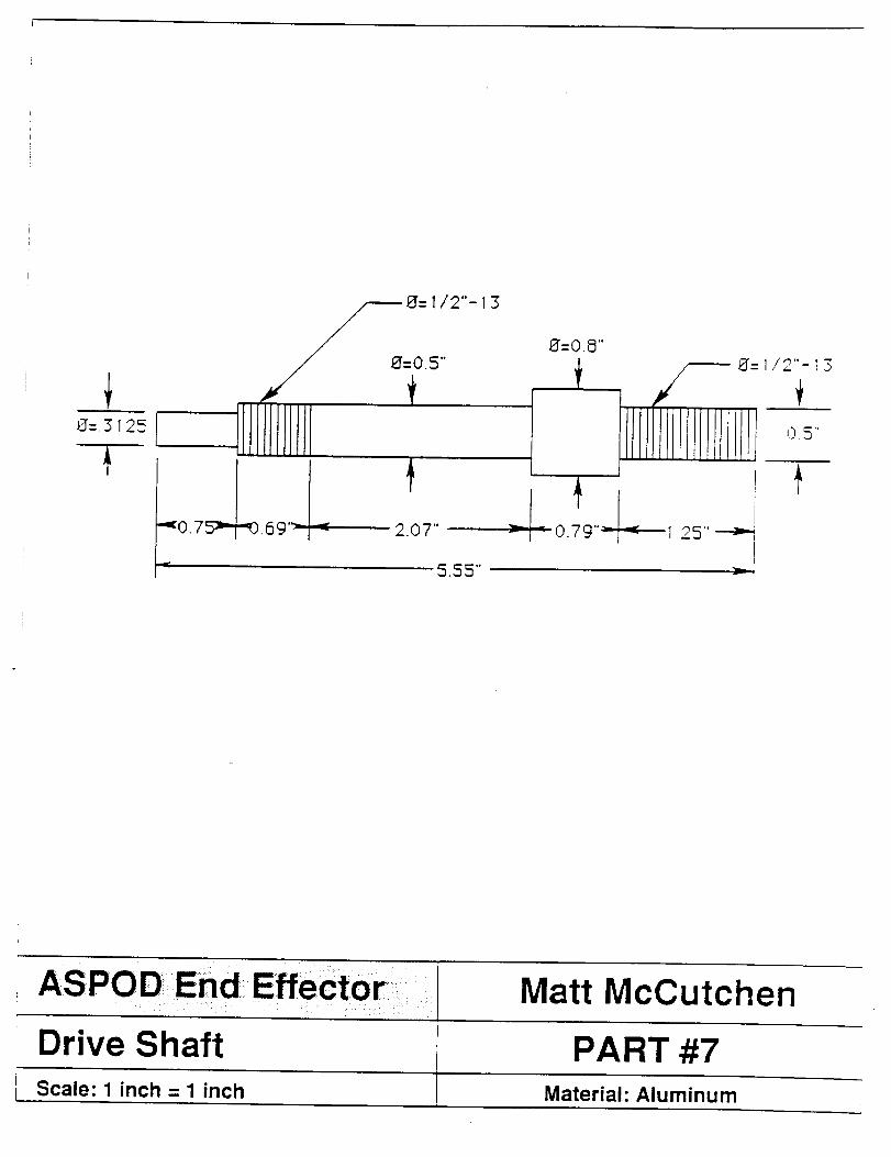
ASPOD End _Effector: i ...... :..... _ _ ix¸¸¸iiii_i:iiii_:! ili
Drive Shaft PART #7Scale: 1 inch = 1 inch Material: Aluminum
Matt McCutchen

SPECIFICATIONS
PART #8
Nut and Washer
Size: 0.5" Nylock Nut0.5" Standard Flat Washer
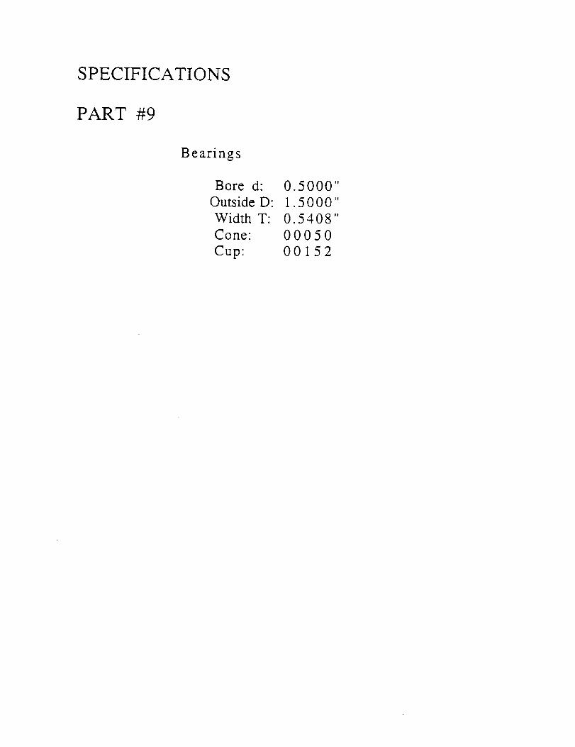
SPECIFICATIONS
PART #9
Bearings
Bore d:
Outside D:
Width T:
Cone:
Cup:
0.5000"
1.5000"
0.5408"
00050
00152
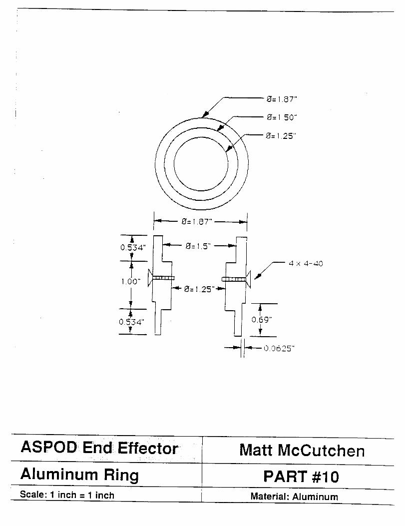
i0.534"
1.00" l
0.534"
!
8"= 1.87"
8"= 1.50"
8"= 1.25"
8"= 1.87" -I
8"= 1.5"'"----_-
=l/--l_I-- 1.25"_
0.69"
4x 4-40
ASPOD End Effe{ _tor Matt McCutchen!
Aluminum Ring PART #10Scale: 1 inch = 1 inch Material: Aluminum
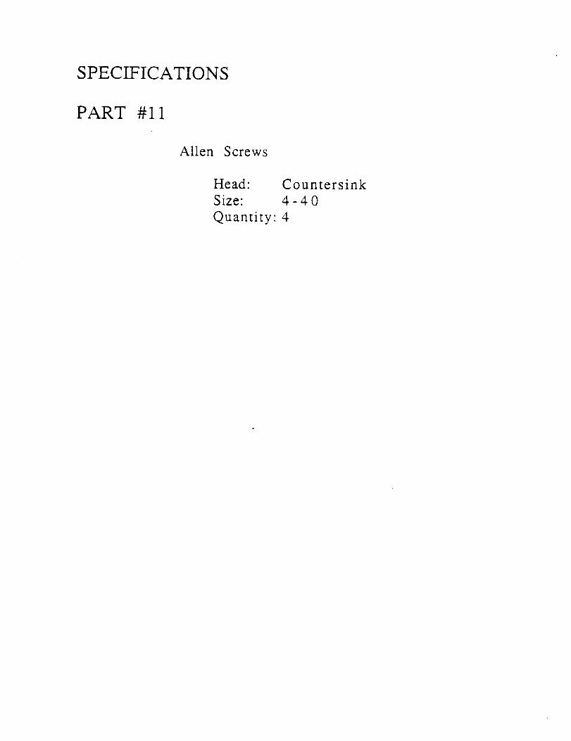
SPECIFICATIONS
PART #11
Allen Screws
Head:
Size"
Quantity"
Countersink
4-40
4
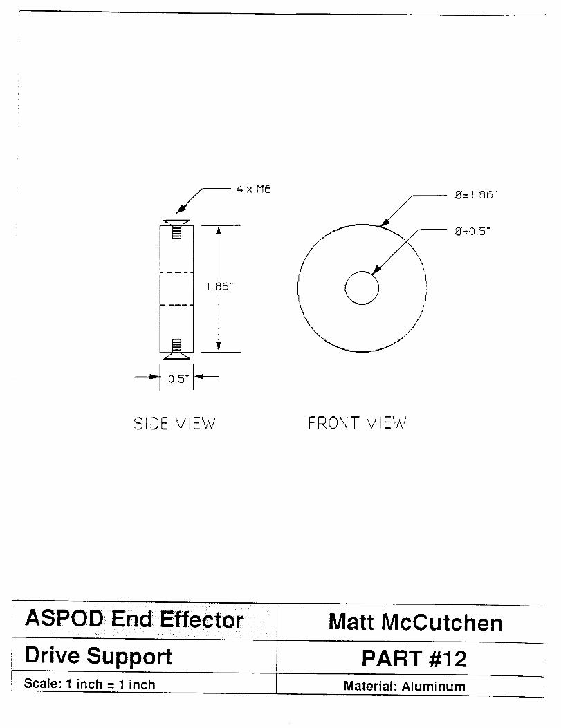
1.86"
4xM68=1.86"
8=0.5"
SIDE V IE'vv' FRONT V lE'vV
ASPOD_ End Effector; Matt McCutcheni
Drive Support PART #12c
Scale: 1 inch = 1 inch Material: Aluminum
SPECIFICATIONS
PART #13
Alien Screws
Head:
Size:
Quantity"
Countersink
M6
4
SPECIFICATIONS
PART #14
Nut and Washer
Size: 0.5" Nylock Nut0.5" Standard Flat Washer
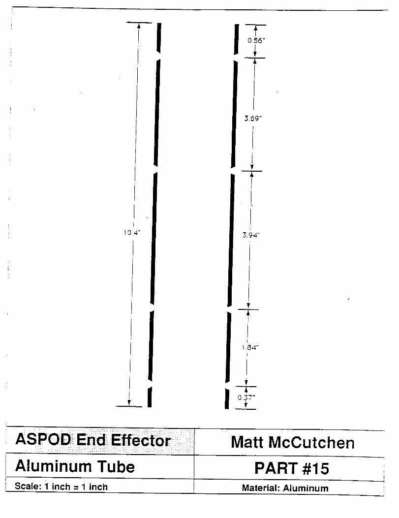
10.4" 3.94"
1.84"
I I
Aluminum Tube
Matt McCutchen
PART #15F
Scale: 1 inch = 1 inch Material: Aluminum i
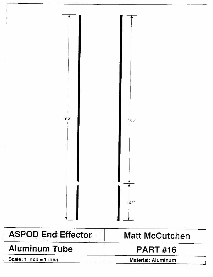
A
'_.5"
T
7.@3"
167""
IIi'
Effector IASPOD End
Aluminum Tube
Matt McCutchen
PART #16Scale: 1 inch = 1 inch Material: Aluminum
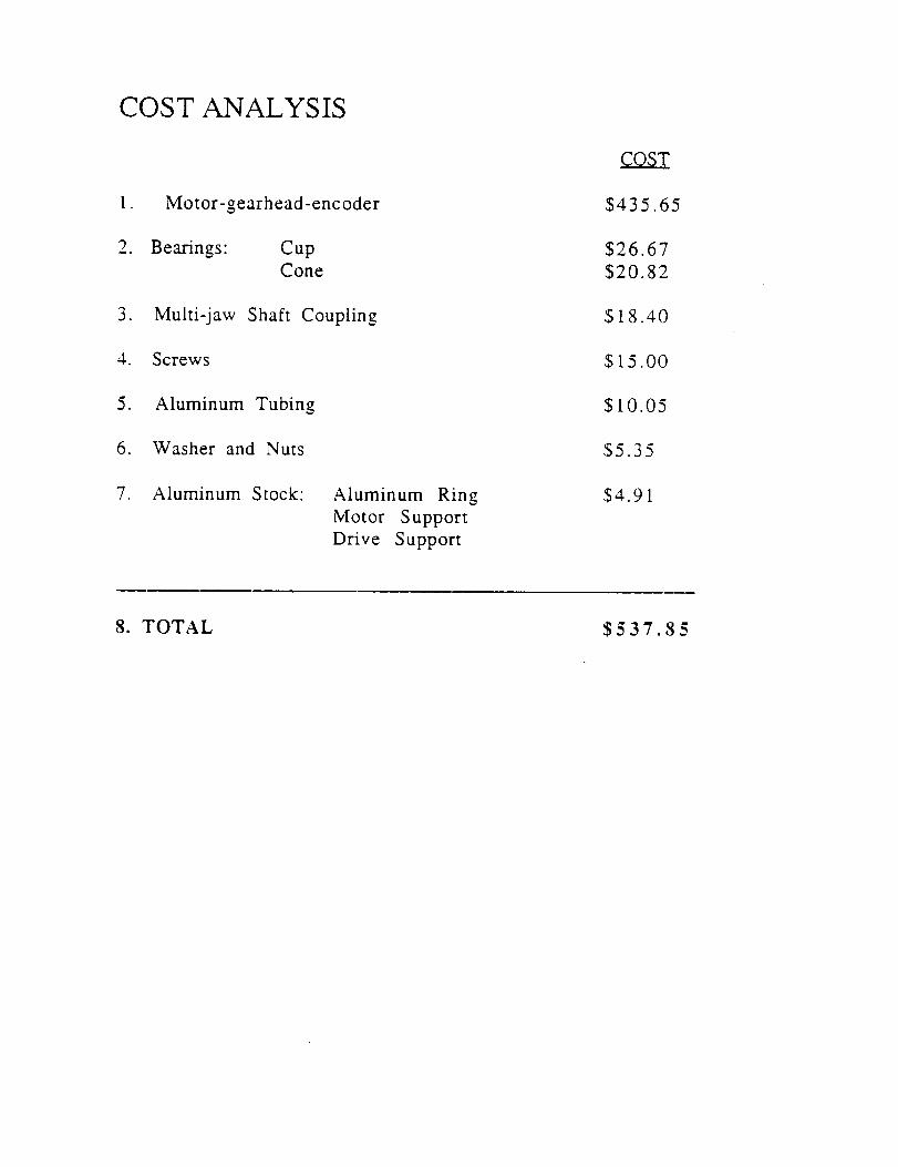
COST ANALYSIS
1. Motor-gearhead-encoder
2. Bearings: CupCone
3. Multi-jaw Shaft Coupling
4. Screws
5. Aluminum Tubing
6. Washer and Nuts
7. Aluminum Stock: Aluminum Ring
Motor Support
Drive Support
COST
$435.65
$26.67
$20.82
$18.40
$15.00
$10.05
$5.35
$4.91
8. TOTAL $537.85
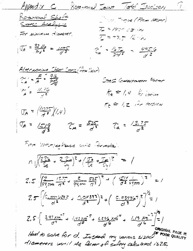
/?k',4,'J c
I t
,d r , _°i_'c__-._<,___,_,._ / t . //
- /_7__ _/-/<_,--J
:/9": '-'_ .-=. ;,+,
• _ . ../_jJ
-- =miiiim==_w-'I" _
2-,/_ ,y a
#
-,,_ <'/, //_
O_-- ,,,./, x',-+')
d _
/!', _ /, _,
_z
i -- ____ i I I
=-i
- " -- ' ORIGINAL
_Au_
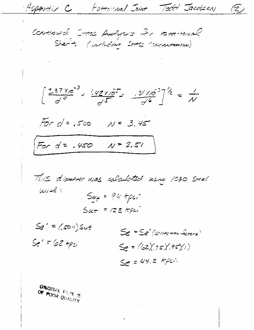
...,'O'd_ ,oW
._w# '' _ l t q
/_¢" I/r- ,ZOO
_'_rd = . _-o Xi _ 2,_"1
_<,._: ?,/,</,.,
t" t
- (_zZ 7r_ :,ey,)
_ _-4/,-/.z *"FJ-
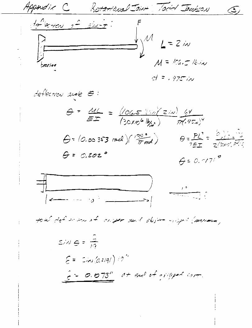
" - #, _,'4"/_-J_'_.,u
. _ "Yd',,+J _ "-" _-.c<.i"--_ .
_r = 40,ZOZ. _
F
,,S- "___.__.__..._---
(-s__,,_<,I_,) _(.<i_,_;_'[ \
?/ • ,_
_ :. 0.'-17/
w
m
1
I" t* ./.2'q- -_-" ..->>,., 2 -- :r ¢. _g_',,,* _M,.,. .
/
. • ,ira
_ ,_.;,_, zlq/ ,"
C , #
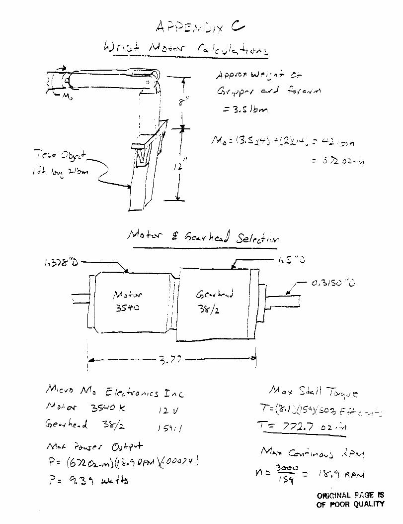
.-.,-_,.r_,_" C.-
i ,m
I
_<'r'P"" =_J
--- 3, _; )b_
{t
i
I
,,M,e,,-_ Nto _ le'=4"o,,,<_ :7.,,c
P: (_&_,,4(L_-,_ ae,_{eooev J4,g
"T'.=- 272,7 = 2 • ._I
/<_<t -
,<Pvf
ORIGINAL F/'_E IS
OF POOR QUALI'PIf

APPENDIX D
ELBOW JOINT
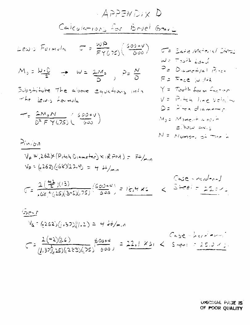
." ,L,/1 :--'1/,.
i
-_,p /
/v_ o - P'_ --_ W-_ W_,_ _ _ _-
q_, =,.z6z: (p,_ b ,.,,,,,,.,q,.)"<::.P_A ) -
o_c ,:2.S::_, ....,L,7_.) ' 6'_ ,,
'W-
,D
r=.:
Y:
V:
,\/t ,) :
t',/ :
<
" ' ' ' !' _:_,"'
:" .?,f..
•-.' "-c
C_¢ - ,_,_,J-,,.J
%') _ =. /"
- '
C t
OF POOR QUALITY
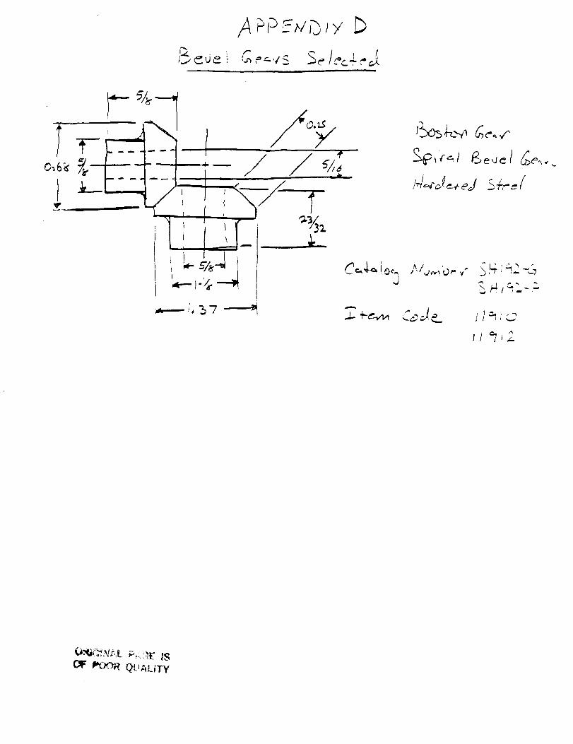
/4 P_t__ _,tP_J>,'
i
J
t4_2__+_d;4-_./
_ _/=,. -
z_
OI_ POOR QUALITY
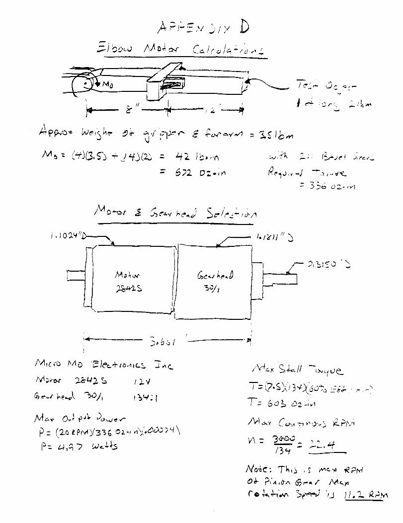
• _ ' , it _%,_
L.P
_, f_j. -r
- 35_ o=-,_,
t
/
p-I_ =
1..I_'_1":h
1
t
/_ __// -_c I oe._
. _o ,_ _,,.F4-- -",
"T'=6 o b _2 -;,,_
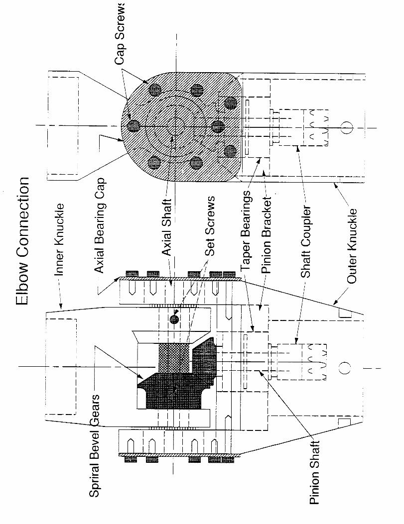
c-O
u_
0CDc-c-O0
©.Q
W
I I
I I I
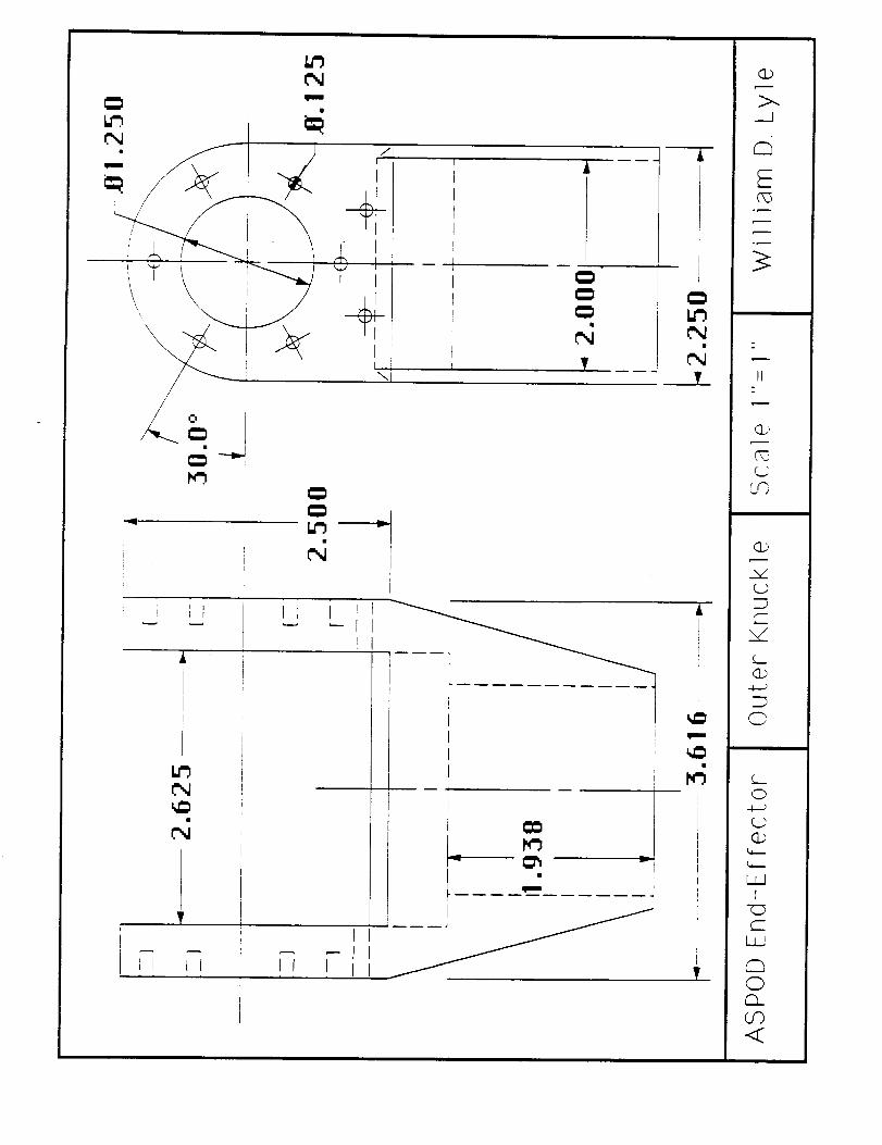
i
[
l
i
i
Jl II
A _
f
II1
rI
\F
Ii I
I
L__J r
r
I
I E
T
1! If
I ¢_
I, T
L._
v
: III
i I
II
A
I
m
r_
T
._J
C_
II
m
_z
C_
C_
L_JI
IiJ
Q
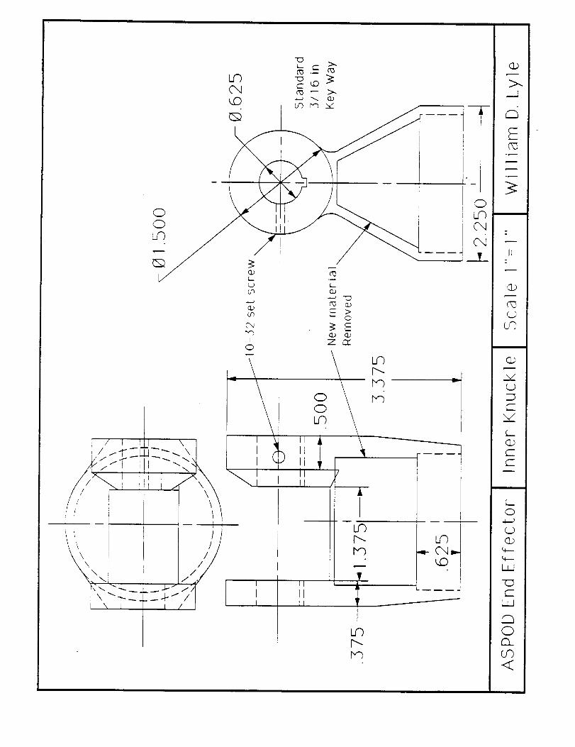
or)
i
0
i / _ 1 [ I \
// \\_ !
r_
IIItIIIIII
_ >O
X C_
\OkD
_r/
/
Ai
p-..
!
"' ! +
\ i //
_'x_\ I ////./I II
I III II
p..
TAI
_P
r'--
L_,q_ (',,,1_
: iI' IIi
I
i
i.I -
, OJ u'_
J___I_
m
>.._2
C_5
II
(D
(D
C-
L_O
-4----)
%--.
"C5C-
r--,,o
O0<
cbc"-
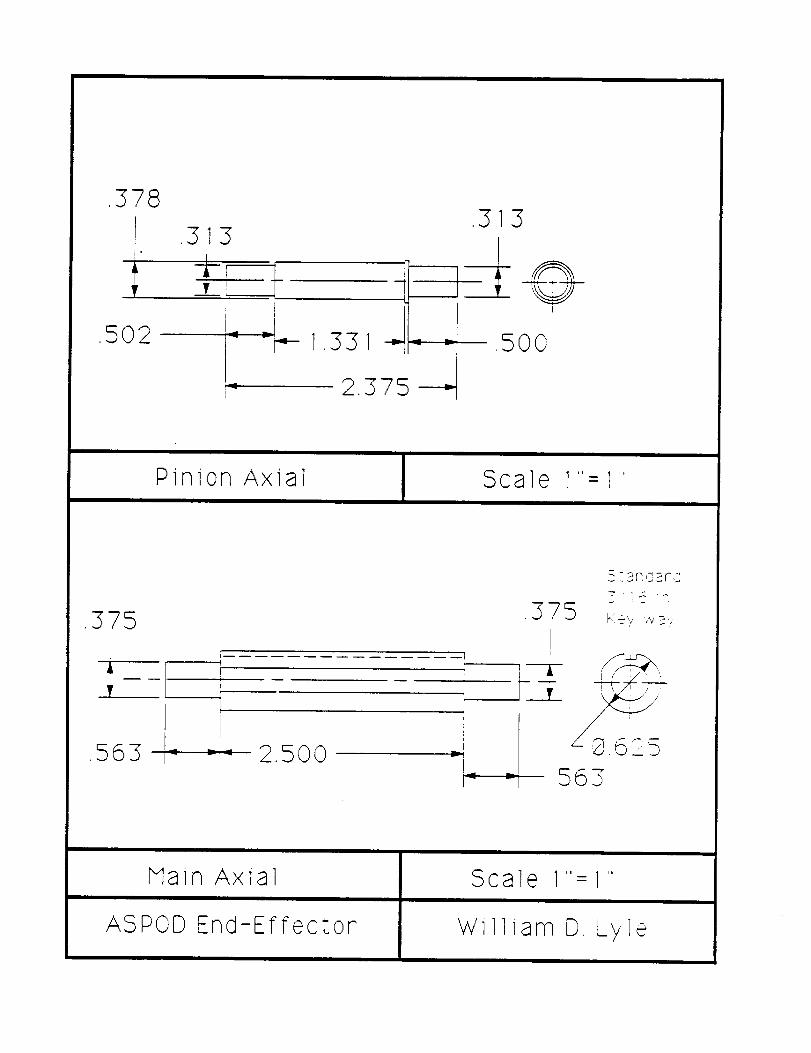
.378
1.T
.502
.313
1,331 ,500
Pinion Axial Scale 1''= 1"
,375
/
.s63+---- 2.500
.375
-- I
1 ;i;I-__3_
v_
.gl-IiIp. m
Q,563
_, .... aF,Z;
625
Main Axial
ASPOD End-Effector
Scale 1''= 1"
William D, Lyle
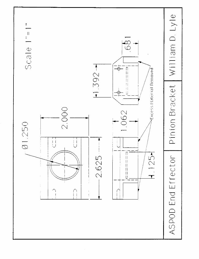
II
,i)
L,©
0r 0
0
cqi i J I I 1
Q v , v
I
: I
I I I I I
A
T
v
_L
I
I
i
bm_1 __
I
IL
IIIII/IIIIU
II
x
T
Q
_.J
or.i.
Q
0° t-'---
C-
0
t__
L__
0
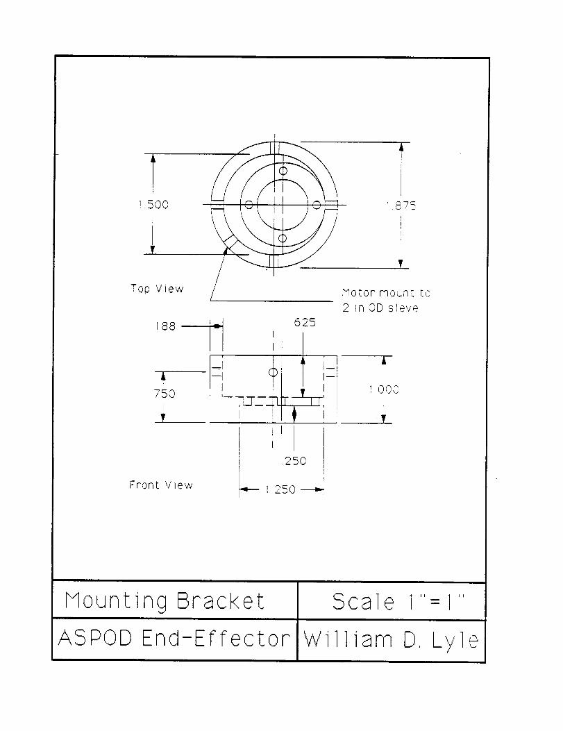
T
Top View
188
AL
750
Motor mount to
2 _nOD sieve
I_1 625
- I
_ I OC,O
VI
Front V_ew
Noun ring Brack e t
ASPOD End-Effector
Scale 1"-1
William D, Lv @
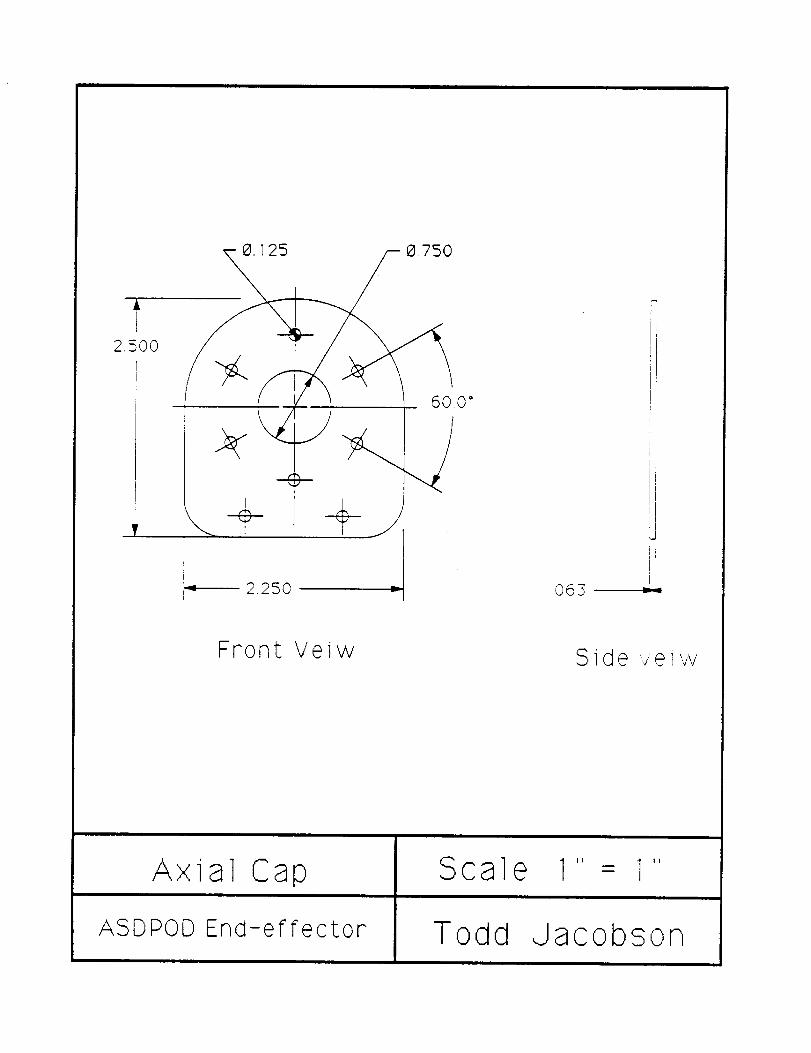
60.0 °
2.250 063
I
I
II-II
Front Veiw S id e v e iw
Axi
ASDPOD
al Cap
End-effector
Scal
Todd
e II ] 11I
Jacobson
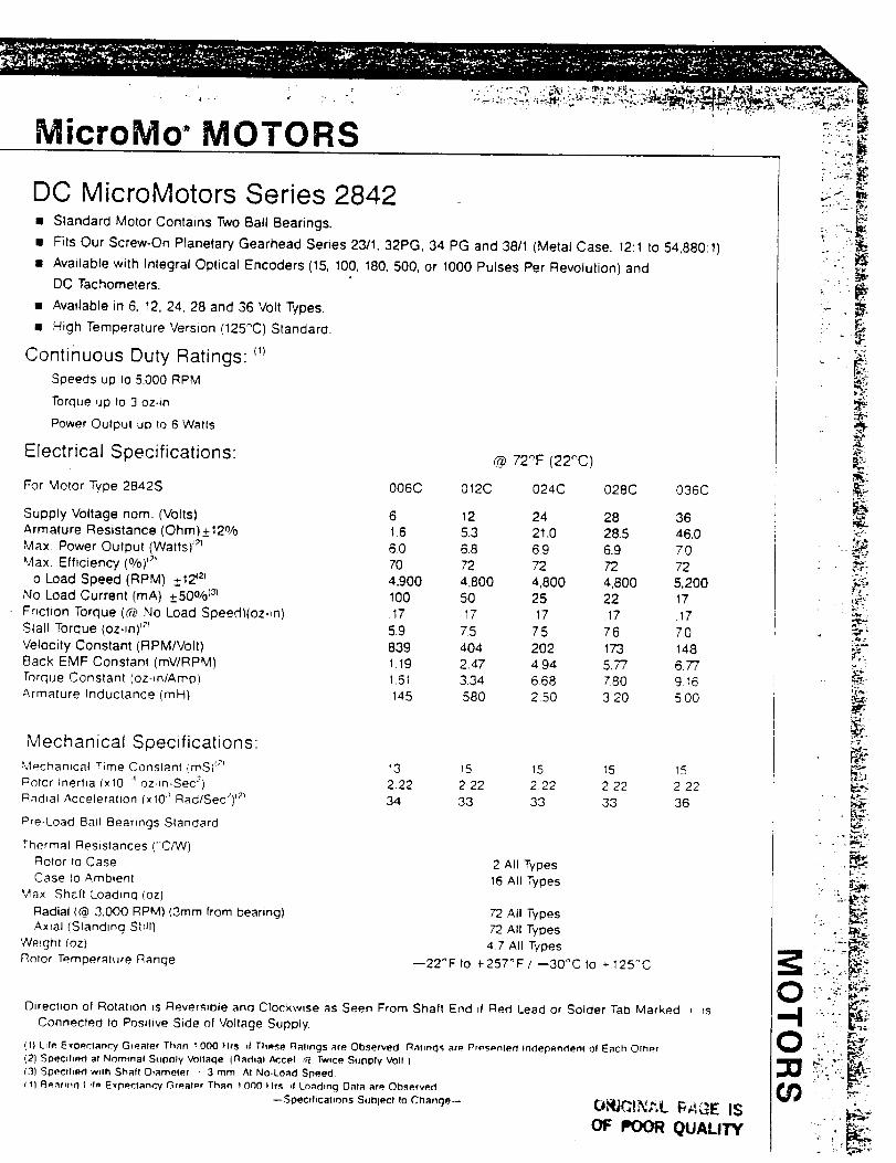
MicroMo • MOTORS
DC MicroMotors Series 2842• Slandard Motor Contains Two Ball Bearings.
• Fits Our Screw-On Planetary Gearhead Series 23/1, 32PG, 34 PG and 38/1 (Metal Case, 12:1 to 54,880:1)
• Available with Integral Oplical Encoders (15, 100, 180, 500, or 1000 Pulses Per Revolution) and
DC Tachometers.
• Available in 6, 12, 24, 28 and 36 Volt Types.
• High Temperature Version (125_C) Standard.
Continuous Duty Ratings: _)
Speeds up 1o 5,000 RPM
Torque up to 3 oz-in
Power Outpul up Io 6 Watts
Electrical Specifications: @ 72OF (22,_C)
For Motor Type 2842S O06C 012C 024C 028C 036C
Supply Voltage nora. (Volts) 6 12 24 28 36
Armature Resistance (Ohm)_+12% 1.6 5.3 21.0 28.5 46.0
Max. Power Output (Watts) al 60 6.8 6.9 6.9 Z0
Max. Efficiency (o/o)_ 70 72 72 72 72
o Load Speed (RPM) +12 _l 4,900 4,800 4,800 4,800 5,200No Load Current (mA) __.50O/o{3_ 100 50 25 22 17
Friction Torque ((_ No Load Speed)ioz-in) .17 17 17 .17 17
Slall Torque (oz-in) a_ 5.9 7.5 75 7.6 7.0
Velocity Constant (RPM/Volt) 83g 404 202 173 148
Back EMF Constant (mVIRPM) 1.19 2.47 4.94 5.77 6.77
Torque Constant (oz-in/Amo) 161 3.34 6.68 7.80 9.16
Armature Inductance (mH) 145 580 250 3.20 5.00
t3 15 15 t5 15
2.22 2 22 2.22 2.22 222
34 33 33 33 36
2 AII Types
16 All Types
72 All Types
72 All Types
4 7 All Types
--22"F to 4.-257"F / --30°C 1o _-125"C
Mechanical Specifications:
,Mechanical Time Constant (mS) I;_
Rolor Inertia ()10 4 oz.in.Sec2)
Radial Acceleration (xl0 J Rad/Sec;) {2_
Pre-Load Ball Bearings Slandard
Thermal Resistances ("C/W)Rotor Io Case
Case to Ambienl
Max Shall Loadinq (oz)
Radial (@ 3,000 RPM) (3ram from bearing)
Axial (Slanding Slrll)Wmght {oz)
_olor Temperalure Range
t]irection of Rotation ns Revem_ble and Cloc.kw_se as Seen From Shaft End _f Red Lead or Solder Tab Marked , _s
Connected Io Posilive Side of Voltage Supply.
(I) Life Exoeclancy G_ealer Than 1.000 _-tts ul Th_se Ralmgs are Observed Ralmq_ are Prn_nled Indepenclenl of Each Olher
(21 Speclhed al Nominal S,_pOly Vollaqe (Radial A_ccel (R, Twice Supply Votl }
(3} Specified wllh Shall Oiameler - 3 mm AI No-Load Speed
(1l R_,,'lrFn£1 I _lp E_per.tancT¢ Greal_r Than 10(30 FIrs *t Loading Oala are Observed
--Soec'fical'onsSul')lecll°Change-- O_GIt_',L I_AGE IS
OF POOR QUALITY
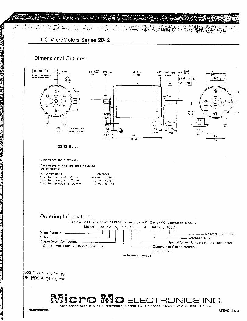
DC MicroMotors Series 2842
Dimensional Outlines:
2842 S . . .
-,300603 -nOlO e28- n,010.oo_,
t _l,i
12!
IlYl
_2
116S3D
Dimensions are _n mm fin )
Dimensions with no tolerance _ndicateq
are as follows:
Por Dimensions: Tolerance
Less than or equal to 6 rnm + 1 mm( 0039"_,
Less than or equal Io 30 mm ,- 2 mm ( 0079"1
Less than or equal Io 120 mm +- 3 mm _ 0t18"]
Ordering Information:Example: To Order a 6 Volt. 2842 Motor _ntended to Fit Our 34 PG Gearheacls. Specify
Motor 28 42 S 006 C ... + 34PG , 480:1
Motor Length L Gearhead Type
Output Shall Configuration . " SI3ec_al Order Numbers (where aOO+_c3t_e_
S = 3.0 mm Diam x 106 mm Shaft End [ Commutator Plating Material:
L C = Copper
Nominal Voltage
MME-O5905K
iC C) ELECTRONICS INC.742 Second Avenue S. / St. Petersburg, Florida 33701 / Phone: 813/822-2529 / Telex: 807-982
UTHO U.S.A.
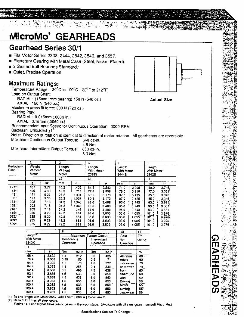
NlicroMo GEARHEADS
[] Fits Motor Series 2338, 2444, 2842, 3540, and 3557. _ _i_!_,_[] Planetary Gearing with Metal Case (Steel, Nickel-Plated). i ._ _
[] 2 Sealed Ball Bearlngs Standard: L _:._[] Quiet, Precise Operation. U J _;-:_"_"_;
Maximum Ratings:Temperature Range: -30°C to 100°C (-22°F to 212°F-')Load on Output Shaft:
RADIAL: (15ram from bearing) 150 N (540 oz.) Actual SizeAXIAL: 150 N (540 oz.)
Maximum press fit force: 200 N (720 oz.)Bearing Play:
RADIAL: 0.015ram (.0006 in.)AXIAL: 0.15ram (.0060 in.)
Recommended Input Speed for Continuous Operation: 3000 RPMBacklash, Unloaded <1°
Note: Direction of rotation is identical to direction of motor rotation. All gearheads are reversible.Maximum Continuous Output Torque: 640 oz-in.
4.5 NmMaximum Intermittent Output Torque: 850 oz-in.
6.0 Nm
1 2 3 4ReductionI::latJop)
3.71:114:14311661
134:1159:1246 1415:1592:1 -'989:1
1526:1
WeightWithoutMotor
_1 oz107 3.77139 49O171 6.03171 6.03203 7.16203 7.16203 7 16235 8.29235 8 29235 8.29235 829
LengthWithoutMotor
L2
mm in
10.2 .40218.2 .71626.2 1.03126.2 1.03134.2 1.34634.2 1.34634 2 I 34642.2 1.66142,2 1.66142.2 1 66142.2 1661
LengthWith Motor2338S
L1
mm in
64.6 2.54372.6 2.85880 6 3.17380.6 3.17368.6 3.48888.6 3.48888.6 348896,6 3.80396.6 3.80396.6 3.80396.6 3.803
5 6
LengthWith Motor2444S
L1
mm in
71. ; 2.7 79.0 3.11087 0 3 42587.0 3.42595.0 3.74O95.0 3.74095,0 3.740
I03.0 4.055103.o 4.osS'_103,0 4.055103.0 4 O55
7 8 9Length_`') Max=mum Toraue Oumut
I0Rot,a-
#V_thMotor3540K
"1
Tim
68.476.484 484492.492,492.4
100.4100.4 ....100.4100.4
ContmuousOl:_eratlon
in Nm oz-in
2.693 1.5 2123.008 0.35 503.323 1 2 170
3.323 1.8 . 2553.638 3.5 4963.638 4.5 6383.638 4.5 6383.953 4.5 6383.0._ 4.5 _m3,953 4.5 6383,953 4.5 638
(1) To find length w_th Motor 3557. add 17ram(2) Ratio 3.71:1 has all steel gears.
Ratios 14:1 and higher have plastic gears
Intermittent
Operation
Nm
3.00.5162.44.56.06.06.06.0 _"6.06.0
(.669 in.) to
oz-in
42571
22734063885O65085O
" 650"65085O
column 7.
_orl
Direction
All rat_m_teclockwiseas vPewedfromShaft Endwith
Driving
tumin_J "clod<wise
LengthWith Motor2842S
L1
mm in
69.0 2,71E'77.0 3.(531_85.0 334685.0 3.346
(_k3.0 3661'93.0 3661
101 0 3.976
101.0 3.976101.0 3.976
11Effi-
(:=ency
%
8880707060"606055
55
in the input stage (Available with all steel gears - consult Micro Mo.)
-- Specifications Subiect To Change --
,::, s,i-'N
•:'._. j. _ _,.
-<_ ' - "_:" t.',_
.. r#,
,.. ,._
• :" .: :_F":I-.-
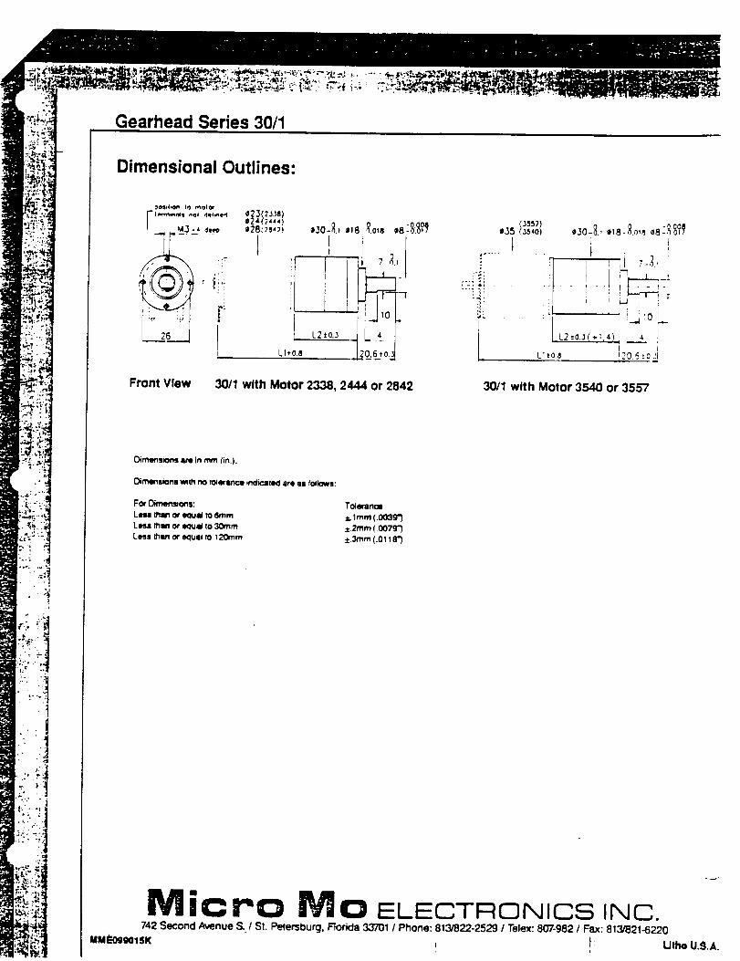
-L
.tl
• :'_J
Gearhead Series 30/1
Dimensional Outlines:
r ._.3-_,,__ ,8:_:_?_
'P _il
,sB
i
_23(zJ,la)e;!46)4,,)¢28c)e.)) ¢30-_ _18 _,o,a
2-
Front View 30/1 with Motor 2338, 2444 or 2842
(.I_57)°is _3_,o) o3o-:_.,o,8-_o,,®8:',__?_
; ,
i'r ......... il j_- !_i" __t
L.2 t OlJ ("m+"; _ I
)
L1_:o.s 120,6_OJl
30/1 with Motor 3540 or 3557
Oimt_s_ons am in r_ (inl).
Oimens=ons _t_ no tolerate +ncl_c_teclare u Iollows:
_C0¢ O_menslo_s:
Les° _am or equal to 6ram
Less _an or e_ual to 30ram
Less 0_n or eoual _o i20mm
Toleranom
_. 1mm (.00:)g')
:_2mm (.0079")
±._rn (.Oii8")
M ic Pc) M ID ELECTRONICS INC.742 Second Avenue S. / St. Pete°burg, Florida 3.3701 / Phone: 813/822-2529 1 Telex: 807-982 1 Fax: 813/821-6220
MMLP'OSi_iOlSK : ) Lithe U.9.A.
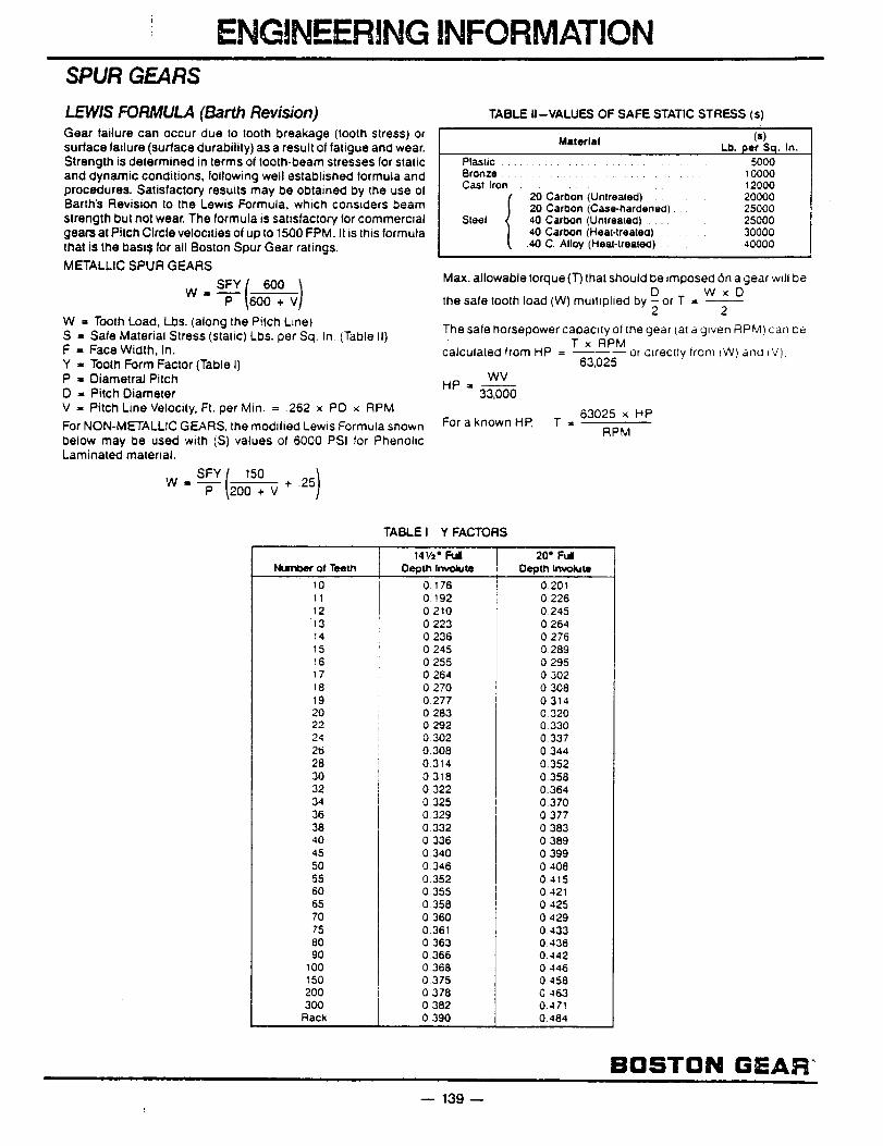
i ENGINEERING INFORMATIONSPUR GEARS
LEWIS FORMULA (Barth Revision)
Gear failure can occur due to tooth breakage (tooth stress) or
surface failure (surface durability) as a result of fatigue and wear.
Strength is determined in terms ot tooth-beam stresses for static
and dynamic conditions, following well established formula and
procedures. Satisfactory results may be obtained by the use of
Barth's Revision to the Lewis Formula, which considers beam
strength but no! wear. The formula is satisfactory for commerc=at
gears at Pitch Circte velocities of up to 1500 FPM It is this formula
that is the basi_t for all Boston Spur Gear ratings.
METALL,CSPURGEARSSFYi 600 1
w. _ _6oo + v /
W = Tooth Load, Lbs. (along the Pitch L_ne)
S = Safe Material Stress (static) L_s. per Sq. In. (Table II)
F = Face Width, In.
Y = Tooth Form Factor (Table I)
P = Diametral Pitch
D = Pitch Diameter
V = Pitch Line Velocity, Ft. per Min. = .262 x PO x RPM
For NON-METALLIC GEARS, the modified Lewis Formula st_own
betow may be usecl with (S) values of 6000 PSI for Phenolic
Laminated material.
SFY[ 150 )W = _ _,200"7 V + 25
TABLE ,--VALUES OF SAFE STATIC STRESS (s)
Material (s)
Lb. per Sq. In.Plastic ...................... 5000Bronze ........................... 10000Cast Iron ................. 12000
.20 Carbon (Unlrealed) 20000
20 Carbon (Case-naraeneo) 25000Steel 40 Carbon (Unlrea{e(:l) 25000
.40 CarOon (Heal-trealea) 30000
.40 C. Alloy (Heal-treate0) .... 40000
Max. allowable Iorque (T) that should be imposed 6n a gear wdl be
the safe tooth load (W) multMplied by D W x D-orT = --2 2
The safe horsepower capacity ot the gear (at a glven RPM) can oe
T x RPMcalculated from HP - or chrectfy from fW) ancl (V),
63,025
WVHP = --
33,000
63025 x HPFor a known HP, T -
RPM
TABLE I Y FACTORS
14112. Full 20 e Ft.dl
NumCm¢ of Teeth Oept,h Invokute Depth Involute
10
11
12
13
14
1516
17
t8
19
2022
24
2628
3O
32
34
36
3840
45
50
55
60
65
7075
80
90
100150
20030O
Racx
01760.192
0.210
0.223
0236
0 245
0 2550 264
0 270
0277
02830 292
0.302
O.308
0 314
03180.322
0 325
0 329
0.332
0336
03400346
0.352
0 355
0.358
0 360
0.361
0 3630.366
0.3680375
0.378
0 3820.390
02010.226
0 245
0.264
0 276
0289
0 2950 302
0 308
0314
0320
0 3300 337
0 344
0.352
0.358
0.364
0.3700377
0 383
0389
0399
0408
0.4150421
0425
0 429
0433
0 4380.442
0 4460 458
C 463
0.471
0484
BOSTON G=AR"
-- 139-
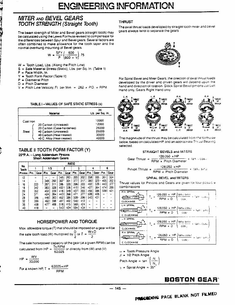
ENGINEERANG INFORMATION
MITER ANOBEVEL GEARSTOOTHSTRENGTH(Straight Tooth)
The beam strength of Miter and Bevel gears (straight toolh) may
lee calculated using the Lewis Formula revised to compensate for
the differences between Spur and Bevel gears. Several factors are
often combined to make allowance for the tooth taper and the
normal overhung mounting ot Bevel gears.
600 /75P _60o. v/
W =, Tooth Load, Lbs. (Along the Pitch Line)
S = Safe Material Stress (Static), Lbs. per Sq. In. (Table 1)
F = Face Width, In.
Y =, Tooth Form Factor (Table II)
P = Diametral Pitch
D = Pitch Diameter
V = Pitch Line VelocIty, Ft. per Min. = 262 x PD. x RPM
TABLE I-VALUES OF SAFE STATIC STRESS (s)
(=)
Material Lb. per Sq. In.
20 Carioon (U ntrealed)
20 Carioon (Case-hardened)40 Carl_on (Unlreaced)
40 Carl_on (Heal.lrealed)
.40 C. Alloy (Heat-lrealed)
10000
12000
25000
25000
30000
40000
Cast Iron
Stee| I
TABLE II TOOTH FORM FACTOR (Y)20=P.A. - Long Ad(:lendum Pinions
Short Addendum Gears
RATIO
Z 3
Pin. i Gear Pin. ] ;ear
345283355i 3023673013771317386320396i 333
402336415346
418349 1427355443 3681 471 377
462 3861 509 396487402; 540 412
518415' 569424543424594434
I 6
Pin. Gear t Ptn. lGeati
358305361 324_
380323405352
402339443_ 377
427 364 4741 399
4563865001421506405 _ -
1543421 - i -
I - I -
No.Teeth. _ 1 1.5
Pinion Pin. I Gear t Pin. Gear
1214 [ - ;9 _2
16 _3 t367] 311
18 342 i383{ 328
20 352 402133924 371 : 424364
28 38¢_ .446 383
32 ! 399 4621 396
36 4O8 477 4O8
40 418 ; -- -
HORSEPOWER AND TORQUE
Max. allowable torque (T) that should be imposed on a gear wdl be
the sate tooth toad (W) multiplied by O or T = WxO2 2
The sate horsepower capac=ty ol the gear (at a gwen RPM) can be
TxRPMcalculated from HP = -- or directly from (W) and (V);
63,025
WVHP=_
33,000
63025 x HPFor a known HP, T =
RPM
THRUST
The axial thrust loads developed by straight tooth m_ter and bevel
gears always tend to separate the gears.
For Spiral Bevel and Miter Gears, the direction of axial thrus[ loads
developed by the driver and driven gears w_tl cte0end upon Ine
hand and d_rectJon ol rotation. Stock Spiral Bevel pm_ons cul Left
Hand only, Gears Right Hand only.
Lit. L. ff. ._. /f. ft.#. •
' _
The magnitude ol the thrust may be calculaled If ore ii_e formulae
below, based on catculaled HP and an appropriate Tmu=I ISear mcj
selected.
STRAIGHT BEVELS and MITERS
126,050 x HPGear Thrust = x tan., cos,;
RPM x Pitch Diameter
126,050 xHPPinion Thrusl = _ Ian,, smJ
RPM x Pitch Diameter
SPIRAL BEVEL and MITERS
Thrusl values for Ptmons and Gears are g_ven rot tour poss_cr_
combinations
L M SPIRAL /_¥
C C[ (.X_KWISE
126.050 x HP(!an,,_s_r_4 )T = FIPM x D \ cos, 'an .:as,,
126.050 x HP(Ian,,CO_ )TG = RPM x O \ cos-, , I.-,n sin,;
L H SPIRAL
126.050 x HP(tan,,s,,_J )--.T4--- T = ,- {an, cus,
CLOCkwiSE 1 RPM x O \ cos,
T_ = RPM x O \ cos-, _ t,q_- _m,>
,= = Tooth Pressure Angle
_,_= 1/2 Pitch Angle
Pitch Angle = tan '( N--_--/
_N_/
"i = Spiral Angle = 35 °
BOSTON GEAR °
-- 145 --
Pli_i;i)lN_ PAGE BLANK NOT FILMED
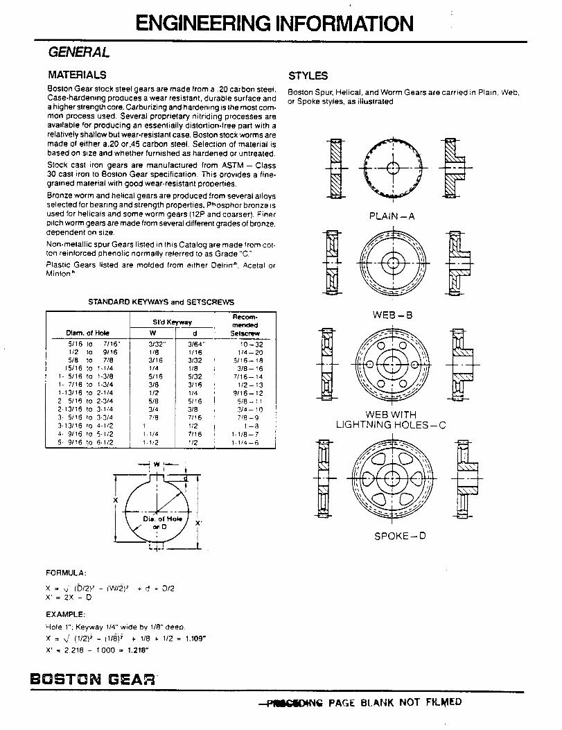
ENGINEERING INFORMATION
GENERAL
MATERIALS
Boston Gear stock steel gears are made from a .20 carbon steel.
Case.hardening produces a wear resistant, durable surface and
a higher strength core. Carburizing and hardening is the most com-
mon process used. Several proprietary nitriding processes are
available for producing an essentially distortion-free part with a
relatively shallow but wear-resistant case. Boston stock worms are
made of either a.20 or.45 carbon steel. Selection of material is
based on size and whether furnished as hardened or untreated.
Stock cast iron gears are manufactured from ASTM -- Class
30 cast iron to Boston Gear specification. This provides a fine-
grained material with good wear-resistant properties.
Bronze worm and helical gears are produced from several alloys
selected for bearing and strength properties. Phosphor bronze is
used for heticals and some worm gears (12P and coarser). Finer
pilch worm gears are made from several different grades of bronze,dependent on size.
Non-metallic spur Gears listed in this Catalog are made from cot-
ton reinforced phenolic normally referred to as Grade "C"
P_astic Gears listed are molded from either Delrin'", Acetal or
Minion _.
STANDARD KEYWAYS and SETSCREWS
Diam. of Hole
5t16 to 7116"
1/2 to 9116
518 to 7/8
15/16 to 1-1/41- 5/16 1o 1-3/8
1- 7/16 to I-3/4
1-13/16 to 2-1/4
2- 5/t6 to 2-314
2-13116 to 3-1/4
3- 5/16 Io 3-3/4
3-13/16 {o 4-1/2
4. 9116 to 5-1/2
5- 9/16 Io 6-1/2
St'd Keyway
3/64"1/16
3/32
1/8
5132
31161/4
5/T6
3/8
7/16
1/2
7fl 6
W
3/32"
1/8
3116
1/4
5/163/8
1/2
5/8
3/4
7f8
1, tt4
R_oerl-
n'_nded
Setscrew
10-32
1/4--205/16-- 18
3/8- 16
7/16-- 14
1/2- 13
9/16-- 12
5i8- 113/4 -- 10
718-91-8
1-1/8--7
1-1/2 , 1/2 1-1t4--6
I . oL,o,,/ ;,.
STYLES
Boston Spur, Helical, and Worm Gears are carried in Plain, Web.
or Spoke styles, as illustrated
PLAIN --A
WEB-B
i,II.1-
-__._-_
WEB WITHLIGHTNING HOLES-C
SPOKE--D
FORMULA:
x = ,v (D/2)' - {W,':_)' + d -,-O/2X'=2X -O
EXAMPLE:
Hole t": Keyway 1/4" wide by 118" deep
X = _f (I/2);' - (I/8) i + 1/8 4- 1/2 = 1.109"
X' = 2218 - I000 = 1.218"
BOSTON GEAR
PAGE Bt.ANK NOT FILMED
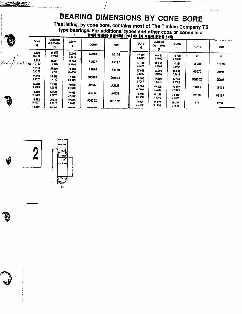
°
bore
d
?Jl_ll0.3125
U=I0.375O
11,1120.4,175
11,1120.4375
12,0000.4724
IL_140.4_12
11111_0.4_7
19 II_
BEARING DIMENSIONS BY CONE BORE
This listing, by cone bore, contains most of The Tlmken company TStype bearings. For additional types and other cu_s or cones in a
o.t_d, " ' .... HIHI_tltqP _lll'l_t _ml'ffi M#I_ttHHN 1=illdiameter
O
11.slt111.25H
31.HI1.25_
_14.Slal.3775
31JI111.4140
1.2596
_.gal137"_
_1.|1=1.4375
JIJLUq___
w_lth1"
io.o_0.3940
I0.0010.3940
10.11110.4330
17.ILLSO.(S_3
IO.O010.3940
lO.tINI0.4330
17,¢110.7067
cone
A2031
A2037
A4044
00068X
A2047
A4049
00079X
cup
A2125
A2127
A4138
00153X
A2126
A4138
00152X
bore
d
17.411;!0.£_7S
17.4620,_75
17.1S30.6950
11,0000.7087
10.0000.7480
I|.0000.7480
19.0040.7482
outside
diameter
D
44.4601.7500
q.9901.8500
4L2251.0380
47.0001,0504
40.22519380
41).22519380
53.9782.1250
widthT
1Z?O0O5OOO
16.2S00.6004
1g.8410.7613
14.3110.5862
23.8120.9375
23.812093?5
]9.3e70.7625
cone CUD
4C 8
05058 05188
09070 09195
05070X 05185
09075 09196
09078 09194
1774 1730
2
l"---_ 4
lT$
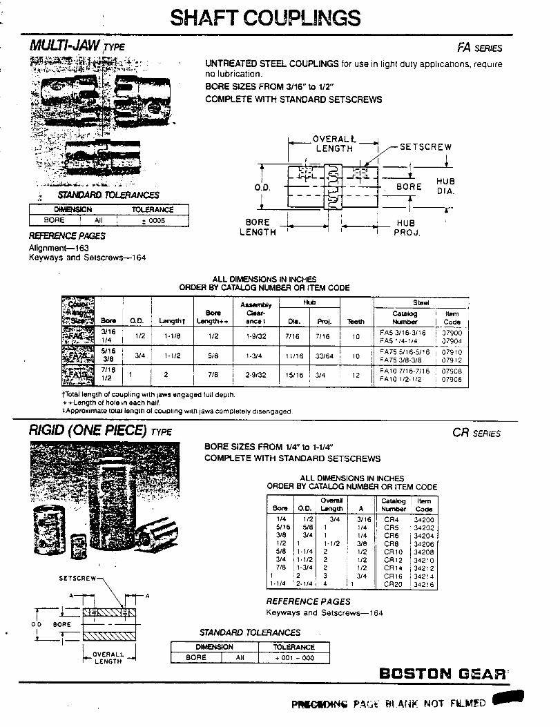
MULTI-JAW _
SHAFT COUPLINGS
FA SERIES
UNTREATED STEEL COUPLINGS for use in light duty applications, requireno lubrication.
BORE SIZES FROM 3116" to 112"
COMPLETE WITH STANDARD SETSCREWS
DIMENSIDN
BORE All
TOLERANC_
± OO05
RB:EP2_CE .PAGES
Alignment--163Keyways and Setscrews--164
T0.D.
BORELENGT H
t1 , -- sSETSC Ew,
rr--- ,_ I _ HUB '
"_ P q PROJ,
ALL DIMENSIONS IN INCHES
ORDER BY CATALOG NUMBER OR ITEM CODE
1-3/4 11/16
2-9/32 15116
•_ Bom ¢_ar-_, Born O.D. Lengmt ! length++ ante
;_._t 3/16 I/2 1-1/8 1/2 1-9/32_,, '_ 11,_ -'%.'_-' 5116
_ 3/8 3/4 1-112 518
1/2 1 2 7/8
"('Total length of coupling w,lh laws engaged full depth.
+ +Length of hole in each hall.
$Approximale lolal length ol coupling wdh laws complelely chsengagecl.
_. Pro i. Teeth
7/16 7116 I 10I
33164 I 0
314 12
S_et
c_,-kxj i I_.mI Code
FA53116.3116 ; 07900FA5 114-1/4 _ 07904
FA755/16-5tt6 i 07910FA75 318-318 i 079_2
FA107116-7/16 i 07908FA10 _/2-1/2 i 07966
RIGID (ONE PIECE) TYPEBORE SIZES FROM 1/4" to 1-1/4"
COMPLETE WITH STANDARD SETSCREWS
Bom O.O.
114 1/25/16 518
318 314
I/2 15t8 1-1/4
3/4 1-1/2
718 1-314
1 2
1-1/4 2-1/4
REFERENCE PAGES
ALL DIMENSIONS IN INCHESORDER BY CATALOG NUMBER OR ITEM
Overal CatalogLan,:jm
3/4I
1
1-I/2
2
22
34 11
CODE
A Numl>er i Codei
3116 CR4 1342001/4 CR5 34202
114 CR6 34204
:3/8 CR8 34206
112 CR10 342081/2 CR12 34210
1/2 CR14 i 34212
3/4 CR16 34214
CR20 34216I
Keyways and Setscrews--164
STANDARD TOLERANCES
DIMENSION TOLERANCEBORE All + 001 - 000
CR SERIES
BOSTON GEAR:
PRICIOiN_ PAGE r_IANK NOT FILMED

APPENDIX E
GRIPPER
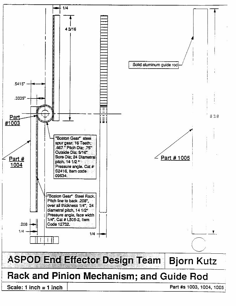
.5415" -_f --_
.3335" -_
1004
L#1003
.t
:z:z
z_=_=_=_=_=
|,
,\
.208 - _._1/4 --
Ilii
)
•gb. 114
EEEE 4 3/16EE==
.=iEE
¢=
Dm
=
i• .._,
.s_rgear:i 16Teeth;: :i!:.6671'rPitch:Dia:_;.75v_
:_Bor_ Dta_i24 Dl_
Pressure angle, Cat #:$241'S;: item code;;:•0963_: ....
-'Boston-Gear "_Steel Rack.Pitch line to back ,208";;ov_aII thickness 1/4"_ 24di_etral:pitch;, 14 112"
Pr_s.sure angle; face width:1/,$!;Cat# L505-2, Item
il1/4
m
m
m
m
n
m_m
I .
mm ,
Soi_ aluminum guide rod
8 3,8
I
i
V
Bjorn Kutz
Rack and Pinion Mec,,hanism; and Guide RodScale: 1 inch = 1 inch Part #s 1003, 1004, 1005
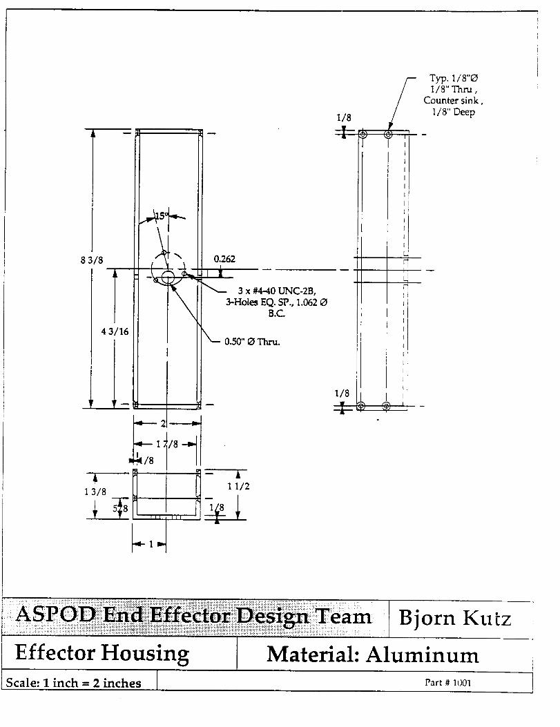
8 3/8
4 3/16
1 1
,,_k15°
\\
"iF i
i
-_---- 2 -------_
_-- 1 /8 -_
/1/8
0.262
iI3 x #4-40 UNC-2B,
3-Hole_ EQ. SP., 1.062 C)B.C.
0.50"_ Thru.
-- A
1 3/8
1/8
--i-
/-/
Typ. 1/8"C)1/8" Thru,
Counter sink,
1/8" Deep
Effector HousingScale: I inch = 2 inches I
i
Bjorn Kutz
Material: Aluminum
Part # 1001
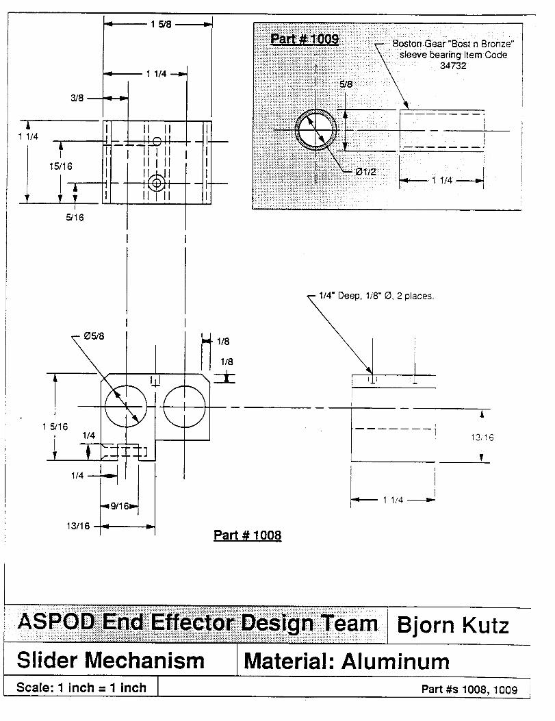
A1 1/4
3/8
15/16
1 5/8
1 1/4 --_
" "• _l_tt!l IIIli!1 illll
i- J I
• - i =
i
I
t:"
1/4 m
13/16Part # 1008
1/4" Deep, 1/8" 0, 2 places.
A
13/16]
T
I
1 1/4 -_---_"
Slider MechanismScale: 1 inch = 1 inch
Bjorn Kutz
'1Material: AluminumPart #s 1008, 1009
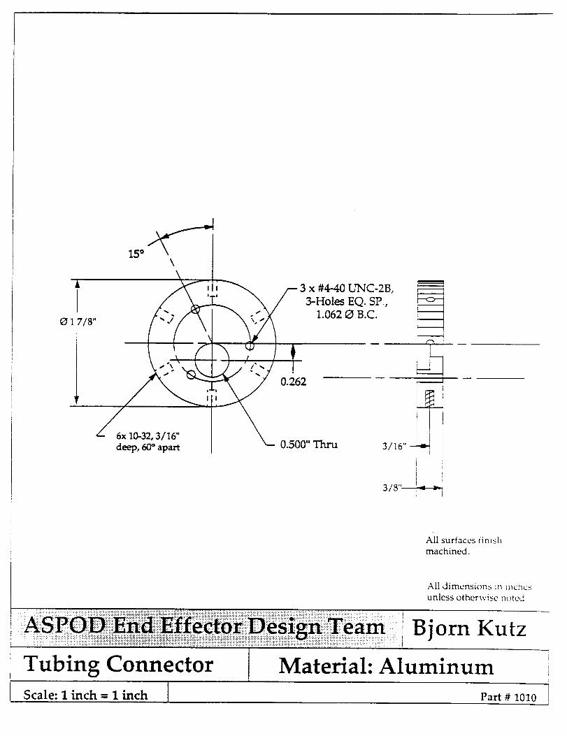
i
IO 1 7/8"
Z
deep, 60 ° apart
I
All surfaces finish
machined.
All dimensions in inches
unless otherwise noted
Tubing ConnectorScale: I inch = I inch I
Bjorn Kutz
Material: Aluminum
Part # 1010
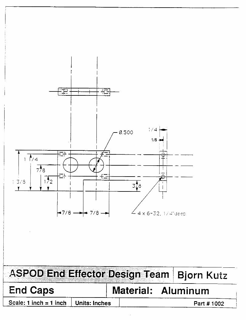
IF.-_i i
1A/4
7_8
v_2v V
,_°
_j__°
J
I7/8
qi-_..
_- 7/8 --) I" 4"_eeO
End CapsScale: 1 inch = 1 inch
I Material:!i
I Units: Inches I
Bjorn Kutz
AluminumPart # 1002
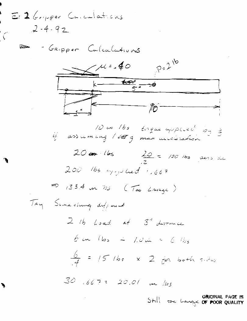
f"
k
I
i
F
i
c'/;
I
rD_
_.,?- :s c__J , d e _
/00 /I-_3 ,._ : _ , : ___
f"
/.u, - - /- i,;j<
•6U -_ _- 20,01
L
/?o5
ORJ_NAL _A_E I_
_,_- o_ e,oo_Q_.J_kl'rY
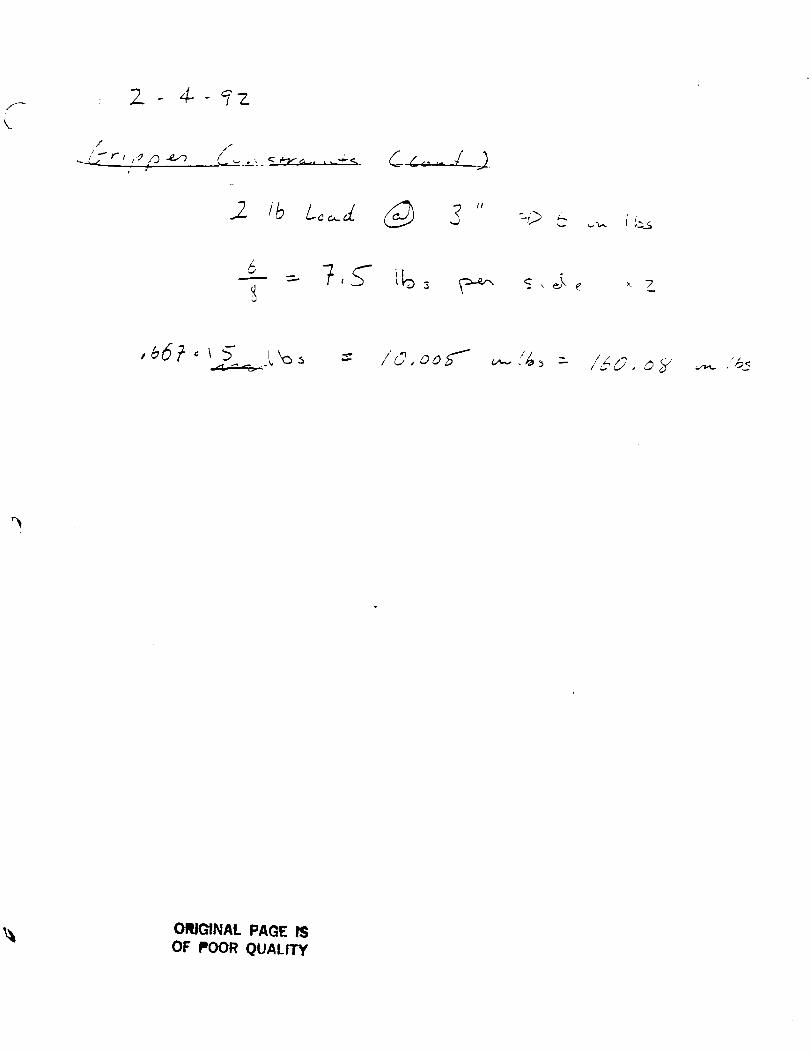
//i
,.j ---t_ _ i' !'_s
6___=.7, S
/C, ooS"" <.,.- > : /_o, o_t• ,.ID "*' //
ORIGINAL PAGE IS
OF POOR QUALITY
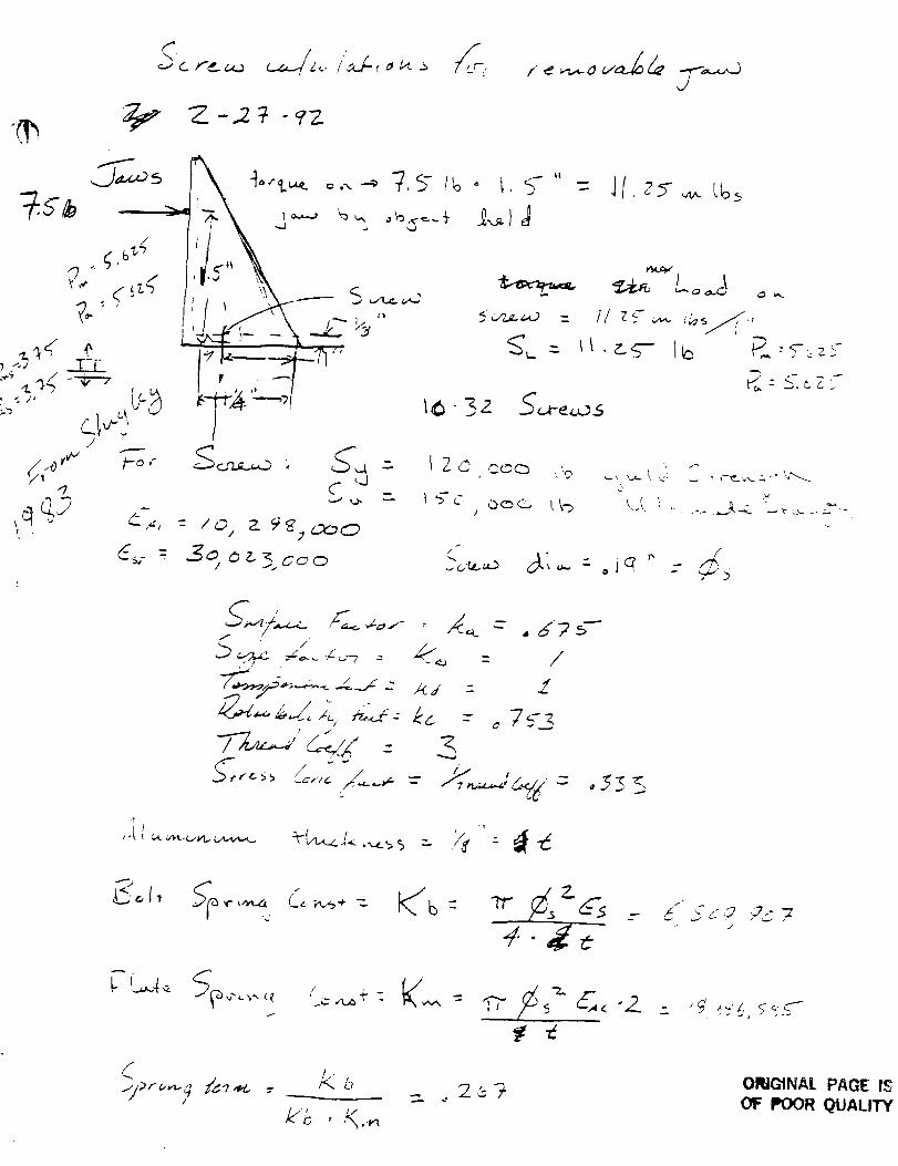
f
11
,j, <i
J
4-_
- &/ 5
4/
! ,
_ _ L,
/_'8 ' K.-_
ORIGtNAL PAGE IS
OF POOR QUALITY
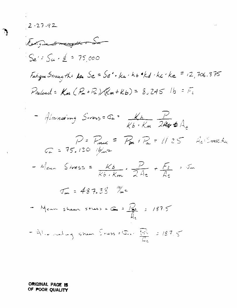
• 2..
f •
U,_be:.d"&'&. = ,:,_._
/
/
.I /"- /":s_,., _ 4_'eSs = I(3
:h_ _h _
,7
_, c .--:,zs< _.
C _ _----..---:r-
_/e_ ,1
ORIGINAL PAG_ IS
OF POOR QUALITY
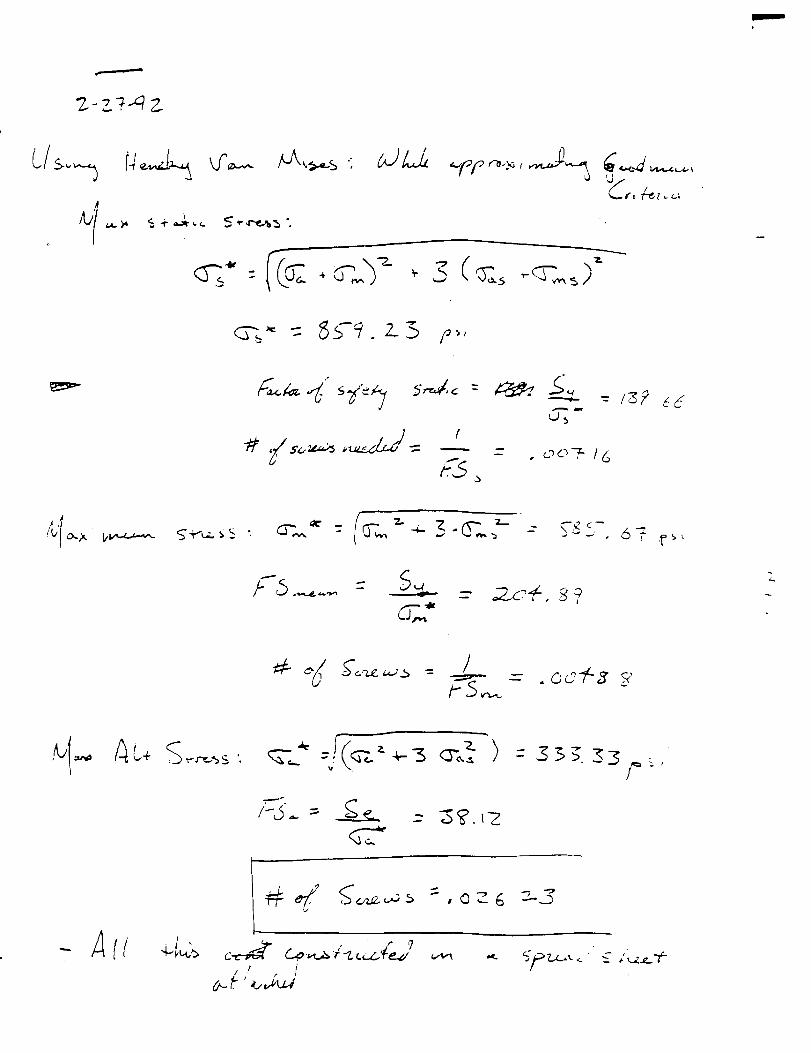
T.
,s.Il_ _ _
Z
I
I
c_/_ ,. '7
, ! /
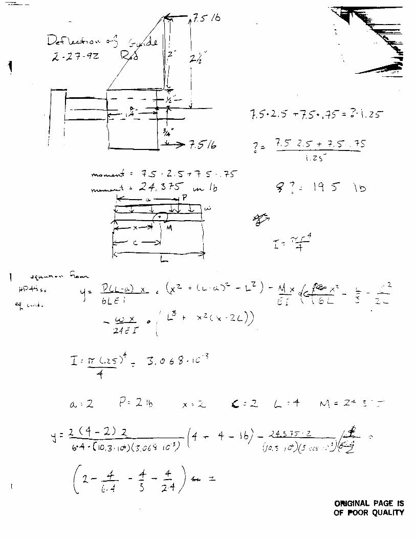
t
_k-'L,-,-_, 0,-
i1
k-
U/
/ , I: 4
p"Ls,z 5 _-7.y.,-_f -_. = o" i. Zs-
C
7,_ 2.5-. 7,5",._4
i,ZS
7 - tq 5- \v
4
'- "4"
bk_l
+ ___.-_.V-- t._z ) -
"k _ * _z__x -'_--.c))
:2.4{ z" t
x C _ L--_ _-_
A.
.L : "rr L,z s "_'
,4- z_(_-- 2) .z_i/c._ ,<37 "<:"'
C"
ORIGINAL PAGE IS
OF POOR QUALITY
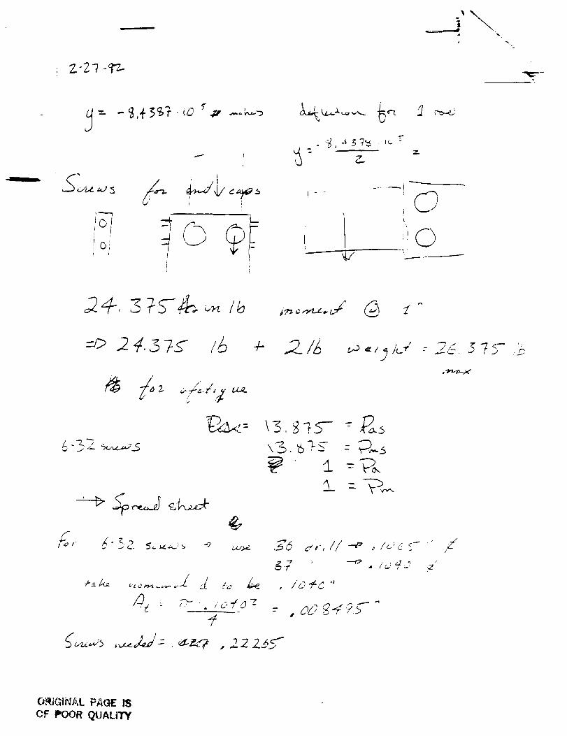
.-IIiil
I ,r
J
0
iI O
=_ 2 4.6 7s /6 4- _?_I_ w.,;j_.".2_'-.57s-._
/_l
/'_)._ --,- ./,07
f
<_ --.-g_.
_._ , --o . I_'4." _"
, IO'Fd "
- oo g-4/s
,z"!
ORIGINAL PAGE IS
OF POOR QUALITY
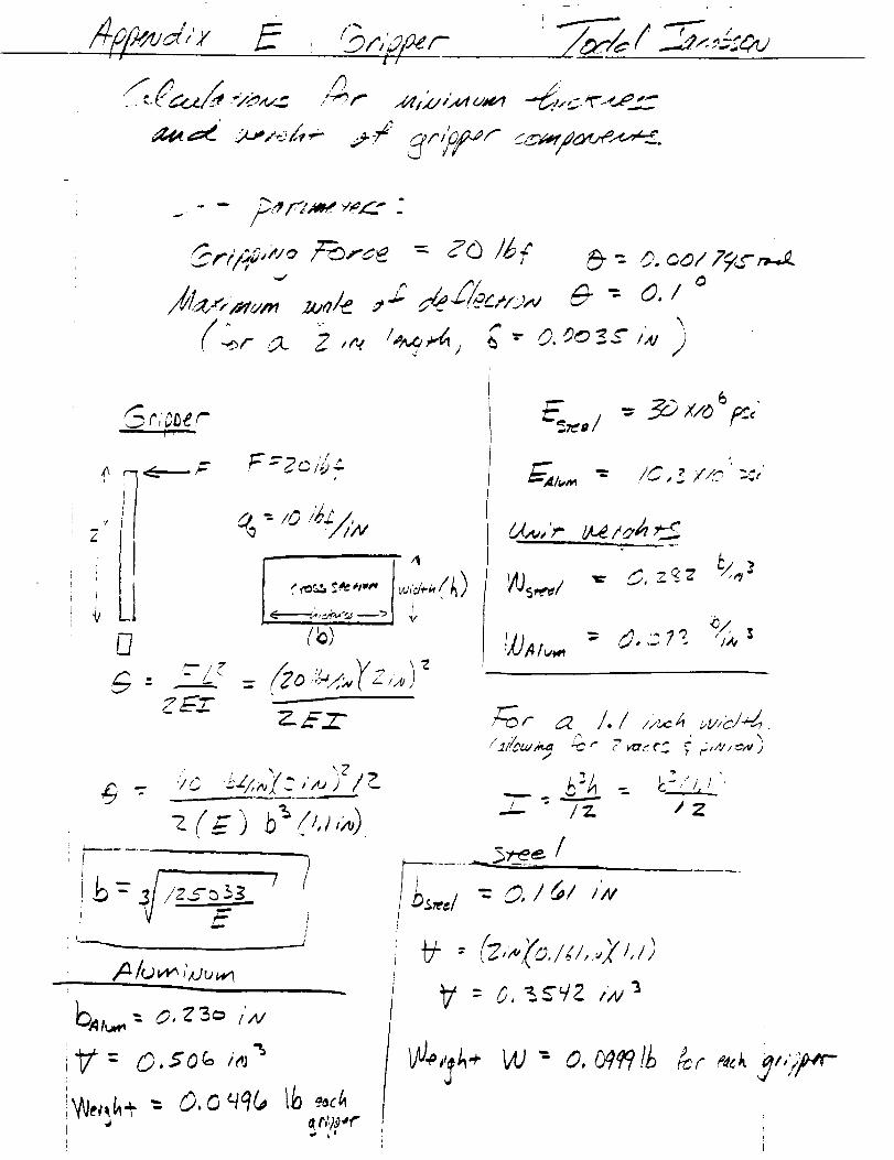
- -- _.,# .r'.,.'_ "- I" _"_ _
.Sr,?_er
#
'I_2
: _o _-'_,._/_,_I_
_o i = .9_>x/__p:<
i,,,- I_ ,Z ¢AO
- d..?_ s
: h,,,yo.I;<,..,7_.<>
6,,;4>,,,-i
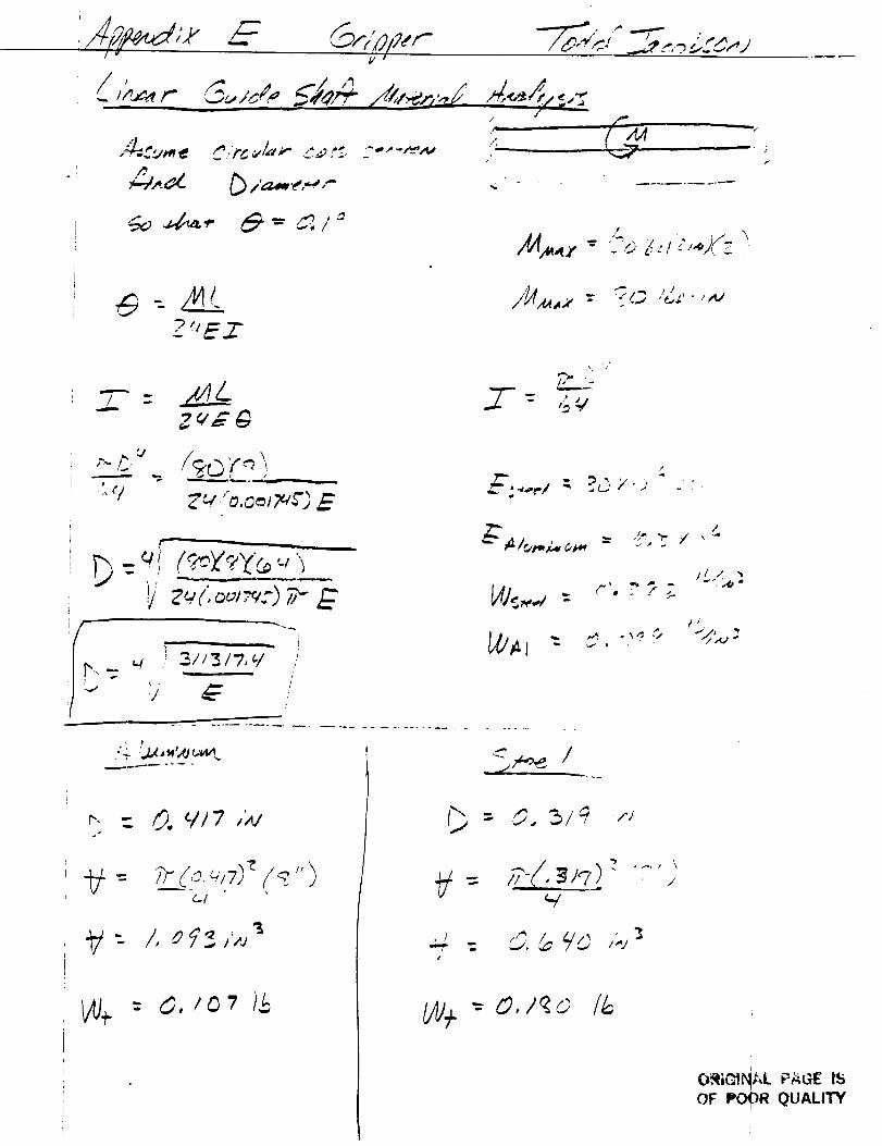
I
i
I
I
I
i
P.
_. t ¸_
f1
/_,r_ I# "--
_ i'_._,_ ,,-
!
'ZEZ
Zv_
------- -_ .... "__
f..--
_j
i
/_ ,
#i
_.. - _o _/17 ,',_
+/: f, _q_ ,_,_
W+ = O,/O't )$
fd
{ _iq) _ .... .,
, ) O, _ 90 ,;.,_
i
O_ielNA.L PAc_ IS
OF POOR QUALITY
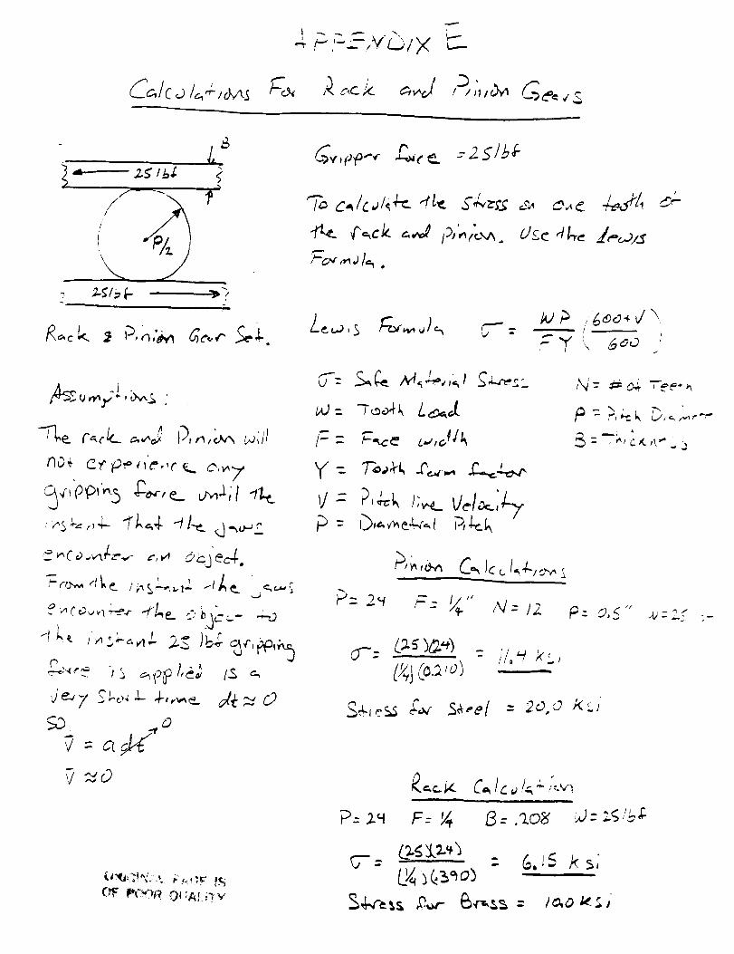
C_,/c_i<__-,_ _-_
!7"-
-,'=-L_ L;I×/'-" .,M _''", t,,-.---
I )'t/_
/"/I\
-., ;._/_ _.
7.¢
re
• o.
Jss_,,,,,;Z.___ .
_,_,Ap,. + r 2 51_6,__ _. -
,-.i
;o,,._1_.
!
t I
,_" "F"k 4<)<2
pV- P,4.:l,/t_ v+/_;7--/
f_: 0,_'" .u-.; -
CS"- (..;1.5 )_._) _ i' l, _ 7<<..,
(D$(_._,o)
_._-_- C_/__i.__,.._
F- _ /_: .?..OL _: :4 ,,'bD
5-= , - G. IS 7_s,
&4-_--_s#_ 6<,,ss= le.o_.;,
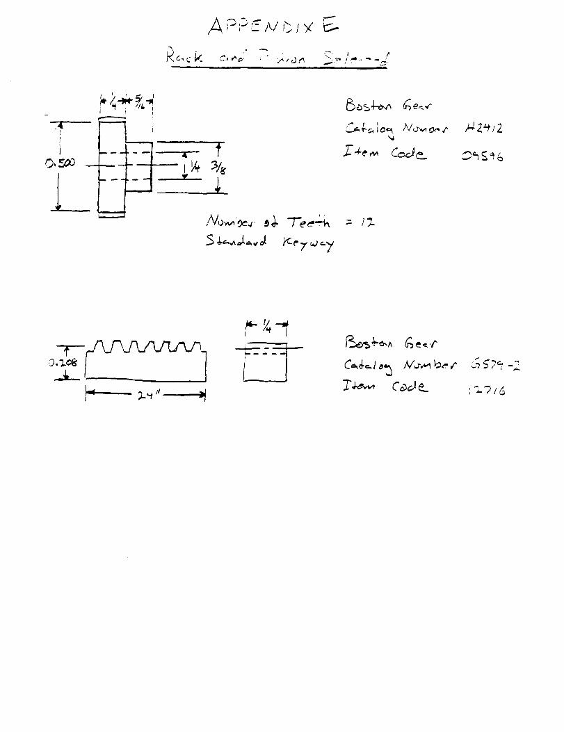
_i'_ ", iI _ .. _ _ ;/P.,,
-I
__ : _
I'2-9/_
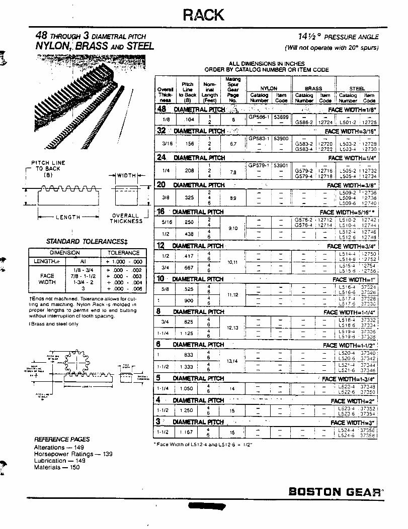
48 THROUGH 3 DIAMETRAL PITCH
NYLON,'. BRASS _ STEEL_ ....
: i "i -r , ,q i
PITCH LINE
__jT0BACK
"_IWI DTH r
OVERALL i
THICKNESS
STANDARD TOLERANCES$
DIMENSIONJ
LENGTH.+ All
1/8 - 3/4FACE 7/8- 1-1/2
WIDTH 1-3/4 - 23
TOLERANCE
+ 1.0OO -.0OO
+ .000 - ,(X)2+ .000 - .003+ .0(30 - .004+ .000 - 006
•Enos not machined. Tolerance allows for cut-
ling and matching. Nylon Rac)', is molded =n
proper lengths to permit end Io end butting
without Interruplion of tooth spacing.
:Brass and steel only.
_vcT=i=,
'" "+ I _'__'_:_-_- --_"-,
REFERENCE PAGES
Alterations- 149
Horsepower Ratings-- 139Lubrication -- 149Materials- 150
RACK
14 Y2 o PRESSUREANGt F
(Will not operate with 20 = spurs)
ALL DIMENSIONS IN INCHESORDER BY CATALOG NUMBER OR ITEM CODE
Pitch Nom- _rIO--, Line Inad i C.-ieat I NYLON BRASS, STEEL J
I T_- I toe_ i_t. I _ II c=,=_j I it=_ ]1c_,=_ [ .0_ II _'_ [ J=m i
1 GP586-1 53899 ....118 .104 2 6 - - G586.2 12724 L501-2 12725
J t 1 J 11GP583-1 53900 i - -3/16 156 2 ) 6,7 ] - . -- G583-2 12720 L503-2 12728
4 l ; - G583-4 ]12722, L503-4 _2730
FACE WIOTH=I/4"24. O_E'mAL' ' 1 ' GP579-1 53901
'" ,2 1: : !120 _='m_m'c. .....
"' 2 - - I
318 325 ; 8,9 _- _-
';161 " DIAMETR/U.
51,6 ,2_12 ,38 r_ 9,10 !I_- ] - t)
12 .B.._u,CWR,_.PrrcH _ .
3/4 667i I_ - I - il
10. =_ErR,=u. pcn::H
1 90o _ 1,,,2, i8 t:X,_C=TR_prmH
314 l 625
1-1,4 t '12'_ _ j 12.13
0 DI_AL PrrCH
4
1 833 6
D13,14
41-1/2 1333 6
6_ ,I 1_ ,J -1-I/2 t250 I
3-: _m,_.._ -. • •
t : ]• Face W_lm o_L512-4 and L512-6 = 1/2"
- ii -
l f -- ( --
t2;_ _505.2,,27321271 L505-4 !12734
FACE W1D"rH=3J8"
' - ; L509-2 112736_- i _ i L509-4 12738
- - .! L509-6 '2740
FACE WIDTH=5116' *G576-2 12712;1 L510-2 12742G576-4 12714 _ L510-4 12744
-- -- ,I L512-4 12746- - ! L512-6 12748
FACE WIDTH=314"
-- -- L514-4 ] _2750- ; - L514-6 i 12752
-- _ -- L515-4 12754
-- -- L5 15-6 ! 2755
FACE WtDTH=I"I ]ii -- ;r L516-4 37324
-- !! L516-6 37326P
-- L517.4 37329
- L517-6 37330
FALSEWIDTH= 1-1t4")- , - ,I L_,84 37332
- ' -- q L5_8-6 37334
-- -- L519-4 37336
-- -- L519-6 37338
FACE WIDTH=l-l/2"
[ - il L520-4 37340- ii L520-6 37342
!I L521-4 ,37344[ -- L521-6 i 3734_
FALSEWIO1"H=1,3/4"
i _ i L522-4 [37348i - , L522.6 '37350
F/t_E Wl::rrl-I=_'
F/tl:_ W1OTH=3"
-- I -- - I L524-4 '37356- - - , L524-6 =37358
ij L523-4 37352L5236 37354
BOSTON GEAR °
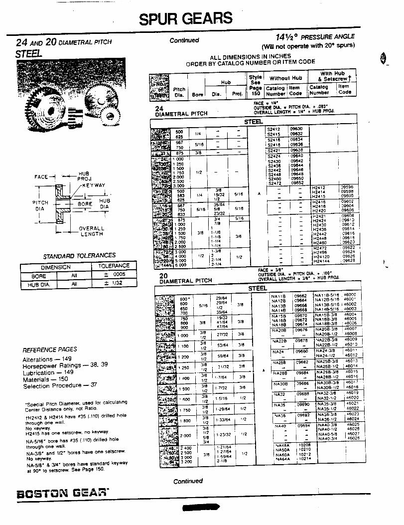
24 AND20 O,AM RALPITCHSTEEL
HUB
FACE _ _'"--PROJ.
P T_H-_ /-KEYWAY
OVERALL--LENGTH
STANDARD TOLERANCESl
I 01MENSION TOLERANCE
BORE All _ 0005
HUB DIA. All + 1/32
REFERENCE PAGES
Alterations- 149Horsepower Ratings- 38. 39Lubrication -- 149Materials- 150Selection Procedure -- 37
• Soecial Pitch Diameter. used for calculating
Center Distance only, not Ratto,
tH2412 & H2414 have #35 (.1101 drilled hole
through one wall.
No keyway.H2415 has one setscrew, no kew,_ey.
NA-5116" bore has #35 (.110} drilled hole
through one wall.
NA-3/8" and 1/2" bores have one setscrew.
NO keyway.
NA-5/8" & 3/4" bores have standard keyway
at 90 e to setscrew. See Page 150.
SPUR GEARS
Continued
FE1_e'_ol,.
24DIAMETRAL PITCH
14 V=o PRESSUREANGLE
(Will not operate with 20" spurs)
ALL DIMENSIONS IN INCHESORDER BY CATALOG NUMBER OR ITEM CODE
,q
With HUb
Setyle Without Hub & Setscrew 1"Hub .=¢
I Pmge Catalog Item Catalog ItemBore Ola. Pmj. 150 Number Code Number Code
RICE = 114"0UTSlOE 0UL. •PtTCH 0IA. _" ,083"OVERAll LI_GTH • 1/4" + HUB PROJ.
_ 500 1/4625
_667 5116750 .
_!_t_J 875 3/8
@° 11 250• t 50O
._: 1750 I/2
_ 2.00012.500
•_-I _I_ 500
•_ 833
s._. 875_ 1ooo_O':;_, 1250_.+,_ t 5oo _e_" °_ -.
-_ _ 7502.0002.500
,_.;_ 3oo0
.,-_-t=O_l5 ooo,,..=-',f4_,', 6000
2ODIAMETRAL PtTCH
s-tl=m_-- $2412 09630
_ $2415 09632_ ,$2416 _09834
_ i $2418 09638
_ _$2421 09638
31815132 5116 A1/2
35/64518 5/_ 623/32
3/4 5/16716
11.1181.118 318I-lf41-I/4
1-3/8
2 1/22-1142-114
52424 _40
$2430 0¢J642S2436 0_44$2442 09646$2448 09_8
$2460 t0_50$2472 09652
:1:;
:!:
- I -
:i:
H2412 09596H2414 09596H2415 109600H2416 _09602H2418 L09604
H2420 109606H2421 09608H2424 J09610
H2430 ]09612H2435 09614H2442 ;09616H2448 1096_8H2460 09620
H2472 09622H2496 109624H24120 109626
H24144 L09628
FACE • 3/11"OUTSIDE OIA. • PITCH 01A..+ .I00"OVERALL LENGTH = 3/8" ÷ HUB PRO J.
5oo"i,_)_ 500_,_ * _'_1 5116
_';:. _ 700
,,..%_r.kl8_ 750_,_ _ 800 318
1 000 112
318, .. - , 100 1/2
29164 i
291641/235164
i 19/3241164
1 47/64
I 27132 3/8
i_l_ 200
___?.: 1250_', _ k" 400_. 1/2
318=:_ ":_ 500 _/2
_'_._ I 600 lf2
3/8,_r,:'_,_ _ 750 t_2
• . • 3/8
i 800 112;_,.,_: ._. 318
,_:j:a_ 2ooo i 5/e
314
je_.4_;..P 2 400
'-_ _i_o o
3/8 591641/2
318 L 31/321/2_._
l.71641-7132
1.5116
i-29164
1-33/64
1-23132
1.21/641.21164
1-591642-t18
ST_'L
I NA118' NA126
318 NA13R
NA146NA158
3/8 NA166NAi86
NA208
3/8 __^2,_NA256
3/8
318 NA32
1/2
ly2
It2
,_A35
NA36
NA40
! -NA48ANASOANA60ANA64A
09662 NA118.5/16 I 4600009664 NA128-5116 I 4600x09668 :NA138-5/16 i 46002
09668 NA 146-5116 146003
09670 NA158-3/8 4600409672 NA16B-318 14600509674 NA188-3/8 i J.6006,09676 NA208-3/8 46007
-- NA20B-1/2 : 46008
] 09678 NA226-3/8 [ 46009' NA228-112 46010
09_;0 NA24-3/8 4601NA24-112 46012
I 09682 NA258-3/8 ', 460i3
i -- NA258-II2 i 48014
09684 NA288.3/8 i 46015NA288-_/2 I46016
NA308-112 46018
NA32-3,/8 l 46019
0 N^32-1/2 46020096 NA35-3/8 I 46021,NA35-)12 ; _8022
09692 NA36.3/8 ', 46023
-- NA36-112 J 46024' 09694 NA40-3/8 46025
_ "4A40.1/2 i 46026
-- NA40-5/8 46027
I -- NA40-3/4 i 4802610208 [
10210 i1021210214 i
Continued
)
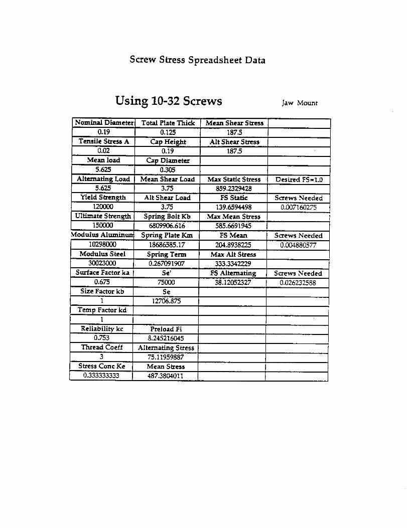
Screw Stress Spreadsheet Data
Using 10-32 Screws Jaw Mount
Nominal Diameter Total Plate Thick Mean Shear Stress
0.19 0.125 187_
Tensile Stress A Alt Shear Stress
0.02
Mean load
5.625
Alternating Load5.625
Yield Strength120000
Cap Height0.19
Cap DiameterO.3O5
Mean Shear Load
3.75
Alt Shear Load
3.75
Ultimate Strength Spring Bolt Kb15OO00 6809906.616
Modulus Alumintm
10298000
Modulus Steel
3OO23OOO
Surface Factor ka
0.675
Size Factor kb
1
Temp Factor kd1
Reliability kc0.753
Spring Plate Km
18686585.17
S pring Term0.267091907
Se'
75OOO
Se
127O6.875
Preload Fi
8.245216045
Thread Coeff Alternating Stress3 75.11959887
Stress Conc Ke Mean Stress
0.333333333 487.3804011
187.5
Max Static Stress Desired FS=I.0
859.2329428
FS Static Screws Needed
139.6594498 0.007160275
Max Mean Stress
585.6691945
FS Mean Screws Needed
204.8938225 0.004880577
Max Air Stress
333.3342229
FS Alternating Screws Needed
38.12052327 0.026232588
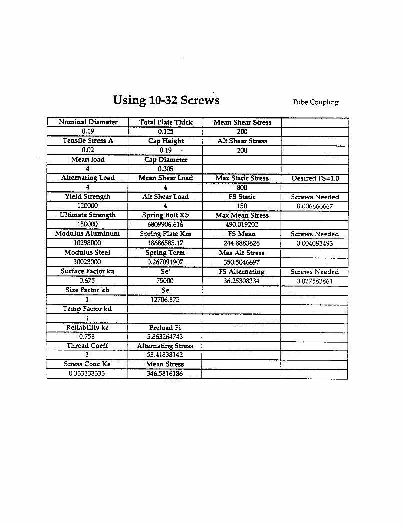
Using 10-32 Screws Tube Coupling
Nominal Diameter
0.19
Total Plate Thick
Alternating Load
4 4 800
Yield Strength Alt Shear Load FS Static Screws Needed12OOOO
Ultimate Strength Spring Bolt Kb150000 6809906.616
Modulus Aluminum Spring Plate Km10298000 18686585.17
Modulus Steel
30023000
Surface Factor ka
0.675
Size Factor kb
1
Temp Factor kd1
Reliability kc Preload Fi0.753
Thread Coeff
3
Stress Conc Ke
0.333333333
Tensile Stress A Cap Height
0.02 0.19
Mean load Cap Diameter4 0.305
Mean Shear Load
Spring Term
0.267091907
Se' FS Alternating Screws Needed75000 36.25308334 0.027583861
Se
12706.875
5.8_2_3
Alternating Stress53.41838142
Mean Stress
346.5816186
Mean Shear Stress
200
Alt Shear Stress
200
Max Static Stress Desired FS=I.0
150 0.006666667
Max Mean Stress
490.019202
FS Mean Screws Needed
244.8883626 0.004083493
Max Alt Stress
350.5046697
0. 25
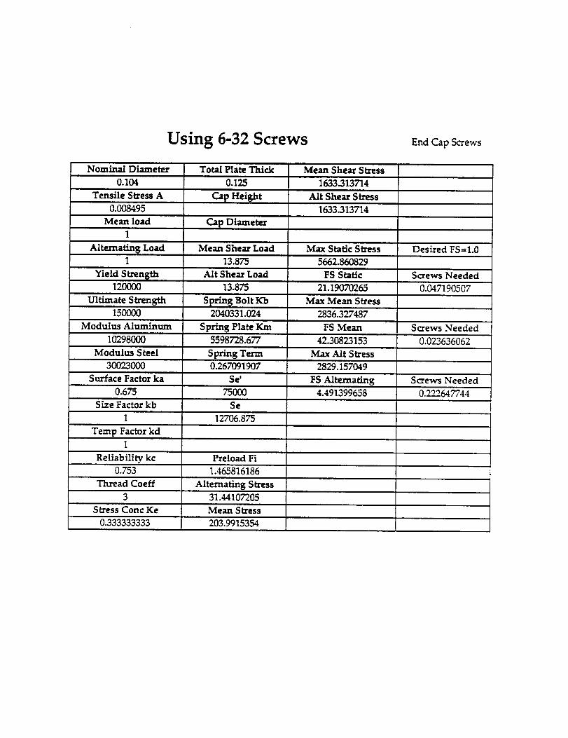
Using 6-32 Screws End Cap Screws
Nominal Diameter
0.104
TensileStressA
0.008495
Mean load
Alternating Load
Yield Strength
12OOOO
UltimateStrength
150OO0
Modulus Aluminum
10298000
Modulus Steel
30023000
Surface Factor ka
0.675
Size Factor kb
Temp Factor kd
Reliabilitykc
0.753
Thread Coeff
Total Plate Thick
0.125
Cap Height
Cap Diameter
Mean Shear Load
13.875
Alt Shear Load
13.875
Spring Bolt Kb2040331.024
Spring Plate Km
5598728.677
S _'ing Term0.267_1_7
Se'
75OOO
Se
12706.875
Preload Fi
1.465816186
Alternating Stress
31.44107205
StressConc Ke Mean Stress
0.333333333 203.9915354
Mean Shear Stress
1633.313714
AftShear Stress
1633.313714
Max StaticStress
5662.860829
FS Static
21.1_70265
Max Mean Stress
2_6.32_87
FS Mean
42.30823153
Max Alt Stress
2829.157049
FS Alternating4.491399658
Desired FS=I.0
Screws Needed
0.047190507
Screws Needed
0.023636062
Screws Needed
0.222647744
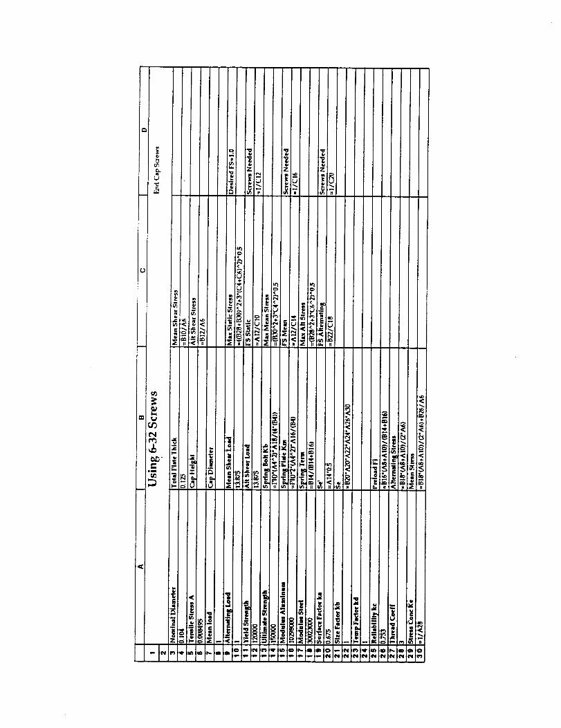
U=_
_- Z Z Z
?
A
u.
r_
• :!_
II IV < 14
-t-
i <! !
)- - I _. _- ' _ _ _'-"_ _'_'! 11" : i)

APPENDIX F
ENCODERS
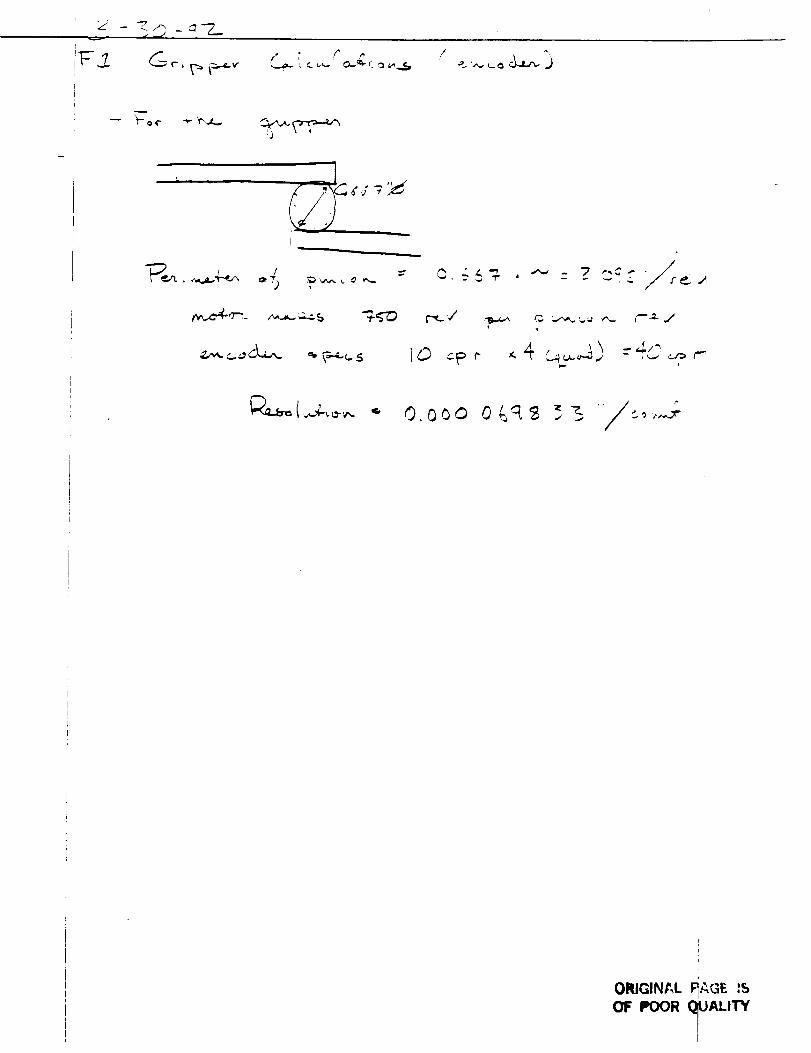
, d_/+
,*" F r p / 3._ ,. c.._.,.- O--it" ___ w_ ' _.. '.,,., t.. _
ORIGINAL RAG_. IS
OF POOR (_UALITY
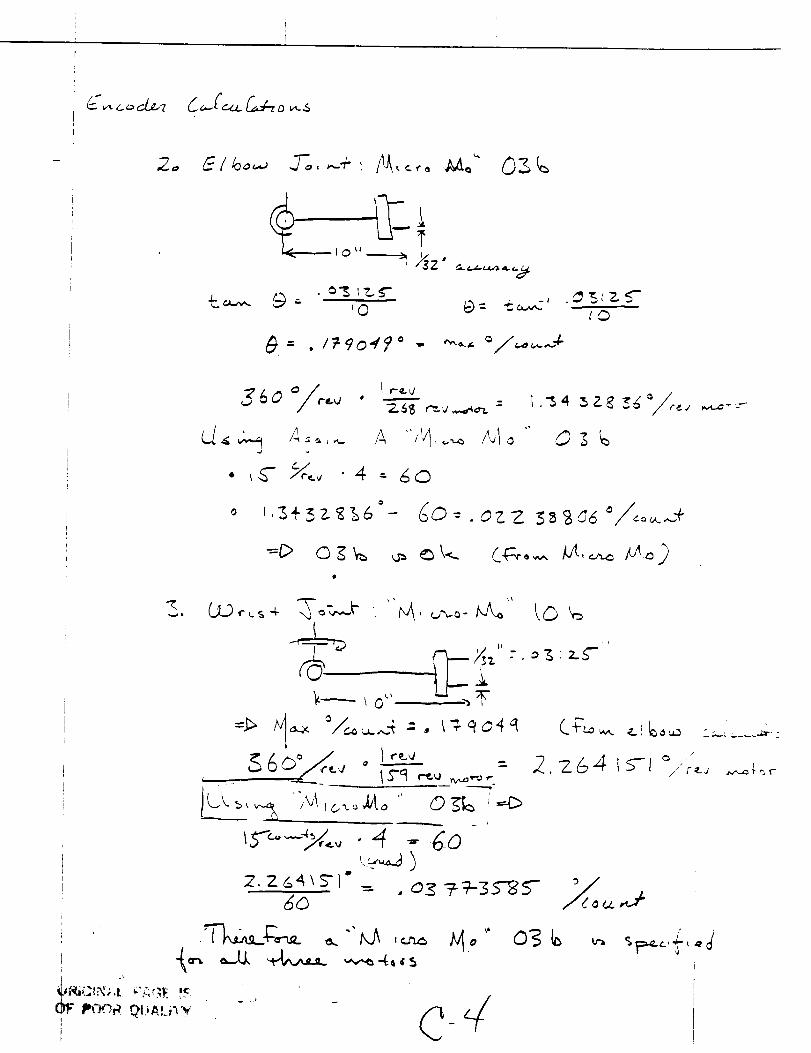
(r_,
_0
_--
_60 _ , ------
CA, ._ >_.-..,-. A ,,',I,.-o A,1o Q_g
(.._,_ ¢ ,. _ ,4..
_. ,
kO_
,,M
f
(_ /,/
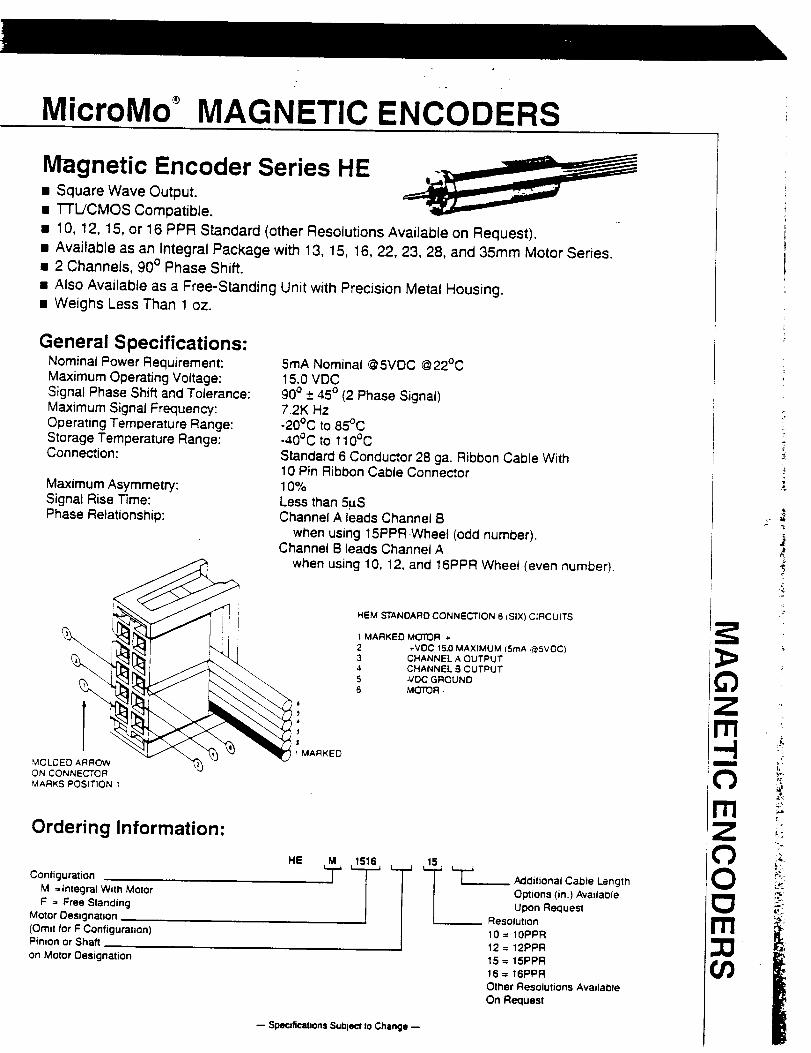
MicroMo MAGNETIC ENCODERS
Magnetic Encoder Series HE• Square Wave Output.
• TTL/CMOS Compatible.
• 10, 12, 15, or 16 PPR Standard (other Resolutions Available on Request).• Available as an Integral Package with 13, 15, 16, 22, 23, 28, and 35mm Motor Series.• 2 Channels, 90 ° Phase Shift.
• Also Available as a Free-Standing Unit with Precision Metal Housing.• Weighs Less Than 1 oz.
General Specifications:Nominal Power Requirement:Maximum Operating Voltage:Signal Phase Shift and Tolerance:Maximum Signal Frequency:Operating Temperature Range:Storage Temperature Range:Connection:
Maximum Asymmetry:Signal Rise Time:Phase Relationship:
5mA Nominal @5VDC @22°C15.0 VDC90° ± 45 ° (2 Phase Signal)7.2K Hz-20°C to 85°C-40°C to 110°C
Standard 6 Conductor 28 ga. Ribbon Cable With10 Pin Ribbon Cable Connector10%
Less than 5uSChannel A leads Channel B
when using 15PPR.Wheet (odd number).Channet B leads Channel A
when using 10, 12, and 16PPR Wheel (even number).HEM STANDARD CONNECTION 6 (SIX) CIRCUITS
2 _VDC 15.0 MAXIMUM (5rnA @SVOC)3 CHANNEL A OUTPUT4 CHANNEL B OUTPUT5 -VDC GROUND6 MOTOR -
J
J
MARKEDMOLCED ARROWON CONNECTORMARKS POSITION 1
Ordering Information:
Configuration _ -- _L_MdJtJonal Cahte Lengtfl
M =integral With Motor Options (in.) AvadaDle
F = Free Standing Ugon Recluest
Motor Oesignation Resolution
(Om=t for F Configuration) 10 = 10PPR
Pinion or Shaft 12 = 12PPR
on Motor Designation 15 = 15PPR
16 = 16PPR
Other Resolutions Avmlable
On Request
-- SPecifications Sui=ject Io Change
I
JJ,
>=.
tl
L;.
tJ)
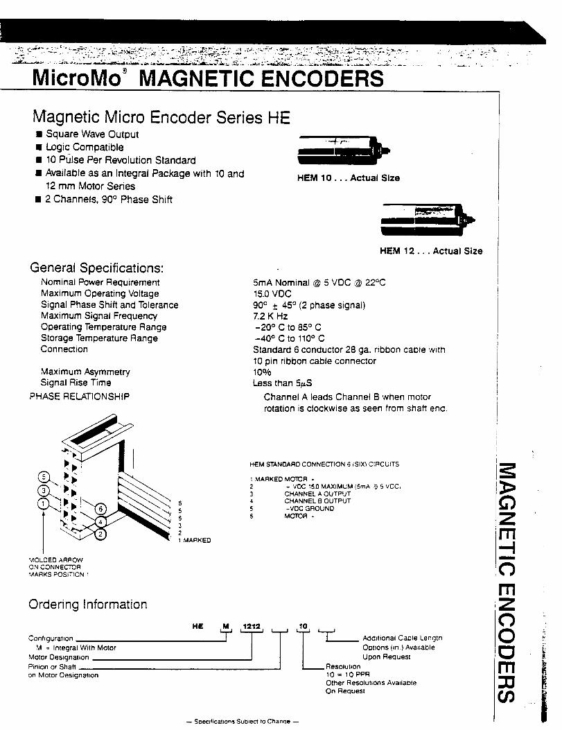
MicroMo MAGNETIC ENCODERS
Magnetic Micro Encoder Series HE• Square Wave Output• Logic Compatible• 10 Pulse Per Revolution Standard
• Available as an Integral Package with 10 and12 mm Motor Series
• 2 Channels, 90 ° Phase Shift
HEM 10... Actual Size
General Specifications:Nominal Power RequirementMaximum Operating VoltageSignal Phase Shift and ToleranceMaximum Signal FrequencyOperating Temperature RangeStorage Temperature RangeConnection
Maximum AsymmetrySignal Rise Time
PHASE RELATIONSHIP
HEM 12... Actual Size
5mA Nominal @ 5 VOC @ 22°C15.0 VDC
90(_ +_45° (2 phase signal)7.2 K Hz-20 ° C to 85° C-40 °ctOl10 °CStandard 6 conductor 28 ga. ribbon cable with10 pin ribbon cable connector10%Less than 5_S
Channel A leads Channel B when motorrotation is clockwise as seen from s_aft end
t_.-,HEM STANDARD CONNECTION 6 (SIX) C=RCUITS
2 * VDC 15.0 MAXIMUM (5rnA _ 5 VOC,
(__. 3 CHANNEL A OUTPUT
5 4 CHANNEL B OUTPUT
5 5 -VOC GROUND
6 6 MOTOR -321 MARKED
MOLDED ARROWON CONNECTOR
MARKS POSITION 1
Ordering Information
HE _.- _.._
Configuration i Addi{ional Cal31e Length
M = Integral Wild Motor OI3tnons (in) AvadaDle
Motor Oes_gnation Upon Fle(:luest
Pinion or Shaft Resolution
on Motor Oesignat_on 10 = 10 PPROther Resolutions Avadable
On Recluesl
-- Soecfficat_on_ Subject to Chancle --
m • -
C)rri
C)O
r.
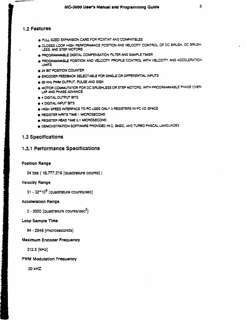
MC-3000 User's Manual and Programming Guide 3
1.2 Features
• FULL S_'D EXPANSION CARD FOR PC_'T/AT AND COMPATIBLES
• CLOSED LOOP HIGH PERFORMANCE POSITION AND VELOCITY CONTROL OF DC BRUSH, DC BRUSH-LESS, AND STEP MOTORS
• PROGRAMMABLE DIGITAL COMPENSATION RLTER AND SAMPLE TIMER
@ PROGRAMM/_LE POSITION AND VELCCrTY PROFILE CONTROL WITH VELOCITY AND ACCELERATIONUMffS
• 24 BIT POSITION COUNTER
• ENCODER FEEDBACK SELECTABLE FOR SINGLE OR DIFFERENTIAL INPUTS
• 20 KHZ PWM OUTPUT, PULSE AND SIGN
• M(:TrOR COMMUTATOR FOR OC BRUSHLESS OR _TEP MOTORS. WITH PROGRAMMABLE PHASE OVER-LAP ANO PHASE ADVANCE
• 4 DIGITAL O_ BITS
• 4 DIGITAL INPUT BITS
• HIGH SPEED INTERFACE TO PC USES ONLY 3 REGISTERS IN PC I/O SPACE
• REGISTER WRITE TIME 1 MICROSECOND
• REGISTER READ TIME 2.1 MICROSECONO
• OEMCNSTRATION SOFTWARE PROVIDED IN C, BASIC. AND TURBO PASCAL LANGUAGES
1.3 Specifications
1.3.1 Performance Specifications
Position Range
24 bits ( 16,777,216 [quadrature counts] )
Velocity Range
31.32"10 s [quadrature countsJsec]
Acceleration Range
2 - 2000 [quadrature counts/sec z]
Loop Sample Time
64 - 2048 [microseconds]
Maximum Encoder Frequency
312.5 [kHz]
PWM Modulation Frequency
20 kHZ
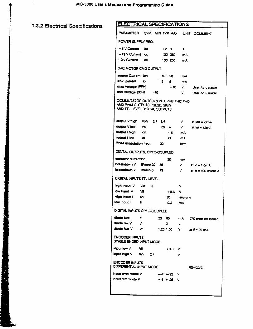
4 MC-3000User'sManualand ProgrammingGuide
1.3.2 Electrical SpecificationsELL=C i HICAL SPECIFICATIONS
PARAMETER SYM MIN TYP MAX UNIT
POWER SUPPLY REQ.
+SVCurrent I¢¢ 1.2 3 A
+ 12 V Current Ic¢ 1(30 250 mA
-12 v C_rrent I¢¢ 100 250 mA
OAC MOTOR CMD OUTPUT
Sou,'_e C_mmt 1011 10 20 mA
=.nk C4aTem Iol 5 8 mA
mu Voltage (FR-I) + 10 V
rnln Voltage (00H) -10 V
COMMUTATOR CUTPUTS PHA, PHB, PHC,PHDAND PWM CUTPUTS PULSE. SIGNAND TT'L LEVEL DIGITAL OUTPUTS
outDut V high Voh 2.4 3.4
o_ V low Vol .2_
output I h_h k=h
output I low Iot
PWM moclulation/rKl. 20
DIGITAL O_ OPTC-COUPLED
¢o_le¢mr current I¢¢ 30
_'uktlmmV BVc=o30 85
I:mUclo_m V BVe¢o 6 13
DIGITAL INPUTS TTL LEVEL
high input V Vih 2
low tnlmJt V Vll +0.8
High Input I lib 20
low inl_Jt I Ill <3.2
DIGITAL INPUTS OPTC_-COUPLED
dio¢lo fwd I ff 20 60
dio¢le my V Vr 3
=1o¢1l fw_ V Vf 1.25 1.50
ENCODER INPUTSSINGLE ENDED INPUT MODE
input low V Vii +0.8
input high V Vth 2.4
EJ_I_DER INPUTSDIFFERE_ITIAL INPUT MODE
=nput c_nn tootle V +-7 +-25
input cliff mo<:le V +-6 +-25
V
4 V
-15 mA
24 mA
kHZ
mA
V
V
V
V
micro A
mA
mA
V
V
V
V
V
V
COMMENT
User AcliustaoJe
User Acliustaole
APPENDIX G
PROGRAM

{ }{ Controller program for }
{ }{ Autonomous Space Processor For Orbital }
{ Debris ( ASPOD ) End Effector }
{ }
program Effector;
{$M8192,8192,655360}{$x+,s-}
uses Dos, Objects, Drivers, Memory, Views, Menus, Dialogs,
StdDlg, MsgBox, App, Calc, Buffers, Editors;
const
HeapSize = 32 * (1024 div 16);
const
MaxLines = I00;
WinCount: Integer = 0;
BaBase:integer = 768;
ShBase: integer = 769;
HBase: integer = 770;
TBase:integer = 776;
BBase: integer = 777;
GBase: integer = 778;
cmOpen = 100;
cmNew = 101;
cmChangeDir = 102;
cmDosShell = 103;
cmCalculator = 104;
cmShowClip = 105;
cmFileOpen = 200;
cmNewWin = 201;
cmGrip = 202;
cmCurGrip = 203;
cmDeltGrip = 204;
cmGoGrip = 205;
cmWhatGrip = 106;
cmGripBox = 107;
cmDefaultset = 108;
cmWhatTwist = 109;
cmCurTwist = 110;
{ Base Addresses for the six axis }
{ Begin Command List}
{ New Window }
{ Yet unassigned for dialog box }
{ Current Position - Gripper }
{ Final Position Setting - Gripper }
{ Execute Trapazoidal Profile Move }
{ Get Final Position Setting for gripper }
{ Create Dialog Box - Dummie }
{ Reset all values to Default }
{ SAA For twisting Joint }
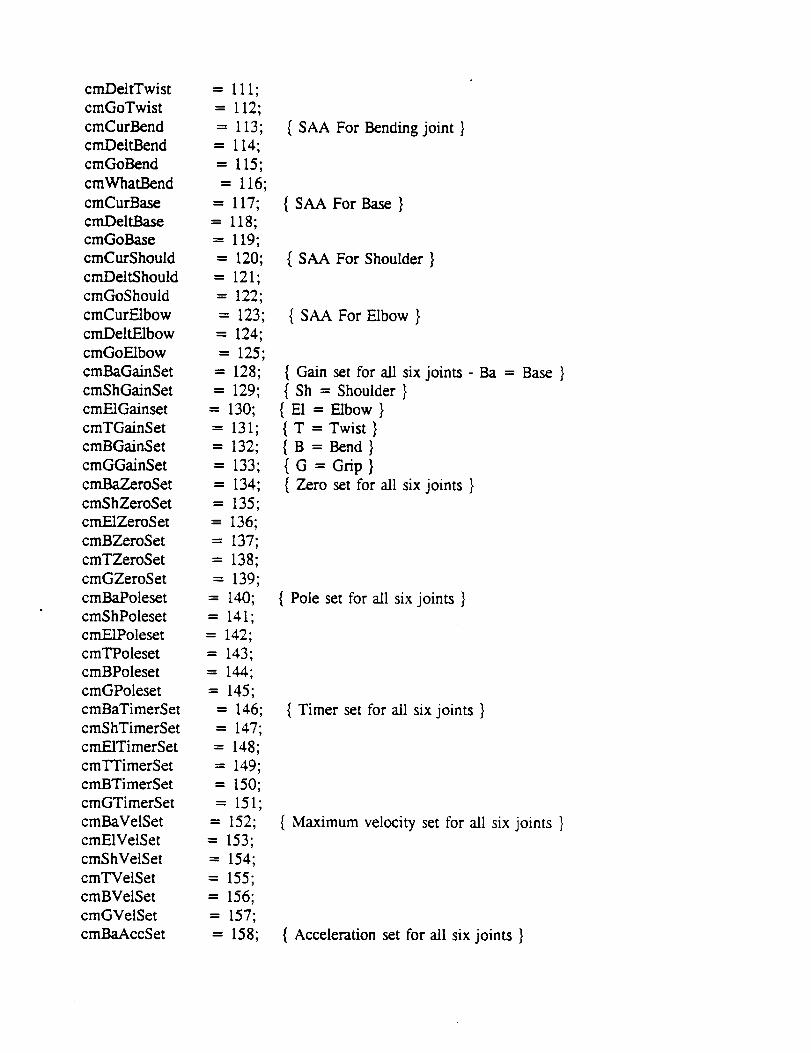
cmDeltTwistcmGoTwistcmCurBendcmDeltBendcmGoBendcmWhatBendcmCurBasecmDeltBasecmGoBasecmCurShouldcmDeltShouldcmGoShouldcmCurE1bowcmDeltE1bowcmGoEIbowcmBaGainSetcmShGainSetcmEIGainsetcmTGainSetcmBGainSetcmGGainSetcmBaZeroSetcmShZeroSetcmEIZeroSetcmBZeroSetcmTZeroSetcmGZeroSetcmBaPolesetcmShPolesetcmEIPolesetcmTPolesetcmBPolesetcmGPolesetcmBaTimerSetcmShTimerSetcmEITimerSetcm2"q'imerSetcmBTimerSetcmGTimerSetcmBaVelSetcmEIVelSetcmShVelSetcmTVelSetcmBVeiSetcmGVelSetcmBaAccSet
= 111;
= 112;
= 113,
= 114;
= 115;
= 116;
= 117;
-- I18;
-- 119;
= 120;
= 121;
= 122;
= 123;
= 124;
-- 125;
- 128;
= 129;
= 130;
= 131;
= 132;
= 133;
= 134;
= 135;
= 136;
= 137;
= 138;
= 139;
- 140;
= 141;
= 142;
= 143,
= 144;
- 145;
= 146;
= 147;
= 148;
-- 149;
= 150;
= 151;
= 152;
= 153;
= 154;
= 155;
= 156;
= 157;
= 158;
{ SAA For Bending joint }
{ SAA For Base }
{ SAA For Shoulder }
{ SAA For Elbow }
{ Gain set for all six joints - Ba = Base }
{ Sh = Shoulder }
{ E1 = Elbow }
{ T = Twist }
{ B = Bend }
{ G = Grip }
{ Zero set for all six joints }
{ Pole set for all six joints }
{ Timer set for all six joints }
{ Maximum velocity set for all six joints }
{ Acceleration set for all six joints }
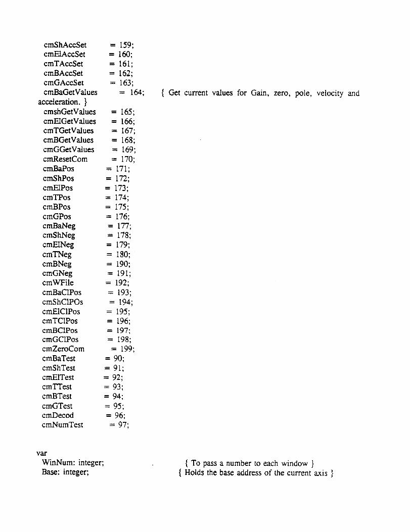
cmShAccSet
cmE1AccSet
cmTAccSet
cmBAccSet
cmGAccSet
cmBaGetValues
acceleration. }
cmshGetValues
cmE1GetValues
cmTGetValues
cmBGetValues
cmGGetValues
cmResetCom
cmBaPos
cmShPos
cmEiPos
cmTPos
cmBPos
cmGPos
cmBaNeg
cmShNeg
cmE1Neg
cmTNeg
cmBNeg
cmGNegcmWFile
cmBaCIPos
cmShCIPOs
cmEICIPos
cmTCIPos
cmBCIPos
cmGCIPos
cmZeroCom
cmBaTest
cmShTest
cmEITest
cmTTest
cmBTest
cmGTest
cmDecod
cmNumTest
--- 159;
= 160;
= 161;
= 162;
= 163;
= 164;
-- 165;
- 166;
= 167;
- 168;
= 169;
= 170;
= 171;
= 172;
= 173;
= 174;
= 175;
= 176;
= 177;
= 178;
= 179;
= 180;
= 190;
= 191;
= 192;
= 193;
= 194;
= 195;
= 196;
= 197;
= 198;
= 199;
= 90;
= 91;
= 92;
= 93;
= 94;
= 95;
= 96;
= 97;
{ Get current values for Gain, zero, pole, velocity and
val-
WinNum: integer;
Base: integer;
{ To pass a number to each window }
{ Holds the base address of the current axis }
Values: array[0.. 10] of string[50];Corn: array[0..9] of string[20];Arg: array[0..9] of integer;J10: integer;ClipWindow: PEditWindow;
{ For the Current Values listing window }{ Array for commandsets}
{ Array for correspondingarguments}{ Ten line counter }
typePASPOD = "ASPOD;
ASPOD = object(TApplication)
constructor Init;
destructor Done; virtual;
procedure
procedure
procedure
procedure
procedure
procedure
procedure
procedure
procedure
procedure
procedure
procedureprocedureprocedureprocedure
procedure
procedure
procedure
procedure
procedure
procedure
procedure
procedure
procedure
procedure
end;
{ Lists objects used in ASPOD-Application }
OutOfMemory; virtual;
HandleEvent(var Event: TEvent); virtual; { Defines Command actions }
IrtitMenuBar; virtual; { Defines MenuBar and menu items }
InitStatusLine; virtual; { Def Status Line }
ANewWindow(Num2: integer); { Current Value O/P Win }
Go(basetmp: integer); { Execute Trap move }
Default; { Sets all values to default-msg }
Res; { Performs a reset on all axis-msg }
zero; { o/p zero command }
PosMove(BaseTmp, pow: integer); { o/p full positive command to Basetmp}
NegMove(BaseTmp, pow: integer); { Full Neg Cm to Basetmp }
TCurrent(BaseTmp: integer); { Displays current position of BaseTmp }
final(BaseTmp: integer); { Sets Final position Of BaseTmp-msg }
whatfinal(BaseTmp: integer); { Dispays Final position of BaseTmp }
SetGain(BaseTmpG: integer); { Sets Gain }
SetZero(BaseTmpZ: integer); { You get the picture }
SetPole(BaseTmpP: integer);
SetTimer(BaseTmpT: integer);
SetVel(BaseTmpV: integer);
SetAcc(BaseTmpA: integer);
ClearPos(BaseTmp: integer);
GetVal(BaseTmpVal: integer); { Displays current values }
Test(BaseTmp: integer); { Tests BaseTmp }Decode;
NTest;
SWindow = "AWindow; { Defines Current value window stuff }AWindow = object(TWindow)
constructor Init(Bound: TRect; WinTit: String; WindowN: Word);
end;
SInterior = AAInterior; { Interior Def for Cur Value Window }
AInterior = objecttTView)
constructor Init(var Bound: TRect);
procedure Draw; virtual;
end;
{ AInterior }
constructor AInterior.Init(var Bound: TRect);
begin
TView.Init(Bound);
GrowMode := gfGrowHiX + gfGrowHiY;
Options := Options or of Fmmed;
end;
{ Current Value O/P Window Stuff }
procedure AInterior.Draw;
var i: integer;const
Greeting: string = 'Hello, World!';
begin
TView.Draw;
fori:=0to 10do
WriteS tr(4, 2 + i, Values[i], $01);
end;
{ AWindow }
constructor AWindow.Init(Bound: TRect; WinTit: String; WindowN: Word);vat
S: string[3];
Interior: slnterior;
begin
Str(WindowN, S);
TWindow.Init(Bound, WinTit + ' ' + S, wnNoNumber);
GetClipRect(Bound);
Bound. Grow(- I,- 1);
Interior:= New(Slnterior, Init(Bound));
Insert(Interior);
end;
function IToS (I:Longint): String;vat
S: String[11];
Begin
Strft,S);
IToS := S;
end;
{ Convert any integer type into a string }
function ExecDialog(P: PDialog; Data: Pointer): Word;vaf
Result: Word;
begin
Result :-- cmCancel;
P :- PDialog(Application".ValidView(P));
ifP < > nil then
begin
ifData < > nil then P".$etData(Data");
Result :- DeskTop".ExecView(P);
if(Result < > cmCancel) and (Data < > nil)then P^.GetData(Data");
Dispose(P, Done);
end;
ExecDialog := Result;
end;
function CreateFindDialog: PDialog;vat
D: PDialog;
Control: PView;
R: TRect;
begin
R.Assign(0, 0, 38, 12);
D :-- New(PDialog, Ink(R, 'Find'));with D" do
begin
Options := Options or of Centered;
R.Assign(3, 3, 32, 4);
Control := New(PInputLine, Init(R, 80));
Insert(Control);
R.Assign(2, 2, 15, 3);
Insert(New(PLabel, Init(R, ' - T- ext to find', Control)));
R.Assign(32, 3, 35, 4);
Insert(New(PHistory, Ink(R, PlnputLine(Control), 10)));
R.Assign(3, 5, 35, 7);
Insert(New(PCheckBoxes, Init(R,
NewSItem(' - C - ase sensitive',
NewSItem(' - W- hole words only', nil)))));
R.Assign(14, 9, 24, 11);
Insert(New(PButton, Ink(R, 'O-K-', croOk, bfDefault)));
Inc(R.A.X, 12); Inc(R.B.X, 12);
Insert(New(PButton, Init(R, 'Cancel', crnCancel, bfNormal)));
SelectNext(False);end;CreateFindDialog := D;
end;
function CreateReplaceDialog: PDialog;
vat
D: PDialog;
Control: PView;
R: TRect;begin
R.Assign(0, 0, 40, 16);
D :-- New(PDialog, Init(R, 'Replace'));
with D A do
begin
Options := Options or of Centered;
R.Assign(3, 3, 34, 4);
Control :- New(PlnputLine, Init(R, 80));
Insert(Control);
R.Assign(2, 2, 15, 3);
Insert(New(PLabel, Init(R, '-T-ext to find', Control)));
R.Assign(34, 3, 37, 4);
Insert(New(PRistory, Init(R, PinputLine(Control), 10)));
R.Assign(3, 6, 34, 7);
Control := New(PlnputLine, Init(R, 80));
Insert(Control);
R.Assign(2, 5, 12, 6);
Insert(New(PLabel, Init(R, ' - N- ew text', Control)));
R.Assign(34, 6, 37, 7);
Insert(New(PHistory, Init(R, PlnputLine(Control), i1)));
R.Assign(3, 8, 37, 12);
Insert(New(PCheckBoxes, Init(R,
NewSItem(' - C - ase sensitive',
NewSItem(' - W - hole words only',
NewSItem(' - P - rompt on replace',
NewSItem(' - R - eplace all', nil)))))));
R.Assign(17, 13, 27, 15);
Insert(New(PButton, Init(R, 'O-K-', crook, bfI)efault)));
R.Assign(28, 13, 38, 15);
Insert(New(PButton, Init(R, 'Cancel', cmCancel, bfNormal)));
SelectNext(False);
end;CreateReplaceDialog:= D;
end;
function DoEditDialog(Dialog: Integer; Info: Pointer):Word; far;var
R: TRect;T: TPoint;
begincase Dialog of
edOutOfMemory:
DoEditDialog := MessageBox('Not enough memory for this operation.',
nil, mfError + mfOkButton);edReadError:
DoEditDialog := MessageBox('Error reading file %s.',
@Info, mfError + mfOkButton);
_WriteError:
DoF_xiitDialog := MessageBox('Error writing file %s.',
@Info, mfFa'ror + mfOkButton);
_CreateError:
Dol=:_xtitDialog := MessageBox('Error creating file %s.',
@Ira"o, m_rror + mfOld3utton);
_SaveModify:
DoExiitDialog := MessageBox(' %s has been modified. Save?',
@Info, mflnformation + mfYesNoCancel);
_SaveUntifl_:
DoF_AitDialog := MessageBox('Save untitled file?',
nil, mfInformation + mfYesNoCancel);
_SaveAs:
DoE_iit.Dialog : = ExecDialog(New(PFileDialog, Init('*.*',
'Save file as', ' - N- ame', fdOkButton, 101)), Info);
edFind:
DoE_iitDialog := ExecDialog(CreateFindDialog, Info);
edSearchFailed:
DoEditDialog := MessageBox('Search string not found.',
nil, mfError + mfOkButton);
edReplace:
DoEditDialog := ExecDialog(CreateReplaceDialog, Info);
edReplacePrompt:
begin
{ Avoid placing the dialog on the same line as the cursor }
R.Assign(0, 1, 40, 8);
R.Move((Desktop".Size.X - R.B.X) div 2, 0);
Desktop".MakeGlobal(R. B, T');
Inc(T. Y);
if TPoint(Info). Y < = T. Y then
R.Move(0, DesktopA.Size.y- R.B.Y - 2);DoEditDialog := MessageBoxRect(R,'Replace this occurence?',
nil, mfYesNoCancel + mflnformation);
end;
end;
end;
function OpenEditor(FileName: FNameStr; Visible: Boolean): PEditWindow;vat
P: PView;
R: TRect;
begin
DeskTop". GetExtent(R);
P := ApplicationA.ValidView(New(PEditWindow,
Init(R, FileName, wnNoNumber)));
if not Visible then P".I-Iide;
DeskTop_'. l.nsert(P);
OpenEditor := PEditWindow(P);
end;
{ List of procedures from MC 3000 }
{ }
procedure set_Base(Num: integer);
Begin
Base := Num;
end;
procedure regout(reg,val,Basetmp :integer);
begin
port[BaseTmp + reg _'1024]: = val;
end;
function regin(reg,BaseTmp :integer) : integer;
begin
regin: = port[BaseTmp + reg* 1024];
end;
procedure resetP;
begin
regout(5,0,768);regout(5,0,769);regout(5,0,770);regout(5,0,776);regout(5,0,777);regout(5,0,778);end;
procedureinitialize;beginregout(5,I ,Base);end;
proceduresel_mode;begin
regout (5,3,base);end;
procedurealign;beginregout(5,2,Base);end;
proceduredelay_sec(sec:Shortint);vat c,c2 :integer;beginfor c: =0 to sec do
beginFor c2: = 1 to 1000 do
inc (c2);
end;
end;
procedure trap_mode;
begin
regout(0, 8, Base);
end;
procedure pv_mode;
begin
regout(0,0,Base);
regout(0,11,Base);
regout(5,3,Base);
end;
procedure int_mode;
beginregout(0,0,Base);regout(0,3,Base);regout(0,13,Base);regout(5,3,Base);.end;
procedureset_cmd...pos(pos:Longint);vatlow,reed,high: Shortint;beginlow: =lo(round(pos));
reed: = hi(round(pos));
high: = hi(round(pos/256));
regout( 14, low, Base);
regout(13,reed,Base);
regout(12,high,Base);
end;
procedure clr_act_pos;
begin
regout(19,0,Base);
end;
procedure set_.final_pos(pos: longint);
var
low,rned,high: Shortint;
begin
low: =pos and $000000FF;
reed: =pos shr 8 and $000000FF;
high: = pos shr 16 and $000000FF;
regout(41, low, Base);
regout(42,med,Base);
regout(43,high,Base);
end;
function get cmd_.pos:real;
begin
get_cmd__pos: =0;
end;
function get_act_pos:longint;var
low,med,high: Shortint; retval: longint;
begin
high: =regin(20,Base);
meal: -" regin ( 19,Base);
low: - regin(18,Base);
retval: - high*65536 + med*256 + low;
if ( retval > 8388607 ) then retval := retval - 16777215;
get_act..pos :- rerval;
end;
function getfinal_.pos: Longint;
vat high, low, med: Shortint; retval: Longint;
begin
high := regin(43,Base);
meal'= regin(42,Base);
Low'= regin(41,Base);
retval • = High*65536 + reed*256 + low;
get_Final_Pos • = retval;
end;
procedure set..gain(gain: Shortint);
begin
regout(34, gain, Base);
end;
function get_gain: Shortint;
begin
get_gain: = regin (34, Base);
end;
procedure set .pole(pole: Shortint);
begin
regout(33, pole, Base);
end;
function get_pole: Shortint;
begin
get_pole: = regin(33,Base);
end;
procedure set_zero(zero: integer);
begin
regout(32, zero, Base);
end;
function get_zero: integer;
begin

get_zero:= rEgin(32, Base);
end;
procedure set_accel(accel: integer);
begin
rEgout(38,10(accEI),BasE);
regout(39, hi(accel), Base);
end;
function get_accel: integer;
begin
getaccel: =regin(38,Base) + regin(39,Base)"256;
end;
procedure set timer(timer: Shortint);
begin
regout(15, timer,Base);
end;
procedure setmax_vel(vet: Shortint);
begin
rEgout(40,vel,Base);
end;
function getmax_vel: Shortint;
begin
get_max_vel: = regin(40,Base);
end;
procedure set prop_vel(vel: integer);
begin
rEgout(35,1o(vel),Base);
regout(36,hi(vel),Base);
end;
function get__prop_vel: integer;
begin
get_.prop_vel: =regin(35,Base) + regin(36,Base)_'256;
end;
procedure set int vet(vel: integer);
begin
regout(60, vel, Base);
end;
function get int vel: integer;

beginget_intvel: = regin (60, Base);
end;
function get_act_vel: integer;
begin
get act vel: =regin(52,Base) + regin(53,Base)*'256;end;
procedure go_cntrl_mode;
begin
regout(5,3,Base);
end;
procedure quit;
begin
exit;
end;
procedure setstatus(status: integer);
begin
regout(7, status,Base);
end;
function get_status: integer;
begin
get_status: =regin(7,Base);
end;
procedure set_bipolar;
begin
regout(0,2, Base);
end;
procedure set_unipolar;
begin
regout(0,10, Base);
end;
procedure open_loop comm;
begin
regout(0,12,Base);
end;
procedure closed_loop_comm;
begin
regout(0,12,Base);end;
procedure set_do(val: integer);
begin
port[776 + 1]: = val;
end;
function getdi: integer;
begin
get di: =port[776+2];
end;
procedure set_ring(ring: integer);
beginregout(24, ring, Base);
end;
function getting: integer;
begin
getting: = regin(24,Base);
end;
procedure set_x_reg(x: integer);
begin
regout(26,x,Base);
end;
function get_x_reg: integer;
begin
get x_reg: = regin (26, Base);
end;
procedure set._y_reg(y: integer);
begin
regout(27, y,Base);
end;
function get_y_reg: integer;
begin
get_.y_reg: = regin(27, Base);
end;
procedure set_offset(offset: integer);
begin
regout(28,offset,Base);

end;
function get_offset:integer;beginget offset:= regin(28, Base);
end;
procedure setmax_adv(adv: integer);
begin
regout(31,adv,Base);
end;
function getmax_adv: integer;
begin
getmax_adv: = regin(31, Base);
end;
procedure set_vel timer(timer: integer);
begin
regout(25, timer, Base);
end;
procedure set dac(dac: Shortint);
begin
regout(8,dac,Base);
end;
function get_dac: Shortint;
begin
get dac: = regin (8, Base);
end;
procedure set pwm(pwm: integer_;
begin
regout(9,pwm,Base);
end;
function get__pwm: integer;
begin
get_pwm: = regin (9, Base);end;
procedure clr_emerg_flags;¥al"
tmp: integer;
begin
tmp: = regin (7, Base);
regout(7, tmp, Base);
end;
procedure home;
begin
regout(5,0,Base);
regout(36,0,Base);
regout(35,- 10,Base);
regout(0,1 !,Base);
regout(5,3,Base);
while (get di = 0) do ;
regout(5,0,Base);
end;
procedure set flag(flag: Shortint);
begin
regout(0, flag + 8, Base);
end;
procedure ch'_flag(flag :Shortint);
begin
regout(0,flag,Base);
end;
procedure set_default;
var i: integer;
Begin
For i "= 768 to 770 do
begin
set_base(i);
set_gain(5);
set_zero(240);
set..pole(0);
set_timer(40);
set_max_vel(10);
setaccel(10);
end;
For i "= 776 to 778 do
begin
setbase(i);
set_gain(10);
set_zero(240);
set..pole(O);
set timer(40);
set_max_vel(10);
set_accel(10);end;
END;
( ){ End of MC-3000 Procedures }
( )
constructor ASPOD. Init;
vat
H: Word;
R: TRect;
begin
H • = PtrRec(HeapEnd). Seg - PtrRec(HeapPtr). Seg;
if H > HeapSize then BufHeapSize "= H - HeapSize else BufHeapSize "= 0;InitBuffers;
TApplication.Init;
DisableCommands([cmSave, cmSaveAs, cmCut, cmCopy, cmPaste, cmClear,
cmUndo, cmFind, cmReplace, cmSearchAgain]);
EditorDialog • -- DoEditDialog;
ClipWindow "- OpenEditor(', False);
if ClipWindow < > nil then
begin
Clipboard "= ClipWindow".Editor;
Clipboard_'.CanUndo • = False;
end;
Values[0] • -
Values[l] "= '.,
Values[2] • =
Values[3] : = '-
Values[4] • = "
Values[5] • = '.
Values[6] • =
Values[7] •= '.
Values[8] • = '-,
Values[9] • =
Values[10]: =
ANewWindow(0);
end;
Autonomous Space Processer of Orbital Debris';
Robotic Arm Controller Program';
Written By: Bjoern J. Kutz';
Adv: Dr. Kumar Ramohalli';
Copyright 1992';
destructor ASPOD.Done;
begin
TApplication. Done;
DoneBuffers;end;
procedureASPOD.HandleEvent(varEvent: TEvent);
procedureFileOpen;var
FileName: FNameStr;begin
FileName := '* *'.
if ExecDialog(New(PFileDialog, Init('*.*', 'Open file',
' - N- ame', fdOpenButton, 100)), @FileName) < > cmCancel then
OpenEditor(FileName, True);end;
procedure FileNew;
begin
OpenEditor(", True);
end;
procedure ChangeDir;
begin
ExecDialogfNew(PChDirDialog, Init(cdNormal, 0)), nil);end;
procedure DosSheU;
begin
DoneSysError;
DoneEvents;
DoneVideo;
DoneMemory;
SetMemTop(Ptr(Bu fHeapPtr, 0));
PrintStr('Type EXIT to return to TVEDIT...');
SwapVectors;
Exec(GetEnv(' COMSPEC'), ");
SwapVectors;
SetMemTop(Ptr(BufHeapEnd, 0));
InitMemory;
InitVideo;
InitEvents;
InitSysError;
Redraw;
end;
procedure ShowClip;
begin

ClipWindow^.Select;ClipWindow^. Show;
end;
procedureTile;vat
R: TRect;
begin
Desktop". GetExtent(R);
Desktop ^. Tile(R);
end;
procedure Cascade;vat
R: TRect;
begin
Desktop ^. GetExtent(R);
Desktop ^. Cascade(R);
end;
procedure Calculator;
begin
DeskTop^.Insert(ValidView(New(PCalculator, Init)));end;
{ ASPOD }
begin
TApplication. HandleEven t(Event);case Event.What of
evCommand:
case Event.Command of
cmOpen: FileOpen;
cmNew: FileNew;
cmChangeDir: ChangeDir;
cmDosShell: DosShell;
cmCalculator: Calculator;
cmShowClip: ShowClip;cmTile: Tile;
cmCascade: Cascade;
cmCurBase: TCurrent(BaBase);
cmDeltBase: final(BaBase);
cmGoBase: go(BaBase);
cmCurShould: TCurrent(ShBase);

cmDeltShould: f'mal(ShBase);
cmGoShould: go(ShBase);
cmCurElbow: TCurrent(EIBase);
cmDeltElbow: final(EIBase);
cmGoElbow: go(EIBase);
cmCurTwist: TCurrent(TBase);
cmDeltTwist: final(TBase);
cmGoTwist: go(TBase);
cmCurBcnd: TCurrent(BBasc);
cmDeltBend: final(BBase);
cmGoBend: go(BBase);
cmCurGdp: TCurrent(GBase);
cmDeltGrip: final(GBase);
cmGoGrip: go(GBase);
cmDefaultSet: Default;
cmBaGainSet: SetGain(BaBase);
cmShGainSet: SetGain(ShBase);
cmEIGainset: SetGain(EIBase);
cmTGainSet: SetGain(TBase);
cmBGainSet: SetGain(BBase);
cmGGainSet: SetGain(GBase);
cmBaZeroSet: SetZero(BaBase);
cmShZeroSet: SetZero(ShBase);
cmE1ZeroSet: SetZero(E1Base);cmTZeroSet:
cmBZeroSet:
cmGZeroSet:
cmBaPoleset:
cmShPoleset:
Set.Zero(TBase);
SetZero(BBase);
SetZero(GBase);
SetPole(BaBase);
SetPole(ShBase);
cmE1Poleset: SetPole(E1Base);
cmTPoleset: SetPole(TBase);
cmBPoleset: SetPole(BBase);
cmGPoleset: SetPole(GBase);
cmBaTimerSet: SetTimer(BaBase);
cmShTimerSet: SetTimer(ShBase);
cmElTimerSet: SetTimer(E1Base);
cmTTimerSet: SetTimer(TBase);
cmBTimerSet: SetTimer(BBase);
cmGTimerSet: SetTimer(GBase);
cmBaVelSet: SetVel(BaBase);
cmShVelSet: SetVel(ShBase);
cmE1VelSet: SetVel(E1Base);
cmTVelSet: SetVel(TBase);
cmBVelSet: SetVel(BBase);
cmGVeISet: SetVet(GBase);
cmBaAccSet: SetAcc(BaBase);

cmShAccSet:SetAcc(ShBase);cmE1AccSet:SetAcc(E1Base);cmTAccSet: SetAcc(TBase);cmBAccSet:SetAcc(BBase);cmGAccSet:SetAcc(GBase);cmBaGetValues:getValfBaBase);cmshGetValues:getVal(ShBase);cmE1GetValues:getVal(EtBase);cmTGetValues:getVal(TBase);cmBGetValues:getVal(BBase);cmGGetValues:getVal(GBase);cmResetCom:Res;cmZeroCom: Zero;cmBa.Pos:PosMove(BaBase,197);cmShPos:PosMove(ShBase,197);cmE1Pos:PosMove(E1Base,197);cmTPos:PosMove(TBase,255);cmBPos:PosMove(BBase,255);cmGPos:PosMove(GBase,255);cmBaNeg: NegMove(BaBase,57);cmShNeg:NegMove(ShBase,57);cmE1Neg:NegMove(EIBase,57);cmTNeg: NegMove(TBase,0);cmBNeg:NegMovefBBase,0);cmGNeg: NegMove(GBase,0);cmBaCIPos:ClearPos(BaBase);cmShC1POs:ClearPos(ShBase);cmE1C1Pos:ClearPos(EIBase);cmTC1Pos:ClearPos(TBase);cmBC1Pos:ClearPos(BBase);cmGC1Pos:ClearPos(GBase);
cmBaTest:Test(BaBase);cmShTest:Test(ShBase);cmE1Test:Test(E1Base);cmTTest: Test(TBase);
cmBTest: Test(BBase);
cmGTest: Test(GBase);
cmDecod: Decode;
cmNumTest: NTest;
else
Exit;
end;
else
Exit;
end;
ClearEvent(Event);
end;
procedureASPOD.InitMenuBar;vat R: TRect;begin
GetExtent(R);R.B.Y "- R.A.Y + 1;MenuBar := New(PMenuBar,Init(R, NewMenu(
NewSubMenu('- F - ile', hcNoContext,NewMenu(Newltem('-O-pen...', 'F3', kbF3, cmOpen,hcNoContext,Newltem(' - N- ew', ", kbNoKey, cmNew, hcNoContext,Newltem('-S- ave', 'F2', kbF2, crnSave,hcNoContext,Newltem('S - a- ve as...', ", kbNoKey, cmSaveAs,hcNoContext,NewLine(
Newltem('- C- hangedir...i, '" kbNoKey, cmChangeDir,hcNoContext,Newltem('-D-OS shell', ' , kbNoKey, cmDosShell,hcNoContext,Newltem(' - R- eset','Esc', kbEsc,cmResetCom,hcNoContext,Newltem('De-f-ault','Ctrl-F10', kbCTRLF10, cmDefaultset,hcNoContext,Newltem('D - e- code',' ', kbNoKey, cmDecod, hcNoContext,Newltem('N- T- est',' ', kbNoKey, cmNumTest,hcNOContext,Newltem('E-x-it', 'AIt-X', kbAltX, cmQuit, hcNoContext,
NewSubMenu('-E-dit', hcNoContext,NewMenu(Newltem(' - U- ndo', ", kbNoKey, cmUndo, hcNoContext,NewLine(Newltem('Cu-t-', 'Shift-Del', kbShiftDel, cmCut, hcNoContext,Newltem('-C-opy', 'Ctrl-Ins', kbCtrtlns, cmCopy, hcNoContext,Newltem(' - P- aste', 'Shift-Ins', kbShiftlns, cmPaste,hcNoContext,Newltem('-S-how clipboard', ", kbNoKey, cmShowClip, hcNoContext,NewLine(NewItem(' - C- lear', 'Ctrl-Det', kbCtrlDel, cmClear, hcNoContext,
nil))))))))),
NewSubMenu(' - S - earch', hcNoContext, NewMenu(
Newltem('- F-ind...', ", kbNoKey, cmFind, hcNoContext,
Newltem(' - R- eplace...', ", kbNoKey, cmReplace, hcNoContext,
Newltem(' - S - earch again', ", kbNoKey, cmSearchAgain, hcNoContext.
nil)))),
NewSubMenu(' - W- indows', hcNoContext, NewMenu(
Newltem(' - S - ize/move','Ctrl-F2', kbCtrlF2, cmResize, hcNoContext,
Newltem('-Z-oom', ", kbNoKey, cmZoom, hcNoContext,
Newltem('-T-ile', ", kbNoKey, cmTile, hcNoContext,
Newltem('C- a- scade', ", kbNoKey, cmCascade, hcNoContext,
Newltem('-N-ext', 'FI', kbF1, cmNext, hcNoContext,
Newltem(' - P- revious', 'Shift-Fl', kbShiftF1, cmPrev, hcNoContext,
NewItem(' - C - lose', 'Alt-F3', kbAltF3, cmClose, hcNoContext,
NewLine(
Newltem('Ca- 1- culator', ", kbNoKey, cmCalculator, hcNoContext,nil)))))))))),
NewSubMenu("- B - ase', hcNoContext, NewMenu(
NewItem(' - G- ain Set',", kbNoKey, cmBaGainSet, hcNoContext,
NewItem(' - Z- ero Set',", kbNoKey, cmBaZeroSet, hcNoContext,
Newltem(' -- P - ole Set_',", kbNokey, cmBaPoleSet, hcNoContext,
NewItem(' - T-- imer Set',", kbNoKey, cmBaTimerSet, hcNoContext,
NewItem('- V- elocity Set',", kbNoKey, cmBaVelSet, hcNoContext,
NewItem(' - A- cceleration Set',", kbNoKey, cmBaAccSet, hcNoContext,
Newltem('P- o- sition',", kbNoKey, cmCurBase, hcNoContext,
NewItem('C-l-ear position', ", kbNoKey, cmBaC1Pos, hcNoContext,Newltem('- M-ove Setting',", kbNoKey, cmDettBase, hcNoContext,
NewItem(' - C - urrent Values','Ctrl-F7', kbCTRLFT, cmBaGetValues, hcNoContext,
Newltem(' - E- xecute','Alt-V', kbALTV, cmGoBase, hcNoContext,Newltem(' - T- est',' ', kbNoKey, cmBaTest, hcNoContext,nil))))))))))))),
NewSubMenu('Shoul - d - ', hcNoContext, NewMenu(
NewItem('- G- ain Set',", kbNoKey, cmShGamSet, hcNoContext,
Newltem(' - Z- ero Set',", kbNoKey, cmShZeroSet, hcNoContext,
Newltem('- P~ ole Set',", kbNokey, cmShPoleSet, hcNoContext,
NewItem(' - T- imer Set',", kbNoKey, cmShTimerSet, hcNoContext,
Newltem('- V- elocity Set',", kbNoKey, cmShVetSet, hcNoContext,
Newltem('- A- cceleration Set',", kbNoKey, crnShAccSet, hcNoContext,
Newltem('P- o- sition',", kbNoKey, cmCurShould, hcNoContext,
Newltem('C - 1- ear position',", kbNoKey, cmShC1Pos, hcNoContext,
Newrtem('- M-ove Setting',", kbNoKey, cmDeltShould, hcNoContext,
NewItem(' - C- urrent Values','Ctrt-FS', kbCtrlF8, cmShGetVa/ues, hcNoContext.
Newltem(' - E- xecute','Alt-M', kbALTM, cmGoShould, hcNoContext,NewItem(' - T- est',' ', kbNoKey, cmShTest, hcNoContext,nil))))))))))))),
NewSubMenu('E- 1- bow', hcNoContext, NewMenu(
Newltem(' - G- ain Set',", kbNoKey, cmE1GainSet, hcNoContext,
Newrtem('-Z-ero Set',", kbNoKey, cmE1ZeroSet, hcNoContext.
NewItem('- P-ole Set',", kbNokey, cmELPoleSet, hcNoContext,
NewItem(' - T- imer Set',", kbNoKey, cmE1TimerSet, hcNoContext,
Newltem('-V-elocity Set',", kbNoKey, cmE1VetSet, hcNoContext,
NewItem('- A- cceleration Set',", kbNoKey, cmE1AccSet, hcNoContext,
NewItem('P - o- sition',", kbNoKey, cmCurElbow, hcNoContext,
Newltem('C- 1- ear position',", kbNoKey, cmELC1Pos, hcNoContext,
NewItem(' - M- ore Setting',", kbNoKey, cmDeltElbow, hcNoContext,
NewItem(' - C- urrent Values','Ctrl-Fg', kbCTRLF9, cmE1GetValues, hcNoContext.Newltem(' - E- xecute','Alt-O', kbALTO, cmGoElbow, hcNoContext,
New[tern(' - T- est',' ', kbNoKey, cmE1Test, hcNoContext,nil))))))))))))),
NewSubMenu(' - T- wist', hcNoContext, NewMenu(
NewItem('-G-ain Set',", kbNoKey, cmTGainSet, hcNoContext,
NewItem(' - Z- ero Set',", kbNoKey, cmTZeroSet, hcNoContext,
Newltem('- P-ole Set',", kbNokey, cmTPoleSet, hcNoContext,
Newltem('-T-imer Set',", kbNoKey, cmTTimerSet, hcNoContext,
Newltem(' - V ~ elocity Set',", kbNoKey, cmTVelSet, hcNoContext,
Newltem('-A-cceleration Set',", kbNoKey, cmTAccSet, hcNoContext,
Newltem('P ~ o-- sition',", kbNoKey, cmCurTwist, hcNoContext,
Newltem('C-l-ear position',", kbNoKey, cmTC1Pos, hcNoContext,
Newltem(' - M - ove Setting',", kbNoKey, cmDeltTwist, hcNoContext,
Newltem(' -- C- urrent Values','Ctrl-F10', kbCTRLF10, cmTGetValues, hcNoContext,
Newltem(' - E- xecute', 'Alt-Z', kbALTZ, cmGoTwist, hcNoContext,
Newltem(' - T- est',' ', kbNoKey, cmTTest, hcNoContext,nil))))))))))))),
NewSubMenu('Be- n- d', hcNoContext, NewMenu(
Newltem(' - G- ain Set',", kbNoKey, cmBGainSet, hcNoContext,
Newltem(' - Z- ero Set',", kbNoKey, cmBZeroSet, hcNoContext,
Newltem('-P-ole Set',", kbNokey, cmBPoleSet, hcNoContext,
Newltem(' - T- imer Set',", kbNoKey, cmBTimerSet, hcNoContext,
Newltem('- V-elocity Set',", kbNoKey, cmBVelSet, hcNoContext,
NewItem('- A- cceleration Set',", kbNoKey, cmBAccSet, hcNoContext,
Newltem('P - o- sition',", kbNoKey, cmCurBend, hcNoContext,
Newltem('C - 1- ear position',", kbNoKey, cmBC1Pos, hcNoContext,
Newltem(' - M- ove Setting',", kbNoKey, cmDeltBend, hcNoContext,
Newltem(' - C - urrent Values','Ctrt-FS', kbCtrlFS, cmBGetValues, hcNoContext,
NewItem(' - E- xecute', 'AIt-Q', kbALTq, cmGoBend, hcNoContext,
NewItem(' - T- est',' ', kbNoKey, cmBTest, hcNoContext,
nil))))))))))))),NewSubMenu(' - G- rip', hcNoContext, NewMenu(
Newltem('- G-ain Set',", kbNoKey, cmGGainSet, hcNoContext,
Newltem('- Z-ero Set',", kbNoKey, cmGZeroSet, hcNoContext,
Newltem('-P-ole Set',", kbNokey, cmGPoleSet, hcNoContext,
Newltem(' - T- imer Set',", kbNoKey, cmGTimerSet, hcNoContext,
Newltem(' - V - elocity Set',", kbNoKey, cmGVelSet, hcNoContext,
Newltem(' - A- ccelemtion Set',", kbNoKey, cmGAccSet, hcNoContext,
Newltem('P- o- sition',", kbNoKey, cmCurGrip, hcNoContext,
NewItem('C-l-ear position',", kbNoKey, cmGC1Pos, hcNoContext,
NewItem('- M-ove Setting',", kbNoKey, cmDeltGrip, hcNoContext,
Newltem(' - C- urrent Values','Ctrl-F6', kbCtrlF6, cmGGetValues, hcNoContext,
Newltem(' - E - xecute','Alt-U', kbALTu, cmGoGrip, hcNoContext,
Newltem('-T-est',' ', kbNoKey, cmGTest, hcNoContext,nil))))))))))))),
NewSubMenu(' - C - ommand' ,hcNoContext, NewMenu(
Newltem(' - R- eset','Home', kbHOME, cmZeroCom, hcNOContext,
Newltem('Base L- e- ft','Alt-FS', kbALTFS, cmBaPos, hcNoContext,
NewItem('Base R-i-ght','Alt-F6', kbALTF6, cmBa.Neg, hcNoContext,
NewItem('Shoulder - U- p','Alt-FT', kbAltF7, cmShPos, hcNoContext,
NewItem('Shoulder - D- own','Alt-F8', kbALtF8, cmShNeg, hcNoContext,
Newltem('E1bow - U- p','Alt-F9', kbALTF9, cmEIPos,hcNoContext,Newltem('Elbow - D- own','Alt-F10', kbALTFI0, cmEINeg, hcNoContext,NewItem('Twist - L- eft', 'F5', kbF5, cmTPos, hcNoContext,
Newltem('Twist --, R - ight', 'F6', kbF6, cmTNeg, hcNoContext,
Newltem('Bend -U-p','F7", kbF7, cmBPos, hcNoContext,
Newltem('Bend - D - own','F8', kbF8, cmBNeg, hcNoContext,
Newltem('Gdpper - C - Iose','F9', kbF9, cmGNeg, hcNoContext,
Newltem('Gripper - O- pen','FlO', kbF10, cmGPos, hcNoContext,
nil)))))))))))))),nil))))
))))))))));end;
procedure ASPOD.InitStatusLine;
vaf
R: TRect;
begin
GetExtent(R);
R.A.Y := R.B.Y - 1;
New(StatusLine, Ink(R,
NewStatusDef(0, SFFFF,
NewStatusKey('-F2- Save', kbF2, cmSave,
NewStatusKey('-F3- Open', kbF3, cmOpen,
NewStatusKey(' - Aft-F3 - Close', kbAltF3, cmClose,
NewStatusKey('-FS- Zoom', kbF5, cmZoom,
NewStatusKey(' - F6- Next', kbF6, cmNext,
NewStatusKey('-Ctrl-F1- Menu', kbCTRLF1, cmMenu,
NewStatusKey(", kbCtrtF5, cmResize,
nil))))))),
nil)));end;
procedure ASPOD.NTest;vat
Low, High: integer;
TestVal: Longint;
NTestVal: Longint;
Begin
TestVal : = 267242409;
low : = Lo(TestVal);
High:= Hi(TestVal);
writeln ( 'the Values Are: ', TestVal,'
NTestVal := TestVal shr 16;
low := Lo(NTestVal);
High :- Hi(NTestVal);
writeln ( 'the Values Are: ', NTestVal,'
', Low ,' ', High);
', Low ,' ', High);

end;
procedureASPOD.zero;Begin
regout(8,127,base);end;
{ o/p zero command}
procedure ASPOD.PosMove(BaseTmp,Basetmp}Begin
Set...Base(BaseTmp);regout(8,pow,BaseTnap);
end;
IX)W: integer); { o/p full positive command to
procedureASPOD.NegMove(BaseTmp,pow: integer);Begin
Set_Base(BaseTrnp);regout(8,pow,BaseTmp);
end;
{ Full Neg Cm to Basetmp }
procedure ASPOD.Res;
var i: integer; { function DoEditDialog(Dialog: Integer; Info: Pointer): Word; far;vat
R: TRect; }
T: TPoint;
Info: Pointer;
com: Tbufstream;
Begin;
resetP;
{ corn }
Fori := 0to 10do
Values[i] := 'All Axis have been RESET';
ANewWindow(000);
end;
procedure ASPOD.Default;
vat i: integer;
begin
setdefault;
Values[0] := 'All Effector values have been set to default.';For i:= 1 to 10 do
Values[i]:= '")
ANewWindow(0);
end;
procedureASPOD.TCurrent(BaseTmp:integer);vat position: Longint;
begin;set_Base(BaseTmp);position •-- get act...pos;
writeln ('The Current Position is for ',BaseTrnp,' is ',position);end;
Procedure ASPOD.f'mal(BaseTmp: integer);
vat FinalPosition: Longint;
begin
writestr (4,4,'BaseTmp',4);
base := BaseTrnp;
writeln ('What is your desired final position?');
readln (finalposition);
set_fmal..pos(l::inalPosition);
writeln ('Position set.')
end;
Procedure ASPOD.WhatFinal(BaseTmp: integer);var
FinalPosition: Longint;
i: integer;
Begin
writeln (BaseTrnp);
Set_BasefBaseTmp);
finalposition := get_final_.pos;
writeln(' The current final position is ',finalposition);end;
procedure ASPOD.SetGaln(BaseTmpG: integer);vat G: integer;
Begin
writeln ('Num = ',BaseTmpg);
set_Base(BaseTmpg);
writeln ('What is the new Gain?');
readln (G);
Set_Gain(G);
writeln ('The new Gain for joint # ',BaseTrnpg,end;
'is ' , get_gain);
procedure ASPOD.SetZero(BaseTmpz: integer);
var Z: integer;
Begin
writeln ('Num = ',BaseTmpz);
set_Base(BaseTmpz);

writcln ('What isthe new Zero?');
rcadln (Z);
Set_Zero(Z);
writcln ('The new Zero forjoint# ',BaseTmpz,
end;
'is' , get_Zero);
procedure ASPOD. SetPole(BaseTmpp: integer);
var G: integer;
Begin
writeln ('Num = ',BaseTmpp);
set Base(BaseTmpp);
writeln ('What is the new Pole?');
readln (G);
SetPole(G);
writeln ('The new Pole for joint # ',BaseTmpp,' is 'end;
, get_Pole);
procedure ASPOD.SetTimer(BaseTmpt: integer);
vat G: integer;
Beginwriteln ('Num -- ',BaseTmpt);
set_Base(BaseTmpt);
writeln ('what is the new Timer Value?');
readln (G);
Settimer(G);
end;
procedure ASPOD.SetVeI(BaseTmpv: integer);
var G: integer;
Begin
writeln ('Num = ',BaseTmpv);
set_Base(BaseTmpv);
writeln ('What is the new Velocity?');
readln (G);
Set_max_vel(G);
writeln ('The new Velocity for joint # ',BaseTmpv,' is 'end;
, get_max_vel);
procedure ASPOD.SetAcc(BaseTmpa: integer);
vat G: integer;
Begin
set_Base(BaseTmpa);
Writeln ('What is the new Acceleration?');
readln (G);
Set_accel(G);
Writeln ('The new Acceleration for joint # ',BaseTmpa,' is ',get_accel);
{ Lout[2] "=''.,Lout[3] •= ' ",BNewWindow(BaseTmpa);}
end;
procedureASPOD.ClearPos(BaseTmp:integer);BeginSet_Base(BaseTmp);clr_act_.pos;
end;
procedure ASPOD.GetVal(BaseTmpval: integer);var
Nstr: string[4];
i, tmp: integer;
begin
set Base(BaseTmpval);
tmp : = BaseTmpVal;
Nstr "-- IToS(BaseTmpval);
Values[0] "= 'The Current GAIN for joint # '+ Nstr + ' is '+ IToS(get_gain);
Values[l] : = 'The Current ZERO for joint # '+ Nstr + ' is '+ 1ToS(get_zero);
Values[2] • = 'The Current POLE for joint # '+ Nstr + ' is '+ IToS(get__pole);
Values[3] • = 'The Current VELOCITY for joint # ' + Nstr + ' is ' + 1ToS(get max vet):
Values[4] • = 'The Current ACCELERATION for joint # ' + Nstr + ' is ' + IToS'(get.._ccel):Fori'=5to 10do
Values[i] • = ' "Y
ANewWindow(tmp);
end;
procedure ASPOD.Go(Basetmp: integer);
Begin
setBase(Basetmo);
trap_mode;
end;
procedure ASPOD.Test(BaseTmp: integer);var
i: integer;
Begin
set_Base(Basetmp);
writeln ('Actual position:', get_act_.pos);
clr_act pos;
writeln ('Actual position:', get_act_pos);fori:= 1 to5do
Begin

PosMove(BaseTmp,197);delay_see(100);Zero;writetn ('Actual position:'
end;
end;
, get act_pos);
procedure ASPOD.Decode;
vat
i,j,k, Low, Med, high: integer;
Fil, Comm: String[13];
SIArg: ShortInt;
IArg, pow: integer;
LIArg: LongInt;
FileName: Text;
Begin
Values[0] := 'What is the File Name you would like to run ?';
for i := 1 to 10 do Values[i] := ' ';
ANewWindow(0);
setCursor(10,12);
readln(Fil);
Assign(FileName, Fil);
{$I- }
reset(FileName);
{$I+ }ifIOResult < > 0 then
writeln('Can not open File');
Comm : = 'Go';
While not Eof(FileName) and (Comm < > 'quit ') and (Comm < > ") do
Begin
readln (fileName, Comm);
if comm = 'set base' thenI
Begin
readln (filename, Iarg);
Base := Iarg;
writeln ('Command is ', Comm,' ',IArg);
end;
if comm = 'set_gain ' then
Begin
readln (filename, Iarg);
regout(34, Iarg, Base);
writeln ('Command is ', Comm,' ',IArg);
end;

if comm = 'set zero ' then
Begin
readln (filename, Iarg);
regout(32, Iaxg, Base);
writeln ('Command is ', Comm,
end;' ',IArg);
if comm = 'set_pole ' then
Begin
readln (f'flename, Iarg);
regout(33, Iarg, Base);
writeln ('Command is ', Comm,' ',IArg);end;
if comm = 'set timer'then
Begin
readln (filename, Iarg);
regout(15, Iarg, Base);
writeln ('Command is ', Comm,' ',IArg);end;
if comm = 'set max vel' then
Begin
readln (filename, Iarg);
regout(40, Iarg, Base);
writeln ('Command is ', Comm,
end;' ',IArg);
if comm = 'set accel ' then
Begin
readln (filename, Iarg);
regout(38, lo(Iarg), Base);
regout(39, hi(Iarg), Base);
writeln ('Command is ', Comm,' ',IArg);
end;
if comm = 'set_final__pos' then
Begin
readln (filename, LIArg);
low: =LIArg and $000000FF;
reed: =LIArg Shr 8 and $_FF;
high: =LIArg shr 16 and $_FF;
regout(41, Low, Base);
regout(42, meal, Base);
regout(43, high, Base);
writeln ('Command is ', Comm,' ',LIArg);
writeln ('Low is ',Low,' Med is ',Med,' High is ',High);end;
if comm = 'delay ' then
Begin
readln (f'rlename, Iarg);
for j := 1 to 1000*Iarg do
for k := 1 to 1000 do;
inc(k);
writeln ('Command is ', Comm, _ ',IArg);
end;
if comm = 'clr..act_pos ' then
Begin
regout(19, 0, Base);
writeln ('Command is ', Comm);
end;
if comm = 'corn out'thenm
Begin
re.attln( fdename, Iarg);
pow :-- Iarg;
port[base+ 8" 1024]: --pow;
writeha ('Command is ',comm,' ',Iarg);
end;
ifcomm = 'sel mode' then
Begin
regout(5, 3, Base);
writeln ('Command is ', Comm);
end;
if comm = 'repeat ' then
Begin
readln (filename, Iarg);
writetn ('Command is ', Comm);
end;
if comm = 'trap mode ' then
Begin
regout(0, 8, Base);
writetn ('Command is ', Comm);
end;
if comm = 'next ' then i: =0;
End;
Close(FileName);
End;
procedure ASPOD.ANewWindow(Num2: integer);vat
Window: SWindow;
R: TRect;
WinTit: String;
begin
WinNum :- Num2;
if (Num2 = BaBase) then Wintit := 'Base';
if (Num2 = ShBase) then Wintit := 'Shoulder';
if (Num2 = E1Base) then Wintit : = 'Elbow';
if (Num2 = TBase) then Wintit : = 'Twist';
if (Num2 = BBase) then Wintit := 'Bend';
if (Num2 = GBase) then Wintit := 'Grip';
if (Num2 = 0) then Wintit := 'Output';
R.Assign(1, 1, 75, 20);
Window:= New(SWindow, l.nit(R, WinTit, WinNum));
DeskTop". Insert(Window);end;
procedure ASPOD. OutOfMemory;
begin
MessageBox('Not enough memory for this operation.'
nil, mfError + mfOkButton);
end;
Val"
MyApp: ASPOD;
begin
MyApp.Init;
MyApp.Run;
MyApp. Done;end.


