Embed Size (px)
Citation preview

Construction and Building Materials 23 (2009) 2265–2276
Contents lists available at ScienceDirect
Construction and Building Materials
journal homepage: www.elsevier .com/locate /conbui ldmat
Axially loaded RC columns strengthened by steel caging. Finite element modelling
Jose M. Adam a,*, Salvador Ivorra b, Francisco J. Pallarés c, Ester Giménez a, Pedro A. Calderón a
a ICITECH, Departamento de Ingeniería de la Construcción y Proyectos de Ingeniería Civil, Universidad Politécnica de Valencia, Camino de Vera s/n, 46071 Valencia, Spainb Departamento de Ingeniería de la Construcción, Obras Pública e Infraestructura Urbana, Universidad de Alicante, Apartado de Correos 99, 03080 Alicante, Spainc Departamento de Física Aplicada, Universidad Politécnica de Valencia, Camino de Vera s/n, 46071 Valencia, Spain
a r t i c l e i n f o a b s t r a c t
Article history:Received 25 August 2008Received in revised form 21 November 2008Accepted 24 November 2008Available online 1 January 2009
Keywords:RC columnsStrengtheningRetrofittingSteel cagingNumerical analysis
0950-0618/$ - see front matter � 2008 Elsevier Ltd. Adoi:10.1016/j.conbuildmat.2008.11.014
* Corresponding author. Tel.: +34 963877562; fax:E-mail address: [email protected] (J.M. Adam).
Reinforced concrete (RC) columns in buildings often need strengthening either due to defects in the col-umns themselves, having to support higher loads than those foreseen in the initial design of the structure,or as the result of ageing or accidental damage. The use of steel caging for this purpose is now a commonpractice in many countries throughout the world. Based on the results of an experimental study, thispaper presents a parametric study using finite element models carried out with the aim of analysingthe behaviour of RC columns strengthened by steel caging. The results of the study are used to analysethe influence that various parameters have on the behaviour of the strengthened column (size of theangles, the yield stress of the steel of the cage, the compressive strength of the concrete in the column,the size of the strips, the addition of an extra strip at the ends of the cage, the friction coefficient betweenthe layer of mortar and the steel of the cage). The results obtained from the parametric study allow a ser-ies of guidelines to be established.
� 2008 Elsevier Ltd. All rights reserved.
1. Introduction
It is often necessary to strengthen RC columns in a buildingeither due to defective construction, or because higher loads thanthose foreseen in the initial design are imposed to the structure(possibly due to a change in building use) or as a result of accidentssuch as seismic loads.
Three principal methods are available for column strengthen-ing: concrete jacketing, steel jacketing and composite jacketing(FRP). Steel caging is a variant of the second category and is knownto be an easily applied and economical strengthening technique[1]. The method involves the use of longitudinal angle sectionsfixed to the corners of the column, to which transverse steel stripsare welded [2,3]. The space between cage and column is filled withcement or epoxy mortar. At the present time it is a common prac-tice [4] in countries such as the Czech Republic [5], Japan [6],Greece [7] and Spain [8]. As Wu et al. [7] have shown, this typeof strengthening is fully effective in increasing the strength andductility of RC columns. CEB-FIB [9] also confirms the effectivenessof this strengthening technique.
Although the use of steel cages is widespread and highly effec-tive, there has been little research into RC columns strengthenedby this technique. Fig. 1 compares the percentage of articles pub-lished in scientific journals relating to the most commonly usedstrengthening techniques. Fig. 2 shows the percentage use of each
ll rights reserved.
+34 963877568.
of the strengthening techniques in Spain. The data included in Figs.1 and 2 were compiled by Adam [8] after an exhaustive review ofthe bibliography and a survey of 73 technical specialists in foren-sics and strengthening of structures. As Figs. 1 and 2 illustrate,the percentage of published articles concerning steel jacketing isvery small, especially when compared to how much this is actuallyused in Spain. These data clearly indicate that there is a need forresearch into the behaviour of RC columns strengthened by steelcages, since this is currently the most used steel jacketing variant[10].
Among the strengthening with steel cages, there are differentvariants which provide a solution to the area nearest the ends ofthe column:
(a) Adding capitals welded to the steel cage so that they are incontact with the beam, in a similar way to the specimensstudied by Ramírez [11], Ramírez and Bárcena [12], andRamírez et al. [13]. This ensures a direct transmission ofloads to the strengthening [14,15].
(b) Welding tubes to the angles of the strengthening, passingthrough the beam–column joint. This variant was proposedinitially by Fernández [16] with the aim of ensuring thetransmission of loads between two sections of strengthenedcolumn. This variant has also been studied by Adam [8] andAdam et al. [15].
(c) Not having any additional element at the ends of the stre-ngthening. This variant coincides with one of the analyzedby Giménez [10] and Giménez et al. [17], and is similar to

Nomenclature
Ac cross-section area of concreteAs cross-section area of reinforcementAL cross-section area of steel anglesa contact cohesion according to Coulomb’s frictional lawCOV coefficient of variationEci elastic modulus of concreteEco 2.15e104 MPa according to CEB-FIB Model Code 90Es elastic modulus of steelfc compressive strength of concretefcmo 10 MPa according to CEB-FIB Model Code 90ft tensile strength of concretefyL yield stress of steel cagefys yield stress of reinforcement steelNc load supported by column concrete
Ns load supported by steel cagePExp ultimate load obtained from experimental studyPFEM ultimate load obtained from FE modelsP load applied by the hydraulic testing machinep contact normal pressurebc shear transfer coefficient (closed cracks)bt shear transfer coefficient (open cracks)n1 parameter which takes into account the effectiveness of
the strengtheningn2 parameter which takes into account the effectiveness of
the strengtheningl friction coefficientslim limit shear stresst poisson ratio
2266 J.M. Adam et al. / Construction and Building Materials 23 (2009) 2265–2276
the specimens studied by Dolce et al. [18] and Cirtek [5,19].However, in the latter, the strengthening was welded tosteel plates located at the ends of the column. Consequently,these specimens did not reflect the true behaviour of astrengthened column [8,10].
This paper studies the behaviour of strengthened columns inthose cases where the ends of the strengthening are worked onusing variant (c) described above. The Institute of Concrete Scienceand Technology (ICITECH) at the Technical University of Valencia isat present researching the behaviour of RC columns strengthenedby this variant. Following the experimental study carried out byGiménez [10], all the laboratory-tested specimens are modelledby the finite element method (FEM). After validating the FE models,a parametric study is carried out which analyses the behaviour ofRC columns strengthened by steel caging.
2. Summary of the experimental study
The experimental study on axially loaded RC columns strength-ened by a steel cage was carried out in the ICITECH laboratories ofthe Technical University of Valencia. The tested specimens wereconsidered to represent a full scale column in an actual building.Total length of each specimen was 3100 mm. The columns were2500 mm long with a cross-section of 300 � 300 mm2. The speci-mens had 300 � 300 � 600 mm3 concrete heads at both ends ofthe column, simulating the beam–column joint.
The reinforcement of the column consisted of four 12 mmdiameter longitudinal rods with 6 mm diameter cross ties every0.20 m. The steel yield stress was 400 MPa and the concrete cover
Composite jacketing-FRP98.4%
Steel jacketing1.2%
Concrete jacketing0.4%
Fig. 1. Percentage of research papers related to each strengthening technique of RCcolumns.
was 35 mm. It should be emphasised that the reinforcement usedwas the minimum permitted under Spanish regulations [20] for RCcolumns and is very close to most international codes [21,22]. Thereinforcement of the heads was designed with the objective ofavoiding interruption of the tests by early failure of this compo-nent, as had occurred in the tests carried out by Ramírez [11],Ramírez and Bárcena [12], and Ramírez et al. [13]. The columnswere strengthened by L80.8 angles (leg size 80 � 80 mm and thick-ness 8 mm) and rectangular strips measuring 270 � 160 � 8 mm3
and 270 � 100 � 8 mm3. The steel grade was Fe430 [23] with ayield stress of 275 MPa.
The concrete mix used in the columns was designed to simulatea column with low compressive strength in need of strengthening.Compressive strength was determined by the cylindrical specimentest carried out at the same time as the tests on the strengthenedcolumns. It should be pointed out that high strength concrete(fc = 90 MPa) was used for the heads at both ends of the specimensto avoid failure due to stress concentration in the zones near to theload application points. The cement mortar between cage and col-umn had a cement/sand weight ratio of 1:2.
In order to measure strain and displacement in the steel cageand column concrete, a minimum of 14 strain gauges and eightLVDTs were attached to each of the specimens tested.
The tests were carried out in a steel frame and the axial loadwas applied by a hydraulic testing machine with a maximumcapacity of 5000 kN. Load was applied in displacement controlmode at a constant rate of 0.5 mm/min. This load was applied untilfailure of the specimen. In Fig. 3 a specimen can be seen in the steelframe ready for testing.
Five types of specimens were used in the experiments, and twospecimens of each type were tested in the laboratory, giving a totalof 10 tests. The differences between the five types of specimenwere in the geometry of the cage and also in the strength of the
Concrete jacketing33%
Steel jacketing59%
Composite jacketing-FRP8%
Fig. 2. Percentage use in Spain of each strengthening technique for RC columns.

Fig. 3. Specimen ready for testing.
Table 1Specimens studied. Comparison between test and finite element analysis.
Specimen fc (MPa) PExp (kN) PFEM (kN) PExp/PFEM
Exp-test 11.9 1352.3 1373.6 0.98Exp-A 8.3 1954.8 1862.2 1.05Exp-B 12.4 2324.1 2233.8 1.04Exp-C 15.5 2599.4 2568.3 1.01Exp-D 8.3 2451.9 2402.1 1.02
Mean – – – 1.02COV – – – 0.026
J.M. Adam et al. / Construction and Building Materials 23 (2009) 2265–2276 2267
concrete used in the column. One of the specimens tested was notstrengthened (Exp-Test) and was used as a control specimen. Theother types of specimen tested can be observed in Fig. 4. Table 1gives the compressive strength of the concrete in each specimen.It should be emphasised that specimen Exp-D was equipped withadditional strips at both ends of the cage with the aim of improvingconfinement in these zones. The results obtained from these testswere analysed in depth by Giménez [10]. It is worth noting, how-ever, that from these tests, two possible mechanisms have beenobserved which could lead to failure of the strengthened column:
(a) Yielding of the angles, due to the axial loading absorbed, incombination with the bending produced by the transversedeformation of the concrete in the column (Poisson’s effect).
150 300 150
ANGLES L80.8
RC COLUMN
300
STRIPS 270x160x8
300
2010
160
410
160
410
160
RC HEAD
a
Fig. 4. Specimens tested: (a) Exp-A,
(b) Yielding of the strips, due to the pressure caused by the tr-ansverse deformation of the concrete under Poisson’s effect.
3. Finite element model
3.1. General approach
The specimens involved in the tests (see Section 2) were mod-elled by the FEM using ANSYS 11.0 [24]. In order to simulate as clo-sely as possible the actual behaviour of the specimens, thenumerical modelling took into account:
(a) The nonlinear behaviour of the steel used in the cage and inthe concrete reinforcement.
(b) The nonlinear behaviour of the concrete, using a constitutivemodel that considered the behaviour of the confinedconcrete.
(c) The contact at the interface between the steel cage and themortar/concrete.
(d) The possible buckling of the steel cage and second-ordereffects.
3.2. Description of the finite elements used, boundary conditions andloads applied
All the specimens tested in the experiments had three planes ofsymmetry, so that for the numerical modelling only 1/8 of thespecimen was considered (see Fig. 5), applying symmetry condi-tions in the corresponding planes.
The concrete and mortar were modelled using hexahedral ele-ments (SOLID65) with eight nodes and three degrees of freedomper node, allowing the treatment of nonlinear behaviour, including
150 300 150
ANGLES L80-8
RC COLUMN
300
STRIPS 270x160x8
300
2010
9016
041
016
0
RC HEAD
100
220
160
STRIPS 270x100x8
b
Exp-B and Exp-C and (b) Exp-D.

Fig. 5. Modelling 1/8 of the specimen.
0
500
1000
1500
2000
2500
3000
0 5 10 15 20 25 30Axial shortening (mm)
Loa
d (k
N)
EXP (Exp-A)
FEM (Exp-A)
EXP (Exp-D)
FEM (Exp-D
2268 J.M. Adam et al. / Construction and Building Materials 23 (2009) 2265–2276
cracking and crushing capabilities. The reinforcement was consid-ered to be smeared within the SOLID65 element [25].
The steel cage was modelled using quadrilateral shell elements(SHELL181), with four nodes and six degrees of freedom per node.This element is appropriate for modelling thin and moderatelythick plate and shell elements, allowing the simulation of buckling.
Contact between the steel cage and mortar/concrete was simu-lated by the contact elements TARGE170 and CONTA174, whichallow a Coulomb friction model to be considered and produce agap between interface elements when tensile stresses are detected.The contact algorithm used was the ‘‘Lagrange and Penalty Meth-od” available in ANSYS 11.0 [24]. For the ‘‘allowable tensile contactpressure” and ‘‘penetration tolerance” parameters, values of 1.00and 0.10, respectively, were used. This methodology meant themodels have a good convergence, without adversely affecting theaccuracy of the results obtained.
The number of finite elements included in each model, and thenumber of degrees of freedom, depend on the type of specimen. Forexample, to model the specimen Exp-A, 7273 finite elements wereused, making a total of 32,241 degrees of freedom.
The load applied by the hydraulic testing machine was consid-ered as a controlled displacement on the concrete head. Each in-crease in load meant a displacement of 0.05 mm Due to thenonlinear nature of the models analysed, arc-length approach withFull Newton–Raphson Method [24] were used to solve the systemof equations obtained.
3.3. Modelling of concrete, cement mortar and steel
During the process of loading the specimens, the concrete in thecolumns becomes confined, since the steel cage prevents expan-sion of the concrete due to the Poisson effect. It is therefore neces-sary to consider a constitutive model that takes into account theimproved strength of the concrete due to confinement.
As commented before, cracking and crushing capabilities havebeen taken into account to properly model the concrete behaviour.The criterion used to separate the elastic from the inelastic behav-iour is based on the work developed by Willam and Warnke [26]for concrete under triaxial conditions in the tension and compres-sion regime. The two main strength parameters needed to definethe failure surface are the ultimate tensile strength (ft) and the ulti-mate compressive strength (fc). Regarding the shear transfer coef-ficients, bt = 0.25 and bc = 0.75 are used for the open and closedcracks, respectively. The reader is referred to Willam and Warnke[26] for more detailed explanations.
The tensile strength of concrete is obtained in Eq. (1) from fc,which matches the one specified by CEB-FIB Model Code 90 [22]
ft ¼ fctko;mðfc=fckoÞ2=3 ð1Þ
where ft is the tensile strength, fc is the compressive strength andfctko,m, fcko are the following parameters defined in CEB-FIB ModelCode 90 [22]: fctko,m = 1.40 MPa; fcko = 10 MPa.
The Poisson ratio used is t = 0.20, while the elastic modulus isdetermined by following the recommendation of CEB-FIB ModelCode 90 [22]:
Eci ¼ Ecoðfc=fcmoÞ1=3 ð2Þ
where Eci is the elastic modulus, fc is the compressive strength, andfcmo, Eco have values as defined in CEB-FIB Model Code 90 [22]:fcmo = 10 MPa; Eco = 21.5 GPa.
No damage was detected in the cement mortar between cageand column in any of the laboratory tests so, it was therefore mod-elled assuming linear elastic behaviour with a Poisson ratio oft = 0.20 and an elastic modulus of 25 GPa.
To consider the nonlinear behaviour of the steel in the concretereinforcement and steel cage, the well-known Von Mises yield cri-terion is used with elastic perfectly-plastic behaviour. The elasticmodulus used for both types of steel is Es = 210 GPa, witht = 0.30 Poisson ratio. The yield stress is fys = 400 MPa and fyL
= 275 MPa, for the reinforcement and steel cage, respectively.
3.4. Modelling of interaction between different materials
The contact between mortar layer and strips and between con-crete and angles is modelled by contact elements. To allow for pos-sible relative slippage between surfaces, Coulomb’s friction modelas expressed in Eq. (3) is considered.
slim ¼ aþ lp ð3Þ
where slim is the limit shear stress, a is the contact adhesion, p is thecontact normal pressure and l is the coefficient of friction.
For contact cohesion, a = 0 MPa is considered, while for the caseof friction coefficient between steel and mortar/concrete the valuel = 0.20 is adopted, following Johansson and Gylltoft [27,28] andAdam et al. [14,29].
4. Verification of the finite element model
In order to verify the finite element model, a comparison be-tween the experimental results and finite element results was car-ried out. It was first determined whether the ultimate loadobtained numerically (PFEM) matched the ultimate load obtainedin the experimental study (PExp). As can be observed in Table 1,these ultimate loads have similar values. A maximum differenceof 5% was observed between experimental and numerical results.The mean value of PExp/PFEM is 1.02 and the corresponding coeffi-cient of variation (COV) is 0.024, showing good agreement.
If the load-axial shortening curves of the experimental studyand the finite element models are compared for each of the speci-mens, an excellent match can be observed. Fig. 6 shows the curvesfor specimens Exp-A and Exp-D.
Fig. 6. Load versus axial shortening. Specimens Exp-A and Exp-D.
J.M. Adam et al. / Construction and Building Materials 23 (2009) 2265–2276 2269
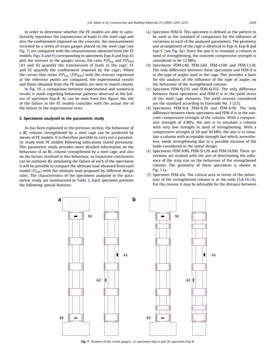
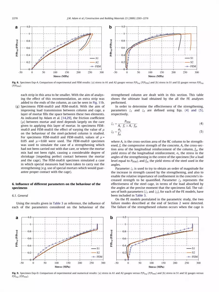
In order to determine whether the FE models are able to satis-factorily reproduce the transmission of loads to the steel cage andalso the confinement imposed on the concrete, the measurementsrecorded by a series of strain gauges placed on the steel cage (seeFig. 7) are compared with the measurements obtained from the FEmodels. Figs. 8 and 9 (corresponding to specimens Exp-A and Exp-D)plot the stresses in the gauges versus the ratio P/PExp and P/PFEM
(A1 and A2 quantify the transmission of loads to the cage; S1and S2 quantify the confinement imposed by the cage). Whenthe curves that relate P/PExp (P/PFEM) with the stresses registeredat the reference points are compared, the experimental resultsand those obtained from the FE models are seen to match closely.
In Fig. 10, a comparison between experimental and numericalresults is made regarding behaviour patterns observed at the fail-ure of specimen Exp-B. As can be seen from this figure, the siteof the failure in the FE models coincides with the actual site ofthe failure in the experimental tests.
5. Specimens analysed in the parametric study
As has been explained in the previous section, the behaviour ofa RC column strengthened by a steel cage can be predicted bymeans of FE models. It is therefore possible to carry out a paramet-ric study with FE models following indications stated previously.This parametric study provides more detailed information on thebehaviour of an RC column strengthened by a steel cage, and alsoon the factors involved in this behaviour, so important conclusionscan be outlined. By simulating the failure of each of the specimensit will be possible to compare the ultimate load obtained from eachmodel (PFEM) with the ultimate load proposed by different designrules. The characteristics of the specimens analysed in the para-metric study are summarized in Table 2. Each specimen presentsthe following special features:
S1
S2
A1
A2
a b
Fig. 7. Position of the strain gauges: (a) spe
(a) Specimen FEM-0. This specimen is defined as the pattern tobe used as the standard of comparison for the influence ofvariations in each of the analysed parameters. The geometryand arrangement of the cage is identical to Exp-A, Exp-B andExp-C (see Fig. 4a). Since the aim is to simulate a column inneed of strengthening, the concrete compressive strength isconsidered to be 12 MPa.
(b) Specimens FEM-L40, FEM-L60, FEM-L100 and FEM-L120.The only difference between these specimens and FEM-0 isin the type of angles used in the cage. This provides a basisfor the analysis of the influence of the type of angles onthe behaviour of the strengthened column.
(c) Specimen FEM-fy235 and FEM-fy355. The only differencebetween these specimens and FEM-0 is in the yield stressof the steel cage elements. The yield stresses consideredare the standard according to Eurocode No. 3 [23].
(d) Specimens FEM-fc4, FEM-fc20 and FEM-fc30. The onlydifference between these specimens and FEM-0 is in the con-crete compressive strength of the column. With a compres-sive strength of 4 MPa, the aim is to simulate a columnwith very low strength in need of strengthening. With acompressive strength of 20 and 30 MPa, the aim is to simu-late a column with acceptable strength but which, neverthe-less, needs strengthening due to a possible increase of theloads considered in the initial design.
(e) Specimens FEM-St80, FEM-St120 and FEM-St200. These sp-ecimens are studied with the aim of determining the influ-ence of the strip size on the behaviour of the strengthenedcolumn. The geometry of these specimens is shown inFig. 11a.
(f) Specimen FEM-aSt. The critical area in terms of the behav-iour of the strengthened column is at the ends [5,8,10,14].For this reason, it may be advisable for the distance between
S1
S2
A1
A2
cimen Exp-A and (b) specimen Exp-B.
0
0.2
0.4
0.6
0.8
1
1.2
-50 0 50 100 150 200 250 300
Stress (MPa)
P/P
Exp
(P/P
FE
M)
A1
A2
FEM0
0.2
0.4
0.6
0.8
1
1.2
-50 0 50 100 150 200 250 300
Stress (MPa)
P/P
Exp
(P/P
FE
M)
S1
S2
FEM
a b
Fig. 8. Specimen Exp-A. Comparison of experimental and FEM results: (a) stress in A1 and A2 gauges versus P/PExp (P/PFEM) and (b) stress in S1 and S2 gauges versus P/PExp
(P/PFEM).
2270 J.M. Adam et al. / Construction and Building Materials 23 (2009) 2265–2276
each strip in this area to be smaller. With the aim of analys-ing the effect of this recommendation, an extra strip wasadded to the ends of the column, as can be seen in Fig. 11b.
(g) Specimens FEM-mu0.0 and FEM-mu0.6. With the aim ofimproving load transmission between column and cage, alayer of mortar fills the space between these two elements.As indicated by Adam et al. [14,29], the friction coefficient(l) between mortar and steel depends largely on the caregiven to applying this layer of mortar. In specimens FEM-mu0.0 and FEM-mu0.6 the effect of varying the value of lon the behaviour of the steel-jacketed column is studied.For specimens FEM-mu0.0 and FEM-mu0.6, values of l =0.05 and l = 0.60 were used. The FEM-mu0.0 specimenwas used to simulate the case of a strengthening whichhad not been carried out with due care, or where the mortarmix had not been right, causing a considerable degree ofshrinkage (impeding perfect contact between the mortarand the cage). The FEM-mu0.6 specimen simulated a casein which special measures had been taken to carry out thestrengthening (e.g. use of special mortars which would guar-antee proper contact with the cage).
6. Influence of different parameters on the behaviour of thespecimens
6.1. General
Using the results given in Table 3 as reference, the influence ofeach of the parameters considered on the behaviour of the
0
0.2
0.4
0.6
0.8
1
1.2
-50 0 50 100 150 200 250 300
Stress (MPa)
P/P
Exp
(P/P
FE
M)
S1
S2
FEM
a
Fig. 9. Specimen Exp-D. Comparison of experimental and numerical results: (a) stress inP/PExp (P/PFEM).
strengthened column are dealt with in this section. This tableshows the ultimate load obtained by the all the FE analysesperformed.
In order to determine the effectiveness of the strengthening,parameters n1 and n2 are defined using Eqs. (4) and (5),respectively.
n1 ¼PFEM
Ac � fc þ As � fysð4Þ
n2 ¼rL
fyLð5Þ
where Ac is the cross-section area of the RC column to be strength-ened, fc the compressive strength of the concrete, As the cross-sec-tion area of the longitudinal reinforcement of the column, fys theyield stress of the longitudinal reinforcement, rL the stress in theangles of the strengthening in the centre of the specimen (for a loadlevel equal to PFEM), and fyL the yield stress of the steel used in theangles.
Parameter n1 is used to try to obtain an order of magnitude forthe increase in strength caused by the strengthening, and also toenable the relative importance of confinement in the concrete’s in-creased strength to be quantified. Parameter n2 represents theeffectiveness of the steel cage, in terms of the load absorbed bythe angles at the precise moment that the specimens fail. The val-ues of both parameters (n1 and n2), for each of the FE models, havebeen included in Table 3.
On the FE models postulated in the parametric study, the twofailure modes described at the end of Section 2 were detected.The failure of the strengthened column occurs when the cage is
0
0.2
0.4
0.6
0.8
1
1.2
-50 0 50 100 150 200 250 300
Stress (MPa)
P/P
Exp
(P/P
FE
M)
S1
S2
FEM
b
A1 and A2 gauges versus P/PExp (P/PFEM) and (b) stress in S1 and S2 gauges versus

Fig. 10. Specimen Exp-B. Failure of concrete at the end of the specimen: (a)experimental test and (b) finite element model (cracking and crushing).
J.M. Adam et al. / Construction and Building Materials 23 (2009) 2265–2276 2271
no longer able to confine the concrete. In Fig. 12 the failure modesdetected can be seen. In Table 3, the failure mode for each of the FEmodels has been included.
6.2. Cross-section area of steel angles
As would be expected, the higher the cross-section area of theangles, the greater the ultimate load of the strengthened column.
Table 2Specimens analysed in parametric study.
Specimen Strengthening
Angles Strips (mm3)
FEM-0 L 80.8 270 � 160 � 8
FEM-L40 L 40.4 270 � 160 � 8FEM-L60 L 60.6 270 � 160 � 8FEM-L100 L 100.10 270 � 160 � 8FEM-L120 L 120.12 270 � 160 � 8
FEM-fy235 L 80.8 270 � 160 � 8FEM-fy355 L 80.8 270 � 160 � 8
FEM-fc4 L 80.8 270 � 160 � 8FEM-fc20 L 80.8 270 � 160 � 8FEM-fc30 L 80.8 270 � 160 � 8
FEM-St80 L 80.8 270 � 80 � 8FEM-St120 L 80.8 270 � 120 � 8FEM-St200 L 80. 8 270 � 200 � 8
FEM-aSt L 80.8 270 � 160 � 8
FEM-mu0.0 L 80.8 270 � 160 � 8FEM-mu0.6 L 80.8 270 � 160 � 8
Likewise, when the cross-section area is increased, the transmis-sion of loads between column and steel cage is also improved, ascan be seen in Fig. 13a. If angle cross-section area is increased,the surface area of concrete covered by the angles also rises. Thisimplies that the effectiveness of the confinement imposed by thecage increases with angle cross-section area (see n1 values includedin Table 3). Fig. 13b shows the compressive stresses on the columnin the axial direction at failure. As can be seen, as angle cross-sec-tion area increases the failure stress of the concrete also increasesdue to the confinement effect described. As regards effectiveness ofthe cage, this presents inverse behaviour, that is to say, as cross-section area increases; effectiveness is reduced, as can be seenfrom the values of parameter n2 included in Table 3.
6.3. Yield stress of the cage steel
Obviously, the higher the yield stresses of the steel in the cage,the greater the ultimate load of the strengthened column. How-ever, as can be seen in Fig. 14a, a higher yield stress of the steelin the cage has little effect on the transmission of loads betweenthe column and the cage. This effect is also confirmed by the valuesof parameter n2, which decreases as the yield stress of the steel inthe cage increases (see Table 3).
The confinement effect imposed by the cage increases when theyield stress of the steel is increased. This can be clearly observed inFig. 14b, which shows the compressive stress in the axial directionof the column at failure. As regards parameter n1, its valueincreases as the yield stress of the steel in the cage increases (seeTable 3).
6.4. Concrete strength
Varying the compressive strength of the concrete in the column,besides affecting the ultimate load of the strengthened column,also affects the load distribution between the column and the steelcage. As can be observed in Fig. 15a, the lower the strength of theconcrete in the column, the better the load distribution obtained.As can be seen in Fig. 15b, the relative importance of the confine-ment is higher for low values of concrete strength. In relation toparameters n1 and n2 which allow the effectiveness of the strength-ening to be estimated, both increase as the strength of the concretedecreases (see Table 3). The variation in n1 and n2 is in line withwhat was observed in Fig 15a and b.
Material properties l
fyL (Mpa) fc (MPa)
275 12 0.20
275 12 0.20275 12 0.20275 12 0.20275 12 0.20
235 12 0.20355 12 0.20
275 4 0.20275 20 0.20275 30 0.20
275 12 0.20275 12 0.20275 12 0.20
275 12 0.20
275 12 0.05275 12 0.60

Table 3Results obtained from parametric study.
Specimen PFEM (kN) Effectiveness Failure mode
n1 n2
FEM-0 2185.7 1.73 0.63 Angles-first
FEM-L40 1611.2 1.28 1.33 Angles-firstFEM-L60 1842.7 1.46 0.85 Angles-firstFEM-L100 2582.5 2.05 0.51 Angles-firstFEM-L120 3065.8 2.43 0.48 Strips-first
FEM-fy235 2109.8 1.67 0.68 Angles-firstFEM-fy355 2349.4 1.86 0.56 Angles-first
FEM-fc4 1572.8 2.91 0.65 Angles-firstFEM-fc20 2944.6 1.49 0.57 Angles-firstFEM-fc30 3992.3 1.39 0.54 Angles-first
FEM-St80 1898.1 1.51 0.42 Angles-firstFEM-St120 1961.9 1.56 0.48 Angles-firstFEM-St200 2396.1 1.90 0.73 Angles-first
FEM-aSt 2678.3 2.12 1.05 Angles-centre
FEM-mu0.0 1823.8 1.45 0.19 Angles-firstFEM-mu0.6 2649.2 2.10 1.06 Angles-centre
RC HEAD
RC COLUMN
STRIPS 270x160x8
ANGLES L80.8
150 300 150 300
300
2010
160
5016
020
016
041
016
0
150 300 150 300
RC HEAD
RC COLUMN
STRIPS 270xStx8
ANGLES L80.8
300
2010
St
=S
t=
St
a b
Fig. 11. (a) Specimens FEM-St80, FEM-St120 and FEM-St200 and (b) Specimen FEM-aSt.
Fig. 12. Failure modes observed in the FE models. Von Mises stresses (MPa): (a) yielding of the first of the angles (angles-first); (b) yielding of the centre angles (angles-centre) and (c) yielding of the first of the strips (strip-first).
2272 J.M. Adam et al. / Construction and Building Materials 23 (2009) 2265–2276
6.5. Strip size
The size of the strips plays an important role in the behaviour ofthe strengthened column. Comparing the ultimate load of speci-mens FEM-0, FEM-St80, FEM-St120 and FEM-St200 in Table 3, it
can be observed that greater strip size increases ultimate load. Boththe load transmission from column to cage and the confinement ef-fect imposed by the cage are improved when the size of the strips isincreased (see Fig. 16). In relation to this, the values for parametersn1 and n2 also increase with the size of the strips (see Table 3).

J.M. Adam et al. / Construction and Building Materials 23 (2009) 2265–2276 2273
6.6. Including additional strips at the ends of the columns
Adding strips to the ends of the cage, as in the case of specimenFEM-aSt, helps to increase the ultimate load of the strengthened
0
250
500
750
1000
1250
0 0.2 0.4 0.6 0.8 1Ns/PFEM
dist
ance
(mm
)
FEM-0
FEM-L40
FEM-L60
FEM-L100
FEM-L120
00.20.40.60.81
Nc/PFEMa
Fig. 13. Specimens FEM-0, FEM-L40, FEM-L60, FEM-100 and FEM-L120 (load applied csupported by the column; Ns, load supported by the cage) and (b) compressive stress in
0
250
500
750
1000
1250
0 0.2 0.4 0.6 0.8 1Ns/PFEM
dist
ance
(mm
)
FEM-fy235
FEM-fy355
FEM-0
00.20.40.60.81
Nc/PFEMa
Fig. 14. Specimens FEM-0, FEM-fy235 and FEM-fy355 (load applied coincides with PFEM
column; Ns, load supported by the cage) and (b) compressive stress in concrete.
0
250
500
750
1000
1250
0 0.2 0.4 0.6 0.8 1Ns/PFEM
dist
ance
(mm
)
FEM-0
FEM-fc4
FEM-fc20
FEM-fc30
00.20.40.60.81
Nc/PFEMa
Fig. 15. Specimens FEM-0, FEM-fc4, FEM-fc20 and FEM-fc30 (load applied coincides witthe column; Ns, load supported by the cage) and (b) compressive stress in concrete.
column, as well as increasing the effectiveness parameters n1 andn2 (see Table 3).
As Fig. 17 illustrates, the presence of the additional strip con-tributes to a better transmission of the loads between the column
0
250
500
750
1000
1250
0 5 10 15 20 25 30
Stress in concrete (MPa)
dist
ance
(mm
)
FEM-0
FEM-L40
FEM-L60
FEM-L100
FEM-L120
12 MPa
b
oincides with PFEM): (a) load distribution between steel cage and column (Nc, loadconcrete.
0
250
500
750
1000
1250
0 5 10 15 20 25 30
Stress in concrete (MPa)
dist
ance
(mm
)
FEM-fy235
FEM-fy355
FEM-0
12 MPa
b
): (a) load distribution between steel cage and column (Nc, load supported by the
0
250
500
750
1000
1250
0 10 20 30 40 50Stress in concrete (MPa)
dist
ance
(mm
)
FEM-0
FEM-fc4
FEM-fc20
FEM-fc3012 MPa4 MPa 20 MPa 30 MPa
b
h PFEM): (a) load distribution between steel cage and column (Nc, load supported by

0
250
500
750
1000
1250
0 5 10 15 20 25 30
Stress in concrete (MPa)
dist
ance
(mm
)
FEM-0
FEM-St80
FEM-St120
FEM-St200
12 MPa
0
250
500
750
1000
1250
0 0.2 0.4 0.6 0.8 1
Ns/PFEM
dist
ance
(mm
)
FEM-0
FEM-St80
FEM-St120
FEM-St200
00.20.40.60.81
Nc/PFEMa b
Fig. 16. Specimens FEM-0, FEM-St80, FEM-St120 and FEM-St 200 (load applied coincides with PFEM): (a) load distribution between steel cage and column (Nc, load supportedby the column; Ns, load supported by the cage) and (b) compressive stress in concrete.
2274 J.M. Adam et al. / Construction and Building Materials 23 (2009) 2265–2276
and the cage in addition to the confinement effect imposed by thestrengthening. It was also noted that while the failure on most ofthe FE models was located on the first section of angles (seeFig. 12a), in the case of the FEM-aSt model, the failure was locatedon the angles situated in the centre (see Fig. 12b).
6.7. Friction coefficient
The friction coefficient between the mortar and the cage steelhas a considerable effect on the behaviour of the strengthened col-umn. As l increases, ultimate load of the column also rises from1823.8 kN for specimen FEM-mu0.0 to 2649.2 kN for specimenFEM-mu0.6. Furthermore, when l increases, the load transmissionbetween column and cage improves (see Fig. 18), as well as theeffectiveness parameters n1 and n2 (see Table 3).
6.8. Analysis of the results obtained
As Adam et al. indicate [15], for the strengthening variant pro-posed, there are fundamentally two mechanisms which influencethe behaviour of the strengthened column:
(1) Transmission by shear stresses. This is the way the load istransmitted between the column and the cage, via the layerof mortar between them. The figures representing the distri-bution of loads between the cage and the column, as well as
0
250
500
750
1000
1250
0 0.2 0.4 0.6 0.8 1
Ns/PFEM
dist
ance
(mm
)
PMEF-aSt
PMEF-0
00.20.40.60.81
Nc/PFEMa
Fig. 17. Specimens FEM-0 and FEM-aSt (load applied coincides with PFEM): (a) load distrsupported by the cage) and (b) compressive stress in concrete.
parameter n2 have been included so as to underline theimportance of the mechanism of transmission by shearstresses.
(2) Confinement imposed by steel caging. The strengtheningproduces a confinement effect on the column since it pre-vents the expansion of the concrete caused by Poisson’seffect. Thus, the compressive strength of the concrete isincreased. The confinement effect was taken into accountwhen parameter n1 was defined.
As the results of the parametric study show, the confinementimposed by the steel cage is very important for the behaviour ofthe strengthened column (see the values of n1 included in Table3). In addition to this, the parameter of effectiveness n2 is, in prac-tically all cases, less than one. This is because the strengthened col-umn does not behave as a composite element since there is nocompatibility in deformation between the cage and the column,especially at the ends of the strengthened column. Thus, slippingis produced between the strengthening and the layer of mortar,as has been observed by Adam et al. [14], Giménez [10] and Giménezet al. [17].
Detailed analysis of the results of the parametric study makesclear that:
(a) If the size of the angles is increased, the effectiveness of theconfinement increases (parameter n1). However, the effec-
0
250
500
750
1000
1250
0 5 10 15 20 25 30Stress in concrete (MPa)
dist
ance
(mm
)
FEM-aSt
FEM-0
12 MPa
b
ibution between steel cage and column (Nc, load supported by the column; Ns, load

0
250
500
750
1000
1250
0 0.2 0.4 0.6 0.8 1Ns/PFEM
dist
ance
(mm
)FEM-0
FEM-mu0.0
FEM-mu0.6
00.20.40.60.81
Nc/PFEM
Fig. 18. Specimens FEM-0, FEM-mu0.0 and FEM-mu0.6. (load applied coincides with PFEM). Load distribution between steel cage and column (Nc, load supported by thecolumn; Ns, load supported by the cage).
J.M. Adam et al. / Construction and Building Materials 23 (2009) 2265–2276 2275
tiveness of the transmission of loads between the cage andthe column (parameter n2). decreases when the size of theangles is increased This phenomenon can be explained bythe fact that in the case of the increased-size angle, the fail-ure of the specimen is conditioned by the yielding of thestrips, due to the tensile stresses they are subjected to (seecomments in Section 2). Thus, the angles are not able toabsorb their full load capacity. This particularity can be seenin Fig. 12c, where the failure mechanism of the cage (yield-ing of the strips) is shown for the FEM-L120 model.
(b) A variation in the yield stress of the steel of the cage slightlyaffects the behaviour of the strengthened column. When thevalue of the yield stress is increased, the ultimate load on thestrengthened column increases slightly but the effectivenessparameter n2 decreases. Considering the increased cost inc-urred by using steels with a high yield stress, it is importantto take the above effect into account when designingstrengthening.
(c) When the compressive strength of the concrete increases,the effectiveness of the strengthening decreases (parametersn1 and n2). The effect mentioned occurs because the lowerdeformability of higher strength of concrete means thatthe strengthening absorbs less load. This lower deformabi-lity will also mean a less lateral deformation of the concretedue to the Poisson effect, which will reduce the confinementeffect. In view of this, it can be stated that the strengtheningwill be more effective in cases where the strength of the con-crete is low.
(d) One way to reduce the slipping which occurs between thestrengthening and the column is to increase the size of thestrips. The bigger the strips, the bigger the confinement ef-fect imposed by the strengthening will be (see Fig. 16b). Thisis due to the greater stiffness of the steel cage in the trans-verse direction. This improvement in confinement will alsoresult in a better transmission of loads between the cageand the column by the shear stress mechanism (seeFig. 16a).
(e) The critical area which conditions the behaviour of the str-engthened column is at the ends [5,8,10,14]. A more eco-nomical way to attain the effects mentioned in (d) wouldbe to put the strips closer together in the area closest tothe ends of the column (see Fig. 11b). Adding an extra stripgives, at only a slight increase in strengthening costs, agreater ultimate load and more efficient strengthening.
(f) Considering that l depends on the thoroughness of the con-struction of the steel cage [14,29], this work should beundertaken with great care, since there is a strong connection
between the value of l and the behaviour of the strength-ened column (see Section 6.7).
7. Conclusions and future work
An experimental program was carried out to study axiallyloaded RC columns strengthened by steel cages. Numerical modelswere verified from the experimental results and a parametric studywas carried out analysing the influence of each of the parameterson the behaviour of RC columns strengthened by steel cages. Theparameters analysed were: the size of the angles; the yield stressof the steel of the cage; the compressive strength of the concretein the column; the size of the strips; the addition of an extra stripat the ends of the cage; the friction coefficient between the layer ofmortar and the steel of the cage. The results obtained from theparametric study allow a series of guidelines to be established(see Section 6.8).
It would seem important for future research to consider columnswhich are strengthened while they are subjected to loading. It wouldthus be possible to simulate what happens when a column formingpart of a real structure is strengthened. This recommendation alsoapplies to the three types of strengthening most widely used nowa-days (steel jacketing, concrete jacketing, and composite jacketing),since little research has been done on this phenomenon.
Acknowledgements
The authors wish to express their gratitude for the financialsupport received from the Spanish Ministry of Science and Tech-nology under the research project MAT 2003-08075, co-financedwith FEDER funds.
References
[1] Oey HS, Aldrete CJ. Simple method for upgrading an existing reinforced-concrete structure. Practice Periodical Struct Design Constr 1996;1(1):47–50.
[2] Frangou M, Pilakoutas K, Dritsos S. Structural repair/strengthening of RCcolumns. Constr Build Mater 1995;9(5):259–66.
[3] Dritsos S, Pilakoutas K. Composite technique for repair/strengthening of RCmembers. In: Second international symposium on composite materials andstructures. China: Peking University Press; 1992.
[4] Tamai S, Sato T, Okamoto M. Hysteresis model of steel jacketed RC columns forrailway viaducts. In: Proceedings of the 16th congress of IABSE. Lucerne; 2000.
[5] Cirtek L. RC columns strengthened with bandage – experimental programmeand design recommendations. Constr Build Mater 2001;15(8):341–9.
[6] Fukuyama H, Sugano S. Japanese seismic rehabilitation of concrete build-ings after the Hyogoken-Nanbu earthquake. Cem Concr Compos 2000;22(1):59–79.
[7] Wu YF, Liu T, Oehlers DJ. Fundamental principles that govern retrofitting ofreinforced concrete columns by steel and FRP jacketing. Adv Struct Eng2006;9(4):507–33.

2276 J.M. Adam et al. / Construction and Building Materials 23 (2009) 2265–2276
[8] Adam JM. Structural behaviour of RC columns strengthened by steel jacketing.Research report, Code 1940/66. Technical University of Valencia; 2007.
[9] CEB-FIB. Seismic assessment and retrofit of reinforced concrete buildings.Bulletin no. 24, Task Group 7.1; 2003.
[10] Giménez E. Experimental and numerical study of reinforced concrete columnsstrengthened with steel angles and strips subjected to axial loads. PhD thesis.Technical University of Valencia; 2007 [in Spanish]. Available in <http://proquest.umi.com>.
[11] Ramírez JL. Ten concrete column repair methods. Constr Build Mater1996;10(3):195–202.
[12] Ramírez JL, Bárcena JM. Eficacia resistente de pilares de hormigón armado debaja calidad reforzados por dos procedimientos diferentes. Informes de laConstrucción 1975;272:89–98 [in Spanish].
[13] Ramírez JL, Bárcena JM, Feijóo JM. Comparación resistente de cuatro métodosde refuerzo de pilares de hormigón armado. Informes de la construcción1977;290:57–68 [in Spanish].
[14] Adam JM, Ivorra S, Giménez E, Moragues JJ, Miguel P, Miragall C, Calderón PA.Behaviour of axially loaded RC columns strengthened by steel angles andstrips. Steel Compos Struct 2007;7(5):405–19.
[15] Adam JM, Giménez E, Calderón PA, Pallarés FJ, Ivorra S. Experimental study ofbeam-columns joints in axially loaded RC columns strengthened by steelangles and strips. Steel Compos Struct 2008;8(4):329–42.
[16] Fernández M. Patología y terapéutica del hormigón armado. Colegio deIngenieros de Caminos, Canales y Puertos, Madrid; 1994 [in Spanish].
[17] Giménez E, Adam JM, Ivorra S, Moragues JJ, Calderón PA. Full-scale testing ofaxially loaded RC columns strengthened by steel angles and strips. Adv StructEng; accepted for publication.
[18] Dolce M, Masi A, Cappa T, Nigro D, Ferrini M. Experimental evaluation ofeffectiveness of local strengthening on columns of R/C existing structures. In:Proceedings of fib-symposium concrete structures in earthquake regions,Athens, Greece; 2003.
[19] Cirtek L. Mathematical model of RC banded column behaviour. Constr BuildMater 2001;15(8):351–9.
[20] de Fomento Ministerio. Instrucción de hormigón estructural. Madrid: EHE;1998 [in Spanish].
[21] ENV 1992-1-1 (Eurocode No. 2). Design of concrete structures. Part 1: Generalrules and rules for buildings; 1991.
[22] CEB-FIB Model Code 90. Laussane; 1991.[23] ENV 1993-1-1 (Eurocode No. 3). Design of steel structures. Part 1: General
rules and rules for buildings; 1993.[24] ANSYS 11.0. Theory reference. ANSYS Inc.; 2006.[25] ANSYS 11.0. Element reference. ANSYS Inc.; 2006.[26] Willam KJ, Warnke ED. Constitutive model for the triaxial behaviour of
concrete. In: Proceedings international association of bridge and structuralengineering. Bergamo, Italy: ISMES; 1974.
[27] Johansson M, Gylltoft K. Structural behaviour of slender circular steel–concrete composite columns under various means of load application. SteelCompos Struct 2001;4:393–410.
[28] Johansson M, Gylltoft K. Mechanical behaviour or circular steel-concretecomposite stub columns. J Struct Eng 2002;128(8):1073–81.
[29] Adam JM, Calderón PA, Giménez E, Hidalgo C, Ivorra S. A study of the behaviourof the cement mortar interface in reinforced concrete columns strengthenedby means of steel angles and strips. In: Structure Faults Repair –2006. Edinburgh; 2006.


