Embed Size (px)
Citation preview
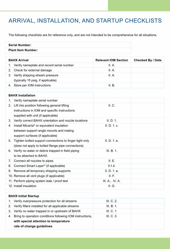
The following checklists are for reference only, and are not intended to be comprehensive for all situations.
Serial Number:Plant Item Number:
BAHX Arrival Relevant IOM Section Checked By / Date1. Verify nameplate and record serial number II. A.2. Check for external damage II. A.3. Verify shipping stream pressure II. A. (typically 15 psig, if applicable) 4. Store per IOM instructions II. B.
BAHX Installation 1. Verify nameplate serial number2. Lift into position following general lifting II. C. instructions in IOM and specific instructions supplied with unit (if applicable)3. Verify correct BAHX orientation and nozzle locations II. D. 1.4. Install Micarta® or equivalent insulation II. D. 1. c. between support angle mounts and mating support surfaces (if applicable)5. Tighten bolted support connections to finger tight only II. D. 1. e. (does not apply to bolted flange pipe connections)6. Verify no water or debris trapped in field piping III. B. 1. to be attached to BAHX.7. Connect all nozzles to pipes II. E.8. Connect Smart Layer® (if applicable) II.1.4.9. Remove all temporary shipping supports II. D. 1. a.10. Remove all vent plugs (if applicable) II. F.11. Perform piping system leak / proof test III. A., IV. A.12. Install insulation II. G.
BAHX Initial Startup 1. Verify overpressure protection for all streams III. C. 2.2. Verify filters installed for all applicable streams III. B. 1.3. Verify no water trapped in or upstream of BAHX III. C. 1.4. Bring to operation conditions following IOM instructions, III. C. 3. with special attention to temperature rate of change guidelines
Arrival, Installation, and Startup Checklists Inside
INSTALLATION, OPERATION, AND MAINTENANCE MANUAL
for Chart Brazed Aluminum Heat Exchangers (BAHX) and Core-in-Kettle® Assemblies.
Chart Energy & Chemicals, Inc. is an ISO:9001,
ISO:14001, and OHSAS:18001 registered company
Chart Energy & Chemicals, Inc.
Brazed Aluminum Heat Exchangers
2191 Ward Avenue
La Crosse, WI 54601
Tel: 608-787-3333
E-mail: [email protected]
www.ChartIndustries.com
Chart Lifecycle, Inc.
8665 New Trails Drive, Suite 100
The Woodlands, TX 77381
Tel: 1-844-GTLS-911 (1-844-485-7911)
E-mail: [email protected]
www.ChartLifecycle.com
JANUARY 2021
INSTALLATION, OPERATION, AND MAINTENANCE MANUAL
for Chart Brazed Aluminum Heat Exchangers (BAHX) and Core-in-Kettle® Assemblies.
JANUARY 2021
ARRIVAL, INSTALLATION, AND STARTUP CHECKLISTS

FIGURE I FIGURE IIBasic Components of a Chart
Brazed Aluminum Heat Exchanger (BAHX)
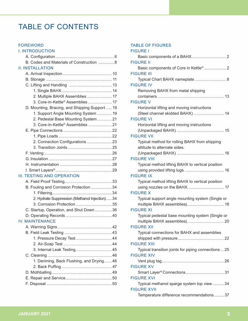
How a Chart Core-in-Kettle® Works
The Chart Energy & Chemicals, Inc. (“Chart”) brazed aluminum heat exchanger (BAHX) business began in 1985 with the acquisition of The Trane Company’s BAHX operation in La Crosse, Wisconsin. Chart is a recognized global leader in the design and manufacture of large BAHX, battery assemblies, and cold boxes for cryogenic applications.
Chart incorporates the former Altec and Marston BAHX brands and consequently all rights to engineering and equipment produced by these companies.
“Core-in-Kettle” is a registered trademark of Chart Energy & Chemicals, Inc.
Brazed aluminum heat exchangers are also referred to as plate fin heat exchangers and abbreviated to PFHE within the industry.
© 2021 Chart Energy & Chemicals, Inc. All rights reserved.
Nozzle
Header
Distributor fin
Parting sheet
Side barWear plate
Heat transfer fin
Support angle
Cap sheet
2JANUARY 2021
Chart Lifecycle has qualified Field Service Engineering teams to provide full installation, commissioning and startup related
services. Chart highly recommends these OEM trained services to ensure a successful equipment startup. Chart also
provides best practices for the maintenance and management of Chart proprietary equipment for optimized performance
and lifespan. Chart Lifecycle, Inc., is also your 24/7 single point of contact for commissioning and startup services, spares,
repairs, warranties, technical expertise, project development, field services, and training. Other services include:
• Annual service agreements
• Extended warranties
• Enhanced operator training and best practices
Tel: 1-844-GTLS-911 (1-844-485-7911) – 24/7 hotline
E-mail: [email protected]
www.ChartLifecycle.com
Installation, Commissioning & Startup ServicesCHART LIFECYCLE IS HERE TO HELP!
1. The warm process stream fluid enters the Brazed Aluminum Heat Exchanger (BAHX) through steel inlet nozzle(s) on the vessel shell. The inlet nozzles are connected to the aluminum inlet pipes of the exchanger by an aluminum to stainless steel transition coupling.
2. Inside the BAHX the warm stream cools as it flows against a cold stream.
3. The cold stream enters the vessel either as a liquid or 2-phase fluid directly from a distillation column (or expansion valve in the case of a refrigerant).
4. A liquid level is formed outside the BAHX core to create a liquid head that drives the cold stream liquid through the core
5. A disengagement space above the core causes the liquid and vapour to separate.
6. The cooled warm stream leaves the BAHX and vessel.7. The cold stream vapour exits the vessel through the outlet
nozzles whilst the liquid falls back to be recirculated.8. A manway is provided in the vessel shell.
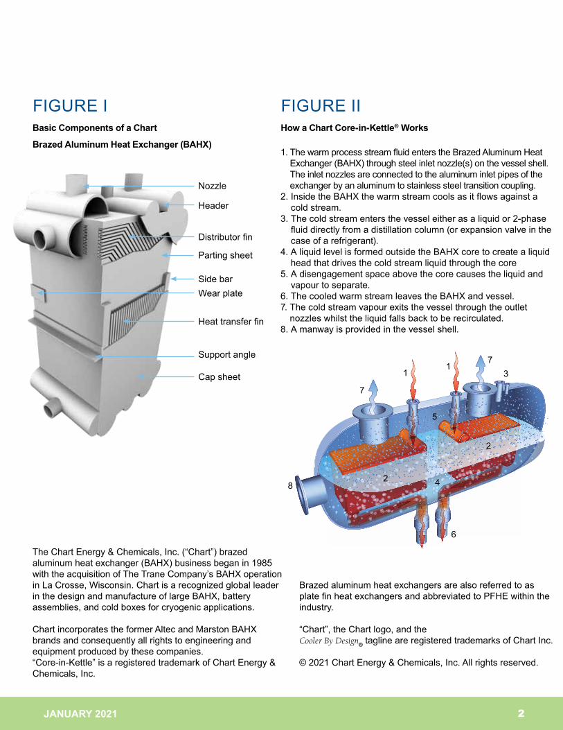
FIGURE I FIGURE IIBasic Components of a Chart
Brazed Aluminum Heat Exchanger (BAHX)
How a Chart Core-in-Kettle® Works
The Chart Energy & Chemicals, Inc. (“Chart”) brazed aluminum heat exchanger (BAHX) business began in 1985 with the acquisition of The Trane Company’s BAHX operation in La Crosse, Wisconsin. Chart is a recognized global leader in the design and manufacture of large BAHX, battery assemblies, and cold boxes for cryogenic applications.
Chart incorporates the former Altec and Marston BAHX brands and consequently all rights to engineering and equipment produced by these companies.“Core-in-Kettle” is a registered trademark of Chart Energy & Chemicals, Inc.
Brazed aluminum heat exchangers are also referred to as plate fin heat exchangers and abbreviated to PFHE within the industry.
“Chart”, the Chart logo, and the Cooler By Design® tagline are registered trademarks of Chart Inc.
© 2021 Chart Energy & Chemicals, Inc. All rights reserved.
Nozzle
Header
Distributor fin
Parting sheet
Side barWear plate
Heat transfer fin
Support angle
Cap sheet
2JANUARY 2021
Chart Lifecycle has qualified Field Service Engineering teams to provide full installation, commissioning and startup related
services. Chart highly recommends these OEM trained services to ensure a successful equipment startup. Chart also
provides best practices for the maintenance and management of Chart proprietary equipment for optimized performance
and lifespan. Chart Lifecycle, Inc., is also your 24/7 single point of contact for commissioning and startup services, spares,
repairs, warranties, technical expertise, project development, field services, and training. Other services include:
• Annual service agreements
• Extended warranties
• Enhanced operator training and best practices
Tel: 1-844-GTLS-911 (1-844-485-7911) – 24/7 hotline
E-mail: [email protected]
www.ChartLifecycle.com
Installation, Commissioning & Startup ServicesCHART LIFECYCLE IS HERE TO HELP!
1. The warm process stream fluid enters the Brazed Aluminum Heat Exchanger (BAHX) through steel inlet nozzle(s) on the vessel shell. The inlet nozzles are connected to the aluminum inlet pipes of the exchanger by an aluminum to stainless steel transition coupling.
2. Inside the BAHX the warm stream cools as it flows against a cold stream.
3. The cold stream enters the vessel either as a liquid or 2-phase fluid directly from a distillation column (or expansion valve in the case of a refrigerant).
4. A liquid level is formed outside the BAHX core to create a liquid head that drives the cold stream liquid through the core
5. A disengagement space above the core causes the liquid and vapour to separate.
6. The cooled warm stream leaves the BAHX and vessel.7. The cold stream vapour exits the vessel through the outlet
nozzles whilst the liquid falls back to be recirculated.8. A manway is provided in the vessel shell.
JANUARY 2021
FOREWORDI. INTRODUCTION A.Configuration ....................................................6 B.CodesandMaterialsofConstruction .............. 8II. INSTALLATION A.ArrivalInspection ............................................ 10 B.Storage .......................................................... 11 C.LiftingandHandling ...................................... 13 1.SingleBAHX ............................................ 14 2.MultipleBAHXAssemblies ...................... 17 3.Core-in-Kettle®Assemblies ..................... 17 D.Mounting,Bracing,andShippingSupport..... 19 1.SupportAngleMountingSystem ............. 19 2.PedestalBaseMountingSystem ............. 21 3.Core-in-Kettle®Assemblies ..................... 21 E.PipeConnections ...........................................22 1.PipeLoads ...............................................22 2.ConnectionConfigurations ......................23 3.TransitionJoints .......................................25 F.Venting ............................................................26 G.Insulation ........................................................27 H.Instrumentation ..............................................28 I.SmartLayers® ..................................................29III. TESTING AND OPERATION A.FieldProofTesting..........................................33 B.FoulingandCorrosionProtection ...................34 1.Filtering.....................................................34 2.HydrateSuppression(MethanolInjection) .....34 3.CorrosionProtection ................................35 C.Startup,Operation,andShutDown ...............36 D.OperatingRecords .........................................40IV.MAINTENANCE A.WarningSigns ................................................ 42 B.FieldLeakTesting ..........................................43 1.PressureDecayTest ................................44 2.Air-SoapTest ...........................................44 3.InternalLeakTesting ................................45 C.Cleaning .........................................................46 1.Deriming,BackFlushing,andDrying .......46 2.BackPuffing ............................................. 47 D.Mothballing .....................................................49 E.RepairandService .........................................50 F.Disposal ..........................................................50
TABLE OF FIGURESFIGURE I BasiccomponentsofaBAHX ...............................2FIGURE II BasiccomponentsofCoreinKettle® ....................2FIGURE III TypicalChartBAHXnameplate ............................8FIGURE IV RemovingBAHXfrommetalshipping
containers ........................................................... 13FIGURE V Horizontalliftingandmovinginstructions
(SteelchannelskiddedBAHX) ........................... 14FIGURE VI Horizontalliftingandmovinginstructions
(UnpackagedBAHX) .......................................... 15FIGURE VII TypicalmethodforrollingBAHXfromshipping
attitudetoalternatesides. (UnpackagedBAHX) .......................................... 16
FIGURE VIII TypicalmethodliftingBAHXtoverticalposition usingprovidedliftinglugs. .................................. 16FIGUREIX TypicalmethodliftingBAHXtoverticalposition
usingnozzlesontheBAHX. ............................... 17FIGUREX Typicalsupportanglemountingsystem(Singleor
multipleBAHXassemblies) ................................. 18FIGUREXI Typicalpedestalbasemountingsystem(Singleor
multipleBAHXassemblies) .................................20FIGUREXII TypicalconnectionsforBAHXandassemblies
shippedwithpressure .........................................22FIGUREXIII Typicaltransitionjointsforpipingconnections ... 25FIGUREXIV Ventplugtag .......................................................26FIGUREXV SmartLayer® Connections .................................. 31FIGUREXVI Typicalmethanolspargesystemtopview ..........34FIGUREXVII Temperaturedifferencerecommendations ......... 37
TABLE OF CONTENTS
3
JANUARY 2021 4
ThismanualincludesChart’sinstructions,practices,
andproceduresregardinginstallation,operation,and
maintenanceofChartBAHX,assemblies,andCore-
in-Kettle®assemblies.PleasecontactChartLifecycle
forassistanceintheinstallation,commissioning,and
startupservicesrelatedtothisequipment.Charthighly
recommendstheseOEMtrainedservicestoassurea
successfulequipmentstartup.
Thismanualisbasedonextensiveexperience,including
morethan60yearsinthedesignandmanufactureof
BAHXforlowtemperatureapplications,includingair
separationandliquefaction,naturalgasprocessingand
liquefaction,heliumliquefaction,andhydrogen,ethylene,
andotherlighthydrocarbonproductrecoveries.
THROUGHOUTTHISMANUAL,SAFETYITEMSARE
HIGHLIGHTEDINCAPITALLETTERSANDLABELED
WITHTHECAUTIONMARKSHOWNHERE.
Thismanualisupdatedperiodically.Beforeattempting
anyprocedureyoushouldverifywithChartthatyouare
usingthecurrentversion.
Thismanualcannotcoverallpossiblevariationsin
equipmentdesignorprovideanswerstoallspecific
installation,operation,andmaintenancequestionsthat
mayarise.Ifforanyreason,anyvariationsorquestions
arisethatarenotaddressedinthismanual,oranyofthese
instructions,practices,andprocedurescannotbefollowed,
thecontractororownermustcontactChartforfurther
information,interpretation,andguidance.Failuretofollow
theinstructions,practices,andproceduresmayresultin
seriousbodilyinjuryordeath,propertydamage,irreparable
damagetotheChartequipment,andthevoidingofany
warrantiesapplicabletotheequipment.
Whentheseinstructions,practices,andproceduresare
followed,extendedandreliableservicefromBAHXand
Core-in-Kettle®assembliescanbeexpected.
FOREWORD
THESEITEMSSHOULDBEREADWITHEXTREMECAREANDTHOROUGHLY
UNDERSTOODBEFORECOMMENCINGANYINSTALLATION,OPERATION,OR
MAINTENANCEOFCHARTEQUIPMENT.FAILURETOPROPERLYFOLLOWINSTRUCTIONSSODESIGNATED
COULDRESULTINRUPTURESOREXPLOSIONSOROTHERDANGEROUSSITUATIONSWHICHMAYRESULT
INSERIOUSBODILYINJURYORDEATHANDPROPERTYDAMAGEASWELLASIRREPARABLEDAMAGETO
THECHARTEQUIPMENTANDTHEVOIDINGOFANYWARRANTIESAPPLICABLETOTHEEQUIPMENT.
DONOTMODIFYTHEEQUIPMENTORDEVIATEFROMTHEINSTRUCTIONS,PRACTICES,ANDPROCEDURES
INTHISMANUAL.
THECONTRACTOROROWNERINSTALLINGCHARTEQUIPMENTMUSTCOMPLYWITHTHESE
INSTRUCTIONS,PRACTICES,ANDPROCEDURESALONGWITHANYLIFTINGANDHANDLINGANDOTHER
INSTRUCTIONS,PRACTICES,ANDPROCEDURESPROVIDEDWITHINDIVIDUALUNITS.
JANUARY 2021
I. INTRODUCTION A.Configuration
B. CodesandMaterialsof Construction
5
JANUARY 2021
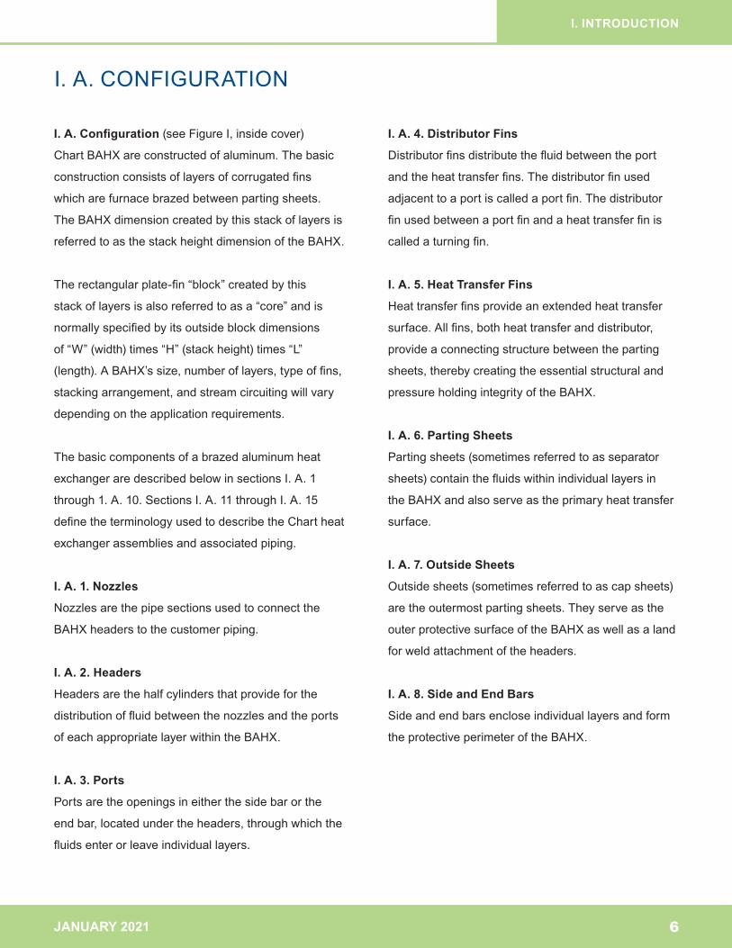
I. A. Configuration(seeFigureI,insidecover)
ChartBAHXareconstructedofaluminum.Thebasic
constructionconsistsoflayersofcorrugatedfins
whicharefurnacebrazedbetweenpartingsheets.
TheBAHXdimensioncreatedbythisstackoflayersis
referredtoasthestackheightdimensionoftheBAHX.
Therectangularplate-fin“block”createdbythis
stackoflayersisalsoreferredtoasa“core”andis
normallyspecifiedbyitsoutsideblockdimensions
of“W”(width)times“H”(stackheight)times“L”
(length).ABAHX’ssize,numberoflayers,typeoffins,
stackingarrangement,andstreamcircuitingwillvary
dependingontheapplicationrequirements.
Thebasiccomponentsofabrazedaluminumheat
exchangeraredescribedbelowinsectionsI.A.1
through1.A.10.SectionsI.A.11throughI.A.15
definetheterminologyusedtodescribetheChartheat
exchangerassembliesandassociatedpiping.
I. A. 1. Nozzles
Nozzlesarethepipesectionsusedtoconnectthe
BAHXheaderstothecustomerpiping.
I. A. 2. Headers
Headersarethehalfcylindersthatprovideforthe
distributionoffluidbetweenthenozzlesandtheports
ofeachappropriatelayerwithintheBAHX.
I. A. 3. Ports
Portsaretheopeningsineitherthesidebarorthe
endbar,locatedundertheheaders,throughwhichthe
fluidsenterorleaveindividuallayers.
I. A. 4. Distributor Fins
Distributorfinsdistributethefluidbetweentheport
andtheheattransferfins.Thedistributorfinused
adjacenttoaportiscalledaportfin.Thedistributor
finusedbetweenaportfinandaheattransferfinis
calledaturningfin.
I. A. 5. Heat Transfer Fins
Heattransferfinsprovideanextendedheattransfer
surface.Allfins,bothheattransferanddistributor,
provideaconnectingstructurebetweentheparting
sheets,therebycreatingtheessentialstructuraland
pressureholdingintegrityoftheBAHX.
I. A. 6. Parting Sheets
Partingsheets(sometimesreferredtoasseparator
sheets)containthefluidswithinindividuallayersin
theBAHXandalsoserveastheprimaryheattransfer
surface.
I. A. 7. Outside Sheets
Outsidesheets(sometimesreferredtoascapsheets)
aretheoutermostpartingsheets.Theyserveasthe
outerprotectivesurfaceoftheBAHXaswellasaland
forweldattachmentoftheheaders.
I. A. 8. Side and End Bars
Sideandendbarsencloseindividuallayersandform
theprotectiveperimeteroftheBAHX.
I. INTRODUCTION
I. A. CONFIGURATION
6
JANUARY 2021
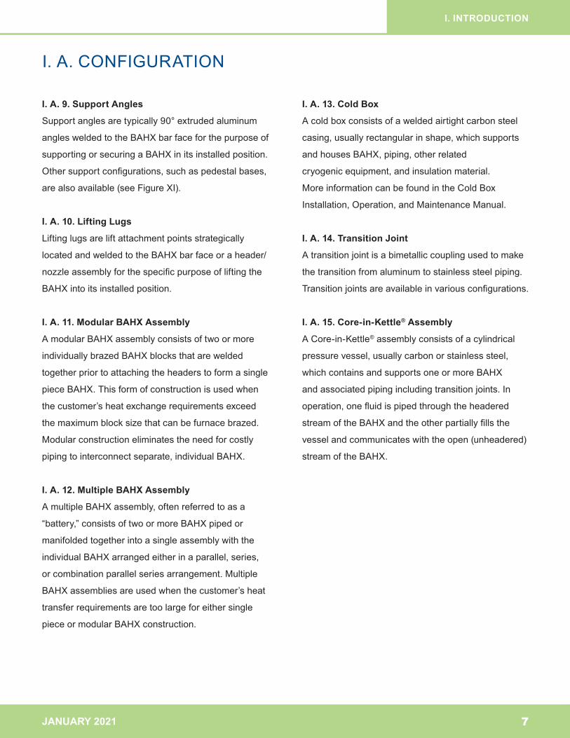
I. A. 9. Support Angles
Supportanglesaretypically90°extruded aluminum
anglesweldedtotheBAHXbarfaceforthepurposeof
supportingorsecuringaBAHXinitsinstalledposition.
Othersupportconfigurations,suchaspedestalbases,
arealsoavailable(seeFigureXI).
I. A. 10. Lifting Lugs
Liftinglugsareliftattachmentpointsstrategically
locatedandweldedtotheBAHXbarfaceoraheader/
nozzleassemblyforthespecificpurposeofliftingthe
BAHXintoitsinstalledposition.
I. A. 11. Modular BAHX Assembly
AmodularBAHXassemblyconsistsoftwoormore
individuallybrazedBAHXblocksthatarewelded
togetherpriortoattachingtheheaderstoformasingle
pieceBAHX.Thisformofconstructionisusedwhen
thecustomer’sheatexchangerequirementsexceed
themaximumblocksizethatcanbefurnacebrazed.
Modularconstructioneliminatestheneedforcostly
pipingtointerconnectseparate,individualBAHX.
I. A. 12. Multiple BAHX Assembly
AmultipleBAHXassembly,oftenreferredtoasa
“battery,”consistsoftwoormoreBAHXpipedor
manifoldedtogetherintoasingleassemblywiththe
individualBAHXarrangedeitherinaparallel,series,
orcombinationparallelseriesarrangement.Multiple
BAHXassembliesareusedwhenthecustomer’sheat
transferrequirementsaretoolargeforeithersingle
pieceormodularBAHXconstruction.
I. A. 13. Cold Box
Acoldboxconsistsofaweldedairtightcarbonsteel
casing,usuallyrectangularinshape,whichsupports
andhousesBAHX,piping,otherrelated
cryogenicequipment,andinsulationmaterial.
MoreinformationcanbefoundintheColdBox
Installation,Operation,andMaintenanceManual.
I. A. 14. Transition Joint
Atransitionjointisabimetalliccouplingusedtomake
thetransitionfromaluminumtostainlesssteelpiping.
Transitionjointsareavailableinvariousconfigurations.
I. A. 15. Core-in-Kettle® Assembly
ACore-in-Kettle®assemblyconsistsofacylindrical
pressurevessel,usuallycarbonorstainlesssteel,
whichcontainsandsupportsoneormoreBAHX
andassociatedpipingincludingtransitionjoints.In
operation,onefluidispipedthroughtheheadered
streamoftheBAHXandtheotherpartiallyfillsthe
vesselandcommunicateswiththeopen(unheadered)
streamoftheBAHX.
I. INTRODUCTION
I. A. CONFIGURATION
7
JANUARY 2021
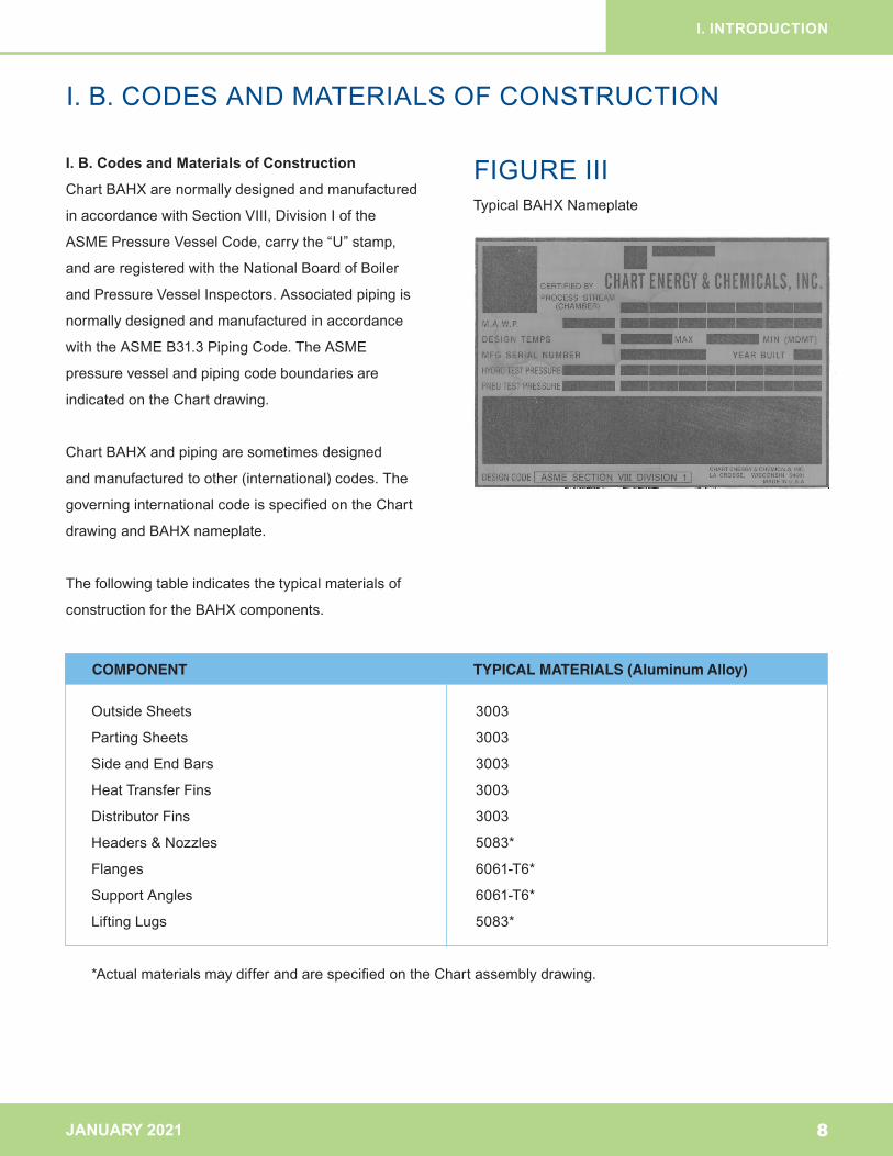
I. B. Codes and Materials of Construction
ChartBAHXarenormallydesignedandmanufactured
inaccordancewithSectionVIII,DivisionIofthe
ASMEPressureVesselCode,carrythe“U”stamp,
andareregisteredwiththeNationalBoardofBoiler
andPressureVesselInspectors.Associatedpipingis
normallydesignedandmanufacturedinaccordance
withtheASMEB31.3PipingCode.TheASME
pressurevesselandpipingcodeboundariesare
indicatedontheChartdrawing.
ChartBAHXandpipingaresometimesdesigned
andmanufacturedtoother(international)codes.The
governinginternationalcodeisspecifiedontheChart
drawingandBAHXnameplate.
Thefollowingtableindicatesthetypicalmaterialsof
constructionfortheBAHXcomponents.
I. INTRODUCTION
I. B.CODESANDMATERIALSOFCONSTRUCTION
8
COMPONENT TYPICAL MATERIALS (Aluminum Alloy)
OutsideSheets 3003
PartingSheets 3003
SideandEndBars 3003
HeatTransferFins 3003
DistributorFins 3003
Headers&Nozzles 5083*
Flanges 6061-T6*
SupportAngles 6061-T6*
LiftingLugs 5083*
*ActualmaterialsmaydifferandarespecifiedontheChartassemblydrawing.
FIGURE IIITypicalBAHXNameplate
JANUARY 2021
II. INSTALLATION A.ArrivalInspection
B.Storage
C.LiftingandHandling D.Mounting,Bracing,andShipping Support
E.PipeConnections
F.Venting
G.Insulation
H.Instrumentation
I.SmartLayers®
BRANDARCHITECTURE
9
JANUARY 2021
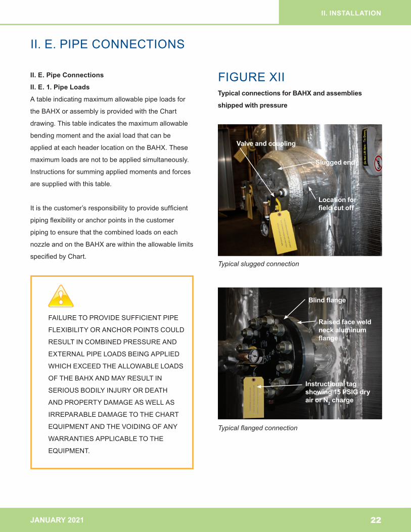
II. A. Arrival Inspection
Uponarrival,verifythenameplatematchesthepurchase
order.TheBAHXshouldbeinspectedforshipping
damageandcontamination.Closelyexamineallunits
forexternaldamage.Forunitsshippedunpressurized,
checkundertheshippingcoversforcontaminationofthe
portopenings.Forunitsshippedpressurized(normallyto
15psig[1barg])withdryairornitrogen,eachheadered
ormanifoldedstreamisprovidedwithavalveand
couplingtowhichapressuregaugecanbemounted
(seeFigureXII).Apositivepressureshouldbeindicated
onthegaugewhenthevalvesareopened.Ifastream
doesnotindicateapositivepressureandthevalveand
couplingconnectionshavebeencheckedforleakage,
itshouldberepressurizedwithdryairornitrogento15
psig(1barg).IfaleakintheBAHX,shippingdamage,
orinternalshippingcontaminationisconfirmed,contact
Chartforfurtherdirection.
II. INSTALLATION
II. A. ARRIVAL INSPECTION
10
JANUARY 2021
II. B. Storage
Anindoorstorageareaawayfromanymainworkarea
isrecommended.IndoorstorageisrequiredforBAHX
havingopenlayersornozzlesnotcoveredwithwelded
orboltedcovers.Anyingressofmoistureintothese
openlayersshouldbeavoided.Inallstorageareas,the
followingadditionalrecommendationsshouldbefollowed.
II. B. 1.
BAHXaretypicallyshippedonwoodorsteelchannel
skids.SkiddedBAHXmayalsobepackagedina
woodencrateormetalshippingcontainer.Donot
stackskiddedorcratedBAHX.
BAHXshouldbestoredintheoriginalpackaging,
whichisgenerallysuitableforthreeyears.Forlonger
termstorage,considerationshouldbegiventospecial
packaging.ConsultChartforpackagingoptions.
II. B. 2.
Thestorageareashouldprovidelevel,uniform
supportwithgooddrainage.
IftheBAHXhasbeenremovedfromitspackaging,
itshouldbelaidonwoodensleepersinahorizontal
positionontheoutsidesheetfaceoftheBAHX.The
woodensleepersshouldbeatleast6inches(152mm)
wideandextendbeyondtheedgesoftheBAHX.Failure
toextendsleepersbeyondtheedgesoftheBAHXcan
resultininternaldamagetotheoutsidelayers.Useonly
twosleepers–oneneareachendoftheBAHX–ata
distancefromeachendthatisapproximatelyonefourth
theBAHX’slength.Avoidpositioningthesleepersunder
anyheaders.Useasoft,resilientmaterialsuchasfiber
boardasabufferbetweenthesleeperandtheBAHX.
II. B. 3.
ThestorageareashouldbelocatedwheretheBAHX
isnotsubjectedtofluidsoratmospheresthatare
corrosivetoaluminum.
II. B. 4.
ThestorageareashouldbelocatedwheretheBAHX
isnotsubjectedtovibration.
II. B. 5.
Avoidalocationwhereotherworkactivityorfalling
objectswillbeinthevicinityofthestoredBAHX.
ExternaldentingoftheBAHXcandamagetheinternal
matrixoftheBAHXandcauseleakage.
II. B. 6.
Avoidalocationthatissubjecttolargefluctuationsin
temperature(especiallybelow32°F[0°C]),orhigh
humiditywhentheBAHXisnotsealedandweather-
proofed,asthiscancausecondensedwaterto
accumulateintheBAHXandfreezewhentheBAHX
isplacedinstorageoroperation.Waterfreezinginside
theBAHXcandamageitsinternalmatrix.
II. B. STORAGE
II. INSTALLATION
11
NEVERSTACKBAHX.STACKINGOFBAHX
COULDRESULTINABAHXFALLINGFROM
ITSSTACKEDPOSITIONWHICHMAYRESULT
INSERIOUSBODILYINJURYORDEATH
ANDPROPERTYDAMAGEASWELLAS
IRREPARABLEDAMAGETOTHECHART
EQUIPMENTANDTHEVOIDINGOFANY
WARRANTIESAPPLICABLETOTHEEQUIPMENT.
JANUARY 2021
II. B. STORAGE
II. INSTALLATION
12
II. B. 7.
BAHXmustbeproperlycoveredandsealedinsuch
amannerthatdirt,sand,water,orforeignmaterials
cannotenteropennozzles,ports,orthroughanyother
accessintotheBAHX.ForBAHXthatareshipped
pressurized,dryairornitrogenwithadewpointof
32°F(0°C)orlessshouldbesealedineachstream
duringstorage.Thedryairornitrogenpressureshould
be15psig(1barg),oronethirdthestreamdesign
pressure,whicheverisless.TheBAHXshouldbe
checkedperiodicallytoensurethatthepressureis
maintained.
ForBAHXthatarenotshippedwithpressureanddo
nothaveweldedshippingcoversonthenozzles,all
nozzleopeningsontheBAHXshouldbecoveredand
sealedwhiletheunitisinadrycondition.
FAMILIARIZATIONWITHALLAPPLICABLE
CHARTDRAWINGSISREQUIREDBEFORE
ANYINSTALLATIONWORKPROCEEDS.
PARTICULARCARESHOULDBETAKEN
WHENEVEROFF-LOADING,MOVING,OR
LIFTINGTHEBAHX.
FAILURETOHANDLEEQUIPMENT
PROPERLYCOULDRESULTINTHEBAHX
BEINGDROPPEDORSOMEOTHER
EQUIPMENTACCIDENTWHICHMAYRESULT
INSERIOUSBODILYINJURYORDEATH
ANDPROPERTYDAMAGEASWELLAS
IRREPARABLEDAMAGETOTHE
CHARTEQUIPMENTANDTHEVOIDINGOF
ANYWARRANTIESAPPLICABLETOTHE
EQUIPMENT.
JANUARY 2021
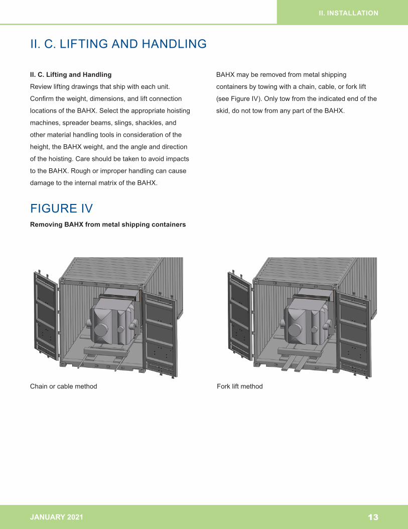
II. C. Lifting and Handling
Reviewliftingdrawingsthatshipwitheachunit.
Confirmtheweight,dimensions,andliftconnection
locationsoftheBAHX.Selecttheappropriatehoisting
machines,spreaderbeams,slings,shackles,and
othermaterialhandlingtoolsinconsiderationofthe
height,theBAHXweight,andtheangleanddirection
ofthehoisting.Careshouldbetakentoavoidimpacts
totheBAHX.Roughorimproperhandlingcancause
damagetotheinternalmatrixoftheBAHX.
BAHXmayberemovedfrommetalshipping
containersbytowingwithachain,cable,orforklift
(seeFigureIV).Onlytowfromtheindicatedendofthe
skid,donottowfromanypartoftheBAHX.
II.C.LIFTINGANDHANDLING
II. INSTALLATION
13
FIGURE IVRemoving BAHX from metal shipping containers
Chainorcablemethod Forkliftmethod
JANUARY 2021
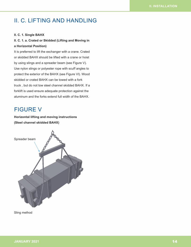
II. C. 1. Single BAHX
II. C. 1. a. Crated or Skidded (Lifting and Moving in
a Horizontal Position)
Itispreferredtolifttheexchangerwithacrane.Crated
orskiddedBAHXshouldbeliftedwithacraneorhoist
byusingslingsandaspreaderbeam(seeFigureV).
Usenylonslingsorpolyesterropewithscuffanglesto
protecttheexterioroftheBAHX(seeFigureVI).Wood
skiddedorcratedBAHXcanbetowedwithafork
truck,butdonottowsteelchannelskiddedBAHX.Ifa
forkliftisusedensureadequateprotectionagainstthe
aluminumandtheforksextendfullwidthoftheBAHX.
II.C.LIFTINGANDHANDLING
II. INSTALLATION
14
FIGURE V Horizontal lifting and moving instructions
(Steel channel skidded BAHX)
Slingmethod
Spreaderbeam
JANUARY 2021
II. INSTALLATION
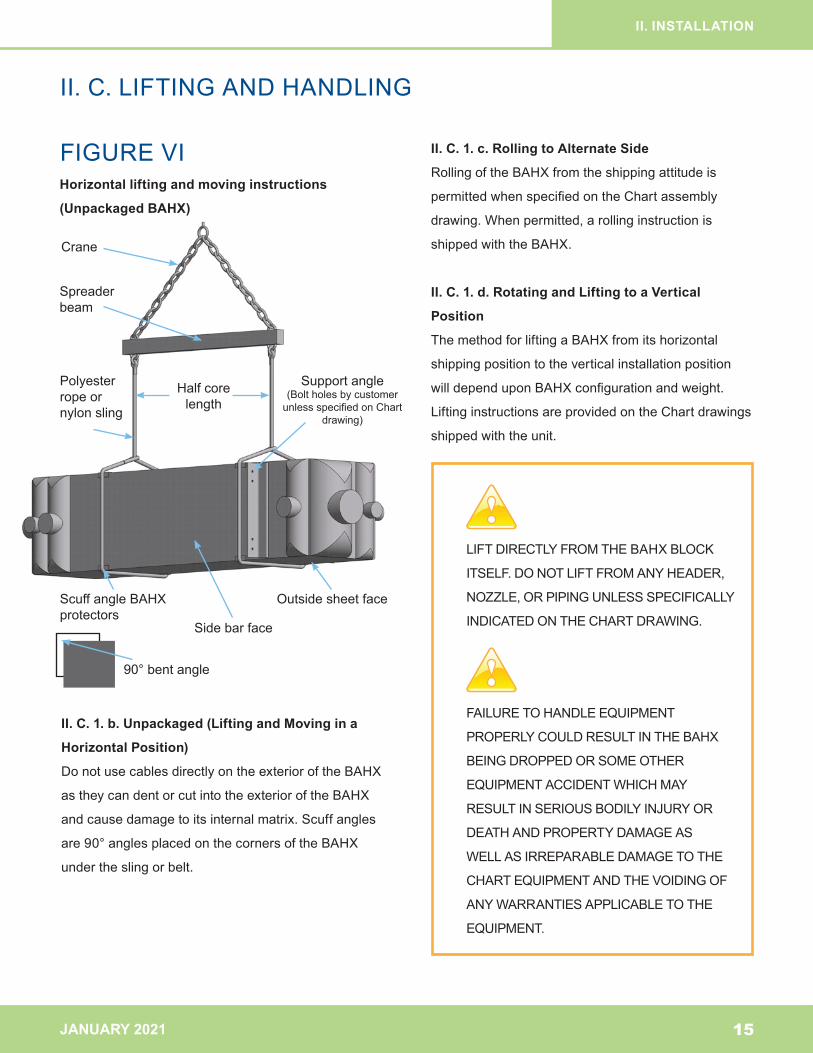
FIGURE VIHorizontal lifting and moving instructions
(Unpackaged BAHX)
II.C.LIFTINGANDHANDLING
LIFTDIRECTLYFROMTHEBAHXBLOCK
ITSELF.DONOTLIFTFROMANYHEADER,
NOZZLE,ORPIPINGUNLESSSPECIFICALLY
INDICATEDONTHECHARTDRAWING.
FAILURETOHANDLEEQUIPMENT
PROPERLYCOULDRESULTINTHEBAHX
BEINGDROPPEDORSOMEOTHER
EQUIPMENTACCIDENTWHICHMAY
RESULTINSERIOUSBODILYINJURYOR
DEATHANDPROPERTYDAMAGEAS
WELLASIRREPARABLEDAMAGETOTHE
CHARTEQUIPMENTANDTHEVOIDINGOF
ANYWARRANTIESAPPLICABLETOTHE
EQUIPMENT.
II. C. 1. c. Rolling to Alternate Side
RollingoftheBAHXfromtheshippingattitudeis
permittedwhenspecifiedontheChartassembly
drawing.Whenpermitted,arollinginstructionis
shippedwiththeBAHX.
II. C. 1. d. Rotating and Lifting to a Vertical
Position
ThemethodforliftingaBAHXfromitshorizontal
shippingpositiontotheverticalinstallationposition
willdependuponBAHXconfigurationandweight.
LiftinginstructionsareprovidedontheChartdrawings
shippedwiththeunit.
II. C. 1. b. Unpackaged (Lifting and Moving in a
Horizontal Position)
DonotusecablesdirectlyontheexterioroftheBAHX
astheycandentorcutintotheexterioroftheBAHX
andcausedamagetoitsinternalmatrix.Scuffangles
are90°anglesplacedonthecornersoftheBAHX
undertheslingorbelt.
15
Supportangle(BoltholesbycustomerunlessspecifiedonChart
drawing)
Crane
Spreaderbeam
Polyesterropeornylonsling
ScuffangleBAHXprotectors
Outsidesheetface
Sidebarface
Halfcorelength
90°bentangle
JANUARY 2021
II. INSTALLATION
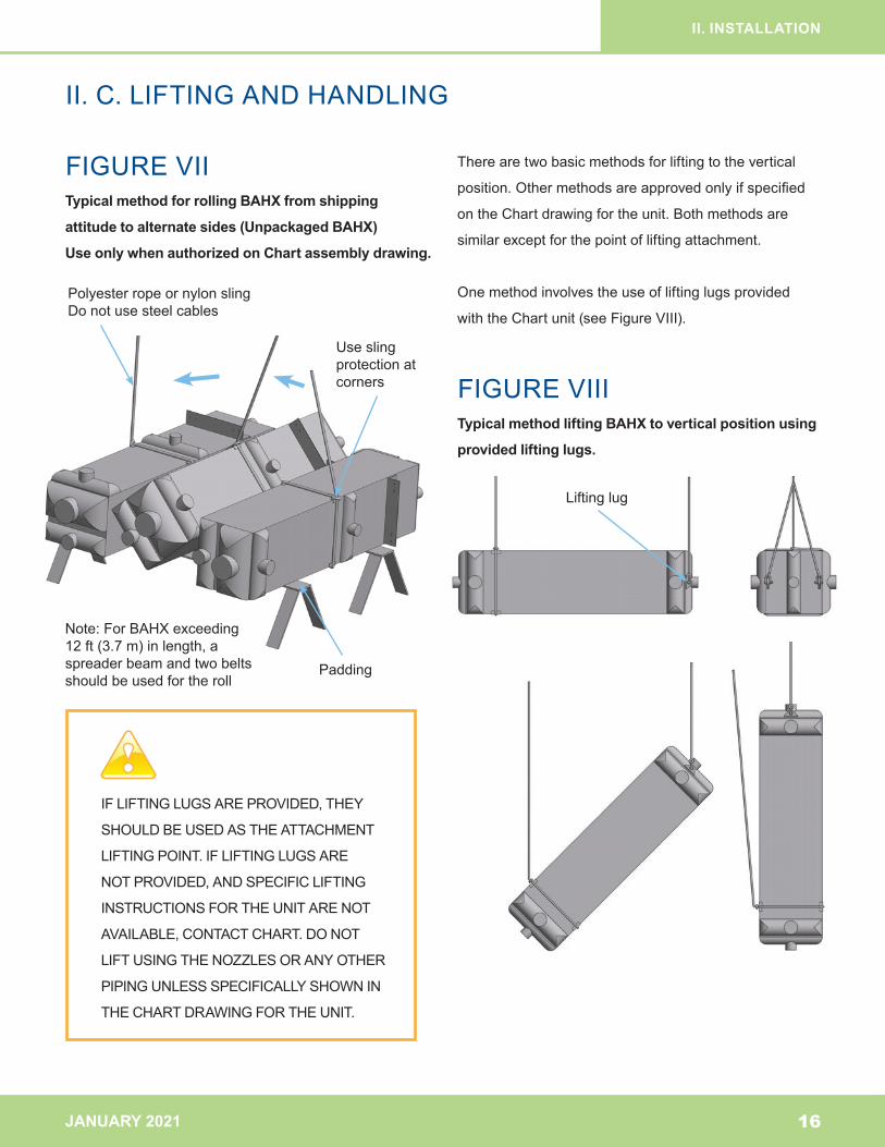
FIGURE VII
FIGURE VIII
Typical method for rolling BAHX from shipping
attitude to alternate sides (Unpackaged BAHX)
Use only when authorized on Chart assembly drawing.
Typical method lifting BAHX to vertical position using
provided lifting lugs.
II.C.LIFTINGANDHANDLING
IFLIFTINGLUGSAREPROVIDED,THEY
SHOULDBEUSEDASTHEATTACHMENT
LIFTING POINT. IF LIFTING LUGS ARE
NOTPROVIDED,ANDSPECIFICLIFTING
INSTRUCTIONSFORTHEUNITARENOT
AVAILABLE,CONTACTCHART.DONOT
LIFTUSINGTHENOZZLESORANYOTHER
PIPINGUNLESSSPECIFICALLYSHOWNIN
THECHARTDRAWINGFORTHEUNIT.
Therearetwobasicmethodsforliftingtothevertical
position.Othermethodsareapprovedonlyifspecified
ontheChartdrawingfortheunit.Bothmethodsare
similarexceptforthepointofliftingattachment.
Onemethodinvolvestheuseofliftinglugsprovided
withtheChartunit(seeFigureVIII).
16
Polyesterropeornylonsling Donotusesteelcables
Note:ForBAHXexceeding 12ft(3.7m)inlength,aspreaderbeamandtwobeltsshouldbeusedfortheroll
Useslingprotectionatcorners
Padding
Liftinglug
JANUARY 2021
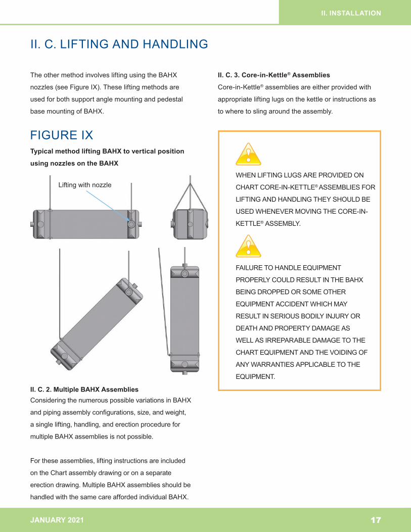
TheothermethodinvolvesliftingusingtheBAHX
nozzles(seeFigureIX).Theseliftingmethodsare
usedforbothsupportanglemountingandpedestal
basemountingofBAHX.
II. C. 2. Multiple BAHX AssembliesConsideringthenumerouspossiblevariationsinBAHX
andpipingassemblyconfigurations,size,andweight,
asinglelifting,handling,anderectionprocedurefor
multipleBAHXassembliesisnotpossible.
Fortheseassemblies,liftinginstructionsareincluded
ontheChartassemblydrawingoronaseparate
erectiondrawing.MultipleBAHXassembliesshouldbe
handledwiththesamecareaffordedindividualBAHX.
II. C. 3. Core-in-Kettle® Assemblies
Core-in-Kettle®assembliesareeitherprovidedwith
appropriateliftinglugsonthekettleorinstructionsas
towheretoslingaroundtheassembly.
II. INSTALLATION
II.C.LIFTINGANDHANDLING
WHENLIFTINGLUGSAREPROVIDEDON
CHARTCORE-IN-KETTLE® ASSEMBLIESFOR
LIFTINGANDHANDLINGTHEYSHOULDBE
USEDWHENEVERMOVINGTHECORE-IN-
KETTLE®ASSEMBLY.
FAILURETOHANDLEEQUIPMENT
PROPERLYCOULDRESULTINTHEBAHX
BEINGDROPPEDORSOMEOTHER
EQUIPMENTACCIDENTWHICHMAY
RESULTINSERIOUSBODILYINJURYOR
DEATHANDPROPERTYDAMAGEAS
WELLASIRREPARABLEDAMAGETOTHE
CHARTEQUIPMENTANDTHEVOIDINGOF
ANYWARRANTIESAPPLICABLETOTHE
EQUIPMENT.
17
FIGUREIXTypical method lifting BAHX to vertical position
using nozzles on the BAHX
Liftingwithnozzle
JANUARY 2021
II. INSTALLATION
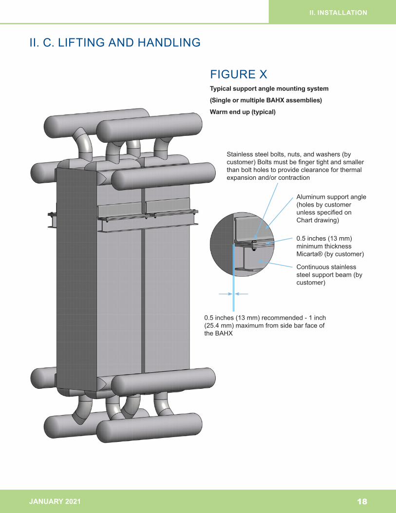
FIGUREXTypical support angle mounting system
(Single or multiple BAHX assemblies)
Warm end up (typical)
II.C.LIFTINGANDHANDLING
18
Stainlesssteelbolts,nuts,andwashers(bycustomer)Boltsmustbefingertightandsmallerthanboltholestoprovideclearanceforthermalexpansionand/orcontraction
Aluminumsupportangle(holesbycustomerunlessspecifiedonChartdrawing)
0.5inches(13mm)minimumthicknessMicarta®(bycustomer)
0.5inches(13mm)recommended-1inch(25.4mm)maximumfromsidebarfaceoftheBAHX
Continuousstainlesssteelsupportbeam(bycustomer)
JANUARY 2021
II. INSTALLATION
II.D.MOUNTING,BRACING,ANDSHIPPINGSUPPORT
II. D. Mounting, Bracing, and Shipping Support
II. D. 1. Support Angle Mounting System (Single or
Multiple BAHX Assemblies)
ChartBAHXarenormallyinstalledverticallywiththe
warmendup(seeFigureX).Otherorientationsare
permissibleonlyifspecifiedontheChartassembly
drawing.ChartBAHXarenormallyprovidedwith
aluminumsupportanglesweldeddirectlytotheside
barfaceoftheBAHXformountingpurposes.
Thefollowingaregeneralmountingrecommendations
forbothsingleBAHXandformultipleBAHX
assembliesutilizingsupportanglemountingsystems
(seeFigureX).
II. D. 1. a.
Allshippingsupportsshouldberemovedasshownon
theChartdrawings.Extremecareshouldbetakento
keepallsteelworkingtorchesandflame-cuttingtools
ataproperdistancefromthealuminumBAHXinorder
topreventseveredamagetobrazedjointsandtothe
internalmatrix.
II. D. 1. b.
ThesupportanglesurfacesontheBAHXareinplane
within0.06inches/foot(0.5%).Thematingsupport
surface(bycustomer)shouldbeacontinuousmember
andbeinplanetothissamestandard.Shimmingis
acceptablebutisnotpreferred.
II. D. 1. c.
SincetheseBAHXarenormallyinstalledincryogenic
services,somemethodofinsulatingbetweenthe
Chartaluminumsupportanglesandthecustomer
matingsupportsurfaceisrecommended.
Aminimumof0.5inch(13mm)thickpieceof
Micarta®(phenoliccanvasbaselaminate)blockis
recommendedforthispurpose.Theinsulationmaterial
thicknessshouldbesufficienttominimizeheat
leakandpreventfrostspotsfromdevelopingonthe
supportsorcoldboxwallsduringoperatingconditions.
II. D. 1. d.
Provisionsforthermalexpansionandcontraction
oftheBAHXinthehorizontalplaneatthesupport
locationmustbeprovided.
Theexpectedthermalmovementshouldbecalculated
inbothhorizontaldirectionsbythefollowingequation:
D=12.6 x 10⁻⁶ x L x ∆T
whereListhedistanceininchesbetweenextreme
boltsinthedirectionunderconsideration,∆Tisthe
changeintemperaturein°Fatthesupportlocation
fromtheinstalled(ambient)temperaturetothecoldest
possibleoperatingtemperature,andDistheexpected
thermalmovementinincheswhichwillresultfromthis
calculation.
19
JANUARY 2021
II. INSTALLATION
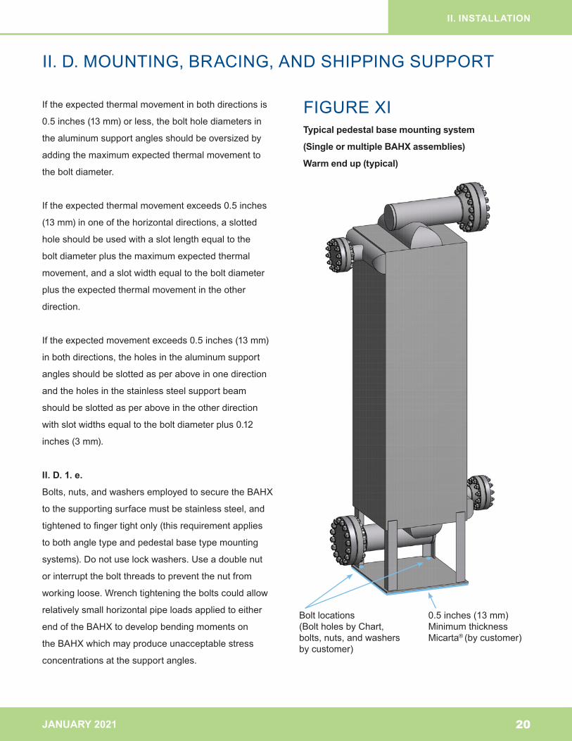
FIGUREXITypical pedestal base mounting system
(Single or multiple BAHX assemblies)
Warm end up (typical)
II.D.MOUNTING,BRACING,ANDSHIPPINGSUPPORT
20
Iftheexpectedthermalmovementinbothdirectionsis
0.5inches(13mm)orless,theboltholediametersin
thealuminumsupportanglesshouldbeoversizedby
addingthemaximumexpectedthermalmovementto
theboltdiameter.
Iftheexpectedthermalmovementexceeds0.5inches
(13mm)inoneofthehorizontaldirections,aslotted
holeshouldbeusedwithaslotlengthequaltothe
boltdiameterplusthemaximumexpectedthermal
movement,andaslotwidthequaltotheboltdiameter
plustheexpectedthermalmovementintheother
direction.
Iftheexpectedmovementexceeds0.5inches(13mm)
inbothdirections,theholesinthealuminumsupport
anglesshouldbeslottedasperaboveinonedirection
andtheholesinthestainlesssteelsupportbeam
shouldbeslottedasperaboveintheotherdirection
withslotwidthsequaltotheboltdiameterplus0.12
inches(3mm).
II. D. 1. e.
Bolts,nuts,andwashersemployedtosecuretheBAHX
tothesupportingsurfacemustbestainlesssteel,and
tightenedtofingertightonly(thisrequirementapplies
tobothangletypeandpedestalbasetypemounting
systems).Donotuselockwashers.Useadoublenut
orinterrupttheboltthreadstopreventthenutfrom
workingloose.Wrenchtighteningtheboltscouldallow
relativelysmallhorizontalpipeloadsappliedtoeither
endoftheBAHXtodevelopbendingmomentson
theBAHXwhichmayproduceunacceptablestress
concentrationsatthesupportangles.
Boltlocations(BoltholesbyChart,bolts,nuts,andwashersbycustomer)
0.5inches(13mm)MinimumthicknessMicarta® (bycustomer)
JANUARY 2021
II. INSTALLATION
II.D.MOUNTING,BRACING,ANDSHIPPINGSUPPORT
II. D. 1. f.
Toavoidexcessivebendingmomentsonthesupport
angleitself,theedgeofthesupportsurfacemustbe
nomorethan1.0inches(25.4mm)fromtheBAHX
sidebarface.Adistanceof0.5inches(13mm)is
recommended(seeFigureX).
II. D. 1. g.
Thesupportsystemshouldbesafeguardedbythe
provisionofaswaybrace,locatedattheoppositeend
oftheBAHXawayfromthemainsupportanglesor
pedestalbase,wheneverthetotalexternalloads
(pipe,wind,andearthquake)aresufficienttocause
lateralmovementoftheBAHX.
AclosefitbetweentheBAHXwearplateandthe
swaybraceisrequiredsincechangingfromambient
tooperatingatcryogenictemperaturesatthisposition
canproduce0.12inches(3mm)ofmovementfrom
thermalcontraction.Ifrequested,wearplatescanbe
furnishedontheBAHXbyChart.
DonotfastenanyswaybracedirectlytotheBAHX.The
BAHXmustbefreetomoveintheverticaldirection.
II. D. 1. h.
Forreversing(airseparationservice)BAHX,supporting
directlyfromthebottom(warmend)manifoldsis
acceptableifprovidedforontheChartassembly
drawing.WarmendmanifoldsforreversingBAHX
shouldalwaysbeprovidedwithsumpsanddrainsof
adequatesizetoreturnanycondensedwaterfromthe
manifoldpipingsothatwaterwillnotbeentrainedinthe
fluidstreamorsluggedintotheBAHXduringpressure
reversals.
II. D. 2. Pedestal Base Mounting System (Single
or Multiple BAHX Assemblies)
Analternativemethodtothesupportanglemounting
systemisanaluminumpedestalbasemounting
systemprovidedwiththeBAHX(seeFigureXI).The
pedestalbasemountingsystemisgenerallyemployed
whencoldboxinstallationisnotrequiredandthe
BAHXcanbemountedatgroundlevelasthisis
usuallyalesscostlymethodformounting.
Thesamerecommendationsregardingshimming,
insulation,boltholesize,bolttightness,andbracing
forsupportanglemountingsystemsinSectionII.D.1.
shouldbefollowedforpedestalbasemountsystems.
II. D. 3. Core-in-Kettle® Assemblies
Theholesfortheanchorboltsareslottedinthesliding
saddletoallowforthermalcontractionandexpansion.
WheninstallingaCore-in-Kettle®assemblyitiscritical
toaligntheanchorboltsinthecenteroftheslots.
Inrarecasesthesaddlegeometrymayrequirethe
anchorboltsbeinstalledoffsetintheslots.Inthese
casestherequiredpositioningisspecifiedonthe
Core-in-Kettle®assemblydrawing.
21
JANUARY 2021
II. INSTALLATION
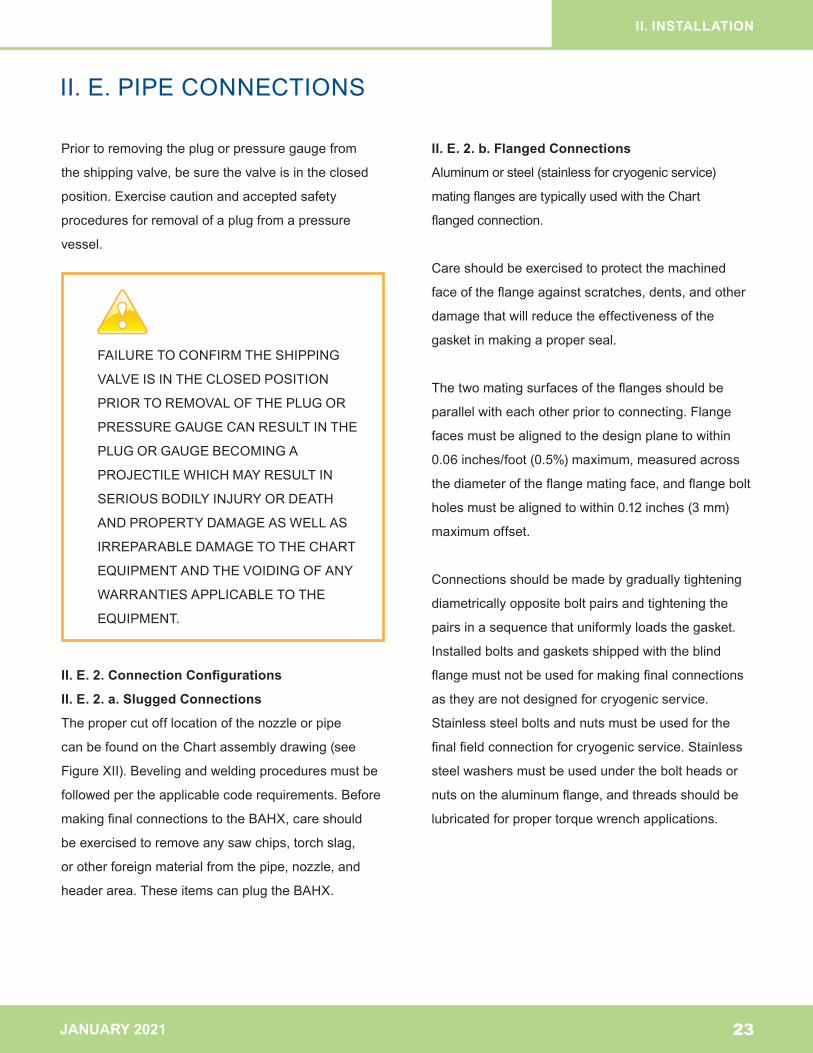
FIGUREXIITypical connections for BAHX and assemblies
shipped with pressure
II. E. PIPE CONNECTIONS
22
II. E. Pipe Connections
II. E. 1. Pipe Loads
Atableindicatingmaximumallowablepipeloadsfor
theBAHXorassemblyisprovidedwiththeChart
drawing.Thistableindicatesthemaximumallowable
bendingmomentandtheaxialloadthatcanbe
appliedateachheaderlocationontheBAHX.These
maximumloadsarenottobeappliedsimultaneously.
Instructionsforsummingappliedmomentsandforces
aresuppliedwiththistable.
Itisthecustomer’sresponsibilitytoprovidesufficient
pipingflexibilityoranchorpointsinthecustomer
pipingtoensurethatthecombinedloadsoneach
nozzleandontheBAHXarewithintheallowablelimits
specifiedbyChart.
FAILURE TO PROVIDE SUFFICIENT PIPE
FLEXIBILITYORANCHORPOINTSCOULD
RESULTINCOMBINEDPRESSUREAND
EXTERNALPIPELOADSBEINGAPPLIED
WHICHEXCEEDTHEALLOWABLELOADS
OFTHEBAHXANDMAYRESULTIN
SERIOUSBODILYINJURYORDEATH
ANDPROPERTYDAMAGEASWELLAS
IRREPARABLEDAMAGETOTHECHART
EQUIPMENTANDTHEVOIDINGOFANY
WARRANTIESAPPLICABLETOTHE
EQUIPMENT.
Valve and coupling
Blind flange
Raised face weld neck aluminum flange
Instructional tag showing 15 PSIG dry air or N2 charge
Slugged end
Location for field cut off
Typical slugged connection
Typical flanged connection
JANUARY 2021
II. INSTALLATION
II. E. PIPE CONNECTIONS
Priortoremovingtheplugorpressuregaugefrom
theshippingvalve,besurethevalveisintheclosed
position.Exercisecautionandacceptedsafety
proceduresforremovalofaplugfromapressure
vessel.
II. E. 2. Connection Configurations
II. E. 2. a. Slugged Connections
Thepropercutofflocationofthenozzleorpipe
canbefoundontheChartassemblydrawing(see
FigureXII).Bevelingandweldingproceduresmustbe
followedpertheapplicablecoderequirements.Before
makingfinalconnectionstotheBAHX,careshould
beexercisedtoremoveanysawchips,torchslag,
orotherforeignmaterialfromthepipe,nozzle,and
headerarea.TheseitemscanplugtheBAHX.
II. E. 2. b. Flanged Connections
Aluminumorsteel(stainlessforcryogenicservice)
matingflangesaretypicallyusedwiththeChart
flangedconnection.
Careshouldbeexercisedtoprotectthemachined
faceoftheflangeagainstscratches,dents,andother
damagethatwillreducetheeffectivenessofthe
gasketinmakingaproperseal.
Thetwomatingsurfacesoftheflangesshouldbe
parallelwitheachotherpriortoconnecting.Flange
facesmustbealignedtothedesignplanetowithin
0.06inches/foot(0.5%)maximum,measuredacross
thediameteroftheflangematingface,andflangebolt
holesmustbealignedtowithin0.12inches(3mm)
maximumoffset.
Connectionsshouldbemadebygraduallytightening
diametricallyoppositeboltpairsandtighteningthe
pairsinasequencethatuniformlyloadsthegasket.
Installedboltsandgasketsshippedwiththeblind
flangemustnotbeusedformakingfinalconnections
astheyarenotdesignedforcryogenicservice.
Stainlesssteelboltsandnutsmustbeusedforthe
finalfieldconnectionforcryogenicservice.Stainless
steelwashersmustbeusedundertheboltheadsor
nutsonthealuminumflange,andthreadsshouldbe
lubricatedforpropertorquewrenchapplications.
23
FAILURETOCONFIRMTHESHIPPING
VALVEISINTHECLOSEDPOSITION
PRIORTOREMOVALOFTHEPLUGOR
PRESSUREGAUGECANRESULTINTHE
PLUGORGAUGEBECOMINGA
PROJECTILEWHICHMAYRESULTIN
SERIOUSBODILYINJURYORDEATH
ANDPROPERTYDAMAGEASWELLAS
IRREPARABLEDAMAGETOTHECHART
EQUIPMENTANDTHEVOIDINGOFANY
WARRANTIESAPPLICABLETOTHE
EQUIPMENT.
JANUARY 2021
II. INSTALLATION
II. E. PIPE CONNECTIONS
Gasket Recommendations For Use With Aluminum
Flanges:
ChartrecommendsFlexitallicFlexprogaskets
orequivalent(m=2.0,y=2500psi[17.2MPa]).If
stainlesssteelspiralwoundgasketsareused,Chart
recommendstheybelowseatingstresssuchas
FlexitallicLS(m=3.0,y=5000psi[34.5MPa]).Ifhigher
seatingstressgasketsareselectedconsultChart
todetermineifChart’sstandardrecommendedbolt
torquesareadequate.
Bolting recommendations:
Recommended Bolt Torques:
Allboltingmustbegivenafinaltighteningbytorque
wrench.Boltsaretobetorquedtothefullvalue
showninthetablebelowandthenre-torquedafter15
minutes.Torquevaluesarebasedonaresultantbolt
stressof30,000psiassumingwelllubricatedstuds,
nuts,andwashers.
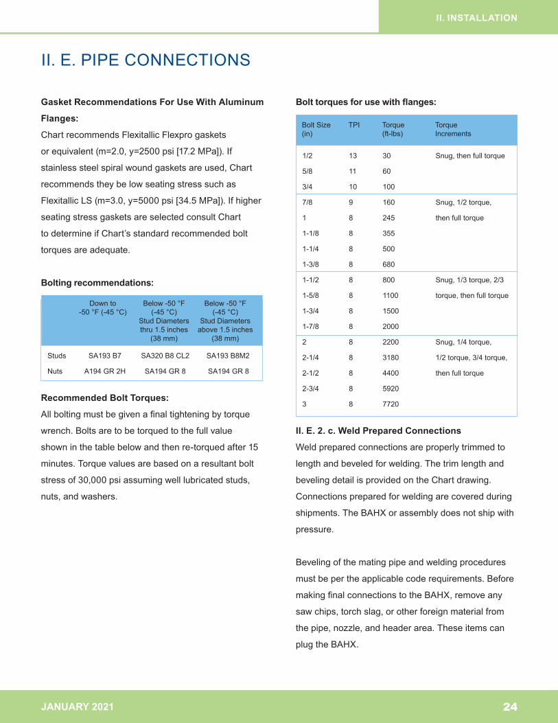
Bolt torques for use with flanges:
II. E. 2. c. Weld Prepared Connections
Weldpreparedconnectionsareproperlytrimmedto
lengthandbeveledforwelding.Thetrimlengthand
bevelingdetailisprovidedontheChartdrawing.
Connectionspreparedforweldingarecoveredduring
shipments.TheBAHXorassemblydoesnotshipwith
pressure.
Bevelingofthematingpipeandweldingprocedures
mustbepertheapplicablecoderequirements.Before
makingfinalconnectionstotheBAHX,removeany
sawchips,torchslag,orotherforeignmaterialfrom
thepipe,nozzle,andheaderarea.Theseitemscan
plugtheBAHX.
24
Downto-50°F(-45°C)
Below-50°F (-45°C)
StudDiametersthru1.5inches
(38mm)
Below-50°F (-45°C)
StudDiametersabove1.5inches
(38mm)
BoltSize TPI Torque Torque(in) (ft-lbs) Increments
Studs SA193B7 SA320B8CL2 SA193B8M2
Nuts A194GR2H SA194GR8 SA194GR8
1/2 13 30 Snug,thenfulltorque
5/8 11 60
3/4 10 100
7/8 9 160 Snug,1/2torque,
1 8 245 thenfulltorque
1-1/8 8 355
1-1/4 8 500
1-3/8 8 680
1-1/2 8 800 Snug,1/3torque,2/3
1-5/8 8 1100 torque,thenfulltorque
1-3/4 8 1500
1-7/8 8 2000
2 8 2200 Snug,1/4torque,
2-1/4 8 3180 1/2torque,3/4torque,
2-1/2 8 4400 thenfulltorque
2-3/4 8 5920
3 8 7720
JANUARY 2021
II. INSTALLATION
II. E. PIPE CONNECTIONS
25
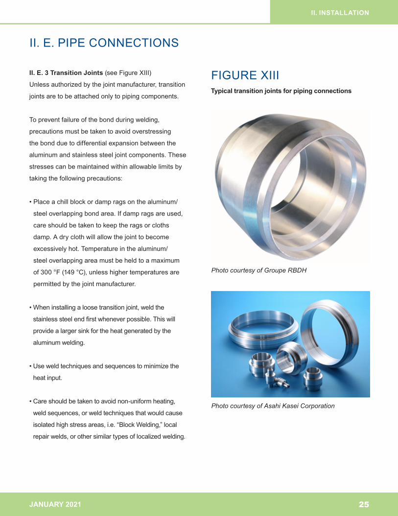
II. E. 3 Transition Joints (seeFigureXIII)
Unlessauthorizedbythejointmanufacturer,transition
jointsaretobeattachedonlytopipingcomponents.
Topreventfailureofthebondduringwelding,
precautionsmustbetakentoavoidoverstressing
thebondduetodifferentialexpansionbetweenthe
aluminumandstainlesssteeljointcomponents.These
stressescanbemaintainedwithinallowablelimitsby
takingthefollowingprecautions:
•Placeachillblockordampragsonthealuminum/
steeloverlappingbondarea.Ifdampragsareused,
careshouldbetakentokeeptheragsorcloths
damp.Adryclothwillallowthejointtobecome
excessivelyhot.Temperatureinthealuminum/
steeloverlappingareamustbeheldtoamaximum
of300°F(149°C),unlesshighertemperaturesare
permittedbythejointmanufacturer.
•Wheninstallingaloosetransitionjoint,weldthe
stainlesssteelendfirstwheneverpossible.Thiswill
providealargersinkfortheheatgeneratedbythe
aluminumwelding.
•Useweldtechniquesandsequencestominimizethe
heatinput.
•Careshouldbetakentoavoidnon-uniformheating,
weldsequences,orweldtechniquesthatwouldcause
isolatedhighstressareas,i.e.“BlockWelding,”local
repairwelds,orothersimilartypesoflocalizedwelding.
FIGUREXIIITypical transition joints for piping connections
Photo courtesy of Groupe RBDH
Photo courtesy of Asahi Kasei Corporation
JANUARY 2021
II. INSTALLATION
II. F. VENTING
26
II. F. Venting
Externalventingofinactiveornon-operationalinternal
zonesofsomeBAHXisrequiredwhenspecified
ontheChartdrawing.Examplesofinactivezonesthat
requireventingare:
•themodularspaceformedbyweldingtogethertwo
BAHXblocks.
•thedeadcornerofareversingstreamwarmend
distributoremployingtheslantbardrainability
feature.
•thespaceformedbetweentwotandemstreams
havingadjacentsideheadersatmidBAHX.
•otherspecialcases.
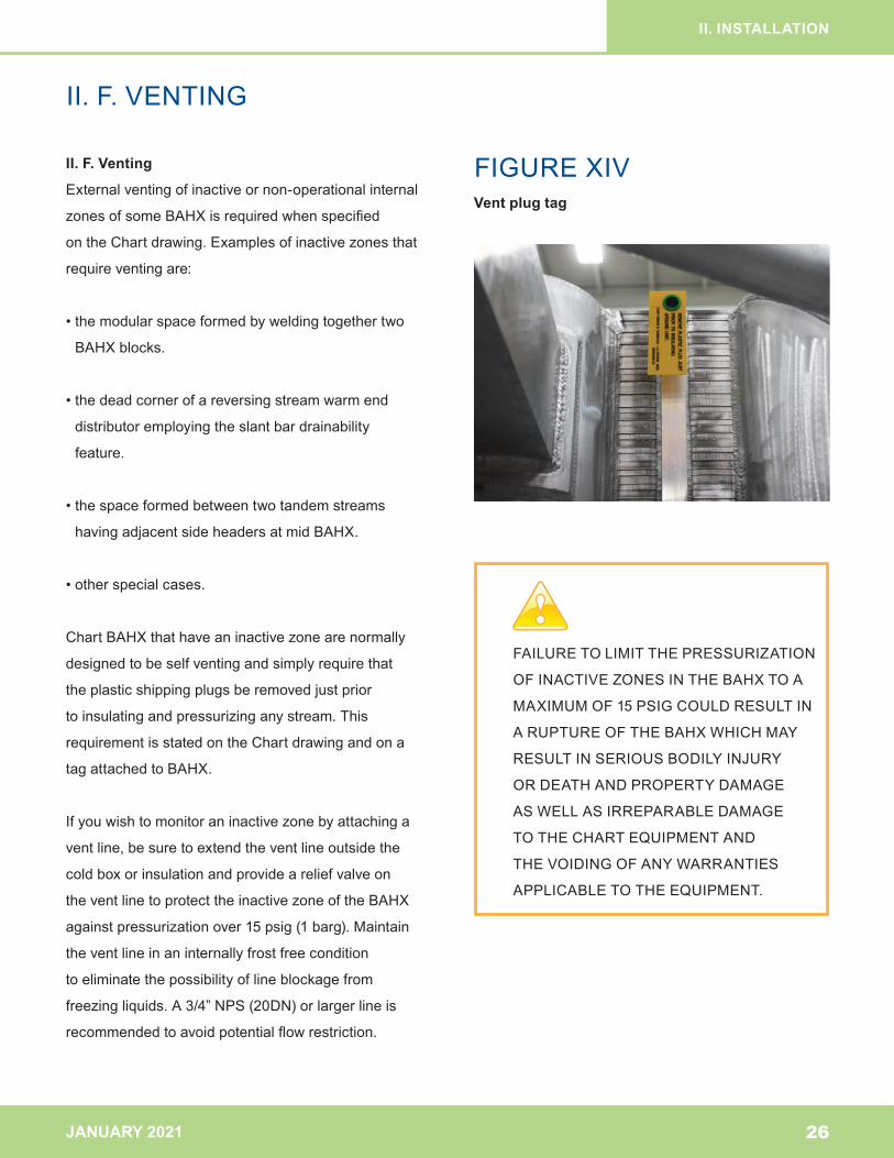
ChartBAHXthathaveaninactivezonearenormally
designedtobeselfventingandsimplyrequirethat
theplasticshippingplugsberemovedjustprior
toinsulatingandpressurizinganystream.This
requirementisstatedontheChartdrawingandona
tagattachedtoBAHX.
Ifyouwishtomonitoraninactivezonebyattachinga
ventline,besuretoextendtheventlineoutsidethe
coldboxorinsulationandprovideareliefvalveon
theventlinetoprotecttheinactivezoneoftheBAHX
againstpressurizationover15psig(1barg).Maintain
theventlineinaninternallyfrostfreecondition
toeliminatethepossibilityoflineblockagefrom
freezingliquids.A3/4”NPS(20DN)orlargerlineis
recommendedtoavoidpotentialflowrestriction.
FIGUREXIVVent plug tag
FAILURETOLIMITTHEPRESSURIZATION
OFINACTIVEZONESINTHEBAHXTOA
MAXIMUMOF15PSIGCOULDRESULTIN
ARUPTUREOFTHEBAHXWHICHMAY
RESULTINSERIOUSBODILYINJURY
ORDEATHANDPROPERTYDAMAGE
ASWELLASIRREPARABLEDAMAGE
TOTHECHARTEQUIPMENTAND
THEVOIDINGOFANYWARRANTIES
APPLICABLETOTHEEQUIPMENT.
JANUARY 2021
II. INSTALLATION
II. G. INSULATION
II. G. Insulation
SinceBAHXusuallyoperateatcryogenic
temperatures,highlyefficientinsulationshould
beappliedbythecustomertominimizeheatleak.
Insulationmaterialisnormallyappliedaftertheunitis
installedatthejobsite.Flammablematerialsshould
beavoidedforinsulation.Insulationmaterialsare
notnormallyappliedtotheBAHXpriortoinstallation
becauseinsulationmaterialsareeasilydamagedin
transit,theyrestricttheuseofshippingtiedowns
andsupports,andtheywouldimpairaccessibilityto
theunitforlifting,mounting,leaktesting,andother
installationpreparations.
WhentheBAHXisnotmountedinsideacoldbox,
theBAHX’sexteriorisnormallyinsulatedwithrigid
polyurethanefoam,orotheralternativessuchas
Foamglass®insulation,accordingtothethicknessand
requirementsspecifiedbytheengineeringcontractor.
Theseinsulationsarepositionedandfastenedaround
theBAHXandcoveredwithavaporbarrier.Protective
metalcoveringsorflashingcanbeusedforthis
purpose.
Inallinstallations,someformofinsulationsuchasa
Micarta®spacershouldbeusedbetweentheBAHX
supportmemberandthesupportingbeamorplatform
(seeSectionII.D.1.c.).
Cautionshouldalwaysbeexercisedwheneverwelding
orflamecuttingnearinsulationmaterials.
RefertotheColdBoxInstallation,Operation,and
MaintenanceManualforinstructionsoninsulating
BAHXinstalledincoldboxassemblies.
27
JANUARY 2021
II.H.INSTRUMENTATION
II. H. Instrumentation
Properinstrumentationmustbeinstalledtoproperly
operateBAHXwithintheguidelines(seeSectionIll.C.).
Fluidtemperaturesandpressuresshouldbemonitored
attheinletandoutletofeverystreamatintervalsof1
minute.Forboilingstreamsinreboilerservicesexternal
tothecolumn,adedicateddifferentialpressure
instrumentshouldbeusedtomonitorforpressure
oscillationsindicatingunstableflow.Fluidflowrates
shouldbemonitoredwithflowmeters,orapproximated
withvalvepositions,pressuredrop,orvesselliquid
levels,atintervalsof1minute.Fluidcompositionshould
bemeasuredandloggedatintervalsof1monthata
minimumorasfrequentlyasthecompositionchanges.
Ifdesired,coreblocktemperaturecanbedirectly
measuredusingtemperaturedevicesinstalledby
Chart.
Gasdetectorsshouldbeinstalledinthevicinitytoalert
ifanyexternalleaksexist.
28
II. INSTALLATION
JANUARY 2021
II. I. 1. Smart Layer®
SmartLayerisawarningsystemcomprisedofinactivelayers
locatedontheoutsideofthestackthathavebeendesigned
andprooftestedforthefulldesignpressureoftheadjacent
processstream(s).Theyareequippedwithconnectionsfor
apressuremonitor,pressurereliefvalve,andaNitrogen
chargingport.ThepurposeofSmartLayeristoalert
operatorswhenacriticalthresholdofthermalstressdamage
hasoccurred,priortoanyexternalleakoccurring.
SmartLayerisanoptionalfeaturenotincludedonall
designs.Thenameplatewillindicateifaunitisequipped
withSmartLayer.
II. I. 2. Function
SmartLayerfunctionsbyaccumulatingthermalstress
damagefasterthanotherpartsoftheBAHX.Whena
criticalthresholdofdamagehasaccumulated,itwillresult
inan“indicationleak”intheSmartLayer.Theindication
leakispartoftheintendedfunctionofSmartLayer,andwill
notcauseanyprocessfluidstoleaktoatmosphere.When
anindicationleakoccurs,theDCSwillsignaltheoperator
thataSmartLayeralarmhasbeenactivated.
II. I. 3. Smart Layer Hardware
Typicalhardwareincludesapressuretransmittertomonitorthe
SmartLayerpressure,apressurereliefdevicethatventseither
toatmosphereortoflare,andaconnectionforchargingand
drainingtheSmartLayers
II. I. 4. Smart Layer Field Installation
SmartLayerisshippedwithtemporaryshippingblinds.The
balanceoftheSmartLayercomponentssuppliedbyChart
(ifany)areshippedloosetoreducetheriskofdamage
duringtransport.AftertheBAHXhasbeeninstalled,remove
thetemporaryshippingblindsandinstalltheSmartLayer
components.FilltheSmartLayerwithnitrogentoacharge
pressureasdescribedbelow.SmartLayerisnotintendedto
beconnectedtoacontinuouslyregulatingnitrogensystem.
SoapbubbletestallSmartLayerconnectionstoensureleak
tightness.
II. I. 5. Smart Layer® Charge Pressure Setpoint
ChargeSmartLayer’snitrogenblankettoalevel
sufficienttoallowforproperoperationofthePSV.The
Chargepressuremustalsobesetbetweenthehighand
lowlevelalarmsdescribedbelow.
II. I. 6. Smart Layer® High-Level Alarm Setpoint
Setthehighlevelalarmbelowoperatingpressureofthe
stream(s)designatedintheSmartLayernotesontheGeneral
AssemblyDrawing.Ensurethereisameasurablepressure
differencebetweenthechargepressureandthehighlevelalarm.
II. I. 7. Smart Layer® Low-Level Alarm Setpoint
Thelow-levelalarmsetpointisslightlyaboveatmospheric
pressure.Thechargepressurewilldecreaseduringcooldown.
Ensurethispressuredecreasewillnottripthelowlevelalarm.
II.I.SMARTLAYER®
FAILURETOINSTALLTHESMARTLAYER
PRESSURERELIEFVALVEMAYRESULTIN
OVERPRESSURIZATIONOFTHESMART
LAYERWHICHMAYRESULTINSERIOUS
BODILYINJURYORDEATHANDPROPERTY
DAMAGEASWELLASIRREPARABLE
DAMAGETOTHECHARTEQUIPMENT
ANDTHEVOIDINGOFANYWARRANTIES
APPLICABLETOTHEEQUIPMENT.
29
II. INSTALLATION
JANUARY 2021
II. I. 8. DCS Integration
Thepressuretransmittershouldbeconnectedtothe
plantDCStorecordandmonitortheSmartLayer
pressure.Pressureshouldberecorded(typicallyat1
minuteintervals)toaidinrootcauseanalysisinthe
eventofaSmartLayeralarm.
II. I. 9. Smart Layer® Alarm
TheDCSshouldbeconfiguredtoalarmtheoperatorif
theSmartLayerpressuredropsbeloworrisesabove
theAlarmsetpoints.ASmartLayeralarmistriggered
byanindicationleakinSmartLayerandsignifiesone
ormorestresscrackshaveoccurredintheBAHX.
Thisismostlikelythermalfatiguedamagecausedby
operationoutsideoftheIOMguidelines.ContactChart
forguidanceifaSmartLayeralarmisreceived.
II.I.SMARTLAYER®
30
II. INSTALLATION
JANUARY 2021
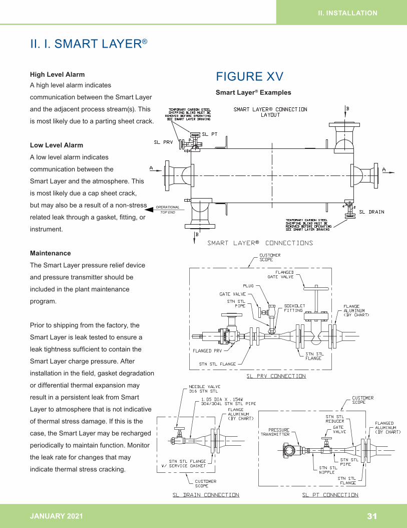
II.I.SMARTLAYER®
High Level AlarmAhighlevelalarmindicates
communicationbetweentheSmartLayer
andtheadjacentprocessstream(s).This
ismostlikelyduetoapartingsheetcrack.
Low Level Alarm
Alowlevelalarmindicates
communicationbetweenthe
SmartLayerandtheatmosphere.This
ismostlikelydueacapsheetcrack,
butmayalsobearesultofanon-stress
relatedleakthroughagasket,fitting,or
instrument.
Maintenance
TheSmartLayerpressurereliefdevice
andpressuretransmittershouldbe
includedintheplantmaintenance
program.
Priortoshippingfromthefactory,the
SmartLayerisleaktestedtoensurea
leaktightnesssufficienttocontainthe
SmartLayerchargepressure.After
installationinthefield,gasketdegradation
ordifferentialthermalexpansionmay
resultinapersistentleakfromSmart
Layertoatmospherethatisnotindicative
ofthermalstressdamage.Ifthisisthe
case,theSmartLayermayberecharged
periodicallytomaintainfunction.Monitor
theleakrateforchangesthatmay
indicatethermalstresscracking.
OPERATIONALTOP END
®
®
31
II. INSTALLATION
FIGUREXVSmart Layer® Examples
JANUARY 2021 32
III. TESTING AND OPERATION
A.FieldProofTesting
B.FoulingandCorrosionProtection
C.Startup,Operation,andShutDown
D.OperatingRecords
BRANDARCHITECTURE
JANUARY 2021
III. TESTING AND OPERATION
III. A. FIELD PROOF TESTING
III. A. Field Proof Testing
Mostcodesrequireapressuretestofthepiping
systemaftertheBAHXorassemblyisinstalled.
Apneumatictestismostoftenperformed.
Onlyclean,drygasesshouldbeusedforpneumatic
proofandsubsequentleaktesting.Water,oranyfluid
thatmayfreezeunderoperatingconditions,shouldnot
beusedinanytestingorcleaningoftheChartBAHX
asitisextremelydifficulttodrytheBAHXinthefield.
TrappedwatercanfreezeintheBAHXmatrixand
develophydraulicpressuressufficienttorupturethe
internalsoftheBAHXwithoutanyexternalevidence.
IfwaterisaccidentallyintroducedintotheBAHX,see
SectionIV.C.1.fordryingprocedures.InSectionIV.
B.,severalpracticalfieldtestsarerecommendedfor
determiningleaks.
Thepneumaticprooftestpressuremustcomply
withNationalBoardInspectionCoderequirements
or,ifapplicable,internationalpressurevesselcode
inspectionrequirementsandmustnotexceed1.1
timesthemaximumworkingpressurespecifiedonthe
Chartnameplate.
33
OVERPRESSURIZATIONOFTHEBAHX
COULD RESULT IN A RUPTURE OF
THEBAHXWHICHMAYRESULTIN
SERIOUSBODILYINJURYORDEATH
ANDPROPERTYDAMAGEASWELLAS
IRREPARABLEDAMAGETOTHECHART
EQUIPMENTANDTHEVOIDINGOFANY
WARRANTIESAPPLICABLETOTHE
EQUIPMENT.
INTRODUCTIONOFWATERTOANY
BAHXEXPOSEDTOMERCURY
CONTAMINATIONCANRESULTIN
ACCELERATED CORROSION AND CAN
CAUSEIRREPARABLEDAMAGEAND
POTENTIAL CATASTROPIC FAILURE AND
EXPOSEPERSONNELTOHAZARDOUS
ANDUNSAFEWORKINGCONDITIONS.
JANUARY 2021
III. TESTING AND OPERATION
III. B. FOULING AND CORROSION PROTECTION
34
III. B. Fouling and Corrosion Protection
BAHXarecapableofhandlingawidevarietyoffluids.
Fluidsshouldbeclean,dry,andnon-corrosiveto
aluminum.Fluidscontainingparticulatematter,waxy
components,orcorrosiveelementsshouldnotbe
usedintheBAHX.
III. B. 1. Filtering
Thepresenceofparticulatesintheprocessstreams
maynotonlyleadtoBAHXpluggingandfouling,but
mayalsocauseerosioninthehighvelocityareasof
theBAHX.FoulingoftheBAHXcanbedetectedby
agradualorsuddenincreaseinpressuredropanda
lossofheattransferperformance.
AllconnectingpipelinescarryingBAHXfluidsshould
bethoroughlycleanedofallpipescale,dirt,sand,and
otherdebrisbeforeplacingtheBAHXinservice.
Allstreamsshouldbefilteredwitha177micron
(80MeshTylerStandard)screenorfiner,directly
upstreamoftheBAHX,BAHXassemblyorcoldbox.
Thefiltersshouldremaininplaceatalltimeswhilethe
BAHXisoperating.Theusershouldconsideradual
filtersystemwithsufficientvalvingtoallowafiltertobe
changedwithoutshuttingdown.Heavyduty,cleanable
filtersorstrainersarerecommended.
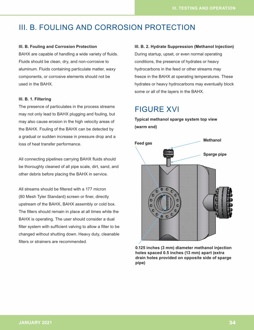
III. B. 2. Hydrate Suppression (Methanol Injection)
Duringstartup,upset,orevennormaloperating
conditions,thepresenceofhydratesorheavy
hydrocarbonsinthefeedorotherstreamsmay
freezeintheBAHXatoperatingtemperatures.These
hydratesorheavyhydrocarbonsmayeventuallyblock
someorallofthelayersintheBAHX.
FIGUREXVITypical methanol sparge system top view
(warm end)
Methanol
Sparge pipe
Feed gas
0.125 inches (3 mm) diameter methanol injection holes spaced 0.5 inches (13 mm) apart (extra drain holes provided on opposite side of sparge pipe)
JANUARY 2021
III. TESTING AND OPERATION
III. B. FOULING AND CORROSION PROTECTION
Whencompleteshutdownforderimingisundesirable
(seeSectionIV.C.1.)methanolinjectioncanbeused
toremovehydratesduringoperationiftheoperating
temperatureiswarmerthan-170°F(-112.2°C)(methanol
freezesatapproximately-170°F).Thismethodofhydrate
suppressioninvolvesinjectingmethanolintotheprocess
fluidupstreamoftheChartBAHX.Analuminumsparge
pipeinjectorcanbeprovidedforthispurposeinsidethe
headeroftheChartBAHX(seeFigureXVI).Methanolis
injectedintotheincomingfeedgasviathisspargepipe.
ThefeedgasthencarriesthemethanolintotheBAHX.
Ifamethanolinjectionspargesystemisnotusedforan
extendedperiodoftime,themethanolshouldbepurged
fromthepipingtoeliminatethepotentialformethanol
corrosion.Thiscanbeaccomplishedbyblowingdryair
ornitrogenthroughthemethanolpiping.Drainholes
ontheundersideofthespargepipeareprovidedfor
drainingpurposes.
Ifhydratecontaminationisanongoingproblem,any
upstreamequipmentwherewatercouldentertheBAHX
streamshouldbeinspectedforleaks.
III. B. 3. Corrosion Protection
TraceimpuritiesofH2S,NH2,CO2,SO2,NO2,CO,CIand
otheracid-forminggasesmaycausecorrosionwhen
liquidwaterispresentinthestream.Additionally,certain
wateraciditylevelscancausecorrosionofaluminum.
Toavoidcorrosion,thepHlevelofthewatercondensate
shouldbebetween5and7.
Carefullyguardagainsttheingressofwatervaporor
liquid,eitherduringcommissioningorsimilarplantevents
wheretheBAHXisvulnerabletowateringress(for
example,duringcorerepairinvolvingremovalofpiping
totheBAHX),orbyprocessfluidscontainingwater.If
allowedtofreeze,accumulatedwaterintrappedareasof
theBAHXcanstructurallydamagetheinternalsof
theBAHX.
Externalsurfacecorrosioncanbeavoidedbykeeping
theexternalsoftheBAHXunderadryenvironment
duringinstallationandoperation.Suchprecautionswill
eliminatethepotentialforintergranularcorrosionattack
orstresscorrosioncrackingoftheBAHXcomponents.
Undercertainconditions,mercurycancorrode
aluminumandthereforecautionmustbeusedwhen
handlingprocessfluidscontainingmercury.However,
ChartBAHXhavebeensuccessfullyusedwithfluids
containingmercuryprovidedtheproperequipment
designandoperatingproceduresareimplemented.
Ifmercuryissuspectedoranticipated:
•BAHXshouldnotbeexposedtoprocessfluids
containingmercuryconcentrationsgreaterthan0.1
μg/Nm3.Abovethislimit,mercuryguardbedsshould
beinstalledandmercurytolerantfeaturesshouldbe
consideredinthedesignoftheexchanger.
•Below0.1μg/Nm3,purchasersshouldconsiderusing
exchangerswithmercurytolerantfeaturesandmercury
guardbedsbecausethesamegasfieldcansometimes
containlargevariationsinmercurylevelsovertime.
35
JANUARY 2021
III. TESTING AND OPERATION
III.C.STARTUP,OPERATION,ANDSHUTDOWN
36
III. C. Startup, Operation, and Shut Down
ChartBAHXcanbeexpectedtoprovidemanyyears
ofusefullifewhenoperatedinstrictaccordancewith
theinstructions,practices,andproceduresoutlined
inthismanual.Therangeoflifecanvarydepending
ontheprocessdesign,howdemandingtheoperating
conditionsare,andotherfactors.Atypicalusefullifeis
20yearsormore.
III. C. 1.
Priortostartup,purgeanddryoutprocedures
mustbecompletedtoremovemoistureandheavy
hydrocarbonswhichmayfreezeatcryogenic
operatingtemperatures.Athoroughdryoutmustbe
carriedoutatthecommissioningandafterevery
subsequentshutdownwheremoisturemayreach
thecryogenicequipment.Awarm(70to100°F)(21
to38°C)drygasmustbeusedtoachieveadequate
dryness.Alldeadlegsinthepipingmustbedrained
andpurged.
FAILURETOOPERATEWITHINTHE
GUIDELINESMAYRESULTINSERIOUS
BODILYINJURYORDEATHAND
PROPERTYDAMAGEASWELLAS
IRREPARABLEDAMAGETOTHECHART
EQUIPMENTANDTHEVOIDINGOFANY
WARRANTIESAPPLICABLETOTHE
EQUIPMENT.
ALLOPERATINGCONDITIONSMUST
BEWITHINTHESPECIFIEDCHART
NAMEPLATELIMITSANDTHECHART
SPECIFICATIONSFORTHEBAHXBEING
OPERATED.THEMAXIMUMWORKING
PRESSUREANDTEMPERATURESARE
SHOWNONTHECHARTNAMEPLATEAND
THECHARTDRAWING(SEEFIGUREIII).
THEBAHXMUSTBEOPERATEDAT
PRESSURESTHATDONOTEXCEED
THEMAXIMUMWORKINGPRESSURE
FOREACHSTREAMONTHECHART
NAMEPLATE.THEBAHXMUSTBE
OPERATEDATTEMPERATURESWITHIN
THELIMITSOFTHECHARTNAMEPLATE
WORKINGTEMPERATURES.
JANUARY 2021
III. TESTING AND OPERATION
III.C.STARTUP,OPERATION,ANDSHUTDOWN
III. C. 2.
Appropriatepressurereliefvalveswithsettingsbelow
theChartnameplatemaximumworkingpressures
mustbeprovidedbytheuser.
III. C. 3.
Aswithanypressurecontainingequipment,stresses
ineachcomponentofaBAHXmustbemaintained
withinallowablelimitsduringoperation.Pressure
loads,externallyappliedloads(e.g.pipingforcesand
moments),andthermallyinducedloadseachproduce
stressinthecomponents.Theresultantstressfrom
theseloadingsmustbecontrolledwithinallowable
limitstopreventcomponentdamageorfailure.
LimitpressureandexternalloadsintheBAHXto
thosespecifiedbyChart.
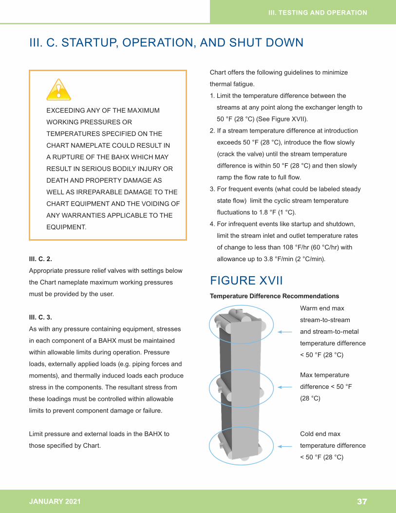
Chartoffersthefollowingguidelinestominimize
thermalfatigue.
1.Limitthetemperaturedifferencebetweenthe
streamsatanypointalongtheexchangerlengthto
50°F(28°C)(SeeFigureXVII).
2.Ifastreamtemperaturedifferenceatintroduction
exceeds50°F(28°C),introducetheflowslowly
(crackthevalve)untilthestreamtemperature
differenceiswithin50°F(28°C)andthenslowly
ramptheflowratetofullflow.
3.Forfrequentevents(whatcouldbelabeledsteady
stateflow)limitthecyclicstreamtemperature
fluctuationsto1.8°F(1°C).
4.Forinfrequenteventslikestartupandshutdown,
limitthestreaminletandoutlettemperaturerates
ofchangetolessthan108°F/hr(60°C/hr)with
allowanceupto3.8°F/min(2°C/min).
37
EXCEEDINGANYOFTHEMAXIMUM
WORKINGPRESSURESOR
TEMPERATURESSPECIFIEDONTHE
CHARTNAMEPLATECOULDRESULTIN
ARUPTUREOFTHEBAHXWHICHMAY
RESULTINSERIOUSBODILYINJURYOR
DEATHANDPROPERTYDAMAGEAS
WELLASIRREPARABLEDAMAGETOTHE
CHARTEQUIPMENTANDTHEVOIDINGOF
ANYWARRANTIESAPPLICABLETOTHE
EQUIPMENT.
FIGUREXVIITemperature Difference Recommendations
Warmendmax
stream-to-stream
andstream-to-metal
temperaturedifference
<50°F(28°C)
Maxtemperature
difference<50°F
(28°C)
Coldendmax
temperaturedifference
<50°F(28°C)
JANUARY 2021
III. TESTING AND OPERATION
III.C.STARTUP,OPERATION,ANDSHUTDOWN
38
Notethatalltemperatureratesofchangeshouldbe
calculatedusingthetimeintervalspecifiedintherate
ofchangetimeunit,i.e.useoneminuteintervalswhen
calculatingtemperatureratesofchangeagainstrates
ofchangeperminuteanduseonehourintervalswhen
comparingagainstratesofchangeperhour.Donotuse
instantaneousratesofchangecalculations.Forexample
ifastreamtemperaturechangedby0.5°Cin3seconds
(aninstantaneousrateofchangeof10°C/min)butthen
onlychangedbyatotalof1°Coveraone-minuteinterval,
thetemperaturerateofchangeis1°C/min.
Iftheflowinonestreamstopssuddenly,oftenthe
recommendedcourseofactionistoimmediatelystopthe
flowofallotherstreamstoavoidarapidwarm-uporcool-
down.Thisshouldbeevaluatedbythesystemdesigner
/operatoronacase-by-casebasisforimportance(e.g.,
stoppingastreamwithinsignificantcontributiontothe
overallheatexchangemightnotbecauseforstopping
flowofallotherstreams).
III. C. 4.
Theguidelinesabovereferencestreamtemperatures
sincestreamtemperaturesarereadilyavailabletoplant
operations.However,theseguidelinesweredeveloped
forlocalmetaltemperaturedifferencesandlocalmetal
temperatureratesofchange.Thermalstressarisesfrom
localmetaltemperaturedifferencesinBAHXcomponents
thatarecloseandrigidlyattachedinalldirections.
However,localmetaltemperaturedifferencesarenot
readilyavailablenoreasilymeasured.Commercially
availablesoftwaretoolscalculateadjacentparting
sheetwalltemperatures;onecansubstituteadjacent
partingsheettemperaturesforstreamtemperaturesin
theguideline.Inmostcases,aproperlydesignedheat
exchangerwillhavemuchloweradjacentpartingsheet
walltemperaturedifferencesthanstreamtemperature
differences.
Fatigueisdefinedasrepeatedstressesresultingin
fracture.AstandardtoolinfatigueistheS-Ncurve,
stressversusthenumberofcycles.Fatigueisinfluenced
byboththemagnitudeofthestressandthenumberof
occurrencesofthestress.Anassumptionintheguideline
iswhentheguidelinesarefollowed,onewouldexpectto
achieveuninterruptedheatexchangeroperationwithouta
fracture(leak)fortheexpectedlifeoftheheatexchanger.
Itisalsowhythetemperaturerateofchangeof2°C/
minuteisallowedforinfrequenteventslikestartupand
shutdownsincetheassumptionisthenumberofevents
isnotfrequent.Butforsteadystateoperationwhere
thenumberofeventsisgreater,therateoftemperature
changeisreducedto1°C/minute.
Formanysituations,exceedingtheguidelineswill
notproducefractures.However,asthemagnitudeof
exceedingtheguidelinesincreasesandasthenumber
ofoccurrencesincrease,theprobabilitytoproduce
fracturesincrease.Highlyspecializedsoftwaretools
arerequiredtoassesstheimpactofthermaleventsand
thecalculatednumberofoccurrencesbeforefracture
occurs.Thecalculatednumberofoccurrenceshave
arangesincenotwoidenticallymanufacturedheat
exchangerswouldfractureattheexactsamemagnitude
ofloadsandoccurrences.Thecalculationsarelimited
toafewselectedexamplesofexcursions.Thismeans
thatpredictingexactlywhenaBAHXwillfailortheexact
lifetimeleftintheunitisnotpossible.Thecalculated
numberofcyclestofatigueshouldbeviewedasan
estimatewitharange.
JANUARY 2021
III. TESTING AND OPERATION
III.C.STARTUP,OPERATION,ANDSHUTDOWN
III. C. 5.
Thehighthermalconductivityofaluminumhelpsto
minimizetemperaturedifferencesinBAHX,butlarge
localmetaltemperaturedifferencescanarisefrom
operationalinstabilities,changesinoperatingconditions,
ortransienteventsassociatedwithstartup,shutdown,
orupsetconditions.Operationalinstabilitiescanresult
fromunstableboilingwithintheBAHXorfromexternally
producedhydraulicfluctuationscausedbyimproperly
designedpipingsystemsorinadequatecontrolsystems.
Detrimentaltransienteventsassociatedwithstartup,
shutdown,orupsetconditionscanresultfromimproper
proceduresorinadequatecontrolsystems.
Topreventdamagefromtheseconditionsthefollowing
isrecommended:
•Reviewplantoperationstoidentifyoperatingconditions
thathavethepotentialtocreatehighthermalstressand
developprocedurestominimizetheimpactofthese
events.Typicalconditionscausinghighthermalstress
includecoldandwarmrestarts.Acoldrestartisdefined
asrestartingflowwhiletheBAHXiscoldfromprior
operations.Awarmrestartisrestartingflowafterthe
BAHXhasbeenwarmedtonearambientconditions.
•Flowcontrolisparticularlycriticalwhenintroducing
liquidortwo-phasestreams.Liquidandtwo-phase
fluidshavealargecapacitytorapidlychangemetal
temperatureintheBAHX.Flowcontrolislesscritical
whenintroducingandsensiblyheatingorcooling
vaporsduetothelimitedcapacityofthevaporto
rapidlychangemetaltemperatureintheBAHX.
Forthisreason,coolingorwarmingoftheBAHXto
orfromoperatingconditionswithavaporpriorto
introducingaliquidortwo-phasestreamishighly
recommended.
•ContinuouslymonitortheBAHXinapplications
wherethefluidmustbetotallyvaporizedinthe
BAHXandthereispotentialforunstableboiling.
Adjusttheprocessconditions(flow,temperature,
pressure)whennecessarytoavoidthiscondition
(e.g.,increasingflowoftenhelpstostabilize
thiscondition).Therelativelylargetemperature
differencesassociatedwithunstableboilingalong
withsurgingofthevaporizingfluidwithintheBAHX
cancausethermallyinducedfatiguefailure.
•Designandoperatetheplantequipmentandpiping
connectedtotheBAHXtopreventflowinstabilities
(forexample,intermittentsluggingofliquidtothe
BAHX).Thisisextremelyimportantwithboiling
streams.
•Maintaincleanlinessofallstreamsfeedingthe
BAHXatalltimesduringoperation,andproperly
protecttheBAHXfromcontaminationwhennotin
use.Contaminationfromsoliddebris,foulants,and
materialfreezingoutofthestreamsinternaltothe
BAHXmayleadtostreammaldistributionwithinthe
BAHX.Internalmetaltemperaturedifferencescan
increasewithmaldistributionandmayhavethesame
detrimentaleffectasstreamtemperaturedifferences.
Theinternalmetaltemperaturedifferencesareoften
impossibletoobserve,sopreventingcontamination
andmaldistributionintheBAHXiscriticalto
eliminatethispossibility.
39
JANUARY 2021
III. TESTING AND OPERATION
III.C.STARTUP,OPERATION,ANDSHUTDOWN,III. D. OPERATING RECORDS•Whiletheguidelinescanbeusefultodetermine
plantcontrolalarmsettings,theguidelinesarenot
recommendedplantalarmsettings.Theprocess
licensorshouldbeconsultedonalarmsettings.
Whileexceedingtheguidelinesisnotrecommended
itisnotbeneficialtoinstallnuisancealarmsthat
maybeturnedoffbyoperations.Someoperations
benefitfromtemperaturerateofchangeindicators
ratherthanalarms.
Ininstanceswhereitisnotpossibletoadheretothese
guidelines,contactCharttodiscussyourspecific
application.
III. D. Operating Records
OperatingoutsidetheguidelinesstatedinSection
III.C.mayleadtoexcessivethermalstresswhich
couldresultinfailureofBAHXcomponentsorleadto
ruptureevenwhenoperatingwithinthedesignlimits
onthenameplate.Anoperatinglogshouldbekeptto
recordnormaloperationprocedures,anyplantupsets,
shutdowns,andanyotheroperatingconditions.It
iscriticaltheoperatingdatabemonitoredtoensure
operationiswithintheIOMstatedguidelines.
Giventheircriticalityindeterminingcause,resolution
andresponsibilityforanyissueswiththeBAHX,
theownershouldmaintainadequateinstallation,
operation,andmaintenancerecordstoensure
compliancewiththeguidelines(seeSectionII.H.and
III.C.).
40
JANUARY 2021
IV. MAINTENANCE
41
IV. MAINTENANCE A.WarningSigns
B.FieldLeakTesting
C.Cleaning
D.Mothballing
E.RepairandService
F.Disposal
BRANDARCHITECTURE
JANUARY 2021
IV. MAINTENANCE
IV. A. WARNING SIGNS
42
IV. A. Warning Signs
Potentialwarningsignswhereequipmentrequires
inspectionorrepairpriortocontinuedoperation:
•Operatingdataindicatesequipmentisbeing
subjectedtooperatingconditionsexceeding
guidelinesinSectionIII.C.
•Measurementofstreamcompositionsindicating
crosscontaminationhasdeveloped
•OtherBAHXatthefacilityhavedevelopedleaksor
failures
•Frostspotsoncoldboxwallorinsulationsheeting
•LiquiddrainagefromBAHXorfromunderinsulation
•Indicationsfromgasdetectionsensors
•VentingfromtheBAHX
•SmartLayer®Alarm
IfanyofthesewarningsignsarepresentcontactChart.
PRIORTOTHEINSPECTION,TESTING,
ORREPAIRINGOFANYUNIT,EITHERIN
SERVICEORRECENTLYREMOVEDFROM
OPERATION,THESYSTEMMUSTBE
SAFETYCHECKEDANDCLEAREDPRIOR
TOTHEADMITTANCEOFPERSONNEL
FORANYSERVICEFUNCTION.
JANUARY 2021
IV. MAINTENANCE
IV.B.FIELDLEAKTESTING
43
IV. B. Field Leak Testing
InternalleaksinaBAHXaregenerallyindicatedbya
changeofpurityinanyofthefluidstreams.External
leakscanbedeterminedbysight,smell,audible
soundsofleakingfluid,externalgasmonitoring
equipment,orlocalizedcoldspotsappearingonthe
externalinsulationorcoldboxcasing.Externalleaks
inBAHXmountedinacoldboxarealsogenerally
indicatedbyexcessiveventingthroughthebreather
valveorcoldspotsonthecoldboxcasing.Breather
valvegasdetectionmethodsarewithinthescopeof
operator.
CAUTIONMUSTBEEXERCISEDWITH
REGARDTOTHEFLAMMABILITY,
TOXICITY,EXPLOSIONPOTENTIAL,OR
PRESSUREPOTENTIALOFANYFLUIDOR
STREAMWITHINORINTHEPROXIMITY
OFTHEBAHX.ALLPERSONNELINVOLVED
WITHINSTALLATIONORMAINTENANCE
OFCOLDBOXASSEMBLIESMUSTBE
MADEAWAREOFTHEDANGERSOF
SUFFOCATION,ESPECIALLYINNITROGEN
FILLED CONTAINERS.
DONOTEXCEEDTHEMAXIMUM
WORKINGPRESSURESPECIFIED
FOREACHSTREAMONTHECHART
NAMEPLATE.OVER–PRESSURIZATION
COULD RESULT IN A RUPTURE OF
THEBAHXWHICHMAYRESULTIN
SERIOUSBODILYINJURYORDEATH
ANDPROPERTYDAMAGEASWELLAS
IRREPARABLEDAMAGETOTHECHART
EQUIPMENTANDTHEVOIDINGOFANY
WARRANTIESAPPLICABLETOTHE
EQUIPMENT.
FAILURETOOBSERVEPROPERSAFETY
PRECAUTIONSINTHISREGARDCOULD
RESULTINEQUIPMENTRUPTURE,FIRES,
TOXICGASORFLUIDESCAPE,
SUFFOCATINGGASATMOSPHERESOR
OTHERACCIDENTSWHICHMAYRESULT
INSERIOUSBODILYINJURYORDEATH
ANDPROPERTYDAMAGEASWELLAS
IRREPARABLEDAMAGETOTHECHART
EQUIPMENTANDTHEVOIDINGOFANY
WARRANTIESAPPLICABLETOTHE
EQUIPMENT.
JANUARY 2021
IV. MAINTENANCE
IV.B.FIELDLEAKTESTING
44
ItiscriticalthatanyleakingBAHXberepaired
immediatelyandthatthecauseoftheleakbeidentified
andcorrected.Prolongedoperationmayleadtofurther
damageoftheunitwhenthecauseisduetocyclical
thermalormechanicalfatigue.Prolongedoperationof
anexternallyleakingBAHXinstalledinaperliteinsulated
coldboxmayleadtofurtherdamageandincreased
leakageduetoperliteerosionoftheBAHXmetal.
Commonfieldtestsusedfordeterminingleaksare
describedbelow.
IV. B. 1. Pressure Decay Test
Pressurizeastreamwithdryairornitrogen.
Astreamisconsideredleakfreeifitmaintainsthe
originalpressureforovereighthourswithcorrectionfor
temperaturechanges.Keepinmindthatthepressure
decaytimetestisafunctionnotonlyoftheleaksizebut
thetestpressure,temperature,andBAHXsize,
aswell.
ForlargeBAHXandassemblieswithlargeinternal
volumes,and/orforleaktestsatlowerpressures(less
than50psig[3.4barg]),leaksmaytakelongerthaneight
hourstodetect,dependinguponthesizeoftheleak.
TheBAHXtemperatureshouldbethesameatthetwo
pressurecheckssinceanychangeintemperaturewill
changetheairpressureintheBAHX.Ifitisimpractical
tomakethetwopressurecheckswhenthetemperatures
arethesame,thefollowingpressurecorrectioncanbe
used:
P1 T2
P2 = ---------
T1
Where
P =AbsolutePressure
T =AbsoluteTemperature(°RorK)
1 =InitialReading
2 =FinalReading
Forindividualrecommendations,contactChart.
IV. B. 2. Air-Soap Test (External Leaks)
Ifthestreamdoesnotmaintaintheoriginalpressure
duringthedecaytest,above,determinewhatkindof
leakexistsbyrepressurizingthestreamandchecking
theexterioroftheBAHXwithasoapbubbletest.Ifthe
BAHXpassesthistest,theleakisinternal.
DONOTEXCEEDTHEMAXIMUM
WORKINGPRESSURESPECIFIED
FOREACHSTREAMONTHECHART
NAMEPLATE.OVER–PRESSURIZATION
COULD RESULT IN A RUPTURE OF
THEBAHXWHICHMAYRESULTIN
SERIOUSBODILYINJURYORDEATH
ANDPROPERTYDAMAGEASWELLAS
IRREPARABLEDAMAGETOTHECHART
EQUIPMENTANDTHEVOIDINGOFANY
WARRANTIESAPPLICABLETOTHE
EQUIPMENT.
JANUARY 2021
IV. MAINTENANCE
IV.B.FIELDLEAKTESTING
45
IV. B. 3. Internal Leak Testing
Themethodusedtolocatetheindividuallayerleak
involvesasoaptestovereachportofthestreamin
questionwhileairornitrogenpressureisappliedto
theotherstream.Thisoperationnormallyinvolves
removaloftheheaderandshouldonlybeperformed
byChartauthorizedservicepersonnel.
JANUARY 2021
IV. MAINTENANCE
IV. C. CLEANING
46
IV. C. Cleaning
IftheBAHXisfouledorplugged,severaloptionsare
availabletotheuserforcleaningtheBAHX.When
thefoulingissolidandcoatsthefinsintheBAHX,
theBAHXshouldbecleanedbychemicalremoval
throughaseriesofderiming,backflushing,anddrying
procedures(seeSectionIV.C.1.).
IftheBAHXisfouledorpluggedbyhydratesand/
orice,awarmderimeisrequiredandconsideration
giventoothermethodsforhydratesuppression(see
SectionIII.B.2.).
IftheBAHXisfouledorpluggedbyparticulatematter,
backpuffingproceduresareusuallysuccessfulin
cleaningtheBAHX(seeSectionIV.C.2.).
Thepipingandinstrumentationdiagramsshould
becarefullyreviewedattheplantdesignphaseto
ensureadequatenozzlesandvalvesonthepiping
areavailabletocarryoutanyoftheabovecleaning
proceduresthatareanticipated.
IV. C. 1. Deriming, Back Flushing, and Drying
Derimingandbackflushinginvolvestheuseof
heatand/orsolventstoremovehydrates,heavy
hydrocarbons,waxymaterials,compressoroils,or
othersolublematterwhichfreezeorcollectinthe
BAHX.Thepresenceofthesematerialsisdetectedby
anincreaseinthestreampressuredropand/orloss
ofheattransferperformance.Asageneralguideline,
ifthemeasuredpressuredropbeginstoexceed2
to3timesthedesignpressuredrop,Chartwould
recommendcleaningeffortsbeundertaken.
Whensystemsforinjectingmethanolduringoperation
havenotbeenprovided(seeSectionIII.B.2.),shut
downandpurgetheBAHXandallowittowarmand
defrostitselfbynaturalheatleakorbyanapproved
derimeprocedure.Normally,thecombinationof
warmingandbackflushingwithasolventrinsesuch
astrichloroethane,toluene,propanol,ormethanolis
successfulforthispurpose.
Priortostartup,purgeanddryouttheBAHXin
accordancewithIII.C.1.
Ifawaterbasedsolventisusedtoderimeorback
flush,orifwateraccidentallygetsintroducedintothe
BAHX,theBAHXmustbecompletelydriedbefore
returningtoserviceinordertopreventpluggingor
rupturecausedbyfreezing.Usedryairornitrogenor
otherdrygasasthedryingmedium.
IV. C. 1. a.
Thederime,backflushing,ordryingtemperature
shouldnotexceed150°F(65°C),unlessthe
maximumworkingtemperatureontheChart
nameplateishigher.Donotexceedthemaximum
workingtemperaturespecifiedontheChart
nameplate.
IV. C. 1. b.
Thederime,backflushingordryingmediamustbe
non-corrosivetoaluminum.Alwaysusecleanfluids.
Ifanyvessels,piping,ortemporarypipesections
areusedduringthecleaning,itisimportanttoclean
themofpipescale,dirt,weldslag,oranyotherforeign
materialwhichcouldenterandplugtheBAHX.
JANUARY 2021
IV. MAINTENANCE
IV. C. CLEANING
47
IV. C. 1. c.
Whenliquidsolventsareusedforpurposesof
derimingorbackflushingtheBAHX,thenozzlefluid
velocityshouldnotexceed10feet(3meters)per
secondtopreventerosioninsidetheBAHX.Liquid
solventsoranycleaningfluidsshouldalwaysbe
circulatedthroughtheBAHXinthereversedirectionof
normaloperatingflow.
IV. C. 1. d.
Cleaningsolventsshouldalwaysbechosenwith
regardtothesuspectedfoulingagent.Ifthefouling
agentisunknown,asampleofitshouldbechemically
analyzedtodetermineitscomposition.
Ifanyspecialproceduresarerequiredtomeet
uncommonderime,backflushing,ordryingconditions,
contactChartforfurtherevaluation.
IV. C. 2. Back Puffing
Whenproperprecautionsaretakenregardingfiltering,
manyyearsofcleanservicecanbeexpected.
However,whenforeignmaterial(pipescale,perlite,
desiccant,molesieve,etc.)isintroducedintothe
BAHXitself,byaccidentormisoperation,backpuffing
canbeaneffectivemethodforremovingentrained
particulates.
Sinceparticulatesnormallycauseblockagesinthe
BAHXattheinletportsanddistributors,puffinginthe
reversedirectionofnormaloperatingflowisrequired
topreventpushingtheparticulatesfartherintothe
BAHX.Thebackpuffingprocedureinvolvesattaching
arupturedisktotheinletnozzleorflangeoftheBAHX
streamtobebackpuffed.
ONLYCLEANINGSOLVENTSTHATARE
NON-CORROSIVETOALUMINUMMUSTBE
USED. CORROSIVE CLEANING SOLVENTS
CANWEAKENPRESSURERETAINING
STRUCTURESWHICHMAYRESULTIN
SERIOUSBODILYINJURYORDEATH
ANDPROPERTYDAMAGEASWELLAS
IRREPARABLEDAMAGETOTHECHART
EQUIPMENTANDTHEVOIDINGOFANY
WARRANTIESAPPLICABLETOTHE
EQUIPMENT.
INTRODUCTIONOFWATER/AQUAEOUS
CLEANINGSOLUTIONSTOANYBAHX
EXPOSEDTOMERCURYCONTAMINATION
CAN RESULT IN ACCELERATED
CORROSION AND CAN CAUSE
IRREPARABLEDAMAGEANDPOTENTIAL
CATASTROPICFAILUREANDEXPOSE
PERSONNELTOHAZARDOUSAND
UNSAFEWORKINGCONDITIONS.
JANUARY 2021
IV. MAINTENANCE
IV. C. CLEANING
48
Thepluggedstreamisslowlyfilledwithdryairor
nitrogenuntiltherupturediskbursts.Thesudden
releaseofgasoutoftheBAHXwillhelpdislodge
particulatematter.Thisbackpuffingprocedureshould
berepeatedfivetotentimes,oruntiltheamount
ofparticulateremovedbecomesminimalandthe
dischargecloudisclear.
ContactChartforguidanceonthemaximumallowed
backpuffingpressure.Ifthemaximumallowable
pressureisreachedandtherupturediskhasnot
burst,thestreamshouldbedepressurizedandanew
rupturediskinstalled.
Abackpuffingeventdoesnotreducethelifeof
theequipment.However,remainingresidueinthe
equipmenthasthepotentialtodistortthethermal
profileandinducethermalstress,whichmayreduce
thelifeoftheequipment.
EXTREMECAUTIONMUSTBEEXERCISED
SOASNOTTOEXCEEDTHEMAXIMUM
WORKINGPRESSUREOFTHESTREAM
ONTHECHARTNAMEPLATE,OR100PSIG,
WHICHEVERISLESS.
FAILURETOLIMITPRESSURIZATION
TOTHESELIMITSCOULDRESULTINA
RUPTUREOFTHEBAHXWHICHMAY
RESULTINSERIOUSBODILYINJURYOR
DEATHANDPROPERTYDAMAGEAS
WELLASIRREPARABLEDAMAGETOTHE
CHARTEQUIPMENTANDTHEVOIDINGOF
ANYWARRANTIESAPPLICABLETOTHE
EQUIPMENT.
ITISTHEUSER’SRESPONSIBILITYTO
TAKETHEAPPROPRIATESAFETY
PRECAUTIONSREGARDINGPERSONNEL,
CLEARINGTHETESTAREA,ANDTHE
SUITABILITYOFTHESUPPORTSAND
BRACINGTOWITHSTANDTHEREACTION
FORCESDEVELOPEDWHENTHE
RUPTUREDISKBURSTS.
EXTREMECAUTIONMUSTBEEXERCISED
ASTHERUPTUREOFTHEDISKAND
THERELEASEOFGASCANRESULTINA
RAPIDDISCHARGEOFGASANDFLYING
DEBRISWHICHMAYRESULTINSERIOUS
BODILYINJURYORDEATHANDPROPERTY
DAMAGEASWELLASIRREPARABLE
DAMAGETOTHECHARTEQUIPMENT
ANDTHEVOIDINGOFANYWARRANTIES
APPLICABLETOTHEEQUIPMENT.
JANUARY 2021
IV. MAINTENANCE
IV.D.MOTHBALLING
49
IV. D. Mothballing
BAHXwhichhaveseenpriorserviceshouldbedried
andpressurizedpriortostorage.Aneighthouror
longerpurgewithdryairornitrogenhavingadew
pointlessthan32°F(0°C)isrecommendedtodry
theBAHX.
Followingthedryingoperation,eachstreamshouldbe
pressurizedwithdryairornitrogenwithadewpointof
lessthan-40°F(-40°C).Thislowdewpointis
recommendedtopreventgalvaniccorrosioninthe
BAHXwhichcouldresultiftracesofrustorother
foreignmaterialshavegainedaccesstotheBAHX
duringoperation.Thedryairornitrogenpressure
shouldbe15psig(1barg)oronethirdthestream
designpressure,whicheverisless.
The15psig(1barg)pressurelevelshouldbechecked
periodicallytoassurethattherearenoleaksinthe
BAHX.Inaddition,thestoragerecommendationsin
SectionII.B.shouldalsobefollowed.
JANUARY 2021
IV. MAINTENANCE
IV.E.REPAIRANDSERVICE,IV.F.DISPOSAL
50
IV. E. Repair and Service
Ifaleakisdetected,Chartshouldbenotifiedforrepair
recommendations.Chartiswellqualifiedandstaffed
toperformfieldorfactoryserviceandrepaironthis
typeofBAHXequipment.
RefertotheNationalBoardNumberandtheChart
serialnumbershownontheASMEU-1datareport
formorunitnameplatewhencontactingChart.
AllASMErepairsmustbecertifiedbyan“R”
stampandmustbeinaccordancewiththeChart
QualityAssurancePolicy,theNationalBoard
InspectionCode,andtheASMECode,andanylocal
jurisdictionalrequirements.
RepairtotheBAHXshouldbemadeonlybyChart
authorizedpersonnel.TheChartwarrantywillbe
voidedifrepairsmadetotheChartBAHXduringthe
warrantyperiodaremadebyunauthorizedservice
personnel.
ImproperweldingontheBAHXblockcandamage
thebrazejoints.Repairsnotmadeinaccordancewith
ASMEprocedure,andidentifiedbythe“R”stampon
theChartnameplate,willinvalidatetheNationalBoard
registrationoftheBAHX.
IV. F. Disposal
WhendisposingofaBAHX,Chartencourages
recyclingwheneverpossible.Adrainedheatexchanger
mayhaveresidualcompoundsinsidefromprioruse.
Duetoaccumulationovertime,theresidualcompounds
maybepresentinmoreconcentratedamountsthan
experiencedintheproductstream.Ownersshouldbe
awarethattheirBAHXmayhaveresidualcompounds
ofsufficientquantitytoposeasafetyorenvironmental
hazard.Ownersshouldknowthecompositionof
theresidualcompoundsandconsiderthesafetyand
environmentalimpactsofthosecompoundsbefore
sendingtheirBAHXtoametalrecycler.Disposal
mustbeinaccordancewithallapplicablelawsand
regulations.
IMPROPERLYREPAIREDBAHXMAY
NOTBESUITABLETOWITHSTANDTHE
NAMEPLATEMAXIMUMWORKING
PRESSURE RATINGS.
PRESSURIZATIONOFANIMPROPERLY
REPAIREDBAHXCOULDRESULT
INARUPTUREOFTHEBAHXWHICHMAY
RESULTINSERIOUSBODILYINJURYOR
DEATHANDPROPERTYDAMAGEAS
WELLASIRREPARABLEDAMAGETOTHE
CHARTEQUIPMENTANDTHEVOIDINGOF
ANYWARRANTIESAPPLICABLETOTHE
EQUIPMENT.

FIGURE I FIGURE IIBasic Components of a Chart
Brazed Aluminum Heat Exchanger (BAHX)
How a Chart Core-in-Kettle® Works
The Chart Energy & Chemicals, Inc. (“Chart”) brazed aluminum heat exchanger (BAHX) business began in 1985 with the acquisition of The Trane Company’s BAHX operation in La Crosse, Wisconsin. Chart is a recognized global leader in the design and manufacture of large BAHX, battery assemblies, and cold boxes for cryogenic applications.
Chart incorporates the former Altec and Marston BAHX brands and consequently all rights to engineering and equipment produced by these companies.
“Core-in-Kettle” is a registered trademark of Chart Energy & Chemicals, Inc.
Brazed aluminum heat exchangers are also referred to as plate fin heat exchangers and abbreviated to PFHE within the industry.
© 2021 Chart Energy & Chemicals, Inc. All rights reserved.
Nozzle
Header
Distributor fin
Parting sheet
Side barWear plate
Heat transfer fin
Support angle
Cap sheet
2JANUARY 2021
Chart Lifecycle has qualified Field Service Engineering teams to provide full installation, commissioning and startup related
services. Chart highly recommends these OEM trained services to ensure a successful equipment startup. Chart also
provides best practices for the maintenance and management of Chart proprietary equipment for optimized performance
and lifespan. Chart Lifecycle, Inc., is also your 24/7 single point of contact for commissioning and startup services, spares,
repairs, warranties, technical expertise, project development, field services, and training. Other services include:
• Annual service agreements
• Extended warranties
• Enhanced operator training and best practices
Tel: 1-844-GTLS-911 (1-844-485-7911) – 24/7 hotline
E-mail: [email protected]
www.ChartLifecycle.com
Installation, Commissioning & Startup ServicesCHART LIFECYCLE IS HERE TO HELP!
1. The warm process stream fluid enters the Brazed Aluminum Heat Exchanger (BAHX) through steel inlet nozzle(s) on the vessel shell. The inlet nozzles are connected to the aluminum inlet pipes of the exchanger by an aluminum to stainless steel transition coupling.
2. Inside the BAHX the warm stream cools as it flows against a cold stream.
3. The cold stream enters the vessel either as a liquid or 2-phase fluid directly from a distillation column (or expansion valve in the case of a refrigerant).
4. A liquid level is formed outside the BAHX core to create a liquid head that drives the cold stream liquid through the core
5. A disengagement space above the core causes the liquid and vapour to separate.
6. The cooled warm stream leaves the BAHX and vessel.7. The cold stream vapour exits the vessel through the outlet
nozzles whilst the liquid falls back to be recirculated.8. A manway is provided in the vessel shell.
The following checklists are for reference only, and are not intended to be comprehensive for all situations.
Serial Number:Plant Item Number:
BAHX Arrival Relevant IOM Section Checked By / Date1. Verify nameplate and record serial number II. A.2. Check for external damage II. A.3. Verify shipping stream pressure II. A. (typically 15 psig, if applicable) 4. Store per IOM instructions II. B.
BAHX Installation 1. Verify nameplate serial number2. Lift into position following general lifting II. C. instructions in IOM and specific instructions supplied with unit (if applicable)3. Verify correct BAHX orientation and nozzle locations II. D. 1.4. Install Micarta® or equivalent insulation II. D. 1. c. between support angle mounts and mating support surfaces (if applicable)5. Tighten bolted support connections to finger tight only II. D. 1. e. (does not apply to bolted flange pipe connections)6. Verify no water or debris trapped in field piping III. B. 1. to be attached to BAHX.7. Connect all nozzles to pipes II. E.8. Connect Smart Layer® (if applicable) II.1.4.9. Remove all temporary shipping supports II. D. 1. a.10. Remove all vent plugs (if applicable) II. F.11. Perform piping system leak / proof test III. A., IV. A.12. Install insulation II. G.
BAHX Initial Startup 1. Verify overpressure protection for all streams III. C. 2.2. Verify filters installed for all applicable streams III. B. 1.3. Verify no water trapped in or upstream of BAHX III. C. 1.4. Bring to operation conditions following IOM instructions, III. C. 3. with special attention to temperature rate of change guidelines
Arrival, Installation, and Startup Checklists Inside
INSTALLATION, OPERATION, AND MAINTENANCE MANUAL
for Chart Brazed Aluminum Heat Exchangers (BAHX) and Core-in-Kettle® Assemblies.
Chart Energy & Chemicals, Inc. is an ISO:9001,
ISO:14001, and OHSAS:18001 registered company
Chart Energy & Chemicals, Inc.
Brazed Aluminum Heat Exchangers
2191 Ward Avenue
La Crosse, WI 54601
Tel: 608-787-3333
E-mail: [email protected]
www.ChartIndustries.com
Chart Lifecycle, Inc.
8665 New Trails Drive, Suite 100
The Woodlands, TX 77381
Tel: 1-844-GTLS-911 (1-844-485-7911)
E-mail: [email protected]
www.ChartLifecycle.com
JANUARY 2021
INSTALLATION, OPERATION, AND MAINTENANCE MANUAL
for Chart Brazed Aluminum Heat Exchangers (BAHX) and Core-in-Kettle® Assemblies.
JANUARY 2021
ARRIVAL, INSTALLATION, AND STARTUP CHECKLISTS