Embed Size (px)
Citation preview
BiomedicalSensors
andInstruments
S E C O N D E D I T I O N
Tatsuo TogawaToshiyo Tamura
P. Åke Oberg¨
CRC Press is an imprint of theTaylor & Francis Group, an informa business
Boca Raton London New York
CRC PressTaylor & Francis Group6000 Broken Sound Parkway NW, Suite 300Boca Raton, FL 33487-2742
© 2011 by Taylor and Francis Group, LLCCRC Press is an imprint of Taylor & Francis Group, an Informa business
No claim to original U.S. Government works
Printed in the United States of America on acid-free paper10 9 8 7 6 5 4 3 2 1
International Standard Book Number-13: 978-1-4200-9079-6 (Ebook-PDF)
This book contains information obtained from authentic and highly regarded sources. Reasonable efforts have been made to publish reliable data and information, but the author and publisher cannot assume responsibility for the valid-ity of all materials or the consequences of their use. The authors and publishers have attempted to trace the copyright holders of all material reproduced in this publication and apologize to copyright holders if permission to publish in this form has not been obtained. If any copyright material has not been acknowledged please write and let us know so we may rectify in any future reprint.
Except as permitted under U.S. Copyright Law, no part of this book may be reprinted, reproduced, transmitted, or uti-lized in any form by any electronic, mechanical, or other means, now known or hereafter invented, including photocopy-ing, microfilming, and recording, or in any information storage or retrieval system, without written permission from the publishers.
For permission to photocopy or use material electronically from this work, please access www.copyright.com (http://www.copyright.com/) or contact the Copyright Clearance Center, Inc. (CCC), 222 Rosewood Drive, Danvers, MA 01923, 978-750-8400. CCC is a not-for-profit organization that provides licenses and registration for a variety of users. For organizations that have been granted a photocopy license by the CCC, a separate system of payment has been arranged.
Trademark Notice: Product or corporate names may be trademarks or registered trademarks, and are used only for identification and explanation without intent to infringe.
Visit the Taylor & Francis Web site athttp://www.taylorandfrancis.com
and the CRC Press Web site athttp://www.crcpress.com
iii
ContentsPreface...............................................................................................................................................xiAuthors............................................................................................................................................ xiii
Chapter 1 Fundamental.Concepts..................................................................................................1
1.1. Signals.and.Noise.in.the.Measurement..............................................................11.1.1. Measurement.........................................................................................11.1.2. Signals.and.Noise..................................................................................11.1.3. Amplitude.and.Power............................................................................21.1.4. Power.Spectrum....................................................................................21.1.5. Signal-to-Noise.Ratio............................................................................31.1.6. Different.Types.of.Noise.......................................................................4
1.1.6.1. Thermal.Noise.......................................................................41.1.6.2. 1/f.Noise.................................................................................41.1.6.3. Interference............................................................................41.1.6.4. Artifact...................................................................................5
1.2. Characteristics.of.the.Measurement.System......................................................51.2.1. Sensor.and.Measurement.System..........................................................51.2.2. Static.Characteristics.............................................................................6
1.2.2.1. Sensitivity,.Resolution,.and.Reproducibility..........................61.2.2.2. Measurement.Range..............................................................71.2.2.3. Linearity.or.Nonlinearity......................................................71.2.2.4. Hysteresis...............................................................................7
1.2.3. Dynamic.Characteristics.......................................................................81.2.3.1. Linear.and.Nonlinear.Systems..............................................81.2.3.2. Frequency.Response..............................................................81.2.3.3. Time.Constant,.Response.Time,.Rise.Time,.
and Settling.Time................................................................ 101.3. Determination.of.Absolute.Quantity................................................................ 10
1.3.1. Standard.and.Calibration.................................................................... 111.3.2. Accuracy.and.Error............................................................................. 111.3.3. Types.of.Error..................................................................................... 11
1.3.3.1. Random.Error...................................................................... 121.3.3.2. Systematic.Error.................................................................. 121.3.3.3. Quantization.Error............................................................... 121.3.3.4. Dynamic.Error..................................................................... 13
1.4. Units.of.Measurement.Quantities..................................................................... 131.4.1. The.International.System.of.Units...................................................... 13
1.4.1.1. Base.Units.and.Derived.Units.............................................. 131.4.1.2. Dimension.of.a.Quantity...................................................... 141.4.1.3. Recommendations.for.the.Use.of.SI.Units.and.Symbols..... 15
1.4.2. Non-SI.Units........................................................................................ 17References................................................................................................................... 17
iv Contents
Chapter 2 Pressure.Measurements............................................................................................... 19
2.1. Object.Quantities.............................................................................................. 192.1.1. Units.of.Pressure................................................................................. 192.1.2. Requirements.for.Pressure.Measurement........................................... 19
2.1.2.1. Physiological.Pressure.Ranges.and.Measurement.Sites...... 192.1.2.2. Reference.Point.for.Pressure.Measurement.........................22
2.2. Direct.Pressure.Measurement..........................................................................242.2.1. Catheters.and.the.Diaphragm-Type.Pressure.Sensor..........................24
2.2.1.1. Catheters.for.Pressure.Measurements.................................242.2.1.2. Diaphragm.Displacement.Sensor........................................24
2.2.2. Dynamic.Response.of.Catheter–Sensor.Systems................................ 292.2.2.1. Evaluation.of.Dynamic.Response.of.the.Catheter–
Sensor.System......................................................................302.2.2.2. Improvement.of.Dynamic.Response................................... 33
2.2.3. Catheter-Tip.Pressure.Sensor..............................................................342.2.4. Implantable.Pressure.Sensors.............................................................. 39
2.2.4.1. Absolute.Pressure.Sensors.for.Implantable.Devices........... 392.2.4.2. Pressure.Monitoring.by.Implantable.Devices..................... 41
2.2.5. Pressure.Measurements.in.Small.Vessels........................................... 452.2.5.1. Highly.Rigid.Pressure.Sensor.System................................. 452.2.5.2. Servo-Controlled.Pressure-Measuring.System...................46
2.2.6. Pressure.Measurements.in.Collapsible.Vessels.and.Interstitial.Spaces.................................................................................................. 472.2.6.1. Pressure.Measurements.in.Collapsible.Vessels................... 472.2.6.2. Interstitial.Pressure.Measurements...................................... 49
2.2.7. Differential.Pressure.Measurements................................................... 532.3. Indirect.Pressure.Measurement........................................................................54
2.3.1. Indirect.Measurement.of.Systolic,.Diastolic,.and.Mean.Blood.Pressure...............................................................................................542.3.1.1. Cuff.Design.for.Indirect.Blood.Pressure.
Measurements............................................................... 552.3.1.2. Detection.of.Korotkoff.Sounds............................................ 572.3.1.3. Mean.Blood.Pressure.Measurements.
by the Oscillometric.Method............................................... 592.3.1.4. Blood.Pressure.Measurements.by.Doppler.Ultrasound....... 61
2.3.2. Indirect.Measurements.of.Instantaneous.Arterial.Pressure................ 632.3.3. Indirect.Pressure.Measurements.by.Reaction.Forces.........................66
2.3.3.1. Applanation.Method............................................................662.3.3.2. Intraocular.Pressure.Measurements.................................... 672.3.3.3. Intra-Amniotic.and.Intra-Abdominal.Pressure.
Measurements...................................................................... 712.3.3.4. Intracranial.Pressure.Measurement.in.Newborn.Infants..... 722.3.3.5. Arterial.Tonometry.............................................................. 73
References................................................................................................................... 74
Chapter 3 Flow.Measurement...................................................................................................... 81
3.1. Object.Quantities.............................................................................................. 813.1.1. Units.in.Flow.Measurements............................................................... 813.1.2. Requirements.for.Measurement.Ranges............................................. 82
Contents v
3.1.2.1. Blood.Flow.in.a.Single.Vessel............................................. 823.1.2.2. Tissue.Blood.Flow............................................................... 833.1.2.3. Respiratory.Gas.Flow..........................................................84
3.2. Blood.Flow.Measurements.in.Single.Vessels................................................... 853.2.1. Electromagnetic.Flowmeter................................................................85
3.2.1.1. Principle...............................................................................853.2.1.2. Factors.Affecting.the.Measurements...................................86
3.2.2. Ultrasonic.Blood.Flowmeters..............................................................863.2.2.1. Propagation.of.Ultrasound.in.the.Tissue.............................863.2.2.2. Transit.Time.and.Phase.Shift.Ultrasound.Flowmeters........883.2.2.3. Ultrasonic.Doppler.Flowmeters...........................................933.2.2.4. Methods.of.Range.Discrimination......................................973.2.2.5. Perivascular.and.Intravascular.Doppler.Probes................. 101
3.2.3. Indicator.Dilution.Method................................................................. 1023.2.3.1. Principle............................................................................. 1023.2.3.2. Dye.Dilution.Method......................................................... 1043.2.3.3. Thermodilution.Method..................................................... 1063.2.3.4. The.Fick.Method................................................................ 1093.2.3.5. Other.Dilution.Methods..................................................... 110
3.2.4. Flow.Velocity.Measurements.by.Heat.Dissipation........................... 1113.2.4.1. Thermistor.Velocity.Probes............................................... 1113.2.4.2. Hot.Film.Velocity.Probes.................................................. 112
3.2.5. Impedance.Cardiography.................................................................. 1133.2.6. Blood.Flow.Recording.in.Single Vessels.by.Laser.Doppler.
Flowmetry......................................................................................... 1163.2.6.1. Introduction....................................................................... 1163.2.6.2. Airborne.Beams................................................................. 1163.2.6.3. Microscope-Based.Instrument........................................... 1163.2.6.4. Catheter-Based.Instruments............................................... 117
3.2.7. Correlation.Methods.for.Microvascular Red Blood Cell.Velocity.Measurement..................................................................................... 119
3.2.8. Miscellaneous.Mechanical.Flowmeters............................................ 1223.2.9. Implantable.Flow.Sensors.................................................................124
3.3. Tissue.Blood.Flow.Measurement................................................................... 1253.3.1. Venous.Occlusion.Plethysmography................................................. 125
3.3.1.1. Venous.Occlusion.Method................................................. 1253.3.1.2. Displacement.Plethysmographies...................................... 1263.3.1.3. Impedance.Plethysmographies.......................................... 129
3.3.2. Clearance.Technique......................................................................... 1313.3.2.1. Principle............................................................................. 1313.3.2.2. Use.of.Radioactive.Indicators............................................ 1333.3.2.3. Hydrogen.Gas.Clearance.Method...................................... 134
3.3.3. Tissue.Blood.Flow.Measurements.by.Indicator.Dilution.Method.......................................................................................137
3.3.4. Tissue.Blood.Flow.Measurements.by.Heat.Transport...................... 1383.3.5. Tissue.Blood.Flow.Measurement.by.Laser.Doppler.Flowmetry...... 138
3.3.5.1. Introduction....................................................................... 1383.3.5.2. Interaction.between.Light.and.Tissue................................ 1393.3.5.3. Instrument.Design.Principles............................................ 1433.3.5.4. Fiberoptic.Arrangements................................................... 1443.3.5.5. Self-Mixing.Laser.Diode.Technology............................... 146
vi Contents
3.3.5.6. Signal.Processing.Principles.............................................. 1463.3.5.7. Calibration.and.Standardization.of.Laser.Doppler.
Flowmeters........................................................................ 1473.3.5.8. Laser.Doppler.Perfusion.Imaging..................................... 148
3.3.6. Tissue.Blood.Flow.Measurements.by.Nuclear.Magnetic.Resonance.......................................................................................... 1513.3.6.1. Principle.of.Nuclear.Magnetic.Resonance........................ 1513.3.6.2. Magnetic.Resonance.Tissue.Blood.Flow.Measurement.
Methods............................................................................. 1553.4. Respiratory.Gas.Flow.Measurements............................................................ 157
3.4.1. Gas.Flow.Sensors.............................................................................. 1573.4.1.1. Rotameter........................................................................... 1573.4.1.2. Pneumotachograph............................................................ 1593.4.1.3. Hot-Wire.Anemometer...................................................... 1613.4.1.4. Time-of-Flight.Flowmeter................................................. 1653.4.1.5. Ultrasonic.Flowmeter........................................................ 1673.4.1.6. Vortex.Flowmeter.............................................................. 1693.4.1.7. Acoustical.Respiratory.Flow.Measurements..................... 170
3.4.2. Volume.Measuring.Spirometers........................................................ 1713.4.3. Lung.Plethysmography...................................................................... 172
3.4.3.1. Body.Plethysmography...................................................... 1723.4.3.2. Inductance.Plethysmography............................................. 1743.4.3.3. Impedance.Pneumography................................................ 175
References................................................................................................................. 177
Chapter 4 Motion.and.Force.Measurement............................................................................... 191
4.1. Objects.of.Measurement................................................................................. 1914.1.1. Units.of.Quantities............................................................................ 1914.1.2. Objects.of.Measurements.................................................................. 1914.1.3. Coordinate.System............................................................................ 192
4.2. Motion.Measurements.................................................................................... 1934.2.1. Displacement.and.Rotation.Measurements.by.Contact.Sensors....... 194
4.2.1.1. Displacement.and.Rotation.Measurements.of the Body and.an.Extracted.Tissue................................. 194
4.2.1.2. Displacement.Measurements.in Vivo.................................2004.2.2. Noncontact.Measurement.of.Displacement.and.Rotation.................203
4.2.2.1. Optical.Methods................................................................2034.2.2.2. Magnetic.Methods.............................................................206
4.2.3. Linear.and.Angular.Velocity.Measurements....................................2074.2.3.1. Electromagnetic.Velocity.Sensors.....................................2084.2.3.2. Doppler.Methods...............................................................2094.2.3.3. Angular.Velocity.Sensors.................................................. 210
4.2.4. Translational.and.Angular.Acceleration.Measurements................... 2114.2.4.1. Translational.Accelerometers............................................ 2124.2.4.2. Angular.Accelerometers.................................................... 215
4.3. Force.Measurements....................................................................................... 2164.3.1. Muscle.Contraction.Measurements................................................... 216
4.3.1.1. Design.of.the.Elastic.Beam.for.Muscle.Contraction.Measurements.................................................................... 216
Contents vii
4.3.1.2. Force.Measurements.in.Isolated.Muscles.......................... 2174.3.1.3. In Vivo.Measurements.of.Muscular.Contraction............... 218
4.3.2. Measurements.of.Stresses.in.the.Bone.............................................. 2194.3.3. Ground.Force.Measurements............................................................ 221
4.3.3.1. The.Force.Plates................................................................ 2214.3.3.2. Stabilometers..................................................................... 2224.3.3.3. Instrumented.Shoe.............................................................2244.3.3.4. Foot.Force.Distribution.Measurements............................. 227
References.................................................................................................................228
Chapter 5 Temperature,.Heat.Flow,.and.Evaporation.Measurements........................................ 235
5.1. Object.Quantities............................................................................................ 2355.1.1. Units.of.Thermal.Quantities.............................................................. 2355.1.2. Requirements.for.Measurement.Ranges........................................... 236
5.2. Temperature.Sensors...................................................................................... 2385.2.1. Thermistors....................................................................................... 2385.2.2. Thermocouples..................................................................................2405.2.3. Wire.and.Thin.Film.Thermoresistive.Elements................................2425.2.4. p–n.Junction.Diodes.and.Transistors................................................ 2435.2.5. Crystal.Resonators............................................................................2455.2.6. Temperature.Sensors.for.Use.in.Strong.Electromagnetic.Fields.......246
5.3. Noncontact.Temperature.Measurement.Techniques......................................2485.3.1. Infrared.Measurements.....................................................................249
5.3.1.1. Infrared.Radiation.Thermometers.....................................2495.3.1.2. Infrared.Detectors..............................................................2505.3.1.3. Infrared.Thermography..................................................... 253
5.3.2. Noninvasive.Thermal.Imaging.in.Deep.Tissue.................................2545.3.2.1. Magnetic.Resonance.Thermal.Imaging............................ 2555.3.2.2. Active.and.Passive.Microwave.Thermal.Imaging............. 2555.3.2.3. Ultrasonic.Thermal.Imaging.............................................2565.3.2.4. Thermal.Imaging.by.Tissue.Electrical.Impedance........... 257
5.4. Clinical.Thermometers................................................................................... 2575.4.1. Indwelling.Thermometer.Probes....................................................... 257
5.4.1.1. Rectal.Temperature.Measurement..................................... 2575.4.1.2. Esophageal.Temperature.Measurement............................. 2585.4.1.3. Bladder.Temperature.Measurement................................... 258
5.4.2. Tympanic.Thermometers.................................................................. 2585.4.2.1. Contact.Probes................................................................... 2585.4.2.2. Noncontact.Tympanic.Thermometers............................... 259
5.4.3. Zero-Heat-Flow.Thermometer..........................................................2605.4.4. Telemetering.Capsules...................................................................... 261
5.4.4.1. Radio.Pill........................................................................... 2615.4.4.2. Ultrasonic-Coupling.Crystal.Resonator............................ 263
5.5. Heat.Flow.Measurements............................................................................... 2635.5.1. Heat.Flow.Sensors............................................................................. 2635.5.2. Heat.Flow.Measurement.at.the.Body.Surface...................................2655.5.3. Direct.Calorimetry............................................................................ 267
5.6. Evaporation.Measurement..............................................................................2685.6.1. Introduction.......................................................................................268
viii Contents
5.6.2. Humidity.Sensors..............................................................................2695.6.2.1. The.Electrolytic.Water.Vapor.Analyzer............................2695.6.2.2. Thermal.Conductivity.Cell................................................2695.6.2.3. Infrared.Water.Vapor.Analyzer......................................... 2705.6.2.4. Dew-Point.Hygrometer...................................................... 2705.6.2.5. Electrohygrometer............................................................. 2705.6.2.6. Capacitive.Humidity.Sensor.............................................. 2715.6.2.7. Impedance.Humidity.Sensor............................................. 2715.6.2.8. Thermoelectric.Psychrometer............................................ 271
5.6.3. Measurement.of.Evaporative.Water.Loss.from.Skin.and.Mucosa.... 2725.6.3.1. Unventilated.Chamber....................................................... 2725.6.3.2. Ventilated.Chamber........................................................... 2725.6.3.3. Gradient.Estimation.Method............................................. 273
References................................................................................................................. 275
Chapter 6 Bioelectric.and.Biomagnetic.Measurements............................................................. 281
6.1. Objects.of.Measurements............................................................................... 2816.1.1. Units.of.Electromagnetic.Measurements.......................................... 281
6.1.1.1. Electrical.Units.................................................................. 2816.1.1.2. Magnetic.Units................................................................... 282
6.1.2. Requirements.for.Measurement.Ranges........................................... 2826.1.2.1. Bioelectric.Events.............................................................. 2826.1.2.2. Biomagnetic.Events........................................................... 283
6.2. Electrode.Theory............................................................................................ 2836.2.1. Electrode–Electrolyte.Interface........................................................ 2836.2.2. Liquid.Junction.Potentials.................................................................2846.2.3. Double.Layer.....................................................................................2856.2.4. Electrode.Potential............................................................................287
6.3. Surface.Potential.Electrodes..........................................................................2886.3.1. ECG.Electrodes.................................................................................288
6.3.1.1. Silver–Silver.Chloride.Electrode....................................... 2896.3.1.2. Stainless.Steel.Electrodes..................................................2906.3.1.3. Electrode.Impedance.........................................................2906.3.1.4. Motion.Artifacts................................................................2946.3.1.5. Dry.Contactless.or.Capacitive.Electrodes.........................294
6.3.2. Electromyogram.Electrodes.............................................................. 2956.3.2.1. Surface.Electrodes............................................................. 2956.3.2.2. Needle.and.Wire.Electrodes..............................................296
6.3.3. Electroencephalogram.Electrodes..................................................... 2966.4. Micro.and.Suction.Electrodes........................................................................ 298
6.4.1. Glass.Microelectrodes....................................................................... 2986.4.2. Metal.Microelectrodes......................................................................2996.4.3. Suction.Electrodes.............................................................................3006.4.4. Patch.Clamping................................................................................. 301
6.5. Biomagnetism................................................................................................. 3016.5.1. Biomagnetic.Fields............................................................................ 301
6.5.1.1. Magnetopneumography.....................................................3026.5.1.2. Magnetoencephalography..................................................303
Contents ix
6.5.2. Induction.Coil.Measurements...........................................................3036.5.3. Fluxgate.Magnetometer.....................................................................3046.5.4. Squid.Systems...................................................................................3066.5.5. Magnetic.Noise.and.Shielding..........................................................308
References................................................................................................................. 311
Chapter 7 Chemical.Measurement............................................................................................. 315
7.1. Objects.of.Measurements............................................................................... 3157.1.1. Units.of.Chemical.Quantities............................................................ 3157.1.2. Objects.of.Chemical.Measurement................................................... 3167.1.3. Requirements.and.Limitations.in.Chemical.Measurements............. 317
7.2. Chemical.Sensors........................................................................................... 3177.2.1. Electrochemical.Sensors................................................................... 317
7.2.1.1. Electrode.Potential.and.Reference.Electrode.................... 3187.2.1.2. Potentiometric.Sensors...................................................... 3217.2.1.3. Amperometric.Sensors...................................................... 3257.2.1.4. Electrochemical.Gas.Sensors............................................ 3287.2.1.5. Impedimetric.Sensors........................................................ 333
7.2.2. Optically.Based.Chemical.Sensors................................................... 3347.2.2.1. Spectrophotometric.Chemical.Analysis............................ 3347.2.2.2. Chemical.Sensors.Based.on.Surface.Plasmon.Resonance.... 3377.2.2.3. Fiber.Optic.Chemical.Sensors........................................... 339
7.2.3. Chemical.Sensors.of.Acoustic.and.Thermal.Principles.................... 3417.2.4. Biosensors......................................................................................... 345
7.2.4.1. Enzyme-Based.Biosensors................................................ 3457.2.4.2. Immunosensors..................................................................3487.2.4.3. DNA.Sensors..................................................................... 3507.2.4.4. Microbial.Sensors.............................................................. 352
7.2.5. Other.Analytical.Methods.and.Instrumentations.............................. 3537.2.5.1. Mass.Spectrometry............................................................ 3537.2.5.2. Chromatography................................................................ 3567.2.5.3. Electrophoresis.................................................................. 3577.2.5.4. Magnetic.Resonance.......................................................... 3597.2.5.5. Other.Analytical.Methods.Based.on.Physical.Material.
Properties........................................................................... 3617.3. Continuous.Measurements.of.Chemical.Quantities....................................... 363
7.3.1. Measurements.by.Indwelling.Sensors...............................................3647.3.1.1. Intravascular.Measurements..............................................3647.3.1.2. Tissue.Measurements......................................................... 367
7.3.2. Ex Vivo.Measurements...................................................................... 3687.3.2.1. Measurements.by.Blood.Drainage.................................... 3687.3.2.2. Microdialysis..................................................................... 371
7.3.3. Transcutaneous.Measurements......................................................... 3737.3.3.1. The.Skin.as.a.Membrane.in.Transcutaneous.
Measurements.................................................................... 3737.3.3.2. Transcutaneous.Blood.Gas.Measurements........................ 3757.3.3.3. Transcutaneous.Arterial.Oxygen.Saturation.Monitoring....3787.3.3.4. Transcutaneous.Glucose.Monitoring................................. 383
x Contents
7.3.4. Respiratory.Gas.Analysis..................................................................3847.3.4.1. Monitoring.Ventilation...................................................... 3857.3.4.2. Estimation.of.Metabolic.Rate............................................ 386
7.3.5. Electronic.Noses................................................................................ 388References................................................................................................................. 389
Index............................................................................................................................................... 399
xi
PrefaceIn.medicine.and.healthcare,.acquisition.and.assessment.of.reliable.physiological.data.are.essential..Many.kinds.of.sensors.and.instruments.are.routinely.used.in.the.clinical.field,.and.many.instru-ments.are.becoming.automatic,.fail.safe,.and.easy.to.use..However,.it.is.still.important.to.know.how.the.sensor.or.instrument.works.when.one.is.responsible.for.presenting.the.obtained.data.in.scientific.meetings.or.explaining.the.evidence.correctly.to.patients.
The.first.edition.of.this.book.was.written.to.meet.these.demands.and.it.was.published.14.years.ago..Since.that.time,.many.new.sensors.and.instruments.have.been.developed..In.the.field.of.sensor.application.where.advanced.technology.was.introduced,.old.techniques.were.replaced.by.new.ones..Such.changes.in.measurement.technologies.and.their.applications.are.covered.in.the.second.edi-tion..Although.the.chapter.titles.are.unchanged,.their.contents.have.been.updated,.new.topics.have.been.added,.and.details.about.techniques.that.are.becoming.obsolete.have.been.reduced.to.keep.the.book.compact..On.the.other.hand,.there.are.potentially.promising.techniques.that.have.already.been.developed.but.their.applications.are.limited.or.have.not.been.attempted.at.all.due.to.some.practical.difficulties..However,.if.such.problems.can.be.solved,.new.possibilities.will.appear..This.book.also.covers.these.kinds.of.techniques.
Micro-.and.nanotechnologies.have.been.introduced.in.almost.all.kinds.of.sensor.devices..While.this.is.topical,.the.fundamental.sensing.principles.of.most.sensors.remain.unchanged..This.book.does.not.go.into.much.detail.about.downscaling.efforts.except.when.essentially.different.phenom-ena.appear.in.micro-.and.nanostructures.
In.the.second.edition,.the.book.title.was.changed.from.Biomedical Transducers and Instruments to Biomedical Sensors and Instruments.because.the.term.sensor.is.becoming.used.more.in.the.field.of.biomedical.engineering,.even.though.the.term.transducer.continues.to.be.used.
We.hope. that. this.new.edition.will.be.of. interest. to.university.students,. industrial.companies.in.the.sensor.field,.as.well.as.serve.as.a.platform.for.courses.in.this.particular.field.of.biomedical.engineering.
Tatsuo TogawaToshiyo Tamura
P. Åke Öberg

xiii
AuthorsTatsuo Togawa. received.his.PhD. in. applied.physics. in.1965. from. the.University.of.Tokyo..He.spent.three.years.at.the.Institute.of.Medical.Electronics,.University.of.Tokyo,.as.a.research.assis-tant.. He. then. moved. to. the. Institute. for. Medical. and. Dental. Engineering,. Tokyo. Medical. and.Dental.University,.and.served.as.professor.of.the.Division.of.Instrumentation.Engineering,.Tokyo.Medical.and.Dental.University,.from.1972.to.2003..Subsequently,.he.moved.to.the.School.of.Human.Sciences,.Waseda.University,.and.served.as.a.professor.until.2008..He.is.now.a.guest.researcher.at.the.Advance.Research.Center.for.Human.Sciences,.Waseda.University..Throughout.his.career,.Togawa.has.been. involved.mostly. in. research. in.biomedical.measurements.and. instrumentation..His.scientific.works.have.been.published.in.various.books.and.as.more.than.110.articles.in.inter-national.journals..Since.1973,.he.has.been.cooperating.with.Professor.P..Åke.Öberg,.Department.of. Biomedical. Engineering,. Linköping. University,. Sweden.. In. 1994,. he. received. the. degree. of.Doctor.honoris causa.from.Linköping.University..He.is.a.foreign.member.of.the.Polish.Academy.of.Sciences.and.a.fellow.of.the.Institute.of.Physics,.United.Kingdom.
Toshiyo Tamura. received. his. PhD. in. 1980. from. the. Tokyo. Medical. and. Dental. University..Subsequently,. he. served. as. a. research. associate. at. the. Institute. for. Medical. and. Dental.Engineering. From.1993. to.1998,.he.was.an.associate.professor.at. the. Institute. for.Medical.and.Dental Engineering,. Tokyo. Medical. and. Dental. University.. From. 1998. to. 2003,. he. served. as. a..director,.Department.of.Gerontechnology,.National.Institute.for.Longevity.Sciences..From.2003,.he.served.as.a.professor.in.the.Department.of.Biomedical.Engineering,.Chiba.University.Graduate.School.of.Engineering..His.research.and.teaching.activities.have.focused.on.biomedical..transducers.involving.noninvasive.apparatus.and.biosignal.analysis..His.scientific.work.is.represented.in.more.than.100.peer-reviewed.articles.in.national.and.international.journals..He.has.presented.numerous.lectures.at.international.meetings.and.is.also.an.active.member.of.several.national.and.international.societies..He.has.served.as.a.chair.of.the.IEEE/EMBS.Tokyo.Chapter.from.1996.to.2000.and.as.the.Asian.Pacific.representative.for.the.EMBS.from.2000.to.2004..He.is.currently.serving.as.president.of.the.Japanese.Society.of.Medical.Electronics.and.Biological.Engineering.(2009–2010).and.has.previously.served.as.president.of.the.Japanese.Society.of.Life.Support.Engineering.(2008–2009).
P. Åke Öberg.received.his.PhD.in.biomedical.engineering.from.the.Department.of.Physiology.and.Medical.Biophysics,.Uppsala.University,.Sweden,.in.1971..He.became.the.founding.professor.of.the.Department.of.Biomedical.Engineering.at.Linköping.University,.Sweden,.in.1972..He.also.served.as. the. director. of. clinical. engineering. at. the. Linköping. University. Hospital.. His. research. inter-ests.include.sensors.and.instruments.in.medicine,.biomagnetics,.and.clinical.engineering..Professor.Öberg.has.published.560.papers.and.conference.presentations.and.a.number.of.books,.many.of.them.with.Japanese.colleagues.as.coauthors..He.is.a.fellow.of.the.Royal.Swedish.Academy.of.Engineering.Sciences,.the.Royal.Swedish.Academy.of.Sciences,.an.honorary.fellow.of.the.Hungarian.Academy.of. Engineering. Sciences,. American. Institute. of. Medical. and. Biological. Engineering,. and. other.international. learned. societies.. He. has. chaired. the. Swedish. Society. for. Medical. Engineering.and.Medical.Physics. for. two.periods.and. the. International.Academy.for.Medical.and.Biological.Engineering.for.three.years..Professor.Öberg.also.has.served.as.a.professor.emeritus.since.2002.

1
1 FundamentalConcepts
This.chapter.provides.brief.definitions.and.explanations.of.some.fundamental.concepts.in.biomedical.measurement.techniques..We.recommend.the.use.of.this.chapter.as.a.checklist.when.doing.research.or.in.medical.practice.involving.measurements.employing.sensors.and.measurement.systems.
Different. definitions. for. the. same. technical. terms. often. appear. in. different. fields.. In. such.cases,.the.content.of.this.chapter.is.limited.to.the.situation.where.physiological.measurements.are.concerned.
1.1 SignalS and noiSe in the MeaSureMent
1.1.1 MeasureMent
A.measurement. is. a. procedure.by.which. an.observer.determines. the.quantity. that. characterizes.the.property.or.state.of.an.object..The.quantity.to.be.determined.is.the.object.quantity.of.the.mea-surement..In.this.book,.physical.or.chemical.quantities.that.contain.physiological.information.are.considered.as.the.object.quantities..Sometimes.such.quantities.can.be.estimated.by.human.sense,.for.instance.through.visible.observations..But,.to.obtain.objective,.reproducible,.and.quantitative.results,.instruments.should.be.used.where.the.results.are.given.as.the.output.of.the.measurement.system.
The.physical.characteristics.of.the.output.depend.on.the.type.of.instrument.used..When.elec-tronic.instruments.are.used,.the.output.will.be.in.the.form.of.an.electric.potential..This.output.can.also.be.converted.into.digital.values.if.desired..In.any.case,.the.original.physical.or.chemical.quan-tity.is.converted.into.convenient.forms.such.as.an.electric.potential.or.a.numerical.value..To.describe.the.object.quantity.correctly.from.the.output.of.an.instrument,.the.relation.between.the.output.of.the.instrument.and.the.object.quantity.must.be.defined..To.obtain.this,.adequate.instrument.calibration.procedure.is.required.as.discussed.in.Section.1.3.1..The.term.measurement.always.implies.the.whole.procedure.by.which.the.object.quantity.is.correctly.determined.
1.1.2 signals and noise
In.a.measurement,.the.signal.is.defined.as.the.component.of.a.variable.that.contains.information.about.the.object.quantity,.whereas.noise.is.defined.as.a.component.unrelated.to.the.object.quan-tity..Thus,.the.signal.is.the.component.that.an.observer.wants.to.obtain,.and.noise.is.the.unwanted.component.
Therefore,.signals.and.noise.are.not.uniquely.defined.by.their.physical.nature,.but.depend.on.the.intention.of.the.observer..For.example,.the.electromyogram.(EMG),.which.is.the.potential.generated.by.muscles,.can.be.regarded.as.a.signal.by.an.observer.who.is.interested.in.muscle.activity..But.the.EMG.is.an.unwanted.component.for.another.observer.who.is.interested.in.obtaining.nerve.action.potentials..In.this.situation,.the.EMG.component.is.considered.to.be.a.kind.of.noise..In.this.sense,.the.definition.of.signals.and.noise.is.arbitrary.in.general.measurement.situations..The.situation.is.different.in.communication.technology,.where.a.sender.sends.signals.to.a.receiver,.so.that.the.signal.is.fully.determined.by.the.intention.of.the.sender.
In.actual.measurement.situations,. there. is.no.general. rule.by.which.signals.and.noise.can.be.distinguished..Only.detailed.knowledge.about.the.nature.of.the.measurement.object.and.possible.disturbances.in.the.system.can.help.to.distinguish.signals.from.noise..Typical.sources.of.noise.and.their.characteristics.are.discussed.in.Section.1.1.6.
2 BiomedicalSensorsandInstruments
1.1.3 aMplitude and power
In.biomedical.measurements,.object.quantities.are.usually.time-varying..Usually,.unwanted.time-varying.components.are.superimposed.on.the.signal..If.an.electronic.instrument.is.used.to.measure.the.object.quantity,.it.provides.an.electric.potential.output.containing.the.signal.and.noise.compo-nents.both.of.which.have.to.be.regarded.as.time-varying.
To.describe.the.range.of.variation.of.a.time-varying.signal,.the.concepts.amplitude.and.power.are.commonly.used..Sinusoidal.variation.is.considered.a.fundamental.pattern.of.variation,.because.any.time-varying.variable.in.a.definite.time.interval.can.be.expressed.as.the.sum.of.sinusoidal.varia-tions.as.described.later.
Where.sinusoidal.variations.are.concerned,. the.difference.between. the.maximal.positive.and.the.maximal.negative.peaks.is.a.measure.of.the.amplitude,.which.is.called.the.peak-to-peak value..The.peak-to-peak.value.can.also.be.defined.for.any.time-varying.signal.which.is.not.sinusoidal.or.periodic.
The.root-mean-square amplitude. is.a.convenient.measure.of.the.variability.of.the.signal.in.a.definite.time.period..If.the.signal.is.denoted.x(t),.then.the.root-mean-square.amplitude.is.defined.as.
x t( )2 ..Both.peak-to-peak.values.and.root-mean-square.amplitudes.have.the.same.dimensions.as.that.of.the.variable.itself.
Power.is.a.quantity.defined.as.the.time.average.of.the.square.of.the.variable..For.a.variable.x(t),.
the.power.is.given.as.x t( )2..If.x(t).corresponds.to.the.electric.potential.developed.over.a.resistor.R,.the.power.dissipation.in.the.resistor.is.given.as.x t R( ) / .2 .In.this.case,.x t( )2 .has.a.physical.meaning.of.power.which.is.defined.as.the.amount.proportional.to.energy.dissipation.per.unit.time..But.the.concept.of.power.defined.as.x t( )2 .is.used.more.widely.even.though.it.does.not.directly.correspond.
to.the.physical.concept.of.power..As.described.in.Section.1.1.4,.the.quantity.x t( )2 .is.useful.when.frequency.components.of.the.variable.are.considered.
1.1.4 power spectruM
The.power.spectrum.is.the.distribution.of.power.of.the.variable.corresponding.to.frequency.com-ponents..As.rigorously.treated.by.the.theory.of.Fourier.series,.any.periodic.function.of.time,.x(t),.having.a.period,.T,.and.time.average.equal.to.zero,.can.be.expressed.as.the.sum.of.sinusoidal.com-ponents.of.different.frequencies.as
. x t A n t B n tn n
n
( ) ( cos( ) sin( ))= +=
∞
∑ ω ω0 0
1
. (1.1)
whereω0.is.equal.to.2π/TAn.and.Bn.are.coefficients.called.the.Fourier.coefficients
defined.as
. AT
x t n t dtn
T
T
=−
+
∫20
2
2
( )cos( )/
/
ω . (1.2)
. BT
x t n t dtn
T
T
=−
+
∫20
2
2
( )sin( )/
/
ω . (1.3)
FundamentalConcepts 3
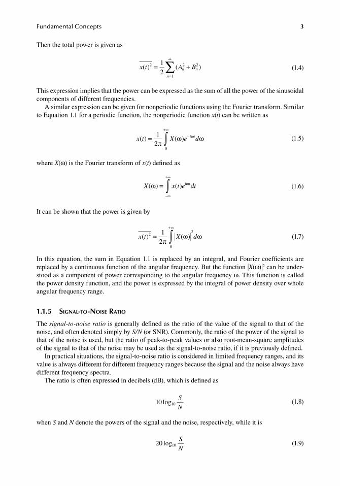
Then.the.total.power.is.given.as
.
x t A Bn n
n
( ) ( )2 2 2
1
12
= +=
∞
∑ . (1.4)
This.expression.implies.that.the.power.can.be.expressed.as.the.sum.of.all.the.power.of.the.sinusoidal.components.of.different.frequencies.
A.similar.expression.can.be.given.for.nonperiodic.functions.using.the.Fourier.transform..Similar.to.Equation.1.1.for.a.periodic.function,.the.nonperiodic.function.x(t).can.be.written.as
.
x t X e di t( ) ( )= −+∞
∫12
0π
ω ωω . (1.5)
where.X(ω).is.the.Fourier.transform.of.x(t).defined.as
.
X x t e dti t( ) ( )ω ω=−∞
+∞
∫ . (1.6)
It.can.be.shown.that.the.power.is.given.by
.
x t X d( ) ( )2
0
212
=+
∫πω ω
∞
. (1.7)
In.this.equation,. the.sum.in.Equation.1.1.is.replaced.by.an.integral,.and.Fourier.coefficients.are.replaced.by.a.continuous.function.of.the.angular.frequency..But.the.function.∙X(ω)∙2.can.be.under-stood.as.a.component.of.power.corresponding.to.the.angular.frequency.ω..This.function.is.called.the.power.density.function,.and.the.power.is.expressed.by.the.integral.of.power.density.over.whole.angular.frequency.range.
1.1.5 signal-to-noise ratio
The.signal-to-noise ratio.is.generally.defined.as.the.ratio.of.the.value.of.the.signal.to.that.of.the.noise,.and.often.denoted.simply.by.S/N.(or.SNR)..Commonly,.the.ratio.of.the.power.of.the.signal.to.that.of.the.noise.is.used,.but.the.ratio.of.peak-to-peak.values.or.also.root-mean-square.amplitudes.of.the.signal.to.that.of.the.noise.may.be.used.as.the.signal-to-noise.ratio,.if.it.is.previously.defined.
In.practical.situations,.the.signal-to-noise.ratio.is.considered.in.limited.frequency.ranges,.and.its.value.is.always.different.for.different.frequency.ranges.because.the.signal.and.the.noise.always.have.different.frequency.spectra.
The.ratio.is.often.expressed.in.decibels.(dB),.which.is.defined.as
.1 log10 0
S
N. (1.8)
when.S.and.N.denote.the.powers.of.the.signal.and.the.noise,.respectively,.while.it.is
.20 0log1
S
N. (1.9)
4 BiomedicalSensorsandInstruments
when.S.and.N.denote.the.root-mean-square.amplitudes.of.the.signal.and.the.noise,.respectively..Due.to.these.different.definitions.of.signal-to-noise.ratio.for.power.and.amplitude,.the.value.expressed.in.decibels.can.be.the.same.regardless.of.whether.S.and.N.are.expressed.in.power.or.in.amplitude.
1.1.6 different types of noise
Different.types.of.noise.arising.from.different.sources.may.appear.in.actual.measurement.situations.and.can.be.characterized.by.their.power.spectra,.and.can.be.treated.theoretically..Some.types.of.noise.are.discussed.briefly.in.the.following.sections,.but.more.detailed.treatment.can.be.found.in.other.text-books.(e.g.,.van.der.Ziel.1976)..In.addition.to.these.types.of.noise,.all.unwanted.signals.superimposed.on.the.signal.are.classified.as.noise,.irrespective.of.whether.the.sources.are.identified.or.not.
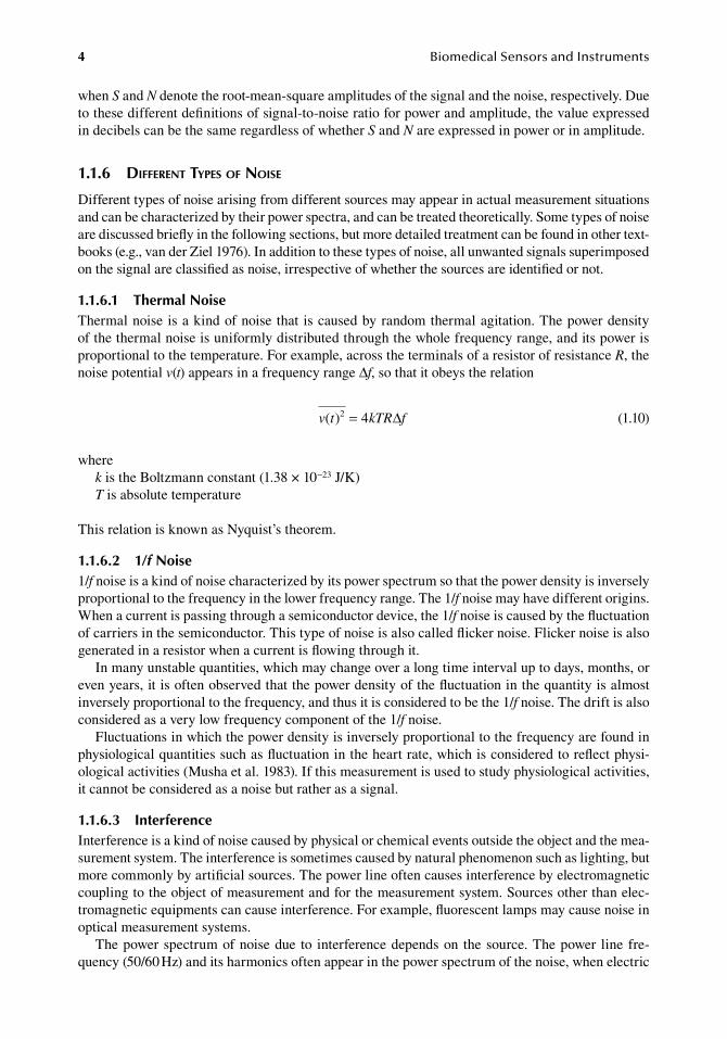
1.1.6.1 thermal noiseThermal.noise.is.a.kind.of.noise.that. is.caused.by.random.thermal.agitation..The.power.density.of.the.thermal.noise.is.uniformly.distributed.through.the.whole.frequency.range,.and.its.power.is.proportional.to.the.temperature..For.example,.across.the.terminals.of.a.resistor.of.resistance.R,.the.noise.potential.v(t).appears.in.a.frequency.range.Δf,.so.that.it.obeys.the.relation
. v t kTR f( )2 4= ∆ . (1.10)
wherek.is.the.Boltzmann.constant.(1.38.×.10−23.J/K)T.is.absolute.temperature
This.relation.is.known.as.Nyquist’s.theorem.
1.1.6.2 1/f noise1/f.noise.is.a.kind.of.noise.characterized.by.its.power.spectrum.so.that.the.power.density.is.inversely.proportional.to.the.frequency.in.the.lower.frequency.range..The.1/f.noise.may.have.different.origins..When.a.current.is.passing.through.a.semiconductor.device,.the.1/f.noise.is.caused.by.the.fluctuation.of.carriers.in.the.semiconductor..This.type.of.noise.is.also.called.flicker.noise..Flicker.noise.is.also.generated.in.a.resistor.when.a.current.is.flowing.through.it.
In.many.unstable.quantities,.which.may.change.over.a.long.time.interval.up.to.days,.months,.or.even.years,.it.is.often.observed.that.the.power.density.of.the.fluctuation.in.the.quantity.is.almost.inversely.proportional.to.the.frequency,.and.thus.it.is.considered.to.be.the.1/f.noise..The.drift.is.also.considered.as.a.very.low.frequency.component.of.the.1/f.noise.
Fluctuations.in.which.the.power.density.is.inversely.proportional.to.the.frequency.are.found.in.physiological.quantities.such.as.fluctuation.in.the.heart.rate,.which.is.considered.to.reflect.physi-ological.activities.(Musha.et.al..1983)..If.this.measurement.is.used.to.study.physiological.activities,.it.cannot.be.considered.as.a.noise.but.rather.as.a.signal.
1.1.6.3 interferenceInterference.is.a.kind.of.noise.caused.by.physical.or.chemical.events.outside.the.object.and.the.mea-surement.system..The.interference.is.sometimes.caused.by.natural.phenomenon.such.as.lighting,.but.more.commonly.by.artificial.sources..The.power.line.often.causes.interference.by.electromagnetic.coupling.to.the.object.of.measurement.and.for.the.measurement.system..Sources.other.than.elec-tromagnetic.equipments.can.cause.interference..For.example,.fluorescent.lamps.may.cause.noise.in.optical.measurement.systems.
The.power.spectrum.of.noise.due. to. interference.depends.on. the.source..The.power. line. fre-quency.(50/60.Hz).and.its.harmonics.often.appear.in.the.power.spectrum.of.the.noise,.when.electric.
FundamentalConcepts 5
equipments.supplied.from.the.power.line.are.used.near.the.object.and.for.the.measurement.system..Electric.equipments.which.utilize.pulse.or.switching.operations.generate.noise.in.a.wider.frequency.range.. Machines. having. mechanical. moving. parts. may. generate. vibration. which. interferes. with.mechanical.measurement.systems..The.power.spectrum.of.the.mechanical.interference.may.have.peaks.corresponding.to.mechanical.resonance.frequencies.of.the.machine.itself.or.materials.excited.mechanically.
Details.of.actual.situations.of. interference.and.practical. techniques.for.reducing.noise.can.be.found.in.appropriate.textbooks.(e.g.,.Morrison.1991).
1.1.6.4 artifactThe.term.artifact.usually.refers.to.a.component.of.noise.superimposed.on.the.object.quantity.and.caused.by.external. influences.such.as.movement..The.motion.artifact.often.appears. in.biopoten-tial.measurement.when.using. skin. surface.electrodes.. It. is. considered. that. this. is.due. in.part. to.the.potential.generated.by.the.epidermal.layers.of.the.skin.and.in.part.to.the.change.in.electrode.potentials.generated.at.the.interfaces.of.the.electrolyte.and.the.metal..The.waveform.of.the.artifact.depends.on.the.nature.of.the.external.influence..Sometimes,.the.motion.artifact.resembles.biopo-tential.signals.such.as.EEG.and.ECG,.and.thus.it.is.difficult.to.remove.the.noise.from.the.signal.by.simple.methods.such.as.the.use.of.a.band-pass.filter.
Artifacts.can.be.reduced.by.suppressing.the.process.which.couples.the.interference.to.the.object.or.the.measurement.system..For.example,.motion.artifacts.at.the.recording.electrodes.can.be.reduced.by.the.use.of.nonpolarizing.electrodes..While.the.electrode.potential.varies.due.to.the.variation.of.the.ionic.concentration.near.the.electrode.surface,.that.variation.is.suppressed.in.nonpolarizing.elec-trodes.by.employing.adequate.dissociation.equilibrium..The.abrasion.or.puncture.of.the.epidermal.part.of.the.skin.also.reduces.motion.artifacts;.as.a.result.the.potential.developed.in.the.skin.is.sup-pressed.by.short-circuiting.the.stratum.corneum.(Tam.and.Webster.1977,.Ödman.1981).
1.2 CharaCteriStiCS of the MeaSureMent SySteM
1.2.1 sensor and MeasureMent systeM
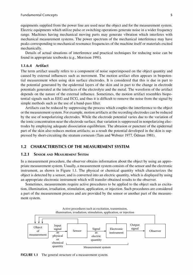
In.a.measurement.procedure,.the.observer.obtains.information.about.the.object.by.using.an.appro-priate.measurement.system..Usually,.a.measurement.system.consists.of.the.sensor.and.the.electronic.instrument,. as. shown. in. Figure. 1.1.. The. physical. or. chemical. quantity. which. characterizes. the.object.is.detected.by.a.sensor,.and.is.converted.into.an.electric.quantity,.which.is.displayed.by.using.an.appropriate.electronic.instrument.which.will.transfer.obtained.results.to.the.observer.
Sometimes,.measurements.require.active.procedures.to.be.applied.to.the.object.such.as.excita-tion,.illumination,.irradiation,.stimulation,.application,.or.injection..Such.procedures.are.considered.a.part.of.the.measurement.process.and.are.provided.by.the.sensor.or.another.part.of.the.measure-ment.system.
Objectof
measurementSensor Electronic
instrument Observer
Active procedures such as excitation, transmission,illumination, irradiation, stimulation, application, or injection
Inputsignal
asphysical
orchemicalquantity
Signalas
electricquantity
Outputsignal
Measurement system
figure 1.1 The.general.structure.of.a.measurement.system.
6 BiomedicalSensorsandInstruments
Although.an.active.procedure.is.unavoidable.in.some.measurements,.its.influence.on.the.object.should.be.minimized.for.two.reasons,.i.e.,.to.minimize.hazard.and.to.minimize.the.change.in.the.object.quantity.due. to. the.active.procedure..On. the.other.hand,.a.situation.often.occurs. in.which.measurement.becomes.much.easier.and.more.accurate.if.the.applied.energy.or.strength.of.the.active.procedure.is.increased..The.level.of.the.active.procedure.should.then.be.determined.as.a.compromise.between.minimized.influence.on.the.object.and.maximized.performance.of.the.measurement.system.
The.sensor.is.an.essential.part.of.the.measurement.system,.because.the.quality.of.the.measure-ment.system.is.determined.mostly.by.the.sensor.used..Signal-to-noise.ratio,.for.example,.is.always.determined.mainly.by.the.sensor,.as.long.as.adequately.interfaced.electronic.circuits.are.employed.
Different. types.of.object.quantities.require.different.kinds.of.sensors..Also.different.kinds.of.sensors. are. required.according. to. the. requirements.of.different.measurement. situations,. such.as.different.signal.amplitudes.and.frequency.ranges,.accuracy.requirements,.limitations.in.size,.shape.or.materials,.or.invasiveness.of.the.measurement.procedure..In.biomedical.measurements,.sensors.designed.for.other.purposes.are.often.unsuitable.even.if.fundamental.characteristics.such.as.type.of.object.quantities,.measurement. ranges,.or. frequency. responses.are.acceptable..Actually,.most.sensors.used.in.biomedical.measurements.are.designed.so.that.they.can.be.applied.to.the.body.with.minimum.subsidiary.effects,.obtaining.desired.biological.information.correctly..Most.parts.of.this.book.concern.such.sensors.that.are.applicable.to.biomedical.measurements.
1.2.2 static characteristics
In.most.measurement.systems,.the.output.of.the.measurement.system.at.every.moment.can.be.fully.determined.by.its.input.as.the.object.quantity.at.that.moment,.if.the.change.of.the.object.quantity.is.slow.enough..In.such.a.situation,.the.input–output.relationship.of.the.measurement.system.can.be.uniquely.determined.without.depending.on.the.time.course..The.object.quantity.and.the.charac-teristics.that.represent.the.relation.between.the.object.quantity.and.the.output.of.the.measurement.system.are.called.the.static.characteristics..Fundamental.features.of.a.measurement.system.can.be.characterized.by.the.static.characteristics.
1.2.2.1 Sensitivity, resolution, and reproducibilityThe.term.sensitivity.is.always.used.in.such.a.way.that.the.sensitivity.of.a.sensor.or.a.measurement.system.is.high.when.a.small.change.in.object.quantity.causes.a.large.change.in.its.output..But.quan-titative.definition.of.sensitivity.is.not.unique..In.some.fields,.the.sensitivity.is.defined.as.the.ratio.of.the.output.to.the.input..In.this.definition,.the.numerical.value.that.represents.the.sensitivity.is.large.when.the.sensitivity.is.high..In.other.fields,.the.sensitivity.is.defined.as.the.ratio.of.the.input.to.the.output..This.factor.corresponds.to.the.amount.of.change.in.the.object.quantity.that.produces.a.unit.change.in.the.output..By.this.definition,.the.numerical.value.is.small.when.the.sensitivity.is.high..The.sensitivity.has.a.dimension.when.the.dimension.of.the.object.quantity.and.that.of.the.output.are.different..Sensitivities.for.different.object’s.quantities.are.represented.in.different.units.such.as.mV/kPa,.μA/K,.mV/pH,.etc.
Sensitivity.can.be.a.constant.value.when.the.change.in.the.output.is.linearly.related.to.the.change.in.the.object.quantity,.whereas.it.cannot.be.constant.when.the.response.is.nonlinear..In.such.a.case,.sensitivity.depends.on.the.absolute.value.of.the.object.quantity.
The.resolution.is.the.least.value.of.the.object.quantity.that.can.be.distinguished.at.the.output.of.the.measurement.system..A.change.in.the.object.quantity,.which.is.smaller.than.the.resolution.of.the.measurement.system,.will.not.produce.a.detectable.change.in.its.output.which.can.be.distinguished.from.noise..The.numerical.value.of.the.resolution.is.small.when.the.resolution.is.high..The.resolu-tion.has.the.same.dimension.as.that.of.the.object.quantity.
The. reproducibility. describes. how. close. to. one. another. repeated. outputs. are. when. the. same.quantity. is. measured. repeatedly.. Quantitatively,. the. reproducibility. of. a. measurement. system. is.defined.as.a.range.in.the.object.quantity.so.that.the.results.of.successive.measurements.for.the.same.
FundamentalConcepts 7
quantity.fall.into.that.range.with.a.given.probability..If.the.probability.level.is.not.specified,.it.is.usu-ally.understood.to.be.95%..When.the.range.is.narrow,.the.reproducibility.is.high..The.term.repeat-ability.is.also.used.to.express.the.similar.concept.of.reproducibility,.but.repeatability.is.understood.as.the.reproducibility.in.a.short.time.interval,.when.these.two.terms.are.distinguished.
1.2.2.2 Measurement rangeThe.measurement range. is. the. total. range.of. the.object.quantity.within.which. the.measurement.system.works.so.as.to.meet.the.nominal.performance.of.the.measurement.system..Thus.the.mea-surement.range.depends.on.performance.requirements.such.as.sensitivity,.resolution,.or.reproduc-ibility..If.the.requirements.are.severe,.the.measurement.range.will.be.narrow..Sometimes.different.measurement.ranges.are.specified.for.different.requirements..For.example,.in.a.thermometer,.mea-surement.range.is.from.30°C.to.40°C.for.reproducibility.of.0.1°C,.and.that.from.0°C.to.50°C.for.reproducibility.of.0.5°C.
The.measurement.range.states.the.maximum.allowable.change.of.the.object.quantity.as.long.as.the.nominal.performance.of.the.measurement.system.is.expected..On.the.other.hand,.the.minimum.detectable.change.of.the.object.quantity.is.stated.by.the.resolution..The.ratio.of.measurement.range.to. resolution. is. called. the.dynamic range..The.dynamic. range. is. a.nondimensional.value.and. is.sometimes.expressed.in.decibels.(dB).
The.dynamic.range.has.to.be.considered.when.the.signal.is.converted.into.a.digital.quantity..For.example,.the.number.of.bits.of.an.analog-to-digital.converter.and.the.data.format.or.number.of.dig-its.of.the.digital.display.are.determined.so.that.the.maximum.digital.number.usable.by.these.devices.is.large.enough.compared.with.the.dynamic.range.
1.2.2.3 linearity or nonlinearityThe. linearity.describes.how.close.the.input–output.relationship.of. the.measurement.system.is. to.an.appropriate.straight.line..Different.definitions.of.linearity.are.used.depending.on.which.straight.line.is.considered..The.straight.line.defined.by.the.least.square.fit.to.the.input–output.relation.can.be.used,.whereas.other.straight. lines.defined.by. the. least.square.fit.positioned. to.pass.either. the.origin,.or.the.terminal.point,.or.both,.can.also.be.used..When.the.straight.line.passing.through.the.origin.is.used,.the.linearity.of.this.specific.definition.is.sometimes.called.zero-based.linearity.or.proportionality.
As.a.quantitative.measure.of.the.linearity,.the.ratio.of.the.maximum.deviation.from.the.input–output.relation.curve.from.a.straight.line.is.used..However,.the.term.nonlinearity.is.conventionally.used.to.indicate.this.value,.because.the.numerical.value.when.using.this.definition.is.large.when.the.deviation.of.the.input–output.relation.curve.from.the.straight.line.is.significant.
When.the.linearity.is.high.(or. the.nonlinearity.is.small),. the.input–output.relationship.can.be.regarded.as.a.straight.line,.and.thus.the.sensitivity.can.be.regarded.as.constant..On.the.other.hand,.when.the.linearity.is.low.(or.nonlinearity.is.large),.the.sensitivity.depends.on.the.input.level.
Although. higher. linearity. is. desired. in. most. measurement. systems,. accurate. measurement. is.possible.even.if.the.response.is.nonlinear.as.long.as.the.input–output.relation.is.fully.determined..By.using.a.computer,. the.input.can.be.estimated.at.every.sampling.interval.from.the.output.and.knowledge.of.the.input–output.relation.
1.2.2.4 hysteresisHysteresis.is.a.kind.of.phenomenon.in.which.different.output.values.appear.corresponding.to.the.same.input.no.matter.how.slow.the.speed.of.change.of.the.input.is..If.a.measurement.system.has.hysteresis,.the.input–output.relation.curve.is.not.unique.but.depends.on.the.direction.and.the.range.of.successive.input.values.
There.are.different.causes.of.hysteresis,.such.as.backlash.in.mechanical.coupling.parts,.visco-elasticity.or.creep.of.mechanical.elements,.magnetization.of.ferromagnetic.materials,.or.adsorp-tion.and.desorption.of.materials.on.electrochemical.devices..While.hysteresis.due.to.backlash.is.
8 BiomedicalSensorsandInstruments
independent.of.the.range.of.variations.of.the.input,.hysteresis.because.of.other.causes.depends.on.the.variations.of.the.input,.so.that.large.variations.cause.large.hysteresis..To.minimize.hysteresis,.larger.inputs.appearing.at.a.transient,.or.by.the.artifacts.beyond.the.normal.variation.range.of.the.signal,.should.be.avoided..The.sensor.design.in.which.the.input.is.limited.within.the.normal.mea-surement.range.is.advantageous.not.only.to.protect.sensing.elements.in.the.sensor.from.destruction.but.also.to.reduce.hysteresis..For.example,.the.stopper.for.the.diaphragm.or.beam.in.mechanical.sensors.is.employed.for.this.reason.
1.2.3 dynaMic characteristics
The.dynamic characteristics.of.a.measurement.system.describe.the.input–output.relation.in.a.tran-sient,.whereas. the.static.characteristics.describe. the. relation.when. the. input. remains.constant.or.changes.slowly..The.dynamic.characteristics.are.required.where.the.response.to.time-varying.inputs.is.of.concern..The.time-varying.pattern.of.the.object.quantity.is.observed.as.a.waveform,.but.true.waveforms.will.not.be.reproduced.unless.its.dynamic.characteristics.are.excellent.
The.dynamic.characteristics.are.particularly.important.when.the.sensor.consists.of.a.part.of.a.control.system..Instability.or.oscillation.may.occur.due.to.a.poor.dynamic.response.of.the.sensor.
The.most.common.cause.that.affects.the.dynamic.characteristics.of.the.measurement.system.is.the.presence.of.elements.which.store.and.release.energy.when.the.object.quantity.varies..For.exam-ple,.inertial.elements.such.as.masses,.capacitances.and.inductances,.and.compliant.elements.such.as.springs,.electric.and.heat.capacitances.are.such.system.components..If.the.displacements.of.mechani-cal.parts.and.fluids.cause.significant.time.delays,.they.will.also.affect.the.dynamic.characteristics.of.the.system..Besides.the.measurement.system,.the.object.matter.of.the.measurement.and.the.interfac-ing.media.may.also.affect.the.dynamic.characteristics.of.the.whole.measurement.process..In.such.a.situation,.the.dynamic.characteristics.should.be.discussed,.including.the.object.or.the.interfacing.media,.as.in.the.case.of.the.catheter-sensor.systems.in.pressure.measurements.(see.Section.2.2.2).
Although.some.important.concepts.and.terms.regarding.the.dynamic.characteristics.of.the.mea-surement.systems.are.explained.briefly.in.the.following.sections,.we.also.recommend.the.study.of.other.textbooks.(e.g.,.Doebelin.1990,.Pallas-Areny.and.Webster.1991).
1.2.3.1 linear and nonlinear SystemsThe.term.linear system,.or.the.expression.that.a.system.is.linear,.always.refers.to.a.system.in.which.the.response.to.simultaneous.inputs.is.the.sum.of.their.independent.inputs..A.system.which.does.not.meet.this.condition.is.called.a.nonlinear.system.
In.linear.systems,.the.dynamic.characteristics.are.the.same.regardless.of.the.input’s.amplitude..The.amplitude.of.the.response.is.simply.proportional.to.the.input.amplitude,.because.a.large.input.can.be.regarded.as.a.sum.of.smaller.inputs,.and.hence.the.response.corresponding.to.the.large.input.is.the.sum.of.the.responses.corresponding.to.the.small.inputs..This.property.is.important.because.many.con-venient.parameters,.which.characterize.the.system,.can.be.defined.regardless.of.the.signal.amplitude.
Real. systems. cannot. always. be. linear. when. the. input. increases. far. beyond. the. measurement.range..On.the.other.hand,.most.measurement.systems.can.be.regarded.as.linear.if.the.variations.of.the.input.are.small..Even.in.a.nonlinear.system,.an.appropriate.linear.system.can.be.assumed.as.a.result.of.the.approximation.in.a.small.measurement.range.
In.a.linear.system,.the.response.to.a.sinusoidal.input.is.also.sinusoidal.with.the.same.frequency.as.that.of.the.input,.while.other.frequency.components.such.as.higher.harmonics.may.appear.in.a.nonlinear.system.
1.2.3.2 frequency responseThe.frequency response.refers.to.the.distribution.of.the.amplitude.and.the.phase.shift.of.the.output.to.sinusoidal.inputs.of.unit.amplitude.over.the.whole.frequency.range.in.which.the.dynamic.charac-teristics.are.considered..Usually,.the.frequency.response.is.defined.only.for.linear.systems.
FundamentalConcepts 9
The.output.of.a.linear.system.can.be.described.as.the.sum.of.the.responses.corresponding.to.sinusoidal.inputs.having.different.frequencies,.because.the.input.is.expressed.as.the.sum.of.sinu-soidal.functions.such.as.Equation.1.1.or.1.5..Therefore,.the.frequency.response.provides.complete.information.about.the.output.of.the.system.for.any.input.
When. the. input–output. relation. of. a. system. is. described. by. a. constant-coefficient. first-order.differential. equation,. the. system. is. called. a. first-order system.. The. differential. equation. which.describes.a.first-order.system.is.written.as
.a
dy t
dta y t x t1 0
( )( ) ( )+ = . (1.11)
wherex(t).and.y(t).are.the.input.and.the.output.of.the.systema0.and.a1.are.constants
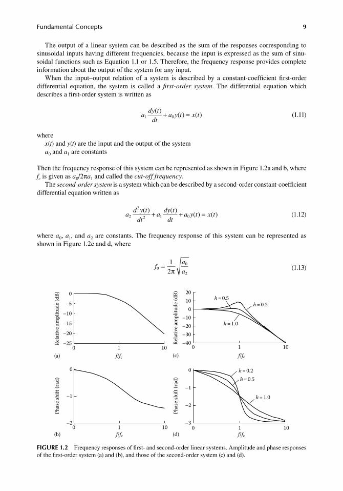
Then.the.frequency.response.of.this.system.can.be.represented.as.shown.in.Figure.1.2a.and.b,.where.fc.is.given.as.a0/2πa1.and.called.the.cut-off frequency.
The.second-order system.is.a.system.which.can.be.described.by.a.second-order.constant-coefficient.differential.equation.written.as
.a
d y t
dta
dy t
dta y t x t2
2
2 1 0( ) ( )
( ) ( )+ + = . (1.12)
where.a0,.a1,.and.a2.are.constants..The.frequency.response.of. this.system.can.be.represented.as.shown.in.Figure.1.2c.and.d,.where
.f
a
a0
0
2
12
=π . (1.13)
0
–1
–2
–3
Phas
e shi
ft (r
ad)
f/fc0 1 10
Phas
e shi
ft (r
ad)
0
–1
–20 1 10
f/fc(b) (d)
h = 0.2h = 0.5
h = 1.0
0
–5
–10
–15
–20
Rela
tive a
mpl
itude
(dB)
–250 1 10
f/fc(a)
Rela
tive a
mpl
itude
(dB) 20
100
–10–20–30–40
f/fc0 1 10
h = 0.2h = 0.5
h = 1.0
(c)
figure 1.2 Frequency.responses.of.first-.and.second-order.linear.systems..Amplitude.and.phase.responses.of.the.first-order.system.(a).and.(b),.and.those.of.the.second-order.system.(c).and.(d).
10 BiomedicalSensorsandInstruments
which.is.called.the.natural frequency,.and
.
ha
a a= 1
0 22. (1.14)
which.is.called.the.damping coefficient.
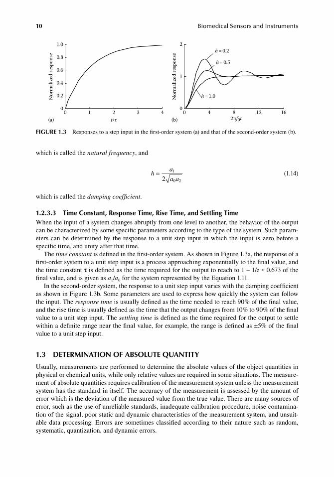
1.2.3.3 time Constant, response time, rise time, and Settling timeWhen.the.input.of.a.system.changes.abruptly.from.one.level.to.another,.the.behavior.of.the.output.can.be.characterized.by.some.specific.parameters.according.to.the.type.of.the.system..Such.param-eters.can.be.determined.by. the. response. to.a.unit.step. input. in.which. the. input. is.zero.before.a.specific.time,.and.unity.after.that.time.
The.time constant.is.defined.in.the.first-order.system..As.shown.in.Figure.1.3a,.the.response.of.a.first-order.system.to.a.unit.step.input.is.a.process.approaching.exponentially.to.the.final.value,.and.the.time.constant.τ.is.defined.as.the.time.required.for.the.output.to.reach.to.1.–.1/e.≈.0.673.of.the.final.value,.and.is.given.as.a1/a0.for.the.system.represented.by.the.Equation.1.11.
In.the.second-order.system,.the.response.to.a.unit.step.input.varies.with.the.damping.coefficient.as.shown.in.Figure.1.3b..Some.parameters.are.used.to.express.how.quickly.the.system.can.follow.the.input..The.response time.is.usually.defined.as.the.time.needed.to.reach.90%.of.the.final.value,.and.the.rise.time.is.usually.defined.as.the.time.that.the.output.changes.from.10%.to.90%.of.the.final.value.to.a.unit.step.input..The.settling time.is.defined.as.the.time.required.for.the.output.to.settle.within.a.definite.range.near.the.final.value,.for.example,.the.range.is.defined.as.±5%.of.the.final.value.to.a.unit.step.input.
1.3 deterMination of abSolute Quantity
Usually,.measurements.are.performed.to.determine.the.absolute.values.of.the.object.quantities.in.physical.or.chemical.units,.while.only.relative.values.are.required.in.some.situations..The.measure-ment.of.absolute.quantities.requires.calibration.of.the.measurement.system.unless.the.measurement.system.has.the.standard.in.itself..The.accuracy.of.the.measurement.is.assessed.by.the.amount.of.error.which.is.the.deviation.of.the.measured.value.from.the.true.value..There.are.many.sources.of.error,.such.as.the.use.of.unreliable.standards,.inadequate.calibration.procedure,.noise.contamina-tion.of.the.signal,.poor.static.and.dynamic.characteristics.of.the.measurement.system,.and.unsuit-able.data.processing..Errors. are. sometimes. classified.according. to. their.nature. such.as. random,.systematic,.quantization,.and.dynamic.errors.
1.0
0.8
0.6
0.4
0.2
00
(a) (b)1 2
t/τ3 4
0
1
2
0 4 8 12 16
Nor
mal
ized
resp
onse
Nor
mal
ized
resp
onse
2πf0t
h = 0.2
h = 0.5
h = 1.0
figure 1.3 Responses.to.a.step.input.in.the.first-order.system.(a).and.that.of.the.second-order.system.(b).
FundamentalConcepts 11
1.3.1 standard and calibration
Any.measurement.system.can.be.calibrated.by.comparing.with.either.an.intrinsic.standard.or.a.reli-able.standard.instrument..There.are.some.convenient.standards.for.different.quantities..For.example,.a.mercury.column.can.be.a.standard.of.pressure..Because.the.density.of.pure.mercury.is.known,.and.the.gravity.of.the.earth.is.also.known,.the.pressure.developed.at.the.bottom.of.a.mercury.column.of.a.definite.height.can.be.a.standard.of.pressure..Ice.point.of.pure.water,.which.is.0°C,.or.melting.point.of.gallium,.which.is.29.771°C,.are.used.as.intrinsic.temperature.standards.
An.instrument.which.is.stable.enough.and.correctly.calibrated.can.also.be.a.standard,.so.that.other.measurement.systems.can.be.calibrated.comparing.with.the.standard.instrument..For.exam-ple,.commercial.standard.thermometers.having.crystal-resonator.temperature.sensors.can.be.used.to.determine.temperatures.absolutely.within.a.deviation.of.0.01°C,.which.is.precise.enough.for.most.biomedical.measurements.
When.the.measurement.system.to.be.calibrated.is.nonlinear,.calibration.has.to.be.performed.at.many.points.in.the.measurement.range..On.the.contrary,.when.the.measurement.system.is.linear,.calibration.at. two.points. is.enough..Even. if. slight.nonlinearity.exists. in. the.whole.measurement.range.of.the.system,.as.long.as.the.variation.of.the.object.quantity.is.limited.to.a.narrow.range.and.the.system.can.be.regarded.as. linear. in. that. limited.range,. two-point.calibration.in. that.range.is.enough.for.all.practical.purposes..In.a.case.where.the.measurement.system.is.linear.and.its.sensitiv-ity.is.stable.but.drift.remains.to.some.extent,.occasional.one-point.calibration.after.initial.two-point.calibration.is.recommended.
Even.if.a.measurement.system.is.nonlinear.but.is.stable.enough.and.its.input–output.relation.can.be.approximated.by.a.simple.formula.having.few.parameters,.what.is.required.in.calibration.is.to.deter-mine.all.parameters.in.the.formula..For.example,.if.the.input–output.relation.is.well.approximated.by.a.quadratic.formula,.the.number.of.parameters.to.be.determined.is.three,.and.thus.the.fitting.curve.can.be.determined.by.three-point.calibration..Such.a.curve-fitting.computation.can.be.performed.eas-ily.even.in.real.time.when.the.output.of.the.measurement.system.is.connected.to.a.computer.
1.3.2 accuracy and error
The. term.accuracy.describes.how.close. the.measured.value. is. to. the. true.value..The.difference.between.them.is.termed.the.error.
The.error.may.depend.on.the.level.of.the.object.quantity,.especially.when.the.measurement.range.includes.small.to.large.values.of.the.object.quantity..The.error.may.be.small.when.the.object.quan-tity.is.small,.while.it.may.be.large.when.the.object.quantity.is.large..In.such.a.situation,.the.relative.error,.which.is.defined.as.the.ratio.of.the.error.to.the.true.value,.can.be.a.convenient.figure.of.the.performance.of.the.measurement.system.
When. the. measurement. system. is. calibrated. adequately,. the. error. will. be. reduced. to. a. limit.which.is.determined.by.the.reproducibility..Sometimes,.the.accuracy.of.the.measurement.system.becomes.poor.due.to.the.drift.in.a.long.period.of.time.even.though.the.reproducibility.in.a.short.period.of.time.has.not.changed.very.much..In.such.a.situation,.the.accuracy.can.be.recovered.to.the.initial.level.by.a.recalibration..By.repeated.calibration.procedures,.the.accuracy.can.be.maintained.within.a.definite.range.for.a.long.time.period.
1.3.3 types of error
In.actual.measurement.situations,.there.are.always.many.sources.of.errors..The.errors.arising.from.different.sources.are.classified.into.different.types..The.nature.of.typical.types.of.error.is.discussed.briefly.in.the.following.sections,.but.more.detailed.explanations.can.be.found.in.standard.textbooks.(e.g.,.Sydenham.1999).
12 BiomedicalSensorsandInstruments
1.3.3.1 random errorThe. random error. is. a. kind. of. error. which. appears. unpredictably. in. repeated. measurements..Random.noise.superimposing.on.the.signal.and.short-term.fluctuations.of.the.measurement.system.may.cause.random.errors..Deviations.of. the.measured.values.are.distributed.on.the.positive.and.negative.sides.of. the. true.value.with.equal.probabilities,.and. the.mean.of. the.deviations. is.zero..Thus,.if.the.measurements.are.repeated.while.the.object.quantity.is.unchanged,.the.average.of.mea-sured.values.approaches.the.true.value.
The.statistical.property.of.random.errors.can.be.determined.from.the.distribution.of.measure-ment.values.when.the.same.object.quantity.is.measured.repeatedly..In.practice,.it.is.often.assumed.that.random.errors.are.distributed.according.to.a.normal.distribution..That.assumption.is.secured.theoretically.when.the.errors.are.considered.to.be.the.result.of.a.large.number.of.small.uncorrelated.component. errors.. According. to. the. central-limit. theorem,. it. is. expected. that. the. sum. of. many.uncorrelated.random.values.forms.a.normal.distribution.
For.the.normal.distribution,.the.standard.deviation.of.measurement.values.of.n.measurements,.which.is.the.standard.error,.is.reduced.inversely.proportional.to.the.square.root.of.n..Consequently,.repeated. measurement. combined. with. signal. averaging. is. an. effective. way. to. reduce. random.errors.
1.3.3.2 Systematic errorThe.systematic error.is.the.bias.from.the.true.value.appearing.equally.in.repeated.measurements.of.the.same.object.quantity..Systematic.errors.have.different.origins,.such.as.very.low.frequency.com-ponents.of.noise.contaminating.the.signal,.drift.of.the.measurement.system,.inadequate.calibration,.uncorrected.nonlinearity,.or.round.down.in.digital.data.processing.
When.the.same.object.quantity.is.measured.by.two.different.measurement.systems,.the.differ-ence.between.averages.of.measurement.values.of. these. two. systems. indicates. the.presence.of. a.systematic.error.
Systematic.errors.cannot.be.eliminated.by.repeated.measurements.and.averaging..It.is.also.dif-ficult.to.identify.all.causes.of.systematic.errors..One.practical.way.of.reducing.systematic.errors.is. recalibration.of. the.measurement. system.under. the.measurement.conditions.over. the. required.measurement.range..As.long.as.recalibrations.are.performed.repeatedly.at.adequate.intervals,.the.systematic.errors.can.be.significantly.reduced.for.a.long.period.of.time.even.though.the.drift.of.the.measurement.system.exists.to.some.extent.
Sometimes,.when.a.systematic.error.is.suspected.due.to.the.influence.of.the.environment.such.as.climatic.change,.two.identical.measurement.systems.are.used,.so.that.the.object.and.a.standard.are.measured.simultaneously,.and.the.measurement.value.is.obtained.from.the.difference.of.their.outputs..If.the.systematic.errors.in.both.outputs.are.the.same,.the.error.will.be.cancelled.out.in.the.difference.between.these.two.outputs,.and.then.the.object.quantity.can.be.measured.correctly.as.the.deviation.from.the.standard.value.
1.3.3.3 Quantization errorThe.quantization error. is. an. error. caused.by. conversion.of. an. analog.value. to. a. corresponding.digital.value,.as.in.an.analog-to-digital.converter..The.error.is.the.difference.between.the.original.analog.value.and.the.converted.digital.value.
When.an.analog.value.is.converted.into.a.digital.value,.an.ambiguity.corresponding.to.1.in.the.least-significant.bit.remains..The.fraction.of.error.due.to.this.ambiguity.depends.on.the.level.of.the.measurement.value..If.measurement.values.always.remain.at.a.higher.level.so.that.1.in.the.least-significant.bit.is.negligible,.quantization.error.is.insignificant..On.the.other.hand,.if.measurement.values.stay.near.the.least-significant.bit,.quantization.error.will.be.serious.even.though.a.precision.analog-to-digital.converter.is.used..To.reduce.quantization.error,.it.is.important.to.adjust.the.input.level.so.as.to.fit.the.input.range.of.the.analog-to-digital.converter.
FundamentalConcepts 13
1.3.3.4 dynamic errorThe.dynamic error.is.a.kind.of.error.occurring.from.imperfect.dynamic.characteristics.of.the.measure-ment.system..It.occurs.when.the.object.quantity.varies.so.quickly.that.the.output.of.the.measurement.system.does.not.follow.the.change.of.the.input..The.difference.between.the.output.value.and.the.object.quantity.is.the.dynamic.error..When.the.dynamic.error.exists,.the.instantaneous.output.of.the.mea-surement.system.cannot.reflect.the.input.at.that.moment,.and.depends.on.the.past.history.of.the.input.
The.possible.dynamic.error.of.a.system.is.estimated.from.the.response.corresponding.to.a.step-wise.input..As.discussed.in.Section.1.2.3.2.and.shown.in.Figure.1.3,.the.response.curve.for.a.stepwise.input.can.be.determined.by.a.few.parameters.in.simple.systems,.such.as.the.first-.or.second-order.linear.systems,.and.the.dynamic.error.for.a.stepwise.input.is.the.deviation.of.the.response.curve.from.the.final.steady-state.value..In.higher.order.systems,.some.parameters,.such.as.the.settling.time,.can.still.be.defined.in.the.response.curve.corresponding.to.a.stepwise.input..It.can.be.expected.that.the.dynamic.error.will.remain.in.a.definite.range.if.a.time.longer.than.the.settling.time.passes.after.an.abrupt.change.in.the.object.quantity.
1.4 unitS of MeaSureMent QuantitieS
Quantitative.measurement.results.are.always.represented.in.numerical.form.using.some.unit.so.that.anyone.can.compare.them.to.other.measurement.results..While.any.unit.can.be.used.in.each.mea-surement.as.long.as.it.is.well.defined,.inconveniences.will.arise.when.different.units.for.the.same.quantity.are.used.in.different.measurement.results.even.though.unit.conversion.is.possible..Even.if.the.same.unit.is.used.for.each.quantity,.if.the.units.of.interrelating.quantities.are.defined.inde-pendently,.numerical.factors.may.appear.in.each.equation.representing.the.relation.between.these.quantities..For.example,.consider.the.heat.produced.by.mechanical.work..If.the.units.of.mechani-cal.work.and.heat.are.defined.independently,.the.developed.heat.cannot.be.obtained.immediately.from.the.mechanical.work,.but.a.numerical.coefficient.has.to.be.used.for.unit.conversion..In.order.to.eliminate.such.inconvenience,.a.coherent.system.of.units.is.used.in.which.each.unit.is.defined.systematically.so.that.the.numerical.coefficient.becomes.unnecessary..While.the.coherent.system.is.not.unique.as.different.coherent.systems.of.units.such.as.CGS.and.MKS.systems.existed,.it.is.now.recommended.to.use.the.International.System.of.Units.(SI).
1.4.1 the international systeM of units
The. International. System. of. Units. (SI). was. established. by. the. International. Organization. of.Standard.(ISO)..SI.is.a.coherent.system.of.units.of.physical.quantities..The.International.Standard.of.quantities.and.units.includes.not.only.the.definitions.of.quantities.and.units.but.also.the.rules.for.writing.them.such.as.the.symbols.to.be.used.to.express.quantities.and.units..Information.about.the.International.Standard.of.quantities.and.units.is.available.in.the.documents.published.by.ISO.referred. to.as. ISO.1000.(International.Standard.ISO.1000.1992).and.ISO.31—Part.0. to.Part.13.(International.Standard.ISO.31.1992).
1.4.1.1 base units and derived unitsThe.SI.is.based.on.the.seven.base.quantities.and.their.units,.called.base units,.which.are.length.in.meter,.mass.in.kilogram,.time.in.second,.electric.current.in.ampere,.thermodynamic.temperature.in.kelvin,.amount.of.substance.in.mol,.and.luminous.intensity.in.candela,.as.listed.in.Table.1.1..The.base.units.are.defined.rigorously.as.follows.(Units.of.Measurements.1982):
•. The.meter.is.the.length.equal.to.1,650,763.73.wavelengths.in.vacuum.of.the.radiation.cor-responding.to.the.transition.between.the.levels.2p10.and.5d5.of.the.krypton-86.atom.
•. The.kilogram.is.equal.to.the.mass.of.the.international.prototype.of.the.kilogram.
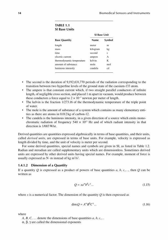
14 BiomedicalSensorsandInstruments
•. The.second.is.the.duration.of.9,192,631,770.periods.of.the.radiation.corresponding.to.the.transition.between.two.hyperfine.levels.of.the.ground.state.of.the.caesium-133.atom.
•. The.ampere.is.that.constant.current.which,.if.two.straight.parallel.conductors.of.infinite.length,.of.negligible.cross.section,.and.placed.1.m.apart.in.vacuum,.would.produce.between.these.conductors.a.force.equal.to.2.×.10−7.newton.per.meter.of.length.
•. The.kelvin.is.the.fraction.1/273.16.of.the.thermodynamic.temperature.of.the.triple.point.of.water.
•. The.mole.is.the.amount.of.substance.of.a.system.which.contains.as.many.elementary.enti-ties.as.there.are.atoms.in.0.012.kg.of.carbon-12.
•. The.candela.is.the.luminous.intensity,.in.a.given.direction.of.a.source.which.emits.mono-chromatic. radiation. of. frequency. 540. ×. 1012. Hz. and. of. which. radiant. intensity. in. that.direction.is.1/683.W/sr.
Derived.quantities.are.quantities.expressed.algebraically.in.terms.of.base.quantities,.and.their.units,.called.derived units,.are.expressed. in. terms.of.base.units..For.example,.velocity. is.expressed.as.length.divided.by.time,.and.the.unit.of.velocity.is.meter.per.second.
For.some.derived.quantities,.special.names.and.symbols.are.given.in.SI,.as.listed.in.Table.1.2..Radian.and.steradian.are.called.supplementary.units.which.are.dimensionless..Sometimes.derived.units.are.expressed.by.other.derived.units.having.special.names..For.example,.moment.of.force.is.usually.expressed.as.N.·.m.instead.of.kg.m2/s2.
1.4.1.2 dimension of a QuantityIf.a.quantity.Q. is.expressed.as.a.product.of.powers.of.base.quantities.a,.b,.c,…,. then.Q.can.be..written.as
. Q xa b c= α β γ ... . (1.15)
where.x.is.a.numerical.factor..The.dimension.of.the.quantity.Q.is.then.expressed.as
. dim ...Q A B C= α β γ . (1.16)
whereA,.B,.C,.….denote.the.dimensions.of.base.quantities.a,.b,.c,…α,.β,.γ.are.called.the.dimensional.exponents
table 1.1Si base units
base Quantity
Si base unit
name Symbol
length meter m
mass kilogram kg
time second s
electric.current ampere A
thermodynamic.temperature kelvin K
amount.of.substance mole mol
luminous.intensity candela cd
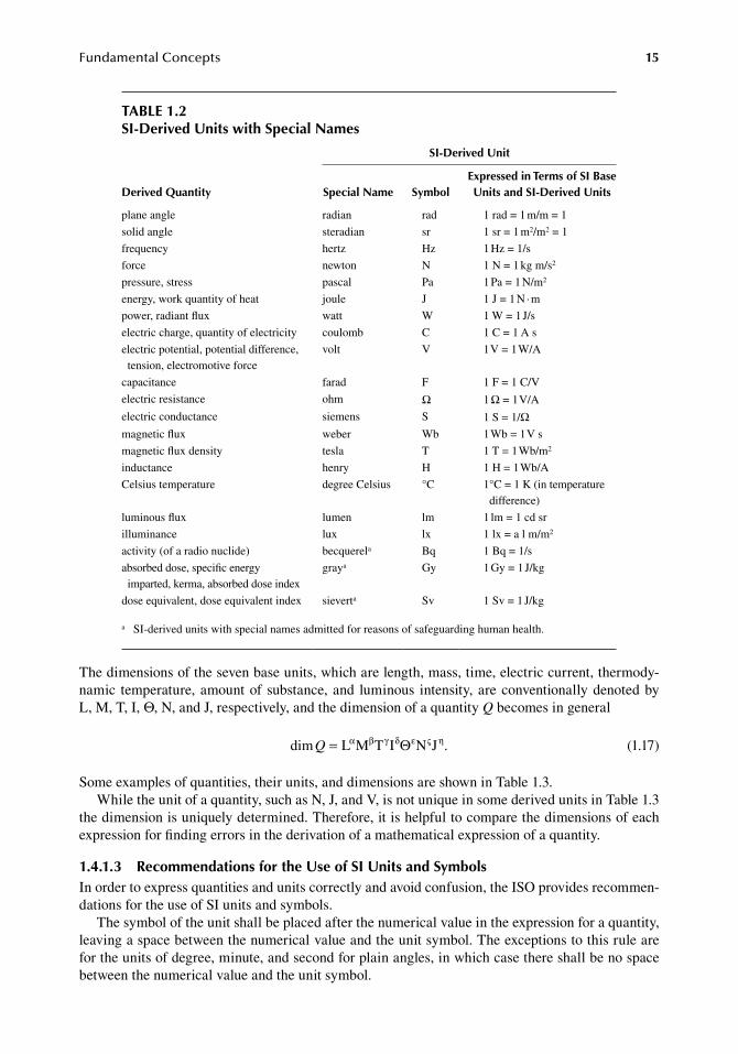
FundamentalConcepts 15
The.dimensions.of.the.seven.base.units,.which.are.length,.mass,.time,.electric.current,.thermody-namic. temperature,.amount.of. substance,.and. luminous. intensity,.are.conventionally.denoted.by.L, M,.T,.I,.Θ,.N,.and.J,.respectively,.and.the.dimension.of.a.quantity.Q.becomes.in.general
. dim .Q = L M T I N Jα β γ δ ε ς ηΘ . (1.17)
Some.examples.of.quantities,.their.units,.and.dimensions.are.shown.in.Table.1.3.While.the.unit.of.a.quantity,.such.as.N,.J,.and.V,.is.not.unique.in.some.derived.units.in.Table.1.3.
the.dimension.is.uniquely.determined..Therefore,.it.is.helpful.to.compare.the.dimensions.of.each.expression.for.finding.errors.in.the.derivation.of.a.mathematical.expression.of.a.quantity.
1.4.1.3 recommendations for the use of Si units and SymbolsIn.order.to.express.quantities.and.units.correctly.and.avoid.confusion,.the.ISO.provides.recommen-dations.for.the.use.of.SI.units.and.symbols.
The.symbol.of.the.unit.shall.be.placed.after.the.numerical.value.in.the.expression.for.a.quantity,.leaving.a.space.between.the.numerical.value.and.the.unit.symbol..The.exceptions.to.this.rule.are.for.the.units.of.degree,.minute,.and.second.for.plain.angles,.in.which.case.there.shall.be.no.space.between.the.numerical.value.and.the.unit.symbol.
table 1.2Si-derived units with Special names
derived Quantity
Si-derived unit
Special name Symbolexpressed in terms of Si base units and Si-derived units
plane.angle radian rad 1.rad.=.1.m/m.=.1
solid.angle steradian sr 1.sr.=.1.m2/m2.=.1
frequency hertz Hz 1.Hz.=.1/s
force newton N 1.N.=.1.kg.m/s2
pressure,.stress pascal Pa 1.Pa.=.1.N/m2
energy,.work.quantity.of.heat joule J 1.J.=.1.N.·.m
power,.radiant.flux watt W 1.W.=.1.J/s
electric.charge,.quantity.of.electricity coulomb C 1.C.=.1.A.s
electric.potential,.potential.difference,.tension,.electromotive.force
volt V 1.V.=.1.W/A
capacitance farad F 1.F.=.1.C/V
electric.resistance ohm Ω 1.Ω.=.1.V/A
electric.conductance siemens S 1.S.=.1/Ωmagnetic.flux weber Wb 1.Wb.=.1.V.s
magnetic.flux.density tesla T 1.T.=.1.Wb/m2
inductance henry H 1.H.=.1.Wb/A
Celsius.temperature degree.Celsius °C 1°C.=.1.K.(in temperature.difference)
luminous.flux lumen lm 1.lm.=.1.cd.sr
illuminance lux lx 1.lx.=.a.l.m/m2
activity.(of.a.radio.nuclide) becquerela Bq 1.Bq.=.1/s
absorbed.dose,.specific.energy.imparted,.kerma,.absorbed.dose.index
graya Gy 1.Gy.=.1.J/kg
dose.equivalent,.dose.equivalent.index sieverta Sv 1.Sv.=.1.J/kg
a. SI-derived.units.with.special.names.admitted.for.reasons.of.safeguarding.human.health.
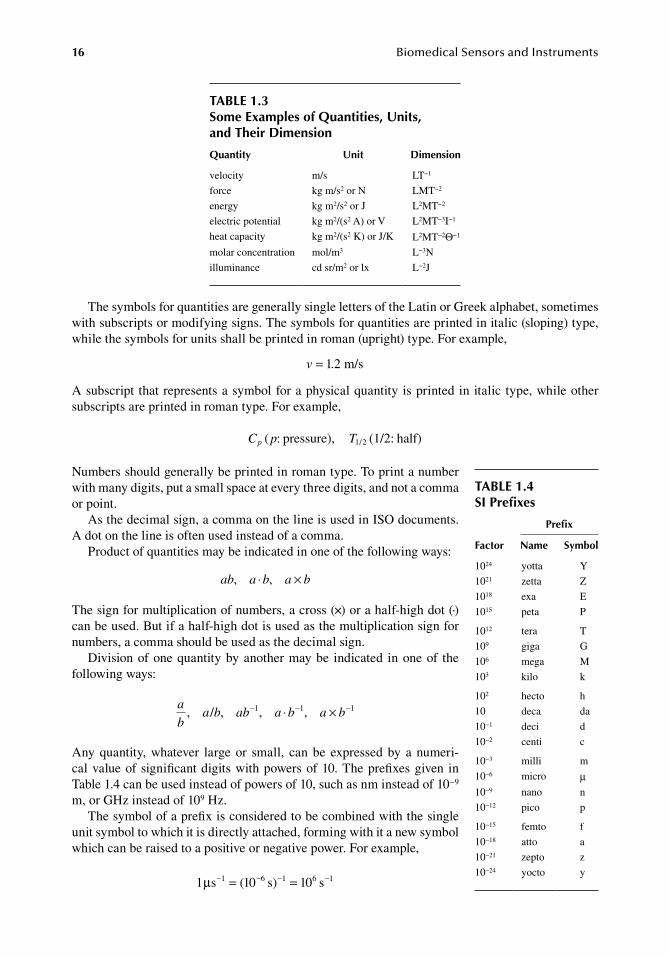
16 BiomedicalSensorsandInstruments
The.symbols.for.quantities.are.generally.single.letters.of.the.Latin.or.Greek.alphabet,.sometimes.with.subscripts.or.modifying.signs..The.symbols.for.quantities.are.printed.in.italic.(sloping).type,.while.the.symbols.for.units.shall.be.printed.in.roman.(upright).type..For.example,
. v = 1 2 m/s.
A.subscript. that.represents.a.symbol.for.a.physical.quantity. is.printed.in.italic. type,.while.other.subscripts.are.printed.in.roman.type..For.example,
C p Tp ( /: pressure), (1/2: half)1 2
Numbers.should.generally.be.printed.in.roman.type..To.print.a.number.with.many.digits,.put.a.small.space.at.every.three.digits,.and.not.a.comma.or.point.
As.the.decimal.sign,.a.comma.on.the.line.is.used.in.ISO.documents..A dot.on.the.line.is.often.used.instead.of.a.comma.
Product.of.quantities.may.be.indicated.in.one.of.the.following.ways:
ab a b a b, ,⋅ ×
The.sign.for.multiplication.of.numbers,.a.cross.(×).or.a.half-high.dot.(·).can.be.used..But.if.a.half-high.dot.is.used.as.the.multiplication.sign.for.numbers,.a.comma.should.be.used.as.the.decimal.sign.
Division.of.one.quantity.by.another.may.be. indicated. in.one.of. the.following.ways:
a
ba b ab a b a b, , ,/ , 1− ⋅ ×1 1− −
Any.quantity,.whatever. large.or. small,. can.be. expressed.by. a.numeri-cal.value.of.significant.digits.with.powers.of.10..The.prefixes.given. in.Table 1.4.can.be.used.instead.of.powers.of.10,.such.as.nm.instead.of.10−9.m,.or.GHz.instead.of.109.Hz.
The.symbol.of.a.prefix.is.considered.to.be.combined.with.the.single.unit.symbol.to.which.it.is.directly.attached,.forming.with.it.a.new.symbol.which.can.be.raised.to.a.positive.or.negative.power..For.example,
1 s 1 s 1 s1 6 1 6 1µ − − − −= =( )0 0
table 1.3Some examples of Quantities, units, and their dimension
Quantity unit dimension
velocity m/s LT−1
force kg.m/s2.or.N LMT−2
energy kg.m2/s2.or.J L2MT−2
electric.potential kg.m2/(s2.A).or.V L2MT−3I−1
heat.capacity kg.m2/(s2.K).or.J/K L2MT−2Θ−1
molar.concentration mol/m3 L−3N
illuminance cd.sr/m2.or.lx L−2J
table 1.4Si Prefixes
factor
Prefix
name Symbol
1024 yotta Y
1021 zetta Z
1018 exa E
1015 peta P
1012 tera T
109 giga G
106 mega M
103 kilo k
102 hecto h
10 deca da
10−1 deci d
10−2 centi c
10−3 milli m
10−6 micro μ10−9 nano n
10−12 pico p
10−15 femto f
10−18 atto a
10−21 zepto z
10−24 yocto y
FundamentalConcepts 17
Symbols.for.chemical.elements.shall.be.written.in.roman.(upright).type..The.nucleon.number.(mass.number).of.a.nuclide.is.shown.in.the.left.superscript.position,.for.example,.14N..The.number.of.atoms.of.a.nuclide.in.a.molecule.is.shown.in.the.right.subscript.position,.for.example,.14N2..The.proton.number.(atomic.number).may.be.indicated.in.the.left.subscript.position,.for.example,.64Gd..A.state.of.ionization.may.be.indicated.in.the.right.superscript.position,.for.example,.Na+,.PO4
3−.
1.4.2 non-si units
There.are.certain.units.which.are.outside.the.SI.but.the.ISO International Committee for Weights and Measurements.has.recognized.them.to.be.retained.because.of.their.practical.importance..These.are.as.follows:.For.time,.minute.(min,.1.min.=.60.s),.hour.(h,.1.h.=.60.min),.and.day.(d,.1.d.=.24.h),.for.plane.angle,.degree.(°,.1°.=.(π/180).rad),.minute.(′,.1′.=.(1/60)°),.and.second.(″,.1″.=.(1/60)′),.for.volume,.liter.(l.or.L,.1.l.=.1.dm3),.for.mass,.tonne.(t,.1.t.=.103.kg).and.unified.atomic.mass.unit.(u,.1.u.≈.1.660.540.×.10−27.kg),.for.energy,.electron.volt.(eV,.1.eV.≈.1.602.177.×.10−19.J).
Many.units.outside.the.SI.have.been.used.traditionally.in.many.documents.and.papers.in.dif-ferent.fields..In.medicine,.for.example,.mmHg.and.cmH2O.are.still.commonly.used.for.pressure.instead.of.Pa,.and.cal.for.metabolic.energy.instead.of.J..Because.immediate.conversion.into.SI.units.will.cause.great.inconvenience,.it.may.be.recommended.to.show.values.in.SI.and.traditional.unit,.such.as.16.kPa.(≈120.mmHg),.or.simply.16.kPa.(120.mmHg).when.it.is.obvious.that.the.converted.value.is.an.approximation..In.this.book,.this.simple.style.is.employed.
referenCeS
Doebelin,.D..O..1990..Measurement Systems: Application and Design,.4th.edn..New.York:.McGraw-Hill.International.Standard.ISO.1000..1992..SI Units and Recommendations for the Use of Their Multiples and of
Certain Other Units..Geneva,.Switzerland:.ISO.International.Standard.ISO.31..1992..Quantities and Units..Geneva,.Switzerland:.ISO.ISO Standard Handbook 2, Units of Measurement..1982..Geneva,.Switzerland:.International.Organization.for.
Standardization.Morrison,.R..1991..Noise and Other Interfering Signals..New.York:.John.Wiley.&.Sons.Musha,.T.,.Takeuchi,.H.,.and.Inoue,.T..1983..1/f.fluctuations.in.the.spontaneous.spike.discharge.intervals.of.a.
giant.snail.neuron,.IEEE Trans. Biomed. Eng..30:.194–197.Ödman,. S.. 1982.. On. biomedical. electrode. technology. with. special. reference. to. long-term. properties. and.
movement-induced. noise. in. surface. electrodes.. PhD. dissertation.. Linköping,. Sweden:. Linköping.University.
Pallas-Areny,.R..and.Webster,.J..G..1991..Sensors and Signal Conditioning..New.York:.John.Willey.&.Sons.Sydenham,.P..1999..Handbook of Measurement Science..New.York:.Wiley.Tam,. H..W.. and.Webster,. J.. G.. 1977.. Minimizing. electrode. motion. artifact. by. skin. abrasion,. IEEE Trans.
Biomed. Eng..24:.134–139.van.der.Ziel,.A..1976..Noise in Measurements..New.York:.John.Wiley.&.Sons.

19
2 PressureMeasurements
2.1 objeCt QuantitieS
2.1.1 units of pressure
Pressure.is.defined.as.the.force.exerted.per.unit.area..In.the.SI.system,.the.unit.of.pressure.is.Pa.(pascal),.which,.by.definition,.is.equal.to.1.newton.per.square.meter..N/m2.is.also.an.accepted.unit.of.pressure.
Physiological.pressures.have.usually.been.expressed.in.millimeters.of.mercury.(mmHg).or.cen-timeters.of.water.(cmH2O)..These.units.will.be.replaced.by.the.SI.unit.pascal.
Because.the.pascal,.Pa,.is.too.small.to.use.for.physiological.pressures,.kPa.(=.103.Pa).is.generally.used..The.conversions.from.mmHg.and.cmH2O.to.kPa.are
1.mmHg.=.133.322.Pa.=.0.133.322.kPa1.cmH2O.=.98.0665.Pa.=.0.098.0665.kPa
Physiological.pressures.are.normally.measured.and.expressed.relative.to.the.atmospheric.pres-sure..Since.the.pressure.is.measured.as.a.differential.pressure.in.relation.to.the.atmosphere,.it.is.normally.unnecessary.to.specify.the.absolute.atmospheric.pressure..However,.when.the.pressure.in.the.body.is.measured.by.an.indwelling.sensor.that.measures.absolute.pressure,.the.physiological.pressure.has.to.be.determined.by.substituting.atmospheric.pressure.from.the.obtained.absolute.pres-sure..In.such.cases,.a.change.in.atmospheric.pressure.can.cause.significant.errors.unless.the.pressure.being.measured.is.properly.corrected.by.means.of.the.actual.atmospheric.pressure.
Atmospheric.pressure.under.standard.conditions.is.1.atm,.and.is.defined.as
1.atm.=.101.325.kPa
Atmospheric.pressure.variation.can.be.measured.by.a.barometer..The.unit.bar.has.been.used.in.the.barometer,.and.the.conversion.to.Pa.is
1.bar.=.105.Pa
Another.unit.of.pressure.which.is.widely.used.in.engineering.fields.is.kgf/cm2,.and.the.conver-sion.to.Pa.is
1.kgf/cm2.=.98.0665.kPa
Torr.is.sometimes.used.and.is.equivalent.to.mmHg.
2.1.2 requireMents for pressure MeasureMent
2.1.2.1 Physiological Pressure ranges and Measurement SitesPressures.in.the.human.body.are.measured.as.a.part.of.clinical.examinations.and.for.physiological.studies..Figure.2.1.shows.the.ranges.of.pressure.in.normal.and.abnormal.situations.
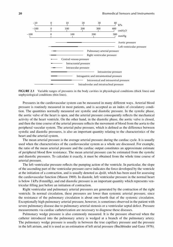
20 BiomedicalSensorsandInstruments
Pressures.in.the.cardiovascular.system.can.be.measured.in.many.different.ways..Arterial.blood.pressure.is.routinely.measured.in.most.patients,.and.is.accepted.as.an.index.of.circulatory.condi-tion..The.quantities.normally.measured.are.systolic.and.diastolic.pressure..In. the.systolic.phase,.the.aortic.valve.of.the.heart.is.open,.and.the.arterial.pressure.consequently.reflects.the.mechanical.activity.of.the.heart.ventricle..On.the.other.hand,.in.the.diastolic.phase,.the.aortic.valve.is.closed,.and.then.the.time.course.of.the.arterial.pressure.reflects.the.movement.of.blood.from.the.aorta.to.the.peripheral.vascular.system..The.arterial.pulse.pressure,.which.is.defined.as.the.difference.between.systolic.and.diastolic.pressures,.is.also.an.important.quantity.relating.to.the.characteristics.of.the.heart.and.the.arterial.system.
The.mean.arterial.pressure.is.the.average.arterial.pressure.during.the.cardiac.cycle..It.is.usually.used.when.the.characteristics.of.the.cardiovascular.system.as.a.whole.are.discussed..For.example,.the.ratio.of.the.mean.arterial.pressure.and.the.cardiac.output.constitutes.an.approximate.estimate.of.peripheral.blood.flow.resistance..The.mean.arterial.pressure.can.be.estimated.from.the.systolic.and.diastolic.pressures..To.calculate.it.exactly,.it.must.be.obtained.from.the.whole.time.course.of.arterial.pressure.
The.left.ventricular.pressure.reflects.the.pumping.action.of.the.ventricle..In.particular,.the.slope.of.the.ascending.part.of.the.ventricular.pressure.curve.indicates.the.force.developed.by.the.ventricle.at.the.initiation.of.a.contraction,.and.is.usually.denoted.as.dp/dt,.which.has.been.used.for.assessing.the.cardiovascular.function.(Mason.1969)..In.diastole,.left.ventricular.pressure.in.the.normal.heart.is.below.1.kPa.(8.mmHg),.and.end.diastolic.pressure.is.an.important.quantity.which.represents.ven-tricular.filling.just.before.an.initiation.of.contraction.
Right.ventricular.and.pulmonary.arterial.pressures.are.generated.by.the.contraction.of.the.right.ventricle.. In.normal. circulation,. these.pressures. are. lower. than. systemic. arterial. pressure,. since.the. resistance. of. the. pulmonary. circulation. is. about. one-fourth. that. of. the. systemic. circulation..Exceptionally.high.pulmonary.arterial.pressure,.however,.is.sometimes.observed.in.the.patient.with.severe.pulmonary.disease.due.to.pulmonary.arterial.stenosis.or.a.ventricular.septal.defect..Pressure.measurements.via.cardiac.catheterization.are.necessary.to.diagnose.these.diseases.
Pulmonary.wedge.pressure.is.also.commonly.measured..It. is. the.pressure.observed.when.the.catheter. introduced. into. the. pulmonary. artery. is. wedged. at. a. branch. of. the. pulmonary. artery..The pulmonary.wedge.pressure.is.usually.in.between.the.true.capillary.pressure.and.the.pressure.in.the.left.atrium,.and.it.is.used.as.an.estimation.of.left.atrial.pressure.(Buchbinder.and.Ganz.1976).
–10 0 10 20 30 40kPa
–100 0 100 200 300 400
3002001000–100cmH2O
mmHg
Aortic pressureLeft ventricular pressure
Pulmonary arterial pressureRight ventricular pressure
Central venous pressureIntracranial pressureIntraocular pressure
Intrauterine pressureIntragastric and intraintestinal pressure
Intravesical and intrauretral pressureIntraalveolar and intratracheal pressure
figure 2.1 Variable.ranges.of.pressures.in.the.body.cavities.in.physiological.conditions.(thick.lines).and.unphysiological.conditions.(thin.lines).
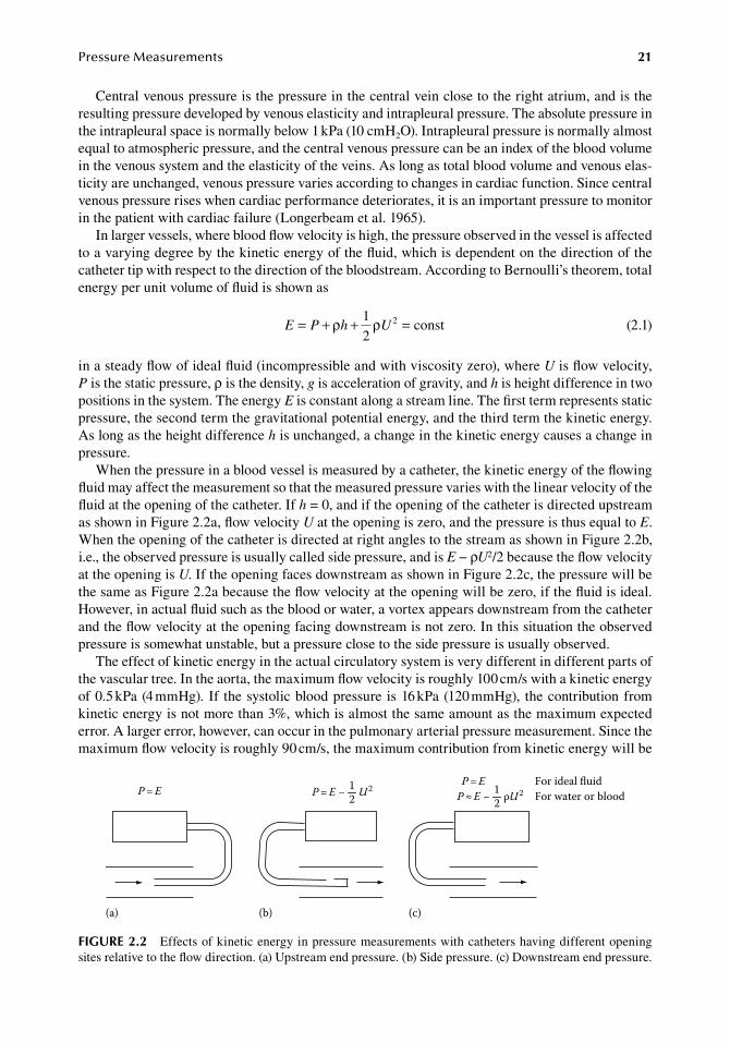
PressureMeasurements 21
Central.venous.pressure.is.the.pressure.in.the.central.vein.close.to.the.right.atrium,.and.is.the.resulting.pressure.developed.by.venous.elasticity.and.intrapleural.pressure..The.absolute.pressure.in.the.intrapleural.space.is.normally.below.1.kPa.(10.cmH2O)..Intrapleural.pressure.is.normally.almost.equal.to.atmospheric.pressure,.and.the.central.venous.pressure.can.be.an.index.of.the.blood.volume.in.the.venous.system.and.the.elasticity.of.the.veins..As.long.as.total.blood.volume.and.venous.elas-ticity.are.unchanged,.venous.pressure.varies.according.to.changes.in.cardiac.function..Since.central.venous.pressure.rises.when.cardiac.performance.deteriorates,.it.is.an.important.pressure.to.monitor.in.the.patient.with.cardiac.failure.(Longerbeam.et al..1965).
In.larger.vessels,.where.blood.flow.velocity.is.high,.the.pressure.observed.in.the.vessel.is.affected.to.a.varying.degree.by.the.kinetic.energy.of.the.fluid,.which.is.dependent.on.the.direction.of.the.catheter.tip.with.respect.to.the.direction.of.the.bloodstream..According.to.Bernoulli’s.theorem,.total.energy.per.unit.volume.of.fluid.is.shown.as
.E P h U= + + =ρ ρ1
2const2
.(2.1)
in.a.steady.flow.of.ideal.fluid.(incompressible.and.with.viscosity.zero),.where.U.is.flow.velocity,.P.is.the.static.pressure,.ρ.is.the.density,.g.is.acceleration.of.gravity,.and.h.is.height.difference.in.two.positions.in.the.system..The.energy.E.is.constant.along.a.stream.line..The.first.term.represents.static.pressure,.the.second.term.the.gravitational.potential.energy,.and.the.third.term.the.kinetic.energy..As.long.as.the.height.difference.h.is.unchanged,.a.change.in.the.kinetic.energy.causes.a.change.in.pressure.
When.the.pressure.in.a.blood.vessel.is.measured.by.a.catheter,.the.kinetic.energy.of.the.flowing.fluid.may.affect.the.measurement.so.that.the.measured.pressure.varies.with.the.linear.velocity.of.the.fluid.at.the.opening.of.the.catheter..If.h.=.0,.and.if.the.opening.of.the.catheter.is.directed.upstream.as.shown.in.Figure.2.2a,.flow.velocity.U.at.the.opening.is.zero,.and.the.pressure.is.thus.equal.to.E..When.the.opening.of.the.catheter.is.directed.at.right.angles.to.the.stream.as.shown.in.Figure.2.2b,.i.e.,.the.observed.pressure.is.usually.called.side.pressure,.and.is.E.−.ρU2/2.because.the.flow.velocity.at.the.opening.is.U..If.the.opening.faces.downstream.as.shown.in.Figure.2.2c,.the.pressure.will.be.the.same.as.Figure.2.2a.because.the.flow.velocity.at.the.opening.will.be.zero,.if.the.fluid.is.ideal..However,.in.actual.fluid.such.as.the.blood.or.water,.a.vortex.appears.downstream.from.the.catheter.and.the.flow.velocity.at.the.opening.facing.downstream.is.not.zero..In.this.situation.the.observed.pressure.is.somewhat.unstable,.but.a.pressure.close.to.the.side.pressure.is.usually.observed.
The.effect.of.kinetic.energy.in.the.actual.circulatory.system.is.very.different.in.different.parts.of.the.vascular.tree..In.the.aorta,.the.maximum.flow.velocity.is.roughly.100.cm/s.with.a.kinetic.energy.of.0.5.kPa.(4.mmHg)..If. the.systolic.blood.pressure. is.16.kPa.(120.mmHg),. the.contribution.from.kinetic.energy.is.not.more.than.3%,.which.is.almost.the.same.amount.as.the.maximum.expected.error..A.larger.error,.however,.can.occur.in.the.pulmonary.arterial.pressure.measurement..Since.the.maximum.flow.velocity.is.roughly.90.cm/s,.the.maximum.contribution.from.kinetic.energy.will.be.
P ≈ E − ρU212
P = E − U212
P = EP = E For ideal fluid
For water or blood
(a) (b) (c)
figure 2.2 Effects.of.kinetic.energy.in.pressure.measurements.with.catheters.having.different.opening.sites.relative.to.the.flow.direction..(a).Upstream.end.pressure..(b).Side.pressure..(c).Downstream.end.pressure.
22 BiomedicalSensorsandInstruments
0.4.kPa.(3.mmHg)..The.pulmonary.arterial.pressure.is.approximately.2.7.kPa.(20.mmHg),.and.the.contribution.from.kinetic.energy.can.consequently.be.about.15%.of.the.total.pressure..If.the.blood.flow.increases,.kinetic.energy.increases.in.proportion.to.the.square.of.the.blood.velocity,.and.the.error.will.increase..In.the.clinical.situation,.however,.the.catheter.introduced.into.the.right.atrium.and.pulmonary.artery. is. facing.downstream,.and. the.observed.pressure. is. thus.considered. to.be.close.to.the.side.pressure..In.a.central.vein,.the.blood.velocity.is.normally.30.cm/s.or.less,.and.the.contribution.of.kinetic.energy.is.not.more.than.0.05.kPa.(0.35.mmHg).(Burton.1965).
In.addition. to. the.cardiovascular.system,. there.are.many.cavities,.conduits,.and.spaces. in. the.human.body.where.pressure.is.measured..Intracranial.pressure.is.considered.as.the.pressure.in.the.intracranial.space,.and.it.is.usually.measured.as.the.pressure.in.the.cerebrospinal.space,.ventricles.of.the.brain,.or.intradural.or.extradural.spaces..These.pressures.are.below.1.kPa.(8.mmHg).in.nor-mal.subjects.and.are.sometimes.elevated.in.the.patient.with.a.brain.tumor,.edema,.or.hemorrhage..Continuous.monitoring.of.intracranial.pressure.is.consequently.recommended.for.patients.in.whom.such.a.condition.is.suspected.
The.intraocular.pressure.is.the.inner.pressure.of.the.eye.ball,.and.it.is.usually.measured.indirectly.at. the.corneal. surface.. In. the.normal.subject,. intraocular.pressure. is. in. the. range.of.1.3–2.6.kPa.(10–20.mmHg),.and.in.a.patient.with.glaucoma.it.is.elevated.above.3.3.kPa.(25.mmHg).
The.intra-uterine.pressure.is.the.pressure.of.the.amniotic.fluid.in.the.amniotic.cavity..It.is.con-sidered.as.the.sum.of.pressures.developed.by.the.uterine.contraction.and.intraperitoneal.pressure..The.elevation.of.the.pressure.caused.by.the.uterine.contraction.is.about.5–11.kPa.(40–80.mmHg).
The.intragastric.and.intraintestinal.pressures.are.measured.in.the.alimentary.canal..These.pres-sures.are.considered.as.the.sum.of.the.pressures.developed.by.the.peristaltic.motions.of.the.stomach.or. intestine. and. the. pressure. in. the. peritoneal. cavity.. The. maximum. pressure. developed. by. the.motion.of.the.gastric.organs.is.about.4.kPa.(30.mmHg).
The.urinary.bladder.pressure. is.caused.by. the.fluid.pressure. in. the.bladder.. It. is.measured. to.examine.urinary.reflex.and.contraction.of.the.urinary.bladder..The.urinary.reflex.occurs.at.about.5.kPa.(50.cmH2O).and.the.urinary.bladder.pressure.increases.to.10–15.kPa.(100–150.cmH2O).dur-ing.micturition..The.urethra.is.always.closed.by.the.sphincter.urethrae,.except.during.micturition,.and.the.pressure.required.to.introduce.fluid.into.the.urethra.is.measured.to.examine.the.strength.of.contraction.of.the.sphincter.urethrae.
Intrapleural.pressure.and.intratracheal.pressure.are.measured.to.estimate.lung.compliance,.air-way.resistance,.and.the.mechanical.activity.of.ventilation..Intrapleural.pressure.is.difficult.to.define.as.a.fluid.pressure.because.there.is.no.appreciable.amount.of.fluid.in.the.intrapleural.space..Thus.intrapleural.pressure. is.usually.determined.by.balloon.pressure.when.a.balloon. is.placed. in. the.esophagus.. Mouth.pressure. is. sometimes. substituted. for. intratracheal. pressure..The.variation. in.intrapleural.pressure.is.always.below.0.5.kPa.(5.cmH2O).in.normal.respiration.and.can.be.varied.from.−10.to.+15.kPa.(−100.to.+150.cmH2O).during.maximum.voluntary.ventilation.
2.1.2.2 reference Point for Pressure MeasurementMost.physiological.pressure.measurements.are.performed.in.order.to.study.physiological.functions.such.as.heart.and.muscle.activity..An.observed.pressure,.however,.is.composed.not.only.of.the.pres-sure.produced.by.organ.and.tissue.activity.but.also.the.pressure.generated.by.gravitational.force.and.atmospheric.pressure..Thus,. it. is.sometimes.necessary. to.differentiate. the.physiological.pressure.component.from.the.components.of.gravitational.and.atmospheric.origin.
Atmospheric. pressure. is. applied. uniformly. to. the. human. body.. Thus. the. sensor. which. mea-sures.pressure.relative.to.the.atmosphere.is.not.affected.by.a.change.in.the.atmospheric.pressure..However,.when.a.sensor.which.measures.absolute.pressures.is.used,.variations.in.atmospheric.pres-sure.should.be.considered..In.such.cases,.it.is.necessary.either.to.calibrate.frequently.in.atmospheric.pressure,.or.to.make.corrections.in.atmospheric.pressure.as.measured.by.another.sensor.
The.effect.of.gravitational.force.is.somewhat.complicated..The.circulatory.system.can.be.depicted.schematically.as.in.Figure.2.3..If.the.pressure.drop.due.to.flow.resistance.and.kinetic.energy.are.
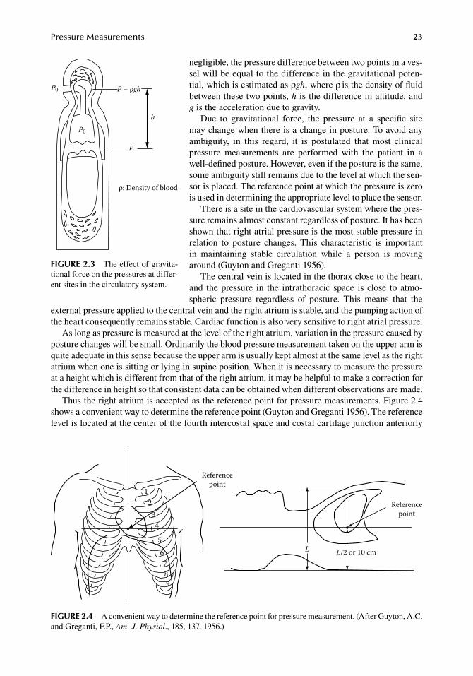
PressureMeasurements 23
negligible,.the.pressure.difference.between.two.points.in.a.ves-sel.will.be.equal.to.the.difference.in.the.gravitational.poten-tial,.which.is.estimated.as.ρgh,.where.ρ. is.the.density.of.fluid.between.these.two.points,.h.is.the.difference.in.altitude,.and.g is.the.acceleration.due.to.gravity.
Due. to. gravitational. force,. the. pressure. at. a. specific. site.may.change.when.there.is.a.change.in.posture..To.avoid.any.ambiguity,. in. this. regard,. it. is. postulated. that. most. clinical.pressure. measurements. are. performed. with. the. patient. in. a.well-defined.posture..However,.even.if.the.posture.is.the.same,.some.ambiguity.still.remains.due.to.the.level.at.which.the.sen-sor.is.placed..The.reference.point.at.which.the.pressure.is.zero.is.used.in.determining.the.appropriate.level.to.place.the.sensor.
There.is.a.site.in.the.cardiovascular.system.where.the.pres-sure.remains.almost.constant.regardless.of.posture..It.has.been.shown.that.right.atrial.pressure.is.the.most.stable.pressure.in.relation. to. posture. changes.. This. characteristic. is. important.in. maintaining. stable. circulation. while. a. person. is. moving.around.(Guyton.and.Greganti.1956).
The.central.vein.is.located.in.the.thorax.close.to.the.heart,.and. the.pressure. in. the. intrathoracic. space. is.close. to.atmo-spheric. pressure. regardless. of. posture.. This. means. that. the.
external.pressure.applied.to.the.central.vein.and.the.right.atrium.is.stable,.and.the.pumping.action.of.the.heart.consequently.remains.stable..Cardiac.function.is.also.very.sensitive.to.right.atrial.pressure.
As.long.as.pressure.is.measured.at.the.level.of.the.right.atrium,.variation.in.the.pressure.caused.by.posture.changes.will.be.small..Ordinarily.the.blood.pressure.measurement.taken.on.the.upper.arm.is.quite.adequate.in.this.sense.because.the.upper.arm.is.usually.kept.almost.at.the.same.level.as.the.right.atrium.when.one.is.sitting.or.lying.in.supine.position..When.it.is.necessary.to.measure.the.pressure.at.a.height.which.is.different.from.that.of.the.right.atrium,.it.may.be.helpful.to.make.a.correction.for.the.difference.in.height.so.that.consistent.data.can.be.obtained.when.different.observations.are.made.
Thus.the.right.atrium.is.accepted.as.the.reference.point.for.pressure.measurements..Figure.2.4.shows.a.convenient.way.to.determine.the.reference.point.(Guyton.and.Greganti.1956)..The.reference.level.is.located.at.the.center.of.the.fourth.intercostal.space.and.costal.cartilage.junction.anteriorly.
h
P0
P
ρ: Density of blood
P – ρgh
P0
figure 2.3 The.effect.of.gravita-tional.force.on.the.pressures.at.differ-ent.sites.in.the.circulatory.system.
12
34
56789
L
Referencepoint
Referencepoint
L/2 or 10 cm
figure 2.4 A.convenient.way.to.determine.the.reference.point.for.pressure.measurement..(After.Guyton,.A.C..and.Greganti,.F.P.,.Am. J. Physiol.,.185,.137,.1956.)
24 BiomedicalSensorsandInstruments
and.about.10.cm.from.the.back,.or.half.of.the.antero-posterior.diameter.of.the.chest.on.longitudinal.axis..The.anterior.chest.wall.to.mid-left.atrium.distance.assessed.by.echocardiography.is.also.con-sidered.an.accurate.determination.of.the.reference.level.(Chandraratna.1975).
When.a.fluid-filled.catheter.is.used.to.transmit.internal.pressure.in.the.body.to.an.external.sensor,.the.pressure.at.the.tip.of.the.catheter.can.be.measured.by.placing.the.sensor.at.the.same.level.as.the.tip..Practically,.it.is.more.convenient.to.place.the.sensor.at.the.reference.level.so.that.the.pressure.at.the.reference.level.can.be.measured.regardless.of.the.exact.level.of.the.tip.of.the.catheter.
However,.this.is.not.precisely.accurate,.since.the.densities.of.the.fluid.in.the.catheter.(for.saline,.the.density.is.about.1.009.g/cm3).and.in.the.conduit.between.the.measuring.site.and.the.reference.point.(for.blood,.the.density.is.about.1.055.g/cm3).are.usually.different,.so.that.the.contribution.of.gravity.to.the.pressure,.ρgh,.is.not.the.same.
For.central.venous.pressure.monitoring.in.patients.whose.body.movements.are.not.restricted,.it.is.difficult.to.keep.the.sensor.at.the.level.of.the.reference.point..To.compensate.for.the.shift.of.the.refer-ence.point,.a.differential.pressure.measurement.has.been.proposed.in.which.an.additional.catheter.filled.with.water.is.attached.to.the.patient.so.that.the.meniscus.in.the.catheter.is.close.enough.to.the.reference.point.and.so.the.difference.in.the.pressures.of.the.venous.and.reference.catheters.gives.the.true.venous.pressure.(Blackburn.1968,.Corbett.et al..1974).
2.2 direCt PreSSure MeaSureMent
2.2.1 catheters and the diaphragM-type pressure sensor
In.order.to.measure.a.pressure.inside.the.body.cavity.directly,.a.catheter.filled.with.saline.with.a.pressure.sensor.connected. to. it. is.commonly.used..According. to.Pascal’s.principle,. the.pressure.change.at.the.tip.of.the.catheter.inside.the.body.can.be.transmitted.to.the.sensor.outside.the.body.
2.2.1.1 Catheters for Pressure MeasurementsCatheters.and.needles.of.different.sizes.can.be.used.for.pressure.measurements..A.typical.setup.for.cardiovascular.pressure.measurement.is.a.flexible.plastic.catheter.with.a.luer-lock.connector.at.the.proximal.end,.so.that.it.can.be.connected.to.a.stop.cock.or.to.other.instruments..The.size.of.the.catheter.is.sometimes.denoted.in.French.scale.(Fr.or.F,.each.unit.being.equivalent.to.0.33.mm.in.outer.diameter).
Catheters.are.available.in.different.designs..Some.have.openings.only.at.the.tip,.and.some.have.an.open.or.closed.tip.with.one.or.many.side.holes,.and.others.have.a.double.lumen.with.one.opening.at.the.tip.and.the.other.at.some.distance.from.the.tip..A.catheter.with.a.balloon.near.the.tip.is.used.for.pulmonary.arterial.measurement..The.balloon.is.carried.forward.naturally.by.the.bloodstream,.and.this.makes.it.possible.to.place.the.catheter.in.the.pulmonary.arteries.(Swan.et al..1970).
X-ray.monitoring.is.sometimes.necessary.during.catheter.insertion..In.such.cases,.the.catheter.should.be.X-ray.opaque.
When.the.catheter.is.placed.in.a.blood.vessel,.care.should.be.taken.to.prevent.blood.coagula-tion,.which.not.only.disturbs.pressure.measurement.but.can.also.cause.serious.thromboembolism..Although. catheters. used. for. these. purposes. are. specially. made,. no. material. is. completely. anti-coagulant..Thus.a.slow.infusion.of.an.anticoagulant.agent.in.saline.is.recommended.for.long-term.measurements..Typically,.saline.containing.about.2000.units.of.heparin.per.liter.can.be.continu-ously.infused.at.a.rate.of.about.3–6.mL/h.
2.2.1.2 diaphragm displacement SensorMost.pressure.sensors.for.direct.pressure.measurements.have.an.elastic.diaphragm,.and.its.displace-ment.or.strain.is.detected.by.a.sensing.element.such.as.the.strain.gauge.or.a.variable.capacitance.
Although.the.amount.of.deformation.of.the.diaphragm.due.to.the.applied.pressure.is.nonlinear,.it.can.be.regarded.as.linear.when.the.diaphragm.is.thin.and.the.deformation.is.small.compared.with.
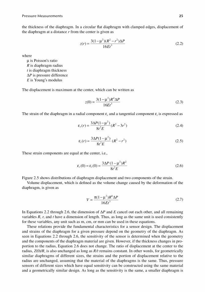
PressureMeasurements 25
the.thickness.of.the.diaphragm..In.a.circular.flat.diaphragm.with.clamped.edges,.displacement.of.the.diaphragm.at.a.distance.r.from.the.center.is.given.as
.z r
R r P
Et( )
3(1 )( )16
2 2 2
3= − −µ ∆.
(2.2)
whereμ.is.Poisson’s.ratioR.is.diaphragm.radiust.is.diaphragm.thicknessΔP.is.pressure.differenceE.is.Young’s.modulus
The.displacement.is.maximum.at.the.center,.which.can.be.written.as
.z
R P
Et(0)
3(116
2 4
3= − )µ ∆.
(2.3)
The.strain.of.the.diaphragm.in.a.radial.component.εr.and.a.tangential.component.εt.is.expressed.as
.ε ∆ µ
r rP
t ER r( )
3 (1 )8
( 3 )2
22 2= − −
.(2.4)
.ε ∆ µ
t rP
t ER r( )
3 (1 )8
( )2
22 2= − −
.(2.5)
These.strain.components.are.equal.at.the.center,.i.e.,
.ε ε ∆ µ
r tP R
t E(0) (0)
3 (1 )8
2 2
2= = −.
(2.6)
Figure.2.5.shows.distributions.of.diaphragm.displacement.and.two.components.of.the.strain.Volume.displacement,.which.is.defined.as.the.volume.change.caused.by.the.deformation.of.the.
diaphragm,.is.given.as
.V
R P
Et= −π µ ∆(1 )
16
2 6
3.
(2.7)
In.Equations.2.2.through.2.6,.the.dimension.of.ΔP.and.E.cancel.out.each.other,.and.all.remaining.variables.R,.r,.and.t.have.a.dimension.of.length..Thus,.as.long.as.the.same.unit.is.used.consistently.for.these.variables,.any.unit.such.as.m,.cm,.or.mm.can.be.used.in.these.equations.
These.relations.provide.the.fundamental.characteristics.for.a.sensor.design..The.displacement.and.strains.of.the.diaphragm.for.a.given.pressure.depend.on.the.geometry.of.the.diaphragm..As.seen.in.Equations.2.2.through.2.6,.the.sensitivity.of.the.sensor.is.determined.when.the.geometry.and.the.components.of.the.diaphragm.material.are.given..However,.if.the.thickness.changes.in.pro-portion.to.the.radius,.Equation.2.6.does.not.change..The.ratio.of.displacement.at.the.center.to.the.radius,.Z(0)/R,.is.also.unchanged.as.long.as.R/t.remains.constant..In.other.words,.for.geometrically.similar.diaphragms.of.different. sizes,. the.strains.and. the.portion.of.displacement. relative. to. the.radius.are.unchanged,.assuming.that.the.material.of.the.diaphragms.is.the.same..Thus,.pressure.sensors.of.different.sizes.which.have.equal.sensitivity.can.be.constructed.using.the.same.material.and.a.geometrically.similar.design..As.long.as.the.sensitivity.is.the.same,.a.smaller.diaphragm.is.
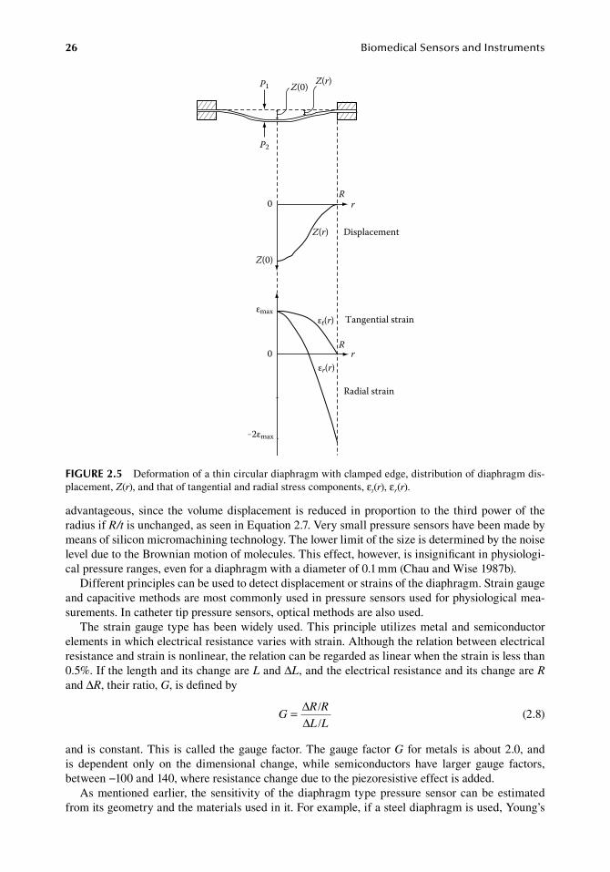
26 BiomedicalSensorsandInstruments
advantageous,. since. the.volume.displacement. is. reduced. in.proportion. to. the. third.power.of. the.radius.if.R/t.is.unchanged,.as.seen.in.Equation.2.7..Very.small.pressure.sensors.have.been.made.by.means.of.silicon.micromachining.technology..The.lower.limit.of.the.size.is.determined.by.the.noise.level.due.to.the.Brownian.motion.of.molecules..This.effect,.however,.is.insignificant.in.physiologi-cal.pressure.ranges,.even.for.a.diaphragm.with.a.diameter.of.0.1.mm.(Chau.and.Wise.1987b).
Different.principles.can.be.used.to.detect.displacement.or.strains.of.the.diaphragm..Strain.gauge.and.capacitive.methods.are.most.commonly.used.in.pressure.sensors.used.for.physiological.mea-surements..In.catheter.tip.pressure.sensors,.optical.methods.are.also.used.
The.strain.gauge.type.has.been.widely.used..This.principle.utilizes.metal.and.semiconductor.elements.in.which.electrical.resistance.varies.with.strain..Although.the.relation.between.electrical.resistance.and.strain.is.nonlinear,.the.relation.can.be.regarded.as.linear.when.the.strain.is.less.than.0.5%..If.the.length.and.its.change.are.L.and.ΔL,.and.the.electrical.resistance.and.its.change.are.R.and.ΔR,.their.ratio,.G,.is.defined.by
.G
R R
L L= /
/∆∆ .
(2.8)
and. is.constant..This. is.called. the.gauge.factor..The.gauge.factor.G. for.metals. is.about.2.0,.and.is. dependent. only. on. the. dimensional. change,. while. semiconductors. have. larger. gauge. factors,.between.−100.and.140,.where.resistance.change.due.to.the.piezoresistive.effect.is.added.
As.mentioned.earlier,. the.sensitivity.of. the.diaphragm. type.pressure.sensor.can.be.estimated.from.its.geometry.and.the.materials.used.in.it..For.example,.if.a.steel.diaphragm.is.used,.Young’s.
Z(0)P1
P2
Z(r)
0 r
Z(0)
Z(r) Displacement
0εr(r)
εt(r)εmax
–2εmax
Tangential strain
Radial strain
R
Rr
figure 2.5 Deformation.of.a.thin.circular.diaphragm.with.clamped.edge,.distribution.of.diaphragm.dis-placement,.Z(r),.and.that.of.tangential.and.radial.stress.components,.εt(r),.εr(r).
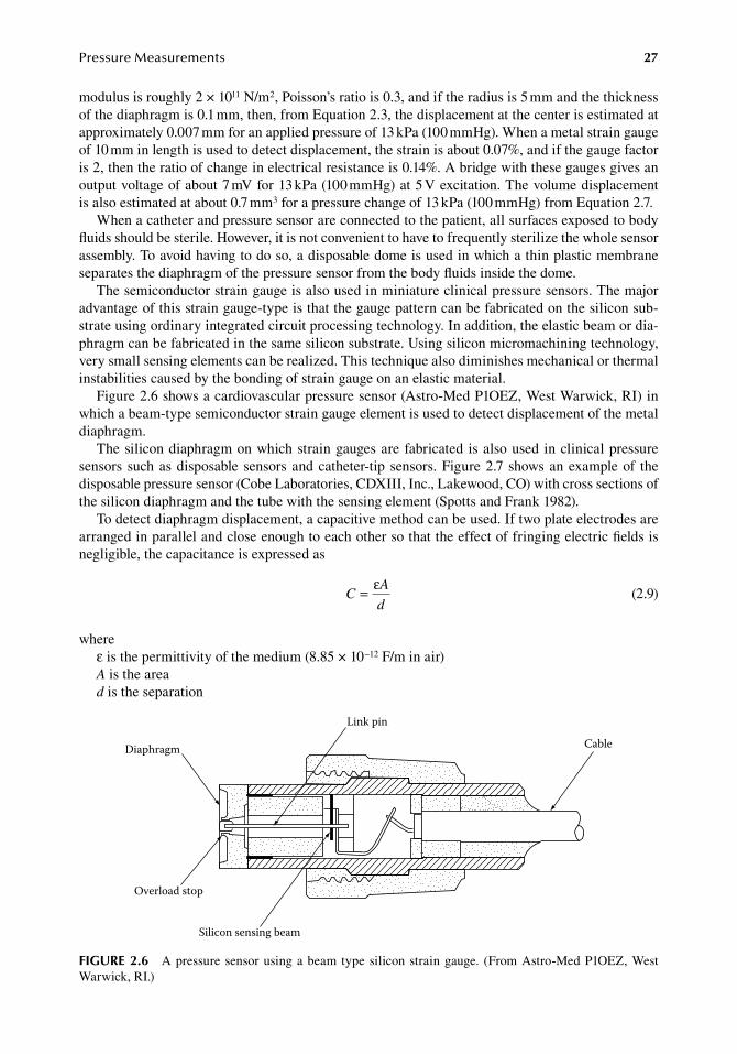
PressureMeasurements 27
modulus.is.roughly.2.×.1011.N/m2,.Poisson’s.ratio.is.0.3,.and.if.the.radius.is.5.mm.and.the.thickness.of.the.diaphragm.is.0.1.mm,.then,.from.Equation.2.3,.the.displacement.at.the.center.is.estimated.at.approximately.0.007.mm.for.an.applied.pressure.of.13.kPa.(100.mmHg)..When.a.metal.strain.gauge.of.10.mm.in.length.is.used.to.detect.displacement,.the.strain.is.about.0.07%,.and.if.the.gauge.factor.is.2,.then.the.ratio.of.change.in.electrical.resistance.is.0.14%..A.bridge.with.these.gauges.gives.an.output.voltage.of.about.7.mV.for.13.kPa.(100.mmHg).at.5.V.excitation..The.volume.displacement.is.also.estimated.at.about.0.7.mm3.for.a.pressure.change.of.13.kPa.(100.mmHg).from.Equation.2.7.
When.a.catheter.and.pressure.sensor.are.connected.to.the.patient,.all.surfaces.exposed.to.body.fluids.should.be.sterile..However,.it.is.not.convenient.to.have.to.frequently.sterilize.the.whole.sensor.assembly..To.avoid.having.to.do.so,.a.disposable.dome.is.used.in.which.a.thin.plastic.membrane.separates.the.diaphragm.of.the.pressure.sensor.from.the.body.fluids.inside.the.dome.
The.semiconductor.strain.gauge.is.also.used.in.miniature.clinical.pressure.sensors..The.major.advantage.of.this.strain.gauge-type.is.that.the.gauge.pattern.can.be.fabricated.on.the.silicon.sub-strate.using.ordinary.integrated.circuit.processing.technology..In.addition,.the.elastic.beam.or.dia-phragm.can.be.fabricated.in.the.same.silicon.substrate..Using.silicon.micromachining.technology,.very.small.sensing.elements.can.be.realized..This.technique.also.diminishes.mechanical.or.thermal.instabilities.caused.by.the.bonding.of.strain.gauge.on.an.elastic.material.
Figure.2.6.shows.a.cardiovascular.pressure.sensor.(Astro-Med.P1OEZ,.West.Warwick,.RI).in.which.a.beam-type.semiconductor.strain.gauge.element.is.used.to.detect.displacement.of.the.metal.diaphragm.
The.silicon.diaphragm.on.which.strain.gauges.are.fabricated. is.also.used. in.clinical.pressure.sensors. such.as.disposable.sensors.and.catheter-tip. sensors..Figure.2.7.shows.an.example.of. the.disposable.pressure.sensor.(Cobe.Laboratories,.CDXIII,.Inc.,.Lakewood,.CO).with.cross.sections.of.the.silicon.diaphragm.and.the.tube.with.the.sensing.element.(Spotts.and.Frank.1982).
To.detect.diaphragm.displacement,.a.capacitive.method.can.be.used..If.two.plate.electrodes.are.arranged.in.parallel.and.close.enough.to.each.other.so.that.the.effect.of.fringing.electric.fields.is.negligible,.the.capacitance.is.expressed.as
.C
A
d= ε
.(2.9)
whereε.is.the.permittivity.of.the.medium.(8.85.×.10−12.F/m.in.air)A.is.the.aread.is.the.separation
Diaphragm
Link pin
Overload stop
Silicon sensing beam
Cable
figure 2.6 A.pressure.sensor.using.a.beam. type.silicon.strain.gauge.. (From.Astro-Med.P1OEZ,.West.Warwick,.RI.)
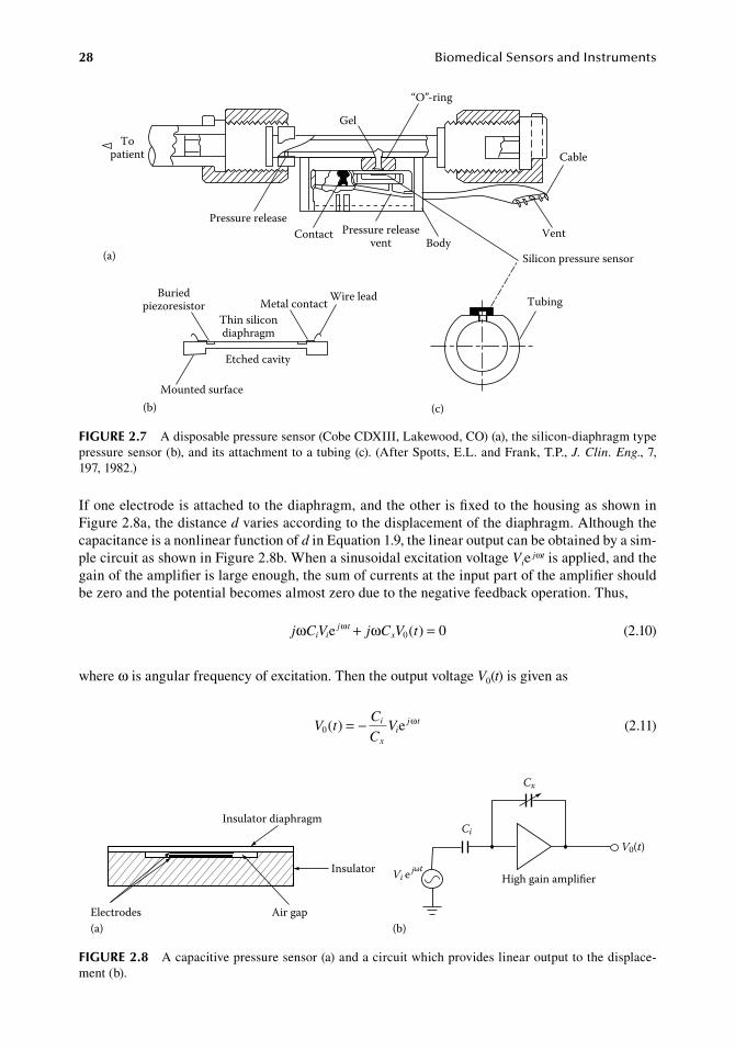
28 BiomedicalSensorsandInstruments
If.one.electrode.is.attached.to.the.diaphragm,.and.the.other.is.fixed.to.the.housing.as.shown.in.Figure.2.8a,.the.distance.d.varies.according.to.the.displacement.of.the.diaphragm..Although.the.capacitance.is.a.nonlinear.function.of.d.in.Equation.1.9,.the.linear.output.can.be.obtained.by.a.sim-ple.circuit.as.shown.in.Figure.2.8b..When.a.sinusoidal.excitation.voltage.Vie.jωt.is.applied,.and.the.gain.of.the.amplifier.is.large.enough,.the.sum.of.currents.at.the.input.part.of.the.amplifier.should.be.zero.and.the.potential.becomes.almost.zero.due.to.the.negative.feedback.operation..Thus,
. j C V j C V ti ij t
xω e ( ) 00ω ω+ = . (2.10)
where.ω.is.angular.frequency.of.excitation..Then.the.output.voltage.V0(t).is.given.as
.V t
C
CVi
xi
j t0( ) e= − ω
.(2.11)
Topatient
Pressure releaseContact Pressure release
vent Body
Gel
“O”-ring
Cable
Vent
Silicon pressure sensor
Metal contact Wire leadBuriedpiezoresistor
Thin silicondiaphragm
Etched cavity
Mounted surface
(a)
(b)
Tubing
(c)
figure 2.7 A.disposable.pressure.sensor.(Cobe.CDXIII,.Lakewood,.CO).(a),.the.silicon-diaphragm.type.pressure.sensor.(b),.and.its.attachment.to.a.tubing.(c)..(After.Spotts,.E.L..and.Frank,.T.P.,.J. Clin. Eng.,.7,.197,.1982.)
Insulator diaphragm
Insulator
Air gapElectrodes(a)
Cx
Ci
High gain amplier
V0(t)
Vi e jωt
(b)
figure 2.8 A.capacitive.pressure.sensor.(a).and.a.circuit.which.provides.linear.output.to.the.displace-ment.(b).
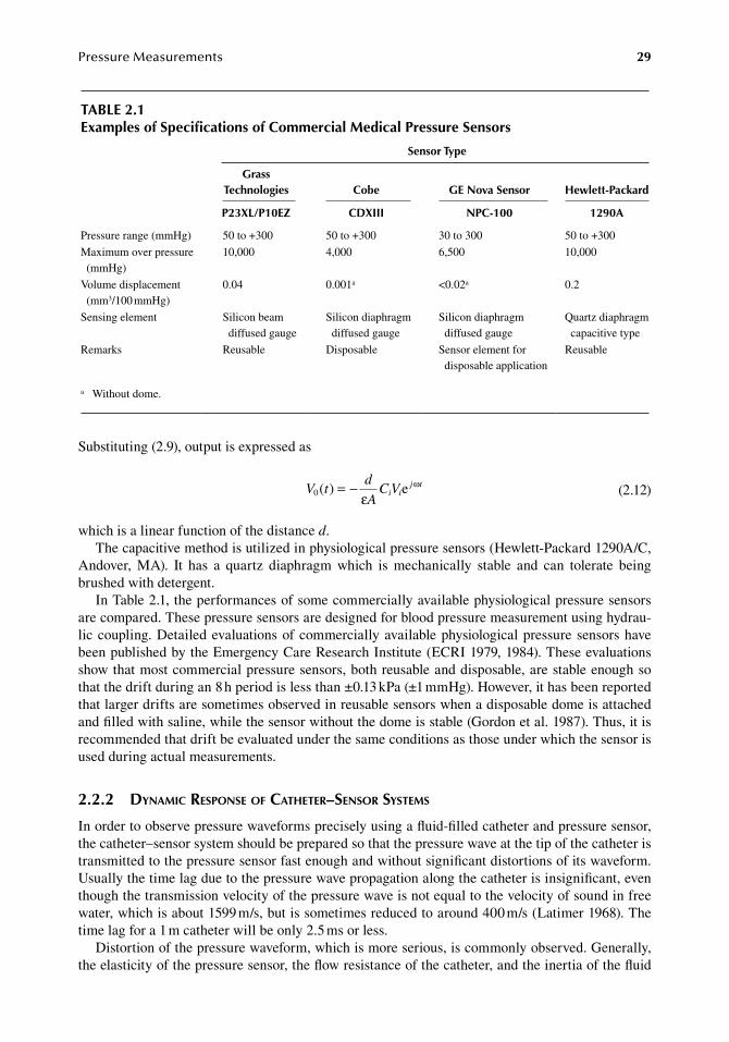
PressureMeasurements 29
Substituting.(2.9),.output.is.expressed.as
.V t
d
AC Vi i
j t0( ) e= −
εω
.(2.12)
which.is.a.linear.function.of.the.distance.d.The.capacitive.method.is.utilized.in.physiological.pressure.sensors.(Hewlett-Packard.1290A/C,.
Andover,. MA).. It. has. a. quartz. diaphragm. which. is. mechanically. stable. and. can. tolerate. being.brushed.with.detergent.
In.Table.2.1,.the.performances.of.some.commercially.available.physiological.pressure.sensors.are.compared..These.pressure.sensors.are.designed.for.blood.pressure.measurement.using.hydrau-lic.coupling..Detailed.evaluations.of.commercially.available.physiological.pressure.sensors.have.been.published.by.the.Emergency.Care.Research.Institute.(ECRI.1979,.1984)..These.evaluations.show.that.most.commercial.pressure.sensors,.both.reusable.and.disposable,.are.stable.enough.so.that.the.drift.during.an.8.h.period.is.less.than.±0.13.kPa.(±1.mmHg)..However,.it.has.been.reported.that.larger.drifts.are.sometimes.observed.in.reusable.sensors.when.a.disposable.dome.is.attached.and.filled.with.saline,.while.the.sensor.without.the.dome.is.stable.(Gordon.et al..1987)..Thus,.it.is.recommended.that.drift.be.evaluated.under.the.same.conditions.as.those.under.which.the.sensor.is.used.during.actual.measurements.
2.2.2 dynaMic response of catheter–sensor systeMs
In.order.to.observe.pressure.waveforms.precisely.using.a.fluid-filled.catheter.and.pressure.sensor,.the.catheter–sensor.system.should.be.prepared.so.that.the.pressure.wave.at.the.tip.of.the.catheter.is.transmitted.to.the.pressure.sensor.fast.enough.and.without.significant.distortions.of.its.waveform..Usually.the.time.lag.due.to.the.pressure.wave.propagation.along.the.catheter.is.insignificant,.even.though.the.transmission.velocity.of.the.pressure.wave.is.not.equal.to.the.velocity.of.sound.in.free.water,.which.is.about.1599.m/s,.but.is.sometimes.reduced.to.around.400.m/s.(Latimer.1968)..The.time.lag.for.a.1.m.catheter.will.be.only.2.5.ms.or.less.
Distortion.of.the.pressure.waveform,.which.is.more.serious,.is.commonly.observed..Generally,.the.elasticity.of.the.pressure.sensor,.the.flow.resistance.of.the.catheter,.and.the.inertia.of.the.fluid.
table 2.1examples of Specifications of Commercial Medical Pressure Sensors
Sensor type
grass technologies Cobe ge nova Sensor hewlett-Packard
P23Xl/P10eZ CdXiii nPC-100 1290a
Pressure.range.(mmHg) 50.to.+300 50.to.+300 30.to.300 50.to.+300
Maximum.over.pressure.(mmHg)
10,000 4,000 6,500 10,000
Volume.displacement.(mm3/100.mmHg)
0.04 0.001a <0.02a 0.2
Sensing.element Silicon.beam.diffused.gauge
Silicon.diaphragm.diffused.gauge
Silicon.diaphragm.diffused.gauge
Quartz.diaphragm.capacitive.type
Remarks Reusable Disposable Sensor.element.for.disposable.application
Reusable
a. Without.dome.
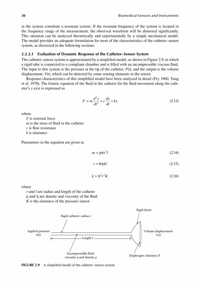
30 BiomedicalSensorsandInstruments
in.the.system.constitute.a.resonant.system..If. the.resonant.frequency.of.the.system.is. located.in.the. frequency. range.of. the.measurement,. the.observed.waveform.will.be.distorted. significantly..This. situation.can.be. analyzed. theoretically. and.experimentally.by.a. simple.mechanical.model..The.model.provides.an.adequate.formulation.for.most.of.the.characteristics.of.the.catheter–sensor.system,.as.discussed.in.the.following.sections.
2.2.2.1 evaluation of dynamic response of the Catheter–Sensor SystemThe.catheter–sensor.system.is.approximated.by.a.simplified.model,.as.shown.in.Figure.2.9,.in.which.a.rigid.tube.is.connected.to.a.compliant.chamber.and.is.filled.with.an.incompressible.viscous.fluid..The.input.to.this.system.is.the.pressure.at.the.tip.of.the.catheter,.P(t),.and.the.output.is.the.volume.displacement,.V(t),.which.can.be.detected.by.some.sensing.elements.in.the.sensor.
Response.characteristics.of.this.simplified.model.have.been.analyzed.in.detail.(Fry.1960,.Yang.et al..1978)..The.kinetic.equation.of.the.fluid.in.the.catheter.for.the.fluid.movement.along.the.cath-eter’s.x.axis.is.expressed.as
.F m
d x
dtc
dx
dtkx= + +
2
2.
(2.13)
whereF.is.external.forcem.is.the.mass.of.fluid.in.the.catheterc.is.flow.resistancek.is.elastance
Parameters.in.the.equation.are.given.as
. m r l= ρπ 2
. (2.14)
. c l= 8ηπ . (2.15)
. k r K= π2 4. (2.16)
wherer.and.l.are.radius.and.length.of.the.catheterρ.and.η.are.density.and.viscosity.of.the.fluidK.is.the.elastance.of.the.pressure.sensor
Rigid dome
Volume displacementV(t)
Diaphragm: elastance K
Rigid catheter: radius r
Applied pressureP(t)
Incompressible uid:viscosity η and density ρ
Length ℓ
figure 2.9 A.simplified.model.of.the.catheter–sensor.system.
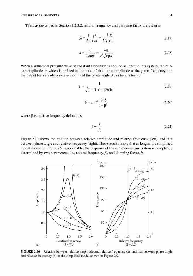
PressureMeasurements 31
Then,.as.described.in.Section.1.2.3.2,.natural.frequency.and.damping.factor.are.given.as
.f
k
m
r K
l0
12 2
= =π πρ .
(2.17)
.
hc
mk
l
r K= =
2
43
ηπρ
.
(2.18)
When.a.sinusoidal.pressure.wave.of.constant.amplitude.is.applied.as.input.to.this.system,.the.rela-tive.amplitude,.γ,.which.is.defined.as.the.ratio.of.the.output.amplitude.at.the.given.frequency.and.the.output.for.a.steady.pressure.input,.and.the.phase.angle.θ.can.be.written.as
.
γβ β
=− + ( )
1
(1 ) 22 2 2h .
(2.19)
.θ β
β−=
−tan
21
12
h
.(2.20)
where.β.is.relative.frequency.defined.as,
.β = f
f0 .(2.21)
Figure.2.10.shows. the. relation.between. relative.amplitude.and. relative. frequency. (left),. and. that.between.phase.angle.and.relative.frequency.(right)..These.results.imply.that.as.long.as.the.simplified.model.shown.in.Figure.2.9.is.applicable,.the.response.of.the.catheter–sensor.system.is.completely.determined.by.two.parameters,.i.e.,.natural.frequency,.f0,.and.damping.factor,.h.
Am
plitu
de
3.0
2.5
2.0
1.5
1.0
(a) (b)
0.5
0 0.5 1.0 1.5 2.0Relative frequency:
(β = f/f0)
h = 0
h = 0.2
h = 0.5
h = 1.0
h = 2.0
Phas
e ang
le
Degree180
150
120
90
60
30
0 0.5 1.0 1.5 2.00
1.0
2.0
3.0h = 0h = 0.2
h = 0.5
h = 1.0
h = 2.0
Relative frequency:(β = f/f0)
Radian
figure 2.10 Relation.between.relative.amplitude.and.relative.frequency.(a),.and.that.between.phase.angle.and.relative.frequency.(b).in.the.simplified.model.shown.in.Figure.2.9.
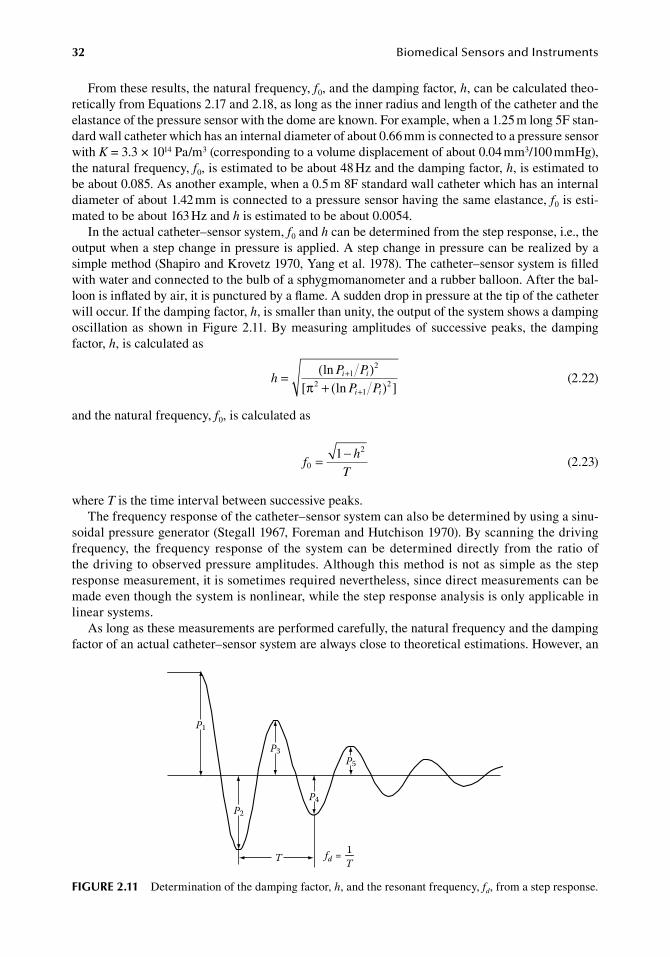
32 BiomedicalSensorsandInstruments
From.these.results,.the.natural.frequency,.f0,.and.the.damping.factor,.h,.can.be.calculated.theo-retically.from.Equations.2.17.and.2.18,.as.long.as.the.inner.radius.and.length.of.the.catheter.and.the.elastance.of.the.pressure.sensor.with.the.dome.are.known..For.example,.when.a.1.25.m.long.5F.stan-dard.wall.catheter.which.has.an.internal.diameter.of.about.0.66.mm.is.connected.to.a.pressure.sensor.with.K.=.3.3.×.1014.Pa/m3.(corresponding.to.a.volume.displacement.of.about.0.04.mm3/100.mmHg),.the.natural.frequency,.f0,.is.estimated.to.be.about.48.Hz.and.the.damping.factor,.h,.is.estimated.to.be.about.0.085..As.another.example,.when.a.0.5.m.8F.standard.wall.catheter.which.has.an.internal.diameter.of.about.1.42.mm.is.connected.to.a.pressure.sensor.having.the.same.elastance,.f0.is.esti-mated.to.be.about.163.Hz.and.h.is.estimated.to.be.about.0.0054.
In.the.actual.catheter–sensor.system,.f0.and.h.can.be.determined.from.the.step.response,.i.e.,.the.output.when.a.step.change.in.pressure.is.applied..A.step.change.in.pressure.can.be.realized.by.a.simple.method.(Shapiro.and.Krovetz.1970,.Yang.et al..1978)..The.catheter–sensor.system.is.filled.with.water.and.connected.to.the.bulb.of.a.sphygmomanometer.and.a.rubber.balloon..After.the.bal-loon.is.inflated.by.air,.it.is.punctured.by.a.flame..A.sudden.drop.in.pressure.at.the.tip.of.the.catheter.will.occur..If.the.damping.factor,.h,.is.smaller.than.unity,.the.output.of.the.system.shows.a.damping.oscillation.as.shown. in.Figure.2.11..By.measuring.amplitudes.of.successive.peaks,. the.damping.factor,.h,.is.calculated.as
.h
P P
P Pi i
i i
= ( )[ + ( ) ]
+
+
lnln
l2
2l
2π .(2.22)
and.the.natural.frequency,.f0,.is.calculated.as
.f
h
T0
21= −.
(2.23)
where.T.is.the.time.interval.between.successive.peaks.The.frequency.response.of.the.catheter–sensor.system.can.also.be.determined.by.using.a.sinu-
soidal.pressure.generator.(Stegall.1967,.Foreman.and.Hutchison.1970)..By.scanning.the.driving.frequency,. the. frequency. response.of. the. system.can.be.determined.directly. from. the. ratio.of.the.driving.to.observed.pressure.amplitudes..Although.this.method.is.not.as.simple.as.the.step.response.measurement,.it.is.sometimes.required.nevertheless,.since.direct.measurements.can.be.made.even.though.the.system.is.nonlinear,.while.the.step.response.analysis.is.only.applicable.in.linear.systems.
As.long.as.these.measurements.are.performed.carefully,.the.natural.frequency.and.the.damping.factor.of.an.actual.catheter–sensor.system.are.always.close.to.theoretical.estimations..However,.an.
P1
P2
P3
P4
P5
T fd = T1
figure 2.11 Determination.of.the.damping.factor,.h,.and.the.resonant.frequency,.fd,.from.a.step.response.
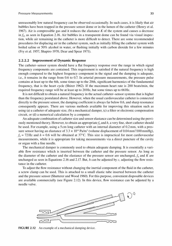
PressureMeasurements 33
unreasonably.low.natural.frequency.can.be.observed.occasionally..In.such.cases,.it.is.likely.that.air.bubbles.have.been.trapped.in.the.pressure.sensor.dome.or.in.the.lumen.of.the.catheter.(Henry.et al..1967)..Air.is.compressible.gas.and.it.reduces.the.elastance.K.of.the.system.and.causes.a.decrease.in.f0,.as.seen.in.Equation.2.16..Air.bubbles.in.a.transparent.dome.can.be.found.via.visual.inspec-tion,.while.air.remaining.in.the.catheter.is.more.difficult.to.detect..There.are.some.recommended.procedures.for.displacing.air.in.the.catheter.system,.such.as.initially.filling.the.catheter.system.with.boiled.saline.or.50%.alcohol.in.water,.or.flushing.initially.with.carbon.dioxide.for.a.few.minutes.(Fry.et al..1957,.Shapiro.1970,.Dear.and.Spear.1971).
2.2.2.2 improvement of dynamic responseThe.catheter–sensor.system.should.have.a.flat.frequency.response.over.the.range.in.which.signal.frequency.components.are.contained..This.requirement.is.satisfied.if.the.natural.frequency.is.high.enough.compared.to.the.highest.frequency.component.in.the.signal.and.the.damping.is.adequate,.i.e.,.h.remains.in.the.range.from.0.6.to.0.7..In.arterial.pressure.measurements,.the.pressure.pulse.contains.at.least.up.to.the.6th,.some.times.up.to.the.20th,.significant.harmonics.of.the.fundamental.frequency,. that. is. the.heart.cycle.(Shirer.1962)..If. the.maximum.heart.rate.is.200.beats/min,. the.required.frequency.range.will.be.at.least.up.to.20.Hz,.but.some.times.up.to.66.Hz.
It.is.not.difficult.to.obtain.a.natural.frequency.in.the.actual.catheter–sensor.systems.that.is.higher.than.the.frequency.postulated.above..However,.when.the.usual.cardiovascular.catheter.is.connected.directly.to.the.pressure.sensor,.the.damping.coefficient.is.always.far.below.0.6,.and.sharp.resonance.consequently. appears.. There. are. various. methods. available. for. improving. this. situation. such. as.using.(a).a.catheter.of.adequate.size,.(b).a.mechanical.damper,.(c).a.filter.or.electronic.compensation.circuit,.or.(d).a.numerical.calculation.by.a.computer.
An.adequate.combination.of.catheter.size.and.sensor.elastance.can.be.determined.using.the.previ-ously.mentioned.theory..However,.to.obtain.an.appropriate.f0.and.h,.a.very.fine,.short.catheter.should.be.used..For.example,.using.a.5.cm.long.catheter.with.an.internal.diameter.of.0.2.mm,.with.a.pres-sure.sensor.having.an.elastance.of.3.3.×.1014.Pa/m3.(volume.displacement.of.0.04.mm3/100.mmHg),.f0.=.72.Hz.and.h.=.0.6.will.be.obtained.at.37°C..This.size.is.impractical.for.most.cardiovascular.measurements,.while.it.is.appropriate.for.taking.measurements.via.a.direct.puncture.of.the.cavity.or.organ.with.a.fine.needle.
The.mechanical.damper.is.commonly.used.to.obtain.adequate.damping..It.is.essentially.a.vari-able. flow. resistance.which. is. inserted. between. the. catheter. and. the.pressure. sensor..As. long. as.the.diameter.of.the.catheter.and.the.elastance.of.the.pressure.sensor.are.unchanged,.f0.and.K.are.unchanged.as.seen.in.Equations.2.16.and.2.17..But,.h.can.be.adjusted.by.c,.adjusting.the.flow.resis-tance.in.the.catheter.
To.adjust.the.flow.resistance.without.changing.the.inertial.component.of.the.fluid.in.the.catheter,.a.screw.clamp.can.be.used..This.is.attached.to.a.small.elastic.tube.inserted.between.the.catheter.and.the.pressure.sensor.(Shutterer.and.Wood.1960)..For.this.purpose,.convenient.disposable.devices.are.available.commercially.(see.Figure.2.12)..In.this.device,.flow.resistance.can.be.adjusted.by.a.needle.valve.
figure 2.12 An.example.of.a.mechanical.damping.device.
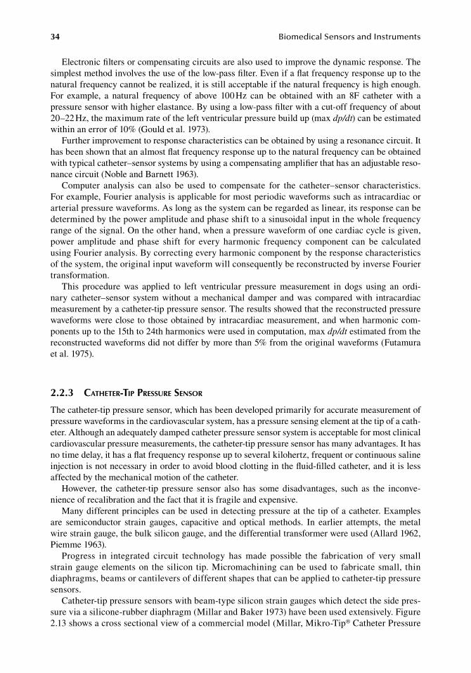
34 BiomedicalSensorsandInstruments
Electronic.filters.or.compensating.circuits.are.also.used.to.improve.the.dynamic.response..The.simplest.method.involves.the.use.of.the.low-pass.filter..Even.if.a.flat.frequency.response.up.to.the.natural.frequency.cannot.be.realized,.it.is.still.acceptable.if.the.natural.frequency.is.high.enough..For. example,. a. natural. frequency. of. above. 100.Hz. can. be. obtained. with. an. 8F. catheter. with. a.pressure.sensor.with.higher.elastance..By.using.a.low-pass.filter.with.a.cut-off.frequency.of.about.20–22.Hz,.the.maximum.rate.of.the.left.ventricular.pressure.build.up.(max.dp/dt).can.be.estimated.within.an.error.of.10%.(Gould.et al..1973).
Further.improvement.to.response.characteristics.can.be.obtained.by.using.a.resonance.circuit..It.has.been.shown.that.an.almost.flat.frequency.response.up.to.the.natural.frequency.can.be.obtained.with.typical.catheter–sensor.systems.by.using.a.compensating.amplifier.that.has.an.adjustable.reso-nance.circuit.(Noble.and.Barnett.1963).
Computer. analysis. can. also. be. used. to. compensate. for. the. catheter–sensor. characteristics..For.example,.Fourier.analysis.is.applicable.for.most.periodic.waveforms.such.as.intracardiac.or.arterial.pressure.waveforms..As.long.as.the.system.can.be.regarded.as.linear,.its.response.can.be.determined.by.the.power.amplitude.and.phase.shift.to.a.sinusoidal.input.in.the.whole.frequency.range.of.the.signal..On.the.other.hand,.when.a.pressure.waveform.of.one.cardiac.cycle.is.given,.power. amplitude. and. phase. shift. for. every. harmonic. frequency. component. can. be. calculated.using.Fourier.analysis..By.correcting.every.harmonic.component.by.the.response.characteristics.of.the.system,.the.original.input.waveform.will.consequently.be.reconstructed.by.inverse.Fourier.transformation.
This. procedure. was. applied. to. left. ventricular. pressure. measurement. in. dogs. using. an. ordi-nary.catheter–sensor. system.without. a.mechanical.damper. and.was.compared.with. intracardiac.measurement.by.a.catheter-tip.pressure.sensor..The.results.showed.that.the.reconstructed.pressure.waveforms.were.close.to.those.obtained.by.intracardiac.measurement,.and.when.harmonic.com-ponents.up.to.the.15th.to.24th.harmonics.were.used.in.computation,.max.dp/dt.estimated.from.the.reconstructed.waveforms.did.not.differ.by.more.than.5%.from.the.original.waveforms.(Futamura.et al..1975).
2.2.3 catheter-tip pressure sensor
The.catheter-tip.pressure.sensor,.which.has.been.developed.primarily.for.accurate.measurement.of.pressure.waveforms.in.the.cardiovascular.system,.has.a.pressure.sensing.element.at.the.tip.of.a.cath-eter..Although.an.adequately.damped.catheter.pressure.sensor.system.is.acceptable.for.most.clinical.cardiovascular.pressure.measurements,.the.catheter-tip.pressure.sensor.has.many.advantages..It.has.no.time.delay,.it.has.a.flat.frequency.response.up.to.several.kilohertz,.frequent.or.continuous.saline.injection.is.not.necessary.in.order.to.avoid.blood.clotting.in.the.fluid-filled.catheter,.and.it.is.less.affected.by.the.mechanical.motion.of.the.catheter.
However,. the. catheter-tip. pressure. sensor. also. has. some. disadvantages,. such. as. the. inconve-nience.of.recalibration.and.the.fact.that.it.is.fragile.and.expensive.
Many.different.principles.can.be.used.in.detecting.pressure.at.the.tip.of.a.catheter..Examples.are. semiconductor. strain. gauges,. capacitive. and. optical. methods.. In. earlier. attempts,. the. metal.wire.strain.gauge,.the.bulk.silicon.gauge,.and.the.differential.transformer.were.used.(Allard.1962,.Piemme.1963).
Progress. in. integrated. circuit. technology. has. made. possible. the. fabrication. of. very. small.strain.gauge.elements.on.the.silicon.tip..Micromachining.can.be.used.to.fabricate.small,. thin.diaphragms,.beams.or.cantilevers.of.different.shapes.that.can.be.applied.to.catheter-tip.pressure.sensors.
Catheter-tip.pressure.sensors.with.beam-type.silicon.strain.gauges.which.detect.the.side.pres-sure.via.a.silicone-rubber.diaphragm.(Millar.and.Baker.1973).have.been.used.extensively..Figure.2.13.shows.a.cross.sectional.view.of.a.commercial.model.(Millar,.Mikro-Tip®.Catheter.Pressure.
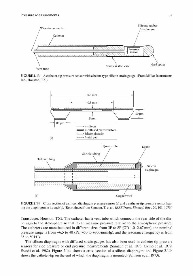
PressureMeasurements 35
Transducer,.Houston,.TX)..The.catheter.has.a.vent.tube.which.connects.the.rear.side.of.the.dia-phragm.to.the.atmosphere.so.that.it.can.measure.pressure.relative.to.the.atmospheric.pressure..The.catheters.are.manufactured.in.different.sizes.from.3F.to.8F.(OD.1.0–2.67.mm),.the.nominal.pressure.range.is.from.−6.5.to.40.kPa.(−50.to.+300.mmHg),.and.the.resonance.frequency.is.from.35.to.50.kHz.
The.silicon.diaphragm.with.diffused.strain.gauges.has.also.been.used.in.catheter-tip.pressure.sensors. for. side.pressure.or.end.pressure.measurements. (Samaun.et al..1973,.Okino.et al..1979,.Esashi.et al..1982)..Figure.2.14a.shows.a.cross.section.of.a.silicon.diaphragm,.and.Figure.2.14b.shows.the.catheter-tip.on.the.end.of.which.the.diaphragm.is.mounted.(Samaun.et al..1973).
0.8 mm
0.5 mm
5 μm80 μm
50 μm
n-siliconp-diffused piezoresistorsSilicon dioxideMetal pad(a)
Teflon tubing
Shrink tubing
Quartz tube
(b) Copper wire
Epoxy
Silicondiaphragm
figure 2.14 Cross.section.of.a.silicon.diaphragm.pressure.sensor.(a).and.a.catheter-tip.pressure.sensor.hav-ing.the.diaphragm.in.its.end.(b)..(Reproduced.from.Samaun,.T..et al.,.IEEE Trans. Biomed. Eng.,.20,.101,.1973.)
Pressuresensor
Silicone rubberdiaphragm
Hard epoxyStainless steel caseVent tube
Wires to connector
Catheter
figure 2.13 A.catheter-tip.pressure.sensor.with.a.beam-type.silicon.strain.gauge..(From.Millar.Instruments.Inc.,.Houston,.TX.)
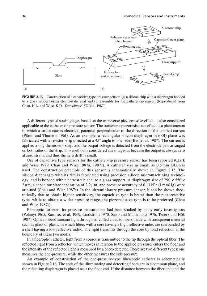
36 BiomedicalSensorsandInstruments
A.different.type.of.strain.gauge,.based.on.the.transverse.piezoresistive.effect,.is.also.considered.applicable.to.the.catheter-tip.pressure.sensor..The.transverse.piezoresistance.effect.is.a.phenomenon.in.which.a.strain.causes.electrical.potential.perpendicular. to.the.direction.of. the.applied.current.(Pfann.and.Thurston.1961)..As.an.example,. a. rectangular. silicon.diaphragm. in. (001).plane.was.fabricated.with.a.resistor.strip.directed.at.a.45°.angle.to.one.side.(Bao.et al..1987)..The.current.is.applied.along.the.resistor.strip,.and.the.output.voltage.is.detected.from.the.electrode.pair.arranged.on.both.sides.of.the.strip..This.method.is.considered.advantageous.because.the.output.is.always.zero.at.zero.strain,.and.thus.the.zero.drift.is.small.
Use.of.capacitive.type.sensors.for.the.catheter-tip.pressure.sensor.has.been.reported.(Clark.and. Wise. 1979,. Chau. and. Wise. 1987a,. 1987c).. A. catheter. size. as. small. as. 0.5.mm. OD. was.used.. The construction. principle. of. this. sensor. is. schematically. shown. in. Figure. 2.15.. The.silicon.diaphragm.with.its.rim.is.fabricated.using.precision.silicon.micromachining.technol-ogy,.and.is.bonded.with.electrostatic.seal.to.a.glass.support..A.diaphragm.size.of.290.×.550.×.2.μm,.a.capacitor.plate.separation.of.2.2.μm,.and.pressure.accuracy.of.0.13.kPa.(1.mmHg).were.attained.(Chau.and.Wise.1987c)..In.the.ultraminiature.pressure.sensor,.it.can.be.shown.theo-retically.that.to.obtain.higher.sensitivity,. the.capacitive.type.is.better.than.the.piezoresistive.type,.while.to.obtain.a.wider.pressure.range,.the.piezoresistive.type.is.to.be.preferred.(Chau.and.Wise.1987a).
Fiberoptic. catheters. for. pressure. measurement. had. been. studied. by. many. early. investigators.(Polanyi.1965,.Ramirez.et al..1969,.Lindström.1970,.Saito.and.Matsumoto.1976,.Tenerz.and.Hök.1987)..Optical.fibers.transmit.light.through.so-called.cladded.fibers.made.with.transparent.material.such.as.glass.or.plastic.in.which.fibers.with.a.core.having.a.high.reflective.index.are.surrounded.by.a.shell.having.a.low.reflective.index..The.light.transmits.through.the.core.by.total.reflection.at.the.boundary.of.these.two.media.
In.a.fiberoptic.catheter,.light.from.a.source.is.transmitted.to.the.tip.through.the.optical.fiber..The.reflected.light.from.a.reflector,.which.moves.in.relation.to.the.applied.pressure,.enters.the.fiber.and.the.intensity.of.the.reflected.light.is.measured.by.a.photo.detector..There.are.two.different.types:.one.measures.the.end-pressure,.while.the.other.measures.the.side.pressure.
An. example. of. construction. of. the. end-pressure-type. fiber-optic. catheter. is. schematically.shown.in.Figure.2.16..The.ends.of.the.illuminating.and.detecting.fibers.are.in.a.common.plane,.and.the.reflecting.diaphragm.is.placed.near.the.fiber.end..If.the.distance.between.the.fiber.end.and.the.
Diaphragm
Glass
(a)
Reference pressureinlet channel
Bonding pad
Si sensor chip
Groove forlead attachment
Capacitor lower plate
Glass support
Circuit chip
(b)
figure 2.15 Construction.of.a.capacitive.type.pressure.sensor:.(a).a.silicon.chip.with.a.diaphragm.bonded.to. a.glass. support. using. electrostatic. seal. and. (b). assembly. for. the. catheter-tip. sensor.. (Reproduced. from.Chau,.H.L..and.Wise,.K.D.,.Transducer’ 87,.344,.1987.)
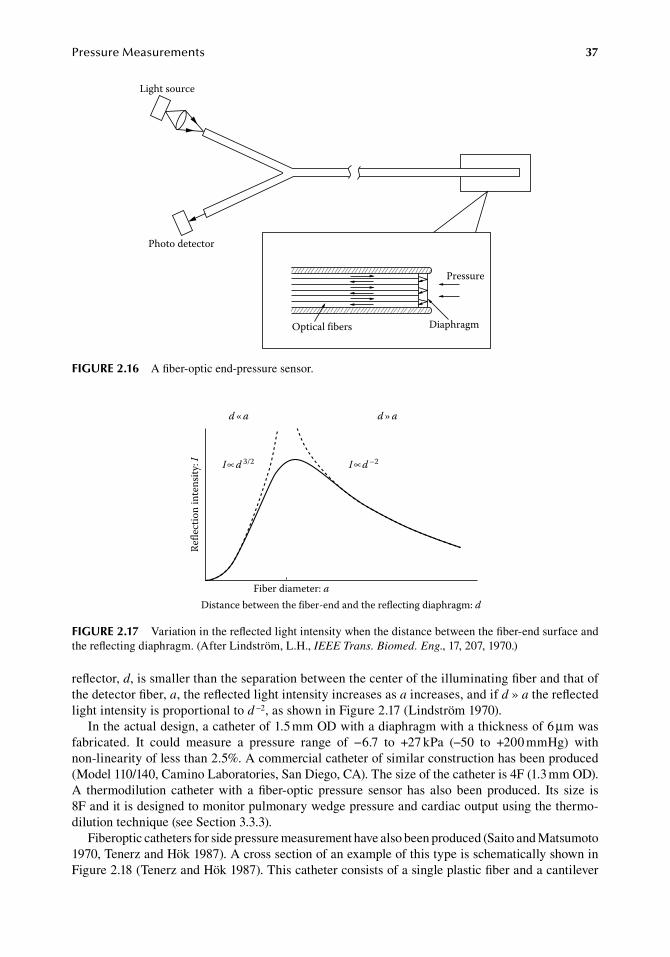
PressureMeasurements 37
reflector,.d,.is.smaller.than.the.separation.between.the.center.of.the.illuminating.fiber.and.that.of.the.detector.fiber,.a,.the.reflected.light.intensity.increases.as.a.increases,.and.if.d » a.the.reflected.light.intensity.is.proportional.to.d −2,.as.shown.in.Figure.2.17.(Lindström.1970).
In.the.actual.design,.a.catheter.of.1.5.mm.OD.with.a.diaphragm.with.a.thickness.of.6.μm.was..fabricated.. It. could. measure. a. pressure. range. of. −6.7. to. +27.kPa. (−50. to. +200.mmHg). with.non-linearity.of.less.than.2.5%..A.commercial.catheter.of.similar.construction.has.been.produced.(Model.110/140,.Camino.Laboratories,.San.Diego,.CA)..The.size.of.the.catheter.is.4F.(1.3.mm.OD)..A. thermodilution. catheter. with. a. fiber-optic. pressure. sensor. has. also. been. produced.. Its. size. is.8F.and.it.is.designed.to.monitor.pulmonary.wedge.pressure.and.cardiac.output.using.the.thermo-dilution.technique.(see.Section.3.3.3).
Fiberoptic.catheters.for.side.pressure.measurement.have.also.been.produced.(Saito.and.Matsumoto.1970,.Tenerz.and.Hök.1987)..A.cross.section.of.an.example.of.this.type.is.schematically.shown.in.Figure.2.18.(Tenerz.and.Hök.1987)..This.catheter.consists.of.a.single.plastic.fiber.and.a.cantilever.
Light source
Photo detector
Pressure
DiaphragmOptical fibers
figure 2.16 A.fiber-optic.end-pressure.sensor.
Refle
ctio
n in
tens
ity: I
Fiber diameter: aDistance between the fiber-end and the reflecting diaphragm: d
d»ad«a
I d 3/2 I d –2
figure 2.17 Variation.in.the.reflected.light.intensity.when.the.distance.between.the.fiber-end.surface.and.the.reflecting.diaphragm..(After.Lindström,.L.H.,.IEEE Trans. Biomed. Eng.,.17,.207,.1970.)
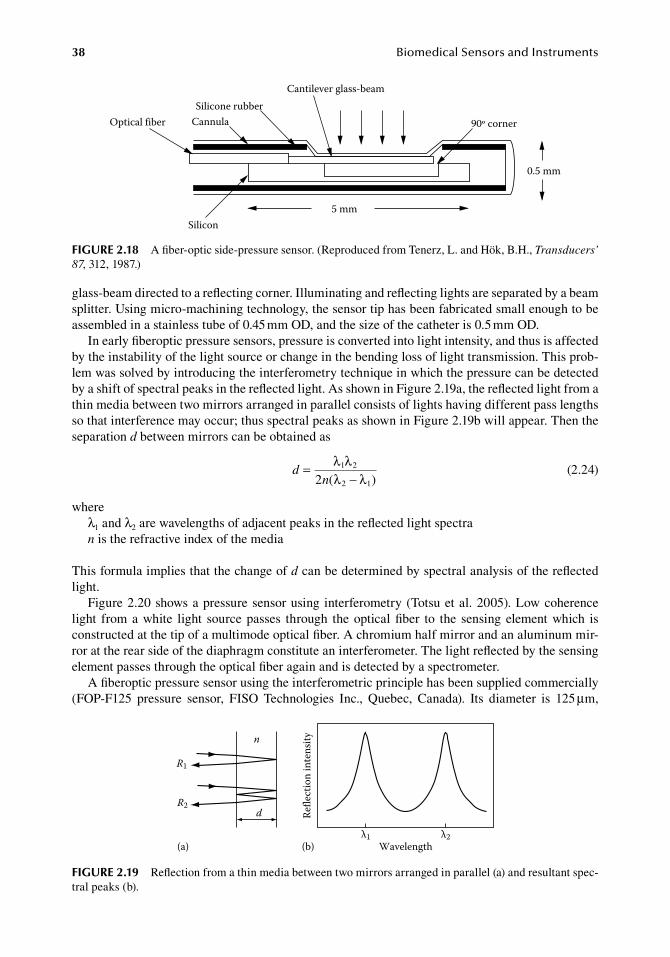
38 BiomedicalSensorsandInstruments
glass-beam.directed.to.a.reflecting.corner..Illuminating.and.reflecting.lights.are.separated.by.a.beam.splitter..Using.micro-machining.technology,.the.sensor.tip.has.been.fabricated.small.enough.to.be.assembled.in.a.stainless.tube.of.0.45.mm.OD,.and.the.size.of.the.catheter.is.0.5.mm.OD.
In.early.fiberoptic.pressure.sensors,.pressure.is.converted.into.light.intensity,.and.thus.is.affected.by.the.instability.of.the.light.source.or.change.in.the.bending.loss.of.light.transmission..This.prob-lem.was.solved.by.introducing.the.interferometry.technique.in.which.the.pressure.can.be.detected.by.a.shift.of.spectral.peaks.in.the.reflected.light..As.shown.in.Figure.2.19a,.the.reflected.light.from.a.thin.media.between.two.mirrors.arranged.in.parallel.consists.of.lights.having.different.pass.lengths.so.that.interference.may.occur;.thus.spectral.peaks.as.shown.in.Figure.2.19b.will.appear..Then.the.separation.d.between.mirrors.can.be.obtained.as
.d
n= λ λ
λ − λ1 2
2 12 ( ) .(2.24)
whereλ1.and.λ2.are.wavelengths.of.adjacent.peaks.in.the.reflected.light.spectran.is.the.refractive.index.of.the.media
This.formula.implies.that.the.change.of.d.can.be.determined.by.spectral.analysis.of.the.reflected.light.
Figure.2.20.shows.a.pressure.sensor.using. interferometry.(Totsu.et al..2005)..Low.coherence.light. from.a.white. light. source.passes. through. the.optical.fiber. to. the. sensing. element.which. is.constructed.at.the.tip.of.a.multimode.optical.fiber..A.chromium.half.mirror.and.an.aluminum.mir-ror.at.the.rear.side.of.the.diaphragm.constitute.an.interferometer..The.light.reflected.by.the.sensing.element.passes.through.the.optical.fiber.again.and.is.detected.by.a.spectrometer.
A.fiberoptic.pressure.sensor.using.the.interferometric.principle.has.been.supplied.commercially.(FOP-F125. pressure. sensor,. FISO. Technologies. Inc.,. Quebec,. Canada).. Its. diameter. is. 125.μm,.
Optical fiber CannulaSilicone rubber
Cantilever glass-beam
Silicon5 mm
0.5 mm
90º corner
figure 2.18 A.fiber-optic.side-pressure.sensor..(Reproduced.from.Tenerz,.L..and.Hök,.B.H.,.Transducers’ 87,.312,.1987.)
n
d
R1
R2
Wavelengthλ1 λ2
Refle
ctio
n in
tens
ity
(a) (b)
figure 2.19 Reflection.from.a.thin.media.between.two.mirrors.arranged.in.parallel.(a).and.resultant.spec-tral.peaks.(b).
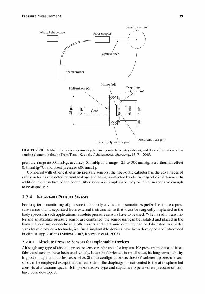
PressureMeasurements 39
pressure.range.±300.mmHg,.accuracy.5.mmHg.in.a.range.−25.to.300.mmHg,.zero.thermal.effect.0.4.mmHg/°C,.and.proof.pressure.600.mmHg.
Compared.with.other.catheter-tip.pressure.sensors,.the.fiber-optic.catheter.has.the.advantages.of.safety.in.terms.of.electric.current.leakage.and.being.unaffected.by.electromagnetic.interference..In.addition,.the.structure.of.the.optical.fiber.system.is.simpler.and.may.become.inexpensive.enough.to.be.disposable.
2.2.4 iMplantable pressure sensors
For.long-term.monitoring.of.pressure.in.the.body.cavities,.it.is.sometimes.preferable.to.use.a.pres-sure.sensor.that.is.separated.from.external.instruments.so.that.it.can.be.surgically.implanted.in.the.body.spaces..In.such.applications,.absolute.pressure.sensors.have.to.be.used..When.a.radio.transmit-ter.and.an.absolute.pressure.sensor.are.combined,.the.sensor.unit.can.be.isolated.and.placed.in.the.body.without.any.connections..Both.sensors.and.electronic.circuitry.can.be.fabricated.in.smaller.sizes.by.microsystem.technologies..Such.implantable.devices.have.been.developed.and.introduced.in.clinical.applications.(Mokwa.2007,.Receveur.et al..2007).
2.2.4.1 absolute Pressure Sensors for implantable devicesAlthough.any.type.of.absolute.pressure.sensor.can.be.used.for.implantable.pressure.monitor,.silicon-fabricated.sensors.have.been.used.widely..It.can.be.fabricated.in.small.sizes,.its.long-term.stability.is.good.enough,.and.it.is.less.expensive..Similar.configurations.as.those.of.catheter-tip.pressure.sen-sors.can.be.employed.except.that.the.rear.side.of.the.diaphragm.is.not.vented.to.the.atmosphere.but.consists.of.a.vacuum.space..Both.piezoresistive.type.and.capacitive.type.absolute.pressure.sensors.have.been.developed.
White light source Fiber coupler
Spectrometer
Sensing element
Optical fiber
Mirror (Al)Half-mirror (Cr)
Core
Diaphragm (SiO2: 0.7 µm)
Spacer (polyimide: 2 µm)Mesa (SiO2: 2.3 µm)
125
µm
50 µ
m
60 µ
m
90 µ
m15
µm
figure 2.20 A.fiberoptic.pressure.sensor.system.using.interferometry.(above),.and.the.configuration.of.the.sensing.element.(below)..(From.Totsu,.K..et al.,.J. Micromech. Microeng.,.15,.71,.2005.)
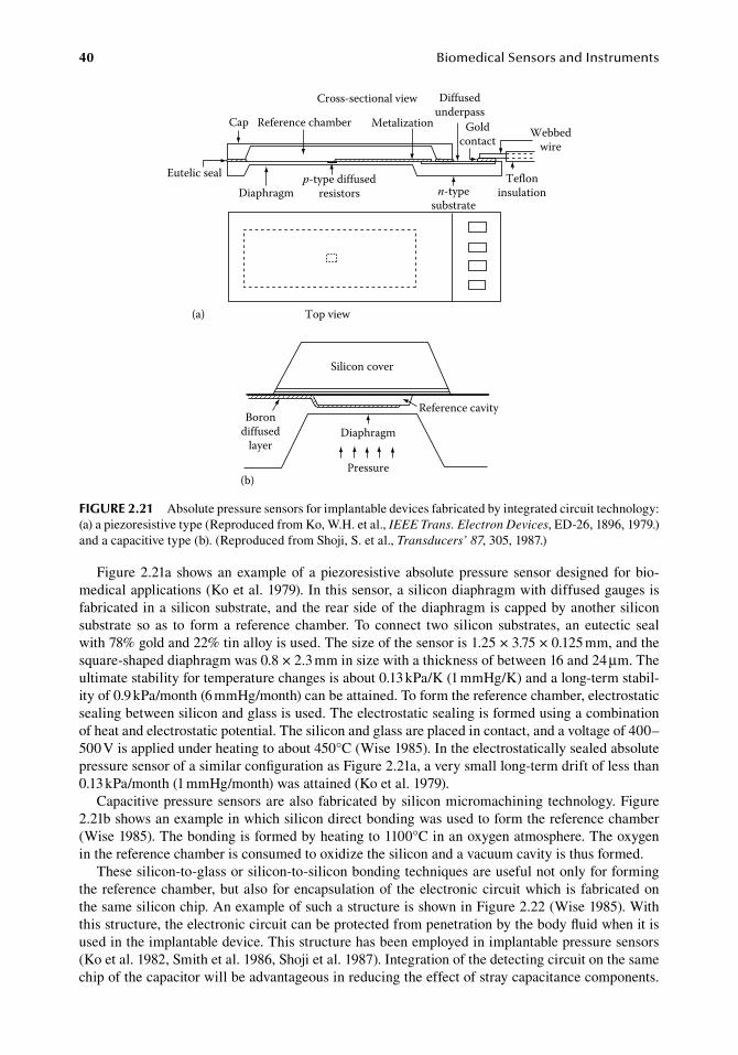
40 BiomedicalSensorsandInstruments
Figure.2.21a. shows.an.example.of.a.piezoresistive.absolute.pressure. sensor.designed. for.bio-medical.applications.(Ko.et al..1979)..In.this.sensor,.a.silicon.diaphragm.with.diffused.gauges.is.fabricated.in.a.silicon.substrate,.and.the.rear.side.of.the.diaphragm.is.capped.by.another.silicon.substrate. so. as. to. form.a. reference. chamber..To. connect. two. silicon. substrates,. an. eutectic. seal.with.78%.gold.and.22%.tin.alloy.is.used..The.size.of.the.sensor.is.1.25.×.3.75.×.0.125.mm,.and.the.square-shaped.diaphragm.was.0.8.×.2.3.mm.in.size.with.a.thickness.of.between.16.and.24.μm..The.ultimate.stability.for.temperature.changes.is.about.0.13.kPa/K.(1.mmHg/K).and.a.long-term.stabil-ity.of.0.9.kPa/month.(6.mmHg/month).can.be.attained..To.form.the.reference.chamber,.electrostatic.sealing.between.silicon.and.glass.is.used..The.electrostatic.sealing.is.formed.using.a.combination.of.heat.and.electrostatic.potential..The.silicon.and.glass.are.placed.in.contact,.and.a.voltage.of.400–500.V.is.applied.under.heating.to.about.450°C.(Wise.1985)..In.the.electrostatically.sealed.absolute.pressure.sensor.of.a.similar.configuration.as.Figure.2.21a,.a.very.small.long-term.drift.of.less.than.0.13.kPa/month.(1.mmHg/month).was.attained.(Ko.et al..1979).
Capacitive.pressure.sensors.are.also.fabricated.by.silicon.micromachining.technology..Figure.2.21b.shows.an.example.in.which.silicon.direct.bonding.was.used.to.form.the.reference.chamber.(Wise.1985)..The.bonding.is.formed.by.heating.to.1100°C.in.an.oxygen.atmosphere..The.oxygen.in.the.reference.chamber.is.consumed.to.oxidize.the.silicon.and.a.vacuum.cavity.is.thus.formed.
These.silicon-to-glass.or.silicon-to-silicon.bonding.techniques.are.useful.not.only.for.forming.the.reference.chamber,.but.also.for.encapsulation.of. the.electronic.circuit.which.is.fabricated.on.the.same.silicon.chip..An.example.of.such.a.structure.is.shown.in.Figure.2.22.(Wise.1985)..With.this.structure,.the.electronic.circuit.can.be.protected.from.penetration.by.the.body.fluid.when.it.is.used.in.the.implantable.device..This.structure.has.been.employed.in.implantable.pressure.sensors.(Ko.et al..1982,.Smith.et al..1986,.Shoji.et al..1987)..Integration.of.the.detecting.circuit.on.the.same.chip.of.the.capacitor.will.be.advantageous.in.reducing.the.effect.of.stray.capacitance.components..
Borondiffused
layer
Reference cavity
Diaphragm
Pressure
Silicon cover
(b)
Reference chamber Metalization
Diffusedunderpass
Goldcontact
n-typesubstrate
Webbedwire
Tefloninsulation
p-type diffusedresistorsDiaphragm
Cap
Eutelic seal
Cross-sectional view
Top view(a)
figure 2.21 Absolute.pressure.sensors.for.implantable.devices.fabricated.by.integrated.circuit.technology:.(a).a.piezoresistive.type.(Reproduced.from.Ko,.W.H..et al.,.IEEE Trans. Electron Devices,.ED-26,.1896,.1979.).and.a.capacitive.type.(b)..(Reproduced.from.Shoji,.S..et al.,.Transducers’ 87,.305,.1987.)
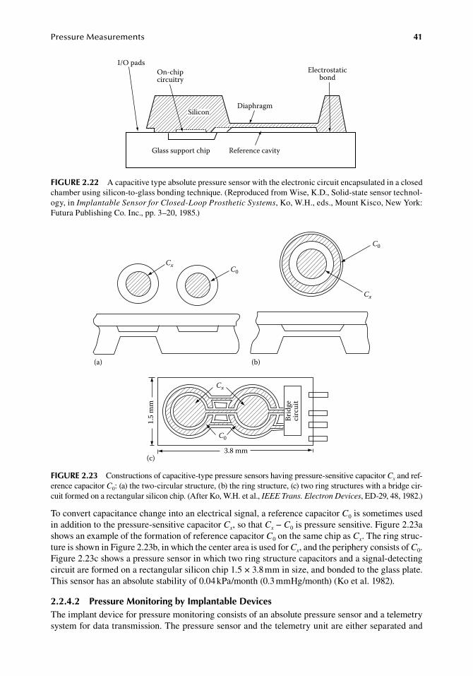
PressureMeasurements 41
To.convert.capacitance.change.into.an.electrical.signal,.a.reference.capacitor.C0.is.sometimes.used.in.addition.to.the.pressure-sensitive.capacitor.Cx,.so.that.Cx.−.C0.is.pressure.sensitive..Figure.2.23a.shows.an.example.of.the.formation.of.reference.capacitor.C0.on.the.same.chip.as.Cx..The.ring.struc-ture.is.shown.in.Figure.2.23b,.in.which.the.center.area.is.used.for.Cx,.and.the.periphery.consists.of.C0..Figure.2.23c.shows.a.pressure.sensor.in.which.two.ring.structure.capacitors.and.a.signal-detecting.circuit.are.formed.on.a.rectangular.silicon.chip.1.5.×.3.8.mm.in.size,.and.bonded.to.the.glass.plate..This.sensor.has.an.absolute.stability.of.0.04.kPa/month.(0.3.mmHg/month).(Ko.et al..1982).
2.2.4.2 Pressure Monitoring by implantable devicesThe.implant.device.for.pressure.monitoring.consists.of.an.absolute.pressure.sensor.and.a.telemetry.system.for.data.transmission..The.pressure.sensor.and.the.telemetry.unit.are.either.separated.and.
C0
Cx
3.8 mm
1.5
mm
Brid
geci
rcui
t
(c)
(a)
Cx C0
C0
Cx
(b)
figure 2.23 Constructions.of.capacitive-type.pressure.sensors.having.pressure-sensitive.capacitor.Cx.and.ref-erence.capacitor.C0:.(a).the.two-circular.structure,.(b).the.ring.structure,.(c).two.ring.structures.with.a.bridge.cir-cuit.formed.on.a.rectangular.silicon.chip..(After.Ko,.W.H..et al.,.IEEE Trans. Electron Devices,.ED-29,.48,.1982.)
On-chipcircuitry
Diaphragm
Electrostaticbond
Reference cavityGlass support chip
Silicon
I/O pads
figure 2.22 A.capacitive.type.absolute.pressure.sensor.with.the.electronic.circuit.encapsulated.in.a.closed.chamber.using.silicon-to-glass.bonding.technique..(Reproduced.from.Wise,.K.D.,.Solid-state.sensor.technol-ogy,.in.Implantable Sensor for Closed-Loop Prosthetic Systems,.Ko,.W.H.,.eds.,.Mount.Kisco,.New.York:.Futura.Publishing.Co..Inc.,.pp..3–20,.1985.)
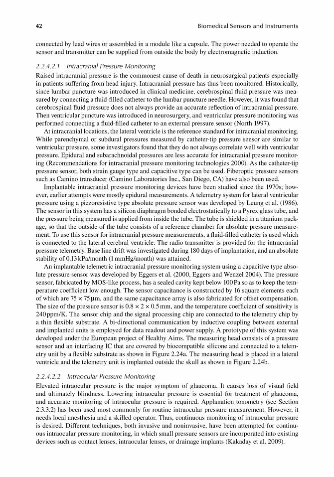
42 BiomedicalSensorsandInstruments
connected.by.lead.wires.or.assembled.in.a.module.like.a.capsule..The.power.needed.to.operate.the.sensor.and.transmitter.can.be.supplied.from.outside.the.body.by.electromagnetic.induction.
2.2.4.2.1 Intracranial Pressure MonitoringRaised.intracranial.pressure.is.the.commonest.cause.of.death.in.neurosurgical.patients.especially.in.patients.suffering.from.head.injury..Intracranial.pressure.has.thus.been.monitored..Historically,.since.lumbar.puncture.was.introduced.in.clinical.medicine,.cerebrospinal.fluid.pressure.was.mea-sured.by.connecting.a.fluid-filled.catheter.to.the.lumbar.puncture.needle..However,.it.was.found.that.cerebrospinal.fluid.pressure.does.not.always.provide.an.accurate.reflection.of.intracranial.pressure..Then.ventricular.puncture.was.introduced.in.neurosurgery,.and.ventricular.pressure.monitoring.was.performed.connecting.a.fluid-filled.catheter.to.an.external.pressure.sensor.(North.1997).
At.intracranial.locations,.the.lateral.ventricle.is.the.reference.standard.for.intracranial.monitoring..While.parenchymal.or.subdural.pressures.measured.by.catheter-tip.pressure.sensor.are.similar.to.ventricular.pressure,.some.investigators.found.that.they.do.not.always.correlate.well.with.ventricular.pressure..Epidural.and.subarachnoidal.pressures.are.less.accurate.for.intracranial.pressure.monitor-ing.(Recommendations.for.intracranial.pressure.monitoring.technologies.2000)..As.the.catheter-tip.pressure.sensor,.both.strain.gauge.type.and.capacitive.type.can.be.used..Fiberoptic.pressure.sensors.such.as.Camino.transducer.(Camino.Laboratories.Inc.,.San.Diego,.CA).have.also.been.used.
Implantable.intracranial.pressure.monitoring.devices.have.been.studied.since.the.1970s;.how-ever,.earlier.attempts.were.mostly.epidural.measurements..A.telemetry.system.for.lateral.ventricular.pressure.using.a.piezoresistive.type.absolute.pressure.sensor.was.developed.by.Leung.et al..(1986)..The.sensor.in.this.system.has.a.silicon.diaphragm.bonded.electrostatically.to.a.Pyrex.glass.tube,.and.the.pressure.being.measured.is.applied.from.inside.the.tube..The.tube.is.shielded.in.a.titanium.pack-age,.so.that.the.outside.of.the.tube.consists.of.a.reference.chamber.for.absolute.pressure.measure-ment..To.use.this.sensor.for.intracranial.pressure.measurements,.a.fluid-filled.catheter.is.used.which.is.connected.to.the.lateral.cerebral.ventricle..The.radio.transmitter.is.provided.for.the.intracranial.pressure.telemetry..Base.line.drift.was.investigated.during.180.days.of.implantation,.and.an.absolute.stability.of.0.13.kPa/month.(1.mmHg/month).was.attained.
An.implantable.telemetric.intracranial.pressure.monitoring.system.using.a.capacitive.type.abso-lute.pressure.sensor.was.developed.by.Eggers.et al..(2000,.Eggers.and.Wenzel.2004)..The.pressure.sensor,.fabricated.by.MOS-like.process,.has.a.sealed.cavity.kept.below.100.Pa.so.as.to.keep.the.tem-perature.coefficient.low.enough..The.sensor.capacitance.is.constructed.by.16.square.elements.each.of.which.are.75.×.75.μm,.and.the.same.capacitance.array.is.also.fabricated.for.offset.compensation..The.size.of.the.pressure.sensor.is.0.8.×.2.×.0.5.mm,.and.the.temperature.coefficient.of.sensitivity.is.240.ppm/K..The.sensor.chip.and.the.signal.processing.chip.are.connected.to.the.telemetry.chip.by.a.thin.flexible.substrate..A.bi-directional.communication.by.inductive.coupling.between.external.and.implanted.units.is.employed.for.data.readout.and.power.supply..A.prototype.of.this.system.was.developed.under.the.European.project.of.Healthy.Aims..The.measuring.head.consists.of.a.pressure.sensor.and.an.interfacing.IC.that.are.covered.by.biocompatible.silicone.and.connected.to.a.telem-etry.unit.by.a.flexible.substrate.as.shown.in.Figure.2.24a..The.measuring.head.is.placed.in.a.lateral.ventricle.and.the.telemetry.unit.is.implanted.outside.the.skull.as.shown.in.Figure.2.24b.
2.2.4.2.2 Intraocular Pressure MonitoringElevated. intraocular. pressure. is. the. major. symptom. of. glaucoma.. It. causes. loss. of. visual. field.and. ultimately. blindness.. Lowering. intraocular. pressure. is. essential. for. treatment. of. glaucoma,.and.accurate.monitoring.of. intraocular.pressure. is.required..Applanation. tonometry.(see.Section.2.3.3.2).has.been.used.most.commonly.for.routine.intraocular.pressure.measurement..However,.it.needs.local.anesthesia.and.a.skilled.operator..Thus,.continuous.monitoring.of.intraocular.pressure.is.desired..Different.techniques,.both.invasive.and.noninvasive,.have.been.attempted.for.continu-ous.intraocular.pressure.monitoring,.in.which.small.pressure.sensors.are.incorporated.into.existing.devices.such.as.contact.lenses,.intraocular.lenses,.or.drainage.implants.(Kakaday.et al..2009).
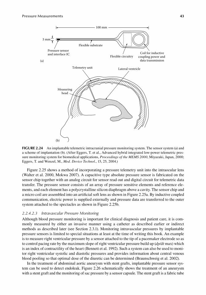
PressureMeasurements 43
Figure.2.25.shows.a.method.of.incorporating.a.pressure.telemetry.unit.into.the.intraocular.lens.(Walter.et al..2000,.Mokwa.2007)..A.capacitive.type.absolute.pressure.sensor.is.fabricated.on.the.sensor.chip.together.with.an.analog.circuit.for.sensor.read.out.and.digital.circuit.for.telemetric.data.transfer..The.pressure.sensor.consists.of.an.array.of.pressure.sensitive.elements.and.reference.ele-ments,.and.each.element.has.a.polycrystalline.silicon.diaphragm.above.a.cavity..The.sensor.chip.and.a.micro.coil.are.assembled.into.an.artificial.soft.lens.as.shown.in.Figure.2.25a..By.inductive.coupled.communication,.electric.power.is.supplied.externally.and.pressure.data.are.transferred.to.the.outer.system.attached.to.the.spectacles.as.shown.in.Figure.2.25b.
2.2.4.2.3 Intravascular Pressure MonitoringAlthough.blood.pressure.monitoring.is.important.for.clinical.diagnosis.and.patient.care,.it.is.com-monly. measured. by. either. an. invasive. manner. using. a. catheter. as. described. earlier. or. indirect.methods.as.described.later.(see.Section.2.3.1)..Monitoring.intravascular.pressures.by.implantable.pressure.sensors.is.limited.to.special.situations.at.least.at.the.time.of.writing.this.book..An.example.is.to.measure.right.ventricular.pressure.by.a.sensor.attached.to.the.tip.of.a.pacemaker.electrode.so.as.to.control.pacing.rate.by.the.maximum.slope.of.right.ventricular.pressure.build.up.(dp/dt.max).which.is.an.index.of.contractility.of.the.heart.(Bennett.et al..1992)..Such.a.system.can.also.be.used.to.moni-tor.right.ventricular.systolic.and.diastolic.pressures.and.provides.information.about.central.venous.blood.pooling.so.that.optimal.dose.of.the.diuretic.can.be.determined.(Braunschweig.et al..2002).
In.the.treatment.of.abdominal.aortic.aneurysm.with.stent.grafts,.implantable.pressure.sensor.sys-tem.can.be.used.to.detect.endoleak..Figure.2.26.schematically.shows.the.treatment.of.an.aneurysm.with.a.stent.graft.and.the.monitoring.of.sac.pressure.by.a.sensor.capsule..The.stent.graft.is.a.fabric.tube.
(a)
Pressure sensor and interface IC
100 mm
3 mm
Coil for inductivecoupling power and
data transmissionFlexible circuitry
Flexible substrate
(b)
Telemetry unit
Measuringhead
Lateral ventricle
figure 2.24 An.implantable.telemetric.intracranial.pressure.monitoring.system..The.sensor.system.(a).and.a.scheme.of.implantation.(b)..(After.Eggers,.T..et al.,.Advanced.hybrid.integrated.low-power.telemetric.pres-sure.monitoring.system.for.biomedical.applications,.Proceedings of the MEMS 2000,.Miyazaki,.Japan,.2000;.Eggers,.T..and.Wenzel,.M.,.Med. Device Technol.,.15,.25,.2004.)
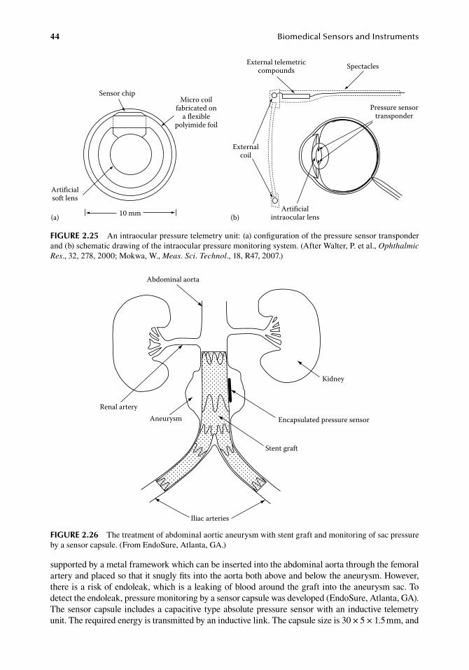
44 BiomedicalSensorsandInstruments
supported.by.a.metal.framework.which.can.be.inserted.into.the.abdominal.aorta.through.the.femoral.artery.and.placed.so.that.it.snugly.fits.into.the.aorta.both.above.and.below.the.aneurysm..However,.there.is.a.risk.of.endoleak,.which.is.a.leaking.of.blood.around.the.graft.into.the.aneurysm.sac..To.detect.the.endoleak,.pressure.monitoring.by.a.sensor.capsule.was.developed.(EndoSure,.Atlanta,.GA)..The.sensor.capsule.includes.a.capacitive.type.absolute.pressure.sensor.with.an.inductive.telemetry.unit..The.required.energy.is.transmitted.by.an.inductive.link..The.capsule.size.is.30.×.5.×.1.5.mm,.and.
Renal arteryAneurysm Encapsulated pressure sensor
Stent graft
Iliac arteries
Abdominal aorta
Kidney
figure 2.26 The.treatment.of.abdominal.aortic.aneurysm.with.stent.graft.and.monitoring.of.sac.pressure.by.a.sensor.capsule..(From.EndoSure,.Atlanta,.GA.)
Pressure sensortransponder
SpectaclesExternal telemetriccompounds
Artificialintraocular lens
Artificialsoft lens
Micro coilfabricated on
a flexiblepolyimide foil
Sensor chip
10 mm(a) (b)
Externalcoil
figure 2.25 An.intraocular.pressure.telemetry.unit:.(a).configuration.of.the.pressure.sensor.transponder.and.(b).schematic.drawing.of.the.intraocular.pressure.monitoring.system..(After.Walter,.P..et al.,.Ophthalmic Res.,.32,.278,.2000;.Mokwa,.W.,.Meas. Sci. Technol.,.18,.R47,.2007.)
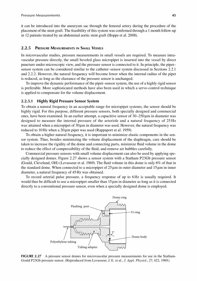
PressureMeasurements 45
it.can.be.introduced.into.the.aneurysm.sac.through.the.femoral.artery.during.the.procedure.of.the.placement.of.the.stent.graft..The.feasibility.of.this.system.was.confirmed.through.a.1.month.follow-up.in.12.patients.treated.by.an.abdominal.aortic.stent.graft.(Hoppe.et al..2008).
2.2.5 pressure MeasureMents in sMall Vessels
In.microvascular.studies,.pressure.measurements.in.small.vessels.are.required..To.measure.intra-vascular.pressure.directly,.the.small.beveled.glass.micropipet.is.inserted.into.the.vessel.by.direct.puncture.under.microscopic.view,.and.the.pressure.sensor.is.connected.to.it..In.principle,.the.pipet–sensor.system.can.be.considered.similar.to.the.catheter–sensor.system.discussed.in.Sections.2.2.1.and.2.2.2..However,.the.natural.frequency.will.become.lower.when.the.internal.radius.of.the.pipet.is.reduced,.as.long.as.the.elastance.of.the.pressure.sensor.is.unchanged.
To.improve.the.dynamic.performance.of.the.pipet–sensor.system,.the.use.of.a.highly.rigid.sensor.is.preferable..More.sophisticated.methods.have.also.been.used.in.which.a.servo-control.technique.is.applied.to.compensate.for.the.volume.displacement.
2.2.5.1 highly rigid Pressure Sensor SystemTo.obtain.a.natural.frequency.in.an.acceptable.range.for.micropipet.systems,.the.sensor.should.be.highly.rigid..For.this.purpose,.different.pressure.sensors,.both.specially.designed.and.commercial.ones,.have.been.examined..In.an.earlier.attempt,.a.capacitive.sensor.of.30–250.μm.in.diameter.was.designed. to. measure. the. internal. pressure. of. the. arteriole. and. a. natural. frequency. of. 25.Hz.was.attained.when.a.micropipet.of.30.μm.in.diameter.was.used..However,.the.natural.frequency.was.reduced.to.10.Hz.when.a.20.μm.pipet.was.used.(Rappaport.et al..1959).
To.obtain.a.higher.natural.frequency,.it.is.important.to.minimize.elastic.components.in.the.sen-sor.system..Thus,.besides.minimizing.the.volume.displacement.of.the.diaphragm,.care.should.be.taken.to.increase.the.rigidity.of.the.dome.and.connecting.parts,.minimize.fluid.volume.in.the.dome.to.reduce.the.effect.of.compressibility.of.the.fluid,.and.remove.air.bubbles.carefully.
Commercial.pressure.sensors.with.small.volume.displacement.can.also.be.used.by.applying.spe-cially.designed.domes..Figure.2.27.shows.a.sensor.system.with.a.Statham.P23Gb.pressure.sensor.(Gould,.Cleveland,.OH).(Levasseur.et al..1969)..The.fluid.volume.in.this.dome.is.only.6%.of.that.in.the.standard.dome..When.connected.to.a.micropipet.of.25.μm.in.outer.diameter.and.15.μm.in.inner.diameter,.a.natural.frequency.of.45.Hz.was.obtained.
To. record. arterial. pulse. pressure,. a. frequency. response. of. up. to. 6.Hz. is. usually. required.. It.would.thus.be.difficult.to.use.a.micropipet.smaller.than.15.μm.in.diameter.as.long.as.it.is.connected.directly.to.a.conventional.pressure.sensor,.even.when.a.specially.designed.dome.is.employed.
2°
O-ring
Dome ring
Dome body
Flushing port
Polyethylene tubingTubing adapter
figure 2.27 A.pressure.sensor.domes.for.microvascular.pressure.measurements.for.use.in.the.Statham-Gould.P23Gb.pressure.sensor..(Reproduced.from.Levasseur,.J..E..et.al.,.J. Appl. Physiol.,.27,.422,.1969.)
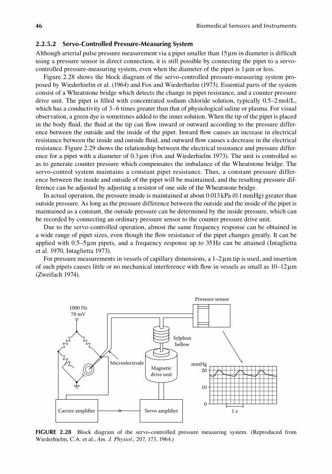
46 BiomedicalSensorsandInstruments
2.2.5.2 Servo-Controlled Pressure-Measuring SystemAlthough.arterial.pulse.pressure.measurement.via.a.pipet.smaller.than.15.μm.in.diameter.is.difficult.using.a.pressure.sensor.in.direct.connection,.it.is.still.possible.by.connecting.the.pipet.to.a.servo-controlled.pressure-measuring.system,.even.when.the.diameter.of.the.pipet.is.1.μm.or.less.
Figure.2.28.shows.the.block.diagram.of. the.servo-controlled.pressure-measuring.system.pro-posed.by.Wiederhielm.et al..(1964).and.Fox.and.Wiederhielm.(1973)..Essential.parts.of.the.system.consist.of.a.Wheatstone.bridge.which.detects.the.change.in.pipet.resistance,.and.a.counter.pressure.drive.unit..The.pipet. is.filled.with.concentrated.sodium.chloride.solution,. typically.0.5–2.mol/L,.which.has.a.conductivity.of.3–6.times.greater.than.that.of.physiological.saline.or.plasma..For.visual.observation,.a.green.dye.is.sometimes.added.to.the.inner.solution..When.the.tip.of.the.pipet.is.placed.in.the.body.fluid,.the.fluid.at.the.tip.can.flow.inward.or.outward.according.to.the.pressure.differ-ence.between.the.outside.and.the.inside.of.the.pipet..Inward.flow.causes.an.increase.in.electrical.resistance.between.the.inside.and.outside.fluid,.and.outward.flow.causes.a.decrease.in.the.electrical.resistance..Figure.2.29.shows.the.relationship.between.the.electrical.resistance.and.pressure.differ-ence.for.a.pipet.with.a.diameter.of.0.3.μm.(Fox.and.Wiederhielm.1973)..The.unit.is.controlled.so.as.to.generate.counter.pressure.which.compensates.the.imbalance.of.the.Wheatstone.bridge..The.servo-control. system.maintains.a.constant.pipet. resistance..Thus,.a.constant.pressure.differ-ence.between.the.inside.and.outside.of.the.pipet.will.be.maintained,.and.the.resulting.pressure.dif-ference.can.be.adjusted.by.adjusting.a.resistor.of.one.side.of.the.Wheatstone.bridge.
In.actual.operation,.the.pressure.inside.is.maintained.at.about.0.013.kPa.(0.1.mmHg).greater.than.outside.pressure..As.long.as.the.pressure.difference.between.the.outside.and.the.inside.of.the.pipet.is.maintained.as.a.constant,.the.outside.pressure.can.be.determined.by.the.inside.pressure,.which.can.be.recorded.by.connecting.an.ordinary.pressure.sensor.to.the.counter.pressure.drive.unit.
Due.to.the.servo-controlled.operation,.almost.the.same.frequency.response.can.be.obtained.in.a.wide.range.of.pipet.sizes,.even.though.the.flow.resistance.of.the.pipet.changes.greatly..It.can.be.applied.with.0.5–5.μm.pipets,.and.a. frequency.response.up. to.35.Hz.can.be.attained.(Intaglietta.et al..1970,.Intaglietta.1973).
For.pressure.measurements.in.vessels.of.capillary.dimensions,.a.1–2.μm.tip.is.used,.and.insertion.of.such.pipets.causes.little.or.no.mechanical.interference.with.flow.in.vessels.as.small.as.10–12.μm.(Zweifach.1974).
1000 Hz70 mV
Carrier amplifier
Microelectrode
Servo amplifier
Magneticdrive unit
1 s
Pressure sensor
mmHg20
10
0
Sylphonbellow
figure 2.28 Block. diagram. of. the. servo-controlled. pressure. measuring. system.. (Reproduced. from.Wiederhielm,.C.A..et al.,.Am. J. Physiol.,.207,.173,.1964.)
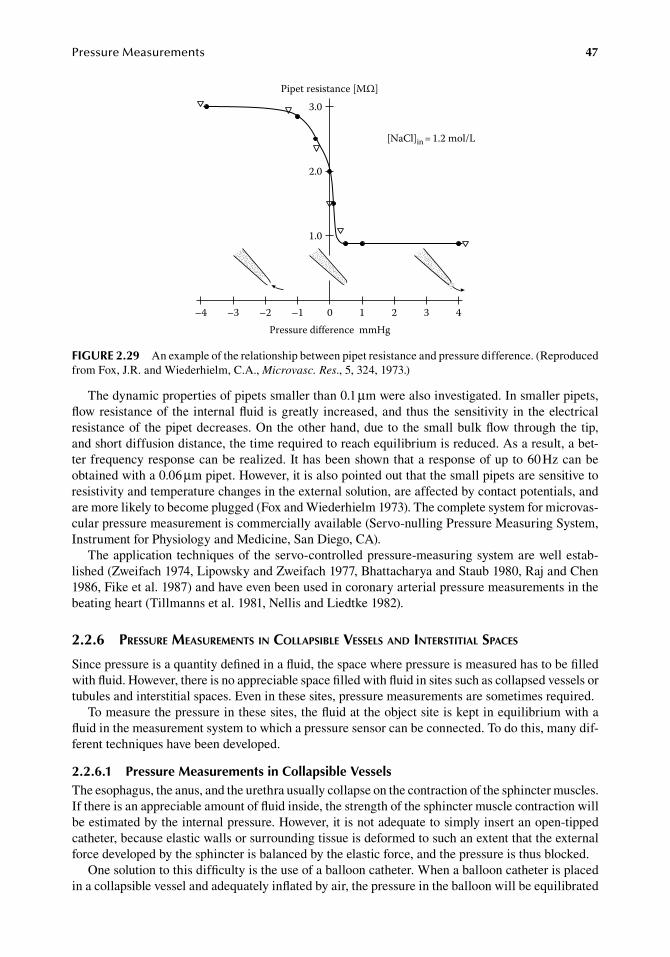
PressureMeasurements 47
The.dynamic.properties.of.pipets.smaller.than.0.1.μm.were.also.investigated..In.smaller.pipets,.flow.resistance.of. the. internal.fluid. is.greatly. increased,.and.thus. the.sensitivity. in. the.electrical.resistance.of. the.pipet.decreases..On.the.other.hand,.due.to. the.small.bulk.flow.through.the.tip,.and.short.diffusion.distance,.the.time.required.to.reach.equilibrium.is.reduced..As.a.result,.a.bet-ter.frequency.response.can.be.realized..It.has.been.shown.that.a.response.of.up.to.60.Hz.can.be.obtained.with.a.0.06.μm.pipet..However,.it.is.also.pointed.out.that.the.small.pipets.are.sensitive.to.resistivity.and.temperature.changes.in.the.external.solution,.are.affected.by.contact.potentials,.and.are.more.likely.to.become.plugged.(Fox.and.Wiederhielm.1973)..The.complete.system.for.microvas-cular.pressure.measurement.is.commercially.available.(Servo-nulling.Pressure.Measuring.System,.Instrument.for.Physiology.and.Medicine,.San.Diego,.CA).
The.application.techniques.of. the.servo-controlled.pressure-measuring.system.are.well.estab-lished.(Zweifach.1974,.Lipowsky.and.Zweifach.1977,.Bhattacharya.and.Staub.1980,.Raj.and.Chen.1986,.Fike.et al..1987).and.have.even.been.used.in.coronary.arterial.pressure.measurements.in.the.beating.heart.(Tillmanns.et al..1981,.Nellis.and.Liedtke.1982).
2.2.6 pressure MeasureMents in collapsible Vessels and interstitial spaces
Since.pressure.is.a.quantity.defined.in.a.fluid,.the.space.where.pressure.is.measured.has.to.be.filled.with.fluid..However,.there.is.no.appreciable.space.filled.with.fluid.in.sites.such.as.collapsed.vessels.or.tubules.and.interstitial.spaces..Even.in.these.sites,.pressure.measurements.are.sometimes.required.
To.measure.the.pressure.in.these.sites,.the.fluid.at.the.object.site.is.kept.in.equilibrium.with.a.fluid.in.the.measurement.system.to.which.a.pressure.sensor.can.be.connected..To.do.this,.many.dif-ferent.techniques.have.been.developed.
2.2.6.1 Pressure Measurements in Collapsible VesselsThe.esophagus,.the.anus,.and.the.urethra.usually.collapse.on.the.contraction.of.the.sphincter.muscles..If.there.is.an.appreciable.amount.of.fluid.inside,.the.strength.of.the.sphincter.muscle.contraction.will.be.estimated.by.the.internal.pressure..However,.it.is.not.adequate.to.simply.insert.an.open-tipped.catheter,.because.elastic.walls.or.surrounding.tissue.is.deformed.to.such.an.extent.that.the.external.force.developed.by.the.sphincter.is.balanced.by.the.elastic.force,.and.the.pressure.is.thus.blocked.
One.solution.to.this.difficulty.is.the.use.of.a.balloon.catheter..When.a.balloon.catheter.is.placed.in.a.collapsible.vessel.and.adequately.inflated.by.air,.the.pressure.in.the.balloon.will.be.equilibrated.
Pipet resistance [MΩ]
[NaCl]in = 1.2 mol/L
3.0
2.0
1.0
–4 –3 –2 –1 0 1 2 3 4Pressure difference mmHg
figure 2.29 An.example.of.the.relationship.between.pipet.resistance.and.pressure.difference..(Reproduced.from.Fox,.J.R..and.Wiederhielm,.C.A.,.Microvasc. Res.,.5,.324,.1973.)
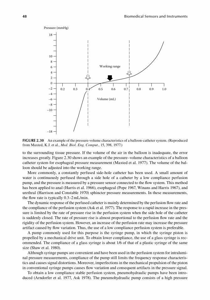
48 BiomedicalSensorsandInstruments
to.the.surrounding.tissue.pressure..If.the.volume.of.the.air.in.the.balloon.is.inadequate,.the.error.increases.greatly..Figure.2.30.shows.an.example.of.the.pressure–volume.characteristics.of.a.balloon.catheter.system.for.esophageal.pressure.measurement.(Maxted.et al..1977)..The.volume.of.the.bal-loon.should.be.adjusted.into.the.working.range.
More.commonly,. a. constantly.perfused. side-hole. catheter.has.been.used..A. small. amount.of.water. is. continuously.perfused. through.a. side.hole.of.a.catheter.by.a. low.compliance.perfusion.pump,.and.the.pressure.is.measured.by.a.pressure.sensor.connected.to.the.flow.system..This.method.has.been.applied.to.anal.(Harris.et al..1966),.esophageal.(Pope.1967,.Winans.and.Harris.1967),.and.urethral.(Harrison.and.Constable.1970).sphincter.pressure.measurements..In.these.measurements,.the.flow.rate.is.typically.0.3–2.mL/min.
The.dynamic.response.of.the.perfused.catheter.is.mainly.determined.by.the.perfusion.flow.rate.and.the.compliance.of.the.perfusion.system.(Ask.et al..1977)..The.response.to.a.rapid.increase.in.the.pres-sure.is.limited.by.the.rate.of.pressure.rise.in.the.perfusion.system.when.the.side.hole.of.the.catheter.is.suddenly.closed..The.rate.of.pressure.rise.is.almost.proportional.to.the.perfusion.flow.rate.and.the.rigidity.of.the.perfusion.system..However,.an.increase.of.the.perfusion.rate.may.increase.the.pressure.artifact.caused.by.flow.variation..Thus,.the.use.of.a.low.compliance.perfusion.system.is.preferable.
A.pump.commonly.used.for. this.purpose.is. the.syringe.pump,. in.which.the.syringe.piston.is.propelled.by.a.mechanical.drive.unit..To.obtain.lower.compliance,.the.use.of.a.glass.syringe.is.rec-ommended..The.compliance.of.a.glass.syringe.is.about.1/6.of.that.of.a.plastic.syringe.of.the.same.size.(Shaw.et al..1980).
Although.syringe.pumps.are.convenient.and.have.been.used.in.the.perfusion.system.for.intralumi-nal.pressure.measurements,.compliance.of.the.pump.still.limits.the.frequency.response.characteris-tics.and.causes.signal.distortions..Moreover,.imperfections.in.the.mechanical.propulsion.of.the.piston.in.conventional.syringe.pumps.causes.flow.variation.and.consequent.artifacts.in.the.pressure.signal.
To.obtain.a.low.compliance.stable.perfusion.system,.pneumohydraulic.pumps.have.been.intro-duced.(Arndorfer.et al..1977,.Ask.1978)..The.pneumohydraulic.pump.consists.of.a.high.pressure.
Working range
Volume (mL)
Pressure (mmHg)
0.2 0.3 0.5 0.6 0.7 0.8 0.9 1.0
02468
10
18
–2–4–6–8
–10
–18
0.4
figure 2.30 An.example.of.the.pressure-volume.characteristics.of.a.balloon-catheter.system..(Reproduced.from.Maxted,.K.J..et al.,.Med. Biol. Eng. Comput.,.15,.398,.1977.)
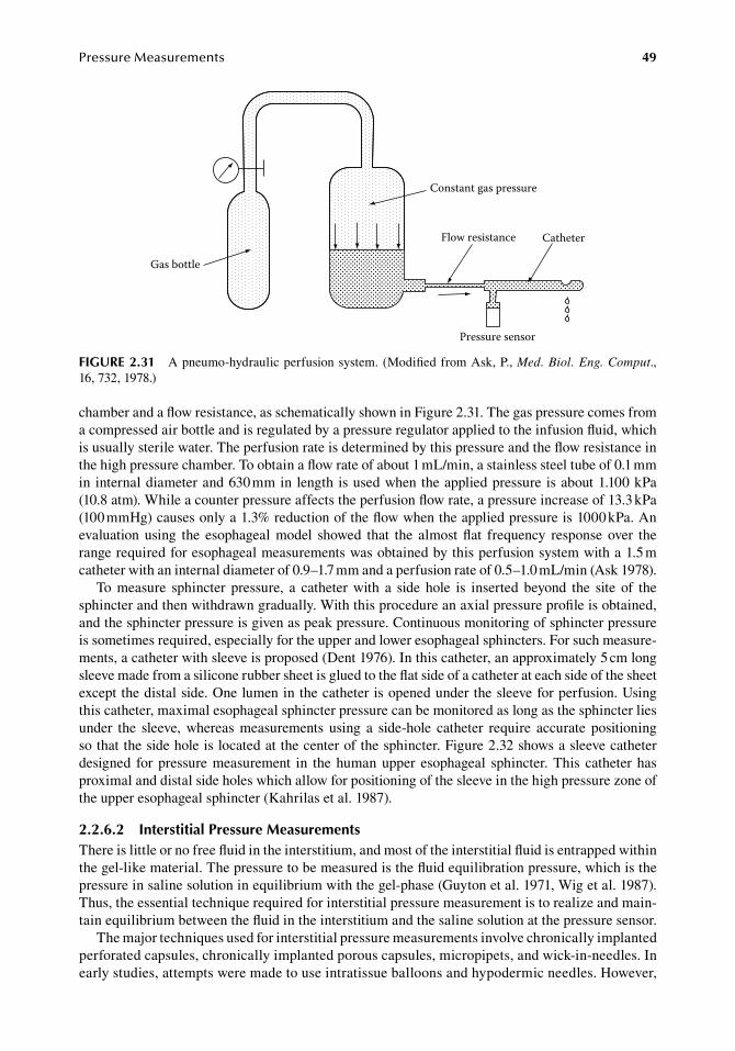
PressureMeasurements 49
chamber.and.a.flow.resistance,.as.schematically.shown.in.Figure.2.31..The.gas.pressure.comes.from.a.compressed.air.bottle.and.is.regulated.by.a.pressure.regulator.applied.to.the.infusion.fluid,.which.is.usually.sterile.water..The.perfusion.rate.is.determined.by.this.pressure.and.the.flow.resistance.in.the.high.pressure.chamber..To.obtain.a.flow.rate.of.about.1.mL/min,.a.stainless.steel.tube.of.0.1.mm.in.internal.diameter.and.630.mm.in.length.is.used.when.the.applied.pressure.is.about.1.100.kPa.(10.8.atm)..While.a.counter.pressure.affects.the.perfusion.flow.rate,.a.pressure.increase.of.13.3.kPa.(100.mmHg).causes.only.a.1.3%.reduction.of.the.flow.when.the.applied.pressure.is.1000.kPa..An.evaluation. using. the. esophageal. model. showed. that. the. almost. flat. frequency. response. over. the.range.required.for.esophageal.measurements.was.obtained.by.this.perfusion.system.with.a.1.5.m.catheter.with.an.internal.diameter.of.0.9–1.7.mm.and.a.perfusion.rate.of.0.5–1.0.mL/min.(Ask.1978).
To. measure. sphincter. pressure,. a. catheter. with. a. side. hole. is. inserted. beyond. the. site. of. the.sphincter.and.then.withdrawn.gradually..With.this.procedure.an.axial.pressure.profile.is.obtained,.and.the.sphincter.pressure.is.given.as.peak.pressure..Continuous.monitoring.of.sphincter.pressure.is.sometimes.required,.especially.for.the.upper.and.lower.esophageal.sphincters..For.such.measure-ments,.a.catheter.with.sleeve.is.proposed.(Dent.1976)..In.this.catheter,.an.approximately.5.cm.long.sleeve.made.from.a.silicone.rubber.sheet.is.glued.to.the.flat.side.of.a.catheter.at.each.side.of.the.sheet.except.the.distal.side..One.lumen.in.the.catheter.is.opened.under.the.sleeve.for.perfusion..Using.this.catheter,.maximal.esophageal.sphincter.pressure.can.be.monitored.as.long.as.the.sphincter.lies.under. the. sleeve,. whereas. measurements. using. a. side-hole. catheter. require. accurate. positioning.so.that.the.side.hole.is.located.at.the.center.of.the.sphincter..Figure.2.32.shows.a.sleeve.catheter.designed. for.pressure.measurement. in. the.human.upper. esophageal. sphincter..This. catheter.has.proximal.and.distal.side.holes.which.allow.for.positioning.of.the.sleeve.in.the.high.pressure.zone.of.the.upper.esophageal.sphincter.(Kahrilas.et al..1987).
2.2.6.2 interstitial Pressure MeasurementsThere.is.little.or.no.free.fluid.in.the.interstitium,.and.most.of.the.interstitial.fluid.is.entrapped.within.the.gel-like.material..The.pressure.to.be.measured.is.the.fluid.equilibration.pressure,.which.is.the.pressure.in.saline.solution.in.equilibrium.with.the.gel-phase.(Guyton.et al..1971,.Wig.et al..1987)..Thus,.the.essential.technique.required.for.interstitial.pressure.measurement.is.to.realize.and.main-tain.equilibrium.between.the.fluid.in.the.interstitium.and.the.saline.solution.at.the.pressure.sensor.
The.major.techniques.used.for.interstitial.pressure.measurements.involve.chronically.implanted.perforated.capsules,.chronically.implanted.porous.capsules,.micropipets,.and.wick-in-needles..In.early.studies,.attempts.were.made.to.use.intratissue.balloons.and.hypodermic.needles..However,.
Gas bottle
Constant gas pressure
Flow resistance Catheter
Pressure sensor
figure 2.31 A.pneumo-hydraulic.perfusion.system..(Modified.from.Ask,.P.,.Med. Biol. Eng. Comput.,.16,.732,.1978.)
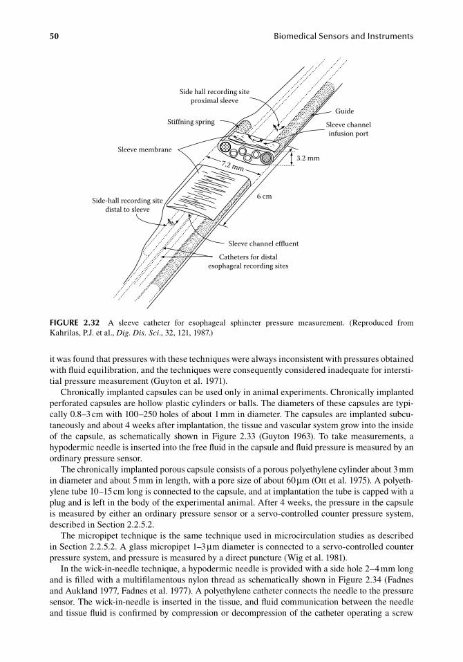
50 BiomedicalSensorsandInstruments
it.was.found.that.pressures.with.these.techniques.were.always.inconsistent.with.pressures.obtained.with.fluid.equilibration,.and.the.techniques.were.consequently.considered.inadequate.for.intersti-tial.pressure.measurement.(Guyton.et al..1971).
Chronically.implanted.capsules.can.be.used.only.in.animal.experiments..Chronically.implanted.perforated.capsules.are.hollow.plastic.cylinders.or.balls..The.diameters.of.these.capsules.are.typi-cally.0.8–3.cm.with.100–250.holes.of.about.1.mm.in.diameter..The.capsules.are.implanted.subcu-taneously.and.about.4.weeks.after.implantation,.the.tissue.and.vascular.system.grow.into.the.inside.of. the. capsule,. as. schematically. shown. in. Figure. 2.33. (Guyton. 1963).. To. take. measurements,. a.hypodermic.needle.is.inserted.into.the.free.fluid.in.the.capsule.and.fluid.pressure.is.measured.by.an.ordinary.pressure.sensor.
The.chronically.implanted.porous.capsule.consists.of.a.porous.polyethylene.cylinder.about.3.mm.in.diameter.and.about.5.mm.in.length,.with.a.pore.size.of.about.60.μm.(Ott.et al..1975)..A.polyeth-ylene.tube.10–15.cm.long.is.connected.to.the.capsule,.and.at.implantation.the.tube.is.capped.with.a.plug.and.is.left.in.the.body.of.the.experimental.animal..After.4.weeks,.the.pressure.in.the.capsule.is.measured.by.either.an.ordinary.pressure.sensor.or.a.servo-controlled.counter.pressure.system,.described.in.Section.2.2.5.2.
The.micropipet.technique.is.the.same.technique.used.in.microcirculation.studies.as.described.in.Section.2.2.5.2..A.glass.micropipet.1–3.μm.diameter.is.connected.to.a.servo-controlled.counter.pressure.system,.and.pressure.is.measured.by.a.direct.puncture.(Wig.et al..1981).
In.the.wick-in-needle.technique,.a.hypodermic.needle.is.provided.with.a.side.hole.2–4.mm.long.and.is.filled.with.a.multifilamentous.nylon.thread.as.schematically.shown.in.Figure.2.34.(Fadnes.and.Aukland.1977,.Fadnes.et al..1977)..A.polyethylene.catheter.connects.the.needle.to.the.pressure.sensor..The.wick-in-needle.is.inserted.in.the.tissue,.and.fluid.communication.between.the.needle.and.tissue.fluid.is.confirmed.by.compression.or.decompression.of.the.catheter.operating.a.screw.
Guide
Sleeve channelinfusion port
3.2 mm7.2 mm
6 cm
Side hall recording siteproximal sleeve
Stiffning spring
Sleeve membrane
Side-hall recording sitedistal to sleeve
Catheters for distalesophageal recording sites
Sleeve channel effluent
figure 2.32 A. sleeve. catheter. for. esophageal. sphincter. pressure. measurement.. (Reproduced. from.Kahrilas,.P.J..et al.,.Dig. Dis. Sci.,.32,.121,.1987.)
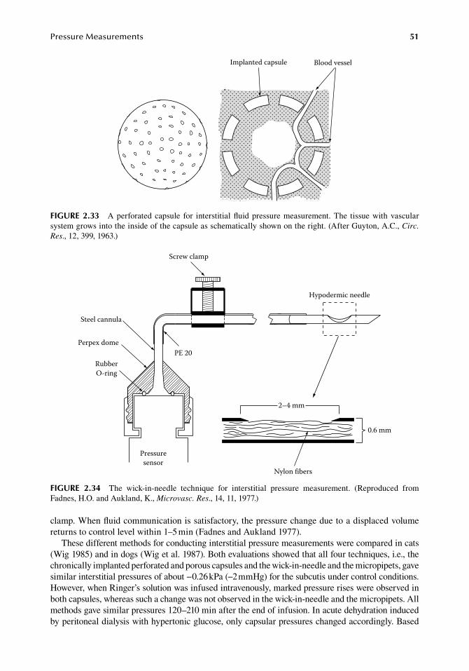
PressureMeasurements 51
clamp..When.fluid.communication.is.satisfactory,.the.pressure.change.due.to.a.displaced.volume.returns.to.control.level.within.1–5.min.(Fadnes.and.Aukland.1977).
These.different.methods.for.conducting.interstitial.pressure.measurements.were.compared.in.cats.(Wig.1985).and.in.dogs.(Wig.et al..1987)..Both.evaluations.showed.that.all.four.techniques,.i.e.,.the.chronically.implanted.perforated.and.porous.capsules.and.the.wick-in-needle.and.the.micropipets,.gave.similar.interstitial.pressures.of.about.−0.26.kPa.(−2.mmHg).for.the.subcutis.under.control.conditions..However,.when.Ringer’s.solution.was.infused.intravenously,.marked.pressure.rises.were.observed.in.both.capsules,.whereas.such.a.change.was.not.observed.in.the.wick-in-needle.and.the.micropipets..All.methods.gave.similar.pressures.120–210.min.after.the.end.of.infusion..In.acute.dehydration.induced.by.peritoneal.dialysis.with.hypertonic.glucose,.only.capsular.pressures.changed.accordingly..Based.
Implanted capsule Blood vessel
figure 2.33 A.perforated.capsule. for. interstitial.fluid.pressure.measurement..The. tissue.with.vascular.system.grows.into.the.inside.of.the.capsule.as.schematically.shown.on.the.right..(After.Guyton,.A.C.,.Circ. Res.,.12,.399,.1963.)
2–4 mm
Screw clamp
Hypodermic needle
Nylon fibers
Pressuresensor
Steel cannula
Perpex dome
RubberO-ring
PE 20
0.6 mm
figure 2.34 The. wick-in-needle. technique. for. interstitial. pressure. measurement.. (Reproduced. from.Fadnes,.H.O..and.Aukland,.K.,.Microvasc. Res.,.14,.11,.1977.)
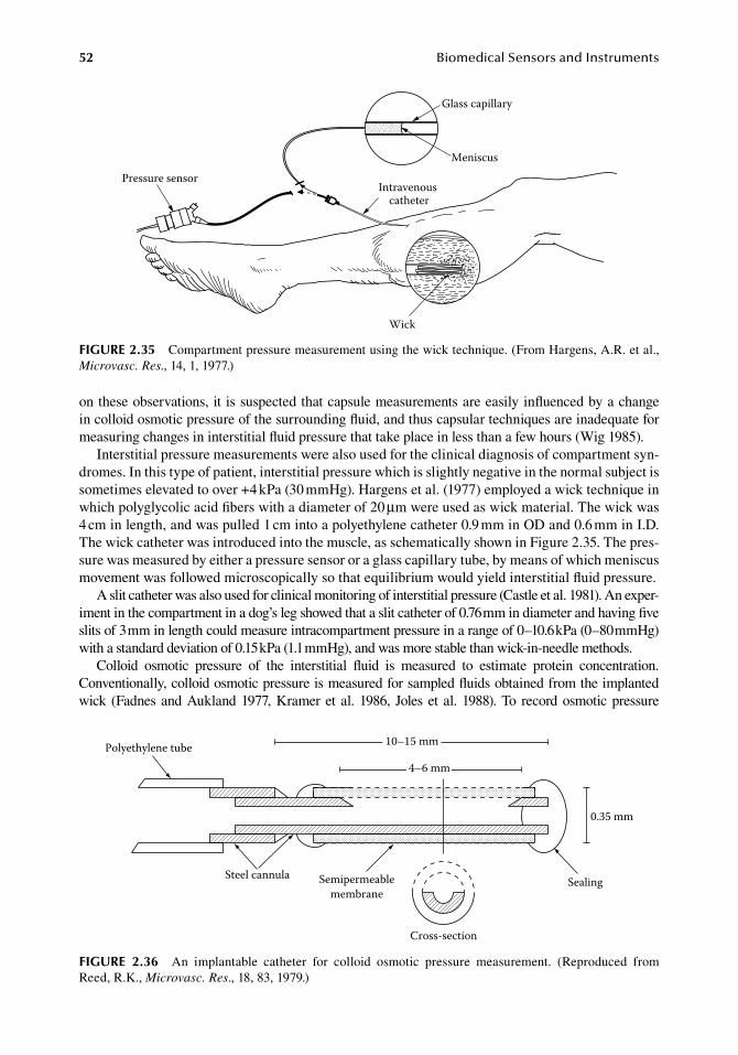
52 BiomedicalSensorsandInstruments
on.these.observations,.it. is.suspected.that.capsule.measurements.are.easily.influenced.by.a.change.in.colloid.osmotic.pressure.of.the.surrounding.fluid,.and.thus.capsular.techniques.are.inadequate.for.measuring.changes.in.interstitial.fluid.pressure.that.take.place.in.less.than.a.few.hours.(Wig.1985).
Interstitial.pressure.measurements.were.also.used.for.the.clinical.diagnosis.of.compartment.syn-dromes..In.this.type.of.patient,.interstitial.pressure.which.is.slightly.negative.in.the.normal.subject.is.sometimes.elevated.to.over.+4.kPa.(30.mmHg)..Hargens.et al..(1977).employed.a.wick.technique.in.which.polyglycolic.acid.fibers.with.a.diameter.of.20.μm.were.used.as.wick.material..The.wick.was.4.cm.in.length,.and.was.pulled.1.cm.into.a.polyethylene.catheter.0.9.mm.in.OD.and.0.6.mm.in.I.D..The.wick.catheter.was.introduced.into.the.muscle,.as.schematically.shown.in.Figure.2.35..The.pres-sure.was.measured.by.either.a.pressure.sensor.or.a.glass.capillary.tube,.by.means.of.which.meniscus.movement.was.followed.microscopically.so.that.equilibrium.would.yield.interstitial.fluid.pressure.
A.slit.catheter.was.also.used.for.clinical.monitoring.of.interstitial.pressure.(Castle.et al..1981)..An.exper-iment.in.the.compartment.in.a.dog’s.leg.showed.that.a.slit.catheter.of.0.76.mm.in.diameter.and.having.five.slits.of.3.mm.in.length.could.measure.intracompartment.pressure.in.a.range.of.0–10.6.kPa.(0–80.mmHg).with.a.standard.deviation.of.0.15.kPa.(1.1.mmHg),.and.was.more.stable.than.wick-in-needle.methods.
Colloid. osmotic. pressure. of. the. interstitial. fluid. is. measured. to. estimate. protein. concentration..Conventionally,.colloid.osmotic.pressure.is.measured.for.sampled.fluids.obtained.from.the.implanted.wick. (Fadnes.and.Aukland.1977,.Kramer.et al..1986,. Joles.et al..1988)..To. record.osmotic.pressure.
Intravenous catheter
Glass capillary
Meniscus
Pressure sensor
Wick
figure 2.35 Compartment.pressure.measurement.using.the.wick.technique..(From.Hargens,.A.R..et al.,.Microvasc. Res.,.14,.1,.1977.)
Polyethylene tube
Steel cannula Semipermeablemembrane
Cross-section
Sealing
0.35 mm
4–6 mm
10–15 mm
figure 2.36 An. implantable. catheter. for. colloid. osmotic. pressure. measurement.. (Reproduced. from.Reed,.R.K.,.Microvasc. Res.,.18,.83,.1979.)
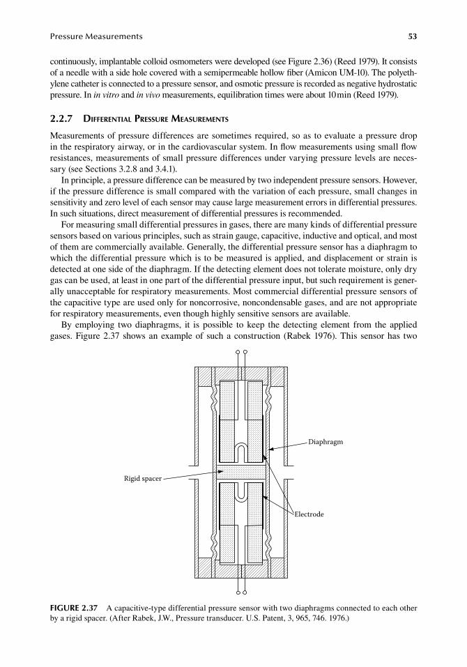
PressureMeasurements 53
continuously,.implantable.colloid.osmometers.were.developed.(see.Figure.2.36).(Reed 1979)..It consists.of.a.needle.with.a.side.hole.covered.with.a.semipermeable.hollow.fiber.(Amicon.UM-10)..The.polyeth-ylene.catheter.is.connected.to.a.pressure.sensor,.and.osmotic.pressure.is.recorded.as.negative.hydrostatic.pressure..In.in vitro.and.in vivo.measurements,.equilibration.times.were.about.10.min.(Reed.1979).
2.2.7 differential pressure MeasureMents
Measurements.of.pressure.differences.are.sometimes.required,.so.as. to.evaluate.a.pressure.drop.in.the.respiratory.airway,.or.in.the.cardiovascular.system..In.flow.measurements.using.small.flow.resistances,.measurements.of.small.pressure.differences.under.varying.pressure.levels.are.neces-sary.(see.Sections.3.2.8.and.3.4.1).
In.principle,.a.pressure.difference.can.be.measured.by.two.independent.pressure.sensors..However,.if.the.pressure.difference.is.small.compared.with.the.variation.of.each.pressure,.small.changes.in.sensitivity.and.zero.level.of.each.sensor.may.cause.large.measurement.errors.in.differential.pressures..In.such.situations,.direct.measurement.of.differential.pressures.is.recommended.
For.measuring.small.differential.pressures.in.gases,.there.are.many.kinds.of.differential.pressure.sensors.based.on.various.principles,.such.as.strain.gauge,.capacitive,.inductive.and.optical,.and.most.of.them.are.commercially.available..Generally,.the.differential.pressure.sensor.has.a.diaphragm.to.which.the.differential.pressure.which.is.to.be.measured.is.applied,.and.displacement.or.strain.is.detected.at.one.side.of.the.diaphragm..If.the.detecting.element.does.not.tolerate.moisture,.only.dry.gas.can.be.used,.at.least.in.one.part.of.the.differential.pressure.input,.but.such.requirement.is.gener-ally.unacceptable.for.respiratory.measurements..Most.commercial.differential.pressure.sensors.of.the.capacitive.type.are.used.only.for.noncorrosive,.noncondensable.gases,.and.are.not.appropriate.for.respiratory.measurements,.even.though.highly.sensitive.sensors.are.available.
By. employing. two.diaphragms,. it. is. possible. to. keep. the.detecting. element. from. the. applied.gases..Figure.2.37.shows.an.example.of. such.a.construction. (Rabek.1976)..This. sensor.has. two.
Diaphragm
Electrode
Rigid spacer
figure 2.37 A.capacitive-type.differential.pressure.sensor.with.two.diaphragms.connected.to.each.other.by.a.rigid.spacer..(After.Rabek,.J.W.,.Pressure.transducer..U.S..Patent,.3,.965,.746..1976.)
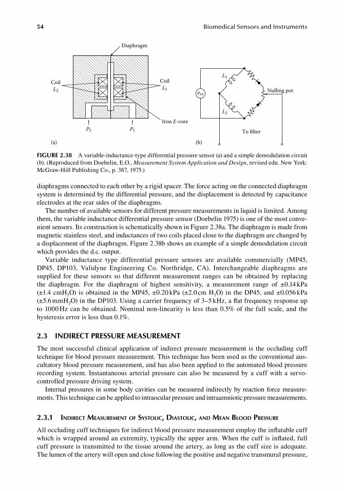
54 BiomedicalSensorsandInstruments
diaphragms.connected.to.each.other.by.a.rigid.spacer..The.force.acting.on.the.connected.diaphragm.system.is.determined.by.the.differential.pressure,.and.the.displacement.is.detected.by.capacitance.electrodes.at.the.rear.sides.of.the.diaphragms.
The.number.of.available.sensors.for.different.pressure.measurements.in.liquid.is.limited..Among.them,.the.variable.inductance.differential.pressure.sensor.(Doebelin.1975).is.one.of.the.most.conve-nient.sensors..Its.construction.is.schematically.shown.in.Figure.2.38a..The.diaphragm.is.made.from.magnetic.stainless.steel,.and.inductances.of.two.coils.placed.close.to.the.diaphragm.are.changed.by.a.displacement.of.the.diaphragm..Figure.2.38b.shows.an.example.of.a.simple.demodulation.circuit.which.provides.the.d.c..output.
Variable. inductance. type. differential. pressure. sensors. are. available. commercially. (MP45,.DP45,. DP103,. Validyne. Engineering. Co.. Northridge,. CA).. Interchangeable. diaphragms. are.supplied. for. these. sensors. so. that. different.measurement. ranges. can.be.obtained.by. replacing.the. diaphragm.. For. the. diaphragm. of. highest. sensitivity,. a. measurement. range. of. ±0.14.kPa.(±1.4.cmH2O). is.obtained. in. the.MP45,.±0.20.kPa.(±2.0.cm.H2O). in. the.DP45,.and.±0.056.kPa.(±5.6.mmH2O).in.the.DP103..Using.a.carrier.frequency.of.3–5.kHz,.a.flat.frequency.response.up.to.1000.Hz.can.be.obtained..Nominal.non-linearity. is. less. than.0.5%.of. the.full.scale,.and.the.hysteresis.error.is.less.than.0.1%.
2.3 indireCt PreSSure MeaSureMent
The.most. successful. clinical. application.of. indirect. pressure.measurement. is. the.occluding. cuff.technique.for.blood.pressure.measurement..This.technique.has.been.used.as.the.conventional.aus-cultatory.blood.pressure.measurement,.and.has.also.been.applied.to.the.automated.blood.pressure.recording. system.. Instantaneous. arterial. pressure. can. also.be.measured.by.a. cuff.with. a. servo-controlled.pressure.driving.system.
Internal.pressures.in.some.body.cavities.can.be.measured.indirectly.by.reaction.force.measure-ments..This.technique.can.be.applied.to.intraocular.pressure.and.intraamniotic.pressure.measurements.
2.3.1 indirect MeasureMent of systolic, diastolic, and Mean blood pressure
All.occluding.cuff.techniques.for.indirect.blood.pressure.measurement.employ.the.inflatable.cuff.which.is.wrapped.around.an.extremity,.typically.the.upper.arm..When.the.cuff.is.inflated,.full.cuff.pressure.is.transmitted.to.the.tissue.around.the.artery,.as.long.as.the.cuff.size.is.adequate..The.lumen.of.the.artery.will.open.and.close.following.the.positive.and.negative.transmural.pressure,.
L1
L2
Nulling pot
To lter
eex
(b)
Diaphragm
CoilL2
CoilL1
Iron E-coreP1P2
(a)
figure 2.38 A.variable-inductance-type.differential.pressure.sensor.(a).and.a.simple.demodulation.circuit.(b)..(Reproduced.from.Doebelin,.E.O.,.Measurement System Application and Design,.revised.edn..New.York:.McGraw-Hill.Publishing.Co.,.p..387,.1975.)
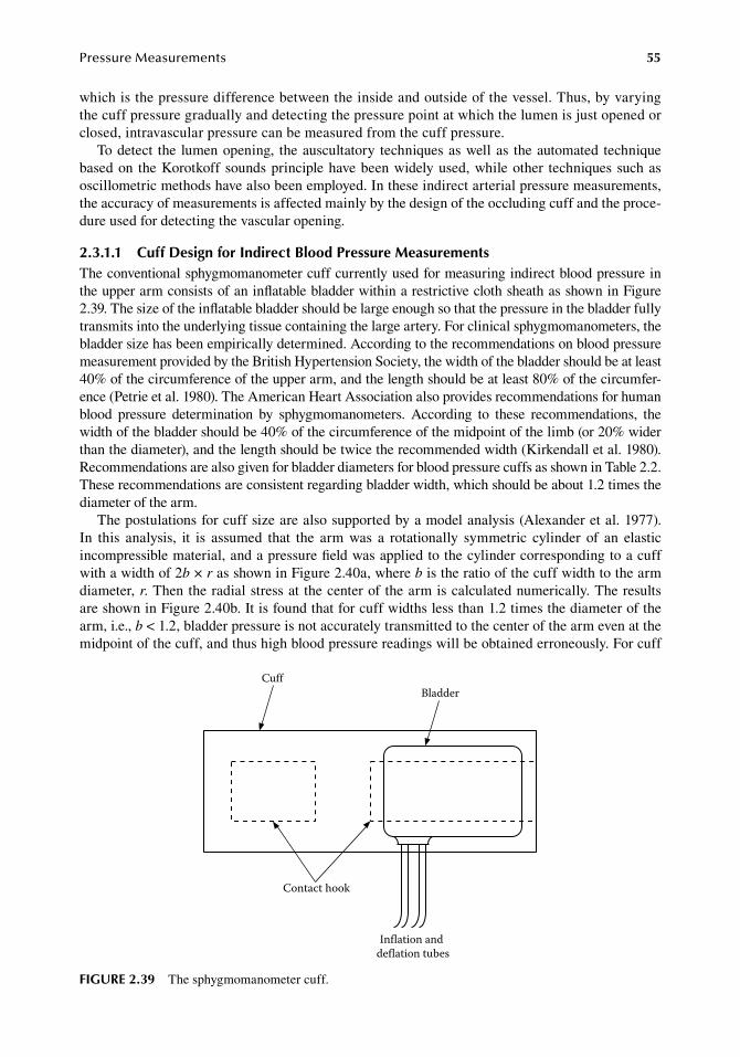
PressureMeasurements 55
which.is.the.pressure.difference.between.the.inside.and.outside.of.the.vessel..Thus,.by.varying.the.cuff.pressure.gradually.and.detecting.the.pressure.point.at.which.the.lumen.is.just.opened.or.closed,.intravascular.pressure.can.be.measured.from.the.cuff.pressure.
To.detect. the. lumen.opening,. the.auscultatory. techniques.as.well.as. the.automated. technique.based.on. the.Korotkoff.sounds.principle.have.been.widely.used,.while.other. techniques.such.as.oscillometric.methods.have.also.been.employed..In.these.indirect.arterial.pressure.measurements,.the.accuracy.of.measurements.is.affected.mainly.by.the.design.of.the.occluding.cuff.and.the.proce-dure.used.for.detecting.the.vascular.opening.
2.3.1.1 Cuff design for indirect blood Pressure MeasurementsThe.conventional.sphygmomanometer.cuff.currently.used.for.measuring.indirect.blood.pressure.in.the.upper.arm.consists.of.an.inflatable.bladder.within.a.restrictive.cloth.sheath.as.shown.in.Figure.2.39..The.size.of.the.inflatable.bladder.should.be.large.enough.so.that.the.pressure.in.the.bladder.fully.transmits.into.the.underlying.tissue.containing.the.large.artery..For.clinical.sphygmomanometers,.the.bladder.size.has.been.empirically.determined..According.to.the.recommendations.on.blood.pressure.measurement.provided.by.the.British.Hypertension.Society,.the.width.of.the.bladder.should.be.at.least.40%.of.the.circumference.of.the.upper.arm,.and.the.length.should.be.at.least.80%.of.the.circumfer-ence.(Petrie.et al..1980)..The.American.Heart.Association.also.provides.recommendations.for.human.blood. pressure. determination. by. sphygmomanometers.. According. to. these. recommendations,. the.width.of.the.bladder.should.be.40%.of.the.circumference.of.the.midpoint.of.the.limb.(or.20%.wider.than.the.diameter),.and.the.length.should.be.twice.the.recommended.width.(Kirkendall.et al..1980)..Recommendations.are.also.given.for.bladder.diameters.for.blood.pressure.cuffs.as.shown.in.Table.2.2..These.recommendations.are.consistent.regarding.bladder.width,.which.should.be.about.1.2.times.the.diameter.of.the.arm.
The.postulations.for.cuff.size.are.also.supported.by.a.model.analysis.(Alexander.et al..1977)..In. this. analysis,. it. is. assumed. that. the. arm. was. a. rotationally. symmetric. cylinder. of. an. elastic.incompressible.material,.and.a.pressure.field.was.applied.to.the.cylinder.corresponding.to.a.cuff.with.a.width.of.2b.×.r.as.shown.in.Figure.2.40a,.where.b.is.the.ratio.of.the.cuff.width.to.the.arm.diameter, r..Then.the.radial.stress.at. the.center.of.the.arm.is.calculated.numerically..The.results.are.shown.in.Figure.2.40b..It.is.found.that.for.cuff.widths.less.than.1.2.times.the.diameter.of.the.arm,.i.e.,.b.<.1.2,.bladder.pressure.is.not.accurately.transmitted.to.the.center.of.the.arm.even.at.the.midpoint.of.the.cuff,.and.thus.high.blood.pressure.readings.will.be.obtained.erroneously..For.cuff.
CuffBladder
Contact hook
Inflation and deflation tubes
figure 2.39 The.sphygmomanometer.cuff.
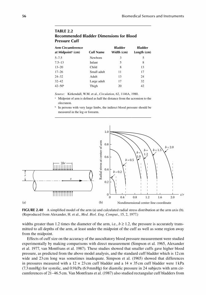
56 BiomedicalSensorsandInstruments
widths.greater.than.1.2.times.the.diameter.of.the.arm,.i.e.,.b.≥.1.2,.the.pressure.is.accurately.trans-mitted.to.all.depths.of.the.arm,.at.least.under.the.midpoint.of.the.cuff.as.well.as.some.region.away.from.the.midpoint.
Effects.of.cuff.size.on.the.accuracy.of.the.auscultatory.blood.pressure.measurement.were.studied.experimentally.by.making.comparisons.with.direct.measurement.(Simpson.et al..1965,.Alexander.et al..1977,.van.Montfrans.et al..1987)..These.studies.showed.that.smaller.cuffs.gave.higher.blood.pressure,.as.predicted.from.the.above.model.analysis,.and.the.standard.cuff.bladder.which.is.12.cm.wide. and. 23.cm. long. was. sometimes. inadequate.. Simpson. et al.. (1965). showed. that. differences.in.pressures.measured.with.a.12.×.23.cm.cuff.bladder.and.a.14.×.35.cm.cuff.bladder.were.1.kPa.(7.3.mmHg).for.systolic,.and.0.9.kPa.(6.9.mmHg).for.diastolic.pressure.in.24.subjects.with.arm.cir-cumferences.of.21–46.5.cm..Van.Montfrans.et al..(1987).also.studied.rectangular.cuff.bladders.from.
table 2.2recommended bladder dimensions for blood Pressure Cuff
arm Circumference at Midpointa (cm) Cuff name
bladder Width (cm)
bladder length (cm)
5–7.5 Newborn 3 5
7.5–13 Infant 5 8
13–20 Child 8 13
17–26 Small.adult 11 17
24–32 Adult 13 24
32–42 Large.adult 17 32
42–50b Thigh 20 42
Source:. Kirkendall,.W.M..et al.,.Circulation,.62,.1146A,.1980.a. Midpoint.of.arm.is.defined.as.half.the.distance.from.the.acromion.to.the.
olecranon.b. In.persons.with.very.large.limbs,.the.indirect.blood.pressure.should.be.
measured.in.the.leg.or.forearm.
2br
rz
(a)
Radi
al st
ress
at ce
nter
of a
rm
1.0
0.8
0.6
0.4
0.2
0 z/r2.00 0.4 0.8 1.2 1.6
b = 0.2
b = 0.5
b =1.2b =
1.0
b = 1.5b = 2.0
Nondimensional center-line coordinate(b)
figure 2.40 A.simplified.model.of.the.arm.(a).and.calculated.radial.stress.distribution.at.the.arm.axis.(b)..(Reproduced.from.Alexander,.H..et al.,.Med. Biol. Eng. Comput.,.15,.2,.1977.)
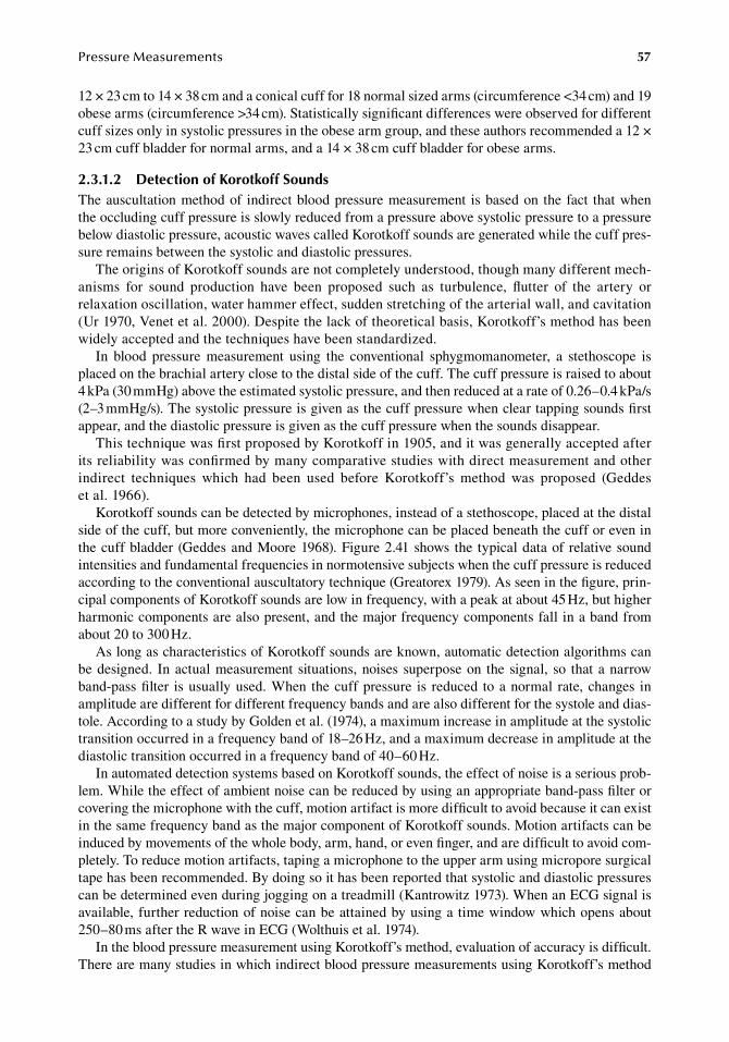
PressureMeasurements 57
12.×.23.cm.to.14.×.38.cm.and.a.conical.cuff.for.18.normal.sized.arms.(circumference.<34.cm).and.19.obese.arms.(circumference.>34.cm)..Statistically.significant.differences.were.observed.for.different.cuff.sizes.only.in.systolic.pressures.in.the.obese.arm.group,.and.these.authors.recommended.a.12.×.23.cm.cuff.bladder.for.normal.arms,.and.a.14.×.38.cm.cuff.bladder.for.obese.arms.
2.3.1.2 detection of Korotkoff SoundsThe.auscultation.method.of. indirect.blood.pressure.measurement. is.based.on. the. fact. that.when.the.occluding.cuff.pressure.is.slowly.reduced.from.a.pressure.above.systolic.pressure.to.a.pressure.below.diastolic.pressure,.acoustic.waves.called.Korotkoff.sounds.are.generated.while.the.cuff.pres-sure.remains.between.the.systolic.and.diastolic.pressures.
The.origins.of.Korotkoff.sounds.are.not.completely.understood,.though.many.different.mech-anisms. for. sound. production. have. been. proposed. such. as. turbulence,. flutter. of. the. artery. or.relaxation.oscillation,.water.hammer.effect,.sudden.stretching.of.the.arterial.wall,.and.cavitation.(Ur.1970,.Venet.et al..2000)..Despite.the.lack.of.theoretical.basis,.Korotkoff’s.method.has.been.widely.accepted.and.the.techniques.have.been.standardized.
In. blood. pressure. measurement. using. the. conventional. sphygmomanometer,. a. stethoscope. is.placed.on.the.brachial.artery.close.to.the.distal.side.of.the.cuff..The.cuff.pressure.is.raised.to.about.4.kPa.(30.mmHg).above.the.estimated.systolic.pressure,.and.then.reduced.at.a.rate.of.0.26–0.4.kPa/s.(2–3.mmHg/s)..The.systolic.pressure.is.given.as.the.cuff.pressure.when.clear.tapping.sounds.first.appear,.and.the.diastolic.pressure.is.given.as.the.cuff.pressure.when.the.sounds.disappear.
This.technique.was.first.proposed.by.Korotkoff.in.1905,.and.it.was.generally.accepted.after.its.reliability.was.confirmed.by.many.comparative.studies.with.direct.measurement.and.other.indirect. techniques. which. had. been. used. before. Korotkoff’s. method. was. proposed. (Geddes.et al..1966).
Korotkoff.sounds.can.be.detected.by.microphones,.instead.of.a.stethoscope,.placed.at.the.distal.side.of.the.cuff,.but.more.conveniently,.the.microphone.can.be.placed.beneath.the.cuff.or.even.in.the.cuff.bladder.(Geddes.and.Moore.1968)..Figure.2.41.shows. the. typical.data.of. relative.sound.intensities.and.fundamental.frequencies.in.normotensive.subjects.when.the.cuff.pressure.is.reduced.according.to.the.conventional.auscultatory.technique.(Greatorex.1979)..As.seen.in.the.figure,.prin-cipal.components.of.Korotkoff.sounds.are.low.in.frequency,.with.a.peak.at.about.45.Hz,.but.higher.harmonic.components.are.also.present,.and.the.major.frequency.components.fall.in.a.band.from.about.20.to.300.Hz.
As.long.as.characteristics.of.Korotkoff.sounds.are.known,.automatic.detection.algorithms.can.be.designed.. In.actual.measurement. situations,.noises. superpose.on. the.signal,. so. that.a.narrow.band-pass.filter. is.usually.used..When. the.cuff.pressure. is. reduced. to.a.normal. rate,.changes. in.amplitude.are.different.for.different.frequency.bands.and.are.also.different.for.the.systole.and.dias-tole..According.to.a.study.by.Golden.et al..(1974),.a.maximum.increase.in.amplitude.at.the.systolic.transition.occurred.in.a.frequency.band.of.18–26.Hz,.and.a.maximum.decrease.in.amplitude.at.the.diastolic.transition.occurred.in.a.frequency.band.of.40–60.Hz.
In.automated.detection.systems.based.on.Korotkoff.sounds,.the.effect.of.noise.is.a.serious.prob-lem..While.the.effect.of.ambient.noise.can.be.reduced.by.using.an.appropriate.band-pass.filter.or.covering.the.microphone.with.the.cuff,.motion.artifact.is.more.difficult.to.avoid.because.it.can.exist.in.the.same.frequency.band.as.the.major.component.of.Korotkoff.sounds..Motion.artifacts.can.be.induced.by.movements.of.the.whole.body,.arm,.hand,.or.even.finger,.and.are.difficult.to.avoid.com-pletely..To.reduce.motion.artifacts,.taping.a.microphone.to.the.upper.arm.using.micropore.surgical.tape.has.been.recommended..By.doing.so.it.has.been.reported.that.systolic.and.diastolic.pressures.can.be.determined.even.during.jogging.on.a.treadmill.(Kantrowitz.1973)..When.an.ECG.signal.is.available,.further.reduction.of.noise.can.be.attained.by.using.a.time.window.which.opens.about.250–80.ms.after.the.R.wave.in.ECG.(Wolthuis.et al..1974).
In.the.blood.pressure.measurement.using.Korotkoff’s.method,.evaluation.of.accuracy.is.difficult..There.are.many.studies.in.which.indirect.blood.pressure.measurements.using.Korotkoff’s.method.
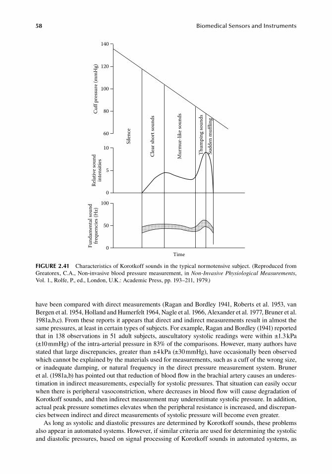
58 BiomedicalSensorsandInstruments
have.been.compared.with.direct.measurements.(Ragan.and.Bordley.1941,.Roberts.et al..1953,.van.Bergen.et al..1954,.Holland.and.Humerfelt.1964,.Nagle.et al..1966,.Alexander.et al..1977,.Bruner.et al..1981a,b,c)..From.these.reports.it.appears.that.direct.and.indirect.measurements.result.in.almost.the.same.pressures,.at.least.in.certain.types.of.subjects..For.example,.Ragan.and.Bordley.(1941).reported.that. in.138.observations. in.51.adult. subjects,.auscultatory.systolic. readings.were.within.±1.3.kPa.(±10.mmHg).of.the.intra-arterial.pressure.in.83%.of.the.comparisons..However,.many.authors.have.stated.that.large.discrepancies,.greater.than.±4.kPa.(±30.mmHg),.have.occasion.ally been.observed.which.cannot.be.explained.by.the.materials.used.for.measurements,.such.as.a.cuff.of.the.wrong.size,.or. inadequate.damping,.or.natural. frequency. in. the.direct.pressure.measurement. system..Bruner.et al..(1981a,b).has.pointed.out.that.reduction.of.blood.flow.in.the.brachial.artery.causes.an.underes-timation.in.indirect.measurements,.especially.for.systolic.pressures..That.situation.can.easily.occur.when.there.is.peripheral.vasoconstriction,.where.decreases.in.blood.flow.will.cause.degradation.of.Korotkoff.sounds,.and.then.indirect.measurement.may.underestimate.systolic.pressure..In.addition,.actual.peak.pressure.sometimes.elevates.when.the.peripheral.resistance.is.increased,.and.discrepan-cies.between.indirect.and.direct.measurements.of.systolic.pressure.will.become.even.greater.
As.long.as.systolic.and.diastolic.pressures.are.determined.by.Korotkoff.sounds,.these.problems.also.appear.in.automated.systems..However,.if.similar.criteria.are.used.for.determining.the.systolic.and.diastolic.pressures,.based.on.signal.processing.of.Korotkoff.sounds.in.automated.systems,.as.
Time
Fund
amen
tal s
ound
frequ
enci
es (H
z)Re
lativ
e sou
ndin
tens
ities
Cuff
pres
sure
(mm
Hg)
140
120
100
80
60
0
5
10
100
50
0
Sile
nce
Clea
r sho
rt so
unds
Mur
mur
-like
soun
ds
Thum
ping
soun
dsSu
dden
muf
fling
figure 2.41 Characteristics.of.Korotkoff.sounds.in.the.typical.normotensive.subject..(Reproduced.from.Greatorex,.C.A.,.Non-invasive.blood.pressure.measurement,. in.Non-Invasive Physiological Measurements,.Vol..1.,.Rolfe,.P.,.ed.,.London,.U.K.:.Academic.Press,.pp..193–211,.1979.)
PressureMeasurements 59
in. conventional. auscultatory. techniques,. it. may. be. expected. that. both. measurements. will. result.in.almost. the.same.pressure,.even. if. this.value.differs. from.the.one.obtained.at.direct.measure-ment..Actually,.Wolthuis. et al.. (1974). showed. that. their. automated. system.can.detect.Korotkoff.sound.signals.corresponding.to.systolic.and.diastolic.pressure.within.two.beats.from.the.auscul-tatory.determination,.when. the.cuff.pressure. is. reduced. to.a. rate.of.about.0.4.kPa/s. (3.mmHg/s)..Thus,.discrepancies.in.systolic.and.diastolic.pressure.for.both.measurements.will.be.within.0.8.kPa.(6.mmHg).when.the.heart.rate.is.60.bpm.
2.3.1.3 Mean blood Pressure Measurements by the oscillometric MethodThe.oscillometric.method.is.an.indirect.method.of.measurement.of.mean.arterial.pressure.based.on.a.principle. in.which. the.oscillation. in. the.occluding.cuff.pressure.due. to. the.arterial.volume.pulsation.has.the.maximum.amplitude.when.the.cuff.pressure.is.close.to.the.mean.arterial.pressure..Historically,. the.oscillation.in.the.occluding.cuff.pressure.was.used.for.blood.pressure.measure-ments.even.before.Korotkoff’s.method.was.proposed,.and.in.earlier.investigations,.the.cuff.pressure.for.maximum.oscillation.was.sometimes.confused.with.the.diastolic.pressure..Many.comparative.studies.with.direct.arterial.pressure.measurements.in.animal.and.human.subjects,.as.well.as.model.experiments,.have.shown.that.the.pressure.for.maximum.oscillation.is.always.very.close.to.the.mean.arterial.pressure.(Posey.et al..1969).
The.principle.of.the.oscillometric.method.was.demonstrated.by.simplified.model.experiments..Posey.et al..(1969).used.a.saline-filled.compression.chamber.as.a.model.of.the.arm..An.arterial.seg-ment.was.placed.in.it.and.was.perfused.by.blood.from.the.carotid.artery.of.the.animal..Oscillation.of.the.chamber.pressure.was.then.observed..Results.from.this.experiment.showed.that.the.lowest.chamber. pressure. for. maximum. oscillations,. when. the. amplitude. remains. constant,. was. only. a.small.percent.below.true.mean.arterial.pressure.
Yamakoshi.et al..(1982a).also.tried.a.similar.model.experiment.but.used.an.air-filled.chamber..They.observed.volumetric.oscillation,.and.concluded.that.the.maximum.volume.pulsation.occurred.when. the.chamber.pressure.was.equal. to. the.mean.arterial.pressure.within.an.error.of.±0.4.kPa.(±3.mmHg)..They.also.compared.the.pressure.for.maximum.oscillation.in.an.amplitude.of.photo-plethysmographic.pulsation.at. the.human.finger. to. the.directly.measured.mean.brachial. arterial.pressure,.and.found.that.indirectly.measured.finger.pressures.were.approximately.5%.lower.than.mean.brachial.pressures.(Yamakoshi.et al..1982b)..Figure.2.42.shows.an.example.of. the.volume.oscillation.signal.detected.by.transmission-type.photo.plethysmography.at.the.index.finger..In.this.example,.cuff.pressure.for.maximum.amplitude.of.the.plethysmographic.signal.was.only.0.4.kPa.(3.mmHg).below.the.directly.measured.mean.pressure.in.the.brachial.artery,.and.the.point.of.disap-pearance.was.0.26.kPa.(2.mmHg).below.systolic.pressure.
Ramsey.(1979).used.a.standard.cuff.and.automatic.determination.system.of.the.maximum.oscilla-tion.in.the.cuff.pressure,.and.pressures.for.maximum.oscillation.were.compared.with.direct.arterial.pressure.measurements..The.results.showed.that.the.overall.error.was.only.0.03.kPa.(0.23.mmHg).with.a.standard.deviation.of.0.56.kPa.(4.21.mmHg),.in.28.measurements.in.17.subjects..These.obser-vations.indicate.that.mean.arterial.pressure.measurement.by.oscillometric.methods.is.reliable.and.accurate.enough.for.most.clinical.applications.
Since.the.auscultatory.method.became.a.standard.technique.of.clinical.blood.pressure.measure-ment,. the.oscillometric.method.was. seldom.used.clinically.until. this.principle.was.employed. in.simple.electronic.blood.pressure.meters..Mean.blood.pressure.measurement.by.the.oscillometric.method.has.some.advantages.which.are.worth.noting:.(a).The.oscillation.can.be.detected.by.either.cuff.pressure.or.the.plethysmogram,.using.the.mechanical,.photoelectric,.or.impedance.method;.(b).the.maximum.amplitude.of.the.oscillation.can.be.determined.objectively.and.easily,.because.a.sharp.maximum.in.amplitude.is.usually.observed;.and.(c).the.procedure.for.detecting.maximum.amplitude.can.easily.be.automated..Thus,. the.oscillometric.method. is.more.convenient. than. the.auscultatory.method.for.continuous.blood.pressure.monitors..The.difficulty.in.applying.the.oscil-lometric.method.clinically.is.due.to.the.fact.that.it.gives.systolic.and.mean.blood.pressures,.while.
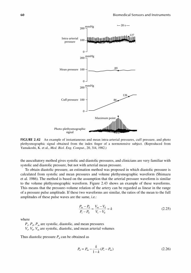
60 BiomedicalSensorsandInstruments
the.auscultatory.method.gives.systolic.and.diastolic.pressures,.and.clinicians.are.very.familiar.with.systolic.and.diastolic.pressure,.but.not.with.arterial.mean.pressure.
To.obtain.diastolic.pressure,.an.estimation.method.was.proposed.in.which.diastolic.pressure.is.calculated. from. systolic. and. mean. pressures. and. volume. plethysmographic. waveform. (Shimazu.et al..1986)..The.method.is.based.on.the.assumption.that.the.arterial.pressure.waveform.is.similar.to. the. volume. plethysmographic. waveform.. Figure. 2.43. shows. an. example. of. these. waveforms..This.means.that.the.pressure–volume.relation.of.the.artery.can.be.regarded.as.linear.in.the.range.of.a.pressure.pulse.amplitude..If.these.two.waveforms.are.similar,.the.ratios.of.the.mean.to.the.full.amplitudes.of.these.pulse.waves.are.the.same,.i.e.:
.
P P
P P
V V
V Vkm d
s d
m d
s d
−−
= −−
=.
(2.25)
wherePs,.Pd,.Pm.are.systolic,.diastolic,.and.mean.pressuresVs,.Vd,.Vm.are.systolic,.diastolic,.and.mean.arterial.volumes
Thus.diastolic.pressure.Pd.can.be.obtained.as
.P P
k
kP Pd m s m
1= −
−−( )
.(2.26)
20 s200 mmHg
100
0
Intra-arterialpressure
mmHg200
100
0
Mean pressure
Cuff pressure
mmHg200
100
0
Photo-plethysmographicsignal
89
86126
Maximum point
127
figure 2.42 An.example.of.instantaneous.and.mean.intra-arterial.pressures,.cuff.pressure,.and.photo.plethysmographic. signal. obtained. from. the. index. finger. of. a. normotensive. subject.. (Reproduced. from.Yamakoshi,.K..et al.,.Med. Biol. Eng. Comput.,.20,.314,.1982.)
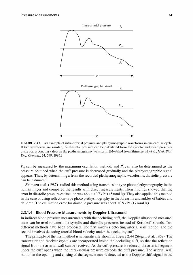
PressureMeasurements 61
Pm.can.be.measured.by. the.maximum.oscillation.method,.and.Ps.can.also.be.determined.as. the.pressure.obtained.when.the.cuff.pressure.is.decreased.gradually.and.the.plethysmographic.signal.appears..Thus,.by.determining.k.from.the.recorded.plethysmographic.waveforms,.diastolic.pressure.can.be.estimated.
Shimazu.et al..(1987).studied.this.method.using.transmission.type.photo.plethysmography.in.the.human.finger.and.compared.the.results.with.direct.measurements..Their.findings.showed.that.the.error.in.diastolic.pressure.estimation.was.about.±0.7.kPa.(±5.mmHg)..They.also.applied.this.method.in.the.case.of.using.reflection-type.photo.plethysmography.in.the.forearms.and.ankles.of.babies.and.children..The.estimation.error.for.diastolic.pressure.was.about.±0.9.kPa.(±7.mmHg).
2.3.1.4 blood Pressure Measurements by doppler ultrasoundIn.indirect.blood.pressure.measurements.with.the.occluding.cuff,.the.Doppler.ultrasound.measure-ment.can.be.used.to.determine.systolic.and.diastolic.pressures.instead.of.Korotkoff.sounds..Two.different.methods.have.been.proposed..The.first. involves.detecting.arterial.wall.motion,.and.the.second.involves.detecting.arterial.blood.velocity.under.the.occluding.cuff.
The.principle.of.the.first.method.is.schematically.shown.in.Figure.2.44.(Stegall.et al..1968)..The.transmitter.and.receiver.crystals.are.incorporated.inside.the.occluding.cuff,.so.that.the.reflection.signal.from.the.arterial.wall.can.be.received..As.the.cuff.pressure.is.reduced,.the.arterial.segment.under.the.cuff.opens.when.the.intravascular.pressure.exceeds.the.cuff.pressure..The.arterial.wall.motion.at.the.opening.and.closing.of.the.segment.can.be.detected.as.the.Doppler.shift.signal.in.the.
Intra-arterial pressure
Plethysmographic signal
T
T
Ps
Pm
Pd
Vs
Vm
Vd
figure 2.43 An.example.of.intra-arterial.pressure.and.plethysmographic.waveforms.in.one.cardiac.cycle..If.two.waveforms.are.similar,.the.diastolic.pressure.can.be.calculated.from.the.systolic.and.mean.pressures.using.corresponding.values.in.the.plethysmographic.waveform..(Modified.from.Shimazu,.H..et al.,.Med. Biol. Eng. Comput.,.24,.549,.1986.)
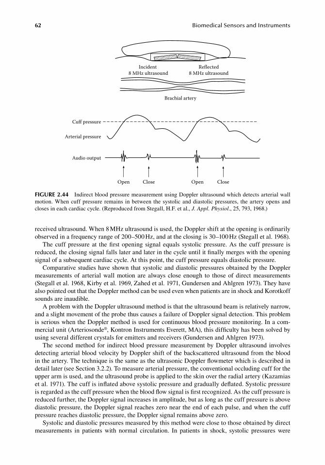
62 BiomedicalSensorsandInstruments
received.ultrasound..When.8.MHz.ultrasound.is.used,.the.Doppler.shift.at.the.opening.is.ordinarily.observed.in.a.frequency.range.of.200–500.Hz,.and.at.the.closing.is.30–100.Hz.(Stegall.et al..1968).
The.cuff.pressure.at. the.first.opening. signal. equals. systolic.pressure..As. the.cuff.pressure. is.reduced,.the.closing.signal.falls.later.and.later.in.the.cycle.until.it.finally.merges.with.the.opening.signal.of.a.subsequent.cardiac.cycle..At.this.point,.the.cuff.pressure.equals.diastolic.pressure.
Comparative.studies.have.shown.that.systolic.and.diastolic.pressures.obtained.by.the.Doppler.measurements.of. arterial.wall.motion. are. always. close. enough. to. those.of.direct.measurements.(Stegall.et al..1968,.Kirby.et al..1969,.Zahed.et al..1971,.Gundersen.and.Ahlgren.1973)..They.have.also.pointed.out.that.the.Doppler.method.can.be.used.even.when.patients.are.in.shock.and.Korotkoff.sounds.are.inaudible.
A.problem.with.the.Doppler.ultrasound.method.is.that.the.ultrasound.beam.is.relatively.narrow,.and.a.slight.movement.of.the.probe.thus.causes.a.failure.of.Doppler.signal.detection..This.problem.is.serious.when.the.Doppler.method.is.used.for.continuous.blood.pressure.monitoring..In.a.com-mercial.unit.(Arteriosonde®,.Kontron.Instruments.Everett,.MA),.this.difficulty.has.been.solved.by.using.several.different.crystals.for.emitters.and.receivers.(Gundersen.and.Ahlgren.1973).
The. second.method. for. indirect.blood.pressure.measurement.by.Doppler.ultrasound. involves.detecting.arterial.blood.velocity.by.Doppler.shift.of.the.backscattered.ultrasound.from.the.blood.in.the.artery..The.technique.is.the.same.as.the.ultrasonic.Doppler.flowmeter.which.is.described.in.detail.later.(see.Section.3.2.2)..To.measure.arterial.pressure,.the.conventional.occluding.cuff.for.the.upper.arm.is.used,.and.the.ultrasound.probe.is.applied.to.the.skin.over.the.radial.artery.(Kazamias.et al..1971)..The.cuff.is.inflated.above.systolic.pressure.and.gradually.deflated..Systolic.pressure.is.regarded.as.the.cuff.pressure.when.the.blood.flow.signal.is.first.recognized..As.the.cuff.pressure.is.reduced.further,.the.Doppler.signal.increases.in.amplitude,.but.as.long.as.the.cuff.pressure.is.above.diastolic.pressure,.the.Doppler.signal.reaches.zero.near.the.end.of.each.pulse,.and.when.the.cuff.pressure.reaches.diastolic.pressure,.the.Doppler.signal.remains.above.zero.
Systolic.and.diastolic.pressures.measured.by.this.method.were.close.to.those.obtained.by.direct.measurements. in. patients. with. normal. circulation.. In. patients. in. shock,. systolic. pressures. were.
Incident 8 MHz ultrasound
Reflected8 MHz ultrasound
Brachial artery
Cuff pressure
Arterial pressure
Audio output
Open Close CloseOpen
figure 2.44 Indirect.blood.pressure.measurement.using.Doppler.ultrasound.which.detects.arterial.wall.motion..When.cuff.pressure. remains. in.between. the.systolic.and.diastolic.pressures,. the.artery.opens.and.closes.in.each.cardiac.cycle..(Reproduced.from.Stegall,.H.F..et al.,.J. Appl. Physiol.,.25,.793,.1968.)
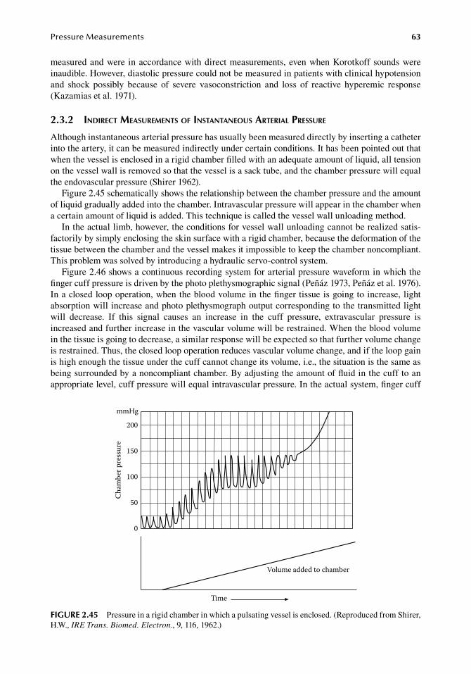
PressureMeasurements 63
measured.and.were. in.accordance.with.direct.measurements,.even.when.Korotkoff.sounds.were.inaudible..However,.diastolic.pressure.could.not.be.measured.in.patients.with.clinical.hypotension.and. shock. possibly. because. of. severe. vasoconstriction. and. loss. of. reactive. hyperemic. response.(Kazamias.et al..1971).
2.3.2 indirect MeasureMents of instantaneous arterial pressure
Although.instantaneous.arterial.pressure.has.usually.been.measured.directly.by.inserting.a.catheter.into.the.artery,.it.can.be.measured.indirectly.under.certain.conditions..It.has.been.pointed.out.that.when.the.vessel.is.enclosed.in.a.rigid.chamber.filled.with.an.adequate.amount.of.liquid,.all.tension.on.the.vessel.wall.is.removed.so.that.the.vessel.is.a.sack.tube,.and.the.chamber.pressure.will.equal.the.endovascular.pressure.(Shirer.1962).
Figure.2.45.schematically.shows.the.relationship.between.the.chamber.pressure.and.the.amount.of.liquid.gradually.added.into.the.chamber..Intravascular.pressure.will.appear.in.the.chamber.when.a.certain.amount.of.liquid.is.added..This.technique.is.called.the.vessel.wall.unloading.method.
In.the.actual.limb,.however,.the.conditions.for.vessel.wall.unloading.cannot.be.realized.satis-factorily.by.simply.enclosing.the.skin.surface.with.a.rigid.chamber,.because.the.deformation.of.the.tissue.between.the.chamber.and.the.vessel.makes.it.impossible.to.keep.the.chamber.noncompliant..This.problem.was.solved.by.introducing.a.hydraulic.servo-control.system.
Figure.2.46.shows.a.continuous.recording.system.for.arterial.pressure.waveform.in.which.the..finger.cuff.pressure.is.driven.by.the.photo.plethysmographic.signal.(Peñáz.1973,.Peñáz.et al..1976)..In a.closed.loop.operation,.when.the.blood.volume.in.the.finger.tissue.is.going.to.increase,.light.absorption.will.increase.and.photo.plethysmograph.output.corresponding.to.the.transmitted.light.will. decrease.. If. this. signal. causes. an. increase. in. the. cuff. pressure,. extravascular. pressure. is.increased.and.further.increase.in.the.vascular.volume.will.be.restrained..When.the.blood.volume.in.the.tissue.is.going.to.decrease,.a.similar.response.will.be.expected.so.that.further.volume.change.is.restrained..Thus,.the.closed.loop.operation.reduces.vascular.volume.change,.and.if.the.loop.gain.is.high.enough.the.tissue.under.the.cuff.cannot.change.its.volume,.i.e.,.the.situation.is.the.same.as.being.surrounded.by.a.noncompliant.chamber..By.adjusting.the.amount.of.fluid.in.the.cuff.to.an.appropriate.level,.cuff.pressure.will.equal.intravascular.pressure..In.the.actual.system,.finger.cuff.
Time
Volume added to chamber
0
50
100
150
200
Cham
ber p
ress
ure
mmHg
figure 2.45 Pressure.in.a.rigid.chamber.in.which.a.pulsating.vessel.is.enclosed..(Reproduced.from.Shirer,.H.W.,.IRE Trans. Biomed. Electron.,.9,.116,.1962.)
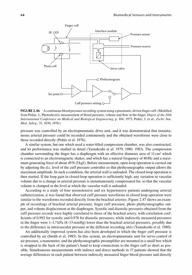
64 BiomedicalSensorsandInstruments
pressure.was.controlled.by.an.electropneumatic.drive.unit,.and.it.was.demonstrated.that.instanta-neous.arterial.pressure.could.be.recorded.continuously.and.the.obtained.waveforms.were.close.to.those.recorded.directly.(Peñáz.et al..1976).
A.similar.system,.but.one.which.used.a.water-filled.compression.chamber,.was.also.constructed,.and.its.performance.was.studied.in.detail.(Yamakoshi.et al..1979,.1980,.1983)..The.compression.chamber.surrounding.the.finger.has.a.diaphragm.with.an.effective.diameter.area.of.11.cm2.which.is.connected.to.an.electromagnetic.shaker,.and.which.has.a.natural.frequency.of.80.Hz.and.a.maxi-mum.generating.force.of.about.49.N.(5.kgf)..Before.measurement,.open-loop.operation.is.carried.out.by.adjusting.the.d.c..level.of.the.cuff.pressure.controller.so.that.plethysmographic.output.allows.the.maximum.amplitude..In.such.a.condition,.the.arterial.wall.is.unloaded..The.closed-loop.operation.is.then.started..If.the.loop.gain.in.closed-loop.operation.is.sufficiently.high,.any.variation.in.vascular.volume.due.to.a.change.in.arterial.pressure.is.instantaneously.compensated.for,.so.that.the.vascular.volume.is.clamped.at.the.level.at.which.the.vascular.wall.is.unloaded.
According.to.a.study.of.four.normotensive.and.six.hypertensive.patients.undergoing.arterial.catheterization,.it.was.found.that.observed.cuff.pressure.waveforms.in.closed.loop.operation.were.similar.to.the.waveforms.recorded.directly.from.the.brachial.arteries..Figure.2.47.shows.an.exam-ple.of.recordings.of.brachial.arterial.pressure,.finger.cuff.pressure,.photo.plethysmographic.out-put,.and.volume.displacement.at.the.diaphragm..Systolic.and.diastolic.pressures.obtained.from.the.cuff.pressure.records.were.highly.correlated.to.those.of.the.brachial.artery,.with.correlation.coef-ficients.of.0.992.for.systolic.and.0.978.for.diastolic.pressures,.while.indirectly.measured.pressures.in.the.finger.were.1–1.7.kPa.(8–13.mmHg).lower.than.the.brachial.arterial.pressures,.possibly.due.to.the.difference.in.intravascular.pressure.at.the.different.recording.sites.(Yamakoshi.et al..1980).
An.additionally.improved.system.has.also.been.developed.in.which.the.finger.cuff.pressure.is.controlled.by.air.(Smith.et al..1985)..In.this.system,.an.electropneumatic.unit.for.servo-control.of.air.pressure,.a.manometer,.and.the.plethysmographic.preamplifier.are.mounted.in.a.small.box.which.is.strapped.to.the.back.of.the.patient’s.hand.to.keep.connections.to.the.finger.cuff.as.short.as.pos-sible..Simultaneous.measurements.with.indirect.and.direct.methods.in.17.patients.showed.that.the.average.differences.in.each.patient.between.indirectly.measured.finger.blood.pressure.and.directly.
IR LED
Photo cell
Finger cu
Set point
Cu pressure setting
Plethysmogram
Servo valve
Interface modulePressure sensor
Pressure source
+
–
figure 2.46 A.continuous.blood.pressure.recording.system.using.a.pneumatic-driven.finger.cuff..(Modified.from.Peñáz,.J.,.Photoelectric.measurement.of.blood.pressure,.volume.and.flow.in.the.finger..Digest of the 10th International Conference on Medical and Biological Engineering, p..104,.1973;.Peñáz,.J..et al.,.Zschr. Inn. Med. Jahrg.,.31,.1030,.1976.)
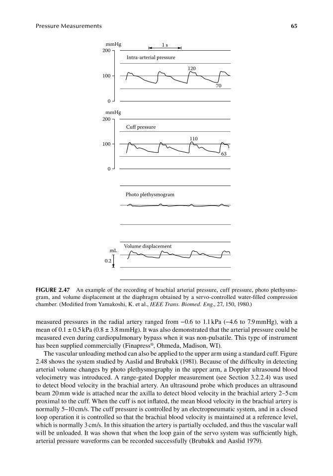
PressureMeasurements 65
measured.pressures. in. the. radial.artery. ranged. from.−0.6. to.1.1.kPa. (−4.6. to.7.9.mmHg),.with.a.mean.of.0.1.±.0.5.kPa.(0.8.±.3.8.mmHg)..It.was.also.demonstrated.that.the.arterial.pressure.could.be.measured.even.during.cardiopulmonary.bypass.when.it.was.non-pulsatile..This.type.of.instrument.has.been.supplied.commercially.(Finapress®,.Ohmeda,.Madison,.WI).
The.vascular.unloading.method.can.also.be.applied.to.the.upper.arm.using.a.standard.cuff..Figure.2.48.shows.the.system.studied.by.Aaslid.and.Brubakk.(1981)..Because.of.the.difficulty.in.detecting.arterial.volume.changes.by.photo.plethysmography.in.the.upper.arm,.a.Doppler.ultrasound.blood.velocimetry.was.introduced..A.range-gated.Doppler.measurement.(see.Section.3.2.2.4).was.used.to.detect.blood.velocity.in.the.brachial.artery..An.ultrasound.probe.which.produces.an.ultrasound.beam.20.mm.wide.is.attached.near.the.axilla.to.detect.blood.velocity.in.the.brachial.artery.2–5.cm.proximal.to.the.cuff..When.the.cuff.is.not.inflated,.the.mean.blood.velocity.in.the.brachial.artery.is.normally.5–10.cm/s..The.cuff.pressure.is.controlled.by.an.electropneumatic.system,.and.in.a.closed.loop.operation.it.is.controlled.so.that.the.brachial.blood.velocity.is.maintained.at.a.reference.level,.which.is.normally.3.cm/s..In.this.situation.the.artery.is.partially.occluded,.and.thus.the.vascular.wall.will.be.unloaded..It.was.shown.that.when.the.loop.gain.of.the.servo.system.was.sufficiently.high,.arterial.pressure.waveforms.can.be.recorded.successfully.(Brubakk.and.Aaslid.1979).
Intra-arterial pressure200
100
0
mmHg
200
100
0
mmHg
0.2
mL
Cuff pressure
Photo plethysmogram
Volume displacement
120
110
70
63
1 s
figure 2.47 An.example.of.the.recording.of.brachial.arterial.pressure,.cuff.pressure,.photo.plethysmo-gram,.and.volume.displacement.at. the.diaphragm.obtained.by.a.servo-controlled.water-filled.compression.chamber..(Modified.from.Yamakoshi,.K..et al.,.IEEE Trans. Biomed. Eng.,.27,.150,.1980.)
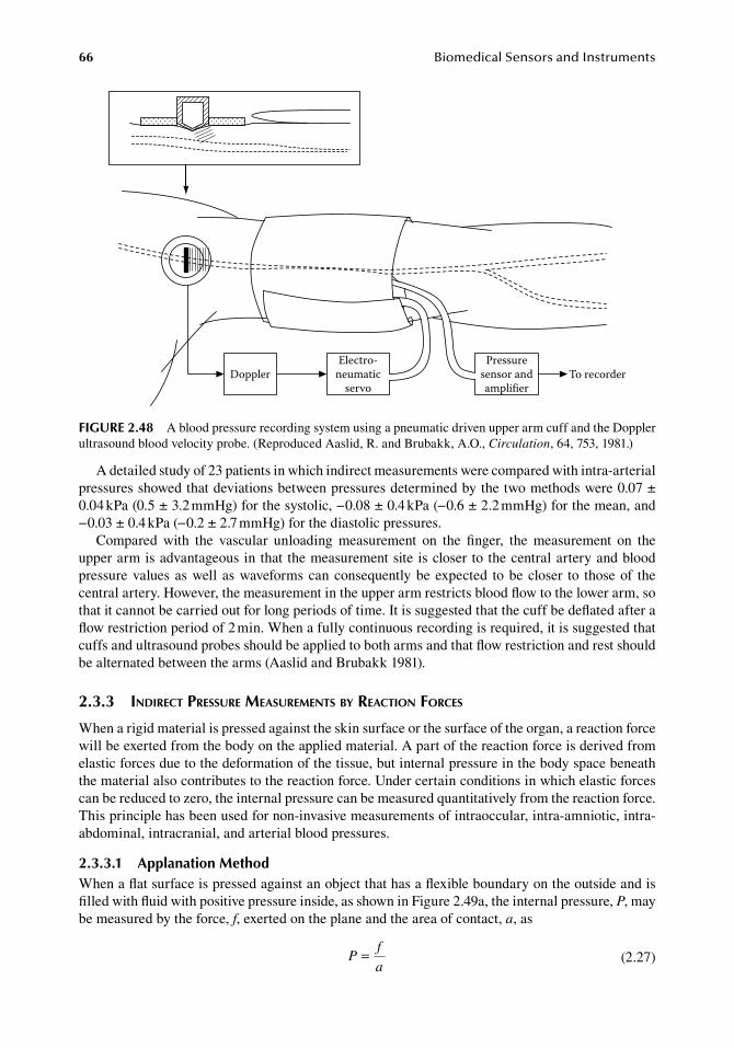
66 BiomedicalSensorsandInstruments
A.detailed.study.of.23.patients.in.which.indirect.measurements.were.compared.with.intra-.arterial.pressures.showed.that.deviations.between.pressures.determined.by.the.two.methods.were.0.07.±.0.04.kPa.(0.5.±.3.2.mmHg).for.the.systolic,.−0.08.±.0.4.kPa.(−0.6.±.2.2.mmHg).for.the.mean,.and.−0.03.±.0.4.kPa.(−0.2.±.2.7.mmHg).for.the.diastolic.pressures.
Compared. with. the. vascular. unloading. measurement. on. the. finger,. the. measurement. on. the.upper.arm.is.advantageous.in.that. the.measurement.site.is.closer.to.the.central.artery.and.blood.pressure.values.as.well.as.waveforms.can.consequently.be.expected. to.be.closer. to. those.of. the.central.artery..However,.the.measurement.in.the.upper.arm.restricts.blood.flow.to.the.lower.arm,.so.that.it.cannot.be.carried.out.for.long.periods.of.time..It.is.suggested.that.the.cuff.be.deflated.after.a.flow.restriction.period.of.2.min..When.a.fully.continuous.recording.is.required,.it.is.suggested.that.cuffs.and.ultrasound.probes.should.be.applied.to.both.arms.and.that.flow.restriction.and.rest.should.be.alternated.between.the.arms.(Aaslid.and.Brubakk.1981).
2.3.3 indirect pressure MeasureMents by reaction forces
When.a.rigid.material.is.pressed.against.the.skin.surface.or.the.surface.of.the.organ,.a.reaction.force.will.be.exerted.from.the.body.on.the.applied.material..A.part.of.the.reaction.force.is.derived.from.elastic.forces.due.to.the.deformation.of.the.tissue,.but.internal.pressure.in.the.body.space.beneath.the.material.also.contributes.to.the.reaction.force..Under.certain.conditions.in.which.elastic.forces.can.be.reduced.to.zero,.the.internal.pressure.can.be.measured.quantitatively.from.the.reaction.force..This.principle.has.been.used.for.non-invasive.measurements.of.intraoccular,.intra-amniotic,.intra-abdominal,.intracranial,.and.arterial.blood.pressures.
2.3.3.1 applanation MethodWhen.a.flat.surface.is.pressed.against.an.object.that.has.a.flexible.boundary.on.the.outside.and.is.filled.with.fluid.with.positive.pressure.inside,.as.shown.in.Figure.2.49a,.the.internal.pressure,.P,.may.be.measured.by.the.force,.f,.exerted.on.the.plane.and.the.area.of.contact,.a,.as
.P
f
a=
.(2.27)
DopplerElectro-
neumaticservo
Pressuresensor andamplifier
To recorder
figure 2.48 A.blood.pressure.recording.system.using.a.pneumatic.driven.upper.arm.cuff.and.the.Doppler.ultrasound.blood.velocity.probe..(Reproduced.Aaslid,.R..and.Brubakk,.A.O.,.Circulation,.64,.753,.1981.)
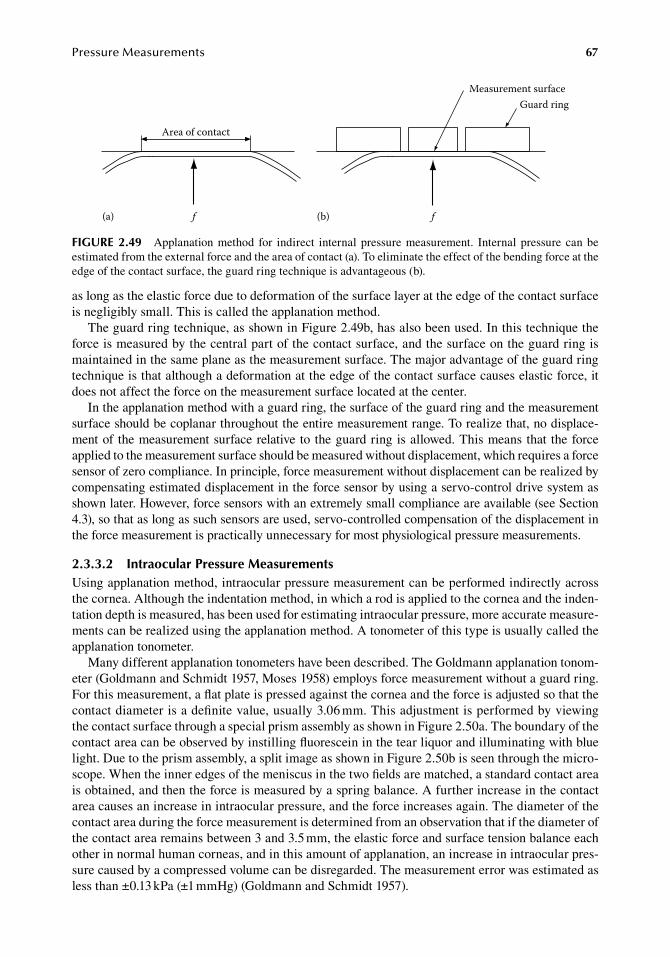
PressureMeasurements 67
as.long.as.the.elastic.force.due.to.deformation.of.the.surface.layer.at.the.edge.of.the.contact.surface.is.negligibly.small..This.is.called.the.applanation.method.
The.guard.ring.technique,.as.shown.in.Figure.2.49b,.has.also.been.used..In.this.technique.the.force.is.measured.by.the.central.part.of.the.contact.surface,.and.the.surface.on.the.guard.ring.is.maintained.in.the.same.plane.as.the.measurement.surface..The.major.advantage.of.the.guard.ring.technique.is.that.although.a.deformation.at.the.edge.of.the.contact.surface.causes.elastic.force,.it.does.not.affect.the.force.on.the.measurement.surface.located.at.the.center.
In.the.applanation.method.with.a.guard.ring,.the.surface.of.the.guard.ring.and.the.measurement.surface.should.be.coplanar.throughout.the.entire.measurement.range..To.realize.that,.no.displace-ment.of. the.measurement.surface.relative. to. the.guard.ring.is.allowed..This.means.that. the.force.applied.to.the.measurement.surface.should.be.measured.without.displacement,.which.requires.a.force.sensor.of.zero.compliance..In.principle,.force.measurement.without.displacement.can.be.realized.by.compensating.estimated.displacement.in.the.force.sensor.by.using.a.servo-control.drive.system.as.shown.later..However,.force.sensors.with.an.extremely.small.compliance.are.available.(see.Section.4.3),.so.that.as.long.as.such.sensors.are.used,.servo-controlled.compensation.of.the.displacement.in.the.force.measurement.is.practically.unnecessary.for.most.physiological.pressure.measurements.
2.3.3.2 intraocular Pressure MeasurementsUsing.applanation.method,.intraocular.pressure.measurement.can.be.performed.indirectly.across.the.cornea..Although.the.indentation.method,.in.which.a.rod.is.applied.to.the.cornea.and.the.inden-tation.depth.is.measured,.has.been.used.for.estimating.intraocular.pressure,.more.accurate.measure-ments.can.be.realized.using.the.applanation.method..A.tonometer.of.this.type.is.usually.called.the.applanation.tonometer.
Many.different.applanation.tonometers.have.been.described..The.Goldmann.applanation.tonom-eter.(Goldmann.and.Schmidt.1957,.Moses.1958).employs.force.measurement.without.a.guard.ring..For.this.measurement,.a.flat.plate.is.pressed.against.the.cornea.and.the.force.is.adjusted.so.that.the.contact.diameter.is.a.definite.value,.usually.3.06.mm..This.adjustment.is.performed.by.viewing.the.contact.surface.through.a.special.prism.assembly.as.shown.in.Figure.2.50a..The.boundary.of.the.contact.area.can.be.observed.by.instilling.fluorescein.in.the.tear.liquor.and.illuminating.with.blue.light..Due.to.the.prism.assembly,.a.split.image.as.shown.in.Figure.2.50b.is.seen.through.the.micro-scope..When.the.inner.edges.of.the.meniscus.in.the.two.fields.are.matched,.a.standard.contact.area.is.obtained,.and.then.the.force.is.measured.by.a.spring.balance..A.further.increase.in.the.contact.area.causes.an.increase.in.intraocular.pressure,.and.the.force.increases.again..The.diameter.of.the.contact.area.during.the.force.measurement.is.determined.from.an.observation.that.if.the.diameter.of.the.contact.area.remains.between.3.and.3.5.mm,.the.elastic.force.and.surface.tension.balance.each.other.in.normal.human.corneas,.and.in.this.amount.of.applanation,.an.increase.in.intraocular.pres-sure.caused.by.a.compressed.volume.can.be.disregarded..The.measurement.error.was.estimated.as.less.than.±0.13.kPa.(±1.mmHg).(Goldmann.and.Schmidt.1957).
Area of contact
Measurement surface
f f(a) (b)
Guard ring
figure 2.49 Applanation.method. for. indirect. internal. pressure.measurement.. Internal. pressure. can.be.estimated.from.the.external.force.and.the.area.of.contact.(a)..To.eliminate.the.effect.of.the.bending.force.at.the.edge.of.the.contact.surface,.the.guard.ring.technique.is.advantageous.(b).
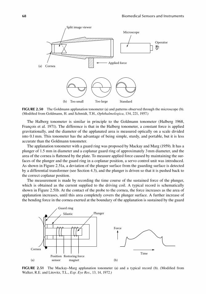
68 BiomedicalSensorsandInstruments
The. Halberg. tonometer. is. similar. in. principle. to. the. Goldmann. tonometer. (Halberg. 1968,.François.et al..1971)..The.difference.is.that.in.the.Halberg.tonometer,.a.constant.force.is.applied.gravitationally,.and.the.diameter.of.the.applanated.area.is.measured.optically.on.a.scale.divided.into.0.1.mm..This.tonometer.has.the.advantage.of.being.simple,.sturdy,.and.portable,.but.it.is.less.accurate.than.the.Goldmann.tonometer.
The.applanation.tonometer.with.a.guard.ring.was.proposed.by.Mackay.and.Marg.(1959)..It.has.a.plunger.of.1.5.mm.in.diameter.and.a.coplanar.guard.ring.of.approximately.3.mm.diameter,.and.the.area.of.the.cornea.is.flattened.by.the.plate..To.measure.applied.force.caused.by.maintaining.the.sur-faces.of.the.plunger.and.the.guard.ring.in.a.coplanar.position,.a.servo.control.unit.was.introduced..As.shown.in.Figure.2.51a,.a.deviation.of.the.plunger.surface.from.the.guarding.surface.is.detected.by.a.differential.transformer.(see.Section.4.3),.and.the.plunger.is.driven.so.that.it.is.pushed.back.to.the.correct.coplanar.position.
The.measurement.is.made.by.recording.the.time.course.of.the.sustained.force.of.the.plunger,.which. is. obtained. as. the. current. supplied. to. the. driving. coil.. A. typical. record. is. schematically.shown.in.Figure.2.51b..At.the.contact.of.the.probe.to.the.cornea,.the.force.increases.as.the.area.of.applanation.increases,.until.this.area.completely.covers.the.plunger.surface..A.further.increase.of.the.bending.force.in.the.cornea.exerted.at.the.boundary.of.the.applanation.is.sustained.by.the.guard.
Split image viewer
Too small Too large Standard
CorneaApplied force
Microscope
Operator
(a)
(b)
figure 2.50 The.Goldmann.applanation.tonometer.(a).and.patterns.observed.through.the.microscope.(b)..(Modified.from.Goldmann,.H..and.Schmidt,.T.H.,.Ophthalmologica,.134,.221,.1957.)
Cornea
SilasticGuard ring
Plunger
Positionsensor(a) (b)
Restoring forcemagnet
Force
Time
figure 2.51 The. Mackay–Marg. applanation. tonometer. (a). and. a. typical. record. (b).. (Modified. from.Walker,.R.E..and.Litovitz,.T.L.,.Exp. Eye Res.,.13,.14,.1972.)
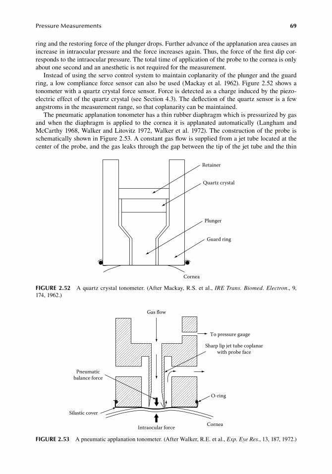
PressureMeasurements 69
ring.and.the.restoring.force.of.the.plunger.drops..Further.advance.of.the.applanation.area.causes.an.increase.in.intraocular.pressure.and.the.force.increases.again..Thus,.the.force.of.the.first.dip.cor-responds.to.the.intraocular.pressure..The.total.time.of.application.of.the.probe.to.the.cornea.is.only.about.one.second.and.an.anesthetic.is.not.required.for.the.measurement.
Instead.of.using.the.servo.control.system.to.maintain.coplanarity.of.the.plunger.and.the.guard.ring,.a. low.compliance.force.sensor.can.also.be.used.(Mackay.et al..1962)..Figure.2.52.shows.a.tonometer.with.a.quartz.crystal.force.sensor..Force.is.detected.as.a.charge.induced.by.the.piezo-electric.effect.of.the.quartz.crystal.(see.Section.4.3)..The.deflection.of.the.quartz.sensor.is.a.few.angstroms.in.the.measurement.range,.so.that.coplanarity.can.be.maintained.
The.pneumatic.applanation.tonometer.has.a.thin.rubber.diaphragm.which.is.pressurized.by.gas.and. when. the. diaphragm. is. applied. to. the. cornea. it. is. applanated. automatically. (Langham. and.McCarthy.1968,.Walker.and.Litovitz.1972,.Walker.et al..1972)..The.construction.of.the.probe.is.schematically.shown.in.Figure.2.53..A.constant.gas.flow.is.supplied.from.a.jet.tube.located.at.the.center.of.the.probe,.and.the.gas.leaks.through.the.gap.between.the.tip.of.the.jet.tube.and.the.thin.
Cornea
Retainer
Quartz crystal
Plunger
Guard ring
figure 2.52 A.quartz.crystal. tonometer.. (After.Mackay,.R.S..et al.,.IRE Trans. Biomed. Electron.,.9,.174,.1962.)
Gas flow
To pressure gauge
Sharp lip jet tube coplanarwith probe face
O-ring
Pneumaticbalance force
Intraocular force
Silastic cover
Cornea
figure 2.53 A.pneumatic.applanation.tonometer..(After.Walker,.R.E..et al.,.Exp. Eye Res.,.13,.187,.1972.)
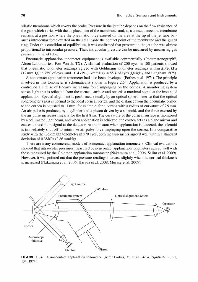
70 BiomedicalSensorsandInstruments
silastic.membrane.which.covers.the.probe..Pressure.in.the.jet.tube.depends.on.the.flow.resistance.of.the.gap,.which.varies.with.the.displacement.of.the.membrane,.and,.as.a.consequence,.the.membrane.remains.at.a.position.where.the.pneumatic.force.exerted.on.the.area.at.the.tip.of.the.jet.tube.bal-ances.intraocular.force.exerted.on.the.area.inside.the.contact.point.of.the.membrane.and.the.guard.ring..Under.this.condition.of.equilibrium,.it.was.confirmed.that.pressure.in.the.jet.tube.was.almost.proportional.to.intraocular.pressure..Thus,.intraocular.pressure.can.be.measured.by.measuring.gas.pressure.in.the.jet.tube.
Pneumatic. applanation. tonometer. equipment. is. available. commercially. (Pneumatonograph®,.Alcon.Laboratories,.Fort.Worth,.TX)..A.clinical. evaluation.of.200.eyes. in.100.patients. showed.that.pneumatic. tonometer. readings.agreed.with.Goldmann. tonometer. readings.within.±0.26.kPa.(±2.mmHg).in.75%.of.eyes,.and.±0.4.kPa.(±3.mmHg).in.85%.of.eyes.(Quigley.and.Langham.1975).
A.noncontact.applanation.tonometer.had.also.been.developed.(Forbes.et al..1974)..The.principle.involved. in. this. tonometer. is.schematically.shown.in.Figure.2.54..Applanation. is.produced.by.a.controlled. air. pulse. of. linearly. increasing. force. impinging. on. the. cornea.. A. monitoring. system.senses.light.that.is.reflected.from.the.corneal.surface.and.records.a.maximal.signal.at.the.instant.of.applanation..Special.alignment.is.performed.visually.by.an.optical.spherometer.so.that.the.optical.spherometer’s.axis.is.normal.to.the.local.corneal.vertex,.and.the.distance.from.the.pneumatic.orifice.to.the.cornea.is.adjusted.to.11.mm,.for.example,.for.a.cornea.with.a.radius.of.curvature.of.7.9.mm..An.air.pulse.is.produced.by.a.cylinder.and.a.piston.driven.by.a.solenoid,.and.the.force.exerted.by.the.air.pulse.increases.linearly.for.the.first.8.ms..The.curvature.of.the.corneal.surface.is.monitored.by.a.collimated.light.beam,.and.when.applanation.is.achieved,.the.cornea.acts.as.a.plane.mirror.and.causes.a.maximum.signal.at.the.detector..At.the.instant.when.applanation.is.detected,.the.solenoid.is.immediately.shut.off.to.minimize.air.pulse.force.impinging.upon.the.cornea..In.a.comparative.study.with.the.Goldmann.tonometer.in.570.eyes,.both.measurements.agreed.well.within.a.standard.deviation.of.0.38.kPa.(2.86.mmHg).
There.are.many.commercial.models.of.noncontact.applanation.tonometers..Clinical.evaluations.showed.that.intraocular.pressures.measured.by.noncontact.applanation.tonometers.agreed.well.with.those.measured.by.the.Goldman.applanation.tonometer.(Nakamura.et al..2006,.Salim.et al..2009)..However,.it.was.pointed.out.that.the.pressure.readings.increase.slightly.when.the.corneal.thickness.is.increased.(Nakamura.et al..2006,.Harada.et al..2008,.Murase.et al..2009).
Cornea
Light source
Microscopeobjective
Detector Piston
Pneumatic system
Window
Optical alignment system
Operator
figure 2.54 A. noncontact. applanation. tonometer.. (After. Forbes,. M.. et al.,. Arch. Ophthalmol.,. 91,.134,.1974.)
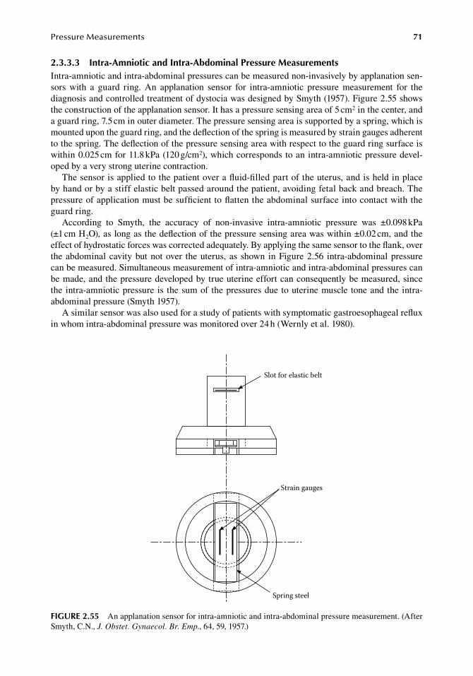
PressureMeasurements 71
2.3.3.3 intra-amniotic and intra-abdominal Pressure MeasurementsIntra-amniotic.and.intra-abdominal.pressures.can.be.measured.non-invasively.by.applanation.sen-sors. with. a. guard. ring.. An. applanation. sensor. for. intra-amniotic. pressure. measurement. for. the.diagnosis.and.controlled.treatment.of.dystocia.was.designed.by.Smyth.(1957)..Figure.2.55.shows.the.construction.of.the.applanation.sensor..It.has.a.pressure.sensing.area.of.5.cm2.in.the.center,.and.a.guard.ring,.7.5.cm.in.outer.diameter..The.pressure.sensing.area.is.supported.by.a.spring,.which.is.mounted.upon.the.guard.ring,.and.the.deflection.of.the.spring.is.measured.by.strain.gauges.adherent.to.the.spring..The.deflection.of.the.pressure.sensing.area.with.respect.to.the.guard.ring.surface.is.within.0.025.cm.for.11.8.kPa.(120.g/cm2),.which.corresponds.to.an.intra-amniotic.pressure.devel-oped.by.a.very.strong.uterine.contraction.
The.sensor.is.applied.to.the.patient.over.a.fluid-filled.part.of.the.uterus,.and.is.held.in.place.by.hand.or.by.a.stiff.elastic.belt.passed.around.the.patient,.avoiding.fetal.back.and.breach..The.pressure.of.application.must.be.sufficient.to.flatten.the.abdominal.surface.into.contact.with.the.guard.ring.
According. to. Smyth,. the. accuracy. of. non-invasive. intra-amniotic. pressure. was. ±0.098.kPa.(±1.cm.H2O),.as.long.as.the.deflection.of.the.pressure.sensing.area.was.within.±0.02.cm,.and.the.effect.of.hydrostatic.forces.was.corrected.adequately..By.applying.the.same.sensor.to.the.flank,.over.the.abdominal.cavity.but.not.over. the.uterus,.as. shown. in.Figure.2.56. intra-abdominal.pressure.can.be.measured..Simultaneous.measurement.of.intra-amniotic.and.intra-abdominal.pressures.can.be.made,.and.the.pressure.developed.by.true.uterine.effort.can.consequently.be.measured,.since.the.intra-amniotic.pressure.is. the.sum.of.the.pressures.due.to.uterine.muscle. tone.and.the.intra-abdominal.pressure.(Smyth.1957).
A.similar.sensor.was.also.used.for.a.study.of.patients.with.symptomatic.gastroesophageal.reflux.in.whom.intra-abdominal.pressure.was.monitored.over.24.h.(Wernly.et al..1980).
Slot for elastic belt
Strain gauges
Spring steel
figure 2.55 An.applanation.sensor.for.intra-amniotic.and.intra-abdominal.pressure.measurement..(After.Smyth,.C.N.,.J. Obstet. Gynaecol. Br. Emp.,.64,.59,.1957.)
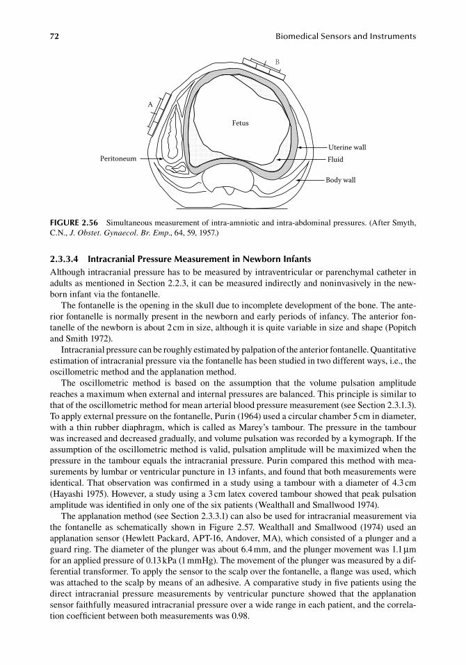
72 BiomedicalSensorsandInstruments
2.3.3.4 intracranial Pressure Measurement in newborn infantsAlthough.intracranial.pressure.has.to.be.measured.by.intraventricular.or.parenchymal.catheter.in.adults.as.mentioned.in.Section.2.2.3,.it.can.be.measured.indirectly.and.noninvasively.in.the.new-born.infant.via.the.fontanelle.
The.fontanelle.is.the.opening.in.the.skull.due.to.incomplete.development.of.the.bone..The.ante-rior.fontanelle.is.normally.present.in.the.newborn.and.early.periods.of.infancy..The.anterior.fon-tanelle.of.the.newborn.is.about.2.cm.in.size,.although.it.is.quite.variable.in.size.and.shape.(Popitch.and.Smith.1972).
Intracranial.pressure.can.be.roughly.estimated.by.palpation.of.the.anterior.fontanelle..Quantitative.estimation.of.intracranial.pressure.via.the.fontanelle.has.been.studied.in.two.different.ways,.i.e.,.the.oscillometric.method.and.the.applanation.method.
The. oscillometric. method. is. based. on. the. assumption. that. the. volume. pulsation. amplitude.reaches.a.maximum.when.external.and.internal.pressures.are.balanced..This.principle.is.similar.to.that.of.the.oscillometric.method.for.mean.arterial.blood.pressure.measurement.(see.Section.2.3.1.3)..To.apply.external.pressure.on.the.fontanelle,.Purin.(1964).used.a.circular.chamber.5.cm.in.diameter,.with.a.thin.rubber.diaphragm,.which.is.called.as.Marey’s.tambour..The.pressure.in.the.tambour.was.increased.and.decreased.gradually,.and.volume.pulsation.was.recorded.by.a.kymograph..If.the.assumption.of.the.oscillometric.method.is.valid,.pulsation.amplitude.will.be.maximized.when.the.pressure.in.the.tambour.equals.the.intracranial.pressure..Purin.compared.this.method.with.mea-surements.by.lumbar.or.ventricular.puncture.in.13.infants,.and.found.that.both.measurements.were.identical..That.observation.was.confirmed.in.a.study.using.a. tambour.with.a.diameter.of.4.3.cm.(Hayashi.1975)..However,.a.study.using.a.3.cm.latex.covered.tambour.showed.that.peak.pulsation.amplitude.was.identified.in.only.one.of.the.six.patients.(Wealthall.and.Smallwood.1974).
The.applanation.method.(see.Section.2.3.3.1).can.also.be.used.for.intracranial.measurement.via.the. fontanelle. as. schematically. shown. in. Figure. 2.57.. Wealthall. and. Smallwood. (1974). used. an.applanation.sensor.(Hewlett.Packard,.APT-16,.Andover,.MA),.which.consisted.of.a.plunger.and.a.guard.ring..The.diameter.of.the.plunger.was.about.6.4.mm,.and.the.plunger.movement.was.1.1.μm.for.an.applied.pressure.of.0.13.kPa.(1.mmHg)..The.movement.of.the.plunger.was.measured.by.a.dif-ferential.transformer..To.apply.the.sensor.to.the.scalp.over.the.fontanelle,.a.flange.was.used,.which.was.attached.to.the.scalp.by.means.of.an.adhesive..A.comparative.study.in.five.patients.using.the.direct. intracranial. pressure. measurements. by. ventricular. puncture. showed. that. the. applanation.sensor.faithfully.measured.intracranial.pressure.over.a.wide.range.in.each.patient,.and.the.correla-tion.coefficient.between.both.measurements.was.0.98.
Uterine wallFluid
Body wall
Peritoneum
A
B
Fetus
figure 2.56 Simultaneous.measurement.of.intra-amniotic.and.intra-abdominal.pressures..(After.Smyth,.C.N.,.J. Obstet. Gynaecol. Br. Emp.,.64,.59,.1957.)
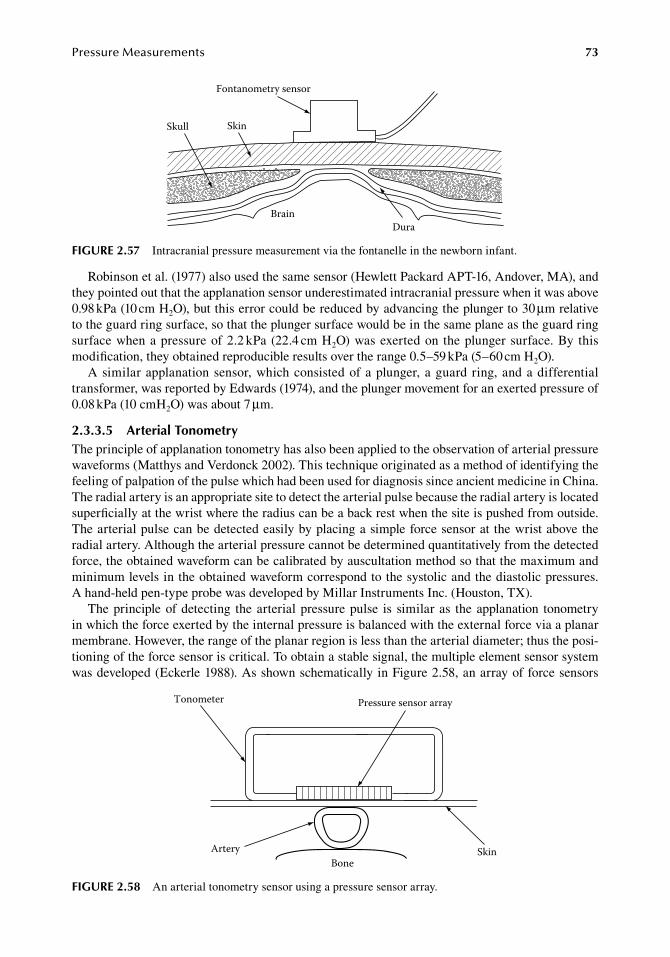
PressureMeasurements 73
Robinson.et al..(1977).also.used.the.same.sensor.(Hewlett.Packard.APT-16,.Andover,.MA),.and.they.pointed.out.that.the.applanation.sensor.underestimated.intracranial.pressure.when.it.was.above.0.98.kPa.(10.cm.H2O),.but.this.error.could.be.reduced.by.advancing.the.plunger.to.30.μm.relative.to.the.guard.ring.surface,.so.that.the.plunger.surface.would.be.in.the.same.plane.as.the.guard.ring.surface.when.a.pressure.of.2.2.kPa.(22.4.cm.H2O).was.exerted.on. the.plunger.surface..By. this.modification,.they.obtained.reproducible.results.over.the.range.0.5–59.kPa.(5–60.cm.H2O).
A.similar.applanation.sensor,.which.consisted.of.a.plunger,.a.guard. ring,.and.a.differential.transformer,.was.reported.by.Edwards.(1974),.and.the.plunger.movement.for.an.exerted.pressure.of.0.08.kPa.(10.cmH2O).was.about.7.μm.
2.3.3.5 arterial tonometryThe.principle.of.applanation.tonometry.has.also.been.applied.to.the.observation.of.arterial.pressure.waveforms.(Matthys.and.Verdonck.2002)..This.technique.originated.as.a.method.of.identifying.the.feeling.of.palpation.of.the.pulse.which.had.been.used.for.diagnosis.since.ancient.medicine.in.China..The.radial.artery.is.an.appropriate.site.to.detect.the.arterial.pulse.because.the.radial.artery.is.located.superficially.at.the.wrist.where.the.radius.can.be.a.back.rest.when.the.site.is.pushed.from.outside..The.arterial.pulse.can.be.detected.easily.by.placing.a.simple.force.sensor.at. the.wrist.above.the.radial.artery..Although.the.arterial.pressure.cannot.be.determined.quantitatively.from.the.detected.force,.the.obtained.waveform.can.be.calibrated.by.auscultation.method.so.that.the.maximum.and.minimum.levels.in.the.obtained.waveform.correspond.to.the.systolic.and.the.diastolic.pressures..A hand-held.pen-type.probe.was.developed.by.Millar.Instruments.Inc..(Houston,.TX).
The.principle.of.detecting. the.arterial.pressure.pulse. is. similar.as. the.applanation. tonometry.in.which.the.force.exerted.by.the.internal.pressure.is.balanced.with.the.external.force.via.a.planar.membrane..However,.the.range.of.the.planar.region.is.less.than.the.arterial.diameter;.thus.the.posi-tioning.of.the.force.sensor.is.critical..To.obtain.a.stable.signal,.the.multiple.element.sensor.system.was.developed.(Eckerle.1988)..As.shown.schematically.in.Figure.2.58,.an.array.of.force.sensors.
Pressure sensor array
BoneSkinArtery
Tonometer
figure 2.58 An.arterial.tonometry.sensor.using.a.pressure.sensor.array.
Fontanometry sensor
Skull Skin
BrainDura
figure 2.57 Intracranial.pressure.measurement.via.the.fontanelle.in.the.newborn.infant.
74 BiomedicalSensorsandInstruments
are.introduced.so.that.the.sensor.right.above.the.artery.provides.the.best.signal..By.selecting.the.sensor.providing.the.best.signal.automatically,.a.stable.signal.can.be.obtained.even.if.the.position.of.the.probe.is.shifted.to.some.extent..A.commercial.model.of.this.type.was.developed.by.Colin.Electronics.Co.,.Ltd..(Komaki,.Japan).
referenCeS
Aaslid,.R..and.Brubakk,.A..O..1981..Accuracy.of.an.ultrasound.Doppler.servo.method.for.noninvasive.determi-nation.of.instantaneous.and.mean.arterial.blood.pressure,.Circulation,.64:.753–759.
Alexander,.H.,.Cohen,.M..L.,.and.Steinfeld,.L..1977..Criteria.in.the.choice.of.an.occluding.cuff.for.the.indirect.measurement.of.blood.pressure,.Med. Biol. Eng. Comput..15:.2–10.
Allard,.E..M..1962..Sound.and.pressure. signals.obtained. from.a. single. intracardiac. transducer,. IRE Trans. Biomed. Electron..9:.74–76.
Arndorfer,.R..C.,.Stef,.J..J.,.Dodds,.W..J.,.Linehan,.J..H.,.and.Hogan,.W..J..1977..Improved.infusion.system.for.intraluminal.esophageal.manometry,.Gastroentorology.73:.23–27.
Ask,. P.. 1978.. Low-compliance. perfusion. pump. for. oesophageal. manometry,. Med. Biol. Eng. Comput.. 16:.732–738.
Ask,. P.,. Öberg,. P..Å.,. and. Tibbling,. L.. 1977.. Static. and. dynamic. characteristics. of. fluid-filled. esophageal.manometry.systems,.Am. J. Physiol..233:.E389–E396.
Bao,.M.,.Wang,.Y.,.and.Qi,.W..1987..New.development.on.design.method.of.piezoresistive.pressure.sensor,.Transducer’ 87:.299–304.
Bennett,.T.,.Sharma,.A.,.Sutton,.R.,.Camm,.A..J.,.Erickson,.M.,.and.Beck,.R..1992..Development.of.a.rate.adap-tive.pacemaker.based.on.the.maximum.rate-of-rise.of.right.ventricular.pressure.(RV.dP/dtmax)..Pacing Clin. Electrophysiol..15:.219–234.
Bhattacharya,.J..and.Staub,.N..C..1980..Direct.measurement.of.microvascular.pressures.in.the.isolated.perfused.dog.lung,.Science.210:.327–328.
Blackburn,.J..P..1968..Self-leveling.venous.pressure.transducer,.Brl. Med. J..4:.825.Braunschweig,.F.,.Linde,.C.,.Eriksson,.M..J.,.Hofman-Bang,.C.,.and.Rydén,.L..2002..Continuous.haemody-
namic.monitoring.during.withdrawal.of.diuretics.in.patients.with.congestive.heart.failure,.Eur. Heart J..23:.59–69.
Brubakk,.A..O..and.Aaslid,.R..1979..A.new.method.for.indirect.measurement.of.pulsatile.arterial.blood.pres-sure,.ISAM 1979,.468–472.
Bruner,.J..M..R.,.Krenis,.L..J.,.Kunsman,.J..M.,.and.Sherman,.A..P..1981a..Comparison.of.direct.and.indirect.methods.of.measuring.arterial.blood.pressure,.Med. Instrum..15:.11–21.
Bruner,.J..M..R.,.Krenis,.L..J.,.Kunsman,.J..M.,.and.Sherman,.A..P..1981b..Comparison.of.direct.and.indirect.methods.of.measuring.arterial.blood.pressure.Part.II,.Med. Instrum..15:.97–101.
Bruner,.J..M..R.,.Krenis,.L..J.,.Kunsman,.J..M.,.and.Sherman,.A..P..1981c..Comparison.of.direct.and.indirect.methods.of.measuring.arterial.blood.pressure.Part.III,.Med. Instrum..15:.182–188.
Buchbinder,.N..and.Ganz,.W..1976..Hemodynamic.monitoring:.Invasive.techniques,.Anesthesiology.45:.146–155.Burton,.A..C..1965..Kinetic.energy.in.the.circulation,.in.Physiology and Biophysics of the Circulation,.Chicago,.
IL:.Year.Book.Medical.Publishers.Inc.,.pp..102–105.Castle,.G..S..P.,.Lorgan,.J..G.,.Rorabeck,.C..H.,.and.Hardie,.R..1981..The.slit.catheter.system:.A.new.diagnostic.
method.for.measurement.of.limb.compartmental.pressure,.J. Clin. Eng..6:.219–223.Chandraratna,.P..A..N..1975..Determination.of.zero.reference.level.for.left.atrial.pressure.by.echocardiography,.
Am. Heart J..89:.159–162.Chau,.H..L..and.Wise,.K..D..1987a..Scaling.limits.in.batch-fabricated.silicon.pressure.sensors,.IEEE Trans.
Electron Devices.ED-34:.850–858.Chau,.H..L..and.Wise,.K..D..1987b..Noise.due.to.Brownian.motion.in.ultrasensitive.solid-state.pressure.sensors,.
IEEE Trans. Electron Devices.ED-34:.859–865.Chau,.H..L..and.Wise,.K..D..1987c..An.ultraminiature.solid-state.pressure.sensor.for.a.cardiovascular.catheter,.
Transducer’ 87:.344–347.Clark,.S..K..and.Wise,.K..D..1979..Pressure.sensitivity.in.anisotropically.etched.thin-diaphragm.pressure.sen-
sors,.IEEE Trans. Electron Devices.ED-26:.1887–1895.Corbett,.G..A.,.Preston,.T..D.,.and.Bailey,.J..S..1974..A.self-leveling.central.venous.electromanometer,.Med.
Biol. Eng..12:.366.Dear,.H..D..and.Spear,.A..F..1971..Accurate.method.for.measuring.dP/dt.with.cardiac.catheters.and.external.
transducers,.J. Appl. Physiol..30:.897–899.
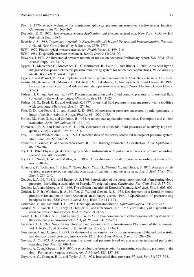
PressureMeasurements 75
Dent,. J.. 1976.. A. new. technique. for. continuous. sphincter. pressure. measurement. cardiovascular. function,.Gastroenterology.71:.263–267.
Doebelin,.E..O..1975..Measurement System Application and Design,. revised.edn..New.York:.McGraw-Hill.Publishing.Co.,.p..387.
Eckerle,.J..S..1988..Tonometry, Arterial, in Encyclopedia of Medical Devices and Instrumentation,.Webster,.J..G.,.ed..New.York:.John.Wiley.&.Sons,.pp..2770–2776.
ECRI..1979..Physiological.pressure.transducer,.Health Device.8:.199–216.ECRI..1984..Disposable.pressure.transducer,.Health Device.13:.268–90.Edwards,.J..1974..An.intracranial.pressure.tonometer.for.use.on.neonates:.Preliminary.report,.Dev. Med. Child
Neurol..Suppl..32:.38–39.Eggers,.T.,.Marschner.C.,.Marschner,.U.,.Clasbrummel,.B.,.Laur,.R.,.and.Binder,.J..2000..Advanced.hybrid.
integrated.low-power.telemetric.pressure.monitoring.system.for.biomedical.applications,.Proceedings of the MEMS 2000,.Miyazaki,.Japan.
Eggers,.T..and.Wenzel,.M..2004..Implantable.telemetric.pressure.measurement..Med. Device Technol..15:.25–27.Esashi,. M.,. Komatsu,. H.,. Matsuo,.T.,.Takahashi,. M.,.Takishima,.T.,. Imabayashi,. K.,. and. Ozawa,. H.. 1982..
Fabrication.of.catheter-tip.and.sidewall.miniature.pressure.sensor,.IEEE Trans. Electron Devices.ED-29:.57–63.
Fadnes,.H..O..and.Aukland,.K..1977..Protein.concentration.and.colloid.osmotic.pressure.of.interstitial.fluid.collected.by.the.wick.technique,.Microvasc. Res..14:.11–25.
Fadnes,.H..O.,.Reed,.R..K.,.and.Aukland,.K..1977..Interstitial.fluid.pressure.in.rats.measured.with.a.modified.wick.technique..Microvasc. Res..14:.27–36.
Fike,.C..D.,.Lai-Fook,.S..J.,.and.Bland,.R..D..1987..Microvascular.pressures.measured.by.micropuncture.in.lungs.of.newborn.rabbits,.J. Appl. Physiol..63:.1070–1075.
Forbes,.M.,.Pico,.G..Jr.,.and.Grolman,.B..1974..A.noncontact.applanation.tonometer..Description.and.clinical.evaluation,.Arch. Ophthalmol..91:.134–140.
Foreman,.J..E..K..and.Hutchison,.K..J..1970..Generation.of.sinusoidal.fluid.pressures.of.relatively.high.fre-quency,.J. Appl. Physiol..29:.511–516.
Fox,.J..R..and.Wiederhielm,.C..A..1973..Characteristics.of.the.servo-controlled.micropipet.pressure.system,.Microvasc. Res..5:.324–335.
François,.J.,.Vancea,.P.,.and.Vanderkerckhove,.R..1971..Halberg.tonometer..An.evaluation,.Arch. Ophthalmol..86:.376–384.
Fry,.D..L..1960..Physiological.recording.by.modern.instruments.with.particular.reference.to.pressure.recording,.Physiol. Rev..40:.753–786.
Fry,.D..L.,.Noble,.F..W.,.and.Mallos,.A..J..1957..An.evaluation.of.modern.pressure.recording.systems,.Circ. Res..5:.40–46.
Futamura,.Y.,.Tachibana,.T.,.Ichie,.Y.,.Takeuchi,.S.,.Yasui,.S.,.Mizuno,.Y.,.and.Hisada,.S..1975..Analysis.of.left.ventricular.pressure.pulses.and.characteristics.of.catheter-manometer.system,.Jpn. J. Med. Elect. Biol. Eng..4:.214–240.
Geddes,.L..A.,.Hoff,.H..E.,.and.Badger,.A..S..1968..Introduction.of.the.auscultatory.method.of.measuring.blood.pressure—Including.a.translation.of.Korotkoff’s.original.paper,.Cardiovasc. Res. Cent. Bull..5:.57–74.
Geddes,.L..A..and.Moore,.A..G..1966..The.efficient.detection.of.Korotkoff.sounds,.Med. Biol. Eng..6:.603–609.Golden,.D..P..Jr.,.Wolthuis,.R..A.,.Hoffler,.G..W.,.and.Gowen,.R..J..1974..Development.of.a.Korotkov.sound.
processor. for. automatic. identification. of. auscultatory. events—Part. 1:. Specification. of. preprocessing.bandpass.filters,.IEEE Trans. Biomed. Eng..BME-21:.114–124.
Goldmann,.H..and.Schmidt,.T..H..1957..Über.Applanationstonometrie,.Ophthalmologica.134:.221–242.Gordon,.V..L.,.Welch,.J..P.,.Carley,.D.,.Teplick,.R.,.and.Newbower,.R..S..1987..Zero.stability.of.disposable.and.
reusable.pressure.transducers,.Med. Instrum..21:.87–91.Gould,.L..K.,.Trenholme,.S.,.and.Kennedy,.J..W..1973..In.vivo.comparison.of.catheter.manometer.systems.with.
the.catheter-tip.micromanometer,.J. Appl. Physiol..34:.263–267.Greatorex,.C..A..1979..Non-invasive.blood.pressure.measurement,.in.Non-Invasive Physiological Measurements,.
Vol..1..Rolfe,.P.,.ed..London,.U.K.:.Academic.Press,.pp..193–211.Gundersen,.J..and.Ahlgren,.I..1973..Evaluation.of.an.automatic.device.for.measurement.of.the.indirect.systolic.
and.diastolic.blood.pressure,.Arteriosonde.1217,.Acta Anaesthesiol. Scand..17:.203–207.Guyton,.A..C..1963..A.concept.of.negative. interstitial.pressure.based.on.pressures. in. implanted.perforated.
capsules,.Circ. Res..12:.399–414.Guyton,.A..C..and.Greganti,.F..P..1956..A.physiologic.reference.point.for.measuring.circulatory.pressures.in.the.
dog—Particularly.venous.pressure,.Am. J. Physiol..185:.137–141.Guyton,.A..C.,.Granger,.H..J.,.and.Taylor,.A..E..1971..Interstitial.fluid.pressure,.Physiol. Rev..51:.527–563.
76 BiomedicalSensorsandInstruments
Halberg,.G..P..1968..Hand.applanation.tonometer,.Trans. Am. Acad. Ophthalmol. Otolaryngol..72:.112–114.Harada,.Y.,.Hirose,.N.,.Kubota,.T.,.and.Tawara,.A..2008..The.influence.of.central.cornea.thickness.and.cor-
neal.curvature.radius.on.the.intraocular.pressure.as.measured.by.different.tonometers:.Noncontact.and.Goldmann.applanation.tonometers,.J. Glaucoma.17:.619–625.
Hargens,.A..R.,.Mubarak,.S..J.,.Owen,.C..A.,.Garetto,.L..P.,.and.Akeson,.W..H..1977..Interstitial.fluid.pressure.in.muscle.and.compartment.syndromes.in.man,.Microvasc. Res..14:.1–10.
Harris,.L..D.,.Winans,.C..S.,.and.Pope,.C..E..II,.1966..Determination.of.yield.pressures:.A.method.for.measur-ing.anal.sphincter.competence,.Gastroenterology.50:.754–760.
Harrison,.N..W..and.Constable,.A..R..1970..Urethral.pressure.measurement:.A.modified.technique,.Br. J. Urol..42:.229–233.
Hayashi,.T..1975..Studies.on.early.diagnosis.of.infantile.central.nervous.system.disorders,.especially,.for.hydro-cephalic.infant—Measurement.of.intracranial.pressure.via.the.anterior.fontanelle.and.analysing.the.fon-tanelle.“pulse.wave,”.Bull. Kurume Med. Coll..38:.401–449.
Henry,.W..L.,.Wilner,.L..B.,.and.Harriso,.D..C..1967..A.calibration.for.detecting.bubbles.in.cardiac.catheter-manometer.systems,.J. Appl. Physiol..23:.1007–1009.
Holland,.W..W..and.Humerfelt,.S..1964..Measurement.of.blood-pressure:.Comparison.of.intra-arterial.and.cuff.values,.Br. Med. J..2:.1241–1243.
Hoppe,.H.,.Segall,.J..A.,.Liem,.T..K.,.Landy,.G..J.,.and.Kaufman,.J..A..2008..Aortic.aneurysm.sac.pressure.measurements.after.endovascular.repair.using.an.implantable.remote.sensor:.Initial.experience.and.short-term.followup,.Eur. Radiol..18:.957–965.
Intaglietta,. M.. 1973.. Pressure. measurements. in. the. microcirculation. with. active. and. passive. transducers,.Microvasc. Res..5:.317–323.
Intaglietta,.M.,.Pawula,.R..F.,.and.Tompkins,.W..R..1970..Pressure.measurements.in.the.mammalian.microvas-culature,.Microvasc. Res..2:.212–220.
Joles,.J..A.,.Koomans,.H..A.,.and.Berckmans,.R..J..1988..Colloid.osmotic.pressure.of.subcutaneous.wick.fluid.in.rats,.Microvasc. Res..35:.139–142.
Kahrilas,.P..J.,.Dent,.J.,.Dodds,.W..J.,.Hogan,.W..J.,.and.Arndorfer,.R..C..1987..A.method.for.continuous.moni-toring.of.upper.esophageal.sphincter.pressure,.Dig. Dis. Sci..32:.121–128.
Kakaday,.T.,.Hewitt,.A..W.,.Voelcker,.N..H.,.Li,.J..S..J.,.and.Craig,.J..E..2009..Advances.in.telemetric.continu-ous.intraocular.pressure.assessment,.Br. J. Ophthalmol..93:.992–996.
Kantrowitz,.P..1973..A.review.of.non-invasive.blood.pressure.measurement.using.a.cuff,.with.particular.respect.to.motion.artifact,.Biomed. Eng..8:.480–481.
Kazamias,.T..M.,.Gander,.M..P.,.Franklin,.D..L.,. and.Ross,. J.. Jr.. 1971..Blood.pressure.measurement.with.Doppler.ultrasonic.flowmeter,.J. Appl. Physiol..30:.585–588.
Kirby,.R..R.,.Kemmerer,.W..T.,.and.Morgan,.J..L..1969..Transcutaneous.Doppler.measurement.of.blood.pressure,.Anesthesiology.31:.86–89.
Kirkendall,.W..M.,.Feinleib,.M.,.Freis,.E..D.,.and.Mark,.A..L..1980..Recommendations.for.human.blood.pressure.determination.by.sphygmomanometers,.Circulation.62:.1146A–1155A.
Ko,.W..H.,.Bao,.M.-H.,.and.Hong,.Y.-D..1982..A.high-sensitivity.integrated-circuit.capacitive.pressure.trans-ducer,.IEEE Trans. Electron Devise.ED-29:.48–56.
Ko,.W..H.,.Hynecek,.J.,.and.Boettcher,.S..F..1979..Development.of.a.miniature.pressure.transducer.for.biomedi-cal.applications,.IEEE Trans. Electron Devices.ED-26:.1896–1905.
Kramer,.G..C.,.Sibley,.L.,.Aukland,.K.,.and.Renkin,.E..M..1986..Wick.sampling.of.interstitial.fluid.in.rat.skin:.Further.analysis.and.modifications.of.the.method,.Microvasc. Res..32:.39–49.
Langham,.M..E..and.McCarthy,.E..1968..A.rapid.pneumatic.applanation.tonometer..Comparative.findings.and.evaluation,.Arch. Ophthalmol..79:.389–399.
Latimer,.K..E..1968..The. transmission.of. sound.waves. in. liquid-filled.catheter. tubes.used. for. intravascular.blood-pressure.recording,.Med. Biol. Eng..6:.29–40.
Leung,.A..M.,.Ko,.W..H.,.Spear,.T..M.,.and.Bettice,.J..A..1986..Intracranial.pressure.telemetry.system.using.semicustom.integrated.circuits,.IEEE Trans. Biomed. Eng..33:.386–395.
Levasseur,.J..E.,.Funk,.F..C.,.and.Patterson,.J..L..Jr..1969..Physiological.pressure.transducer.for.microhemocir-culatory.studies..J. Appl. Physiol..27:.422–425.
Lindström,.L..H..1970..Miniaturized.pressure.transducer.intended.for.intravascular.use,.IEEE Trans. Biomed. Eng..17:.207–219.
Lipowsky,.H..H..and.Zweifach,.B..W..1977..Methods.for.the.simultaneous.measurement.of.pressure.differen-tials.and.flow.in.single.unbranched.vessels.of.the.microcirculation.for.rheological.studies,.Microvasc. Res..14:.345–361.
PressureMeasurements 77
Longerbeam,.J..K.,.Vannix,.R.,.Wagner,.W.,.and.Joergenson,.E..1965..Central.venous.pressure.monitoring:.A useful.guide.to.fluid.therapy.during.shock.and.other.forms.of.cardiovascular.stress,.Am. J. Surg..110:.220–230.
Mackay,. R.. S.. and. Marg,. E.. 1959.. Fast,. automatic,. electronic. tonometers. based. on. an. exact. theory,. Acta Ophthalmol..37:.495–507.
Mackay,.R..S.,.Marg,.E.,.and.Oechsli,.R..1962..Quartz.crystal.tonometer,.IRE Trans. Biomed. Electron..9:.174.Mason,.D..T..1969..Usefulness.and.limitations.of.the.rate.of.rise.of.intraventricular.pressure.(dp/dt).in.the.evalu-
ation.of.myocardial.contractility.in.man,.Am. J. Cardiol..23:.516–527.Matthys,.K..and.Verdonck,.P..2002..Development.and.modelling.of.arterial.applanation.tonometry:.A.review..
Technol. Health Care.10:.65–76.Maxted,.K..J.,.Shaw,.A.,.and.Macdonald,.T..H..1977..Choosing.a.catheter.system.for.measuring.intra-oesophageal.
pressure,.Med. Biol. Eng. Comput..15:.398–401.Millar,.H..D..and.Baker,.L..E..1973..A.stable.ultraminiature.catheter-tip.pressure.transducer,.Med. Biol. Eng..
11:.86–89.Mokwa,.W..2007..Medical.implants.based.on.Microsystems,.Meas. Sci. Technol..18:.R47–R57.Moses,.R..A..1958..The.Goldmann.applanation.tonometer,.Am. J. Ophthalmol..46:.865–869.Murase,.H.,.Sawada,.A.,.Mochizuki,.K.,.and.Yamamoto,.T..2009..Effects.of.corneal.thickness.on.intraocular.
pressure.measured.with.three.different.tonometers,.Jpn. J. Ophthalmol..53:.1–6.Nagle,.F..J.,.Naughton,.J.,.and.Balke,.B..1966..Comparisons.of.direct.and.indirect.blood.pressure.with.pressure-
flow.dynamics.during.exercise,.J. Appl. Physiol..21:.317–320.Nakamura,.M.,.Darhad,.U.,.Tatsumi,.Y.,.Fujioka,.M.,.Kusuhara,.M.,.Maeda,.H.,.and.Negi,.A..2006,.Agreement.
of. rebound. tonometer. in.measuring. intraocular.pressure.with. three. types.of.applanation. tonometers,.Am. J. Ophthalmol..142:.332–334.
Nellis,.S..H..and.Liedtke,.A..J..1982..Pressure.and.dimensions.in.the.terminal.vascular.bed.of.the.myocardium.determined.by.a.new.free-motion.technique,.in.Microcirculation of the Heart..Tillmanns,.H.,.Kübler,.W.,.and.Zebe,.H.,.eds..Berlin,.Germany:.Springer-Verlag,.pp..61–74.
Noble,.F..W..and.Barnett,.G..O..1963..An.electric.circuit.for.improving.the.dynamic.response.of.the.conven-tional.cardiac.catheter.system,.Med. Electron. Biol. Eng..1:.537–544.
North,.B.,.1997..Intracranial.pressure.monitoring,.in.Head Injury..Reilly.P..and.Bullok.R.,.eds..London,.U.K.:.Chapman.and.Hall,.pp..209–216.
Okino,.H.,.Kitano,.T.,.Igarashi,.I.,.Inagaki,.H.,.and.Mizuno,.M..1979..Miniaturized.blood.pressure.transducer,.Biomed. Tech..(Berlin).24:.56–57.
Ott,.C..E.,.Cluche,.J.-L.,.and.Knox,.F..G..1975..Measurement.of.renal.interstitial.fluid.pressure.with.polyethyl-ene.matrix.capsules,.J. Appl. Physiol..38:.937–940.
Peñáz,.J..1973..Photoelectric.measurement.of.blood.pressure,.volume.and.flow.in.the.finger..Digest of the 10th International Conference on Medical and Biological Engineering. Dresden,.Germany p..104.
Peñáz,.J.,.Voigt,.A.,.and.Teichmann,.W..1976..Beitrag.zur.fortlaufenden.indirekten.Blutdruckmessung,.Zschr. Inn. Med. Jahrg..31:.1030–1033.
Petrie,.J..C.,.O’brien,.E..T.,.Littler,.W..A.,.and.de.Swiet,.M..1980..Recommendations.on.blood.pressure.mea-surement,.Br. Med. J..293:.611–615.
Pfann,.W..G..and.Thurston,.R..N..1961..Semiconducting.stress.transducers.utilizing.the.transverse.and.shear.piezoresistance.effects,.J. Appl. Phys..32:.2008–2019.
Piemme,. T.. E.. 1963.. Pressure. measurement:. Electrical. pressure. transducers,. Prog. Cardiovasc. Dis.. 5:.574–594.
Polanyi,.M..L..1965..Medical.application.of.fiber.optics,.Digest of the 6th International Conference on Medical Electronics and Biological Engineering,.Tokyo,.Japan,.pp..598–599.
Pope,. C.. E.. 1967..A. dynamic. test. of. sphincter. strength:. Its. application. to. the. lower. esophageal. sphincter,.Gastroenterology.52:.779–786.
Popitch,.G..A..and.Smith,.D..W..1972..Fontanels:.Range.of.normal.size,.J. Pediatr..80:.749–752.Posey,.J..A.,.Geddes,.L..A.,.Williams,.H.,.and.Moore,.A..G..1969..The.meaning.of.the.point.of.maximum.oscil-
lations.in.cuff.pressure.in. the.indirect.measurement.of.blood.pressure..Part.1,.Cardiovasc. Res. Cent. Bull..8:.15–25.
Purin,.V.. R.. 1964.. Measurement. of. the. cerebrospinal. fluid. pressure. in. the. infant. without. puncture..A. new.method,.Pediatriia.43:.82–84.
Quigley,.H..A..and.Langham,.M..E..1975..Comparative.intraocular.pressure.measurements.with.the.pneuma-tonograph.and.Goldmann.tonometer,.Am. J. Ophthalmol..80:.266–273.
Rabek,.J..W..1976..Pressure.transducer..U.S..Patent.3,.965,.746.
78 BiomedicalSensorsandInstruments
Ragan,.C..and.Bordley,.J..III,.1941..The.accuracy.of.clinical.measurements.of.arterial.blood.pressure,.Bull. Johns Hopkins Hosp..49:.504–528.
Raj,.J..U..and.Chen,.P..1986..Microvascular.pressures.measured.by.micropuncture.in.isolated.perfused.lamb.lungs,.J. Appl. Physiol..61:.2194–2201.
Ramirez,. A.,. Hood,. W.. B.. Jr.,. Polanyi,. M.,. Wagner,. R.,.Yankopolos,. N.. A.,. and. Abelmann,. W.. H.. 1969..Registration.of.intravascular.pressure.and.sound.by.a.fiberoptic.catheter,.J. Appl. Physiol..26:.679–683.
Ramsey,.M..III,.1979..Noninvasive.automatic.determination.of.mean.arterial.pressure,.Med. Biol. Eng. Comput..17:.11–18.
Rappaport,.M..B.,.Bloch,.E..H.,.and.Irwin,.J..W..1959..A.monometer.for.measuring.dynamic.pressures.in.the.microvascular.system,.J. Appl. Physiol..14:.651–655.
Receveur,.R..M..A.,.Lindemans,.F..W.,.and.de.Rooij,.N..F..2007..Microsystem.technologies.for.implantable.application,.J. Micromech. Microeng..17:.R50–R80.
Recommendations.for.intracranial.pressure.monitoring.technologies..2000..J. Neurotrauma.17:.497–506.Reed,.R..K..1979..An.implantable.colloid.osmometer:.Measurements.in.subcutis.and.skeletal.muscle.of.rats,.
Microvasc. Res..18:.83–94.Roberts,.L..N.,.Smiley,.J..R.,.and.Manning,.G..W..1953..A.comparison.of.direct.and.indirect.blood-pressure.
determinations,.Circulation.8:.232–242.Robinson,.R..O.,.Rolfe,.P.,.and.Sutton,.P..1977..Non-invasive.method.for.measuring.intracranial.pressure.in.
normal.newborn.infants,.Dev. Med. Child Neurol..19:.305–308.Saito,.K..and.Matsumoto,.H..1976..Development.and.evaluation.of.fiber.optic.pressure.catheter,.Digest of the
11th International Conference on Medical and Biological Engineering,.Ottawa,.Canada,.pp..690–670.Salim,. S.,. Lin,. D.. J.,. Echols,. J.. R.. Jr.,. and. Netland,. P..A.. 2009.. Comparison. of. intraocular. pressure. mea-
surements.with. the.portable.PT100.noncontact. tonometer. and.Goldman.applanation. tonometry,.Clin. Ophthalmol..3:.341–344.
Samaun,.T.,.Wise,.K..D.,.and.Angell,.J..B..1973..An.IC.piezoresistive.pressure.sensor.for.biomedical.instrumen-tation,.IEEE Trans. Biomed. Eng..20:.101–109.
Shapiro,.G..G..and.Krovetz,.L..J..1970..Damped.and.undamped.frequency.responses.of.underdamped.catheter.manometer.systems,.Am. Heart J..80:.226–236.
Shaw,.A.,.Baillie,.A..D.,.and.Runcie,.J..1980..Oesophageal.manometry.by.liquid-filled.catheters,.Med. Biol. Eng. Comput..18:.488–492.
Shimazu,.H.,.Ito,.H.,.Kobayashi,.H.,.and.Yamakoshi,.Y..1986..Idea.to.measure.diastolic.arterial.pressure.by.volume.oscillometric.method.in.human.fingers,.Med. Biol. Eng. Comput..24:.549–554.
Shimazu,.H.,.Kobayashi,.H.,.Ito,.H.,.and.Yamakoshi,.K..1987..Indirect.measurement.of.arterial.pressure.in.the.limbs.of.babies.&.children.by.the.volume.oscillometric.method,.J. Clin. Eng..12:.297–303.
Shirer,.H..W..1962..Blood.pressure.measuring.methods,.IRE Trans. Biomed. Electron..9:.116–125.Shoji,.S.,.Nisase,.T.,.Esashi,.M.,.and.Matsuo,.T..1987..Fabrication.of.an.implantable.capacitive.type.pressure.
sensor,.Transducers’ 87,.305–308.Shutterer,.W..F..and.Wood,.E..H..1960..Strain-gauge.manometers:.Application.to.recording.of.intravascular.
and. intracardiac.pressures,. in.Medical Physics,.3rd.edn..Glasser,.O.,.ed..Chicago,. IL:.Year.Book,.pp..641–651.
Simpson,.J..A.,.Jamieson,.G.,.Dickhaus,.D..W.,.and.Grover,.R..F..1965..Effect.of.size.of.cuff.bladder.on.accu-racy.of.measurement.of.indirect.blood.pressure,.Am. Heart J..70:.208–215.
Smith,.M..J..S.,.Bowman,.L.,.and.Meindl,.J..D..1986..Analysis,.design,.and.performance.of.a.capacitive.pres-sure.sensor.IC,.IEEE Trans. Biomed. Eng..33,.163–174.
Smith,.N..T.,.Weseling,.K..H.,.and.de.Wit,.B..1985..Evaluation.of.two.prototype.devices.producing.noninvasive,.pulsatile,.calibrated.blood.pressure.measurement.from.a.finger,.J. Clin. Monit..1:.17–29.
Smyth,.C..N..1957..The.guard-ring.tocodynamometer..Absolute.measurement.of.intra-amniotic.pressure.by.a.new.instrument,.J. Obstet. Gynaecol. Br. Emp..64:.59–67.
Spotts,.E..L..and.Frank,.T..P..1982..A.disposable.blood.pressure.transducer.system,.J. Clin. Eng..7:.197–200.Stegall,.H..F..1967..A.simple,.inexpensive,.sinusiodal.pressure.generator,.J. Appl. Physiol..22:.591–592.Stegall,.H..F.,.Kardon,.M..B.,.and.Kemmerer,.W..T..1968..Indirect.measurement.of.arterial.blood.pressure.by.
Doppler.ultrasonic.sphygmomanometry,.J. Appl. Physiol..25:.793–798.Swan,.H..J..C.,.Ganz,.W.,.Forrester,.J.,.Marcus,.H.,.Diamond.G.,.and.Chonette,.D..1970..Catheterization.of.the.
heart.in.man.with.use.of.a.flow-directed.balloon-tipped.catheter,.N. Engl. J. Med..283:.447–451.Tenerz,.L..and.Hök,.B..H..1987..0.5.mm.diameter.pressure.sensor.for.biomedical.applications,.Transducers’
87:.312–315.Tillmanns,.H.,.Steinhausen,.M.,.Leinberger,.H.,.Thederan,.H.,.and.Kübler,.W..1981..Pressure.measurements.in.
the.terminal.vascular.bed.of.the.epimyocardium.of.rats.and.cats,.Circ. Res..49:.1202–1211.
PressureMeasurements 79
Totsu,.K.,.Haga.Y.,.and.Esashi,.M..2005..Ultraminiature.fiber-optic.pressure.sensor.using.white.light.interfer-ometry,.J. Micromech. Microeng..15:.71–75.
Ur,.A..and.Gordon,.M..1970..Origin.of.Korotkoff.sounds,.Am. J. Physiol..218,.524–529.van.Bergen,.F..H.,.Weatherhead,.S.,.Treloar,.A..E.,.Dobkin,.A..B.,.and.Buckley,.J..1954..Comparison.of.indirect.
and.direct.methods.of.measuring.arterial.blood.pressure,.Circulation.10:.481–490.van.Montfrans,.G..A.,.van.der.Hoeven,.G..M..A.,.Karemaker,.J..M.,.Wieling,.W.,.and.Dunning,.A..J..1987..
Accuracy.of.auscultatory.blood.pressure.measurement.with.a.long.cuff,.Br. Med. J..295:.354–355.Venet,.R.,.Miric,.D.,.Pavie,.A.,. and.Lacheheb,.D.. 2000..Korotkoff. sound:.The. cavitation.hypothesis,.Med.
Hypotheses.55:141–146.Walker,.R..E..and.Litovitz,.T..L..1972..An.experimental.and.theoretical.study.of.the.pneumatic.tonometer,.Exp.
Eye Res..13:.14–23.Walker,.R..E.,.Litovitz,.T..L.,.and.Langham,.M..E..1972..Pnematic.applanation.tonometer.studies.II..Rabbit.
cornea.data,.Exp. Eye Res..13:.187–193.Walter,.P.,.Schnakenberg,.U.,.von.Bögel,.G.,.Ruokonen,.P.,.Krügel,.C.,.Dinslage,.S.,.Handjery,.H..C..L.,.Richter,.H.,.
Mokwa,.W.,.Diestelhorst,.M.,.and.Kriegelstein,.G..K..2000..Development.of.a.completely.encapsulated.intraocular.pressure.sensor,.Ophthalmic Res..32:.278–284.
Wealthall,.S..R..and.Smallwood,.R..1974..Methods.of.measuring.intracranial.pressure.via.the.fontanelle.with-out.puncture,.J. Neurol. Neurosurg. Psychiatr..37:.88–96.
Wernly,. J..A.,.DeMeester,.T..R.,.Bryant,.G..H.,.Wang,.C.-I.,.Smith,.R..B.,. and.Skinner,.D..B..1980.. Intra-abdominal.pressure.and.manometric.data.of.the.distal.esophageal.sphincter,.Arch. Surg..115:.534–539.
Wiederhielm,.C..A.,.Woodbury,.J..W.,.Kirk,.S.,.and.Rushmer,.R..F..1964..Pulsatile.pressures.in.the.microcircu-lation.of.frog’s.mesentery,.Am. J. Physiol..207:.173–176.
Wig,.H..1985..Comparison.of.methods.for.measurement.of.interstitial.fluid.pressure.in.cat.skin/subcuits.and.muscle,.Am. J. Physiol..(Heart Circ. Physiol..18).249:.H929–H944.
Wig,.H.,.Reed,.R..K.,.and.Aukland,.K..1981..Micropuncture.measurement.of.interstitial.fluid.pressure.in.rat.subcutis.and.skeletal.muscle:.Comparison.to.wick-in-needle.technique,.Microvasc. Res..21:.308–319.
Wig,.H.,.Reed,.R..K.,.and.Aukland,.K..1987..Measurement.of.interstitial.fluid.pressure.in.dogs:.Evaluation.of.method,.Am. J. Physiol..(Heart Circ. Physiol..22).253:.H283–H290.
Winans,.C..S..and.Harris,.L..D..1967..Quantitation.of.lower.esophageal.sphincter.competence,.Gastroenterology.52:.773–778.
Wise,.K..D..1985..Solid-state.sensor.technology,.in.Implantable Sensor for Closed-Loop Prosthetic Systems..Ko,.W..H.,.ed..Mount.Kisco,.New.York:.Futura.Publishing.Co..Inc.,.pp..3–20.
Wolthuis,.R..A.,.Golden,.D..P..Jr.,.and.Hoffler,.G..W..1974..Development.of.a.Korotkov.sound.processor.for.automatic. identification. of. auscultatory. events.. Part. II:. Decision. logic. specifications. and. operational.verification,.IEEE Trans. Biomed. Eng..21:.119–124.
Yamakoshi.K.,.Kamiya,.A.,.Shimazu,.H.,.Ito,.H.,.and.Togawa,.T..1983..Noninvasive.automatic.monitoring.of.instantaneous.arterial.blood.pressure.using.vascular.unloading.technique,.Med. Biol. Eng. Comput..21:.557–565.
Yamakoshi,.K.,.Shimazu,.H.,.Shibata,.M.,.and.Kamiya,.A..1982a..New.oscillometric.method.for.indirect.mea-surement.of.systolic.and.mean.arterial.pressure.in.the.human.finger..Part.1:.Model.experiment,.Med. Biol. Eng. Comput..20:.307–313.
Yamakoshi,.K.,.Shimazu,.H.,.Shibata,.M.,.and.Kamiya,.A..1982b..New.oscillometric.method.for.indirect.mea-surement.of.systolic.and.mean.arterial.pressure.in.the.human.finger..Part.2:.Correlation.study,.Med. Biol. Eng. Comput..20:.314–318.
Yamakoshi,.K.,.Shimazu,.H.,.and.Togawa,.T..1979..Indirect.measurement.of.instantaneous.arterial.blood.pres-sure.in.the.rat,.Am. J. Physiol..237:.H632–H637.
Yamakoshi,.K.,.Shimazu,.H.,.and.Togawa,.T..1980..Indirect.measurement.of.instantaneous.arterial.blood.pres-sure.in.the.human.finger.by.the.vascular.unloading.technique,.IEEE Trans. Biomed. Eng..27:.150–155.
Yang,.S..S.,.Bentivoglio,.L..G.,.Maranhão,.V.,.and.Goldberg,.H..1978..Basic.measurements.and.calculations,.in.Cardiac Catheterization Data to Hemodynamic Parameters,.2nd.edn..Philadelphia,.PA:.F..A..Davis.Co.,.pp..1–54.
Zahed,.B.,.Sadove,.M..A.,.Hatano,.S.,.and.Wu,.H..H..1971..Comparison.of.automated.Doppler.ultrasound.and.Korotkoff.measurements.of.blood.pressure.of.children,.Anesth. Analg..50:.699–704.
Zweifach,.B..W..1974..Quantitative.studies.of.micro-circulatory.structure.and.function.1..Analysis.of.pressure.distribution.in.the.terminal.vascular.bed.in.cat.mesentry,.Circ. Res..34:.843–857.

81
3 FlowMeasurement
3.1 objeCt QuantitieS
3.1.1 units in flow MeasureMents
The.amount.of.flow.is.usually.measured.as.a.volume.flow.rate,.which.is.the.rate.at.which.volume.crosses. a. surface.. In. the.SI. system,. the.unit. of.volume.flow. rate. is.m3/s,. but,. in.physiological.measurements,.the.units.L/s,.L/min,.or.mL/min.are.commonly.used..The.mass.flow.rate.can.also.be.used,.which.is.the.rate.at.which.mass.crosses.a.surface..The.unit.of.mass.flow.rate.in.the.SI.system.is.kg/s.
When.a.body.fluid,.such.as.blood,.is.supplied.to.or.drained.from.the.tissue.uniformly,.the.amount.of.flow.is.commonly.measured.as.volume.flow.rate.per.unit.mass.of.the.tissue..The.SI.unit.is.m3/s.kg,.but.mL/min.·.100g.is.still.commonly.used.in.physiological.measurements..Similarly,.a.volume.flow.rate.per.unit.volume.of.tissue.can.also.be.considered,.which.represents.the.number.of.turnovers.of.the.fluid.in.the.unit.time.interval,.and.thus.the.units.are.s−1,.min−1,.etc.
Flow.can.also.be.characterized.in.terms.of.flow.velocity..The.SI.unit.for.flow.velocity.is.m/s.If.the.flow.velocity.is.not.uniform,.a.velocity.gradient,.which.is.the.derivative.of.velocity.with.
respect. to. a. specific. coordinate,. exists.. In. viscous. fluid,. a. tangential. force,. called. shear. stress,.appears.in.proportion.to.the.velocity.gradient..In.other.words,.when.the.flow.velocity.U(z).has.a.velocity.gradient.dU(z)/dz.in.the.z.direction,.the.shear.stress.τ.can.be.represented.as
.τ µ= dU z
dz
( )
.(3.1)
where.μ.is.the.viscosity.of.the.fluid,.which.is.constant.in.Newtonian.fluids..The.unit.of.shear.stress.in.the.SI.system.is.pascal.(Pa).and.that.of.viscosity.is.Pa.·.s..In.physiological.measurements,.P.(poise).and.cP.(centipoise).are.commonly.used.for.viscosity,.which.are.converted.to.Pa.·.s.as
. 1 P 1 Pa s= ⋅0. . (3.2)
. 1 cP 1 Pa s3= ⋅0–. (3.3)
For.a.flow.having.mean.flow.velocity.U–.in.a.circular.cross.sectional.tube.with.an.internal.diameter.d,.
a.quantity.Re.defined.as
.Re = ρ
µUd
.(3.4)
is.called.the.Reynold’s.number,.where.ρ.is.the.density.of.the.fluid..Reynold’s.number.is.a.nondimen-sional.quantity.
For.gas.flow,.the.volume.flow.rate.can.be.defined.in.a.similar.way.as.for.a.liquid..However,.a.gas. is.compressible,.and.thermal.expansion.is.not.negligible.under.many.physiological.measure-ment.conditions..Thus,.the.exact.molar.content.of.a.gas.or.each.gas.fraction.across.a.surface.cannot.
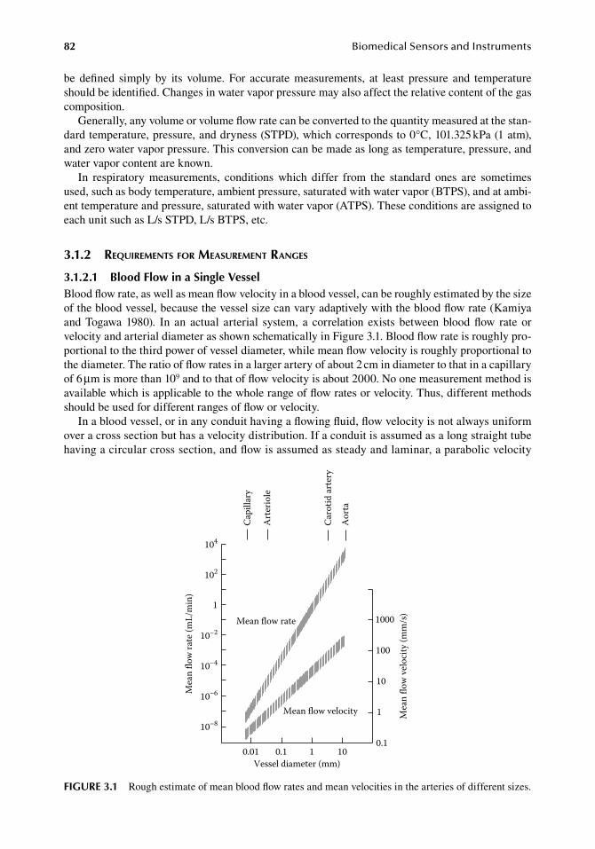
82 BiomedicalSensorsandInstruments
be. defined. simply. by. its. volume.. For. accurate. measurements,. at. least. pressure. and. temperature.should.be.identified..Changes.in.water.vapor.pressure.may.also.affect.the.relative.content.of.the.gas.composition.
Generally,.any.volume.or.volume.flow.rate.can.be.converted.to.the.quantity.measured.at.the.stan-dard.temperature,.pressure,.and.dryness.(STPD),.which.corresponds.to.0°C,.101.325.kPa.(1.atm),.and.zero.water.vapor.pressure..This.conversion.can.be.made.as.long.as.temperature,.pressure,.and.water.vapor.content.are.known.
In. respiratory. measurements,. conditions. which. differ. from. the. standard. ones. are. sometimes.used,.such.as.body.temperature,.ambient.pressure,.saturated.with.water.vapor.(BTPS),.and.at.ambi-ent.temperature.and.pressure,.saturated.with.water.vapor.(ATPS)..These.conditions.are.assigned.to.each.unit.such.as.L/s.STPD,.L/s.BTPS,.etc.
3.1.2 requireMents for MeasureMent ranges
3.1.2.1 blood flow in a Single VesselBlood.flow.rate,.as.well.as.mean.flow.velocity.in.a.blood.vessel,.can.be.roughly.estimated.by.the.size.of.the.blood.vessel,.because.the.vessel.size.can.vary.adaptively.with.the.blood.flow.rate.(Kamiya.and. Togawa. 1980).. In. an. actual. arterial. system,. a. correlation. exists. between. blood. flow. rate. or.velocity.and.arterial.diameter.as.shown.schematically.in.Figure.3.1..Blood.flow.rate.is.roughly.pro-portional.to.the.third.power.of.vessel.diameter,.while.mean.flow.velocity.is.roughly.proportional.to.the.diameter..The.ratio.of.flow.rates.in.a.larger.artery.of.about.2.cm.in.diameter.to.that.in.a.capillary.of.6.μm.is.more.than.109.and.to.that.of.flow.velocity.is.about.2000..No.one.measurement.method.is.available.which.is.applicable.to.the.whole.range.of.flow.rates.or.velocity..Thus,.different.methods.should.be.used.for.different.ranges.of.flow.or.velocity.
In.a.blood.vessel,.or.in.any.conduit.having.a.flowing.fluid,.flow.velocity.is.not.always.uniform.over.a.cross.section.but.has.a.velocity.distribution..If.a.conduit.is.assumed.as.a.long.straight.tube.having.a.circular.cross.section,.and.flow.is.assumed.as.steady.and.laminar,.a.parabolic.velocity.
Capi
llary
Art
erio
le
Caro
tid ar
tery
Aor
ta
Vessel diameter (mm)
Mea
n flo
w ra
te (m
L/m
in)
Mea
n flo
w v
eloc
ity (m
m/s
)
0.01 0.1 1 10
100
10
1
0.1
104
102
1
10–2
10–4
10–6
10–8
1000Mean flow rate
Mean flow velocity
figure 3.1 Rough.estimate.of.mean.blood.flow.rates.and.mean.velocities.in.the.arteries.of.different.sizes.
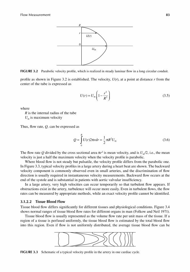
FlowMeasurement 83
profile.as.shown.in.Figure.3.2.is.established..The.velocity,.U(r),.at.a.point.at.distance.r.from.the.center.of.the.tube.is.expressed.as
.
U r Ur
R( ) 1m
2
2= −
.
(3.5)
whereR.is.the.internal.radius.of.the.tubeUm.is.maximum.velocity
Thus,.flow.rate,.Q,.can.be.expressed.as
.
Q U r rdr R U
R
= =∫ ( )0
2212
π π m
.
(3.6)
The.flow.rate.Q.divided.by.the.cross.sectional.area.πr2.is.mean.velocity,.and.is.Um/2,.i.e.,.the.mean.velocity.is.just.a.half.the.maximum.velocity.when.the.velocity.profile.is.parabolic.
Where.blood.flow.is.not.steady.but.pulsatile,.the.velocity.profile.differs.from.the.parabolic.one..In.Figure.3.3,.typical.velocity.profiles.in.a.large.artery.during.a.heart.beat.are.shown..The.backward.velocity.component.is.commonly.observed.even.in.small.arteries,.and.the.discrimination.of.flow.direction.is.usually.required.in.instantaneous.velocity.measurements..Backward.flow.occurs.at.the.end.of.the.systole.and.is.substantial.in.patients.with.aortic.valvular.insufficiency.
In.a.large.artery,.very.high.velocities.can.occur.temporarily.so.that.turbulent.flow.appears..If.obstructions.exist.in.the.artery,.turbulence.will.occur.more.easily..Even.in.turbulent.flows,.the.flow.rates.can.be.measured.by.appropriate.methods,.while.an.exact.velocity.profile.cannot.be.identified.
3.1.2.2 tissue blood flowTissue.blood.flow.differs.significantly.for.different.tissues.and.physiological.conditions..Figure.3.4.shows.normal.ranges.of.tissue.blood.flow.rates.for.different.organs.in.man.(Folkow.and.Neil.1971).
Tissue.blood.flow.is.usually.represented.as.the.volume.flow.rate.per.unit.mass.of.the.tissue..If.a.region.of.a.tissue.is.perfused.uniformly,.the.tissue.blood.flow.is.estimated.by.the.total.blood.flow.into. this. region..Even. if.flow. is.not.uniformly.distributed,. the. average. tissue.blood.flow.can.be.
R
rU(r)
0Um
figure 3.2 Parabolic.velocity.profile,.which.is.realized.in.steady.laminar.flow.in.a.long.circular.conduit.
figure 3.3 Schematic.of.a.typical.velocity.profile.in.the.artery.in.one.cardiac.cycle.
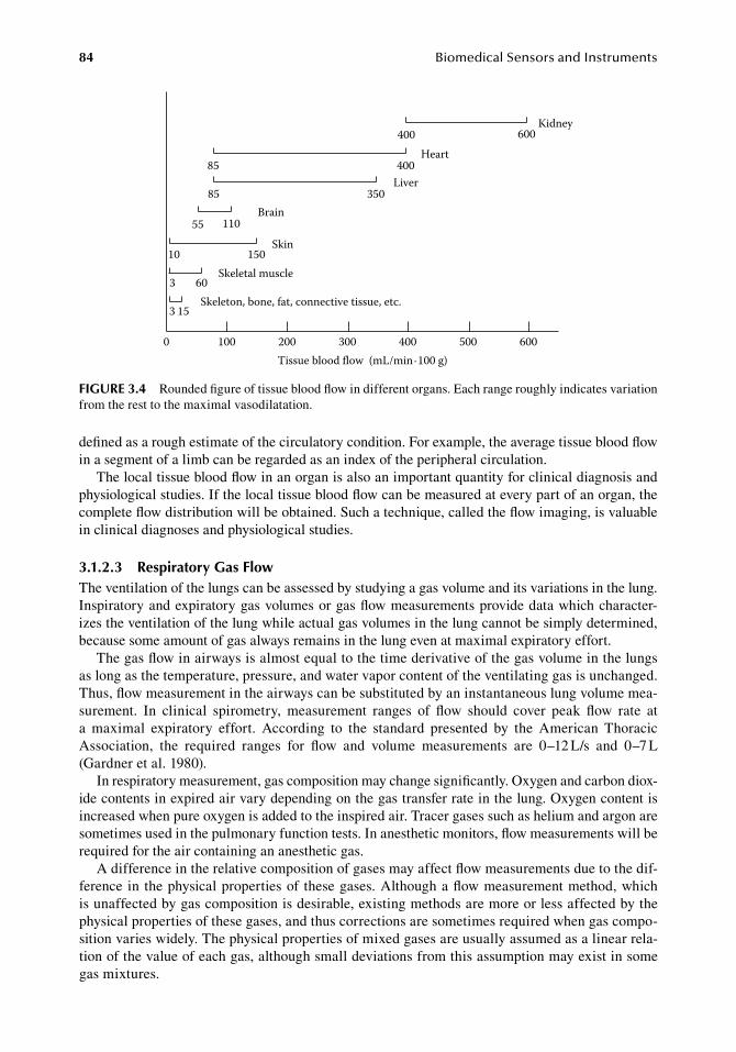
84 BiomedicalSensorsandInstruments
defined.as.a.rough.estimate.of.the.circulatory.condition..For.example,.the.average.tissue.blood.flow.in.a.segment.of.a.limb.can.be.regarded.as.an.index.of.the.peripheral.circulation.
The.local.tissue.blood.flow.in.an.organ.is.also.an.important.quantity.for.clinical.diagnosis.and.physiological.studies..If.the.local.tissue.blood.flow.can.be.measured.at.every.part.of.an.organ,.the.complete.flow.distribution.will.be.obtained..Such.a.technique,.called.the.flow.imaging,.is.valuable.in.clinical.diagnoses.and.physiological.studies.
3.1.2.3 respiratory gas flowThe.ventilation.of.the.lungs.can.be.assessed.by.studying.a.gas.volume.and.its.variations.in.the.lung..Inspiratory.and.expiratory.gas.volumes.or.gas.flow.measurements.provide.data.which.character-izes.the.ventilation.of.the.lung.while.actual.gas.volumes.in.the.lung.cannot.be.simply.determined,.because.some.amount.of.gas.always.remains.in.the.lung.even.at.maximal.expiratory.effort.
The.gas.flow.in.airways.is.almost.equal.to.the.time.derivative.of.the.gas.volume.in.the.lungs.as.long.as.the.temperature,.pressure,.and.water.vapor.content.of.the.ventilating.gas.is.unchanged..Thus,.flow.measurement.in.the.airways.can.be.substituted.by.an.instantaneous.lung.volume.mea-surement.. In. clinical. spirometry,. measurement. ranges. of. flow. should. cover. peak. flow. rate. at.a. maximal. expiratory. effort.. According. to. the. standard. presented. by. the. American. Thoracic.Association,. the. required. ranges. for. flow. and. volume. measurements. are. 0–12.L/s. and. 0–7.L.(Gardner.et al..1980).
In.respiratory.measurement,.gas.composition.may.change.significantly..Oxygen.and.carbon.diox-ide.contents.in.expired.air.vary.depending.on.the.gas.transfer.rate.in.the.lung..Oxygen.content.is.increased.when.pure.oxygen.is.added.to.the.inspired.air..Tracer.gases.such.as.helium.and.argon.are.sometimes.used.in.the.pulmonary.function.tests..In.anesthetic.monitors,.flow.measurements.will.be.required.for.the.air.containing.an.anesthetic.gas.
A.difference.in.the.relative.composition.of.gases.may.affect.flow.measurements.due.to.the.dif-ference.in. the.physical.properties.of. these.gases..Although.a.flow.measurement.method,.which.is.unaffected.by.gas.composition.is.desirable,.existing.methods.are.more.or.less.affected.by.the.physical.properties.of.these.gases,.and.thus.corrections.are.sometimes.required.when.gas.compo-sition.varies.widely..The.physical.properties.of.mixed.gases.are.usually.assumed.as.a.linear.rela-tion.of.the.value.of.each.gas,.although.small.deviations.from.this.assumption.may.exist.in.some.gas.mixtures.
400 600Kidney
Heart85 400
Liver85 350
Brain55 110
Skin10 150
Skeletal muscle3 60
3 15Skeleton, bone, fat, connective tissue, etc.
0 100 200 300 400 500 600Tissue blood flow (mL/min·100 g)
figure 3.4 Rounded.figure.of.tissue.blood.flow.in.different.organs..Each.range.roughly.indicates.variation.from.the.rest.to.the.maximal.vasodilatation.
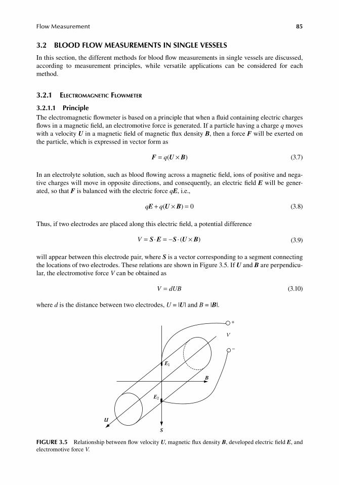
FlowMeasurement 85
3.2 blood floW MeaSureMentS in Single VeSSelS
In.this.section,.the.different.methods.for.blood.flow.measurements.in.single.vessels.are.discussed,.according. to. measurement. principles,. while. versatile. applications. can. be. considered. for. each.method.
3.2.1 electroMagnetic flowMeter
3.2.1.1 PrincipleThe.electromagnetic.flowmeter.is.based.on.a.principle.that.when.a.fluid.containing.electric.charges.flows.in.a.magnetic.field,.an.electromotive.force.is.generated..If.a.particle.having.a.charge.q.moves.with.a.velocity.U.in.a.magnetic.field.of.magnetic.flux.density.B,.then.a.force.F.will.be.exerted.on.the.particle,.which.is.expressed.in.vector.form.as
. F U B= ×q( ) . (3.7)
In.an.electrolyte.solution,.such.as.blood.flowing.across.a.magnetic.field,.ions.of.positive.and.nega-tive.charges.will.move.in.opposite.directions,.and.consequently,.an.electric.field.E.will.be.gener-ated,.so.that.F.is.balanced.with.the.electric.force.qE,.i.e.,
. q qE U B+ × =( ) 0 . (3.8)
Thus,.if.two.electrodes.are.placed.along.this.electric.field,.a.potential.difference
. V = = − ×S E S U B· · ( ) . (3.9)
will.appear.between.this.electrode.pair,.where.S.is.a.vector.corresponding.to.a.segment.connecting.the.locations.of.two.electrodes..These.relations.are.shown.in.Figure.3.5..If.U.and.B.are.perpendicu-lar,.the.electromotive.force.V.can.be.obtained.as
. V d= UB . (3.10)
where.d.is.the.distance.between.two.electrodes,.U.=.|U|.and.B.=.|B|.
U
E1
E2
B
V
+
–
S
figure 3.5 Relationship.between.flow.velocity.U,.magnetic.flux.density.B,.developed.electric.field.E,.and.electromotive.force.V.
86 BiomedicalSensorsandInstruments
In.blood.vessels,.the.velocity.is.not.uniform..Nevertheless,.it.can.be.shown.that.Equation.3.10.is.still.valid.by.taking.U.as.the.mean.velocity.as.long.as.the.velocity.profile.is.axisymmetric.about.the.longitudial.axis.of.the.vessel..This.is.an.advantage.of.the.electromagnetic.flowmeter..Using.mean.velocity,.the.flow.rate.Q.is.expressed.as
.Q
d U dV
B= =π π2
4 4 .(3.11)
as.long.as.the.flow.is.axisymmetric..In.SI.units,.Q.is.in.m3/s,.B.in.Tesla,.d.in.meter,.and.V.in.volts.are.used.
3.2.1.2 factors affecting the MeasurementsWhile.the.principle.of.the.electromagnetic.blood.flowmeter.is.rather.simple,.there.are.many.factors.which.may.affect.sensitivity..At.the.very.least,.velocity.profile,.magnetic.field.distribution,.and.elec-tric.conductivities.of.the.inside.vessel.wall.and.outside.media.may.affect.the.electromotive.force.to.some.extent.(Shercliff.1954,.1955,.Goldman.et al..1963).
Today,.the.electromagnetic.flowmeter.principle.is.replaced.to.a.large.extent.by.other.methods.like.ultrasound.and.thermodilution.that.require.less.surgical.incisions.and.are.more.convenient.to.use..For.more.details.about.principles,.advantages,.and.problems.with.electromagnetic.flow.measure-ments,.the.reader.is.referred.to.Togawa.et al..(1997).
3.2.2 ultrasonic blood flowMeters
A.sound.wave.propagating. in.a.moving.medium.is.affected.by. the.velocity.of. the.medium,.and.the. sound. scattered.by.a.moving.object. is. also.affected.by. the.velocity.of. the. scattering.object..Both.phenomena.can.be.used.to.measure.blood.flow.velocity.or.flow.rate.in.a.blood.vessel..The.fundamental.properties.of.sound.wave.propagation.are.summarized.in.the.first.part.of.this.section,.but.more.details.can.be.found.in.other.textbooks.(Woodcock.1975,.Atkinson.and.Woodcock.1982,.Goldstein.1988)..In.the.later.part,.two.types.of.ultrasonic.flowmeters,.the.transit.time.or.phase.shift.flowmeter.and.the.Doppler.flowmeter,.are.described.
3.2.2.1 Propagation of ultrasound in the tissueUltrasound.is.defined.as.sound.having.a.frequency.content.higher.than.20.kHz..Ultrasound.propa-gates.in.the.soft. tissue.with.a.velocity.of.about.1500.m/s..The.sound.velocity.c,.frequency. f,.and.wavelength.λ.are.related.as
. c f= λ . (3.12)
As.an.example,.the.wavelength.of.ultrasound.of.1.MHz.is.about.1.5.mm.in.tissue.A.sound.at.a.point.in.a.medium.is.characterized.by.the.sound.pressure.and.the.sound.particle.
velocity.(or.medium.velocity)..If.a.sound.wave.propagates.in.one.direction,.the.amplitude.of.sound.pressure.p.is.proportional.to.that.of.sound.particle.velocity.U,.so.that
. p cU= ρ . (3.13)
where.ρ.is.the.density.of.the.medium..The.ratio.of.the.amplitude.of.sound.pressure.to.particle.velocity.is.called.a.characteristic.impedance.(or.a.characteristic.acoustic.impedance).of.the.medium,.that.is
.Z
p
Uc= = ρ
.(3.14)
Characteristic.impedances.of.actual.media.are.listed.in.Table.3.1.
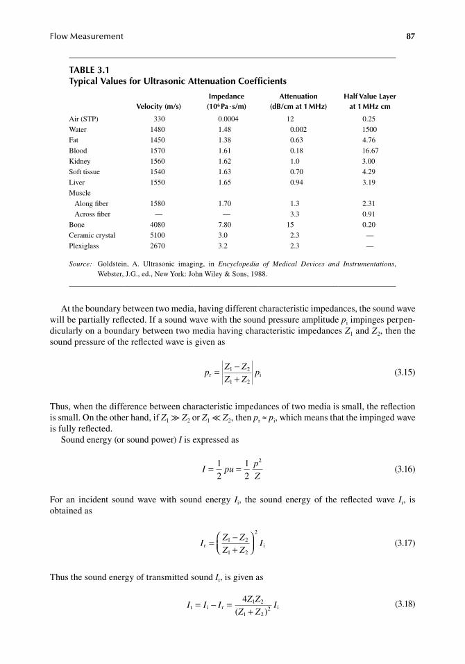
FlowMeasurement 87
At.the.boundary.between.two.media,.having.different.characteristic.impedances,.the.sound.wave.will.be.partially.reflected..If.a.sound.wave.with.the.sound.pressure.amplitude.pi.impinges.perpen-dicularly.on.a.boundary.between.two.media.having.characteristic.impedances.Z1.and.Z2,.then.the.sound.pressure.of.the.reflected.wave.is.given.as
.p
Z Z
Z Zpr
1 2
1 2i= −
+ .(3.15)
Thus,.when.the.difference.between.characteristic.impedances.of.two.media.is.small,.the.reflection.is.small..On.the.other.hand,.if.Z1.≫.Z2.or.Z1.≪.Z2,.then.pr.≈.pi,.which.means.that.the.impinged.wave.is.fully.reflected.
Sound.energy.(or.sound.power).I.is.expressed.as
.I pu
p
Z= =1
212
2
.
(3.16)
For. an. incident. sound. wave. with. sound. energy. Ii,. the. sound. energy. of. the. reflected. wave. Ir,. is.obtained.as
.I
Z Z
Z ZIr
1 2
1 2
2
i= −+
.(3.17)
Thus.the.sound.energy.of.transmitted.sound.It,.is.given.as
.I I I
Z Z
Z ZIt i r
1 2
1 22 i
4( )
= − =+ .
(3.18)
table 3.1typical Values for ultrasonic attenuation Coefficients
Velocity (m/s)impedance
(106 Pa · s/m)attenuation
(db/ cm at 1 Mhz)half Value layer
at 1 Mhz cm
Air.(STP) 330 0.0004 12 0.25
Water 1480 1.48 0.002 1500
Fat 1450 1.38 0.63 4.76
Blood 1570 1.61 0.18 16.67
Kidney 1560 1.62 1.0 3.00
Soft.tissue 1540 1.63 0.70 4.29
Liver 1550 1.65 0.94 3.19
Muscle
Along.fiber 1580 1.70 1.3 2.31
Across.fiber — — 3.3 0.91
Bone 4080 7.80 15 0.20
Ceramic.crystal 5100 3.0 2.3 —
Plexiglass 2670 3.2 2.3 —
Source:. Goldstein,. A.. Ultrasonic. imaging,. in. Encyclopedia of Medical Devices and Instrumentations,.Webster,.J.G.,.ed.,.New.York:.John.Wiley.&.Sons,.1988.
88 BiomedicalSensorsandInstruments
Substituting.characteristic.impedance.values.of.mediums,.the.transmittance.of.the.boundary.of.air.and.water.is.obtained.as.about.0.13%,.and.that.of.a.ceramic.crystal.and.water.is.about.20%.
When.ultrasound.propagates.in.tissue,.it.is.attenuated.by.absorption,.reflection,.and.scattering..If.a.plane.wave.propagates.in.the.x.direction.in.an.absorbing.medium,.and.if.it.has.a.sound.pressure.p(0).at.x.=.0,.then.sound.pressure.at.x.is.represented.as
. p x p x( ) ( )= −0 e α. (3.19)
where.α.is.the.absorption.coefficient..The.absorption.coefficients.for.the.ultrasound.of.1.MHz.are.also.listed.in.Table.3.1..It.varies.almost.in.proportion.to.the.sound.frequency..Because.sound.energy.is.proportional.to.a.square.of.sound.pressure,.sound.energy.at.x,.I(x).is.expressed.as
. I x I x( ) ( )= −0 e 2α. (3.20)
To.generate.and.detect.ultrasound,.a.piezoelectric.crystal.is.commonly.used..The.active.element.of.the.transmitter.or.receiver.crystal.is.a.plate.of.piezoelectric.crystal.with.thin.metallic.electrodes.on.both.sides..When.an.alternating.potential.is.applied.to.the.electrodes,.the.thickness.of.the.piezoelec-tric.crystal.changes.instantaneously.and.a.sound.wave.is.generated.into.the.surrounding.medium..When. a. sound.wave.penetrates. into. a. piezoelectric. crystal,. it. causes. a.mechanical. strain. in. the.material,.and.electric.polarization.appears.at.the.electrodes,.thus.generating.a.signal.related.to.the.sound.pressure.
The.piezoelectric.crystal.of.lead.zircorate.titanate.(PZT).is.commonly.used.for.generating.and.detecting.ultrasound..In.this.material,.about.50%.of.the.applied.electric.energy.can.be.converted.into.mechanical.energy,.when.the.crystal.is.operated.at.below.mechanical.resonant.frequency,.while.the.efficiency.may.be.as.high.as.90%.when. it. is.operated.at. the. resonance. frequency. (Henning.1988)..Although.mechanical.resonance.is.advantageous.to.increase.efficiency.in.continuous.wave.operations,.it.is.undesirable.for.pulsed.operation.because.it.lengthens.the.pulse.duration..To.dampen.the.mechanical.resonance,.an.absorbing.medium.is.attached.to.the.rear.side.of.the.crystal.as.the.backing.material.
When.a.transmitter.crystal.is.operated.in.a.continuous.wave,.a.specific.beam.pattern.is.generated.in.the.medium..The.beam.pattern.can.be.determined.by.the.geometry.of.the.transmitter.crystal..By.applying.Huygens’.principle,.it.can.be.assumed.that.the.transmitter.crystal.surface.consists.of.a.number.of.point.sources.emitting.spherical.waves..If.a.flat,.disk-shaped.crystal.is.operated.in.the.thickness.expanding.mode,.the.beam.pattern.is.characterized.by.a.near.field.(or.Fresnel.zone).and.a.far.field.(or.Fraunhofer.zone)..In.the.near.field,.diffraction.can.occur.among.sound.waves.gener-ated. at. different. sites. on. the. crystal. surface,. and. consequently. spatially. varying. sound.pressure.amplitude.appears..In.the.far.field,.the.sound.pressure.amplitude.is.spatially.uniform..Figure.3.6.shows.the.beam.pattern.when.the.crystal.radius,.r,.is.about.10.λ..The.beam.pattern.of.the.near.field.is.cylindrical,.and.its.length.is.about.r2/λ..The.beam.pattern.of.the.far.field.is.conical.and.the.half.angle,.γ,.of.divergence.of.the.cone.is.given.by
.sin γ λ= 0.6
r .(3.21)
3.2.2.2 transit time and Phase Shift ultrasound flowmetersWhen.a.sound.wave.travels.upstream.or.downstream.in.a.flowing.fluid,.the.apparent.sound.velocity.dif-fers.from.the.sound.velocity.in.resting.fluid,.because.a.sound.wave.travels.at.a.constant.velocity.relative.
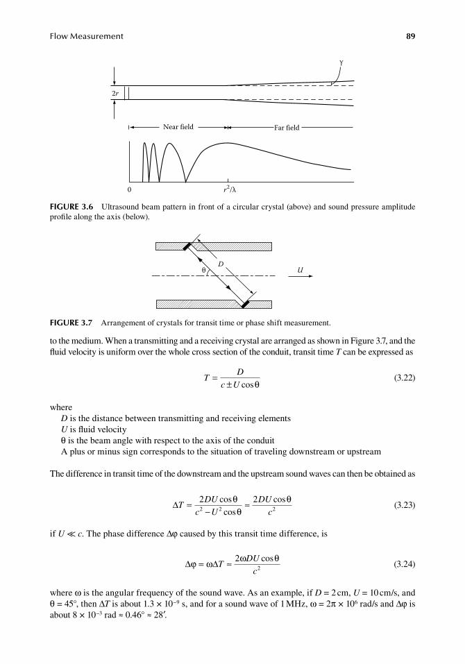
FlowMeasurement 89
to.the.medium..When.a.transmitting.and.a.receiving.crystal.are.arranged.as.shown.in.Figure.3.7,.and.the.fluid.velocity.is.uniform.over.the.whole.cross.section.of.the.conduit,.transit.time.T.can.be.expressed.as
.T
D
c U=
± cosθ .(3.22)
whereD.is.the.distance.between.transmitting.and.receiving.elementsU.is.fluid.velocityθ.is.the.beam.angle.with.respect.to.the.axis.of.the.conduitA.plus.or.minus.sign.corresponds.to.the.situation.of.traveling.downstream.or.upstream
The.difference.in.transit.time.of.the.downstream.and.the.upstream.sound.waves.can.then.be.obtained.as
.∆T
DU
c U
DU
c=
−≈2 2
2 2 2
coscos
cosθθ
θ.
(3.23)
if.U ≪ c..The.phase.difference.Δφ.caused.by.this.transit.time.difference,.is
.∆ ∆ϕ ω ω θ= ≈T
DU
c
22
cos
.(3.24)
where.ω.is.the.angular.frequency.of.the.sound.wave..As.an.example,.if.D.=.2.cm,.U.=.10.cm/s,.and.θ.=.45°,.then.ΔT.is.about.1.3.×.10−9.s,.and.for.a.sound.wave.of.1.MHz,.ω.=.2π.×.106.rad/s.and.Δφ.is.about.8.×.10−3.rad.≈.0.46°.≈.28′.
Near field Far field
γ
r2/λ0
2r
figure 3.6 Ultrasound.beam.pattern.in.front.of.a.circular.crystal.(above).and.sound.pressure.amplitude.profile.along.the.axis.(below).
UD
θ
figure 3.7 Arrangement.of.crystals.for.transit.time.or.phase.shift.measurement.
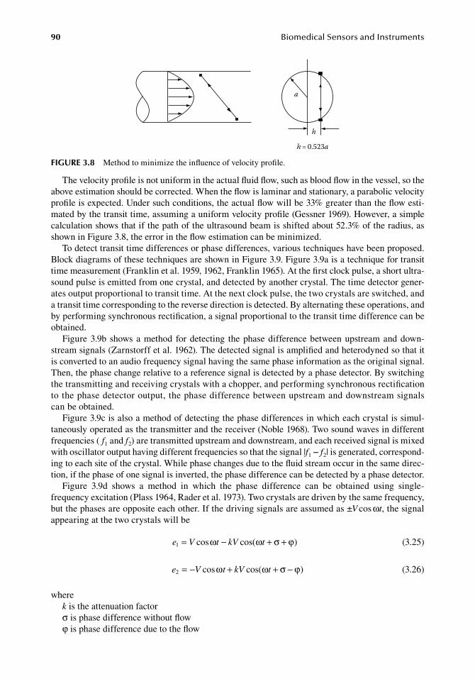
90 BiomedicalSensorsandInstruments
The.velocity.profile.is.not.uniform.in.the.actual.fluid.flow,.such.as.blood.flow.in.the.vessel,.so.the.above.estimation.should.be.corrected..When.the.flow.is.laminar.and.stationary,.a.parabolic.velocity.profile.is.expected..Under.such.conditions,.the.actual.flow.will.be.33%.greater.than.the.flow.esti-mated.by.the.transit.time,.assuming.a.uniform.velocity.profile.(Gessner.1969)..However,.a.simple.calculation.shows.that.if.the.path.of.the.ultrasound.beam.is.shifted.about.52.3%.of.the.radius,.as.shown.in.Figure.3.8,.the.error.in.the.flow.estimation.can.be.minimized.
To.detect.transit.time.differences.or.phase.differences,.various.techniques.have.been.proposed..Block.diagrams.of.these.techniques.are.shown.in.Figure.3.9..Figure.3.9a.is.a.technique.for.transit.time.measurement.(Franklin.et al..1959,.1962,.Franklin.1965)..At.the.first.clock.pulse,.a.short.ultra-sound.pulse.is.emitted.from.one.crystal,.and.detected.by.another.crystal..The.time.detector.gener-ates.output.proportional.to.transit.time..At.the.next.clock.pulse,.the.two.crystals.are.switched,.and.a.transit.time.corresponding.to.the.reverse.direction.is.detected..By.alternating.these.operations,.and.by.performing.synchronous.rectification,.a.signal.proportional.to.the.transit.time.difference.can.be.obtained.
Figure.3.9b.shows.a.method. for.detecting. the.phase.difference.between.upstream.and.down-stream.signals.(Zarnstorff.et al..1962)..The.detected.signal.is.amplified.and.heterodyned.so.that.it.is.converted.to.an.audio.frequency.signal.having.the.same.phase.information.as.the.original.signal..Then,.the.phase.change.relative.to.a.reference.signal.is.detected.by.a.phase.detector..By.switching.the.transmitting.and.receiving.crystals.with.a.chopper,.and.performing.synchronous.rectification.to.the.phase.detector.output,.the.phase.difference.between.upstream.and.downstream.signals.can.be.obtained.
Figure.3.9c.is.also.a.method.of.detecting.the.phase.differences.in.which.each.crystal.is.simul-taneously.operated.as.the.transmitter.and.the.receiver.(Noble.1968)..Two.sound.waves.in.different.frequencies.( f1.and.f2).are.transmitted.upstream.and.downstream,.and.each.received.signal.is.mixed.with.oscillator.output.having.different.frequencies.so.that.the.signal.|f1.−.f2|.is.generated,.correspond-ing.to.each.site.of.the.crystal..While.phase.changes.due.to.the.fluid.stream.occur.in.the.same.direc-tion,.if.the.phase.of.one.signal.is.inverted,.the.phase.difference.can.be.detected.by.a.phase.detector.
Figure. 3.9d. shows. a. method. in. which. the. phase. difference. can. be. obtained. using. single-frequency.excitation.(Plass.1964,.Rader.et al..1973)..Two.crystals.are.driven.by.the.same.frequency,.but.the.phases.are.opposite.each.other..If.the.driving.signals.are.assumed.as.±V cos.ωt,.the.signal.appearing.at.the.two.crystals.will.be
. e V t kV t1 cos cos= − + +( )ω ω σ ϕ . (3.25)
. e V kV t2 cos cos= − + + −( )ω ω σ ϕt . (3.26)
wherek.is.the.attenuation.factorσ.is.phase.difference.without.flowφ.is.phase.difference.due.to.the.flow
a
h
h = 0.523a
figure 3.8 Method.to.minimize.the.influence.of.velocity.profile.
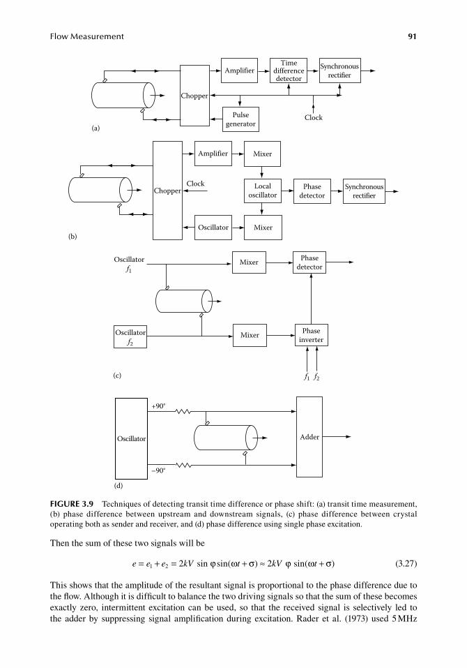
FlowMeasurement 91
Then.the.sum.of.these.two.signals.will.be
. e e e kV t kV t= + = + ≈ +1 2 2 sin sin 2 sinϕ ω σ ϕ ω σ( ) ( ) . (3.27)
This.shows.that.the.amplitude.of.the.resultant.signal.is.proportional.to.the.phase.difference.due.to.the.flow..Although.it.is.difficult.to.balance.the.two.driving.signals.so.that.the.sum.of.these.becomes.exactly.zero,. intermittent.excitation.can.be.used,. so. that. the. received.signal. is. selectively. led. to.the. adder.by. suppressing. signal. amplification.during.excitation..Rader. et al.. (1973).used.5.MHz.
(a)
Chopper
AmplifierTime
differencedetector
Pulsegenerator
Synchronousrectifier
Clock
(b)
Chopper
Amplifier Mixer
Clock Localoscillator
Oscillator Mixer
Phasedetector
Synchronousrectifier
(c)
Mixer
Mixer
Phasedetector
Phaseinverter
Oscillatorf1
Oscillatorf2
f1 f2
Oscillator Adder
+90°
–90°
(d)
figure 3.9 Techniques.of.detecting.transit.time.difference.or.phase.shift:.(a).transit.time.measurement,.(b). phase. difference. between. upstream. and. downstream. signals,. (c). phase. difference. between. crystal.operating.both.as.sender.and.receiver,.and.(d).phase.difference.using.single.phase.excitation.
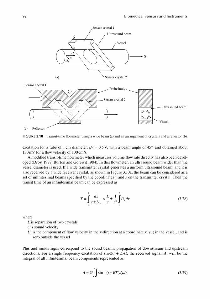
92 BiomedicalSensorsandInstruments
excitation.for.a.tube.of.1.cm.diameter,.kV.=.0.5.V,.with.a.beam.angle.of.45°,.and.obtained.about.130.mV.for.a.flow.velocity.of.100.cm/s.
A.modified.transit-time.flowmeter.which.measures.volume.flow.rate.directly.has.also.been.devel-oped.(Drost.1978,.Burton.and.Gorewit.1984)..In.this.flowmeter,.an.ultrasound.beam.wider.than.the.vessel.diameter.is.used..If.a.wide.transmitter.crystal.generates.a.uniform.ultrasound.beam,.and.it.is.also.received.by.a.wide.receiver.crystal,.as.shown.in.Figure.3.10a,.the.beam.can.be.considered.as.a.set.of.infinitesimal.beams.specified.by.the.coordinates.y.and.z.on.the.transmitter.crystal..Then.the.transit.time.of.an.infinitesimal.beam.can.be.expressed.as
.
Tdx
c U
L
c cU dx
x
L
x
L
=±
≈ ±∫ ∫0
2
0
1
.
(3.28)
whereL.is.separation.of.two.crystalsc.is.sound.velocityUx.is.the.component.of.flow.velocity.in.the.x-direction.at.a.coordinate.x,.y,.z.in.the.vessel,.and.is.
zero.outside.the.vessel
Plus.and.minus.signs.correspond. to. the.sound.beam’s.propagation.of.downstream.and.upstream.directions..For.a.single.frequency.excitation.of.sin.ω(t + L /c),. the.received.signal,.A,.will.be.the.integral.of.all.infinitesimal.beam.components.represented.as
.A G t T dydz= ±∫∫ sin ( )ω δ
.(3.29)
(b)
Sensor crystal 1
Ultrasound beam
Vessel
Sensor crystal 2
UU
α
x
yz
Ux
(a)
Probe bodySensor crystal 1
Sensor crystal 2
Reflector
Vessel
Ultrasound beam
figure 3.10 Transit-time.flowmeter.using.a.wide.beam.(a).and.an.arrangement.of.crystals.and.a.reflector.(b).
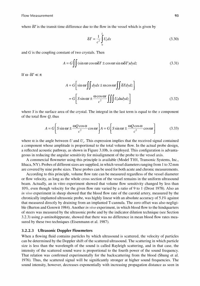
FlowMeasurement 93
where.δT.is.the.transit.time.difference.due.to.the.flow.in.the.vessel.which.is.given.by
.
δTc
U dxx
L
= ∫12
0 .
(3.30)
and.G.is.the.coupling.constant.of.two.crystals..Then
.A G t T t T dydz= ±∫∫ (sin cos cos sin )ω ωδ ω ωδ
.(3.31)
If.ω ·.δT.≪.π
.
A G t dydx t Tdydz
G S tt
cU dx
= ±
= ±
∫∫∫∫
∫∫∫
sin cos
sincos
ω ω ω δ
ω ω ω2 xxdydz
.
(3.32)
where.S.is.the.surface.area.of.the.crystal..The.integral.in.the.last.term.is.equal.to.the.x.component.of.the.total.flow.Q,.thus
.A G S t
Q
ct A G S t
Q
ct= ±
= ±
sincos
cos sincos
cosω ω α ω ω ω α ω2 2
.(3.33)
where.α.is.the.angle.between.U.and.Ux..This.expression.implies.that.the.received.signal.contained.a.component.whose.amplitude.is.proportional.to.the.total.volume.flow..In.the.actual.probe.design,.a.reflected.acoustic.pathway,.as.shown.in.Figure.3.10b,.is.employed..This.configuration.is.advanta-geous.in.reducing.the.angular.sensitivity.for.misalignment.of.the.probe.to.the.vessel.axis.
A.commercial.flowmeter.using.this.principle.is.available.(Model.T101,.Transonic.Systems,.Inc.,.Ithaca,.NY)..Probes.of.different.sizes.are.supplied,.in.which.vessel.diameters.ranging.from.1.to.32.mm.are.covered.by.nine.probe.sizes..These.probes.can.be.used.for.both.acute.and.chronic.measurements.
According.to.this.principle,.volume.flow.rate.can.be.measured.regardless.of.the.vessel.diameter.or.flow.velocity,.as.long.as.the.whole.cross.section.of.the.vessel.remains.in.the.uniform.ultrasound.beam..Actually,.an.in.vitro.experiment.showed.that.volume.flow.sensitivity.changed.by.less.than.10%,.even.though.velocity.for.the.given.flow.rate.varied.by.a.ratio.of.9.to.1.(Drost.1978)..Also.an.in vivo.experiment.in.sheep.showed.that.the.blood.flow.rate.of.the.carotid.artery,.measured.by.the.chronically.implanted.ultrasonic.probe,.was.highly.linear.with.an.absolute.accuracy.of.5.1%.against.that.measured.directly.by.draining.from.an.implanted.T-cannula..The.zero.offset.was.also.negligi-ble.(Burton.and.Gorewit.1984)..Another.in vivo.experiment,.in.which.blood.flow.to.the.hindquarters.of.steers.was.measured.by.the.ultrasonic.probe.and.by.the.indicator.dilution.technique.(see.Section.3.2.3).using.p-aminohippurate,.showed.that.there.was.no.difference.in.mean.blood.flow.rates.mea-sured.by.these.two.techniques.(Eisenmann.et al..1987).
3.2.2.3 ultrasonic doppler flowmetersWhen.a.flowing.fluid.contains.particles.by.which.ultrasound.is.scattered,.the.velocity.of.particles.can.be.determined.by.the.Doppler.shift.of.the.scattered.ultrasound..The.scattering.in.which.particle.size. is. less. than. the.wavelength.of. the. sound. is.called.Rayleigh.scattering,.and. in. that.case,. the.intensity.of.the.scattered.sound.wave.is.proportional.to.the.fourth.power.of.the.sound.frequency..That. relation.was.confirmed.experimentally. for. the.backscattering. from. the.blood. (Shung.et al..1976)..Thus,. the. scattered. signal.will.be. significantly. stronger.at.higher. sound. frequencies..The.sound.intensity,.however,.decreases.exponentially.with.increasing.propagation.distance.as.seen.in.
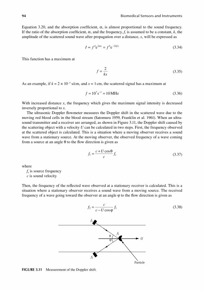
94 BiomedicalSensorsandInstruments
Equation.3.20,.and.the.absorption.coefficient,.α,. is.almost.proportional.to.the.sound.frequency..If.the.ratio.of.the.absorption.coefficient,.α,.and.the.frequency,.f,.is.assumed.to.be.a.constant,.k,.the.amplitude.of.the.scattered.sound.wave.after.propagation.over.a.distance,.x,.will.be.expressed.as
. I f fx kfx∝ α4 2 4 2e e= −. (3.34)
This.function.has.a.maximum.at
.f
kx= 2
.(3.35)
As.an.example,.if.k.=.2.×.10−7.s/cm,.and.x.=.1.cm,.the.scattered.signal.has.a.maximum.at
. f = =−10 107 1s MHz . (3.36)
With.increased.distance.x,.the.frequency.which.gives.the.maximum.signal.intensity.is.decreased.inversely.proportional.to.x.
The.ultrasonic.Doppler.flowmeter.measures.the.Doppler.shift.in.the.scattered.wave.due.to.the.moving.red.blood.cells.in.the.blood.stream.(Satomura.1959,.Franklin.et al..1961)..When.an.ultra-sound.transmitter.and.a.receiver.are.arranged,.as.shown.in.Figure.3.11,.the.Doppler.shift.caused.by.the.scattering.object.with.a.velocity.U.can.be.calculated.in.two.steps..First,.the.frequency.observed.at.the.scattered.object.is.calculated..This.is.a.situation.where.a.moving.observer.receives.a.sound.wave.from.a.stationary.source..At.the.moving.observer,.the.observed.frequency.of.a.wave.coming.from.a.source.at.an.angle.θ.to.the.flow.direction.is.given.as
.f
c U
cf1 = + cosθs.
(3.37)
wherefs.is.source.frequencyc.is.sound.velocity
Then,.the.frequency.of.the.reflected.wave.observed.at.a.stationary.receiver.is.calculated..This.is.a.situation.where.a.stationary.observer.receives.a.sound.wave.from.a.moving.source..The.received.frequency.of.a.wave.going.toward.the.observer.at.an.angle.φ.to.the.flow.direction.is.given.as
.f
c
c Uf2 1=
− cosϕ .(3.38)
fs
f2
f1θU
Particle
figure 3.11 Measurement.of.the.Doppler.shift.
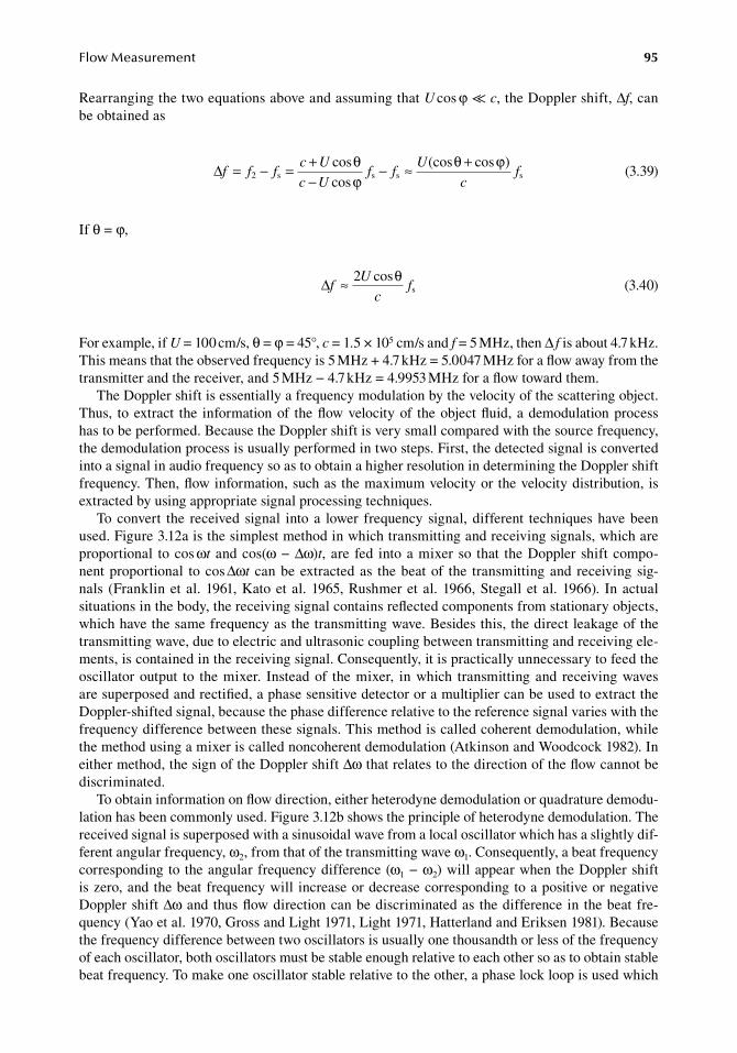
FlowMeasurement 95
Rearranging.the.two.equations.above.and.assuming.that.U.cos.φ.≪.c,.the.Doppler.shift,.Δf,.can.be.obtained.as
.∆f f f
c U
c Uf f
U
cf= − = +
−− ≈ +
2 s s s scoscos
(cos cos )θ θϕ
ϕ
.(3.39)
If.θ.=.φ,
.∆f
U
cf≈ 2 cosθs
.(3.40)
For.example,.if.U.=.100.cm/s,.θ.=.φ.=.45°,.c.=.1.5.×.105.cm/s.and.f.=.5.MHz,.then.Δ f.is.about.4.7.kHz..This.means.that.the.observed.frequency.is.5.MHz.+.4.7.kHz.=.5.0047.MHz.for.a.flow.away.from.the.transmitter.and.the.receiver,.and.5.MHz.−.4.7.kHz.=.4.9953.MHz.for.a.flow.toward.them.
The.Doppler.shift.is.essentially.a.frequency.modulation.by.the.velocity.of.the.scattering.object..Thus,. to.extract. the. information.of. the.flow.velocity.of. the.object.fluid,.a.demodulation.process.has.to.be.performed..Because.the.Doppler.shift.is.very.small.compared.with.the.source.frequency,.the.demodulation.process.is.usually.performed.in.two.steps..First,.the.detected.signal.is.converted.into.a.signal.in.audio.frequency.so.as.to.obtain.a.higher.resolution.in.determining.the.Doppler.shift.frequency..Then,.flow.information,.such.as.the.maximum.velocity.or.the.velocity.distribution,.is.extracted.by.using.appropriate.signal.processing.techniques.
To.convert. the. received.signal. into.a. lower. frequency.signal,.different. techniques.have.been.used..Figure.3.12a.is.the.simplest.method.in.which.transmitting.and.receiving.signals,.which.are.proportional. to.cos.ωt.and.cos(ω.−.Δω)t,.are. fed. into.a.mixer.so. that. the.Doppler.shift.compo-nent.proportional. to.cos.Δωt. can.be.extracted.as. the.beat.of. the. transmitting.and. receiving.sig-nals. (Franklin.et al..1961,.Kato.et al..1965,.Rushmer.et al..1966,.Stegall.et al..1966).. In.actual.situations.in.the.body,.the.receiving.signal.contains.reflected.components.from.stationary.objects,.which.have.the.same.frequency.as.the.transmitting.wave..Besides.this,.the.direct.leakage.of.the.transmitting.wave,.due.to.electric.and.ultrasonic.coupling.between.transmitting.and.receiving.ele-ments,.is.contained.in.the.receiving.signal..Consequently,.it.is.practically.unnecessary.to.feed.the.oscillator.output. to. the.mixer.. Instead.of. the.mixer,. in.which. transmitting.and. receiving.waves.are.superposed.and.rectified,.a.phase.sensitive.detector.or.a.multiplier.can.be.used.to.extract.the.Doppler-shifted.signal,.because.the.phase.difference.relative.to.the.reference.signal.varies.with.the.frequency.difference.between.these.signals..This.method.is.called.coherent.demodulation,.while.the.method.using.a.mixer.is.called.noncoherent.demodulation.(Atkinson.and.Woodcock.1982)..In.either.method,.the.sign.of.the.Doppler.shift.Δω.that.relates.to.the.direction.of.the.flow.cannot.be.discriminated.
To.obtain.information.on.flow.direction,.either.heterodyne.demodulation.or.quadrature.demodu-lation.has.been.commonly.used..Figure.3.12b.shows.the.principle.of.heterodyne.demodulation..The.received.signal.is.superposed.with.a.sinusoidal.wave.from.a.local.oscillator.which.has.a.slightly.dif-ferent.angular.frequency,.ω2,.from.that.of.the.transmitting.wave.ω1..Consequently,.a.beat.frequency.corresponding.to.the.angular.frequency.difference.(ω1.−.ω2).will.appear.when.the.Doppler.shift.is.zero,.and.the.beat.frequency.will. increase.or.decrease.corresponding.to.a.positive.or.negative.Doppler.shift.Δω.and.thus.flow.direction.can.be.discriminated.as. the.difference.in. the.beat.fre-quency.(Yao.et al..1970,.Gross.and.Light.1971,.Light.1971,.Hatterland.and.Eriksen.1981)..Because.the.frequency.difference.between.two.oscillators.is.usually.one.thousandth.or.less.of.the.frequency.of.each.oscillator,.both.oscillators.must.be.stable.enough.relative.to.each.other.so.as.to.obtain.stable.beat.frequency..To.make.one.oscillator.stable.relative.to.the.other,.a.phase.lock.loop.is.used.which.
96 BiomedicalSensorsandInstruments
involves.a.low-frequency.oscillator.corresponding.to.the.frequency.difference,.and.the.phase.of.the.beat.of.two.oscillator.outputs.is.locked.to.that.of.the.low.frequency.oscillator.output.(Mackay.1972).
Figure.3.12c.shows.the.configuration.of.the.quadrature.demodulation,.which.was.also.devised.for.directional.Doppler.measurement.(Mackay.1972,.Arts.and.Roevros.1972)..The.upper.half.of.this.configuration.is.identical.to.the.simple.coherent.demodulation.which.provides.Doppler.frequency.output.proportional.to.cos.Δωt.preserving.phase.information..The.lower.part.is.also.a.coherent.demodulation,.but. the.phase.of. the. reference.wave. is.shifted.90°. from.that.of. the.upper. part.. It. also. provides. Doppler. frequency. output. proportional. to. sin.Δωt. which. has. the.same.frequency.as.the.first,.but.the.phase.differs.by.90°..Thus,.the.phase.of.the.second.output.relative.to.that.of.the.first.one.changes.+90°.to.−90°,.when.the.sign.of.Δω.changes..This.means.that.flow.direction.can.be.discriminated.by. the. relative.phase. relation.between. two.coherent.demodulation.outputs.
To.extract.velocity.information.from.the.signal.containing.Doppler.shift.components,.either.a.zero-cross.count.or. spectrum.analysis. is.commonly.used..The.principle.of. the.zero-cross.count.is.based.on.the.theory.of.random.noise..Because.the.reflected.signal.involves.a.great.number.of.waves.scattered.by.independent.red.blood.cells.moving.in.the.transmitting.ultrasound.beam,.the.signal.can.be.regarded.as.a.kind.of. the.random.noise..According.to.Rice.(1944),. the.number.of.
Oscillator Localoscillator
Flow
Mixer(b)
Oscillatorcos ωt
cos ω1t
cos ω2t
Flow
cos(ω – Δω)t
cos ωtcos Δωt
sin ωt
cos(ω1 – Δω)t
cos(ω – Δω)tsin Δωt
cos(ω1 – ω2Δω)t
cos ΔωtMixer(a)
Flow
Multiplier andlow-pass filter
Multiplier andlow-pass filterOscillator
(c)
figure 3.12 Techniques.of.extracting.Doppler.shift.components:.(a).simple.noncoherent.demodulation,.(b).heterodyne.demodulation,.and.(c).quardrature.demodulation.
FlowMeasurement 97
zero-crossings.of.the.random.noise.signal.in.unit.time.is.given.as.the.root.mean.square.of.the.fre-quency.component,.f,.that.is,
.
Nf P f df
P f df=
∞
∞∫∫
2( )2
0
0
1 2
( )
/
.
(3.41)
where.P( f ).is.the.spectral.power.distribution.function.of.the.signal..Note.that.an.alternating.wave.has.two.zero-crossings.in.one.cycle,.and.if.f.is.taken.as.the.f
– mean.frequency.in.the.above.equation,.
then.N.=.2f–.
The.spectral.power.distribution.function,.P( f ),.is.determined.by.the.velocity.distribution.of.the.red.blood.cells;.thus.it.depends.on.the.velocity.profile.in.the.vessel..If.a.parabolic.velocity.profile.is.assumed,.it.can.be.shown.that.the.number.of.zero-crossings.is.expressed.as
.N
U
cf
U
cf= × = ×1 03
21 03
4.
cos.
cosm θ θs s
.(3.42)
where.Um.and.U .are.maximum.and.mean.velocity,.respectively.(Flax.et al..1970)..Because.a.zero-cross.counter.can.easily.be.realized.by.ordinary.electronic.components,.it.has.been.used.in.simple.flowmeters..However,.the.zero-cross.counter.is.influenced.by.the.velocity.profile,.and.it.does.not.give.any.information.about.velocity.distribution..Besides.that,.the.zero-cross.counter.is.sensitive.to.noise,.and.thus.adjustment.of.the.threshold.level.of.the.zero-crossing.detection.is.critical.
The.spectrum.analysis.is.a.technique.which.measures.the.power.of.each.frequency.component.of. the.Doppler-shifted.wave.corresponding. to.each.velocity.component. in. the.blood.flow..Thus,.spectrum.analysis.is.a.straightforward.method.for.extracting.velocity.information.from.the.received.signal.which.contains. reflected.waves.coming. from.many.scattering.objects.moving.at.different.velocities..Actually,.this.technique.has.been.used.in.earlier.studies.of.the.ultrasonic.blood.flow.mea-surement.(Satomura.1959,.Light.1969)..In.the.artery,.the.blood.flow.is.pulsatile,.and.the.spectrum.of.the.Doppler.signal.varies.during.the.cardiac.cycle..To.observe.the.variation.of.each.velocity.com-ponent,.spectrum.analysis.should.be.performed.for.every.short.time.interval,.and.it.is.also.desirable.that.the.obtained.spectrum.is.displayed.without.any.time.lag.
Spectrum.analysis.of.the.Doppler-shifted.signal.is.usually.performed.by.the.fast.Fourier.trans-form.(FFT).analysis.
The.advantage.of.the.spectrum.analyzer.is.that.it.provides.information.on.velocity.distribution,.whereas.the.zero-crossing.counter.provides.only.a.mean.velocity..However,.measurement.of.veloc-ity.distribution.is.not.so.important.in.most.clinical.applications..When.it.is.necessary.to.measure.only. the. mean. velocity. then. either. method. is. acceptable,. as. long. as. its. accuracy. is. satisfactory..A study.showed.that.the.accuracy.of.a.zero-crossing.counter.and.that.of.an.FFT.spectrum.analyzer.were.comparable.for. the.measurement.of. the.carotid.arterial.velocity.waveform,.while. the.zero-crossing.counter.was.more.accurate.for.measurement.in.the.popliteal.and.radial.arteries.in.which.the.signal-to-noise.ratio.was.lower.(Cote.and.Fox.1988).
3.2.2.4 Methods of range discriminationThe.most.significant.advantage.of. the.ultrasound.Doppler.blood.flow.measurement. is. the.ability.to.observe.blood.flow.in.a.vessel.from.a.distant.site..By.this.feature,.the.blood.flow.in.deep.arter-ies.or.veins.can.be.assessed.noninvasively.from.the.body.surface..However,.if.two.or.more.large.vessels.exist.in.an.ultrasound.beam,.Doppler.shift.signals.from.these.vessels.will.also.enter.into.
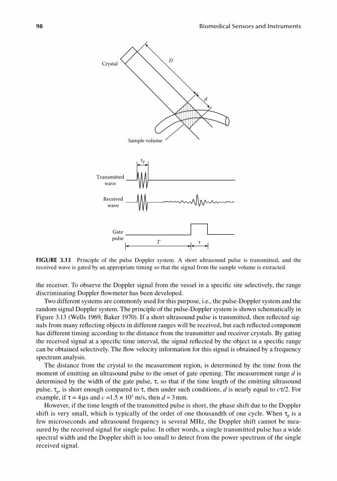
98 BiomedicalSensorsandInstruments
the.receiver..To.observe.the.Doppler.signal.from.the.vessel.in.a.specific.site.selectively,.the.range.discriminating.Doppler.flowmeter.has.been.developed.
Two.different.systems.are.commonly.used.for.this.purpose,.i.e.,.the.pulse-Doppler.system.and.the.random.signal.Doppler.system..The.principle.of.the.pulse-Doppler.system.is.shown.schematically.in.Figure.3.13.(Wells.1969,.Baker.1970)..If.a.short.ultrasound.pulse.is.transmitted,.then.reflected.sig-nals.from.many.reflecting.objects.in.different.ranges.will.be.received,.but.each.reflected.component.has.different.timing.according.to.the.distance.from.the.transmitter.and.receiver.crystals..By.gating.the.received.signal.at.a.specific.time.interval,.the.signal.reflected.by.the.object.in.a.specific.range.can.be.obtained.selectively..The.flow.velocity.information.for.this.signal.is.obtained.by.a.frequency.spectrum.analysis.
The.distance.from.the.crystal.to.the.measurement.region,.is.determined.by.the.time.from.the.moment.of.emitting.an.ultrasound.pulse.to.the.onset.of.gate.opening..The.measurement.range.d.is.determined.by.the.width.of.the.gate.pulse,.τ,.so.that.if.the.time.length.of.the.emitting.ultrasound.pulse,.τp,.is.short.enough.compared.to.τ,.then.under.such.conditions,.d.is.nearly.equal.to.cτ/2..For.example,.if.τ.=.4.μs.and.c.=1.5.×.103.m/s,.then.d.≈.3.mm.
However,.if.the.time.length.of.the.transmitted.pulse.is.short,.the.phase.shift.due.to.the.Doppler.shift.is.very.small,.which.is.typically.of.the.order.of.one.thousandth.of.one.cycle..When.τp.is.a.few.microseconds.and.ultrasound.frequency.is.several.MHz,.the.Doppler.shift.cannot.be.mea-sured.by.the.received.signal.for.single.pulse..In.other.words,.a.single.transmitted.pulse.has.a.wide.spectral.width.and.the.Doppler.shift.is.too.small.to.detect.from.the.power.spectrum.of.the.single.received.signal.
T τ
Transmittedwave
Receivedwave
Gatepulse
Sample volume
τp
D
d
Crystal
figure 3.13 Principle. of. the. pulse. Doppler. system.. A. short. ultrasound. pulse. is. transmitted,. and. the.received.wave.is.gated.by.an.appropriate.timing.so.that.the.signal.from.the.sample.volume.is.extracted.
FlowMeasurement 99
This.difficulty.can.be.eliminated.by.the.use.of.repetitive.ultrasound.pulses.having.a.fixed.phase.relation,.which.is.realized.by.gating.the.output.of.a.master.oscillator..Although.the.wave.is.not.con-tinuous.but.appears.intermittently,.a.signal.including.many.pulses.can.have.a.very.sharp.spectrum.as.long.as.the.phase.relation.is.maintained,.and.small.Doppler.shifts.can.be.determined.by.spectral.analysis..Theoretically,.there.is.no.lower.limit.in.Doppler.shift.frequency.which.can.be.detected.by.spectral.analysis.
On. the. other. hand,. there. is. an. upper. limit. for. detectable. flow. velocity. in. the. pulse. Doppler.system,.due. to. the. limit. in. the.allowable. repetition.frequency.of. the.ultrasound.pulses..To.avoid.ambiguity.among.reflected.waves.of.different.pulses,.a.pulse.should.be.emitted.after.all.the.returned.echos.of.preceding.pulses.have.been.received..Thus,.the.pulse.repetition.frequency.fp.is.limited.as
.f
c
Dp
max2=
.(3.43)
where. Dmax. is. the. maximum. range. of. the. measurement.. Because. the. Doppler. shift. frequency.is .determined.by.sampled.data.corresponding.to.repetitive.pulses,.it.is.postulated.by.the.Nyquist.relation. that. the. sampling. frequency. should. be. higher. than. twice. that. of. the. maximum. signal..frequency,.fmax,.i.e.,
.f
fmax
p
2=
.(3.44)
Applying.an.ordinary.expression.for.the.Doppler.shift,.the.maximum.velocity.which.can.be.mea-sured.by.the.pulse.Doppler.system.is.obtained.by
.U
cf
f
c
f Dmax
max
s
2
s max2 8= =
.(3.45)
This.expression.shows.that.the.maximum.observable.velocity.is.limited.by.the.ultrasound.frequency.and.the.maximum.range.to.be.measured,.although.the.maximum.velocity.and.range.can.be.increased.by.decreasing.the.ultrasound.frequency,.fs,.which.will.reduce.the.resolution.of.range.discrimination.
The.limitation.of.the.maximum.velocity.and.range.in.the.pulse.Doppler.system.can.be.elimi-nated.by.the.random.signal.Doppler.system..To.extract.a.specific.signal.from.among.large.unwanted.waves,.the.correlation.technique.has.been.effectively.used,.especially.in.radar.and.telecommunica-tions..The.principle.is.based.on.the.fundamental.property.of.random.noise..Random.noise.in.a.time.interval.can.have.a.strong.correlation.only.when.the.correlation.is.taken.to.the.same.wave.in.the.same.time.interval,.and.the.correlation.is.practically.zero.for.a.wave.in.a.different.time.interval,.or.any.other.signal,.if.the.observed.time.interval.is.long.enough.
In.a.random.signal.Doppler.system,.the.transmitted.wave.is.modulated.by.a.noise.wave,.and.cor-relation.is.taken.between.the.received.wave.and.the.delayed.noise.wave.with.a.definite.delay.time,.as.shown.in.Figure.3.14.(Jethwa.et al..1975)..Among.the.received.waves,.only.the.reflected.wave.com-ponents.from.an.object.in.a.definite.range,.at.which.the.transit.time.is.just.the.delay.time,.can.have.a.strong.correlation.to.the.delayed.noise.wave,.and.the.correlation.to.other.reflected.components.from.objects.out.of.the.range.becomes.small.enough..Thus,.the.reflected.wave.component.in.any.range.can.be.extracted.by.adjusting.the.delay.time.of.the.noise.wave.
Instead.of.random.noise,.a.pseudo-random.signal.can.also.be.used.for.this.purpose..The.pseudo-random.signal.is.a.periodic.function.of.time,.but.has.a.strong.autocorrelation.just.as.the.true.random.noise.does,.and.the.period.is.long.enough..There.are.many.kinds.of.pseudo-random.signals.(Kedem.1986)..An.example.is.the.pseudo-random.binary.sequence..It.accepts.only.two.values,.+1.and.−1.in.
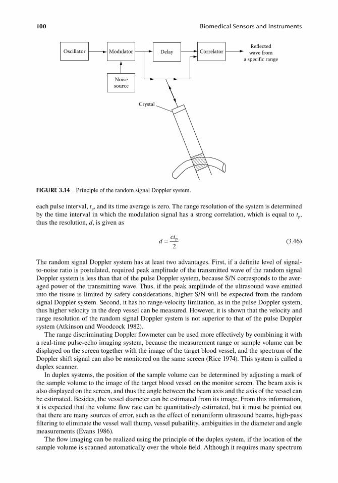
100 BiomedicalSensorsandInstruments
each.pulse.interval,.tp,.and.its.time.average.is.zero..The.range.resolution.of.the.system.is.determined.by.the.time.interval.in.which.the.modulation.signal.has.a.strong.correlation,.which.is.equal.to.tp,.thus.the.resolution,.d,.is.given.as
.d
ct= p
2 .(3.46)
The.random.signal.Doppler.system.has.at.least.two.advantages..First,.if.a.definite.level.of.signal-to-noise.ratio.is.postulated,.required.peak.amplitude.of.the.transmitted.wave.of.the.random.signal.Doppler.system.is.less.than.that.of.the.pulse.Doppler.system,.because.S/N.corresponds.to.the.aver-aged.power.of.the.transmitting.wave..Thus,.if.the.peak.amplitude.of.the.ultrasound.wave.emitted.into.the.tissue.is.limited.by.safety.considerations,.higher.S/N.will.be.expected.from.the.random.signal.Doppler.system..Second,.it.has.no.range-velocity.limitation,.as.in.the.pulse.Doppler.system,.thus.higher.velocity.in.the.deep.vessel.can.be.measured..However,.it.is.shown.that.the.velocity.and.range.resolution.of.the.random.signal.Doppler.system.is.not.superior.to.that.of.the.pulse.Doppler.system.(Atkinson.and.Woodcock.1982).
The.range.discriminating.Doppler.flowmeter.can.be.used.more.effectively.by.combining.it.with.a.real-time.pulse-echo.imaging.system,.because.the.measurement.range.or.sample.volume.can.be.displayed.on.the.screen.together.with.the.image.of.the.target.blood.vessel,.and.the.spectrum.of.the.Doppler.shift.signal.can.also.be.monitored.on.the.same.screen.(Rice.1974)..This.system.is.called.a.duplex.scanner.
In.duplex.systems,.the.position.of.the.sample.volume.can.be.determined.by.adjusting.a.mark.of.the.sample.volume.to.the.image.of.the.target.blood.vessel.on.the.monitor.screen..The.beam.axis.is.also.displayed.on.the.screen,.and.thus.the.angle.between.the.beam.axis.and.the.axis.of.the.vessel.can.be.estimated..Besides,.the.vessel.diameter.can.be.estimated.from.its.image..From.this.information,.it.is.expected.that.the.volume.flow.rate.can.be.quantitatively.estimated,.but.it.must.be.pointed.out.that.there.are.many.sources.of.error,.such.as.the.effect.of.nonuniform.ultrasound.beams,.high-pass.filtering.to.eliminate.the.vessel.wall.thump,.vessel.pulsatility,.ambiguities.in.the.diameter.and.angle.measurements.(Evans.1986).
The.flow.imaging.can.be.realized.using.the.principle.of.the.duplex.system,.if.the.location.of.the.sample.volume.is.scanned.automatically.over.the.whole.field..Although.it.requires.many.spectrum.
Oscillator Modulator Delay Correlator
Noisesource
Crystal
Reflectedwave from
a specific range
figure 3.14 Principle.of.the.random.signal.Doppler.system.
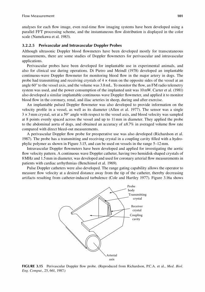
FlowMeasurement 101
analyses.for.each.flow.image,.even.real-time.flow.imaging.systems.have.been.developed.using.a.parallel.FFT.processing.scheme,.and.the.instantaneous.flow.distribution.is.displayed.in.the.color.scale.(Namekawa.et al..1983).
3.2.2.5 Perivascular and intravascular doppler ProbesAlthough. ultrasonic. Doppler. blood. flowmeters. have. been. developed. mostly. for. transcutaneous.measurements,. there. are. some. studies. of. Doppler. flowmeters. for. perivascular. and. intravascular.applications.
Perivascular. probes. have. been. developed. for. implantable. use. in. experimental. animals,. and.also. for. clinical. use. during. operations.. Di. Pietro. and. Meindl. (1978). developed. an. implantable.continuous-wave.Doppler.flowmeter. for.monitoring.blood.flow. in. the.major.artery. in.dogs..The.probe.had.transmitting.and.receiving.crystals.of.4.×.4.mm.on.the.opposite.sides.of.the.vessel.at.an.angle.60°.to.the.vessel.axis,.and.the.volume.was.3.8.mL..To.monitor.the.flow,.an.FM.radio.telemetry.system.was.used,.and.the.power.consumption.of.the.implanted.unit.was.10.mW..Carter.et al..(1981).also.developed.a.similar.implantable.continuous.wave.Doppler.flowmeter,.and.applied.it.to.monitor.blood.flow.in.the.coronary,.renal,.and.iliac.arteries.in.sheep,.during.and.after.exercise.
An. implantable. pulsed.Doppler.flowmeter.was. also.developed. to.provide. information.on. the.velocity. profile. in. a. vessel,. as. well. as. its. diameter. (Allen. et al.. 1977).. The. sensor. was. a. single.3 × 3.mm.crystal,.set.at.a.59°.angle.with.respect.to.the.vessel.axis,.and.blood.velocity.was.sampled.at.8.points.evenly.spaced.across.the.vessel.and.up.to.11.mm.in.diameter..They.applied.the.probe.to.the.abdominal.aorta.of.dogs,.and.obtained.an.accuracy.of.±8.7%.in.averaged.volume.flow.rate.compared.with.direct.bleed-out.measurements.
A.perivascular.Doppler.flow.probe.for.preoperative.use.was.also.developed.(Richardson.et al..1987)..The.probe.has.a.transmitting.and.receiving.crystal.in.a.coupling.cavity.filled.with.a.hydro-phylic.polymer.as.shown.in.Figure.3.15,.and.can.be.used.on.vessels.in.the.range.5–12.mm.
Intravascular.Doppler.flowmeters.have.been.developed.and.applied.for.investigating.the.aortic.flow.velocity.pattern..A.continuous.wave.Doppler.catheter,.having.two.hemidisk-shaped.crystals.of.8.MHz.and.1.5.mm.in.diameter,.was.developed.and.used.for.coronary.arterial.flow.measurements.in.patients.with.cardiac.arrhythmias.(Benchimol.et al..1969).
Pulse.Doppler.catheters.were.also.developed..The.range.gating.capability.allows.the.operator.to.measure.flow.velocity.at.a.desired.distance.away.from.the.tip.of.the.catheter,.thereby.decreasing.artifacts.resulting.from.catheter-induced.turbulence.(Cole.and.Hartley.1977)..Figure.3.16a.shows.
ProbebodyTransmitting
crystal
Receivercrystal
Couplingcavity
Arterialaxis
figure 3.15 Perivascular.Doppler.flow.probe.. (Reproduced. from.Richardson,.P.C.A.. et al.,.Med. Biol. Eng. Comput.,.25,.661,.1987.)
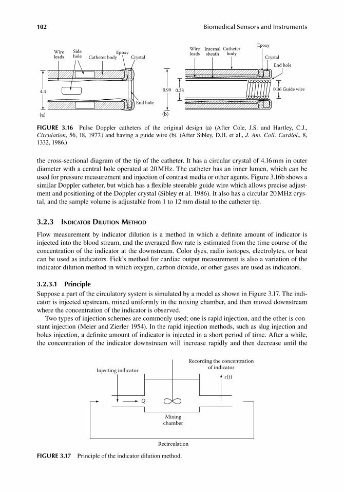
102 BiomedicalSensorsandInstruments
the.cross-sectional.diagram.of.the.tip.of.the.catheter..It.has.a.circular.crystal.of.4.16.mm.in.outer.diameter.with.a.central.hole.operated.at.20.MHz..The.catheter.has.an.inner.lumen,.which.can.be.used.for.pressure.measurement.and.injection.of.contrast.media.or.other.agents..Figure.3.16b.shows.a.similar.Doppler.catheter,.but.which.has.a.flexible.steerable.guide.wire.which.allows.precise.adjust-ment.and.positioning.of.the.Doppler.crystal.(Sibley.et al..1986)..It.also.has.a.circular.20.MHz.crys-tal,.and.the.sample.volume.is.adjustable.from.1.to.12.mm.distal.to.the.catheter.tip.
3.2.3 indicator dilution Method
Flow. measurement. by. indicator. dilution. is. a. method. in. which. a. definite. amount. of. indicator. is.injected.into.the.blood.stream,.and.the.averaged.flow.rate.is.estimated.from.the.time.course.of.the.concentration.of.the.indicator.at.the.downstream..Color.dyes,.radio.isotopes,.electrolytes,.or.heat.can.be.used.as.indicators..Fick’s.method.for.cardiac.output.measurement.is.also.a.variation.of.the.indicator.dilution.method.in.which.oxygen,.carbon.dioxide,.or.other.gases.are.used.as.indicators.
3.2.3.1 PrincipleSuppose.a.part.of.the.circulatory.system.is.simulated.by.a.model.as.shown.in.Figure.3.17..The.indi-cator.is.injected.upstream,.mixed.uniformly.in.the.mixing.chamber,.and.then.moved.downstream.where.the.concentration.of.the.indicator.is.observed.
Two.types.of.injection.schemes.are.commonly.used;.one.is.rapid.injection,.and.the.other.is.con-stant.injection.(Meier.and.Zierler.1954)..In.the.rapid.injection.methods,.such.as.slug.injection.and.bolus.injection,.a.definite.amount.of.indicator.is.injected.in.a.short.period.of.time..After.a.while,.the. concentration.of. the. indicator. downstream.will. increase. rapidly. and. then.decrease.until. the.
0.99 0.38 0.36 Guide wire
Internalsheath
Catheterbody
Epoxy
CrystalEnd hole
(b)
WireleadsWire
leadsSidehole Catheter body
EpoxyCrystal
End hole
4.3
(a)
figure 3.16 Pulse. Doppler. catheters. of. the. original. design. (a). (After. Cole,. J.S.. and. Hartley,. C.J.,.Circulation,.56,.18,.1977.).and.having.a.guide.wire.(b)..(After.Sibley,.D.H..et al.,.J. Am. Coll. Cardiol.,.8,.1332,.1986.)
Injecting indicator
Q
Mixingchamber
Recording the concentrationof indicator
c(t)
Recirculation
figure 3.17 Principle.of.the.indicator.dilution.method.
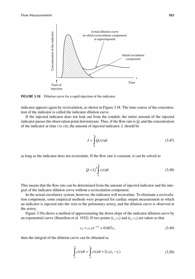
FlowMeasurement 103
indicator.appears.again.by.recirculation,.as.shown.in.Figure.3.18..The.time.course.of.the.concentra-tion.of.the.indicator.is.called.the.indicator.dilution.curve.
If. the.injected.indicator.does.not.leak.out.from.the.conduit,. the.entire.amount.of. the.injected.indicator.passes.the.observation.point.downstream..Thus,.if.the.flow.rate.is.Q,.and.the.concentration.of.the.indicator.at.time.t.is.c(t),.the.amount.of.injected.indicator,.I,.should.be
.
I Qc t dt=∞
∫ ( )0 .
(3.47)
as.long.as.the.indicator.does.not.recirculate..If.the.flow.rate.is.constant,.it.can.be.solved.as
.
Q I c t dt=∞
∫ ( )0 .
(3.48)
This.means.that.the.flow.rate.can.be.determined.from.the.amount.of.injected.indicator.and.the.inte-gral.of.the.indicator.dilution.curve.without.a.recirculation.component.
In.the.actual.circulatory.system,.however,.the.indicator.will.recirculate..To.eliminate.a.recircula-tion.component,.some.empirical.methods.were.proposed.for.cardiac.output.measurement.in.which.an.indicator.is.injected.into.the.vein.or.the.pulmonary.artery,.and.the.dilution.curve.is.observed.at.the.artery.
Figure.3.19a.shows.a.method.of.approximating.the.down.slope.of.the.indicator.dilution.curve.by.an.exponential.curve.(Hamilton.et al..1932)..If.two.points.(t1,.c1).and.(t2,.c2).are.taken.so.that
. c c c c2 11 2
1e 6 7= =– / .0 0 . (3.49)
then.the.integral.of.the.dilution.curve.can.be.obtained.as
.
c t dt c t dt c t t
t
( ) ( ) ( )0 0
1 2 1
1
2
∞
∫ ∫≈ + −
.
(3.50)
Actual dilution curvein which recirculation component
is superimposed
Initial circulationcomponent
tTime
Conc
entr
atio
n of
the i
ndic
ator
Time of injection
figure 3.18 Dilution.curve.for.a.rapid.injection.of.the.indicator.
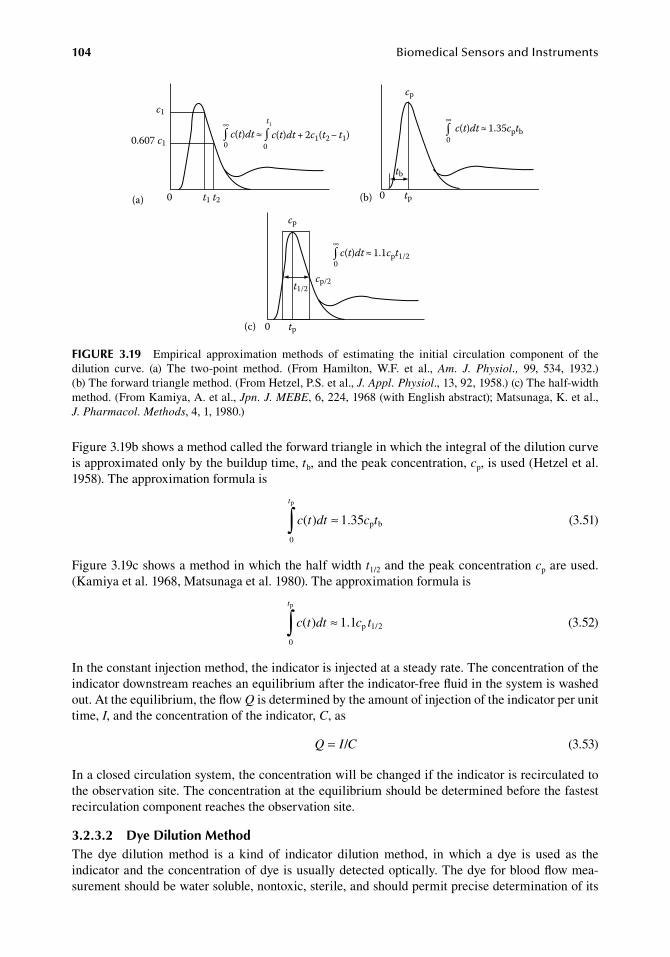
104 BiomedicalSensorsandInstruments
Figure.3.19b.shows.a.method.called.the.forward.triangle.in.which.the.integral.of.the.dilution.curve.is.approximated.only.by.the.buildup.time,.tb,.and.the.peak.concentration,.cp,.is.used.(Hetzel.et al..1958)..The.approximation.formula.is
.
c t dt c t
t
( ) .0
1 35
p
p b∫ ≈.
(3.51)
Figure.3.19c.shows.a.method.in.which.the.half.width.t1/2.and.the.peak.concentration.cp.are.used..(Kamiya.et al..1968,.Matsunaga.et al..1980)..The.approximation.formula.is
.
c t dt c t
t
( ) 1.10
p 1/2
p
∫ ≈.
(3.52)
In.the.constant.injection.method,.the.indicator.is.injected.at.a.steady.rate..The.concentration.of.the.indicator.downstream.reaches.an.equilibrium.after.the.indicator-free.fluid.in.the.system.is.washed.out..At.the.equilibrium,.the.flow.Q.is.determined.by.the.amount.of.injection.of.the.indicator.per.unit.time,.I,.and.the.concentration.of.the.indicator,.C,.as
. Q I C= / . (3.53)
In.a.closed.circulation.system,.the.concentration.will.be.changed.if.the.indicator.is.recirculated.to.the.observation.site..The.concentration.at.the.equilibrium.should.be.determined.before.the.fastest.recirculation.component.reaches.the.observation.site.
3.2.3.2 dye dilution MethodThe. dye. dilution. method. is. a. kind. of. indicator. dilution. method,. in. which. a. dye. is. used. as. the.indicator.and.the.concentration.of.dye.is.usually.detected.optically..The.dye.for.blood.flow.mea-surement.should.be.water.soluble,.nontoxic,.sterile,.and.should.permit.precise.determination.of.its.
(a)
0∫
0∫∞
0∫∞t1
c(t)dt + 2c1(t2 − t1)c(t)dt ≈
c1
0.607 c1
0 t1 t2
cp
tb
0 tp(b)
c(t)dt ≈ 1.35cptb
0∫∞
cp
0 tp(c)
cp/2t1/2
c(t)dt ≈ 1.1cpt1/2
figure 3.19 Empirical. approximation. methods. of. estimating. the. initial. circulation. component. of. the.dilution. curve.. (a). The. two-point. method.. (From. Hamilton,. W.F.. et. al.,. Am. J. Physiol.,. 99,. 534,. 1932.).(b) The.forward.triangle.method..(From.Hetzel,.P.S..et.al.,.J. Appl. Physiol.,.13,.92,.1958.).(c).The.half-width.method..(From.Kamiya,.A..et.al.,.Jpn. J. MEBE,.6,.224,.1968.(with.English.abstract);.Matsunaga,.K..et.al.,.J. Pharmacol. Methods,.4,.1,.1980.)
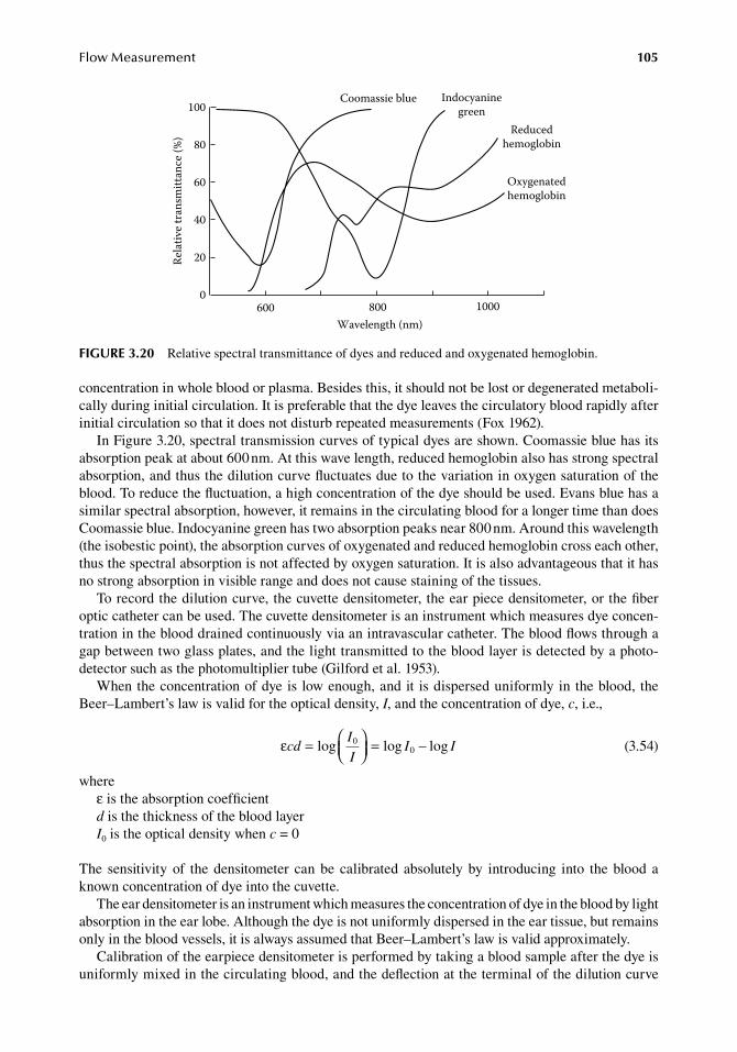
FlowMeasurement 105
concentration.in.whole.blood.or.plasma..Besides.this,.it.should.not.be.lost.or.degenerated.metaboli-cally.during.initial.circulation..It.is.preferable.that.the.dye.leaves.the.circulatory.blood.rapidly.after.initial.circulation.so.that.it.does.not.disturb.repeated.measurements.(Fox.1962).
In.Figure.3.20,.spectral.transmission.curves.of.typical.dyes.are.shown..Coomassie.blue.has.its.absorption.peak.at.about.600.nm..At.this.wave.length,.reduced.hemoglobin.also.has.strong.spectral.absorption,.and.thus.the.dilution.curve.fluctuates.due.to.the.variation.in.oxygen.saturation.of.the.blood..To.reduce.the.fluctuation,.a.high.concentration.of.the.dye.should.be.used..Evans.blue.has.a.similar.spectral.absorption,.however,.it.remains.in.the.circulating.blood.for.a.longer.time.than.does.Coomassie.blue..Indocyanine.green.has.two.absorption.peaks.near.800.nm..Around.this.wavelength.(the.isobestic.point),.the.absorption.curves.of.oxygenated.and.reduced.hemoglobin.cross.each.other,.thus.the.spectral.absorption.is.not.affected.by.oxygen.saturation..It.is.also.advantageous.that.it.has.no.strong.absorption.in.visible.range.and.does.not.cause.staining.of.the.tissues.
To.record.the.dilution.curve,.the.cuvette.densitometer,. the.ear.piece.densitometer,.or.the.fiber.optic.catheter.can.be.used..The.cuvette.densitometer.is.an.instrument.which.measures.dye.concen-tration.in.the.blood.drained.continuously.via.an.intravascular.catheter..The.blood.flows.through.a.gap.between.two.glass.plates,.and.the.light.transmitted.to.the.blood.layer.is.detected.by.a.photo-detector.such.as.the.photomultiplier.tube.(Gilford.et al..1953).
When.the.concentration.of.dye.is. low.enough,.and.it. is.dispersed.uniformly.in.the.blood,. the.Beer–Lambert’s.law.is.valid.for.the.optical.density,.I,.and.the.concentration.of.dye,.c,.i.e.,
.εcd
I
II I=
= −log log log00
.(3.54)
whereε.is.the.absorption.coefficientd.is.the.thickness.of.the.blood.layerI0.is.the.optical.density.when.c.=.0
The. sensitivity.of. the.densitometer. can.be. calibrated. absolutely.by. introducing. into. the.blood. a.known.concentration.of.dye.into.the.cuvette.
The.ear.densitometer.is.an.instrument.which.measures.the.concentration.of.dye.in.the.blood.by.light.absorption.in.the.ear.lobe..Although.the.dye.is.not.uniformly.dispersed.in.the.ear.tissue,.but.remains.only.in.the.blood.vessels,.it.is.always.assumed.that.Beer–Lambert’s.law.is.valid.approximately.
Calibration.of.the.earpiece.densitometer.is.performed.by.taking.a.blood.sample.after.the.dye.is.uniformly.mixed.in.the.circulating.blood,.and.the.deflection.at.the.terminal.of.the.dilution.curve.
100
80
60
40
20
0600 800 1000
Wavelength (nm)
Rela
tive t
rans
mitt
ance
(%)
Coomassie blue Indocyaninegreen
Reducedhemoglobin
Oxygenatedhemoglobin
figure 3.20 Relative.spectral.transmittance.of.dyes.and.reduced.and.oxygenated.hemoglobin.
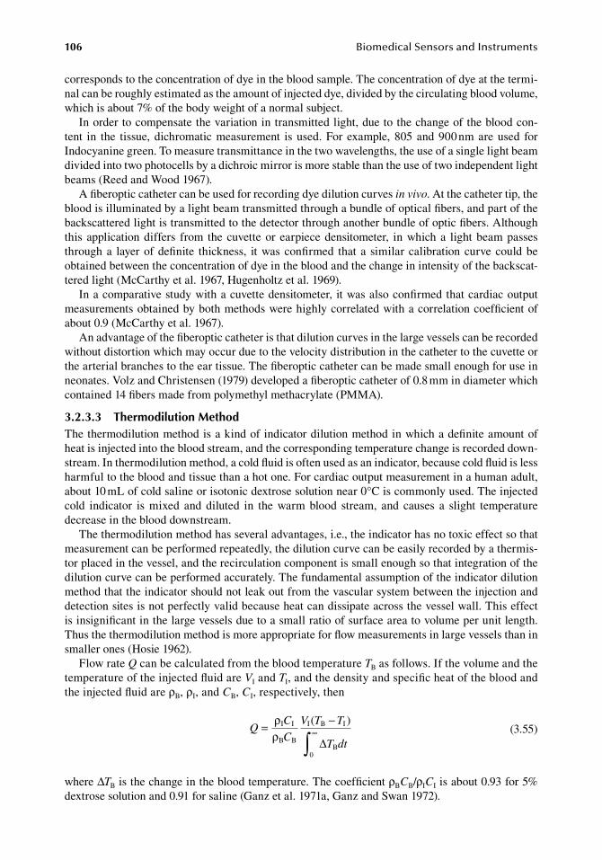
106 BiomedicalSensorsandInstruments
corresponds.to.the.concentration.of.dye.in.the.blood.sample..The.concentration.of.dye.at.the.termi-nal.can.be.roughly.estimated.as.the.amount.of.injected.dye,.divided.by.the.circulating.blood.volume,.which.is.about.7%.of.the.body.weight.of.a.normal.subject.
In.order.to.compensate.the.variation.in.transmitted.light,.due.to.the.change.of.the.blood.con-tent. in. the. tissue,.dichromatic.measurement. is.used..For. example,.805.and.900.nm.are.used. for.Indocyanine.green..To.measure.transmittance.in.the.two.wavelengths,.the.use.of.a.single.light.beam.divided.into.two.photocells.by.a.dichroic.mirror.is.more.stable.than.the.use.of.two.independent.light.beams.(Reed.and.Wood.1967).
A.fiberoptic.catheter.can.be.used.for.recording.dye.dilution.curves.in vivo..At.the.catheter.tip,.the.blood.is.illuminated.by.a.light.beam.transmitted.through.a.bundle.of.optical.fibers,.and.part.of.the.backscattered.light.is.transmitted.to.the.detector.through.another.bundle.of.optic.fibers..Although.this. application.differs. from. the.cuvette.or. earpiece.densitometer,. in.which.a. light.beam.passes.through.a. layer.of.definite. thickness,. it.was.confirmed. that. a. similar. calibration.curve.could.be.obtained.between.the.concentration.of.dye.in.the.blood.and.the.change.in.intensity.of.the.backscat-tered.light.(McCarthy.et al..1967,.Hugenholtz.et al..1969).
In.a.comparative.study.with.a.cuvette.densitometer,. it.was.also.confirmed.that.cardiac.output.measurements.obtained.by.both.methods.were.highly.correlated.with.a.correlation.coefficient.of.about.0.9.(McCarthy.et al..1967).
An.advantage.of.the.fiberoptic.catheter.is.that.dilution.curves.in.the.large.vessels.can.be.recorded.without.distortion.which.may.occur.due.to.the.velocity.distribution.in.the.catheter.to.the.cuvette.or.the.arterial.branches.to.the.ear.tissue..The.fiberoptic.catheter.can.be.made.small.enough.for.use.in.neonates..Volz.and.Christensen.(1979).developed.a.fiberoptic.catheter.of.0.8.mm.in.diameter.which.contained.14.fibers.made.from.polymethyl.methacrylate.(PMMA).
3.2.3.3 thermodilution MethodThe.thermodilution.method.is.a.kind.of.indicator.dilution.method.in.which.a.definite.amount.of.heat.is.injected.into.the.blood.stream,.and.the.corresponding.temperature.change.is.recorded.down-stream..In.thermodilution.method,.a.cold.fluid.is.often.used.as.an.indicator,.because.cold.fluid.is.less.harmful.to.the.blood.and.tissue.than.a.hot.one..For.cardiac.output.measurement.in.a.human.adult,.about.10.mL.of.cold.saline.or.isotonic.dextrose.solution.near.0°C.is.commonly.used..The.injected.cold. indicator. is. mixed. and. diluted. in. the. warm. blood. stream,. and. causes. a. slight. temperature.decrease.in.the.blood.downstream.
The.thermodilution.method.has.several.advantages,.i.e.,.the.indicator.has.no.toxic.effect.so.that.measurement.can.be.performed.repeatedly,.the.dilution.curve.can.be.easily.recorded.by.a.thermis-tor.placed.in.the.vessel,.and.the.recirculation.component.is.small.enough.so.that.integration.of.the.dilution.curve.can.be.performed.accurately..The.fundamental.assumption.of.the.indicator.dilution.method.that.the.indicator.should.not.leak.out.from.the.vascular.system.between.the.injection.and.detection.sites.is.not.perfectly.valid.because.heat.can.dissipate.across.the.vessel.wall..This.effect.is.insignificant.in.the.large.vessels.due.to.a.small.ratio.of.surface.area.to.volume.per.unit.length..Thus.the.thermodilution.method.is.more.appropriate.for.flow.measurements.in.large.vessels.than.in.smaller.ones.(Hosie.1962).
Flow.rate.Q.can.be.calculated.from.the.blood.temperature.TB.as.follows..If.the.volume.and.the.temperature.of.the.injected.fluid.are.VI.and.TI,.and.the.density.and.specific.heat.of.the.blood.and.the.injected.fluid.are.ρB,.ρI,.and.CB,.CI,.respectively,.then
.
QC
C
V T T
T dt= −
∞
∫ρρ
I I
B B
I B I
B
( )
∆0 .
(3.55)
where.ΔTB.is.the.change.in.the.blood.temperature..The.coefficient.ρBCB/ρICI.is.about.0.93.for.5%.dextrose.solution.and.0.91.for.saline.(Ganz.et al..1971a,.Ganz.and.Swan.1972).
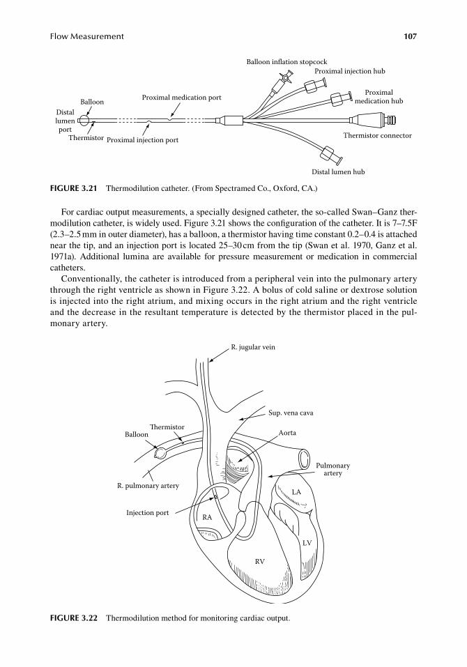
FlowMeasurement 107
For.cardiac.output.measurements,.a.specially.designed.catheter,.the.so-called.Swan–Ganz.ther-modilution.catheter,.is.widely.used..Figure.3.21.shows.the.configuration.of.the.catheter..It.is.7–7.5F.(2.3–2.5.mm.in.outer.diameter),.has.a.balloon,.a.thermistor.having.time.constant.0.2–0.4.is.attached.near.the.tip,.and.an.injection.port.is.located.25–30.cm.from.the.tip.(Swan.et al..1970,.Ganz.et al..1971a).. Additional. lumina. are. available. for. pressure. measurement. or. medication. in. commercial.catheters.
Conventionally,.the.catheter.is.introduced.from.a.peripheral.vein.into.the.pulmonary.artery.through.the.right.ventricle.as.shown.in.Figure.3.22..A.bolus.of.cold.saline.or.dextrose.solution.is.injected.into.the.right.atrium,.and.mixing.occurs.in.the.right.atrium.and.the.right.ventricle.and.the.decrease.in.the.resultant.temperature.is.detected.by.the.thermistor.placed.in.the.pul-monary.artery.
BalloonDistallumenport
Thermistor Proximal injection port
Proximal medication port
Balloon inflation stopcockProximal injection hub
Proximalmedication hub
Thermistor connector
Distal lumen hub
figure 3.21 Thermodilution.catheter..(From.Spectramed.Co.,.Oxford,.CA.)
Balloonermistor
R. pulmonary artery
Injection port RA
LA
RV
LV
Aorta
Sup. vena cava
R. jugular vein
Pulmonaryartery
figure 3.22 Thermodilution.method.for.monitoring.cardiac.output.
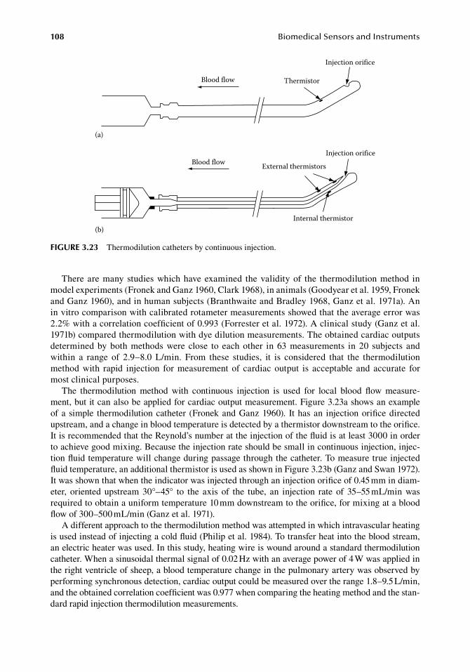
108 BiomedicalSensorsandInstruments
There.are.many.studies.which.have.examined. the.validity.of. the. thermodilution.method. in.model.experiments.(Fronek.and.Ganz.1960,.Clark.1968),.in.animals.(Goodyear.et al..1959,.Fronek.and.Ganz.1960),.and.in.human.subjects.(Branthwaite.and.Bradley.1968,.Ganz.et al..1971a)..An.in.vitro.comparison.with.calibrated.rotameter.measurements.showed.that.the.average.error.was.2.2%.with.a.correlation.coefficient.of.0.993.(Forrester.et al..1972)..A.clinical.study.(Ganz.et al..1971b).compared.thermodilution.with.dye.dilution.measurements..The.obtained.cardiac.outputs.determined.by.both.methods.were.close. to.each.other. in.63.measurements. in.20. subjects. and.within. a. range. of. 2.9–8.0. L/min.. From. these. studies,. it. is. considered. that. the. thermodilution.method.with. rapid. injection. for.measurement.of. cardiac.output. is. acceptable. and. accurate. for.most.clinical.purposes.
The. thermodilution. method. with. continuous. injection. is. used. for. local. blood. flow. measure-ment,.but.it.can.also.be.applied.for.cardiac.output.measurement..Figure.3.23a.shows.an.example.of.a.simple. thermodilution.catheter. (Fronek.and.Ganz.1960).. It.has.an. injection.orifice.directed.upstream,.and.a.change.in.blood.temperature.is.detected.by.a.thermistor.downstream.to.the.orifice..It.is.recommended.that.the.Reynold’s.number.at.the.injection.of.the.fluid.is.at.least.3000.in.order.to.achieve.good.mixing..Because.the.injection.rate.should.be.small.in.continuous.injection,.injec-tion.fluid.temperature.will.change.during.passage.through.the.catheter..To.measure.true.injected.fluid.temperature,.an.additional.thermistor.is.used.as.shown.in.Figure.3.23b.(Ganz.and.Swan.1972)..It was shown that.when.the.indicator.was.injected.through.an.injection.orifice.of.0.45.mm.in.diam-eter,. oriented. upstream. 30°–45°. to. the. axis. of. the. tube,. an. injection. rate. of. 35–55.mL/min. was.required.to.obtain.a.uniform.temperature.10.mm.downstream.to.the.orifice,.for.mixing.at.a.blood.flow.of.300–500.mL/min.(Ganz.et al..1971).
A.different.approach.to.the.thermodilution.method.was.attempted.in.which.intravascular.heating.is.used.instead.of.injecting.a.cold.fluid.(Philip.et al..1984)..To.transfer.heat.into.the.blood.stream,.an.electric.heater.was.used..In.this.study,.heating.wire.is.wound.around.a.standard.thermodilution.catheter..When.a.sinusoidal.thermal.signal.of.0.02.Hz.with.an.average.power.of.4.W.was.applied.in.the.right.ventricle.of.sheep,.a.blood.temperature.change.in.the.pulmonary.artery.was.observed.by.performing.synchronous.detection,.cardiac.output.could.be.measured.over.the.range.1.8–9.5.L/min,.and.the.obtained.correlation.coefficient.was.0.977.when.comparing.the.heating.method.and.the.stan-dard.rapid.injection.thermodilution.measurements.
Thermistor
Injection orifice
Injection orifice
External thermistors
Internal thermistor
Blood flow
Blood flow
(a)
(b)
figure 3.23 Thermodilution.catheters.by.continuous.injection.
FlowMeasurement 109
3.2.3.4 the fick MethodPulmonary.blood.flow.can.be.determined.by.measuring.the.rate.of.gas.intake.to.or.extraction.from.the.blood.in.the.lung,.and.the.change.in.the.gas.concentration.in.the.blood.stream.through.the.lung..This.technique.is.called.the.Fick.method,.and.has.been.used.as.a.standard.method.of.cardiac.output.measurement.(Guyton.1963).
If.oxygen.uptake,. VO2.and.oxygen.concentration.in.the.pulmonary.arterial.blood,.CaO2,.and.that.in.the.
pulmonary.venous.blood,.CvO2,.are.known,.the.blood.flow.rate.through.the.lung.Q.can.be.obtained.as
.Q
V
C C=
−
O
aO vO
2
2 2 .(3.56)
This.expression.is.equivalent.to.Equation.3.53.in.which.C.is.considered.as.the.increment.of.indicator.concentration.
When.a.gas.is.used.as.an.indicator,.the.amount.of.indicator.is.usually.represented.by.volume,.thus.the.concentration.in.Equation.3.56.should.be.represented.by.a.volume.fraction..The.volume.of.oxygen.in.the.blood.can.be.calculated.from.oxygen.saturation,.using.the.oxygen.capacity.of.hemo-globin,.i.e.,.1.g.hemoglobin.can.be.combined.with.1.38.mL.oxygen.in.standard.condition.
VO2.can.be.obtained.by.measuring.tidal.volume.and.oxygen.content.in.the.expiratory.air.as.long.as.the.oxygen.content.in.the.atmospheric.air.is.known.(see.Section.7.3.4)..CaO2
is.given.by.gas.analy-sis.of.any.arterial.blood..CvO2 is.also.given.by.the.gas.analysis.of.venous.blood..The.determination.should.be.performed.on.mixed.venous.blood,.because.the.oxygen.content.of.venous.blood.in.dif-ferent.organs.varies..Thus,.venous.blood.has.to.be.sampled.in.the.right.ventricle.or.the.pulmonary.artery.via.cardiac.catheterization.
Because.blood.samples.cannot.be.taken.so.frequently,.continuous.information.on.cardiac.output.is.difficult.to.obtain..Only.in.animal.experiments,.continuous.monitoring.of.cardiac.output.is.per-formed,.in.which.arterial.and.venous.blood.were.circulated.through.cuvettes,.and.oxygen.satura-tions.were.measured.continuously.(Guyton.and.Farish.1959,.Guyton.et al..1959,.Guyton.1963).
The.Fick.method.is.considered.as.the.most.reliable.method.of.cardiac.output.measurement.as.long.as.the.mixed.venous.blood.is.sampled..However,.it.requires.cardiac.catheterization.and.that.is.one.disadvantage.with.the.Fick.method.
There.is.a.different.approach.to.cardiac.output.measurement.called.the.indirect.Fick.method..It.employs.the.same.principle.as.the.direct.Fick.method.but.information.on.blood.gas.contents.are.obtained.only.by.expiratory.gas.analysis,.so.that.cardiac.catheterization.is.unnecessary..In.the.indi-rect.Fick.method,.carbon.dioxide.or.other.gases,.such.as.acetylene.or.nitrous.oxide,.are.used.as.an.indicator.instead.of.oxygen.as.in.the.direct.Fick.method.
When.a.carbon.dioxide.measurement.is.employed.the.pulmonary.blood.flow.is.expressed.as
.Q
V
C C=
−
CO
vCO aCO
2
2 2 .(3.57)
whereVCO2.is.carbon.dioxide.output
CvCO2.and.CaCO2.are.carbon.dioxide.contents.in.the.mixed.venous.and.the.arterial.blood
VCO2.can.be.measured.by.expiratory.gas.analysis.(see.Section.7.3.4)..CaCO2 .can.be.determined.by.the.arterial.carbon.dioxide.partial.pressure,.which.is.equal.to.the.mean.carbon.dioxide.partial.pressure.of.the.alveolar.gas,.and.this.is.obtained.as.the.carbon.dioxide.partial.pressure.of.the.expiration.gas.(Dubois.et al..1952).
110 BiomedicalSensorsandInstruments
To.convert.partial.pressure.to.volume.fraction,.the.dissociation.curve.of.carbon.dioxide.should.be.used,.while.the.slope.can.be.regarded.as.linear.in.the.physiological.range,.and.is.approximated.as.3.46.vol.%/kPa.(0.46.vol.%/mmHg).(Dubois.1952).
The.most.important.part.of.the.indirect.Fick.method.is.the.determination.of.the.carbon.dioxide.con-tent.in.the.mixed.venous.blood,.CvCO2,.from.respiratory.gas.analysis..To.achieve.this,.the.rebreathing.method.has.been.studied.extensively.(Collier.1956,.Defares.1958,.Campbell.and.Howell.1962,.Farhi.et al..1976).while.the.breath-holding.method.was.also.used.(Dubois.et al..1952,.Knowles.et al..1960).
The.principle.of.the.rebreathing.method.is.that.when.the.subject.breathes.the.air.from.an.anes-thetic.bag.for.15–30.s,.the.carbon.dioxide.partial.pressure.of.the.air.in.the.bag.is.equilibrated.to.that.of.the.mixed.venous.blood..By.approximating.the.time.course.of.the.carbon.dioxide.content.in.the.bag.by.an.exponential.function,.the.final.asymptotic.level.can.be.predicted.from.the.time.course.(Defares.1958),.and.a.fully.automated.system.of.this.procedure.has.been.developed.(Leavell.et al..1986).
In.the.breath-holding.method,.the.mixed.venous.carbon.dioxide.content.is.estimated.from.the.time.course.of.carbon.dioxide.partial.pressure.in.the.alveolar.gas.during.breath-holding.of.about.20.s. (Dubois.et al..1952)..By. inhaling.air.with.different.carbon.dioxide.concentrations. from.5%.to.7%.before.breath-holding,.and.plotting.the.rate.of.change.of.carbon.dioxide.partial.pressure.in.expired.gas,.the.partial.pressure.of.the.mixed.venous.blood.can.be.estimated.as.a.condition.where.the.rate.of.change.is.zero.(Knowles.et al..1960).
A.different.method.was.proposed.in.which.the.information.on.gas.contents.in.the.mixed.venous.blood.is.not.taken.into.account,.but.only.carbon.dioxide.output.and.partial.pressure.in.expired.gas.are.measured.(Gedeon.et al..1980)..The.pulmonary.blood.flow.is.determined.from.the.change.in.the.carbon.dioxide.output.corresponding.to.the.change.in.the.carbon.dioxide.partial.pressure.in.the.alveolar.gas.when.the.ventilation.pattern.is.altered.between.hyper-.and.hypoventilation.
Gases.except.oxygen.and.carbon.dioxide.can.also.be.used.as.indicators..If.these.gases.do.not.initially.exist.in.the.blood,.concentration.of.the.gas.in.the.mixed.venous.blood.is.zero.before.appear-ing.in.recirculation,.and.pulmonary.blood.flow.can.only.be.determined.by.the.concentration.in.the.alveolar.gas.and.the.uptake.of.the.gas..Acetylene.or.nitrous.oxide.has.been.used.as.the.indicator.gas.(Asmussen.and.Nielsen.1952,.Becklake.et al..1962)..By.using.a.mass.spectrometer,.different.gases.can.be.measured.simultaneously.(Sackner.et al..1975).(see.also.Section.7.3.4).
3.2.3.5 other dilution MethodsBesides.the.indicators.described.above,.radio.isotopes.and.solutions.having.different.electric.con-ductivities.from.that.of.blood.have.also.been.used.as.indicators.for.the.dilution.method.
As.the.radioactive.indicator,.substances.labelled.with.131I,.especially.radio-iodinated.serum.albu-min.(RISA).have.been.used.(Huff.et al..1955,.Seldon.et al..1958,.Gorten.and.Stauffer.1959,.Schreiner.et al..1959)..For.cardiac.output.measurements,.RISA.of.10–100.μCi.(micro.curie).is.injected.into.the.vein,.and.the.concentration.of.RISA.in.the.arterial.blood.is.measured.externally.by.a.gamma.ray.detector.with.a.collimator.directed.to.the.left.ventricle.or.the.aortic.arc..The.sensitivity.of.the.detec-tor.can.be.calibrated.comparing.the.external.gamma.ray.count,.10–20.min.after.injection,.with.the.direct.count.of.the.sampled.blood.at.that.moment.
The. problem. with. the. radio-iodine. is. its. uptake. by. the. thyroid. gland.. To. minimize. this,. the.patient.is.given.potassium.iodide.before.and.after.the.examination.to.saturate.the.thyroid.gland.with.nonradioactive.iodide.
To.reduce.radiation.dosage.further,.131I-labelled.Cholografin.is.recommended,.because.its.half.life.of.remaining.in.the.body.is.5.34.h,.while.that.of.RISA.is.10.5.days.(Austin.et al..1961).
In.the.dilution.method,.as.an.indicator.having.different.electrical.conductivity,.a.hypertonic.saline. is.used..For. cardiac.output.measurement,.1–10.mL.of.2%–8%.saline. is. rapidly. injected.into.the.central.vein,.and.the.electrical.conductivity.change.is.detected.in.the.pulmonary.artery.(Bourdillon. et al.. 1979,. Trautman. and. Newbower. 1984,. Voorhees. et al.. 1985). or. in. the. aorta.(Grubbs.et al..1982)..By.simultaneous.measurements.with.other.methods,.it.has.been.shown.that.cardiac.outputs.measured.by.saline.dilution.method.were.highly.correlated.to.those.measured.by.
FlowMeasurement 111
the.electromagnetic.flowmeter.(Voorhees.et al..1985).and.the.dye.dilution.method.(Trautman.and.Newbower.1984)..Detection.of.electric.conductivity.changes.in.the.blood.by.perivascular.elec-trodes.(Smith.et al..1967).and.the.use.of.autogenous.plasma.as.indicator.(Goodwin.and.Sapirstein.1957).were.also.evaluated.
An.interesting.technique.is.the.use.of.photoacoustic.flow.estimation.based.on.wash-in.analysis.of.gold.nanorods.(Li.et al..2005,.Wei.et al..2007,.Liao.et al..2007)..In.this.method.rod-to-sphere.shape.transformation.of.gold.nanorods.is.used..The.gold.nanorod.exhibits.photoacoustic.emission,.and.thus.it.can.be.used.as.an.indicator.for.the.dilution.technique..The.shape.transformation.is.induced.by.pulsed.laser.illumination..The.shape.change.results.in.a.shift.in.peak.optical.absorption.wavelength..A.comparison.of.absorption.of.“undestructed”.rods.to.“destructed”.spheres.forms.the.base.for.flow.rate.estimation.via.recording.ultrasound.intensity.
The.evaluation.in.model.systems.shows.very.good.correlation.between.“true”.flow.values.and.the.ones.measured.with.the.photoacoustic.method.
3.2.4 flow Velocity MeasureMents by heat dissipation
The. rate. of. heat. dissipation. from. a. heated. element. placed. in. the. blood. stream. depends. on. the.flow.velocity..Although.it.also.depends.on.many.other.factors,.such.as.the.temperature.difference.between. the.element.and. the.surrounding.fluid,. the.size.and. the.shape.of. the.element,.viscosity,.thermal.conductivity,.specific.heat.and.density.of.the.fluid,.and.the.state.of.the.flow,.i.e.,.if.the.flow.is.laminar.or.turbulent,.flow.velocity.can.still.be.determined.from.the.rate.of.heat.dissipation.when.the.changes.of.the.above.parameters.are.insignificant..In.such.a.situation,.the.rate.of.heat.dissipation.H.can.be.approximated.as
. H a bU m= + . (3.58)
whereU.is.the.flow.velocitya,.b,.and.m.are.constants
The.constants.a.and.b.should.be.determined.by.calibration,.while.m.is.always.taken.as.0.5.(King.1914).To.maintain.the.element.at.a.constant.temperature,.electric.heating.is.commonly.used..In.equi-
librium.the.rate.of.heat.dissipation.is.equal.to.heat.production,.i.e.,.heat.production,.H,.is.given.by
. H RI= 2. (3.59)
whereR.is.the.resistance.of.the.heating.elementI.is.the.applied.current.
If.R.has.a.temperature.coefficient,.the.temperature.of.the.heating.element.can.be.kept.constant.using.a.bridge.with.a.feedback.amplifier.as.shown.in.Figure.3.24.
3.2.4.1 thermistor Velocity ProbesThe. thermistor. is. a. convenient. device. for. use. in. thermal. velocity. probes. because. it. has. a. large.temperature.coefficient..Two.thermistors.are.commonly.used.in.the.flow.probe..One.measures.the.fluid.temperature,.and.the.other.is.heated.to.a.higher.temperature,.and.the.temperature.difference.between.the.heated.thermistor.and.the.fluid.is.kept.constant.
Figure.3.25.shows.two.examples.of.such.probes..(a).is.a.6F.(2.mm.in.outer.diameter).cardiac.cath-eter.having.two.thermistors.near.the.tip.and,.because.of.a.bend,.the.thermistors.are.placed.near.the.center.of.the.blood.stream.when.it.is.introduced.into.the.vessel.(Katsura.et al..1959)..The.response.
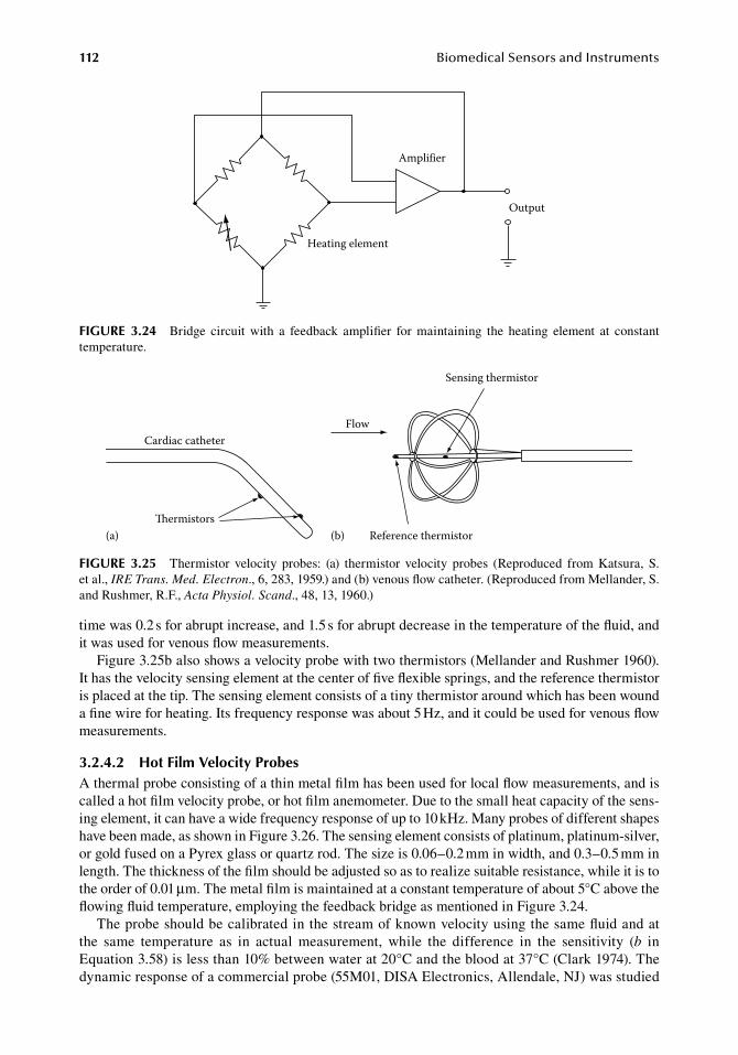
112 BiomedicalSensorsandInstruments
time.was.0.2.s.for.abrupt.increase,.and.1.5.s.for.abrupt.decrease.in.the.temperature.of.the.fluid,.and.it.was.used.for.venous.flow.measurements.
Figure.3.25b.also.shows.a.velocity.probe.with.two.thermistors.(Mellander.and.Rushmer.1960)..It has.the.velocity.sensing.element.at.the.center.of.five.flexible.springs,.and.the.reference.thermistor.is.placed.at.the.tip..The.sensing.element.consists.of.a.tiny.thermistor.around.which.has.been.wound.a.fine.wire.for.heating..Its.frequency.response.was.about.5.Hz,.and.it.could.be.used.for.venous.flow.measurements.
3.2.4.2 hot film Velocity ProbesA.thermal.probe.consisting.of.a.thin.metal.film.has.been.used.for.local.flow.measurements,.and.is.called.a.hot.film.velocity.probe,.or.hot.film.anemometer..Due.to.the.small.heat.capacity.of.the.sens-ing.element,.it.can.have.a.wide.frequency.response.of.up.to.10.kHz..Many.probes.of.different.shapes.have.been.made,.as.shown.in.Figure.3.26..The.sensing.element.consists.of.platinum,.platinum-silver,.or.gold.fused.on.a.Pyrex.glass.or.quartz.rod..The.size.is.0.06–0.2.mm.in.width,.and.0.3–0.5.mm.in.length..The.thickness.of.the.film.should.be.adjusted.so.as.to.realize.suitable.resistance,.while.it.is.to.the.order.of.0.01.μm..The.metal.film.is.maintained.at.a.constant.temperature.of.about.5°C.above.the.flowing.fluid.temperature,.employing.the.feedback.bridge.as.mentioned.in.Figure.3.24.
The.probe.should.be.calibrated.in.the.stream.of.known.velocity.using.the.same.fluid.and.at.the. same. temperature. as. in. actual. measurement,. while. the. difference. in. the. sensitivity. (b. in.Equation.3.58).is.less.than.10%.between.water.at.20°C.and.the.blood.at.37°C.(Clark.1974)..The.dynamic.response.of.a.commercial.probe.(55M01,.DISA.Electronics,.Allendale,.NJ).was.studied.
Cardiac catheter
ermistors(a)
Flow
Sensing thermistor
Reference thermistor(b)
figure 3.25 Thermistor. velocity. probes:. (a). thermistor. velocity. probes. (Reproduced. from. Katsura,. S..et al.,.IRE Trans. Med. Electron.,.6,.283,.1959.).and.(b).venous.flow.catheter..(Reproduced.from.Mellander,.S..and.Rushmer,.R.F.,.Acta Physiol. Scand.,.48,.13,.1960.)
Amplifier
Heating element
Output
figure 3.24 Bridge. circuit. with. a. feedback. amplifier. for. maintaining. the. heating. element. at. constant.temperature.
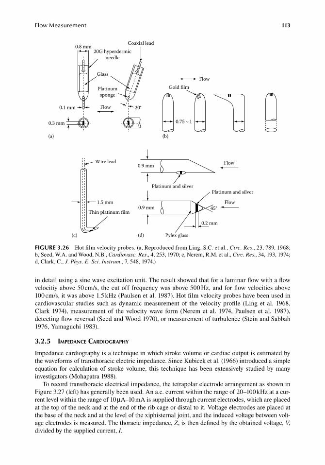
FlowMeasurement 113
in.detail.using.a.sine.wave.excitation.unit..The.result.showed.that.for.a.laminar.flow.with.a.flow.velocitiy.above.50.cm/s,. the.cut.off.frequency.was.above.500.Hz,.and.for.flow.velocities.above.100.cm/s,.it.was.above.1.5.kHz.(Paulsen.et al..1987)..Hot.film.velocity.probes.have.been.used.in.cardiovascular. studies. such.as.dynamic.measurement.of. the.velocity.profile. (Ling.et al..1968,.Clark.1974),.measurement.of. the.velocity.wave. form.(Nerem.et al..1974,.Paulsen.et al..1987),.detecting.flow.reversal.(Seed.and.Wood.1970),.or.measurement.of.turbulence.(Stein.and.Sabbah.1976,.Yamaguchi.1983).
3.2.5 iMpedance cardiography
Impedance.cardiography.is.a.technique.in.which.stroke.volume.or.cardiac.output.is.estimated.by.the.waveforms.of.transthoracic.electric.impedance..Since.Kubicek.et al..(1966).introduced.a.simple.equation. for. calculation. of. stroke. volume,. this. technique. has. been. extensively. studied. by. many.investigators.(Mohapatra.1988).
To.record.transthoracic.electrical.impedance,.the.tetrapolar.electrode.arrangement.as.shown.in.Figure.3.27.(left).has.generally.been.used..An.a.c..current.within.the.range.of.20–100.kHz.at.a.cur-rent.level.within.the.range.of.10.μA–10.mA.is.supplied.through.current.electrodes,.which.are.placed.at.the.top.of.the.neck.and.at.the.end.of.the.rib.cage.or.distal.to.it..Voltage.electrodes.are.placed.at.the.base.of.the.neck.and.at.the.level.of.the.xiphisternal.joint,.and.the.induced.voltage.between.volt-age.electrodes.is.measured..The.thoracic.impedance,.Z,.is.then.defined.by.the.obtained.voltage,.V,.divided.by.the.supplied.current,.I.
0.8 mm20G hyperdermic
needle
Coaxial lead
Glass
Platinumsponge
Flow 20°0.1 mm
0.3 mm
Flow
(a)
0.75 ~ 1
Gold film
(b)
Thin platinum film
Platinum and silver
0.2 mm
Platinum and silver
Flow
Flow
(d)(c)
Wire lead
1.5 mm
0.9 mm
0.9 mm
Pylex glass
45°
figure 3.26 Hot.film.velocity.probes..(a,.Reproduced.from.Ling,.S.C..et.al.,.Circ. Res.,.23,.789,.1968;.b,.Seed,.W.A..and.Wood,.N.B.,.Cardiovasc. Res.,.4,.253,.1970;.c,.Nerem,.R.M..et.al.,.Circ. Res.,.34,.193,.1974;.d,.Clark,.C.,.J. Phys. E. Sci. Instrum.,.7,.548,.1974.)
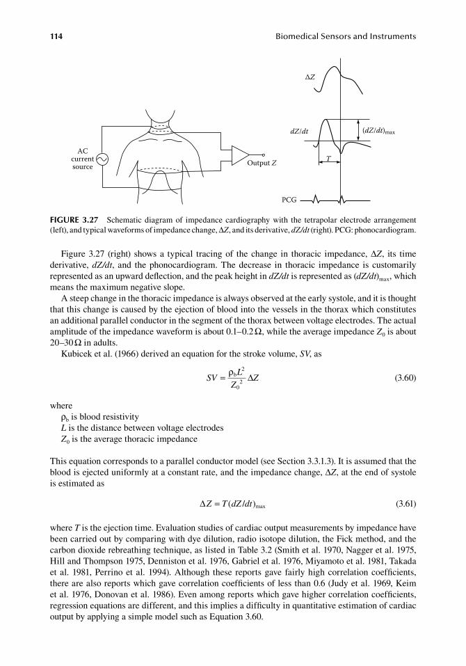
114 BiomedicalSensorsandInstruments
Figure.3.27. (right). shows.a. typical. tracing.of. the.change. in. thoracic. impedance,.ΔZ,. its. time.derivative,.dZ/dt,. and. the.phonocardiogram..The.decrease. in. thoracic. impedance. is. customarily.represented.as.an.upward.deflection,.and.the.peak.height.in.dZ/dt.is.represented.as.(dZ/dt)max,.which.means.the.maximum.negative.slope.
A.steep.change.in.the.thoracic.impedance.is.always.observed.at.the.early.systole,.and.it.is.thought.that.this.change.is.caused.by.the.ejection.of.blood.into.the.vessels.in.the.thorax.which.constitutes.an.additional.parallel.conductor.in.the.segment.of.the.thorax.between.voltage.electrodes..The.actual.amplitude.of.the.impedance.waveform.is.about.0.1–0.2.Ω,.while.the.average.impedance.Z0.is.about.20–30.Ω.in.adults.
Kubicek.et al..(1966).derived.an.equation.for.the.stroke.volume,.SV,.as
.SV
L
ZZ= ρb
2
02 ∆
.(3.60)
whereρb.is.blood.resistivityL.is.the.distance.between.voltage.electrodesZ0.is.the.average.thoracic.impedance
This.equation.corresponds.to.a.parallel.conductor.model.(see.Section.3.3.1.3)..It.is.assumed.that.the.blood.is.ejected.uniformly.at.a.constant.rate,.and.the.impedance.change,.ΔZ,.at.the.end.of.systole.is.estimated.as
. ∆Z T dZ dt= ( / )max . (3.61)
where.T.is.the.ejection.time..Evaluation.studies.of.cardiac.output.measurements.by.impedance.have.been.carried.out.by.comparing.with.dye.dilution,.radio.isotope.dilution,.the.Fick.method,.and.the.carbon.dioxide.rebreathing.technique,.as.listed.in.Table.3.2.(Smith.et al..1970,.Nagger.et al..1975,.Hill.and.Thompson.1975,.Denniston.et al..1976,.Gabriel.et al..1976,.Miyamoto.et al..1981,.Takada.et al..1981,.Perrino.et al..1994)..Although. these. reports.gave. fairly.high.correlation.coefficients,.there.are.also.reports.which.gave.correlation.coefficients.of.less.than.0.6.(Judy.et al..1969,.Keim.et al..1976,.Donovan.et al..1986)..Even.among.reports.which.gave.higher.correlation.coefficients,.regression.equations.are.different,.and.this.implies.a.difficulty.in.quantitative.estimation.of.cardiac.output.by.applying.a.simple.model.such.as.Equation.3.60.
ACcurrentsource Output Z
ΔZ
dZ/dt (dZ/dt)max
T
PCG
figure 3.27 Schematic.diagram.of. impedance.cardiography.with. the. tetrapolar. electrode.arrangement.(left),.and.typical.waveforms.of.impedance.change,.ΔZ,.and.its.derivative,.dZ/dt.(right)..PCG:.phonocardiogram.
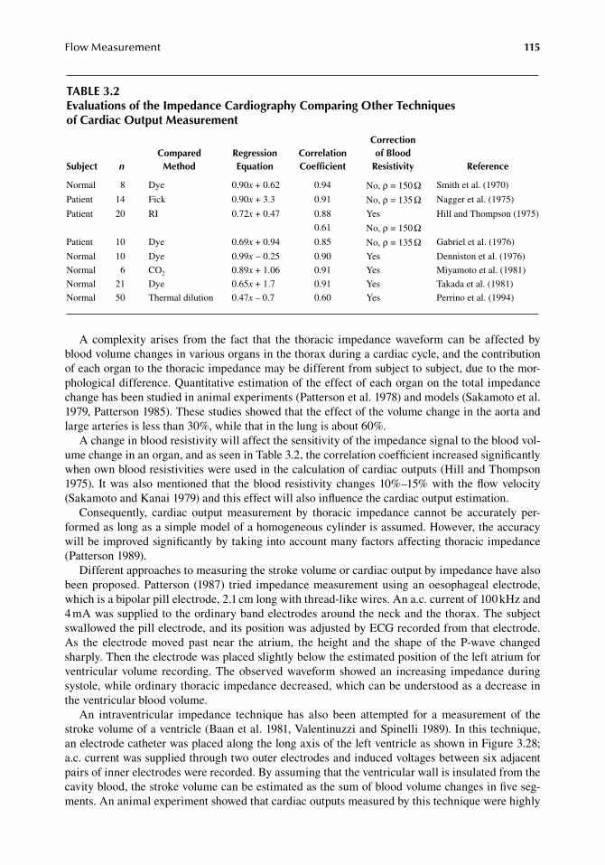
FlowMeasurement 115
A.complexity. arises. from. the. fact. that. the. thoracic. impedance.waveform.can.be. affected.by.blood.volume.changes.in.various.organs.in.the.thorax.during.a.cardiac.cycle,.and.the.contribution.of.each.organ.to.the.thoracic.impedance.may.be.different.from.subject.to.subject,.due.to.the.mor-phological.difference..Quantitative.estimation.of.the.effect.of.each.organ.on.the.total.impedance.change.has.been.studied.in.animal.experiments.(Patterson.et al..1978).and.models.(Sakamoto.et al..1979,.Patterson.1985)..These.studies.showed.that.the.effect.of.the.volume.change.in.the.aorta.and.large.arteries.is.less.than.30%,.while.that.in.the.lung.is.about.60%.
A.change.in.blood.resistivity.will.affect.the.sensitivity.of.the.impedance.signal.to.the.blood.vol-ume.change.in.an.organ,.and.as.seen.in.Table.3.2,.the.correlation.coefficient.increased.significantly.when.own.blood.resistivities.were.used.in.the.calculation.of.cardiac.outputs.(Hill.and.Thompson.1975).. It.was.also.mentioned. that. the.blood. resistivity.changes.10%–15%.with. the.flow.velocity.(Sakamoto.and.Kanai.1979).and.this.effect.will.also.influence.the.cardiac.output.estimation.
Consequently,. cardiac. output. measurement. by. thoracic. impedance. cannot. be. accurately. per-formed.as.long.as.a.simple.model.of.a.homogeneous.cylinder.is.assumed..However,.the.accuracy.will.be.improved.significantly.by.taking.into.account.many.factors.affecting.thoracic.impedance.(Patterson.1989).
Different.approaches.to.measuring.the.stroke.volume.or.cardiac.output.by.impedance.have.also.been.proposed..Patterson. (1987). tried. impedance.measurement.using.an.oesophageal.electrode,.which.is.a.bipolar.pill.electrode,.2.1.cm.long.with.thread-like.wires..An.a.c..current.of.100.kHz.and.4.mA.was.supplied.to.the.ordinary.band.electrodes.around.the.neck.and.the.thorax..The.subject.swallowed.the.pill.electrode,.and.its.position.was.adjusted.by.ECG.recorded.from.that.electrode..As. the. electrode. moved. past. near. the. atrium,. the. height. and. the. shape. of. the. P-wave. changed.sharply..Then.the.electrode.was.placed.slightly.below.the.estimated.position.of.the.left.atrium.for.ventricular.volume. recording..The.observed.waveform.showed.an. increasing. impedance.during.systole,.while.ordinary.thoracic.impedance.decreased,.which.can.be.understood.as.a.decrease.in.the.ventricular.blood.volume.
An. intraventricular. impedance. technique. has. also. been. attempted. for. a. measurement. of. the.stroke.volume.of.a.ventricle.(Baan.et al..1981,.Valentinuzzi.and.Spinelli.1989)..In.this.technique,.an.electrode.catheter.was.placed.along.the.long.axis.of.the.left.ventricle.as.shown.in.Figure.3.28;.a.c..current.was.supplied.through.two.outer.electrodes.and.induced.voltages.between.six.adjacent.pairs.of.inner.electrodes.were.recorded..By.assuming.that.the.ventricular.wall.is.insulated.from.the.cavity.blood,.the.stroke.volume.can.be.estimated.as.the.sum.of.blood.volume.changes.in.five.seg-ments..An.animal.experiment.showed.that.cardiac.outputs.measured.by.this.technique.were.highly.
table 3.2evaluations of the impedance Cardiography Comparing other techniques of Cardiac output Measurement
Subject nCompared
Methodregression equation
Correlation Coefficient
Correction of blood
resistivity reference
Normal 8 Dye 0.90x.+.0.62 0.94 No,.ρ.=.150.Ω Smith.et al..(1970)
Patient 14 Fick 0.90x.+.3.3 0.91 No,.ρ.=.135.Ω Nagger.et al..(1975)
Patient 20 RI 0.72x.+.0.47 0.88 Yes Hill.and.Thompson.(1975)
0.61 No,.ρ.=.150.ΩPatient 10 Dye 0.69x.+.0.94 0.85 No,.ρ.=.135.Ω Gabriel.et al..(1976)
Normal 10 Dye 0.99x.−.0.25 0.90 Yes Denniston.et al..(1976)
Normal 6 CO2 0.89x.+.1.06 0.91 Yes Miyamoto.et al..(1981)
Normal 21 Dye 0.65x.+.1.7 0.91 Yes Takada.et al..(1981)
Normal 50 Thermal.dilution 0.47x –.0.7 0.60 Yes Perrino.et al..(1994)
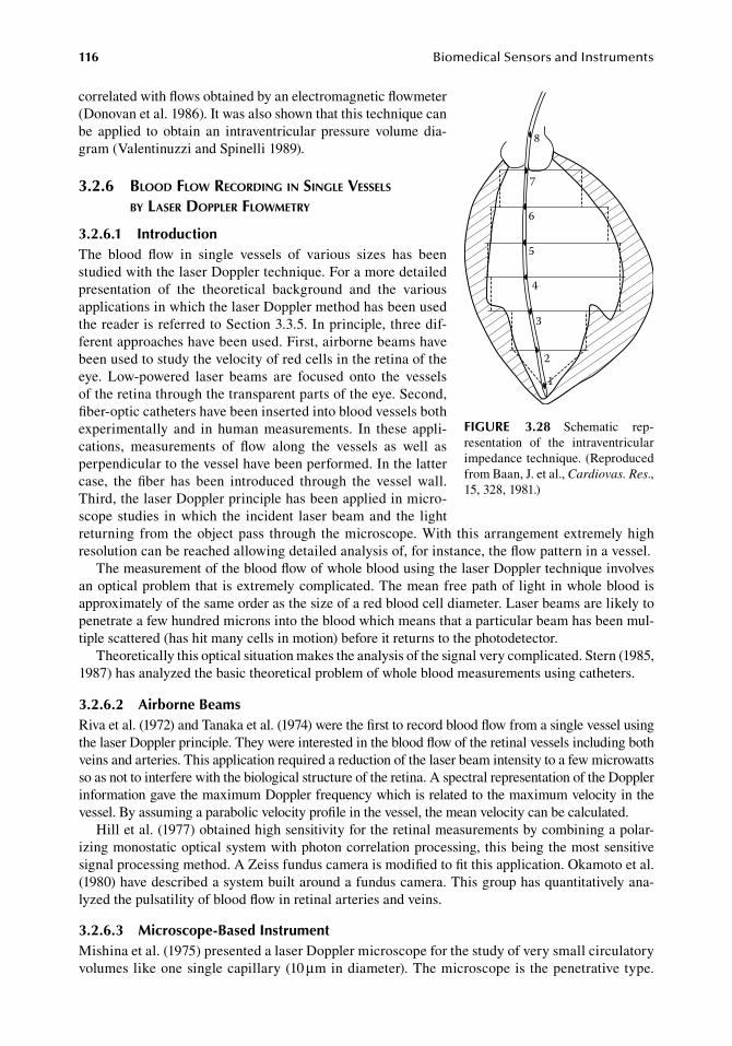
116 BiomedicalSensorsandInstruments
correlated.with.flows.obtained.by.an.electromagnetic.flowmeter.(Donovan.et al..1986)..It.was.also.shown.that.this.technique.can.be. applied. to. obtain. an. intraventricular. pressure. volume. dia-gram.(Valentinuzzi.and.Spinelli.1989).
3.2.6 blood flow recording in single Vessels by laser doppler flowMetry
3.2.6.1 introductionThe. blood. flow. in. single. vessels. of. various. sizes. has. been.studied.with.the.laser.Doppler.technique..For.a.more.detailed.presentation. of. the. theoretical. background. and. the. various.applications.in.which.the.laser.Doppler.method.has.been.used.the.reader.is.referred.to.Section.3.3.5..In.principle,.three.dif-ferent.approaches.have.been.used..First,.airborne.beams.have.been.used.to.study.the.velocity.of.red.cells.in.the.retina.of.the.eye.. Low-powered. laser. beams. are. focused. onto. the. vessels.of.the.retina.through.the.transparent.parts.of.the.eye..Second,.fiber-optic.catheters.have.been.inserted.into.blood.vessels.both.experimentally. and. in. human. measurements.. In. these. appli-cations,. measurements. of. flow. along. the. vessels. as. well. as.perpendicular.to.the.vessel.have.been.performed..In.the.latter.case,. the. fiber. has. been. introduced. through. the. vessel. wall..Third,.the.laser.Doppler.principle.has.been.applied.in.micro-scope.studies. in.which. the. incident. laser.beam.and. the. light.returning. from. the.object.pass. through. the.microscope..With. this.arrangement.extremely.high.resolution.can.be.reached.allowing.detailed.analysis.of,.for.instance,.the.flow.pattern.in.a.vessel.
The.measurement.of.the.blood.flow.of.whole.blood.using.the.laser.Doppler.technique.involves.an.optical.problem.that. is.extremely.complicated..The.mean.free.path.of. light. in.whole.blood.is.approximately.of.the.same.order.as.the.size.of.a.red.blood.cell.diameter..Laser.beams.are.likely.to.penetrate.a.few.hundred.microns.into.the.blood.which.means.that.a.particular.beam.has.been.mul-tiple.scattered.(has.hit.many.cells.in.motion).before.it.returns.to.the.photodetector.
Theoretically.this.optical.situation.makes.the.analysis.of.the.signal.very.complicated..Stern.(1985,.1987).has.analyzed.the.basic.theoretical.problem.of.whole.blood.measurements.using.catheters.
3.2.6.2 airborne beamsRiva.et al..(1972).and.Tanaka.et al..(1974).were.the.first.to.record.blood.flow.from.a.single.vessel.using.the.laser.Doppler.principle..They.were.interested.in.the.blood.flow.of.the.retinal.vessels.including.both.veins.and.arteries..This.application.required.a.reduction.of.the.laser.beam.intensity.to.a.few.microwatts.so.as.not.to.interfere.with.the.biological.structure.of.the.retina..A.spectral.representation.of.the.Doppler.information.gave.the.maximum.Doppler.frequency.which.is.related.to.the.maximum.velocity.in.the.vessel..By.assuming.a.parabolic.velocity.profile.in.the.vessel,.the.mean.velocity.can.be.calculated.
Hill.et al..(1977).obtained.high.sensitivity.for.the.retinal.measurements.by.combining.a.polar-izing.monostatic.optical.system.with.photon.correlation.processing,.this.being.the.most.sensitive.signal.processing.method..A.Zeiss.fundus.camera.is.modified.to.fit.this.application..Okamoto.et al..(1980).have.described.a.system.built.around.a.fundus.camera..This.group.has.quantitatively.ana-lyzed.the.pulsatility.of.blood.flow.in.retinal.arteries.and.veins.
3.2.6.3 Microscope-based instrumentMishina.et al..(1975).presented.a.laser.Doppler.microscope.for.the.study.of.very.small.circulatory.volumes.like.one.single.capillary.(10.μm.in.diameter)..The.microscope.is.the.penetrative.type..
1
2
3
4
5
6
7
8
figure 3.28 Schematic. rep-resentation. of. the. intraventricular.impedance.technique..(Reproduced.from.Baan,.J..et al.,.Cardiovas. Res.,.15,.328,.1981.)
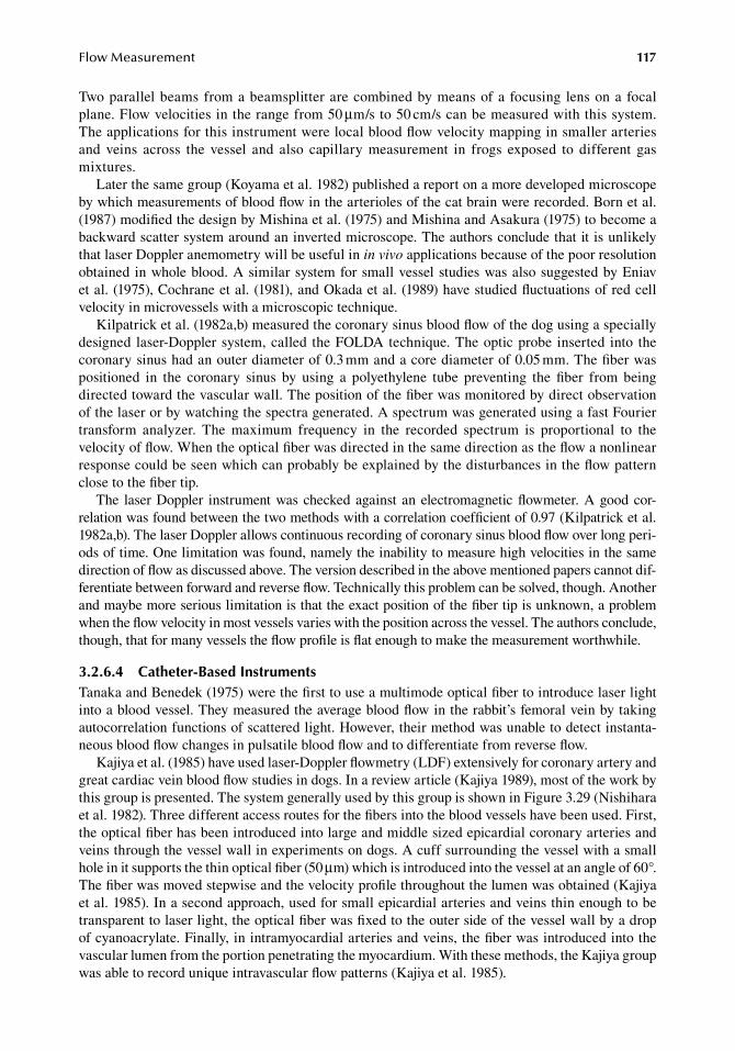
FlowMeasurement 117
Two.parallel.beams.from.a.beamsplitter.are.combined.by.means.of.a.focusing. lens.on.a.focal.plane..Flow.velocities.in.the.range.from.50.μm/s.to.50.cm/s.can.be.measured.with.this.system..The.applications.for.this.instrument.were.local.blood.flow.velocity.mapping.in.smaller.arteries.and. veins. across. the. vessel. and. also. capillary. measurement. in. frogs. exposed. to. different. gas.mixtures.
Later.the.same.group.(Koyama.et al..1982).published.a.report.on.a.more.developed.microscope.by.which.measurements.of.blood.flow.in.the.arterioles.of.the.cat.brain.were.recorded..Born.et al..(1987).modified.the.design.by.Mishina.et al..(1975).and.Mishina.and.Asakura.(1975).to.become.a.backward.scatter.system.around.an.inverted.microscope..The.authors.conclude.that.it.is.unlikely.that.laser.Doppler.anemometry.will.be.useful.in.in vivo.applications.because.of.the.poor.resolution.obtained.in.whole.blood..A.similar.system.for.small.vessel.studies.was.also.suggested.by.Eniav.et al..(1975),.Cochrane.et al..(1981),.and.Okada.et al..(1989).have.studied.fluctuations.of.red.cell.velocity.in.microvessels.with.a.microscopic.technique.
Kilpatrick.et al..(1982a,b).measured.the.coronary.sinus.blood.flow.of.the.dog.using.a.specially.designed. laser-Doppler.system,.called. the.FOLDA.technique..The.optic.probe. inserted. into. the.coronary.sinus.had.an.outer.diameter.of.0.3.mm.and.a.core.diameter.of.0.05.mm..The.fiber.was.positioned. in. the. coronary. sinus. by. using. a. polyethylene. tube. preventing. the. fiber. from. being.directed.toward.the.vascular.wall..The.position.of.the.fiber.was.monitored.by.direct.observation.of.the.laser.or.by.watching.the.spectra.generated..A.spectrum.was.generated.using.a.fast.Fourier.transform. analyzer.. The. maximum. frequency. in. the. recorded. spectrum. is. proportional. to. the.velocity.of.flow..When.the.optical.fiber.was.directed.in.the.same.direction.as.the.flow.a.nonlinear.response.could.be.seen.which.can.probably.be.explained.by.the.disturbances.in.the.flow.pattern.close.to.the.fiber.tip.
The. laser.Doppler. instrument.was.checked.against. an.electromagnetic.flowmeter..A.good.cor-relation.was.found.between.the.two.methods.with.a.correlation.coefficient.of.0.97.(Kilpatrick.et al..1982a,b)..The.laser.Doppler.allows.continuous.recording.of.coronary.sinus.blood.flow.over.long.peri-ods.of.time..One.limitation.was.found,.namely.the.inability.to.measure.high.velocities.in.the.same.direction.of.flow.as.discussed.above..The.version.described.in.the.above.mentioned.papers.cannot.dif-ferentiate.between.forward.and.reverse.flow..Technically.this.problem.can.be.solved,.though..Another.and.maybe.more.serious.limitation.is.that.the.exact.position.of.the.fiber.tip.is.unknown,.a.problem.when.the.flow.velocity.in.most.vessels.varies.with.the.position.across.the.vessel..The.authors.conclude,.though,.that.for.many.vessels.the.flow.profile.is.flat.enough.to.make.the.measurement.worthwhile.
3.2.6.4 Catheter-based instrumentsTanaka.and.Benedek.(1975).were.the.first.to.use.a.multimode.optical.fiber.to.introduce.laser.light.into.a.blood.vessel..They.measured.the.average.blood.flow.in.the.rabbit’s.femoral.vein.by.taking.autocorrelation.functions.of.scattered.light..However,.their.method.was.unable.to.detect.instanta-neous.blood.flow.changes.in.pulsatile.blood.flow.and.to.differentiate.from.reverse.flow.
Kajiya.et al..(1985).have.used.laser-Doppler.flowmetry.(LDF).extensively.for.coronary.artery.and.great.cardiac.vein.blood.flow.studies.in.dogs..In.a.review.article.(Kajiya.1989),.most.of.the.work.by.this.group.is.presented..The.system.generally.used.by.this.group.is.shown.in.Figure.3.29.(Nishihara.et al..1982)..Three.different.access.routes.for.the.fibers.into.the.blood.vessels.have.been.used..First,.the.optical.fiber.has.been.introduced.into.large.and.middle.sized.epicardial.coronary.arteries.and.veins.through.the.vessel.wall.in.experiments.on.dogs..A.cuff.surrounding.the.vessel.with.a.small.hole.in.it.supports.the.thin.optical.fiber.(50.μm).which.is.introduced.into.the.vessel.at.an.angle.of.60°..The.fiber.was.moved.stepwise.and.the.velocity.profile.throughout.the.lumen.was.obtained.(Kajiya.et al..1985)..In.a.second.approach,.used.for.small.epicardial.arteries.and.veins.thin.enough.to.be.transparent.to.laser.light,.the.optical.fiber.was.fixed.to.the.outer.side.of.the.vessel.wall.by.a.drop.of.cyanoacrylate..Finally,.in.intramyocardial.arteries.and.veins,.the.fiber.was.introduced.into.the.vascular.lumen.from.the.portion.penetrating.the.myocardium..With.these.methods,.the.Kajiya.group.was.able.to.record.unique.intravascular.flow.patterns.(Kajiya.et al..1985).
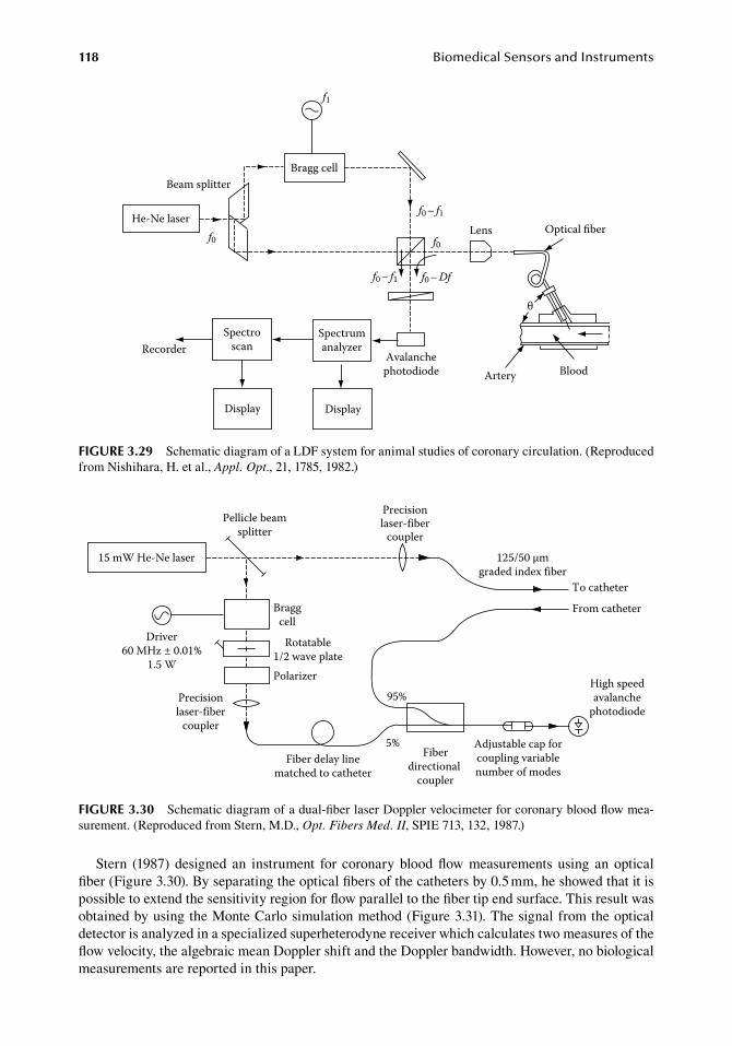
118 BiomedicalSensorsandInstruments
Stern. (1987). designed. an. instrument. for. coronary.blood.flow.measurements. using. an. optical.fiber.(Figure.3.30)..By.separating.the.optical.fibers.of.the.catheters.by.0.5.mm,.he.showed.that.it.is.possible.to.extend.the.sensitivity.region.for.flow.parallel.to.the.fiber.tip.end.surface..This.result.was.obtained.by.using.the.Monte.Carlo.simulation.method.(Figure.3.31)..The.signal.from.the.optical.detector.is.analyzed.in.a.specialized.superheterodyne.receiver.which.calculates.two.measures.of.the.flow.velocity,.the.algebraic.mean.Doppler.shift.and.the.Doppler.bandwidth..However,.no.biological.measurements.are.reported.in.this.paper.
15 mW He-Ne laser
Pellicle beamsplitter
Braggcell
Rotatable1/2 wave platePolarizer
Driver60 MHz ± 0.01%
1.5 W
Precisionlaser-fiber
coupler
Precisionlaser-fiber
coupler
Fiber delay linematched to catheter
95%
5%Fiber
directional coupler
Adjustable cap forcoupling variablenumber of modes
125/50 μmgraded index fiber
To catheter
From catheter
High speedavalanche
photodiode
figure 3.30 Schematic.diagram.of.a.dual-fiber.laser.Doppler.velocimeter.for.coronary.blood.flow.mea-surement..(Reproduced.from.Stern,.M.D.,.Opt. Fibers Med. II,.SPIE.713,.132,.1987.)
f1
Bragg cell
He-Ne laser
Beam splitter
f0
f0 – f1
f0
f0 – f1 f0 – Df
Avalanchephotodiode
Spectrumanalyzer
DisplayDisplay
SpectroscanRecorder
Lens
θ
Optical ber
Artery Blood
figure 3.29 Schematic.diagram.of.a.LDF.system.for.animal.studies.of.coronary.circulation..(Reproduced.from.Nishihara,.H..et al.,.Appl. Opt.,.21,.1785,.1982.)
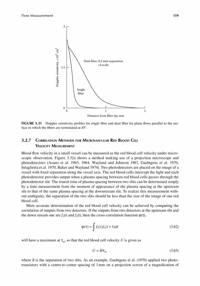
FlowMeasurement 119
3.2.7 correlation Methods for MicroVascular red blood cell Velocity MeasureMent
Blood.flow.velocity.in.a.small.vessel.can.be.measured.as.the.red.blood.cell.velocity.under.micro-scopic. observation.. Figure. 3.32a. shows. a. method. making. use. of. a. projection. microscope. and.photodetectors. (Asano. et al.. 1963,. 1964,. Wayland. and. Johnson. 1967,. Gaehtgens. et al.. 1970,.Intaglietta.et al..1970,.Baker.and.Wayland.1974)..Two.photodetectors.are.placed.on.the.image.of.a.vessel.with.fixed.separation.along.the.vessel.axis..The.red.blood.cells.intercept.the.light.and.each.photodetector.provides.output.when.a.plasma.spacing.between.red.blood.cells.passes.through.the.photodetector.slit..The.transit.time.of.plasma.spacing.between.two.slits.can.be.determined.simply.by.a.time.measurement.from.the.moment.of.appearance.of.the.plasma.spacing.at.the.upstream.slit.to.that.of.the.same.plasma.spacing.at.the.downstream.slit..To.realize.this.measurement.with-out.ambiguity,.the.separation.of.the.two.slits.should.be.less.than.the.size.of.the.image.of.one.red.blood.cell.
More.accurate.determination.of.the.red.blood.cell.velocity.can.be.achieved.by.computing.the.correlation.of.outputs.from.two.detectors..If.the.outputs.from.two.detectors.at.the.upstream.slit.and.the.down.stream.one.are.f1(t).and.f2(t),.then.the.cross-correlation.function.φ(τ),
.ϕ τ τ( ) ( ) ( )= +∫ f t f t dt1 2
.(3.62)
will.have.a.maximum.at.τm,.so.that.the.red.blood.cell.velocity.U.is.given.as
. U = δ τ/ m . (3.63)
where.δ.is.the.separation.of.two.slits..As.an.example,.Gaehtgens.et al..(1970).applied.two.photo-transistors.with.a.center-to-center.spacing.of.1.mm.on.a.projection.screen.of.a.magnification.of.
Dual fiber, 0.5 mm separation×4 scale
Singlefiber
0 1 2Distance from fiber tip, mm
3
1.5
0
Dop
pler
sens
itivi
ty, ×
105 cm
2
figure 3.31 Doppler.sensitivity.profiles.for.single.fiber.and.dual.fiber.for.plane.flows.parallel.to.the.sur-face.in.which.the.fibers.are.terminated.at.45°.
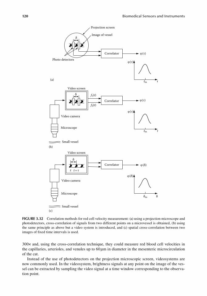
120 BiomedicalSensorsandInstruments
300×.and,.using.the.cross-correlation.technique,.they.could.measure.red.blood.cell.velocities.in.the.capillaries,.arterioles,.and.venules.up.to.60.μm.in.diameter.in.the.mesenteric.microcirculation.of.the.cat.
Instead.of.the.use.of.photodetectors.on.the.projection.microscopic.screen,.videosystems.are.now.commonly.used..In.the.videosystem,.brightness.signals.at.any.point.on.the.image.of.the.ves-sel.can.be.extracted.by.sampling.the.video.signal.at.a.time.window.corresponding.to.the.observa-tion.point.
Video screen
Correlator
(δ)
(δ)
δm δ
t t + τ
(c)
Video camera
Microscope
Small vessel
Video screen
δ
δ
f1(t)
f2(t)Correlator
(b)
Video camera
Microscope
Small vessel
Correlator
(a)
Projection screen
Image of vessel
(τ)
(τ)
(τ)
(τ)
tm τ
tm τ
Photo detectors
δ
figure 3.32 Correlation.methods.for.red.cell.velocity.measurement:.(a).using.a.projection.microscope.and.photodetectors,.cross-correlation.of.signals.from.two.different.points.on.a.microvessel.is.obtained,.(b).using.the.same.principle.as.above.but.a.video.system.is.introduced,.and.(c).spatial.cross-correlation.between.two.images.of.fixed.time.intervals.is.used.
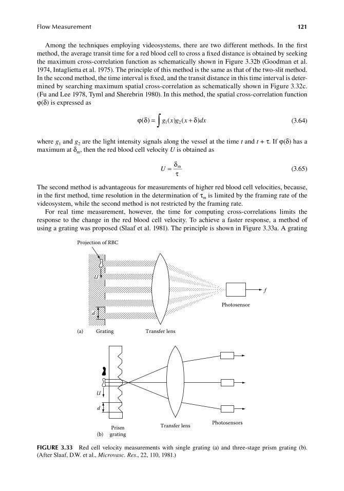
FlowMeasurement 121
Among. the. techniques. employing.videosystems,. there. are. two.different.methods.. In. the.first.method,.the.average.transit.time.for.a.red.blood.cell.to.cross.a.fixed.distance.is.obtained.by.seeking.the.maximum.cross-correlation.function.as.schematically.shown.in.Figure.3.32b.(Goodman.et al..1974,.Intaglietta.et al..1975)..The.principle.of.this.method.is.the.same.as.that.of.the.two-slit.method..In.the.second.method,.the.time.interval.is.fixed,.and.the.transit.distance.in.this.time.interval.is.deter-mined.by.searching.maximum.spatial.cross-correlation.as.schematically.shown.in.Figure.3.32c..(Fu.and.Lee.1978,.Tyml.and.Sherebrin.1980)..In.this.method,.the.spatial.cross-correlation.function.φ(δ).is.expressed.as
.ϕ δ δ( ) ( ) ( )= +∫ g x g x dx1 2
.(3.64)
where.g1.and.g2.are.the.light.intensity.signals.along.the.vessel.at.the.time.t.and.t.+.τ..If.φ(δ).has.a.maximum.at.δm,.then.the.red.blood.cell.velocity.U.is.obtained.as
.U = δ
τm
.(3.65)
The.second.method.is.advantageous.for.measurements.of.higher.red.blood.cell.velocities,.because,.in.the.first.method,.time.resolution.in.the.determination.of.τm.is.limited.by.the.framing.rate.of.the.videosystem,.while.the.second.method.is.not.restricted.by.the.framing.rate.
For. real. time. measurement,. however,. the. time. for. computing. cross-correlations. limits. the.response. to. the.change. in. the. red.blood.cell.velocity..To.achieve.a. faster. response,. a.method.of.using.a.grating.was.proposed.(Slaaf.et al..1981)..The.principle.is.shown.in.Figure.3.33a..A.grating.
Transfer lens Photosensors
U
d
Prismgrating(b)
Projection of RBC
U
d
Grating(a)
f
Transfer lens
Photosensor
figure 3.33 Red.cell. velocity.measurements.with. single.grating. (a). and. three-stage.prism.grating. (b)..(After.Slaaf,.D.W..et al.,.Microvasc. Res.,.22,.110,.1981.)
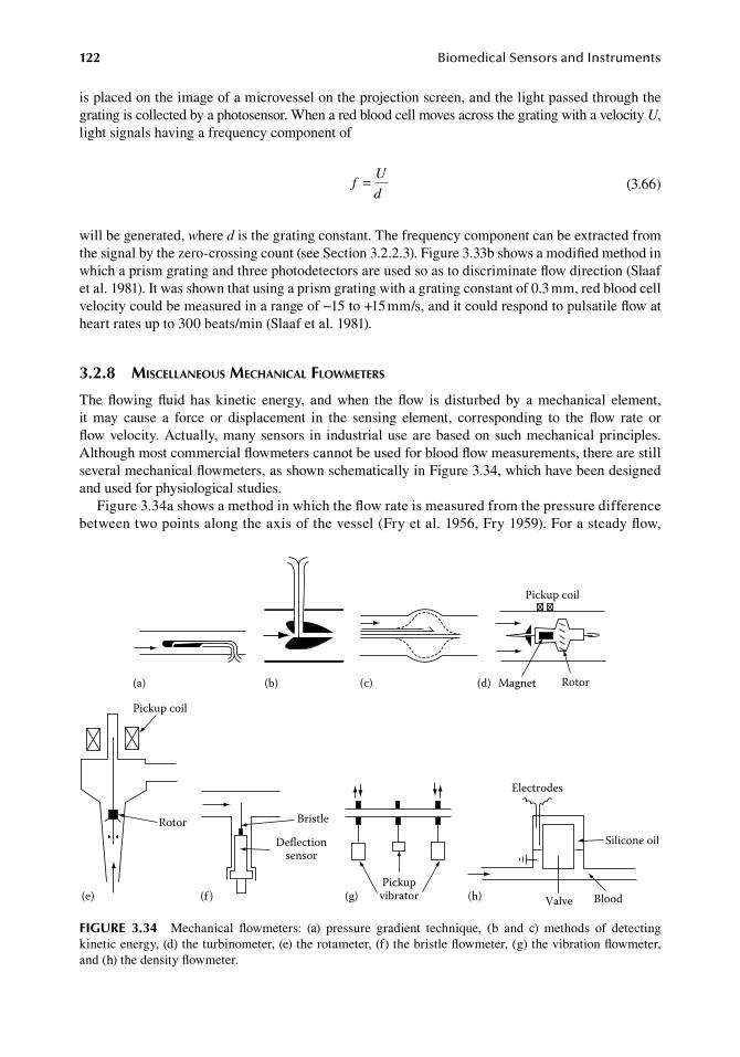
122 BiomedicalSensorsandInstruments
is.placed.on.the.image.of.a.microvessel.on.the.projection.screen,.and.the.light.passed.through.the.grating.is.collected.by.a.photosensor..When.a.red.blood.cell.moves.across.the.grating.with.a.velocity.U,.light.signals.having.a.frequency.component.of
.f
U
d=
.(3.66)
will.be.generated,.where.d.is.the.grating.constant..The.frequency.component.can.be.extracted.from.the.signal.by.the.zero-crossing.count.(see.Section.3.2.2.3)..Figure.3.33b.shows.a.modified.method.in.which.a.prism.grating.and.three.photodetectors.are.used.so.as.to.discriminate.flow.direction.(Slaaf.et al..1981)..It.was.shown.that.using.a.prism.grating.with.a.grating.constant.of.0.3.mm,.red.blood.cell.velocity.could.be.measured.in.a.range.of.−15.to.+15.mm/s,.and.it.could.respond.to.pulsatile.flow.at.heart.rates.up.to.300.beats/min.(Slaaf.et al..1981).
3.2.8 Miscellaneous Mechanical flowMeters
The. flowing. fluid. has. kinetic. energy,. and. when. the. flow. is. disturbed. by. a. mechanical. element,.it. may. cause. a. force. or. displacement. in. the. sensing. element,. corresponding. to. the. flow. rate. or.flow. .velocity..Actually,.many.sensors. in. industrial.use.are.based.on.such.mechanical.principles..Although.most.commercial.flowmeters.cannot.be.used.for.blood.flow.measurements,.there.are.still.several.mechanical.flowmeters,.as.shown.schematically.in.Figure.3.34,.which.have.been.designed.and.used.for.physiological.studies.
Figure.3.34a.shows.a.method.in.which.the.flow.rate.is.measured.from.the.pressure.difference.between.two.points.along.the.axis.of.the.vessel.(Fry.et al..1956,.Fry.1959)..For.a.steady.flow,.
(a)
Pickup coil
Magnet Rotor(d)(b) (c)
Pickupvibrator(f )
Bristle
Deflectionsensor
Electrodes
Valve Blood
Silicone oil
(h)(g)
Pickup coil
Rotor
(e)
figure 3.34 Mechanical. flowmeters:. (a). pressure. gradient. technique,. (b. and. c). methods. of. detecting.kinetic.energy,.(d).the.turbinometer,.(e).the.rotameter,.(f).the.bristle.flowmeter,.(g).the.vibration.flowmeter,.and.(h).the.density.flowmeter.
FlowMeasurement 123
the.pressure.difference.can.be.determined.as.the.frictional.pressure.drop..However,.when.the.flow.rate.is.changed,.additional.pressure.will.be.developed.due.to.the.inertia.of.the.fluid,.which.is.proportional.to.the.time.derivative.of.the.flow.velocity..If.the.velocity.is.U(t),.the.pressure.difference.ΔP.is.given.as
.∆P
dU t
dtU t= +ρδ α( )
( ).
(3.67)
whereρ.is.density.of.the.fluidδ.is.the.distance.between.the.two.pointsα.is.the.proportionality.constant.between.the.velocity.and.the.frictional.pressure.drop.between.
the.two.points.(Fry.et al..1956)
As.long.as.α.is.constant,.the.differential.equation.(3.67).is.linear,.and.the.instantaneous.velocity.U(t).can.be.obtained.as.the.solution.of.the.differential.equation..Fry.(1959).reported.that.this.method.could.be.applied.in.animals.and.human.subjects,.and.pulsatile.blood.velocity.patterns.in.the.ascend-ing.aorta.could.be.obtained.by.using.a.specially.designed.double-lumen.catheter.
Figure.3.34b.shows.a.flowmeter.head.designed.for.use.in.the.vena.cava.of.animals.(Mixter.1953)..The.kinetic.energy.of.the.blood.flow.causes.a.pressure.difference.between.the.upstream.and.down-stream.orifices,.and.the.flow.rate.can.be.determined.from.the.differential.pressure.output,.nonlinear.to.flow.rate.
Figure. 3.34c. also. shows. a. flowmeter. head. for. detecting. the. differential. pressure. (Brecher.1953)..The.pressure.difference.is.measured.between.the.tube.which.has.a.funnel-shape.opening.to.the.upstream.and.the.adjacent.tube.which.has.an.opening.to.the.downstream..The.catheter.head.is.held.in.midstream.by.five.stainless.steel.springs..The.catheter.also.has.an.additional.lumen,.which.can.be.used.for.atrial.pressure.measurement,.when.the.catheter. is. introduced.into.the.superior.vena.cava.
Figure. 3.34d. shows. a. flowmeter. called. the. Potter. electroturbinometer. (Sarnoff. et al.. 1952,.Sarnoff.and.Berglund.1953)..It.has.an.armature.with.blades,.an.inside.magnet,.and.the.rotation.of.the.armature.is.detected.by.a.pickup.coil..This.type.of.flowmeter.is.relatively.insensitive.to.change.in.viscosity..However,.it.has.disadvantages,.i.e.,.it.causes.a.significant.pressure.drop,.and.it.cannot.measure.flow.below.a.certain.critical.level.due.to.the.friction.between.the.armature.shaft.and.the.bearing.surface.
Figure.3.34e.shows.an.apparatus.called.a.rotameter.(Shipley.and.Wilson.1951)..The.flow.causes.elevation.of.the.float,.and.the.float.position.is.detected.by.a.differential. transformer.(see.Section.4.2.1)..This.flowmeter.is.also.relatively.insensitive.to.changes.in.viscosity,.and.it.can.be.designed.so.that.the.float.elevates.in.proportion.to.the.flow.rate..The.pressure.drop.is.not.proportional.to.the.flow.rate,.but.remains.in.a.narrow.range..As.an.example,.it.was.shown.that,.in.a.rotameter,.the.pressure.drop.remained.between.0.2.kPa.(2.cm.H2O).and.0.35.kPa.(3.5.cm.H2O).when.the.flow.varied.from.a.very.low.rate.up.to.3.L/min.
Figure.3.34f.shows.a.technique.called.the.bristle.flowmeter.(Brecher.and.Praglin.1953,.Brecher.1954,.1959)..It.measured.the.deviation.of.a.fine.bristle.caused.by.a.stream..If.the.deviation.of.the.bristle.is.proportional.to.the.drag.force.due.to.the.kinetic.energy.of.the.fluid,.it.will.be.proportional.to.the.square.of.the.flow.velocity..A.vacuum.tube.was.used.for.detecting.the.deviation.of.the.bristle,.in.which.the.deflection.of.a.plate.pin.could.be.converted.to.the.plate.current.
Figure.3.34g.shows.a.technique.of.mass.flow.measurement.in.which.the.Coriollis’.force.induced.by.a.rotational.motion.of.the.flowing.fluid.is.detected.(Togawa.and.Suma.1965)..An.elastic.tube.is.supported.at.three.points,.and.both.ends.are.driven.sinusoidally.in.opposite.directions.so.that.a.
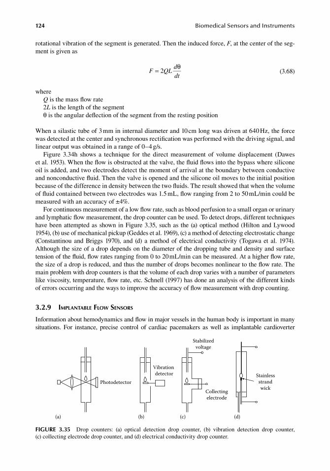
124 BiomedicalSensorsandInstruments
rotational.vibration.of.the.segment.is.generated..Then.the.induced.force,.F,.at.the.center.of.the.seg-ment.is.given.as
.F QL
d
dt= 2
θ.
(3.68)
whereQ.is.the.mass.flow.rate2L.is.the.length.of.the.segmentθ.is.the.angular.deflection.of.the.segment.from.the.resting.position
When.a.silastic.tube.of.3.mm.in.internal.diameter.and.10.cm.long.was.driven.at.640.Hz,.the.force.was.detected.at.the.center.and.synchronous.rectification.was.performed.with.the.driving.signal,.and.linear.output.was.obtained.in.a.range.of.0–4.g/s.
Figure. 3.34h. shows. a. technique. for. the. direct. measurement. of. volume. displacement. (Dawes.et al..1953)..When.the.flow.is.obstructed.at.the.valve,.the.fluid.flows.into.the.bypass.where.silicone.oil.is.added,.and.two.electrodes.detect.the.moment.of.arrival.at.the.boundary.between.conductive.and.nonconductive.fluid..Then.the.valve.is.opened.and.the.silicone.oil.moves.to.the.initial.position.because.of.the.difference.in.density.between.the.two.fluids..The.result.showed.that.when.the.volume.of.fluid.contained.between.two.electrodes.was.1.5.mL,.flow.ranging.from.2.to.50.mL/min.could.be.measured.with.an.accuracy.of.±4%.
For.continuous.measurement.of.a.low.flow.rate,.such.as.blood.perfusion.to.a.small.organ.or.urinary.and.lymphatic.flow.measurement,.the.drop.counter.can.be.used..To.detect.drops,.different.techniques.have.been.attempted.as.shown.in.Figure.3.35,.such.as. the.(a).optical.method.(Hilton.and.Lywood.1954),.(b).use.of.mechanical.pickup.(Geddes.et al..1969),.(c).a.method.of.detecting.electrostatic.change.(Constantinou.and.Briggs.1970),. and. (d). a.method.of. electrical. conductivity. (Togawa.et al.. 1974)..Although.the.size.of.a.drop.depends.on.the.diameter.of.the.dropping.tube.and.density.and.surface.tension.of.the.fluid,.flow.rates.ranging.from.0.to.20.mL/min.can.be.measured..At.a.higher.flow.rate,.the.size.of.a.drop.is.reduced,.and.thus.the.number.of.drops.becomes.nonlinear.to.the.flow.rate..The.main.problem.with.drop.counters.is.that.the.volume.of.each.drop.varies.with.a.number.of.parameters.like.viscosity,.temperature,.flow.rate,.etc..Schnell.(1997).has.done.an.analysis.of.the.different.kinds.of.errors.occurring.and.the.ways.to.improve.the.accuracy.of.flow.measurement.with.drop.counting.
3.2.9 iMplantable flow sensors
Information.about.hemodynamics.and.flow.in.major.vessels.in.the.human.body.is.important.in.many.situations.. For. instance,. precise. control. of. cardiac. pacemakers. as. well. as. implantable. cardioverter.
Vibration detector
Photodetector
Stabilizedvoltage
Collectingelectrode
(d)
Stainlessstrandwick
(a) (b) (c)
figure 3.35 Drop. counters:. (a). optical. detection. drop. counter,. (b). vibration. detection. drop. counter,.(c).collecting.electrode.drop.counter,.and.(d).electrical.conductivity.drop.counter.
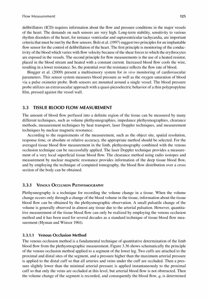
FlowMeasurement 125
defibrillators.(ICD).requires.information.about.the.flow.and.pressure.conditions.in.the.major.vessels.of.the.heart..The.demands.on.such.sensors.are.very.high..Long-term.stability,.sensitivity.to.various.rhythm.disorders.of.the.heart,.for.instance.ventricular.and.supraventricular.tachycardia,.are.important.criteria.that.must.be.met.by.the.flow.sensors..Bolz.et al..(1997).suggest.two.principles.for.an.implantable.flow.sensor.for.the.control.of.defibrillation.of.the.heart..The.first.principle.is.monitoring.of.the.conduc-tivity.of.the.blood.which.varies.with.flow.velocity.because.of.the.shear.forces.to.which.the.erythrocytes.are.exposed.in.the.vessels..The.second.principle.for.flow.measurements.is.the.use.of.a.heated.resistor,.placed.in.the.blood.stream.and.heated.with.a.constant.current..Increased.blood.flow.cools.the.wire,.resulting.in.a.lower.resistance..So,.the.potential.over.the.resistance.reflects.the.flow.rate.of.blood.
Bingger. et al.. (2009). present. a. multisensory. system. for. in vivo. monitoring.of. cardiovascular.parameters..This.sensor.system.measures.blood.pressure.as.well.as.the.oxygen.saturation.of.blood.via.a.pulse.oximeter.probe..Both.sensors.are.mounted.around.a.single.vessel..The.blood.pressure.probe.utilizes.an.extravascular.approach.with.a.quasi-piezoelectric.behavior.of.a.thin.polypropylene.film,.pressed.against.the.vessel.wall.
3.3 tiSSue blood floW MeaSureMent
The.amount.of.blood.flow.perfused.into.a.definite.region.of.the.tissue.can.be.measured.by.many.different.techniques,.such.as.volume.plethysmographies,.impedance.plethysmographies,.clearance.methods,.measurement.techniques.by.heat.transport,.laser.Doppler.techniques,.and.measurement.techniques.by.nuclear.magnetic.resonance.
According.to. the.requirements.of. the.measurement,.such.as. the.object.site,.spatial.resolution,.response.time,.or.absolute.or.relative.accuracy,.the.appropriate.method.should.be.selected..For.the.averaged.tissue.blood.flow.measurement.in.the.limb,.plethysmography.combined.with.the.venous.occlusion.technique.can.be.successfully.applied..The.laser.Doppler.technique.provides.a.measure-ment.of.a.very.local.superficial.tissue.blood.flow..The.clearance.method.using.radio.isotopes.and.measurement.by.nuclear.magnetic.resonance.provides.information.of.the.deep.tissue.blood.flow,.and.by.employing.the.technique.of.computed.tomography,.the.blood.flow.distribution.over.a.cross.section.of.the.body.can.be.obtained.
3.3.1 Venous occlusion plethysMography
Plethysmography. is. a. technique. for. recording. the.volume. change. in. a. tissue..When. the.volume.change.occurs.only.through.a.change.of.the.blood.volume.in.the.tissue,.information.about.the.tissue.blood.flow.can.be.obtained.by.the.plethysmographic.observation..A.small.pulsatile.change.of.the.volume.is.generally.observed.in.almost.any.tissue.due.to.the.arterial.pulsation..However,.quantita-tive.measurement.of.the.tissue.blood.flow.can.only.be.realized.by.employing.the.venous.occlusion.method.and.it.has.been.used.for.several.decades.as.a.standard.technique.of.tissue.blood.flow.mea-surement.(Hyman.and.Winsor.1961).
3.3.1.1 Venous occlusion MethodThe.venous.occlusion.method.is.a.fundamental.technique.of.quantitative.determination.of.the.limb.blood.flow.from.the.plethysmographic.measurement..Figure.3.36.shows.schematically.the.principle.of.the.venous.occlusion.method.applied.to.a.segment.of.the.lower.leg..Two.cuffs.are.attached.to.the.proximal.and.distal.sites.of.the.segment,.and.a.pressure.higher.than.the.maximum.arterial.pressure.is.applied.to.the.distal.cuff.so.that.all.arteries.and.veins.under.the.cuff.are.occluded..Then.a.pres-sure.slightly. lower.than.the.minimal.arterial.pressure. is.applied.instantaneously. to. the.proximal.cuff.so.that.only.the.veins.are.occluded.at.this.level,.but.arterial.blood.flow.is.not.obstructed..Then.the.volume.change.of.the.segment.is.recorded,.and.consequently.the.blood.flow,.q,.is.determined.
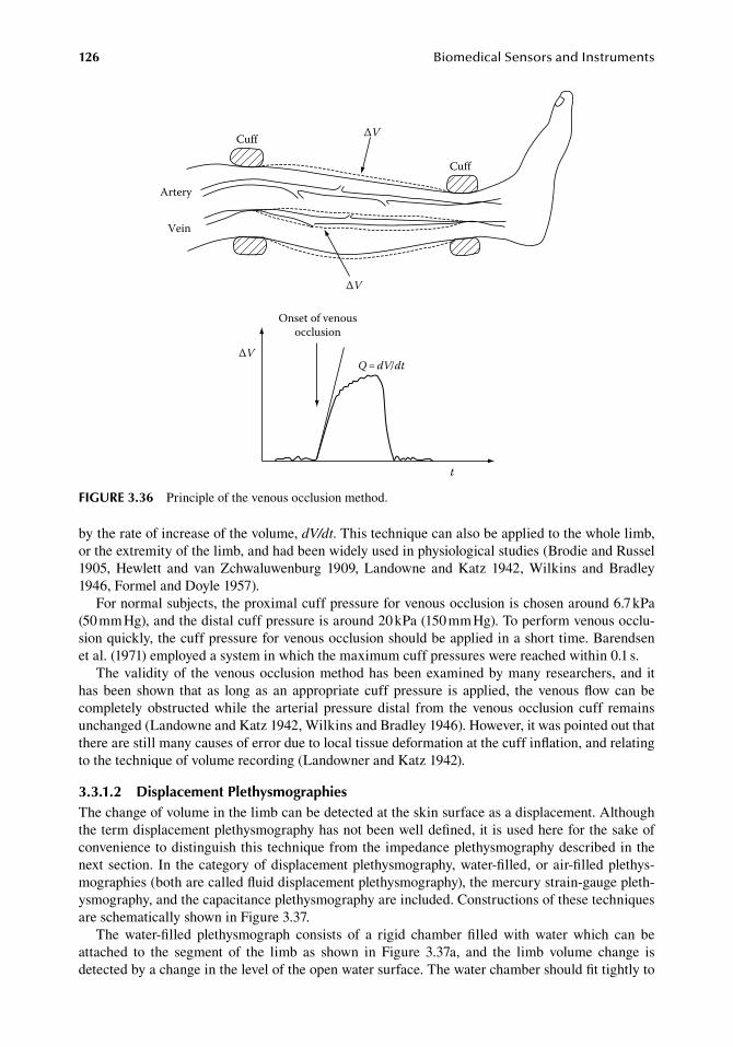
126 BiomedicalSensorsandInstruments
by.the.rate.of.increase.of.the.volume,.dV/dt..This.technique.can.also.be.applied.to.the.whole.limb,.or.the.extremity.of.the.limb,.and.had.been.widely.used.in.physiological.studies.(Brodie.and.Russel.1905,. Hewlett. and. van. Zchwaluwenburg. 1909,. Landowne. and. Katz. 1942,. Wilkins. and. Bradley.1946,.Formel.and.Doyle.1957).
For.normal.subjects,.the.proximal.cuff.pressure.for.venous.occlusion.is.chosen.around.6.7.kPa.(50.mm.Hg),.and.the.distal.cuff.pressure.is.around.20.kPa.(150.mm.Hg)..To.perform.venous.occlu-sion.quickly,.the.cuff.pressure.for.venous.occlusion.should.be.applied.in.a.short.time..Barendsen.et al..(1971).employed.a.system.in.which.the.maximum.cuff.pressures.were.reached.within.0.1.s.
The.validity.of. the.venous.occlusion.method.has.been.examined.by.many.researchers,.and. it.has.been. shown. that. as. long.as. an. appropriate. cuff.pressure. is. applied,. the.venous.flow.can.be.completely.obstructed.while. the. arterial.pressure.distal. from. the.venous.occlusion.cuff. remains.unchanged.(Landowne.and.Katz.1942,.Wilkins.and.Bradley.1946)..However,.it.was.pointed.out.that.there.are.still.many.causes.of.error.due.to.local.tissue.deformation.at.the.cuff.inflation,.and.relating.to.the.technique.of.volume.recording.(Landowner.and.Katz.1942).
3.3.1.2 displacement PlethysmographiesThe.change.of.volume.in.the.limb.can.be.detected.at.the.skin.surface.as.a.displacement..Although.the.term.displacement.plethysmography.has.not.been.well.defined,.it.is.used.here.for.the.sake.of.convenience.to.distinguish.this.technique.from.the.impedance.plethysmography.described.in.the.next.section.. In. the.category.of.displacement.plethysmography,.water-filled,.or.air-filled.plethys-mographies.(both.are.called.fluid.displacement.plethysmography),.the.mercury.strain-gauge.pleth-ysmography,.and.the.capacitance.plethysmography.are.included..Constructions.of.these.techniques.are.schematically.shown.in.Figure.3.37.
The. water-filled. plethysmograph. consists. of. a. rigid. chamber. filled. with. water. which. can. be.attached. to. the. segment. of. the. limb. as. shown. in. Figure. 3.37a,. and. the. limb. volume. change. is.detected.by.a.change.in.the.level.of.the.open.water.surface..The.water.chamber.should.fit.tightly.to.
Onset of venousocclusion
ΔVQ = dV/dt
t
Artery
Vein
Cuff
Cuff
ΔV
ΔV
figure 3.36 Principle.of.the.venous.occlusion.method.
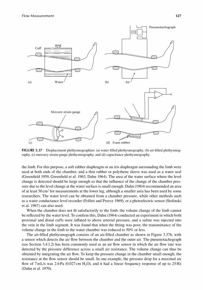
FlowMeasurement 127
the.limb..For.this.purpose,.a.soft.rubber.diaphragm.or.an.iris.diaphragm.surrounding.the.limb.were.used.at.both.ends.of.the.chamber,.and.a.thin.rubber.or.polythene.sleeve.was.used.as.a.water.seal.(Greenfield.1959,.Greenfield.et al..1963,.Dahn.1964)..The.area.of.the.water.surface.where.the.level.change.is.detected.should.be.large.enough.so.that.the.influence.of.the.change.of.the.chamber.pres-sure.due.to.the.level.change.at.the.water.surface.is.small.enough..Dahn.(1964).recommended.an.area.of.at.least.50.cm2.for.measurements.at.the.lower.leg,.although.a.smaller.area.has.been.used.by.some.researchers..The.water.level.can.be.obtained.from.a.chamber.pressure,.while.other.methods.such.as.a.water.conductance.level.recorder.(Follett.and.Preece.1969),.or.a.photoelectric.sensor.(Stolinski.et al..1967).can.also.used.
When.the.chamber.does.not.fit.satisfactorily.to.the.limb,.the.volume.change.of.the.limb.cannot.be.reflected.by.the.water.level..To.confirm.this,.Dahn.(1964).conducted.an.experiment.in.which.both.proximal.and.distal.cuffs.were.inflated.to.above.arterial.pressure,.and.a.saline.was.injected.into.the.vein.in.the.limb.segment..It.was.found.that.when.the.fitting.was.poor,.the.transmittance.of.the.volume.change.in.the.limb.to.the.water.chamber.was.reduced.to.50%.or.less.
The.air-filled.plethysmograph.consists.of.an.air-filled.chamber.as.shown.in.Figure.3.37b,.with.a.sensor.which.detects.the.air.flow.between.the.chamber.and.the.outer.air..The.pneumotachograph.(see.Section.3.4.1.2).has.been.commonly.used.as.an.air.flow.sensor.in.which.the.air.flow.rate.was.detected.by.the.pressure.difference.across.a.small.air.resistance..The.volume.change.can.thus.be.obtained.by.integrating.the.air.flow..To.keep.the.pressure.change.in.the.chamber.small.enough,.the.resistance.at.the.flow.sensor.should.be.small..In.one.example,.the.pressure.drop.for.a.maximal.air.flow.of.7.mL/s.was.2.6.Pa.(0.027.cm.H2O),.and.it.had.a.linear.frequency.response.of.up.to.25.Hz.(Dahn.et al..1970).
Cuff
Water(a)
Pneumotachograph
Air(b)
Foam rubber(d)
Mercury-strain-gauge
(c)
+–
figure 3.37 Displacement.plethysmographies:.(a).water.filled.plethysmography,.(b).air-filled.plethysmog-raphy,.(c).mercury-strain-gauge.plethysmography,.and.(d).capacitance.plethysmography.
128 BiomedicalSensorsandInstruments
A.simplified.method.of.air-filled.plethysmography.was.also.proposed.in.which.a.cuff.was.used.instead.of.a.rigid.air.chamber.(Winsor.1957,.Hyman.and.Winsor.1960)..The.cuff.was.4–8.cm.in.width,.and.a.pressure.of.1.3–2.7.kPa.(10.to.20.mm.Hg).was.maintained.in.it,.and.the.pressure.differ-ence.between.the.cuff.and.a.chamber.maintained.at.constant.pressure.at.the.average.cuff.pressure.was.detected.by.a.sensitive.diaphragm..In.comparison.with.the.water-filled.plethysmograph.in.the.contralateral.arm,.it.was.shown.that.both.measurements.correlated.fairly.well.
Figure. 3.37c. illustrates. a. technique. called. mercury. strain-gauge. plethysmography,. in. which.changes. in. the.circumference.of. the. limb.are.detected.by. the.electrical. resistance.change.of. the.mercury. conductor. in. a. fine. distensible. tube.. This. technique. had. been. investigated. extensively.(Whitney.1949,.1953,.Brakkee.and.Vendrik.1966,.Sigdell.1969,.Dahn.and.Hallböök.1970,.Hallböök.et al..1970)..In.order.to.estimate.the.volume.change.of.the.limb.segment.correctly.from.the.change.of.circumference,.it.is.postulated.that.the.tissue.does.not.deform.in.the.direction.of.the.limb.axis,.and.the.cross-sectional.area.is.uniform.along.the.limb.segment..Although.these.assumptions.are.not.fully.valid.in.actual.human.limbs,.it.was.pointed.out.that.a.fairly.accurate.estimation.of.the.volume.change.is.possible.(Whitney.1949).
The.actual.mercury.strain-gauges.are.usually.composed.of.fine.and.highly.distensible.tubes..For.example,.a.latex.tube.with.an.internal.diameter.of.0.5.mm.and.a.wall.thickness.of.0.8.mm.was.used,.and.the.developed.tension.for.1%.elongation.from.the.natural.length.was.2.5.gf.(Whitney.1953)..The.resistance.is.of.an.order.of.1.Ω.
The.sensitivity.of.the.mercury.strain-gauge.is.given.as
.
dr
r
dL
Lm
m
2=.
(3.69)
whererm.is.gauge.resistanceL.is.the.length.of.the.gauge
Because.the.resistance.of.the.gauge.is.small,.the.resistance.of.the.lead.wire.cannot.be.neglected..If.the.lead.wire.has.a.resistance.rw,.relative.change.in.the.total.resistance,.r,.is,
.
dr
r
dL
L r r=
+2
11
w m/ .(3.70)
On.the.other.hand,.if.the.gauge.does.not.cover.the.whole.circumference.of.the.limb,.but.a.gap.of.length,.g,.exists,.the.circumferential.length.is.c = L + g,.and.the.resulting.strain.is.given.as
.
dL
L
dc
c
g
L= +
1.
(3.71)
If.the.gauge.resistance.is.written.as.rm.=.Lk,.then,
.
dr
r
dc
c
g L
r kL= +
+2
11
//m .
(3.72)
Thus,.if.the.wire.resistance.is.chosen.as.rm.=.k · g,.the.effects.of.the.gap.and.the.wire.resistance.can.compensate.each.other.(Brakkee.and.Vendrik.1966).
Although.the.mercury.strain-gauge.plethysmograph.measures.the.circumferential.length.change.only.at.one.or.a.few.sections.in.the.limb.segment,.it.was.shown.that.practically.equal.plethysmographs.
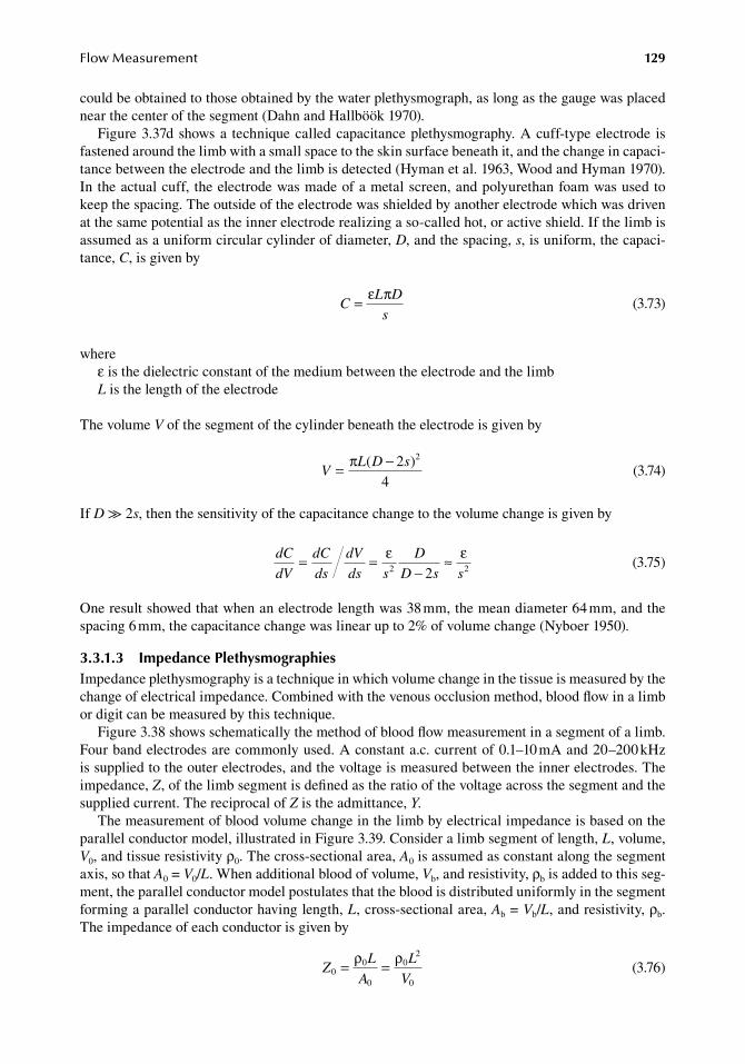
FlowMeasurement 129
could.be.obtained.to.those.obtained.by.the.water.plethysmograph,.as.long.as.the.gauge.was.placed.near.the.center.of.the.segment.(Dahn.and.Hallböök.1970).
Figure.3.37d.shows.a. technique.called.capacitance.plethysmography..A.cuff-type.electrode. is.fastened.around.the.limb.with.a.small.space.to.the.skin.surface.beneath.it,.and.the.change.in.capaci-tance.between.the.electrode.and.the.limb.is.detected.(Hyman.et al..1963,.Wood.and.Hyman.1970)..In.the.actual.cuff,. the.electrode.was.made.of.a.metal.screen,.and.polyurethan.foam.was.used.to.keep.the.spacing..The.outside.of.the.electrode.was.shielded.by.another.electrode.which.was.driven.at.the.same.potential.as.the.inner.electrode.realizing.a.so-called.hot,.or.active.shield..If.the.limb.is.assumed.as.a.uniform.circular.cylinder.of.diameter,.D,.and.the.spacing,.s,.is.uniform,.the.capaci-tance,.C,.is.given.by
.C
L D
s= ε π
.(3.73)
whereε.is.the.dielectric.constant.of.the.medium.between.the.electrode.and.the.limbL.is.the.length.of.the.electrode
The.volume.V.of.the.segment.of.the.cylinder.beneath.the.electrode.is.given.by
.V
L D s= −π ( )24
2
.(3.74)
If.D.≫.2s,.then.the.sensitivity.of.the.capacitance.change.to.the.volume.change.is.given.by
.
dC
dV
dC
ds
dV
ds s
D
D s s= =
−≈ε ε
2 22 .(3.75)
One.result.showed.that.when.an.electrode.length.was.38.mm,.the.mean.diameter.64.mm,.and.the.spacing.6.mm,.the.capacitance.change.was.linear.up.to.2%.of.volume.change.(Nyboer.1950).
3.3.1.3 impedance PlethysmographiesImpedance.plethysmography.is.a.technique.in.which.volume.change.in.the.tissue.is.measured.by.the.change.of.electrical.impedance..Combined.with.the.venous.occlusion.method,.blood.flow.in.a.limb.or.digit.can.be.measured.by.this.technique.
Figure.3.38.shows.schematically.the.method.of.blood.flow.measurement.in.a.segment.of.a.limb..Four.band.electrodes.are.commonly.used..A.constant.a.c..current.of.0.1–10.mA.and.20–200.kHz.is.supplied.to.the.outer.electrodes,.and.the.voltage.is.measured.between.the.inner.electrodes..The.impedance,.Z,.of.the.limb.segment.is.defined.as.the.ratio.of.the.voltage.across.the.segment.and.the.supplied.current..The.reciprocal.of.Z.is.the.admittance,.Y.
The.measurement.of.blood.volume.change.in.the.limb.by.electrical.impedance.is.based.on.the.parallel.conductor.model,.illustrated.in.Figure.3.39..Consider.a.limb.segment.of.length,.L,.volume,.V0,.and.tissue.resistivity.ρ0..The.cross-sectional.area,.A0.is.assumed.as.constant.along.the.segment.axis,.so.that.A0.=.V0/L..When.additional.blood.of.volume,.Vb,.and.resistivity,.ρb.is.added.to.this.seg-ment,.the.parallel.conductor.model.postulates.that.the.blood.is.distributed.uniformly.in.the.segment.forming.a.parallel.conductor.having.length,.L,.cross-sectional.area,.Ab.=.Vb/L,.and.resistivity,.ρb..The.impedance.of.each.conductor.is.given.by
.Z
L
A
L
V0
0
0
02
0
= =ρ ρ
.(3.76)
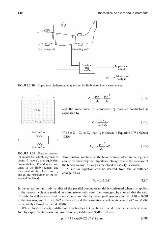
130 BiomedicalSensorsandInstruments
.Z
L
A
L
Vb
b
b
b
b
= =ρ ρ 2
.(3.77)
and. the. impedance,. Z,. composed. by. parallel. conductors. is.expressed.by
.Z
Z Z
Z Z=
+0
0
b
b .(3.78)
If.ΔZ.=.Z − Z0.≪.Z0,.then.Vb.is.shown.in.Equation.3.78.(Nyboer.1950):
.V
L
ZZb
b= − ρ 2
02
∆.
(3.79)
This.equation.implies.that.the.blood.volume.added.to.the.segment.can.be.estimated.by.the.impedance.change.due.to.the.increase.of.the.blood.volume,.as.long.as.the.blood.resistivity.is.known.
A. similar. equation. can. be. derived. from. the. admittance.change.ΔY.as
. V L Yb b2= ρ ∆ . (3.80)
In.the.actual.human.limb,.validity.of.the.parallel.conductor.model.is.confirmed.when.it.is.applied.to.the.venous.occlusion.method..A.comparison.with.water.plethysmography.showed.that.the.ratio.of.limb.blood.flow.measured.by.impedance.and.that.by.water.plethysmography.was.1.01.±.0.091.in.the.forearm,.and.1.01.±.0.092.in.the.calf,.and.the.correlation.coefficients.were.0.987.and.0.989,.respectively.(Yamakoshi.et al..1978).
While.blood.resistivity.is.different.in.each.subject,.it.can.be.estimated.from.the.hematocrit.value,.Hct,.by.experimental.formulas..An.example.(Geddes.and.Sadler.1973).is
. ρb 53 2 exp 22 cm= . ( . )0 0 Hct Ω . (3.81)
Amplifierand
rectifier
1/X
Impedanceoutput
Admittanceoutput
Occluding cuff Occluding cuff
figure 3.38 Impedance.plethysmography.system.for.limb.blood.flow.measurement.
L
V0, ρ0
Vb, ρb
Z0 = ρ0L2/V0
Zb = ρbL2/Vb
figure 3.39 Parallel. conduc-tor. model. for. a. limb. segment. of.length. L. (above),. and. equivalent.circuit.(below)..V0.and.Vb.are.vol-umes. of. the. limb. segment. and.increment. of. the. blood,. and. ρ0.and.ρb. are. resistivities.of. the. tis-sue.and.the.blood.
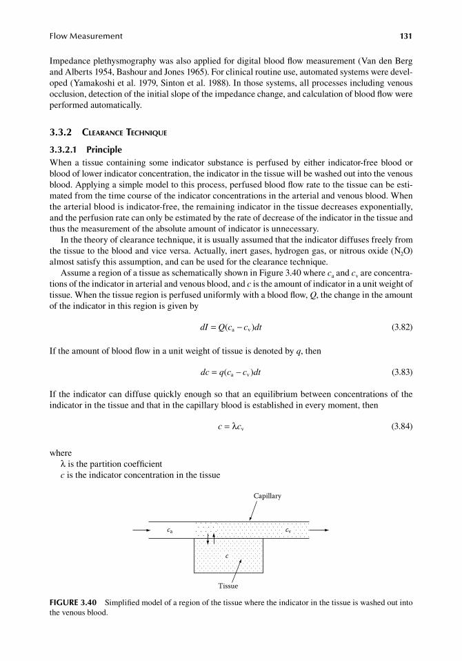
FlowMeasurement 131
Impedance.plethysmography.was.also.applied.for.digital.blood.flow.measurement.(Van.den.Berg.and.Alberts.1954,.Bashour.and.Jones.1965)..For.clinical.routine.use,.automated.systems.were.devel-oped.(Yamakoshi.et al..1979,.Sinton.et al..1988)..In.those.systems,.all.processes.including.venous.occlusion,.detection.of.the.initial.slope.of.the.impedance.change,.and.calculation.of.blood.flow.were.performed.automatically.
3.3.2 clearance technique
3.3.2.1 PrincipleWhen.a. tissue.containing.some. indicator. substance. is.perfused.by.either. indicator-free.blood.or.blood.of.lower.indicator.concentration,.the.indicator.in.the.tissue.will.be.washed.out.into.the.venous.blood..Applying.a.simple.model.to.this.process,.perfused.blood.flow.rate.to.the.tissue.can.be.esti-mated.from.the.time.course.of.the.indicator.concentrations.in.the.arterial.and.venous.blood..When.the.arterial.blood.is.indicator-free,.the.remaining.indicator.in.the.tissue.decreases.exponentially,.and.the.perfusion.rate.can.only.be.estimated.by.the.rate.of.decrease.of.the.indicator.in.the.tissue.and.thus.the.measurement.of.the.absolute.amount.of.indicator.is.unnecessary.
In.the.theory.of.clearance.technique,.it.is.usually.assumed.that.the.indicator.diffuses.freely.from.the.tissue.to.the.blood.and.vice.versa..Actually,.inert.gases,.hydrogen.gas,.or.nitrous.oxide.(N2O).almost.satisfy.this.assumption,.and.can.be.used.for.the.clearance.technique.
Assume.a.region.of.a.tissue.as.schematically.shown.in.Figure.3.40.where.ca.and.cv.are.concentra-tions.of.the.indicator.in.arterial.and.venous.blood,.and.c.is.the.amount.of.indicator.in.a.unit.weight.of.tissue..When.the.tissue.region.is.perfused.uniformly.with.a.blood.flow,.Q,.the.change.in.the.amount.of.the.indicator.in.this.region.is.given.by
. dI dt= −Q c c( a v ) . (3.82)
If.the.amount.of.blood.flow.in.a.unit.weight.of.tissue.is.denoted.by.q,.then
. dc dt= −q c c( a v ) . (3.83)
If.the.indicator.can.diffuse.quickly.enough.so.that.an.equilibrium.between.concentrations.of.the.indicator.in.the.tissue.and.that.in.the.capillary.blood.is.established.in.every.moment,.then
.c c= λ v .
(3.84)
whereλ.is.the.partition.coefficientc.is.the.indicator.concentration.in.the.tissue
Capillary
Tissue
ca
c
cv
figure 3.40 Simplified.model.of.a.region.of.the.tissue.where.the.indicator.in.the.tissue.is.washed.out.into.the.venous.blood.
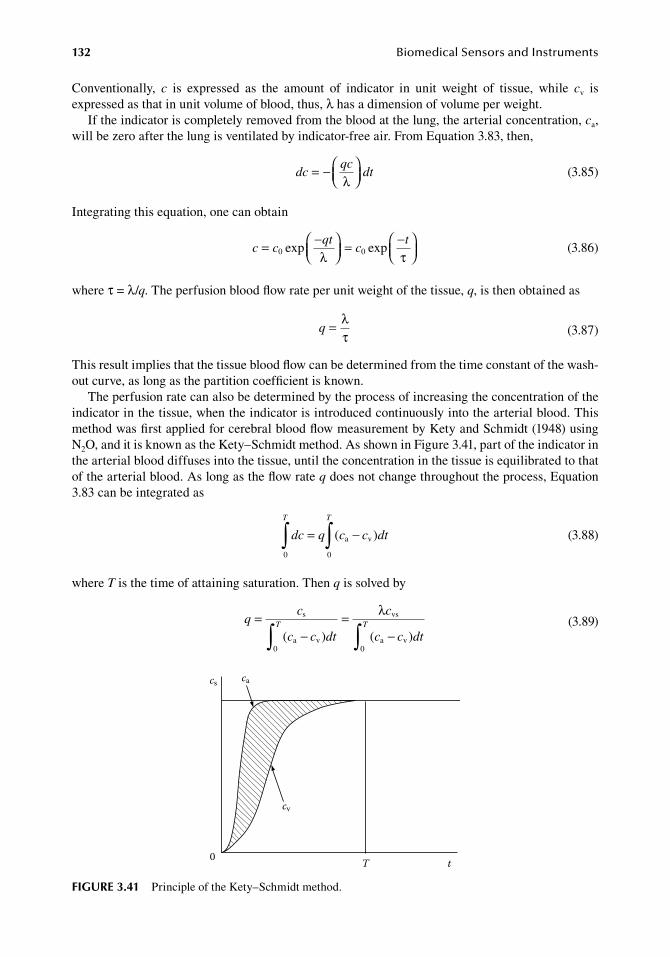
132 BiomedicalSensorsandInstruments
Conventionally,. c. is. expressed. as. the. amount. of. indicator. in. unit. weight. of. tissue,. while. cv. is.expressed.as.that.in.unit.volume.of.blood,.thus,.λ.has.a.dimension.of.volume.per.weight.
If.the.indicator.is.completely.removed.from.the.blood.at.the.lung,.the.arterial.concentration,.ca,.will.be.zero.after.the.lung.is.ventilated.by.indicator-free.air..From.Equation.3.83,.then,
.dc
qcdt=
−λ .
(3.85)
Integrating.this.equation,.one.can.obtain
.c c
qtc
t=
=
0 0exp exp
− −λ τ .
(3.86)
where.τ.=.λ/q..The.perfusion.blood.flow.rate.per.unit.weight.of.the.tissue,.q,.is.then.obtained.as
.q = λ
τ .(3.87)
This.result.implies.that.the.tissue.blood.flow.can.be.determined.from.the.time.constant.of.the.wash-out.curve,.as.long.as.the.partition.coefficient.is.known.
The.perfusion.rate.can.also.be.determined.by.the.process.of.increasing.the.concentration.of.the.indicator.in.the.tissue,.when.the.indicator.is.introduced.continuously.into.the.arterial.blood..This.method.was.first.applied.for.cerebral.blood.flow.measurement.by.Kety.and.Schmidt.(1948).using.N2O,.and.it.is.known.as.the.Kety–Schmidt.method..As.shown.in.Figure.3.41,.part.of.the.indicator.in.the.arterial.blood.diffuses.into.the.tissue,.until.the.concentration.in.the.tissue.is.equilibrated.to.that.of.the.arterial.blood..As.long.as.the.flow.rate.q.does.not.change.throughout.the.process,.Equation.3.83.can.be.integrated.as
.
dc q c c dt
T T
0 0∫ ∫= −( )a v
.
(3.88)
where.T.is.the.time.of.attaining.saturation..Then.q.is.solved.by
.
qc
c c dt
c
c c dtT T=
−=
−∫ ∫s
a v
vs
a v( ) ( )0 0
λ
.
(3.89)
cs
0 T
cv
ca
t
figure 3.41 Principle.of.the.Kety–Schmidt.method.
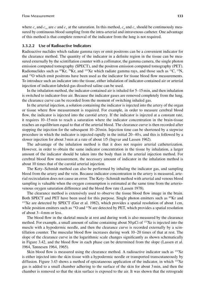
FlowMeasurement 133
where.cs.and.cvs.are.c.and.cv.at.the.saturation..In.this.method,.ca.and.cv.should.be.continuously.mea-sured.by.continuous.blood.sampling.from.the.intra-arterial.and.intravenous.catheter..One.advantage.of.this.method.is.that.complete.removal.of.the.indicator.from.the.lung.is.not.required.
3.3.2.2 use of radioactive indicatorsRadioactive.nuclides.which.radiate.gamma.rays.or.emit.positrons.can.be.a.convenient.indicator.for.the.clearance.method..The.quantity.of.the.indicator.in.a.definite.region.in.the.tissue.can.be.mea-sured.externally.by.the.scintillation.counter.with.a.collimator,.the.gamma.camera,.the.single.photon.emission.computed.tomography.(SPECT),.and.the.positron.emission.computed.tomography.(PET)..Radionuclides.such.as.85Kr,.79Kr,.and.133Xe.which.radiate.gamma.rays,.and.those.such.as.11C,.13N,.and.15O.which.emit.positrons.have.been.used.as.the.indicator.for.tissue.blood.flow.measurements..To.introduce.such.an.indicator.into.the.tissue,.either.inhalation.of.indicator-contained.air.or.arterial.injection.of.indicator-labeled-gas.dissolved.saline.can.be.used.
In.the.inhalation.method,.the.indicator-contained.air.is.inhaled.for.5–15.min,.and.then.inhalation.is.switched.to.indicator-free.air..Because.the.indicator.gases.are.removed.completely.from.the.lung,.the.clearance.curve.can.be.recorded.from.the.moment.of.switching.inhaled.gas.
In.the.arterial.injection,.a.solution.containing.the.indicator.is.injected.into.the.artery.of.the.organ.or. tissue.where.flow.measurement. is. required..For. example,. in.order. to.measure.cerebral.blood.flow,.the.indicator.is.injected.into.the.carotid.artery..If.the.indicator.is.injected.at.a.constant.rate,.it. requires.10–15.min. to. reach. a. saturation.where. the. indicator. concentration. in. the.brain-tissue.reaches.an.equilibrium.equal.to.that.of.the.arterial.blood..The.clearance.curve.is.then.recorded.after.stopping.the.injection.for.the.subsequent.10–20.min..Injection.time.can.be.shortened.by.a.stepwise.procedure.in.which.the.indicator.is.injected.rapidly.in.the.initial.20–40.s,.and.this.is.followed.by.a.slower.injection.for.about.3.min.at.a.rate.of.about.1/5.(Ingvar.and.Lassen.1962).
The. advantage. of. the. inhalation. method. is. that. it. does. not. require. arterial. catheterization..However,.in.order.to.obtain.the.same.indicator.concentration.in.the.tissue.by.inhalation,.a.larger.amount.of. the. indicator.should.be.taken.into.the.body.than.in. the.arterial. injection.method..For.cerebral.blood.flow.measurement,. the.necessary.amount.of.indicator.in.the.inhalation.method.is.about.10.times.that.of.the.carotid.arterial.injection.
The.Kety–Schmidt.method.can.also.be.performed.by.inhaling.the.indicator.gas,.and.sampling.blood.from.the.artery.and.the.vein..Because.indicator.concentration.in.the.artery.is.measured,.arte-rial.recirculation.does.not.cause.an.error..The.Kety–Schmidt.method.with.arterial.and.venous.blood.sampling.is.valuable.when.the.oxygen.consumption.is.estimated.at.the.same.time.from.the.arterio-venous.oxygen.saturation.difference.and.the.blood.flow.rate.(Lassen.1978).
The.clearance.method.is.extensively.used.to.observe.the.tissue.blood.flow.image.in.the.brain..Both.SPECT.and.PET.have.been.used.for.this.purpose..Single.photon.emitters.such.as.85Kr.and.133Xe.are.detected.by.SPECT.(Gur.et al..1982),.which.provides.a.spatial.resolution.of.about.1.cm,.while.position.emitters.such.as.15O.and.13N.are.detected.by.PET,.which.provides.a.spatial.resolution.of.about.3–4.mm.or.less.
The.blood.flow.in.the.skeletal.muscle.at.rest.and.during.work.is.also.measured.by.the.clearance.method..For.example,.a.small.amount.of.saline.containing.about.50.μCi.of.133Xe.is.injected.into.the.muscle.with.a.hypodermic.needle,.and.then.the.clearance.curve.is.recorded.externally.by.a.scin-tillation.counter..The.muscular.blood.flow.increases.during.work.10–20.times.of.that.at.rest..The.slope.of.the.clearance.curve.in.the.logarithmic.scale.changes.significantly.as.shown.schematically.in.Figure.3.42,.and.the.blood.flow.in.each.phase.can.be.determined.from.the.slope.(Lassen.et al..1964,.Tønnesen.1964,.1965).
Skin.blood.flow.is.measured.using.the.clearance.method..A.radioactive.indicator.such.as.133Xe.is.either.injected.into.the.skin.tissue.with.a.hypodermic.needle.or.transported.transcutaneously.by.diffusion..Figure.3.43.shows.a.method.of.epicutaneous.application.of.the.indicator,.in.which.133Xe.gas.is.added.to.a.small.chamber.adhering.to.the.surface.of.the.skin.for.about.3.min,.and.then.the.chamber.is.removed.so.that.the.skin.surface.is.exposed.to.the.air..It.was.shown.that.the.retrograde.
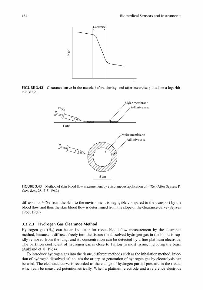
134 BiomedicalSensorsandInstruments
diffusion.of.133Xe.from.the.skin.to.the.environment.is.negligible.compared.to.the.transport.by.the.blood.flow,.and.thus.the.skin.blood.flow.is.determined.from.the.slope.of.the.clearance.curve.(Sejrsen.1968,.1969).
3.3.2.3 hydrogen gas Clearance MethodHydrogen. gas. (H2.). can. be. an. indicator. for. tissue. blood. flow. measurement. by. the. clearance.method,.because.it.diffuses.freely.into.the.tissue;.the.dissolved.hydrogen.gas.in.the.blood.is.rap-idly.removed.from.the.lung,.and.its.concentration.can.be.detected.by.a.fine.platinum.electrode..The.partition.coefficient.of.hydrogen.gas. is.close.to.1.mL/g.in.most. tissue,. including.the.brain.(Aukland.et al..1964).
To.introduce.hydrogen.gas.into.the.tissue,.different.methods.such.as.the.inhalation.method,.injec-tion.of.hydrogen.dissolved.saline.into.the.artery,.or.generation.of.hydrogen.gas.by.electrolysis.can.be.used..The.clearance.curve.is.recorded.as.the.change.of.hydrogen.partial.pressure.in.the.tissue,.which.can.be.measured.potentiometrically..When.a.platinum.electrode.and.a.reference.electrode.
Excercise
Log
c
t
figure 3.42 Clearance.curve.in.the.muscle.before,.during,.and.after.excercise.plotted.on.a.logarith-mic.scale.
Mylar membraneAdhesive area133Xe
Cutis
Adhesive areaMylar membrane
5 cm
figure 3.43 Method.of.skin.blood.flow.measurement.by.epicutaneous.application.of.133Xe..(After.Sejrsen,.P.,.Circ. Res.,.28,.215,.1969.)
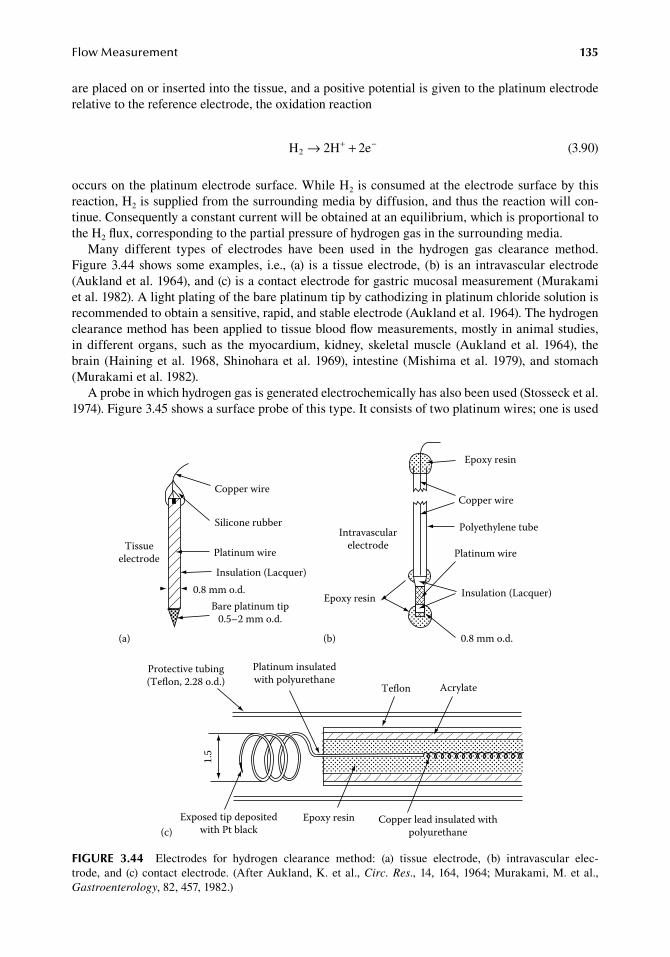
FlowMeasurement 135
are.placed.on.or.inserted.into.the.tissue,.and.a.positive.potential.is.given.to.the.platinum.electrode.relative.to.the.reference.electrode,.the.oxidation.reaction
. H 2H 2e2 → ++ −. (3.90)
occurs.on.the.platinum.electrode.surface..While.H2.is.consumed.at.the.electrode.surface.by.this.reaction,.H2.is.supplied.from.the.surrounding.media.by.diffusion,.and.thus.the.reaction.will.con-tinue..Consequently.a.constant.current.will.be.obtained.at.an.equilibrium,.which.is.proportional.to.the.H2.flux,.corresponding.to.the.partial.pressure.of.hydrogen.gas.in.the.surrounding.media.
Many. different. types. of. electrodes. have. been. used. in. the. hydrogen. gas. clearance. method..Figure.3.44.shows.some.examples,. i.e.,. (a). is.a. tissue.electrode,. (b). is.an. intravascular.electrode.(Aukland.et al..1964),.and.(c).is.a.contact.electrode.for.gastric.mucosal.measurement.(Murakami.et al..1982)..A.light.plating.of.the.bare.platinum.tip.by.cathodizing.in.platinum.chloride.solution.is.recommended.to.obtain.a.sensitive,.rapid,.and.stable.electrode.(Aukland.et al..1964)..The.hydrogen.clearance.method.has.been.applied.to.tissue.blood.flow.measurements,.mostly.in.animal.studies,.in.different.organs,. such.as. the.myocardium,.kidney,. skeletal.muscle. (Aukland.et al.. 1964),. the.brain. (Haining.et al..1968,.Shinohara.et al..1969),. intestine. (Mishima.et al..1979),.and.stomach.(Murakami.et al..1982).
A.probe.in.which.hydrogen.gas.is.generated.electrochemically.has.also.been.used.(Stosseck.et al..1974)..Figure.3.45.shows.a.surface.probe.of.this.type..It.consists.of.two.platinum.wires;.one.is.used.
Tissueelectrode
Copper wire
Silicone rubber
Platinum wire
Insulation (Lacquer)0.8 mm o.d.
Bare platinum tip0.5–2 mm o.d.
(a)
Intravascularelectrode
Epoxy resin
Copper wire
Polyethylene tube
Platinum wire
Insulation (Lacquer)Epoxy resin
0.8 mm o.d.(b)
Protective tubing(Teon, 2.28 o.d.)
Platinum insulatedwith polyurethane
Teon Acrylate
1.5
Exposed tip depositedwith Pt black
Epoxy resin Copper lead insulated withpolyurethane(c)
figure 3.44 Electrodes. for. hydrogen. clearance. method:. (a). tissue. electrode,. (b). intravascular. elec-trode,.and. (c).contact.electrode.. (After.Aukland,.K..et al.,.Circ. Res.,.14,.164,.1964;.Murakami,.M..et al.,.Gastroenterology,.82,.457,.1982.)
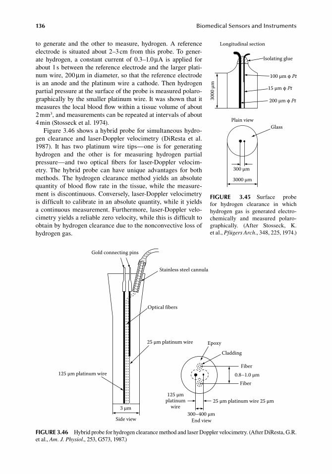
136 BiomedicalSensorsandInstruments
to. generate. and. the. other. to. measure,. hydrogen.. A. reference.electrode. is. situated.about.2–3.cm.from. this.probe..To.gener-ate. hydrogen,. a. constant. current. of. 0.3–1.0.μA. is. applied. for.about.1.s.between.the.reference.electrode.and.the.larger.plati-num.wire,.200.μm.in.diameter,.so.that.the.reference.electrode.is.an.anode.and. the.platinum.wire.a.cathode..Then.hydrogen.partial.pressure.at.the.surface.of.the.probe.is.measured.polaro-graphically.by.the.smaller.platinum.wire..It.was.shown.that.it.measures.the.local.blood.flow.within.a.tissue.volume.of.about.2.mm3,.and.measurements.can.be.repeated.at.intervals.of.about.4.min.(Stosseck.et al..1974).
Figure.3.46.shows.a.hybrid.probe.for.simultaneous.hydro-gen. clearance. and. laser-Doppler. velocimetry. (DiResta. et al..1987).. It. has. two. platinum. wire. tips—one. is. for. generating.hydrogen. and. the. other. is. for. measuring. hydrogen. partial.pressure—and. two. optical. fibers. for. laser-Doppler. velocim-etry.. The. hybrid. probe. can. have. unique. advantages. for. both.methods..The.hydrogen. clearance.method.yields. an. absolute.quantity.of.blood.flow. rate. in. the. tissue,.while. the.measure-ment.is.discontinuous..Conversely,.laser-Doppler.velocimetry.is.difficult.to.calibrate.in.an.absolute.quantity,.while.it.yields.a.continuous.measurement..Furthermore,. laser-Doppler.velo-cimetry.yields.a.reliable.zero.velocity,.while.this.is.difficult.to.obtain.by.hydrogen.clearance.due.to.the.nonconvective.loss.of.hydrogen.gas.
Plain viewGlass
Longitudinal section
Isolating glue
100 μm φ Pt
15 μm φ Pt
200 μm φ Pt
300 μm
3000 μm
3000
μm
figure 3.45 Surface. probe.for. hydrogen. clearance. in. which.hydrogen. gas. is. generated. electro-chemically. and. measured. polaro-graphically.. (After. Stosseck,. K..et al.,.Pfügers Arch.,.348,.225,.1974.)
Gold connecting pins
Stainless steel cannula
Optical fibers
25 μm platinum wire
25 μm platinum wire 25 μm
300–400 μm
125 μmplatinum
wire
125 μm platinum wire
3 μm
Side view
Epoxy
Cladding
Fiber
Fiber0.8–1.0 μm
End view
figure 3.46 Hybrid.probe.for.hydrogen.clearance.method.and.laser.Doppler.velocimetry..(After.DiResta,.G.R..et al.,.Am. J. Physiol.,.253,.G573,.1987.)
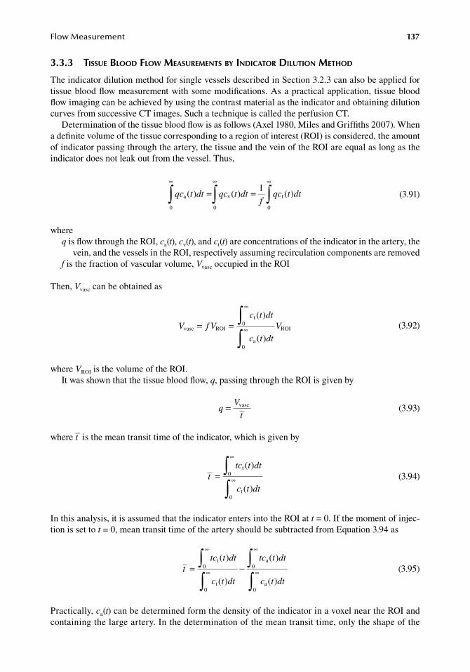
FlowMeasurement 137
3.3.3 tissue blood flow MeasureMents by indicator dilution Method
The.indicator.dilution.method.for.single.vessels.described.in.Section.3.2.3.can.also.be.applied.for.tissue.blood.flow.measurement.with.some.modifications..As.a.practical.application,. tissue.blood.flow.imaging.can.be.achieved.by.using.the.contrast.material.as.the.indicator.and.obtaining.dilution.curves.from.successive.CT.images..Such.a.technique.is.called.the.perfusion.CT.
Determination.of.the.tissue.blood.flow.is.as.follows.(Axel.1980,.Miles.and.Griffiths.2007)..When.a.definite.volume.of.the.tissue.corresponding.to.a.region.of.interest.(ROI).is.considered,.the.amount.of.indicator.passing.through.the.artery,.the.tissue.and.the.vein.of.the.ROI.are.equal.as.long.as.the.indicator.does.not.leak.out.from.the.vessel..Thus,
.
qc t dt qc t dtf
qc t dta v t( ) ( ) ( )= =∞ ∞ ∞
∫ ∫ ∫0 0 0
1
.
(3.91)
whereq.is.flow.through.the.ROI,.ca(t),.cv(t),.and.ct(t).are.concentrations.of.the.indicator.in.the.artery,.the.
vein,.and.the.vessels.in.the.ROI,.respectively.assuming.recirculation.components.are.removedf.is.the.fraction.of.vascular.volume,.Vvasc.occupied.in.the.ROI
Then,.Vvasc.can.be.obtained.as
.
V f Vc t dt
c t dtVvasc ROI
t0
a0
ROI
( )
( )= =
∞
∞∫∫ .
(3.92)
where.VROI.is.the.volume.of.the.ROI.It.was.shown.that.the.tissue.blood.flow,.q,.passing.through.the.ROI.is.given.by
.q
V
t= vasc
.(3.93)
where.t– is.the.mean.transit.time.of.the.indicator,.which.is.given.by
.
ttc t dt
c t dt=
∞
∞∫∫
t
t
0
0
( )
( ).
(3.94)
In.this.analysis,.it.is.assumed.that.the.indicator.enters.into.the.ROI.at.t.=.0..If.the.moment.of.injec-tion.is.set.to.t.=.0,.mean.transit.time.of.the.artery.should.be.subtracted.from.Equation.3.94.as
.
ttc t dt
c t dt
tc t dt
c t dt=
∞
∞
∞
∞∫∫
∫∫
t
t
a
a
0
0
0
0
( )
( )
( )
( )−
.
(3.95)
Practically,.ca(t).can.be.determined.form.the.density.of.the.indicator.in.a.voxel.near.the.ROI.and.containing.the.large.artery..In.the.determination.of.the.mean.transit.time,.only.the.shape.of.the.
138 BiomedicalSensorsandInstruments
dilution.curve. is. concerned.and. thus. the.amplitude. is.unaffected..Therefore,. it. is.unnecessary.that.the.artery.covers.the.whole.area.of.the.voxel..Consequently,.the.tissue.blood.flow,.q,.can.be.determined.by.Equations.3.92,.3.93,.and.3.95.
3.3.4 tissue blood flow MeasureMents by heat transport
When.a. region.of. the. tissue. is.heated.or.cooled,.continuously.or.step-wise,.heat. tranport.occurs.between.the.tissue.and.the.perfusing.blood,.and.the.tissue.blood.flow.can.be.estimated.from.the.amount.of.heat.transfer..For.the.perfusing.blood,.the.arteriores,.capillaries,.and.venules.act.as.per-fect.heat.exchangers,.in.which.the.blood.quickly.reaches.the.tissue.temperature.(Chato.1980).
The.rate.of.heat.transfer.from.the.tissue.of.temperature.Ts.and.the.arterial.blood.of.temperature.Ta.is.expressed.as
. H cq T T= −ρ ( )s a . (3.96)
whereρ.and.c.are.the.density.and.specific.heat.of.the.blood,.respectivelyq.is.tissue.blood.flow.rate
Thus.tissue.blood.flow.can.be.determined.from.the.rate.of.heat.transfer.when.a.constant.temperature.dif-ference.is.maintained.between.a.region.of.the.tissue.and.the.arterial.blood..In.steady.state,.when.the.tis-sue.is.heated.by.an.electric.heater.in.a.probe,.the.rate.of.heat.transfer.from.the.tissue.to.the.blood.is.equal.to.the.heat.applied.to.the.tissue.in.unit.time,.which.is.the.power.consumption.of.the.heater.in.the.probe.
Many.different.probes.utilizing.this.principle.have.been.tried.(Hensel.and.Ruef.1954,.Mowbray.1959,.Levy.et al..1967,.Adams.et al..1980)..For.blood.flow.measurements.in.a.small.region.of.the.tissue,.needle.type.probes.are.inserted.into.the.region..Figure.3.47.shows.examples.of.probes.of.this.type.(Adams.et al..1980)..On.the.other.hand,.contact.probes.are.used.for.skin.blood.flow.measure-ments,.some.of.which.are.shown.in.Figure.3.48.(Hensel.and.Bender.1956,.Hensel.1959,.Harding.et al..1967,.Holti.and.Mitchell.1979).
Experimental.evaluations.show.that.the.outputs.of.these.thermal.probes.are.linearly.related.to.tissue.blood.flows.measured.by.other.methods.such.as.the.venous.occlusion.method.(Hensel.and.Bender.1956),.the.isotope.clearance.method.(Tønnesen.1965),.or.a.direct.measurement.of.venous.flow.in.isolated.perfused.organs.(Grayson.1952).
Transient.operation.of.thermal.probes.has.been.studied.mainly.for.apparent.thermal.conductivity.measurement.in.living.tissues,.but.this.technique.also.provides.an.estimation.of.tissue.blood.flow,.because.the.apparent.thermal.conductivity.of.a.tissue.varies.with.the.tissue.blood.flow.rate..A.small.thermistor.bead.is.commonly.used.for.this.purpose..A.thermistor.bead.generates.heat.when.an.elec-tric.current.is.applied,.and.the.temperature.of.the.bead.can.be.measured.by.its.resistance.
3.3.5 tissue blood flow MeasureMent by laser doppler flowMetry
3.3.5.1 introductionLDF.is.a.method.for.the.continuous.and.noninvasive.measuring.of.the.tissue.blood.flow,.utilizing.the.Doppler.shift.of.laser.light.as.the.information.carrier..The.method.has.already.proved.its.poten-tial.usefulness.in.the.clinical.assessment.of.blood.flow.in.disciplines.such.as.dermatology,.plastic.surgery,.and.gastrointestinal.surgery..In.experimental.medicine,.LDF.has.been.used.in.the.study.of.spontaneous.rhythmical.variations.as.well.as.in.the.study.of.spatial.and.temporal.fluctuations.in.human.skin.blood.flow..The.method.has.facilitated.further.investigations.of.the.nature.of.blood.flow.in.a.variety.of.tissue.types..The.method.is.rapidly.spreading.to.many.new.applications.in.microvas-cular.blood.flow.measurements..Several.commercial.laser-Doppler.instruments.are.available..This.chapter.is.a.presentation.on.the.theory.and.practice.of.LDF.
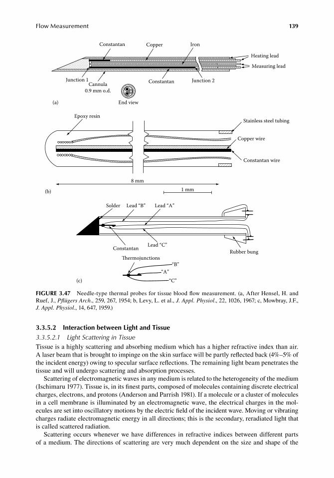
FlowMeasurement 139
3.3.5.2 interaction between light and tissue3.3.5.2.1 Light Scattering in TissueTissue.is.a.highly.scattering.and.absorbing.medium.which.has.a.higher.refractive.index.than.air..A.laser.beam.that.is.brought.to.impinge.on.the.skin.surface.will.be.partly.reflected.back.(4%–5%.of.the.incident.energy).owing.to.specular.surface.reflections..The.remaining.light.beam.penetrates.the.tissue.and.will.undergo.scattering.and.absorption.processes.
Scattering.of.electromagnetic.waves.in.any.medium.is.related.to.the.heterogeneity.of.the.medium.(Ischimaru.1977)..Tissue.is,.in.its.finest.parts,.composed.of.molecules.containing.discrete.electrical.charges,.electrons,.and.protons.(Anderson.and.Parrish.1981)..If.a.molecule.or.a.cluster.of.molecules.in.a.cell.membrane.is.illuminated.by.an.electromagnetic.wave,.the.electrical.charges.in.the.mol-ecules.are.set.into.oscillatory.motions.by.the.electric.field.of.the.incident.wave..Moving.or.vibrating.charges.radiate.electromagnetic.energy.in.all.directions;.this.is.the.secondary,.reradiated.light.that.is.called.scattered.radiation.
Scattering.occurs.whenever.we.have.differences. in. refractive. indices.between.different. parts.of.a.medium..The.directions.of.scattering.are.very.much.dependent.on.the.size.and.shape.of.the.
Rubber bung
Solder Lead “B” Lead “A”
Lead “C”Constantan
ermojunctions
“A”“B”
“C”(c)
1 mm8 mm
Stainless steel tubing
Copper wire
Constantan wire
Epoxy resin
(b)
Heating lead
Measuring lead
Iron
Junction 2Junction 1Cannula
0.9 mm o.d.
Constantan
Constantan
End view
Copper
(a)
figure 3.47 Needle-type.thermal.probes.for.tissue.blood.flow.measurement..(a,.After.Hensel,.H..and.Ruef,.J.,.Pflügers Arch.,.259,.267,.1954;.b,.Levy,.L..et al.,.J. Appl. Physiol.,.22,.1026,.1967;.c,.Mowbray,.J.F.,.J. Appl. Physiol.,.14,.647,.1959.)
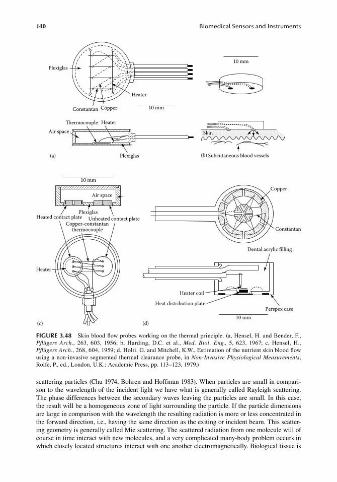
140 BiomedicalSensorsandInstruments
scattering.particles.(Chu.1974,.Bohren.and.Hoffman.1983)..When.particles.are.small.in.compari-son.to.the.wavelength.of. the.incident. light.we.have.what. is.generally.called.Rayleigh.scattering..The.phase.differences.between.the.secondary.waves.leaving.the.particles.are.small..In.this.case,.the.result.will.be.a.homogeneous.zone.of.light.surrounding.the.particle..If.the.particle.dimensions.are large.in.comparison.with.the.wavelength.the.resulting.radiation.is.more.or.less.concentrated.in.the.forward.direction,.i.e.,.having.the.same.direction.as.the.exiting.or.incident.beam..This.scatter-ing.geometry.is.generally.called.Mie.scattering..The.scattered.radiation.from.one.molecule.will.of.course.in.time.interact.with.new.molecules,.and.a.very.complicated.many-body.problem.occurs.in.which.closely.located.structures.interact.with.one.another.electromagnetically..Biological.tissue.is.
Air space
Heater
PlexiglasHeated contact plate
Copper-constantanthermocouple
Unheated contact plate
10 mm
(c)10 mm
Heater coil
Heat distribution platePerspex case
Dental acrylic lling
Copper
Constantan
(d)
10 mm
Heater
Plexiglas
Constantan Copper
ermocouple HeaterAir space
Plexiglas(a) Subcutaneous blood vessels(b)
10 mm
Skin
figure 3.48 Skin.blood.flow.probes.working.on.the.thermal.principle..(a,.Hensel,.H..and.Bender,.F.,.Pflügers Arch.,. 263,. 603,. 1956;. b,. Harding,. D.C.. et al.,. Med. Biol. Eng.,. 5,. 623,. 1967;. c,. Hensel,. H.,.Pflügers Arch.,.268,.604,.1959;.d,.Holti, G..and.Mitchell,.K.W.,.Estimation.of.the.nutrient.skin.blood.flow.using.a.non-invasive. segmented. thermal. clearance.probe,. in.Non-Invasive Physiological Measurements,.Rolfe,.P.,.ed.,.London,.U.K.:.Academic.Press,.pp..113–123,.1979.)
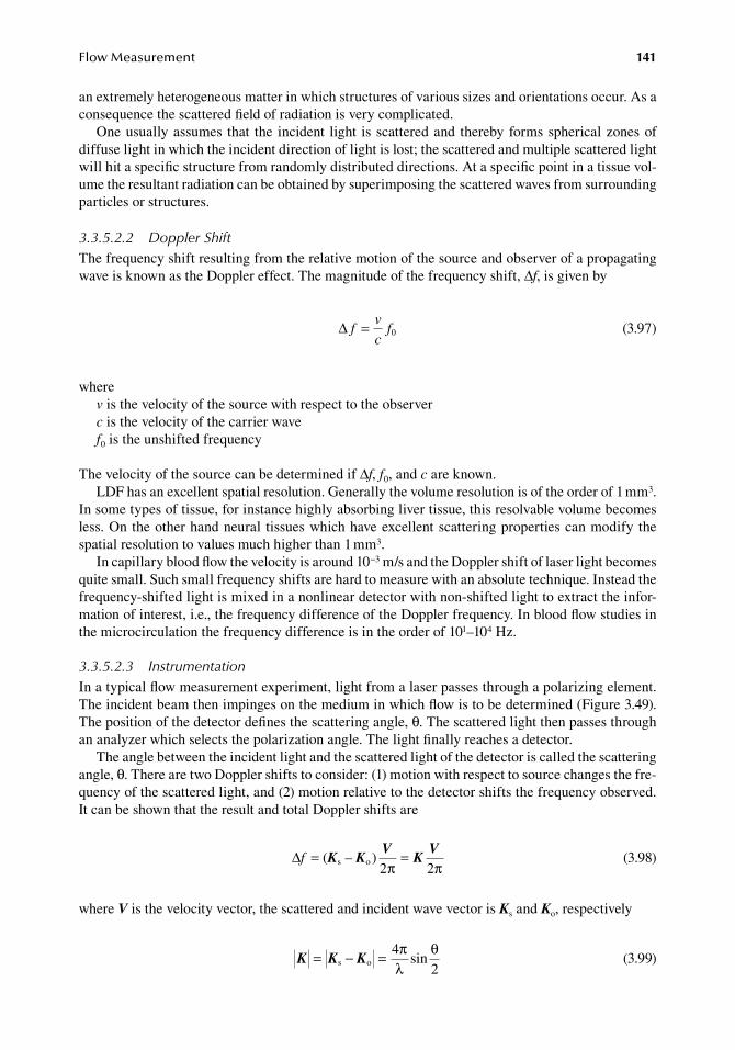
FlowMeasurement 141
an.extremely.heterogeneous.matter.in.which.structures.of.various.sizes.and.orientations.occur..As.a.consequence.the.scattered.field.of.radiation.is.very.complicated.
One.usually.assumes. that. the. incident. light. is.scattered.and. thereby.forms.spherical.zones.of.diffuse.light.in.which.the.incident.direction.of.light.is.lost;.the.scattered.and.multiple.scattered.light.will.hit.a.specific.structure.from.randomly.distributed.directions..At.a.specific.point.in.a.tissue.vol-ume.the.resultant.radiation.can.be.obtained.by.superimposing.the.scattered.waves.from.surrounding.particles.or.structures.
3.3.5.2.2 Doppler ShiftThe.frequency.shift.resulting.from.the.relative.motion.of.the.source.and.observer.of.a.propagating.wave.is.known.as.the.Doppler.effect..The.magnitude.of.the.frequency.shift,.Δf,.is.given.by
.∆ f
v
cf= 0
.(3.97)
wherev.is.the.velocity.of.the.source.with.respect.to.the.observerc.is.the.velocity.of.the.carrier.wavef0.is.the.unshifted.frequency
The.velocity.of.the.source.can.be.determined.if.Δf,.f0,.and.c.are.known.LDF.has.an.excellent.spatial.resolution..Generally.the.volume.resolution.is.of.the.order.of.1.mm3..
In.some.types.of.tissue,.for.instance.highly.absorbing.liver.tissue,.this.resolvable.volume.becomes.less..On.the.other.hand.neural. tissues.which.have.excellent.scattering.properties.can.modify.the.spatial.resolution.to.values.much.higher.than.1.mm3.
In.capillary.blood.flow.the.velocity.is.around.10−3.m/s.and.the.Doppler.shift.of.laser.light.becomes.quite.small..Such.small.frequency.shifts.are.hard.to.measure.with.an.absolute.technique..Instead.the.frequency-shifted.light.is.mixed.in.a.nonlinear.detector.with.non-shifted.light.to.extract.the.infor-mation.of.interest,.i.e.,.the.frequency.difference.of.the.Doppler.frequency..In.blood.flow.studies.in.the.microcirculation.the.frequency.difference.is.in.the.order.of.101–104.Hz.
3.3.5.2.3 InstrumentationIn.a.typical.flow.measurement.experiment,.light.from.a.laser.passes.through.a.polarizing.element..The.incident.beam.then.impinges.on.the.medium.in.which.flow.is.to.be.determined.(Figure.3.49)..The.position.of.the.detector.defines.the.scattering.angle,.θ..The.scattered.light.then.passes.through.an.analyzer.which.selects.the.polarization.angle..The.light.finally.reaches.a.detector.
The.angle.between.the.incident.light.and.the.scattered.light.of.the.detector.is.called.the.scattering.angle,.θ..There.are.two.Doppler.shifts.to.consider:.(1).motion.with.respect.to.source.changes.the.fre-quency.of.the.scattered.light,.and.(2).motion.relative.to.the.detector.shifts.the.frequency.observed..It.can.be.shown.that.the.result.and.total.Doppler.shifts.are
.∆f = =( )
2s oK K
VKV
–2π π .
(3.98)
where.V.is.the.velocity.vector,.the.scattered.and.incident.wave.vector.is.Ks.and.Ko,.respectively
.K = − =K Ks o
4sin
2π
λθ
.(3.99)
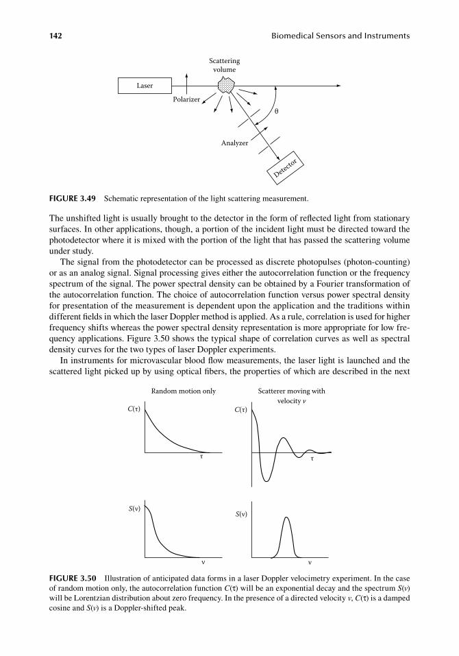
142 BiomedicalSensorsandInstruments
The.unshifted.light.is.usually.brought.to.the.detector.in.the.form.of.reflected.light.from.stationary.surfaces..In.other.applications,.though,.a.portion.of.the.incident.light.must.be.directed.toward.the.photodetector.where.it.is.mixed.with.the.portion.of.the.light.that.has.passed.the.scattering.volume.under.study.
The.signal.from.the.photodetector.can.be.processed.as.discrete.photopulses.(photon-counting).or.as.an.analog.signal..Signal.processing.gives.either.the.autocorrelation.function.or.the.frequency.spectrum.of.the.signal..The.power.spectral.density.can.be.obtained.by.a.Fourier.transformation.of.the.autocorrelation.function..The.choice.of.autocorrelation.function.versus.power.spectral.density.for.presentation.of.the.measurement.is.dependent.upon.the.application.and.the.traditions.within.different.fields.in.which.the.laser.Doppler.method.is.applied..As.a.rule,.correlation.is.used.for.higher.frequency.shifts.whereas.the.power.spectral.density.representation.is.more.appropriate.for.low.fre-quency.applications..Figure.3.50.shows.the.typical.shape.of.correlation.curves.as.well.as.spectral.density.curves.for.the.two.types.of.laser.Doppler.experiments.
In.instruments.for.microvascular.blood.flow.measurements,.the.laser.light.is.launched.and.the.scattered.light.picked.up.by.using.optical.fibers,.the.properties.of.which.are.described.in.the.next.
Random motion only
S(ν)
C(τ) C(τ)
τ τ
S(ν)
νν
Scatterer moving withvelocity v
figure 3.50 Illustration.of.anticipated.data.forms.in.a.laser.Doppler.velocimetry.experiment..In.the.case.of.random.motion.only,.the.autocorrelation.function.C(τ).will.be.an.exponential.decay.and.the.spectrum.S(v).will.be.Lorentzian.distribution.about.zero.frequency..In.the.presence.of.a.directed.velocity.v,.C(τ).is.a.damped.cosine.and.S(v).is.a.Doppler-shifted.peak.
Laser
Polarizer
Analyzer
θ
Scatteringvolume
Detector
figure 3.49 Schematic.representation.of.the.light.scattering.measurement.
FlowMeasurement 143
paragraph.of.this.chapter..A.more.detailed.presentation.of.the.physics.of.LDF.(light.scattering.in.tissue,.photon.diffusion.and.models.for.the.interaction.between.light.and.tissue,.etc.).can.be.studied.in.numerous.books.(Chu.1974).and.articles.(Yeh.and.Cummins.1964,.Johnson.1970,.Twersky.1970,.Nilsson.et al..1980a,.Bonner.and.Nossal.1981,.Nossal.1982,.Duteil.et al..1985,.Stern.1985,.Bonner.et al..1987,.Khan.et al..1987,.Maret.and.Wolf.1987,.Steinke.and.Shepherd.1988).
3.3.5.3 instrument design Principles3.3.5.3.1 Light SourcesIn.most.laser.Doppler.flowmeter.instruments.designed.during.the.early.years,.the.gas.laser.has.been.the.light.source.of.choice..This.laser.type.is.cheap,.easy.to.use,.reliable,.and.has.reasonable.stabil-ity..In.several.recent.constructions,.the.semiconductor.laser.diode.has.been.used.as.an.interesting.alternative.light.source.(de.Mul.et al..1984,.Kolari.1984,.Haumschild.1986,.Pettersson.et al..1989).
The.helium–neon.laser.has.been.used.extensively.in.LDF..It.is.beyond.the.scope.of.this.chapter.to.discuss.basic.laser.physics.but.readers.interested.in.this.topic.are.referred.to.Shimoda.(1984),.Young.(1984),.Yariv.(1985),.and.Chu.(1974).or.other.specialized.textbooks.
In. more. recently. designed. instruments,. the. laser. diode. has. been. the. light. source. of. choice.because.of.its.low.price.and.convenience.in.circuit.design..Semiconductor.laser.diodes.have.been.used.successfully.in.LDF.by.several.groups.(de.Mul.et al..1984,.Kolari.1984,.Haumschild.1986,.Pettersson.et al..1989)..Several.commercially.available. instruments.utilize. laser.diodes.at.wave-lengths.around.800.nm..The.main.advantage.of.the.laser.diode.is.related.to.its.physical.size.and.energy.supply..The.diode.is.very.small.in.comparison.with.gas.lasers.and.can.be.housed.in.small.probes.near.the.skin..In.some.applications,.fiber.optics.can.be.entirely.eliminated.(de.Mul.et al..1984)..High.voltage.power.supplies.necessary.for.gas.lasers.can.be.eliminated.because.a.laser.diode.can.be.fed.from.a.low.voltage.source..The.laser.diodes.designed.for.use.in.CD-disc.players.and.for.communication.purposes.are.low-priced.compared.with.gas.lasers..The.disadvantage.of.the.diode.laser.for.laser.Doppler.work.is.the.limited.coherence.length.as.well.as.the.divergence.of.the.emitted.light.beam..The.need.for.careful.temperature.stabilization.to.avoid.instability.is.another..Temperature.variations.will.induce.a.wavelength.drift.at.a.rate.of.0.23.nm/K..Variations.in.tem-perature.will.result.in.mode.jumps,.i.e.,.jumps.in.frequency,.a.devastating.condition.in.any.type.of.laser.Doppler.application.
3.3.5.3.2 Light DetectorsThe.photomultiplier.is.a.photodetector.with.inherent.high.current.gain.and.low.noise..It.can.be.used.to.detect.power.levels.as.low.as.10−19.W.(Engström.1947)..Photomultipliers.have.been.extensively.used.in.the.analysis.of.scattered.laser.light..Chu.(1974).has.conducted.a.survey.of.the.technical.fac-tors.necessary.to.take.into.account.when.choosing.and.operating.photomultipliers.
Semiconductor.diodes.are.the.most.common.type.of.photodetector.for.laser.Doppler.flowmeter.applications..The.p–n.and.p–i–n.diodes.basically.utilize.the.same.physical.mechanism.as.that.of.the.p–n.junction..An.incoming.photon.is.absorbed.and.generates.a.hole.and.a.free.electron.both.of.which.will.drift.across.the.p–n.junction.under.the.influence.of.an.externally.applied.electric.field.
The.p–i–n.diode.has.an.intrinsic.(pure).high.resistivity.layer.which.is.sandwiched.between.the.p.and.n.regions..The.intrinsic.layer.decreases.the.diffusion.time.and.thus.the.response.time.of.the.diode..The.p–i–n.diode.has.so.far.been.the.most.popular.in.laser.Doppler.works,.e.g.,.the.UDT.450.(UDT.Sensors,.Hawthorne,.CA),.the.HP.2-4203.(Hewlett.Packard,.San.Jose,.CA).and.the.Philips.diode.BPX.40.(Phillips,.Eindhoven,.the.Netherlands)..An.alternative.to.the.UDT.450.is.the.HUV.1000B.from.Hamamatsu.Corp..(Hamamatsu,.Japan)..The.diodes.have.been.used.in.the.conventional.way.following.the.recommendations.of.the.manufacturers..Kajiya.et al..(1981).have.used.avalanche.diodes.(PF-1005,.Mitsubishi,.Tokyo).in.their.system.for.blood.flow.measurements.in.the.coronary.and.femoral.arteries..Their.motivation.for.using.an.avalanche.diode.is.the.high.signal-to-noise.ratio.that.is.obtained.at.low.signal.levels.(∼1.μW).
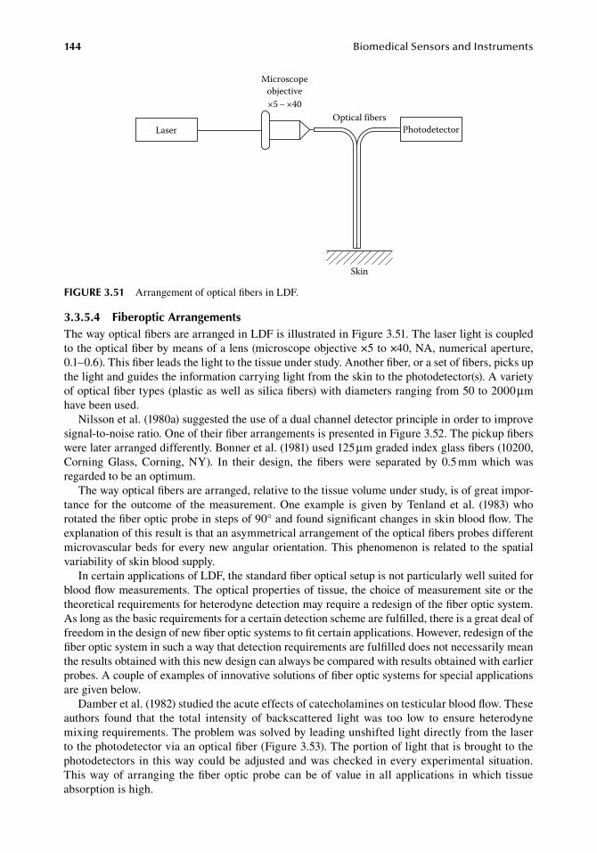
144 BiomedicalSensorsandInstruments
3.3.5.4 fiberoptic arrangementsThe.way.optical.fibers.are.arranged.in.LDF.is.illustrated.in.Figure.3.51..The.laser.light.is.coupled.to.the.optical.fiber.by.means.of.a.lens.(microscope.objective.×5.to.×40,.NA,.numerical.aperture,.0.1–0.6)..This.fiber.leads.the.light.to.the.tissue.under.study..Another.fiber,.or.a.set.of.fibers,.picks.up.the.light.and.guides.the.information.carrying.light.from.the.skin.to.the.photodetector(s)..A.variety.of.optical.fiber.types.(plastic.as.well.as.silica.fibers).with.diameters.ranging.from.50.to.2000.μm.have.been.used.
Nilsson.et al..(1980a).suggested.the.use.of.a.dual.channel.detector.principle.in.order.to.improve.signal-to-noise.ratio..One.of.their.fiber.arrangements.is.presented.in.Figure.3.52..The.pickup.fibers.were.later.arranged.differently..Bonner.et al..(1981).used.125.μm.graded.index.glass.fibers.(10200,.Corning. Glass,. Corning,. NY).. In. their. design,. the. fibers. were. separated. by. 0.5.mm. which. was.regarded.to.be.an.optimum.
The.way.optical.fibers.are.arranged,.relative.to.the.tissue.volume.under.study,.is.of.great.impor-tance. for. the.outcome.of. the.measurement..One. example. is. given.by.Tenland. et al.. (1983).who.rotated.the.fiber.optic.probe.in.steps.of.90°.and.found.significant.changes.in.skin.blood.flow..The.explanation.of.this.result.is.that.an.asymmetrical.arrangement.of.the.optical.fibers.probes.different.microvascular.beds.for.every.new.angular.orientation..This.phenomenon.is.related.to.the.spatial.variability.of.skin.blood.supply.
In.certain.applications.of.LDF,.the.standard.fiber.optical.setup.is.not.particularly.well.suited.for.blood.flow.measurements..The.optical.properties.of.tissue,.the.choice.of.measurement.site.or.the.theoretical.requirements.for.heterodyne.detection.may.require.a.redesign.of.the.fiber.optic.system..As.long.as.the.basic.requirements.for.a.certain.detection.scheme.are.fulfilled,.there.is.a.great.deal.of.freedom.in.the.design.of.new.fiber.optic.systems.to.fit.certain.applications..However,.redesign.of.the.fiber.optic.system.in.such.a.way.that.detection.requirements.are.fulfilled.does.not.necessarily.mean.the.results.obtained.with.this.new.design.can.always.be.compared.with.results.obtained.with.earlier.probes..A.couple.of.examples.of.innovative.solutions.of.fiber.optic.systems.for.special.applications.are.given.below.
Damber.et al..(1982).studied.the.acute.effects.of.catecholamines.on.testicular.blood.flow..These.authors. found. that. the. total. intensity. of. backscattered. light. was. too. low. to. ensure. heterodyne.mixing.requirements..The.problem.was.solved.by.leading.unshifted.light.directly.from.the.laser.to.the.photodetector.via.an.optical.fiber.(Figure.3.53)..The.portion.of.light.that.is.brought.to.the.photodetectors. in. this.way.could.be.adjusted.and.was.checked. in.every.experimental.situation..This.way.of.arranging. the.fiber.optic.probe.can.be.of.value. in.all.applications. in.which. tissue.absorption.is.high.
Laser
Microscopeobjective×5 – ×40
Optical fibersPhotodetector
Skin
figure 3.51 Arrangement.of.optical.fibers.in.LDF.
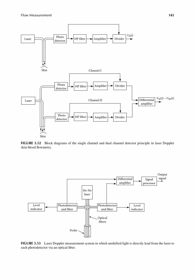
FlowMeasurement 145
Laser Photodetector
Photodetector
Skin
Skin
Photodetector
HP filter
HP filter
HP filter
Laser
Amplifier
Amplifier
Amplifier
DividerV0(t)
Divider
Channel I
Channel II
Divider
Differentialamplifier
V0I(t) – V0II(t)
figure 3.52 Block.diagrams.of.the.single.channel.and.dual.channel.detector.principle.in.laser.Doppler.skin.blood.flowmetry.
Differentialamplifier
Signalprocessor
Levelindicator
Outputsignal
He-Nelaser
Levelindicator
Photodetectorand filter
Opticalfibers
Probe
Photodetectorand filter
figure 3.53 Laser.Doppler.measurement.system.in.which.unshifted.light.is.directly.lead.from.the.laser.to.each.photodetector.via.an.optical.fiber.
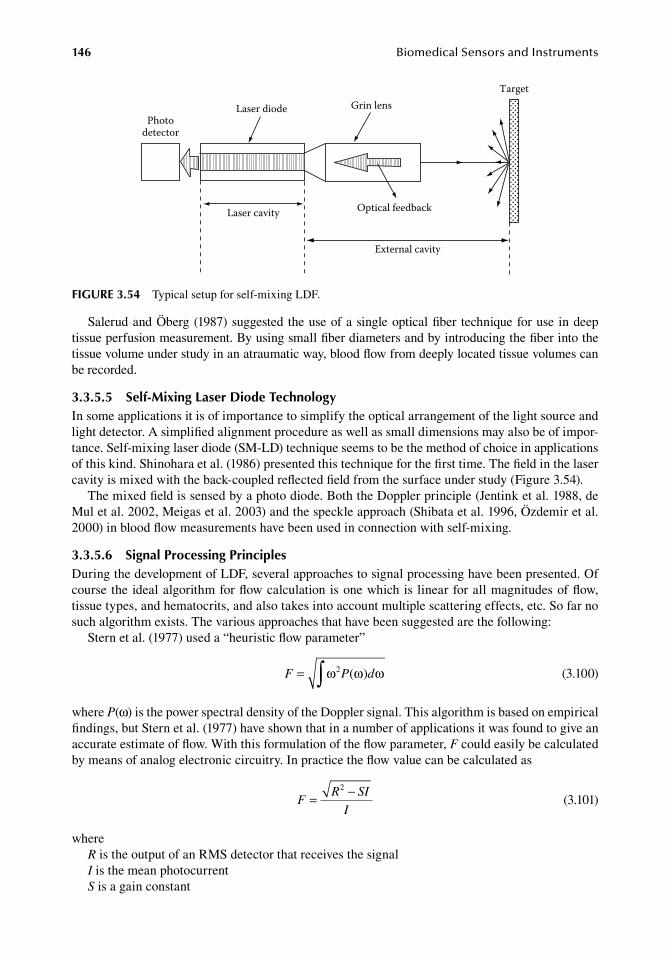
146 BiomedicalSensorsandInstruments
Salerud.and.Öberg.(1987).suggested. the.use.of.a.single.optical.fiber. technique.for.use. in.deep.tissue.perfusion.measurement..By.using.small.fiber.diameters.and.by.introducing.the.fiber.into.the.tissue.volume.under.study.in.an.atraumatic.way,.blood.flow.from.deeply.located.tissue.volumes.can.be.recorded.
3.3.5.5 Self-Mixing laser diode technologyIn.some.applications.it.is.of.importance.to.simplify.the.optical.arrangement.of.the.light.source.and.light.detector..A.simplified.alignment.procedure.as.well.as.small.dimensions.may.also.be.of.impor-tance..Self-mixing.laser.diode.(SM-LD).technique.seems.to.be.the.method.of.choice.in.applications.of.this.kind..Shinohara.et al..(1986).presented.this.technique.for.the.first.time..The.field.in.the.laser.cavity.is.mixed.with.the.back-coupled.reflected.field.from.the.surface.under.study.(Figure.3.54).
The.mixed.field.is.sensed.by.a.photo.diode..Both.the.Doppler.principle.(Jentink.et al..1988,.de.Mul.et al..2002,.Meigas.et al..2003).and.the.speckle.approach.(Shibata.et al..1996,.Özdemir.et al..2000).in.blood.flow.measurements.have.been.used.in.connection.with.self-mixing.
3.3.5.6 Signal Processing PrinciplesDuring.the.development.of.LDF,.several.approaches.to.signal.processing.have.been.presented..Of.course.the.ideal.algorithm.for.flow.calculation.is.one.which.is. linear.for.all.magnitudes.of.flow,.tissue.types,.and.hematocrits,.and.also.takes.into.account.multiple.scattering.effects,.etc..So.far.no.such.algorithm.exists..The.various.approaches.that.have.been.suggested.are.the.following:
Stern.et al..(1977).used.a.“heuristic.flow.parameter”
.F P d= ∫ω ω ω2 ( )
.(3.100)
where.P(ω).is.the.power.spectral.density.of.the.Doppler.signal..This.algorithm.is.based.on.empirical.findings,.but.Stern.et al..(1977).have.shown.that.in.a.number.of.applications.it.was.found.to.give.an.accurate.estimate.of.flow..With.this.formulation.of.the.flow.parameter,.F.could.easily.be.calculated.by.means.of.analog.electronic.circuitry..In.practice.the.flow.value.can.be.calculated.as
.F
R SI
I= −2
.(3.101)
whereR.is.the.output.of.an.RMS.detector.that.receives.the.signalI.is.the.mean.photocurrentS.is.a.gain.constant
Laser diode Grin lens
Laser cavity
External cavity
Optical feedback
Photodetector
Target
figure 3.54 Typical.setup.for.self-mixing.LDF.
FlowMeasurement 147
Normalization.with.respect.to.the.photocurrent.serves.to.make.the.flow.parameter.independent.of.the.laser.intensity.and.total.reflectivity.of.the.tissue.
Bonner.and.Nossal.(1981).developed.a.mathematical.model.for.laser.Doppler.measurement.of.blood.flow.in.tissue..Their.model.is.based.on.the.following.assumptions..The.scattering.cross.section.for.particles.of.the.size.of.a.blood.cell.is.sharply.peaked.in.the.forward.direction.(Mie.scattering)..The.radiation.in.a.tissue.matrix.of.this.kind.mostly.contains.photons.which.have.been.scattered.at.least.once.by.surrounding.tissue.elements..A.small.percentage.of. the.back-scattered. light.comes.from.photons.scattered.only.by.moving.blood.cells..Such.a.complex.tissue.matrix.cannot.generally.be.characterized.in.detail..As.long.as.the.tissue.scattering.cross.section.is.much.greater.than.that.of.the.moving.cells,.a.model.can.be.designed.which.can.be.of.guidance.in.instrument.construction.
In.a.tissue.matrix,.photons.generally.suffer.several.collisions.before.they.interact.with.a.blood.cell,.which.means. that. the.direction.of. light.will.be. randomized.before. the.collision.between.a.photon.and.a.moving.blood.cell.occurs..The.same.authors.(Bonner.and.Nossal.1981).showed.that.the.normalized.first.moment.of. the.spectrum,.⟨ω⟩,. is.proportional. to. the.RMS.speed.of.moving.particles.⟨ ⟩V 2 1 2/ .as
.⟨ ⟩ ⟨ ⟩ω
ξβ= V
af m
2 1/2
1/ 2(12( )
) •
.(3.102)
wherea.is.the.radius.of.an.average.spherical.scattererξ.is.an.empirical.factor.related.to.the.shape.of.the.cellβ.an.instrumental.factor,.namely.the.optical.coherence.of.the.signal.at.the.detector.surfacem– is.the.average.number.of.collisions.which.a.detected.photon.makes.with.a.moving.cellf(m–).is.a.function.of.the.hematocrit.of.the.blood.in.the.tissue.and.is.linear.if.m–.«.1.(low.hematocrits)
In.experiments.with.a.flow.model. system.built.of.hollow.silicon.fibers. surrounded.by.a. scatter-ing.medium,.these.authors.could.demonstrate.that.the.Doppler.shift.varied.linearly.with.the.mean.velocity.of.the.flowing.cells..Nilsson.et al..(1980b).independently.came.to.a.similar.conclusion.con-cerning.the.algorithm.using.a.more.experimental.approach.
So,.for.low.and.moderate.red.cell.volume.fractions,.the.first.moment.of.the.power.spectral.den-sity.is.approximately.proportional.to.the.flux.of.red.blood.cells..However,.for.higher.hematocrits,.this.algorithm.underestimates.the.flux..Ahn.et al..(1987).have.evaluated.the.first.moment.algorithm.in.experiments.on.an.isolated.part.of.the.feline.small.intestine.which.was.perfused.by.a.controlled.blood.supply.from.the.superior.mesenteric.artery..Their.conclusion.was.that.the.first.moment-type.of. signal.processor. (not. linearized). seriously.underestimated. the.flow.at.higher.flow.rates. (>100..mL/min.·.100.g.tissue).
3.3.5.7 Calibration and Standardization of laser doppler flowmeters3.3.5.7.1 CalibrationsMost. measurement. methods. need. to. be. calibrated. at. regular. intervals. by. comparing. them. with.a.standard. to.maintain.accuracy.over. longer.periods.of. time..The.standard.usually.has.a.well-specified.accuracy.and.long-term.stability..An.instrument.under.calibration.is.adjusted.to.give.read-ings.coinciding.with. the. setting.of. the. standard..An.alternative.way. is. to.make.up.a.calibration.curve,.i.e.,.a.diagram.describing.the.difference.between.the.“true”.value.(standard).and.the.reading.of. the. instrument.under.calibration..The.calibration.curve. is. then.used. for.correcting. the.actual.measurements.obtained.with.the.instrument.
It.is.not.possible.to.perform.such.calibrations.with.laser.Doppler.instruments,.simply.because.there. is. no. “gold. standard”. for. measuring. blood. flow. in. tissue.. Nevertheless,. the. laser. Doppler.
148 BiomedicalSensorsandInstruments
method.has.been.compared.with.a.variety.of.other.methods..Such.calibrations.cannot.generally.be.regarded.as.“comparisons”.since.the.other.flow.measurements.have.unspecified.accuracies.or.even.measure.a.different.physiological.variable.related.to.the.flux.of.red.blood.cells,.but.comparisons.of.this.type.can.give.useful.information.in.a.specific.experiment.or.preparation.
Some. examples. of. such. comparisons. are. given. below:. comparisons. with. the. xenon. isotope.technique.have.been.performed.by.Holloway.(1980),.Kastrup.et al.. (1987),.Neufeld.et al.. (1988),.Engelhart.and.Kristensen.(1983),.Nicholson.et al..(1985),.and.Engelhart.et al..(1988)..Radioactive.microspheres.for.blood.flow.measurements.have.been.studied.in.rabbits.by.Eyre.et al..(1988).and.Matsen.et al..(1984).used.an.ischemic.human.model.to.compare.transcutaneous.pO2.with.the.LDF..Kvietys. et al.. (1985).have.compared.LDF,.hydrogen.clearance,. and.microspheres. in. cat.models..Sundberg.and.Castrén.(1986).used.drug-.and.temperature-induced.changes.in.peripheral.circulation.to.compare.LDF.and.digital-pulse.plethysmography.
These. types. of. evaluations. and. comparisons. give,. in. general,. a. more. or. less. linear. relation.between.the.laser.Doppler.method.and.some.other.method.if.the.flow.and.local.hematocrit.does.not.reach.extreme.values..Each.relation.depends.on.the.specific.organs.and.sites.used..The.correlation.coefficient.can.vary.between.different.measurement.sites.in.one.and.the.same.organ.
3.3.5.7.2 StandardizationTo.standardize.an.instrument.or.a.method.is.to.make.sure.it.maintains.stability,.linearity,.and.repro-ducibility..However,.such.standardization.does.not.mean.that.an.absolute.value.of.flow.is.achievable..Several.methods.have.been.suggested.for.the.standardization.of.laser.Doppler.instruments.
Several.authors.(Nilsson.et al..1980b,.de.Mul.et al..1984,.Shepherd.et al..1987,.Jentink.et al..1988,.Öberg.1988).have.designed.rotating.discs.for.the.standardization.of.laser.Doppler.instruments.
The. Brownian. motion. of. particles. in. a. suspension. can. be. used. to. standardize. laser. Doppler.instruments..For. short. term.use. (≈1–2.h),.ordinary.milk.can.be.used..For. standardization.during.longer.periods.(≈2–3.months),.it.is.important.to.use.a.suspension.that.is.not.affected.by.sedimenta-tion.or.particle.aggregation.
A.variety.of.mechanical.flow.models.have.been.described.in.the.laser.Doppler.literature.(Stern.et al..1977,.Roman.and.Smits.1986,.Smits.et al..1986,.Shepherd.et al..1987)..Although.most.of.them.were.originally.used.for.the.study.of.the.principles.of.LDF,.they.can.all.be.of.great.value.for.stan-dardizing.or.calibrating.laser.Doppler.flowmeters..They.all.seem.to.give.similar.results.when.effects.of.variations.of.hematocrit,.average.velocity,.and.volume.flow.are.studied.
The.laser-Doppler.method.has.been.used.in.a.great.variety.of.applications.in.medicine.and.biol-ogy..It.is.beyond.the.scope.of.this.chapter.to.present.the.way.in.which.the.laser.Doppler.principle.has.been.applied.to.the.various.problems..The.reader.is.referred.to.Shepherd.and.Öberg.(1990).or.Öberg.(1990).for.a.review..The.bibliography.presented.by.Perimed.Reference.List.(1988).also.gives.an.extensive.presentation.of.the.various.applications.
Since.1997.when.the.first.edition.of.this.book.was.released.several.thousands.of.scientific.papers.and.a.few.textbooks.have.been.published.in.the.field.of.LDF..A.variety.of.biomedical.and.clinical.applications.have.been.covered..It.is.beyond.the.scope.of.this.book.to.cover.this.literature.in.detail..The.reader.is.referred,.among.others,.to.the.following.publications:.Belcaro.et al..(1994),.de.Mul.et al..(1995),.Leahy.et al..(1999),.Perimed.Reference.list.(2001).
3.3.5.8 laser doppler Perfusion imagingLDF.is.usually.applied.to.single.point.measurements.in.a.tissue.volume..The.volume.monitored.is.small.(in.the.order.of.1.mm3)..The.spatial.variability.(Tenland.et al..1983,.Shepherd.et al..1987).for.microvascular.blood.perfusion.can.be.very.high.in.some.tissue.types..The.combination.of.small.monitoring.volumes.and.high.spatial.heterogeneity.of.flow.can. lead. to. serious.misinterpretation.of.the.actual.flow..In.some.applications.a.variant.of.the.laser.Doppler.method.that.can.give.spatial.information.about.the.flow.that.is.preferred.
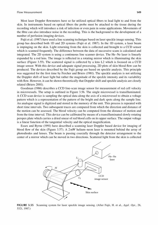
FlowMeasurement 149
Most.laser.Doppler.flowmeters.have.so.far.utilized.optical.fibers.to.lead.light.to.and.from.the.skin.. In. instruments.based.on.optical.fibers. the.probe.must.be.attached. to. the. tissue.during. the.recording.which.will.introduce.a.risk.of.infection.or.even.pain.in.some.applications..Movements.of.the.fibre.can.also.introduce.noise.in.the.recording..This.is.the.background.to.the.development.of.a.number.of.perfusion.imaging.devices.
Fujii.et al..(1987).have.used.a.line.scanning.technique.based.on.laser.speckle.image.sensing..This.group.has.described.both.1D.and.2D.systems.(Fujii.et al..1987)..In.the.1D.system,.a.laser.beam.is.impinging.on.the.skin..Light.returning.from.the.skin.is.collected.and.brought.to.a.CCD.sensor.which.is.scanned.frequently..The.difference.between.the.data.of.successive.scans.is.calculated.and.integrated..The.2D.system.is.using.a.continuous.line.scanner.device..The.He–Ne.laser.is.linearly.expanded.by.a.rod.lens..The.image.is.reflected.in.a.rotating.mirror.which.is.illuminating.the.skin.surface.(Figure.3.55)..The.scattered.signal. is.collected.by.a.lens.L2.which.is.focused.on.a.CCD.image.sensor..With.this.device.and.adequate.signal.processing,.2D.plots.of.skin.blood.flow.can.be.produced..The.devices.described.by.the.Fujii.group.are.based.on.speckle.analysis..This.principle.was.suggested.for.the.first.time.by.Fercher.and.Briers.(1981)..The.speckle.analysis.is.not.utilizing.the.Doppler.shift.of.laser.light.but.rather.the.magnitude.of.the.speckle.intensity.and.its.variability.with.flow..However,.it.can.be.shown.theoretically.that.Doppler.shift.and.speckle.analysis.are.closely.related.(Briers.2001).
Goodman.(1986).describes.a.CCD.line-scan.image.sensor.for.measurement.of.red.cell.velocity.in.microvessels..The.setup.is.outlined.in.Figure.3.56..The.single.microvessel.is.transilluminated..A.CCD.scan.device.is.sampling.the.optical.data.along.the.axis.of.a.microvessel.to.obtain.a.voltage.pattern.which.is.a.representation.of.the.pattern.of.the.bright.and.dark.spots.along.the.sample.line..An.analogue.signal.is.digitized.and.stored.in.the.memory.of.the.unit..This.process.is.repeated.with.short.time.intervals..Two.subsequent.traces.are.compared.from.which.the.direction.and.distance.of.the.motion.can.be.assessed..The.blood.velocity.can.be.computed.from.the.distance.of.motion.and.from.the.time.interval..This.device.can.be.calibrated.by.means.of.a.transilluminated.slowly.rotating.perspex.plate.which.carries.a.dried.smear.of.red.blood.cells.on.its.upper.surface..The.output.voltage.is.a.linear.function.of.the.tangential.velocity.and.the.optical.magnification.
Essex.and.Byrne.(1991).have.described.a.scanning.laser.Doppler.based.device.for.imaging.of.blood.flow.of.the.skin.(Figure.3.57)..A.2.mW.helium–neon.laser.is.mounted.behind.the.array.of.photodiodes.and. lenses..The.beam. is.passing.coaxially. through. the.detector.arrangement. to. the.center.of.a.mirror.which.can.be.moved.in.two.directions..Scattered.light.from.the.skin.is.collected.
He–Nelaser
CCDimage sensor
L1
L2
Skin surface
M
figure 3.55 Scanning. system. for. laser. speckle. image. sensing.. (After. Fujii,. H.. et al.,. Appl. Opt.,. 26,.5321, 1987.)
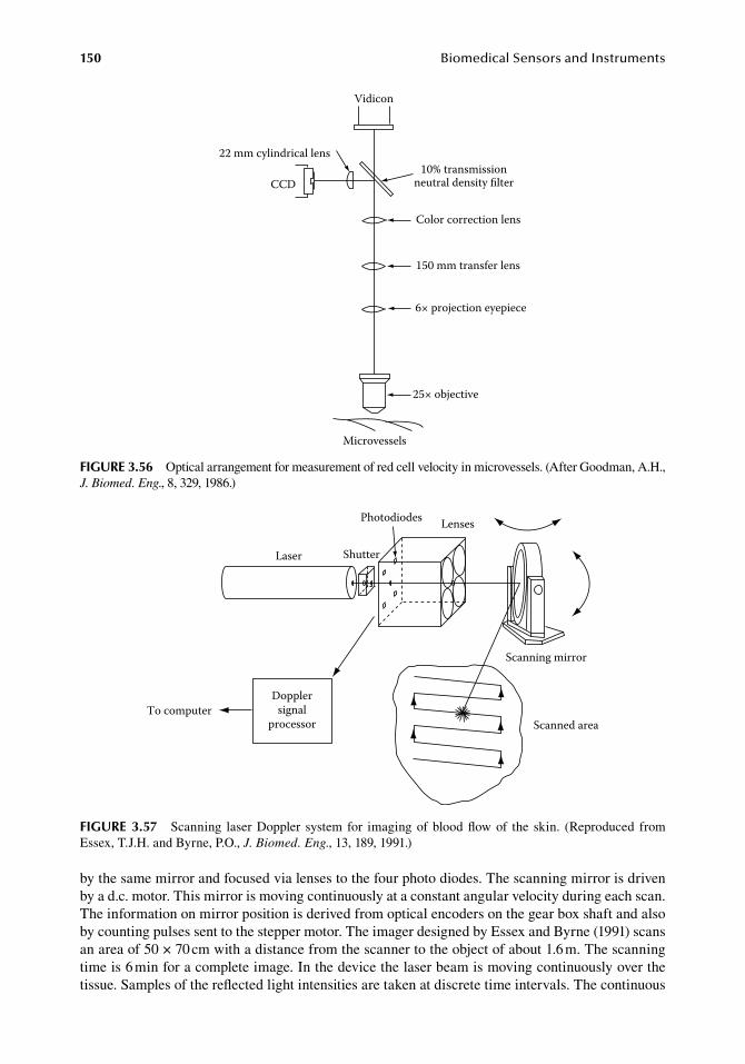
150 BiomedicalSensorsandInstruments
by.the.same.mirror.and.focused.via.lenses.to.the.four.photo.diodes..The.scanning.mirror.is.driven.by.a.d.c..motor..This.mirror.is.moving.continuously.at.a.constant.angular.velocity.during.each.scan..The.information.on.mirror.position.is.derived.from.optical.encoders.on.the.gear.box.shaft.and.also.by.counting.pulses.sent.to.the.stepper.motor..The.imager.designed.by.Essex.and.Byrne.(1991).scans.an.area.of.50.×.70.cm.with.a.distance.from.the.scanner.to.the.object.of.about.1.6.m..The.scanning.time.is.6.min.for.a.complete.image..In.the.device.the.laser.beam.is.moving.continuously.over.the.tissue..Samples.of.the.reflected.light.intensities.are.taken.at.discrete.time.intervals..The.continuous.
Dopplersignal
processorTo computer
Laser Shutter
Photodiodes Lenses
Scanning mirror
Scanned area
figure 3.57 Scanning. laser.Doppler. system. for. imaging.of.blood.flow.of. the. skin.. (Reproduced. from.Essex,.T.J.H..and.Byrne,.P.O.,.J. Biomed. Eng.,.13,.189,.1991.)
Vidicon
22 mm cylindrical lens
CCD10% transmission
neutral density lter
Color correction lens
150 mm transfer lens
6× projection eyepiece
25× objective
Microvessels
figure 3.56 Optical.arrangement.for.measurement.of.red.cell.velocity.in.microvessels..(After.Goodman,.A.H.,.J. Biomed. Eng.,.8,.329,.1986.)
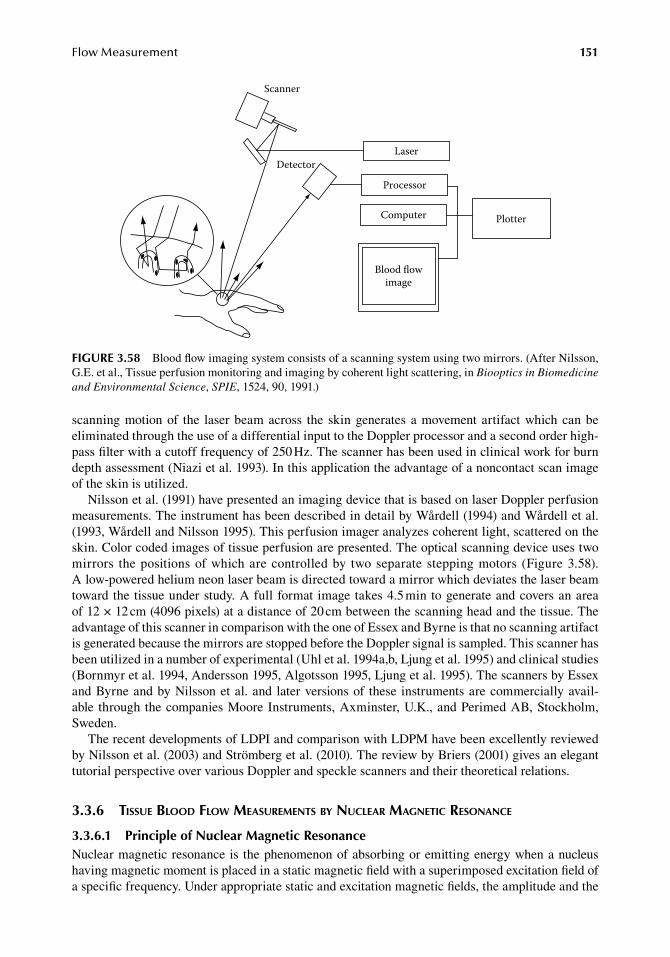
FlowMeasurement 151
scanning.motion.of. the. laser.beam.across. the. skin.generates. a.movement. artifact.which.can.be.eliminated.through.the.use.of.a.differential.input.to.the.Doppler.processor.and.a.second.order.high-pass.filter.with.a.cutoff.frequency.of.250.Hz..The.scanner.has.been.used.in.clinical.work.for.burn.depth.assessment.(Niazi.et al..1993)..In.this.application.the.advantage.of.a.noncontact.scan.image.of.the.skin.is.utilized.
Nilsson.et al..(1991).have.presented.an.imaging.device.that.is.based.on.laser.Doppler.perfusion.measurements..The.instrument.has.been.described.in.detail.by.Wårdell.(1994).and.Wårdell.et al..(1993,.Wårdell.and.Nilsson.1995)..This.perfusion.imager.analyzes.coherent.light,.scattered.on.the.skin..Color.coded.images.of.tissue.perfusion.are.presented..The.optical.scanning.device.uses.two.mirrors. the.positions.of.which.are.controlled.by. two.separate.stepping.motors. (Figure.3.58)..A.low-powered.helium.neon.laser.beam.is.directed.toward.a.mirror.which.deviates.the.laser.beam.toward.the. tissue.under.study..A.full. format. image.takes.4.5.min.to.generate.and.covers.an.area.of.12 ×.12.cm.(4096.pixels).at.a.distance.of.20.cm.between.the.scanning.head.and.the.tissue..The.advantage.of.this.scanner.in.comparison.with.the.one.of.Essex.and.Byrne.is.that.no.scanning.artifact.is.generated.because.the.mirrors.are.stopped.before.the.Doppler.signal.is.sampled..This.scanner.has.been.utilized.in.a.number.of.experimental.(Uhl.et al..1994a,b,.Ljung.et al..1995).and.clinical.studies.(Bornmyr.et al..1994,.Andersson.1995,.Algotsson.1995,.Ljung.et al..1995)..The.scanners.by.Essex.and.Byrne.and.by.Nilsson.et al..and. later.versions.of. these. instruments.are.commercially.avail-able. through.the.companies.Moore.Instruments,.Axminster,.U.K.,.and.Perimed.AB,.Stockholm,.Sweden.
The.recent.developments.of.LDPI.and.comparison.with.LDPM.have.been.excellently.reviewed.by.Nilsson.et al..(2003).and.Strömberg.et al..(2010)..The.review.by.Briers.(2001).gives.an.elegant.tutorial.perspective.over.various.Doppler.and.speckle.scanners.and.their.theoretical.relations.
3.3.6 tissue blood flow MeasureMents by nuclear Magnetic resonance
3.3.6.1 Principle of nuclear Magnetic resonanceNuclear.magnetic.resonance.is. the.phenomenon.of.absorbing.or.emitting.energy.when.a.nucleus.having.magnetic.moment.is.placed.in.a.static.magnetic.field.with.a.superimposed.excitation.field.of.a.specific.frequency..Under.appropriate.static.and.excitation.magnetic.fields,.the.amplitude.and.the.
Scanner
Detector
Blood flowimage
Laser
Processor
Computer Plotter
figure 3.58 Blood.flow.imaging.system.consists.of.a.scanning.system.using.two.mirrors..(After.Nilsson,.G.E..et al.,.Tissue.perfusion.monitoring.and.imaging.by.coherent.light.scattering,.in.Biooptics in Biomedicine and Environmental Science,.SPIE,.1524,.90,.1991.)
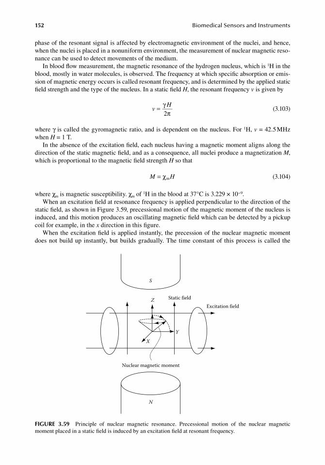
152 BiomedicalSensorsandInstruments
phase.of.the.resonant.signal.is.affected.by.electromagnetic.environment.of.the.nuclei,.and.hence,.when.the.nuclei.is.placed.in.a.nonuniform.environment,.the.measurement.of.nuclear.magnetic.reso-nance.can.be.used.to.detect.movements.of.the.medium.
In.blood.flow.measurement,.the.magnetic.resonance.of.the.hydrogen.nucleus,.which.is.1H.in.the.blood,.mostly.in.water.molecules,.is.observed..The.frequency.at.which.specific.absorption.or.emis-sion.of.magnetic.energy.occurs.is.called.resonant.frequency,.and.is.determined.by.the.applied.static.field.strength.and.the.type.of.the.nucleus..In.a.static.field.H,.the.resonant.frequency.v.is.given.by
.v = γ
πH
2 .(3.103)
where.γ.is.called.the.gyromagnetic.ratio,.and.is.dependent.on.the.nucleus..For.1H,.v.=.42.5.MHz.when.H.=.1.T.
In.the.absence.of.the.excitation.field,.each.nucleus.having.a.magnetic.moment.aligns.along.the.direction.of.the.static.magnetic.field,.and.as.a.consequence,.all.nuclei.produce.a.magnetization.M,.which.is.proportional.to.the.magnetic.field.strength.H.so.that
. M H= χm . (3.104)
where.χm.is.magnetic.susceptibility..χm.of.1H.in.the.blood.at.37°C.is.3.229.×.10−9.When.an.excitation.field.at.resonance.frequency.is.applied.perpendicular.to.the.direction.of.the.
static.field,.as.shown.in.Figure.3.59,.precessional.motion.of.the.magnetic.moment.of.the.nucleus.is.induced,.and.this.motion.produces.an.oscillating.magnetic.field.which.can.be.detected.by.a.pickup.coil.for.example,.in.the.x.direction.in.this.figure.
When.the.excitation.field. is.applied.instantly,. the.precession.of. the.nuclear.magnetic.moment.does.not.build.up. instantly,.but.builds.gradually..The. time.constant.of. this.process. is.called. the.
S
Z Static field
X
Y
Nuclear magnetic moment
Excitation field
N
figure 3.59 Principle. of. nuclear. magnetic. resonance.. Precessional. motion. of. the. nuclear. magnetic.moment.placed.in.a.static.field.is.induced.by.an.excitation.field.at.resonant.frequency.
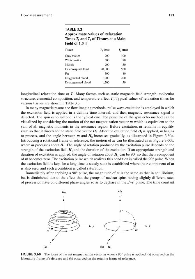
FlowMeasurement 153
longitudinal.relaxation.time.or.T1..Many.factors.such.as.static.magnetic.field.strength,.molecular.structure,.elemental.composition,.and.temperature.affect.T1..Typical.values.of.relaxation.times.for.various.tissues.are.shown.in.Table.3.3.
In.many.magnetic.resonance.flow.imaging.methods,.pulse.wave.excitation.is.employed.in.which.the. excitation. field. is. applied. in. a. definite. time. interval,. and. then. magnetic. resonance. signal. is.detected..The.spin.echo.method.is.the.typical.one..The.principle.of.the.spin.echo.method.can.be.visualized.by.considering.the.motion.of.the.net.magnetization.vector.m.which.is.equivalent.to.the.sum.of. all.magnetic.moments. in. the. resonance. region..Before.excitation,.m remains. in. equilib-rium.so.that.it.directs.to.the.static.field.vector.H0..After.the.excitation.field.Hl.is.applied,.m.begins.to. precess,. and. the. angle. between.m. and.H0. increases. gradually,. as. illustrated. in.Figure. 3.60a..Introducing.a.rotational.frame.of.reference,.the.motion.of.m.can.be.illustrated.as.in.Figure.3.60b,.where.m.precesses.about.H1..The.angle.of.rotation.produced.by.the.excitation.pulse.depends.on.the.strength.of.the.excitation.field.H1.and.the.duration.of.the.excitation..If.an.appropriate.strength.and.duration.of.excitation.is.applied,.the.angle.of.rotation.about.H1.can.be.90°.so.that.the.z.component.of.m.becomes.zero..The.excitation.pulse.which.realizes.this.condition.is.called.the.90°.pulse..When.the.excitation.field.is.kept.for.a.long.time,.a.steady.state.is.established.where.the.z component.of.m.is.also.zero,.and.such.a.condition.is.called.saturation.
Immediately.after.applying.a.90°.pulse,.the.magnitude.of.m.is.the.same.as.that.in.equilibrium,.but.is.diminished.due.to.the.effect.that.the.groups.of.nuclear.spins.having.slightly.different.rates.of.precession.have.on.different.phase.angles.so.as.to.dephase.in.the.x′–y′.plane..The.time.constant.
x΄
y΄
z΄
m
H0
H1(b)
y
x
m
(a)
zH0
figure 3.60 The.locus.of.the.net.magnetization.vector.m.when.a.90°.pulse.is.applied:.(a).observed.on.the.laboratory.frame.of.reference.and.(b).observed.on.the.rotating.frame.of.reference.
table 3.3approximate Values of relaxation times T1 and T2 of tissues at a Main field of 1.5 t
tissue T1 (ms) T2 (ms)
Gray.matter 900 100
White.matter 600 80
Muscle 900 50
Celebrospinal.fluid 20,000 500
Fat 300 80
Oxygenated.blood 1,200 200
Deoxygenated.blood 1,200 50
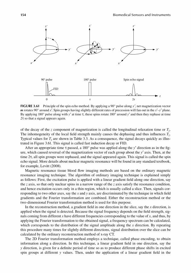
154 BiomedicalSensorsandInstruments
of.the.decay.of.the.z.component.of.magnetization.is.called.the.longitudinal.relaxation.time.or.T2..The.inhomogeneity.of.the.local.field.strength.mainly.causes.the.dephasing.and.thus.influences.T2..Typical.values.for.T2.are.shown.in.Table.3.3..As.a.consequence,.the.signal.decays.quickly.as.illus-trated.in.Figure.3.61..This.signal.is.called.fast.induction.decay.or.FID.
After.an.appropriate.time.τ.passed,.a.180°.pulse.was.applied.along.the.y′.direction.as.in.the.fig-ure,.which.caused.reversal.of.the.magnetization.vector.of.each.group.about.the.y′.axis..Then,.at.the.time.2τ,.all.spin.groups.were.rephased,.and.the.signal.appeared.again..This.signal.is.called.the.spin.echo.signal..More.details.about.nuclear.magnetic.resonance.will.be.found.in.any.standard.textbook,.for.example,.Levitt.(2008).
Magnetic. resonance. tissue. blood. flow. imaging. methods. are. based. on. the. ordinary. magnetic.resonance. imaging. technique..The.algorithm.of.ordinary. imaging. technique. is.explained.simply.as.follows:.First,.the.excitation.pulse.is.applied.with.a.linear.gradient.field.along.one.direction,.say.the.z.axis,.so.that.only.nuclear.spins.in.a.narrow.range.of.the.z.axis.satisfy.the.resonance.condition,.and.hence.excitation.occurs.only.in.a.thin.region,.which.is.usually.called.a.slice..Then,.signals.cor-responding.to.two.other.axes,.say.the.x.and.y.axis,.are.discriminated.by.the.technique.in.which.field.gradients.and. the.Fourier. transformation.are.combined..Either. the. reconstruction.method.or. the.two-dimensional.Fourier.transformation.method.is.used.for.this.purpose.
In.the.reconstruction.method,.a.gradient.field.in.one.direction.in.the.slice,.say.the.x.direction,.is.applied.when.the.signal.is.detected..Because.the.signal.frequency.depends.on.the.field.strength,.sig-nals.coming.from.different.x.have.different.frequencies.corresponding.to.the.value.of.x,.and.thus,.by.applying.the.Fourier.transformation.to.the.obtained.signal,.a.frequency.spectrum.can.be.calculated,.which.corresponds.to.the.distribution.of.the.signal.amplitude.along.the.x.direction..By.repeating.this.procedure.many.times.for.slightly.different.directions,.signal.distribution.over.the.slice.can.be.calculated.by.the.ordinary.reconstruction.method.of.x-ray.CT.
The.2D.Fourier.transformation.method.employs.a.technique,.called.phase.encoding,.to.obtain.information.along.a.direction.. In. this. technique,.a. linear.gradient.field. in.one.direction,. say. the.y direction,.is.given.for.a.definite.period.of.time.so.as.to.produce.different.phase.shifts.in.excited.spin. groups. at. different. y. values.. Then,. under. the. application. of. a. linear. gradient. field. in. the.
t
Spin echo signal180° pulse90° pulse
FID
0 τ 2τ
z΄ z΄ z΄
y΄ y΄ y΄
x΄ x΄ x΄
figure 3.61 Principle.of.the.spin.echo.method..By.applying.a.90°.pulse.along.x ′,.net.magnetization.vector.m.rotates.90°.around.x′..Spin.groups.having.slightly.different.rates.of.precession.will.fan.out.in.the.x′–y′.plane..By.applying.180°.pulse.along.with.y′.at.time.τ,.these.spins.rotate.180°.around.y′.and.then.they.rephase.at.time.2τ.so.that.a.signal.appears.again.
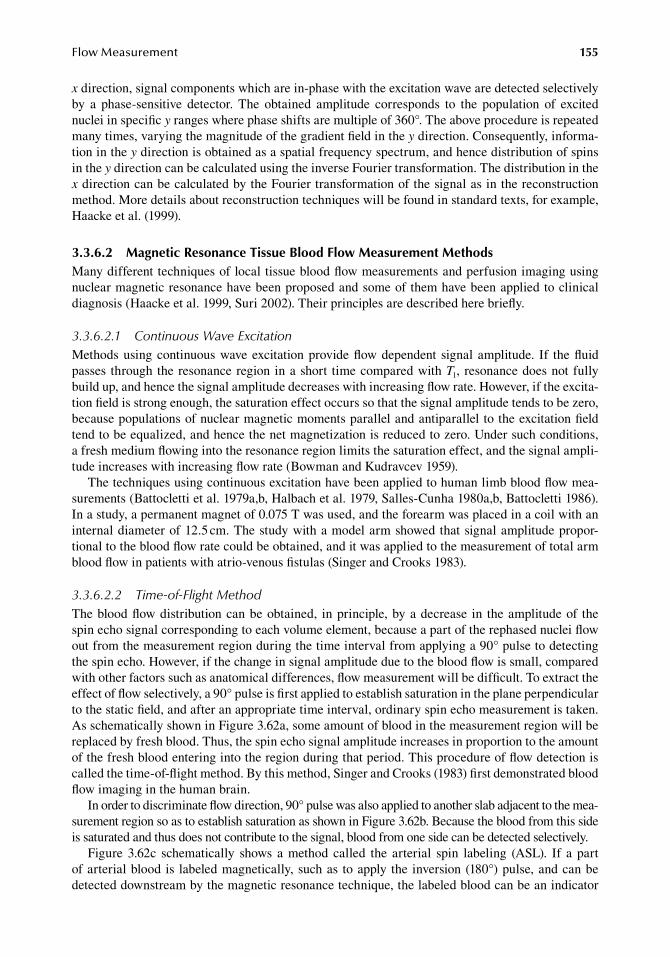
FlowMeasurement 155
x direction,.signal.components.which.are.in-phase.with.the.excitation.wave.are.detected.selectively.by. a. phase-sensitive. detector.. The. obtained. amplitude. corresponds. to. the. population. of. excited.nuclei.in.specific.y.ranges.where.phase.shifts.are.multiple.of.360°..The.above.procedure.is.repeated.many.times,.varying.the.magnitude.of.the.gradient.field.in.the.y.direction..Consequently,.informa-tion.in.the.y direction.is.obtained.as.a.spatial.frequency.spectrum,.and.hence.distribution.of.spins.in.the.y.direction.can.be.calculated.using.the.inverse.Fourier.transformation..The.distribution.in.the.x.direction.can.be.calculated.by.the.Fourier.transformation.of.the.signal.as.in.the.reconstruction.method..More.details.about.reconstruction.techniques.will.be.found.in.standard.texts,.for.example,.Haacke.et al..(1999).
3.3.6.2 Magnetic resonance tissue blood flow Measurement MethodsMany.different.techniques.of.local.tissue.blood.flow.measurements.and.perfusion.imaging.using.nuclear.magnetic.resonance.have.been.proposed.and.some.of.them.have.been.applied.to.clinical.diagnosis.(Haacke.et al..1999,.Suri.2002)..Their.principles.are.described.here.briefly.
3.3.6.2.1 Continuous Wave ExcitationMethods.using.continuous.wave.excitation.provide.flow.dependent. signal.amplitude.. If. the.fluid.passes. through.the.resonance.region. in.a.short. time.compared.with.T1,. resonance.does.not.fully.build.up,.and.hence.the.signal.amplitude.decreases.with.increasing.flow.rate..However,.if.the.excita-tion.field.is.strong.enough,.the.saturation.effect.occurs.so.that.the.signal.amplitude.tends.to.be.zero,.because.populations.of.nuclear.magnetic.moments.parallel.and.antiparallel.to.the.excitation.field.tend.to.be.equalized,.and.hence.the.net.magnetization.is.reduced.to.zero..Under.such.conditions,.a fresh.medium.flowing.into.the.resonance.region.limits.the.saturation.effect,.and.the.signal.ampli-tude.increases.with.increasing.flow.rate.(Bowman.and.Kudravcev.1959).
The.techniques.using.continuous.excitation.have.been.applied.to.human.limb.blood.flow.mea-surements.(Battocletti.et al..1979a,b,.Halbach.et al..1979,.Salles-Cunha.1980a,b,.Battocletti.1986)..In.a.study,.a.permanent.magnet.of.0.075.T.was.used,.and.the.forearm.was.placed.in.a.coil.with.an.internal.diameter.of.12.5.cm..The.study.with.a.model.arm.showed.that.signal.amplitude.propor-tional.to.the.blood.flow.rate.could.be.obtained,.and.it.was.applied.to.the.measurement.of.total.arm.blood.flow.in.patients.with.atrio-venous.fistulas.(Singer.and.Crooks.1983).
3.3.6.2.2 Time-of-Flight MethodThe.blood.flow.distribution.can.be.obtained,. in.principle,.by.a.decrease. in. the.amplitude.of. the.spin.echo.signal.corresponding.to.each.volume.element,.because.a.part.of.the.rephased.nuclei.flow.out.from.the.measurement.region.during.the.time.interval.from.applying.a.90°.pulse.to.detecting.the.spin.echo..However,.if.the.change.in.signal.amplitude.due.to.the.blood.flow.is.small,.compared.with.other.factors.such.as.anatomical.differences,.flow.measurement.will.be.difficult..To.extract.the.effect.of.flow.selectively,.a.90°.pulse.is.first.applied.to.establish.saturation.in.the.plane.perpendicular.to.the.static.field,.and.after.an.appropriate.time.interval,.ordinary.spin.echo.measurement.is.taken..As.schematically.shown.in.Figure.3.62a,.some.amount.of.blood.in.the.measurement.region.will.be.replaced.by.fresh.blood..Thus,.the.spin.echo.signal.amplitude.increases.in.proportion.to.the.amount.of.the.fresh.blood.entering.into.the.region.during.that.period..This.procedure.of.flow.detection.is.called.the.time-of-flight.method..By.this.method,.Singer.and.Crooks.(1983).first.demonstrated.blood.flow.imaging.in.the.human.brain.
In.order.to.discriminate.flow.direction,.90°.pulse.was.also.applied.to.another.slab.adjacent.to.the.mea-surement.region.so.as.to.establish.saturation.as.shown.in.Figure.3.62b..Because.the.blood.from.this.side.is.saturated.and.thus.does.not.contribute.to.the.signal,.blood.from.one.side.can.be.detected.selectively.
Figure. 3.62c. schematically. shows. a. method. called. the. arterial. spin. labeling. (ASL).. If. a. part.of.arterial.blood.is. labeled.magnetically,.such.as. to.apply.the. inversion.(180°).pulse,.and.can.be.detected.downstream.by.the.magnetic.resonance.technique,.the.labeled.blood.can.be.an.indicator.
156 BiomedicalSensorsandInstruments
as.in.the.indicator.dilution.method..The.advantage.of.ASL.is.the.capability.of.extracting.flow.signal.selectively.by.subtracting.the.image.without.arterial.labeling.from.that.with.arterial.labeling..Many.ASL.techniques.using.different.modalities.of.labeling.and.detecting.methods.have.been.developed.(Wong.et al..1997,.Buxton.et al..1998,.Luh.et al..1999,.Buxton.2005).
3.3.6.2.3 Phase Contrast MethodPhase.contrast.method.is.based.on.the.fact. that. if. the.static.field.has.a.gradient. in.one.direction.it.causes.a.phase.difference.of.precession.in.the.spin.echo.process..A.nucleus.moving.toward.the.field.gradient.gains.phase.in.proportion.to.the.distance.of.motion.which.corresponds.to.the.velocity.component.along.the.field.gradient.times.echo.time.(2τ.in.Figure.3.61)..Consequently,.nuclei.having.different.velocity.components.have.different.phases,.and.the.amplitude.of.the.spin.echo.signal.is.affected.by.the.velocity.distribution..It.is.shown.that.the.velocity.distribution.can.be.calculated.from.amplitudes.of.spin.echo.signals.obtained.with.many.different.τ..Grover.and.Singer.(1971).applied.this.method.to.examine.blood.flow.in.the.human.fingers,.and.obtained.a.plot.of.the.density.of.nuclei.versus.velocity.component.along.the.finger.axis.
The.velocity. component. in. an. arbitrary.direction. can.be.detected. selectively.by.a.method. in.which.a.biphasic.gradient.modulation.is.applied.to.the.image.sequence.as.illustrated.in.Figure.3.63.(Moran.1982)..The.gradient.causes.no.phase.shift.for.spins.having.no.velocity.components.in.the.direction.of. the.gradient..But. if. spins.have.velocity. components. in. that. direction,. the. effects. of.positive.and.negative.parts.of.the.biphasic.gradient.field.do.not.cancel.out.each.other,.and.thus.the.velocity.component.can.be.detected.by.a.phase.shift.of.the.spin.echo.signal..To.detect.phase.shifts,.quadrature.detection.is.needed.in.which.both.the.in-phase.component.and.the.component.having.
Blood flow
Saturated tissue
Saturatedblood
Fresh bloodArtery
Imaging slice
(a) Arterial blood flow
Imagingslice
Saturationslab
Fresh blood
Artery
Vein
(b)
Venous blood flow
Saturatedblood
Artery
Imaging slice
Labeling slab
(c) Arterial blood flow
Spin-labeled blood
figure 3.62 Time-of-flight.methods.for.tissue.blood.flow.measurement:.(a).replacement.of.saturated.blood.by.fresh.blood,.(b).a.method.of.flow.direction.discrimination,.and.(c).the.arterial.spin.labeling.
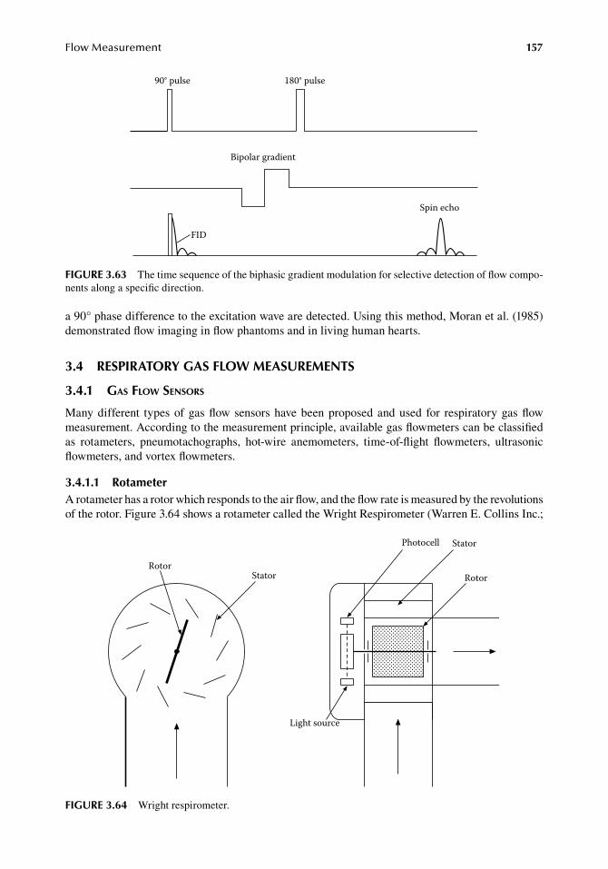
FlowMeasurement 157
a.90°.phase.difference.to.the.excitation.wave.are.detected..Using.this.method,.Moran.et al..(1985).demonstrated.flow.imaging.in.flow.phantoms.and.in.living.human.hearts.
3.4 reSPiratory gaS floW MeaSureMentS
3.4.1 gas flow sensors
Many.different. types.of.gas.flow.sensors.have.been.proposed.and.used. for. respiratory.gas.flow.measurement..According.to.the.measurement.principle,.available.gas.flowmeters.can.be.classified.as. rotameters,. pneumotachographs,. hot-wire. anemometers,. time-of-flight. flowmeters,. ultrasonic.flowmeters,.and.vortex.flowmeters.
3.4.1.1 rotameterA.rotameter.has.a.rotor.which.responds.to.the.air.flow,.and.the.flow.rate.is.measured.by.the.revolutions.of.the.rotor..Figure.3.64.shows.a.rotameter.called.the.Wright.Respirometer.(Warren.E..Collins Inc.;.
FID
90° pulse 180° pulse
Bipolar gradient
Spin echo
figure 3.63 The.time.sequence.of.the.biphasic.gradient.modulation.for.selective.detection.of.flow.compo-nents.along.a.specific.direction.
RotorStator
Photocell Stator
Rotor
Light source
figure 3.64 Wright.respirometer.
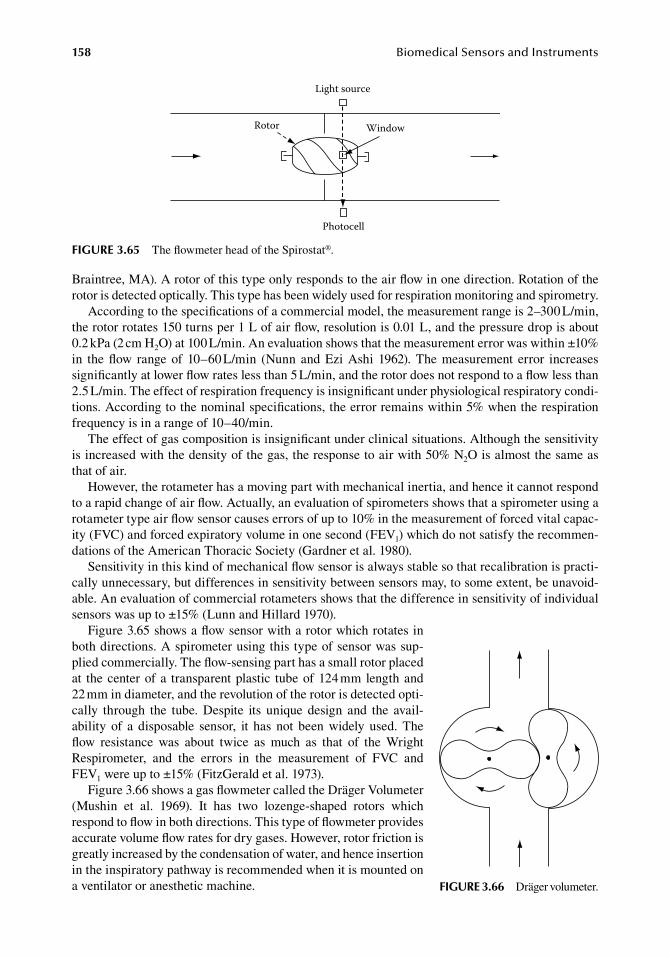
158 BiomedicalSensorsandInstruments
Braintree,.MA)..A.rotor.of.this.type.only.responds.to.the.air.flow.in.one.direction..Rotation.of.the.rotor.is.detected.optically..This.type.has.been.widely.used.for.respiration.monitoring.and.spirometry.
According.to.the.specifications.of.a.commercial.model,.the.measurement.range.is.2–300.L/min,.the.rotor.rotates.150.turns.per.1.L.of.air.flow,.resolution.is.0.01.L,.and.the.pressure.drop.is.about.0.2.kPa.(2.cm.H2O).at.100.L/min..An.evaluation.shows.that.the.measurement.error.was.within.±10%.in. the.flow. range. of. 10–60.L/min. (Nunn. and. Ezi.Ashi. 1962).. The.measurement. error. increases.significantly.at.lower.flow.rates.less.than.5.L/min,.and.the.rotor.does.not.respond.to.a.flow.less.than.2.5.L/min..The.effect.of.respiration.frequency.is.insignificant.under.physiological.respiratory.condi-tions..According.to.the.nominal.specifications,.the.error.remains.within.5%.when.the.respiration.frequency.is.in.a.range.of.10–40/min.
The.effect.of.gas.composition.is.insignificant.under.clinical.situations..Although.the.sensitivity.is.increased.with.the.density.of.the.gas,.the.response.to.air.with.50%.N2O.is.almost.the.same.as.that of.air.
However,.the.rotameter.has.a.moving.part.with.mechanical.inertia,.and.hence.it.cannot.respond.to.a.rapid.change.of.air.flow..Actually,.an.evaluation.of.spirometers.shows.that.a.spirometer.using.a.rotameter.type.air.flow.sensor.causes.errors.of.up.to.10%.in.the.measurement.of.forced.vital.capac-ity.(FVC).and.forced.expiratory.volume.in.one.second.(FEV1).which.do.not.satisfy.the.recommen-dations.of.the.American.Thoracic.Society.(Gardner.et al..1980).
Sensitivity.in.this.kind.of.mechanical.flow.sensor.is.always.stable.so.that.recalibration.is.practi-cally.unnecessary,.but.differences.in.sensitivity.between.sensors.may,.to.some.extent,.be.unavoid-able..An.evaluation.of.commercial.rotameters.shows.that.the.difference.in.sensitivity.of.individual.sensors.was.up.to.±15%.(Lunn.and.Hillard.1970).
Figure.3.65.shows.a.flow.sensor.with.a.rotor.which.rotates.in.both.directions..A.spirometer.using.this.type.of.sensor.was.sup-plied.commercially..The.flow-sensing.part.has.a.small.rotor.placed.at. the.center.of.a. transparent.plastic. tube.of.124.mm.length.and.22.mm.in.diameter,.and.the.revolution.of.the.rotor.is.detected.opti-cally. through. the. tube.. Despite. its. unique. design. and. the. avail-ability. of. a. disposable. sensor,. it. has. not. been. widely. used.. The.flow. resistance. was. about. twice. as. much. as. that. of. the. Wright.Respirometer,. and. the. errors. in. the. measurement. of. FVC. and.FEV1.were.up.to.±15%.(FitzGerald.et al..1973).
Figure.3.66.shows.a.gas.flowmeter.called.the.Dräger.Volumeter.(Mushin. et al.. 1969).. It. has. two. lozenge-shaped. rotors. which.respond.to.flow.in.both.directions..This.type.of.flowmeter.provides.accurate.volume.flow.rates.for.dry.gases..However,.rotor.friction.is.greatly.increased.by.the.condensation.of.water,.and.hence.insertion.in.the.inspiratory.pathway.is.recommended.when.it.is.mounted.on.a.ventilator.or.anesthetic.machine.
Window
Light source
Rotor
Photocell
figure 3.65 The.flowmeter.head.of.the.Spirostat®.
figure 3.66 Dräger.volumeter.
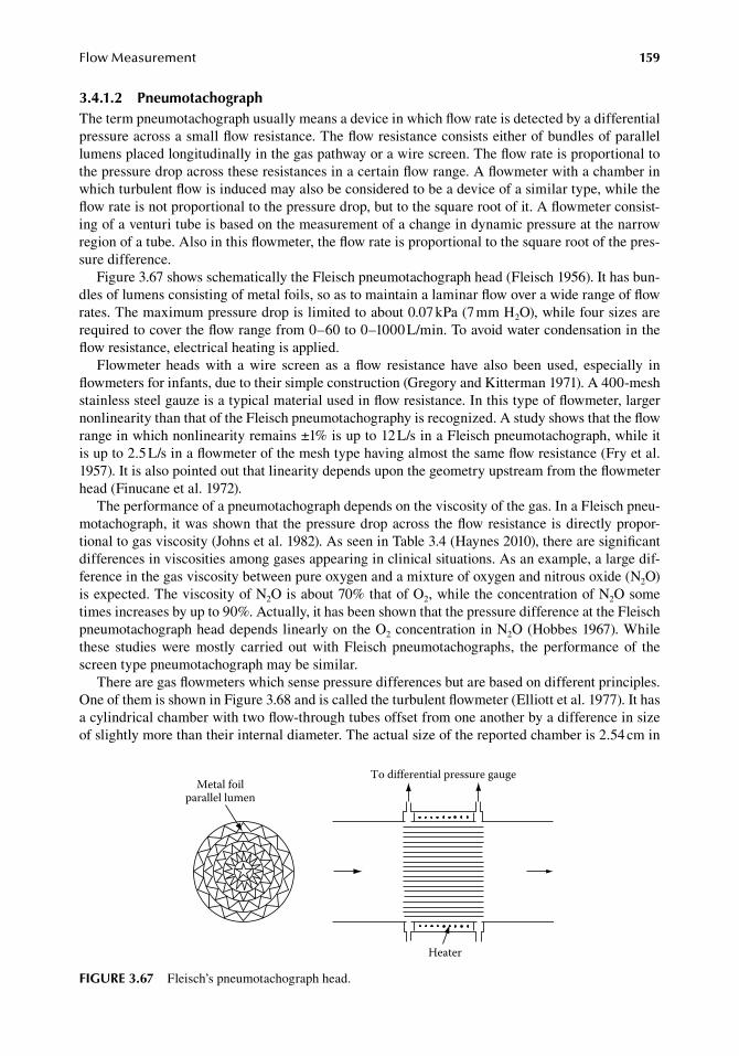
FlowMeasurement 159
3.4.1.2 PneumotachographThe.term.pneumotachograph.usually.means.a.device.in.which.flow.rate.is.detected.by.a.differential.pressure.across.a.small.flow.resistance..The.flow.resistance.consists.either.of.bundles.of.parallel.lumens.placed.longitudinally.in.the.gas.pathway.or.a.wire.screen..The.flow.rate.is.proportional.to.the.pressure.drop.across.these.resistances.in.a.certain.flow.range..A flowmeter.with.a.chamber.in.which.turbulent.flow.is.induced.may.also.be.considered.to.be.a.device.of.a.similar.type,.while.the.flow.rate.is.not.proportional.to.the.pressure.drop,.but.to.the.square.root.of.it..A.flowmeter.consist-ing.of.a.venturi.tube.is.based.on.the.measurement.of.a.change.in.dynamic.pressure.at.the.narrow.region.of.a.tube..Also.in.this.flowmeter,.the.flow.rate.is.proportional.to.the.square.root.of.the.pres-sure.difference.
Figure.3.67.shows.schematically.the.Fleisch.pneumotachograph.head.(Fleisch.1956)..It.has.bun-dles.of.lumens.consisting.of.metal.foils,.so.as.to.maintain.a.laminar.flow.over.a.wide.range.of.flow.rates..The.maximum.pressure.drop.is.limited.to.about.0.07.kPa.(7.mm.H2O),.while.four.sizes.are.required.to.cover.the.flow.range.from.0–60.to.0–1000.L/min..To.avoid.water.condensation.in.the.flow.resistance,.electrical.heating.is.applied.
Flowmeter. heads. with. a. wire. screen. as. a. flow. resistance. have. also. been. used,. especially. in.flowmeters.for.infants,.due.to.their.simple.construction.(Gregory.and.Kitterman.1971)..A.400-mesh.stainless.steel.gauze.is.a.typical.material.used.in.flow.resistance..In.this.type.of.flowmeter,.larger.nonlinearity.than.that.of.the.Fleisch.pneumotachography.is.recognized..A.study.shows.that.the.flow.range.in.which.nonlinearity.remains.±1%.is.up.to.12.L/s.in.a.Fleisch.pneumotachograph,.while.it.is.up.to.2.5.L/s.in.a.flowmeter.of.the.mesh.type.having.almost.the.same.flow.resistance.(Fry.et al..1957)..It.is.also.pointed.out.that.linearity.depends.upon.the.geometry.upstream.from.the.flowmeter.head.(Finucane.et al..1972).
The.performance.of.a.pneumotachograph.depends.on.the.viscosity.of.the.gas..In.a.Fleisch.pneu-motachograph,. it.was.shown.that. the.pressure.drop.across. the.flow.resistance.is.directly.propor-tional.to.gas.viscosity.(Johns.et al..1982)..As.seen.in.Table.3.4.(Haynes.2010),.there.are.significant.differences.in.viscosities.among.gases.appearing.in.clinical.situations..As.an.example,.a.large.dif-ference.in.the.gas.viscosity.between.pure.oxygen.and.a.mixture.of.oxygen.and.nitrous.oxide.(N2O).is.expected..The.viscosity.of.N2O.is.about.70%.that.of.O2,.while.the.concentration.of.N2O.some.times.increases.by.up.to.90%..Actually,.it.has.been.shown.that.the.pressure.difference.at.the.Fleisch.pneumotachograph.head.depends.linearly.on.the.O2.concentration.in.N2O.(Hobbes.1967)..While.these. studies. were. mostly. carried. out. with. Fleisch. pneumotachographs,. the. performance. of. the.screen.type.pneumotachograph.may.be.similar.
There.are.gas.flowmeters.which.sense.pressure.differences.but.are.based.on.different.principles..One.of.them.is.shown.in.Figure.3.68.and.is.called.the.turbulent.flowmeter.(Elliott.et al..1977)..It.has.a.cylindrical.chamber.with.two.flow-through.tubes.offset.from.one.another.by.a.difference.in.size.of.slightly.more.than.their.internal.diameter..The.actual.size.of.the.reported.chamber.is.2.54.cm.in.
To differential pressure gauge
Heater
Metal foilparallel lumen
figure 3.67 Fleisch’s.pneumotachograph.head.
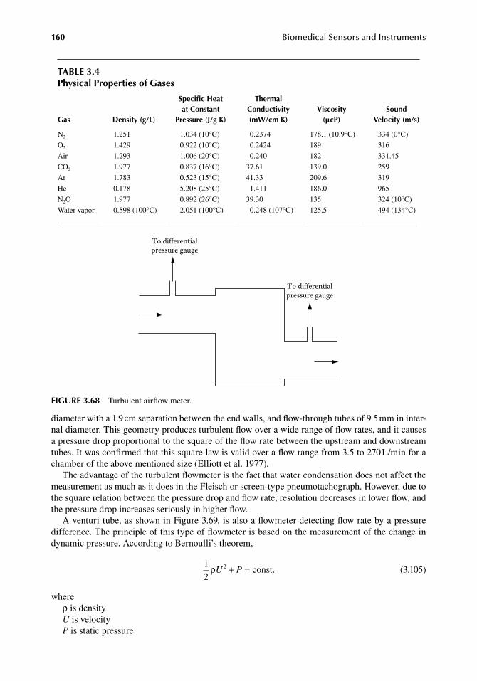
160 BiomedicalSensorsandInstruments
diameter.with.a.1.9.cm.separation.between.the.end.walls,.and.flow-through.tubes.of.9.5.mm.in.inter-nal.diameter..This.geometry.produces.turbulent.flow.over.a.wide.range.of.flow.rates,.and.it.causes.a.pressure.drop.proportional.to.the.square.of.the.flow.rate.between.the.upstream.and.downstream.tubes..It.was.confirmed.that.this.square.law.is.valid.over.a.flow.range.from.3.5.to.270.L/min.for.a.chamber.of.the.above.mentioned.size.(Elliott.et al..1977).
The.advantage.of.the.turbulent.flowmeter.is.the.fact.that.water.condensation.does.not.affect.the.measurement.as.much.as.it.does.in.the.Fleisch.or.screen-type.pneumotachograph..However,.due.to.the.square.relation.between.the.pressure.drop.and.flow.rate,.resolution.decreases.in.lower.flow,.and.the.pressure.drop.increases.seriously.in.higher.flow.
A.venturi.tube,.as.shown.in.Figure.3.69,.is.also.a.flowmeter.detecting.flow.rate.by.a.pressure.difference..The.principle.of.this.type.of.flowmeter.is.based.on.the.measurement.of.the.change.in.dynamic.pressure..According.to.Bernoulli’s.theorem,
.
12
const.2ρU P+ =.
(3.105)
whereρ.is.densityU.is.velocityP.is.static.pressure
table 3.4Physical Properties of gases
gas density (g/l)
Specific heat at Constant
Pressure (j/g K)
thermal Conductivity (mW/cm K)
Viscosity (μcP)
Sound Velocity (m/s)
N2 1.251 1.034.(10°C) . 0.2374 178.1.(10.9°C) 334.(0°C)
O2 1.429 0.922.(10°C) . 0.2424 189 316
Air 1.293 1.006.(20°C) . 0.240 182 331.45
CO2 1.977 0.837.(16°C) 37.61 139.0 259
Ar 1.783 0.523.(15°C) 41.33 209.6 319
He 0.178 5.208.(25°C) . 1.411 186.0 965
N2O 1.977 0.892.(26°C) 39.30 135 324.(10°C)
Water.vapor 0.598.(100°C) 2.051.(100°C) . 0.248.(107°C) 125.5 494.(134°C)
To differentialpressure gauge
To differentialpressure gauge
figure 3.68 Turbulent.airflow.meter.
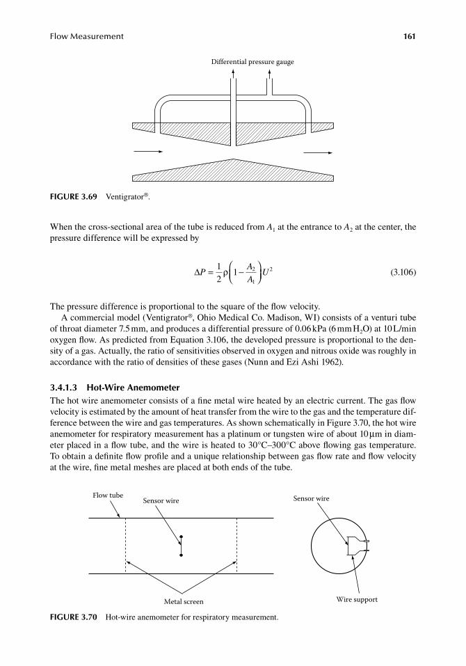
FlowMeasurement 161
When.the.cross-sectional.area.of.the.tube.is.reduced.from.A1.at.the.entrance.to.A2.at.the.center,.the.pressure.difference.will.be.expressed.by
.∆P
A
AU= −
12
1 2
1
2ρ.
(3.106)
The.pressure.difference.is.proportional.to.the.square.of.the.flow.velocity.A.commercial.model.(Ventigrator®,.Ohio.Medical.Co..Madison,.WI).consists.of.a.venturi.tube.
of.throat.diameter.7.5.mm,.and.produces.a.differential.pressure.of.0.06.kPa.(6.mm.H2O).at.10.L/min.oxygen.flow..As.predicted.from.Equation.3.106,.the.developed.pressure.is.proportional.to.the.den-sity.of.a.gas..Actually,.the.ratio.of.sensitivities.observed.in.oxygen.and.nitrous.oxide.was.roughly.in.accordance.with.the.ratio.of.densities.of.these.gases.(Nunn.and.Ezi.Ashi.1962).
3.4.1.3 hot-Wire anemometerThe.hot.wire.anemometer.consists.of.a.fine.metal.wire.heated.by.an.electric.current..The.gas.flow.velocity.is.estimated.by.the.amount.of.heat.transfer.from.the.wire.to.the.gas.and.the.temperature.dif-ference.between.the.wire.and.gas.temperatures..As.shown.schematically.in.Figure.3.70,.the.hot.wire.anemometer.for.respiratory.measurement.has.a.platinum.or.tungsten.wire.of.about.10.μm.in.diam-eter.placed.in.a.flow.tube,.and.the.wire.is.heated.to.30°C–300°C.above.flowing.gas.temperature..To obtain.a.definite.flow.profile.and.a.unique.relationship.between.gas.flow.rate.and.flow.velocity.at the.wire,.fine.metal.meshes.are.placed.at.both.ends.of.the.tube.
Sensor wireFlow tube
Metal screen
Sensor wire
Wire support
figure 3.70 Hot-wire.anemometer.for.respiratory.measurement.
Differential pressure gauge
figure 3.69 Ventigrator®.
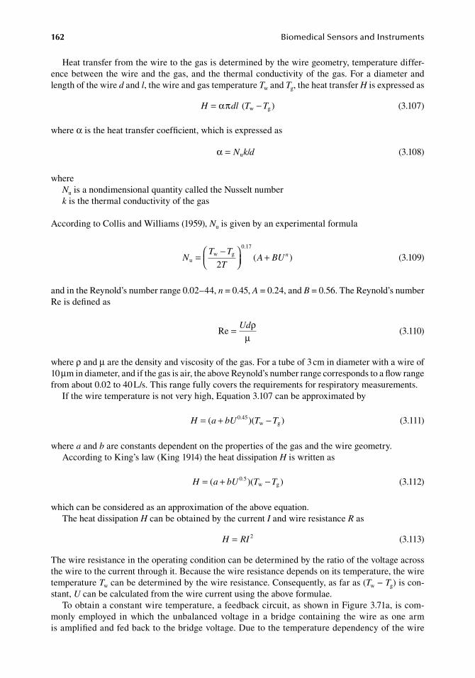
162 BiomedicalSensorsandInstruments
Heat.transfer.from.the.wire.to.the.gas.is.determined.by.the.wire.geometry,.temperature.differ-ence.between.the.wire.and.the.gas,.and.the. thermal.conductivity.of. the.gas..For.a.diameter.and.length.of.the.wire.d.and.l,.the.wire.and.gas.temperature.Tw.and.Tg,.the.heat.transfer.H.is.expressed.as
.H dl T T= −απ w g( )
.(3.107)
where.α.is.the.heat.transfer.coefficient,.which.is.expressed.as
. α = N k du / . (3.108)
whereNu.is.a.nondimensional.quantity.called.the.Nusselt.numberk.is.the.thermal.conductivity.of.the.gas
According.to.Collis.and.Williams.(1959),.Nu.is.given.by.an.experimental.formula
.N
T T
TA BU n
uw g
0.17
2=
−
+( ).
(3.109)
and.in.the.Reynold’s.number.range.0.02–44,.n.=.0.45,.A.=.0.24,.and.B.=.0.56..The.Reynold’s.number.Re.is.defined.as
.Re = Udρ
µ .(3.110)
where.ρ.and.μ.are.the.density.and.viscosity.of.the.gas..For.a.tube.of.3.cm.in.diameter.with.a.wire.of.10.μm.in.diameter,.and.if.the.gas.is.air,.the.above.Reynold’s.number.range.corresponds.to.a.flow.range.from.about.0.02.to.40.L/s..This.range.fully.covers.the.requirements.for.respiratory.measurements.
If.the.wire.temperature.is.not.very.high,.Equation.3.107.can.be.approximated.by
.H a bU T T= + −( )( )0.45
w g .(3.111)
where.a.and.b.are.constants.dependent.on.the.properties.of.the.gas.and.the.wire.geometry.According.to.King’s.law.(King.1914).the.heat.dissipation.H.is.written.as
.H a bU T T= + −( )( )0.5
w g .(3.112)
which.can.be.considered.as.an.approximation.of.the.above.equation.The.heat.dissipation.H.can.be.obtained.by.the.current.I.and.wire.resistance.R.as
. H RI= 2. (3.113)
The.wire.resistance.in.the.operating.condition.can.be.determined.by.the.ratio.of.the.voltage.across.the.wire.to.the.current.through.it..Because.the.wire.resistance.depends.on.its.temperature,.the.wire.temperature.Tw.can.be.determined.by.the.wire.resistance..Consequently,.as.far.as.(Tw.−.Tg).is.con-stant,.U.can.be.calculated.from.the.wire.current.using.the.above.formulae.
To.obtain.a.constant.wire.temperature,.a.feedback.circuit,.as.shown.in.Figure.3.71a,.is.com-monly.employed. in.which. the.unbalanced.voltage. in. a.bridge.containing. the.wire. as.one.arm.is.amplified.and.fed.back.to.the.bridge.voltage..Due.to.the.temperature.dependency.of.the.wire.
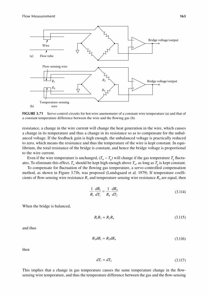
FlowMeasurement 163
resistance,.a.change.in.the.wire.current.will.change.the.heat.generation.in.the.wire,.which.causes.a.change.in.its.temperature.and.thus.a.change.in.its.resistance.so.as.to.compensate.for.the.unbal-anced.voltage..If.the.feedback.gain.is.high.enough,.the.unbalanced.voltage.is.practically.reduced.to.zero,.which.means.the.resistance.and.thus.the.temperature.of.the.wire.is.kept.constant..In.equi-librium,.the.total.resistance.of.the.bridge.is.constant,.and.hence.the.bridge.voltage.is.proportional.to.the.wire.current.
Even.if.the.wire.temperature.is.unchanged,.(Tw.−.Tg).will.change.if.the.gas.temperature.Tg.fluctu-ates..To.eliminate.this.effect,.Tw.should.be.kept.high.enough.above.Tw,.as.long.as.Tg.is.kept.constant.
To.compensate.for.fluctuation.of.the.flowing.gas.temperature,.a.servo-controlled.compensation.method,.as.shown.in.Figure.3.71b,.was.proposed.(Lundsgaard.et al..1979)..If.temperature.coeffi-cients.of.flow-sensing.wire.resistance.R1.and.temperature.sensing.wire.resistance.R4.are.equal,.then
.
1 1
1
1
1 4
4
2R
dR
dT R
dR
dT=
.(3.114)
When.the.bridge.is.balanced,
. R R R R1 3 2 4= . (3.115)
and.thus
. R dR R dR3 1 2 4= . (3.116)
then
. dT dT1 2= . (3.117)
This. implies. that.a.change. in.gas. temperature.causes. the. same. temperature.change. in. the.flow-sensing.wire.temperature,.and.thus.the.temperature.difference.between.the.gas.and.the.flow-sensing.
+
–
+
–
Wire
Flow tube(a)
Bridge voltage/output
Bridge voltage/output
Flow-sensing wire
Temperature-sensingwire
R1
R4
R2
R3
(b)
figure 3.71 Servo-control.circuits.for.hot-wire.anemometer.of.a.constant.wire.temperature.(a).and.that.of.a.constant.temperature.difference.between.the.wire.and.the.flowing.gas.(b).
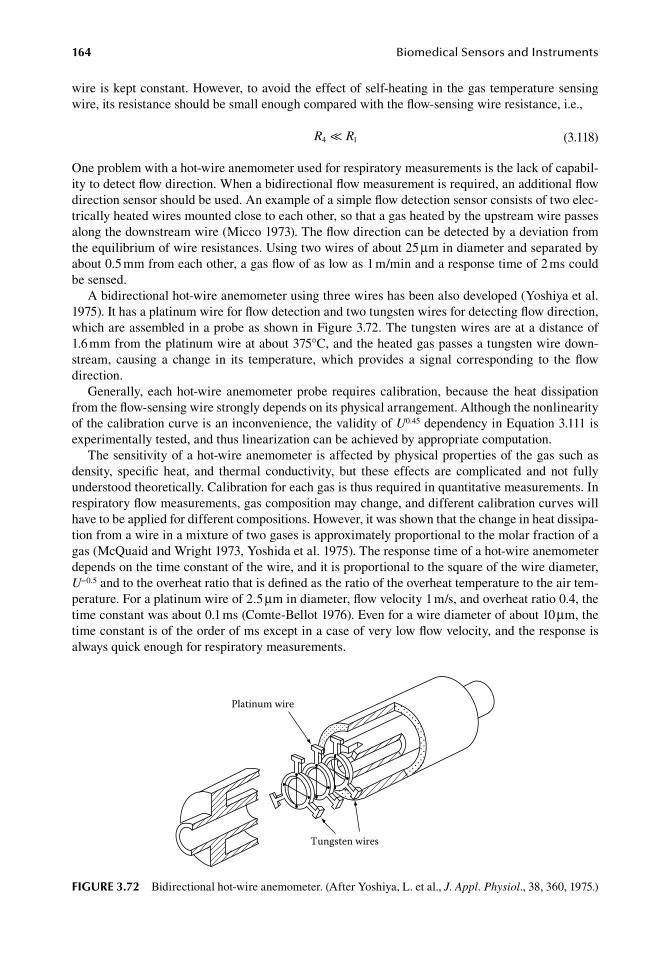
164 BiomedicalSensorsandInstruments
wire.is.kept.constant..However,.to.avoid.the.effect.of.self-heating.in.the.gas.temperature.sensing.wire,.its.resistance.should.be.small.enough.compared.with.the.flow-sensing.wire.resistance,.i.e.,
. R R4 1<< . (3.118)
One.problem.with.a.hot-wire.anemometer.used.for.respiratory.measurements.is.the.lack.of.capabil-ity.to.detect.flow.direction..When.a.bidirectional.flow.measurement.is.required,.an.additional.flow.direction.sensor.should.be.used..An.example.of.a.simple.flow.detection.sensor.consists.of.two.elec-trically.heated.wires.mounted.close.to.each.other,.so.that.a.gas.heated.by.the.upstream.wire.passes.along.the.downstream.wire.(Micco.1973)..The.flow.direction.can.be.detected.by.a.deviation.from.the.equilibrium.of.wire.resistances..Using.two.wires.of.about.25.μm.in.diameter.and.separated.by.about.0.5.mm.from.each.other,.a.gas.flow.of.as.low.as.1.m/min.and.a.response.time.of.2.ms.could.be.sensed.
A.bidirectional.hot-wire.anemometer.using.three.wires.has.been.also.developed.(Yoshiya.et al..1975)..It.has.a.platinum.wire.for.flow.detection.and.two.tungsten.wires.for.detecting.flow.direction,.which.are.assembled.in.a.probe.as.shown.in.Figure.3.72..The.tungsten.wires.are.at.a.distance.of.1.6.mm.from.the.platinum.wire.at.about.375°C,.and.the.heated.gas.passes.a.tungsten.wire.down-stream,. causing. a. change. in. its. temperature,. which. provides. a. signal. corresponding. to. the. flow.direction.
Generally,.each.hot-wire.anemometer.probe. requires.calibration,.because. the.heat.dissipation.from.the.flow-sensing.wire.strongly.depends.on.its.physical.arrangement..Although.the.nonlinearity.of.the.calibration.curve.is.an.inconvenience,.the.validity.of.U0.45.dependency.in.Equation.3.111.is.experimentally.tested,.and.thus.linearization.can.be.achieved.by.appropriate.computation.
The.sensitivity.of.a.hot-wire.anemometer.is.affected.by.physical.properties.of.the.gas.such.as.density,. specific. heat,. and. thermal. conductivity,. but. these. effects. are. complicated. and. not. fully.understood.theoretically..Calibration.for.each.gas.is.thus.required.in.quantitative.measurements..In.respiratory.flow.measurements,.gas.composition.may.change,.and.different.calibration.curves.will.have.to.be.applied.for.different.compositions..However,.it.was.shown.that.the.change.in.heat.dissipa-tion.from.a.wire.in.a.mixture.of.two.gases.is.approximately.proportional.to.the.molar.fraction.of.a.gas.(McQuaid.and.Wright.1973,.Yoshida.et al..1975)..The.response.time.of.a.hot-wire.anemometer.depends.on.the.time.constant.of.the.wire,.and.it.is.proportional.to.the.square.of.the.wire.diameter,.U−0.5.and.to.the.overheat.ratio.that.is.defined.as.the.ratio.of.the.overheat.temperature.to.the.air.tem-perature..For.a.platinum.wire.of.2.5.μm.in.diameter,.flow.velocity.1.m/s,.and.overheat.ratio.0.4,.the.time.constant.was.about.0.1.ms.(Comte-Bellot.1976)..Even.for.a.wire.diameter.of.about.10.μm,.the.time.constant.is.of.the.order.of.ms.except.in.a.case.of.very.low.flow.velocity,.and.the.response.is.always.quick.enough.for.respiratory.measurements.
Platinum wire
Tungsten wires
figure 3.72 Bidirectional.hot-wire.anemometer..(After.Yoshiya,.L..et al.,.J. Appl. Physiol.,.38,.360,.1975.)
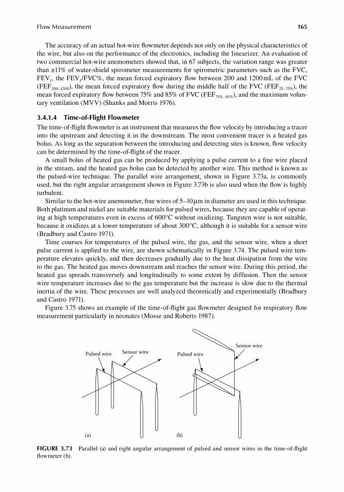
FlowMeasurement 165
The.accuracy.of.an.actual.hot-wire.flowmeter.depends.not.only.on.the.physical.characteristics.of.the.wire,.but.also.on.the.performance.of.the.electronics,.including.the.linearizer..An.evaluation.of.two.commercial.hot-wire.anemometers.showed.that,.in.67.subjects,.the.variation.range.was.greater.than.±11%.of.water-shield.spirometer.measurements.for.spirometric.parameters.such.as.the.FVC,.FEV1,. the.FEV1/FVC%,.the.mean.forced.expiratory.flow.between.200.and.1200.mL.of.the.FVC.(FEF200–1200),.the.mean.forced.expiratory.flow.during.the.middle.half.of.the.FVC.(FEF25–75%),.the.mean.forced.expiratory.flow.between.75%.and.85%.of.FVC.(FEF75%–85%),.and.the.maximum.volun-tary.ventilation.(MVV).(Shanks.and.Morris.1976).
3.4.1.4 time-of-flight flowmeterThe.time-of-flight.flowmeter.is.an.instrument.that.measures.the.flow.velocity.by.introducing.a.tracer.into.the.upstream.and.detecting.it.in.the.downstream..The.most.convenient.tracer.is.a.heated.gas.bolus..As.long.as.the.separation.between.the.introducing.and.detecting.sites.is.known,.flow.velocity.can.be.determined.by.the.time-of-flight.of.the.tracer.
A.small.bolus.of.heated.gas.can.be.produced.by.applying.a.pulse.current.to.a.fine.wire.placed.in.the.stream,.and.the.heated.gas.bolus.can.be.detected.by.another.wire..This.method.is.known.as.the.pulsed-wire. technique..The.parallel.wire. arrangement,. shown. in.Figure.3.73a,. is. commonly.used,.but.the.right.angular.arrangement.shown.in.Figure.3.73b.is.also.used.when.the.flow.is.highly.turbulent.
Similar.to.the.hot-wire.anemometer,.fine.wires.of.5–10.μm.in.diameter.are.used.in.this.technique..Both.platinum.and.nickel.are.suitable.materials.for.pulsed.wires,.because.they.are.capable.of.operat-ing.at.high.temperatures.even.in.excess.of.600°C.without.oxidizing..Tungsten.wire.is.not.suitable,.because.it.oxidizes.at.a.lower.temperature.of.about.300°C,.although.it.is.suitable.for.a.sensor.wire.(Bradbury.and.Castro.1971).
Time.courses.for.temperatures.of. the.pulsed.wire,. the.gas,.and.the.sensor.wire,.when.a.short.pulse.current.is.applied.to.the.wire,.are.shown.schematically.in.Figure.3.74..The.pulsed.wire.tem-perature.elevates.quickly,.and.then.decreases.gradually.due.to.the.heat.dissipation.from.the.wire.to.the.gas..The.heated.gas.moves.downstream.and.reaches.the.sensor.wire..During.this.period,.the.heated.gas. spreads. transversely.and. longitudinally. to. some.extent.by.diffusion..Then. the.sensor.wire.temperature.increases.due.to.the.gas.temperature.but.the.increase.is.slow.due.to.the.thermal.inertia.of.the.wire..These.processes.are.well.analyzed.theoretically.and.experimentally.(Bradbury.and.Castro.1971).
Figure.3.75.shows.an.example.of.the.time-of-flight.gas.flowmeter.designed.for.respiratory.flow.measurement.particularly.in.neonates.(Mosse.and.Roberts.1987).
Pulsed wire Sensor wire Pulsed wireSensor wire
(a) (b)
figure 3.73 Parallel.(a).and.right.angular.arrangement.of.pulsed.and.sensor.wires.in.the.time-of-flight.flowmeter.(b).
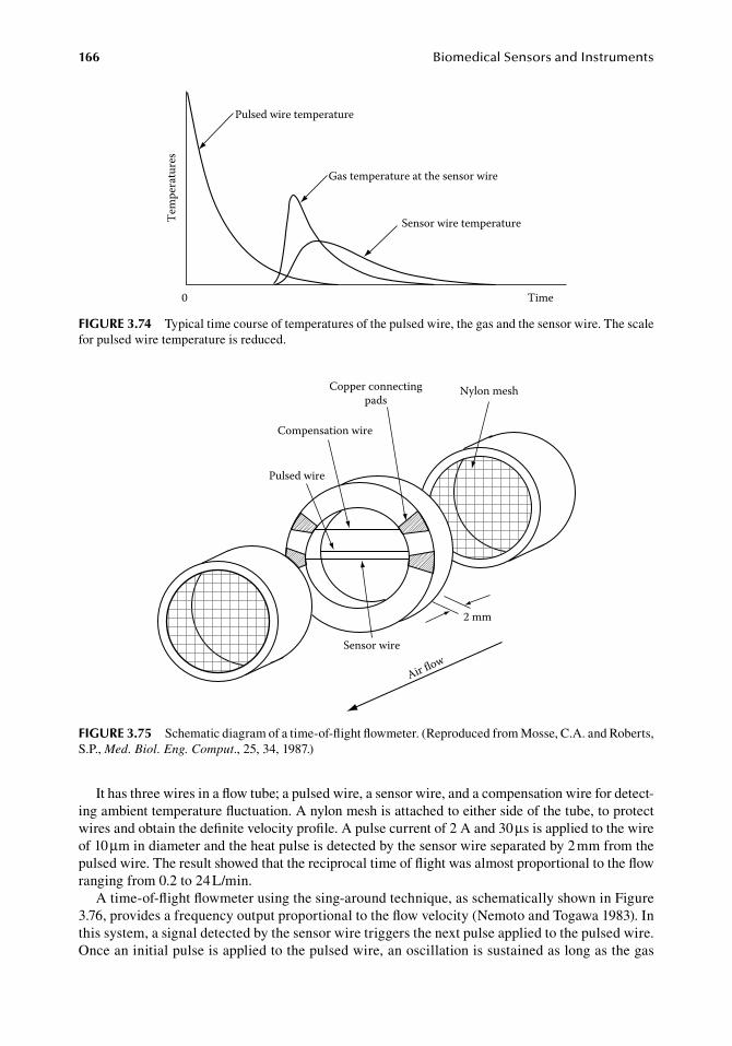
166 BiomedicalSensorsandInstruments
It.has.three.wires.in.a.flow.tube;.a.pulsed.wire,.a.sensor.wire,.and.a.compensation.wire.for.detect-ing.ambient.temperature.fluctuation..A.nylon.mesh.is.attached.to.either.side.of.the.tube,.to.protect.wires.and.obtain.the.definite.velocity.profile..A.pulse.current.of.2.A.and.30.μs.is.applied.to.the.wire.of.10.μm.in.diameter.and.the.heat.pulse.is.detected.by.the.sensor.wire.separated.by.2.mm.from.the.pulsed.wire..The.result.showed.that.the.reciprocal.time.of.flight.was.almost.proportional.to.the.flow.ranging.from.0.2.to.24.L/min.
A.time-of-flight.flowmeter.using.the.sing-around.technique,.as.schematically.shown.in.Figure.3.76,.provides.a.frequency.output.proportional.to.the.flow.velocity.(Nemoto.and.Togawa.1983)..In.this.system,.a.signal.detected.by.the.sensor.wire.triggers.the.next.pulse.applied.to.the.pulsed.wire..Once.an.initial.pulse.is.applied.to.the.pulsed.wire,.an.oscillation.is.sustained.as.long.as.the.gas.
Pulsed wire temperature
Gas temperature at the sensor wire
Sensor wire temperatureTem
pera
ture
s
0 Time
figure 3.74 Typical.time.course.of.temperatures.of.the.pulsed.wire,.the.gas.and.the.sensor.wire..The.scale.for.pulsed.wire.temperature.is.reduced.
2 mm
Air flowSensor wire
Pulsed wire
Compensation wire
Copper connectingpads
Nylon mesh
figure 3.75 Schematic.diagram.of.a.time-of-flight.flowmeter..(Reproduced.from.Mosse,.C.A..and.Roberts,.S.P.,.Med. Biol. Eng. Comput.,.25,.34,.1987.)
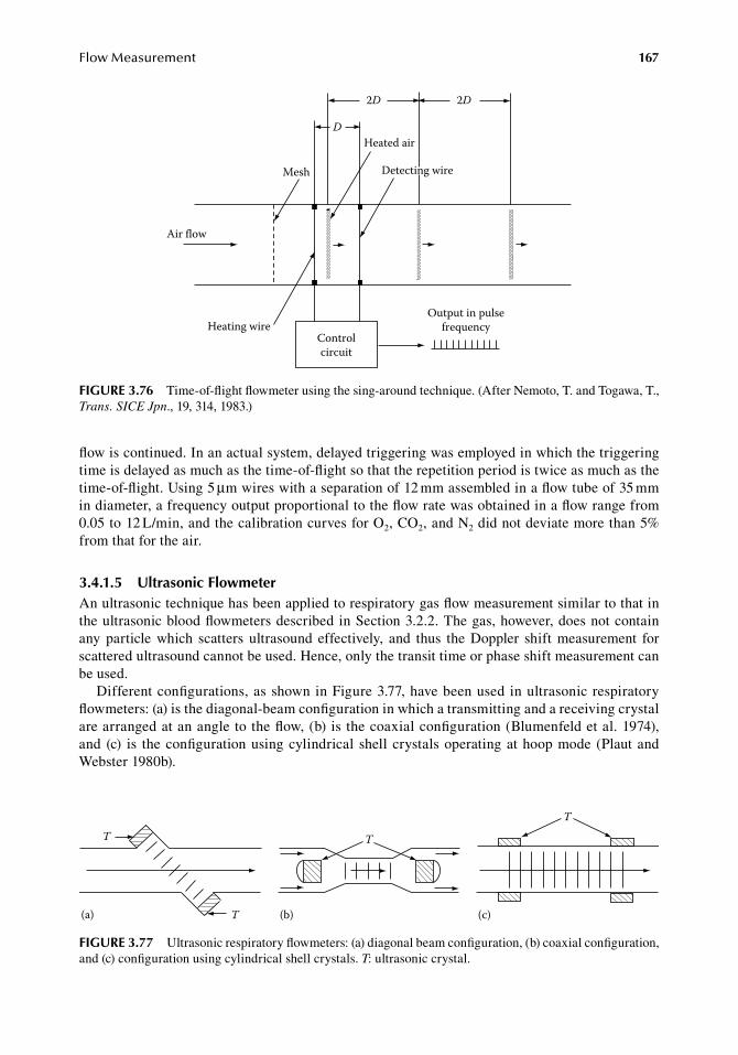
FlowMeasurement 167
flow.is.continued..In.an.actual.system,.delayed.triggering.was.employed.in.which.the.triggering.time.is.delayed.as.much.as.the.time-of-flight.so.that.the.repetition.period.is.twice.as.much.as.the.time-of-flight..Using.5.μm.wires.with.a.separation.of.12.mm.assembled.in.a.flow.tube.of.35.mm.in.diameter,.a.frequency.output.proportional.to.the.flow.rate.was.obtained.in.a.flow.range.from.0.05.to.12.L/min,.and.the.calibration.curves.for.O2,.CO2,.and.N2.did.not.deviate.more.than.5%.from.that.for.the.air.
3.4.1.5 ultrasonic flowmeterAn.ultrasonic.technique.has.been.applied.to.respiratory.gas.flow.measurement.similar.to.that.in.the.ultrasonic.blood.flowmeters.described.in.Section.3.2.2..The.gas,.however,.does.not.contain.any. particle. which. scatters. ultrasound. effectively,. and. thus. the. Doppler. shift. measurement. for.scattered.ultrasound.cannot.be.used..Hence,.only.the.transit.time.or.phase.shift.measurement.can.be.used.
Different.configurations,.as.shown.in.Figure.3.77,.have.been.used.in.ultrasonic.respiratory.flowmeters:.(a).is.the.diagonal-beam.configuration.in.which.a.transmitting.and.a.receiving.crystal.are.arranged.at.an.angle.to.the.flow,.(b).is.the.coaxial.configuration.(Blumenfeld.et al..1974),.and. (c). is. the.configuration.using.cylindrical. shell.crystals.operating.at.hoop.mode. (Plaut.and.Webster.1980b).
D
2D 2D
Heated air
Detecting wireMesh
Heating wireControlcircuit
Output in pulsefrequency
Air flow
figure 3.76 Time-of-flight.flowmeter.using.the.sing-around.technique..(After.Nemoto,.T..and.Togawa,.T.,.Trans. SICE Jpn.,.19,.314,.1983.)
T
T(a)
T
(b)
T
(c)
figure 3.77 Ultrasonic.respiratory.flowmeters:.(a).diagonal.beam.configuration,.(b).coaxial.configuration,.and.(c).configuration.using.cylindrical.shell.crystals..T:.ultrasonic.crystal.
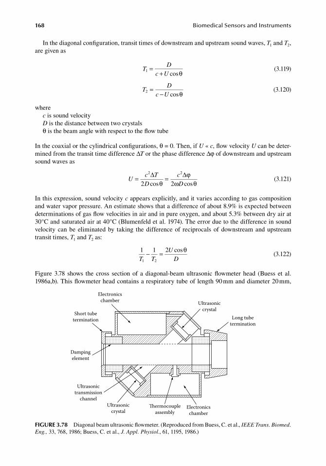
168 BiomedicalSensorsandInstruments
In.the.diagonal.configuration,.transit.times.of.downstream.and.upstream.sound.waves,.T1.and.T2,.are.given.as
.T
D
c U1 =
+ cosθ .(3.119)
.T
D
c U2 =
− cosθ .(3.120)
wherec.is.sound.velocityD.is.the.distance.between.two.crystalsθ.is.the.beam.angle.with.respect.to.the.flow.tube
In.the.coaxial.or.the.cylindrical.configurations,.θ.=.0..Then,.if.U « c,.flow.velocity.U.can.be.deter-mined.from.the.transit.time.difference.ΔT.or.the.phase.difference.Δφ.of.downstream.and.upstream.sound.waves.as
.U
c T
D
c
D= =
2 2
2 2∆ ∆cos cosθ
ϕω θ .
(3.121)
In.this.expression,.sound.velocity.c.appears.explicitly,.and.it.varies.according.to.gas.composition.and.water.vapor.pressure..An.estimate.shows.that.a.difference.of.about.8.9%.is.expected.between.determinations.of.gas.flow.velocities.in.air.and.in.pure.oxygen,.and.about.5.3%.between.dry.air.at.30°C.and.saturated.air.at.40°C.(Blumenfeld.et al..1974)..The.error.due.to.the.difference.in.sound.velocity.can.be.eliminated.by. taking. the.difference.of. reciprocals.of.downstream.and.upstream.transit.times,.T1.and.T2.as:
.
1 1 2
1 2T T
U
D− = cosθ
.(3.122)
Figure.3.78. shows. the. cross. section.of. a.diagonal-beam.ultrasonic.flowmeter.head. (Buess. et al..1986a,b)..This.flowmeter.head.contains.a.respiratory.tube.of.length.90.mm.and.diameter.20.mm,.
Electronicschamber
Short tubetermination
Dampingelement
Ultrasonictransmission
channelUltrasonic
crystal
Ultrasoniccrystal
Electronicschamber
ermocoupleassembly
Long tubetermination
figure 3.78 Diagonal.beam.ultrasonic.flowmeter..(Reproduced.from.Buess,.C..et al.,.IEEE Trans. Biomed. Eng.,.33,.768,.1986;.Buess,.C..et al.,.J. Appl. Physiol.,.61,.1195,.1986.)
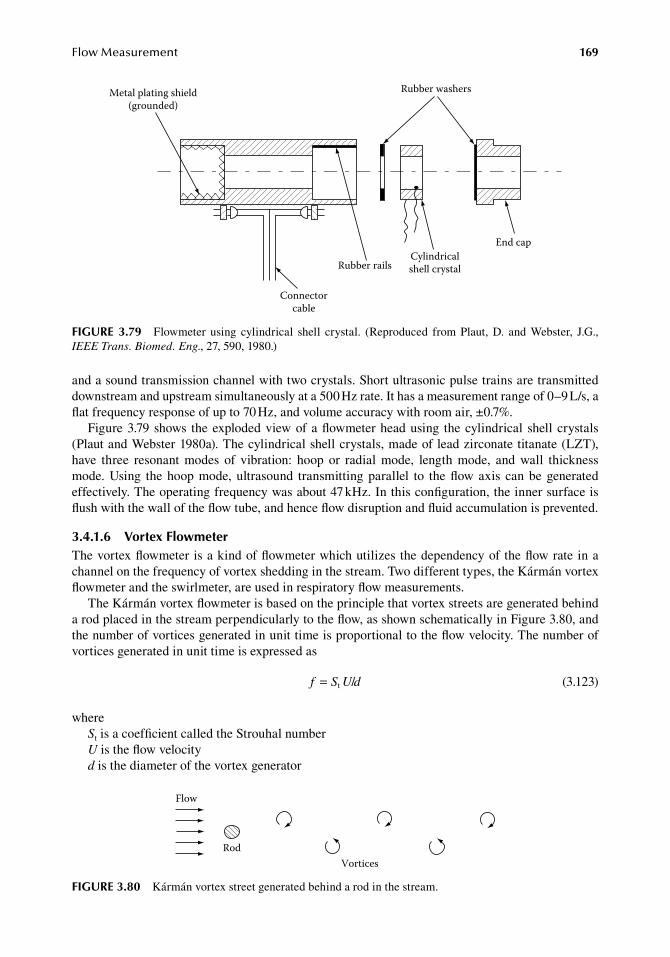
FlowMeasurement 169
and.a.sound.transmission.channel.with.two.crystals..Short.ultrasonic.pulse.trains.are.transmitted.downstream.and.upstream.simultaneously.at.a.500.Hz.rate..It.has.a.measurement.range.of.0–9.L/s,.a.flat.frequency.response.of.up.to.70.Hz,.and.volume.accuracy.with.room.air,.±0.7%.
Figure.3.79.shows. the.exploded.view.of.a.flowmeter.head.using. the.cylindrical. shell.crystals.(Plaut.and.Webster.1980a)..The.cylindrical.shell.crystals,.made.of.lead.zirconate.titanate.(LZT),.have. three. resonant. modes. of. vibration:. hoop. or. radial. mode,. length. mode,. and. wall. thickness.mode..Using. the.hoop.mode,.ultrasound. transmitting.parallel. to. the.flow.axis. can.be.generated.effectively..The.operating.frequency.was.about.47.kHz..In.this.configuration,.the.inner.surface.is.flush.with.the.wall.of.the.flow.tube,.and.hence.flow.disruption.and.fluid.accumulation.is.prevented.
3.4.1.6 Vortex flowmeterThe.vortex.flowmeter.is.a.kind.of.flowmeter.which.utilizes.the.dependency.of.the.flow.rate.in.a.channel.on.the.frequency.of.vortex.shedding.in.the.stream..Two.different.types,.the.Kármán.vortex.flowmeter.and.the.swirlmeter,.are.used.in.respiratory.flow.measurements.
The.Kármán.vortex.flowmeter.is.based.on.the.principle.that.vortex.streets.are.generated.behind.a.rod.placed.in.the.stream.perpendicularly.to.the.flow,.as.shown.schematically.in.Figure.3.80,.and.the.number.of.vortices.generated.in.unit.time.is.proportional.to.the.flow.velocity..The.number.of.vortices.generated.in.unit.time.is.expressed.as
. f S U d= t / . (3.123)
whereSt.is.a.coefficient.called.the.Strouhal.numberU.is.the.flow.velocityd.is.the.diameter.of.the.vortex.generator
Cylindricalshell crystal
Rubber washers
End cap
Rubber rails
Connectorcable
Metal plating shield(grounded)
figure 3.79 Flowmeter. using. cylindrical. shell. crystal.. (Reproduced. from. Plaut,. D.. and. Webster,. J.G.,.IEEE Trans. Biomed. Eng.,.27,.590,.1980.)
Flow
RodVortices
figure 3.80 Kármán.vortex.street.generated.behind.a.rod.in.the.stream.
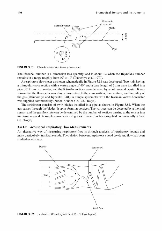
170 BiomedicalSensorsandInstruments
The.Strouhal.number. is.a.dimension-less.quantity,.and. is.about.0.2.when. the.Reynold’s.number.remains.in.a.range.roughly.from.103.to.105.(Tsuhchiya.et al..1970).
A.respiratory.flowmeter.as.shown.schematically.in.Figure.3.81.was.developed..Two.rods.having.a.triangular.cross.section.with.a.vortex.angle.of.40°.and.a.base.length.of.2.mm.were.installed.in.a.pipe.of.12.mm.in.diameter,.and.the.Kármán.vortices.were.detected.by.an.ultrasound.crystal..It.was.shown.that.the.flowmeter.was.almost.insensitive.to.the.composition,.temperature,.and.humidity.of.the.gas.(Utsunomiya.and.Kyozuka.1981)..A.simple.spirometer.with.the.Kármán.vortex.flowmeter.was.supplied.commercially.(Nihon.Kohden.Co..Ltd.,.Tokyo).
The.swirlmeter.consists.of.swirl.blades.installed.in.a.pipe.as.shown.in.Figure.3.82..When.the.gas.passes.through.the.blades,.it.spins.forming.vortices..The.vortices.can.be.detected.by.a.thermal.sensor,.and.the.gas.flow.rate.can.be.determined.by.the.number.of.vortices.passing.at.the.sensor.in.a.unit.time.interval..A.simple.spirometer.using.a.swirlmeter.has.been.supplied.commercially.(Chest.Co.,.Tokyo).
3.4.1.7 acoustical respiratory flow MeasurementsAn.alternative.way.of.measuring. respiratory. flow. is. through. analysis. of. respiratory. sounds. and.more.particularly,.tracheal.sounds..The.relation.between.respiratory.sound.levels.and.flow.has.been.studied.extensively.
40°
2 m
m
Kármán vortex
Pipe
Ultrasoniccrystals
Mesh
12 m
m
figure 3.81 Kármán.vortex.respiratory.flowmeter.
Swirler Sensor (Pt)
Flow
Swirl flow
figure 3.82 Swirlmeter..(Courtesy.of.Chest.Co.,.Tokyo,.Japan.)
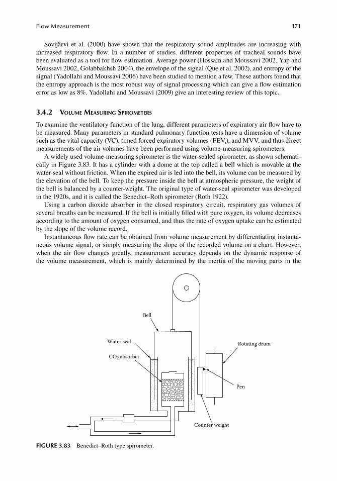
FlowMeasurement 171
Sovijärvi. et al.. (2000).have. shown. that. the. respiratory. sound.amplitudes. are. increasing.with.increased. respiratory. flow.. In. a. number. of. studies,. different. properties. of. tracheal. sounds. have.been.evaluated.as.a.tool.for.flow.estimation..Average.power.(Hossain.and.Moussavi.2002,.Yap.and.Moussavi.2002,.Golabbakhsh.2004),.the.envelope.of.the.signal.(Que.et al..2002),.and.entropy.of.the.signal.(Yadollahi.and.Moussavi.2006).have.been.studied.to.mention.a.few..These.authors.found.that.the.entropy.approach.is.the.most.robust.way.of.signal.processing.which.can.give.a.flow.estimation.error.as.low.as.8%..Yadollahi.and.Moussavi.(2009).give.an.interesting.review.of.this.topic.
3.4.2 VoluMe Measuring spiroMeters
To.examine.the.ventilatory.function.of.the.lung,.different.parameters.of.expiratory.air.flow.have.to.be.measured..Many.parameters.in.standard.pulmonary.function.tests.have.a.dimension.of.volume.such.as.the.vital.capacity.(VC),.timed.forced.expiratory.volumes.(FEVt),.and.MVV,.and.thus.direct.measurements.of.the.air.volumes.have.been.performed.using.volume-measuring.spirometers.
A.widely.used.volume-measuring.spirometer.is.the.water-sealed.spirometer,.as.shown.schemati-cally.in.Figure.3.83..It.has.a.cylinder.with.a.dome.at.the.top.called.a.bell.which.is.movable.at.the.water-seal.without.friction..When.the.expired.air.is.led.into.the.bell,.its.volume.can.be.measured.by.the.elevation.of.the.bell..To.keep.the.pressure.inside.the.bell.at.atmospheric.pressure,.the.weight.of.the.bell.is.balanced.by.a.counter-weight..The.original.type.of.water-seal.spirometer.was.developed.in.the.1920s,.and.it.is.called.the.Benedict–Roth.spirometer.(Roth.1922).
Using.a. carbon.dioxide.absorber. in. the.closed. respiratory.circuit,. respiratory.gas.volumes.of.several.breaths.can.be.measured..If.the.bell.is.initially.filled.with.pure.oxygen,.its.volume.decreases.according.to.the.amount.of.oxygen.consumed,.and.thus.the.rate.of.oxygen.uptake.can.be.estimated.by.the.slope.of.the.volume.record.
Instantaneous.flow.rate.can.be.obtained.from.volume.measurement.by.differentiating.instanta-neous.volume.signal,.or.simply.measuring.the.slope.of.the.recorded.volume.on.a.chart..However,.when. the. air. flow. changes. greatly,. measurement. accuracy. depends. on. the. dynamic. response. of.the.volume.measurement,.which. is.mainly.determined.by. the. inertia.of. the.moving.parts. in. the.
Bell
Water seal
CO2 absorber
Pen
Counter weight
Rotating drum
figure 3.83 Benedict–Roth.type.spirometer.
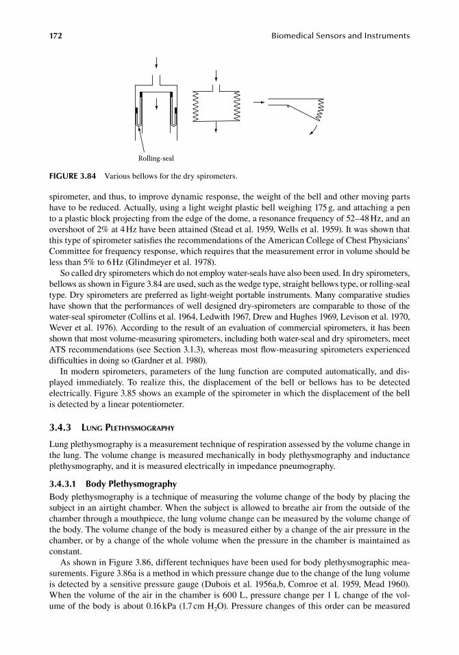
172 BiomedicalSensorsandInstruments
spirometer,.and.thus,.to.improve.dynamic.response,.the.weight.of.the.bell.and.other.moving.parts.have.to.be.reduced..Actually,.using.a.light.weight.plastic.bell.weighing.175.g,.and.attaching.a.pen.to.a.plastic.block.projecting.from.the.edge.of.the.dome,.a.resonance.frequency.of.52–48.Hz,.and.an.overshoot.of.2%.at.4.Hz.have.been.attained.(Stead.et al..1959,.Wells.et al..1959)..It.was.shown.that.this.type.of.spirometer.satisfies.the.recommendations.of.the.American.College.of.Chest.Physicians’.Committee.for.frequency.response,.which.requires.that.the.measurement.error.in.volume.should.be.less.than.5%.to.6.Hz.(Glindmeyer.et al..1978).
So.called.dry.spirometers.which.do.not.employ.water-seals.have.also.been.used..In.dry.spirometers,.bellows.as.shown.in.Figure.3.84.are.used,.such.as.the.wedge.type,.straight.bellows.type,.or.rolling-seal.type..Dry.spirometers.are.preferred.as.light-weight.portable.instruments..Many.comparative.studies.have.shown.that.the.performances.of.well.designed.dry-spirometers.are.comparable.to.those.of.the.water-seal.spirometer.(Collins.et al..1964,.Ledwith.1967,.Drew.and.Hughes.1969,.Levison.et al..1970,.Wever.et al..1976)..According.to.the.result.of.an.evaluation.of.commercial.spirometers,.it.has.been.shown.that.most.volume-measuring.spirometers,.including.both.water-seal.and.dry.spirometers,.meet.ATS.recommendations.(see.Section.3.1.3),.whereas.most.flow-measuring.spirometers.experienced.difficulties.in.doing.so.(Gardner.et al..1980).
In.modern.spirometers,.parameters.of. the.lung.function.are.computed.automatically,.and.dis-played. immediately.. To. realize. this,. the. displacement. of. the. bell. or. bellows. has. to. be. detected.electrically..Figure.3.85.shows.an.example.of.the.spirometer.in.which.the.displacement.of.the.bell.is.detected.by.a.linear.potentiometer.
3.4.3 lung plethysMography
Lung.plethysmography.is.a.measurement.technique.of.respiration.assessed.by.the.volume.change.in.the.lung..The.volume.change.is.measured.mechanically.in.body.plethysmography.and.inductance.plethysmography,.and.it.is.measured.electrically.in.impedance.pneumography.
3.4.3.1 body PlethysmographyBody.plethysmography.is.a.technique.of.measuring.the.volume.change.of.the.body.by.placing.the.subject.in.an.airtight.chamber..When.the.subject.is.allowed.to.breathe.air.from.the.outside.of.the.chamber.through.a.mouthpiece,.the.lung.volume.change.can.be.measured.by.the.volume.change.of.the.body..The.volume.change.of.the.body.is.measured.either.by.a.change.of.the.air.pressure.in.the.chamber,.or.by.a.change.of.the.whole.volume.when.the.pressure.in.the.chamber.is.maintained.as.constant.
As.shown.in.Figure.3.86,.different.techniques.have.been.used.for.body.plethysmographic.mea-surements..Figure.3.86a.is.a.method.in.which.pressure.change.due.to.the.change.of.the.lung.volume.is.detected.by.a.sensitive.pressure.gauge.(Dubois.et al..1956a,b,.Comroe.et al..1959,.Mead.1960)..When.the.volume.of.the.air.in.the.chamber.is.600.L,.pressure.change.per.1.L.change.of.the.vol-ume.of.the.body.is.about.0.16.kPa.(1.7.cm.H2O)..Pressure.changes.of.this.order.can.be.measured.
Rolling-seal
figure 3.84 Various.bellows.for.the.dry.spirometers.
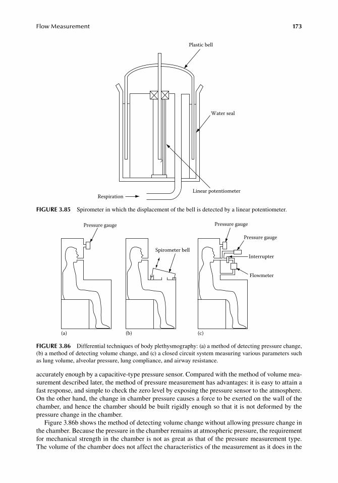
FlowMeasurement 173
accurately.enough.by.a.capacitive-type.pressure.sensor..Compared.with.the.method.of.volume.mea-surement.described.later,.the.method.of.pressure.measurement.has.advantages:.it.is.easy.to.attain.a.fast.response,.and.simple.to.check.the.zero.level.by.exposing.the.pressure.sensor.to.the.atmosphere..On.the.other.hand,.the.change.in.chamber.pressure.causes.a.force.to.be.exerted.on.the.wall.of.the.chamber,.and.hence.the.chamber.should.be.built.rigidly.enough.so.that.it.is.not.deformed.by.the.pressure.change.in.the.chamber.
Figure.3.86b.shows.the.method.of.detecting.volume.change.without.allowing.pressure.change.in.the.chamber..Because.the.pressure.in.the.chamber.remains.at.atmospheric.pressure,.the.requirement.for.mechanical.strength.in.the.chamber.is.not.as.great.as.that.of.the.pressure.measurement.type..The.volume.of.the.chamber.does.not.affect.the.characteristics.of.the.measurement.as.it.does.in.the.
Plastic bell
Water seal
Linear potentiometerRespiration
figure 3.85 Spirometer.in.which.the.displacement.of.the.bell.is.detected.by.a.linear.potentiometer.
Pressure gauge
Spirometer bell
Pressure gauge
Pressure gauge
Interrupter
Flowmeter
(a) (b) (c)
figure 3.86 Differential.techniques.of.body.plethysmography:.(a).a.method.of.detecting.pressure.change,.(b).a.method.of.detecting.volume.change,.and.(c).a.closed.circuit.system.measuring.various.parameters.such.as.lung.volume,.alveolar.pressure,.lung.compliance,.and.airway.resistance.
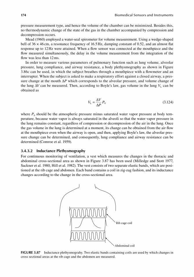
174 BiomedicalSensorsandInstruments
pressure.measurement.type,.and.hence.the.volume.of.the.chamber.can.be.minimized..Besides.this,.no.thermodynamic.change.of.the.state.of.the.gas.in.the.chamber.accompanied.by.compression.and.decompression.occurs.
Mead.(1960).employed.a.water-seal.spirometer.for.volume.measurement..Using.a.wedge-shaped.bell.of.36.×.46.cm,.a.resonance.frequency.of.16.5.Hz,.damping.constant.of.0.52,.and.an.almost.flat.response.up.to.12.Hz.were.attained..When.a.flow.sensor.was.connected.at.the.mouthpiece.and.the.flow.measured.simultaneously,. the.delay.in. the.volume.measurement.from.the.integration.of. the.flow.was.less.than.12.ms.
In.order.to.measure.various.parameters.of.pulmonary.function.such.as.lung.volume,.alveolar.pressure,.lung.compliance,.and.airway.resistance,.a.body.plethysmography.as.shown.in.Figure.3.86c.can.be.used,.in.which.the.subject.breathes.through.a.mouthpiece.with.a.flowmeter.and.an.interrupter..When.the.subject.is.asked.to.make.a.respiratory.effort.against.a.closed.airway,.a.pres-sure.change.at.the.mouth.ΔP.which.corresponds.to.the.alveolar.pressure,.and.volume.change.of.the.lung.ΔV.can.be.measured..Then,.according.to.Boyle’s.law,.gas.volume.in.the.lung.VL.can.be.obtained.as
.V
V
PPL 0 = ∆
∆ .(3.124)
where.P0.should.be.the.atmospheric.pressure.minus.saturated.water.vapor.pressure.at.body.tem-perature,.because.water.vapor.is.always.saturated.in.the.alveoli.so.that.the.water.vapor.pressure.in.the.lung.remains.constant,.regardless.of.compression.or.decompression.of.the.air.in.the.lung..Once.the.gas.volume.in.the.lung.is.determined.at.a.moment,.its.change.can.be.obtained.from.the.air.flow.at.the.mouthpiece.even.when.the.airway.is.open,.and.then,.applying.Boyle’s.law,.the.alveolar.pres-sure.change.can.be.determined,.and.consequently,.lung.compliance.and.airway.resistance.can.be.determined.(Comroe.et al..1959).
3.4.3.2 inductance PlethysmographyFor.continuous.monitoring.of.ventilation,.a.vest.which.measures.the.changes.in.the.thoracic.and.abdominal.cross-sectional.area.as.shown.in.Figure.3.87.has.been.used.(Milledge.and.Stott.1977,.Sackner.et al..1980,.Hill.et al..1982)..The.vest.consists.of.two.separate.elastic.bands,.which.are.posi-tioned.at.the.rib.cage.and.abdomen..Each.band.contains.a.coil.in.zig-zag.fashion,.and.its.inductance.changes.according.to.the.change.in.the.cross-sectional.area.
Rib cage coil
Abdominal coil
figure 3.87 Inductance.plethysmograhy..Two.elastic.bands.containing.coils.are.used.by.which.changes.in.cross.sectional.areas.at.the.rib.cage.and.the.abdomen.are.measured.
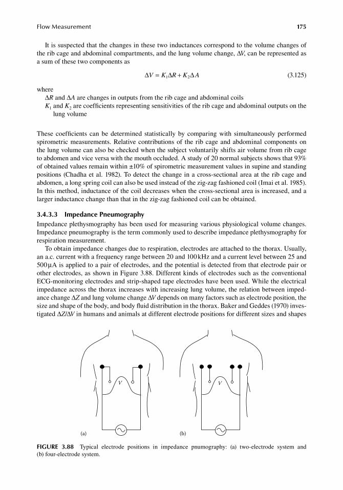
FlowMeasurement 175
It.is.suspected.that.the.changes.in.these.two.inductances.correspond.to.the.volume.changes.of.the.rib.cage.and.abdominal.compartments,.and.the.lung.volume.change,.ΔV,.can.be.represented.as.a.sum.of.these.two.components.as
. ∆ ∆ ∆V K R K A= +1 2 . (3.125)
whereΔR.and.ΔA.are.changes.in.outputs.from.the.rib.cage.and.abdominal.coilsK1.and.K2.are.coefficients.representing.sensitivities.of.the.rib.cage.and.abdominal.outputs.on.the.
lung.volume
These. coefficients. can.be.determined. statistically.by.comparing.with. simultaneously.performed.spirometric.measurements..Relative.contributions.of. the. rib.cage.and.abdominal.components.on.the.lung.volume.can.also.be.checked.when.the.subject.voluntarily.shifts.air.volume.from.rib.cage.to.abdomen.and.vice.versa.with.the.mouth.occluded..A.study.of.20.normal.subjects.shows.that.93%.of.obtained.values.remain.within.±10%.of.spirometric.measurement.values.in.supine.and.standing.positions.(Chadha.et al..1982)..To.detect.the.change.in.a.cross-sectional.area.at. the.rib.cage.and.abdomen,.a.long.spring.coil.can.also.be.used.instead.of.the.zig-zag.fashioned.coil.(Imai.et al..1985)..In.this.method,.inductance.of.the.coil.decreases.when.the.cross-sectional.area.is.increased,.and.a.larger.inductance.change.than.that.in.the.zig-zag.fashioned.coil.can.be.obtained.
3.4.3.3 impedance PneumographyImpedance.plethysmography.has.been.used.for.measuring.various.physiological.volume.changes..Impedance.pneumography.is.the.term.commonly.used.to.describe.impedance.plethysmography.for.respiration.measurement.
To.obtain.impedance.changes.due.to.respiration,.electrodes.are.attached.to.the.thorax..Usually,.an.a.c..current.with.a.frequency.range.between.20.and.100.kHz.and.a.current.level.between.25.and.500.μA.is.applied.to.a.pair.of.electrodes,.and.the.potential.is.detected.from.that.electrode.pair.or.other.electrodes,.as.shown.in.Figure.3.88..Different.kinds.of.electrodes.such.as.the.conventional.ECG-monitoring.electrodes.and.strip-shaped.tape.electrodes.have.been.used..While.the.electrical.impedance.across.the.thorax.increases.with.increasing.lung.volume,.the.relation.between.imped-ance.change.ΔZ.and.lung.volume.change.ΔV.depends.on.many.factors.such.as.electrode.position,.the.size.and.shape.of.the.body,.and.body.fluid.distribution.in.the.thorax..Baker.and.Geddes.(1970).inves-tigated.ΔZ/ΔV.in.humans.and.animals.at.different.electrode.positions.for.different.sizes.and.shapes.
V
(a)
V
(b)
figure 3.88 Typical. electrode. positions. in. impedance. pnumography:. (a). two-electrode. system. and.(b) four-electrode.system.
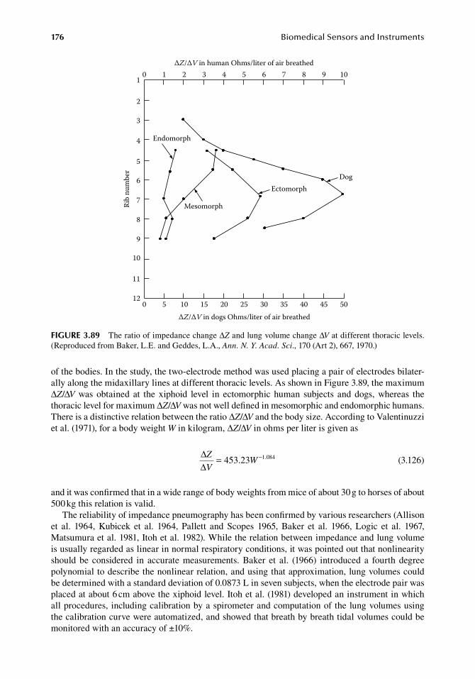
176 BiomedicalSensorsandInstruments
of.the.bodies..In.the.study,.the.two-electrode.method.was.used.placing.a.pair.of.electrodes.bilater-ally.along.the.midaxillary.lines.at.different.thoracic.levels..As.shown.in.Figure.3.89,.the.maximum.ΔZ/ΔV.was.obtained. at. the.xiphoid. level. in. ectomorphic. human. subjects. and. dogs,. whereas. the.thoracic.level.for.maximum.ΔZ/ΔV.was.not.well.defined.in.mesomorphic.and.endomorphic.humans..There.is.a.distinctive.relation.between.the.ratio.ΔZ/ΔV.and.the.body.size..According.to.Valentinuzzi.et al..(1971),.for.a.body.weight.W.in.kilogram,.ΔZ/ΔV.in.ohms.per.liter.is.given.as
.
∆∆
Z
VW= −453 23 1 084. .
.(3.126)
and.it.was.confirmed.that.in.a.wide.range.of.body.weights.from.mice.of.about.30.g.to.horses.of.about.500.kg.this.relation.is.valid.
The.reliability.of.impedance.pneumography.has.been.confirmed.by.various.researchers.(Allison.et al.. 1964,. Kubicek. et al.. 1964,. Pallett. and. Scopes. 1965,. Baker. et al.. 1966,. Logic. et al.. 1967,.Matsumura.et al..1981,.Itoh.et al..1982)..While.the.relation.between.impedance.and.lung.volume.is.usually.regarded.as.linear.in.normal.respiratory.conditions,.it.was.pointed.out.that.nonlinearity.should. be. considered. in. accurate. measurements.. Baker. et al.. (1966). introduced. a. fourth. degree.polynomial.to.describe.the.nonlinear.relation,.and.using.that.approximation,.lung.volumes.could.be.determined.with.a.standard.deviation.of.0.0873.L.in.seven.subjects,.when.the.electrode.pair.was.placed.at.about.6.cm.above.the.xiphoid.level..Itoh.et al..(1981).developed.an.instrument.in.which.all.procedures,.including.calibration.by.a.spirometer.and.computation.of.the.lung.volumes.using.the.calibration.curve.were.automatized,.and.showed.that.breath.by.breath.tidal.volumes.could.be.monitored.with.an.accuracy.of.±10%.
Endomorph
Mesomorph
EctomorphDog
Rib
num
ber
ΔZ/ΔV in human Ohms/liter of air breathed
ΔZ/ΔV in dogs Ohms/liter of air breathed
0 1 2 3 4 5 6 7 8 9 101
2
3
4
5
6
7
8
9
10
11
120 5 10 15 20 25 30 35 40 45 50
figure 3.89 The.ratio.of.impedance.change.ΔZ.and.lung.volume.change.ΔV.at.different.thoracic.levels..(Reproduced.from.Baker,.L.E..and.Geddes,.L.A.,.Ann. N. Y. Acad. Sci.,.170.(Art.2),.667,.1970.)
FlowMeasurement 177
referenCeS
Adams,.T.,.Heisey,.S..R.,.Smith,.M..C.,.Steinmetz,.M..A.,.Hartman,.J..C.,.and.Fly,.H..K..1980..Thermodynamic.technique. for. the.quantification.of. regional.blood.flow,.Am. J. Physiol.. (Heart Circ. Physiol.. 7).238:.H682–H696.
Ahn,.H.,.Johansson,.K.,.Lundgren,.O.,.and.Nilsson,.G..E..1987..In-vivo.evaluation.of.signal.processors.for.laser.Doppler.tissue.flowmeters,.Med. Biol. Eng. Comput..25:.207–211.
Algotsson,.A..1995..Vascular. reactivity.and.autonomic.functions. in.Alzheimer’s.disease..Thesis..Huddinge,.Sweden:.Karolinska.Institutet,.Huddinge.University.Hospital.
Allen,.H..V.,.Anderson,.M..F.,.and.Meindl,.J..D..1977..Direct.calibration.of.a.totally.implantable.pulsed.Doppler.ultrasonic.blood.flowmeter,.Am. J. Physiol..232:.H537–H544.
Allison,.R..D.,.Holmes,.E..L.,.and.Nyboer,.J..1964..Volumetric.dynamics.of.respiration.as.measured.by.electri-cal.impedance.plethysmography,.J. Appl. Physiol..19:.66–73.
Anderson,.R..R..and.Parrish,.J..A..1981..The.optics.of.human.skin,.J. Invest. Dermatol..77:.13–19.Andersson,.T..1995..Cutaneous.microdialysis..Linköping.University.Medical.Dissertation,.No..456..Linköping,.
Sweden:.Linköping.University.Arts,.M..G..J..and.Roevros,.J..M..J..G..1972..On.the.instantaneous.measurement.of.blood.flow.by.ultrasonic.
means,.Med. Biol. Eng..10:.23–34.Asano,.M.,.Yoshida,.K.,. and.Tatai,.K..1963..Observation.of. the.behavior.of.microcirculation.by. rabbit. ear.
chamber.technique..I..On.a.modification.of.rabbit.ear.chamber,.development.of.microphotoelectric.pleth-ysmography,.and.rhythmic.fluctuation.of.microcirculation,.Bull. Inst. Publ. Health.12:.34–43.
Asano,.M.,.Yoshida,.K.,.and.Tatai,.K..1964..Blood.flow.rate.in.the.microcirculation.as.measured.by.photoelec-tric.microscopy,.Bull. Inst. Publ. Health.13:.201–209.
Asmussen,.E..and.Nielsen,.M..1952..The.cardiac.output.in.rest.and.work.determined.simultaneously.by.the.acetylene.and.the.dye.injection.methods,.Acta Physiol. Scand..27:.217–230.
Atkinson,.P..and.Woodcock,.J..P..1982..Doppler Ultrasound and its Use in Clinical Measurement,.London,.U.K.:.Academic.Press,.p..22.
Aukland,.K.,.Bower,.B..F.,.and.Berliner,.R..W..1964..Measurement.of.local.blood.flow.with.hydrogen.gas,.Circ. Res..14:.164–187.
Austin,.W..H.,.Poppell,.J..W.,.and.Baliff,.R..J..1961..Cardiac.output.measurement.by.external.counting.of.a.rapidly.excreted.indicator,.Am. J. Med. Sci..242:.457–462.
Axel,. L.. 1980.. Cerebral. blood. flow. determination. by. rapid-sequence. computed. tomography:.A. theoretical.analysis,.Radiology.137:.679–86.
Baan,.J.,.Aouw.Jong,.T..T.,.Kerkhof,.P..L..M.,.Moene,.R..J.,.van.Dijk,.A..D.,.van.der.Velde,.E..T.,.and.Koops,.J..1981.. Continuous. stroke. volume. and. cardiac. output. from. intra-ventricular. dimensions. obtained. with.impedance.catheter,.Cardiovasc. Res..15:.328–334.
Baker,. D.. W.. 1970.. Pulsed. ultrasonic. Doppler. blood-flow. sensing,. IEEE Trans. Sonics Ultrason.. 17:.170–185.
Baker,.L..E..and.Geddes,.L..A..1970..The.measurement.of.respiratory.volumes.in.animals.and.man.with.use.of.electrical.impedance,.Ann. N. Y. Acad. Sci..170.(Art.2):.667–688.
Baker,.M..and.Wayland,.H..1974..One-line.volume.flow.rate.and.velocity.profile.measurement.for.blood.in.microvessels,.Microvasc. Res..7:.131–143.
Baker,.L..E.,.Geddes,.L..A.,.and.Hoff,.H..E..1966..A.comparison.of.linear.and.non-linear.characterizations.of.impedance.spirometry.data,.Med. Biol. Eng..4:.371–379.
Barendsen,.G..J.,.Venema,.H.,.and.van.den.Berg,.J..W..1971..Semicontinuous.blood.flow.measurement.by.trig-gered.venous.occlusion.plethysmography,.J. Appl. Physiol..31:.288–291.
Bashour,.F..A..and.Jones,.R..E..1965..Digital.blood.flow,.1..Correlative.study.of.the.electrical.impedance.and.venous.occlusion.plethysmographs,.Dis. Chest.47:.465–469.
Battocletti,.J..H..1986..Blood.flow.measurement.by.NMR,.CRC Crit. Rev..13:.311–367.Battocletti,.J..H.,.Halbach,.R..E.,.Salles-Cunha,.S..X.,.Sances,.A..Jr.,.Towne,.J..B.,.Hebert,.L..A.,.and.Kauffman,.H. M..
1979a..Clinical.applications.of.the.NMR.limb.blood.flowmeter,.Proc. IEEE.67:.l359–1361.Battocletti,.J..H.,.Halbach,.R..E.,.Sances,.A..Jr.,.Larson,.S..L.,.Bowman,.R..L.,.and.Kudravcev,.V..1979b,.A.flat.
crossed.coil.detector.for.blood.flow.measurement.using.NMR,.Med. Biol. Eng. Comput..17:.183–191.Becklake,.M..R.,.Varvis,.C..J.,.Pengelly,.L..D.,.Kenning,.S.,.McGregor,.M.,.and.Bates,.D..V..1962..Measurement.
of.pulmonary.blood.flow.during.exercise.using.nitrous.oxide,.J. Appl. Physiol..17:.579–586.Belcaro,.G.,.Labropoulos,.N.,.Laurora,.G.,.Cesarone,.M..R.,.De.Sanctis,.M..T.,.and.Incandela,.L..1994..Laser.
Doppler.skin.perfusion.pressure.in.normal.and.vascular.subjects.with.rest.pain:.An.universal.measure-ment?.J. Cardiovasc. Surg..35:.7–9.
178 BiomedicalSensorsandInstruments
Benchimol,.A.,.Stegall,.H..F.,.Maroko,.P..R.,.Gartlan,.J..L.,.and.Brener,.L..1969..Aortic.flow.velocity.in.man.during. cardiac. arrhythmias. measured. with. the. Doppler. catheter-flowmeter. system,. Am. Heart J.. 78:.649–659.
Bingger,.F.,.Fiala,. J.,.Seifert,.A.,.Weber,.N.,.Moser,.A.,.Goldschmidtboeing,.F.,.Foerster,.K.,.Heilmann,.C.,.Beyersdorf,.F.,.Woias,.P.,.and.Zappe,.H..2009..Implantable.multisensor.system.for.in.vivo.monitoring.of. cardiovascular. parameters.. IEEE Conference on Transducers 2009,. Denver,. CO,. June. 21–25,.pp. 1469–1472.
Blumenfeld,.W.,.Wilson,.P..D.,.and.Turney,.S..1974..A.mathematical.model.for.the.ultrasonic.measurement.of.respiratory.flow,.Med. Biol. Eng..l2:.621–625.
Bohren,.C..F..and.Hoffman,.D..R..1983..Absorption and Scattering of Light by Small Particles,.New.York:.John.Wiley.&.Sons.
Bolz,.A.,.Lang,.V.,.Merkly,.B.,.Popp,.T.,.and.Schaldach,.M..1997..Evaluation.of.hemodynamic.sensors. for.implantable.defibrillators,.Biomed. Tech..Suppl..42:.263–264.
Bonner,.R..F..and.Nossal,.R..1981..Model.for.laser.Doppler.measurements.of.blood.flow.in.tissue,.Appl. Opt..20:.2097–2107.
Bonner,.R..F.,.Clem,.T..R.,.Bowen,.P..D.,.and.Bowman,.R..L..1981..Laser-Doppler.continuous.real-time.moni-tor. of. pulsatile. and. mean. blood. flow. in. tissue. microcirculation,. in. Scattering Techniques Applied to Supra-Molecular and Nonequilibrium Systems,.Vol..73..Chen,.S..H.,.Chu,.B.,.and.Nossal,.R.,.eds..New.York:.Plenum.Press,.pp..685–701.
Bonner,.R..F.,.Nossal,.R.,.Havlin,.S.,.and.Weiss,.G..H..1987..Model.for.photon.migration.in.turbid.biological.media,.J. Opt. Soc. Am..A4:.423–432.
Born,.G..V..R.,.Melling,.A.,.and.Whitelaw,.J..W..1987..Laser.Doppler.microscope.for.blood.velocity.measure-ments,.Biorheology.15,.163–172.
Bornmyr,.S.,.Arner,.M.,.and.Svensson,.H..1994..Laser.Doppler.Imaging.of.finger.skin.blood.flow.in.patients.after.microvascular.repair.of.the.ulnar.artery.at.the.wrist,.J. Hand. Surg..19B:.295–300.
Bourdillon,.P..J.,.Becket,.J..M.,.and.Duffin,.P..1979..Saline.conductivity.method.for.measuring.cardiac.output.simplified,.Med. Biol. Eng. Comput..17:.323–329.
Bowman,.R..L..and.Kudravcev,.V..1959..Blood.flow.utilizing.nuclear.magnetic.resonance,.IRE Trans. Med. Electron..6:.267–269.
Bradbury,.L..J..S..and.Castro,.L..P..1971..A.pulsed.wire.technique.for.velocity.measurements.in.high.turbulent.flows,.J. Fluid Mech..49:.657–691.
Brakkee,.A..J..M..and.Vendrik,.A..J..H..1966..Strain-gauge.plethysmography:.Theoretical.and.practical.notes.on.a.new.design,.J. Appl. Physiol..21:.701–704.
Branthwaite,. M..A.. and. Bradley,. R.. D.. 1968.. Measurement. of. cardiac. output. by. thermal. dilution. in. man,.J. Appl. Physiol..24:.434–438.
Brecher,.G..A..1953..Venous.return.during.intermittent.positive-negative.pressure.respiration.studied.with.a.new.catheter.flowmeter,.Am. J. Physiol..174:.299–303.
Brecher,.G..A..1954..Cardiac.variations.in.venous.return.studied.with.a.new.bristle.flowmeter,.Am. J. Physiol..176,.423–430.
Brecher,.G..A..1959..Critical.review.of.bristle.flowmeter.techniques,.IRE Trans. Med. Electro..6:.294–304.Brecher,.G..A..and.Praglin,.J..1953..A.modified.bristle.flowmeter.for.measuring.phasic.blood.flow,.Proc. Soc.
Exp. Biol. Med..83:.155–157.Briers,.J..D..2001..Laser.Doppler,.speckle.and.related.techniques.for.blood.perfusion.mapping.and.imaging,.
Physiol. Meas..22:.R35–R66.Brodie,. T.. G.. and. Russell,.A.. E.. 1905.. On. the. determination. of. the. rate. of. blood-flow. through. an. organ,.
J. Physiol. (London).32:.47P–49P.Buess,.C.,.Pietsch,.P.,.Guggenbühl,.W.,.and.Koller,.E..A..1986a..A.pulsed.diagonal-beam.ultrasonic.airflow.
meter,.J. Appl. Physiol..61:.1195–1199.Buess,.C.,.Pietsch,.P.,.Guggenbühl,.W.,.and.Koller,.E..A..1986b..Design.and.construction.of.a.pulsed.ultrasonic.
air.flowmeter,.IEEE Trans. Biomed. Eng..33:.768–774.Burton,.R..G..and.Gorewit,.R..C..1984..Ultrasonic.flowmeter.uses.wide-beam.transit-time. technique,.Med.
Electron..15:.68–73.Buxton,.R..B..2005..Quantifying.CBF.with.arterial.spin.labeling,.J. Magn. Reson. Imag..22:.723–726.Buxton,.R..B.,.Frank,.L..R.,.Wong,.E..C.,.Siewert,.B.,.Warach,.S.,.and.Edelman,.R..R..1998..A.general.
kinetic.model.for.quantitative.perfusion.imaging.with.arterial.spin.labeling,.Magn. Reson. Med..40:.383–396.
Campbell,.E..J..M..and.Howell,.J..B..L..1962..Rebreathing.method.for.measurement.of.mixed.venous.Pco2,.Br. Med. J..8:.630–633.
FlowMeasurement 179
Carter,.J.,.Reynoldson,.J..A.,.Thorburn,.G..D.,.and.Bates,.W..A..1981..Blood.flow.measurement.during.exercise.in.sheep.using.Doppler.ultrasonic.method,.Med. Biol. Eng. Comput..19:.373–376.
Chadha,.T..S.,.Watson,.H.,.Birch,.S.,.Jenouri,.G..A.,.Schneider,.A..W.,.Cohn,.M..A.,.and.Sackner,.M..A..1982..Validation. of. respiratory. inductive. plethysmography. using. different. calibration. procedures,. Am. Rev. Respir. Dis..125:.644–649.
Chato,.J..C..1980..Heat.transfer.to.blood.vessels,.Trans. ASME.102:.110–118.Chu,.B..1974..Laser Light Scattering,.New.York:.Academic.Press.Clark,.C..1968..A.local.thermal.dilution.flowmeter.for.the.measurement.of.venous.blood.flow.in.man,.Med.
Biol. Eng..6:.133–142.Clark,.C..1974..Thin.film.gauges. for.fluctuating.velocity.measurements. in.blood,.J. Phys. E. Sci. Instrum..
7: 548–556.Cochrane,. T.,. Earnshaw,. J.. C.,. and. Love,.A.. H.. 1981.. Laser. Doppler. measurements. of. blood. velocity. in.
microvessels,.Med. Biol. Eng. Comput..19:.589–596.Cole,.J..S..and.Hartley,.C..J..1977..The.pulsed.Doppler.coronary.artery.catheter..Preliminary.report.of.a.new.
technique.for.measuring.rapid.changes.in.coronary.artery.flow.velocity.in.man,.Circulation.56:.18–25.Collier,.C..R..1956..Determination.of.mixed.venous.CO2.tensions.by.rebreathing,.J. Appl. Physiol..9:.25–29.Collis,.D..C..and.Williams,.M..J..1959..Two-dimensional.convection.from.heated.wire.at.low.Reynolds.num-
bers,.J. Fluid Mech..6:.357–384.Collins,.M..M.,.McDermott,.M.,.and.McDermott,.T..J..1964..Bellows.spirometer.and.transistor.timer.for.the.
measurement.of.forced.expiratory.volume.and.vital.capacity,.J. Physiol. (London).172:.39P–41P.Comroe,.J..H.,.Botelho,.S..Y.,.and.Dubois,.A..B..1959..Design.of.a.body.plethysmograph.for.studying.cardio-
pulmonary.physiology,.J. Appl. Physiol..14:.439–444.Comte-Bellot,.G..1976..Hot-wire.anemometry,.Ann. Rev. Fluid Mech..8:.209–231.Constantinou,.C..E..and.Briggs,.E..M..1970..Precision.electrostatic.urine.flowmeter,.J. Appl. Physiol..9:.96–77.Cote,.G..L..and.Fox,.M..D..1988..Comparison.of.zero-crossing.counter.to.FFT.spectrum.of.ultrasound.Doppler,.
IEEE Trans. Biomed. Eng..35:.498–502.Dahn,.I..1964..On.the.calibration.and.accuracy.of.segmental.calf.plethysmography.with.a.description.of.a.new.
expansion.chamber.and.a.new.sleeve,.Scand. J. Clin. Lab. Invest..16:.347–54.Dahn,.I..and.Hallböök,.T..1970..Simultaneous.blood.flow.measurement.by.water.and.strain.gauge.plethysmog-
raphy,.Scand. J. Clin. Lab. Invest..25:.419–428.Dahn,.I.,.Jonson,.B.,.and.Nilsèn,.R..1970..A.plethysmographic.method.for.determination.of.flow.and.volume.
pulsations.in.a.limb,.J. Appl. Physiol..28:.333–336.Damber,.J..E.,.Lindahl,.O.,.Selstam,.G.,.and.Tenland,.T..1982..Testicular.blood.flow.measured.with.a. laser.
Doppler.flowmeter:.Acute.effects.of.cathecolamines,.Acta Physiol. Scand..115:.209–215.Dawes,.G..S.,.Mott,.J..C.,.and.Vane,.J..R..1953..The.density.flowmeter,.a.direct.method.for.the.measurement.of.
the.rate.of.blood.flow,.J. Physiol..121:.72–79.de.Mul,.F..F.,.Steenbergen,.W.,.and.Greve,.J..1999..Doppler.Monte.Carlo.simulations.of.light.scattering.in.tissue.
to.support.laser-Doppler.perfusion.measurements..Technol. Health Care.7:.171–183.de.Mul,.F..F..M.,.van.Spijker,.J.,.van.der.Plas,.D.,.Greve,.J.,.Aarnoudse,.J..G.,.and.Smits,.T..M..1984..Mini.
laser-Doppler.(blood).flow.monitor.with.diode.laser.source.and.detection.integrated.in.the.probe,.Appl. Opt..23:.2970.
de.Mul,.F..F..M.,.Scalise,.L.,.Petoukhova,.A..L.,.van.Herwijnen,.M.,.Moes,.P.,.and.Steenbergen,W..2002..Glass-fiber.self-mixing.intra-arterial.laser.Doppler.velocimetry;.signal.stability.and.feedback.analysis..Appl. Opt..41:.658–667.
Defares,.J..G..1958..Determination.of.Pvco2.from.the.exponential.CO2.rise.during.rebreathing,.J. Appl. Phys..13:.159–164.
Denniston,.J..C.,.Maher,.J..T.,.Reeves,.J..T.,.Cruz,.J..C.,.Cymerman,.A.,.and.Grover,.R..F..1976..Measurement.of.cardiac.output.by.electrical.impedance.at.rest.and.during.exercise,.J. Appl. Physiol..40:.91–98.
Di.Pietro,.D..M..and.Meindl,.J..D..1978..Optimal.system.design.for.an.implantable.CW.Doppler.ultrasonic.flowmeter,.IEEE Trans. Biomed. Eng..25:.255–264.
DiResta,.G..R.,.Kiel,.J..W.,.Riedel,.G..L.,.Kaplan,.P.,.and.Shepherd,.A..P..1987..Hybrid.blood.flow.probe.for.simultaneous.H2.clearance.and.laser-Doppler.velocimetry,.Am. J. Physiol..253:.G573–G581.
Donovan,.K..D.,.Dobb,.G..J.,.Woods,.W..P.,.and.Hockings,.B..E..1986..Comparison.of.transthoracic.electrical.impedance.and.thermodilution.methods.for.measuring.cardiac.output,.Crit. Care Med..14:.1038–1044.
Drew,. C.. D.. M.. and. Hughes,. D.. T.. D.. 1969.. Characteristics. of. the.Vitalograph. spirometer,. Thorax. 24:.703–706.
Drost,.C..J..1978..Vessel.diameter-independent.volume.flow.measurements.using.ultrasound..Proc. San Diego Biomed. Symp.,.San.Diego,.CA.17:.299–302.

180 BiomedicalSensorsandInstruments
Dubois,.A..B.,.Britt,.A..B.,.and.Fenn,.W..O..1952..Alveolar.CO2.during.the.respiratory.cycle,.J. Appl. Physiol..4:.535–548.
Dubois,.A..B.,.Botelho,.S..Y.,.and.Comroe,.J..H..1956a..A.new.method.for.measuring.airway.resistance.in.man.using.a.body.plethysmograph:.Value.in.normal.subjects.and.in.patients.with.respiratory.disease,.J. Clin. Invest..35:.327–335.
Dubois,.A..B.,.Botelho,.S..Y.,.Bedell,.G..N.,.Marshall,.R.,.and.Comroe,.J..H..1956b..A.rapid.plethysmographic.method.for.measuring.thoracic.gas.volume:.A.comparison.with.a.nitrogen.washout.method.for.measuring.functional.residual.capacity.in.normal.subjects,.J. Clin. Invest..35:.322–326.
Duteil,.L.,.Bernengo,.J..C.,.and.Schalla,.W..1985..A.double.wavelength.laser.Doppler.system.to.investigate.skin.microcirculation,.IEEE Trans. Biomed. Eng..32:.439–447.
Eisenmann,.J..H.,.Huntington,.G..B.,.and.Ferrell,.C..L..1987..Blood.flow.to.hindquarters.of.steers.measured.by.transit.time.ultrasound.and.indicator.dilution,.J. Dairy Sci..70:.1385–1390.
Elliott,.S..E.,.Shore,.J..K.,.Barnes,.C..W.,.Lindauer,.J.,.and.Osborn,.J..J..1977..Turbulent.air.flow.meter.for.long-term.monitoring.in.patient-ventilator.circuits,.J. Appl. Physiol. Respir. Environ. Exerc. Physiol..42:.456–460.
Engelhart,.M..and.Kristensen,.J..K..1983..Evaluation.of.cutaneous.blood.flow.responses.by.133Xenon.washout.and.a.laser-Doppler.flowmeter,.J. Invest. Dermatol..80:.12–15.
Engelhart,.M.,.Petersen,.L..J.,.and.Kristensen,.J..K..1988..The.local.regulation.of.blood.flow.evaluated.simulta-neously.by.133-xenon.washout.and.laser.Doppler.flowmetry,.J. Invest. Dermatol..91:.451–453.
Engström,.R..W..1947..Multiplier.phototube.characteristics:.Application.to.low.light.levels,.J. Opt. Soc..37:.420–431.
Eniav,.S.,.Berman,.H..J.,.Fuhro,.R..L.,.DiGiovanni,.P..R.,.Fridman,.J..D.,.and.Fine,.S..1975..Measurement.of.blood.flow.in.vivo.by.laser.Doppler.anemometry.through.a.microscope,.Biorheology.12:.203–205.
Essex,.T..J..H..and.Byrne,.P..O..1991..A.laser.Doppler.scanner.for.imaging.blood.flow.in.skin,.J. Biomed. Eng..13:.189–194.
Evans,. D.. H.. 1986.. Can. ultrasonic. duplex. scanners. really. measure. volumetric. blood. flow?,. in. Physics in Medical Ultrasound,.Evans,.J..A.,.ed..London,.U.K.:.The.Institute.of.Physical.Sciences. in.Medicine,.pp..145–154.
Eyre,.J..A.,.Essex,.T..J..H.,.Flecknell,.P..A.,.Bartholomew,.P..H.,.and.Sinclair,.J..I..1988..A.comparison.of.mea-surements.of.cerebral.blood.flow.in.the.rabbit.using.laser.Doppler.spectroscopy.and.radionuclide.labelled.microspheres,.Clin. Phys. Physiol. Meas..9:.65–74.
Farhi,.L..E.,.Nesarajah,.M..S.,.Olszowka,.A..J.,.Metildi,.L..A.,.and.Ellis,.A..K..1976..Cardiac.output.determina-tion.by.simple.one-step.breathing.technique,.Respir. Physiol..28:.141–189.
Fercher,.A..F..and.Briers,.J..D..1981..Flow.visualization.by.means.of.single-exposure.speckle.photography,.Opt. Commun..37:.326–330.
Finucane,.K..E.,.Egan,.B..A.,.and.Dawson,.S..V..1972..Linearity.and.frequency.response.of.pneumotacho-graphs,.J. Appl. Physiol..32:.121–126.
FitzGerald,.M..X.,.Smith,.A..A.,.and.Gaensler,.E..A..1973..Evaluation.of.“electronic”.spirometers,.N. Engl. J. Med..289:.1283–1288.
Flax,.S..W.,.Webster,.J..G.,.and.Updike,.S..J..1970..Statistical.evaluation.of.the.Doppler.ultrasonic.blood.flow-meter,.Biomed. Sci. Instr..7:.201–222.
Fleisch,.A..1956..Le.pneumotachographe,.Helv. Physiol. Pharmacol. Acta.14:.363–368.Folkow,.B..and.Neil,.E..1971..Circulation,.Vol..3,.London,.U.K.:.Oxford.University.Press.Follett,.D..H..and.Preece,.A..W..1969..A.new.principle.for.level.recording.in.venous.occlusion.plethysmography,.
Med. Biol. Eng..7:.217–220.Formel,.P..F..and.Doyle,.J..T..1957..Rationale.of.venous.occlusion.plethysmography,.Circ. Res..5:.354–356.Forrester,.J..S.,.Ganz,.W.,.Diamand,.G.,.McHugh,.T.,.Chonette,.D..W.,.and.Swan,.H..J..C..1972..Thermodilution.
cadiac.output.determination.with.a.single.flow-directed.catheter,.Am. Heart J..83:.306–311.Fox,.I..J..1962..Indicators.and.detectors.for.circulatory.dilution.studies.and.their.application.to.organ.or.regional.
blood-flow.determination,.Circ. Res..10:.447–471.Franklin,.D..L.,.Baker,.D..W.,.Ellis,.R..M.,.and.Rushmer,.R..F..1959..A.pulsed.ultrasonic.flowmeter,.IRE Trans.
Med. Electron..6:.204–206.Franklin,.D..L.,.Schlegel,.W.,.and.Rushmer,.R..F..1961..Blood.flow.measured.by.Doppler.frequency.shift.of.
back-scattered.ultrasound,.Science.134:.564–565.Franklin,.D..L.,.Baker,.D..W.,.and.Rushmer,.R..F..1962..Pulsed.ultrasonic.transit.time.flowmeter,.IRE Trans.
Biomed. Electron..9:.44–49.Franklin,.D..L..1965..Techniques.for.measurement.of.blood.flow.through.intact.vessels,.Med. Electron. Biol.
Eng..3:.27–37.
FlowMeasurement 181
Fronek,.A..and.Ganz,.V..1960..Measurement.of.flow.in.single.blood.vessels.including.cardiac.output.by.local.thermodilution,.Circ. Res..8:.175–182.
Fry,.D..L..1959..The.measurement.of.pulsatile.blood.flow.by.the.computed.pressure.gradient.technique,.IRE Trans. Med. Electron..6:.259–264.
Fry,.D..L.,.Mallos,.A..J.,.and.Casper,.A..G..T..1956..A.catheter.tip.method.for.measurement.of.the.instantaneous.aortic.blood.velocity,.Circ. Res..4:.627–632.
Fry,.D..L.,.Hyatt,.R..E.,.McCall,.C..B.,.and.Mallos,.A..J..1957..Evaluation.of.three.types.of.respiration.flowme-ter,.J. Appl. Physiol..10:.2l0–214.
Fu,.S..E..and.Lee,.J..S..1978..A.video.system.for.measuring.the.blood.flow.velocity.in.microvessels,.IEEE Trans. Biomed. Eng..25:.295–297.
Fujii,.H.,.Nohira,.K.,.Yamamoto,.Y.,.Ikawa,.H.,.and.Ohura,.T..1987..Evaluation.of.blood.flow.by.laser.speckle.image.sensing,.Part.1,.Appl. Opt..26:.5321–5325.
Gabriel,.S.,.Atterhög,.J..H.,.Orö,.L.,.and.Ekelund,.L..G..1976..Measurement.of.cardiac.output.by.impedance.cardiology.in.patients.with.myocardial.infarction,.Scand. J. Clin. Lab. Invest..36:.29–34.
Gaehtgens,.P.,.Meiselman,.H..J.,.and.Wayland,.H..1970..Erythrocyte.flow.velocities.in.mesenteric.microvessels.of.the.cat,.Microvasc. Res..2:.151–162.
Ganz,.W..and.Swan,.H..J..C..1972..Measurement.of.blood.flow.by.thermodilution,.Am. J. Cardiol..29:.241–246.Ganz,.W.,.Donoso,.R.,.Marcus,.H..S.,.Forrester,.J..S.,.and.Swan,.H..J..C..1971a..A.new.technique.for.measure-
ment.of.cardiac.output.by.thermodilution.in.man,.Am. J. Cardiol..27:.392–396.Ganz,.W.,.Tamura,.K.,.Marcus,.H..S.,.Donoso,.R.,.Yoshida,.S.,.and.Swan,.H..J..C..1971b..Measurement.of.
coronary.sinus.blood.flow.by.continuous.thermodilution.in.man,.Circulation.44:.181–195.Gardner,.R..M.,.Hankinson,.J..L.,.and.West,.B..J..1980..Evaluating.commercially.available.spirometers,.Am.
Rev. Respir. Dis..121:.73–82.Geddes,.L..A..and.Sadler,.C..1973..The.specific.resistance.of.blood.at.body.temperature,.Med. Biol. Eng..11:.
336–339.Geddes,.L..A.,.Moore,.A..G.,.Bourland,.J.,.Vasku,.J.,.and.Contrell,.G..1969..An.efficient.indirect.drop.trans-
ducer,.Med. Res. Eng..8:.27–28.Gedeon,.G.,.Forslund,.L.,.Hedenstierna,.G.,.and.Romano,.E..1980..A.new.method.for.noninvasive.bedside.
determination.of.pulmonary.blood.flow,.Med. Biol. Eng. Comput..18:.411–418.Gessner,. U.. 1969..The. performance. of. the. ultrasonic. flowmeter. in. complex. velocity. profiles,. IEEE Trans.
Biomed. Eng..16:.139–142.Gilford,.S..R.,.Gregg,.D..E.,.Shadle,.O..W.,.Ferguson,.T..B.,.and.Marzetta,.L..A..1953..An.improved.cuvette.den-
sitometer.for.cardiac.output.determination.by.the.dye-dilution.method,.Rev. Sci. Instrum..24:.696–702.Glindmeyer,.H..W.,.Sharon,.D..E.,.Anderson,.S..T.,.Drem,.J..E.,.and.Weill,.H..1978..Comparison.of.the.Jones.
and.Stead-Wells.spirometer,.Chest.73:.596–602.Golabbakhsh,. M.. 2004.. Tracheal. breath. sound. relationship. with. respiratory. flow:. Modeling,. the. effect. of.
age. and. airflow. estimation.. MSc. thesis.. Manitoba,. Canada:. Department. of. Electrical. and. Computer.Engineering,.University.of.Manitoba.
Goldman,.S..C.,.Marple,.N..B.,.and.Scolnik,.W..L..1963..Effects.of.flow.profile.on.electromagnetic.flowmeter.accuracy,.J. Appl. Phys..18:.652–657.
Goldstein,.A..1988..Ultrasonic.imaging,.in.Encyclopedia of Medical Devices and Instrumentations,.Webster.J. G.,.ed..New.York:.John.Wiley.&.Sons.
Goodman,.A..H..1986..CCD.line-scan.image.sensor.for.the.measurement.of.red.cell.velocity.in.microvessels,.J. Biomed. Eng..8:.329–333.
Goodman,.A..H.,.Guyton,.A..C.,.Drake,.R.,.and.Loflin,.J..H..1974..A.television.method.for.measuring.capillary.red.cell.velocities,.J. Appl. Physiol..37:.126–130.
Goodwin,. R.. S.. and. Sapirstein,. L..A.. 1957.. Measurement. of. the. cardiac. output. in. dogs. by. a. conductivity.method.after.single.intravenous.injections.of.autogenous.plasma,.Circ. Res..5:.531–538.
Goodyear,.A..V..N.,.Huvos,.A.,.Eckhardt,.W..F.,.and.Ostberg,.R..H..1959..Thermal.dilution.curves.in.the.intact.animal,.Circ. Res..7:.432–441.
Gorten,.R..J..and.Stauffer,.J..C..1959..A.study.of.the.techniques.and.sources.of.error.in.the.clinical.application.of.the.external.counting.method.of.estimating.cardiac.output,.Am. J. Med. Sci..238:.274–279.
Grayson,.J..1952..Internal.calorimetry.in.the.determination.of.thermal.conductivity.and.blood.flow,.J. Physiol..118:.54–72.
Greenfield,.A..D..M..1959..A.simple.water-filled.plethysmograph.for.the.hand.or.forearm.with.temperature.control,.J. Physiol. (London).123:.62P–55P.
Greenfield,.A..D..M.,.Whitney,.R..J.,.and.Mowbray,.J..F..1963..Methods.for. the. investigation.of.peripheral.blood.flow,.Br. Med. Bull..19:.101–109.
182 BiomedicalSensorsandInstruments
Gregory,. G..A.. and. Kitterman,. J..A.. 1971.. Pneumotachograph. for. use. with. infants. during. spontaneous. or.assisted.ventilation,.J. Appl. Phys..31:.766–767.
Gross,.G..and.Light,.L..H..1971..Direction-resolving.Doppler. instrument.with. improved.rejection.of. tissue.artifacts.for.transcutaneous.aortovelography,.J. Physiol..217:.5P–7P.
Grover,.T..and.Singer,.J..R..1971..NMR.spin.echo.flow.measurements,.J. Appl. Phys..42:.938–940.Grubbs,.D..S.,.Worley,.D..S.,.and.Geddes,.L..A..1982..A.new.technique.for.obtaining.values.of.cardiac.output.
in.rapid.succession,.IEEE Trans. Biomed. Eng..29:.769–772.Gur,.D.,.Good,.W..F.,.Wolfson,.S..K..Jr.,.Yonas,.H.,.and.Shabason,.L..1982..In.vivo.mapping.of.local.cerebral.
blood.flow.by.xenon-enhanced.computed.tomography,.Science.215:.1267–1268.Guyton,.A.. C.. 1963.. Circulatory Physiology: Cardiac Output and Its Regulation,. Philadelphia,. PA:.W.. B..
Sanders.Co.,.pp..21–39.Guyton,.A..C..and.Farish,.C..A..1959..A.rapidly.responding.continuous.oxygen.consumption.recorder,.J. Appl.
Physiol..14:.143–147.Guyton,.A..C.,.Farish,.C..A.,.and.Williams,.J..W..1959..An.improved.arteriovenous.oxygen.difference.recorder,.
J. Appl. Physiol..14:.145–147.Haacke,.E..M.,.Brown,.R..W.,.Thompson,.M..R.,. and.Venkatesan,.R..1999..Magnetic Resonance Imaging,
Physical Principles and Sequence Design,.New.York:.John.Wiley.&.Sons.Haining,.J..L.,.Turner,.M..D.,.and.Pantall,.R..M..1968..Measurement.of.local.cerebral.blood.flow.in.the.unanes-
thetized.rat.using.a.hydrogen.clearance.method,.Circ. Res..23:.313–324.Halbach,.R..E.,.Battocletti,.J..H.,.and.Sances,.A..Jr..1979..Cylindrical.crossed-coil.NMR.limb.blood.flowmeter,.
Rev. Sci. Instrum..50:.428–434.Hallböök,.T.,.Männson,.B.,. and.Nilsén,.R..1970..Strain.gauge.plethysmography.with.electrical. calibration,.
Scand. J. Clin. Lab. Invest..25:.413–418.Hamilton,.W..F.,.Moore,.J..W.,.Kinsman,.J..M.,.and.Spurling,.R..G..1932..Studies.on.the.circulation.IV..Further.
analysis.of.the.injection.method,.and.of.changes.in.hemodynamics.under.physiological.and.pathological.conditions,.Am. J. Physiol..99:.534–551.
Harding,.D..C.,.Rushmer,.R..F.,.and.Baker,.D..W..1967..Thermal.transcutaneous.flowmeter,.Med. Biol. Eng..5:.623–626.
Hatterland,.K..and.Eriksen,.M..1981..A.heterodyne.ultrasound.blood.velocity.meter,.Med. Biol. Eng. Comput..19:.91–96.
Haumschild,.D..J..1986..Microvascular.blood.flow.measurement.by.laser.Doppler.flowmetry,.in.TSI Application Note,.St..Paul,.MN:.TSI.Inc.,.1650.
Haynes,.W..M..ed..2010..CRC Handbook of Chemistry and Physics,.90th.edn..CRC.Press.Taylor.&.Francis,.Boca.Raton,.FL,.pp..6–48.
Henning,.E..M..1988..Piezoelectric.sensors,.in.Encyclopedia of Medical Devices and Instrumentations,.Webster.J..G.,.ed..New.York:.John.Wiley.&.Sons,.pp..2310–2319.
Hensel,.H..1959..Messkopf.zur.Durchblutungsregistrierung.an.Obserflächen,.Pflügers Arch..268:.604–608.Hensel,.H..and.Bender,.F..1956..Fortlaufende.Bestimmung.der.Hautdurchblutung.am.Menschen.mit.einem.
elektrischen.Wärmeleitmesser,.Pflügers Arch..263:.603–614.Hensel,.H..and.Ruef,. J..1954..Fortlaufende.Registrierung.der.Muskeldurchblutung.am.Menschen.mit.einer.
Calorimetersonde,.Pflügers Arch..259:.267–280.Hetzel,.P..S.,.Swan,.H..J..S.,.Ramirez.de.Arellano,.A..A.,.and.Wood,.E..H..1958..Estimation.of.cardiac.output.
from.first.part.of.arterial.dye-dilution.curves,.J. Appl. Physiol..13:.92–96.Hewlett,.A..W..and.van.Zwaluwenburg,.J..G..1909..The.rate.of.blood.flow.in.the.arm,.Heart.1:.87–97.Hill,.D..W..and.Thompson,.F..D..1975..The.importance.of.blood.resistivity.in.the.measurement.of.cardiac.out-
put.by.the.throracic.impedance.method,.Med. Biol. Eng..13:.187–190.Hill,.D..W.,.Young,.S.,.Parker,.P.,.and.Pike,.E..R..1977..Photon.correlation.velocimetry.of.blood.flow.in.the.
retina,.IEEE J. Quantum Electron..13:.85–86.Hill,.S..L.,.Blackburn,.J..P.,.and.Williams,.T..R..1982..Measurement.of.respiratory.flow.by.inductance.pneu-
mography,.Med. Biol. Eng. Comput..20:.517–518.Hilton,.S..M..and.Lywood,.D..W..1954..A.photoelectric.drop-counter,.J. Physiol..123:.64P–66P.Hobbes,.A..F..T..1967..A.comparison.of.methods.of.calibrating.the.pneumo-tachograph,.Br. J. Anaesth..39:.
899–907.Holloway,.G..A..1980..Cutaneous.blood.flow.responses.to.injection.trauma.measured.by.laser.Doppler.velo-
cimetry,.J. Invest. Dermatol..74:.1–4.Holti,.G..and.Mitchell,.K..W..1979..Estimation.of.the.nutrient.skin.blood.flow.using.a.non-invasive.segmented.
thermal. clearance. probe,. in. Non-invasive Physiological Measurements,. Rolfe,. P.,. ed.. London,. U.K.:.Academic.Press,.pp..113–123.
FlowMeasurement 183
Hosie,.K..F..1962..Thermal-dilution.technics,.Circ. Res..10:.491–504.Hossain,.I..and.Moussavi,.Z..2002..Respiratory.air.flow.estimation.by.acoustical.means..Proceedings of the 2nd
Joint EMBS/BMES Conference, Houston,.TX,.pp..1476–1477.Huff,.R..L.,.Feller,.D..D.,.Judo,.O..J.,.and.Bogardus,.G..M..1955..Cardiac.output.of.men.and.dogs.measured.by.
in.vivo.analysis.of.iodinated.(I131).human.serum.albumin,.Circ. Res..3:.564–569.Hugenholtz,.P..G.,.Wanger,.H..R.,.Gamble,.W..J.,.and.Polanyi,.M..L..1969..Direct.read-out.of.cardiac.output.by.
means.of.the.fiberoptic.indicator.dilution.method,.Am. Heart J..77:.178–186.Hyman,.C..and.Winsor,.T..1960..The.application.of.the.segmental.plethysmograph.to.the.measurement.of.blood.
flow.through.the.limbs.of.human.beings,.Am. J. Cardiol..6:.667–671.Hyman,.C..and.Winsor,.T..1961..History.of.plethysmography,.J. Cardiovasc. Surg..2:.506–518.Hyman,. C.,. Burnap,. D.,. and. Figar,. S.. 1963.. Bilateral. differences. in. forearm. blood. flow. as. measured. with.
capacitance.plethysmograph,.J. Appl. Physiol..18:.997–1002.Imai,.S.,.Noshiro,.M.,.and.Ishida,.A..1985..Prototype.of.a.respiratory.monitor.using.inductive.transducer,.Jpn.
J. Med. Electron. Biol. Eng..23:.46–48.Ingvar,.D..H..and.Lassen,.N..A..1962..Regional.blood.flow.of.the.cerebral.cortex.determined.by.Krypton85,.Acta
Physiol. Scand..54:.325–328.Intaglietta,.M.,.Tompkins,.W..R.,.and.Richardson,.D..R..1970..Velocity.measurements.in.the.microvasculature.
of.the.cat.omentum.by.one-line.method,.Microvasc. Res..2:.462–473.Intaglietta,.M.,.Silverman,.N..R.,.and.Tompkins,.W..R..1975..Capillary.flow.velocity.measurements.in.vivo.and.
in.site.by.television.methods,.Microvasc. Res..10:.165–179.Ischimaru,.S..1977..Theory.and.application.of.wave.propagation.and.scattering.in.random.media,.Proc. IEEE.
65:.1030–1061.Itoh,.A.,.Kikuchi,.N.,. Ishida,.A.,.Kuratomi,.Y.,. Ishihara,.T.,.Okazaki,.N.,.Arai,.T.,. and.Kira,.S..1981..Non-
invasive.respiratory.function.monitoring.system,.Proc. Vth Int. Conf. Electrical Bio-Impedance, Tokyo,.pp..341–344.
Itoh,.A.,.Ishida,.A.,.Kikuchi,.N.,.Okazaki,.N.,.Ishihara,.T.,.and.Kira,.S..1982..Non-invasive.ventilatory.volume.monitor,.Med. Biol. Eng. Comput..20,.613–619.
Jentink,.H..W.,.Hermsen,.R..G..A..M.,.de.Mul,.F..F..M.,.Suichies,.H..E.,.Aarnoudse,.J..G.,.and.Greve,.J..1988..Tissue.perfusion.measurements.using.a.mini.diode.laser.Doppler.perfusion.sensor,.in.Microsensors and Catheter-Based Imaging Technology,.SPIE.Conference,.Vol..904,.Los.Angeles,.CA.
Jethwa,.C..P.,.Kaveh,.M.,.Cooper,.G..R.,.and.Saggio,.F..1975..Blood.flow.measurements.using.ultrasonic.pulsed.random.signal.Doppler.system,.IEEE Trans. Sonics Ultrason..22:.1–10.
Johns,.D..P.,.Pretto,.J..J.,.and.Streeton,.J..A..1982..Measurement.of.gas.viscosity.with.a.Fleisch.pneumotacho-graph,.J. Appl. Physiol. Respir. Environ. Exerc. Physiol..53:.290–293.
Johnson,.C..1970..Optical.diffusion.in.blood,.IEEE Trans. Biomed. Eng..17:.129–133.Judy,.W..V.,.Largely,.F..M.,.McCowen,.K..D.,.Stinnett,.D..M.,.Baker,.L..E.,.and.Lohnson,.P..C..1969..Comparative.
evaluation.of.the.thoracic.impedance.and.isotope.dilution.methods.for.measuring.cardiac.output,.Aerosp. Med..40:.532–537.
Kajiya,.F..1989..Progress.and.recent.topics.in.blood.flow.measurements,.Front. Med. Biol. Eng..1:.271–285.Kajiya,.F.,.Hoki,.N.,.Tomonaga,.G.,.and.Nishihara,.H..1981..A.laser-Doppler-velocimeter.using.an.optical.fiber.
and.its.application.to.local.velocity.measurement.in.the.coronary.artery,.Experientia.37:.1171–1173.Kajiya,.F.,.Tomogawa,.G.,.Tsujioka,.K.,.Ogasawara,.Y.,.and.Nishihara..H..1985..Evaluation.of.local.blood.flow.
velocity.in.proximal.and.distal.coronary.arteries.by.laser.Doppler.method,.Trans. ASME J. Biomech. Eng..107:.10–15.
Kamiya,.A..and.Togawa,.T..1980..Adaptive.regulation.of.wall.shear.stress.to.flow.change.in.the.canine.carotid.artery,.Am. J. Physiol..239:.H14–H21.
Kamiya,.A.,.Togawa,.T.,. and.Oshima,.M..1968..Simple. formulae. for. calculation.of. cardiac.output,.Jpn. J. MEBE.6:.224–331.(with.English.abstract).
Kastrup,.J.,.Bülow,.J.,.and.Lassen,.N..A..1987..A.comparison.between.133Xenon.washout.technique.and.Laser.Doppler.flowmetry.in.the.measurement.of.local.vasoconstrictor.effects.on.the.microcirculation.in.subcu-taneous.tissue.and.skin,.Clin. Physiol..7:.403–409.
Kato,.K.,.Motomiya,.M.,.Izumi,.T.,.Kaneko,.Z.,.Shiraishi,.J.,.Omizo,.H.,.and.Nakao,.S..1965..Linearity.of.read-ings.on.ultrasonic.flowmeter,.in.Digest of the 6th International Conference on Medical and Biological Engineering,.pp..284–285.
Katsura,.S.,.Weiss,.R.,.Baker,.D.,.and.Rushmer,.R..F..1959..Isothermal.blood.flow.velocity.probe,.IRE Trans. Med. Electron..6:.283–285.
Keim,.H..J.,.Wallace,.J..M.,.Thurston,.H.,.Case,.D..B.,.Drayer,.J..I..M.,.and.Laragh,.J..H..1976..Impedance.cardiography.for.determination.of.stroke.index,.J. Appl. Phys..41:.797–799.
184 BiomedicalSensorsandInstruments
Kety,.S..S..and.Schmidt,.C..F..1948..The.nitrous.oxide.method.for.the.quantitative.determination.of.cerebral.blood.flow.in.man:.Theory.procedure.and.normal.values,.J. Clin. Invest..27:.476–483.
Khan,.A.,.Schall,.L..M.,.Tur,.E.,.Maibach,.H..I.,.and.Guy,.R..H..1987..Blood.flow.in.psoriatic.skin.lesions:.The.effect.of.treatment,.Br. J. Dermatol..117:.193–201.
Kilpatrick,.D.,.Thomas.Linderer,.T.,.Sievers.R..E.,.and.Tyberg,.J..A..1982a..Measurement.of.coronary.sinus.blood.flow.by.fiberoptic.laser.Doppler.anemometry,.Am. J. Physiol..242:.H1111–H1114.
Kilpatrick,. D.,.Tyberg,. J..V.,. and. Parmley,.W..W.. 1982b.. Blood. velocity. measurement. by. fiber. optic. laser.Doppler.anemometry,.IEEE Trans..29:.142–145.
King,.L..V..1914..On.the.convection.of.heat.from.small.cylinders.in.a.stream.of.fluid:.Determination.of.the.convection.constants.of.small.platinum.wire.with.application.to.hot-wire.anemometry,.Philos. Trans. A..214:.373–433.
Knowles,.J..H.,.Newman,.W.,.and.Fenn,.W..O..1960..Determination.of.oxygenated,.mixed.venous.blood.CO2.tension.by.a.breath-holding.method,.J. Appl. Physiol..15:.225–228.
Kolari,.P..J..1984..Optoelectronic.Doppler.velocimetry.based.on.semi-conductor.laser.diode.for.measurements.of.cutaneous.blood.flow,.Int. J. Microcirc..3:.476.
Koyama,.T.,.Horimoto,.M.,.Mishina,.H.,.and.Asakura,.T..1982..Measurement.of.blood.flow.velocity.by.means.of.a.laser.Doppler.microscope,.Optic.61:.411–426.
Kubicek,.W..G.,.Kinnen,.E.,.and.Edin,.A..1964..Calibration.of.an.impedance.pneumograph,.J. Appl. Physiol..19:.557–560.
Kubicek,.W..G.,.Karnegis,.J..N.,.Patterson,.R.,.Witsoe,.D..A.,.and.Mattson,.R..H..1966..Development.and.evalu-ation.of.an.impedance.cardiac.output.system,.Aerosp. Med..37:.1208–1212.
Kvietys,.P..R.,.Shepherd,.A..P.,.and.Granger,.D..N..1985..Laser-Doppler.H2.clearance,.and.microsphere.esti-mates.of.mucosal.blood.flow,.Am. J. Physiol..249:.G221–G227.
Landowne,.M..and.Katz,.L..N..1942..A.critique.of.the.plethysmographic.method.of.measuring.blood.flow.in.the.extremities.of.man,.Am. Heart J..23:.644–675.
Lassen,.N..A..1978..Brain,.in.Peripheral Circulation,.Johnson,.P..C.,.ed..New.York:.John.Wiley.&.Sons,.pp..337–358.
Lassen,.N..A.,.Lindbjerg,. J.,. and.Munck,.O..1964..Measurement.of.blood.flow. through.skeletal.muscle.by.intramuscular.injection.of.Xenon-133,.Lancet.1:.686–689.
Leahy,.M..J.,.de.Mul,.F..F.,.Nilsson,.G..E.,.and.Maniewski,.R..1999..Principles.and.practice.of.the.laser-Doppler.perfusion.technique,.Technol. Health Care.7:.143–162.
Leavell,.K.,.Finkelstein,.S..M.,.Warwick,.W..J.,.and.Budd,.J..R..1986..Automated.noninvasive.determination.of.mixed.venous.pCO2,.Med. Instrum..20:.248–254.
Ledwith,.J..W..1967..Comparative.spirometry.measurements.using.a.bellows-type.and.water-sealed.spirometer,.Rev. Dis. Chest.95:.512–515.
Levison,.H.,.Kamel,.M.,.Weng,.T..R.,.and.Kruger,.K..1970..Expiratory.flow.rates.determined.in.children.and.young.adults,.Acta Ped. Scand..59:.648–652.
Levitt,.M..H..2008..Spin Dynamics: Basics of Nuclear Magnetic Resonance,.2nd.edn..New.York:.John.Wiley.&.Sons.
Levy,.L.,.Grainchen,.H.,.Stolwijk,.J..A..J.,.and.Calabresi,.M..1967..Evaluation.of.local.tissue.blood.flow.by.continuous.direct.measurement.of.thermal.conductivity,.J. Appl. Physiol..22:.1026–1029.
Li,.P..C.,.Wei,.C..W.,.Liao,.C..K.,.Tseng,.H..C.,.Lin,.Y..P.,.and.Chen,.C..C..2005..Time-intensity.based.opto-acoustic.flow.measurements.with.gold.nanoparticles,.Proc. SPIE.5697:.163–172.
Liao,.C..K.,.Huang,.S..W.,.Wei,.C..W.,.and.Li,.P..C..2007..Nanorod-based.flow.estimation.using.a.high-frame-rate.photoacoustic.imaging.system,.J. Biomed. Opt..12:.064006.
Lide,.D..R..2007..Handbook of Chemistry and Physics,.2006–2007..Boca.Raton,.FL:.CRC.Press,.pp..6.16–6.24.Light,. L.. H.. 1969.. Non-injurious. ultrasonic. technique. for. observing. flow. in. the. human. aorta,. Nature. 224:.
1119–1121.Light,. L.. H.. 1971.. Direction-resolving. Doppler. system. and. real-time. analogue. spectral. recorder. for. trans-
cutaneous.aortovelography,. in.Digest of the 9th International Conference on Medical and Biological Engineering,.p..228.
Ling,.S..C.,.Atobek,.H..B.,.Fry,.D..L.,.Patel,.D..J.,.and.Jamicki,.J..S..1968..Application.of.heated-film.velocity.and.shear.probes.to.hemodynamic.studies,.Circ. Res..23:.789–801.
Ljung,.P.,.Bornmyr,.S.,.and.Svensson,.M..1995..Wound.healing.after.total.elbow.replacement.in.rheumatoid.arthritis..Wound.complications.in.50.cases.and.laser-Doppler. imaging.of.skin.microcirculations,.Acta Orthop. Scand..66:.59–63.
Logic,.J..L.,.Maksud,.M..G.,.and.Hamilton,.L..H..1967..Factors.affecting.transthoracic.impedance.signals.used.to.measure.breathing,.J. Appl. Physiol..22:.251–254.
FlowMeasurement 185
Luh,.W..M.,.Wong,.E..C.,.Bandettini,.P..A.,.and.Hyde,.J..S..1999..QUIPPS.II.with.thin.slice.TI1.periodic.satu-ration:.A.method.for. improving.accuracy.of.quantitative.perfusion. imaging.using.pulsed.arterial. spin.labeling,.Magn. Reson. Med..41:.1246–1254.
Lundsgaard,. J..L.,.Gronlund,. J.,. and.Einer-Jensen,.N..1979..Evaluation.of. a. constant. temperature.hot.wire.anemometer.for.respiratory.gas.flow.measurements,.Med. Biol. Eng. Comput..17:.211–215.
Lunn,.S..N..and.Hillard,.E..K..1970..The.effect.of.repairs.of.the.Wright.respirometer,.Br. J. Anaesth..42:.1127–1130.Mackay,.S..1972..Non-invasive.cardiac.output.measurement,.Microvasc. Res..4:438–452.Maret,.G..and.Wolf,.P..E..1987..Multiple.light.scattering.from.disordered.media..The.effect.of.Brownian.motion.
of.scatterers,.Z. Phys. B..65:.409–414.Matsen,.F..A.,.Wyss,.C..R.,.Robertson,.C..L.,.Öberg,.P..Å.,.and.Holloway,.G..A..1984..The.relationship.of.trans-
cutaneous.pO2.and.laser.Doppler.measurement.in.a.human.model.of.local.arterial.insufficiency,.Surg. Gynecol. Obstet..159:.418–422.
Matsumura,. N.,. Nishijima,. H.,. Kojima,. S.,. and.Yasuda,. H.. 1981.. Electrical. impedance. pneumography. for.the.respiratory.monitoring.during.exercise.in.cardiac.patients,. in.Proceedings of the 5th International Conference on Electrcal Bio-Impedance,.Tokyo,.pp..355–358.
Matsunaga,.K.,.Imamura,.N.,.and.Ueda,.M..1980..Cardiac.output.by.dye.dilution.using.a.left.carotid.loop.in.conscious.rats,.J. Pharmacol. Methods.4:.1–10.
McCarthy,.B.,.Hood,.W..B..Jr.,.and.Lown,.B..1967..Fiberoptic.monitoring.of.cardiac.output.and.hepatic.dye.clearance.in.dogs,.J. Appl. Phys..23:.641–645.
McQuaid,.J..and.Wright,.W..1973..The.response.of.a.hot-wire.anemometer.in.flow.of.gas.mixtures,.Int. J. Heat Mass Transf..15:.819–828.
Mead,.J..1960..Volume.displacement.body.plethysmograph.for.respiratory.measurements.in.human.subjects,.J. Appl. Phys..15:.736–740.
Meier,.P..and.Zierler,.K..L..1954..On.the.theory.of.the.indicator-dilution.method.for.measurement.of.blood.flow.and.volume,.J. Appl. Phys..6:.731–744.
Meigas,.K.,.Hinrikus,.H.,.and.Katai,.K..2003..Self-mixing.in.a.diode.laser.as.a.method.for.cardiovascular.diag-nostics,.J. Biomed. Opt..8:.152–160.
Mellander,. S.. and. Rushmer,. R.. F.. 1960..Venous. blood. flow. recorded. with. an. isothermal. flowmeter,. Acta Physiol. Scand..48:.13–18.
Micco,.A..J..1973..A.sensitive.flow.direction.sensor,.J. Appl. Physiol..35:.420–422.Miles,. K..A.. and. Griffiths,. M.. R.. 2007.. Perfusion. CT:.A. worthwhile. enhancement?. Br. J. Radiol.. 76:.
220–231.Milledge,.J..S..and.Stott,.F..D..1977..Inductive.plethysmography—A.new.respiratory.transducer,.J. Physiol..
267:.4P–5P.Mishima,.Y.,.Shigematsu,.H.,.Horie,.Y.,.and.Satoh,.M..1979..Measurement.of.local.blood.flow.of.the.intestine.
by.hydrogen.clearance.method:.Experimental.study,.Jpn. J. Surg..9:.63–70.Mishina,.M..and.Asakura,.T..1975..Measurement.of.velocity.fluctuations.in.Laser.Doppler.microscope.by.the.
new.system.employing.the.time-to-pulse.height.converter,.Appl. Phys..5:.351–359.Mishina,.H.,.Koyama,.T.,.and.Asakura,.T..1975..Velocity.measurements.of.blood.flow.in.the.capillary.and.vein.
using.a.laser.Doppler.microscope,.Appl. Opt..14:.2326–2327.Mixter,.G.. Jr..1953..Respiratory.augmentation.of. inferio.vena.caval.flow.demonstrated.by.a. low-resistance.
phasic.flowmeter,.Am. J. Physiol..172:.446–456.Miyamoto,.Y.,.Takahashi,.M.,.Tamura,.T.,.Nakakmura,.T.,.Hiura,.T.,.and.Mikami,.M..1981..Continuous.deter-
mination.of.cardiac.output.during.exercise.by.the.use.of.impedance.plethysmography,.Med. Biol. Eng. Comput..19:.638–644.
Mohapatra,.S..N..1988..Impedance.cardiography,.in.Encyclopedia of Medical Devices and Instrumentations,.Webster,.J..G.,.ed..New.York:.John.Wiley.&.Sons,.pp..1622–1632.
Moran,.P..R..1982..A.flow.velocity.zeugmatographic.interface.for.NMR.imaging.in.humans,.Magn. Reson. Imag..1:.197–203.
Moran,.P..R.,.Moran,.R..A.,.and.Karstaedt,.N..1985..Verification.and.evaluation.of.internal.flow.and.motion,.Radiology.154:.433–441.
Mosse,. C..A.. and. Roberts,. S.. P.. 1987.. Microprocessor. based. time-of-flight. respirometer,. Med. Biol. Eng. Comput..25:.34–40.
Mowbray,.J..F..1959..Measurement.of.tissue.blood.flow.using.small.heated.thermocouple,.J. Appl. Physiol..14:.647–648.
Murakami,.M.,.Moriga,.M.,.Miyake,.T.,.and.Uchino,.H..1982..Contact.electrode.method.in.hydrogen.gas.clear-ance.technique:.A.new.method.for.determination.of.regional.gastric.mucosal.blood.flow.in.animals.and.humans,.Gastroenterology.82:.457–467.
186 BiomedicalSensorsandInstruments
Mushin,.W..W.,.Rendell.Baker,.L.,.Thompson,.P..W.,.and.Mapleson,.W..W..1969..Automatic Ventilation of the Lung,.2nd.edn..Oxford,.U.K.:.Blackwell.Scientific.Publications.
Nagger,.C..Z.,.Dobnik,.D..B.,.Hessas,.A..P.,.Kripke,.B..J.,.and.Ryan,.T..J..1975..Accuracy.of.the.stroke.index.as.determined.by.the.transthoracic.electrical.impedance.method,.Anaesthesiology.42:.201–205.
Namekawa,.K.,.Kasai,.C.,.Tsukamoto,.M.,.and.Koyano,.A..1983..Realtime.bloodflow.imaging.system.utilizing.auto-correlation.techniques,.Ultrasound Med. Biol..9.(Suppl..2):.203–208.
Nemoto,.T..and.Togawa,.T..1983..A.pulsed-wire.spirometer.using.the.sing-around.method,.Trans. SICE Jpn..19:.314–318.
Nerem,.R..M.,.Rumberger,.J..A..Jr.,.Gross,.D..R.,.Hamlin,.R..L.,.and.Geiger,.G..L..1974..Hot-film.anemometer.velocity.measurements.of.arterial.blood.flow.in.horses,.Circ. Res..34:.193–203.
Neufeld,.G..R.,.Galante,.S..R.,.Whang,.J..M.,.deVries,.D.,.Baumgardner,.J..E.,.Graves,.D..J.,.and.Quinn,.J..A..1988..Skin.blood.flow.from.gas.transport:.Helium.xenon.and.laser.Doppler.compared,.Microvasc. Res..35:.143–52.
Niazi,.Z..B..M.,.Essex,.T..J..H.,.Papini,.R.,.Scott,.D.,.MacLean,.N..R.,.and.Black,.M..J..1993..New.laser.Doppler.scanner,.a.valuable.adjunct.in.burn.depth.assessment,.Burns.19:.485–489.
Nicholson,.C..D.,.Schmitt,.R..M.,.and.Wilke,.R..1985..The.effect.of.acute.and.chronic.femoral.artery.ligation.on.the.blood.flow.through.the.gastrocnemius.muscle.of.the.rat.examined.using.laser.Doppler.flowmetry.and.xenon-133.clearance,.Int. J. Microcirc. Clin. Exp..4:.157–171.
Nilsson,.G..E.,.Tenland,.T.,.and.Öberg,.P..Å..1980a..A.new.instrument.for.continuous.measurement.of.tissue.blood.flow.by.light.beating.spectroscopy,.IEEE Trans. Biomed. Eng..27:.12–19.
Nilsson,.G..E.,.Tenland,.T.,.and.Öberg,.P..Å..1980b..Evaluation.of.laser.Doppler.flowmeter.for.measurement.of.tissue.blood.flow,.IEEE Trans. Biomed. Eng..27:.597–604.
Nilsson,.G..E.,.Jakobsson,.A.,.and.Wårdell,.K..1991..Tissue.perfusion.monitoring.and.imaging.by.coherent.light.scattering,.in.Biooptics in Biomedicine and Environmental Science,.SPIE,.1524,.pp..90–109.
Nilsson,.G.,.Salerud,.E..G.,.Strömberg,.T.,. and.Wårdell,.K..2003..Laser.Doppler.perfusion.monitoring.and.imaging,.in.Biomedical Photonics Handbook,.Vo-Dinh.T.,.ed.,.CRC.Press,.Boca.Raton,.FL.
Nishihara,.H.,.Koyama,.J.,.Hoki,.N.,.Kajiya,.F.,.Hironaga,.M.,.and.Kano,.M..1982..Optical-fiber.laser.Doppler.velocimeter.for.high-resolution.measurement.of.pulsatile.blood.flows,.Appl. Opt..21:.1785–1790.
Noble,.F..W..1968..Dual.frequency.ultrasonic.fluid.flowmeter,.Rev. Sci. Instrum..39:.1327–1331.Nossal,.R..1982..Laser.light.scattering,.Methods Exp. Phys..20:.299–336.Nunn,.J..F..and.Ezi.Ashi,.T.. I..1962..The.accuracy.of. the.respirometer.and.venti-grator,.Br. J. Anaesth..34:.
422–432.Nyboer,.J..1950..Electrical.impedance.plethysmography..A.physical.and.physiologic.approach.to.peripheral.
vascular.study,.Circulation.2:.811–821.Öberg,.P..Å..1988..A.method.for.frequency.stabilization.of.multimode.He-Ne.lasers.in.laser-Doppler.flowmetry,.
in.Proceedings of the World Congress on Medical Physics and Biomedical Engineering.BE18-E.1,.San.Antonio,.TX.
Öberg,.P..Å..1990..Laser.Doppler.flowmetry,.CRC Crit. Rev. Bioeng..18(2):.125–140.Okada,.E.,.Fukuoka,.Y.,.Umetani,.J.,.Sekizuka,.E.,.Oshio,.V..C.,.and.Minamitani,.H..September.1989..Spectrum.
analysis.of.fluctuations.of.RBC.velocity.in.microvessels.by.using.microscopic.laser.Doppler.velocimeter,.IEEE Engineering in Medicine and Biology Society, 11th International Meeting,.Seattle,.WA..Vol..6,.pp. 1741–1743.
Okamoto,.S.,.Shimizu,.H.,.and.Ozawa,.T..1980..Measurement.of.blood.flow.in.the.retina.by.differential.laser.Doppler.method,.Jpn. J. Ophthalmol..24:.128–135.
Özdemir,.S..K.,.Takamiya,.S..T.,.Ito,.S.,.Shinohara,.S.,.and.Yoshida,.H..2000..Self-mixing.laser.speckle.velo-cimeter.for.blood.flow.measurement,.IEEE Trans. Instrum. Meas..49:.1029–1035.
Pallett,.J..E..and.Scopes,.J..W..1965..Recording.respirations.in.newborn.babies.by.measuring.impedance.of.the.chest,.Med. Electron Biol. Eng..3:.161–167.
Patterson,. R.. P.. 1985.. Sources. of. the. thoracic. cardiogenic. electrical. impedance. signal. as. determined. by. a.model,.Med. Biol. Eng. Comput..23:.411–417.
Patterson,.R..P..1987..Possible.technique.to.measure.ventricular.volume.using.electrical.impedance.measure-ments.with.an.oesophageal.electrode,.Med. Biol. Eng. Comput..25:.677–679.
Patterson,.R..P..1989..Fundamentals.of.impedance.cardiography,.IEEE Eng. Med. Biol. Mag..8–1:.35–38.Patterson,.R..P.,.Kubicek,.W..G.,.Witsoe,.D..A.,.and.From,.A..H..L..1978..Studies.on.the.effect.of.controlled.
volume.change.on.the.thoracic.electrical.impedance,.Med. Biol. Eng. Comput..16:.537–541.Paulsen,.P..K.,.Hasenkam,.J..M.,.Nygaard,.H.,.and.Gormsen,.J..1987..Analysis.of.the.dynamic.properties.of.a.
hot-film.anemometer.system.for.blood.velocity.measurements.in.humans,.Med. Biol. Eng. Comput..25:.195–200.
FlowMeasurement 187
Perimed.Reference.List,.1988..Stockholm,.Sweden:.Perimed.AB.Perimed.Reference.List,.2001..Stockholm,.Sweden:.Perimed.AB.Perrino,.A..C..Jr.,.Lippman,.A.,.Ariyan,.C.,.O’Connor,.T..Z.,.and.Luther,.M..1994..Intraoperative.cardiac.output.
monitoring:.Comparison.of.impedance.cardiography.and.thermodilution,.J. Cardiothorac. Vasc. Anesth..8:.24–29.
Pettersson,.H.,.Öberg,.P..Å.,.Rohman,.H.,.Gazelius,.B.,. and.Olgart,.L..1989..Vitality.assessment. in.human.teeth.by.laser.Doppler.flowmetry,.in.Images of the Twenty-First Century,.Vol..11..Kim,.Y..and.Spelman,.F. A.,.eds..Proceedings of the Annual International Conference of the IEEE Engineering in Medicine and Biology Society,.Seattle,.WA.
Philip,.J..H.,.Long,.M..C.,.Quinn,.M..D.,.and.Newbower,.R..S..1984..Continuous. thermal.measurement.of.cardiac.output,.IEEE Trans. Biomed. Eng..31,.393–400.
Plass,.K..G..1964..A.new.ultrasonic.flowmeter.for. intravascular.application,.IEEE Trans. Biomed. Eng..11:.154–156.
Plaut,.D..and.Webster,.J..G..1980a..Design.and.construction.of.an.ultrasonic.pneumotachometer,.IEEE Trans. Biomed. Eng..27:.590–597.
Plaut,.D..and.Webster,.J..G..1980b..Ultrasonic.measurement.of.respiratory.flow,.IEEE Trans. Biomed. Eng..27,.549–558.
Que,.C.,.Kolmaga,.C.,.Durand,.L.,.Kelly,.S.,.and.Macklem,.P..2002..Phonospirometry.for.noninvasive.measure-ment.of.ventilation:.Methodology.and.preliminary.results,.J. Appl. Physiol..93:.1515–1526.
Rader,.R..D.,.Meehan,.J..P.,.and.Henriksen,.J..K..C..1973..An.implantable.blood.pressure.and.flow.transmitter,.IEEE Trans. Biomed. Eng..20:.37–43.
Reed,.J..H..Jr..and.Wood,.E..H..1967..Use.of.dichromatic.earpiece.densitometry.for.determination.of.cardiac.output,.J. Appl. Phys..23:.373–380.
Rice,.S..O..1944..Mathematical.analysis.of.random.noise,.Bell Syst. Tech. J..23.and.24:.1–162.Richardson,.P..C..A.,.Stevens,.A..L.,.Cowan,.D.,.Calil,.S.,.and.Roberts,.V..C..1987..Design.of.a.continuous-wave.
Doppler.ultrasonic.flowmeter.for.perivascular.application..Part.1..Probe.design,.Med. Biol. Eng. Comput..25:.661–666.
Riva,.C.,.Ross,.B.,.and.Benedek,.G..B..1972..Laser.Doppler.measurements.of.blood.flow.in.capillary.tubes.and.retinal.arteries,.Invest. Ophthalmol..11:.936–944.
Roman,.R..J..and.Smits,.C..1986..Laser-Doppler.determination.of.papillary.blood.flow.in.young.and.adult.rats,.Am. J. Physiol..251:.F115–F124.
Roth,.P..1922..Modifications.of.apparatus.and.improved.technic.adaptable.to.the.Benedict.type.of.respiration.apparatus,.Boston Med. Surg. J..186:.457–491.
Rushmer,.R..F.,.Baker,.D..W.,.and.Stegall,.H..F..1966..Transcutaneous.Doppler.flow.detection.as.a.nondestruc-tive.technique,.J. Appl. Phys..21:.554–566.
Sackner,.M..A.,.Greeneltch,.D.,.Heiman,.M..S.,.Epstein,.S.,.and.Atkins,.N..1975..Diffusing.capacity,.membrane.diffusing.capacity,.capillary.blood.volume,.pulmonary.tissue.volume,.and.cardiac.output.measured.by.a.rebreathing.technique,.Am. Rev. Respir. Dis..111:.157–165.
Sackner,.J..D.,.Nixon,.A..J.,.Davis,.B.,.Atkins,.N.,.and.Sackner,.M..A..1980..Non-invasive.measurement.of.ventilation.during.exercise.using.a.respiratory.inductive.plethysmograph..1,.Am. Rev. Respir. Dis..122:.867–871.
Sakamoto,. K.. and. Kanai,. H.. 1979.. Electrical. characterisitics. of. flowing. blood,. IEEE Trans. Bio. Eng.. 26:.686–695.
Sakamoto,.K.,.Muto,.K.,.Kanai,.H.,.and.Iizuka,.M..1979..Problems.of.impedance.cardiography,.Med. Biol. Eng. Comput..17:.697–709.
Salerud,.E..G..and.Öberg,.P..Å..1987..Single-fibre.laser.Doppler.flowmetry..A.method.for.deep.tissue.perfusion.measurements,.Med. Biol. Eng. Comput..25:.329–334.
Salles-Cunha,.S..X.,.Battocletti,.J..H.,.and.Sances,.A..Jr..1980a..Steady.magnetic.fields.in.noninvasive.electro-magnetic.flowmetry,.Proc. IEEE.68:.149–155.
Salles-Cunha,.S..X.,.Halbach,.R..E.,.Battocletti,. J..H.,.and.Sances,.A..Jr..1980b..Clear.magnetic. resonance.(NMR).cylindrical.blood.flowmeter:.In.vivo.evaluation,.J. Clin. Eng..5:.205–213.
Sarnoff,.S..J..and.Berglund,.E..1953..The.Potter.electroturbinometer..An.instrument.for.recording.total.system-atic.blood.flow.in.the.dog,.Circ. Res..1:.331–336.
Sarnoff,.S..J.,.Berglund,.E.,.and.Wathe,.P..E..1952..The.measurement.of.systemic.blood.flow,.Proc. Soc. Exp. Biol. Med..79:.414–416.
Satomura,.S.. 1959..Study.of. the.flow.patterns. in.peripheral. arteries.by.ultrasonic,.J. Acoust. Soc. Jpn.. 15:.151–159.(with.English.abstract).
Schnell,.G..1997..Measurement.of.flow.in.infusion.systems..Med. Biol. Eng. Comput..35:.737–741.
188 BiomedicalSensorsandInstruments
Schreiner,.B..F..Jr.,.Lovejoy,.F..W..Jr.,.and.Yu,.P..N..1959..Estimation.of.cardiac.output.from.precordial.dilution.curves.in.patients.with.cardiopulmonary.disease,.Circ. Res..7:.595–601.
Seed,.W..A..and.Wood,.N..B..1970..Development.and.evaluation.of.a.hot-film.velocity.probe.for.cardiovascular.studies,.Cardiovasc. Res..4:.253–263.
Sejrsen,.P..1968..Epidermal.diffusion.barrier.to.133Xe.in.man.and.studies.of.clearance.of.133Xe.by.sweat,.J. Appl. Physiol..24:.211–216.
Sejrsen,.P..1969..Blood.flow.in.cutaneous.tissue.in.man.studied.by.washout.of.radioactive.xenon,.Circ. Res..28:.215–230.
Seldon,.W..A.,.Hickie,.J..B.,.and.George,.E..P..1958..Measurement.of.cardiac.output.using.a.radioisotope.and.a.scintillation.counter,.Br. Heart J..21:.401–406.
Shanks,.D..E..and.Morris,.J..F..1976..Clinical.comparison.of.two.electronic.spirometers.with.a.water.sealed.spirometer,.Chest.69:.461–466.
Shepherd,.A..P..and.Öberg,.P..Å..1990..Laser Doppler Flowmetry,.London,.U.K.:.Kluwer.Academic.Shepherd,.A..P.,.Riedel,.G..L.,.Kiel,.J..W.,.Haumschild,.D..J.,.and.Maxwell,.L..C..1987..Evaluation.of.an.infra-
red.laser.Doppler.blood.flowmeter,.Am. J. Physiol..252:.G832–G839.Shercliff,.J..A..1954..Relation.between.the.velocity.profile.and.the.sensitivity.of.electromagnetic.flowmeters,.
J. Appl. Phys..25:.817–818.Shercliff,.J..A..1955..Experiments.on.the.dependence.of.sensitivity.on.velocity.profile.in.electromagnetic.flow-
meters,.J. Sci. Instrum..32:.441–442.Shibata,.T.,.Shinohara,.S.,.Ikeda,.H.,.Yoshida,.H.,.and.Sumi,.M..1996..Laser.Speckle.velocimeter.using.self-
mixing.diode,.IEEE Trans. Instrum. Meas..45:.499–503.Shimoda,.K..1984..Introduction to Laser Physics,.Berlin,.Germany:.Springer.Verlag.Shinohara,.Y.,.Meyer,.J..S.,.Kitamura,.A.,.Toyoda,.M.,.and.Ryu,.T..1969..Measurement.of.cerebral.hemispheric.
blood.flow.by.intracarotid.injection.of.hydrogen.gas..Validation.of.the.method.in.the.monkey,.Circ. Res..25:.735–745.
Shinohara,. S.,. Mochizuki,.A.,.Yoshida,. H.,. and. Sumi,. M.. 1986.. Laser. Doppler. velocimeter. using. the. self-mixing.effect.of.a.semiconductor.laser.diode,.Appl. Opt..25:.1417.
Shipley,. R.. E.. and. Wilson,. C.. 1951..An. improved. recording. rotameter,. Proc. Soc. Exp. Biol. Med.. 78:.724–728.
Shung,.K..K.,.Sigelmann,.R..A.,.and.Reid,.J..M..1976..Scattering.of.ultrasound.by.blood,.IEEE Trans. Biomed. Eng..23:.460–467.
Sibley,.D..H.,.Millar,.H..D.,.Hartley,.C..J.,.and.Whitlow,.P..L..1986..Subselective.measurement.of.coronary.blood.flow.velocity.using.a.steerable.Doppler.catheter,.J. Am. Coll. Cardiol..8:.1332–1340.
Sigdell,.J..E..1969..A.critical.review.of.the.theory.of.the.mercury.strain-gauge.plethysmograph,.Med. Biol. Eng..7:.365–371.
Singer,.J..R..and.Crooks,.L..E..1983..Nuclear.magnetic.resonance.blood.flow.measurements.in.the.human.brain,.Science.221:.654–656.
Sinton,.A..M.,.Seagar,.A..D.,.and.Davis,.F..M..1988..Automated.venous.occlusion.plethysmograph,.Med. Biol. Eng. Comput..26:.295–302.
Slaaf,.D..W.,.Rood,.J..P..S..M.,.Tangleder,.G..J.,.Jeurens,.T..J..M.,.Alewijnse,.R.,.Reneman,.R..S.,.and.Arts,.T..1981..A.bidirectional.optical.(BDO).three-stage.prism.grating.system.for.one-line.measurement.of.red.blood.cell.velocity.in.microvessels,.Microvasc. Res..22:.110–122.
Smith,.M.,.Geddes,.L..A.,.and.Hoff,.H..E..1967..Cardiac.output.determined.by.the.saline.conductivity.method.using.an.extraarterial.conductivity.cell,.Cardiovasc. Res. Cent. Bull..5:.123–134.
Smith,.I..J.,.Bush,.J..E.,.Wiedmeier,.V..T.,.and.Tristani,.F..E..1970..Application.of.impedance.cardiography.to.study.of.postural.stress,.J. Appl. Phyiol..29:.133–137.
Smits,.G..J.,.Roman,.R..J.,.and.Lombard,.J..H..1986..Evaluation.of.laser-Doppler.flowmetry.as.a.measure.of.tissue.blood.flow,.J. Appl. Physiol..61:.666–672.
Sovijärvi,. L.,. Malmberg,. G.,. Charbonneau,. G.,.Vanderschoot,. J.,. Dalmasso,. F.,. Sacco,. C.,. Rossi,. M.,. and.Earis, J..2000..Characterisitic.of.breath.sounds.and.adventitious.respiratory.sounds,.Eur. Respir. Rev..10:.77,.591–596.
Stead,.W..W.,.Wells,.H..S.,.Gault,.N..L.,.and.Ognanovich,.J..1959..Inaccuracy.of.the.conventional.water-filled.spirometer.for.recording.rapid.breathing,.J. Appl. Physiol..14:.448–450.
Stegall,. H.. F.,. Rushmer,. R.. F.,. and. Baker,. D.. W.. 1966..A. transcutaneous. ultrasonic. blood-velocity. meter,.J. Appl. Phys..21:.707–711.
Stein,.P..D..and.Sabbah,.H..N..1976..Turbulent.blood.flow.in.the.ascending.aorta.of.humans.with.normal.and.diseased.aortic.valves,.Circ. Res..39:.58–63.
FlowMeasurement 189
Steinke,.J..M..and.Shepherd,.A..P..1988..Diffusion.model.of.the.optical.absorbance.of.whole.blood,.J. Opt. Soc. Am..5:.813–822.
Stern,.M..D..1985..Laser.Doppler.velocimetry.in.blood.and.multiple.scattering.fluids:.Theory,.Appl. Opt..24:.1968–1986.
Stern,.M..D..1987..Laser.Doppler.measurement.of.coronary.blood.flow.velocity,.Opt. Fibers Med. II,.SPIE.713:.132–136.
Stern,.M..D.,.Lappe,.D..L.,.Bowen,.P..D.,.Chimosky,.J..E.,.Holloway,.G..A.,.Keiser,.H..R.,.and.Bowman,.R..L..1977..Continuous.measurement.of.tissue.blood.flow.by.laser-Doppler.spectroscopy,.Am. J. Physiol..232:.H441–H448.
Stolinski,.C.,.Sirs,.J..A.,.Aroill,.B..L.,.and.Fentem,.P..H..1967..A.photoelectric.volume.transducer.for.use.with.a.water-filled.plethysmograph,.J. Appl. Physiol..22:.1161–1164.
Stosseck,.K.,.Lübbers,.D..W.,.and.Cottin,.N..1974..Determination.of.local.blood.flow.(Microflow).by.electro-chemically.generated.hydrogen..Construction.and.application.of.the.measuring.probe,.Pfügers Arch..348:.225–228.
Strömberg,.T.,.Wårdell,.K.,.Larsson,.M.,.and.Salerud,.E..G..2010..Laser.Doppler.perfusion.monitoring.and.imaging,.Biomedical Optics Handbook..In.press.
Sundberg,.S..and.Castrén,.M..1986..Drug-.and.temperature-induced.changes.in.peripheral.circulation.mea-sured.by.laser-Doppler.flowmetry.and.digital-pulse.plethysmography,.Scand. J. Clin. Lab. Invest..46:.359–365.
Suri,.J..S..2002..A.review.on.MR.vascular.image.processing.algorithms:.Acquisition.and.prefiltering:.Part.1,.IEEE Trans. Inform. Technol. Biomed..6:.324–337.
Swan,.H..J..C.,.Ganz,.W.,.Forrester,.J.,.Marcus,.H.,.Diamond,.G.,.and.Chonette,.D..1970..Catheterization.of.the.heart.in.man.with.use.of.a.flow-directed.balloon-tipped.catheter,.N. Engl. J. Med..283:.447–451.
Takada,.K.,.Fujinami,.T.,.Okuda,.N.,.Hokimoto,.S.,.Ouhashi,.N.,.Nakayama,.K.,.Okamoto,.M.,.and.Okutani,.H..1981..Reliability.and.usefulness.of.impedance.cardiography.to.measure.cardiac.response.during.exercise,.Proceedings of the 5th International Conference on Electrical Bio-Impedance,.Tokyo,.pp..157–160.
Tanaka,.T..and.Benedek,.G..B..1975..Measurement.of.the.velocity.of.blood.flow.(in.vivo).using.a.fiber.optic.catheter.and.optical.mixing.spectroscopy,.Appl. Opt..14:.189–196.
Tanaka,.T.,.Riva,.C.,. and.Ben-Sira,. I.. 1974..Velocity.measurements. in.human. retinal. vessels,.Science. 186:.830–831.
Tenland,.T.,.Salerud,.E..G.,.Nilsson,.G..E.,.and.Öberg,.P..Å..1983..Spatial.and.temporal.variations.in.human.skin.blood.flow,.Int. J. Microcirc. Clin. Exp..2:.81–90.
Togawa,.T..and.Suma,.K..1965..A.study.on.vibrational.flowmeter,.Digest of the 6th International Conference on Medical Electronics and Biological Engineering,.Tokyo,.pp..48–49.
Togawa,.T.,.Kamiya,.A.,.Yamazaki,.Z.,.and.Fujimori,.Y..1974..A.drop.transducer.for.the.simultaneous.record-ing.of.flow.rate.and.electrolyte.concentration.of.urine,.Jpn. J. Med. Elecron. Biol. Eng..12:16–19.(with.English.abstract).
Togawa,.T.,.Tamura,.T.,.and.Öberg,.P..Å..1997..Biomedical Transducers and Instruments..Boca.Raton,.FL:.CRC.Press.
Tønnesen,.K..H..1964..Blood-flow.through.muscle.during.rhythmic.contraction.measured.by.133Xenon,.Scand. J. Clin. Lab. Invest..16:.646–654.
Tønnesen,.K..H..1965..The.blood-flow.through.the.calf.muscle.during.rhythmic.contraction.and.in.rest.in.patients.with.occlusive.arterial.disease.measured.by. 133Xenon,.Scand. J. Clin. Lab. Invest.. 17:.433–446.
Trautman,.E..D..and.Newbower,.R..S..1984..The.development.of.indicator-dilution.techniques,.IEEE Trans. Biomed. Eng..31:.800–807.
Tsuhchiya,.K.,.Ogata,.S.,.and.Ueta,.N..1970..Kármán.vortex.flow.meter,.Bull. JSME.13:.573–582.Twersky,. V.. 1970.. Absorption. and. multiple. scattering. by. biological. suspensions,. J. Opt. Soc. Am.. 60:.
1084–1093.Tyml,.K..and.Sherebrin,.M..H..1980..A.method.for.one-line.measurements.of.red.cell.velocity.in.microvessels.
using.computerized.frame-by-frame.analysis.of.television.images,.Microvasc. Res..20:.1–8.Uhl,.E.,.Sirsjö,.A.,.Haapaniemi,.T.,.Nilsson,.G.,.and.Nylander,.G..1994a..Hyperbaric.oxygen.improves.wound.
healing.in.normal.and.ischemic.skin.tissue,.Plast. Reconstr. Surg..93:.835–841.Uhl,.E.,.Sirsjö,.A.,.Nilsson,.G.,.and.Nylander,.G..1994b..Influence.of.Ketamine.and.Pentobarbital.on.microvas-
cular.perfusion.in.normal.skin.and.skin.flaps,.Int. J. Microcirc..14:.308–312.Utsunomiya,.H..and.Kyozuka,.S..1981..Development.of.an.ultrasonic.ventilation.monitor.by.counting.vortexes,.
JJME.Suppl..19:.138.(in.Japanese).
190 BiomedicalSensorsandInstruments
Valentinuzzi,.M..E..and.Spinelli,.J..C..1989..Intracardiac.measurements.with.the.impedance.technique,.IEEE Eng. Med. Biol. Mag..8–1:.27–34.
Valentinuzzi,.M..E.,.Geddes,.L..A.,.and.Baker,.L..E..1971..The.law.of.impedance.pneumography,.Med. Biol. Eng. Comput..9:.157–163.
van.den.Berg,.J..and.Alberts,.A..J..1954..Limitations.of.electric.impedance.plethysmography,.Circ. Res..2:.333–339.Volz,.R..J..and.Christensen,.D..A..1979..A.neonatal.fiberoptic.probe.for.oximetry.and.dye.curves,.IEEE Trans.
Biomed. Eng..26:.416–422.Voorhees,.W..D..III,.Bourland,.J..D.,.Lamp,.M..L.,.Mullikin,.J..C.,.and.Geddes,.L..A..1985..Validation.of.the.
saline-dilution.method.for.measuring.cardiac.output.by.simultaneous.measurement.with.a.perivascular.electromagnetic.flowprobe,.Med. Instrum..19:.34–37.
Wårdell,.K..1994..Laser.Doppler.perfusion.imaging..Linköping.Studies.in.Science.and.Technology.Dissertations.No..329..Linköping,.Sweden:.Linköping.University.
Wårdell,.K..and.Nilsson,.G..E..1995..Laser.Doppler.imaging.of.skin,.in.Handbook of Non-Invasive Methods and the Skin,.Chap..17.4..Serup,.J..and.Jemec.B..E.,.ed..London,.U.K.:.CRC.Press,.p..421.
Wårdell,.K.,.Jakobsson,.A.,.and.Nilsson,.G..E..1993..Laser.Doppler.perfusion.imaging.by.dynamic.light.scat-tering,.IEEE Trans. Biomed. Eng..40:.309–316.
Wayland,.H..and.Johnson,.P..C..1967..Erthrocyte.velocity.measurement.in.microvessels.by.a.two-slit.photomet-ric.method,.J. Appl. Physiol..22:.333–337.
Wei,.C..W.,.Huang,.S..W.,.Wang,.C..R..C.,.and.Li,.P..C..2007..Photoacoustic.flow.measurements.based.on.wash-in.analysis.of.gold.nanorods,.IEEE Trans. Ultrason. Ferroelectr. Freq. Control.54:.1131–1141.
Wells,.P..N..T..1969..A.range-gated.ultrasonic.Doppler.system,.Med. Biol. Eng..7:.641–652.Wells,.H..S.,.Stead,.W..W.,.Rossing,.T..D.,.and.Ognanovich,.J..1959..Accuracy.of.an.improved.spirometer.for.
recording.of.fast.breathing,.J. Appl. Physiol..14:.451–454.Wever,.A..M..J,.Britton,.M..G.,.and.Hughes,.D..T..D..1976..Evaluation.of.two.spirometers,.Chest.70:.244–250.Whitney,.R..J..1949..The.measurement.of.changes.in.human.limb-volume.by.means.of.a.mercury-in-rubber.
strain.gauge,.J. Physiol. (London).109,.5P–6P.Whitney,.R..J..1953..The.measurement.of.volume.changes.in.human.limbs,.J. Physiol..(London).121:.1–27.Wilkins,.R..W..and.Bradley,.S..E..1946..Changes.in.arterial.and.venous.blood.pressure.and.flow.distal.to.a.cuff.
inflated.on.the.human.arm,.Am. J. Physiol..147:.260–269.Winsor,.T..1957..The.segmental.plethysmograph:.A.description.of.the.instrument,.Angiology.8:.87–101.Wong,.E..C.,.Buxton,.R..B.,.and.Frank,.L..R..1997..Implementation.of.quantitative.perfusion.imaging.tech-
niques.for.functional.brain.mapping.using.pulsed.arterial.spin.labeling,.NMR Biomed..10:.237–249.Wood,.J..R..and.Hyman,.C..1970..A.direct.reading.capacitance.plethysmograph,.Med. Biol. Eng..8:.59–70.Woodcock,.J..P..1975..Theory and Practice of Blood Flow Measurement,.London,.U.K.:.Butterworths.Yadollahi,.A..and.Moussavi,.Z..2006..A.robust.method.for.estimating.respiratory.flow.using.tracheal.sound.
entropy,.IEEE Trans. Biomed. Eng..53:.662–668.Yamaguchi,.T.,.Kikkawa,.S.,.Yoshikawa,.T.,.Tanishita,.K.,.and.Sugawara,.M..1983..Measurement.of.turbulence.
intensity.in.the.center.of.the.canine.ascending.aorta.with.a.Hot-film.anemometer,.J. Biomech. Eng..105:.177–187.
Yamakoshi,.K.,.Shimazu,.H.,.Togawa,.T.,.and.Ito,.H..1978..Admittance.plethysmography.for.accurate.measure-ment.of.human.limb.blood.flow,.Am. J. Physiol..235:.H821–H829.
Yamakoshi,.K.,.Shimazu,.H.,.Bukhari,.A..R..S.,.Togawa,.T.,.and.Ito,.H..1979..Clinical.evaluation.of.an.electrical.admittance.blood.flow.monitor,.J. Clin. Eng..4:.341–346.
Yao,.S..T.,.Needham,.T..N.,.and.Ashton,.J..P..1970..Transcutaneous.measurement.of.blood.flow.by.ultrasound,.Biomed. Eng..5:.230–233.
Yap,.Y..and.Moussavi,.Z..2002..Acoustic.air.flow.estimation.from.tracheal.sound.power,.in.Proceedings of the IEEE Canadian Conference on Electrical Computer Engineering,.pp..1073–1076.
Yariv,.A..1985..Optical Electronics,.3rd.edn..New.York:.Holt,.Rinehart,.and.Winston.Yeh,.Y..and.Cummins,.H..Z..1964..Localized.fluid.flow.measurements.with.a.HeNe.laser.spectrometer,.Appl.
Phys. Lett..4:.176–178.Yoshiya,.L.,.Nakajima,.T.,.Nagai,.L.,.and.Jitsukawa,.S..1975..A.bidirectional.respiratory.flowmeter.using.the.
hot.wire.principle,.J. Appl. Physiol..38:.360–365.Young,.M..1984..Optics and Lasers,.2nd.edn..Berlin,.Germany:.Springer.Verlag.Zarnstorff,.W..C.,.Castillo,.C..A.,.and.Crumpton,.C..W..1962..A.phase-shift.ultrasonic.flowmeter,.IRE Trans.
Biomed. Electron..9:.199–203.
191
4 MotionandForceMeasurement
4.1 objeCtS of MeaSureMent
4.1.1 units of quantities
The.fundamental.quantities.that.represent.motion.are.time.and.length..In.the.SI.unit.system,.the.unit.of.time.is.second.(s),.and.that.of.length.is.meter.(m)..The.units.of.velocity.and.acceleration.are.meter.per.second.(m/s).and.meter.per.second.squared.(m/s2),.respectively..The.standard.gravitational.acceleration.is.9.806.65.m/s2..To.express.rotation,.the.angle,.angular.velocity,.and.angular.accelera-tion.are.used,.and.their.units.in.the.SI.system.are.radian.(rad),.radian.per.second.(rad/s),.and.radian.per. second. squared. (rad/s2),. respectively.. Degree,. minute,. and. second. have. been. conventionally.used,.which.are.denoted.by.the.symbols.°,.′,.and.″,.respectively,.and.1°.=.π/180.rad,.1′.=.(1/60)°,.and.1″.=.(1/60)′..The.unit.of.frequency.is.hertz.(Hz);.1.Hz.=.1.s−1.
Mass.is.the.quantity.of.matter;.the.unit.of.mass.in.the.SI.system.is.kilogram.(kg)..The.force.is.defined.by.the.product.of.mass.and.acceleration.so.that.when.a.unit.force.is.applied.to.a.unit.mass.in.free.space,.unit.acceleration.is.generated..The.unit.of.force.in.the.SI.system.is.newton.(N),.defined.by.a.relation.1.N.=.1.kg.m/s2.
The. force. acting. on. a. mass. under. gravity. is. the. weight.. The. gravity. field. is. not. uniform. in.strength.over. the. earth.. Influences.of. centrifugal. force. and. atmospheric.buoyancy. exist,. but. the.weight.of.a.unit.mass.can.still.be.a.convenient.unit.of.force..Thus,.kilogram-force.(kgf).has.been.widely.used,.which.is.the.weight.of.1.kg.mass.under.standard.gravity,.and
1.kgf.=.9.806.65.N.(exactly).
The.following.approximate.conversions.are.sometimes.helpful:
1.kgf.≈.10.N1.gf.≈.10−2.N1.mgf.≈.10−5.N1.μgf.≈.10−8.N
In.the.SI.system,.the.unit.of.momentum.is.kilogram.meter.per.second.(kgm/s),.and.the.unit.of.the.moment.of. force,.or. torque,. is.newton.meter. (Nm)..The.unit.of. angular.momentum. is.kilogram.square.meter.per.second.(kgm2/s)..The.unit.of.moment.of.inertia.is.kilogram.square.meter.(kgm2)..The.unit.of.work.is.joule.(J).defined.by.a.relation.1.J.=.1.Nm..The.unit.of.power.is.watt.(W).defined.by.a.relation.1.W.=.1.J/s.
4.1.2 objects of MeasureMents
Many.kinds.of.body.motions.generated.by.muscular.activities.are.objects.of.motion.measurements,.while.passive.motions.due.to.externally.applied.forces.are.sometimes.also.of.interest..Three.types.of.muscle. exist,. i.e.,. skeletal.muscle,. cardiac.muscle,. and. smooth.muscle..The.characteristics.of.the. mechanical. activities. of. these. muscles. are. different. from. each. other,. as. shown. in. Table. 4.1..
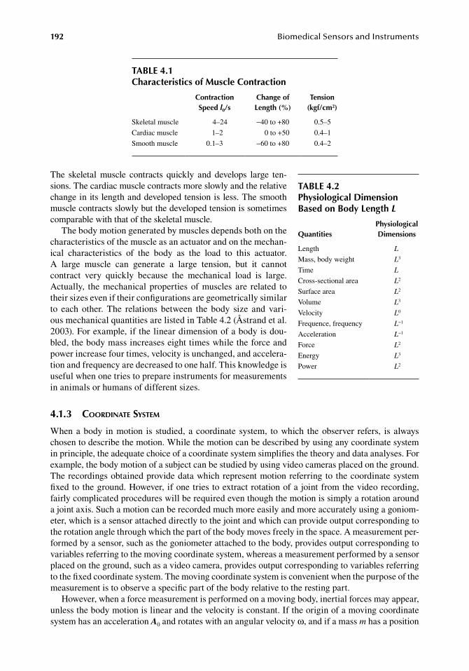
192 BiomedicalSensorsandInstruments
The. skeletal. muscle. contracts. quickly. and. develops. large. ten-sions..The.cardiac.muscle.contracts.more.slowly.and.the.relative.change.in.its.length.and.developed.tension.is.less..The.smooth.muscle.contracts.slowly.but.the.developed.tension.is.sometimes.comparable.with.that.of.the.skeletal.muscle.
The.body.motion.generated.by.muscles.depends.both.on.the.characteristics.of.the.muscle.as.an.actuator.and.on.the.mechan-ical. characteristics. of. the. body. as. the. load. to. this actuator..A large. muscle. can. generate. a. large. tension,. but. it. cannot.contract. very. quickly. because. the. mechanical. load. is. large..Actually,. the.mechanical.properties.of.muscles.are. related. to.their.sizes.even.if.their.configurations.are.geometrically.similar.to. each. other.. The. relations. between. the. body. size. and. vari-ous.mechanical.quantities.are.listed.in.Table.4.2.(Åstrand.et al..2003)..For.example,.if.the.linear.dimension.of.a.body.is.dou-bled,.the.body.mass.increases.eight.times.while.the.force.and.power.increase.four.times,.velocity.is.unchanged,.and.accelera-tion.and.frequency.are.decreased.to.one.half..This.knowledge.is.useful.when.one.tries.to.prepare.instruments.for.measurements.in.animals.or.humans.of.different.sizes.
4.1.3 coordinate systeM
When.a.body. in.motion. is. studied,. a.coordinate. system,. to.which. the.observer. refers,. is. always.chosen.to.describe.the.motion..While.the.motion.can.be.described.by.using.any.coordinate.system.in.principle,.the.adequate.choice.of.a.coordinate.system.simplifies.the.theory.and.data.analyses..For.example,.the.body.motion.of.a.subject.can.be.studied.by.using.video.cameras.placed.on.the.ground..The.recordings.obtained.provide.data.which.represent.motion.referring.to.the.coordinate.system.fixed.to.the.ground..However,.if.one.tries.to.extract.rotation.of.a.joint.from.the.video.recording,.fairly.complicated.procedures.will.be.required.even.though.the.motion.is.simply.a.rotation.around.a.joint.axis..Such.a.motion.can.be.recorded.much.more.easily.and.more.accurately.using.a.goniom-eter,.which.is.a.sensor.attached.directly.to.the.joint.and.which.can.provide.output.corresponding.to.the.rotation.angle.through.which.the.part.of.the.body.moves.freely.in.the.space..A.measurement.per-formed.by.a.sensor,.such.as.the.goniometer.attached.to.the.body,.provides.output.corresponding.to.variables.referring.to.the.moving.coordinate.system,.whereas.a.measurement.performed.by.a.sensor.placed.on.the.ground,.such.as.a.video.camera,.provides.output.corresponding.to.variables.referring.to.the.fixed.coordinate.system..The.moving.coordinate.system.is.convenient.when.the.purpose.of.the.measurement.is.to.observe.a.specific.part.of.the.body.relative.to.the.resting.part.
However,.when.a.force.measurement.is.performed.on.a.moving.body,.inertial.forces.may.appear,.unless.the.body.motion.is.linear.and.the.velocity.is.constant..If.the.origin.of.a.moving.coordinate.system.has.an.acceleration.A0.and.rotates.with.an.angular.velocity.ω,.and.if.a.mass.m.has.a.position.
table 4.1Characteristics of Muscle Contraction
Contraction Speed l0/s
Change of length (%)
tension (kgf/cm2)
Skeletal.muscle 4–24 −40.to.+80 0.5–5
Cardiac.muscle 1–2 0.to.+50 0.4–1
Smooth.muscle 0.1–3 −60.to.+80 0.4–2
table 4.2Physiological dimension based on body length L
QuantitiesPhysiological dimensions
Length L
Mass,.body.weight L3
Time L
Cross-sectional.area L2
Surface.area L2
Volume L3
Velocity L0
Frequence,.frequency L−1
Acceleration L−1
Force L2
Energy L3
Power L2
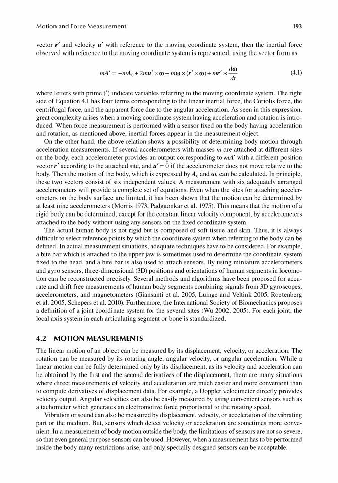
MotionandForceMeasurement 193
vector.r′.and.velocity.u′.with. reference. to. the.moving.coordinate.system,. then. the. inertial. force.observed.with.reference.to.the.moving.coordinate.system.is.represented,.using.the.vector.form.as
.m m m m
dt′ = − + ′ × + × ′ × + ′ ×A A u r r0 2 ( )
dm w w w w
.(4.1)
where.letters.with.prime.(′).indicate.variables.referring.to.the.moving.coordinate.system..The.right.side.of.Equation.4.1.has.four.terms.corresponding.to.the.linear.inertial.force,.the.Coriolis.force,.the.centrifugal.force,.and.the.apparent.force.due.to.the.angular.acceleration..As.seen.in.this.expression,.great.complexity.arises.when.a.moving.coordinate.system.having.acceleration.and.rotation.is.intro-duced..When.force.measurement.is.performed.with.a.sensor.fixed.on.the.body.having.acceleration.and.rotation,.as.mentioned.above,.inertial.forces.appear.in.the.measurement.object.
On.the.other.hand,.the.above.relation.shows.a.possibility.of.determining.body.motion.through.acceleration.measurements..If.several.accelerometers.with.masses.m.are.attached.at.different.sites.on.the.body,.each.accelerometer.provides.an.output.corresponding.to.mA′.with.a.different.position.vector.r′.according.to.the.attached.site,.and.u′.=.0.if.the.accelerometer.does.not.move.relative.to.the.body..Then.the.motion.of.the.body,.which.is.expressed.by.A0.and.ω,.can.be.calculated..In.principle,.these.two.vectors.consist.of.six.independent.values..A.measurement.with.six.adequately.arranged.accelerometers.will.provide.a.complete.set.of.equations..Even.when.the.sites.for.attaching.acceler-ometers.on.the.body.surface.are.limited,.it.has.been.shown.that.the.motion.can.be.determined.by.at.least.nine.accelerometers.(Morris.1973,.Padgaonkar.et al..1975)..This.means.that.the.motion.of.a.rigid.body.can.be.determined,.except.for.the.constant.linear.velocity.component,.by.accelerometers.attached.to.the.body.without.using.any.sensors.on.the.fixed.coordinate.system.
The.actual.human.body.is.not.rigid.but.is.composed.of.soft.tissue.and.skin..Thus,.it.is.always.difficult.to.select.reference.points.by.which.the.coordinate.system.when.referring.to.the.body.can.be.defined..In.actual.measurement.situations,.adequate.techniques.have.to.be.considered..For.example,.a.bite.bar.which.is.attached.to.the.upper.jaw.is.sometimes.used.to.determine.the.coordinate.system.fixed.to.the.head,.and.a.bite.bar.is.also.used.to.attach.sensors..By.using.miniature.accelerometers.and.gyro.sensors,.three-dimensional.(3D).positions.and.orientations.of.human.segments.in.locomo-tion.can.be.reconstructed.precisely..Several.methods.and.algorithms.have.been.proposed.for.accu-rate.and.drift.free.measurements.of.human.body.segments.combining.signals.from.3D.gyroscopes,.accelerometers,.and.magnetometers.(Giansanti.et al..2005,.Luinge.and.Veltink.2005,.Roetenberg.et al..2005,.Schepers.et al..2010)..Furthermore,.the.International.Society.of.Biomechanics.proposes.a.definition.of.a.joint.coordinate.system.for.the.several.sites.(Wu.2002,.2005)..For.each.joint,.the.local.axis.system.in.each.articulating.segment.or.bone.is.standardized.
4.2 Motion MeaSureMentS
The.linear.motion.of.an.object.can.be.measured.by.its.displacement,.velocity,.or.acceleration..The.rotation.can.be.measured.by.its.rotating.angle,.angular.velocity,.or.angular.acceleration..While.a.linear.motion.can.be.fully.determined.only.by.its.displacement,.as.its.velocity.and.acceleration.can.be.obtained.by.the.first.and.the.second.derivatives.of.the.displacement,.there.are.many.situations.where.direct.measurements.of.velocity.and.acceleration.are.much.easier.and.more.convenient.than.to.compute.derivatives.of.displacement.data..For.example,.a.Doppler.velocimeter.directly.provides.velocity.output..Angular.velocities.can.also.be.easily.measured.by.using.convenient.sensors.such.as.a.tachometer.which.generates.an.electromotive.force.proportional.to.the.rotating.speed.
Vibration.or.sound.can.also.be.measured.by.displacement,.velocity,.or.acceleration.of.the.vibrating.part.or.the.medium..But,.sensors.which.detect.velocity.or.acceleration.are.sometimes.more.conve-nient..In.a.measurement.of.body.motion.outside.the.body,.the.limitations.of.sensors.are.not.so.severe,.so.that.even.general.purpose.sensors.can.be.used..However,.when.a.measurement.has.to.be.performed.inside.the.body.many.restrictions.arise,.and.only.specially.designed.sensors.can.be.acceptable.
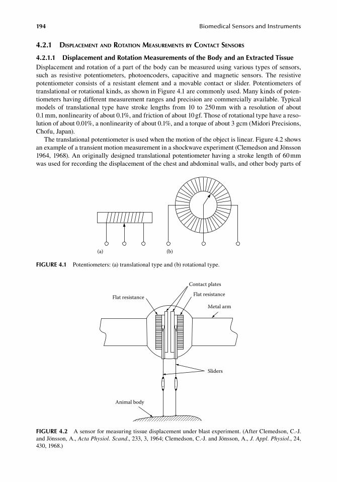
194 BiomedicalSensorsandInstruments
4.2.1 displaceMent and rotation MeasureMents by contact sensors
4.2.1.1 displacement and rotation Measurements of the body and an extracted tissueDisplacement.and.rotation.of.a.part.of.the.body.can.be.measured.using.various.types.of.sensors,.such. as. resistive. potentiometers,. photoencoders,. capacitive. and. magnetic. sensors.. The. resistive.potentiometer. consists. of. a. resistant. element. and. a.movable. contact. or. slider..Potentiometers. of.translational.or.rotational.kinds,.as.shown.in.Figure.4.1.are.commonly.used..Many.kinds.of.poten-tiometers.having.different.measurement.ranges.and.precision.are.commercially.available..Typical.models. of. translational. type. have. stroke. lengths. from. 10. to. 250.mm. with. a. resolution. of. about.0.1.mm,.nonlinearity.of.about.0.1%,.and.friction.of.about.10.gf..Those.of.rotational.type.have.a.reso-lution.of.about.0.01%,.a.nonlinearity.of.about.0.1%,.and.a.torque.of.about.3.gcm.(Midori.Precisions,.Chofu,.Japan).
The.translational.potentiometer.is.used.when.the.motion.of.the.object.is.linear..Figure.4.2.shows.an.example.of.a.transient.motion.measurement.in.a.shockwave.experiment.(Clemedson.and.Jönsson.1964,.1968)..An.originally.designed.translational.potentiometer.having.a.stroke.length.of.60.mm.was.used.for.recording.the.displacement.of.the.chest.and.abdominal.walls,.and.other.body.parts.of.
(b)(a)
figure 4.1 Potentiometers:.(a).translational.type.and.(b).rotational.type.
Flat resistance
Contact plates
Flat resistance
Metal arm
Sliders
Animal body
figure 4.2 A.sensor.for.measuring.tissue.displacement.under.blast.experiment..(After.Clemedson,.C.-J..and.Jönsson,.A.,.Acta Physiol. Scand.,.233,.3,.1964;.Clemedson,.C.-J..and.Jönsson,.A.,.J. Appl. Physiol.,.24,.430,.1968.)
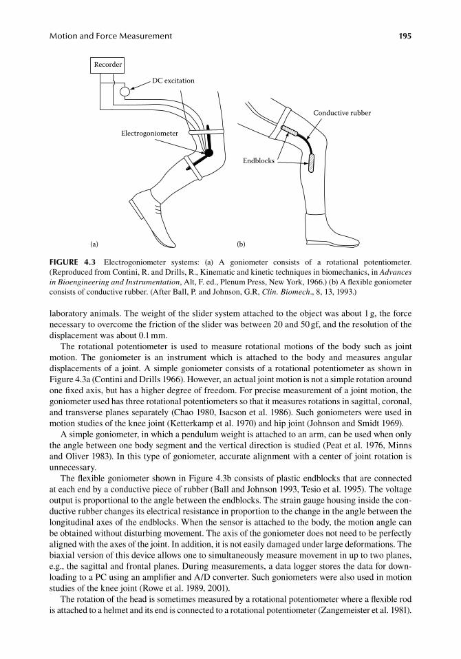
MotionandForceMeasurement 195
laboratory.animals..The.weight.of.the.slider.system.attached.to.the.object.was.about.1.g,.the.force.necessary.to.overcome.the.friction.of.the.slider.was.between.20.and.50.gf,.and.the.resolution.of.the.displacement.was.about.0.1.mm.
The. rotational. potentiometer. is. used. to. measure. rotational. motions. of. the. body. such. as. joint.motion.. The. goniometer. is. an. instrument. which. is. attached. to. the. body. and. measures. angular.displacements.of.a. joint..A.simple.goniometer.consists.of.a.rotational.potentiometer.as.shown.in.Figure 4.3a.(Contini.and.Drills.1966)..However,.an.actual.joint.motion.is.not.a.simple.rotation.around.one.fixed.axis,.but.has.a.higher.degree.of.freedom..For.precise.measurement.of.a.joint.motion,.the.goniometer.used.has.three.rotational.potentiometers.so.that.it.measures.rotations.in.sagittal,.coronal,.and.transverse.planes.separately.(Chao.1980,.Isacson.et al..1986)..Such.goniometers.were.used.in.motion.studies.of.the.knee.joint.(Ketterkamp.et al..1970).and.hip.joint.(Johnson.and.Smidt.1969).
A.simple.goniometer,.in.which.a.pendulum.weight.is.attached.to.an.arm,.can.be.used.when.only.the.angle.between.one.body.segment.and.the.vertical.direction.is.studied.(Peat.et.al..1976,.Minns.and.Oliver.1983)..In.this.type.of.goniometer,.accurate.alignment.with.a.center.of.joint.rotation.is.unnecessary.
The.flexible.goniometer.shown.in.Figure.4.3b.consists.of.plastic.endblocks.that.are.connected.at.each.end.by.a.conductive.piece.of.rubber.(Ball.and.Johnson.1993,.Tesio.et al..1995)..The.voltage.output.is.proportional.to.the.angle.between.the.endblocks..The.strain.gauge.housing.inside.the.con-ductive.rubber.changes.its.electrical.resistance.in.proportion.to.the.change.in.the.angle.between.the.longitudinal.axes.of.the.endblocks..When.the.sensor.is.attached.to.the.body,.the.motion.angle.can.be.obtained.without.disturbing.movement..The.axis.of.the.goniometer.does.not.need.to.be.perfectly.aligned.with.the.axes.of.the.joint..In.addition,.it.is.not.easily.damaged.under.large.deformations..The.biaxial.version.of.this.device.allows.one.to.simultaneously.measure.movement.in.up.to.two.planes,.e.g.,.the.sagittal.and.frontal.planes..During.measurements,.a.data.logger.stores.the.data.for.down-loading.to.a.PC.using.an.amplifier.and.A/D.converter..Such.goniometers.were.also.used.in.motion.studies.of.the.knee.joint.(Rowe.et.al..1989,.2001).
The.rotation.of.the.head.is.sometimes.measured.by.a.rotational.potentiometer.where.a.flexible.rod.is.attached.to.a.helmet.and.its.end.is.connected.to.a.rotational.potentiometer.(Zangemeister.et al..1981).
Recorder
DC excitation
Electrogoniometer
Endblocks
Conductive rubber
(a) (b)
figure 4.3 Electrogoniometer. systems:. (a). A. goniometer. consists. of. a. rotational. potentiometer..(Reproduced.from.Contini,.R..and.Drills,.R.,.Kinematic.and.kinetic.techniques.in.biomechanics,.in.Advances in Bioengineering and Instrumentation,.Alt,.F..ed.,.Plenum.Press,.New.York,.1966.).(b).A.flexible.goniometer.consists.of.conductive.rubber..(After.Ball,.P..and.Johnson,.G.R,.Clin. Biomech.,.8,.13,.1993.)
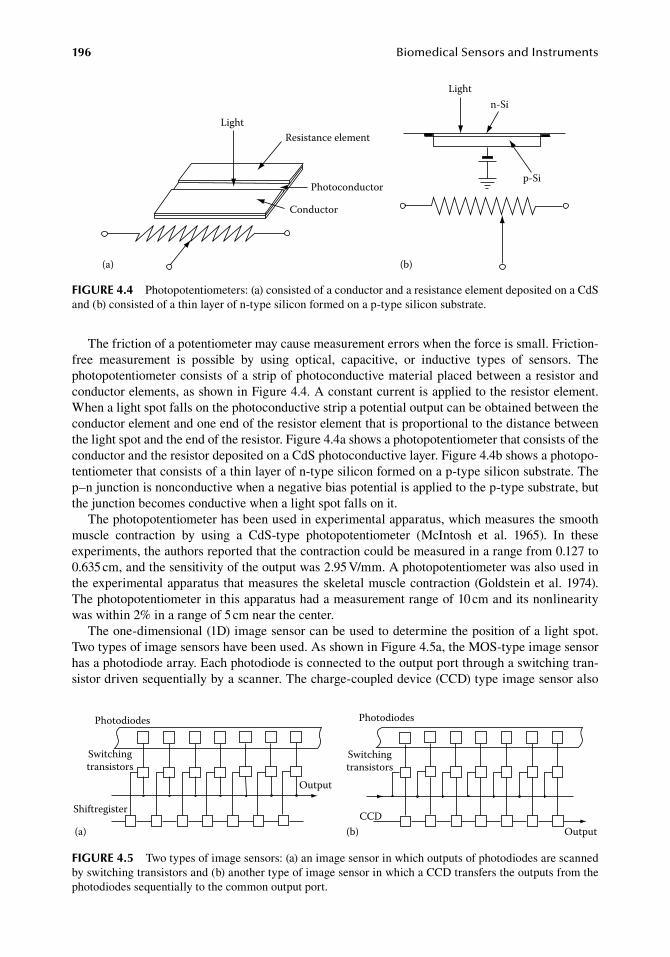
196 BiomedicalSensorsandInstruments
The.friction.of.a.potentiometer.may.cause.measurement.errors.when.the.force.is.small..Friction-free. measurement. is. possible. by. using. optical,. capacitive,. or. inductive. types. of. sensors.. The..photopotentiometer.consists.of.a.strip.of.photoconductive.material.placed.between.a.resistor.and.conductor.elements,.as.shown.in.Figure.4.4..A.constant.current.is.applied.to.the.resistor.element..When.a.light.spot.falls.on.the.photoconductive.strip.a.potential.output.can.be.obtained.between.the.conductor.element.and.one.end.of.the.resistor.element.that.is.proportional.to.the.distance.between.the.light.spot.and.the.end.of.the.resistor..Figure.4.4a.shows.a.photopotentiometer.that.consists.of.the.conductor.and.the.resistor.deposited.on.a.CdS.photoconductive.layer..Figure.4.4b.shows.a.photopo-tentiometer.that.consists.of.a.thin.layer.of.n-type.silicon.formed.on.a.p-type.silicon.substrate..The.p–n.junction.is.nonconductive.when.a.negative.bias.potential.is.applied.to.the.p-type.substrate,.but.the.junction.becomes.conductive.when.a.light.spot.falls.on.it.
The.photopotentiometer.has.been.used.in.experimental.apparatus,.which.measures.the.smooth.muscle. contraction. by. using. a. CdS-type. photopotentiometer. (McIntosh. et al.. 1965).. In. these.experiments,.the.authors.reported.that.the.contraction.could.be.measured.in.a.range.from.0.127.to.0.635.cm,.and.the.sensitivity.of.the.output.was.2.95.V/mm..A.photopotentiometer.was.also.used.in.the.experimental.apparatus.that.measures.the.skeletal.muscle.contraction.(Goldstein.et al..1974)..The.photopotentiometer.in.this.apparatus.had.a.measurement.range.of.10.cm.and.its.nonlinearity.was.within.2%.in.a.range.of.5.cm.near.the.center.
The.one-dimensional.(1D).image.sensor.can.be.used.to.determine.the.position.of.a.light.spot..Two.types.of.image.sensors.have.been.used..As.shown.in.Figure.4.5a,.the.MOS-type.image.sensor.has.a.photodiode.array..Each.photodiode.is.connected.to.the.output.port.through.a.switching.tran-sistor.driven.sequentially.by.a.scanner..The.charge-coupled.device.(CCD).type.image.sensor.also.
(b)
Lightn-Si
p-Si
LightResistance element
Photoconductor
Conductor
(a)
figure 4.4 Photopotentiometers:.(a).consisted.of.a.conductor.and.a.resistance.element.deposited.on.a.CdS.and.(b).consisted.of.a.thin.layer.of.n-type.silicon.formed.on.a.p-type.silicon.substrate.
Photodiodes
Switchingtransistors
Shiftregister
Output
Switchingtransistors
Photodiodes
CCD(b) Output(a)
figure 4.5 Two.types.of.image.sensors:.(a).an.image.sensor.in.which.outputs.of.photodiodes.are.scanned.by.switching.transistors.and.(b).another.type.of.image.sensor.in.which.a.CCD.transfers.the.outputs.from.the.photodiodes.sequentially.to.the.common.output.port.
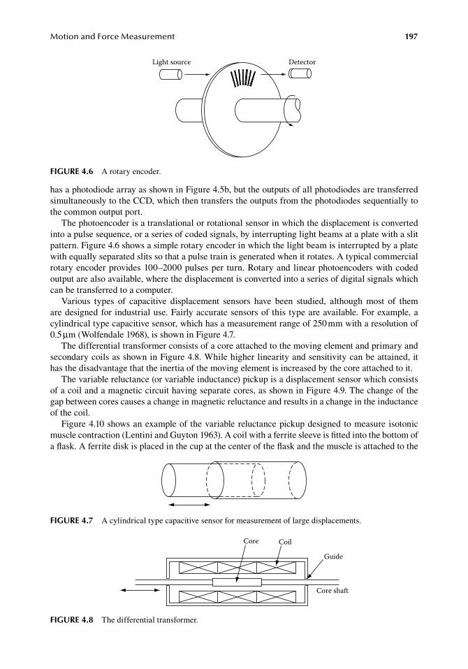
MotionandForceMeasurement 197
has.a.photodiode.array.as.shown.in.Figure.4.5b,.but.the.outputs.of.all.photodiodes.are.transferred.simultaneously.to.the.CCD,.which.then.transfers.the.outputs.from.the.photodiodes.sequentially.to.the.common.output.port.
The.photoencoder.is.a.translational.or.rotational.sensor.in.which.the.displacement.is.converted.into.a.pulse.sequence,.or.a.series.of.coded.signals,.by.interrupting.light.beams.at.a.plate.with.a.slit.pattern..Figure.4.6.shows.a.simple.rotary.encoder.in.which.the.light.beam.is.interrupted.by.a.plate.with.equally.separated.slits.so.that.a.pulse.train.is.generated.when.it.rotates..A.typical.commercial.rotary.encoder.provides.100–2000.pulses.per. turn..Rotary.and.linear.photoencoders.with.coded.output.are.also.available,.where.the.displacement.is.converted.into.a.series.of.digital.signals.which.can.be.transferred.to.a.computer.
Various. types. of. capacitive. displacement. sensors. have. been. studied,. although. most. of. them.are designed.for.industrial.use..Fairly.accurate.sensors.of.this.type.are.available..For.example,.a.cylindrical.type.capacitive.sensor,.which.has.a.measurement.range.of.250.mm.with.a.resolution.of.0.5.μm.(Wolfendale.1968),.is.shown.in.Figure.4.7.
The.differential.transformer.consists.of.a.core.attached.to.the.moving.element.and.primary.and.secondary.coils.as.shown.in.Figure.4.8..While.higher.linearity.and.sensitivity.can.be.attained,.it.has.the.disadvantage.that.the.inertia.of.the.moving.element.is.increased.by.the.core.attached.to.it.
The.variable.reluctance.(or.variable.inductance).pickup.is.a.displacement.sensor.which.consists.of.a.coil.and.a.magnetic.circuit.having.separate.cores,.as.shown.in.Figure.4.9..The.change.of.the.gap.between.cores.causes.a.change.in.magnetic.reluctance.and.results.in.a.change.in.the.inductance.of.the.coil.
Figure.4.10.shows.an.example.of. the.variable.reluctance.pickup.designed.to.measure.isotonic.muscle.contraction.(Lentini.and.Guyton.1963)..A.coil.with.a.ferrite.sleeve.is.fitted.into.the.bottom.of.a.flask..A.ferrite.disk.is.placed.in.the.cup.at.the.center.of.the.flask.and.the.muscle.is.attached.to.the.
Light source Detector
figure 4.6 A.rotary.encoder.
figure 4.7 A.cylindrical.type.capacitive.sensor.for.measurement.of.large.displacements.
Core Coil
Guide
Core shaft
figure 4.8 The.differential.transformer.
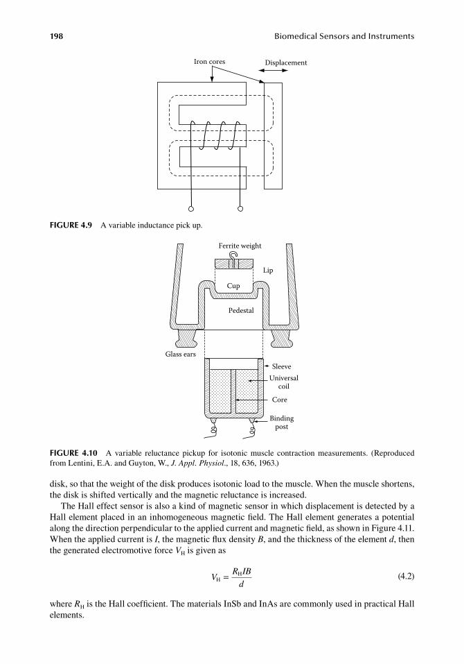
198 BiomedicalSensorsandInstruments
disk,.so.that.the.weight.of.the.disk.produces.isotonic.load.to.the.muscle..When.the.muscle.shortens,.the.disk.is.shifted.vertically.and.the.magnetic.reluctance.is.increased.
The.Hall.effect.sensor.is.also.a.kind.of.magnetic.sensor.in.which.displacement.is.detected.by.a.Hall.element.placed.in.an.inhomogeneous.magnetic.field..The.Hall.element.generates.a.potential.along.the.direction.perpendicular.to.the.applied.current.and.magnetic.field,.as.shown.in.Figure.4.11..When.the.applied.current.is.I,.the.magnetic.flux.density.B,.and.the.thickness.of.the.element.d,.then.the.generated.electromotive.force.VH.is.given.as
.V
R IB
dH
H=.
(4.2)
where.RH.is.the.Hall.coefficient..The.materials.InSb.and.InAs.are.commonly.used.in.practical.Hall.elements.
Iron cores Displacement
figure 4.9 A.variable.inductance.pick.up.
Ferrite weight
Cup
Lip
Pedestal
Glass earsSleeve
Universalcoil
Core
Bindingpost
figure 4.10 A. variable. reluctance. pickup. for. isotonic. muscle. contraction. measurements.. (Reproduced.from.Lentini,.E.A..and.Guyton,.W.,.J. Appl. Physiol.,.18,.636,.1963.)
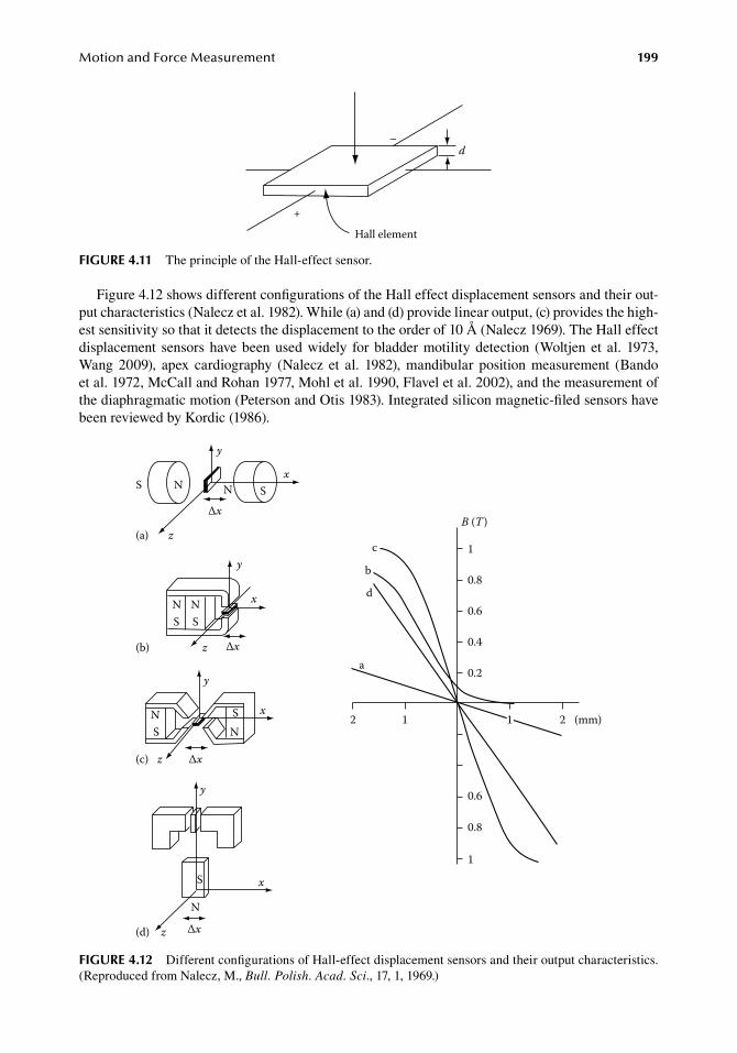
MotionandForceMeasurement 199
Figure.4.12.shows.different.configurations.of.the.Hall.effect.displacement.sensors.and.their.out-put.characteristics.(Nalecz.et al..1982)..While.(a).and.(d).provide.linear.output,.(c).provides.the.high-est.sensitivity.so.that.it.detects.the.displacement.to.the.order.of.10.Å.(Nalecz.1969)..The.Hall.effect.displacement. sensors.have.been.used.widely. for.bladder.motility.detection. (Woltjen.et al..1973,.Wang. 2009),. apex. cardiography. (Nalecz. et al.. 1982),. mandibular. position. measurement. (Bando.et al..1972,.McCall.and.Rohan.1977,.Mohl.et al..1990,.Flavel.et al..2002),.and.the.measurement.of.the.diaphragmatic.motion.(Peterson.and.Otis.1983)..Integrated.silicon.magnetic-filed.sensors.have.been.reviewed.by.Kordic.(1986).
Hall element
d
+
–
figure 4.11 The.principle.of.the.Hall-effect.sensor.
B (T )
a
b
d
c 1
0.8
0.6
0.4
0.2
0.6
0.8
1 1
1
2 2 (mm)
x
y
z
S N N
ΔxS
S SN N
y
x
z Δx
(a)
(b)
NNSS x
y
z Δx
y
(c)
(d)
x
z
N
Δx
S
figure 4.12 Different.configurations.of.Hall-effect.displacement.sensors.and.their.output.characteristics..(Reproduced.from.Nalecz,.M.,.Bull. Polish. Acad. Sci.,.17,.1,.1969.)
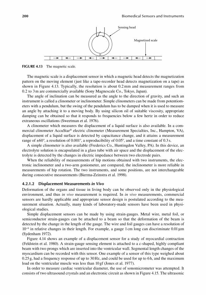
200 BiomedicalSensorsandInstruments
The.magnetic.scale.is.a.displacement.sensor.in.which.a.magnetic.head.detects.the.magnetization.pattern.on.the.moving.element.(just.like.a.tape-recorder.head.detects.magnetization.on.a.tape).as.shown.in.Figure.4.13..Typically,.the.resolution.is.about.0.2.mm.and.measurement.ranges.from.0.2.to.3.m.are.commercially.available.(Sony.Magnescale.Co.,.Tokyo,.Japan).
The.angle.of.inclination.can.be.measured.as.the.angle.to.the.direction.of.gravity,.and.such.an.instrument.is.called.a.clinometer.or.inclinometer..Simple.clinometers.can.be.made.from.potentiom-eters.with.a.pendulum,.but.the.swing.of.the.pendulum.has.to.be.damped.when.it.is.used.to.measure.an.angle.by.attaching. it. to.a.moving.body..By.using.silicon.oil.of.suitable.viscosity,.appropriate.damping.can.be.obtained.so.that.it.responds.to.frequencies.below.a.few.hertz.in.order.to.reduce.extraneous.oscillations.(Sweetman.et al..1976).
A.clinometer.which.measures.the.displacement.of.a.liquid.surface.is.also.available..In.a.com-mercial.clinometer.AccuStar®.electric.clinometer.(Measurement.Specialties,.Inc.,.Hampton,.VA),.displacement.of.a.liquid.surface.is.detected.by.capacitance.change,.and.it.attains.a.measurement.range.of.±60°,.a.resolution.of.0.001°,.a.reproducibility.of.0.05°,.and.a.time.constant.of.0.3.s.
A.simple.clinometer.is.also.available.(Frederics.Co.,.Huntingdon.Valley,.PA)..In.this.device,.an.electrolyte.solution.is.encapsulated.in.a.glass.tube.with.air.space.and.the.displacement.of.the.elec-trolyte.is.detected.by.the.changes.in.electric.impedance.between.two.electrode.pairs.
When.the.reliability.of.measurements.of.hip.motions.obtained.with.two.instruments,.the.elec-tronic.inclinometer.and.a.two-arm.goniometer,.are.compared,.the.inclinometer.is.more.reliable.in.measurements.of.hip.rotation..The.two.instruments,.and.some.positions,.are.not. interchangeable.during.consecutive.measurements.(Bierma-Zeinstra.et al..1998).
4.2.1.2 displacement Measurements in VivoDeformation.of. the.organs.and. tissue. in. living.body.can.be.observed.only. in. the.physiological.environment,. and. thus. in vivo. measurement. is. required.. In. in vivo. measurements,. commercial..sensors.are.hardly.applicable.and.appropriate.sensor.design.is.postulated.according.to.the.mea-surement. situation..Actually,.many.kinds.of. laboratory-made. sensors.have.been.used. in.physi-ological.studies.
Simple. displacement. sensors. can. be. made. by. using. strain-gauges.. Metal. wire,. metal. foil,. or.semiconductor. strain-gauges. can. be. attached. to. a. beam. so. that. the. deformation. of. the. beam. is.detected.by.the.change.in.the.length.of.the.gauge..The.wire.and.foil.gauges.can.have.a.resolution.of.10−6.in.relative.changes.in.their.length..For.example,.a.gauge.1.cm.long.can.discriminate.0.01.μm.(Sydenham.1972).
Figure.4.14.shows.an.example.of.a.displacement.sensor.for.a.study.of.myocardial.contraction.(Feldstein.et al..1980)..A.strain-gauge.sensing.element.is.attached.to.a.c-shaped,.highly.compliant.beam.with.two.prongs.which.are.inserted.into.the.ventricular.wall..Segmental.length.changes.of.the.myocardium.can.be.recorded.with.this.sensor..One.example.of.a.sensor.of.this.type.weighed.about.0.25.g,.had.a.frequency.response.of.up.to.30.Hz,.and.could.be.used.for.up.to.6.h,.and.the.maximum.load.on.the.ventricular.muscle.was.less.than.10.gf.(Jones.et al..1977).
In.order.to.measure.cardiac.ventricular.diameter,.the.use.of.sonomicrometer.was.attempted..It.consists.of.two.ultrasound.crystals.and.an.electronic.circuit.as.shown.in.Figure.4.15..The.ultrasonic.
Sensing head
Magnetized scale
figure 4.13 The.magnetic.scale.
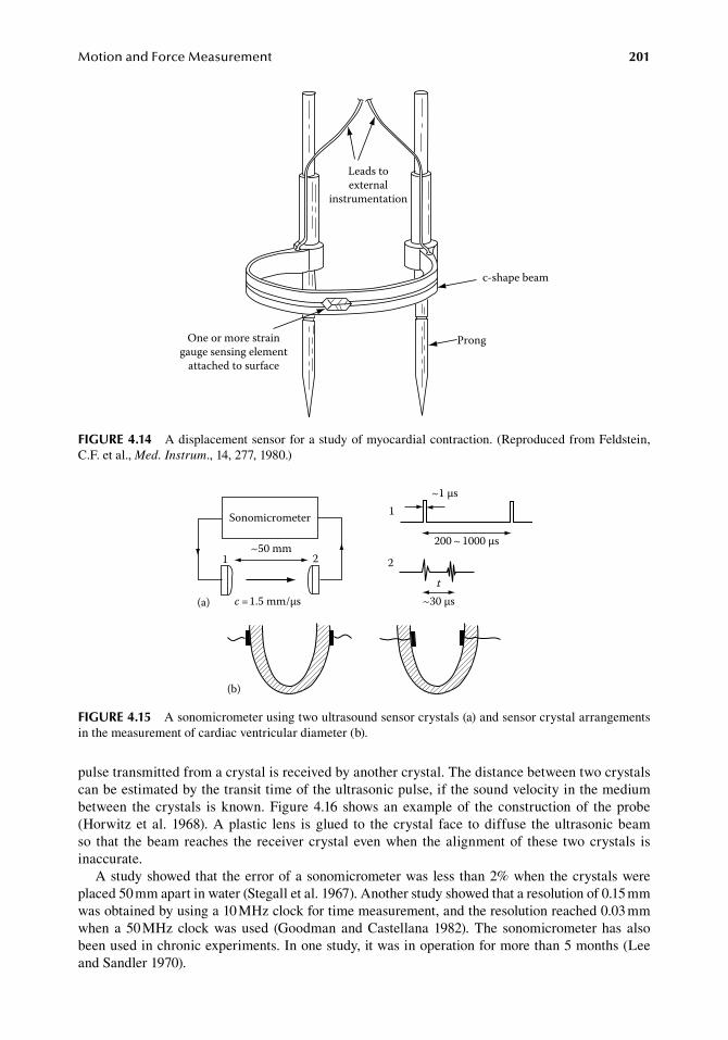
MotionandForceMeasurement 201
pulse.transmitted.from.a.crystal.is.received.by.another.crystal..The.distance.between.two.crystals.can.be.estimated.by.the.transit.time.of.the.ultrasonic.pulse,.if.the.sound.velocity.in.the.medium.between. the.crystals. is.known..Figure.4.16. shows.an.example.of. the.construction.of. the.probe.(Horwitz.et al..1968)..A.plastic. lens. is.glued. to. the.crystal. face. to.diffuse. the.ultrasonic.beam.so. that. the.beam.reaches. the. receiver.crystal. even.when. the.alignment.of. these. two.crystals. is.inaccurate.
A.study.showed.that. the.error.of.a.sonomicrometer.was.less. than.2%.when.the.crystals.were.placed.50.mm.apart.in.water.(Stegall.et al..1967)..Another.study.showed.that.a.resolution.of.0.15.mm.was.obtained.by.using.a.10.MHz.clock.for.time.measurement,.and.the.resolution.reached.0.03.mm.when.a.50.MHz.clock.was.used. (Goodman.and.Castellana.1982)..The. sonomicrometer.has. also.been.used.in.chronic.experiments..In.one.study,.it.was.in.operation.for.more.than.5.months.(Lee.and.Sandler.1970).
c-shape beam
Prong
Leads toexternal
instrumentation
One or more straingauge sensing element
attached to surface
figure 4.14 A.displacement.sensor.for.a.study.of.myocardial.contraction..(Reproduced.from.Feldstein,.C.F..et al.,.Med. Instrum.,.14,.277,.1980.)
Sonomicrometer
1 2~50 mm
1
2
t(a) c =1.5 mm/μs
200 ~ 1000 μs
~30 μs
~1 μs
(b)
figure 4.15 A.sonomicrometer.using.two.ultrasound.sensor.crystals.(a).and.sensor.crystal.arrangements.in.the.measurement.of.cardiac.ventricular.diameter.(b).
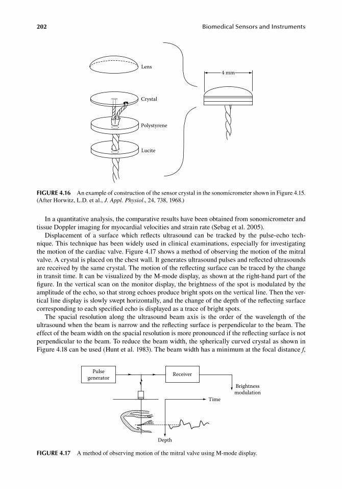
202 BiomedicalSensorsandInstruments
In.a.quantitative.analysis,.the.comparative.results.have.been.obtained.from.sonomicrometer.and.tissue.Doppler.imaging.for.myocardial.velocities.and.strain.rate.(Sebag.et al..2005).
Displacement. of. a. surface. which. reflects. ultrasound. can. be. tracked. by. the. pulse-echo. tech-nique..This.technique.has.been.widely.used.in.clinical.examinations,.especially.for.investigating.the.motion.of.the.cardiac.valve..Figure.4.17.shows.a.method.of.observing.the.motion.of.the.mitral.valve..A.crystal.is.placed.on.the.chest.wall..It.generates.ultrasound.pulses.and.reflected.ultrasounds.are.received.by.the.same.crystal..The.motion.of.the.reflecting.surface.can.be.traced.by.the.change.in.transit.time..It.can.be.visualized.by.the.M-mode.display,.as.shown.at.the.right-hand.part.of.the.figure..In.the.vertical.scan.on.the.monitor.display,.the.brightness.of.the.spot.is.modulated.by.the.amplitude.of.the.echo,.so.that.strong.echoes.produce.bright.spots.on.the.vertical.line..Then.the.ver-tical.line.display.is.slowly.swept.horizontally,.and.the.change.of.the.depth.of.the.reflecting.surface.corresponding.to.each.specified.echo.is.displayed.as.a.trace.of.bright.spots.
The. spacial. resolution. along. the. ultrasound. beam. axis. is. the. order. of. the. wavelength. of. the.ultrasound.when.the.beam.is.narrow.and.the.reflecting.surface.is.perpendicular.to.the.beam..The.effect.of.the.beam.width.on.the.spacial.resolution.is.more.pronounced.if.the.reflecting.surface.is.not.perpendicular.to.the.beam..To.reduce.the.beam.width,.the.spherically.curved.crystal.as.shown.in.Figure.4.18.can.be.used.(Hunt.et al..1983)..The.beam.width.has.a.minimum.at.the.focal.distance.f,.
4 mmLens
Crystal
Polystyrene
Lucite
figure 4.16 An.example.of.construction.of.the.sensor.crystal.in.the.sonomicrometer.shown.in.Figure.4.15..(After.Horwitz,.L.D..et al.,.J. Appl. Physiol.,.24,.738,.1968.)
Pulsegenerator Receiver
Depth
Time
Brightnessmodulation
figure 4.17 A.method.of.observing.motion.of.the.mitral.valve.using.M-mode.display.
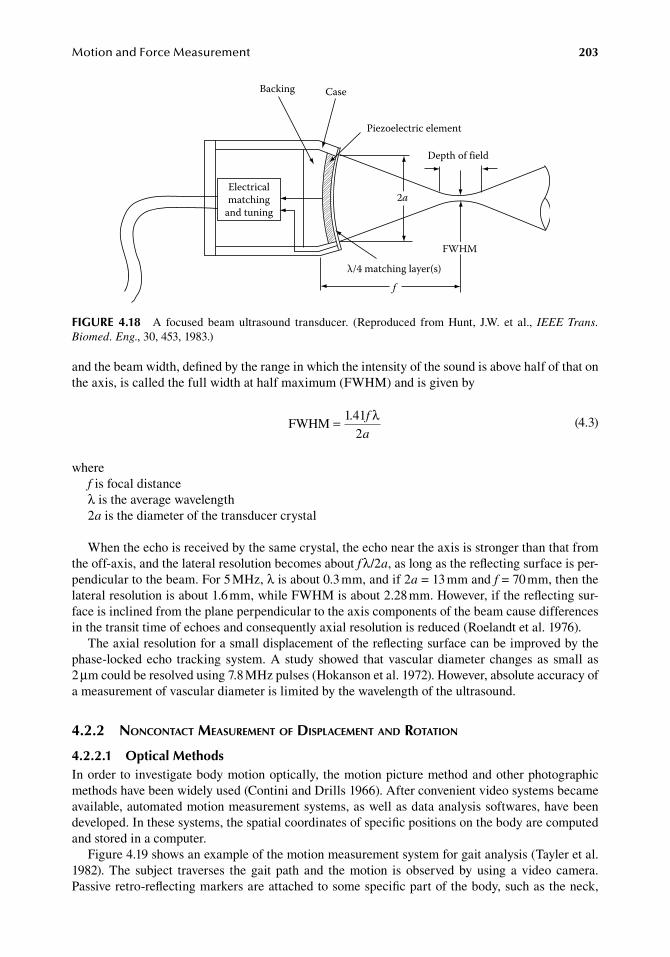
MotionandForceMeasurement 203
and.the.beam.width,.defined.by.the.range.in.which.the.intensity.of.the.sound.is.above.half.of.that.on.the.axis,.is.called.the.full.width.at.half.maximum.(FWHM).and.is.given.by
.FWHM
1 41= . f
a
λ2 .
(4.3)
wheref.is.focal.distanceλ.is.the.average.wavelength2a.is.the.diameter.of.the.transducer.crystal
When.the.echo.is.received.by.the.same.crystal,.the.echo.near.the.axis.is.stronger.than.that.from.the.off-axis,.and.the.lateral.resolution.becomes.about.f λ/2a,.as.long.as.the.reflecting.surface.is.per-pendicular.to.the.beam..For.5.MHz,.λ.is.about.0.3.mm,.and.if.2a.=.13.mm.and.f.=.70.mm,.then.the.lateral.resolution.is.about.1.6.mm,.while.FWHM.is.about.2.28.mm..However,.if.the.reflecting.sur-face.is.inclined.from.the.plane.perpendicular.to.the.axis.components.of.the.beam.cause.differences.in.the.transit.time.of.echoes.and.consequently.axial.resolution.is.reduced.(Roelandt.et al..1976).
The.axial.resolution.for.a.small.displacement.of.the.reflecting.surface.can.be.improved.by.the.phase-locked.echo. tracking. system..A.study.showed. that.vascular.diameter.changes.as. small. as.2.μm.could.be.resolved.using.7.8.MHz.pulses.(Hokanson.et al..1972)..However,.absolute.accuracy.of.a.measurement.of.vascular.diameter.is.limited.by.the.wavelength.of.the.ultrasound.
4.2.2 noncontact MeasureMent of displaceMent and rotation
4.2.2.1 optical MethodsIn.order.to.investigate.body.motion.optically,.the.motion.picture.method.and.other.photographic.methods.have.been.widely.used.(Contini.and.Drills.1966)..After.convenient.video.systems.became.available,.automated.motion.measurement.systems,.as.well.as.data.analysis.softwares,.have.been.developed..In.these.systems,.the.spatial.coordinates.of.specific.positions.on.the.body.are.computed.and.stored.in.a.computer.
Figure.4.19.shows.an.example.of.the.motion.measurement.system.for.gait.analysis.(Tayler.et al..1982)..The. subject. traverses. the.gait. path. and. the.motion. is. observed.by.using. a.video. camera..Passive.retro-reflecting.markers.are.attached.to.some.specific.part.of.the.body,.such.as.the.neck,.
Backing Case
Piezoelectric element
Depth of field
2a
f
λ/4 matching layer(s)
Electricalmatching
and tuning
FWHM
figure 4.18 A. focused. beam. ultrasound. transducer.. (Reproduced. from. Hunt,. J.W.. et al.,. IEEE Trans. Biomed. Eng.,.30,.453,.1983.)
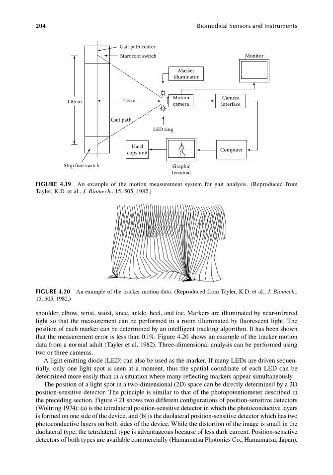
204 BiomedicalSensorsandInstruments
shoulder,.elbow,.wrist,.waist,.knee,.ankle,.heel,.and.toe..Markers.are.illuminated.by.near-infrared.light.so. that. the.measurement.can.be.performed.in.a.room.illuminated.by.fluorescent. light..The.position.of.each.marker.can.be.determined.by.an.intelligent.tracking.algorithm..It.has.been.shown.that.the.measurement.error.is.less.than.0.1%..Figure.4.20.shows.an.example.of.the.tracker.motion.data.from.a.normal.adult.(Tayler.et al..1982)..Three-dimensional.analysis.can.be.performed.using.two.or.three.cameras.
A.light.emitting.diode.(LED).can.also.be.used.as.the.marker..If.many.LEDs.are.driven.sequen-tially,. only.one. light. spot. is. seen. at. a.moment,. thus. the. spatial. coordinate.of. each.LED.can.be.determined.more.easily.than.in.a.situation.where.many.reflecting.markers.appear.simultaneously.
The.position.of.a.light.spot.in.a.two-dimensional.(2D).space.can.be.directly.determined.by.a.2D.position-sensitive.detector..The.principle.is.similar.to.that.of.the.photopotentiometer.described.in.the.preceding.section..Figure.4.21.shows.two.different.configurations.of.position-sensitive.detectors.(Woltring.1974):.(a).is.the.tetralateral.position-sensitive.detector.in.which.the.photoconductive.layers.is.formed.on.one.side.of.the.device,.and.(b).is.the.duolateral.position-sensitive.detector.which.has.two.photoconductive.layers.on.both.sides.of.the.device..While.the.distortion.of.the.image.is.small.in.the.duolateral.type,.the.tetralateral.type.is.advantageous.because.of.less.dark.current..Position-sensitive.detectors.of.both.types.are.available.commercially.(Hamamatsu.Photonics.Co.,.Hamamatsu,.Japan).
figure 4.20 An.example.of.the.tracker.motion.data..(Reproduced.from.Tayler,.K.D..et al.,.J. Biomech.,.15,.505,.1982.)
1.85 m
Gait path center
Start foot switch
4.3 m
Stop foot switch
Gait path
Markerilluminator
LED ring
Motioncamera
Graphicterminal
Hardcopy unit
Camerainterface
Monitor
Computer
figure 4.19 An. example. of. the. motion. measurement. system. for. gait. analysis.. (Reproduced. from.Tayler,.K.D..et al.,.J. Biomech.,.15,.505,.1982.)
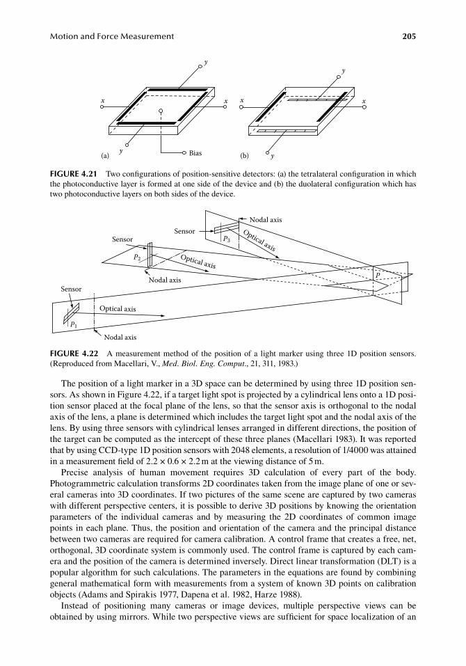
MotionandForceMeasurement 205
The.position.of.a.light.marker.in.a.3D.space.can.be.determined.by.using.three.1D.position.sen-sors..As.shown.in.Figure.4.22,.if.a.target.light.spot.is.projected.by.a.cylindrical.lens.onto.a.1D.posi-tion.sensor.placed.at.the.focal.plane.of.the.lens,.so.that.the.sensor.axis.is.orthogonal.to.the.nodal.axis.of.the.lens,.a.plane.is.determined.which.includes.the.target.light.spot.and.the.nodal.axis.of.the.lens..By.using.three.sensors.with.cylindrical.lenses.arranged.in.different.directions,.the.position.of.the.target.can.be.computed.as.the.intercept.of.these.three.planes.(Macellari.1983)..It.was.reported.that.by.using.CCD-type.1D.position.sensors.with.2048.elements,.a.resolution.of.1/4000.was.attained.in.a.measurement.field.of.2.2.×.0.6.×.2.2.m.at.the.viewing.distance.of.5.m.
Precise. analysis. of. human. movement. requires. 3D. calculation. of. every. part. of. the. body..Photogrammetric.calculation.transforms.2D.coordinates.taken.from.the.image.plane.of.one.or.sev-eral.cameras.into.3D.coordinates..If.two.pictures.of.the.same.scene.are.captured.by.two.cameras.with.different.perspective.centers,.it.is.possible.to.derive.3D.positions.by.knowing.the.orientation.parameters. of. the. individual. cameras. and. by. measuring. the. 2D. coordinates. of. common. image.points.in.each.plane..Thus,.the.position.and.orientation.of.the.camera.and.the.principal.distance.between.two.cameras.are.required.for.camera.calibration..A.control.frame.that.creates.a.free,.net,.orthogonal,.3D.coordinate.system.is.commonly.used..The.control.frame.is.captured.by.each.cam-era.and.the.position.of.the.camera.is.determined.inversely..Direct.linear.transformation.(DLT).is.a.popular.algorithm.for.such.calculations..The.parameters.in.the.equations.are.found.by.combining.general.mathematical.form.with.measurements.from.a.system.of.known.3D.points.on.calibration.objects.(Adams.and.Spirakis.1977,.Dapena.et al..1982,.Harze.1988).
Instead. of. positioning. many. cameras. or. image. devices,. multiple. perspective. views. can. be.obtained.by.using.mirrors..While.two.perspective.views.are.sufficient.for.space.localization.of.an.
x
y
x x
y yBias(a) (b)
x
y
figure 4.21 Two.configurations.of.position-sensitive.detectors:.(a).the.tetralateral.configuration.in.which.the.photoconductive.layer.is.formed.at.one.side.of.the.device.and.(b).the.duolateral.configuration.which.has.two.photoconductive.layers.on.both.sides.of.the.device.
Nodal axisSensor
P3Optical axis
Optical axis
Sensor
Nodal axis
P2
Sensor
Nodal axis
Optical axis
P1
P
figure 4.22 A.measurement.method.of. the.position.of.a. light.marker.using. three.1D.position.sensors..(Reproduced.from.Macellari,.V.,.Med. Biol. Eng. Comput.,.21,.311,.1983.)
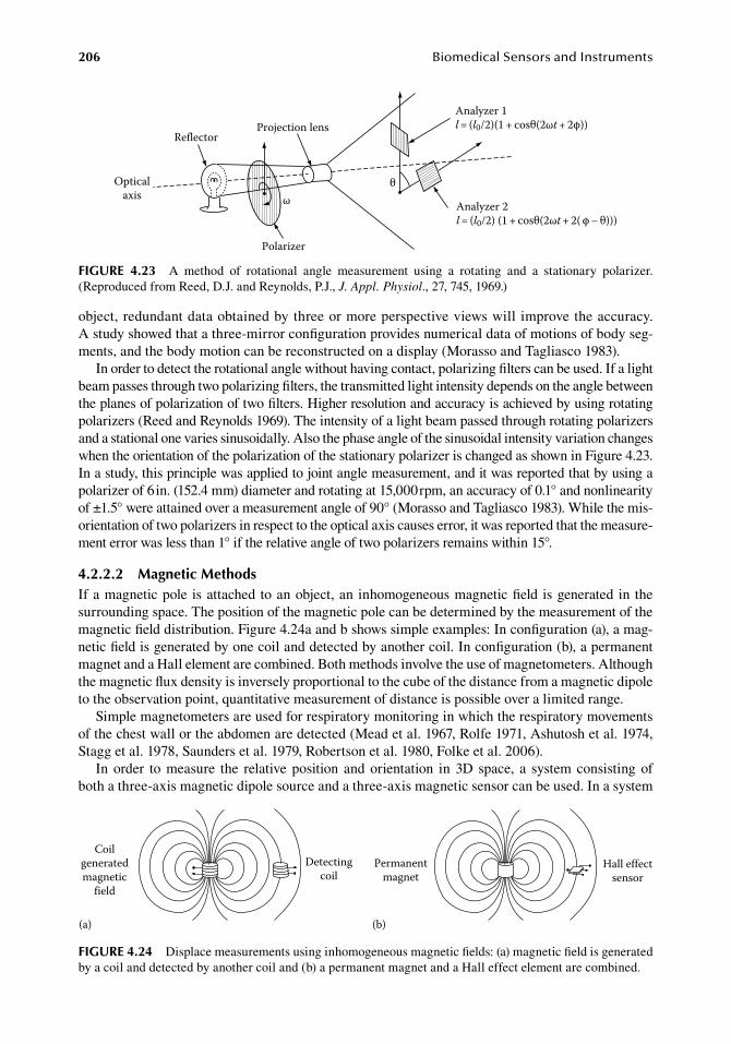
206 BiomedicalSensorsandInstruments
object,.redundant.data.obtained.by.three.or.more.perspective.views.will. improve.the.accuracy..A.study.showed.that.a.three-mirror.configuration.provides.numerical.data.of.motions.of.body.seg-ments,.and.the.body.motion.can.be.reconstructed.on.a.display.(Morasso.and.Tagliasco.1983).
In.order.to.detect.the.rotational.angle.without.having.contact,.polarizing.filters.can.be.used..If.a.light.beam.passes.through.two.polarizing.filters,.the.transmitted.light.intensity.depends.on.the.angle.between.the.planes.of.polarization.of.two.filters..Higher.resolution.and.accuracy.is.achieved.by.using.rotating.polarizers.(Reed.and.Reynolds.1969)..The.intensity.of.a.light.beam.passed.through.rotating.polarizers.and.a.stational.one.varies.sinusoidally..Also.the.phase.angle.of.the.sinusoidal.intensity.variation.changes.when.the.orientation.of.the.polarization.of.the.stationary.polarizer.is.changed.as.shown.in.Figure.4.23..In.a.study,.this.principle.was.applied.to.joint.angle.measurement,.and.it.was.reported.that.by.using.a.polarizer.of.6.in..(152.4.mm).diameter.and.rotating.at.15,000.rpm,.an.accuracy.of.0.1°.and.nonlinearity.of.±1.5°.were.attained.over.a.measurement.angle.of.90°.(Morasso.and.Tagliasco.1983)..While.the.mis-orientation.of.two.polarizers.in.respect.to.the.optical.axis.causes error,.it.was.reported.that.the.measure-ment.error.was.less.than.1°.if.the.relative.angle.of.two.polarizers.remains.within.15°.
4.2.2.2 Magnetic MethodsIf.a.magnetic.pole. is.attached.to.an.object,.an. inhomogeneous.magnetic.field. is.generated. in. the.surrounding.space..The.position.of.the.magnetic.pole.can.be.determined.by.the.measurement.of.the.magnetic.field.distribution..Figure.4.24a.and.b.shows.simple.examples:.In.configuration.(a),.a.mag-netic.field.is.generated.by.one.coil.and.detected.by.another.coil..In.configuration.(b),.a.permanent.magnet.and.a.Hall.element.are.combined..Both.methods.involve.the.use.of.magnetometers..Although.the.magnetic.flux.density.is.inversely.proportional.to.the.cube.of.the.distance.from.a.magnetic.dipole.to.the.observation.point,.quantitative.measurement.of.distance.is.possible.over.a.limited.range.
Simple.magnetometers.are.used.for.respiratory.monitoring.in.which.the.respiratory.movements.of.the.chest.wall.or.the.abdomen.are.detected.(Mead.et al..1967,.Rolfe.1971,.Ashutosh.et al..1974,.Stagg.et al..1978,.Saunders.et.al..1979,.Robertson.et al..1980,.Folke.et al..2006).
In.order. to.measure. the. relative.position. and.orientation. in.3D. space,. a. system.consisting.of.both.a.three-axis.magnetic.dipole.source.and.a.three-axis.magnetic.sensor.can.be.used..In.a.system.
Opticalaxis
Reflector
Polarizer
ωθ
Projection lensAnalyzer 1l= (l0/2)(1 + cosθ(2ωt+ 2φ))
Analyzer 2l= (l0/2) (1 + cosθ(2ωt+ 2( φ – θ)))
figure 4.23 A. method. of. rotational. angle. measurement. using. a. rotating. and. a. stationary. polarizer..(Reproduced.from.Reed,.D.J..and.Reynolds,.P.J.,.J. Appl. Physiol.,.27,.745,.1969.)
Coilgeneratedmagnetic
field
Detectingcoil
(a)
Permanentmagnet
Hall effectsensor
(b)
figure 4.24 Displace.measurements.using.inhomogeneous.magnetic.fields:.(a).magnetic.field.is.generated.by.a.coil.and.detected.by.another.coil.and.(b).a.permanent.magnet.and.a.Hall.effect.element.are.combined.
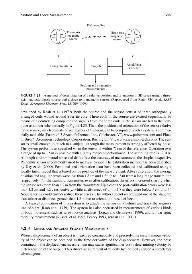
MotionandForceMeasurement 207
developed. by. Raab. et al.. (1979),. both. the. source. and. the. sensor. consist. of. three. orthogonally.arranged.coils.wound.around.a.ferrite.core..Three.coils.in.the.source.are.excited.sequentially.by.means.of.a.controlling.computer.and.signals.from.the.three.coils.in.the.sensor.are.led.to.the.com-puter.as.shown.schematically.in.Figure.4.25..Then,.the.position.and.orientation.of.the.sensor.relative.to.the.source,.which.consists.of.six.degrees.of.freedom,.can.be.computed..Such.a.system.is.commer-cially.available.(Fastrak®.3.Space,.Polhemus,.Inc.,.Colchester,.VT,.www.polhemus.com.and.Flock.of.Birds®,.Ascension.Technology.Corporation,.Burlington,.VT,.www.ascension-tech.com)..The.sen-sor.is.small.enough.to.attach.to.a.subject,.although.the.measurement.is.strongly.affected.by.noise..The.system.performs.as.specified.when.the.sensor.is.within.75.cm.of.the.reference..Operation.over.a.range.of.up.to.1.5.m.is.possible.with.slightly.reduced.performance..The.sampling.rate.is.120.Hz..Although.environmental.noise.and.drift.affect.the.accuracy.of.measurement,.the.simple.inexpensive.Polhemus.sensor.is.commonly.used.to.measure.tremor..The.calibration.method.has.been.described.by.Day.et al.. (2000)..Positional. and.orientation.data.have.been.collected.and.calibrated.using.a.locally.linear.model.that.is.based.on.the.position.of.the.measurement..After.calibration,.the.average.position.and.angular.errors.were.less.than.1.8.cm.and.1.2°.up.to.1.8.m.from.a.long-range.transmitter,.respectively..For.the.standard.transmitter,.even.after.calibration,.the.errors.increased.sharply.when.the.sensor.was.more.than.1.2.m.from.the.transmitter..Up.closer,.the.post-calibration.errors.were.less.than.1.2.cm.and.1.2°,.respectively,.while.at.distances.of.up.to.1.8.m.they.were.below.5.cm.and.4°..Noise.filtering.could.further.reduce.these.errors..The.authors.do.not.recommend.use.of.the.standard.transmitter.at.distances.greater.than.1.2.m.due.to.orientation-based.effects.
A.typical.application.of.this.system.is.to.attach.the.sensor.on.a.helmet.and.track.the.wearer’s.line-of-sight.(Raab.et al..1979)..The.system.has.also.been.used.in.measurements.of.various.kinds.of.body.movement,.such.as.wrist.motion.analysis.(Logan.and.Groszevski.1989),.and.lumbar.spine.mobility.measurement.(Russell.et al..1992,.Pearcy.1993,.Jordan.et al..2001).
4.2.3 linear and angular Velocity MeasureMents
When.a.displacement.of.an.object.is.measured.continuously.and.precisely,.the.instantaneous.veloc-ity.of. the.object.can.be.obtained.as. the. time.derivative.of. the.displacement..However,. the.noise.contained.in.the.displacement.measurement.may.cause.significant.errors.in.determining.velocity.by.differentiation.of.the.output..Thus.direct.measurement.of.velocity.by.a.velocity.sensor.is.sometimes.advantageous.
Field coupling
Three-axismagnetic
source
Three-axismagnetic
sensor
Driving circuits Computer Amplifyingcircuits
Position and orientationmeasurements
figure 4.25 A.method.of.determination.of.a.relative.position.and.orientation.in.3D.space.using.a.three-axis.magnetic. dipole. source. and. a. three-axis.magnetic. sensor.. (Reproduced. from.Raab,.F.H.. et al.,. IEEE Trans. Aerospace Electron. Syst.,.15,.709,.1979.)
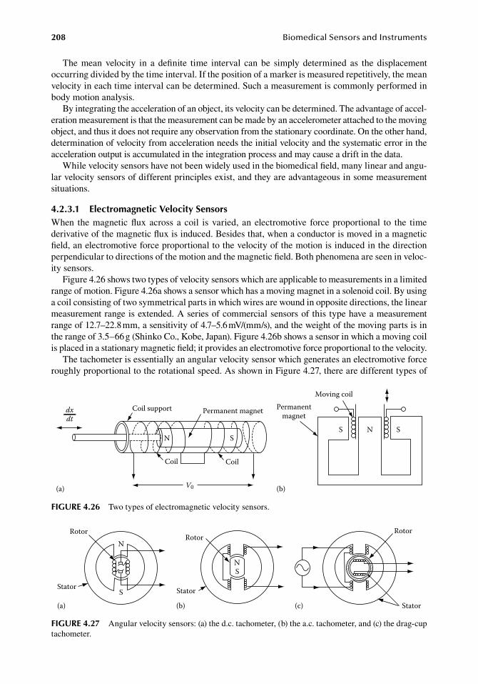
208 BiomedicalSensorsandInstruments
The. mean. velocity. in. a. definite. time. interval. can. be. simply. determined. as. the. displacement.occurring.divided.by.the.time.interval..If.the.position.of.a.marker.is.measured.repetitively,.the.mean.velocity.in.each.time.interval.can.be.determined..Such.a.measurement.is.commonly.performed.in.body.motion.analysis.
By.integrating.the.acceleration.of.an.object,.its.velocity.can.be.determined..The.advantage.of.accel-eration.measurement.is.that.the.measurement.can.be.made.by.an.accelerometer.attached.to.the.moving.object,.and.thus.it.does.not.require.any.observation.from.the.stationary.coordinate..On.the.other.hand,.determination.of.velocity.from.acceleration.needs.the.initial.velocity.and.the.systematic.error.in.the.acceleration.output.is.accumulated.in.the.integration.process.and.may.cause.a.drift.in.the.data.
While.velocity.sensors.have.not.been.widely.used.in.the.biomedical.field,.many.linear.and.angu-lar.velocity.sensors.of.different.principles.exist,.and.they.are.advantageous.in.some.measurement.situations.
4.2.3.1 electromagnetic Velocity SensorsWhen. the.magnetic.flux.across. a. coil. is.varied,. an.electromotive. force.proportional. to. the. time.derivative.of.the.magnetic.flux.is.induced..Besides.that,.when.a.conductor.is.moved.in.a.magnetic.field,.an.electromotive.force.proportional.to.the.velocity.of.the.motion.is.induced.in.the.direction.perpendicular.to.directions.of.the.motion.and.the.magnetic.field..Both.phenomena.are.seen.in.veloc-ity.sensors.
Figure.4.26.shows.two.types.of.velocity.sensors.which.are.applicable.to.measurements.in.a.limited.range.of.motion..Figure.4.26a.shows.a.sensor.which.has.a.moving.magnet.in.a.solenoid.coil..By.using.a.coil.consisting.of.two.symmetrical.parts.in.which.wires.are.wound.in.opposite.directions,.the.linear.measurement.range.is.extended..A.series.of.commercial.sensors.of.this.type.have.a.measurement.range.of.12.7–22.8.mm,.a.sensitivity.of.4.7–5.6.mV/(mm/s),.and.the.weight.of.the.moving.parts.is.in.the.range.of.3.5–66.g.(Shinko.Co.,.Kobe,.Japan)..Figure.4.26b.shows.a.sensor.in.which.a.moving.coil.is.placed.in.a.stationary.magnetic.field;.it.provides.an.electromotive.force.proportional.to.the.velocity.
The.tachometer.is.essentially.an.angular.velocity.sensor.which.generates.an.electromotive.force.roughly.proportional.to.the.rotational.speed..As.shown.in.Figure.4.27,.there.are.different.types.of.
dxdt
Coil support
V0
Coil Coil
Permanent magnet
N SS N S
(a) (b)
Moving coilPermanent
magnet
figure 4.26 Two.types.of.electromagnetic.velocity.sensors.
Rotor
Stator(c)
Rotor
Stator
NS
(b)
N
S
(a)
Rotor
Stator
figure 4.27 Angular.velocity.sensors:.(a).the.d.c..tachometer,.(b).the.a.c..tachometer,.and.(c).the.drag-cup.tachometer.
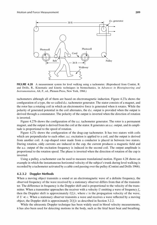
MotionandForceMeasurement 209
tachometers.although.all.of.them.are.based.on.electromagnetic.induction..Figure.4.27a.shows.the.configuration.of.a.type,.the.so-called.d.c..tachometer.generator..The.stator.consists.of.a.magnet,.and.the.rotor.has.a.rotating.coil.in.which.an.electromotive.force.is.generated.when.it.rotates..While.the.polarity.of.generated.potential.in.the.coil.alternates,.the.d.c..output.is.provided.when.the.output.is.derived.through.a.commutator..The.polarity.of.the.output.is.inverted.when.the.direction.of.rotation.is.inverted.
Figure.4.27b.shows.the.configuration.of.the.a.c..tachometer.generator..The.rotor.is.a.permanent.magnet,.and.the.output.is.derived.from.the.coil.at.the.stator..It.generates.an.a.c..output,.and.its.ampli-tude.is.proportional.to.the.speed.of.rotation.
Figure.4.27c.shows.the.configuration.of. the.drag-cup.tachometer..It.has.two.stators.with.coils.which.are.perpendicular.to.each.other;.a.c..excitation.is.applied.to.a.coil,.and.the.output.is.derived.from.another.coil..A.cup-shaped. rotor.made. from.a.conductor. is.placed. in.between. two.stators..During.rotation,.eddy.currents.are.induced.in.the.cup,. the.current.produces.a.magnetic.field.and.the.a.c..output.of. the.excitation.frequency.is. induced.in.the.second.coil..The.output.amplitude.is.proportional.to.the.rotation.speed..The.phase.is.inverted.when.the.direction.of.rotation.of.the.cup.is.inverted.
Using.a.pulley,.a.tachometer.can.be.used.to.measure.translational.motion..Figure.4.28.shows.an.example.in.which.the.instantaneous.horizontal.velocity.of.the.subject’s.trunk.during.level.walking.is.recorded.by.a.tachometer.activated.by.a.cable.cord.passing.over.the.pulley.(Contini.and.Drills.1966).
4.2.3.2 doppler MethodsWhen.a.moving.object.transmits.a.sound.or.an.electromagnetic.wave.of.a.definite.frequency,.the.observed.frequency.of.the.wave.received.by.a.stationary.observer.differs.from.that.of.the.transmit-ter..The.difference.in.frequency.is.the.Doppler.shift.and.is.proportional.to.the.velocity.of.the.trans-mitter..When.a.transmitter.approaches.the.receiver.with.a.velocity.U.emitting.a.wave.of.frequency.fs,.then.the.Doppler.shift.is.approximately.Ufs/c,.where.c.is.the.propagation.velocity.of.the.wave,.if.U.≪.c..When.a.stationary.observer.transmits.a.wave.and.receives.a.wave.reflected.by.a.moving.object,.the.Doppler.shift.is.approximately.2Ufs/c.as.described.in.Section.3.2.2.
While.the.ultrasonic.Doppler.technique.has.been.widely.used.in.blood.velocity.measurements,.it.has.also.been.used.for.detecting.motions.in.the.body,.such.as.the.fetal.heart.beat.and.breathing..
50 ft d.c. generator
Pulley
PhotocellCord
Walkway
26 ftBelt
Photocell
figure 4.28 A. measurement. system. for. level. walking. using. a. tachometer.. (Reproduced. from. Contini, R..and. Drills,. R.,. Kinematic. and. kinetic. techniques. in. biomechanics,. in. Advances in Bioengineering and Instrumentation,.Alt,.F.,.ed.,.Plenum.Press,.New.York,.1966.)
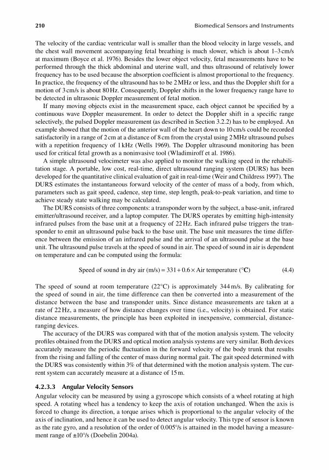
210 BiomedicalSensorsandInstruments
The.velocity.of.the.cardiac.ventricular.wall.is.smaller.than.the.blood.velocity.in.large.vessels,.and.the.chest.wall.movement.accompanying.fetal.breathing. is.much.slower,.which. is.about.1–3.cm/s.at.maximum.(Boyce.et al..1976)..Besides.the.lower.object.velocity,.fetal.measurements.have.to.be.performed.through.the.thick.abdominal.and.uterine.wall,.and.thus.ultrasound.of.relatively.lower.frequency.has.to.be.used.because.the.absorption.coefficient.is.almost.proportional.to.the.frequency..In.practice,.the.frequency.of.the.ultrasound.has.to.be.2.MHz.or.less,.and.thus.the.Doppler.shift.for.a.motion.of.3.cm/s.is.about.80.Hz..Consequently,.Doppler.shifts.in.the.lower.frequency.range.have.to.be.detected.in.ultrasonic.Doppler.measurement.of.fetal.motion.
If.many.moving.objects.exist.in.the.measurement.space,.each.object.cannot.be.specified.by.a.continuous. wave. Doppler. measurement.. In. order. to. detect. the. Doppler. shift. in. a. specific. range.selectively,.the.pulsed.Doppler.measurement.(as.described.in.Section.3.2.2).has.to.be.employed..An.example.showed.that.the.motion.of.the.anterior.wall.of.the.heart.down.to.10.cm/s.could.be.recorded.satisfactorily.in.a.range.of.2.cm.at.a.distance.of.8.cm.from.the.crystal.using.2.MHz.ultrasound.pulses.with.a.repetition.frequency.of.1.kHz.(Wells.1969)..The.Doppler.ultrasound.monitoring.has.been.used.for.critical.fetal.growth.as.a.noninvasive.tool.(Wladimiroff.et al..1986).
A.simple.ultrasound.velocimeter.was.also.applied.to.monitor.the.walking.speed.in.the.rehabili-tation.stage..A.portable,. low.cost,. real-time,.direct.ultrasound.ranging.system.(DURS).has.been.developed.for.the.quantitative.clinical.evaluation.of.gait.in.real-time.(Weir.and.Childress.1997)..The.DURS.estimates.the.instantaneous.forward.velocity.of.the.center.of.mass.of.a.body,.from.which,.parameters.such.as.gait.speed,.cadence,.step.time,.step.length,.peak-to-peak.variation,.and.time.to.achieve.steady.state.walking.may.be.calculated.
The.DURS.consists.of.three.components:.a.transponder.worn.by.the.subject,.a.base-unit,.infrared.emitter/ultrasound.receiver,.and.a.laptop.computer..The.DURS.operates.by.emitting.high-intensity.infrared.pulses.from.the.base.unit.at.a.frequency.of.22.Hz..Each.infrared.pulse.triggers.the.tran-sponder.to.emit.an.ultrasound.pulse.back.to.the.base.unit..The.base.unit.measures.the.time.differ-ence.between.the.emission.of.an.infrared.pulse.and.the.arrival.of.an.ultrasound.pulse.at.the.base.unit..The.ultrasound.pulse.travels.at.the.speed.of.sound.in.air..The.speed.of.sound.in.air.is.dependent.on.temperature.and.can.be.computed.using.the.formula:
. Speed of sound in dry air (m/s) 331 0.6 Air temperature (= + × °CC) . (4.4)
The. speed. of. sound. at. room. temperature. (22°C). is. approximately. 344.m/s.. By. calibrating. for.the.speed.of.sound.in.air,.the.time.difference.can.then.be.converted.into.a.measurement.of.the.distance. between. the. base. and. transponder. units.. Since. distance. measurements. are. taken. at. a.rate.of.22.Hz,.a.measure.of.how.distance.changes.over.time.(i.e.,.velocity).is.obtained..For.static.distance.measurements,. the.principle.has.been.exploited. in. inexpensive,.commercial,.distance-ranging.devices.
The.accuracy.of.the.DURS.was.compared.with.that.of.the.motion.analysis.system..The.velocity.profiles.obtained.from.the.DURS.and.optical.motion.analysis.systems.are.very.similar..Both.devices.accurately.measure.the.periodic.fluctuation.in.the.forward.velocity.of.the.body.trunk.that.results.from.the.rising.and.falling.of.the.center.of.mass.during.normal.gait..The.gait.speed.determined.with.the.DURS.was.consistently.within.3%.of.that.determined.with.the.motion.analysis.system..The.cur-rent.system.can.accurately.measure.at.a.distance.of.15.m.
4.2.3.3 angular Velocity SensorsAngular.velocity.can.be.measured.by.using.a.gyroscope.which.consists.of.a.wheel.rotating.at.high.speed..A.rotating.wheel.has.a.tendency.to.keep.the.axis.of.rotation.unchanged..When.the.axis.is.forced.to.change.its.direction,.a.torque.arises.which.is.proportional.to.the.angular.velocity.of.the.axis.of.inclination,.and.hence.it.can.be.used.to.detect.angular.velocity..This.type.of.sensor.is.known.as.the.rate.gyro,.and.a.resolution.of.the.order.of.0.005°/s.is.attained.in.the.model.having.a.measure-ment.range.of.±10°/s.(Doebelin.2004a).
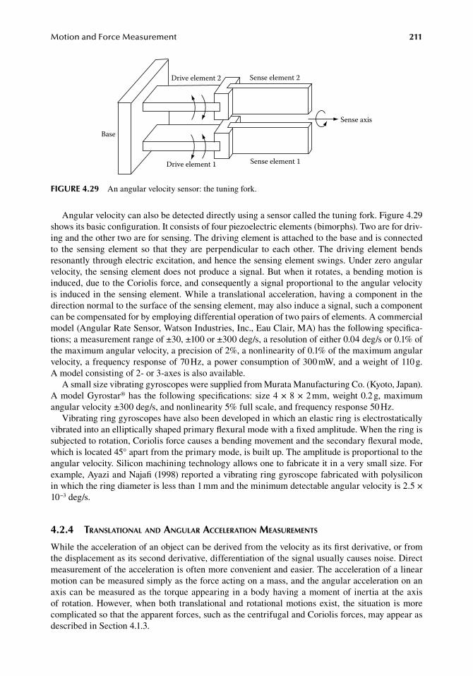
MotionandForceMeasurement 211
Angular.velocity.can.also.be.detected.directly.using.a.sensor.called.the.tuning.fork..Figure.4.29.shows.its.basic.configuration..It.consists.of.four.piezoelectric.elements.(bimorphs)..Two.are.for.driv-ing.and.the.other.two.are.for.sensing..The.driving.element.is.attached.to.the.base.and.is.connected.to. the. sensing. element. so. that. they. are. perpendicular. to. each. other..The. driving. element. bends.resonantly.through.electric.excitation,.and.hence.the.sensing.element.swings..Under.zero.angular.velocity,.the.sensing.element.does.not.produce.a.signal..But.when.it.rotates,.a.bending.motion.is.induced,.due.to.the.Coriolis.force,.and.consequently.a.signal.proportional.to.the.angular.velocity.is. induced.in.the.sensing.element..While.a.translational.acceleration,.having.a.component.in.the.direction.normal.to.the.surface.of.the.sensing.element,.may.also.induce.a.signal,.such.a.component.can.be.compensated.for.by.employing.differential.operation.of.two.pairs.of.elements..A.commercial.model.(Angular.Rate.Sensor,.Watson.Industries,.Inc.,.Eau.Clair,.MA).has.the.following.specifica-tions;.a.measurement.range.of.±30,.±100.or.±300.deg/s,.a.resolution.of.either.0.04.deg/s.or.0.1%.of.the.maximum.angular.velocity,.a.precision.of.2%,.a.nonlinearity.of.0.1%.of.the.maximum.angular.velocity,.a.frequency.response.of.70.Hz,.a.power.consumption.of.300.mW,.and.a.weight.of.110.g..A model.consisting.of.2-.or.3-axes.is.also.available.
A.small.size.vibrating.gyroscopes.were.supplied.from.Murata.Manufacturing.Co..(Kyoto,.Japan)..A.model.Gyrostar®.has. the.following.specifications:.size.4.×.8.×.2.mm,.weight.0.2.g,.maximum.angular.velocity.±300.deg/s,.and.nonlinearity.5%.full.scale,.and.frequency.response.50.Hz.
Vibrating.ring.gyroscopes.have.also.been.developed.in.which.an.elastic.ring.is.electrostatically.vibrated.into.an.elliptically.shaped.primary.flexural.mode.with.a.fixed.amplitude..When.the.ring.is.subjected.to.rotation,.Coriolis.force.causes.a.bending.movement.and.the.secondary.flexural.mode,.which.is.located.45°.apart.from.the.primary.mode,.is.built.up..The.amplitude.is.proportional.to.the.angular.velocity..Silicon.machining.technology.allows.one.to.fabricate.it.in.a.very.small.size..For.example,.Ayazi.and.Najafi.(1998).reported.a.vibrating.ring.gyroscope.fabricated.with.polysilicon.in.which.the.ring.diameter.is.less.than.1.mm.and.the.minimum.detectable.angular.velocity.is.2.5.×.10−3.deg/s.
4.2.4 translational and angular acceleration MeasureMents
While.the.acceleration.of.an.object.can.be.derived.from.the.velocity.as.its.first.derivative,.or.from.the.displacement.as.its.second.derivative,.differentiation.of.the.signal.usually.causes.noise..Direct.measurement.of.the.acceleration.is.often.more.convenient.and.easier..The.acceleration.of.a.linear.motion.can.be.measured.simply.as.the.force.acting.on.a.mass,.and.the.angular.acceleration.on.an.axis.can.be.measured.as. the. torque.appearing. in.a.body.having.a.moment.of. inertia.at. the.axis.of. rotation..However,.when.both. translational.and. rotational.motions.exist,. the.situation. is.more.complicated.so.that.the.apparent.forces,.such.as.the.centrifugal.and.Coriolis.forces,.may.appear.as.described.in.Section.4.1.3.
Drive element 2
Drive element 1
Sense element 2
Sense element 1
Base
Sense axis
figure 4.29 An.angular.velocity.sensor:.the.tuning.fork.
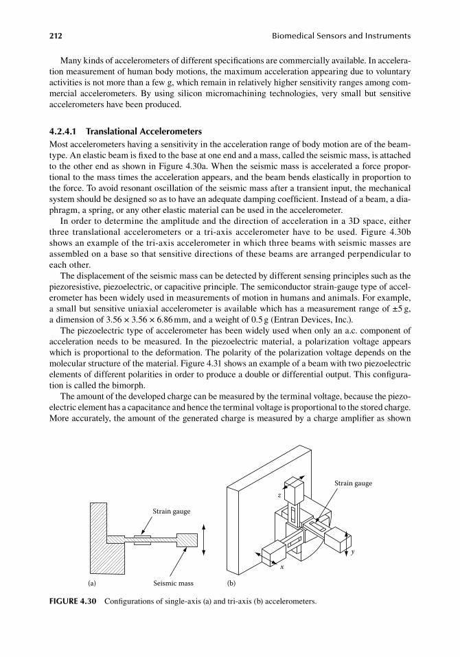
212 BiomedicalSensorsandInstruments
Many.kinds.of.accelerometers.of.different.specifications.are.commercially.available..In.accelera-tion.measurement.of.human.body.motions,.the.maximum.acceleration.appearing.due.to.voluntary.activities.is.not.more.than.a.few.g,.which.remain.in.relatively.higher.sensitivity.ranges.among.com-mercial. accelerometers.. By. using. silicon. micromachining. technologies,. very. small. but. sensitive.accelerometers.have.been.produced.
4.2.4.1 translational accelerometersMost.accelerometers.having.a.sensitivity.in.the.acceleration.range.of.body.motion.are.of.the.beam-type..An.elastic.beam.is.fixed.to.the.base.at.one.end.and.a.mass,.called.the.seismic.mass,.is.attached.to.the.other.end.as.shown.in.Figure.4.30a..When.the.seismic.mass.is.accelerated.a.force.propor-tional.to.the.mass.times.the.acceleration.appears,.and.the.beam.bends.elastically.in.proportion.to.the.force..To.avoid.resonant.oscillation.of.the.seismic.mass.after.a.transient.input,.the.mechanical.system.should.be.designed.so.as.to.have.an.adequate.damping.coefficient..Instead.of.a.beam,.a.dia-phragm,.a.spring,.or.any.other.elastic.material.can.be.used.in.the.accelerometer.
In.order.to.determine.the.amplitude.and.the.direction.of.acceleration.in.a.3D.space,.either.three. translational. accelerometers. or. a. tri-axis. accelerometer. have. to. be. used.. Figure. 4.30b.shows.an.example.of.the.tri-axis.accelerometer.in.which.three.beams.with.seismic.masses.are.assembled.on.a.base.so.that.sensitive.directions.of.these.beams.are.arranged.perpendicular.to.each.other.
The.displacement.of.the.seismic.mass.can.be.detected.by.different.sensing.principles.such.as.the.piezoresistive,.piezoelectric,.or.capacitive.principle..The.semiconductor.strain-gauge.type.of.accel-erometer.has.been.widely.used.in.measurements.of.motion.in.humans.and.animals..For.example,.a.small.but.sensitive.uniaxial.accelerometer.is.available.which.has.a.measurement.range.of.±5.g,.a dimension.of.3.56.×.3.56.×.6.86.mm,.and.a.weight.of.0.5.g.(Entran.Devices,.Inc.).
The.piezoelectric.type.of.accelerometer.has.been.widely.used.when.only.an.a.c..component.of.acceleration. needs. to. be. measured.. In. the. piezoelectric. material,. a. polarization. voltage. appears.which.is.proportional.to.the.deformation..The.polarity.of.the.polarization.voltage.depends.on.the.molecular.structure.of.the.material..Figure.4.31.shows.an.example.of.a.beam.with.two.piezoelectric.elements.of.different.polarities.in.order.to.produce.a.double.or.differential.output..This.configura-tion.is.called.the.bimorph.
The.amount.of.the.developed.charge.can.be.measured.by.the.terminal.voltage,.because.the.piezo-electric.element.has.a.capacitance.and.hence.the.terminal.voltage.is.proportional.to.the.stored.charge..More.accurately,.the.amount.of.the.generated.charge.is.measured.by.a.charge.amplifier.as.shown.
Strain gauge
Seismic mass(a)
x
y
zStrain gauge
(b)
figure 4.30 Configurations.of.single-axis.(a).and.tri-axis.(b).accelerometers.
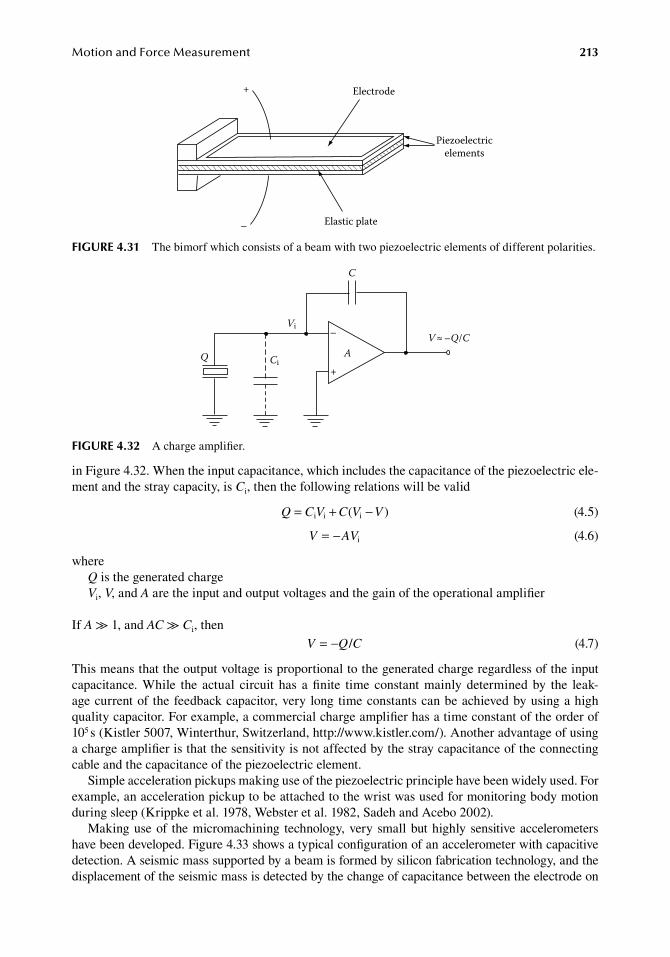
MotionandForceMeasurement 213
in.Figure.4.32..When.the.input.capacitance,.which.includes.the.capacitance.of.the.piezoelectric.ele-ment.and.the.stray.capacity,.is.Ci,.then.the.following.relations.will.be.valid
. Q C V C V V= + −i i i( ) . (4.5)
. V AV= − i . (4.6)
whereQ.is.the.generated.chargeVi,.V,.and.A.are.the.input.and.output.voltages.and.the.gain.of.the.operational.amplifier
If.A.≫.1,.and.AC.≫.Ci,.then
. V Q C= − / . (4.7)
This.means.that.the.output.voltage.is.proportional.to.the.generated.charge.regardless.of.the.input.capacitance.. While. the. actual. circuit. has. a. finite. time. constant. mainly. determined. by. the. leak-age.current.of. the.feedback.capacitor,.very.long.time.constants.can.be.achieved.by.using.a.high.quality.capacitor..For.example,.a.commercial.charge.amplifier.has.a.time.constant.of.the.order.of.105.s.(Kistler.5007,.Winterthur,.Switzerland,.http://www.kistler.com/)..Another.advantage.of.using.a.charge.amplifier.is.that.the.sensitivity.is.not.affected.by.the.stray.capacitance.of.the.connecting.cable.and.the.capacitance.of.the.piezoelectric.element.
Simple.acceleration.pickups.making.use.of.the.piezoelectric.principle.have.been.widely.used..For.example,.an.acceleration.pickup.to.be.attached.to.the.wrist.was.used.for.monitoring.body.motion.during.sleep.(Krippke.et al..1978,.Webster.et al..1982,.Sadeh.and.Acebo.2002).
Making.use.of. the.micromachining. technology,.very.small.but.highly.sensitive.accelerometers.have.been.developed..Figure.4.33.shows.a.typical.configuration.of.an.accelerometer.with.capacitive.detection..A.seismic.mass.supported.by.a.beam.is.formed.by.silicon.fabrication.technology,.and.the.displacement.of.the.seismic.mass.is.detected.by.the.change.of.capacitance.between.the.electrode.on.
Q
Vi
Ci
V ≈ –Q/C–
+
C
A
figure 4.32 A.charge.amplifier.
Elastic plate
Piezoelectricelements
+
–
Electrode
figure 4.31 The.bimorf.which.consists.of.a.beam.with.two.piezoelectric.elements.of.different.polarities.
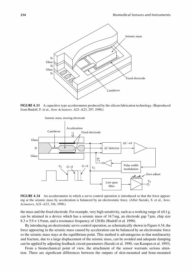
214 BiomedicalSensorsandInstruments
the.mass.and.the.fixed.electrode..For.example,.very.high.sensitivity,.such.as.a.working.range.of.±0.1.g,.can.be.attained.in.a.device.which.has.a.seismic.mass.of.14.7.mg,.an.electrode.gap.7.μm,.chip.size.8.3 ×.5.9.×.1.9.mm,.and.a.resonance.frequency.of.126.Hz.(Rudolf.et al..1990).
By.introducing.an.electrostatic.servo-control.operation,.as.schematically.shown.in.Figure.4.34,.the.force.appearing.in.the.seismic.mass.caused.by.acceleration.can.be.balanced.by.an.electrostatic.force.so.the.seismic.mass.stays.at.the.equilibrium.point..This.method.is.advantageous.in.that.nonlinearity.and.fracture,.due.to.a.large.displacement.of.the.seismic.mass,.can.be.avoided.and.adequate.damping.can.be.applied.by.adjusting.feedback.circuit.parameters.(Suzuki.et al..1990,.van.Kampen.et al..1993).
From. a. biomechanical. point. of. view,. the. attachment. of. the. sensor. warrants. serious. atten-tion.. There. are. significant. differences. between. the. outputs. of. skin-mounted. and. bone-mounted.
Seismic mass, moving electrode
CantileverAcceleration
Fixed electrode
Glass
Si
Glass
VE G < 0 G > 0 VE
VE
ΔC 0ΔC detector
Pulse widthmodulation
Zero adjust
V0Low-passfilter
figure 4.34 An.accelerometer.in.which.a.servo-control.operation.is.introduced.so.that.the.force.appear-ing.at.the.seismic.mass.by.acceleration.is.balanced.by.an.electrostatic.force..(After.Suzuki,.S..et al.,.Sens. Actuators,.A21–A23,.316,.1990.)
SiGlass
Si
SiGlass
Cantilever
Fixed electrode
Seismic mass
figure 4.33 A.capacitive.type.accelerometer.produced.by.the.silicon.fabrication.technology..(Reproduced.from.Rudolf,.F..et al.,.Sens Actuators,.A21–A23,.297,.1990.)
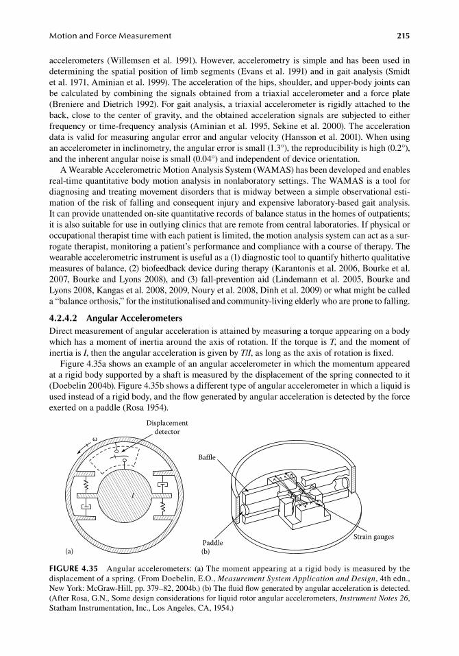
MotionandForceMeasurement 215
accelerometers. (Willemsen.et al..1991)..However,. accelerometry. is. simple.and.has.been.used. in.determining.the.spatial.position.of.limb.segments.(Evans.et al..1991).and.in.gait.analysis.(Smidt.et al..1971,.Aminian.et al..1999)..The.acceleration.of.the.hips,.shoulder,.and.upper-body.joints.can.be.calculated.by.combining. the.signals.obtained.from.a. triaxial.accelerometer.and.a. force.plate.(Breniere.and.Dietrich.1992)..For.gait.analysis,.a.triaxial.accelerometer.is.rigidly.attached.to.the.back,.close. to. the.center.of.gravity,.and. the.obtained.acceleration.signals.are.subjected. to.either.frequency.or.time-frequency.analysis.(Aminian.et al..1995,.Sekine.et al..2000)..The.acceleration.data.is.valid.for.measuring.angular.error.and.angular.velocity.(Hansson.et al..2001)..When.using.an.accelerometer.in.inclinometry,.the.angular.error.is.small.(1.3°),.the.reproducibility.is.high.(0.2°),.and.the.inherent.angular.noise.is.small.(0.04°).and.independent.of.device.orientation.
A.Wearable.Accelerometric.Motion.Analysis.System.(WAMAS).has.been.developed.and.enables.real-time.quantitative.body.motion.analysis.in.nonlaboratory.settings..The.WAMAS.is.a.tool.for.diagnosing.and.treating.movement.disorders.that.is.midway.between.a.simple.observational.esti-mation.of.the.risk.of.falling.and.consequent.injury.and.expensive.laboratory-based.gait.analysis..It can.provide.unattended.on-site.quantitative.records.of.balance.status.in.the.homes.of.outpatients;.it.is.also.suitable.for.use.in.outlying.clinics.that.are.remote.from.central.laboratories..If.physical.or.occupational.therapist.time.with.each.patient.is.limited,.the.motion.analysis.system.can.act.as.a.sur-rogate.therapist,.monitoring.a.patient’s.performance.and.compliance.with.a.course.of.therapy..The.wearable.accelerometric.instrument.is.useful.as.a.(1).diagnostic.tool.to.quantify.hitherto.qualitative.measures.of.balance,.(2).biofeedback.device.during.therapy.(Karantonis.et al..2006,.Bourke.et al..2007,.Bourke.and.Lyons.2008),.and. (3). fall-prevention.aid. (Lindemann.et al..2005,.Bourke.and.Lyons.2008,.Kangas.et al..2008,.2009,.Noury.et al..2008,.Dinh.et al..2009).or.what.might.be.called.a.“balance.orthosis,”.for.the.institutionalised.and.community-living.elderly.who.are.prone.to.falling.
4.2.4.2 angular accelerometersDirect.measurement.of.angular.acceleration.is.attained.by.measuring.a.torque.appearing.on.a.body.which.has.a.moment.of.inertia.around.the.axis.of.rotation..If.the.torque.is.T,.and.the.moment.of.inertia.is.I,.then.the.angular.acceleration.is.given.by.T/I,.as.long.as.the.axis.of.rotation.is.fixed.
Figure.4.35a.shows.an.example.of.an.angular.accelerometer.in.which.the.momentum.appeared.at.a.rigid.body.supported.by.a.shaft.is.measured.by.the.displacement.of.the.spring.connected.to.it.(Doebelin.2004b)..Figure.4.35b.shows.a.different.type.of.angular.accelerometer.in.which.a.liquid.is.used.instead.of.a.rigid.body,.and.the.flow.generated.by.angular.acceleration.is.detected.by.the.force.exerted.on.a.paddle.(Rosa.1954).
ω
Displacementdetector
(a)
Strain gaugesPaddle
Baffle
(b)
l
figure 4.35 Angular.accelerometers:.(a).The.moment.appearing.at.a.rigid.body.is.measured.by.the.displacement.of.a.spring..(From.Doebelin,.E.O.,.Measurement System Application and Design,.4th.edn.,.New.York:.McGraw-Hill,.pp..379–82,.2004b.).(b).The.fluid.flow.generated.by.angular.acceleration.is.detected..(After.Rosa, G.N.,.Some.design.considerations.for.liquid.rotor.angular.accelerometers,.Instrument Notes 26,.Statham.Instrumentation,.Inc.,.Los.Angeles,.CA,.1954.)
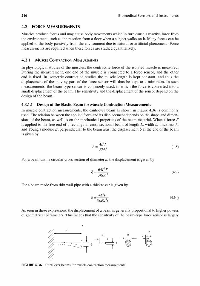
216 BiomedicalSensorsandInstruments
4.3 forCe MeaSureMentS
Muscles.produce.forces.and.may.cause.body.movements.which.in.turn.cause.a.reactive.force.from.the.environment,.such.as.the.reaction.from.a.floor.when.a.subject.walks.on.it..Many.forces.can.be.applied.to.the.body.passively.from.the.environment.due.to.natural.or.artificial.phenomena..Force.measurements.are.required.when.these.forces.are.studied.quantitatively.
4.3.1 Muscle contraction MeasureMents
In.physiological.studies.of.the.muscles,.the.contractile.force.of.the.isolated.muscle.is.measured..During. the.measurement,. one.end.of. the.muscle. is. connected. to. a. force. sensor,. and. the.other.end. is. fixed.. In. isometric. contraction. studies. the. muscle. length. is. kept. constant,. and. thus. the.displacement.of. the.moving.part. of. the. force. sensor.will. thus.be.kept. to. a.minimum.. In. such.measurements,.the.beam-type.sensor.is.commonly.used,.in.which.the.force.is.converted.into.a.small.displacement.of.the.beam..The.sensitivity.and.the.displacement.of.the.sensor.depend.on.the.design.of.the.beam.
4.3.1.1 design of the elastic beam for Muscle Contraction MeasurementsIn.muscle.contraction.measurements,. the.cantilever.beam.as.shown.in.Figure.4.36. is.commonly.used..The.relation.between.the.applied.force.and.its.displacement.depends.on.the.shape.and.dimen-sions.of.the.beam,.as.well.as.on.the.mechanical.properties.of.the.beam.material..When.a.force.F.is.applied.to.the.free.end.of.a.rectangular.cross.sectional.beam.of.length.L,.width.b,.thickness.h,.and.Young’s.module.E,.perpendicular.to.the.beam.axis,.the.displacement.δ.at.the.end.of.the.beam.is.given.by
.δ = 4 3L F
Ebh3.
(4.8)
For.a.beam.with.a.circular.cross.section.of.diameter.d,.the.displacement.is.given.by
.δ
π= 64 3L F
Ed3 4.
(4.9)
For.a.beam.made.from.thin.wall.pipe.with.a.thickness.t.is.given.by
.δ
π=
43
3
3
L F
Ed t .(4.10)
As.seen.in.these.expressions,.the.displacement.of.a.beam.is.generally.proportional.to.higher.powers.of.geometrical.parameters..This.means.that.the.sensitivity.of.the.beam-type.force.sensor.is.largely.
Fl
d
δ h
dd
t
figure 4.36 Cantilever.beams.for.muscle.contraction.measurements.
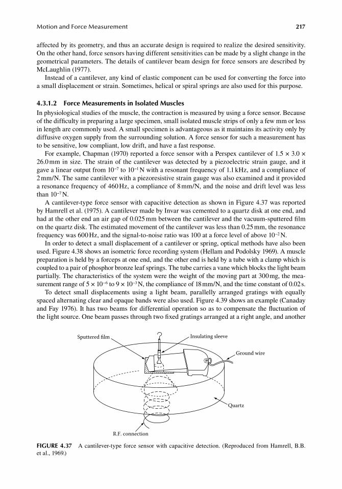
MotionandForceMeasurement 217
affected.by.its.geometry,.and.thus.an.accurate.design.is.required.to.realize.the.desired.sensitivity..On.the.other.hand,.force.sensors.having.different.sensitivities.can.be.made.by.a.slight.change.in.the.geometrical.parameters..The.details.of.cantilever.beam.design.for.force.sensors.are.described.by.McLaughlin.(1977).
Instead.of.a.cantilever,.any.kind.of.elastic.component.can.be.used.for.converting.the.force.into.a.small.displacement.or.strain..Sometimes,.helical.or.spiral.springs.are.also.used.for.this.purpose.
4.3.1.2 force Measurements in isolated MusclesIn.physiological.studies.of.the.muscle,.the.contraction.is.measured.by.using.a.force.sensor..Because.of.the.difficulty.in.preparing.a.large.specimen,.small.isolated.muscle.strips.of.only.a.few.mm.or.less.in.length.are.commonly.used..A.small.specimen.is.advantageous.as.it.maintains.its.activity.only.by.diffusive.oxygen.supply.from.the.surrounding.solution..A.force.sensor.for.such.a.measurement.has.to.be.sensitive,.low.compliant,.low.drift,.and.have.a.fast.response.
For.example,.Chapman.(1970).reported.a.force.sensor.with.a.Perspex.cantilever.of.1.5.×.3.0 ×.26.0.mm.in.size..The.strain.of.the.cantilever.was.detected.by.a.piezoelectric.strain.gauge,.and.it.gave.a.linear.output.from.10−7.to.10−1.N.with.a.resonant.frequency.of.1.1.kHz,.and.a.compliance.of.2.mm/N..The.same.cantilever.with.a.piezoresistive.strain.gauge.was.also.examined.and.it.provided.a.resonance.frequency.of.460.Hz,.a.compliance.of.8.mm/N,.and.the.noise.and.drift.level.was.less.than.10−7.N.
A.cantilever-type.force.sensor.with.capacitive.detection.as.shown.in.Figure.4.37.was.reported.by.Hamrell.et al..(1975)..A.cantilever.made.by.Invar.was.cemented.to.a.quartz.disk.at.one.end,.and.had.at.the.other.end.an.air.gap.of.0.025.mm.between.the.cantilever.and.the.vacuum-sputtered.film.on.the.quartz.disk..The.estimated.movement.of.the.cantilever.was.less.than.0.25.mm,.the.resonance.frequency.was.600.Hz,.and.the.signal-to-noise.ratio.was.100.at.a.force.level.of.above.10−2.N.
In.order.to.detect.a.small.displacement.of.a.cantilever.or.spring,.optical.methods.have.also.been.used..Figure.4.38.shows.an.isometric.force.recording.system.(Hellam.and.Podolsky.1969)..A.muscle.preparation.is.held.by.a.forceps.at.one.end,.and.the.other.end.is.held.by.a.tube.with.a.clamp.which.is.coupled.to.a.pair.of.phosphor.bronze.leaf.springs..The.tube.carries.a.vane.which.blocks.the.light.beam.partially..The.characteristics.of.the.system.were.the.weight.of.the.moving.part.at.300.mg,.the.mea-surement.range.of.5.×.10−6.to.9.×.10−3.N,.the.compliance.of.18.mm/N,.and.the.time.constant.of.0.02.s.
To. detect. small. displacements. using. a. light. beam,. parallelly. arranged. gratings. with. equally.spaced.alternating.clear.and.opaque.bands.were.also.used..Figure.4.39.shows.an.example.(Canaday.and.Fay.1976)..It.has.two.beams.for.differential.operation.so.as.to.compensate.the.fluctuation.of.the.light.source..One.beam.passes.through.two.fixed.gratings.arranged.at.a.right.angle,.and.another.
Insulating sleeve
Ground wire
Quartz
Sputtered lm
R.F. connection
figure 4.37 A.cantilever-type.force.sensor.with.capacitive.detection..(Reproduced.from.Hamrell, B.B..et al.,.1969.)

218 BiomedicalSensorsandInstruments
beam.passes.through.two.parallel.gratings.in.which.one.of.them.moves.in.respect.to.the.other..The.gratings.used.had.250.lines/in.,.and.the.force.ranged.from.10−7.to.2.×.10−5.N.with.a.compliance.of.160.mm/N.and.a.resonant.frequency.of.105.Hz..Minns.and.Franz.(1972).also.reported.a.force.sensor.using.gratings.as.shown.in.Figure.4.40a,.which.had.a.measurement.range.of.up.to.3.×.10−4.N.with.a.compliance.of.33.mm/N.and.a.resonance.frequency.of.400.Hz..Figure.4.40b.shows.a.method.of.mounting.components.in.a.microscope.body.
4.3.1.3 In Vivo Measurements of Muscular ContractionIn.order. to.measure. the. contracting. force.of. a.muscle. in vivo,. special. force. sensors. that. can.be.attached.to.the.muscle.are.required..Sometimes,.chronic.observations.over.several.days.or.weeks.are.required,.using.implantable.sensors.in.experimental.animals.
Forceps
Screw
Lucite block
Perfusion solution
Stainlesssteel tube
Silicone oil
Sample
Clamp
0 1 2 cm
Leafsprings
Vane
Light beamMechanical ground
figure 4.38 An. isometric. force. recording. system.. (After.Hellam,.D.C.. and.Podolsky,.R.J.,.J. Physiol. (Lond.),.200,.807,.1969.)
FiberopticsQuartzhalogen lamp
Grating 4
Grating 3
Workingposition
Grating 1
Grating 2
Grating 4
Grating 3
Photodetector 1
Photodetector 2
figure 4.39 Methods.of.detecting.small.forces.using.light.beams.and.gratings..(After.Canaday,.P.G..and.Fay,.F.S.,.J. Appl. Physiol.,.40,.243,.1976.)
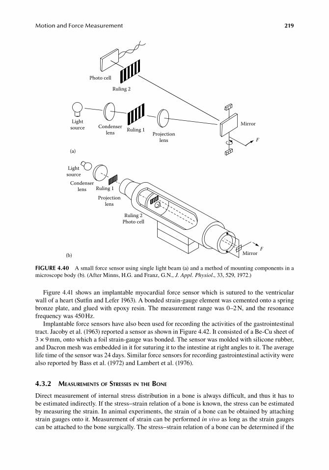
MotionandForceMeasurement 219
Figure.4.41.shows.an.implantable.myocardial.force.sensor.which.is.sutured.to.the.ventricular.wall.of.a.heart.(Sutfin.and.Lefer.1963)..A.bonded.strain-gauge.element.was.cemented.onto.a.spring.bronze.plate,.and.glued.with.epoxy.resin..The.measurement.range.was.0–2.N,.and.the.resonance.frequency.was.450.Hz.
Implantable.force.sensors.have.also.been.used.for.recording.the.activities.of.the.gastrointestinal.tract..Jacoby.et al..(1963).reported.a.sensor.as.shown.in.Figure.4.42..It.consisted.of.a.Be-Cu.sheet.of.3.×.9.mm,.onto.which.a.foil.strain-gauge.was.bonded..The.sensor.was.molded.with.silicone.rubber,.and.Dacron.mesh.was.embedded.in.it.for.suturing.it.to.the.intestine.at.right.angles.to.it..The.average.life.time.of.the.sensor.was.24.days..Similar.force.sensors.for.recording.gastrointestinal.activity.were.also.reported.by.Bass.et al..(1972).and.Lambert.et al..(1976).
4.3.2 MeasureMents of stresses in the bone
Direct.measurement.of.internal.stress.distribution.in.a.bone.is.always.difficult,.and.thus.it.has.to.be.estimated.indirectly..If.the.stress–strain.relation.of.a.bone.is.known,.the.stress.can.be.estimated.by.measuring.the.strain..In.animal.experiments,.the.strain.of.a.bone.can.be.obtained.by.attaching.strain.gauges.onto.it..Measurement.of.strain.can.be.performed.in vivo.as.long.as.the.strain.gauges.can.be.attached.to.the.bone.surgically..The.stress–strain.relation.of.a.bone.can.be.determined.if.the.
Lightsource Ruling 1
Photo cell
Ruling 2
Condenserlens Projection
lens
Mirror
F
(a)
Lightsource
Condenserlens Ruling 1
Projectionlens
Ruling 2Photo cell
MirrorF
(b)
figure 4.40 A.small.force.sensor.using.single.light.beam.(a).and.a.method.of.mounting.components.in.a.microscope.body.(b)..(After.Minns,.H.G..and.Franz,.G.N.,.J. Appl. Physiol.,.33,.529,.1972.)
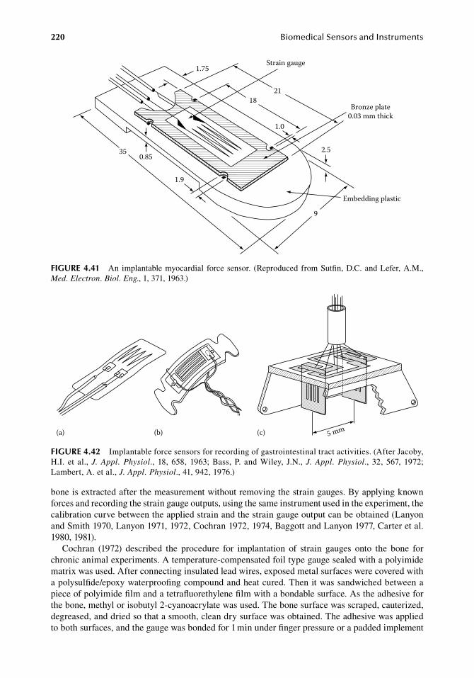
220 BiomedicalSensorsandInstruments
bone.is.extracted.after.the.measurement.without.removing.the.strain.gauges..By.applying.known.forces.and.recording.the.strain.gauge.outputs,.using.the.same.instrument.used.in.the.experiment,.the.calibration.curve.between.the.applied.strain.and.the.strain.gauge.output.can.be.obtained.(Lanyon.and.Smith.1970,.Lanyon.1971,.1972,.Cochran.1972,.1974,.Baggott.and.Lanyon.1977,.Carter.et al..1980,.1981).
Cochran. (1972). described. the. procedure. for. implantation. of. strain. gauges. onto. the. bone. for.chronic.animal.experiments..A.temperature-compensated.foil.type.gauge.sealed.with.a.polyimide.matrix.was.used..After.connecting.insulated.lead.wires,.exposed.metal.surfaces.were.covered.with.a.polysulfide/epoxy.waterproofing.compound.and.heat.cured..Then.it.was.sandwiched.between.a.piece.of.polyimide.film.and.a.tetrafluorethylene.film.with.a.bondable.surface..As.the.adhesive.for.the.bone,.methyl.or.isobutyl.2-cyanoacrylate.was.used..The.bone.surface.was.scraped,.cauterized,.degreased,.and.dried.so.that.a.smooth,.clean.dry.surface.was.obtained..The.adhesive.was.applied.to.both.surfaces,.and.the.gauge.was.bonded.for.1.min.under.finger.pressure.or.a.padded.implement.
Strain gauge
Bronze plate0.03 mm thick
Embedding plastic
350.85
1.9
1.75
1821
1.0
2.5
9
figure 4.41 An.implantable.myocardial. force.sensor.. (Reproduced. from.Sutfin,.D.C..and.Lefer,.A.M.,.Med. Electron. Biol. Eng.,.1,.371,.1963.)
(a) (b) 5 mm(c)
figure 4.42 Implantable.force.sensors.for.recording.of.gastrointestinal.tract.activities..(After.Jacoby,.H.I.. et al.,.J. Appl. Physiol.,. 18,. 658,. 1963;.Bass,.P.. and.Wiley,. J.N.,.J. Appl. Physiol.,. 32,. 567,. 1972;.Lambert,.A..et al.,.J. Appl. Physiol.,.41,.942,.1976.)
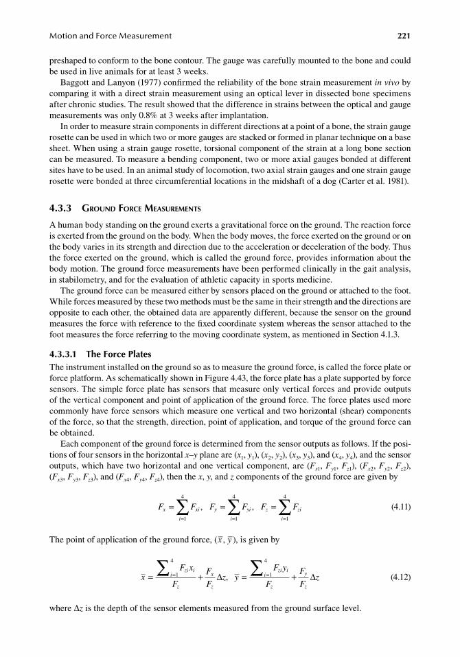
MotionandForceMeasurement 221
preshaped.to.conform.to.the.bone.contour..The.gauge.was.carefully.mounted.to.the.bone.and.could.be.used.in.live.animals.for.at.least.3.weeks.
Baggott.and.Lanyon.(1977).confirmed.the.reliability.of.the.bone.strain.measurement.in vivo.by.comparing.it.with.a.direct.strain.measurement.using.an.optical.lever.in.dissected.bone.specimens.after.chronic.studies..The.result.showed.that.the.difference.in.strains.between.the.optical.and.gauge.measurements.was.only.0.8%.at.3.weeks.after.implantation.
In.order.to.measure.strain.components.in.different.directions.at.a.point.of.a.bone,.the.strain.gauge.rosette.can.be.used.in.which.two.or.more.gauges.are.stacked.or.formed.in.planar.technique.on.a.base.sheet..When.using.a.strain.gauge.rosette,.torsional.component.of.the.strain.at.a.long.bone.section.can.be.measured..To.measure.a.bending.component,.two.or.more.axial.gauges.bonded.at.different.sites.have.to.be.used..In.an.animal.study.of.locomotion,.two.axial.strain.gauges.and.one.strain.gauge.rosette.were.bonded.at.three.circumferential.locations.in.the.midshaft.of.a.dog.(Carter.et al..1981).
4.3.3 ground force MeasureMents
A.human.body.standing.on.the.ground.exerts.a.gravitational.force.on.the.ground..The.reaction.force.is.exerted.from.the.ground.on.the.body..When.the.body.moves,.the.force.exerted.on.the.ground.or.on.the.body.varies.in.its.strength.and.direction.due.to.the.acceleration.or.deceleration.of.the.body..Thus.the.force.exerted.on.the.ground,.which.is.called.the.ground.force,.provides.information.about.the.body.motion..The.ground.force.measurements.have.been.performed.clinically.in.the.gait.analysis,.in.stabilometry,.and.for.the.evaluation.of.athletic.capacity.in.sports.medicine.
The.ground.force.can.be.measured.either.by.sensors.placed.on.the.ground.or.attached.to.the.foot..While.forces.measured.by.these.two.methods.must.be.the.same.in.their.strength.and.the.directions.are.opposite.to.each.other,.the.obtained.data.are.apparently.different,.because.the.sensor.on.the.ground.measures.the.force.with.reference.to.the.fixed.coordinate.system.whereas.the.sensor.attached.to.the.foot.measures.the.force.referring.to.the.moving.coordinate.system,.as.mentioned.in.Section.4.1.3.
4.3.3.1 the force PlatesThe.instrument.installed.on.the.ground.so.as.to.measure.the.ground.force,.is.called.the.force.plate.or.force.platform..As.schematically.shown.in.Figure.4.43,.the.force.plate.has.a.plate.supported.by.force.sensors..The.simple.force.plate.has.sensors.that.measure.only.vertical.forces.and.provide.outputs.of.the.vertical.component.and.point.of.application.of.the.ground.force..The.force.plates.used.more.commonly.have.force.sensors.which.measure.one.vertical.and.two.horizontal.(shear).components.of.the.force,.so.that.the.strength,.direction,.point.of.application,.and.torque.of.the.ground.force.can.be.obtained.
Each.component.of.the.ground.force.is.determined.from.the.sensor.outputs.as.follows..If.the.posi-tions.of.four.sensors.in.the.horizontal.x–y.plane.are.(x1,.y1),.(x2,.y2),.(x3,.y3),.and.(x4,.y4),.and.the.sensor.outputs,.which.have.two.horizontal.and.one.vertical.component,.are.(Fx1,.Fy1,.Fz1),.(Fx2,.Fy2, Fz2),.(Fx3,.Fy3,.Fz3),.and.(Fx4,.Fy4,.Fz4),.then.the.x,.y,.and.z.components.of.the.ground.force.are.given.by
.
F F F F F Fx xi
i
y yi
i
z zi
i
= = == = =
∑ ∑ ∑, ,1
4
1
4
1
4
.
(4.11)
The.point.of.application.of.the.ground.force,.(x–,.y–),.is.given.by
.x
F x
F
F
Fz y
F y
F
F
Fz
zi ii
z
x
z
zi ii
z
y
z
= + = += =∑ ∑1
4
1
4
∆ ∆,.
(4.12)
where.Δz.is.the.depth.of.the.sensor.elements.measured.from.the.ground.surface.level.
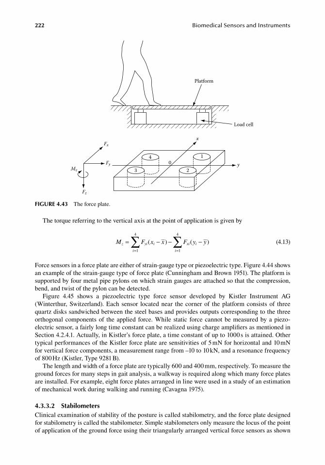
222 BiomedicalSensorsandInstruments
The.torque.referring.to.the.vertical.axis.at.the.point.of.application.is.given.by
.
M F x x F y yz yi i
i
xi i
i
= − − −= =
∑ ∑( ) ( )1
4
1
4
.
(4.13)
Force.sensors.in.a.force.plate.are.either.of.strain-gauge.type.or.piezoelectric.type..Figure.4.44.shows.an.example.of.the.strain-gauge.type.of.force.plate.(Cunningham.and.Brown.1951)..The.platform.is.supported.by.four.metal.pipe.pylons.on.which.strain.gauges.are.attached.so.that.the.compression,.bend,.and.twist.of.the.pylon.can.be.detected.
Figure. 4.45. shows. a. piezoelectric. type. force. sensor. developed. by. Kistler. Instrument. AG.(Winterthur,.Switzerland)..Each.sensor. located.near. the.corner.of. the.platform.consists.of. three.quartz.disks.sandwiched.between.the.steel.bases.and.provides.outputs.corresponding.to.the.three.orthogonal.components.of. the.applied. force..While. static. force.cannot.be.measured.by.a.piezo-electric.sensor,.a.fairly.long.time.constant.can.be.realized.using.charge.amplifiers.as.mentioned.in.Section.4.2.4.1..Actually,.in.Kistler’s.force.plate,.a.time.constant.of.up.to.1000.s.is.attained..Other.typical.performances.of.the.Kistler.force.plate.are.sensitivities.of.5.mN.for.horizontal.and.10.mN.for.vertical.force.components,.a.measurement.range.from.–10.to.10.kN,.and.a.resonance.frequency.of.800.Hz.(Kistler,.Type.9281.B).
The.length.and.width.of.a.force.plate.are.typically.600.and.400.mm,.respectively..To.measure.the.ground.forces.for.many.steps.in.gait.analysis,.a.walkway.is.required.along.which.many.force.plates.are.installed..For.example,.eight.force.plates.arranged.in.line.were.used.in.a.study.of.an.estimation.of.mechanical.work.during.walking.and.running.(Cavagna.1975).
4.3.3.2 StabilometersClinical.examination.of.stability.of.the.posture.is.called.stabilometry,.and.the.force.plate.designed.for.stabilometry.is.called.the.stabilometer..Simple.stabilometers.only.measure.the.locus.of.the.point.of.application.of.the.ground.force.using.their.triangularly.arranged.vertical.force.sensors.as.shown.
Platform
Load cell
01
23
4
x
y
Fx
Fy
Fz
Mz
figure 4.43 The.force.plate.
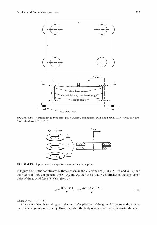
MotionandForceMeasurement 223
in.Figure.4.46..If.the.coordinates.of.these.sensors.in.the.x–y.plane.are.(0,.a),.(−b,.−c),.and.(b,.−c),.and.their.vertical.force.components.are.F1,.F2,.and.F3,.then.the.x-.and.y-coordinates.of.the.application.point.of.the.ground.force.(x–,.y–).is.given.by
.x
b F F
Fy
aF c F F
F= − = − +( )
,( )3 2 1 2 3
.(4.14)
where.F.=.F1.+.F2.+.F3.When.the.subject.is.standing.still,.the.point.of.application.of.the.ground.force.stays.right.below.
the.center.of.gravity.of.the.body..However,.when.the.body.is.accelerated.in.a.horizontal.direction,.
Platform
Shear force gauges
Vertical force, xy coordinate gauges
Torque gauges
Leveling screw
x
y
figure 4.44 A.strain-gauge-type.force.plate..(After.Cunningham,.D.M..and.Brown,.G.W.,.Proc. Soc. Exp. Stress Analysis.9,.75,.1951.)
ForceQuartz plates
Fx
Fy
Fz
figure 4.45 A.piezo-electric-type.force.sensor.for.a.force.plate.
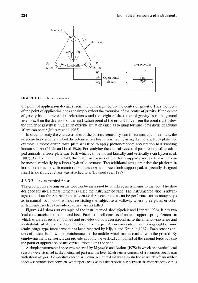
224 BiomedicalSensorsandInstruments
the.point.of.application.deviates.from.the.point.right.below.the.center.of.gravity..Thus.the.locus.of.the.point.of.application.does.not.simply.reflect.the.excursion.of.the.center.of.gravity..If.the.center.of.gravity.has.a.horizontal.acceleration.a.and.the.height.of.the.center.of.gravity.from.the.ground.level.is.h,.then.the.deviation.of.the.application.point.of.the.ground.force.from.the.point.right.below.the.center.of.gravity.is.ah/g..In.an.extreme.situation.(such.as.to.jump.forward).deviations.of.around.30.cm.can.occur.(Murray.et al..1967).
In.order.to.study.the.characteristics.of.the.posture.control.system.in.humans.and.in.animals,.the.response.to.externally.applied.disturbances.has.been.measured.by.using.the.moving.force.plate..For.example,.a.motor.driven.force.plate.was.used.to.apply.pseudo-random.acceleration.to.a.standing.human.subject.(Ishida.and.Imai.1980)..For.studying.the.control.system.of.posture.in.small.quadru-ped.animals,.a.force.plate.was.built.which.can.be.moved.laterally.and.vertically.(van.Eyken.et al..1987)..As.shown.in.Figure.4.47,.this.platform.consists.of.four.limb-support.pads,.each.of.which.can.be.moved.vertically.by.a.linear.hydraulic.actuator..Two.additional.actuators.drive.the.platform.in.horizontal.directions..To.monitor.the.forces.exerted.to.each.limb-support.pad,.a.specially.designed.small.triaxial.force.sensor.was.attached.to.it.(Lywood.et al..1987).
4.3.3.3 instrumented ShoeThe.ground.force.acting.on.the.foot.can.be.measured.by.attaching.instruments.to.the.foot..The.shoe.designed.for.such.a.measurement.is.called.the.instrumented.shoe..The.instrumented.shoe.is.advan-tageous.in.foot.force.measurement.because.the.measurement.can.be.performed.for.as.many.steps.as.in.natural.locomotion.without.restricting.the.subject.to.a.walkway.where.force.plates.or.other.instruments,.such.as.the.video.camera,.are.installed.
Figure.4.48.shows.an.example.of.the.instrumented.shoe.(Spolek.and.Lippert.1976)..It.has.two.load.cells.attached.at.the.toe.and.heel..Each.load.cell.consists.of.an.end.support.spring.element.on.which.strain.gauges.are.mounted.and.provides.outputs.corresponding.to.the.anterior–posterior.and.medial–lateral.shears,.axial.compression,.and.torque..An.instrumented.shoe.having.eight.or.nine.strain-gauge.type.force.sensors.has.been.reported.by.Kljajic.and.Krajnik.(1987)..Each.sensor.con-sists.of.a.steel.beam.with.a.protuberance.in.the.middle.which.makes.contact.with.the.ground..By.employing.many.sensors,.it.can.provide.not.only.the.vertical.component.of.the.ground.force.but.also.the.point.of.application.of.the.vertical.force.along.the.shoe.
A.simple.instrumented.shoe.was.reported.by.Miyazaki.and.Iwakua.(1978).in.which.two.vertical.load.sensors.were.attached.at.the.metatarsal.part.and.the.heel..Each.sensor.consists.of.a.stainless.steel.beam.with.strain.gauges..A.capacitive.sensor,.as.shown.in.Figure.4.49,.was.also.studied.in.which.a.foam.rubber.sheet.was.sandwiched.between.two.copper.sheets.so.that.the.capacitance.between.the.copper.sheets.varies.
Load celly
F1(0, a)
Platform
x
F3(b, –c)
Load cellsF2(–b, –c)
W1
W2
W3
Operationalcircuit
x
y
x–y recorder
y
x
figure 4.46 The.stabilometer.
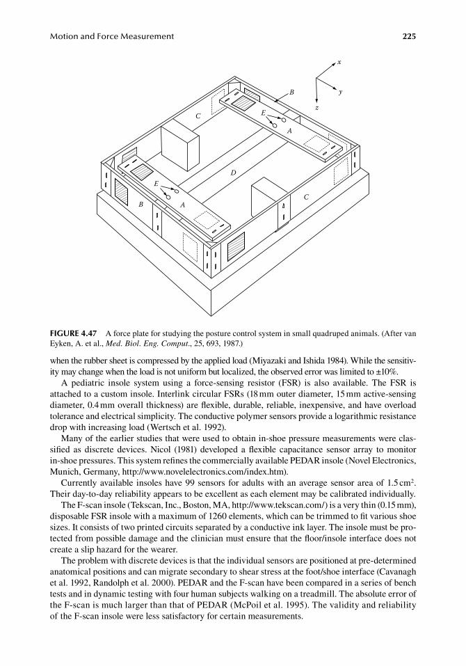
MotionandForceMeasurement 225
when.the.rubber.sheet.is.compressed.by.the.applied.load.(Miyazaki.and.Ishida.1984)..While.the.sensitiv-ity.may.change.when.the.load.is.not.uniform.but.localized,.the.observed.error.was.limited.to.±10%.
A. pediatric. insole. system. using. a. force-sensing. resistor. (FSR). is. also. available.. The. FSR. is.attached.to.a.custom.insole..Interlink.circular.FSRs.(18.mm.outer.diameter,.15.mm.active-sensing.diameter,.0.4.mm.overall.thickness).are.flexible,.durable,.reliable,.inexpensive,.and.have.overload.tolerance.and.electrical.simplicity..The.conductive.polymer.sensors.provide.a.logarithmic.resistance.drop.with.increasing.load.(Wertsch.et al..1992).
Many.of.the.earlier.studies.that.were.used.to.obtain.in-shoe.pressure.measurements.were.clas-sified. as. discrete. devices..Nicol. (1981). developed. a.flexible. capacitance. sensor. array. to.monitor..in-shoe.pressures..This.system.refines.the.commercially.available.PEDAR.insole.(Novel.Electronics,.Munich,.Germany,.http://www.novelelectronics.com/index.htm).
Currently.available. insoles.have.99.sensors.for.adults.with.an.average.sensor.area.of.1.5.cm2..Their.day-to-day.reliability.appears.to.be.excellent.as.each.element.may.be.calibrated.individually.
The.F-scan.insole.(Tekscan,.Inc.,.Boston,.MA,.http://www.tekscan.com/).is.a.very.thin.(0.15.mm),.disposable.FSR.insole.with.a.maximum.of.1260.elements,.which.can.be.trimmed.to.fit.various.shoe.sizes..It.consists.of.two.printed.circuits.separated.by.a.conductive.ink.layer..The.insole.must.be.pro-tected.from.possible.damage.and.the.clinician.must.ensure.that.the.floor/insole.interface.does.not.create.a.slip.hazard.for.the.wearer.
The.problem.with.discrete.devices.is.that.the.individual.sensors.are.positioned.at.pre-determined.anatomical.positions.and.can.migrate.secondary.to.shear.stress.at.the.foot/shoe.interface.(Cavanagh.et al..1992,.Randolph.et al..2000)..PEDAR.and.the.F-scan.have.been.compared.in.a.series.of.bench.tests.and.in.dynamic.testing.with.four.human.subjects.walking.on.a.treadmill..The.absolute.error.of.the.F-scan.is.much.larger.than.that.of.PEDAR.(McPoil.et al..1995)..The.validity.and.reliability.of.the.F-scan.insole.were.less.satisfactory.for.certain.measurements.
E
AB
E
A
x
y
z
B
C
C
D
figure 4.47 A.force.plate.for.studying.the.posture.control.system.in.small.quadruped.animals..(After.van.Eyken,.A..et al.,.Med. Biol. Eng. Comput.,.25,.693,.1987.)
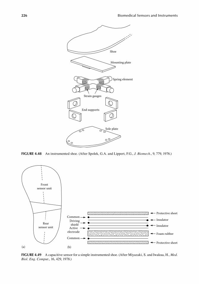
226 BiomedicalSensorsandInstruments
Sole plate
End supports
Strain gauges
Spring element
Mounting plate
Shoe
figure 4.48 An.instrumented.shoe..(After.Spolek,.G.A..and.Lippert,.F.G.,.J. Biomech.,.9,.779,.1976.)
Frontsensor unit
Rearsensor unit
CommonDrivingshield
Activeelectrode
Common
Protective sheet
Insulator
Insulator
Foam rubber
Protective sheet(a) (b)
figure 4.49 A.capacitive.sensor.for.a.simple.instrumented.shoe..(After.Miyazaki,.S..and.Iwakua,.H.,.Med. Biol. Eng. Comput.,.16,.429,.1978.)
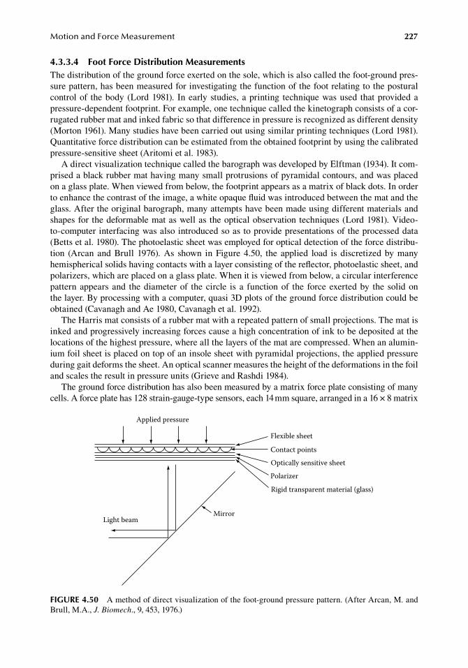
MotionandForceMeasurement 227
4.3.3.4 foot force distribution MeasurementsThe.distribution.of.the.ground.force.exerted.on.the.sole,.which.is.also.called.the.foot-ground.pres-sure.pattern,.has.been.measured.for.investigating.the.function.of.the.foot.relating.to.the.postural.control.of. the.body.(Lord.1981).. In.early.studies,.a.printing. technique.was.used. that.provided.a.pressure-dependent.footprint..For.example,.one.technique.called.the.kinetograph.consists.of.a.cor-rugated.rubber.mat.and.inked.fabric.so.that.difference.in.pressure.is.recognized.as.different.density.(Morton.1961)..Many.studies.have.been.carried.out.using.similar.printing.techniques.(Lord.1981)..Quantitative.force.distribution.can.be.estimated.from.the.obtained.footprint.by.using.the.calibrated.pressure-sensitive.sheet.(Aritomi.et al..1983).
A.direct.visualization.technique.called.the.barograph.was.developed.by.Elftman.(1934)..It.com-prised.a.black.rubber.mat.having.many.small.protrusions.of.pyramidal.contours,.and.was.placed.on.a.glass.plate..When.viewed.from.below,.the.footprint.appears.as.a.matrix.of.black.dots..In.order.to.enhance.the.contrast.of.the.image,.a.white.opaque.fluid.was.introduced.between.the.mat.and.the.glass..After.the.original.barograph,.many.attempts.have.been.made.using.different.materials.and.shapes.for.the.deformable.mat.as.well.as.the.optical.observation.techniques.(Lord.1981)..Video-to-computer.interfacing.was.also.introduced.so.as.to.provide.presentations.of.the.processed.data.(Betts.et al..1980)..The.photoelastic.sheet.was.employed.for.optical.detection.of.the.force.distribu-tion. (Arcan. and.Brull. 1976)..As. shown. in.Figure.4.50,. the. applied. load. is. discretized.by.many.hemispherical.solids.having.contacts.with.a.layer.consisting.of.the.reflector,.photoelastic.sheet,.and.polarizers,.which.are.placed.on.a.glass.plate..When.it.is.viewed.from.below,.a.circular.interference.pattern.appears.and. the.diameter.of. the.circle. is.a. function.of. the. force.exerted.by. the. solid.on.the.layer..By.processing.with.a.computer,.quasi.3D.plots.of.the.ground.force.distribution.could.be.obtained.(Cavanagh.and.Ae.1980,.Cavanagh.et al..1992).
The.Harris.mat.consists.of.a.rubber.mat.with.a.repeated.pattern.of.small.projections..The.mat.is.inked.and.progressively.increasing.forces.cause.a.high.concentration.of.ink.to.be.deposited.at.the.locations.of.the.highest.pressure,.where.all.the.layers.of.the.mat.are.compressed..When.an.alumin-ium.foil.sheet.is.placed.on.top.of.an.insole.sheet.with.pyramidal.projections,.the.applied.pressure.during.gait.deforms.the.sheet..An.optical.scanner.measures.the.height.of.the.deformations.in.the.foil.and.scales.the.result.in.pressure.units.(Grieve.and.Rashdi.1984).
The.ground.force.distribution.has.also.been.measured.by.a.matrix.force.plate.consisting.of.many.cells..A.force.plate.has.128.strain-gauge-type.sensors,.each.14.mm.square,.arranged.in.a.16.×.8.matrix.
Applied pressure
Mirror
Flexible sheet
Contact points
Optically sensitive sheet
Polarizer
Rigid transparent material (glass)
Light beam
figure 4.50 A.method.of.direct.visualization.of.the.foot-ground.pressure.pattern..(After.Arcan,.M..and.Brull,.M.A.,.J. Biomech.,.9,.453,.1976.)

228 BiomedicalSensorsandInstruments
(Dhanendran.et al..1978,.Soames.et al..1982)..The.use.of.a.capacitive.force.sensor.consisting.of.a.com-pressible.elastic.dielectric.material.was.presented.by.Nichol.(1981)..Square-shaped.sensors.between.3.×.3.mm.and.30.×.30.mm.were.used.in.a.matrix.arrangement..Matrices.of.up.to.256.×.128.=.32,768.sensors.were.evaluated.
A.commercially.available.force.plate.that.contains.960.capacitance.points.and.is.scanned.by.a.computer.30.times.per.second.is.available.for.clinical.application.(Footmaxx,.http://www.footmaxx.com/)..Polyvinylidene.fluoride.(PVDF;.Albuquerque,.NM,.http://ktech.com/index.cfm).is.the.most.popular.piezoelectric.polymer.material.for.shock.sensors..PVDF.can.be.used.as.a.stress.gauge.and.for.pedobarography.
The. instrumented.walkway.can.be.used. to.determine. stride. characteristics.without. attaching.any device.to.the.subjects..Sensors.are.placed.on.the.floor,.not.on.the.subject..A.gait.mat.automates.the.spatial.and.temporal.measurements.of.gait..The.gait.mat.consists.of.an.array.of.switches.along.the.walkway.that.are.covered.by.a.protective.mat..As.a.subject.walks.along.the.mat,.the.switches.close.underfoot,.enabling.the.computer.to.calculate.the.timing.of.each.switch.closure..Such.walk-ways.are.portable,.can.be.laid.over.any.flat.surface,.require.minimum.setup.and.test.time,.and.do.not.require.the.placement.of.any.devices.on.the.patient.
The.standard.gait.mat.(GaitRite,.CIR.systems,.Havertown,.PA,.http://www.gaitrite.com/).and.elec-tronic.walkway.contains.six.sensor.pads.in.a.roll-up.carpet.and.produces.an.active.area.61.cm.wide.and.366.cm.long..In.this.arrangement,.the.active.area.forms.a.grid.of.48.×.288.switches.placed.on.1.27.cm.centers..On.the.other.hand,.GaitMat.(Gait.Mat,.E.Q.,.Inc.,.Chalfont,.PA,.http://www.gaitmat.com/).uses.pressure.sensitive.switches.arranged.in.38.rows.of.256.switches.and.has.a.walking.surface.of.60.×.3.84.m..The.switches.are.on.15.mm.centers,.giving.a.spatial.resolution.of.15.mm.to.the.system.
As. the. patient. ambulates. across. the. walkway,. the. system. captures. the. relative. arrangement,.geometry,.and.applied.pressure.of.each.footfall.as.a.function.of.time..The.application.software.con-trols.the.functionality.of.the.walkway,.processes.the.raw.data.into.footfall.patterns,.and.computes.temporal.and.spatial.parameters..The.software.stores.each.test.by.patient.and.supports.a.variety.of.reports.and.analyses..These.systems.can.be.used.to.test.patients.with.or.without.shoes,.including.those.using.assistance.devices.and.ambulatory.aids,.such.as.crutches,.canes,.or.walkers.
The.advantages.of.such.devices.are.the.elimination.of.any.gait-encumbering.attachments,.low.cost,.and.portability..The.disadvantages.include.limitations.on.spatial.resolution.due.to.the.finite.size.of.the.switches.and.on.temporal.resolution.due.to.restricted.scan.rates.
A.pressure.mat.is.placed.on.the.center.of.a.walkway.and.used.as.a.force.plate.that.the.subject.steps.on..This.provides.a.quick.and.easy.way.of.obtaining.a.plantar-pressure.distribution..The.pres-sure.mat.is.factory.calibrated.and.comes.with.software.that.produces.color.pressure.pictures,.force.and.pressure.versus. time.plots,.etc..The.principle.of. the.sensor. is. the.same.as. that.of. the. insole.pressure.distribution.system..(Novel.Munich.Germany,.http://www.novel.de/.uses.capacitive.sen-sors.and.F-Mat.and.Big.mat.use.FSR.sensors.).EMEDs.are.high-resolution.sensor.platforms.for.the.fast.diagnosis.of.dynamic.foot.function.and.foot.deformities..The.measurement.method.is.based.on.calibrated.capacitive.sensors..The.signals,.produced.from.a.maximum.of.4000.pressure.sensors,.are.displayed.as.conformational.color.pictures.on.a.monitor.or.as.printouts.on.a.color.printer..EMED.system.platforms.are.available.in.different.sizes.and.with.various.local.resolutions.
referenCeS
Adams,.L..P..and.Spirakis,.A..1997..Stereo.photogrammetry,.in.Optical Measurement Methods in Biomechanics,.Orr,.J..F..and.Shelton,.J..C.,.eds..London,.U.K.:.Chapman.&.Hall,.pp..17–38.
Aminian,.K.,.Robert,.P.,.Jequiuer,.E.,.and.Schuts,.Y..1995..Estimation.of.speed.and.incline.of.walking.using.neural.network,.IEEE Trans. Instrum. Meas..44:.743–746.
Aminian.K.,.Rezakhanlou,.A..E.,.Fritsch,.C.,.Leyvraz.P..F.,.and.Robert,.P..1999..Temporal.feature.estimation.during.walking.using.miniature.accelerometers:.An.analysis.of.gait.improvement.after.hip.arthroplasty,.Med. Biol. Eng. Comput..37:.686–691.
MotionandForceMeasurement 229
Arcan,.M..and.Brull,.M..A..1976..A.fundamental.characteristic.of.the.human.body.and.foot,.the.foot-ground.pressure.pattern,.J. Biomech..9:.453–457.
Aritomi,.H.,.Morita,.M.,.and.Yonemoto,.K..1983..A.simple.method.of.measuring.the.footstole.pressure.of.nor-mal.subjects.using.prescale.pressure-detecting.sheets,.J. Biomech..16:.157–165.
Ashutosh,.K.,.Gilbert,.R.,.Auchincloss,.J..H.,.Erlebacher,.J.,.and.Peppi,.D..1974..Impedance.pnemograph.and.magnetometer.methods.for.monitoring.tidal.volume,.J. Appl. Physiol..37:.964–966.
Åstrand,.P..O.,.Rodahl,.K.,.Dahl,.H..A.,. and.Stromme,.S..B..2003..Textbook of Work Physiology, 4th edn: Physiological Bases of Exercise..Champaign,.IL:.Human.Kinetics.Publishers.
Ayazi,.F..and.Najafi,.K..1998..Design.and.fabrication.of.a.high-performance.polysilicon.vibrating.ring.gyro-scope.. Proceedings of 11th IEEE/ASME International Workshop Micro Electromechanical Systems,.Heidelberg,.Germany,.pp..621–626.
Baggott,.D..G.. and.Lanyon,.L..E..1977..An. independent. “post-mortem”.calibration.of. electrical. resistance.strain.gauges.bonded.to.bone.surfaces.“in.vivo”,.J. Biomech..10:.615–622.
Ball,.P..and.Johnson,.G..R..1993..Reliability.of.hindfoot.goniometry.when.using.a.flexible.electrogoniometer,.Clin. Biomech..8:.13–19.
Bando,.E.,.Fukushima,.S.,.Kawabata,.H.,.and.Kohno,.S..1972..Continuous.observation.of.mandibular.positions.by.telemetry,.J. Prosthet. Dent..28:485–490.
Bass,.P..and.Wiley,.J..N..1972..Contractile.force.transducer.for.recording.muscle.activity. in.unanesthetized.animals,.J. Appl. Physiol..32:.567–570.
Betts,.R..P.,.Franks,.C..I.,.Duckworth,.T.,.and.Burke,.J..1980..Static.and.dynamic.foot-pressure.measurements.in.clinical.orthopaedics,.Med. Biol. Eng. Comput..18:.674–684.
Bierma-Zeinstra,.S.,.Bohnen,.A..M.,.Ramlal,.R.,.Ridderikhoffm,.J.,.and.Verhaarm,.J..A..N..1998..Comparison.between.two.devices.for.measuring.hip.joint.motions,.Clin. Rehabil..12:.497–505.
Bourke,.A..K.,.O’Brien,.J..V.,.and.Lyons,.G..M..2007..Evaluation.of.a.threshold-based.tri-axial.accelerometer.fall.detection.algorithm,.Gait Posture.26:.194–199.
Bourke,.A..K..and.Lyons,.G..M..2008..A.threshold-based.fall-detection.algorithm.using.a.bi-axial.gyroscope.sensor,.Med. Biol. Eng. Comput..30:.84–90.
Bourke,.A..K.,.O’Donovan,.K..J.,.and.Ólaighin,.G..2008..The.identification.of.vertical.velocity.profiles.using.an.inertial.sensor.to.investigate.pre-impact.detection.of.falls,.Med. Eng. Phys..30:.937–946.
Boyce,.E..S.,.Dawes,.G..S.,.Gough,.J..D.,.and.Poore,.E..R..1976..Doppler.ultrasound.method.for.detecting.human.fetal.breathing.in.utero,.Brit. Med. J..2:.17–18.
Breniere,.Y..and.Dietrich,.G..1992..Heel-off.perturbation.during.gait.initiation:.Biomechanical.analysis.using.triaxial.accelerometry.and.a.force.plate,.J. Biomech..25:.121–127.
Canaday,.P..G..and.Fay,.F..S..1976..An.ultrasensitive.isometric.force.transducer.for.single.smooth.muscle.cell.mechanics,.J. Appl. Physiol..40:.243–246.
Carter,.D..R.,.Smith,.D..J.,.Spengler,.D..M.,.Daly,.C..H.,.and.Frankel,.V..H..1980..Measurement.and.analysis.of.in-vivo.bone.strains.on.the.canine.radius.and.ulna,.J. Biomech..13:.27–38.
Carter,.D..R.,.Vasu,.R.,.Spengler,.D..M.,.and.Dueland,.R..T..1981..Stress.fields.in.the.unplated.and.plated.canine.femur.calculated.from.in.vivo.strain.measurements,.J. Biomech..14:.63–70.
Cavagna,.G..A..1975..Force.platform.as.ergometers,.J. Appl. Physiol..39:.174–179.Cavanagh,. P.. R.. and.Ae,. M.. 1980..A. technique. for. the. display. of. pressure. distribution. beneath. the. foot,.
J. Biomech..13:.69–75.Cavanagh,.P..R.,.Bewitt,.F..G.,.and.Perry,.J..E..1992..In-shoe.plantar.pressure.measurement:.A.review..Foot.2:.
185–194.Chao,.E..Y..S..1980..Justification.of.triaxial.goniometer.for.the.measurement.of.joint.rotation,.J. Biomech..13:.
989–993,.995–1006.Chapman,.R..A..1970..High.sensitivity.isometric.force.transducers.made.with.piezo-electric.or.piezo-resistive.
strain.gauges,.J. Physiol. (Lond.).210:.4P–6P.Clemedson,.C.-J..and.Jönsson,.A..1964..Dynamic.response.of.chest.wall.and.lung.injuries.in.rabbits.exposed.to.
air.shock.waves.of.short.duration,.Acta Physiol. Scand..233.(Suppl..62):.3.Clemedson,.C.-J..and.Jönsson,.A..1968..A.mechanoelectric.transducer.for.recording.transient.motion.in.bio-
logical.experiments,.J. Appl. Physiol..24:.430–433.Cochran,.G..V..B..1972..Implantation.of.strain.gages.on.bone.in.vivo,.J. Biomech..5:.119–123.Cochran,.G..V..B..1974..A.method.for.direct.recording.of.electromechanical.data.from.skeletal.bone.in.living.
animals,.J. Biomech..7:.563–565.Contini,. R.. and. Drills,. R.. 1966.. Kinematic. and. kinetic. techniques. in. biomechanics,. in. Advances in
Bioengineering and Instrumentation,.Alt,.F.,.ed..New.York:.Plenum.Press,.pp..3–68.
230 BiomedicalSensorsandInstruments
Cunningham,.D..M..and.Brown,.G..W..1951..Two.devices.for.measuring.the.forces.acting.on.the.human.body.during.walking,.Proc. Soc. Exp. Stress Analysis.9:.75–90.
Dapena,.J.,.Harman,.E..A.,.and.Miller,.J..A..1982..Three-dimensional.cinematography.with.control.object.of.unknown.shape,.J. Biomech..15:.11–19.
Day,.J..S.,.Murdoch,.D..J.,.and.Dumas,.G..A..2000..Calibration.of.position.and.angular.data.from.a.magnetic.tracking.device,.J. Biomech..33:.1039–1045.
Dhanendran,.M.,.Hutton,.W..C.,.and.Parker,.Y..1978..The.distribution.of.force.under.the.human.foot,.an.on-line.measuring.system,.Meas. Control.11:.261–264.
Dinh,.A.,.Shi,.Y.,.Teng,.D.,.Ralhan,.A.,.Chen,.L.,.Bello-Haas,.V..D.,.Basran,.J.,.Ko,.S.-B.,.and.McCrowsky,.C..2009..A.fall.and.near-fall.assessment.and.evaluation.system,.Open Biomed. Eng. J.,.3:.1–7.
Doebelin,.E..O..2004a..Measurement System Application and Design,.4th.edn..New.York:.McGraw-Hill,.p..342.Doebelin,.E..O..2004b..Measurement System Application and Design,.4th.edn..New.York:.McGraw-Hill,.
pp..379–82.Elftman,.H..O..1934..A.cinematic.study.of.the.distribution.of.pressure.in.the.human.foot,.Anat. Record.59:.
481–491.Evans,.A.,.Duncan,.G.,.and.Gilchirst,.W..1991..Recording.acceleration.in.body.movements,.Med. Biol. Eng.
Comput..29:.102–104.Feldstein,.C..F.,.Meerbsum,.S.,.Lewis,.G.,. and.Culler,.V..1980..Transducers. for.myocardial. research,.Med.
Instrum..14:.277–282.Flavel,.S..C.,.Nordstrom,.M..A.,.and.Miles,.T..S..2002..A.simple.and.inexpensive.system.for.monitoring.jaw.
movements.in.ambulatory.humans,.J. Biomech..35:.573–577.Folke,.M.,.Cernerud,.L.,.Ekström,.M.,.and.Hök,.B..2006..Critical.review.of.non-invasive.respiratory.monitoring.
in.medical.care,.Med. Biol. Eng. Comput..41:.377–383.Giansanti,.D.,.Maccioni,.G.,.and.Macellari,.V..2005..The.development.and.test.of.a.device.for.the.reconstruc-
tion.of.3-D.position.and.orientation.by.means.of.a.kinematic.sensor.assembly.with.rate.gyroscopes.and.accelerometers,.IEEE Trans. Biomed. Eng..52:.1271–1277.
Goldstein,.S..R.,.Friauf,.W..S.,.and.Wells,.J..B..1974..A.novel.instrument.for.dynamic.and.static.measurement.of.large.length.changes.in.muscle,.J. Appl. Physiol..36:.128–130.
Goodman,.C..A..and.Castellana,.F..S..1982..A.digital.sonomicrometer.for.two-point.length.and.velocity.mea-surement,.Am. J. Physiol..243:.H634–.H639.
Grieve,.D..W..and.Rashdi,.T..1984..Pressures.under.normal.feet.in.standing.and.walking.as.measured.by.foil.pedobarography,.Ann. Rheum. Dis..43:.816–818.
Hamrell,.B..B.,.Panaanan,.R.,.Trono,.J.,.and.Alpert,.N..R..1975..A.stable,.sensitive,.low-compliance.capacitance.force.transducer,.J. Appl. Physiol..38:.190–193.
Hansson,.G..Å.,.Asterland,.P.,.Holmer,.N..G.,.and.Skerfving,.S..2001..Validity.and.reliability.of.triaxial.accel-erometers.for.inclinometry.in.posture.analysis,.Med. Biol. Eng. Comput..39:.405–413.
Harze,.H..1988..High.precision.three-dimensional.photogrammetric.calibration.and.object-space.reconstruc-tion.using.a.modified.DLT-approach,.J. Biomech..21:.533–538.
Hellam,.D..C..and.Podolsky,.R..J..1969..Force.measurements.in.skinned.muscle.fibers,.J. Physiol. (Lond.).200:.807–819.
Hokanson,.D..E.,.Mozersky,.D..J.,.Sumner,.D..S.,.and.Strandness,.D..E..Jr..1972..A.phase-locked.echo.tracking.system.for.recording.arterial.diameter.changes.in.vivo,.J. Appl. Physiol..32:.728–733.
Horwitz,.L..D.,.Bishop,.V..S.,.Stone,.H..L.,.and.Stegall,.H..F..1968..Continuous.measurement.of.internal.left.ventricular.diameter,.J. Appl. Physiol..24:.738–740.
Hunt,.J..W.,.Arditi,.M.,.and.Foster,.F..S..1983..Ultrasound.transducers.for.pulse-echo.medical.imaging,.IEEE Trans. Biomed. Eng..30:.453–481.
Isacson,. J.,. Gransberg,. L.,. and. Knutsson,. E.. 1986.. Three-dimensional. electrogoniometric. gait. recording,.J. Biomech..19:.627–629,.631–635.
Ishida,.A..and.Imai,.S..1980..Responses.of.the.posture-control.system.to.pseudo-random.acceleration.distur-bances,.Med. Biol. Eng. Comput..18:.433–438.
Jacoby,.H..I.,.Bass,.P.,.and.Benett,.D..R..1963..In.vivo.extraluminal.contractile.force.transducer.for.gastrointes-tinal.muscle,.J. Appl. Physiol..18:.658–665.
Jones,.R..D.,.Adams,.R..B.,.and.Luria,.M..H..1977..A.miniature.segment-length.strain.gauge.arch.for.the.assess-ment.of.myocardial.function,.Med. Instrum..11:.244–249.
Johnson,.R..C..and.Smidt,.G..L..1969..Measurement.of.hip-joint.motion.during.walking,.J. Bone Joint Surg..51-A:.1083–1094.
Jordan,.K.,.Dziedzic,.K.,.Mullis,.R.,.Dawes,.P..T.,.and.Jones,.P..W..2001..The.development.of.three-dimensional.range.of.motion.measurement.systems.for.clinical.practice,.Rheumatology.40:.1081–1084.
MotionandForceMeasurement 231
Kangas,.M.,.Konttila,.A.,.Lindgren,.P.,.Winblad,.I.,.and.Jämsä,.T..2008..Comparison.of.low.complexity.fall.detection.algorithms.for.body.attached.accelerometers,.Gait Posture.28:.285–291.
Kangas,.M.,.Vikman,.I.,.Wiklander,.J.,.Lindgren,.P.,.Nyberg,.L.,.and.Jämsä,.T..2009..Sensitivity.and.specificity.of.fall.detection.in.people.aged.40.years.and.over,.Gait Posture.29:.571–574.
Karantonis,.D..M.,.Narayanan,.M..R.,.Mathie,.M.,.Lovell,.N..H.,.and.Cellerm,.B..G..2006..Implementation.of.a.real-time.human.movement.classifier.using.a.triaxial.accelerometer.for.ambulatory.monitoring,.IEEE Trans. Inf. Technol. Biomed..10:.156–167.
Ketterkamp,.D..B.,.Johnson,.R..J.,.Smidt,.G..L.,.Chao,.E..Y..S.,.and.Walker,.M..1970..An.electrogoniometric.study.of.knee.motion.in.normal.gait,.J. Bone Joint Surg..52-A:.775–790.
Kljajic,.M..and.Krajnik,.J..1987..The.use.of.ground.reaction.measuring.shoe.in.gait.evaluation,.Clin. Phys. Physiol. Meas..8:.133–142.
Kordic,.S..1986..Integrated.silicon.magnetic-field.sensors,.Sens. Actuator.10:.347–378.Krippke,.D..F.,.Mullaney,.D..J.,.Messin,.S.,.and.Wyborney,.V..G..1978..Wrist.actigraphic.measures.of.sleep.and.
rhythms,.Electroencephalogr. Clin. Neurophysiol..44:.674–676.Lambert,.A.,.Eloy,.R.,. and.Grenier,. J..F.. 1976..Transducer. for. recording.electrical. and.mechanical. chronic.
intestinal.activity,.J. Appl. Physiol..41:.942–945.Lanyon,.L..E..1971..Strain.in.sheep.lumbar.vertebrae.recorded.during.life,.Acta Orthop. Scand..42,.102–112.Lanyon,.L..E..1972..In-vivo.bone.strain.recorded.from.thoracic.vertebrae.of.sheep,.J. Biomech..5:.277–281.Lanyon,.L..E..and.Smith,.R..N..1970..Bone.strain.in.the.tibia.during.normal.quadrupedal.locomotion,.Acta
Orthop. Scand..41:.238–248.Lee,.R..D..and.Sandler,.H..1970..Miniature.implantable.sonomicrometer.system,.J. Appl. Physiol..28:110–112.Lentini,.E..A..and.Guyton,.W..1963..Electronic.micrometer,.J. Appl. Physiol..18:.636–638.Lindemann,.U.,.Hock,.A.,.Stuber,.M.,.Keck,.W.,.and.Becker,.C..2005..Evaluation.of.a.fall.detector.based.on.
accelerometers:.A.pilot.study,.Med. Biol. Eng. Comput..43:.548–551.Logan,.S..E.,.and.Groszevski,.P..1989..Dynamic.wrist.motion.analysis.using.six.degree.of.freedom.sensors,.
Biomed. Sci. Instrum..25:.213–220.Lord,.M..1981..Foot.pressure.measurement:.A.review.of.methology,.J. Biomed. Eng..3:.91–99.Luinge,.H..J..and.Veltink,.P..H..2005..Measuring.orientation.of.human.body.segments.using.miniature.gyro-
scopes.and.accelerometers,.Med. Biol. Eng. Comput..43:.273–282.Lywood,.D..W.,.Adams,.D..J.,.van.Eyken,.A.,.and.Macqpherson,.J..M..1987..Small,.triaxial.force.plate,.Med.
Biol. Eng. Comput..25:.698–701.Macellari,.V..1983..CoSTEL:.A.computer.peripheral.remote.sensing.device.for.3-dimentional.monitoring.of.
human.motion,.Med. Biol. Eng. Comput..21:.311–318.McCall,.W..D..and.Rohan,.E..J..1977..A.linear.position.transducer.using.a.magnet.and.Hall.effect.devices,.IEEE
Trans. Instrum. Meas..26:.133–136.McIntosh,.M.,.Duggan,.D..E.,.Watt,.D..D.,.and.Goodson,.L..H..1965..A.photopotentiometric.transducer.for.
detecting.in.vitro.muscle.contractions,.J. Appl. Physiol..20:.349–350.McLaughlin,.R..J..1977..Systematic.design.of.cantilever.beams.for.muscle.research,.J. Appl. Physiol. Respir.
Environ. Exerc. Physiol..42:.786–794.McPoil,.T..G.,.Cornwall,.M..W.,.and.Yamada,.W..1995..A.comparison.of.two.in-shoe.plantar.pressure.measure-
ment.systems,.Low. Extrem..2:.95–103.Mead,.J.,.Peterson,.N.,.Grimby,.G.,.and.Mead,.J..1967..Pulmonary.ventilation.measured.from.body.surface.
movements,.Science.156:.1383–1384.Minns,.H..G..and.Franz,.G..N..1972..A.low-drift.transducer.for.small.forces,.J. Appl. Physiol..33:.529–531.Minns,.R..J..and.Oliver,.R..J..1983..A.digital.electrogoniometer.for.clinical.use,.Clin. Phys. Physiol. Meas..4:.89–90.Miyazaki,.S..and.Ishida,.A..1984..Capacitive. transducer.for.continuous.measurement.of.vertical. foot.force,.
Med. Biol. Eng. Comput..22:.309–316.Miyazaki,.S..and.Iwakua,.H..1978..Foot-force.measuring.device.for.clinical.assessment.of.pathological.gait,.
Med. Biol. Eng. Comput..16:.429–436.Mohl,.N..D.,.McCall.W..D..Jr.,.Lund,.J..P.,.and.Plesh,.O..P..1990..Devices.for.the.diagnosis.and.treatment.of.
temporomandibular.disorders..Part.I:.Introduction,.scientific.evidence,.and.jaw.tracking,.J. Prosthetic. Dent..63:.198–201.
Morasso,.P..and.Tagliasco.V..1983..Analysis.of.human.movements:.Spatial.localisation.with.multiple.perspec-tive.views,.Med. Biol. Eng. Comput..21:.74–82.
Morris.J..R.W..1973..Accelerometry—A.technique.for.the.measurement.of.human.body.movements,.J. Biomech..6:.729–736.
Morton,.D..J..1961..Foot.biomechanics:.Functional.disorders.and.deformities,.in.Medical Physics,.Glasser,.O.,.ed..Chicago,.IL:.The.Year.Book.Publishers,.pp..457–466.
232 BiomedicalSensorsandInstruments
Murray,.M..P.,.Seireg,.A.,.and.Scholz,.R..C..1967..Center.of.gravity,.center.of.pressure,.and.supportive.force.during.human.activities,.J. Appl. Physiol..23:.831–838.
Nalecz,.M..1969..Measurement.of.mechanical.displacements.of.the.order.of.10.angstroms.using.the.Hall.gen-erator,.Bull. Polish. Acad. Sci..17:.1–5.
Nalecz,.M.,.Haffman,.M.,.Maniewski,.R.,.Nowicka,.J..Rydlewska-Sadowska,.W.,.and.Tarlowski,.A..1982..Hall.effect.transducer.for.apexcardiography.and.sphygmography,.J. Biomed. Eng..4:.313–318.
Nicol,.K..1981..A.new.capacitive.transducer.system.for.measuring.force.distribution.statically.and.dynamically,.Proc Transducer Tempcon.81:.1–32.
Noury,.N.,.Rumeau,.P.,.Bourke,.A..K.,.Ólaighin,.G.,.and.Lundy,.J..E..2008..A.proposal.for.the.classification.and.evaluation.of.fall.detectors,.IRBM.29:.340–349.
Padgaonkar,.A..J.,.Krieger,.K..W.,.and.King,.A..L..1975..Measurement.of.angular.acceleration.of.a.rigid.body.using.linear.accelerometers,.Trans. ASME J. Appl. Mech..97:.552–556.
Pearcy,.M..J..1993..Twisting.mobility.of.the.human.back.in.flexed.postures,.Spine.18:.114–119.Peat.M.,.Grahame.R..E.,.Filford,.R.,.and.Quanbury,.R..E..1976..An.electrogoniometer.for.the.measurement.of.
single.plane.movements,.J. Biomech..9:.423–424.Peterson,.C.V..Jr..and.Otis,.A..B..1983..A.Hall.effect.transducer.for.measuring.length.changes.in.mammalian.
diaphragm,.J. Appl. Physiol. Respirat. Environ. Exerc. Physiol..55:.635–641.Raab,.F..H.,.Blood,.E..B.,.Steiner,.T..O.,.and.Jones,.H..R..1979..Magnetic.position.and.orientation.tracking.
system,.IEEE Trans. Aerospace Electron. Syst..15:.709–719.Randolph,.A..L.,.Nelson,.M.,.Akkapeddi,.S.,.Levin,.A.,.and.Alexandrescu,.R..2000..Reliability.of.measurement.
of.pressure.applied.on.the.foot.during.walking.by.a.computerized.insole.sensor.system,.Arch. Phys. Med. Rehabil..81:.573–578.
Reed,.D..J..and.Reynolds,.P..J..1969..A.joint.angle.detector,.J. Appl. Physiol..27:.745–748.Robertson,.C..H..Jr.,.Bradley,.M..E.,.and.Homer,.L..D..1980..Comparison.of.two-and.four-magnetometer.meth-
ods.of.measuring.ventilation,.J. Appl. Physiol. Respirat. Environ. Exerc. Physiol..49:.355–362.Roelandt,.J.,.van.Dorp,.W..G.,.Bom,.N.,.Laird,.J..D.,.and.Hugenholtz,.P..G..1976..Resolution.problems.in.echo-
cardiology:.A.source.of.interpretation.errors,.Am. J. Cardiol..37:.256–262.Roetenberg,.D.,.Luinge,.H..J.,.Baten,.C..T..M.,.and.Veltink,.P..H..2005..Compensation.of.magnetic.disturbances.
improves.inertial.and.magnetic.sensing.of.human.body.segment.orientation,.IEEE Trans. Neural. Syst. Rehabil. Eng..13:.395–405.
Rolfe,. P.. 1971.. A. magnetometer. respiration. monitor. for. use. with. premature. babies,. Biomed. Eng.. 6:.402–404.
Rosa,.G..N..1954..Some.design.considerations.for.liquid.rotor.angular.accelerometers,.Instrument Notes 26,.Statham.Instrumentation,.Inc.,.Los.Angeles,.CA.
Rowe,.P..J.,.Nicol,.A..C.,.and.Kelly,.I..G..1989..Flexible.goniometer.computer.system.for.the.assessment.of.hip.function,.Clin. Biomech..4:.68–72.
Rowe,.P..J.,.Myles,.C..M.,.Hillmann,.S..J.,.and.Hazlewood,.M..E..2001..Validation.of.flexible.electrogoniom-etry.as.a.measure.of.joint.kinematics,.Physiotherapy.87:.479–488.
Rudolf,.F.,.Jornod,.A.,.Bergqvist,.J.,.and.Leuthold,.H..1990..Precision.accelerometer.with.μg.resolution,.Sens. Actuators.A21–A23:.297–302.
Russell,.P.,.Weld,.A.,.Pearcy,.M..J.,.Hogg,.R.,.and.Unsworth,.A..1992..Variation.in.lumbar.spine.mobility.mea-sured.over.a.24-hours.period,.Br. J. Rheumatol..31:.329–332.
Sadeh,.A..and.Acebo,.C..2002..The.role.of.actigraphy.in.sleep.medicine,.Sleep Med. Rev..6:.113–124.Saunders,.N..A.,.Kreitzer,.S..M.,.and.Ingram,.R..H..1979..Rib.cage.deformation.during.static.inspiratory.efforts,.
J. Appl. Physiol..46:.1071–1075.Schepers,.H..M.,.Roetenberg,.D.,.and.Veltink,.P..H..2010..Ambulatory.human.motion.tracking.by.fusion.of.
inertial.and.magnetic.sensing.with.adaptive.actuation,.Med. Biol. Eng. Comput..48:.27–37.Sebag,.I..A.,.Handschumacher,.M..D.,.Ichinose,.F.,.Morgan,.J..G.,.Hataishi,.R.,.Rodrigues,.A..C..T.,.Guerrero,.
J..L.,.Steudel,.W.,.Raher,.M..J.,.Halpern,.E..F.,.Derumeaux,.G.,.Bloch,.K..D.,.Picard,.M..H.,.and.Scherrer-Crosbie,.M..2005..Quantitative.Assessment.of.regional.myocardial.function.in.mice.by.tissue.Doppler.imaging.comparison.with.hemodynamics.and.sonomicrometry,.Circulation.111:.2611–2616.
Sekine,.M.,.Tamua,.T.,.Togawa,.T.,.and.Fukui,.Y..2000..Classification.of.waist-acceleration.signals.in.a.continu-ous.walking.record,.Med. Eng. Phys..22:.285–291.
Smidt,.G..L.,.Arora.J..S.,.and.Johnston,.R..C..1971..Accelerographic.analysis.of.several.types.of.walking,.Am. J. Phys. Med..50:.285–300.
Soames,.R..W.,.Stott,.J..R.,.Goodbody,.A.,.Blake,.C..D.,.and.Brewerton,.D..A..1982..Measurement.of.pressure.under.the.foot.during.function,.Med. Biol. Eng. Comput..20:.489–495.
MotionandForceMeasurement 233
Spolek,.G..A..and.Lippert,.F..G..1976..An.instrumented.shoe—A.portable.force.measuring.device,.J. Biomech..9:.779–783.
Stagg,.D.,.Goldman,.M.,.and.Davis,.J..N..1978..Computer-aided.measurement.of.breath.volume.and.time.com-ponents.using.magnetometers,.J. Appl. Physiol. Respirat. Environ. Exerc. Physiol..44:.623–633.
Stegall,.H..F.,.Kardon,.M..B.,.Stone,.H..L.,.and.Bishop,.V..S..1967..A.portable,.simple.sonomicrometer,.J. Appl. Physiol..23:.289–293.
Sutfin,.D..C..and.Lefer,.A..M..1963..A.modified.strain.gage.arch.for.measurement.of.heart.contractile.force,.Med. Electron. Biol. Eng..1:.371–376.
Suzuki,.S.,.Tsuchitani,.S.,.Sato,.K.,.Ueno,.S.,.Yokota,.Y.,.Sato..M.,.and.Eshashi,.M..1990..Semiconductor.capac-itance-type.accelerometer.with.PWM.electrostatic.servo.technique,.Sens. Actuators.A21–A23:.316–319.
Sweetman,.B..J.,.Jayasinge,.W..J.,.Moore,.C..S.,.and.Anderson,.J..D..A..1976..Monitoring.work.factors.relating.to.back.pain,.Postgrad. Med. J..52.(Suppl..7):.151–156.
Sydenham,.P..H..1972..Microdisplacement.transducers,.J. Phys. E.5:.721–733.Tayler,.K..D.,.Mottier,.F..M.,.Simmons,.D..W.,.Cohen,.W.,.Pavlak,.R.,.Cornell,.D..P.,.and.Hankins,.G..B..1982..
An.automated.motion.measurement.system.for.clinical.gait.analysis,.J. Biomech..15:.505–516.Tesio,. L.,. Monzani,. M.,. and. Gatti,. R.. 1995.. Flexible. electrogoniometers:. Kinesiological. advantages. with.
respect.to.potentiometric.goniometers..Clin. Biomech..10:.275–277.van.Eyken,.A.,.Perlin,.S.,.Lywood,.D..W.,.and.Macpherson,.J..M..1987..Robotic.force.platform.for.the.study.of.
posture.and.stance.in.the.quadruped,.Med. Biol. Eng. Comput..25:.693–697.van. Kampen,. R.. P.,.Vellekoop,. M.. J.,. Sarro,. P.. M.,. and.Wolffenbuttel,. R.. F.. 1993..Application. of. electro-
static.feedback.to.critical.damping.of.an.integrated.silicon.capacitive.accelerometer,.Digest of the 7th International Conference on Solid-State Sens Act,.Yokohama,.pp..818–821.
Webster,.J..B..Messin,.S.,.Mullaney.D..J.,.and.Kripke,.D..F..1982..Transducer.design.and.placement.for.activity.recording,.Med. Biol. Eng. Comput..20:.741–744.
Weir,.R..F..and.Childress,.D..S..1997..A.portable,.real-time,.clinical.gait.velocity.analysis.system,.IEEE Trans. Rehab. Eng..5:.310–321.
Wells,.P..N..T..1969..A.range-gated.ultrasonic.Doppler.system,.Med. Biol. Eng..7:.641–652.Wertsch,.J..J.,.Webster,.J..G.,.and.Tomkins,.W..J..1992..A.portable.insole.plantar.pressure.measurement.system,.
J. Rehabil. Res. Dev..29:.13–18.Willemsen,.A..T..H..M.,.Frigo,.C.,.and.Boom,.H..B..K..1991..Lower.extremity.angle.measurement.with.accel-
erometers-error.and.sensitivity.analysis,.IEEE Trans. Biomed. Eng..38:.1186–1193.Wladimiroff,.J..W.,.Tonge,.H..M.,.and.Stewart,.P..A..1986..Doppler.ultrasound.assessment.of.cerebral.blood.
flow.in.the.human.fetus,.Br. J. Obstet. Gynaecol..93:.471–475.Wolfendale,.P..C..F..1968..Capacitive.displacement.transducers.with.high.accuracy.and.resolution,.J. Phys. E.
1:.817–818.Woltjen,.J..A.,.Timm,.G..W.,.Waltz,.F..M.,.and.Bradley,.W..E..1973..Bladder.motility.detection.using.the.Hall.
effect,.IEEE Trans. Biomed. Eng..20:.295–299.Woltring,.H..J..1974..New.possibilities.for.human.motion.studies.by.real-time.light.spot.position.measurement,.
Biotelemetry.3:.132–146.Wu,. G.,. van. der. Helm,. F.. C.. T.,.Veeger,. H.. E.. J.,. Makhsous,. M.,.Van. Roy,. P.,.Anglin,. C.,. Nagels,. J.,.
Karduna,.A. R.,.McQuade,.K.,.Wang,.A.,.Werner,.F..W.,.and.Buchholz,.B..2005..ISB.recommendation.on.definitions.of.joint.coordinate.systems.of.various.joints.for.the.reporting.of.human.joint.motion—Part.II:.Shoulder,.elbow,.wrist.and.hand,.J. Biomech..38:.981–992.
Zangemeister,.W..H.,.Jones,.A.,.and.Stark,.L..1981..Dynamics.of.head.movement.trajectories:.Main.sequence.relationship,.Exp. Neurol..71:.76–91.

235
5 Temperature,HeatFlow,andEvaporationMeasurements
5.1 objeCt QuantitieS
5.1.1 units of therMal quantities
In.the.SI.system,.thermodynamic.temperature.or.absolute.temperature.is.expressed.in.kelvin.(K),.and.Celsius.temperature.is.expressed.in.degrees.Celsius.(°C)..The.Celsius.temperature.is.defined.as
. 0 273 15° =C K. . (5.1)
and.a.temperature.interval.or.difference.expressed.in.kelvin.and.in.degrees.Celsius.are.identical..0°C.is.0.01.K.below.the.triple.point.of.water..The.temperature.coefficient.is.expressed.in.reciprocal.kelvin.(K−1).
The.unit.of.heat. is. joule.(J). in. the.SI.system..While.calorie.has.been.widely.used.in.medical.fields,. it. should.be. converted. into. joule. in. the.SI. system..The. conversion. factor.depends.on. the.definition..15°C.calorie.(cal15).was.defined.as.the.heat.required.to.warm.1.g.of.water.from.14.5°C.to.15.5°C.at.a.pressure.of.101,325.kPa,.i.e.,
. 1 4 185515cal J= . . (5.2)
and.IT.calorie.(International.Table.calorie,.calIT).was.defined.as
. 1 4 1868cal JIT = . . (5.3)
Units.of.other.quantities.relating.to.temperature,.heat,.and.heat.flow.are.given.as.follows:
Heat.flow.rate. W.(watt);.1.W.=.1.J/sDensity.of.heat.flow.rate. W/m2.(watt.per.square.meter)Thermal.conductivity. W/(m.K).(watt.per.meter.kelvin)Heat.capacity. J/K.(joule.per.kelvin).
The.content.of.water.vapor.in.a.gas.can.be.expressed.in.various.ways,.such.as.absolute.humid-ity,.water.vapor.pressure,.relative.humidity,.or.dew.point..Absolute.humidity.is.defined.as.the.water.vapor.concentration.usually.expressed.in.grams.per.cubic.meter..Water.vapor.pressure.is.expressed.in.pascal.(Pa).in.the.SI.system..Relative.humidity.RH.is.defined.as
.RH
P
P= ×H O
H O(Sat)
2
2
100(%).
(5.4)
wherePH O2 .is.the.water.vapor.pressurePH O(Sat)2 .is.the.saturated.water.vapor.pressure.at.the.gas.temperature
236 BiomedicalSensorsandInstruments
Dew.point.is.the.temperature.at.which.relative.humidity.becomes.100%.when.the.gas.is.cooled..When.the.gas.is.cooled.below.the.dew.point,.water.condensation.may.occur.
The.evaporation. rate.of.water.vapor. from. the.body. is.usually.expressed. in.grams.per. square.meter.per.hour,.or.in.milligrams.per.square.centimeter.per.hour.
5.1.2 requireMents for MeasureMent ranges
Temperature.is.measured.at.many.different.sites.of.the.body.for.clinical.diagnosis.and.patient.moni-toring..In.humans.and.in.homeothermic.animals,.the.temperature.of.the.central.part.of.the.body.is.stabilized.by.a.physiological.thermoregulatory.function,.and.the.deep.tissue.temperature.at.the.central.part.of.the.body.is.called.core.temperature.or.deep.body.temperature..The.term.“body.tem-perature”.is.often.used.to.indicate.the.core.temperature,.even.though.the.temperature.of.the.body.is.not.uniform.but.can.vary.from.site.to.site.
The.core. temperature.always. remains. in.a. range. from.35°C. to.40°C..Most.physiological.and.pathological.temperature.variations.occur.in.this.range,.from.the.lowest.temperature.in.early.morn-ing.or.in.cold.weather.to.the.highest.one.during.febrile.disease.or.hard.exercise.(DuBois.1951)..In.the.case.of.therapeutic.or.accidental.hypothermia.or.hyperthermia,.temperature.measurements.in.a.wider.temperature.range.are.required.
A.temperature.resolution.of.0.1°C.is.generally.required.in.core.temperature.measurement,.and.that.of.0.05°C.is.sometimes.required.such.as.in.basal.temperature.measurement..An.absolute.accu-racy.of.0.1°C.is.acceptable.for.most.purposes.(Dinovo.1982).
Skin.temperature.is.also.measured.in.physiological.studies,.clinical.diagnosis,.and.patient.moni-toring..To.estimate.heat.exchange.between.the.body.and.its.environment,.the.mean.skin.temperature.is.considered..Mean.skin.temperature.
–Ts.is.defined.as.the.sum.of.the.products.of.the.area.of.each.
regional.surface.element.Aj.and.its.mean.temperature.Tj.divided.by.the.total.area.of.the.body.surface.Ab.(Bligh.and.Johnson.1973):
.T
A T
A
j jj
s
s
b
( )=∑
.(5.5)
Practically,.the.simplified.weighted.sum.of.the.skin.temperatures.at.3.to.15.points.is.accepted.as.an.approximation.of.mean.skin.temperature.as
.
T W Tjj
s s= j∑.
(5.6)
While.many.different.weighting.systems.have.been.proposed.in.which.different.measurement.sites.and.corresponding.weights.Wj.are.assigned,.a.comparative.study.showed.that.most.of.them.agreed.with.one.another.within.1°C.over.85%.of.measurements.in.a.wide.range.of.controlled.environments.(Mitchell.and.Wyndham.1969).
In.clinical.patient.care,.skin.temperature.has.been.measured.for.monitoring.peripheral.circula-tion..The.temperature.of.the.big.toe.has.commonly.been.measured.for.this.purpose.(Ibsen.1967,.Joly.and.Weil.1969,.Henning.et.al..1979,.Koholousky.et.al..1980,.Sato.et.al..1994).
The.temperature.of.the.skin.can.vary.at.least.between.ambient.temperature.and.core.temperature..The.temperature.of.sweating.skin.sometimes.drops.below.the.ambient.temperature.and,.at.the.lowest,.falls.to.the.dew.point..Skin.temperature.may.vary.much.more.widely.when.the.skin.is.cooled.or.warmed.externally..A.thermometer.for.skin.temperature.measurement.should.therefore.have.a.wider.range,.for.example,.0°C–50°C,.although.a.higher.resolution.within.a.narrow.range.is.required.in.
Temperature,HeatFlow,andEvaporationMeasurements 237
some.cases..The.resolution,.absolute.accuracy,.and.response.time.of.the.thermometer.required.for.measuring.skin.temperature.vary.according.to.the.purpose,.but.a.comparable.performance.of.the.thermometer.for.core.temperature.measurement.may.be.acceptable.in.most.applications.
Anomalies.of.skin.temperature.distribution.are.often.observed.together.with.abnormal.circula-tion,.vascularization,.or.heat.production. in. the.underlying. tissue..Visualization.of. the. skin. tem-perature. distribution. by. thermography. is. a. convenient. method. for. discovering. these. anomalies..Thermography.should.cover.the.whole.range.of.skin.temperature.with.sufficient.resolution.to.detect.thermal.anomalies.of.physiological.or.pathological.origin..For.example,.in.breast.cancer.screening,.the.conventional.criterion.of.temperature.difference.for.a.positive.anomaly.is.about.0.9°C.(Ohsumi.et.al..2002),.and.for.the.thermal.feature.of.breast.disease.is.about.3°C.(Kennedy.et.al..2009).
Local. temperature. measurements. in. the. tissue. are. sometimes. required.. At. thermal. equilib-rium,. the. temperature.of.a. tissue. is.determined.by. local.heat.production.and.heat. transport. into.and.from the.site..Metabolically.active.tissues.have.a.higher.temperature.than.other.sites,.and.can.maintain.temperatures.higher.than.the.arterial.blood.temperature..However,.when.the.temperature.of.the.tissue.increases.to.a.level.higher.than.that.of.the.arterial.blood.temperature,.the.blood.cools.the.tissue..To.increase.metabolism,.the.oxygen.supply.from.arterial.blood.has.to.be.increased,.and.hence.the.cooling.effect.of.the.arterial.blood.is.enhanced..Since.1.L.of.arterial.blood.contains.about.0.2.L.of.oxygen,.and.metabolic.heat.production.is.about.21.J.(5.kcal).per.1.L.oxygen,.the.increment.in.the.temperature.of.metabolically.active.tissue.is.not.more.than.1°C,.except.when.an.effective.coun-tercurrent.heat.exchange.exists.between.arteries.and.veins,.as.seen.in.some.animals.(Scholander.and.Schevill.1955)..Actual.observations.of.muscle.temperatures.during.exercise.have.shown.that.the.maximum.temperature.rise.of.the.quadriceps.muscle.during.bicycle.exercise.is.0.95°C.above.rectal.temperature.(Saltin.et.al..1968)..In.malignant.tumors,.temperatures.1°C–2°C.higher.than.arterial.blood.temperature.have.been.observed.(Lawson.and.Chughtai.1963,.Gautherie.1980).
In.hyperthermia.cancer.therapy,.local.temperature.measurement.of.tissue.is.required..To.achieve.maximum.therapeutic.effect,.the.temperature.is.maintained.at.about.43°C,.which.is.close.to.the.limit.of.survival.for.normal.cells,.while.on.the.other.hand,.cancer.cells.can.survive.at.a.slightly.lower.temperature..An.error.of.0.5°C.in.temperature.control.would.therefore.have.serious.consequences..Temperature.measurement.should.be.accurate.enough.to.keep. the. tissue. temperature.within. this.critical.range..Christensen.(1983).suggests.that.the.requirements.of.thermometry.during.hyperther-mia.therapy.should.be.accurate.within.a.resolution.of.0.1°C.and.spacial.resolution.should.be.within.1.cm.in.a. range.of.20°C–55°C..In.addition,.under.electromagnetic.heating.used. in.hyperthermia.therapy,.temperature.measurement.in.the.presence.of.a.strong.electromagnetic.field.is.required.
Heat.flow.measurement.is.required.to.estimate.heat.dissipation.from.the.body.surface.to.the.envi-ronment..The.heat.dissipation.from.the.body.surface.depends.on.many.factors,.such.as.the.skin.tem-perature,.moisture.on.the.skin.surface,.environmental.temperature.and.humidity,.air.velocity.near.the.surface,.and.the.condition.of.covering.of.the.surface..A.model.experiment.showed.that,.at.an.environ-mental.temperature.of.22°C,.the.density.of.heat.flow.rate.from.a.body.surface.at.35°C–37.5°C.covered.by.a.dry.cloth.in.still.air.was.3.7.W/m2,.whereas.when.the.same.surface.was.covered.by.a.wet.cloth.and.air.blown.onto.it,.the.density.of.heat.flow.rate.increased.to.47.W/m2.(Kleiber.1975).
In.a.cold.environment,.a.much.higher.heat.dissipation.will.occur,.and.hence.the.heat.dissipation.measurement.from.the.body.surface.requires.a.range.from.a.few.watts.per.square.meter.to.several.hundreds.watts.per.square.meter.
The.range.required.for.humidity.measurement.is.from.zero.up.to.100%.in.relative.humidity,.or.saturated.water.vapor.pressure.or.concentration.at.the.highest.temperature.suspected.during.mea-surement..At.37°C,.absolute.humidity. is.43.83.g/m3.when.water.vapor. is.saturated.and.saturated.water.vapor.pressure.is.6279.Pa.(47.1.mmHg).
When.humidity.is.expressed.in.terms.of.relative.humidity,.temperature.should.also.be.measured.with.sufficient.accuracy..Near.the.body.temperature,.saturated.water.vapor.pressure.varies.largely.with.temperature.so.that.a.temperature.change.of.1°C.may.cause.changes.of.more.than.5%.in.rela-tive.humidity.
238 BiomedicalSensorsandInstruments
The.rate.of.evaporation.from.the.skin.ranges.between.a.few.g/m2.h.to.several.ten.g/m2.h.for.nor-mal.skin,.while.it.increases.to.100.g/m2.h.or.more.in.extreme.pathological.situations.such.as.severe.burns.
5.2 teMPerature SenSorS
Many.different.kinds.of.temperature.sensors.are.available.that.are.used.by.themselves.or.installed.in.surface.probes,.catheters,.or.needles.making.contact.with.or.introduced.to.the.object.site.of.the.body..To.choose.one.suitable.for.medical.thermometry,.it.may.be.worthwhile.to.compare.different.kinds.of. temperature.sensors.of.different.principles..There.are.always.several.alternatives. in. the.choice.of.sensing.devices.
5.2.1 therMistors
A.thermistor.is.a.semiconductor-resistive.temperature.sensor.made.by.sintered.oxides.of.metals.such.as.manganese,.cobalt,.nickel,.iron,.or.copper..The.resistance.of.a.thermistor.has.a.negative.temperature.coefficient,.typically.about.−0.04/K..Compared.with.a.platinum.wire.resister,.which.has.a.temperature.coefficient.of.about.0.0039/K,.the.sensitivity.of.a.thermistor.is.about.10.times.that.of.a.platinum.wire.temperature.probe,.and.hence,.a.thermistor.is.suitable.for.use.in.physiologi-cal.temperature.measurement,.where.relatively.higher.resolution.is.required.in.a.narrow.tempera-ture.range.
The.resistivity.of.a.thermistor.material,.ρ,.at.an.absolute.temperature.T.is.generally.expressed.as
.ρ ∝
exp2
gE
kT .(5.7)
whereEg.is.the.band.gap.energy.of.the.semiconductork.is.the.Boltzmann.constant
Thus,.if.the.resistance.of.a.thermistor.is.R0.at.a.temperature.T0,.then.the.resistance.at.temperature.T.is.expressed.as
.
R T R1
T
1
TB( ) exp0
0
= −
.
(5.8)
where.B.=.Eg/2k.is.a.constant.that.depends.on.the.thermistor.material,.and.has.the.dimension.of.temperature..B.always.remains.in.a.range.from.1500.to.6000.K.
Temperature.coefficient.α.of.a.thermistor.is.derived.from.the.above.expression.as
.α = = −1
2R
dR
dT
d
dT
B
T
B
T
=.
(5.9)
This.means.that.the.temperature.coefficient.is.negative.and.is.temperature.dependent..If.B.=.4000.K,.α.is.about.−0.0416/K.at.37°C.
Commercial.thermistors.for.general.use.have.resistance.ranging.from.6.to.60.kΩ.at.0°C,.or.from.15.to.150.Ω.at.37°C..Thermistors.having.a.much.higher.resistance.are.sometimes.required.for.use.
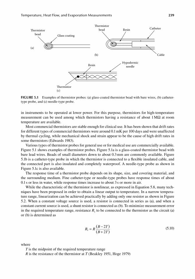
Temperature,HeatFlow,andEvaporationMeasurements 239
in.instruments.to.be.operated.at.lower.power..For.this.purpose,.thermistors.for.high-temperature.measurement.can.be.used.among.which. thermistors.having.a. resistance.of.about.1.MΩ. at. room.temperature.are.available.
Most.commercial.thermistors.are.stable.enough.for.clinical.use..It.has.been.shown.that.drift.rates.for.different.types.of.commercial.thermistors.were.around.0.1.mK.per.100.days.and.were.unaffected.by.thermal.cycling,.while.mechanical.shock.and.strain.appear.to.be.the.cause.of.high.drift.rates.in.some.thermistors.(Edwards.1983).
Various.types.of.thermistor.probes.for.general.use.or.for.medical.use.are.commercially.available..Figure.5.1.shows.examples.of.thermistor.probes..Figure.5.1a.is.a.glass-coated.thermistor.bead.with.bare.lead.wires..Beads.of.small.diameters.down.to.about.0.3.mm.are.commonly.available..Figure.5.1b.is.a.catheter-type.probe.in.which.the.thermistor.is.connected.to.a.flexible.insulated.cable,.and.the.connected.part.is.also.insulated.and.completely.waterproof..A.needle-type.probe.as.shown.in.Figure.5.1c.is.also.available.
The.response.time.of.a.thermistor.probe.depends.on.its.shape,.size,.and.covering.material,.and.the.surrounding.medium..Fine.catheter-type.or.needle-type.probes.have.response.times.of.about.0.1.s.or.less.in.water,.while.response.times.increase.to.about.3.s.or.more.in.air.
While.the.characteristic.of.the.thermistor.is.nonlinear,.as.expressed.in.Equation.5.8,.many.tech-niques.have.been.proposed.in.order.to.obtain.a.linear.output.to.temperature..In.a.narrow.tempera-ture.range,.linearization.can.be.achieved.practically.by.adding.only.one.resistor.as.shown.in.Figure.5.2..When.a.constant.voltage.source. is.used,.a. resistor. is.connected. in.series.as. (a),.and.when.a.constant.current.source.is.used,.a.shunt.resistor.is.connected.as.(b)..To.minimize.measurement.error.in.the.required.temperature.range,.resistance.R1.to.be.connected.to.the.thermistor.as.the.circuit.(a).or.(b).is.determined.as
.R R
B T
B T1
22
= −+
( )( ) .
(5.10)
whereT.is.the.midpoint.of.the.required.temperature.rangeR.is.the.resistance.of.the.thermistor.at.T.(Beakley.1951,.Hoge.1979)
ResinHypodermic
needle
(c)ermistor
ermistorbead Glass coating
(a)
ermistorbead Resin Catheter
Cable(b)
figure 5.1 Examples.of.thermistor.probes:.(a).glass-coated.thermistor.bead.with.bare.wires,.(b).catheter-type.probe,.and.(c).needle-type.probe.
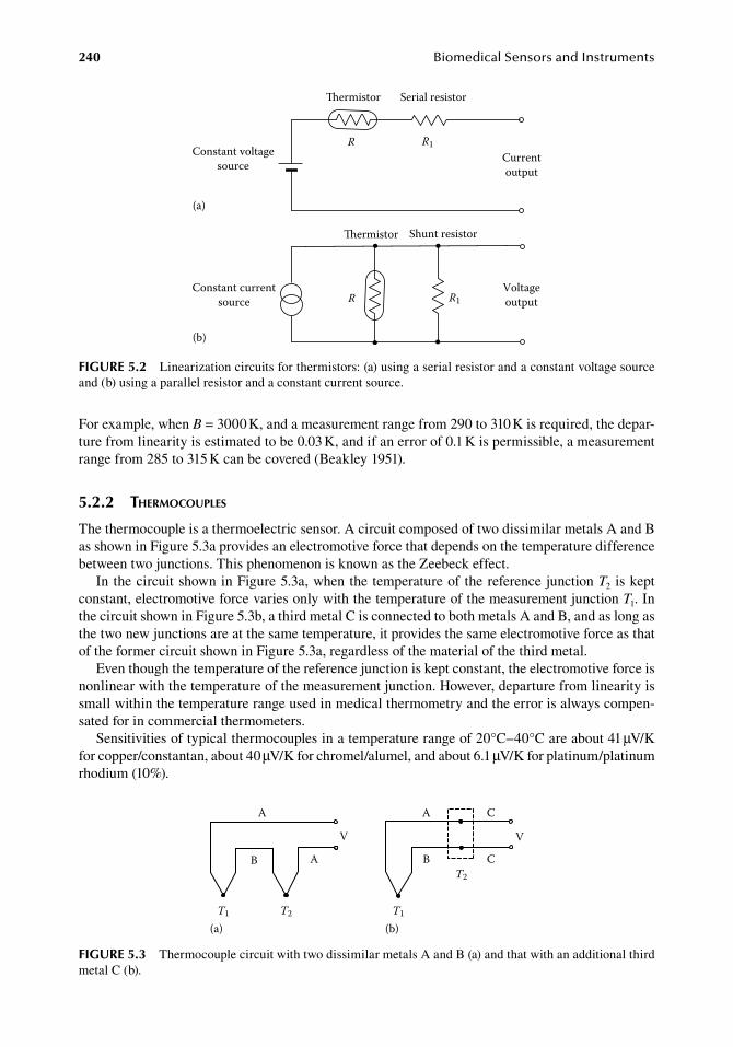
240 BiomedicalSensorsandInstruments
For.example,.when.B.=.3000.K,.and.a.measurement.range.from.290.to.310.K.is.required,.the.depar-ture.from.linearity.is.estimated.to.be.0.03.K,.and.if.an.error.of.0.1.K.is.permissible,.a.measurement.range.from.285.to.315.K.can.be.covered.(Beakley.1951).
5.2.2 therMocouples
The.thermocouple.is.a.thermoelectric.sensor..A.circuit.composed.of.two.dissimilar.metals.A.and.B.as.shown.in.Figure.5.3a.provides.an.electromotive.force.that.depends.on.the.temperature.difference.between.two.junctions..This.phenomenon.is.known.as.the.Zeebeck.effect.
In.the.circuit.shown.in.Figure.5.3a,.when.the.temperature.of.the.reference.junction.T2. is.kept.constant,.electromotive.force.varies.only.with.the.temperature.of.the.measurement.junction.T1..In.the.circuit.shown.in.Figure.5.3b,.a.third.metal.C.is.connected.to.both.metals.A.and.B,.and.as.long.as.the.two.new.junctions.are.at.the.same.temperature,.it.provides.the.same.electromotive.force.as.that.of.the.former.circuit.shown.in.Figure.5.3a,.regardless.of.the.material.of.the.third.metal.
Even.though.the.temperature.of.the.reference.junction.is.kept.constant,.the.electromotive.force.is.nonlinear.with.the.temperature.of.the.measurement.junction..However,.departure.from.linearity.is.small.within.the.temperature.range.used.in.medical.thermometry.and.the.error.is.always.compen-sated.for.in.commercial.thermometers.
Sensitivities.of.typical.thermocouples.in.a.temperature.range.of.20°C–40°C.are.about.41.μV/K.for.copper/constantan,.about.40.μV/K.for.chromel/alumel,.and.about.6.1.μV/K.for.platinum/platinum.rhodium.(10%).
Constant voltagesource
ermistor Serial resistor
Currentoutput
R R1
(a)
ermistor Shunt resistor
R R1Constant current
source
(b)
Voltageoutput
figure 5.2 Linearization.circuits.for.thermistors:.(a).using.a.serial.resistor.and.a.constant.voltage.source.and.(b).using.a.parallel.resistor.and.a.constant.current.source.
A
B A
A
B
V
T1 T2
(a)
C
C
V
T2
T1
(b)
figure 5.3 Thermocouple.circuit.with.two.dissimilar.metals.A.and.B.(a).and.that.with.an.additional.third.metal.C.(b).
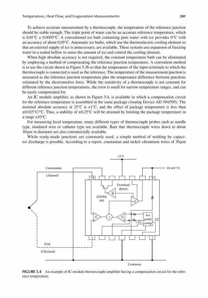
Temperature,HeatFlow,andEvaporationMeasurements 241
To.achieve.accurate.measurement.by.a.thermocouple,.the.temperature.of.the.reference.junction.should.be.stable.enough..The.triple.point.of.water.can.be.an.accurate.reference.temperature,.which.is.0.01°C.±.0.0005°C..A.conventional.ice.bath.containing.pure.water.with.ice.provides.0°C.with.an.accuracy.of.about.0.05°C..Automatic.ice.baths,.which.use.the.thermoelectric.cooling.element.so.that.an.external.supply.of.ice.is.unnecessary,.are.available..These.systems.use.expansion.of.freezing.water.in.a.sealed.bellow.to.sense.the.amount.of.ice.and.control.the.cooling.element.
When.high.absolute.accuracy.is.not.required,.the.constant.temperature.bath.can.be.eliminated.by.employing.a.method.of.compensating.the.reference.junction.temperature..A.convenient.method.is.to.use.the.circuit.shown.in.Figure.5.3b.so.that.the.temperature.of.the.input.terminals.to.which.the.thermocouple.is.connected.is.used.as.the.reference..The.temperature.of.the.measurement.junction.is.measured.as.the.reference.junction.temperature.plus.the.temperature.difference.between.junctions.estimated.by.the.electromotive.force..While.the.sensitivity.of.a. thermocouple.is.not.constant.for.different.reference.junction.temperatures,.the.error.is.small.for.narrow.temperature.ranges,.and.can.be.easily.compensated.for.
An.IC.module.amplifier,.as.shown.in.Figure.5.4,.is.available.in.which.a.compensation.circuit.for.the.reference.temperature.is.assembled.in.the.same.package.(Analog.Device.AD.594/595)..The.nominal. absolute. accuracy. at. 25°C. is. ±1°C,. and. the. effect. of. package. temperature. is. less. than.±0.025°C/°C..Thus,.a.stability.of.±0.25°C.will.be.attained.by.limiting.the.package.temperature.in.a.range.±10°C.
For.measuring.local.temperature,.many.different.types.of.thermocouple.probes.such.as.needle.type,. insulated.wire.or.catheter. type.are.available..Bare.fine. thermocouple.wires.down. to.about.10.μm.in.diameter.are.also.commercially.available.
While. ready-made. junctions. are. commonly. used,. a. simple. method. of. welding. by. capaci-tor.discharge.is.possible..According.to.a.report,.constantan.and.nickel–chromium.wires.of.30.μm.
+A
+ G–+
Icepointcomp+TC
–TC
Constantan
(Alumel)
Iron
(Chromel)
1
G+–
Common
7
14 8
+5 V
10 mV/°C
Overloaddetect
AD594/595
figure 5.4 An.example.of.IC-module.thermocouple.amplifier.having.a.compensation.circuit.for.the.refer-ence.temperature.
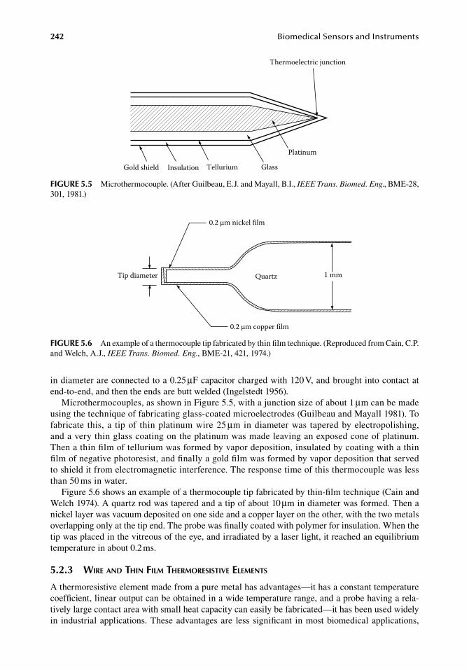
242 BiomedicalSensorsandInstruments
in.diameter.are.connected.to.a.0.25.μF.capacitor.charged.with.120.V,.and.brought.into.contact.at.end-to-end,.and.then.the.ends.are.butt.welded.(Ingelstedt.1956).
Microthermocouples,.as.shown.in.Figure.5.5,.with.a.junction.size.of.about.1.μm.can.be.made.using.the.technique.of.fabricating.glass-coated.microelectrodes.(Guilbeau.and.Mayall.1981)..To.fabricate. this,.a. tip.of. thin.platinum.wire.25.μm.in.diameter.was. tapered.by.electropolishing,.and.a.very.thin.glass.coating.on.the.platinum.was.made.leaving.an.exposed.cone.of.platinum..Then.a.thin.film.of.tellurium.was.formed.by.vapor.deposition,.insulated.by.coating.with.a.thin.film.of.negative.photoresist,.and.finally.a.gold.film.was.formed.by.vapor.deposition.that.served.to.shield.it.from.electromagnetic.interference..The.response.time.of.this.thermocouple.was.less.than.50.ms.in.water.
Figure.5.6.shows.an.example.of.a.thermocouple.tip.fabricated.by.thin-film.technique.(Cain.and.Welch.1974)..A.quartz.rod.was.tapered.and.a.tip.of.about.10.μm.in.diameter.was.formed..Then.a.nickel.layer.was.vacuum.deposited.on.one.side.and.a.copper.layer.on.the.other,.with.the.two.metals.overlapping.only.at.the.tip.end..The.probe.was.finally.coated.with.polymer.for.insulation..When.the.tip.was.placed.in.the.vitreous.of.the.eye,.and.irradiated.by.a.laser.light,.it.reached.an.equilibrium.temperature.in.about.0.2.ms.
5.2.3 wire and thin filM therMoresistiVe eleMents
A.thermoresistive.element.made.from.a.pure.metal.has.advantages—it.has.a.constant.temperature.coefficient,.linear.output.can.be.obtained.in.a.wide.temperature.range,.and.a.probe.having.a.rela-tively.large.contact.area.with.small.heat.capacity.can.easily.be.fabricated—it.has.been.used.widely.in. industrial.applications..These.advantages.are. less.significant. in.most.biomedical.applications,.
Thermoelectric junction
Platinum
GlassTelluriumInsulationGold shield
figure 5.5 Microthermocouple..(After.Guilbeau,.E.J..and.Mayall,.B.I.,.IEEE Trans. Biomed. Eng.,.BME-28,.301,.1981.)
0.2 µm nickel film
0.2 µm copper film
Tip diameter Quartz 1 mm
figure 5.6 An.example.of.a.thermocouple.tip.fabricated.by.thin.film.technique..(Reproduced.from.Cain,.C.P..and.Welch,.A.J.,.IEEE Trans. Biomed. Eng.,.BME-21,.421,.1974.)
Temperature,HeatFlow,andEvaporationMeasurements 243
where.very.local.temperature.has.to.be.measured.in.a.narrow.temperature.range,.while.it.is.useful.in.special.situations.where.an.extremely.fast.response.is.required,.such.as.in.hot-wire.or.hot-film.anemometry.
The.most.common.material.used.as.the.wire.or.thin-film.thermoresistive.element.is.platinum..The.platinum.thermoresistive.element.has.a.higher.stability.and.smaller.nonlinearity.than.thermis-tors,.but.its.temperature.coefficient.of.about.0.0039/K.is.about.one-tenth.that.of.the.thermistor.
Various.types.of.probes.have.been.made.for.surface.and.fluid.temperature.measurement..Flat.grid.winding.type.probes.are.used.for.measuring.surface.temperature.of.solids,.and.probes.hav-ing.winding.wires.encased. in.protective. tubes.are.used. for.fluid. temperature.measurement..The.metal.wire.or.film.can.also.be.cemented.onto.the.surface.at.which.temperature.has.to.be.measured..However,.the.resistance.change.can.occur.not.only.due.to.a.temperature.change.but.also.due.to.a.strain,.and.hence.it.may.exhibit.spurious.output.due.to.a.differential.thermal.expansion.or.mechani-cal.load.
5.2.4 p–n junction diodes and transistors
The.voltage.across.a.p–n.junction.at.constant.forward-bias.current.exhibits.excellent.linear.tem-perature.dependency.over.a.wide.temperature.range,.and.thus.any.diode.or.transistor.having.a.p–n.junction.can.be.a. temperature. sensor. (MacNamara.1962,.Cohen.et. al..1963).. It. is. also.advanta-geous.that.a.p–n.junction.can.be.fabricated.on.a.silicon.chip.with.interfacing.circuits.by.integrated.circuitry. technology,. and. many. convenient. IC. temperature. sensors. are. commercially. available.(Togawa.2006).
The.voltage–current.characteristics.of.the.forward-biased.p–n.junction.is.approximated.as
.
I AqV E
kT=
−( )
exp
g
.
(5.11)
whereI.is.forward.bias.currentA.is.constant.depending.on.the.geometry.of.the.junctionq.is.the.electron.chargeV.is.the.voltage.across.the.junctionEg.is.the.band.gap.energyk.is.the.Boltzmann.constantT.is.the.absolute.temperature.(Sah.et.al..1957)
When.the.current.I.is.held.constant,.(qV.−.Eg)/kT.is.kept.constant,.and.thus,.the.voltage.across.the.junction.V.is.a.linear.function.of.the.absolute.temperature.T..The.temperature.coefficient.of.V.is.always.negative.and.observed.dV/dT.in.typical.small-signal.silicon.p–n.junction.diodes.ranges.from.−1.3.to.−2.4.mV/K.at.a.current.level.of.about.100.μA.(Sclar.and.Pollock.1972)..The.base–emitter.p–n.junction.in.the.transistor.in.which.the.base.is.connected.to.the.collector.is.also.used.because.of.the.fact.that.nonlinearity.in.temperature.dependency.is.lower.than.that.of.most.diodes.(Davis.and.Coates.1977).
If.the.p–n.junction.in.a.diode.or.transistor.is.driven.by.different.forward.current.levels.I1.and.I2,.and.voltages.V1.and.V2.are.developed.at.these.current.levels,.then,.from.Equation.5.11,
.V V
kT
q
I
I1 2
1
2
ln− =
.(5.12)
Thus,.the.difference.in.voltages.corresponding.to.different.current.levels.maintained.at.a.constant.ratio.is.proportional.to.the.absolute.temperature,.without.any.offset..By.this.principle,.a.thermometer.providing.
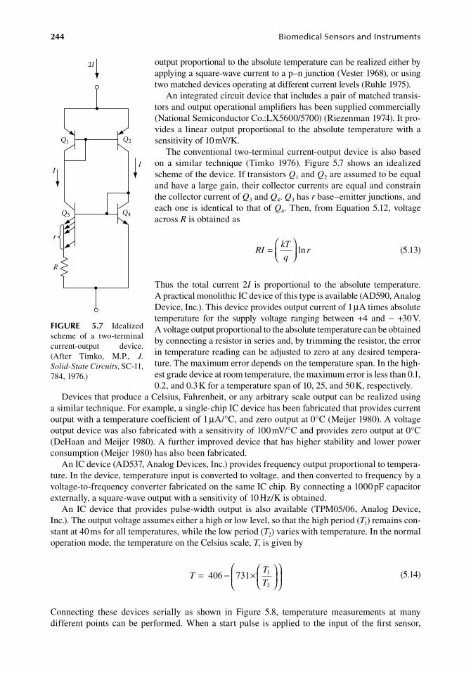
244 BiomedicalSensorsandInstruments
output.proportional.to.the.absolute.temperature.can.be.realized.either.by.applying.a.square-wave.current.to.a.p–n.junction.(Vester.1968),.or.using.two.matched.devices.operating.at.different.current.levels.(Ruhle.1975).
An.integrated.circuit.device.that.includes.a.pair.of.matched.transis-tors.and.output.operational.amplifiers.has.been.supplied.commercially.(National.Semiconductor.Co.:LX5600/5700).(Riezenman.1974)..It.pro-vides.a. linear.output.proportional. to. the.absolute. temperature.with.a.sensitivity.of.10.mV/K.
The.conventional. two-terminal.current-output.device.is.also.based.on. a. similar. technique. (Timko. 1976).. Figure. 5.7. shows. an. idealized.scheme.of.the.device..If.transistors.Q1.and.Q2.are.assumed.to.be.equal.and.have.a.large.gain,.their.collector.currents.are.equal.and.constrain.the.collector.current.of.Q3.and.Q4..Q3.has.r.base–emitter.junctions,.and.each.one.is.identical.to.that.of.Q4..Then,.from.Equation.5.12,.voltage.across.R.is.obtained.as
.RI
kT
qr=
ln.
(5.13)
Thus. the. total. current. 2I. is. proportional. to. the. absolute. temperature..A practical.monolithic.IC.device.of.this.type.is.available.(AD590, Analog.Device,.Inc.)..This.device.provides.output.current.of.1.μA.times.absolute.temperature. for. the. supply. voltage. ranging. between. +4. and. ∼. +30.V..A voltage.output.proportional.to.the.absolute.temperature.can.be.obtained.by.connecting.a.resistor.in.series.and,.by.trimming.the.resistor,.the.error.in.temperature.reading.can.be.adjusted.to.zero.at.any.desired.tempera-ture..The.maximum.error.depends.on.the.temperature.span..In.the.high-est.grade.device.at.room.temperature,.the.maximum.error.is.less.than.0.1,.0.2,.and.0.3.K.for.a.temperature.span.of.10,.25,.and.50.K,.respectively.
Devices.that.produce.a.Celsius,.Fahrenheit,.or.any.arbitrary.scale.output.can.be.realized.using.a.similar.technique..For.example,.a.single-chip.IC.device.has.been.fabricated.that.provides.current.output.with.a.temperature.coefficient.of.1.μA/°C,.and.zero.output.at.0°C.(Meijer.1980)..A.voltage.output.device.was.also.fabricated.with.a.sensitivity.of.100.mV/°C.and.provides.zero.output.at.0°C.(DeHaan.and.Meijer.1980)..A.further.improved.device.that.has.higher.stability.and.lower.power.consumption.(Meijer.1980).has.also.been.fabricated.
An.IC.device.(AD537,.Analog.Devices,.Inc.).provides.frequency.output.proportional.to.tempera-ture..In.the.device,.temperature.input.is.converted.to.voltage,.and.then.converted.to.frequency.by.a.voltage-to-frequency.converter.fabricated.on.the.same.IC.chip..By.connecting.a.1000.pF.capacitor.externally,.a.square-wave.output.with.a.sensitivity.of.10.Hz/K.is.obtained.
An. IC. device. that. provides. pulse-width. output. is. also. available. (TPM05/06,. Analog. Device,.Inc.)..The.output.voltage.assumes.either.a.high.or.low.level,.so.that.the.high.period.(T1).remains.con-stant.at.40.ms.for.all.temperatures,.while.the.low.period.(T2).varies.with.temperature..In.the.normal.operation.mode,.the.temperature.on.the.Celsius.scale,.T,.is.given.by
.T
T
T= − ×
4 6 7310 1
2 .
(5.14)
Connecting. these. devices. serially. as. shown. in. Figure. 5.8,. temperature. measurements. at. many.different.points.can.be.performed..When.a.start.pulse. is.applied. to. the. input.of. the.first. sensor,.
2I
Q1 Q2
Q3 Q4
r
R
II
figure 5.7 Idealized.scheme. of. a. two-terminal.current-output. device..(After. Timko,. M.P.,. J. Solid-State Circuits,.SC-11,.784,.1976.)
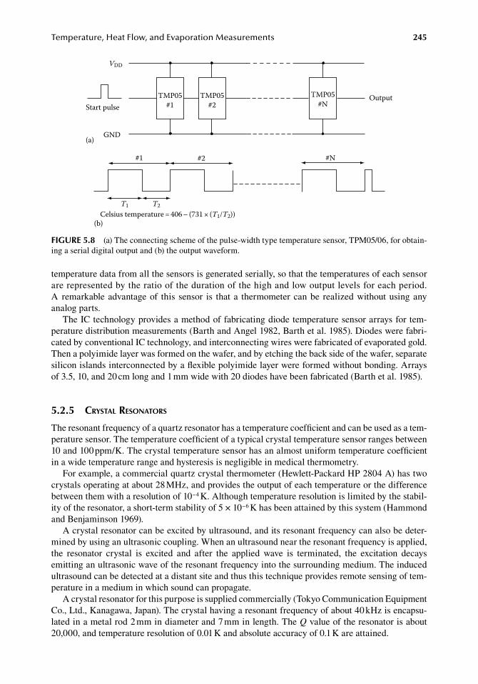
Temperature,HeatFlow,andEvaporationMeasurements 245
temperature.data.from.all.the.sensors.is.generated.serially,.so.that.the.temperatures.of.each.sensor.are.represented.by.the.ratio.of.the.duration.of.the.high.and.low.output.levels.for.each.period..A remarkable.advantage.of. this. sensor. is. that.a. thermometer.can.be. realized.without.using.any.analog.parts.
The.IC.technology.provides.a.method.of.fabricating.diode.temperature.sensor.arrays.for.tem-perature.distribution.measurements.(Barth.and.Angel.1982,.Barth.et.al..1985)..Diodes.were.fabri-cated.by.conventional.IC.technology,.and.interconnecting.wires.were.fabricated.of.evaporated.gold..Then.a.polyimide.layer.was.formed.on.the.wafer,.and.by.etching.the.back.side.of.the.wafer,.separate.silicon.islands.interconnected.by.a.flexible.polyimide.layer.were.formed.without.bonding..Arrays.of.3.5,.10,.and.20.cm.long.and.1.mm.wide.with.20.diodes.have.been.fabricated.(Barth.et.al..1985).
5.2.5 crystal resonators
The.resonant.frequency.of.a.quartz.resonator.has.a.temperature.coefficient.and.can.be.used.as.a.tem-perature.sensor..The.temperature.coefficient.of.a.typical.crystal.temperature.sensor.ranges.between.10.and.100.ppm/K..The.crystal.temperature.sensor.has.an.almost.uniform.temperature.coefficient.in.a.wide.temperature.range.and.hysteresis.is.negligible.in.medical.thermometry.
For.example,.a.commercial.quartz.crystal.thermometer.(Hewlett-Packard.HP.2804.A).has.two.crystals.operating.at.about.28.MHz,.and.provides.the.output.of.each.temperature.or.the.difference.between.them.with.a.resolution.of.10−4.K..Although.temperature.resolution.is.limited.by.the.stabil-ity.of.the.resonator,.a.short-term.stability.of.5.×.10−6.K.has.been.attained.by.this.system.(Hammond.and.Benjaminson.1969).
A.crystal.resonator.can.be.excited.by.ultrasound,.and.its.resonant.frequency.can.also.be.deter-mined.by.using.an.ultrasonic.coupling..When.an.ultrasound.near.the.resonant.frequency.is.applied,.the. resonator. crystal. is. excited. and. after. the. applied. wave. is. terminated,. the. excitation. decays.emitting.an.ultrasonic.wave.of.the.resonant.frequency.into.the.surrounding.medium..The.induced.ultrasound.can.be.detected.at.a.distant.site.and.thus.this.technique.provides.remote.sensing.of.tem-perature.in.a.medium.in.which.sound.can.propagate.
A.crystal.resonator.for.this.purpose.is.supplied.commercially.(Tokyo.Communication.Equipment.Co.,.Ltd.,.Kanagawa,.Japan)..The.crystal.having.a.resonant.frequency.of.about.40.kHz.is.encapsu-lated.in.a.metal.rod.2.mm.in.diameter.and.7.mm.in.length..The.Q.value.of.the.resonator.is.about.20,000,.and.temperature.resolution.of.0.01.K.and.absolute.accuracy.of.0.1.K.are.attained.
Start pulse
VDD
GND
TMP05#1
TMP05#2
TMP05#N
Output
(a)
#N#1 #2
T1 T2Celsius temperature = 406 – (731 × (T1/T2))
(b)
figure 5.8 (a).The.connecting.scheme.of.the.pulse-width.type.temperature.sensor,.TPM05/06,.for.obtain-ing.a.serial.digital.output.and.(b).the.output.waveform.
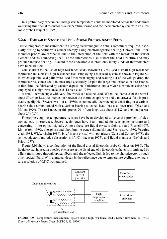
246 BiomedicalSensorsandInstruments
In.a.preliminary.experiment,.intragastric.temperature.could.be.monitored.across.the.abdominal.wall.using.this.crystal.resonator.as.a.temperature.sensor,.and.the.thermometer.system.with.an.ultra-sonic.probe.(Tsuji.et.al..1990).
5.2.6 teMperature sensors for use in strong electroMagnetic fields
Tissue.temperature.measurement.in.a.strong.electromagnetic.field.is.sometimes.required,.espe-cially.during.hyperthermia.cancer. therapy.using.electromagnetic.heating..Conventional. ther-mometer.probes.are.erroneous.due.to.the.interaction.of.the.field.with.the.metals.in.the.sensor.element. and. its. connecting. lead.. These. interactions. also. distort. the. field. structure. and. may.produce.intense.heating..To.avoid.these.undesirable.interactions,.many.kinds.of.thermometers.have.been.studied.
One.solution.is.the.use.of.high-resistance.leads..Bowman.(1976).used.a.small.high-resistance.thermistor.and.a.plastic.high-resistance.lead..Employing.a.four-lead.system.as.shown.in.Figure.5.9,.in.which.separate.lead.pairs.were.used.for.current.supply,.and.reading.out.of.the.voltage.drop,.the.thermistor.resistance.could.be.measured.accurately.despite.the.large.and.unstable.lead.resistance..A.thin.film.line.fabricated.by.vacuum.deposition.of.nichrome.onto.a.Mylar.substrate.has.also.been.employed.as.a.high-resistance.lead.(Larsen.et.al..1979).
A.small.thermocouple.with.very.fine.wires.can.also.be.used..When.the.diameter.of.the.wire.is.about.50.μm.or.less,.the.interaction.between.the.thermocouple.wire.and.a.microwave.field.is.prac-tically.negligible.(Szwarnowski.et.al..1980)..A.nonmetalic. thermocouple.consisting.of.a.carbon-bearing.fluorcarbon.strand.with.a.carbon-bearing.silicone.sheath.has.also.been. tried.(Olsen.and.Molina.1979)..The.resistance.of.this.probe,.20–40.cm.long,.was.about.25.kΩ,.and.its.output.was.about.20.mV/K.
Fiberoptic.coupling. temperature.sensors.have.been.developed. to.solve. the.problem.of.elec-tromagnetic. interference.. Several. techniques. have. been. studied. for. sensing. temperature. and.converting. it. into.optical.signals..Among. these.are. liquid.crystals. (Johnson.and.Rozzell.1975,.Livingston,.1980),.phosphors.and.photoluminescence.(Samulski.and.Shrivastava.1980,.Vaguine.et.al..1984,.Wickersheim.1986),.birefringent.crystal.with.polarizers.(Ceta.and.Connor.1978),.the.semiconductor.band-edge.absorption.shift.(Christensen.1977),.and.liquid.meniscus.(Deficis.and.Priou.1977).
Figure.5.10.shows.a.configuration.of.the.liquid.crystal.fiberoptic.probe.(Livingston.1980)..The.liquid.crystal.housed.in.a.sealed.enclosure.at.the.distal.end.of.a.fiberoptic.catheter.is.illuminated.by.a.light.transmitted.through.optical.fibers,.and.the.reflected.light.is.led.to.the.photodetector.through.other.optical.fibers..With.a.gradual.decay.in.the.reflectance.due.to.temperature.cycling,.a.tempera-ture.resolution.of.0.1°C.was.attained.
ick-lm thermistor
High-resistance lead
Constantcurrent
generator
High-impedanceamplier
Recorder orother readout
Logarithmicamplier
figure 5.9 Temperature. measurement. system. using. high-resistance. leads.. (After. Bowman,. R.,. IEEE Trans. Microwave Theor. Tech.,.MTT-24,.43,.1976.)
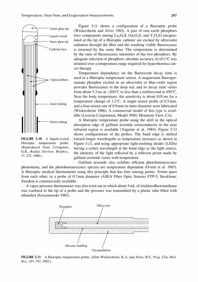
Temperature,HeatFlow,andEvaporationMeasurements 247
Figure. 5.11. shows. a. configuration. of. a. fluoroptic. probe.(Wickersheim. and. Alves. 1982).. A. pair. of. rare-earth. phosphors.(two.components.among.La2O2S,.Gd2O2S,.and.Y2O2S).encapsu-lated.at. the. tip.of.a.fiberoptic.catheter.are.excited.by.ultraviolet.radiation.through.the.fiber.and.the.resulting.visible.fluorescence.is. returned. by. the. same. fiber.. The. temperature. is. determined.by.the.ratio.of.fluorescence.intensities.of.the.two.phosphors..By.adequate.selection.of.phosphors,.absolute.accuracy.of.±0.1°C.was.attained.over.a.temperature.range.required.for.hyperthermia.can-cer.therapy.
Temperature. dependency. on. the. fluorescent. decay. time. is.used.in.a.fiberoptic.temperature.sensor..A.magnesium.fluoroger-manate. phosphor. excited. in. an. ultraviolet. or. blue-violet. region.provides.fluorescence.in.the.deep.red,.and.its.decay.time.varies.from.about.5.3.ms.at.−200°C.to.less.than.a.millisecond.at.450°C..Near.the.body.temperature,.the.sensitivity.is.about.0.01.ms.for.a.temperature. change.of.1.2°C..A. single-sensor.probe.of.0.5.mm,.and.a.four-sensor.one.of.0.9.mm.in.outer.diameter.were.fabricated.(Wickersheim.1986)..A.commercial.model.of. this. type. is.avail-able.(Luxtron.Corporation,.Model.3000,.Mountain.View,.CA).
A.fiberoptic. temperature. probe.using. the. shift. in. the.optical.absorption. edge. of. gallium. arsenide. semiconductor. in. the. near.infrared. region. is. available. (Vaguine. et. al.. 1984).. Figure. 5.12.shows. configurations. of. the. probes.. The. band. edge. is. shifted.toward.longer.wavelengths.as.temperature.increases.as.shown.in.Figure.5.13,.and.using.appropriate. light-emitting.diodes.(LEDs).having.a.center.wavelength.at.the.band.edge.as.the.light.source,.the. intensity.of. the. light. reflected.by.a. reflector.prism.made.by.gallium.arsenide.varies.with.temperature.
Gallium. arsenide. also. exhibits. efficient. photoluminescence.phenomena,. and. the. photoluminescence. spectra. are. temperature. dependent. (Ovrén. et. al.. 1983)..A fiberoptic.medical. thermometer.using. this.principle. that.has. four.sensing.points,.10.mm.apart.from. each. other,. in. a. probe. of. 0.7.mm. diameter. (ASEA. Fiber. Optic. Sensors. FTP-5,. Stockhom,.Sweden).is.commercially.available.
A.vapor.pressure.thermometer.was.also.tried.out.in.which.about.5.mL.of.trichlorofluoromethane.was.confined.to.the.tip.of.a.probe.and.the.pressure.was.transmitted.by.a.plastic. tube.filled.with.ethandiol.(Szwarnowski.1983).
Outer glass tip
Liquid crystal
Inner glass tip
Catheter face
Optical fibers
Inner tubing
Outer tubing
figure 5.10 A. liquid-crystal.fiberoptic. temperature. probe..(Reproduced. from. Livingston,.G.K.,.Radiat. Environ. Biophys.,.17,.233,.1980.)
Phosphor Silica core
Silicone claddingEncapsulation
figure 5.11 A.fluoroptic.temperature.probe..(After.Wickersheim,.K.A..and.Alves,.R.V.,.Prog. Clin. Biol. Res.,.107,.547,.1982.)
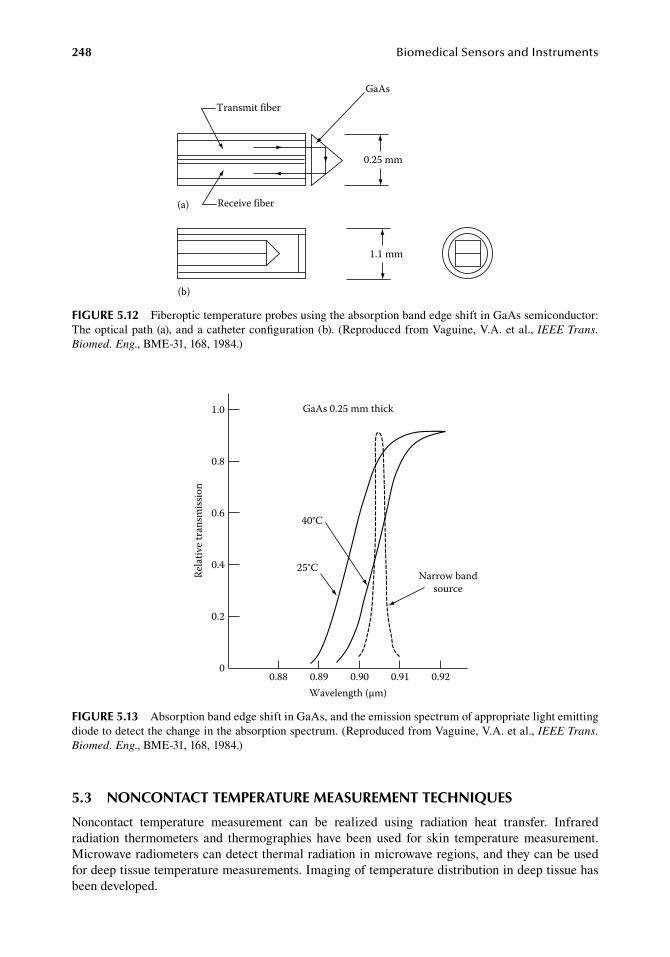
248 BiomedicalSensorsandInstruments
5.3 nonContaCt teMPerature MeaSureMent teChniQueS
Noncontact. temperature. measurement. can. be. realized. using. radiation. heat. transfer.. Infrared.radiation. thermometers. and. thermographies. have. been. used. for. skin. temperature. measurement..Microwave.radiometers.can.detect.thermal.radiation.in.microwave.regions,.and.they.can.be.used.for.deep.tissue.temperature.measurements..Imaging.of.temperature.distribution.in.deep.tissue.has.been.developed.
Transmit fiber
GaAs
0.25 mm
Receive fiber(a)
1.1 mm
(b)
figure 5.12 Fiberoptic.temperature.probes.using.the.absorption.band.edge.shift.in.GaAs.semiconductor:.The.optical.path.(a),.and.a.catheter.configuration.(b)..(Reproduced.from.Vaguine,.V.A..et.al.,.IEEE Trans. Biomed. Eng.,.BME-31,.168,.1984.)
40°C
25°CNarrow band
source
Rela
tive t
rans
miss
ion
1.0
0.8
0.6
0.4
0.2
00.88 0.89 0.90 0.91 0.92
Wavelength (µm)
GaAs 0.25 mm thick
figure 5.13 Absorption.band.edge.shift.in.GaAs,.and.the.emission.spectrum.of.appropriate.light.emitting.diode.to.detect.the.change.in.the.absorption.spectrum..(Reproduced.from.Vaguine,.V.A..et.al.,.IEEE Trans. Biomed. Eng.,.BME-31,.168,.1984.)
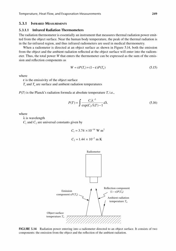
Temperature,HeatFlow,andEvaporationMeasurements 249
5.3.1 infrared MeasureMents
5.3.1.1 infrared radiation thermometersThe.radiation.thermometer.is.essentially.an.instrument.that.measures.thermal.radiation.power.emit-ted.from.the.object.surface..Near.the.human.body.temperature,.the.peak.of.the.thermal.radiation.is.in.the.far-infrared.region,.and.thus.infrared.radiometers.are.used.in.medical.thermometry.
When.a.radiometer.is.directed.at.an.object.surface.as.shown.in.Figure.5.14,.both.the.emission.from.the.object.and.the.ambient.radiation.reflected.at.the.object.surface.will.enter.into.the.radiom-eter..Thus,.the.total.power.W.that.enters.the.thermometer.can.be.expressed.as.the.sum.of.the.emis-sion.and.reflection.components.as
. W P T P T= + −ε ε( ) ( ) ( )s a1 . (5.15)
whereε.is.the.emissivity.of.the.object.surfaceTs.and.Ta.are.surface.and.ambient.radiation.temperatures
P(T).is.the.Planck’s.radiation.formula.at.absolute.temperature.T,.i.e.,
.P T
C
C / Td( )
exp( ) 11
5
2
=−∫ λ
λλ
−
.(5.16)
whereλ.is.wavelengthC1.and.C2.are.universal.constants.given.by
. C116 23 74 10= × −. W m .
. C221 44 10= × −. m K .
Radiometer
Object surfacetemperature Ts
Emission component εP(Ts)
Reflection component(1 – ε)P(Ta)
Ambient radiationtemperature Ta
figure 5.14 Radiation.power.entering.into.a.radiometer.directed.to.an.object.surface..It.consists.of.two.components:.the.emission.from.the.object.and.the.reflection.of.the.ambient.radiation.
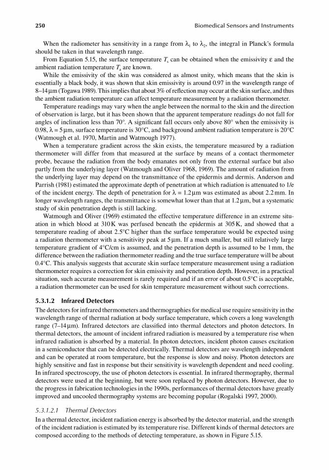
250 BiomedicalSensorsandInstruments
When.the.radiometer.has.sensitivity.in.a.range.from.λ1.to.λ2,.the.integral.in.Planck’s.formula.should.be.taken.in.that.wavelength.range.
From.Equation.5.15,.the.surface.temperature.Ts.can.be.obtained.when.the.emissivity.ε.and.the.ambient.radiation.temperature.Ta.are.known.
While. the.emissivity.of. the.skin.was.considered.as.almost.unity,.which.means. that. the.skin. is.essentially.a.black.body,.it.was.shown.that.skin.emissivity.is.around.0.97.in.the.wavelength.range.of.8–14.μm.(Togawa.1989)..This.implies.that.about.3%.of.reflection.may.occur.at.the.skin.surface,.and.thus.the.ambient.radiation.temperature.can.affect.temperature.measurement.by.a.radiation.thermometer.
Temperature.readings.may.vary.when.the.angle.between.the.normal.to.the.skin.and.the.direction.of.observation.is.large,.but.it.has.been.shown.that.the.apparent.temperature.readings.do.not.fall.for.angles.of.inclination.less.than.70°..A.significant.fall.occurs.only.above.80°.when.the.emissivity.is.0.98,.λ.=.5.μm,.surface.temperature.is.30°C,.and.background.ambient.radiation.temperature.is.20°C.(Watmough.et.al..1970,.Martin.and.Watmough.1977).
When.a. temperature.gradient.across. the.skin.exists,. the. temperature.measured.by.a.radiation.thermometer. will. differ. from. that. measured. at. the. surface. by. means. of. a. contact. thermometer.probe,.because.the.radiation.from.the.body.emanates.not.only.from.the.external.surface.but.also.partly.from.the.underlying.layer.(Watmough.and.Oliver.1968,.1969)..The.amount.of.radiation.from.the.underlying.layer.may.depend.on.the.transmittance.of.the.epidermis.and.dermis..Anderson.and.Parrish.(1981).estimated.the.approximate.depth.of.penetration.at.which.radiation.is.attenuated.to.1/e.of.the.incident.energy..The.depth.of.penetration.for.λ.=.1.2.μm.was.estimated.as.about.2.2.mm..In.longer.wavelength.ranges,.the.transmittance.is.somewhat.lower.than.that.at.1.2.μm,.but.a.systematic.study.of.skin.penetration.depth.is.still.lacking.
Watmough.and.Oliver.(1969).estimated.the.effective.temperature.difference.in.an.extreme.situ-ation. in. which. blood. at. 310.K. was. perfused. beneath. the. epidermis. at. 305.K,. and. showed. that. a.temperature.reading.of.about.2.5°C.higher.than.the.surface.temperature.would.be.expected.using.a.radiation.thermometer.with.a.sensitivity.peak.at.5.μm..If.a.much.smaller,.but.still.relatively.large.temperature.gradient.of.4°C/cm.is.assumed,.and.the.penetration.depth.is.assumed.to.be.1.mm,.the.difference.between.the.radiation.thermometer.reading.and.the.true.surface.temperature.will.be.about.0.4°C..This.analysis.suggests.that.accurate.skin.surface.temperature.measurement.using.a.radiation.thermometer.requires.a.correction.for.skin.emissivity.and.penetration.depth..However,.in.a.practical.situation,.such.accurate.measurement.is.rarely.required.and.if.an.error.of.about.0.5°C.is.acceptable,.a.radiation.thermometer.can.be.used.for.skin.temperature.measurement.without.such.corrections.
5.3.1.2 infrared detectorsThe.detectors.for.infrared.thermometers.and.thermographies.for.medical.use.require.sensitivity.in.the.wavelength.range.of.thermal.radiation.at.body.surface.temperature,.which.covers.a.long.wavelength.range.(7–14.μm)..Infrared.detectors.are.classified.into. thermal.detectors.and.photon.detectors.. In.thermal.detectors,.the.amount.of.incident.infrared.radiation.is.measured.by.a.temperature.rise.when.infrared.radiation.is.absorbed.by.a.material..In.photon.detectors,.incident.photon.causes.excitation.in.a.semiconductor.that.can.be.detected.electrically..Thermal.detectors.are.wavelength.independent.and.can.be.operated.at.room.temperature,.but.the.response.is.slow.and.noisy..Photon.detectors.are.highly.sensitive.and.fast.in.response.but.their.sensitivity.is.wavelength.dependent.and.need.cooling..In.infrared.spectroscopy,.the.use.of.photon.detectors.is.essential..In.infrared.thermography,.thermal.detectors.were.used.at.the.beginning,.but.were.soon.replaced.by.photon.detectors..However,.due.to.the.progress.in.fabrication.technologies.in.the.1990s,.performances.of.thermal.detectors.have.greatly.improved.and.uncooled.thermography.systems.are.becoming.popular.(Rogalski.1997,.2000).
5.3.1.2.1 Thermal DetectorsIn.a.thermal.detector,.incident.radiation.energy.is.absorbed.by.the.detector.material,.and.the.strength.of.the.incident.radiation.is.estimated.by.its.temperature.rise..Different.kinds.of.thermal.detectors.are.composed.according.to.the.methods.of.detecting.temperature,.as.shown.in.Figure.5.15.
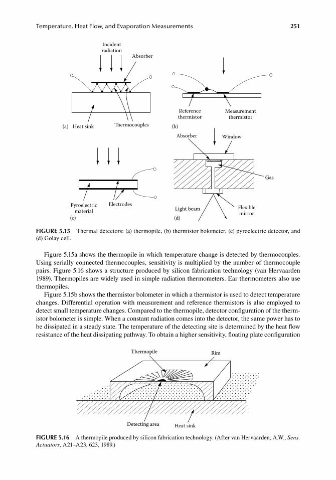
Temperature,HeatFlow,andEvaporationMeasurements 251
Figure.5.15a.shows.the.thermopile.in.which.temperature.change.is.detected.by.thermocouples..Using.serially.connected.thermocouples,.sensitivity.is.multiplied.by.the.number.of.thermocouple.pairs..Figure.5.16.shows.a.structure.produced.by.silicon.fabrication.technology.(van.Hervaarden.1989)..Thermopiles.are.widely.used.in.simple.radiation.thermometers..Ear.thermometers.also.use.thermopiles.
Figure.5.15b.shows.the.thermistor.bolometer.in.which.a.thermistor.is.used.to.detect.temperature.changes..Differential.operation.with.measurement.and.reference. thermistors. is.also.employed. to.detect.small.temperature.changes..Compared.to.the.thermopile,.detector.configuration.of.the.therm-istor.bolometer.is.simple..When.a.constant.radiation.comes.into.the.detector,.the.same.power.has.to.be.dissipated.in.a.steady.state..The.temperature.of.the.detecting.site.is.determined.by.the.heat.flow.resistance.of.the.heat.dissipating.pathway..To.obtain.a.higher.sensitivity,.floating.plate.configuration.
Pyroelectricmaterial
Electrodes
Absorber Window
Gas
Flexiblemirror
Light beam(c) (d)
Absorber
Heat sink ermocouples
Referencethermistor
Measurementthermistor
(a) (b)
Incidentradiation
figure 5.15 Thermal.detectors:.(a).thermopile,.(b).thermistor.bolometer,.(c).pyroelectric.detector,.and.(d).Golay.cell.
Heat sink
Thermopile Rim
Detecting area
figure 5.16 A.thermopile.produced.by.silicon.fabrication.technology..(After.van.Hervaarden,.A.W.,.Sens. Actuators,.A21–A23,.623,.1989.)
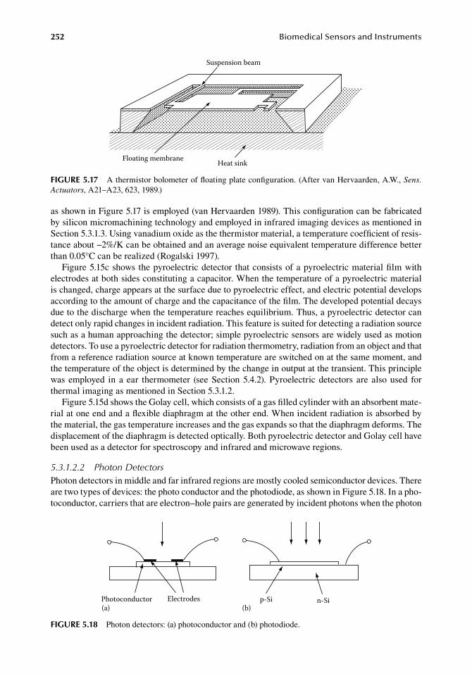
252 BiomedicalSensorsandInstruments
as.shown.in.Figure.5.17.is.employed.(van.Hervaarden.1989)..This.configuration.can.be.fabricated.by.silicon.micromachining.technology.and.employed.in.infrared.imaging.devices.as.mentioned.in.Section.5.3.1.3..Using.vanadium.oxide.as.the.thermistor.material,.a.temperature.coefficient.of.resis-tance.about.−2%/K.can.be.obtained.and.an.average.noise.equivalent.temperature.difference.better.than.0.05°C.can.be.realized.(Rogalski.1997).
Figure.5.15c.shows.the.pyroelectric.detector. that.consists.of.a.pyroelectric.material.film.with.electrodes.at.both.sides.constituting.a.capacitor..When.the.temperature.of.a.pyroelectric.material.is.changed,.charge.appears.at.the.surface.due.to.pyroelectric.effect,.and.electric.potential.develops.according.to.the.amount.of.charge.and.the.capacitance.of.the.film..The.developed.potential.decays.due.to.the.discharge.when.the.temperature.reaches.equilibrium..Thus,.a.pyroelectric.detector.can.detect.only.rapid.changes.in.incident.radiation..This.feature.is.suited.for.detecting.a.radiation.source.such.as.a.human.approaching.the.detector;.simple.pyroelectric.sensors.are.widely.used.as.motion.detectors..To.use.a.pyroelectric.detector.for.radiation.thermometry,.radiation.from.an.object.and.that.from.a.reference.radiation.source.at.known.temperature.are.switched.on.at.the.same.moment,.and.the.temperature.of.the.object.is.determined.by.the.change.in.output.at.the.transient..This.principle.was.employed. in. a. ear. thermometer. (see.Section.5.4.2)..Pyroelectric.detectors. are. also.used. for.thermal.imaging.as.mentioned.in.Section.5.3.1.2.
Figure.5.15d.shows.the.Golay.cell,.which.consists.of.a.gas.filled.cylinder.with.an.absorbent.mate-rial.at.one.end.and.a.flexible.diaphragm.at.the.other.end..When.incident.radiation.is.absorbed.by.the.material,.the.gas.temperature.increases.and.the.gas.expands.so.that.the.diaphragm.deforms..The.displacement.of.the.diaphragm.is.detected.optically..Both.pyroelectric.detector.and.Golay.cell.have.been.used.as.a.detector.for.spectroscopy.and.infrared.and.microwave.regions.
5.3.1.2.2 Photon DetectorsPhoton.detectors.in.middle.and.far.infrared.regions.are.mostly.cooled.semiconductor.devices..There.are.two.types.of.devices:.the.photo.conductor.and.the.photodiode,.as.shown.in.Figure.5.18..In.a.pho-toconductor,.carriers.that.are.electron–hole.pairs.are.generated.by.incident.photons.when.the.photon.
Suspension beam
Floating membrane Heat sink
figure 5.17 A.thermistor.bolometer.of.floating.plate.configuration..(After.van.Hervaarden,.A.W.,.Sens. Actuators,.A21–A23,.623,.1989.)
Photoconductor Electrodes p-Si n-Si(a) (b)
figure 5.18 Photon.detectors:.(a).photoconductor.and.(b).photodiode.
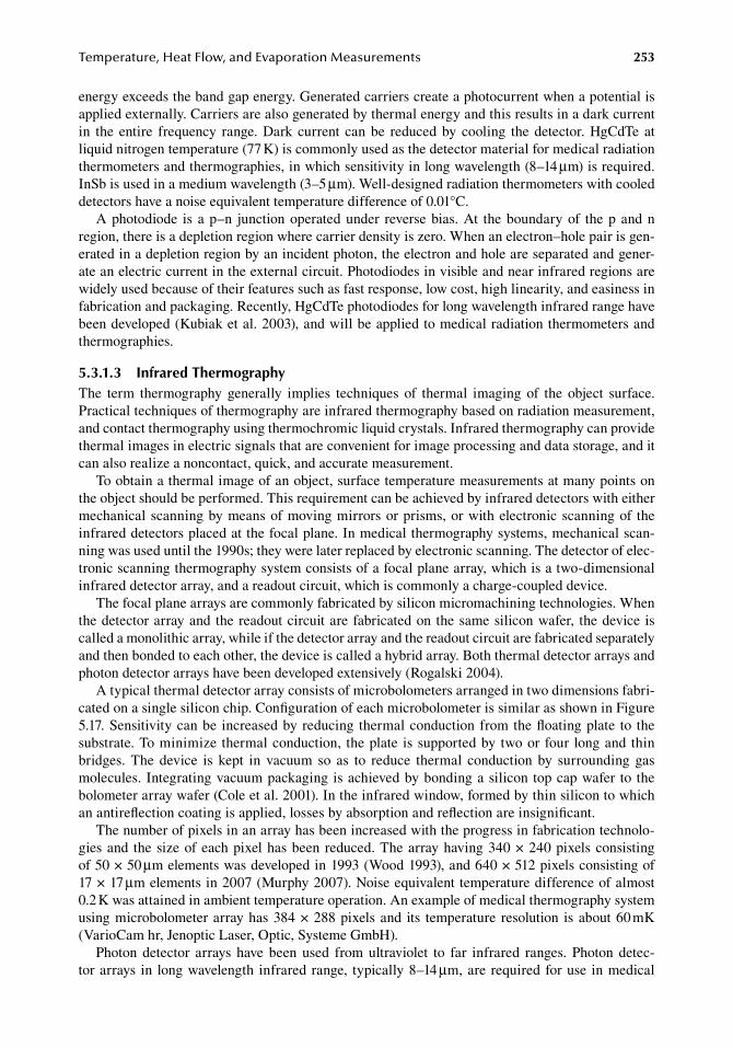
Temperature,HeatFlow,andEvaporationMeasurements 253
energy.exceeds.the.band.gap.energy..Generated.carriers.create.a.photocurrent.when.a.potential.is.applied.externally..Carriers.are.also.generated.by.thermal.energy.and.this.results.in.a.dark.current.in. the. entire. frequency. range..Dark. current. can.be. reduced.by. cooling. the.detector..HgCdTe.at.liquid.nitrogen.temperature.(77.K).is.commonly.used.as.the.detector.material.for.medical.radiation.thermometers.and.thermographies,.in.which.sensitivity.in.long.wavelength.(8–14.μm).is.required..InSb.is.used.in.a.medium.wavelength.(3–5.μm)..Well-designed.radiation.thermometers.with.cooled.detectors.have.a.noise.equivalent.temperature.difference.of.0.01°C.
A.photodiode. is. a.p–n. junction.operated.under. reverse.bias..At. the.boundary.of. the.p.and.n.region,.there.is.a.depletion.region.where.carrier.density.is.zero..When.an.electron–hole.pair.is.gen-erated.in.a.depletion.region.by.an.incident.photon,.the.electron.and.hole.are.separated.and.gener-ate.an.electric.current.in.the.external.circuit..Photodiodes.in.visible.and.near.infrared.regions.are.widely.used.because.of.their.features.such.as.fast.response,.low.cost,.high.linearity,.and.easiness.in.fabrication.and.packaging..Recently,.HgCdTe.photodiodes.for.long.wavelength.infrared.range.have.been.developed.(Kubiak.et.al..2003),.and.will.be.applied.to.medical.radiation.thermometers.and.thermographies.
5.3.1.3 infrared thermographyThe. term. thermography. generally. implies. techniques. of. thermal. imaging. of. the. object. surface..Practical.techniques.of.thermography.are.infrared.thermography.based.on.radiation.measurement,.and.contact.thermography.using.thermochromic.liquid.crystals..Infrared.thermography.can.provide.thermal.images.in.electric.signals.that.are.convenient.for.image.processing.and.data.storage,.and.it.can.also.realize.a.noncontact,.quick,.and.accurate.measurement.
To.obtain.a.thermal.image.of.an.object,.surface.temperature.measurements.at.many.points.on.the.object.should.be.performed..This.requirement.can.be.achieved.by.infrared.detectors.with.either.mechanical.scanning.by.means.of.moving.mirrors.or.prisms,.or.with.electronic.scanning.of. the.infrared.detectors.placed.at.the.focal.plane..In.medical.thermography.systems,.mechanical.scan-ning.was.used.until.the.1990s;.they.were.later.replaced.by.electronic.scanning..The.detector.of.elec-tronic.scanning.thermography.system.consists.of.a.focal.plane.array,.which.is.a.two-dimensional.infrared.detector.array,.and.a.readout.circuit,.which.is.commonly.a.charge-coupled.device.
The.focal.plane.arrays.are.commonly.fabricated.by.silicon.micromachining.technologies..When.the.detector.array.and. the.readout.circuit.are.fabricated.on. the.same.silicon.wafer,. the.device. is.called.a.monolithic.array,.while.if.the.detector.array.and.the.readout.circuit.are.fabricated.separately.and.then.bonded.to.each.other,.the.device.is.called.a.hybrid.array..Both.thermal.detector.arrays.and.photon.detector.arrays.have.been.developed.extensively.(Rogalski.2004).
A.typical.thermal.detector.array.consists.of.microbolometers.arranged.in.two.dimensions.fabri-cated.on.a.single.silicon.chip..Configuration.of.each.microbolometer.is.similar.as.shown.in.Figure.5.17..Sensitivity.can.be. increased.by.reducing.thermal.conduction.from.the.floating.plate. to. the.substrate..To.minimize. thermal.conduction,. the.plate. is.supported.by.two.or.four. long.and.thin.bridges.. The. device. is. kept. in. vacuum. so. as. to. reduce. thermal. conduction. by. surrounding. gas.molecules..Integrating.vacuum.packaging.is.achieved.by.bonding.a.silicon.top.cap.wafer. to. the.bolometer.array.wafer.(Cole.et.al..2001)..In.the.infrared.window,.formed.by.thin.silicon.to.which.an.antireflection.coating.is.applied,.losses.by.absorption.and.reflection.are.insignificant.
The.number.of.pixels.in.an.array.has.been.increased.with.the.progress.in.fabrication.technolo-gies.and. the.size.of.each.pixel.has.been.reduced..The.array.having.340.×.240.pixels.consisting.of.50.×.50.μm.elements.was.developed.in.1993.(Wood.1993),.and.640.×.512.pixels.consisting.of.17.×.17.μm.elements.in.2007.(Murphy.2007)..Noise.equivalent.temperature.difference.of.almost.0.2.K.was.attained.in.ambient.temperature.operation..An.example.of.medical.thermography.system.using.microbolometer.array.has.384.×.288.pixels.and. its. temperature. resolution. is.about.60.mK.(VarioCam.hr,.Jenoptic.Laser,.Optic,.Systeme.GmbH).
Photon. detector. arrays. have. been. used. from. ultraviolet. to. far. infrared. ranges.. Photon. detec-tor.arrays. in. long.wavelength. infrared.range,. typically.8–14.μm,.are.required.for.use. in.medical.
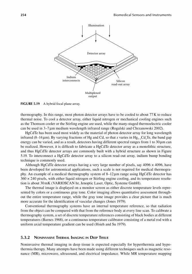
254 BiomedicalSensorsandInstruments
thermography..In.this.range,.most.photon.detector.arrays.have.to.be.cooled.to.about.77.K.to.reduce.thermal.noise..To.cool.a.detector.array,.either.liquid.nitrogen.or.mechanical.cooling.engines.such.as.the.Thomson.cooler.or.the.Stirling.engine.are.used,.while.the.many-staged.thermoelectric.cooler.can.be.used.in.3–7.μm.medium.wavelength.infrared.range.(Rogalski.and.Chrzanowski.2002).
HgCdTe.has.been.used.most.widely.as.the.material.of.photon.detector.array.for.long.wavelength.infrared.(8–14.μm)..By.varying.fractions.of.Hg.and.Cd,.so.that.x.varies.in.Hg1−xCdxTe,.the.band.gap.energy.can.be.varied,.and.as.a.result,.detectors.having.different.spectral.ranges.from.1.to.30.μm.can.be.realized..However,.it.is.difficult.to.fabricate.a.HgCdTe.detector.array.as.a.monolithic.structure,.and.thus.HgCdTe.detector.arrays.are.commonly.built.with.a.hybrid.structure.as.shown.in.Figure.5.19..To.interconnect.a.HgCdTe.detector.array.to.a.silicon.read-out.array,.indium.bump.bonding.technique.is.commonly.used.
Although.HgCdTe.detector.arrays.having.a.very.large.number.of.pixels,.say.4096.×.4096,.have.been.developed.for.astronomical.applications,.such.a.scale.is.not.required.for.medical.thermogra-phy..An.example.of.a.medical.thermography.system.of.8–12.μm.range.using.HgCdTe.detector.has.360.×.240.pixels,.with.either.liquid.nitrogen.or.Stirling.engine.cooling,.and.its.temperature.resolu-tion.is.about.30.mK.(VARIOSCAN.hr,.Jenoptic.Laser,.Optic,.Systeme.GmbH).
The.thermal.image.is.displayed.on.a.monitor.screen.as.either.discrete.temperature.levels.repre-sented.by.colors.or.a.continuous.gray.tone..Color.imaging.allows.quantitative.assessment.through-out.the.entire.temperature.range,.while.the.gray.tone.image.provides.a.clear.picture.that.is.much.more.accurate.for.the.identification.of.vascular.changes.(Jones.1979).
Conventional. thermography.systems.have.an. internal. temperature. reference,. so. that. radiation.from.the.object.can.be.compared.with.that.from.the.reference.body.at.every.line.scan..To.calibrate.a.thermography.system,.a.set.of.discrete.temperature.references.consisting.of.black.bodies.at.different.temperatures.(Barnes.1968),.or.a.continuous.temperature.calibrator.consisting.of.a.metal.rod.with.a.uniform.axial.temperature.gradient.can.be.used.(Hsieh.and.Su.1979).
5.3.2 noninVasiVe therMal iMaging in deep tissue
Noninvasive.thermal.imaging.in.deep.tissue.is.expected.especially.for.hyperthermia.and.hypo-thermia.therapy..Many.attempts.have.been.made.using.different.techniques.such.as.magnetic.reso-nance.(MR),.microwave,.ultrasound,.and.electrical.impedance..While.MR.temperature.mapping.
Illumination
Detector array
Indiuminterconnects
Multiplexedoutput
Siliconread-out array
figure 5.19 A.hybrid.focal.plane.array.
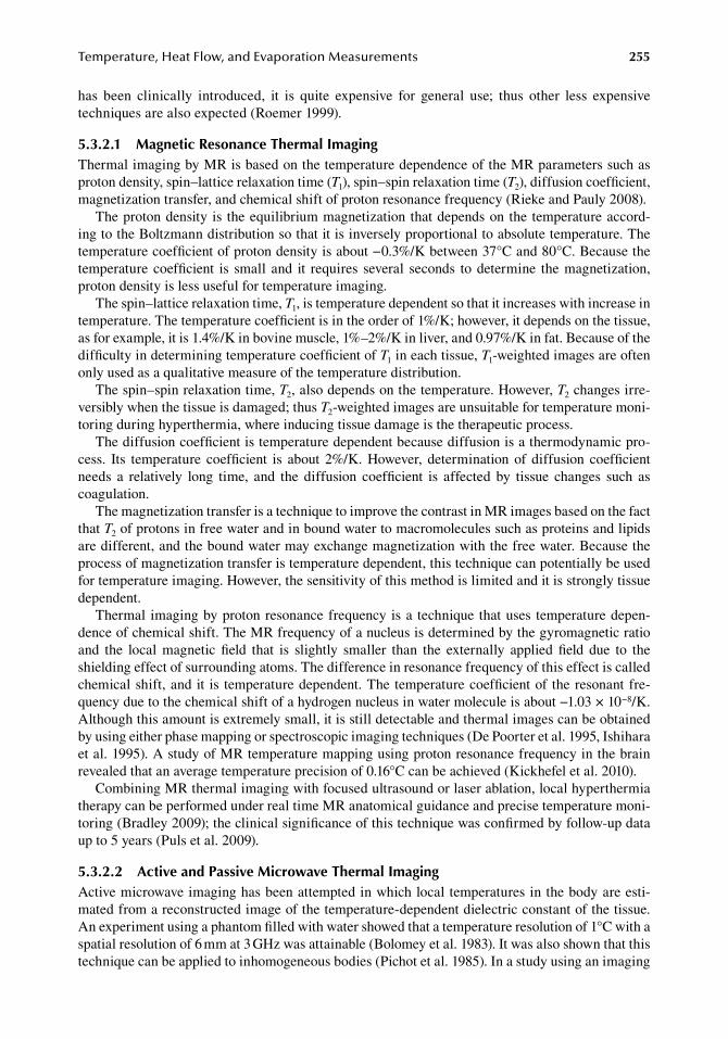
Temperature,HeatFlow,andEvaporationMeasurements 255
has. been. clinically. introduced,. it. is. quite. expensive. for. general. use;. thus. other. less. expensive.techniques.are.also.expected.(Roemer.1999).
5.3.2.1 Magnetic resonance thermal imagingThermal.imaging.by.MR.is.based.on.the.temperature.dependence.of.the.MR.parameters.such.as.proton.density,.spin–lattice.relaxation.time.(T1),.spin–spin.relaxation.time.(T2),.diffusion.coefficient,.magnetization.transfer,.and.chemical.shift.of.proton.resonance.frequency.(Rieke.and.Pauly.2008).
The.proton.density. is. the.equilibrium.magnetization.that.depends.on.the.temperature.accord-ing.to.the.Boltzmann.distribution.so.that.it.is.inversely.proportional.to.absolute.temperature..The.temperature.coefficient.of.proton.density.is.about.−0.3%/K.between.37°C.and.80°C..Because.the.temperature.coefficient. is. small. and. it. requires. several. seconds. to.determine. the.magnetization,.proton.density.is.less.useful.for.temperature.imaging.
The.spin–lattice.relaxation.time,.T1,.is.temperature.dependent.so.that.it.increases.with.increase.in.temperature..The.temperature.coefficient.is.in.the.order.of.1%/K;.however,.it.depends.on.the.tissue,.as.for.example,.it.is.1.4%/K.in.bovine.muscle,.1%–2%/K.in.liver,.and.0.97%/K.in.fat..Because.of.the.difficulty.in.determining.temperature.coefficient.of.T1.in.each.tissue,.T1-weighted.images.are.often.only.used.as.a.qualitative.measure.of.the.temperature.distribution.
The.spin–spin.relaxation.time,.T2,.also.depends.on.the.temperature..However,.T2.changes.irre-versibly.when.the.tissue.is.damaged;.thus.T2-weighted.images.are.unsuitable.for.temperature.moni-toring.during.hyperthermia,.where.inducing.tissue.damage.is.the.therapeutic.process.
The.diffusion.coefficient.is.temperature.dependent.because.diffusion.is.a.thermodynamic.pro-cess.. Its. temperature. coefficient. is. about. 2%/K.. However,. determination. of. diffusion. coefficient.needs. a. relatively. long. time,. and. the. diffusion. coefficient. is. affected. by. tissue. changes. such. as.coagulation.
The.magnetization.transfer.is.a.technique.to.improve.the.contrast.in.MR.images.based.on.the.fact.that.T2.of.protons.in.free.water.and.in.bound.water.to.macromolecules.such.as.proteins.and.lipids.are.different,.and.the.bound.water.may.exchange.magnetization.with.the.free.water..Because.the.process.of.magnetization.transfer.is.temperature.dependent,.this.technique.can.potentially.be.used.for.temperature.imaging..However,.the.sensitivity.of.this.method.is.limited.and.it.is.strongly.tissue.dependent.
Thermal. imaging.by.proton.resonance.frequency. is.a. technique. that.uses. temperature.depen-dence.of.chemical.shift..The.MR.frequency.of.a.nucleus.is.determined.by.the.gyromagnetic.ratio.and. the. local. magnetic. field. that. is. slightly. smaller. than. the. externally. applied. field. due. to. the.shielding.effect.of.surrounding.atoms..The.difference.in.resonance.frequency.of.this.effect.is.called.chemical.shift,.and.it. is. temperature.dependent..The.temperature.coefficient.of. the.resonant.fre-quency.due.to.the.chemical.shift.of.a.hydrogen.nucleus.in.water.molecule.is.about.−1.03.×.10−8/K..Although.this.amount.is.extremely.small,.it.is.still.detectable.and.thermal.images.can.be.obtained.by.using.either.phase.mapping.or.spectroscopic.imaging.techniques.(De.Poorter.et.al..1995,.Ishihara.et.al..1995)..A.study.of.MR.temperature.mapping.using.proton.resonance.frequency.in.the.brain.revealed.that.an.average.temperature.precision.of.0.16°C.can.be.achieved.(Kickhefel.et.al..2010).
Combining.MR.thermal.imaging.with.focused.ultrasound.or.laser.ablation,.local.hyperthermia.therapy.can.be.performed.under.real.time.MR.anatomical.guidance.and.precise.temperature.moni-toring.(Bradley.2009);.the.clinical.significance.of.this.technique.was.confirmed.by.follow-up.data.up.to.5.years.(Puls.et.al..2009).
5.3.2.2 active and Passive Microwave thermal imagingActive.microwave.imaging.has.been.attempted.in.which.local.temperatures.in.the.body.are.esti-mated.from.a.reconstructed.image.of.the.temperature-dependent.dielectric.constant.of.the.tissue..An.experiment.using.a.phantom.filled.with.water.showed.that.a.temperature.resolution.of.1°C.with.a.spatial.resolution.of.6.mm.at.3.GHz.was.attainable.(Bolomey.et.al..1983)..It.was.also.shown.that.this.technique.can.be.applied.to.inhomogeneous.bodies.(Pichot.et.al..1985)..In.a.study.using.an.imaging.
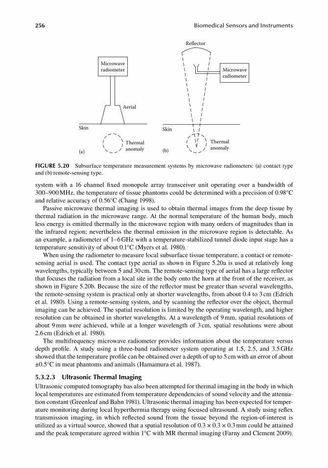
256 BiomedicalSensorsandInstruments
system. with. a. 16. channel. fixed. monopole. array. transceiver. unit. operating. over. a. bandwidth. of.300–900.MHz,.the.temperature.of.tissue.phantoms.could.be.determined.with.a.precision.of.0.98°C.and.relative.accuracy.of.0.56°C.(Chang.1998).
Passive.microwave.thermal.imaging.is.used.to.obtain.thermal.images.from.the.deep.tissue.by.thermal. radiation. in. the.microwave.range..At. the.normal. temperature.of. the.human.body,.much.less.energy.is.emitted.thermally.in.the.microwave.region.with.many.orders.of.magnitudes.than.in.the.infrared.region;.nevertheless. the.thermal.emission.in. the.microwave.region.is.detectable..As.an.example,.a.radiometer.of.1–6.GHz.with.a.temperature-stabilized.tunnel.diode.input.stage.has.a.temperature.sensitivity.of.about.0.1°C.(Myers.et.al..1980).
When.using.the.radiometer.to.measure.local.subsurface.tissue.temperature,.a.contact.or.remote-sensing.aerial.is.used..The.contact.type.aerial.as.shown.in.Figure.5.20a.is.used.at.relatively.long.wavelengths,.typically.between.5.and.30.cm..The.remote-sensing.type.of.aerial.has.a.large.reflector.that.focuses.the.radiation.from.a.local.site.in.the.body.onto.the.horn.at.the.front.of.the.receiver,.as.shown.in.Figure.5.20b..Because.the.size.of.the.reflector.must.be.greater.than.several.wavelengths,.the.remote-sensing.system.is.practical.only.at.shorter.wavelengths,.from.about.0.4.to.3.cm.(Edrich.et.al..1980)..Using.a.remote-sensing.system,.and.by.scanning.the.reflector.over.the.object,.thermal.imaging.can.be.achieved..The.spatial.resolution.is.limited.by.the.operating.wavelength,.and.higher.resolution.can.be.obtained.in.shorter.wavelengths..At.a.wavelength.of.9.mm,.spatial.resolutions.of.about.9.mm.were.achieved,.while.at.a. longer.wavelength.of.3.cm,.spatial. resolutions.were.about.2.6.cm.(Edrich.et.al..1980).
The.multifrequency.microwave.radiometer.provides.information.about.the.temperature.versus.depth. profile.. A. study. using. a. three-band. radiometer. system. operating. at. 1.5,. 2.5,. and. 3.5.GHz.showed.that.the.temperature.profile.can.be.obtained.over.a.depth.of.up.to.5.cm.with.an.error.of.about.±0.5°C.in.meat.phantoms.and.animals.(Hamamura.et.al..1987).
5.3.2.3 ultrasonic thermal imagingUltrasonic.computed.tomography.has.also.been.attempted.for.thermal.imaging.in.the.body.in.which.local.temperatures.are.estimated.from.temperature.dependencies.of.sound.velocity.and.the.attenua-tion.constant.(Greenleaf.and.Bahn.1981)..Ultrasonic.thermal.imaging.has.been.expected.for.temper-ature.monitoring.during.local.hyperthermia.therapy.using.focused.ultrasound..A.study.using.reflex.transmission. imaging,. in. which. reflected. sound. from. the. tissue. beyond. the. region-of-interest. is.utilized.as.a.virtual.source,.showed.that.a.spatial.resolution.of.0.3.×.0.3.×.0.3.mm.could.be.attained.and.the.peak.temperature.agreed.within.1°C.with.MR.thermal.imaging.(Farny.and.Clement.2009).
Microwaveradiometer
Skin
Thermalanomaly
Thermalanomaly
Aerial
Skin
Microwaveradiometer
Reflector
(a) (b)
figure 5.20 Subsurface. temperature.measurement.systems.by.microwave.radiometers:. (a).contact. type.and.(b).remote-sensing.type.
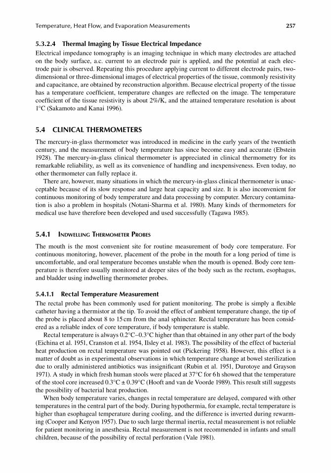
Temperature,HeatFlow,andEvaporationMeasurements 257
5.3.2.4 thermal imaging by tissue electrical impedanceElectrical.impedance.tomography.is.an.imaging.technique.in.which.many.electrodes.are.attached.on. the.body. surface,. a.c.. current. to. an. electrode.pair. is. applied,. and. the.potential. at. each. elec-trode.pair.is.observed..Repeating.this.procedure.applying.current.to.different.electrode.pairs,.two-dimensional.or.three-dimensional.images.of.electrical.properties.of.the.tissue,.commonly.resistivity.and.capacitance,.are.obtained.by.reconstruction.algorithm..Because.electrical.property.of.the.tissue.has. a. temperature. coefficient,. temperature. changes. are. reflected.on. the. image..The. temperature.coefficient.of.the.tissue.resistivity.is.about.2%/K,.and.the.attained.temperature.resolution.is.about.1°C.(Sakamoto.and.Kanai.1996).
5.4 CliniCal therMoMeterS
The.mercury-in-glass.thermometer.was.introduced.in.medicine.in.the.early.years.of.the.twentieth.century,.and.the.measurement.of.body.temperature.has.since.become.easy.and.accurate.(Ebstein.1928).. The. mercury-in-glass. clinical. thermometer. is. appreciated. in. clinical. thermometry. for. its.remarkable.reliability,.as.well.as.its.convenience.of.handling.and.inexpensiveness..Even.today,.no.other.thermometer.can.fully.replace.it.
There.are,.however,.many.situations.in.which.the.mercury-in-glass.clinical.thermometer.is.unac-ceptable.because.of.its.slow.response.and.large.heat.capacity.and.size..It.is.also.inconvenient.for.continuous.monitoring.of.body.temperature.and.data.processing.by.computer..Mercury.contamina-tion.is.also.a.problem.in.hospitals.(Notani-Sharma.et.al..1980)..Many.kinds.of.thermometers.for.medical.use.have.therefore.been.developed.and.used.successfully.(Tagawa.1985).
5.4.1 indwelling therMoMeter probes
The. mouth. is. the. most. convenient. site. for. routine. measurement. of. body. core. temperature.. For.continuous.monitoring,.however,.placement.of.the.probe.in.the.mouth.for.a.long.period.of.time.is.uncomfortable,.and.oral.temperature.becomes.unstable.when.the.mouth.is.opened..Body.core.tem-perature.is.therefore.usually.monitored.at.deeper.sites.of.the.body.such.as.the.rectum,.esophagus,.and.bladder.using.indwelling.thermometer.probes.
5.4.1.1 rectal temperature MeasurementThe.rectal.probe.has.been.commonly.used.for.patient.monitoring..The.probe.is.simply.a.flexible.catheter.having.a.thermistor.at.the.tip..To.avoid.the.effect.of.ambient.temperature.change,.the.tip.of.the.probe.is.placed.about.8.to.15.cm.from.the.anal.sphincter..Rectal.temperature.has.been.consid-ered.as.a.reliable.index.of.core.temperature,.if.body.temperature.is.stable.
Rectal.temperature.is.always.0.2°C–0.3°C.higher.than.that.obtained.in.any.other.part.of.the.body.(Eichina.et.al..1951,.Cranston.et.al..1954,.Ilsley.et.al..1983)..The.possibility.of.the.effect.of.bacterial.heat.production.on.rectal.temperature.was.pointed.out.(Pickering.1958)..However,.this.effect.is.a.matter.of.doubt.as.in.experimental.observations.in.which.temperature.change.at.bowel.sterilization.due.to.orally.administered.antibiotics.was.insignificant.(Rubin.et.al..1951,.Durotoye.and.Grayson.1971)..A study.in.which.fresh.human.stools.were.placed.at.37°C.for.6.h.showed.that.the.temperature.of.the.stool.core.increased.0.3°C.±.0.39°C.(Hooft.and.van.de.Voorde.1989)..This.result.still.suggests.the.possibility.of.bacterial.heat.production.
When.body.temperature.varies,.changes.in.rectal.temperature.are.delayed,.compared.with.other.temperatures.in.the.central.part.of.the.body..During.hypothermia,.for.example,.rectal.temperature.is.higher.than.esophageal.temperature.during.cooling,.and.the.difference.is.inverted.during.rewarm-ing.(Cooper.and.Kenyon.1957)..Due.to.such.large.thermal.inertia,.rectal.measurement.is.not.reliable.for.patient.monitoring.in.anesthesia..Rectal.measurement.is.not.recommended.in.infants.and.small.children,.because.of.the.possibility.of.rectal.perforation.(Vale.1981).
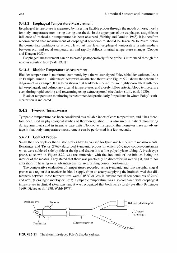
258 BiomedicalSensorsandInstruments
5.4.1.2 esophageal temperature MeasurementEsophageal.temperature.is.measured.by.inserting.flexible.probes.through.the.mouth.or.nose,.mostly.for.body.temperature.monitoring.during.anesthesia..In.the.upper.part.of.the.esophagus,.a.significant.influence.of.tracheal.air.temperature.has.been.observed.(Whitby.and.Dunkin.1968)..It.is.therefore.recommended. that. measurement. of. esophageal. temperature. should. be. taken. 24. to. 28.cm. below.the.corniculate.cartilages.or.at.heart. level..At. this. level,.esophageal. temperature. is. intermediate.between.oral.and.rectal. temperatures,.and.rapidly.follows. internal. temperature.changes. (Cooper.and.Kenyon.1957).
Esophageal.measurement.can.be.tolerated.postoperatively.if.the.probe.is.introduced.through.the.nose.as.a.gastric.tube.(Vale.1981).
5.4.1.3 bladder temperature MeasurementBladder.temperature.is.monitored.commonly.by.a.thermistor-tipped.Foley’s.bladder.catheter,.i.e.,.a.16.Fr.triple-lumen.all-silicone.catheter.with.an.attached.thermistor..Figure.5.21.shows.the.schematic.diagram.of.an.example..It.has.been.shown.that.bladder.temperatures.are.highly.correlated.with.rec-tal,.esophageal,.and.pulmonary.arterial.temperatures,.and.closely.follow.arterial.blood.temperature.even.during.rapid.cooling.and.rewarming.using.extracorporeal.circulation.(Lilly.et.al..1980).
Bladder.temperature.monitoring.is.recommended.particularly.for.patients.in.whom.Foley’s.cath-eterization.is.indicated.
5.4.2 tyMpanic therMoMeters
Tympanic.temperature.has.been.considered.as.a.reliable.index.of.core.temperature,.and.it.has.there-fore.been.used.in.physiological.studies.of.thermoregulation..It. is.also.used.in.patient.monitoring.during.anesthesia.and.in.intensive.care.units..Noncontact.tympanic.thermometers.have.an.advan-tage.in.that.body.temperature.measurement.can.be.performed.in.a.few.seconds.
5.4.2.1 Contact ProbesSmall.thermocouple.or.thermistor.probes.have.been.used.for.tympanic.temperature.measurements..Benzinger. and. Taylor. (1963). described. tympanic. probes. in. which. 36-gauge. copper–constantan.wires.were.soldered.side.by.side.at.the.tip.and.drawn.into.a.fine.polyethylene.tubing..A.brush-type.probe,. as. shown. in.Figure.5.22,.was. recommended.with. the. free.ends.of. the.bristles. facing. the.interior.of.the.meatus..They.stated.that.there.was.practically.no.discomfort.in.wearing.it,.and.minor.alterations.in.hearing.were.advantageous.for.ascertaining.correct.positioning.
The.comparative.evaluation.of.temperatures.recorded.using.tympanic.and.two.nasopharyngeal.probes.at.a.region.that.receives.its.blood.supply.from.an.artery.supplying.the.brain.showed.that.dif-ferences.between.these.temperatures.were.0.05°C.or.less.in.environmental.temperatures.of.24°C.and.45°C.(Benzinger.and.Taylor.1963)..Tympanic.temperature.was.also.compared.with.esophageal.temperature.in.clinical.situations,.and.it.was.recognized.that.both.were.closely.parallel.(Benzinger.1969,.Dickey.et.al..1970,.Webb.1973).
Balloon inflation port
Urinarydrainage
Cable
Silicone catheter
BalloonDrainage eye
ermistor
figure 5.21 The.thermistor-tipped.Foley’s.bladder.catheter.
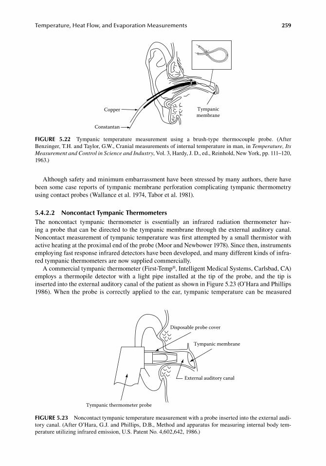
Temperature,HeatFlow,andEvaporationMeasurements 259
Although.safety.and.minimum.embarrassment.have.been.stressed.by.many.authors,.there.have.been.some.case.reports.of. tympanic.membrane.perforation.complicating. tympanic. thermometry.using.contact.probes.(Wallance.et.al..1974,.Tabor.et.al..1981).
5.4.2.2 noncontact tympanic thermometersThe. noncontact. tympanic. thermometer. is. essentially. an. infrared. radiation. thermometer. hav-ing.a.probe.that.can.be.directed.to.the.tympanic.membrane.through.the.external.auditory.canal..Noncontact.measurement.of.tympanic.temperature.was.first.attempted.by.a.small.thermistor.with.active.heating.at.the.proximal.end.of.the.probe.(Moor.and.Newbower.1978)..Since.then,.instruments.employing.fast.response.infrared.detectors.have.been.developed,.and.many.different.kinds.of.infra-red.tympanic.thermometers.are.now.supplied.commercially.
A.commercial.tympanic.thermometer.(First-Temp®,.Intelligent.Medical.Systems,.Carlsbad,.CA).employs. a. thermopile. detector. with. a. light. pipe. installed. at. the. tip. of. the. probe,. and. the. tip. is.inserted.into.the.external.auditory.canal.of.the.patient.as.shown.in.Figure.5.23.(O’Hara.and.Phillips.1986)..When.the.probe. is.correctly.applied. to. the.ear,. tympanic. temperature.can.be.measured.
Tympanicmembrane
Copper
Constantan
figure 5.22 Tympanic. temperature. measurement. using. a. brush-type. thermocouple. probe.. (After.Benzinger,.T.H..and.Taylor,.G.W.,.Cranial.measurements.of.internal.temperature.in.man,.in.Temperature, Its Measurement and Control in Science and Industry,.Vol..3,.Hardy,.J..D.,.ed.,.Reinhold,.New.York,.pp..111–120,.1963.)
Tympanic thermometer probe
Disposable probe cover
Tympanic membrane
External auditory canal
figure 5.23 Noncontact.tympanic.temperature.measurement.with.a.probe.inserted.into.the.external.audi-tory.canal..(After.O’Hara,.G.J..and.Phillips,.D.B.,.Method.and.apparatus.for.measuring.internal.body.tem-perature.utilizing.infrared.emission,.U.S..Patent.No..4,602,642,.1986.)
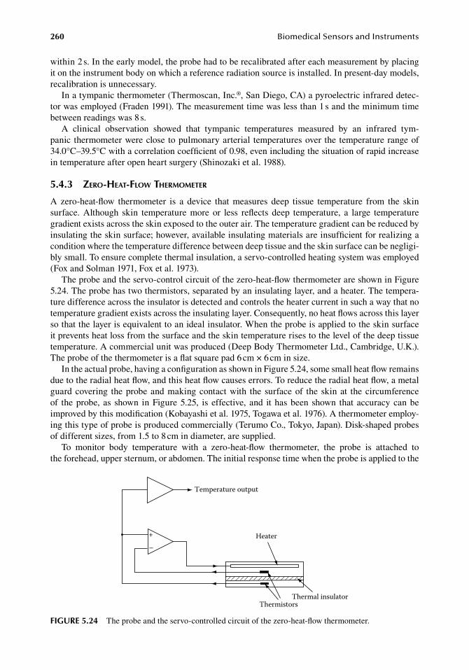
260 BiomedicalSensorsandInstruments
within.2.s..In.the.early.model,.the.probe.had.to.be.recalibrated.after.each.measurement.by.placing.it.on.the.instrument.body.on.which.a.reference.radiation.source.is.installed..In.present-day.models,.recalibration.is.unnecessary.
In.a.tympanic.thermometer.(Thermoscan,.Inc.®,.San.Diego,.CA).a.pyroelectric.infrared.detec-tor.was.employed.(Fraden.1991)..The.measurement.time.was.less.than.1.s.and.the.minimum.time.between.readings.was.8.s.
A. clinical. observation. showed. that. tympanic. temperatures. measured. by. an. infrared. tym-panic. thermometer.were.close.to.pulmonary.arterial. temperatures.over. the.temperature.range.of.34.0°C–39.5°C.with.a.correlation.coefficient.of.0.98,.even.including.the.situation.of.rapid.increase.in.temperature.after.open.heart.surgery.(Shinozaki.et.al..1988).
5.4.3 Zero-heat-flow therMoMeter
A. zero-heat-flow. thermometer. is. a. device. that. measures. deep. tissue. temperature. from. the. skin.surface.. Although. skin. temperature. more. or. less. reflects. deep. temperature,. a. large. temperature.gradient.exists.across.the.skin.exposed.to.the.outer.air..The.temperature.gradient.can.be.reduced.by.insulating.the.skin.surface;.however,.available.insulating.materials.are.insufficient.for.realizing.a.condition.where.the.temperature.difference.between.deep.tissue.and.the.skin.surface.can.be.negligi-bly.small..To.ensure.complete.thermal.insulation,.a.servo-controlled.heating.system.was.employed.(Fox.and.Solman.1971,.Fox.et.al..1973).
The.probe.and.the.servo-control.circuit.of.the.zero-heat-flow.thermometer.are.shown.in.Figure.5.24..The.probe.has.two.thermistors,.separated.by.an.insulating.layer,.and.a.heater..The.tempera-ture.difference.across.the.insulator.is.detected.and.controls.the.heater.current.in.such.a.way.that.no.temperature.gradient.exists.across.the.insulating.layer..Consequently,.no.heat.flows.across.this.layer.so.that.the.layer.is.equivalent.to.an.ideal.insulator..When.the.probe.is.applied.to.the.skin.surface.it.prevents.heat.loss.from.the.surface.and.the.skin.temperature.rises.to.the.level.of.the.deep.tissue.temperature..A.commercial.unit.was.produced.(Deep.Body.Thermometer.Ltd.,.Cambridge,.U.K.)..The.probe.of.the.thermometer.is.a.flat.square.pad.6.cm.×.6.cm.in.size.
In.the.actual.probe,.having.a.configuration.as.shown.in.Figure.5.24,.some.small.heat.flow remains.due.to.the.radial.heat.flow,.and.this.heat.flow.causes.errors..To.reduce.the.radial.heat.flow,.a.metal.guard.covering. the.probe.and.making.contact.with. the. surface.of. the. skin.at. the.circumference.of. the.probe,. as. shown. in.Figure.5.25,. is. effective,. and. it.has.been. shown. that. accuracy.can.be.improved.by.this.modification.(Kobayashi.et.al..1975,.Togawa.et.al..1976)..A.thermometer.employ-ing.this.type.of.probe.is.produced.commercially.(Terumo.Co.,.Tokyo,.Japan)..Disk-shaped.probes.of.different.sizes,.from.1.5.to.8.cm.in.diameter,.are.supplied.
To. monitor. body. temperature. with. a. zero-heat-flow. thermometer,. the. probe. is. attached. to.the forehead,.upper.sternum,.or.abdomen..The.initial.response.time.when.the.probe.is.applied.to.the.
Heater
ThermistorsThermal insulator
Temperature output
+
–
figure 5.24 The.probe.and.the.servo-controlled.circuit.of.the.zero-heat-flow.thermometer.
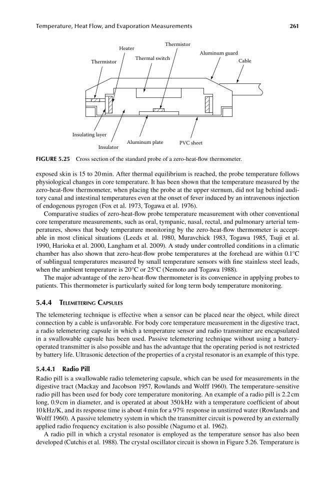
Temperature,HeatFlow,andEvaporationMeasurements 261
exposed.skin.is.15.to.20.min..After.thermal.equilibrium.is.reached,.the.probe.temperature.follows.physiological.changes.in.core.temperature..It.has.been.shown.that.the.temperature.measured.by.the.zero-heat-flow.thermometer,.when.placing.the.probe.at.the.upper.sternum,.did.not.lag.behind.audi-tory.canal.and.intestinal.temperatures.even.at.the.onset.of.fever.induced.by.an.intravenous.injection.of.endogenous.pyrogen.(Fox.et.al..1973,.Togawa.et.al..1976).
Comparative.studies.of.zero-heat-flow.probe.temperature.measurement.with.other.conventional.core.temperature.measurements,.such.as.oral,.tympanic,.nasal,.rectal,.and.pulmonary.arterial.tem-peratures,.shows.that.body.temperature.monitoring.by.the.zero-heat-flow.thermometer.is.accept-able. in. most. clinical. situations. (Leeds. et. al.. 1980,. Muravchick. 1983,. Togawa. 1985,. Tsuji. et. al..1990,.Harioka.et.al..2000,.Langham.et.al..2009)..A.study.under.controlled.conditions.in.a.climatic.chamber.has.also.shown.that.zero-heat-flow.probe.temperatures.at.the.forehead.are.within.0.1°C.of.sublingual.temperatures.measured.by.small.temperature.sensors.with.fine.stainless.steel.leads,.when.the.ambient.temperature.is.20°C.or.25°C.(Nemoto.and.Togawa.1988).
The.major.advantage.of.the.zero-heat-flow.thermometer.is.its.convenience.in.applying.probes.to.patients..This.thermometer.is.particularly.suited.for.long.term.body.temperature.monitoring.
5.4.4 teleMetering capsules
The.telemetering.technique.is.effective.when.a.sensor.can.be.placed.near.the.object,.while.direct.connection.by.a.cable.is.unfavorable..For.body.core.temperature.measurement.in.the.digestive.tract,.a.radio.telemetering.capsule.in.which.a.temperature.sensor.and.radio.transmitter.are.encapsulated.in.a.swallowable.capsule.has.been.used..Passive. telemetering. technique.without.using.a.battery-operated.transmitter.is.also.possible.and.has.the.advantage.that.the.operating.period.is.not.restricted.by.battery.life..Ultrasonic.detection.of.the.properties.of.a.crystal.resonator.is.an.example.of.this.type.
5.4.4.1 radio PillRadio.pill.is.a.swallowable.radio.telemetering.capsule,.which.can.be.used.for.measurements.in.the.digestive.tract.(Mackay.and.Jacobson.1957,.Rowlands.and.Wolff.1960)..The.temperature-sensitive.radio.pill.has.been.used.for.body.core.temperature.monitoring..An.example.of.a.radio.pill.is.2.2.cm.long,.0.9.cm.in.diameter,.and.is.operated.at.about.350.kHz.with.a.temperature.coefficient.of.about.10.kHz/K,.and.its.response.time.is.about.4.min.for.a.97%.response.in.unstirred.water.(Rowlands.and.Wolff.1960)..A.passive.telemetry.system.in.which.the.transmitter.circuit.is.powered.by.an.externally.applied.radio.frequency.excitation.is.also.possible.(Nagumo.et.al..1962).
A.radio.pill.in.which.a.crystal.resonator.is.employed.as.the.temperature.sensor.has.also.been.developed.(Cutchis.et.al..1988)..The.crystal.oscillator.circuit.is.shown.in.Figure.5.26..Temperature.is.
Thermistor
Heater
Thermal switch
ThermistorAluminum guard
Cable
Insulating layer
InsulatorAluminum plate PVC sheet
figure 5.25 Cross.section.of.the.standard.probe.of.a.zero-heat-flow.thermometer.
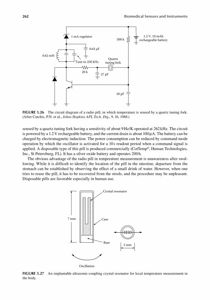
262 BiomedicalSensorsandInstruments
sensed.by.a.quartz.tuning.fork.having.a.sensitivity.of.about.9.Hz/K.operated.at.262.kHz..The.circuit.is.powered.by.a.1.2.V.rechargeable.battery,.and.the.current.drain.is.about.100.μA..The.battery.can.be.charged.by.electromagnetic.induction..The.power.consumption.can.be.reduced.by.command.mode.operation.by.which.the.oscillator.is.activated.for.a.10.s.readout.period.when.a.command.signal.is.applied..A.disposable.type.of.this.pill.is.produced.commercially.(CorTemp®,.Human.Technologies,.Inc.,.St.Petersburg,.FL)..It.has.a.silver.oxide.battery.and.operates.200.h.
The.obvious.advantage.of.the.radio.pill.in.temperature.measurement.is.unawareness.after.swal-lowing..While.it.is.difficult.to.identify.the.location.of.the.pill.in.the.intestine,.departure.from.the.stomach.can.be.established.by.observing.the.effect.of.a.small.drink.of.water..However,.when.one.tries.to.reuse.the.pill,.it.has.to.be.recovered.from.the.stools,.and.the.procedure.may.be.unpleasant..Disposable.pills.are.favorable.especially.in.human.use.
1 mA regulator
0.62 mH
Tune to 250 kHz
0.62 μF
20 k27 pF
50 pF
500 k1.2 V, 10 mAh
rechargeable battery
Quartztuning fork
figure 5.26 The.circuit.diagram.of.a.radio.pill,.in.which.temperature.is.sensed.by.a.quartz.tuning.fork..(After.Cutchis,.P.N..et.al.,.Johns Hopkins APL Tech. Dig.,.9,.16,.1988.)
Crystal resonator
Case
Base
7 mm
2 mm
Oscillation
figure 5.27 An.implantable.ultrasonic-coupling.crystal.resonator.for.local.temperature.measurement.in.the.body.
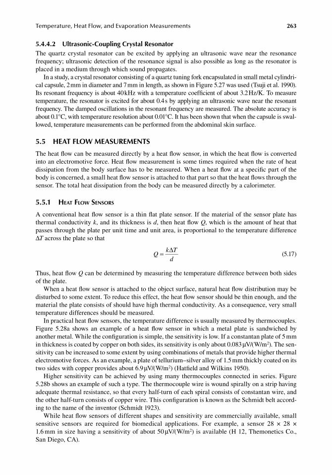
Temperature,HeatFlow,andEvaporationMeasurements 263
5.4.4.2 ultrasonic-Coupling Crystal resonatorThe. quartz. crystal. resonator. can. be. excited. by. applying. an. ultrasonic. wave. near. the. resonance.frequency;.ultrasonic.detection.of.the.resonance.signal.is.also.possible.as.long.as.the.resonator.is.placed.in.a.medium.through.which.sound.propagates.
In.a.study,.a.crystal.resonator.consisting.of.a.quartz.tuning.fork.encapsulated.in.small.metal.cylindri-cal.capsule,.2.mm.in.diameter.and.7.mm.in.length,.as.shown.in.Figure.5.27.was.used.(Tsuji.et al..1990)..Its.resonant.frequency.is.about.40.kHz.with.a.temperature.coefficient.of.about.3.2.Hz/K..To.measure.temperature,.the.resonator.is.excited.for.about.0.4.s.by.applying.an.ultrasonic.wave.near.the.resonant.frequency..The.damped.oscillations.in.the.resonant.frequency.are.measured..The.absolute.accuracy.is.about.0.1°C,.with.temperature.resolution.about.0.01°C..It.has.been.shown.that.when.the.capsule.is.swal-lowed,.temperature.measurements.can.be.performed.from.the.abdominal.skin.surface.
5.5 heat floW MeaSureMentS
The.heat.flow.can.be.measured.directly.by.a.heat.flow.sensor,.in.which.the.heat.flow.is.converted.into.an.electromotive.force..Heat.flow.measurement.is.some.times.required.when.the.rate.of.heat.dissipation.from.the.body.surface.has.to.be.measured..When.a.heat.flow.at.a.specific.part.of.the.body.is.concerned,.a.small.heat.flow.sensor.is.attached.to.that.part.so.that.the.heat.flows.through.the.sensor..The.total.heat.dissipation.from.the.body.can.be.measured.directly.by.a.calorimeter.
5.5.1 heat flow sensors
A.conventional.heat.flow.sensor.is.a.thin.flat.plate.sensor..If.the.material.of.the.sensor.plate.has.thermal.conductivity.k,.and.its.thickness.is.d,.then.heat.flow.Q,.which.is.the.amount.of.heat.that.passes.through.the.plate.per.unit.time.and.unit.area,.is.proportional.to.the.temperature.difference.ΔT.across.the.plate.so.that
.Q
k T
d= ∆
.(5.17)
Thus,.heat.flow.Q.can.be.determined.by.measuring.the.temperature.difference.between.both.sides.of.the.plate.
When.a.heat.flow.sensor.is.attached.to.the.object.surface,.natural.heat.flow.distribution.may.be.disturbed.to.some.extent..To.reduce.this.effect,.the.heat.flow.sensor.should.be.thin.enough,.and.the.material.the.plate.consists.of.should.have.high.thermal.conductivity..As.a.consequence,.very.small.temperature.differences.should.be.measured.
In.practical.heat.flow.sensors,.the.temperature.difference.is.usually.measured.by.thermocouples..Figure. 5.28a. shows. an. example. of. a. heat. flow. sensor. in. which. a. metal. plate. is. sandwiched. by.another.metal..While.the.configuration.is.simple,.the.sensitivity.is.low..If.a.constantan.plate.of.5.mm.in.thickness.is.coated.by.copper.on.both.sides,.its.sensitivity.is.only.about.0.083.μV/(W/m2)..The.sen-sitivity.can.be.increased.to.some.extent.by.using.combinations.of.metals.that.provide.higher.thermal.electromotive.forces..As.an.example,.a.plate.of.tellurium–silver.alloy.of.1.5.mm.thickly.coated.on.its.two.sides.with.copper.provides.about.6.9.μV/(W/m2).(Hatfield.and.Wilkins.1950).
Higher. sensitivity.can.be.achieved.by.using.many. thermocouples.connected. in. series..Figure.5.28b.shows.an.example.of.such.a.type..The.thermocouple.wire.is.wound.spirally.on.a.strip.having.adequate.thermal.resistance,.so.that.every.half-turn.of.each.spiral.consists.of.constantan.wire,.and.the.other.half-turn.consists.of.copper.wire..This.configuration.is.known.as.the.Schmidt.belt.accord-ing.to.the.name.of.the.inventor.(Schmidt.1923).
While.heat.flow.sensors.of.different.shapes.and.sensitivity.are.commercially.available,.small.sensitive. sensors. are. required. for. biomedical. applications.. For. example,. a. sensor. 28. ×. 28. ×.1.6.mm.in.size.having.a.sensitivity.of.about.50.μV/(W/m2).is.available.(H.12,.Themonetics.Co.,.San.Diego,.CA).
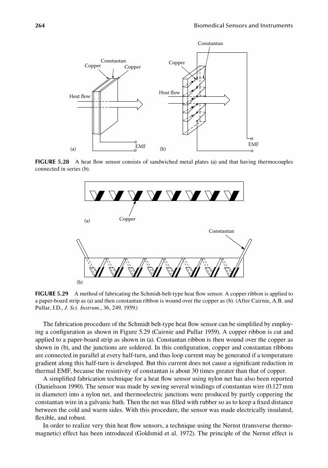
264 BiomedicalSensorsandInstruments
The.fabrication.procedure.of.the.Schmidt.belt-type.heat.flow.sensor.can.be.simplified.by.employ-ing.a.configuration.as.shown.in.Figure.5.29.(Cairnie.and.Pullar.1959)..A.copper.ribbon.is.cut.and.applied.to.a.paper-board.strip.as.shown.in.(a)..Constantan.ribbon.is.then.wound.over.the.copper.as.shown.in.(b),.and.the.junctions.are.soldered..In.this.configuration,.copper.and.constantan.ribbons.are.connected.in.parallel.at.every.half-turn,.and.thus.loop.current.may.be.generated.if.a.temperature.gradient.along.this.half-turn.is.developed..But.this.current.does.not.cause.a.significant.reduction.in.thermal.EMF,.because.the.resistivity.of.constantan.is.about.30.times.greater.than.that.of.copper.
A.simplified.fabrication.technique.for.a.heat.flow.sensor.using.nylon.net.has.also.been.reported.(Danielsson.1990)..The.sensor.was.made.by.sewing.several.windings.of.constantan.wire.(0.127.mm.in.diameter).into.a.nylon.net,.and.thermoelectric.junctions.were.produced.by.partly.coppering.the.constantan.wire.in.a.galvanic.bath..Then.the.net.was.filled.with.rubber.so.as.to.keep.a.fixed.distance.between.the.cold.and.warm.sides..With.this.procedure,.the.sensor.was.made.electrically.insulated,.flexible,.and.robust.
In.order.to.realize.very.thin.heat.flow.sensors,.a.technique.using.the.Nernst.(transverse.thermo-magnetic).effect.has.been.introduced.(Goldsmid.et.al..1972)..The.principle.of.the.Nernst.effect.is.
Copper(a)
Constantan
(b)
figure 5.29 A.method.of.fabricating.the.Schmidt-belt-type.heat.flow.sensor..A.copper.ribbon.is.applied.to.a.paper-board.strip.as.(a).and.then.constantan.ribbon.is.wound.over.the.copper.as.(b)..(After.Cairnie,.A.B..and.Pullar,.J.D.,.J. Sci. Instrum.,.36,.249,.1959.)
Constantan
Copper
Heat flow
Copper CopperConstantan
Heat flow
EMF EMF(b)(a)
figure 5.28 A.heat.flow.sensor.consists.of.sandwiched.metal.plates.(a).and.that.having.thermocouples.connected.in.series.(b).
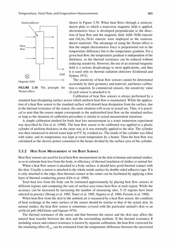
Temperature,HeatFlow,andEvaporationMeasurements 265
shown. in.Figure.5.30..When.heat.flows. through.a. semicon-ductor.plate. to.which.a. transverse.magnetic.field. is.applied,.electromotive. force. is.developed.perpendicular. to. the.direc-tion.of.heat.flow.and.the.magnetic.field..InSb–NiSb.eutectic.and. Gd3As2-NiAs. eutectic. were. employed. as. the. semicon-ductor.materials..The.advantage.of.using.the.Nernst.effect.is.that.the.output.electromotive.force.is.proportional.not.to.the.temperature.difference.but.to.the.temperature.gradient..For.a.given.heat.flow,.the.temperature.gradient.is.independent.of.the.thickness,. so. the. thermal. resistance.can.be. reduced.without.reducing.sensitivity..However,.the.use.of.an.external.magnetic.field.is.a.serious.disadvantage.to.most.applications,.and.thus.it. is.used.only.in.thermal.radiation.detectors.(Goldsmid.and.Sydney.1971).
The.sensitivity.of.heat.flow.sensors.cannot.be.determined.accurately.by.their.geometry.and.material,.and.hence.calibra-tion.is.required..In.commercial.sensors,.the.sensitivity.value.of.each.sensor.is.attached.to.it.
Calibration.of.heat.flow.sensors.is.always.performed.by.a.standard.heat.dissipating.surface.across.which.uniform.heat.flow.is.maintained..While.the.applica-tion.of.a.heat.flow.sensor.to.the.standard.surface.will.disturb.heat.dissipation.from.the.surface,.due.to.the.thermal.resistance.of.the.sensor,.the.same.situation.will.occur.in.actual.use..Thus,.it.is.practi-cal.to.note.that.the.sensor.output.corresponds.to.the.undisturbed.heat.flow.on.the.standard.surface.as.long.as.the.situation.of.calibration.procedure.is.similar.to.actual.measurement.situations.
A.simple.calibration.method.for.body.heat.loss.measurement.in.a.water.immersion.experiment.was.described.by.Gin.et.al..(1980)..The.heat.flow.sensor.to.be.calibrated.was.applied.to.a.plastic.cylinder.of.uniform.thickness.in.the.same.way.as.it.was.normally.applied.to.the.skin..The.cylinder.was.then.immersed.in.stirred.water.kept.at.0°C.by.crushed.ice..The.inside.of.the.cylinder.was.filled.with.water,.and.its.temperature.was.kept.at.room.temperature.by.a.heater..Then.the.heat.flow.was.calculated.as.the.electric.power.consumed.in.the.heater.divided.by.the.surface.area.of.the.cylinder.
5.5.2 heat flow MeasureMent at the body surface
Heat.flow.sensors.are.used.for.local.heat.flow.measurement.on.the.skin.in.human.and.animal.studies,.so.as.to.estimate.heat.loss.from.the.body,.or.efficiency.of.thermal.insulation.of.clothes.or.animal.fur.
When.a.heat.flow.sensor.is.attached.to.a.body.surface,.it.should.have.good.thermal.contact.with.the.skin..Usually.a.sensor.is.attached.to.the.whole.inside.surface.by.double-sided.adhesive.tape..If.it.is.only.attached.to.the.edge,.then.thermal.contact.at.the.center.can.be.facilitated.by.applying.a.thin.layer.of.thermal.conducting.grease.(Gin.et.al..1980).
Total.heat.loss.from.the.body.can.be.estimated.approximately.by.placing.heat.flow.sensors.in.different.regions.and.computing.the.sum.of.surface.area.times.heat.flow.at.each.region..While.the.accuracy.can.be.increased.by.increasing.the.number.of.measuring.sites,.5–15.regions.have.been.selected.in.practice.(Strong.et.al..1985,.Toner.et.al..1985,.Sagawa.et.al..1986,.Ferretti.et.al..1988).
When.heat.flow.from.the.skin.to.the.ambient.air.is.measured.by.a.heat.flow.sensor,.the.condition.of.heat.exchange.at.the.outer.surface.of.the.sensor.should.be.similar.to.that.of.the.actual.skin..In.animal.studies,.the.heat.flow.sensor.is.sometimes.covered.with.the.particular.animal’s.skin.or.an.artificial.pelt.(McGinnis.and.Ingram.1974).
The.thermal.resistance.of.the.sensor.and.that.between.the.sensor.and.the.skin.may.affect.the.natural.heat. transfer.between. the.skin.and. the.surrounding.medium.. If. the. thermal. resistance.R.including.sensor.and.contact.resistance.is.known.by.separate.calibration,.the.heat.flow.corrected.for.the.insulating.effect.Hcorr.can.be.estimated.from.the.temperature.difference.between.the.uncovered.
Semiconductor
Heatflow
EMF
Magnetic field
figure 5.30 The. principle. the.Nernst.effect.
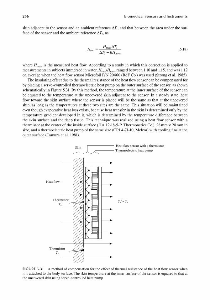
266 BiomedicalSensorsandInstruments
skin.adjacent.to.the.sensor.and.an.ambient.reference.ΔT1,.and.that.between.the.area.under.the.sur-face.of.the.sensor.and.the.ambient.reference.ΔT2,.as
.H
H T
T RHcorr
meas 1
2 meas
= ∆∆ − .
(5.18)
where.Hmeas.is.the.measured.heat.flow..According.to.a.study.in.which.this.correction.is.applied.to.measurements.in.subjects.immersed.in.water,.Hcorr/Hmeas.ranged.between.1.10.and.1.15,.and.was.1.12.on.average.when.the.heat.flow.sensor.Microfoil.P/N.20460.(RdF.Co.).was.used.(Strong.et.al..1985).
The.insulating.effect.due.to.the.thermal.resistance.of.the.heat.flow.sensor.can.be.compensated.for.by.placing.a.servo-controlled.thermoelectric.heat.pump.on.the.outer.surface.of.the.sensor,.as.shown.schematically.in.Figure.5.31..By.this.method,.the.temperature.at.the.inner.surface.of.the.sensor.can.be.equated.to.the.temperature.at.the.uncovered.skin.adjacent.to.the.sensor..In.a.steady.state,.heat.flow.toward.the.skin.surface.where.the.sensor.is.placed.will.be.the.same.as.that.at.the.uncovered.skin,.as.long.as.the.temperatures.at.these.two.sites.are.the.same..This.situation.will.be.maintained.even.though.evaporative.heat.loss.exists,.because.heat.transfer.in.the.skin.is.determined.only.by.the.temperature.gradient.developed.in.it,.which.is.determined.by.the.temperature.difference.between.the.skin.surface.and.the.deep.tissue..This.technique.was.realized.using.a.heat.flow.sensor.with.a.thermistor.at.the.center.of.the.inside.surface.(HA.12-18-5-P,.Thermonetics.Co.),.28.mm.×.28.mm.in.size,.and.a.thermoelectric.heat.pump.of.the.same.size.(CP1.4-71-10,.Melcor).with.cooling.fins.at.the.outer.surface.(Tamura.et.al..1981).
Skin Heat flow sensor with a thermistorThermoelectric heat pump
Heat flow
ThermistorTs΄
ThermistorTs
Ts΄= Ts
figure 5.31 A.method.of.compensation.for.the.effect.of.thermal.resistance.of.the.heat.flow.sensor.when.it.is.attached.to.the.body.surface..The.skin.temperature.at.the.inner.surface.of.the.sensor.is.equated.to.that.at.the.uncovered.skin.using.servo-controlled.heat.pump.
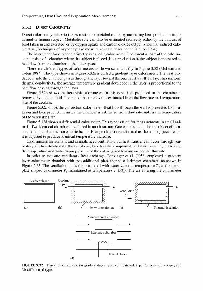
Temperature,HeatFlow,andEvaporationMeasurements 267
5.5.3 direct caloriMetry
Direct.calorimetry.refers.to.the.estimation.of.metabolic.rate.by.measuring.heat.production.in.the.animal.or.human.subject..Metabolic.rate.can.also.be.estimated.indirectly.either.by.the.amount.of.food.taken.in.and.excreted,.or.by.oxygen.uptake.and.carbon.dioxide.output,.known.as.indirect.calo-rimetry..(Techniques.of.oxygen.uptake.measurement.are.described.in.Section.7.3.4.)
The.instrument.for.direct.calorimetry.is.called.a.calorimeter..The.essential.part.of.the.calorim-eter.consists.of.a.chamber.where.the.subject.is.placed..Heat.production.in.the.subject.is.measured.as.heat.flow.from.the.chamber.to.the.outer.space.
There.are.different.types.of.calorimeters.as.shown.schematically.in.Figure.5.32.(McLean.and.Tobin.1987)..The.type.shown.in.Figure.5.32a.is.called.a.gradient-layer.calorimeter..The.heat.pro-duced.inside.the.chamber.passes.through.the.layer.toward.the.outer.surface..If.the.layer.has.uniform.thermal.conductivity,.the.average.temperature.gradient.developed.in.the.layer.is.proportional.to.the.heat.flow.passing.through.the.layer.
Figure. 5.32b. shows. the. heat-sink. calorimeter.. In. this. type,. heat. produced. in. the. chamber. is.removed.by.coolant.fluid..The.rate.of.heat.removal.is.estimated.from.the.flow.rate.and.temperature.rise.of.the.coolant.
Figure.5.32c.shows.the.convection.calorimeter..Heat.flow.through.the.wall.is.prevented.by.insu-lation.and.heat.production.inside.the.chamber.is.estimated.from.flow.rate.and.rise.in.temperature.of.the.ventilating.air.
Figure.5.32d.shows.a.differential.calorimeter..This.type.is.used.for.measurements.in.small.ani-mals..Two.identical.chambers.are.placed.in.an.air.stream..One.chamber.contains.the.object.of.mea-surement,.and.the.other.an.electric.heater..Heat.production.is.estimated.as.the.heating.power.when.it.is.adjusted.to.produce.identical.temperature.increase.
Calorimeters.for.humans.and.animals.need.ventilation,.but.heat.transfer.can.occur.through.ven-tilatory.air..In.a.steady.state,.the.ventilatory.heat.transfer.component.can.be.estimated.by.measuring.the.temperature.and.water.vapor.pressure.of.the.entering.and.leaving.air.and.air.flowrate.
In. order. to. measure. ventilatory. heat. exchange,. Benzinger. et. al.. (1958). employed. a. gradient.layer. calorimeter. chamber. with. two. additional. plate-shaped. calorimeter. chambers,. as. shown. in.Figure.5.33..The.ventilation.air.is.first.saturated.with.water.vapor.at.temperature.T2,.and.enters.a.plate-shaped.calorimeter.P1.maintained.at. temperature.T1. (>T2)..The.air.entering. the.calorimeter.
Measurement chamber
Reference chamber
Electric heater(d)
Gradient layer
(a)
Coolantliquid
Thermal insulation(b) Thermal insulation
Ventilationair
(c)
figure 5.32 Direct.calorimeters:.(a).gradient-layer.type,.(b).heat-sink.type,.(c).convective.type,.and.(d).differential.type.
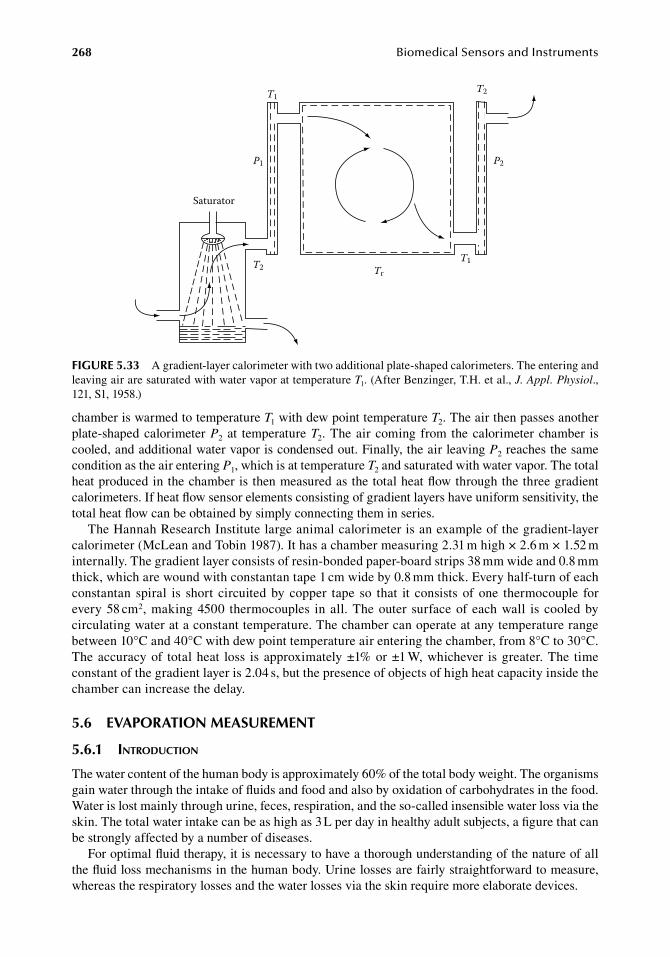
268 BiomedicalSensorsandInstruments
chamber.is.warmed.to.temperature.T1.with.dew.point.temperature.T2..The.air.then.passes.another.plate-shaped.calorimeter.P2. at. temperature.T2..The.air. coming. from. the.calorimeter.chamber. is.cooled,.and.additional.water.vapor.is.condensed.out..Finally,.the.air.leaving.P2.reaches.the.same.condition.as.the.air.entering.P1,.which.is.at.temperature.T2.and.saturated.with.water.vapor..The.total.heat.produced.in.the.chamber.is.then.measured.as.the.total.heat.flow.through.the.three.gradient.calorimeters..If.heat.flow.sensor.elements.consisting.of.gradient.layers.have.uniform.sensitivity,.the.total.heat.flow.can.be.obtained.by.simply.connecting.them.in.series.
The.Hannah.Research.Institute.large.animal.calorimeter.is.an.example.of.the.gradient-layer.calorimeter.(McLean.and.Tobin.1987)..It.has.a.chamber.measuring.2.31.m.high.×.2.6.m.×.1.52.m.internally..The.gradient.layer.consists.of.resin-bonded.paper-board.strips.38.mm.wide.and.0.8.mm.thick,.which.are.wound.with.constantan.tape.1.cm.wide.by.0.8.mm.thick..Every.half-turn.of.each.constantan. spiral. is. short. circuited.by. copper. tape. so. that. it. consists. of. one. thermocouple. for.every.58.cm2,.making.4500. thermocouples. in.all..The.outer. surface.of.each.wall. is. cooled.by.circulating.water.at.a.constant.temperature..The.chamber.can.operate.at.any.temperature.range.between.10°C.and.40°C.with.dew.point.temperature.air.entering.the.chamber,.from.8°C.to.30°C..The.accuracy.of. total.heat. loss. is.approximately.±1%.or.±1.W,.whichever. is.greater..The. time.constant.of.the.gradient.layer.is.2.04.s,.but.the.presence.of.objects.of.high.heat.capacity.inside.the.chamber.can.increase.the.delay.
5.6 eVaPoration MeaSureMent
5.6.1 introduction
The.water.content.of.the.human.body.is.approximately.60%.of.the.total.body.weight..The.organisms.gain.water.through.the.intake.of.fluids.and.food.and.also.by.oxidation.of.carbohydrates.in.the.food..Water.is.lost.mainly.through.urine,.feces,.respiration,.and.the.so-called.insensible.water.loss.via.the.skin..The.total.water.intake.can.be.as.high.as.3.L.per.day.in.healthy.adult.subjects,.a.figure.that.can.be.strongly.affected.by.a.number.of.diseases.
For.optimal.fluid.therapy,.it.is.necessary.to.have.a.thorough.understanding.of.the.nature.of.all.the.fluid.loss.mechanisms.in.the.human.body..Urine.losses.are.fairly.straightforward.to.measure,.whereas.the.respiratory.losses.and.the.water.losses.via.the.skin.require.more.elaborate.devices.
Saturator
T1
T1T2
T2
P2P1
Tr
figure 5.33 A.gradient-layer.calorimeter.with.two.additional.plate-shaped.calorimeters..The.entering.and.leaving.air.are.saturated.with.water.vapor.at.temperature.T1..(After.Benzinger,.T.H..et.al.,.J. Appl. Physiol.,.121,.S1,.1958.)
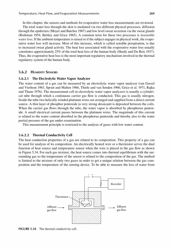
Temperature,HeatFlow,andEvaporationMeasurements 269
In.this.chapter,.the.sensors.and.methods.for.evaporative.water.loss.measurements.are.reviewed.The.total.water.loss.through.the.skin.is.mediated.via.two.different.physical.processes,.diffusion.
through.the.epidermis.(Moyer.and.Butcher.1967).and.low.level.sweat.secretion.via.the.sweat.glands.(Rothman.1954,.Bettley.and.Grice.1965)..A.common.term.for. these. two.processes. is. insensible water loss..If.the.ambient.temperature.is.raised.or.if.the.subject.engages.in.physical.work,.the.evapo-rative.water.loss.will.increase..Most.of.this.increase,.which.is.called.sensible.perspiration,.is.due.to.increased.sweat.gland.activity..The.heat.loss.associated.with.the.evaporative.water.loss.usually.constitutes.approximately.25%.of.the.total.heat.loss.of.the.human.body.(Hardy.and.Du.Bois.1937)..Thus,.the.evaporative.heat.loss.is.the.most.important.regulatory.mechanism.involved.in.the.thermal.regulatory.system.of.the.human.body.
5.6.2 huMidity sensors
5.6.2.1 the electrolytic Water Vapor analyzerThe.water.content.of.a.gas.can.be.measured.by.an.electrolytic.water.vapor.analyzer.(van.Gassel.and.Vierhout.1963,.Spruit.and.Malten.1966,.Thiele.and.van.Senden.1966,.Grice.et.al..1971,.Rajka.and.Thune.1976)..The.measurement.cell.in.electrolytic.water.vapor.analyzers.is.usually.a.cylindri-cal. tube. through.which.a.continuous.carrier.gas.flow.is.conducted..This.gas. is.usually.nitrogen..Inside.the.tube.two.helically.winded.platinum.wires.are.arranged.and.supplied.from.a.direct.current.source..A.thin.layer.of.phosphor.pentoxide.(a.very.strong.dessicant).is.deposited.between.the.coils..When.the.carrier.gas.flows.through.the.tube,.the.water.vapor.is.absorbed.by.phosphorus.pentox-ide..A small.electrical.current.passes.between.the.platinum.wires..The.magnitude.of.this.current.is.related.to.the.water.content.absorbed.in.the.phosphorus.pentoxide.and.thereby.also.to.the.water.partial.pressure.of.the.gas.under.examination.
This.measurement.principle.is.restricted.to.the.analysis.of.gases.with.low.water.content.
5.6.2.2 thermal Conductivity CellThe.heat.conduction.properties.of.a.gas.are.related.to.its.composition..This.property.of.a.gas.can.be.used.for.analysis.of.its.composition..An.electrically.heated.wire.or.a.thermistor.serves.the.dual.function.of.heat.source.and.temperature.sensor.when.the.wire.is.placed.in.the.gas.flow.as.shown.in.Figure.5.34..For.each.gas.mixture,.the.heat.source.comes.into.thermal.equilibrium.with.the.sur-rounding.gas.so.the.temperature.of.the.sensor.is.related.to.the.composition.of.the.gas..The.method.is.limited.to.the.mixture.of.only.two.gases.in.order.to.get.a.unique.relation.between.the.gas.com-position.and.the.temperature.of.the.sensing.device..To.be.able.to.measure.the.loss.of.water.from.
Thermistor
Affluentgas flow
– +
Effluentgas flow
Recorder
figure 5.34 The.thermal.conductivity.cell.
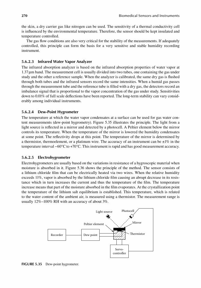
270 BiomedicalSensorsandInstruments
the.skin,.a.dry.carrier.gas.like.nitrogen.can.be.used..The.sensitivity.of.a.thermal.conductivity.cell.is.influenced.by.the.environmental.temperature..Therefore,.the.sensor.should.be.kept.insulated.and.temperature.controlled.
The.gas.flow.conditions.are.also.very.critical.for.the.stability.of.the.measurements..If.adequately.controlled,. this. principle. can. form. the. basis. for. a. very. sensitive. and. stable. humidity. recording.instrument.
5.6.2.3 infrared Water Vapor analyzerThe.infrared.absorption.analyzer.is.based.on.the.infrared.absorption.properties.of.water.vapor.at.1.37.μm.band..The.measurement.cell.is.usually.divided.into.two.tubes,.one.containing.the.gas.under.study.and.the.other.a.reference.sample..When.the.analyzer.is.calibrated,.the.same.dry.gas.is.flushed.through.both.tubes.and.the.infrared.sensors.record.the.same.intensities..When.a.humid.gas.passes.through.the.measurement.tube.and.the.reference.tube.is.filled.with.a.dry.gas,.the.detectors.record.an.imbalance.signal.that.is.proportional.to.the.vapor.concentration.of.the.gas.under.study..Sensitivities.down.to.0.01%.of.full.scale.deflections.have.been.reported..The.long-term.stability.can.vary.consid-erably.among.individual.instruments.
5.6.2.4 dew-Point hygrometerThe.temperature.at.which.the.water.vapor.condensates.at.a.surface.can.be.used.for.gas.water.con-tent.measurements.(dew-point.hygrometry)..Figure.5.35.illustrates.the.principle..The.light.from.a.light.source.is.reflected.in.a.mirror.and.detected.by.a.photocell..A.Peltier.element.below.the.mirror.controls.its.temperature..When.the.temperature.of.the.mirror.is.lowered.the.humidity.condensates.at.some.point..The.reflectivity.drops.at.this.point..The.temperature.of.the.mirror.is.determined.by.a.thermistor,.thermoelement,.or.a.platinum.wire..The.accuracy.of.an.instrument.can.be.±1%.in.the.temperature.interval.−60°C.to.+70°C..This.instrument.is.rapid.and.has.good.measurement.accuracy.
5.6.2.5 electrohygrometerElectrohygrometers.are.usually.based.on.the.variations.in.resistance.of.a.hygroscopic.material.when.moisture.is.absorbed.in.it..Figure.5.36.shows.the.principle.of.the.method..The.sensor.consists.of.a.lithium.chloride.film.that.can.be.electrically.heated.via.two.wires..When.the.relative.humidity.exceeds.11%,.vapor.is.absorbed.by.the.lithium.chloride.film.causing.an.abrupt.decrease.in.its.resis-tance.which.in. turn. increases. the.current.and.thus. the. temperature.of. the.film..The.temperature.increase.means.that.part.of.the.moisture.absorbed.in.the.film.evaporates..At.the.crystallization.point.the.temperature.of.the.lithium.salt.equilibrium.is.established..This.temperature,.which.is.related.to.the.water.content.of.the.ambient.air,.is.measured.using.a.thermistor..The.measurement.range.is.usually.12%–100%.RH.with.an.accuracy.of.about.3%.
Mirror
ermistor
Peltier element
Light source Photocell
Servo-controller
Dew pointRecorder
figure 5.35 Dew-point.hygrometer.
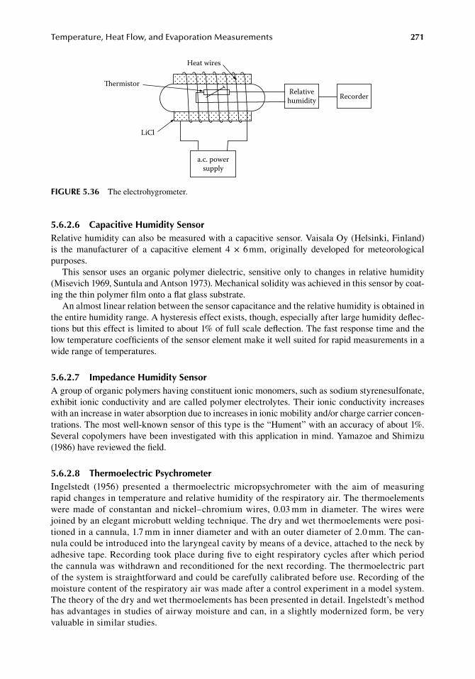
Temperature,HeatFlow,andEvaporationMeasurements 271
5.6.2.6 Capacitive humidity SensorRelative.humidity.can.also.be.measured.with.a.capacitive.sensor..Vaisala.Oy.(Helsinki,.Finland).is. the. manufacturer. of. a. capacitive. element. 4. ×. 6.mm,. originally. developed. for. meteorological.purposes.
This.sensor.uses.an.organic.polymer.dielectric,.sensitive.only.to.changes.in.relative.humidity.(Misevich.1969,.Suntula.and.Antson.1973)..Mechanical.solidity.was.achieved.in.this.sensor.by.coat-ing.the.thin.polymer.film.onto.a.flat.glass.substrate.
An.almost.linear.relation.between.the.sensor.capacitance.and.the.relative.humidity.is.obtained.in.the.entire.humidity.range..A.hysteresis.effect.exists,.though,.especially.after.large.humidity.deflec-tions.but.this.effect.is.limited.to.about.1%.of.full.scale.deflection..The.fast.response.time.and.the.low.temperature.coefficients.of.the.sensor.element.make.it.well.suited.for.rapid.measurements.in.a.wide.range.of.temperatures.
5.6.2.7 impedance humidity SensorA.group.of.organic.polymers.having.constituent.ionic.monomers,.such.as.sodium.styrenesulfonate,.exhibit. ionic.conductivity.and.are.called.polymer.electrolytes..Their.ionic.conductivity.increases.with.an.increase.in.water.absorption.due.to.increases.in.ionic.mobility.and/or.charge.carrier.concen-trations..The.most.well-known.sensor.of.this.type.is.the.“Hument”.with.an.accuracy.of.about.1%..Several.copolymers.have.been.investigated.with.this.application.in.mind..Yamazoe.and.Shimizu.(1986).have.reviewed.the.field.
5.6.2.8 thermoelectric PsychrometerIngelstedt. (1956). presented. a. thermoelectric. micropsychrometer. with. the. aim. of. measuring.rapid.changes.in.temperature.and.relative.humidity.of.the.respiratory.air..The.thermoelements.were.made.of.constantan.and.nickel–chromium.wires,.0.03.mm. in.diameter..The.wires.were.joined.by.an.elegant.microbutt.welding.technique..The.dry.and.wet.thermoelements.were.posi-tioned.in.a.cannula,.1.7.mm.in.inner.diameter.and.with.an.outer.diameter.of.2.0.mm..The.can-nula.could.be.introduced.into.the.laryngeal.cavity.by.means.of.a.device,.attached.to.the.neck.by.adhesive.tape..Recording.took.place.during.five.to.eight.respiratory.cycles.after.which.period.the.cannula.was.withdrawn.and.reconditioned.for.the.next.recording..The.thermoelectric.part.of.the.system.is.straightforward.and.could.be.carefully.calibrated.before.use..Recording.of.the.moisture.content.of.the.respiratory.air.was.made.after.a.control.experiment.in.a.model.system..The.theory.of.the.dry.and.wet.thermoelements.has.been.presented.in.detail..Ingelstedt’s.method.has.advantages.in.studies.of.airway.moisture.and.can,.in.a.slightly.modernized.form,.be.very.valuable.in.similar.studies.
Heat wires
ermistor
LiCl
a.c. powersupply
Relativehumidity Recorder
figure 5.36 The.electrohygrometer.
272 BiomedicalSensorsandInstruments
5.6.3 MeasureMent of eVaporatiVe water loss froM skin and Mucosa
Several.principles.exist.when.it.comes.to.the.practical.arrangements.of.the.humidity.sensors.in.the.measurement.setups..In.the.following.paragraphs.the.most.common.principles.are.reviewed.
5.6.3.1 unventilated ChamberOne.of.the.first.measurement.principles.for.evaporative.water. loss.from.the.skin.was.the.unven-tilated.chamber.method.(Felsher.and.Rothman.1945,.Monash.and.Blank.1958,.Shahidullah.et.al..1969)..A.volume.of.a.hygroscopic.salt.is.placed.within.a.closed.chamber.with.its.opening.facing.the.skin.surface..The.hygroscopic.salt.(8–10.g.calcium.chloride).is.desiccated.in.a.linen.bag.placed.in.an.oven.at.a.temperature.over.200°C..The.bag.containing.the.salt.is.then.quickly.weighed.on.a.sensitive.balance.and.suspended.on.hooks.in.a.glass.tube.with.the.open.end.facing.the.skin..To.prevent.leak-age.of.water.vapor,.the.base.of.the.tube.is.attached.to.the.skin.by.double.adhesive.tape..All.the.water.that.evaporates.from.the.circumscribed.area.of.the.skin.is.absorbed.by.the.salt..After.15–30.min.the.measurement.procedure.is.terminated..The.bag.containing.the.salt.is.reweighed.and.the.increase.in.mass,.which.is.equal.to.the.loss.of.water.from.the.skin.surface.investigated,.is.calculated..The.amount.of.water.vapor.evaporated.from.the.skin.is.generally.expressed.in.grams.per.square.meter.per.hour,.or.in.milligrams.per.square.centimeter.per.hour.
.WL
W W
A t= −
∆after before
uv .(5.19)
whereWL.is.the.water.loss.by.evaporation.(g/m2.h)Wafter.and.Wbefore.are.the.weights.of.the.hygroscopic.salt.after.and.before.the.period.of.measurement,.
respectively.(g)Auv.is.the.area.of.measurement.in.the.unventilated.chamber.(m2)Δt.is.the.period.of.measurement.(h)
The.unventilated.chamber.method.is.the.least.used.method.because.of.some.serious.disadvan-tages.associated.with.it..First,.the.humidity.level.in.the.chamber.rises.during.the.measurement.procedure..It.is.well.known.that.the.diffusion.of.water.molecules.through.the.skin.is.a.function.of.the.transepidermal.gradient.of.humidity..When.this.gradient.is.disturbed,.the.transport.process.is.affected..Using.the.capsule.unventilated.seriously.disturbs.the.conditions.for.measurements..In.addition,.a.sensitive.scale.is.required.to.get.good.resolution..To.get.a.resolution.of.10%.at.a.measurement.on.normal.skin,.an.accuracy.on. the.scale.of.0.1.mg.is. required.(Smallwood.and.Thomas.1985)..The. transport.of. the.hygroscopic.material.between. the. scale.and. the.chamber.can.introduce.serious.errors..The.unventilated.chamber.method.cannot.be.used.to.study.transient.conditions.
5.6.3.2 Ventilated ChamberIn.the.method.based.on.the.ventilated.chamber,.the.evaporative.water.loss.from.the.skin.is.estimated.by.passing.a.continuous.flow.of.gas.with.a.known.water.content.(can.be.dry).and.a.known.flow.rate.through.the.measurement.chamber..Generally.the.humidity.and.flow.rate.are.measured.both.in.the.affluent.and.effluent.gas.flow..The.amount.of.water.lost.by.the.skin.surface.investigated.per.unit.time.and.area.is.calculated.according.to.the.equation
.
WLFM p p
RTA= ( )H O(eff) H O(aff)
v
2 2−
.(5.20)
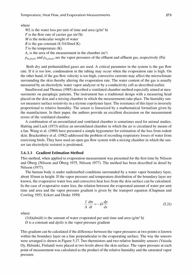
Temperature,HeatFlow,andEvaporationMeasurements 273
whereWL.is.the.water.loss.per.unit.of.time.and.area.(g/m2.h)F.is.the.flow.rate.of.carrier.gas.(m3/h)M.is.the.molecular.weight.of.waterR.is.the.gas.constant.(8.314.J/mol.K)T.is.the.temperature.(K)Av.is.the.area.of.the.measurement.in.the.chamber.(m2)pH2O(eff).and.pH2O(aff).are.the.vapor.pressures.of.the.effluent.and.affluent.gas,.respectively.(Pa)
.Both.dry.and.prehumidified.gases.are.used..A.critical.parameter.in.the.system.is.the.gas.flow.rate..If.it.is.too.low,.condensation.in.the.tubing.may.occur.when.the.evaporation.rate.is.high..On.the.other.hand,.if.the.gas.flow.velocity.is.too.high,.convective.currents.may.affect.the.microclimate.surrounding.the.skin.thereby.altering.the.evaporation.rate..The.water.content.of.the.gas.is.usually.measured.by.an.electrolytic.water.vapor.analyzer.or.by.a.conductivity.cell.as.described.earlier.
Smallwood.and.Thomas.(1985).described.a.ventilated.chamber.method.especially.aimed.at.mea-surements.on.paraplegic.patients..The.instrument.has.a.traditional.design.with.a.measuring.head.placed.on.the.skin.and.a.mixing.chamber.in.which.the.measurements.take.place..The.humidity.sen-sor.measures.surface.resistivity.in.a.styrene.copolymer.layer..The.resistance.of.this.layer.is.inversely.proportional.to.relative.humidity..The.sensor.is.linearized.by.a.mathematical.formalism.given.by.the.manufacturer..In.their.paper,.the.authors.provide.an.excellent.discussion.on.the.measurement.errors.of.the.ventilated.chamber.
A.combination.of.an.unventilated.and.ventilated.chamber.is.sometimes.used.for.animal.studies..Hatting.and.Luck.(1973).utilize.an.unventilated.chamber.in.which.the.air.is.circulated.by.means.of.a.fan..Wang.et.al..(1980).have.presented.a.simple.hygrometer.for.estimation.of.the.loss.from.rodent.skin..Brackenbury.et.al..(1982).addressed.the.problem.of.recording.respiratory.losses.of.water.from.exercising.birds..They.have.used.an.open.gas.flow.system.with.a.mixing.chamber.in.which.the.sen-sor.(an.electrolytic.resistor).is.positioned.
5.6.3.3 gradient estimation MethodThis.method,.when.applied.to.evaporation.measurement.was.presented.for.the.first.time.by.Nilsson.and.Öberg.(Nilsson.and.Öberg.1975,.Nilsson.1977)..The.method.has.been.described.in.detail.by.Nilsson.(1977).
The.human.body.is.under.undisturbed.conditions.surrounded.by.a.water.vapor.boundary.layer,.about.10.mm.in.height..If.the.vapor.pressure.and.temperature.distribution.of.the.boundary.layer.are.known,.the.evaporative.water.loss.and.convective.heat.loss.from.the.skin.surface.can.be.calculated..In.the.case.of.evaporative.water.loss,.the.relation.between.the.evaporated.amount.of.water.per.unit.time.and.area.and. the.vapor.pressure.gradient. is.given.by. the. transport.equation.(Chapman.and.Cowling.1953,.Eckert.and.Drake.1959)
.
1
A
dm
dtD
dp
dx= −
.(5.21)
where(1/A)(dm/dt).is.the.amount.of.water.evaporated.per.unit.time.and.area.(g/m2.h)D.is.a.constant.and.dp/dx.is.the.vapor.pressure.gradient
This.gradient.can.be.calculated.if.the.difference.between.the.vapor.pressures.at.two.points.is.known.within.the.boundary.layer.on.a.line.perpendicular.to.the.evaporating.surface..The.way.the.sensors.were.arranged.is.shown.in.Figure.5.37..Two.thermistors.and.two.relative.humidity.sensors.(Vaisala.Oy,.Helsinki,.Finland).were.placed.at.two.levels.above.the.skin.surface..The.vapor.pressure.at.each.point.of.measurement.was.calculated.as.the.product.of.the.relative.humidity.and.the.saturated.vapor.pressure.
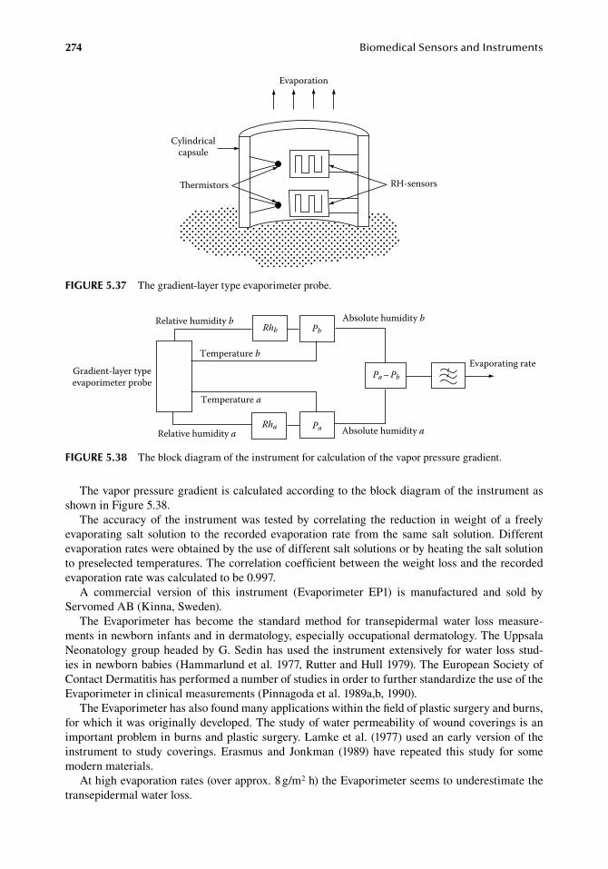
274 BiomedicalSensorsandInstruments
The.vapor.pressure.gradient.is.calculated.according.to.the.block.diagram.of.the.instrument.as.shown.in.Figure.5.38.
The.accuracy.of. the. instrument.was. tested.by.correlating. the. reduction. in.weight.of. a. freely.evaporating. salt. solution. to. the. recorded. evaporation. rate. from. the. same. salt. solution..Different.evaporation.rates.were.obtained.by.the.use.of.different.salt.solutions.or.by.heating.the.salt.solution.to.preselected.temperatures..The.correlation.coefficient.between.the.weight.loss.and.the.recorded.evaporation.rate.was.calculated.to.be.0.997.
A. commercial. version. of. this. instrument. (Evaporimeter. EP1). is. manufactured. and. sold. by.Servomed.AB.(Kinna,.Sweden).
The. Evaporimeter. has. become. the. standard. method. for. transepidermal. water. loss. measure-ments.in.newborn.infants.and.in.dermatology,.especially.occupational.dermatology..The.Uppsala.Neonatology.group.headed.by.G..Sedin.has.used. the. instrument.extensively. for.water. loss.stud-ies.in.newborn.babies.(Hammarlund.et.al..1977,.Rutter.and.Hull.1979)..The.European.Society.of.Contact.Dermatitis.has.performed.a.number.of.studies.in.order.to.further.standardize.the.use.of.the.Evaporimeter.in.clinical.measurements.(Pinnagoda.et.al..1989a,b,.1990).
The.Evaporimeter.has.also.found.many.applications.within.the.field.of.plastic.surgery.and.burns,.for.which.it.was.originally.developed..The.study.of.water.permeability.of.wound.coverings.is.an.important.problem.in.burns.and.plastic.surgery..Lamke.et.al..(1977).used.an.early.version.of.the.instrument. to. study. coverings.. Erasmus. and. Jonkman. (1989). have. repeated. this. study. for. some.modern.materials.
At.high.evaporation.rates.(over.approx..8.g/m2.h).the.Evaporimeter.seems.to.underestimate.the.transepidermal.water.loss.
Cylindricalcapsule
ermistors RH-sensors
Evaporation
figure 5.37 The.gradient-layer.type.evaporimeter.probe.
Gradient-layer typeevaporimeter probe
Relative humidity b
Temperature b
Relative humidity a
Temperature a
Rhb
Rha Pa
PbAbsolute humidity b
Absolute humidity a
Pa – Pb
Evaporating rate
figure 5.38 The.block.diagram.of.the.instrument.for.calculation.of.the.vapor.pressure.gradient.
Temperature,HeatFlow,andEvaporationMeasurements 275
Wheldon.and.Monteith.(1980).have.analyzed.the.Evaporimeter.both.theoretically.and.experimen-tally..These.authors.found.that.the.relation.between.the.diffusion.resistance.of.the.skin.to.the.diffusion.resistance.of.the.probe.is.important.for.the.accuracy.of.the.method..As.long.as.the.probe.resistance.is.small,.in.comparison.with.the.sum.of.the.skin.and.boundary.layer.resistance,.the.Evaporimeter.seems.to.estimate.the.rate.of.transepidermal.water.loss.accurately.
Scott.et.al..(1982).compared.the.Evaporimeter.with.the.ventilated.chamber.method.in.measure-ments.at.normal.and.disturbed.human.skin.function..They.could.verify.the.results.of.Wheldon.and.Monteith.(1980)..At.high.TEWLs.occuring.when.the.barrier.function.of.the.skin.is.lost,.the.gradient.method.underestimates.the.water.loss.over.evaporation.rates.of.7.5.g/m2.h..At.levels.higher.than.this.rate,.these.authors.prefer.the.ventilated.chamber.method.
referenCeS
Anderson,.R..R..and.Parrish,.J..A..1981..The.optics.of.human.skin,.J. Invest. Dermatol..77:.13–19.Barnes,.R..B..1968..Diagnostic.thermography,.Appl. Optics.7:.1673–1685.Barth,.P..W..and.Angel,.J..B..1982..Thin.linear.thermometer.arrays.for.use.in.localized.cancer.hyperthermia,.
IEEE Trans. Electron Devices.ED-29:.144–150.Barth,.P..W.,.Bernard,.S..L.,.and.Angell,.J..B..1985..Flexible.circuit.and.sensor.arrays.fabricated.by.monolithic.
silicon.technology,.IEEE Trans. Electron Devices.ED-32:.1202–1205.Beakley,.W..R..1951..The.design.of.thermometers.with.linear.calibration,.J. Sci. Instrum..28:.176–179.Benzinger,.M..1969..Tympanic.thermometry.in.surgery.and.anesthesia,.J. Am. Med. Soc..209:.1207–1211.Benzinger,.T..H..and.Taylor,.G..W..1963..Cranial.measurements.of.internal.temperature.in.man,.in.Temperature,
Its Measurement and Control in Science and Industry,.Vol..3..Hardy,.J..D.,.ed..New.York:.Reinhold,.pp..111–120.
Benzinger,.T..H.,.Heubscher,.R..G.,.Minard,.D.,.and.Kitzinger,.C..1958..Human.calorimetry.by.means.of.the.gradient.principle,.J. Appl. Physiol..121(Suppl):.S1–S24.
Bettley,.F..R..and.Grice,.K..A..1965..A.method.for.measuring.the.transepidermal.water.loss.and.a.means.of.inactivating.sweat.glands,.Br. J. Derm..77:.627–638.
Bligh,. J.. and. Johnson,. K.. G.. 1973.. Glossary. of. terms. for. thermal. physiology,. J. Appl. Physiol.. 35:.941–961.
Bolomey,.J..C.,.Jofre,.L.,.and.Peronnet,.G..1983..On.the.possible.use.of.microwave-active.imaging.for.remote.thermal.sensing,.IEEE Trans. Microwave Theor. Tech..MTT-31:.777–781.
Bowman,. R.. 1976.. A. probe. for. measuring. temperature. in. radiofrequency-heated. material,. IEEE Trans. Microwave Theor. Tech..MTT-24:.43–45.
Brackenbury,.J..H.,.Avery,.P.,.and.Gleason,.M..1982..Measurement.of.water.loss.in.exercising.animals.using.an.electronic.humidity.detector,.Med. Biol. Eng. Comput..20:.433–436.
Bradley,. W.. G.. 2009.. MR-guided. ultrasound:.A. potentially. disruptive. technology,. J. Am. Coll. Radiol.. 6:.510–513.
Cain,.C..P..and.Welch,.A..J..1974..Thin-film.temperature.sensors.for.biological.measurements,.IEEE Trans. Biomed. Eng..BME-21:.421–423.
Cairnie,.A..B..and.Pullar,.J..D..1959..Temperature.controller.based.on.measurement.of.rate-of-change.of.tem-perature,.J. Sci. Instrum..36:.249–252.
Ceta,.T..C..and.Connor,.W..G..1978..Thermometry.considerations.in.localized.hyperthermia,.Med. Phys..5:.79–91.
Chang,.J..T.,.Paulsen,.K.,.Meaney,.P.,.and.Fanning,.M..1998..Non-invasive.thermal.assessment.of.tissue.phantoms.using.an.active.near.field.microwave.imaging.technique,.Int. J. Hyperthemia.14:.513–514.
Chapman,.S..and.Cowling,.T..G..1953..The Mathematical Theory of Non-Uniform Gases..Cambridge,.U.K.:.Cambridge.University.Press,.pp..244–260.
Christensen,. D..A.. 1977..A. new. non-perturbing. probe. using. semiconductor. band. edge. shift,. J. Bioeng.. 1:.541–545.
Christensen,.D..A..1983..Thermometry.and.thermography,.in.Hyperthermia in Cancer Therapy,.Storm,.F..K.,.ed..Boston,.MA:.G.S.Hall,.pp..223–232.
Cohen,.B..G.,.Snow,.W..B.,.and.Tretola,.A..R..1963..GaAs.p–n.junction.diodes.for.wide.range.thermometry,.Rev. Sci. Instrum..34:.1091–1093.
Cole,.B..E.,.Higashi,.R..E.,.Ridley,.J..A.,.and.Wood,.R..A..2001..Integrated.vacuum.packaging.for.low-cost.light-weight.uncooled.microbolometer.arrays,.Proc. SPIE.4369:.235–239.
276 BiomedicalSensorsandInstruments
Cooper,.K..E..and.Kenyon,.J..R..1957..A.comparison.of.temperature.measured.in.the.rectum,.oesophagus,.and.on.the.surface.of.the.aorta.during.hypothermia.in.man,.Br. J. Surg..44:.616–619.
Cranston,.W..I.,.Gerbrandy,.J.,.and.Snell,.E..S..1954..Oral,.rectal.and.oesophageal.temperatures.and.some.fac-tors.affecting.them.in.man,.J. Physiol..126:.347–358.
Cutchis,.P..N.,.Hogrefe,.A..F.,.and.Lesho,.J..C..1988..The.ingestible.thermal.monitoring.system,.Johns Hopkins APL Tech. Dig..9:.16–21.
Danielsson,.U..1990..Convective.heat.transfer.measured.directly.with.a.heat.flux.sensor,.J. Appl. Physiol..63:.1275–1281.
Davis,.C..E..and.Coates,.P..B..1977..Linearization.of.silicon.junction.characteristics.for.temperature.measure-ment,.J. Phys. E.10:.613–616.
Deficis,. A.. and. Priou,. A.. 1977.. Non-perturbing. microprobes. for. measurement. in. electromagnetic. field,.Microwave J..20:.55–56.
DeHaan,.G..and.Meijer,.G..C..M..1980..An.accurate.small-range.IC.temperature.transducer,.IEEE J. Solid State Circuits.SC-15:.1089–1091.
De.Poorter,.J.,.De.Wagter,.C.,.De.Deene,.Y.,.Thomsen,.C.,.Stahlberg,.F.,.and.Achten,.E..1995..Noninvasive.MRI.thermometry.with.the.proton.resonance.frequency.(PRF).method:.In.vivo.results.in.human.muscle,.Magn. Reson. Med..33:.74–81.
Dickey,.W..T.,.Ahlgren,.E..W.,.and.Lawes,.A..J..1970..Body.temperature.monitoring.via.the.tympanic.mem-brane,.Surgery.67:.981–984.
Dinovo,.J..A..1982..Testing.the.clinical.thermometer,.J. Clin. Eng..7:.119–122.DuBois,.E..F..1951..The.many.different.temperatures.of.the.human.body.and.its.parts,.Western J. Surg. Obstet.
Gynecol..59:.476–489.Durotoye,.A..O..and.Grayson,.J..1971..Heat.production.in.the.gastro-intestinal.tract.of.the.dog,.J. Physiol..214:.
417–426.Ebstein,.E..1928..Die.entwicklung.der.klinishen.thermometrie,.Ergeb. Inn. Med. Kinderheilkd..33:.407–503.Eckert,.E..R..G..and.Drake,.R..M..1959..Heat and Mass Transfer,.New.York:.McGraw.Hill,.p..449.Edrich,.J.,.Jobe,.W..E.,.Cacak,.R..K.,.Hendee,.W..R.,.Smyth,.C..J.,.Gautherie,.M.,.Gros,.C..et.al..1980..Imaging.
at.centimeter.and.millimeter.wavelength,.Ann. N. Y. Acad. Sci..335:.456–474.Edwards,.T..J..1983..Observations.on.the.stability.of.thermistors,.Rev. Sci. Instrum..54:.613–617.Eichina,.L..W.,.Berger,.A..R.,.Rader,.B.,.and.Becker,.W..H..1951..Comparison.of.intracardiac.and.intravascular.
temperatures.with.rectal.temperatures.in.man,.J. Clin. Invest..30:.353–359.Erasmus,.M..E..and.Jonkman,.M..F..1989..Water.vapour.permeance:.A.meaningful.measure.for.water.vapour.
permeability.of.wound.coverings,.Burns.15:.371–375.Farny,.C..H..and.Clement,.G..T..2009..Ultrasound.phase.contrast. thermal. imaging.with.reflex. transmission.
imaging.methods.in.tissue.phantoms,.Ultrasound Med. Biol..35:.1995–2006.Felsher,.Z..and.Rothman,.S..1945..The.insensible.perspiration.of.the.skin.in.hyperkeratotic.conditions,.J. Invest.
Derm..6:.271–278.Ferretti,.G.,.Veicsteinas,.A.,.and.Rennie,.D..W..1988..Regional.heat.flow.of.resting.and.exercising.men.immersed.
in.cool.water,.J. Appl. Physiol..64:.1239–1248.Fox,.R..H..and.Solman,.A..J..1971..A.new.technique.for.monitoring.the.deep.body.temperature.in.man.from.the.
intact.skin.surface,.J. Physiol..212:.8P–10P.Fox,.R..H.,.Solman,.A..J.,.Isaacs,.R.,.Fry,.A..J.,.and.MacDonald,.I..C..1973..A.new.technique.for.monitoring.
deep.body.temperature.from.the.skin.surface,.Clin. Sci..44:.81–86.Fraden,.J..1991..The.development.of.Thermoscan®.Instant.Thermometer,.Clin. Pediatr..304(Suppl):.11–12.Gautherie,.M..1980..Thermopathology.of.breast.cancer:.Measurement.and.analysis.of.in.vivo.temperature.and.
blood.flow,.Ann. N. Y. Acad. Sci..335:.383–413.Gin,.A..R.,.Hayward,.M..G.,.and.Keatinge,.W..R..1980..Method.of.measuring.heat.loss.in.man,.J. Appl. Physiol..
49:.533–535.Goldsmid,.H..J..and.Sydney,.K..R..1971..A.thermal.radiation.detector.employing.the.Nernst.effect.in.Cd3As3–
NiAs,.J. Phys..D.4:.869–875.Goldsmid,.H..J.,.Knittel,.T.,.Savvides,.N.,.and.Uher,.C..1972..Measurement.of.heat-flow.by.means.of.Nernst.
effect,.J. Phys. E Sci. Instrum..5:.313–314.Greenleaf,.J..F..and.Bahn,.R..C..1981..Clinical.imaging.with.transmissive.ultrasonic.computorized.tomography,.
IEEE Trans. Biomed. Eng..BME-28:.177–185.Grice,.K.,.Sattar,.H.,.Sharratt,.M.,.and.Baker,.H..1971..Skin.temperature.and.transepidermal.loss,.J. Invest.
Derm..57:.108–110.Guilbeau,.E..J..and.Mayall,.B..I..1981..Microthermocouple.for.soft.tissue.temperature.determination,.IEEE
Trans. Biomed. Eng..BME-28:.301–305.
Temperature,HeatFlow,andEvaporationMeasurements 277
Hamamura,.Y.,.Mizushina,.S.,.and.Sugiura,.T..1987..Non-invasive.measurement.of.temperature-versus-depth.profile.in.biological.systems.using.multiple-frequency-band.microwave.radiometer.systems,.Automedica.8:.213–232.
Hammarlund,.K.,.Nilsson,.G..E.,.Öberg,.P..A.,. and.Sedin,.G..1977..Transepidermal.water. loss. in.newborn.babies,.Acta Pediatr..66:.553–562.
Hammond,.D..L.. and.Benjaminson,.A.. 1969..The. crystal. resonator—A.digital. transducer,. IEEE Spectr.. 6:.53–58.
Hardy,.J..D..and.Du.Bois,.E..F..1937..Basal.metabolism,.radiation,.convection.and.vaporization.at.temperatures.of.22.to.35°C,.J. Nutr..15:.477–497.
Harioka,.T.,.Matsukawa,.T.,.Ozaki,.M.,.Nomura,.K.,.Sone,.T.,.Kakuyama,.M.,. and.Toda,.H..2000.. “Deep-forehead”.temperature.correlates.well.with.blood.temperature,.Can. J. Anaesth..47:.980–983.
Hatfield,.H..S..and.Wilkins,.F..J..1950..New.heat-flow.meter,.J. Sci. Instrum..27:.1–3.Hatting,.J..and.Luck,.C..P..1973..A.sensitive,.direct.method.for.the.measurement.of.water.loss.from.body.
surface,.S. Afr. J. Med. Sci..38:.31–35.Henning,.R..J.,.Wiener,.F.,.and.Valdes,.S..1979..Measurement.of.toe.temperature.for.assessing.the.severity.of.
acute.circulatory.failure,.Surg. Gynechol. Obstet..149:.1–7.Hoge,.H..J..1979..Comparison.of.circuits.for.linearizing.the.temperature.indications.of.thermistors,.Rev. Sci.
Instrum..50:.316–320.Hooft,.P..and.van.de.Voorde,.H..1989..The.role.of.intestinal.bacterial.heat.production.in.confounding.postmor-
tem.temperature.measurements,.Z. Rechtsmed..102:.331–336.Hsieh,.C..K..and.Su,.K..C..1979..Design,.construction,.and.analysis.of.a.continuous-temperature.infrared.
calibrator.for.temperature.measurement.using.an.infrared.scanner,.Rev. Sci. Instrum..50:.888–896.Ibsen,.B..1967..Treatment.of.shock.with.vasodilators.measuring.skin.temperature.on.the.big.toe:.Ten.year’s.
experience.in.150.cases,.Dis. Chest.52:.425–429.Ilsley,.A.. H.,. Rutten,.A.. J.,. and. Runciman,.W.. B.. 1983..An. evaluation. of. body. temperature. measurement,.
Aneasth. Intensive Care.11:.31–39.Ingelstedt,.S..1956..Studies.on.the.conditioning.of.air.in.the.respiratory.tract,.Acta Otolaryngeol. Suppl..131:.
1–80.Ishihara,.Y.,.Calderon,.A.,.Watanabe,.H.,.Okamotom.K.,.Suzukim.Y.,.Kuroda,.K.,.and.Suzuki,.Y..1995..A.pre-
cise.and.fast.temperature.mapping.using.water.proton.chemical.shift,.Magn. Reson. Med..34:.814–823.Johnson,.C..C..and.Rozzell,.T..C..1975..Temperature.probe.for.M/W.fields,.Microwave J..18:.55–57.Joly,.H..R..and.Weil,.M..H..1969..Temperature.of.great.toe.as.an.indication.of.the.severity.of.shock,.Circulation.
39:.131–138.Jones,.C..H..1979..An.evaluation.of.colour.thermography.with.respect.to.the.diagnosis.of.breast.disease,.Acta
Thermographica.4:.59–63.Kennedy,.D..A.,.Lee,.T.,.and.Seely,.D..2009..A.comparative.review.of.thermography.as.a.breast.cancer.screen-
ing.technique,.Integr. Cancer Ther..8:.9–16.Kickhefel,.A.,.Roland,.J.,.Weiss,.C.,.and.Schick,.F..2010..Accuracy.of.real-time.MR.temperature.mapping.in.
the.brain:.A.comparison.of.fast.sequences,.Phys. Med..20:.192–201.Kleiber,.M..1975..The Fire of Life, an Introduction to Animal Energetics,.Revised.edition..New.York:.Robert.
E.Krieger.Pub.Co.Kobayashi,.T.,.Nemoto,.T.,.Kamiya,.A.,.and.Togawa,.T..1975..Improvement.of.deep.body.thermometer.for.man,.
Ann. Biomed. Eng..3:.181–188.Koholousky,.A..M.,.Sufian,.S.,.Pavlides,.C.,.and.Matsumoto,.T..1980..Central.peripheral.temperature.gradient:.
Its.value.and.limitations.in.the.management.of.critically.ill.surgical.patients..Am. J. Surg..140:.609–612.Kubiak,.L.,.Madeiczyk,.P.,.Wenus,.W.,.Gawron,.K.,.Jozwikowski,.K.,.Rutkowski,.J.,.and.Rogalski,.A..2003..
Status. of. HgCdTe. photodiodes. at. the. Military. University. of. Technology,. Opto-Electron. Rev.. 11:.211–226.
Lamke,.L.-O.,.Nilsson,.G..E.,.and.Reitner,.L..1977..The.evaporative.water.loss.from.burns.and.the.water-vapour.permeability.of.grafts.and.artificial.membranes.used.in.the.treatment.of.burns,.Burns.3:.159–167.
Langham,.G..E.,.Maheshwari,.A.,.Contrera,.K.,.You,.J.,.Mascha,.E.,.and.Sessler,.D..I..2009..Noninvasive.temperature.monitoring.in.postanesthesia.care.units,.Anesthesiology.111:.90–96.
Larsen,.L..E.,.Moore,.R..A.,.Jacobi,.J..H.,.Halgas,.F..A.,.and.Brown,.P..V..1979..A.microwave.compatible.MIC.temperature.electrode.for.use. in.biological.dielectrics,.IEEE Trans. Microwave Theor. Tech..MTT-27:.673–679.
Lawson,.R..N..and.Chughtai,.M..S..1963..Breast.cancer.and.body.temperature,.Can. Med. Assoc. J..88:.68–70.Leeds,.D..E.,.Kim,.Y..D.,.and.MacNamara,.T..E..1980..Noninvasive.determination.of.core.temperature.during.
anesthesia,.South Med. J..73:.1322–1324.
278 BiomedicalSensorsandInstruments
Lilly,.J..K.,.Boland,.J..P.,.and.Zekan,.S..1980..Urinary.bladder.temperature.monitoring:.A.new.index.of.body.core.temperature,.Crit. Care Med..8:.742–744.
Livingston,.G..K..1980..Thermometry.and.dosimetry.of.heat.with.specific.reference.to.the.liquid-crystal.optical.fiber.temperature.probe,.Radiat. Environ. Biophys..17:.233–243.
Mackay,.S..and.Jacobson,.J..1957..Endoradiosonde,.Nature.179:.1239–1240.MacNamara,.A..G..1962..Semiconductor.diodes.and.transistors.as.electrical.thermometers,.Rev. Sci. Instrum..
33:.330–333.Martin,.C..J..and.Watmough,.D..J..1977..Thermal.scanning.of.curved.surfaces,.Acta Thermographica.2:.18–22.McGinnis,.S..M..and.Ingram,.D..L..1974..Use.of.heat-flow.meters.to.estimate.rate.of.heat.loss.from.animal,.
J. Appl. Physiol..37:.443–446.McLean,.J..A..and.Tobin,.G..1987..Animal and Human Calorimetry..Cambridge,.U.K.:.Cambridge.University.
Press.Meijer,.G..C..M..1980..An.IC.temperature.transducer,.IEEE J. Solid-State Circuits.SC-15:.370–373.Misevich,.K..W..1969..Capacitive.humidity.transducers,.IEEE Trans..IECI-16:.6–12.Mitchell,.D..and.Wyndham,.C..H..1969..Comparison.of.weighting.formulae.for.calculating.skin.temperature,.
J. Appl. Physiol..26:.616–622.Monash,. S.. and. Blank,. H.. 1958.. Location. and. reformation. of. the. epithelial. barrier. to. water. vapour,. Arch.
Dermatol..78:.710–714.Moor,. J..W.. and. Newbower,. R.. S.. 1978.. Noncontact. tympanic. thermoneter,. Med. Biol. Eng. Comput.. 16:.
580–584.Moyer,.C..A..and.Butcher,.H..R..1967..Burns, Chock and Plasma Volume Regulation..St..Louis,.MO:.C.V..Mosby.Muravchick,.S..1983..Deep.body.thermometry.during.general.anesthesia,.Anesthesiology.58:.271–275.Murphy,.D.,.Ray,.M.,.Wyles,.R.,.Asbrock,.J.,.Lum,.N.,.Kennedy,.A.,.Wyles,.J.,.Hewitt,.S.,.Graham,.G.,.and.
Radford,.W..2001..High.sensitivity.(25.μm.pitch).microbolometer.FPAs.and.application.development,.Proc. SPIE.4369:.222–234.
Murphy,.D.,.Ray,.M.,.Wyles,.J.,.Hewitt,.C.,.Wyles,.R.,.Gordon.E.,.Almada,.K.,.Sessler,.T.,.Baur,.S.,.Van.Lue,.D.,.and.Black,.S..2007..640.×.512.17.μm.microbolometer.FPA.and.sensor.development,.Proc. SPIE.6542:.65421Z-1–65421Z-10.
Myers,.P..C.,.Barret,.A..H.,.and.Sadowski,.N..L..1980..Microwave. thermography.of.normal.and.cancerous.breast,.Ann. N. Y. Acad. Sci..335:.443–455.
Nagumo,. J.,. Uchiyama,.A.,. Kimoto,. S.,. Watanuki,. T.,. Hori,. M.,. Suma,. K.,. Ouchi,.A.,. Kumano,. M.,. and.Watanabe,.H..1962..Echo.capsule.for.medical.use.(a.batteryless.endoradiosonde),.IRE Trans. Biomed. Electron..BME-9:.195–199.
Nemoto,.T..and.Togawa,.T..1988..Improved.probe.for.a.deep.body.thermometer,.Med. Biol. Eng. Comput..26:.456–459.
Nilsson,.G..E..1977..Measurement.of.water.exchange.through.the.skin,.Med Biol Eng. Comput.15:.209–218.Nilsson,.G..E..and.Öberg,.P..A..1975..A.new.method.for.measurement.of.transepidermal.water.loss,.3rd Nordic
Meeting Med Biol Engng,.Tampere,.Finland,.53,.pp..1–3.Notani-Sharma,.P.,.Chiva,.R..K.,.and.Katchen,.M..1980..Little.known.mercury.hazards,.Hospitals.54:.76–78.O’Hara,.G..J..and.Phillips,.D..B..1986..Method.and.apparatus.for.measuring.internal.body.temperature.utilizing.
infrared.emission,.U.S..Patent.No..4,602,642.Ohsumi,.S.,.Takashima,.S.,.Aogi,.K.,. and.Usuki,.H..2002..Prognostic.value.of. thermographical.findings. in.
patients.with.primary.breast.cancer,.Breast Cancer Res. Treat..74:.213–220.Olsen,.R..G..and.Molina,.E..A..1979..The.non-metalic.thermocouple:.A.differential-temperature.probe.for.use.
in.microwave.field,.Radiol. Sci..14:.81–84.Ovrén,.C.,.Adolfsson,.M.,.and.Hök,.B..1983..Fiber-optic.systems.for.temperature.and.vibration.measurements.
in. industrial.applications,.International Conference on Optical Techniques in Process Control, Hague Paper,.B2,.pp..67–81.
Pichot,.C.,.Jofre,.L.,.Peronnet,.G.,.and.Bolomey,.J..C..1985..Active.microwave.imaging.of. inhomogeneous.bodies,.IEEE Trans. Antennas Propag..AP-33:.416–425.
Pickering,.G..1958..Regulation.of.body.temperature.in.health.and.disease,.Lancet.1:.1–9,.59–64.Pinnagoda,.J.,.Tupker,.R..A.,.Agner,.T.,.and.Serup,.J..1990..Guidelines.for.transepidermal.waterloss.(TEWL).
measurements,.Contact Derm..22:.164–178.Pinnagoda,.J.,.Tupker,.R..A.,.Coenraads,.P..J.,.and.Nater,.J..P..1989a..Comparability.and.reproducibility.of.the.
result.of.water.loss.measurements:.A.study.of.4.evaporimeters,.Contact Derm.,.20:.241–246.Pinnagoda,.J.,.Tupker,.R..A.,.Smit,.J..A.,.Coenraads,.P..J.,.and.Nater,.J..P..1989b..The.intra-.and.inter-individual.
variability.and.reliability.of.transepidermal.water.loss.measurements,.Contact Derm..21:.255–259.
Temperature,HeatFlow,andEvaporationMeasurements 279
Puls,.R.,.Langner,.S.,.Rosenberg,.C.,.Hegenscheid,.K.,.Kuehn,.J..P.,.Noeckler,.K.,.and.Hosten,.N..2009..Laser.ablation.of.liver.metastases.from.colorectal.cancer.with.MR.thermometry:.5-year.survival,.J. Vasc. Interv. Radiol..20:.225–234.
Rajka,.G..and.Thune,.P..1976..The.relationship.between.the.course.of.psoriasis.and.the.transepidermal.water.loss,.photoelectric.plethysmography.and.reflex.photometry,.Br. J. Derm..94:.253–261.
Rieke,.V..and.Pauly,.K..B..2008..MR.thermometry,.J. Magn. Reson. Imaging.27:.376–390.Riezenman,.M..J..1974..Integrated.temperature.transducers,.Electronics.47:.130–132.Roemer,.R..B..1999..Engineering.aspects.of.hyperthermia.therapy,.Ann. Rev. Biomed. Eng..1:.347–376.Rogalski,.A..1997..Thermal.detectors—Breakthrough.in.infrared.technology,.Opto-Electr. Rev..5:.55–58.Rogalski,.A..2000..Infrared Detectors..Amsterdam,.the.Netherlands:.Gordon.and.Breach.Science.Publishers,.
pp..3–30.Rogalski,.A..2004..Optical.detectors.for.focal.plane.arrays,.Opto-Electron Rev..12:.221–245.Rogalski,.A..and.Chrzanowski,.K..2002..Infrared.devices.and.techniques,.Opto-Electron Rev.10:.111–136.Rothman,.S..1954..Physiology and Biochemistry of the Skin..Chicago,.IL:.University.Press.Rowlands,.E..N..and.Wolff,.H..S..1960..The. radio.pill,. telemetering. from.the.digestive. tract,.Br. Commun.
Electron..7:.598–601.Rubin,.A.,.Horvath,.S..M.,.and.Mellette,.H..C..1951..Effect.of.fecal.bacterial.activity.on.rectal.temperature.of.
man,.Proc. Soc. Exp. Biol. Med..76:.410–411.Ruhle,.R..A..1975..Solid-state.temperature.sensor.outperforms.previous.transducers,.Electronics.48:.127–130.Rutter,. N.. and. Hull,. D.. 1979..Water. loss. from. the. skin. of. term. and. preterm. babies,. Arch. Dis. Child.. 54:.
858–868.Sagawa,.S.,.Shiraki,.K.,.and.Honda..1986..Cutaneous.vascular.responses.to.heat.simulated.at.a.high.altitude.of.
5600.m,.J. Appl. Physiol..60:.1150–1154.Sah,.C.,.Noyce,.R..N.,. and.Shockley,.W..1957..Carrier.generation.and. recombination. in.p–n. junctions.and.
p-n.junction.characteristics,.Proc. IRE.45:.1228–1243.Sakamoto,.K..and.Kanai,.H..1996..Electrical.impedance.tomography,.in.Non-Invasive Thermometry in Human
Body,.Miyakawa,.M..and.Bolomey,.J..Ch.,.eds..Boca.Raton,.FL:.CRC.Press,.pp..9–42.Saltin,.B.,.Gagge,.A..P.,.and.Stolwijk,.J..A..J..1968..Muscle.temperature.during.submaximal.exercise.in.man,.
J. Appl. Physiol..25:.679–688.Samulski,.T..and.Shrivastava,.P..N..1980..Photoluminescent.thermometer.probes:.Temperature.measurements.
in.microwave.fields,.Science.208:.193–194.Sato,.S.,.Akiyoshi,.Y.,.Ashimura,.H.,.Nishijima,.Y.,.Okubo,.N.,.and.Takahashi,.H..1994..Toe.skin.temperature.
as.a.guide.to.epidural.anaesthesia.dosing,.Can. J. Anaesth..41:.232–235.Schmidt,.E..1923..U.S..Patent.No..1,.528,.383.Scholander,.P..F..and.Schevill,.W..E..1955..Counter-current.heat.exchange.in.the.fins.of.whales,.J. Appl. Physiol..
8:.279–282.Sclar,.N..and.Pollock,.D..B..1972..On.diode.thermometers,.Solid State Electron..15:.473–480.Scott,.R..C.,.Oliver,.G..J..A.,.Dugard,.P..H.,.and.Singh,.H..J..1982..A.comparison.of.techniques.for.the.measure-
ments.of.transepidermal.water.loss,.Arch. Dermatol. Res..274:.57–64.Shahidullah,.M.,.Raffe,.E..J.,.Rimmer,.A..R.,.and.Frain-Bell,.W..1969..Transepidermal.water.loss.in.patients.
with.dermatitis,.Br. J. Dermatol..81:.722–730.Shinozaki,.T.,.Deane,.R.,.and.Perkins,.F..M..1988..Infrared.tympanic.thermometer:.Evaluation.of.a.new.clinical.
thermometer,.Crit. Care Med..16:.148–150.Smallwood,.R..H..and.Thomas,.S..E..1985..An.inexpensive.portable.monitor.for.measuring.evaporative.water.
loss,.Clin. Phys. Physiol. Meas..6:.147–154.Spruit,. D.. and. Malten,. K.. E.. 1966.. The. regeneration. rate. of. water. vapour. loss. of. heavily. damaged. skin,.
Dermatologica.132:.115–123.Strong,.L..H.,.Gee,.G..K.,.and.Goldman,.R..F..1985..Metabolic.and.vasomotor.insulative.responses.occuring.on.
immersion.in.cold.water,.J. Appl. Physiol..58:.964–977.Suntula,.T..and.Antson,.J..1973..A.thin.film.humidity.sensor,.in.Vaisala News,.Vol..59,.ed..A..Lindqvist,.12,.
Helsinki,.Finland:.Vaisala.Oy.Szwarnowski,.S..1983..A.thermometer.for.measuring.temperatures.in.the.presence.of.electromagnetic.fields,.
Clin. Phys. Physiol. Meas..4:.79–84.Szwarnowski,.S.,.Sheppard,.R..J.,.Grant,.E..H.,.and.Bleehen,.N..M..1980..A.thermocouple.measuring.tempera-
ture.in.biological.material.heated.by.microwave.at.2.45.GHz,.Br. J. Radiol..53:.711–715.Tabor,.M..W.,.Blaho,.D..M.,.and.Schriver,.W..R..1981..Tympanic.membrane.perforation:.Complication.of.tym-
panic.thermometry.during.general.anesthesia,.Oral Surg..51:.581–583.
280 BiomedicalSensorsandInstruments
Tamura,.T.,.Nemoto,.T.,.and.Togawa,.T..1981..Heat.flow.meter.for.measuring.regional.heat.flux.in.man,.Rep. Inst. Med. Dent. Eng..15:.103–108.
Thiele,.F..A..and.van.Senden,.K..G..1966..Relation.between.skin.temperature.and.the.insensible.perspiration.of.the.human.skin,.J. Invest. Dermatol.,.47:.307–312.
Timko,.M..P..1976..A.two-terminal.IC.temperature.sensor,.J. Solid-State Circuits.SC-11:.784–788.Togawa,.T..1985..Body.temperature.measurement,.Clin. Phys. Physiol. Meas..6:.83–108.Togawa,.T..1989..Non-contact.skin.emissivitiy:.Measurement.from.reflectance.using.step.change.in.ambient.
radiation.temperature,.Clin. Phys. Physiol. Meas..10:.39–48.Togawa,.T..2006..Integrated.circuit.temperature.sensors,.in.Medical Devices and Instrumentation,.2nd.edn,.
Vol..4,.Webster,.J..G.,.ed..Hoboken,.NJ:.John.Wiley.&.Sons,.pp..157–162.Togawa,.T.,.Nemoto,.T.,.Yamazaki,.T.,.and.Kobayashi,.T..1976..A.modified.internal.temperature.measurement.
device,.Med. Biol. Eng..14:.361–364.Toner,.M..M.,.Sawka,.M..N.,.Holden,.W..L.,.and.Pandolf,.K..B..1985..Comparison.of.thermal.response.between.
rest.and.leg.exercise.in.water,.J. Appl. Physiol..59:.248–253.Tsuji,.T.,.Oshima,.T.,.Hashimoto,.D.,.and.Togawa,.T..1990..Telemetry.of.human.organ.temperature.with.quartz.
crystal.resonator.using.ultrasonic.detection,.Proceedings of.Biotelemetry XI, Yokohama,.Japan,.pp..378–80.Vaguine,.V..A.,.Christensen,.D..A.,.Lindley,.J..H.,.and.Walston,.T..E..1984..Multiple.sensor.optical.thermometry.
system.for.application.in.clinical.hyperthermia,.IEEE Trans. Biomed. Eng..BME-31:.168–172.Vale,.R..J..1981..Monitoring.of.temperature.during.anesthesia,.Int. Anesthesiol. Clin..19:.61–83.van.Gassel,.T..H..and.Vierhout,.R..R..1963..Registration.of.insensible.perspiration.of.small.quantities.of.sweat,.
Dermatologica.127:.255–259.van.Hervaarden,.A..W..1989..Integrated.thermopile.sensors,.Sens. Actuators.A21–A23:.621–630.Vester,.T..C..1968..P-n.junction.as.an.ultralinear.calcurable.thermometer,.Electron Lett..4:.175–176.Yamazoe,.N..and.Shimizu,.Y..1986..Humidity.sensors:.Principles.and.applications,.Sens. Actuators.10:.379–389.Wallance,.C..T.,.Marks,.W..E.,.Adkins,.W..Y.,.and.Mahaffey,.J..E..1974..Perforation.of.the.tympanic.membrane,.
a.complication.of.tympanic.thermometry.during.anesthesia,.Anesthesiology.41:.290–291.Wang,.P..Y.,.Evans,.D..W.,.Samji,.N.,.and.Llewellyn-Thomas,.E..1980..A.simple.hygrometer.for.the.measure-
ment.of.evaporative.water.loss.from.rodent.skin,.J. Surg. Res..28:.182–187.Watmough,.D..J..and.Oliver,.R..1968..Emissivity.of.human.skin.in.the.waveband.between.2μ.and.6μ,.Nature.
219:.622–624.Watmough,.D..J..and.Oliver,.R..1969..The.emission.of.infrared.radiation.from.human.skin—Implications.for.
clinical.thermography,.Br. J. Radiol..42:.411–415.Watmough,.D..J.,.Fowler,.P..W.,.and.Oliver,.R..1970..The.thermal.scanning.of.a.curved.isothermal.surface:.
Implication.for.clinical.thermography,.Phys. Med. Biol..15:.1–8.Webb,.G..E..1973..Comparison.of.esophageal.and.tympanic.temperature.monitoring.during.cardiopulmonary.
bypass,.Anesth. Analg..52:.729–733.Wheldon,.A..E..and.Monteith,.J..L..1980..Performance.of.a.skin.evaporimeter,.Med. Biol. Eng. Comput..18:.
201–205.Whitby,.J..D..and.Dunkin,.L..J..1968..Temperature.difference.in.the.oesophagus,.Br. J. Anaesth..40,.991–915.Wickersheim,.K..A..1986..A.new.fiber.optic.thermometry.system.for.use.in.medical.hyperthermia,.Proc. SPIE.
713:.150–157.Wickersheim,.K..A..and.Alves,.R..V..1982..Fluoroptic.thermometer:.A.new.RF-immune.technology,.Prog. Clin.
Biol. Res..107:.547–554.Wood,.R..A..1993..Uncooled.thermal.imaging.with.monolithic.silicon.focal.planes,.SPIE.2020:.322–329.
281
6 BioelectricandBiomagneticMeasurements
6.1 objeCtS of MeaSureMentS
6.1.1 units of electroMagnetic MeasureMents
6.1.1.1 electrical unitsSignals.and.bias.potentials.from.electrodes.are.expressed.in.volts.or.fractions.of.volts.(millivolts,.microvolts,.or.nanovolts)..In.some.applications,.the.power.of.a.physiological.signal.is.used.and.then.expressed.in.watts..Spectral.representations.of.signals.are.usually.expressed.in
.
(volts)hertz
2
.(6.1)
or
.
volts
hertz .
(6.2)
where.hertz.(Hz).is.the.unit.of.frequency.in.the.SI.system.Electrode.properties.are.closely.related.to.signals.and.noise..A.common.way.to.express. the.
properties.of.signals.and.noise.is.to.regard.the.power
.P
R= v2
.(6.3)
where
v2 .is.the.root-mean-square.voltageR.is.the.circuit.resistance
Alternatively,.it.is.sometimes.more.convenient.to.consider.the.spectral.distribution.of.the.signal.or.noise.present.and.to.evaluate.its.spectral.density.S( f ).in.a.given.bandwidth.df..The.average.power.of.signals.or.noise.can.be.evaluated.for.a.load.resistance.of.1.ohm.by.the.use.of.integration.
Electrode.currents.are.measured. in.amperes.or.a. fraction. thereof..Resistance. to. the.flow.of.electrical.charges.is.usually.expressed.as.a.complex.unit.impedance
. Z R jX= + . (6.4)
whereR.is.the.real.part.and.is.called.the.resistance.and.is.measured.in.ohmsX.is.called.the.reactance.and.is.also.expressed.in.ohms
Reactances.of.physiological.electrodes.can.be.capacitive.or.inductive.
282 BiomedicalSensorsandInstruments
Capacitance.is.measured.in.farad.(F).and.inductance.is.measured.in.henry.(H).The.quotient.between.X.and.R.can.be.used.to.express.the.tangent.of.the.phase.angle.between.the.
current.through.an.electrical.component.and.the.voltage.drop.across.the.same.component.so.that
.
X
R= tanθ
.(6.5)
where.θ.is.expressed.in.degrees.or.radians.Usually.electrodes.have.resistive.and.capacitive.properties.and.can.be.modeled.by.an.RC.equivalent.
circuit..On.rare.occasions,.the.electrodes.have.inductive.properties..The.reactance.is.then.an.inductive.reactance.
6.1.1.2 Magnetic unitsMagnetic.flux.density.or.magnetic.induction,.B,.has.the.dimension.[Q−1MT−1].
The.unit.is.derived.from.the.equation
. F I B= × . (6.6)
where.F.is.the.force.vector.acting.on.a.unit.length.of.a.linear.conductor.carrying.the.current.vector.I.in.a.field.vector.B.
The.unit.for.B.is.Tesla.(T).when.I.is.expressed.in.amperes.and.F.in.newtons.per.meter..The.conversion.from.the.unit.gauss.is
. 1 1 102 4T V s/m gauss= =
Magnetic.flux.has.the.dimension.[Q−1ML2T−1].Magnetic.flux.is.expressed.in.webers.(Wb).as.the.surface.integral.of.B.and.expressed.as
1 1 2Wb T m=
The.magnetic.field.has.the.dimension.[QL−1T−1].The.magnetic.field.strength,.H,.is.a.vector.quantity.defined.as.that.the.rotation.of.which.is.equal.
to.the.current.density.including.the.displacement.current.and.is.expressed.as.current.per.unit.length..Its.unit.is.amperes.per.meter.
The.magnetic.field.strength.and.the.magnetic.flux.density.are.related.as
. B H= µ . (6.7)
where.μ.is.permeability.expressed.in.henry.per.meter.
6.1.2 requireMents for MeasureMent ranges
6.1.2.1 bioelectric eventsMost.electrical.events. in. the.human.body.have.amplitudes.or. levels.well.below.1.V..The. resting.potential.of.a.cell.may.be.as.high.as.0.05–0.1.V,.whereas.voltages.recorded.from.the.skull.related.to.activity.of.the.central.nervous.system.may.be.as.low.as.a.few.microvolts..Table.6.1.summarizes.the.magnitude.and.frequency.domain.required.for.the.recording.of.some.common.physiological.signals.
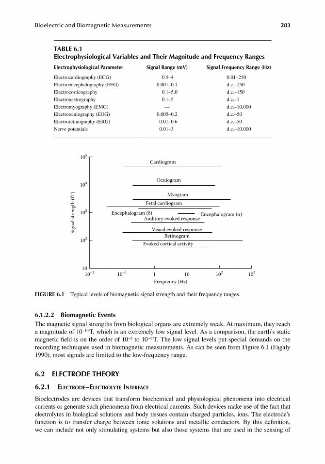
BioelectricandBiomagneticMeasurements 283
6.1.2.2 biomagnetic eventsThe.magnetic.signal.strengths.from.biological.organs.are.extremely.weak..At.maximum,.they.reach.a.magnitude.of.10−10.T,.which.is.an.extremely.low.signal.level..As.a.comparison,.the.earth’s.static.magnetic.field.is.on.the.order.of.10−5.to.10−6.T..The.low.signal.levels.put.special.demands.on.the.recording.techniques.used.in.biomagnetic.measurements..As.can.be.seen.from.Figure.6.1.(Fagaly.1990),.most.signals.are.limited.to.the.low-frequency.range.
6.2 eleCtrode theory
6.2.1 electrode–electrolyte interface
Bioelectrodes. are. devices. that. transform. biochemical. and. physiological. phenomena. into. electrical.currents.or.generate.such.phenomena.from.electrical.currents..Such.devices.make.use.of.the.fact.that.electrolytes.in.biological.solutions.and.body.tissues.contain.charged.particles,.ions..The.electrode’s.function. is. to. transfer. charge. between. ionic. solutions. and. metallic. conductors.. By. this. definition,.we.can.include.not.only.stimulating.systems.but.also.those.systems.that.are.used.in.the.sensing.of.
Cardiogram
Oculogram
MyogramFetal cardiogram
Encephalogram (δ) Encephalogram (α)Auditory evoked response
Visual evoked response
Evoked cortical activity
10–2 10–1 102 103101Frequency (Hz)
102
103
104
105
10
Sign
al st
reng
th (f
T)
Retinogram
figure 6.1 Typical.levels.of.biomagnetic.signal.strength.and.their.frequency.ranges.
table 6.1electrophysiological Variables and their Magnitude and frequency ranges
electrophysiological Parameter Signal range (mV) Signal frequency range (hz)
Electrocardiography.(ECG) 0.5–4 0.01–250
Electroencephalography.(EEG) 0.001–0.1 d.c.–150
Electrocorticography 0.1–5.0 d.c.–150
Electrogastrography 0.1–5 d.c.–1
Electromyography.(EMG) — d.c.–10,000
Electrooculography.(EOG) 0.005–0.2 d.c.–50
Electroretinography.(ERG) 0.01–0.6 d.c.–50
Nerve.potentials 0.01–3 d.c.–10,000
284 BiomedicalSensorsandInstruments
electrophysiological.information,.such.as.electrocardiograms.(ECG)..In.the.latter.case,.the.signals.to.be.recorded.are.electrical.events.resulting.from.biochemical.activity.of.nerve.and.muscle.tissues..The.presence.of.ions.in.a.solution.has.two.electrical.meanings..The.ions.are.the.carriers.of.electrical.charge.and.they.are.atoms.or.molecules.with.a.finite.mass..When.we.pass.currents.through.either.solutions.or.tissues,.we.are.using.ions.to.conduct.the.current..We.must.distinguish.between.majority.carriers.and.minority.carriers.in.the.solution..In.the.human.body,.a.majority.carrier.is.an.ion.such.as.sodium.or.chloride..Intracellular.potassium.also.contributes.to.conduct.current.in.higher.frequency.ranges..Such.ions.are.quite.mobile.and.are.present.in.large.enough.concentrations.so.that.when.current.flows.they.are.in.the.majority.and.carry.most.of.the.transferred.charge..Minority.carriers.are.ions.in.a.very.low.concentration..Minority.ions.do.not.normally.carry.much.of.the.total.transfer.charge.
Ions. interface. between. metals. and. electrolytes,. between. one. kind. of. electrolyte. and. another,.across.membranes,.etc..They.generate.potentials. independently..They.describe.how.batteries.act.and.how.electrodes.polarize..The.amount.of.the.ion.in.a.unit.volume.of.the.solution.is.measured.as.a.concentration..If.the.concentration.is.low.on.one.side.of.a.boundary.and.high.on.the.other.side,.then.there.is.a.force.acting.on.that.ion.influencing.it.to.move.and.to.equalize.the.difference.in.concentra-tions..The.ion.must.respond.to.the.concentration.gradient..Quite.independent.of.this.mechanism,.the.ion.is.specified.as.a.charged.carrier..All.other.molecules.in.a.solution.are.not.charged..For.instance,.sugar. is. readily. soluble.but. does.not. ionize..An.uncharged.molecule.moves.only. in. response. to.concentration.gradients..Conversely,.an.electron,.which.is.basically.a.charged.particle.with.almost.zero.mass,.moves.only.in.response.to.electrical.fields..The.electrical.potentials.developed.by.ions.in.solution.result.from.their.activity.following.exposure.to.these.two.forces.at.once,.so.the.ion.concen-tration.is.a.function.of.both.the.charge.and.the.concentration.gradient.
The.charge.is.further.described.by.an.equation.that.says.that.its.potential.is.equal.to.a.Nernst.potential.that.is.proportional.to.the.gas.constant,.R,.and.the.absolute.temperature,.T:
.E
RT
nFM Em 0ln( )= ++
.(6.8)
The.derivation.of.this.equation.is.described.in.Section.7.2.1.2..The.electrode.potential.is.inversely.proportional.to.the.number.of.charges.per.ion.(n,.valence).and.the.Faraday.constant,.F..M+.is.the.activity.of.the.ion,.and.E0.is.a.constant..If.we.introduce.constants.for.a.monovalent.ion.at.25°C.in.the.formula,.we.obtain
. E M Em = ++0 059 0. ln( ) . (6.9)
Most.of.physiological.electrochemistry.is.based.on.the.assumption.that.one.ion.does.not.interfere.with.another.ion.that.will.have.to.compete.with.it..This.means.that.the.solution.is.dilute.and.there.is.enough.free.space.between.ions.that.will.act.freely..The.activity.of.such.an.ion.will.be.linearly.related.to.its.concentrations,.and.activity.and.molar.concentration.will.be.equal..Most.solutions.in.the.human.body.are.dilute..For.example,.in.normal.saline.we.have.0.9%.by.weight.of.sodium.chlo-ride.in.solution..If.we.go.to.very.high.sodium.chloride.concentrations,.we.could.not.consider.their.chemical.activity.proportional.to.their.concentration..The.equilibrium.of.ion.movement.would.then.be.affected.
6.2.2 liquid junction potentials
The.mobility.of.individual.ions.is.very.different.depending.mainly.on.their.size..When.ions.exist.in.a.water.solution,.they.very.often.hydrate.or.accumulate.water.molecules..The.accumulation.of.water.molecules.means. that. the.geometrical. size.of. the.molecule.changes.dramatically,.which.affects.the.mobility.of.the.ion.in.solution..A.good.example.is.sodium.and.chloride.ions.in.a.water.
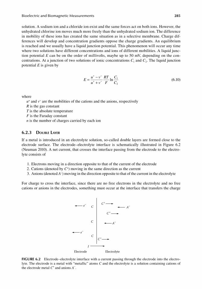
BioelectricandBiomagneticMeasurements 285
solution..A sodium.ion.and.a.chloride.ion.exist.and.the.same.forces.act.on.both.ions..However,.the.unhydrated.chlorine.ion.moves.much.more.freely.than.the.unhydrated.sodium.ion..The.difference.in.mobility.of.these.ions.has.created.the.same.situation.as.in.a.selective.membrane..Charge.dif-ferences.will.develop.and.concentration.gradients.oppose.the.charge.gradients..An.equilibrium.is.reached.and.we.usually.have.a.liquid.junction.potential..This.phenomenon.will.occur.any.time.where.two.solutions.have.different.concentrations.and.ions.of.different.mobilities..A.liquid.junc-tion.potential.E.can.be.on.the.order.of.millivolts,.maybe.up.to.50.mV,.depending.on.the.con-centrations..At.a.junction.of.two.solutions.of.ionic.concentrations.C1.and.C2..The.liquid.junction.potential.E.is.given.by
.E
u v
u v
RT
F
C
C= −
+
+ −
+ − ln 1
2 .(6.10)
whereu+.and.v−.are.the.mobilities.of.the.cations.and.the.anions,.respectivelyR.is.the.gas.constantT.is.the.absolute.temperatureF.is.the.Faraday.constantn.is.the.number.of.charges.carried.by.each.ion
6.2.3 double layer
If.a.metal.is.introduced.in.an.electrolyte.solution,.so-called.double.layers.are.formed.close.to.the.electrode. surface.. The. electrode–electrolyte. interface. is. schematically. illustrated. in. Figure. 6.2.(Neuman.2010)..A.net.current,.that.crosses.the.interface.passing.from.the.electrode.to.the.electro-lyte.consists.of
. 1..Electrons.moving.in.a.direction.opposite.to.that.of.the.current.of.the.electrode
. 2..Cations.(denoted.by.C+).moving.in.the.same.direction.as.the.current
. 3..Anions.(denoted.A−).moving.in.the.direction.opposite.to.that.of.the.current.in.the.electrolyte
For.charge. to.cross. the. interface,.since. there.are.no.free.electrons. in. the.electrolyte.and.no.free.cations.or.anions.in.the.electrodes,.something.must.occur.at.the.interface.that.transfers.the.charge.
C+
C+
C+
C
C
C
A–
A–e–
e–
IElectrode Electrolyte
figure 6.2 Electrode–electrolyte.interface.with.a.current.passing.through.the.electrode.into.the.electro-lyte..The.electrode.is.a.metal.with.“metallic”.atoms.C.and.the.electrolyte.is.a.solution.containing.cations.of.the.electrode.metal.C+.and.anions.A−.
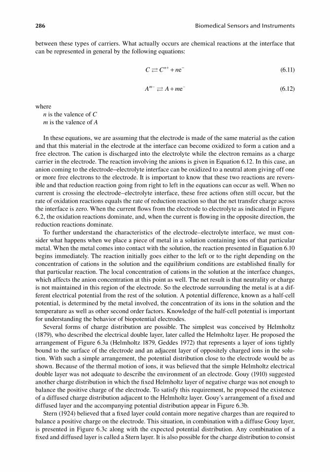
286 BiomedicalSensorsandInstruments
between.these.types.of.carriers..What.actually.occurs.are.chemical.reactions.at.the.interface.that.can.be.represented.in.general.by.the.following.equations:
. C C nn + −+ e . (6.11)
. A A mm− −+ e . (6.12)
wheren.is.the.valence.of.Cm.is.the.valence.of.A
In.these.equations,.we.are.assuming.that.the.electrode.is.made.of.the.same.material.as.the.cation.and.that.this.material.in.the.electrode.at.the.interface.can.become.oxidized.to.form.a.cation.and.a.free.electron..The.cation.is.discharged.into.the.electrolyte.while.the.electron.remains.as.a.charge.carrier.in.the.electrode..The.reaction.involving.the.anions.is.given.in.Equation.6.12..In.this.case,.an.anion.coming.to.the.electrode–electrolyte.interface.can.be.oxidized.to.a.neutral.atom.giving.off.one.or.more.free.electrons.to.the.electrode..It.is.important.to.know.that.these.two.reactions.are.revers-ible.and.that.reduction.reaction.going.from.right.to.left.in.the.equations.can.occur.as.well..When.no.current.is.crossing.the.electrode–electrolyte.interface,.these.free.actions.often.still.occur,.but.the.rate.of.oxidation.reactions.equals.the.rate.of.reduction.reaction.so.that.the.net.transfer.charge.across.the.interface.is.zero..When.the.current.flows.from.the.electrode.to.electrolyte.as.indicated.in.Figure.6.2,.the.oxidation.reactions.dominate,.and,.when.the.current.is.flowing.in.the.opposite.direction,.the.reduction.reactions.dominate.
To. further.understand. the.characteristics.of. the.electrode–electrolyte. interface,.we.must.con-sider.what.happens.when.we.place.a.piece.of.metal.in.a.solution.containing.ions.of.that.particular.metal..When.the.metal.comes.into.contact.with.the.solution,.the.reaction.presented.in.Equation.6.10.begins.immediately..The.reaction.initially.goes.either.to.the.left.or.to.the.right.depending.on.the.concentration.of.cations.in.the.solution.and.the.equilibrium.conditions.are.established.finally.for.that.particular.reaction..The.local.concentration.of.cations.in.the.solution.at.the.interface.changes,.which.affects.the.anion.concentration.at.this.point.as.well..The.net.result.is.that.neutrality.or.charge.is.not.maintained.in.this.region.of.the.electrode..So.the.electrode.surrounding.the.metal.is.at.a.dif-ferent.electrical.potential.from.the.rest.of.the.solution..A.potential.difference,.known.as.a.half-cell.potential,.is.determined.by.the.metal.involved,.the.concentration.of.its.ions.in.the.solution.and.the.temperature.as.well.as.other.second.order.factors..Knowledge.of.the.half-cell.potential.is.important.for.understanding.the.behavior.of.biopotential.electrodes.
Several. forms. of. charge. distribution. are. possible.. The. simplest. was. conceived. by. Helmholtz.(1879),.who.described.the.electrical.double.layer,.later.called.the.Helmholtz.layer..He.proposed.the.arrangement.of.Figure.6.3a.(Helmholtz.1879,.Geddes.1972).that.represents.a.layer.of.ions.tightly.bound.to.the.surface.of.the.electrode.and.an.adjacent.layer.of.oppositely.charged.ions.in.the.solu-tion..With.such.a.simple.arrangement,.the.potential.distribution.close.to.the.electrode.would.be.as.shown..Because.of.the.thermal.motion.of.ions,.it.was.believed.that.the.simple.Helmholtz.electrical.double.layer.was.not.adequate.to.describe.the.environment.of.an.electrode..Gouy.(1910).suggested.another.charge.distribution.in.which.the.fixed.Helmholtz.layer.of.negative.charge.was.not.enough.to.balance.the.positive.charge.of.the.electrode..To.satisfy.this.requirement,.he.proposed.the.existence.of.a.diffused.charge.distribution.adjacent.to.the.Helmholtz.layer..Gouy’s.arrangement.of.a.fixed.and.diffused.layer.and.the.accompanying.potential.distribution.appear.in.Figure.6.3b.
Stern.(1924).believed.that.a.fixed.layer.could.contain.more.negative.charges.than.are.required.to.balance.a.positive.charge.on.the.electrode..This.situation,.in.combination.with.a.diffuse.Gouy.layer,.is.presented.in.Figure.6.3c.along.with.the.expected.potential.distribution..Any.combination.of.a.fixed.and.diffused.layer.is.called.a.Stern.layer..It.is.also.possible.for.the.charge.distribution.to.consist.
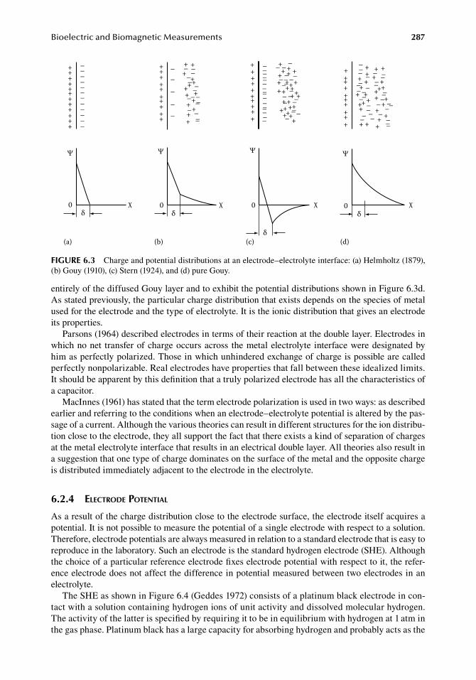
BioelectricandBiomagneticMeasurements 287
entirely.of.the.diffused.Gouy.layer.and.to.exhibit.the.potential.distributions.shown.in.Figure.6.3d..As.stated.previously,.the.particular.charge.distribution.that.exists.depends.on.the.species.of.metal.used.for.the.electrode.and.the.type.of.electrolyte..It.is.the.ionic.distribution.that.gives.an.electrode.its.properties.
Parsons.(1964).described.electrodes.in.terms.of.their.reaction.at.the.double.layer..Electrodes.in.which.no.net. transfer.of.charge.occurs.across. the.metal.electrolyte. interface.were.designated.by.him.as.perfectly.polarized..Those.in.which.unhindered.exchange.of.charge.is.possible.are.called.perfectly.nonpolarizable..Real.electrodes.have.properties.that.fall.between.these.idealized.limits..It.should.be.apparent.by.this.definition.that.a.truly.polarized.electrode.has.all.the.characteristics.of.a.capacitor.
MacInnes.(1961).has.stated.that.the.term.electrode.polarization.is.used.in.two.ways:.as.described.earlier.and.referring.to.the.conditions.when.an.electrode–electrolyte.potential.is.altered.by.the.pas-sage.of.a.current..Although.the.various.theories.can.result.in.different.structures.for.the.ion.distribu-tion.close.to.the.electrode,.they.all.support.the.fact.that.there.exists.a.kind.of.separation.of.charges.at.the.metal.electrolyte.interface.that.results.in.an.electrical.double.layer..All.theories.also.result.in.a.suggestion.that.one.type.of.charge.dominates.on.the.surface.of.the.metal.and.the.opposite.charge.is.distributed.immediately.adjacent.to.the.electrode.in.the.electrolyte.
6.2.4 electrode potential
As.a.result.of.the.charge.distribution.close.to.the.electrode.surface,.the.electrode.itself.acquires.a.potential..It.is.not.possible.to.measure.the.potential.of.a.single.electrode.with.respect.to.a.solution..Therefore,.electrode.potentials.are.always.measured.in.relation.to.a.standard.electrode.that.is.easy.to.reproduce.in.the.laboratory..Such.an.electrode.is.the.standard.hydrogen.electrode.(SHE)..Although.the.choice.of.a.particular.reference.electrode.fixes.electrode.potential.with.respect.to.it,.the.refer-ence.electrode.does.not.affect.the.difference.in.potential.measured.between.two.electrodes.in.an.electrolyte.
The.SHE.as.shown.in.Figure.6.4.(Geddes.1972).consists.of.a.platinum.black.electrode.in.con-tact.with.a.solution.containing.hydrogen.ions.of.unit.activity.and.dissolved.molecular.hydrogen..The.activity.of.the.latter.is.specified.by.requiring.it.to.be.in.equilibrium.with.hydrogen.at.1.atm.in.the.gas.phase..Platinum.black.has.a.large.capacity.for.absorbing.hydrogen.and.probably.acts.as.the.
+
+++++++++++
–––––––––––
–
++++++++++
–––––
– –––– ––––– –
– –––
–
+ ++
+++++ +
++ +++
++++++++++
––––––––––––––––
– ––– ––– –
–––
– –– ––
––––
++ + +++
++++++++++
++
+
++++ ++ ++
++++++++++
+ + ++ ++ + +
+ +++++
+++++
+ ++
++ + ++
––– – –– –––– –––– ––––– –– –––– – –– –– –––
0δ
χ
Ψ
δ
0 χ
Ψ
χ
Ψ
0δ
0δ
Ψ
χ
(a) (b) (c) (d)
figure 6.3 Charge.and.potential.distributions.at.an.electrode–electrolyte.interface:.(a).Helmholtz.(1879),.(b).Gouy.(1910),.(c).Stern.(1924),.and.(d).pure.Gouy.
288 BiomedicalSensorsandInstruments
catalyst.to.convert.the.hydrogen.to.its.ionic.form..The.hydrogen.gas.is.bubbled.over.the.electrode.and.the.cell.is.operated.at.1.atm..The.potential.of.such.an.electrode.is.defined.as.zero.volts.at.all.temperatures,.a.fact.that.is.contrary.to.the.physical.reality.but.can.be.circumvented.by.identifying.the.temperature.at.which.the.measurement.of.the.electrode.is.made.
6.3 SurfaCe Potential eleCtrodeS
6.3.1 ecg electrodes
Analyses.of.the.ECG.are.one.of.the.most.common.diagnostic.procedures.in.modern.health.care..Several.million.diagnostic.ECGs.are.recorded.every.day..In.addition,.monitoring.of.the.ECG.and.heart.rate.in.intensive.care.is.adding.to.the.earlier.presented.values..The.electrode.on.the.skin.surface.has.many.important.properties.for.making.these.measurements.reliable.and.undisturbed.
ECG.electrodes. exist. in. a.variety.of.models. and. sizes. for.various.purposes,. from.disposable.simple.electrodes.for. temporary.purposes. to.very.advanced.high-quality.designs.for.quantitative.and.highly.sophisticated.measurements.
Most.electrodes.used.today.are.disposable.with.an.adhesive.tape.surrounding.the.electrode’s.metal. surface.. Both. so-called. recessed. electrodes. exist. permitting. the. use. of. a. paste. between.the.skin.and.the.metal.and.electrodes.with.the.metal.in.direct.contact.with.the.skin..Pregelled.electrodes.are.delivered.with.a.conducting.foam.or.paste.as.a.medium.between.the.metal.and.the.skin..For.a.survey.of.existing.design.principles,. the.reader. is.referred.to.Geddes.(1972).and.to.Carim.(1988).
Reusable.electrodes.are.made.from.silver,.zinc.alloys,.copper,.and.nickel..Usually.they.can.be.utilized.for.several.years.and.are.mainly.used.for.ECG.analysis.requiring.up.to.10.electrodes.or.more.on.the.skin.surface.
Bulb.and.plate.electrodes.of.various.sizes.and.shapes.are.the.most.common.ones..However,.disposable.electrodes.are.used.increasingly.instead.of.bulb–plate.electrodes.
Artifacts.from.ECG.electrodes.are.mainly.of.the.type.power-line.frequency.or.baseline.insta-bility.. The. half-cell. potential. and. the. electrolyte. skin. impedance. are. important. factors. when.trying.to.reduce.the.stability.and.noise.sensitivity.(Huhta.and.Webster.1973,.Tam.and.Webster.1977)..Typical.examples.of.baseline.wander.and.power-line.interference.are.seen.in.Figure.6.5a.and.b.(Carim.1988).
These.disturbances.can.be.considerably.reduced.by.the.use.of.properly.chosen.electrode.pastes.that. reduce. electrode. impedance. and. the. intraelectrode. offset. potential.. The. latter. reduction. is.important.also.from.the.standpoint.of.ECG.amplifier.saturation.
Today. pregelled. silver–silver. chloride. disposable. electrodes. are. used. almost. exclusively. in.monitoring. and. diagnostic. ECG. recordings.. The. surface. of. the. electrode. is. partially. covered.
ExEh
Metal “x”Platinum black
Pure hydrogen gas
figure 6.4 Standard.hydrogen.electrode.

BioelectricandBiomagneticMeasurements 289
with.Ag–AgCl..The.disposable.electrodes.have.a.number.of.advantages.compared.to.the.plates:.less. risk. of. infection,. smaller. size,. better. long-term. adhesive. properties,. and. better. electrical.properties.
The.chloridization.of.Ag–AgCl.electrodes. is.an. important.procedure. in. regard. to.electrode.stability..Geddes.(1972).suggests.several.good.methods.for.this.process..Chloridization.and.pregelling.of.electrodes.improves.the.electrical.properties.substantially.
6.3.1.1 Silver–Silver Chloride electrodeAt.the.surface.of.an.Ag–AgCl.electrode,.a.reversible.electrochemical.reaction.takes.place..If.the.electrode.is.operated.as.a.half-cell,.chloride.is.deposited.on.the.electrode.when.it.is.the.anode,.and.AgCl.on.the.electrode.surface.is.reduced.to.Ag..The.Cl−.ions.leave.the.electrode.and.enter.the.electrolyte.solution.when.it.is.operating.as.a.cathode.
The.Ag–AgCl.electrode.is.generally.described.as
Ag AgCl Cl+ −| |
and.consists.of.a.metal.silver.substrate.coated.with.AgCl.(Ives.and.Janz.1961)..When.such.an.electrode.comes.into.direct.contact.with.an.electrolyte.containing.chloride.ions,.an.exchange.takes. place. between. the. electrode. and. the. solution.. The. electrode. can. pass. a. current. of. a. lim-ited.strength.without.changes.in.the.chemical.composition.of.the.solute.close.to.the.electrode..As indicated.earlier,.the.potential.of.a.silver–silver.chloride.electrode.can.be.described.by.two.equilibrium.reactions:
. Ag(solid) Ag solution) e metal phase + −+( ( ) . (6.13)
. Ag (solution) Cl solution AgCl(solid)+ + −( ) . (6.14)
The.reactions.above.are.valid.under.the.assumption.that.the.product.of.the.activity.coefficients.for.Ag+,.α
Ag+,.and.that.for.Cl−,.αCl−,.is.a.constant.
.α α
Ag Cl+ −× = k.
(6.15)
The. ionic. product. equals. the. solubility. product.. When. an. electrolyte. solution. containing. Cl−. at.physiological.concentration.is.used,.α
Cl−.is.larger.than.α
Ag+.by.several.orders.of.magnitude.and.thus.the.change.in.αCl−.due.to.the.electrode.reaction.is.a.negligible.fraction..On.the.other.hand,.α
Ag+.is.correlating.with.α
Cl−.by.Equation.6.15,.hence.α
Ag+.cannot.also.be.changed..Consequently,.αAg+.
is.practically.a.constant.under.these.circumstances.
(a)
(b)
1 mV
figure 6.5 Baseline.wander.(a),.and.power-line.interference.(b).
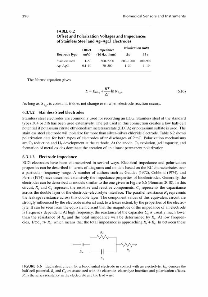
290 BiomedicalSensorsandInstruments
The.Nernst.equation.gives
.E E
RT
ZF= + +0 Ag Agln α
.(6.16)
As.long.as.αAg+.is.constant,.E.does.not.change.even.when.electrode.reaction.occurs.
6.3.1.2 Stainless Steel electrodesStainless.steel.electrodes.are.commonly.used.for.recording.an.ECG..Stainless.steel.of.the.standard.types.304.or.316.has.been.used.extensively..The.gel.used.in.this.connection.creates.a.low.half-cell.potential.if.potassium.citrate.ethylenediaminetetraacetate.(EDTA).or.potassium.sulfate.is.used..The.stainless.steel.electrode.will.polarize.far.more.than.silver–silver.chloride.electrode..Table.6.2.shows.polarization.data.for.both.types.of.electrodes.after.discharges.of.2.mC..Polarization.mechanisms.are.O2.reduction.and.H2.development.at.the.cathode..At.the.anode,.O2.evolution,.gel.impurity,.and.formation.of.metal.oxides.dominate.the.creation.of.an.almost.permanent.polarization.
6.3.1.3 electrode impedanceECG.electrodes.have.been.characterized. in.several.ways..Electrical. impedance.and.polarization.properties.can.be.described.in.terms.of.diagrams.and.models.based.on.the.RC.characteristics.over.a.particular. frequency. range..A.number.of. authors. such. as.Geddes. (1972),.Cobbold. (1974),. and.Ferris.(1974).have.described.extensively.the.impedance.properties.of.bioelectrodes..Generally,.the.electrodes.can.be.described.as.models.similar.to.the.one.given.in.Figure.6.6.(Neuman.2010)..In.this.circuit,.Rd.and.Cd. represent. the. resistive.and.reactive.components..Cd. represents. the.capacitance.across.the.double.layer.of.the.electrode–electrolyte.interface..The.parallel.resistance.Rd.represents.the.leakage.resistance.across.this.double.layer..The.component.values.of.this.equivalent.circuit.are.strongly.influenced.by.the.electrode.material.and,.to.a.lesser.extent,.by.the.properties.of.the.electro-lyte..It.can.be.seen.from.the.equivalent.circuit.that.the.magnitude.of.the.impedance.of.an.electrode.is.frequency.dependent..At.high.frequency,.the.reactance.of.the.capacitor.Cd.is.usually.much.lower.than.the.resistance.of.Rd.and.the.total. impedance.will.be.determined.by.Rs..At.low.frequen-cies,.1/ωCd.≫.Rd,.which.means.that.the.total.impedance.is.approaching.Rs.+.Rd..In.between.these.
Ehc
Cd
Rd
Rs
figure 6.6 Equivalent.circuit.for.a.biopotential.electrode.in.contact.with.an.electrolyte..Ehc.denotes.the.half-cell.potential..Rd.and.Cd.are.associated.with.the.electrode–electrolyte.interface.and.polarization.effects..Rs.is.the.series.resistance.in.the.electrolyte.and.the.lead.wire.
table 6.2offset and Polarization Voltages and impedances of Stainless Steel and ag–agCl electrodes
electrode typeoffset (mV)
impedance (10 hz, ohms)
Polarization (mV)
5 s 35 s
Stainless.steel 1–50 800–2200 600–1200 400–900
Ag–AgCl 0.1–50 70–300 1–30 1–10
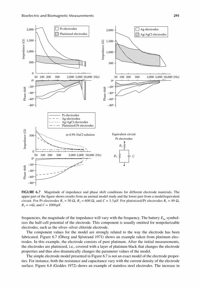
BioelectricandBiomagneticMeasurements 291
frequencies,.the.magnitude.of.the.impedance.will.vary.with.the.frequency..The.battery.Ehc.symbol-izes.the.half-cell.potential.of.the.electrode..This.component.is.usually.omitted.for.nonpolarizable.electrodes,.such.as.the.silver–silver.chloride.electrode.
The. component. values. for. the. model. are. strongly. related. to. the. way. the. electrode. has. been.fabricated..Figure.6.7.(Öberg.and.Sjöstrand.1971).shows.an.example.taken.from.platinum.elec-trodes..In.this.example,.the.electrode.consists.of.pure.platinum..After.the.initial.measurements,.the.electrodes.are.platinized,.i.e.,.covered.with.a.layer.of.platinum.black.that.changes.the.electrode.properties.and.thus.also.dramatically.changes.the.parameter.values.of.the.model.
The.simple.electrode.model.presented.in.Figure.6.7.is.not.an.exact.model.of.the.electrode.proper-ties..For.instance,.both.the.resistance.and.capacitance.vary.with.the.current.density.of.the.electrode.surface..Figure.6.8.(Geddes.1972).shows.an.example.of.stainless.steel.electrodes..The.increase.in.
Impe
danc
e (Ω
)
2,000
1,000
1,500
500
0
Pt electrodesPlatinized electrodes
50 100 200 500 2,000 5,000 50,000 (Hz)
Phas
e shi
ft –20º
–40º
–60º
–80º
0º
Phas
e shi
ft –20º
–40º
–60º
–80º
0º50 100 200 500 2,000 5,000 50,000 (Hz)
Impe
danc
e (Ω
)
2,000
1,000
1,500
500
Ag electrodesAg/AgCl electrodes
50 100 200 500 2,000 5,000 50,000 (Hz)
Impe
danc
e (Ω
)Ph
ase s
hift
500
0
–20º
–40º
–60º
–80º
0º
Pt electrodesAg electrodesAg/AgCl electrodesPlatinized/Pt electrodes
in 0.9% NaCl solution Equivalent circuitPt electrodes
R1
CR2
figure 6.7 Magnitude. of. impedance. and. phase. shift. conditions. for. different. electrode. materials.. The.upper.part.of.the.figure.shows.results.from.an.animal.model.study.and.the.lower.part.from.a.model/equivalent.circuit..For.Pt.electrodes.R1.=.50.Ω,.R2.=.600.Ω,.and.C.=.3.3.μF..For.platinized/Pt.electrodes.R1.=.49.Ω,.R2.=.∞Ω,.and.C.=.1000.μF.
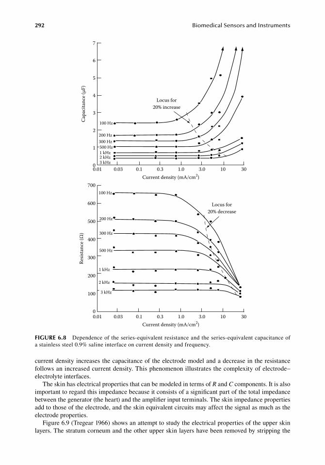
292 BiomedicalSensorsandInstruments
current.density.increases.the.capacitance.of.the.electrode.model.and.a.decrease.in.the.resistance.follows.an.increased.current.density..This.phenomenon.illustrates.the.complexity.of.electrode–electrolyte.interfaces.
The.skin.has.electrical.properties.that.can.be.modeled.in.terms.of.R.and.C.components..It.is.also.important.to.regard.this.impedance.because.it.consists.of.a.significant.part.of.the.total.impedance.between.the.generator.(the.heart).and.the.amplifier.input.terminals..The.skin.impedance.properties.add.to.those.of.the.electrode,.and.the.skin.equivalent.circuits.may.affect.the.signal.as.much.as.the.electrode.properties.
Figure.6.9.(Tregear.1966).shows.an.attempt.to.study.the.electrical.properties.of.the.upper.skin.layers..The.stratum.corneum.and.the.other.upper.skin.layers.have.been.removed.by.stripping.the.
Capa
cita
nce (
µF)
7
6
5
4
3
2
1
00.01 0.03 0.30.1 1.0 3.0 10 30
100 Hz
200 Hz300 Hz500 Hz1 kHz2 kHz3 kHz
Locus for20% increase
Resis
tanc
e (Ω
)
700
600
500
400
300
200
100
00.01 0.03 0.1 0.3 1.0 3.0 10 30
Current density (mA/cm2)
100 Hz
200 Hz
300 Hz
500 Hz
1 kHz
2 kHz
3 kHz
Current density (mA/cm2)
Locus for20% decrease
figure 6.8 Dependence.of.the.series-equivalent.resistance.and.the.series-equivalent.capacitance.of.a stainless.steel.0.9%.saline.interface.on.current.density.and.frequency.
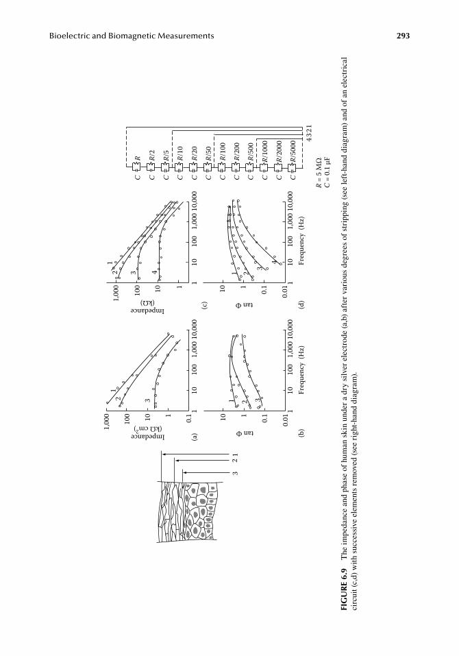
BioelectricandBiomagneticMeasurements 293
110
100
1,00
010
,000
110
100
1,00
010
,000
110100
1,00
0
0.1
32
1
tan Φ
Freq
uenc
y (H
z)
10 1
0.1
0.01
(d)
(a)
12 3
Freq
uenc
y (H
z)
Impedance(kΩ)
110
100
1,00
010
,000
110100
1,00
0
(c)
12 3 4
110
100
1,00
010
,000
110 0.1
0.01
tan Φ
(b)
1 2 3
1 2 3
4
CR
CR/
2
CR/
5
CR/
10
CR/
20
CR/
50
CR/
100
CR/
200
CR/
500
CR/
1000
CR/
2000
CR/
5000
4321
Impedance(kΩ cm2)
R =
5 M
ΩC
= 0.
1 μF
fig
ur
e 6.
9 T
he.im
peda
nce.
and.
phas
e.of
.hum
an.s
kin.
unde
r.a.
dry.
silv
er.e
lect
rode
.(a,b
).af
ter.
vari
ous.
degr
ees.
of.s
trip
ping
.(see
.left
-han
d.di
agra
m).
and.
of.a
n.el
ectr
ical
.ci
rcui
t.(c,
d).w
ith.
succ
essi
ve.e
lem
ents
.rem
oved
.(see
.rig
ht-h
and.
diag
ram
).
294 BiomedicalSensorsandInstruments
skin.with.adhesive.tape..Every.time.the.tape.is.removed,.parts.of.the.skin.are.attached.to.the.tape,.and. in. this.way. the.skin.changes. its.electrical.properties..As.can.be.seen. from.Figure.6.9. the.impedance.of.the.skin.can.be.closely.modeled.by.RC.parallel.circuits.connected.in.series..Stripping.of.the.outer.cell.layers.corresponds.to.the.removal.of.a.few.of.the.RC.circuits.
Skin.properties.can.be.changed.dramatically.from.an.electrical.point.of.view.either.by.stripping.or.by.rubbing.the.skin.surface.with.sandpaper..This.technique.is.used.for.lowering.the.skin.imped-ance.and. thereby. improving. the.quality.of.ECG.recordings..A.similar. technique.called. the.skin.drilling.technique.was.suggested.by.Schackel.(1958)..Here.the.skin.is.abraded.with.a.dental.burr..Schackel.(1958).obtained.a.reduction.in.resistance.of.1/5.to.1/10.of.those.of.the.undrilled.sites.and.ECG.recordings.of.very.high.quality.with.this.technique.
ECG.paste.applied.on.the.electrode.can.have.the.same.effect.as.skin.abrasion.or.skin.drilling..Geddes.(1972).has.extensively.covered.this.topic..A.variety.of.gel.or.paste.compositions.have.been.manufactured..All.of.them.have.been.composed.to.improve.the.conductive.properties.of.the.skin..When.using.an.electrode.preparation.with.surface.electrodes,.it.is.important.to.remember.that.the.electrode.impedance.is.initially.high.but.decreases.when.the.applied.paste.diffuses.into.the.skin..Roman.(1966).and.Almasi.and.Schmitt.(1970).have.studied.the.10.Hz.impedance..The.latter.authors.reported.that.the.decrease.in.impedance.with.time.was.exponential.in.nature.with.a.time.constant.of.6.9.min..The.final.impedance.values.were.reached.about.30.min.after.the.application.of.the.paste..They.also.noted.major.differences.in.the.skin.impedances.at.various.sites.on.the.human.skin.
6.3.1.4 Motion artifactsAs.described.earlier.in.this.chapter,.polarizable.electrodes.in.direct.contact.develop.a.double.layer.of.charges.adjacent.to.the.electrode.surface..If.the.electrode.is.moving.with.respect.to.the.electrolyte,.the.double.layer.is.disturbed,.which.results.in.a.change.in.the.half-cell.potential..When.the.motion.stops,. the. double. layer. is. reestablished. and. the. electrode. develops. the. initial. half-cell. potential..When.recordings.are.made.between.two.electrodes.and.one.of.the.electrodes.is.moving,.a.poten-tial.difference. is.generated.between. the.electrodes.during. the.movement..This. type.of.potential.difference.is.called.a.motion.artifact,.the.existence.of.which.is.a.serious.problem.in.most.types.of.electrode.measurements..It.is.reasonable.to.assume.that.nonpolarizing.electrodes.are.better.in.this.respect.than.polarizable.ones..Neuman.(2010).has.shown.this.in.a.simple.experiment..By.moving.a.metallic.Ag-electrode.in.a.saline.solution.before.and.after.chloridization,.he.was.able.to.demon-strate.the.difference.in.motion.sensitivity.between.two.electrode.preparations.
The.double.layer.is.not.the.only.source.of.motion.artifacts.in.ECG.recordings..Tam.and.Webster.(1977).have.shown.that.variations.in.the.electrolyte.paste-skin.potential.can.also.cause.motion.arti-facts.if.this.potential.varies.with.the.motion.of.the.electrode..They.indicated.that.this.effect.can.be.significantly.reduced.by.removing.the.stratum.corneum.with.abrasive.paper..Ödman.(1981).found.that.dielectric.and.piezoelectric.properties.of.the.stratum.corneum.can.cause.motion.artifacts..If.the.stratum.corneum.is.stretched.mechanically,.a.redistribution.of.charges.occurs..Such.a.redistribution.will.result.in.a.motion.artifact.at.the.electrode..This.mechanism.is.closely.related.to.the.dielectric.and.piezoelectric.properties.of.the.stratum.corneum..Removal.of.this.part.of.the.skin.eliminates.this.motion.artifact.generator..However,.the.removal.of.the.body’s.outer.protective.barrier.opens.a.way.for.infectious.diseases.to.enter.the.body..Cautious.use.of.this.method.is.recommended.
6.3.1.5 dry Contactless or Capacitive electrodesThe.invention.of.the.field.effect.transistor.made.it.possible.to.design.amplifiers.with.a.very.high.input.impedance..With.such.an.amplifier.as.input.stage,.it.is.possible.to.design.electrodes.that.can.be.used.directly.on.the.skin.without.paste.or.low-ohmic.paths.between.the.electrode.and.the.tissue..Such.electrodes.are.called.dry.or.capacitive.electrodes.
A.common.type.of.capacitive.electrode.functions.in.the.following.way..A.metal.plate.is.placed.against.the.stratum.corneum.and.a.metal.electrolyte.interface.is.created..The.impedance.is.mainly.resistive.because.of.the.stratum.corneum.that.works.as.an.isolating.medium..The.deeper.parts.of.
BioelectricandBiomagneticMeasurements 295
the.skin.have.higher.conductivities..Therefore,.we.have.a.capacitor.with.the.metal.plate,.the.dermis.as.conducting.plates,.and.the.stratum.corneum.serving.as.the.dielectric.
The.distance.between.the.plates.is.much.larger.than.the.corresponding.distance.in.an.electrode.double.layer.and.the.capacitor.formed.has.a.much.lower.capacitance..The.resistance.is.much.higher,.however,.in.comparison.to.the.wet.electrodes.
By.using.an.impedance-converting.amplifier.in.direct.contact.with.the.electrode,.we.can.detect.the.biopotential.even.if.the.source.impedance.is.very.high..Usually,.the.input.impedance.of.the.amplifier.exceeds.1.GΩ..Examples.of.such.an.electrode.have.been.described.by.Ko.and.Hynech.(1974).
Richardson.et.al..(1968).and.Richardson.(1967).suggested.a.type.of.insulated.electrode.in.which.an.oxide.layer.(Al2O3,.SiO2).constitutes.the.isolation.layer.between.the.metal.and.the.tissue..A.field.effect.transistor.source.follower.was.mounted.close.to.the.electrode.and.used.as.an.impedance.trans-forming.device..Variations.of.the.same.theme.have.been.presented.by.David.and.Portnoy.(1972),.Matsuo.et.al..(1973),.and.Yon.et.al..(1970)..As.mentioned.earlier,.the.dry.electrodes.have.the.advan-tage.of.not.requiring.the.use.of.electrode.paste..There.are.also.some.disadvantages.associated.with.this.type.of.electrode..The.very.high.impedance.amplifier.is.very.sensitive.to.electric.fields.around.the.electrode..In.addition,.capacitive.changes.in.the.stratum.corneum.may.affect.the.low-frequency.response.of.the.electrode.(Webster.1977).
Bergey.et.al..(1971).suggest.the.use.of.a.pasteless.electrode.for.long-term.applications.such.as.space.missions.and.intensive.care..High-impedance.electrodes.have.to.be.used.in.connection.with.these.types.of.electrodes.because.of.the.high.skin-to-electrode.impedance.
6.3.2 electroMyograM electrodes
Two.electrode.types.are.used.to.record.the.electromyograph.(EMG).signal..Surface.electrodes.are.used.on.the.surface.of.a.muscle.or.the.skin.above.the.muscle.under.study..Needle.or.wire.electrodes.are. inserted. into. the.muscle. for. signal. extraction..Electrodes. for.EMG.can.be.used. singularly.(monopolar).or.in.pairs.(bipolar).
6.3.2.1 Surface electrodesThe.most.common.surface.electrode.used.for.EMG.analysis.is.a.variant.of.the.ordinary.disc.Ag–AgCl.electrode..Coupling.to.the.muscle.and.electrode.is.improved.by.using.electrode.gel.between.the.electrode.surface.and.the.tissue..The.EMG.Ag–AgCl.electrode.has.the.advantages.and.draw-backs.described.earlier.in.this.chapter..Special.types.are.manufactured.and.sold;.in.comparison.with.the.ECG.electrode,.they.are.usually.small.and.lightweight..In.addition,.dry.or.isolated.electrodes.are.used.in.electromyography..As.described.earlier,.this.electrode.type.has.the.advantage.of.not.requir-ing.paste.or.other.conducting.media.between.the.electrode.surface.and.the.tissue..However,.the.dry.electrode.for.EMG.has.a.higher.inherent.noise.level.than.the.disc.types..The.dry.electrodes.do.not.have.the.long-term.stability.required.because.of.changes.in.the.dielectric.properties.caused.by.per-spiration..Because.of.these.reasons,.they.have.been.little.used.in.electromyography.(de.Luca.1988).
Godin.et.al..(1991).has.modeled.the.noise.characteristics.of.stainless.steel.surface.electrodes..The.effect.of.electrode.surface.area.on.electrode.impedance.and.noise.was.studied.using.circular.stain-less.steel.electrodes.of.varying.diameters..The.results.were.formulated.in.terms.of.mathematical.models..The.primary.noise.components.are.thermal.and.amplifier.impedance.generated..Electrode.impedance.was.found.to.be.a.power.function.of.both.electrode.diameter.and.frequency.
The.surface.electrodes.can.only.be.used.for.EMG.recordings.from.superficial.muscle.groups..Selective.recordings.from.small.muscles.are.also.difficult.to.perform..However,.the.surface.elec-trode.has.a.number.of.advantages.such.as.noninvasiveness,.in.child.measurements,.for.controlling.external.prostheses,.and.in.psychophysiological.measurements.where.relaxation.is.important.
A.number.of.electrode.design.ideas.have.been.described.for.a.variety.of.applications..Cram.and.Engstrom.(1986).and.Cram.and.Steger.(1983).introduced.a.muscle.scanning.technique.that.can.be.used.for.EMG.assessment.of.multiple.muscle.sites..The.technique.involves.the.use.of.“post-style”.
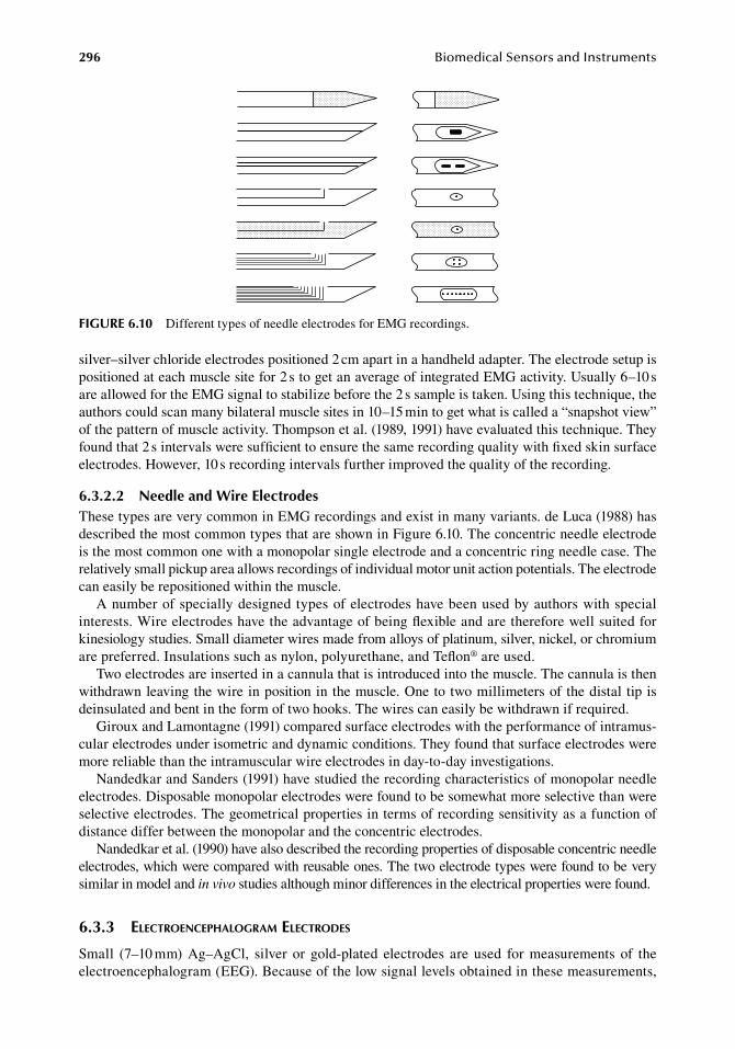
296 BiomedicalSensorsandInstruments
silver–silver.chloride.electrodes.positioned.2.cm.apart.in.a.handheld.adapter..The.electrode.setup.is.positioned.at.each.muscle.site.for.2.s.to.get.an.average.of.integrated.EMG.activity..Usually.6–10.s.are.allowed.for.the.EMG.signal.to.stabilize.before.the.2.s.sample.is.taken..Using.this.technique,.the.authors.could.scan.many.bilateral.muscle.sites.in.10–15.min.to.get.what.is.called.a.“snapshot.view”.of.the.pattern.of.muscle.activity..Thompson.et.al..(1989,.1991).have.evaluated.this.technique..They.found.that.2.s.intervals.were.sufficient.to.ensure.the.same.recording.quality.with.fixed.skin.surface.electrodes..However,.10.s.recording.intervals.further.improved.the.quality.of.the.recording.
6.3.2.2 needle and Wire electrodesThese.types.are.very.common.in.EMG.recordings.and.exist.in.many.variants..de.Luca.(1988).has.described.the.most.common.types.that.are.shown.in.Figure.6.10..The.concentric.needle.electrode.is.the.most.common.one.with.a.monopolar.single.electrode.and.a.concentric.ring.needle.case..The.relatively.small.pickup.area.allows.recordings.of.individual.motor.unit.action.potentials..The.electrode.can.easily.be.repositioned.within.the.muscle.
A.number.of.specially.designed.types.of.electrodes.have.been.used.by.authors.with.special.interests..Wire.electrodes.have.the.advantage.of.being.flexible.and.are.therefore.well.suited.for.kinesiology.studies..Small.diameter.wires.made.from.alloys.of.platinum,.silver,.nickel,.or.chromium.are.preferred..Insulations.such.as.nylon,.polyurethane,.and.Teflon®.are.used.
Two.electrodes.are.inserted.in.a.cannula.that.is.introduced.into.the.muscle..The.cannula.is.then.withdrawn.leaving.the.wire.in.position.in.the.muscle..One.to.two.millimeters.of.the.distal.tip.is.deinsulated.and.bent.in.the.form.of.two.hooks..The.wires.can.easily.be.withdrawn.if.required.
Giroux.and.Lamontagne.(1991).compared.surface.electrodes.with.the.performance.of.intramus-cular.electrodes.under.isometric.and.dynamic.conditions..They.found.that.surface.electrodes.were.more.reliable.than.the.intramuscular.wire.electrodes.in.day-to-day.investigations.
Nandedkar.and.Sanders.(1991).have.studied.the.recording.characteristics.of.monopolar.needle.electrodes..Disposable.monopolar.electrodes.were.found.to.be.somewhat.more.selective.than.were.selective.electrodes..The.geometrical.properties.in.terms.of.recording.sensitivity.as.a.function.of.distance.differ.between.the.monopolar.and.the.concentric.electrodes.
Nandedkar.et.al..(1990).have.also.described.the.recording.properties.of.disposable.concentric.needle.electrodes,.which.were.compared.with.reusable.ones..The.two.electrode.types.were.found.to.be.very.similar.in.model.and.in vivo.studies.although.minor.differences.in.the.electrical.properties.were.found.
6.3.3 electroencephalograM electrodes
Small. (7–10.mm).Ag–AgCl,. silver. or. gold-plated. electrodes. are. used. for.measurements. of. the.electroencephalogram.(EEG)..Because.of.the.low.signal.levels.obtained.in.these.measurements,.
figure 6.10 Different.types.of.needle.electrodes.for.EMG.recordings.
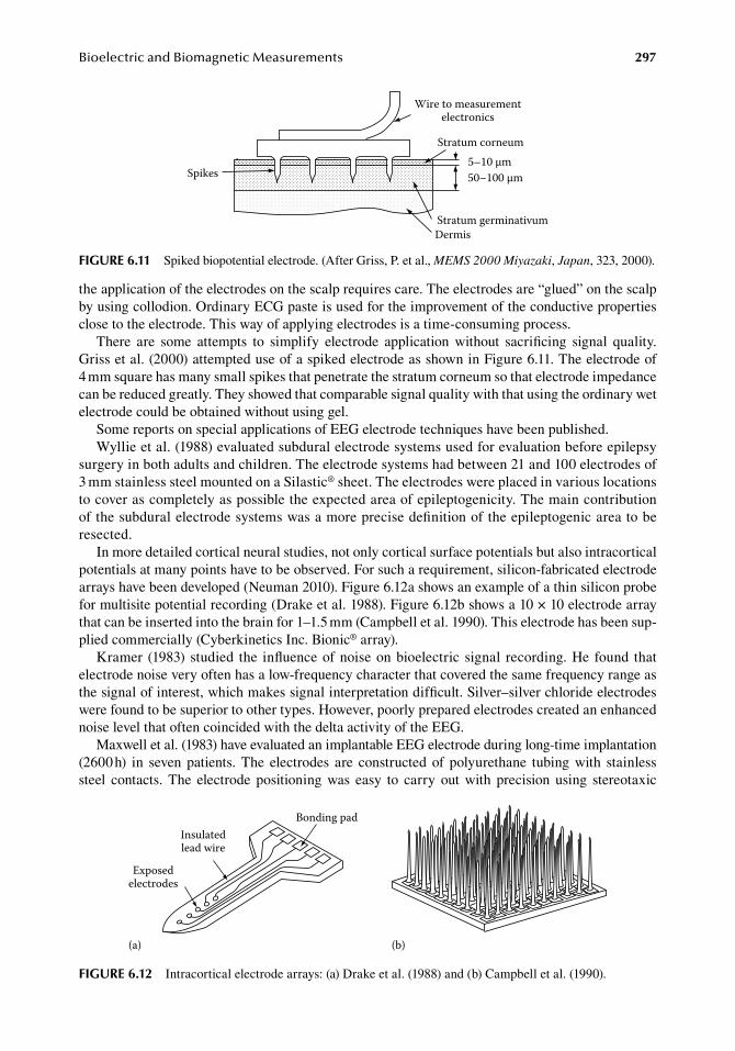
BioelectricandBiomagneticMeasurements 297
the.application.of.the.electrodes.on.the.scalp.requires.care..The.electrodes.are.“glued”.on.the.scalp.by.using.collodion..Ordinary.ECG.paste.is.used.for.the.improvement.of.the.conductive.properties.close.to.the.electrode..This.way.of.applying.electrodes.is.a.time-consuming.process.
There. are. some. attempts. to. simplify. electrode. application. without. sacrificing. signal. quality..Griss.et.al..(2000).attempted.use.of.a.spiked.electrode.as.shown.in.Figure.6.11..The.electrode.of.4.mm.square.has.many.small.spikes.that.penetrate.the.stratum.corneum.so.that.electrode.impedance.can.be.reduced.greatly..They.showed.that.comparable.signal.quality.with.that.using.the.ordinary.wet.electrode.could.be.obtained.without.using.gel.
Some.reports.on.special.applications.of.EEG.electrode.techniques.have.been.published.Wyllie.et.al..(1988).evaluated.subdural.electrode.systems.used.for.evaluation.before.epilepsy.
surgery.in.both.adults.and.children..The.electrode.systems.had.between.21.and.100.electrodes.of.3.mm.stainless.steel.mounted.on.a.Silastic®.sheet..The.electrodes.were.placed.in.various.locations.to.cover.as.completely.as.possible.the.expected.area.of.epileptogenicity..The.main.contribution.of.the.subdural.electrode.systems.was.a.more.precise.definition.of.the.epileptogenic.area.to.be.resected.
In.more.detailed.cortical.neural.studies,.not.only.cortical.surface.potentials.but.also.intracortical.potentials.at.many.points.have.to.be.observed..For.such.a.requirement,.silicon-fabricated.electrode.arrays.have.been.developed.(Neuman.2010)..Figure.6.12a.shows.an.example.of.a.thin.silicon.probe.for.multisite.potential.recording.(Drake.et.al..1988)..Figure.6.12b.shows.a.10.×.10.electrode.array.that.can.be.inserted.into.the.brain.for.1–1.5.mm.(Campbell.et.al..1990)..This.electrode.has.been.sup-plied.commercially.(Cyberkinetics.Inc..Bionic®.array).
Kramer. (1983).studied. the. influence.of.noise.on.bioelectric.signal. recording..He.found. that.electrode.noise.very.often.has.a.low-frequency.character.that.covered.the.same.frequency.range.as.the.signal.of.interest,.which.makes.signal.interpretation.difficult..Silver–silver.chloride.electrodes.were.found.to.be.superior.to.other.types..However,.poorly.prepared.electrodes.created.an.enhanced.noise.level.that.often.coincided.with.the.delta.activity.of.the.EEG.
Maxwell.et.al..(1983).have.evaluated.an.implantable.EEG.electrode.during.long-time.implantation.(2600.h). in. seven. patients.. The. electrodes. are. constructed. of. polyurethane. tubing. with. stainless.steel. contacts.. The. electrode. positioning. was. easy. to. carry. out. with. precision. using. stereotaxic.
5–10 µm50–100 µm
Stratum corneum
Stratum germinativumDermis
Spikes
Wire to measurementelectronics
figure 6.11 Spiked.biopotential.electrode..(After.Griss,.P..et.al.,.MEMS 2000 Miyazaki,.Japan,.323,.2000).
Exposedelectrodes
Insulatedlead wire
Bonding pad
(a) (b)
figure 6.12 Intracortical.electrode.arrays:.(a).Drake.et.al..(1988).and.(b).Campbell.et.al..(1990).
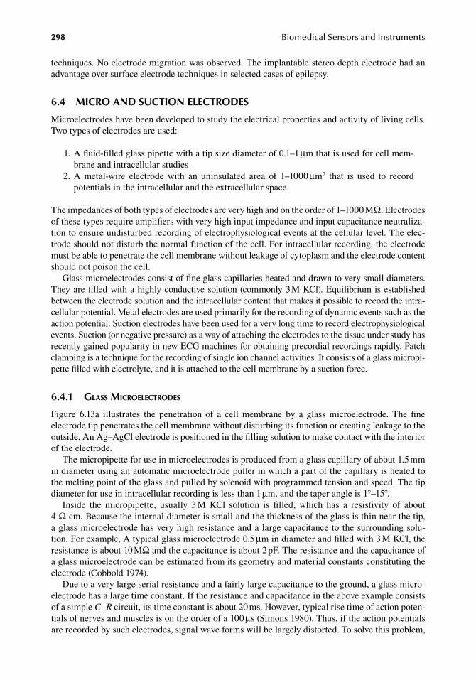
298 BiomedicalSensorsandInstruments
techniques..No.electrode.migration.was.observed..The.implantable.stereo.depth.electrode.had.an.advantage.over.surface.electrode.techniques.in.selected.cases.of.epilepsy.
6.4 MiCro and SuCtion eleCtrodeS
Microelectrodes.have.been.developed.to.study.the.electrical.properties.and.activity.of.living.cells..Two.types.of.electrodes.are.used:
. 1..A.fluid-filled.glass.pipette.with.a.tip.size.diameter.of.0.1–1.μm.that.is.used.for.cell.mem-brane.and.intracellular.studies
. 2..A. metal-wire. electrode. with. an. uninsulated. area. of. 1–1000.μm2. that. is. used. to. record.potentials.in.the.intracellular.and.the.extracellular.space
The.impedances.of.both.types.of.electrodes.are.very.high.and.on.the.order.of.1–1000.MΩ..Electrodes.of.these.types.require.amplifiers.with.very.high.input.impedance.and.input.capacitance.neutraliza-tion.to.ensure.undisturbed.recording.of.electrophysiological.events.at.the.cellular.level..The.elec-trode.should.not.disturb.the.normal.function.of.the.cell..For.intracellular.recording,.the.electrode.must.be.able.to.penetrate.the.cell.membrane.without.leakage.of.cytoplasm.and.the.electrode.content.should.not.poison.the.cell.
Glass.microelectrodes.consist.of.fine.glass.capillaries.heated.and.drawn.to.very.small.diameters..They.are.filled.with.a.highly.conductive.solution.(commonly.3.M.KCl)..Equilibrium.is.established.between.the.electrode.solution.and.the.intracellular.content.that.makes.it.possible.to.record.the.intra-cellular.potential..Metal.electrodes.are.used.primarily.for.the.recording.of.dynamic.events.such.as.the.action.potential..Suction.electrodes.have.been.used.for.a.very.long.time.to.record.electrophysiological.events..Suction.(or.negative.pressure).as.a.way.of.attaching.the.electrodes.to.the.tissue.under.study.has.recently.gained.popularity.in.new.ECG.machines.for.obtaining.precordial.recordings.rapidly..Patch.clamping.is.a.technique.for.the.recording.of.single.ion.channel.activities..It.consists.of.a.glass.micropi-pette.filled.with.electrolyte,.and.it.is.attached.to.the.cell.membrane.by.a.suction.force.
6.4.1 glass Microelectrodes
Figure. 6.13a. illustrates. the. penetration. of. a. cell. membrane. by. a. glass. microelectrode.. The. fine.electrode.tip.penetrates.the.cell.membrane.without.disturbing.its.function.or.creating.leakage.to.the.outside..An.Ag–AgCl.electrode.is.positioned.in.the.filling.solution.to.make.contact.with.the.interior.of.the.electrode.
The.micropipette.for.use.in.microelectrodes.is.produced.from.a.glass.capillary.of.about.1.5.mm.in.diameter.using.an.automatic.microelectrode.puller.in.which.a.part.of.the.capillary.is.heated.to.the.melting.point.of.the.glass.and.pulled.by.solenoid.with.programmed.tension.and.speed..The.tip.diameter.for.use.in.intracellular.recording.is.less.than.1.μm,.and.the.taper.angle.is.1°–15°.
Inside. the. micropipette,. usually. 3.M. KCl. solution. is. filled,. which. has. a. resistivity. of. about.4 Ω cm..Because.the.internal.diameter.is.small.and.the.thickness.of.the.glass.is.thin.near.the.tip,.a.glass.microelectrode.has.very.high.resistance.and.a.large.capacitance.to.the.surrounding.solu-tion..For.example,.A.typical.glass.microelectrode.0.5.μm.in.diameter.and.filled.with.3.M.KCl,.the.resistance.is.about.10.MΩ.and.the.capacitance.is.about.2.pF..The.resistance.and.the.capacitance.of.a.glass.microelectrode.can.be.estimated.from.its.geometry.and.material.constants.constituting.the.electrode.(Cobbold.1974).
Due.to.a.very.large.serial.resistance.and.a.fairly.large.capacitance.to.the.ground,.a.glass.micro-electrode.has.a.large.time.constant..If.the.resistance.and.capacitance.in.the.above.example.consists.of.a.simple.C–R.circuit,.its.time.constant.is.about.20.ms..However,.typical.rise.time.of.action.poten-tials.of.nerves.and.muscles.is.on.the.order.of.a.100.μs.(Simons.1980)..Thus,.if.the.action.potentials.are.recorded.by.such.electrodes,.signal.wave.forms.will.be.largely.distorted..To.solve.this.problem,.
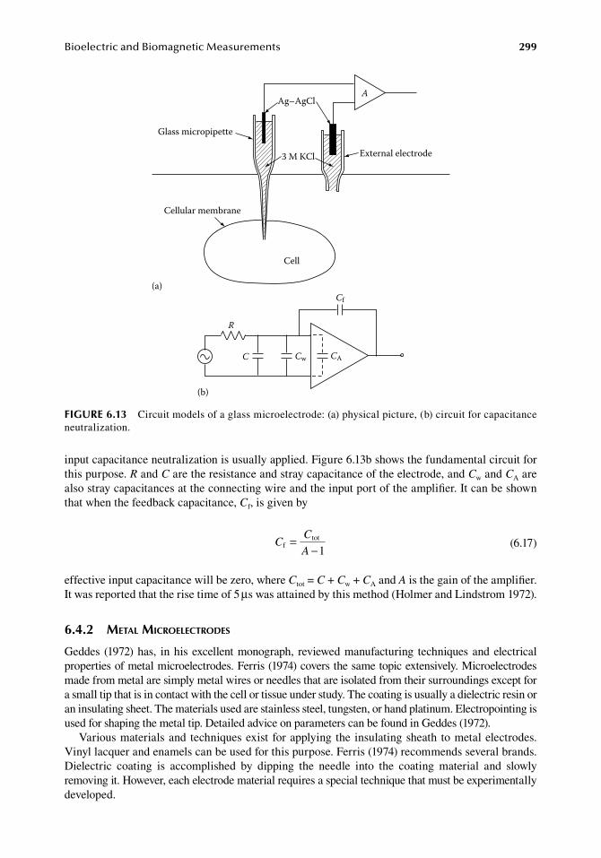
BioelectricandBiomagneticMeasurements 299
input.capacitance.neutralization.is.usually.applied..Figure.6.13b.shows.the.fundamental.circuit.for.this.purpose..R.and.C.are.the.resistance.and.stray.capacitance.of.the.electrode,.and.Cw.and.CA.are.also.stray.capacitances.at.the.connecting.wire.and.the.input.port.of.the.amplifier..It.can.be.shown.that.when.the.feedback.capacitance,.Cf,.is.given.by
.C
C
Af
tot
1=
− .(6.17)
effective.input.capacitance.will.be.zero,.where.Ctot.=.C.+.Cw.+.CA.and.A.is.the.gain.of.the.amplifier..It.was.reported.that.the.rise.time.of.5.μs.was.attained.by.this.method.(Holmer.and.Lindstrom.1972).
6.4.2 Metal Microelectrodes
Geddes. (1972).has,. in.his.excellent.monograph,. reviewed.manufacturing. techniques.and.electrical.properties.of.metal.microelectrodes..Ferris.(1974).covers.the.same.topic.extensively..Microelectrodes.made.from.metal.are.simply.metal.wires.or.needles.that.are.isolated.from.their.surroundings.except.for.a.small.tip.that.is.in.contact.with.the.cell.or.tissue.under.study..The.coating.is.usually.a.dielectric.resin.or.an.insulating.sheet..The.materials.used.are.stainless.steel,.tungsten,.or.hand.platinum..Electropointing.is.used.for.shaping.the.metal.tip..Detailed.advice.on.parameters.can.be.found.in.Geddes.(1972).
Various.materials.and. techniques.exist. for.applying.the. insulating.sheath. to.metal.electrodes..Vinyl.lacquer.and.enamels.can.be.used.for.this.purpose..Ferris.(1974).recommends.several.brands..Dielectric. coating. is. accomplished. by. dipping. the. needle. into. the. coating. material. and. slowly.removing.it..However,.each.electrode.material.requires.a.special.technique.that.must.be.experimentally.developed.
Glass micropipette
External electrode3 M KCl
Ag–AgCl
Cellular membrane
Cell
A
(a)
(b)
R
C Cw CA
Cf
figure 6.13 Circuit.models.of.a.glass.microelectrode:.(a).physical.picture,.(b).circuit.for.capacitance.neutralization.
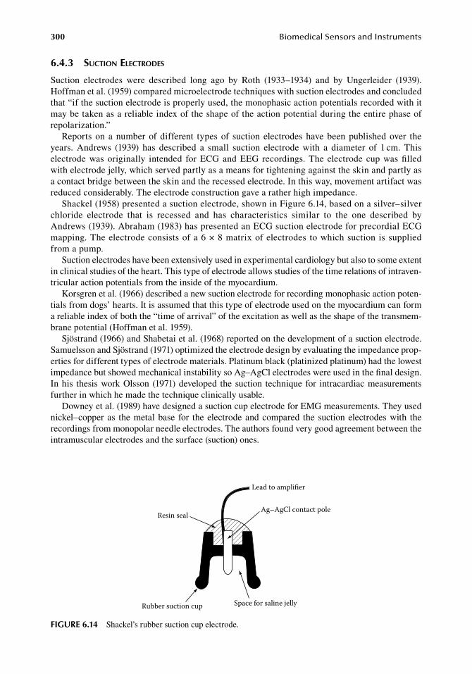
300 BiomedicalSensorsandInstruments
6.4.3 suction electrodes
Suction. electrodes. were. described. long. ago. by. Roth. (1933–1934). and. by. Ungerleider. (1939)..Hoffman.et.al..(1959).compared.microelectrode.techniques.with.suction.electrodes.and.concluded.that.“if.the.suction.electrode.is.properly.used,.the.monophasic.action.potentials.recorded.with.it.may.be.taken.as.a.reliable.index.of.the.shape.of.the.action.potential.during.the.entire.phase.of.repolarization.”
Reports. on. a.number.of. different. types.of. suction. electrodes.have.been.published.over. the.years.. Andrews. (1939). has. described. a. small. suction. electrode. with. a. diameter. of. 1.cm.. This.electrode.was.originally. intended. for.ECG.and.EEG. recordings..The. electrode. cup.was.filled.with.electrode.jelly,.which.served.partly.as.a.means.for.tightening.against.the.skin.and.partly.as.a.contact.bridge.between.the.skin.and.the.recessed.electrode..In.this.way,.movement.artifact.was.reduced.considerably..The.electrode.construction.gave.a.rather.high.impedance.
Shackel.(1958).presented.a.suction.electrode,.shown.in.Figure.6.14,.based.on.a.silver–silver.chloride. electrode. that. is. recessed. and. has. characteristics. similar. to. the. one. described. by.Andrews.(1939)..Abraham.(1983).has.presented.an.ECG.suction.electrode.for.precordial.ECG.mapping..The.electrode.consists.of.a.6.×.8.matrix.of.electrodes.to.which.suction.is.supplied.from.a.pump.
Suction.electrodes.have.been.extensively.used.in.experimental.cardiology.but.also.to.some.extent.in.clinical.studies.of.the.heart..This.type.of.electrode.allows.studies.of.the.time.relations.of.intraven-tricular.action.potentials.from.the.inside.of.the.myocardium.
Korsgren.et.al..(1966).described.a.new.suction.electrode.for.recording.monophasic.action.poten-tials.from.dogs’.hearts..It.is.assumed.that.this.type.of.electrode.used.on.the.myocardium.can.form.a.reliable.index.of.both.the.“time.of.arrival”.of.the.excitation.as.well.as.the.shape.of.the.transmem-brane.potential.(Hoffman.et.al..1959).
Sjöstrand.(1966).and.Shabetai.et.al..(1968).reported.on.the.development.of.a.suction.electrode..Samuelsson.and.Sjöstrand.(1971).optimized.the.electrode.design.by.evaluating.the.impedance.prop-erties.for.different.types.of.electrode.materials..Platinum.black.(platinized.platinum).had.the.lowest.impedance.but.showed.mechanical.instability.so.Ag–AgCl.electrodes.were.used.in.the.final.design..In.his. thesis.work.Olsson. (1971).developed. the.suction. technique. for. intracardiac.measurements.further.in.which.he.made.the.technique.clinically.usable.
Downey.et.al..(1989).have.designed.a.suction.cup.electrode.for.EMG.measurements..They.used.nickel–copper.as. the.metal.base. for. the.electrode.and.compared. the. suction.electrodes.with. the.recordings.from.monopolar.needle.electrodes..The.authors.found.very.good.agreement.between.the.intramuscular.electrodes.and.the.surface.(suction).ones.
Resin seal
Lead to amplifier
Ag–AgCl contact pole
Space for saline jellyRubber suction cup
figure 6.14 Shackel’s.rubber.suction.cup.electrode.
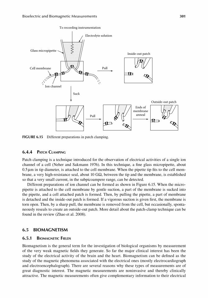
BioelectricandBiomagneticMeasurements 301
6.4.4 patch claMping
Patch.clamping.is.a.technique.introduced.for.the.observation.of.electrical.activities.of.a.single.ion.channel.of.a.cell. (Neher.and.Sakmann.1976).. In. this. technique,.a.fine.glass.micropipette,.about.0.5.μm.in.tip.diameter,.is.attached.to.the.cell.membrane..When.the.pipette.tip.fits.to.the.cell.mem-brane,.a.very.high-resistance.seal,.about.10.GΩ,.between.the.tip.and.the.membrane,.is.established.so.that.a.very.small.current,.in.the.subpicoampere.range,.can.be.detected.
Different.preparations.of.ion.channel.can.be.formed.as.shown.in.Figure.6.15..When.the.micro-pipette.is.attached.to.the.cell.membrane.by.gentle.suction,.a.part.of.the.membrane.is.sucked.into.the.pipette,.and.a.cell.attached.patch.is.formed..Then,.by.pulling.the.pipette,.a.part.of.membrane.is.detached.and.the.inside-out.patch.is.formed..If.a.vigorous.suction.is.given.first,.the.membrane.is.torn.open..Then,.by.a.sharp.pull,.the.membrane.is.removed.from.the.cell,.but.occasionally,.sponta-neously.reseals.to.create.an.outside-out.patch..More.detail.about.the.patch-clamp.technique.can.be.found.in.the.review.(Zhao.et.al..2008).
6.5 bioMagnetiSM
6.5.1 bioMagnetic fields
Biomagnetism.is.the.general.term.for.the.investigation.of.biological.organisms.by.measurement.of. the.very.weak.magnetic.fields. they.generate..So.far. the.major.clinical. interest.has.been. the.study.of. the.electrical.activity.of. the.brain.and.the.heart..Biomagnetism.can.be.defined.as. the.study.of.the.magnetic.phenomena.associated.with.the.electrical.ones.(mostly.electrocardiograph.and.electroencephalograph)..There.are.several.reasons.why.these.types.of.measurements.are.of.great. diagnostic. interest.. The. magnetic. measurements. are. noninvasive. and. thereby. clinically.attractive..The.magnetic.measurements.often.give.complementary.information.to.their.electrical.
To recording instrumentation
Electrolyte solution
Glass micropipette
Cell membrane
Ion channel
Pull
Suck
Pull
Ends ofmembrane
anneal
Inside-out patch
Outside-out patch
figure 6.15 Different.preparations.in.patch.clamping.
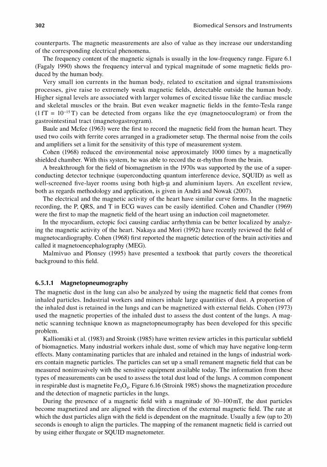
302 BiomedicalSensorsandInstruments
counterparts..The magnetic.measurements.are.also.of.value.as.they.increase.our.understanding.of.the.corresponding.electrical.phenomena.
The.frequency.content.of.the.magnetic.signals.is.usually.in.the.low-frequency.range..Figure.6.1.(Fagaly.1990).shows. the. frequency. interval.and. typical.magnitude.of.some.magnetic.fields.pro-duced.by.the.human.body.
Very.small. ion.currents. in. the.human.body,. related. to.excitation.and.signal. transmissions.processes,.give. raise. to.extremely.weak.magnetic.fields,.detectable.outside. the.human.body..Higher.signal.levels.are.associated.with.larger.volumes.of.excited.tissue.like.the.cardiac.muscle.and. skeletal.muscles.or. the.brain..But. even.weaker.magnetic.fields. in. the. femto-Tesla. range.(1.fT. =. 10−15.T). can. be. detected. from. organs. like. the. eye. (magnetooculogram). or. from. the.gastrointestinal.tract.(magnetogastrogram).
Baule.and.Mcfee.(1963).were.the.first.to.record.the.magnetic.field.from.the.human.heart..They.used.two.coils.with.ferrite.cores.arranged.in.a.gradiometer.setup..The.thermal.noise.from.the.coils.and.amplifiers.set.a.limit.for.the.sensitivity.of.this.type.of.measurement.system.
Cohen. (1968). reduced. the. environmental. noise. approximately. 1000. times. by. a. magnetically.shielded.chamber..With.this.system,.he.was.able.to.record.the.α-rhythm.from.the.brain.
A.breakthrough.for.the.field.of.biomagnetism.in.the.1970s.was.supported.by.the.use.of.a.super-conducting.detector.technique.(superconducting.quantum.interference.device,.SQUID).as.well.as.well-screened. five-layer. rooms. using. both. high-μ. and. aluminium. layers.. An. excellent. review,.both.as.regards.methodology.and.application,.is.given.in.Andrä.and.Nowak.(2007).
The.electrical.and.the.magnetic.activity.of.the.heart.have.similar.curve.forms..In.the.magnetic.recording,.the.P,.QRS,.and.T.in.ECG.waves.can.be.easily.identified..Cohen.and.Chandler.(1969).were.the.first.to.map.the.magnetic.field.of.the.heart.using.an.induction.coil.magnetometer.
In.the.myocardium,.ectopic.foci.causing.cardiac.arrhythmia.can.be.better.localized.by.analyz-ing.the.magnetic.activity.of.the.heart..Nakaya.and.Mori.(1992).have.recently.reviewed.the.field.of.magnetocardiography..Cohen.(1968).first.reported.the.magnetic.detection.of.the.brain.activities.and.called.it.magnetoencephalography.(MEG).
Malmivuo. and. Plonsey. (1995). have. presented. a. textbook. that. partly. covers. the. theoretical.background.to.this.field.
6.5.1.1 MagnetopneumographyThe.magnetic.dust.in.the.lung.can.also.be.analyzed.by.using.the.magnetic.field.that.comes.from.inhaled.particles..Industrial.workers.and.miners.inhale.large.quantities.of.dust..A.proportion.of.the.inhaled.dust.is.retained.in.the.lungs.and.can.be.magnetized.with.external.fields..Cohen.(1973).used.the.magnetic.properties.of.the.inhaled.dust.to.assess.the.dust.content.of.the.lungs..A.mag-netic.scanning.technique.known.as.magnetopneumography.has.been.developed.for.this.specific.problem.
Kalliomäki.et.al..(1983).and.Stroink.(1985).have.written.review.articles.in.this.particular.subfield.of.biomagnetics..Many.industrial.workers.inhale.dust,.some.of.which.may.have.negative.long-term.effects..Many.contaminating.particles.that.are.inhaled.and.retained.in.the.lungs.of.industrial.work-ers.contain.magnetic.particles..The.particles.can.set.up.a.small.remanent.magnetic.field.that.can.be.measured.noninvasively.with.the.sensitive.equipment.available.today..The.information.from.these.types.of.measurements.can.be.used.to.assess.the.total.dust.load.of.the.lungs..A.common.component.in.respirable.dust.is.magnetite.Fe3O4..Figure.6.16.(Stroink.1985).shows.the.magnetization.procedure.and.the.detection.of.magnetic.particles.in.the.lungs.
During. the. presence. of. a. magnetic. field. with. a. magnitude. of. 30–100.mT,. the. dust. particles.become.magnetized.and.are.aligned.with.the.direction.of.the.external.magnetic.field..The.rate.at.which.the.dust.particles.align.with.the.field.is.dependent.on.the.magnitude..Usually.a.few.(up.to.20).seconds.is.enough.to.align.the.particles..The.mapping.of.the.remanent.magnetic.field.is.carried.out.by.using.either.fluxgate.or.SQUID.magnetometer.
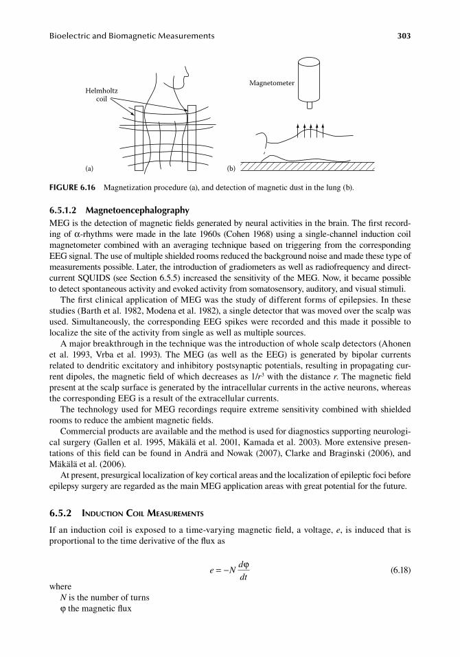
BioelectricandBiomagneticMeasurements 303
6.5.1.2 MagnetoencephalographyMEG.is.the.detection.of.magnetic.fields.generated.by.neural.activities.in.the.brain..The.first.record-ing.of.α-rhythms.were.made.in. the. late.1960s.(Cohen.1968).using.a.single-channel. induction.coil.magnetometer.combined.with.an.averaging. technique.based.on. triggering.from.the.corresponding.EEG.signal..The.use.of.multiple.shielded.rooms.reduced.the.background.noise.and.made.these.type.of.measurements.possible..Later,.the.introduction.of.gradiometers.as.well.as.radiofrequency.and.direct-current.SQUIDS.(see.Section.6.5.5).increased.the.sensitivity.of.the.MEG..Now,.it.became.possible.to.detect.spontaneous.activity.and.evoked.activity.from.somatosensory,.auditory,.and.visual.stimuli.
The.first.clinical.application.of.MEG.was.the.study.of.different.forms.of.epilepsies..In.these.studies.(Barth.et.al..1982,.Modena.et.al..1982),.a.single.detector.that.was.moved.over.the.scalp.was.used..Simultaneously,. the.corresponding.EEG.spikes.were.recorded.and. this.made. it.possible. to.localize.the.site.of.the.activity.from.single.as.well.as.multiple.sources.
A.major.breakthrough.in.the.technique.was.the.introduction.of.whole.scalp.detectors.(Ahonen.et. al.. 1993,. Vrba. et. al.. 1993).. The. MEG. (as. well. as. the. EEG). is. generated. by. bipolar. currents.related.to.dendritic.excitatory.and.inhibitory.postsynaptic.potentials,.resulting.in.propagating.cur-rent.dipoles,.the.magnetic.field.of.which.decreases.as.1/r3.with.the.distance.r..The.magnetic.field.present.at.the.scalp.surface.is.generated.by.the.intracellular.currents.in.the.active.neurons,.whereas.the.corresponding.EEG.is.a.result.of.the.extracellular.currents.
The.technology.used.for.MEG.recordings.require.extreme.sensitivity.combined.with.shielded.rooms.to.reduce.the.ambient.magnetic.fields.
Commercial.products.are.available.and.the.method.is.used.for.diagnostics.supporting.neurologi-cal.surgery.(Gallen.et.al..1995,.Mäkälä.et.al..2001,.Kamada.et.al..2003)..More.extensive.presen-tations.of.this.field.can.be.found.in.Andrä.and.Nowak.(2007),.Clarke.and.Braginski.(2006),.and.Mäkälä.et.al..(2006).
At.present,.presurgical.localization.of.key.cortical.areas.and.the.localization.of.epileptic.foci.before.epilepsy.surgery.are.regarded.as.the.main.MEG.application.areas.with.great.potential.for.the.future.
6.5.2 induction coil MeasureMents
If.an.induction.coil.is.exposed.to.a.time-varying.magnetic.field,.a.voltage,.e,.is.induced.that.is.proportional.to.the.time.derivative.of.the.flux.as
. e Nd
dt= − ϕ
. (6.18)
whereN.is.the.number.of.turnsφ.the.magnetic.flux
(a) (b)
Helmholtzcoil
Magnetometer
figure 6.16 Magnetization.procedure.(a),.and.detection.of.magnetic.dust.in.the.lung.(b).

304 BiomedicalSensorsandInstruments
Induction.coil-based.measurements.have.only.had. limited.use. in.biomagnetic.measurements..The.sensitivity.is.limited.but.can.be.improved.somewhat.if.a.high.permeability.core.is.used..Baule.and.Mcfee.(1963).used.a.magnetic.coil.arrangement.in.their.first.studies.of.the.magnetic.field.of.the.heart..They.used.two.coils,.each.containing.two.million.turns.wound.on.a.core.of.magnetic.material..The.output.voltage.was.on.the.order.of.30.μV,.which.was.amplified.after.60.Hz.noise.sup-pression..The.curve.form.these.authors.obtained.was.similar.to.that.of.the.ECG.and.it.was.named.the.magnetocardiogram.(MCG)..Wikswo.et.al..(1980).and.Wikswo.(1985).present.recordings.from.a.single.giant.axon.of.the.crayfish..This.group.used.both.closed.one.piece.coil.and.a.coil.with.a.clip-on.toroidal.core..The.sensitivity.with.this.room-temperature.equipment.was.limited.by.a.cur-rent.noise.at.the.input.of.about.0.15.nA/Hz1/2..This.technique.allows.multiple.measurements.along.the.nerve.
6.5.3 fluxgate MagnetoMeter
Fluxgate.magnetometer.is.a.magnetic.sensor.for.d.c..and.low-frequency.a.c..magnetic.field.in.the.range.of.approximately.10−10.to.10−4.T..Although.its.sensitivity.is.fairly.high.among.magnetic.sen-sors.operated.at.room.temperature,.it.is.not.enough.for.use.to.record.biomagnetic.signals.except.for.magnetopneumography..The.fluxgate.sensor.technology.is.well.established.and.many.commercial.products.are.available..Details.about.fluxgate.magnetometers.are.found.in.any.standard. text,. for.example,.Ripka.(2000).
The.basic.principle.of.the.magnetometer.is.illustrated.in.Figure.6.17..When.a.strong.a.c..excita-tion.is.applied.to.a.magnetic.core.through.the.excitation.coil.as.shown.in.Figure.6.17a,.the.core.is.saturated.periodically.in.both.polarities,.and.a.potential.is.induced.in.the.pickup.coil.at.the.tran-sient.of.polarity.change.as.shown.in.Figure.6.17b..When.the.external.field,.H0,.is.zero,.the.induced.voltage.is.symmetric.in.both.polarities.because.the.B–H.curve.of.the.core.is.exactly.symmetric,.but.if.H0.is.not.zero,.asymmetric.component.appears.in.induced.voltage..Thus,.the.strength.of.the.external.field.can.be.measured.by. the.amount.of.asymmetric.components. in. the. induced.signal.waveform.
There. are. different. methods. to. detect. the. asymmetric. component. that. is. proportional. to. the.strength.of.external.field..Figure.6.18.is.a.method.of.using.second.harmonics..As.long.as.a.waveform.is.symmetric.in.both.polarities,.the.second.harmonic.component.is.zero,.and.the.amplitude.of.the.second.harmonics.is.almost.proportional.to.the.external.field.strength,.H0.
B0
Vexc
Vind
B(t)
(a) (b)
B
H
H
t
B
V
t
tH0
figure 6.17 Principle.of.the.fluxgate.magnetometer:.(a).senor.configuration.and.(b).excitation.and.induced.potential.waveforms.
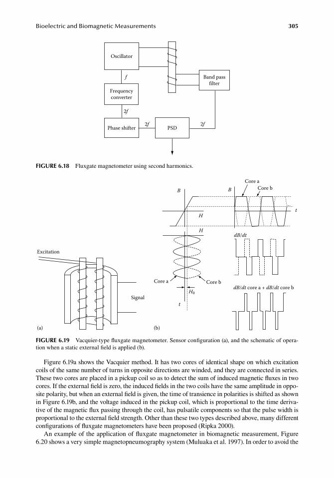
BioelectricandBiomagneticMeasurements 305
Figure.6.19a.shows.the.Vacquier.method..It.has.two.cores.of.identical.shape.on.which.excitation.coils.of.the.same.number.of.turns.in.opposite.directions.are.winded,.and.they.are.connected.in.series..These.two.cores.are.placed.in.a.pickup.coil.so.as.to.detect.the.sum.of.induced.magnetic.fluxes.in.two.cores..If.the.external.field.is.zero,.the.induced.fields.in.the.two.coils.have.the.same.amplitude.in.oppo-site.polarity,.but.when.an.external.field.is.given,.the.time.of.transience.in.polarities.is.shifted.as.shown.in.Figure.6.19b,.and.the.voltage.induced.in.the.pickup.coil,.which.is.proportional.to.the.time.deriva-tive.of.the.magnetic.flux.passing.through.the.coil,.has.pulsatile.components.so.that.the.pulse.width.is.proportional.to.the.external.field.strength..Other.than.these.two.types.described.above,.many.different.configurations.of.fluxgate.magnetometers.have.been.proposed.(Ripka.2000).
An.example.of.the.application.of.fluxgate.magnetometer.in.biomagnetic.measurement,.Figure.6.20.shows.a.very.simple.magnetopneumography.system.(Muluaka.et.al..1997)..In.order.to.avoid.the.
Oscillator
Frequencyconverter
Band passfilter
PSDPhase shifter
f
2f
2f 2f
figure 6.18 Fluxgate.magnetometer.using.second.harmonics.
Excitation
Signal
B B
H
H
t
Core bCore a
t
dB/dt
Core aCore b
dB/dt core a + dB/dt core b
(a) (b)
H0
figure 6.19 Vacquier-type.fluxgate.magnetometer..Sensor.configuration.(a),.and.the.schematic.of.opera-tion.when.a.static.external.field.is.applied.(b).
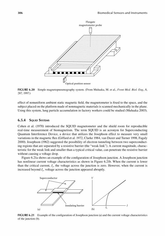
306 BiomedicalSensorsandInstruments
effect.of.nonuniform.ambient.static.magnetic.field,.the.magnetometer.is.fixed.to.the.space,.and.the.subject.placed.on.the.platform.made.of.nonmagnetic.materials.is.scanned.mechanically.in.the.plane..Using.this.system,.lung.particle.accumulation.in.factory.workers.could.be.studied.(Muluaka.2003).
6.5.4 squid systeMs
Cohen. et. al.. (1970). introduced. the. SQUID. magnetometer. and. the. shield. room. for. reproducible.real-time. measurement. of. biomagnetism.. The. term. SQUID. is. an. acronym. for. Superconducting.Quantum.Interference.Device,.a.device. that.utilizes. the. Josephson.effect. to.measure.very.small.variations.in.the.magnetic.flux.(Giffard.et.al..1972,.Clarke.1984,.van.Duzer.and.Turner.1998,.Fagaly.2000)..Josephson.(1962).suggested.the.possibility.of.electron.tunneling.between.two.superconduct-ing.regions.that.are.separated.by.a.resistive.barrier.(the.“weak.link”)..A.current.magnitude,.charac-teristic.for.the.weak.link.and.smaller.than.a.typical.critical.value,.can.penetrate.the.resistive.barrier.without.causing.a.voltage.drop.
Figure.6.21a.shows.an.example.of.the.configuration.of.Josephson.junction..A.Josephson.junction.has.nonlinear.current.voltage.characteristics.as.shown.in.Figure.6.21b..When.the.current.is.lower.than.the.critical.current,.Ic,. the.voltage.across.the.junction.is.zero..However,.when.the.current.is.increased.beyond.Ic,.voltage.across.the.junction.appeared.abruptly.
Fluxgatemagnetometer probe
Optical position sensor
figure 6.20 Simple.magnetopneumography.system..(From.Muluaka,.M..et.al.,.Front Med. Biol. Eng.,.8,.287,.1997.)
Superconductor
Insulating barrier(a)
I
V
Ic(b)
figure 6.21 Example.of.the.configuration.of.Josephson.junction.(a).and.the.current.voltage.characteristics.of.the.junction.(b).
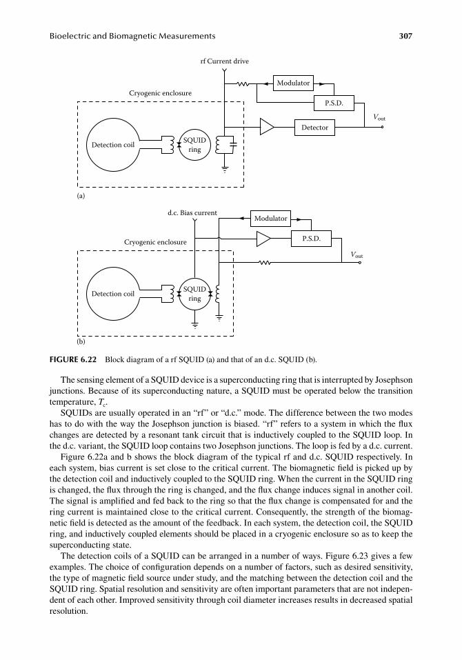
BioelectricandBiomagneticMeasurements 307
The.sensing.element.of.a.SQUID.device.is.a.superconducting.ring.that.is.interrupted.by.Josephson.junctions..Because.of.its.superconducting.nature,.a.SQUID.must.be.operated.below.the.transition.temperature,.Tc.
SQUIDs.are.usually.operated.in.an.“rf”.or.“d.c.”.mode..The.difference.between.the.two.modes.has.to.do.with.the.way.the.Josephson.junction.is.biased..“rf”.refers.to.a.system.in.which.the.flux.changes.are.detected.by.a.resonant.tank.circuit.that.is.inductively.coupled.to.the.SQUID.loop..In.the.d.c..variant,.the.SQUID.loop.contains.two.Josephson.junctions..The.loop.is.fed.by.a.d.c..current.
Figure.6.22a.and.b.shows.the.block.diagram.of.the.typical.rf.and.d.c..SQUID.respectively..In.each.system,.bias.current.is.set.close.to.the.critical.current..The.biomagnetic.field.is.picked.up.by.the.detection.coil.and.inductively.coupled.to.the.SQUID.ring..When.the.current.in.the.SQUID.ring.is.changed,.the.flux.through.the.ring.is.changed,.and.the.flux.change.induces.signal.in.another.coil..The.signal.is.amplified.and.fed.back.to.the.ring.so.that.the.flux.change.is.compensated.for.and.the.ring.current.is.maintained.close.to.the.critical.current..Consequently,.the.strength.of.the.biomag-netic.field.is.detected.as.the.amount.of.the.feedback..In.each.system,.the.detection.coil,.the.SQUID.ring,.and.inductively.coupled.elements.should.be.placed.in.a.cryogenic.enclosure.so.as.to.keep.the.superconducting.state.
The.detection.coils.of.a.SQUID.can.be.arranged.in.a.number.of.ways..Figure.6.23.gives.a.few.examples..The.choice.of.configuration.depends.on.a.number.of.factors,.such.as.desired.sensitivity,.the.type.of.magnetic.field.source.under.study,.and.the.matching.between.the.detection.coil.and.the.SQUID.ring..Spatial.resolution.and.sensitivity.are.often.important.parameters.that.are.not.indepen-dent.of.each.other..Improved.sensitivity.through.coil.diameter.increases.results.in.decreased.spatial.resolution.
Modulator
P.S.D.
Detector
Detection coil
Vout
Cryogenic enclosure
rf Current drive
Modulator
P.S.D.
Detection coil
Vout
Cryogenic enclosure
SQUIDring
SQUIDring
d.c. Bias current
(a)
(b)
figure 6.22 Block.diagram.of.a.rf.SQUID.(a).and.that.of.an.d.c..SQUID.(b).
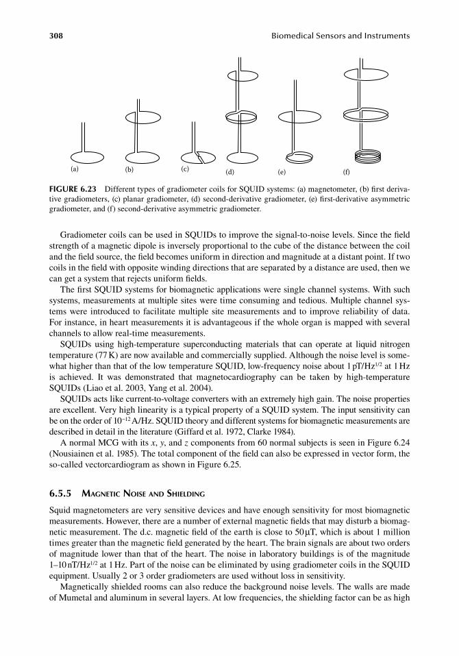
308 BiomedicalSensorsandInstruments
Gradiometer.coils.can.be.used.in.SQUIDs.to.improve.the.signal-to-noise.levels..Since.the.field.strength.of.a.magnetic.dipole.is.inversely.proportional.to.the.cube.of.the.distance.between.the.coil.and.the.field.source,.the.field.becomes.uniform.in.direction.and.magnitude.at.a.distant.point..If.two.coils.in.the.field.with.opposite.winding.directions.that.are.separated.by.a.distance.are.used,.then.we.can.get.a.system.that.rejects.uniform.fields.
The.first.SQUID.systems.for.biomagnetic.applications.were.single.channel.systems..With.such.systems,.measurements.at.multiple.sites.were.time.consuming.and.tedious..Multiple.channel.sys-tems.were. introduced. to.facilitate.multiple.site.measurements.and. to. improve.reliability.of.data..For.instance,.in.heart.measurements.it.is.advantageous.if.the.whole.organ.is.mapped.with.several.channels.to.allow.real-time.measurements.
SQUIDs. using. high-temperature. superconducting. materials. that. can. operate. at. liquid. nitrogen.temperature.(77.K).are.now.available.and.commercially.supplied..Although.the.noise.level.is.some-what.higher.than.that.of.the.low.temperature.SQUID,.low-frequency.noise.about.1.pT/Hz1/2.at.1.Hz.is. achieved.. It. was. demonstrated. that. magnetocardiography. can. be. taken. by. high-temperature.SQUIDs.(Liao.et.al..2003,.Yang.et.al..2004).
SQUIDs.acts.like.current-to-voltage.converters.with.an.extremely.high.gain..The.noise.properties.are.excellent..Very.high.linearity.is.a.typical.property.of.a.SQUID.system..The.input.sensitivity.can.be.on.the.order.of.10−12.A/Hz..SQUID.theory.and.different.systems.for.biomagnetic.measurements.are.described.in.detail.in.the.literature.(Giffard.et.al..1972,.Clarke.1984).
A.normal.MCG.with.its.x,.y,.and.z.components.from.60.normal.subjects.is.seen.in.Figure.6.24.(Nousiainen.et.al..1985)..The.total.component.of.the.field.can.also.be.expressed.in.vector.form,.the.so-called.vectorcardiogram.as.shown.in.Figure.6.25.
6.5.5 Magnetic noise and shielding
Squid.magnetometers.are.very.sensitive.devices.and.have.enough.sensitivity.for.most.biomagnetic.measurements..However,.there.are.a.number.of.external.magnetic.fields.that.may.disturb.a.biomag-netic.measurement..The.d.c..magnetic.field.of.the.earth.is.close.to.50.μT,.which.is.about.1.million.times.greater.than.the.magnetic.field.generated.by.the.heart..The.brain.signals.are.about.two.orders.of.magnitude.lower.than.that.of.the.heart..The.noise.in.laboratory.buildings.is.of.the.magnitude.1–10.nT/Hz1/2.at.1.Hz..Part.of.the.noise.can.be.eliminated.by.using.gradiometer.coils.in.the.SQUID.equipment..Usually.2.or.3.order.gradiometers.are.used.without.loss.in.sensitivity.
Magnetically.shielded.rooms.can.also.reduce.the.background.noise.levels..The.walls.are.made.of.Mumetal.and.aluminum.in.several.layers..At.low.frequencies,.the.shielding.factor.can.be.as.high.
(a) (b) (c) (d) (e) (f)
figure 6.23 Different.types.of.gradiometer.coils.for.SQUID.systems:.(a).magnetometer,.(b).first.deriva-tive.gradiometers,.(c).planar.gradiometer,.(d).second-derivative.gradiometer,.(e).first-derivative.asymmetric.gradiometer,.and.(f).second-derivative.asymmetric.gradiometer.
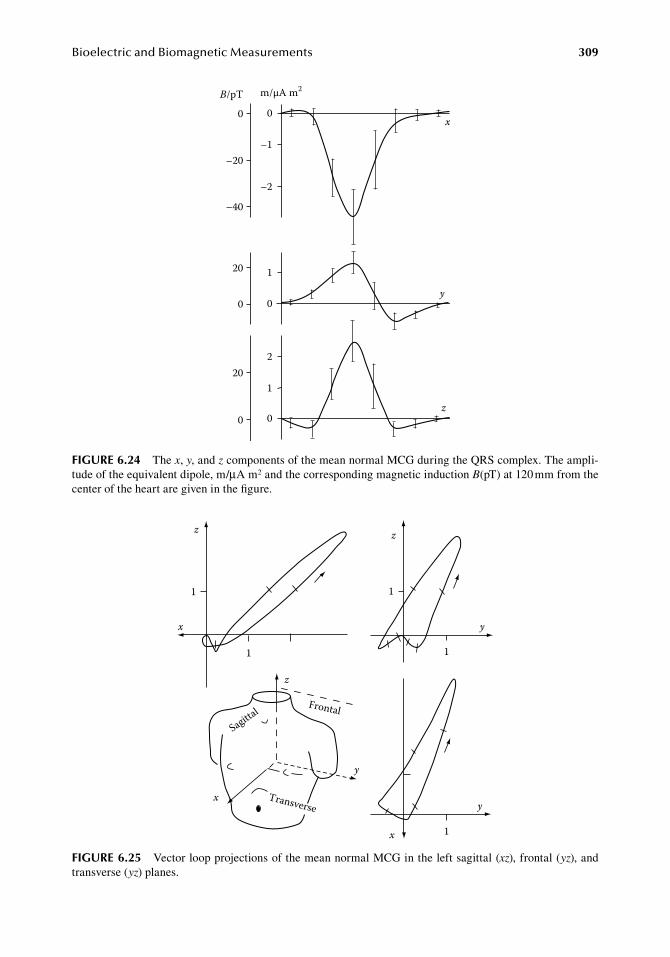
BioelectricandBiomagneticMeasurements 309
0 0
–20
–40
–1
–2
0
1
0
20
0
2
1
0
x
y
z
B/pT m/µA m2
20
figure 6.24 The.x,.y,.and.z.components.of.the.mean.normal.MCG.during.the.QRS.complex..The.ampli-tude.of.the.equivalent.dipole,.m/μA.m2.and.the.corresponding.magnetic.induction.B(pT).at.120.mm.from.the.center.of.the.heart.are.given.in.the.figure.
Sagittal Frontal
Transversex
z
y
z
1
x
1
z
1
1
y
x 1
y
figure 6.25 Vector.loop.projections.of.the.mean.normal.MCG.in.the.left.sagittal.(xz),.frontal.(yz),.and.transverse.(yz).planes.
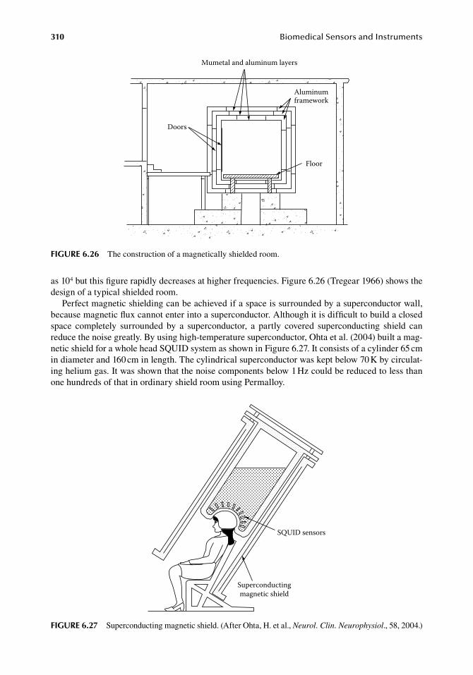
310 BiomedicalSensorsandInstruments
as.104.but.this.figure.rapidly.decreases.at.higher.frequencies..Figure.6.26.(Tregear.1966).shows.the.design.of.a.typical.shielded.room.
Perfect.magnetic.shielding.can.be.achieved.if.a.space.is.surrounded.by.a.superconductor.wall,.because.magnetic.flux.cannot.enter.into.a.superconductor..Although.it.is.difficult.to.build.a.closed.space. completely. surrounded. by. a. superconductor,. a. partly. covered. superconducting. shield. can.reduce.the.noise.greatly..By.using.high-temperature.superconductor,.Ohta.et.al..(2004).built.a.mag-netic.shield.for.a.whole.head.SQUID.system.as.shown.in.Figure.6.27..It.consists.of.a.cylinder.65.cm.in.diameter.and.160.cm.in.length..The.cylindrical.superconductor.was.kept.below.70.K.by.circulat-ing.helium.gas..It.was.shown.that.the.noise.components.below.1.Hz.could.be.reduced.to.less.than.one.hundreds.of.that.in.ordinary.shield.room.using.Permalloy.
Floor
Aluminumframework
Doors
Mumetal and aluminum layers
figure 6.26 The.construction.of.a.magnetically.shielded.room.
SQUID sensors
Superconductingmagnetic shield
figure 6.27 Superconducting.magnetic.shield..(After.Ohta,.H..et.al.,.Neurol. Clin. Neurophysiol.,.58,.2004.)
BioelectricandBiomagneticMeasurements 311
referenCeS
Abraham,. N.. G.. 1983..A. suction. electrode. net. for. precordial. ECG. mapping,. J. Med. Eng. Technol.. 7:.285–287.
Ahonen,.A.,.Hämäläinen,.M.,.Kajola,.M.,.Knuutila,.J.,.Laine,.P.,.Lounasmaa,.O.V.,.Parkkonen,.I.,.Simula,.J.,.and.Tesche,.C..1993..122-channel.SQUID.instrument.for.investigating.the.magnetic.signals.from.human.brain,.Phys. Scr..T49:.198–205.
Almasi,.J..J..and.Schmitt,.O..H..1970..Systematic.and.random.variations.of.ECG.electrode.system.impedance,.Ann. NY Acad. Sci..170.(Part.2):.509–519.
Andrä,.W..and.Nowak,.H.,.eds..2007..Magnetism in Medicine. A Handbook,.2nd.edn..Weinheim,.Germany:.Wiley-VCH.Verlag.
Andrews,.H..L..1939..A.new.electrode.for.recording.bioelectric.potentials,.Am. Heart J..17:.599–601.Barth,.D..S.,.Sutherling,.W.,.Engel,.J..Jr.,.and.Beatty,.J..1982..Neuromagnetic.localization.of.epileptiform.spike.
activity.in.the.human.brain,.Science.218:.891–894.Baule,.G..and.Mcfee,.R..1963..Detection.of.the.magnetic.field.of.the.heart,.Am. Heart J..66:.95–96.Bergey,.G..E.,.Squires,.R..D.,.and.Sipple,.W..C..1971..Electrocardiogram.recording.with.pasteless.electrodes,.
IEEE Trans. Biomed. Eng..18:.206–211.Campbell,.P..K.,.Jones,.K..E.,.and.Normann,.R..A..1990..A.100.electrode.intracortical.array:.Structural.
variability,.Biomed. Sci. Instrum..26:.161–165.Carim,.H..M..1988..Bioelectrodes,.in.Encyclopedia of Medical Devices and Instrumentation,.Webster,.J..G.,.ed..
New.York:.John.Wiley.&.Sons,.pp..195–226.Clarke,.J..1984..Ultrasensitive.measuring.devices,.Physica.126B:.441–448.Clarke,.J..and.Braginski,.A.. I..2006..The SQUID Handbook Vol. II. Applications of SQUIDs and SQUID
Systems..Weinheim,.Germany:.Wiley-VCH.Verlag.Cobbold,.R..S..C..1974..Transducers for Biomedical Measurements: Principles and Applications..New.York:.
John.Wiley.&.Sons.Cohen,.D..1968..Magnetoencephalography:.Evidence.of.magnetic.fields.produced.by.alpha-rhythm.currents,.
Science.161:.784–786.Cohen,.D..1973..Ferromagnetic.contamination.in.the.lungs.and.other.organs.of.the.human.body,.Science.180:.
745–748.Cohen,.D..and.Chandler,.L..1969..Measurements.and.simplified.interpretation.of.magnetocardiograms.from.
humans,.Circulation.39:.395–402.Cohen,.D.,.Edelsack,.E..A.,.and.Zimmerman,.J..E..1970..Magnetocardiograms.taken.inside.a.shielded.room.
with.a.superconducting.point-contact.magnetometer,.Appl. Phys. Lett..16:.278–280.Cram,.J..R..and.Engstrom,.D..1986..Patterns.of.neuromuscular.activity.in.pain.and.non-pain.patients,.Clin.
Biofeedback Health.9:.106–116.Cram,.J..R..and.Steger,.J..C..1983..EMG.scanning.in.the.diagnosis.of.chronic.pain,.Biofeedback Self Regul..
8: 229–241.David,. R.. M.. and. Portnoy,. W.. M.. 1972.. Insulated. electrocardiogram. electrodes,. Med. Biol. Eng.. 10:.
742–751.de. Luca,. C.. J.. 1988.. Electromyography,. in. Encyclopedia of Medical Devices and Instrumentation,.Vol.. 2,.
Webster,.J..G.,.ed..New.York:.John.Wiley.&.Sons,.pp..1111–1120.Downey,.J..M.,.Belandres,.P..V.,.and.Di.Benedetto,.M..1989..Suction.cup.ground.and.reference.electrodes.in.
electrodiagnosis,.Arch. Phys. Med. Rehab..70:.64–66.Drake,.K..L.,.Wise,.K..D.,.Farraye,.J.,.Anderson,.D..J.,.and.BeMent,.S..L..1988..Performance.of.planar.multisite.
microprobes.in.recording.extracellular.single-unit.intracortical.activity,.IEEE Trans. Biomed. Eng..35:.719–732.
Fagaly,.R..L..1990..Neuromagnetic.instrumentation.in.magnetoencephalography,.in.Advances in Neurology,.Vol..54,.Chap..2..Sato,.S.,.ed..New.York:.Raven.Press.
Fagaly,. R.. L.. 2000.. Superconducting. quantum. interference. devices. (SQUIDs),. in. Magnetic Sensors and Magnetometers,.Ripka,.P.,.ed..Boston,.MA:.Artech.House,.pp..75–128.
Ferris,.C..D..1974..Introduction to Bioelectrodes..London,.U.K.:.Plenum.Press.Gallen,.C..C.,.Schwartz,.B..J.,.and.Bucholtz,.R..D..1995..Presurgical.localization.of.functional.cortex.using.
magnetic.source.imaging..J. Neurosurg..82:.988–994.Geddes,.L..A..1972..Electrodes and the Measurements of Bioelectric Events..London,.U.K.:.Wiley-Interscience.Giffard,.R..P.,.Webb,.R..A.,.and.Wheatley,.J..C..1972..Principles.and.methods.of.low-frequency.electric.and.
magnetic.measurements.using.an.rf-biased.point-contact.superconducting.device,.J. Low Temp. Phys..6: 533–610.
312 BiomedicalSensorsandInstruments
Giroux,.B..and.Lamontagne,.M..1991..Comparisons.between.surface.electrodes.and.intramuscular.wire.electrodes.in.isometric.and.dynamic.conditions,.Electromyogr. Clin..Neurophysiol..30:.397–405.
Godin,.D..T.,.Parker,.P..A.,.and.Scott,.R..N..1991..Noise.characteristics.of.stainless.steel.surface.electrodes,.Med. Biol. Eng. Comput..29:.585–590.
Gouy,. M.. 1910.. Sur. la. constitution. de. la. charge. électrique. à. la. surface. d’un. électrolyte,. J. Phys. Paris. 9:.457–468.
Griss,.P.,.Enoksson,.P.,.and.Stemme,.G..2000..Spiked.biopotential.electrodes,.MEMS 2000 Miyazaki, Japan,.pp..323–328.
Helmholtz,.H..1879..Studien.über.Elektrischen.Grenzschichten,.Ann. Phys. Chem..7:.337–382.Hoffman,.B..L.,.Cranefield,.P..F.,.Lepeschkin,.E.,.Surawicz,.B.,.and.Herrlich,.H..C..1959..Comparison.of.
cardiac.monophasic.action.potentials.recorded.by.intracellular.and.suction.electrodes,.Am. J. Physiol..196:.1297–1301.
Holmer,.N..G..and.Lindstrom,.K..1972..An.electrometer.amplifier.with.low.input.capacitance.and.large.input.dynamic.range,.IEEE Trans. Biomed. Eng..19:.162–164.
Huhta,.J..C..and.Webster,.J..G..1973..60-Hz.interference.in.electrocardiography,.IEEE Trans. Biomed. Eng..20:.91–101.
Ives,.D..J..G..and.Janz,.G..J.,.eds..1961..Reference Electrodes. Theory and Practice..London,.U.K.:.Academic.Press.
Josephson,.B..D..1962..Possible.new.effect.in.superconductive.tunneling,.Phys. Lett..1:.251–253.Kalliomäki,.P.-L.,.Aittoniemi,.K.,.and.Kalliomäki,.K..1983..Occupational.health.applications.and.magneto-
pneumography,. in. Biomagnetism: An Interdisciplinary Approach.. Williamson,. S.. J.,. Romani,. G.-L.,.Kaufman,.L.,.and.Modena,.I.,.eds..New.York:.Plenum.Press,.p..561.
Kamada,.K.,.Houkin,.K.,.Takeuchi,.F.,. Ishii,.N.,. Ikeda,. J.,.Sawamura,.Y.,.Kuriki,.S.,.Kawaguchi,.H.,.and.Iwasaki,.Y..2003..Visualization.of. the.eloquent.motor.system.by.integration.of.MEG,.func-tional.and.anisotropic.diffusion-weighted.MRI. in. functional.neuronavigation,.Surg. Neurol..59:.353–362.
Ko,.W..H..and.Hynech,.J..1974..Dry.electrodes.and.electrode.amplifiers,.in.Biomedical Electrode Technology..Miller,.H..A..and.Harrison,.D..C.,.eds..New.York:.Academic.Press,.p..169.
Korsgren,.M.,.Leskinen,.E.,.Sjöstrand,.U.,. and.Varnauskas,.E..1966.. Intracardiac. recording.of.monophasic.action.potentials.in.the.human.heart,.Scand. J. Clin. Lab. Invest..18:.561–564.
Kramer,.G..S..1983..Influence.of.electrode.noise.on.bioelectric.signal.recording,.J. Clin. Eng..8:.243–247.Liao,.S..H.,.Hsu,.S..C.,.Lin,.C..C.,.Horng,.H..E.,.Chen,.J..C.,.Chen,.M..J.,.Wu,.C..H.,.and.Yang,.H..C..2003..
High-Tc.SQUID.gradiometer.system.for.magnetocardiography.in.an.unshielded.Environment,.Supercond. Sci. Technol..16:.1426–1429.
MacInnes,.D..A..1961..The Principles of Electrochemistry..New.York:.Dover.Publications.Mäkälä..J..P.,.Forss,.N.,.Jääskeläinen,.J.,.Kirveskari,.E.,.Korvenoja,.A.,.and.Paetau,.R..2006..Magnetoence-
phalography.in.neurosurgery..Neurosurgery.59:.493–511.Mäkälä,.J..P.,.Kirveskari,.E.,.Seppä,.M.,.Hämäläinen,.M.,.Forss,.N.,.Avikainen,.S.,.Salonen,.O..et.al..2001..Three-
dimensional.integration.of.brain.anatomy.and.function.to.facilitate.intraoperative.navigation.around.the.sensimotor.strip,.Hum. Brain Mapp..12:.180–192.
Malmivuo,.J..and.Plonsey,.R..1995..Bioelectromagnetics..New.York:.Oxford.University.Press.Matsuo,.T.,.Iinuma,.K.,.and.Esashi,.M..1973..A.barium-titanate-ceramics.capacitive-type.EEG.electrode,.IEEE
Trans. Biomed. Eng..20:.299–300.Maxwell,.R..E.,.Gates,.J..R.,.Fiol,.M..E.,.Johnsson,.M..J.,.Yap,.J..C.,.Leppik,.I..E.,.and.Gumnit,.R..J..1983..
Clinical.evaluation.of.a.depth.electroencephalography.electrode,.Neurosurgery.12:.561–564.Modena,. I.,. Ricci,. G.. B.,. Barbanera,. S.,. Romani,. G.. L.,. and. Carelli,. P.. 1982.. Biomagnetic. measure-
ments.of.spontaneous.brain.activity. in.epileptic.patients..Electroencephalogr. Clin. Neurophysiol..54:.622–628.
Muluaka,.M..2003..Assessment.of.lung.particle.accumulation.in.factory.workers.by.magnetic.field.measurement,.Int. J. Occup. Med. Environ. Health.16:.209–213.
Muluaka,.M.,.Zheng,.Y.,.Kotani,.M.,.and.Uchikawa,.Y..1997..Measurements.of. the.quantities.of.particles.accumulated.in.the.lungs.of.workers,.Front Med. Biol. Eng..8:.287–294.
Nakaya,.Y..and.Mori,.H..1992..Magnetocardiography,.Clin. Phys. Physiol. Meas..13:.191–229.Nandedkar,.S..D..and.Sanders,.D..B..1991..Recording.characteristics.of.monopolar.EMG.electrodes,.Muscle
Nerve.14:.108–112.Nandedkar,.S..D.,.Tedman,.B.,.and.Sanders,.D..B..1990..Recording.and.physical.characteristics.of.disposable.
concentric.needle.EMG.electrodes,.Muscle Nerve.13:.909–914.
BioelectricandBiomagneticMeasurements 313
Neher,.E..and.Sakmann,.B..1976..Single-channel.currents.recorded.from.membrane.of.denervated.frog.muscle.fibres,.Nature.260(5554):.799–802.
Neuman,.M..R..2010..Biopotential.electrodes,.in.Medical Instrumentation. Application and Design,.4th.edn..Webster,.J..G.,.ed..Boston,.MA:.Houghton.Mifflin.Co.,.pp..189–240.
Nousiainen,.J.,.Oja,.O..S.,.Tuominen,.T.,.and.Malmivuo,.J..1985..Normal.magnetocardiogram,.Med. Biol. Eng. Comput..23.Suppl..(part.1):.69–70.
Öberg,.P..Å..and.Sjöstrand,.U..1971..Studies.of.blood-pressure.regulation..III..Dynamics.of.arterial.blood.pressure.on.carotid-sinus.nerve.stimulation,.Acta Physiol. Scand..81:.96–109.
Ödman,.S..1981..Potential.and.impedance.variations.following.skin.deformation,.Med. Biol. Eng. Comput..19:.271–278.
Ohta,.H.,.Matsui,.T.,.and.Uchikawa,.Y..2004..Whole-head.SQUID.system.in.a.superconducting.magnetic.shield,.Neurol. Clin. Neurophysiol..Nov..30;.2004:.58.
Olsson,. S.. B.. 1971.. Monophasic Action Potentials of Right Heart.. Gothenburg,. Sweden:. Elanders.Boktryckeri.AB.
Parsons,.R..1964..Electrode.double. layer,. in.The Encyclopedia of Electrochemistry..Hampel,.C..A.,.ed..New.York:.Reinhold.Publishing.Co.
Richardson,.P..C..1967..Progress.in.long-term.physiologic.sensor.development,.in.Proceedings of the Biomedical Engineering Symposium, San Diego.39.
Richardson,.P..C.,.Coombs,.F..K.,.and.Adams,.R..M..1968..Some.new.electrode.techniques.for.long-term.physiologic.monitoring,.Aerosp. Med..39:.745–750.
Ripka,.P..2000..Fluxgate.sensors,.in.Magnetic Sensors and Magnetometers..Ripka,.P..ed..Boston,.MA:.Artech.House,.pp..75–128.
Roman,. J.. 1966.. Flight. research. program. III.. High. impedance. electrode. techniques,. Aerosp.. Med.. 37:.790–795.
Roth,.I..1933–1934..A.self-retaining.skin.contact.electrode.for.chest.leads.in.electrocardiography,.Am. Heart J..9:.526.
Samuelsson,.R..and.Sjöstrand,.U..1971..Endocardial.recording.of.monophasic.action.potentials.in.the.intact.dog,.Acta Soc. Med. Ups..76:.191–210.
Shabetai,. R.,. Surawicz,. B.,. and. Hammill,. W.. 1968.. Monophasic. action. potentials. in. man,. Circ. Res.. 38:.341–352.
Shackel,.B..1958..A.rubber.suction.cup.surface.electrode.with.high.electrical.stability,.J. Appl. Physiol..13:.153–158.
Simons,.A.. J.. 1980..Measurement. of. rise. time.of. averaged.muscle. action.potential. in. normal. subjects. and.patients.with.myopathy,.J. Neurol. Neurosurg. Psychiatr..43:.56–62.
Sjöstrand,.U..1966..Intrakardiellt.registrerade.monofasiska.aktionspotentialer,.Paper.given.at.Fysiologföreningen.(Stockholm),.Nov..22.
Stern,.O..1924..Zur.Theorie.der.electrolytischen.Doppelschicht,.Z. Electrochem..30:.508–516.Stroink,.G..1985..Magnetic.measurements.to.determine.dust.loads.and.clearance.rates.in.industrial.workers.and.
miners,.Med. Biol. Eng. Comput..23.Suppl.1:.44–49.Tam,. H..W.. and.Webster,. J.. G.. 1977.. Minimizing. electrode. motion. artifact. by. skin. abrasion,. IEEE Trans.
Biomed. Eng..24:.134–139.Thompson,.J..M.,.Erickson,.R..P.,.and.Offord,.K..P..1989..EMG.muscle.scanning:.Stability.of.hand-held.surface.
electrodes,.Biofeedback Self Regul..14:.55–62.Thompson,.J..M.,.Madsen,.T..J.,.and.Erickson,.R..P..1991..EMG.muscle.scanning:.Comparison.to.attached.
surface.electrodes,.Biofeedback Self Regul..16:.167–179.Tregear,.R..T..1966..Physical Functions of Skin..London,.U.K.:.Academic.Press.Ungerleider,.H..E..1939..A.new.precordial.electrode,.Am. Heart J..18:.94.van.Duzer,.T..and.Turner,.C..W..1998..Principles of Superconducting Devices and Circuits,.2nd.edn..New.York:.
Elsevier.Vrba,.J.,.Betts,.K.,.Brubank,.M.,.Cheung,.T.,.Fife,.A..A.,.Haid,.G.,.Kubik,.P..R..et.al..1993..Whole.cortex.64 chan-
nel.SQUID.biomagnetometer.system..IEEE Trans. Appl. Supercond..3:.1878–1882.Webster,.J..G..1977..Interference.and.motion.artifact.in.biopotentials,.IEEE Region 6 Conference Record,.
pp..53–64.Wikswo,.J..P..1985..Magnetic.measurements.on.single.nerve.axons.and.nerve.bundles,.Med. Biol. Eng. Comput..
23.Suppl..(part.I):.3–6.Wikswo,.J..P..Jr.,.Barach,.J..P.,.and.Freeman,.J..A..1980..Magnetic.field.of.a.nerve.impulse:.First.measurement,.
Science.208:.53–55.
314 BiomedicalSensorsandInstruments
Wyllie,.E.,.Lüders,.H.,.Morris.III,.H..H.,.Lesser,.R..P.,.Dinner,.D..S.,.Rothner,.A..D.,.Erenberg,.G.,.Cruse,.R.,.and.Friedman,.D..1988..Subdural.electrodes.in.the.evaluation.for.epilepsy.surgery.in.children.and.adults,.Neuropediatrics.19:.80–86.
Yang,.H..C.,.Hung,.S..Y.,.Wu,.C..H.,.Chen,.J..C.,.Hsu,.S..J.,.Liao,.S..H.,.and.Horng,.H..E..2004..High-Tc.SQUID.magnetocardiography.Imaging.System,.Neurol. Clin. Neurophysiol..Nov..30;.2004:.23.
Yon,.E..T.,.Neuman,.M..R.,.Wolfson,.R..N.,.and.Ko,.W..H..1970..Insulated.active.electrodes,.IEEE Trans. Ind. Electron. Control Instrum..17:.195.
Zhao,.Y.,.Inayat,.S.,.Dikin,.D..A.,.Singer,.J..H.,.Ruoffand,.R..S.,.and.Troy,.J..B..2008..Patch.clamp.technique:.Review.of.the.current.state.of.the.art.and.potential.contributions.from.nanoengineering,.Proc. Inst. Mech. Eng.: J. Nanoeng. Nanosyst..222.JNN149:.1–11.
315
7 ChemicalMeasurement
7.1 objeCtS of MeaSureMentS
7.1.1 units of cheMical quantities
The.amount.of.substance.is.usually.expressed.in.terms.of.mass..The.unit.of.mass.is.kilogram.(kg).in.the.SI.unit.system..The.amount.of.substance.can.also.be.expressed.by.mole.(mol)..The.number.of.elementary.entities.in.1.mol.is.the.Avogadro.constant,.which.is.usually.denoted.by.NA,.and.is.6.0221367.×.1023..While.the.term.mol.came.from.molecule,.this.unit.can.also.be.applied.to.atoms,.ions,.or.any.elementary.entities.of.substance,.if.adequately.defined..In.the.SI.unit.system,.mol.is.defined.as.the.number.of.atoms.in.0.012.kg.of.12C.
The.amount.of.a.specific.substance.in.a.solution.can.be.expressed.by.its.mass,.volume,.or.mole..The.concentration.is.the.mass.of.the.substance.in.unit.volume.of.the.solution,.and.the.unit.of.con-centration.in.the.SI.system.is.kilogram.per.cubic.meter..In.physiological.texts,.relating.units.such.as.g/L,.mg/dL,.or.mg/L.have.also.been.used.
The.molar.concentration.is.the.amount.of.substance.expressed.in.mol.in.unit.volume.of.the.solu-tion,.and.the.unit.in.the.SI.system.is.mol/m3..In.physiological.texts,.mol/L,.mmol/L,.μmol/L,.and.nmol/L.have.also.been.used..The.concentration.and.molar.concentration.are.usually.denoted.by.c,.but.molar.concentration.of.a.specific.substance.is.often.denoted.by.a.chemical.formula.with.brackets..For.example,.[H+].and.[HCO3
−].are.the.molar.concentrations.of.H+.and.HCO3−,.respectively.
The.ratio.of.quantities.of.substances.in.a.mixture.is.usually.expressed.either.by.a.mass.fraction.or.molar.fraction..Both.quantities.are.nondimensional.values..Molar.concentration,.mass.fraction,.and.molar.fraction.are.also.called.concentrations..Fractions.can.be.expressed.in.percent..To.express.very.small.fractions,.ppm.(parts.per.million).and.ppb.(parts.per.billion).are.also.used.
In.standard.chemical.reactions,.the.reaction.rate.depends.on.the.concentrations.of.the.substances.involved.in.the.reaction..However,. the.tendency.of.facilitating.the.reaction.is.not.strictly.propor-tional.to.the.concentration.of.the.substance,.but.proportional.to.a.quantity.called.activity..The.con-cept.of.activity.is.especially.important.in.estimating.the.condition.of.equilibrium..The.activity.is.a.dimensionless.quantity.and.is.unity.for.a.pure.substance..When.the.concentration.is.low.enough,.the.activity.is.equivalent.to.a.molar.fraction..Activity.is.denoted.by.a,.or.a.with.a.subscript.that.denotes.the.substance.
In.an.electrolyte.solution,.the.dissociation.and.association.occur.as
. AB A B + −+ . (7.1)
and. the. rates. of. both. reactions. are. balanced. in. equilibrium.. The. degree. of. dissociation. can. be.described.as
.
[A+ −
=][B ][AB]
k.
(7.2)
or
.
a a
aA B
AB
⋅ = K.
(7.3)
316 BiomedicalSensorsandInstruments
where.aA+,.aA
−,.and.aAB.are.activities.of.A+,.B−,.and.AB,.respectively..Both.k.and.K.are.called.equilib-rium.constants..When.a.molar.concentration.is.used.as.in.Equation.7.2,.the.equilibrium.constant.k.depends.on.the.concentration.of.the.solution..However,.when.activities.are.used.as.in.Equation.7.3,.the.equilibrium.constant.K.is.independent.of.the.concentration..K.is.called.the.thermodynamic.dis-sociation.constant..The.unit.of.k.is.molar.concentration,.but.the.unit.of.K.is.dimensionless..In.weak.electrolytes,.the.dependency.of.k.on.the.concentration.is.negligible.
To.describe.the.concentration.of.a.hydrogen.ion,.pH.has.been.used.that.is.defined.as
. pH log H1= − +0 [ ] . (7.4)
where.[H+].is.expressed.by.mol/L..In.a.neutral.solution,.pH.=.7.0.Partial.pressure.of.dissolved.gas.is.denoted.by.p.followed.by.the.chemical.formula.of.the.gas..For.
example,.partial.pressure.of.oxygen.and.carbon.dioxide.are.denoted.as.pO2.and.pCO2,.respectively..The.unit.of.partial.pressure.is.Pa.in.the.SI.system,.but.mmHg.is.still.generally.used.
The.total.amount.of.gas.dissolved.in.a.solution.is.expressed.by.the.ratio.of.the.equivalent.volume.of.the.gas.at.standard.condition.(0°C,.1.atm).to.the.volume.of.the.solution..It. is.a.dimensionless.quantity.and.generally.expressed.by.volume.per.cent.(vol%)..The.amount.of.dissolved.gas.is.also.expressed.by.a.molar.concentration.such.as.mmol/L.
7.1.2 objects of cheMical MeasureMent
Chemical.quantities.in.the.body.are.estimated.by.analyzing.a.sampled.material.such.as.the.blood.or.urine..However,.the.concentrations.of.some.chemical.quantities.may.vary.rapidly.so.that.continuous.monitoring.in vivo.is.required.
The. blood. is. the. most. common. object. for. chemical. measurement,. because. many. important.chemical. substances. are. transported. by. means. of. blood. circulation.. Actually,. concentrations. of.many.substances.in.blood.reflect.those.in.the.whole.body.
Conventionally,.blood.samples.are.taken.from.a.vein,.and.analyzed.by.chemical.analyzers..In.order.to.monitor.chemical.quantities.in.the.blood.continuously,.either.continuous.drainage.of.the.blood.or.placing.a.chemical.sensor.in.a.blood.vessel.is.required..However,.if.the.object.substance.is.highly.permeable.to.the.capillary.wall,.the.concentration.in.the.interstitial.fluid.is.considered.to.be.equal.to.that.in.the.blood..Thus,.the.concentration.of.the.substance.in.the.blood.can.be.monitored.by.a.sensor.placed.in.the.interstitial.fluid.space..Urine.is.also.a.common.object.in.clinical.labora-tory.analysis..Although.the.information.available.from.the.urine.is.less.compared.to.that.from.the.blood,.urine.analysis.is.advantageous.because.of.the.ease.of.obtaining.samples..During.continuous.drainage.of.urine,.continuous.monitoring.of.chemical.quantities.is.conceivable..However,.the.ranges.of.concentrations.of.substances.in.urine.can.vary.widely.when.the.urine.volume.varies..Actually,.urine.pH.normally.ranges.from.4.6.to.8.0,.and.urine.osmotic.pressure,.which.corresponds.to.the.molar.concentration.of.the.solute,.ranges.from.200.to.850.mmol/L..To.monitor.the.rate.of.excretion.of.a.substance.into.urine,.both.the.amount.of.urine.and.the.concentration.of.the.substance.should.be.determined.
On.the.other.hand,.glucose,.protein,.or.hemoglobin.in.the.urine.are.not.detected.in.normal.urine,.and.thus.the.appearance.of.such.substances.in.the.urine.can.be.a.sensitive.sign.of.abnormality.
Continuous. in vivo. measurement. of. some. chemical. species,. especially. nitric. oxide. (NO),. is.required.in.a.local.area.in.investigations.at.the.cellular.level..For.such.purposes,.sensors.of.micro.or.nanometer.scale.are.used.
Components.of.the.expiratory.gas.are.also.important.clinically,.and.are.sometimes.monitored.during.anesthesia.and.in.intensive.care..Oxygen.and.carbon.dioxide.are.also.measured.to.determine.the.metabolic.rate.
ChemicalMeasurement 317
7.1.3 requireMents and liMitations in cheMical MeasureMents
Chemical.sensors.are.used.in.various.clinical.situations.such.as.during.anesthesia,.in.an.intensive.care. unit,. in. an. emergency. situation,. and. in. ambulatory. monitoring. of. postoperative. or. chronic.patients..It.is.also.necessary.to.use.a.closed-loop.artificial.organ,.in.which.chemical.quantities.in.the.body.are.servo-controlled.to.a.desired.level.
To.monitor.chemical.quantities.in.subjects,.there.are.different.approaches.to.applying.a.sensor.to.the.body,.such.as.attaching.a.sensor.to.the.body.surface,.inserting.it.into.the.tissue.or.blood.vessel,.implanting.it.in.the.body,.attaching.it.to.the.extracorporeal.circulation.circuit,.or.installing.it.in.the.artificial.organ..When.totally.implanted.devices.are.desired.for.chronic.use,.long-term.stability.must.be.a.requirement..The.use.of.a.catheter.through.which.a.sensor.can.be.inserted,.and.removed.for.recalibration,.or.replaced.by.a.new.one.can.be.a.possible.solution.when.ultimate.stability.cannot.be.attained..However,.the.risk.of.infection.will.still.remain.if.there.is.a.gap.between.the.outer.surface.of.the.catheter.and.the.skin.tissue..Although.several.attempts.with.percutaneous.connectors.that.form.a.tight.contact.between.the.artificial.material.and.the.skin.have.been.made,.most.artificial.materials.have.been.unsatisfactory.for.this.purpose.(Park.1979)..Only.some.materials,.such.as.hydroxyapatite,.could.be.used.to.form.a.fairly.good.contact.with.the.skin.tissue..It.is.expected.that.by.using.such.a.material,.reliable.transcutaneous.sockets.or.connectors.for.long-term.use.can.be.effected.(Aoki.et al..1987,.Tsuji.et al..1990).
When.a.chemical.sensor.is.used.in vivo,.some.general.requirements.summarized.below.need.to.be.considered:
•. Initial.calibration.and.recalibration,.if.necessary,.should.be.performed.in.sterile.conditions.•. A.chemical.reaction.occurring.at.the.sensor.should.not.cause.toxicity.to.the.tissue.•. The.temperature.coefficient.of.the.sensor.should.be.compensated.for.so.that.it.can.be.used.
at.an.in situ.temperature.•. When.the.sensor.is.placed.in.the.blood.vessel,.its.surface.should.be.anticoagulant,.and.it.
should.be.small.enough.not.to.obstruct.blood.flow.•. The.sensor.should.be.electrically. insulated.from.the.body.fluid.so. that.current. leakage,.
which.may.cause.an.electrical.hazard,.never.occurs.even.if.a.power.line.voltage.is.acciden-tally.applied.between.the.transducer.cable.and.the.body.
•. The.size.and.shape.of.the.sensor.should.be.designed.so.that.it.does.not.cause.any.mechani-cal.hazard.to.the.surrounding.tissue.
7.2 CheMiCal SenSorS
7.2.1 electrocheMical sensors
The.electrochemical.sensor.is.a.device.that.converts.chemical.quantity.into.electric.potential.or.cur-rent,.making.use.of.the.electrochemical.principle..Figure.7.1.shows.the.fundamental.electrochemi-cal.measurement.system..It.consists.of. two.electrodes,. the.electrolyte.solution.and.the.electronic.instrumentation.for.potential.or.current.measurement..When.the.electrolyte.is.dissolved.in.water,.it.dissociates.into.ions..The.ion.moves.when.an.electric.field.is.developed.in.the.solution.and.causes.ionic.current..However,. the.ionic.current.cannot.be.measured.directly.by.the.standard.electronic.instrument.in.which.the.current.is.sustained.by.the.movement.of.free.electrons.in.the.electric.con-ductor..Therefore,.in.order.to.measure.ionic.current.with.an.electronic.instrument,.a.pair.of.interfac-ing.parts.are.required.which.converts.an.ionic.current.into.an.electronic.one..In.electrochemistry,.the. electrode. is. defined. as. the. interface.between. the. electrolyte. and. the. electric. conductor..The.system.comprising. electrodes. and. electrolytes. can.be. an. electrochemical. sensor.where. the. con-centration.of.the.substance.to.be.measured.is.reflected.in.the.potential.between.the.electrodes,.or.
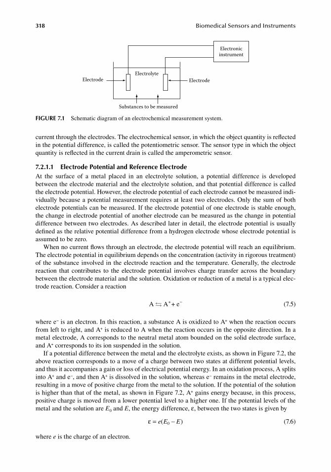
318 BiomedicalSensorsandInstruments
current.through.the.electrodes..The.electrochemical.sensor,.in.which.the.object.quantity.is.reflected.in.the.potential.difference,.is.called.the.potentiometric.sensor..The.sensor.type.in.which.the.object.quantity.is.reflected.in.the.current.drain.is.called.the.amperometric.sensor.
7.2.1.1 electrode Potential and reference electrodeAt. the. surface. of. a. metal. placed. in. an. electrolyte. solution,. a. potential. difference. is. developed.between.the.electrode.material.and.the.electrolyte.solution,.and.that.potential.difference.is.called.the.electrode.potential..However,.the.electrode.potential.of.each.electrode.cannot.be.measured.indi-vidually.because.a.potential.measurement.requires.at.least.two.electrodes..Only.the.sum.of.both.electrode.potentials.can.be.measured..If.the.electrode.potential.of.one.electrode.is.stable.enough,.the.change.in.electrode.potential.of.another.electrode.can.be.measured.as.the.change.in.potential.difference.between.two.electrodes..As.described.later.in.detail,.the.electrode.potential.is.usually.defined.as.the.relative.potential.difference.from.a.hydrogen.electrode.whose.electrode.potential.is.assumed.to.be.zero.
When.no.current.flows.through.an.electrode,.the.electrode.potential.will.reach.an.equilibrium..The.electrode.potential.in.equilibrium.depends.on.the.concentration.(activity.in.rigorous.treatment).of. the.substance.involved.in.the.electrode.reaction.and.the.temperature..Generally,. the.electrode.reaction. that. contributes. to. the. electrode. potential. involves. charge. transfer. across. the. boundary.between.the.electrode.material.and.the.solution..Oxidation.or.reduction.of.a.metal.is.a.typical.elec-trode.reaction..Consider.a.reaction
. A A + e+ −. (7.5)
where.e−.is.an.electron..In.this.reaction,.a.substance.A.is.oxidized.to.A+.when.the.reaction.occurs.from.left.to.right,.and.A+.is.reduced.to.A.when.the.reaction.occurs.in.the.opposite.direction..In.a.metal.electrode,.A.corresponds.to.the.neutral.metal.atom.bounded.on.the.solid.electrode.surface,.and.A+.corresponds.to.its.ion.suspended.in.the.solution.
If.a.potential.difference.between.the.metal.and.the.electrolyte.exists,.as.shown.in.Figure.7.2,.the.above.reaction.corresponds.to.a.move.of.a.charge.between.two.states.at.different.potential.levels,.and.thus.it.accompanies.a.gain.or.loss.of.electrical.potential.energy..In.an.oxidation.process,.A.splits.into.A+.and.e−,.and.then.A+.is.dissolved.in.the.solution,.whereas.e−.remains.in.the.metal.electrode,.resulting.in.a.move.of.positive.charge.from.the.metal.to.the.solution..If.the.potential.of.the.solution.is.higher.than.that.of.the.metal,.as.shown.in.Figure.7.2,.A+.gains.energy.because,.in.this.process,.positive.charge.is.moved.from.a.lower.potential.level.to.a.higher.one..If.the.potential.levels.of.the.metal.and.the.solution.are.E0.and.E,.the.energy.difference,.ε,.between.the.two.states.is.given.by
. ε = −e E E( )0 . (7.6)
where.e.is.the.charge.of.an.electron.
Electrode ElectrodeElectrolyte
Substances to be measured
Electronicinstrument
figure 7.1 Schematic.diagram.of.an.electrochemical.measurement.system.
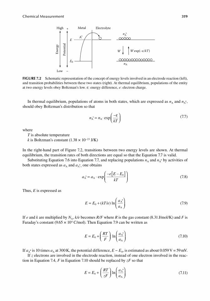
ChemicalMeasurement 319
In.thermal.equilibrium,.populations.of.atoms.in.both.states,.which.are.expressed.as.nA.and.nA+,.
should.obey.Boltzman’s.distribution.so.that
.n n
kTA A exp+ = ⋅
–ε
.
(7.7)
whereT.is.absolute.temperaturek.is.Boltzman’s.constant.(1.38.×.10−23.J/K)
In.the.right-hand.part.of.Figure.7.2,.transitions.between.two.energy.levels.are.shown..At.thermal.equilibrium,.the.transition.rates.of.both.directions.are.equal.so.that.the.Equation.7.7.is.valid.
Substituting.Equation.7.6.into.Equation.7.7,.and.replacing.populations.nA.and.nA+.by.activities.of.
both.states.expressed.as.aA.and.aA+,.one.obtains
.
a ae E E
kTA A exp+ = ⋅ [ ]
– – 0
.
(7.8)
Thus,.E.is.expressed.as
.
E E kT ea
a= +
+
0 ( / ) ln A
A .
(7.9)
If.e.and.k.are.multiplied.by.NA,.k/e.becomes.R/F.where.R.is.the.gas.constant.(8.31.J/mol/K).and.F.is.Faraday’s.constant.(9.65.×.104.C/mol)..Then.Equation.7.9.can.be.written.as
.
E ERT
F
a
a= +
+
0 ln A
A .
(7.10)
If.aA+.is.10.times.aA.at.300.K,.the.potential.difference,.E − E0,.is.estimated.as.about.0.059.V.= 59.mV.
If.z.electrons.are.involved.in.the.electrode.reaction,.instead.of.one.electron.involved.in.the.reac-tion.in.Equation.7.4,.F.in.Equation.7.10.should.be.replaced.by.zF.so.that
.
E ERT
zF
a
a= +
+
0 ln A
A .(7.11)
W W exp(–ε/kT )
nA+
nA
High
Low
Ener
gy
Pote
ntia
l
+
–
E
E0
A+
Metal Electrolyte
figure 7.2 Schematic.representation.of.the.concept.of.energy.levels.involved.in.an.electrode.reaction.(left),.and.transition.probabilities.between.these.two.states.(right)..At.thermal.equilibrium,.populations.of.the.entity.at.two.energy.levels.obey.Boltzman’s.low..ε:.energy.difference,.e:.electron.charge.
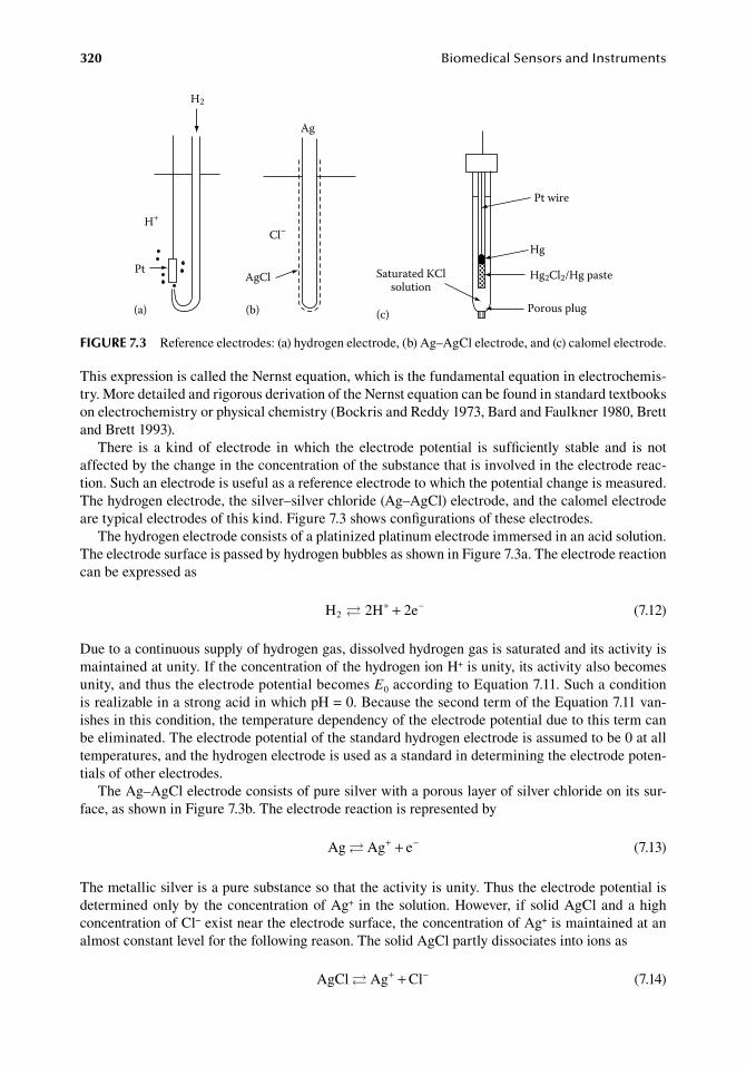
320 BiomedicalSensorsandInstruments
This.expression.is.called.the.Nernst.equation,.which.is.the.fundamental.equation.in.electrochemis-try..More.detailed.and.rigorous.derivation.of.the.Nernst.equation.can.be.found.in.standard.textbooks.on.electrochemistry.or.physical.chemistry.(Bockris.and.Reddy.1973,.Bard.and.Faulkner.1980,.Brett.and.Brett.1993).
There. is. a. kind. of. electrode. in. which. the. electrode. potential. is. sufficiently. stable. and. is. not.affected.by.the.change.in.the.concentration.of.the.substance.that.is.involved.in.the.electrode.reac-tion..Such.an.electrode.is.useful.as.a.reference.electrode.to.which.the.potential.change.is.measured..The.hydrogen.electrode,.the.silver–silver.chloride.(Ag–AgCl).electrode,.and.the.calomel.electrode.are.typical.electrodes.of.this.kind..Figure.7.3.shows.configurations.of.these.electrodes.
The.hydrogen.electrode.consists.of.a.platinized.platinum.electrode.immersed.in.an.acid.solution..The.electrode.surface.is.passed.by.hydrogen.bubbles.as.shown.in.Figure.7.3a..The.electrode.reaction.can.be.expressed.as
. H 2H 2e2 + −+ . (7.12)
Due.to.a.continuous.supply.of.hydrogen.gas,.dissolved.hydrogen.gas.is.saturated.and.its.activity.is.maintained.at.unity..If.the.concentration.of.the.hydrogen.ion.H+.is.unity,.its.activity.also.becomes.unity,.and.thus.the.electrode.potential.becomes.E0.according.to.Equation.7.11..Such.a.condition.is.realizable.in.a.strong.acid.in.which.pH.=.0..Because.the.second.term.of.the.Equation.7.11.van-ishes.in.this.condition,.the.temperature.dependency.of.the.electrode.potential.due.to.this.term.can.be.eliminated..The.electrode.potential.of.the.standard.hydrogen.electrode.is.assumed.to.be.0.at.all.temperatures,.and.the.hydrogen.electrode.is.used.as.a.standard.in.determining.the.electrode.poten-tials.of.other.electrodes.
The.Ag–AgCl.electrode.consists.of.pure.silver.with.a.porous.layer.of.silver.chloride.on.its.sur-face,.as.shown.in.Figure.7.3b..The.electrode.reaction.is.represented.by
. Ag Ag e + −+ . (7.13)
The.metallic.silver.is.a.pure.substance.so.that.the.activity.is.unity..Thus.the.electrode.potential.is.determined.only.by. the.concentration.of.Ag+. in. the.solution..However,. if.solid.AgCl.and.a.high.concentration.of.Cl−.exist.near.the.electrode.surface,.the.concentration.of.Ag+.is.maintained.at.an.almost.constant.level.for.the.following.reason..The.solid.AgCl.partly.dissociates.into.ions.as
. AgCl Ag Cl + −+ . (7.14)
H2
H+
Pt
Ag
Cl–
AgCl Saturated KClsolution
Pt wire
Hg
Hg2Cl2/Hg paste
Porous plug(a) (b) (c)
figure 7.3 Reference.electrodes:.(a).hydrogen.electrode,.(b).Ag–AgCl.electrode,.and.(c).calomel.electrode.
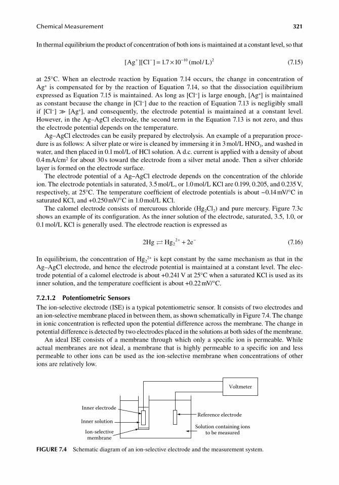
ChemicalMeasurement 321
In.thermal.equilibrium.the.product.of.concentration.of.both.ions.is.maintained.at.a.constant.level,.so.that
. [ ][ ] . ( / )Ag Cl 1 7 1 mol L1 2+ − −= × 0 0
. (7.15)
at. 25°C.. When. an. electrode. reaction. by. Equation. 7.14. occurs,. the. change. in. concentration. of.Ag+. is. compensated. for. by. the. reaction. of. Equation. 7.14,. so. that. the. dissociation. equilibrium.expressed.as.Equation.7.15.is.maintained..As.long.as.[Cl−].is.large.enough,.[Ag+].is.maintained.as.constant.because.the.change.in.[Cl−].due.to.the.reaction.of.Equation.7.13.is.negligibly.small.if. [Cl−]. ≫. [Ag+],. and. consequently,. the. electrode. potential. is. maintained. at. a. constant. level..However,.in.the.Ag–AgCl.electrode,.the.second.term.in.the.Equation.7.13.is.not.zero,.and.thus.the.electrode.potential.depends.on.the.temperature.
Ag–AgCl.electrodes.can.be.easily.prepared.by.electrolysis..An.example.of.a.preparation.proce-dure.is.as.follows:.A.silver.plate.or.wire.is.cleaned.by.immersing.it.in.3.mol/L.HNO3,.and.washed.in.water,.and.then.placed.in.0.1.mol/L.of.HCl.solution..A.d.c..current.is.applied.with.a.density.of.about.0.4.mA/cm2.for.about.30.s.toward.the.electrode.from.a.silver.metal.anode..Then.a.silver.chloride.layer.is.formed.on.the.electrode.surface.
The.electrode.potential.of.a.Ag–AgCl.electrode.depends.on.the.concentration.of. the.chloride.ion..The.electrode.potentials.in.saturated,.3.5.mol/L,.or.1.0.mol/L.KCl.are.0.199,.0.205,.and.0.235.V,.respectively,.at.25°C..The.temperature.coefficient.of.electrode.potentials.is.about.−0.14.mV/°C.in.saturated.KCl,.and.+0.250.mV/°C.in.1.0.mol/L.KCl.
The.calomel.electrode.consists.of.mercurous.chloride.(Hg2Cl2).and.pure.mercury..Figure.7.3c.shows.an.example.of.its.configuration..As.the.inner.solution.of.the.electrode,.saturated,.3.5,.1.0,.or.0.1.mol/L.KCl.is.generally.used..The.electrode.reaction.is.expressed.as
. 2Hg Hg 2e22 + −+ . (7.16)
In.equilibrium,.the.concentration.of.Hg22+.is.kept.constant.by.the.same.mechanism.as.that.in.the.
Ag–AgCl.electrode,.and.hence.the.electrode.potential.is.maintained.at.a.constant.level..The.elec-trode.potential.of.a.calomel.electrode.is.about.+0.241.V.at.25°C.when.a.saturated.KCl.is.used.as.its.inner.solution,.and.the.temperature.coefficient.is.about.+0.22.mV/°C.
7.2.1.2 Potentiometric SensorsThe.ion-selective.electrode.(ISE).is.a.typical.potentiometric.sensor..It.consists.of.two.electrodes.and.an.ion-selective.membrane.placed.in.between.them,.as.shown.schematically.in.Figure.7.4..The.change.in.ionic.concentration.is.reflected.upon.the.potential.difference.across.the.membrane..The.change.in.potential.difference.is.detected.by.two.electrodes.placed.in.the.solutions.at.both.sides.of.the.membrane.
An. ideal. ISE.consists.of.a.membrane. through.which.only.a.specific. ion. is.permeable..While.actual.membranes.are.not. ideal,.a.membrane. that. is.highly.permeable. to.a.specific. ion.and. less.permeable.to.other.ions.can.be.used.as.the.ion-selective.membrane.when.concentrations.of.other.ions.are.relatively.low.
Inner electrode
Inner solution
Ion-selectivemembrane
Reference electrode
Solution containing ionsto be measured
Voltmeter
figure 7.4 Schematic.diagram.of.an.ion-selective.electrode.and.the.measurement.system.
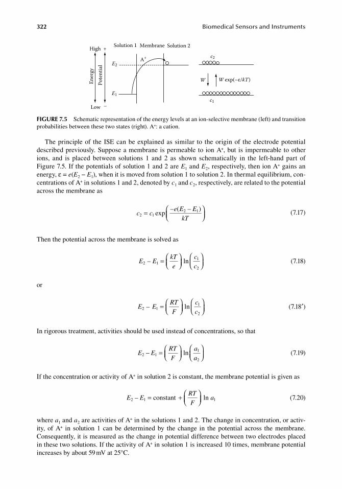
322 BiomedicalSensorsandInstruments
The.principle.of. the. ISE.can.be.explained.as.similar. to. the.origin.of. the.electrode.potential.described.previously..Suppose.a.membrane.is.permeable.to.ion.A+,.but.is.impermeable.to.other.ions,. and. is. placed. between. solutions. 1. and. 2. as. shown. schematically. in. the. left-hand. part. of.Figure.7.5..If.the.potentials.of.solution.1.and.2.are.E1.and.E2,.respectively,.then.ion.A+.gains.an.energy,.ε.=.e(E2.−.E1),.when.it.is.moved.from.solution.1.to.solution.2..In.thermal.equilibrium,.con-centrations.of.A+.in.solutions.1.and.2,.denoted.by.c1.and.c2,.respectively,.are.related.to.the.potential.across.the.membrane.as
.
c ce E E
kT2 1
2 1exp=
– ( – )
.
(7.17)
Then.the.potential.across.the.membrane.is.solved.as
.E E
kT
e
c
c2 1
1
2
ln– =
.(7.18)
or
.E E
RT
F
c
c2 1
1
2
ln– =
.(7.18′)
In.rigorous.treatment,.activities.should.be.used.instead.of.concentrations,.so.that
.E E
RT
F
a
a2 1
1
2
ln– =
.(7.19)
If.the.concentration.or.activity.of.A+.in.solution.2.is.constant,.the.membrane.potential.is.given.as
.E E
RT
Fa2 1 1constant ln– = +
.
(7.20)
where.a1.and.a2.are.activities.of.A+.in.the.solutions.1.and.2..The.change.in.concentration,.or.activ-ity,.of.A+. in. solution.1. can.be.determined.by. the. change. in. the.potential. across. the.membrane..Consequently,.it.is.measured.as.the.change.in.potential.difference.between.two.electrodes.placed.in.these.two.solutions..If.the.activity.of.A+.in.solution.1.is.increased.10.times,.membrane.potential.increases.by.about.59.mV.at.25°C.
W W exp(–ε/kT)
c2
c1
High
Low
Ener
gyPo
tent
ial
+
–
E1
A+E2
Solution 1 Membrane Solution 2
figure 7.5 Schematic.representation.of.the.energy.levels.at.an.ion-selective.membrane.(left).and.transition.probabilities.between.these.two.states.(right)..A+:.a.cation.
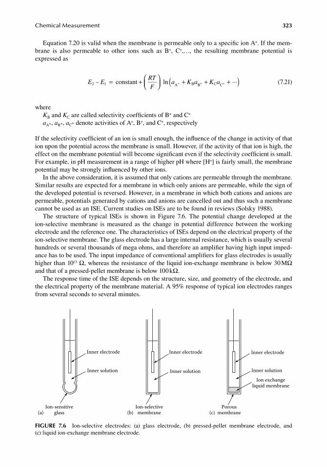
ChemicalMeasurement 323
Equation.7.20.is.valid.when.the.membrane.is.permeable.only.to.a.specific.ion.A+..If.the.mem-brane. is. also. permeable. to. other. ions. such. as. B+,. C+,…,. the. resulting. membrane. potential. is.expressed.as
.E E
RT
Fa K a K a2 1 A B B C C
constant ln– ···= +
+ + +( )+ + +
.(7.21)
whereKB.and.KC.are.called.selectivity.coefficients.of.B+.and.C+
aA+,.aB+,.aC+.denote.activities.of.A+,.B+,.and.C+,.respectively
If.the.selectivity.coefficient.of.an.ion.is.small.enough,.the.influence.of.the.change.in.activity.of.that.ion.upon.the.potential.across.the.membrane.is.small..However,.if.the.activity.of.that.ion.is.high,.the.effect.on.the.membrane.potential.will.become.significant.even.if.the.selectivity.coefficient.is.small..For.example,.in.pH.measurement.in.a.range.of.higher.pH.where.[H+].is.fairly.small,.the.membrane.potential.may.be.strongly.influenced.by.other.ions.
In.the.above.consideration,.it.is.assumed.that.only.cations.are.permeable.through.the.membrane..Similar.results.are.expected.for.a.membrane.in.which.only.anions.are.permeable,.while.the.sign.of.the.developed.potential.is.reversed..However,.in.a.membrane.in.which.both.cations.and.anions.are.permeable,.potentials.generated.by.cations.and.anions.are.cancelled.out.and.thus.such.a.membrane.cannot.be.used.as.an.ISE..Current.studies.on.ISEs.are.to.be.found.in.reviews.(Solsky.1988).
The. structure. of. typical. ISEs. is. shown. in. Figure. 7.6.. The. potential. change. developed. at. the.ion-selective. membrane. is. measured. as. the. change. in. potential. difference. between. the. working.electrode.and.the.reference.one..The.characteristics.of.ISEs.depend.on.the.electrical.property.of.the.ion-selective.membrane..The.glass.electrode.has.a.large.internal.resistance,.which.is.usually.several.hundreds.or.several.thousands.of.mega.ohms,.and.therefore.an.amplifier.having.high.input.imped-ance.has.to.be.used..The.input.impedance.of.conventional.amplifiers.for.glass.electrodes.is.usually.higher.than.1013.Ω,.whereas.the.resistance.of.the.liquid.ion-exchange.membrane.is.below.30.MΩ.and.that.of.a.pressed-pellet.membrane.is.below.100.kΩ.
The.response.time.of.the.ISE.depends.on.the.structure,.size,.and.geometry.of.the.electrode,.and.the.electrical.property.of.the.membrane.material..A.95%.response.of.typical.ion.electrodes.ranges.from.several.seconds.to.several.minutes.
Ion-sensitiveglass
Inner electrode
Inner solution
Inner electrode
Inner solution
Ion exchangeliquid membrane
Porousmembrane
Ion-selectivemembrane(b)
Inner electrode
Inner solution
(c)(a)
figure 7.6 Ion-selective. electrodes:. (a). glass. electrode,. (b). pressed-pellet. membrane. electrode,. and.(c) liquid.ion-exchange.membrane.electrode.
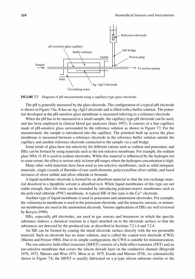
324 BiomedicalSensorsandInstruments
The.pH.is.generally.measured.by.the.glass.electrode..The.configuration.of.a.typical.pH.electrode.is.shown.in.Figure.7.6a..It.has.an.Ag–AgCl.electrode.and.is.filled.with.a.buffer.solution..The.poten-tial.developed.at.the.pH-sensitive.glass.membrane.is.measured.referring.to.a.reference.electrode.
When.the.pH.has.to.be.measured.in.a.small.sample,.the.capillary-type.pH.electrode.can.be.used,.and.has.been.employed.in.clinical.blood.gas.analyzers.(Sanz.1957)..It.consists.of.a.fine.capillary.made.of.pH-sensitive.glass.surrounded.by. the.reference.solution.as.shown.in.Figure.7.7..For. the.measurement,. the.sample.is.introduced.into.the.capillary..The.potential.built.up.across.the.glass.membrane.is.measured.between.a.reference.electrode.in.the.reference.buffer.solution.outside.the.capillary.and.another.reference.electrode.connected.to.the.sample.via.a.salt.bridge.
Some.kinds.of.glass.have.ion.selectivity.for.different.cations.such.as.sodium.and.potassium,.and.ISEs.can.be.formed.by.using.materials.such.as.the.ion-selective.membrane..For.example,.the.sodium.glass.NSA.11-18.is.used.in.sodium.electrodes..While.this.material.is.influenced.by.the.hydrogen.ion.to.some.extent,.the.effect.is.serious.only.in.lower.pH.ranges.where.the.hydrogen.concentration.is.high.
Many.other.solid.materials.have.been.used.as.ion-selective.membranes,.such.as.solid.inorganic.materials,.single.crystals.of.fluorides.of.rare.earth.elements,.polycrystalline.silver.sulfide,.and.fused.mixtures.of.silver.sulfide.and.silver.chloride.or.bromide.
A.liquid.membrane.electrode.is.formed.by.an.absorbent.material.so.that.the.ion-exchange.mate-rial.dissolved.in.a.lipophilic.solvent.is.absorbed.in.it..While.liquid.membranes.of.this.type.are.not.stable.enough,.their.life.time.can.be.extended.by.introducing.polymer-matrix.membranes.such.as.the.polyvinyl.chloride.(PVC).membrane..A.typical.ISE.of.this.type.is.the.Ca2+.electrode.
Another.type.of.liquid.membrane.is.used.in.potassium.and.ammonium.electrodes..For.example,.the.valinomycin.membrane.is.used.in.the.potassium.electrode,.and.the.nonactin,.narasin,.or.monen-sin.membranes.are.used.in.the.ammonium.electrode..Various.applications.of.ISEs.are.well.reviewed.by.Koryta.(1990).
ISEs,. especially. pH. electrodes,. are. used. in. gas. sensors. and. biosensors. in. which. the. specific.substance. induces.a.chemical.reaction. in.a. layer.attached.on.to. the.electrode.surface.so. that. the.substances.are.detected.by.the.produced.ion,.as.described.in.Sections.7.2.1.4.and.7.2.4.
An.ISE.can.be.formed.by.coating.the.metal.electrode.surface.directly.with.the.ion.permeable.material..Such.an.electrode.has.no.inner.solution,.and.is.called.the.coated-wire.electrode.(CWE).(Martin.and.Freiser.1980)..Due.to.its.simple.configuration,.the.CWE.is.suitable.for.miniaturization.
The.ion-selective.field-effect.transistor.(ISFET).consists.of.a.field-effect.transistor.(FET).and.an.ion-selective.membrane.that.covers.the.silicon.dioxide.layer.on.the.conductive.channel.(Bergveld.1970,.1972,.Matsuo.and.Wise.1971,.Moss.et al..1975,.Esashi.and.Matsuo.1978)..As.schematically.shown.in.Figure.7.8,. the.ISFET.is.usually.fabricated.on.a.p-type.silicon.substrate.similar. to. the.
Sample
pH sensitive glass capillary
Buffer solution
Inlet
Circulating waterAg–AgCl electrode
Outlet
To suction pump
Porous plug
Salt bridge
Reference electrode
figure 7.7 Diagram.of.pH.measurement.using.a.capillary-type.glass.electrode.
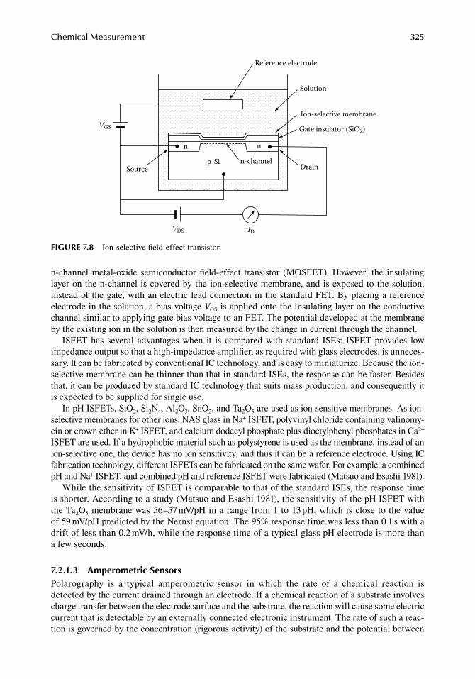
ChemicalMeasurement 325
n-channel.metal-oxide. semiconductor.field-effect. transistor. (MOSFET)..However,. the. insulating.layer.on.the.n-channel. is.covered.by.the.ion-selective.membrane,.and.is.exposed.to.the.solution,.instead.of.the.gate,.with.an.electric.lead.connection.in.the.standard.FET..By.placing.a.reference.electrode.in.the.solution,.a.bias.voltage.VGS.is.applied.onto.the.insulating.layer.on.the.conductive.channel.similar.to.applying.gate.bias.voltage.to.an.FET..The.potential.developed.at.the.membrane.by.the.existing.ion.in.the.solution.is.then.measured.by.the.change.in.current.through.the.channel.
ISFET. has. several. advantages.when. it. is. compared.with. standard. ISEs:. ISFET. provides. low.impedance.output.so.that.a.high-impedance.amplifier,.as.required.with.glass.electrodes,.is.unneces-sary..It.can.be.fabricated.by.conventional.IC.technology,.and.is.easy.to.miniaturize..Because.the.ion-selective.membrane.can.be.thinner.than.that.in.standard.ISEs,.the.response.can.be.faster..Besides.that,.it.can.be.produced.by.standard.IC.technology.that.suits.mass.production,.and.consequently.it.is.expected.to.be.supplied.for.single.use.
In.pH.ISFETs,.SiO2,.Si2N4,.Al2O3,.SnO2,.and.Ta2O5.are.used.as.ion-sensitive.membranes..As.ion-selective.membranes.for.other.ions,.NAS.glass.in.Na+.ISFET,.polyvinyl.chloride.containing.valinomy-cin.or.crown.ether.in.K+.ISFET,.and.calcium.dodecyl.phosphate.plus.dioctylphenyl.phosphates.in.Ca2+.ISFET.are.used..If.a.hydrophobic.material.such.as.polystyrene.is.used.as.the.membrane,.instead.of.an.ion-selective.one,.the.device.has.no.ion.sensitivity,.and.thus.it.can.be.a.reference.electrode..Using.IC.fabrication.technology,.different.ISFETs.can.be.fabricated.on.the.same.wafer..For.example,.a.combined.pH.and.Na+.ISFET,.and.combined.pH.and.reference.ISFET.were.fabricated.(Matsuo.and.Esashi.1981).
While.the.sensitivity.of.ISFET.is.comparable.to.that.of.the.standard.ISEs,.the.response.time.is.shorter..According.to.a.study.(Matsuo.and.Esashi.1981),.the.sensitivity.of.the.pH.ISFET.with.the.Ta2O5.membrane.was.56–57.mV/pH.in.a.range.from.1.to.13.pH,.which.is.close.to.the.value.of.59.mV/pH.predicted.by.the.Nernst.equation..The.95%.response.time.was.less.than.0.1.s.with.a.drift.of.less.than.0.2.mV/h,.while.the.response.time.of.a.typical.glass.pH.electrode.is.more.than.a.few.seconds.
7.2.1.3 amperometric SensorsPolarography. is. a. typical. amperometric. sensor. in. which. the. rate. of. a. chemical. reaction. is.detected.by.the.current.drained.through.an.electrode..If.a.chemical.reaction.of.a.substrate.involves.charge.transfer.between.the.electrode.surface.and.the.substrate,.the.reaction.will.cause.some.electric.current.that.is.detectable.by.an.externally.connected.electronic.instrument..The.rate.of.such.a.reac-tion.is.governed.by.the.concentration.(rigorous.activity).of.the.substrate.and.the.potential.between.
n n
p-SiSource
VGS
VDS ID
Reference electrode
Solution
Ion-selective membrane
Gate insulator (SiO2)
Drainn-channel
figure 7.8 Ion-selective.field-effect.transistor.
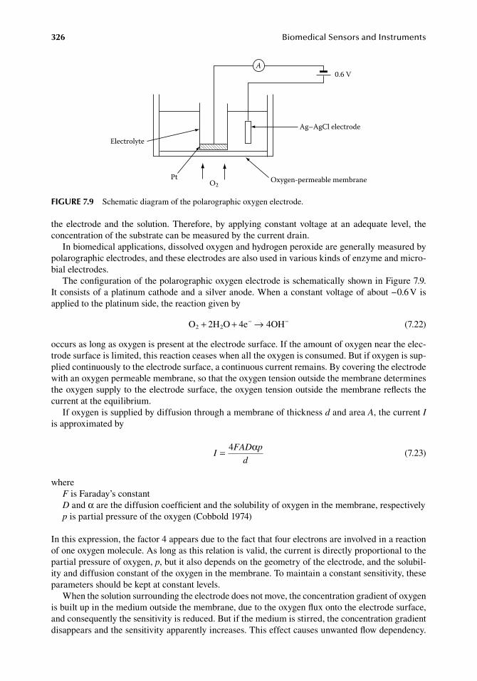
326 BiomedicalSensorsandInstruments
the.electrode.and. the. solution..Therefore,.by.applying.constant.voltage.at. an.adequate. level,. the.concentration.of.the.substrate.can.be.measured.by.the.current.drain.
In.biomedical.applications,.dissolved.oxygen.and.hydrogen.peroxide.are.generally.measured.by.polarographic.electrodes,.and.these.electrodes.are.also.used.in.various.kinds.of.enzyme.and.micro-bial.electrodes.
The.configuration.of.the.polarographic.oxygen.electrode.is.schematically.shown.in.Figure.7.9..It.consists.of.a.platinum.cathode.and.a.silver.anode..When.a.constant.voltage.of.about.−0.6.V.is.applied.to.the.platinum.side,.the.reaction.given.by
. O 2H O 4e 4OH2 2+ + →− −. (7.22)
occurs.as.long.as.oxygen.is.present.at.the.electrode.surface..If.the.amount.of.oxygen.near.the.elec-trode.surface.is.limited,.this.reaction.ceases.when.all.the.oxygen.is.consumed..But.if.oxygen.is.sup-plied.continuously.to.the.electrode.surface,.a.continuous.current.remains..By.covering.the.electrode.with.an.oxygen.permeable.membrane,.so.that.the.oxygen.tension.outside.the.membrane.determines.the.oxygen.supply.to.the.electrode.surface,.the.oxygen.tension.outside.the.membrane.reflects.the.current.at.the.equilibrium.
If.oxygen.is.supplied.by.diffusion.through.a.membrane.of.thickness.d.and.area.A,.the.current.I.is.approximated.by
.I
FAD p
d= 4 α
.(7.23)
whereF.is.Faraday’s.constantD.and.α.are.the.diffusion.coefficient.and.the.solubility.of.oxygen.in.the.membrane,.respectivelyp.is.partial.pressure.of.the.oxygen.(Cobbold.1974)
In.this.expression,.the.factor.4.appears.due.to.the.fact.that.four.electrons.are.involved.in.a.reaction.of.one.oxygen.molecule..As.long.as.this.relation.is.valid,.the.current.is.directly.proportional.to.the.partial.pressure.of.oxygen,.p,.but.it.also.depends.on.the.geometry.of.the.electrode,.and.the.solubil-ity.and.diffusion.constant.of.the.oxygen.in.the.membrane..To.maintain.a.constant.sensitivity,.these.parameters.should.be.kept.at.constant.levels.
When.the.solution.surrounding.the.electrode.does.not.move,.the.concentration.gradient.of.oxygen.is.built.up.in.the.medium.outside.the.membrane,.due.to.the.oxygen.flux.onto.the.electrode.surface,.and.consequently.the.sensitivity.is.reduced..But.if.the.medium.is.stirred,.the.concentration.gradient.disappears.and.the.sensitivity.apparently.increases..This.effect.causes.unwanted.flow.dependency..
Ag–AgCl electrode
Oxygen-permeable membrane
0.6 V
Electrolyte
PtO2
A
figure 7.9 Schematic.diagram.of.the.polarographic.oxygen.electrode.
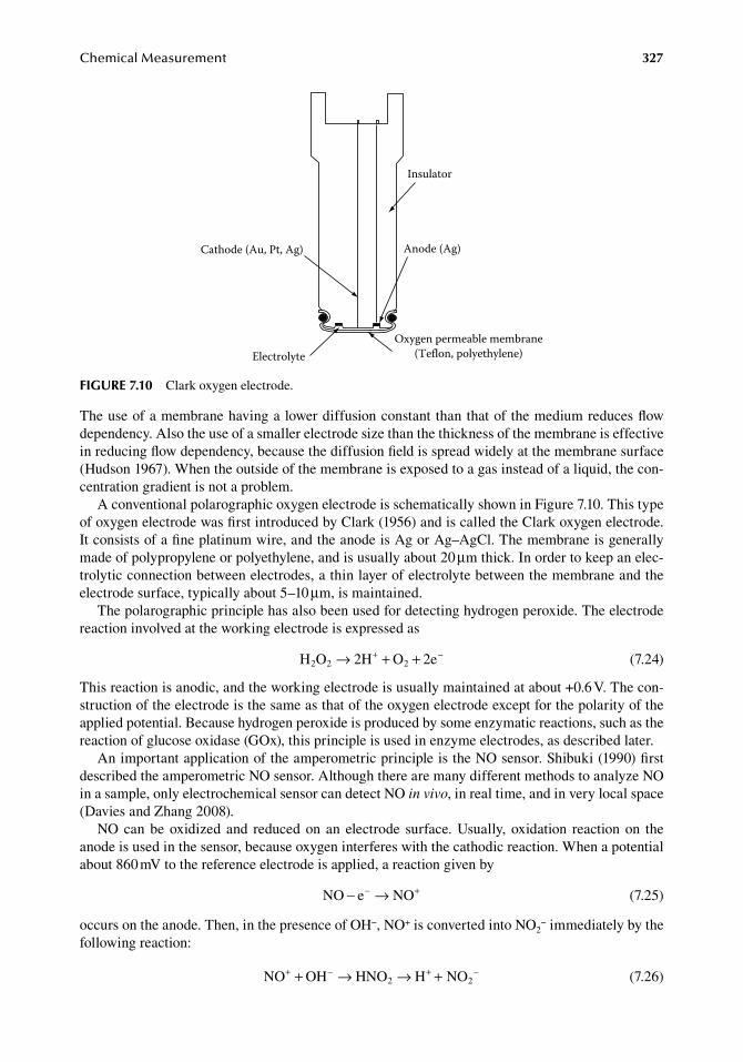
ChemicalMeasurement 327
The.use.of.a.membrane.having.a.lower.diffusion.constant.than.that.of.the.medium.reduces.flow.dependency..Also.the.use.of.a.smaller.electrode.size.than.the.thickness.of.the.membrane.is.effective.in.reducing.flow.dependency,.because.the.diffusion.field.is.spread.widely.at.the.membrane.surface.(Hudson.1967)..When.the.outside.of.the.membrane.is.exposed.to.a.gas.instead.of.a.liquid,.the.con-centration.gradient.is.not.a.problem.
A.conventional.polarographic.oxygen.electrode.is.schematically.shown.in.Figure.7.10..This.type.of.oxygen.electrode.was.first.introduced.by.Clark.(1956).and.is.called.the.Clark.oxygen.electrode..It consists.of.a.fine.platinum.wire,.and.the.anode.is.Ag.or.Ag–AgCl..The.membrane.is.generally.made.of.polypropylene.or.polyethylene,.and.is.usually.about.20.μm.thick..In.order.to.keep.an.elec-trolytic.connection.between.electrodes,.a.thin.layer.of.electrolyte.between.the.membrane.and.the.electrode.surface,.typically.about.5–10.μm,.is.maintained.
The.polarographic.principle.has.also.been.used.for.detecting.hydrogen.peroxide..The.electrode.reaction.involved.at.the.working.electrode.is.expressed.as
. H O 2H O 2e2 2 2→ + ++ −. (7.24)
This.reaction.is.anodic,.and.the.working.electrode.is.usually.maintained.at.about.+0.6.V..The.con-struction.of.the.electrode.is.the.same.as.that.of.the.oxygen.electrode.except.for.the.polarity.of.the.applied.potential..Because.hydrogen.peroxide.is.produced.by.some.enzymatic.reactions,.such.as.the.reaction.of.glucose.oxidase.(GOx),.this.principle.is.used.in.enzyme.electrodes,.as.described.later.
An.important.application.of.the.amperometric.principle.is.the.NO.sensor..Shibuki.(1990).first.described.the.amperometric.NO.sensor..Although.there.are.many.different.methods.to.analyze.NO.in.a.sample,.only.electrochemical.sensor.can.detect.NO.in vivo,.in.real.time,.and.in.very.local.space.(Davies.and.Zhang.2008).
NO.can.be.oxidized.and. reduced.on. an. electrode. surface..Usually,. oxidation. reaction.on. the.anode.is.used.in.the.sensor,.because.oxygen.interferes.with.the.cathodic.reaction..When.a.potential.about.860.mV.to.the.reference.electrode.is.applied,.a.reaction.given.by
. NO e NO− →− +. (7.25)
occurs.on.the.anode..Then,.in.the.presence.of.OH−,.NO+.is.converted.into.NO2−.immediately.by.the.
following.reaction:
. NO OH HNO H NO2 2+ − + −+ → → + . (7.26)
ElectrolyteOxygen permeable membrane
(Teflon, polyethylene)
Anode (Ag)Cathode (Au, Pt, Ag)
Insulator
figure 7.10 Clark.oxygen.electrode.
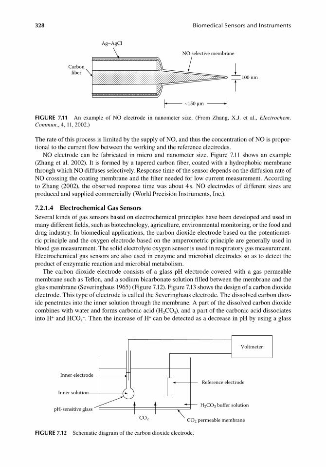
328 BiomedicalSensorsandInstruments
The.rate.of.this.process.is.limited.by.the.supply.of.NO,.and.thus.the.concentration.of.NO.is.propor-tional.to.the.current.flow.between.the.working.and.the.reference.electrodes.
NO. electrode. can. be. fabricated. in. micro. and. nanometer. size.. Figure. 7.11. shows. an. example.(Zhang.et al..2002)..It.is.formed.by.a.tapered.carbon.fiber,.coated.with.a.hydrophobic.membrane.through.which.NO.diffuses.selectively..Response.time.of.the.sensor.depends.on.the.diffusion.rate.of.NO.crossing.the.coating.membrane.and.the.filter.needed.for.low.current.measurement..According.to.Zhang.(2002),. the.observed.response. time.was.about.4.s..NO.electrodes.of.different.sizes.are.produced.and.supplied.commercially.(World.Precision.Instruments,.Inc.).
7.2.1.4 electrochemical gas SensorsSeveral.kinds.of.gas.sensors.based.on.electrochemical.principles.have.been.developed.and.used.in.many.different.fields,.such.as.biotechnology,.agriculture,.environmental.monitoring,.or.the.food.and.drug.industry..In.biomedical.applications,.the.carbon.dioxide.electrode.based.on.the.potentiomet-ric.principle.and.the.oxygen.electrode.based.on.the.amperometric.principle.are.generally.used.in.blood.gas.measurement..The.solid.electrolyte.oxygen.sensor.is.used.in.respiratory.gas.measurement..Electrochemical.gas.sensors.are.also.used.in.enzyme.and.microbial.electrodes.so.as.to.detect.the.product.of.enzymatic.reaction.and.microbial.metabolism.
The. carbon.dioxide. electrode. consists. of. a. glass.pH.electrode. covered.with. a. gas.permeable.membrane.such.as.Teflon,.and.a.sodium.bicarbonate.solution.filled.between.the.membrane.and.the.glass.membrane.(Severinghaus.1965).(Figure.7.12)..Figure.7.13.shows.the.design.of.a.carbon.dioxide.electrode..This.type.of.electrode.is.called.the.Severinghaus.electrode..The.dissolved.carbon.diox-ide.penetrates.into.the.inner.solution.through.the.membrane..A.part.of.the.dissolved.carbon.dioxide.combines.with.water.and.forms.carbonic.acid.(H2CO3),.and.a.part.of.the.carbonic.acid.dissociates.into.H+.and.HCO3
−..Then.the.increase.of.H+.can.be.detected.as.a.decrease.in.pH.by.using.a.glass.
Carbonfiber
Ag–AgCl
NO selective membrane
100 nm
~150 µm
figure 7.11 An. example. of. NO. electrode. in. nanometer. size.. (From. Zhang,. X.J.. et al.,. Electrochem. Commun.,.4,.11,.2002.)
Inner electrode
Inner solution
pH-sensitive glassCO2
Voltmeter
Reference electrode
H2CO3 buffer solution
CO2 permeable membrane
figure 7.12 Schematic.diagram.of.the.carbon.dioxide.electrode.
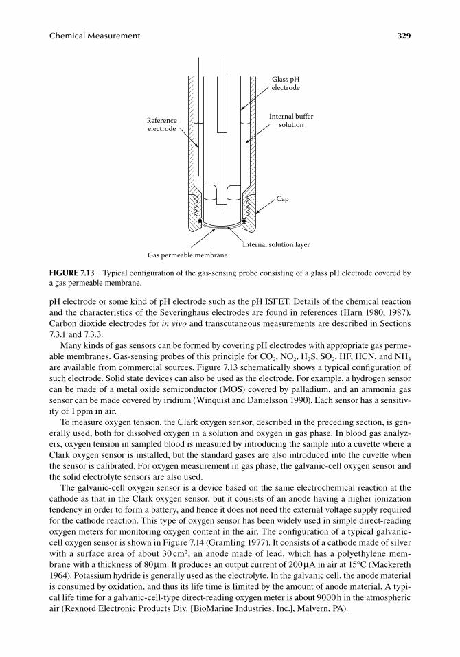
ChemicalMeasurement 329
pH.electrode.or.some.kind.of.pH.electrode.such.as.the.pH.ISFET..Details.of.the.chemical.reaction.and.the.characteristics.of.the.Severinghaus.electrodes.are.found.in.references.(Harn.1980,.1987)..Carbon.dioxide.electrodes.for.in vivo.and.transcutaneous.measurements.are.described.in.Sections.7.3.1.and.7.3.3.
Many.kinds.of.gas.sensors.can.be.formed.by.covering.pH.electrodes.with.appropriate.gas.perme-able.membranes..Gas-sensing.probes.of.this.principle.for.CO2,.NO2,.H2S,.SO2,.HF,.HCN,.and.NH3.are.available.from.commercial.sources..Figure.7.13.schematically.shows.a.typical.configuration.of.such.electrode..Solid.state.devices.can.also.be.used.as.the.electrode..For.example,.a.hydrogen.sensor.can.be.made.of.a.metal.oxide.semiconductor.(MOS).covered.by.palladium,.and.an.ammonia.gas.sensor.can.be.made.covered.by.iridium.(Winquist.and.Danielsson.1990)..Each.sensor.has.a.sensitiv-ity.of.1.ppm.in.air.
To.measure.oxygen.tension,.the.Clark.oxygen.sensor,.described.in.the.preceding.section,.is.gen-erally.used,.both.for.dissolved.oxygen.in.a.solution.and.oxygen.in.gas.phase..In.blood.gas.analyz-ers,.oxygen.tension.in.sampled.blood.is.measured.by.introducing.the.sample.into.a.cuvette.where.a.Clark.oxygen.sensor.is.installed,.but.the.standard.gases.are.also.introduced.into.the.cuvette.when.the.sensor.is.calibrated..For.oxygen.measurement.in.gas.phase,.the.galvanic-cell.oxygen.sensor.and.the.solid.electrolyte.sensors.are.also.used.
The.galvanic-cell.oxygen.sensor.is.a.device.based.on.the.same.electrochemical.reaction.at.the.cathode.as.that.in.the.Clark.oxygen.sensor,.but.it.consists.of.an.anode.having.a.higher.ionization.tendency.in.order.to.form.a.battery,.and.hence.it.does.not.need.the.external.voltage.supply.required.for.the.cathode.reaction..This.type.of.oxygen.sensor.has.been.widely.used.in.simple.direct-reading.oxygen.meters.for.monitoring.oxygen.content.in.the.air..The.configuration.of.a.typical.galvanic-cell.oxygen.sensor.is.shown.in.Figure.7.14.(Gramling.1977)..It.consists.of.a.cathode.made.of.silver.with.a.surface.area.of.about.30.cm2,.an.anode.made.of.lead,.which.has.a.polyethylene.mem-brane.with.a.thickness.of.80.μm..It.produces.an.output.current.of.200.μA.in.air.at.15°C.(Mackereth.1964)..Potassium.hydride.is.generally.used.as.the.electrolyte..In.the.galvanic.cell,.the.anode.material.is.consumed.by.oxidation,.and.thus.its.life.time.is.limited.by.the.amount.of.anode.material..A.typi-cal.life.time.for.a.galvanic-cell-type.direct-reading.oxygen.meter.is.about.9000.h.in.the.atmospheric.air.(Rexnord.Electronic.Products.Div..[BioMarine.Industries,.Inc.],.Malvern,.PA).
Referenceelectrode
Glass pHelectrode
Internal buersolution
Cap
Gas permeable membraneInternal solution layer
figure 7.13 Typical.configuration.of.the.gas-sensing.probe.consisting.of.a.glass.pH.electrode.covered.by.a.gas.permeable.membrane.
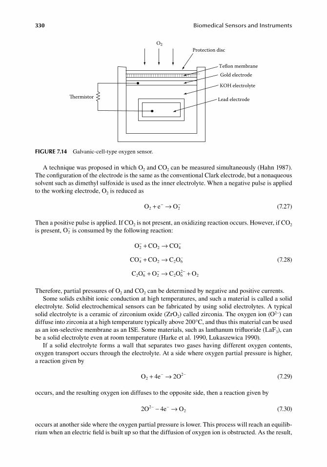
330 BiomedicalSensorsandInstruments
A.technique.was.proposed.in.which.O2.and.CO2.can.be.measured.simultaneously.(Hahn.1987)..The.configuration.of.the.electrode.is.the.same.as.the.conventional.Clark.electrode,.but.a.nonaqueous.solvent.such.as.dimethyl.sulfoxide.is.used.as.the.inner.electrolyte..When.a.negative.pulse.is.applied.to.the.working.electrode,.O2.is.reduced.as
. O e O2 2+ →− −. (7.27)
Then.a.positive.pulse.is.applied..If.CO2.is.not.present,.an.oxidizing.reaction.occurs..However,.if.CO2.is.present,.O2
−.is.consumed.by.the.following.reaction:
.
O CO CO
CO CO C O
C O O C O O
2 2 4
4 2 2 6
2 6 2 2 62
2
− −
− −
− − −
+ →
+ →
+ → + .
(7.28)
Therefore,.partial.pressures.of.O2.and.CO2.can.be.determined.by.negative.and.positive.currents.Some.solids.exhibit.ionic.conduction.at.high.temperatures,.and.such.a.material.is.called.a.solid.
electrolyte..Solid.electrochemical.sensors.can.be.fabricated.by.using.solid.electrolytes..A.typical.solid.electrolyte.is.a.ceramic.of.zirconium.oxide.(ZrO2).called.zirconia..The.oxygen.ion.(O2−).can.diffuse.into.zirconia.at.a.high.temperature.typically.above.200°C,.and.thus.this.material.can.be.used.as.an.ion-selective.membrane.as.an.ISE..Some.materials,.such.as.lanthanum.trifluoride.(LaF3),.can.be.a.solid.electrolyte.even.at.room.temperature.(Harke.et al..1990,.Lukaszewica.1990).
If. a. solid.electrolyte. forms.a.wall. that. separates. two.gases.having.different.oxygen.contents,.oxygen.transport.occurs.through.the.electrolyte..At.a.side.where.oxygen.partial.pressure.is.higher,.a.reaction.given.by
. O 4e 2O22+ →− −
. (7.29)
occurs,.and.the.resulting.oxygen.ion.diffuses.to.the.opposite.side,.then.a.reaction.given.by
. 2O 4e O22
− −− → . (7.30)
occurs.at.another.side.where.the.oxygen.partial.pressure.is.lower..This.process.will.reach.an.equilib-rium.when.an.electric.field.is.built.up.so.that.the.diffusion.of.oxygen.ion.is.obstructed..As.the.result,.
Protection disc
Teon membraneGold electrode
KOH electrolyte
Lead electrode
O2
ermistor
figure 7.14 Galvanic-cell-type.oxygen.sensor.
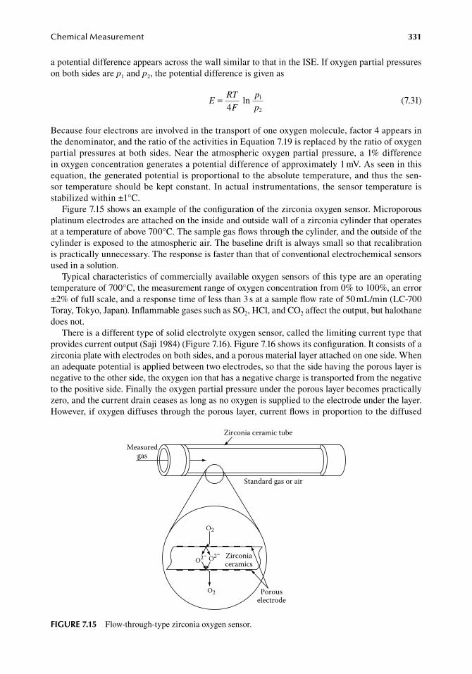
ChemicalMeasurement 331
a.potential.difference.appears.across.the.wall.similar.to.that.in.the.ISE..If.oxygen.partial.pressures.on.both.sides.are.p1.and.p2,.the.potential.difference.is.given.as
.E
RT
F
p
p=
41
2
ln.
(7.31)
Because.four.electrons.are.involved.in.the.transport.of.one.oxygen.molecule,.factor.4.appears.in.the.denominator,.and.the.ratio.of.the.activities.in.Equation.7.19.is.replaced.by.the.ratio.of.oxygen.partial.pressures.at.both.sides..Near. the.atmospheric.oxygen.partial.pressure,.a.1%.difference.in.oxygen.concentration.generates.a.potential.difference.of.approximately.1.mV..As.seen.in.this.equation,.the.generated.potential.is.proportional.to.the.absolute.temperature,.and.thus.the.sen-sor.temperature.should.be.kept.constant..In.actual. instrumentations,. the.sensor.temperature.is.stabilized.within.±1°C.
Figure.7.15.shows.an.example.of.the.configuration.of.the.zirconia.oxygen.sensor..Microporous.platinum.electrodes.are.attached.on.the.inside.and.outside.wall.of.a.zirconia.cylinder.that.operates.at.a.temperature.of.above.700°C..The.sample.gas.flows.through.the.cylinder,.and.the.outside.of.the.cylinder.is.exposed.to.the.atmospheric.air..The.baseline.drift.is.always.small.so.that.recalibration.is.practically.unnecessary..The.response.is.faster.than.that.of.conventional.electrochemical.sensors.used.in.a.solution.
Typical.characteristics.of.commercially.available.oxygen.sensors.of.this.type.are.an.operating.temperature.of.700°C,.the.measurement.range.of.oxygen.concentration.from.0%.to.100%,.an.error.±2%.of.full.scale,.and.a.response.time.of.less.than.3.s.at.a.sample.flow.rate.of.50.mL/min.(LC-700.Toray,.Tokyo,.Japan)..Inflammable.gases.such.as.SO2,.HCl,.and.CO2.affect.the.output,.but.halothane.does.not.
There.is.a.different.type.of.solid.electrolyte.oxygen.sensor,.called.the.limiting.current.type.that.provides.current.output.(Saji.1984).(Figure.7.16)..Figure.7.16.shows.its.configuration..It.consists.of.a.zirconia.plate.with.electrodes.on.both.sides,.and.a.porous.material.layer.attached.on.one.side..When.an.adequate.potential.is.applied.between.two.electrodes,.so.that.the.side.having.the.porous.layer.is.negative.to.the.other.side,.the.oxygen.ion.that.has.a.negative.charge.is.transported.from.the.negative.to.the.positive.side..Finally.the.oxygen.partial.pressure.under.the.porous.layer.becomes.practically.zero,.and.the.current.drain.ceases.as.long.as.no.oxygen.is.supplied.to.the.electrode.under.the.layer..However,.if.oxygen.diffuses.through.the.porous.layer,.current.flows.in.proportion.to.the.diffused.
O2– O2–
O2
O2
Zirconiaceramics
Porouselectrode
Measuredgas
Zirconia ceramic tube
Standard gas or air
figure 7.15 Flow-through-type.zirconia.oxygen.sensor.
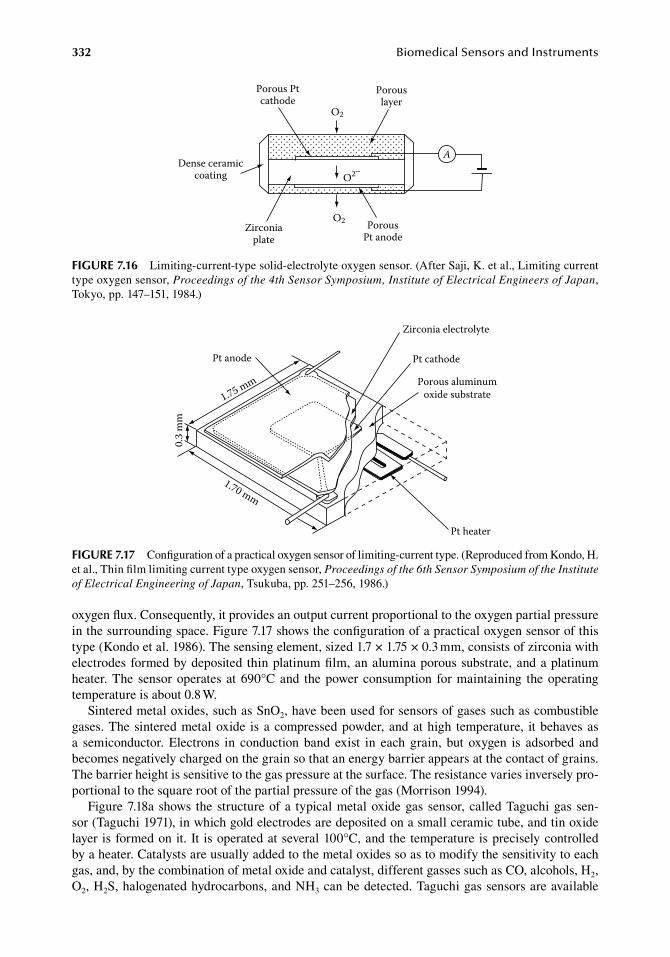
332 BiomedicalSensorsandInstruments
oxygen.flux..Consequently,.it.provides.an.output.current.proportional.to.the.oxygen.partial.pressure.in.the.surrounding.space..Figure.7.17.shows.the.configuration.of.a.practical.oxygen.sensor.of.this.type.(Kondo.et al..1986)..The.sensing.element,.sized.1.7.×.1.75.×.0.3.mm,.consists.of.zirconia.with.electrodes.formed.by.deposited. thin.platinum.film,.an.alumina.porous.substrate,.and.a.platinum.heater..The. sensor.operates. at.690°C.and. the.power.consumption. for.maintaining. the.operating.temperature.is.about.0.8.W.
Sintered.metal.oxides,.such.as.SnO2,.have.been.used.for.sensors.of.gases.such.as.combustible.gases..The.sintered.metal.oxide. is.a.compressed.powder,.and.at.high. temperature,. it.behaves.as.a. semiconductor.. Electrons. in. conduction. band. exist. in. each. grain,. but. oxygen. is. adsorbed. and.becomes.negatively.charged.on.the.grain.so.that.an.energy.barrier.appears.at.the.contact.of.grains..The.barrier.height.is.sensitive.to.the.gas.pressure.at.the.surface..The.resistance.varies.inversely.pro-portional.to.the.square.root.of.the.partial.pressure.of.the.gas.(Morrison.1994).
Figure.7.18a.shows. the.structure.of.a. typical.metal.oxide.gas.sensor,.called.Taguchi.gas.sen-sor.(Taguchi.1971),.in.which.gold.electrodes.are.deposited.on.a.small.ceramic.tube,.and.tin.oxide.layer. is.formed.on.it.. It. is.operated.at.several.100°C,.and.the.temperature.is.precisely.controlled.by.a.heater..Catalysts.are.usually.added.to.the.metal.oxides.so.as.to.modify.the.sensitivity.to.each.gas,.and,.by.the.combination.of.metal.oxide.and.catalyst,.different.gasses.such.as.CO,.alcohols,.H2,.O2,.H2S,.halogenated.hydrocarbons,.and.NH3.can.be.detected..Taguchi.gas.sensors.are.available.
Dense ceramiccoating
Zirconiaplate
Porous Ptcathode
O2
O2
O2–
PorousPt anode
A
Porouslayer
figure 7.16 Limiting-current-type.solid-electrolyte.oxygen.sensor..(After.Saji,.K..et al.,.Limiting.current.type.oxygen.sensor,.Proceedings of the 4th Sensor Symposium, Institute of Electrical Engineers of Japan,.Tokyo,.pp..147–151,.1984.)
Pt anode
1.75 mm
0.3
mm
1.70 mm
Zirconia electrolyte
Pt cathode
Porous aluminumoxide substrate
Pt heater
figure 7.17 Configuration.of.a.practical.oxygen.sensor.of.limiting-current.type..(Reproduced.from.Kondo,.H..et al.,.Thin.film.limiting.current.type.oxygen.sensor,.Proceedings of the 6th Sensor Symposium of the Institute of Electrical Engineering of Japan,.Tsukuba,.pp..251–256,.1986.)
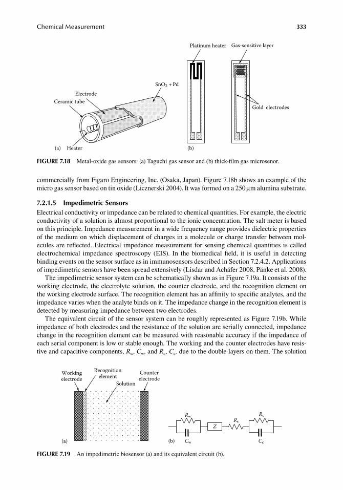
ChemicalMeasurement 333
commercially.from.Figaro.Engineering,.Inc..(Osaka,.Japan)..Figure.7.18b.shows.an.example.of.the.micro.gas.sensor.based.on.tin.oxide.(Licznerski.2004)..It.was.formed.on.a.250.μm.alumina.substrate.
7.2.1.5 impedimetric SensorsElectrical.conductivity.or.impedance.can.be.related.to.chemical.quantities..For.example,.the.electric.conductivity.of.a.solution.is.almost.proportional.to.the.ionic.concentration..The.salt.meter.is.based.on.this.principle..Impedance.measurement.in.a.wide.frequency.range.provides.dielectric.properties.of.the.medium.on.which.displacement.of.charges.in.a.molecule.or.charge.transfer.between.mol-ecules.are.reflected..Electrical. impedance.measurement.for.sensing.chemical.quantities. is.called.electrochemical. impedance. spectroscopy. (EIS).. In. the. biomedical.field,. it. is. useful. in. detecting.binding.events.on.the.sensor.surface.as.in.immunosensors.described.in.Section.7.2.4.2..Applications.of.impedimetric.sensors.have.been.spread.extensively.(Lisdar.and.Achäfer.2008,.Pänke.et al..2008).
The.impedimetric.sensor.system.can.be.schematically.shown.as.in.Figure.7.19a..It.consists.of.the.working.electrode,.the.electrolyte.solution,.the.counter.electrode,.and.the.recognition.element.on.the.working.electrode.surface..The.recognition.element.has.an.affinity.to.specific.analytes,.and.the.impedance.varies.when.the.analyte.binds.on.it..The.impedance.change.in.the.recognition.element.is.detected.by.measuring.impedance.between.two.electrodes.
The.equivalent.circuit.of.the.sensor.system.can.be.roughly.represented.as.Figure.7.19b..While.impedance.of.both.electrodes.and.the.resistance.of.the.solution.are.serially.connected,.impedance.change.in.the.recognition.element.can.be.measured.with.reasonable.accuracy.if.the.impedance.of.each.serial.component.is.low.or.stable.enough..The.working.and.the.counter.electrodes.have.resis-tive.and.capacitive.components,.Rw,.Cw,.and.Rc,.Cc..due.to.the.double.layers.on.them..The.solution.
Electrode
Heater
SnO2 + Pd
Ceramic tube
(a) (b)
Platinum heater Gas-sensitive layer
Gold electrodes
figure 7.18 Metal-oxide.gas.sensors:.(a).Taguchi.gas.sensor.and.(b).thick-film.gas.microsenor.
(b)
RwRs
Cw
Z
Rc
Cc(a)
Workingelectrode
Counterelectrode
Recognitionelement
Solution
figure 7.19 An.impedimetric.biosensor.(a).and.its.equivalent.circuit.(b).
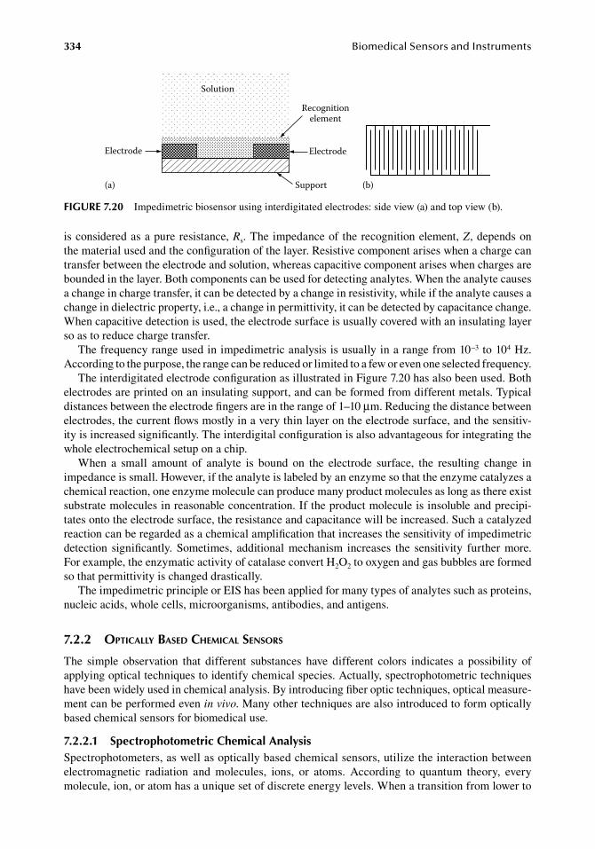
334 BiomedicalSensorsandInstruments
is.considered.as.a.pure.resistance,.Rs..The.impedance.of. the.recognition.element,.Z,.depends.on.the.material.used.and.the.configuration.of.the.layer..Resistive.component.arises.when.a.charge.can.transfer.between.the.electrode.and.solution,.whereas.capacitive.component.arises.when.charges.are.bounded.in.the.layer..Both.components.can.be.used.for.detecting.analytes..When.the.analyte.causes.a.change.in.charge.transfer,.it.can.be.detected.by.a.change.in.resistivity,.while.if.the.analyte.causes.a.change.in.dielectric.property,.i.e.,.a.change.in.permittivity,.it.can.be.detected.by.capacitance.change..When.capacitive.detection.is.used,.the.electrode.surface.is.usually.covered.with.an.insulating.layer.so.as.to.reduce.charge.transfer.
The.frequency.range.used.in.impedimetric.analysis.is.usually.in.a.range.from.10−3.to.104.Hz..According.to.the.purpose,.the.range.can.be.reduced.or.limited.to.a.few.or.even.one.selected.frequency.
The.interdigitated.electrode.configuration.as.illustrated.in.Figure.7.20.has.also.been.used..Both.electrodes.are.printed.on.an.insulating.support,.and.can.be.formed.from.different.metals..Typical.distances.between.the.electrode.fingers.are.in.the.range.of.1–10.μm..Reducing.the.distance.between.electrodes,.the.current.flows.mostly.in.a.very.thin.layer.on.the.electrode.surface,.and.the.sensitiv-ity.is.increased.significantly..The.interdigital.configuration.is.also.advantageous.for.integrating.the.whole.electrochemical.setup.on.a.chip.
When. a. small. amount. of. analyte. is. bound. on. the. electrode. surface,. the. resulting. change. in.impedance.is.small..However,.if.the.analyte.is.labeled.by.an.enzyme.so.that.the.enzyme.catalyzes.a.chemical.reaction,.one.enzyme.molecule.can.produce.many.product.molecules.as.long.as.there.exist.substrate.molecules.in.reasonable.concentration..If.the.product.molecule.is.insoluble.and.precipi-tates.onto.the.electrode.surface,.the.resistance.and.capacitance.will.be.increased..Such.a.catalyzed.reaction.can.be.regarded.as.a.chemical.amplification.that.increases.the.sensitivity.of.impedimetric.detection. significantly..Sometimes,. additional.mechanism. increases. the. sensitivity. further.more..For.example,.the.enzymatic.activity.of.catalase.convert.H2O2.to.oxygen.and.gas.bubbles.are.formed.so.that.permittivity.is.changed.drastically.
The.impedimetric.principle.or.EIS.has.been.applied.for.many.types.of.analytes.such.as.proteins,.nucleic.acids,.whole.cells,.microorganisms,.antibodies,.and.antigens.
7.2.2 optically based cheMical sensors
The. simple. observation. that. different. substances. have. different. colors. indicates. a. possibility. of.applying.optical.techniques.to.identify.chemical.species..Actually,.spectrophotometric.techniques.have.been.widely.used.in.chemical.analysis..By.introducing.fiber.optic.techniques,.optical.measure-ment.can.be.performed.even.in vivo..Many.other.techniques.are.also.introduced.to.form.optically.based.chemical.sensors.for.biomedical.use.
7.2.2.1 Spectrophotometric Chemical analysisSpectrophotometers,.as.well.as.optically.based.chemical.sensors,.utilize.the.interaction.between.electromagnetic. radiation. and. molecules,. ions,. or. atoms.. According. to. quantum. theory,. every.molecule,.ion,.or.atom.has.a.unique.set.of.discrete.energy.levels..When.a.transition.from.lower.to.
(b)(a)
Solution
Recognitionelement
ElectrodeElectrode
Support
figure 7.20 Impedimetric.biosensor.using.interdigitated.electrodes:.side.view.(a).and.top.view.(b).
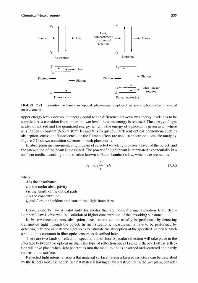
ChemicalMeasurement 335
upper.energy.levels.occurs,.an.energy.equal.to.the.difference.between.two.energy.levels.has.to.be.supplied..At.a.transition.from.upper.to.lower.level,.the.same.energy.is.released..The.energy.of.light.is.also.quantized.and.the.quantized.energy,.which.is.the.energy.of.a.photon,.is.given.as.hv.where.h.is.Planck’s.constant.(6.63.×.10−34.Js).and.ν.is.frequency..Different.optical.phenomena.such.as.absorption,.emission,.fluorescence,.or.the.Raman.effect.are.used.in.spectrophotometric.analysis..Figure.7.21.shows.transition.schemes.of.such.phenomena.
In.absorption.measurement,.a.light.beam.of.selected.wavelength.passes.a.layer.of.the.object,.and.the.attenuation.of.the.beam.is.measured..The.power.of.a.light.beam.is.attenuated.exponentially.in.a.uniform.media.according.to.the.relation.known.as.Beer–Lambert’s.law,.which.is.expressed.as
.A = =log
I
Ilc0 ε
.(7.32)
whereA.is.the.absorbanceε.is.the.molar.absorptivityl.is.the.length.of.the.optical.pathc.is.the.concentrationI0.and.I.are.the.incident.and.transmitted.light.intensities
Beer–Lambert’s. law. is. valid. only. for. media. that. are. nonscattering.. Deviation. from. Beer–Lambert’s.law.is.observed.in.a.solution.of.higher.concentration.of.the.absorbing.substance.
In. in vivo.measurements,. absorption.measurement. cannot.usually.be.performed.by.detecting.transmitted. light. through. the.object.. In. such. situations,.measurements.have. to.be.performed.by.detecting.reflected.or.scattered.light.so.as.to.estimate.the.absorption.of.the.specified.materials..Such.a.situation.is.common.in.fiber.optic.sensors.as.described.later.
There.are.two.kinds.of.reflection:.specular.and.diffuse..Specular.reflection.will.take.place.in.the.interface.between.two.optical.media..This.type.of.reflection.obeys.Fresnel’s.theory..Diffuse.reflec-tion.will.take.place.when.light.penetrates.into.the.medium.and.is.absorbed.and.scattered.and.partly.returns.to.the.surface.
Reflected.light.intensity.from.a.flat.material.surface.having.a.layered.structure.can.be.described.by.the.Kubelka–Munk.theory..In.a.flat.material.having.a.layered.structure.in.the.x–y.plain,.consider.
Photon Heat
Emission
Heat,bombardment,
or chemicalreaction
Photon
Fluorescence
PhotonPhoton
Heat
Raman scattering
Photon Photon
Vibration androtation
Absorption
E0
E1
E2
E0
E1
E0
E1
E0
E2
E1
figure 7.21 Transition. schemes. in. optical. phenomena. employed. in. spectrophotometric. chemical.measurements.
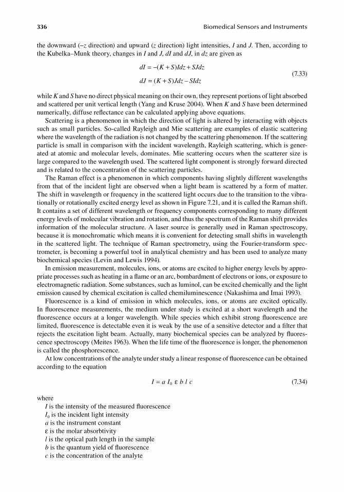
336 BiomedicalSensorsandInstruments
the.downward.(−z.direction).and.upward.(z.direction).light.intensities,.I.and.J..Then,.according.to.the.Kubelka–Munk.theory,.changes.in.I.and.J,.dI.and.dJ,.in.dz.are.given.as
.
dI K S Idz SJdz
dJ K S Jdz SIdz
= + +
= +
–( )
( ) – .
(7.33)
while.K.and.S.have.no.direct.physical.meaning.on.their.own,.they.represent.portions.of.light.absorbed.and.scattered.per.unit.vertical.length.(Yang.and.Kruse.2004)..When.K.and.S.have.been.determined.numerically,.diffuse.reflectance.can.be.calculated.applying.above.equations.
Scattering.is.a.phenomenon.in.which.the.direction.of.light.is.altered.by.interacting.with.objects.such.as.small.particles..So-called.Rayleigh.and.Mie.scattering.are.examples.of.elastic.scattering.where.the.wavelength.of.the.radiation.is.not.changed.by.the.scattering.phenomenon..If.the.scattering.particle.is.small.in.comparison.with.the.incident.wavelength,.Rayleigh.scattering,.which.is.gener-ated.at.atomic.and.molecular. levels,.dominates..Mie.scattering.occurs.when.the.scatterer.size. is.large.compared.to.the.wavelength.used..The.scattered.light.component.is.strongly.forward.directed.and.is.related.to.the.concentration.of.the.scattering.particles.
The.Raman.effect.is.a.phenomenon.in.which.components.having.slightly.different.wavelengths.from.that.of. the. incident. light.are.observed.when.a. light.beam.is.scattered.by.a.form.of.matter..The.shift.in.wavelength.or.frequency.in.the.scattered.light.occurs.due.to.the.transition.to.the.vibra-tionally.or.rotationally.excited.energy.level.as.shown.in.Figure.7.21,.and.it.is.called.the.Raman.shift..It.contains.a.set.of.different.wavelength.or.frequency.components.corresponding.to.many.different.energy.levels.of.molecular.vibration.and.rotation,.and.thus.the.spectrum.of.the.Raman.shift.provides.information.of.the.molecular.structure..A.laser.source.is.generally.used.in.Raman.spectroscopy,.because.it.is.monochromatic.which.means.it.is.convenient.for.detecting.small.shifts.in.wavelength.in. the. scattered. light..The. technique.of.Raman. spectrometry,. using. the.Fourier-transform. spec-trometer,.is.becoming.a.powerful.tool.in.analytical.chemistry.and.has.been.used.to.analyze.many.biochemical.species.(Levin.and.Lewis.1994).
In.emission.measurement,.molecules,.ions,.or.atoms.are.excited.to.higher.energy.levels.by.appro-priate.processes.such.as.heating.in.a.flame.or.an.arc,.bombardment.of.electrons.or.ions,.or.exposure.to.electromagnetic.radiation..Some.substances,.such.as.luminol,.can.be.excited.chemically.and.the.light.emission.caused.by.chemical.excitation.is.called.chemiluminescence.(Nakashima.and.Imai.1993).
Fluorescence. is. a. kind. of. emission. in. which. molecules,. ions,. or. atoms. are. excited. optically..In.fluorescence.measurements,. the.medium.under.study. is.excited.at.a.short.wavelength.and. the.fluorescence.occurs.at.a. longer.wavelength..While.species.which.exhibit.strong.fluorescence.are.limited,.fluorescence.is.detectable.even.it.is.weak.by.the.use.of.a.sensitive.detector.and.a.filter.that.rejects.the.excitation.light.beam..Actually,.many.biochemical.species.can.be.analyzed.by.fluores-cence.spectroscopy.(Meites.1963)..When.the.life.time.of.the.fluorescence.is.longer,.the.phenomenon.is.called.the.phosphorescence.
At.low.concentrations.of.the.analyte.under.study.a.linear.response.of.fluorescence.can.be.obtained.according.to.the.equation
. I a I b l c= 0 ε . (7.34)
whereI.is.the.intensity.of.the.measured.fluorescenceI0.is.the.incident.light.intensitya.is.the.instrument.constantε.is.the.molar.absorbtivityl.is.the.optical.path.length.in.the.sampleb.is.the.quantum.yield.of.fluorescencec.is.the.concentration.of.the.analyte
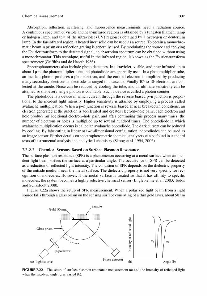
ChemicalMeasurement 337
Absorption,. reflection,. scattering,. and. fluorescence. measurements. need. a. radiation. source..A continuous.spectrum.of.visible.and.near-infrared.regions.is.obtained.by.a.tungsten.filament.lamp.or.halogen.lamp,.and.that.of.the.ultraviolet.(UV).region.is.obtained.by.a.hydrogen.or.deuterium.lamp..In.the.far-infrared.region,.a.heated.inert.solid.can.be.used.as.a.source..To.obtain.a.monochro-matic.beam,.a.prism.or.a.reflection.grating.is.generally.used..By.modulating.the.source.and.applying.the.Fourier.transform.to.the.detected.signal,.an.absorption.spectrum.can.be.obtained.without.using.a.monochromator..This.technique,.useful.in.the.infrared.region,.is.known.as.the.Fourier-transform.spectrometer.(Griffiths.and.de.Haseth.1986).
Spectrophotometers.also.include.photo.detectors..In.ultraviolet,.visible,.and.near.infrared.up.to.about.1.μm,.the.photomultiplier.tube.and.photodiode.are.generally.used..In.a.photomultiplier.tube,.an.incident.photon.produces.a.photoelectron,.and.the.emitted.electron.is.amplified.by.producing.many.secondary.electrons.at.electrodes.arranged.in.a.cascade..Finally.106.to.107.electrons.are.col-lected.at.the.anode..Noise.can.be.reduced.by.cooling.the.tube,.and.an.ultimate.sensitivity.can.be.attained.so.that.every.single.photon.is.countable..Such.a.device.is.called.a.photon.counter.
The.photodiode.is.a.device.in.which.current.through.the.reverse.biased.p–n.junction.is.propor-tional. to.the.incident. light. intensity..Higher.sensitivity.is.attained.by.employing.a.process.called.avalanche.multiplication..When.a.p–n.junction.is.reverse.biased.at.near.breakdown.conditions,.an.electron.generated.at.the.junction.is.accelerated.and.creates.electron–hole.pairs,.each.electron.and.hole.produce.an.additional.electron–hole.pair,.and.after.continuing.this.process.many.times,. the.number.of.electrons.or.holes.is.multiplied.up.to.several.hundred.times..The.photodiode.in.which.avalanche.multiplication.occurs.is.called.an.avalanche.photodiode..The.dark.current.can.be.reduced.by.cooling..By.fabricating.in.linear.or.two-dimensional.configuration,.photodiodes.can.be.used.as.an.image.sensor..Further.details.on.spectrophotometric.chemical.analyzers.can.be.found.in.standard.texts.of.instrumental.analysis.and.analytical.chemistry.(Skoog.et al..1994,.2006).
7.2.2.2 Chemical Sensors based on Surface Plasmon resonanceThe.surface.plasmon.resonance.(SPR).is.a.phenomenon.occurring.at.a.metal.surface.when.an.inci-dent.light.beam.strikes.the.surface.at.a.particular.angle..The.occurrence.of.SPR.can.be.detected.as.a.reduction.of.reflected.light.intensity..The.condition.of.SPR.depends.on.the.dielectric.property.of.the.outside.medium.near.the.metal.surface..The.dielectric.property.is.not.very.specific.for.rec-ognition.of.molecules..However,. if. the.metal.surface. is. treated.so. that. it.has.affinity. to.specific.molecules,.the.system.becomes.a.highly.selective.chemical.sensor.(Englebienne.et al..2003,.Tudos.and.Schasfoolt.2008).
Figure.7.22a.shows.the.setup.of.SPR.measurement..When.a.polarized.light.beam.from.a.light.source.falls.through.a.glass.prism.on.the.sensing.surface.consisting.of.a.thin.gold.layer,.about.50.nm.
Gold 50 nm
Glass prism
Light source
p-polarizer
θ
Photo detector(a)
Inte
nsity
of r
eec
ted
light
Angle (θ)(b)
Sample
n1 n2
figure 7.22 The.setup.of.surface.plasmon.resonance.measurement.(a).and.the.intensity.of.reflected.light.when.the.incident.angle,.θ,.is.varied.(b).
338 BiomedicalSensorsandInstruments
thick,.the.light.is.reflected.and.detected.by.a.photo.detector..If.the.angle.of.incidence.is.changed,.θ,.a minimum.appears.in.the.detected.light.intensity.as.shown.in.Figure.7.22b..The.angle.correspond-ing.to.the.minimum.depends.on.the.refractive.index.of.the.outside.medium.
The.component.of.incident.wave.vector.perpendicular.to.the.metal.surface,.Ki,.is.given.as
.K
cni sin=
ω θ.
(7.35)
whereω.is.the.angular.frequency.of.the.incident.lightc.is.light.velocityn.is.the.refractive.index.(=.ε1/2,.ε:.permittivity).of.the.prism
The.component.of.wave.vector.of.SPR.perpendicular.to.the.metal.surface,.Ks,.is.given.as
.K
cs
1 2
1 2
1/2
=
+
ω ε εε ε .
(7.36)
where.ε1.and.ε2.are.permittivities.of.the.metal.layer.and.the.exit.medium..The.SPR.occurs.when.Ki.=.Ks.The.sensitivity.is.determined.by.the.relation.between.the.change.in.incident.angle.at.the.reso-
nance.and.the.amount.of.substance.binding.on.the.sensing.layer..It.is.known.that.about.1.ng/mm2.of.binding.protein.produces.an.angle.change.of.0.1°.(Englebienne.et al..2003).
In.some.applications,.the.sensitivity.of.the.angle.change.can.be.significantly.increased.by.the.use.of.metal.nanoparticles..When.noble.metal.spherical.nanoparticles.in.solution.are.excited.by.elec-tromagnetic.radiation,.they.exhibit.collective.oscillations.of.their.conduction.electrons.that.result.in.permittivity.change.in.a.selected.wavelength.(Englebienne.1998,.Englebienne.et al..2003)..This.technique.is.called.the.localized.SPR.(LSPR),.and.has.been.well.developed.(Willets and.Van.Duyne.2006).
SPR.devices.have.been.supplied.commercially..Figure.7.23.shows.an.example.(Texas.Instrument,.Spreeta™)..It.has.a.photo.detector.array.by.which.reflected.light.intensities.for.different.angles.of.incidence.can.be.measured.simultaneously.
LED
Polarizer
Gold film
Photo detectorarray
Prism
Gold mirror
21.8 mm
21.7 mm
36.4 mm
figure 7.23 Commercial.surface.plasmon.resonance.sensor.(Texas.Instrument,.Spreeta™).
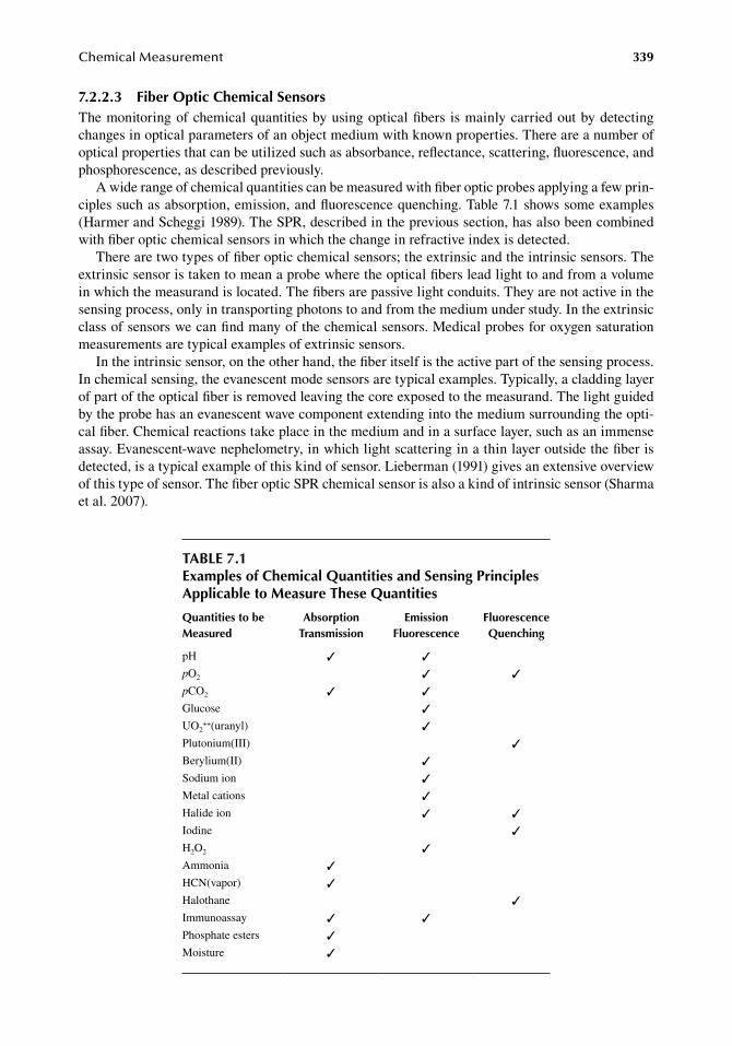
ChemicalMeasurement 339
7.2.2.3 fiber optic Chemical SensorsThe.monitoring.of.chemical.quantities.by.using.optical.fibers. is.mainly.carried.out.by.detecting.changes.in.optical.parameters.of.an.object.medium.with.known.properties..There.are.a.number.of.optical.properties.that.can.be.utilized.such.as.absorbance,.reflectance,.scattering,.fluorescence,.and.phosphorescence,.as.described.previously.
A.wide.range.of.chemical.quantities.can.be.measured.with.fiber.optic.probes.applying.a.few.prin-ciples.such.as.absorption,.emission,.and.fluorescence.quenching..Table.7.1.shows.some.examples.(Harmer.and.Scheggi.1989)..The.SPR,.described.in.the.previous.section,.has.also.been.combined.with.fiber.optic.chemical.sensors.in.which.the.change.in.refractive.index.is.detected.
There.are.two.types.of.fiber.optic.chemical.sensors;.the.extrinsic.and.the.intrinsic.sensors..The.extrinsic.sensor.is.taken.to.mean.a.probe.where.the.optical.fibers.lead.light.to.and.from.a.volume.in.which.the.measurand.is.located..The.fibers.are.passive.light.conduits..They.are.not.active.in.the.sensing.process,.only.in.transporting.photons.to.and.from.the.medium.under.study..In.the.extrinsic.class.of.sensors.we.can.find.many.of.the.chemical.sensors..Medical.probes.for.oxygen.saturation.measurements.are.typical.examples.of.extrinsic.sensors.
In.the.intrinsic.sensor,.on.the.other.hand,.the.fiber.itself.is.the.active.part.of.the.sensing.process..In.chemical.sensing,.the.evanescent.mode.sensors.are.typical.examples..Typically,.a.cladding.layer.of.part.of.the.optical.fiber.is.removed.leaving.the.core.exposed.to.the.measurand..The.light.guided.by.the.probe.has.an.evanescent.wave.component.extending.into.the.medium.surrounding.the.opti-cal.fiber..Chemical.reactions.take.place.in.the.medium.and.in.a.surface.layer,.such.as.an.immense.assay..Evanescent-wave.nephelometry,.in.which.light.scattering.in.a.thin.layer.outside.the.fiber.is.detected,.is.a.typical.example.of.this.kind.of.sensor..Lieberman.(1991).gives.an.extensive.overview.of.this.type.of.sensor..The.fiber.optic.SPR.chemical.sensor.is.also.a.kind.of.intrinsic.sensor.(Sharma.et al..2007).
table 7.1examples of Chemical Quantities and Sensing Principles applicable to Measure these Quantities
Quantities to be Measured
absorption transmission
emission fluorescence
fluorescence Quenching
pH pO2 pCO2 Glucose UO2
++(uranyl) Plutonium(III) Berylium(II) Sodium.ion Metal.cations Halide.ion Iodine H2O2 Ammonia HCN(vapor) Halothane Immunoassay Phosphate.esters Moisture
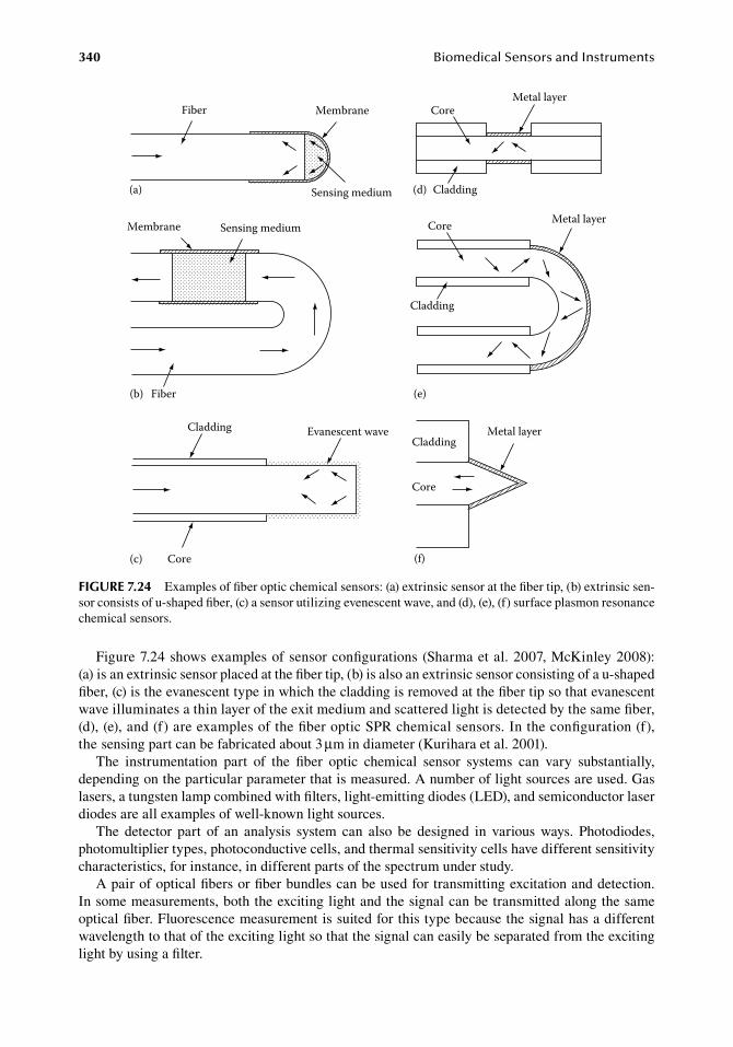
340 BiomedicalSensorsandInstruments
Figure.7.24.shows.examples.of.sensor.configurations.(Sharma.et al..2007,.McKinley.2008):.(a) is.an.extrinsic.sensor.placed.at.the.fiber.tip,.(b).is.also.an.extrinsic.sensor.consisting.of.a.u-shaped.fiber,.(c).is.the.evanescent.type.in.which.the.cladding.is.removed.at.the.fiber.tip.so.that.evanescent.wave.illuminates.a.thin.layer.of.the.exit.medium.and.scattered.light.is.detected.by.the.same.fiber,.(d),.(e),.and.(f).are.examples.of.the.fiber.optic.SPR.chemical.sensors..In.the.configuration.(f),.the.sensing.part.can.be.fabricated.about.3.μm.in.diameter.(Kurihara.et al..2001).
The. instrumentation. part. of. the. fiber. optic. chemical. sensor. systems. can. vary. substantially,.depending.on.the.particular.parameter.that.is.measured..A.number.of.light.sources.are.used..Gas.lasers,.a.tungsten.lamp.combined.with.filters,.light-emitting.diodes.(LED),.and.semiconductor.laser.diodes.are.all.examples.of.well-known.light.sources.
The. detector. part. of. an. analysis. system. can. also. be. designed. in. various. ways.. Photodiodes,.photomultiplier.types,.photoconductive.cells,.and.thermal.sensitivity.cells.have.different.sensitivity.characteristics,.for.instance,.in.different.parts.of.the.spectrum.under.study.
A.pair.of.optical.fibers.or.fiber.bundles.can.be.used.for.transmitting.excitation.and.detection..In.some.measurements,.both.the.exciting.light.and.the.signal.can.be.transmitted.along.the.same.optical.fiber..Fluorescence.measurement.is.suited.for.this.type.because.the.signal.has.a.different.wavelength.to.that.of.the.exciting.light.so.that.the.signal.can.easily.be.separated.from.the.exciting.light.by.using.a.filter.
(c)
Evanescent waveCladding
Core
Core
CladdingMetal layer
(f)
Fiber Membrane
Sensing medium(a)
Membrane Sensing medium
(b) Fiber
Metal layerCore
Cladding(d)
Metal layerCore
Cladding
(e)
figure 7.24 Examples.of.fiber.optic.chemical.sensors:.(a).extrinsic.sensor.at.the.fiber.tip,.(b).extrinsic.sen-sor.consists.of.u-shaped.fiber,.(c).a.sensor.utilizing.evenescent.wave,.and.(d),.(e),.(f).surface.plasmon.resonance.chemical.sensors.
ChemicalMeasurement 341
The.variations. in.optical.fiber.attenuation.must. sometimes.be. taken. into.account.. If. the.fiber.lengths.are.short.this.is.generally.not.a.problem..Silica.fibers.have.a.good.transmission.from.the.UV.region.to.the.near.infrared.
In.comparison.with.other.sensor.principles.the.fiber.optic.sensor.for.chemical.sensing,.or.optrode,.has.a.number.of.advantages:
. 1..The.optical.fibers.are.thin.and.flexible..They.permit.the.design.of.small.and.light.sensors.by.which.invasive.measurements.can.be.performed.at.various.sites.in.the.human.body.
. 2..Optical.fibers.do.not.corrode.and.can.be. implanted. in. the.body. for. long.periods.with-out. changing. their. optical. properties.. This. property. is. of. importance. in. experimental.medicine.
. 3..Electrical.and.magnetic.noise.can.easily.be.eliminated.by.using.optical.fibers.as.transmis-sion.lines.for.sensor.information..The.materials.of.an.optical.fiber.are.isolators.and.thus.do.not. allow. the. induction. of. currents. from.external.fields.. This. property. is. especially.important.in.sensor.use.in.connection.with.magnetic.resonance.imaging.
. 4..Fiber.optic.sensors.are.available.for.response.to.chemical.analytes.or.parameters.for.which.electrodes.are.not.available.
. 5..The.isolating.nature.of.the.fiber.material.means.that.the.patient.is.galvanically.insulated.from.the.monitoring.devices..This.contributes.to.the.electrical.safety.of.the.patient.
. 6..Optical.fiber.probes.can.be. introduced. into. the. tissue.of.organs. that.are. located.deeper.with.very.little.trauma..A.number.of.interesting.parameters.can.be.studied.with.this.type.of.probe.
. 7..The.low.cost.of.optical.fibers.will.make.it.likely.that.future.fiber.optic.sensors.for.medical.monitoring.applications.can.be.made.for.disposal.and.thereby.have.a.low.price.
Optical.fiber.sensors.also.have.certain.disadvantages:
. 1..They.can.be.sensitive.to.ambient.light,.for.instance.surgical.lamps..This.problem.can.be.solved.by.coding.the.optical.information..Another.way.is.to.cover.the.fiber.with.a.light.yet.tight.layer.
. 2..The.optical.fibers.have.impurities.that.can.give.additional.absorption,.fluorescence,.and.Raman.scattering.distortion.to.the.signal.spectrum.
. 3.. Immobilized. indicators. often. suffer. a. reduction. in. sensitivity. after. immobilization..Sterilization.agents.can.interfere.with.the.properties.of.the.indicators.
Extensive.reviews.of.fiber.optic.probes.for.chemical.analytes.can.be.found.in.text.books.and.review.papers. (Culshaw. and. Dakin. 1989,. Wolfbeis. 1991,. 2004,. Marazuela. and. Moreno-Bondi. 2002,.McKinley.2008).
7.2.3 cheMical sensors of acoustic and therMal principles
The.amount.of.a.substance.can.be.measured.by.its.mass..To.weigh.a.small.amount.of.substance,.a.microbalance.is.generally.used,.and.the.measurement.by.weighing.a.mass.is.called.gravimetry..A.mass.can.also.be.measured.by.acoustic.techniques..If.a.substance.is.deposited.on.a.mechanical.resonator,.the.mass.will.be.estimated.from.the.change.in.its.resonance.frequency..If.a.substance.is.uniformly.deposited.on.the.surface.of.a.mechanical.element.through.which.sound.propagates,.the.propagation.pattern.will.be.changed,.and. thus. the.mass. is.estimated. from.a.change. in. the.propagation.parameter,.such.as.the.sound.velocity..A.mechanical.device.in.which.the.amount.of.a.substance.is.measured.by.its.mass.is.called.the.mass.sensor,.or.gravimetric.sensor..There.are.two.types.of.mass.sensors;.the.bulk.acoustic.wave.(BAW).sensor.and.the.surface.acoustic.wave.
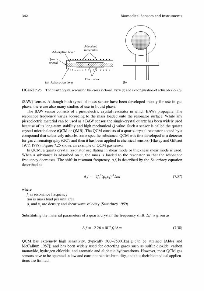
342 BiomedicalSensorsandInstruments
(SAW).sensor..Although.both.types.of.mass.sensor.have.been.developed.mostly.for.use.in.gas.phase,.there.are.also.many.studies.of.use.in.liquid.phase.
The.BAW.sensor.consists.of.a.piezoelectric.crystal. resonator. in.which.BAWs.propagate..The.resonance. frequency.varies.according. to. the.mass. loaded.onto. the. resonator. surface..While.any.piezoelectric.material.can.be.used.as.a.BAW.sensor,.the.single-crystal.quartz.has.been.widely.used.because.of.its.long-term.stability.and.high.mechanical.Q.value..Such.a.sensor.is.called.the.quartz.crystal.microbalance.(QCM.or.QMB)..The.QCM.consists.of.a.quartz.crystal.resonator.coated.by.a.compound.that.selectively.adsorbs.some.specific.substance..QCM.was.first.developed.as.a.detector.for.gas.chromatography.(GC),.and.then.it.has.been.applied.to.chemical.sensors.(Hlavay.and.Gilbaut.1977,.1978)..Figure.7.25.shows.an.example.of.QCM.gas.sensor.
In.QCM,.a.quartz.crystal.resonator.oscillating.in.shear.mode.or.thickness.shear.mode.is.used..When. a. substance. is. adsorbed. on. it,. the. mass. is. loaded. to. the. resonator. so. that. the. resonance.frequency.decreases..The.shift.in.resonant.frequency,.Δ f,.is.described.by.the.Sauerbrey.equation.described.as
.∆ ∆f f v m= – ( )–2 2
q q1
0 ρ.
(7.37)
wheref0.is.resonance.frequencyΔm.is.mass.load.per.unit.areaρq.and.vq.are.density.and.shear.wave.velocity.(Sauerbrey.1959)
Substituting.the.material.parameters.of.a.quartz.crystal,.the.frequency.shift,.Δ f,.is.given.as
. ∆ ∆f f m= × −– .2 26 1 6 20 0 . (7.38)
QCM. has. extremely. high. sensitivity,. (typically. 500–2500.Hz/μg. can. be. attained. [Alder. and.McCallum. 1987]). and. has. been. widely. used. for. detecting. gases. such. as. sulfur. dioxide,. carbon.monoxide,.hydrogen.chloride,.and.aromatic.and.aliphatic.hydrocarbons..However,.most.QCM.gas.sensors.have.to.be.operated.in.low.and.constant.relative.humidity,.and.thus.their.biomedical.applica-tions.are.limited.
AdsorbedmoleculesAdsorption layer
Quartzcrystal
ElectrodesAdsorption layer(a) (b)
figure 7.25 The.quartz.crystal.resonator:.the.cross.sectional.view.(a).and.a.configuration.of.actual.device.(b).
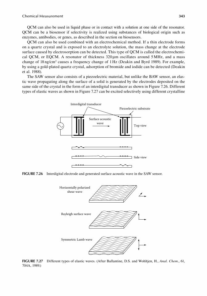
ChemicalMeasurement 343
QCM.can.also.be.used.in.liquid.phase.or.in.contact.with.a.solution.at.one.side.of.the.resonator..QCM. can. be. a. biosensor. if. selectivity. is. realized. using. substances. of. biological. origin. such. as.enzymes,.antibodies,.or.genes,.as.described.in.the.section.on.biosensors.
QCM.can.also.be.used.combined.with.an.electrochemical.method..If.a.thin.electrode.forms.on.a.quartz.crystal.and.is.exposed.to.an.electrolyte.solution,.the.mass.change.at.the.electrode.surface.caused.by.electrosorption.can.be.detected..This.type.of.QCM.is.called.the.electrochemi-cal. QCM,. or. EQCM.. A. resonator. of. thickness. 320.μm. oscillates. around. 5.MHz,. and. a. mass.change.of.18.ng/cm2.causes.a.frequency.change.of.1.Hz.(Deakin.and.Byrd.1989)..For.example,.by.using.a.gold-plated.quartz.crystal,.adsorption.of.bromide.and.iodide.can.be.detected.(Deakin.et al..1988).
The.SAW.sensor.also.consists.of.a.piezoelectric.material,.but.unlike.the.BAW.sensor,.an.elas-tic.wave.propagating.along.the.surface.of.a.solid.is.generated.by.the.electrodes.deposited.on.the.same.side.of.the.crystal.in.the.form.of.an.interdigital.transducer.as.shown.in.Figure.7.26..Different.types.of.elastic.waves.as.shown.in.Figure.7.27.can.be.excited.selectively.using.different.crystalline.
Interdigital transducer
Surface acousticwave
Piezoelectric substrate
Top view
Side view
figure 7.26 Interdigital.electrode.and.generated.surface.acoustic.wave.in.the.SAW.sensor.
Horizontally polarizedshear wave
Rayleigh surface wave
Symmetric Lamb wave
figure 7.27 Different.types.of.elastic.waves..(After.Ballantine,.D.S..and.Wohltjen,.H.,.Anal. Chem.,.61,.704A,.1989.)
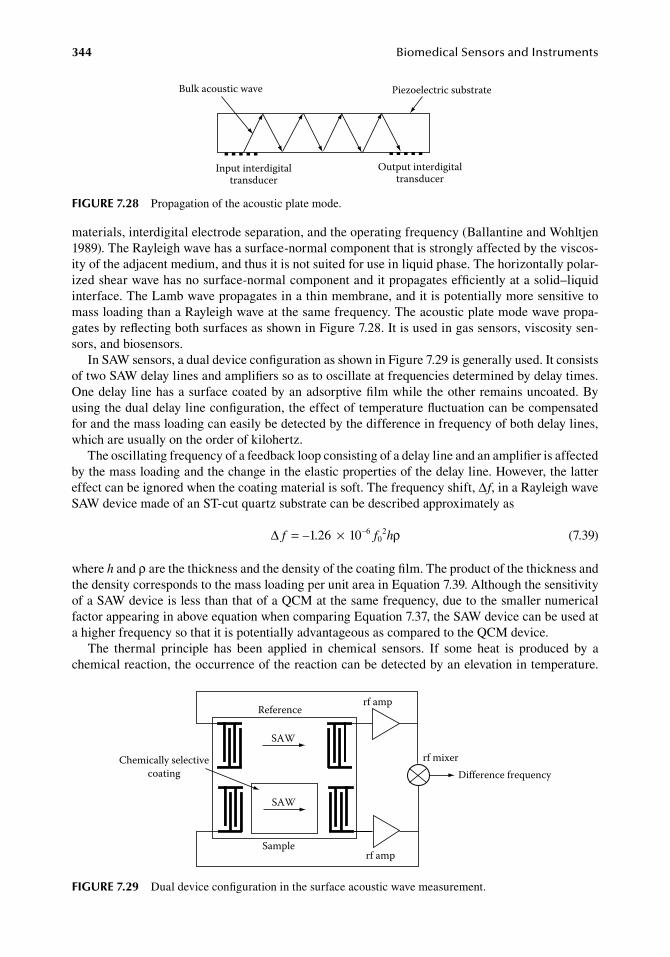
344 BiomedicalSensorsandInstruments
materials,.interdigital.electrode.separation,.and.the.operating.frequency.(Ballantine.and.Wohltjen.1989)..The.Rayleigh.wave.has.a.surface-normal.component.that.is.strongly.affected.by.the.viscos-ity.of.the.adjacent.medium,.and.thus.it.is.not.suited.for.use.in.liquid.phase..The.horizontally.polar-ized.shear.wave.has.no.surface-normal.component.and.it.propagates.efficiently.at.a.solid–liquid.interface..The.Lamb.wave.propagates.in.a.thin.membrane,.and.it.is.potentially.more.sensitive.to.mass.loading.than.a.Rayleigh.wave.at.the.same.frequency..The.acoustic.plate.mode.wave.propa-gates.by.reflecting.both.surfaces.as.shown.in.Figure.7.28..It.is.used.in.gas.sensors,.viscosity.sen-sors,.and.biosensors.
In.SAW.sensors,.a.dual.device.configuration.as.shown.in.Figure.7.29.is.generally.used..It.consists.of.two.SAW.delay.lines.and.amplifiers.so.as.to.oscillate.at.frequencies.determined.by.delay.times..One.delay.line.has.a.surface.coated.by.an.adsorptive.film.while.the.other.remains.uncoated..By.using.the.dual.delay.line.configuration,.the.effect.of.temperature.fluctuation.can.be.compensated.for.and.the.mass.loading.can.easily.be.detected.by.the.difference.in.frequency.of.both.delay.lines,.which.are.usually.on.the.order.of.kilohertz.
The.oscillating.frequency.of.a.feedback.loop.consisting.of.a.delay.line.and.an.amplifier.is.affected.by.the.mass.loading.and.the.change.in.the.elastic.properties.of.the.delay.line..However,.the.latter.effect.can.be.ignored.when.the.coating.material.is.soft..The.frequency.shift,.Δf,.in.a.Rayleigh.wave.SAW.device.made.of.an.ST-cut.quartz.substrate.can.be.described.approximately.as
. ∆ f f h= ×– . –1 26 1 6 20 0 ρ . (7.39)
where.h.and.ρ.are.the.thickness.and.the.density.of.the.coating.film..The.product.of.the.thickness.and.the.density.corresponds.to.the.mass.loading.per.unit.area.in.Equation.7.39..Although.the.sensitivity.of.a.SAW.device.is.less.than.that.of.a.QCM.at.the.same.frequency,.due.to.the.smaller.numerical.factor.appearing.in.above.equation.when.comparing.Equation.7.37,.the.SAW.device.can.be.used.at.a.higher.frequency.so.that.it.is.potentially.advantageous.as.compared.to.the.QCM.device.
The. thermal. principle. has. been. applied. in. chemical. sensors.. If. some. heat. is. produced. by. a.chemical.reaction,.the.occurrence.of.the.reaction.can.be.detected.by.an.elevation.in.temperature..
Chemically selectivecoating
SAW
SAW
Reference
Sample
rf amp
rf amp
rf mixerDifference frequency
figure 7.29 Dual.device.configuration.in.the.surface.acoustic.wave.measurement.
Bulk acoustic wave
Input interdigitaltransducer
Output interdigitaltransducer
Piezoelectric substrate
figure 7.28 Propagation.of.the.acoustic.plate.mode.
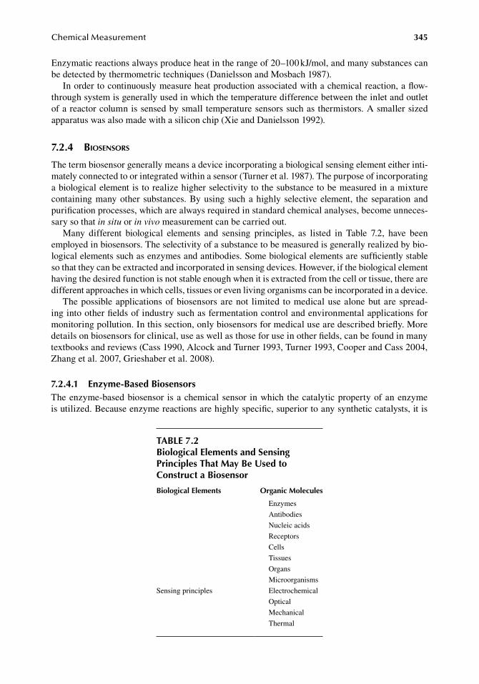
ChemicalMeasurement 345
Enzymatic.reactions.always.produce.heat.in.the.range.of.20–100.kJ/mol,.and.many.substances.can.be.detected.by.thermometric.techniques.(Danielsson.and.Mosbach.1987).
In.order.to.continuously.measure.heat.production.associated.with.a.chemical.reaction,.a.flow-through.system.is.generally.used.in.which.the.temperature.difference.between.the.inlet.and.outlet.of.a.reactor.column.is.sensed.by.small.temperature.sensors.such.as.thermistors..A.smaller.sized.apparatus.was.also.made.with.a.silicon.chip.(Xie.and.Danielsson.1992).
7.2.4 biosensors
The.term.biosensor.generally.means.a.device.incorporating.a.biological.sensing.element.either.inti-mately.connected.to.or.integrated.within.a.sensor.(Turner.et al..1987)..The.purpose.of.incorporating.a.biological.element.is.to.realize.higher.selectivity.to.the.substance.to.be.measured.in.a.mixture.containing.many.other. substances..By.using.such.a.highly.selective.element,. the. separation.and.purification.processes,.which.are.always.required.in.standard.chemical.analyses,.become.unneces-sary.so.that.in situ.or.in vivo.measurement.can.be.carried.out.
Many. different. biological. elements. and. sensing. principles,. as. listed. in. Table. 7.2,. have. been.employed.in.biosensors..The.selectivity.of.a.substance.to.be.measured.is.generally.realized.by.bio-logical.elements.such.as.enzymes.and.antibodies..Some.biological.elements.are.sufficiently.stable.so.that.they.can.be.extracted.and.incorporated.in.sensing.devices..However,.if.the.biological.element.having.the.desired.function.is.not.stable.enough.when.it.is.extracted.from.the.cell.or.tissue,.there.are.different.approaches.in.which.cells,.tissues.or.even.living.organisms.can.be.incorporated.in.a.device.
The.possible.applications.of.biosensors.are.not. limited. to.medical.use.alone.but.are.spread-ing.into.other.fields.of.industry.such.as.fermentation.control.and.environmental.applications.for.monitoring.pollution..In.this.section,.only.biosensors.for.medical.use.are.described.briefly..More.details.on.biosensors.for.clinical,.use.as.well.as.those.for.use.in.other.fields,.can.be.found.in.many.textbooks.and.reviews.(Cass.1990,.Alcock.and.Turner.1993,.Turner.1993,.Cooper.and.Cass.2004,.Zhang.et al..2007,.Grieshaber.et al..2008).
7.2.4.1 enzyme-based biosensorsThe.enzyme-based.biosensor. is.a.chemical.sensor. in.which. the.catalytic.property.of.an.enzyme.is.utilized..Because.enzyme.reactions.are.highly.specific,.superior.to.any.synthetic.catalysts,.it.is.
table 7.2biological elements and Sensing Principles that May be used to Construct a biosensor
biological elements organic Molecules
Enzymes
Antibodies
Nucleic.acids
Receptors
Cells
Tissues
Organs
Microorganisms
Sensing.principles Electrochemical
Optical
Mechanical
Thermal
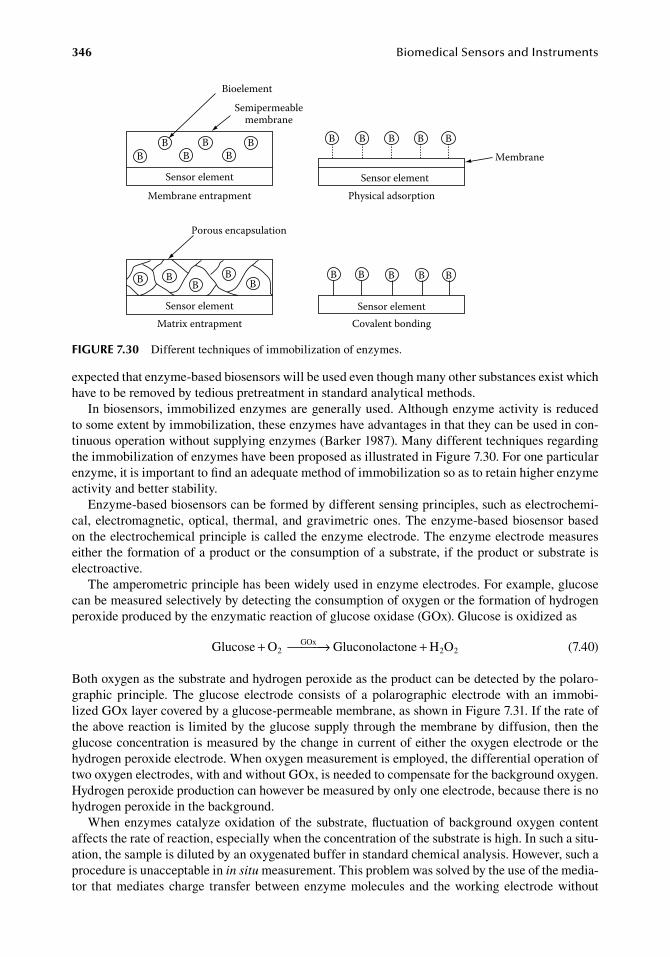
346 BiomedicalSensorsandInstruments
expected.that.enzyme-based.biosensors.will.be.used.even.though.many.other.substances.exist.which.have.to.be.removed.by.tedious.pretreatment.in.standard.analytical.methods.
In.biosensors,.immobilized.enzymes.are.generally.used..Although.enzyme.activity.is.reduced.to.some.extent.by.immobilization,.these.enzymes.have.advantages.in.that.they.can.be.used.in.con-tinuous.operation.without.supplying.enzymes.(Barker.1987)..Many.different.techniques.regarding.the.immobilization.of.enzymes.have.been.proposed.as.illustrated.in.Figure.7.30..For.one.particular.enzyme,.it.is.important.to.find.an.adequate.method.of.immobilization.so.as.to.retain.higher.enzyme.activity.and.better.stability.
Enzyme-based.biosensors.can.be.formed.by.different.sensing.principles,.such.as.electrochemi-cal,.electromagnetic,.optical,. thermal,.and.gravimetric.ones..The.enzyme-based.biosensor.based.on.the.electrochemical.principle.is.called.the.enzyme.electrode..The.enzyme.electrode.measures.either.the.formation.of.a.product.or.the.consumption.of.a.substrate,.if.the.product.or.substrate.is.electroactive.
The.amperometric.principle.has.been.widely.used.in.enzyme.electrodes..For.example,.glucose.can.be.measured.selectively.by.detecting.the.consumption.of.oxygen.or.the.formation.of.hydrogen.peroxide.produced.by.the.enzymatic.reaction.of.glucose.oxidase.(GOx)..Glucose.is.oxidized.as
. Glucose O Gluconolactone H O2GOx
2 2+ → + . (7.40)
Both.oxygen.as.the.substrate.and.hydrogen.peroxide.as.the.product.can.be.detected.by.the.polaro-graphic. principle.. The. glucose. electrode. consists. of. a. polarographic. electrode. with. an. immobi-lized.GOx.layer.covered.by.a.glucose-permeable.membrane,.as.shown.in.Figure.7.31..If.the.rate.of.the.above.reaction.is.limited.by.the.glucose.supply.through.the.membrane.by.diffusion,.then.the.glucose.concentration.is.measured.by.the.change.in.current.of.either.the.oxygen.electrode.or.the.hydrogen.peroxide.electrode..When.oxygen.measurement.is.employed,.the.differential.operation.of.two.oxygen.electrodes,.with.and.without.GOx,.is.needed.to.compensate.for.the.background.oxygen..Hydrogen.peroxide.production.can.however.be.measured.by.only.one.electrode,.because.there.is.no.hydrogen.peroxide.in.the.background.
When.enzymes.catalyze.oxidation.of. the.substrate,.fluctuation.of.background.oxygen.content.affects.the.rate.of.reaction,.especially.when.the.concentration.of.the.substrate.is.high..In.such.a.situ-ation,.the.sample.is.diluted.by.an.oxygenated.buffer.in.standard.chemical.analysis..However,.such.a.procedure.is.unacceptable.in.in situ.measurement..This.problem.was.solved.by.the.use.of.the.media-tor. that.mediates. charge. transfer.between.enzyme.molecules.and. the.working.electrode.without.
BB
BB
BB B B B B B
BB B B BB BB
BB
Sensor element
Membrane
Bioelement
Membrane entrapment
Semipermeablemembrane
Physical adsorption
Matrix entrapment
Porous encapsulation
Covalent bonding
Sensor element
Sensor elementSensor element
figure 7.30 Different.techniques.of.immobilization.of.enzymes.
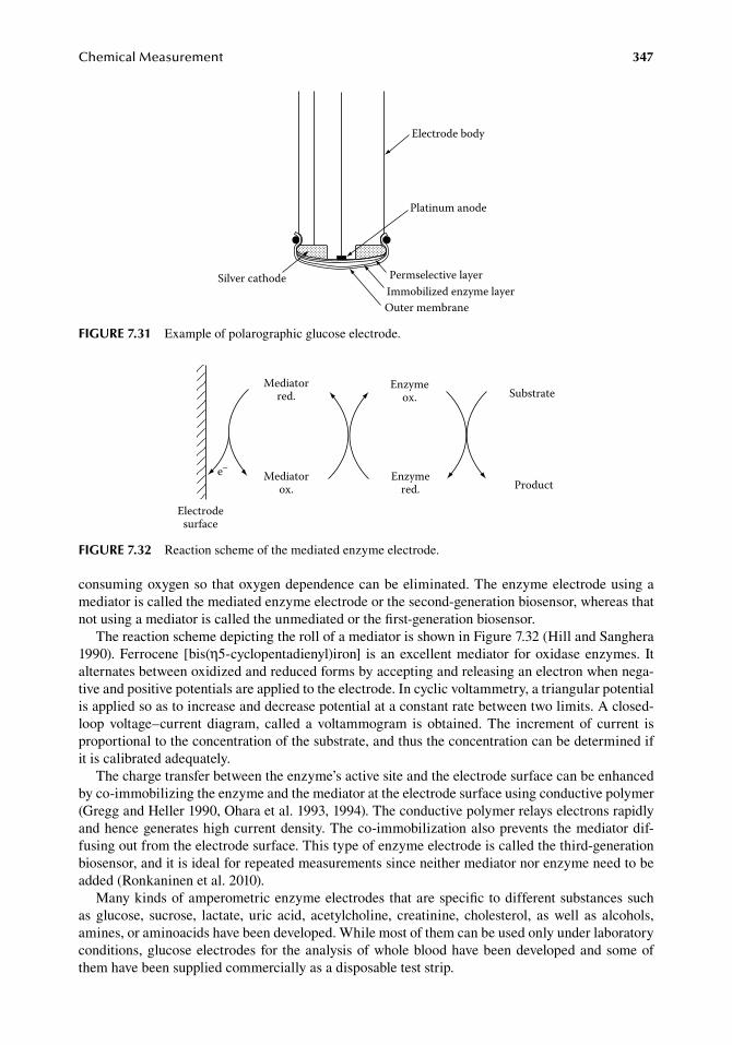
ChemicalMeasurement 347
consuming.oxygen.so.that.oxygen.dependence.can.be.eliminated..The.enzyme.electrode.using.a.mediator.is.called.the.mediated.enzyme.electrode.or.the.second-generation.biosensor,.whereas.that.not.using.a.mediator.is.called.the.unmediated.or.the.first-generation.biosensor.
The.reaction.scheme.depicting.the.roll.of.a.mediator.is.shown.in.Figure.7.32.(Hill.and.Sanghera.1990)..Ferrocene. [bis(η5-cyclopentadienyl)iron]. is.an.excellent.mediator. for.oxidase.enzymes.. It.alternates.between.oxidized.and.reduced.forms.by.accepting.and.releasing.an.electron.when.nega-tive.and.positive.potentials.are.applied.to.the.electrode..In.cyclic.voltammetry,.a.triangular.potential.is.applied.so.as.to.increase.and.decrease.potential.at.a.constant.rate.between.two.limits..A.closed-loop. voltage–current. diagram,. called. a. voltammogram. is. obtained.. The. increment. of. current. is.proportional.to.the.concentration.of.the.substrate,.and.thus.the.concentration.can.be.determined.if.it.is.calibrated.adequately.
The.charge.transfer.between.the.enzyme’s.active.site.and.the.electrode.surface.can.be.enhanced.by.co-immobilizing.the.enzyme.and.the.mediator.at.the.electrode.surface.using.conductive.polymer.(Gregg.and.Heller.1990,.Ohara.et al..1993,.1994)..The.conductive.polymer.relays.electrons.rapidly.and.hence.generates.high.current.density..The.co-immobilization.also.prevents.the.mediator.dif-fusing.out.from.the.electrode.surface..This.type.of.enzyme.electrode.is.called.the.third-generation.biosensor,.and.it.is.ideal.for.repeated.measurements.since.neither.mediator.nor.enzyme.need.to.be.added.(Ronkaninen.et al..2010).
Many.kinds.of.amperometric.enzyme.electrodes.that.are.specific.to.different.substances.such.as.glucose,. sucrose,. lactate,. uric. acid,. acetylcholine,. creatinine,. cholesterol,. as.well. as. alcohols,.amines,.or.aminoacids.have.been.developed..While.most.of.them.can.be.used.only.under.laboratory.conditions,.glucose.electrodes.for. the.analysis.of.whole.blood.have.been.developed.and.some.of.them.have.been.supplied.commercially.as.a.disposable.test.strip.
Substrate
Product
Enzymeox.
Enzymered.
Mediatorred.
Mediatorox.
Electrodesurface
e–
figure 7.32 Reaction.scheme.of.the.mediated.enzyme.electrode.
Silver cathode
Electrode body
Platinum anode
Permselective layerImmobilized enzyme layerOuter membrane
figure 7.31 Example.of.polarographic.glucose.electrode.
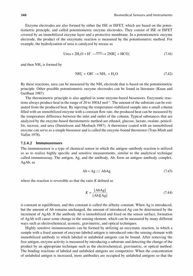
348 BiomedicalSensorsandInstruments
Enzyme.electrodes.are.also.formed.by.either.the.ISE.or.ISFET,.which.are.based.on.the.poten-tiometric.principle,. and.called.potentiometric.enzyme.electrodes..They.consist.of. ISE.or. ISFET.covered.by.an.immobilized.enzyme.layer.and.a.protective.membrane..In.a.potentiometric.enzyme.electrode,. the.product.of. the.enzymatic. reaction. is.measured.by. the.potentiometric.method..For.example,.the.hydrolyzation.of.urea.is.catalyzed.by.urease.as
. Urea 2H O H 2NH HCO2urease
4+ + → ++ + −3 . (7.41)
and.then.NH3.is.formed.by
. NH OH NH H O3 24+ −+ → + . (7.42)
By.these.reactions,.urea.can.be.measured.by.the.NH3.electrode.that.is.based.on.the.potentiometric.principle..Other.possible.potentiometric.enzyme.electrodes.can.be.found.in.literature.(Kuan.and.Guilbaut.1987).
The.thermometric.principle.is.also.applied.in.some.enzyme-based.biosensors..Enzymatic.reac-tions.always.produce.heat.in.the.range.of.20.to.100.kJ.mol−1..The.amount.of.the.substrate.can.be.esti-mated.from.the.produced.heat..By.injecting.the.temperature-stabilized.sample.into.a.small.column.filled.with.an.immobilized.enzyme.with.a.constant.flow.rate,.the.produced.heat.can.be.measured.by.the.temperature.difference.between.the.inlet.and.outlet.of.the.column..Typical.substances.that.are.analyzed.by.the.enzyme-based.thermometric.method.are.ethanol,.glucose,.lactate,.oxalate,.penicil-lin,.sucrose,.and.urea.(Danielsson.and.Mosbach.1987)..A.thermistor.coated.with.an.immobilized.enzyme.can.serve.as.a.simple.biosensor.and.is.called.the.enzyme-bound.thermistor.(Tran-Minh.and.Vallin.1978).
7.2.4.2 immunosensorsThe.immunosensor.is.a.type.of.chemical.sensor.in.which.the.antigen–antibody.reaction.is.utilized.so. as. to. realize. highly. specific. and. sensitive. measurements,. similar. to. the. analytical. technique.called.immunoassay..The.antigen,.Ag,.and.the.antibody,.Ab,.form.an.antigen–antibody.complex,.AgAb,.as
. Ab Ag AbAg+ . (7.43)
where.the.reaction.is.reversible.so.that.the.ratio.K.defined.as
.K = [ ]
[ ][ ]AbAg
Ab Ag .(7.44)
is.constant.at.equilibrium,.and.this.constant.is.called.the.affinity.constant..When.Ag.is.introduced,.but.the.amount.of.Ab.remains.unchanged,.the.amount.of.introduced.Ag.can.be.determined.by.the.increment.of.AgAb..If.the.antibody.Ab.is.immobilized.and.fixed.on.the.sensor.surface,.formation.of.AgAb.will.cause.some.change.in.the.sensing.element,.which.can.be.measured.by.many.different.ways.such.as.electrochemical,.acoustic,.gravimetric,.and.optical.techniques.
Highly.sensitive.immunosensors.can.be.formed.by.utilizing.an.enzymatic.reaction,.in.which.a.sample.with.a.fixed.amount.of.enzyme-labeled.antigen.is.introduced.onto.the.sensing.element.with.immobilized.antibody.to.which.labeled.or.unlabeled.antigens.can.be.bound..After.removing.the.free.antigen,.enzyme.activity.is.measured.by.introducing.a.substrate.and.detecting.the.change.of.the.product.by.an.appropriate.technique.such.as.the.electrochemical,.gravimetric,.or.optical.method..The.binding.reactions.of.labeled.and.unlabeled.antigens.are.competitive:.When.the.concentration.of.unlabeled.antigen.is.increased,.more.antibodies.are.occupied.by.unlabeled.antigens.so.that.the.
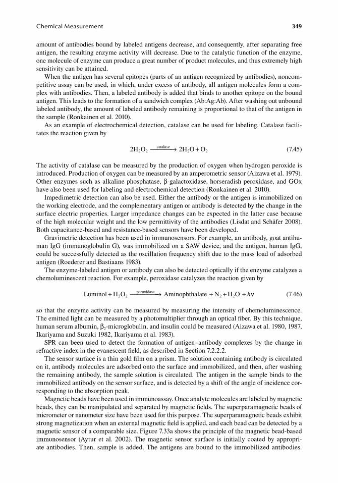
ChemicalMeasurement 349
amount.of.antibodies.bound.by.labeled.antigens.decrease,.and.consequently,.after.separating.free.antigen,.the.resulting.enzyme.activity.will.decrease..Due.to.the.catalytic.function.of.the.enzyme,.one.molecule.of.enzyme.can.produce.a.great.number.of.product.molecules,.and.thus.extremely.high.sensitivity.can.be.attained.
When.the.antigen.has.several.epitopes.(parts.of.an.antigen.recognized.by.antibodies),.noncom-petitive.assay.can.be.used,.in.which,.under.excess.of.antibody,.all.antigen.molecules.form.a.com-plex.with.antibodies..Then,.a.labeled.antibody.is.added.that.binds.to.another.epitope.on.the.bound.antigen..This.leads.to.the.formation.of.a.sandwich.complex.(Ab:Ag:Ab)..After.washing.out.unbound.labeled.antibody,.the.amount.of.labeled.antibody.remaining.is.proportional.to.that.of.the.antigen.in.the.sample.(Ronkainen.et al..2010).
As.an.example.of.electrochemical.detection,.catalase.can.be.used.for.labeling..Catalase.facili-tates.the.reaction.given.by
. 2H O 2H O O2 2catalase
2 2 → + . (7.45)
The.activity.of.catalase.can.be.measured.by.the.production.of.oxygen.when.hydrogen.peroxide.is.introduced..Production.of.oxygen.can.be.measured.by.an.amperometric.sensor.(Aizawa.et al..1979)..Other.enzymes.such.as.alkaline.phosphatase,.β-galactoxidase,.horseradish.peroxidase,.and.GOx.have.also.been.used.for.labeling.and.electrochemical.detection.(Ronkainen.et al..2010).
Impedimetric.detection.can.also.be.used..Either.the.antibody.or.the.antigen.is.immobilized.on.the.working.electrode,.and.the.complementary.antigen.or.antibody.is.detected.by.the.change.in.the.surface.electric.properties..Larger.impedance.changes.can.be.expected.in.the.latter.case.because.of.the.high.molecular.weight.and.the.low.permittivity.of.the.antibodies.(Lisdat.and.Schäfer.2008)..Both.capacitance-based.and.resistance-based.sensors.have.been.developed.
Gravimetric.detection.has.been.used.in.immunosensors..For.example,.an.antibody,.goat.antihu-man.IgG.(immunoglobulin.G),.was.immobilized.on.a.SAW.device,.and.the.antigen,.human.IgG,.could.be.successfully.detected.as.the.oscillation.frequency.shift.due.to.the.mass.load.of.adsorbed.antigen.(Roederer.and.Bastiaans.1983).
The.enzyme-labeled.antigen.or.antibody.can.also.be.detected.optically.if.the.enzyme.catalyzes.a.chemoluminescent.reaction..For.example,.peroxidase.catalyzes.the.reaction.given.by
. Luminol H O Aminophthalate N H O2 2peroxidase
2 2+ → + + + hν . (7.46)
so. that. the.enzyme.activity.can.be.measured.by.measuring. the. intensity.of.chemoluminescence..The.emitted.light.can.be.measured.by.a.photomultiplier.through.an.optical.fiber..By.this.technique,.human.serum.albumin,.β2-microglobulin,.and.insulin.could.be.measured.(Aizawa.et al..1980,.1987,.Ikariyama.and.Suzuki.1982,.Ikariyama.et al..1983).
SPR. can. been. used. to. detect. the. formation. of. antigen–antibody. complexes. by. the. change. in.refractive.index.in.the.evanescent.field,.as.described.in.Section.7.2.2.2.
The.sensor.surface.is.a.thin.gold.film.on.a.prism..The.solution.containing.antibody.is.circulated.on.it,.antibody.molecules.are.adsorbed.onto.the.surface.and.immobilized,.and.then,.after.washing.the.remaining.antibody,.the.sample.solution.is.circulated..The.antigen.in.the.sample.binds.to.the.immobilized.antibody.on.the.sensor.surface,.and.is.detected.by.a.shift.of.the.angle.of.incidence.cor-responding.to.the.absorption.peak.
Magnetic.beads.have.been.used.in.immunoassay..Once.analyte.molecules.are.labeled.by.magnetic.beads,.they.can.be.manipulated.and.separated.by.magnetic.fields..The.superparamagnetic.beads.of.micrometer.or.nanometer.size.have.been.used.for.this.purpose..The.superparamagnetic.beads.exhibit.strong.magnetization.when.an.external.magnetic.field.is.applied,.and.each.bead.can.be.detected.by.a.magnetic.sensor.of.a.comparable.size..Figure.7.33a.shows.the.principle.of.the.magnetic.bead-based.immunosensor. (Aytur. et al.. 2002).. The. magnetic. sensor. surface. is. initially. coated. by. appropri-ate.antibodies..Then,.sample. is.added..The.antigens.are.bound. to. the. immobilized.antibodies..
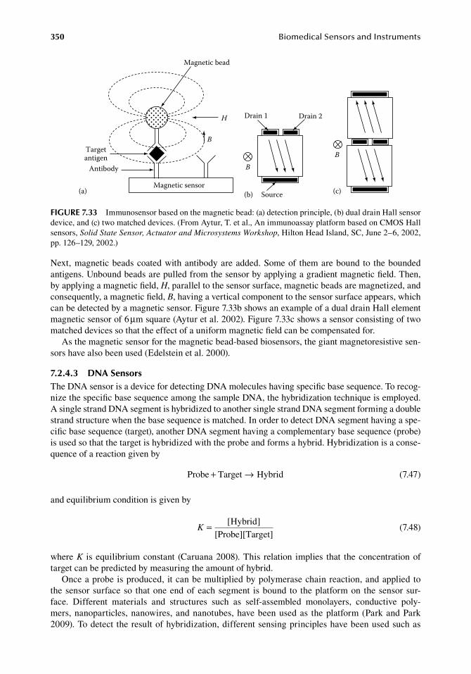
350 BiomedicalSensorsandInstruments
Next,.magnetic.beads.coated.with.antibody.are.added..Some.of. them.are.bound.to. the.bounded.antigens..Unbound.beads.are.pulled.from.the.sensor.by.applying.a.gradient.magnetic.field..Then,.by.applying.a.magnetic.field,.H,.parallel.to.the.sensor.surface,.magnetic.beads.are.magnetized,.and.consequently,.a.magnetic.field,.B,.having.a.vertical.component.to.the.sensor.surface.appears,.which.can.be.detected.by.a.magnetic.sensor..Figure.7.33b.shows.an.example.of.a.dual.drain.Hall.element.magnetic.sensor.of.6.μm.square.(Aytur.et al..2002)..Figure.7.33c.shows.a.sensor.consisting.of.two.matched.devices.so.that.the.effect.of.a.uniform.magnetic.field.can.be.compensated.for.
As.the.magnetic.sensor.for.the.magnetic.bead-based.biosensors,.the.giant.magnetoresistive.sen-sors.have.also.been.used.(Edelstein.et al..2000).
7.2.4.3 dna SensorsThe.DNA.sensor.is.a.device.for.detecting.DNA.molecules.having.specific.base.sequence..To.recog-nize.the.specific.base.sequence.among.the.sample.DNA,.the.hybridization.technique.is.employed..A.single.strand.DNA.segment.is.hybridized.to.another.single.strand.DNA.segment.forming.a.double.strand.structure.when.the.base.sequence.is.matched..In.order.to.detect.DNA.segment.having.a.spe-cific.base.sequence.(target),.another.DNA.segment.having.a.complementary.base.sequence.(probe).is.used.so.that.the.target.is.hybridized.with.the.probe.and.forms.a.hybrid..Hybridization.is.a.conse-quence.of.a.reaction.given.by
. Probe Target Hybrid+ → . (7.47)
and.equilibrium.condition.is.given.by
.K = [ ]Hybrid
[Probe][Target] .(7.48)
where.K. is.equilibrium.constant. (Caruana.2008)..This. relation. implies. that. the.concentration.of.target.can.be.predicted.by.measuring.the.amount.of.hybrid.
Once.a.probe.is.produced,.it.can.be.multiplied.by.polymerase.chain.reaction,.and.applied.to.the.sensor.surface.so. that.one.end.of.each.segment. is.bound. to. the.platform.on. the.sensor.sur-face.. Different. materials. and. structures. such. as. self-assembled. monolayers,. conductive. poly-mers,.nanoparticles,.nanowires,.and.nanotubes,.have.been.used.as. the.platform.(Park.and.Park.2009)..To.detect.the.result.of.hybridization,.different.sensing.principles.have.been.used.such.as.
B
Source
Drain 1 Drain 2
B
(a) (b) (c)Magnetic sensor
B
H
Magnetic bead
Antibody
Targetantigen
figure 7.33 Immunosensor.based.on.the.magnetic.bead:.(a).detection.principle,.(b).dual.drain.Hall.sensor.device,.and.(c).two.matched.devices..(From.Aytur,.T..et al.,.An.immunoassay.platform.based.on.CMOS.Hall.sensors,.Solid State Sensor, Actuator and Microsystems Workshop,.Hilton.Head.Island,.SC,.June.2–6,.2002,.pp..126–129,.2002.)
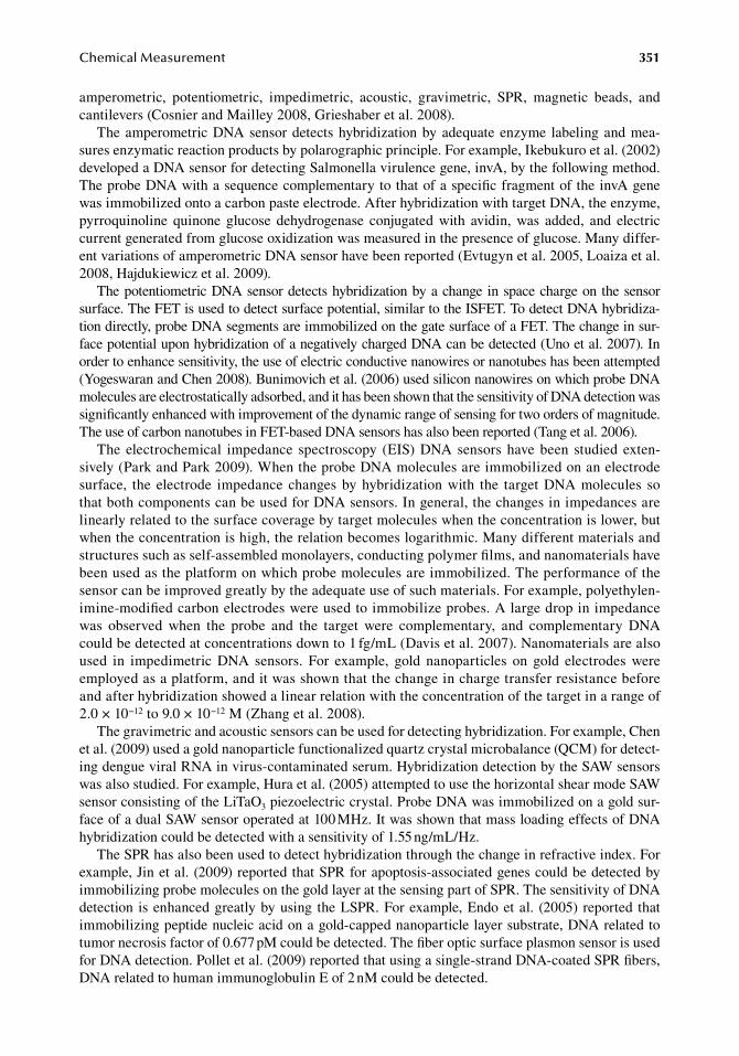
ChemicalMeasurement 351
amperometric,. potentiometric,. impedimetric,. acoustic,. gravimetric,. SPR,. magnetic. beads,. and.cantilevers.(Cosnier.and.Mailley.2008,.Grieshaber.et al..2008).
The.amperometric.DNA.sensor.detects.hybridization.by.adequate.enzyme. labeling.and.mea-sures.enzymatic.reaction.products.by.polarographic.principle..For.example,.Ikebukuro.et al..(2002).developed.a.DNA.sensor.for.detecting.Salmonella.virulence.gene,.invA,.by.the.following.method..The.probe.DNA.with.a.sequence.complementary.to.that.of.a.specific.fragment.of.the.invA.gene.was.immobilized.onto.a.carbon.paste.electrode..After.hybridization.with.target.DNA,.the.enzyme,.pyrroquinoline. quinone. glucose. dehydrogenase. conjugated. with. avidin,. was. added,. and. electric.current.generated.from.glucose.oxidization.was.measured.in.the.presence.of.glucose..Many.differ-ent.variations.of.amperometric.DNA.sensor.have.been.reported.(Evtugyn.et al..2005,.Loaiza.et al..2008,.Hajdukiewicz.et al..2009).
The.potentiometric.DNA.sensor.detects.hybridization.by.a.change.in.space.charge.on.the.sensor.surface..The.FET.is.used.to.detect.surface.potential,.similar.to.the.ISFET..To.detect.DNA.hybridiza-tion.directly,.probe.DNA.segments.are.immobilized.on.the.gate.surface.of.a.FET..The.change.in.sur-face.potential.upon.hybridization.of.a.negatively.charged.DNA.can.be.detected.(Uno.et al..2007)..In.order.to.enhance.sensitivity,.the.use.of.electric.conductive.nanowires.or.nanotubes.has.been.attempted.(Yogeswaran.and.Chen.2008)..Bunimovich.et al..(2006).used.silicon.nanowires.on.which.probe.DNA.molecules.are.electrostatically.adsorbed,.and.it.has.been.shown.that.the.sensitivity.of.DNA.detection.was.significantly.enhanced.with.improvement.of.the.dynamic.range.of.sensing.for.two.orders.of.magnitude..The.use.of.carbon.nanotubes.in.FET-based.DNA.sensors.has.also.been.reported.(Tang.et al..2006).
The.electrochemical. impedance. spectroscopy. (EIS).DNA.sensors.have.been. studied.exten-sively.(Park.and.Park.2009)..When.the.probe.DNA.molecules.are.immobilized.on.an.electrode.surface,. the. electrode. impedance.changes.by.hybridization.with. the. target.DNA.molecules. so.that.both.components.can.be.used.for.DNA.sensors..In.general,.the.changes.in.impedances.are.linearly.related.to.the.surface.coverage.by.target.molecules.when.the.concentration.is.lower,.but.when.the.concentration.is.high,.the.relation.becomes.logarithmic..Many.different.materials.and.structures.such.as.self-assembled.monolayers,.conducting.polymer.films,.and.nanomaterials.have.been.used.as.the.platform.on.which.probe.molecules.are.immobilized..The.performance.of.the.sensor.can.be.improved.greatly.by.the.adequate.use.of.such.materials..For.example,.polyethylen-imine-modified.carbon.electrodes.were.used.to.immobilize.probes..A.large.drop.in.impedance.was. observed. when. the. probe. and. the. target. were. complementary,. and. complementary. DNA.could.be.detected.at.concentrations.down.to.1.fg/mL.(Davis.et al..2007)..Nanomaterials.are.also.used. in. impedimetric. DNA. sensors.. For. example,. gold. nanoparticles. on. gold. electrodes. were.employed.as.a.platform,.and.it.was.shown.that.the.change.in.charge.transfer.resistance.before.and.after.hybridization.showed.a.linear.relation.with.the.concentration.of.the.target.in.a.range.of.2.0.×.10−12.to.9.0.×.10−12.M.(Zhang.et al..2008).
The.gravimetric.and.acoustic.sensors.can.be.used.for.detecting.hybridization..For.example,.Chen.et al..(2009).used.a.gold.nanoparticle.functionalized.quartz.crystal.microbalance.(QCM).for.detect-ing.dengue.viral.RNA.in.virus-contaminated.serum..Hybridization.detection.by.the.SAW.sensors.was.also.studied..For.example,.Hura.et al..(2005).attempted.to.use.the.horizontal.shear.mode.SAW.sensor.consisting.of.the.LiTaO3.piezoelectric.crystal..Probe.DNA.was.immobilized.on.a.gold.sur-face.of.a.dual.SAW.sensor.operated.at.100.MHz..It.was.shown.that.mass.loading.effects.of.DNA.hybridization.could.be.detected.with.a.sensitivity.of.1.55.ng/mL/Hz.
The.SPR.has.also.been.used.to.detect.hybridization.through.the.change.in.refractive.index..For.example,.Jin.et al..(2009).reported.that.SPR.for.apoptosis-associated.genes.could.be.detected.by.immobilizing.probe.molecules.on.the.gold.layer.at.the.sensing.part.of.SPR..The.sensitivity.of.DNA.detection. is.enhanced.greatly.by.using. the.LSPR..For.example,.Endo.et al.. (2005). reported. that.immobilizing.peptide.nucleic.acid.on.a.gold-capped.nanoparticle.layer.substrate,.DNA.related.to.tumor.necrosis.factor.of.0.677.pM.could.be.detected..The.fiber.optic.surface.plasmon.sensor.is.used.for.DNA.detection..Pollet.et al..(2009).reported.that.using.a.single-strand.DNA-coated.SPR.fibers,.DNA.related.to.human.immunoglobulin.E.of.2.nM.could.be.detected.
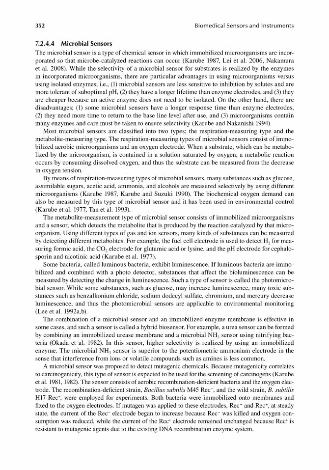
352 BiomedicalSensorsandInstruments
7.2.4.4 Microbial SensorsThe.microbial.sensor.is.a.type.of.chemical.sensor.in.which.immobilized.microorganisms.are.incor-porated.so.that.microbe-catalyzed.reactions.can.occur.(Karube.1987,.Lei.et al..2006,.Nakamura.et al..2008)..While.the.selectivity.of.a.microbial.sensor.for.substrates.is.realized.by.the.enzymes.in.incorporated.microorganisms,.there.are.particular.advantages.in.using.microorganisms.versus.using.isolated.enzymes;.i.e.,.(1).microbial.sensors.are.less.sensitive.to.inhibition.by.solutes.and.are.more.tolerant.of.suboptimal.pH,.(2).they.have.a.longer.lifetime.than.enzyme.electrodes,.and.(3) they.are.cheaper.because.an.active.enzyme.does.not.need.to.be.isolated..On.the.other.hand,.there.are.disadvantages;. (1). some.microbial. sensors.have. a. longer. response. time. than. enzyme.electrodes,.(2) they.need.more.time.to.return.to.the.base.line.level.after.use,.and.(3).microorganisms.contain.many.enzymes.and.care.must.be.taken.to.ensure.selectivity.(Karube.and.Nakanishi.1994).
Most. microbial. sensors. are. classified. into. two. types;. the. respiration-measuring. type. and. the.metabolite-measuring.type..The.respiration-measuring.types.of.microbial.sensors.consist.of.immo-bilized.aerobic.microorganisms.and.an.oxygen.electrode..When.a.substrate,.which.can.be.metabo-lized.by.the.microorganism,.is.contained.in.a.solution.saturated.by.oxygen,.a.metabolic.reaction.occurs.by.consuming.dissolved.oxygen,.and.thus.the.substrate.can.be.measured.from.the.decrease.in.oxygen.tension.
By.means.of.respiration-measuring.types.of.microbial.sensors,.many.substances.such.as.glucose,.assimilable.sugars,.acetic.acid,.ammonia,.and.alcohols.are.measured.selectively.by.using.different.microorganisms.(Karube.1987,.Karube.and.Suzuki.1990)..The.biochemical.oxygen.demand.can.also.be.measured.by.this.type.of.microbial.sensor.and.it.has.been.used.in.environmental.control.(Karube.et al..1977,.Tan.et al..1993).
The.metabolite-measurement.type.of.microbial.sensor.consists.of.immobilized.microorganisms.and.a.sensor,.which.detects.the.metabolite.that.is.produced.by.the.reaction.catalyzed.by.that.micro-organism..Using.different.types.of.gas.and.ion.sensors,.many.kinds.of.substances.can.be.measured.by.detecting.different.metabolites..For.example,.the.fuel.cell.electrode.is.used.to.detect.H2.for.mea-suring.formic.acid,.the.CO2.electrode.for.glutamic.acid.or.lysine,.and.the.pH.electrode.for.cephalo-sporin.and.nicotinic.acid.(Karube.et al..1977).
Some.bacteria,.called.luminous.bacteria,.exhibit.luminescence..If.luminous.bacteria.are.immo-bilized. and. combined.with. a. photo.detector,. substances. that. affect. the.bioluminescence. can.be.measured.by.detecting.the.change.in.luminescence..Such.a.type.of.sensor.is.called.the.photomicro-bial.sensor..While.some.substances,.such.as.glucose,.may.increase.luminescence,.many.toxic.sub-stances.such.as.benzalkonium.chloride,.sodium.dodecyl.sulfate,.chromium,.and.mercury.decrease.luminescence,. and. thus. the. photomicrobial. sensors. are. applicable. to. environmental. monitoring.(Lee.et al..1992a,b).
The.combination.of.a.microbial.sensor.and.an.immobilized.enzyme.membrane.is.effective.in.some.cases,.and.such.a.sensor.is.called.a.hybrid.biosensor..For.example,.a.urea.sensor.can.be.formed.by.combining.an.immobilized.urease.membrane.and.a.microbial.NH3.sensor.using.nitrifying.bac-teria. (Okada. et al.. 1982).. In. this. sensor,. higher. selectivity. is. realized. by. using. an. immobilized.enzyme..The.microbial.NH3.sensor.is.superior.to.the.potentiometric.ammonium.electrode.in.the.sense.that.interference.from.ions.or.volatile.compounds.such.as.amines.is.less.common.
A.microbial.sensor.was.proposed.to.detect.mutagenic.chemicals..Because.mutagenicity.correlates.to.carcinogenicity,.this.type.of.sensor.is.expected.to.be.used.for.the.screening.of.carcinogens.(Karube.et al..1981,.1982)..The.sensor.consists.of.aerobic.recombination-deficient.bacteria.and.the.oxygen.elec-trode..The.recombination-deficient.strain,.Bacillus subtilis.M45.Rec−,.and.the.wild.strain,.B. subtilis.H17.Rec+,.were. employed. for. experiments..Both.bacteria.were. immobilized.onto.membranes. and.fixed.to.the.oxygen.electrodes..If.mutagen.was.applied.to.these.electrodes,.Rec−.and.Rec+,.at.steady.state,.the.current.of.the.Rec−.electrode.began.to.increase.because.Rec−.was.killed.and.oxygen.con-sumption.was.reduced,.while.the.current.of.the.Rec+.electrode.remained.unchanged.because.Rec+.is.resistant.to.mutagenic.agents.due.to.the.existing.DNA.recombination.enzyme.system.
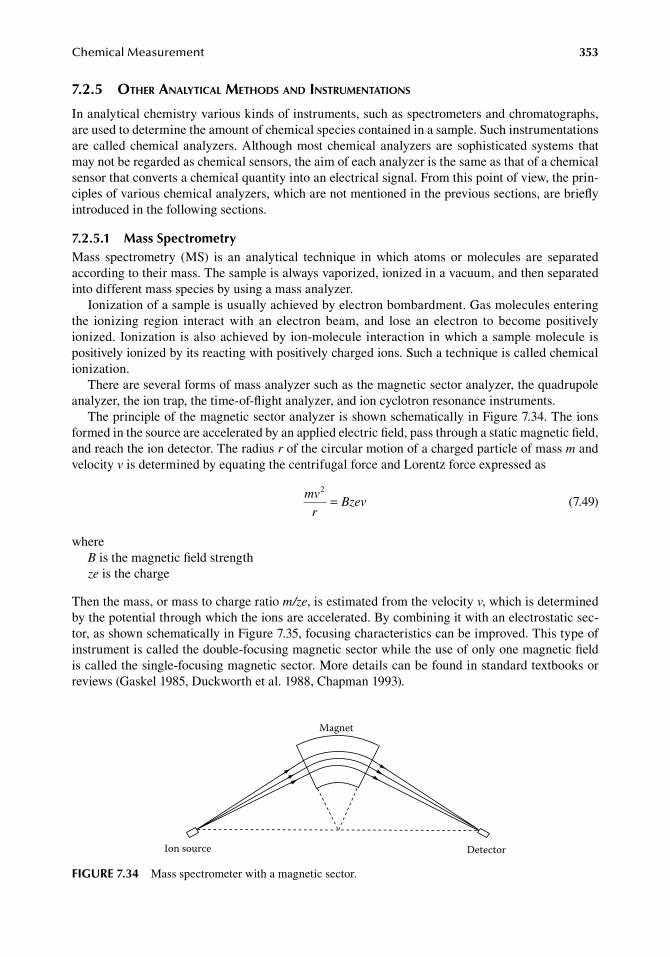
ChemicalMeasurement 353
7.2.5 other analytical Methods and instruMentations
In.analytical.chemistry.various.kinds.of.instruments,.such.as.spectrometers.and.chromatographs,.are.used.to.determine.the.amount.of.chemical.species.contained.in.a.sample..Such.instrumentations.are.called.chemical.analyzers..Although.most.chemical.analyzers.are.sophisticated.systems. that.may.not.be.regarded.as.chemical.sensors,.the.aim.of.each.analyzer.is.the.same.as.that.of.a.chemical.sensor.that.converts.a.chemical.quantity.into.an.electrical.signal..From.this.point.of.view,.the.prin-ciples.of.various.chemical.analyzers,.which.are.not.mentioned.in.the.previous.sections,.are.briefly.introduced.in.the.following.sections.
7.2.5.1 Mass SpectrometryMass. spectrometry. (MS). is. an. analytical. technique. in. which. atoms. or. molecules. are. separated.according.to.their.mass..The.sample.is.always.vaporized,.ionized.in.a.vacuum,.and.then.separated.into.different.mass.species.by.using.a.mass.analyzer.
Ionization.of.a.sample.is.usually.achieved.by.electron.bombardment..Gas.molecules.entering.the. ionizing. region. interact. with. an. electron. beam,. and. lose. an. electron. to. become. positively.ionized..Ionization.is.also.achieved.by.ion-molecule.interaction.in.which.a.sample.molecule.is.positively.ionized.by.its.reacting.with.positively.charged.ions..Such.a.technique.is.called.chemical.ionization.
There.are.several.forms.of.mass.analyzer.such.as.the.magnetic.sector.analyzer,.the.quadrupole.analyzer,.the.ion.trap,.the.time-of-flight.analyzer,.and.ion.cyclotron.resonance.instruments.
The.principle.of.the.magnetic.sector.analyzer.is.shown.schematically.in.Figure.7.34..The.ions.formed.in.the.source.are.accelerated.by.an.applied.electric.field,.pass.through.a.static.magnetic.field,.and.reach.the.ion.detector..The.radius.r.of.the.circular.motion.of.a.charged.particle.of.mass.m.and.velocity.v.is.determined.by.equating.the.centrifugal.force.and.Lorentz.force.expressed.as
.
mv
rBzev
2
=.
(7.49)
whereB.is.the.magnetic.field.strengthze.is.the.charge
Then.the.mass,.or.mass.to.charge.ratio.m/ze,.is.estimated.from.the.velocity.v,.which.is.determined.by.the.potential.through.which.the.ions.are.accelerated..By.combining.it.with.an.electrostatic.sec-tor,.as.shown.schematically.in.Figure.7.35,.focusing.characteristics.can.be.improved..This.type.of.instrument.is.called.the.double-focusing.magnetic.sector.while.the.use.of.only.one.magnetic.field.is.called.the.single-focusing.magnetic.sector..More.details.can.be.found.in.standard.textbooks.or.reviews.(Gaskel.1985,.Duckworth.et al..1988,.Chapman.1993).
Magnet
Ion source Detector
figure 7.34 Mass.spectrometer.with.a.magnetic.sector.
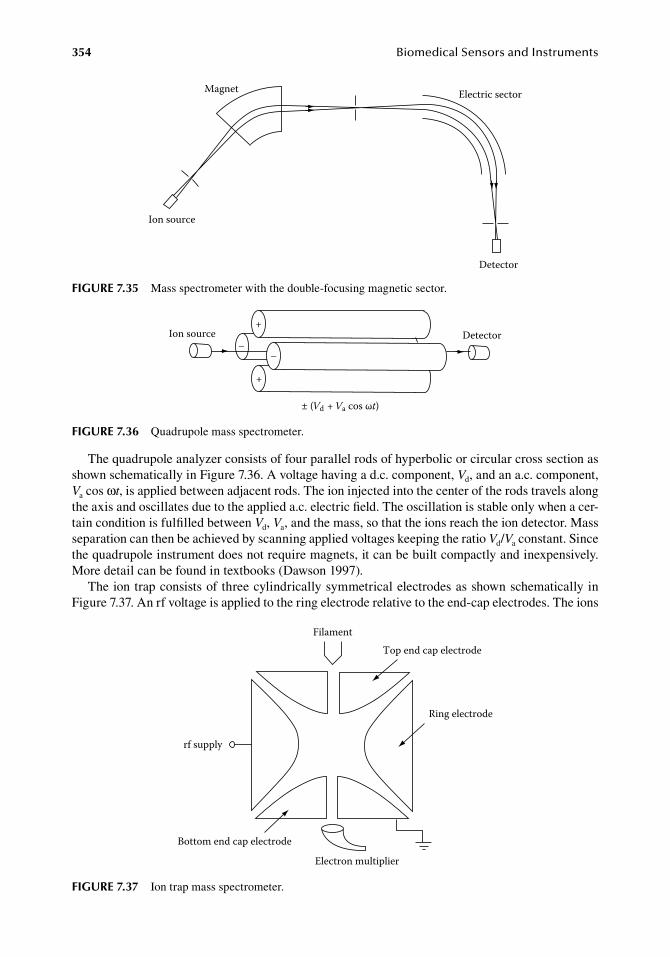
354 BiomedicalSensorsandInstruments
The.quadrupole.analyzer.consists.of.four.parallel.rods.of.hyperbolic.or.circular.cross.section.as.shown.schematically.in.Figure.7.36..A.voltage.having.a.d.c..component,.Vd,.and.an.a.c..component,.Va.cos.ωt,.is.applied.between.adjacent.rods..The.ion.injected.into.the.center.of.the.rods.travels.along.the.axis.and.oscillates.due.to.the.applied.a.c..electric.field..The.oscillation.is.stable.only.when.a.cer-tain.condition.is.fulfilled.between.Vd,.Va,.and.the.mass,.so.that.the.ions.reach.the.ion.detector..Mass.separation.can.then.be.achieved.by.scanning.applied.voltages.keeping.the.ratio.Vd/Va.constant..Since.the.quadrupole.instrument.does.not.require.magnets,.it.can.be.built.compactly.and.inexpensively..More.detail.can.be.found.in.textbooks.(Dawson.1997).
The.ion.trap.consists.of.three.cylindrically.symmetrical.electrodes.as.shown.schematically.in.Figure.7.37..An.rf.voltage.is.applied.to.the.ring.electrode.relative.to.the.end-cap.electrodes..The.ions.
Ring electrode
FilamentTop end cap electrode
Electron multiplier
rf supply
Bottom end cap electrode
figure 7.37 Ion.trap.mass.spectrometer.
Magnet
Ion source
Detector
Electric sector
figure 7.35 Mass.spectrometer.with.the.double-focusing.magnetic.sector.
Ion source+
+
––
± (Vd + Va cos ωt)
Detector
figure 7.36 Quadrupole.mass.spectrometer.
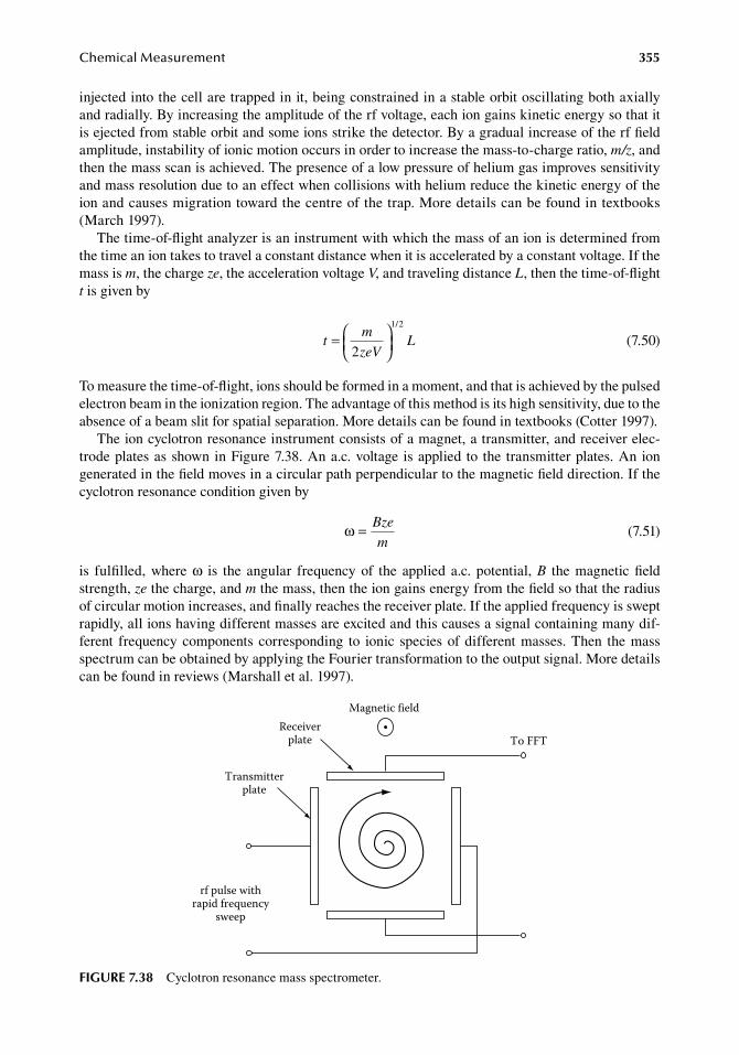
ChemicalMeasurement 355
injected.into.the.cell.are.trapped.in.it,.being.constrained.in.a.stable.orbit.oscillating.both.axially.and.radially..By.increasing.the.amplitude.of.the.rf.voltage,.each.ion.gains.kinetic.energy.so.that.it.is.ejected.from.stable.orbit.and.some.ions.strike.the.detector..By.a.gradual.increase.of.the.rf.field.amplitude,.instability.of.ionic.motion.occurs.in.order.to.increase.the.mass-to-charge.ratio,.m/z,.and.then.the.mass.scan.is.achieved..The.presence.of.a.low.pressure.of.helium.gas.improves.sensitivity.and.mass.resolution.due.to.an.effect.when.collisions.with.helium.reduce.the.kinetic.energy.of.the.ion.and.causes.migration.toward.the.centre.of.the.trap..More.details.can.be.found.in.textbooks.(March.1997).
The.time-of-flight.analyzer.is.an.instrument.with.which.the.mass.of.an.ion.is.determined.from.the.time.an.ion.takes.to.travel.a.constant.distance.when.it.is.accelerated.by.a.constant.voltage..If.the.mass.is.m,.the.charge.ze,.the.acceleration.voltage.V,.and.traveling.distance.L,.then.the.time-of-flight.t.is.given.by
.t
m
zeVL=
2
1 2/
.(7.50)
To.measure.the.time-of-flight,.ions.should.be.formed.in.a.moment,.and.that.is.achieved.by.the.pulsed.electron.beam.in.the.ionization.region..The.advantage.of.this.method.is.its.high.sensitivity,.due.to.the.absence.of.a.beam.slit.for.spatial.separation..More.details.can.be.found.in.textbooks.(Cotter.1997).
The.ion.cyclotron.resonance.instrument.consists.of.a.magnet,.a.transmitter,.and.receiver.elec-trode.plates.as.shown.in.Figure.7.38..An.a.c..voltage. is.applied. to. the. transmitter.plates..An.ion.generated.in.the.field.moves.in.a.circular.path.perpendicular.to.the.magnetic.field.direction..If.the.cyclotron.resonance.condition.given.by
.ω = Bze
m .(7.51)
is. fulfilled,.where.ω. is. the. angular. frequency.of. the. applied. a.c.. potential,.B. the.magnetic.field.strength,.ze.the.charge,.and.m.the.mass,.then.the.ion.gains.energy.from.the.field.so.that.the.radius.of.circular.motion.increases,.and.finally.reaches.the.receiver.plate..If.the.applied.frequency.is.swept.rapidly,.all.ions.having.different.masses.are.excited.and.this.causes.a.signal.containing.many.dif-ferent. frequency.components.corresponding. to. ionic. species.of.different.masses..Then. the.mass.spectrum.can.be.obtained.by.applying.the.Fourier.transformation.to.the.output.signal..More.details.can.be.found.in.reviews.(Marshall.et al..1997).
Magnetic field
To FFTReceiver
plate
Transmitterplate
rf pulse withrapid frequency
sweep
figure 7.38 Cyclotron.resonance.mass.spectrometer.
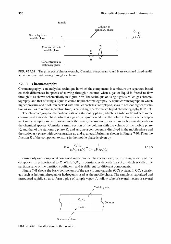
356 BiomedicalSensorsandInstruments
7.2.5.2 ChromatographyChromatography.is.an.analytical.technique.in.which.the.components.in.a.mixture.are.separated.based.on. their.differences. in. speeds.of.moving. through.a.column.when.a.gas.or. liquid. is. forced. to.flow.through.it,.as.shown.schematically.in.Figure.7.39..The.technique.of.using.a.gas.is.called.gas.chroma-tography,.and.that.of.using.a.liquid.is.called.liquid.chromatography..A.liquid.chromatograph.in.which.higher.pressure.and.a.column.packed.with.smaller.particles.is.employed,.so.as.to.achieve.higher.resolu-tion.as.well.as.to.reduce.separation.time,.is.called.high-performance.liquid.chromatography.(HPLC).
The.chromatographic.method.consists.of.a.stationary.phase,.which.is.a.solid.or.liquid.held.in.the.column,.and.a.mobile.phase,.which.is.a.gas.or.a.liquid.forced.into.the.column..Even.if.each.compo-nent.in.the.sample.can.be.dissolved.in.both.phases,.the.amount.dissolved.in.each.phase.depends.on.the.chemical.species..Consider.a.small.section.of.the.column.with.the.volume.of.the.mobile.phase.Vm.and.that.of.the.stationary.phase.Vs,.and.assume.a.component.is.dissolved.in.the.mobile.phase.and.the.stationary.phase.with.concentration.cm.and.cs.at.equilibrium.as.shown.in.Figure.7.40..Then.the.fraction.R.of.the.component.existing.in.the.mobile.phase.is.given.by
.R
c V
V c V c V c V=
+=
+m m
m m s s s s m m
11 /c .
(7.52)
Because.only.one.component.contained.in.the.mobile.phase.can.move,.the.resulting.velocity.of.that.component.is.proportional.to.R..While.Vs/Vm.is.constant,.R.depends.on.cs/cm,.which.is.called.the.partition.ratio.or.the.partition.coefficient,.and.is.different.for.different.components.
Figure.7.41.shows.the.basic.components.of.the.gas.chromatography.(GC).system..In.GC,.a.carrier.gas.such.as.helium,.nitrogen,.or.hydrogen.is.used.as.the.mobile.phase..The.sample.is.vaporized.and.introduced.rapidly.so.as.to.form.a.plug.of.sample.vapor..A.hollow.tube.of.several.meters.or.several.
Vm, cm
Vs, cs
Stationary phase
Mobile phase
Column
figure 7.40 Small.section.of.the.column.
Gas or liquid asmobile phase
Sample
Concentration inmobile phase
Concentration instationary phase
A
B
Column asstationary phase A
B
figure 7.39 The.principle.of.chromatography..Chemical.components.A.and.B.are.separated.based.on.dif-ference.in.speeds.of.moving.through.a.column.
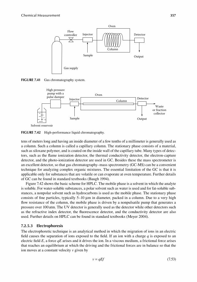
ChemicalMeasurement 357
tens.of.meters.long.and.having.an.inside.diameter.of.a.few.tenths.of.a.millimeter.is.generally.used.as.a.column..Such.a.column.is.called.a.capillary.column..The.stationary.phase.consists.of.a.material,.such.as.siloxane.polymer,.and.is.coated.on.the.inside.wall.of.the.capillary.tube..Many.types.of.detec-tors,.such.as.the.flame.ionization.detector,.the.thermal.conductivity.detector,.the.electron-capture.detector,.and.the.photo-ionization.detector.are.used.in.GC..Besides.these.the.mass.spectrometer.is.an.excellent.detector,.so.that.gas.chromatography–mass.spectrometry.(GC-MS).can.be.a.convenient.technique.for.analyzing.complex.organic.mixtures..The.essential.limitation.of.the.GC.is.that.it.is.applicable.only.for.substances.that.are.volatile.or.can.evaporate.at.oven.temperature..Further.details.of.GC.can.be.found.in.standard.textbooks.(Baugh.1994).
Figure.7.42.shows.the.basic.scheme.for.HPLC..The.mobile.phase.is.a.solvent.in.which.the.analyte.is.soluble..For.water-soluble.substances,.a.polar.solvent.such.as.water.is.used.and.for.fat-soluble.sub-stances,.a.nonpolar.solvent.such.as.hydrocarbons.is.used.as.the.mobile.phase..The.stationary.phase.consists.of.fine.particles,.typically.5–10.μm.in.diameter,.packed.in.a.column..Due.to.a.very.high.flow.resistance.of.the.column,.the.mobile.phase.is.driven.by.a.nonpulsatile.pump.that.generates.a.pressure.over.100.atm..The.UV.detector.is.generally.used.as.the.detector.while.other.detectors.such.as. the.refractive. index.detector,. the.fluorescence.detector,.and. the.conductivity.detector.are.also.used..Further.details.on.HPLC.can.be.found.in.standard.textbooks.(Meyer.2004).
7.2.5.3 electrophoresisThe.electrophoretic.technique.is.an.analytical.method.in.which.the.migration.of.ions.in.an.electric.field.causes.the.separation.of.ions.exposed.to.the.field..If.an.ion.with.a.charge.q.is.exposed.to.an.electric.field.E,.a.force.qE.arises.and.it.drives.the.ion..In.a.viscous.medium,.a.frictional.force.arises.that.reaches.an.equilibrium.at.which.the.driving.and.the.frictional.forces.are.in.balance.so.that.the.ion.moves.at.a.constant.velocity.v.given.by
. v qEf= . (7.53)
Oven
ColumnDetector
Output
Wasteor fractioncollector
High pressurepump with apulse damper
Injector
Sample
Solvent reservoir
figure 7.42 High-performance.liquid.chromatography.
Gas supply
Flowcontroller Injector
Sample
Column
Oven
Detector
Output
figure 7.41 Gas.chromatography.system.
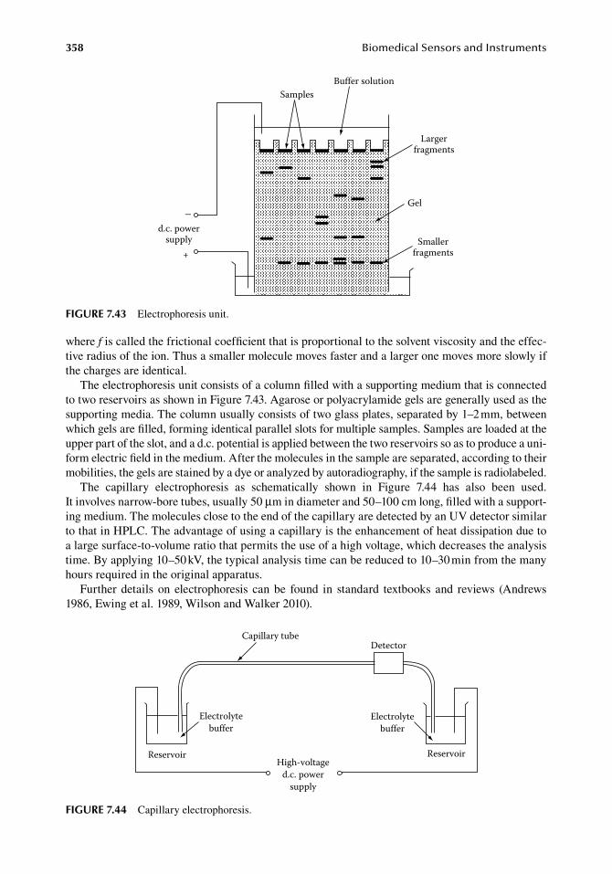
358 BiomedicalSensorsandInstruments
where.f.is.called.the.frictional.coefficient.that.is.proportional.to.the.solvent.viscosity.and.the.effec-tive.radius.of.the.ion..Thus.a.smaller.molecule.moves.faster.and.a.larger.one.moves.more.slowly.if.the.charges.are.identical.
The.electrophoresis.unit.consists.of.a.column.filled.with.a.supporting.medium.that.is.connected.to.two.reservoirs.as.shown.in.Figure.7.43..Agarose.or.polyacrylamide.gels.are.generally.used.as.the.supporting.media..The.column.usually.consists.of.two.glass.plates,.separated.by.1–2.mm,.between.which.gels.are.filled,.forming.identical.parallel.slots.for.multiple.samples..Samples.are.loaded.at.the.upper.part.of.the.slot,.and.a.d.c..potential.is.applied.between.the.two.reservoirs.so.as.to.produce.a.uni-form.electric.field.in.the.medium..After.the.molecules.in.the.sample.are.separated,.according.to.their.mobilities,.the.gels.are.stained.by.a.dye.or.analyzed.by.autoradiography,.if.the.sample.is.radiolabeled.
The. capillary. electrophoresis. as. schematically. shown. in. Figure. 7.44. has. also. been. used..It involves.narrow-bore.tubes,.usually.50.μm.in.diameter.and.50–100.cm.long,.filled.with.a.support-ing.medium..The.molecules.close.to.the.end.of.the.capillary.are.detected.by.an.UV.detector.similar.to.that.in.HPLC..The.advantage.of.using.a.capillary.is.the.enhancement.of.heat.dissipation.due.to.a.large.surface-to-volume.ratio.that.permits.the.use.of.a.high.voltage,.which.decreases.the.analysis.time..By.applying.10–50.kV,.the.typical.analysis.time.can.be.reduced.to.10–30.min.from.the.many.hours.required.in.the.original.apparatus.
Further.details. on. electrophoresis. can.be. found. in. standard. textbooks. and. reviews. (Andrews.1986,.Ewing.et al..1989,.Wilson.and.Walker.2010).
d.c. powersupply
+
–
SamplesBuffer solution
Gel
Largerfragments
Smallerfragments
figure 7.43 Electrophoresis.unit.
Detector
Electrolytebuffer
ReservoirHigh-voltage
d.c. powersupply
Electrolytebuffer
Capillary tube
Reservoir
figure 7.44 Capillary.electrophoresis.
ChemicalMeasurement 359
7.2.5.4 Magnetic resonanceMagnetic.resonance.is.an.analytical.technique.based.on.the.measurement.of.absorption.of.elec-tromagnetic.radiation.by.either.electrons.or.nuclei.in.the.presence.of.an.external.magnetic.field..When.the.absorption.of.electrons.is.measured,.the.technique.is.called.the.electron.spin.resonance.(ESR),.and.when.that.of.nuclei.is.measured,.it.is.called.the.nuclear.magnetic.resonance.(NMR).Electron.paramagnetic.resonance.is.used.as.an.alternative.to.the.term.ESR.and.is.more.rigorous.because.the.resonance.condition.is.determined.not.only.by.the.electron.spin.but.also.by.the.change.in.electron.orbit.
The.principle.of.magnetic.resonance.can.be.explained.by.a.simple.classical.model.in.which.an.electron.or.a.nucleus.can.be.regarded.as.a.spinning.charged.particle..Due.to.the.spinning.motion,.the.particle.has.an.angular.momentum..At.the.same.time,.it.causes.a.magnetic.moment.induced.by.the.effective.ring.current.due.to.the.rotating.charge..Because.angular.momentum.is.quantized.in.atomic.scale,.the.emerged.magnetic.moment.is.also.quantized,.and.consequently,.the.particle.has.a.magnetic.moment.at.discrete.levels.only,.which.is.proportional.to.the.quantized.angular.momentum..The.proportionality.constant.is.called.the.gyromagnetic.ratio.and.denoted.by.γ..Then,.the.magnetic.moment.vector.μ.is.written.as
. m = γl . (7.54)
where.l.is.the.angular.momentum.vector..In.a.free.electron.and.a.nucleus.having.a.spin.1/2.(such.as.1H,.13C.and.31P),.only.two.states.of.the.angular.momentum.are.allowed..In.an.external.magnetic.field,.B,.a.particle.having.a.magnetic.moment.μ.has.a.magnetic.energy.U.expressed.as
. U = − ⋅m B . (7.55)
When.the.magnetic.moment.is.quantized,.only.discrete.states.can.be.realized..For.a.particle.having.a.spin.1/2,.there.are.two.states.of.magnetic.moments.corresponding.to.the.parallel.and.antiparallel.to.the.external.magnetic.field..The.energy.difference.between.these.two.states.is.then.given.by
.∆U B= −
.γ
.(7.56)
where.ℏ.is.one.quantum.unit.of.angular.momentum.and.equal.to.h/2π.where.h.is.Planck’s.constant..Transition.between.these.two.states.can.occur.when.a.photon.having.an.energy.hν.equal.to.ΔU.is.absorbed..Thus
. h Bv = γ . (7.57)
The.coefficient.γ ℏ.is.often.expressed.as.a.product.of.a.dimensionless.factor.g.called.the.Zeeman.splitting.constant,.and.a.factor.β.called.the.magneton.so.that
. h g Bv = β . (7.58)
The.Zeeman.splitting.factor.of.a.free.electron.is
. ge 2 23193= .00 . (7.59)
and.the.factor.β.for.a.free.electron,.called.the.Bohr.magneton,.is
. βe24 19 274153 1 JT= × − −. 0 . (7.60)
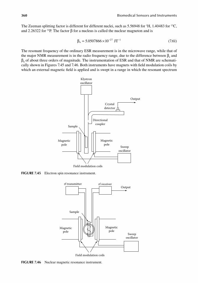
360 BiomedicalSensorsandInstruments
The.Zeeman.splitting.factor.is.different.for.different.nuclei,.such.as.5.56948.for.1H,.1.40483.for.13C,.and.2.26322.for.31P..The.factor.β.for.a.nucleus.is.called.the.nuclear.magneton.and.is
. βn27 15 5 7866 1 JT= × − −.0 0 0 . (7.61)
The.resonant.frequency.of.the.ordinary.ESR.measurement.is.in.the.microwave.range,.while.that.of.the.major.NMR.measurement.is.in.the.radio.frequency.range,.due.to.the.difference.between.βe.and.βn.of.about.three.orders.of.magnitude..The.instrumentation.of.ESR.and.that.of.NMR.are.schemati-cally.shown.in.Figures.7.45.and.7.46..Both.instruments.have.magnets.with.field.modulation.coils.by.which.an.external.magnetic.field.is.applied.and.is.swept.in.a.range.in.which.the.resonant.spectrum.
rf transmitter rf receiver
Sample
Magneticpole
Magneticpole
Field modulation coils
Sweeposcillator
Output
figure 7.46 Nuclear.magnetic.resonance.instrument.
Crystaldetector
Output
Directionalcoupler
Klystronoscillator
Sample
Magneticpole
Magneticpole
Field modulation coils
Sweeposcillator
figure 7.45 Electron.spin.resonance.instrument.
ChemicalMeasurement 361
can.be.observed..In.ESR,.the.resonance.is.observed.in.the.microwave.range..Thus,.the.sample.is.placed.in.a.microwave.cavity..The.microwave.is.produced.by.a.klystron.oscillator.and.detected.by.a.crystal.detector..In.NMR,.a.radio.frequency.transmitter.and.a.receiver.with.two.sets.of.transmitter.and.receiver.coils.are.used.
In.ESR.measurement,. species.having.unpaired.electrons,. such.as. free. radicals. and. transition.metal.ions,.are.analyzed..These.species.consist.of.only.a.small.part.of.the.sample..In.NMR,.gener-ally.the.resonance.of.protons.(1H).is.measured..Because.1H.exists.in.water.and.any.organic.sub-stance,. observation. of. the. strength. of. absorption. does. not. provide. much. information. about. the.chemical.composition.of.a.sample..However,.the.resonant.frequency.is.affected.by.the.local.field.in.a.molecule..Local.fields.in.hydrogen.nuclei.at.different.sites.in.a.molecule.are.different,.leading.to.differences.in.resonant.frequencies.that.are.called.chemical.shifts..This.principle.can.be.applied.to.chemical.analyses..Other.nuclei.having.a.magnetic.moment.such.as.13C,.15N,.and.31P.are.also.used.in.biochemical.studies.
Further. details. of. ESR. and. NMR. for. chemical. analysis. can. be. found. in. standard. textbooks.(Skoog.et al..2006,.Weil.and.Bolton.2007,.Wilson.and.Walker.2010).
7.2.5.5 other analytical Methods based on Physical Material PropertiesPhysical.properties.such.as.mechanical,.thermal,.electromagnetic,.or.optical.properties.of.a.matter.depend.on.its.chemical.composition..Thus,.measurement.of.each.physical.material.property.can.be.potentially.applicable.to.chemical.analysis..However,.for.a.mixture.of.many.different.chemical.spe-cies,.no.single.measurement.of.a.physical.material.property,.such.as.density,.thermal.conductivity,.refractive.index,.etc.,.provides.sufficient.information.to.identify.and.determine.their.constituents..A possible.situation.in.which.such.a.measurement.can.be.useful.is.that.where.only.the.chemical.spe-cies.of.interest.dominantly.contributes.to.the.material.property..For.example,.the.content.of.plasma.protein.can.be.estimated.by.the.refractive.index,.because.the.contribution.of.other.constituents.is.small.enough..Another.possible.application.is.a.combination.of.a.separating.device,.such.as.a.chro-matographic.column,.and.a.nonspecific.sensing.element..For.example,.a.sensing.element.based.on.thermal.conductivity.can.be.a.convenient.detector.of.GC.
7.2.5.5.1 DensityThe.density.or.specific.gravity.of.a.solution.provides.an.estimate.of.the.amount.of.the.solutes..The.specific.gravity.of.a.fluid.can.be.measured.by.a.float.gauge..It.is.based.on.the.principle.that.buoyancy.exerted.on.a.matter.in.a.fluid.is.just.the.weight.of.the.fluid.excluded.when.the.matter.enters..This.principle.has.been.used.in.the.clinical.examination.of.urine.using.an.instrument,.called.the.urinom-eter.that.is.a.float.with.a.scale.in.specific.gravity.
The.density.of.a.fluid.can.also.be.estimated.from.sound.velocity..For.gases.and.liquids,.sound.velocity.c.is.given.by
.c
K=ρ .
(7.62)
whereK.is.the.bulk.modulus.of.elasticityρ.is.the.density
7.2.5.5.2 ViscosityThe. viscosity. of. a. liquid. is. generally. measured. by. either. a. capillary. viscometer. or. a. rotational.viscometer..The.capillary.viscometer.consists.of.a.narrow.capillary.tube.of.known.diameter.and.length..The.sample.is.forced.into.it,.and.viscosity.is.determined.from.the.pressure.drop.and.flow.
362 BiomedicalSensorsandInstruments
rate.using.Poiseuille’s.law..In.the.rotational.viscometer,.the.sample.is.filled.in.a.narrow.gap.between.two.surfaces,.one.rotating.and.the.other.stationary,.and.viscosity.is.determined.from.the.torque.of.the.rotating.element.
7.2.5.5.3 Thermal ConductivityThe.thermal.conductivity.of.a.gas,.liquid,.or.solid.depends.on.its.composition..Thus,.in.principle,.its.measurement.can.be.used.in.chemical.analysis..An.example.is.a.detector.of.the.GC.as.mentioned.in.Section.7.2.5.2..In.this.application,.the.instrument.detects.any.chemical.species.separated.by.the.column.if.its.thermal.conductivity.is.different.from.that.of.the.carrier.gas..In.the.detector,.differ-ences.in.thermal.conductivity.are.detected.as.a.change.in.heat.dissipation.from.the.heated.filament.
7.2.5.5.4 Refractive IndexIn.a.solution,.the.refractive.index.may.vary.with.the.concentration.of.solutes..If.the.refractive.index.varies.with.only.one.known.solute,.its.concentration.can.be.estimated.by.refractometry..For.exam-ple,.the.serum.protein.content.has.been.measured.by.a.simple.refractometer,.in.which.the.refractive.index. is.measured.by.measuring. the.critical. angle.of. the. total. reflection..Total. reflection.occurs.when.a.light.beam.passes.across.an.interface.of.two.media.from.one.having.a.larger.refractive.indi-ces.to.another.having.a.smaller.refractive.index..When.the.refractive.indices.of.two.media.are.n1.and.n2.(n1.>.n2),.then.the.critical.angle.θc.for.total.reflection.is.given.by
.sin c
2
1
θ = n
n .(7.63)
7.2.5.5.5 Optical RotationOptical. rotation. is. a. phenomenon. that. occurs. when. a. plane-polarized. light. beam. is. transmitted.through.a.certain.medium.and.the.plane.of.polarization.rotates..When.optical.rotation.is.measured.in.a.sample.of.constant.length,.the.amount.of.optical.rotation.is.proportional.to.the.rotatory.power.and.concentration.of.the.substance,.which.possesses.the.property.of.optical.rotation..Thus.the.con-centration.can.be.estimated.if.the.rotatory.power.of.the.substance.is.known..This.technique.has.been.used.for.measurement.of.sucrose.concentrations..It.is.also.applicable,.in.principle,.for.measurement.of.the.glucose.concentration.in.a.body.fluid.because.of.the.fact.that.only.d-glucose.(dextroglusoce,.dextrose).exists.in.biological.organisms..Actually,.glucose.measurement.in.the.aqueous.humor.of.the.eye.has.been.attempted.using.a.contact. lens. to.which.a. light.source,.polarizers,.and.a.photo.detector.were.attached.(March.et al..1982,.Rabinovitch.et al..1982,.King.et al..1994).
7.2.5.5.6 Electric Conductivity and PermittivityThe.conductivity.of.a.solution.depends.on.its.ionic.concentration.and.is.proportional.to.the.ionic.concentration,.as.long.as.the.concentration.is.low..While.the.proportionality.coefficients.are.differ-ent.for.different.ions,.the.conductivity.of.a.solution.provides.information.about.the.ionic.concentra-tion.if.the.relative.ionic.compositions.of.the.solution.are.known..For.example,.conductivity.can.be.a.convenient.measure.of.the.quality.of.purified.water.
The.permittivity.(dielectric.constant).can.be.determined.by.measuring.the.capacitive.component.of.the.impedance..If.an.a.c..electric.field.is.applied.to.a.solution.that.contains.molecules.with.per-manent.dipole.moments,.the.dipoles.will.reorient.themselves.in.the.field.direction.at.every.cycle,.and.this.causes.a.displacement.current..Because.permittivity.is.frequency.dependent,.and.the.fre-quency.characteristics.depend.on.the.chemical.species,.permittivity.measurement.in.the.adequate.frequency.range.can.be.used.as.an.analytical.technique.(Kell.and.Davey.1990).
7.2.5.5.7 Magnetic SusceptibilityMagnetic. susceptibility. is. a. quantity. that. determines. magnetization. relative. to. magnetic. field.strength..When.a.specific.substance.in.a.sample.exhibits.strong.magnetism,.but.others.do.not,.the.
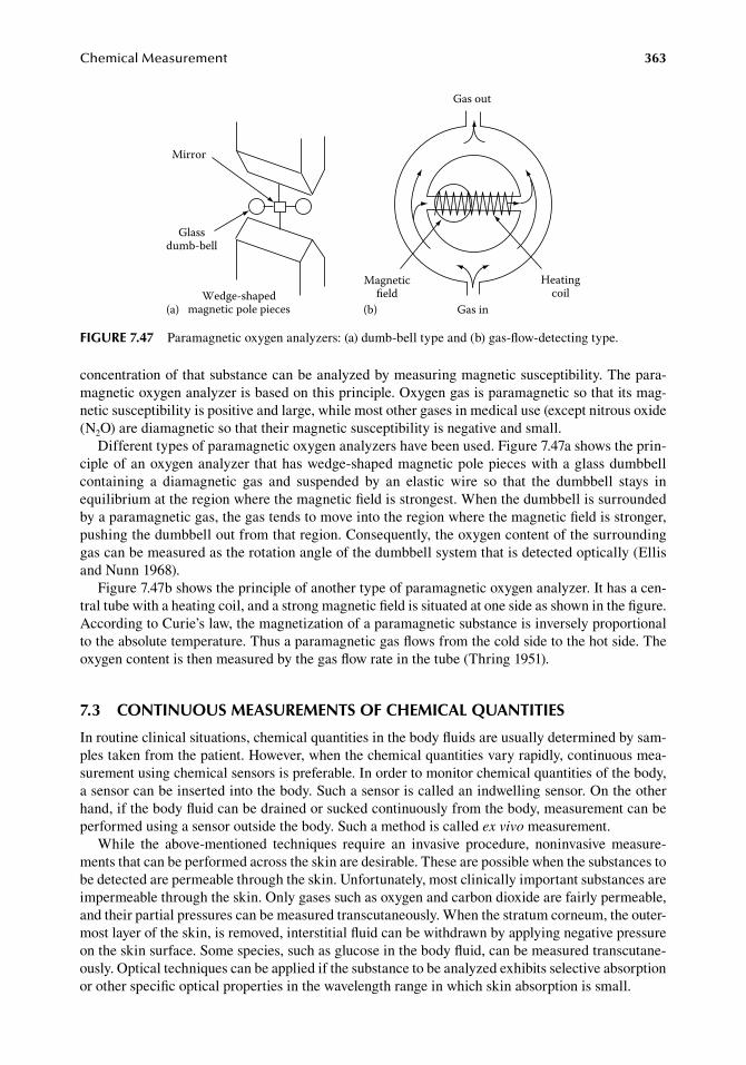
ChemicalMeasurement 363
concentration.of.that.substance.can.be.analyzed.by.measuring.magnetic.susceptibility..The.para-magnetic.oxygen.analyzer.is.based.on.this.principle..Oxygen.gas.is.paramagnetic.so.that.its.mag-netic.susceptibility.is.positive.and.large,.while.most.other.gases.in.medical.use.(except.nitrous.oxide.(N2O).are.diamagnetic.so.that.their.magnetic.susceptibility.is.negative.and.small.
Different.types.of.paramagnetic.oxygen.analyzers.have.been.used..Figure.7.47a.shows.the.prin-ciple.of.an.oxygen.analyzer.that.has.wedge-shaped.magnetic.pole.pieces.with.a.glass.dumbbell.containing. a. diamagnetic. gas. and. suspended. by. an. elastic. wire. so. that. the. dumbbell. stays. in.equilibrium.at.the.region.where.the.magnetic.field.is.strongest..When.the.dumbbell.is.surrounded.by.a.paramagnetic.gas,.the.gas.tends.to.move.into.the.region.where.the.magnetic.field.is.stronger,.pushing.the.dumbbell.out.from.that.region..Consequently,.the.oxygen.content.of.the.surrounding.gas.can.be.measured.as.the.rotation.angle.of.the.dumbbell.system.that.is.detected.optically.(Ellis.and.Nunn.1968).
Figure.7.47b.shows.the.principle.of.another.type.of.paramagnetic.oxygen.analyzer..It.has.a.cen-tral.tube.with.a.heating.coil,.and.a.strong.magnetic.field.is.situated.at.one.side.as.shown.in.the.figure..According.to.Curie’s.law,.the.magnetization.of.a.paramagnetic.substance.is.inversely.proportional.to.the.absolute.temperature..Thus.a.paramagnetic.gas.flows.from.the.cold.side.to.the.hot.side..The.oxygen.content.is.then.measured.by.the.gas.flow.rate.in.the.tube.(Thring.1951).
7.3 ContinuouS MeaSureMentS of CheMiCal QuantitieS
In.routine.clinical.situations,.chemical.quantities.in.the.body.fluids.are.usually.determined.by.sam-ples.taken.from.the.patient..However,.when.the.chemical.quantities.vary.rapidly,.continuous.mea-surement.using.chemical.sensors.is.preferable..In.order.to.monitor.chemical.quantities.of.the.body,.a.sensor.can.be.inserted.into.the.body..Such.a.sensor.is.called.an.indwelling.sensor..On.the.other.hand,.if.the.body.fluid.can.be.drained.or.sucked.continuously.from.the.body,.measurement.can.be.performed.using.a.sensor.outside.the.body..Such.a.method.is.called.ex vivo.measurement.
While. the. above-mentioned. techniques. require. an. invasive. procedure,. noninvasive. measure-ments.that.can.be.performed.across.the.skin.are.desirable..These.are.possible.when.the.substances.to.be.detected.are.permeable.through.the.skin..Unfortunately,.most.clinically.important.substances.are.impermeable.through.the.skin..Only.gases.such.as.oxygen.and.carbon.dioxide.are.fairly.permeable,.and.their.partial.pressures.can.be.measured.transcutaneously..When.the.stratum.corneum,.the.outer-most.layer.of.the.skin,.is.removed,.interstitial.fluid.can.be.withdrawn.by.applying.negative.pressure.on.the.skin.surface..Some.species,.such.as.glucose.in.the.body.fluid,.can.be.measured.transcutane-ously..Optical.techniques.can.be.applied.if.the.substance.to.be.analyzed.exhibits.selective.absorption.or.other.specific.optical.properties.in.the.wavelength.range.in.which.skin.absorption.is.small.
Gas out
Gas in
Heatingcoil
Magneticeld
(b)
Mirror
Glassdumb-bell
Wedge-shapedmagnetic pole pieces(a)
figure 7.47 Paramagnetic.oxygen.analyzers:.(a).dumb-bell.type.and.(b).gas-flow-detecting.type.
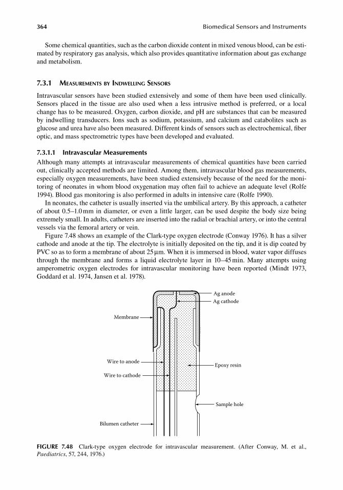
364 BiomedicalSensorsandInstruments
Some.chemical.quantities,.such.as.the.carbon.dioxide.content.in.mixed.venous.blood,.can.be.esti-mated.by.respiratory.gas.analysis,.which.also.provides.quantitative.information.about.gas.exchange.and.metabolism.
7.3.1 MeasureMents by indwelling sensors
Intravascular.sensors.have.been.studied.extensively.and.some.of.them.have.been.used.clinically..Sensors. placed. in. the. tissue. are. also. used. when. a. less. intrusive. method. is. preferred,. or. a. local.change.has.to.be.measured..Oxygen,.carbon.dioxide,.and.pH.are.substances.that.can.be.measured.by. indwelling. transducers.. Ions.such.as.sodium,.potassium,.and.calcium.and.catabolites.such.as.glucose.and.urea.have.also.been.measured..Different.kinds.of.sensors.such.as.electrochemical,.fiber.optic,.and.mass.spectrometric.types.have.been.developed.and.evaluated.
7.3.1.1 intravascular MeasurementsAlthough.many.attempts.at.intravascular.measurements.of.chemical.quantities.have.been.carried.out,.clinically.accepted.methods.are.limited..Among.them,.intravascular.blood.gas.measurements,.especially.oxygen.measurements,.have.been.studied.extensively.because.of.the.need.for.the.moni-toring.of.neonates.in.whom.blood.oxygenation.may.often.fail.to.achieve.an.adequate.level.(Rolfe.1994)..Blood.gas.monitoring.is.also.performed.in.adults.in.intensive.care.(Rolfe.1990).
In.neonates,.the.catheter.is.usually.inserted.via.the.umbilical.artery..By.this.approach,.a.catheter.of.about.0.5–1.0.mm.in.diameter,.or.even.a. little. larger,.can.be.used.despite. the.body.size.being.extremely.small..In.adults,.catheters.are.inserted.into.the.radial.or.brachial.artery,.or.into.the.central.vessels.via.the.femoral.artery.or.vein.
Figure.7.48.shows.an.example.of.the.Clark-type.oxygen.electrode.(Conway.1976)..It.has.a.silver.cathode.and.anode.at.the.tip..The.electrolyte.is.initially.deposited.on.the.tip,.and.it.is.dip.coated.by.PVC.so.as.to.form.a.membrane.of.about.25.μm..When.it.is.immersed.in.blood,.water.vapor.diffuses.through. the. membrane. and. forms. a. liquid. electrolyte. layer. in. 10–45.min.. Many. attempts. using.amperometric. oxygen. electrodes. for. intravascular. monitoring. have. been. reported. (Mindt. 1973,.Goddard.et al..1974,.Jansen.et al..1978).
Ag anodeAg cathode
Epoxy resin
Membrane
Wire to anode
Wire to cathode
Bilumen catheter
Sample hole
figure 7.48 Clark-type. oxygen. electrode. for. intravascular. measurement.. (After. Conway,. M.. et al.,.Paediatrics,.57,.244,.1976.)
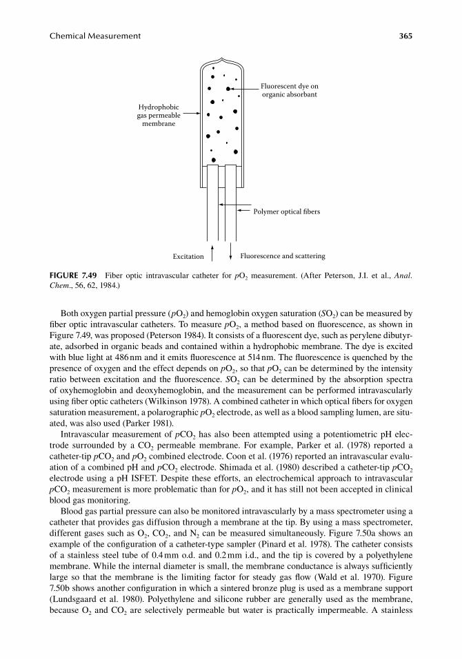
ChemicalMeasurement 365
Both.oxygen.partial.pressure.(pO2).and.hemoglobin.oxygen.saturation.(SO2).can.be.measured.by.fiber.optic.intravascular.catheters..To.measure.pO2,.a.method.based.on.fluorescence,.as.shown.in.Figure.7.49,.was.proposed.(Peterson.1984)..It.consists.of.a.fluorescent.dye,.such.as.perylene.dibutyr-ate,.adsorbed.in.organic.beads.and.contained.within.a.hydrophobic.membrane..The.dye.is.excited.with.blue.light.at.486.nm.and.it.emits.fluorescence.at.514.nm..The.fluorescence.is.quenched.by.the.presence.of.oxygen.and.the.effect.depends.on.pO2,.so.that.pO2.can.be.determined.by.the.intensity.ratio.between.excitation.and. the.fluorescence..SO2.can.be.determined.by. the.absorption. spectra.of.oxyhemoglobin.and.deoxyhemoglobin,.and.the.measurement.can.be.performed.intravascularly.using.fiber.optic.catheters.(Wilkinson.1978)..A.combined.catheter.in.which.optical.fibers.for.oxygen.saturation.measurement,.a.polarographic.pO2.electrode,.as.well.as.a.blood.sampling.lumen,.are.situ-ated,.was.also.used.(Parker.1981).
Intravascular.measurement.of.pCO2.has.also.been.attempted.using.a.potentiometric.pH.elec-trode. surrounded. by. a. CO2. permeable. membrane.. For. example,. Parker. et al.. (1978). reported. a.catheter-tip.pCO2.and.pO2.combined.electrode..Coon.et al..(1976).reported.an.intravascular.evalu-ation.of.a.combined.pH.and.pCO2.electrode..Shimada.et al..(1980).described.a.catheter-tip.pCO2.electrode.using.a.pH.ISFET..Despite. these.efforts,.an.electrochemical.approach.to. intravascular.pCO2.measurement.is.more.problematic.than.for.pO2,.and.it.has.still.not.been.accepted.in.clinical.blood.gas.monitoring.
Blood.gas.partial.pressure.can.also.be.monitored.intravascularly.by.a.mass.spectrometer.using.a.catheter.that.provides.gas.diffusion.through.a.membrane.at.the.tip..By.using.a.mass.spectrometer,.different.gases.such.as.O2,.CO2,.and.N2.can.be.measured.simultaneously..Figure.7.50a.shows.an.example.of.the.configuration.of.a.catheter-type.sampler.(Pinard.et al..1978)..The.catheter.consists.of.a.stainless.steel. tube.of.0.4.mm.o.d..and.0.2.mm.i.d.,.and.the. tip. is.covered.by.a.polyethylene.membrane..While.the.internal.diameter.is.small,.the.membrane.conductance.is.always.sufficiently.large. so. that. the.membrane. is. the. limiting. factor. for. steady.gas.flow. (Wald.et al.. 1970)..Figure.7.50b.shows.another.configuration.in.which.a.sintered.bronze.plug.is.used.as.a.membrane.support.(Lundsgaard.et al..1980)..Polyethylene.and.silicone. rubber.are.generally.used.as. the.membrane,.because.O2.and.CO2.are.selectively.permeable.but.water. is.practically. impermeable..A.stainless.
Polymer optical bers
Excitation Fluorescence and scattering
Hydrophobicgas permeable
membrane
Fluorescent dye onorganic absorbant
figure 7.49 Fiber. optic. intravascular. catheter. for. pO2. measurement.. (After. Peterson,. J.I.. et al.,. Anal. Chem.,.56,.62,.1984.)
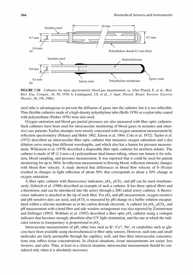
366 BiomedicalSensorsandInstruments
steel.tube.is.advantageous.to.prevent.the.diffusion.of.gases.into.the.catheter,.but.it.is.too.inflexible..Thus.flexible.catheters.made.of.a.high-density.polyethylene.tube.(Rolfe.1976).or.a.nylon.tube.coated.with.polyurethane.(Parker.1976).were.also.used.
Oxygen.saturation.and.blood.gas.partial.pressures.are.also.measured.with.fiber.optic.catheters..Such.catheters.have.been.used.for.intravascular.monitoring.of.blood.gases.in.neonates.and.inten-sive.care.patients..Earlier.attempts.were.mostly.concerned.with.oxygen.saturation.measurement.by.reflection.spectrometry.(Polanyi.and.Hehir.1962,.Enson.et al..1964,.Cole.et al..1972)..Taylor.et al..(1972).described.an.intravascular.fiber.optic.catheter.that.measures.oxygen.saturation.and.a.dye.dilution.curve.using.four.different.wavelengths,.and.which.also.has.a.lumen.for.pressure.measure-ment..Wilkinson.et al..(1978).described.a.disposable.fiber.optic.catheter.for.newborn.infants..The.catheter.is.made.of.4F.(1.3.mm.o.d.).polyurethane.dual-lumen.tubing,.where.one.lumen.is.for.infu-sion,.blood.sampling,.and.pressure.measurement..It.was.reported.that.it.could.be.used.for.patient.monitoring.for.up.to.180.h..In.reflection.measurement.in.flowing.blood,.reflection.intensity.changes.with. blood. flow. velocity.. A. study. showed. that. differences. in. blood. flow. velocity. of. 0–30.cm/s.resulted. in.changes. in. light. reflection.of.about.50%.that.corresponds. to.about.a.10%.change. in.oxygen.saturation.
A.fiber.optic.catheter.with.fluorescence.indicators,.pO2,.pCO2,.and.pH.can.be.used.simultane-ously..Gehrich.et al..(1986).described.an.example.of.such.a.catheter..It.has.three.optical.fibers.and.a.thermistor,.and.can.be.introduced.into.the.artery.through.a.20G.radial.artery.catheter..A.fluores-cence.indicator.is.attached.at.the.tip.of.each.fiber..For.pO2.and.pH.measurement,.oxygen-sensitive.and.pH-sensitive.dyes.are.used,.and.pCO2.is.measured.by.pH.change.in.a.buffer.solution.encapsu-lated.within.a.silicone.membrane.as.in.the.carbon.dioxide.electrode..A.catheter.for.pO2,.pCO2,.and.pH.measurement.with.a.bend.fiber.and.side.window.arrangement.was.also.reported.by.Zimmerman.and.Dellinger.(1993)..Wolthuis.et al..(1992).described.a.fiber.optic.pO2.catheter.using.a.viologen.indicator.that.becomes.strongly.absorbent.after.UV.light.stimulation,.and.the.rate.at.which.the.indi-cator.returns.to.transparency.is.proportional.to.pO2.
Intravascular.measurements.of.pH,.other.ions.such.as.K+,.Ca2+,.Na+,.or.catabolites.such.as.glu-cose.have.been.available.using.electrochemical.or.fiber.optic.sensors..However,.such.ions.and.small.molecules.are.fairly.permeable.through.the.capillary.wall,.and.thus.their.intravascular.concentra-tions.may.reflect.tissue.concentrations..In.clinical.situations,.tissue.measurements.are.easier,.less.invasive,.and.safer..Thus,.at.least.in.a.clinical.situation,.intravascular.measurement.should.be.con-sidered.only.when.it.is.absolutely.necessary.
50 mm
Polyethylene sheath 0.1 mm thick
0.7 mm
Stainless steel
0.7 mm
0.4 mm(a)
0.8 mm
0.5 mm
Stainless steel
Epoxy resin
Sintered bronze
Polyethylene membrane Epoxy resin(b)
figure 7.50 Catheters.for.mass.spectrometric.blood.gas.measurement..(a,.After.Pinard,.E..et al.,.Med. Biol. Eng. Comput.,. 16,. 59,. 1978;. b,. Lundsgaard,. J.S.. et al.,. J. Appl. Physiol. Respir. Environ. Exercise Physiol.,.48,.376,.1980.)
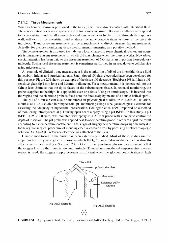
ChemicalMeasurement 367
7.3.1.2 tissue MeasurementsWhen.a.chemical.sensor.is.positioned.in.the.tissue,.it.will.have.direct.contact.with.interstitial.fluid..The.concentration.of.chemical.species.in.this.fluid.can.be.measured..Because.capillaries.are.exposed.to.the.interstitial.fluid,.smaller.molecules.and.ions,.which.can.freely.diffuse.through.the.capillary.wall,.will.exist. in.the.interstitial.fluid.at.almost.the.same.concentrations.as.those.in.the.circulat-ing. blood.. Thus,. tissue. measurement. can. be. a. supplement. to. direct. intravascular. measurement..Actually,.for.glucose.monitoring,.tissue.measurement.is.emerging.as.a.possible.method.
Tissue.measurement.is.also.used.to.study.very.local.changes.in.some.chemical.species..An.exam-ple.is.intramuscular.measurements.in.which.pH.may.change.when.the.muscle.works..Nowadays,.special.attention.has.been.paid.to.the.tissue.measurement.of.NO.that.is.an.important.bioregulatory.molecule..Such.a.local.tissue.measurement.is.sometimes.performed.in.an.area.down.to.cellular.size.using.microsensors.
An.example.of.clinical.tissue.measurement.is.the.monitoring.of.pH.of.the.interstitial.tissue.fluid.in.newborn.infants.and.surgical.patients..Small.tipped.pH.glass.electrodes.have.been.developed.for.this.purpose..Figure.7.51.shows.an.example.of.the.tissue.pH.electrode.(Hochberg.1981)..It.has.a.pH-sensitive.glass.tip.1.mm.long.and.1.3.mm.in.diameter..For.a.measurement,.it.is.penetrated.into.the.skin.at.least.3.mm.so.that.the.tip.is.placed.in.the.subcutaneous.tissue..In.neonatal.monitoring,.the.probe.is.applied.to.the.thigh..It.is.applicable.even.on.a.fetus..Using.an.amnioscope,.it.is.inserted.into.the.vagina.and.the.electrode.probe.is.fixed.onto.the.fetal.scalp.by.means.of.a.double-helical.spiral.
The.pH.of. a.muscle.can.also.be.monitored. in.physiological. studies.or. in.a.clinical. situation..Khuri.et al..(1983).studied.intramyocardial.pH.monitoring.using.a.steel-jacketed.glass.electrode.for.assessing.the.adequacy.of.myocardial.preservation..Covington.et al..(1993).reported.on.a.method.of.monitoring.intramyocardial.pH.during.open.heart.surgery.using.a.pH.ISFET..In.this.study,.a.pH.ISFET,.1.25.×.2.00.mm,.was.mounted.with.epoxy.in.a.2.0.mm.probe.with.a.collar.to.control.the.depth.of.insertion..The.pH.probe.was.applied.next.to.a.temperature.probe.in.order.to.adjust.the.result.according.to.its.temperature.coefficient..In.this.type.of.surgery,.temperature.drops.significantly.due.to.the.regular.surgical.procedure.of.inducing.elective.cardiac.arrest.by.perfusing.a.cold.cardioplegic.solution..An.Ag–AgCl.reference.electrode.was.attached.to.the.skin.
Glucose.monitoring. in. the. tissue.has.been.extensively. studied..Most.of. these. studies.use. the.amperometric.enzymatic.glucose.sensor.in.which.H2O2,.O2,.or.a.redox.mediator.such.as.dimeth-ylferrocene.is.measured.(see.Section.7.2.4.1)..One.difficulty.in.tissue.glucose.measurement.is.that.the.oxygen.level.in.the.tissue.is.low.and.unstable..Thus,.if.an.unmediated.amperometric.glucose.sensor. is. used,. the. oxygen. supply. becomes. insufficient. when. the. glucose. concentration. is. high.
V
Tissue fluid
pH-sensitive glass
Membrane
Reference buffersolution
Ag–AgCl electrodeAg–AgCl electrode
figure 7.51 A.pH.glass.electrode.for.tissue.pH.measurement..(After.Hochberg,.H.M.,.J. Clin. Eng.,.6,.17,.1981.)
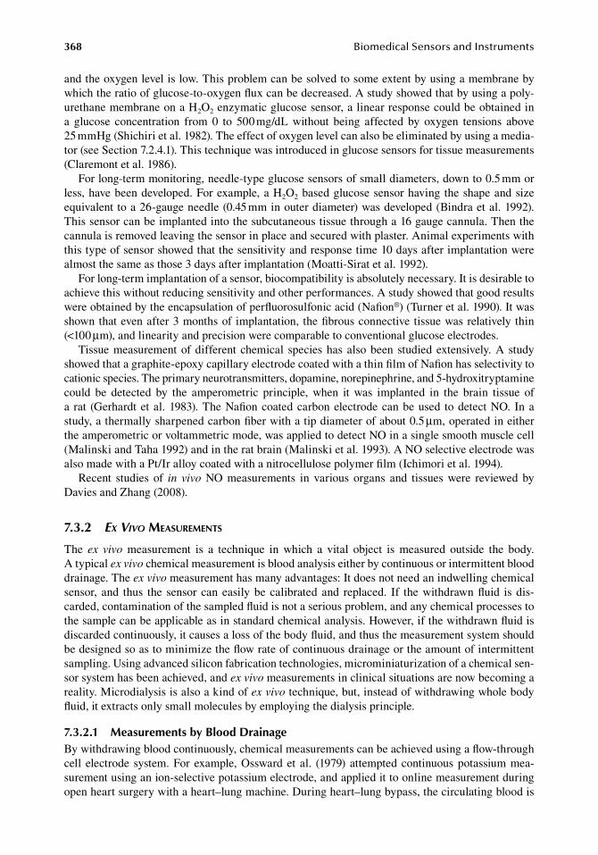
368 BiomedicalSensorsandInstruments
and.the.oxygen.level.is.low..This.problem.can.be.solved.to.some.extent.by.using.a.membrane.by.which.the.ratio.of.glucose-to-oxygen.flux.can.be.decreased..A.study.showed.that.by.using.a.poly-urethane.membrane.on.a.H2O2.enzymatic.glucose.sensor,.a.linear.response.could.be.obtained.in.a. glucose. concentration. from. 0. to. 500.mg/dL. without. being. affected. by. oxygen. tensions. above.25.mmHg.(Shichiri.et al..1982)..The.effect.of.oxygen.level.can.also.be.eliminated.by.using.a.media-tor.(see.Section.7.2.4.1)..This.technique.was.introduced.in.glucose.sensors.for.tissue.measurements.(Claremont.et al..1986).
For.long-term.monitoring,.needle-type.glucose.sensors.of.small.diameters,.down.to.0.5.mm.or.less,.have.been.developed..For.example,.a.H2O2.based.glucose.sensor.having.the.shape.and.size.equivalent.to.a.26-gauge.needle.(0.45.mm.in.outer.diameter).was.developed.(Bindra.et al..1992)..This.sensor.can.be.implanted.into.the.subcutaneous.tissue.through.a.16.gauge.cannula..Then.the.cannula.is.removed.leaving.the.sensor.in.place.and.secured.with.plaster..Animal.experiments.with.this.type.of.sensor.showed.that.the.sensitivity.and.response.time.10.days.after.implantation.were.almost.the.same.as.those.3.days.after.implantation.(Moatti-Sirat.et al..1992).
For.long-term.implantation.of.a.sensor,.biocompatibility.is.absolutely.necessary..It.is.desirable.to.achieve.this.without.reducing.sensitivity.and.other.performances..A.study.showed.that.good.results.were.obtained.by.the.encapsulation.of.perfluorosulfonic.acid.(Nafion®).(Turner.et al..1990)..It.was.shown.that.even.after.3.months.of. implantation,. the.fibrous.connective.tissue.was.relatively.thin.(<100.μm),.and.linearity.and.precision.were.comparable.to.conventional.glucose.electrodes.
Tissue.measurement.of.different. chemical. species.has.also.been. studied.extensively..A.study.showed.that.a.graphite-epoxy.capillary.electrode.coated.with.a.thin.film.of.Nafion.has.selectivity.to.cationic.species..The.primary.neurotransmitters,.dopamine,.norepinephrine,.and.5-hydroxitryptamine.could. be. detected. by. the. amperometric. principle,. when. it. was. implanted. in. the. brain. tissue. of.a. rat. (Gerhardt.et al..1983)..The.Nafion.coated.carbon.electrode.can.be.used. to.detect.NO.. In.a.study,.a.thermally.sharpened.carbon.fiber.with.a.tip.diameter.of.about.0.5.μm,.operated.in.either.the.amperometric.or.voltammetric.mode,.was.applied.to.detect.NO.in.a.single.smooth.muscle.cell.(Malinski.and.Taha.1992).and.in.the.rat.brain.(Malinski.et al..1993)..A.NO.selective.electrode.was.also.made.with.a.Pt/Ir.alloy.coated.with.a.nitrocellulose.polymer.film.(Ichimori.et al..1994).
Recent. studies. of. in vivo. NO. measurements. in. various. organs. and. tissues. were. reviewed. by.Davies.and.Zhang.(2008).
7.3.2 Ex ViVo MeasureMents
The. ex vivo. measurement. is. a. technique. in. which. a. vital. object. is. measured. outside. the. body..A typical.ex vivo.chemical.measurement.is.blood.analysis.either.by.continuous.or.intermittent.blood.drainage..The.ex vivo.measurement.has.many.advantages:.It.does.not.need.an.indwelling.chemical.sensor,. and. thus. the. sensor. can.easily.be. calibrated. and. replaced.. If. the.withdrawn.fluid. is.dis-carded,.contamination.of.the.sampled.fluid.is.not.a.serious.problem,.and.any.chemical.processes.to.the.sample.can.be.applicable.as.in.standard.chemical.analysis..However,.if.the.withdrawn.fluid.is.discarded.continuously,.it.causes.a.loss.of.the.body.fluid,.and.thus.the.measurement.system.should.be.designed.so.as.to.minimize.the.flow.rate.of.continuous.drainage.or.the.amount.of.intermittent.sampling..Using.advanced.silicon.fabrication.technologies,.microminiaturization.of.a.chemical.sen-sor.system.has.been.achieved,.and.ex vivo.measurements.in.clinical.situations.are.now.becoming.a.reality..Microdialysis.is.also.a.kind.of.ex vivo.technique,.but,.instead.of.withdrawing.whole.body.fluid,.it.extracts.only.small.molecules.by.employing.the.dialysis.principle.
7.3.2.1 Measurements by blood drainageBy.withdrawing.blood.continuously,.chemical.measurements.can.be.achieved.using.a.flow-through.cell. electrode. system..For.example,.Ossward.et al.. (1979).attempted.continuous.potassium.mea-surement.using.an.ion-selective.potassium.electrode,.and.applied.it.to.online.measurement.during.open.heart.surgery.with.a.heart–lung.machine..During.heart–lung.bypass,.the.circulating.blood.is.
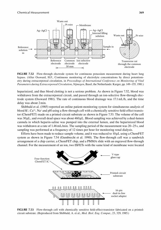
ChemicalMeasurement 369
heparinized,.and.thus.blood.clotting.is.not.a.serious.problem..As.shown.in.Figure.7.52,.blood.was.withdrawn.from.the.extracorporeal.circuit,.and.passed.through.an.ion-selective.flow-through.elec-trode.system.(Ossward.1981)..The.rate.of.continuous.blood.drainage.was.17.1.mL/h,.and.the.time.delay.was.about.2.min.
Shibbald.et al..(1985).reported.an.online.patient-monitoring.system.for.simultaneous.analysis.of.blood.K+,.Ca2+,.Na+.and.pH.using.a.flow-through.cell.with.a.chemically.sensitive.field-effect.transis-tor.(ChemFET).made.on.a.printed-circuit.substrate.as.shown.in.Figure.7.53..The.volume.of.the.cell.was.30.μL,.and.overall.dead.space.was.about.460.μL..Blood.sampling.was.achieved.by.a.dual-lumen.cannula.in.which.heparin-saline.was.pumped.into.the.external.lumen,.and.the.heparinized.blood.was.withdrawn.at.a.rate.of.1.46.mL/min..The.sampling.period.of.the.measurement.was.20–25.s,.and.sampling.was.performed.at.a.frequency.of.12.times.per.hour.for.monitoring.renal.dialysis.
Efforts.have.been.made.to.reduce.sample.volume,.and.it.was.reduced.to.10.μL.using.a.ChemFET.system.as.shown. in.Figure.7.54. (Gumbrecht.et al..1990)..The.flow-through.cell.was.a. sandwich.arrangement.of.a.chip.carrier,.a.ChemFET.chip,.and.a.PMMA.slide.with.an.engraved.flow-through.channel..For.the.measurement.of.an.ion,.two.ISFETs.with.the.same.kind.of.membrane.were.located.
Referenceelectrode
Commonelectrode
Ion-selectiveelectrode
Transverse cutthrough the common
electrode50 mm
Waste out
Ag–AgClInternal filling
solution
Sample in
Pt wire
MembranePt wireWaste out
Ag–AgCl
Referencesolution
in
figure 7.52 Flow-through. electrode. system. for. continuous. potassium. measurement. during. heart. lung.bypass.. (After. Ossward,. H.F.,. Continuous. monitoring. of. electrolyte. concentrations. by. direct. potentiom-etry.during.extracorporeal.circulation,. in.Proceedings of International Conference on Monitoring of Vital Parameters during Extracorporeal Circulation,.Nijmegen,.Basel,.the.Netherlands:.Karger,.pp..149–155,.1981.)
Printed-circuitsubstrate
16-pindual-in-line
socket adapter
Four-functionChemFET IC
V-typeglass cap
figure 7.53 Flow-through.cell.with. chemically. sensitive.field-effect-transistor. fabricated.on. a.printed-circuit.substrate..(Reproduced.from.Shibbald,.A..et al.,.Med. Biol. Eng. Comput.,.23,.329,.1985.)
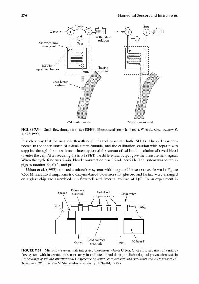
370 BiomedicalSensorsandInstruments
in.such.a.way.that. the.meander.flow-through.channel.separated.both.ISFETs..The.cell.was.con-nected.to.the.inner.lumen.of.a.dual-lumen.cannula,.and.the.calibration.solution.with.heparin.was.supplied.through.the.outer.lumen..Interruption.of.the.stream.of.calibration.solution.allowed.blood.to.enter.the.cell..After.reaching.the.first.ISFET,.the.differential.output.gave.the.measurement.signal..When.the.cycle.time.was.2.min,.blood.consumption.was.7.2.mL.per.24.h..The.system.was.tested.in.pigs.to.monitor.K+,.Ca2+,.and.pH.
Urban.et al..(1995).reported.a.microflow.system.with.integrated.biosensors.as.shown.in.Figure.7.55..Miniaturized.amperometric.enzyme-based.biosensors.for.glucose.and.lactate.were.arranged.on.a.glass.chip.and.assembled. in.a.flow.cell.with. internal.volume.of.1.μL.. In.an.experiment. in.
Pumps1 2Waste
Sandwich flowthrough cell
Callibrationsolution
UDiff
ISFETs equal membranes
Two-lumencatheter
Calibration mode
Flowinganalyte
1 2
Stop
Measurement mode
figure 7.54 Small.flow-through.with.two.ISFETs..(Reproduced.from.Gumbrecht,.W..et al.,.Sens. Actuator B,.1,.477,.1990.)
SpacerReferenceelectrode Indivisual
enzyme sensors Glass wafer
Glue SiNx
OutletGold counter
electrode Inlet PC board
figure 7.55 Microflow.system.with.integrated.biosensors..(After.Urban,.G..et al.,.Evaluation.of.a.micro-flow.system.with.integrated.biosensor.array.in.undiluted.blood.during.in.diabetological.provocation.test,.in.Proceedings of the 8th International Conference on Solid-State Sensors and Actuators and Eurosensors IX, Transducer’95,.June.25–29,.Stockholm,.Sweden,.pp..459–461,.1995.)
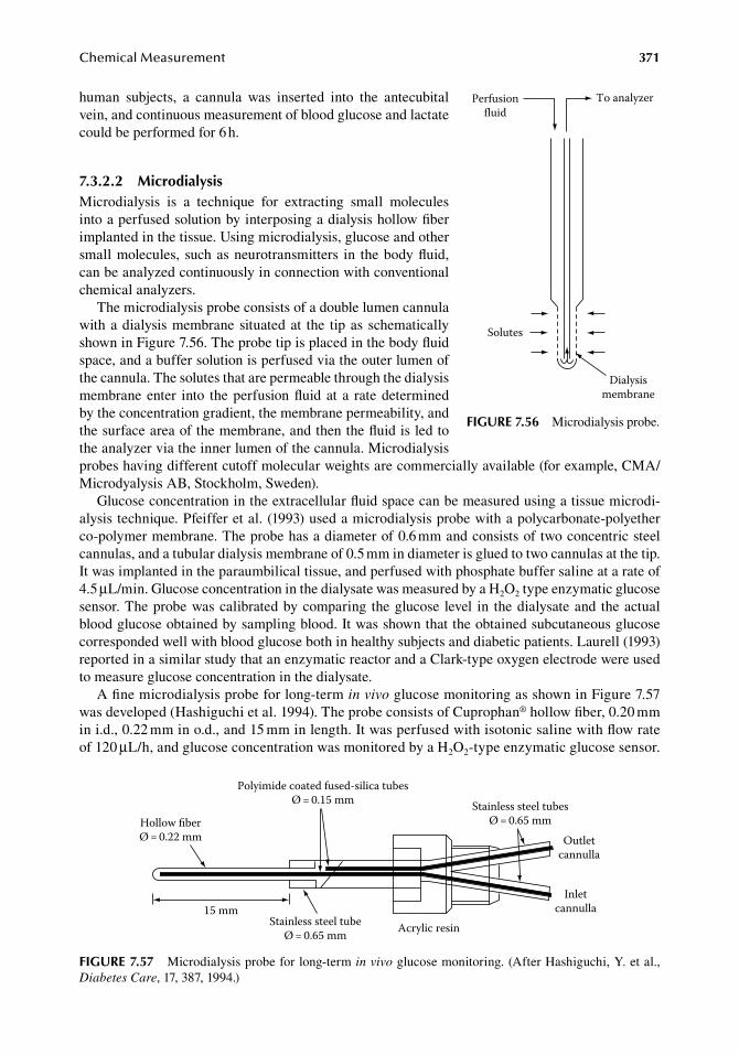
ChemicalMeasurement 371
human. subjects,. a. cannula. was. inserted. into. the. antecubital.vein,.and.continuous.measurement.of.blood.glucose.and.lactate.could.be.performed.for.6.h.
7.3.2.2 MicrodialysisMicrodialysis. is. a. technique. for. extracting. small. molecules.into.a.perfused.solution.by.interposing.a.dialysis.hollow.fiber.implanted.in.the.tissue..Using.microdialysis,.glucose.and.other.small.molecules,. such.as.neurotransmitters. in. the.body.fluid,.can.be.analyzed.continuously.in.connection.with.conventional.chemical.analyzers.
The.microdialysis.probe.consists.of.a.double.lumen.cannula.with.a.dialysis.membrane.situated.at. the. tip.as.schematically.shown.in.Figure.7.56..The.probe.tip.is.placed.in.the.body.fluid.space,.and.a.buffer.solution.is.perfused.via.the.outer.lumen.of.the.cannula..The.solutes.that.are.permeable.through.the.dialysis.membrane.enter. into. the.perfusion.fluid.at. a. rate.determined.by.the.concentration.gradient,.the.membrane.permeability,.and.the.surface.area.of.the.membrane,.and.then.the.fluid.is.led.to.the.analyzer.via.the.inner.lumen.of.the.cannula..Microdialysis.probes.having.different.cutoff.molecular.weights.are.commercially.available.(for.example,.CMA/Microdyalysis.AB,.Stockholm,.Sweden).
Glucose.concentration.in.the.extracellular.fluid.space.can.be.measured.using.a.tissue.microdi-alysis.technique..Pfeiffer.et al..(1993).used.a.microdialysis.probe.with.a.polycarbonate-polyether.co-polymer.membrane..The.probe.has.a.diameter.of.0.6.mm.and.consists.of.two.concentric.steel.cannulas,.and.a.tubular.dialysis.membrane.of.0.5.mm.in.diameter.is.glued.to.two.cannulas.at.the.tip..It.was.implanted.in.the.paraumbilical.tissue,.and.perfused.with.phosphate.buffer.saline.at.a.rate.of.4.5.μL/min..Glucose.concentration.in.the.dialysate.was.measured.by.a.H2O2.type.enzymatic.glucose.sensor..The.probe.was.calibrated.by.comparing. the.glucose. level. in. the.dialysate.and. the.actual.blood.glucose.obtained.by.sampling.blood..It.was.shown.that.the.obtained.subcutaneous.glucose.corresponded.well.with.blood.glucose.both.in.healthy.subjects.and.diabetic.patients..Laurell.(1993).reported.in.a.similar.study.that.an.enzymatic.reactor.and.a.Clark-type.oxygen.electrode.were.used.to.measure.glucose.concentration.in.the.dialysate.
A.fine.microdialysis.probe.for.long-term.in vivo.glucose.monitoring.as.shown.in.Figure.7.57.was.developed.(Hashiguchi.et al..1994)..The.probe.consists.of.Cuprophan®.hollow.fiber,.0.20.mm.in.i.d.,.0.22.mm.in.o.d.,.and.15.mm.in.length..It.was.perfused.with.isotonic.saline.with.flow.rate.of.120.μL/h,.and.glucose.concentration.was.monitored.by.a.H2O2-type.enzymatic.glucose.sensor..
Perfusionfluid
To analyzer
Solutes
Dialysismembrane
figure 7.56 Microdialysis.probe.
Polyimide coated fused-silica tubesØ = 0.15 mm
Acrylic resin
Hollow fiberØ = 0.22 mm
15 mmStainless steel tube
Ø = 0.65 mm
Stainless steel tubesØ = 0.65 mm
Outletcannulla
Inletcannulla
figure 7.57 Microdialysis.probe.for.long-term.in vivo.glucose.monitoring..(After.Hashiguchi,.Y..et al.,.Diabetes Care,.17,.387,.1994.)
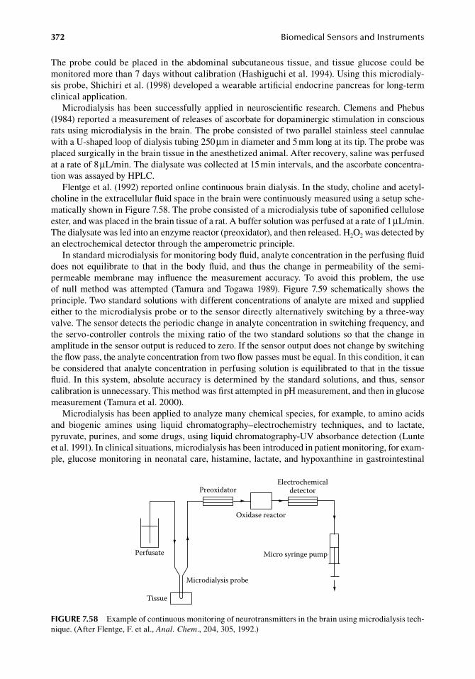
372 BiomedicalSensorsandInstruments
The.probe.could.be.placed. in. the.abdominal. subcutaneous. tissue,.and. tissue.glucose.could.be.monitored.more.than.7.days.without.calibration.(Hashiguchi.et al..1994)..Using.this.microdialy-sis.probe,.Shichiri.et al..(1998).developed.a.wearable.artificial.endocrine.pancreas.for.long-term.clinical.application.
Microdialysis.has.been. successfully. applied. in.neuroscientific. research..Clemens.and.Phebus.(1984).reported.a.measurement.of.releases.of.ascorbate.for.dopaminergic.stimulation.in.conscious.rats.using.microdialysis.in.the.brain..The.probe.consisted.of.two.parallel.stainless.steel.cannulae.with.a.U-shaped.loop.of.dialysis.tubing.250.μm.in.diameter.and.5.mm.long.at.its.tip..The.probe.was.placed.surgically.in.the.brain.tissue.in.the.anesthetized.animal..After.recovery,.saline.was.perfused.at.a.rate.of.8.μL/min..The.dialysate.was.collected.at.15.min.intervals,.and.the.ascorbate.concentra-tion.was.assayed.by.HPLC.
Flentge.et al..(1992).reported.online.continuous.brain.dialysis..In.the.study,.choline.and.acetyl-choline.in.the.extracellular.fluid.space.in.the.brain.were.continuously.measured.using.a.setup.sche-matically.shown.in.Figure.7.58..The.probe.consisted.of.a.microdialysis.tube.of.saponified.cellulose.ester,.and.was.placed.in.the.brain.tissue.of.a.rat..A.buffer.solution.was.perfused.at.a.rate.of.1.μL/min..The.dialysate.was.led.into.an.enzyme.reactor.(preoxidator),.and.then.released..H2O2.was.detected.by.an.electrochemical.detector.through.the.amperometric.principle.
In.standard.microdialysis.for.monitoring.body.fluid,.analyte.concentration.in.the.perfusing.fluid.does.not. equilibrate. to. that. in. the.body.fluid,. and. thus. the. change. in.permeability.of. the. semi-permeable. membrane. may. influence. the. measurement. accuracy.. To. avoid. this. problem,. the. use.of.null.method.was.attempted. (Tamura.and.Togawa.1989)..Figure.7.59. schematically. shows. the.principle..Two.standard.solutions.with.different.concentrations.of.analyte.are.mixed.and.supplied.either.to.the.microdialysis.probe.or.to.the.sensor.directly.alternatively.switching.by.a.three-way.valve..The sensor.detects.the.periodic.change.in.analyte.concentration.in.switching.frequency,.and.the.servo-controller.controls.the.mixing.ratio.of.the.two.standard.solutions.so.that.the.change.in.amplitude.in.the.sensor.output.is.reduced.to.zero..If.the.sensor.output.does.not.change.by.switching.the.flow.pass,.the.analyte.concentration.from.two.flow.passes.must.be.equal..In.this.condition,.it.can.be.considered.that.analyte.concentration.in.perfusing.solution.is.equilibrated.to.that.in.the.tissue.fluid..In.this.system,.absolute.accuracy.is.determined.by.the.standard.solutions,.and.thus,.sensor.calibration.is.unnecessary..This.method.was.first.attempted.in.pH.measurement,.and.then.in.glucose.measurement.(Tamura.et al..2000).
Microdialysis.has.been.applied.to.analyze.many.chemical.species,.for.example,.to.amino.acids.and. biogenic. amines. using. liquid. chromatography–electrochemistry. techniques,. and. to. lactate,.pyruvate,.purines,.and.some.drugs,.using.liquid.chromatography-UV.absorbance.detection.(Lunte.et al..1991)..In.clinical.situations,.microdialysis.has.been.introduced.in.patient.monitoring,.for.exam-ple,.glucose.monitoring.in.neonatal.care,.histamine,.lactate,.and.hypoxanthine.in.gastrointestinal.
Perfusate
Preoxidator
Tissue
Microdialysis probe
Oxidase reactor
Micro syringe pump
Electrochemicaldetector
figure 7.58 Example.of.continuous.monitoring.of.neurotransmitters.in.the.brain.using.microdialysis.tech-nique..(After.Flentge,.F..et al.,.Anal. Chem.,.204,.305,.1992.)
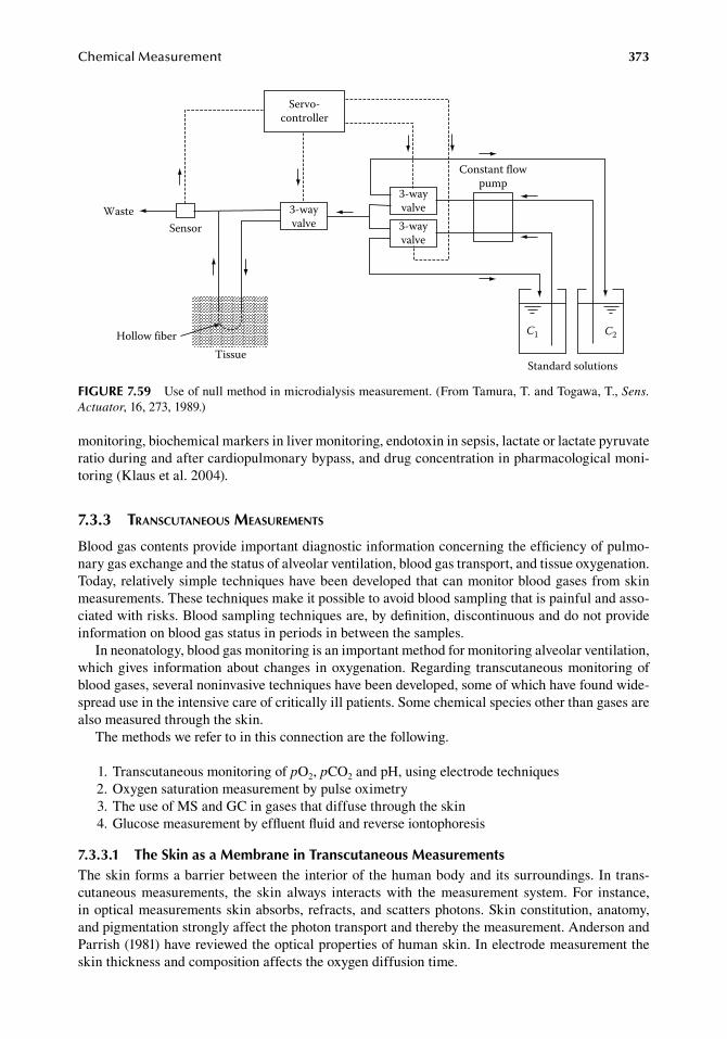
ChemicalMeasurement 373
monitoring,.biochemical.markers.in.liver.monitoring,.endotoxin.in.sepsis,.lactate.or.lactate.pyruvate.ratio.during.and.after.cardiopulmonary.bypass,.and.drug.concentration.in.pharmacological.moni-toring.(Klaus.et al..2004).
7.3.3 transcutaneous MeasureMents
Blood.gas.contents.provide.important.diagnostic.information.concerning.the.efficiency.of.pulmo-nary.gas.exchange.and.the.status.of.alveolar.ventilation,.blood.gas.transport,.and.tissue.oxygenation..Today,.relatively.simple.techniques.have.been.developed.that.can.monitor.blood.gases.from.skin.measurements..These.techniques.make.it.possible.to.avoid.blood.sampling.that.is.painful.and.asso-ciated.with.risks..Blood.sampling.techniques.are,.by.definition,.discontinuous.and.do.not.provide.information.on.blood.gas.status.in.periods.in.between.the.samples.
In.neonatology,.blood.gas.monitoring.is.an.important.method.for.monitoring.alveolar.ventilation,.which.gives. information.about.changes. in.oxygenation..Regarding. transcutaneous.monitoring.of.blood.gases,.several.noninvasive.techniques.have.been.developed,.some.of.which.have.found.wide-spread.use.in.the.intensive.care.of.critically.ill.patients..Some.chemical.species.other.than.gases.are.also.measured.through.the.skin.
The.methods.we.refer.to.in.this.connection.are.the.following.
. 1..Transcutaneous.monitoring.of.pO2,.pCO2.and.pH,.using.electrode.techniques
. 2..Oxygen.saturation.measurement.by.pulse.oximetry
. 3..The.use.of.MS.and.GC.in.gases.that.diffuse.through.the.skin
. 4..Glucose.measurement.by.effluent.fluid.and.reverse.iontophoresis
7.3.3.1 the Skin as a Membrane in transcutaneous MeasurementsThe.skin.forms.a.barrier.between.the.interior.of.the.human.body.and.its.surroundings..In.trans-cutaneous. measurements,. the. skin. always. interacts. with. the. measurement. system.. For. instance,.in.optical.measurements.skin.absorbs,.refracts,.and.scatters.photons..Skin.constitution,.anatomy,.and.pigmentation.strongly.affect.the.photon.transport.and.thereby.the.measurement..Anderson.and.Parrish.(1981).have.reviewed.the.optical.properties.of.human.skin..In.electrode.measurement.the.skin.thickness.and.composition.affects.the.oxygen.diffusion.time.
3-wayvalve
Constant flowpump
3-wayvalve3-wayvalve
Servo-controller
SensorWaste
Standard solutions
C1 C2
TissueHollow fiber
figure 7.59 Use.of.null.method.in.microdialysis.measurement..(From.Tamura,.T..and.Togawa,.T.,.Sens. Actuator,.16,.273,.1989.)
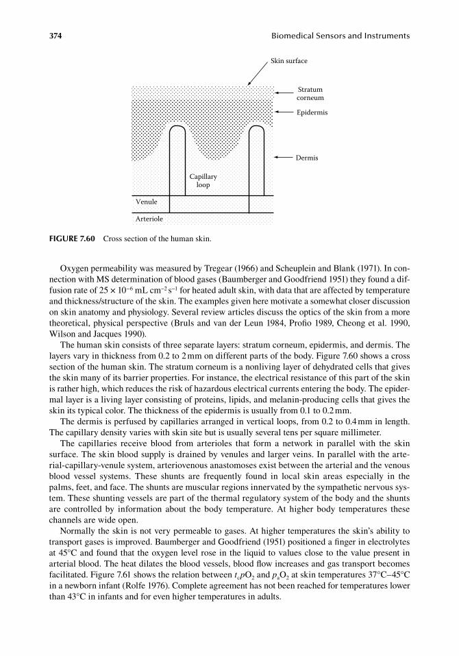
374 BiomedicalSensorsandInstruments
Oxygen.permeability.was.measured.by.Tregear.(1966).and.Scheuplein.and.Blank.(1971)..In.con-nection.with.MS.determination.of.blood.gases.(Baumberger.and.Goodfriend.1951).they.found.a.dif-fusion.rate.of.25.×.10−6.mL.cm−2.s−1.for.heated.adult.skin,.with.data.that.are.affected.by.temperature.and.thickness/structure.of.the.skin..The.examples.given.here.motivate.a.somewhat.closer.discussion.on.skin.anatomy.and.physiology..Several.review.articles.discuss.the.optics.of.the.skin.from.a.more.theoretical,.physical.perspective.(Bruls.and.van.der.Leun.1984,.Profio.1989,.Cheong.et al..1990,.Wilson.and.Jacques.1990).
The.human.skin.consists.of.three.separate.layers:.stratum.corneum,.epidermis,.and.dermis..The.layers.vary.in.thickness.from.0.2.to.2.mm.on.different.parts.of.the.body..Figure.7.60.shows.a.cross.section.of.the.human.skin..The.stratum.corneum.is.a.nonliving.layer.of.dehydrated.cells.that.gives.the.skin.many.of.its.barrier.properties..For.instance,.the.electrical.resistance.of.this.part.of.the.skin.is.rather.high,.which.reduces.the.risk.of.hazardous.electrical.currents.entering.the.body..The.epider-mal.layer.is.a.living.layer.consisting.of.proteins,.lipids,.and.melanin-producing.cells.that.gives.the.skin.its.typical.color..The.thickness.of.the.epidermis.is.usually.from.0.1.to 0.2.mm.
The.dermis.is.perfused.by.capillaries.arranged.in.vertical.loops,.from.0.2.to.0.4.mm.in.length..The.capillary.density.varies.with.skin.site.but.is.usually.several.tens.per.square.millimeter.
The. capillaries. receive. blood. from. arterioles. that. form. a. network. in. parallel. with. the. skin.surface..The.skin.blood.supply.is.drained.by.venules.and.larger.veins..In.parallel.with.the.arte-rial-capillary-venule.system,.arteriovenous.anastomoses.exist.between.the.arterial.and.the.venous.blood. vessel. systems.. These. shunts. are. frequently. found. in. local. skin. areas. especially. in. the.palms,.feet,.and.face..The.shunts.are.muscular.regions.innervated.by.the.sympathetic.nervous.sys-tem..These.shunting.vessels.are.part.of.the.thermal.regulatory.system.of.the.body.and.the.shunts.are. controlled. by. information. about. the. body. temperature.. At. higher. body. temperatures. these.channels.are.wide.open.
Normally.the.skin.is.not.very.permeable.to.gases..At.higher.temperatures.the.skin’s.ability.to.transport.gases.is.improved..Baumberger.and.Goodfriend.(1951).positioned.a.finger.in.electrolytes.at.45°C.and.found.that. the.oxygen.level.rose.in.the.liquid.to.values.close.to.the.value.present.in.arterial.blood..The.heat.dilates.the.blood.vessels,.blood.flow.increases.and.gas.transport.becomes.facilitated..Figure.7.61.shows.the.relation.between.tcpO2.and.paO2.at.skin.temperatures.37°C–45°C.in.a.newborn.infant.(Rolfe.1976)..Complete.agreement.has.not.been.reached.for.temperatures.lower.than.43°C.in.infants.and.for.even.higher.temperatures.in.adults.
Skin surface
Capillaryloop
Venule
Arteriole
Dermis
Epidermis
Stratumcorneum
figure 7.60 Cross.section.of.the.human.skin.
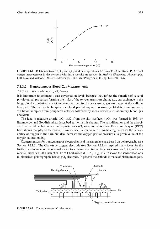
ChemicalMeasurement 375
7.3.3.2 transcutaneous blood gas Measurements7.3.3.2.1 Transcutaneous pO2 SensorIt.is.important.to.estimate.tissue.oxygenation.levels.because.they.reflect.the.function.of.several.physiological.processes.forming.the.links.of.the.oxygen.transport.chain,.e.g.,.gas.exchange.in.the.lung,.blood.circulation.at.various. levels. in. the.circulatory.system,.gas.exchange.at. the.cellular.level,. etc.. The. earlier. techniques. for. blood. partial. oxygen. pressure. (pO2). determination. were.via.blood.samples. from.peripheral.arteries. followed.by.measurements. in. laboratory.blood.gas.analyzers.
The. idea. to.measure.arterial.pO2,.paO2. from. the. skin. surface,. tcpO2,.was. formed. in.1951.by.Baumberger.and.Goodfriend,.as.described.earlier.in.this.chapter..The.vasodilatation.and.the.associ-ated.increased.perfusion.is.a.prerequisite.for.tcpO2.measurements.since.Evans.and.Naylor.(1967).have.shown.that.pO2.on.the.covered.skin.surface.is.close.to.zero..Skin.heating.increases.the.perme-ability.of.oxygen.in.the.skin.but.also.increases.the.oxygen.partial.pressure.at.a.given.value.of.the.oxygen.saturation.SO2.
Oxygen.sensors.for.transcutaneous.electrochemical.measurements.are.based.on.polarography.(see.Section.7.2.1.3)..The.Clark-type.oxygen.electrode. (see.Section.7.2.1.4). inspired.many. ideas. for. the.further.development.of.the.original.idea.into.a.commercial.transcutaneous.sensor.for.tcpO2.measure-ments.(Lübbers.1960,.Huch.et.al..1969,.Eberhard.et al..1973)..Figure.7.62.shows.the.sensor.head.of.a.miniaturized.polarographic.heated.pO2.electrode..In.general.the.cathode.is.made.of.platinum.or.gold..
37 40 43 46Skin surface temperature (ºC)
0
1
t cpO
2p a
O2
figure 7.61 Relation.between.tcpO2.and.paO2.at.skin.temperatures.37°C–45°C..(After.Rolfe,.P.,.Arterial.oxygen.measurement. in. the.newborn.with. intra-vascular. transducer,. in.Medical Electronics Monographs,.Hill,.D.W..and.Watson,.B.W.,.eds.,.Stevenage,.U.K.:.Peter.Peregrinus.Ltd.,.pp..126–158,.1976.)
Skin
Oxygen permeable membrane
Anode
CathodeermistorHeating element
Capillaries
figure 7.62 Transcutaneous.pO2.electrodes.
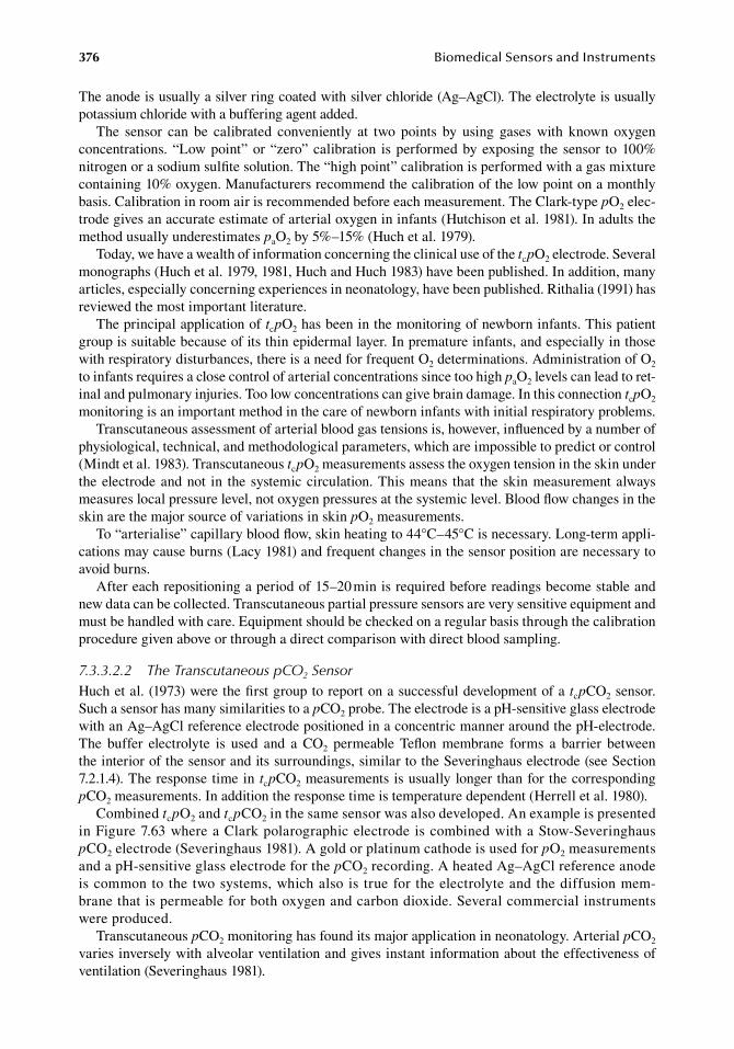
376 BiomedicalSensorsandInstruments
The.anode.is.usually.a.silver.ring.coated.with.silver.chloride.(Ag–AgCl)..The.electrolyte.is.usually.potassium.chloride.with.a.buffering.agent.added.
The. sensor. can. be. calibrated. conveniently. at. two. points. by. using. gases. with. known. oxygen.concentrations..“Low.point”.or.“zero”.calibration. is.performed.by.exposing. the.sensor. to.100%.nitrogen.or.a.sodium.sulfite.solution..The.“high.point”.calibration.is.performed.with.a.gas.mixture.containing.10%.oxygen..Manufacturers.recommend.the.calibration.of.the.low.point.on.a.monthly.basis..Calibration.in.room.air.is.recommended.before.each.measurement..The.Clark-type.pO2.elec-trode.gives.an.accurate.estimate.of.arterial.oxygen.in.infants.(Hutchison.et al..1981)..In.adults.the.method.usually.underestimates.paO2.by.5%–15%.(Huch.et al..1979).
Today,.we.have.a.wealth.of.information.concerning.the.clinical.use.of.the.tcpO2.electrode..Several.monographs.(Huch.et al..1979,.1981,.Huch.and.Huch.1983).have.been.published..In.addition,.many.articles,.especially.concerning.experiences.in.neonatology,.have.been.published..Rithalia.(1991).has.reviewed.the.most.important.literature.
The.principal.application.of.tcpO2.has.been.in.the.monitoring.of.newborn.infants..This.patient.group.is.suitable.because.of.its.thin.epidermal.layer..In.premature.infants,.and.especially.in.those.with.respiratory.disturbances,.there.is.a.need.for.frequent.O2.determinations..Administration.of.O2.to.infants.requires.a.close.control.of.arterial.concentrations.since.too.high.paO2.levels.can.lead.to.ret-inal.and.pulmonary.injuries..Too.low.concentrations.can.give.brain.damage..In.this.connection.tcpO2.monitoring.is.an.important.method.in.the.care.of.newborn.infants.with.initial.respiratory.problems.
Transcutaneous.assessment.of.arterial.blood.gas.tensions.is,.however,.influenced.by.a.number.of.physiological,.technical,.and.methodological.parameters,.which.are.impossible.to.predict.or.control.(Mindt.et al..1983)..Transcutaneous.tcpO2.measurements.assess.the.oxygen.tension.in.the.skin.under.the.electrode.and.not. in. the.systemic.circulation..This.means. that. the.skin.measurement.always.measures.local.pressure.level,.not.oxygen.pressures.at.the.systemic.level..Blood.flow.changes.in.the.skin.are.the.major.source.of.variations.in.skin.pO2.measurements.
To.“arterialise”.capillary.blood.flow,.skin.heating.to.44°C–45°C.is.necessary..Long-term.appli-cations.may.cause.burns.(Lacy.1981).and.frequent.changes.in.the.sensor.position.are.necessary.to.avoid.burns.
After.each.repositioning.a.period.of.15–20.min.is.required.before.readings.become.stable.and.new.data.can.be.collected..Transcutaneous.partial.pressure.sensors.are.very.sensitive.equipment.and.must.be.handled.with.care..Equipment.should.be.checked.on.a.regular.basis.through.the.calibration.procedure.given.above.or.through.a.direct.comparison.with.direct.blood.sampling.
7.3.3.2.2 The Transcutaneous pCO2 SensorHuch.et al..(1973).were.the.first.group.to.report.on.a.successful.development.of.a.tcpCO2.sensor..Such.a.sensor.has.many.similarities.to.a.pCO2.probe..The.electrode.is.a.pH-sensitive.glass.electrode.with.an.Ag–AgCl.reference.electrode.positioned.in.a.concentric.manner.around.the.pH-electrode..The. buffer. electrolyte. is. used. and. a. CO2. permeable. Teflon. membrane. forms. a. barrier. between.the.interior.of.the.sensor.and.its.surroundings,.similar.to.the.Severinghaus.electrode.(see.Section.7.2.1.4)..The.response.time.in. tcpCO2.measurements.is.usually.longer.than.for.the.corresponding.pCO2.measurements..In.addition.the.response.time.is.temperature.dependent.(Herrell.et al..1980).
Combined.tcpO2.and.tcpCO2.in.the.same.sensor.was.also.developed..An.example.is.presented.in.Figure.7.63.where.a.Clark.polarographic.electrode.is.combined.with.a.Stow-Severinghaus.pCO2.electrode.(Severinghaus.1981)..A.gold.or.platinum.cathode.is.used.for.pO2.measurements.and.a.pH-sensitive.glass.electrode.for.the.pCO2.recording..A.heated.Ag–AgCl.reference.anode.is.common.to.the.two.systems,.which.also.is. true.for. the.electrolyte.and.the.diffusion.mem-brane.that.is.permeable.for.both.oxygen.and.carbon.dioxide..Several.commercial.instruments.were.produced.
Transcutaneous.pCO2.monitoring.has.found.its.major.application.in.neonatology..Arterial.pCO2.varies.inversely.with.alveolar.ventilation.and.gives.instant.information.about.the.effectiveness.of.ventilation.(Severinghaus.1981).
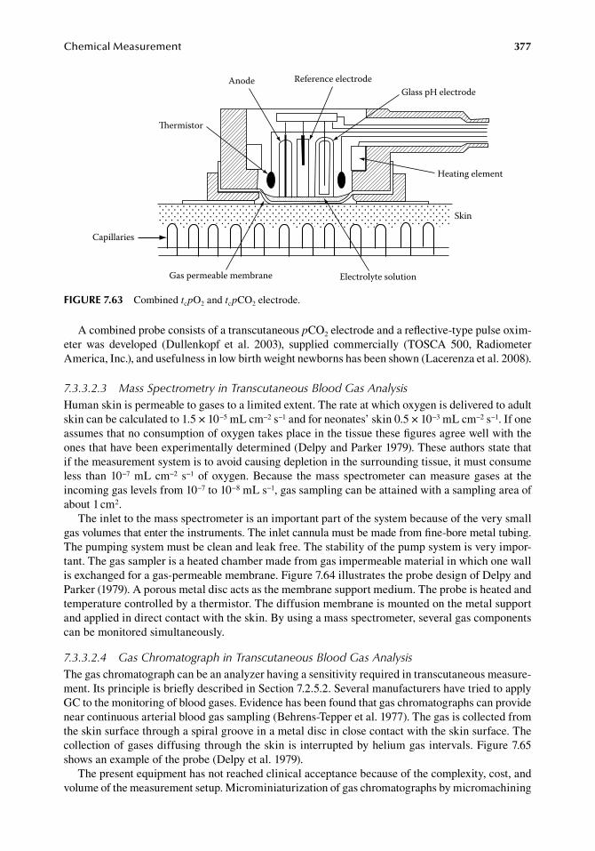
ChemicalMeasurement 377
A.combined.probe.consists.of.a.transcutaneous.pCO2.electrode.and.a.reflective-type.pulse.oxim-eter. was. developed. (Dullenkopf. et al.. 2003),. supplied. commercially. (TOSCA. 500,. Radiometer.America,.Inc.),.and.usefulness.in.low.birth.weight.newborns.has.been.shown.(Lacerenza.et al..2008).
7.3.3.2.3 Mass Spectrometry in Transcutaneous Blood Gas AnalysisHuman.skin.is.permeable.to.gases.to.a.limited.extent..The.rate.at.which.oxygen.is.delivered.to.adult.skin.can.be.calculated.to.1.5.×.10−5.mL.cm−2.s−1.and.for.neonates’.skin.0.5.×.10−3.mL.cm−2.s−1..If one.assumes.that.no.consumption.of.oxygen.takes.place.in.the.tissue.these.figures.agree.well.with.the.ones.that.have.been.experimentally.determined.(Delpy.and.Parker.1979)..These.authors.state.that.if.the.measurement.system.is.to.avoid.causing.depletion.in.the.surrounding.tissue,.it.must.consume.less. than.10−7.mL.cm−2. s−1.of.oxygen..Because. the.mass. spectrometer.can.measure.gases.at. the.incoming.gas.levels.from.10−7.to.10−8.mL.s−1,.gas.sampling.can.be.attained.with.a.sampling.area.of.about.1.cm2.
The.inlet.to.the.mass.spectrometer.is.an.important.part.of.the.system.because.of.the.very.small.gas.volumes.that.enter.the.instruments..The.inlet.cannula.must.be.made.from.fine-bore.metal.tubing..The.pumping.system.must.be.clean.and.leak.free..The.stability.of.the.pump.system.is.very.impor-tant..The.gas.sampler.is.a.heated.chamber.made.from.gas.impermeable.material.in.which.one.wall.is.exchanged.for.a.gas-permeable.membrane..Figure.7.64.illustrates.the.probe.design.of.Delpy.and.Parker.(1979)..A.porous.metal.disc.acts.as.the.membrane.support.medium..The.probe.is.heated.and.temperature.controlled.by.a.thermistor..The.diffusion.membrane.is.mounted.on.the.metal.support.and.applied.in.direct.contact.with.the.skin..By.using.a.mass.spectrometer,.several.gas.components.can.be.monitored.simultaneously.
7.3.3.2.4 Gas Chromatograph in Transcutaneous Blood Gas AnalysisThe.gas.chromatograph.can.be.an.analyzer.having.a.sensitivity.required.in.transcutaneous.measure-ment..Its.principle.is.briefly.described.in.Section.7.2.5.2..Several.manufacturers.have.tried.to.apply.GC.to.the.monitoring.of.blood.gases..Evidence.has.been.found.that.gas.chromatographs.can.provide.near.continuous.arterial.blood.gas.sampling.(Behrens-Tepper.et al..1977)..The.gas.is.collected.from.the.skin.surface.through.a.spiral.groove.in.a.metal.disc.in.close.contact.with.the.skin.surface..The.collection.of.gases.diffusing.through.the.skin.is.interrupted.by.helium.gas.intervals..Figure.7.65.shows.an.example.of.the.probe.(Delpy.et al..1979).
The.present.equipment.has.not.reached.clinical.acceptance.because.of.the.complexity,.cost,.and.volume.of.the.measurement.setup..Microminiaturization.of.gas.chromatographs.by.micromachining.
Skin
Capillaries
ermistor
Anode Reference electrodeGlass pH electrode
Heating element
Gas permeable membrane Electrolyte solution
figure 7.63 Combined.tcpO2.and.tcpCO2.electrode.
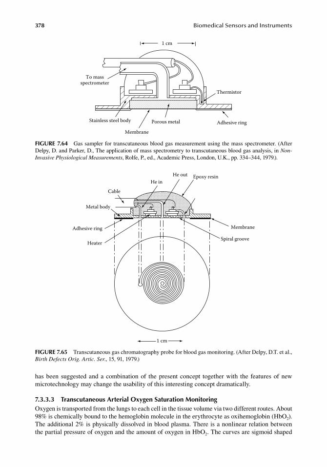
378 BiomedicalSensorsandInstruments
has.been. suggested.and.a. combination.of. the.present. concept. together.with. the. features.of.new.microtechnology.may.change.the.usability.of.this.interesting.concept.dramatically.
7.3.3.3 transcutaneous arterial oxygen Saturation MonitoringOxygen.is.transported.from.the.lungs.to.each.cell.in.the.tissue.volume.via.two.different.routes..About.98%.is.chemically.bound.to.the.hemoglobin.molecule.in.the.erythrocyte.as.oxihemoglobin.(HbO2)..The.additional.2%.is.physically.dissolved.in.blood.plasma..There.is.a.nonlinear.relation.between.the.partial.pressure.of.oxygen.and.the.amount.of.oxygen.in.HbO2..The.curves.are.sigmoid.shaped.
Porous metalStainless steel body Adhesive ring
Membrane
Thermistor
To massspectrometer
1 cm
figure 7.64 Gas.sampler.for. transcutaneous.blood.gas.measurement.using. the.mass.spectrometer.. (After.Delpy,.D..and.Parker,.D.,.The.application.of.mass.spectrometry.to.transcutaneous.blood.gas.analysis,.in.Non-Invasive Physiological Measurements,.Rolfe,.P.,.ed.,.Academic.Press,.London,.U.K.,.pp..334–344,.1979.).
He inHe out Epoxy resin
Cable
Metal body
Membrane
Spiral groove
Adhesive ring
Heater
1 cm
figure 7.65 Transcutaneous.gas.chromatography.probe.for.blood.gas.monitoring..(After.Delpy,.D.T..et al.,.Birth Defects Orig. Artic. Ser.,.15,.91,.1979.)
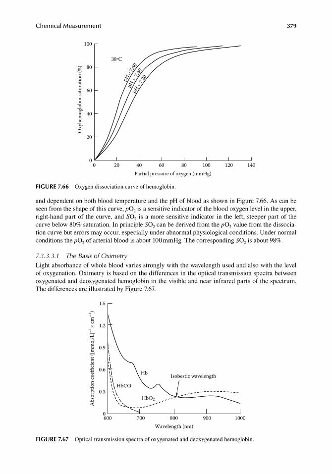
ChemicalMeasurement 379
and.dependent.on.both.blood.temperature.and.the.pH.of.blood.as.shown.in.Figure.7.66..As.can.be.seen.from.the.shape.of.this.curve,.pO2.is.a.sensitive.indicator.of.the.blood.oxygen.level.in.the.upper,.right-hand.part.of. the.curve,.and.SO2.is.a.more.sensitive. indicator. in. the. left,.steeper.part.of. the.curve.below.80%.saturation..In.principle.SO2.can.be.derived.from.the.pO2.value.from.the.dissocia-tion.curve.but.errors.may.occur,.especially.under.abnormal.physiological.conditions..Under.normal.conditions.the.pO2.of.arterial.blood.is.about.100.mmHg..The.corresponding.SO2.is.about.98%.
7.3.3.3.1 The Basis of OximetryLight.absorbance.of.whole.blood.varies.strongly.with.the.wavelength.used.and.also.with.the.level.of.oxygenation..Oximetry.is.based.on.the.differences.in.the.optical.transmission.spectra.between.oxygenated.and.deoxygenated.hemoglobin.in.the.visible.and.near.infrared.parts.of.the.spectrum..The.differences.are.illustrated.by.Figure.7.67.
Oxy
hem
oglo
bin
satu
ratio
n (%
)
100
80
60
40
20
00 20 40 60 80 100 120 140
Partial pressure of oxygen (mmHg)
38ºC
pH=7.6
0pH
= 7.40
pH=7.2
0
figure 7.66 Oxygen.dissociation.curve.of.hemoglobin.
1.5
1.2
0.9
0.6
0.3
0
Abs
orpt
ion
coe
cien
t ([m
mol
/L]–1
×cm
–1)
600 700 800 900 1000Wavelength (nm)
Isobestic wavelengthHb
HbO2
HbCO
figure 7.67 Optical.transmission.spectra.of.oxygenated.and.deoxygenated.hemoglobin.
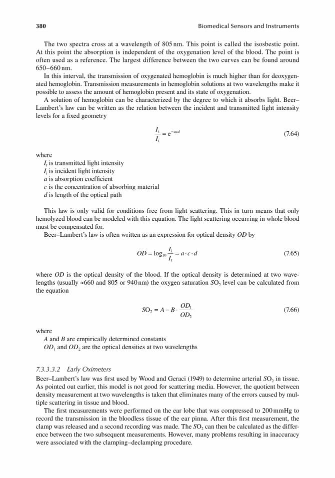
380 BiomedicalSensorsandInstruments
The.two.spectra.cross.at.a.wavelength.of.805.nm..This.point. is.called. the. isosbestic.point..At this.point.the.absorption.is.independent.of.the.oxygenation.level.of.the.blood..The.point.is.often.used.as.a.reference..The.largest.difference.between.the.two.curves.can.be.found.around.650–660.nm.
In.this.interval,.the.transmission.of.oxygenated.hemoglobin.is.much.higher.than.for.deoxygen-ated.hemoglobin..Transmission.measurements.in.hemoglobin.solutions.at.two.wavelengths.make.it.possible.to.assess.the.amount.of.hemoglobin.present.and.its.state.of.oxygenation.
A.solution.of.hemoglobin.can.be.characterized.by.the.degree.to.which.it.absorbs.light..Beer–Lambert’s.law.can.be.written.as.the.relation.between.the.incident.and.transmitted.light.intensity.levels.for.a.fixed.geometry
.
I
Iacdt
i
e= −
.(7.64)
whereIt.is.transmitted.light.intensityIi.is.incident.light.intensitya.is.absorption.coefficientc.is.the.concentration.of.absorbing.materiald.is.length.of.the.optical.path
This. law. is.only.valid. for.conditions. free. from. light. scattering..This. in. turn.means. that.only.hemolyzed.blood.can.be.modeled.with.this.equation..The.light.scattering.occurring.in.whole.blood.must.be.compensated.for.
Beer–Lambert’s.law.is.often.written.as.an.expression.for.optical.density.OD.by
.OD
I
Ia c d= = ⋅ ⋅log10
i
t .(7.65)
where.OD. is. the.optical.density.of. the.blood.. If. the.optical.density. is.determined.at. two.wave-lengths.(usually.≈660.and.805.or.940.nm).the.oxygen.saturation.SO2.level.can.be.calculated.from.the.equation
.S A B
OD
ODO2
1
2
= − ⋅.
(7.66)
whereA.and.B.are.empirically.determined.constantsOD1.and.OD2.are.the.optical.densities.at.two.wavelengths
7.3.3.3.2 Early OximetersBeer–Lambert’s.law.was.first.used.by.Wood.and.Geraci.(1949).to.determine.arterial.SO2.in.tissue..As.pointed.out.earlier,.this.model.is.not.good.for.scattering.media..However,.the.quotient.between.density.measurement.at.two.wavelengths.is.taken.that.eliminates.many.of.the.errors.caused.by.mul-tiple.scattering.in.tissue.and.blood.
The.first.measurements.were.performed.on.the.ear.lobe.that.was.compressed.to.200.mmHg.to.record.the.transmission.in.the.bloodless.tissue.of.the.ear.pinna..After.this.first.measurement,.the.clamp.was.released.and.a.second.recording.was.made..The.SO2.can.then.be.calculated.as.the.differ-ence.between.the.two.subsequent.measurements..However,.many.problems.resulting.in.inaccuracy.were.associated.with.the.clamping–declamping.procedure.
ChemicalMeasurement 381
The.Hewlett-Packard.Company.released. the.first.commercial.oxymeter. in.1970.(Merrick.and.Hayes.1976)..This.instrument.was.based.on.a.high.intensity.tungsten.lamp.and.narrow.band.filter.for.eight.wavelengths.between.650.and.1050.nm..The.filters.are.mounted.on.a.rotating.wheel.in.the.light.beam..The.beam.is.focused.onto.the.end.of.an.optical.fiber.that.leads.the.light.to.the.ear..Photons.that.have.passed.the.ear.are.collected.and.brought.to.the.instrumental.part.of.the.system..A.heater.arterializes.the.blood.in.the.volume.under.study.for.about.20.s.
Oxygen. saturation. was. determined. by. comparing. the. transmissions. at. the. eight. wavelengths.used..From.Beer–Lambert’s.law.oxygen.saturation.was.determined.as
.
SA A T
B B T
n nn
n nn
Olog
log2
01
01
=+
+=
=
∑∑
8
8
.
(7.67)
where.An.and.Bn.are.constants.that.can.be.determined.from.experiments.in.which.gases.of.known.oxygen.concentrations.have.been.inhaled.
The.Hewlett-Packard.Oximeter.has.an.accuracy.of.about.3%.and.a.response.time.close.to.1.5.s..The.major.disadvantage.with.this.product.is.the.heavy.fiber.optic.cable..The.oximeter.is.no.longer.manufactured.
7.3.3.3.3 Pulse OximetersThe.Japanese.scientist.Aoyagi.was.the.first.to.suggest.a.different.approach.to.saturation.measure-ments.(Aoyagi.et al..1974)..He.suggested.that.the.optical.absorption.differences.seen.at.every.heart.beat.are.caused.by.an. influx.of.arterial.blood.only..Therefore,. the.pulsatile.component. in. tissue.absorption. spectra. reflects. the. absorption. of. the. arterial. blood. selectively.. Differentiating. light.intensities.by.time,.steady.components.can.be.removed,.then.the.contribution.of.arterial.blood.can.be.extracted.
Although.rigorous.derivation.of.oxygen.saturation.from.optical.densities.is.difficult,.a.simplified.model.where.Beer–Lambert’s.law.is.valid.can.be.analyzed.as.follows.(Öberg.2004)..Consider.light.transmission.through.a.tissue.at.two.wavelengths,.λ1.and.λ2..Applying.Equation.7.65,.optical.densi-ties,.OD1.and.OD2,.for.λ1.and.λ2,.can.be.expressed.by.absorption.coefficients,.a,.concentrations,.c,.and.path.length,.d,.for.each.wavelength,.as
. OD a c d a c d a c d1 o1 o r1 r x1 x x= ⋅ ⋅ + ⋅ ⋅ + ⋅ ⋅ . (7.68)
. OD a c d a c d a c d2 o2 o r2 r x2 x x= ⋅ ⋅ + ⋅ ⋅ + ⋅ ⋅ . (7.69)
wheresuffixes.1.and.2.correspond.to.wavelength.λ1.and.λ2
o.and.r.denote.oxygenated.and.reduced.hemoglobinx.denotes.tissue.outside.the.blood.vessel
The.arterial.pulsation.can.be.considered.as.the.change.in.arterial.diameter.that.corresponds.to.the.change.in.optical.path.length,.d,.while.dx.remains.unchanged..The.changes.in.optical.densities.are.given.as
. ∆ ∆ ∆OD a c d a c d1 o1 o r1 r = ⋅ ⋅ + ⋅ ⋅ . (7.70)
. ∆ ∆ ∆OD a c d a c d2 o2 o r2 r = ⋅ ⋅ + ⋅ ⋅ . (7.71)
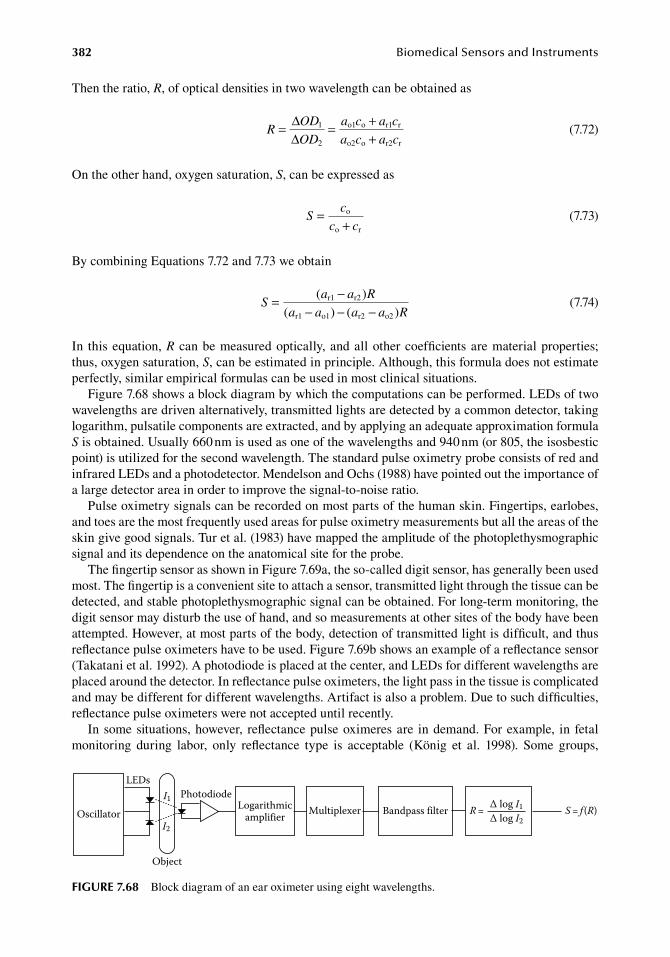
382 BiomedicalSensorsandInstruments
Then.the.ratio,.R,.of.optical.densities.in.two.wavelength.can.be.obtained.as
.R
OD
OD
a c a c
a c a c= = +
+∆∆
1
2
o1 o r1 r
o2 o r2 r .(7.72)
On.the.other.hand,.oxygen.saturation,.S,.can.be.expressed.as
.S
c
c c=
+o
o r .(7.73)
By.combining.Equations.7.72.and.7.73.we.obtain
.S
a a R
a a a a R= −
− − −( )
( ) ( )r1 r2
r1 o1 r2 o2 .(7.74)
In. this.equation,.R. can.be.measured.optically,.and.all.other.coefficients.are.material.properties;.thus,.oxygen.saturation,.S,.can.be.estimated.in.principle..Although,.this.formula.does.not.estimate.perfectly,.similar.empirical.formulas.can.be.used.in.most.clinical.situations.
Figure.7.68.shows.a.block.diagram.by.which.the.computations.can.be.performed..LEDs.of.two.wavelengths.are.driven.alternatively,.transmitted.lights.are.detected.by.a.common.detector,.taking.logarithm,.pulsatile.components.are.extracted,.and.by.applying.an.adequate.approximation.formula.S.is.obtained..Usually.660.nm.is.used.as.one.of.the.wavelengths.and.940.nm.(or.805,.the.isosbestic.point).is.utilized.for.the.second.wavelength..The.standard.pulse.oximetry.probe.consists.of.red.and.infrared.LEDs.and.a.photodetector..Mendelson.and.Ochs.(1988).have.pointed.out.the.importance.of.a.large.detector.area.in.order.to.improve.the.signal-to-noise.ratio.
Pulse.oximetry.signals.can.be.recorded.on.most.parts.of.the.human.skin..Fingertips,.earlobes,.and.toes.are.the.most.frequently.used.areas.for.pulse.oximetry.measurements.but.all.the.areas.of.the.skin.give.good.signals..Tur.et al..(1983).have.mapped.the.amplitude.of.the.photoplethysmographic.signal.and.its.dependence.on.the.anatomical.site.for.the.probe.
The.fingertip.sensor.as.shown.in.Figure.7.69a,.the.so-called.digit.sensor,.has.generally.been.used.most..The.fingertip.is.a.convenient.site.to.attach.a.sensor,.transmitted.light.through.the.tissue.can.be.detected,.and.stable.photoplethysmographic.signal.can.be.obtained..For.long-term.monitoring,.the.digit.sensor.may.disturb.the.use.of.hand,.and.so.measurements.at.other.sites.of.the.body.have.been.attempted..However,.at.most.parts.of.the.body,.detection.of.transmitted.light.is.difficult,.and.thus.reflectance.pulse.oximeters.have.to.be.used..Figure.7.69b.shows.an.example.of.a.reflectance.sensor.(Takatani.et al..1992)..A.photodiode.is.placed.at.the.center,.and.LEDs.for.different.wavelengths.are.placed.around.the.detector..In.reflectance.pulse.oximeters,.the.light.pass.in.the.tissue.is.complicated.and.may.be.different.for.different.wavelengths..Artifact.is.also.a.problem..Due.to.such.difficulties,.reflectance.pulse.oximeters.were.not.accepted.until.recently.
In.some.situations,.however,. reflectance.pulse.oximeres.are. in.demand..For.example,. in. fetal.monitoring. during. labor,. only. reflectance. type. is. acceptable. (König. et al.. 1998).. Some. groups,.
R= ∆ log I1∆ log I2
S= f (R)Bandpass filterMultiplexerLogarithmicamplifierOscillator
LEDs
Object
PhotodiodeI1
I2
figure 7.68 Block.diagram.of.an.ear.oximeter.using.eight.wavelengths.
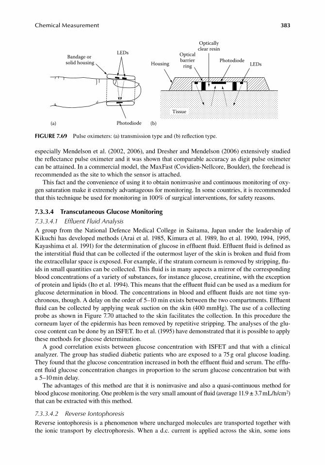
ChemicalMeasurement 383
especially.Mendelson.et al..(2002,.2006),.and.Dresher.and.Mendelson.(2006).extensively.studied.the.reflectance.pulse.oximeter.and.it.was.shown.that.comparable.accuracy.as.digit.pulse.oximeter.can.be.attained..In.a.commercial.model,.the.MaxFast.(Covidien-Nellcore,.Boulder),.the.forehead.is.recommended.as.the.site.to.which.the.sensor.is.attached.
This.fact.and.the.convenience.of.using.it.to.obtain.noninvasive.and.continuous.monitoring.of.oxy-gen.saturation.make.it.extremely.advantageous.for.monitoring..In.some.countries,.it.is.recommended.that.this.technique.be.used.for.monitoring.in.100%.of.surgical.interventions,.for.safety.reasons.
7.3.3.4 transcutaneous glucose Monitoring7.3.3.4.1 Effluent Fluid AnalysisA.group. from. the.National.Defence.Medical.College. in.Saitama,. Japan.under. the. leadership.of.Kikuchi.has.developed.methods.(Arai.et al..1985,.Kimura.et al..1989,.Ito.et al..1990,.1994,.1995,.Kayashima.et al..1991).for.the.determination.of.glucose.in.effluent.fluid..Effluent.fluid.is.defined.as.the.interstitial.fluid.that.can.be.collected.if.the.outermost.layer.of.the.skin.is.broken.and.fluid.from.the.extracellular.space.is.exposed..For.example,.if.the.stratum.corneum.is.removed.by.stripping,.flu-ids.in.small.quantities.can.be.collected..This.fluid.is.in.many.aspects.a.mirror.of.the.corresponding.blood.concentrations.of.a.variety.of.substances,.for.instance.glucose,.creatinine,.with.the.exception.of.protein.and.lipids.(Ito.et al..1994)..This.means.that.the.effluent.fluid.can.be.used.as.a.medium.for.glucose.determination.in.blood..The.concentrations.in.blood.and.effluent.fluids.are.not.time.syn-chronous,.though..A.delay.on.the.order.of.5–10.min.exists.between.the.two.compartments..Effluent.fluid.can.be.collected.by.applying.weak.suction.on.the.skin.(400.mmHg)..The.use.of.a.collecting.probe.as.shown.in.Figure.7.70.attached.to.the.skin.facilitates.the.collection..In.this.procedure.the.corneum.layer.of.the.epidermis.has.been.removed.by.repetitive.stripping..The.analyses.of.the.glu-cose.content.can.be.done.by.an.ISFET..Ito.et al..(1995).have.demonstrated.that.it.is.possible.to.apply.these.methods.for.glucose.determination.
A.good.correlation.exists.between.glucose.concentration.with. ISFET.and. that.with.a.clinical.analyzer..The.group.has.studied.diabetic.patients.who.are.exposed.to.a.75.g.oral.glucose.loading..They.found.that.the.glucose.concentration.increased.in.both.the.effluent.fluid.and.serum..The.efflu-ent.fluid.glucose.concentration.changes.in.proportion.to.the.serum.glucose.concentration.but.with.a.5–10.min.delay.
The.advantages.of.this.method.are.that.it.is.noninvasive.and.also.a.quasi-continuous.method.for.blood.glucose.monitoring..One.problem.is.the.very.small.amount.of.fluid.(average.11.9.±.3.7.mL/h/cm2).that.can.be.extracted.with.this.method.
7.3.3.4.2 Reverse IontophoresisReverse.iontophoresis.is.a.phenomenon.where.uncharged.molecules.are.transported.together.with.the. ionic. transport.by.electrophoresis..When.a.d.c..current. is.applied.across. the.skin,.some. ions.
LEDs
Photodiode(a) (b)
Tissue
Opticalbarrier
ring
Opticallyclear resin
PhotodiodeLEDsHousing
Bandage or solid housing
figure 7.69 Pulse.oximeters:.(a).transmission.type.and.(b).reflection.type.
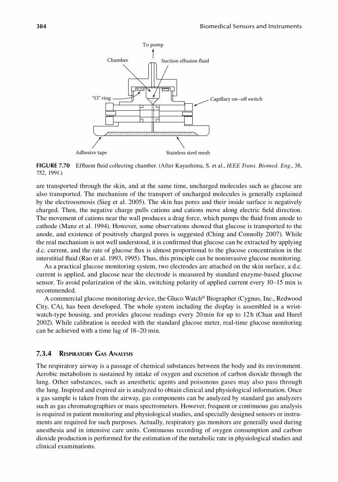
384 BiomedicalSensorsandInstruments
are.transported.through.the.skin,.and.at.the.same.time,.uncharged.molecules.such.as.glucose.are.also.transported..The.mechanism.of.the.transport.of.uncharged.molecules.is.generally.explained.by.the.electroosmosis.(Sieg.et al..2005)..The.skin.has.pores.and.their.inside.surface.is.negatively.charged..Then,. the.negative.charge.pulls.cations.and.cations.move.along.electric.field.direction..The.movement.of.cations.near.the.wall.produces.a.drag.force,.which.pumps.the.fluid.from.anode.to.cathode.(Manz.et al..1994)..However,.some.observations.showed.that.glucose.is.transported.to.the.anode,.and.existence.of.positively.charged.pores.is.suggested.(Ching.and.Connolly.2007)..While.the.real.mechanism.is.not.well.understood,.it.is.confirmed.that.glucose.can.be.extracted.by.applying.d.c..current,.and.the.rate.of.glucose.flux.is.almost.proportional.to.the.glucose.concentration.in.the.interstitial.fluid.(Rao.et al..1993,.1995)..Thus,.this.principle.can.be.noninvasive.glucose.monitoring.
As.a.practical.glucose.monitoring.system,.two.electrodes.are.attached.on.the.skin.surface,.a.d.c..current.is.applied,.and.glucose.near.the.electrode.is.measured.by.standard.enzyme-based.glucose.sensor..To.avoid.polarization.of.the.skin,.switching.polarity.of.applied.current.every.10–15.min.is.recommended.
A.commercial.glucose.monitoring.device,.the.Gluco.Watch®.Biographer.(Cygnus,.Inc.,.Redwood.City,.CA),.has.been.developed..The.whole.system.including. the.display. is.assembled. in.a.wrist-watch-type.housing,.and.provides.glucose.readings.every.20.min.for.up.to.12.h.(Chan.and.Hurel.2002)..While.calibration.is.needed.with.the.standard.glucose.meter,.real-time.glucose.monitoring.can.be.achieved.with.a.time.lag.of.18–20.min.
7.3.4 respiratory gas analysis
The.respiratory.airway.is.a.passage.of.chemical.substances.between.the.body.and.its.environment..Aerobic.metabolism.is.sustained.by.intake.of.oxygen.and.excretion.of.carbon.dioxide.through.the.lung..Other.substances,.such.as.anesthetic.agents.and.poisonous.gases.may.also.pass.through.the.lung..Inspired.and.expired.air.is.analyzed.to.obtain.clinical.and.physiological.information..Once.a.gas.sample.is.taken.from.the.airway,.gas.components.can.be.analyzed.by.standard.gas.analyzers.such.as.gas.chromatographies.or.mass.spectrometers..However,.frequent.or.continuous.gas.analysis.is.required.in.patient.monitoring.and.physiological.studies,.and.specially.designed.sensors.or.instru-ments.are.required.for.such.purposes..Actually,.respiratory.gas.monitors.are.generally.used.during.anesthesia.and. in. intensive.care.units..Continuous. recording.of.oxygen.consumption.and.carbon.dioxide.production.is.performed.for.the.estimation.of.the.metabolic.rate.in.physiological.studies.and.clinical.examinations.
Adhesive tape
“O” ring
Chamber
To pump
Stainless steel mesh
Capillary on–off switch
Suction effusion fluid
figure 7.70 Effluent.fluid.collecting.chamber..(After.Kayashima,.S..et al.,.IEEE Trans. Biomed. Eng.,.38,.752,.1991.)
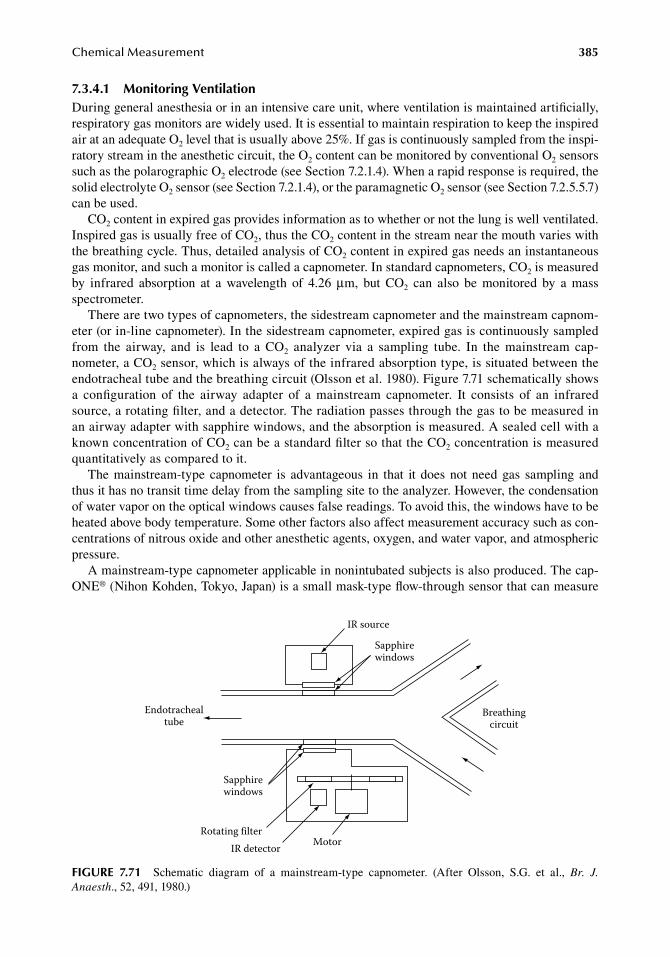
ChemicalMeasurement 385
7.3.4.1 Monitoring VentilationDuring.general.anesthesia.or.in.an.intensive.care.unit,.where.ventilation.is.maintained.artificially,.respiratory.gas.monitors.are.widely.used..It.is.essential.to.maintain.respiration.to.keep.the.inspired.air.at.an.adequate.O2.level.that.is.usually.above.25%..If.gas.is.continuously.sampled.from.the.inspi-ratory.stream.in.the.anesthetic.circuit,.the.O2.content.can.be.monitored.by.conventional.O2.sensors.such.as.the.polarographic.O2.electrode.(see.Section.7.2.1.4)..When.a.rapid.response.is.required,.the.solid.electrolyte.O2.sensor.(see.Section.7.2.1.4),.or.the.paramagnetic.O2.sensor.(see.Section.7.2.5.5.7).can.be.used.
CO2.content.in.expired.gas.provides.information.as.to.whether.or.not.the.lung.is.well.ventilated..Inspired.gas.is.usually.free.of.CO2,.thus.the.CO2.content.in.the.stream.near.the.mouth.varies.with.the.breathing.cycle..Thus,.detailed.analysis.of.CO2.content.in.expired.gas.needs.an.instantaneous.gas.monitor,.and.such.a.monitor.is.called.a.capnometer..In.standard.capnometers,.CO2.is.measured.by. infrared. absorption. at. a. wavelength. of. 4.26. μm,. but. CO2. can. also. be. monitored. by. a. mass.spectrometer.
There.are.two.types.of.capnometers,.the.sidestream.capnometer.and.the.mainstream.capnom-eter.(or.in-line.capnometer)..In.the.sidestream.capnometer,.expired.gas.is.continuously.sampled.from. the. airway,. and. is. lead. to. a. CO2. analyzer. via. a. sampling. tube.. In. the. mainstream. cap-nometer,.a.CO2.sensor,.which.is.always.of.the.infrared.absorption.type,.is.situated.between.the.endotracheal.tube.and.the.breathing.circuit.(Olsson.et al..1980)..Figure.7.71.schematically.shows.a. configuration. of. the. airway. adapter. of. a. mainstream. capnometer.. It. consists. of. an. infrared.source,.a.rotating.filter,.and.a.detector..The.radiation.passes.through.the.gas.to.be.measured.in.an.airway.adapter.with.sapphire.windows,.and.the.absorption.is.measured..A.sealed.cell.with.a.known.concentration.of.CO2.can.be.a.standard.filter.so.that.the.CO2.concentration.is.measured.quantitatively.as.compared.to.it.
The.mainstream-type. capnometer. is. advantageous. in. that. it. does.not. need.gas. sampling. and.thus.it.has.no.transit.time.delay.from.the.sampling.site.to.the.analyzer..However,.the.condensation.of.water.vapor.on.the.optical.windows.causes.false.readings..To.avoid.this,.the.windows.have.to.be.heated.above.body.temperature..Some.other.factors.also.affect.measurement.accuracy.such.as.con-centrations.of.nitrous.oxide.and.other.anesthetic.agents,.oxygen,.and.water.vapor,.and.atmospheric.pressure.
A.mainstream-type.capnometer.applicable.in.nonintubated.subjects.is.also.produced..The.cap-ONE®.(Nihon.Kohden,.Tokyo,.Japan).is.a.small.mask-type.flow-through.sensor.that.can.measure.
IR source
Sapphirewindows
Endotrachealtube
Sapphirewindows
Rotating filterIR detector Motor
Breathingcircuit
figure 7.71 Schematic. diagram. of. a. mainstream-type. capnometer.. (After. Olsson,. S.G.. et al.,. Br. J. Anaesth.,.52,.491,.1980.)
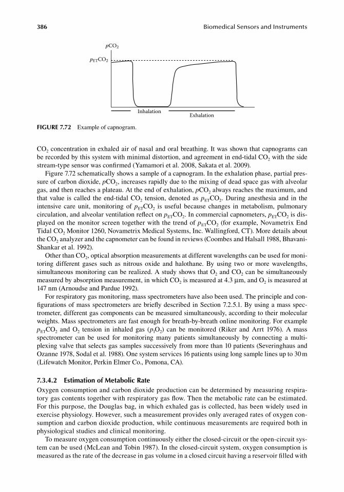
386 BiomedicalSensorsandInstruments
CO2.concentration.in.exhaled.air.of.nasal.and.oral.breathing..It.was.shown.that.capnograms.can.be.recorded.by.this.system.with.minimal.distortion,.and.agreement.in.end-tidal.CO2.with.the.side.stream-type.sensor.was.confirmed.(Yamamori.et al..2008,.Sakata.et al..2009).
Figure.7.72.schematically.shows.a.sample.of.a.capnogram..In.the.exhalation.phase,.partial.pres-sure.of.carbon.dioxide,.pCO2,.increases.rapidly.due.to.the.mixing.of.dead.space.gas.with.alveolar.gas,.and.then.reaches.a.plateau..At.the.end.of.exhalation,.pCO2.always.reaches.the.maximum,.and.that.value. is.called. the.end-tidal.CO2. tension,.denoted.as.pETCO2..During.anesthesia.and. in. the.intensive. care. unit,. monitoring. of. pETCO2. is. useful. because. changes. in. metabolism,. pulmonary.circulation,.and.alveolar.ventilation.reflect.on.pETCO2..In.commercial.capnometers,.pETCO2.is.dis-played.on.the.monitor.screen.together.with.the.trend.of.pETCO2.(for.example,.Novametrix.End.Tidal.CO2.Monitor.1260,.Novametrix.Medical.Systems,.Inc..Wallingford,.CT)..More.details.about.the.CO2.analyzer.and.the.capnometer.can.be.found.in.reviews.(Coombes.and.Halsall.1988,.Bhavani-Shankar.et al..1992).
Other.than.CO2,.optical.absorption.measurements.at.different.wavelengths.can.be.used.for.moni-toring. different. gases. such. as. nitrous. oxide. and. halothane.. By. using. two. or. more. wavelengths,.simultaneous.monitoring.can.be.realized..A.study.shows.that.O2.and.CO2.can.be.simultaneously.measured.by.absorption.measurement,.in.which.CO2.is.measured.at.4.3.μm,.and.O2.is.measured.at.147.nm.(Arnoudse.and.Pardue.1992).
For.respiratory.gas.monitoring,.mass.spectrometers.have.also.been.used..The.principle.and.con-figurations.of.mass.spectrometers.are.briefly.described.in.Section.7.2.5.1..By.using.a.mass.spec-trometer,.different.gas.components.can.be.measured.simultaneously,.according.to.their.molecular.weights..Mass.spectrometers.are.fast.enough.for.breath-by-breath.online.monitoring..For.example.pETCO2. and. O2. tension. in. inhaled. gas. (pIO2). can. be. monitored. (Riker. and. Arrt. 1976).. A. mass.spectrometer. can. be. used. for. monitoring. many. patients. simultaneously. by. connecting. a. multi-plexing.valve.that.selects.gas.samples.successively.from.more.than.10.patients.(Severinghaus.and.Ozanne.1978,.Sodal.et al..1988)..One.system.services.16.patients.using.long.sample.lines.up.to.30.m.(Lifewatch.Monitor,.Perkin.Elmer.Co.,.Pomona,.CA).
7.3.4.2 estimation of Metabolic rateOxygen.consumption.and.carbon.dioxide.production.can.be.determined.by.measuring.respira-tory.gas.contents.together.with.respiratory.gas.flow..Then.the.metabolic.rate.can.be.estimated..For.this.purpose,.the.Douglas.bag,.in.which.exhaled.gas.is.collected,.has.been.widely.used.in.exercise.physiology..However,.such.a.measurement.provides.only.averaged.rates.of.oxygen.con-sumption.and.carbon.dioxide.production,.while.continuous.measurements.are.required.both.in.physiological.studies.and.clinical.monitoring.
To.measure.oxygen.consumption.continuously.either.the.closed-circuit.or.the.open-circuit.sys-tem.can.be.used.(McLean.and.Tobin.1987)..In.the.closed-circuit.system,.oxygen.consumption.is.measured.as.the.rate.of.the.decrease.in.gas.volume.in.a.closed.circuit.having.a.reservoir.filled.with.
InhalationExhalation
pETCO2
pCO2
figure 7.72 Example.of.capnogram.
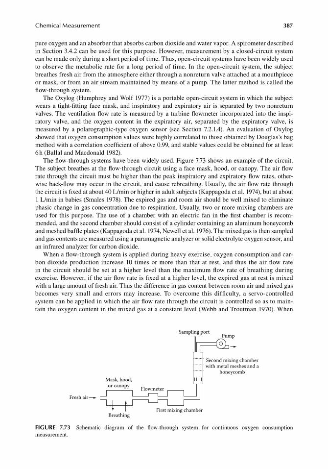
ChemicalMeasurement 387
pure.oxygen.and.an.absorber.that.absorbs.carbon.dioxide.and.water.vapor..A.spirometer.described.in.Section.3.4.2.can.be.used.for.this.purpose..However,.measurement.by.a.closed-circuit.system.can.be.made.only.during.a.short.period.of.time..Thus,.open-circuit.systems.have.been.widely.used.to.observe.the.metabolic.rate.for.a. long.period.of. time..In.the.open-circuit.system,.the.subject.breathes.fresh.air.from.the.atmosphere.either.through.a.nonreturn.valve.attached.at.a.mouthpiece.or.mask,.or.from.an.air.stream.maintained.by.means.of.a.pump..The.latter.method.is.called.the.flow-through.system.
The.Oxylog.(Humphrey.and.Wolf.1977).is.a.portable.open-circuit.system.in.which.the.subject.wears.a.tight-fitting.face.mask,.and.inspiratory.and.expiratory.air. is.separated.by.two.nonreturn.valves..The.ventilation.flow.rate.is.measured.by.a.turbine.flowmeter.incorporated.into.the.inspi-ratory. valve,. and. the. oxygen. content. in. the. expiratory. air,. separated. by. the. expiratory. valve,. is.measured.by.a.polarographic-type.oxygen. sensor. (see.Section.7.2.1.4)..An.evaluation.of.Oxylog.showed.that.oxygen.consumption.values.were.highly.correlated.to.those.obtained.by.Douglas’s.bag.method.with.a.correlation.coefficient.of.above.0.99,.and.stable.values.could.be.obtained.for.at.least.6.h.(Ballal.and.Macdonald.1982).
The.flow-through.systems.have.been.widely.used..Figure.7.73.shows.an.example.of.the.circuit..The.subject.breathes.at.the.flow-through.circuit.using.a.face.mask,.hood,.or.canopy..The.air.flow.rate.through.the.circuit.must.be.higher.than.the.peak.inspiratory.and.expiratory.flow.rates,.other-wise.back-flow.may.occur.in.the.circuit,.and.cause.rebreathing..Usually,.the.air.flow.rate.through.the.circuit.is.fixed.at.about.40.L/min.or.higher.in.adult.subjects.(Kappagoda.et al..1974),.but.at.about.1.L/min.in.babies.(Smales.1978)..The.expired.gas.and.room.air.should.be.well.mixed.to.eliminate.phasic.change.in.gas.concentration.due.to.respiration..Usually,.two.or.more.mixing.chambers.are.used. for. this.purpose..The.use.of.a.chamber.with.an.electric. fan. in. the.first.chamber. is. recom-mended,.and.the.second.chamber.should.consist.of.a.cylinder.containing.an.aluminum.honeycomb.and.meshed.baffle.plates.(Kappagoda.et al..1974,.Newell.et al..1976)..The.mixed.gas.is.then.sampled.and.gas.contents.are.measured.using.a.paramagnetic.analyzer.or.solid.electrolyte.oxygen.sensor,.and.an.infrared.analyzer.for.carbon.dioxide.
When.a.flow-through.system.is.applied.during.heavy.exercise,.oxygen.consumption.and.car-bon.dioxide.production. increase.10. times.or.more. than. that.at. rest,.and. thus. the.air.flow.rate.in. the.circuit.should.be.set.at.a.higher. level. than. the.maximum.flow.rate.of.breathing.during.exercise..However,.if.the.air.flow.rate.is.fixed.at.a.higher.level,.the.expired.gas.at.rest.is.mixed.with.a.large.amount.of.fresh.air..Thus.the.difference.in.gas.content.between.room.air.and.mixed.gas.becomes. very. small. and. errors. may. increase.. To. overcome. this. difficulty,. a. servo-controlled.system.can.be.applied.in.which.the.air.flow.rate.through.the.circuit.is.controlled.so.as.to.main-tain.the.oxygen.content.in.the.mixed.gas.at.a.constant.level.(Webb.and.Troutman.1970)..When.
Fresh air
Mask, hood,or canopy
Breathing
Flowmeter
First mixing chamber
Second mixing chamberwith metal meshes and a
honeycomb
Sampling portPump
figure 7.73 Schematic. diagram. of. the. flow-through. system. for. continuous. oxygen. consumption.measurement.
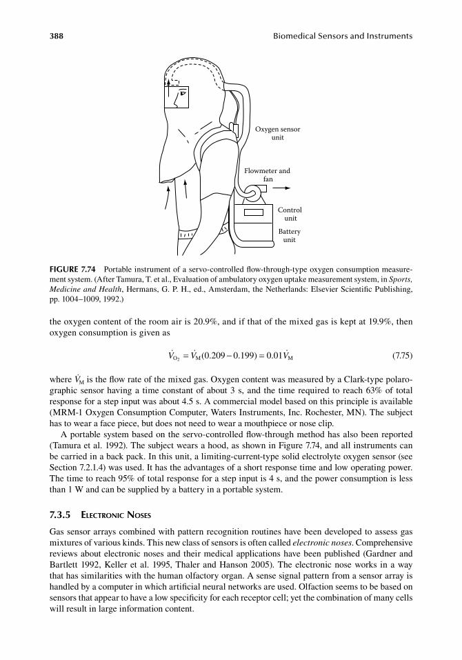
388 BiomedicalSensorsandInstruments
the.oxygen.content.of.the.room.air.is.20.9%,.and.if.that.of.the.mixed.gas.is.kept.at.19.9%,.then.oxygen.consumption.is.given.as
. V V VO M M2 (0.209 0.199) 0.01= − = . (7.75)
where.VM.is.the.flow.rate.of.the.mixed.gas..Oxygen.content.was.measured.by.a.Clark-type.polaro-graphic.sensor.having.a. time.constant.of.about.3.s,.and. the. time.required. to.reach.63%.of. total.response.for.a.step.input.was.about.4.5.s..A.commercial.model.based.on.this.principle.is.available.(MRM-1.Oxygen.Consumption.Computer,.Waters.Instruments,.Inc..Rochester,.MN)..The.subject.has.to.wear.a.face.piece,.but.does.not.need.to.wear.a.mouthpiece.or.nose.clip.
A.portable.system.based.on.the.servo-controlled.flow-through.method.has.also.been.reported.(Tamura.et al..1992)..The.subject.wears.a.hood,.as.shown.in.Figure.7.74,.and.all.instruments.can.be.carried.in.a.back.pack..In.this.unit,.a.limiting-current-type.solid.electrolyte.oxygen.sensor.(see.Section.7.2.1.4).was.used..It.has.the.advantages.of.a.short.response.time.and.low.operating.power..The.time.to.reach.95%.of.total.response.for.a.step.input.is.4.s,.and.the.power.consumption.is.less.than.1.W.and.can.be.supplied.by.a.battery.in.a.portable.system.
7.3.5 electronic noses
Gas.sensor.arrays.combined.with.pattern.recognition.routines.have.been.developed.to.assess.gas.mixtures.of.various.kinds..This.new.class.of.sensors.is.often.called.electronic noses..Comprehensive.reviews.about.electronic.noses.and.their.medical.applications.have.been.published.(Gardner.and.Bartlett.1992,.Keller.et al..1995,.Thaler.and.Hanson.2005)..The.electronic.nose.works. in.a.way.that.has.similarities.with.the.human.olfactory.organ..A.sense.signal.pattern.from.a.sensor.array.is.handled.by.a.computer.in.which.artificial.neural.networks.are.used..Olfaction.seems.to.be.based.on.sensors.that.appear.to.have.a.low.specificity.for.each.receptor.cell;.yet.the.combination.of.many.cells.will.result.in.large.information.content.
Oxygen sensorunit
Flowmeter and fan
Control unit
Batteryunit
figure 7.74 Portable.instrument.of.a.servo-controlled.flow-through-type.oxygen.consumption.measure-ment.system..(After.Tamura,.T..et.al.,.Evaluation.of.ambulatory.oxygen.uptake.measurement.system,.in.Sports, Medicine and Health,.Hermans,.G..P..H.,.ed.,.Amsterdam,.the.Netherlands:.Elsevier.Scientific.Publishing,.pp. 1004–1009,.1992.)
ChemicalMeasurement 389
Electronic.noses.seem.to.have.interesting.applications.in.a.variety.of.fields..It.has.been.possible.to.classify.liquors,.tobacco.brands,.perfumes,.and.beers.(Shurmer.et al..1989,.1991,.Nakamoto.et al..1990)..Smells.from.humans.have.also.been.investigated.by.Ödman.(1995)..His.application.has.been.able.to.find.victims.in.debris.following.catastrophes,.etc.
The.sensor.mechanisms.are.of.various.design.principles..Tin.oxide.sensors.have.been.used.by.the.Warwick.group.(Shurmer.and.Gardner.1992)..The.active.part.of.the.sensor.is.doped.tin.oxide.that.essentially.works.as.an.n-type.semiconductor..Odors.react.with.the.chemisorbed.lattice.oxygen..The.reaction.injects.electrons.into.the.conduction.band.of.the.semiconductor.but.also.increases.the.electron.mobility.through.the.lowering.of.the.intragranular.barriers..Figaro,.Inc.,.Japan,.is.manu-facturing.a.commercial.version.of.this.sensor.type..This.sensor.type.needs.to.be.operated.at.about.300°C–400°C..The.response.time.is.usually.a.few.seconds.
Another.type.of.odor.sensor.is.made.from.electroactive.polymers..The.polymer.changes.its.resis-tance.when.exposed.to.various.gases..Polymer.sensors.can.operate.at.room.temperatures..Several.polymer-odor.combinations.have.been.tested.(Bartlett.and.Ling.Chang.1989)..Langmuir–Blodgett.films.have.also.shown.sensitivity.to.odors.(Moriizumi.1988).
Lundström.et al..(1992).have.designed.a.structure.of.gas-sensitive.FETs.with.gates.of.catalytic.metals.like.Pd,.Ir,.and.Pt..The.gas-sensing.property.is.based.on.the.horizontal.shift.of.the.ID.−.Vg.curve.that.occurs.on.exposure.to.gas.mixtures.of.different.kinds.
The.operational.temperature.of.the.field.effect.devices.is.usually.50°C–200°C.It.is.likely.that.the.gas.sensors.in.the.form.of.“electronic.noses”.presented.earlier.can.be.used.
in.medical.diagnosis..Actually,.many.attempts.have.been.done.in.diagnostic.application.to.several.diseases:. for. example,. tuberculosis. (Pavlou. et al.. 2004),. pneumonia. (Hanson. and. Thaler. 2005),.lung.cancer. (Di.Natale. et al.. 1999,.Machado.et al.. 2005,.D’Amico.et al.. 2010),.nose.and. throat.infections.(Shykhon.et al..2004,.Bruno.et al..2008),.and.urinary.tract.infections.(Pavlou.et al..2002,.Kodogiannis.et al..2008).
referenCeS
Aizawa,.M.,.Morioka,.A.,.Suzuki,.S.,.and.Nagamura,.Y..1979..Enzyme.immunosensor.III..Amperometric.determination.of.human.chorionic.gonadotropin.by.membrane-bound.antibody,.Anal. Biochem..94:.22–28.
Aizawa,.M.,.Suzuki,.S.,.Kato,.T.,.Fujiwara,.T.,.and.Fujita,.Y..1980..Solid-phase.enzyme.immunoassay.of.IgG.and.anti-IgG.using.a.transparent.and.nonporous.antibody-bound.plate,.J. Appl. Biochem..2:.190–195.
Aizawa,.M.,.Ikariyama,.Y.,.Matsuzawa,.M.,.and.Shinohara,.H..June.1987..Optical.biosensors.and.chemical.sen-sors,.Digest of the 4th International Conference on the Solid-State Sensors & Actuators (Transducers ’87), Institute of Electrical Engineers of Japan,.Tokyo,.pp..783–788.
Alcock,. S.. J.. and. Turner,.A.. P.. F.. 1993.. In Vivo Chemical Sensors, Recent Developments.. Bedford,. U.K.:.Cranfield.Press.
Alder,.J..F..and.McCallum,.J..J..1987..Piezoelectric.crystals.for.mass.and.chemical.measurements..Analyst.108:.1169–1189.
Anderson,.R..R..and.Parrish,.J..H..1981..The.optics.of.human.skin,.J. Invest Dermatol..77:.13–19.Andrews,.A..T..1986..Electrophoresis..Oxford,.U.K.:.Clarendon.Press.Aoki,.H.,.Akao,.M.,.Shin,.Y.,.Tsuji,.T.,.and.Togawa,.T..1987..Sintered.hydroxiapatite.for.a.percutaneous.device.
and.its.clinical.application,.Med. Prog. Technol..12:.213–220.Aoyagi,. T.,. Kishi,. T.,.Yamaguchi,. K.,. and. Watanabe,. S.. June. 1974.. Improvement. of. ear-piece. oximator..
Proceedings of the 13th Annual Meeting of the Japanese Society of Medical Electronics and Biological Engineering,.Osaka,.pp..90–91.
Arai,.T.,.Tomita,.Y.,.Kikuchi,.M.,.and.Negishi,.N..1985..Transcutaneous.detection.for.blood.glucose.change.by.measurement.of.effusion.fluid.using.suction.ATR.method,.in.Proceedings of the 14th International Conference on Medical and Biological Engineering and 12th Internatinal Conference on Medical Physics, Espoo,.Finland,.p..303.
Arnoudse,.P..B..and.Pardue,.H..L..1992..Instrumentation.for.the.breath-by-breath.determination.of.oxygen.and.carbon.dioxide.based.on.nondispersive.absorption.measurements,.Anal. Chem..64:.200–204.
390 BiomedicalSensorsandInstruments
Aytur,.T.,.Beatty,.P..R.,.Boser,.B.,.Anvar,.M.,.and.Ishikawa,.T..2002..An.immunoassay.platform.based.on.CMOS.Hall.sensors,.Solid State Sensor, Actuator and Microsystems Workshop,.Hilton.Head.Island,.SC,.June.2–6,.2002,.pp..126–129.
Ballal,.M..A..and.Macdonald,.I..A..1982..An.evaluation.of.the.Oxylog.as.a.portable.device.with.which.to.mea-sure.oxygen.consumption..Clin. Phys. Physiol. Meas..3:.57–65.
Ballantine,.D..S..and.Wohltjen,.H..1989..Surface.acoustic.wave,.Anal. Chem..61:.704A–715A.Bard,.A..J..and.Faulkner,.L..R..1980..Electrochemical Methods—Fundamentals and Applications..New.York:.
John.Wiley.&.Sons.Barker,.S..A..1987..Immobilization.of.the.biological.component.of.biosensors,.in.Biosensors, Fundamentals
and Applications..Turner,.A..P..F.,.Karube,. I.,. and.Wilson,.G..S.,. eds..Oxford,.U.K.:.Oxford.Science.Publications.
Bartlett,.P..N..and.Ling.Chang,.S..K..1989..Conducting.polymer.gas.sensors..Part.III..Results.for.four.different.polymers.and.five.different.vapours,.Sens. Actuator.20:.287–292.
Baugh,.P..J.,.ed..1994..Gas Chromatography, A Practical Approach..Oxford,.U.K.:.Oxford.University.Press.Baumberger,.J..P..and.Goodfriend,.R..B..1951..Determination.of.arterial.oxygen.tension.in.man.by.equilibration.
through.intact.skin..Fed. Proc..10:.10–11.Behrens-Tepper,.J..C.,.Massaro,.T..A.,.Updike,.S..J.,.and.Folts,.J..D..1977..Non-polarographic.blood.gas.analy-
sis.II..In vivo.evaluation.of.gas.chromatograph.system,.Biomater. Med. Devices Artif. Organs.5:.293–302.Bergveld,.P..1970..Development.of.an.ion-selective.solid-state.device.for.neurophysiological.measurements,.
IEEE Trans. Biomed. Eng..17:.70–71.Bergveld,.P..1972..Development,.operation,.and.application.of.the.ion-sensitive.field-effect-transistor.as.a.tool.
for.electrophysiology,.IEEE Trans. Biomed. Eng..19:.342–351.Bhavani-Shankar,. K.,. Moseley,. H.,. Kumar,.A..Y.,. and. Delf,.Y.. 1992.. Capnometry. and. anaesthesia,. Can. J.
Anaesth..39:.617–632.Bindra,.D..S.,.Zhang,.Y.,.and.Wilson,.G..S..1992..Design.and.in.vitro.studies.of.a.needle-type.glucose.sensor.
for.subcutaneous.monitoring,.Anal. Chem..63:.1692–1696.Bockris,.J..O..M..and.Reddy,.A..K..N..1973..Modern Electrochemistry..New.York:.Plenum.Press.Brett,.C..M..A..and.Brett,.A..M..O..1993..Electrochemistry—Principles, Methods and Applications..Oxford,.
U.K.:.Oxford.University.Press.Bruls,. W..A.. G.. and. van. der. Leun,. J.. C.. 1984.. Forward. scattering. properties. of. human. epidermal. layers,.
Photochem. Photobiol..40:.231–242.Bruno,. E.,. Alessandrini,. M.,. Ottaviani,. F.,. Delfini,. A.,. Di. Pierro,. D.,. Camillo,. A.,. and. De. Lorenzo,. A..
2008..Can. the.electronic.nose.diagnose.chronic. rhinosinusitis?.A.new.experimental. study,.Eur. Arch. Otorhinolaryngol..265:.425–428.
Bunimovich,.Y..L.,.Shin,.Y..S.,.Yeo,.W..S.,.Amori,.M.,.Kwong,.G.,.and.Heath,.J..R..2006..Quantitative.real-time.measurements.of.DNA.hybridization.with.alkylated.nonoxidized.silicon.nanowires.in.electrolyte.solu-tion,.J. Am. Chem. Soc..128:.16323–16331.
Cass,.A..E..G.,.ed..1990..Biosensors, A Practical Approach..Oxford,.U.K.:.Oxford.University.Press.Chan,.N..N..and.Hurel,.S..J..2002..Potential. impact.of.a.new.blood.glucose.monitoring.device:.The.Gluco.
Watch®.Biographer,.Pract. Diab. Int..19:.97–100.Chapman,.J..R..1993..Practical Organic Mass Spectrometry,.2nd.edn..Chichester,.U.K.:.John.Wiley.&.Sons.Chen,.S..H.,.Chuang,.Y..C.,.Lu,.Y..C.,.Lin,.H..C.,.Yang,.Y..L.,.and.Lin,.C..S..2009..A.method.of.layer-by-layer.
gold.nanoparticle.hybridization. in. a.quartz. crystal.microbalance.DNA.sensing. system.used. to.detect.dengue.virus,.Nanotechnology.20:.215501.
Cheong,.W..G.,.Prahl,.S..A.,.and.Welch,.A..J..1990..A.review.of.the.optical.properties.of.biological.tissues,.IEEE J. Quantum Elect..26:.2166–2185.
Ching,.C..T..S..and.Connolly,.P..2007..Reverse.iontophoresis:.A.new.approach.to.measure.blood.glucose.level,.Asian J. Health Info. Sci..1:.393–410.
Claremont,.D..J.,.Sambrook,.I..E.,.Penton,.C.,.and.Pickup,.J..C..1986..Subcutaneous.implantation.of.a.ferro-cene-mediated.glucose.sensor.in.pigs,.Diabetologia.29:.817–821.
Clark,.L..C..1956..Monitor.and.control.of.blood.and. tissue.oxygen. tensions,.Trans. Am. Soc. Artif. Intern. Organs.2:.41–57.
Clemens,.J..A..and.Phebus,.L..A..1984..Brain.dialysis.in.conscious.rat.confirms.in.vivo.electrochemical.evi-dence.that.dopaminergic.stimulation.releases.ascorbate,.Life Sci..35:.671–677.
Cobbold,.R..S..C..1974..Transducers for Biomedical Measurements: Principles and Applications..New.York:.John.Wiley.&.Sons.
Cole,.J..S.,.Martin,.W..E.,.Cheung,.P..W.,.and.Johnson,.C..C..1972..Clinical.studies.with.a.solid.state.fiberoptic.oximeter,.Am. J. Cardiol..29:.383–388.
ChemicalMeasurement 391
Conway,.M.,.Durbin,.G..M.,.Ingram,.D.,.MacIntosh,.N.,.Parker,.D.,.Reynolds,.E..O..R.,.and.Souter,.L..1976..Continuous.monitoring.of.arterial.oxygen.tension.using.a.catheter-tip.polarographic.electrode.in.infants,.Paediatrics.57:.244–250.
Coombes,.R..G..and.Halsall,.D..1988..Carbon.dioxide.analyzers,. in.Encyclopedia of Medical Devices and Instrumentations..Webster,.J..G.,.ed..New.York:.John.Wiley.&.Sons,.pp..556–564.
Coon,.R..L.,.Lai,.N..C..J.,.and.Kampine,.J..P..1976..Evaluation.of.a.dual-function.pH.and.PCO2.in.vivo.sensor,.J. Appl. Physiol..40:.625–629.
Cooper,. J.. and. Cass,.T.. 2004.. Biosensors, The Practical Approach Series,. 2nd. edn.. Oxford,. U.K.:. Oxford.University.Press.
Cosnier,.S..and.Mailley,.P..2008..Recent.advances.in.DNA.sensors,.Analyst.133:.984–991.Cotter,.R..J..1997..Time-of-Flight Mass Spectrometry: Instrumentation and Applications in Biological Research..
Washington,.DC:.An.American.Chemical.Society.Publication.Covington,.A..K.,.Vardes-PerezCasga,.F.,.Weeks,.P..A.,.and.Brown,.A..H..1993..pH.ISFETs.for.intramyocardial.
pH.monitoring.in.man,.Anal. Mag..21:.M43–M46.Culshaw,.B..and.Dakin,.J..1989..Optical Fiber Sensor. Systems and Applications,.Norwood,.MA:.Artech.House.D’Amico,.A.,. Pennazza,. G.,. Santonico,. M.,. Martinelli,. E.,. Roscioni,. C.,. Galluccio,. G.,. Paolesse,. R.,. and.
Di. Natale,. C.. 2010..An. investigation. on. electronic. nose. diagnosis. of. lung. cancer,. Lung Cancer. 68:.170–176.
Danielsson,. B.. and. Mosbach,. K.. 1987.. Theory. and. application. of. calorimetric. sensors,. in. Biosensors, Fundamentals and Applications.. Turner,.A.. P.. F.,. Karube,. I.,. and.Wilson,. G.. S.,. eds.. Oxford,. U.K.:.Oxford.Science.Publications,.pp..575–595.
Davies,.I..R..and.Zhang,.X..2008..Nitric.oxide.selective.electrodes,.Meth. Enzymol..436:.63–95.Davis,.F.,.Hughes,.M..A.,.Cossins,.A..R.,.and.Higson,.S..P..2007..Single.gene.differentiation.by.DNA-modified.
carbon.electrodes.using.an.AC.impedimetric.approach,.Anal. Chem..79:.1153–1157.Dawson,.P..H..1997..Quadrupole Mass Spectrometry and Its Applications..New.York:.American.Institute.of.
Physics.Deakin,.M..R..and.Byrd,.H..1989..Prussian.blue.coated.quartz.crystal.microbalance.as.a.detector.for.electroin-
active.cations.in.aqueous.solution,.Anal. Chem..61:.2905.Deakin,.M..R.,.Li,.T..T.,.and.Melroy,.O..R..1988..A.study.of.the.electrosorption.of.bromide.and.iodide.ions.on.
gold.using.the.quartz.crystal.microbalance,.J. Electroanal. Chem..243:.343–351.Delpy,.D..and.Parker,.D..1979..The.application.of.mass.spectrometry.to.transcutaneous.blood.gas.analysis,.in.
Non-Invasive Physiological Measurements..Rolfe.P.,.ed..London,.U.K.:.Academic.Press,.pp..334–344.Delpy,.D..T.,.Parker,.D.,.Reynolds,.E..O.,.and.Wilhite,.W..F..1979..Transcutaneous.blood.gas.analysis.by.mass.
spectrometry.and.gas.chromatography,.Birth Defects Orig. Artic. Ser..15:.91–101.Di.Natale,.C.,.Mantini,.A.,.Macagnano,.A.,.Antuzzi,.D.,.Paolesse,.R.,.and.D’Amico,.A..1999..Electronic.nose.
analysis.of.urine.samples.containing.blood,.Physiol. Meas..20:.377–384.Dresher,.R..P..and.Mendelson,.Y..2006..Reflectance.forehead.pulse.oximetry:.Effects.of.contact.pressure.during.
walking,.Conf. Proc. IEEE Eng. Med. Biol. Soc..1:.3529–3532.Duckworth,.H..E.,.Barber,.R..C.,.and.Venkatasubramanian,.V..S..1988..Mass Spectroscopy,.2nd.edn..Cambridge,.
U.K.:.Cambridge.University.Press.Dullenkopf,.A.,.Bernardo,.S..D.,.Berger,.F.,.Fasnacht,.M.,.Gerber,.A..C.,.and.Weiss,.M..2003..Evaluation.
of. a. new. combined. SpO2/PtcCO2. sensor. in. anaesthetized. paediatric. patients.. Paediatr. Anaesth.. 13:.777–784.
Eberhard,.P.,.Hammacher,.K.,.and.Mindt,.W..1973..Methode.zur.kutanen.Messung.des.Sauerstoffpartialdruckes,.Biomed. Tech..6:.216–221.
Edelstein,.R..L.,.Tamanaha,.C..R.,.Sheehan,.P..E.,.Miller,.M..M.,.Baselt,.D..R.,.Whitman,.L..J.,.and.Colton,.R. J..2000..The.BARC.biosensor.applied.to.the.detection.of.biological.warfare.agents,.Biosens. Bioelectron..14:.805–813.
Ellis,.F..R..and.Nunn,.J..F..1968..The.measurement.of.gaseous.oxygen.tension.utilizing.paramagnetism:.An.evaluation.of.the.“Servomex”.OA.150.analyzer,.Br. J. Anaesth..40:.569–578.
Endo,.T.,.Kerman,.K.,.Nagatani,.N.,.Takamura,.Y.,.and.Tamiya,.E..2005..Label-free.detection.of.peptide.nucleic.acid-DNA.hybridization.using.localized.surface.plasmon.resonance.based.optical.biosensor,.Anal. Chem..77:.6976–6984.
Englebienne,.P..1998..Use.of.colloidal.gold.surface.plasmon.resonance.peak.shift.to.infer.affinity.constant.from.the.interaction.between.protein.antigens.and.antibodies.specific.for.single.or.multiple.epitopes,.Analyst.123:.1599–1603.
Englebienne,.P.,.Van.Hoonacker,.A.,.and.Verhas,.M..2003..Surface.plasmon.resonance:.Principles,.methods.and.applications.in.biomedical.sciences,.Spectroscopy.17:.255–273.
392 BiomedicalSensorsandInstruments
Enson,.Y.,.Jameson,.A..G.,.and.Cournand,.A..1964..Intracardiac.oximetry.in.congenital.heart.disease,.Circulation.29:.499–507.
Esashi,.M..and.Matsuo,.T..1978..Integrated.micro.multi.ion.sensor.using.field.effect.transistor,.IEEE Trans. Biomed. Eng..25:.184–192.
Evans,.N..T..S..and.Naylor,.P..F..D..1967..The.systemic.oxygen.supply.to.the.surface.of.human.skin,.Respir. Physiol..3:.21–37.
Evtugyn,.G..A.,.Goldfarb,.O..E.,.Budnikov,.H..C.,.Ivanov,.A..N.,.and.Vinter,.V..G..2005..Amperometric.DNA-peroxidase.sensor.for.the.detection.of.pharmaceutical.preparations,.Sensors.5:.364–376.
Ewing,.A..G.,.Wallingford,.R..A.,.and.Olefirowicz,.T..M..1989..Capillary.electrophoresis,.Anal. Chem..61:.292A–303A.
Flentge,.F.,.Venema,.K.,.Koch,.T.,.and.Korf,.J..1992..An.enzyme-reactor.for.electrochemical.monitoring.of.choline.and.acetylcholine:.Applications.in.high-performance.liquid.chromatography,.brain.tissue,.micro-dialysis.and.cerebrospinal.fluid..Anal. Chem..204:.305–310.
Gardner,.J..W..and.Bartlett,.P..N..1992..Sensors and Sensory Systems for an Electronic Nose, NATO ASI Series E,.Vol..212..Dordrecht,.the.Netherlands:.Kluwer.Academic.Publishers.
Gaskel,.S..J..1985..Mass.spectrometry.in.medical.research,.Clin. Phys. Physiol. Meas..6:.1–16.Gehrich,.J..L.,.Lübers,.D..W.,.Opitz,.N.,.Hansman,.D..R.,.Miller,.W..W.,.Tusa,.J..K.,.and.Yafuso,.M..1986..
Optical.fluorescence.and.its.application.to.an.intravascular.blood.gas.monitoring.system,.IEEE Trans. Biomed. Eng..33:.117–132.
Gerhardt,.G..A.,.Oke,.A..F.,.Nagy,.G.,.Moghaddam,.B.,.and.Adams,.R..N..1983..Nafion-coated.electrodes.with.high.selectivity.for.CNS.electrochemistry,.Brain Res..290:.390–395.
Goddard,.P.,.Keith,.I.,.Marcovitch,.H.,.Robertson,.N..R..C.,.Rolfe,.P.,.and.Scopes,.J..W..1974..Use.of.continu-ously.recording.intravascular.oxygen.electrode.in.the.newborn,.Arch. Dis. Child..49:.853–860.
Gramling,.J..J..1977..Oxygen.analyzers,.in.Hospital Instrumentation Care and Servicing for Critical Care Unit..Spooner,.R..B.,.ed..Pittsburgh,.PA:.Instrument.Society.of.America.
Gregg,.B..A..and.Heller,.A..1990..Cross-linked.redox.gels.containing.glucose.oxidase.for.amperometric.biosen-sor.applications,.Anal. Chem..62(3):.258–263.
Grieshaber,.D.,.MacKenzie,.R.,.Vörös,.J.,.and.Reimhult,.E..2008..Electrochemical.biosensor—Principle.and.architecture,.Sensors.8:.1400–1458.
Griffiths,.P..R..and.de.Haseth,.J..A..1986..Fourier Transform Infrared Spectrometry..New.York:.John.Wiley.&.Sons.Gumbrecht,.W.,.Schelter,.W.,.Montag,.B.,.Rasinski,.M.,.and.Pfeifer,.U..1990..Online.blood.electrolyte.monitor-
ing.with.a.ChemFET.microcell.system,.Sens. Actuator,.B1:.477–480.Hajdukiewicz,.J.,.Boland,.S.,.Kavanagh,.P.,.and.Leech,.D..2009..An.enzyme-amplified.amperometric.DNA.
hybridisation.assay.using.DNA.immobilised.in.a.carboxymethylated.dextran.film.anchored.to.a.graphite.surface,.Biosens. Bioelectron..25:1037–1042.
Hanson,.C..W..and.Thaler,.E..R..2005..Electronic.nose.prediction.of.a.clinical.pneumonia.score:.Biosensors.and.microbes,.Anesthesiology.102:.63–68.
Harke,.S.,.Wiemhöfer,.H..D.,.and.Göpel,.W..1990..Investigations.of.electrodes.for.oxygen.sensors.based.on.lanthanum.trifluoride.as.solid.electrolyte,.Sens. Actuator B.1:.188–194.
Harmer,.A.. and. Scheggi,.A.. 1989.. Chemical,. biochemical,. and. medical. sensors,. in. Optical Fiber Sensor. Systems and Applications..Culshaw,.B..and.Dakin,.J.,.eds..Norwood,.MA:.Artech.House..p..559.
Harn,.C..E..W..1980..Techniques.for.measuring.the.partial.pressures.of.gases. in. the.blood..Part.1—in.vivo.measurements,.J. Phys. E: Sci. Instrum..13:.470–482.
Harn,.C..E..W..1987..Blood.gas.measurement,.Clin. Phys. Physiol. Meas..8:.3–39.Hashiguchi,.Y.,.Sakakida,.M.,.Nishida,.K.,.Uemura,.T.,.Kajiwara,.K.,.and.Shichiri.M..1994..Development.of.a.
miniaturized.glucose.monitoring.system.by.combining.a.needle-type.glucose.sensor.with.microdialysis.sampling.method..Long-term.subcutaneous.tissue.glucose.monitoring.in.ambulatory.diabetic.patients,.Diabetes Care.17:.387–396.
Herrell,.N.,.Martin,.R..J.,.Pultasher,.M.,.Lough,.M.,.and.Fanaraff,.A..1980..Optimal.temperature.for.the.mea-surement.of.transcutaneous.carbon.dioxide.tension.in.the.neonate,.J. Pediatr..97:.114–117.
Hill,.H..A..O..and.Sanghera,.G..S..1990..Mediated.amperometric.enzyme.electrodes,.in.Biosensors, A Practical Approach..Cass,.A..E..G.,.ed..Oxford,.U.K.:.Oxford.University.Press,.pp..19–46.
Hlavay,.J..and.Gilbaut,.G..G..1977..Applications.of.the.piezoelectric.crystal.detector.in.analytical.chemistry,.Anal. Chem..49:.1890–1898.
Hlavay,. J.. and.Gilbaut,.G..G..1978..Detection.of.ammonia. in.ambient.air.with.coated.piezoelectric.crystal.detector..Anal. Chem..50:.1044–1049.
Hochberg,.H..M..1981..Current.clinical.experience.with.continuous.tissue.pH.monitoring,.J. Clin. Eng..6:.17–34.Huch,.R..and.Huch,.A..1983..Continuous Transcutaneous Blood Gas Monitoring..New.York:.Marcel.Dekker.
ChemicalMeasurement 393
Huch,.A.,.Huch,.R.,.and.Lübbers,.D..W..1969..Quantitative.polarographische.Sauerstoff.druckmessung.auf.der.Kopfhaut.des.Neugeborenen,.Arch. Gynakol..207:.443–451.
Huch,.A.,.Lübbers,.D..W.,.and.Huch,.R..1973..Patientübervachung.durch.transcutane.pCO2.Messung.bei.glei-chzeiligen.kontrolle.der.relativen.lokalen.perfusion,.Anaesthetist.22:.379–380.
Huch,.R.,.Huch,.A.,.and.Rolfe,.P..1979..Transcutaneous.measurement.of.pO2.using.electrochemical.analysis,.in.Non-invasive Physiological Measurements,.Vol..1..Rolfe,.P.,.ed..London,.U.K.:.Academic.Press,.pp..313–331.
Huch,.R.,.Huch,.A.,.and.Lübbers,.D..W..1981..Transcutaneous pO2..New.York:.Thieme-Stratton.Hudson,.J..A..1967..Measurement.of.oxygen.tension.by.the.oxygen.cathode,.Med. Biol. Eng..5:.207–222.Humphrey,.S..J..E..and.Wolf,.H..S..1977..The.Oxylog,.J. Physiol..267:.12.Hura,.Y.,.Hana,.J.,.Seonb,.J.,.Pakc,.Y..E.,.and.Roha,.Y..2005..Development.of.an.SH-SAW.sensor.for.the.detec-
tion.of.DNA.hybridization,.Sens. Actuator A.120:.462–467.Hutchison,.D..S..C.,.Rocca,.G.,.and.Honeybourne,.D..1981..Estimation.of.arterial.oxygen.tension.in.adult.sub-
jects.using.a.transcutaneous.electrode..Thorax.36:.473–477.Ichimori,.K.,.Ishida,.H.,.Fukahori,.M.,.Nakazawa,.H.,.and.Murakami,.E..1994..Practical.nitric.oxide.measure-
ment.employing.a.nitric.oxide-selective.electrode,.Rev. Sci. Instrum..65:.2714–2717.Ikariyama,.Y..and.Suzuki,.S..1982..Luminescence.immunoassay.of.human.serum.albumin.with.haemin.as.label-
ing.catalyst,.Anal. Chem..54:.1126–1129.Ikariyama,.Y.,.Suzuki,.S.,.and.Karube,.M..1983..Luminescence.catalyst.immunoassay.of.β2-microglobulin.with.
haemin.as.a.chemically.amplifiable.label,.Enzyme Microb. Technol..5:.215–218.Ikebukuro,.K.,.Kohiki,.Y.,.and.Sode,.K..2002..Amperometric.DNA.sensor.using.the.pyrroquinoline.quinone.
glucose.dehydrogenase-avidin.conjugate,.Biosens. Bioelectron..17:.1075–1080.Ito,.N.,.Saito,.A.,.Miyamoto,.S.,.Shinohara,.S.,.Kuriyama,.T.,.Kimura,.J.,.Arai,.T.,.Kikuchi,.M.,.Kayashima,.S.,.
Nagata,.N.,.and.Takatani,.O..1990..A.novel.blood.glucose.monitoring.system.based.on.an.ISFET.biosen-sor.and.its.application.to.a.human.75.g.oral.glucose.tolerance.test,.Sens. Actuator B.1:.488–490.
Ito,.N.,.Kayashima,.S.,.Kimura,.J.,.Kuriyama,.T.,.Arai,.T.,.Kikuchi,.M.,.and.Nagata,.N..1994..Development.of.a.transcutaneous.blood-constituent.monitoring.method.using.a.suction.effusion.fluid.collection.technique.and.an.ion-sensitive.field-effect.transistor.glucose.sensor,.Med. Biol. Eng. Comput..32:.242–246.
Ito,. N.,. Saito,.A.,. Kayashima,. S.,. Kimura,. J.,. Kuriyama,. T.,. Nagata,. N.,.Arai,. T.,. and. Kikuchi,. M.. 1995..Transcutaneous. blood. glucose. monitoring. system. based. on. an. ISFET. glucose. sensor. and. studies. on.diabetic.patients,.Front. Med. Biol. Eng..6:.269–280.
Jansen,.T..C.,.Lafeber,.H..N.,.Visser,.H..K..A.,.Kwant,.G.,.Oeseburg,.B.,.and.Zijlstra,.W..G..1978..Construction.and.performance.of.a.new.catheter-tip.oxygen.electrode,.Med. Biol. Eng. Comput..16:.274–277.
Jin,.W.,.Lin,.X.,.Lv,.S.,.Zhang,.Y.,.Jin,.Q.,.and.Mu,.Y..2009..A.DNA.sensor.based.on.surface.plasmon.resonance.for.apoptosis-associated.genes.detection,.Biosens. Bioelectron..24:.1266–1269.
Kappagoda,.C..T.,.Stoker,.J..B.,.and.Linden,.R..J..1974..A.method.for.the.continuous.measurement.of.oxygen.consumption,.J. Appl. Physiol..37:.604–607.
Karube,.I..1987..Micro-organism.based.sensors,.in.Biosensors, Fundamentals and Applications..Turner,.A..P..F.,.Karube,.I.,.and.Wilson,.G..S.,.eds..Oxford,.U.K.:.Oxford.Science.Publications,.pp..13–29.
Karube,.I..and.Nakanishi,.K..1994..Microbial.biosensors.for.process.and.environmental.control,.IEEE Eng. Med. Biol..13:.364–374.
Karube,.I..and.Suzuki,.S..1990..Microbial.biosensors,.in.Biosensors, A Practical Approach,.Cass,.A..E..G.,.ed..Oxford:.Oxford.University.Press,.pp..155–170.
Karube,.I.,.Matsunaga,.T.,.and.Suzuki,.S..1977..A.new.microbial.electrode.for.BOD.estimation,.J. Solid Phase Biochem..2:.97–104.
Karube,.I.,.Matsunaga,.T.,.Nakahara,.T.,.and.Suzuki,.S..1981..Preliminary.screening.of.mutagens.with.a.micro-bial.sensor..Anal. Chem..53:.1024–1026.
Karube,.I.,.Nakahara,.T.,.Matsunaga,.T.,.and.Suzuki,.S..1982..Salmonella.electrode.for.screening.mutagens,.Anal. Chem..54:.1725–1727.
Kayashima,.S.,.Arai,.T.,.Kikuchi,.M.,.Sato,.N.,.Nagata,.N.,.Takatani,.O.,.Ito,.N.,.Kimura,.J.,.Kuriyama,.T.,.and.Kaneyoshi,.A..1991..New.noninvasive.transcutaneous.approach.to.blood.glucose.monitoring:.Successful.glucose.monitoring.on.human.75.g.OGTT.with.novel.sampling.chamber,.IEEE Trans. Biomed. Eng..38:.752–771.
Kell,.D..B..and.Davey,.C..L..1990..Conductimetric.and.impedimetric.devices,.in.Biosensors,.Cass,.A..E..G.,.ed..Oxford:.Oxford.University.Press,.pp..125–154.
Khuri,.S..F.,.Josa,.M.,.Marston,.W.,.Braunwald,.N..S.,.Smith,.B.,.Tow,.D.,.VanCisin,.M.,.and.Barsamian,.E..M..1983..First.report.of.intramyocardial.pH.in.man,.II..Asssessment.of.adequancy.of.myocardial.preserva-tion,.J. Thorac. Cardiovasc. Surg..86:.667–678.
394 BiomedicalSensorsandInstruments
Kimura,.J.,.Ito,.N.,.and.Kuriyama,.T..1989..A.novel.blood.glucose.monitoring.method.and.ISFET.biosensor.applied.to.transcutaneous.effusion.fluid,.J. Electrochem. Soc..136:.1744–1747.
King,.T..W.,.Cote,.G..L.,.McNichols,.R.,.and.Goetz,.M..J..1994..Multispectral.polarimetric.glucose.detection.using.a.single.pockels.cell,.Opt. Eng..33:.2746–2753.
Klaus,.S.,.Heringlake,.M.,.and.Bahlmann,.L..2004..Bench-to-bedside.review:.Microdialysis.in.intensive.care.medicine,.Crit. Care.8:.363–368.
Kodogiannis,.V..S.,.Lygouras,.J..N.,.Tarczynski,.A.,.and.Chowdrey,.H..S..2008..Artificial.odor.discrimination.system.using.electronic.nose.and.neural.networks.for.the.identification.of.urinary.tract.infection,.IEEE Trans. Inf. Technol. Biomed..12:.707–713.
Kondo,.H.,.Takahashi,.H.,.Saji,.K.,.Takeuchi,.T.,.and.Igarashi,.I..June.1986..Thin.film.limiting.current.type.oxygen.sensor..Proceedings of the 6th Sensor Symposium of the Institute of Electrical Engineering of Japan,.Tsukuba,.pp..251–256.
König,.V.,.Huch,.R.,.and.Huch,.A..1998..Reflectance.pulse.oximetry—Principles.and.obstetric.application.in.the.Zurich.system,.J. Clin. Monit. Comput..14:.403–412.
Koryta,.J..1990..Theory.and.application.of.ion-selective.electrodes..Anal. Chem. Acta..233:.1–30.Kuan,.S..S..and.Guilbaut,.G..G..1987..Ion-selective.electrodes.and.biosensors.based.on.ISEs,.in.Biosensors,
Fundamentals and Applications..Turner,.A..P..F.,.Karube,.I.,.and.Wilson,.G..S.,.eds..Oxford,.U.K.:.Oxford.Science.Publishers,.pp..135–152.
Lacerenza,.S.,.De.Carolis,.M..P.,.Fusco,.F..P.,.La.Torre,.G.,.Chiaradia,.G.,. and.Romagnoli,.C..2008..An.evaluation.of.a.new.combined.Spo2/PtcCO2.sensor. in.very. low.birth.weight. infants,.Anesth. Analg..107:125–129.
Lacy,.J..F..1981..Clinical.uses.of.transcutaneous.blood.gas.measurements,.Adv. Pediatr..28:.27–56.Laurell,.T..1993..Microdialysis.implemented.in.the.design.of.a.system.for.continuous.glucose.monitoring,.Sens.
Actuator B.13–14:.323–326.Lee,.S.,.Sode,.K.,.Nakanishi,.K.,.Marty,.J.,.Tamiya,.E.,.and.Karube,.I..1992a..A.novel.microbial.sensor.using.
luminous.bacteria,.Biosens. Bioelectron..7:.273–277.Lee,.S.,.Suzuki,.S.,.Tamiya,.E.,.and.Karube,.I..1992b..Sensitive.bioluminescent.detection.of.pesticides.utiliz-
ing.a.membrane.mutant.of.Escherichia coli.and.recombinant.DNA.technology,.Anal. Chem. Acta.257:.183–188.
Lei,.Y.,.Chen,.W.,.and.Mulchandani,.A..2006..Microbial.biosensor,.Anal. Chim. Acta.568:.200–210.Levin,.I..W..and.Lewis,.E..N..1994..Application.of.Fourier.transform.Raman.spectroscopy.to.biological.assem-
blies,.in.Fourier Transform Raman Spectroscopy..Chase,.D..B..and.Rabolt,.J..F.,.eds..San.Diego,.CA:.Academic.Press,.pp..157–208.
Licznerski,.B..2004..Thick-film.gas.microsensors.based.on. tin.dioxide,.Bull. Pol. Acad. Sci. Tech. Sci.. 52:.37–42.
Lieberman,.R..A..1991..Intrinsic.fiber.optic.sensors,.in.Fiber Optic Chemical Sensors and Biosensors,.Vol..1,.Chap..5.edn..Wolfbeis,.O..S.,.ed..Boca.Raton,.FL:.CRC.Press.
Lisdat,.F.. and.Schäfer,.D..2008..The.use.of. electrochemical. impedance. spectroscopy. for.biosensing,.Anal. Bioanal. Chem..391:.1555–1567.
Loaiza,. O..A.,. Campuzano,. S.,. Guzman-Vazquez. De. Prada,.A.,. Pedrero,. M.,. and. Pingarron,. J.. M.. 2008..Amperometric. DNA. quantification. based. on. the. use. of. peroxidase-mercaptopropionic. acid-modified.gold.electrodes,.Sens. Actuators B.132:.250–257.
Lübbers,.D..W..1960..Methods.of.measuring.oxygen.tensions.of.blood.and.organ.surfaces,.in.Oxygen Measure-ments in Blood and Tissues..Payne,.J..P..and.Hill,.D..W.,.eds..London,.U.K.:.Churchill,.pp..103–128.
Lukaszewica,.J..P..1990..A.LaF3-based.oxygen.sensor.with.perovskite-type.oxide.electrode.operative.at.room.temperature,.Sens. Actuator B.1:.195–198.
Lundsgaard,.J..S.,.Jensen,.B.,.and.Grønlund..J..1980..Fast-responding.flow-independent.blood.gas.catheter.for.oxygen.measurement,.J. Appl. Physiol. Respir. Environ. Exercise Physiol..48:.376–381.
Lundström,.I.,.Hedberg,.E.,.Spetz,.H.,.Sundgren,.H.,.and.Winqvist,.F..1992..Electronic.noses.based.on.field.effect.structures,.in.Sensors and Sensory Systems for an Electronic Nose,.NATO ASI Series E..Gardner,.J..W..and.Bartlett,.P..N.,.eds..Dordrecht,.the.Netherlands:.Kluwer.Academic.Publishers,.p..212.
Lunte,.C..E.,.Scott,.D..O.,.and.Kissinger,.P..T..1991..Sampling.living.systems.using.microdialysis.probes,.Anal. Chem..63:.773A–780A.
Machado,.R..F.,.Laskowski,.D.,.Deffenderfer,.O.,.Burch,.T.,.Zheng,.S.,.Mazzone,.P..J.,.Mekhail,.T.,.Jennings,.C.,.Stoller,.J..K.,.Pyle,.J.,.Duncan,.J.,.Dweik,.R..A.,.and.Erzurum,.S..C..2005..Detection.of.lung.cancer.by.sensor.array.analyses.of.exhaled.breath,.Am. J. Respir. Crit. Care Med..171:.1286–1291.
Mackereth,.F..J..H..1964..An.improved.galvanic.cell.for.determination.of.oxygen.concentrations.in.fluid..J. Sci. Instrum..41:.38–41.
ChemicalMeasurement 395
Malinski,.T..and.Taha,.Z..1992..Nitric.oxide.release.from.a.single.cell.measured.in.situ.by.a.porphyrinic-based.microsensor,.Nature.358:.676–678.
Malinski,.T.,.Bailey,.F.,.Zhang,.Z..G.,.and.Chopp,.M..1993..Nitric.oxide.measured.by.a.porphyrinic.micro-sensor. in. rat.brain.after. transient.middle.cerebral.artery.occlusion,.J. Cereb. Blood Flow Metab..13:.355–358.
Manz,.A.,.Effenhauser,.C..S.,.Burggraf,.N.,.Harrison,.D.. J.,. Seiler,.K.,. and.Fluri,.K.. 1994..Electroosmotic.pumping. and. electrophoretic. separations. for. miniaturized. chemical. analysis. system,. J. Micromech. Microeng..4:.257–265.
March,.R..E..1997..An.introduction.to.quadrupole.ion.trap.mass.spectrometry,.J. Mass Spectrom..32:.351–369.March,.W..F.,.Rabinovitch,.B.,.and.Adams,.R..L..1982..Noninvasive.glucose.monitoring.of.the.aqueous.humor.
of.the.eye:.Part.II..Animal.studies.and.the.scleral.lens,.Diabetes Care.5:.259–265.Marshall,.A..G.,.Hendrickson,.C..L.,.and.Jackson,.G..S..1997..Fourier.transform.ion.cyclotron.resonance.mass.
spectrometry:.A.primer,.Mass Spectrom. Rev..17:.1–35.Martin,.C..R..and.Freiser,.H..1980..Coated-wire.ion.selective.electrodes.and.their.application.to.the.teaching.
laboratory..J. Chem. Educ..57:.512–514.Matsuo,.T..and.Esashi,.M..1981..Methods.of.ISFET.fabrication,.Sens. Actuator.1:.77–96.Matsuo,.T.. and.Wise,.K..1971..An. integrated.field-effect. electrode. for.biopotential. recording.. IEEE Trans.
Biomed. Eng..21:.485–487.McLean,.J..A..and.Tobin,.G..1987..Animal and Human Calorimetry..Cambridge,.U.K.:.Cambridge.University.
Press.Meites,.L..1963..Handbook of Analytical Chemistry..New.York:.McGraw-Hill.Mendelson,.Y..and.Ochs,.B..D..1988..Non-invasive.pulse.oximetry.utilizing.skin.reflectance.photoplethysmog-
raphy,.IEEE Trans. Biomed. Eng..10:.798–805.Mendelson,.Y.,. Lewinsky,. R.. M.,. and. Wasserman,.Y.. 2002.. Multi-wavelength. reflectance. pulse. oximetry,.
Anesth. Analg..94.Suppl..1:.S26–S30.Mendelson,.Y.,.Duckworth,.R..J.,.and.Comtois,.G..2006..A.wearable.reflectance.pulse.oximeter. for. remote.
physiological.monitoring,.Conf. Proc. IEEE Eng. Med. Biol. Soc..1:.912–915.Meyer,.V..R..2004..Practical High-Performance Liquid Chromatography,.4th.edn..Chichester,.U.K.:.Wiley.
Interscience.Mindt,. W.. 1973.. Sauerstoffsensoren. fur. in. vivo-Mussungen,. Proc. Jahrestagung D Ges. Biomed. Tech.,
Erlangen,.Germany,.pp..29–30.Mindt,.W.,.Eberhard,.P.,.and.Schäfer,.R..1983..Methodological.factors.affecting.the.relationship.between.trans-
cutaneous.and.arterial.pCO2,.in.Continuous Transcutaneous Blood Gas Monitoring..Huch,.A..and.Huch,.R.,.eds..New.York:.Marcel.Dekker,.p..199.
Moatti-Sirat,.D.,.Capron,.F.,.Poitout,.V.,.Reach,.G.,.Bindra,.D..S.,.Zhang,.Y.,.Wilson,.G..S.,.and.Thévenot,.D..R..1992..Toward.continuous.glucose.monitoring:.In.vivo.evaluation.of.a.miniaturized.glucose.sensor.implanted.for.a.several.days.in.rat.subcutaneous.tissue,.Diabetologia.35:.224–230.
Moriizumi,.T..1988..Langmuir-Blodgett.films.as.chemical.sensors,.Thin Solid Films.160:.413–429.Morrison,.S..R..1994..Chemica.sensor,.in.Semiconductor Sensors..Sze,.S..M.,.ed..New.York:.John.Wiley.&.
Sons,.pp..683–413.Moss,.S..D.,.Janata,.J.,.and.Johnson,.C..C..1975..Potassium.ion-selective.field.effect.transistor,.Anal. Chem..
47:.2238–2243.Nakamoto,.T.,.Fukuhischi,.K.,.and.Moriizumi,.T..1990..Identification.capacity.of.odour.using.quartz-resonator.
array.and.neural-network.pattern.recognitions,.Sens. Actuator B.1:.473–476.Nakamura,.H.,.Shimomura,.M.,.Shimizu,.M.,.and.Karube,.I..2008..Development.of.microbial.sensors.and.their.
application,.Adv. Biochem. Eng. Biotechnol..109:.351–394.Nakashima,.K..and.Imai,.K..1993..Chemiluminescence,.molecular.luminescence.spectroscopy,.in.Chemical
Analysis Series,.Vol..77..Schulman,.S..G.,.ed..New.York:.John.Wiley.&.Sons.Inc.,.pp..1–23.Newell,.J..P.,.Kappagoda,.C..T.,.and.Linden,.R..J..1976..Method.for.continuous.measurement.of.carbon.dioxide.
output,.J. Appl. Physiol..41:.810–813.Öberg,.P..A..2004..Optical.sensors.in.medical.care,.in,.Sensors in Medicine and Health Care..Öberg,.P..A.,.
Togawa,.T.,.and.Spelman,.F..A.,.eds..Weinheim,.Germany:.Wiley-VCH,.pp..15–43.Ödman,.S..1995..Personal.communication.Ohara,.T..J.,.Rajagopalan,.R.,.and.Heller,.A..1993..Glucose.electrodes.based.on.cross-linked.[Os(bpy)2Cl]+/2+.
complexed.poly(1-vinylimidazole).films,.Anal. Chem..65:.3512–3517.Ohara,.T..J.,.Rajagopalan,.R.,.and.Heller,.A..1994..“Wired”.enzyme.electrodes.for.amperometric.determination.
of.glucose.or.lactate.in.the.presence.of.interfering.substances,.Anal. Chem..66:.2451–2457.Okada,.T.,.Karube,.I.,.and.Suzuki,.S..1982..Hybrid.urea.sensor..Eur. J. Appl. Microbiol. Biotechnol..14:.149–154.
396 BiomedicalSensorsandInstruments
Olsson,.S..G.,.Fletcher,.F.,.Johnson,.B.,.Nordström,.L.,.and.Prakash,.O..1980..Clinical.studies.of.gas.exchange.during.ventilatory.support—A.method.using.the.Siemens-Elema.CO2.analyzer,.Br. J. Anaesth..52:.491–499.
Ossward,.H..F..1981..Continuous.monitoring.of.electrolyte.concentrations.by.direct.potentiometry.during.extra-corporeal.circulation,.in.Proceedings of International Conference on Monitoring of Vital Parameters dur-ing Extracorporeal Circulation,.Nijmegen..Basel,.the.Netherlands:.Karger,.pp..149–155.
Ossward,.H..F.,.Asper,.R.,.Dimai,.W.,.and.Simon,.W..1979..On-line.continuous.potentiometric.measurement.of.potassium.concentration.in.whole.blood.during.open-heart.surgery,.Clin. Chem..25:.39–43.
Pänke,.O.,.Balkenhohl,.T.,.Kafka,.J.,.Schäfer,.D.,.and.Lisdat,.F..2008..Impedance.spectroscopy.and.biosensing,.Adv. Biochem. Eng. Biotechnol..109:.195–237.
Park,.J..B..1979..Biomaterials—An Introduction..New.York:.Plenum.Press,.pp..152–157.Park,.J..Y..and.Park,.S..M..2009..DNA.hybridization.sensors.based.on.electrochemical.impedance.spectroscopy.
as.a.detection.tool,.Sensors.9:.9513–9532.Parker,.D..1976..A.flexible.catheter.for.continuous.measurement.of.blood-gas.tensions.in.vivo.by.mass.spec-
trometry,.in.Digest of the International Conference on Medical and Biological Engineering,.Ottawa,.pp..60–61.
Parker,. D.. 1981.. Continuous. measurement. of. blood. oxygen. tension. and. saturation,. in. Monitoring Vital Parameters During Extracorporeal Circulation..Kimmich,.H..P.,.ed..Basel:.Karger,.pp..23–28.
Parker,.D.,.Delpy,.D.,. and.Lewis,.M..1978..Catheter-tip. electrode. for. continuous.measurement.of.pO2.and.pCO2,.Med. Biol. Eng. Comput..16:.599–600.
Pavlou,.A..K.,.Magan,.N.,.McNulty,.C.,.Jones,.J.,.Sharp,.D.,.Brown,.J.,.and.Turner,.A..P..2002..Use.of.an.elec-tronic.nose.system.for.diagnoses.of.urinary.tract.infections,.Biosens. Bioelectron..17:.893–899.
Pavlou,.A..K.,.Magan,.N.,.Jones,.J..M.,.Brown,.J.,.Klatser,.P.,.and.Turner,.A..P..2004..Detection.of.mycobacte-rium.tuberculosis.(TB).in.vitro.and.in.situ.using.an.electronic.nose.in.combination.with.a.neural.network.system,.Biosens. Bioelectron..20:.538–544.
Peterson,.J..I.,.Fitzgerald,.R..V.,.and.Buckhold,.D..K..1984..Fiber-optic.probe.for.in.vivo.measurement.of.oxy-gen.partial.pressure,.Anal. Chem..56:.62–67.
Pfeiffer,.E..F.,.Meyerhoff,.C.,.Bishof,.F.,.Keck,.F..S.,.and.Kerner,.W..1993..On.line.continuous.monitoring.of.subcutaneous.tissue.glucose.is.feasible.by.combining.portable.glucosensor.with.microdialysis,.Horm. Metab. Res..25:.121–124.
Pinard,.E.,.Seylaz,.J.,.and.Mamo,.H..1978..Quantitative.continuous.measurement.of.pO2.and.pCO2.in.artery.and.vein,.Med. Biol. Eng. Comput..16:.59–64.
Polanyi,.M..L..and.Hehir,.R..M..1962..In.vivo.oximeter.with.fast.dynamic.response,.Rev. Sci. Instrum..33:.1050–1054.
Profio,.A..E..1989..Light.transport.in.tissue,.Appl. Opt.,.28:.2216–2222.Rabinovitch,.B.,.March,.W..F.,.and.Adams,.R..L..1982..Noninvasive.glucose.monitoring.of.the.aqueous.humor.
of.the.eye:.Part.I..Measurement.of.very.small.optical.rotation,.Diabetes Care.5:.254–258.Rao,.G.,.Glikfeld,.P.,.and.Guy,.R..H..1993..Reverse.iontophoresis:.development.of.a.noninvasive.approach.for.
glucose.monitoring,.Pharm. Res..10:.1751–1755.Rao,.G.,.Guy,.R..H.,.Glikfeld,.P.,.LaCourse,.W..R.,.Leung,.L.,.Tamada,.J.,.Potts,.R..O.,.and.Azimi,.N..1995..
Reverse.iontophoresis:.Noninvasive.glucose.monitoring.in.vivo.in.humans,.Pharm. Res..12:.1869–1873.Riker,.J..B..and.Arrt,.B..H..1976..Expired.gas.monitoring.by.mass.spectrometry.in.a.respiratory.intensive.care.
unit,.Crit. Care Med..4:.223–229.Rithalia,.S..V..S..1991..Developments.in.transcutaneous.blood.gas.monitoring:.A.review,.J. Med. Eng. Technol..
15:.143–153.Roederer,.J..E..and.Bastiaans,.G..J..1983..Microgravimetric.immunoassay.with.piezoelectric.crystals,.Anal.
Chem..55:.2333–2336.Rolfe,.P..1976..Arterial.oxygen.measurement.in.the.newborn.with.intra-vascular.transducer,.in.Medical Electronics
Monographs..Hill,.D..W..and.Watson,.B..W.,.eds..Stevenage,.U.K.:.Peter.Peregrinus.Ltd.,.pp..126–158.Rolfe,.P..1990..In.vivo.chemical.sensors.for.intensive-care.monitoring..Med. Biol. Eng. Comput..28:.B34–B47.Rolfe,.P..1994..Intra-vascular.oxygen.sensors.for.neonatal.monitoring,.IEEE Eng. Med. Biol. Eng..13:.336–346.Ronkainen,.N..J.,.Halsall,.H..B.,.and.Heineman,.W..R..2010..Electrochemical.biosensors,.Chem. Soc. Rev..39:.
1747–1763.Saji,.K.,.Takahashi,.H.,.Kondo,.H.,.Takeuchi,.T.,.and.Igarashi,.I..1984..Limiting.current.type.oxygen.sensor,.
Proceedings of the 4th Sensor Symposium, Institute of Electrical Engineers of Japan,.Tokyo,.pp..147–151.Sakata,.D..J.,.Matsubara,.I.,.Gopalakrishnan,.N..A.,.Westenskow,.D..R.,.White,.J..L.,.Yamamori,.S.,.Egan,.T..D.,.
and.Pace,.N..L..J..2009..Flow-through.versus.sidestream.capnometry.for.detection.of.end.tidal.carbon.dioxide.in.the.sedated.patient,.J. Clin. Monit. Comput..23:.115–122.
Sanz,.M..C..1957..Ultramicro.methods.and.standardization.of.equipment..Clin. Chem..3:.406–419.
ChemicalMeasurement 397
Sauerbrey,.G..1959..Verwendung.von.Schwingquarzen.zur.Wägung.dünner.Schichten.und.zur.Mikrowägung,.Z. Phys..155:.206–222.
Scheuplein,.R..J..and.Blank,.I..H..1971..Permeability.of.the.skin,.Physiol. Rev..51:.702–747.Severinghaus,.J..W..1965..Blood.gas.concentrations,.in.Handbook of Physiology, Respiration,.Vol..II..Fenn,.W..O..
and.Rahn,.H.,.eds..Washington,.DC:.American.Physiological.Society,.pp..1475–1487.Severinghaus,. J.. W.. 1981..A. combined. transcutaneous. pO2–pCO2. electrode. with. electrochemical. HCO3
–.stabilization,.J. Appl. Physiol..51:.1027–1032.
Severinghaus,.J..W..and.Ozanne,.G..1978..Multioperating.room.monitoring.with.one.mass.spectrometer,.Acta Anaesthesiol. Scand. Suppl..70:.186–187.
Sharma,.A.. K.,. Jha,. R.,. and. Gupta,. B.. D.. 2007.. Fiber-optic. sensors. based. on. surface. plasmon. resonance:.A comprehensive.review,.IEEE Sensors J..7:.1118–1129.
Shibbald,.A.,.Covington,.A..K.,.and.Carter,.R..F..1985..Online.patient.monitoring.system.for.the.simultaneous.analysis.of.K+,.Ca2+,.Na+.and.pH.using.a.quadruple-function.ChemFET.integrated-circuit.sensor,.Med. Biol. Eng. Comput..23:.329–338.
Shibuki,.K..1990..An.electrochemical.microprobe.for.detecting.nitric-oxide.release.in.brain-tissue..Neurosci. Res..9:.69–76.
Shichiri,.M.,.Kawamori,.R.,.Yamazaki,.Y.,.Hakui,.N.,.and.Abe,.H..1982..Wearable.artificial.endocrine.pancreas.with.needle-type.glucose.sensor,.Lancet.2:.1129–1131.
Shichiri,.M.,.Sakakida,.M.,.Nishida,.K.,.and.Shimoda,.S..1998..Enhanced,.simplified.glucose.sensors:.Long-term.clinical.application.of.wearable.artificial.endocrine.pancreas,.Artif. Organs.22:.32–42.
Shimada,.K.,.Yano,.M.,.Shibatani,.K.,.Komoto,.Y.,.Eshashi,.M.,.and.Matsuo,.T..1980..Application.of.a.catheter-tip.i.s.f.e.t..for.continuous.in.vivo.measurement,.Med. Biol. Eng. Comput..18:.741–745.
Shurmer,.H..V..and.Gardner,.J..W..1992..Odour.discrimination.with.an.electronic.nose,.Sens. Actuator B.8:.1–11.Shurmer,.H..V.,.Gardner,.J..W.,.and.Chan,.H..T..1989..The.application.of.discrimination.techniques.to.alcohols.
and.tobaccos.using.tin.oxide.sensors,.Sens. Actuator.18:.361–371.Shurmer,.H..V.,.Gardner,.J..W.,.and.Corcoran,.P..1991..Intelligent.vapour.discrimination.using.a.composite.
12-element.sensor.array,.Sens. Actuators B.1:.256–260.Shykhon,.M..E.,.Morgan,.D..W.,.Dutta,.R.,.Hines,.E..L.,.and.Gardner,.J..W..2004..Clinical.evaluation.of.the.
electronic.nose.in.the.diagnosis.of.ear,.nose.and.throat.infection:.A.preliminary.study,.J. Laryngol. Otol..118:.706–709.
Sieg,.A.,.Guy,.R..H.,.and.Delgado-Charro,.M..B..2005..Noninvasive.and.minimally.invasive.methods.for.trans-dermal.glucose.monitoring,.Diabetes Technol. Ther..7:.174–197.
Skoog,.D..A.,.West,.D..M.,.and.Holler,.F..J..1994..Analytical Chemistry,.6th.edn..Philadelphia,.PA:.Saunders.College.Publications.
Skoog,.D..A.,.Holler,.F..J.,.and.Crouch,.S..R..2006..Principles of Instrumental Analysis,.6th.edn..Pacific.Grove,.CA:.Brooks.Cole.
Smales,.O..R..C..1978..Simple.method.for.measuring.oxygen.consumption.in.babies,.Arch. Dis. Child.53:.53–57.Sodal,.I..E.,.Clark,.J..S.,.and.Swanson,.G..D..1988..Mass.spectrometers.in.medical.monitoring,.in.Encyclopedia of
Medical Devices and Instrumentations..Webster,.J..G.,.ed..New.York:.John.Wiley.&.Sons,.pp..1848–1859.Solsky,.R..L..1988..Ion-selective.electrodes,.Anal. Chem..60:.106R–113R.Taguchi,.N..1971..Gas.detection.device,.U.S..Patent.3,631,436.Takatani,.S.,.Davies,.C.,.Sakakibara,.N.,.Zurick,.A.,.Kraenzler,.E.,.Golding,.L..R.,.Noon,.G..P.,.Nose,.Y.,.and.
DeBakey,.M..E..1992..Experimental.and.clinical.evaluation.of.a.noninvasive.reflectance.pulse.oximeter.sensor,.J. Clin. Monit..8:.257–266.
Tamura,.T..and.Togawa,.T..1989..Continuous.blood.pH.monitoring.by.use.of.null.method,.Sens. Actuator.16:.273–285.
Tamura,.T.,.Higuchi,.T.,.Sato,.K.,.and.Togawa,.T..1992..Evaluation.of.ambulatory.oxygen.uptake.measurement.system,.in.Sports, Medicine and Health..Hermans,.G..P..H.,.ed..Amsterdam,.the.Netherlands:.Elsevier.Scientific.Publishing,.pp..1004–1009.
Tamura,.T.,. Koseki,. K.,. Sumino,.T.,. Ogawa,. M.,.Togawa,.T.,. and.Tsuchya,. K.. 2000.. Preliminary. study. of.continuous.glucose.monitoring.with.a.microdialysis.technique.and.null.method—A.numerical.analysis,.Front. Med. Biol. Eng..10:.147–156.
Tan,.T..C.,.Li,.F.,.and.Neoh,.K..G..1993..Measurement.of.BOD.by.initial.rate.of.response.of.a.microbial.sensor,.Sens. Actuator B.10:.137–142.
Tang,.X.,.Bansaruntip,.S.,.Nakayama,.N.,.Yenilmez,.E.,.Chang,.Y.,.and.Wang,.Q..2006..Carbon.nanotube.DNA.sensor.and.sensing.mechanism,.Nano Lett..6:.1632–1636.
Taylor,. J.. B.,. Lown,. B.,. and. Polanyi,. M.. 1972.. In. vivo. monitoring. with. a. fiber. optic. catheter,. JAMA. 221:.667–672.
398 BiomedicalSensorsandInstruments
Thring,.M..W..1951..British.instrument.exhibition—London.1951,.J. Sci. Instrum..28:.293–300.Tran-Minh,.C..and.Vallin,.D..1978..Enzyme-bound.thermistor.as.an.enthalpimetric.sensor,.Anal. Chem..50:.
1874–1878.Tsuji,.T.,.Aoki,.H.,.Shin,.Y.,.and.Togawa,.T..1990..Hydroxyapatite.percutaneous.devices.implanted.in.forearms.
of.three.volunteers.for.four.years..Artif. Organs..14.Suppl..3:.185–186.Tudos,.A..J..and.Schasfoolt,.R..B..M..2008..Introduction.to.surface.plasmon.resonance,.in.Handbook of Surface
Plasmon Resonance..Schasfoolt,.R..B..M..and.Tudos,.A..J.,.eds..Cambridge,.U.K.:.The.Royal.Society.of.Chemistry,.pp..2–14.
Tur,.E.,.Tur,.M.,.Maibach,.H.. I.,. and.Guy,.H..R..1983..Basal. perfusion.of. the. cutaneous.microcirculation:.Measurements.as.a.function.of.anatomic.position,.J. Invest. Dermatol..81:.442–446.
Turner,.A..P..F..1993..Advances in Biosensors..Hampton.Hill,.U.K.:.JAI.Press.Turner,.A..P..F.,.Karube,.I.,.and.Wilson,.G..S..1987..Biosensors, Fundamentals and Applications..Oxford,.U.K.:.
Oxford.Science.Publications.Turner,.R..F..B.,.Harrison,.D..J.,.Rajotte,.R..V.,.and.Baltes,.H..P..1990..A.biocompatible.enzyme.electrode.for.
continuous.in.vivo.glucose.monitoring.in.whole.blood,.Sens. Actuator B.1:.561–564.Uno,.T.,.Tabata,.H.,. and.Kawai,.T..2007..Peptide-nucleic.acid-modified. ion-sensitive.field-effect. transistor-
based.biosensor.for.direct.detection.of.DNA.hybridization..Anal. Chem..79(1):.52–59.Urban,.G.,.Jobst,.G.,.Svasek,.P.,.Varahram,.M.,.Moser,.I.,.Aschauer,.E.,.Trajanoski,.Z.,.Wach,.P.,.Gfrerer,.R.,.
Kotanko,.P.,. and.Skrabal,.F..1995..Evaluation.of. a.microflow.system.with. integrated.biosensor. array.in. undiluted. blood. during. in. diabetological. provocation. test,. in Proceedings of the 8th International Conference on Solid-State Sensors and Actuators and Eurosensors IX, Transducer’95, June. 25–29, Stockholm,.Sweden,.pp..459–461.
Wald,.A.,.Hass,.W..K.,.Siew,.F..P.,.and.Wood,.D..H..1970..Continuous.measurement.of.blood.gases.in.vivo.by.mass.spectrography,.Med. Biol. Eng..8:.111–128.
Webb,.P..and.Troutman,.S..J..1970..An.instrument.for.continuous.measurement.of.oxygen.consumption,.J. Appl. Physiol..28:.867–871.
Weil,. J..A.. and. Bolton,. J.. R.. 2007.. Electron Paramagnetic Resonance: Elementary Theory and Practical Applications,.2nd.edn..Chichester,.U.K.:.Wiley-Interscience.
Wilkinson,.A..R.,.Phibbs,.R..H.,.and.Gregory,.G..A..1978..Continuous.measurement.of.oxygen.saturation.in.sick.newborn.infants,.J. Pediatr..93:.1016–1019.
Willets,.K..A..and.Van.Duyne,.R..P..2006..Localized.surface.plasmon.resonance.spectroscopy.and.sensing,.Annu. Rev. Phys. Chem..58:.267–297.
Wilson,.B..C..and.Jacques,.S..L..1990..Optical.reflectance.and.transmittance.of.tissues:.Principles.and.applica-tions,.IEEE J. Quantum Electron..26:.2186–2199.
Wilson,.K..and.Walker,.J..M.,.eds..2010..Principles and Techniques of Practical Biochemistry and Molecular Biology,.7th.edn..Cambridge,.U.K.:.Cambridge.University.Press.
Winquist,.F..and.Danielsson,.B..1990..Semiconductor.field.effect.devices,.in.Biosensors, A Practical Approach..Cass.A..E..G.,.ed..Oxford,.U.K.:.Oxford.University.Press,.pp..171–190.
Wolfbeis,.O..S..1991..Fiber Optic Chemical Sensors and Biosensors,.Vol..1..Boca.Raton,.FL:.CRC.Press.Wolthuis,. R..A.,. McCrae,. D.,. Hartl,. J.. C.,. Saaski,. E.,. Mitchell,. G.. L.,. Garcin,. K.,. and. Willard,. R.. 1992..
Development.of.a.medical.fiber-optic.oxygen.sensor.based.on.optical.absorption.change,.IEEE Trans. Biomed. Eng..39:.185–193.
Wood,.E..and.Geraci,.J..E..1949..Photoelectric.determination.of.arterial.oxygen.saturation.in.man,.J. Lab. Clin. Med..34:.387–401.
Xie,.B..and.Danielsson,.B..1992..Development.of.a.thermal.micro-biosensor.fabricated.on.a.silicon.chip,.Sens. Actuator B.6:.127–130.
Yamamori,.S.,.Takasaki,.Y.,.Ozaki,.M.,.and.Iseki,.H..2008..A.flow-through.capnometer.for.obstructive.sleep.apnea,.J. Clin. Monit. Comput..22:.209–220.
Yang,.L..and.Kruse,.B..2004..Revised.Kubelka-Munk.theory..1..Theory.and.application,.J. Opt. Soc. Am..21:.1933–1941.
Yogeswaran,.U..and.Chen,.S..M..2008..A.review.on.the.electrochemical.sensors.and.biosensors.composed.of.nanowires.as.sensing.material,.Sensors.8:.290–313.
Zhang,.X..J.,.Kislyak,.Y.,.Lin,.J.,.Dickson,.A.,.Cardoso,.L.,.Broderick,.M.,.and.Fein,.H..2002..Nanometer.size.electrode.for.nitric.oxide.and.S-nitrosothiols.measurement,.Electrochem. Commun..4:.11–16.
Zhang,. X.. J.,. Ju,. H.,. and. Wang,. J.,. eds.. 2007.. Electrochemical Sensors, Biosensors and their Biomedical Applications,.London,.U.K.:.Academic.Press.
Zimmerman,. J.. L.. and. Dellinger,. R.. P.. 1993.. Initial. evaluation. of. a. new. intra-arterial. blood. gas. system. in.humans,.Crit. Care Med..21:.495–500.