Embed Size (px)
Citation preview

������� ����
� ������� ����� ��� ���� ������
� ���� ���

������ ����
R
Durometer (rubber / plastic, stiffness scale)
Custom MadeProducts
Dial indicator Test indicator
Thickness gauge
Depth gauge Caliper gauge
Bore gauge &Micro-hole test
Other precisionmeasuring instrument
Electronicinstrument
Stand
Durometer (rubber / plastic, stiffness scale)
Custom madeproductsCustom madeproducts
Dial indicator Test indicator
Thickness gauge
Depth gauge Caliper gauge
Bore gauge &Micro-hole test
Other precisionmeasuring instrument
Electronicinstrument
Stand
46-54 55-56
2-9 10-12
13-18
19-24 25-30
31-35
36-39 40-43
44-45
46-54 55-56
2-9 10-12
13-18
19-24 25-30
31-35
36-39 40-43
44-45

Dimensions
unit : mmM2.5×P0.45
40Aφ8
D
20
E (with Flat back)
(C)
φ56
φ52
.5
B
R8
φ6.55
0-0.022
2
DIAL INDICATORSDIAL INDICATORSTECLOCK Dial Indicator is definitely utilized at the production site where dimensional high accuracy is needed to be confirmed. The graduation (1-graduation) depends on usage and TECLOCK offers best quality dial indicators with 0.001mm, 0.005mm, 0.01mm, 0.05mm and 0.1mm graduations. The strokes are available from 0.16mm (the shortest) up to 150mm. Dial Indicator is normally not used independent but its stem or lugback is fixed to a jig and holds workpiece with measuring stands and contact point, and displacement volume is read by short hand and pointer. This dial indicator is applied for direct measurement to measure actual dimension and comparative measurement for measuring displacement volume from a certain standard dimension.
¡Durability is pursued by protecting mechanical parts like gears with unique shock proof mechanism.
¡Jeweled bearing for extreme durability, toughness and stability.¡Stable repeatability is realized by most advanced TECLOCK Lever
enlargement mechanism built-in.
¡Tolerance hand is provided as standard accessory (all models) for positive tolerance setting.
¡Lifting lever can be mounted.¡Bezel clamp can be mounted (Option), excepting TM-1201PW.
0.001mm Dial Indicator
Model
TM-1201
TM-1201PW
TM-1251
TM-1202
TM-1205
A
62
65.5
62
62
62
B
18
(18)
18
18
18
C
15
13.5
15
15
15.5
D
7.5
11
7.5
7.5
7.5
E
8
8.5
8
8
8
Dimension Table
unit : mm
Specifications
TM-1201
TM-1201PW
TM-1251
TM-1202
TM-1205
ZS-017
ZS-028
ZS-017
ZS-017
ZS-017
0.001
0.001
0.001
0.001
0.001
1(3)
1(3)
1(3)
2(2)
5(-)
0.5
0.5
0.5
0.5
1
2.5
2.5
2.5
4
5
±3
±3
±3
±5
±6
±5
±5
±5
±7
±10
Graduation(mm)
Measuring Range(Free stroke)
(mm)3
3
3
3
4
1.5 or less
1.5 or less
1.5 or less
1.5 or less
1.5 or less
Hysteresis(μm)
Repeatability(μm)
Indication Error(μm)
Adjacent Error Total Range1/2 RevolutionModel
Measuring Force(N)
170
180
170
170
170
W e i g h t(g)
±4
±4
±4
±6
±7
1 Revolution
±4
±4
±4
±6
±8
2 Revolution
In case flat back is required, please add suffix "f" to the end of model number. (example =TM-1201f)
Standard Contact Point
¡Achieved highest accuracy and durability made by pursuing precision components.
¡TECLOCK unique and original shock proof mechanism is built-in
¡Lifting lever can be mounted.¡Bezel clamp can be mounted (Option),
excepting TM-110 PW / TM-110G.
0.01mm Dial Indicator
TM-1202Graduation 0.001mmMeasuring Range 2mm
TM-1205Graduation 0.001mmMeasuring Range 5mm
TM-1201Graduation 0.001mmMeasuring Range 1mm
TM-1201PWGraduation 0.001mmMeasuring Range 1mmOil-Proof Type
TM-1251Graduation 0.001mmMeasuring Range 1mmOne Revolution 0.1mmGreen Colored Dial
TM-110Graduation 0.01mmMeasuring Range 10mmHardened Stainless Steel Stem
TM-110RGraduation 0.01mmMeasuring Range 10mmReverse Reading
TM-110DGraduation 0.01mmMeasuring Range 10mm

TM-110PGraduation 0.01mmMeasuring Range 10mmDial Reading(0-0.5-1.0) Green Colored Dial
3
TM-110PWGraduation 0.01mmMeasuring Range 10mmOil-Proof Type
TM-110GGraduation 0.01mmMeasuring Range 10mmwith Stop Hand
Peak RetainingFunction
TM-110-4AGraduation 0.01mmMeasuring Range 10mmwith Oil Ejection Holed Bezel
TM-105WGraduation 0.01mmMeasuring Range 5mmContinuous Dial
TM-5105Graduation 0.005mmMeasuring Range 5mm
TM-5106Graduation 0.01mmMeasuring Range 5mm
0.005mm Dial Indicator
Dimensions
unit : mm
5
H (with Flat back)
0-0.03
M2.5×P0.45
ABφ8
G
F(E)
φC
φ52
D
R8
φ6.5
Model
TM-110
TM-110R
TM-110D
TM-110-4A
TM-110PW
TM-110G
TM-110P
TM-105
TM-105W
TM-5106
TM-5105
A
48.7
48
48
48
44.5
48
48
48
48
48
48
B
65
65
65
65
68.5
65
65
65
65
65
65
C
55
55
55
55
56
55
55
55
55
55
55
D
18
18
18
18
(17.5)
18
18
18
18
18
18
E
15.5
15.5
17.6
15.5
14.5
17.3
15.5
15.5
15.5
15.5
15.5
F
20
20
20
20
20
20
20
※
20
20
20
G
7.5
7.5
7.5
7.5
11
7.5
7.5
7.5
7.5
7.5
7.5
H
7.8
7.8
7.8
7.8
8.3
7.8
7.8
7.8
7.8
7.8
7.8
Dimension Table
unit : mm*Indicator is supplied with Flat back
*
TM-105Graduation 0.01mmMeasuring Range 5mmSymmetrical DialFlat Back
In case flat back is required, please add suffix "f" to the end of model name.
101010101010105555
Specifications
TM-110TM-110RTM-110DTM-110-4ATM-110PWTM-110GTM-110PTM-105TM-105WTM-5106TM-5105
0.010.010.010.010.010.010.010.010.010.010.005
55555555533
88888888877
±9±9±9±9±9±9±9±9±9±8±8
±15±15±15±15±15±15±15±12±12±12±12
Graduation(mm)
55555555555
1.4 or less1.4 or less1.4 or less1.4 or less1.4 or less2.0 or less1.4 or less1.4 or less1.4 or less1.4 or less1.4 or less
ZS-017ZS-017ZS-017ZS-017ZS-028ZS-017ZS-017ZS-017ZS-017ZS-017ZS-017
Hysteresis(μm)
Repeatability(μm)
Indication Error(μm)
Adjacent Error Total Range1/2 RevolutionModel
Measuring Force(N)
110165165165165165145145145145145
We i g h t(g)
±10±10±10±10±10±10±10±10±10±9±9
1 Revolution
±15±15±15±15±15±15±15±12±12±10±10
2 RevolutionMeasuring Range
(mm)Standard Contact
Point
DIAL INDICATORS

TM-36Graduation 0.005mmMeasuring Range 3.5mm
TM-37Graduation 0.01mmMeasuring Range 3.5mm
TM-37CGraduation 0.01mmMeasuring Range 3.5mmFlat Back
KM-121DGraduation 0.01mmMeasuring Range 20mm
KM-121Graduation 0.01mmMeasuring Range 20mm
TM-34Graduation 0.01mmMeasuring Range 4mm
TM-35-01Graduation 0.1mmMeasuring Range 10mm
4
¡Lifting lever can be mounted, excepting TM-34.¡Line-up of measuring range 3.5mm, 4mm, 5mm and 10mm.
¡Bezel clamp(Option) can be mounted on TM-35, TM-35-01, TM-35-02D.
Small Dial Indicator
¡20mm, 30mm long stroke dial indicators are available.
¡TECLOCK unique shock proof mechanism is built-in to all models.
¡Lifting lever can be mounted, excepting KM-121PW.
¡Bezel clamp(Option) can be mounted, excepting KM-121PW.
TM-35Graduation 0.01mmMeasuring Range 5mm
Model
TM-35
TM-35-01
TM-35-02D
TM-34
TM-36
TM-37
TM-37C
A
27.4
32.5
32.5
20
33.5
33.5
33.5
B
41.3
46
46
39.5
50
50
50
C
39
39
39
36
47
47
47
D
36.5
36.5
36.5
32
44
44
44
E
10
10
10
11.5
13
13
13
F
14.5
14.5
16.5
13
15.5
15.5
15.5
G
19
19
19
19
19.7
19.7
19.7
H
5
5
5
5
7.5
7.5
7.5
I
6.2
6.2
6.2
6.5
7
7
7
*Indicator is supplied with flat back.
*unit : mm
Dimensions
unit : mm
G(F)
φ8
M2.5×P0.45
φC
E
B
H
A
φD
φ6.55
R8
0-0.03
I (with Flat back)
TM-35
TM-35-01
TM-35-02D
TM-34
TM-36
TM-37
TM-37C
0.01
0.1
0.01
0.01
0.005
0.01
0.01
5
10
10
4
3.5
3.5
3.5
5
-
5
5
5
5
5
Graduation(mm)
Measuring Range(mm)
6
-
7
6
5
6
6
ZS-014
ZS-014
ZS-014
ZS-014
ZS-017
ZS-017
ZS-017
1.3 or less
1.5 or less
1.6 or less
1.0 or less
1.2 or less
1.2 or less
1.2 or less
Hysteresis(μm)
Repeatability(μm)
Indication Error(μm)Model Measuring Force
(N)
70
70
75
60
115
115
115
Weight(g)
In case flat back is required, please add suffix "f" to the end of model name.
Adjacent Error
9
-
9
8
8
8
8
1 Revolution
±13
-
±13
±11
±10
±10
±10
Total Range
±15
±50
±18
±15
±12
±12
±12
Standard Contact Point
KM-131Graduation 0.01mmMeasuring Range 30mm
Dimension Table
Specifications
0.01mm Long StrokeDial Indicator
TM-35-02DGraduation 0.01mmMeasuring Range 10mm
KM-121PWGraduation 0.01mmMeasuring Range 20mmOil-proof type
DIAL INDICATORS

KM-130Graduation 0.01mmMeasuring Range 30mm
5
Dimension Table
unit : mm
Model
KM-121
KM-121D
KM-121PW
KM-131
KM-132D
KM-130
KM-130R
KM-130D
A
36
36
55
36
36
38.5
38.5
38.5
B
75
75
89
85
85
92
92
92
C
55
55
56
55
55
59
59
59
D
52
52
52
52
52
54.5
54.5
54.5
E
18
18
(17.5)
18
18
22.7
22.7
22.7
F
15.5
17.6
14.5
15.5
17.3
17.5
17.5
19.5
G
20
20
20
20
20
22
22
22
H
7.5
7.5
11
7.5
7.5
7.5
7.5
7.5
I
7.8
7.8
8.3
8
8
9.6
9.6
9.6
KM-132DGraduation 0.01mmMeasuring Range 30mm
Dimensions
unit : mmM2.5×P0.45
ABφ8
5
H
G(F)
φC
φD
E
R8
φ6.5
0-0.03
I (with Flat back)
¡50mm, 100mm, 150mm long stroke dial indicators with a bezel diameter of 83mm are available.
¡Measuring up to 150mm stroke is materialized with highest precision components of high durability and TECLOCK original and unique enlargement mechanism is built-in.
¡Bezel clamp (Option) can be mounted, excepting KM-05100, KM-05150.¡Long stroke dial indicator is widely used for construction, civil engineering
industries etc.
Long Stroke Dial Indicator
KM-155Graduation 0.01mmMeasuring Range 50mm
KM-155DGraduation 0.01mmMeasuring Range 50mm
KM-55Graduation 0.05mmMeasuring Range 50mm
Dimensions
unit : mm
79
φ83
30.5
KM-155,KM-155:(16)KM-155D:(18) 21.5
φ80
132.
5
7.5
φ10
φ6.5φ6.5
0-0.03
5
M2.5×P0.45 8.2 (with Flat back)
KM-55
KM-155
KM-155D
0.05
0.01
0.01
50
50
50
20
5
5
30
15
15
±50
±20
±20
±100
±35
±35
Graduation(mm)
Measuring Range(mm)
15
9
9
2.5 or less
2.5 or less
2.5 or less
Hysteresis(μm)
Repeatability(μm)
Indication Error(μm)
Adjacent Error 1 Revolution Total RangeModel Measuring Force
(N)
370
370
370
Weight(g)
Specifications
In case flat back is required, please add suffix "f" to the end of model name.
ZS-017
ZS-017
ZS-017
Standard Contact Point
KM-130DGraduation 0.01mmMeasuring Range 30mm
KM-130RGraduation 0.01mmMeasuring Range 30mmReverse Reading
KM-121
KM-121D
KM-121PW
KM-131
KM-132D
KM-130
KM-130R
KM-130D
0.01
0.01
0.01
0.01
0.01
0.01
0.01
0.01
20
20
20
30
30
30
30
30
5
5
5
5
5
5
5
5
10
10
10
14
14
14
14
14
±15
±15
±15
±18
±18
±18
±18
±18
±20
±20
±20
±35
±35
±25
±25
±25
Graduation(mm)
MeasuringRange(mm)
7
7
7
8
8
7
7
7
2.2 or less
2.2 or less
2.2 or less
2.5 or less
2.5 or less
2.2 or less
2.2 or less
2.2 or less
Hysteresis(μm)
Repeatability(μm)
Indication Error(μm)
Adjacent Error 1 Revolution Total RangeModel
Measuring Force(N)
145
150
165
150
150
200
200
200
Weight(g)
Specifications
In case flat back is required, please add suffix "f" to the end of model name.
ZS-017
ZS-017
ZS-028
ZS-017
ZS-017
ZS-017
ZS-017
ZS-017
Standard ContactPoint
DIAL INDICATORS

The longest mechanical type model : KM-05150
525mm
525mm
525mm
KM-05150Graduation 0.05mmMeasuring Range 150mm
6
DIAL INDICATORS
¡The One revolution dial indicator eliminates reading errors which may occur on conventional continuous-reading dial indicators, and effective for comparative measurement with 0.001mm and 0.01mm graduation.
¡Highest Durability is materialized with TECLOCK original enlargement mechanism.
¡Measuring ranges are subdivided for 0.08mm, 0.16mm, 0.2mm and 1.0mm.
¡Bezel clamp is supplied with 0.001mm dial indicator.¡Lifting lever can be mounted.
One Revolution Dial Indicator
KM-05100Graduation 0.05mmMeasuring Range 100mm
Dimensions
AB
φ83 16
16
3-φ6.5
7
C φ12
D8
(22)20
unit : mm
0-0.05
M2.5×P0.45 10(with Flat back)
KM-05100
KM-05150
0.05
0.05
100
150
30
30
±100
±150
Graduation(mm)
Measuring Range(mm)
15
15
2.5 or less
3.0 or less
Hysteresis(μm)
Repeatability(μm)
Total RangeIndication Error
(μm)Model Measuring Force
(N)
550
680
Weight(g)
Specifications
ZS-018
ZS-018
Standard Contact Point
Model
KM-05100
KM-05150
A
140
190
B
235
335
C
44
55
Dimension TableD
80
120
unit : mm
Model
TM-1200
TM-1210
TM-1211
TM-102
A
44.5
44.5
44.5
48
B
62
62
62
65
C
56
56
56
55
D
52.5
52.5
52.5
52
E
15
15
15
15.5
F
8
8
8
8
Dimension Table
unit : mm
Dimensions
unit : mmM2.5×P0.45
ABφ8
5
7.5
20(E)
φC
φD
18
R8
φ6.5
0 -0.022
F (With Flat back)
TM-102Graduation 0.01mmMeasuring Range 1.0mm
TM-1200
TM-1210
TM-1211
TM-102
0.001
0.001
0.001
0.01
0.16(3.5)
0.08(3.5)
0.2(3.5)
1(4.0)
0.5
0.5
0.5
5
2.5
2.5
2.5
7
-
-
-
-
±5
±3.5
±5
±10
Graduation(mm)
MeasuringRange(mm)
3
3
3
5
1.5 or less
1.5 or less
1.5 or less
1.4 or less
Hysteresis(μm)
Repeatability(μm)
Indication Error(μm)
Adjacent Error 1 Revolution Total RangeModel
Measuring Force(N)
170
170
170
145
Weight(g)
Specifications
In case flat back is required, please add suffix "f" to the end of model name.
ZS-017
ZS-017
ZS-017
ZS-017
Standard ContactPoint
TM-1200Graduation 0.001mmMeasuring Range 0.16mm
TM-1210Graduation 0.001mmMeasuring Range 0.08mm
TM-1211Graduation 0.001mmMeasuring Range 0.2mm

ArmST-305AArm typeGraduation 0.01mmMeasuring Range 5mm
ST-305BStem typeGraduation 0.01mmMeasuring Range 5mm
7
DIAL INDICATORS
¡0.1mm graduation series dial indicators and 10mm, 20mm and 30mm stroke are available.
¡Lifting lever can be mounted.
¡This is used to measure approximate dimensional judgment for woodwork and leather goods etc., and also applicable for measurement of judge deviation dimension.
¡Bezel clamp can be mounted (Option).
0.1mm Dial Indicator
¡The dial face is perpendicular to the spindle, which makes it suitable for leveling machine tables, measuring narrow portions, and measuring other configurations where readings are not easily obtained with standard dial indicators.
Back Plunger Dial Indicator
KM-92Graduation 0.1mmMeasuring Range 20mm
TM-91RGraduation 0.1mmMeasuring Range 10mmReverse Reading
TM-91Graduation 0.1mmMeasuring Range 10mm
KM-93Graduation 0.1mmMeasuring Range 30mm
TM-35-01Graduation 0.1mmMeasuring Range 10mmSmall type(See page 4)
Red mark
KM-92
Model
TM-91
TM-91R
KM-92
KM-93
A
48
48
36
36
B
65
65
75
85
C
7.8
7.8
7.8
7.8
Dimension Table
unit : mm
Dimensions
unit : mmM2.5×P0.45
ABφ8
5
7.5
10m
m
20(15.5)
φ55
φ52
18
R8
φ6.5
0-0.03
C(with Flat back)
TM-91
TM-91R
KM-92
KM-93
0.1
0.1
0.1
0.1
10
10
20
30
35
35
35
35
±50
±50
±60
±70
-
-
±50
±50
Graduation(mm)
Measuring Range(mm)
-
-
-
-
1.4 or less
1.4 or less
2.2 or less
2.5 or less
Hysteresis(μm)
Repeatability(μm)Model
Measuring Force(N)
140
140
145
145
Weight(g)
Specifications
In case flat back is required, please add suffix "f" to the end of model name.
Indication Error(μm)
1 Revolution Total Range
ZS-017
ZS-017
ZS-017
ZS-017
Standard ContactPoint
Dimensions : ST-305A
unit : mm
57
4.5
(44)
28.1
φ6.
35
9
φ38
φ30
M2.5×P0.45
Dimensions : ST-305B
unit : mm
φ38
(58.5)
18.5
12.5
5.5
φ8
4.5
M2.5×P0.45
0-0.03
ST-305A
ST-305B
0.01
0.01
5
5
5
5
10
10
±15
±15
±20
±20
Graduation(mm)
Measuring Range(mm)
6
6
1.4 or less
1.4 or less
Hysteresis(μm)
Repeatability(μm)
Indication Error(μm)
Adjacent Error 1 Revolution
±12
±12
±20
±20
1/2 Revolution 2 Revolution Total RangeModel
Measuring Force(N)
80
80
Weight(g)
Specifications

8
Parts & AccessoriesBacks
Contact point set (Metric & Inch)
ZL-005ZL-007ZL-009ZL-010
ZL-012ZL-013ZL-017ZL-021ZL-024
ZL-060ZL-062ZL-063ZL-066(Plastic)ZL-067(Alumi)ZL-072ZL-073ZL-076ZL-081ZL-120
ZL-121ZL-122ZL-123ZL-124
ZL-130
ZL-131ZL-132ZL-133ZL-134
ZL-140
ZL-142ZL-141ZL-143
ZL-900
mm1.5〃〃2.3
1.2
2〃〃〃
inch0.06〃〃
0.09
0.05
0.08〃〃〃
Backs Code No. Applicable models
AI-935, AI-936TM-36, TM-37, TM-37CAI-9111, AI-9112, AI-964-1, AI-964-2, AI-905, AI-906, AI-911, AI-912, AI-921, AI-921B, AI-922, AM-921, AM-922, TM-1200, TM-1201, TM-1201PW, TM-1202, TM-102, TM-110, TM-110D, TM-5105, TM-5106, TM-91, KM-92, KM-93, KM-121, KM-121D, KM-121PW, KM-131, KM-132DTM-1205, TI-1205KM-130, KM-130DKM-55, KM-155, KM-155DTM-34TM-35, TM-35-01, TM-35-02D, TI-35
TM-34TM-35, TM-35-01, TM-35-02D, AI-935, AI-936, TI-35TM-36, TM-37, TM-37CTM-1200, TM-1201, TM-1201PW, TM-1202, TM-102, TM-110, TM-110D, TM-110PW, TM-110G, TM-105, TM-105W, TM-5105, TM-5106, TM-91, KM-92, KM-93, KM-121, KM-121D, KM-121PW, KM-131, KM-132D, AI-9111, AI-9112, AI-964-1, AI-964-2, AI-905, AI-906, AI-911, AI-912, AI-921, AI-921B, AI-922, AM-921, AM-922, TI-111, TI-105, TI-105W, KI-121, TI-1111, TI-1112KM-55, KM-155, KM-155DTM-1205, TI-1205KM-130, KM-130DAI-951, AI-951BTM-1200, TM-1201, TM-1201PW, TM-1202, TM-102, TM-110, TM-110D, TM-110PW, TM-110G, TM-105, TM-105W, TM-5105, TM-5106, TM-91, KM-92, KM-93, KM-121, KM-121D, KM-121PW, KM-131, KM-132D, AI-9111, AI-9112, AI-964-1, AI-964-2, AI-905, AI-906, AI-911, AI-912, AI-921, AI-921B, AI-922, AM-921, AM-922, TI-111, TI-105, TI-105W, KI-121, TI-1111, TI-1112TM-35, TM-35-01, TM-35-02D, AI-935, AI-936, TI-35TM-36, TM-37, TM-37CKM-130, KM-130DKM-55, KM-155, KM-155D
TM-1200, TM-1201, TM-1201PW, TM-1202, TM-102, TM-110, TM-110D, TM-110PW, TM-110G, TM-105, TM-105W, TM-5105, TM-5106, TM-91, KM-92, KM-93, KM-121, KM-121D, KM-121PW, KM-131, KM-132D, AI-9111, AI-9112, AI-964-1, AI-964-2, AI-905, AI-906, AI-911, AI-912, AI-921, AI-921B, AI-922, AM-921, AM-922, TI-111, TI-105, TI-105W, KI-121, TI-1111, TI-1112TM-35, TM-35-01, TM-35-02D, AI-935, AI-936, TI-35TM-36, TM-37, TM-37CKM-130, KM-130DKM-55, KM-155, KM-155D
TM-1200, TM-1201, TM-1201PW, TM-1202, TM-102, TM-110, TM-110D, TM-110PW, TM-110G, TM-105, TM-105W, TM-5105, TM-5106, TM-91, KM-92, KM-93, KM-121, KM-121D, KM-121PW, KM-131, KM-132D, AI-9111, AI-9112, AI-964-1, AI-964-2, AI-905, AI-906, AI-911, AI-912, AI-921, AI-921B, AI-922, AM-921, AM-922, TI-111, TI-105, TI-105W, KI-121, TI-1111, TI-1112TM-35, TM-35-01, TM-35-02D, AI-935, AI-936, TI-35TM-36, TM-37, TM-37CKM-55, KM-155, KM-155D
TM-1200, TM-1201, TM-1201PW, TM-1202, TM-102, TM-110, TM-110D, TM-110PW, TM-110G, TM-105, TM-105W, TM-5105, TM-5106, TM-91, KM-92, KM-93, KM-121, KM-121D, KM-121PW, KM-131, KM-132D, AI-9111, AI-9112, AI-964-1, AI-964-2, AI-905, AI-906, AI-911, AI-912, AI-921, AI-921B, AI-922, AM-921, AM-922, TI-111, TI-105, TI-105W, KI-121, TI-1111, TI-1112
φ6.5(.25DIA.)
5(.2")
t
2.5(.1")
31.5(1.24")
φ12
.7(.
5DIA
.)
3 (.12") 7(.275")
φ12
.7(.
5DIA
.)
M6×1
8(.315")
φ50
(2.0
DIA
.)
φ44
(1.7
3DIA
.)
unit : mmSmall type have 2-holes.
Small type have 2-holes.
Small type have 2-holes.
Small type have 2-holes.
Small type have 2-holes.
Small type have 2-holes.
unit : mm
unit : mm
unit : mm
unit : mm
unit : mm
2.5(.1") 7.5(.315")
4(.157")
22.2
(.87
4DIA
.)
12.7
(.5D
IA.)
M6×1
Lug BackBezel clamping by nipping lug back part.
Flat BackIt can not be clamping by using back lid.
Post Back (make to order)Used by clamping post.
Screw Post Back (make to order)Used with screw as guide and clamping this with screw.
Adjustable Bracket Back (make to order)Can be slide with gutter as guide. Clamped by screw.
Magnetic Back (make to order)Can be easily installed with magnet on iron Plates or machinery.
ZS-900M2.5×P0.45
ZS-9014-48UNF
A
3 (.12")
5 (.2")
φ10
(.4D
IA.)
8.5 (.35") 5 (.2")
φ5
(.2D
IA.)
8.5 (.35") 5 (.2")
φ5
(.2D
IA.)
25 (1") 5 (.2")
φ5
(.2D
IA.)
φ2(
.08D
IA.)
A
5 (.2") 5 (.2")
φ10
(.4D
IA.)
φ8(.31DIA.)
5 (.2") 5 (.2")
φ10
(.4D
IA.)
A
M2.5×P0.45 ZS-5124-48UNF ZS-165
M2.5×P0.45 ZS-0204-48UNF ZS-154
M2.5×P0.45 ZS-0364-48UNF ZS-155
M2.5×P0.45 ZS-0084-48UNF ZS-150
M2.5×P0.45 ZS-5084-48UNF ZS-167
M2.5×P0.45 ZS-5094-48UNF ZS-168
t=
DIAL INDICATORS

9
φ3.2 (.125DIA.) Ball Point
A
L 5 (0.2")
φ5
(.2D
IA.)
L
7.5
11
11.7
15
17.3
22
.3"
Material
Carbide
Steel
Steel
Steel
Steel
Steel
Steel
Steel
Code No.
ZS-047
ZS-017
ZS-018
ZS-600
ZS-031
ZS-034
ZS-105
ZS-151
A
M2.5×P0.45
M2.5×P0.45
M2.5×P0.45
M2.5×P0.45
M2.5×P0.45
M2.5×P0.45
M2.5×P0.45
4-48UNF
Flat Needle Point
Flat Point
L
4
10
4
17.3
4
4
D
10
5
5
4.5
30
18
Material
Carbide
Ceramics
Carbide
Carbide
Steel
Steel
Steel
Code No.
ZS-505
ZS-539
ZS-532
ZS-533
ZS-594
ZS-536
ZS-506
L2
17.3
17.3
27.3
17.3
27.3
37.3
17.3
17.3
17.3
17.3
27.3
17.3
27.3
L1
14.5
14.5
24.5
14.5
24.5
34.5
12
12
12
12
22
12
22
D
1.0
1.5
1.5
2.0
2.0
2.0
0.5
0.8
1.0
1.5
1.5
2.0
2.0
Material
Steel
Steel
Steel
Steel
Steel
Steel
Carbide
Carbide
Carbide
Carbide
Carbide
Carbide
Carbide
Code No.
ZS-527
ZS-528
ZS-529
ZS-530
ZS-531
ZS-541
ZS-577
ZS-578
ZS-579
ZS-580
ZS-581
ZS-582
ZS-583
L 5(.2")
φD
M2.5×P0.45
M2.5×P0.45
L1
L2 5
φ4.
5(.
177D
IA.)
φD
Needle Point
L2
10.1
12.5
17.3
37.3
12.5
31.7
L1
3.4
8.0
14.5
34.3
6
28.7
D2
1.12
1.3
1.7
0.97
1.3
0.97
D1
0.12
0.3
0.3
0.3
0.12
0.3
Material
Steel
Steel
Steel
Steel
Steel
Steel
Code No.
ZS-515
ZS-518
ZS-523
ZS-543
ZS-595
ZS-113
M2.5×P0.45
L2 5 (.2")
φ4.
5(.
177D
IA.)φD
1
φD
2
L1
Roller Point
Lifting Lever Set
W
2.6
4
7
L
16.5
21.5
32.5
D
6
11
14
B
6
11
22
A
5.5
8
13.5
Material
Steel
Steel
Steel
Code No.
ZS-802
ZS-803
ZS-804
Extension Rod
L
10
20
40
60
80
Material
Stainless Steel
Stainless Steel
Stainless Steel
Stainless Steel
Stainless Steel
Code No.
ZS-670
ZS-663
ZS-664
ZS-665
ZS-666
M2.5×P0.45
2.0
A8
L
φB
φD
W
M2.5×P0.45
L 5 (.2")
M2.5×P0.45
φ4.
5(.
177D
IA.)
6(.24")
For improved inspection efficiency when using a dial indicator mounted on a stand Spindle can be moved up and down by installing lift lever.
Top PointLift Lever Nut
With Lifting LeverTM-110
①When lifting lever is down.
②Spindle moves upwards.
③Pointer rotates in clockwise direction.
④Short hand rotates in counter clockwise direction.
Code No.
ZY-900
ZY-901
ZY-902
ZY-903
ZY-904
ZY-905
ZY-907
ZY-909
ZY-910
ZY-911
ZY-914
Applicable Models
TM-91, TM-110, TM-110P, TM-110D, TM-110-4A,
TM-110G, DM-210, DM-210P, DM-211, DM-213,
DM-214, DM-280, DM-283, TI-111
TM-35, TI-35
TM-102, TM-105, TM-105W, TM-5105, TM-1200,
TM-1201, TM-1202, TM-1205, TM-1251,
TM-1210, TM-1211, DM-250, DM-250P, DM-251,
TI-1111, TI-1112, TI-1205, TI-105, TI-105W
KM-130, KM-130D
KM-121, KM-121D, KM-131, KM-132D,
KM-92, KM-93, DM-220, DM-221, DM-223,
DM-223P, DM-224, DM-224P, DM-230, DM-233,
DM-234, KI-121
TM-36, TM-37, TM-37C
PC-440, PC-465, DMD-210, DMD-211, DMD-213,
DMD-214, DMD-215, DMD-293
AI-905, AI-906, AI-9111, AI-9112, AI-964-1, AI-964-2
AI-921, AI-921B, AI-922, AM-921, AM-922
AI-911, AI-912
PC-480, PC-485, DMD-210S, DMD-211S,
DMD-213S, DMD-250S, DMD-252S
DIAL INDICATORS

36.3
mm
LT-352Graduation 0.01mmMeasuring Range 0.8mm
LT-353Graduation 0.01mmMeasuring Range 0.8mm
LT-355Graduation 0.002mmMeasuring Range 0.28mm
LT-358Graduation 0.001mmMeasuring Range 0.2mm
10
TEST INDICATORSTEST INDICATORS
¡As miniature bearing (pivot ball bearing) is used for stylus revolution bearing, it is not affected by grooved axis and the indication is very stable.
¡Measuring direction is proper and opposite automatically changed by auto-clutch mechanism without change lever. It is always read accurately in any case, as stylus always rotates in clockwise direction.
¡Stylus can be set at any desired position of angle of 220°circle.
¡Stem with dovetail slot (option) can be mounted to 2 points such as front and back part.
¡A carbide ball stylus is provided as standard for less abrasion and stylus is made of stainless.
¡Stylus and pointer are anti-magnetic and not affected by magnetism.
Auto-Clutch Test Indicator
Using stem with dovetail slot (option) can be set both vertical and horizontal posture. (page 12)
stem with dovetail slot (Option)
dovetail
Standard Stem
Model
LT-352
LT-353
LT-355
LT-358
A
35
35
38.4
38.4
B
21
40.6
18
15
Dimension TableC
59
78.5
56
53
D
101
120.5
98
87.5
unit : mm
Dimensions
unit : mm
D
φ2 Carbide Ball 10.5
19.33
B
17
110゚
110゚
26.7
φA
9.6
4.3
C
φ6
M3×P0.5
Move toabout 29mm
LT-352
LT-353
LT-355
LT-358
0.01
0.01
0.002
0.001
ZS-709
ZS-710
ZS-711
ZS-712
Graduation(mm)
0.8
0.8
0.28
0.2
Measuring Range(mm) Standard StylusModel
0.2 or less
0.2 or less
0.25 or less
0.25 or less
Measuring Force(N)
Adjacent Error(μm)
Accuracy on full range (μm)
0-40-0
0-40-0
0-140-0
0-100-0
Dial Reading
3
3
1
1
Repeatability(μm)
8
8
3
2
5
5
2
2
Hysteresis(μm)
3
4
2
2
75
75
75
75
Weight(g)
Specifications
Dial Test Indicator are designed to the positioned for easy and accurate readability and are applicable for various usages such as measuring dimension, parallelism and centering of workpiece and measuring revolution axis of machinery equipment and turn-out of workpieces processed by Lathe etc., and making table face of machinery equipment parallel. This has strong point if compared with standard dial indicator and has sensitivity for microscopic dimension displacement measurement. As its stylus is leg type with ball edge, narrow space can be measured, where its edge (standard φ2mm ultra hard ball) can enter. φ0.6mm, φ0.8mm, and φ1.0mm stylus are also available

LT-370Graduation 0.002mmMeasuring Range 0.28mm
LT-315Graduation 0.01mmMeasuring Range 0.8mm
LT-316Graduation 0.01mmMeasuring Range 1.0mm
11
Lever type Test Indicator
TEST INDICATORS
Measuring direction is changed by Change Lever.
LT-314Graduation 0.01mmMeasuring Range 0.5mm
LT-310Graduation 0.01mmMeasuring Range 0.8mm
LT-311Graduation 0.01mmMeasuring Range 0.8mm
¡Performs easy and accurate measurement of narrow or deep portions, and inside and outside run-out that dial indicators cannot access.
¡Measuring direction can be changed by change lever.
¡Main bearings are jeweled for high-sensitivity and quick-response (all models).
¡A carbide ball stylus is provided as standard for less abrasion.
¡Stylus is made of stainless steel.¡Stylus and pointer are anti-magnetic and not
affected by magnetism.¡Due to the low measuring force, this is
suitable for measurement of thin workpiece as well.
LT-316PSGraduation 0.01mmMeasuring Range 1.0mm
LT-315PSGraduation 0.01mmMeasuring Range 0.8mm
¡Shock from the angle excepting measuring direction can be avoided and body is protected by TECLOCK original shock preventing mechanism ( PS mechanism) of center of stylus.
PS type Test Indicator
Movement to avoidshock from sidedirection
Stylus movementdirection
TECLOCK original PS mechanism is set at center of stylus to prevent shock excepting measuring directions.
Shock Preventing mechanism
Model
LT-310
LT-311
LT-314
LT-315
LT-316
LT-370
A
28.4
35
35
35
35
38.4
B
15.3
15.3
21.4
20.1
42.8
12
C
14
13.8
13.5
13.5
13.5
13.5
D
21.7
21.5
21.2
21.4
21.4
21.4
E
47.3
47.3
64.4
63.1
85.8
55
F
79.3
78.3
97.4
97.1
118.8
89
G
5
5
4.8
4.8
4.8
4.8
H
7
7
6.8
6.8
6.8
6.8
Dimension Table
unit : mm
Dimensions
unit : mm
DC
G
7.2
φ2 Carbide Ball
100° 100°
φA
E
B
3.5
17
F
φ6
H
M3.5×P0.5
LT-310
LT-311
LT-314
LT-315
LT-316
LT-370
LT-315PS
LT-316PS
0.01
0.01
0.01
0.01
0.01
0.002
0.01
0.01
ZS-700
ZS-700
ZS-701
ZS-702
ZS-704
ZS-713
ZS-703
ZS-705
Graduation(mm)
0.8
0.8
0.5
0.8
1.0
0.28
0.8
1.0
Measuring Range(mm) Standard StylusModel
0.4 or less
0.4 or less
0.4 or less
0.4 or less
0.4 or less
0.4 or less
0.4 or less
0.4 or less
Measuring Force(N)
Adjacent Error(μm)
0-40-0
0-40-0
0-25-0
0-40-0
0-50-0
0-140-0
0-40-0
0-50-0
Dial Reading
3
3
3
3
3
1
3
3
Repeatability(μm)
8
8
5
8
10
3
8
10
5
5
5
5
5
2
5
5
3
3
3
3
4
2
3
4
50
60
70
70
70
75
70
70
Weight(g)
Specifications
Major dimension is equal to LT-315 and LT-316.
Accuracy on full range (μm)
Hysteresis(μm)
Stylus can be set at any desired position of angle of 200° circle.

12
Parts & AccessoriesStylus
Holder with Clamp
TEST INDICATORS
φ1.0mm φ0.8mm φ0.6mmφ2.0mm
Dimensions
unit : mm
L1φdCarbide Ball
M1.7×P0.35
L2
(LT-315PS LT-316PS M1.4×P0.3)
Model
LT-310
LT-311
LT-314
LT-315
LT-316
LT-370
LT-352
LT-353
LT-355
LT-358
LT-315PS
LT-316PS
L1
(mm)
13.30
13.30
19.45
18.10
28.40
10.00
17.80
37.38
14.80
11.80
8.65
28.40
L2
(mm)
4.00
4.00
4.00
4.00
4.00
4.00
4.00
4.00
4.00
4.00
1.80
1.80
φ0.6
ZS-744
ZS-744
ZS-745
ZS-746
ZS-748
ZS-754
ZS-750
ZS-751
ZS-752
ZS-753
ZS-747
ZS-749
φ0.8
ZS-755
ZS-755
ZS-756
ZS-757
ZS-759
ZS-765
ZS-761
ZS-762
ZS-763
ZS-764
ZS-758
ZS-760
φ1.0
ZS-766
ZS-766
ZS-767
ZS-768
ZS-770
ZS-776
ZS-772
ZS-773
ZS-774
ZS-775
ZS-769
ZS-771
φ2.0(Standard)
ZS-700
ZS-700
ZS-701
ZS-702
ZS-704
ZS-713
ZS-709
ZS-710
ZS-711
ZS-712
ZS-703
ZS-705
φd(mm)
Table for applicable Stylus and Parts
Holds a dial test indicator by its dovetail or by its stem mounting hole of φ6mm. Since holder allows the indicator to move freely about a clamp, it is useful for centering workpieces and setting up workpieces on a machine tool.
Stem with dovetail slot for Auto-Clutch Test indicator (Option)Standard stem diameter is 6mm but φ4mm and φ8mm are also available on request
The photo shows that a part is inspected with Dial Test Indicator fixed to ZY-073 holder which is installed on Stand.
ZY-062
ZY-073
Dimensions: ZY-062
unit : mm
32 99
100
φ6 StemDovetail Slot
Dimensions: ZY-073
unit : mm
45゚
M4×P0.7
φ8
φ12
φ6
Fixing Screw
4530 15
Code No.
ZY-062
ZY-073
Specification
Dovetail slot or φ6mm stem
φ6mm stem (Setting angle 45°)
ZY-068φ4mm
ZY-069φ6mm
ZY-070φ8mm
Nut
stem withdovetail slot
Applicable for LT-352, LT-353, LT-355, LT-358

13
THICKNESS GAUGESTHICKNESS GAUGESDial indicator is used by fitted to Jig etc., while thickness gauge is held simply with our hand. After inserting workpiece between the measuring contacts, releasing the lever will cause the spindle to contact the workpeice and give an accurate size reading. Contact point moves to upward when lifting lever is pressed down, and Contact point returns to "zero" when it is released. As operation is easy, it can measure for a short period compared with micrometer. There are 2 kinds of Dial ,0.01mm, 0.001mm for both of analog and digital. The stroke depends on size of workpiece and a model is available to measure maximum thickness up to 50mm . This can be used for various thickness measurement such as paper, hair, rubber plate, Metal Tube, small molded components.
SM-112Graduation 0.01mmMeasuring Range 10mm
¡Suitable for measuring thickness and diameter of metal, lens, rubber, plastic, paper, felt, hair, pearl etc., in actual dimension.¡Ceramic contact point and anvil feature high flatness, parallelism, excellent durability and are superior for anti-abrasion and rust.¡Various type ceramic contact point are also available.
Dial Thickness Gauge
1.17mm reading example
SM-112P (direct reading graduation)
SM-112
SM-112LS
SM-112LW
SM-112-3A
SM-112-80g
SM-112P
SM-112FE
SM-112AT
0.01
0.01
0.01
0.01
0.01
0.01
0.01
0.01
Graduation(mm)
10
10
10
10
10
10
10
10
Measuring Range(mm)
15
15
15
15
15
15
15
15
0-50-100
0-50-100
0-50-100
0-50-100
0-50-100
0-0.5-1
0-50-100
0-50-100
Parallelism(μm) Dial ReadingAccuracy
(μm)5
ー
ー
5
5
5
5
8
Model
2.5 or less
2.5 or less
2.5 or less
2.5 or less
Stop Point Measuring Forced 0.8±0.05
2.5 or less
2.5 or less
2.5 or less
Measuring Force(N)
φ 10 Flat
φ 3.2 Ball
φ 3.2 Ball
φ 5 Flat
φ 10 Flat
φ 10 Flat
φ 10 Flat
φ 10 Flat
Contact point form(mm)
φ 10 Flat
φ 10 Flat
φ 3.2 Ball
φ 5 Flat
φ 10 Flat
φ 10 Flat
φ 10 Flat
φ 10 Flat
145
145
145
145
145
145
145
145
Anvil form(mm)
Weight(g)
SpecificationsSM-112 SERIES
SM-528 SERIES
SM-112ATContact point and Anvil have special coating for free from adherence.Suitable for measurement of adhesive tapes etc.
FE typeφ10 Flat (steel)
LS type LW type
3A type
SM-528Graduation 0.01mmMeasuring Range 20mm
SM-528
SM-528LS
SM-528LW
SM-528-3A
SM-528-80g
SM-528FE
0.01
0.01
0.01
0.01
0.01
0.01
20
20
20
20
20
20
20
20
20
20
20
20
0-50-100
0-50-100
0-50-100
0-50-100
0-50-100
0-50-100
5
ー
ー
5
5
5
3.5 or less
3.5 or less
3.5 or less
3.5 or less
Stop Point Measuring Forced 0.8±0.05
3.5 or less
φ 10 Flat
φ 3.2 Ball
φ 3.2 Ball
φ 5 Flat
φ 10 Flat
φ 10 Flat
φ 10 Flat
φ 10 Flat
φ 3.2 Ball
φ 5 Flat
φ 10 Flat
φ 10 Flat
200
200
200
200
200
200
Dimensions: SM-112
Standard Type
102
1218
.3
34
26
Lifting Lever
Frame
Anvil
Contactpoint
64
unit : mm
126
21
3027
34
76
Standard Type unit : mm
Dimensions: SM-528

14
THICKNESS GAUGES
SpecificationsSM-114 SERIES
SM-123
SM-124 SERIES
SM-114
SM-114LS
SM-114LW
SM-114P
0.01
0.01
0.01
0.01
Graduation(mm)
10
10
10
10
Measuring Range(mm)
15
15
15
15
0-50-100
0-50-100
0-50-100
0-0.5-1
Parallelism(μm) Dial ReadingAccuracy
(μm)5
ー
ー
5
Model
2.5 or less
2.5 or less
2.5 or less
2.5 or less
Measuring Force(N)
φ 10 Flat
φ 3.2 Ball
φ 3.2 Ball
φ 10 Flat
Contact point form(mm)
φ 10 Flat
φ 10 Flat
φ 3.2 Ball
φ 10 Flat
270
270
270
270
Anvil form(mm)
Weight(g)
SM-114Graduation 0.01mmMeasuring Range 10mm
SM-123 0.01 20 20 ±0-50-1005 3.5 or less φ 10 Flat φ 10 Flat 440
It can stand on its own with stand.
unit : mm
142
36 26
332768
φ10150
3
25
4
SM-124
SM-124LS
SM-124LW
0.01
0.01
0.01
20
20
20
20
20
20
0-50-100
0-50-100
0-50-100
5
ー
ー
3.5 or less
3.5 or less
3.5 or less
φ 10 Flat
φ 3.2 Ball
φ 3.2 Ball
φ 10 Flat
φ 10 Flat
φ 3.2 Ball
270
270
270
132
2815 3
4
φ1026 30
108
120
157
65
unit : mmStandard Type
SM-124Graduation 0.01mmMeasuring Range 20mm
132
2815 3
4
φ10
26 30
108
120
157
66
unit : mmStandard Type
SM-130
SM-130LS
SM-130LW
0.01
0.01
0.01
50
50
50
25
25
25
±0-50-100
±0-50-100
±0-50-100
5
ー
ー
2.2 or less
2.2 or less
2.2 or less
φ 10 Flat
φ 3.2 Ball
φ 3.2 Ball
φ 10 Flat
φ 10 Flat
φ 3.2 Ball
620
620
620
unit : mm
185
120
4574
18
20Li
fting
of a
nvil
45
21 95116
Standard Type
SM-130Graduation 0.01mmMeasuring Range 50mmIndication Range 30mm(Lifting of anvil)Upward Shockproof
SM-130 SERIES
SM-123Graduation 0.01mmMeasuring Range 20mm
Contact Point
Anvil fixing screw
Anvil
Dimensions: SM-114
Dimensions: SM-123
Dimensions: SM-124
Dimensions: SM-130

THICKNESS GAUGES
Push top point down and nip workpiece for measurement.
15
Graduation(mm)
Measuring Range(mm)
Parallelism(μm) Dial ReadingAccuracy
(μm)Measuring Force
(N)Contact point form
(mm)Anvil form
(mm)Weight
(g)
SM-1201Graduation 0.001mmMeasuring Range 10mmIndication Range 1mm(Lifting of anvil)Contact point, Anvil = Solid Carbide
SM-1201 SERIESSpecifications
Specifications
Carbide Contact Point
Anvil adjusting screw
Anvil
Anvil fixing screw
SM-1201
SM-1201LS
SM-1201LW
0.001
0.001
0.001
10
10
10
3
3
3
0-100-0
0-100-0
0-100-0
3
ー
ー
Model
1.5 or less
1.5 or less
1.5 or less
φ 8.5 Flat (Carbide)
φ 3 Ball (Carbide)
φ 3 Ball (Carbide)
φ 8.5 Flat (Carbide)
φ 8.5 Flat (Carbide)
φ 3 Ball (Carbide)
440
440
440
Dimensions
unit : mm
58.5
134
11
259 Lifting of anvil
30φ8.5
18 70.5Standard Type
Dial Pipe Gauge
Dial Swift Gauge
TPM-116 0.01
Graduation(mm)
10
Measuring Range(mm)
15 0-50-100
Parallelism(μm)
Accuracy(μm)
ー
Model
2.3 or less
Measuring Force(N)Dial Reading
φ 2.5 Flat
Contact point form(mm)
φ 3.5 Ball 160
Anvil form(mm)
Weight(g)
Dimensions
unit : mm
103
42.7
25.3
(5)
59
22Ball Anvilφ3.5mm
Edge of point φ2.5mm Flat
TPM-116Graduation 0.01mmMeasuring Range 10mmUpward Shockproof
SFM-627Graduation 0.01mmMeasuring Range 20mmUpward Shockproof
*Suitable for measuring thickness of pipe and curved plate etc. Radial thickness can be measured up to minimum diameter φ 3.5mm.
Dimensions
unit : mm
Specifications
SFM-627 0.01
Graduation(mm)
20
Measuring Range(mm)
20 0-50-100
Parallelism(μm) Dial ReadingAccuracy
(μm)5
Model
φ 10 Flat
Contact point form(mm)
φ 10 Flat 240
Anvil form(mm)
Weight(g)
20
159.
5
139
68.5
26
76
31.5φ10
45
16
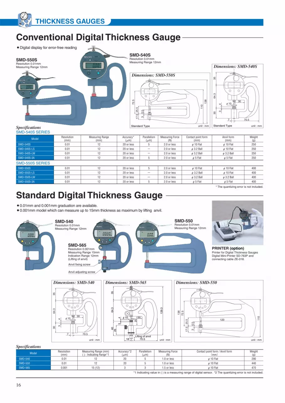
Conventional Digital Thickness Gauge
SMD-540SResolution 0.01mmMeasuring Range 12mm
SMD-550SResolution 0.01mmMeasuring Range 12mm
¡Digital display for error-free reading
SpecificationsSMD-540S SERIES
SMD-540S
SMD-540S-LS
SMD-540S-LW
SMD-540S-3A
0.01
0.01
0.01
0.01
Resolution(mm)
12
12
12
12
20 or less
20 or less
20 or less
20 or less
5
ー
ー
5
Model
2.0 or less
2.0 or less
2.0 or less
2.0 or less
Measuring Force(N)
Accuracy*(μm)
Parallelism(μm)
Contact point form(mm)φ 10 Flat
φ 3.2 Ball
φ 3.2 Ball
φ 5 Flat
Anvil form(mm)φ 10 Flat
φ 10 Flat
φ 3.2 Ball
φ 5 Flat
250
250
250
250
Weight(g)
unit : mm
3564
.330
30φ10
70.57
34
Standard Type
Measuring Range(mm)
* The quantizing error is not included.
SMD-550S
SMD-550S-LS
SMD-550S-LW
SMD-550S-3A
0.01
0.01
0.01
0.01
12
12
12
12
20 or less
20 or less
20 or less
20 or less
5
-
-
5
2.0 or less
2.0 or less
2.0 or less
2.0 or less
400
400
400
400
φ 10 Flat
φ 3.2 Ball
φ 3.2 Ball
φ 5 Flat
φ 10 Flat
φ 10 Flat
φ 3.2 Ball
φ 5 Flat
Dimensions: SMD-540S
Dimensions: SMD-550S
72.5
25.5
17.5
138
110
120
312
.5
Standard Type unit : mm
Anvil fixing screw
Anvil adjusting screw
Standard Digital Thickness Gauge¡0.01mm and 0.001mm graduation are available.¡0.001mm model which can measure up to 15mm thickness as maximum by lifting anvil.
PRINTER (option)Printer for Digital Thickness Gauges Digital Mini-Printer SD-763P andconnecting cable ZE-018.
Dimensions: SMD-540
unit : mm
3564
.330
30φ10
70.57
34
SMD-540Resolution 0.01mmMeasuring Range 12mm
SMD-565Resolution 0.001mmMeasuring Range 15mmIndication Range 12mm(Lifting of anvil)
SMD-550Resolution 0.01mmMeasuring Range 12mm
Dimensions: SMD-550
unit : mm
72.5
25.5
17.5
138
110
120
312
.5
Dimensions: SMD-565
unit : mm
64.3
4026
43
35
139.
3
25
30φ10
18 70.5Lifting of anvil
*1 Indicating value in ( ) is a measuring range of digital sensor. *2 The quantizing error is not included.
Specifications
SMD-540
SMD-550
SMD-565
0.01
0.01
0.001
Resolution(mm)
12
12
15 (12)
Measuring Range (mm) ( ) : Indicating Range*1
20
20
3
5
5
3
Model
1.0 or less
1.0 or less
1.5 or less
Measuring Force(N)
Accuracy*2(μm)
Parallelism(μm)
Contact point form / Anvil form(mm) φ 10 Flat
φ 10 Flat
φ 10 Flat
290
440
470
Weight(g)
SMD-550S SERIES
THICKNESS GAUGES

PG-20
SD-763P(Printer = Option)
ZE-018(Connecting cable = Option)
17
Constant Pressured Thickness Measuring InstrumentThickness measuring method for tested piece used for physical test such as rubber, heat plasticity elastomer, plastic film, cloth, textile, leathers, are ruled in detail by JIS or ISO standard. PG/PF series are digital type thickness measuring instrument in compliance with these major standard.Stand type (fixed type) and frame type (handy type) are widely used for test & research dept., quality control dept. and manufacturing line.
Features¡Wide range of line-up complying with various standard of the field are available.¡High accuracy digital type with weight type for all the versions realizing stable static load, which is not got
by analog type utilizing gears or springs.¡PG series uses micro-granite which is superior for abrasion resistance , chemical resistance , impact
resistance in addition to high unstriated for measurable table. It can avoid scratches and stains for metal.¡Stainless steel is used for contact point and anvil (excluding partial model). Acid resistance , alkali proof,
water resistance are improved.¡Power source is silver oxide batteries (SR-44) which is convenient to carry.¡This makes treating statistics of measured data possible with connected to optional printer SD-763P.¡Please refer to the next page for specifications of each model.
SMD-565LConversional type ofModel : SMD-565 butwithout Anvil Adjustment.Resolution 0.001mmMeasuring Range 12mm
Specifications
SMD-130Long stroke digitalThickness Gauge.Resolution 0.01mmMeasuring Range 50mmIndication Range 25mm(Lifting of anvil)
DimensionsDimensions
unit : mm
unit : mm
3869
.929
30φ10
70.57.5
39.
5
222.
5
127.
48
7418
.5
25 45
95
Lifti
ng o
f anv
il
SMD-565L
SMD-130
0.001
0.01
Resolution(mm)
12
50 (25)
Measuring Range (mm) ( ) : Indicating Range*1
3
30
3
5
Model
1.5 or less
2.0 or less
Measuring Force(N)
Accuracy*2(μm)
Parallelism(μm)
Contact point form(mm)
Anvil form(mm)
φ 10 Flat
φ 10 Flat
φ 10 Flat
φ 10 Flat
410
610
Weight(g)
PG-20JIS K 6250 Method A
PG SERIES stand typeDimensions: PG-01~PG-20
unit : mm
175
(47)
φD
50
100 150
70
φ24.8(25)
12
PG-20 is the thickness measuring instrument compliant with A Law for measuring thickness which is standardized in JIS K 6250 (ruled in physical test method general rule of rubber for vulcanized rubber and thermoplastic rubber.)This is sheet block compatible type which can measure both thickness of test piece hardness IRHD below 35 and over 35 by this one unit. Contact point is diameter 5mm and pressure can be changed by only attaching and detaching weights.
*1 Indicating value in ( ) is a measuring range of digital sensor. *2 The quantizing error is not included.
THICKNESS GAUGES

18
PF SERIES frame type
Specifications
PF-01
Dimensions: PF-01/PF-02
Dimensions: PF-11~18
unit : mm
unit : mm
Anvil
Anvil
PF-01:φ20PF-02:φ25
PF
-01:
122
PF
-02:
125
29
30
70.5
3.2
4
φ32
φ5
153
162
110
30φD120
PF-11
Contact point
Contact point
Resolution(mm)
Measuring range(mm)
Contact point
φD (mm)
Load(Measuring Force)
Measured pressureReference standardModel
Stand-type Frame-type JIS Measured item
PF-01
PF-02
PF-11
PF-12
PF-13
PF-14
PF-15
PF-16
PF-17
PF-18
PG-01
PG-02
PG-11
PG-12
PG-13
PG-14
PG-15
PG-16
PG-17
PG-18
PG-20
K6732-1996
K6783-1994
Z1702-1994
Z1709-1995
K6400-1997
K6301-1995
K6328-1999
K6250-2001
L1086-1999
L1086-1999
L1096-1999
L1018-1999
L1086-1999
L1096-1999
K6505-1995
K6550-1994
K6250-2001
K6250-2001
0.001
0.001
0.01
0.01
0.01
0.01
0.01
0.01
0.01
0.01
0.01
12
12
12
12
12
12
12
12
12
13
13
φ5
φ5
φ35.7
φ5
φ10
φ16
φ11.3
φ25.2
φ10
φ5
φ5
0.363kPa (3.7gf/cm2)
2kPa (20gf/cm2)
23.5kPa (240gf/cm2)
0.7kPa (7gf/cm2)
49.03±1.177kPa
(500±12gf/cm2)
(IRHD 35 and over) 22±5kPa (2.24±0.51gf/mm2)
(Less than IRHD 35) 10±2kPa (1.02±0.20gf/mm2)
(IRHD 35 and over) 22±5kPa (2.24±0.51gf/mm2)
0.8N (80gf) or less
1226±143mN
(125gf±15gf)
0.363N (37gf)
0.785N (80gf)
0.785N (80gf)
0.394N (40gf)
2.35N (240gf)
0.343N (35gf)
3.85±0.1N
(390gf±10gf)
0.431N (44±10gf)
0.196±0.038N
(20±3.9gf)
0.431±0.098N
(44±10gf)
poly vinyl chloride films for agriculture
ethylene / vinyl acetate copolymer films for
agriculture
polyethylene films for packaging
heat shrinkable plastic films for packaging
flexible polyurethane foam
vulcanized rubber
rubber coated fabrics
rubber / for A method (less than IRHD 35)
fusible interlining fabrics (non woven textile)
fusible interlining fabrics (ordinary textile)
woven fabrics (ordinary textile)
knitted fabrics (ordinary knit)
fusible interlining fabrics (ordinary knitting
fabric)
woven fabrics (crinose textile)
man-made upper material of shoes
leathers
rubber
A method (IRHD 35 and over)
rubber
A method for both (less than IRHD 35, IRHD
35 and over)
Aluminium alloy is used for material of contact point (including anvil) of PG-11 and PF-11. Contact point for other model are all stainless steel.PG-13 and PF-13 can be also used for IRHD below 35 of JIS K 6250 A law.
THICKNESS GAUGES

19
DEPTH GAUGESDEPTH GAUGESThis is a exclusive instrument which measures steps and depth of workpiece by hand. These depth gauges are direct reading instruments referencing from their hardened and ground bases.Setting "0" by sticking bottom face of base to measuring basics (zero point) and rotating Bezel. (Bezel is fixed by clamp at that time) Then, it reads with short hand and pointer how contact point is salient from that position. Analog and Digital modelsare available and they correspond to usage of shape of contact point and basic size. There are such standard models of stroke of 10mm, 20m, 30mm, and it can comparatively measure depth of 220mm to 240mm by connecting extension rods.
¡Dial Depth Gauge can be used to measure depth and steps of workpiece and coating thickness.¡5~240mm Range (with the supplied extension rods) are available for wide application.¡Lifting lever can be mounted (option).
Dial Depth Gauge
Measuring Range : 10mm
Measuring Range : 5mm
DM-214Graduation 0.01mmMeasuring Range 220mmIndication Range 10mmwith 5-Extension rods
DM-213Graduation 0.01mmMeasuring Range 10mm
DM-210Graduation 0.01mmMeasuring Range 10mm
DM-211Graduation 0.01mmMeasuring Range 10mm
Model
DM-210
DM-211
DM-213
DM-214
Base foama×b
75×16
75×16
75×16
100×16
Base hole
diameter
φ2.5
φ2.5
φ5.2
φ5.2
Dimension Table
unit : mm
33.5
64.7
(23.6)
φ55
a b
unit : mm
Dimension
Base hole
Base
DM-210DM-211DM-213DM-214
0.010.010.010.01
1.4 or less1.4 or less2.5 or less2.5 or less
Graduation(mm)
12121212
Accuracy(μm)
270270270335
Weight(g)
Measuring Force (N)
101010
10(220)
Measuring Range(mm)
Needleφ2 Flatφ3.2 Ballφ3.2 Ball
Contact point form(or shape) (mm)
ZS-523ZS-530ZS-034ZS-034
Standard Contact PointModel
※Measuring range : ( ) value is a range by using 5pcs extension rods.Specifications
DM-250 0.01 1.4 or less
Graduation(mm)
10
Accuracy(μm)
230
Weight(g)
Measuring Force (N)
5
MeasuringRange (mm)
Needle
Contact point form(or shape)
ZS-518
StandardContact PointModel
Specifications
DM-250Graduation 0.01mmMeasuring Range 5mm
Dimension
33.5
64.9
(23.6)
φ55
50 16
unit : mm
Base holeφ2.0

20
DEPTH GAUGES
DM-251Exclusive instrument tomeasure depth of V-grooveof print circuit board.Graduation 0.01mmMeasuring Range 5mm
DM-252Convex-concave surfacecan be measured.Graduation 0.01mmMeasuring Range Concave 5mm Convex 4mm
DM-220DM-221DM-223DM-224
0.010.010.010.01
2.2 or less2.2 or less2.2 or less2.5 or less
Graduation(mm)
15151515
Accuracy(μm)
300300275340
Weight(g)
Measuring Force (N)
202020
20(230)
Measuring Range(mm)
Needleφ2 Flatφ3.2 Ballφ3.2 Ball
Contact point form(or shape) (mm)
ZS-543ZS-541ZS-034ZS-034
Standard Contact PointModel
※Measuring range : ( ) value is a range by using 5pcs extension rods.Specifications
Measuring Range : 20mm
V-Grooved depth measurement of Print circuit board by using DM-251.
Dimension:DM-251
unit : mm
33.5
8
64.7
3
5.1
7φ1.3φ1.3
φ16
φ55
(23.6)
φ52
36
SR0.05
30°
edge of point
Dimension:DM-252
unit : mm
edge of point
φ55
(23.6)
16
33.5
64.9
50
10 φ0.12
DM-251DM-252
0.010.01
1.4 or less1.4 or less
Graduation(mm)
1010
Accuracy(μm)
165230
Weight(g)
Measuring Force (N)
5Concave 5, Convex 4
MeasuringRange (mm)
Special NeedleNeedle
Contact point form(or shape)
ZS-106ZS-595
StandardContact PointModel
Specifications
DM-223Graduation 0.01mmMeasuring Range 20mm
DM-224Graduation 0.01mmMeasuring Range 230mmwith 5-Extension rodsIndication Range 20mm
DM-220Graduation 0.01mmMeasuring Range 20mm
DM-221Graduation 0.01mmMeasuring Range 20mm
Model
DM-220
DM-221
DM-223
DM-224
A
84.7
84.7
64.7
64.7
Base foama×b
75×16
75×16
75×16
100×16
Base hole
diameter
φ2.5
φ2.5
φ5.2
φ5.2
Dimension Table
unit : mm
Dimension
35.8
A
25.6
φ55
a b
unit : mm
Base hole

21
DEPTH GAUGES
P Series (0.1mm type)
DM-230DM-233DM-234
0.010.010.01
2.5 or less2.5 or less2.5 or less
Graduation(mm)
353535
Accuracy(μm)
315315355
Weight(g)
Measuring Force (N)
3030(240)30(240)
Measuring Range(mm)
Needleφ3.2 Ballφ3.2 Ball
Contact point form(or shape) (mm)
ZS-543ZS-034ZS-034
Standard Contact PointModel
※Measuring range : ( ) value is a range by using 5pcs extension rods.Specifications
Measuring Range : 30mm
DM-230Graduation 0.01mmMeasuring Range 30mm
DM-233Graduation 0.01mmMeasuring Range 240mmIndication Range 30mmwith 5-Extension rods
DM-234Graduation 0.01mmMeasuring Range 240mmIndication Range 30mmwith 5-Extension rods
Model
DM-230
DM-233
DM-234
A
84.7
64.7
64.7
Base foama×b
75×16
75×16
100×16
Base hole
diameter
φ2.5
φ5.2
φ5.2
Dimension Table
unit : mm
Dimension
35.8
A
25.6
φ55
a b
unit : mm
Base hole
DM-210PDM-250PDM-223PDM-224P
0.010.010.010.01
1.4 or less1.4 or less2.2 or less2.5 or less
Graduation(mm)
12101515
Accuracy(μm)
270230275340
Weight(g)
Measuring Force (N)
10520
20(230)
Measuring Range(mm)
NeedleNeedleφ3.2 Ballφ3.2 Ball
Contact point form(or shape) (mm)
ZS-523ZS-518ZS-034ZS-034
Standard Contact PointModel
※Measuring range : ( ) value is a range by using 5pcs extension rods.Specifications
This is direct reading specification of which graduation are 0.1~0.9 mm.1~10mm can be read by short hand and figure below decimal can be read by pointer. It prevents misreading.
DM-223PGraduation 0.01mmMeasuring Range 20mm
DM-224PGraduation 0.01mmMeasuring Range 230mmIndication Range 20mmwith 5-Extension rods
DM-250PGraduation 0.01mmMeasuring Range 5mm
DM-210PGraduation 0.01mmMeasuring Range 10mm
exp. 3.18mm of direct reading.
Model
DM-210P
DM-250P
DM-223P
DM-224P
A
33.5
33.5
35.8
35.8
B
64.7
64.9
64.7
64.7
C
23.6
23.6
25.6
25.6
Base foama×b
75×16
50×16
75×16
100×16
Base hole
diameter
φ2.5
φ2.0
φ5.2
φ5.2
Dimension Table
unit : mm
Dimension
A
C
B
φ55
a b
unit : mm
Base hole

DM-264Graduation 0.01mmMeasuring Range 5mm
DM-280Graduation 0.01mmMeasuring Range 10mm
DM-283Graduation 0.01mmMeasuring Range 10mm
DM-273Graduation 0.01mmMeasuring Range 5mm
Dial Depth Gauges (Special)Back plunger type
Coating thickness Gauges
Gauge Slide type
Round Base type
DM-273 0.01 1.4 or less
Graduation(mm)
±20
Accuracy(μm)
300
Weight(g)
Measuring Force (N)
5
MeasuringRange (mm)
φ3.2 Ball
Contact point form(or shape)
ZS-105
StandardContact PointModel
Specifications
DM-280DM-283
0.010.01
1.4 or less1.4 or less
Graduation(mm)
1212
Accuracy(μm)
175185
Weight(g)
Measuring Force (N)
1010
MeasuringRange (mm)
Needleφ3.2 Ball
Contact point form(or shape)
ZS-523ZS-034
StandardContact PointModel
Specifications
DM-293 0.01 2.5 or less
Graduation(mm)
15
Accuracy(μm)
340
Weight(g)
Measuring Force (N)
20(230)
MeasuringRange (mm)
φ3.2 Ball
Contact point form(or shape)
ZS-034
StandardContact PointModel
Specifications
24.0
38.9
75 16
unit : mm
φ38Dimension
Dimension :DM-280
33.5
64.7
φ55
23.6
φ16unit : mmBase holeφ3.0
Dimension :DM-283
33.5
64.7
φ55
23.6
φ25unit : mm
Base holeφ8
Steps measurement can be easily made by moving the gauge to 3 mounting holes.
¡Exclusive instrument to measure coating thickness of paint, coating materials and sealing materials.
¡Handy type and operation is easy.
DM-293Graduation 0.01mmMeasuring Range 230mmwith 5-Extension rodsIndication Range 20mm
Dial indicator can bemoved to 3 points.
Dimension 25.6
18
35.8
φ55
64.7
25
Hex. hole tighteningscrew M5×5
150
25
unit : mm
※Measuring range : ( ) value is a range by using 5pcs extension rods.
DM-264 0.01 1.4 or less
Graduation(mm)
10
Accuracy(μm)
230
Weight(g)
Measuring Force (N)
5
MeasuringRange (mm)
Needle
Contact point form(or shape)
ZS-518
StandardContact PointModel
Specifications
paint coatingthickness
Material such as steel, iron etc.
pressureWhen top point is pressurized, needle contact point penetrates into painted film and stops at basic material. The penetrating length is thickness of film.
Thickness measurement of painted film waterproof stuff (measuring by pressurization)
Examples of measurement
unit : mm
39.5
64.9
50
23.6
16
φ55
edge of point
φ0.3
Dimension
22
DEPTH GAUGES

DMD-240Needle contact pointsResolution 0.01mmMeasuring Range 25.4mm
Conventional Digital Depth Gauges
23
DEPTH GAUGES
0.01mm Conventional Digital Depth Gauge
0.001mm Conventional Digital Depth Gauge
¡Digital Exclusive instrument to measure depth and steps of workpiece.
¡Low cost and conventional model of which preset function is deleted from standard digital depth gauges.
¡Operation is equal to standard digital depth gauges, but it can not measure by installing extension rods. In case that measuring range is over 10mm, please use standard digital depth gauges.
¡Printing out of measured data and statistics arithmetic operation can be implemented by connecting it to optional Digital mini-printer SD-763P shown on page 42.
Standard Digital Depth Gauges
0.01mm Standard Digital Depth Gauge
¡Digital Depth Gauge can be used for direct measuring depth and steps of workpiece.¡Printing out of measured data and statistics arithmetic operation can be implemented by connecting it to optional Digital mini-printer SD-763P
shown on page 42.¡Extension rods can be used by Preset function. (excepting DMD-210, DMD-211 and DMD-2100).
DMD-210SNeedle contact pointsResolution 0.01mmMeasuring Range 10mm
DMD-213Sφ3.2Steel Ball Contact PointResolution 0.01mmMeasuring Range 10mm
Dimension
49.6
L
65.6
16
φ60
.5
34.1
unit : mm
Model
DMD-210S
DMD-211S
DMD-213S
DMD-250S
DMD-252S
DMD-2100S
DMD-2110S
DMD-2130S
DMD-2500S
DMD-2520S
Base hole
diameter
φ2.5
φ2.5
φ5.2
φ2.0
φ8.0
φ2.5
φ2.5
φ5.2
φ2.0
φ8.0
L
75
75
75
50
50
75
75
75
50
50
Dimension Table
unit : mm
Base hole
DMD-210SDMD-211SDMD-213SDMD-250SDMD-252SDMD-2100SDMD-2110SDMD-2130SDMD-2500SDMD-2520S
0.010.010.010.010.010.0010.0010.0010.0010.001
2.0 or less2.0 or less2.0 or less2.0 or less2.0 or less2.0 or less2.0 or less2.0 or less2.0 or less2.0 or less
Resolution(mm)
202020202033333
Accuracy*(μm)
270270270205200300300300235230
Weight(g)
Measuring Force (N)
1010105
Concave 5, Convex 41010105
Concave 5, Convex 4
Measuring Range(mm)
Needleφ2 flat
φ3.2 Steel BallNeedleNeedleNeedleφ2 flat
φ3.2 Steel BallNeedleNeedle
Contact point form(or shape) (mm)
ZS-523ZS-530ZS-034ZS-518ZS-595ZS-523ZS-530ZS-034ZS-518ZS-595
Standard Contact PointModel
Specifications
*The quantizing error function is not included.
DMD-2520SFor measuring print circuit boardResolution 0.001mmMeasuring Range Concave 5mm Convex4mm
DMD-211Resolution 0.01mmMeasuring Range 12mm
Dimension
b
φ60
.5
34.1
unit : mm
49.6
a
65.6
Base hole
Model
DMD-210
DMD-211
DMD-213
DMD-214
DMD-215
Base foama×b
75×16
75×16
75×16
75×16
100×16
Base hole
diameter
φ2.5
φ2.5
φ5.2
φ5.2
φ5.2
Dimension Table
unit : mm
Model
DMD-240
DMD-241
A
108.7
88.7
Dimension Table
unit : mm
Dimension: DMD-240/241
56.5
100
A
16
φ60
.5
38.5
unit : mm

DMD-293Resolution 0.01mmMeasuring Range 220mmwith 5-Extension rodsIndication Range 12mm
24
DEPTH GAUGES
0.001mm Standard Digital Depth Gauge
DMD-210DMD-211DMD-213DMD-214DMD-215DMD-240DMD-241DMD-293DMD-2100DMD-2150DMD-2400DMD-2410
0.010.010.010.010.010.010.010.01
0.0010.0010.0010.001
1.0 or less1.0 or less1.0 or less2.3 or less2.3 or less1.6 or less1.6 or less2.3 or less1.0 or less2.3 or less1.6 or less1.6 or less
Resolution(mm)
20202020203030203333
Accuracy*(μm)
310310310335375390370545310375390370
Weight(g)
Measuring Force (N)
121212
12(220)12(220)
25.425.4
12(220) 12
12(220)25.425.4
Measuring Range(mm)
Needleφ2 flat
φ3.2 Steel Ballφ3.2 Steel Ballφ3.2 Steel Ball
Needleφ3.2 Steel Ballφ3.2 Steel Ball
Needleφ3.2 Steel Ball
Needleφ3.2 Steel Ball
Contact point form(or shape) (mm)
ZS-523ZS-530ZS-034ZS-034ZS-034ZS-113ZS-600ZS-034ZS-523ZS-034ZS-113ZS-600
Standard Contact PointModel
*The quantizing error function is not included.
Digital indicator can be moved to 3 positions.
Dimension: DMD-293
18
φ60
.5
34.1
49.6
65.6
25
150
25
unit : mm
DMD-2150Resolution 0.001mmMeasuring Range 220mmwith 5-Extension rodsIndication Range 12mm
Specifications ※Measuring range : ( ) value is a range by using 5pcs extension rods.
Dimension: DMD-2100/215049
.6
a
65.6
b
φ60
.5
34.1
unit : mm
Model
DMD-2100DMD-2150
Base foama×b
75×16100×16
Base hole diameterφ2.5φ5.2
Dimension Table
unit : mm
Base hole
Dimension: DMD-2400/2410
56.5
100
A
16
φ60
.5
38.5
Model
DMD-2400
DMD-2410
A
108.7
88.7
Dimension Table
unit : mm

IM-880Maximum measuring depth 50mmGraduation 0.01mmMeasuring Range 20~35mm
25
CALIPER GAUGESCALIPER GAUGESAs to internal caliper gauge IM-880 series, the distance between contact points facing outside is firstly set at standard dimension with ring gauge or micrometer. Then, it is measured by inserting contact point into internal dimension part to be measured after its Outer Dial of which moves together with rotated Bezel is set at "zero". The displacement of indicator from "0" point of outer dial is to be measured at that time. The value adding the read displacement to standard dimension or deducting it from standard dimension is the dimension of internal diameter. This series attaches spare contact point which can set accurate dimension corresponding to size of internal dimension. External caliper gauge is opposite, namely reading the value by holding workpiece with 2 contact points facing inside.
¡These gauges are designed for use in measuring deep internal diameter of bores of castings etc, and for internal reading in fabrications. Clearance has been provided for use in recessed bores. The convenient retraction lever allows one-hand operation.
¡Internal caliper gauge to measure internal diameter of cylindrical workpiece and recessed groove diameter. It can measure groove diameter of "O" ring by modifying spare contact point.
¡Set dimension within ±1mm (indication range 2mm) can be comparatively measured (880 series) by alternatively using auxiliary spare contact point in accordance with measured dimension.
¡Please set standard dimension within measuring range with micrometer or ring gauge.
Internal Dial Caliper Gauge
IM-1Maximum measuring depth 130mmGraduation 0.1mmMeasuring Range 10~100mm
IM-2Maximum measuring depth 180mmGraduation 0.1mmMeasuring Range 10~100mm
IM-4Maximum measuring depth 100mmGraduation 0.01mmMeasuring Range 0~30mm
IM-5Maximum measuring depth 150mmGraduation 0.01mmMeasuring Range 20~40mm
Dimensions
unit : mm
maximum measuring depth
contact point height
Mea
surin
g R
ange
90
24
IM-1
IM-2
IM-4
IM-5
0.1
0.1
0.01
0.01
10~100
10~100
10~30
20~40
500
620
500
600
Graduation (mm)
Weight(g)
±0.1
±0.1
±0.02
±0.02
Indication Error (mm)
5 or less
5 or less
5 or less
5 or less
Measuring Force
(N)
Measuring Range (mm)
130
180
100
150
Maximum measuring depth
(mm)2
2
2
4
Contact point height(mm)
Model
Specifications
Internal size
Model
IM-1
IM-2
IM-4
IM-5
10
35
35
35
-
Internal size of workpiece is 10mm, 15mm, 20mm and 30mm or over against measuring applicable depth.
15
50
50
50
-
20
80
80
80
140
30~
130
180
100
150
unit : mm
Measuring applicable depth
Internal sizeInside of workpiece should be straight or round shape without step etc.
IM-881Maximum measuring depth 70mmGraduation 0.01mmMeasuring Range 30~62mm

26
CALIPER GAUGES
extension rods (option)
Spare Contact Point
L
IM-882Maximum measuring depth 90mmGraduation 0.01mmMeasuring Range 55~153mm
¡IM-880 series dialcaliper gauges can measure internal dimension up to measuring range in the right list by installing extension rods. Standard products of spare extension rods can be used as it is.
Optional Extension Rods
φ1.
5
φ4.
5L1
3
M2.6×P0.45
L2
Dimensions:Spare Contact Point (option)
unit : mm
SR0.5
Dimensions
External Dimensions
maximum measuring depth
maximumgroove depth
minimum groove width
A
B
min
imum
ent
ranc
edi
amet
erφ
DH
unit : mm
L
φ62
Model
IM-880
IM-881
IM-882
L
153
164.8
183unit : mm
Moving Arm
SpareContact Point
Fixed Arm
Specifications
0.01
0.01
0.01
20~35
30~62
55~153
175
185
200
2
2
2
Graduation (mm)
Weight(g)
Indicating range(mm)
3 or less
3 or less
3 or less
Measuring Force(N)
ZS-401ZS-402ZS-403ZS-404ZS-405ZS-406ZS-407ZS-408ZS-409ZS-410ZS-411ZS-412ZS-413ZS-414ZS-415ZS-416ZS-417ZS-418
Code No.
Spare Contact Point
20~2322~2524~2726~2928~3130~3332~3530~3836~4442~5048~5654~6255~7371~89
87~105103~121119~137135~153
Measuring Range (mm)
±20
±20
±20
Indication Error(μm)
Measuring Range(mm)
Model
IM-880
IM-881
IM-882
2.53.5444443
4.34.34.34.35
8.58.58.58.58.5
groove depthH (mm)
minimum groove width
B (mm)1515161820222424
27.433.439.445.445547086
102118
entrance diameterφD (mm)
maximum measuring depth
A (mm)
50
70
90
2.5
2.5
3.5
ZS-401ZS-402ZS-403ZS-404ZS-405ZS-406ZS-407
ZS-689L=7
34~3736~3938~4140~4342~4544~4746~49
ZS-401ZS-402ZS-403ZS-404ZS-405ZS-406ZS-407
ZS-690L=14
48~5150~5352~5554~5756~5958~6160~63
ZS-401ZS-402ZS-403ZS-404ZS-405ZS-406ZS-407
ZS-691L=21
62~6564~6766~6968~7170~7372~7574~77
ZS-401ZS-402ZS-403ZS-404ZS-405ZS-406ZS-407
ZS-692L=28
76~7978~8180~8382~8584~8786~8988~91
extension rodsSpare Contact Point Measuring RangeIM-880: measuring range with extension rods (mm)
ZS-408ZS-409ZS-410ZS-411ZS-412
ZS-693L=15
60~6866~7472~8078~8684~92
ZS-408ZS-409ZS-410ZS-411ZS-412
ZS-694L=30
90~9896~104
102~110108~116114~122
ZS-408ZS-409ZS-410ZS-411ZS-412
ZS-695L=45
120~128126~134132~140138~146144~152
IM-881: measuring range with extension rods (mm)
extension rodsSpare Contact Point Measuring Range
ZS-413ZS-414ZS-415ZS-416ZS-417ZS-418
ZS-696L=48
151~169167~185183~201199~217215~233231~249
ZS-413ZS-414ZS-415ZS-416ZS-417ZS-418
ZS-697L=96
247~265263~281279~297295~313311~329327~345
IM-882: measuring range with extension rods (mm)
extension rodsSpare Contact Point Measuring Range
Mounting Method of Spare Contact Point
Spanner is supplied as standard accessory.
Spanner
ArmHexagon lock nutFine adjustment enabled.
Spanner

IM-815Graduation 0.01mmMeasuring Range 5~15mm
27
CALIPER GAUGES
¡Measuring internal diameter of workpiece by arm lever operation.¡Suitable for measuring groove of narrow place of workpiece.¡Hard metal of arm edges minimizes the wear.¡Easy direct reading with coaxial short hand.
IM-807Graduation 0.005mmMeasuring Range 2.5~7.5mm
IM-820Graduation 0.01mmMeasuring Range 10~20mm
IM-830Graduation 0.01mmMeasuring Range 20~30mm
Dimensions: IM-807
unit : mm
110
27
R0.1 φ
577.5 0.
9
Movablecaliper arm
Tolerance Hand
Arm thumb lever
Dimensions: IM-815
unit : mm
14361
φ5715
2.3
φ0.6
Dimensions: IM-820
unit : mm
14361
φ5720
5.3
φ1
Dimensions: IM-830
unit : mm
14360.6
φ57
305.
4
φ1
IM-807
IM-815
IM-820
IM-830
2.5~7.5
5~15
10~20
20~30
2.3~7.8
4.7~15.5
9.5~20.5
14.7~30.5
120
140
140
140
MeasuringRange(mm)
0.005
0.01
0.01
0.01
Graduation(mm)
±15
±20
±20
±20
Indication Error(μm)
Weight(g)
1.7 or less
1.7 or less
1.7 or less
1.7 or less
MeasuringForce(N)
Movable Range(mm)
0.5
1
1
1
Pointer Revolution
(mm)
5
5
5
5
Repeatability(μm) Model
Specifications
0
0.5
1
1.5
2
2.5
3
3.5
4
4.5
10
/
B/L
0 55
11
/
/
12
/
/
/
13
/
/
/
/
14
/
/
/
/
/
15
/
/
/
/
/
/
16
/
/
/
/
/
/
/
17
/
/
/
/
/
/
/
/
18
/
/
/
/
/
/
/
/
/
19
/
/
/
/
/
/
/
/
/
/
20
/
/
/
/
/
/
/
/
/
/
0
1.4
0
1.4
1.4
0
1.4
1.4
1.4
0
1.4
1.4
1.4
1.4
0
1.4
1.4
1.4
1.4
1.4
0
1.4
1.4
1.4
1.4
1.5
1.5
0
1.4
1.4
1.4
1.5
1.5
1.6
1.6
0
1.4
1.4
1.4
1.5
1.6
1.6
1.6
1.7
0
1.4
1.4
1.4
1.5
1.6
1.6
1.6
1.7
1.7
0
1.4
1.4
1.4
1.5
1.6
1.6
1.7
1.7
1.8
56
55
56
56
56
56
56
56
55
57
56
56
55
55
57
56
56
55
55
55
57
56
56
55
55
55
54
57
56
56
56
55
55
54
54
57
57
56
56
55
55
55
54
54
57
57
56
56
56
55
55
54
54
53
58
57
57
56
56
55
55
55
54
54
IM-820 Internal diameter groove : M(mm)
One
sid
e m
easu
ring
dept
h : A(
mm)
0
0.5
1
1.5
2
2.3
5
/
B/L
0 29
6
/
/
7
/
/
/
8
/
/
/
/
9
/
/
/
/
/
10
/
/
/
/
/
/
11
/
/
/
/
/
/
12
/
/
/
/
/
/
13
/
/
/
/
/
/
14
/
/
/
/
/
/
15
/
/
/
/
/
/
0
0.6
0
0.6
0.9
0
0.6
0.9
1.1
0
0.6
0.9
1.1
1.3
0
0.6
0.9
1.1
1.3
1.6
0
0.6
0.9
1.1
1.3
1.6
0
0.6
0.9
1.1
1.3
1.6
0
0.6
0.9
1.1
1.3
1.7
0
0.6
0.9
1.1
1.3
1.8
0
0.6
0.9
1.1
1.3
1.7
31
9
31
29
25
32
29
25
22
32
29
26
23
12
33
29
26
23
13
4
34
30
27
24
15
4
35
31
28
25
19
5
36
32
29
26
22
7
37
34
30
27
23
11
39
35
31
28
24
22
IM-815 Internal diameter groove : M(mm)
One
sid
e m
easu
ring
dept
h : A(
mm)
0
0.2
0.4
0.6
0.7
2.5
/
B/L
0 10
3
/
/
3.5
/
/
/
4
/
/
/
/
/
4.5
/
/
/
/
/
5
/
/
/
/
/
5.5
/
/
/
/
/
6
/
/
/
/
/
6.5
/
/
/
/
/
7
/
/
/
/
/
7.5
/
/
/
/
/
0
0.3
0
0.3
0.4
0
0.3
0.4
0.5
0.6
0
0.3
0.4
0.5
0.6
0
0.3
0.4
0.5
0.6
0
0.4
0.4
0.5
0.6
0
0.4
0.4
0.5
0.6
0
0.4
0.4
0.5
0.6
0
0.4
0.4
0.5
0.6
0
0.4
0.4
0.5
0.6
10
9
10
9
8
10
9
8
7
5
10
9
8
7
5
11
10
9
7
6
11
10
9
8
6
11
10
9
8
6
11
10
9
8
6
12
10
10
8
7
12
10
10
9
7
IM-807 Internal diameter groove : M(mm)
One
sid
e m
easu
ring
dept
h : A(
mm)
0
0.5
1
1.5
2
2.5
3
3.5
4
4.5
20
/
B/L
0 58
21
/
/
22
/
/
/
23
/
/
/
/
24
/
/
/
/
/
25
/
/
/
/
/
/
26
/
/
/
/
/
/
/
27
/
/
/
/
/
/
/
/
28
/
/
/
/
/
/
/
/
/
29
/
/
/
/
/
/
/
/
/
/
30
/
/
/
/
/
/
/
/
/
/
0
1.3
0
1.4
1.4
0
1.4
1.4
1.5
0
1.4
1.4
1.5
1.5
0
1.4
1.4
1.5
1.5
1.6
0
1.4
1.4
1.5
1.5
1.6
1.6
0
1.4
1.4
1.5
1.5
1.6
1.6
1.6
0
1.4
1.4
1.5
1.5
1.6
1.6
1.7
1.8
0
1.5
1.5
1.6
1.6
1.7
1.7
1.9
1.9
2.0
0
1.5
1.5
1.6
1.6
1.7
1.8
1.8
1.9
20
58
58
58
58
58
59
59
58
58
59
59
59
58
58
59
59
59
59
59
58
60
60
59
59
59
59
58
61
60
60
59
59
59
59
58
61
61
60
60
60
59
59
59
59
61
61
61
60
60
60
60
59
59
53
61
61
61
61
61
60
60
60
59
59
IM-830 Internal diameter groove : M(mm)
One
sid
e m
easu
ring
dept
h : A(
mm)
B=Minimum groove width L=Maximum measuring depth
Measuring depth
unit : mm
inte
rnal
dia
met
ergr
oove
: M
maximum measuring depth (L)
minimum groove width (B)
one sidegroove depth (A)
Relationship Table of "Internal diameter groove" and "Maximum measuring depth"

28
CALIPER GAUGES
Overall length of GM-3 is large as 635mm.
GM-20Maximum measuring depth 125mmGraduation 0.1mmMeasuring Range 0~80mm
External Dial Caliper Gauges¡These Gauges are designed for use in measuring external dimension of large measuring work piece and special form workpiece such as
castings, forgings and sheet metal work which are difficult to measure . Please select according to shape and measuring depth. The convenient retraction lever allows for one-hand operation and good gauge control.
GM-3Maximum measuring depth 400mm Graduation 0.1mmMeasuring Range 0~90mm
GM-2Maximum measuring depth 250mmGraduation 0.1mmMeasuring Range 0~90mm
GM-1Maximum measuring depth 125mmGraduation 0.1mmMeasuring Range 0~90mm
GM-9Maximum measuring depth 100mmGraduation 0.1mmMeasuring Range 0~30mm
GM-11Maximum measuring depth 125mmGraduation 0.1mmMeasuring Range 0~50mm
GM-8Maximum measuring depth 130mmGraduation 0.1mmMeasuring Range 0~80mm
GM-21Maximum measuring depth 220mmGraduation 0.1mmMeasuring Range 0~90mm
GM-22Maximum measuring depth 250mmGraduation 0.1mmMeasuring Range 0~90mm
Dimensions
maximum measuring depth
90(110)
( ):GM-3
24 (32)
H3
H1
H2
H4
Mea
surin
g R
ange
unit : mm
H1
25
50
60
2
2
17
65
20
Model
GM-1
GM-2
GM-3
GM-9
GM-11
GM-20
GM-21
GM-22
H2
40
60
70
12
6
11
70
25
H3
25
50
60
2
2
17
10
65
H4
40
60
80
12
6
11
15
70
Dimension Table
unit : mm
Dimensions: GM-8
unit : mm
90
130 R180
80
24
GM-1
GM-2
GM-3
GM-8
GM-9
GM-11
GM-20
GM-21
GM-22
0.1
0.1
0.1
0.1
0.1
0.1
0.1
0.1
0.1
0~90
0~90
0~90
0~80
0~30
0~50
0~80
0~90
0~90
Graduation(mm)
Measuring Range(mm)
125
250
400
130
100
125
125
220
250
maximum measuring depth(mm)
5 or less
5 or less
10 or less
5 or less
5 or less
5 or less
5 or less
5 or less
5 or less
530
800
1,400
550
460
480
500
660
720
Measuring Force(N)
Weight(g)Model
Specifications
±0.1
±0.2
±0.2
±0.1
±0.1
±0.1
±0.1
±0.1
±0.2
Indication Error(mm)
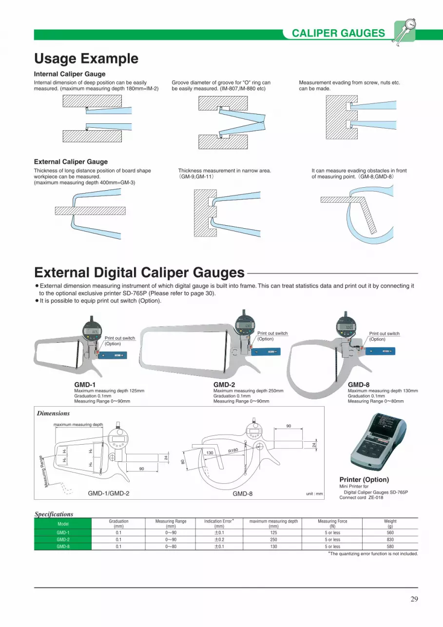
29
CALIPER GAUGES
External Digital Caliper Gauges¡External dimension measuring instrument of which digital gauge is built into frame. This can treat statistics data and print out it by connecting it
to the optional exclusive printer SD-765P (Please refer to page 30).¡It is possible to equip print out switch (Option).
Usage Example
Thickness of long distance position of board shape workpiece can be measured.(maximum measuring depth 400mm=GM-3)
Thickness measurement in narrow area. (GM-9,GM-11)
It can measure evading obstacles in front of measuring point. (GM-8,GMD-8)
Internal Caliper Gauge
External Caliper Gauge
Internal dimension of deep position can be easily measured. (maximum measuring depth 180mm=IM-2)
Groove diameter of groove for "O" ring can be easily measured. (IM-807,IM-880 etc)
Measurement evading from screw, nuts etc. can be made.
Print out switch(Option)Print out switch
(Option)
Print out switch(Option)
GMD-1Maximum measuring depth 125mmGraduation 0.1mmMeasuring Range 0~90mm
GMD-2Maximum measuring depth 250mmGraduation 0.1mmMeasuring Range 0~90mm
GMD-8Maximum measuring depth 130mmGraduation 0.1mmMeasuring Range 0~80mm
Printer (Option) Mini Printer for Digital Caliper Gauges SD-765PConnect cord ZE-018
Dimensions
GMD-1/GMD-2 GMD-8 unit : mm
maximum measuring depth
90
24H3
H1
H2
H4
Mea
surin
g R
ange
90
130 R180
80
24
GMD-1
GMD-2
GMD-8
0.1
0.1
0.1
0~90
0~90
0~80
Graduation(mm)
Measuring Range(mm)
125
250
130
maximum measuring depth(mm)
5 or less
5 or less
5 or less
560
830
580
Measuring Force(N)
Weight(g)Model
Specifications
±0.1
±0.2
±0.1
Indication Error*(mm)
*The quantizing error function is not included.

30
CALIPER GAUGES
Mini Printer for Digital Caliper Gauges¡SD-765P is the exclusive mini printer for Digital Caliper Gauge (GMD series) which displays minimum readable value 0.1mm.
* RESULT *NMAXMINRxσnσn-1
15 79.1 mm5.7 mm
73.4 mm41.72O mm2O.232 mm2O.942 mm
-NG+NGPCpCpk
DIV
-NGLSL A B C D E F G H I JUSL+NG
= 1
1O
3
OO2O211O12
3
* HISTOGRAM *LSLUSLTOL
18.7 mm58.9 mm4O.2 mm
3 3
4O.OOO %O.32O O.273
ABCDEFGHIJ
18.7OO mm ~22.72O mm ~26.74O mm ~3O.76O mm ~34.78O mm ~38.8OO mm ~42.82O mm ~46.84O mm ~5O.86O mm ~54.88O mm ~58.9OO mm ~
SD-765P
* MODE O *
*LIMIT MODE**LIMIT DATA 1**NO LIMIT DATA*LIMIT1 6O.3 mm
LIMIT2 3O.9 mm
*NEW LIMIT DATA**LIMIT DATA 1*DATE 2OO2/ 7/1OTIME 8:49
DATE 2OO2/ 7/1OTIME 8:49
* MODE 1*
DATE 2OO2/ 7/1OTIME 8:54
LSLUSLTOL
3O.9 mm6O.3 mm29.4 mm
24.4 mm24.2 mm41.4 mm55.7 mm54.2 mm53.5 mm17.2 mm16.2 mm32.7 mm32.7 mm54.6 mm
123456789
1O11
▼▼
▼▼
Mode 0To print measured data, and judgement.
Mode 1To print measured data, judgement, perform statistical calculations, and generate histogram.
Mode 2To print D-chart, perform statistical calculations, and generate histogram.
*NEW LIMIT DATA**LIMIT DATA 1*DATE 2OO2/ 7/1OTIME 8:54
LSLUSLTOL
18.7 mm58.9 mm4O.2 mm
D-Chart
Judgement
Perform statisticalcalculations
Histogram
*LIMIT MODE**LIMIT DATA 1**NO LIMIT DATA*LIMIT1 52.8 mm
LIMIT2 21.8 mm
* MODE 2 *
DATE 2OO2/ 7/1OTIME 8:56
*NEW LIMIT DATA**LIMIT DATA 1*DATE 2OO2/ 7/10TIME 8:57
LSLUSLTOL
21.8 mm52.8 mm31.O mm
L C U
45.7mm44.6mm39.6mm22.9mm99.3mm42.8mm38.5mm38.5mm28.2mm28.1mm
1O 36.6mm37.Omm37.Omm86.8mm16.Omm16.4mm
Operation result
*CLEAR ALL DATA*
SUB GR. NO. 129.7 mm42.7 mm46.2 mm4O.7 mm6O.6 mm79.5 mm38.1 mm39.O mm45.1 mm33.7 mm
45.35O mm51.6 mm
123456789
1O
x R
Mode 3 By entering data, it will calculate and draw a R-control chart.
75.2
43.9
Adapter jack
Release lever
Output connector
Input connector
INPUTOUTPUTADAPTER
OPEN
94
201.1
Foot switch connectorGO/±NG LED
Power source LED
Recording paper cover/Recording paper
�����������
Dimensions
OptionsModel
ZE-304
ZE-110
ZE-018
ZE-019
ZE-020
ZE-109
ZE-013
Accessories
Recording Paper (10 packs)
RS-232C conversion cable 9 pins for AT
connector
Extension cable 1m
Extension cable 2m
Extension cable 5m
Judgment result output cable
Foot switch
unit : mm
Printing MethodCharacter formatPrinting Speed Printing line numbers per printing roll Power supply
Operating Temperature
Storage Temperature Accuracy Clock battery life expectancyBattery life
DimensionsWeight Printouts
Processing capability
Output function
Timer-controlled data inputStandard accessories
Line thermal 384 dot 36 × 24 (Large) 24 × 14 (Normal) 0.5 sec. per line 7000 lines / 1 roll (normal)/1000 lines / 1 roll (large) AC adapter (6V, 500 mA)4 Alkali batteries size AA (LR6)or 4 size AA Ni-MH batteries 0 ~ 45°C (AC Adapter)10 ~ 45°C (batteries) –10 ~ 50°C ±2 min. max / month Approx. 10 years
10000 lines 1600 mAh Ni-MHPrinting every 5 sec. 201.1 × 94 × 75.2 (D × W ×H) 390 g Measurements, GO/±NG judgment resultsMeasurements, GO/±NG judgment results, Number of measurements, MAX., MIN., Range, Standard deviation (σ-n,σn-1), Number of defects, Percentage of defects, Process capability index (Cp, Cpk), Histogram Same as above plus D-Chart Function of calculating the center value between the control limits required for generating various control charts100000 9999 10 × 9999 = 99990(Sample size × Number of sub-groups = total number of measurements)5 sets of limit data Measured data (RS-232C, TTL level)GO/±NGJudgment results (+NG, GO, –NG) 0.25 sec, 1 sec, 5 sec, 30 sec, 1 min, 30 min, 60 min.AC Adapter
Recording paper: 1 pc.(58 mm (W) 48 m (L))
Strap Quick Reference Operation manual
When using AC adapter
Dual power supply*AC adapter input voltagewithin a range of 100VAC ±5%
In a package as specified by TECLOCK
Average life expectancy
Average life expectancy but varies with usage
Without accessories Mode 0
Mode 1
Mode 2 Mode 3
Mode 0 Both Mode 1 and 2 Mode3
100V~240V ZE-217 (JAPAN, USA, KOREA)100V~240V ZE-218 (GERMANY)100V~240V ZE-219 (U.K. and Other)When orderingPart No. ZE-304(10 packs.) ZY-111 Q-036 Q-035
Item Description Remarks
Specifications

31
BORE GAUGES & MICRO-HOLE TESTBORE GAUGES & MICRO-HOLE TESTBore GaugesBore gauge is the comparative measuring instrument which measures internal diameter of a hole by comparing with master gauge (micrometer, ring gauge etc.) Center of probe and anvil are guided to diameter part of a hole by guide assembly, and displacement of contact point is transferred to dial indicator by right angle change in the ratio of 1:1 with cam mechanism. Measurement accuracy is changed according to graduation (resolution) of used dial indicator. Measuring range are available from φ6mm toφ450mm according to size of diameter.
Micro-Hole testThis is designed for measuring diameter of small holes exclusively and can measures diameters from minimum φ1.7mm to maximum φ10mm. When the edge of probe is inserted to a small hole, the edge is closed to inside and presses inner driving rod upward. The principle is that movement is transferred to the contact point and instructs to dial indicator. Swing width of dial graduation is read as well as bore gauge. It is a marked characteristic that stability accuracy indicating performance is high as 2μm.
Bore Gauge (CN type)
Bore Gauge (CN type) for shallow hole
CN-150Measuring Range 50~150mmThe dial indicator is optional.
CN-35FMeasuring Range 15~35mmThe dial indicator is optional.
CN-35SShort sizeMeasuring Range 18~35mmThe dial indicator is optional.
Dimensions AB (measuring depth) E D
C
I
φG φF
φJ
HCN-60, 60S
φH
CN-35, 35S
φH
Model
CN-35
CN-60
CN-100
CN-150
CN-160
CN-250
CN-400
CN-450
A
214.6
262.6
262.6
262.6
262.6
386.6
386.6
386.6
B
103
150
150
150
150
250
250
250
C
6
9
9
9
9
13
13
13
D
23.6
23.6
23.6
23.6
23.6
23.6
23.6
23.6
Dimension TableE
82
80
80
80
80
100
100
100
φF
20
20
20
20
20
21
21
21
φG
8.7
12
12
12
12
15
15
15
H
φ12.7
φ20
37.8
37.8
46.4
89
89
120
I
11.2
17.5
26
26
39
88.5
88.5
88.5
φJ
-
-
12.8
12.8
12.8
19.8
19.8
19.8
unit : mm
unit : mm
Model
CN-35S
CN-60S
CN-100S
CN-150S
CN-160S
CN-250S
CN-400S
CN-450S
A
161.6
162.6
162.6
162.6
162.6
286.6
286.6
286.6
B
50
50
50
50
50
150
150
150
C
6
9
9
9
9
13
13
13
D
23.6
23.6
23.6
23.6
23.6
23.6
23.6
23.6
Dimension Table: Short sizeE
82
80
80
80
80
100
100
100
I
11.2
17.5
26
26
39
88.5
88.5
88.5
unit : mm
φF
20
20
20
20
20
21
21
21
φG
8.7
12
12
12
12
15
15
15
H
φ12.7
φ20
37.8
37.8
46.4
89
89
120
φJ
-
-
12.8
12.8
12.8
19.8
19.8
19.8
CN-35F CN-60F CN-150F
2.5m
m
Internal measurement is possibleat the position from shallow holebottom by 2.5mm.
Dimensions
unit : mm
25A
80 B (measuring depth) 2.5
φ20
φ8.
7
C
φE
DF
fittin
g ho
leφ
8
Model
CN-35F
CN-60F
CN-150F
CN-35FS
CN-60FS
CN-150FS
A
257.5
257.5
257.5
157.5
157.5
157.5
Dimension TableC
10
18
27
10
18
27
B
150
150
150
50
50
50
D
15.7
35.7
50.7
15.7
35.7
50.7
E
5
5
5
5
5
5
F
9.7
14.7
23.7
9.7
14.7
23.7
unit : mm
Fitt
ing
hole
φ8

32
BORE GAUGES & MICRO-HOLE TEST
CN-35
CN-60
CN-100
CN-150
CN-160
CN-250
CN-400
CN-450
18~35
35~60
50~100
50~150
100~160
160~250
250~400
250~450
MeasuringRange(mm)
103
150
150
150
150
250
250
250
ProbeDepth(mm)
Model
9pcs./2mm incream.
6pcs./5mm incream.
11pcs./5mm incream.
11pcs./5mm incream.
13pcs./5mm incream.
6pcs./15mm incream.
5pcs./15mm incream.
5pcs./15mm incream.
Number of Anvils
2
4
4
4
4
7
7
7
Numberof
Washers–
–
–
50
–
50
75
50,75
SubAnvil
145
210
240
280
330
740
1,000
1,050
Weight(g)
Specifications
CN-35S
CN-60S
CN-100S
CN-150S
CN-160S
CN-250S
CN-400S
CN-450S
18~35
35~60
50~100
50~150
100~160
160~250
250~400
250~450
MeasuringRange(mm)
50
50
50
50
50
150
150
150
ProbeDepth(mm)
Model
9pcs./2mm incream.
6pcs./5mm incream.
11pcs./5mm incream.
11pcs./5mm incream.
13pcs./5mm incream.
6pcs./15mm incream.
5pcs./15mm incream.
5pcs./15mm incream.
Number of Anvils
2
4
4
4
4
7
7
7
Numberof
Washers–
–
–
50
–
50
75
50,75
SubAnvil
125
160
190
230
280
660
920
970
Weight(g)
Specifications: Short size
CN-35F
CN-60F
CN-150F
CN-35FS
CN-60FS
CN-150FS
15~35
35~60
50~150
15~35
35~60
50~150
MeasuringRange(mm)
150
150
150
50
50
50
ProbeDepth(mm)
Model
9pcs./2mm incream.
6pcs./5mm incream.
11pcs./5mm incream.
9pcs./2mm incream.
6pcs./5mm incream.
11pcs./5mm incream.
Number of Anvils
1
4
4
1
4
4
Numberof
Washers10
–
50
10
–
50
SubAnvil
160
180
220
130
150
190
Weight(g)
Specifications: Bore Gauges (CN type) for shallow hole
CN-10
CN-18
6~10
10~18.5
MeasuringRange(mm)
49
100
ProbeDepth(mm)
Model
9pcs.
9pcs.
Number of Anvils
–
1
Numberof
Washers–
–
SubAnvil
70
80
Weight(g)
Specifications: Bore Gauges (CN type) for small holes
Bore Gauge (CN type) for small holes
CN-10Short sizeMeasuring Range 6~10mmThe dial indicator is optional.
CN-18Short sizeMeasuring Range 10~18.5mmThe dial indicator is optional.
Dimensions
Model
CN-10
CN-18
A
80
76.7
B
49
100
C
5.4
8.5
D
4
6
Dimension Table
unit : mm
unit : mm
CA
B (
mea
surin
g de
pth)
fitting holeφ8
φ15
φD

33
BORE GAUGES & MICRO-HOLE TEST
PartsInterchangeable rods (anvils) , Washers and Extension rods (sub anvils)
125
250
500
750
1000
ZJ-400
ZJ-401
ZJ-402
-
-
Length (mm)
Extension sleeve dia. (mm) φ8.7
Spanner ZZ-018 ZZ-019
CN-35
ZJ-403
ZJ-404
ZJ-405
ZJ-406
ZJ-407
ZJ-408
ZJ-409
ZJ-410
ZJ-411
ZJ-412
φ12 φ15
CN-60~
CN-160
CN-250~
CN-450
Extension sleeve is to be 1unit as it may cause bend and error.
Extension sleeves Dial Gauge Protection Cover(ZY-094)
This is protection cover for conventional
bore gauge and can not be used for
Micro-hole test.
In case of measuring deep
holes which can not be
measured by standard bore
gauge, measuring depth is
extended by extension sleeve.
extension sleeve
Can not be used for CN-10, 18, 35F, 60F, 150F.
Extension Rods andWasher Set
Model
CN-10
CN-18
CN-35F
CN-60F
CN-150F
CN-35
CN-60
CN-100・150
CN-160
CN-250
CN-400・450
Code No.
ZJ-918
ZJ-919
ZJ-920
ZJ-921
ZJ-922
ZJ-923
ZJ-924
ZJ-925
ZJ-926
ZJ-927
ZJ-928
CN-10
CN-18
CN-35
CN-35S
CN-60
CN-60S
CN-100
CN-100S
CN-150
CN-150S
CN-160
CN-160S
CN-250
CN-250S
CN-400
CN-400S
CN-450
CN-450S
CN-35F
CN-35FS
CN-60F
CN-60FS
CN-150F
CN-150FS
50mm
ZJ-379
75mm
ZJ-380
75mm
ZJ-380
50mm
ZJ-381
10mm
ZJ-341
50㎜
ZJ-342
6
ZJ-300
10
ZJ-310
18
ZJ-350
35
ZJ-360
50
ZJ-360
50
ZJ-360
(100)
(ZJ-360)
100
ZJ-360
160
ZJ-373
250
ZJ-373
325
ZJ-373
250
ZJ-373
325
ZJ-373
375
ZJ-373
15
ZJ-319
(25)
(ZJ-319)
35
ZJ-330
50
ZJ-330
(100)
(ZJ-330)
6.5
ZJ-301
11
ZJ-311
20
ZJ-351
40
ZJ-361
55
ZJ-361
55
ZJ-361
105
ZJ-361
105
ZJ-361
175
ZJ-374
265
ZJ-374
340
ZJ-374
265
ZJ-374
340
ZJ-374
390
ZJ-374
16
ZJ-320
26
ZJ-320
40
ZJ-331
55
ZJ-331
105
ZJ-331
7
ZJ-302
12
ZJ-312
22
ZJ-352
45
ZJ-362
60
ZJ-362
60
ZJ-362
110
ZJ-362
110
ZJ-362
190
ZJ-375
280
ZJ-375
355
ZJ-375
280
ZJ-375
355
ZJ-375
405
ZJ-375
17
ZJ-321
27
ZJ-321
45
ZJ-332
60
ZJ-332
110
ZJ-332
7.5
ZJ-303
13
ZJ-313
24
ZJ-353
50
ZJ-363
65
ZJ-363
65
ZJ-363
115
ZJ-363
115
ZJ-363
205
ZJ-376
295
ZJ-376
370
ZJ-376
295
ZJ-376
370
ZJ-376
420
ZJ-376
18
ZJ-322
28
ZJ-322
50
ZJ-333
65
ZJ-333
115
ZJ-333
8
ZJ-304
14
ZJ-314
26
ZJ-354
55
ZJ-364
70
ZJ-364
70
ZJ-364
120
ZJ-364
120
ZJ-364
220
ZJ-377
310
ZJ-377
385
ZJ-377
310
ZJ-377
385
ZJ-377
435
ZJ-377
19
ZJ-323
29
ZJ-323
55
ZJ-334
70
ZJ-334
120
ZJ-334
8.5
ZJ-305
15
ZJ-315
28
ZJ-355
60
ZJ-365
75
ZJ-365
75
ZJ-365
125
ZJ-365
125
ZJ-365
235
ZJ-378
400
*ZJ-377
400
*ZJ-377
450
*ZJ-377
20
ZJ-324
30
ZJ-324
60
ZJ-335
75
ZJ-335
125
ZJ-335
9
ZJ-306
16
ZJ-316
30
ZJ-356
80
ZJ-366
80
ZJ-366
130
ZJ-366
130
ZJ-366
21
ZJ-325
31
ZJ-325
80
ZJ-336
130
ZJ-336
9.5
ZJ-307
17
ZJ-317
32
ZJ-357
85
ZJ-367
85
ZJ-367
135
ZJ-367
135
ZJ-367
22
ZJ-326
32
ZJ-326
85
ZJ-337
135
ZJ-337
10
ZJ-308
18
ZJ-318
34
ZJ-358
90
ZJ-368
90
ZJ-368
140
ZJ-368
140
ZJ-368
23
ZJ-327
33
ZJ-327
90
ZJ-338
140
ZJ-338
95
ZJ-369
95
ZJ-369
145
ZJ-369
145
ZJ-369
24
ZJ-328
34
ZJ-328
95
ZJ-339
145
ZJ-339
100
ZJ-370
100
ZJ-370
150
ZJ-370
150
ZJ-370
25
ZJ-329
35
ZJ-329
100
ZJ-340
150
ZJ-340
155
ZJ-371
160
ZJ-372
ZJ-343
ZJ-382
ZJ-384
ZJ-388
ZJ-344
ZJ-344
ZJ-383
ZJ-385
ZJ-389
ZJ-345
ZJ-386
ZJ-390
ZJ-346
ZJ-387
ZJ-391
ZJ-347
ZJ-392
ModelExtension
rods(sub anvils)
Interchangeable rods (anvils) Washers
No.1 No.2 No.3 No.4 No.5 No.6 No.7 No.8 No.9 No.10 No.11 No.12 No.13 0.5㎜ 1㎜ 2㎜ 3㎜ 4㎜
ZJ-393
5㎜
ZJ-394
6㎜
Part
Nominal No.
NML
code No.
NML
code No.
NML
code No.
NML
code No.
NML
code No.
NML
code No.
NML
code No.
NML
code No.
NML
code No.
NML
code No.
NML
code No.
NML
code No.
NML
code No.
NML
code No.
NML
code No.
NML
code No.
NML
code No.
NML
code No.
NML
code No.
NML : Nominal measuring length * : Using washers.

34
BORE GAUGES & MICRO-HOLE TEST
Micro-Hole test
MT-10NMeasuring Range 6~10mmThe dial indicator is optional.
Dimensions
76
2050
ABC
φ16
Grip
Probe
Point screw
Indicator Holder Holder clamp screw
Deal drawing
Driving rod
Model
MT-3N
MT-4N
MT-6N
MT-10N
Measuring Range
(mm)
1.7~3.2
2.7~4.3
3.8~6.2
6.0~10.0
Indication Error
(μm)
8
8
8
8
Repeatability
(μm)
2
2
2
2
No.
012
013
014
015
015
016
017
018
018
021
022
023
024
025
026
027
028
029
Number of
probe
4
4
4
6
Measuring Range (mm)
1.70~2.10
2.10~2.40
2.30~2.70
2.70~3.20
2.70~3.20
3.10~3.50
3.40~3.80
3.80~4.30
3.80~4.30
4.20~5.00
4.70~5.50
5.30~6.20
6.00~6.80
6.60~7.50
7.30~8.10
8.00~8.80
8.50~9.40
9.20~10.00
A
25.3
30.6
30.6
30.6
30.6
47.3
47.3
B
17
22
22
22
22
40
40
50
C
0.9
1.2
1.2
2.0
2.0
2.0
Driving rod
Driving rod1
Driving rod2
Driving rod3
Extension rods
1
1
1
1
Spanner
1
1
1
1
Probe AccessoriesWeight (g)
100
100
100
100
Probe dimension (mm)
Specifications
¡It can comply with measuring internal diameter from minimum φ1.7mm to maximum φ10mm.¡It has realized stability accuracy 2μm, even though it is applied for small internal diameter which is difficult to measure.¡It realizes smooth operation with hard chrome plating. It can be naturally inserted to small internal diameter and obtain stable indication value.¡In case the measuring range is limited, it is possible to select required contact point.
Fitting hole φ8

35
Technical Data¡Dial indicator can be installed to bore gauges and Micro-hole Test. It is selectable for easier reading in compliance with objective and dimension
range.
As to dial indicator installed to bore gauge, dial indicator with flat back is recommended. Lug back is standard for ordinary dial indicators but it will be with flat back by adding suffix "f" to the end of model name. TM-105 and TM-37C dial indicator is supplied with Flat back as standard.
( )
Measuring purpose
Graduation 0.001mm
Graduation 0.001mm
Continuous Dial
Graduation 0.001mm
One Revolution Dial
Indicator
Graduation 0.01mm
Graduation 0.01mm
One Revolution Dial
Indicator
Small Dial Indicators
Applicable Models (with flat back)
TM-1201f
(Measuring Range 1mm)
TM-1202f
(Measuring Range 2mm)
TM-1251f
(Measuring Range 1mm)
TM-1200f
(Measuring Range 0.16mm)
TM-105
(Measuring Range 5mm)
TM-102f
(Measuring Range 1mm)
TM-36f
TM-37C
Graduation 0.005mmMeasuring Range 3.5mm
( )Graduation 0.01mmMeasuring Range 3.5mm
BORE GAUGES & MICRO-HOLE TEST
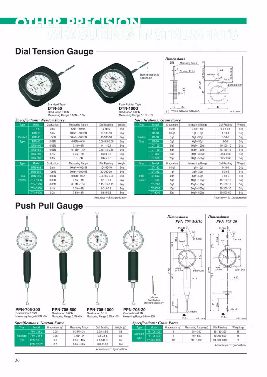
OTHER PRECISION MEASURING INSTRUMENTS
36
OTHER PRECISION MEASURING INSTRUMENTS
Standard Type
DTN-50Graduation 0.02NMeasuring Range 0.06N~0.5N
Peak Pointer Type
DTN-100GGraduation 0.05NMeasuring Range 0.1N~1N
Both direction isapplicable
Dial Tension Gauge
Push Pull Gauge
Dimensions
unit : mm
19
9.3
3
Measuring holeφ1
(5)
4
0.8
47
55
90(1
00)
33.5
(43.
5)
39.5
(49.
5)
1.5
φ6
Contact Point
hand
peak pointer
fulcrum
( ): DTN-5、DTN-10、DTN-10G
Weight
54g
54g
54g
54g
54g
54g
54g
54g
Dial Reading
6-50-6
10-100-10
30-300-30
0.06-0.5-0.06
0.1-1-0.1
0.15-1.5-0.15
0.3-3-0.3
0.6-5-0.6
Measuring Range
6mN~50mN
10mN~100mN
30mN~300mN
0.06N~0.5N
0.1N~1N
0.15N~1.5N
0.3N~3N
0.6~5N
Graduation
2mN
5mN
10mN
0.02N
0.05N
0.05N
0.1N
0.2N
Model
DTN-5
DTN-10
DTN-30
DTN-50
DTN-100
DTN-150
DTN-300
DTN-500
Type
Standard
Type
Weight
54g
54g
54g
54g
54g
54g
54g
Dial Reading
10-100-10
30-300-30
0.06-0.5-0.06
0.1-1-0.1
0.15-1.5-0.15
0.3-3-0.3
0.6-5-0.6
Measuring Range
10mN~100mN
30mN~300mN
0.06N~0.5N
0.1N~1N
0.15N~1.5N
0.3N~3N
0.6N~5N
Graduation
5mN
10mN
0.02N
0.05N
0.05N
0.1N
0.2N
Model
DTN-10G
DTN-30G
DTN-50G
DTN-100G
DTN-150G
DTN-300G
DTN-500G
Type
Peak
Pointer
Specifications: Newton Force
Accuracy=±1/2graduation
Weight
54g
54g
54g
54g
54g
54g
54g
54g
Dial Reading
0.6-5-0.6
1-10-1
3-30-3
6-5-6
10-100-10
15-150-15
30-300-30
60-500-60
Measuring Range
0.6gf~5gf
1gf~10gf
3gf~30gf
6gf~50gf
10gf~100gf
15gf~150gf
30gf~300gf
60gf~500gf
Graduation
0.2gf
0.5gf
1gf
2gf
5gf
5gf
10gf
20gf
Model
DT-5
DT-10
DT-30
DT-50
DT-100
DT-150
DT-300
DT-500
Type
Standard
Type
Weight
54g
54g
54g
54g
54g
54g
54g
Dial Reading
1-10-1
3-30-3
6-50-6
10-100-10
15-150-15
30-300-30
60-500-60
Measuring Range
1gf~10gf
3gf~30gf
6gf~50gf
10gf~100gf
15gf~150gf
30gf~300gf
60gf~500gf
Graduation
0.5gf
1gf
2gf
5gf
5gf
10gf
20gf
Model
DT-10G
DT-30G
DT-50G
DT-100G
DT-150G
DT-300G
DT-500G
Type
Peak
Pointer
Specifications: Gram Force
Accuracy=±1/2graduation
PPN-705-1000Graduation 0.1NMeasuring Range 0.5N~10N
PPN-705-300Graduation 0.05NMeasuring Range 0.35N~3N
PPN-705-500Graduation 0.05NMeasuring Range 0.4N~5N
PPN-705-20Graduation 0.2NMeasuring Range 0.6N~20N
L-hookSupplied as
standard accessory
Dimensions: PPN-705-3/5/10
unit : mm
Y-head
PUSH
hand31.7
51.7
φ40
outer Dialpeakpointer
(177
)85
.3
J-hook
PULL
(31)(4
0)
φ15
Dimensions: PPN-705-20
unit : mm
J-hook
Y-head
PUSH
hand25.4
(55)
φ40
outer Dialpeakpointer
(175
)79
.2
PULL
(30)(4
1)
φ20
Weight (g)
85
85
85
124
Dial Reading
0.35-1.5-3
0.4-2.5-5
0.5-5.0-10
0.8-10-20
Measuring Range
0.35N~3N
0.4N~5N
0.5N~10N
0.6N~20N
Model
PPN-705-3
PPN-705-5
PPN-705-10
PPN-705-20
Type
Standard
Type
Specifications: Newton ForceWeight (g)
85
85
85
Dial Reading
35-150-300
40-250-500
50-500-1000
Measuring Range (gf)
35~300
40~500
50~1,000
Graduation (gf)
5
5
10
Model
PP-705-300
PP-705-500
PP-705-1000
Type
Standard
Type
Specifications: Gram Force
Accuracy=±1graduation
Accuracy=±1graduation
Graduation (gf)
0.05
0.05
0.1
0.2

37
OTHER PRECISION MEASURING INSTRUMENTS
Hand Tachometer¡Clock type hand tachometer to measure revolution per minute of engine, machineries and motor, and moving velocity of belt conveyor etc., with
high accuracy.¡This is analog type and can be used without battery, and 3 kinds of contact points are provided as standard accessory.
Crankshaft Deflection Gauge¡Exclusive instrument to measure deflections of engine crank of automobiles and ships etc.¡This is analog type and can be used without battery, and 3 kinds of extension rods are provided as standard accessory.
L LowGraduation 0.2rpmMeasuring Range 0~1,000rpm
HL Low-peed, high-speed selection typeGraduation 5/0.5rpmMeasuring Range 0~10,000rpm 0~1,000rpm
H,L change lever
H Middle, HighGraduation 2rpmMeasuring Range 0~10,000rpm
Measuring revolution of shaft by installingcontact point A type
Option
Contact point A type (Conical type)
Revolution
Contact point B type (Hollowed Conical type)
Revolution
Contact point C type (Disk type)
Circumferential speed
each component is sold as spare parts
Black figure RPM =Contact point A,B
Red figure m/min. =Contact point C
Dimensions
unit : mm
O I L
φ7
0 -0.0
2
41 71
spindle
φ1.2pin
Oil Cap
reset button
case
trigger button
Measuring Range
0~10,000
0~1,000
0~10,000/0~1,000
Graduation
2
0.2
5/0.5
Accuracy *±0.5%
±0.5%
±0.5%
Measuring Range
0~1,000
0~100
0~1,000/0~100
Graduation
0.2
0.02
0.5/0.05
Indicating Constancy*±0.3%
±0.3%
±0.3%
Model
H
L
HL
Weight
(g)
185
185
215
Revolution (rpm) Circumferential speed measuring capability (m/min)
Specifications
*Stability of accuracy and indication are the values at 0~40℃.
CSDG-AGraduation 0.01mmMeasuring Range 110~230mm
Dimensions
unit : mm
337.
564
41.3
φ33
27(37)
39.5
L
(31.5)
φ8φ8
extension rods
unit : mm
NO.
1
2
3
L
40
80
120
Measuring Range
110~150mm
150~190mm
190~230mm
Dimension Table (extension rods)
Measuring
Range (mm)
110~230
Indication Error
(μm)
±15
Graduation
0.01
Weight
(g)
300
Model
CSDG-A
Specifications

38
OTHER PRECISION MEASURING INSTRUMENTS
Crankshaft Deflection Gauge with magnet
Small Bench Center
¡Small type which can be fixed to measuring position by magnet.
¡Suitable to measure swing of various precision shafts, round manufactured workpiece, precision gears and pinions.¡Convex and concave of center can be easily changed according to shape of workpiece. Center can be shifted.¡Standard type (Graduation 0.01mm) and precision type (graduation 0.001mm) are available.
TM-104YSGraduation 0.01mmMeasuring Range 65~82mm
TM-106YSGraduation 0.01mmMeasuring Range 99~113mm
Dimensions
unit : mm
φB
φF
E
CD
indicating range Amm
unit : mm
Model
TM-104YS
TM-106YS
A
4
5
B
35
32
C
22
32
D
4.5
7
E
68.5
102.3
F
35
47
Dimension TableMeasuring Range
(mm)
65~82
99~113
Dial Gauge error
(μm)
±15
±15
Indicating Range of Dial
Indicator (mm)
4
5
holding
power (N)
100
100
Graduation
(mm)
0.01
0.01
Model
TM-104YS
TM-106YS
SpecificationsWeight
(g)
230
330
FM-5Standard type
center convex center side concave center side
Measurement example for swing of round bar.
Both convexcenter measuring
Both concavecenter measuring
Convex and concavecenter measuring
Work
Dimensions
Dimensions
unit : mmunit : mm
Center pole
(180)
(78)
MA
X.6
79
0~750~75
60°
φ20
dial indicator
20(73)32
80
(19)
35
MIN
.22
MIN
.22
MIN
.22
(120
)
60°
φ4φ
6.4
φ8
(4.8)
φ1
60°
120°
Measuring Range
(mm)
10
1
Dial indicator error
(μm)
±15
±5
Weight
(kg)
2
2
Measuring Force
(N)
1.4 or less
1.5 or less
Graduation (mm)
0.01
0.001
Diameter
Upto φ60mm
Upto φ60mm
Width
Upto 75mm
Upto 75mm
Model
FM-5 Standard type
FM-5 High Precision type
SpecificationsApplicable dimension

39
OTHER PRECISION MEASURING INSTRUMENTS
Calibration Tester¡FM-10 is an calibration device to check accuracy of dial indicators, test indicators, back plunger type dial indicators and bore gauges. Accuracy
of various gauges mentioned in the following list can be measured according to combination of various units. Optional Pole (ZY-095) is needed for 400~600mm measuring range bore gauges.
Used Micrometer HeadPitch 0.5mmRange 25mmSleeve graduation 1μmInstrumental error ±1μm
Dial Indicator
Bore GaugeBack Plunger Dial IndicatorDial Test Indicator
0.01mm Dial Indicators
0.01mm Dial Indicators (20mm)
0.001mm Dial Indicators
Small Dial Indicators
Test Indicator
Back Plunger Type Dial Indicators
Bore Gauges
Bore Gauges for small holes
JIS B 7503
JAMS 2001
JIS B 7503
JAMS 2001
JIS B 7533
–
JIS B 7515
JAMS 2009
Applicable gauges and industrial standardFM-10 With a certificate of calibrationGraduation 0.001mmMeasuring Range 25mmWeight 9kg

40
ELECTRONIC EQUIPMENTSELECTRONIC EQUIPMENTS
¡Data output and statistics transaction can be easily made by using digital indicator.¡0.01mm and 0.001mm resolution digital indicators are available.¡Standard models are equipped with preset function and conventional models deleting preset functions are available.¡Lower measuring forces on conventional models is not available.
Electronic Digital Indicators (0.01 / 0.001mm), PC-series
As compact as standard dial indicators and can be placed where dial indicator is used. Application can be enlarged like statistical calculation of measured value, comprising measuring system by output signal.
The photo shows connection sample that PC-440 is mounted to granite standand SD-763P Digital Mini Printer.
Digital mini printerSD-763P (option)
connecting cable ZE-018 (option)
PC-440
Granite baseUSG-24 (option)
Release ZY-201 (option)
PC-440Resolution 0.01mmMeasuring Range 12.7mm
PC-465Resolution 0.001mmMeasuring Range 12.7mm
49.6
φ60
.5
φ54
16.5
2027.6
10.6
46.5
φ8Release hole (option)
7.3
67.7
5
φ6.5
R8
Dimensions: PC-440/465
0-0.009
Measuring Range 12.7mm type / Standard model
unit : mm

41
Electronic equipments
PC-480Resolution 0.01mmMeasuring Range 12.7mm
PC-485Resolution 0.001mmMeasuring Range 12.7mm
Measuring Range 12.7mm type / Popular model
Dimensions: PC-480 / 485
Dimensions: PC-450f / 455f
φ8
46.5
7.3
52.2
67.7
φ60
.416
.3
φ58
.4
10.6
17.5 20
φ6.5
R8
0 -0.009
5
Release hole (option)
PC-450fResolution 0.01mmMeasuring Range 25.4mm
PC-455fResolution 0.001mmMeasuring Range 25.4mm
* The quantising error is not included.
φ8
50.5
7.3
56.5
70
φ60
.5
φ50
38.5 (Flat back)
11φ19.6
52 (Lug Back)
0-0.008
Supplied with Flat back as standard model.
Supplied with Lug back as standard model.
7.3
unit : mm
unit : mm
Model Measuring Range
ResolutionAccuracy
Maximum response speed Contact force
DisplayOperating temp
Functions
Power supplyBattery life
Contact PointContact point thread (ISO/JIS type)
Weight
PC-440
0.01mm0.02mm or less*1000mm/sec1.0N or less
0~12.7mm
160g
0~25.4mm
1.8N or less*
186g
PC-465
0.001mm0.003mm or less*480mm/sec1.5N or less*
PC-450f
0.01mm0.03mm or less*480mm/sec
PC-455f
0.001mm0.003mm or less*480mm/sec
PC-480
0.01mm0.02mm or less*
LCD display (5-digital & minus)
120g
PC-485
0.001mm0.003mm or less*
LCD display (6-digital & minus)
150g
0~40℃
SR44 (Button、Silver oxide cell)
R=1.5mm (carbide)M2.5×P0.45mm
LCD display (6-digital & minus)
Preset, Zero-set, Power OM/OFF, Counting direction switching,Digimatic code output
Approx. 5,000hours in continuous service
0~12.7mm
unlimited2.0N or less*
Origin-set, Power ON/OFF, Counting direction Switching, Digimatic code output Display rotation(330°)
Approx. 20,000hours in continuous service
Specifications
Measuring Range 25.4mm type / Standard model
mm
REV
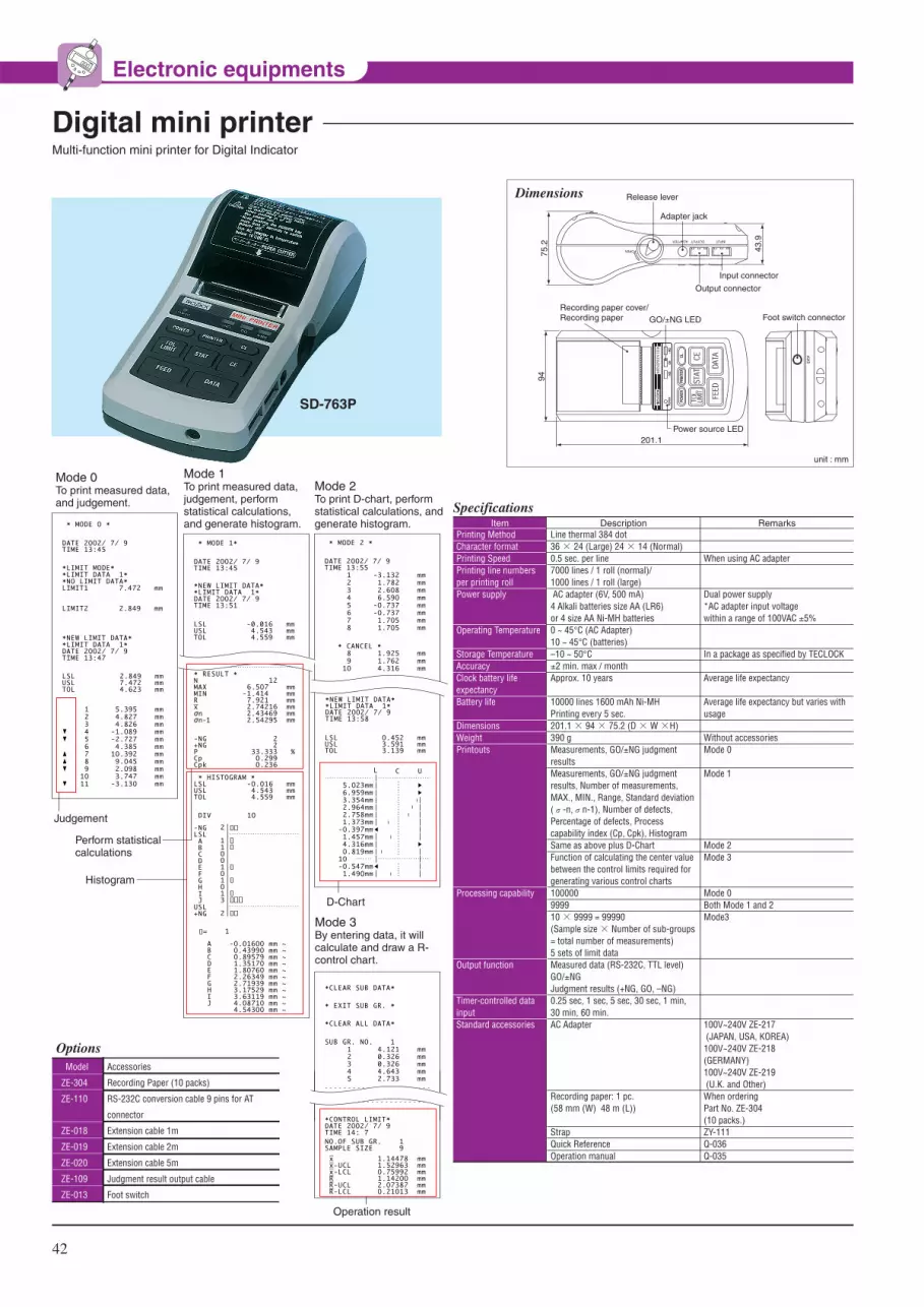
42
Electronic equipments
Multi-function mini printer for Digital Indicator
Digital mini printer
* RESULT *NMAXMINRxσnσn-1
12 6.5O7 mm
-1.414 mm7.921 mm2.74216 mm2.43469 mm2.54295 mm
-NG+NGPCpCpk
DIV
-NGLSL A B C D E F G H I JUSL+NG
= 1
1O
2
11OO1O1O13
2
* HISTOGRAM *LSLUSLTOL
-O.O16 mm4.543 mm4.559 mm
2 2
33.333 %O.299 O.236
ABCDEFGHIJ
-O.O16OO mm ~O.4399O mm ~O.89579 mm ~1.3517O mm ~1.8O76O mm ~2.26349 mm ~2.71939 mm ~3.17529 mm ~3.63119 mm ~4.O871O mm ~4.543OO mm ~
SD-763P
75.2
43.9
Adapter jack
Release lever
Output connector
Input connector
INPUTOUTPUTADAPTER
OPEN
94
201.1
Foot switch connectorGO/±NG LED
Power source LED
Recording paper cover/Recording paper
�����������
Dimensions
* MODE O *
*LIMIT MODE**LIMIT DATA 1**NO LIMIT DATA*LIMIT1 7.472 mm
LIMIT2 2.849 mm
*NEW LIMIT DATA**LIMIT DATA 1*DATE 2OO2/ 7/ 9TIME 13:47
DATE 2OO2/ 7/ 9TIME 13:45
* MODE 1*
DATE 2OO2/ 7/ 9TIME 13:45
LSLUSLTOL
2.849 mm7.472 mm4.623 mm
5.395 mm4.827 mm4.826 mm
-1.O89 mm-2.727 mm4.385 mm
1O.392 mm9.O45 mm2.O98 mm3.747 mm
-3.13O mm
123456789
1O11
▼▼
▲▲▼
▼
Mode 0To print measured data, and judgement.
Mode 1To print measured data, judgement, perform statistical calculations, and generate histogram.
Mode 2To print D-chart, perform statistical calculations, and generate histogram.
*NEW LIMIT DATA**LIMIT DATA 1*DATE 2OO2/ 7/ 9TIME 13:51
LSLUSLTOL
-0.016 mm4.543 mm4.559 mm
* MODE 2 *
DATE 2OO2/ 7/ 9TIME 13:55
-3.132 mm1.782 mm2.6O8 mm6.59O mm
-O.737 mm-O.737 mm1.7O5 mm1.7O5 mm
12345678
* CANCEL *1.925 mm1.762 mm4.316 mm
89
1O
PART NO.:
DATE 2OO2/ 7/ 9TIME 13:58
NAME:
* RESULT *NMAXMINRxσnσn-1
1O 6.59O mm
-3.132 mm9.722 mm1.6O82O mm2.58424 mm2.724O3 mm
*NEW LIMIT DATA**LIMIT DATA 1*DATE 2OO2/ 7/ 9TIME 13:58
LSLUSLTOL
O.452 mm3.591 mm3.139 mm
L C U
5.O23mm6.959mm3.354mm2.964mm2.758mm1.373mm
-O.397mm1.457mm4.316mmO.819mm
1O -O.547mm1.49Omm
D-Chart
Operation result
Judgement
Perform statisticalcalculations
Histogram
*CLEAR SUB DATA*
* EXIT SUB GR. *
*CLEAR ALL DATA*
SUB GR. NO. 14.121 mm0.326 mm0.326 mm4.643 mm2.733 mm
12345
*CONTROL LIMIT*DATE 2OO2/ 7/ 9TIME 14: 7NO.OF SUB GR. 1SAMPLE SIZE 9
xx-UCLx-LCLRR-UCLR-LCL
1.14478 mm1.52963 mmO.75992 mm1.142OO mm2.O7387 mmO.21O13 mm
Mode 3 By entering data, it will calculate and draw a R-control chart.
OptionsModel
ZE-304
ZE-110
ZE-018
ZE-019
ZE-020
ZE-109
ZE-013
Accessories
Recording Paper (10 packs)
RS-232C conversion cable 9 pins for AT
connector
Extension cable 1m
Extension cable 2m
Extension cable 5m
Judgment result output cable
Foot switch
unit : mm
Printing MethodCharacter formatPrinting Speed Printing line numbers per printing roll Power supply
Operating Temperature
Storage Temperature Accuracy Clock battery life expectancyBattery life
DimensionsWeight Printouts
Processing capability
Output function
Timer-controlled data inputStandard accessories
Line thermal 384 dot 36 × 24 (Large) 24 × 14 (Normal) 0.5 sec. per line 7000 lines / 1 roll (normal)/1000 lines / 1 roll (large) AC adapter (6V, 500 mA)4 Alkali batteries size AA (LR6)or 4 size AA Ni-MH batteries 0 ~ 45°C (AC Adapter)10 ~ 45°C (batteries) –10 ~ 50°C ±2 min. max / month Approx. 10 years
10000 lines 1600 mAh Ni-MHPrinting every 5 sec. 201.1 × 94 × 75.2 (D × W ×H) 390 g Measurements, GO/±NG judgment resultsMeasurements, GO/±NG judgment results, Number of measurements, MAX., MIN., Range, Standard deviation (σ-n,σn-1), Number of defects, Percentage of defects, Process capability index (Cp, Cpk), Histogram Same as above plus D-Chart Function of calculating the center value between the control limits required for generating various control charts100000 9999 10 × 9999 = 99990(Sample size × Number of sub-groups = total number of measurements)5 sets of limit data Measured data (RS-232C, TTL level)GO/±NGJudgment results (+NG, GO, –NG) 0.25 sec, 1 sec, 5 sec, 30 sec, 1 min, 30 min, 60 min.AC Adapter
Recording paper: 1 pc.(58 mm (W) 48 m (L))
Strap Quick Reference Operation manual
When using AC adapter
Dual power supply*AC adapter input voltagewithin a range of 100VAC ±5%
In a package as specified by TECLOCK
Average life expectancy
Average life expectancy but varies with usage
Without accessories Mode 0
Mode 1
Mode 2 Mode 3
Mode 0 Both Mode 1 and 2 Mode3
100V~240V ZE-217 (JAPAN, USA, KOREA)100V~240V ZE-218 (GERMANY)100V~240V ZE-219 (U.K. and Other)When orderingPart No. ZE-304(10 packs.) ZY-111 Q-036 Q-035
Item Description Remarks
Specifications
mm
REV

43
Electronic equipments
¡Tolerance can be set in the wide range of 0~5mm and it can be judged with lighting lamp apart from indication value of dial indicator.
¡It can be directly connected to sequencer by protection circuit.¡Signal gauges are widely used not only in watch production
but also in production lines of automobile engines, bearings etc., to allow automatic inspection and sorting.
Signal Gauge
¡Dimension of springs and pressed parts used for precision machinery, computer terminal equipment and electric appliances etc. can be measured just before its shape is transformed by measuring force.
¡When contact of sensor (contact point) and workpiece is detected by electrifying, buzzer rings and indication of dial indicator is read at that time.
¡Fine adjustment can be made by rotating adjusting knob (SD-101:10mm SD-465:12.7mm).¡150mm workpiece (maximum) can be measured by using block gauge.¡Workpiece having no electrifying can not be measured as it is detected by electrifying.¡SD-465 is digital type Sensor and resolution display is 0.001mm.
Sensor Dial
PU-490Graduation 0.01mmMeasuring Range 5mm
SD-101Graduation 0.01mmMeasuring Range 10mm
SD-465Resolution 0.001mmMeasuring Range 12.7mm
Dimensions50
Cable 2m
φ8
with lug back
with flat back
55
φ56
65.5
8
20
φ6.5
R8
0-0.022
unit : mmPU-490 0.01 5
Max. Indicating Range (mm)
Graduation(mm)
6
Spindle travel (mm)
±0-50-100
Gauge error(μm)
A point of contact response (mm)
Measuring force (N)
±12 0.005 2.5 or less 180
Model Dial Reading weight(g)
example
Measuring height of coil spring
adjusting knob
0.01
0.001
Resolution(mm)
SD-101
SD-465
Model Display
10
12.7
Indicating Range(mm)
Dial (analog)
Digital
±15
±3*1
Gauge error(μm)
Max. 150
Max. 150
Measuring Range(mm)
W70×D80
W70×D80
specimen table size(mm)
DC6V (単Ⅲ×4)
DC6V (単Ⅲ×4) *2
Power supply
3.4
3.4
Weight(kg)
Specifications
Specifications
*1 The quantizing error is not included. *2 SR-44 battery
mm
REV

44
STANDSSTANDSThis is stand which can make precision measurement of workpiece by mounting Dial Indicator or Digital Indicator. As to native granite (micro-granite) base, its organization is fine particle and workpiece slides smoothly with no ringing. Stable and high flatness accuracy within 0.001mm / 200mm square is also characteristics. Please select referring to size of base or fine adjustment device from rich lineup and also select the best suited TECLOCK dial indicators to your comparison work.
¡Native micro-granite is used for all Granite comparator stands.¡Flatness accuracy: within 0.001mm / 200mm square.¡Slides smoothly and objects to be measured are not damaged. It is
superior for anti-abrasion.
¡The rigid Granite base is free from burrs, pileups, rust, and deterioration over time.
Granite Comparator Stand
USG-10Specimen table size100×150×50mm
USG-24Specimen table size150×150×50mm
USG-29Specimen table size150×200×50mm
USG-31Specimen table size200×250×50mm
Dimension: USG-10,14,18
Dimension: USG-20,24,28
Dimension: USG-29
A B
alternativefor left and right
(φ25)
D
C50
70
bushφ8
unit : mm
unit : mm
unit : mm
unit : mm
240
304
50
D
80
bushφ8
B:200A:150
alternativefor left and right
(φ25)
A B
alternativefor left and right
(φ25)
D
C50
70
bushφ8
micro-motion rangemicro-motion range5.0micro-motion range5.0
Dimension: USG-30,31,32
A
50
φ29.8
34
φ25
.8
D
280
B
MAX167 MIN37
bushφ8
(USG-31& USG-32…0)
USG-10
USG-14
USG-18
USG-20
USG-24
USG-28
USG-29
USG-30
USG-31
USG-32
Model Type Specimen table size(A×B) (mm)
Height of Pole (C) (mm)
Movable Range (D)(mm)
Weight(kg)
Standard
Standard
Standard
Fine Adjustment
Fine Adjustment
Fine Adjustment
Precision fine adjustment
Square screw, arm slide
Square screw, arm slide
Square screw, arm slide
100×150
150×150
150×200
100×150
150×150
150×200
150×200
150×200
200×250
250×250
175
175
240
175
175
240
240
280
280
280
0~130
0~130
0~200
0~115
0~115
0~180
0~200
53~250
53~250
53~250
3.5
4.9
5.8
3.5
4.9
5.8
6.0
7.3
10.5
12.5
Specifications
micro-motion range 2.0

MB-1040
MB-1050
MB-B
45
STANDS
¡This can be easily used by only mounting Dial Indicator for comparison measurement.¡This small stand is suitable for measuring small parts etc.
US-16B
US-22B
US-25
Model Type Specimen table size(A×B) (mm)
Movable Range (D)(mm)
Weight(kg)
Standard Type
With Micro-Motion Device
Parallel Spring Type Precision Micro-Motion Device
80×80
80×80
φ60
0~140
0~110
0~120
3.4
3.5
3.9
Specifications
Upright Stand
¡Magnetic Base can hold a measuring device such as dial indicators etc., for general measurements of diverse measurements, as in machining ship and tool room.
¡Adaptor (φ6mm) is supplied for holding test indicators on model : MB-1040 and MB-1050.¡Dial indicators is mounted with Lug back and test indicator is clamped with stem
Magnetic Base
US-16BSpecimen table size 80×80mmStandard TypePrecision Grinding Cast Iron base
US-22BSpecimen table size 80×80mmWith fine adjustment devicePrecision Grinding Cast Iron base
Dimension: US-25
unit : mm
160
bushφ8
MA
X12
0
micro-motionmicro-motionrange range 2.0
micro-motionrange 2.0
58
φ60(φ25)
80
166100
alternativefor left and right
Dimension: US-22B
unit : mm
150
(φ25)
40
15
175
MA
X11
041
65
bushφ8
8080 80
alternativefor left and right
Dimension: US-16B
unit : mm
102
80 80
148
alternativefor left and right
(φ25)
MA
X 1
40
175
38
65
bushφ8
US-25Specimen table size φ60mmWith fine adjustment deviceφ60mm Ceramics base
Dimension: MB-1040 Dimension: MB-1050 Dimension: MB-B
unit : mmunit : mmunit : mm
165
φ10 φ12 175
55
6250
ON OFF
60
ON/OFF knob
fine adjustment knob
φ8
φ6(Test Indicator)
dovetail
65
110
101
27
φ6
φ8
(Test Indicator)dovetail
ON/OFF knob
fine adjustment knob
40
44
56
51
27
MB-1040
MB-1050
MB-B
Model Type Holding Power (N) Mount hole diameter(mm) Weight (kg)
One-touch, fine adjustment, small
One-touch, fine adjustment
Standard
320
800
800
6.0/8.0
6.0/8.0
4.5/6.5
0.5
1.4
1.5
Specifications
Dial Indicator is also applied.
Micro-motion Micro-motion range 5.0range 5.0Micro-motion range 5.0
Set of MB-1040 and LT-310 Test Indicator

46
DUROMETER(RUBBER, PLASTIC HARDNESS TESTER)DUROMETER(RUBBER, PLASTIC HARDNESS TESTER)
GS-720NType D DurometerHard rubber
GS-719NType A DurometerGeneral rubber
GS-721NType E DurometerSoft rubber
Dimension
unit : mm
60φ18
39
13.5
2.5
90.7
(23.5)
φ55
M6×P1 depth 5.5
16
Peak Pointer Typepointer
Upper / lower limiter
peak pointer
Some of Rubbers, Elastomer' elastic body is not easily read the maximum value after firm contacting with a presser foot of durometer , due to the stress relaxation. The pointer indicates the descendent value but the peak pointer is holding the maximum measured value. The peak pointer type can easily read the maximum value efficiently. In case the pointer cannot be read directly due to some obstacles altough the measuring can be done, the mesured value can be confirmed from peak pointer after measuring. The upper / lower limiters equipped will be effectively used in tolerance judgment.
This is Durometer to comply with JIS K 6253 (new JIS) standard established in 1993 for the purpose of conforming to ISO ( International Standard Organization ). Durometrers consist of 3 types namely, Type A for medium hardness, Type D for high hardness and Type E for low hardness. Type A tends to indicates higher value by 1~2 points compared with former Type A durometers. Type D is suitable for hard rubber having more than 90 hardness measured by type A durometer and Type E is suitable for soft rubber of which hardness is 20 and below measured by Type A durometer.
Compliance with JIS K 6253, ISO7619, ISO868 and ASTM D 2240standard for hardness test of vulcanized or thermoplastic rubber
Spring load value0-100
Model Conform standardsAPPLICATION / MATERIALS
GS-719N
GS-719G
GS-720N
GS-720G
GS-721N
GS-721G
General rubber
(Medium hardness)
General rubber
(Medium hardness))
Hard rubber
(High hardness)
Hard rubber
(High hardness)
Soft rubber
(Low hardness)
Soft rubber
(Low hardness)
JIS K 6253
ISO7619
ISO868
ASTM D 2240
JIS K 6253
ASTM D 2240
550-8050mN
(56.1-821.1gf)
550-8050mN
(56.1-821.1gf)
0-44450mN
(0-4533gf)
0-44450mN
(0-4533gf)
550-8050mN
(56.1-821.1gf)
550-8050mN
(56.1-821.1gf)
Indentor shape(mm)
Indentor height(mm)
Truncated Cone of φ 0.79
with 35° angle
Truncated Cone of φ 0.79
with 35° angle
Conical Cone of R0.1
with 35° angle
Conical Cone of R0.1
with 35° angle
Hemisphere of R2.50
Hemisphere of R2.50
2.50
2.50
2.50
2.50
2.50
2.50
Weight(g)
180
180
180
180
180
180
Type
Type A
Type A
(Peak pointer type)
Type D
Type D
(Peak pointer type)
Type E
Type E
(Peak pointer type)
Specifications
When the base of Durometer and workpiece are cohered each other, the indentor changes shape of workpiece by pressurized force caused by spring of Durometer and workpiece makes force against this force. Force amount of indentor is indicated as hardness when this pressurized force and repulsive force are equivalent. The reason why there are various kinds of Durometer, it is for the purpose of measuring various hardness for soft materials like sponge and hard materials like plastic by combining strong and weak spring force and shape of needle indentor (sharp pointed or round)

47
DUROMETER (RUBBER, PLASTIC HARDNESS TESTER)
Compliance with JIS K 7215, ISO868 and ASTM D 2240standard Durometer for hardness test of plastic
Dimension
unit : mm
60φ18
39
13.5
2.5
90.7
(23.5)
φ55
M6×P1 depth5.5
16
Deep Hole / Long Leg TypeIn some cases, such as the measurement surface of uneven or with a narrow flat area and the bottom of deep hollow, it may be impossible to achieve the proper results because of the difficult contact of the presser foot. The Deep Hole (H) type and the Long Leg (L) type make such measurements possible with a small or long presser foot. Both are supplied with Peak Pointer and the upper/lower limiters. The Long Leg type meets also to DIN 53505 standard.
This standard is prescribed by plastic industry in Japan apart from testing method of hardness of rubber. This is basically equal to Durometer of JIS K 6253, as only its round up method of spring load value etc. is different. But we distinguish model name as another Durometer according to the view of conformity to standard.
Spring load value0-100Model Conform standardsAPPLICATION /
MATERIALS
GS-702N
GS-702G
GS-709N
GS-709G
Plastics
Hard rubber
Plastics
Hard rubber
Soft plastic
General rubber
Soft plastic
General rubber
JIS K 7215
ISO868
ASTM D 2240
0-44483mN
(0-4536gf)
0-44483mN
(0-4536gf)
549-8061mN
(56-822gf)
549-8061mN
(56-822gf)
Indentor shape(mm)
Indentor height(mm)
Conical Cone of R0.1
with 35° angle
Conical Cone of R0.1
with 35° angle
Truncated Cone of φ 0.79
with 35° angle
Truncated Cone of φ 0.79
with 35° angle
2.50
2.50
2.50
2.50
Weight(g)
180
180
180
180
Type
Type D
Type D
(Peak pointer type)
Type A
Type A
(Peak pointer type)
Specifications
Model Conform standardsAPPLICATION / MATERIALS
GS-719H
GS-719L
GS-720H
GS-720L
General rubber / Deep hole type (narrow hole)
General rubber / Long leg type (thick hole)
Hard rubber / Deep hole type (narrow hole)
Hard rubber / Long leg type (thick hole)
JIS K 6253, ISO7619
ASTM D 2240
JIS K 6253, ISO7619
ASTM D 2240, *DIN 53 505
JIS K 6253, ISO7619
ASTM D 2240
JIS K 6253, ISO7619
ASTM D 2240, *DIN 53 505
φ12(Minimum size Specified in standards)
φ18(Specified size in DIN standards)
φ12(Minimum size Specified in standards)
φ18(Specified size in DIN standards)
Presser Foot Diameter (mm) Weight (g)
160
360
160
360
Type
Type A
Type A
Type D
Type D
Specifications
GS-719LType A DurometerLong leg typePeak pointer type
GS-720HType D DurometerDeep hole typePeak pointer type
Dimension: Long leg type
unit : mm
φ55
24.1
0
50
90
80
70
60
10
20
30
40
G-LTYPE DILOMETER
ISO 7619/868DIN 53 505
ASTM D 2240JIS K 6253/K7215MADE IN JAPAN
φ15
2.5
519
3
φ18
109
φ25φ25
Dimension: Deep hole type
unit : mm
0
50
90
80
70
60
10
20
30
40
GS-720HTYPE A
ASTD 2240 AJIS K 6253 A
ISO 7619 AMADE IN JAPAN
φ15
φ12
26.5
2.5
124 φ
55
24.1
φ18
*Permissible value such as edge diameter of indenter and spring load value prescribed in DIN are the value complying with ISO.
GS-702NType D DurometerPlastics Hard rubber
GS-709NType A DurometerGeneral rubberSoft plastic

unit : mm
φ25.2
φ80
112.
5
48
TECLOCK Original Standard Durometer This is available as TECLOCK original standard based on customers' requirement, even though they are not prescribed in JIS or ISO. Type E 2 durometer for soft rubber with around half of spring load value of Type E, and Type FO to measure hardness of polystyrene sponge for the level of sponge for washing dishes are available.
DUROMETER (RUBBER, PLASTIC HARDNESS TESTER)
Compliance with ASTM D 2240 standardDurometer for hardness test of rubber characteristic ASTM (American Society for Testing and Materials) is historically old and various types of durometers are prescribed. ISO applies durometer of type A and Type D among this standard and they are prescribed in JIS standard. TECLOCK provides all of this ASTM Durometer for the usage of hard material application to ultra soft material application in our line up. Please select according to usage in addition to type A and Type D.
Spring load value0-100Model Conform standards
APPLICATION / MATERIALS
GS-743G
GS-744G
Soft rubber
Soft styrene foam
TECKLOCK E2
TECKLOCK FO
550-4300mN
(56.1-438.6gf)
550-4300mN
(56.1-438.6gf)
Indentor shape(mm)
Indentor height(mm)
Hemisphere of R2.50
Cylindrical cone of φ 25.2
2.50
2.50
Weight(g)
180
500
Type
Type E2
(Peak Pointer type)
Type FO
(Peak Pointer type)
Specifications
GS-750GType B DurometerMedium-hard rubber
GS-743GType E2 DurometerSoft rubber
GS-744GType FO DurometerSoft styrene foam
GS-751GType C DurometerHard rubber
GS-752GType DO DurometerMedium-hard rubber
Spring load value0-100Model Conform standardsAPPLICATION /
MATERIALS
GS-750G
GS-751G
GS-752G
GS-753G
GS-754G
Medium-hard rubber
Hard rubber
Medium-hard rubber
Soft rubber
Very soft rubber
ASTM D 2240
ASTM D 2240
ASTM D 2240
ASTM D 2240
ASTM D 2240
550-8050mN
(56.1-821.1gf)
0-44450mN
(0-4533gf)
0-44450mN
(0-4533gf)
550-8050mN
(56.1-821.1gf)
203-1111mN
(20.7-113.3gf)
Indentor shape(mm)
Indentor height(mm)
Conical corn of R 0.1
with 30° angle
Truncated cone of φ 0.79
with 35° angle
Hemisphere of R 1.19
Hemisphere of R 1.19
Hemisphere of R 1.19
2.50
2.50
2.50
2.50
2.50
Weight(g)
180
180
180
180
180
Type
Type B
(Peak Pointer type)
Type C
(Peak Pointer type)
Type DO
(Peak Pointer type)
Type O
(Peak Pointer type)
Type OO
(Peak Pointer type)
Specifications
Hardness is measured by placing GS-744G on the sponge sheet. Dispersion of polystyrene level can be judged.

49
DUROMETER (RUBBER, PLASTIC HARDNESS TESTER)
Greensand Hardness Tester
Digital Durometer
¡Exclusive durometer to measure surface hardness of greensand mold.¡As casting is made on better condition by adjusting density of casting sand based on acquired measurement result, quality of products are
stable.¡Limiter to be able to set permissible value and peak pointer to indicate maximum value are equipped. It can be judged according to distinguish
of color of dial face.
¡Possible to observe a change of hardness with the passage in time.¡Minimum readable value is 0.5HS which 1/2 of analog type.¡Statistics calculation is possible by connected to SD-764P Printer (Option) shown on page 51.
Spring load value0-100
Model Conform standardsAPPLICATION / MATERIALS
GSD-719S
GSD-720S
GSD-721S
GSD-701S
GSD-706S
GSD-743S
GSD-744S
GSD-750S
GSD-751S
GSD-752S
GSD-753S
GSD-754S
General rubber
Soft plastic
Hard rubber
Plastic
Soft rubber
Soft rubber
General rubber
Soft rubber
Soft styrene foam
Medium-hard rubber
Hard rubber
Medium-hard rubber
Soft rubber
Very soft rubber
JIS K 6253, JIS K 7215, ISO7619
ISO868, ASTM D 2240 Type A durometer
JIS K 6253, JIS K 7215, ISO7619
ISO868, ASTM D 2240 Type D durometer
JIS K 6253, ASTM D 2240
Type E durometer
SRIS 0101, JIS S 6050
JIS K 6301, Spring type A style
TECKLOCK E2 durometer
TECKLOCK FO durometer
ASTM D 2240, Type B durometer
ASTM D 2240, Type C durometer
ASTM D 2240, Type DO durometer
ASTM D 2240, Type O durometer
ASTM D 2240, Type OO durometer
550-8050mN
(56.1-821.1gf)
0-44450mN
(0-4533gf)
550-8050mN
(56.1-821.1gf)
539-8379mN
(55-855gf)
539-8379mN
(55-855gf)
550-4300mN
(56.1-438.6gf)
550-4300mN
(56.1-438.6gf)
550-8050mN
(56.1-821.1gf)
0-44450mN
(0-4533gf)
0-44450mN
(0-4533gf)
550-8050mN
(56.1-821.1gf)
203-1111mN
(20.7-113.3gf)
Indentor shape(mm)
Indentor height(mm)
Truncated cone of φ 0.79
with 35° angle
Conical corn of R 0.1
with 30° angle
Hemisphere of R 2.50
Hemisphere of φ 5.08
Truncated cone of φ 0.79
with 35° angle
Hemisphere of R 2.50
Cylindrical cone of φ 25.2
Conical corn of R 0.1
with 30° angle
Truncated cone of φ 0.79
with 35° angle
Hemisphere of R 1.19
Hemisphere of R 1.19
Hemisphere of R 1.19
2.50
2.50
2.50
2.54
2.54
2.50
2.50
2.50
2.50
2.50
2.50
2.50
Weight(g)
250
250
250
250
250
250
250
250
250
250
250
250
Type
Type A
Type D
Type E
Type SRIS
Type A(old)
Type E2
Type FO
Type B
Type C
Type DO
Type O
Type OO
Specifications
Spring load value0-100Model Conform standards
APPLICATION / MATERIALS
GS-756G Sand mold Teclock original1,030-2,324mN
(105-237gf)
Indentor shape(mm)
Indentor height(mm)
Hemisphere of R 2.54 2.54
Weight(g)
180
Specifications
GS-756G
Mold condition
mold hardened extremely soft
mold hardened soft
mold hardened normal
mold hardened solid
mold hardened extremely solid
hardness data
~20
20~35
35~60
60~75
75~
GSD-719SType A DurometerDigital type
Dimension
unit : mm
M6×P1 depth5.5 9(27.6)
1618
3956
φ18
φ60.5
61.3
(68.9) (130.2)
2.50
P
ZERO
ON/OFF

GSD-719SHType A DurometerDeep hole (H) model
GSD-719SLType A DurometerLong leg (L) model
GS-710
4kg weight ZY-046 (option)
Durometer is option
Durometer is option
50
Constant Pressure Load Instrument for DurometerThis is hydraulic exclusive instrument with constant speed / constant load, which has dissolved individual difference to measure rubber hardness. Each durometer of Type A,E,B,O and SRIS with fixing around 1kg weight and Type D, DO, C with fixing around 4kg weight can measure by static loading around 5kg. These load values are specified in ISO, JIS, ASTM.
Durometer Tester GS-707 Series
DUROMETER (RUBBER, PLASTIC HARDNESS TESTER)
Deep Hole / Long Leg Type Digital Durometer
Dimension
φ18
φ15
26.5
φ12
7.6(27.6)
φ60
.5
2.5
127.
358
.3(6
9.0)
P
ZERO
ON/OFF
unit : mm
Spring Load0 - 100
GSD-719SH
GSD-720SH
GSD-719SL
GSD-720SL
General rubber
Hard rubber
General rubber
Hard rubber
JIS K 6253, JIS K 7215, ISO7619, ISO868,
ASTM D 2240
JIS K 6253, JIS K 7215, ISO7619, ISO868,
ASTM D 2240
JIS K 6253, JIS K 7215, ISO7619, ISO868,
ASTM D 2240, DIN53 505*
JIS K 6253, JIS K 7215, ISO7619, ISO868,
ASTM D 2240, DIN53 505*
550-8050mN
(56.1-821.1gf)
0-44450mN
(0-4533gf)
550-8050mN
(56.1-821.1gf)
0-44450mN
(0-4533gf)
SpecificationsType
Truncated cone of φ 0.79
with 35° angle
Conical corn of R 0.1
with 30° angle
Truncated cone of φ 0.79
with 35° angle
Conical corn of R 0.1
with 30° angle
2.50
2.50
2.50
2.50
170
170
380
380
Model Shape of Indentor(mm)
Weight(g)
Application /Materials Standards
Type A
Deep hole model
Type D
Deep hole model
Type A
Long leg model
Type D
Long leg model
Height ofIndentor (mm)
Dimension
φ25
φ18
5
58.3
136.
362.
5
φ15
P
ZERO
ON/OFF
7.6(27.6)
φ60
.5
unit : mm
*Permissible value such as edge diameter prescribed in DIN and spring load value is the value complying with ISO.
Load Value Applicable Durometer type
About 1kg A , B , E , A (old) , SRIS , O
About 5kg D , C , DO , C (old)
Model
GS-710
ZY-046
7kg
4kg
Weight
Specifications
4kg weight (option)
M6×P1
Durometer(option)(mounting screw)
315
65
60(※
1)φ59
165116
Dimension
unit : mm
※Dimension(※1)Maximum workpiece Thickness Digital Durometer : 20mm Analog Durometer : 63mm
GS-707
Dimension
100 147
8080 70
125
(216
)
unit : mm
GS-707
GS-707A
GS-707B
Applicable Durometer model
GS-701N/GS-701G/GS-706N/GS-706G
GS-709N/GS-709G
GS-719N/GS-719G/GS-721N/GS-721G
Weight (kg)
3.7
3.7
3.7
SpecificationsModel
This is an calibration instrument to simply confirm spring load value of analog type durometer. It inspects whether dial 25, 50 and 75 are correctly indicating by providing prescribed load to inverted durometer with 3 pieces of standard weight. Calibration Certificate for analog type durometers can be issued on request (option) but it is not available for Digital Durometer calibration method that durometer is erect condition by using mechanism of balance is introduced in domestic and international standard.

51
DUROMETER (RUBBER, PLASTIC HARDNESS TESTER)
This is a exclusive Printer for Digital Durometer and suitable for statistics transaction of hardness test data.
Mini-printer for Digital Durometer
SD-764P
75.2
43.9
Adapter jack
Release lever
Output connector
Input connector
INPUTOUTPUTADAPTER
OPEN
94
201.1
Foot switch connectorGO/±NG LED
Power source LED
Recording paper cover/Recording paper
�����������
Dimensions
Mode 0To print measured data, and judgement.
Mode 1To print measured data, judgement, perform statistical calculations, and generate histogram.
Mode 2To print D-chart, perform statistical calculations, and generate histogram.
D-Chart
Judgement
Perform statisticalcalculations
Histogram
OptionsModel
ZE-304
ZE-110
ZE-018
ZE-019
ZE-020
ZE-013
Accessories
Recording Paper (10 packs)
RS-232C conversion cable 9 pins for AT
connector
Extension cable 1m
Extension cable 2m
Extension cable 5m
Foot switch
unit : mm
Printing MethodCharacter formatPrinting Speed Printing line numbers per printing roll Power supply
Operating Temperature
Storage Temperature Accuracy Clock battery life expectancyBattery life
DimensionsWeight Printouts
Processing capability
Output function
Timer-controlled data inputStandard accessories
Line thermal 384 dot 36 × 24 (Large) 24 × 14 (Normal) 0.5 sec. per line 7000 lines / 1 roll (normal)/1000 lines / 1 roll (large) AC adapter (6V, 500 mA)4 Alkali batteries size AA (LR6)or 4 size AA Ni-MH batteries 0 ~ 45°C (AC Adapter)10 ~ 45°C (batteries) –10 ~ 50°C ±2 min. max / month Approx. 10 years
10000 lines 1600 mAh Ni-MHPrinting every 5 sec. 201.1 × 94 × 75.2 (D × W ×H) 390 g Measurements, GO/±NG judgment resultsMeasurements, GO/±NG judgment results, Number of measurements, MAX., MIN., Range, Standard deviation (σ-n,σn-1), Number of defects, Percentage of defects, Process capability index (Cp, Cpk), Histogram Same as above plus D-Chart Function of calculating the center value between the control limits required for generating various control charts100000 9999 10 × 9999 = 99990(Sample size × Number of sub-groups = total number of measurements)5 sets of limit data Measured data (RS-232C, TTL level)GO/±NGJudgment results (+NG, GO, –NG) 0.25 sec, 1 sec, 5 sec, 30 sec, 1 min, 30 min, 60 min.AC Adapter
Recording paper: 1 pc.(58 mm (W) 48 m (L))
Strap Quick Reference Operation manual
When using AC adapter
Dual power supply*AC adapter input voltagewithin a range of 100VAC ±5%
In a package as specified by TECLOCK
Average life expectancy
Average life expectancy but varies with usage
Without accessories Mode 0
Mode 1
Mode 2 Mode 3
Mode 0 Both Mode 1 and 2 Mode3
100V~240V ZE-217 (JAPAN, USA, KOREA)100V~240V ZE-218 (GERMANY)100V~240V ZE-219 (U.K. and Other)When orderingPart No. ZE-304(10 packs.) ZY-111 Q-036 Q-035
Item Description Remarks
Specifications
* RESULT *NMAXMINRxσnσn-1
15 74.5 16.5 58.0 39.133 15.278 15.814
-NG+NGPCpCpk
DIV
-NGLSL A B C D E F G H I JUSL+NG
= 1
1O
3
21OO2O112O
3
* HISTOGRAM *LSLUSLTOL
25.O 53.O 28.O
3 3
4O.OOO %O.295 O.292
ABCDEFGHIJ
25.OOO ~27.799 ~3O.599 ~33.399 ~36.199 ~38.999 ~41.799 ~44.599 ~47.399 ~5O.199 ~53.OOO ~
* MODE O *
*LIMIT MODE**LIMIT DATA 1**NO LIMIT DATA*LIMIT1 47.O
LIMIT2 76.5
*LIMIT MODE**LIMIT DATA 1**NO LIMIT DATA*LIMIT1 57.5
LIMIT2 26.5*NEW LIMIT DATA**LIMIT DATA 1*DATE 2OO2/ 7/1OTIME 9:19
DATE 2OO2/ 7/1OTIME 9:18
* MODE 1*
DATE 2OO2/ 7/1OTIME 9:21
LSLUSLTOL
47.O76.529.5
57.O48.532.553.O61.577.579.567.O63.O49.O17.5
123456789
1O11
▼▼
▲▲▼
▼
*NEW LIMIT DATA**LIMIT DATA 1*DATE 2OO2/ 7/1OTIME 9:21
LSLUSLTOL
25.O53.O28.O
* MODE 2 *
DATE 2OO2/ 7/1OTIME 9:23
PART NO.:
DATE 2OO2/ 7/ 9TIME 13:58
NAME:
* RESULT *NMAXMINRxσnσn-1
1O 6.59O mm
-3.132 mm9.722 mm1.6O82O mm2.58424 mm2.724O3 mm
*NEW LIMIT DATA**LIMIT DATA 1*DATE 2OO2/ 7/ 9TIME 13:58
LSLUSLTOL
26.557.531.O
L C U
26.536.535.O16.511.566.O66.O65.556.O35.O
1O 31.525.O25.O29.555.5
Operation result
*CLEAR SUB DATA*
* EXIT SUB GR. *
*CLEAR ALL DATA*
SUB GR. NO. 14.121 mm0.326 mm0.326 mm4.643 mm2.733 mm
12345
*CONTROL LIMIT*DATE 2OO2/ 7/ 9TIME 14: 7NO.OF SUB GR. 1SAMPLE SIZE 9
xx-UCLx-LCLRR-UCLR-LCL
1.14478 mm1.52963 mmO.75992 mm1.142OO mm2.O7387 mmO.21O13 mm
Mode 3 By entering data, it will calculate and draw a R-control chart.

52
DUROMETER (RUBBER, PLASTIC HARDNESS TESTER)
Parts
Data
Test Block (option)These are rubber test pieces which can simply check whether accuracy of durometer is in the range of standard value . It is absolutely approximate value but accuracy of durometer can be easily controlled in a short period.
Recently, Durometer is sometimes regarded as one of "inspection, measurement and test instrument" of ISO 9000 series. TECLOCK can issue so called 3 sets documents such as traceability system chart, calibration certificate and inspection certificate which are necessary for ISO. Details are to be referred at the nearest outlet.
Comparison Table ofmeasurement valueby DurometerThis is a comparison table of measuring data of each Durometer based on Type A. As hardness value changes in the certain range due to various factors like temperature, humidity, dimension, shape and vulcanization condition, justification of complete correlation between each type is impossible. But please refer to the right table as comparison value.
Calibration Certificate can be issued for all of TECLOCK durometers (option)
ZY-107ZY-108
ZY-109 ZY-110Code No. Dimension(mm)
ZY-107
ZY-108
ZY-109
ZY-110
Durometer A Hardness:50
Durometer A Hardness:80
Durometer D Hardness:40
Durometer E Hardness:80
40×80×12 thickness
40×80×12 thickness
70×80×7 thickness
40×80×12 thickness
Applicable Durometer
GS-719N・GS-719G・GSD-719S
Measuring value: nearly 50
GS9719N・GS-719G・GSD-719S
Measuring value: nearly 80
GS-720N・GS-720G・GSD-720S
Measuring value: nearly 40
GS-721N・GS-721G・GSD-721S
Measuring value: nearly 80
SpecificationsType
*Durometers complying with these test pieces are Type A, Type D, Type E, which are compliant with JIS K 6253.*Calibration Certificate about test pieces can not be issued.
TYPE A JIS K6253 JIS K7215
(old A) JIS K6301
(Discontinued standard)
TYPE E JIS K6253
TYPE SRIS SRIS 0101
(Discontinued standard)
TYPE E2 TECLOCK E2
TYPE D JIS K6253 JIS K7215
TYPE DO ASTM D2240
TYPE O ASTM D2240
TYPE OO ASTM D2240
TYPE B ASTM D2240
TYPE C ASTM D2240
10 20 30 40 50 60 70 80 90 100
10 20 30 40 50 60 70 80 90
20 30 40 50 60 70 80 90
20 30 40 50 60 70 80 90
30 40 50 60 70 80 90
10 20 30 40 50
10 20 30 40 50 60 70 80
20 30 40 50 60 70 80
50 60 70 80 90
10 20 30 40 6050 70 80 90
10 20 30 40 50 607080
0
90

53
DUROMETER (RUBBER, PLASTIC HARDNESS TESTER)
Durometer Standard TableJIS K 6253-1997 JIS K 6301-1995(1998 abolition)
JIS K 7215-1992
Type A Type D Type E Type A Type C
more than 12mm, Diameter3 mm hole more than Diameter 10mm , approx. 3.2mm hole+0.2-0.5 more than 14mm,φ5.4 mm hole
more than pressurized surfacemore than 6mm more than 12mm more than 6mm
more than 12mmmore than 10mm
────
5-points median more than 6mm offTest report (example):E 60 Test report (example):Hs(JIS A)50 Test report (example):Hs(JIS C)50Test report (example):A45 Test report (example):D50
more than A90 use TypeDunder A20 use TypeD
within 1-sec.
Normal Rubber
23±2℃/more than 3 hour 20°~30℃/one hour
ASTM D 2240ISO 7619
──── ────
550mN(56.1gf)8,050mN(821.1gf)
550mN(56.1gf)8,050mN(821.1gf)
±80mN(8.16gf) ±80mN(8.16gf)
1㎏ (preferable)
GS-719NGS-719G
GSD-719S
Normal Rubber(hard)
GS-720NGS-720G
GSD-720S
Soft Rubber
GS-721NGS-721G
GSD-721S
± 1 ± 1
0 mN( 0 gf)44,450mN(4,533gf)±440mN(44.9gf)
5.0㎏ (preferable) 1kg (preferable)
± 1
more than pressurized surface
539.5mN(55gf)8,385mN(855gf)
±8gf± 1
981mN(100gf)44,130mN(4,500gf)
±20gf±0.45
5-points average value
A>70 use C typeC type is preferable for range of 30-90
Read at once (or after regulating time)
Normal Rubber
1,000g
GS-706NGS-706G
GSD-706S
Hard Rubber
GS-703NGS-703G────
5,000g
SRIS-0101-1968
(2002 abolition)Type A Type D
more than diameter 12mm, diameter3 mm hole Center about 14×50mm approx. 5.2mm hole in Center±0.5
Width : about 25mm or more6mm or more, 2mm acceptable for HDD 40 pr above more than 10mm
12mm or more from edge ────
5 or preferably 10meas, at 6mm or moreTest report (example):HDA83 Test report (example):HDD56
As a rule, use in range 20-90Use D for A>90, Use A for D<20
1sec or less (time to be specified for over 1sec)
Plastic(plastic film, tape and foam plastic excluded) (usable for elastomer)
23±2℃ 50±5%(humidity)88h(Time can be shortened if measured value does not vary)
ASTM D 2240 / ISO 868(SHORE A)(DIN 53505)
ASTM D 2240 / ISO 868(SHORE D)(DIN 53505)
549mN(56gf)8,061mN(822gf)±78mN(± 8 gf)
approx. 1kg
GS-709NGS-709G
GSD-719S
GS-702NGS-702G
GSD-720S
± 1
0 mN( 0 gf)44,483mN(4,536gf)±441mN(±45gf)
approx. 5kg
± 1
more than pressurized surface
539.5mN(55gf)8,385mN(855gf)
±8gf± 1
JIS S 6050 (Plastics Erasers)
Average value of 5initial and 30sec later measurement.
At first weighing and 30sec later
Expanded rubber
20 /h
────
1,000g
GS-701NGS-701G
GSD-701S
2.5±
0.04
φ0.79
φ3.0φ1.25
35°
Indentor
Presser foot
+0.2-0.5
±0.25
±0.03
±0.15
2.5±
0.04
φ3.0 +0.2-0.5
30°±1°
SR0.1±0.012
φ1.25±0.15
Presser foot
Indentor
2.54
0
-0.
05
φ0.79
approx.φ3φ1.3±0.1
35°
Indentor
Presser foot
±0.25°
±0.02
2.5±
0.04
φ3.0 ±0.5
30°±1°
SR0.1 ±0.012
φ1.25 ±0.1
Presser foot
Indentpr
2.5±
0.04
φ0.79
φ3.0φ1.25
35°
Indentpr
Presser foot
±0.5
±0.25
±0.03
±0.1
±0.2
Indentor
φ5.08 ±0.02
Presser foot
Indentor
approx. 5.22.
54
0-
0.05
±0.02
Presser foot
SR2.5
φ5.4
2.5±
0.04
±0.2
Sp
ecif
icat
ion
of
Tes
ters
Test
Pie
ce a
nd M
easu
ring
con
ditio
n
Name of standard
Presser foot dimension
Indentor shaft diameter
Indentor tip diameter
Indentor tip angle
Indentor amount exceeding
from force surface
weight at 0
weight at 100
loadaccuracy
Load allowance value
Indicating tolerance value
Other standards
Test piecesFlat area dimension
Thickness
Measuring position
Time to read
Number of measurement and data
summery
Weight of constant pressure weighter
Temperature condition
Acclimate time of specimen
Use range
Suitable specimen to the standards
Our original durometer
Our original digital durometer
Standard
Peak Pointer
Sp
ecif
icat
ion
of
Tes
ters
Test
Pie
ce a
nd M
easu
ring
con
ditio
n
Presser foot dimension
Indentor shaft diameter
Indentor tip diameter
Indentor tip angle
Indentor amount exceeding
from force surface
weight at 0
weight at 100
loadaccuracy
Load allowance value
Indicating tolerance value
Other standards
Test piecesFlat area dimension
Thickness
Measuring position
Time to read
Number of measurement and data
summery
Weight of constant pressure weighter
Temperature condition
Acclimate time of specimen
Use range
Suitable specimen to the standards
Our original durometer
Our original digital durometer
Standard
Peak Pointer
Name of standard
+10 0

54
DUROMETER (RUBBER, PLASTIC HARDNESS TESTER)S
pec
ific
atio
n o
f T
este
rsTe
st P
iece
and
Mea
suri
ng c
ondi
tion
Name of standard
Presser foot dimension
Indentor shaft diameter
Indentor tip diameter
Indentor tip angle
Indentor amount exceeding
from force surface
weight at 0
weight at 100
loadaccuracy
Load allowance value
Indicating tolerance value
Other standards
Test piecesFlat area dimension
Thickness
Measuring position
Time to read
Number of measurement and data
summery
Weight of constant pressure weighter
Temperature condition
Acclimate time of specimen
Use range
Suitable specimen to the standards
Our original durometer
Our original digital durometer
Standard
Peak Pointer
Sp
ecif
icat
ion
of
Tes
ters
Test
Pie
ce a
nd M
easu
ring
con
ditio
n
Presser foot dimension
Indentor shaft diameter
Indentor tip diameter
Indentor tip angle
Indentor amount exceeding
from force surface
weight at 0
weight at 100
loadaccuracy
Load allowance value
Indicating tolerance value
Other standards
Test piecesFlat area dimension
Thickness
Measuring position
Time to read
Number of measurement and data
summery
Weight of constant pressure weighter
Temperature condition
Acclimate time of specimen
Use range
Suitable specimen to the standards
Our original durometer
Our original digital durometer
Standard
Peak Pointer
8,050mN(821.1gf)
ASTM D 2240-02b
Type B Type C Type DO Type O Type OO
6mm diameter 2.5~3.2mm hole
550mN(56.1gf)
±0.075N8,050mN(821.1gf)
550mN(56.1gf)
±0.075N1,111mN(113.3gf)
203mN(20.7gf)
±0.0182N±2±1
────
more than radius 6mm thanmore than 6mm
more than 12mm (length and width)within 1-sec.
5-points of average value or medium 6mm off
1㎏ (preferable) 1㎏ (preferable) ──── 5㎏ (preferable)
Rubber, Cellular, Elasticity material, Thermoplastic elastomers, Hard plastic, Soft plastic
────GS-750G
GSD-750S
────GS-751G
GSD-751S
────GS-752G
GSD-752S
────GS-753G
GSD-753S
────GS-754G
GSD-754S
23±2℃
20~90
Name of standardTeclock standard
Type E2 Type FO
more than 16mm, Diameter 5.5mm hole more than 80mm diameter, 26mm hole in Center diameter
550mN(56.1gf)4,300mN(438.6gf)
0.4N(±40gf)±1
0.4N(±40gf)±1
────
────1㎏ (preferable)
────
550mN(56.1gf)4,300mN(438.6gf)
more than 10mm
5-points median more than 6mm off
more than 30mm
23±2℃ 23±2℃
5-points median more than 80mm off
more than pressurized surface more than pressurized surface
within 1-sec. within 1-sec.
Soft sponge
────GS-743G
GSD-743S
Foam sponge, Polyurethane foam
────GS-744G
GSD-744S
0 mN(0 gf)44,450mN(4,533gf)±0.4445N
2.5±
0.04
φ3.0 +0.2-0.5
30°±1°
SR0.1 ±0.012
φ1.25±0.15
Presser foot
Indentor
2.5±
0.04
φ0.79
φ3.0φ1.25
35°
Indentor
Presser foot
+0.2-0.5
±0.25
±0.03
±0.15
Indentor
Presser foot
φ3.5~3.7
2.38 ±0.08
SR1.192.5±
0.04
Presser foot
Indentor
2.5±
0.04
φ5.5
SR2.5
Presser foot
Weight of Durometer 500gφ26
φ25.2 ±0.05
Indentor
2.5±
0.04
±0.05
±0.02

CUSTOM MADE PRODUCTS
55
CUSTOM MADE PRODUCTS
Flow Meters
Dial Indicator for Dynamometers
Test Indicators for Run-out (TIR) measurement
TM-110LM85-1AGraduation 0.01mmMeasuring Range 10mm
TM-5105LM85-1AGraduation 0.005mmMeasuring Range 7mm
Dimensions
unit : mm
φ56 85
(14.6) (7.8)
Example
¡Exclusive instrument to confirm not Run-out value but Run-out condition.¡This can measure Run-out of workpiece which standard test indicators can not measure, since stylus complying with shape of workpiece is
installed to it.¡Unit is not available for graduation line. (Certificate of Calibration can not be issued.)¡Stylus is not included in standard price of LR-316. Please select stylus from the following list and use by combination.
¡This is a dial indicator and jig set for the suction (expansion/ contraction) measuring.
LR-316for Run-out (TIR)measurement
Stylus (Option)
LR-316
Model
70
Weight (g)
Specifications
Dimensions
unit : mm
34
17
42.9
814
.55
φ35
17
φ6
φ5
16.4 4.8
Stylus(Option)
Fixing Nut for stylus(Option)
M3.5×P0.5
The photograph shows that Run-out of edge of Cutting Tool installed to machine is detected and measured.
LR-316 stylus (with Fixing Nut)
M2×P0.4
Sφ2
φ3
15
1.6
L
M2×P0.4
Sφ2
φ3
0.5
51.
6L
M2×P0.4
φ3
51.
6L
Sφ2
1.0
0.4
M2×P0.4
φ3
51.
6L
2
0.4 φ2
M2×P0.4
φ3
51.
616
φ1
Code No.
ZS-777
ZS-782
ZS-778
ZS-783
ZS-779
ZS-784
ZS-780
ZS-785
ZS-781
ZS-786
Shape of stylus
Spherical
Shape
Half
Spherical
Shape
Fan
Shape
Square
Shape
Round Bar
Shape
L (mm)
25.8
68.7
25.8
68.7
25.8
68.7
25.8
68.7
25.8
68.7
Dimensions (mm)
716Graduation 0.1mmMeasuring Range 25mm
Dimensions
unit : mm
φ55
8
150
87
φ13
φ19
φ13
φ19
Measuring Range (mm)
25
Dial Reading
0-5-10
Gauge error
±60μm
Short Hand
non
Weight (g)
260
Graduation (mm)
0.1
Model
716
Specifications
Dynamometers

Digital in sideComparatorFM-55Graduation 0.001mmMeasuring Range4~55mm
Digital out sideComparatorFM-60Graduation 0.001mmMeasuring Range10~60mm
56
CUSTOM MADE PRODUCTS
Arm Slide Type Caliper Gauges¡Stable and accurate measuring dimension (comparative measurement) is possible for internal and external dimension, as this can well stick to
workpiece with measurement method by sliding movable arm.¡Boxy type, easily to hold, lightweight and solid, this is suitable to inspect large volume at work site.¡This can be used for various objectives to measure internal gears, internal diameter female screw, plain gear, spline shaft of special key, over
pin diameter of separation shaft and pitch gear thickness.¡Contact point is separately produced on demand such as ball type, flat type, knife edge type. Please advise dimension and shape.¡As Digital indicator is an option, please select it according to an objective. Because dial indicator can be installed.¡This can print out data by connected to Digital mini printer SD-763P (option).
Digital Comparator¡Exclusive measuring instrument which comparatively measures inside and outside diameter.¡After placing master gauge to measuring table and basis value setting (Zero setting), tolerance judgment measuring against basis value is
measured by measuring workpiece.¡Carbide contact point and anvil (anvil pin) are provided as standard.¡Special ordered product is utilized for the measuring range except for the following list.
FM-20Internal measurement
FM-25External measurement
PC-465 (Option)Contact point (Option) Contact point (Option)
PC-465 (Option)
Groove internal diameter is comparatively measured by using Digital indicator with 0.001mm resolution
Example
FM-20
FM-25
Internal
External
20~130
0~100
Measuring Range(mm)
30
30
380
380
Arm length(mm)
7~9
7~9
Measuring force(N)
φ3.5
φ3.5
Fitting holes(mm)
Weight (g)
Model Application
Specifications
Contact point and digital indicator are not included.
FM-55
FM-60
0.001
0.001
4~55
10~60
0.003
0.003
Gauge accuracy (mm)
Measuring Range (mm)
12
12
Indicating Range(mm)
1.5 or less
1.5 or less
Measuring force(N)Model Resolution
(mm)
Specifications
The quantizing error is not included.Both models can print out data with SD-763P digital mini printer and ZE-018 connection cable.
Dimensions:FM-55
unit : mm
70
210
min
.φ4
max
.φ55
50
42
φ1.5Carbide Pole
4 27
35(92)
φ1.5Carbide Pole
Dimensions:FM-60
unit : mm
70
210
min
.φ10
max
.φ60
50
333
φ6
27
35(92)
Effective for measuring internal diameter of thin ring (FM-55)
Example

R
Dial indicator Test Indicator
Thickness gauge
Depth gauge Bore gauge &Micro-hole test
Electronicinstrument
58-60 61
62-63
64 65-66
66
Dial indicator Test Indicator
Thickness gauge
Depth gauge Bore gauge &Micro-hole test
Electronicinstrument
58-60 61
62-63
64 65-66
66
���� ����
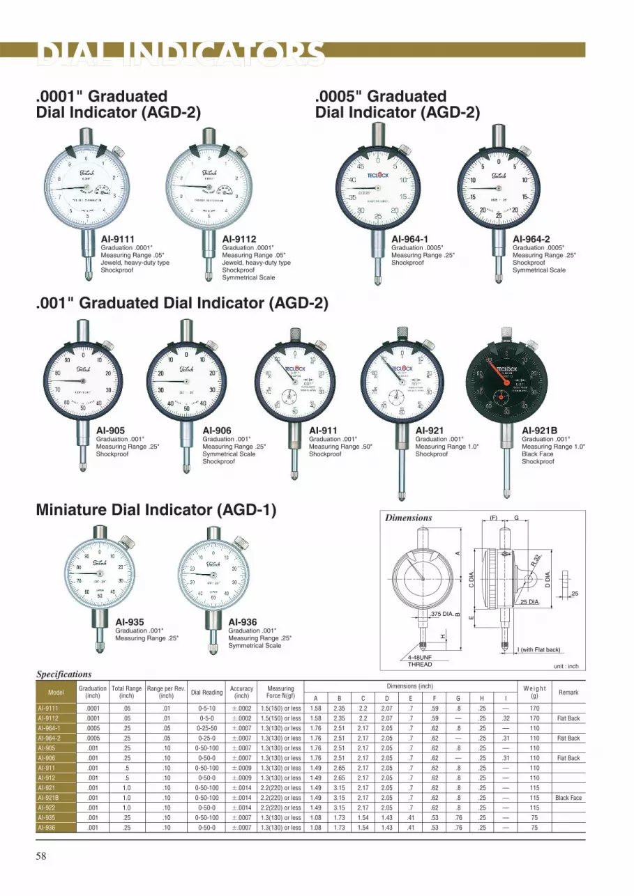
AI-936Graduation .001"Measuring Range .25"Symmetrical Scale
58
DIAL INDICATORSDIAL INDICATORS
Specifications
AI-9111
AI-9112
AI-964-1
AI-964-2
AI-905
AI-906
AI-911
AI-912
AI-921
AI-921B
AI-922
AI-935
AI-936
.0001
.0001
.0005
.0005
.001
.001
.001
.001
.001
.001
.001
.001
.001
.05
.05
.25
.25
.25
.25
.5
.5
1.0
1.0
1.0
.25
.25
.01
.01
.05
.05
.10
.10
.10
.10
.10
.10
.10
.10
.10
Graduation(inch)
Total Range(inch)
Range per Rev.(inch)
0-5-10
0-5-0
0-25-50
0-25-0
0-50-100
0-50-0
0-50-100
0-50-0
0-50-100
0-50-100
0-50-0
0-50-100
0-50-0
Dial Reading
±.0002
±.0002
±.0007
±.0007
±.0007
±.0007
±.0009
±.0009
±.0014
±.0014
±.0014
±.0007
±.0007
Accuracy(inch) Remark
1.5(150) or less
1.5(150) or less
1.3(130) or less
1.3(130) or less
1.3(130) or less
1.3(130) or less
1.3(130) or less
1.3(130) or less
2.2(220) or less
2.2(220) or less
2.2(220) or less
1.3(130) or less
1.3(130) or less
A
1.58
1.58
1.76
1.76
1.76
1.76
1.49
1.49
1.49
1.49
1.49
1.08
1.08
Measuring Force N(gf)Model
Flat Back
Flat Back
Flat Back
Black Face
170
170
110
110
110
110
110
110
115
115
115
75
75
W e i g h t(g)
.0001" GraduatedDial Indicator (AGD-2)
.0005" GraduatedDial Indicator (AGD-2)
AI-9111Graduation .0001"Measuring Range .05"Jeweld, heavy-duty typeShockproof
AI-9112Graduation .0001"Measuring Range .05"Jeweld, heavy-duty typeShockproofSymmetrical Scale
AI-964-2Graduation .0005"Measuring Range .25"ShockproofSymmetrical Scale
.001" Graduated Dial Indicator (AGD-2)
AI-905Graduation .001"Measuring Range .25"Shockproof
Miniature Dial Indicator (AGD-1)
AI-935Graduation .001"Measuring Range .25"
AI-906Graduation .001"Measuring Range .25"Symmetrical ScaleShockproof
AI-911Graduation .001"Measuring Range .50"Shockproof
AI-921Graduation .001"Measuring Range 1.0"Shockproof
AI-921BGraduation .001"Measuring Range 1.0"Black FaceShockproof
AI-964-1Graduation .0005"Measuring Range .25"Shockproof
Dimensions
unit : inch
4-48UNFTHREAD
AB.375 DIA.
H
G(F)
C D
IA.
D D
IA.
E
R.3
2
.25 DIA..25
I (with Flat back)
B
2.35
2.35
2.51
2.51
2.51
2.51
2.65
2.65
3.15
3.15
3.15
1.73
1.73
C
2.2
2.2
2.17
2.17
2.17
2.17
2.17
2.17
2.17
2.17
2.17
1.54
1.54
D
2.07
2.07
2.05
2.05
2.05
2.05
2.05
2.05
2.05
2.05
2.05
1.43
1.43
E
.7
.7
.7
.7
.7
.7
.7
.7
.7
.7
.7
.41
.41
F
.59
.59
.62
.62
.62
.62
.62
.62
.62
.62
.62
.53
.53
G
.8
–
.8
–
.8
–
.8
.8
.8
.8
.8
.76
.76
H
.25
.25
.25
.25
.25
.25
.25
.25
.25
.25
.25
.25
.25
I
–
.32
–
.31
–
.31
–
–
–
–
–
–
–
Dimensions (inch)

59
DIAL INDICATORS
Long Range Dial Indicator (AGD-2)
0.01mm Graduated Dial Indicator (AGD-2)
AM-921Graduation 0.01mmMeasuring Range 25mm.375" DIA. STEMcontact point (4-48UNF)Shockproof
AM-110Graduation 0.01mmMeasuring Range 10mm.375" DIA. STEMcontact point (M2.5×P0.45)Shockproof
AI-951Graduation .001"Measuring Range 2.0"Shockproof
AI-951BGraduation .001"Measuring Range 2.0"Black FaceShockproof
Dimensions
unit : inch
4-48UNFTHREAD
AB.375 DIA.
H
G(F)
C D
IA.
D D
IA.
E
R.3
2
.25 DIA..25
Dimensions
unit : inch
4-48UNFM2.5×P0.45
ABC DIA.
.25
.8.62
2.17
DIA
.
2.05
DIA
.
.69
R.3
2
.25 DIA.D
Specifications
AI-951
AI-951B
.001
.001
2.0
2.0
.10
.10
Graduation(inch)
Total Range(inch)
Range per Rev.(inch)
0-50-100
0-50-100
Dial Reading
±.0032
±.0032
Accuracy(inch) Remark
2.5(250) or less
2.5(250) or less
A
4.71
4.71
Measuring Force N(gf)Model
215
215
Weight(g)
Black Face
B
5.5
5.5
C
2.3
2.3
D
2.1
2.1
E
2.0
2.0
F
.71
.71
G
.79
.79
H
.25
.25
Dimensions (inch)
Specifications
AM-110
KM-121
AM-921
AM-922
0.01
0.01
0.01
0.01
10
20
25
25
1.0
1.0
1.0
1.0
Graduation(mm)
Total Range(mm)
Range per Rev.(mm)
0-50-100
0-50-100
0-50-100
0-50-0
Dial Reading
±0.015
±0.020
±0.030
±0.030
Accuracy(mm)
1.4(140) or less
2.2(220) or less
2.2(220) or less
2.2(220) or less
A
1.91
1.42
1.49
1.49
Measuring Force N(gf)Model
110
115
115
115
Weight(g)B
2.56
2.95
3.15
3.15
M2.5×P0.45
M2.5×P0.45
4-48UNF
4-48UNF
ContactPointScrew
φ.375"
φ8mm
φ.375"
φ.375"
Stem Dia : φC
.25
.196
.25
.25
Lug Thickness : D
Dimensions (inch)

60
Specifications
TI-111
TI-105
TI-105W
kI-121
TI-1111
TI-1112
TI-1205
TI-35
.001
.001
.001
.001
.0001
.0001
.0001
.001
.50
.25
.25
1.0
.05
.05
.20
.20
.10
.10
.10
.10
.01
.01
.01
.10
Graduation(inch)
Total Range(inch)
Range per Rev.(inch)
0-50-100
0-50-0
0-50-100
0-50-100
0-5-10
0-5-0
0-5-10
0-50-100
Dial Reading
±.0009
±.0007
±.0007
±.0014
±.0002
±.0002
±.0004
±.0006
Accuracy(inch) Remark
1.4(140) or less
1.3(130) or less
1.4(140) or less
2.2(220)or less
1.5(150) or less
1.5(150) or less
1.5(150) or less
1.3(130) or less
A
1.76
1.76
1.76
1.44
1.57
1.57
1.57
1.08
Measuring Force N(gf)Model
Flat Back
Flat Back
110
110
110
115
170
170
170
70
Weight(g)
Dial Indicator (with 8mm stem)
TI-1111Graduation .0001"Measuring Range .05"Heavy-duty, jeweled typeShockproof
DIAL INDICATORS
TI-1205Graduation .0001"Measuring Range .20"
TI-111Graduation .001"Measuring Range .50Shockproof
KI-121Graduation .001"Measuring Range 1.0"Shockproof
Miniature Dial Indicator (AGD-1)Dimensions
unit : inch
M2.5×P0.45THREAD
ABφ8mm
(.315 DIA.)
H
G(F)
C D
IA.
D D
IA.
E
R.3
2
.25 DIA..25
I (with Flat back)
B
2.7
2.7
2.7
3.19
2.44
2.44
2.44
1.63
C
2.17
2.17
2.17
2.17
2.2
2.2
2.2
1.54
D
2.05
2.05
2.05
2.05
2.05
2.05
2.07
1.43
E
.69
.69
.69
.69
.71
.71
.59
.39
F
.62
.62
.62
.62
.62
.62
.8
.57
G
.79
–
.79
.79
.79
.79
.79
.76
H
.30
.30
.30
.30
.30
.30
.30
.20
I
–
.31
–
–
–
.30
–
–
Dimensions (inch)
TI-35Graduation .001"Measuring Range .20"

61
Auto Clutch Type
LTI-352Graduation .005"Measuring Range .03"
Specifications
LTI-352
LTI-352B
LTI-353
LTI-355
.0005
.0005
.0005
.0001
.03
.03
.03
.01
Graduation(inch)
Total Range(inch)
0-15-0
0-15-0
0-15-0
0-5-0
Dial Reading
.0004
.0004
.0004
.0002
Accuracy(inch) Remark
0.2(20) or less
0.2(20) or less
0.2(20) or less
0.25(25) or less
A
1.38
1.38
1.38
1.51
Measuring Force N(gf)Model
Standard
Black Face
Long Contact Point
Precision
75
75
75
75
Weight(g)B
.787
.787
1.52
.64
C
2.28
2.28
3.02
2.14
D
3.1
3.1
3.64
2.76
Dimensions (inch)
DIAL TEST INDICATORSDIAL TEST INDICATORS
LTI-355Graduation .0001"Measuring Range .01"
Standard Accessories Set.375" DIA. Stem.157" DIA. Stem.125" Stylus (Steel ball).039" Stylus (Steel ball)
Dimensions
unit : inch
D
.079 DIA. Carbide Ball
10.5
.76.12
B
.67
115゚
115゚
1.05
"A"
DIA
.
.38
.17
C
.236DIA.
DovetailLTI-352 only
Move toabout 1.14
Lever Type
Parts
LTI-310Graduation .001"Measuring Range .03"
Specifications
LTI-310
LTI-315
LTI-316
LTI-370
.001
.0005
.0005
.0001
.03
.03
.04
.01
Graduation(inch)
Total Range(inch)
0-15-0
0-15-0
0-20-0
0-5-0
Dial Reading
.0004
.0004
.0005
.0002
Accuracy(inch)
0.4(40) or less
0.4(40) or less
0.4(40) or less
0.4(40) or less
A
1.12
1.38
1.38
1.51
Measuring Force N(gf)Model
50
60
70
70
Weight(g)B
.56
.75
1.72
.43
C
.54
.53
.53
.53
D
.85
.85
.85
.85
E
1.83
2.44
3.41
2.12
F
3.1
3.74
4.70
3.41
G
.2
.19
.19
.19
H
.28
.27
.27
.27
Dimensions (inch)
LTI-315Graduation .0005"Measuring Range .03"
LTI-370Graduation .001"Measuring Range .01"
Dimensions
unit : mm
DC
G
.283
φ.079Carbide Ball
100°
100°
"A"
DIA
.
E
B
.138
.63
F
.236 DIA.
H
Stylus Universal Holder with Clamp
Code No.
ZS-722
ZS-723
ZS-724
ZS-735
ZS-725
ZS-726
ZS-727
Type
LTI-310
LTI-315
LTI-316
LTI-370
LTI-352
.078" DIA.
.039" DIA.
.125" DIA.
Code No.
ZS-729
ZS-730
ZS-731
ZS-732
ZS-733
ZS-734
Type
LTI-353
LTI-355
Code No.
ZY-062
Dimensions (inch)
Dovetail.236 DIA.
.078" DIA.
.039" DIA.
.125" DIA.
.078" DIA.
.039" DIA.
.125" DIA.
Steel ball
ZY-062

62
THICKNESS GAUGESTHICKNESS GAUGES
Specifications
SI-112
SI-112LS
SI-112LW
SI-112-3A
SI-530
SI-530LS
SI-530LW
SI-530-3A
.001
.001
.001
.001
.001
.001
.001
.001
.5
.5
.5
.5
1.0
1.0
1.0
1.0
.10
.10
.10
.10
.10
.10
.10
.10
Graduation(inch)
Total Range(inch)
Range per Rev.(inch)
±0-50-100
±0-50-100
±0-50-100
±0-50-100
±0-50-100
±0-50-100
±0-50-100
±0-50-100
Dial Reading
.394 DIA. Flat
S.125(1/8) DIA.
S.125(1/8) DIA.
.197 DIA. Flat
.394 DIA. Flat
S.125(1/8) DIA.
S.125(1/8) DIA.
.197 DIA. Flat
Contact point form(inch)
2.5(250) or less
2.5(250) or less
2.5(250) or less
2.5(250) or less
3.5(350) or less
3.5(350) or less
3.5(350) or less
3.5(350) or less
Measuring Force N(gf)Model
145
145
145
145
200
200
200
200
Weight(g)
Digital Thickness Gauge
SID-540Resolution .0005"/0.01mmMeasuring Range .5"/12.7mmDepth 1.18"/30mmContact Point and Anvil(Ceramic)
SID-565Resolution .00005"/0.001mmMeasuring Range .5"/12.7mmDepth 1.18"/30mmContact Point and Anvil(Ceramic)(Movable anvil type)
SI-112Graduation .001"Measuring Range .5"Contact Point and Anvil (Ceramic)
SI-530Graduation .001"Measuring Range 1.0"Contact Point and Anvil (Ceramic)
SID-550Resolution .0005"/0.01mmMeasuring Range .5"/12.7mmDepth 4.72"/120mmContact Point and Anvil(Ceramic)
Specifications
SID-540
SID-550
SID-565
.0005/0.01
.0005/0.01
.00005/0.001
.5/12.7
.5/12.7
.59/15
Resolution(inch/mm)
Total Range(inch/mm) Remark
1.0(100) or less
1.0(100) or less
1.5(150) or less
Measuring Force N(gf)Model
290
440
470
Weight(g)
Dial Thickness Gauge
Dimensions: SID-540
unit : inch
1.38
(2.5
3)1.
18
1.18.394 DIA.
2.77.275
.118
.157
Dimensions: SID-565
unit : inch
(2.5
3)(1
.57)
(.29
).2
5(.
72)
(.13
)
1.38
5.48
1.0
1.18.394 DIA
.71 2.77Lifting of anvil
.118
.118
.157
.157
Dimensions: SID-550
unit : inch
2.85
1.0
1.18
.69
5.43
4.33
4.72
6.38
.118
.118
.157
.118
.157
Dimensions: SI-112
Standard Type
4.02
.47
.72
.12
.16
1.03
Lifting Lever
Frame
Anvil
Contactpoint
2.52
unit : inch
5.43
.91
1.18
1.3
.12
.16
2.99
Standard Type unit : inch
Dimensions: SI-530
.394 DIA. Flat
.394 DIA. Flat
S.125(1/8) DIA.
.197 DIA. Flat
.394 DIA. Flat
.394 DIA. Flat
S.125(1/8) DIA.
.197 DIA. Flat
Anvil form(inch)

63
SI-114Graduation .001"Measuring Range .5"Contact Point and Anvil (Ceramic)
SI-1111Graduation .0001"Measuring Range .4"Indic. Range .05"(Movable anvil)Contact Point and Anvil (Ceramic)
THICKNESS GAUGES
Anvil & Contact Point
5.2
1.10 .5
9.1
2.1
6
.39 DIA.
1.02
1.18
4.17
4.72
6.18
2.6
unit : inchStandard Type
Dimensions: SI-114
Dimensions : SI-1111
unit : inch2.
30
5.78
.43 .9
89 Lifting of anvil
1.18.33 DIA.
.71 2.78Standard Type
Specifications
SI-114
SI-114LS
SI-114LW
SI-124
SI-124LS
SI-124LW
SI-1111
SI-1111LS
SI-1111LW
.001
.001
.001
.001
.001
.001
.0001
.0001
.0001
.5
.5
.5
1.0
1.0
1.0
.4(.05)
.4(.05)
.4(.05)
.10
.10
.10
.10
.10
.10
.01
.01
.01
Graduation(inch)
Total Range(inch)
Range per Rev.(inch)
±0-50-100
±0-50-100
±0-50-100
±0-50-100
±0-50-100
±0-50-100
±0-5-10
±0-5-10
±0-5-10
Dial Reading
.394 DIA. Flat
S.125 (1/8) DIA.
S.125 (1/8) DIA.
.394 DIA. Flat
S.125 (1/8) DIA.
S.125 (1/8) DIA.
.33 DIA. Flat (Carbide)
S.118 DIA. (Carbide)
S.118 DIA. (Carbide)
Contact point form(inch)
2.5(250) or less
2.5(250) or less
2.5(250) or less
3.5(350) or less
3.5(350) or less
3.5(350) or less
1.5(150) or less
1.5(150) or less
1.5(150) or less
Measuring Force N(gf)Model
270
270
270
270
270
270
440
440
440
Weight(g)
.394 DIA. Flat
.394 DIA. Flat
S.125 (1/8) DIA.
.394 DIA. Flat
.394 DIA. Flat
S.125 (1/8) DIA.
.33 DIA. Flat (Carbide)
.33 DIA. Flat (Carbide)
S.118 DIA. (Carbide)
Anvil form(mm)
Standard Type LS Type LW Type 3A Type
.394 DIA.
anvil
S.125 DIA. Ball
contact point
anvil
S.125 DIA. Ball
S.125 DIA. Ball
.197 DIA.
contact point
anvil
contact point
.394 DIA.
anvil
contact point
unit : inch

64
DEPTH GAUGESDEPTH GAUGESDigital Depth Gauge
Specifications
DID-210
DID-211
DID-213
DID-215
.0005/0.01
.0005/0.01
.0005/0.01
.0005/0.01
.5/12.7
.5/12.7
.5/12.7
8.0/230
Resolution(inch/mm)
Total Range(inch/mm) Remark
1.0(100) or less
1.0(100) or less
1.0(100) or less
2.3(230) or less
Measuring ForceN(gf)
Needle
.079 DIA. Flat
S.125 DIA. (1/8)
S.125 DIA. (1/8)
Contact PointInchModel
Extension Rods
310
310
310
375
Weight(g)
Specifications
DI-223
DI-224
.001
.001
1.0
8.0
Graduation(inch)
Total Range(inch) Remark
2.2(220) or less
2.5(250) or less
Measuring Force N(gf)
.01
.01
0-50-100
0-50-100
Dial ReadingRange per Rev.Model
Extension Rods
275
340
Weight(g)
S.125 DIA. (1/8)
S.125 DIA. (1/8)
Contact Point(inch)
Dial Depth Gauges
DID-210Resolution .0005"/0.01mmMeasuring Range .5"/12.7mm
DI-223Graduation .001"Measuring Range 1.0"
DI-224Graduation .001"Measuring Range 8.0"Indication Range 1.0"with 5-Extensint rods
DID-211Resolution .0005"/0.01mmMeasuring Range .5"/12.7mm
DID-213Resolution .0005"/0.01mmMeasuring Range .5"/12.7mm
DID-215Resolution .0005"/0.01mmMeasuring Range 8.0"/230mmIndication Range .5"/12.7mmwith 5-Extensint rods
Dimension
b
2.38
DIA
.
1.34
unit : inch
1.95
a
2.59
Base hole
Dimension
1.41
2.55
1.0
2.17 DIA.
a b
unit : inch
Base hole
Base a×b
2.95×.63
2.95×.63
2.95×.63
3.94×.63
Base hole
.098 DIA.
.098 DIA.
.20 DIA.
.20 DIA.
Dimensions (inch)
Base a×b
2.95×.63
3.94×.63
Base hole
.20 DIA.
.20 DIA.
Dimensions (inch)

65
Standard type
Small Hole Bore Gauge
CNI-150Measuring Range 2.0"~6.0"
CNI-10Measuring Range .24"~.40"
BORE GAUGESBORE GAUGES
DimensionsA
B (measuring depth) E D
C
I
φG φF
φJ
H
CNI-60
φH
CNI-35
φH
unit : inch
Specifications
CNI-35
CNI-60
CNI-100
CNI-150
CNI-160
CNI-250
CNI-400
.70~1.4
1.4~2.5
2.0~4.0
2.0~6.0
4.0~6.5
6.5~10
10~16
MeasuringRange(inch)
4
6
6
6
6
10
10
MeasuringDepth(inch)
8
6
11
13
13
6
5
Number of Interchangeable
rods3
4
4
4
4
6
6
Number of Interchangeable
washers–
2"×1
–
–
3"×1
–
–
Extension rods(Sub anvils)
(inch) A
8.45
10.34
10.34
10.34
10.34
15.22
15.22
Model
145
210
240
280
330
740
1000
Weight(g)B
4.06
5.91
5.91
5.91
5.91
9.84
9.84
C
.24
.35
.35
.35
.35
.51
.51
D
.93
.93
.93
.93
.93
.93
.93
E
3.23
3.15
3.15
3.15
3.15
3.94
3.94
φF
.79
.79
.79
.79
.79
.83
.83
φG
.34
.47
.47
.47
.47
.59
.59
H
φ.50
φ.79
1.49
1.49
1.83
3.50
3.50
I
.44
.69
1.02
1.02
1.54
3.48
3.48
J
–
–
.50
.50
.50
.78
.78
Dimensions (inch)
Specifications
CNI-10
CNI-18
.24~.40
.40~.74
MeasuringRange(inch)
2
4
MeasuringDepth(inch)
9
9
Number of Interchangeable rods
–
1
Number of Interchangeable
washers A
3.15
3.02
Model
70
80
Weight(g)B
1.93
3.94
C
.21
.33
D
.16
.24
Dimensions (inch)
C AB (probe depth)
.375
(3/8
) D
IA.
φ.5
9φD
Dimensions
unit : inch
.375(3/8)DIA.

66
PartsInterchangeable rods (anvils) , Washers and Extension rods (sub anvils)
BORE GAUGES
Smole Hole type
Standard type
PartNominal No.
NMLcode No.
NMLcode No.
2″ZJ-396
3″ZJ-397
ModelExtension
rods(sub anvils)
interchangeable rods(anvils) WashersNo.1 No.2 No.3 No.4 No.5 No.6 No.7 No.8 No.9 No.10 No.11 No.12 No.13 .02″ .04″ .08″ .12″ .16″ .20″
CNI-10
CNI-18
.24″ZJ-300
.40″ZJ-310
.26″ZJ-301
.43″ZJ-311
.28″ZJ-302
.47″ZJ-312
.30″ZJ-303
.51″ZJ-313
.32″ZJ-304
.55″ZJ-314
.34″ZJ-305
.59″ZJ-315
.36″ZJ-306
.63″ZJ-316
.38″ZJ-307
.67″ZJ-317
.40″ZJ-308
.71″ZJ-318
ZJ-343
PartNominal No.
NMLcode No.
NMLcode No.
NMLcode No.
NMLcode No.
NMLcode No.
NMLcode No.
NMLcode No.
NMLcode No.
NMLcode No.
ModelExtension
rods(sub anvils)
interchangeable rods(anvils) WashersE1 E2 E3 E4 E5 E6 E7 E8 E9 E10 E11 E12 E13 .02″ .04″ .08″ .12″ .16″ .20″
CNI-35
CNI-60
CNI-100
CNI-150
CNI-160
CNI-250
CNI-400
.7″ZJ-420
1.4″ZJ-430
2″ZJ-430
2″ZJ-430
4.0″ZJ-430
6.4″ZJ-44510.0″
ZJ-44513″
ZJ-445
.8″ZJ-421
1.6″ZJ-431
2.2″ZJ-431
2.2″ZJ-431
4.2″ZJ-431
4.2″ZJ-431
7.0″ZJ-44610.6″
ZJ-44613.6″
ZJ-446
.9″ZJ-422
1.8″ZJ-432
2.4″ZJ-432
2.4″ZJ-432
4.4″ZJ-432
4.4″ZJ-432
7.6″ZJ-44711.2″
ZJ-44714.2″
ZJ-447
1.0″ZJ-423
2.0″ZJ-433
2.6″ZJ-433
2.6″ZJ-433
4.6″ZJ-433
4.6″ZJ-433
8.2″ZJ-44811.8″
ZJ-44814.8″
ZJ-448
1.1″ZJ-424
2.2″ZJ-434
2.8″ZJ-434
2.8″ZJ-434
4.8″ZJ-434
4.8″ZJ-434
8.8″ZJ-44912.4″
ZJ-44915.4″
ZJ-449
1.2″ZJ-425
2.4″ZJ-435
3.0″ZJ-435
3.0″ZJ-435
5.0″ZJ-435
5.0″ZJ-435
9.4″ZJ-450
1.3″ZJ-426
3.2″ZJ-436
3.2″ZJ-436
5.2″ZJ-436
5.2″ZJ-436
1.4″ZJ-427
3.4″ZJ-437
3.4″ZJ-437
5.4″ZJ-437
5.4″ZJ-437
3.6″ZJ-438
3.6″ZJ-438
5.6″ZJ-438
5.6″ZJ-438
3.8″ZJ-439
3.8″ZJ-439
5.8″ZJ-439
5.8″ZJ-439
4.0″ZJ-440
4.0″ZJ-440
6.0″ZJ-440
6.0″ZJ-440
ZJ-382
ZJ-384
ZJ-388
ZJ-395
ZJ-386
ZJ-390
ZJ-383
ZJ-385
ZJ-389
ZJ-387
ZJ-391 ZJ-392 ZJ-393
6.2″ZJ-441
6.4″ZJ-442
DIGITAL INDICATORSDIGITAL INDICATORS
PC-442Resolution .0005"/0.01mmMeasuring Range .5"/12.7mm
PC-467Resolution .00005"/0.001mmMeasuring Range .5"/12.7mm
Specifications
PC-442
PC-467
12.7-0.01/.5-.0005
12.7-0.001/.5-.00005
0.01/.0005
0.001/.00005
.5/12.7
.5/12.7
Designations(inch/mm)
Resolution(inch/mm)
Measuring Range(inch/mm)
.0002 or less
.00012 or less
Accracy(inch)
Carbide
Carbide
Contact PointModel
M2.5×0.45
M2.5×0.45
Point Screw
1.2(120) or less
1.2(120) or less
Measuring Force N(gf)
160
160
Weight(g)
φ8
φ8
Stem Diameter(mm)
1.95
2.38
DIA
.
2.13
DIA
.
.65
.791.09
.42
1.83
φ.315 Release hole (option)
.29
2.67
.20
φ.26
Dimensions: PC-440/465
unit : inch

��������� � �� �� ��� �������� � ��� ��������
�� ���������� �� ����������
Please confirm whether prescribed performance is maintained with
implementation of receiving inspection based on purchasers' specifications.
Please refer to contents of standard of Dial Indicator JIS B 7503, JIMAS2001,
and Dial Test Indicator JIS B 7533 on the occasion of their treatment.
�� �������� �������� � ������
(1) Temperature : 0℃to 40℃, Relative Humidity : 30% ~ 70% (no condensation)
(2) Please do not use the indicator with little dust, oil mist and where it will be
exposed to direct sunlight.
(3) Please keep it in good condition that oil mist and dust will not be adhered
������ �������
(1) Dial Indicator : Please do not suddenly displace spindle and not force
perpendicular to the spindle.
(2) Dial Test Indicator : In case of adding more than enough force to contact
point from the excepting contact point direction, its performance will get worse
or it will be damaged.
�� ��������� � ��
(1) Check before using
① Confirm whether operation is smooth.
② Confirm whether quiescent point of indicator (pointer / short hand) is
stable.
③ Dial Indicator : Confirm whether contact point and lug back (back lid) are
not loose.
④ Dial Test Indicator : Please confirm whether contact point and stem are not
loose. Torque for fastening screws of contact point is to be in the range 1.5
~2.0kg・cm. If it is fastened too strong, screw part will be damaged.
(2) Installation method
① Dial Indicator should be installed with only stem or lug back. (Dial Test Indicator should be with stem or dovetail )
② Holding tool should be sufficiently stiff.
③ Whether installation is right or wrong can be confirmed by that the pointer will return to the set position even after contact point of Dial
indicator (Test Lever) is touched to measured substance and inner frame (case) is pushed from up and down by finger.
④ Angle of Dial Test Indicator contact point Please set contact point to be perpendicular to measuring direction. In case of measuring large
angle, please correct it. Otherwise, angle error will occur.
(3) Suppose dial is read from oblique direction of outer dial, error will happen. Please read from front face.
(4) In case of changing contact point and back lid of dial indicator, please use only the parts designated by Teclock.
(5) In case of changing contact point of dial test indicator, please use only the parts designated by Teclock. As to contact point, please use the
same length. As to dial test indicator, since expansion mechanism is provided, large error will occur, in case of using contact point of
different length.
(6) In case of using it where temperature changes, please frequently confirm the setting point of pointer with master gauge etc.
(7) In case of dropping it down or making impact with it, please use it after inspection.
�� �������! ������� �� ������
(1) In case of operation is deteriorated due to dirt of sliding part of spindle, please wipe stains from the spindle by using a dry cloth or a cloth
dampened with alcohol.
(2) In case that outer dial can not be read due to dirt of crystal, please wipe stains from the crystal by using a dry cloth or a cloth dampened
with neutral detergent. Please do not use organic solvent like benzine、thinner and alcohol etc.
(3) The performance of the indicator may deteriorate depending on the operating environment and conditions. Please determine the inspection
period according to user's operating frequency, environment, and method and periodically inspect the performance.
(4) Instruments repaired or disassembled by parties not authorized by TECLOCK can not be warranted by us.
67
Nomenclature
Bezel Clamp
010
20
30
40
90
80
70
6050
5
5
Tolerance Hand
Pointer
Short Hand
Stem
Spindle
Contact Point
Outer Dial
Case
Back
Lug Back
Bezel
Crystal
Dial Gauge
Hand
Outer Dial
Stylus
Bezel
Change Lever
dovetail
Stem
Crystal
Length of stylus
Test Indicators

��������� � �� �� �������� ������� � ������ ����� ����������
������������ �� ����������
Please confirm requested standard and type of durometer on the occasion of receiving.
Please refer to the standard of JIS K 6253, K 7215, K 6301, ISO 7619, ISO 868 and ASTM
D 2240 in detail.
�� ��� ��������
(1) Test environment for measuring samples is prescribed at internal and external standard
as " 23±2℃、humidity 50±5%".
(2) please avoid using it where dust and oil mist attach to it.
�� ��������� � ��
(1) Check before using
① Confirm whether operation is smooth.
② Confirm whether accretion is on pressurized surface or indentor.
③ Confirm whether the indicator indicates "0 point".)
(2) Never disassemble device and loose screws.
(3) Do not give the products any shock by being dropped or excessive load.
(4) Keep the products away from direct sun light, excessive high or low temperature, and high humidity or dust. Avoid using and storing the
products under the circumstances of water or oil.
(5) Do not press the products to hard samples like glass or metals excepting for the purpose of checkup and inspection.
(6) Do not clean with organic detergent ( thinner or benzine ) and not put oil onto the products.
(7) Do not apply a load to the indentor in right angle. Do not hit the products with a hard item.
�� ��������
(1) In case that outer dial can not be read due to dirt of crystal, please wipe stains from the crystal by using a dry cloth or a cloth dampened
with neutral detergent.
(2) In case that some sort of defect is observed for indicator, indentor and spring load value by check up and repair or adjustment is needed,
please inform the sales outlet where the products are bought. Products repaired or adjusted by parties not authorized by TECLOCK can not
be warranted by us.
����������� �������
Durometers are needed to be inspected during a certain period, which depends on usage frequency. Especially, in case that instruments are
controlled by "inspection, measuring and test instruments " of ISO 9000 series, it is important element.
(1)Indentor height : Indicator should indicate 0 on free condition. Then it is checked whether indicator is in 100 by pressing pressurized surface
onto hard and flat and smooth surface. Meanwhile, be careful so that indentor edge shape of Type D durometer is not changed.
(2)Indentor shape : It is checked by measuring microscope whether dimension and shape of indentor edge is in the permissible value of
standard. In case that there is abrasion or damage , indentor needed to be changed.
(3)Spring force : It is checked by giving load against each indicated value whether indicator correctly indicates. Please use durometer tester
"GS-707 series" to check load of ● mark check point of 25, 50 and 75 on outer dial. Permissible error of indicated value is ± 1.
68
Adapter
Indicator
Peak pointer
Base
indentor
Outer Dial
Check point
Nomenclature
Durometer

NEWMODELDurometer Stand GS-612
Pressure Value Weight code-No.
1㎏analog ZY-078 Accessorydigital ZY-079 Option
5㎏ (4kg) ZY-046 Option
(31
3)
180
(88)
Max Test Pieces HeightDigital 40mmAnalogue 65mm
Alignment Unit
Speed adjustingthumbscrew
Specifications ■Up/Down stroke More than 18mm ■Usage environment Temperature 10℃~40℃ Humidity 40~85%
Applicable durometer model
■ Newly, adding GS-612 to the line-up, as a stand for the hardness measurement of rubber and plastic.■ Possible to issue a calibration certificate (with Hardness meter) for themass specified by ISO/JIS.■ Adopting the high-reliable speed controller for the lowering speed adjustment.■ The alignment unit follows to the tilt of works as the same as GS-615 and GS-610.■ Ensuring the measureable range of 65mm Analog and 40mm Digital.■ Adopting the shaft having a square thread nut, which can prevent the dropping of holder, and easily operate the fine movement of up and down
5kg weight
1kg weight
Nut
Shaft
Note 1) The JIS K 6301 has been abolished in 1998.
Note 2) The SRIS-0101 has been abolished in 2002.
Note 3) The N version of durometer model has no peak pointer. The G version has the peak pointer. The R version is the φ18 base type.
Note 4) For the details, refer to the TECLOCK product catalogs or the operation manual of durometer.
TECLOCK Corporation http://www.teclock.co.jp
Nominal weight
Durometertype
Major compliance standards of durometer (Note 4) Applicable durometer model (Note 3)
1㎏
Type A ISO 7619 , ASTM D 2240 GS-719(N/G/R)GSD-719J(R)ASTM D 2240 GS-709(N/G)GSD-719J(R)
A form JIS K 6301 (Note1) GS-706(N/G)GSD-706JType E ISO 7619 , ASTM D 2240 GS-721(N/G)GSD-721JType C SRIS-0101 (Note2) GS-701(N/G)GSD-701JType B ASTM D 2240 GS-750G GSD-750JType O GS-753G GSD-753J
5㎏Type D ISO 7619 , ASTM D 2240 GS-720(N/G/R)GSD-720J(R)
ASTM D 2240 GS-702(N/G)GSD-720J(R)C form JIS K 6301 (Note1) GS-703(N/G)Type C ASTM D 2240 GS-751G GSD-751JType DO GS-752G GSD-752J
Equipping a new feature which actualizes the highly close contact between the pressing surface of durometer and the measuring surface of test piece due to the movability freely in back and forth and right and left (also, equipped in GS-610, GS-615 and GX-01 series).
※The alignment unit adopted to the stand for the durometer.Alignmentunit
5kg Weight(4kg)Option=ZY-046
1kg WeightAccessory=ZY-078(Analog)
ZY-079(Digital)
QAIC/JP/0917

Alignmentunit
http://www.teclock.co.jpHEAD OFFICE & FACTORY 2-10-3 NARUTA-CHO, OKAYA-SHI, NAGANO-KEN 394-0042 PHONE:81-266-22-4911 FAX:81-266-22-4914EAST JAPAN OFFICE 3-25-14 MINAMI OI, SINAGAWA-KU, TOKYO 140-0013 PHONE:81-35471-9621 FAX:81-35471-9624WEST JAPAN OFFICE 2-13-8 SINMACHI, NISHI-KU OSAKA-SHI, OSAKA 550-0013 PHONE:81-66532-3365 FAX:81-66532-3367
TECLOCK Corporation
13.9.1000
Durometers & StandsSmall Dial Durometer
Durometer Stand
Compliance withISO 7619 and ASTM D2240
J typeDigitalDurometer
Pocket type
Pocket type forsoft thin sheet
GS-615(Manual type)
GS-610(Electric type)
Total Length: 88.4mmWeight: 125gGS-719P(for natural rubber etc.)GS-709P(for soft plastic etc.)Strap can be put for easy carryand convenience
Total Length: 88.4mmWeight: 125gGS-779Gcan be used from 2.5mm thicksheets and for comparativehardness measurement
Quick and simplemeasurement withISO standard load
This is Automatic Constant Loaddurometer stand. The load andspeed are set with standardand measurement can bedone by touch button
Digital/Dial Durometer for using with Durometer stands
Pressure Foot: φ18mmGSD-719J-R Digital type AGSD-720J-R Digital type DGS-719R Dial type AGS-720R Dial type D
Peak data holdfunction typeGraduation : 0.5GSD-719J(type A)GSD-720J(type D)18models are availableaccording to standards
Compliancewith ISO 7619and ASTM D2240
The installation ofthe strap (option)is possible
Pressure Foot
18mm

R
Dial indicator Test Indicator
Thickness gauge
Depth gauge Bore gauge &Micro-hole test
Electronicinstrument
58-60 61
62-63
64 65-66
66
Dial indicator Test Indicator
Thickness gauge
Depth gauge Bore gauge &Micro-hole test
Electronicinstrument
58-60 61
62-63
64 65-66
66
���� ����

AI-936Graduation .001"Measuring Range .25"Symmetrical Scale
58
DIAL INDICATORSDIAL INDICATORS
Specifications
AI-9111
AI-9112
AI-964-1
AI-964-2
AI-905
AI-906
AI-911
AI-912
AI-921
AI-921B
AI-922
AI-935
AI-936
.0001
.0001
.0005
.0005
.001
.001
.001
.001
.001
.001
.001
.001
.001
.05
.05
.25
.25
.25
.25
.5
.5
1.0
1.0
1.0
.25
.25
.01
.01
.05
.05
.10
.10
.10
.10
.10
.10
.10
.10
.10
Graduation(inch)
Total Range(inch)
Range per Rev.(inch)
0-5-10
0-5-0
0-25-50
0-25-0
0-50-100
0-50-0
0-50-100
0-50-0
0-50-100
0-50-100
0-50-0
0-50-100
0-50-0
Dial Reading
±.0002
±.0002
±.0007
±.0007
±.0007
±.0007
±.0009
±.0009
±.0014
±.0014
±.0014
±.0007
±.0007
Accuracy(inch) Remark
1.5(150) or less
1.5(150) or less
1.3(130) or less
1.3(130) or less
1.3(130) or less
1.3(130) or less
1.3(130) or less
1.3(130) or less
2.2(220) or less
2.2(220) or less
2.2(220) or less
1.3(130) or less
1.3(130) or less
A
1.58
1.58
1.76
1.76
1.76
1.76
1.49
1.49
1.49
1.49
1.49
1.08
1.08
Measuring Force N(gf)Model
Flat Back
Flat Back
Flat Back
Black Face
170
170
110
110
110
110
110
110
115
115
115
75
75
W e i g h t(g)
.0001" GraduatedDial Indicator (AGD-2)
.0005" GraduatedDial Indicator (AGD-2)
AI-9111Graduation .0001"Measuring Range .05"Jeweld, heavy-duty typeShockproof
AI-9112Graduation .0001"Measuring Range .05"Jeweld, heavy-duty typeShockproofSymmetrical Scale
AI-964-2Graduation .0005"Measuring Range .25"ShockproofSymmetrical Scale
.001" Graduated Dial Indicator (AGD-2)
AI-905Graduation .001"Measuring Range .25"Shockproof
Miniature Dial Indicator (AGD-1)
AI-935Graduation .001"Measuring Range .25"
AI-906Graduation .001"Measuring Range .25"Symmetrical ScaleShockproof
AI-911Graduation .001"Measuring Range .50"Shockproof
AI-921Graduation .001"Measuring Range 1.0"Shockproof
AI-921BGraduation .001"Measuring Range 1.0"Black FaceShockproof
AI-964-1Graduation .0005"Measuring Range .25"Shockproof
Dimensions
unit : inch
4-48UNFTHREAD
AB.375 DIA.
H
G(F)
C D
IA.
D D
IA.
E
R.3
2
.25 DIA..25
I (with Flat back)
B
2.35
2.35
2.51
2.51
2.51
2.51
2.65
2.65
3.15
3.15
3.15
1.73
1.73
C
2.2
2.2
2.17
2.17
2.17
2.17
2.17
2.17
2.17
2.17
2.17
1.54
1.54
D
2.07
2.07
2.05
2.05
2.05
2.05
2.05
2.05
2.05
2.05
2.05
1.43
1.43
E
.7
.7
.7
.7
.7
.7
.7
.7
.7
.7
.7
.41
.41
F
.59
.59
.62
.62
.62
.62
.62
.62
.62
.62
.62
.53
.53
G
.8
–
.8
–
.8
–
.8
.8
.8
.8
.8
.76
.76
H
.25
.25
.25
.25
.25
.25
.25
.25
.25
.25
.25
.25
.25
I
–
.32
–
.31
–
.31
–
–
–
–
–
–
–
Dimensions (inch)
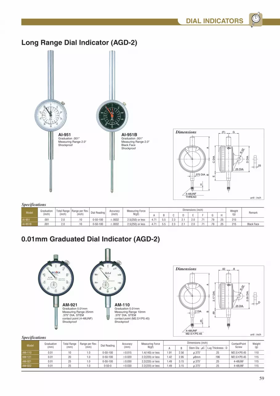
59
DIAL INDICATORS
Long Range Dial Indicator (AGD-2)
0.01mm Graduated Dial Indicator (AGD-2)
AM-921Graduation 0.01mmMeasuring Range 25mm.375" DIA. STEMcontact point (4-48UNF)Shockproof
AM-110Graduation 0.01mmMeasuring Range 10mm.375" DIA. STEMcontact point (M2.5×P0.45)Shockproof
AI-951Graduation .001"Measuring Range 2.0"Shockproof
AI-951BGraduation .001"Measuring Range 2.0"Black FaceShockproof
Dimensions
unit : inch
4-48UNFTHREAD
AB.375 DIA.
H
G(F)
C D
IA.
D D
IA.
E
R.3
2
.25 DIA..25
Dimensions
unit : inch
4-48UNFM2.5×P0.45
ABC DIA.
.25
.8.62
2.17
DIA
.
2.05
DIA
.
.69
R.3
2
.25 DIA.D
Specifications
AI-951
AI-951B
.001
.001
2.0
2.0
.10
.10
Graduation(inch)
Total Range(inch)
Range per Rev.(inch)
0-50-100
0-50-100
Dial Reading
±.0032
±.0032
Accuracy(inch) Remark
2.5(250) or less
2.5(250) or less
A
4.71
4.71
Measuring Force N(gf)Model
215
215
Weight(g)
Black Face
B
5.5
5.5
C
2.3
2.3
D
2.1
2.1
E
2.0
2.0
F
.71
.71
G
.79
.79
H
.25
.25
Dimensions (inch)
Specifications
AM-110
KM-121
AM-921
AM-922
0.01
0.01
0.01
0.01
10
20
25
25
1.0
1.0
1.0
1.0
Graduation(mm)
Total Range(mm)
Range per Rev.(mm)
0-50-100
0-50-100
0-50-100
0-50-0
Dial Reading
±0.015
±0.020
±0.030
±0.030
Accuracy(mm)
1.4(140) or less
2.2(220) or less
2.2(220) or less
2.2(220) or less
A
1.91
1.42
1.49
1.49
Measuring Force N(gf)Model
110
115
115
115
Weight(g)B
2.56
2.95
3.15
3.15
M2.5×P0.45
M2.5×P0.45
4-48UNF
4-48UNF
ContactPointScrew
φ.375"
φ8mm
φ.375"
φ.375"
Stem Dia : φC
.25
.196
.25
.25
Lug Thickness : D
Dimensions (inch)

60
Specifications
TI-111
TI-105
TI-105W
kI-121
TI-1111
TI-1112
TI-1205
TI-35
.001
.001
.001
.001
.0001
.0001
.0001
.001
.50
.25
.25
1.0
.05
.05
.20
.20
.10
.10
.10
.10
.01
.01
.01
.10
Graduation(inch)
Total Range(inch)
Range per Rev.(inch)
0-50-100
0-50-0
0-50-100
0-50-100
0-5-10
0-5-0
0-5-10
0-50-100
Dial Reading
±.0009
±.0007
±.0007
±.0014
±.0002
±.0002
±.0004
±.0006
Accuracy(inch) Remark
1.4(140) or less
1.3(130) or less
1.4(140) or less
2.2(220)or less
1.5(150) or less
1.5(150) or less
1.5(150) or less
1.3(130) or less
A
1.76
1.76
1.76
1.44
1.57
1.57
1.57
1.08
Measuring Force N(gf)Model
Flat Back
Flat Back
110
110
110
115
170
170
170
70
Weight(g)
Dial Indicator (with 8mm stem)
TI-1111Graduation .0001"Measuring Range .05"Heavy-duty, jeweled typeShockproof
DIAL INDICATORS
TI-1205Graduation .0001"Measuring Range .20"
TI-111Graduation .001"Measuring Range .50Shockproof
KI-121Graduation .001"Measuring Range 1.0"Shockproof
Miniature Dial Indicator (AGD-1)Dimensions
unit : inch
M2.5×P0.45THREAD
ABφ8mm
(.315 DIA.)
H
G(F)
C D
IA.
D D
IA.
E
R.3
2
.25 DIA..25
I (with Flat back)
B
2.7
2.7
2.7
3.19
2.44
2.44
2.44
1.63
C
2.17
2.17
2.17
2.17
2.2
2.2
2.2
1.54
D
2.05
2.05
2.05
2.05
2.05
2.05
2.07
1.43
E
.69
.69
.69
.69
.71
.71
.59
.39
F
.62
.62
.62
.62
.62
.62
.8
.57
G
.79
–
.79
.79
.79
.79
.79
.76
H
.30
.30
.30
.30
.30
.30
.30
.20
I
–
.31
–
–
–
.30
–
–
Dimensions (inch)
TI-35Graduation .001"Measuring Range .20"

61
Auto Clutch Type
LTI-352Graduation .005"Measuring Range .03"
Specifications
LTI-352
LTI-352B
LTI-353
LTI-355
.0005
.0005
.0005
.0001
.03
.03
.03
.01
Graduation(inch)
Total Range(inch)
0-15-0
0-15-0
0-15-0
0-5-0
Dial Reading
.0004
.0004
.0004
.0002
Accuracy(inch) Remark
0.2(20) or less
0.2(20) or less
0.2(20) or less
0.25(25) or less
A
1.38
1.38
1.38
1.51
Measuring Force N(gf)Model
Standard
Black Face
Long Contact Point
Precision
75
75
75
75
Weight(g)B
.787
.787
1.52
.64
C
2.28
2.28
3.02
2.14
D
3.1
3.1
3.64
2.76
Dimensions (inch)
DIAL TEST INDICATORSDIAL TEST INDICATORS
LTI-355Graduation .0001"Measuring Range .01"
Standard Accessories Set.375" DIA. Stem.157" DIA. Stem.125" Stylus (Steel ball).039" Stylus (Steel ball)
Dimensions
unit : inch
D
.079 DIA. Carbide Ball
10.5
.76.12
B
.67
115゚
115゚
1.05
"A"
DIA
.
.38
.17
C
.236DIA.
DovetailLTI-352 only
Move toabout 1.14
Lever Type
Parts
LTI-310Graduation .001"Measuring Range .03"
Specifications
LTI-310
LTI-315
LTI-316
LTI-370
.001
.0005
.0005
.0001
.03
.03
.04
.01
Graduation(inch)
Total Range(inch)
0-15-0
0-15-0
0-20-0
0-5-0
Dial Reading
.0004
.0004
.0005
.0002
Accuracy(inch)
0.4(40) or less
0.4(40) or less
0.4(40) or less
0.4(40) or less
A
1.12
1.38
1.38
1.51
Measuring Force N(gf)Model
50
60
70
70
Weight(g)B
.56
.75
1.72
.43
C
.54
.53
.53
.53
D
.85
.85
.85
.85
E
1.83
2.44
3.41
2.12
F
3.1
3.74
4.70
3.41
G
.2
.19
.19
.19
H
.28
.27
.27
.27
Dimensions (inch)
LTI-315Graduation .0005"Measuring Range .03"
LTI-370Graduation .001"Measuring Range .01"
Dimensions
unit : mm
DC
G
.283
φ.079Carbide Ball
100°
100°
"A"
DIA
.
E
B
.138
.63
F
.236 DIA.
H
Stylus Universal Holder with Clamp
Code No.
ZS-722
ZS-723
ZS-724
ZS-735
ZS-725
ZS-726
ZS-727
Type
LTI-310
LTI-315
LTI-316
LTI-370
LTI-352
.078" DIA.
.039" DIA.
.125" DIA.
Code No.
ZS-729
ZS-730
ZS-731
ZS-732
ZS-733
ZS-734
Type
LTI-353
LTI-355
Code No.
ZY-062
Dimensions (inch)
Dovetail.236 DIA.
.078" DIA.
.039" DIA.
.125" DIA.
.078" DIA.
.039" DIA.
.125" DIA.
Steel ball
ZY-062

62
THICKNESS GAUGESTHICKNESS GAUGES
Specifications
SI-112
SI-112LS
SI-112LW
SI-112-3A
SI-530
SI-530LS
SI-530LW
SI-530-3A
.001
.001
.001
.001
.001
.001
.001
.001
.5
.5
.5
.5
1.0
1.0
1.0
1.0
.10
.10
.10
.10
.10
.10
.10
.10
Graduation(inch)
Total Range(inch)
Range per Rev.(inch)
±0-50-100
±0-50-100
±0-50-100
±0-50-100
±0-50-100
±0-50-100
±0-50-100
±0-50-100
Dial Reading
.394 DIA. Flat
S.125(1/8) DIA.
S.125(1/8) DIA.
.197 DIA. Flat
.394 DIA. Flat
S.125(1/8) DIA.
S.125(1/8) DIA.
.197 DIA. Flat
Contact point form(inch)
2.5(250) or less
2.5(250) or less
2.5(250) or less
2.5(250) or less
3.5(350) or less
3.5(350) or less
3.5(350) or less
3.5(350) or less
Measuring Force N(gf)Model
145
145
145
145
200
200
200
200
Weight(g)
Digital Thickness Gauge
SID-540Resolution .0005"/0.01mmMeasuring Range .5"/12.7mmDepth 1.18"/30mmContact Point and Anvil(Ceramic)
SID-565Resolution .00005"/0.001mmMeasuring Range .5"/12.7mmDepth 1.18"/30mmContact Point and Anvil(Ceramic)(Movable anvil type)
SI-112Graduation .001"Measuring Range .5"Contact Point and Anvil (Ceramic)
SI-530Graduation .001"Measuring Range 1.0"Contact Point and Anvil (Ceramic)
SID-550Resolution .0005"/0.01mmMeasuring Range .5"/12.7mmDepth 4.72"/120mmContact Point and Anvil(Ceramic)
Specifications
SID-540
SID-550
SID-565
.0005/0.01
.0005/0.01
.00005/0.001
.5/12.7
.5/12.7
.59/15
Resolution(inch/mm)
Total Range(inch/mm) Remark
1.0(100) or less
1.0(100) or less
1.5(150) or less
Measuring Force N(gf)Model
290
440
470
Weight(g)
Dial Thickness Gauge
Dimensions: SID-540
unit : inch
1.38
(2.5
3)1.
18
1.18.394 DIA.
2.77.275
.118
.157
Dimensions: SID-565
unit : inch
(2.5
3)(1
.57)
(.29
).2
5(.
72)
(.13
)
1.38
5.48
1.0
1.18.394 DIA
.71 2.77Lifting of anvil
.118
.118
.157
.157
Dimensions: SID-550
unit : inch
2.85
1.0
1.18
.69
5.43
4.33
4.72
6.38
.118
.118
.157
.118
.157
Dimensions: SI-112
Standard Type
4.02
.47
.72
.12
.16
1.03
Lifting Lever
Frame
Anvil
Contactpoint
2.52
unit : inch
5.43
.91
1.18
1.3
.12
.16
2.99
Standard Type unit : inch
Dimensions: SI-530
.394 DIA. Flat
.394 DIA. Flat
S.125(1/8) DIA.
.197 DIA. Flat
.394 DIA. Flat
.394 DIA. Flat
S.125(1/8) DIA.
.197 DIA. Flat
Anvil form(inch)

63
SI-114Graduation .001"Measuring Range .5"Contact Point and Anvil (Ceramic)
SI-1111Graduation .0001"Measuring Range .4"Indic. Range .05"(Movable anvil)Contact Point and Anvil (Ceramic)
THICKNESS GAUGES
Anvil & Contact Point
5.2
1.10 .5
9.1
2.1
6
.39 DIA.
1.02
1.18
4.17
4.72
6.18
2.6
unit : inchStandard Type
Dimensions: SI-114
Dimensions : SI-1111
unit : inch2.
30
5.78
.43 .9
89 Lifting of anvil
1.18.33 DIA.
.71 2.78Standard Type
Specifications
SI-114
SI-114LS
SI-114LW
SI-124
SI-124LS
SI-124LW
SI-1111
SI-1111LS
SI-1111LW
.001
.001
.001
.001
.001
.001
.0001
.0001
.0001
.5
.5
.5
1.0
1.0
1.0
.4(.05)
.4(.05)
.4(.05)
.10
.10
.10
.10
.10
.10
.01
.01
.01
Graduation(inch)
Total Range(inch)
Range per Rev.(inch)
±0-50-100
±0-50-100
±0-50-100
±0-50-100
±0-50-100
±0-50-100
±0-5-10
±0-5-10
±0-5-10
Dial Reading
.394 DIA. Flat
S.125 (1/8) DIA.
S.125 (1/8) DIA.
.394 DIA. Flat
S.125 (1/8) DIA.
S.125 (1/8) DIA.
.33 DIA. Flat (Carbide)
S.118 DIA. (Carbide)
S.118 DIA. (Carbide)
Contact point form(inch)
2.5(250) or less
2.5(250) or less
2.5(250) or less
3.5(350) or less
3.5(350) or less
3.5(350) or less
1.5(150) or less
1.5(150) or less
1.5(150) or less
Measuring Force N(gf)Model
270
270
270
270
270
270
440
440
440
Weight(g)
.394 DIA. Flat
.394 DIA. Flat
S.125 (1/8) DIA.
.394 DIA. Flat
.394 DIA. Flat
S.125 (1/8) DIA.
.33 DIA. Flat (Carbide)
.33 DIA. Flat (Carbide)
S.118 DIA. (Carbide)
Anvil form(mm)
Standard Type LS Type LW Type 3A Type
.394 DIA.
anvil
S.125 DIA. Ball
contact point
anvil
S.125 DIA. Ball
S.125 DIA. Ball
.197 DIA.
contact point
anvil
contact point
.394 DIA.
anvil
contact point
unit : inch

64
DEPTH GAUGESDEPTH GAUGESDigital Depth Gauge
Specifications
DID-210
DID-211
DID-213
DID-215
.0005/0.01
.0005/0.01
.0005/0.01
.0005/0.01
.5/12.7
.5/12.7
.5/12.7
8.0/230
Resolution(inch/mm)
Total Range(inch/mm) Remark
1.0(100) or less
1.0(100) or less
1.0(100) or less
2.3(230) or less
Measuring ForceN(gf)
Needle
.079 DIA. Flat
S.125 DIA. (1/8)
S.125 DIA. (1/8)
Contact PointInchModel
Extension Rods
310
310
310
375
Weight(g)
Specifications
DI-223
DI-224
.001
.001
1.0
8.0
Graduation(inch)
Total Range(inch) Remark
2.2(220) or less
2.5(250) or less
Measuring Force N(gf)
.01
.01
0-50-100
0-50-100
Dial ReadingRange per Rev.Model
Extension Rods
275
340
Weight(g)
S.125 DIA. (1/8)
S.125 DIA. (1/8)
Contact Point(inch)
Dial Depth Gauges
DID-210Resolution .0005"/0.01mmMeasuring Range .5"/12.7mm
DI-223Graduation .001"Measuring Range 1.0"
DI-224Graduation .001"Measuring Range 8.0"Indication Range 1.0"with 5-Extensint rods
DID-211Resolution .0005"/0.01mmMeasuring Range .5"/12.7mm
DID-213Resolution .0005"/0.01mmMeasuring Range .5"/12.7mm
DID-215Resolution .0005"/0.01mmMeasuring Range 8.0"/230mmIndication Range .5"/12.7mmwith 5-Extensint rods
Dimension
b
2.38
DIA
.
1.34
unit : inch
1.95
a
2.59
Base hole
Dimension
1.41
2.55
1.0
2.17 DIA.
a b
unit : inch
Base hole
Base a×b
2.95×.63
2.95×.63
2.95×.63
3.94×.63
Base hole
.098 DIA.
.098 DIA.
.20 DIA.
.20 DIA.
Dimensions (inch)
Base a×b
2.95×.63
3.94×.63
Base hole
.20 DIA.
.20 DIA.
Dimensions (inch)

65
Standard type
Small Hole Bore Gauge
CNI-150Measuring Range 2.0"~6.0"
CNI-10Measuring Range .24"~.40"
BORE GAUGESBORE GAUGES
DimensionsA
B (measuring depth) E D
C
I
φG φF
φJ
H
CNI-60
φH
CNI-35
φH
unit : inch
Specifications
CNI-35
CNI-60
CNI-100
CNI-150
CNI-160
CNI-250
CNI-400
.70~1.4
1.4~2.5
2.0~4.0
2.0~6.0
4.0~6.5
6.5~10
10~16
MeasuringRange(inch)
4
6
6
6
6
10
10
MeasuringDepth(inch)
8
6
11
13
13
6
5
Number of Interchangeable
rods3
4
4
4
4
6
6
Number of Interchangeable
washers–
2"×1
–
–
3"×1
–
–
Extension rods(Sub anvils)
(inch) A
8.45
10.34
10.34
10.34
10.34
15.22
15.22
Model
145
210
240
280
330
740
1000
Weight(g)B
4.06
5.91
5.91
5.91
5.91
9.84
9.84
C
.24
.35
.35
.35
.35
.51
.51
D
.93
.93
.93
.93
.93
.93
.93
E
3.23
3.15
3.15
3.15
3.15
3.94
3.94
φF
.79
.79
.79
.79
.79
.83
.83
φG
.34
.47
.47
.47
.47
.59
.59
H
φ.50
φ.79
1.49
1.49
1.83
3.50
3.50
I
.44
.69
1.02
1.02
1.54
3.48
3.48
J
–
–
.50
.50
.50
.78
.78
Dimensions (inch)
Specifications
CNI-10
CNI-18
.24~.40
.40~.74
MeasuringRange(inch)
2
4
MeasuringDepth(inch)
9
9
Number of Interchangeable rods
–
1
Number of Interchangeable
washers A
3.15
3.02
Model
70
80
Weight(g)B
1.93
3.94
C
.21
.33
D
.16
.24
Dimensions (inch)
C AB (probe depth)
.375
(3/8
) D
IA.
φ.5
9φD
Dimensions
unit : inch
.375(3/8)DIA.

66
PartsInterchangeable rods (anvils) , Washers and Extension rods (sub anvils)
BORE GAUGES
Smole Hole type
Standard type
PartNominal No.
NMLcode No.
NMLcode No.
2″ZJ-396
3″ZJ-397
ModelExtension
rods(sub anvils)
interchangeable rods(anvils) WashersNo.1 No.2 No.3 No.4 No.5 No.6 No.7 No.8 No.9 No.10 No.11 No.12 No.13 .02″ .04″ .08″ .12″ .16″ .20″
CNI-10
CNI-18
.24″ZJ-300
.40″ZJ-310
.26″ZJ-301
.43″ZJ-311
.28″ZJ-302
.47″ZJ-312
.30″ZJ-303
.51″ZJ-313
.32″ZJ-304
.55″ZJ-314
.34″ZJ-305
.59″ZJ-315
.36″ZJ-306
.63″ZJ-316
.38″ZJ-307
.67″ZJ-317
.40″ZJ-308
.71″ZJ-318
ZJ-343
PartNominal No.
NMLcode No.
NMLcode No.
NMLcode No.
NMLcode No.
NMLcode No.
NMLcode No.
NMLcode No.
NMLcode No.
NMLcode No.
ModelExtension
rods(sub anvils)
interchangeable rods(anvils) WashersE1 E2 E3 E4 E5 E6 E7 E8 E9 E10 E11 E12 E13 .02″ .04″ .08″ .12″ .16″ .20″
CNI-35
CNI-60
CNI-100
CNI-150
CNI-160
CNI-250
CNI-400
.7″ZJ-420
1.4″ZJ-430
2″ZJ-430
2″ZJ-430
4.0″ZJ-430
6.4″ZJ-44510.0″
ZJ-44513″
ZJ-445
.8″ZJ-421
1.6″ZJ-431
2.2″ZJ-431
2.2″ZJ-431
4.2″ZJ-431
4.2″ZJ-431
7.0″ZJ-44610.6″
ZJ-44613.6″
ZJ-446
.9″ZJ-422
1.8″ZJ-432
2.4″ZJ-432
2.4″ZJ-432
4.4″ZJ-432
4.4″ZJ-432
7.6″ZJ-44711.2″
ZJ-44714.2″
ZJ-447
1.0″ZJ-423
2.0″ZJ-433
2.6″ZJ-433
2.6″ZJ-433
4.6″ZJ-433
4.6″ZJ-433
8.2″ZJ-44811.8″
ZJ-44814.8″
ZJ-448
1.1″ZJ-424
2.2″ZJ-434
2.8″ZJ-434
2.8″ZJ-434
4.8″ZJ-434
4.8″ZJ-434
8.8″ZJ-44912.4″
ZJ-44915.4″
ZJ-449
1.2″ZJ-425
2.4″ZJ-435
3.0″ZJ-435
3.0″ZJ-435
5.0″ZJ-435
5.0″ZJ-435
9.4″ZJ-450
1.3″ZJ-426
3.2″ZJ-436
3.2″ZJ-436
5.2″ZJ-436
5.2″ZJ-436
1.4″ZJ-427
3.4″ZJ-437
3.4″ZJ-437
5.4″ZJ-437
5.4″ZJ-437
3.6″ZJ-438
3.6″ZJ-438
5.6″ZJ-438
5.6″ZJ-438
3.8″ZJ-439
3.8″ZJ-439
5.8″ZJ-439
5.8″ZJ-439
4.0″ZJ-440
4.0″ZJ-440
6.0″ZJ-440
6.0″ZJ-440
ZJ-382
ZJ-384
ZJ-388
ZJ-395
ZJ-386
ZJ-390
ZJ-383
ZJ-385
ZJ-389
ZJ-387
ZJ-391 ZJ-392 ZJ-393
6.2″ZJ-441
6.4″ZJ-442
DIGITAL INDICATORSDIGITAL INDICATORS
PC-442Resolution .0005"/0.01mmMeasuring Range .5"/12.7mm
PC-467Resolution .00005"/0.001mmMeasuring Range .5"/12.7mm
Specifications
PC-442
PC-467
12.7-0.01/.5-.0005
12.7-0.001/.5-.00005
0.01/.0005
0.001/.00005
.5/12.7
.5/12.7
Designations(inch/mm)
Resolution(inch/mm)
Measuring Range(inch/mm)
.0002 or less
.00012 or less
Accracy(inch)
Carbide
Carbide
Contact PointModel
M2.5×0.45
M2.5×0.45
Point Screw
1.2(120) or less
1.2(120) or less
Measuring Force N(gf)
160
160
Weight(g)
φ8
φ8
Stem Diameter(mm)
1.95
2.38
DIA
.
2.13
DIA
.
.65
.791.09
.42
1.83
φ.315 Release hole (option)
.29
2.67
.20
φ.26
Dimensions: PC-440/465
unit : inch

Durometers are used to numerically display the hardness of rubber, plastic and othermaterials. Some of the particulars for rubber hardness testing equipment and themethods used for measuring hardness have been changed due to the recent broadrevisions of both ISO and JIS standards.
As a general manufacturer and supplier of Durometers, we can propose various methods for measuring not only rubber and plastic, but a wide range of soft and elastic bodies.
New Lineup of Testers in Compliance with Broad ISO and JIS Revisions for Rubber Hardness Measurements
RR
Durometer(Rubber/Plastic Hardness Tester) &IRHD Automatic Micro Hardness Tester

Full AutomaticIRHD Micro Rubber Hardnes Tester GS-680GS-680 is Micro Rubber Hardness Tester to measure international rubber Hardness(IRHD-M method) complying with ISO 48 and JIS K 6253 standards or the like, regarding the hardness of vulcanized rubber and thermoplastic rubbers. This model is a full automated measuring type and applicable software is also included, and all of the operations are operable with PC.(PC is option)
(PC is option)
□ SpecificationMeasuring range: 30~100 IRHDMinimum scale unit: 0.1 IRHDMeasuring accuracy: ±0.1 IRHD(converted on measuring distance)Measuring distance: 100mm(Up/Down)Outer interface: RS-232C outputConforming standards: EC Directive(EN61326) ,ISOMeasurable specimen: W=160 D=110 H=100mmPower: 100~240V AC/Adapter: 24V DCWeight: 7.8kg(body), 0.6kg(Adapter)Accessories: Software(CD), a spare plunger, PC cable, AC adapter
□ SpecificationModel: ZY-921Stage dimension: 90x86mmO-Ring diameter: φ0.5 ~φ10mmWeight: 2.9kg
160124 156
240
200 3.5
337
117.5
145
2
90 107.5
273.5
10
60 5112.5
104
mm
This device is a device for putting center of 0.5~10mm O-Ringpin of center of stage positioning O-ring moves slightly to back and froth,right and left direction, and stage ratate for optional position
■O-Ring Device
ISO
*Designed as a device for measuring the hardness of O-rings, small rubber parts, thin rubber sheets and other such materials
*Measurement values are obtainable just by placing a material to be measured on specimen table by pushing switches only
*Voice coil motor adopted in loading system is designed for highest accuracy and repeatability of measurement than the conventional weight type due to no effect by friction of internal mechanism
*Plug in type plunger(probe) make simple replacement of plunger(probe)
*Wide specimen table enables to install various type of measuring tools and jigs etc.
*All of the settings, such as number of measurements, Upper/Lower limit determination or median indication are operable with front panel
*PC application software(CD) enables management of various data analysis and accumulations
ZY-921(Option)
2
I R H D

Full AutomaticIRHD Micro Rubber Hardnes Tester GS-680GS-680 is Micro Rubber Hardness Tester to measure international rubber Hardness(IRHD-M method) complying with ISO 48 and JIS K 6253 standards or the like, regarding the hardness of vulcanized rubber and thermoplastic rubbers. This model is a full automated measuring type and applicable software is also included, and all of the operations are operable with PC.(PC is option)
(PC is option)
□ SpecificationMeasuring range: 30~100 IRHDMinimum scale unit: 0.1 IRHDMeasuring accuracy: ±0.1 IRHD(converted on measuring distance)Measuring distance: 100mm(Up/Down)Outer interface: RS-232C outputConforming standards: EC Directive(EN61326) ,ISOMeasurable specimen: W=160 D=110 H=100mmPower: 100~240V AC/Adapter: 24V DCWeight: 7.8kg(body), 0.6kg(Adapter)Accessories: Software(CD), a spare plunger, PC cable, AC adapter
□ SpecificationModel: ZY-921Stage dimension: 90x86mmO-Ring diameter: φ0.5 ~φ10mmWeight: 2.9kg
160124 156
240
200 3.5
337
117.5
145
2
90 107.5
273.5
10
60 5112.5
104
mm
This device is a device for putting center of 0.5~10mm O-Ringpin of center of stage positioning O-ring moves slightly to back and froth,right and left direction, and stage ratate for optional position
■O-Ring Device
ISO
*Designed as a device for measuring the hardness of O-rings, small rubber parts, thin rubber sheets and other such materials
*Measurement values are obtainable just by placing a material to be measured on specimen table by pushing switches only
*Voice coil motor adopted in loading system is designed for highest accuracy and repeatability of measurement than the conventional weight type due to no effect by friction of internal mechanism
*Plug in type plunger(probe) make simple replacement of plunger(probe)
*Wide specimen table enables to install various type of measuring tools and jigs etc.
*All of the settings, such as number of measurements, Upper/Lower limit determination or median indication are operable with front panel
*PC application software(CD) enables management of various data analysis and accumulations
ZY-921(Option)
GS-610
GSS-719(TypeA)GSS-720(TypeD)
Alignmentunit
Durometer Sensor
□ Specifications(Counter)
[Automatic Hardness Measurement System Configuration]
Model GSS-C01Standard ISO7619/JIS K6253 Min. display unit 0.1External interface RS-232CPower AC100-240 adapter Dimension 150(W)x160(L)x45(H)mmWeight 2kg
□ Specifications(Sensor)
*The ZY-089 1kg weight will need to be replaced with the ZY-078 weight in order to make measurements.
[System Function]Peak hold, timer hold(timer value 0.5, 1~30 seconds), common difference assessments, median value assessment(n=1~30), average value output, data output(PC printer), external function control output(automatic measurements started with the push of one button when used with GS-610)
GSS-719
Sensor
GS-610Durometer stand
GSS-C01 RS-232COutput
(PCprinter)
counter
GSS-720
Sensor
GS-610Durometer stand
ZY-0464kg weight
GSS-C01 RS-232COutput
(PCprinter)
counter
GSS-C01 CounterGSS-719(Type A) Sensor
4kg weight(Option=ZY-046)
Model: GX-01A(Type A) Model: GX-01D(Type D)
*work thickness : Max.35mm
Automatic Rubber Hardness Measuring SystemGX-01 series ISO
*Can display and output PEAK hold, TIMER hold, median and average values as well as common difference assessments.*Automatic hardness measurements can be conducted with 1-kg weight for the type A, GX-01A durometer and with a 5kg weight for the type D, GX-01D durometer.*Type A and D sensors can be changed The optional 4kg weight(ZY-046) is required for measurements using the Type D durometer.
*This system can connect to a PC and Computer.*The durometer sensor attachment section incorporates an alignment unit allowing for very good cohesion with the test materials.
*ISO documents can be issued(Option)Operating speed: up to 3.2mm/sec. Measurement weight: Type A=1+9,5kg, Type D=5+0.5kg (both cases include the weight of the duromeer) Presser foot diameter: φ18±0.5mm*A special platform(optional) allows for the system to be installed standing on its side, ideal when not much installation space is available.
The GX-01 series is a system for conducting automatic hardness measurements using the operation speeds, measurement loads and presser foot dimensions stipulated in ISO and JIS K6253 standard(hardness test method for vulcanized or thermoplastic rubbers).This GX-01 series consists of an automatic measurement stand(GS-610), durometer sensor(GSS-719 or GSS-720) and counter(GSS-C01).
Model GSS-719(Type A) GSS-720(Type D)Presser foot diameter Cord length 2mDimensions 22.6(W)x24(L)x138.6(H)mmWeight 160g
3
System

Inspection and Calibration of DurometerDurometers are testing devices and are included in the category of “monitoring and measuring equipment” as stipulated by ISO and JIS. Teclock is one of only a few durometer manufacturers that have received ISO 9001 certification. As such, we can independently issue the set to three documents required for ISO, especially traceability system diagrams, calibration certificates and inspection reports. These three documents can also be issued for the durometer tester and indenter height gauge needed for making in-house inspections.
This inspection device allows for the easy confirmation of the calibrated spring load for analog durometers. Three standard weights are used to apply the prescribed loads to an upside down durometer in order to confirm whether the 25, 50 and 75 graduations are properly displayed. Calibration certificates can also be issued (cannot be issued for digital models and durometers produced by other companies.) Domestic and foreign standards use an even-balance mechanism and propose inspection methods with the durometer in an upright position.
GS-607
mm
Model
GS-607GS-607AGS-607BGS-607C
Compartible Durometer
GS-701N/GS-701G/GS-706N/GS-706GGS-709N/GS-709G
GS-719N/GS-719G/GS-721N/GS-721GGS-743G
Weight
3.7kg3.7kg3.7kg3.7kg
□ Specification
The durometer shown in the photo is sold separately
Calibration certificates can be issued(option)
102
(39)φ24.8
φ38
Standard weight CStandard weight BStandard weight A
70
80Durometer(GStype,option)
40225
265
148
80
■Durometer Tester
■Indenter Height Gauge These gauges can be used to easily confirm the height of Durometers.The ZY-119 gauge is used for JIS K6301(GS-703N,GS-706N) and ZY-120 gauge is used for JIS K6253, ISO 7619, ISO 0868, ASTM D 2240, DIN 53.505 Durometers
ZY–119 ZY–120
There is no tester for Type D DurometerCalibration Certificates can be issued(option)
Model
ZY-119
ZY-120
1.27mm
1.25mm
for 2.54mm
for 2.5mm
2.489mm
2.45mm
GS-701N, 706N
GS-719N, 720N
□ Specifications
Supplementary Device for Rubber Durometer■Constant Loader for Rubber Durometer
This supplementary device assists hardnessmeasurements by using hydraulics to provided a constant load. Measurements can be taken with a roughly 1kg load for type A Durometer and a roughly 5kg (using optional 4kg weight (ZY-046) load for type D Durometers.
GS-710
4kg weight
Weight Applicable Durometers
Approx. 1kg A, B, E, old A, SRIS, O
Approx. 5kg D, ASTM C, DO, old JIS C
(Option ZY-046)
*Dimensions for opening by lever Note: Maximum work thickness Digital Durometer: 20mm Analog Durometer: 63mm L-type cannot be used
mm
Model
GS-710ZY-046
7kg4kg
Weight
□ Specification
※20
4kg Weight (option) Weight for 1kg
Durometer(option)
315
65
60(Note)
φ59
165116
M6×P1(Mount screw)
Option
Indenter height 50 Indenter height 2 Main compartible modelIndenter height
4
Tester

Inspection and Calibration of DurometerDurometers are testing devices and are included in the category of “monitoring and measuring equipment” as stipulated by ISO and JIS. Teclock is one of only a few durometer manufacturers that have received ISO 9001 certification. As such, we can independently issue the set to three documents required for ISO, especially traceability system diagrams, calibration certificates and inspection reports. These three documents can also be issued for the durometer tester and indenter height gauge needed for making in-house inspections.
This inspection device allows for the easy confirmation of the calibrated spring load for analog durometers. Three standard weights are used to apply the prescribed loads to an upside down durometer in order to confirm whether the 25, 50 and 75 graduations are properly displayed. Calibration certificates can also be issued (cannot be issued for digital models and durometers produced by other companies.) Domestic and foreign standards use an even-balance mechanism and propose inspection methods with the durometer in an upright position.
GS-607
mm
Model
GS-607GS-607AGS-607BGS-607C
Compartible Durometer
GS-701N/GS-701G/GS-706N/GS-706GGS-709N/GS-709G
GS-719N/GS-719G/GS-721N/GS-721GGS-743G
Weight
3.7kg3.7kg3.7kg3.7kg
□ Specification
The durometer shown in the photo is sold separately
Calibration certificates can be issued(option)
102
(39)φ24.8
φ38
Standard weight CStandard weight BStandard weight A
70
80Durometer(GStype,option)
40225
265
148
80
■Durometer Tester
■Indenter Height Gauge These gauges can be used to easily confirm the height of Durometers.The ZY-119 gauge is used for JIS K6301(GS-703N,GS-706N) and ZY-120 gauge is used for JIS K6253, ISO 7619, ISO 0868, ASTM D 2240, DIN 53.505 Durometers
ZY–119 ZY–120
There is no tester for Type D DurometerCalibration Certificates can be issued(option)
Model
ZY-119
ZY-120
1.27mm
1.25mm
for 2.54mm
for 2.5mm
2.489mm
2.45mm
GS-701N, 706N
GS-719N, 720N
□ Specifications
Supplementary Device for Rubber Durometer■Constant Loader for Rubber Durometer
This supplementary device assists hardnessmeasurements by using hydraulics to provided a constant load. Measurements can be taken with a roughly 1kg load for type A Durometer and a roughly 5kg (using optional 4kg weight (ZY-046) load for type D Durometers.
GS-710
4kg weight
Weight Applicable Durometers
Approx. 1kg A, B, E, old A, SRIS, O
Approx. 5kg D, ASTM C, DO, old JIS C
(Option ZY-046)
*Dimensions for opening by lever Note: Maximum work thickness Digital Durometer: 20mm Analog Durometer: 63mm L-type cannot be used
mm
Model
GS-710ZY-046
7kg4kg
Weight
□ Specification
※20
4kg Weight (option) Weight for 1kg
Durometer(option)
315
65
60(Note)
φ59
165116
M6×P1(Mount screw)
Option
Indenter height 50 Indenter height 2 Main compartible modelIndenter height
Measuring Stand for DurometerWhen hardness measurements are taken with the hand-push type durometers, there can be wide differences in the obtained values due to differences among users. Therefore, measurement stands in accordance with ISO and JIS standards have been commercialized to provide measurements with greater stability and higher reproducibility
*By simply operating switches, durometer measurements can be taken with the exact load and speed stipulated in the standards
*The use of a stepping motor when measuring rubber hardness allows for stable measurement results, greatly eliminating the data disparities common with the hand-push method
*The stand is equipped with an alignment unit to realize very good cohesion between the durometer indenter and test material
*1kg measurements can be made using Type A and Type E durometers without any special modifications. The optional ZY-046 weight is required when taking measurements using Type D durometers. Likewise, the ZY-090 1kg weight is required when making measurements using GSD series of digital durometers.
*ISO documents can be issued when using this stand. (option)
*Rubber hardness measurement with loads stipulated by JIS, ISO and others can be made by attaching a durometer and conducting manual operations.
*Equipped with an alignment unit for easy use at an affordable price.*This alignment unit realizes very good cohesion between the durometer indenter and test material
*1kg measurements can be made using Type A and Type E durometers without any special modificationsThe optional ZY-046 4kg weight is required when taking measurements using Type D Durometer. Likewise, the ZY-090 1kg weight is required when making measurements using the GSD series Digital durometers
*ISO documents can be issued when using this stand.(The operating speed cannot be certified)
■Automatic Motorized Durometer Stand
■Manual Durometer Stand
GS-610
Alignment Unit
4kg weightZY-046(option)
(*17)Dimensions for opening by motor Note 1: Maximum work thickness Digital durometer: 21mm Analog durometer:47mm L-type cannot be used
mm
Dimensions
for Analog for Digital
ZY-089(standard) ZY-090(option)ZY-046(option)
□ Specifications
Lowering speed variable range 1-19mm/sec. in 1mm/sec. interval Power source AC100V Adapter Weight 9kg
Attachment screw section (Option)
M6×P1
※(17)
(52)
4kg weight(option)
1kg weight(built-in)
□(100)
(Note 1)
(68)
(190)
(345)
(146)
GS-615
Unit: mm
Dimensions
Durometer(option)
1kg weight(built-in)
4kg weight(option)
Stroke 30
290
180(55)180
(422.8)
M6×P1
Max.80
Alignment unit
Option
Option
1kg weight(ZY-089 built-in)
1kg weight ZY-089(standard)
4kg weight (Option ZY-046)
1kg weight
4kg weight
for Analogfor Digital
ZY-089(standard) ZY-090(option)ZY-046(option)
□ Specifications
Weight 3.9kg
1kg weight 4kg weight
ISO
This new Alignment Unit is exclusively designed by Teclock and can be moved forward, backward, up and down to achieve very good cohesion between the durometer presser foot and test material surface. The GS-610, GS-615 and CX-01 series are equipped with this unit.
Alignment Unit(new function): Alignmentunit
A,B,E,old A, old SRIS,O
D, ASTM, C, DO, old JIS C
Measuring load Weight code Compatible durometer
D, ASTM, C, DO, old JIS C
A,B,E,old A, old SRIS,O
Measuring load Weight code Compatible durometer
5
Stand
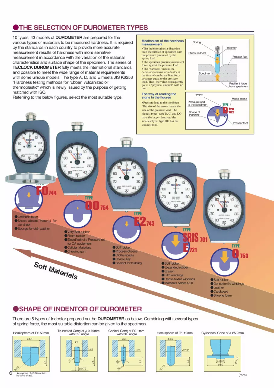
Based on the type A, below is a comparison table of measurement data. It is impossible to prove the exact correlation between the each type-to-type data, since the measured data may be affected by many factors such as temperature, humidity, size and shape at the measurement, and the condition of vulcanization. Use the below table for your reference to concern the equivalency of measurement data from each type of DUROMETER.
Hard Materials
Soft Materials
●Very Soft rubber●Foam rubber●Electrified roll / Pressure roll
for OA equipment●Cellular Materials●Chewing gum
●Soft rubber●Process cheese●Clothe scrolls●China Clay●Sealant for building ●Soft rubber
●Expanded rubber●Eraser●Film windings●Dense textile windings●Materials below A 20
●Soft rubber●Dense textile windings●Leather●Cardboard●Styrene foam
●General rubber, elastomers, soft plastic●Tires●Rubber roll●Rubber hose●Materials below D 20
●Medium-hard rubber●Biscuit ware clay●Wood
●Medium-hard rubber●Floor plate, building wood●Car handle material / inner
decoration materials●Hard rubber●Golf ball●Break rubber for bicycle
●Hard rubber ●Plastics●Ebonite●Materials beyond A 90
●Urethane foam●Shock absorb material for
car sheet●Sponge for dish washer
Truncated Cone of φ 0.79mm with 35° angle
Conical Cone of R0.1mm with 30° angleHemisphere of R2.50mm
Hemisphere of φ 5.08mm is inthe same shape.
Hemisphere of R1.19mm Cylindrical Cone of φ 25.2mm
φ3
2.5
φ0.79
1.25
35°
φ2.38
φ3.5
R1.19
2.5
R2.5
φ5.4
2.5
R0.1
30°
2.5
1.25
φ3
φ25.2φ80
2.5
There are 5 types of Indentor prepared on the DUROMETER as below. Combining with several types of spring force, the most suitable distortion can be given to the specimen.
Indentor
Spring
・・・・ ・・・・ ・・・・ ・・・・・ ・・・・ ・・・・・ ・・・・・・・・・・・ ・・・・・・・・・・
Specimen
Shape ofIndentor
TYPEModel name
Presser foot
Pressure loadto the specimen
Mechanism of the hardness measurement*The indentor gives a distortion onto the surface of specimen with the pressure produced by the spring load.*The specimen produces a resilient force against the pressure load.*The "hardness" means the depressed amount of indentor at the time when the resilient force becomes equal to the pressure load. Thus, the value consequently got is a "physical amount" with no unit.
The way of reading the signs in the figures *Pressure load to the specimen The size of the arrow means the size of the pressure load. The biggest types, type D, C, and DO have the largest load and the smallest type, type OO has the weakest load.
Presser footPressure load
Resilient forcefrom specimen
TYPE AJIS K6253JIS K7215
(old A)JIS K6301
TYPE EJIS K6253
TYPE SRISSRIS 0101
TYPE E2TECLOCK E2
TYPE DJIS K6253JIS K7215
TYPE DOASTM D2240
TYPE OASTM D2240
TYPE OOASTM D2240
TYPE BASTM D2240
TYPE CASTM D2240
10 20 30 40 50 60 70 80 90 100
10 20 30 40 50 60 70 80 90
20 30 40 50 60 70 80 90
20 30 40 50 60 70 80 90
30 40 50 60 70 80 90
10 20 30 40 50
10 20 30 40 50 60 70 80
20 30 40 50 60 70 80
50 60 70 80 90
10 20 30 40 6050 70 80 90
10 20 30 40 50 60 70 80
0
90
●THE SELECTION OF DUROMETER TYPES ●COMPARISON TABLE OF MEASUREMENT DATA
●SHAPE OF INDENTOR OF DUROMETER
(mm)
10 types, 43 models of DUROMETER are prepared for the various types of materials to be measured hardness. It is required by the standards in each country to provide more accurate measurement results of hardness with more sensitive measurement in accordance with the variation of the material characteristics and surface shape of the specimen. The series of TECLOCK DUROMETER fully meets the international standards and possible to meet the wide range of material requirements with some unique models. The type A, D, and E meets JIS K6253 "Hardness testing methods for rubber, vulcanized orthermoplastic" which is newly issued by the purpose of getting matched with ISO.Referring to the below figures, select the most suitable type.
6

Based on the type A, below is a comparison table of measurement data. It is impossible to prove the exact correlation between the each type-to-type data, since the measured data may be affected by many factors such as temperature, humidity, size and shape at the measurement, and the condition of vulcanization. Use the below table for your reference to concern the equivalency of measurement data from each type of DUROMETER.
Hard Materials
Soft Materials
●Very Soft rubber●Foam rubber●Electrified roll / Pressure roll
for OA equipment●Cellular Materials●Chewing gum
●Soft rubber●Process cheese●Clothe scrolls●China Clay●Sealant for building ●Soft rubber
●Expanded rubber●Eraser●Film windings●Dense textile windings●Materials below A 20
●Soft rubber●Dense textile windings●Leather●Cardboard●Styrene foam
●General rubber, elastomers, soft plastic
●Tires●Rubber roll●Rubber hose●Materials below D 20
●Medium-hard rubber●Biscuit ware clay●Wood
●Medium-hard rubber●Floor plate, building wood●Car handle material / inner
decoration materials●Hard rubber●Golf ball●Break rubber for bicycle
●Hard rubber ●Plastics●Ebonite●Materials beyond A 90
●Urethane foam●Shock absorb material for
car sheet●Sponge for dish washer
Truncated Cone of φ 0.79mm with 35° angle
Conical Cone of R0.1mm with 30° angleHemisphere of R2.50mm
Hemisphere of φ 5.08mm is inthe same shape.
Hemisphere of R1.19mm Cylindrical Cone of φ 25.2mm
φ3
2.5
φ0.79
1.25
35°
φ2.38
φ3.5
R1.19
2.5
R2.5
φ5.4
2.5
R0.1
30°
2.5
1.25
φ3
φ25.2φ80
2.5
There are 5 types of Indentor prepared on the DUROMETER as below. Combining with several types of spring force, the most suitable distortion can be given to the specimen.
Indentor
Spring
・・・・ ・・・・ ・・・・ ・・・・・ ・・・・ ・・・・・ ・・・・・・・・・・・ ・・・・・・・・・・
Specimen
Shape ofIndentor
TYPEModel name
Presser foot
Pressure loadto the specimen
Mechanism of the hardness measurement*The indentor gives a distortion onto the surface of specimen with the pressure produced by the spring load.*The specimen produces a resilient force against the pressure load.*The "hardness" means the depressed amount of indentor at the time when the resilient force becomes equal to the pressure load. Thus, the value consequently got is a "physical amount" with no unit.
The way of reading the signs in the figures *Pressure load to the specimen The size of the arrow means the size of the pressure load. The biggest types, type D, C, and DO have the largest load and the smallest type, type OO has the weakest load.
Presser footPressure load
Resilient forcefrom specimen
TYPE AJIS K6253JIS K7215
(old A)JIS K6301
TYPE EJIS K6253
TYPE SRISSRIS 0101
TYPE E2TECLOCK E2
TYPE DJIS K6253JIS K7215
TYPE DOASTM D2240
TYPE OASTM D2240
TYPE OOASTM D2240
TYPE BASTM D2240
TYPE CASTM D2240
10 20 30 40 50 60 70 80 90 100
10 20 30 40 50 60 70 80 90
20 30 40 50 60 70 80 90
20 30 40 50 60 70 80 90
30 40 50 60 70 80 90
10 20 30 40 50
10 20 30 40 50 60 70 80
20 30 40 50 60 70 80
50 60 70 80 90
10 20 30 40 6050 70 80 90
10 20 30 40 50 60 70 80
0
90
●THE SELECTION OF DUROMETER TYPES ●COMPARISON TABLE OF MEASUREMENT DATA
●SHAPE OF INDENTOR OF DUROMETER
(mm)
10 types, 43 models of DUROMETER are prepared for the various types of materials to be measured hardness. It is required by the standards in each country to provide more accurate measurement results of hardness with more sensitive measurement in accordance with the variation of the material characteristics and surface shape of the specimen. The series of TECLOCK DUROMETER fully meets the international standards and possible to meet the wide range of material requirements with some unique models. The type A, D, and E meets JIS K6253 "Hardness testing methods for rubber, vulcanized orthermoplastic" which is newly issued by the purpose of getting matched with ISO.Referring to the below figures, select the most suitable type.
7

Digital/Analog Durometer compliance with ISO, ASTM, DIN and JIS
These durometers comply with ISO, ASTM, DIN and JIS K 6253(new JIS). There are three different type of durometers corresponding to different degrees of hardness. Type A, the most common or central durometer,is used to measure medium hardness, while Type D is for high hardness and Type E is for low hardness.Type A, tends to indicate readings 1 to 2 points higher compared to the previous JIS A-type hardness tester.Type D durometer is used to measure super hard rubber that has a reading of more than 90 points when measuring with a Type A durometer. Type E durometer is used to measure soft rubber that has a reading of less than 20 points when measured with a Type A durometer. The Type A GS-719N model has also been designated for use in
unbonded capping tests, which is a method for testing concrete compression. Further more, ISO7619 refers to the Type E as the Type AO durometer.
GS-719NType A Durometer
Type A Digital Durometer
for general rubber
GS-719RType A Durometer
GSD-719J-RType D Digital Durometer
Spring Load Hardness 0-100
GS-719N
GS-719G
GS-719R
GS-720N
GS-720G
GS-720R
GS-721N
GS-721G
GS-719P
GSD-719J
GSD-720J
GSD-721J
GSD‒719J‒R
GSD‒720J‒R
General Rubber
General Rubber
General Rubber
Hard Rubber
Hard Rubber
Hard Rubber
Soft Rubber
Soft Rubber
General Rubber
General Rubber
Hard Rubber
Soft Rubber
General Rubber
Hard Rubber
JIS K 6253
ISO 7619
ISO 868
ASTM D 2240
DIN 53 505(R type only)
JIS K 6253ISO 7619
ASTM D 2240
JIS K 6253
JIS K 6253, JIS K 7215,ISO 7619, ISO 868, ASTM D 2240
JIS K 6253, ISO 7619ASTM D 2240
JIS K 6253, ISO 7619ISO 868, ASTM D 2240
DIN 53 505
550-8050mN(56.1-821.1gf)550-8050mN(56.1-821.1gf)550-8050mN(56.1-821.1gf)0-44450mN(0-4538gf)0-44450mN(0-4538gf)0-44450mN(0-4538gf)550-8050mN(56.1-821.1gf)550-8050mN(56.1-821.1gf)550-8050mN(56.1-821.1gf)550-8050mN(56.1-821.1gf)0-44450mN(0-4533gf)550-8050mN(56.1-821.1gf)550-8050mN(56.1-821.1gf)0-44450mN(0-4533gf)
Indenter Shape (mm)
Indenter Height(mm)
φ0.79 with 35°angleTruncated Cone φ0.79 with 35°angleTruncated Cone φ0.79 with 35°angleTruncated Cone R0.1 with 30°angleConical Cone
R0.1 with 30°angleConical Cone
R0.1 with 30°angleConical Cone Hemisphereof R2.50Hemispherewith φ0.79
φ0.79 with 35°angleTruncated Coneφ0.79 with 35°angleTruncated ConeHemisphereof R2.50Hemispherewith φ0.79
φ0.79 with 35°angleTruncated ConeConical with30° angle
2.50
2.50
2.50
2.50
2.50
2.50
2.50
2.50
2.50
2.50
2.50
2.50
2.50
2.50
Weight(g)
200
208
213
200
208
213
200
208
125
313
313
313
320
320
A
A
A
D
D
D
E(AO)
E
A
A
D
E(AO)
A
D
□ Specification
needle
upper/lowerlimiter
pointer
Peak Pointer(model numbers ending with G, R, H, L or P)Sometimes it is difficult to read the peak value immediately after the presser foot makes contact with rubber, elastomer and other soft elastic bodies as creep characteristics and other factors cause the indicated value to decline. Even though the indicator needle continues to indicate the lower value, the pointer stays at the peak value, which greatly improves precision. This feature is also useful in cases where something blocks the view of the display when the measurement is taken, as the pointer remains at the peak value and can be confirmed after taking the measurement.The peak pointer method is also effective for making common difference assessmentsof the hardness value as upper and lower limiters are standard.
■Standard Type
18mm
■φ18mm Presser Foot Durometer
GSD-719Jwith peak hold functionfor general rubber
can both used as withand without standswith Peak Hold function
can both be used withand without stands with Peak pointer
ISODigitalAnalog
*N: standard *G: with peak pointer *P: Pocket type *R:φ18mm surface type *Indenter Height:2.50mm
Analog
Digital
Model Type Application Applicable Standards
can both used as with Stands and without stands
The presser foot diameters for the Type A and D druometers which can be with measurement stands, is φ18mm surface as stipulated in the ISO and JIS standards. The φ18mm type A(GS-719R) and type D (GS-720R) can both be used without the measurement stands.
*Model J equipped with “peak hold” function (maintains the peak reading) effective for measuring elastomer and other materials for which obtaining the peak reading is difficult due to stress relaxation and other issues*Minimum reading of 0.5(1/2 for analog type durometer)*Connection to SD-763P Printer(Option) allows for easy statistical processing of the measured data.
Methods for determining hardness of vulcanized rubber and thermoplastic rubber
Peak Hold Function(J)
8
Durometer

Digital/Analog Durometer compliance with ISO, ASTM, DIN and JIS
These durometers comply with ISO, ASTM, DIN and JIS K 6253(new JIS). There are three different type of durometers corresponding to different degrees of hardness. Type A, the most common or central durometer,is used to measure medium hardness, while Type D is for high hardness and Type E is for low hardness.Type A, tends to indicate readings 1 to 2 points higher compared to the previous JIS A-type hardness tester.Type D durometer is used to measure super hard rubber that has a reading of more than 90 points when measuring with a Type A durometer. Type E durometer is used to measure soft rubber that has a reading of less than 20 points when measured with a Type A durometer. The Type A GS-719N model has also been designated for use in
unbonded capping tests, which is a method for testing concrete compression. Further more, ISO7619 refers to the Type E as the Type AO durometer.
GS-719NType A Durometer
Type A Digital Durometer
for general rubber
GS-719RType A Durometer
GSD-719J-RType D Digital Durometer
Spring Load Hardness 0-100
GS-719N
GS-719G
GS-719R
GS-720N
GS-720G
GS-720R
GS-721N
GS-721G
GS-719P
GSD-719J
GSD-720J
GSD-721J
GSD‒719J‒R
GSD‒720J‒R
General Rubber
General Rubber
General Rubber
Hard Rubber
Hard Rubber
Hard Rubber
Soft Rubber
Soft Rubber
General Rubber
General Rubber
Hard Rubber
Soft Rubber
General Rubber
Hard Rubber
JIS K 6253
ISO 7619
ISO 868
ASTM D 2240
DIN 53 505(R type only)
JIS K 6253ISO 7619
ASTM D 2240
JIS K 6253
JIS K 6253, JIS K 7215,ISO 7619, ISO 868, ASTM D 2240
JIS K 6253, ISO 7619ASTM D 2240
JIS K 6253, ISO 7619ISO 868, ASTM D 2240
DIN 53 505
550-8050mN(56.1-821.1gf)550-8050mN(56.1-821.1gf)550-8050mN(56.1-821.1gf)0-44450mN(0-4538gf)0-44450mN(0-4538gf)0-44450mN(0-4538gf)550-8050mN(56.1-821.1gf)550-8050mN(56.1-821.1gf)550-8050mN(56.1-821.1gf)550-8050mN(56.1-821.1gf)0-44450mN(0-4533gf)550-8050mN(56.1-821.1gf)550-8050mN(56.1-821.1gf)0-44450mN(0-4533gf)
Indenter Shape (mm)
Indenter Height(mm)
φ0.79 with 35°angleTruncated Cone φ0.79 with 35°angleTruncated Cone φ0.79 with 35°angleTruncated Cone R0.1 with 30°angleConical Cone
R0.1 with 30°angleConical Cone
R0.1 with 30°angleConical Cone Hemisphereof R2.50Hemispherewith φ0.79
φ0.79 with 35°angleTruncated Coneφ0.79 with 35°angleTruncated ConeHemisphereof R2.50Hemispherewith φ0.79
φ0.79 with 35°angleTruncated ConeConical with30° angle
2.50
2.50
2.50
2.50
2.50
2.50
2.50
2.50
2.50
2.50
2.50
2.50
2.50
2.50
Weight(g)
200
208
213
200
208
213
200
208
125
313
313
313
320
320
A
A
A
D
D
D
E(AO)
E
A
A
D
E(AO)
A
D
□ Specification
needle
upper/lowerlimiter
pointer
Peak Pointer(model numbers ending with G, R, H, L or P)Sometimes it is difficult to read the peak value immediately after the presser foot makes contact with rubber, elastomer and other soft elastic bodies as creep characteristics and other factors cause the indicated value to decline. Even though the indicator needle continues to indicate the lower value, the pointer stays at the peak value, which greatly improves precision. This feature is also useful in cases where something blocks the view of the display when the measurement is taken, as the pointer remains at the peak value and can be confirmed after taking the measurement.The peak pointer method is also effective for making common difference assessmentsof the hardness value as upper and lower limiters are standard.
■Standard Type
18mm
■φ18mm Presser Foot Durometer
GSD-719Jwith peak hold functionfor general rubber
can both used as withand without standswith Peak Hold function
can both be used withand without stands with Peak pointer
ISODigitalAnalog
*N: standard *G: with peak pointer *P: Pocket type *R:φ18mm surface type *Indenter Height:2.50mm
Analog
Digital
Model Type Application Applicable Standards
can both used as with Stands and without stands
The presser foot diameters for the Type A and D druometers which can be with measurement stands, is φ18mm surface as stipulated in the ISO and JIS standards. The φ18mm type A(GS-719R) and type D (GS-720R) can both be used without the measurement stands.
*Model J equipped with “peak hold” function (maintains the peak reading) effective for measuring elastomer and other materials for which obtaining the peak reading is difficult due to stress relaxation and other issues*Minimum reading of 0.5(1/2 for analog type durometer)*Connection to SD-763P Printer(Option) allows for easy statistical processing of the measured data.
Methods for determining hardness of vulcanized rubber and thermoplastic rubber
Peak Hold Function(J)
GS-719LType A DurometerLong leg(L) modelwith Peak pointer
GS-720HType D DurometerDeep hole(H) model with Peak pointer
Deep Hole/Long Leg DurometerWhen the measurement surface is uneven, has limited flat areas due to irregular shapes or has deep hallows, good contact with the durometer presser foot and accurate measurements become very difficult. In such cases, measurements are only possible if the presser foot is smaller or has a longer reach, such as with the deep hole(H) and long leg(L) durometer models. Pointers and upper/lower limits are standard for both models.
GS-719H
GS-719L
GS-720H
GS-720L
GSD-719J-H
GSD-719J-L
GSD-720J-H
GSD-720J-L
JIS K 6253, ISO 7619ASTM D 2240
JIS K 6253, ISO 7619ASTM D 2240, DIN 53 505JIS K 6253, ISO 7619ASTM D 2240
JIS K 6253, ISO 7619ASTM D 2240, DIN 53 505
JIS K 6253, JIS K 7215, ISO 7619, ISO868, ASTM D 2240
JIS K 6253, JIS K 7215, ISO 7619, ISO868, ASTM D 2240, DIN 53 505JIS K 6253, JIS K 7215, ISO 7619,
ISO868, ASTM D 2240JIS K 6253, JIS K 7215, ISO 7619, ISO868, ASTM D 2240, DIN 53 505
φ12
φ18
φ12
φ18
φ12
φ18
φ12
φ18
550-8050mN(56.1-821.1gf)550-8050mN(56.1-821.1gf)0-44450mN(0-4533gf)0-44450mN(0-4533gf)550-8050mN(56.1-821.1gf)550-8050mN(56.1-821.1gf)0-44450mN(0-4533gf)0-44450mN(0-4533gf)
2.50
2.50
2.50
2.50
2.50
2.50
2.50
2.50
A
A
D
D
A
A
D
D
120
360
120
360
170
380
170
380
GSD-719J-LType A Digital DurometerLong leg(L) Modelwith Peak hold function
GSD-719J-HType A Digital DurometerDeep hole(H) model with Peak hold function
*All of above Durometers cannot be used with Stands.
Comparison of Standard type(left) and Pocket type
Pocket DurometerThis is compact and lightweight Durometer, and convenient to use at any places(inside or outside). Peak Pointer is equippedfor accurate measurement.
Dimension
GS-719P
GS-709P
JIS K 6253
JIS K 7215
550-8050mN(56.1-821.1gf)549-8061mN(55-822gf)
2.50 125A
A
□ Specification
GS-719PGS-709PType A Durometer
unit: mm
DigitalAnalog
Analog
with Peak Pointer
φ39.5
46.2
42.2
2.5
φ18±0.5
Strap hole
16.4φ15
φ0.79±0.01
2.5±0.02
φ1.25±0.15
φ3±0.1
35゚±0.25°
S=4/1
φ19φ19
Surface
Indenter Height(mm)
Weight(g)
□ Specification
Analog
Digital
Model Type
Model Type Application Applicable Standards Spring LoadHardness 0-100
Indenter shape(mm)
Indenter Height(mm) Weight(g)
Application Applicable Standards
General Rubber, deep/small hole
General Rubber, deep/small hole
Hard rubber, long/large hole
Hard rubber, long/large hole
General rubber, deep/small hole
General Rubber, deep/small hole
Hard rubber, deep/small hole
Hard rubber, long/large hole
φ0.79 with 35°Truncated Coneφ0.79 with 35°Truncated ConeR0.1 with 30°Conical ConeR0.1 with 30°Conical Coneφ0.79 with 35°Truncated Coneφ0.79 with 35°Truncated Coneφ0.79 with 35°Truncated Coneφ0.79 with 35°Truncated Cone
Surface DiameterIndenter shape Spring Load
Hardness 0-100
General Rubber
General RubberSoft Plastic
φ0.79 with 25°Truncated Cone
9
Durometer

Digital/Analog Durometer compliance with ISO, ASTM, DIN and JIS
GS-702NType D Durometerfor Plastic/Hard rubber
GS-709NType A Durometerfor Soft plastic/general rubber
GS-702N
GS-702G
GS-709N
GS-709G
GS-709P
GSD-719J
GSD-720J
Plastic/Hard Rubber
Plastic/Hard Rubber
Soft Plastic/General Rubber
Soft Plastic/General Rubber
Soft Plastic/General Rubber
Soft Plastic/General Rubber
Hard Rubber/Plastic
JIS K 7215
ISO 868
ASTM D 2240
JIS K 7215
JIS K 6253, JIS K 7215, ISO 7619, ISO 868, ASTM D 2240
0-44483mN(0-4536gf)0-44483mN(0-4536gf)549-8061mN(56-822gf)549-8061mN(56-822gf)550-8050mN(56.1-821.1gf549-8061mN(55-822gf)0-44450mN(0-4533gf)
2.50
2.50
2.50
2.50
2.50
2.50
2.50
D
D
A
A
A
A,digital
D,digital
200
208
200
208
125
313
313
□ Specification
Digital/Analog Durometer compliance with SIRS and JISThese durometer is used according to a regulation of physics testing method for Polyurethane Elastomer formed materials, and comply with JIS K732/JIS S6050 standard. Type A durometer is called as Shore A, and Type D durometer is called as Shore D and Type C for lower hardness is ASKER C. GS-701N(G) is same with ASKER C Durometer and comply with JIS 6050 standard (measurement hardness of eraser). SRIS 0101 standard(Japanese Rubber Association standard) based on above measuring method has been repealing now.
These durometers comply with ISO, ASTM, DIN and JIS K 7215. These durometers are designed for JIS 7215 standards which are used in Japanese plastic industry. These durometers are basically same with JIS K6253 new JIS standard, and only sphere method of spring is different. Teclock is making as another durometers from point of compartible JIS standard.
GS-701NType C(Asker C)for soft rubber and eraser
GS-701N
GS-701G
GSD-701J
JIS K 7312JIS S 6050SRIS 0101
0.54N-8.39N(55.1-855.5gf)0.54N-8.39N(55.1-855.5gf)0.54N-8.39N(55.1-855.5gf)
2.54
2.54
2.54
200
208
313
C
C
C
□ Specification
□ Specification
*N: standard *G: with Peak Pointer *P: Pocket type *J: Peak hold function *Indenter Height: 2.50mm
*N: Standard *G: Peak Pointer *J: with Peak hold function *Indenter height: 2.54mm
DigitalAnalog
DigitalAnalog
PartsTest Block (option)These are rubber test pieces which can simply check whether accuracy of durometer is in the range of standard value . It is absolutely approximate value but accuracy of durometer can be easily controlled in a short period.
ZY-107ZY-108
ZY-109 ZY-110Code No. Dimension(mm)
ZY-107
ZY-108
ZY-109
ZY-110
Durometer A Hardness:50
Durometer A Hardness:80
Durometer D Hardness:40
Durometer E Hardness:80
40×80×12 thickness
40×80×12 thickness
70×80×7 thickness
40×80×12 thickness
Applicable Durometer
GS-719N・GS-719G・GSD-719S
Measuring value: nearly 50
GS9719N・GS-719G・GSD-719S
Measuring value: nearly 80
GS-720N・GS-720G・GSD-720S
Measuring value: nearly 40
GS-721N・GS-721G・GSD-721S
Measuring value: nearly 80
type
*Durometers complying with these test pieces are Type A, Type D, Type E, which are compliant with JIS K 6253.*Calibration Certificate about test pieces can not be issued.
Analog
Digital
Analog
Digital
Model Type Application Applicable StandardsSpring Load Hardness 0-100 Indenter shape Weight
(g)Indenter Height(mm)
Model Type Application Applicable Standards Spring Load Hardness 0-100 Indenter Shape Weight
(g)Indenter Height(mm)
Method for determining hardness of vulcanized rubber and thermoplastic rubber
R0.1 with 30°angleConical Cone
R0.1 with 30°angleConical Cone
R0.1 with 30°angleConical Cone
φ0.79 with 35°angle Truncated Cone φ0.79 with 35°angle Truncated Cone
φ0.79 with 35°angle Truncated Cone
φ0.79 with 35°angle Truncated Cone
Soft Rubber, Foam rubber, eraser, Yarn hardness
φ5.08 hemisphereshape
φ5.08 hemisphereshape
φ5.08 hemisphereshape
10
Durometer

Digital/Analog Durometer compliance with ISO, ASTM, DIN and JIS
GS-702NType D Durometerfor Plastic/Hard rubber
GS-709NType A Durometerfor Soft plastic/general rubber
GS-702N
GS-702G
GS-709N
GS-709G
GS-709P
GSD-719J
GSD-720J
Plastic/Hard Rubber
Plastic/Hard Rubber
Soft Plastic/General Rubber
Soft Plastic/General Rubber
Soft Plastic/General Rubber
Soft Plastic/General Rubber
Hard Rubber/Plastic
JIS K 7215
ISO 868
ASTM D 2240
JIS K 7215
JIS K 6253, JIS K 7215, ISO 7619, ISO 868, ASTM D 2240
0-44483mN(0-4536gf)0-44483mN(0-4536gf)549-8061mN(56-822gf)549-8061mN(56-822gf)550-8050mN(56.1-821.1gf549-8061mN(55-822gf)0-44450mN(0-4533gf)
2.50
2.50
2.50
2.50
2.50
2.50
2.50
D
D
A
A
A
A,digital
D,digital
200
208
200
208
125
313
313
□ Specification
Digital/Analog Durometer compliance with SIRS and JISThese durometer is used according to a regulation of physics testing method for Polyurethane Elastomer formed materials, and comply with JIS K732/JIS S6050 standard. Type A durometer is called as Shore A, and Type D durometer is called as Shore D and Type C for lower hardness is ASKER C. GS-701N(G) is same with ASKER C Durometer and comply with JIS 6050 standard (measurement hardness of eraser). SRIS 0101 standard(Japanese Rubber Association standard) based on above measuring method has been repealing now.
These durometers comply with ISO, ASTM, DIN and JIS K 7215. These durometers are designed for JIS 7215 standards which are used in Japanese plastic industry. These durometers are basically same with JIS K6253 new JIS standard, and only sphere method of spring is different. Teclock is making as another durometers from point of compartible JIS standard.
GS-701NType C(Asker C)for soft rubber and eraser
GS-701N
GS-701G
GSD-701J
JIS K 7312JIS S 6050SRIS 0101
0.54N-8.39N(55.1-855.5gf)0.54N-8.39N(55.1-855.5gf)0.54N-8.39N(55.1-855.5gf)
2.54
2.54
2.54
200
208
313
C
C
C
□ Specification
□ Specification
*N: standard *G: with Peak Pointer *P: Pocket type *J: Peak hold function *Indenter Height: 2.50mm
*N: Standard *G: Peak Pointer *J: with Peak hold function *Indenter height: 2.54mm
DigitalAnalog
DigitalAnalog
PartsTest Block (option)These are rubber test pieces which can simply check whether accuracy of durometer is in the range of standard value . It is absolutely approximate value but accuracy of durometer can be easily controlled in a short period.
ZY-107ZY-108
ZY-109 ZY-110Code No. Dimension(mm)
ZY-107
ZY-108
ZY-109
ZY-110
Durometer A Hardness:50
Durometer A Hardness:80
Durometer D Hardness:40
Durometer E Hardness:80
40×80×12 thickness
40×80×12 thickness
70×80×7 thickness
40×80×12 thickness
Applicable Durometer
GS-719N・GS-719G・GSD-719S
Measuring value: nearly 50
GS9719N・GS-719G・GSD-719S
Measuring value: nearly 80
GS-720N・GS-720G・GSD-720S
Measuring value: nearly 40
GS-721N・GS-721G・GSD-721S
Measuring value: nearly 80
type
*Durometers complying with these test pieces are Type A, Type D, Type E, which are compliant with JIS K 6253.*Calibration Certificate about test pieces can not be issued.
Analog
Digital
Analog
Digital
Model Type Application Applicable StandardsSpring Load Hardness 0-100 Indenter shape Weight
(g)Indenter Height(mm)
Model Type Application Applicable Standards Spring Load Hardness 0-100 Indenter Shape Weight
(g)Indenter Height(mm)
Method for determining hardness of vulcanized rubber and thermoplastic rubber
R0.1 with 30°angleConical Cone
R0.1 with 30°angleConical Cone
R0.1 with 30°angleConical Cone
φ0.79 with 35°angle Truncated Cone φ0.79 with 35°angle Truncated Cone
φ0.79 with 35°angle Truncated Cone
φ0.79 with 35°angle Truncated Cone
Soft Rubber, Foam rubber, eraser, Yarn hardness
φ5.08 hemisphereshape
φ5.08 hemisphereshape
φ5.08 hemisphereshape
GS-754GType OO Durometerfor very soft plastic rubber
GS-743GType E2 Durometerfor soft rubber
GS-744GType FO Durometersoft foam material
mm
φ25.2φ80
11
Digital/Analog Durometer compliance with ASTM D 2240Method for determining hardness of vulcanized rubber and thermoplastic rubber
GS-750GType B Durometerfor medium hardness rubber
*G: Peak Pointer *J: with Peak hold function *Indenter height: 2.50mm
These durometers comply with ASTM D 2240. Teclock have a good selection of ASTM Durometers for determing hardness for hard materials to very soft materials. Again Type OOO Durometers are also available on request.
GS-750G
GS-751G
GS-752G
GS-753G
GS-754G
GSD-750J
GSD-751J
GSD-752J
GSD-753J
GSD-754J
Medium Hard Rubber
Hard Rubber
Medium Hard Rubber
Soft Rubber
Very Soft Rubber
Medium Hard Rubber
Hard Rubber
Medium Hard Rubber
Soft Rubber
Very Soft Rubber
ASTM D 2240
550-8050mN(56.1-821.1gf)0-44450mN(0-4533gf)0-44450mN(0-4533gf)550-8050mN(56.1-821.1gf)203-1111mN(20.7-113.3gf)550-8050mN(56.1-821.1gf)0-44450mN(0-4533gf)0-44450mN(0-4533gf)550-8050mN(56.1-821.1gf)203-1111mN(20.7-113.3gf)
2.50
2.50
2.50
2.50
2.50
2.50
2.50
2.50
2.50
2.50
208
208
208
208
208
313
313
313
313
313
B
C
DO
O
OO
B
C
DO
O
OO
□ Specification
Digital/Analog Durometer
This is TECLOCK original standard Durometers. The measurement of hardness for difficult materials (thin rubber sheet etc) can be applied easily now and could secure approximated hardness value of Type A by using a indenter height shortened and weaker spring force. Type E2 Durometer have 1/2 of spring load of Type E Durometer and Type FO is used for measurement of Sponge and foam materials
GS-743G
GS-744G
GSD-743J
GSD-744J
Soft Rubber
Foam/Sponge
Soft Rubber
Foam/Sponge
Teclock E2
Teclcok FO
Teclock E2
Teclock FO
550-4300mN(56.1-438.6gf)550-4300mN(56.1-438.6gf)550-4300mN(56.1-438.6gf)550-4300mN(56.1-438.6gf)
2.50
2.50
2.50
2.50
E2
FO
E2
FO
208
500
313
500
□ Specification
Hardness measurement of sponge sheet wi th GS-744G.Judge o f dispersibility of foam measure
DigitalAnalog
DigitalAnalog
Analog
Digital
Analog
Digital
Model Type Application Applicable StandardsSpring Load Hardness 0-100 Indenter Shape Weight
(g)Indenter Height(mm)
Model Type Application Applicable Standards
Spring Load Hardness 0-100 Indenter Shape Weight
(g)Indenter Height(mm)
R0.1 with 30°angleConical Cone
R0.1 with 30°angleConical Cone
φ0.79 with 35°angleTruncated Cone
φ0.79 with 35°angleTruncated Cone
R1.19 Conical cone
R1.19 Conical cone
R1.19 Conical cone
R1.19 Conical cone
R1.19 Conical cone
R1.19 Conical cone
*N: standard *G: with Peak Pointer *P: Pocket type *J: Peak hold function *Indenter Height: 2.50mm*Type A, D, E Durometer comply with ASTM D2240
compliance with TECLOCK Original Standard
R2.5 Hemisphere
φ25.2 Cylindrical
R2.5 Hemisphere
φ25.2 Cylindrical
11
Durometer

Analog Pocket DurometerThese durometer is used for hardness measurement of thin sheets of Elastomer and rubber.The Indenter height is shortened(1mm of 1/2.5) and these durometer is suitable for sheets hardness measurement of relative comparison and dispersion. This is Teclock original standard but the pocket durometer is designed for obtaining approximate value of Type A.
Dimension
mm
weight: 125gwith Peak pointer
GS-779G
●Dimension of Durometers
60φ18
39
13.5
2.5
91.7
(23.5)
φ55
M6×P1Depth5.5
16
69.9
131
61.1
3956
16
φ60.5
M6×P1Depth5.5 (27.8) 9
18
2.5
φ18
Digital/Analog Durometer compliance JIS K6301
Since JIS K 6253 was new established, the JIS K 6301 established in 1950 has been abolished in August 1998 due to the reason that JIS K 6301 have not been matching with ISO standard. The durometers compliance JIS 6301 has been used during 60 years and the durometers are still required in the worldwide countries since the data measured by durometer compliance JIS K6301 are still used in the existing market. Type A(for general rubber) and Type C(for hard rubber) could be continued to supply from Teclock.
GS-706NGS-703NType old JISC Durometerfor Hard rubber and ebonite
Type old JISA Durometerfor General rubber
GS-703N
GS-703G
GS-706N
GS-706G
GSD-706J
Hard Rubber
Hard Rubber
General Rubber
General Rubber
General Rubber
980-44100mN(100-4500gf)980-44100mN(100-4500gf)539-8385mN(55-855gf)539-8385mN(55-855gf)539-8385mN(55-855gf)
2.54
2.54
2.54
2.54
2.54
old JIS C
old Type C
old JIS A
old Type A
old Type A
200
208
200
208
313
□ Specification
mm
Analog Type
Deep hole type(Analog) Long leg type(Analog) Deep hole Type(Digital) Long leg Type(Digital)
Digital Type Type D(744G)60φ18
φ25.2
φ80
1113.5
2.5
98.7 φ55
25.1
φ55
24.1
0
50
90
80
70
60
10
20
30
40
G-LTYPE DILOMETER
ISO 7619/868DIN 53 505
ASTM D 2240JIS K 6253/K7215MADE IN JAPAN
φ15
2.5
519
3
φ18
109
φ25φ25
0
50
90
80
70
60
10
20
30
40
GS-720HTYPE A
ASTD 2240 AJIS K 6253 A
ISO 7619 AMADE IN JAPAN
φ15
φ12
26.5
2.5
124 φ
55
24.1
φ18
2.5
137
58.1
φ18±0.5
6
φ25
φ60.5
(27.8)6.8φ15
2.5
69.9
58.1
128
27.5
φ18
φ12
φ60.5
(27.8)6.8φ15
*N: standard *G: with Peak Pointer *J: Peak hold function *Indenter Height: 2.54mm
DigitalAnalog
Analog
φ0.35±0.01
1±0.02
φ1.8±0.15
S=5/1
φ39.5
φ18
38.4
46.2
φ19φ19
srap hole
φ15 16.4
(0.7)
1
surface
Analog
Digital
Model Type Application Applicable StandardsSpring Load Hardness 0-100 Indenter Shape Weight
(g)Indenter Height(mm)
JIS K 6301 Spring Type C
JIS K 6301 Spring Type C
JIS K 6301 SpringType A
JIS K 6301 SpringType A
JIS K 6301 SpringType A
φ0.79 with 30°angleTruncated Coneφ0.79 with 30°angleTruncated Coneφ0.79 with 30°angleTruncated Coneφ0.79 with 30°angleTruncated Coneφ0.79 with 30°angleTruncated Cone
Method for determining hardness of vulcanized rubber and thermoplastic rubber
12
Durometer

Analog Pocket DurometerThese durometer is used for hardness measurement of thin sheets of Elastomer and rubber.The Indenter height is shortened(1mm of 1/2.5) and these durometer is suitable for sheets hardness measurement of relative comparison and dispersion. This is Teclock original standard but the pocket durometer is designed for obtaining approximate value of Type A.
Dimension
mm
weight: 125gwith Peak pointer
GS-779G
●Dimension of Durometers
60φ18
39
13.5
2.5
91.7
(23.5)
φ55
M6×P1Depth5.5
16
69.9
131
61.1
3956
16
φ60.5
M6×P1Depth5.5 (27.8) 9
18
2.5
φ18
Digital/Analog Durometer compliance JIS K6301
Since JIS K 6253 was new established, the JIS K 6301 established in 1950 has been abolished in August 1998 due to the reason that JIS K 6301 have not been matching with ISO standard. The durometers compliance JIS 6301 has been used during 60 years and the durometers are still required in the worldwide countries since the data measured by durometer compliance JIS K6301 are still used in the existing market. Type A(for general rubber) and Type C(for hard rubber) could be continued to supply from Teclock.
GS-706NGS-703NType old JISC Durometerfor Hard rubber and ebonite
Type old JISA Durometerfor General rubber
GS-703N
GS-703G
GS-706N
GS-706G
GSD-706J
Hard Rubber
Hard Rubber
General Rubber
General Rubber
General Rubber
980-44100mN(100-4500gf)980-44100mN(100-4500gf)539-8385mN(55-855gf)539-8385mN(55-855gf)539-8385mN(55-855gf)
2.54
2.54
2.54
2.54
2.54
old JIS C
old Type C
old JIS A
old Type A
old Type A
200
208
200
208
313
□ Specification
mm
Analog Type
Deep hole type(Analog) Long leg type(Analog) Deep hole Type(Digital) Long leg Type(Digital)
Digital Type Type D(744G)60φ18
φ25.2
φ80
1113.5
2.5
98.7 φ55
25.1
φ55
24.1
0
50
90
80
70
60
10
20
30
40
G-LTYPE DILOMETER
ISO 7619/868DIN 53 505
ASTM D 2240JIS K 6253/K7215MADE IN JAPAN
φ15
2.5
519
3
φ18
109
φ25φ25
0
50
90
80
70
60
10
20
30
40
GS-720HTYPE A
ASTD 2240 AJIS K 6253 A
ISO 7619 AMADE IN JAPAN
φ15
φ12
26.5
2.5
124 φ
55
24.1
φ18
2.5
137
58.1
φ18±0.5
6
φ25
φ60.5
(27.8)6.8φ15
2.5
69.9
58.1
128
27.5
φ18
φ12
φ60.5
(27.8)6.8φ15
*N: standard *G: with Peak Pointer *J: Peak hold function *Indenter Height: 2.54mm
DigitalAnalog
Analog
φ0.35±0.01
1±0.02
φ1.8±0.15
S=5/1
φ39.5
φ18
38.4
46.2
φ19φ19
srap hole
φ15 16.4
(0.7)
1
surface
Analog
Digital
Model Type Application Applicable StandardsSpring Load Hardness 0-100 Indenter Shape Weight
(g)Indenter Height(mm)
JIS K 6301 Spring Type C
JIS K 6301 Spring Type C
JIS K 6301 SpringType A
JIS K 6301 SpringType A
JIS K 6301 SpringType A
φ0.79 with 30°angleTruncated Coneφ0.79 with 30°angleTruncated Coneφ0.79 with 30°angleTruncated Coneφ0.79 with 30°angleTruncated Coneφ0.79 with 30°angleTruncated Cone
Method for determining hardness of vulcanized rubber and thermoplastic rubber
The durometer’s presser foot makes contact with the surface of the material being measured and a calibrated spring within the meter pushes the indenter into the material causing the
material to deform. The amount of force from the material in responses to this applied force is the value measured by the durometer. The amount of pressure applied to the indenter when these two forces are balanced is displayed as the “hardness” value. When this value is weak(small), the material is considered to be soft, and when the value is strong(high), the material is considered to be hard. There are various types of durometers based on the force of the calibrated spring and the shape of the indenter. These are determined by standards in order to measure hardness with greater degree of sensitivity to the differences in materials properties and surface configurations.Refer to the chart on the right to help select The durometer best suited for your needs
Urethane foam Car seat cushion material Dish washing sponges Kon-nyaku(jell-like food made from devil’s tunque
Ultra-soft rubber Foam rubber Electrically charged rolls for OA equipment/pressure rolls Chewing gum
Soft rubber Processed cheese Wound cloth China clay construction sealant
Soft rubber Erasers Film rolls Spinning rolls Foam rubber rolls, Used when reading with a Type A Durometer is less than 20
Soft rubber, Spinning rolls, Leather, Cardboard boxes,Styrene foam
General rubber/elastomer/soft plastic, tire, Rolled rubber, Used when reading with a type D durometer is less than 20
Semi-hard rubber, Unglazed China clay, wood
Semi-hard rubber, Floor materials, Car handles interior material
Hard rubber, Golf balls, Bicycle brake rubber
Hard rubber, Plastic, Ebonite, Used when reading with a Type A duromeer is more than 90
Soft material
Hard material
A
C
D
OO GS-754G
E2 GS-743G
C GS-701NE GS-721N
O GS-753G
B GS-750G
FO GS-744G
DO GS-752G
GS-719NGS-709NGS-706N
GS-751GGS-703N
GS-720NGS-702N
* Types with model numbers ending with “N” are also available in the “G” type(with indication pointer)format.
When measuring hardness using hands, please the durometer straight down onto the test material andthen read the value when the presser foot makes contact
Hardness measurements in which the durometer is used with a stand( in order to eliminate measurement differences among are also stated in standards
①In case of measuring using hands, hold the durometer with both hands, lower straight down at a consistent speed onto a level surface of the test material that has been placed on a flat surface. “Hardness” is the value obtained after the described amount of time has elapsed.②In case of measuring using stand, measurement speed(less than 3.2mm/sec.), load(Type A and E: 1kgf, Type D: 5kgf) and presser foot diameters for Type A and D durometers(φ18mm), as well as common differences, are all stipulated.③Measurement positions are within 12mm from the edge of the material with spacing of more than 6mm.④The measurement environment must have a temperature of 23±2 and humidity of 50±5%. The median or average value for 5 measurement points is used as the measured value. A score of 50 using a Type A durometer is recorded as “A50”
IndenterSpring
・・・ ・・・・・・・・ ・・・・・・・・・ ・・・・・・・・・・・・・・・・・・・・・・・・・・
Work
Surface of work
PressureFoot
Elasticity(resilience) of work
Base
Standard Designated Types Measurement Timing Arrangement of MeasuredResults
Inscription for MeasuredValue 50 By type A
ISO 7619 Method for testing rubber using pocket durometer
Type A, E(AO), D Vulcanized rubber: 3 sec
Thermoplastic Rubber:15 sec.or after a specified time
A 50 Median Value for
5 points
ISO 868Method for testing plastic usingdurometer
Type A, D Within 1 sec. after making
contact or 15± 1 sec.
A/50/1 Average value for
5 points
ASTM D 2240 Method for rubber Properties using durometer
Type A,B,C, D, E, DO, O, OO
Within 1 sec. after contact(Max) or after a prearranged specified
timeA/50/1 Median value for
5 points
DIN 53.505Testing Shore A, D hardnessof rubber and plastic
Type A, D After 3 sec. or 15 sec. 50 A(Statement of elapsed time)
Median value forat least 3 points
JIS K 6253 Methods for determining of vulcanized rubber and thermoplastic rubber
Type A, D, E Vulcanized rubber: 3 sec.
Thermoplastic rubber: 15 sec.or after a specified time
A 50 Median value for
5 points
JIS K 7215Methods for plastic using durometers
Type A, D
Generally within 1 sec.
HAD 50 Average value forat least 5 points
JIS K 6050 for plastic erasers - Soon after making contact
- Median value for
3 points
JIS K 7312Physical testing of rubber for molded products of thermosetting polyurethane elastomers
Type A(Shore A)Type D(Shore D)Type C(Asker C)
Soon after making contact
HsA 50 Median value for5 points
JIS K 6301Physical testing of rubber using pocket durometer
Spring-typeHardness Tester
A, CSoon after presser foot makes
contacts
50 HsJIS A
Average value for 5 points
● Measuring Hardness with Durometers
●Durometer Selection
●Main Durometer Standards
13
Durometer
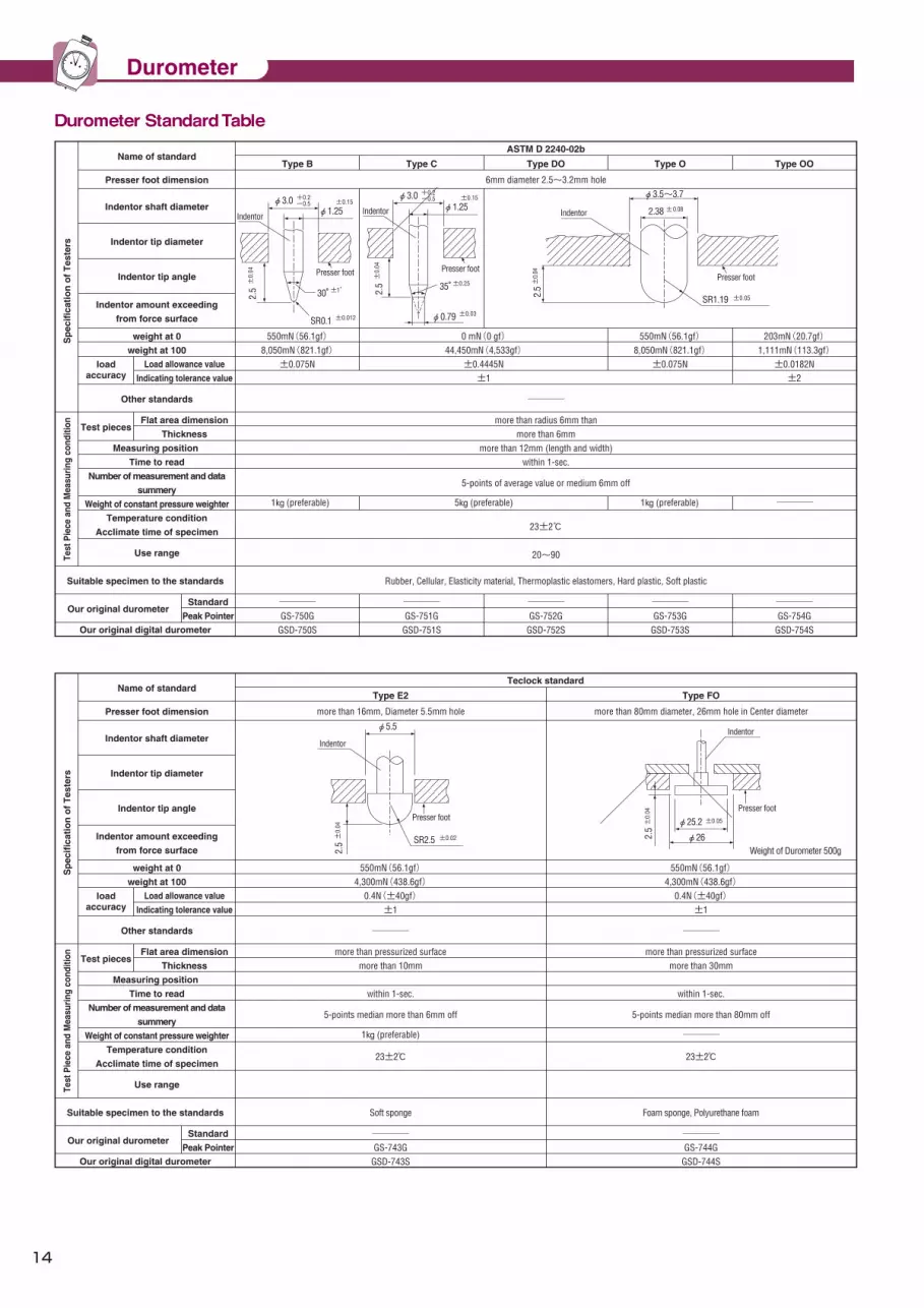
54
DUROMETER (RUBBER, PLASTIC HARDNESS TESTER)S
pec
ific
atio
n o
f T
este
rsTe
st P
iece
and
Mea
suri
ng c
ondi
tion
Name of standard
Presser foot dimension
Indentor shaft diameter
Indentor tip diameter
Indentor tip angle
Indentor amount exceeding
from force surface
weight at 0
weight at 100
loadaccuracy
Load allowance value
Indicating tolerance value
Other standards
Test piecesFlat area dimension
Thickness
Measuring position
Time to read
Number of measurement and data
summery
Weight of constant pressure weighter
Temperature condition
Acclimate time of specimen
Use range
Suitable specimen to the standards
Our original durometer
Our original digital durometer
Standard
Peak Pointer
Sp
ecif
icat
ion
of
Tes
ters
Test
Pie
ce a
nd M
easu
ring
con
ditio
n
Presser foot dimension
Indentor shaft diameter
Indentor tip diameter
Indentor tip angle
Indentor amount exceeding
from force surface
weight at 0
weight at 100
loadaccuracy
Load allowance value
Indicating tolerance value
Other standards
Test piecesFlat area dimension
Thickness
Measuring position
Time to read
Number of measurement and data
summery
Weight of constant pressure weighter
Temperature condition
Acclimate time of specimen
Use range
Suitable specimen to the standards
Our original durometer
Our original digital durometer
Standard
Peak Pointer
8,050mN(821.1gf)
ASTM D 2240-02b
Type B Type C Type DO Type O Type OO
6mm diameter 2.5~3.2mm hole
550mN(56.1gf)
±0.075N8,050mN(821.1gf)
550mN(56.1gf)
±0.075N1,111mN(113.3gf)
203mN(20.7gf)
±0.0182N±2±1
────
more than radius 6mm thanmore than 6mm
more than 12mm (length and width)within 1-sec.
5-points of average value or medium 6mm off
1㎏ (preferable) 1㎏ (preferable) ──── 5㎏ (preferable)
Rubber, Cellular, Elasticity material, Thermoplastic elastomers, Hard plastic, Soft plastic
────GS-750G
GSD-750S
────GS-751G
GSD-751S
────GS-752G
GSD-752S
────GS-753G
GSD-753S
────GS-754G
GSD-754S
23±2℃
20~90
Name of standardTeclock standard
Type E2 Type FO
more than 16mm, Diameter 5.5mm hole more than 80mm diameter, 26mm hole in Center diameter
550mN(56.1gf)4,300mN(438.6gf)
0.4N(±40gf)±1
0.4N(±40gf)±1
────
────1㎏ (preferable)
────
550mN(56.1gf)4,300mN(438.6gf)
more than 10mm
5-points median more than 6mm off
more than 30mm
23±2℃ 23±2℃
5-points median more than 80mm off
more than pressurized surface more than pressurized surface
within 1-sec. within 1-sec.
Soft sponge
────GS-743G
GSD-743S
Foam sponge, Polyurethane foam
────GS-744G
GSD-744S
0 mN(0 gf)44,450mN(4,533gf)±0.4445N
2.5±
0.04
φ3.0 +0.2-0.5
30°±1°
SR0.1 ±0.012
φ1.25±0.15
Presser foot
Indentor
2.5±
0.04
φ0.79
φ3.0φ1.25
35°
Indentor
Presser foot
+0.2-0.5
±0.25
±0.03
±0.15
Indentor
Presser foot
φ3.5~3.7
2.38 ±0.08
SR1.192.5±
0.04
Presser foot
Indentor
2.5±
0.04
φ5.5
SR2.5
Presser foot
Weight of Durometer 500gφ26
φ25.2 ±0.05
Indentor
2.5±
0.04
±0.05
±0.02
14
Durometer
Durometer Standard Table

53
DUROMETER (RUBBER, PLASTIC HARDNESS TESTER)
Durometer Standard TableJIS K 6253-1997 JIS K 6301-1995(1998 abolition)
JIS K 7215-1992
Type A Type D Type E Type A Type C
more than 12mm, Diameter3 mm hole more than Diameter 10mm , approx. 3.2mm hole+0.2-0.5 more than 14mm,φ5.4 mm hole
more than pressurized surfacemore than 6mm more than 12mm more than 6mm
more than 12mmmore than 10mm
────
5-points median more than 6mm offTest report (example):E 60 Test report (example):Hs(JIS A)50 Test report (example):Hs(JIS C)50Test report (example):A45 Test report (example):D50
more than A90 use TypeDunder A20 use TypeD
within 1-sec.
Normal Rubber
23±2℃/more than 3 hour 20°~30℃/one hour
ASTM D 2240ISO 7619
──── ────
550mN(56.1gf)8,050mN(821.1gf)
550mN(56.1gf)8,050mN(821.1gf)
±80mN(8.16gf) ±80mN(8.16gf)
1㎏ (preferable)
GS-719NGS-719G
GSD-719S
Normal Rubber(hard)
GS-720NGS-720G
GSD-720S
Soft Rubber
GS-721NGS-721G
GSD-721S
± 1 ± 1
0 mN( 0 gf)44,450mN(4,533gf)±440mN(44.9gf)
5.0㎏ (preferable) 1kg (preferable)
± 1
more than pressurized surface
539.5mN(55gf)8,385mN(855gf)
±8gf± 1
981mN(100gf)44,130mN(4,500gf)
±20gf±0.45
5-points average value
A>70 use C typeC type is preferable for range of 30-90
Read at once (or after regulating time)
Normal Rubber
1,000g
GS-706NGS-706G
GSD-706S
Hard Rubber
GS-703NGS-703G────
5,000g
SRIS-0101-1968
(2002 abolition)Type A Type D
more than diameter 12mm, diameter3 mm hole Center about 14×50mm approx. 5.2mm hole in Center±0.5
Width : about 25mm or more6mm or more, 2mm acceptable for HDD 40 pr above more than 10mm
12mm or more from edge ────
5 or preferably 10meas, at 6mm or moreTest report (example):HDA83 Test report (example):HDD56
As a rule, use in range 20-90Use D for A>90, Use A for D<20
1sec or less (time to be specified for over 1sec)
Plastic(plastic film, tape and foam plastic excluded) (usable for elastomer)
23±2℃ 50±5%(humidity)88h(Time can be shortened if measured value does not vary)
ASTM D 2240 / ISO 868(SHORE A)(DIN 53505)
ASTM D 2240 / ISO 868(SHORE D)(DIN 53505)
549mN(56gf)8,061mN(822gf)±78mN(± 8 gf)
approx. 1kg
GS-709NGS-709G
GSD-719S
GS-702NGS-702G
GSD-720S
± 1
0 mN( 0 gf)44,483mN(4,536gf)±441mN(±45gf)
approx. 5kg
± 1
more than pressurized surface
539.5mN(55gf)8,385mN(855gf)
±8gf± 1
JIS S 6050 (Plastics Erasers)
Average value of 5initial and 30sec later measurement.
At first weighing and 30sec later
Expanded rubber
20 /h
────
1,000g
GS-701NGS-701G
GSD-701S
2.5±
0.04
φ0.79
φ3.0φ1.25
35°
Indentor
Presser foot
+0.2-0.5
±0.25
±0.03
±0.15
2.5±
0.04
φ3.0 +0.2-0.5
30°±1°
SR0.1±0.012
φ1.25±0.15
Presser foot
Indentor
2.54
0-
0.05
φ0.79
approx.φ3φ1.3±0.1
35°
Indentor
Presser foot
±0.25°
±0.02
2.5±
0.04
φ3.0 ±0.5
30°±1°
SR0.1 ±0.012
φ1.25 ±0.1
Presser foot
Indentpr
2.5±
0.04
φ0.79
φ3.0φ1.25
35°
Indentpr
Presser foot
±0.5
±0.25
±0.03
±0.1
±0.2
Indentor
φ5.08 ±0.02
Presser foot
Indentor
approx. 5.2
2.54
0-
0.05
±0.02
Presser foot
SR2.5
φ5.4
2.5±
0.04
±0.2
Sp
ecif
icat
ion
of
Tes
ters
Test
Pie
ce a
nd M
easu
ring
con
ditio
n
Name of standard
Presser foot dimension
Indentor shaft diameter
Indentor tip diameter
Indentor tip angle
Indentor amount exceeding
from force surface
weight at 0
weight at 100
loadaccuracy
Load allowance value
Indicating tolerance value
Other standards
Test piecesFlat area dimension
Thickness
Measuring position
Time to read
Number of measurement and data
summery
Weight of constant pressure weighter
Temperature condition
Acclimate time of specimen
Use range
Suitable specimen to the standards
Our original durometer
Our original digital durometer
Standard
Peak Pointer
Sp
ecif
icat
ion
of
Tes
ters
Test
Pie
ce a
nd M
easu
ring
con
ditio
n
Presser foot dimension
Indentor shaft diameter
Indentor tip diameter
Indentor tip angle
Indentor amount exceeding
from force surface
weight at 0
weight at 100
loadaccuracy
Load allowance value
Indicating tolerance value
Other standards
Test piecesFlat area dimension
Thickness
Measuring position
Time to read
Number of measurement and data
summery
Weight of constant pressure weighter
Temperature condition
Acclimate time of specimen
Use range
Suitable specimen to the standards
Our original durometer
Our original digital durometer
Standard
Peak Pointer
Name of standard
+10 0
15
Durometer
Durometer Standard Table

This is multi-function Mini Printer for Digital Durometer(GSD-series) and Constant Pressured Thickness MeasuringInstruments(PG-series), and can be used for various arithmetic calculation management.
This instruments comply with ISO(IRHD A-method) and JIS K 6250 standards(ruled in physical test method general rule of rubber for vulcanized rubber and thermoplastic). This is sheet block compatible type which can measure both thickness of test piece hardness IRHD below 35 and over 35 by this one unit. Contact point is diameter 5mm and pressure can be changed by only attaching and detaching weights. A product line-up with φ45mm contact point and the measuring range of 0~13mm, is prepared for both the sheet-like specimen and compression set specimen. The ISO document can also be issued(option).
■Constant Pressured Thickness Measuring Instruments
■Mini Printer
PG series
Model Application
sheet-like specimen and
compression set specimen
Resolution
0.01mm
Load for surface(Measuring force)
0~13mm 5mm
ISO/JIS K 6250 A-Method
IRHD35 and over
ISO/JIS K 6250 A-Method IRHD35 under IRHD35 and
over
□ Specification
Applicable standard
(Printer unit: 0.5)for PG-series instrument(Printer unit: 0.01/0.001mm)
Optional AccessoriesModelZE-304ZE-110ZE-018ZE-019ZE-020ZE-109ZE-013
Name of article Roll paper(10pcs)RS-232C cable Connecting cable 1MConnecting cable 2MConnecting cable 5MCable for JudgmentFoot switch
*ZE-110 is a cable from printer to PC
ISO/JIS
(*1) Load: 22±5kPa giving to surface (*2) Load: 10±2kPa giving to both surface
1-3-2500 Umeda 1-Chome, Kita-Ku, Osaka 530-0001, Japan. Phone: 81-6-6347-0685Fax: 81-6-6347-7555e-mail: [email protected]: www.ttsjapan.com
Factory & Head Office:2-10-3 Naruta-Cho, Okaya-city, Nagano Pref. 394-0042, Japanhttp://www.teclock.co.jp
<Agent> <Manufacturer>
Teclock CorporationTTS Unlimited,Inc
PG-18J
PG-20J
Contact point diameter(φ)
44g(※1)
20g(※2)44g(※1)
Measuring range
SD-763P for Durometer

R
HEAD OFFICE & FACTORY:2-10-3 NARUTA-CHO, OKAYA-SHI, NAGANO-KEN 394-0042PHONE: 81-266-22-4911, FACSIMILE: 81-266-22-4914E-mail: [email protected]
TECLOCK Corporationhttp://www.teclock.co.jp/
Distributer


