Embed Size (px)
Citation preview
Universita degli Studi di Roma ”La Sapienza”
DIPARTIMENTO DI INGEGNERIA CHIMICA, MATERIALI, AMBIENTE
Corso di Dottorato di ricerca in Ingegneria chimica XXX ciclo
Buccal and Topical drug delivery
Candidato:
Gabriele VaraniRelatore:
Chiar.ma Prof.ssa
Alessandra Adrover
Anno Accademico 2016–2017
Buccal and Topical drug deliveryPh.D Thesis. Sapienza-University of RomeAuthor: Gabriele Varani, Roma, 2017email: [email protected]
This thesis has been typeset by LATEXand the Book class.
A thesis submitted in partial fulfillment of the requirements for the degreeof Doctor of Philosophy in Ingegneria chimica.
Ottobre 2017Thesis not yet defended.

iii
Dedicated to Riccardo..........perchè vorrei portarti in tutti i
posti che sogni.
iv
Abstract
The aim of this work is to investigate new and classical techniques, methods and formu-lations for topical and buccal release.
All the formulations proposed are based on natural and biocompatible polymer ma-trices such as gellan gum, scleroglucan and hydroxypropylmethylcellulose.
The proposed formulations are tested by in vitro release tests. In fact they representsa valid support and a useful starting point for the realization of a potentially usablein-vivo pharmaceutical formulation that may have commercial utility.
The research work is both experimental and theoretical. Each topic presents a morechemical-pharmaceutical part, based on the formulation preparation and release exper-iments, and a more theoretical-numerical approach that allows a correct interpretationand description of the experimental data obtained.
Release from hydrogels and thin films require different modelling approaches. Alsothe physico-mathematical description of different release experiments (different releasedevices such as Franz cell, millifluidic device and USP II) requires different theoreticaland numerical techniques.
The outcome of an accurate model development is of fundamental importance forfuture design of pharmaceutical formulations with prescribed release properties.
In addition the formulations are investigated through rheological, mechanical, thermo-analytic and mucoadhesive tests in order to have a more comprehensive picture of theirpractical utilization.
Contents
1 General Introduction 11.1 Thin films for buccal drug delivery . . . . . . . . . . . . . . . . . . . . . . 1
1.1.1 Anatomy of the oral mucosa . . . . . . . . . . . . . . . . . . . . . . 21.1.2 Oral thin films: a general presentation . . . . . . . . . . . . . . . . 61.1.3 Polymers for the preparation of thin films . . . . . . . . . . . . . . 81.1.4 Mucoadhesive properties of buccal films . . . . . . . . . . . . . . . 91.1.5 Films evaluation . . . . . . . . . . . . . . . . . . . . . . . . . . . . 101.1.6 Manufacturing techniques . . . . . . . . . . . . . . . . . . . . . . . 131.1.7 In vitro dissolution testing of buccal thin films . . . . . . . . . . . 15
1.2 Hydrogels for topical drug delivery . . . . . . . . . . . . . . . . . . . . . . 191.2.1 Anatomy of skin . . . . . . . . . . . . . . . . . . . . . . . . . . . . 201.2.2 Formulation design of Hydrogels . . . . . . . . . . . . . . . . . . . 231.2.3 Hydrogels evaluation . . . . . . . . . . . . . . . . . . . . . . . . . . 271.2.4 In vitro release from Hydrogels . . . . . . . . . . . . . . . . . . . . 29
1.3 Oral thin films and Hydrogels in this work . . . . . . . . . . . . . . . . . . 331.3.1 Gellan gum, HPMC, Scleroglucan . . . . . . . . . . . . . . . . . . 331.3.2 Cyclodextrins(CD) . . . . . . . . . . . . . . . . . . . . . . . . . . . 36
2 Aim of the work 41
3 Scleroglucan based hydrogel for topical drug delivery 433.1 Introduction . . . . . . . . . . . . . . . . . . . . . . . . . . . . . . . . . . . 433.2 Materials and methods . . . . . . . . . . . . . . . . . . . . . . . . . . . . . 44
3.2.1 Chemicals . . . . . . . . . . . . . . . . . . . . . . . . . . . . . . . . 443.2.2 Synthesis of carboxymethyl scleroglucan (Scl − CM300) . . . . . . 443.2.3 Hydrogel preparation . . . . . . . . . . . . . . . . . . . . . . . . . 443.2.4 Rheological characterization . . . . . . . . . . . . . . . . . . . . . . 453.2.5 Release studies with Franz diffusion cell . . . . . . . . . . . . . . . 453.2.6 Mathematical models of permeation experiments in a vertical Franz
cell . . . . . . . . . . . . . . . . . . . . . . . . . . . . . . . . . . . . 463.2.7 Primary skin irritation experiments . . . . . . . . . . . . . . . . . 48
3.3 Results . . . . . . . . . . . . . . . . . . . . . . . . . . . . . . . . . . . . . . 493.3.1 Physical hydrogel preparation and characterization . . . . . . . . . 493.3.2 Rheological characterization of drug loaded Scl − CM300 physical
hydrogels . . . . . . . . . . . . . . . . . . . . . . . . . . . . . . . . 493.3.3 Release studies . . . . . . . . . . . . . . . . . . . . . . . . . . . . . 533.3.4 Primary skin irritation experiments . . . . . . . . . . . . . . . . . 57
3.4 Conclusion . . . . . . . . . . . . . . . . . . . . . . . . . . . . . . . . . . . 58
4 Drug delivery from Oral thin films 594.1 Introduction . . . . . . . . . . . . . . . . . . . . . . . . . . . . . . . . . . . 594.2 Materials and method . . . . . . . . . . . . . . . . . . . . . . . . . . . . . 59
4.2.1 Chemicals . . . . . . . . . . . . . . . . . . . . . . . . . . . . . . . . 594.2.2 Film forming technology . . . . . . . . . . . . . . . . . . . . . . . . 60
v
vi CONTENTS
4.2.3 Thermogravimetric analysis . . . . . . . . . . . . . . . . . . . . . . 604.2.4 Swelling . . . . . . . . . . . . . . . . . . . . . . . . . . . . . . . . . 614.2.5 USP II, Paddle apparatus . . . . . . . . . . . . . . . . . . . . . . . 624.2.6 Novel millifluidic device . . . . . . . . . . . . . . . . . . . . . . . . 62
4.3 Results . . . . . . . . . . . . . . . . . . . . . . . . . . . . . . . . . . . . . . 654.3.1 Swelling model for OTF . . . . . . . . . . . . . . . . . . . . . . . . 654.3.2 Drug release time scales . . . . . . . . . . . . . . . . . . . . . . . . 694.3.3 Model of release . . . . . . . . . . . . . . . . . . . . . . . . . . . . 714.3.4 2D-Model . . . . . . . . . . . . . . . . . . . . . . . . . . . . . . . . 75
4.4 Conclusion . . . . . . . . . . . . . . . . . . . . . . . . . . . . . . . . . . . 79
5 Release analysis from HPMC based erodible thin films 815.1 Introduction . . . . . . . . . . . . . . . . . . . . . . . . . . . . . . . . . . . 81
5.1.1 Rapid disintegrating film (RDF) . . . . . . . . . . . . . . . . . . . 815.1.2 Furosemide features . . . . . . . . . . . . . . . . . . . . . . . . . . 82
5.2 Materials and method . . . . . . . . . . . . . . . . . . . . . . . . . . . . . 835.3 Results and discussion . . . . . . . . . . . . . . . . . . . . . . . . . . . . . 84
5.3.1 Preliminary analysis . . . . . . . . . . . . . . . . . . . . . . . . . . 845.3.2 Release from Franz Cell . . . . . . . . . . . . . . . . . . . . . . . . 855.3.3 Swelling-Erosion tests . . . . . . . . . . . . . . . . . . . . . . . . 955.3.4 Sotax Vs Millifluidic device . . . . . . . . . . . . . . . . . . . . . . 96
5.4 Conclusion . . . . . . . . . . . . . . . . . . . . . . . . . . . . . . . . . . . 98
6 Preventing drug crystallization in glycerol-plasticized gellan gum thinfilms 996.1 Introduction . . . . . . . . . . . . . . . . . . . . . . . . . . . . . . . . . . . 996.2 Materials and method . . . . . . . . . . . . . . . . . . . . . . . . . . . . . 100
6.2.1 Materials . . . . . . . . . . . . . . . . . . . . . . . . . . . . . . . . 1006.2.2 Preparation of polymeric films . . . . . . . . . . . . . . . . . . . . 1006.2.3 Preparation of inclusion complex cyclodextrins-drug . . . . . . . . 1016.2.4 Rheological studies . . . . . . . . . . . . . . . . . . . . . . . . . . . 1016.2.5 Thickness measurements . . . . . . . . . . . . . . . . . . . . . . . . 1016.2.6 Thermogravimetric analysis . . . . . . . . . . . . . . . . . . . . . . 1016.2.7 Differential scanning calorimetry . . . . . . . . . . . . . . . . . . . 1016.2.8 Tensile tests . . . . . . . . . . . . . . . . . . . . . . . . . . . . . . . 1026.2.9 Swelling studies . . . . . . . . . . . . . . . . . . . . . . . . . . . . . 1026.2.10 Mucoadhesion tests . . . . . . . . . . . . . . . . . . . . . . . . . . . 1026.2.11 Uniformity of drug content tests . . . . . . . . . . . . . . . . . . . 1026.2.12 In vitro release studies . . . . . . . . . . . . . . . . . . . . . . . . . 103
6.3 Results and discussion . . . . . . . . . . . . . . . . . . . . . . . . . . . . . 1036.3.1 Preparation of GG:Gly thin films . . . . . . . . . . . . . . . . . . . 1036.3.2 Mechanical properties of GG:Gly thin films . . . . . . . . . . . . . 1066.3.3 Swelling studies . . . . . . . . . . . . . . . . . . . . . . . . . . . . . 1086.3.4 Evaluation of the mucoadhesive properties of GG:Gly thin films . . 1086.3.5 Drug loaded films . . . . . . . . . . . . . . . . . . . . . . . . . . . . 1096.3.6 Release studies . . . . . . . . . . . . . . . . . . . . . . . . . . . . . 113
6.4 Conclusion . . . . . . . . . . . . . . . . . . . . . . . . . . . . . . . . . . . 115
7 General conclusions 117
Bibliography 119
Chapter 1
General Introduction
1.1 Thin films for buccal drug delivery
The oral route is the most important method of administration for systemic effect, dueto low cost, ease of administration and high level of patient compliance. Among thepharmaceutical dosage form for oral delivery, the conventional tablet seems to be mostpopular, because of its ease of transportability and comparatively low manufacturingcost [1]. Nonetheless, two main types of disadvantages can be ascribed to the oral route:first pass drug metabolism in the liver and pre-systemic elimination of the drug in thegastrointestinal tract (GI first pass) could lessen the effective biodisponibility to an un-acceptable level, or even destroy the drug, as it is the case of biological active ingredientsas proteins and peptides; moreover, a fast administration of emergency drugs and agentswith a rapid onset action could not be possible [2]. In these cases, the traditional choiceis parenteral drug administration, which is, on the patient side, uncomfortable, uneasyand undesired. Difficulties associated with parenteral delivery and poor drug availability,together with substantial efforts focused on placing a drug or drug delivery system ina particular region of the body for extended periods of time, provided the impetus forexploring alternative routes, such as the mucosal layer lining a number of regions of thegastrointestinal tract, the airways, mouth, the ear, nose, and the eye.
Mucosal tissues can interact with the hydrophilic macromolecules of drug matrices,bringing about an adhesive attachment called mucoadhesion. This interaction retainsa formulation in intimate contact with the adsorption site. The buccal region of oralcavity is the most attractive site for the delivery of drugs. Buccal drug delivery involvesthe administration of desired drug through the buccal mucosal membrane lining of theoral cavity. This route is useful for mucosal (local effect) and transmucosal (systemiceffect) drug administration. In the first case, the aim is to achieve a site-specific releaseof the drug on the mucosa, whereas the second case involves drug absorption throughthe mucosal barrier to reach the systemic circulation [3–7].
The buccal mucosa is permeable, with a rich blood supply, more robust and havemore tolerance to potential sensitizers in comparison to the other mucosal tissues. Noactivation of the drug absorption is required. Local modification of tissue permeability,inhibition of protease activity and reduction in immunogenic response are allowed.
On the other hand, the environment of the oral cavity presents some significant chal-lenges for systemic drug delivery, given that the mucosa has barrier properties. Theprinciple physiological environment of the oral cavity, in terms of pH, fluid volume andcomposition, is shaped by the secretion of saliva.Saliva covers the surface area of themouth (around 217 cm2)with a layer of average thickness 70-100 µm for adults and 60-90 µm for children. It is continuously secreted at average flow rate of 0.3-1 ml/min, butcan be elicitated up to 7.07 ml/min by stimulating agents; flow rates < 0.1 ml/min mustbe considered pathological. The volume of saliva in the mouth ranges from 0.8 ml, afterswallowing, to 1.1 ml just before swallowing [8–11]. The continuous secretion of saliva
1
2 General Introduction
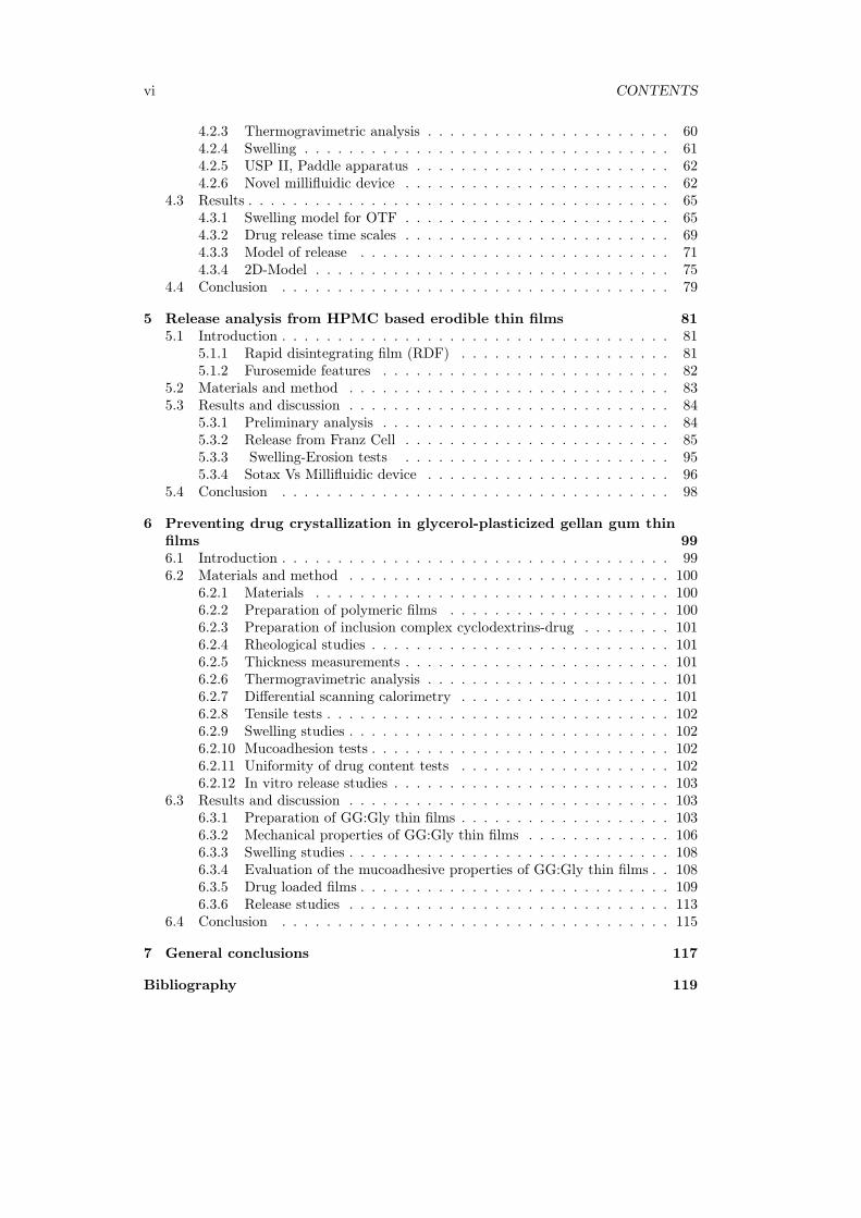
Figure 1.1: Structure of oral cavity.
leads to subsequent dilution of the drug; saliva swallowing can provoke the partial ortotal removal of the dosage form. The volume of saliva constantly present in the mouth,around 1 ml, provides a relatively low fluid volume available for drug release from deliverysystems compared to the GI tract [12,13].
The different types of buccal dosage forms are buccal tablets, ointments, gels, patchesand thin films [14]. Over and above the mentioned demands, oral delivery systemsalternative to tablets and syrups have been of interest since the latest 1970’s, as a possibleimprovement for a particular, and not so small, class of patients who have difficulties inswallowing. This disorder affects more frequently for old people, children and mentallyillness, but the oral administration without swallowing could be helpful also for travellingor military patients who may not have ready access to water [15,16].
1.1.1 Anatomy of the oral mucosa
Buccal region is that part of the mouth bounded anteriorly and laterally by the lips andthe cheeks, posteriorly and medianly by the teeth and/or gums, and above and below bythe reflections of the mucosa from the lips and cheeks to the gums.
Numerous racemose, mucous, or serous glands are present in the sub mucous tissue ofthe cheeks. The buccal glands are placed between the mucous membrane and buccinatormuscle: they are similar in structure to the labial glands, but smaller ( figure 1.1).
About five, of a larger size than the rest, are placed between the masseter and buc-cinator muscles around the distal extremity of the parotid duct; their ducts open in themouth opposite the last molar tooth. They are called molar glands. Maxillary artery sup-plies blood to buccal mucosa and blood flow is faster and richer (2.4ml/min/cm2) thanthat in the sub lingual, gingival and palatal regions, thus facilitates passive diffusion ofdrug molecules across the mucosa.
The thickness of the buccal mucosa is measured to be 500–800 µm and is roughtextured, hence suitable for retentive delivery systems. The turnover time for the buccal
Chapter 1 3
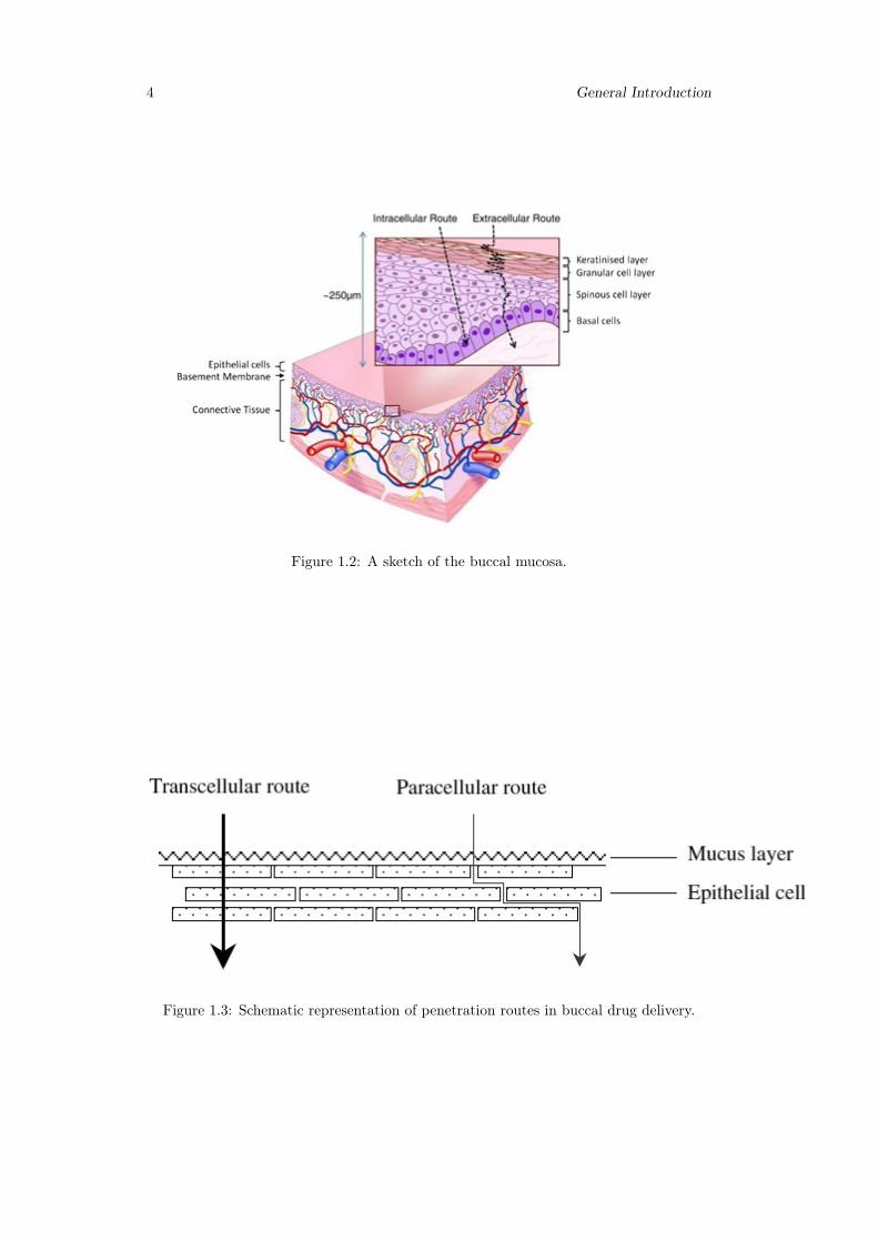
epithelium has been estimated at 5–6 days. Buccal mucosa composed of several layersof different cells as shown in figure 1.2. The epithelium is similar to stratified squamousepithelia found in rest of the body and is about 40–50 cell layers thick.
Lining epithelium of buccal mucosa is the nonkeratinized stratified squamous epithe-lium that has thickness of approximately 500–600 µm and surface area of 50.2 cm2.Basement membrane, lamina propria followed by the sub mucosa is present below theepithelial layer. Lamina propria is rich with blood vessels and capillaries that open tothe internal jugular vein [17].
The barriers such as saliva,mucus,membrane coating granules, basement membraneetc retard the rate and extent of drug absorption through the buccal mucosa. The mainpenetration barrier exists in the outermost quarter to one third of the epithelium.
Oral mucosa, a barrier to permeability
The effective permeability coefficient (Peff) values reported in the literature across thebuccal mucosa for different molecules range from a lower limit of 2.2 · 10−9 cm/s fordextran 4000 across rabbit buccal membrane to an upper limit of 1.5 · 10−−5 cm/s forboth benzylamine and amphetamine across rabbit and dog buccal mucosa, respectively.This range clearly demonstrates the presence of a permeability barrier in the oral mucosa,which is mostly imposed by the oral epithelium acting as a protective layer for the tissuesbeneath, and as a barrier to the entry of foreign material and microorganisms. However,this range is estimated to be 4–4000 times more permeable than that of skin. Thepermeability barrier property of the oral mucosa is predominantly due to inter cellularmaterials derived from the so-called "membrane coating granules" (MCGs). MCGs arespherical or oval organelles that are 100–300 nm in diameter and found in both keratinizedand non-keratinized epithelia.
These organelles have also been referred to as "small spherically shaped granules","corpusula", "small dense granules", "small lamellated bodies", "lamellated dense bod-ies", "keratinosomes", "transitor dense bodies", and "cementsomes" . However, mostof these descriptive names have not fully defined the functions of this cellular species.MCGs were first named as such because it was believed that they were subject to ex-ocytosis from the cytoplasm of the stratum spinosum of keratinized epithelia followingthickening of these cells. Nonetheless, it is actually the contents of MCGs that are subjectto exocytosis prior to the onset of membrane thickening.
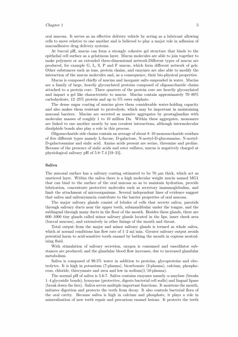
The main mechanisms responsible for the penetration of various substances includesimple diffusion (paracellular, transcellular), carrier-mediated diffusion, active transport,and pinocytosis or endocytosis. Recent evidence has shown that passive diffusion isthe primary mechanism for the transport of drugs across the buccal mucosa, althoughcarrier-mediated transport has been reported to have a small role.
Two routes of passive transport are available in the buccal epithelium(figure 1.3); oneinvolves the transport of compounds through the inter cellular spaces between the cells(paracellular), and the other involves passage into and across the cells (transcellular). De-pending on the nature of the permeant, the molecular geometry, lipophilicity, and charge,either of the transport pathways across buccal epithelium can be selected. While consid-erable evidence has been presented to document that most compounds diffuse throughthe buccal mucosa by passive diffusion or simple Fickian diffusion, some are transportedby a carrier mediated process across the buccal mucosa. Glucose, monocarboxylic acidsand salicylic acid, and nicotinic acid, are examples of substances which utilize a carrier-mediated diffusion mechanism for permeation across buccal epithelium [18].
Mucus
The epithelial cells of buccal mucosa are surrounded by the intercellular ground substancecalled mucus with the thickness varies from 40 µm to 300 µm. Though the sublingualglands and minor salivary glands contribute only about 10% of all saliva, together theyproduce the majority of mucus and are critical in maintaining the mucin layer over the
4 General Introduction
Figure 1.2: A sketch of the buccal mucosa.
Figure 1.3: Schematic representation of penetration routes in buccal drug delivery.
Chapter 1 5
oral mucosa. It serves as an effective delivery vehicle by acting as a lubricant allowingcells to move relative to one another and is believed to play a major role in adhesion ofmucoadhesive drug delivery systems.
At buccal pH, mucus can form a strongly cohesive gel structure that binds to theepithelial cell surface as a gelatinous layer. Mucus molecules are able to join together tomake polymers or an extended three-dimensional network.Different types of mucus areproduced, for example G, L, S, P and F mucus, which form different network of gels.Other substances such as ions, protein chains, and enzymes are also able to modify theinteraction of the mucus molecules and, as a consequence, their bio-physical properties.
Mucus is composed chiefly of mucins and inorganic salts suspended in water. Mucinsare a family of large, heavily glycosylated proteins composed of oligosaccharide chainsattached to a protein core. Three quarters of the protein core are heavily glycosylatedand impart a gel like characteristic to mucus. Mucins contain approximately 70–80%carbohydrate, 12–25% protein and up to 5% ester sulphate.
The dense sugar coating of mucins gives them considerable water-holding capacityand also makes them resistant to proteolysis, which may be important in maintainingmucosal barriers. Mucins are secreted as massive aggregates by prostaglandins withmolecular masses of roughly 1 to 10 million Da. Within these aggregates, monomersare linked to one another mostly by non covalent interactions, although intermoleculardisulphide bonds also play a role in this process.
Oligosaccharide side chains contain an average of about 8–10 monosaccharide residuesof five different types namely L-fucose, D-galactose, N-acetyl-D-glucosamine, N-acetyl-D-galactosamine and sialic acid. Amino acids present are serine, threonine and proline.Because of the presence of sialic acids and ester sulfates, mucus is negatively charged atphysiological salivary pH of 5.8–7.4 [19–21].
Saliva
The mucosal surface has a salivary coating estimated to be 70 µm thick, which act asunstirred layer. Within the saliva there is a high molecular weight mucin named MG1that can bind to the surface of the oral mucosa so as to maintain hydration, providelubrication, concentrate protective molecules such as secretory immunoglobulins, andlimit the attachment of microorganisms. Several independent lines of evidence suggestthat saliva and salivarymucin contribute to the barrier properties of oral mucosa.
The major salivary glands consist of lobules of cells that secrete saliva; parotidsthrough salivary ducts near the upper teeth, submandibular under the tongue, and thesublingual through many ducts in the floor of the mouth. Besides these glands, there are600–1000 tiny glands called minor salivary glands located in the lips, inner cheek area(buccal mucosa), and extensively in other linings of the mouth and throat.
Total output from the major and minor salivary glands is termed as whole saliva,which at normal conditions has flow rate of 1–2 ml/min. Greater salivary output avoidspotential harm to acid-sensitive tooth enamel by bathing the mouth in copious neutral-izing fluid.
With stimulation of salivary secretion, oxygen is consumed and vasodilator sub-stances are produced; and the glandular blood flow increases, due to increased glandularmetabolism.
Saliva is composed of 99.5% water in addition to proteins, glycoproteins and elec-trolytes. It is high in potassium (7·plasma), bicarbonate (3·plasma), calcium, phospho-rous, chloride, thiocyanate and urea and low in sodium(1/10·plasma).
The normal pH of saliva is 5.6-7. Saliva contains enzymes namely α-amylase (breaks1–4 glycosidic bonds), lysozyme (protective, digests bacterial cell walls) and lingual lipase(break down the fats). Saliva serves multiple important functions. It moistens the mouth,initiates digestion and protects the teeth from decay. It also controls bacterial flora ofthe oral cavity. Because saliva is high in calcium and phosphate, it plays a role inmineralization of new teeth repair and precarious enamel lesions. It protects the teeth
6 General Introduction
by forming “protective pellicle”. This signifies a saliva protein coat on the teeth, whichcontains antibacterial compounds.
However, salivary flow rate may play role in oral hygiene. Intraoral complicationsof salivary hypofunction may cause candidiasis, oral lichen planus, burning mouth syn-drome, recurrent aphthous ulcers and dental caries.
A constant flowing down of saliva within the oral cavity makes it very difficult fordrugs to be retained for a significant amount of time in order to facilitate absorption inthis site.
In general, intercellular spaces pose as the major barrier to permeation of lipophiliccompounds, and the cell membrane which is lipophilic in nature acts as the major trans-port barrier for hydrophilic compounds because it is difficult to permeate through thecell membrane due to a low partition coefficient. Permeabilities between different regionsof the oral cavity vary greatly because of the diverse structures and functions. In gen-eral, the permeability is based on the relative thickness and degree of keratinization ofthese tissues in the order of sublingual> buccal> palatal. The permeability of the buccalmucosa was estimated to be 4–4000 times greater than that of the skin [13,17,18,22,23].
1.1.2 Oral thin films: a general presentation
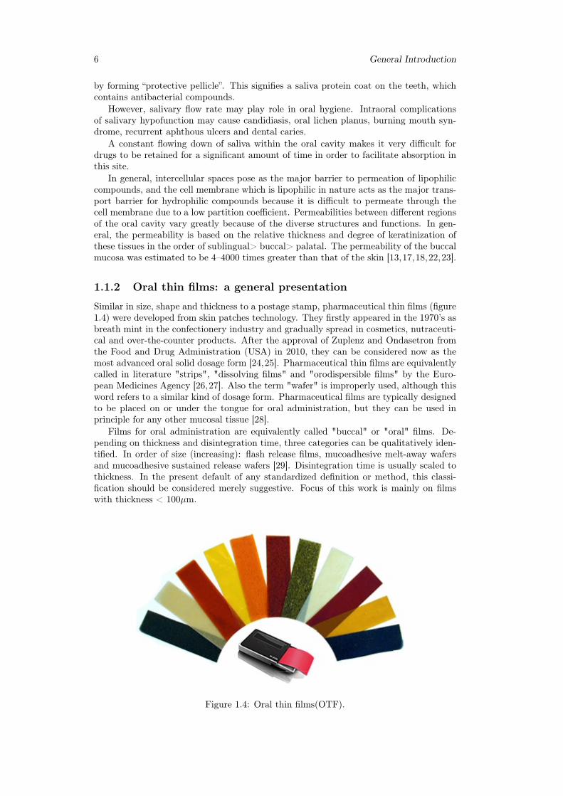
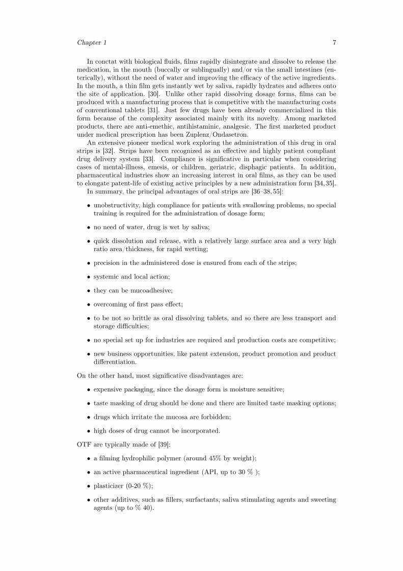
Similar in size, shape and thickness to a postage stamp, pharmaceutical thin films (figure1.4) were developed from skin patches technology. They firstly appeared in the 1970’s asbreath mint in the confectionery industry and gradually spread in cosmetics, nutraceuti-cal and over-the-counter products. After the approval of Zuplenz and Ondasetron fromthe Food and Drug Administration (USA) in 2010, they can be considered now as themost advanced oral solid dosage form [24,25]. Pharmaceutical thin films are equivalentlycalled in literature "strips", "dissolving films" and "orodispersible films" by the Euro-pean Medicines Agency [26,27]. Also the term "wafer" is improperly used, although thisword refers to a similar kind of dosage form. Pharmaceutical films are typically designedto be placed on or under the tongue for oral administration, but they can be used inprinciple for any other mucosal tissue [28].
Films for oral administration are equivalently called "buccal" or "oral" films. De-pending on thickness and disintegration time, three categories can be qualitatively iden-tified. In order of size (increasing): flash release films, mucoadhesive melt-away wafersand mucoadhesive sustained release wafers [29]. Disintegration time is usually scaled tothickness. In the present default of any standardized definition or method, this classi-fication should be considered merely suggestive. Focus of this work is mainly on filmswith thickness < 100µm.
Figure 1.4: Oral thin films(OTF).
Chapter 1 7
In conctat with biological fluids, films rapidly disintegrate and dissolve to release themedication, in the mouth (buccally or sublingually) and/or via the small intestines (en-terically), without the need of water and improving the efficacy of the active ingredients.In the mouth, a thin film gets instantly wet by saliva, rapidly hydrates and adheres ontothe site of application. [30]. Unlike other rapid dissolving dosage forms, films can beproduced with a manufacturing process that is competitive with the manufacturing costsof conventional tablets [31]. Just few drugs have been already commercialized in thisform because of the complexity associated mainly with its novelty. Among marketedproducts, there are anti-emethic, antihistaminic, analgesic. The first marketed productunder medical prescription has been Zuplenz/Ondasetron.
An extensive pioneer medical work exploring the administration of this drug in oralstrips is [32]. Strips have been recognized as an effective and highly patient compliantdrug delivery system [33]. Compliance is significative in particular when consideringcases of mental-illness, emesis, or children, geriatric, disphagic patients. In addition,pharmaceutical industries show an increasing interest in oral films, as they can be usedto elongate patent-life of existing active principles by a new administration form [34,35].
In summary, the principal advantages of oral strips are [36–38,55]:
• unobstructivity, high compliance for patients with swallowing problems, no specialtraining is required for the administration of dosage form;
• no need of water, drug is wet by saliva;
• quick dissolution and release, with a relatively large surface area and a very highratio area/thickness, for rapid wetting;
• precision in the administered dose is ensured from each of the strips;
• systemic and local action;
• they can be mucoadhesive;
• overcoming of first pass effect;
• to be not so brittle as oral dissolving tablets, and so there are less transport andstorage difficulties;
• no special set up for industries are required and production costs are competitive;
• new business opportunities, like patent extension, product promotion and productdifferentiation.
On the other hand, most significative disadvantages are:
• expensive packaging, since the dosage form is moisture sensitive;
• taste masking of drug should be done and there are limited taste masking options;
• drugs which irritate the mucosa are forbidden;
• high doses of drug cannot be incorporated.
OTF are typically made of [39]:
• a filming hydrophilic polymer (around 45% by weight);
• an active pharmaceutical ingredient (API, up to 30 % );
• plasticizer (0-20 %);
• other additives, such as fillers, surfactants, saliva stimulating agents and sweetingagents (up to % 40).
8 General Introduction
Drug and polymer are the essential components of OS. Knowledge and techniques aboutincluding drugs in thin films have been continuously increasing in the last ten years[40–54]. Desiderable characteristics are a low required dose ( < 40 mg), low molecularweight, possibly good taste.
The drug should also be stable and soluble both in saliva and water and partiallyunionized in water. The active component must be able to pass the mucosa barrier, notprovoking irritations. Eligible API are anti emetic, neuroleptics, cardiovascular agents,analgesics, anti allergic, anti epileptics, anxiolytics, sedatives, hypnotics, diuretics, an-tiparkinsonism agents, anti-bacterial agents and drugs used for erectile dysfunction, an-tialzheimers,expectorants, antitussive.For mucosal and transmucosal administration, con-ventional dosage forms are not able to assure therapeutic drug levels in the mucosa andcirculation because of the physiological removal of the oral cavity (washing effect of salivaand mechanical stress), which take the formulation away from the mucosa, resulting ina very short exposure time and unpredictable distribution of the drug on the site ofaction/absorption. To obtain the therapeutic action, it is therefore necessary to prolongand improve the contact between the active substance and the mucosa [20].
1.1.3 Polymers for the preparation of thin films
Polymers are the backbone of film formulations and various polymers are available forthe preparation of thin films [55]. The polymers can be used alone or in combination withother polymers to achieve the desired film properties. The polymers employed shouldbe non-toxic, non-irritant, and absence of leachable impurities is required.Water-solublepolymers are used as film formers to produce a thin film with rapid disintegration, goodmechanical strength, and good mouth feel effects. Both natural and synthetic polymersare used for film preparation [56, 57]. Availability of diverse polymers allows impartingspecific properties in the thin films. For instance, gelatine are available in differentmolecular weights, and thus the appealing and glossy films could be obtained with thegelatin having a high molecular weight. Pullulan is frequently used for producing athin film with great solubility,high mechanical strength and they are stable over a widerange of temperatures. The blending of chitosan and high methoxy pectin (HMP) orlow methoxy pectin (LMP) resulted in a thin film exhibiting an excellent mechanicalstrength. The film forming polymers such as hydroxypropyl cellulose (HPC), methylcellulose, and carboxymethyl cellulose (CMC) produce a thin film with less water vaporbarrier due to hydrophilic nature which aids in water retention [58,59].
The basic idea of pharmaceutical thin strips is exactly that a dissolved componentcould be immobilized in a solid film, and be released from a gel as soon as the dosageform comes in conctat with biological fluids.
Natural and semi-natural polymers have also been reported in the literature as mu-coadhesive. Chitosan was first introduced in 1994 by Guo for its use in mucoadhesivefilm formulations [68]. Following Carbopol and HPMC as polymeric matrices for mu-coadhesive films, chitosan exhibited better adhesion than acacia in a peeling test usingan Instron 4201.
Mucoadhesive films are thin and flexible retentive dosage forms, and release drug di-rectly into a biological substrate. They facilitate in extending residence time at the appli-cation site leading to prolonged therapeutic effects [65]. Majority of the thin film havingmucoadhesive properties are hydrophilic in nature and undergoes swelling and form achain interaction with the mucin.Among the several studied polymers, the most com-pelling mucoadhesion properties are exhibited by chitosan, hyaluronan, cellulose deriva-tives, polyacrylates, alginate, gelatin and pectin [66]. Compared with non-ionic polymers,the cationic and anionic polymers facilitate strong interaction with mucus [67].
Plasticizers can significatively help OTF formulation. They improve mechanical prop-erties such as flexibility and brittleness, by reducing the glass transition temperature ofthe filming polymer. Plasticizers should be compatible with the drug, as well as otheradditives used in the preparation of OTF. Most attractive plasticizers for OTF are glyc-erol, propylene glycol, low molecular weight polyethylene glycols, phthalate derivatives
Chapter 1 9
like dibutyl phthalate, citrate derivatives such as tributyl, triethyl, acetyl citrate, cas-tor oil [60, 61]. Improving palatability is probably the first reason that why additivesare added in OTF. A simple obscuration technique, which means mixing and blend-ing bitter tasting API with pleasurable taste substances, can be used. Also, barriertechniques, which includes complexation, polymeric coating and coated particle, haverecently appeared. Sweetening and flavoring agents are typical additives for palatabil-ity improvement. Sweetening agents are the most major part of the food product or inpharmaceutical dosage forms proposed to be disintegrated or dissolved in the oral cavity.Natural as well as artificial sweetening agents are used to improve the palatability ofthe formulation. Common agents are sugar, dextrose, lactose, mannitol, sucrose, xyli-tol, malitol, acesulfame potassium, talin, glycyrrhizin, sucralose, aspartame, saccharin,essential oils or water soluble extracts of menthol, wintergreen, peppermint, sweet mint,spearmint, vanillin, cherry, chocolate, cinnamon, clove, lemon, orange. Sweetening agentare generally used either alone as in combination between the concentrations of 3 to 6 %by weight of the film. Selection of flavoring agents is depending on which type of drugis to be incorporated in the formulation. The recognition of the oral disintegrating /dissolving formulation by an individual, depends on the initial flavor quality, which isobserved in the first few seconds after the product has been consumed, and on the aftertaste of the formulation, which lasts for at least about 10 min.
Other functional additives are surfactants and saliva stimulating agents. Surfactantsare used as a solubilizing or wetting dispersing agent so that the film gets dissolved withinseconds and releases active agent immediately. Some of the commonly used are sodiumlauryl sulfate, benzalkonium chloride, tweens, poloxamer 407. Saliva stimulating agents,as citric acid, malic acid, lactic acid, ascorbic acid and tartaric acid, are used to increasethe rate of production of saliva. This would aid in the more rapidly disintegration offast dissolving film formation. Saliva stimulating agents are used alone as well as incombination between 2 to 6 % w/w by weight. Finally, fillers and colorants can be addedto improve film’s aspect and handling. Typical colorants are natural coloring agents,and natural juice concentrates, pigments such as titanium oxide, silicon dioxide and zincoxide. Maximum colorants’s concentration is 1 % by weight [62–64].
In common terms, polymers are understood as excipients, but it has become an es-sential component while designing and formulating thin films.Therefore, understandingthe properties of polymers such as chemistry, rheology, and physicochemical proper-ties of polymer seems to be imminent for maximizing their uses to develop a thin film.The selection of appropriate polymer during the development of polymeric thin filmsmay be critical; thereby, several points should be considered according to the require-ments.Therefore, it is imperative to consider the appropriate polymer for producing athin film with a better performance that assures high therapeutic success.
1.1.4 Mucoadhesive properties of buccal films
Bioadhesion is the general term describing adhesion between any biological and syntheticsurface. Mucoadhesion is a specific term describing the particular interaction of a mucosalmembrane with a synthetic surface [69]. The phenomenon of mucoadhesion has beenexplained by applying any of the five theories of adhesion into the interaction of thedosage form and the biological substrate [70, 71]: electronic [72], adsorption [73, 74],wetting [75], diffusion [76], and fracture theory [77]; here, we briefly summarize theoriesrelated to mucoadhesion theory. Since mucoadhesive buccal films include the interactionof a dry polymeric matrix that undergoes hydration, drug release, and sometimes erosion,the phenomenon is very complex. Smart has defined four possible scenarios for theanalysis of the mucoadhesion process based on the hydration state of the dosage formand on the amount of mucus layer available for mucoadhesion [78].
Mucoadhesive buccal films can be classified as a "case 3" scenario since they aresolid dry substrates that come in contact with a mucosa having thin or discontinuousmucus layers. Relevant to the analysis of the mucoadhesion of polymeric films on thebuccal mucosa are the adhesion theories of adsorption and diffusion. The adsorption
10 General Introduction
theory states that the main contributors to the adhesive bond are the inter-polymerinteractions, such as hydrogen bonds and van der Waals forces [79]. The diffusion theoryassumes that polymeric chains from the solid substrate, i.e. the mucoadhesive film, andthe biological substrate, i.e. mucin in the mucosa layer, interdiffuse across the adhesiveinterface. Important variables in this process are the diffusion coefficient of the polymerinto the mucin layer and vice versa, the contact time, and the molecular chain lengthand their mobility [79,80].
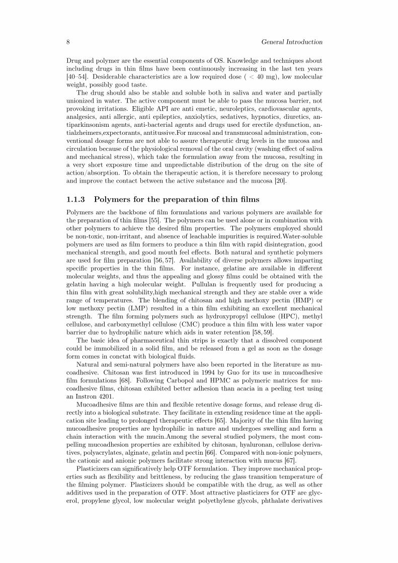
Most of the mucoadhesive phenomena have two main stages that control the perfor-mance of the dosage form: the contact stage and the consolidation stage (figure 1.5) [81].Since mucoadhesive films are dosage forms that are brought in contact with the biologicalmembrane by the patient, the contact stage is initiated by the patient. During the con-tact process, the film will start dehydrating the mucus gel layer and will itself hydrate,initiating the interpenetration of the polymeric chains into the mucus and vice versa.
Figure 1.5: Contact and consolidation stage of mucoadhesion.
For mucoadhesive films, which usually are designed to remain for prolonged timesin contact with the buccal mucosa, a second stage, the consolidation stage, needs totake place in order to maintain this bond. In the consolidation stage, the mucoadhe-sive strength will be determined by the polymer in the formulation, and how readily thedosage form hydrates upon contact with the mucus gel layer. This process is explainedby the dehydration theory, which explains that when a material capable of gelation, suchas a mucoadhesive polymer in a buccal film, is brought into contact with an aqueousviscous colloid, water will move until equilibrium is reached between the two layers [77].The strength of the mucoadhesive bond will then be determined by the extent of in-termixing that occurs after water migrates and reaches equilibrium. Mucoadhesive filmshave been designed to remain in contact with the buccal mucosa for therapeutic purposesfor prolonged periods of time. The measurement of the mucoadhesive strength and timeof mucoadhesion [82] are very important parameters.
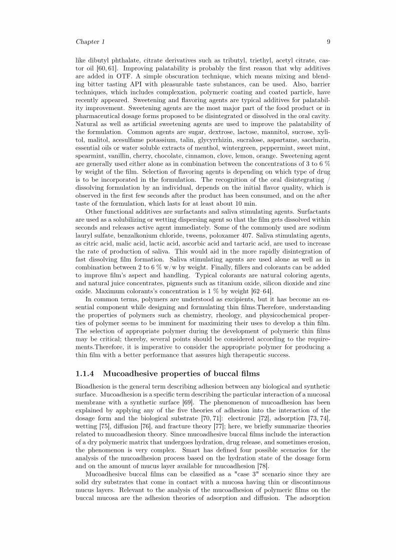
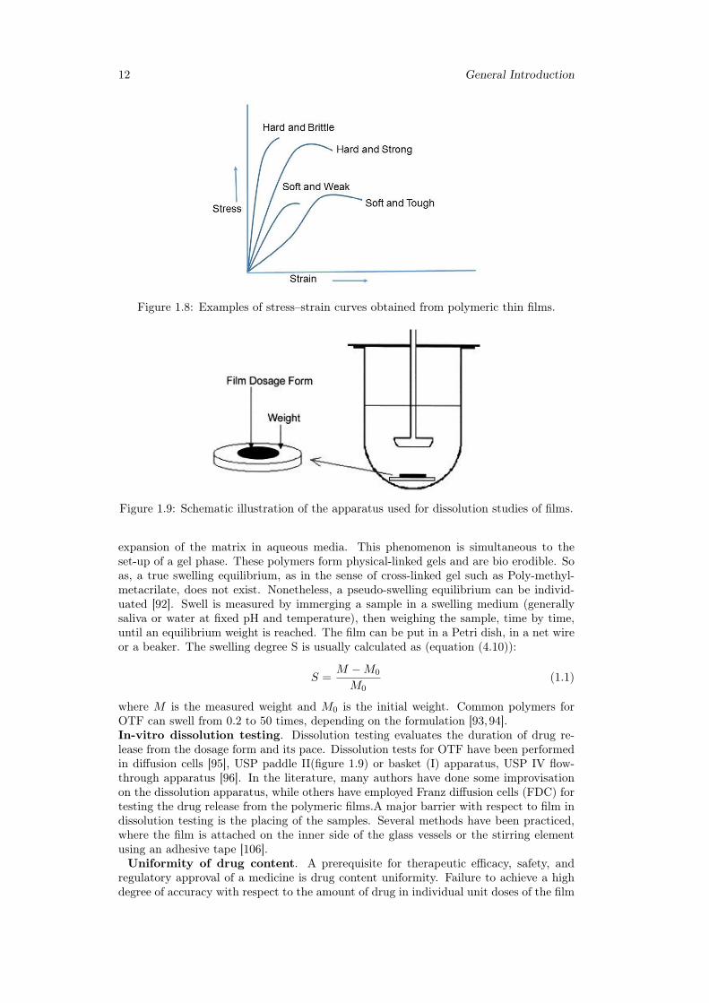
1.1.5 Films evaluationMany different characteristics play a significative role in production and handling ofpharmaceutical strips, such as mechanical strength, structure, dissolution or storage be-haviour. Tests on films assess basic properties which are meaningful in research andquality control. Here we go into details of the main type of analysis.Tensile/mechanical properties. Mechanical properties indicate at what extent thefilm can withstand force or stress during processing, packaging, transport and handling.Tensile testing is usually conducted using a texture analyzer device (figure 1.6,1.7), con-ceptually similar to a classical stress-strain test. The film is inserted and elongated untilit breaks. Tensile strength, percent elongation at break, elastic modulus (Young’s modu-lus), tensile energy to break are measured.Some general behaviors of films observed fromstress—strain curves are shown in figure 1.8. Part of the literature suggests to follow
Chapter 1 11
ASTM International Test Method for Thin Plastic Sheeting D882. Moderate tensilestrength and low elastic modulus are desidered features. The mechanical properties ofpharmaceutical strips are main determined by the hydrophilic polymer and plasticizerused in formulation. Typical values are tensile strength 1-30 MPa, Young’s module 10-2000 MPa, elongation at break 1-150 % [83–86,107].Film forming capacity and appearance. Film forming capacity and appearance
Figure 1.6: Experimental setup (left) and sample holder for the film preparation (right),where rs indicates radius of samples, and rp indicates radius of probe. Geometry ofcylindrical probes A and B and spherical probe C is shown on the right bottom [105].
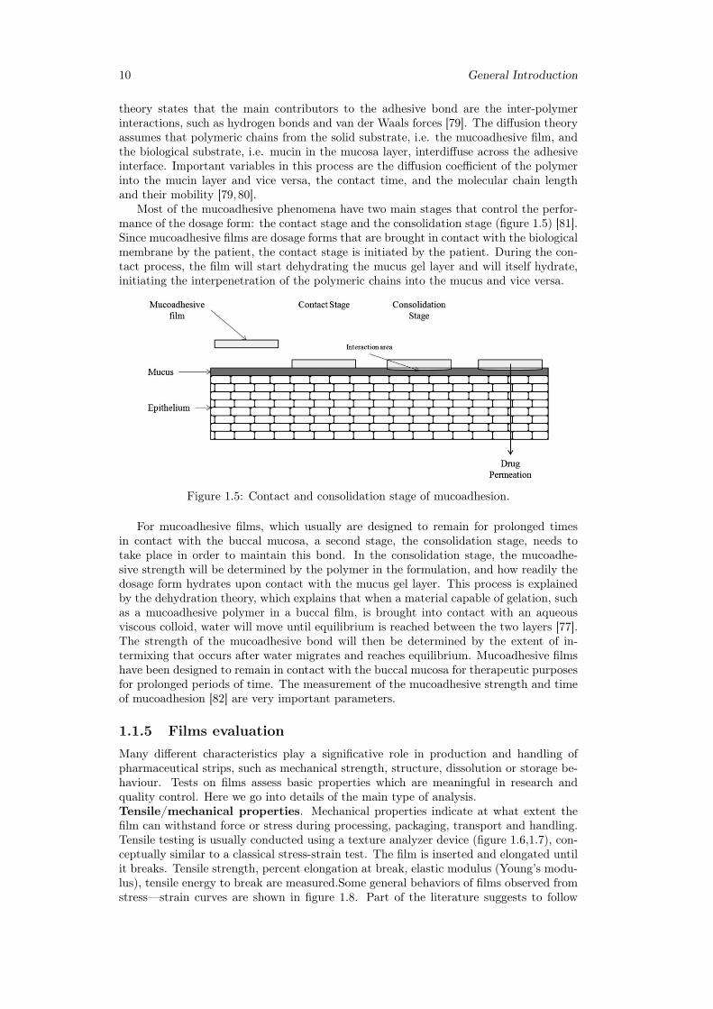
Figure 1.7: Determination of percent elongation of thin films using a texture analyzer,where a = initial length of the film in the sample holder opening, a
′= initial length -
radius of probe, b = displacement of the probe, c′+ r = length after strain, c
′= length
of a′after strain, r = radius of the probe [105].
of films are two qualitative concepts. Film forming capacity is the ability of film formersto form desired films. It is categorized according to strip forming capacity such as verypoor, poor, average, good, very good, excellent. Appearance of strip is evaluated byvisual observation such as transparent, semi transparent,opaque [87,88].Thickness. Thickness is measured at different points (normally 5) by a micrometricscrew gauge.Folding endurance. Folding endurance is determined by folding a film up to it breakat the folding point. The number of attempt required to break the film is the foldingendurance value [89,90].Solid state characterization. Solid state properties of films can be analyzed bymeans of differential scanning calorimetry, Fourier transform infrared spectroscopy, X-Ray diffraction [91].Swelling properties. Hydrophilic polymers undergo swelling, which is defined as an
12 General Introduction
Figure 1.8: Examples of stress–strain curves obtained from polymeric thin films.
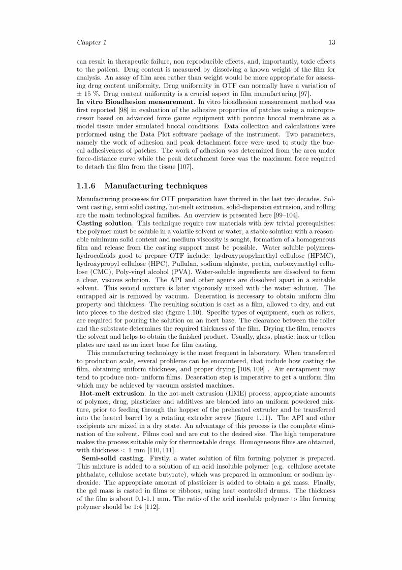
Figure 1.9: Schematic illustration of the apparatus used for dissolution studies of films.
expansion of the matrix in aqueous media. This phenomenon is simultaneous to theset-up of a gel phase. These polymers form physical-linked gels and are bio erodible. Soas, a true swelling equilibrium, as in the sense of cross-linked gel such as Poly-methyl-metacrilate, does not exist. Nonetheless, a pseudo-swelling equilibrium can be individ-uated [92]. Swell is measured by immerging a sample in a swelling medium (generallysaliva or water at fixed pH and temperature), then weighing the sample, time by time,until an equilibrium weight is reached. The film can be put in a Petri dish, in a net wireor a beaker. The swelling degree S is usually calculated as (equation (4.10)):
S =M −M0
M0(1.1)
where M is the measured weight and M0 is the initial weight. Common polymers forOTF can swell from 0.2 to 50 times, depending on the formulation [93,94].In-vitro dissolution testing. Dissolution testing evaluates the duration of drug re-lease from the dosage form and its pace. Dissolution tests for OTF have been performedin diffusion cells [95], USP paddle II(figure 1.9) or basket (I) apparatus, USP IV flow-through apparatus [96]. In the literature, many authors have done some improvisationon the dissolution apparatus, while others have employed Franz diffusion cells (FDC) fortesting the drug release from the polymeric films.A major barrier with respect to film indissolution testing is the placing of the samples. Several methods have been practiced,where the film is attached on the inner side of the glass vessels or the stirring elementusing an adhesive tape [106].Uniformity of drug content. A prerequisite for therapeutic efficacy, safety, and
regulatory approval of a medicine is drug content uniformity. Failure to achieve a highdegree of accuracy with respect to the amount of drug in individual unit doses of the film
Chapter 1 13
can result in therapeutic failure, non reproducible effects, and, importantly, toxic effectsto the patient. Drug content is measured by dissolving a known weight of the film foranalysis. An assay of film area rather than weight would be more appropriate for assess-ing drug content uniformity. Drug uniformity in OTF can normally have a variation of± 15 %. Drug content uniformity is a crucial aspect in film manufacturing [97].In vitro Bioadhesion measurement. In vitro bioadhesion measurement method wasfirst reported [98] in evaluation of the adhesive properties of patches using a micropro-cessor based on advanced force gauze equipment with porcine buccal membrane as amodel tissue under simulated buccal conditions. Data collection and calculations wereperformed using the Data Plot software package of the instrument. Two parameters,namely the work of adhesion and peak detachment force were used to study the buc-cal adhesiveness of patches. The work of adhesion was determined from the area underforce-distance curve while the peak detachment force was the maximum force requiredto detach the film from the tissue [107].
1.1.6 Manufacturing techniques
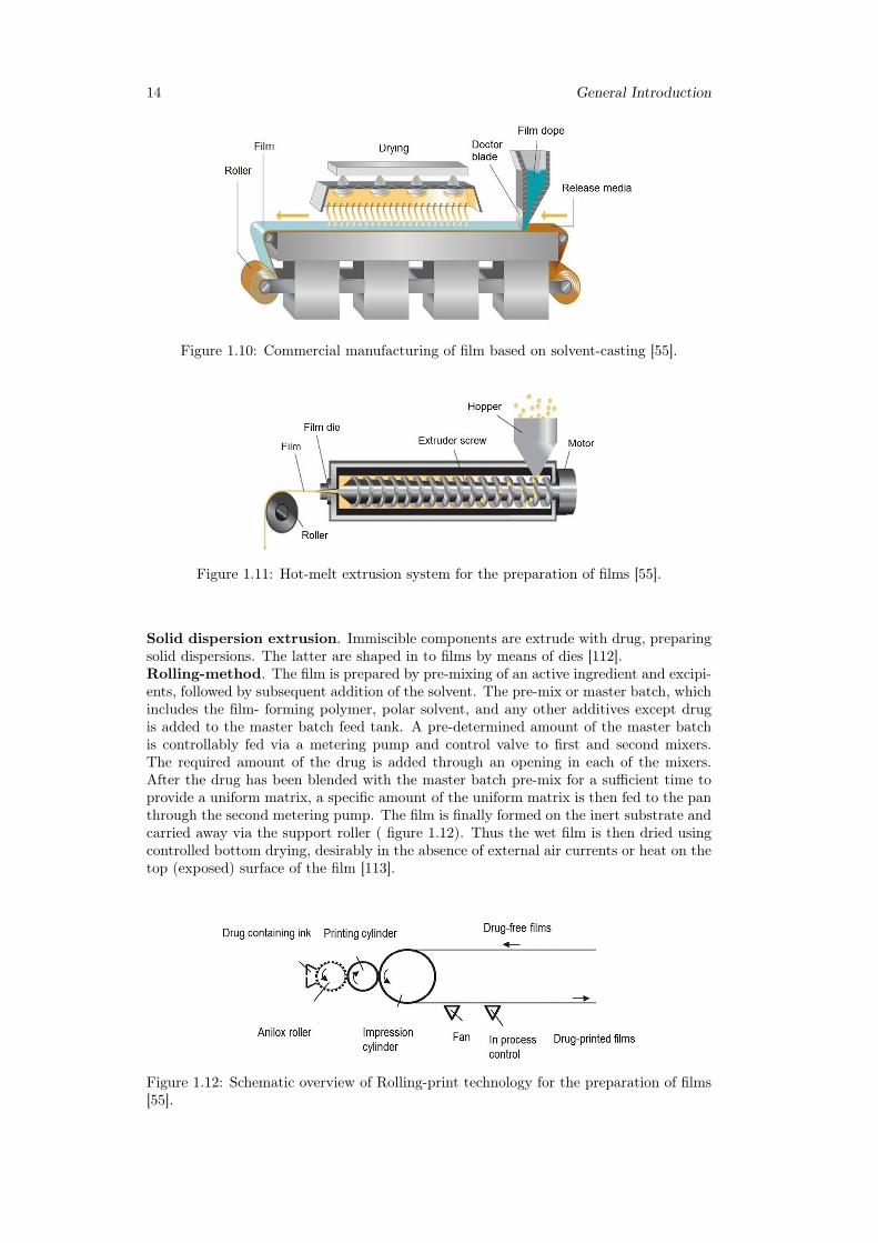
Manufacturing processes for OTF preparation have thrived in the last two decades. Sol-vent casting, semi solid casting, hot-melt extrusion, solid-dispersion extrusion, and rollingare the main technological families. An overview is presented here [99–104].Casting solution. This technique require raw materials with few trivial prerequisites:the polymer must be soluble in a volatile solvent or water, a stable solution with a reason-able minimum solid content and medium viscosity is sought, formation of a homogeneousfilm and release from the casting support must be possible. Water soluble polymers-hydrocolloids good to prepare OTF include: hydroxypropylmethyl cellulose (HPMC),hydroxypropyl cellulose (HPC), Pullulan, sodium alginate, pectin, carboxymethyl cellu-lose (CMC), Poly-vinyl alcohol (PVA). Water-soluble ingredients are dissolved to forma clear, viscous solution. The API and other agents are dissolved apart in a suitablesolvent. This second mixture is later vigorously mixed with the water solution. Theentrapped air is removed by vacuum. Deaeration is necessary to obtain uniform filmproperty and thickness. The resulting solution is cast as a film, allowed to dry, and cutinto pieces to the desired size (figure 1.10). Specific types of equipment, such as rollers,are required for pouring the solution on an inert base. The clearance between the rollerand the substrate determines the required thickness of the film. Drying the film, removesthe solvent and helps to obtain the finished product. Usually, glass, plastic, inox or teflonplates are used as an inert base for film casting.
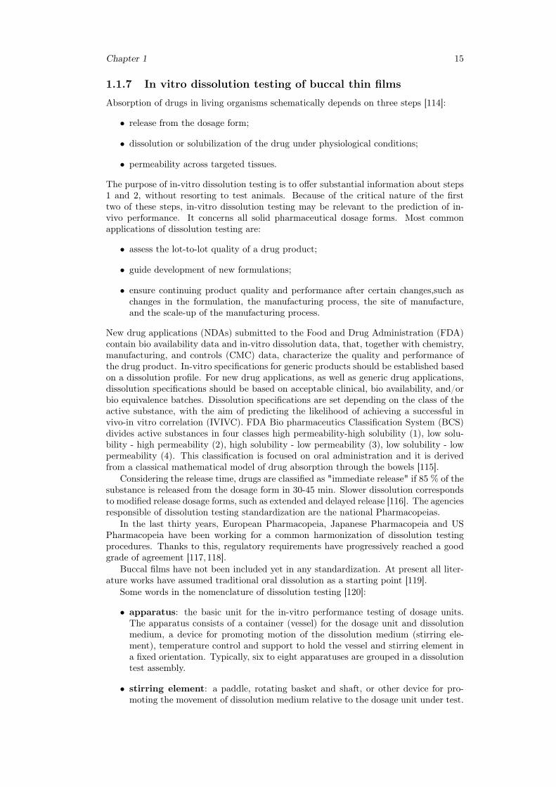
This manufacturing technology is the most frequent in laboratory. When transferredto production scale, several problems can be encountered, that include how casting thefilm, obtaining uniform thickness, and proper drying [108, 109] . Air entrapment maytend to produce non- uniform films. Deaeration step is imperative to get a uniform filmwhich may be achieved by vacuum assisted machines.Hot-melt extrusion. In the hot-melt extrusion (HME) process, appropriate amountsof polymer, drug, plasticizer and additives are blended into an uniform powdered mix-ture, prior to feeding through the hopper of the preheated extruder and be transferredinto the heated barrel by a rotating extruder screw (figure 1.11). The API and otherexcipients are mixed in a dry state. An advantage of this process is the complete elimi-nation of the solvent. Films cool and are cut to the desired size. The high temperaturemakes the process suitable only for thermostable drugs. Homogeneous films are obtained,with thickness < 1 mm [110,111].Semi-solid casting. Firstly, a water solution of film forming polymer is prepared.
This mixture is added to a solution of an acid insoluble polymer (e.g. cellulose acetatephthalate, cellulose acetate butyrate), which was prepared in ammonium or sodium hy-droxide. The appropriate amount of plasticizer is added to obtain a gel mass. Finally,the gel mass is casted in films or ribbons, using heat controlled drums. The thicknessof the film is about 0.1-1.1 mm. The ratio of the acid insoluble polymer to film formingpolymer should be 1:4 [112].
14 General Introduction
Figure 1.10: Commercial manufacturing of film based on solvent-casting [55].
Figure 1.11: Hot-melt extrusion system for the preparation of films [55].
Solid dispersion extrusion. Immiscible components are extrude with drug, preparingsolid dispersions. The latter are shaped in to films by means of dies [112].Rolling-method. The film is prepared by pre-mixing of an active ingredient and excipi-ents, followed by subsequent addition of the solvent. The pre-mix or master batch, whichincludes the film- forming polymer, polar solvent, and any other additives except drugis added to the master batch feed tank. A pre-determined amount of the master batchis controllably fed via a metering pump and control valve to first and second mixers.The required amount of the drug is added through an opening in each of the mixers.After the drug has been blended with the master batch pre-mix for a sufficient time toprovide a uniform matrix, a specific amount of the uniform matrix is then fed to the panthrough the second metering pump. The film is finally formed on the inert substrate andcarried away via the support roller ( figure 1.12). Thus the wet film is then dried usingcontrolled bottom drying, desirably in the absence of external air currents or heat on thetop (exposed) surface of the film [113].
Figure 1.12: Schematic overview of Rolling-print technology for the preparation of films[55].
Chapter 1 15
1.1.7 In vitro dissolution testing of buccal thin films
Absorption of drugs in living organisms schematically depends on three steps [114]:
• release from the dosage form;
• dissolution or solubilization of the drug under physiological conditions;
• permeability across targeted tissues.
The purpose of in-vitro dissolution testing is to offer substantial information about steps1 and 2, without resorting to test animals. Because of the critical nature of the firsttwo of these steps, in-vitro dissolution testing may be relevant to the prediction of in-vivo performance. It concerns all solid pharmaceutical dosage forms. Most commonapplications of dissolution testing are:
• assess the lot-to-lot quality of a drug product;
• guide development of new formulations;
• ensure continuing product quality and performance after certain changes,such aschanges in the formulation, the manufacturing process, the site of manufacture,and the scale-up of the manufacturing process.
New drug applications (NDAs) submitted to the Food and Drug Administration (FDA)contain bio availability data and in-vitro dissolution data, that, together with chemistry,manufacturing, and controls (CMC) data, characterize the quality and performance ofthe drug product. In-vitro specifications for generic products should be established basedon a dissolution profile. For new drug applications, as well as generic drug applications,dissolution specifications should be based on acceptable clinical, bio availability, and/orbio equivalence batches. Dissolution specifications are set depending on the class of theactive substance, with the aim of predicting the likelihood of achieving a successful invivo-in vitro correlation (IVIVC). FDA Bio pharmaceutics Classification System (BCS)divides active substances in four classes high permeability-high solubility (1), low solu-bility - high permeability (2), high solubility - low permeability (3), low solubility - lowpermeability (4). This classification is focused on oral administration and it is derivedfrom a classical mathematical model of drug absorption through the bowels [115].
Considering the release time, drugs are classified as "immediate release" if 85 % of thesubstance is released from the dosage form in 30-45 min. Slower dissolution correspondsto modified release dosage forms, such as extended and delayed release [116]. The agenciesresponsible of dissolution testing standardization are the national Pharmacopeias.
In the last thirty years, European Pharmacopeia, Japanese Pharmacopeia and USPharmacopeia have been working for a common harmonization of dissolution testingprocedures. Thanks to this, regulatory requirements have progressively reached a goodgrade of agreement [117,118].
Buccal films have not been included yet in any standardization. At present all liter-ature works have assumed traditional oral dissolution as a starting point [119].
Some words in the nomenclature of dissolution testing [120]:
• apparatus: the basic unit for the in-vitro performance testing of dosage units.The apparatus consists of a container (vessel) for the dosage unit and dissolutionmedium, a device for promoting motion of the dissolution medium (stirring ele-ment), temperature control and support to hold the vessel and stirring element ina fixed orientation. Typically, six to eight apparatuses are grouped in a dissolutiontest assembly.
• stirring element: a paddle, rotating basket and shaft, or other device for pro-moting the movement of dissolution medium relative to the dosage unit under test.
16 General Introduction
• assembly: a combination of multiple apparatuses providing temperature control,controlled unified motion of stirring elements, and providing the opportunity forsimultaneous or individual start of the apparatuses.
• dissolution system: test assembly connected to sampling and filter unit but with-out instrumentation such as UV/VIS spectrophotometer or HPLC chromatograph.
Four different apparatuses are in use [121]:
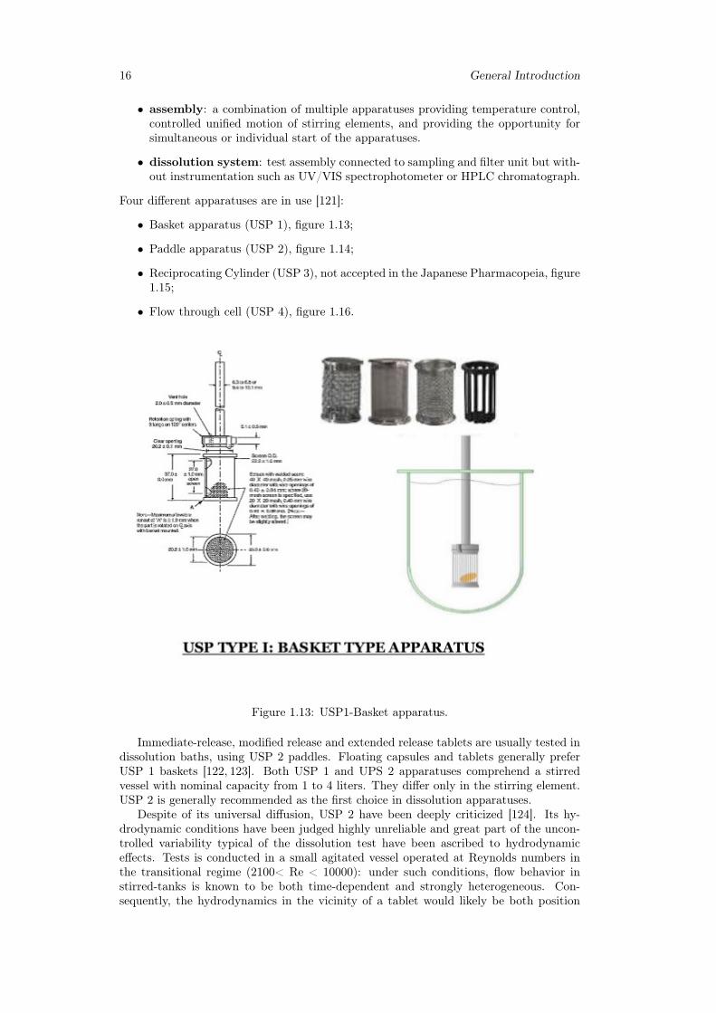
• Basket apparatus (USP 1), figure 1.13;
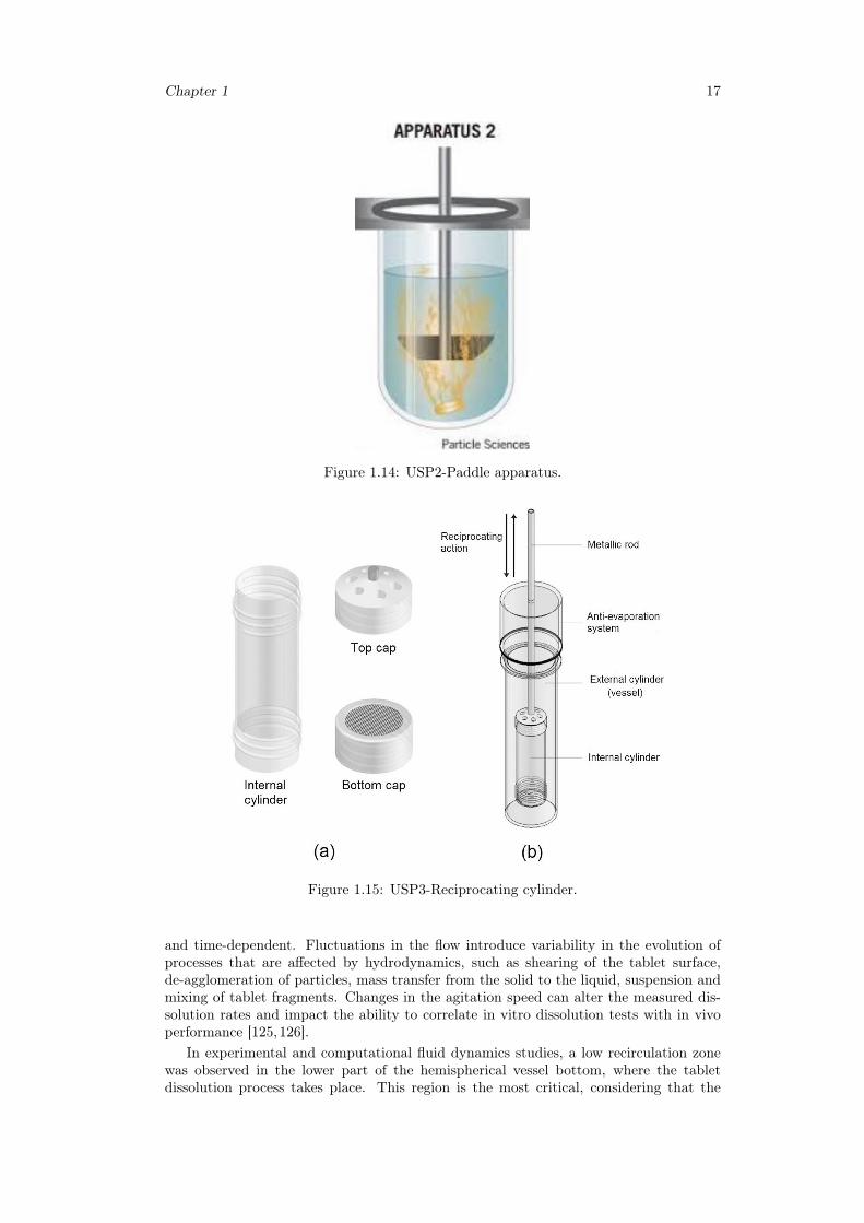
• Paddle apparatus (USP 2), figure 1.14;
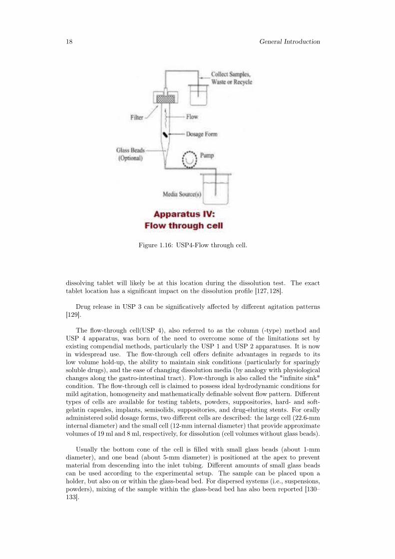
• Reciprocating Cylinder (USP 3), not accepted in the Japanese Pharmacopeia, figure1.15;
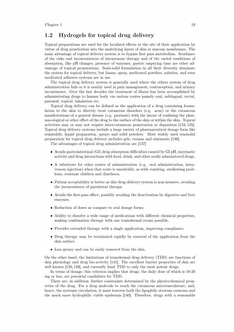
• Flow through cell (USP 4), figure 1.16.
Figure 1.13: USP1-Basket apparatus.
Immediate-release, modified release and extended release tablets are usually tested indissolution baths, using USP 2 paddles. Floating capsules and tablets generally preferUSP 1 baskets [122, 123]. Both USP 1 and UPS 2 apparatuses comprehend a stirredvessel with nominal capacity from 1 to 4 liters. They differ only in the stirring element.USP 2 is generally recommended as the first choice in dissolution apparatuses.
Despite of its universal diffusion, USP 2 have been deeply criticized [124]. Its hy-drodynamic conditions have been judged highly unreliable and great part of the uncon-trolled variability typical of the dissolution test have been ascribed to hydrodynamiceffects. Tests is conducted in a small agitated vessel operated at Reynolds numbers inthe transitional regime (2100< Re < 10000): under such conditions, flow behavior instirred-tanks is known to be both time-dependent and strongly heterogeneous. Con-sequently, the hydrodynamics in the vicinity of a tablet would likely be both position
Chapter 1 17
Figure 1.14: USP2-Paddle apparatus.
Figure 1.15: USP3-Reciprocating cylinder.
and time-dependent. Fluctuations in the flow introduce variability in the evolution ofprocesses that are affected by hydrodynamics, such as shearing of the tablet surface,de-agglomeration of particles, mass transfer from the solid to the liquid, suspension andmixing of tablet fragments. Changes in the agitation speed can alter the measured dis-solution rates and impact the ability to correlate in vitro dissolution tests with in vivoperformance [125,126].
In experimental and computational fluid dynamics studies, a low recirculation zonewas observed in the lower part of the hemispherical vessel bottom, where the tabletdissolution process takes place. This region is the most critical, considering that the
18 General Introduction
Figure 1.16: USP4-Flow through cell.
dissolving tablet will likely be at this location during the dissolution test. The exacttablet location has a significant impact on the dissolution profile [127,128].
Drug release in USP 3 can be significatively affected by different agitation patterns[129].
The flow-through cell(USP 4), also referred to as the column (-type) method andUSP 4 apparatus, was born of the need to overcome some of the limitations set byexisting compendial methods, particularly the USP 1 and USP 2 apparatuses. It is nowin widespread use. The flow-through cell offers definite advantages in regards to itslow volume hold-up, the ability to maintain sink conditions (particularly for sparinglysoluble drugs), and the ease of changing dissolution media (by analogy with physiologicalchanges along the gastro-intestinal tract). Flow-through is also called the "infinite sink"condition. The flow-through cell is claimed to possess ideal hydrodynamic conditions formild agitation, homogeneity and mathematically definable solvent flow pattern. Differenttypes of cells are available for testing tablets, powders, suppositories, hard- and soft-gelatin capsules, implants, semisolids, suppositories, and drug-eluting stents. For orallyadministered solid dosage forms, two different cells are described: the large cell (22.6-mminternal diameter) and the small cell (12-mm internal diameter) that provide approximatevolumes of 19 ml and 8 ml, respectively, for dissolution (cell volumes without glass beads).
Usually the bottom cone of the cell is filled with small glass beads (about 1-mmdiameter), and one bead (about 5-mm diameter) is positioned at the apex to preventmaterial from descending into the inlet tubing. Different amounts of small glass beadscan be used according to the experimental setup. The sample can be placed upon aholder, but also on or within the glass-bead bed. For dispersed systems (i.e., suspensions,powders), mixing of the sample within the glass-bead bed has also been reported [130–133].
Chapter 1 19
1.2 Hydrogels for topical drug deliveryTopical preparations are used for the localized effects at the site of their application byvirtue of drug penetration into the underlying layers of skin or mucous membranes. Themain advantage of topical delivery system is to bypass first pass metabolism. Avoidanceof the risks and inconveniences of intravenous therapy and of the varied conditions ofabsorption, like pH changes, presence of enzymes, gastric emptying time are other ad-vantage of topical preparations. Semi-solid formulation in all their diversity dominatethe system for topical delivery, but foams, spray, medicated powders, solution, and evenmedicated adhesive systems are in use.
The topical drug delivery system is generally used where the others system of drugadministration fails or it is mainly used in pain management, contraception, and urinaryincontinence. Over the last decades the treatment of illness has been accomplished byadministrating drugs to human body via various routes namely oral, sublingual, rectal,parental, topical, inhalation etc.
Topical drug delivery can be defined as the application of a drug containing formu-lation to the skin to directly treat cutaneous disorders (e.g. acne) or the cutaneousmanifestations of a general disease (e.g. psoriasis) with the intent of confining the phar-macological or other effect of the drug to the surface of the skin or within the skin. Topicalactivities may or may not require intra-cutaneous penetration or deposition [134, 135].Topical drug delivery systems include a large variety of pharmaceutical dosage form likesemisolids, liquid preparation, sprays and solid powders. Most widely used semisolidpreparation for topical drug delivery includes gels, creams and ointments [136].
The advantages of topical drug administration are [137]
• Avoids gastrointestinal (GI) drug absorption difficulties caused by GI pH, enzymaticactivity and drug interactions with food, drink, and other orally administered drugs.
• A substitute for other routes of administration (e.g. oral administration, intra-venous injection) when that route is unsuitable, as with vomiting, swallowing prob-lems, resistant children and diarrhoea.
• Patient acceptability is better as this drug delivery system is non-invasive, avoidingthe inconvenience of parenteral therapy.
• Avoids the first-pass effect, possibly avoiding the deactivation by digestive and liverenzymes.
• Reduction of doses as compare to oral dosage forms.
• Ability to dissolve a wide range of medications with different chemical properties,making combination therapy with one transdermal cream possible.
• Provides extended therapy with a single application, improving compliance.
• Drug therapy may be terminated rapidly by removal of the application from theskin surface.
• Less greasy and can be easily removed from the skin.
On the other hand, the limitations of transdermal drug delivery (TDD) are functions ofskin physiology and drug bio-activity [141]. The excellent barrier properties of skin arewell known [138,139], and currently limit TDD to only the most potent drugs.
In terms of dosage, this criterion implies that drugs, the daily dose of which is 10-20mg or less, are potential candidates for TDD.
There are, in addition, further constraints determined by the physicochemical prop-erties of the drug. For a drug molecule to reach the cutaneous microvasculature, and,hence, the systemic circulation, it must traverse both the lipophilic stratum corneum andthe much more hydrophilic viable epidermis [140]. Therefore, drugs with a reasonable
20 General Introduction
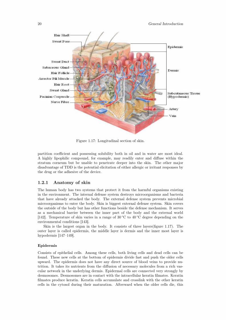
Figure 1.17: Longitudinal section of skin.
partition coefficient and possessing solubility both in oil and in water are most ideal.A highly lipophilic compound, for example, may readily enter and diffuse within thestratum corneum but be unable to penetrate deeper into the skin. The other majordisadvantage of TDD is the potential elicitation of either allergic or irritant responses bythe drug or the adhesive of the device.
1.2.1 Anatomy of skin
The human body has two systems that protect it from the harmful organisms existingin the environment. The internal defense system destroys microorganisms and bacteriathat have already attacked the body. The external defense system prevents microbialmicroorganisms to enter the body. Skin is biggest external defense system. Skin coversthe outside of the body but has other functions beside the defense mechanism. It servesas a mechanical barrier between the inner part of the body and the external world[142]. Temperature of skin varies in a range of 30 ◦C to 40 ◦C degree depending on theenvironmental conditions [143].
Skin is the largest organ in the body. It consists of three layers(figure 1.17). Theouter layer is called epidermis, the middle layer is dermis and the inner most layer ishypodermis [147–149].
Epidermis
Consists of epithelial cells. Among these cells, both living cells and dead cells can befound. These new cells at the bottom of epidermis divide fast and push the older cellsupward. The epidermis does not have any direct source of blood veins to provide nu-trition. It takes its nutrients from the diffusion of necessary molecules from a rich vas-cular network in the underlying dermis. Epidermal cells are connected very strongly bydesmosomes. Desmosomes are in contact with the intracellular keratin filmates. Keratinfilmates produce keratin. Keratin cells accumulate and crosslink with the other keratincells in the cytosol during their maturation. Afterward when the older cells die, this
Chapter 1 21
network of keratin fibroses remains and provides a tough and hard protective layer inepidermis, called protective keratinized layer. This layer is waterproof and airtight. Itprevents most substances to enter the body or leave from the body. In diseased skin,particularly burns, epidermis is destroyed causing potential loss of body fluid and anincrease in susceptibility to microbial infections, leading to fatal consequences untreated.
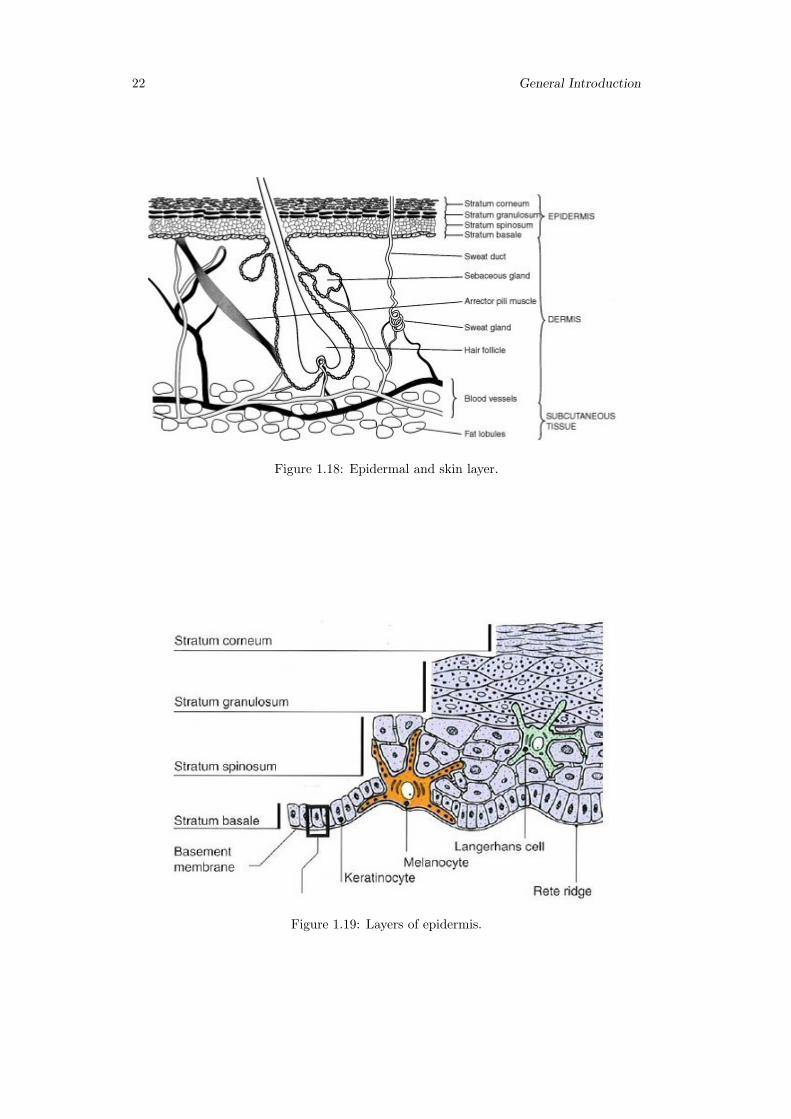
Cell types that exist in the epidermis are (figure 1.19):
• Keratinocytes; these are the main cell types in epidermis (95% of cells);
• Melanocytes; these are the pigment producer cells and found in the basal layers ofepidermis;
• Langerhans cells; these cells are important immunological cells and can be foundin the mid dermis as well Merkel cells; these cells are found in the basal layer ofepidermis and are one part of amine precursor and decarboxylation system [144,145].
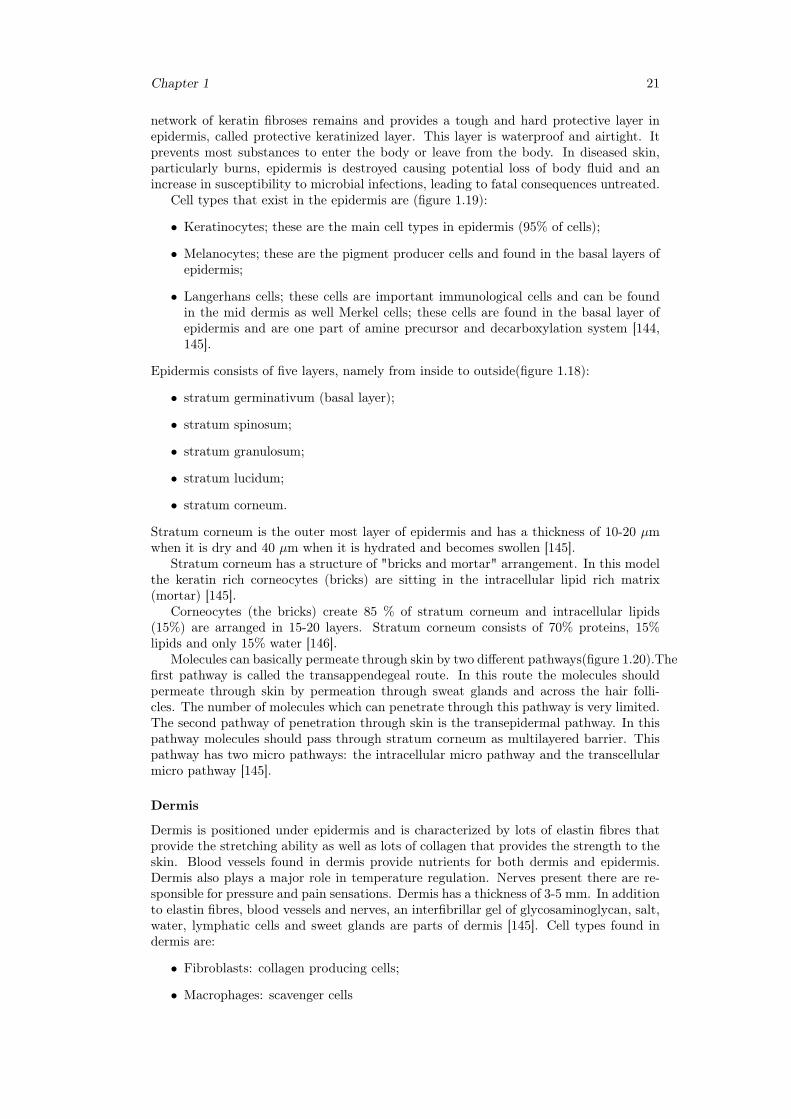
Epidermis consists of five layers, namely from inside to outside(figure 1.18):
• stratum germinativum (basal layer);
• stratum spinosum;
• stratum granulosum;
• stratum lucidum;
• stratum corneum.
Stratum corneum is the outer most layer of epidermis and has a thickness of 10-20 µmwhen it is dry and 40 µm when it is hydrated and becomes swollen [145].
Stratum corneum has a structure of "bricks and mortar" arrangement. In this modelthe keratin rich corneocytes (bricks) are sitting in the intracellular lipid rich matrix(mortar) [145].
Corneocytes (the bricks) create 85 % of stratum corneum and intracellular lipids(15%) are arranged in 15-20 layers. Stratum corneum consists of 70% proteins, 15%lipids and only 15% water [146].
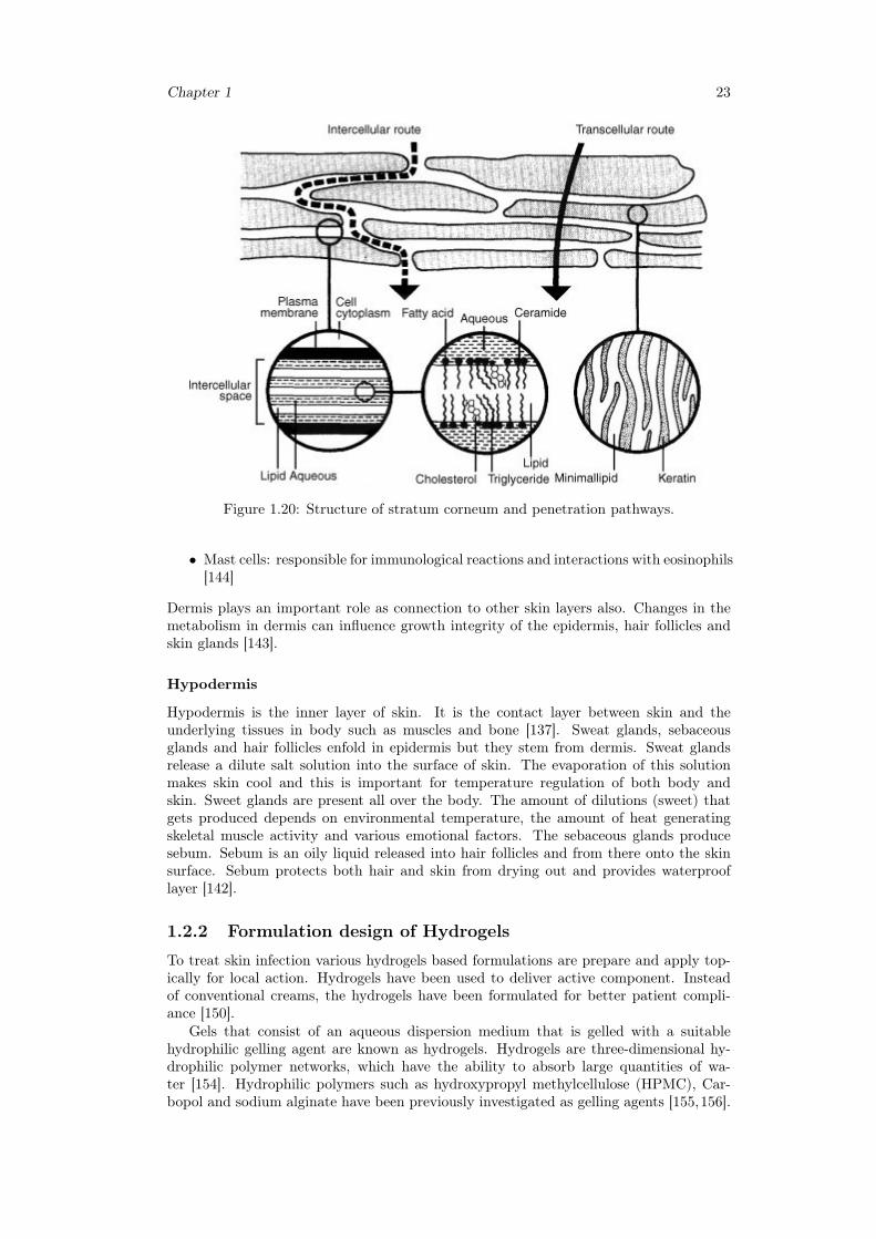
Molecules can basically permeate through skin by two different pathways(figure 1.20).Thefirst pathway is called the transappendegeal route. In this route the molecules shouldpermeate through skin by permeation through sweat glands and across the hair folli-cles. The number of molecules which can penetrate through this pathway is very limited.The second pathway of penetration through skin is the transepidermal pathway. In thispathway molecules should pass through stratum corneum as multilayered barrier. Thispathway has two micro pathways: the intracellular micro pathway and the transcellularmicro pathway [145].
Dermis
Dermis is positioned under epidermis and is characterized by lots of elastin fibres thatprovide the stretching ability as well as lots of collagen that provides the strength to theskin. Blood vessels found in dermis provide nutrients for both dermis and epidermis.Dermis also plays a major role in temperature regulation. Nerves present there are re-sponsible for pressure and pain sensations. Dermis has a thickness of 3-5 mm. In additionto elastin fibres, blood vessels and nerves, an interfibrillar gel of glycosaminoglycan, salt,water, lymphatic cells and sweet glands are parts of dermis [145]. Cell types found indermis are:
• Fibroblasts: collagen producing cells;
• Macrophages: scavenger cells
22 General Introduction
Figure 1.18: Epidermal and skin layer.
Figure 1.19: Layers of epidermis.
Chapter 1 23
Figure 1.20: Structure of stratum corneum and penetration pathways.
• Mast cells: responsible for immunological reactions and interactions with eosinophils[144]
Dermis plays an important role as connection to other skin layers also. Changes in themetabolism in dermis can influence growth integrity of the epidermis, hair follicles andskin glands [143].
Hypodermis
Hypodermis is the inner layer of skin. It is the contact layer between skin and theunderlying tissues in body such as muscles and bone [137]. Sweat glands, sebaceousglands and hair follicles enfold in epidermis but they stem from dermis. Sweat glandsrelease a dilute salt solution into the surface of skin. The evaporation of this solutionmakes skin cool and this is important for temperature regulation of both body andskin. Sweet glands are present all over the body. The amount of dilutions (sweet) thatgets produced depends on environmental temperature, the amount of heat generatingskeletal muscle activity and various emotional factors. The sebaceous glands producesebum. Sebum is an oily liquid released into hair follicles and from there onto the skinsurface. Sebum protects both hair and skin from drying out and provides waterprooflayer [142].
1.2.2 Formulation design of Hydrogels
To treat skin infection various hydrogels based formulations are prepare and apply top-ically for local action. Hydrogels have been used to deliver active component. Insteadof conventional creams, the hydrogels have been formulated for better patient compli-ance [150].
Gels that consist of an aqueous dispersion medium that is gelled with a suitablehydrophilic gelling agent are known as hydrogels. Hydrogels are three-dimensional hy-drophilic polymer networks, which have the ability to absorb large quantities of wa-ter [154]. Hydrophilic polymers such as hydroxypropyl methylcellulose (HPMC), Car-bopol and sodium alginate have been previously investigated as gelling agents [155,156].
24 General Introduction
Hydrogels can be formed via chemical or physical crosslinks, which provide a networkedstructure and physical stability. These physical crosslinks include entanglements, crys-tallites, Van der Waals interactions or hydrogen bonding. Hydrogels formed from phys-ical crosslinks are known as "reversible" or "physical" hydrogels [153, 157]. In contrast,hydrogels known as "chemical" or "permanent" gels are formed via covalently bondedcrosslinked networks [151,152].
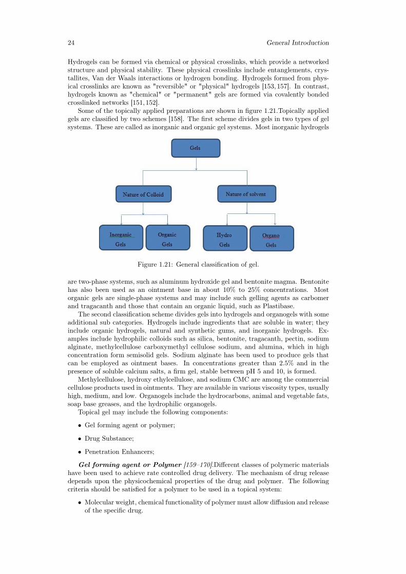
Some of the topically applied preparations are shown in figure 1.21.Topically appliedgels are classified by two schemes [158]. The first scheme divides gels in two types of gelsystems. These are called as inorganic and organic gel systems. Most inorganic hydrogels
Figure 1.21: General classification of gel.
are two-phase systems, such as aluminum hydroxide gel and bentonite magma. Bentonitehas also been used as an ointment base in about 10% to 25% concentrations. Mostorganic gels are single-phase systems and may include such gelling agents as carbomerand tragacanth and those that contain an organic liquid, such as Plastibase.
The second classification scheme divides gels into hydrogels and organogels with someadditional sub categories. Hydrogels include ingredients that are soluble in water; theyinclude organic hydrogels, natural and synthetic gums, and inorganic hydrogels. Ex-amples include hydrophilic colloids such as silica, bentonite, tragacanth, pectin, sodiumalginate, methylcellulose carboxymethyl cellulose sodium, and alumina, which in highconcentration form semisolid gels. Sodium alginate has been used to produce gels thatcan be employed as ointment bases. In concentrations greater than 2.5% and in thepresence of soluble calcium salts, a firm gel, stable between pH 5 and 10, is formed.
Methylcellulose, hydroxy ethylcellulose, and sodium CMC are among the commercialcellulose products used in ointments. They are available in various viscosity types, usuallyhigh, medium, and low. Organogels include the hydrocarbons, animal and vegetable fats,soap base greases, and the hydrophilic organogels.
Topical gel may include the following components:
• Gel forming agent or polymer;
• Drug Substance;
• Penetration Enhancers;
Gel forming agent or Polymer [159–170].Different classes of polymeric materialshave been used to achieve rate controlled drug delivery. The mechanism of drug releasedepends upon the physicochemical properties of the drug and polymer. The followingcriteria should be satisfied for a polymer to be used in a topical system:
• Molecular weight, chemical functionality of polymer must allow diffusion and releaseof the specific drug.
Chapter 1 25
• The polymer should permit the incorporation of a large amount of drug.
• The polymer should not react, physically or chemically with the drug.
• The polymer should be easily manufactured and fabricated into the desired productand inexpensive.
• The polymer must be stable and must not decompose in the presence of drug andother excipients used in the formulation, at high humidity conditions, or at bodytemperature.
• Polymers and its degradation products must be nontoxic. No single material mayhave all these attributes, certain excipients may be incorporated to alter someproperties for example Co-solvents such as ethanol, propylene glycol, PEG 400could be added to increase drug solubility.
Gel forming polymers are classified as below:
• Natural Polymers:
– Proteins-E.g. Collagen, Gelatin, Xanthin, Gellum Gum;
– Polysaccharides-E.g. Agar, Alginic acid, Sodium or potassium carrageenan,Tragacanth, Pectin, Guar Gum, Cassia tora;
• Semi synthetic Polymers:
– Cellulose Derivatives-E.g. Carboxymethyl cellulose Methylcellulose, Hydrox-ypropyl cellulose, Hydroxypropyl methylcellulose, Hydroxyethyl cellulose;
• Synthetic Polymers:
– Carbomer-E.g. Carbopol-940, Carbopol-934, Carbopol -941;
– Poloxamer;
– Polyacrylamide;
– Polyvinyl Alcohol;
– Polyethylene and its copolymers;
• Inorganic Substances-E.g. Aluminum Hydroxide bentonite;
• Surfactants-E.g. Cetosteryl alcohol, Brij-96;
Drug Substance [159–170].Drug Substance plays a very important role in the suc-cessful development of a topical product. The important drug properties that effect itsdiffusion through gels as well as through skin are as follows.
• Physicochemical properties:
– Drug should have a molecular weight of less than 500 Daltons.
– Drugs highly acidic or alkaline in solution are not suitable for topical delivery.
– Drug must have adequate lipophilicity.
– A saturated aqueous solution of the drug should have a pH value between 5and 9.
• Biological properties:
– The drug should not be directly irritated to the skin.
– Drugs, which degrade in gastrointestinal tract or are inactivated by hepaticfirst pass effect, are suitable for topical delivery.
26 General Introduction
– Tolerance to the drug must not develop under the near zero order releaseprofile of topical delivery.
– The drug should not stimulate an immune reaction in the skin.
– Drugs which have to be administered for a long time or which cause adverseeffects to non-target tissue can also be formulated for topical delivery.
Penetration Enhancer [171–183].Penetration enhancers (also called accelerants orsorption promoters) are defined as substances that are capable of promoting penetra-tion of drugs into skin, or their permeation through skin, by reversible reducing the skinbarrier resistance. Percutaneous absorption involves the passage of the drug moleculefrom the skin surface into the stratum corneum under the influence of a concentrationgradient and its subsequent diffusion through the stratum corneum and underlying epi-dermis, through the dermis, and into the blood circulation. The skin behaves as a passivebarrier to the penetrant molecule. The stratum corneum provides the greatest resistanceto penetration, and it is the rate-limiting step in percutaneous absorption.
A penetration enhancer acts by altering the skin as a barrier to the flux of a de-sired penetrant and are considered as an integral part of most topical formulations. Toachieve and maintain therapeutic concentration of drug in the blood, the resistance ofskin (stratum corneum) to diffusion of drugs has to be reduced in order to allow drugmolecules to cross skin and to maintain therapeutic levels in blood. They can modify theskin’s barrier to penetration either by interacting with the formulation that applied orwith the skin itself. Ideally, these materials should be pharmacologically inert, nontoxic,non-irritating, non-allergenic, and compatible with the drug and excipients, odorless,tasteless, colorless, and in-expensive and have good solvent properties. The enhancershould not lead to the loss of body fluids, electrolytes, and other endogenous materials,and skin should immediately regain its barrier properties on its removal.
An ideal penetration enhancer should have the following properties:
• It should be pharmacologically and chemically inert, and chemically stable.
• It should be non-toxic, non-irritant, noncomedogenic and non-allergenic.
• It should have a rapid onset of action, predictable duration of activity, as well as areproducible and reversible effect.
• It should be chemically and physically compatible with the formulation ingredients.
• After it is removed from the skin, the stratum corneum should rapidly and fullyrecover its normal barrier property.
• It should be odorless, tasteless, colorless, and inexpensive.
• It should be pharmaceutically and cosmetically acceptable.
• It should have a solubility parameter similar to that of skin.
In spite of the fact that a variety of compounds have been proposed as skin penetra-tion enhancers, to date, no substance has been found to possess all the aforementionedideal properties. Nevertheless, many known and newly developed compounds have beenassessed for their enhancing abilities and some have shown more promising characteris-tics.
Preparation methods of Hydrogels
Hydrogels are polymeric networks. This implies that crosslinks have to be present inorder to avoid dissolution of the hydrophilic polymer chain in aqueous solution. Thevarious methods for crosslinking are as follows:
Chapter 1 27
Crosslinking of Polymers.In this method chemically crosslinked gels are formedby radical polymerization of low molecular weight monomers, or branched homopoly-mers, or copolymers in the presence of crosslinking agent. This reaction is mostly carriedout in solution for biomedical applications.
Copolymerization/Crosslinking Reactions.Copolymerization reactions are usedto produce polymer gels, many hydrogels are produced in this fashion, for example poly(hydroxyalkyl methylacrylates).
Crosslinking by High Energy Radiation.High energy radiation, such as gammaand electron beam radiation can be used to polymerize unsaturated compounds. Watersoluble polymers derivatized with vinyl groups can be converted into hydrogels usinghigh energy radiation.
Crosslinking Using Enzymes.Recently a new method was published using an en-zyme to synthesize PEGbased hydrogels. A tetrahydroxy PEG was functionalized withaddition of glutaminyl groups and networks were formed by addition of transglutami-nase into solution of PEG and poly (lysinecophenylalanine). The synthesis of hydrogelin industry is Consist of solution and reversed suspension and reversed emulsion poly-merizations [184–187].
1.2.3 Hydrogels evaluationGels should possess the following properties:
• Ideally, the gelling agent for pharmaceutical or cosmetic use should be inert, safe,and should not react with other formulation components;
• The gelling agent included in the preparation should produce a reasonable solid-like nature during storage that can be easily broken when subjected to shear forcesgenerated by shaking the bottle, squeezing the tube, or during topical application;
• It should possess suitable anti-microbial activity against microbial attack;
• The topical gel should not be tacky;
• The gels intended for ophthalmic use should be sterile; [188,189]
Hydrogels are water swollen polymer matrices, with a tendency to imbibe water whenplaced in aqueous environment. This ability to swell, under biological conditions, makesit an ideal material for use in drug delivery and immobilization of proteins, peptides,and other biological compounds. Due to their high water content, these gels resemblenatural living tissue more than any other type of synthetic biomaterial. These networks,have a three dimensional structure, crosslinked together either physically (entanglements,crystallites), or chemically (tie-points, junctions). This insoluble crosslinked structureallows immobilization of active agents, biomolecules effectively, and allows for its releasein well-defined specific manner.
Thus the hydrogels biocompatibility and crosslinked structure are responsible forits varied applications [196, 197].Due to their hydrophilicity, hydrogels can imbibe largeamounts of water. Therefore, the molecule release mechanisms from hydrogels are verydifferent from hydrophobic polymers. Both simple and sophisticated models have beenpreviously developed to predict the release of an active agent from a hydrogel device as afunction of time. These models are based on the rate limiting step for controlled releaseand are therefore categorized as diffusion, swelling et chemically controlled mechanism.
Diffusion controlled.It is most widely applicable mechanism relating to drug re-lease. Fick’s law of diffusion is commonly used in modeling this release. Types ofdiffusion-controlled hydrogel delivery systems are as follows:
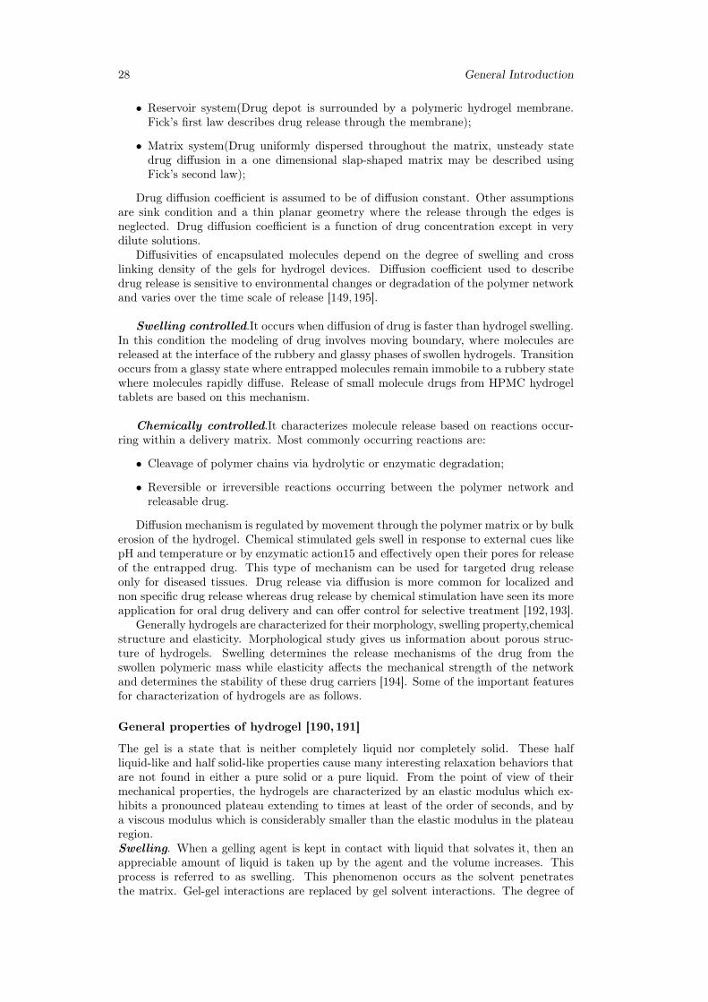
28 General Introduction
• Reservoir system(Drug depot is surrounded by a polymeric hydrogel membrane.Fick’s first law describes drug release through the membrane);
• Matrix system(Drug uniformly dispersed throughout the matrix, unsteady statedrug diffusion in a one dimensional slap-shaped matrix may be described usingFick’s second law);
Drug diffusion coefficient is assumed to be of diffusion constant. Other assumptionsare sink condition and a thin planar geometry where the release through the edges isneglected. Drug diffusion coefficient is a function of drug concentration except in verydilute solutions.
Diffusivities of encapsulated molecules depend on the degree of swelling and crosslinking density of the gels for hydrogel devices. Diffusion coefficient used to describedrug release is sensitive to environmental changes or degradation of the polymer networkand varies over the time scale of release [149,195].
Swelling controlled.It occurs when diffusion of drug is faster than hydrogel swelling.In this condition the modeling of drug involves moving boundary, where molecules arereleased at the interface of the rubbery and glassy phases of swollen hydrogels. Transitionoccurs from a glassy state where entrapped molecules remain immobile to a rubbery statewhere molecules rapidly diffuse. Release of small molecule drugs from HPMC hydrogeltablets are based on this mechanism.
Chemically controlled.It characterizes molecule release based on reactions occur-ring within a delivery matrix. Most commonly occurring reactions are:
• Cleavage of polymer chains via hydrolytic or enzymatic degradation;
• Reversible or irreversible reactions occurring between the polymer network andreleasable drug.
Diffusion mechanism is regulated by movement through the polymer matrix or by bulkerosion of the hydrogel. Chemical stimulated gels swell in response to external cues likepH and temperature or by enzymatic action15 and effectively open their pores for releaseof the entrapped drug. This type of mechanism can be used for targeted drug releaseonly for diseased tissues. Drug release via diffusion is more common for localized andnon specific drug release whereas drug release by chemical stimulation have seen its moreapplication for oral drug delivery and can offer control for selective treatment [192,193].
Generally hydrogels are characterized for their morphology, swelling property,chemicalstructure and elasticity. Morphological study gives us information about porous struc-ture of hydrogels. Swelling determines the release mechanisms of the drug from theswollen polymeric mass while elasticity affects the mechanical strength of the networkand determines the stability of these drug carriers [194]. Some of the important featuresfor characterization of hydrogels are as follows.
General properties of hydrogel [190,191]
The gel is a state that is neither completely liquid nor completely solid. These halfliquid-like and half solid-like properties cause many interesting relaxation behaviors thatare not found in either a pure solid or a pure liquid. From the point of view of theirmechanical properties, the hydrogels are characterized by an elastic modulus which ex-hibits a pronounced plateau extending to times at least of the order of seconds, and bya viscous modulus which is considerably smaller than the elastic modulus in the plateauregion.Swelling. When a gelling agent is kept in contact with liquid that solvates it, then anappreciable amount of liquid is taken up by the agent and the volume increases. Thisprocess is referred to as swelling. This phenomenon occurs as the solvent penetratesthe matrix. Gel-gel interactions are replaced by gel solvent interactions. The degree of
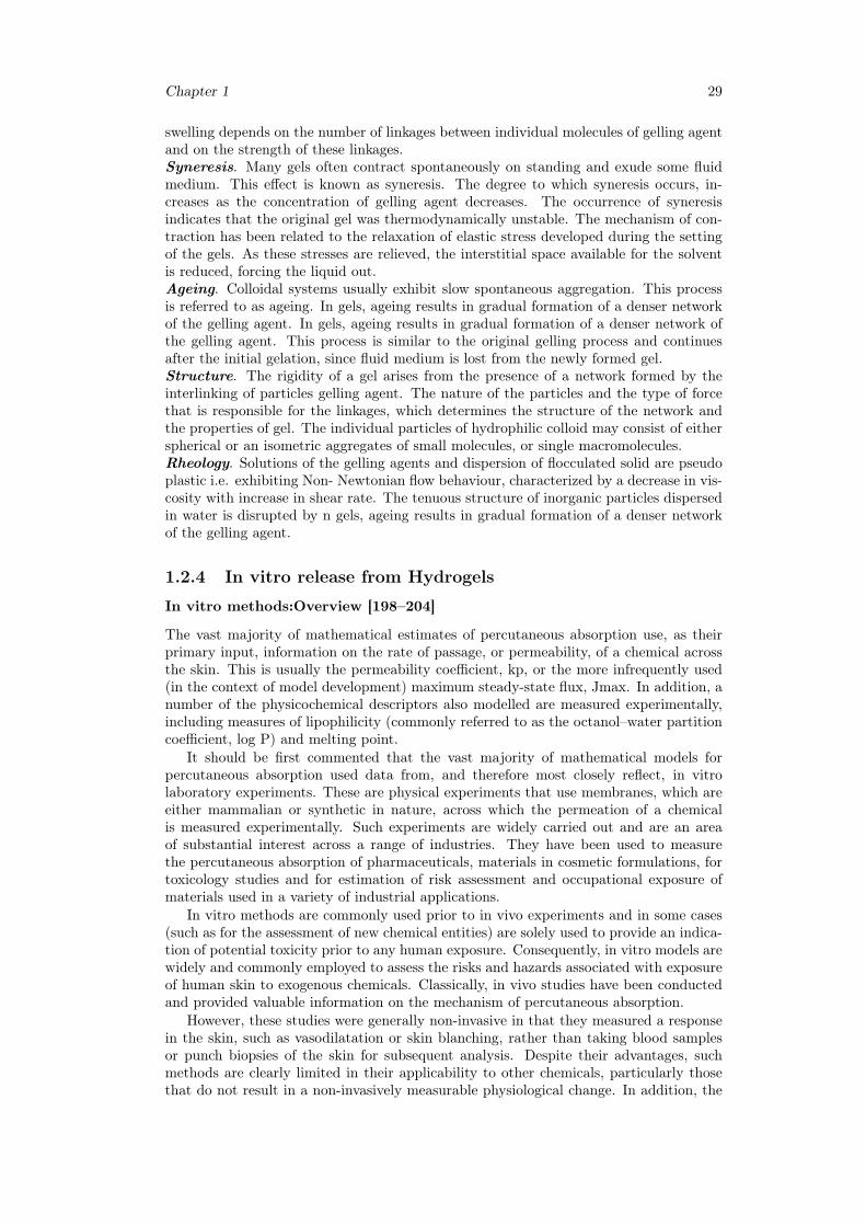
Chapter 1 29
swelling depends on the number of linkages between individual molecules of gelling agentand on the strength of these linkages.Syneresis. Many gels often contract spontaneously on standing and exude some fluidmedium. This effect is known as syneresis. The degree to which syneresis occurs, in-creases as the concentration of gelling agent decreases. The occurrence of syneresisindicates that the original gel was thermodynamically unstable. The mechanism of con-traction has been related to the relaxation of elastic stress developed during the settingof the gels. As these stresses are relieved, the interstitial space available for the solventis reduced, forcing the liquid out.Ageing. Colloidal systems usually exhibit slow spontaneous aggregation. This processis referred to as ageing. In gels, ageing results in gradual formation of a denser networkof the gelling agent. In gels, ageing results in gradual formation of a denser network ofthe gelling agent. This process is similar to the original gelling process and continuesafter the initial gelation, since fluid medium is lost from the newly formed gel.Structure. The rigidity of a gel arises from the presence of a network formed by theinterlinking of particles gelling agent. The nature of the particles and the type of forcethat is responsible for the linkages, which determines the structure of the network andthe properties of gel. The individual particles of hydrophilic colloid may consist of eitherspherical or an isometric aggregates of small molecules, or single macromolecules.Rheology. Solutions of the gelling agents and dispersion of flocculated solid are pseudoplastic i.e. exhibiting Non- Newtonian flow behaviour, characterized by a decrease in vis-cosity with increase in shear rate. The tenuous structure of inorganic particles dispersedin water is disrupted by n gels, ageing results in gradual formation of a denser networkof the gelling agent.
1.2.4 In vitro release from Hydrogels
In vitro methods:Overview [198–204]
The vast majority of mathematical estimates of percutaneous absorption use, as theirprimary input, information on the rate of passage, or permeability, of a chemical acrossthe skin. This is usually the permeability coefficient, kp, or the more infrequently used(in the context of model development) maximum steady-state flux, Jmax. In addition, anumber of the physicochemical descriptors also modelled are measured experimentally,including measures of lipophilicity (commonly referred to as the octanol–water partitioncoefficient, log P) and melting point.
It should be first commented that the vast majority of mathematical models forpercutaneous absorption used data from, and therefore most closely reflect, in vitrolaboratory experiments. These are physical experiments that use membranes, which areeither mammalian or synthetic in nature, across which the permeation of a chemicalis measured experimentally. Such experiments are widely carried out and are an areaof substantial interest across a range of industries. They have been used to measurethe percutaneous absorption of pharmaceuticals, materials in cosmetic formulations, fortoxicology studies and for estimation of risk assessment and occupational exposure ofmaterials used in a variety of industrial applications.
In vitro methods are commonly used prior to in vivo experiments and in some cases(such as for the assessment of new chemical entities) are solely used to provide an indica-tion of potential toxicity prior to any human exposure. Consequently, in vitro models arewidely and commonly employed to assess the risks and hazards associated with exposureof human skin to exogenous chemicals. Classically, in vivo studies have been conductedand provided valuable information on the mechanism of percutaneous absorption.
However, these studies were generally non-invasive in that they measured a responsein the skin, such as vasodilatation or skin blanching, rather than taking blood samplesor punch biopsies of the skin for subsequent analysis. Despite their advantages, suchmethods are clearly limited in their applicability to other chemicals, particularly thosethat do not result in a non-invasively measurable physiological change. In addition, the
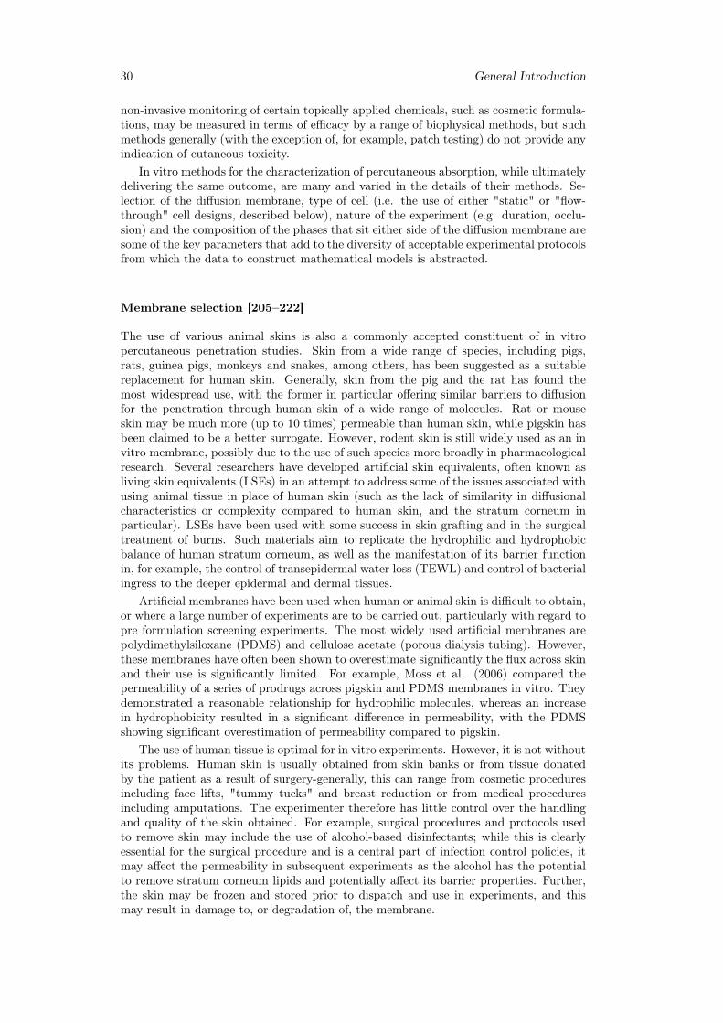
30 General Introduction
non-invasive monitoring of certain topically applied chemicals, such as cosmetic formula-tions, may be measured in terms of efficacy by a range of biophysical methods, but suchmethods generally (with the exception of, for example, patch testing) do not provide anyindication of cutaneous toxicity.
In vitro methods for the characterization of percutaneous absorption, while ultimatelydelivering the same outcome, are many and varied in the details of their methods. Se-lection of the diffusion membrane, type of cell (i.e. the use of either "static" or "flow-through" cell designs, described below), nature of the experiment (e.g. duration, occlu-sion) and the composition of the phases that sit either side of the diffusion membrane aresome of the key parameters that add to the diversity of acceptable experimental protocolsfrom which the data to construct mathematical models is abstracted.
Membrane selection [205–222]
The use of various animal skins is also a commonly accepted constituent of in vitropercutaneous penetration studies. Skin from a wide range of species, including pigs,rats, guinea pigs, monkeys and snakes, among others, has been suggested as a suitablereplacement for human skin. Generally, skin from the pig and the rat has found themost widespread use, with the former in particular offering similar barriers to diffusionfor the penetration through human skin of a wide range of molecules. Rat or mouseskin may be much more (up to 10 times) permeable than human skin, while pigskin hasbeen claimed to be a better surrogate. However, rodent skin is still widely used as an invitro membrane, possibly due to the use of such species more broadly in pharmacologicalresearch. Several researchers have developed artificial skin equivalents, often known asliving skin equivalents (LSEs) in an attempt to address some of the issues associated withusing animal tissue in place of human skin (such as the lack of similarity in diffusionalcharacteristics or complexity compared to human skin, and the stratum corneum inparticular). LSEs have been used with some success in skin grafting and in the surgicaltreatment of burns. Such materials aim to replicate the hydrophilic and hydrophobicbalance of human stratum corneum, as well as the manifestation of its barrier functionin, for example, the control of transepidermal water loss (TEWL) and control of bacterialingress to the deeper epidermal and dermal tissues.
Artificial membranes have been used when human or animal skin is difficult to obtain,or where a large number of experiments are to be carried out, particularly with regard topre formulation screening experiments. The most widely used artificial membranes arepolydimethylsiloxane (PDMS) and cellulose acetate (porous dialysis tubing). However,these membranes have often been shown to overestimate significantly the flux across skinand their use is significantly limited. For example, Moss et al. (2006) compared thepermeability of a series of prodrugs across pigskin and PDMS membranes in vitro. Theydemonstrated a reasonable relationship for hydrophilic molecules, whereas an increasein hydrophobicity resulted in a significant difference in permeability, with the PDMSshowing significant overestimation of permeability compared to pigskin.
The use of human tissue is optimal for in vitro experiments. However, it is not withoutits problems. Human skin is usually obtained from skin banks or from tissue donatedby the patient as a result of surgery-generally, this can range from cosmetic proceduresincluding face lifts, "tummy tucks" and breast reduction or from medical proceduresincluding amputations. The experimenter therefore has little control over the handlingand quality of the skin obtained. For example, surgical procedures and protocols usedto remove skin may include the use of alcohol-based disinfectants; while this is clearlyessential for the surgical procedure and is a central part of infection control policies, itmay affect the permeability in subsequent experiments as the alcohol has the potentialto remove stratum corneum lipids and potentially affect its barrier properties. Further,the skin may be frozen and stored prior to dispatch and use in experiments, and thismay result in damage to, or degradation of, the membrane.
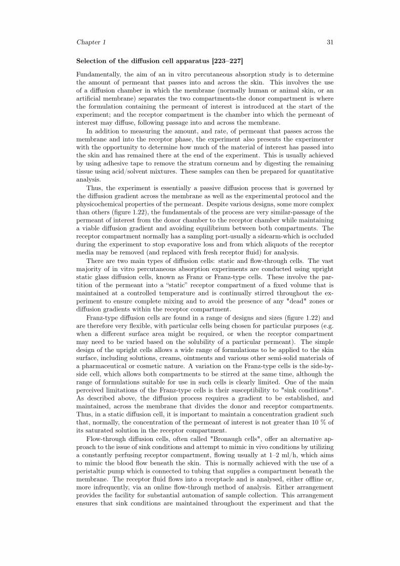
Chapter 1 31
Selection of the diffusion cell apparatus [223–227]
Fundamentally, the aim of an in vitro percutaneous absorption study is to determinethe amount of permeant that passes into and across the skin. This involves the useof a diffusion chamber in which the membrane (normally human or animal skin, or anartificial membrane) separates the two compartments-the donor compartment is wherethe formulation containing the permeant of interest is introduced at the start of theexperiment; and the receptor compartment is the chamber into which the permeant ofinterest may diffuse, following passage into and across the membrane.
In addition to measuring the amount, and rate, of permeant that passes across themembrane and into the receptor phase, the experiment also presents the experimenterwith the opportunity to determine how much of the material of interest has passed intothe skin and has remained there at the end of the experiment. This is usually achievedby using adhesive tape to remove the stratum corneum and by digesting the remainingtissue using acid/solvent mixtures. These samples can then be prepared for quantitativeanalysis.
Thus, the experiment is essentially a passive diffusion process that is governed bythe diffusion gradient across the membrane as well as the experimental protocol and thephysicochemical properties of the permeant. Despite various designs, some more complexthan others (figure 1.22), the fundamentals of the process are very similar-passage of thepermeant of interest from the donor chamber to the receptor chamber while maintaininga viable diffusion gradient and avoiding equilibrium between both compartments. Thereceptor compartment normally has a sampling port-usually a sidearm-which is occludedduring the experiment to stop evaporative loss and from which aliquots of the receptormedia may be removed (and replaced with fresh receptor fluid) for analysis.
There are two main types of diffusion cells: static and flow-through cells. The vastmajority of in vitro percutaneous absorption experiments are conducted using uprightstatic glass diffusion cells, known as Franz or Franz-type cells. These involve the par-tition of the permeant into a “static” receptor compartment of a fixed volume that ismaintained at a controlled temperature and is continually stirred throughout the ex-periment to ensure complete mixing and to avoid the presence of any "dead" zones ordiffusion gradients within the receptor compartment.
Franz-type diffusion cells are found in a range of designs and sizes (figure 1.22) andare therefore very flexible, with particular cells being chosen for particular purposes (e.g.when a different surface area might be required, or when the receptor compartmentmay need to be varied based on the solubility of a particular permeant). The simpledesign of the upright cells allows a wide range of formulations to be applied to the skinsurface, including solutions, creams, ointments and various other semi-solid materials ofa pharmaceutical or cosmetic nature. A variation on the Franz-type cells is the side-by-side cell, which allows both compartments to be stirred at the same time, although therange of formulations suitable for use in such cells is clearly limited. One of the mainperceived limitations of the Franz-type cells is their susceptibility to "sink conditions".As described above, the diffusion process requires a gradient to be established, andmaintained, across the membrane that divides the donor and receptor compartments.Thus, in a static diffusion cell, it is important to maintain a concentration gradient suchthat, normally, the concentration of the permeant of interest is not greater than 10 % ofits saturated solution in the receptor compartment.
Flow-through diffusion cells, often called "Bronaugh cells", offer an alternative ap-proach to the issue of sink conditions and attempt to mimic in vivo conditions by utilizinga constantly perfusing receptor compartment, flowing usually at 1–2 ml/h, which aimsto mimic the blood flow beneath the skin. This is normally achieved with the use of aperistaltic pump which is connected to tubing that supplies a compartment beneath themembrane. The receptor fluid flows into a receptacle and is analysed, either offline or,more infrequently, via an online flow-through method of analysis. Either arrangementprovides the facility for substantial automation of sample collection. This arrangementensures that sink conditions are maintained throughout the experiment and that the
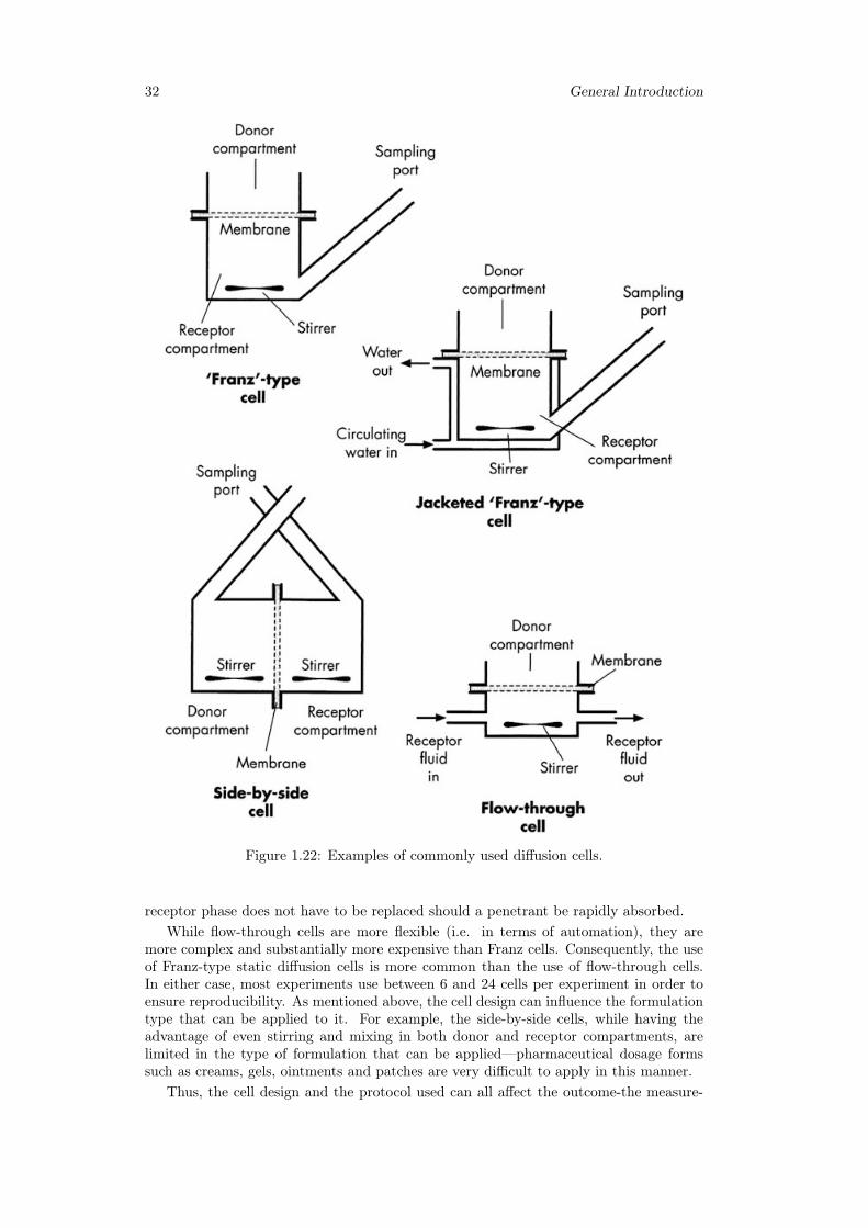
32 General Introduction
Figure 1.22: Examples of commonly used diffusion cells.
receptor phase does not have to be replaced should a penetrant be rapidly absorbed.While flow-through cells are more flexible (i.e. in terms of automation), they are
more complex and substantially more expensive than Franz cells. Consequently, the useof Franz-type static diffusion cells is more common than the use of flow-through cells.In either case, most experiments use between 6 and 24 cells per experiment in order toensure reproducibility. As mentioned above, the cell design can influence the formulationtype that can be applied to it. For example, the side-by-side cells, while having theadvantage of even stirring and mixing in both donor and receptor compartments, arelimited in the type of formulation that can be applied—pharmaceutical dosage formssuch as creams, gels, ointments and patches are very difficult to apply in this manner.
Thus, the cell design and the protocol used can all affect the outcome-the measure-
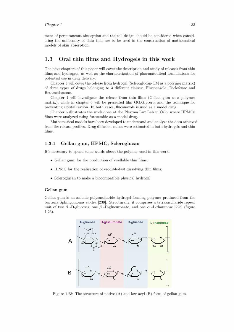
Chapter 1 33
ment of percutaneous absorption and the cell design should be considered when consid-ering the uniformity of data that are to be used in the construction of mathematicalmodels of skin absorption.
1.3 Oral thin films and Hydrogels in this work
The next chapters of this paper will cover the description and study of releases from thinfilms and hydrogels, as well as the characterization of pharmaceutical formulations forpotential use in drug delivery.
Chapter 3 will cover the release from hydrogel (Scleroglucan-CM as a polymer matrix)of three types of drugs belonging to 3 different classes: Fluconazole, Diclofenac andBetamethasone.
Chapter 4 will investigate the release from thin films (Gellan gum as a polymermatrix), while in chapter 6 will be presented film GG:Glycerol and the technique forpreventing crystallization. In both cases, fluconazole is used as a model drug.
Chapter 5 illustrates the work done at the Pharma Lux Lab in Oslo, where HPMC5films were analyzed using furosemide as a model drug.
Mathematical models have been developed to understand and analyze the data achievedfrom the release profiles. Drug diffusion values were estimated in both hydrogels and thinfilms.
1.3.1 Gellan gum, HPMC, Scleroglucan
It’s necessary to spend some words about the polymer used in this work:
• Gellan gum, for the production of swellable thin films;
• HPMC for the realization of erodible-fast dissolving thin films;
• Scleroglucan to make a biocompatible physical hydrogel.
Gellan gum
Gellan gum is an anionic polysaccharide hydrogel-forming polymer produced from thebacteria Sphingomonas elodea [239]. Structurally, it comprises a tetrasaccharide repeatunit of two β -D-glucoses, one β -D-glucuronate, and one α -L-rhamnose [228] (figure1.23).
Figure 1.23: The structure of native (A) and low acyl (B) form of gellan gum.
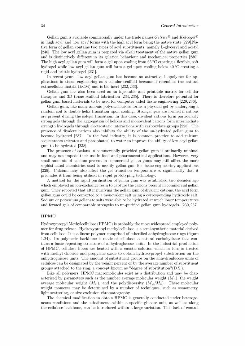
34 General Introduction
Gellan gum is available commercially under the trade names Gelriter and Kelcogelrin ’high acyl’ and ’low acyl’ forms with the high acyl form being the native state [229].Na-tive form of gellan contains two types of acyl substituents, namely L-glyceryl and acetyl[240]. The low acyl gellan gum is prepared via alkali treatment of the native gellan gumand is distinctively different in its gelation behaviour and mechanical properties [230].The high acyl gellan gum will form a gel upon cooling from 65 ◦C creating a flexible, softhydrogel while low acyl gellan gum will form a gel upon cooling below 40 ◦C creating arigid and brittle hydrogel [231].
In recent years, low acyl gellan gum has become an attractive biopolymer for ap-plications in tissue engineering as a cellular scaffold because it resembles the naturalextracellular matrix (ECM) and is bio-inert [232,233].
Gellan gum has also been used as an injectable and printable matrix for cellulartherapies and 3D tissue scaffold fabrication [234, 235]. There is therefore potential forgellan gum based materials to be used for computer aided tissue engineering [229,236].
Gellan gum, like many anionic polysaccharides forms a physical gel by undergoing arandom coil to double helix transition upon cooling. Stronger gels are formed if cationsare present during the sol-gel transition. In this case, divalent cations form particularlystrong gels through the aggregation of helixes and monovalent cations form intermediatestrength hydrogels through electrostatic interactions with carboxylate groups [228]. Thepresence of divalent cations also inhibits the ability of the un-hydrated gellan gum tobecome hydrated [237]. In the food industry, it is common practice to add calciumsequestrants (citrates and phosphates) to water to improve the ability of low acyl gellangum to be hydrated [238].
The presence of cations in commercially provided gellan gum is ordinarily minimaland may not impede their use in food and pharmaceutical applications. However, verysmall amounts of calcium present in commercial gellan gums may still affect the moresophisticated chemistries used to modify gellan gum for tissue engineering applications[229]. Calcium may also affect the gel transition temperature so significantly that itprecludes it from being utilised in rapid prototyping technology.
A method for the rapid purification of gellan gum was established two decades agowhich employed an ion-exchange resin to capture the cations present in commercial gellangum. They reported that after purifying the gellan gum of divalent cations, the acid formgellan gum could be converted to a monovalent salt using a corresponding hydroxide salt.Sodium or potassium gellanate salts were able to be hydrated at much lower temperaturesand formed gels of comparable strengths to un-purified gellan gum hydrogels. [230,237]
HPMC
Hydroxypropyl Methylcellulose (HPMC) is probably the most widespread employed poly-mer for drug release. Hydroxypropyl methylcellulose is a semi-synthetic material derivedfrom cellulose. It is a linear polymer comprised of etherified anhydroglucose rings (figure1.24). Its polymeric backbone is made of cellulose, a natural carbohydrate that con-tains a basic repeating structure of anhydroglucose units. In the industrial productionof HPMC, cellulose fibers are heated with a caustic solution which in turn is treatedwith methyl chloride and propylene oxide to obtain hydroxypropyl substitution on theanhydroglucose units. The amount of substituent groups on the anhydroglucose units ofcellulose can be designated by the weight percent or by the average number of substituentgroups attached to the ring, a concept known as "degree of substitution"(D.S.).
Like all polymers, HPMC macromolecules exist as a distribution and may be char-acterized by parameters such as the number average molecular weight (Mn), the weightaverage molecular weight (Mw), and the polydispersity (Mw/Mn). These molecularweight moments may be determined by a number of techniques, such as osmometry,light scattering, or size exclusion chromatography.
The chemical modification to obtain HPMC is generally conducted under heteroge-neous conditions and the substituents within a specific glucose unit, as well as alongthe cellulose backbone, can be introduced within a large variation. This lack of control
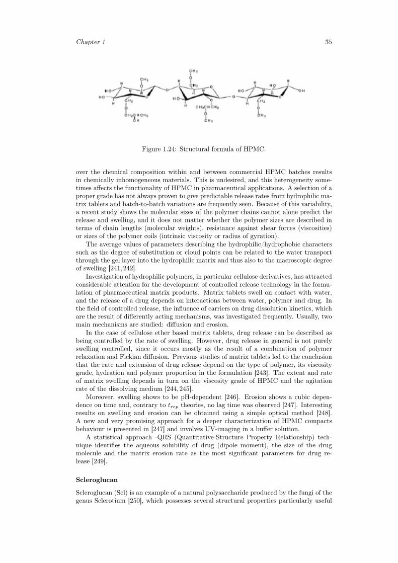
Chapter 1 35
Figure 1.24: Structural formula of HPMC.
over the chemical composition within and between commercial HPMC batches resultsin chemically inhomogeneous materials. This is undesired, and this heterogeneity some-times affects the functionality of HPMC in pharmaceutical applications. A selection of aproper grade has not always proven to give predictable release rates from hydrophilic ma-trix tablets and batch-to-batch variations are frequently seen. Because of this variability,a recent study shows the molecular sizes of the polymer chains cannot alone predict therelease and swelling, and it does not matter whether the polymer sizes are described interms of chain lengths (molecular weights), resistance against shear forces (viscosities)or sizes of the polymer coils (intrinsic viscosity or radius of gyration).
The average values of parameters describing the hydrophilic/hydrophobic characterssuch as the degree of substitution or cloud points can be related to the water transportthrough the gel layer into the hydrophilic matrix and thus also to the macroscopic degreeof swelling [241,242].
Investigation of hydrophilic polymers, in particular cellulose derivatives, has attractedconsiderable attention for the development of controlled release technology in the formu-lation of pharmaceutical matrix products. Matrix tablets swell on contact with water,and the release of a drug depends on interactions between water, polymer and drug. Inthe field of controlled release, the influence of carriers on drug dissolution kinetics, whichare the result of differently acting mechanisms, was investigated frequently. Usually, twomain mechanisms are studied: diffusion and erosion.
In the case of cellulose ether based matrix tablets, drug release can be described asbeing controlled by the rate of swelling. However, drug release in general is not purelyswelling controlled, since it occurs mostly as the result of a combination of polymerrelaxation and Fickian diffusion. Previous studies of matrix tablets led to the conclusionthat the rate and extension of drug release depend on the type of polymer, its viscositygrade, hydration and polymer proportion in the formulation [243]. The extent and rateof matrix swelling depends in turn on the viscosity grade of HPMC and the agitationrate of the dissolving medium [244,245].
Moreover, swelling shows to be pH-dependent [246]. Erosion shows a cubic depen-dence on time and, contrary to trep theories, no lag time was observed [247]. Interestingresults on swelling and erosion can be obtained using a simple optical method [248].A new and very promising approach for a deeper characterization of HPMC compactsbehaviour is presented in [247] and involves UV-imaging in a buffer solution.
A statistical approach -QRS (Quantitative-Structure Property Relationship) tech-nique identifies the aqueous solubility of drug (dipole moment), the size of the drugmolecule and the matrix erosion rate as the most significant parameters for drug re-lease [249].
Scleroglucan
Scleroglucan (Scl) is an example of a natural polysaccharide produced by the fungi of thegenus Sclerotium [250], which possesses several structural properties particularly useful
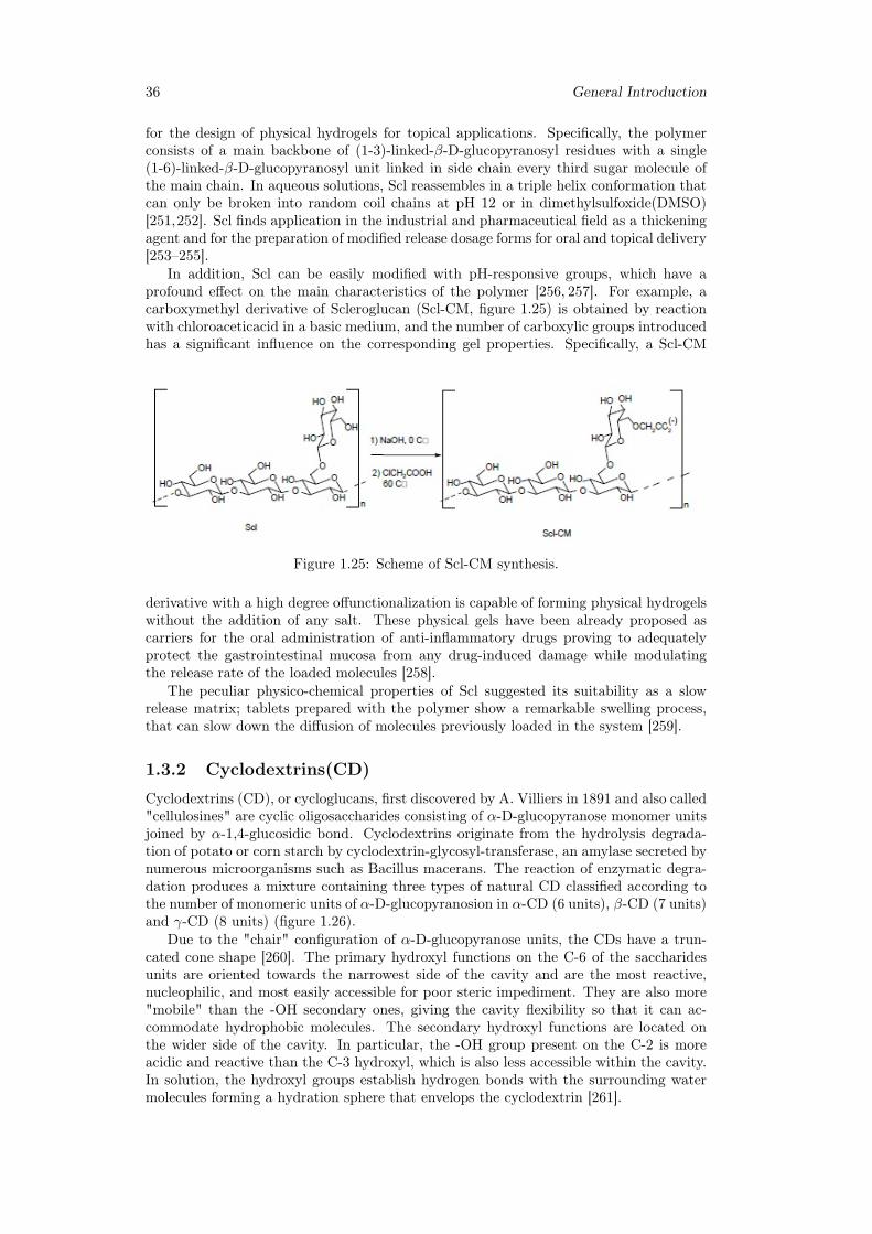
36 General Introduction
for the design of physical hydrogels for topical applications. Specifically, the polymerconsists of a main backbone of (1-3)-linked-β-D-glucopyranosyl residues with a single(1-6)-linked-β-D-glucopyranosyl unit linked in side chain every third sugar molecule ofthe main chain. In aqueous solutions, Scl reassembles in a triple helix conformation thatcan only be broken into random coil chains at pH 12 or in dimethylsulfoxide(DMSO)[251,252]. Scl finds application in the industrial and pharmaceutical field as a thickeningagent and for the preparation of modified release dosage forms for oral and topical delivery[253–255].
In addition, Scl can be easily modified with pH-responsive groups, which have aprofound effect on the main characteristics of the polymer [256, 257]. For example, acarboxymethyl derivative of Scleroglucan (Scl-CM, figure 1.25) is obtained by reactionwith chloroaceticacid in a basic medium, and the number of carboxylic groups introducedhas a significant influence on the corresponding gel properties. Specifically, a Scl-CM
Figure 1.25: Scheme of Scl-CM synthesis.
derivative with a high degree offunctionalization is capable of forming physical hydrogelswithout the addition of any salt. These physical gels have been already proposed ascarriers for the oral administration of anti-inflammatory drugs proving to adequatelyprotect the gastrointestinal mucosa from any drug-induced damage while modulatingthe release rate of the loaded molecules [258].
The peculiar physico-chemical properties of Scl suggested its suitability as a slowrelease matrix; tablets prepared with the polymer show a remarkable swelling process,that can slow down the diffusion of molecules previously loaded in the system [259].
1.3.2 Cyclodextrins(CD)
Cyclodextrins (CD), or cycloglucans, first discovered by A. Villiers in 1891 and also called"cellulosines" are cyclic oligosaccharides consisting of α-D-glucopyranose monomer unitsjoined by α-1,4-glucosidic bond. Cyclodextrins originate from the hydrolysis degrada-tion of potato or corn starch by cyclodextrin-glycosyl-transferase, an amylase secreted bynumerous microorganisms such as Bacillus macerans. The reaction of enzymatic degra-dation produces a mixture containing three types of natural CD classified according tothe number of monomeric units of α-D-glucopyranosion in α-CD (6 units), β-CD (7 units)and γ-CD (8 units) (figure 1.26).
Due to the "chair" configuration of α-D-glucopyranose units, the CDs have a trun-cated cone shape [260]. The primary hydroxyl functions on the C-6 of the saccharidesunits are oriented towards the narrowest side of the cavity and are the most reactive,nucleophilic, and most easily accessible for poor steric impediment. They are also more"mobile" than the -OH secondary ones, giving the cavity flexibility so that it can ac-commodate hydrophobic molecules. The secondary hydroxyl functions are located onthe wider side of the cavity. In particular, the -OH group present on the C-2 is moreacidic and reactive than the C-3 hydroxyl, which is also less accessible within the cavity.In solution, the hydroxyl groups establish hydrogen bonds with the surrounding watermolecules forming a hydration sphere that envelops the cyclodextrin [261].
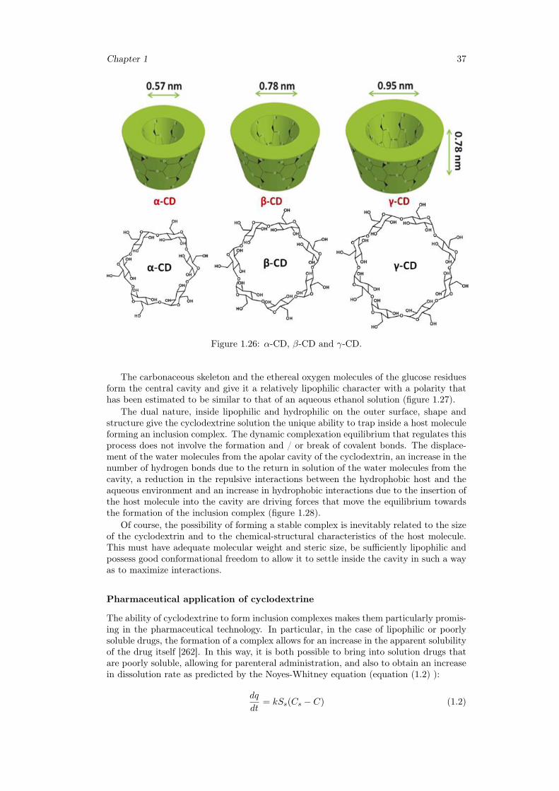
Chapter 1 37
Figure 1.26: α-CD, β-CD and γ-CD.
The carbonaceous skeleton and the ethereal oxygen molecules of the glucose residuesform the central cavity and give it a relatively lipophilic character with a polarity thathas been estimated to be similar to that of an aqueous ethanol solution (figure 1.27).
The dual nature, inside lipophilic and hydrophilic on the outer surface, shape andstructure give the cyclodextrine solution the unique ability to trap inside a host moleculeforming an inclusion complex. The dynamic complexation equilibrium that regulates thisprocess does not involve the formation and / or break of covalent bonds. The displace-ment of the water molecules from the apolar cavity of the cyclodextrin, an increase in thenumber of hydrogen bonds due to the return in solution of the water molecules from thecavity, a reduction in the repulsive interactions between the hydrophobic host and theaqueous environment and an increase in hydrophobic interactions due to the insertion ofthe host molecule into the cavity are driving forces that move the equilibrium towardsthe formation of the inclusion complex (figure 1.28).
Of course, the possibility of forming a stable complex is inevitably related to the sizeof the cyclodextrin and to the chemical-structural characteristics of the host molecule.This must have adequate molecular weight and steric size, be sufficiently lipophilic andpossess good conformational freedom to allow it to settle inside the cavity in such a wayas to maximize interactions.
Pharmaceutical application of cyclodextrine
The ability of cyclodextrine to form inclusion complexes makes them particularly promis-ing in the pharmaceutical technology. In particular, in the case of lipophilic or poorlysoluble drugs, the formation of a complex allows for an increase in the apparent solubilityof the drug itself [262]. In this way, it is both possible to bring into solution drugs thatare poorly soluble, allowing for parenteral administration, and also to obtain an increasein dissolution rate as predicted by the Noyes-Whitney equation (equation (1.2) ):
dq
dt= kSs(Cs − C) (1.2)
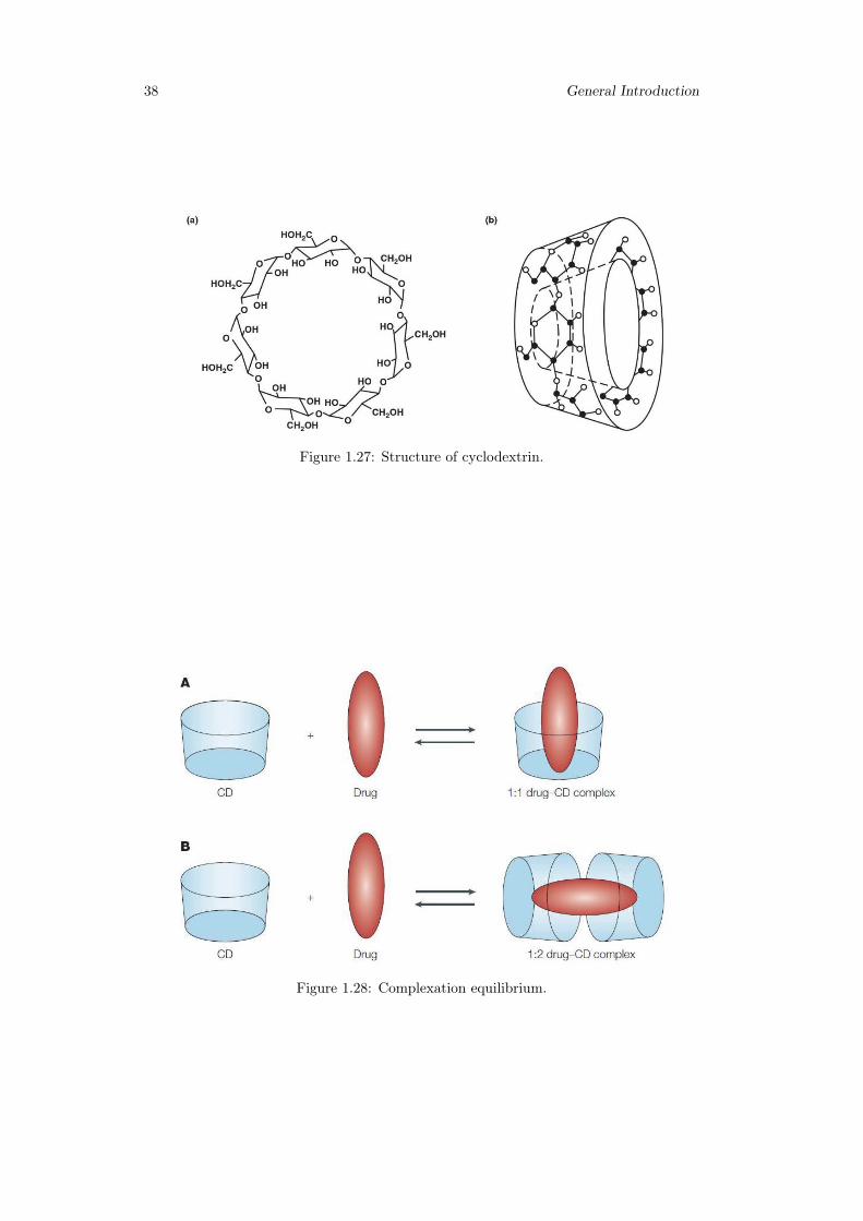
38 General Introduction
Figure 1.27: Structure of cyclodextrin.
Figure 1.28: Complexation equilibrium.
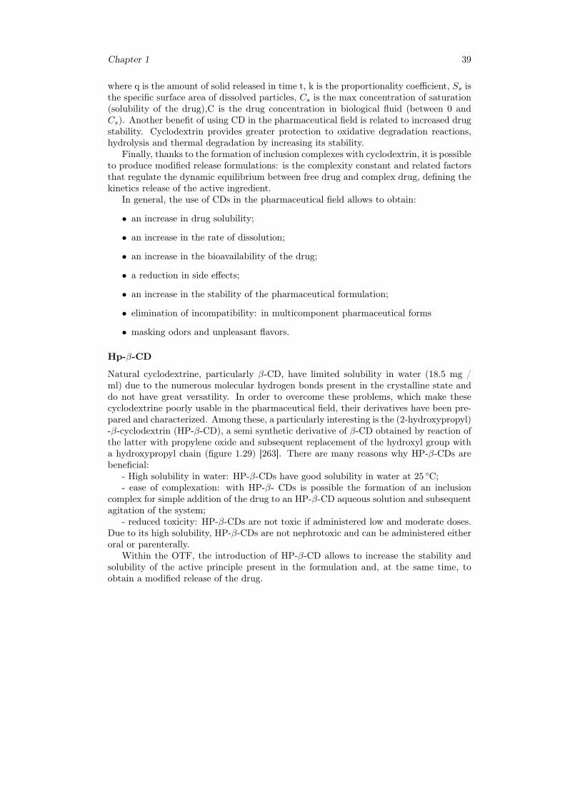
Chapter 1 39
where q is the amount of solid released in time t, k is the proportionality coefficient, Ss isthe specific surface area of dissolved particles, Cs is the max concentration of saturation(solubility of the drug),C is the drug concentration in biological fluid (between 0 andCs). Another benefit of using CD in the pharmaceutical field is related to increased drugstability. Cyclodextrin provides greater protection to oxidative degradation reactions,hydrolysis and thermal degradation by increasing its stability.
Finally, thanks to the formation of inclusion complexes with cyclodextrin, it is possibleto produce modified release formulations: is the complexity constant and related factorsthat regulate the dynamic equilibrium between free drug and complex drug, defining thekinetics release of the active ingredient.
In general, the use of CDs in the pharmaceutical field allows to obtain:
• an increase in drug solubility;
• an increase in the rate of dissolution;
• an increase in the bioavailability of the drug;
• a reduction in side effects;
• an increase in the stability of the pharmaceutical formulation;
• elimination of incompatibility: in multicomponent pharmaceutical forms
• masking odors and unpleasant flavors.
Hp-β-CD
Natural cyclodextrine, particularly β-CD, have limited solubility in water (18.5 mg /ml) due to the numerous molecular hydrogen bonds present in the crystalline state anddo not have great versatility. In order to overcome these problems, which make thesecyclodextrine poorly usable in the pharmaceutical field, their derivatives have been pre-pared and characterized. Among these, a particularly interesting is the (2-hydroxypropyl)-β-cyclodextrin (HP-β-CD), a semi synthetic derivative of β-CD obtained by reaction ofthe latter with propylene oxide and subsequent replacement of the hydroxyl group witha hydroxypropyl chain (figure 1.29) [263]. There are many reasons why HP-β-CDs arebeneficial:
- High solubility in water: HP-β-CDs have good solubility in water at 25 ◦C;- ease of complexation: with HP-β- CDs is possible the formation of an inclusion
complex for simple addition of the drug to an HP-β-CD aqueous solution and subsequentagitation of the system;
- reduced toxicity: HP-β-CDs are not toxic if administered low and moderate doses.Due to its high solubility, HP-β-CDs are not nephrotoxic and can be administered eitheroral or parenterally.
Within the OTF, the introduction of HP-β-CD allows to increase the stability andsolubility of the active principle present in the formulation and, at the same time, toobtain a modified release of the drug.
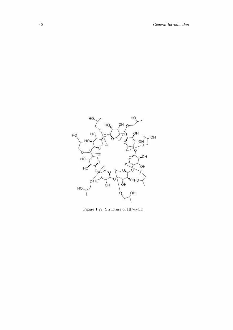
40 General Introduction
Figure 1.29: Structure of HP-β-CD.
Chapter 2
Aim of the work
The aim of this work is to develop innovative pharmaceutical formulations in the formof hydrogels and thin films that can improve existing solutions in the field of topical andoral drug delivery.
The main objectives can be summarized as follows:
• to realize innovative pharmaceutical formulations with biocompatible polymers;
• to optimize concentrations and proportions of the various components to obtainthe best performances in terms of mechanical properties, workability, controlled ormodulated drug release;
• to prepare versatile pharmaceutical formulations for fast or sustained release ofdrugs belonging to different pharmaceutical classes;
• to choose the dissolution apparatus most suitable for topical or buccal in-vitrorelease experiment in order to reproduce release conditions as close as possible toreal/physiological ones;
• to critically evaluate already existing and commonly used apparatuses and to testnew or recently proposed ones.
• to develop mathematical models to properly describe the physics of release experi-ments with the aim to:
– estimate the physical parameters (such as diffusivity values of the drug and-or solvent within the polymeric matrix), which are essential for a properformulation design and development;
– predict the release time scales when changing the operating conditions orchanging from in-vitro to ex-vivo experiments.
41

42 Aim of the work
Chapter 3
Scleroglucan based hydrogel fortopical drug delivery
3.1 Introduction
Topical formulations are a valid strategy to treat common disorders, including acute andchronic inflammations, skin infections and acute pain [265].The use of the skin as a portalof entry for drugs is particularly attractive since it can overcome the challenges associ-ated with other administration routes [266]. However, beside its great accessibility, theskin possesses highly efficient barrier properties, which frequently hamper drug deliverythrough it. In this context, hydrogels represent a primary solution to design innovativetopical formulations [267]. In fact, their soft consistency combined with their ability toswell, make them the perfect candidate for topical applications. Moreover, they possessa pleasant texture, which does not create any greasy residue on the skin compared tocreams and ointments [268].
Hydrogels properties can be modulated by varying the type of polymer and thecrosslinking step during their fabrication. Chemical or physical bonds can hold the poly-meric matrix together, and its swelling behavior can be tuned by introducing pH-sensitivefunctional groups [269].
For all these reasons, hydrogels offer a versatile platform as carriers of a varietyof drugs for topical delivery. This concept particularly holds true for physical hydro-gels made of bio compatible polysaccharides where the presence of hydrogen bonds,iondipole,and electrostatic interactions are the driving forces responsible for the hydro-gel formation. The same interactions can influence the hydrogel strength and elasticityas well as the release behavior of the loaded drugs from the hydrophilic matrix.
Among polysaccharides, scleroglucan (Scl) has been proposed for the preparation ofeffective modified drug delivery systems. Scl is a water-soluble extra-cellular polysaccha-ride produced by fungi of the genus Sclerotium.
The carboxymethyl derivative (Scl-CM) of scleroglucan is able to form physical hy-drogels with divalent ions, such as Ca+2.The release rate of the drug critically dependedon the concentration of the salt and the molar ratio carboxylated repetitive units of thepolymer/Ca+2.
To further extend the potentiality of high carboxymethylated Scl-based hydrogels inthe pharmaceutical field, their use as a topical formulation for a variety of drugs includinganti fungal,steroidal and non-steroidal anti-inflammatory molecules, was here attempted.
Specifically, three different therapeutic drugs, namely diclofenac, betamethasone, andfluconazole, were tested in this work. Flow curves and frequency sweep tests were carriedout on the loaded Scl − CM300 hydrogels along with release studies in a vertical Franzcell.Particular attention was paid to possible interactions between the hydrogel matrixand the loaded drugs, and how their presence could influence both the rheological andrelease properties of the corresponding physical hydrogels.
43
44 Scleroglucan based hydrogel for topical drug delivery
Mathematical models, describing transport and possible interactions between the se-lected drugs and Scl−CM300 , were adopted to estimate the effective diffusion coefficientof these molecules in the polymeric network. Numerical solutions were obtained by COM-SOL 3.5 multiphysics.
Finally, preliminary in-vivo experiments were carried out on rabbits to verify the skintolerability of the Scl − CM300-based formulations.
3.2 Materials and methods
3.2.1 Chemicals
All used reagents were of analytical grade. Scleroglucan with Mw= 1.4 · 106, as evalu-ated by viscosimetric measurements in 0.01 M NaOH, was provided by Carbomer (USA).Dimethylsulfoxide (DMSO) and chloroacetic acid were purchased from Fluka(Switzerland).Diclofenac sodium salt, DOWEX 50WX4-50 ion exchange resin, acetonitrile, and methanolwere purchased fromSigma-Aldrich (England). Betamethasone phosphate sodium saltand fluconazole were received as gifts from Sigma-Tau (Italy) and Recordati S.p.A.(Italy), respectively. Dialysis membranes with cut-off 12,000-14,000 Da were purchasedfrom Medicell International(UK).
3.2.2 Synthesis of carboxymethyl scleroglucan (Scl − CM300)
Scleroglucan was modified into its carboxymethyl derivative(Scl − CM300) following areported procedure [258].Scleroglucan (1.0 g) was dissolved in water (40 ml) at 60 ◦Cfor 24 h. NaOH (28.0 g) was then added to the polymeric solution in an ice bath todisrupt the triple helix. Finally, chloroacetic acid (40.0 g) was added drop wise to startthe reaction. The polymeric mixture was kept under stirring at 60 ◦C for 24 h followedby neutralization with glacial acetic acid.The obtained Scl − CM300 was purified byexhaustive dialysis (cellophane membrane, Visking tubing, cut-off 12,000-14,000 Da) toremove the excess of salts and unreacted products. The dialyzed solution was elutedthrough a DOWEX 50WX4-50 ion-exchange resin column previously treated with 2.0 MHCl, to obtain all the carboxylic groups in the undissociated form.
The number of carboxylic groups added to the backbone of the polymer was quantifiedby potentiometer titration. Fully protonated Scl−CM300(100 mg) was dissolved in waterand submitted to potentiometer titration using 1 · 10−2M NaOH. The amount of acid inmmol (equal to the mmol of NaOH used) was inserted in the following equation:
Scl−CMamount(mg) = X ·MWrepetitive−unit+(mmol−of−acid)MWacid−group (3.1)
allowing the calculation of X which represents the mmoles of repetitive units of thepolymer. The ratio between the mmol of acid and the mmol of the repetitive units of thepolymer multiplied by 100 is necessary to obtain the degree of derivatization(DD). Thisvalue represents the number of carboxylic groups per 100 repetitive units. A derivativehaving a DD equal to 300 ± 10 was obtained (labeled as Scl − CM300) and used for allthe studies.The freeze-dried polymer was mixed with KBr and characterized by FT-IRspectroscopy in the range of 4000–650 cm−1(resolution of 1 cm−1), using a FT-IR PerkinElmer Paragon 1000 spectrophotometer.
3.2.3 Hydrogel preparation
Solutions of Scl − CM300(2.0% w/v) were prepared by solubilizing Scl − CM300 (0.1g) in 5 ml of distilled water. The mixtures were kept under stirring at 60 ◦C for 30minutes to allow a complete solubilization of the polymer. The polymeric solutions werethen left to cool down at room temperature (20 ◦C), to obtain the formation of thecorresponding physical hydrogels.Hydrogels loaded with drugs were prepared followingthe same procedure described above. Specifically, fluconazole, diclofenac sodium salt,
Chapter 3 45
and betamethasone phosphate sodium salt were selected as model molecules for thepreparation of the medicated physical hydrogels of Scl − CM300. Each drug was mixedwith the polymeric solution before the gel formation at 60 ◦C in the range of concentrationfrom 0.1 up to 0.5% w/v.
3.2.4 Rheological characterization
Rheological experiments were carried out with a Haake RheoStress 300 Rotational Rheome-ter (Germany) equipped witha Haake DC10 thermostat. Flow curves were recorded witha share stress in the range of 0.01–100 Pa at 37 ◦C ± 0,01 ◦C. Physical hydrogels ofScl − CM300 (2% w/v) with and without drugs were placed on a cone-plate geometry(angle of 1◦) in order to completely cover the surface. In addition, frequency sweep testswere carried out on the same samples in the range of 0.01 up to 10 Hz. Mechanicalspectra were recorded within the linear viscoelastic region measuring hydrogels responseat a strain amplitude of 1%.
3.2.5 Release studies with Franz diffusion cell
Release studies were carried out from hydrogels loaded with fluconazole, diclofenacsodium salt and betamethasone phosphate sodium salt (0.25% w/v) using a verticalFranz cell [270]. The cylindrical donor chamber (cross-section area 0.5 cm2) was loadedwith a weighted amount (100 mg) of the drug-carrying hydrogel, gel thickness Lg= 2mm.The donor chamber was separated by the receptor one with a dialysis membrane(cellophane membrane, Visking tubing, cut-off 12,000-14,000 Da) having an area of 0.5cm2and thickness Lm= 48 µm.
The receptor chamber was filled with 4.1 ml of phosphate buffer pH 7.4 under con-stant stirring (50 rpm). pH 7.4 was chosen for this study because of the dependenceof diclofenac solubility from pH ( [271]). At pH 7.4 we have the maximum solubilityof diclofenac, therefore even if back-diffusion of the release medium towards the donorcompartment occurred during the study, no drug precipitation is expected within thegel.
Release experiments were carried out keeping the diffusion cell in a water bath at37 ◦C ± 0,01 ◦C for 24 h. Aliquots of 250 µl were withdrawn at fixed time intervalsand replaced with equal volumes of fresh buffer.The release rate of diclofenac from Scl−CM300-based hydrogels was also studied at room temperature (20 ◦C) following the sameexperimental set-up.In addition, diffusion profiles of 0.25% w/v aqueous solutions of thethree investigated drugs (0.1 ml, solvent thickness in the donor chamber Ls= Lg= 2 mm)were used as blanks.Diffusion profiles of 0.25% w/v aqueous solutions of theophylline werealso used as blanks to investigate the dependence of the drug diffusion coefficient in thedialysis membrane on the drug molecular weight.
All the drugs were quantified by HPLC analysis carried out with a Perkin-Elmerapparatus equipped with a Perkin Elmer Series 200LC pump and a series 235 DiodeArray Detector, using a Merck Hibar LiChrocart (250-4, 5 µm) RP-18 column. Thethree drugs were determined according to already reported analytical methods, withsome modifications. Diclofenac was analyzed using a mixture consisting of methanol and0.01 M phosphoric acid (80:20, v:v), as the mobile phase, with a flow rate 0.7 ml/minand measuring the drug at 215 nm ( [258]). Fluconazole was analyzed using a mobilephase consisting of methanol, water and acetic acid(50:48:2, v:v:v), with a flow rate of0.9 ml/min and monitoring the drug at 260 nm ( [272]). Betamethasone was insteaddetected using a mobile phase made of methanol and 0.01 M phos-phoric acid (60:40,v:v), with a flow rate 0.8 ml/min and detecting the drug at 215 nm ( [273]).
All the experiments were repeated in triplicate, and the results reported as meanvalue ± standard deviation.
46 Scleroglucan based hydrogel for topical drug delivery
3.2.6 Mathematical models of permeation experiments in a ver-tical Franz cell
We present the time-dependent one-dimensional Fickian and non-Fickian transport mod-els adopted to describe drug permeation in a Franz vertical cell, both accounting for thepresence of the cellophane (dialysis) membrane and finite volume of the receptor cham-ber. Both transport models are numerically solved by Finite Element Method (FEM)using Comsol 3.5 Multiphysics. The Convection-Diffusion Package in Transient Analysishas been used. The linear solver adopted is UMFPACK, with relative tolerance 10−3andabsolute tolerance 10−6. The Time Stepping Method adopted is BDF with a Strict pol-icy for Time steps taken by the solver. Lagrangian quadratic elements are chosen. Thenumber of finite elements is 2 · 104with a non-uniform mesh. Maximum-minimum ele-ment sizes 2.5 · 10−3 − 2.5 · 10−7 in dimensionless units (total length of the domain indimensionless units 1.024). Smaller elements are located in the membrane domain andclose to the boundaries gel/membrane and membrane/receptor chamber to guarantee theconvergence of the numerical scheme and accurate resolution of concentration gradients.
Fickian diffusion model
Drug release from Scl − CM300 networks can be described as a purely one-dimensionalFickian diffusion process (along the vertical coordinate z spanning the donor chamber),assuming that no drug/hydrogel matrix interaction and no matrix erosion of the fullyswollen hydrogel occurs during the release experiments. A purely Fickian transportmodel can be adopted to describe blank experimental release data as well as release datafrom Scl − CM300 hydrogels for molecules that exhibit a typical Fickian behavior, i.e.Mt/M∞ ∼ t1/2 at short-intermediate time scales. Let us indicate with Cg, Dg, Cm, andDm the drug concentrations and the effective diffusion coefficients in the hydrogel andthe dialysis membrane, respectively. C0 indicates the initial drug concentration in thehydrogel (thickness Lg= 2 mm, volume Vg= 0.1 cm3). The dialysis membrane used inthe study has a thickness Lm= 48 µm and a volume Vm= 2.4 mm3. Let Cres be thedrug concentration in the perfectly mixed receptor chamber of volume Vres= 4.1 ml.
By introducing the dimensionless time and space variables τ ,ζ, β, αm and the diffu-sivity ratio γg:
τ = tDm/L2g, ζ = z/Lg, αm = Lm/Lg, β = Vg/Vres, γg = Dg/Dm (3.2)
the transport equations and the boundary/initial conditions can be written as:
∂Cg∂τ
= γg∂2Cg∂ζ2
for 0 < ζ < 1,∂Cg∂ζ
= 0 at ζ = 0, Cg(0, ζ) = C0 (3.3)
∂Cm∂τ
=∂2Cm∂ζ2
for 0 < ζ < 1 + αm, Cm = Cg at ζ = 1 (3.4)
γg∂Cg∂ζ
=∂Cm∂ζ
at ζ = 1 , Cm = Cres at ζ = 1 + αm, Cm(0, ζ) = 0 (3.5)
dCresdτ
= −β ∂Cm∂ζ
at ζ = 1 + αm, Cres(0) = 0 (3.6)
We assume no mass-transfer resistance at the membrane-receptor chamber interface andunitary partition coefficients at the membrane-receptor chamber interface as well as at thegel membrane interface. The balance equation for Cres, equation (3.6), and the boundarycondition Cm= Cres at ζ = 1+αm account for the finite volume of the receptor chamber.By solving the transport equations eq:(3.3)-(3.6) for Cg, Cm,and Cres,the drug-releasecurve can be computed as follows:
Mτ
M∞=VresCres(τ)
VresC∞res, M∞ = Vres
βC0
1 + β(1 + αm)=
VgC0
1 + β(1 + αm)(3.7)
Chapter 3 47
where M∞< VgC0 because of the finite volume of the receptor chamber. The same setof transport equations can be used to describe the blanks, representing the drug releasestudies from the aqueous solutions without the hydrogel. This is possible by simplyreplacing Cg(drug concentration in the gel) with Cs(drug concentration in the aqueoussolution placed in the donor chamber) and considering the diffusivity ratio γs = Ds/Dm
instead of γg = Dg/Dm,where Ds represents the drug diffusivity in the solvent solution.The Wilke-Chang correlation ( [274]) was used to estimate Ds for each model drug:
Ddrugs [
cm2
s] = 7.4 · 10−8
√ΨBMWBT )
ηBV 0.6drug
(3.8)
where B indicates the solvent (water, ΨB = 2.26) and Vdrug is the LeBas drug molar vol-ume usually obtained from a group contribution approach, considering the contributionsof individual atoms,functional groups and cycles composing each molecule [274]. Fromthe blanks, we estimate the effective diffusion coefficient of the different model drugs inthe dialysis membrane Dm, by best fitting the only unknown parameter γs. Hence, fromthe release data from Scl − CM300 hydrogel, we estimate the effective diffusion coeffi-cient of each model drug Dg in the hydrogel by best fitting the only unknown parameterγg = Dg/Dm. This model fits well blank experimental release data as well as releasedata from Scl − CM300 hydrogel for molecules that exhibit a typical Fickian behavior,i.e. Mτ/M∞ ∼ τ1/2 at short-intermediate time scales.
Drug/hydrogel interaction model
A second mathematical model was introduced to describe possible interactions betweena model drug and the hydrogel matrix and their effects on the drug release kinetics. Thismodel can be used to explain the apparent "anomalous" non-Fickian behaviorMτ/M∞ ∼τncharacterized by an exponent n »1/2 that can be observed at short-intermediate timescales in the presence of solute/polymeric matrix interactions (for a fully swollen gel).In this case, a two-phases kinetic model, originally proposed by Adrover [275] for drugrelease from water swollen scleroglucan matrices, is adopted to describe the system.Specifically, it is possible to define a fraction ε of the drug molecules that is capableof interacting with the polymeric network, which can be separated from the other drugmolecules that are simply dissolved in the water phase of the hydrogel, where they arefree to diffuse with an effective diffusion coefficient Dg. A similar approach has beenadopted by Singh et al., modeling drug release from hydrogels via a diffusion transportcoupled with adsorption/desorption mechanism [276].
The "two-phases" model adopted in the present work actually describes the ad-sorption/desorption mechanism in terms of a linear transfer rate from the adsorbed"bounded" phase to the desorbed "free" (or gel-solvent) phase and viceversa. Let usthen indicate Cb and Cg as the drug concentrations in the bounded and free (gel-solvent)phases, respectively. By assuming a reversible reaction and a linear transfer rate fromthe bounded to the free phase −rb→g = KbgCb as well as a linear transfer rate fromthe free to the bounded phase −rb→g = KgbCg, the dynamic equations describing thephenomenon can be written as:
∂Cg∂τ
= γg∂2Cg∂ζ2
+ φ2γg(Cb − Cg/Keq) for 0 ≤ ζ ≤ 1 (3.9)
∂Cb∂τ
= −φ2γg(Cb − Cg/Keq) for 0 ≤ ζ ≤ 1 (3.10)
∂Cg∂ζ
= 0 at ζ = 0, Cg = Cm at ζ = 1 (3.11)
Cg(0, ζ) = (1− ε)C0, Cb(0, ζ) = εC0 (3.12)
48 Scleroglucan based hydrogel for topical drug delivery
where Keq = Kgb/Kbg is the equilibrium constant (depending on the temperature of
the experiment) and φ2 =KbgL
2g
Dgis a dimensionless parameter, equivalent to a square
Thiele modulus, representing the ratio between the characteristic diffusion time L2g/Dg
in the free(gel-solvent) phase and the characteristic time for the reversible transfer fromthe bounded to the free phase 1/Kbg. No drug diffusion occurs in the bounded phase.Balance equations for Cm and Cres,as well as the boundary conditions for Cg and Cmremain unchanged with respect to the purely Fickian diffusion model.
In this case, the total amount of drug released up to an infinite time reads as:
limτ→∞
Mτ =VgC0
1 + β(1 + αm +K−1eq )
(3.13)
that can be significantly smaller than M∞ (see eq:(3.7)),depending on the value ofKeq, because for any finite value of Keq,part of the drug, namely the total amount
VgC0βK−1eq
1 + β(1 + αm +K−1eq )
, get trapped in the bounded phase and never released. The initial
partition coefficient ε depends on the initial temperature of the gel sample. If the gelsample is kept at constant ambient temperature T0 prior of the experiment and then, attime t=0, placed in the donor chamber in contact with the solvent solution in the re-ceptor chamber kept at constant temperature 37 ◦C ± 0,01 ◦C(temperature of the waterbath), the initial partition coefficient reads as:
ε =1
1 +Keq(T0)(3.14)
The gel sample, initially at temperature T0, rapidly warms up(1–3 minutes) to the waterbath temperature T and the release process takes place at constant temperature T. Theequilibrium constant Keq(T0) at the initial temperature T0, and therefore the initial par-tition coefficient ε, can be estimated from an independent release experiment performedat temperature T0 of the water bath, by experimentally estimating limτ→∞Mτ at T = T0
and therefore Keq(T0) from equation (3.13) and ε from equation (3.14).
3.2.7 Primary skin irritation experiments
Three healthy male New Zealand White rabbits were purchased from Charles River(Calco Lecco, Italy) and acclimated to the laboratory for a week. The rabbits wereindividually housed and received a standard diet and tap water ad libitum. Laboratoryanimal care guidelines (EEC Directive of 1986; 86/609/EEC) were followed. The back ofthe animals was clipped free of their fur with an electric clipper 24 h before applicationof the samples. Clipped rabbit skin was divided into four sites of same area (30 ·30 mm).
Scl, Scl−CM300-based hydrogels were spread on two of the four different locations(500mg/site), whereas the other two ones were kept free from any material application andused as a visual control. The treated and the control areas were covered with a gauze, andthe back of the rabbit was wrapped with a non-occlusive bandage. After the treatment,the animals were returned to their cages. Bandages and the test hydrogels were removedafter 4 h and rabbits were examined for skin irritation 1 hour later.
Observation of the different sites was repeated at 24, 48 and 72 h. The reaction,defined as erythema or edema, was evaluated according to the score of the skin reactionsalready reported. The score of primary irritation (SPI) was calculated for each rabbitas the difference between the sum of the scores of erythema and edema at 24, 48 and72 h in the treated sites and the control areas. These values were also divided by thenumber of observations. The primary skin irritation index (PII) was calculated as thearithmetical mean of the SPI values of the three animals.The evaluation of PII wasperformed according to the categories reported in the literature [277].
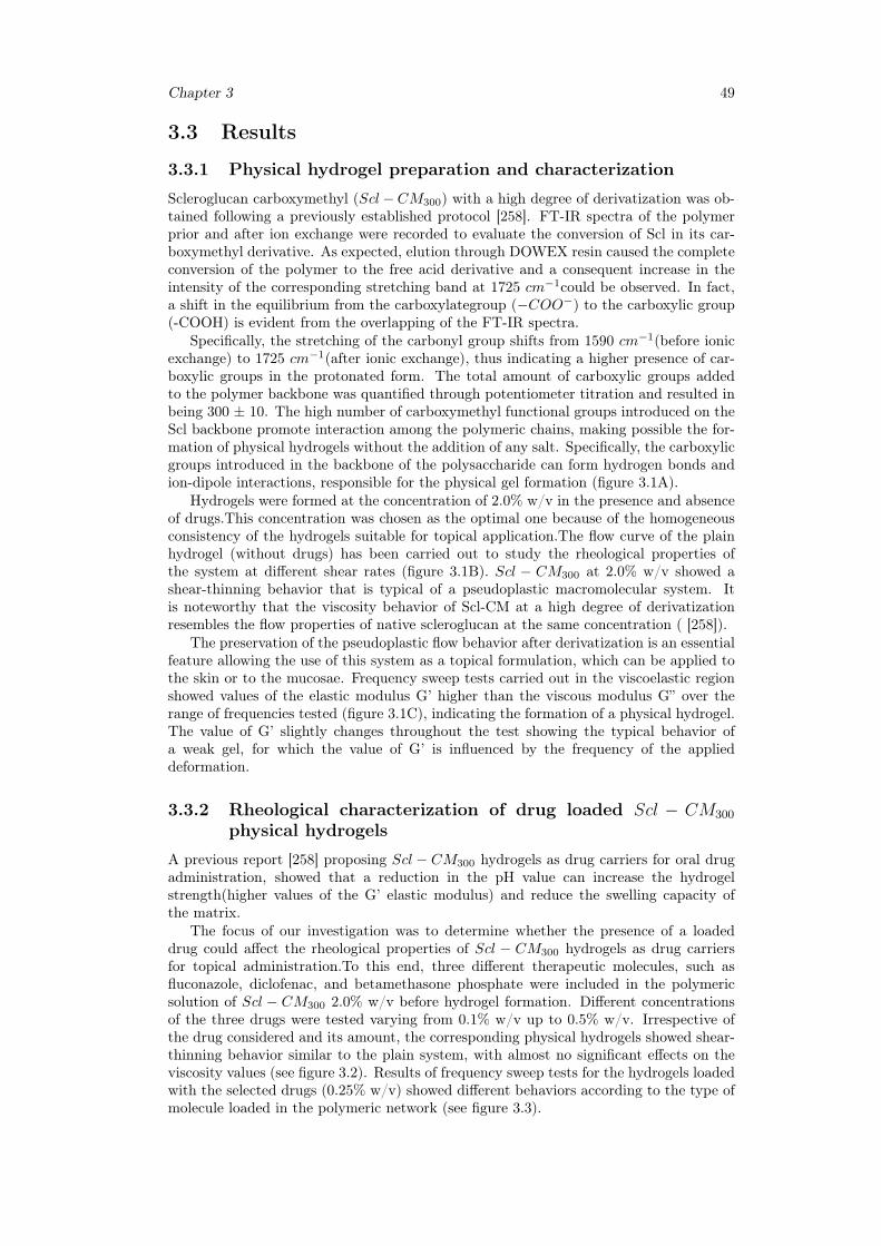
Chapter 3 49
3.3 Results
3.3.1 Physical hydrogel preparation and characterization
Scleroglucan carboxymethyl (Scl−CM300) with a high degree of derivatization was ob-tained following a previously established protocol [258]. FT-IR spectra of the polymerprior and after ion exchange were recorded to evaluate the conversion of Scl in its car-boxymethyl derivative. As expected, elution through DOWEX resin caused the completeconversion of the polymer to the free acid derivative and a consequent increase in theintensity of the corresponding stretching band at 1725 cm−1could be observed. In fact,a shift in the equilibrium from the carboxylategroup (−COO−) to the carboxylic group(-COOH) is evident from the overlapping of the FT-IR spectra.
Specifically, the stretching of the carbonyl group shifts from 1590 cm−1(before ionicexchange) to 1725 cm−1(after ionic exchange), thus indicating a higher presence of car-boxylic groups in the protonated form. The total amount of carboxylic groups addedto the polymer backbone was quantified through potentiometer titration and resulted inbeing 300 ± 10. The high number of carboxymethyl functional groups introduced on theScl backbone promote interaction among the polymeric chains, making possible the for-mation of physical hydrogels without the addition of any salt. Specifically, the carboxylicgroups introduced in the backbone of the polysaccharide can form hydrogen bonds andion-dipole interactions, responsible for the physical gel formation (figure 3.1A).
Hydrogels were formed at the concentration of 2.0% w/v in the presence and absenceof drugs.This concentration was chosen as the optimal one because of the homogeneousconsistency of the hydrogels suitable for topical application.The flow curve of the plainhydrogel (without drugs) has been carried out to study the rheological properties ofthe system at different shear rates (figure 3.1B). Scl − CM300 at 2.0% w/v showed ashear-thinning behavior that is typical of a pseudoplastic macromolecular system. Itis noteworthy that the viscosity behavior of Scl-CM at a high degree of derivatizationresembles the flow properties of native scleroglucan at the same concentration ( [258]).
The preservation of the pseudoplastic flow behavior after derivatization is an essentialfeature allowing the use of this system as a topical formulation, which can be applied tothe skin or to the mucosae. Frequency sweep tests carried out in the viscoelastic regionshowed values of the elastic modulus G’ higher than the viscous modulus G” over therange of frequencies tested (figure 3.1C), indicating the formation of a physical hydrogel.The value of G’ slightly changes throughout the test showing the typical behavior ofa weak gel, for which the value of G’ is influenced by the frequency of the applieddeformation.
3.3.2 Rheological characterization of drug loaded Scl − CM300
physical hydrogels
A previous report [258] proposing Scl − CM300 hydrogels as drug carriers for oral drugadministration, showed that a reduction in the pH value can increase the hydrogelstrength(higher values of the G’ elastic modulus) and reduce the swelling capacity ofthe matrix.
The focus of our investigation was to determine whether the presence of a loadeddrug could affect the rheological properties of Scl − CM300 hydrogels as drug carriersfor topical administration.To this end, three different therapeutic molecules, such asfluconazole, diclofenac, and betamethasone phosphate were included in the polymericsolution of Scl − CM300 2.0% w/v before hydrogel formation. Different concentrationsof the three drugs were tested varying from 0.1% w/v up to 0.5% w/v. Irrespective ofthe drug considered and its amount, the corresponding physical hydrogels showed shear-thinning behavior similar to the plain system, with almost no significant effects on theviscosity values (see figure 3.2). Results of frequency sweep tests for the hydrogels loadedwith the selected drugs (0.25% w/v) showed different behaviors according to the type ofmolecule loaded in the polymeric network (see figure 3.3).
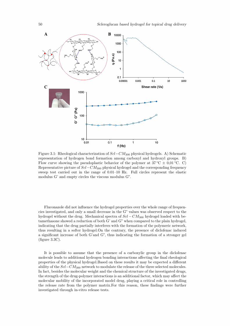
50 Scleroglucan based hydrogel for topical drug delivery
Figure 3.1: Rheological characterization of Scl−CM300 physical hydrogels. A) Schematicrepresentation of hydrogen bond formation among carboxyl and hydroxyl groups. B)Flow curve showing the pseudoplastic behavior of the polymer at 37 ◦C ± 0,01 ◦C. C)Representative picture of Scl−CM300 physical hydrogel and the corresponding frequencysweep test carried out in the range of 0.01–10 Hz. Full circles represent the elasticmodulus G’ and empty circles the viscous modulus G”.
Fluconazole did not influence the hydrogel properties over the whole range of frequen-cies investigated, and only a small decrease in the G” values was observed respect to thehydrogel without the drug. Mechanical spectra of Scl−CM300 hydrogel loaded with be-tamethasone showed a reduction of both G’ and G” when compared to the plain hydrogel,indicating that the drug partially interferes with the formation of the polymeric network,thus resulting in a softer hydrogel.On the contrary, the presence of diclofenac induceda significant increase of both G’and G”, thus indicating the formation of a stronger gel(figure 3.3C).
It is possible to assume that the presence of a carboxylic group in the diclofenacmolecule leads to additional hydrogen bonding interactions affecting the final rheologicalproperties of the physical hydrogel.Based on these results it may be expected a differentability of the Scl−CM300 network to modulate the release of the three selected molecules.In fact, besides the molecular weight and the chemical structure of the investigated drugs,the strength of the drug-polymer interactions is an additional factor, which may affect themolecular mobility of the incorporated model drug, playing a critical role in controllingthe release rate from the polymer matrix.For this reason, these findings were furtherinvestigated through in-vitro release tests.
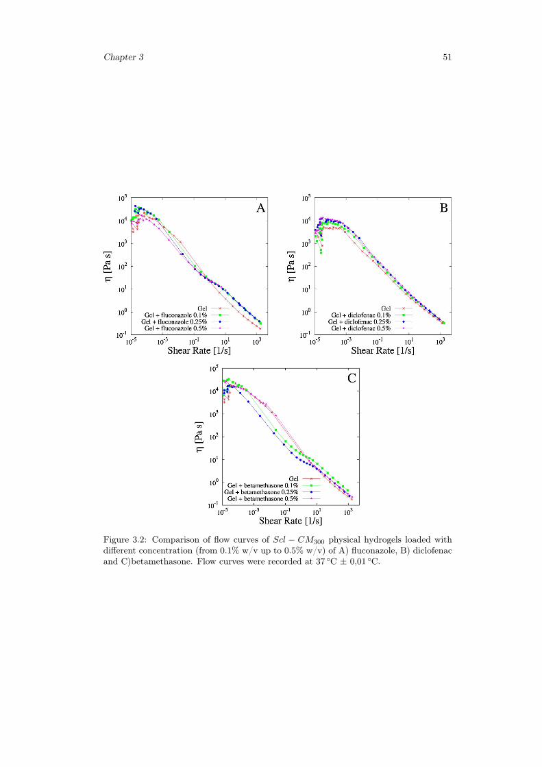
Chapter 3 51
Figure 3.2: Comparison of flow curves of Scl − CM300 physical hydrogels loaded withdifferent concentration (from 0.1% w/v up to 0.5% w/v) of A) fluconazole, B) diclofenacand C)betamethasone. Flow curves were recorded at 37 ◦C ± 0,01 ◦C.
52 Scleroglucan based hydrogel for topical drug delivery
Figure 3.3: Frequency sweep tests carried out in the range of 0.01–10 Hz for plain Scl−CM300 hydrogel (red square and circular points for G’ and G”, respectively) and loadedwith different model drugs (upper and lower triangular points for G’ and G”, respectively).A) fluconazole; B) betamethasone; C) diclofenac.
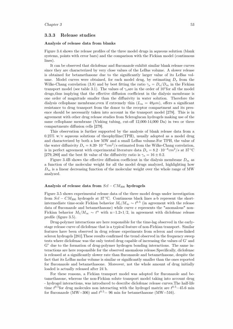
Chapter 3 53
3.3.3 Release studies
Analysis of release data from blanks
Figure 3.4 shows the release profiles of the three model drugs in aqueous solution (blanksystems, points with error bars) and the comparison with the Fickian model (continuouslines).
It can be observed that diclofenac and fluconazole exhibit similar blank release curvessince they are characterized by very close values of the LeBas volume. A slower releaseis obtained for betamethasone due to the significantly larger value of its LeBas vol-ume. Model curves were obtained, for each model drug, by estimating Ds from theWilke-Chang correlation (3.8) and by best fitting the ratio γs = Ds/Dm in the Fickiantransport model (see table 3.1). The values of γsare in the order of 101for all the modeldrugs,thus implying that the effective diffusion coefficient in the dialysis membrane isone order of magnitude smaller than the diffusivity in water solution. Therefore thedialysis cellophane membrane,even if extremely thin (Lm = 48µm), offers a significantresistance to drug transport from the donor to the receptor compartment and its pres-ence should be necessarily taken into account in the transport model [278]. This is inagreement with other drug release studies from Scleroglucan hydrogels making use of thesame cellophane membrane (Visking tubing, cut-off 12,000-14,000 Da) in two or threecompartments diffusion cells [279].
This observation is further supported by the analysis of blank release data from a0.25% w/v aqueous solutions of theophylline(TPH), usually adopted as a model drugand characterized by both a low MW and a small LeBas volume.For TPH, the value ofthe water diffusivity Ds = 8.39 ·10−6cm2/s estimated from the Wilke-Chang correlation,is in perfect agreement with experimental literature data Ds = 8.2 · 10−6cm2/s at 37 ◦C[279,280] and the best fit value of the diffusivity ratio is γs = 16± 0.2.
Figure 3.4B shows the effective diffusion coefficient in the dialysis membrane Dm asa function of the molecular weight for all the model drugs analyzed, highlighting howDm is a linear decreasing function of the molecular weight over the whole range of MWanalyzed.
Analysis of release data from Scl − CM300 hydrogels
Figure 3.5 shows experimental release data of the three model drugs under investigationfrom Scl − CM300 hydrogels at 37 ◦C. Continuous black lines a-b represent the short-intermediate time-scale Fickian behavior Mt/M∞ ∼ t0.5 (in agreement with the releasedata of fluconazole and betamethasone) while curve c represents the "anomalous" non-Fickian behavior Mt/M∞ ∼ tn with n=1.2»1/2, in agreement with diclofenac releaseprofile (figure 3.5).
Drug-polymer interactions are here responsible for the time-lag observed in the early-stage release curve of diclofenac that is a typical feature of non-Fickian transport. Similarfeatures have been observed in drug release experiments from sclerox and cross-linkedsclerox hydrogels [281].These results confirmed the trend observed in the frequency sweeptests where diclofenac was the only tested drug capable of increasing the values of G’ andG” due to the formation of drug-polymer hydrogen bonding interactions. The same in-teractions are here responsible for the observed anomalous release.Specifically, diclofenacis released at a significantly slower rate than fluconazole and betamethasone, despite thefact that its LeBas molar volume is similar or significantly smaller than the ones reportedfor fluconazole and betamethasone. Moreover, not the whole amount of drug initiallyloaded is actually released after 24 h.
For these reasons, a Fickian transport model was adopted for fluconazole and be-tamethasone, whereas the non-Fickian solute transport model taking into account drug- hydrogel interactions, was introduced to describe diclofenac release curves.The half-lifetime t0.5for drug molecules non interacting with the hydrogel matrix are t0.5=45.6 minfor fluconazole (MW=306) and t0.5= 96 min for betamethasone (MW=516).
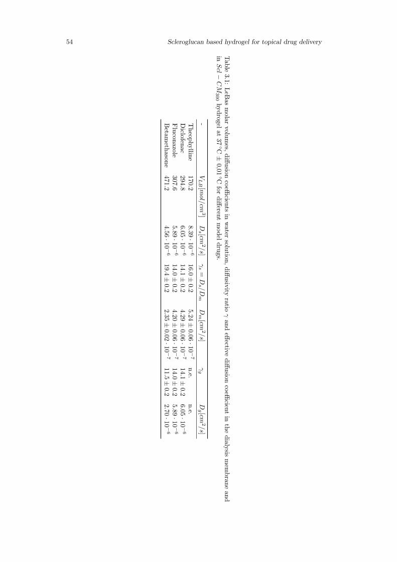
54 Scleroglucan based hydrogel for topical drug delivery
Table
3.1:LeB
asmolar
volumes,diffusion
coefficients
inwater
solution,diffusivityratio
γand
effectivediffusion
coefficient
inthe
dialysismem
braneand
inScl−
CM
300hydrogelat
37◦C±
0,01◦C
fordifferent
modeldrugs.
-VLB
[mol/cm
3]Ds [cm
2/s]
γs
=Ds /Dm
Dm
[cm2/s]
γg
Dg [cm
2/s]
Theophylline
170.2
8.3
9·1
0−
616.0±
0.25.2
4±
0.06·10−
7n.e.
n.e.Diclofenac
294.8
6.0
5·1
0−
614.1±
0.2
4.29±
0.06·10−
714.1±
0.2
6.05·10−
6
Fluconazole
307.6
5.8
9·1
0−
614.0±
0.2
4.20±
0.06·10−
714.0±
0.2
5.89·10−
6
Betam
ethasone471.2
4.5
6·10−
619.4±
0.2
2.35±
0.02·10−
711.5±
0.2
2.70·10−
6
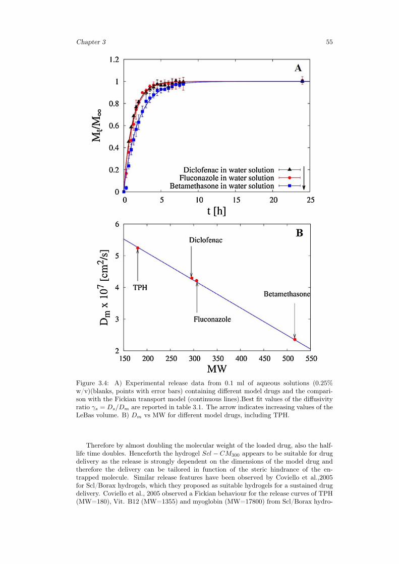
Chapter 3 55
Figure 3.4: A) Experimental release data from 0.1 ml of aqueous solutions (0.25%w/v)(blanks, points with error bars) containing different model drugs and the compari-son with the Fickian transport model (continuous lines).Best fit values of the diffusivityratio γs = Ds/Dm are reported in table 3.1. The arrow indicates increasing values of theLeBas volume. B) Dm vs MW for different model drugs, including TPH.
Therefore by almost doubling the molecular weight of the loaded drug, also the half-life time doubles. Henceforth the hydrogel Scl − CM300 appears to be suitable for drugdelivery as the release is strongly dependent on the dimensions of the model drug andtherefore the delivery can be tailored in function of the steric hindrance of the en-trapped molecule. Similar release features have been observed by Coviello et al.,2005for Scl/Borax hydrogels, which they proposed as suitable hydrogels for a sustained drugdelivery. Coviello et al., 2005 observed a Fickian behaviour for the release curves of TPH(MW=180), Vit. B12 (MW=1355) and myoglobin (MW=17800) from Scl/Borax hydro-
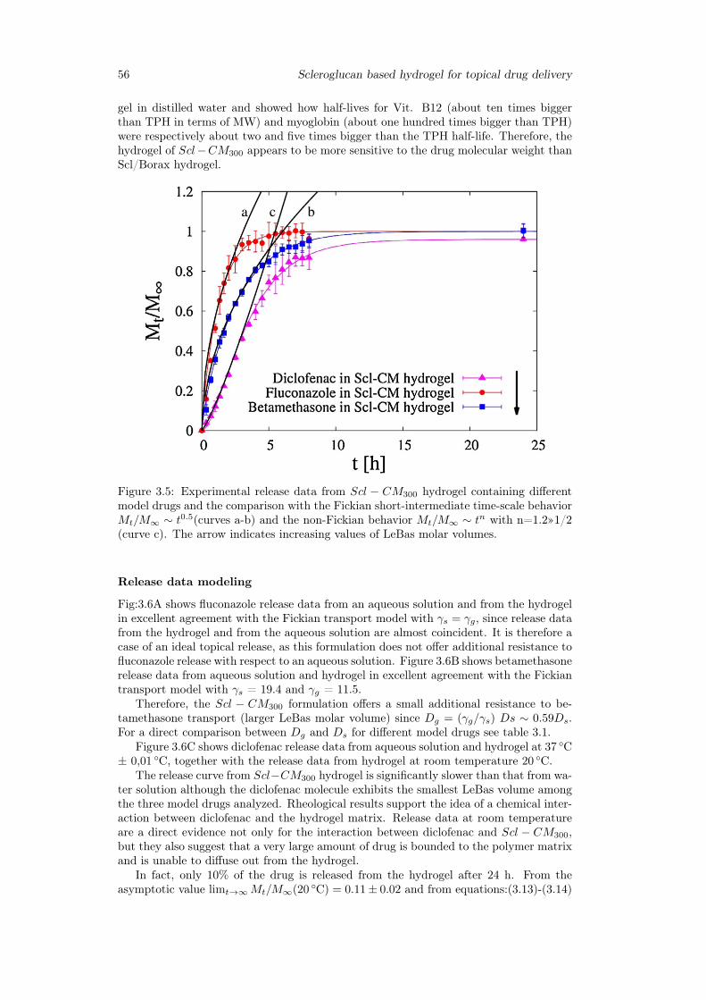
56 Scleroglucan based hydrogel for topical drug delivery
gel in distilled water and showed how half-lives for Vit. B12 (about ten times biggerthan TPH in terms of MW) and myoglobin (about one hundred times bigger than TPH)were respectively about two and five times bigger than the TPH half-life. Therefore, thehydrogel of Scl−CM300 appears to be more sensitive to the drug molecular weight thanScl/Borax hydrogel.
Figure 3.5: Experimental release data from Scl − CM300 hydrogel containing differentmodel drugs and the comparison with the Fickian short-intermediate time-scale behaviorMt/M∞ ∼ t0.5(curves a-b) and the non-Fickian behavior Mt/M∞ ∼ tn with n=1.2»1/2(curve c). The arrow indicates increasing values of LeBas molar volumes.
Release data modeling
Fig:3.6A shows fluconazole release data from an aqueous solution and from the hydrogelin excellent agreement with the Fickian transport model with γs = γg, since release datafrom the hydrogel and from the aqueous solution are almost coincident. It is therefore acase of an ideal topical release, as this formulation does not offer additional resistance tofluconazole release with respect to an aqueous solution. Figure 3.6B shows betamethasonerelease data from aqueous solution and hydrogel in excellent agreement with the Fickiantransport model with γs = 19.4 and γg = 11.5.
Therefore, the Scl − CM300 formulation offers a small additional resistance to be-tamethasone transport (larger LeBas molar volume) since Dg = (γg/γs) Ds ∼ 0.59Ds.For a direct comparison between Dg and Ds for different model drugs see table 3.1.
Figure 3.6C shows diclofenac release data from aqueous solution and hydrogel at 37 ◦C± 0,01 ◦C, together with the release data from hydrogel at room temperature 20 ◦C.
The release curve from Scl−CM300 hydrogel is significantly slower than that from wa-ter solution although the diclofenac molecule exhibits the smallest LeBas volume amongthe three model drugs analyzed. Rheological results support the idea of a chemical inter-action between diclofenac and the hydrogel matrix. Release data at room temperatureare a direct evidence not only for the interaction between diclofenac and Scl − CM300,but they also suggest that a very large amount of drug is bounded to the polymer matrixand is unable to diffuse out from the hydrogel.
In fact, only 10% of the drug is released from the hydrogel after 24 h. From theasymptotic value limt→∞Mt/M∞(20 ◦C) = 0.11± 0.02 and from equations:(3.13)-(3.14)
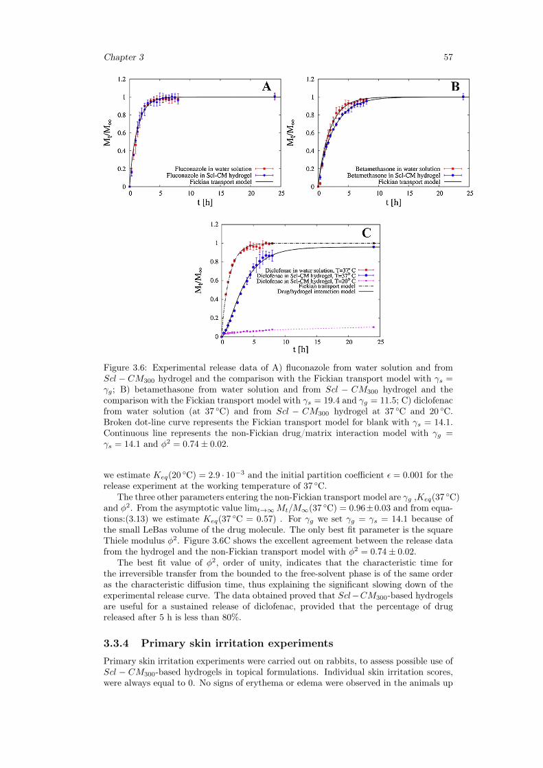
Chapter 3 57
Figure 3.6: Experimental release data of A) fluconazole from water solution and fromScl − CM300 hydrogel and the comparison with the Fickian transport model with γs =γg; B) betamethasone from water solution and from Scl − CM300 hydrogel and thecomparison with the Fickian transport model with γs = 19.4 and γg = 11.5; C) diclofenacfrom water solution (at 37 ◦C) and from Scl − CM300 hydrogel at 37 ◦C and 20 ◦C.Broken dot-line curve represents the Fickian transport model for blank with γs = 14.1.Continuous line represents the non-Fickian drug/matrix interaction model with γg =γs = 14.1 and φ2 = 0.74± 0.02.
we estimate Keq(20 ◦C) = 2.9 · 10−3 and the initial partition coefficient ε = 0.001 for therelease experiment at the working temperature of 37 ◦C.
The three other parameters entering the non-Fickian transport model are γg ,Keq(37 ◦C)and φ2. From the asymptotic value limt→∞Mt/M∞(37 ◦C) = 0.96±0.03 and from equa-tions:(3.13) we estimate Keq(37 ◦C = 0.57) . For γg we set γg = γs = 14.1 because ofthe small LeBas volume of the drug molecule. The only best fit parameter is the squareThiele modulus φ2. Figure 3.6C shows the excellent agreement between the release datafrom the hydrogel and the non-Fickian transport model with φ2 = 0.74± 0.02.
The best fit value of φ2, order of unity, indicates that the characteristic time forthe irreversible transfer from the bounded to the free-solvent phase is of the same orderas the characteristic diffusion time, thus explaining the significant slowing down of theexperimental release curve. The data obtained proved that Scl−CM300-based hydrogelsare useful for a sustained release of diclofenac, provided that the percentage of drugreleased after 5 h is less than 80%.
3.3.4 Primary skin irritation experiments
Primary skin irritation experiments were carried out on rabbits, to assess possible use ofScl − CM300-based hydrogels in topical formulations. Individual skin irritation scores,were always equal to 0. No signs of erythema or edema were observed in the animals up
58 Scleroglucan based hydrogel for topical drug delivery
to 72 h after the application of the samples. According to these data, the primary skinirritation index (PII) of the tested materials was negligible, highlighting that Scl−CM300
possesses adequate properties for application as a modified drug delivery system in topicalformulations.
3.4 ConclusionHigh-carboxymethylated scleroglucan can form physical hydrogels with negligible pri-mary skin irritation index and adequate rheological properties even in the presence ofdifferent therapeutic drugs such as fluconazole, diclofenac sodium salt, and betametha-sone phosphate sodium.
The shear thinning behavior of the system was not affected by loading these moleculeswithin the polymeric network. A slightly weaker hydrogel was obtained with betametha-sone. On the contrary, the carboxylic group of diclofenac made it able to interact withScl−CM300, thus strengthening the mechanical properties of the corresponding physicalgel.
These findings are supported by experimental drug release studies carried out ondrug-loaded Scl−CM300 hydrogels and further confirmed by mathematical modeling ofthe release profiles. In fact, while betamethasone and fluconazole were released accordingto a Fickian transport model, model analysis applied to diclofenac explained the non-Fickian feature of its release profile. The estimated values of effective drug diffusioncoefficients in the hydrogel for betamethasone and fluconazole, compared to those in anaqueous solution, led us to propose Scl − CM300 as an excellent formulation for fasttopical release.
The slower release rate observed for diclofenac, due to drug-polymer interactions,made Scl − CM300 useful for a sustained topical release of this drug.
Chapter 4
Drug delivery from Oral thinfilms
4.1 IntroductionOral mucosal drug delivery is an alternative and promising method of systemic deliverywhich offers several advantages [282, 283]. The oral mucosa is highly vascularized; forthis reason, drugs that are absorbed through it directly enter the systemic circulation,bypassing the gastrointestinal tract and first-pass metabolism in the liver [284]. Whensublingual mucosa administration is chosen, a rapid onset of action results via a morecomfortable and convenient delivery route than the intravenous route [285].
Additional advantages include an improved bioavailability for certain drugs and aneasy access to the absorption sites so that the delivery system can be applied and removedeasily [286,287].
In this work, novel OTFs were prepared combining Gellan gum, along with Glycerol,used as plasticizer. Gellan gum thin films were fabricated casting aqueous solutions ofthe polymer containing different concentrations of glycerol and loaded with two differentamount of Fluconazole, used as model drug. The manufacturing process was optimizedmonitoring some critical parameters including the rheological properties of the startingpolymeric solutions, air bubbles entrapped, content uniformity, residual water in thefinal films and drying rate. All these parameters have an important part on the physicalappearance, thickness homogeneity, content uniformity, mechanical and release propertiesof the resulting films and for this reason they were throughly investigated.
Moreover, the influence of the plasticizer on the swelling equilibrium and release ofthe drug is investigated in simulated saliva (pH 6.7) at 37 ◦C. Release studies were carriedout in a novel millifluidic flow-through device that using a laminar tangential flow is ableto better mime physiological mouth conditions.
4.2 Materials and method
4.2.1 Chemicals
Fluconazole, Gellan gum and Glycerol used in this work were procured from SigmaAldrich. Cellulose membrane filters were purchased fromMedicell International. Methanol(CH3OH), glacial acetic acid (CH3COOH), bidistilled water (for HPLC), potassium di-hydrogen phosphate (KH2PO4), di-sodium hydrogen phosphate dehydrate (Na2HPO4),sodium chloride (NaCl) and hydrochloric acid (HCl), (used to prepare simulated salivapH = 6.7), were supplied by Carlo Erba Reagents.
Gellan was added to glycerol to confer plasticity to the films. The glycerol is a triol,that is, an organic structure with three -OH groups. Glycerol is a component of lipidsand phospholipids from which it is obtained by hydrolysis. At environment temperature
59
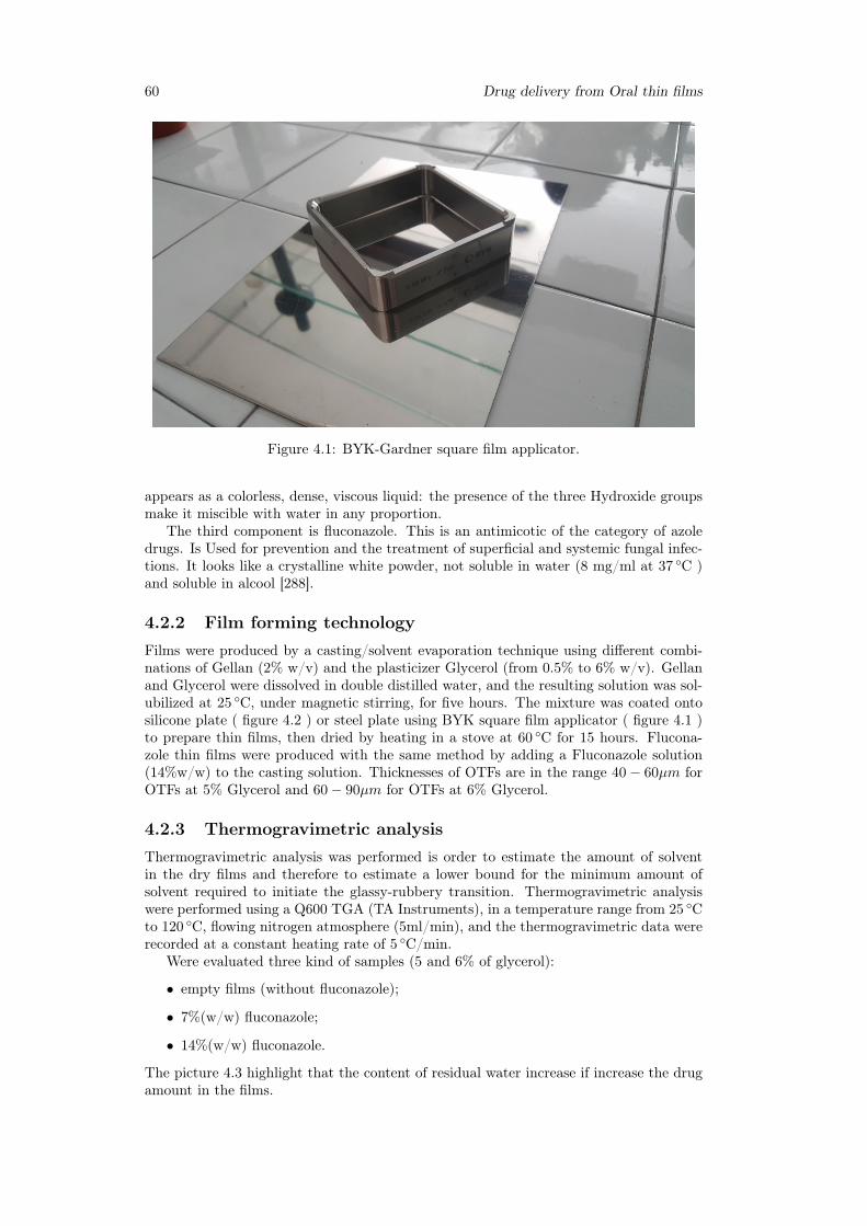
60 Drug delivery from Oral thin films
Figure 4.1: BYK-Gardner square film applicator.
appears as a colorless, dense, viscous liquid: the presence of the three Hydroxide groupsmake it miscible with water in any proportion.
The third component is fluconazole. This is an antimicotic of the category of azoledrugs. Is Used for prevention and the treatment of superficial and systemic fungal infec-tions. It looks like a crystalline white powder, not soluble in water (8 mg/ml at 37 ◦C )and soluble in alcool [288].
4.2.2 Film forming technologyFilms were produced by a casting/solvent evaporation technique using different combi-nations of Gellan (2% w/v) and the plasticizer Glycerol (from 0.5% to 6% w/v). Gellanand Glycerol were dissolved in double distilled water, and the resulting solution was sol-ubilized at 25 ◦C, under magnetic stirring, for five hours. The mixture was coated ontosilicone plate ( figure 4.2 ) or steel plate using BYK square film applicator ( figure 4.1 )to prepare thin films, then dried by heating in a stove at 60 ◦C for 15 hours. Flucona-zole thin films were produced with the same method by adding a Fluconazole solution(14%w/w) to the casting solution. Thicknesses of OTFs are in the range 40− 60µm forOTFs at 5% Glycerol and 60− 90µm for OTFs at 6% Glycerol.
4.2.3 Thermogravimetric analysisThermogravimetric analysis was performed is order to estimate the amount of solventin the dry films and therefore to estimate a lower bound for the minimum amount ofsolvent required to initiate the glassy-rubbery transition. Thermogravimetric analysiswere performed using a Q600 TGA (TA Instruments), in a temperature range from 25 ◦Cto 120 ◦C, flowing nitrogen atmosphere (5ml/min), and the thermogravimetric data wererecorded at a constant heating rate of 5 ◦C/min.
Were evaluated three kind of samples (5 and 6% of glycerol):
• empty films (without fluconazole);
• 7%(w/w) fluconazole;
• 14%(w/w) fluconazole.
The picture 4.3 highlight that the content of residual water increase if increase the drugamount in the films.
Chapter 4 61
Figure 4.2: Picture of silicon mold for casting solution.
Moreover films at 5% glycerol have more residual water than films at 6%.
Figure 4.3: Thermogravimetric tests for several kind of films. Wt is the weight of thefilm at time t, while W0 is the weight at time 0, at the start of the thermogravimetrictest
4.2.4 Swelling
Films were cut, weighted and inserted in a beaker of 5 ml contained simulated salivapH 6.7. At regular time intervals, non-adsorbed water was drained and wet film wasweighted. Tests were performed at 37 ◦C and repeated in triplicate. From the swellingtests is it possible to calculate the polymer volume fraction at equilibrium and the solventdiffusion coefficient in the completely swollen film.
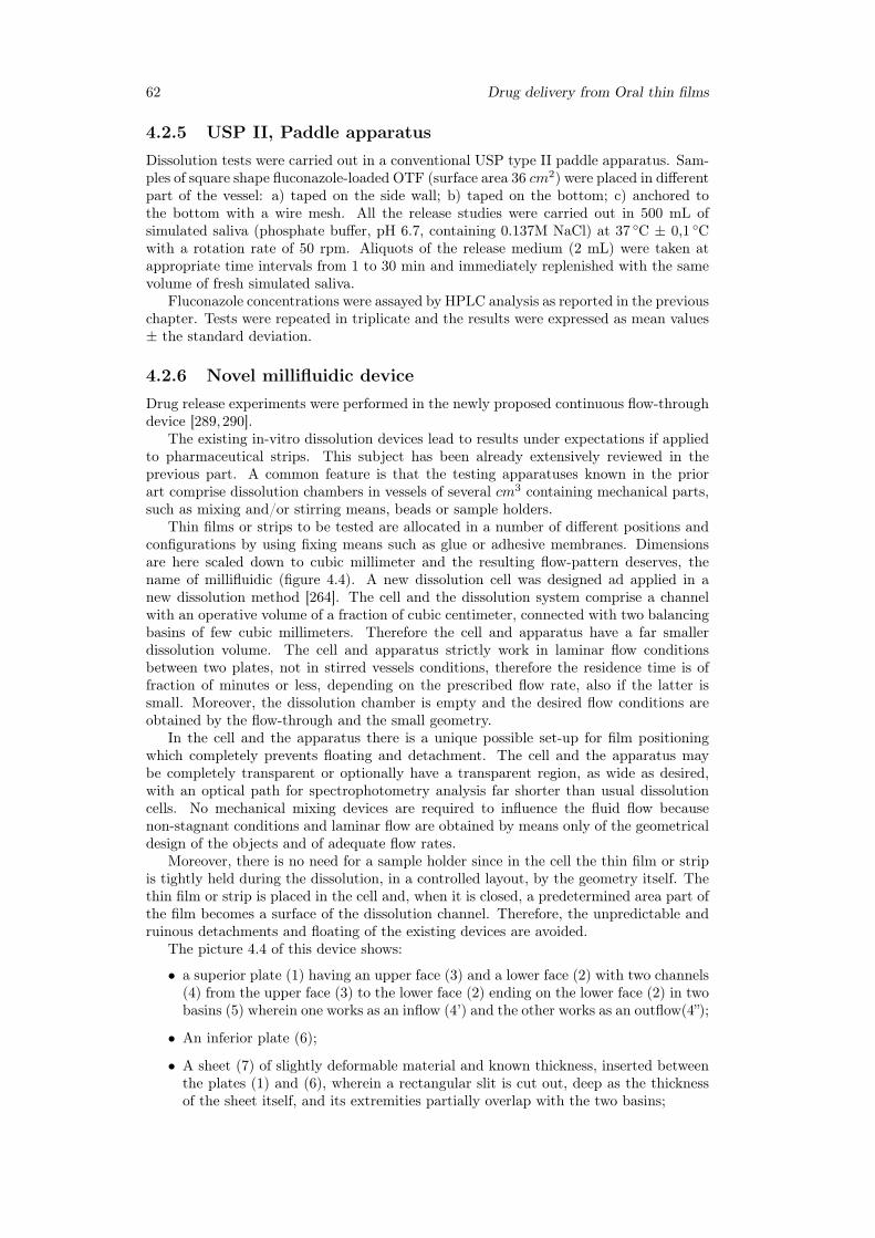
62 Drug delivery from Oral thin films
4.2.5 USP II, Paddle apparatusDissolution tests were carried out in a conventional USP type II paddle apparatus. Sam-ples of square shape fluconazole-loaded OTF (surface area 36 cm2) were placed in differentpart of the vessel: a) taped on the side wall; b) taped on the bottom; c) anchored tothe bottom with a wire mesh. All the release studies were carried out in 500 mL ofsimulated saliva (phosphate buffer, pH 6.7, containing 0.137M NaCl) at 37 ◦C ± 0,1 ◦Cwith a rotation rate of 50 rpm. Aliquots of the release medium (2 mL) were taken atappropriate time intervals from 1 to 30 min and immediately replenished with the samevolume of fresh simulated saliva.
Fluconazole concentrations were assayed by HPLC analysis as reported in the previouschapter. Tests were repeated in triplicate and the results were expressed as mean values± the standard deviation.
4.2.6 Novel millifluidic deviceDrug release experiments were performed in the newly proposed continuous flow-throughdevice [289,290].
The existing in-vitro dissolution devices lead to results under expectations if appliedto pharmaceutical strips. This subject has been already extensively reviewed in theprevious part. A common feature is that the testing apparatuses known in the priorart comprise dissolution chambers in vessels of several cm3 containing mechanical parts,such as mixing and/or stirring means, beads or sample holders.
Thin films or strips to be tested are allocated in a number of different positions andconfigurations by using fixing means such as glue or adhesive membranes. Dimensionsare here scaled down to cubic millimeter and the resulting flow-pattern deserves, thename of millifluidic (figure 4.4). A new dissolution cell was designed ad applied in anew dissolution method [264]. The cell and the dissolution system comprise a channelwith an operative volume of a fraction of cubic centimeter, connected with two balancingbasins of few cubic millimeters. Therefore the cell and apparatus have a far smallerdissolution volume. The cell and apparatus strictly work in laminar flow conditionsbetween two plates, not in stirred vessels conditions, therefore the residence time is offraction of minutes or less, depending on the prescribed flow rate, also if the latter issmall. Moreover, the dissolution chamber is empty and the desired flow conditions areobtained by the flow-through and the small geometry.
In the cell and the apparatus there is a unique possible set-up for film positioningwhich completely prevents floating and detachment. The cell and the apparatus maybe completely transparent or optionally have a transparent region, as wide as desired,with an optical path for spectrophotometry analysis far shorter than usual dissolutioncells. No mechanical mixing devices are required to influence the fluid flow becausenon-stagnant conditions and laminar flow are obtained by means only of the geometricaldesign of the objects and of adequate flow rates.
Moreover, there is no need for a sample holder since in the cell the thin film or stripis tightly held during the dissolution, in a controlled layout, by the geometry itself. Thethin film or strip is placed in the cell and, when it is closed, a predetermined area part ofthe film becomes a surface of the dissolution channel. Therefore, the unpredictable andruinous detachments and floating of the existing devices are avoided.
The picture 4.4 of this device shows:
• a superior plate (1) having an upper face (3) and a lower face (2) with two channels(4) from the upper face (3) to the lower face (2) ending on the lower face (2) in twobasins (5) wherein one works as an inflow (4’) and the other works as an outflow(4”);
• An inferior plate (6);
• A sheet (7) of slightly deformable material and known thickness, inserted betweenthe plates (1) and (6), wherein a rectangular slit is cut out, deep as the thicknessof the sheet itself, and its extremities partially overlap with the two basins;
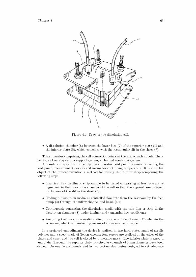
Chapter 4 63
Figure 4.4: Draw of the dissolution cell.
• A dissolution chamber (8) between the lower face (2) of the superior plate (1) andthe inferior plate (5), which coincides with the rectangular slit in the sheet (7).
The apparatus comprising the cell connection joints at the exit of each circular chan-nel(4), a closure system, a support system, a thermal insulation system.
A dissolution system is formed by the apparatus, feed pump, a reservoir feeding thefeed pump, measurement devices and means for controlling temperature. It is a furtherobject of the present invention a method for testing thin film or strip comprising thefollowing steps:
• Inserting the thin film or strip sample to be tested comprising at least one activeingredient in the dissolution chamber of the cell so that the exposed area is equalto the area of the slit in the sheet (7);
• Feeding a dissolution media at controlled flow rate from the reservoir by the feedpump (4) through the inflow channel and basin (4’);
• Continuously contacting the dissolution media with the thin film or strip in thedissolution chamber (8) under laminar and tangential flow conditions;
• Analyzing the dissolution media exiting from the outflow channel (4”) wherein theactive ingredient is dissolved by means of a measurement device.
In a preferred embodiment the device is realized in two hard plates made of acrylicpolymer and a sheet made of Teflon wherein four screws are realized at the edges of theplates and sheet and the cell is closed by a metallic mask. The inferior plate is smoothand plain. Through the superior plate two circular channels of 2 mm diameter have beendrilled. On one face, channels end in two rectangular basins designed to set adequate
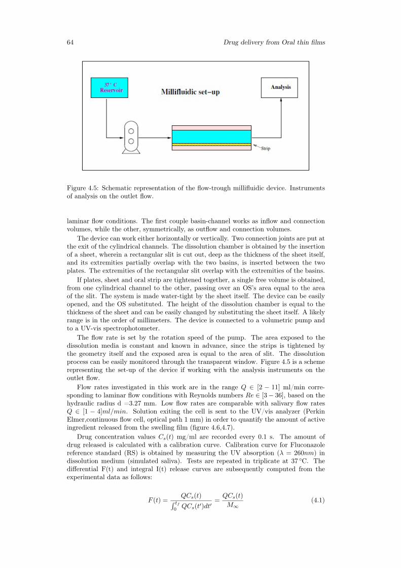
64 Drug delivery from Oral thin films
Figure 4.5: Schematic representation of the flow-trough millifluidic device. Instrumentsof analysis on the outlet flow.
laminar flow conditions. The first couple basin-channel works as inflow and connectionvolumes, while the other, symmetrically, as outflow and connection volumes.
The device can work either horizontally or vertically. Two connection joints are put atthe exit of the cylindrical channels. The dissolution chamber is obtained by the insertionof a sheet, wherein a rectangular slit is cut out, deep as the thickness of the sheet itself,and its extremities partially overlap with the two basins, is inserted between the twoplates. The extremities of the rectangular slit overlap with the extremities of the basins.
If plates, sheet and oral strip are tightened together, a single free volume is obtained,from one cylindrical channel to the other, passing over an OS’s area equal to the areaof the slit. The system is made water-tight by the sheet itself. The device can be easilyopened, and the OS substituted. The height of the dissolution chamber is equal to thethickness of the sheet and can be easily changed by substituting the sheet itself. A likelyrange is in the order of millimeters. The device is connected to a volumetric pump andto a UV-vis spectrophotometer.
The flow rate is set by the rotation speed of the pump. The area exposed to thedissolution media is constant and known in advance, since the strips is tightened bythe geometry itself and the exposed area is equal to the area of slit. The dissolutionprocess can be easily monitored through the transparent window. Figure 4.5 is a schemerepresenting the set-up of the device if working with the analysis instruments on theoutlet flow.
Flow rates investigated in this work are in the range Q ∈ [2 − 11] ml/min corre-sponding to laminar flow conditions with Reynolds numbers Re ∈ [3− 36], based on thehydraulic radius d =3.27 mm. Low flow rates are comparable with salivary flow ratesQ ∈ [1 − 4]ml/min. Solution exiting the cell is sent to the UV/vis analyzer (PerkinElmer,continuous flow cell, optical path 1 mm) in order to quantify the amount of activeingredient released from the swelling film (figure 4.6,4.7).
Drug concentration values Cs(t) mg/ml are recorded every 0.1 s. The amount ofdrug released is calculated with a calibration curve. Calibration curve for Fluconazolereference standard (RS) is obtained by measuring the UV absorption (λ = 260nm) indissolution medium (simulated saliva). Tests are repeated in triplicate at 37 ◦C. Thedifferential F(t) and integral I(t) release curves are subsequently computed from theexperimental data as follows:
F (t) =QCs(t)∫ tf
0QCs(t′)dt′
=QCs(t)
M∞(4.1)
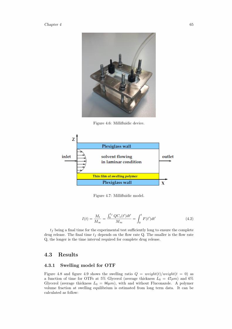
Chapter 4 65
Figure 4.6: Millifluidic device.
Figure 4.7: Millifluidic model.
I(t) =Mt
M∞=
∫ tf0QCs(t
′)dt′
M∞=
∫ t
0
F (t′)dt′ (4.2)
tf being a final time for the experimental test sufficiently long to ensure the completedrug release. The final time tf depends on the flow rate Q. The smaller is the flow rateQ, the longer is the time interval required for complete drug release.
4.3 Results
4.3.1 Swelling model for OTF
Figure 4.8 and figure 4.9 shows the swelling ratio Q = weight(t)/weight(t = 0) asa function of time for OTFs at 5% Glycerol (average thickness L0 = 47µm) and 6%Glycerol (average thickness L0 = 86µm), with and without Fluconazole. A polymervolume fraction at swelling equilibrium is estimated from long term data. It can becalculated as follow:
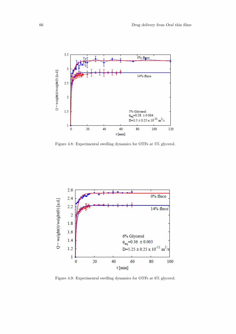
66 Drug delivery from Oral thin films
Figure 4.8: Experimental swelling dynamics for OTFs at 5% glycerol.
Figure 4.9: Experimental swelling dynamics for OTFs at 6% glycerol.
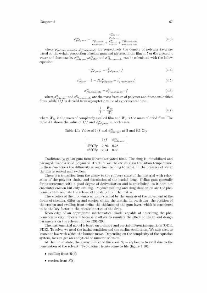
Chapter 4 67
φ∞polymer =
x∞polymer
ρpolymer
x∞polymer
ρpolimero+
x∞water
ρwater+
x∞fluconazole
ρfluconazole
(4.3)
where ρpolimer, ρwater, ρfluconazole are respectively the density of polymer (averagebased on the weight proportion of gellan gum and glycerol in the film at 5 or 6% glycerol),water and fluconazole. x∞polymer, x
∞water and x∞fluconazole can be calculated with the follow
equation:
x∞polymer = x0polymer · f (4.4)
x∞water = 1− f(x0polymer + x0
fluconazole) (4.5)
x∞fluconazole = x0fluconazole · f (4.6)
where x0polymer and x
0fluconazole are the mass fraction of polymer and fluconazole dried
films, while 1/f is derived from asymptotic value of experimental data:
1
f=W∞W0
(4.7)
where W∞ is the mass of completely swelled film and W0 is the mass of dried film. Thetable 4.1 shows the value of 1/f and φ∞polymer in both cases.
Table 4.1: Value of 1/f and φ∞polymer at 5 and 6% Gly
- 1/f φ∞polymer
5%Gly 2.86 0.286%Gly 2.24 0.36
Traditionally, gellan gum form solvent-activated films. The drug is immobilized andpackaged inside a solid polymeric structure well below its glass transition temperature.In these conditions the diffusivity is very low (tending to zero). In the presence of waterthe film is soaked and swollen.
There is a transition from the glassy to the rubbery state of the material with relax-ation of the polymer chains and dissolution of the loaded drug. Gellan gum generallyforms structures with a good degree of derivatization and is crosslinked, so it does notencounter erosion but only swelling. Polymer swelling and drug dissolution are the phe-nomena that regulate the release of the drug from the matrix.
The kinetics of the problem is actually studied by the analysis of the movement of thefronts of swelling, diffusion and erosion within the matrix. In particular, the position ofthe erosion and swelling front define the thickness of the gum layer, which is consideredto be the key factor in the release kinetics of the drug.
Knowledge of an appropriate mathematical model capable of describing the phe-nomenon is very important because it allows to simulate the effect of design and designparameters on the release profiles [291–293].
The mathematical model is based on ordinary and partial differential equations (ODE,PDE). To solve, we need the initial condition and the outline conditions. We also need toknow the law with which the bounds move. Depending on the complexity of the equationsystem, we can get an analytical or numeric solution.
At the initial state, the glassy matrix of thickness S0 = R0 begins to swell due to thepenetration of the solvent. Two distinct fronts come to life (figure 4.10):
• swelling front R(t);
• erosion front S(t);
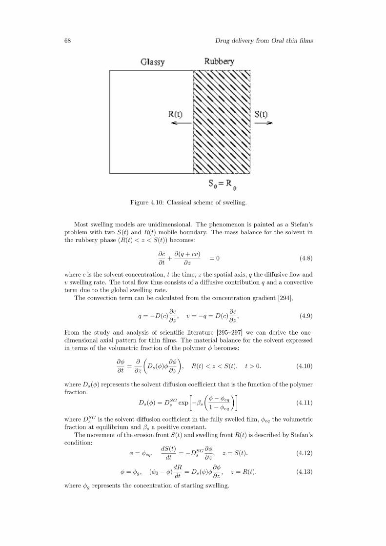
68 Drug delivery from Oral thin films
Figure 4.10: Classical scheme of swelling.
Most swelling models are unidimensional. The phenomenon is painted as a Stefan’sproblem with two S(t) and R(t) mobile boundary. The mass balance for the solvent inthe rubbery phase (R(t) < z < S(t)) becomes:
∂c
∂t+∂(q + cv)
∂z= 0 (4.8)
where c is the solvent concentration, t the time, z the spatial axis, q the diffusive flow andv swelling rate. The total flow thus consists of a diffusive contribution q and a convectiveterm due to the global swelling rate.
The convection term can be calculated from the concentration gradient [294],
q = −D(c)∂c
∂z, v = −q = D(c)
∂c
∂z, (4.9)
From the study and analysis of scientific literature [295–297] we can derive the one-dimensional axial pattern for thin films. The material balance for the solvent expressedin terms of the volumetric fraction of the polymer φ becomes:
∂φ
∂t=
∂
∂z
(Ds(φ)φ
∂φ
∂z
), R(t) < z < S(t), t > 0. (4.10)
whereDs(φ) represents the solvent diffusion coefficient that is the function of the polymerfraction.
Ds(φ) = DSGs exp
[−βs
(φ− φeq1− φeq
)](4.11)
where DSGs is the solvent diffusion coefficient in the fully swelled film, φeq the volumetric
fraction at equilibrium and βs a positive constant.The movement of the erosion front S(t) and swelling front R(t) is described by Stefan’s
condition:
φ = φeq,dS(t)
dt= −DSG
s
∂φ
∂z, z = S(t). (4.12)
φ = φg, (φ0 − φ)dR
dt= Ds(φ)φ
∂φ
∂z, z = R(t). (4.13)
where φg represents the concentration of starting swelling.
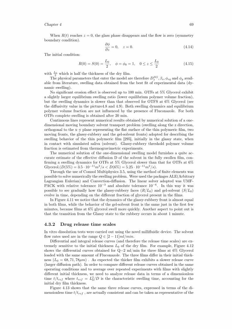
Chapter 4 69
When R(t) reaches z = 0, the glass phase disappears and the flow is zero (symmetryboundary condition).
∂φ
∂z= 0, z = 0. (4.14)
The initial condition:
R(0) = S(0) =L0
2, φ = φ0 = 1, 0 ≤ z ≤ L0
2(4.15)
with L0
2 which is half the thickness of the dry film.The physical parameters that enter the model are therefore DSG
s , βs, φeq and φg avail-able from literature, swelling data obtained from the best fit of experimental data (dy-namic swelling).
No significant erosion effect is observed up to 100 min. OTFs at 5% Glycerol exhibita slightly larger equilibrium swelling ratio (lower equilibrium polymer volume fraction),but the swelling dynamics is slower than that observed for OTFS at 6% Glycerol (seethe diffusivity value in the picture4.8 and 4.9). Both swelling dynamics and equilibriumpolymer volume fraction are not influenced by the presence of Fluconazole. For bothOTFs complete swelling is obtained after 20 min.
Continuous lines represent numerical results obtained by numerical solution of a one-dimensional moving boundary solvent transport problem (swelling along the z direction,orthogonal to the x–y plane representing the flat surface of the thin polymeric film, twomoving fronts, the glassy-rubbery and the gel-solvent fronts) adopted for describing theswelling behavior of the thin polymeric film [295], initially in the glassy state, whenin contact with simulated saliva (solvent). Glassy-rubbery threshold polymer volumefraction is estimated from thermogravimetric experiments.
The numerical solution of the one-dimensional swelling model furnishes a quite ac-curate estimate of the effective diffusion D of the solvent in the fully swollen film, con-firming a swelling dynamics for OTFs at 5% Glycerol slower than that for OTFs at 6%Glycerol.(D(5%) = 3.5 · 10−11m2/s < D(6%) = 5.25 · 10−11m2/s).
Through the use of Comsol Multiphysics 3.5, using the method of finite elements waspossible to solve numerically the swelling problem. Were used the packages ALE(ArbitraryLagrangian Eulerian) and Convection-diffusion. The linear solver adopted was UMF-PACK with relative tolerance 10−3 and absolute tolerance 10−6. In this way it waspossible to see gradually how the glassy-rubbery faces (R/L0) and gel-solvent (S/L0)evolve in time, depending on the different fraction of glycerol present in the films.
In Figure 4.11 we notice that the dynamics of the glassy-rubbery front is almost equalin both films, while the behavior of the gel-solvent front is the same just in the first fewminutes, because films at 6% glycerol swell more quickly. Another aspect to point out isthat the transition from the Glassy state to the rubbery occurs in about 1 minute.
4.3.2 Drug release time scalesIn vitro dissolution tests were carried out using the novel millifluidic device. The solventflow rates used are in the range Q ∈ [2− 11]ml/min.
Differential and integral release curves (and therefore the release time scales) are ex-tremely sensitive to the initial thickness L0 of the dry film. For example, Figure 4.12shows the differential curves obtained for Q=2 ml/min for three films at 6% Glycerolloaded with the same amount of Fluconazole. The three films differ in their initial thick-ness (L0 = 68, 71, 78µm) . As expected the thicker film exhibits a slower release curve(larger diffusion path). In order to compare different release curves obtained in the sameoperating conditions and to average over repeated experiments with films with slightlydifferent initial thickness, we need to analyze release data in terms of a dimensionlesstime t/tref where tref = L2
0/D is the characteristic swelling time, accounting for theinitial dry film thickness.
Figure 4.13 shows that the same three release curves, expressed in terms of the di-mensionless time t/tref , are actually consistent and can be taken as representative of the
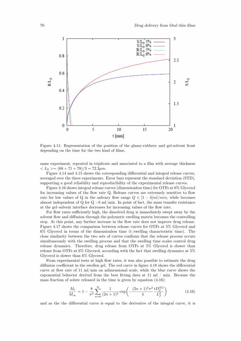
70 Drug delivery from Oral thin films
Figure 4.11: Representation of the position of the glassy-rubbery and gel-solvent frontdepending on the time for the two kind of films.
same experiment, repeated in triplicate and associated to a film with average thickness< L0 >= (68 + 71 + 78)/3 = 72.3µm.
Figure 4.14 and 4.15 shows the corresponding differential and integral release curves,averaged over the three experiments. Error bars represent the standard deviation (STD),supporting a good reliability and reproducibility of the experimental release curves.
Figure 4.16 shows integral release curves (dimensionless time) for OTFs at 6% Glycerolfor increasing values of the flow rate Q. Release curves are extremely sensitive to flowrate for low values of Q in the salivary flow range Q ∈ [1 − 4]ml/min, while becomesalmost independent of Q for Q >8 ml/min. In point of fact, the mass transfer resistanceat the gel–solvent interface decreases for increasing values of the flow rate.
For flow rates sufficiently high, the dissolved drug is immediately swept away by thesolvent flow and diffusion through the polymeric swelling matrix becomes the controllingstep. At this point, any further increase in the flow rate does not improve drug release.Figure 4.17 shows the comparison between release curves for OTFs at 5% Glycerol and6% Glycerol in terms of the dimensionless time (t/swelling characteristic time). Theclose similarity between the two sets of curves confirms that the release process occurssimultaneously with the swelling process and that the swelling time scales control drugrelease dynamics. Therefore, drug release from OTFs at 5% Glycerol is slower thanrelease from OTFs at 6% Glycerol, according with the fact that swelling dynamics at 5%Glycerol is slower than 6% Glycerol.
From experimental tests at high flow rates, it was also possible to estimate the drugdiffusion coefficient in the swollen gel. The red curve in figure 4.18 shows the differentialcurve at flow rate of 11 ml/min on adimensional scale, while the blue curve shows theexponential behavior derived from the best fitting data at 11 ml / min. Because themass fraction of solute released in the time is given by equation (4.16):
Mt
M∞= 1− 8
π2
∞∑n=0
1
(2n+ 1)2exp
(− (2n+ 1)2π2
4
tDSGd
L2f
)(4.16)
and as the the differential curve is equal to the derivative of the integral curve, it is
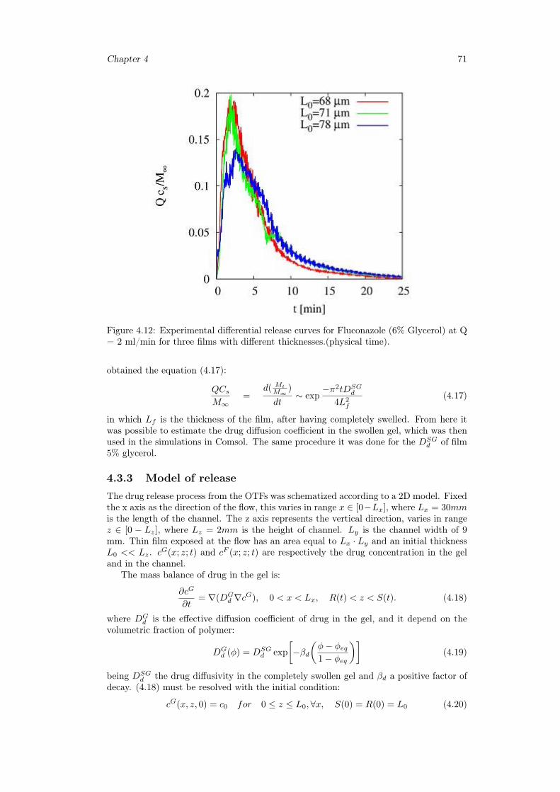
Chapter 4 71
Figure 4.12: Experimental differential release curves for Fluconazole (6% Glycerol) at Q= 2 ml/min for three films with different thicknesses.(physical time).
obtained the equation (4.17):
QCsM∞
=d( Mt
M∞)
dt∼ exp
−π2tDSGd
4L2f
(4.17)
in which Lf is the thickness of the film, after having completely swelled. From here itwas possible to estimate the drug diffusion coefficient in the swollen gel, which was thenused in the simulations in Comsol. The same procedure it was done for the DSG
d of film5% glycerol.
4.3.3 Model of releaseThe drug release process from the OTFs was schematized according to a 2D model. Fixedthe x axis as the direction of the flow, this varies in range x ∈ [0−Lx], where Lx = 30mmis the length of the channel. The z axis represents the vertical direction, varies in rangez ∈ [0 − Lz], where Lz = 2mm is the height of channel. Ly is the channel width of 9mm. Thin film exposed at the flow has an area equal to Lx · Ly and an initial thicknessL0 << Lz. cG(x; z; t) and cF (x; z; t) are respectively the drug concentration in the geland in the channel.
The mass balance of drug in the gel is:
∂cG
∂t= ∇(DG
d ∇cG), 0 < x < Lx, R(t) < z < S(t). (4.18)
where DGd is the effective diffusion coefficient of drug in the gel, and it depend on the
volumetric fraction of polymer:
DGd (φ) = DSG
d exp
[−βd
(φ− φeq1− φeq
)](4.19)
being DSGd the drug diffusivity in the completely swollen gel and βd a positive factor of
decay. (4.18) must be resolved with the initial condition:
cG(x, z, 0) = c0 for 0 ≤ z ≤ L0,∀x, S(0) = R(0) = L0 (4.20)
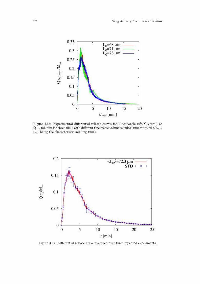
72 Drug delivery from Oral thin films
Figure 4.13: Experimental differential release curves for Fluconazole (6% Glycerol) atQ=2 ml/min for three films with different thicknesses.(dimensionless time rescaled t/tref ,tref being the characteristic swelling time).
Figure 4.14: Differential release curve averaged over three repeated experiments.
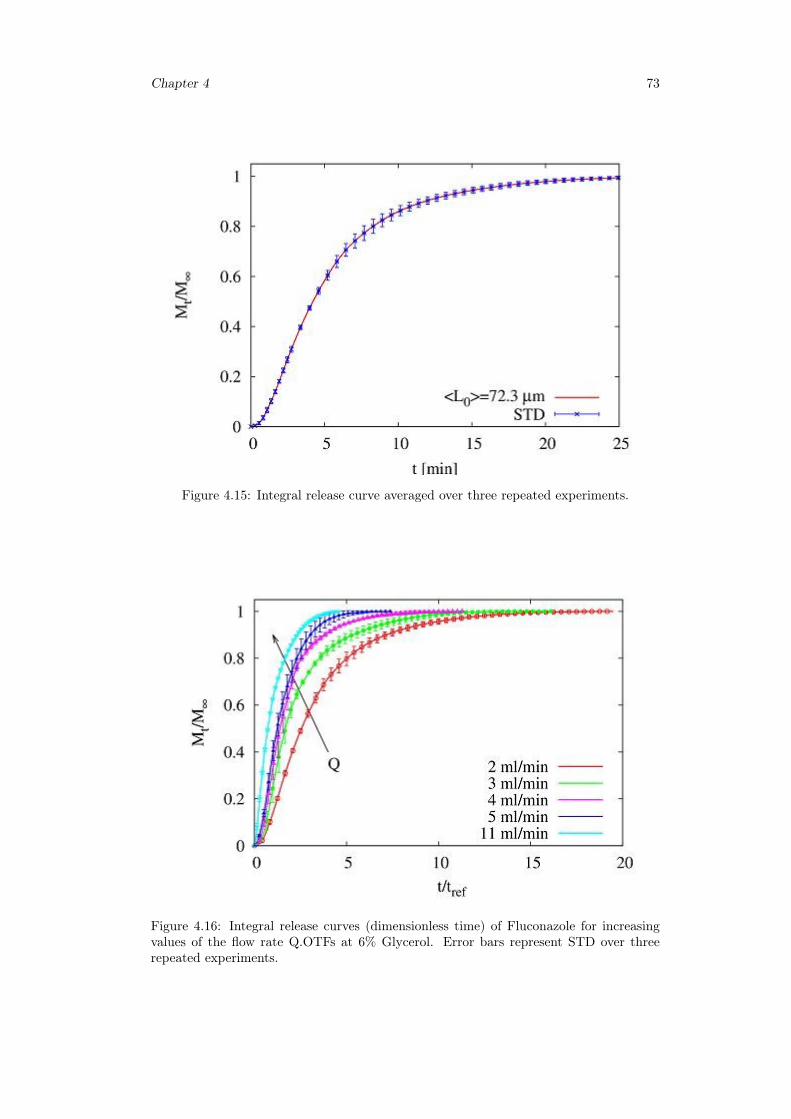
Chapter 4 73
Figure 4.15: Integral release curve averaged over three repeated experiments.
Figure 4.16: Integral release curves (dimensionless time) of Fluconazole for increasingvalues of the flow rate Q.OTFs at 6% Glycerol. Error bars represent STD over threerepeated experiments.
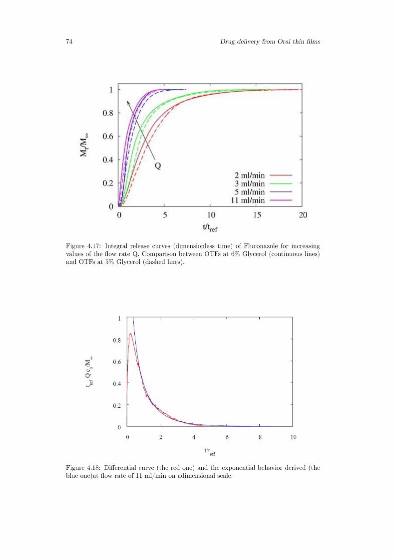
74 Drug delivery from Oral thin films
Figure 4.17: Integral release curves (dimensionless time) of Fluconazole for increasingvalues of the flow rate Q. Comparison between OTFs at 6% Glycerol (continuous lines)and OTFs at 5% Glycerol (dashed lines).
Figure 4.18: Differential curve (the red one) and the exponential behavior derived (theblue one)at flow rate of 11 ml/min on adimensional scale.
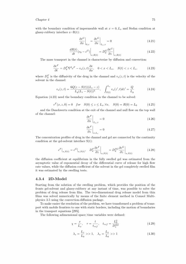
Chapter 4 75
with the boundary condition of impermeable wall at x = 0, Lx and Stefan condition atglassy-rubbery interface z=R(t):
∂cG
∂x
∣∣∣∣0,z
=∂cG
∂x
∣∣∣∣Lx,z
= 0 (4.21)
dR(t)
dt(c0 − cG)
∣∣∣∣x,R(t)
= DGd
∂cG
∂z
∣∣∣∣x,R(t)
(4.22)
The mass transport in the channel is characterize by diffusion and convection:
∂cF
∂t= DF
d ∇2cF − vx(z, t)∂c
∂x, 0 < x < Lx, S(t) < z < Lz. (4.23)
where DFd is the diffusivity of the drug in the channel and vx(z, t) is the velocity of the
solvent in the channel:
vx(z, t) =6Q(z − S(t))(Lz − z)
Ly(Lz − S(t))3,
∫ Lz
S(t)
vx(z′, t)dz′ =Q
Ly(4.24)
Equation (4.23) need the boundary condition in the channel to be solved:
cF (x, z, 0) = 0 for S(0) ≤ z ≤ Lx,∀x, S(0) = R(0) = L0 (4.25)
and the Danckwertz condition at the exit of the channel and null flow on the top wallof the channel:
∂cF
∂x
∣∣∣∣Lx,z
= 0 (4.26)
∂cF
∂z
∣∣∣∣x,Lz
= 0 (4.27)
The concentration profiles of drug in the channel and gel are connected by the continuitycondition at the gel-solvent interface S(t):
cF∣∣x,S(t)
= cG∣∣x,S(t)
, DFd
∂cF
∂z
∣∣∣∣x,S(t)
= DSGd
∂cG
∂z
∣∣∣∣x,S(t)
(4.28)
the diffusion coefficient at equilibrium in the fully swelled gel was estimated from theasymptotic value of exponential decay of the differential curve of release for high flowrate values, while the diffusion coefficient of the solvent in the gel completely swelled filmit was estimated by the swelling tests.
4.3.4 2D-ModelStarting from the solution of the swelling problem, which provides the position of thefronts gel-solvent and glassy-rubbery at any instant of time, was possible to solve theproblem of drug release from film. The two-dimensional drug release model from thinfilms was solved numerically by means of the finite element method in Comsol Multi-physics 3.5 using the convection-diffusion package.
To make easier the resolution of the problem, we have transformed a problem of trans-port with mobile frontiers to one with static borders, including the motion of boundariesin the transport equations [295].
The following adimensional space/time variables were defined:
χ =x
Lx, τ =
t
tref, tref =
L20
DSGs
(4.29)
λz =LzL0
>> 1, λx =LxL0
>> 1 (4.30)
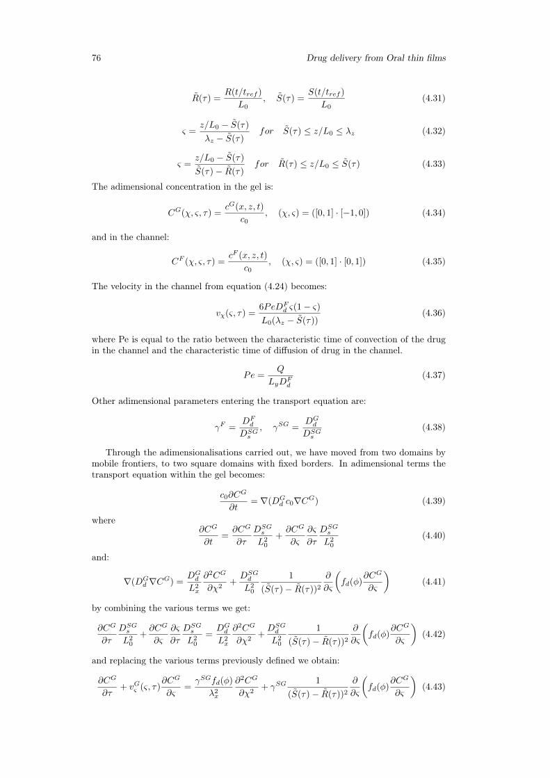
76 Drug delivery from Oral thin films
R(τ) =R(t/tref )
L0, S(τ) =
S(t/tref )
L0(4.31)
ς =z/L0 − S(τ)
λz − S(τ)for S(τ) ≤ z/L0 ≤ λz (4.32)
ς =z/L0 − S(τ)
S(τ)− R(τ)for R(τ) ≤ z/L0 ≤ S(τ) (4.33)
The adimensional concentration in the gel is:
CG(χ, ς, τ) =cG(x, z, t)
c0, (χ, ς) = ([0, 1] · [−1, 0]) (4.34)
and in the channel:
CF (χ, ς, τ) =cF (x, z, t)
c0, (χ, ς) = ([0, 1] · [0, 1]) (4.35)
The velocity in the channel from equation (4.24) becomes:
vχ(ς, τ) =6PeDF
d ς(1− ς)L0(λz − S(τ))
(4.36)
where Pe is equal to the ratio between the characteristic time of convection of the drugin the channel and the characteristic time of diffusion of drug in the channel.
Pe =Q
LyDFd
(4.37)
Other adimensional parameters entering the transport equation are:
γF =DFd
DSGs
, γSG =DGd
DSGs
(4.38)
Through the adimensionalisations carried out, we have moved from two domains bymobile frontiers, to two square domains with fixed borders. In adimensional terms thetransport equation within the gel becomes:
c0∂CG
∂t= ∇(DG
d c0∇CG) (4.39)
where∂CG
∂t=∂CG
∂τ
DSGs
L20
+∂CG
∂ς
∂ς
∂τ
DSGs
L20
(4.40)
and:
∇(DGd ∇CG) =
DGd
L2x
∂2CG
∂χ2+DSGd
L20
1
(S(τ)− R(τ))2
∂
∂ς
(fd(φ)
∂CG
∂ς
)(4.41)
by combining the various terms we get:
∂CG
∂τ
DSGs
L20
+∂CG
∂ς
∂ς
∂τ
DSGs
L20
=DGd
L2x
∂2CG
∂χ2+DSGd
L20
1
(S(τ)− R(τ))2
∂
∂ς
(fd(φ)
∂CG
∂ς
)(4.42)
and replacing the various terms previously defined we obtain:
∂CG
∂τ+ vGς (ς, τ)
∂CG
∂ς=γSGfd(φ)
λ2x
∂2CG
∂χ2+ γSG
1
(S(τ)− R(τ))2
∂
∂ς
(fd(φ)
∂CG
∂ς
)(4.43)
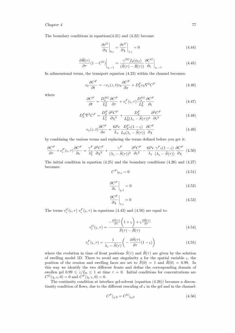
Chapter 4 77
The boundary conditions in equations(4.21) and (4.22) become:
∂cG
∂χ
∣∣∣∣0,ς
=∂cG
∂χ
∣∣∣∣1,ς
= 0 (4.44)
∂R(τ)
∂τ(1− CG)
∣∣∣∣χ,−1
=γSGfd(φG)
(S(τ)− R(τ))
∂CG
∂ς
∣∣∣∣χ,−1
(4.45)
In adimensional terms, the transport equation (4.23) within the channel becomes:
c0∂CF
∂t= −vx(z, t)c0
∂CF
∂x+DF
d c0∇2CF (4.46)
where∂CF
∂t=DSGs
L20
∂CF
∂τ+ vFς (ς, τ)
DSGs
L20
∂CF
∂ς(4.47)
DFd ∇2CF =
DFd
L2x
∂2CF
∂χ2+
DFd
L20(λz − S(τ))2
∂2CF
∂ς2(4.48)
vx(z, t)∂CF
∂x=
6Pe
Lx
DFd ς(1− ς)
L0(λz − S(τ))
∂CF
∂χ(4.49)
by combining the various terms and replacing the terms defined before you get it:
∂CF
∂τ+ vFς (ς, τ)
∂CF
∂ς=γF
λ2x
∂2CF
∂χ2+
γF
(λz − S(τ))2
∂2CF
∂ς2− 6Pe
λx
γF ς(1− ς)(λz − S(τ))
∂CF
∂χ(4.50)
The initial condition in equation (4.25) and the boundary conditions (4.26) and (4.27)becomes:
CF |0,ς = 0 (4.51)
∂CF
∂ς
∣∣∣∣χ,1
= 0 (4.52)
∂CF
∂χ
∣∣∣∣1,ς
= 0 (4.53)
The terms vGς (ς, τ) vFς (ς, τ) in equations (4.43) and (4.50) are equal to:
vGς (ς, τ) =
−∂S(τ)∂τ
(1 + ς
)+ ς ∂R(τ)
∂τ
S(τ)− R(τ)(4.54)
vFς (ς, τ) =1
λz − S(τ)
(− ∂S(τ)
∂τ(1− ς)
)(4.55)
where the evolution in time of front positions S(τ) and R(τ) are given by the solutionof swelling model 1D. There to avoid any singularity a for the spatial variable ς, theposition of the erosion and swelling faces are set to S(0) = 1 and R(0) = 0.99. Inthis way we identify the two different fronts and define the corresponding domain ofswollen gel 0.99 ≤ z/L0 ≤ 1 at time τ = 0. Initial conditions for concentrations areCG(χ, ς, 0) = 0 and CF (χ, ς, 0) = 0.
The continuity condition at interface gel-solvent (equation (4.28)) becames a discon-tinuity condition of flows, due to the different rescaling of ς in the gel and in the channel:
CF |χ,0 = CG|χ,0 (4.56)
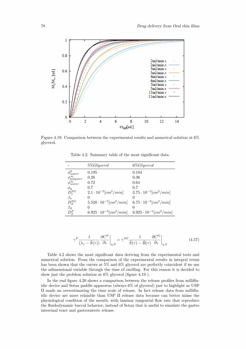
78 Drug delivery from Oral thin films
Figure 4.19: Comparison between the experimental results and numerical solution at 6%glycerol.
Table 4.2: Summary table of the most significant data.
- 5%Glycerol 6%Glycerol
φ0water 0.195 0.184φ∞polymer 0.28 0.36
φ∞water 0.72 0.64φg 0.7 0.7DSGs 2.1 · 10−5[cm2/min] 3.75 · 10−5[cm2/min]
βs 0 0DSGd 5.528 · 10−5[cm2/min] 6.75 · 10−5[cm2/min]
βd 0 0DFd 6.925 · 10−5[cm2/min] 6.925 · 10−5[cm2/min]
γF1
(λz − S(τ))
∂CF
∂ς
∣∣∣∣χ,0
= γSG1
S(τ)− R(τ)
∂CG
∂ς
∣∣∣∣χ,0
(4.57)
Table 4.2 shows the most significant data deriving from the experimental tests andnumerical solution. From the comparison of the experimental results in integral termshas been shown that the curves at 5% and 6% glycerol are perfectly coincident if we usethe adimensional variable through the time of swelling. For this reason it is decided toshow just the problem solution at 6% glycerol (figure 4.19 ).
In the end figure 4.20 shows a comparison between the release profiles from milliflu-idic device and Sotax paddle apparatus (always 6% of glycerol) just to highlight as USPII made an overestimating the time scale of release. In fact release data from milliflu-idic device are more relaiable than USP II release data because can better mime thephysiological condition of the mouth, with laminar tangential flow rate that reproducethe fluidodynamic buccal behavior, instead of Sotax that is useful to simulate the gastrointestinal tract and gastroenteric release.
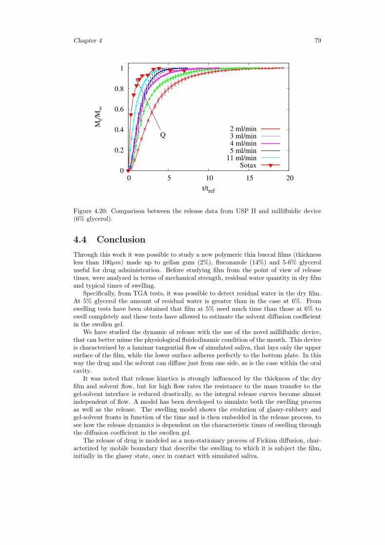
Chapter 4 79
0
0.2
0.4
0.6
0.8
1
0 5 10 15 20
Mt/
M∞
t/tref
Q2 ml/min3 ml/min4 ml/min5 ml/min
11 ml/minSotax
Figure 4.20: Comparison between the release data from USP II and millifluidic device(6% glycerol).
4.4 ConclusionThrough this work it was possible to study a new polymeric thin buccal films (thicknessless than 100µm) made up to gellan gum (2%), fluconazole (14%) and 5-6% glyceroluseful for drug administration. Before studying film from the point of view of releasetimes, were analyzed in terms of mechanical strength, residual water quantity in dry filmand typical times of swelling.
Specifically, from TGA tests, it was possible to detect residual water in the dry film.At 5% glycerol the amount of residual water is greater than in the case at 6%. Fromswelling tests have been obtained that film at 5% need much time than those at 6% toswell completely and these tests have allowed to estimate the solvent diffusion coefficientin the swollen gel.
We have studied the dynamic of release with the use of the novel millifluidic device,that can better mime the physiological fluidodinamic condition of the mouth. This deviceis characterized by a laminar tangential flow of simulated saliva, that lays only the uppersurface of the film, while the lower surface adheres perfectly to the bottom plate. In thisway the drug and the solvent can diffuse just from one side, as is the case within the oralcavity.
It was noted that release kinetics is strongly influenced by the thickness of the dryfilm and solvent flow, but for high flow rates the resistance to the mass transfer to thegel-solvent interface is reduced drastically, so the integral release curves become almostindependent of flow. A model has been developed to simulate both the swelling processas well as the release. The swelling model shows the evolution of glassy-rubbery andgel-solvent fronts in function of the time and is then embedded in the release process, tosee how the release dynamics is dependent on the characteristic times of swelling throughthe diffusion coefficient in the swollen gel.
The release of drug is modeled as a non-stationary process of Fickian diffusion, char-acterized by mobile boundary that describe the swelling to which it is subject the film,initially in the glassy state, once in contact with simulated saliva.

80 Drug delivery from Oral thin films
Chapter 5
Release analysis from HPMCbased erodible thin films
5.1 Introduction
5.1.1 Rapid disintegrating film (RDF)
Many pharmaceutical dosages are administered in the form of pills, granules, powders andliquids. Generally a pill design is for swallowing intact or chewing to deliver a precisedosage of medication to patients. The pills, which include tablets and capsules, areable to retain their shapes under moderate pressure. However some patients particularlypediatric and geriatric patients have difficulty in swallowing or chewing solid dosage forms[298]. Many pediatric and geriatric patients are unwilling to take these solid preparationsdue to fear of choking. Oral fast dissolving drug delivery system (OFDDS) is one suchnovel approach to increase consumer acceptance by virtue of rapid disintegration, selfadministration without water or chewing [299].
It is estimated that 50% of the population is affected by dysphasia which results inhigh incidence of non-compliance and ineffective therapy [300]. To overcome this problem,Oral Disintegrating Tablets (ODTs) were developed which are also known as fast dissolve,rapid dissolve, rapid melt and quick disintegrating tablets. ODTs have been defined as"A solid dosage form containing medicinal substances which disintegrates rapidly, usuallywithin a matter of seconds, when placed upon the tongue".
United States Food and Drug Administration (US FDA) further defines ODTs as solidoral preparations that disintegrate rapidly in the oral cavity, with an in-vitro disintegra-tion time of approximately 30 s or less, when based on the United States Pharmacopeia(USP) disintegration test method or alternative [301]. Oral drug delivery technologyhas improved from conventional dosage forms to modified release dosage forms to oraldisintegrating tablet to the recent development of oral disintegrating films (ODF). MostODTs are fragile and brittle, which need special package for protection during storageand transportation. But the films are flexible, they are not as fragile as ODTs, easytransportation, handling and storage [298].
Oral disintegrating film or strip can be defined as a dosage form that employs a waterdissolving polymer which allows the dosage form to quickly hydrate by saliva, adhereto mucosa, and disintegrate within a few seconds, dissolve and releases medication fororomucosal absorption when placed on the tongue or oral cavity. The sublingual mucosais relatively permeable due to thin membrane and large veins [302].
Dissolvable oral thin films (OTFs) or oral strip (OS) or rapid disintegrating films(RDF) evolved over the past few years from the confection and oral care markets in theform of breath strips and became a novel and widely accepted form by consumers fordelivering vitamins and personal care products.
RDFs are useful in patients, such as pediatric, geriatric, bedridden, or developmen-
81
82 Release analysis from HPMC based erodible thin films
tally disabled, who may face difficulty in swallowing conventional tablets or capsulesand liquid orals or syrup, leading to ineffective therapy, with persistent nausea, suddenepisodes of allergic attacks, or coughing for those who have an active life style [303,304].RDFs are also applicable when local action in the mouth is desirable such as local anes-thetic for toothaches, oral ulcers, cold sores, or teething [305, 306]. Many drugs likecough/cold remedies, sore throat, erectile dysfunction drugs, antihistaminics, antiasth-matics, gastrointestinal disorders, nausea, pain and CNS drugs can be incorporated intothese delivery systems. Other applications include the preparation of caffeine strips,multivitamins, sleeping aid snoring aid, etc.
Fast dissolving oral film when placed in the oral cavity, rapidly disintegrates anddissolves to release the medication without chewing and intake of water [317, 318]. Itgives quick absorption and bioavailability comparable to intravenous administration.
Bioadhesive sublingual formulations [319], such as tablets [320], patches, and films,have been developed using mucoadhesive polymers that can establish a strong adhesivecontact with the mucosa, allowing for an increase in residence time of the delivery systemand optimizing drug bioavailability [321]. The release kinetics of a given drug froma polymeric matrix could be governed predominantly by the polymer morphology andexcipients present in the system [322].
5.1.2 Furosemide features
Furosemide (FUR) is a loop diuretic used orally in the treatment of edematous statesassociated with cardiac, renal, and hepatic failures and in the treatment of hypertension[307]. The usual dosage is 40–120 mg/day.
Data on solubility, oral absorption, and permeability are sufficiently exhaustive toclassify FUR into Class IV of the Biopharmaceutics Classification System. Due to thecarboxyl and sulfonamidic groups in the structure, with pKa of 3.8 and 9.6, respectively[308], FUR shows a very low solubility in water that increases as a function of pH from0.01 mg/mL at pH 2 to 1.9 mg/mL at pH 7.4 [309], determining a higher absorptionin the gastric rather than intestinal tracts. The bioavailability problems, reported asconsequences of variable and erratic gastrointestinal absorption, are probably due tothe low and pH-dependent solubility together with various existing polymorphic forms ofFUR [310]. Indeed, FUR presents different polymorphic forms: four are true polymorphs(I, II, III, IV), two are solvates (IV-DMSO and V-dioxane) and one is an amorphousform [323,324].
It is well known that different polymorphic forms of an active administered in theoral or topical form can modify many properties like solubility, stability, color, com-pressibility, flowability, and workability and as a consequence can cause differences inbioavailability, toxicological safety, clinical effectiveness, and productive efficiency [311].Different approaches have been proposed to enhance FUR absorption and bioavailabilitysuch as co-crystallisation [312,313], solid dispersion [314], microemulsification [315], andsupramolecular complexes formation [316].
A number of techniques are employed to improve solubility of low solubility drugs.Supersaturation is, in fact, a reality; solubility enhancing techniques do not augment thesolubility of insoluble drugs. Rather, these approaches present the drug in a form whichis optimal to its solubility. These techniques include solid dispersion, solvent disposition,co-solvents, salt formation, pH control, micronization, co-grinding, use of surfactants,use of precipitation inhibitors, solid solution, selective adsorption on insoluble carriersand complexation [325,326].
In solvent disposition, solvent free solid dispersion are prepared for solubility en-hancement where dispersion of drug takes place in a highly water soluble matrix wherebythe drug is dispersed in a hydrophilic matrix and solid solution or eutectic mixture isformed [327–332].
In this work, the aim is to try to improve the solubilisation of a greater amount offurosemide using cyclodextrins that is able to make a complex. The release of furosemide
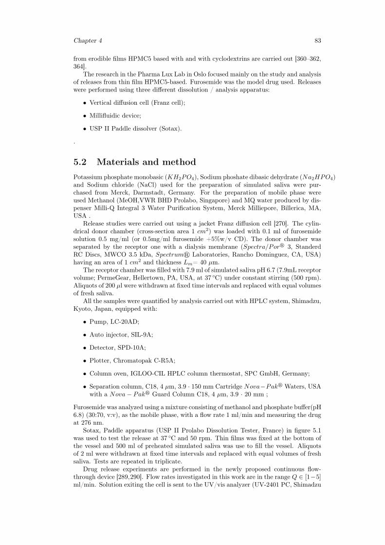
Chapter 4 83
from erodible films HPMC5 based with and with cyclodextrins are carried out [360–362,364].
The research in the Pharma Lux Lab in Oslo focused mainly on the study and analysisof releases from thin film HPMC5-based. Furosemide was the model drug used. Releaseswere performed using three different dissolution / analysis apparatus:
• Vertical diffusion cell (Franz cell);
• Millifluidic device;
• USP II Paddle dissolver (Sotax).
.
5.2 Materials and methodPotassium phosphate monobasic (KH2PO4), Sodium phoshate dibasic dehydrate (Na2HPO4)and Sodium chloride (NaCl) used for the preparation of simulated saliva were pur-chased from Merck, Darmstadt, Germany. For the preparation of mobile phase wereused Methanol (MeOH,VWR BHD Prolabo, Singapore) and MQ water produced by dis-penser Milli-Q Integral 3 Water Purification System, Merck Milliepore, Billerica, MA,USA .
Release studies were carried out using a jacket Franz diffusion cell [270]. The cylin-drical donor chamber (cross-section area 1 cm2) was loaded with 0.1 ml of furosemidesolution 0.5 mg/ml (or 0.5mg/ml furosemide +5%w/v CD). The donor chamber wasseparated by the receptor one with a dialysis membrane (Spectra/Porr 3, StanderdRC Discs, MWCO 3.5 kDa, Spectrumr Laboratories, Rancho Dominguez, CA, USA)having an area of 1 cm2 and thickness Lm= 40 µm.
The receptor chamber was filled with 7.9 ml of simulated saliva pH 6.7 (7.9mL receptorvolume; PermeGear, Hellertown, PA, USA, at 37 ◦C) under constant stirring (500 rpm).Aliquots of 200 µl were withdrawn at fixed time intervals and replaced with equal volumesof fresh saliva.
All the samples were quantified by analysis carried out with HPLC system, Shimadzu,Kyoto, Japan, equipped with:
• Pump, LC-20AD;
• Auto injector, SIL-9A;
• Detector, SPD-10A;
• Plotter, Chromatopak C-R5A;
• Column oven, IGLOO-CIL HPLC column thermostat, SPC GmbH, Germany;
• Separation column, C18, 4 µm, 3.9 · 150 mm Cartridge Nova−Pakr Waters, USAwith a Nova− Pakr Guard Column C18, 4 µm, 3.9 · 20 mm ;
Furosemide was analyzed using a mixture consisting of methanol and phosphate buffer(pH6.8) (30:70, v:v), as the mobile phase, with a flow rate 1 ml/min and measuring the drugat 276 nm.
Sotax, Paddle apparatus (USP II Prolabo Dissolution Tester, France) in figure 5.1was used to test the release at 37 ◦C and 50 rpm. Thin films was fixed at the bottom ofthe vessel and 500 ml of preheated simulated saliva was use to fill the vessel. Aliquotsof 2 ml were withdrawn at fixed time intervals and replaced with equal volumes of freshsaliva. Tests are repeated in triplicate.
Drug release experiments are performed in the newly proposed continuous flow-through device [289,290]. Flow rates investigated in this work are in the range Q ∈ [1−5]ml/min. Solution exiting the cell is sent to the UV/vis analyzer (UV-2401 PC, Shimadzu
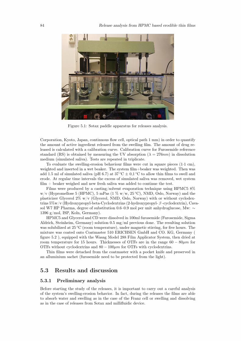
84 Release analysis from HPMC based erodible thin films
Figure 5.1: Sotax paddle apparatus for releases analysis.
Corporation, Kyoto, Japan, continuous flow cell, optical path 1 mm) in order to quantifythe amount of active ingredient released from the swelling film. The amount of drug re-leased is calculated with a calibration curve. Calibration curve for Furosemide referencestandard (RS) is obtained by measuring the UV absorption (λ = 276nm) in dissolutionmedium (simulated saliva). Tests are repeated in triplicate.
To evaluate the swelling-erosion behaviour films were cut in square pieces (1·1 cm),weighted and inserted in a wet beaker. The system film+beaker was weighted. Then wasadd 1.5 ml of simulated saliva (pH 6.7) at 37 ◦C ± 0,1 ◦C to allow thin films to swell anderode. At regular time intervals the excess of simulated saliva was removed, wet systemfilm + beaker weighed and new fresh saliva was added to continue the test.
Films were produced by a casting/solvent evaporation technique using HPMC5 8%w/v (Hypromellose 5 (HPMC), 5 mPas (1 % w/w, 25 ◦C), NMD, Oslo, Norway) and theplasticizer Glycerol 2% w/v (Glycerol, NMD, Oslo, Norway) with or without cyclodex-trins 5%w/v (Hydroxypropyl-beta-Cyclodextrins (2-hydroxypropyl- β -cyclodextrin), Cava-sol W7 HP Pharma, degree of substitution 0.6–0.9 mol per unit anhydroglucose, Mw: ∼1396 g/mol, ISP, Koln, Germany).
HPMC5 and Glycerol and CD were dissolved in 100ml furosemide (Furosemide, SigmaAldrich, Steinheim, Germany) solution 0.5 mg/ml previous done. The resulting solutionwas solubilized at 25 ◦C (room temperature), under magnetic stirring, for five hours. Themixture was coated onto Coatmaster 510 ERICHSEN GmbH and CO. KG, Germany (figure 5.2 ), equipped with the Wasag Model 288 Film Applicator System, then dried atroom temperature for 15 hours. Thicknesses of OTFs are in the range 60 − 80µm forOTFs without cyclodextrins and 80− 100µm for OTFs with cyclodextrins.
Thin films were detached from the coatmaster with a pocket knife and preserved inan alluminium sachet (furosemide need to be protected from the light).
5.3 Results and discussion
5.3.1 Preliminary analysis
Before starting the study of the releases, it is important to carry out a careful analysisof the system’s swelling-erosion behavior. In fact, during the releases the films are ableto absorb water and swelling as in the case of the Franz cell or swelling and dissolvingas in the case of releases from Sotax and millifluidic device.
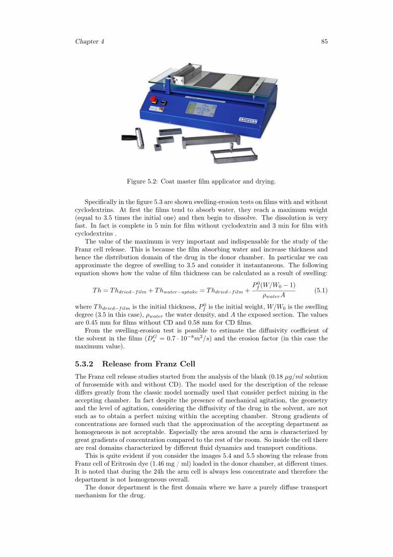
Chapter 4 85
Figure 5.2: Coat master film applicator and drying.
Specifically in the figure 5.3 are shown swelling-erosion tests on films with and withoutcyclodextrins. At first the films tend to absorb water, they reach a maximum weight(equal to 3.5 times the initial one) and then begin to dissolve. The dissolution is veryfast. In fact is complete in 5 min for film without cyclodextrin and 3 min for film withcyclodextrins .
The value of the maximum is very important and indispensable for the study of theFranz cell release. This is because the film absorbing water and increase thickness andhence the distribution domain of the drug in the donor chamber. In particular we canapproximate the degree of swelling to 3.5 and consider it instantaneous. The followingequation shows how the value of film thickness can be calculated as a result of swelling:
Th = Thdried−film + Thwater−uptake = Thdried−film +P 0f (W/W0 − 1)
ρwaterA(5.1)
where Thdried−film is the initial thickness, P 0f is the initial weight, W/W0 is the swelling
degree (3.5 in this case), ρwater the water density, and A the exposed section. The valuesare 0.45 mm for films without CD and 0.58 mm for CD films.
From the swelling-erosion test is possible to estimate the diffusivity coefficient ofthe solvent in the films (DG
s = 0.7 · 10−8m2/s) and the erosion factor (in this case themaximum value).
5.3.2 Release from Franz CellThe Franz cell release studies started from the analysis of the blank (0.18 µg/ml solutionof furosemide with and without CD). The model used for the description of the releasediffers greatly from the classic model normally used that consider perfect mixing in theaccepting chamber. In fact despite the presence of mechanical agitation, the geometryand the level of agitation, considering the diffusivity of the drug in the solvent, are notsuch as to obtain a perfect mixing within the accepting chamber. Strong gradients ofconcentrations are formed such that the approximation of the accepting department ashomogeneous is not acceptable. Especially the area around the arm is characterized bygreat gradients of concentration compared to the rest of the room. So inside the cell thereare real domains characterized by different fluid dynamics and transport conditions.
This is quite evident if you consider the images 5.4 and 5.5 showing the release fromFranz cell of Eritrosin dye (1.46 mg / ml) loaded in the donor chamber, at different times.It is noted that during the 24h the arm cell is always less concentrate and therefore thedepartment is not homogeneous overall.
The donor department is the first domain where we have a purely diffuse transportmechanism for the drug.
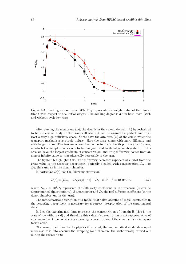
86 Release analysis from HPMC based erodible thin films
-0.5
0
0.5
1
1.5
2
2.5
3
3.5
4
0 1 2 3 4 5
W(t
)/W
0
t [min]
film furosemidefilm furosemide + CD
3.5
Figure 5.3: Swelling erosion tests. W (t)/W0 represents the weight value of the film attime t with respect to the initial weight. The swelling degree is 3.5 in both cases (withand without cyclodextrins)
After passing the membrane (D), the drug is in the second domain (A) hypothesizedto be the central body of the Franz cell where it can be assumed a perfect mix or atleast a very high diffusivity space. So we have the arm area (C) of the cell in which thetransport mechanism is purely diffuse. Here the drug comes with more difficulty andwith longer times. The two zones are then connected by a fourth portion (B) of space,in which the samples comes out to be analyzed and fresh saliva reintegrated. In thisarea we have the largest gradients of concentration, and drug diffusivity passes from analmost infinite value to that physically detectable in the arm.
The figure 5.6 highlights this. The diffusivity decreases exponentially D(s) from thegreat value in the acceptor department, perfectly blended with concentration Cres, toD0, the same as in the donor chamber.
In particular D(s) has the following expression:
D(s) = (Dres −D0)exp(−βs) +D0 with β = 1000m−1. (5.2)
where Dres ' 105D0 represents the diffusivity coefficient in the reservoir (it can beapproximated almost infinity), β a parameter and D0 the real diffusion coefficient (in thedonor chamber and in the arm).
The mathematical description of a model that takes account of these inequalities inthe accepting department is necessary for a correct interpretation of the experimentaldata.
In fact the experimental data represent the concentration of domain B (this is thezone of the withdrawal) and therefore this value of concentration is not representative ofall compartment. So considering an average concentration of the chamber is an interpre-tation error.
Of course, in addition to the physics illustrated, the mathematical model developedmust also take into account the sampling (and therefore the withdrawals) carried outduring the release tests.
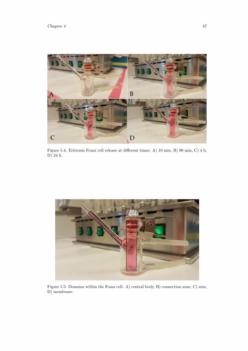
Chapter 4 87
Figure 5.4: Eritrosin Franz cell release at different times: A) 10 min, B) 90 min, C) 4 h,D) 24 h.
Figure 5.5: Domains within the Franz cell. A) central body, B) connection zone, C) arm,D) membrane.
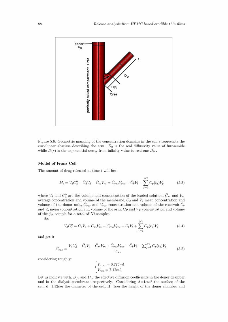
88 Release analysis from HPMC based erodible thin films
Figure 5.6: Geometric mapping of the concentration domains in the cell:s represents thecurvilinear abscissa describing the arm. D0 is the real diffusivity value of furosemidewhile D(s) is the exponential decay from infinity value to real one D0 .
Model of Franz Cell
The amount of drug released at time t will be:
Mt = VdC0d − CdVd − CmVm = CresVres + CbVb +
Ni∑j=1
Cp(tj)Vp (5.3)
where Vd and C0d are the volume and concentration of the loaded solution, Cm and Vm
average concentration and volume of the membrane, Cd and Vd mean concentration andvolume of the donor unit, Cres and Vres concentration and volume of the reservoir,Cband Vb mean concentration and volume of the arm, Cp and V p concentration and volumeof the jth sample for a total of Ni samples.
So:
VdC0d = CdVd + CmVm + CresVres + CbVb +
Ni∑j=1
Cp(tj)Vp (5.4)
and get it:
Cres =VdC
0d − CdVd − CmVm + CresVres − CbVb −
∑Nij=1 Cp(tj)Vp
Vres(5.5)
considering roughly: {Varm = 0.775ml
Vres = 7.12ml
Let us indicate with, Df , and Dm the effective diffusion coefficients in the donor chamberand in the dialysis membrane, respectively. Considering A=1cm2 the surface of thecell, d=1.12cm the diameter of the cell, H=1cm the height of the donor chamber and
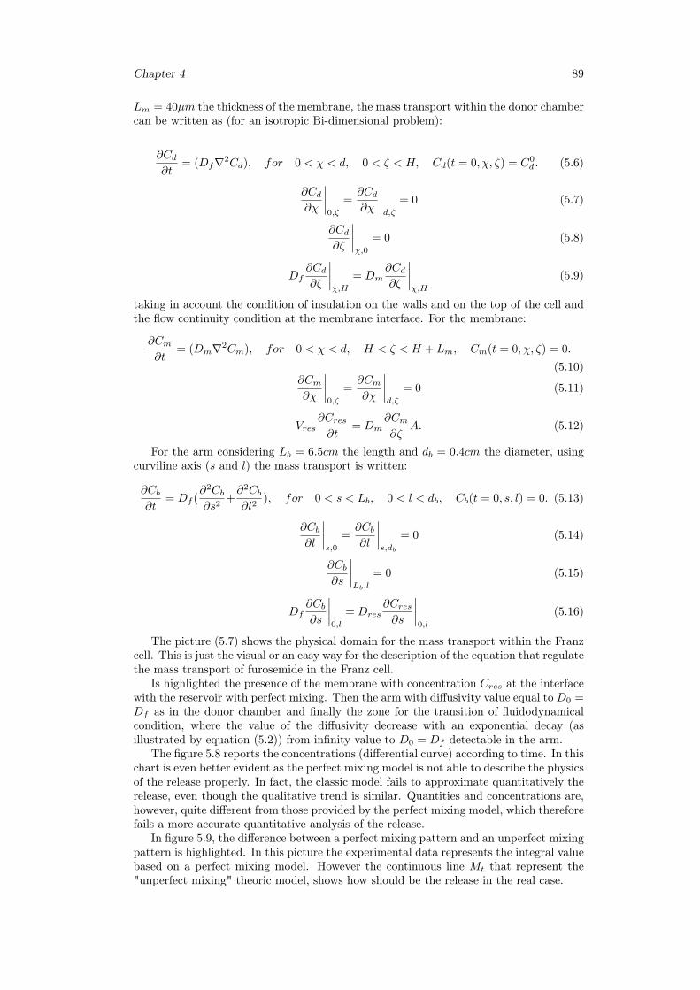
Chapter 4 89
Lm = 40µm the thickness of the membrane, the mass transport within the donor chambercan be written as (for an isotropic Bi-dimensional problem):
∂Cd∂t
= (Df∇2Cd), for 0 < χ < d, 0 < ζ < H, Cd(t = 0, χ, ζ) = C0d . (5.6)
∂Cd∂χ
∣∣∣∣0,ζ
=∂Cd∂χ
∣∣∣∣d,ζ
= 0 (5.7)
∂Cd∂ζ
∣∣∣∣χ,0
= 0 (5.8)
Df∂Cd∂ζ
∣∣∣∣χ,H
= Dm∂Cd∂ζ
∣∣∣∣χ,H
(5.9)
taking in account the condition of insulation on the walls and on the top of the cell andthe flow continuity condition at the membrane interface. For the membrane:
∂Cm∂t
= (Dm∇2Cm), for 0 < χ < d, H < ζ < H + Lm, Cm(t = 0, χ, ζ) = 0.
(5.10)∂Cm∂χ
∣∣∣∣0,ζ
=∂Cm∂χ
∣∣∣∣d,ζ
= 0 (5.11)
Vres∂Cres∂t
= Dm∂Cm∂ζ
A. (5.12)
For the arm considering Lb = 6.5cm the length and db = 0.4cm the diameter, usingcurviline axis (s and l) the mass transport is written:
∂Cb∂t
= Df (∂2Cb∂s2
+∂2Cb∂l2
), for 0 < s < Lb, 0 < l < db, Cb(t = 0, s, l) = 0. (5.13)
∂Cb∂l
∣∣∣∣s,0
=∂Cb∂l
∣∣∣∣s,db
= 0 (5.14)
∂Cb∂s
∣∣∣∣Lb,l
= 0 (5.15)
Df∂Cb∂s
∣∣∣∣0,l
= Dres∂Cres∂s
∣∣∣∣0,l
(5.16)
The picture (5.7) shows the physical domain for the mass transport within the Franzcell. This is just the visual or an easy way for the description of the equation that regulatethe mass transport of furosemide in the Franz cell.
Is highlighted the presence of the membrane with concentration Cres at the interfacewith the reservoir with perfect mixing. Then the arm with diffusivity value equal to D0 =Df as in the donor chamber and finally the zone for the transition of fluidodynamicalcondition, where the value of the diffusivity decrease with an exponential decay (asillustrated by equation (5.2)) from infinity value to D0 = Df detectable in the arm.
The figure 5.8 reports the concentrations (differential curve) according to time. In thischart is even better evident as the perfect mixing model is not able to describe the physicsof the release properly. In fact, the classic model fails to approximate quantitatively therelease, even though the qualitative trend is similar. Quantities and concentrations are,however, quite different from those provided by the perfect mixing model, which thereforefails a more accurate quantitative analysis of the release.
In figure 5.9, the difference between a perfect mixing pattern and an unperfect mixingpattern is highlighted. In this picture the experimental data represents the integral valuebased on a perfect mixing model. However the continuous line Mt that represent the"unperfect mixing" theoric model, shows how should be the release in the real case.
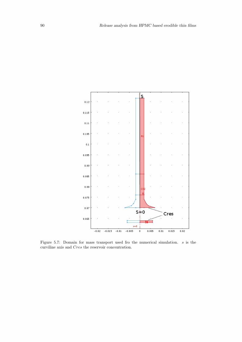
90 Release analysis from HPMC based erodible thin films
Figure 5.7: Domain for mass transport used fro the numerical simulation. s is thecurviline axis and Cres the reservoir concentration.
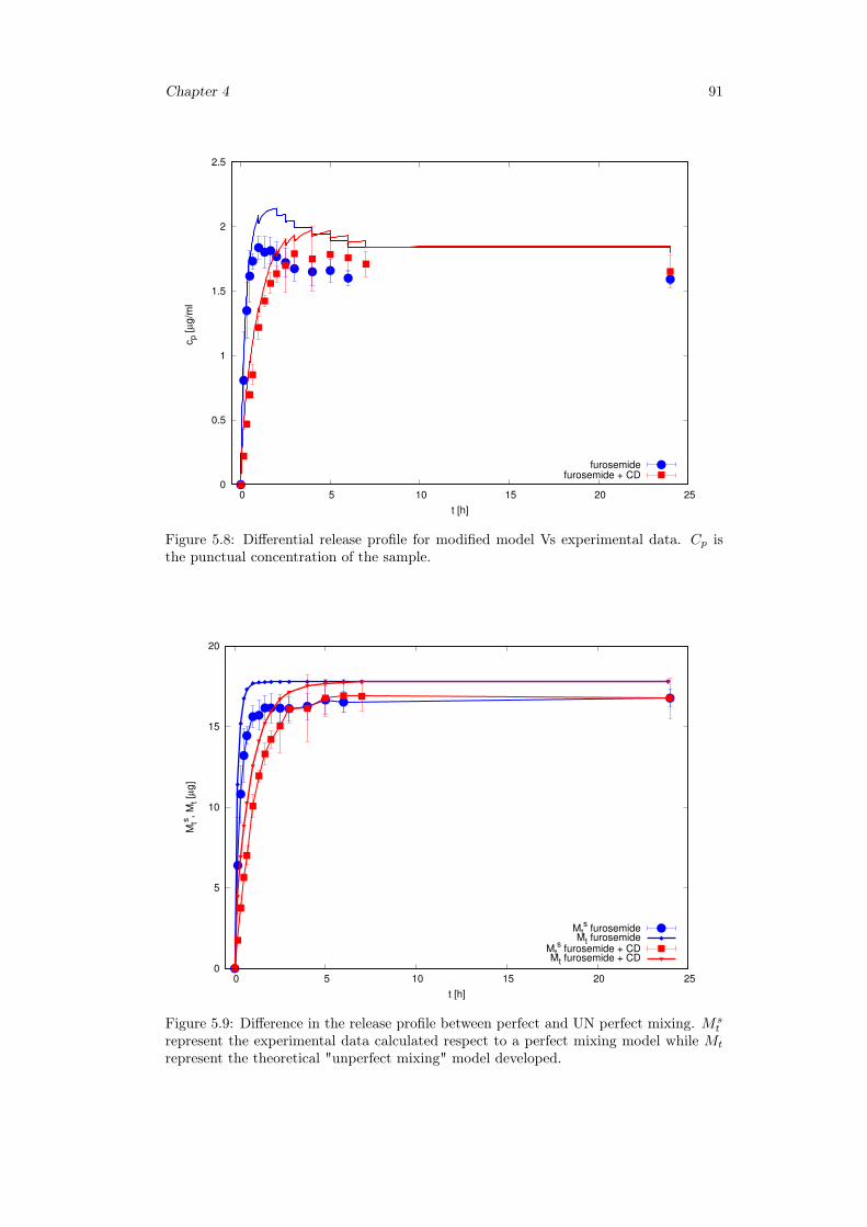
Chapter 4 91
0
0.5
1
1.5
2
2.5
0 5 10 15 20 25
cp [
µg/m
l
t [h]
furosemidefurosemide + CD
Figure 5.8: Differential release profile for modified model Vs experimental data. Cp isthe punctual concentration of the sample.
0
5
10
15
20
0 5 10 15 20 25
Mts
, M
t [µ
g]
t [h]
Mts furosemide
Mt furosemideMt
s furosemide + CD
Mt furosemide + CD
Figure 5.9: Difference in the release profile between perfect and UN perfect mixing. Mst
represent the experimental data calculated respect to a perfect mixing model while Mt
represent the theoretical "unperfect mixing" model developed.
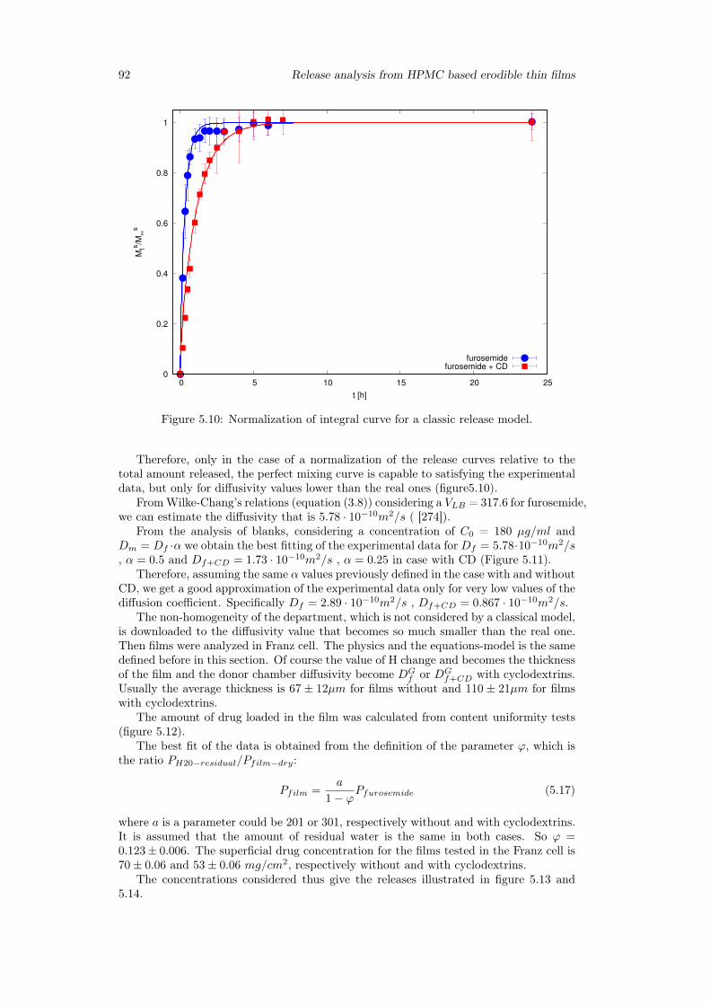
92 Release analysis from HPMC based erodible thin films
0
0.2
0.4
0.6
0.8
1
0 5 10 15 20 25
Mts
/M∞
s
t [h]
furosemidefurosemide + CD
Figure 5.10: Normalization of integral curve for a classic release model.
Therefore, only in the case of a normalization of the release curves relative to thetotal amount released, the perfect mixing curve is capable to satisfying the experimentaldata, but only for diffusivity values lower than the real ones (figure5.10).
FromWilke-Chang’s relations (equation (3.8)) considering a VLB = 317.6 for furosemide,we can estimate the diffusivity that is 5.78 · 10−10m2/s ( [274]).
From the analysis of blanks, considering a concentration of C0 = 180 µg/ml andDm = Df ·α we obtain the best fitting of the experimental data for Df = 5.78·10−10m2/s, α = 0.5 and Df+CD = 1.73 · 10−10m2/s , α = 0.25 in case with CD (Figure 5.11).
Therefore, assuming the same α values previously defined in the case with and withoutCD, we get a good approximation of the experimental data only for very low values of thediffusion coefficient. Specifically Df = 2.89 · 10−10m2/s , Df+CD = 0.867 · 10−10m2/s.
The non-homogeneity of the department, which is not considered by a classical model,is downloaded to the diffusivity value that becomes so much smaller than the real one.Then films were analyzed in Franz cell. The physics and the equations-model is the samedefined before in this section. Of course the value of H change and becomes the thicknessof the film and the donor chamber diffusivity become DG
f or DGf+CD with cyclodextrins.
Usually the average thickness is 67 ± 12µm for films without and 110 ± 21µm for filmswith cyclodextrins.
The amount of drug loaded in the film was calculated from content uniformity tests(figure 5.12).
The best fit of the data is obtained from the definition of the parameter ϕ, which isthe ratio PH20−residual/Pfilm−dry:
Pfilm =a
1− ϕPfurosemide (5.17)
where a is a parameter could be 201 or 301, respectively without and with cyclodextrins.It is assumed that the amount of residual water is the same in both cases. So ϕ =0.123± 0.006. The superficial drug concentration for the films tested in the Franz cell is70± 0.06 and 53± 0.06 mg/cm2, respectively without and with cyclodextrins.
The concentrations considered thus give the releases illustrated in figure 5.13 and5.14.
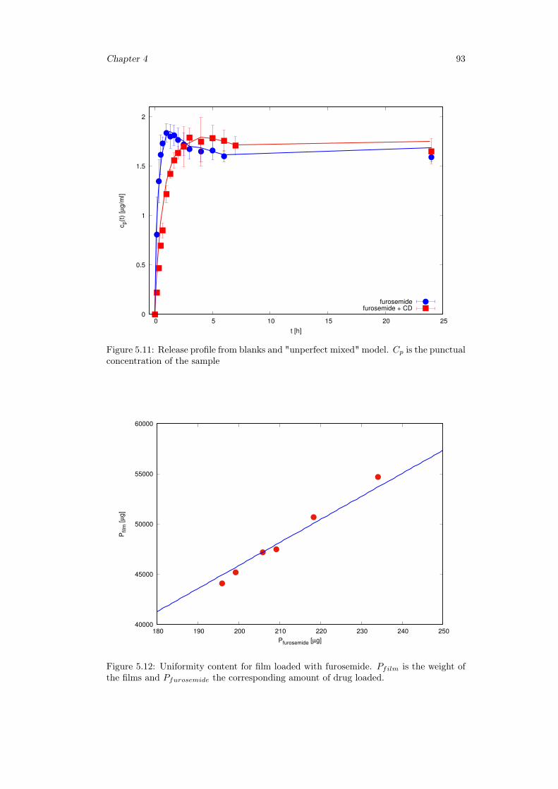
Chapter 4 93
0
0.5
1
1.5
2
0 5 10 15 20 25
cp(t
) [µ
g/m
l]
t [h]
furosemidefurosemide + CD
Figure 5.11: Release profile from blanks and "unperfect mixed" model. Cp is the punctualconcentration of the sample
40000
45000
50000
55000
60000
180 190 200 210 220 230 240 250
Pfilm
[µ
g]
Pfurosemide [µg]
Figure 5.12: Uniformity content for film loaded with furosemide. Pfilm is the weight ofthe films and Pfurosemide the corresponding amount of drug loaded.
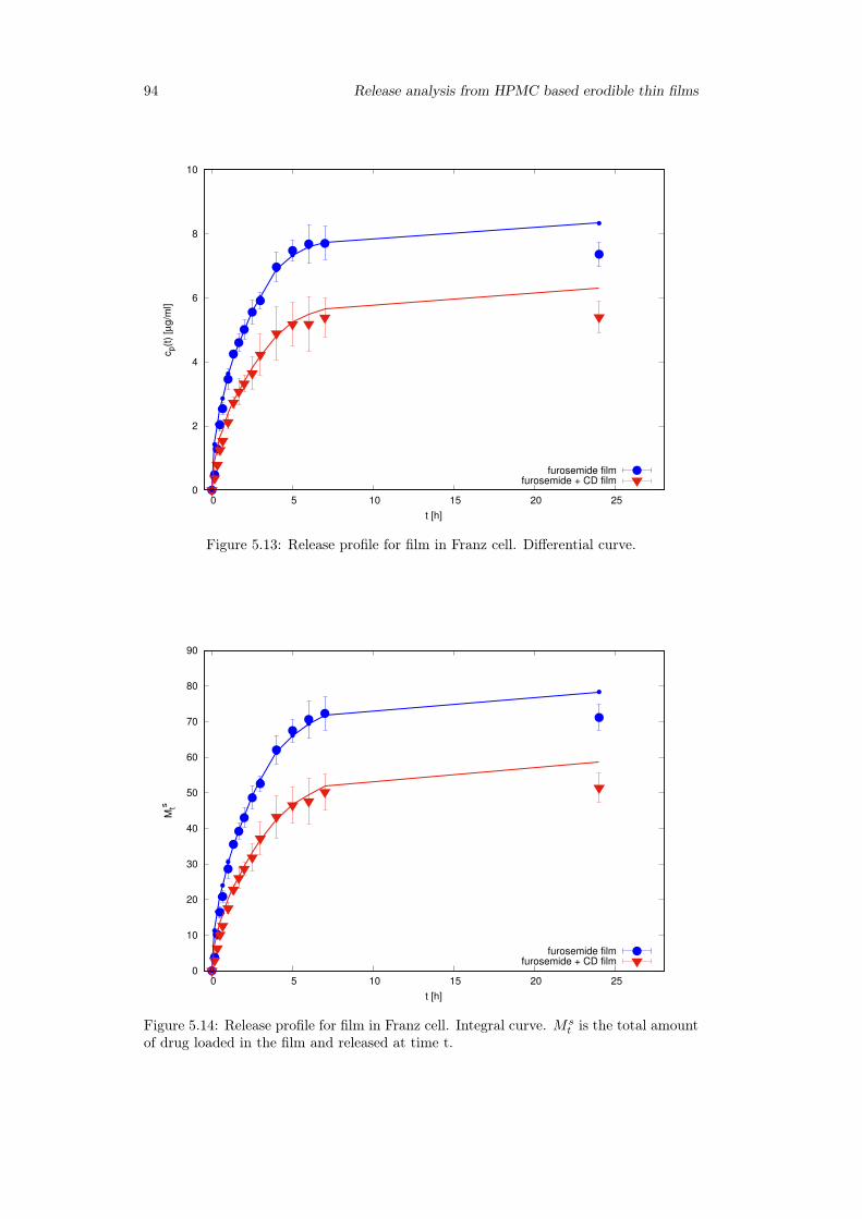
94 Release analysis from HPMC based erodible thin films
0
2
4
6
8
10
0 5 10 15 20 25
cp(t
) [µ
g/m
l]
t [h]
furosemide filmfurosemide + CD film
Figure 5.13: Release profile for film in Franz cell. Differential curve.
0
10
20
30
40
50
60
70
80
90
0 5 10 15 20 25
Mts
t [h]
furosemide filmfurosemide + CD film
Figure 5.14: Release profile for film in Franz cell. Integral curve. Mst is the total amount
of drug loaded in the film and released at time t.
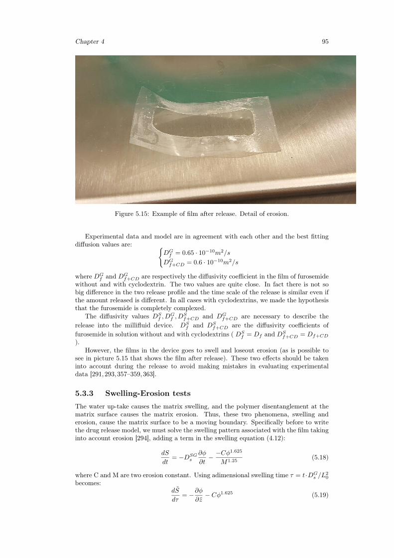
Chapter 4 95
Figure 5.15: Example of film after release. Detail of erosion.
Experimental data and model are in agreement with each other and the best fittingdiffusion values are: {
DGf = 0.65 · 10−10m2/s
DGf+CD = 0.6 · 10−10m2/s
where DGf and DG
f+CD are respectively the diffusivity coefficient in the film of furosemidewithout and with cyclodextrin. The two values are quite close. In fact there is not sobig difference in the two release profile and the time scale of the release is similar even ifthe amount released is different. In all cases with cyclodextrins, we made the hypothesisthat the furosemide is completely complexed.
The diffusivity values DSf , D
Gf , D
Sf+CD and DG
f+CD are necessary to describe therelease into the millifluid device. DS
f and DSf+CD are the diffusivity coefficients of
furosemide in solution without and with cyclodextrins ( DSf = Df and DS
f+CD = Df+CD
).However, the films in the device goes to swell and loseout erosion (as is possible to
see in picture 5.15 that shows the film after release). These two effects should be takeninto account during the release to avoid making mistakes in evaluating experimentaldata [291,293,357–359,363].
5.3.3 Swelling-Erosion tests
The water up-take causes the matrix swelling, and the polymer disentanglement at thematrix surface causes the matrix erosion. Thus, these two phenomena, swelling anderosion, cause the matrix surface to be a moving boundary. Specifically before to writethe drug release model, we must solve the swelling pattern associated with the film takinginto account erosion [294], adding a term in the swelling equation (4.12):
dS
dt= −DSG
s
∂φ
∂t− −Cφ
1.625
M1.25(5.18)
where C and M are two erosion constant. Using adimensional swelling time τ = t·DGs /L
20
becomes:dS
dτ= −∂φ
∂z− Cφ1.625 (5.19)
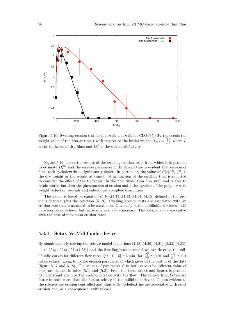
96 Release analysis from HPMC based erodible thin films
0
0.5
1
1.5
2
2.5
3
3.5
4
0 200 400 600 800 1000 1200
W(τ
)/W
0
τ=t/tref
film furosemidefilm furosemide + CD
Figure 5.16: Swelling-erosion test for film with and without CD.W (t)/W0 represents theweight value of the film at time t with respect to the initial weight. tref = L2
DGs
where Lis the thickness of dry films and DG
s is the solvent diffusivity.
Figure 5.16, shows the results of the swelling/erosion tests from which it is possibleto estimate DSG
s and the erosion parameter C. In this picture is evident that erosion offilms with cyclodextrin is significantly faster. In particular, the value of P (t)/P0 (P0 isthe dry weight or the weight at time t=0) in function of the swelling time is reportedto consider the effect of the thickness. In the first times, thin film swell and is able toretain water, but then the phenomenon of erosion and disintegration of the polymer withweight reduction prevails and subsequent complete dissolution.
The model is based on equation (4.10),(4.11),(4.13),(4.14),(4.15) defined in the pre-vious chapter, plus the equation (5.19). Swelling/erosion tests are associated with anerosion rate that is assumed to be maximum. Obviously in the millifluidic device we willhave erosion rates lower but increasing as the flow increase. The Sotax may be associatedwith the case of maximum erosion rates.
5.3.4 Sotax Vs Millifluidic device
By simultaneously solving the release model (equations (4.18),(4.20),(4.21),(4.22),(4.23),
(4.25),(4.26),(4.27),(4.28)) and the Swelling/erosion model we can describe the mil-
lifluidic curves for different flow rates Q ∈ [1− 5] ml/min (for DGf
DGs' 0.01 and DS
f
DGs' 0.1
ratios values), going to fix the erosion parameter C which gives us the best fit of the data(figure 5.17 and 5.18). The values of parameter C in both cases (for different value offlow) are defined in table (5.1) and (5.2). From the these tables and figures is possibleto understand again as the erosion increase with the flow. The release from Sotax arefaster in both cases than the fastest release in the millifluidic device. Is also evident asthe releases are erosion-controlled and films with cyclodextrins are associated with swifterosion and, as a consequence, swift release.
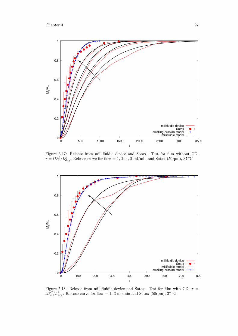
Chapter 4 97
0
0.2
0.4
0.6
0.8
1
0 500 1000 1500 2000 2500 3000 3500
Mτ/M
∞
τ
millifluidic deviceSotax
swelling-erosion modelmillifluidic model
Figure 5.17: Release from millifluidic device and Sotax. Test for film without CD.τ = tDG
s /L2dry. Release curve for flow = 1, 2, 4, 5 ml/min and Sotax (50rpm), 37 ◦C
0
0.2
0.4
0.6
0.8
1
0 100 200 300 400 500 600 700 800
Mτ/M
∞
τ
millifluidic deviceSotax
millifluidic modelswelling-erosion model
Figure 5.18: Release from millifluidic device and Sotax. Test for film with CD. τ =tDG
s /L2dry. Release curve for flow = 1, 3 ml/min and Sotax (50rpm), 37 ◦C
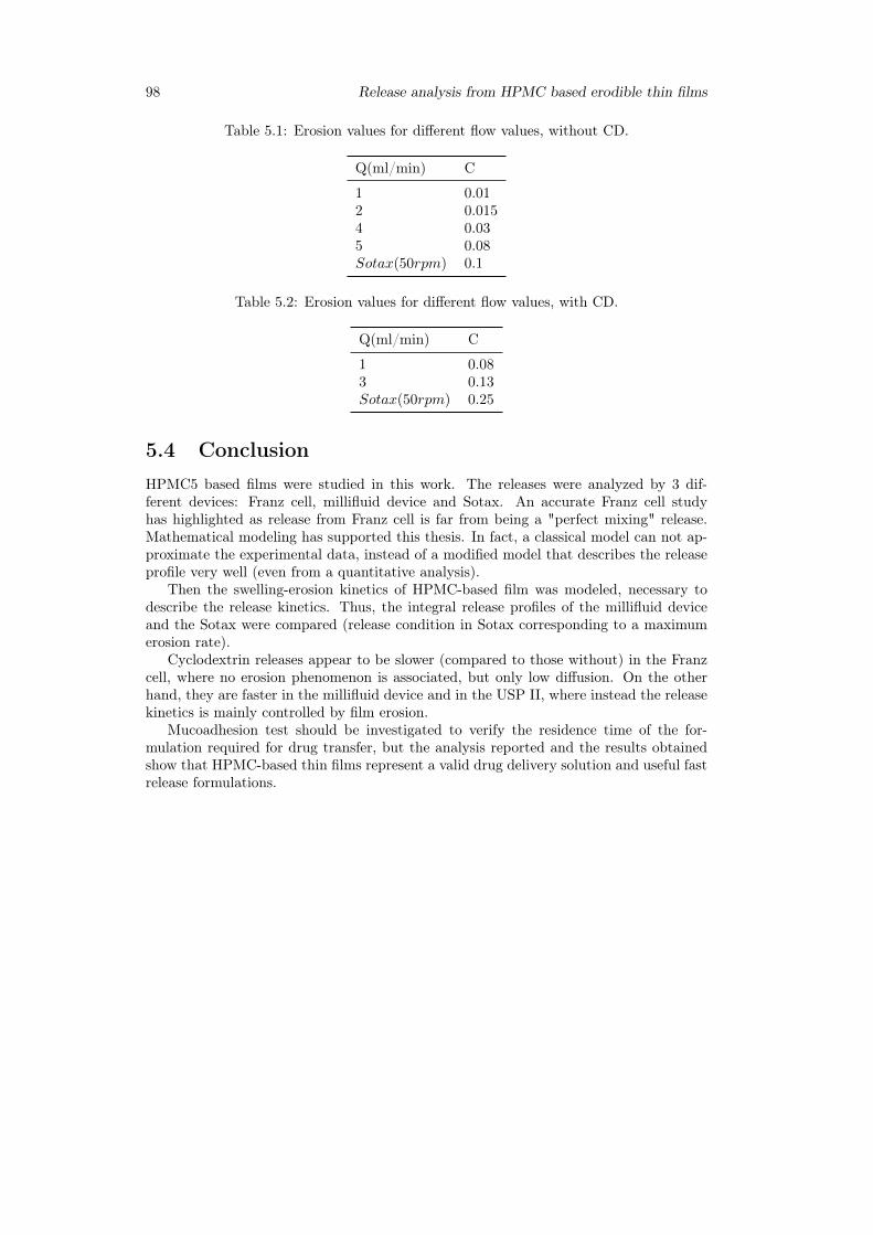
98 Release analysis from HPMC based erodible thin films
Table 5.1: Erosion values for different flow values, without CD.
Q(ml/min) C
1 0.012 0.0154 0.035 0.08Sotax(50rpm) 0.1
Table 5.2: Erosion values for different flow values, with CD.
Q(ml/min) C
1 0.083 0.13Sotax(50rpm) 0.25
5.4 ConclusionHPMC5 based films were studied in this work. The releases were analyzed by 3 dif-ferent devices: Franz cell, millifluid device and Sotax. An accurate Franz cell studyhas highlighted as release from Franz cell is far from being a "perfect mixing" release.Mathematical modeling has supported this thesis. In fact, a classical model can not ap-proximate the experimental data, instead of a modified model that describes the releaseprofile very well (even from a quantitative analysis).
Then the swelling-erosion kinetics of HPMC-based film was modeled, necessary todescribe the release kinetics. Thus, the integral release profiles of the millifluid deviceand the Sotax were compared (release condition in Sotax corresponding to a maximumerosion rate).
Cyclodextrin releases appear to be slower (compared to those without) in the Franzcell, where no erosion phenomenon is associated, but only low diffusion. On the otherhand, they are faster in the millifluid device and in the USP II, where instead the releasekinetics is mainly controlled by film erosion.
Mucoadhesion test should be investigated to verify the residence time of the for-mulation required for drug transfer, but the analysis reported and the results obtainedshow that HPMC-based thin films represent a valid drug delivery solution and useful fastrelease formulations.
Chapter 6
Preventing drug crystallization inglycerol-plasticized gellan gumthin films
6.1 Introduction
The design of efficient films as carriers for drug delivery applications requires a properselection of the polymer and excipients used for their fabrication as they can affectthe ability of the films to swell, degrade and modulate the release of the therapeuticmolecule included in the formulation [333, 334]. The type of polymer can also influencethe mechanical properties of the film produced that should be robust enough to ensureexcellent resistance during handling, and application to the target site.
A large variety of film-forming polymers have been investigated over the last decade,and among them, gellan gum, an anionic and linear biopolymer produced by Pseu-domonas elodea, presents a set of unique properties that make this polysaccharide avalid option for the fabrication of films. Specifically, gellan gum has attracted much at-tention in both academic and industrial research because of its biocompatibility as well asits gelling, texturizing, thickening, emulsifying, suspending, stabilizing and film-formingproperties [335,336].
Gellan gum films have been investigated in a great variety of applications rangingfrom protective coatings to preserve the integrity of food [337–340] to more biomedicalrelated fields. For instance, gellan gum-based films have been studied as protective andbiodegradable film in wound healing [341,342] and bone regeneration [343]. The uniqueproperties of gellan gum films should be particularly beneficial also for the design of drugdelivery systems, however their application in this field is still almost unexplored. Infact, only few works have investigated the inclusion of an active principle in gellan gumfilms and their application as dosage forms [344].
These premises have motivated this study on gellan gum-based thin monolayered filmas potential materials for drug delivery applications. Particular attention was focused onthe homogeneous distribution of the active principle within the polymeric thin films, asit represents the main challenge for this type of formulation when used for drug admin-istration [344]. In fact, both the reduced size and thickness characteristics of the thinfilms as well as the large number of excipients used in their formulation, including sol-uble polymers, plasticizers, preservatives, may severely limit the loading levels capacityof the dosage form. Uncontrolled crystallization of drug upon fabrication or storage isfrequently described for this kind of delivery systems, especially in all that cases wherea high dose of the active molecule is required. High drug loadings throughout the hy-drophilic polymeric system may lead to aggregation processes with the formation offractal-shaped aggregates randomly distributes within the matrix, which adversely affect
99
100 Preventing drug crystallization in glycerol-plasticized gellan gum thin films
the uniformity of the resulting film [345,346].Moreover, considering that most of the polymers used for film fabrication are hy-
drophilic macromolecules, as it is the case for gellan gum, the always-troubling integrationof drugs within polymeric films becomes particularly critical for lipophilic molecules [347].Upon fabrication and storage, uncontrolled crystallization and crystal growth of the drugare frequently facilitated by the short diffusion distances of molecules embedded withinthin films, therefore the resulting fractal patterns formed in thin polymer films are oftenrelated to diffusion-controlled growth processes. If the active pharmaceutical ingredientis not freely soluble in the polymer and is present at a supersaturated concentration,then it may phase-separate from the polymer and subsequently crystallize. Such effectspotentially cause inhomogeneous drug distribution within drug-loaded films affectinguniformity of the system as well as drug release kinetics and physical stability duringstorage.
Casting, solidification processing and drying conditions as well as the right drug-polymer-plasticizer combinations can have a significant impact on the homogeneous dis-tribution of the drug in the dried final product [348]. Therefore, from a pharmaceuticalperspective, the stability of the film and the investigation of strategies aimed to avoiddrug nucleation and crystal growth as well as inhomogeneous distribution of the thera-peutic molecule within the matrix deserve special attention as these aspects are of criticalimportance for the development of commercially viable formulations.
To this end, process conditions and bulk materials characteristics, such as the viscosityof the polymeric systems prior to drying as well as the drying conditions, need to be deeplyinvestigated as they have a contribution in preventing inhomogeneous drug distribution inthe final dry product. These critical aspects have motivated a study on gellan gum basedthin monolayered film as potential materials for drug delivery applications. Film castingmethod was used as preliminary screening technique to determine the optimum ratioamong drug, polymer and plasticizer in order to overcome diffusion limited aggregation(DLA) phenomena during fabrication and storage.
Fluconazole (F) and glycerol (Gly) were used as BCS I model drug and plasticizer,respectively. The manufacturing process was optimized monitoring some critical param-eters including the rheological properties of the starting polymeric solutions, air bubblesentrapped, residual water in the final films and drying rate. The physical appearance,thickness, mechanical and release properties of the resulting films were thoroughly inves-tigated.
6.2 Materials and method
6.2.1 Materials
Fluconazole [C13H12F2N6O, 1H−1, 2, 4−Triazole−1−ethanol, α−(2, 4−difluorophenyl)−α − (1H − 1, 2, 4 − triazol − 1 −methyl], gellan gum and glycerol used in the presentstudy were purchased from Sigma Aldrich. Cellulose membrane filters were obtainedfrom Medicell International. Methanol (CH3OH), glacial acetic acid (CH3COOH),bidistilled water (for HPLC), potassium dihydrogen phosphate (KH2PO4), di-sodiumhydrogen phosphate dehydrate (Na2HPO4), sodium chloride (NaCl) and hydrochloricacid (HCl), (used to prepare simulated saliva, pH= 6.7), were supplied by Carlo ErbaReagents. HP − β − CD was purchased from Roquette.
6.2.2 Preparation of polymeric films
Films were produced by casting polymeric solutions (6 ml) containing constant concen-tration of GG (2% w/v) and different amounts of the glycerol, ranging from 0.5% to6% w/v. In specific, the following GG:Gly weight ratios were investigated: 1:0; 1:0.25;1:0.5; 1:1; 1:1.5; 1:2; 1:2.5 and 1:3 (w/w). For film preparation, GG and glycerol weredissolved in double distilled water and solubilized at 60 ◦C , for 5 hours under mild mag-
Chapter 6 101
netic stirring to avoid air bubble incorporation. The hot polymeric mixtures were pouredonto leveled silicone plates (diameter = 5.6 cm), let set and then dried in an oven at theconstant temperature of 40 ◦C ± 2 ◦C for 15 hours.
The same procedure was followed to prepare fluconazole-loaded thin films and, in thiscase, 6 ml of 9.25 mM fluconazole solution in water were used to dissolve the differentGG:Gly mixtures, before the drying process.
All the samples were labelled as OTFX , where X indicate the amount of Gly usedfor film preparation respect to GG. Instead, OTFXF was used for films containing alsofluconazole. Other samples were prepared including HP−β−CD in the formulation. Anequimolar amount of the selected cyclodextrin and fluconazole was used for the prepara-tion of OTFCD films.
6.2.3 Preparation of inclusion complex cyclodextrins-drugBinary complexes between fluconazole and HP-β-CD are prepared by the kneading tech-nique or lyophilization. In the first case, equimolar amounts of the two components aretriturated in mortar until a homogeneous mixture is obtained. To this, 0.5 ml of a 50:50(v / v) ethanol-water mixture is added and the mixture obtained, after mixing in a mor-tar for another 30 minutes, is placed in a stove for 24 hours at temperature of 70 ◦C. Theproduct obtained, after complete drying, is again reduced to powder.
Binary system fluconazole/HP-β-CD were produced even for lyophilization. A sto-ichiometric amount of drug was added to a HP-β-CD solution in order to obtain anequimolar solution 1:1 of this two component. The solution obtained was mixed for 24hat 25 ◦C and then freezed at −30 ◦C. At the end the solution was lyofilizated for the timethat the operation need to complete.
6.2.4 Rheological studiesRheological experiments were carried out with a Haake Rheo Stress 300 RotationalRheometer (Germany) equipped with a Haake DC10 thermostat. Flow curves of all thepolymeric solutions were obtained with a cone-plate geometry in the range of 0.01–1000Pa, working at 60 ◦C ± 0,1 ◦C. The effect of temperature on the viscoelastic propertiesof the polymeric mixtures was also investigated through temperature sweep analysis inthe range 60 ◦C - 30 ◦C. All the experiments were carried out at least in triplicate.
6.2.5 Thickness measurementsThickness of dry films was measured by means of a Mitutoyo Digimatic Micrometer,characterized by an instrument error ±2µm. Measurements were taken at least at threedifferent points of each film.
6.2.6 Thermogravimetric analysisThermogravimetric analyses were carried out using a Q600 TGA (TA Instruments). Sam-ples of the films (30mg) were put in open aluminum pans and submitted to three heat-ing/cooling cycles in the temperature range from 25 ◦C - 120 ◦C under nitrogen atmo-sphere (5ml/min). Thermograms were recorded at the constant heating rate of 5 ◦C/min.
6.2.7 Differential scanning calorimetryCalorimetric measurements were carried out using a DSC131 (Setaram, France) differ-ential scanning calorimeter. Samples (5mg) of anhydrous dust fluconazole, freeze-driedfluconazole, buccal film of fluconazole, gellan and glycerol with different concentrationswere weighted in sealed aluminum pans. Then were examined at three heating/coolingcycles in a temperature range from 25 ◦C - 170 ◦C, flowing nitrogen atmosphere (20ml/min). Thermograms were recorded at the constant heating rate of 5 ◦C/min. Anempty aluminum pan was used as reference.
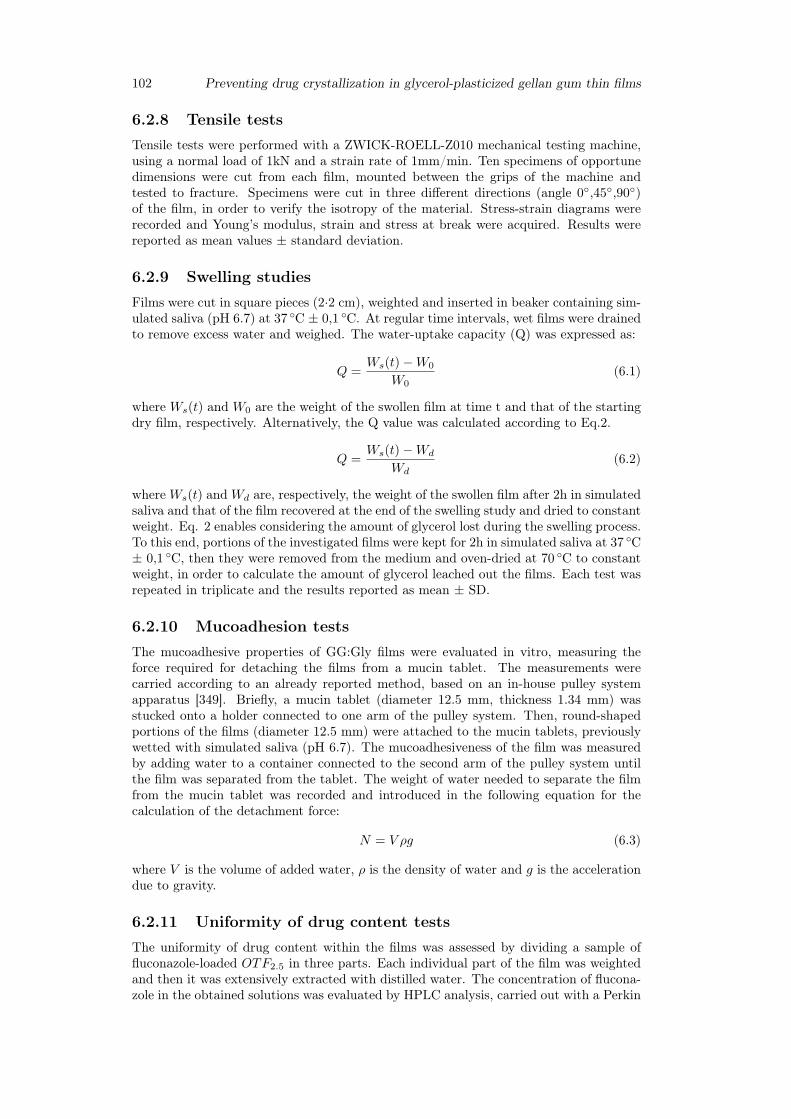
102 Preventing drug crystallization in glycerol-plasticized gellan gum thin films
6.2.8 Tensile testsTensile tests were performed with a ZWICK-ROELL-Z010 mechanical testing machine,using a normal load of 1kN and a strain rate of 1mm/min. Ten specimens of opportunedimensions were cut from each film, mounted between the grips of the machine andtested to fracture. Specimens were cut in three different directions (angle 0◦,45◦,90◦)of the film, in order to verify the isotropy of the material. Stress-strain diagrams wererecorded and Young’s modulus, strain and stress at break were acquired. Results werereported as mean values ± standard deviation.
6.2.9 Swelling studiesFilms were cut in square pieces (2·2 cm), weighted and inserted in beaker containing sim-ulated saliva (pH 6.7) at 37 ◦C ± 0,1 ◦C. At regular time intervals, wet films were drainedto remove excess water and weighed. The water-uptake capacity (Q) was expressed as:
Q =Ws(t)−W0
W0(6.1)
where Ws(t) and W0 are the weight of the swollen film at time t and that of the startingdry film, respectively. Alternatively, the Q value was calculated according to Eq.2.
Q =Ws(t)−Wd
Wd(6.2)
whereWs(t) andWd are, respectively, the weight of the swollen film after 2h in simulatedsaliva and that of the film recovered at the end of the swelling study and dried to constantweight. Eq. 2 enables considering the amount of glycerol lost during the swelling process.To this end, portions of the investigated films were kept for 2h in simulated saliva at 37 ◦C± 0,1 ◦C, then they were removed from the medium and oven-dried at 70 ◦C to constantweight, in order to calculate the amount of glycerol leached out the films. Each test wasrepeated in triplicate and the results reported as mean ± SD.
6.2.10 Mucoadhesion testsThe mucoadhesive properties of GG:Gly films were evaluated in vitro, measuring theforce required for detaching the films from a mucin tablet. The measurements werecarried according to an already reported method, based on an in-house pulley systemapparatus [349]. Briefly, a mucin tablet (diameter 12.5 mm, thickness 1.34 mm) wasstucked onto a holder connected to one arm of the pulley system. Then, round-shapedportions of the films (diameter 12.5 mm) were attached to the mucin tablets, previouslywetted with simulated saliva (pH 6.7). The mucoadhesiveness of the film was measuredby adding water to a container connected to the second arm of the pulley system untilthe film was separated from the tablet. The weight of water needed to separate the filmfrom the mucin tablet was recorded and introduced in the following equation for thecalculation of the detachment force:
N = V ρg (6.3)
where V is the volume of added water, ρ is the density of water and g is the accelerationdue to gravity.
6.2.11 Uniformity of drug content testsThe uniformity of drug content within the films was assessed by dividing a sample offluconazole-loaded OTF2.5 in three parts. Each individual part of the film was weightedand then it was extensively extracted with distilled water. The concentration of flucona-zole in the obtained solutions was evaluated by HPLC analysis, carried out with a Perkin
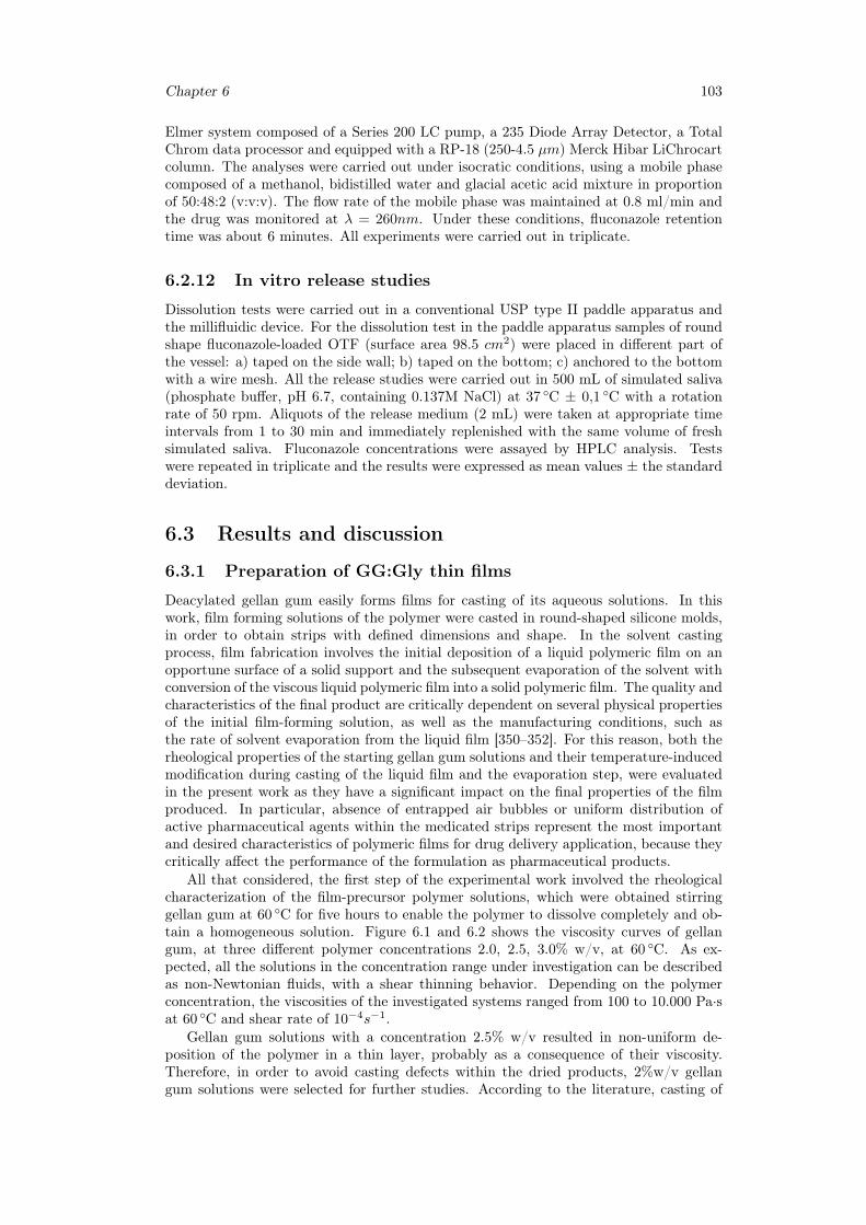
Chapter 6 103
Elmer system composed of a Series 200 LC pump, a 235 Diode Array Detector, a TotalChrom data processor and equipped with a RP-18 (250-4.5 µm) Merck Hibar LiChrocartcolumn. The analyses were carried out under isocratic conditions, using a mobile phasecomposed of a methanol, bidistilled water and glacial acetic acid mixture in proportionof 50:48:2 (v:v:v). The flow rate of the mobile phase was maintained at 0.8 ml/min andthe drug was monitored at λ = 260nm. Under these conditions, fluconazole retentiontime was about 6 minutes. All experiments were carried out in triplicate.
6.2.12 In vitro release studies
Dissolution tests were carried out in a conventional USP type II paddle apparatus andthe millifluidic device. For the dissolution test in the paddle apparatus samples of roundshape fluconazole-loaded OTF (surface area 98.5 cm2) were placed in different part ofthe vessel: a) taped on the side wall; b) taped on the bottom; c) anchored to the bottomwith a wire mesh. All the release studies were carried out in 500 mL of simulated saliva(phosphate buffer, pH 6.7, containing 0.137M NaCl) at 37 ◦C ± 0,1 ◦C with a rotationrate of 50 rpm. Aliquots of the release medium (2 mL) were taken at appropriate timeintervals from 1 to 30 min and immediately replenished with the same volume of freshsimulated saliva. Fluconazole concentrations were assayed by HPLC analysis. Testswere repeated in triplicate and the results were expressed as mean values ± the standarddeviation.
6.3 Results and discussion
6.3.1 Preparation of GG:Gly thin films
Deacylated gellan gum easily forms films for casting of its aqueous solutions. In thiswork, film forming solutions of the polymer were casted in round-shaped silicone molds,in order to obtain strips with defined dimensions and shape. In the solvent castingprocess, film fabrication involves the initial deposition of a liquid polymeric film on anopportune surface of a solid support and the subsequent evaporation of the solvent withconversion of the viscous liquid polymeric film into a solid polymeric film. The quality andcharacteristics of the final product are critically dependent on several physical propertiesof the initial film-forming solution, as well as the manufacturing conditions, such asthe rate of solvent evaporation from the liquid film [350–352]. For this reason, both therheological properties of the starting gellan gum solutions and their temperature-inducedmodification during casting of the liquid film and the evaporation step, were evaluatedin the present work as they have a significant impact on the final properties of the filmproduced. In particular, absence of entrapped air bubbles or uniform distribution ofactive pharmaceutical agents within the medicated strips represent the most importantand desired characteristics of polymeric films for drug delivery application, because theycritically affect the performance of the formulation as pharmaceutical products.
All that considered, the first step of the experimental work involved the rheologicalcharacterization of the film-precursor polymer solutions, which were obtained stirringgellan gum at 60 ◦C for five hours to enable the polymer to dissolve completely and ob-tain a homogeneous solution. Figure 6.1 and 6.2 shows the viscosity curves of gellangum, at three different polymer concentrations 2.0, 2.5, 3.0% w/v, at 60 ◦C. As ex-pected, all the solutions in the concentration range under investigation can be describedas non-Newtonian fluids, with a shear thinning behavior. Depending on the polymerconcentration, the viscosities of the investigated systems ranged from 100 to 10.000 Pa·sat 60 ◦C and shear rate of 10−4s−1.
Gellan gum solutions with a concentration 2.5% w/v resulted in non-uniform de-position of the polymer in a thin layer, probably as a consequence of their viscosity.Therefore, in order to avoid casting defects within the dried products, 2%w/v gellangum solutions were selected for further studies. According to the literature, casting of
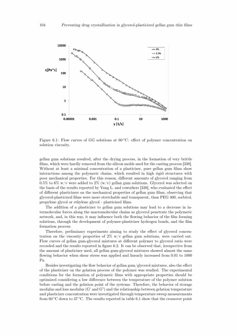
104 Preventing drug crystallization in glycerol-plasticized gellan gum thin films
Figure 6.1: Flow curves of GG solutions at 60 ◦C: effect of polymer concentration onsolution viscosity.
gellan gum solutions resulted, after the drying process, in the formation of very brittlefilms, which were hardly removed from the silicon molds used for the casting process [338].Without at least a minimal concentration of a plasticizer, pure gellan gum films showinteractions among the polymeric chains, which resulted in high rigid structures withpoor mechanical properties. For this reason, different amounts of glycerol ranging from0.5% to 6% w/v were added to 2% (w/v) gellan gum solutions. Glycerol was selected onthe basis of the results reported by Yang L. and coworkers [338], who evaluated the effectof different plasticizers on the mechanical properties of gellan gum films, observing thatglycerol-plasticized films were more stretchable and transparent, than PEG 400, sorbitol,propylene glycol or ethylene glycol - plasticized films.
The addition of a plasticizer to gellan gum solutions may lead to a decrease in in-termolecular forces along the macromolecular chains as glycerol penetrate the polymericnetwork, and, in this way, it may influence both the flowing behavior of the film formingsolutions, through the development of polymer-plasticizer hydrogen bonds, and the filmformation process.
Therefore, preliminary experiments aiming to study the effect of glycerol concen-tration on the viscosity properties of 2% w/v gellan gum solutions, were carried out.Flow curves of gellan gum-glycerol mixtures at different polymer to glycerol ratio wererecorded and the results reported in figure 6.2. It can be observed that, irrespective fromthe amount of plasticizer used, all gellan gum-glycerol mixtures showed almost the sameflowing behavior when shear stress was applied and linearly increased from 0.01 to 1000Pa.
Besides investigating the flow behavior of gellan gum/glycerol mixtures, also the effectof the plasticizer on the gelation process of the polymer was studied. The experimentalconditions for the formation of polymeric films with appropriate properties should beoptimized considering a low difference between the temperature of the polymer solutionbefore casting and the gelation point of the systems. Therefore, the behavior of storagemodulus and loss modulus (G’ and G”) and the relationship between gelation temperatureand plasticizer concentration were investigated through temperature sweep measurementsfrom 60 ◦C down to 37 ◦C. The results reported in table 6.1 show that the crossover point

Chapter 6 105
Figure 6.2: Flow curves of GG solutions at 60 ◦C: effect of glycerol concentration on GG(2% w/v) viscosity.
Table 6.1: Effect of glycerol concentration on the gelation temperature of gellan gumsolutions, 2% (w/v).
% Glycerol(w/v) % Gellan gum (w/v) Gelation temperature (◦C)
0 2 49.3± 1.50.5 2 51.9± 0.41 2 51.0± 1.02 2 52.4± 0.25 2 51.7± 1.4
of G’ and G” slightly shifted toward higher temperature when glycerol was added to GGsolutions, with almost no differences for the different polymer-plasticizer combinationsanalyzed. At 60 ◦C all the systems behave like solutions, as the loss modulus G” is, inall the cases, higher than the corresponding storage modulus G’.
Therefore, in the film formation process, all the GG:Gly mixtures behave like solutionswhen poured in the silicon molds, then they formed thin liquid layers, which experienceda rapid temperature modification, due to the reduced thickness, and consequent sol-geltransitions with the inversion of the G’ and G” moduli.
After the casting step, all the systems were dehydrated at the constant temperatureof 40 ◦C until polymeric films were obtained and easily peeled off from the molds. TGAwas used to monitor residual water content in the plasticized films during the dryingstep. Residence time lower than 15 hours in the drying oven, did not produce films ofacceptable flexibility; instead clear and transparent films were obtained and easily peeledoff from the support, when the residual water content in the final plasticized film, was inthe range 9.4-11.5%, depending on the glycerol percentage. Such residual water contentwas obtained keeping the systems at the constant temperature of 40 ◦C for 15 hours.
Therefore, the maximum drying time for complete film formation was set at 15 h,
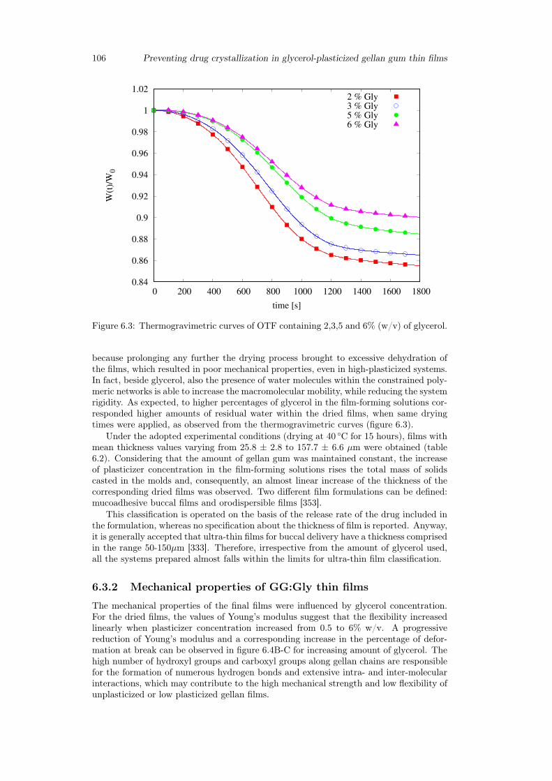
106 Preventing drug crystallization in glycerol-plasticized gellan gum thin films
0.84
0.86
0.88
0.9
0.92
0.94
0.96
0.98
1
1.02
0 200 400 600 800 1000 1200 1400 1600 1800
W(t
)/W
0
time [s]
2 % Gly3 % Gly5 % Gly6 % Gly
Figure 6.3: Thermogravimetric curves of OTF containing 2,3,5 and 6% (w/v) of glycerol.
because prolonging any further the drying process brought to excessive dehydration ofthe films, which resulted in poor mechanical properties, even in high-plasticized systems.In fact, beside glycerol, also the presence of water molecules within the constrained poly-meric networks is able to increase the macromolecular mobility, while reducing the systemrigidity. As expected, to higher percentages of glycerol in the film-forming solutions cor-responded higher amounts of residual water within the dried films, when same dryingtimes were applied, as observed from the thermogravimetric curves (figure 6.3).
Under the adopted experimental conditions (drying at 40 ◦C for 15 hours), films withmean thickness values varying from 25.8 ± 2.8 to 157.7 ± 6.6 µm were obtained (table6.2). Considering that the amount of gellan gum was maintained constant, the increaseof plasticizer concentration in the film-forming solutions rises the total mass of solidscasted in the molds and, consequently, an almost linear increase of the thickness of thecorresponding dried films was observed. Two different film formulations can be defined:mucoadhesive buccal films and orodispersible films [353].
This classification is operated on the basis of the release rate of the drug included inthe formulation, whereas no specification about the thickness of film is reported. Anyway,it is generally accepted that ultra-thin films for buccal delivery have a thickness comprisedin the range 50-150µm [333]. Therefore, irrespective from the amount of glycerol used,all the systems prepared almost falls within the limits for ultra-thin film classification.
6.3.2 Mechanical properties of GG:Gly thin films
The mechanical properties of the final films were influenced by glycerol concentration.For the dried films, the values of Young’s modulus suggest that the flexibility increasedlinearly when plasticizer concentration increased from 0.5 to 6% w/v. A progressivereduction of Young’s modulus and a corresponding increase in the percentage of defor-mation at break can be observed in figure 6.4B-C for increasing amount of glycerol. Thehigh number of hydroxyl groups and carboxyl groups along gellan chains are responsiblefor the formation of numerous hydrogen bonds and extensive intra- and inter-molecularinteractions, which may contribute to the high mechanical strength and low flexibility ofunplasticized or low plasticized gellan films.
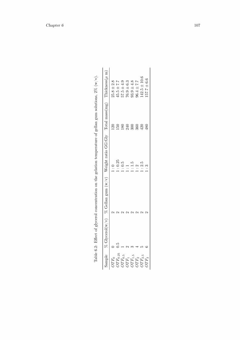
Chapter 6 107
Tab
le6.2:
Effe
ctof
glycerol
concentrationon
thegelation
tempe
rature
ofgella
ngu
msolution
s,2%
(w/v
).
Sample
%Glycerol(w/v
)%
Gellangu
m(w
/v)
Weigh
tratioGG:G
lyTotal
mass(mg)
Thickness(µ
m)
OTF
00
21
:0
120
25.
8±
2.8
OTF
0.2
50.
52
1:
0.2
5150
45.5±
7.7
OTF
0.5
12
1:
0.5
180
57.5±
4.9
OTF
12
21
:1
240
76.
9±
6.3
OTF
1.5
32
1:
1.5
300
93.9±
4.8
OTF
24
21
:2
360
96.
4±
7.7
OTF
2.5
52
1:
2.5
420
142.5±
10.
6OTF
36
21
:3
480
157.
7±
6.6
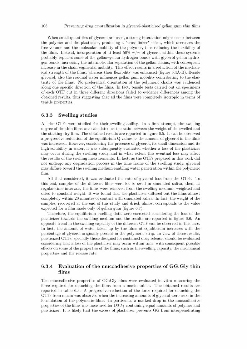
108 Preventing drug crystallization in glycerol-plasticized gellan gum thin films
When small quantities of glycerol are used, a strong interaction might occur betweenthe polymer and the plasticizer, producing a "cross-linker" effect, which decreases thefree volume and the molecular mobility of the polymer, thus reducing the flexibility ofthe films. Instead, incorporation of at least 50% w/w of glycerol within these systemsprobably replaces some of the gellan–gellan hydrogen bonds with glycerol-gellan hydro-gen bonds, increasing the intermolecular separation of the gellan chains, with consequentincrease in the chain segmental mobility. This effect results in a reduction of the mechan-ical strength of the films, whereas their flexibility was enhanced (figure 6.4A-B). Besideglycerol, also the residual water influences gellan gum mobility contributing to the elas-ticity of the films. No preferential orientation of the polymeric chains was evidencedalong one specific direction of the films. In fact, tensile tests carried out on specimensof each OTF cut in three different directions failed to evidence differences among theobtained results, thus suggesting that all the films were completely isotropic in terms oftensile properties.
6.3.3 Swelling studies
All the OTFs were studied for their swelling ability. In a first attempt, the swellingdegree of the thin films was calculated as the ratio between the weight of the swelled andthe starting dry film. The obtained results are reported in figure 6.5. It can be observeda progressive reduction of the equilibrium Q values as the amount of glycerol in the filmswas increased. However, considering the presence of glycerol, its small dimension and itshigh solubility in water, it was subsequently evaluated whether a loss of the plasticizermay occur during the swelling study and in what extent this eventual loss may affectthe results of the swelling measurements. In fact, as the OTFs prepared in this work didnot undergo any degradation process in the time frame of the swelling study, glycerolmay diffuse toward the swelling medium enabling water penetration within the polymericfilm.
All that considered, it was evaluated the rate of glycerol loss from the OTFs. Tothis end, samples of the different films were let to swell in simulated saliva, then, atregular time intervals, the films were removed from the swelling medium, weighted anddried to constant weight. It was found that the plasticizer diffused out the films almostcompletely within 20 minutes of contact with simulated saliva. In fact, the weight of thesamples, recovered at the end of this study and dried, almost corresponds to the valueexpected for a film made only of gellan gum (figure 6.7).
Therefore, the equilibrium swelling data were corrected considering the loss of theplasticizer towards the swelling medium and the results are reported in figure 6.6. Anopposite trend in the swelling capacity of the different OTF can be observed in this case.In fact, the amount of water taken up by the films at equilibrium increases with thepercentage of glycerol originally present in the polymeric strip. In view of these results,plasticized OTFs, specially those designed for sustained drug release, should be evaluatedconsidering that a loss of the plasticizer may occur within time, with consequent possibleeffects on some of the properties of the films, such as the swelling capacity, the mechanicalproperties and the release rate.
6.3.4 Evaluation of the mucoadhesive properties of GG:Gly thinfilms
The mucoadhesive properties of GG:Gly films were evaluated in vitro measuring theforce required for detaching the films from a mucin tablet. The obtained results arereported in table 6.3. A progressive reduction of the force required for detaching theOTFs from mucin was observed when the increasing amounts of glycerol were used in theformulation of the polymeric films. In particular, a marked drop in the mucoadhesiveproperties of the films was measured for OTF1 containing equal amounts of polymer andplasticizer. It is likely that the excess of plasticizer prevents GG from interpenetrating
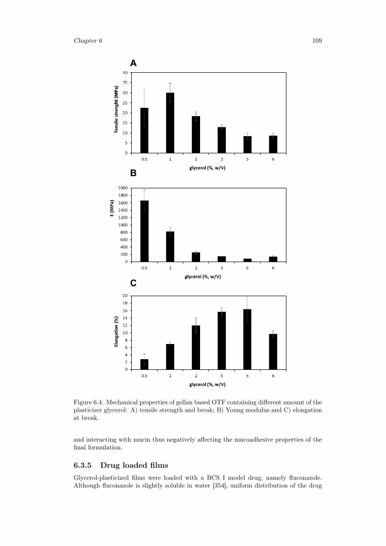
Chapter 6 109
Figure 6.4: Mechanical properties of gellan based OTF containing different amount of theplasticizer glycerol: A) tensile strength and break; B) Young modulus and C) elongationat break.
and interacting with mucin thus negatively affecting the mucoadhesive properties of thefinal formulation.
6.3.5 Drug loaded filmsGlycerol-plasticized films were loaded with a BCS I model drug, namely fluconazole.Although fluconazole is slightly soluble in water [354], uniform distribution of the drug
110 Preventing drug crystallization in glycerol-plasticized gellan gum thin films
0
2
4
6
8
10
0 50 100 150 200 250 300
(Ws(
t)-W
0)/
W0
time [min]
0.5 % Gly1 % Gly2 % Gly5 % Gly6 % Gly
Figure 6.5: Dynamic swelling study. Evaluation of the variation of the swelling capacitywithin time for the gellan based OTFs containing different amount of the plasticizerglycerol.
Table 6.3: Mucoadhesive properties of GG:Gly thin films.
Sample Weight ratio GG:Gly Force(N)
OTF0.25 1 : 0.25 0.71± 0.03OTF0.5 1 : 0.5 0.58± 0.01OTF1 1 : 1 0.13± 0.01OTF2.5 1 : 2.5 0.05± 0.01
within gellan gum films was critically dependent on the amount of glycerol used, when0.64mg/cm2 of fluconazole was included in the formulation. In fact, strips containingconcentration of the plasticizer lower than 70% w/w resulted in separation of whiteaggregates within the polymeric matrix, probably due to phenomena of limited diffusionaggregation of the drug molecules (figure 6.8).
After the drying process, all the systems showed an initial homogeneous appearancewith no presence of aggregates, as evidenced by visual observation and confirmed by DSCanalysis. In fact, no melting peaks of fluconazole were observed in the correspondingthermograms. However, films containing an amount of glycerol 50% w/w shown theappearance of some aggregates of fluconazole within few days from the preparation. Itwas observed that fluconazole aggregation depends on glycerol concentration within thefilms. In fact, a faster appearance of drug aggregates was observed in strips with loweramount of the plasticizer, maybe because of the different ability of fluconazole to diffusewithin the differently plasticized systems. Low mobility of the drug may cause segregationof fluconazole within drug-rich regions of the film where local concentration may exceedits saturation limit, thus promoting its nucleation and crystallization, according to thegeneral believing that branch-structured dendritic crystallization is a result of phaseseparation from supersaturated states [355,356].
In contrast, a more homogeneous drug distribution could be achieved when highamount of the plasticizer were added to the formulation. According with the effect of
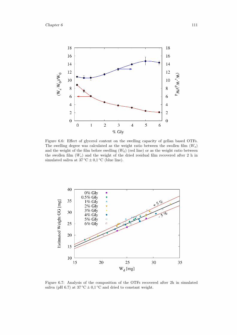
Chapter 6 111
Figure 6.6: Effect of glycerol content on the swelling capacity of gellan based OTFs.The swelling degree was calculated as the weight ratio between the swollen film (Ws)and the weight of the film before swelling (W0) (red line) or as the weight ratio betweenthe swollen film (Ws) and the weight of the dried residual film recovered after 2 h insimulated saliva at 37 ◦C± 0,1 ◦C (blue line).
Figure 6.7: Analysis of the composition of the OTFs recovered after 2h in simulatedsaliva (pH 6.7) at 37 ◦C± 0,1 ◦C and dried to constant weight.
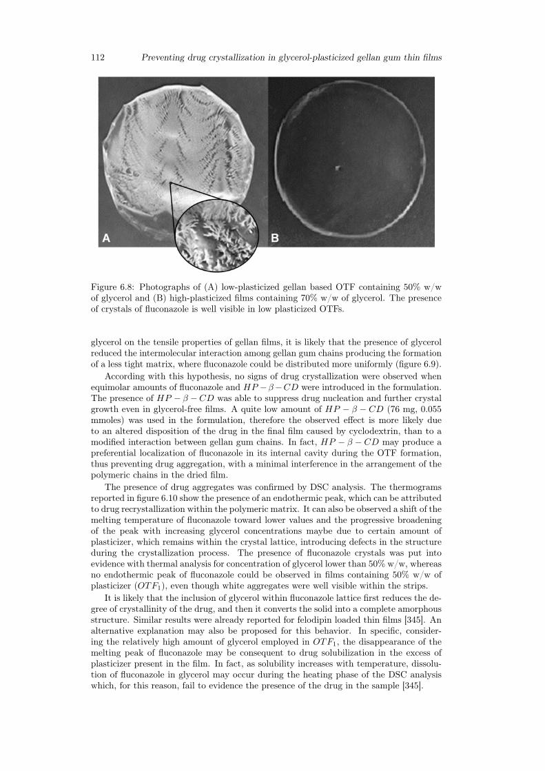
112 Preventing drug crystallization in glycerol-plasticized gellan gum thin films
Figure 6.8: Photographs of (A) low-plasticized gellan based OTF containing 50% w/wof glycerol and (B) high-plasticized films containing 70% w/w of glycerol. The presenceof crystals of fluconazole is well visible in low plasticized OTFs.
glycerol on the tensile properties of gellan films, it is likely that the presence of glycerolreduced the intermolecular interaction among gellan gum chains producing the formationof a less tight matrix, where fluconazole could be distributed more uniformly (figure 6.9).
According with this hypothesis, no signs of drug crystallization were observed whenequimolar amounts of fluconazole and HP −β−CD were introduced in the formulation.The presence of HP − β −CD was able to suppress drug nucleation and further crystalgrowth even in glycerol-free films. A quite low amount of HP − β − CD (76 mg, 0.055mmoles) was used in the formulation, therefore the observed effect is more likely dueto an altered disposition of the drug in the final film caused by cyclodextrin, than to amodified interaction between gellan gum chains. In fact, HP − β − CD may produce apreferential localization of fluconazole in its internal cavity during the OTF formation,thus preventing drug aggregation, with a minimal interference in the arrangement of thepolymeric chains in the dried film.
The presence of drug aggregates was confirmed by DSC analysis. The thermogramsreported in figure 6.10 show the presence of an endothermic peak, which can be attributedto drug recrystallization within the polymeric matrix. It can also be observed a shift of themelting temperature of fluconazole toward lower values and the progressive broadeningof the peak with increasing glycerol concentrations maybe due to certain amount ofplasticizer, which remains within the crystal lattice, introducing defects in the structureduring the crystallization process. The presence of fluconazole crystals was put intoevidence with thermal analysis for concentration of glycerol lower than 50% w/w, whereasno endothermic peak of fluconazole could be observed in films containing 50% w/w ofplasticizer (OTF1), even though white aggregates were well visible within the strips.
It is likely that the inclusion of glycerol within fluconazole lattice first reduces the de-gree of crystallinity of the drug, and then it converts the solid into a complete amorphousstructure. Similar results were already reported for felodipin loaded thin films [345]. Analternative explanation may also be proposed for this behavior. In specific, consider-ing the relatively high amount of glycerol employed in OTF1, the disappearance of themelting peak of fluconazole may be consequent to drug solubilization in the excess ofplasticizer present in the film. In fact, as solubility increases with temperature, dissolu-tion of fluconazole in glycerol may occur during the heating phase of the DSC analysiswhich, for this reason, fail to evidence the presence of the drug in the sample [345].
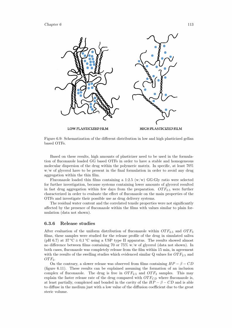
Chapter 6 113
Figure 6.9: Schematization of the different distribution in low and high plasticized gellanbased OTFs.
Based on these results, high amounts of plasticizer need to be used in the formula-tion of fluconazole loaded GG based OTFs in order to have a stable and homogeneousmolecular dispersion of the drug within the polymeric matrix. In specific, at least 70%w/w of glycerol have to be present in the final formulation in order to avoid any drugaggregation within the thin film.
Fluconazole loaded thin films containing a 1:2.5 (w/w) GG:Gly ratio were selectedfor further investigation, because systems containing lower amounts of glycerol resultedin fast drug aggregation within few days from the preparation. OTF2.5 were furthercharacterized in order to evaluate the effect of fluconazole on the main properties of theOTFs and investigate their possible use as drug delivery systems.
The residual water content and the correlated tensile properties were not significantlyaffected by the presence of fluconazole within the films with values similar to plain for-mulation (data not shown).
6.3.6 Release studies
After evaluation of the uniform distribution of fluconazole within OTF2.5 and OTF3
films, these samples were studied for the release profile of the drug in simulated saliva(pH 6.7) at 37 ◦C ± 0,1 ◦C using a USP type II apparatus. The results showed almostno difference between films containing 70 or 75% w/w of glycerol (data not shown). Inboth cases, fluconazole was completely release from the film within 15 min, in agreementwith the results of the swelling studies which evidenced similar Q values for OTF2.5 andOTF3.
On the contrary, a slower release was observed from films containing HP − β − CD(figure 6.11). These results can be explained assuming the formation of an inclusioncomplex of fluconazole. The drug is free in OTF2.5 and OTF3 samples. This mayexplain the faster release rate of the drug compared with OTFCD where fluconazole is,at least partially, complexed and bonded in the cavity of the HP − β − CD and is ableto diffuse in the medium just with a low value of the diffusion coefficient due to the greatsteric volume.
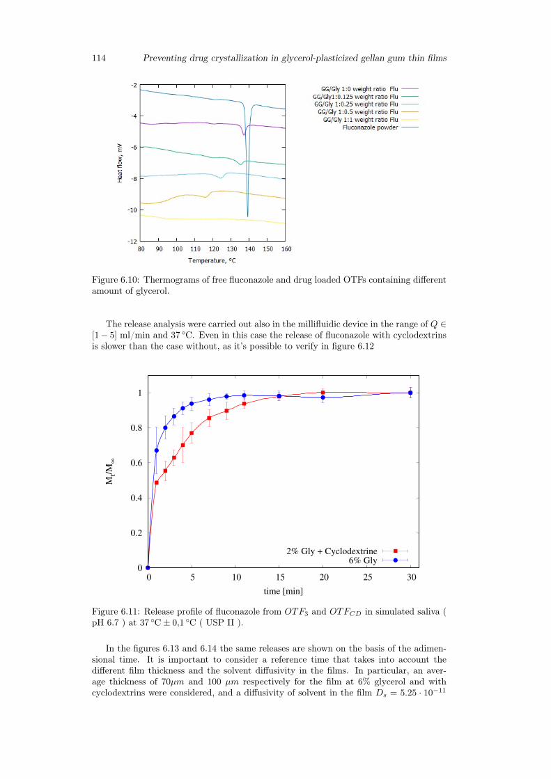
114 Preventing drug crystallization in glycerol-plasticized gellan gum thin films
Figure 6.10: Thermograms of free fluconazole and drug loaded OTFs containing differentamount of glycerol.
The release analysis were carried out also in the millifluidic device in the range of Q ∈[1− 5] ml/min and 37 ◦C. Even in this case the release of fluconazole with cyclodextrinsis slower than the case without, as it’s possible to verify in figure 6.12
0
0.2
0.4
0.6
0.8
1
0 5 10 15 20 25 30
Mt/
M∞
time [min]
2% Gly + Cyclodextrine6% Gly
Figure 6.11: Release profile of fluconazole from OTF3 and OTFCD in simulated saliva (pH 6.7 ) at 37 ◦C± 0,1 ◦C ( USP II ).
In the figures 6.13 and 6.14 the same releases are shown on the basis of the adimen-sional time. It is important to consider a reference time that takes into account thedifferent film thickness and the solvent diffusivity in the films. In particular, an aver-age thickness of 70µm and 100 µm respectively for the film at 6% glycerol and withcyclodextrins were considered, and a diffusivity of solvent in the film Ds = 5.25 · 10−11
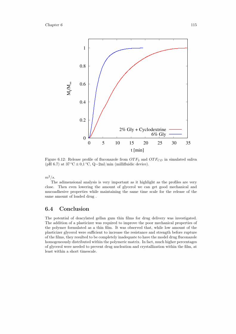
Chapter 6 115
0
0.2
0.4
0.6
0.8
1
0 5 10 15 20 25 30 35
Mt/
M∞
t [min]
2% Gly + Cyclodextrine6% Gly
Figure 6.12: Release profile of fluconazole from OTF3 and OTFCD in simulated saliva(pH 6.7) at 37 ◦C± 0,1 ◦C, Q=2ml/min (millifluidic device).
m2/s.The adimensional analysis is very important as it highlight as the profiles are very
close. Then even lowering the amount of glycerol we can get good mechanical andmucoadhesive properties while maintaining the same time scale for the release of thesame amount of loaded drug .
6.4 ConclusionThe potential of deacylated gellan gum thin films for drug delivery was investigated.The addition of a plasticizer was required to improve the poor mechanical properties ofthe polymer formulated as a thin film. It was observed that, while low amount of theplasticizer glycerol were sufficient to increase the resistance and strength before ruptureof the films, they resulted to be completely inadequate to have the model drug fluconazolehomogeneously distributed within the polymeric matrix. In fact, much higher percentagesof glycerol were needed to prevent drug nucleation and crystallization within the film, atleast within a short timescale.
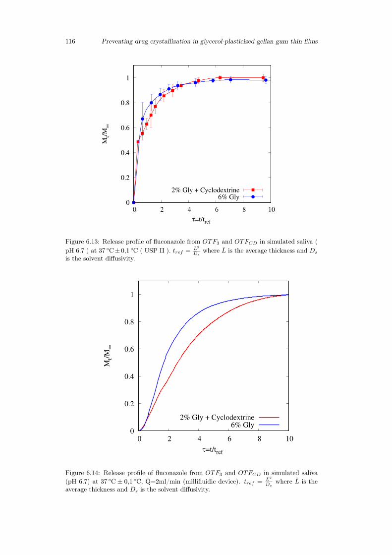
116 Preventing drug crystallization in glycerol-plasticized gellan gum thin films
0
0.2
0.4
0.6
0.8
1
0 2 4 6 8 10
Mt/
M∞
τ=t/tref
2% Gly + Cyclodextrine6% Gly
Figure 6.13: Release profile of fluconazole from OTF3 and OTFCD in simulated saliva (pH 6.7 ) at 37 ◦C± 0,1 ◦C ( USP II ). tref = L2
Dswhere L is the average thickness and Ds
is the solvent diffusivity.
0
0.2
0.4
0.6
0.8
1
0 2 4 6 8 10
Mt/
M∞
τ=t/tref
2% Gly + Cyclodextrine6% Gly
Figure 6.14: Release profile of fluconazole from OTF3 and OTFCD in simulated saliva(pH 6.7) at 37 ◦C ± 0,1 ◦C, Q=2ml/min (millifluidic device). tref = L2
Dswhere L is the
average thickness and Ds is the solvent diffusivity.
Chapter 7
General conclusions
The main results presented in this research work can be summarized as follows:
• the design and preparation of hydrogels and OTFs based on natural and biocompat-ible polysaccharides for topical and buccal drugs delivery and the optimization ofconcentrations of the main components (polymer, plasticizer and / or cyclodextrins)to provide the best performances for an effective utilization of the formulation;
• a proper estimate of release time-scales from OTFs for buccal release by means ofthe recently proposed millifluidic flow-through device;
• the development of mathematical models able to properly describe the experimentaldata and release kinetics in different apparatuses. In particular:
– a double-moving boundary model describing swelling and release from OTFsin the millifluic device;
– a polymer-drug interaction model for describing diffusion and release fromhydrogels in a vertical Franz cell;
– a new approach to the description and interpretation of Franz cell releasedata including the effects of the "unperfect mixing" chamber and withdrawalposition.
117

118
Bibliography
[1] Vishwkarma, D.K.Tripathi, A.K., Yoshev, P., et Maddheshiyab, B.(2011). Reviewarticleon mouth dissolving film. Journal of global pharma Technology, 3(1), 1-8.
[2] Hearnden, V., Sankar, V., Hull, K., Juras, D. V., Greenberg, M., Kerr, A. R.,et Thornhill, M. H. (2012). New developments and opportunities in oral mucosaldrug delivery for local and systemic disease. Advanced drug delivery reviews, 64(1),16-28.
[3] Puratchikody, A.,et Mathew, S.T.(2011). Buccal Drug Delivery: Past, Present andFuture-A Review. International Journal of Drug Delivery, 3(2), 171-184.
[4] Asane, G.S. Nirmal, S.A., Rasal, K.B., Naik, A.A., Mahadik, M.S., et Rao,Y.M.(2008). Polymers for mucoadhesive drug delivery system: A current sta-tus.Drug development and industrial pharmacy, 34(11), 1246-1266.
[5] Smart,J.D. (2005). The basic and underlying mechanisms of mucoadhesion. Ad-vanced drug delivery reviews, 57(11), 1556-1568.
[6] Serra, Laura, Josep Dom, and Nicholas A. Peppas. "Engineering design and molecu-lar dynamics of mucoadhesive drug delivery systems as targeting agents." Europeanjournal of pharmaceutics and biopharmaceutics 71.3 (2009):519-528.
[7] Kharenko, E.A.,N. I. Larionova, and N. B. Demina. "Mucoadhesive drug deliv-ery systems: quantitative assessment of interaction between synthetic and naturalpolymer films and mucosa." Pharmaceutical Chemistry Journal 42.7 (2008):392-399.
[8] Collins,L. M. C., and C. Dawes. "The surface area of the adult human mouth andthickness of the salivary film covering the teeth and oral mucosa." Journal of dentalresearch 66.8 (1987): 1300-1302.
[9] Watabane, S., and C. Dawes. "Salivary flow rates and salivary film thickness infive-year-old children." Journal of Dental Research 69.5 (1990):1150-1153.
[10] C. Dawes, Salivary flow patterns and the health of hard and soft oral tissues,Journal of american dental association 139 (suppl.2) (2008) 18S-24S.
[11] Wolff, M., and I. Kleinberg."oral mucosal wetness in hypo-and normosaliva-tors."Archives of oral biology 43.6 (1998):455-462.
[12] Verma, S., Kaul, M., Rawat, A., et saini, S. (2011). An overview on buccal drugdelivery system. International Journal of Pharmaceutical Sciences and Research,2(6), 1303-1321.
[13] Patel, Viralkumar F., Fang Liu and Marc B. Brown. "Advanced in oral transmu-cosal drug delivery." Journal of Controlled Release 153.2 (2011):106-116.
[14] Mamatha, Y., selvi, A., Prasanth, V. V., Sipai, M., et Yadav, V. (2012). Buccaldrug delivery: a technical approach. journal of Drug Delivery and Therapeutics,2(2).
119
[15] Andersen, O.,Zweidorff, O.K., Hjelde, T., et Rodland, E. A. (1995). Problems whenswallowing tablets. A questionnaire study from general practice.
[16] Bhyan, B., Jangra, S., Kaur, M., et Singh, H. (2011). Orally fast dissolving films:innovations in formulation and technology. Int J Pharm Sci Rev Res, 9,9.
[17] Yajaman Sudhakar, Ketousetuo Kuotsu, A.K. Bandyopadhyay. "Buccal bioadhe-sive drug delivery - A promising option for orally less efficient drugs. Journal ofcontrolled release, 114(2006), 15-40.
[18] Nazila Salamat-Miller, Montakarna Chittchang, Thomas P. Johnston. The use ofmucoadhesive polymers in buccal drug delivery. Advanced drug delivery reviews,57(2015), 1666-1691.
[19] N.Vidyasagar, K.MallikarjunaRao, K. Gnanaprakash, A. Divya, A.Sowjanya, M.Gobinath. "A rewiew on buccal drug delivery system". Journal of PharmaceuticalResearch and Development, 2012.
[20] Chinna Reddy P, Chaitanya K.S.C., Madhusudan Rao Y."A review on bioadhe-sive buccal drug delivery systems: current status of formulation and evaluationmethods", DARU Journal of Pharmaceutical Sciences Vol. 19, No. 6 2011.
[21] R. Jagadeeshwar Reddy , Maimuna Anjum and Mohammed Asif Hussain, "AComprehensive Review on Buccal Drug Delivery System", American Journal ofAdvanced Drug Delivery,2013.
[22] N. G. Raghavendra Rao, B. Shravani, Mettu Srikanth Reddy, "Overview on BuccalDrug Delivery Systems", J. Pharm. Sciences and Research. Vol.5(4), 2013, 80 - 88
[23] Jasvir Singh and Pawan Deep, "A REVIEW ARTICLE ON MUCOADHESIVEBUCCAL DRUG DELIVERY SYSTEM", International journal of pharmaceuticalsciences and research, 2013; Vol. 4(3): 916-927
[24] Radhakisan, Udhan Ravindra, Vijayalaxmi Chavan, and Nitin Tribhuvan."MOUTH DISSOLVING FILM AND THEIR PATENT: AN OVERVIEW." In-ternational Research Journal of Pharmacy 3.
[25] Bala, R., Pawar, P., Khanna, S., et Arora, S. (2013). Orally dissolving strips: Anew approach to oral drug delivery system. International Journal of PharmaceuticalInvestigation, 3(2), 67.
[26] Siddiqui, MD Nehal, Garima Garg, and Pramod Kumar Sharma. "A short re-view on "A novel approach in oral fast dissolving drug delivery system and theirpatents"." Advances in Biological Research 5.6 (2011): 291-303.
[27] E.M. Hoffmann, A. Breitenbach, J. Breitkreutz, Expert Opinion on Drug Delivery,March 2011, Vol. 8, No. 3 : Pages 299-316
[28] Schiraldi et al., US Patent 4,713,243, December 1987
[29] Raval, K. M. (2013). OVERVIEW ON ORAL STRIP. Journal of drug discoveryand therapeutics, 1(03).
[30] Apoorva Mahajan et al, Der Pharmacia Lettre, 2011, 3(1):152-165
[31] Arun Arya et al /Int.J. ChemTech Res.2010,2(1)
[32] Shimoda, H., Taniguchi, K., Nishimura, M., Matsuura, K., Tsukioka, T., Ya-mashita, H., ... et Itoh, Y. (2009). Preparation of a fast dissolving oral thinfilm containing dexamethasone: a possible application to antiemesis during cancerchemotherapy. European journal of pharmaceutics and biopharmaceutics, 73(3),361-365.
120
[33] Nishigaki, M., Kawahara, K., Nawa, M., Futamura, M., Nishimura, M., Matsuura,K., ... et Itoh, Y. (2012). Development of fast dissolving oral film containing dex-amethasone as an antiemetic medication: Clinical usefulness. International journalof pharmaceutics, 424(1), 12-17.
[34] Dixit, R. P., et Puthli, S. P. (2009). Oral strip technology: Overview and futurepotential. Journal of controlled release, 139(2), 94-107.
[35] Thin film drug delivery, From Wikipedia, the free encyclopedia
[36] Morales, Javier O., and Jason T. McConville. "Manufacture and characterizationof mucoadhesive buccal films." European Journal of Pharmaceutics and Biophar-maceutics 77.2 (2011): 187-199.
[37] Cremer K., Life cycle management using orally disintegrating dosage forms, Inter-national Association for pharmaceutical technology, Issue 01/2005
[38] Reeta et al., Journal of Drug Delivery and Therapeutics; 2012, 2(3): 87-96
[39] Vollmer et al., Rapid film: Oral Thin Film (OTF) as an Innovative Drug DeliverySystem and Dosage Form. Drug Delivery Report. Spring/Summer 2006.
[40] R. C. Mashru et al., Drug Development and Industrial Pharmacy, 31:25-34, 2005
[41] Y.I. Muzib, K.S. Kumari, International Journal of Pharmaceutical Investigation,2011, Vol 1, 1
[42] M. Semalty et al.International Journal of Pharmaceutical Sciences and Nanotech-nology Volume 1, Issue 2, July-September 2008
[43] Sane, Novel Science International Journal of Pharmaceutical Science (2012), 1(7):452-456
[44] Sournac et al., US Patent 20100041703A1, Feb. 2010
[45] A. B. Bogue et al., EP 2461796 A2, June 2012
[46] B. Assmussen and J. Moorman EP 1656112 B1, Feb. 2010
[47] M. Mencherif, EP 2112923 A1, Nov. 2009
[48] A. Breitenbach and N. Schwier, EP 2486913 A1, Aug 2012
[49] Fuisz et al., US20120328688A1, Dec 2012
[50] Panda et al., Int J Pharm Sci Nanotech, Vol 5; Issue 2, July-September 2012
[51] S.L. Patil et al, IJRRPAS, 2(3).482-496, 2012
[52] Sievens-Figueroa, L., Bhakay, A., Jerez-Rozo, J. I., Pandya, N., Romanach, R.J., Michniak-Kohn, B., ... et Dave, R. N. (2012). Preparation and characteriza-tion of hydroxypropyl methyl cellulose films containing stable BCS Class II drugnanoparticles for pharmaceutical applications. International Journal of Pharma-ceutics, 423(2), 496-508.
[53] Mishra. A., Ramteke.S. "Formulation and Evaluation of Mucoadhesive Buccal Filmof Flurbiprofen" International Journal of PharmTech Research, Vol.3, No.3, pp1825-1830, July-Sept 2011
[54] Perioli, L., Ambrogi, V., Angelici, F., Ricci, M., Giovagnoli, S., Capuccella, M., etRossi, C. (2004). Development of mucoadhesive patches for buccal administrationof ibuprofen. Journal of controlled release, 99(1), 73-82.
121
[55] Sandeep Karki, Hyeongmin Kim, Seon-Jeong Na, Dohyun Shin, Kanghee Jo, Jae-hwi Lee,"Thin films as an emerging platform for drug delivery",Asian journal ofpharmaceutical sciences11(2016) 559–574.
[56] Renukuntla J, Vadlapudi AD, Patel A, et al. Approaches for enhancing oralbioavailability of peptides and proteins. Int J Pharm 2013;447:75–93.
[57] Khairnar GA, Sayyad FJ. Development of buccal drug delivery system based onmucoadhesive polymers. Int J PharmTech Res 2010;2:719–735.
[58] Juluru N. Fast dissolving oral films: a novel drug delivery system. Int J Pharm SciRev Res 2013;2:108–112.
[59] Irfan M, Rabel S, Bukhtar Q, et al. Orally disintegrating films: a modern expansionin drug delivery system. Saudi Pharm J 2015;2015:1–10.
[60] Liew et al., Drug Development and Industrial Pharmacy 0 (2013): 1-10.
[61] P. Sakellariou, R.C. Rowe, Interactions in cellulose derivative films for oral drugdelivery, Prog. Polym. Sci. 20 (1995) 889-942.
[62] Shweta Kalyan et al /Int.J. PharmTech Res.2012,4(2)
[63] S. Malke et al., The Internet Journal of Pediatrics and Neonatology. 2010 Volume11 Number 2
[64] Karen et. al., American Journal PharmTech Research 2012; 2(3)
[65] Landová H, Vetchý V, Gajdziok J. Evaluation of the influence of formulation andprocess variables on mechanical properties of oral mucoadhesive films using multi-variate data analysis. Biomed Res Int 2014;2014:1–9.
[66] Smart JD, Kellaway IW,Worthington HEC. An in-vitro investigation of mucosa-adhesive materials for use in controlled drug delivery. J Pharm Pharmacol1984;36:295– 299.
[67] Ludwig A. The use of mucoadhesive polymers in ocular drug delivery. Adv DrugDeliv Rev 2005;57:1595–1639.
[68] J. Guo, Bioadhesive polymer buccal patches for buprenorphine controlled deliv-ery: formulation, in-vitro adhesion and release properties, Drug Development andIndustrial Pharmacy 20 (1994) 2809–2821.
[69] D. Chickering, E. Mathiowitz, Definitions, mechanisms, and theories of bioadhe-sion, in: E. Mathiowitz, D. Chickering, C. Lehr (Eds.), Bioadhesive Drug DeliverySystems: Fundamentals, Novel Approaches, and Development, Marcel Dekker, Inc.,New York, 1999.
[70] N.A. Peppas, J.J. Sahlin, Hydrogels as mucoadhesive and bioadhesive materials: areview, Biomaterials 17 (1996) 1553–1561.
[71] B. Derjaguin, V. Smilga, Adhesion: Fundamentals and Practice, McLaren, London,1969.
[72] A.J. Kinloch, The science of adhesion. I: Surface and interfacial aspects, Journalof Materials Science 15 (1980) 2141–2166
[73] L.L. Hench, E.C. Ethridge, Biomaterials: An Interfacial Approach, AcademicPress, New York, 1982.
[74] A. Baszkin, J.E. Proust, P. Monsenego, M.M. Boissonnade, Wettability of polymersby mucin aqueous solutions, Biorheology 27 (1990) 503–514.
122
[75] S. Prager, The healing process at polymer–polymer interfaces, Journal of ChemicalPhysics 75 (1981) 5194
[76] H.W. Kammer, Adhesion between polymers. Review, Acta Polymerica 34 (1983)112–118.
[77] J. Smart, The role of water movement and polymer hydration in mucoadhesion,in: E. Mathiowitz, D. Chickering, C. Lehr (Eds.), Bioadhesive Drug Delivery Sys-tems: Fundamentals, Novel Approaches, and Development, Marcel Dekker, Inc,New York, 1999, pp. 11–23.
[78] A.J. Kinloch, The science of adhesion. Part 1: Surface and interfacial aspects,Journal of Materials Science 15 (1980) 2141–2166.
[79] A.G. Mikos, N.A. Peppas, Systems for controlled release of drugs. V: Bioadhesivesystems, STP Pharma Sciences 2 (1986) 705–716.
[80] S. Voiutskii, Autohesion and Adhesion of High Polymers, Wiley-Interscience, NewYork, 1963.
[81] J. Smart, The basics and underlying mechanisms of mucoadhesion, Advanced DrugDelivery Reviews 57 (2005) 1556–1568.
[82] J. Guo, Bioadhesive polymer buccal patches for buprenorphine controlled deliv-ery: formulation, in-vitro adhesion and release properties, Drug Development andIndustrial Pharmacy 20 (1994) 2809–2821.
[83] Nitesh S Chauhan et al., Int. J. Drug Dev. and Res., April-June 2012, 4 (2): 408-417
[84] F. Cilurzo et al. / European Journal of Pharmaceutics and Biopharmaceutics 70(2008) 895-900
[85] Rotta et al, Cienc. Tecnol. Aliment., Campinas, 31(2): 450-455, abr.-jun. 2011
[86] Peh, Kok Khiang, and Choy Fun Wong. "Polymeric films as vehicle for buccaldelivery: swelling, mechanical, and bioadhesive properties." J Pharm Pharm Sci2.2 (1999): 53-61.
[87] Kulkarni A.S. et al., Journal of Current Pharmaceutical Research 2010; 2(1): 33-35
[88] Dhagla Ram Choudhary et al /Int.J. ChemTech Res.2011,3(2)
[89] N.L Prasanthi et al, Der Pharmacia Lettre, 2011, 3(1): 382-395
[90] Dhere P.M. et al. /International Journal Of Pharmacy and Technology, 2011 3(4),1572-1585
[91] Dhanikula et al., The AAPS Journal 2004; 6 (3) Article 27
[92] Murata et al., Pharmacology and Pharmacy, 2011, 2, 194-198
[93] C. Eouani et al., European Journal of Pharmaceutics and Biopharmaceutics 52(2001) 45-55
[94] Nep and Conway, Trop J Pharm Res, August 2011;10 (4): 389
[95] Boateng et al., Drug Development and Industrial Pharmacy, 2012; 38(1): 47-54
[96] Sievens-Figueroa, L., Pandya, N., Bhakay, A., Keyvan, G., Michniak-Kohn, B.,Bilgili, E., et Dave, R. N. (2012). Using USP I and USP IV for DiscriminatingDissolution Rates of Nano-and Microparticle-Loaded Pharmaceutical Strip- Films.AAPS PharmSciTech, 13(4), 1473-1482.
123
[97] V. A. Perumal, T. Govender, D. Lutchman, I. Mackraj, Drug Development andIndustrial Pharmacy, 34:1036-1047, 2008.
[98] Wong CF, Yuen KH, Khiang peh K. An in vitro method for buccal adhesion studies:importance of instrument variables. Int.J.Pharm.1999; 180: 47-57.
[99] Julie Mariam Joshua, R Hari, Fithal K Jyothish, Saritha A Surendran, Fast Dis-solving Oral Thin Films: An Effective Dosage Form for Quick Releases. Int. J.Pharm. Sci. Rev. Res., 38(1), May – June 2016; Article No. 50, Pages: 282-289.
[100] Prasanna P. Ghodake, Kailas M. Karande, Riyaz Ali Osmani, Rohit R. Bhosale,Bhargav R. Harkare, Birudev B. Kale. Mouth Dissolving Films: Innovative Vehiclefor Oral Drug Delivery. International Journal of Pharma Research et Review, Oct2013; 2(10):41-47.
[101] Naga Sowjanya Juluru, Fast Dissolving Oral Films: A Review, INTERNATIONALJOURNAL OF ADVANCES IN PHARMACY, BIOLOGY AND CHEMISTRY,Vol. 2(1), Jan- Mar, 2013.
[102] Muhammad Hanif, Muhammad Zaman and Vesh Chaurasiya, Polymers used inbuccal film: a review , Designed Monomers and Polymers, 2015 ,Vol. 18, No. 2,105–111.
[103] Ms. Prakruti M. Amin, Prof. A. B. Gangurde, Ms. Pranali V. Alai, Oral Film Tech-nology: Challenges and Future Scope for Pharmaceutical Industry,Internationaljournal of pharmacy et pharmaceutical research, June 2015 Vol.:3, Issue:3.
[104] Rajni Bala, Pravin Pawar, Sushil Khanna, Sandeep Arora, "Orally dissolving strips:A new approach to oral drug delivery system", International journal of Pharma-ceutical Investigation, April 2013, Vol3(2).
[105] Preis M, Knop K, Breitkreutz J. Mechanical strength test for orodispersible andbuccal films. Int J Pharm 2014;461:22–29.
[106] Hoffmann EM, Breitenbach A, Breitkreutz J. Advances in orodispersible films fordrug delivery. Expert Opin Drug Deliv 2011;8:299–316.
[107] Anroop B.Nair, Rachna Kumria, Sree Harsha, Mahesh Attimarad, Bandar E. Al-Dhubiab, Ibrahim A. Alhaider, In vitro techniques to evaluate buccal films, Journalof Controlled Release 166(2013), 10-21.
[108] Mishra, Renukra, and Avani Amin. "Quick API delivery." (2007).
[109] U. Siemann, Progr Colloid Polym Sci (2005) 130: 1-14
[110] Mishra and Avani, PHARMACEUTICAL TECHNOLOGY, 2011, Volume 35, Issue1, pp. 70-73
[111] Maniruzzaman, Mohammed, et al. "Hot-Melt Extrusion (HME): From Process toPharmaceutical Applications." (2012).
[112] Saini et al., Pharmacologyonline 2: 919-928 (2011)
[113] Varun Rathi, et al. "A brief review on oral film technology." International Journal2 (2011).
[114] Guidance for Industry. Orally Disintegrating Tablets. U.S. Department of Healthand Human Services, FDA Center for Drug Evaluation and Research (CDER),2007.
[115] G.L. Amidon et al., Pharmaceutical Research, Vol.12, No. 3, 1995
124
[116] J.L. Cohen et al., Pharmaceutical Research, Vol. 7, No. 10, 1990
[117] Carli et al., Ann. Ist. Sup. Sanita’, Vol. 18, N. 3 (1982), pp. 551-558
[118] FIP/AAPS Guidelines for Dissolution/In Vitro Release Testing of Novel/SpecialDosage Forms AA.VV. Dissolution Technologies, 2003
[119] Brown, C. K., Friedel, H. D., Barker, A. R., Buhse, L. F., Keitel, S., Cecil, T. L.,... et Shah, V. P. (2011). FIP/AAPS joint workshop report: dissolution/in vitrorelease testing of novel/special dosage forms. AAPS PharmSciTech, 12(2), 782-794.
[120] Dissolution Toolkit Procedures for Mechanical Calibration and Performance Veri-fication Test Apparatus 1 and Apparatus 2, Version 2.0, March 2010, www.usp.org
[121] 711 Dissolution, Revision Bulletin Official February 1, 2012, The United StatesPharmacopeial Convention
[122] S. M. A. Frost, Introduction to the Validation of a Dissolution Apparatus, Disso-lution Technologies | FEBRUARY 2004
[123] AA. VV., In Vitro Dissolution Testing for Solid Oral Dosage Forms Technical Brief2010 Volume 5, Particle science Drug development services.
[124] Kukura et al., The AAPS Journal 2006; 7 (4) Article 83
[125] J. Kukura et al., International Journal of Pharmaceutics 279 (2004) 9-17
[126] E. Kaunisto et al., AIChE Journal October 2011 Vol. 57, No. 10
[127] G. Bai et al., Journal of Pharmaceutical sciences, vol. 96, no. 9, 2007
[128] G. Bai et P. Armenante, Journal of Pharmaceutical sciences, vol. 98, no. 4, 2008
[129] K. Asare-Addo et al. / Colloids and Surfaces B: Biointerfaces 81 (2010) 452-460
[130] M. Kakhi, International Journal of Pharmaceutics 376 (2009) 22-40
[131] M. Kakhi, European Journal of Pharmaceutical Sciences 37 (2009) 531-544
[132] Fotaki, Flow-Through Cell Apparatus (USP Apparatus 4): Operation and Fea-tures, Dissolution Technologies | NOVEMBER 2011
[133] Gao, Zongming. "In Vitro Dissolution Testing with Flow-Through Method: ATechnical Note." AAPS PharmSciTech 10.4 (2009): 1401-1405
[134] Shah VP, Maibach HI, Topical Drug Bioavailability, Bioequivalence, and Penetra-tion, 1, Springer, USA, 1993, 369-391.
[135] Kaur J, Singh G, Saini S, Aspects Related To the Solid Lipid Nanoparticles Deliverythrough the Topical Route, Journal of Drug Delivery and Therapeutics, 2(6), 2012,111-116
[136] Gisby J, Bryant J, Efficacy of a new cream formulation of mupirocin: Comparisonwith oral and topical agents in Experimental skin infections, Antimicrobial agentsand chemotherapy, 44(2), 2000, 255- 260.
[137] Ashni Verma, Sukhdev Singh, Rupinder Kaur, Upendra K. Jain, Topical Gels asDrug Delivery Systems: A Review, Int. J. Pharm. Sci. Rev. Res., 23(2), Nov – Dec2013; n. 60, 374-382
[138] B.W. Barry, Dermatological Formulations: Percutaneous Absorption, MarcelDekker, New York, NY, 1983.
125
[139] H. Schaeffer, A. Zesch and G. Stiittgen, Skin Permeability, Springer Verlag, Berlin,1982.
[140] G.L. Flynn, Topical drug absorption and topical pharmaceutical systems, in: G.S.Banker and C.T. Rhodes (Eds.), Modern Pharmaceutics, Marcel Dekker, New York,1979, pp. 263-327.
[141] Richard H. Guy and Jonathan Hadgraft, TRANSDERMAL DRUG DELIVERY:A PERSPECTIVE, Journal of Controlled Release, 4 (1987) 237-251
[142] Sherwood L, Human Physiology: From cells to systems, 6, Thomson Brooks, Stam-ford, 2007.
[143] Noble WC, The skin microflora and microbial skin disease, University of Cam-bridge, Cambridge.
[144] Mackie RM, Clinical dermatology, 5, Oxford University Press, Oxford, 2002.
[145] Maghraby GM, Barry BW, Williams AC, Liposomes and skin: From drug deliveryto model membranes, European Journal of Pharmaceutical Sciences, 34(4), 2008,203-222.
[146] Nino M, Calabro G, Santoianni P, Topical delivery of active principles: The fieldof dermatological research, Dermatology online Journal, 16(1), 2010, 4.
[147] Khurram Rehman and Mohd Hanif Zulfakar,Recent advances in gel technologies fortopical and transdermal drug delivery, Drug Development and Industrial Pharmacy,2014; 40(4): 433–440.
[148] Kamal Saroha, Sarabjeet Singh, Ajay Aggarwal and Sanju Nanda, TRANSDER-MAL GELS - AN ALTERNATIVE VEHICLE FOR DRUG DELIVERY, INTER-NATIONAL JOURNAL OF PHARMACEUTICAL, CHEMICAL AND BIOLOG-ICAL SCIENCES, 2013, 3(3), 495-503.
[149] Tahsildar Apeksha Ganesh, Shinkar Dattatraya Manohar, Saudagar RavindraBhanudas, HYDROGEL-A NOVEL TECHNIQUE FOR PREPARTION OF TOP-ICAL GEL, WORLD JOURNAL OF PHARMACY AND PHARMACEUTICALSCIENCES, Volume 2, Issue 6, 4520-4541.
[150] Anita Devi, Ujjwal Nautiyal, Sarabjot kaur, Komal, Hydrogels: a smart drug de-livery device, Asian Pac. J. Health Sci., 2014; 1(4S): 92-105
[151] Allan SH. Hydrogels for biomedical applications. Adv Drug Deliv Rev2012;64:18–23.
[152] Otto W, Drahoslav L. Hydrophilic gels in biologic use. Nature 1960; 185:117–18.
[153] Shapiro YE. Structure and dynamics of hydrogels and organogels: an NMR spec-troscopy approach. Prog Polym Sci 2011;36: 1184–253.
[154] Peppas NA, Bures P, Leobandung W, Ichikawa H. Hydrogels in pharmaceuticalformulation. Eur J Pharm Biopharm 2000;50:27–46.
[155] Gupta A, Mishra AK, Singh AK, et al. Formulation and evaluation of topical gelof diclofenac sodium using different polymers. Drug Invention Today 2010;5:250–3.
[156] Martinez RMA, Julian LVG, Maria MdB, et al. Rheological behavior of gels andmeloxicam release. Int J Pharm 2007;333: 17–23.
[157] Davide C, Patrick D, Marco R, et al. Semisynthetic resorbable materials fromhyaluronan esterification. Biomaterial 1998;19: 2101–27.
126
[158] Ansel HC, Popovich NG Loyd VA, Pharmaceutical Dosage Forms and Drug Deliv-ery Systems, 9, B. I. Publications, New Delhi, 2005, 407-408.
[159] Jain NK, Misra AN, Controlled and Novel Drug Delivery, 1, CBS Publishers andDistributors, New Delhi, 2005.
[160] Vyas SP, Khar K, Controlled Drug Delivery, 1, Vallabh Prakashan, New Delhi,2002.
[161] Pandey S, Badola A, Bhatt GK, Kothiyal P, An Overview on Transdermal DrugDelivery System, Int Journal of Phr and Chemical Sciences, 2(3), 2013, 1171-1180.
[162] Thakar B, Soni S, Patel, T, Pandya V, Bharadia PD, Transdermal drug deliverysystems: A Review, International Journal of Universal Pharmacy and Life Sciences,2(2), 2012, 374-393.
[163] Jalwal P, Jangra A, Dahiya L, Sangwan Y, Saroha R, A review on transdermalpatches, The Pharma Research, 3, 2010, 139-149
[164] Balasubramanian R, Gopal RV, Design and In Silico Analysis Of Ring-Amonosubstituted Chalcones As Potential Anti-Inflammatory Agents, Bulletin ofPharmaceutical Research, 2(2), 2012, 70-77.
[165] Patel H, Patel U, Bhimani B, Daslaniya D, Patel G, Transdermal drug deliverysystem as prominent dosage forms for the highly lipophilic drugs, Int journal ofPhr Research and bio science, 1(3), 2012, 42-65.
[166] Finnin BC, Morgan TM, Transdermal penetration enhancers: applications, limita-tions, and potential, Journal of pharmaceutical sciences, 88(10), 1999, 955-958.
[167] Sandhu P, Bilandi A, Kataria S, Middha A, Transdermal drug delivery system(patches), Application in present scenario, International Journal of Research inPharmacy and Chemistry, 1(4), 2011, 1139-1151.
[168] Kumar SKP, Bhowmik D, Jaiswal J, Transdermal Iontophoresis Technique-A Po-tential Emerging Drug Delivery System, Indian Journal of Research in Pharmacyand Biotechnology, 1(1), 2013, 38-45.
[169] Prabhakar D, Sreekanth J, Jayaveera KN, Transdermal Drug Delivery Patches: AReview. Journal of Drug Delivery and Therapeutics, 3(4), 2013, 213-221.
[170] Bhowmik D, Pusupoleti KR, Duraivel S, Kumar KS, Recent Approaches in Trans-dermal Drug Delivery System, The pharma-Innovation Journal, 2(3), 2013, 99-108.
[171] Barry BW, Dermatological Formulations: Percutaneous Absorption, 1, MarcelDekker Inc, New York, 1983, 49-94.
[172] Pfister WR, Hsieh DS, Permeation enhancers compatible with transdermal drugdelivery system Part I Selection and formulation considerations, Medical DeviceTechnology, 1(5), 1990a, 48-55.
[173] Finnin BC, Morgan TM, Transdermal penetration enhancers: application limita-tions and potential, Journal of Pharmaceutical Sciences, 88(10), 1999, 955-958.
[174] Liron Z, Cohen S, Percutaneous absorption of alkanoic acids II: Application ofregular solution theory, Journal of Pharmaceutical Sciences, 73(4), 1984, 538-542.
[175] Songkro S, An overview of skin penetration enhancers: penetration enhancing ac-tivity, skin irritation potential and mechanism of action, Songklanakarin J SciTechnol, 31(3), 2010, 299-321.
127
[176] Lambert WJ, Kudla RJ, Holland JM, Curry JT, A biodegradable transdermalpenetration enhancer based on N-(2-hydroxyethyl)-2-pyrrolidone I. Synthesis andcharacterization, International Journal of Pharmaceutics, 95(1), 1993, 181-192.
[177] Hori M, Satoh S, Maibach HI, Classification of percutaneous penetration enhancers:A conceptional diagram, Journal of Pharmacy and Pharmacology, 42(1), 1990, 71-72.
[178] Swarbrick J, Boylan JC, Encyclopedia of pharmaceutical Technology, 3, MarcelDekker, New York, 1995, 449-493.
[179] Pfister WR, Hsieh DS, Permeation enhancers compatible with transdermal drugdelivery system. Part I. Selection and formulation considerations, Medical DeviceTechnology, 1(5), 1989, 48-55.
[180] Pfister WR, Hsieh DS, Permeation enhancers compatible with transdermal drugdelivery system. Part II. System design considerations, Medical Device Technology,1(6), 1990, 28-33.
[181] Smith W, Maibach EW, Percutaneous Penetration Enhancers, 2, CRC Press,Florida, 1995, 5-20.
[182] Asbill CS, Michniak BB, Percutaneous penetration enhancers: local versus trans-dermal activity, Pharmaceutical Science et Technology Today, 3(1), 2000, 36-41.
[183] Osborne DW, Henke JJ, Skin penetration enhancers cited in the technical litera-ture, Pharmaceutical Technology, 21(11), 1997, 58-66.
[184] Peppas N.A.,: Hydrogels in Medicine and Pharmacy, Vol. 1. Fundamentals, CRCPress, Boca Raton, FL, 1986,180
[185] Malcolm B. Huglin, M.B.Z., Swelling properties of copolymeric hydrogels preparedby gamma irradiation. 1986. p.457-475.
[186] Sperinde, J.J. and L.G. Griffith, Control and Prediction of Gelation Kinetics inEnzymatically Cross- Linked Poly(ethylene glycol) Hydrogels. 2000. p. 5476-5480.
[187] Peppas N.A., Crystallization of polyvinyl alcohol-water film by slows dehydration.
[188] Carter SJ, Disperse system In: Cooper and Gunn’s Tutorial Pharmacy, 6, CBSPublishers and Distributors, New Delhi, 2000, 68-72.
[189] Lieberman HA, Rieger MM, Banker GS, Pharmaceutical dosage form: Dispersesystem, 2, Marcel Dekker, New York, 2005, 399-421.
[190] Byrne ME, Park K, Pappas NA.A review on molecular imprinting within hydrogels.Advanced Drug Delivery Reviews 54.2002; 149–161.
[191] Khaled MH, Majd M. Tayeb, Osama MF, Aladdin A, Motaz S. Preparation andEvaluation of Ketorolac Tromethamine Hydrogel.2013;20(2):269-274.
[192] Peppas NA, Bures P, Leobandung W, Ichikawa H. Hydrogels in pharmaceuticalformulation. Eur J Pharm Biopharm 2000;50:27–46.
[193] Naryan B, Jonathan G, Miqin Z. Chitosan-based hydrogels for controlled, localizeddrug delivery. Adv Drug Deliv Rev 2010;62: 83–99.
[194] Saima Amin, Saeid Rajabnezhad and Kanchan Kohli, Hydrogels as potential drugdelivery systems. Scientific Research and Essay. Nov 2009; 3:1175- 1183.
[195] Satish CS, Satish KP, Shivakumar.A review on hydrogel as controlled drug deliverysystem. Synthesis, crosslinking, water and drug transport mechanism. InternationalJournal of Pharmaceutical Sciences. 2006; 60(2):133-140.
128
[196] Lin, C.C. and Metters A.T., Hydrogels in controlled release formulations: Net-workdesign and mathematical modeling, Advanced Drug Delivery Reviews, 2006,58(12-13), p. 1379-1408.
[197] Bindu Sri. M, Ashok. V and Arkendu chatterjee, As A Review on Hydrogels asDrug Delivery in the Pharmaceutical Field, INTERNATIONAL JOURNAL OFPHARMACEUTICAL AND CHEMICAL SCIENCES, Vol. 1 (2) Apr – Jun 2012
[198] Johannes P. Venter, Douw G. Muller, Jeanetta du Plessis, Colleen Goosen, A com-parative study of an in situ adapted diffusion cell and an in vitro Franz diffusioncell method for transdermal absorption of doxylamine, European Journal of Phar-maceutical Sciences 13 (2001) 169–177.
[199] Shiow-Fern Ng, Jennifer J. Rouse, Francis D. Sanderson, Victor Meidan, andGillian M. Eccleston,Validation of a Static Franz Diffusion Cell System for In VitroPermeation Studies, AAPS PharmSciTech, Vol. 11, No. 3, September 2010.
[200] Joseph Sclafani,James Nightingale, Puchun Liu and Tamie Kurihara-Bergstrom,Flow-Through system effects on in vitro analysis of transdermal system, Pharma-ceutical research, vol.10, N.10,1993.
[201] Pil H. Lee, Robert Conradi, Veerabahu Shanmugasundaram, Development of anin silico model for human skin permeation based on a Franz cell skin permeabilityassay, Bioorganic et Medicinal Chemistry Letters 20 (2010) 69–73.
[202] Yuliya Levintova, Fotios M. Plakogiannis, Robert A. Bellantone, An improved invitro method for measuring skin permeability that controls excess hydration ofskin using modified Franz diffusion cells, International Journal of Pharmaceutics419 (2011) 96-106.
[203] Matthew Alexander Miller and Gerald Kasting, A measurement of the unstirredaqueous boundary layer in a Franz diffusion cell, Pharmaceutical Development andTechnology, 2012; 17(6): 705–711.
[204] David R. Friend, In vitro skin permeation techniques, Journal of controlled release,18 (1992) 235-248.
[205] Bartek MJ, LaBudde JA, Maibach HI (1972) Skin permeability in vivo: comparisonin rat, rabbit, pig and man. J Invest Dermatol 58:114–123.
[206] Maibach HI (1975) Animal models in dermatology. Churchill-Livingstone, Edin-burgh.
[207] Wester RC, Maibach HI (1976) Relationship of total dose and percutaneous ab-sorption in Rhesus monkey and man. J Invest Dermatol. 67:518–520.
[208] Chow C, Chow AYK, Downie RH, Buttar HS (1978) Percutaneous absorption ofhexachlorophene in rats, guinea pigs and pigs. Toxicology 9:147–154.
[209] Wester RC, Noonan PK (1980) Relevance of animal models for percutaneous ab-sorption. Int J Pharm 7:99–110.
[210] Itoh T, Xia J, Magavi R, Nishihata T, Rytting JH (1990) Use of shed snake skin asa membrane for in vitro percutaneous penetration studies. Pharm Res 7:1042–1047.
[211] Roberts ME, Mueller KR (1990) Comparisons of in vitro nitroglycerin (TNG) fluxacross Yucatan pig, hairless mouse and human skins. Pharm Res 7:673–676.
[212] Sato K, Sugibayashi K, Morimoto Y (1991) Species differences in percutaneousabsorption of nicorandil. J Pharm Sci 80:104–107.
129
[213] Lin SY, Hou SJ, Hsu THS, Yeh FL (1992) Comparisons of different animal skinswith human skin in drug percutaneous absorption studies. Meth Find Exp ClinPharmacol 14:645–654.
[214] Harada K, Murakami T, Kawasaki E, Hagashi Y, Yamamoto S, Yata N (1993) Invitro skin permeability to salicyclic acid of human, rodent and shed snake skin. JPharm Pharmacol 45:414–418.
[215] Young CD, Wu JR, Tsou TL (1998) Fabrication and characteristics of polyHEMAartificial skin with improved tensile properties. J Mem Sci. 146:83–93
[216] Berger A, Tanzella U, Machens HG, Liebau J (2000) Use of Integra in burn woundsand unstable scars. Chirurgia 71:558–563.
[217] Machens HG, Berger AC, Mailaender P (2000) Bioartificial skin. Cells Tissue Or-gans 167:88–94.
[218] Mizunuma M, Yanai A, Seno H, Hirabayashi S (2000) Experience in repair utilizingartificial skin for exposed bone surfaces. Eur J Plast Surg 23:305–308.
[219] Moss GP, Gullick DR, Cox PA, Alexander C, Ingram MJ, Smart JD, Pugh WJ(2006) Design, synthesis and characterisation of captopril prodrugs for enhancedpercutaneous absorption. J Pharm Pharmacol 58:167–177.
[220] Stott PW, Williams AC, Barry BW (2001) Mechanistic study into the enhancedtransdermal permeation of a model β-blocker, propranolol, by fatty acids: a meltingpoint depression effect. Int J Pharm 219:161–176
[221] Esposito E, Zanella C, Cortesi R, Menegatti E, Nastruzzi C (1998) Influence ofliposomal formulation parameters on the in vitro absorption of methyl nicotinate.Int J Pharm 172:255–260.
[222] Minghetti P, Casiraghi A, Cilurzo F, Montanari L, Marazzi M, Falcone L, Donati V(1999) Comparison of different membranes with cultures of keratinocytes from manfor percutaneous absorption of nitroglycerine. J Pharm Pharmacol 51:673–678.
[223] Franz TJ (1975) On the relevance of in vitro data. J Invest Dermatol 64:190–195.
[224] Martin A, Swarbrick J, Cammarata A (1983) Physical pharmacy, 3rd edn. Lea etFebinger, Philadelphia.
[225] Anissimov YG, Roberts MS (1999) Diffusion modelling of percutaneous absorp-tion kinetics. 1. Effects of flow rate, receptor sampling rate and viable epidermalresistance for a constant donor concentration. J Pharm Sci 88:1201–1209.
[226] Roberts MS, Cross SE (1999) A physiological pharmacokinetic model for solutedisposition in tissues below a topical application site. Pharm Res 9:1392–1398.
[227] Bronaugh RL, Maibach HI (1999) Percutaneous absorption, 3rd edn. MarcelDekker, Inc. CRC Press, New York.
[228] Morris, E. R.; Nishinari, K.; Rinaudo, M. Food Hydrocolloid 2012, 28, 373–411.
[229] Ferris, C. J.; Gilmore, K. J.; Wallace, G. G.; in het Panhuis, M. Soft Matter 2013,9, 3705–3711.
[230] Doner, L. W.; Douds, D. D. Carbohydr. Res. 1995, 273, 225–233.
[231] CP Kelco Product Infromtation: KELCOGEL gellan gum; 2007.
[232] Smith, A. M.; Shelton, R. M.; Perrie, Y.; Harris, J. J. J. Biomater. Appl. 2007, 22,241–254.
130
[233] Oliveira, J. M.; Caridade, S. G.; Oliveira, J. T.; Sousa, R. A.; Mano, J. F. J. TissueEng. Regen. Med. 2011, 5, 97–107.
[234] Oliveira, J. T.; Santos, T. C.; Martins, L.; Picciochi, R.; Marques, A. P.; Castro, A.G.; Neves, N. M.; Mano, J. F.; Reis, R. L. Tissue Eng. Part A 2010, 16, 343–353.
[235] Ferris, C. J.; Gilmore, K. J.; Beirne, S.; McCallum, D.; Wallace, G. G.; in hetPanhuis, M. Biomater. Sci. 2013, 1, 224–232.
[236] Sun, W.; Darling, A.; Starly, B.; Nam, J. Biotechnol. Appl. Biochem. 2004, 39,29-47.
[237] Doner, L. W. Carbohydr. Polym. 1997, 32, 245–247.
[238] Camelin, I.; Lacroix, C.; Paquin, C.; Prévost, H.; Cachon, R.; Divies, C. Biotechnol.Prog. 1993, 9, 291–297.
[239] O’Neill, M. A.; Selvendran, R. R.; Morris, V. J. Carbohydr. Res. 1983, 124,123–133.
[240] Chandrasekaran, R., Radha, A., Thailambal, V.G., 1992. Roles of potassium ionsacetyl and L-glyceryl groups in native gellan double helix: an X-ray study. Carbo-hydrate Research 224, 1–17.
[241] Bengt Wittgren, and Anette Larsson. "Investigation of critical polymer propertiesfor polymer release and swelling of HPMC matrix tablets." European Journal ofPharmaceutical Sciences 36.2 (2009): 297-309.
[242] Larsson, Mikael, et al. "The influence of HPMC substitution pattern on solidstateproperties." Carbohydrate Polymers 82.4 (2010): 1074-1081.
[243] Sasa, Baumgartner, et al. "Analysis of surface properties of cellulose ethers anddrug release from their matrix tablets." European journal of pharmaceutical sci-ences 27.4 (2006): 375-383.
[244] L.S. Cheong Wan et al, International Journal of Pharmaceutics 116 (1995),159-168
[245] Kavanagh, Nicole, and Owen I. Corrigan. "Swelling and erosion properties of hy-droxypropylmethylcellulose (Hypromellose) matrices-influence of agitation rate anddissolution medium composition." International journal of pharmaceutics 279.1(2004): 141-152.
[246] S. Chirico, A. Dalmoro, G. Lamberti, G. Russo, G. Titomanlio, Journal of Con-trolled Release 122 (2007) 181-188.
[247] J. Pajander et al. , International Journal of Pharmaceutics 427 (2012) 345-353.
[248] J. Tritt-Goc, N. Pislewski , Journal of Controlled Release 80 (2002) 79-86
[249] Gafourian, Taravat, et al. "A drug release study from hydroxypropylmethylcellulose(HPMC) matrices using QSPR modeling." Journal of pharmaceutical sciences 96.12(2007): 3334-3351
[250] Ioannis, G., Harvey, L. M., et McNeil, B. (2005). Scleroglucan.In Biopolymers Online.Wiley-VCH Verlag GmbH et Co. KGaA.http://dx.doi.org/10.1002/3527600035.bpol6002
[251] Palleschi, A., Bocchinfuso, G., Coviello, T., et Alhaique, F. (2005). Moleculardy-namics investigations of the polysaccharide scleroglucan: first study on thetriplehelix structure. Carbohydrate Research, 340, 2154–2162.
131
[252] Guo, B., Stokke, B. T., et Elgsaeter, A. (1996). Swelling of Sclerolucan gels inbinaryDMSO water solvents. Colloids and Surfaces A: Physicochemical and Engi-neeringAspects, 112, 185–191.
[253] Coviello, T., Palleschi, A., Grassi, M., Matricardi, P., Bocchinfuso, G., et Al-haique, F.(2005). Scleroglucan: a versatile polysaccharide for modified drug deliv-ery.Molecules, 10, 6–33.
[254] Corrente, F., Matricardi, P., Paolicelli, P., Tita, B., Vitali, F., et Casadei, M.A. (2009).Physical Carboxymethylscleroglucan/Calcium ion hydrogels as modifieddrugdelivery systems in topical formulations. Molecules, 14, 2684–2698.
[255] Vi narta, S. C., Franc¸ ois, N. J., Daraio, M. E., Figueroa, L. I. C., et Fari~na, J. I.(2007).Sclerotium rolfsii scleroglucan: The promising behavior of a naturalpolysac-charide as a drug delivery vehicle: suspension stabilizer and emulsifier.InternationalJournal of Biological Macromolecules, 41, 314–323.
[256] Corrente, F., Abu Amara, H. M., Pacelli, S., Paolicelli, P., et Casadei, M. A.(2013).Novel injectable and in situ cross-linkable hydrogels of dextran methacry-lateand scleroglucan derivatives: preparation and characterization. Carbohy-dratePolymers, 92, 1033–1039.
[257] Cerreto, A., Corrente, F., Botta, B., Pacelli, S., Paolicelli, P., Mannina, L., etCasadei, M.A. (2013). NMR investigation of carboxymethyl scleroglucan. Interna-tionalJournal of Polymer Analysis and Characterization, 18, 587–595.
[258] Corrente, F., Paolicelli, P., Matricardi, P., Tita, B., Vitali, F., et Casadei, M. A.(2012).Novel pH-sensitive physical hydrogels of carboxymethyl scleroglucan. Jour-nalof Pharmaceutical Sciences, 101, 256–267.
[259] Touitou, E.; Alhaique, F., Riccieri, F. M.; Riccioni, G.; Santucci, E. Scleroglucansustained release oral preparations. Part I. In vitro experiments. Drug Des. Deliv.1989, 5, 141.
[260] M. E. Brewster, T. Loftsson, "Cyclodextrins as pharmaceutical solubilizers", Sci-enceDirect, 59, (2007), pp. 645-666;
[261] S.S. Jambhekar, P. Breen, “Cyclodextrins in pharmaceutical formulations I, struc-ture and physiochemical properties, formation of complexes, and types of complex”,Drug Delivery Today, 21, (2016), pp. 356-362;
[262] S.S. Jambhekar, P. Breen, “Cyclodextrins in pharmaceutical formulations II, solu-bilization, binding costant, and complexation efficiency”, Drug Delivery Today, 21,(2016), pp. 363-368;
[263] www.cyclodextrin.com,"Hydroxypropylbetacyclodextrin". An enabling Technologyfor challenging pharmaceutical formulations”, (2009), pp. 36-39;
[264] Adrover, A., Capparucci, C., De Filippis, P., Pedacchia„ A., Scarsella, M., "De-vices and method for testing pharmaceutical thin films and strips", Italian patentapplication N: RM2013A000163, filed on March 18th, 2013
[265] Arnstein, P. M. (2012). Evolution of Topical NSAIDs in the Guidelines for Treat-ment of Osteoarthritis in Elderly Patients. Drugs et Aging, 29, 523–531.
[266] Touitou, E. (2002). Drug delivery across the skin. Expert Opinion on BiologicalTherapy, 2, 723–733.
[267] Caló, E., et Khutoryanskiy, V. V. (2015). Biomedical applications of hydro-gels: A review of patents and commercial products. European Polymer Journal,65,252–267.
132
[268] Trookman, N. S., et Rizer, R. L. (2011). Randomized Controlled Trial of DesonldeHydrogel 0.05% versus Desonide Ointment 0.05% in the Treatment of Mild-to-moderate Atopic Dermatitis. Journal of Clinical and Aesthetic Dermatology, 4,34–38.
[269] Hoare, T. R., et Kohane, D. S. (2008). Hydrogels in drug delivery. Progress andchallenges. Polymer, 49, 1993–2007.
[270] Olejnik, A., Goscianska, J., et Nowak, I. (2012). Active compounds release fromsemisolid dosage forms. Journal of Pharmaceutical Sciences, 101(11),4032–4045.
[271] Pobudkowska, A., et Domanska, U. (2014). Study of pH-dependent drugs solubilityin water. Chemical Industry et Chemical Engineering Quarterly, 20, 115–126.
[272] Moraes, L. A., Lerner, F. E., Moraes, M. E., Moraes, M. O., Corso, G., et DeNucci, G.(1999). Fluconazole Bioequivalence Study: Quantification by TandemMass Spectrometry. Therapeutic Drug Monitoring, 21, 200–207.
[273] Gonzalo-Lumbreras, R., Santos-Montes, A., Garcia-Moreno, E., et IzquierdoHornillos, R. (1997). High-Performance Liquid Chromatographic Separation of Cor-ticoid Alcohols and Their Derivatives: A Hydrolysis Study Including Applicationto Pharmaceuticals. Journal of Chromatographic Science,35, 439–445.
[274] Hayduk, W., et Laudie, H. (1974). Prediction of diffusion coefficients for non elec-trolytes in dilute aqueous solutions. AIChE Journal, 20, 611–615.
[275] Adrover, A., Giona, M., Grassi, M., Lapasin, R., et Pricl, S. (1996). Controlledrelease of theophylline from water-swollen scleroglucan matrices. Journal of Mem-brane Science, 113, 7–20.
[276] Singh, M., Lumpkin, J. A., et Rosenblatt, J. (1994). Mathematical modeling of drugrelease from hydrogel matrices via a diffusion coupled with desorption mechanism.Journal of Controlled Release, 32, 17–25.
[277] Draize, J. H., Woodard, G., et Calvery, H. O. (1944). Methods for the study ofirritation and toxicity of substances applied topically to the skin and mucous mem-brane.Journal of Pharmacology and Experimental Therapapeutics, 82, 377–390.
[278] Ng, S. F., Rouse, J., Sanderson, D., et Eccleston, G. (2010). A comparative studyoftransmembrane diffusion and permeation of ibuprofen across synthetic mem-branes using Franz diffusion cells. Pharmaceutics, 2, 209–223.
[279] Coviello, T., Grassi, M., Lapasin, R., Marino, A., et Alhaique, F. (2003).Scleroglu-can/borax: characterization of a novel hydrogel system suitable fordrug delivery.Biomaterials, 24, 2789–2798.
[280] Grassi, M., Colombo, I., Lapasin, R., et Pricl, S. (2001). Experimental determi-nation of the theophylline diffusion coefficient in swollen sodium-alginate mem-branes.Journal of Controlled Release, 76, 93–105.
[281] Coviello, T., Grassi, M., Rambone, G., et Alhaique, F. (2001). A crosslinked systemfrom Scleroglucan derivative: preparation and characterization. Biomaterials,22,1899–1909.
[282] De Caro, V.; Giandalia, G.; Siragusa, M.G.; Sutera, F.M.; Giannola, L.I. Newprospective in treatment of Parkinson’s disease: Studies on permeation of ropinirolethrough buccal mucosa. Int. J. Pharm. 2012, 429, 78–83.
[283] Campisi, G.; Giannola, L.I.; Florena, A.M.; De Caro, V.; Schumacher, A.;Göttsche, T.; Paderni, C.;Wolff, A. Bioavailability in vivo of naltrexone follow-ing transbuccal administration by an electronically-controlled intraoral device: Atrial on pigs. J. Control. Release 2010, 145, 214–220.
133
[284] Giannola, L.I.; De Caro, V.; Giandalia, G.; Siragusa, M.G.; Campisi, G.; Wolff, A.Current status in buccal drug delivery. Pharm. Technol. Eur. 2008, 20, 32–39.
[285] Zhang, H.; Zhang, J.; Streisand, J.B. Oral Mucosal Drug Delivery Clinical Pharma-cokinetics and Therapeutic Applications. Clin. Pharmacokinet. 2002, 41, 661–680.
[286] Madhav, N.V.S.; Shakya, A.K.; Shakya, P.; Singh, K. Orotransmucosal drug de-livery systems: A review. J. Control. Release 2009, 140, 2–11.
[287] Nibha, K.P. An Overview on: Sublingual Route for Systemic Drug Delivery. Int.J. Res. Pharma. Biomed. Sci 2012, 3, 913–923.
[288] Coneac, G., Vlaia, v., Olariu, I., Mut, A. M., Anghel, D. F., Ilie, C., Popoiu,C., Lupuleasa, D., Vlaia, L., Development and Evaluation of New Microemulsion-Based Hydrogel Formulations for Topical Delivery of Fluconazole, AAPS Pharm-SciTech, Gennaio 2015, vol.16, n.4, p.889-904.
[289] A. Adrover , A. Pedacchia, S. Petralito and R. Spera, Chemical Engineering Re-search and Design 95, 173-178 (2015)
[290] A. Adrover , M. Nobili, Chemical Engineering Research and Design 98, 188-211(2015)
[291] J. Siepmann, N.A. Peppas, Modeling of drug release from delivery systems basedon hydroxypropyl methylcellulose (HPMC),Advanced Drug Delivery Reviews 48(2001) 139-157.
[292] J.Siepmann et al./International Journal of Pharmaceutics165(1998)191-200.
[293] Siepmann, J. "Mathematical modeling of bioerodible, polymeric drug delivery sys-tems."Advanced Drug Delivery Reviews 48.2(2001): 229-24.
[294] Papanu, D.S Soane, A.T. Bell and D.W. Hess,1989,Transport Models forswelling and dissolution of thin polymer films,Journal of Applied PolymerSciences,Vol.38,859-885.
[295] Adrover, A., Nobili, M., Release kinetics from oral thin films: theory and experi-ments, Chemical Engineering Research and Design, 2015, vol.98, p.188-201
[296] Yih-O Tu,A. C. Ouano,1977,Model for the Kinematics of Polymer Dissolution
[297] Vivek V.,Ranade and Ramesh A. Mashelkar,1995, Convective Diffusion from adissolving Polymeric Particle,AICHE journal ,Vol.41,No.3
[298] Dixit, R.P.; Puthli, S.P. Oral strip technology: Overview and future potential. J.Control Release, 2009, 139(2), 94-10.
[299] Suresh, B.; Rajender, K. Mittapalli.; Ramesh Gannu.; Madhusudan, Rao Y. Oroldispersible tablets: An overview. Asian. J. Pharm., 2008, 2(1), 2-11.
[300] Barnhart, S.D.; Sloboda, M.S. Dissolvable films the future of dissolvable films.Drug Dev. Tech., 2007, 1, 34- 35.
[301] Guidance for Industry: Orally Disintegrating Tablets, Center for Drug Evaluationand Research (Centre for Drug Evaluation and Research, CDER) US FDA, Dec.2008.
[302] Barnhart, S.D.; Sloboda, M.S. Dissolvable films the future of dissolvable films.Drug Dev. Tech., 2007, 1, 34-35.
[303] Renuka, M.; Avaniamin. Pharm. Technol., 2009, 33(2), 48- 56.
[304] Ito, A.; Sugihara, M. Chem. Pharm. Bull, 1996, 44 (11), 2132-2136.
134
[305] Chang, R.K.; Guo, X.; Burnside, B.A.; Couch, R.A. Pharma. Tech., 2000, 24(6),52-58.
[306] Kuchekar, B.S.; Arumugam, V. Indian J. Pharm. Edu., 2001, 35, 150.
[307] Swedberg, K.; Cleland, J.; Dargie, H.; Drexler, H.; Follath, F.; Komajda, M.;Tavazzi, L.; Smiseth, O.A.; Gavazzi, A.; Haverich, A.; et al. Guidelines for the di-agnosis and treatment of chronic heart failure: Executive summary (update 2005).Eur. Heart J. 2005, 26, 1115–1140
[308] Berthod, A.; Carda-Broch, S.; Garcia-Alvarez-Coque, M.C. Hydrophobicity of ion-izable compounds. A theoretical study and measurements of diuretic octanol-waterpartition coefficients by countercurrent chromatography. Anal. Chem. 1999, 71,879–888
[309] Devarakonda, B.; Otto, D.P.; Judefeind, A.; Hill, R.A.; de Villiers, M.M. Effectof pH on the solubility and release of furosemide from polyamidoamine (PAMAM)dendrimer complexes. Int. J. Pharm. 2007, 345, 142–153.
[310] Granero, G.E.; Longhi, M.R.; Mora, M.J.; Junginger, H.E.; Midha, K.K.; Shah,V.P.; Stavchansky, S.; Dressman, J.B.; Barends, D.M. Biowaiver Monographs forImmediate Release Solid Oral Dosage Forms: Furosemide. J. Pharm. Sci. 2010, 99,2544–2556.
[311] Censi, R.; Di Martino, P. Polymorph impact on the bioavailability and stability ofpoorly soluble drugs. Molecules 2015, 20, 18759–18776
[312] Nidhi, K.; Indrajeet, S.; Khushboo, M.; Gauri, K.; Sen, D.J. Hydrotropy: A promis-ing tool for solubility enhancement: A review. Int. J. Drug Dev. Res. 2011, 3, 26–33.
[313] Harriss, B.I.; Vella-Zarb, L.; Wilson, C.; Evans, I.R. Furosemide cocrystals: Struc-tures, hydrogen bonding, and implications for properties. Cryst. Growth Des. 2014,14, 783–791.
[314] Siahi-Shadbad, M.R.; Ghanbarzadeh, S.; Barzegar-Jalali, M.; Valizadeh, H.; Taher-poor, A.; Mohammadi, G.; Barzegar-Jalali, A.; Adibkia, K. Development andCharacterization of Solid Dispersion for Dissolution Improvement of Furosemideby Cogrinding Method. Adv. Pharm. Bull. 2014, 4, 391–399.
[315] Zvonar, A.; Berginc, K.; Kristl, A.; Gašperlin, M. Microencapsulation of self-microemulsifying system: Improving solubility and permeability of furosemide. Int.J. Pharm. 2010, 388, 151–158.
[316] Garnero, C.; Chattah, A.K.; Longhi, M. Improving furosemide polymorphs prop-erties through supramolecular complexes of
-cyclodextrin. J. Pharm. Biomed. Anal. 2014, 95, 139–145.
[317] Dixit, R.P.; Puthli, S.P. Oral strip technology: Overview and future potential. J.Control. Release 2009, 139, 94–107.
[318] Chandra, A.; Arya, A.; Chandra, A.; Sharma, V.; Pathak, K. Fast Dissolving OralFilms: An Innovative Drug Delivery System and Dosage Form. Int. J. ChemTechRes. 2010, 2, 576–583.
[319] Sudhakar, Y.; Kuotsu, K.; Bandyopadhyay, A.K. Buccal bioadhesive drug delivery- A promising option for orally less efficient drugs. J. Control. Release 2006, 114,15–40.
[320] Llabot, J.; Manzo, R.; Allemandi, D. Double-Layered Mucoadhesive Tablets Con-taining Nystatin. AAPS PharmSciTech 2002, 3, e22.
135
[321] Abruzzo, A.; Bigucci, F.; Cerchiara, T.; Cruciani, F.; Vitali, B.; Luppi, B. Mu-coadhesive chitosan/gelatin films for buccal delivery of propranolol hydrochloride.Carbohydr. Polym. 2012, 87, 581–588.
[322] Mizrahi, B.; Domb, A.J. Mucoadhesive Polymers for Delivery of Drugs to the OralCavity. Recent Pat. Drug Deliv. Formul. 2008, 2, 108–119.
[323] Matsuda, Y.; Tatsumi, E. Physicochemical characterization of furosemide modifi-cations. Int. J. Pharm. 1990, 60, 11–26.
[324] Latosinska, J.N.; Latosinska, M.; Medycki, W.; Osuchowicz, J. Molecular dynamicsof solid furosemide (4-chloro-2-furfurylamino-5-sulfamoyl-benzoic acid) studied byNMR and DFT methods. Chem. Phys. Lett. 2006, 430, 127–132.
[325] Karkhile VG, Karmarkar RR and Sontakke MA (2010). Formulation and evaluationof floating tablets of furosemide. Int. J. Pharm. Res. Dev., 1: 1-9.
[326] Vemula VR, Lagishetty V and Lingala S (2010). Solubility enhancement techniques.Int. J. Pharm. Sci. Rev. Res., 5: 41-51.
[327] Craig DQM (2002). The mechanisms of drug release from solid dispersions in water-soluble polymers. Int. J.Pharm., 31: 131-144.
[328] Sekiguchi K and Obi N (1961). Studies on absorption of eutectic mixture-I: Acomparison of the behavior of eutectic mixture of sulfathiazole and that of ordinarysulfathiazole in man. Chem. Pharm. Bull., 9: 866-872.
[329] Jain P, Goel A, Sharma S and Parmar M (2010). Solubility enhancement techniqueswith special emphasis on hydrotrophy. Int. J. Pharm. Prof. Res., 1: 34-45.
[330] Ahire BR, Rane BR, Bakliwal SR and Pawar SP (2010). Solubility enhancementof poorly water soluble drug by solid dispersion techniques. Int. J. Pharm. Tech.Res., 2: 2007-2015.
[331] Uekama K, Fujnaga T, Hirayama F, Otagiri M and Yamasaki M (1982). Inclusioncomplexations of steroid hormones with cyclodextrins in water and in solid phase.Int. J. Pharm., 10: 1-15.
[332] Sapkal NP, Kilor VA, Bhusari KP and Daud AS (2007). Evaluation of some methodsfor preparing gliclazide-β-cyclodextrin inclusion complexes. Trop. J. Pharm. Res.,6: 833-840.
[333] S. Karki, H. Kim, S.-J. Na, D. Shin, K. Jo, J. Lee, Thin films as an emergingplatform for drug delivery, Asian J. Pharm. Sci. 11 (2016) 559–574.
[334] A.F. Borges, C. Silva, J.F. Coelho, S. Simoes, Oral films: Current status and futureperspectives I-Galenical development and quality attributes, J. Control. Release206 (2015) 1–19.
[335] V.D. Prajapati, G.K. Jani, B.S. Zala, T.A. Khutliwala, An insight into the emergingexopolysaccharide gellan gum as a novel polymer. Carbohydr. Polym. 93 (2013)670-678.
[336] T. Osmalek, A. Froelich, S. Tasarek, Application of gellan gum in pharmacy andmedicine, Int. J. Pharm. 466 (2014) 328-340.
[337] P.G. Leóna, A.M. Rojas, Gellan gum films as carriers of l-(+)-ascorbic acid, FoodRes. Int. 40 (2007) 565–575.
[338] L. Yang, A.T. Paulson, Mechanical and water vapour barrier properties of ediblegellan films, Food Res. Int. 33 (2000) 563-570.
136
[339] L. Yang, A.T. Paulson, M.T. Nickerson, Mechanical and physical properties ofcalcium-treated gellan films, Food Res. Int. 43 (2010) 1439–1443.
[340] Y.C. Wei, C.H. Cheng, Y.C. Ho, M.L. Tsai, F.L. Mi. Active gellan gum/purplesweet potato composite films capable of monitoring pH variations. Food Hydrocoll.69 (2017) 491-502.
[341] M.W. Lee, H.J. Chen, S.W. Tsao, Preparation, characterization and biologicalproperties of gellan gum films with 1-ethyl-3-(3-dimethylaminopropyl) carbodi-imide cross-linker, Carbohydrate Polymers 82 (2010) 920–926.
[342] N.A. Ismail, S.F. Mohamad, M.A. Ibrahim, K.A.Mat Amin, Evaluation of GellanGum film containing virgin coconut oil for transparent dressing materials, Advancesin Biomaterials 2014 (2014) 1-12.
[343] S.J. Chang, S.M. Kuo, W.T. Liu, C.C.G. Niu, M.W. Lee, C.S. Wu, 2010. Gellangum films for effective guided bone regeneration, J Medical and Biological Engi-neering 30 (2010) 99–103.
[344] V.A. Perumal, T. Govender, D. Lutchman, I. Mackraj, Investigating a new ap-proach to film casting for enhanced drug content uniformity in polymeric films,Drug Dev. Ind. Pharm. 34 (2008) 1036–1047.
[345] S. Qi, J.G. Moffat, Z.Yang, Early stage phase separation in pharmaceutical soliddispersion thin films under high humidity: improved spatial understanding us-ing probe-based thermal and spectroscopic nanocharacterization methods. Mol.Pharm. 10 (2013) 918-30.
[346] Y.C. Ng, Z. Yang, W.J. McAuley, S. Qi, Stabilisation of amorphous drugs underhigh humidity using pharmaceutical thin films, Eur. J. Pharm. Biopharm. 84 (2013)555–565.
[347] V.A. Perumala, D. Lutchmanb, I. Mackrajc, T. Govendera, Formulation of mono-layered films with drug and polymers of opposing solubilities, Int. J. Pharm. 358(2008) 184–191.
[348] U.S. Kestur, L.S. Taylor, Role of polymer chemistry in influencing crystal growthrates from amorphous felodipine, Cryst. Eng. Comm. 12 (2010) 2390–2397.
[349] A. Gupta, S. Garg, R.K. Khar, Measurement of bioadhesion strength of mucoad-hesive buccal tablet: design of an in vitro assembly, Ind. Drugs 30 (1993) 152–155.
[350] Y.-C. Huang, T.-Z. Wang, T.-J. Liu, C. Tiu, Operating window of solution casting.II. Non-Newtonian fluids, J. Appl. Polym. Sci. 132 (2015) 41411.
[351] R. Krampe, J.C. Visser, H.W. Frijlink, J. Breitkreutz, H.J.Woerdenbag, M. Preis,Oromucosal film preparations: points to consider for patient centricity and manu-facturing processes, Expert Opin. Drug Deliv. 13 (2016) 493-506.
[352] U. Siemann, Solvent cast technology -a versatile tool for thin film production, Prog.Colloid Polym. Sci. 130 (2005) 1–14.
[353] European Pharmacopoeia Commission. Oromucosal Preparations. In: EuropeanPharmacopoeia. 8th ed. Strasbourg: European Directorate for the Quality ofMedicines (EDQM); 2014.
[354] A.K. Dash, W.F. Elmquist, Fluconazole. Analytical Profiles of Drug Substancesand Excipients, H.G. Brittain Ed., 27, 85-88.
[355] S. Seif, L. Franzen, M. Windbergs, Overcoming drug crystallization in electrospunfibers–Elucidating key parameters and developing strategies for drug delivery. Int.J. Pharm. 478 (2015) 390-397.
137
[356] M. Alhijjaj, J. Bouman, N. Wellner, P. Belton, S. Qi, Creating drug solubilizationcompartments via phase separation in multicomponent buccal patches preparedby direct Hot Melt Extrusion-Injection Molding, Mol. Pharmaceutics 12 (2015)4349-4362.
[357] Gaetano Lambertia, Ivan Galdi, Anna Angela Barba, Controlled release fromhydrogel-based solid matrices. A model accounting for water up-take, swelling anderosion, International Journal of Pharmaceutics 407 (2011) 78–86.
[358] Luciana Lisa Lao, Nicholas A. Peppas, Freddy Yin Chiang Boey, Subbu S. Venka-traman, Modeling of drug release from bulk-degrading polymers, InternationalJournal of Pharmaceutics 418 (2011) 28-41.
[359] Iosif-Daniel Rosca, Jean-Maurice Vergnaud, Evaluation of the characteristics oforal dosage forms with release controlled by erosion, Computers in Biology andMedicine 38 (2008) 668 – 675.
[360] Sharad S. Darandale, Pradeep R. Vavian, Design of a gastroretentive mucoadhesivedosage form of furosemide for controlled release, Acta Pharmaceutica Sinica B2012;2(5):509–517.
[361] Nurten Ozdemir and Sefika Ordu, Improvement of Dissolution Properties ofFurosemide by Complexation with β-cyclodextrin, Drug Development and Indus-trial Pharmacy, 24( l), 19-25 (1998).
[362] R.M. AMIN KREAZ, E.Y. ABU-EIDA, I. EROS and M. KATA, Freeze-DriedComplexes of Furosemide with β-Cyclodextrin Derivatives, Journal of InclusionPhenomena and Macrocyclic Chemistry 34: 39–48, 1999.
[363] Muhammad U. Ghori, Gidion Ginting, Alan M. Smith, Barbara R. Conway, Simul-taneous quantification of drug release and erosion from hypromellose hydrophilicmatrices, International Journal of Pharmaceutics 465 (2014) 405–412.
[364] Cheong-Weon Cho, Jun-Shik Choi, Sang-Chul Shin, Controlled release offurosemide from the ethylene-vinyl acetate matrix, International Journal of Phar-maceutics 299 (2005) 127–133.
138
Papers
• Adrover A., Casadei M. A., Paolicelli P., Petralito S., Varani G. (2016). Swellingand drug release from oral thin films (OTFs). In: Volume 1736: VIII InternationalConference on “Times of Polymers and Composites” From Aerospace to Nanotech-nology. vol. 1736, AIP publishing, ISBN: 9780735413900, Naples, Italy, 19–23 June2016, doi: 10.1063/1.4949660.
• Patrizia Paolicelli, Gabriele Varani, Settimio Pacelli, Elisa Ogliani, Martina Nar-doni, Stefania Petralito, Alessandra Adrover, Maria Antonietta Casadei, Designand characterization of a biocompatible physical hydrogel based on scleroglucan fortopical drug delivery, Carbohydrate Polymers 174 (2017) 960–969.
• Patrizia Paolicelli, Gabriele Varani, Settimio Pacelli, Martina Nardoni,Stefania Pe-tralito, Alessandra Adrover, Maria Antonietta Casadei, Manufacturing and char-acterization of polymeric thin films for buccal delivery of drugs. 10th world meet-ings on pharmaceutics, biopharmaceutics and pharmaceutical technology, Glasgow,April 2016.
• Patrizia Paolicelli, Stefania Petralito, Gabriele Varani, Martina Nardoni, SettimioPacelli, Jacopo Tirillo’, Cecilia Bartuli, Stefania Cesa, Maria Antonietta Casadei,Alessandra Adrover, Drug crystallization in glycerol-plasticized gellan gum thinfilms, not yet submitted.
• Settimio Pacelli, Patrizia Paolicelli, Michele Avitabile, Gabriele Varani, StefaniaPetralito, Laura Di Muzio, Stefania Cesa, Jacopo Tirillo’, Cecilia Bartuli, MartinaNardoni, Stefania Petralito, Alessandra Adrover, Maria Antonietta Casadei, Designof a tunable nanocomposite double network hydrogel based on gellan gum for drugdelivery application, not yet submitted.
139
Acknowledgments
Partirò da tutte le persone che ho conosciuto in questi tre anni. . . e vorrei farlo in ordinecronologico. Sarà così come rivivere questi tre anni intensi e bellissimi.
E allora non posso che iniziare dalla mia prof. Alessandra Adrover. Neanche ciconoscevamo. Mi ha dato la possibilità di fare questa esperienza. Mi ha dato fiducia. Laringrazio per avermi dato questa possibilità, di essermi stata sempre vicina. La ringrazioperché senza di lei non ce l’avrei fatta. Senza chi mi spronava sempre e comunque, chenon mi nascondeva mai niente e se c’era da rimproverare lo faceva. Grazie perché miha insegnato tanto. Oltre che dal punto professionale come persona. Era bello poterparlare con lei di tutto. Quando entravo nel suo studio sapevo che non era solo film, gelo articoli. Si poteva parlare di Roma di sport di qualsiasi cosa.
Ringrazio la professoressa Casadei, Paolicelli e Petralito che mi hanno accolto nel lorolab. Sono stato benissimo. Un lab in cui si lavorava, in cui si mangiava rideva scherzava.Ero sempre allegro li. E questo per me era una cosa splendida, bellissima. Grazie peravermi dato la possibilità di usare tanti strumenti e di avermi insegnato tante cose, cheneanche sapevo esistessero.
Grazie a Settimio. I primi giorni in lab insieme non si sa la quantità di cose che mihai imparato. E mi stavi vicino. Io che non sapevo niente di quel mondo. Come si usala pipetta? Sempre presente. E poi non so cosa è successo. Da amici a migliori amici.Così. Naturale. Non so bene come. E quante corse a villa torlonia insieme al direttore.Poi sei partito, ma non ci siamo mai spenti. Per me sei forte. Uno dei piu’ forti inassoluto. Spero un giorno di arrivare ad essere un ricercatore bravo come te. Io lo so chedall’altra parte del mondo batte il cuore di una persona che si farebbe tagliare un braccioper me. Grazie per non avermi mai abbandonato. Sono triste. . . .fammi chiama Settimio!
E poi ci sei te. Giuseppe non ci sono parole per descriverlo. E’ difficile. Quando unoè tanto in tutto come fai. La forza senza la superbia e l’intelligenza senza la saccenza.La persona piu’ pura e vera che abbia mai conosciuto. Così come sei. Un pagnottonepure te. Che bello stare insieme in lab. Non c’era un momento in cui non mi faceviridere. Quando mancavi te il lab era spento. Bastava la tua presenza per mettere allegritutti. Ti vedevo sempre come un esempio, come un fratello maggiore da imitare. Sperodi rivederti presto. Di riabbracciarti e ridere ancora insieme. Solo il meglio per te.
E come avrei fatto se il primo giorno non ci fosse stato Pierluigi ad insegnarmi a farei film. Certo c’era pure Claudia ma destino ha voluto fossi proprio te. Sono contentodi averti conosciuto e spero di vederci ancora. Perché con te mi divertivo parecchio.Tenevi sempre banco con le tue storie e le tue avventure. I tuoi giudizi solenni e le tueosservazioni. Con te era tutta un’altra storia. Le risate e gli scherzi non mancavano.Sapevi sempre stare al gioco. Io te l’ho detto. Per me sei una persona fantastica. Noncambiare mai. Rimani sempre così. Perché sei splendido così. Solare e spensierato.
Quanto ci sarebbe da dire Elisa . Ci vorrebbe una tesi solo per te. Me e te era undiscorso apparte. Te forse sei quella che mi ha cambiato di piu’. Come dici sempre. . . erientrato che eri un pagnottone fagotto. . . adesso sei un ottacchiotto dottorato. Un po’ piu’forte. Eh si. Forse te mi ha aiutato ad uscire dal guscio piu’ di tutti. Sei una personasplendida. In assoluto. Una pagnotta. Sei una persona altruista è dire poco. Il cuorepiu’ grande e luminoso del firmamento. Con il telescopio si vede bene lo sai?. Pensiagli altri e a te non ce pensi mai praticamente. E quanto mi hai aiutato in lab. Dovevaessere il contrario. Ma eri sempre te che aiutavi me. Una passione per quello che faisorprendente. Fortissima. Come montavi la cella di Franz te io non sono mai riuscito afarlo. Sono sicuro che arriverai ad essere una delle migliori ricercatrici del mondo. Perchései forte. Tanto. E meriti di arrivare ai massimi livelli. Tei tempe la piu’ baba.
140
Quando penso ai film non può non venirmi in mente Giulia Carella. Siamo entratiinsieme ed abbiamo imparato insieme. Insieme a fare i film. Per un anno. Un anno incui abbiamo fatto tanto. Non se sa quanti film. Grazie perché come dicevi te mi sgrullaviogni tanto . E quante volte abbiamo litigato? Un botto. E quante risate ci siamo fattiinsieme? Tantissime. Grazie per per avermi capito tante volte. Come mi tenevi testa tenessuno.
Grazie a Cinzia ed Ilaria. In particolare Cinzia il tuo buffet ha vinto il titolo comemiglior buffet di laurea. Non cè mai stata storia se proprio vuoi saperlo. Il top. C’era ilbuffet di Cinzia e poi tutti gli altri. Una vittoria schiacciante e clamorosa. Ancora me losogno guarda. Quei cornetti e quei tramezzini erano una cosa assurda per quanto eranoboni. Che buffet cavolo!
Grazie Al professor Tirillo’ e alla dottoressa Veca per la pazienza avuta nell’ ospi-tarmi nel loro lab e per il tempo che mi hanno dedicato. E’ stato un onore ed un privilegiopoter lavorare con voi. Vi ringrazio della vostra disponibilità e della vostra gentilezza.
Ringrazio tanto Claudio Capparucci. Nel laboratorietto quanto ne abbiamo dette sudzeko ahah. Quanti rilasci. E quanti consigli. Grazie per avermi insegnato ad usare ildispositivo e tutto il circuito e per tutti i consigli prima della partenza in norvegia. Perogni cosa sempre disponibile e gentile. Ti ringrazio per avermi guidato e aiutato durantetutto il percorso.
Come avrei fatto questi tre anni senza mia sorellina Martina. Quanti ricordi con te.Quanti caffè. Quanti periodi buii abbiamo passato insieme e ci siamo sostenuti a vicenda.E insieme a Glasgow è stato il viaggio piu’ pazzo di mai. Gabry dai vatte a lavà dajeun po’. Gabry dai rifai la valigia. . . .ahahaha. Quando avevo bisogno c’eri sempre e soche ci sarai sempre. Anche ad Oslo non mi hai mai abbandonato. Non cè bisogno didimostrare niente. Io lo sapevo che andavo bene così come sono. Mia sorella mi volevabene comunque vada. Grazie per essere stata la mia ancora.
E chi l’avrebbe detto che avrei conosciuto la mia migliore amica in lab. Questo sei perme Valentina. Quanti rilasci zi. Quante iniezioni all’HPLZI. Pure il sabato andavamoinsieme. La mia spalla destra. Quanto tempo mi hai ascoltato. Io tra 2000 problemi.Tante cose , tanti pensieri. Ma zia stava li. E io pure non potevo che stare li. Perchésapevo che potevo contare su di te. E quella colonna e quel DD. Quei rilasci a zig-zag.Abbiamo pianto e riso insieme. E perché ci veniva una cosa ogni mille. Ma alla fine cel’abbiamo fatta. Grazie per avermi sempre incoraggiato, perché so che ormai faccio partedella tua vita.
Poi c’era un pandino che faceva caramelle da schiacciare a forma di cubetto. Splen-dido Michele, una sensibiltà di un livello stratosferico. Una bontà pazzesca. Un cuocoperfetto. Ancora mi sogno la frittata con i funghi e la verza con la salsiccia. Ti ho vistopiangere, sorridere, gioire e soffrire. Ma ti vorrei sempre felice. Perché questo che meriti.E so che te vorresti lo stesso per me. Mi hai sostenuto quando per me sarebbe stato piu’facile lasciarsi andare. Sei il meglio che si può trovare in una persona. Non aver maipaura. Quella porchetta insieme ad ariccia dopo un giro imprevisto a zagarolo mi hafatto sentire come fratelli.
La barbie girl del laboratorio non potevo scordarla. Barabara col suo trolley la ri-conoscevi prima dal rumore delle rotelle. Ogni tanto quando vedevo un trolley da lontanoti associavo sempre ahah. Avevi la capacità di essere sempre tranquilla e serena. In realtàun po’ mascheravi quello che avevi dentro. Grazie perché abbiamo condiviso momentidivertenti insieme.
141
Nel lab ad un certo punto è entrata un’ onda rossa. Così eri Valeria Chiaula. La tesipiu’ folle di sempre. 4 mesi per fare tutto. So uscito fori de testa co te ahah. Però forseanche per questo è stato divertente fare la tesi insieme. Grazie per tutte le crostatine e igiorni di perdizione al reometro. Me ce so pure addormentato li ahah. Grazie per esserestata sempre sorridente e solare.
Grazie a Marta Dionisi . quante discussioni tra politica, rilasci, modelli e piastre. Tiho sempre stimato per il tuo carattere forte. Anche se qualche volta non ci prendevamo.So però che anche te mi stimavi parecchio e ti ringrazio di questo.
Grazie a Franceso Pardo. Ci conosciamo dal primo anno. Tanti esami insieme. Tantecene e tante uscite. Grazie per la tua simpatia. Facevi sembrare tutto facile. Una calmaolimpionica a tutti gli esami. Non so come facevi. Poi il dottorato insieme. Ad anacaprice semo divertiti un sacco. Tra cene, sigari, funivie e foto, non c’era un momento chenon ridevamo insieme. Certo ogni tanto siamo pure andati al convegno ahaha. Spero dicontinuare a vederci e frequentarci. Sei grande.
Grazie a Laura Quintarelli. Sei stata l’unica ingegnera a lavorar con me alla fine. Haicondiviso il millifluidico ed i rilasci con me. Sei stata forte con la tesi. Non hai sbagliatoun colpo. Farai bene ovunque andrai perchè ho conosciuto una persona davvero brava.
Grazie ad Alessandra. Grazie per aver organizzato tutti quegli aperitivi e cene. Quellisi che mi facevano felici ahah. Anche se come ho detto posso dare un terzo posto al tuobuffet. Dopo medusa mi dispiace. Cinzia era irraggiungibile. Grazie per tutte le chiac-chierate davanti alle macchinette.
Grazie Flavia . Guarda mi dispiace essermi scordato tutti i tuoi compleanni e peraver perso il tuo numero ( in Norvegia ho cambiato numero). Il fatto è che sei nata aLuglio. Come me e quelli di luglio non me li ricordo mai, compreso il mio. Grazie perla tua dolcezza. Cavolo ogni volta che mi rivedevi eri contenta davvero. Lo vedevo dalvolto. Non mi scorderò la faccia che hai fatto quando sono tornato da Oslo. Mi è rimastaimpressa. Grazie per avermi voluto bene. Pure io te ne voglio . Ricordati che sei fortee finalmente è finita. Meriti un applauso per la forza che hai dimostrato. Mai come neltuo caso. Tanto studio, tanta sofferenza e adesso festeggiamenti assoluti.
La migliore di tutti era però Emily. Te e valeria eravate sempre a 2000. Inarresta-bili e instancabili. Sei una persona semplice umile e simpatica. Sono contento di averticonosciuto, davvero. Così come tutta la tua famiglia, fantastici. Mi facevi ridere quandomi chiamavi gabrio ahah, mi faceva pensare ad una macchinina. Mi mettevi allegria.Era bello stare con te in lab anche se ci siamo conosciuti quando la pompa da vuoto èesplosa. Un inizio col botto.
Una volta mi hai chiesto di ottimizzare la quantità di fotoiniziatore. Giulia De an-gelis io te l’avevo fatta. Sto aspettando che la usi ahah. Mesà che non verrà mai usata.Peccato era un modello fico tutto sommato. Grazie per la tua dolcezza e la tua com-prensione. Mi infondevi tranquillità. Sei una bravissima ragazza e ti ringrazio di tuttele merendine insieme nella 12. Con i succhi di frutta che non ti mancavano mai. Ancheio sono un appassionato di ACE.
Imma te stavi sopra a fare liposomi quindi non abbiamo mai lavorato insieme maquell’Italia-Germania la ricorderò sempre. Con tutta quella frutta affettata. Grazie peril passaggio in macchina quella sera dai granai. Avrei perso il treno. Nonostante tutti glischerzi e le battute so che mi volevi bene. Grazie di tutto.
Grazie a Valeria Fortunati. Se cè una persona che aveva una forza di volontà di ferroeri te. Non hai mollato nonostante tutto girava male e ad un certo punto volevi buttare
142
tutto. Davvero la piu’ determinata di tutti. Non ti sei mai arresa. Sono contento diaverti conosciuto. Ti ringrazio di avermi coinvolto nel tuo lavoro. Questo vuol dire chemi stimavi. Sono sicuro che andrai alla grande. A te non ti ferma niente.
Poi c’era una beads girl. Grazie Valeria de Carlo. Anche se insieme abbiamo misuratosolo lo spessore delle beads con lo spessimetro (cavolo era difficile, erano minuscole) erapiacevole stare in tua compagnia. Mi dispiace aver legato con te solo alla fine. Fino aquando ero un punto interrogativo per te.
Una sera mi ritrovo una marea di chiamate perse ahaha. Vero Silvia? Ricordati chela valvola zigrinata dell’HPLZI va chiusa. Sempre impeccabile. Ma quella valvola quellasera ti ha fatto smaltire ahah.
Come non posso ringraziare la juventina piu’ accanita di sempre. Chiara Odri midispiace per il tuo errore sportivo ma ti ringrazio per tutte le risate che ci siamo fattiinsieme, per tue le discussioni su arbitri, rigori, roma, juve e tutti i litigi via wa conbomber. Mi hai fatto divertire. Spero che continueremo ad essere ancora amici. Grazieper esserti ricordato di me anche quando non c’ero. Ho sentito che mi volevi bene davvero.
Poco prima di partire ho avuto modo di conoscere Mariangela , per fortuna. Perché letue parole mi hanno aiutato tanto. Te che hai avuto la pazienza di ascoltarmi e capirmi.Grazie per tutte le volte che sei venuta a trovarmi in lab. Grazie per avermi salvato apasqua con le tue parole e durante il periodo norvegese. Non mi scordo quello che haifatto per me. Auguro a te e tuo marito il meglio. Vedi col cuore veramente.
Ma la farmacista per eccellenza rimane sempre Laura . Quante te ne ho dette. Ahahinvece quello che penso è che sei la piu’ brava con cui ho lavorato. Davvero, ormai loposso dire. Te sei forte. Un’intelligenza superiore. Sei felice di fare ricerca. Ti diverti inlab. Non ti pesa fare quello che fai. Ti ho visto sempre felice di entrare in laboratorio.Sono sicuro che andrai alla grande e farai un percorso 100 volte migliore del mio che nonho mai avuto la passione che hai tu e l’intelligenza che hai te. Per non parlare di te per-sona. Un amica vera. Sempre vicina a chi ne ha bisogno. Grazie per avermi consideratosempre un grande dottorando anche se non lo sono affatto. Grazie per la stima che hainei miei confronti e sappi che io ne ho la stessa per te. Davvero. Per qualsiasi cosa cisono. Anche se ormai i periodi buii sei brava a superarli dasola.
Dicono che il reometro non funziona piu’. Te credo dico io. Lo usava medusa chefaceva picassi e van gogh a tutto spiano. Federica apparte tutti gli scherzi e le battutegrazie per tutte le risate che ci siamo fatti insieme. Stavi sempre al gioco. Sei grande.E sei forte. Lo so. Un po’ come la tua amica. Ovunque andrai saprai cavartela e farebene. E dimostrare quanto sei brava.
E stando su a fare liposomi ci siamo conosciuti poco. Poi sono partito. Ma per quelche ho visto sei in linea con le tue amiche Manuel . Un lavoratore instancabile. Sempreperfetto. Ma in fondo, alla festa di laurea, ho visto pure in te un pizzico di follia. In quelvideo con la farmacista ubriaca ce la semo tagliata. Pure te stavi un pezzo avanti. Mihai fatto ride.
Ultimamente invece ho scoperto che se voglio fare discorsi scientifici devo cercareSimone. Pure sulla solubilizzazione dello zucchero finisce che parliamo di costanti eparametri termodinamici. Mi raccomando con la tesi. Io ci conto su di te. Sempreconcentrato e vedrai che andrai forte. Una delle persone piu’ curiose che ho conosciuto.Con il mouse del computer piu’ grande mai visto. Sei pronto per la nasa. Grazie peravermi intrattenuto con decine di discorsi scientifici. Vai così.
Grazie ad Alessia Mirone . Anche se pochi giorni, mi sono bastati per scoprire una
143
persona seria ma allo stesso tempo divertente, a cui piace scherzare e giocare. Forse sieri da 13 e non da 254 ahah. Quell’aperitivo ha aperto il mondo ad un’alessia diversa,quella che non ti aspetti. Quella parte del carattere fantastica che è uscita fuori e che fadi te il top.
Grazie ad Alessia Sangiuliano . Sei tante cose messe insieme. Forse perché convivonoin te piu’ sfumature diverse. E allora ci ho visto una persona che sa scherzare, solare,divertente, a volte spensierata e a volte super affaccendata. Un carattere estroverso eparticolare. Nonostante a volte ti sminuisci secondo me sei in gamba e vali molto di piu’di quanto pensi. Basta che credi in te stessa perché in fondo so che hai un cuore grande euna grande forza. E vedrai che non cè niente che non puoi fare. Grazie perché comunquein tua compagnia sono stato bene e mi hai fatto sorridere.
Grazie a tizi. Tiziana è difficile da descrivere. Non si apre facilmente. Eppur unavolta che sboccia tira fuori tutto quello che da fuori neanche si riesce ad immaginare.Introspettiva. Sa vedere oltre. Capisce prima degli altri quello che è difficile da compren-dere e forse davvero sai vedere quello che gli altri non riescono a vedere. Forse perchéhai una sensibiltà superiore. Se i sensi sono 5 ed il sesto tipico dell’uomo è l’emozione,te ti sei evoluta perché ne hai sette. Grazie di tutti gli aperitivi. Anche se bisogna stasempre attenti a dare buca sennò è finita ahah!
Chiara N., Chiara P., Jordan, Giulio, Marta P., Marta S. purtroppo ci siamo conosciutitardi. Mi sarebbe piaciuto conoscervi bene anche a voi e perdermi nei test con voi ancorauna volta. Ma è andata così. Vi auguro di finire gli studi nel modo migliore possibilee di seguire e realizzare tutti i vostri sogni. Tutti quelli per cui pensate vale la pena diaddannarsi e che vi facciano sentire vivi.
L’esperienza ad Oslo è stata indimenticabile. Mi ha dato tanto sotto tutti i punti divista. Dal punto di vista professionale, ma anche e soprattutto come crescita personale.Forse li sono diventato piu’ uomo. Una vera e propria tempra norvegese. E non si saquante persone ho conosciuto.
Voglio ringraziare Flavio e Giuseppe i miei co-worker italiani che condividevanol’ufficio della little italy ad Oslo. Grazie perché con voi potevo riassaporare quello spiritoe quel modo di fare tipico italiano e a mio parere unico nel modo. Ci siamo sostenuti avicenda. Tra neve ( tanta neve mamma mia) e freddo riuscivamo comunque a divertircitra laboratorio, palestra, pub e musei. Flavio grazie perché te forse sei quello che piu miha sostenuto nell’approccio a quel mondo che per me è stato difficile. Senza il tuo aiutoall’inizio forse non ce l’avrei fatta. Avevi capito come mi sentivo. Come stavo. Ed erabello ridere e scherzare con te. Con te mi sentivo a mio agio. Mi mettevi allegria nelgelo norvegese. Grazie di esserci stato vecchio scarpone. Nonostante la distanza Roma-Padova, spero di vederci ancora e di continuare questa amicizia.
Poi dopo pasqua ci siamo conosciuti meglio, zio peppe. Tra alti e bassi tra Stoccolmaed Helsinki abbiamo condiviso momenti bellissimi e litigate in mensa clamorose ahah.Però hai una gande forza ed un grande spirito di adattamento. Ti stimo tanto per questo.E una grande passione per la chimica farmaceutica. Quante discussioni per le rivalità traingegneri, chimici e farmacisti ahah. Ti ringrazio per tutte le cene a casa e tutti i piattiche hai preparato. Devo ammettere che la pizza fatta al tuo compleanno era veramentebona. Spero di vederci ancora anche con te.
I want to thank my supervisor Ingunn Tho. Thank you for welcoming me. I didn’tmiss anything. Thank you for giving me this chance. Staying with you was so beautiful.I learned so much from this experience that it was really important. Thank you for yourcomprehension and kindness. You are really a fantastic teacher.
Thanks to Ivar Groove. I knew that for any problem I could ask you. And every
144
time I did not find something or I needed something you were always ready and willingto help me. Thank you so much for all the help you gave me in the laboratory.
Thank you so much to Bente and Tove for helping me with the DSC measurement.It was nice to exchange opinions with you.
Thanks to Krister, Julia and Anca. You are fantastic and prepared Ph.D. Really. Itwas nice to meet you and exchange different opinions and ways of thinking about themost disparate topics. Not just scientific. Thanks for all the friday meetings where itwas nice to socialize with you in front of a good and tasty cake.
Obviously I can not forget my roommates. Intann, Maik, Leonie, Victor, Anuragand Hakoon thank you so much. Thanks for all the dinners together, for all the beersbetween pub and home (thanks Victor). For all the tacos on Friday evenings, the walksin Sognsvann and the party party. It was fun to get drunk together and forget my nameahahah. Thank you because you supported me by understanding how difficult it wasfor me. It was fun to go to the stadium together. I remember when we saw NorwayVs Sweden. Damn Sweden has eliminated us. This year worldcup without Italy. Thankyou for May 17th. It was great. I hope to see you soon. I would to come back to visit Oslo.
Mentre ero ancora li a giugno te ne sei andato Jerry. Davanti al sole di mezzanottee a pescatori norvegesi sulla riva del mare non si sa quanto ho pianto. Per non avertisalutato ancora una volta. Per non esserci stato quando stavi morendo. Sei stato il canepiu’ bello e piu’ bravo di tutti. Non ci poteva essere uno migliore per me. Mi mancachi ogni sera al tramontare del sole viene a bussare per il wurstel. Quando ti venivi amettere vicino a me ogni volta che mi sedevo in giardino e salutare ogni volta che tornavoa casa. Grazie per essere stato il cane del mio cuore.
Ed adesso è arrivato il momento degli amici di sempre. Che ci sono sempre stati, eche rappresentano la mia storia.
Grazie a Bomber e Rom. Gianluca e Mattia ci conosciamo da non so quanto tempo.Forse ringraziarvi non ha neanche molto senso perché tanto noi staremo sempre insieme.Forse non cè bisogno di farlo. Ormai abbiamo passato così tanto tempo insieme che sieteuna parte di me. In qualunque posto ci trovavamo, qualunque lavoro facevamo eravamosempre li, sempre insieme. Quante serate insieme, quante partite a tifare Roma insieme.Quanto ci siamo divertiti insieme e quanto ancora lo faremo. Grazie perché in questi treanni anche grazie a voi riuscivo a riderci sopra ed allentare la tensione. Qualunque cosasuccedeva sempre pronti per una birra dalla meravigliosa.
Grazie a Giorgio. Io l’ho sempre detto che eravamo un trio perfetto con Settimio.Ogni volta hai qualcosa da raccontare, qualcosa da fare. Con te non ci si annoia mai. Mimetti allegria. Pronti per un altro capodanno insieme.
Non posso dimenticarmi di Ludovico ed Edoardo. I miei compagni di banco per ec-cellenza. Mi dispiace vederci solo saltuariamente. Ma il ricordo di come eravamo insiemeè sempre vivo. Da delvecchio a Costanzo ahah. Le classe di delvi e cette paole mita tecoddanno fazimmente ahah. Al matrimonio del capitano me avete fatto ammazza da ride.
E allora adesso devo passare a ringraziare tutta la squadra. Dal capitano Domenico aTommaso, Luca, Daniele, Michele, Mirko, Fabio, Iacopo, Alessandrino, Franz, Wurz. . . ..Grazie a tutti. In quel di Borgonara quante botte, quante sconfitte ahah. Ma stare convoi, giocare con voi è sempre il massimo del divertimento. Grazie per tutte le cene e glieventi di squadra in cui se sfonnamo. Poi dimo perché perdemo sempre ahahahah.
E alla fine mi sono sentito di ringraziare anche te Marika. Si penso sia giusto così.
145
Perché comunque rappresenti il mio passato. 5 anni insieme non si cancellano così. Anziio non voglio nemmeno cancellarli. Perché sei stata importante per me in passato. Dispi-ace solo sia finita così male. Ma se sono arrivato a fare il dottorato è anche grazie a teche mi hai sostenuto durante gli anni universitari.
Ringrazio la mia famiglia: Francesco, Daniela e Alberto.Ringrazio Mamma e Papà perché nonostante tante incomprensioni e alcuni che sem-
bravano punti di non ritorno, è grazie a voi se sono arrivato fin qua. Mi avete datotanto. Vi ringrazio di avermi dato la possibilità di studiare e intraprendere il percorsoche desideravo. Vi ti stimo tanto, per quello che siete e quello che fate tutti i giornitra casa e lavoro. Non c’è una mamma e un papà piu’ forte di voi. Mi dispiace che avolte non ci capiamo. Forse perché siamo caratteri uguali. Forse perché siamo nervositutti quanti. Forse perché tutti vorremmo dare di piu’ e non ce la facciamo, forse perchéabbiamo paura o forse perché vorremmo vedere andare le cose in modo diverso. Ma ilvostro affetto non mi è mai mancato. Vi voglio bene.
Ringrazio mio fratello perchè quando riesce ad essere calmo e tranquillo riusciamo an-cora a giocare come un tempo in cui mi divertivo a passare del tempo insieme. Basterebbepoco. In fondo so che ce la puoi fare. Basta liberare la mente da pensieri e fantasmiinutili. Sei qui con noi va tutto bene.
Ringrazio Nonna perché sono cresciuto forse piu’ con lei e zio che con mamma. Quantemerende, quanti pranzi da piccolo. Adesso quanti caffè ogni giorno. Ha sempre qualcosada mangiare per il nipote ahah. Riempie il piatto in continuazione fino a scoppiare. Inlinea con la tradizione calabrese. Quando se magna se fa sul serio.
Ringrazio i miei cugini Lorenzo e Iacopo, Raffaele e Tiziana per tutte le chiamateskype durante il periodo Norvegese.
E se la tesi l’avevo dedicata a Nonno, il mio immenso Nonno, adesso questa tesi ladedico a Ricky. La mia forza, il mio amico, mio zio. Tutti i giorni. Ci sono tanti modidi amare. I primi 10 anni sono cresciuto mangiando insieme e giocando a carte con te.Dormivo con te. Facevo tutto con te. E come farei senza vederti sorridere ogni giorno.Senza vedere le partite della domenica insieme. Non si può. Mi basta vederti gioireper riprendere forza. Fare qualcosa per farti stare meglio. Portarti in tutti i posti chevorresti vedere. Per farti divertire. Quando guardi fuori dalla finestra lo so che pensi. Sivede negli occhi. Forse chi non ha mai viaggiato riesce a vedere luoghi magici. Perchél’immaginazione è libera di volare. Il tuo pensiero viaggia verso posti remoti. Che nonsi possono descrivere. Vorrei farti vivere la magia. Almeno una volta. Spero di riuscirci.Forse se Dio da una parte toglie dall’altra dona qualcosa di straordinario. Infatti solo tehai il dono di dare gioia a tutti quelli che ti guardano sorridere. Una forza della naturache ti fa rinvenire e capire come a volte essere tristi per della cavolate è davvero stupido.
Ringrazio il laboratorio 254-11-13 ed ogni pipetta becker, matraccio, beuta o pallonecon cui abbia lavorato. Rimarrò sempre affezionato a questi posti.
Sono stati tre anni intensi. Sono entrato in un modo ed esco totalmente cambiato.Nel carattere e nella tecnica. Sono stati tre anni tosti in cui ho alternato periodi buii(alcuni davvero darkness assoluto) e periodi positivi. Sono caduto e mi sono rialzato, perpoi cadere di nuovo e rialzarmi ancora. Non se sa quante volte l’ho fatto sto ciclo. Maanche grazie a tutti voi sono riuscito a farcela e ad andare avanti.
E allora sai che ti dico. . . .spero di continuare a cadere e rialzarmi. Perché in fondo ècosi’ che deve andare. Se vuoi veramente una cosa rischia. Se senti che ne vale la penaprova. Certo chi non rischia non cade mai. Chi rischia può cadere. Ma se non ti buttimai non vedrai mai quello che c’è dietro. L’essenza vera. Rimane solo il rimpianto dinon averci provato.
Spero in futuro di avere questa forza. Ancora e per sempre. Quella di non avere
146
paura mai. Di niente. Di provare sempre. Di seguire l’istinto. Di fare quello che sentodi fare. In tutti i campi. E se mai cadrò, di avere ancora piu’ forza a rialzarmi.
E se sei arrivato fin qui ti faccio i complimenti perchè io me sarei già stufato da unpezzo de legge. . . . . . . . . .
147


![Topical cream-based dosage forms of the macrocyclic drug delivery vehicle cucurbit[6]uril](https://img.pdfslide.net/doc/110x75/6315e78a3ed465f0570bc997/topical-cream-based-dosage-forms-of-the-macrocyclic-drug-delivery-vehicle-cucurbit6uril.jpg)


