Embed Size (px)
Citation preview
Lots ofGraphicsandpictures.Allow timeto load!
SEARCHAbout HamuniverseAntenna DesignAsk ElmerAbout BatteriesCode PracticeComputer HelpElectronicsFCC InformationHam Hints - HumorHam Radio News!HF & ShortwaveLicense StudyLinksMidi MusicReading RoomRepeater BasicsRepeater BuildersInfoRFI Tips and TricksHam SatellitesShortwave ListeningSSTVSupport The SiteSTOREVhf and UpContactSite MapPrivacy PolicyLegal Stuff
Passport to World BandRadio
Lawrence MagneBest Price $0.13
or Buy New
Privacy Information
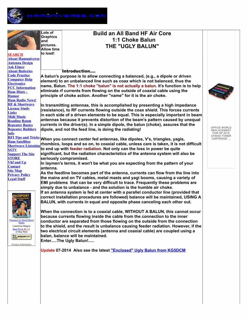
Build an All Band HF Air Core 1:1 Choke Balun
THE "UGLY BALUN"
Introduction....A balun's purpose is to allow connecting a balanced, (e.g., a dipole or drivenelement) to an unbalanced line such as coax which is not balanced, thus thename, Balun. The 1:1 choke "balun" is not actually a balun. It's function is to helpeliminate rf currents from flowing on the outside of coaxial cable using theprinciple of choke action. Another "name" for it is the air choke.
In transmitting antennas, this is accomplished by presenting a high impedance(resistance), to RF currents flowing outside the coax shield. This forces currentsin each side of a driven elements to be equal. This is especially important in beamantennas because it prevents distortion of the beam's pattern caused by unequalcurrents in the driver(s). In a simple dipole, the balun (choke), assures that thedipole, and not the feed line, is doing the radiating!
When you connect center fed antennas, like dipoles, V's, triangles, yagis,rhombics, loops and so on, to coaxial cable, unless care is taken, it is not difficultto end up with feeder radiation. Not only can the loss in power be quitesignificant, but the radiation characteristics of the antenna system will also beseriously compromised.In laymen's terms, it won't be what you are expecting from the pattern of yourantenna. As the feedline becomes part of the antenna, currents can flow from the line intothe mains and on TV cables, metal masts and yagi booms, causing a variety ofEMI problems that can be very difficult to trace. Frequently these problems aresimply due to unbalance - and the solution is the humble air choke.If an antenna system is fed at center with a parallel conductor line (provided thatcorrect installation procedures are followed) balance will be maintained, USING ABALUN, with currents in equal and opposite phase canceling each other out.
When the connection is to a coaxial cable, WITHOUT A BALUN, this cannot occurbecause currents flowing inside the cable from the connection to the innerconductor are separated from those flowing on the outside from the connectionto the shield, and the result is unbalance causing feeder radiation. However, if thetwo electrical circuit elements (antenna and coaxial cable) are coupled using abalan, balance will be maintained.Enter.....The Ugly Balun!.....
Update 07-2014 Also see the latest "Enclosed" Ugly Balun from KG5DCM
OFFICE WORLDREPLACEMENT
FOR HP 201XCF400X TONERCARTRIDGE …
An Inexpensive, High-Performance, Ugly 50 ohm Balun "Building a no-grief 1.8MHz to 30MHz 50ohm-balun is easy.!"
"No costly ferrite-cores are needed, just a short length of 3 to 5 inch size plasticpipe, about 25 feet of 50ohm coax plus some nylon cable ties.
Solid-dielectric coax is best for this application because foam-dielectric has atendency to allow a change in the conductor to conductor spacing over a periodof time if it is bent into a tight circle. This can eventually result in voltagebreakdown of the internal insulation.
The required length of the plastic pipe depends on the diameter and length of thecoax used and the diameter of the pipe. For RG-213/U coax, about one foot of 5inch size pipe is needed for a 1.8MHz to 30MHz balun. For 3.5MHz to 30MHzcoverage, about 18 to 21 feet of coax is needed. This length of coax is alsoadequate for most applications on 1.8MHz.
18 to 21 feet should cover all of 160 through 10 meters.The number of turns is not critical because the inductance depends more on thelength of the wire (coax) than on the number of turns, which will vary dependingon the diameter of the plastic pipe that is used.
The coax is single-layer close-wound on the plastic pipe.
The first and last turns of the coax are secured to the plastic pipe with nyloncable ties passed through small holes drilled in the plastic pipe.
The coil winding must not be placed against a conductor. The name of this simple but effective device is a choke balun. NOTE: Some people build choke-baluns, without a plastic coil-form, by scramble-winding the coax into a coil and taping it together. The problem with scramble-winding is that the first and last turns of the coax may touch each other. Thiscreates two complications. The distributed-capacitance of the balun is increasedand the RF-lossy vinyl jacket of the coax is subjected to a high RF-voltage. The
single-layer winding on the plastic coil-form construction method solves theseproblems since it divides the RF-voltage and capacitance evenly across each turnof the balun"....AG6K
Credit for this article goes to AG6K, Rick Measures and was edited from a Pre-copy version of another article titled "A BALANCED - BALANCED ANTENNATUNER" published in QST,February, 1990.
Video from K8CPA and his ugly balun -----------------------------------------------------------------
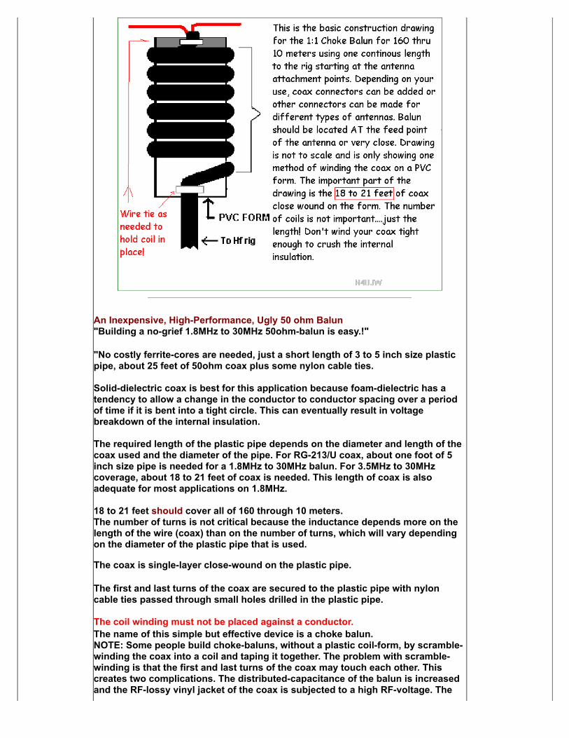
Step by Step Sequence of building the "Ugly Balun" incorporated as a centerinsulator also using PVC by KC7AVA. (Sequence is from left to right and down
page.)
4" PVC and RG213 Winding the 21' of coax Securing coax with cable ties
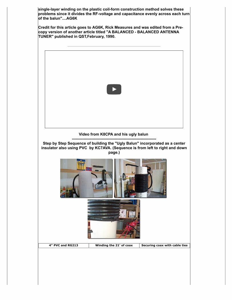
So239 installed Preparing the coax Adding a solder lug
Connecting the coax to theSO239
Taping the leads Eye-bolt antenna terminalsinstalled
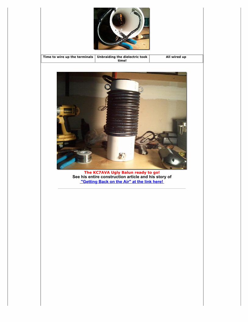
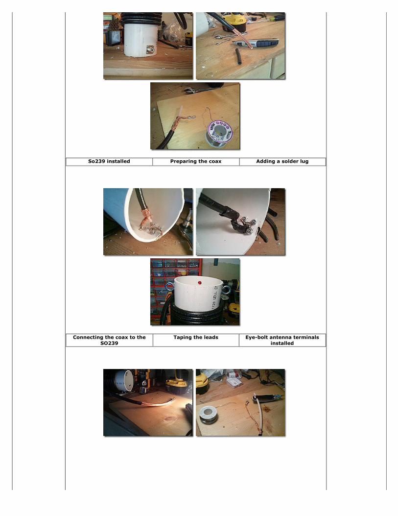
Time to wire up the terminals Unbraiding the dielectric tooktime!
All wired up
The KC7AVA Ugly Balun ready to go!See his entire construction article and his story of
"Getting Back on the Air" at the link here!
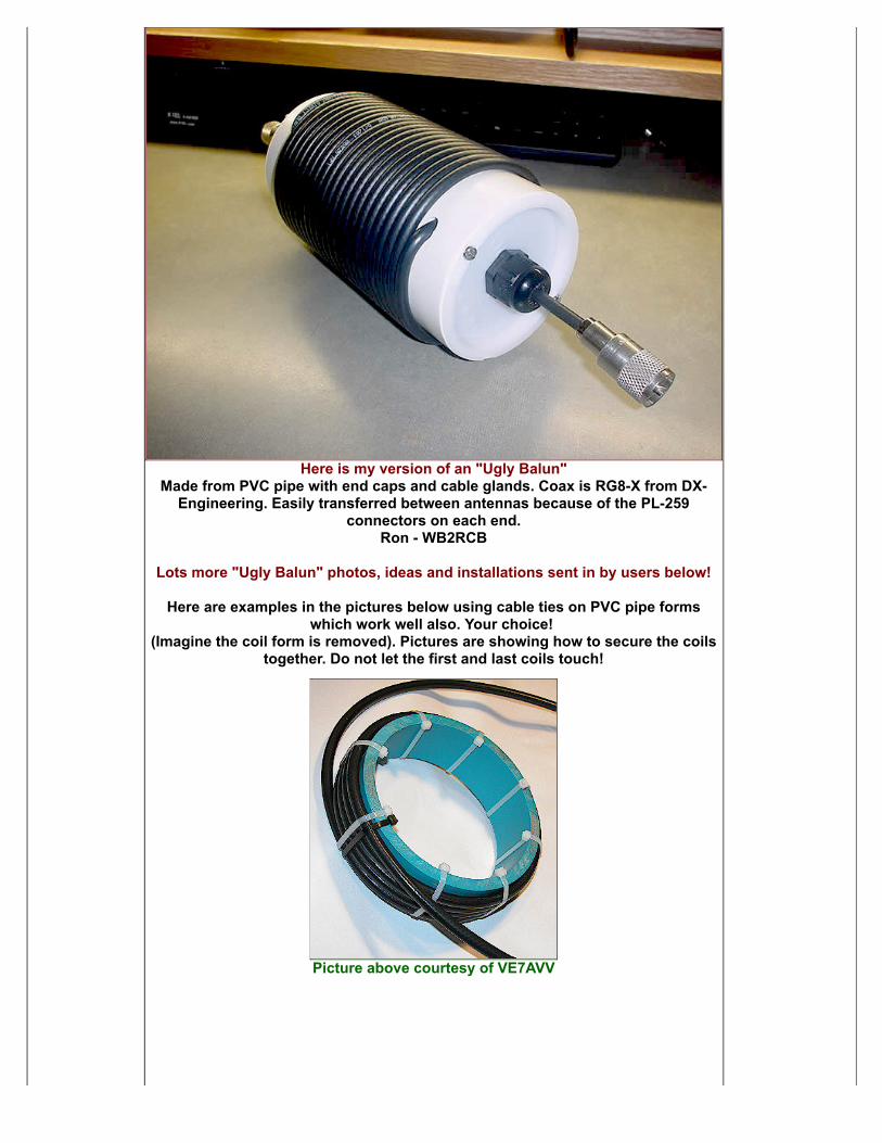
Here is my version of an "Ugly Balun"Made from PVC pipe with end caps and cable glands. Coax is RG8-X from DX-
Engineering. Easily transferred between antennas because of the PL-259connectors on each end.
Ron - WB2RCB
Lots more "Ugly Balun" photos, ideas and installations sent in by users below!
Here are examples in the pictures below using cable ties on PVC pipe formswhich work well also. Your choice!
(Imagine the coil form is removed). Pictures are showing how to secure the coilstogether. Do not let the first and last coils touch!
Picture above courtesy of VE7AVV
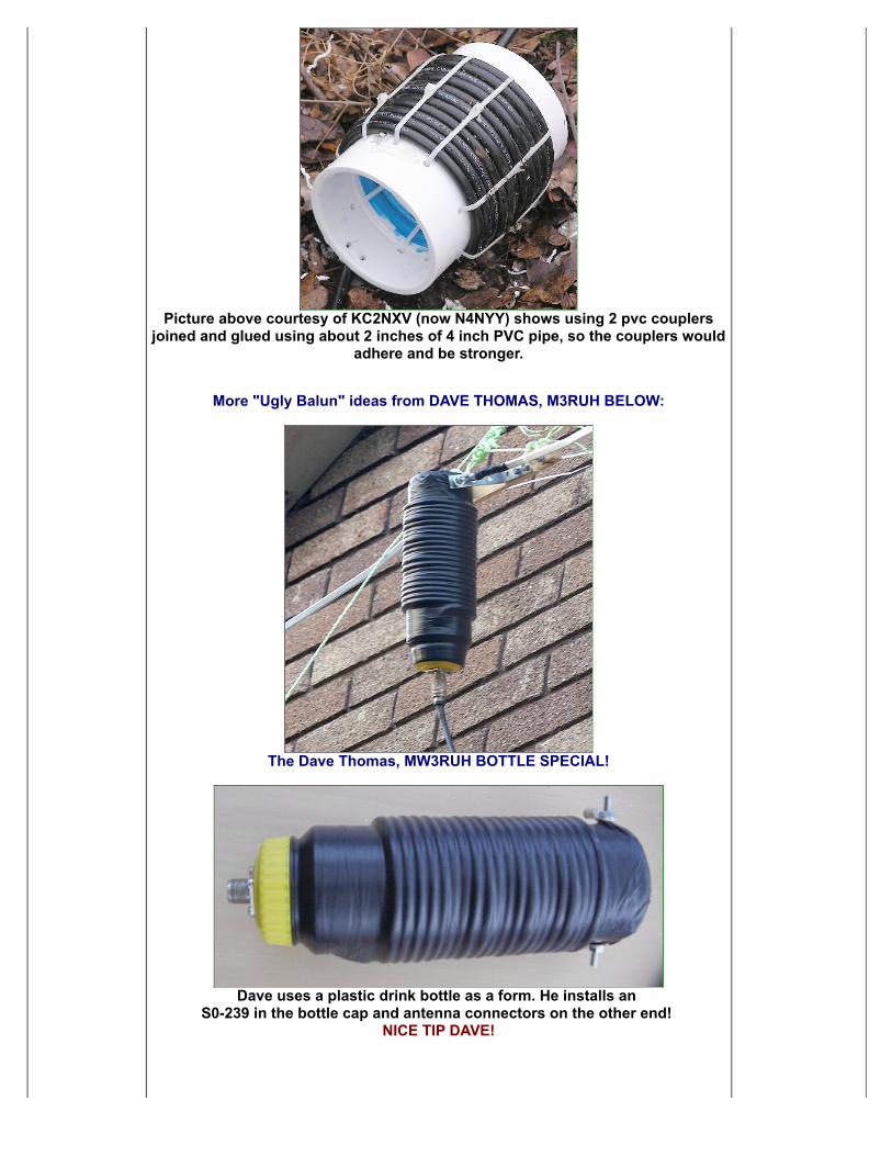
Picture above courtesy of KC2NXV (now N4NYY) shows using 2 pvc couplersjoined and glued using about 2 inches of 4 inch PVC pipe, so the couplers would
adhere and be stronger.
More "Ugly Balun" ideas from DAVE THOMAS, M3RUH BELOW:
The Dave Thomas, MW3RUH BOTTLE SPECIAL!
Dave uses a plastic drink bottle as a form. He installs an S0-239 in the bottle cap and antenna connectors on the other end!
NICE TIP DAVE!
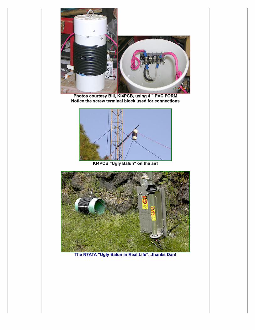
Photos courtesy Bill, KI4PCB, using 4 " PVC FORMNotice the screw terminal block used for connections
KI4PCB "Ugly Balun" on the air!
The N7ATA "Ugly Balun in Real Life"...thanks Dan!
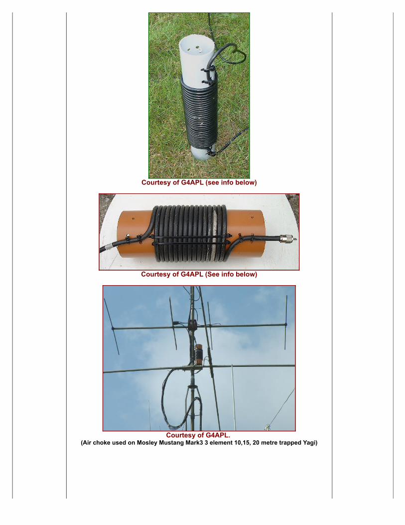
Courtesy of G4APL (see info below)
Courtesy of G4APL (See info below)
Courtesy of G4APL. (Air choke used on Mosley Mustang Mark3 3 element 10,15, 20 metre trapped Yagi)
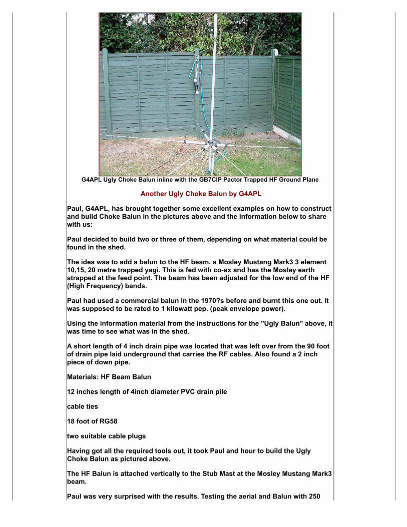
G4APL Ugly Choke Balun inline with the GB7CIP Pactor Trapped HF Ground Plane
Another Ugly Choke Balun by G4APL
Paul, G4APL, has brought together some excellent examples on how to constructand build Choke Balun in the pictures above and the information below to sharewith us:
Paul decided to build two or three of them, depending on what material could befound in the shed.
The idea was to add a balun to the HF beam, a Mosley Mustang Mark3 3 element10,15, 20 metre trapped yagi. This is fed with co-ax and has the Mosley earthstrapped at the feed point. The beam has been adjusted for the low end of the HF(High Frequency) bands.
Paul had used a commercial balun in the 1970?s before and burnt this one out. Itwas supposed to be rated to 1 kilowatt pep. (peak envelope power).
Using the information material from the instructions for the "Ugly Balun" above, itwas time to see what was in the shed.
A short length of 4 inch drain pipe was located that was left over from the 90 footof drain pipe laid underground that carries the RF cables. Also found a 2 inchpiece of down pipe.
Materials: HF Beam Balun
12 inches length of 4inch diameter PVC drain pile
cable ties
18 foot of RG58
two suitable cable plugs
Having got all the required tools out, it took Paul and hour to build the UglyChoke Balun as pictured above.
The HF Balun is attached vertically to the Stub Mast at the Mosley Mustang Mark3beam.
Paul was very surprised with the results. Testing the aerial and Balun with 250

Watts the standing wave was surprisingly good.
Never seen this beam produce these results before!
14.005MHz to 14.150MHz 1.1:1
14.200MHz 1.2:1
14.250MHz 1.4:1
14.300MHz 1.9:1
21.005MHz to 21.300 1.1:1
21.400MHz 1.2:1
28.005MHz ? 28:400MHz 1.1:1
28.500MHz 1.2:1
Now to do some dxing and see how the aerial performs.Hope the above is of use to you.........73 Paul G4APL
============================================
More from ZL1ALZ, JOHN from New Zealand!"Ugly Balun" construction used on a 40 meter vertical!
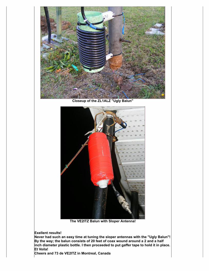
Closeup of the ZL1ALZ "Ugly Balun"
The VE2ITZ Balun with Sloper Antenna!
Exellent results! Never had such an easy time at tuning the sloper antennas with the "Ugly Balun"!By the way; the balun consists of 20 feet of coax wound around a 2 and a halfinch diameter plastic bottle. I then proceeded to put gaffer tape to hold it in place.Et Voila! Cheers and 73 de VE2ITZ in Montreal, Canada
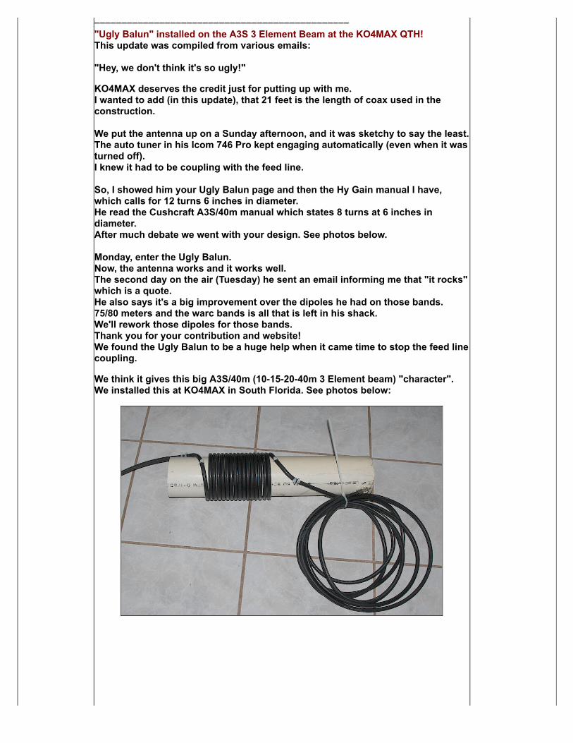
==============================================="Ugly Balun" installed on the A3S 3 Element Beam at the KO4MAX QTH!This update was compiled from various emails:
"Hey, we don't think it's so ugly!"
KO4MAX deserves the credit just for putting up with me. I wanted to add (in this update), that 21 feet is the length of coax used in theconstruction. We put the antenna up on a Sunday afternoon, and it was sketchy to say the least.The auto tuner in his Icom 746 Pro kept engaging automatically (even when it wasturned off).I knew it had to be coupling with the feed line. So, I showed him your Ugly Balun page and then the Hy Gain manual I have,which calls for 12 turns 6 inches in diameter.He read the Cushcraft A3S/40m manual which states 8 turns at 6 inches indiameter.After much debate we went with your design. See photos below. Monday, enter the Ugly Balun.Now, the antenna works and it works well.The second day on the air (Tuesday) he sent an email informing me that "it rocks"which is a quote.He also says it's a big improvement over the dipoles he had on those bands.75/80 meters and the warc bands is all that is left in his shack.We'll rework those dipoles for those bands.Thank you for your contribution and website!We found the Ugly Balun to be a huge help when it came time to stop the feed linecoupling.
We think it gives this big A3S/40m (10-15-20-40m 3 Element beam) "character".We installed this at KO4MAX in South Florida. See photos below:
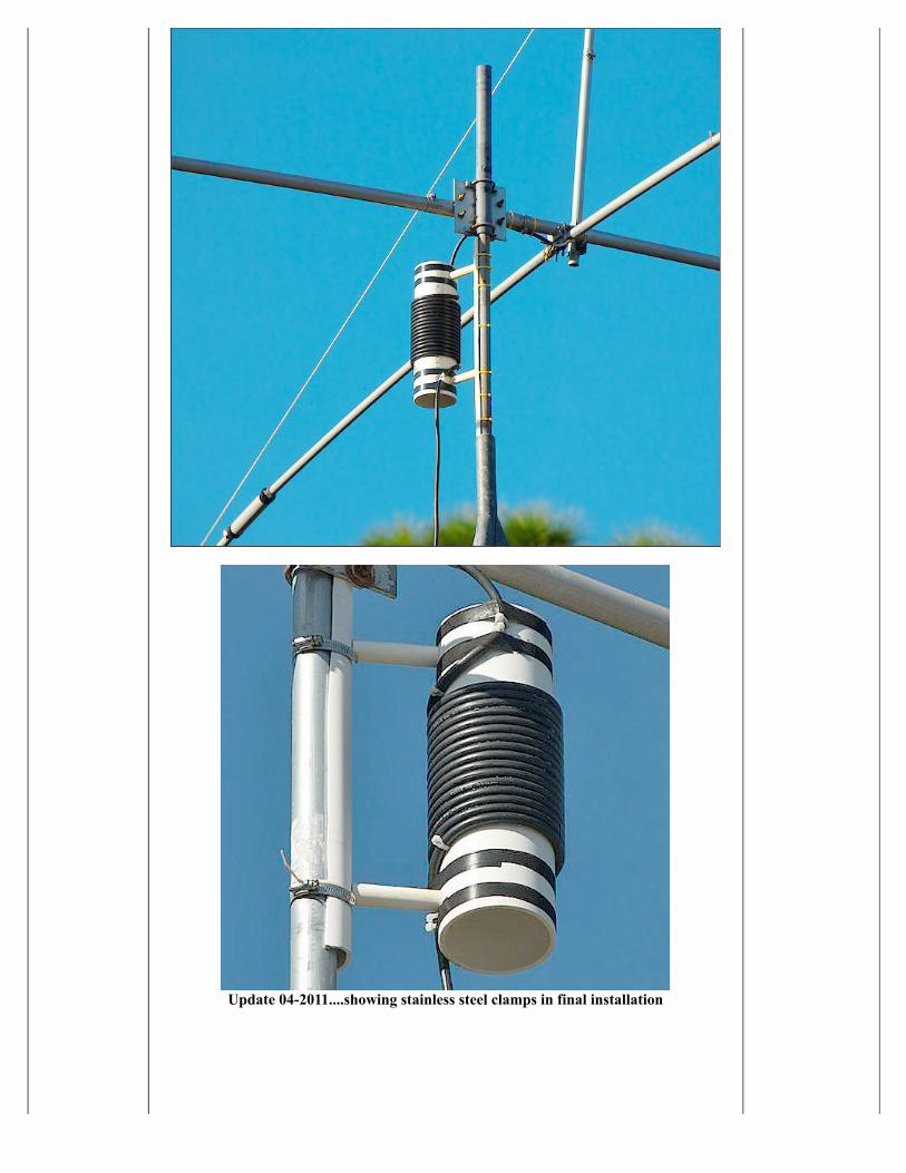
Update 04-2011....showing stainless steel clamps in final installation
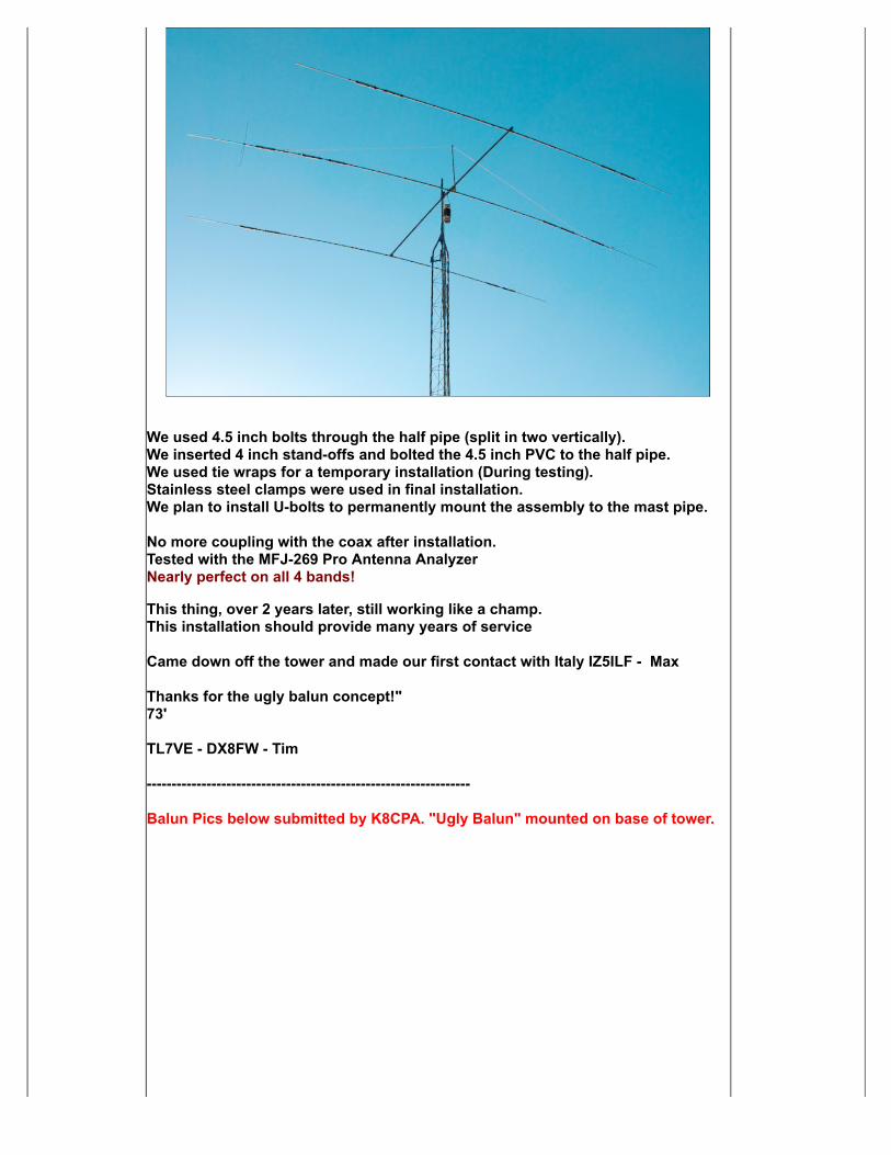
We used 4.5 inch bolts through the half pipe (split in two vertically).We inserted 4 inch stand-offs and bolted the 4.5 inch PVC to the half pipe.We used tie wraps for a temporary installation (During testing). Stainless steel clamps were used in final installation.We plan to install U-bolts to permanently mount the assembly to the mast pipe.
No more coupling with the coax after installation.Tested with the MFJ-269 Pro Antenna AnalyzerNearly perfect on all 4 bands!
This thing, over 2 years later, still working like a champ.This installation should provide many years of service
Came down off the tower and made our first contact with Italy IZ5ILF - Max
Thanks for the ugly balun concept!"73'
TL7VE - DX8FW - Tim
-----------------------------------------------------------------
Balun Pics below submitted by K8CPA. "Ugly Balun" mounted on base of tower.
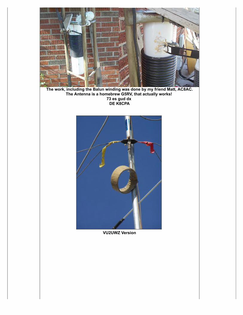
The work, including the Balun winding was done by my friend Matt, AC8AC.The Antenna is a homebrew G5RV, that actually works!
73 es gud dx DE K8CPA
VU2UWZ Version
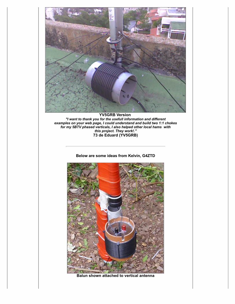
YV5GRB Version "I want to thank you for the usefull information and different
examples on your web page, I could understand and build two 1:1 chokesfor my 5BTV phased verticals, I also helped other local hams with
this project. They work!."73 de Eduard (YV5GRB)
Below are some ideas from Kelvin, G4ZTD
Balun shown attached to vertical antenna
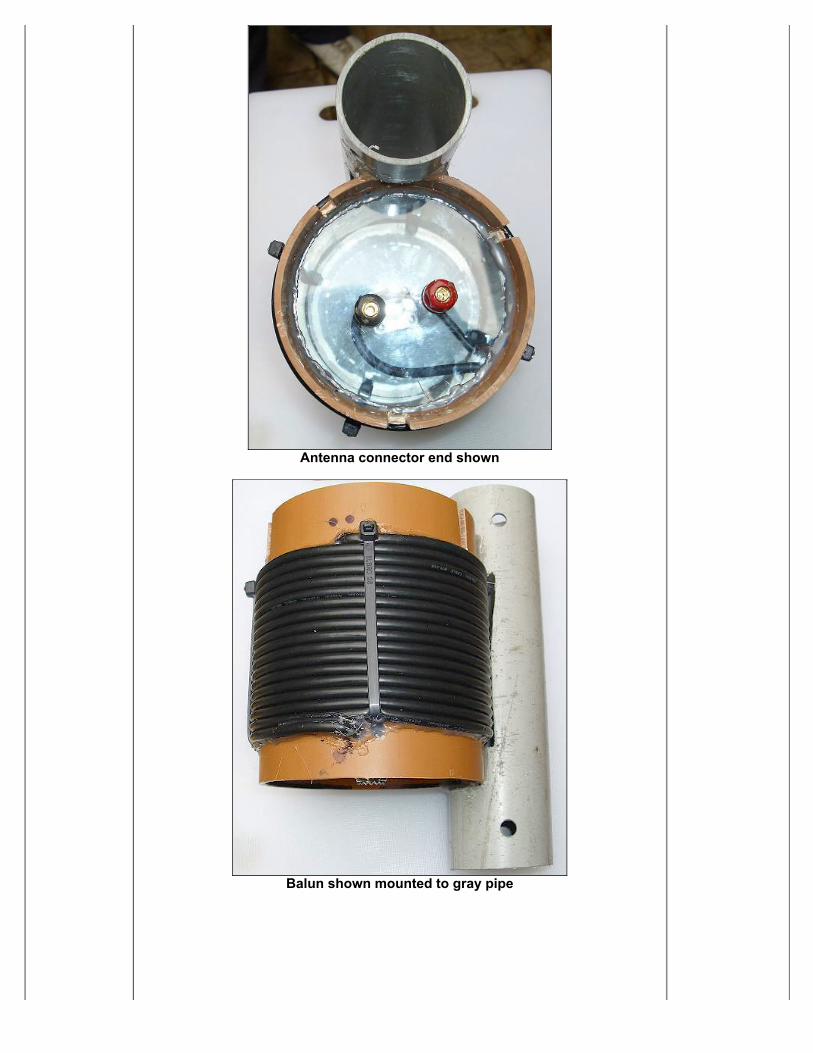
Antenna connector end shown
Balun shown mounted to gray pipe
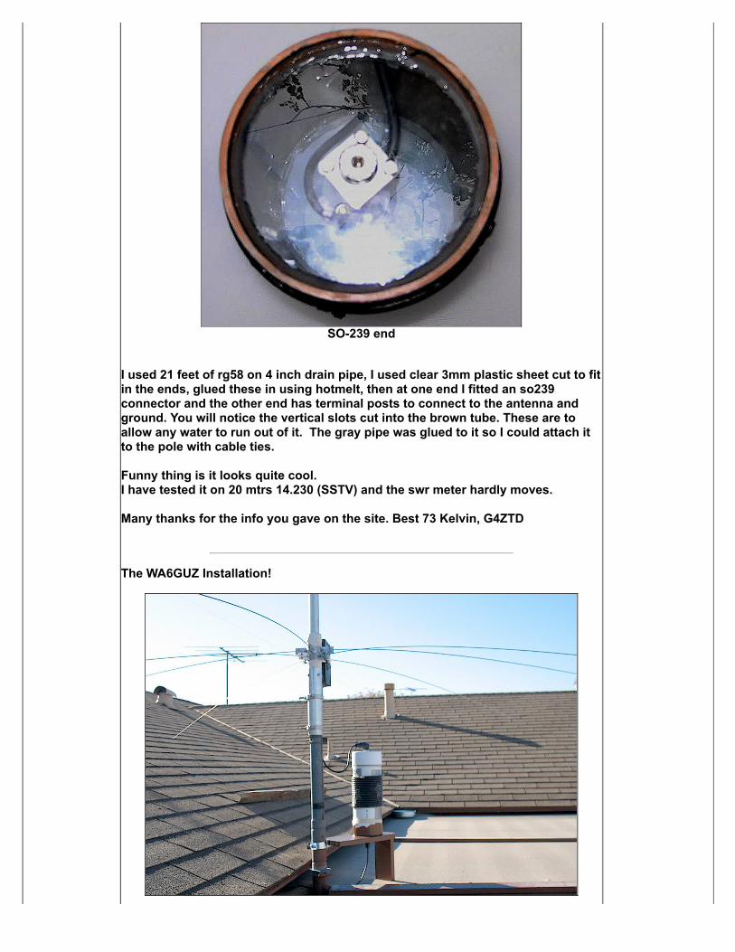
SO-239 end
I used 21 feet of rg58 on 4 inch drain pipe, I used clear 3mm plastic sheet cut to fitin the ends, glued these in using hotmelt, then at one end I fitted an so239connector and the other end has terminal posts to connect to the antenna andground. You will notice the vertical slots cut into the brown tube. These are toallow any water to run out of it. The gray pipe was glued to it so I could attach itto the pole with cable ties.
Funny thing is it looks quite cool.I have tested it on 20 mtrs 14.230 (SSTV) and the swr meter hardly moves.
Many thanks for the info you gave on the site. Best 73 Kelvin, G4ZTD
The WA6GUZ Installation!
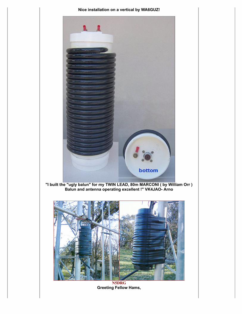
Nice installation on a vertical by WA6GUZ!
"I built the "ugly balun" for my TWIN LEAD, 80m MARCONI ( by William Orr )Balun and antenna operating excellent !" VK4JAO- Arno
N5DRGGreeting Fellow Hams,
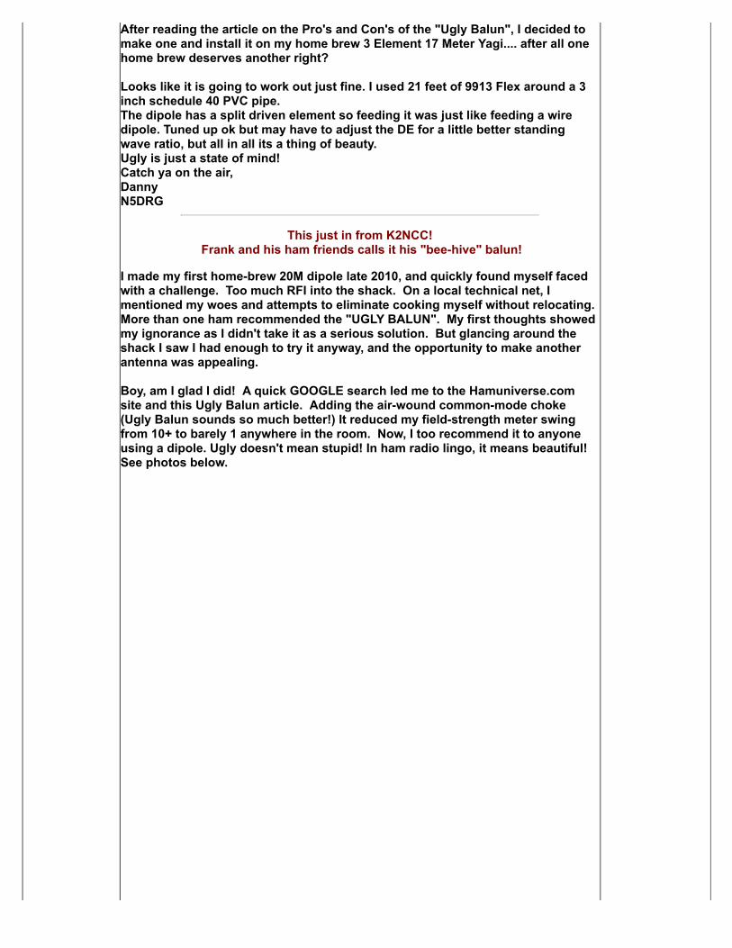
After reading the article on the Pro's and Con's of the "Ugly Balun", I decided tomake one and install it on my home brew 3 Element 17 Meter Yagi.... after all onehome brew deserves another right? Looks like it is going to work out just fine. I used 21 feet of 9913 Flex around a 3inch schedule 40 PVC pipe.The dipole has a split driven element so feeding it was just like feeding a wiredipole. Tuned up ok but may have to adjust the DE for a little better standingwave ratio, but all in all its a thing of beauty.Ugly is just a state of mind!Catch ya on the air,DannyN5DRG
This just in from K2NCC! Frank and his ham friends calls it his "bee-hive" balun!
I made my first home-brew 20M dipole late 2010, and quickly found myself facedwith a challenge. Too much RFI into the shack. On a local technical net, Imentioned my woes and attempts to eliminate cooking myself without relocating. More than one ham recommended the "UGLY BALUN". My first thoughts showedmy ignorance as I didn't take it as a serious solution. But glancing around theshack I saw I had enough to try it anyway, and the opportunity to make anotherantenna was appealing.
Boy, am I glad I did! A quick GOOGLE search led me to the Hamuniverse.comsite and this Ugly Balun article. Adding the air-wound common-mode choke(Ugly Balun sounds so much better!) It reduced my field-strength meter swingfrom 10+ to barely 1 anywhere in the room. Now, I too recommend it to anyoneusing a dipole. Ugly doesn't mean stupid! In ham radio lingo, it means beautiful!See photos below.
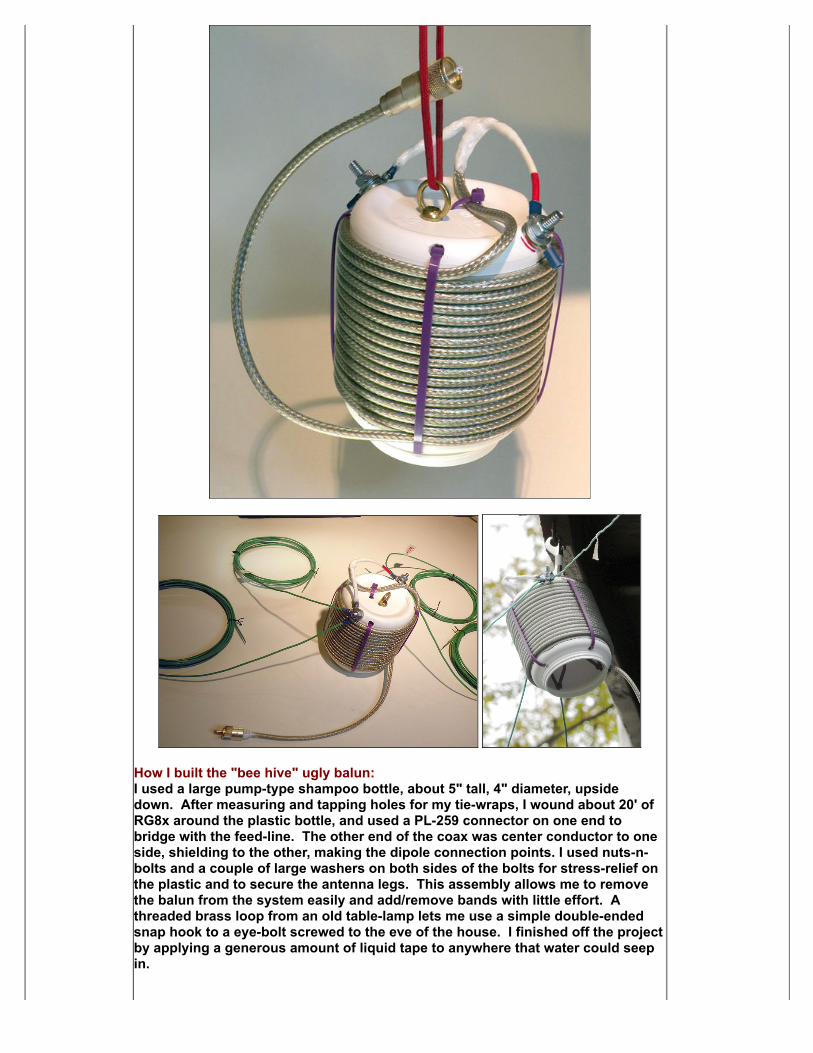
How I built the "bee hive" ugly balun:I used a large pump-type shampoo bottle, about 5" tall, 4" diameter, upsidedown. After measuring and tapping holes for my tie-wraps, I wound about 20' ofRG8x around the plastic bottle, and used a PL-259 connector on one end tobridge with the feed-line. The other end of the coax was center conductor to oneside, shielding to the other, making the dipole connection points. I used nuts-n-bolts and a couple of large washers on both sides of the bolts for stress-relief onthe plastic and to secure the antenna legs. This assembly allows me to removethe balun from the system easily and add/remove bands with little effort. Athreaded brass loop from an old table-lamp lets me use a simple double-endedsnap hook to a eye-bolt screwed to the eve of the house. I finished off the projectby applying a generous amount of liquid tape to anywhere that water could seepin.
Now I'm happy as a (uncooked!) clam. (I should'a said ham!!). What a superb and simple solution. Thank you!Frank, K2NCCHillsboro, Oregon
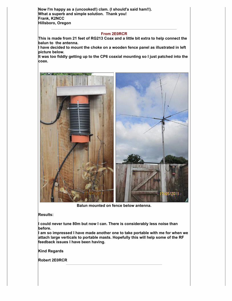
From 2E0RCRThis is made from 21 feet of RG213 Coax and a little bit extra to help connect thebalun to the antenna.I have decided to mount the choke on a wooden fence panel as illustrated in leftpicture below. It was too fiddly getting up to the CP6 coaxial mounting so I just patched into thecoax.
Balun mounted on fence below antenna.
Results: I could never tune 80m but now I can. There is considerably less noise thanbefore.I am so impressed I have made another one to take portable with me for when weattach large verticals to portable masts. Hopefully this will help some of the RFfeedback issues I have been having. Kind Regards Robert 2E0RCR
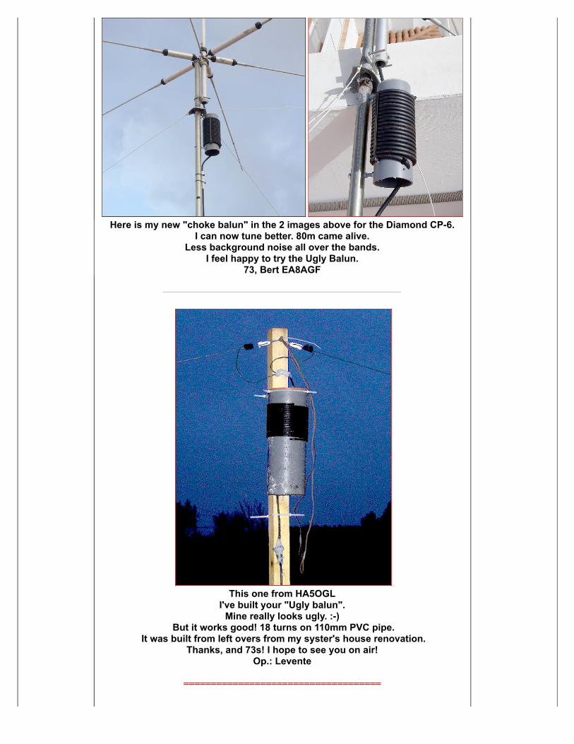
Here is my new "choke balun" in the 2 images above for the Diamond CP-6.
I can now tune better. 80m came alive.Less background noise all over the bands.
I feel happy to try the Ugly Balun.73, Bert EA8AGF
This one from HA5OGL
I've built your "Ugly balun".Mine really looks ugly. :-)
But it works good! 18 turns on 110mm PVC pipe. It was built from left overs from my syster's house renovation.
Thanks, and 73s! I hope to see you on air!Op.: Levente
====================================
More reading about the "Ugly Balun from N6JSX and how he built his. (pdfdocument download, 3 pages)
Notes from builders:Email Concerning the "Ugly Balun" From Russ Wilson <ve6vk@telusplanetlnet>
"Don. I built one of the "Ugly Baluns". I was using it on a dipole for 80/40 meters. I had some TVI without the balun, so no doubt the feedline was radiating. With the balun attached, the TVI completely disappeared. I built a second one as Ihad the same TVI problem with an R7. The balun cured this as well. I can run mylinear now with no problems as all. So I appreciate your expertise and your article." Thank you. Best Wishes Russ, VE6VK CHECK OUT RUSS'S ANTENNA PROJECTS ON THIS SITE: 20 METER MINI BEAM
20 METER V BEAM
Photo Credit VE7AVV taken with permission from his project at:The TH6 Balun Replacement ProjectSee the rest of his site here!
Find here gifts along with leather jackets for women. How we can forget the faux fur coatswhich are highly being demanded by varsity jackets. Youngsters also buy gifts along withwholesale leather jackets closeout. Get here also Pass4sure Pass4sure ccna dumps trainingand Pass4sure 352-001 exam questions.
Powered by Ham Radio!
© 2000 - 2017 N4UJW Hamuniverse.com and/or article author! - All Rights Reserved.