Embed Size (px)
Citation preview

i
MECHANICAL ENGINEERING DESIGN 1 (MECN2014)
Title: BRIDGE DESIGN PROJECT
Group Number: 44
Names: Phuti Balty Tjale (607911)
Masego Erens (569332)
Thabo Lepota (568571)
Humphry Tlou (681141)
Date: 15 September 2015


Table of Contents Executive summary .......................................................................................................................1
1. Introduction ...........................................................................................................................2
1.1 Task as given ............................................................................................................................. 2
1.2 Literature review ....................................................................................................................... 2
1.3 Material strength ....................................................................................................................... 3
1.4 Material availability .................................................................................................................. 4
1.5 Glue information ....................................................................................................................... 4
1.6 Competition requirements and rules ......................................................................................... 5
2. Task as understood ................................................................................................................6
3. Product Requirements and Specifications (PRS) ...................................................................7
3.1 Requirements ............................................................................................................................ 7
3.2 Constraints ................................................................................................................................ 7
3.3 Criteria ...................................................................................................................................... 8
4. Functional Analysis ...............................................................................................................9
5. Concept development and analysis ...................................................................................... 10
5.1 Concept 1 ................................................................................................................................ 10
5.2 Concept 2 ................................................................................................................................ 11
5.3 Concept 3 ................................................................................................................................ 12
5.4 Concept 4 ................................................................................................................................ 12
6. Concept selection ................................................................................................................. 14
7. Detailed design development ................................................................................................ 16
7.1 Calculation of forces on each member .................................................................................... 16
7.2 Buckling .................................................................................................................................. 18
8. Design Specifications ........................................................................................................... 21
8.1 Performance Specification ............................................................................................................ 22
8.2 Recommendations ......................................................................................................................... 22
9. References ........................................................................................................................... 23
10. Appendices .......................................................................................................................... 24

1
Executive summary
This report outlines the design process followed in the construction of a cardboard paper bridge –
built from only cardboard paper of 300gsm and glue. The primary aim of the task was to design
the bridge that is engineered to complete the task of supporting loadings at its mid-span while
flat and when tilted to an angle of 30˚ to the horizontal with a maximum deflection of 5mm.
Initially, individual concepts of the bridge were designed separately. Team members
brainstormed and integrated ideas for the concepts. New sketches were created from the
individual concepts and discussions were held regarding the proposed function of the
components and the overall bridge. In total, four concepts were proposed and a selection matrix
used to identify which of the four scored the most in terms of the criteria used. Stress, buckling
and deflection calculations were incorporated to determine which would withstand the most
loads and strength of each.
The most suitable design came out as the third concept. It has fewer members than the rest but
can withstand the most forces. The deflection thereof was found to be 1.866mm downwards
under a load of 5kg and the component through which the axle that will have the rope attached to
it will go has very minimal chances of tearing since it is attached to the bottom of the deck of the
bridge. The highest stressed member in has a load of 33.04N but with a critical load of 2.89kN,
thus the possibility of members failing is minimal.
It is manufactured by cutting the specified paper size with a knife cutter and folding until
specified thickness. Only triangular and cylindrical members are used, which are easy to fold
out. Holes the same size and shape as the cross-section of each member are drilled to the specific
member and location they have to be connected to. Glue is smeared onto the joints before they
are attached to members.
The overall design lacks resemblance to an actual bridge in terms of the small details which
make it possible to use a bridge. Hand or side rails could be introduced to avoid passengers of
vehicles from falling over. Lane markings on the road to indicate a proper road surface would
also enhance aesthetics. Careful attention should be paid to the dimensions used so that one can
carefully estimate the mass of the bridge without weighing (which is only done after it is built).

2
1. Introduction
1.1 Task as given
A project has been assigned where it is expected of us to design a cardboard bridge from
cardboard paper that has a maximum weight of 300 gsm and restricted dimensions of 841mm x
1189mm (A0). The bridge must be able to support a minimum mid-span load of 3kg without any
sign of structural failure with a maximum deflection of 5mm. A truck having the dimensions:
125mm (H) x 75mm (W) must pass through without any obstruction. The bridge will be capable
of spanning a river that is 500mm wide while it has a supporting structure which may not extend
20mm below the straight level support line (point where it rests on the testing station). The
support structure of the bridge will have a 5mm pin connection to support one side of a bridge
while the other bridge support will have a smooth horizontal surface to support the other side of
the bridge. In addition, the bridge has to pivot about the pinned connection to an angle of 30° to
allow boats to pass under the bridge with sufficient clearance.
1.2 Literature review
Bridge design is constantly revolutionized by the significant demand of bridges by the
community or public. While bridges are in demand, many factors which affect the quality of the
designs thereof have imposed a competitive innovation of various types of bridges which have
different capabilities.
The wooden truss bridges were used since 1700s because of their high level of strength. They
were also used for railroad bridges mainly because of the heavy loads they can support, however
they were not preferred since they are very difficult to construct, requires a high maintenance
which is costly and difficult to widen if necessary [1].
Nevertheless, beam bridges came to the rescue since they are simplest to design and build. These
beam bridges consist of vertical piers and horizontal beam, while their strength depends on the
strength of the roadway so their strength can be increased by additional piers which are mainly a
firm combination of concrete and steel. The steel enhances the strength of concrete when
stretched under tension [2]. The weight of the beam bridges pushes straight down on the piers

3
[3].Although beam bridges can be quite long, the span or distance between adjacent piers is
usually small. However beam bridges have a limited span and do not allow large ships or heavy
boat traffic to pass underneath [1].
For that reason, newly innovated suspension bridges were designed and built in 1801 in
Pennsylvania. Suspension bridges are strong, have a long span distance and allow large ships and
heavy boats traffic to pass underneath the bridge [1]. Since suspension bridges are suspended
from the cables, as traffic passes on the road, the weight is carried by the cables which transfer
the force of compression to the two towers and the cable also have the constant force of tension
which are stretched because the roadway is suspended from them. However they are very
expensive because they take a long time to build and require a large amount of materials [1].
It is clear from the existing bridges that various factors which may affect the functionality,
strength and criteria of the bridges are considered for the improvement of bridge designs.
1.3 Material strength
Cardboard paper is generally stronger than the average normal paper. In tension it does not snap
easily when pulled from both ends with equal forces but components made from it will buckle
easily under a compressive loading [6]. The tensile properties of paper are measured by clamping
a strip between two grips and applying a tensile load until the strip breaks but it is difficult to
obtain the exact value of the tensile strength of cardboard paper. Tensile strength is defined as
the breaking force divided by the width of the strip and has the units 𝑁/𝑚 [6]. The modulus of
elasticity of cardboard paper is also very difficult to obtain due to paper being very thin and
snapping too quickly during testing.
Due to the manufacturing process of paper, the elastic modulus 𝐸 thereof is significantly
anisotropic, which makes it very different from most materials. The manufacturing process
results in paper 𝐸𝑥 > 𝐸𝑦. This means that the elastic modulus of fibres in the longitudinal
direction is larger than that of the fibres in the transverse direction [7]. Experimentally the
modulus of elasticity of paper board (100 − 400 gsm) for the 𝑥(MD) and 𝑦(CD) directions have
been determined to be 5420𝑀𝑝𝑎 and 1900𝑀𝑝𝑎 respectively. Thus combining the two gives an
average of 5724.5𝑀𝑝𝑎.

4
The other factors that influence the strength of cardboard paper are the moisture content of the
paper (thus air humidity), paper directionality, folding endurance, stiffness and effects of
recycling. The moister the cardboard becomes, the weaker it gets [8]. All types of paper gain or
lose moisture due to ambient humidity and the properties of paper change with the moisture
content. Paper fibres become weakened through every recycling cycle, thus virgin paper will
inherently be stronger than recycled paper. The ability of paper to resist being bent is what
stiffness is. When a strip of paper is subjected to continuous folding under tension it will
eventually break. The number of folds it can endure before it breaks is the measure of the
endurance resistance of paper. Cardboard paper is stiffer when bent and folded across the grain
than along the grain (machined direction) [8].
1.4 Material availability
Cardboard A0 sheets are readily available and do not require any additional work on them. Most
printer shops and gift shops (which also have a number of glues) sell these at a price of
approximately R50 per sheet. There are plenty of such shops in close vicinity thus it will not be a
problem to acquire all the material needed for the construction of the bridge. Literally only two
materials are needed for the entire construction; glue and cardboard.
1.5 Glue information
Glues are part of a larger family called adhesives. The two classes are distinguished by the fact
that glue comes from organic compounds while adhesives are chemical-based. Adhering
materials called epoxies, caulks, or sealants are also chemical compounds that have special
additives to give them properties suitable for particular jobs or applications [4].
It is every group’s responsibility to choose their own glue type to use on their construction of the
bridge but with the exception of super glue and epoxy. The glue is selected in such a way that it
will bond to every component of the bridge; making the joints very strong in order to keep the
bridge rigid and stable without causing the cardboard to warp.
There’s a quite a variety of glue types to choose from. In order to select glue, certain types of
glues had to be investigated to check which product best suits our design. In order to select

5
adhesives, mechanical properties were the simpler way to see which glue best suits our design.
The criterion used to select glue is the following: weight distribution, drying time, transparency
and colour after drying, strength and temperature resistance [5]. The one glue that fits our
criterion is white glue. The fact that it’s friendly to use, not toxic cheap unless ingested, readily
available and cleans up with water which is a solvent in them makes them the top contenders for
the design.
1.6 Competition requirements and rules
- The project should be done by groups of a maximum of four members with each member
spending at least 50 hours working on it.
- Strictly only a single sheet of A0 cardboard paper with dimensions 841mmx1189mm can
be used for all the parts of the bridge.
- Any glue other than super glue and epoxy glue are allowed for any joining needed.
- The scoring equation that will be used to assess the constructed bridge is the following:
𝑺𝒄𝒐𝒓𝒆 = 0.3 (0.35
𝐵𝑟𝑖𝑑𝑔𝑒 𝑚𝑎𝑠𝑠) + 0.4(𝑀𝑎𝑥𝑖𝑚𝑢𝑚 𝐿𝑜𝑎𝑑) + 0.3(𝑆𝑡𝑟𝑢𝑐𝑡𝑢𝑟𝑎𝑙 𝐹𝑎𝑖𝑙𝑢𝑟𝑒)

6
2. Task as understood
A bridge constructed out of cardboard paper has to be designed by groups of four. This should be
done from a single A0 sheet of 300gsm cardboard paper and must span a river that is 500mm
wide. The height at any location above the deck or road way must be greater than 125mm with a
width that is greater than 75mm in order to allow a truck of the dimensions; 125mm (H) x75mm
(W) to pass through. It must be capable of supporting a load of at least 3kg at the mid-span
without sustaining deflection of more than 5mm below its lowest point. The bridge should have
provisions for three 5mm axle pins at the mid-span, one end (below road surface and acting as a
pivot for the bridge) and somewhere on the bridge to allow attachment of a cable hoist. It should
be able to pivot about a pinned connection to an elevation of 30° to the horizontal for allowance
of boats to pass below it. Finally at this tilted position, it must sustain a 0.5kg weight attached to
the mid-span for about 10s. The bridge must be designed in such a way that the strength to
weight ratio is as high as possible to not compromise on weight even when optimizing its
strength.

7
3. Product Requirements and Specifications (PRS)
3.1 Requirements
Must span a 500mm wide river
A truck with the dimensions (125mm H × 75mm W) must be able to go through
the bridge with ease
Must pivot about pinned connection
Must be able to support a load of up to 3kg
Must be able to hold a suspended 0.5 kg mass for at least 10 seconds while being
tilted to an angle of 30˚
Provision must be made at the mid-span and one end of the bridge for a 5mm
diameter axle pin
3.2 Constraints
Bridge must be manufactured using only single sheet of A0 cardboard
Weight specification of the cardboard must not exceed 300gsm
The dimensions of the cardboard must be 841 mm × 1189 mm
The design components must be joined together by any type of glue except for
super glue and epoxy glue
The bridge must be able to hold a weight without a deflection greater than 5 mm
at most
Width of the bridge cannot exceed length of pin (i.e. must be less than 100mm)
Supporting structure may not be extended for more than 20mm below the straight
level support line

8
3.3 Criteria
Mass of the bridge should be at most or preferably 0.35kg (for a good score on
the equation)
The design must be for ease of manufacture (e.g. 2D development components
that can be cut out and folded easily)
It must be able to be tested with ease
The cost of the bridge should preferably not exceed R100
Number of components should not be too high to avoid needing more material
than allowed
The design should be aesthetically pleasing
Load carrying capacity must be greater than 3kg
A high stiffness (strength to weight ratio must be high )
The different 2D components must be easy to assemble
Deflection is minimum

9
4. Functional Analysis
START
Place bridge on
station for
testing
Insert pivot
axle through
bridge
Load bridge
with minimum
weight
Is the
deflection
≤5mm?
Hook rope to
axle placed at
top corner
Stop increasing
loads and then
remove
Pull rope until
bridge is tilted
30° to
horizontal
Keep increasing
load
Place the 0.5kg
load Is the
load
≤3kg?
STOP
Is there
imminent
failure?
No
No
No
Yes
Yes
Yes
Wait 10s
Remove weight
and bridge
from station

10
5. Concept development and analysis
It is common knowledge in structural engineering that to obtain optimum rigidity in a structure
that is under loading it is best to make use of triangulation in it. The concept designs that follow
have been developed in light of this fact, thus triangular trusses have been incorporated in all of
the concepts as much as possible to take advantage of their rigidity. Cutting triangles from
cardboard can also be done fairly easily than most shapes.
5.1 Concept 1
Figure 1
The well-known bridge that inspired this concept is the Warren Bridge. The basic design of this
concept is taking two trapeziums and joining them across the width of the bridge at the top joints
and midway through the bridge to make a complete bridge. This is done by having one beam
defining the height of the bridge that runs from end to end. The advantage with this is that there
will be fewer joints at the top of the bridge which suggests that there will be fewer points where
failure is most probable to occur.
A hole for the 3mm diameter axle pin that functions as a pivot is cut out from the material as part
of a component during manufacturing and thus the pin does not rest on any joints. Whereas the
axle pin to which the rope will be attached rests on the short member at the top right corner joint.
Although the weight of the pin before being pulled rests on a member it will not cause significant
buckling as the member onto which it rests is very short in comparison to the others. The joints
of the bridge are made more rigid by cutting out gusset plates according to the size and shape of
each joint in a particular position on the bridge. All the members forming a specific joint are
Height of the
bridge all
throughout is
160mm
Hole (±3.5mm) for
axle by which
bridge pivots
Road level
(where
cardboard
sheet will
rest)
The two
trapeziums
are the basic
structure
3mm diameter axle goes
through here and rests on the
short member
One of three beams
joining both trapeziums
of the bridge together

11
attached to these cut out gusset plates. These ensure less likelihood of failure at the joints due to
loading.
When loading is at the top of the bridge, normally trusses would follow the configuration
outlined by the dotted lines on the sketch. Since loading is the bottom, they have been placed in
such a way that they spread out to the bottom
5.2 Concept 2
Figure 2
In this concept the main objective was to come up with a bridge that has a strong member that
can bare the weight rather that most of it being taken by the lower deck. Another consideration
that led to this design was that when it tilts there will be a moment introduced so more mass was
moved at the back of the pivot to counteract this moment.
The advantage with this one is that where the axles will be positioned is strong and made of thick
material unlike being put at the joints. This minimizes stresses at the joints and ensures minimal
chances of failure at the axle locations. Another advantage is that while tilting, the problem of
having the part of the bridge to the left of the pivot being squashed to the ground is eliminated.
The disadvantage is that there are too many joints and thus as far as manufacturing is concerned
it might pose as a challenge. One other disadvantage is that the hollow members will be weak,
making it easier for failure at the joints.
The left side and right side are exactly
identical. Some members might have not
been excluded from the right side for
simplicity.
The components
coloured with black are
thick components with
a thickness that is a lot
more than the other
members
6 mm diameter
holes through
which 5mm
diameter axles will
be slit This arm also runs along the right
side of the bridge and supports a
lot of the downward load

12
5.3 Concept 3
Figure 3
The thinking behind this design was to remove as many members as possible, thus as many
joints as possible. In doing that it would result in a simple bridge that can be manufactured from
2D rolled sheets of paper instead of having too many members supporting loads. The advantage
with this design is that a lot of the members are cylindrical, which is easier to manufacture as one
just rolls paper to the desired dimensions. Another advantage is that when tilted the axle will lift
the component from the bridge but there is no potential for it to tear from the bridge unlike with
the previous design. Disadvantage is that aesthetic wise is not up to scratch, it lacks some
creativity
5.4 Concept 4
The diagonal and upright
members are triangular in
cross section.
Since this design has very fewer
members than the others, the
members can be made less
hollow
These members are
cylindrical
6mm diameter hole by
which the bridge will pivot
This curved part is thicker
than all the other part on
the bridge
The rope will be
hooked to axle slit
through here
Road level
Beam running beneath
the bridge

13
The advantage with this design is that below the deck of each bridge runs a beam looking like
corrugated cardboard. This will be constructed of two cardboard sheets sandwiching triangular
trusses folded from another cardboard paper. This beam together with the trusses above the deck
will absorb the load placed at the mid span of the bridge. Another advantage is due to the curved
section. It was introduced to allow for easy rotation, thus it is definite that no material after the
hole will touch the ground.
The disadvantages with this design are that the curve might be difficult to construct physically.
There are too many members and therefore many joints, hence there will be too much stresses
induced in the hole drilled into the joint to allow an axle for the rope to be put through.

14
6. Concept selection
To thoroughly select the best design concept, Matrix selection table is constructed where in all
the proposed ideas are judged according to the proposed criteria stated in the PRS. Below is a
tabulated data of all the three concepts.
Weightings start from 1-5
Scoring 5 = Excellent
4 = Good
3 = Average
2 = poor
1 = very poor
For a concept meeting a certain criteria specified in the requirements outstandingly it will receive
a score of 5, and if it meets averagely it will be accredited a score of 4. A concept scoring below
3 is attributed as a poor concept for a particular criterion.
Table 1: Matrix Selection
Criteria Weighting Concept
1
Concept
2
Concept
3
Concept 4
Weight 4 3(× 4) 3(× 4) 4(× 4) 4(× 4)
Manufacturability 5 3(× 5) 3(× 5) 4(× 5) 3(× 5)
Effective cost 4 3(× 4) 3(× 4) 4(× 4) 3(× 4)
Max load Support 5 4(× 5) 3(× 5) 4(× 5) 3(× 5)
Deflection 5 3(× 5) 2(× 5) 4(× 5) 2(× 5)
Aesthetics 4 3(× 4) 4(× 4) 3(× 4) 4(× 4)
Stiffness 4 2(× 4) 2(× 4) 3(× 4) 2(× 4)
Material
Consumption
5 3(× 5) 3(× 5) 2(× 5) 2(× 5)
Total Rating 109 103 126 102

15
From the matrix above it is observed that all concepts have relatively high total rating with very
little differences. All the concepts appear to be meeting the criteria of effective cost very well.
Although concept 1 can support relatively huge load, it’s not easy to be manufactured. Thorough
analysis revealed that concept 3 of the bridge meets meet most of the criteria listed above in the
matrix selection, with zero deflection, average aesthetic and can support at a load of 4 kg which
is greater than the one specified in the design requirement, hence this concept is selected as the
best among all the proposed designs.

16
7. Detailed design development
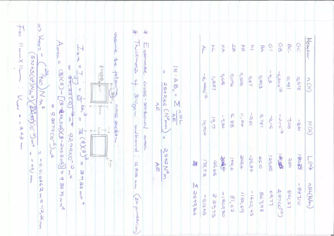
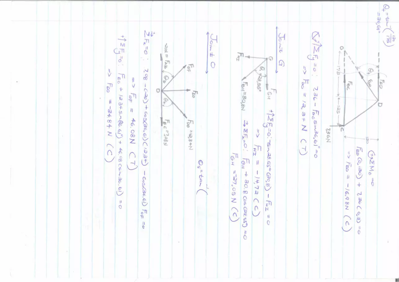
7.1 Calculation of forces on each member
Assumptions made for force analysis:
The load placed at the mid-span is 5kg and shared between the two vertical posts equally.
All joints are fixed joints
Thickness of the axles is neglected (thus dealing with point loads)
Area of contact between surface and bridge is negligible, thus reaction is a point load
Thickness of members ignored
↺ + ∑𝐵 = 0; −𝐴𝑦(0.68) + 24.53(0.42) + 24.53(0.26) = 0
𝐴𝑦 = 24.53𝑁
↑ + ∑𝐹𝑦 = 0; 𝐵𝑦 + 24.53 − 24.53 − 24.53 = 0 ∴ 𝐵𝑦 = 24.53𝑁
260 260 160
𝐴𝑦 2.5(9.81)
𝐵𝑥
2.5(9.81) 𝐵𝑦
𝐶
𝐵
𝐷
𝐹 𝐸
𝐴
193 304
𝐴𝑦
𝐹𝐴𝐸
𝐹𝐴𝐶
36.59∘
Joint A

17
↑ + ∑𝐹𝑦 = 0; 𝐹𝐴𝐶 sin(36.59∘) + 24.53 = 0
𝐹𝐴𝐶 = −41.15𝑁 = 41.15(𝐶)
→ + ∑𝐹𝑥 = 0; 𝐹𝐴𝐶 cos(36.59∘) + 𝐹𝐴𝐸 = 0
−41.15 × cos(36.59∘) + 𝐹𝐴𝐸 =
𝐹𝐴𝐸 = 33.04𝑁
→ + ∑𝐹𝑥 = 0; 𝐹𝐴𝐶 cos(36.59∘) + 𝐹𝐶𝐷 = 0
−(−41.15) × cos(36.59∘) + 𝐹𝐶𝐷 = 0
𝐹𝐶𝐷 = −33.04𝑁
𝐹𝐶𝐸 = 𝐹𝐶𝐹 𝐹𝐵𝐷 = 𝐹𝐴𝐶 𝐹𝐴𝐸 = 𝐹𝐸𝐹 = 𝐹𝐵𝐹
↑ + ∑𝐹𝑦 = 0; 𝐹𝐶𝐸 − 24.53 = 0
𝐹𝐶𝐸 = 24.53𝑁
36.59∘ 𝐶 𝐹𝐶𝐷
𝐹𝐶𝐸 𝐹𝐴𝐶
Joint C
𝐹𝐸𝐹 𝐹𝐴𝐸
𝐹𝐶𝐸
24.53𝑁
𝐸
Joint E

18
7.2 Buckling
𝑃𝑐𝑟 =𝜋2𝐸𝐼
(𝐾𝐿)2
Where 𝑃𝑐𝑟 = critical or maximum axial load on the column just before it begins to buckle
𝜎𝑐𝑟 = critical stress, which is an average normal stress in the columns moments before it buckles
𝐸 = modulus of elasticity for the material
𝐼 = least moment of inertia for the column’s cross-sectional area
𝐿 = unsupported length of the column, whose ends are pinned
𝑟 = smallest radius of gyration of the column, determined from 𝑟 = √𝐼 𝐴⁄ , where I is the least
moment of inertia of the column’s cross-sectional area
The members that are under compression are 𝐴𝐶, 𝐶𝐷 and 𝐷𝐵. In the following calculation the
maximum axial load on the column before it begins to buckle will be assessed.
Since the joints of the members are glued together it is assumed that the ends of the members are
fixed, thus the effective length 𝐿𝑒 (𝐾𝐿) is calculated using 𝐾 = 0.5.
𝑃𝑐𝑟 =𝜋2𝐸𝐼
(𝐾𝐿)2=𝜋2(5724.5 × 106)(3.78 × 10⁻⁹)
(0.5 × 0.16)2= 33.37𝑘𝑁
17𝑚𝑚 9𝑚𝑚
𝐼 =𝜋
64(𝑑04 − 𝑑𝑖0
4)
=𝜋
64(174 − 94) = 3777.77𝑚𝑚4
= 3.78 × 10⁻⁹𝑚4
𝑟 = √𝐼 𝐴⁄ = 3777.77
𝜋4(172 − 92)
= 4.81𝑚𝑚
19
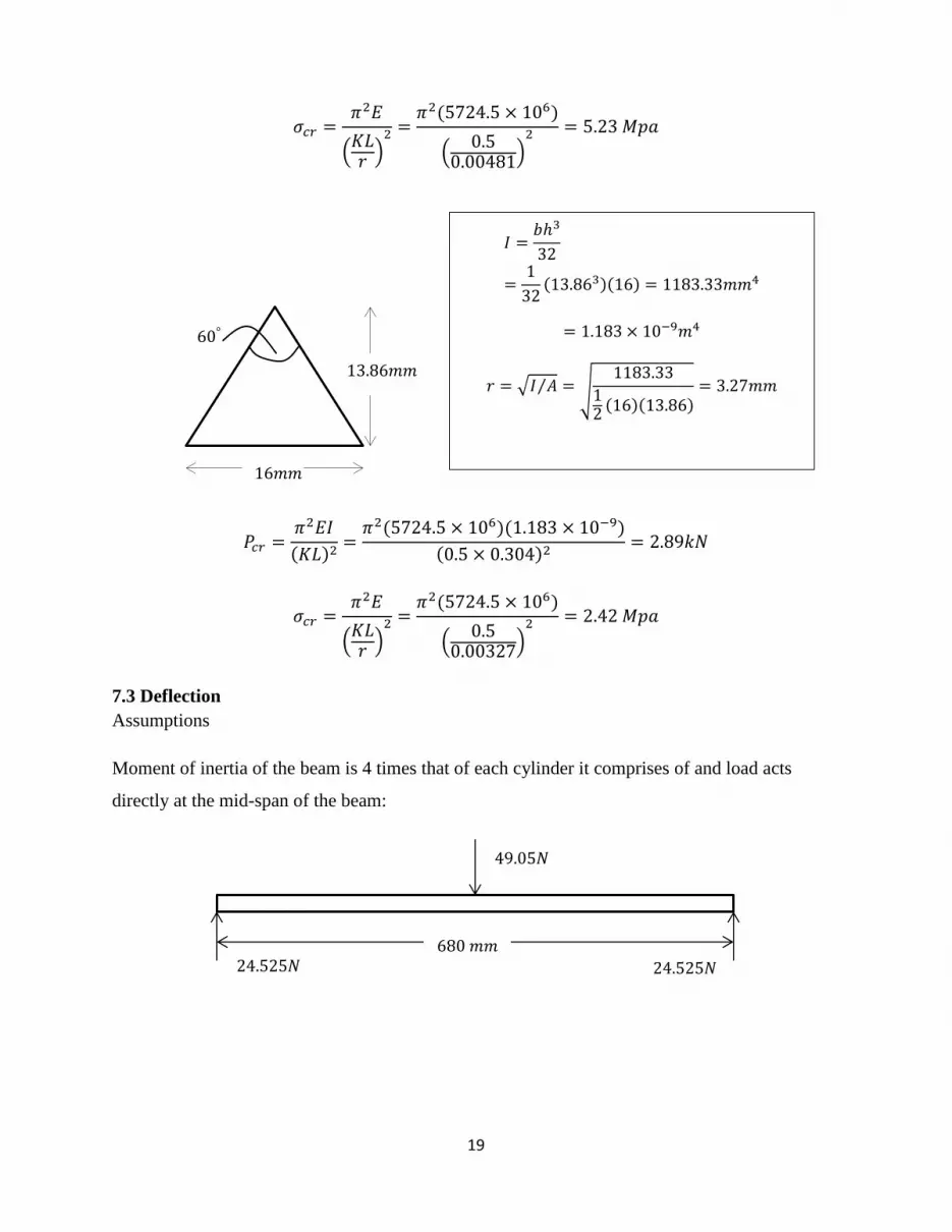
𝜎𝑐𝑟 =𝜋2𝐸
(𝐾𝐿𝑟 )
2 =𝜋2(5724.5 × 106)
(0.5
0.00481)2 = 5.23 𝑀𝑝𝑎
𝑃𝑐𝑟 =𝜋2𝐸𝐼
(𝐾𝐿)2=𝜋2(5724.5 × 106)(1.183 × 10⁻⁹)
(0.5 × 0.304)2= 2.89𝑘𝑁
𝜎𝑐𝑟 =𝜋2𝐸
(𝐾𝐿𝑟 )
2 =𝜋2(5724.5 × 106)
(0.5
0.00327)2 = 2.42 𝑀𝑝𝑎
7.3 Deflection
Assumptions
Moment of inertia of the beam is 4 times that of each cylinder it comprises of and load acts
directly at the mid-span of the beam:
16𝑚𝑚
60°
13.86𝑚𝑚
𝐼 =𝑏ℎ3
32
=1
32(13.863)(16) = 1183.33𝑚𝑚4
= 1.183 × 10⁻⁹𝑚4
𝑟 = √𝐼 𝐴⁄ = 1183.33
12(16)(13.86)
= 3.27𝑚𝑚
24.525𝑁 24.525𝑁
49.05𝑁
680 𝑚𝑚

20
𝐸𝐼𝑑2𝑣
𝑑𝑥2= 𝑀(𝑥) = 24.525𝑥
𝐸𝐼𝑑𝑣
𝑑𝑥=24.525
2𝑥2 + 𝐶1 ⟹ 𝐸𝐼𝑣 =
24.525
6𝑥3 + 𝐶1𝑥 + 𝐶2
𝑎𝑡 𝑥 = 0, 𝑣 = 0 𝑎𝑛𝑑 𝑎𝑡 𝑥 = 0.68, 𝑣 = 0
∴ 0 = 0 + 𝐶2⟹ 𝐶2 = 0
0 =24.525
6(0.68)3 + 𝐶1(0.68) ⟹ 𝐶1 = −1.89006
Due to the symmetry of arrangement, it can easily be seen that 𝑣𝑚𝑎𝑥 occurs at 𝑥 = 0.68 2⁄ :
∴ 𝐸𝐼𝑣 = (24.525
6) 𝑥3 − 1.89006𝑥
𝐼 =𝜋
64(234 − 154) = 11251.61𝑚4 = 1.125(10−8)𝑚𝑚4 ⟹ 𝐼𝑡𝑜𝑡 = 4.50(10
−8)𝑚𝑚4
𝑣𝑚𝑎𝑥 =1
𝐸𝐼𝑡𝑜𝑡[(24.525
6) (0.34)3 − 1.89006(0.34)] = −1.87𝑚𝑚
From the appendix, the displacement of the joint F was calculated to be −3.55(10−3)𝑚𝑚. The
negative sign indicates that it is displaced upwards. It makes complete sense since the member
DF is in tension and thus pulls the joint upwards. Since the joint F is identical to joint E the same
calculation applies.
The resultant deflection of the entire bridge should be approximately 1.866𝑚𝑚 downwards.
𝑥
𝑀 𝑉 24.525𝑁
↑ + ∑𝐹𝑦 = 0; −𝑉 + 24.525 = 0
∴ 𝑉 = 24.525𝑁
↺ + ∑𝐴 = 0; −24.525(𝑥) +𝑀 = 0
∴ 𝑀(𝑥) = 24.525𝑥

21
8. Design Specifications
The following is a selection matrix on the best material to use for the building of the Bridge.
Since the Constrain in the PRS require the bridge to be constructed out of a cardboard of
maximum size of 300gsm, it was necessary to determine the best cardboard size that will be
suitable for the construction of the components for the selected design.
The cardboard material was selected based on the ability to be folded in triangular or round
shapes because these were easier to construct as compared to rectangular or square shapes.
Table 2: Material Selection Matrix
Material Size 240gsm 300gsm
Components
Road surface
Vertical triangular
beam
Diagonal triangular
beam
Horizontal shafts with
protrusions
Hook
22
8.1 Performance Specification
Components Specification
Road surface Allow smooth mobility of transport and persons
Hook Provide allowance for lifting the bridge
Vertical triangular
column
Prevent the bridge from failing in compression, when subjected to a
downward load.
Diagonal triangular
column
Provide a tensile upward force, thus resist the bridge from failing at
the ends.
Top Protruded
horizontal column
Ensures that the bridge becomes more rigid and stable
Bottom Horizontal
column
Prevent the bridge from failing in the middle and minimizes
deflection
8.2 Recommendations
The bridge built, performed very well, and indeed it was well designed with very ingenious
ideas. Modification that can be applied to improve the bridge is to include side or hand rails for
mobility guidance along the road surface. Including diagonal members between the two
horizontal members on both sides of the bridge will increase the rigidity of the bridge especially
at the top. To Prevent buckling or deflection of the bridge, it would be necessary to constrain the
horizontal columns by introducing flat sheets at both ends.

23
9. References
[1] Meter, N. V. (2004). Cities/layout L. Bridge Basics, 14-17. Retrieved May 10 2015:
http://www.nbm.org/assets/pdfs/youth-education/bridges_erpacket.pdf
[2] Beam Bridges. (2015). Retrieved May 14, 2015, from Design-technology.org:
http://www.design-technology.org/beambridges.htm
[3] Beam. (2015). Retrieved May 14, 2015, from Warwickallen.com:
http://www.warwickallen.com/bridges/BeamBridges.htm
[4] Mechanical properties of adhesives. (2015). Retrieved May 14, 2015, From
Adhesiveandglue.com: http://www.adhesiveandglue.com/mechanical-properties-adhesives.html
[5] Wood Glue uses and information . (2015). Retrieved May 14, 2015, From
Naturalhandyman.com: http://www.naturalhandyman.com/iip/infadh/infadhe.html
[6] Karlson, H. (2010). Strength Properties of Paper produced from Softwood Kraft Pulp.
Karlstads University: Faculty of Technology and Science. Retrieved 14 May 2015, From:
http://www.diva-portal.org/smash/get/diva2:317178/fulltext01.pdf
[7] Sekulić, B. (2013). Structural Cardboard: Feasibility Study of Cardboard As A Long-Term
Structural Material In Architecture, University of Politècnica De Catalunya. Retrieved 24 June
2015, From: http://upcommons.upc.edu/pfc/bitstream/2099.1/21603/1/BrankoSekulic_TFM.pdf.
[8] Guyana. (2010). Paper and Board packaging: Properties, specifications and sourcing.
Retrieved 24 June 2015, From:
http://www.iica.int/Eng/regiones/caribe/guyana/IICA%20Office%20Documents/tfo_packaging_
workshop/Guyana%20TFO%20Pkg%20W'shp%20Session%203%20-
%20Paper%20and%20Board.pdf

24
10. Appendices

PARTS LIST
DESCRIPTIONPART NUMBERQTYITEM
Cut from 240
gsm,0.09724 metre
squared paper
cover page
11
240gsm paper hollow
rolled tubes.Use ponal
wood glue for every
joint.
bottom_column42
300gsm folded paperbottom beam23
300gsm paper folded
in triangular shapes
vertical triangular
column
44
240gsm rolled solid
paper tubes with two
steps
horizontal shaft with
protrusions
25
240gsm rolled hollow
paper,cuttings made
with a cutting knife
across column26
300gsm paper folded
in triangular shapes
diagonal triangular
beam
47
240gsm paper foldedhook18
1
1
2
2
3
3
4
4
5
5
6
6
A A
B B
C C
D D
full assembly
Humphry Tlou - 681141
2015-09-14
Designed by Checked by Approved byDate
1 / 1
Edition Sheet
Date
6
7
28
3 4
1
5
680,00
160,00
25,50
33,50
40,00
50,00
3
6
,
8
2
°
221,00

1
1
2
2
3
3
4
4
5
5
6
6
A A
B B
C C
D D
acros column
Humphry Tlou - 681141
2015-09-14
Designed by Checked by Approved byDate
1 / 1
Edition Sheet
Date
150,00
9,00
15,00
25,00
160,00
190,00
17,00
9,00
155,00
50,00
25,00
8,00
60,00°
1
6
,
0
0
1
6
,
0
0
16,00
Part 6
Part 5
Part 3
Hole cut to fit vertical triangular column
Hole drill to suit part 5
1
1
2
2
3
3
4
4
5
5
6
6
A A
B B
C C
D D
cover page
Humphry Tlou - 681141
2015-09-14
Designed by Checked by Approved byDate
1 / 1
Edition Sheet
Date
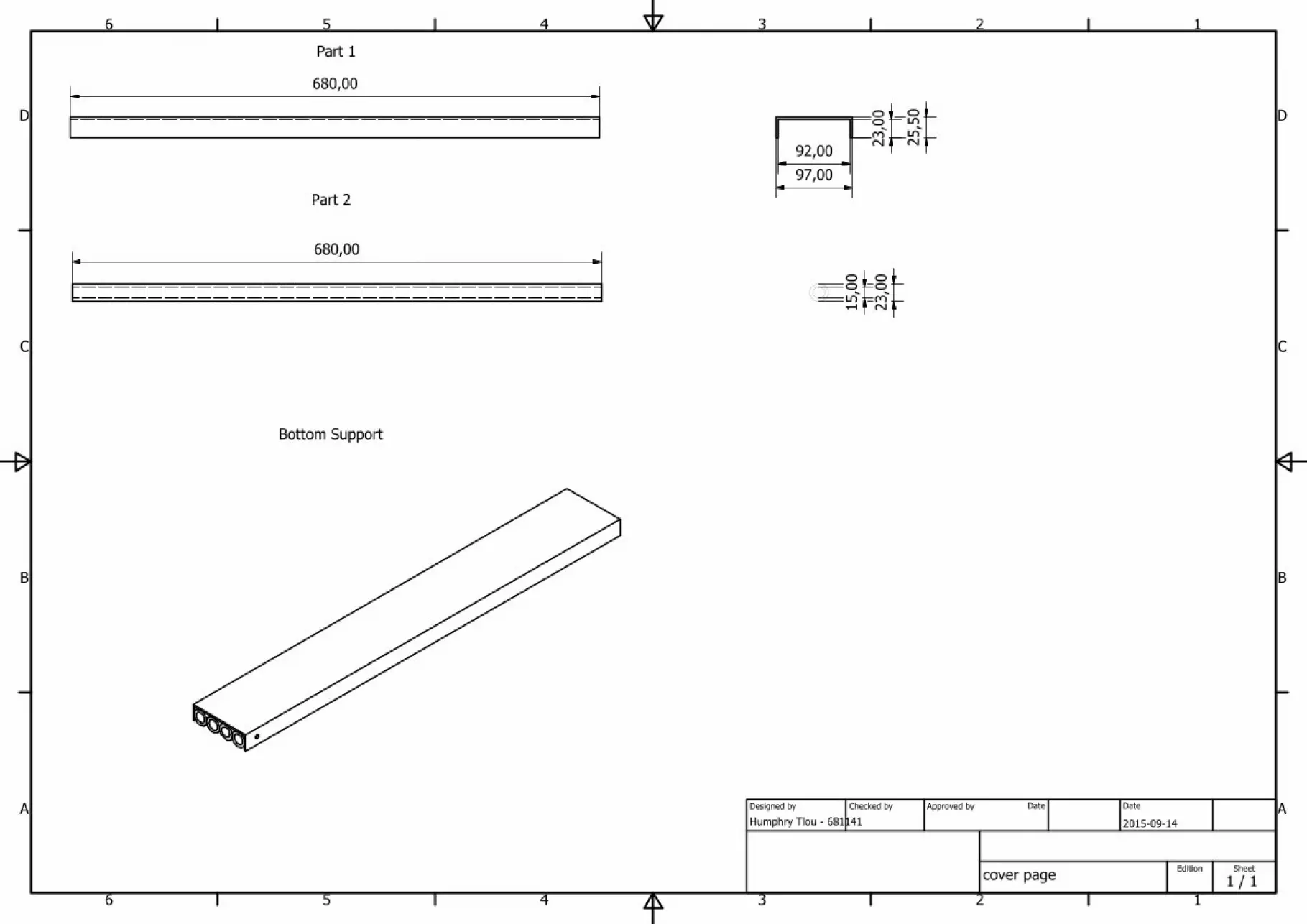
680,00
680,00
23,00
15,00
97,00
92,00
23,00
25,50
Part 1
Part 2
Bottom Support