Embed Size (px)
Citation preview
CECW-EG
Engineer Manual1110-2-2002
Department of the ArmyU.S. Army Corps of Engineers
Washington, DC 20314-1000
EM 1110-2-2002
30 June 1995
Engineering and Design
EVALUATION AND REPAIR OF CONCRETE STRUCTURES
Distribution Restriction StatementApproved for public release; distribution is
unlimited.
DEPARTMENT OF THE ARMY EM 1110-2-2002U.S. Army Corps of Engineers
CECW-EG Washington, DC 20314-1000
ManualNo. 1110-2-2002 30 June 1995
Engineering and DesignEVALUATION AND REPAIR OF CONCRETE STRUCTURES
1. Purpose. This manual provides guidance on evaluating the condition of the concrete in a struc-ture, relating the condition of the concrete to the underlying cause or causes of that condition, selectingan appropriate repair material and method for any deficiency found, and using the selected materialsand methods to repair or rehabilitate the structure. Guidance is also included on maintenance of con-crete and on preparation of concrete investigation reports for repair and rehabilitation projects. Con-siderations for certain specialized types of rehabilitation projects are also given.
2. Applicability. This manual is applicable to all HQUSACE elements, major subordinate commands,districts, laboratories, and field operating activities having civil works responsibilities.
FOR THE COMMANDER:
____________________________________________________________________________________This manual supersedes EM 1110-2-2002, dated 25 July 1986.
DEPARTMENT OF THE ARMY EM 1110-2-2002U.S. Army Corps of Engineers
CECW-EG Washington, DC 20314-1000
ManualNo. 1110-2-2002 30 June 1995
Engineering and DesignEVALUATION AND REPAIR OF CONCRETE STRUCTURES
Table of Contents
Subject Paragraph Page Subject Paragraph Page
Chapter 1IntroductionPurpose . . . . . . . . . . . . . . . . . . . . . 1-1 1-1Applicability . . . . . . . . . . . . . . . . . . 1-2 1-1References . . . . . . . . . . . . . . . . . . . 1-3 1-1Definitions and Abbreviations. . . . . . 1-4 1-1Methodology for Repair
and Rehabilitation. . . . . . . . . . . . . 1-5 1-1
Chapter 2Evaluation of the Concretein Concrete StructuresIntroduction . . . . . . . . . . . . . . . . . . 2-1 2-1Review of Engineering Data. . . . . . . 2-2 2-1Condition Survey. . . . . . . . . . . . . . . 2-3 2-1Underwater Inspection. . . . . . . . . . . 2-4 2-13Laboratory Investigations. . . . . . . . . 2-5 2-18Nondestructive Testing. . . . . . . . . . . 2-6 2-18Stability Analysis. . . . . . . . . . . . . . . 2-7 2-22Deformation Monitoring. . . . . . . . . . 2-8 2-22Concrete Service Life. . . . . . . . . . . . 2-9 2-22Reliability Analysis . . . . . . . . . . . . . 2-10 2-23
Chapter 3Causes of Distress andDeterioration of ConcreteIntroduction . . . . . . . . . . . . . . . . . . 3-1 3-1Causes of Distress
and Deterioration. . . . . . . . . . . . . . 3-2 3-1Relating Symptoms to Causes of
Distress and Deterioration. . . . . . . . 3-3 3-12
Chapter 4Planning and Designof Concrete RepairGeneral Considerations. . . . . . . . . . . 4-1 4-1
Properties of Repair Materials. . . . . 4-2 4-2Application and Service Conditions . 4-3 4-4Material Selection . . . . . . . . . . . . . 4-4 4-5Repair Materials Database. . . . . . . . 4-5 4-5General Categorization
of Repair Approach. . . . . . . . . . . 4-6 4-6Repair of Cracking. . . . . . . . . . . . . 4-7 4-6Repair of Spalling
and Disintegration. . . . . . . . . . . . 4-8 4-7
Chapter 5Concrete Removal andPreparation for RepairIntroduction . . . . . . . . . . . . . . . . . 5-1 5-1Concrete Removal. . . . . . . . . . . . . 5-2 5-1Preparation for Repair. . . . . . . . . . 5-3 5-17
Chapter 6Materials and Methods forRepair and RehabilitationIntroduction . . . . . . . . . . . . . . . . . 6-1 6-1Additional Reinforcement. . . . . . . . 6-2 6-1Autogenous Healing. . . . . . . . . . . . 6-3 6-2Conventional Concrete Placement . . 6-4 6-2Crack Arrest Techniques. . . . . . . . . 6-5 6-4Drilling and Plugging. . . . . . . . . . . 6-6 6-5Drypacking . . . . . . . . . . . . . . . . . . 6-7 6-5Fiber-Reinforced Concrete. . . . . . . 6-8 6-6Flexible Sealing. . . . . . . . . . . . . . . 6-9 6-6Gravity Soak. . . . . . . . . . . . . . . . .6-10 6-7Grouting (Chemical). . . . . . . . . . . .6-11 6-8Grouting (Hydraulic-Cement). . . . . 6-12 6-8High-Strength Concrete. . . . . . . . .6-13 6-9Jacketing . . . . . . . . . . . . . . . . . . .6-14 6-9Judicious Neglect. . . . . . . . . . . . . .6-15 6-9Overlays (Polymer) . . . . . . . . . . . .6-16 6-10
i
EM 1110-2-200230 Jun 95
Subject Paragraph Page Subject Paragraph Page
Overlays (Portland-Cement). . . . . . . 6-17 6-12Polymer Coatings. . . . . . . . . . . . . . . 6-18 6-13Polymer Concrete/Mortar. . . . . . . . . 6-19 6-13Polymer Portland-Cement
Concrete. . . . . . . . . . . . . . . . . . . .6-20 6-14Polymer Impregnation . . . . . . . . . . . 6-21 6-14Polymer Injection. . . . . . . . . . . . . . . 6-22 6-14Precast Concrete. . . . . . . . . . . . . . . 6-23 6-17Preplaced-Aggregate Concrete. . . . . . 6-24 6-17Rapid-Hardening Cements. . . . . . . . . 6-25 6-17Roller-Compacted Concrete. . . . . . . . 6-26 6-18Routing and Sealing. . . . . . . . . . . . . 6-27 6-18Shotcrete . . . . . . . . . . . . . . . . . . . .6-28 6-19Shrinkage-Compensating Concrete . . . 6-29 6-19Silica-Fume Concrete. . . . . . . . . . . . 6-30 6-21Slabjacking . . . . . . . . . . . . . . . . . . . 6-31 6-21Stitching . . . . . . . . . . . . . . . . . . . . .6-32 6-21Underwater Concrete Placement. . . . 6-33 6-22
Chapter 7Maintenance of ConcreteGeneral. . . . . . . . . . . . . . . . . . . . . . 7-1 7-1Cleaning . . . . . . . . . . . . . . . . . . . . . 7-2 7-1Surface Coatings and
Sealing Compounds. . . . . . . . . . . . 7-3 7-3Joint Maintenance. . . . . . . . . . . . . . 7-4 7-6
Chapter 8Specialized RepairsLock Wall Rehabilitation . . . . . . . . 8-1 8-1Repair of Waterstop Failures. . . . . . 8-2 8-15Stilling Basin Repairs. . . . . . . . . . . 8-3 8-21Concrete Cutoff Walls . . . . . . . . . . 8-4 8-34Precast Concrete Applications. . . . . 8-5 8-35Underwater Repairs. . . . . . . . . . . . 8-6 8-47Geomembrane Applications. . . . . . . 8-7 8-54RCC Applications . . . . . . . . . . . . . 8-8 8-59
Chapter 9Concrete Investigation ReportsGeneral. . . . . . . . . . . . . . . . . . . . . 9-1 9-1Concrete Materials
Design Memorandum. . . . . . . . . . 9-2 9-1Concrete Repair Report. . . . . . . . . 9-3 9-1
Appendix AReferences
Appendix BGlossary
Appendix CAbbreviations
ii
EM 1110-2-200230 Jun 95
Chapter 1Introduction
1-1. Purpose
This manual provides guidance on evaluating the con-dition of the concrete in a structure, relating the conditionof the concrete to the underlying cause or causes of thatcondition, selecting an appropriate repair material andmethod for any deficiency found, and using the selectedmaterials and methods to repair or rehabilitate the struc-ture. Guidance is also included on maintenance of con-crete and on preparation of concrete investigation reportsfor repair and rehabilitation projects. Considerations forcertain specialized types of rehabilitation projects are alsogiven.
1-2. Applicability
This manual is applicable to all HQUSACE elements andUSACE commands having civil works responsibilities.
1-3. References
References are listed in Appendix A. Copies of all thereferences listed should be maintained in their most cur-rent versions by districts and divisions having civil worksresponsibilities. The copies should be kept in a locationeasily accessible to personnel responsible for concretecondition evaluations and concrete repair projects.
1-4. Definitions and Abbreviations
Terms frequently used in this manual are defined in theGlossary (Appendix B). Also, abbreviations used in thismanual are explained in Appendix C.
1-5. Methodology for Repair and Rehabilitation
This manual deals primarily with evaluation and repair ofconcrete structures; however, a basic understanding ofunderlying causes of concrete deficiencies is essential toperforming meaningful evaluations and successful repairs.If the cause of a deficiency is understood, it is much morelikely that the correct repair method will be selected andthat, consequently, the repair will be successful. Symp-toms or observations of a deficiency must be differen-tiated from the actual cause of the deficiency, and it isimperative that causes and not symptoms be addressed inrepairs. For example, cracking is a symptom of distressthat may have a variety of causes. Selection of the cor-rect repair technique for cracking depends upon knowing
whether the cracking is caused by repeated freezing andthawing of the concrete, accidental loading, or some othercause. Only after the cause or causes are known canrational decisions be made concerning the selection of aproper method of repair and in determining how to avoida repetition of the circumstances that led to the problem.The following general procedure should be followed forevaluating the condition and correcting the deficiencies ofthe concrete in a structure:
a. Evaluation. The first step is to evaluate thecurrent condition of the concrete. This evaluation mayinclude a review of design and construction documents, areview of structural instrumentation data, a visual exami-nation, nondestructive testing (NDT), and laboratoryanalysis of concrete samples. Upon completion of thisevaluation step, personnel making the evaluation shouldhave a thorough understanding of the condition of theconcrete and may have insights into the causes of anydeterioration noted.
b. Relating observations to causes.Once the eval-uation of a structure has been completed, the visual obser-vations and other supporting data must be related to themechanism or mechanisms that caused the damage. Sincemany deficiencies are caused by more than one mecha-nism, a basic understanding of causes of deterioration ofconcrete is needed to determine the actual damage-causingmechanism for a particular structure.
c. Selecting methods and materials. Once theunderlying cause of the damage observed in a structurehas been determined, selection of appropriate repair mate-rials and methods should be based on the followingconsiderations:
(1) Prerepair adjustments or modifications requiredto remedy the cause, such as changing the water drainagepattern, correcting differential foundation subsidence,eliminating causes of cavitation damage, etc.
(2) Constraints such as access to the structure, theoperating schedule of the structure, and the weather.
(3) Advantages and disadvantages of making per-manent versus temporary repairs.
(4) Available repair materials and methods and thetechnical feasibility of using them.
(5) Quality of those technically feasible methods andmaterials to determine the most economically viable toensure a satisfactory job.
1-1
EM 1110-2-200230 Jun 95
d. Preparation of plans and specifications.The nextstep in the repair or rehabilitation process is preparationof project plans and specifications. When required by amajor rehabilitation project, a Concrete Materials DesignMemorandum, in the form of a separate report or a partof the Rehabilitation Evaluation report, should be preparedas outlined in Chapter 9. Existing guide specificationsshould be used to the maximum extent possible. How-ever, many of the materials and methods described in thismanual are not covered in the existing guide specifica-tions. If the materials and methods needed for a par-ticular repair project are not covered in the guidespecifications, a detailed specification based upon theguidance given in this manual and upon experience gainedfrom similar projects should be prepared. Since the fullextent of concrete damage may not be completely knownuntil concrete removal begins, plans and specifications forrepair projects should be prepared with as much flexibilitywith regard to material quantities as possible. A thoroughcondition survey, as outlined in Chapter 2, performed asclose as possible to the time repair work is executedshould help minimize errors in estimated quantities.
e. Execution of the work.The success of a repairor rehabilitation project will depend upon the degree towhich the work is executed in conformance with plansand specifications. There is growing evidence, basedupon experience gained on a number of projects, thatconcrete work on repair projects requires much greaterattention to good practice than may be necessary for newconstruction. Because of the importance of the attentionto detail and the highly specialized construction tech-niques required for most repairs, it is important that thedesign engineer responsible for the investigation of thedistress and selection of repair materials and methods beintimately involved in the execution of the work. Forexample, many repair projects require placing relativelythin overlays, either vertically or horizontally. The poten-tial for cracking in these placements is much greater thanit is during placement of concrete in new constructionbecause of the high degree of restraint.
1-2
EM 1110-2-200230 Jun 95
Chapter 2Evaluation of the Concretein Concrete Structures
2-1. Introduction
This chapter presents information on how to conduct anevaluation of the concrete in a concrete structure. As wasdescribed in Chapter 1, a thorough and logical evaluationof the current condition of the concrete in a structure isthe first step of any repair or rehabilitation project. Whenthe condition of a structure indicates that major repair orrehabilitation is probably necessary, a comprehensiveevaluation of the structure should be conducted to deter-mine the scope of the work required. Such an evaluationcould include the following: a review of the availabledesign and construction documentation; a review of theoperation and maintenance records; a review of the instru-mentation data; a visual examination of the condition ofthe concrete in the structure; an evaluation of the structureby nondestructive testing means; a laboratory evaluationof the condition of concrete specimens recovered from thestructure; a stress analysis; and a stability analysis of theentire structure. With the exception of performing stressand stability analyses, each of these general areas isdescribed in detail in this chapter.
2-2. Review of Engineering Data
A thorough review of all of the pertinent data relating to astructure should be accomplished early in the evaluationprocess. To understand the current condition of the con-crete in a structure, it is imperative to consider howdesign, construction, operation, and maintenance haveinteracted over the years since the structure was designedand constructed. Sources of engineering data which canyield useful information of this nature include projectdesign memoranda, plans and specifications, constructionhistory reports, as-built drawings, concrete report or con-crete records (including materials used, batch plant andfield inspection records, and laboratory test data), instru-mentation data, operation and maintenance records, andperiodic inspection reports. Instrumentation data andmonument survey data to detect movement of the struc-ture should be examined.
2-3. Condition Survey
A condition survey involves visual examination ofexposed concrete for the purpose of identifying and defin-ing areas of distress. A condition survey will usuallyinclude a mapping of the various types of concrete defi-ciencies that may be found, such as cracking, surface
problems (disintegration and spalling), and jointdeterioration. Cracks are usually mapped on fold-outsketches of the monolith surfaces. Mapping must includeinspection and delineating of pipe and electrical galleries,filling and emptying culverts (if possible), and other sim-ilar openings. Additionally, a condition survey willfrequently include core drilling to obtain specimens forlaboratory testing and analysis. Stowe and Thornton(1984), American Concrete Institute (ACI) 207.3R, andACI 364.1R1 provide additional information on proceduresfor conducting condition surveys.
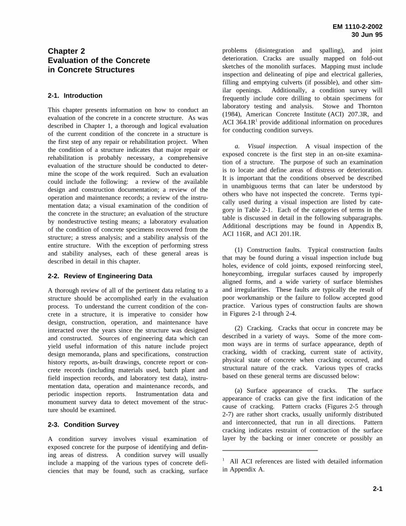
a. Visual inspection. A visual inspection of theexposed concrete is the first step in an on-site examina-tion of a structure. The purpose of such an examinationis to locate and define areas of distress or deterioration.It is important that the conditions observed be describedin unambiguous terms that can later be understood byothers who have not inspected the concrete. Terms typi-cally used during a visual inspection are listed by cate-gory in Table 2-1. Each of the categories of terms in thetable is discussed in detail in the following subparagraphs.Additional descriptions may be found in Appendix B,ACI 116R, and ACI 201.1R.
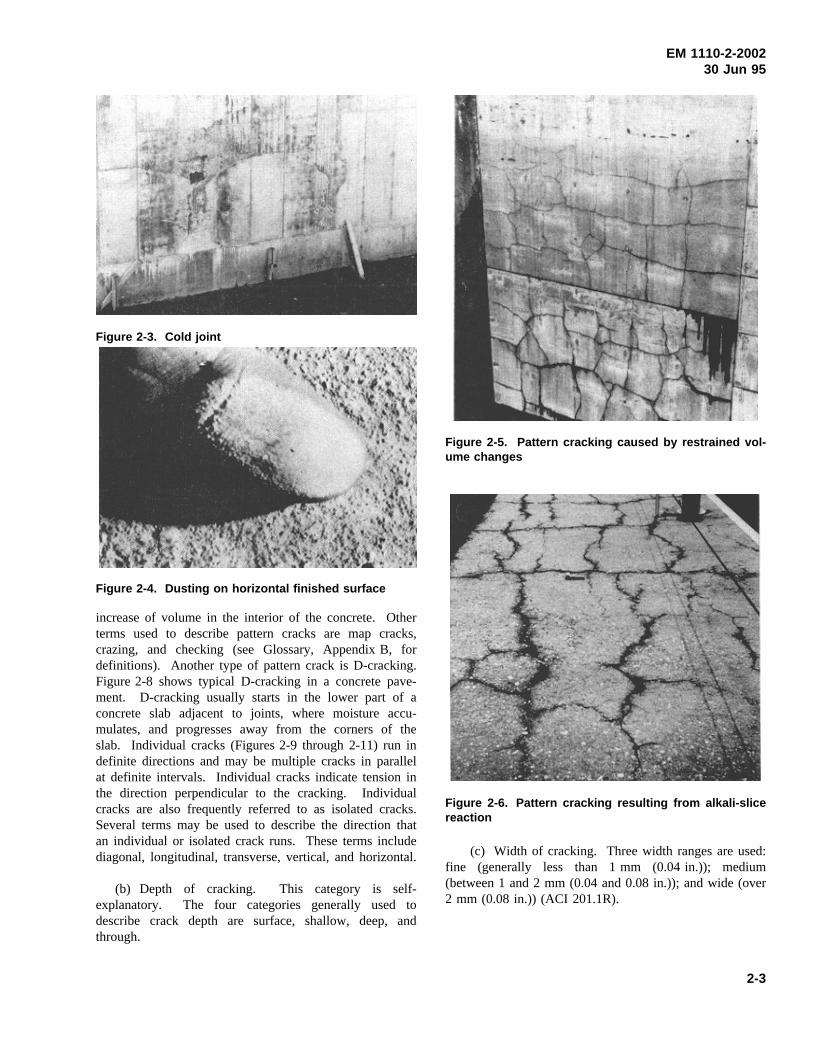
(1) Construction faults. Typical construction faultsthat may be found during a visual inspection include bugholes, evidence of cold joints, exposed reinforcing steel,honeycombing, irregular surfaces caused by improperlyaligned forms, and a wide variety of surface blemishesand irregularities. These faults are typically the result ofpoor workmanship or the failure to follow accepted goodpractice. Various types of construction faults are shownin Figures 2-1 through 2-4.
(2) Cracking. Cracks that occur in concrete may bedescribed in a variety of ways. Some of the more com-mon ways are in terms of surface appearance, depth ofcracking, width of cracking, current state of activity,physical state of concrete when cracking occurred, andstructural nature of the crack. Various types of cracksbased on these general terms are discussed below:
(a) Surface appearance of cracks. The surfaceappearance of cracks can give the first indication of thecause of cracking. Pattern cracks (Figures 2-5 through2-7) are rather short cracks, usually uniformly distributedand interconnected, that run in all directions. Patterncracking indicates restraint of contraction of the surfacelayer by the backing or inner concrete or possibly an
1 All ACI references are listed with detailed informationin Appendix A.
2-1
EM 1110-2-200230 Jun 95
Table 2-1Terms Associated with Visual Inspection of Concrete
Construction faults Distortion or movement
Bug holes Buckling
Cold joints Curling or warping
Exposed reinforcing steel Faulting
Honeycombing Settling
Irregular surface Tilting
Cracking
Checking or crazing Erosion
D-cracking Abrasion
Diagonal Cavitation
Hairline Joint-sealant failure
Longitudinal Seepage
Map or pattern Corrosion
Random Discoloration or staining
Transverse Exudation
Vertical Efflorescence
Horizontal Incrustation
Disintegration Spalling
Blistering Popouts
Chalking Spall
Delamination
Dusting
Peeling
Scaling
Weathering
Figure 2-1. Bug holes in a vertical wall Figure 2-2. Honeycombing and cold joint
2-2
EM 1110-2-200230 Jun 95
Figure 2-3. Cold joint
Figure 2-4. Dusting on horizontal finished surface
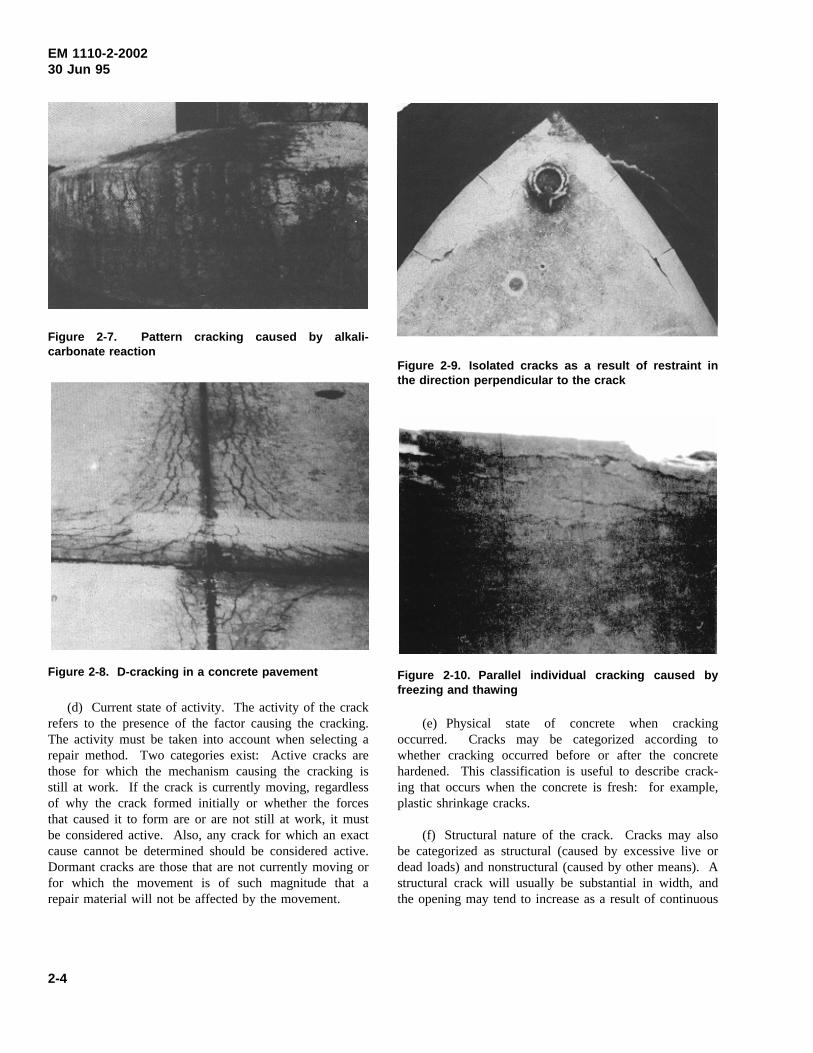
increase of volume in the interior of the concrete. Otherterms used to describe pattern cracks are map cracks,crazing, and checking (see Glossary, Appendix B, fordefinitions). Another type of pattern crack is D-cracking.Figure 2-8 shows typical D-cracking in a concrete pave-ment. D-cracking usually starts in the lower part of aconcrete slab adjacent to joints, where moisture accu-mulates, and progresses away from the corners of theslab. Individual cracks (Figures 2-9 through 2-11) run indefinite directions and may be multiple cracks in parallelat definite intervals. Individual cracks indicate tension inthe direction perpendicular to the cracking. Individualcracks are also frequently referred to as isolated cracks.Several terms may be used to describe the direction thatan individual or isolated crack runs. These terms includediagonal, longitudinal, transverse, vertical, and horizontal.
(b) Depth of cracking. This category is self-explanatory. The four categories generally used todescribe crack depth are surface, shallow, deep, andthrough.
Figure 2-5. Pattern cracking caused by restrained vol-ume changes
Figure 2-6. Pattern cracking resulting from alkali-slicereaction
(c) Width of cracking. Three width ranges are used:fine (generally less than 1 mm (0.04 in.)); medium(between 1 and 2 mm (0.04 and 0.08 in.)); and wide (over2 mm (0.08 in.)) (ACI 201.1R).
2-3
EM 1110-2-200230 Jun 95
Figure 2-7. Pattern cracking caused by alkali-carbonate reaction
Figure 2-8. D-cracking in a concrete pavement
(d) Current state of activity. The activity of the crackrefers to the presence of the factor causing the cracking.The activity must be taken into account when selecting arepair method. Two categories exist: Active cracks arethose for which the mechanism causing the cracking isstill at work. If the crack is currently moving, regardlessof why the crack formed initially or whether the forcesthat caused it to form are or are not still at work, it mustbe considered active. Also, any crack for which an exactcause cannot be determined should be considered active.Dormant cracks are those that are not currently moving orfor which the movement is of such magnitude that arepair material will not be affected by the movement.
Figure 2-9. Isolated cracks as a result of restraint inthe direction perpendicular to the crack
Figure 2-10. Parallel individual cracking caused byfreezing and thawing
(e) Physical state of concrete when crackingoccurred. Cracks may be categorized according towhether cracking occurred before or after the concretehardened. This classification is useful to describe crack-ing that occurs when the concrete is fresh: for example,plastic shrinkage cracks.
(f) Structural nature of the crack. Cracks may alsobe categorized as structural (caused by excessive live ordead loads) and nonstructural (caused by other means). Astructural crack will usually be substantial in width, andthe opening may tend to increase as a result of continuous
2-4
EM 1110-2-200230 Jun 95
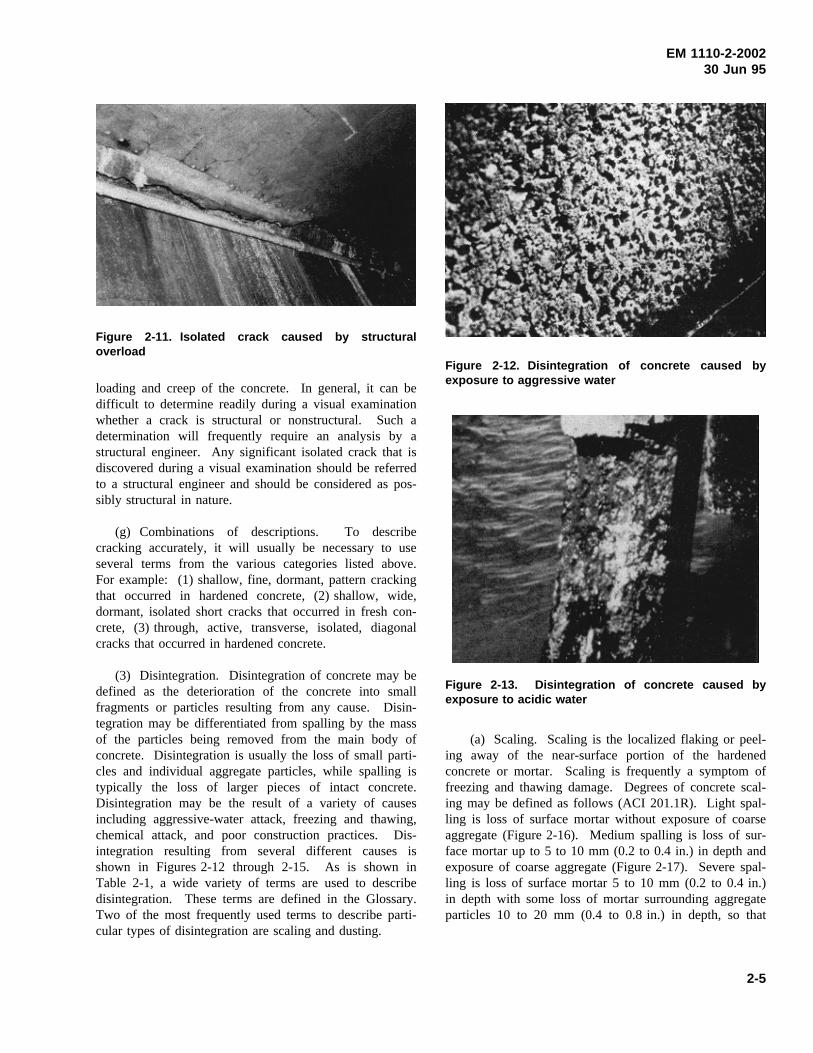
Figure 2-11. Isolated crack caused by structuraloverload
loading and creep of the concrete. In general, it can bedifficult to determine readily during a visual examinationwhether a crack is structural or nonstructural. Such adetermination will frequently require an analysis by astructural engineer. Any significant isolated crack that isdiscovered during a visual examination should be referredto a structural engineer and should be considered as pos-sibly structural in nature.
(g) Combinations of descriptions. To describecracking accurately, it will usually be necessary to useseveral terms from the various categories listed above.For example: (1) shallow, fine, dormant, pattern crackingthat occurred in hardened concrete, (2) shallow, wide,dormant, isolated short cracks that occurred in fresh con-crete, (3) through, active, transverse, isolated, diagonalcracks that occurred in hardened concrete.
(3) Disintegration. Disintegration of concrete may bedefined as the deterioration of the concrete into smallfragments or particles resulting from any cause. Disin-tegration may be differentiated from spalling by the massof the particles being removed from the main body ofconcrete. Disintegration is usually the loss of small parti-cles and individual aggregate particles, while spalling istypically the loss of larger pieces of intact concrete.Disintegration may be the result of a variety of causesincluding aggressive-water attack, freezing and thawing,chemical attack, and poor construction practices. Dis-integration resulting from several different causes isshown in Figures 2-12 through 2-15. As is shown inTable 2-1, a wide variety of terms are used to describedisintegration. These terms are defined in the Glossary.Two of the most frequently used terms to describe parti-cular types of disintegration are scaling and dusting.
Figure 2-12. Disintegration of concrete caused byexposure to aggressive water
Figure 2-13. Disintegration of concrete caused byexposure to acidic water
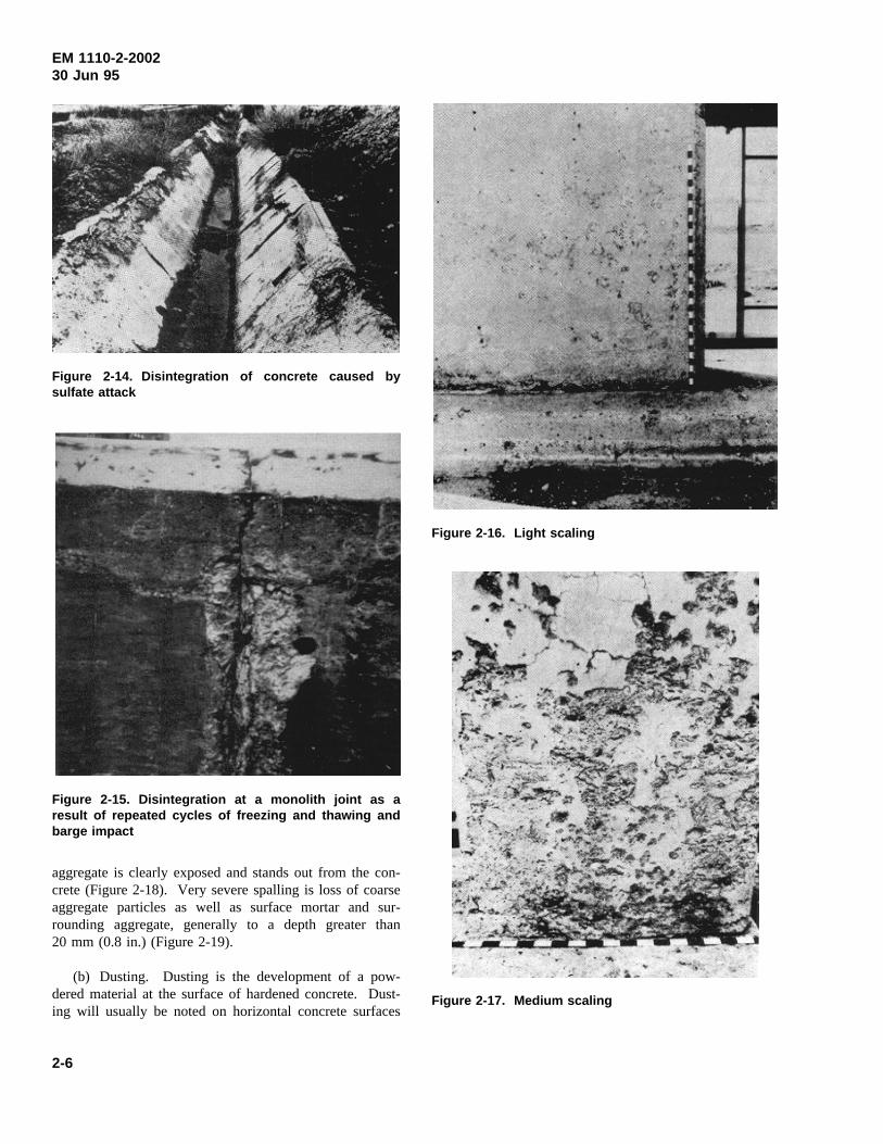
(a) Scaling. Scaling is the localized flaking or peel-ing away of the near-surface portion of the hardenedconcrete or mortar. Scaling is frequently a symptom offreezing and thawing damage. Degrees of concrete scal-ing may be defined as follows (ACI 201.1R). Light spal-ling is loss of surface mortar without exposure of coarseaggregate (Figure 2-16). Medium spalling is loss of sur-face mortar up to 5 to 10 mm (0.2 to 0.4 in.) in depth andexposure of coarse aggregate (Figure 2-17). Severe spal-ling is loss of surface mortar 5 to 10 mm (0.2 to 0.4 in.)in depth with some loss of mortar surrounding aggregateparticles 10 to 20 mm (0.4 to 0.8 in.) in depth, so that
2-5
EM 1110-2-200230 Jun 95
Figure 2-14. Disintegration of concrete caused bysulfate attack
Figure 2-15. Disintegration at a monolith joint as aresult of repeated cycles of freezing and thawing andbarge impact
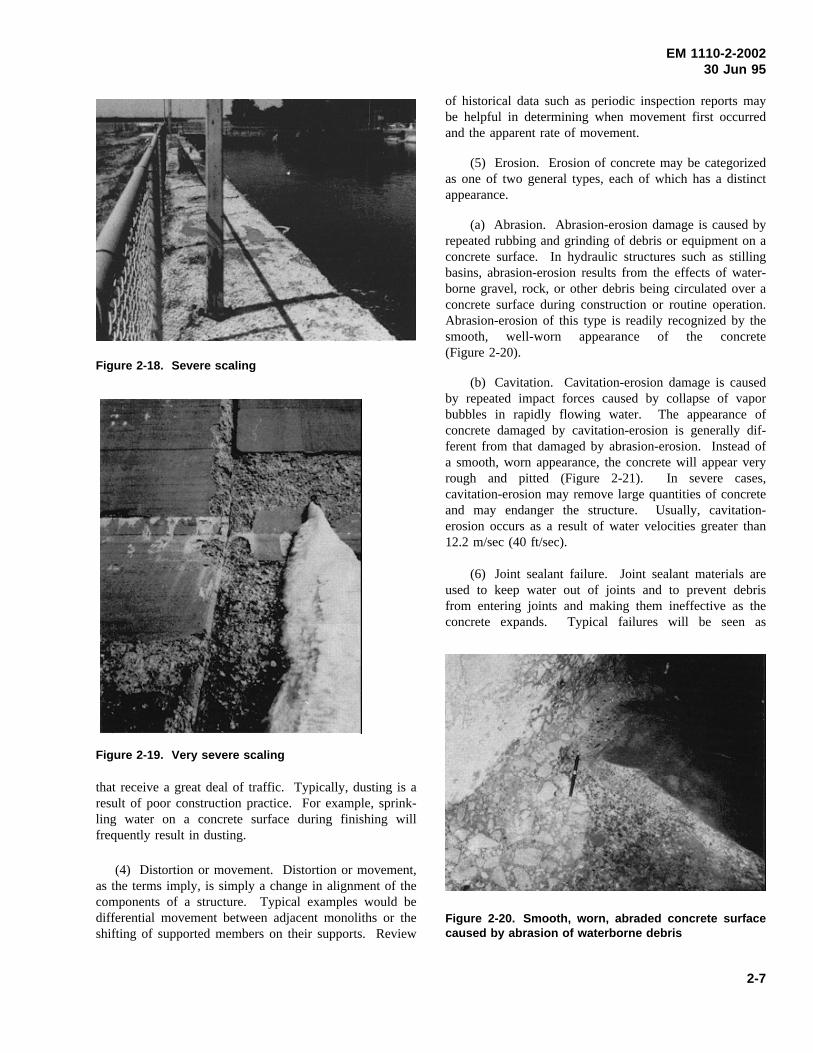
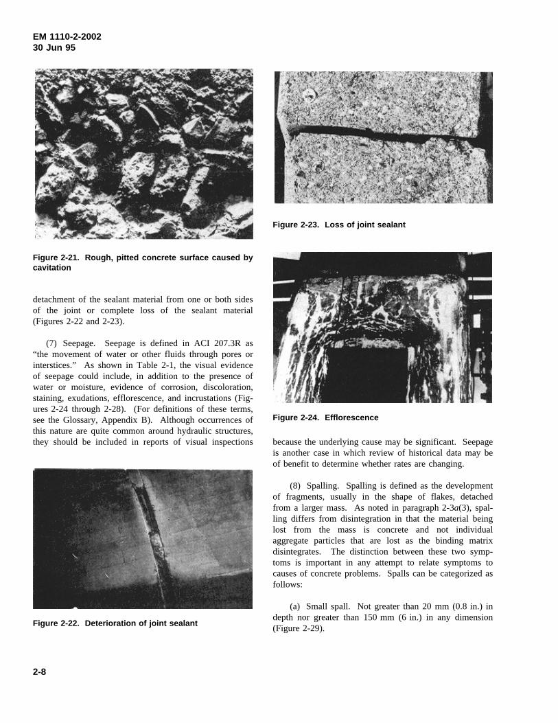
aggregate is clearly exposed and stands out from the con-crete (Figure 2-18). Very severe spalling is loss of coarseaggregate particles as well as surface mortar and sur-rounding aggregate, generally to a depth greater than20 mm (0.8 in.) (Figure 2-19).
(b) Dusting. Dusting is the development of a pow-dered material at the surface of hardened concrete. Dust-ing will usually be noted on horizontal concrete surfaces
Figure 2-16. Light scaling
Figure 2-17. Medium scaling
2-6
EM 1110-2-200230 Jun 95
Figure 2-18. Severe scaling
Figure 2-19. Very severe scaling
that receive a great deal of traffic. Typically, dusting is aresult of poor construction practice. For example, sprink-ling water on a concrete surface during finishing willfrequently result in dusting.
(4) Distortion or movement. Distortion or movement,as the terms imply, is simply a change in alignment of thecomponents of a structure. Typical examples would bedifferential movement between adjacent monoliths or theshifting of supported members on their supports. Review
of historical data such as periodic inspection reports maybe helpful in determining when movement first occurredand the apparent rate of movement.
(5) Erosion. Erosion of concrete may be categorizedas one of two general types, each of which has a distinctappearance.
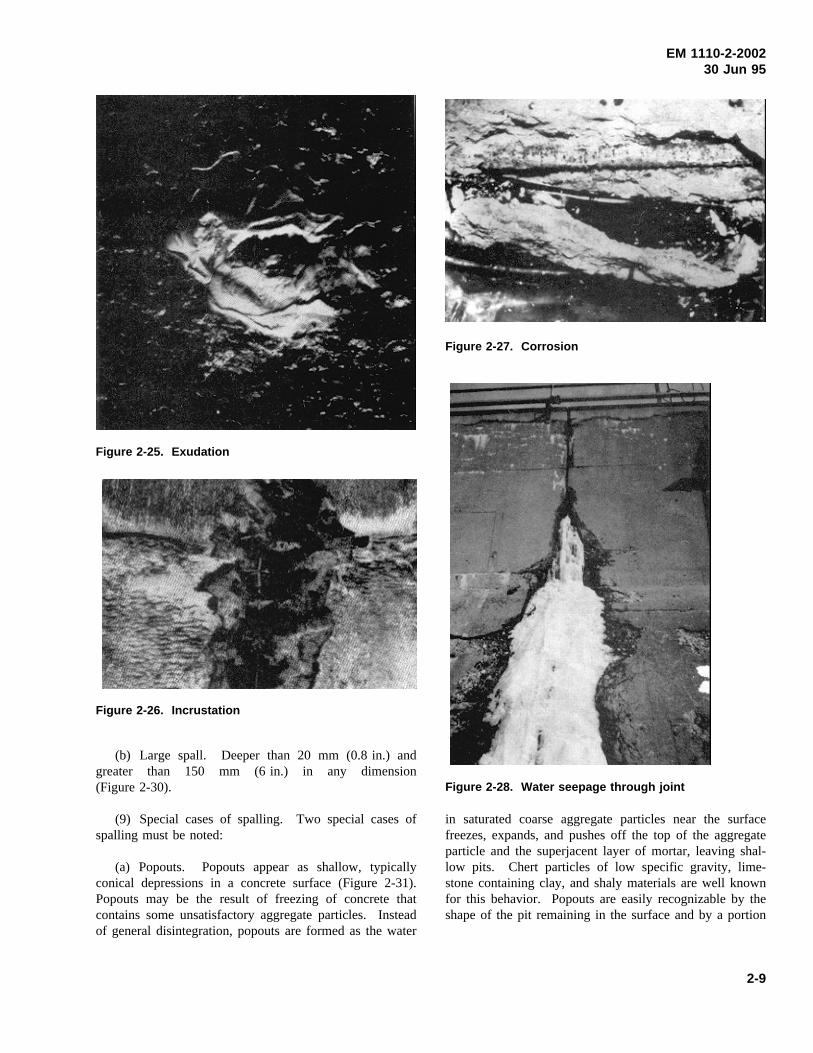
(a) Abrasion. Abrasion-erosion damage is caused byrepeated rubbing and grinding of debris or equipment on aconcrete surface. In hydraulic structures such as stillingbasins, abrasion-erosion results from the effects of water-borne gravel, rock, or other debris being circulated over aconcrete surface during construction or routine operation.Abrasion-erosion of this type is readily recognized by thesmooth, well-worn appearance of the concrete(Figure 2-20).
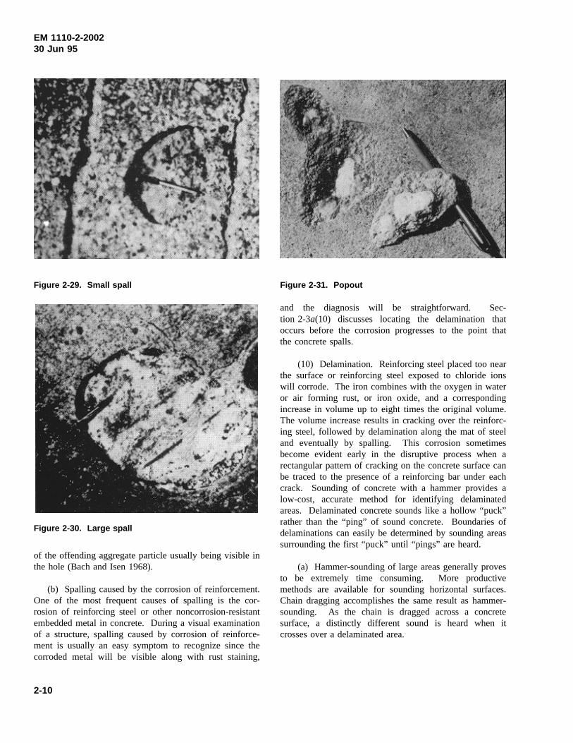
(b) Cavitation. Cavitation-erosion damage is causedby repeated impact forces caused by collapse of vaporbubbles in rapidly flowing water. The appearance ofconcrete damaged by cavitation-erosion is generally dif-ferent from that damaged by abrasion-erosion. Instead ofa smooth, worn appearance, the concrete will appear veryrough and pitted (Figure 2-21). In severe cases,cavitation-erosion may remove large quantities of concreteand may endanger the structure. Usually, cavitation-erosion occurs as a result of water velocities greater than12.2 m/sec (40 ft/sec).
(6) Joint sealant failure. Joint sealant materials areused to keep water out of joints and to prevent debrisfrom entering joints and making them ineffective as theconcrete expands. Typical failures will be seen as
Figure 2-20. Smooth, worn, abraded concrete surfacecaused by abrasion of waterborne debris
2-7
EM 1110-2-200230 Jun 95
Figure 2-21. Rough, pitted concrete surface caused bycavitation
detachment of the sealant material from one or both sidesof the joint or complete loss of the sealant material(Figures 2-22 and 2-23).
(7) Seepage. Seepage is defined in ACI 207.3R as“the movement of water or other fluids through pores orinterstices.” As shown in Table 2-1, the visual evidenceof seepage could include, in addition to the presence ofwater or moisture, evidence of corrosion, discoloration,staining, exudations, efflorescence, and incrustations (Fig-ures 2-24 through 2-28). (For definitions of these terms,see the Glossary, Appendix B). Although occurrences ofthis nature are quite common around hydraulic structures,they should be included in reports of visual inspections
Figure 2-22. Deterioration of joint sealant
Figure 2-23. Loss of joint sealant
Figure 2-24. Efflorescence
because the underlying cause may be significant. Seepageis another case in which review of historical data may beof benefit to determine whether rates are changing.
(8) Spalling. Spalling is defined as the developmentof fragments, usually in the shape of flakes, detachedfrom a larger mass. As noted in paragraph 2-3a(3), spal-ling differs from disintegration in that the material beinglost from the mass is concrete and not individualaggregate particles that are lost as the binding matrixdisintegrates. The distinction between these two symp-toms is important in any attempt to relate symptoms tocauses of concrete problems. Spalls can be categorized asfollows:
(a) Small spall. Not greater than 20 mm (0.8 in.) indepth nor greater than 150 mm (6 in.) in any dimension(Figure 2-29).
2-8
EM 1110-2-200230 Jun 95
Figure 2-25. Exudation
Figure 2-26. Incrustation
(b) Large spall. Deeper than 20 mm (0.8 in.) andgreater than 150 mm (6 in.) in any dimension(Figure 2-30).
(9) Special cases of spalling. Two special cases ofspalling must be noted:
(a) Popouts. Popouts appear as shallow, typicallyconical depressions in a concrete surface (Figure 2-31).Popouts may be the result of freezing of concrete thatcontains some unsatisfactory aggregate particles. Insteadof general disintegration, popouts are formed as the water
Figure 2-27. Corrosion
Figure 2-28. Water seepage through joint
in saturated coarse aggregate particles near the surfacefreezes, expands, and pushes off the top of the aggregateparticle and the superjacent layer of mortar, leaving shal-low pits. Chert particles of low specific gravity, lime-stone containing clay, and shaly materials are well knownfor this behavior. Popouts are easily recognizable by theshape of the pit remaining in the surface and by a portion
2-9
EM 1110-2-200230 Jun 95
Figure 2-29. Small spall
Figure 2-30. Large spall
of the offending aggregate particle usually being visible inthe hole (Bach and Isen 1968).
(b) Spalling caused by the corrosion of reinforcement.One of the most frequent causes of spalling is the cor-rosion of reinforcing steel or other noncorrosion-resistantembedded metal in concrete. During a visual examinationof a structure, spalling caused by corrosion of reinforce-ment is usually an easy symptom to recognize since thecorroded metal will be visible along with rust staining,
Figure 2-31. Popout
and the diagnosis will be straightforward. Sec-tion 2-3a(10) discusses locating the delamination thatoccurs before the corrosion progresses to the point thatthe concrete spalls.
(10) Delamination. Reinforcing steel placed too nearthe surface or reinforcing steel exposed to chloride ionswill corrode. The iron combines with the oxygen in wateror air forming rust, or iron oxide, and a correspondingincrease in volume up to eight times the original volume.The volume increase results in cracking over the reinforc-ing steel, followed by delamination along the mat of steeland eventually by spalling. This corrosion sometimesbecome evident early in the disruptive process when arectangular pattern of cracking on the concrete surface canbe traced to the presence of a reinforcing bar under eachcrack. Sounding of concrete with a hammer provides alow-cost, accurate method for identifying delaminatedareas. Delaminated concrete sounds like a hollow “puck”rather than the “ping” of sound concrete. Boundaries ofdelaminations can easily be determined by sounding areassurrounding the first “puck” until “pings” are heard.
(a) Hammer-sounding of large areas generally provesto be extremely time consuming. More productivemethods are available for sounding horizontal surfaces.Chain dragging accomplishes the same result as hammer-sounding. As the chain is dragged across a concretesurface, a distinctly different sound is heard when itcrosses over a delaminated area.
2-10
EM 1110-2-200230 Jun 95
(b) Infrared thermography is a useful method ofdetecting delaminations in bridge checks. This method isalso used for other concrete components exposed to directsunlight. The method works on the principle that asconcrete heats and cools there is substantial thermal gra-dient within the concrete. Delaminations and other dis-continuities interrupt the heat transfer through theconcrete. These defects cause a higher surface tempera-ture than that of the surrounding concrete during periodsof heating, and a lower surface temperature than that ofthe surrounding concrete during periods of cooling. Theequipment can record and identify areas of delaminationsbelow the surface.
b. Cracking survey. A crack survey is an examina-tion of a concrete structure for the purpose of locating,marking, and identifying cracks and determining the rela-tionship of the cracks with other destructive phenomena(ACI 207.3R). In most cases, cracking is the first symp-tom of concrete distress. Hence, a cracking survey issignificant in evaluating the future serviceability of thestructure. The first step in making a crack survey is tolocate and mark the cracking and define it by type. Theterms for and descriptions of cracks given in Section 2-3should be used to describe any cracking that is found.
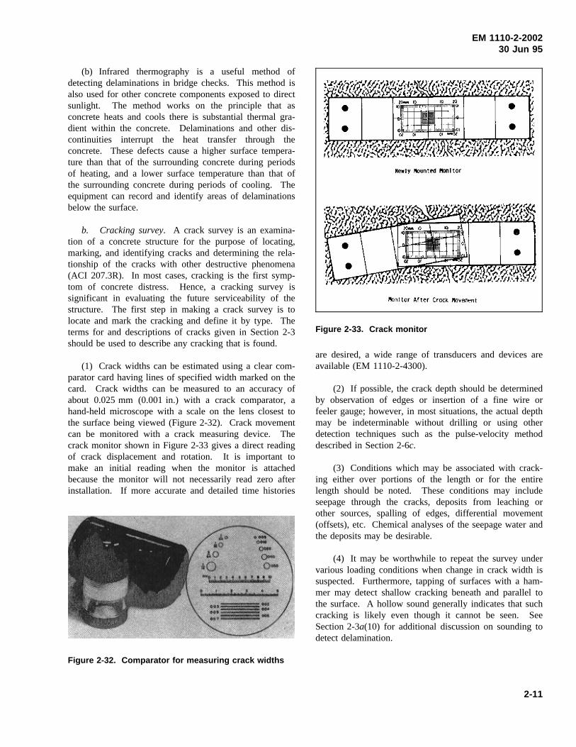
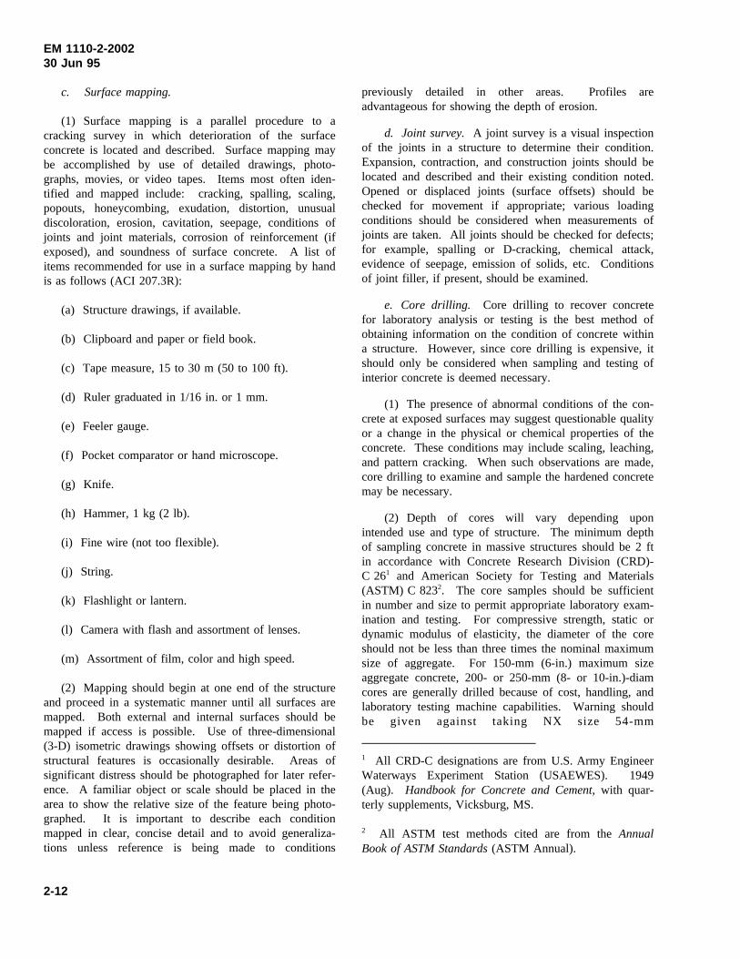
(1) Crack widths can be estimated using a clear com-parator card having lines of specified width marked on thecard. Crack widths can be measured to an accuracy ofabout 0.025 mm (0.001 in.) with a crack comparator, ahand-held microscope with a scale on the lens closest tothe surface being viewed (Figure 2-32). Crack movementcan be monitored with a crack measuring device. Thecrack monitor shown in Figure 2-33 gives a direct readingof crack displacement and rotation. It is important tomake an initial reading when the monitor is attachedbecause the monitor will not necessarily read zero afterinstallation. If more accurate and detailed time histories
Figure 2-32. Comparator for measuring crack widths
Figure 2-33. Crack monitor
are desired, a wide range of transducers and devices areavailable (EM 1110-2-4300).
(2) If possible, the crack depth should be determinedby observation of edges or insertion of a fine wire orfeeler gauge; however, in most situations, the actual depthmay be indeterminable without drilling or using otherdetection techniques such as the pulse-velocity methoddescribed in Section 2-6c.
(3) Conditions which may be associated with crack-ing either over portions of the length or for the entirelength should be noted. These conditions may includeseepage through the cracks, deposits from leaching orother sources, spalling of edges, differential movement(offsets), etc. Chemical analyses of the seepage water andthe deposits may be desirable.
(4) It may be worthwhile to repeat the survey undervarious loading conditions when change in crack width issuspected. Furthermore, tapping of surfaces with a ham-mer may detect shallow cracking beneath and parallel tothe surface. A hollow sound generally indicates that suchcracking is likely even though it cannot be seen. SeeSection 2-3a(10) for additional discussion on sounding todetect delamination.
2-11
EM 1110-2-200230 Jun 95
c. Surface mapping.
(1) Surface mapping is a parallel procedure to acracking survey in which deterioration of the surfaceconcrete is located and described. Surface mapping maybe accomplished by use of detailed drawings, photo-graphs, movies, or video tapes. Items most often iden-tified and mapped include: cracking, spalling, scaling,popouts, honeycombing, exudation, distortion, unusualdiscoloration, erosion, cavitation, seepage, conditions ofjoints and joint materials, corrosion of reinforcement (ifexposed), and soundness of surface concrete. A list ofitems recommended for use in a surface mapping by handis as follows (ACI 207.3R):
(a) Structure drawings, if available.
(b) Clipboard and paper or field book.
(c) Tape measure, 15 to 30 m (50 to 100 ft).
(d) Ruler graduated in 1/16 in. or 1 mm.
(e) Feeler gauge.
(f) Pocket comparator or hand microscope.
(g) Knife.
(h) Hammer, 1 kg (2 lb).
(i) Fine wire (not too flexible).
(j) String.
(k) Flashlight or lantern.
(l) Camera with flash and assortment of lenses.
(m) Assortment of film, color and high speed.
(2) Mapping should begin at one end of the structureand proceed in a systematic manner until all surfaces aremapped. Both external and internal surfaces should bemapped if access is possible. Use of three-dimensional(3-D) isometric drawings showing offsets or distortion ofstructural features is occasionally desirable. Areas ofsignificant distress should be photographed for later refer-ence. A familiar object or scale should be placed in thearea to show the relative size of the feature being photo-graphed. It is important to describe each conditionmapped in clear, concise detail and to avoid generaliza-tions unless reference is being made to conditions
previously detailed in other areas. Profiles areadvantageous for showing the depth of erosion.
d. Joint survey.A joint survey is a visual inspectionof the joints in a structure to determine their condition.Expansion, contraction, and construction joints should belocated and described and their existing condition noted.Opened or displaced joints (surface offsets) should bechecked for movement if appropriate; various loadingconditions should be considered when measurements ofjoints are taken. All joints should be checked for defects;for example, spalling or D-cracking, chemical attack,evidence of seepage, emission of solids, etc. Conditionsof joint filler, if present, should be examined.
e. Core drilling. Core drilling to recover concretefor laboratory analysis or testing is the best method ofobtaining information on the condition of concrete withina structure. However, since core drilling is expensive, itshould only be considered when sampling and testing ofinterior concrete is deemed necessary.
(1) The presence of abnormal conditions of the con-crete at exposed surfaces may suggest questionable qualityor a change in the physical or chemical properties of theconcrete. These conditions may include scaling, leaching,and pattern cracking. When such observations are made,core drilling to examine and sample the hardened concretemay be necessary.
(2) Depth of cores will vary depending uponintended use and type of structure. The minimum depthof sampling concrete in massive structures should be 2 ftin accordance with Concrete Research Division (CRD)-C 261 and American Society for Testing and Materials(ASTM) C 8232. The core samples should be sufficientin number and size to permit appropriate laboratory exam-ination and testing. For compressive strength, static ordynamic modulus of elasticity, the diameter of the coreshould not be less than three times the nominal maximumsize of aggregate. For 150-mm (6-in.) maximum sizeaggregate concrete, 200- or 250-mm (8- or 10-in.)-diamcores are generally drilled because of cost, handling, andlaboratory testing machine capabilities. Warning shouldbe given against taking NX size 54-mm
1 All CRD-C designations are from U.S. Army EngineerWaterways Experiment Station (USAEWES). 1949(Aug). Handbook for Concrete and Cement, with quar-terly supplements, Vicksburg, MS.
2 All ASTM test methods cited are from theAnnualBook of ASTM Standards(ASTM Annual).
2-12
EM 1110-2-200230 Jun 95
(2-1/8-in.)-diam cores in concrete. When 50- to 150-mm(2- to 6-in.) maximum size aggregate concrete is cored, anNX size core will generally be recovered in short piecesor broken core. The reason for breakage is that there issimply little mortar bonding the concrete across the diam-eter of the core. Thus, the drilling action can easily breakthe core. When drilling in poor-quality concrete with anysize core barrel, the material generally comes out asrubble.
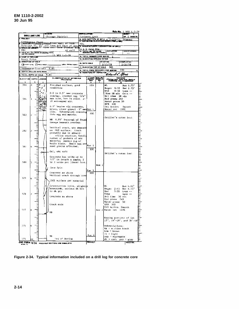
(3) Core samples must be properly identified andoriented with permanent markings on the material itselfwhen feasible. Location of borings must be accuratelydescribed and marked on photographs or drawings. Coresshould be logged by methods similar to those used forgeological subsurface exploration. Logs should show, inaddition to general information on the hole, conditions atthe surface, depth of obvious deterioration, fractures andconditions of fractured surfaces, unusual deposits, coloringor staining, distribution and size of voids, locations ofobserved construction joints, and contact with the foun-dation or other surface (ACI 207.3R). The concreteshould be wrapped and sealed as may be appropriate topreserve the moisture content representative of the struc-ture at the time of sampling and should be packed so asto be properly protected from freezing or damage in tran-sit or storage, especially if the concrete is very weak.Figure 2-34 illustrates a typical log for a concrete corerecovered during a condition survey.
(4) When drill hole coring is not practical or corerecovery is poor, a viewing system such as a boreholecamera, bore hole television, or borehole televiewer maybe used for evaluating the interior concrete conditions. Adescription and information on the availability of theseborehole viewing systems can be found in EP 1110-1-10.Evaluation of distress in massive concrete structures maybe desirable to determine in situ stress conditions.ACI 207.3R is an excellent guide to determining existingstress conditions in the structure.
2-4. Underwater Inspection
A variety of procedures and equipment for conductingunderwater surveys are available (Popovics and McDonald1989). Included are several nondestructive techniqueswhich can be used in dark or turbid conditions that pre-clude visual inspection. Some techniques originallydeveloped for other purposes have been adapted for appli-cation in underwater inspections. Prior to an underwater
survey, it is sometimes necessary for the surface of thestructure to be cleaned. A number of procedures anddevices for underwater cleaning of civil works structuresare described by Keeney (1987).
a. Visual inspection by divers. Underwater surveysby divers are usually either scuba or surface-supplieddiving operations. Basic scuba diving equipment is anoxygen tank, typically weighing about 34 kg (75 lb)which is carried by the diver. Surface-supplied diving,where the air supply is provided from the surface orshore, is a more elaborate operation in terms of equip-ment, safety concerns, diver skills, etc., especially whenthe diver approaches maximum allowable depths. Diverequipment for surface-supplied diving includes air com-pressors, helmets, weighted shoes, air supply lines, breast-plates, etc., which can weigh as much as 90 kg (200 lb).The free-swimming scuba diver has more flexibility andmaneuverability than the surface-supplied diver. How-ever, he cannot dive as deep or stay underwater as long asa surface-supplied diver.
(1) Advantages. Underwater inspections performedby divers offer a number of advantages: they are(a) applicable to a wide variety of structures; (b) flexibleinspection procedures; (c) simple (especially the scubadiver in shallow-water applications); and in most cases,(d) relatively inexpensive. Also, a variety of commer-cially available instruments for testing concrete abovewater have been modified for underwater use by divers.These instruments include a rebound hammer to providedata on concrete surface hardness, a magnetic reinforcingsteel locator to locate and measure the amount of concretecover over the reinforcement, and direct and indirectultrasonic pulse-velocity systems which can be used todetermine the general condition of concrete based onsound velocity measurements (Smith 1987).
(2) Limitations. Limitations on diver inspectionsinclude the regulations (Engineer Manual 385-1-1) thatrestrict the allowable depths and durations of dives andthe number of repeat dives in a given period. Also, inturbid water a diver’s visibility may be reduced to only afew inches, or in extreme cases, a diver may be limited toa tactile inspection. Also, cold climates tend to reducethe diver’s ability to perform at normal levels. In anycase, a diver’s visual, auditory, tactile, and spatial percep-tions are different underwater from what they are in air.Therefore, he is susceptible to making errors in observa-tions and recording data.
2-13
EM 1110-2-200230 Jun 95
Figure 2-34. Typical information included on a drill log for concrete core
2-14
Mel•"-. L liES L-2-78
' DIILLIIIG LOG; Chica o Distcict
rn lLan P L o __. ___ '"
~onuliLh 57 I ~/S from D/5 fa<ee nf rnon . O'ES
<-::!,•:,:~----·"'·, ot \<all
..... U ... OTY ... <WOOT6:t- -ln. 01
MSL
...... 0 .........
Henry i'kGee ,._ ,.,.,. ... ...,_,R c-• '"""'' 2 00. CCOY&TI- G-00 WATI"
• OI~·CToOO o• •OLO
0!1••"'"•'" D••••••n 9.85 •••C•n,.o• Co<tcrH~
OI~TM .. IL'-00 OMTO ltOCE
TOT&LM ..... •o••OO.I 9,85
10-UAU""'-1 ~ " ILIV&TIOO T- o• MOL.O 585
!,,_ ......
'i81
\78 ' -
" -
Finishe-d surfa~e, ~uod 100 c.onditiO<l
0.0 to 0.9' new cnncrete Dv"-rlay, crushed dgg ·J/4" max she, hrn In color. 2-JX eotlrapped air.
MB 0.8'\' Interval of fras J~mase beneath overlay.
Verticdl nack, wht depool un 1(1% surface. Lrack probably due to alkali-
sll\ca reactiun. Goodl number uf p<•rkets of wht OtaLedal easily dug ,.f knife blade. Small agg an sand grains affected,
Gel, ><ht soft
Conc<ete has voids up to 1/2" in len~th o depth; l to J v"td-• p~l: linear fooL
Core Spin
Concrete as above Vertical crack through cor
)100% surface ,.ht material
/con,truotion lolnt, ~l!ght honeyconf>, •u<[ace d~ brn to dk gry
(ra~k e<tds
Ruot 2
t-roo
Run 3 wo
Box 1
lolL Run 1.15' Began 9!32 Re~ 1.75' End 9: 30 Loss -Time 18 min Gdn -Dr 1 tillle 18 min Hyd press 240 ~ .. ter press 50 RPII 100 Orl Action SmoMh ~atH ret lOOt
OrillN '" notes lost
" """ Be san ' " """ '"' ' " ],oss TiOO! Gain Dr! ti"'e 50 min Hyd pre.o 240 Water press 50 RP>! 100
4. 15' 4. 15'
----
Or! Action Smooth Box 2 Water ret 100%
E
t-=-
=-E
EE-
WaJ<in~ portion" of lst b-15', 1Y'-29', and ]8 -48'
-
Mil m chine break E-
brn = br""" - It light
r---07'l 10 f.nu ot Bori(ljl agg " a~gregate
dk Jark gry • ~ray
I •oL• ""·
EM 1110-2-200230 Jun 95
b. Manned and unmanned underwater vehicles.
(1) Underwater vehicles can be thought of as plat-formed, underwater camera systems with manipulator andpropulsion systems. They consist of a video unit, a powersource for propulsion, vehicle controllers (referred to as“joysticks”), and display monitor. Available accessorieswhich allow the vehicles to be more functional includeangle lens, lighting components, instrumentations foranalyses, attachments for grasping, and a variety of othercapabilities.
(2) There are five categories of manned underwatervehicles: (a) untethered, (b) tethered, (c) diver lockout,(d) observation/work bells, and (e) atmospheric divingsuits. All are operated by a person inside, have view-ports, are dry inside the pressure hull(s), and have somedegree of mobility.
(3) There are six types of unmanned underwatervehicles: (a) tethered, free swimming, (b) towed, mid-water, (c) towed, bottom-reliant, (d) bottom-crawling,(e) structurally reliant, and (f) untethered (Busby Asso-ciates, Inc. 1987). These remotely operated vehicles(ROV’s) are primarily distinguished by their powersource. All include a TV camera to provide real-time orslow-scan viewing, and all have some degree of mobility.They are controlled from the surface via operator-observed video systems. Joysticks are used to controlpropulsion and manipulation of the ROV and accessoryequipment. Exceptions are the untethered types of ROV’swhich are self-propelled and operated without any connec-tion to the surface. Most ROV’s are capable of accom-modating various attachments for grasping, cleaning, andperforming other inspection chores. Specially designedROV’s can accommodate and operate nondestructivetesting equipment.
(4) Underwater vehicles can compensate for the limi-tations inherent in diver systems because they can func-tion at extreme depths, remain underwater for longdurations, and repeatedly perform the same missionwithout sacrifice in quality. Also, they can be operated inenvironments where water temperatures, currents, andtidal conditions preclude the use of divers.
(5) Manned underwater vehicles are usually large andbulky systems which require significant operational sup-port. Therefore, they are used less frequently than thesmaller unmanned ROV’s. Although the dependability ofROV’s has steadily increased, some limitations remain.Most ROV systems provide two-dimensional (2-D) viewsonly and, therefore, may not project the full extent of any
defects. Murky water limits the effectiveness of ROVsystems. In some situations, it may be difficult to deter-mine the exact orientation or position of the ROV, thusimpeding accurate identification of an area being observed(U.S. Dept. of Transportation 1989). Also, ROV’s do notpossess the maneuverability offered by divers. As aresult, controlling the ROV in “tight” areas and in swiftcurrents is difficult and can result in entanglement of theumbilical (REMR Technical Note CS-ES-2.6(USAEWES 1985a)).
(6) Underwater vehicles are being increasinglyaccepted as a viable means to effectively perform under-water surveys in practically all instances where traditionaldiver systems are normally used. Manned underwatervehicles have been used in the inspection of stillingbasins, in direct support of divers, and in support of per-sonnel maintaining and repairing wellheads. Applicationsof ROV’s include inspection of dams, breakwaters, jetties,concrete platforms, pipelines, sewers, mine shafts, shiphulls, etc. (Busby Associates, Inc. 1987). They have alsobeen used in leak detection and structure cleaning.
c. Photography systems.
(1) Photography systems used in underwater inspec-tion include still-photography equipment, video recordingsystems, video imaging systems, and any accessories.
(2) Still-photographic equipment includes cameras,film, and lighting. Most above-water cameras rangingfrom the “instamatic” type to sophisticated 35-mm cam-eras can be used underwater in waterproof cases(U.S. Dept. of Transportation 1989). There are alsowaterproof 35-mm cameras designed specifically forunderwater photography (REMR Technical Note CS-ES-3.2 (USAEWES 1985b)). These cameras usually includespecially equipped lens and electronic flashes to compen-sate for the underwater environment. Most film, colorand black and white, can be used in underwater photog-raphy if ample lighting is provided. High-speed film thatcompensates for inherent difficulties in underwater pho-tography is available.
(3) Underwater video equipment has improved dra-matically in recent years (REMR Technical Note CS-ES-2.6 (USAEWES 1985a)). Video cameras can be usedwith an umbilical cable to the surface for real-time view-ing on a monitor or for recording. Compact camera-recorder systems in waterproof housings can be used withor without the umbilical to the surface. These videosystems can be configured to provide on-screen titles and
2-15
EM 1110-2-200230 Jun 95
clock, as well as narration by a diver and surfaceobserver.
(4) Video systems can provide pictorial representa-tions of existing conditions, transmit visual data to topsidepersonnel for analysis and interpretation, and provide apermanent record of the inspection process. Visualrecordings can be used to monitor the performance of astructure with time. Additionally, video systems canpenetrate turbid areas where the human eye cannot see.Video systems are typically used concurrently with diversand underwater vehicles.
d. High-resolution acoustic mapping system.
(1) Erosion and faulting of submerged surfaces havealways been difficult to accurately map. To see intodepressions and close to vertical surfaces requires a nar-row beam. Also, there is a need to record exactly wherea mapping system is located at any instant so that defectsmay be precisely located and continuity maintained inrepeat surveys. These capabilities are provided by thehigh-resolution acoustic mapping system developedthrough a joint research and development effort betweenthe U.S. Army Corps of Engineers and the U.S. Bureau ofReclamation (Thornton 1985 and Thornton and Alexander1987).
(2) The system can be broken into three main com-ponents: the acoustic subsystem, a positioning subsystem,and a compute-and-record subsystem. The acoustic sub-system consists of a boat-mounted transducer array andthe signal processing electronics. During a survey, eachtransducer generates acoustic signals which are reflectedfrom the bottom surface and received at the transducerarray. The time of flight for the acoustic signal from thetransducer to the bottom surface and back is output to acomputer. The computer calculates the elevation of thebottom surface from this information, and the basic dataare recorded on magnetic disks.
(3) The lateral positioning subsystem consists of asonic transmitter on the boat and two or more trans-ponders in the water at known or surveyed locations. Aseach transponder receives the sonic pulse from the trans-mitter, it radios the time of detection of the survey boat.The position of the boat is calculated from this infor-mation and displayed by an onboard computer. The net-work can be easily reestablished, making it possible toreturn the survey boat and transducer array bar to a spe-cific location.
(4) The compute-and-record subsystem provides forcomputer-controlled operation of the system and for pro-cessing, display, and storage of data. Survey results arein the form of real-time strip charts showing the absoluterelief for each run, 3-D surface relief plots showing com-posite data from all the survey runs in a given area, con-tour maps selected areas, and printouts of the individualdata points.
(5) The high-resolution acoustic mapping system isdesigned to operate in water depths of 1.5 m to 12 m(5 to 40 ft) and produce accuracies of ± 50 mm (2 in.)vertically and ± 0.3 m (1 ft) laterally. The major limita-tion of the system is that it can be used only in relativelycalm water. Wave action causing a roll angle of morethan 5 deg will automatically shut down the system.
(6) To date, the primary application of this systemhas been in rapid and accurate surveying of erosiondamage in stilling basins. The system has been suc-cessfully used at a number of BuRec and Corps of Engi-neers (CE) dams including Folsom, Pine Flat, Ice Harbor,Locks and Dams 25 and 26 (Miss. River), Lookout Point,and Dexter.
e. Side-scan sonar.
(1) The side-scan sonar, which evolved from theecho sounding depth finders developed during WorldWar II, basically consists of a pair of transducers mountedin a waterproof housing referred to as a “fish,” a graphicchart-recorder set up for signal transmission and process-ing, and tow cable which connects the “fish” andrecorder. The system directs sound waves at a targetsurface. The reflected signals are received by the trans-ducers and transmitted to the chart-recorder as plottedimages. The recorded image, called a sonograph, ischaracterized by various shades of darkened areas, orshadows, on the chart. Characteristics of the reflectingsurface are indicated by the intensity of the reflectedsignals. Steel will reflect a more intense signal and pro-duce a darker shaded area than wood, and gravel willreflect a more intense signal than sand. Acoustic shad-ows, shades of white, are projected directly behind thereflecting surface. The width of these shadows and theposition of the object relative to the towfish are used tocalculate the height of the object (Morang 1987).
(2) Electronic advances in the side-scan sonar havebroadened its potential applications to include underwatersurveying. In the normal position, the system looks at
2-16
EM 1110-2-200230 Jun 95
vertical surfaces. However, it can be configured to lookdownward at horizontal surfaces in a manner similar tothat of the high-resolution acoustic mapping system. Theside-scan sonar is known for its photograph-like image.Current commercial side-scan sonar systems are availablewith microprocessors and advanced electronic features(built in or as accessory components) to print sonographscorrected for slant-range and true bottom distances(Clausner and Pope 1988).
(3) Side-scan sonar has proven useful in surveys ofbreakwaters, jetties, groins, port structures, and inlandwaterway facilities such as lock and dams. It has provenespecially effective in examing the toe portion of rubblestructures for scour and displacement of armor units(Kucharski and Clausner 1990). The ability of sonar topenetrate waters too turbid or dangerous for visual oroptical inspection makes it the only effective means ofinspecting many coastal structures.
f. Radar.
(1) Radar and acoustics work in a similar manner,except radar uses an electromagnetic signal which travelsvery fast compared to the relatively slow mechanicalwave used in acoustics. In both cases, the time ofarrival (TOA) is measured and a predetermined calibrationvelocity is used to calculate the depth of the reflectinginterface. The two main factors that influence radar sig-nals are electrical conductivity and dielectric constant ofthe material (Alongi, Cantor, Kneeter, and Alongi 1982and Morey 1974). The conductivity controls the loss ofenergy and, therefore, the penetration depth. The dielec-tric constant determines the propagation velocity.
(2) The resistivity (reciprocal of conductivity) ofconcrete structures varies considerably in the dry, and thepresence of water further complicates the measurement.Therefore, those who have a need for this type of under-water survey should contact one or more of the sourcesreferenced for assistance in determining the proper meas-urement system for a given application.
g. Ultrasonic pulse velocity.
(1) Ultrasonic pulse velocity provides a nondestruc-tive method for evaluating structures by measuring thetime of travel of acoustic pulses of energy through amaterial of known thickness (Thornton and Alexander1987). Piezoelectric transducers, housed in metal casingsand excited by high-impulse voltages, transmit and receivethe acoustic pulses. An oscilloscope configured in the
system measures time and displays the acoustic waves.Dividing the length of the travel path by the travel timeyields the pulse velocity, which is proportioned to thedynamic modulus of elasticity of the material. Velocitymeasurements through materials of good quality usuallyresult in high velocities and signal strengths, whilematerials of poor quality usually exhibit decreased veloci-ties and weak signals. For example, good quality, con-tinuous concrete produces velocities in the range of 3,700to 4,600 mps (12,000 to 15,000 fps); poor quality ordeteriorated concrete, 2,400 to 3,000 mps (8,000 to10,000 fps).
(2) The pulse-velocity method has provided reliablein situ delineations of the extent and severity of cracks,areas of deterioration, and general assessments of thecondition of concrete structures for many years. Theequipment can penetrate approximately 91 m (300 ft) ofcontinuous concrete with the aid of amplifiers, is easilyportable, and has a high data acquisition-to-cost ratio.Although most applications of the pulse-velocity methodhave been under dry conditions, the transducers can bewaterproofed for underwater surveys.
h. Ultrasonic pulse-echo system.
(1) A new improved prototype ultrasonic pulse-echo(UPE) system for evaluating concrete has been developedby the U.S. Army Engineer Waterways Experiment Sta-tion (CEWES). The new system (Alexander andThornton 1988 and Thornton and Alexander 1987) usespiezoelectric crystals to generate and detect signals andthe accurate time base of an oscilloscope to measure theTOA of a longitudinal ultrasonic pulse in concrete.
(2) Tests have shown that the system is capable ofdelineating sound concrete, concrete of questionable qual-ity, and deteriorated concrete, as well as delaminations,voids, reinforcing steel, and other objects within concrete.Also, the system can be used to determine the thicknessof a concrete section in which only one surface is acces-sible. The system will work on vertical or horizontalsurfaces. However, the present system is limited to athickness of about 0.5 m (1.5 ft). For maximum use ofthis system, the operator should have had considerableexperience using the system and interpreting the results.
(3) The system, which was originally developed tooperate in a dry environment, was adapted for use inwater to determine the condition of a reinforced concretesea wall at a large marina (Thornton and Alexander1988).
2-17
EM 1110-2-200230 Jun 95
i. Sonic pulse-echo technique for piles.
(1) A sonic pulse-echo technique for determining thelength of concrete and timber piles in dry soil or under-water has been developed at WES (Alexander 1980).Sonic energy is introduced into the accessible end of thepile with a hammer. If the pulse length generated by thehammer is less than round-trip echo time in the pile, thenthe TOA can be measured with the accurate time base ofan oscilloscope. With a digital oscilloscope, the signalcan be recorded on magnetic disc and the signal enteredinto the computer for added signal processing. If thelength, mass, and hardness of the head of the hammer issuch that the hammer generates energy in the frequencyrange that corresponds to the longitudinal resonant fre-quency of the pile, then the frequency can be measuredwith a spectrum analyzer.
(2) In addition to determining pile lengths to depthsof tens of feet, this system can also detect breaks in apile. Because the surrounding soil dissipates the energyfrom the hammer, the length-to-diameter ratio of the pileshould be greater than 5 and less than 30. To date, workhas been limited only to those applications where theimpact end of the pile was above water.
2-5. Laboratory Investigations
Once samples of concrete have been obtained, whether bycoring or other means, they should be examined in aqualified laboratory. In general, the examination shouldinclude petrographic, chemical, or physical tests. Each ofthese examinations is described in this paragraph.
a. Petrographic examination. Petrographic exami-nation is the application of petrography, a branch of geol-ogy concerned with the description and classification ofrocks, to the examination of hardened concrete, a syn-thetic sedimentary rock. Petrographic examination mayinclude visual inspection of the samples, visual inspectionat various levels of magnification using appropriate micro-scopes, X-ray diffraction analysis, differential thermalanalysis, X-ray emission techniques, and thin sectionanalysis. Petrographic techniques may be expected toprovide information on the following (ACI 207.3R):(1) condition of the aggregate; (2) pronouncedcement-aggregate reactions; (3) deterioration of aggregateparticles in place; (4) denseness of cement paste;(5) homogeneity of the concrete; (6) occurrence of settle-ment and bleeding of fresh concrete; (7) depth and extentof carbonation; (8) occurrence and distribution of frac-tures; (9) characteristics and distribution of voids; and(10) presence of contaminating substances. Petrographic
examination of hardened concrete should be performed inaccordance with ASTM C 856 (CRD-C 57) by a personqualified by education and experience so that proper inter-pretation of test results can be made.
b. Chemical analysis. Chemical analysis of hard-ened concrete or of selected portions (paste, mortar,aggregate, reaction products, etc.) may be used to estimatethe cement content, original water-cement ratio, and thepresence and amount of chloride and other admixtures.
c. Physical analysis. The following physical andmechanical tests are generally performed on concretecores:
(1) Density.
(2) Compressive strength.
(3) Modulus of elasticity.
(4) Poisson’s ratio.
(5) Pulse velocity.
(6) Direct shear strength of concrete bonded to foun-dation rock.
(7) Friction sliding of concrete on foundation rock.
(8) Resistance of concrete to deterioration caused byfreezing and thawing.
(9) Air content and parameters of the air-voidsystem.
Testing core samples for compressive strength and tensilestrength should follow the method specified inASTM C 42 (CRD-C 27).
2-6. Nondestructive Testing
The purpose of NDT is to determine the various relativeproperties of concrete such as strength, modulus of elas-ticity, homogeneity, and integrity, as well as conditions ofstrain and stress, without damaging the structure. Selec-tion of the most applicable method or methods of testingwill require good judgment based on the informationneeded, size and nature of the project, site conditions andrisk to the structure (ACI 207.3R). Proper utilization ofNDT requires a “toolbox” of techniques and someonewith the expertise to know the proper tool to use in thevarious circumstances. In this paragraph, the commonly
2-18
EM 1110-2-200230 Jun 95
used nondestructive testing techniques for evaluating insitu concrete will be discussed. Malhotra (1976), Thorn-ton and Alexander (1987), and Alexander (1993) provideadditional information on NDT techniques. Also, recentadvances in nondestructive testing of concrete are sum-marized by Carino (1992). Test methods are classifiedinto those used to assess in-place strength and those usedto locate hidden defects. In the first category, recentdevelopments are presented on the pullout test, the break-off test, the torque test, the pulloff test, and the maturitymethod. In the second category, a review is presented ofinfrared thermography, ground penetrating radar, andseveral methods based upon stress wave propagation. Theprinciples of the methods, their advantages, and theirinherent limitations are discussed. Where appropriate,requirements of relevant ASTM standards are discussed.
a. Rebound number (hammer).
(1) Description.
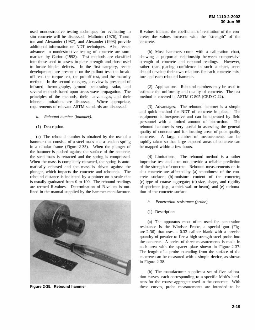
(a) The rebound number is obtained by the use of ahammer that consists of a steel mass and a tension springin a tubular frame (Figure 2-35). When the plunger ofthe hammer is pushed against the surface of the concrete,the steel mass is retracted and the spring is compressed.When the mass is completely retracted, the spring is auto-matically released and the mass is driven against theplunger, which impacts the concrete and rebounds. Therebound distance is indicated by a pointer on a scale thatis usually graduated from 0 to 100. The rebound readingsare termed R-values. Determination of R-values is out-lined in the manual supplied by the hammer manufacturer.
Figure 2-35. Rebound hammer
R-values indicate the coefficient of restitution of the con-crete; the values increase with the “strength” of theconcrete.
(b) Most hammers come with a calibration chart,showing a purported relationship between compressivestrength of concrete and rebound readings. However,rather than placing confidence in such a chart, usersshould develop their own relations for each concrete mix-ture and each rebound hammer.
(2) Applications. Rebound numbers may be used toestimate the uniformity and quality of concrete. The testmethod is covered in ASTM C 805 (CRD-C 22).
(3) Advantages. The rebound hammer is a simpleand quick method for NDT of concrete in place. Theequipment is inexpensive and can be operated by fieldpersonnel with a limited amount of instruction. Therebound hammer is very useful in assessing the generalquality of concrete and for locating areas of poor qualityconcrete. A large number of measurements can berapidly taken so that large exposed areas of concrete canbe mapped within a few hours.
(4) Limitations. The rebound method is a ratherimprecise test and does not provide a reliable predictionof the strength of concrete. Rebound measurements on insitu concrete are affected by (a) smoothness of the con-crete surface; (b) moisture content of the concrete;(c) type of coarse aggregate; (d) size, shape, and rigidityof specimen (e.g., a thick wall or beam); and (e) carbona-tion of the concrete surface.
b. Penetration resistance (probe).
(1) Description.
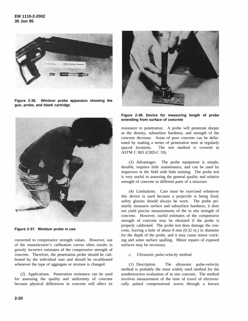
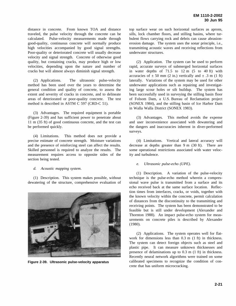
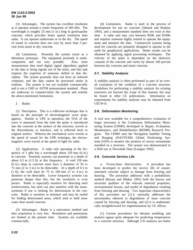
(a) The apparatus most often used for penetrationresistance is the Windsor Probe, a special gun (Fig-ure 2-36) that uses a 0.32 caliber blank with a precisequantity of powder to fire a high-strength steel probe intothe concrete. A series of three measurements is made ineach area with the spacer plate shown in Figure 2-37.The length of a probe extending from the surface of theconcrete can be measured with a simple device, as shownin Figure 2-38.
(b) The manufacturer supplies a set of five calibra-tion curves, each corresponding to a specific Moh’s hard-ness for the coarse aggregate used in the concrete. Withthese curves, probe measurements are intended to be
2-19
EM 1110-2-200230 Jun 95
Figure 2-36. Windsor probe apparatus showing thegun, probe, and blank cartridge
Figure 2-37. Windsor probe in use
converted to compressive strength values. However, useof the manufacturer’s calibration curves often results ingrossly incorrect estimates of the compressive strength ofconcrete. Therefore, the penetration probe should be cali-brated by the individual user and should be recalibratedwhenever the type of aggregate or mixture is changed.
(2) Applications. Penetration resistance can be usedfor assessing the quality and uniformity of concretebecause physical differences in concrete will affect its
resistance to penetration. A probe will penetrate deeper
Figure 2-38. Device for measuring length of probeextending from surface of concrete
as the density, subsurface hardness, and strength of theconcrete decrease. Areas of poor concrete can be delin-eated by making a series of penetration tests at regularlyspaced locations. The test method is covered inASTM C 803 (CRD-C 59).
(3) Advantages. The probe equipment is simple,durable, requires little maintenance, and can be used byinspectors in the field with little training. The probe testis very useful in assessing the general quality and relativestrength of concrete in different parts of a structure.
(4) Limitations. Care must be exercised wheneverthis device is used because a projectile is being fired;safety glasses should always be worn. The probe pri-marily measures surface and subsurface hardness; it doesnot yield precise measurements of the in situ strength ofconcrete. However, useful estimates of the compressivestrength of concrete may be obtained if the probe isproperly calibrated. The probe test does damage the con-crete, leaving a hole of about 8 mm (0.32 in.) in diameterfor the depth of the probe, and it may cause minor crack-ing and some surface spalling. Minor repairs of exposedsurfaces may be necessary.
c. Ultrasonic pulse-velocity method.
(1) Description. The ultrasonic pulse-velocitymethod is probably the most widely used method for thenondestructive evaluation of in situ concrete. The methodinvolves measurement of the time of travel of electroni-cally pulsed compressional waves through a known
2-20
EM 1110-2-200230 Jun 95
distance in concrete. From known TOA and distancetraveled, the pulse velocity through the concrete can becalculated. Pulse-velocity measurements made throughgood-quality, continuous concrete will normally producehigh velocities accompanied by good signal strengths.Poor-quality or deteriorated concrete will usually decreasevelocity and signal strength. Concrete of otherwise goodquality, but containing cracks, may produce high or lowvelocities, depending upon the nature and number ofcracks but will almost always diminish signal strength.
(2) Applications. The ultrasonic pulse-velocitymethod has been used over the years to determine thegeneral condition and quality of concrete, to assess theextent and severity of cracks in concrete, and to delineateareas of deteriorated or poor-quality concrete. The testmethod is described in ASTM C 597 (CRD-C 51).
(3) Advantages. The required equipment is portable(Figure 2-39) and has sufficient power to penetrate about11 m (35 ft) of good continuous concrete, and the test canbe performed quickly.
(4) Limitations. This method does not provide aprecise estimate of concrete strength. Moisture variationsand the presence of reinforcing steel can affect the results.Skilled personnel is required to analyze the results. Themeasurement requires access to opposite sides of thesection being tested.
d. Acoustic mapping system.
(1) Description. This system makes possible, withoutdewatering of the structure, comprehensive evaluation of
Figure 2-39. Ultrasonic pulse-velocity apparatus
top surface wear on such horizontal surfaces as aprons,sills, lock chamber floors, and stilling basins, where tur-bulent flows carrying rock and debris can cause abrasion-erosion damage. The system uses the sonar principle, i.e.,transmitting acoustic waves and receiving reflections fromunderwater structures.
(2) Application. The system can be used to performrapid, accurate surveys of submerged horizontal surfacesin water depths of 71.5 to 12 m (5 to 40 ft) withaccuracies of ± 50 mm (2 in.) vertically and ± .3 m (1 ft)laterally. Variations of the system may be used for otherunderwater applications such as repairing and investigat-ing large scour holes or silt buildup. The system hasbeen successfully used in surveying the stilling basin floorof Folsom Dam, a U.S. Bureau of Reclamation project(SONEX 1984), and the stilling basin of Ice Harbor Damin Walla Walla District (SONEX 1983).
(3) Advantages. This method avoids the expenseand user inconvenience associated with dewatering andthe dangers and inaccuracies inherent in diver-performedsurveys.
(4) Limitations. Vertical and lateral accuracy willdecrease at depths greater than 9 m (30 ft). There aresome operational restrictions associated with water veloc-ity and turbulence.
e. Ultrasonic pulse-echo (UPE).
(1) Description. A variation of the pulse-velocitytechnique is the pulse-echo method wherein a compres-sional wave pulse is transmitted from a surface and itsecho received back at the same surface location. Reflec-tion times from interfaces, cracks, or voids, together withthe known velocity within the concrete, permit calculationof distances from the discontinuity to the transmitting andreceiving points. The system has been demonstrated to befeasible but is still under development (Alexander andThornton 1988). An impact pulse-echo system for meas-urements on concrete piles is described by Alexander(1980).
(2) Applications. The system operates well for flat-work for dimensions less than 0.3 m (1 ft) in thickness.The system can detect foreign objects such as steel andplastic pipe. It can measure unknown thicknesses andpresence of delaminations up to 0.3 m (1 ft) in thickness.Recently neural network algorithms were trained on somecalibrated specimens to recognize the condition of con-crete that has uniform microcracking.
2-21
EM 1110-2-200230 Jun 95
(3) Advantages. The system has excellent resolutionas it operates around a center frequently of 200 kHz. Thewavelength is roughly 25 mm (1 in.) long in good-qualityconcrete, which provides better spatial resolution thanradar. It can operate underwater or in the dry. The speedof sound in concrete does not vary by more than 5 per-cent from moist to dry concrete.
(4) Limitations. Presently the system exists as alaboratory prototype. The equipment presently is multi-component and not very portable. Also, mostmeasurement data need digital signal algorithms appliedto the data to bring signals out of the noise, and this taskrequires the expertise of someone skilled in that dis-cipline. The system presently does not have an onboardcomputer, and the data cannot be processed onsite inrealtime. The system is not yet available commerciallyand is not a CRD or ASTM measurement standard. Plansare underway to commercialize the system and remedythe above-mentioned limitations.
f. Radar.
(1) Description. This is a reflection technique that isbased on the principle of electromagnetic wave prop-agation. Similar to UPE in operation, the TOA of thewave is measured from the time the pulse is introducedinto the concrete at the surface of the structure, travels tothe discontinuity or interface, and is reflected back tooriginal surface. Whereas the mechanical wave travels atthe speed of sound for the UPE technique, the electro-magnetic wave travels at the speed of light for radar.
(2) Applications. A radar unit operating at the fre-quency of 1 gHz has a wavelength about 150 mm (6 in.)in concrete. Presently systems can penetrate to a depth ofabout 0.5 m (1.5 ft) at this frequency. A void 150 mm(6 in.) deep in concrete must have a diameter of 50 to75 mm (2 to 3 in.) to be detectable. At a depth of 0.3 m(1 ft), the void must be 75 to 100 mm (3 to 4 in.) indiameter to be detectable. Lower frequency systems canpenetrate deeper than this, but the resolution is evenpoorer. Radar is especially sensitive for detecting steelreinforcement, but steel can also interfere with the meas-urements if one is looking for deterioration in the con-crete. Radar is sensitive to moisture and may be usefulfor finding deteriorated areas, which tend to hold morewater than sound concrete.
(3) Advantages. Radar is a noncontact method anddata acquisition is very fast. Resolution and penetrationare limited at the present time. Systems are availablecommercially.
(4) Limitations. Radar is steel in the process ofdevelopment for use on concrete (Ahmad and Haskins1993), and a measurement standard does not exist at thistime. A radar unit may cost between $50K and $100Kand requires someone highly trained to operate the equip-ment and interpret the data. Commercial systems beingused for concrete are primarily designed to operate in theearth for geophysical applications. Better results can beobtained by applying signal processing techniques. Thevelocity of the pulse is dependent on the dielectricconstant of the concrete and varies by almost 100 percentbetween dry concrete and moist concrete.
2-7. Stability Analysis
A stability analysis is often performed as part of an over-all evaluation of the condition of a concrete structure.Guidelines for performing a stability analysis for existingstructures are beyond the scope of this manual, but maybe found in other CE publications. Information onrequirements for stability analyses may be obtained fromCECW-E.
2-8. Deformation Monitoring
A tool now available for a comprehensive evaluation oflarger structures is the Continuous Deformation Moni-toring System (CDMS) developed in Repair, Evaluation,Maintenance, and Rehabilitation (REMR) Research Pro-gram. The CDMS uses the Navigation Satellite Timingand Ranging (NAVSTAR) Global Positioning Sys-tems (GPS) to monitor the position of survey monumentsinstalled on a structure. The system was demonstrated ina field test at Dworshak Dam (Lanigan 1992).
2-9. Concrete Service Life
a. Freeze-thaw deterioration. A procedure hasbeen developed to predict the service life of nonair-entrained concrete subject to damage from freezing andthawing. The procedure addresses with a probabilisticmethod (Bryant and Mlakar 1991) both the known anduncertain qualities of the relevant material properties,environmental factors, and model of degradation resultingfrom freezing and thawing. Two important characteristicsof this procedure are (1) it rationally addresses theuncertainties inherent in degradation of mass concretecaused by freezing and thawing, and (2) it is mathemati-cally straightforward for implementation by CE offices.
(1) Current procedures for thermal modeling andanalysis appear quite adequate for predicting temperaturesin a concrete structure. Although 2-D analyses are better
2-22
EM 1110-2-200230 Jun 95
for determining complex thermal response, in many casesa series of much simpler one-dimensional (1-D) analysesprovide a very good estimation of temperatures. Theexternal temperature inputs to a thermal analysis, i.e.,water-air temperatures, were well represented by sinusoi-dal curves.
(2) The general understanding and analytical modelsfor predicting moisture migration and degree of saturationare not as well developed as those for the thermal prob-lem. A seepage model for predicting the degree of satu-ration appears to provide adequate answers for theprediction of service life; however, further study is appro-priate to substantiate this indication.
(3) The procedure was demonstrated by hindcastapplication to the middle wall and landwall at DashieldsLock which exhibited an appreciable degree of meas-urable damage caused by freezing and thawing. Requireddata for application of the procedure, e.g., temperatureand concrete properties, were available for these features,which were representative of typical CE projects.
(4) Damage predicted by the procedure was in agree-ment with observed damage resulting from freezing andthawing at each site. The general trends of location andspatial variation of damage were very similar to obser-vations and measurements at the two sites. More encour-agingly, the actual magnitudes of damage predicted by theprocedure compared favorably with the previous measure-ments. This result provides the strongest indication thatthe procedure is rational and would enhance the ability ofthe CE to predict service life at its many other concretestructures.
b. Other deterioration mechanisms. A completeand comprehensive report by Clifton (1991) examines thebasis for predicting the remaining service lives of concretematerials of nuclear power facilities. The study consistedof two major activities: the evaluation of models whichcan be used in predicting the remaining service life ofconcrete exposed to the major environmental stressors andaging factors; and, the evaluation of accelerated agingtechniques and tests which can provide data for servicelife models or which themselves can be used to predictthe remaining service life of concrete. Methods for ser-vice life prediction which are discussed in this reportinclude: (1) estimates based on experience; (2) deduc-tions from performance of similar materials;(3) accelerated testing; (4) applications of reliability andstochastic concepts; and (5) mathematical modeling basedon the chemistry and physics of the degradation pro-cesses. Models for corrosion, sulfate attack, frost attack,and leaching were identified and analyzed. While nomodel was identified for distress caused by alkali-aggregate reactions, an approach for modeling the processwas outlined.
2-10. Reliability Analysis
A reliability analysis may be required for major rehabilita-tion projects. Guidelines for performing a reliabilityanalysis are beyond the scope of this manual.Information on requirements for reliability analyses maybe obtained from CECW-E.
2-23
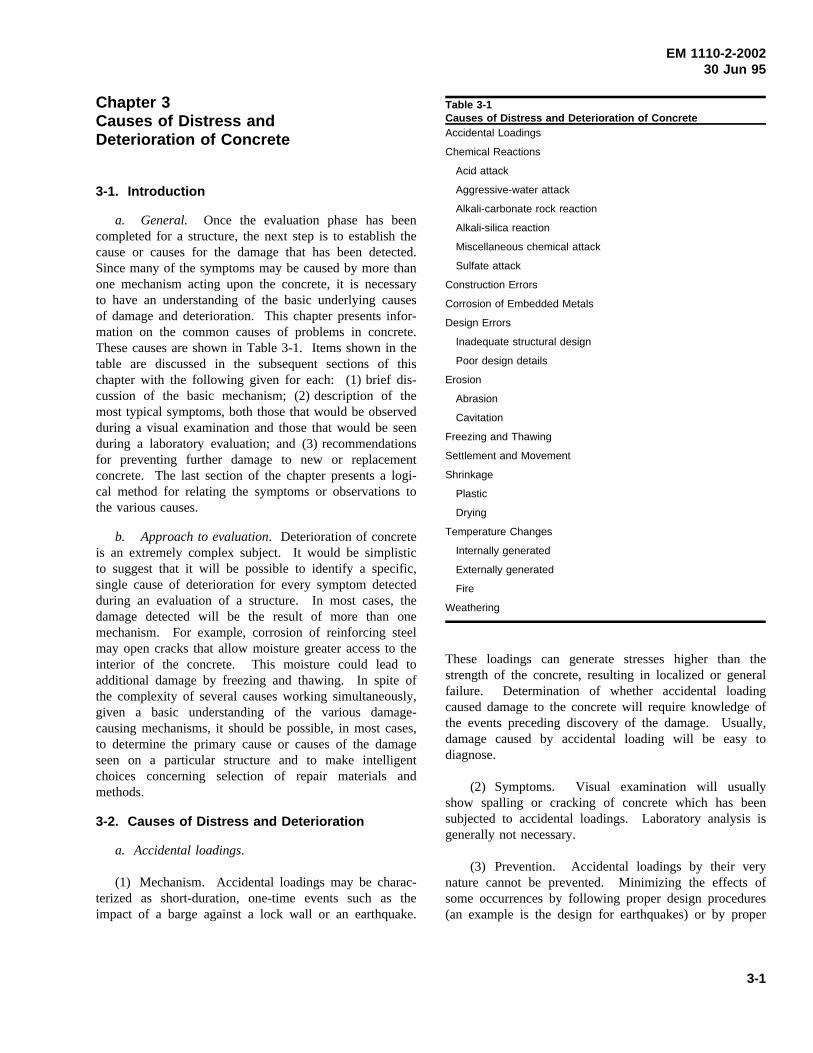
EM 1110-2-200230 Jun 95
Chapter 3Causes of Distress andDeterioration of Concrete
3-1. Introduction
a. General. Once the evaluation phase has beencompleted for a structure, the next step is to establish thecause or causes for the damage that has been detected.Since many of the symptoms may be caused by more thanone mechanism acting upon the concrete, it is necessaryto have an understanding of the basic underlying causesof damage and deterioration. This chapter presents infor-mation on the common causes of problems in concrete.These causes are shown in Table 3-1. Items shown in thetable are discussed in the subsequent sections of thischapter with the following given for each: (1) brief dis-cussion of the basic mechanism; (2) description of themost typical symptoms, both those that would be observedduring a visual examination and those that would be seenduring a laboratory evaluation; and (3) recommendationsfor preventing further damage to new or replacementconcrete. The last section of the chapter presents a logi-cal method for relating the symptoms or observations tothe various causes.
b. Approach to evaluation. Deterioration of concreteis an extremely complex subject. It would be simplisticto suggest that it will be possible to identify a specific,single cause of deterioration for every symptom detectedduring an evaluation of a structure. In most cases, thedamage detected will be the result of more than onemechanism. For example, corrosion of reinforcing steelmay open cracks that allow moisture greater access to theinterior of the concrete. This moisture could lead toadditional damage by freezing and thawing. In spite ofthe complexity of several causes working simultaneously,given a basic understanding of the various damage-causing mechanisms, it should be possible, in most cases,to determine the primary cause or causes of the damageseen on a particular structure and to make intelligentchoices concerning selection of repair materials andmethods.
3-2. Causes of Distress and Deterioration
a. Accidental loadings.
(1) Mechanism. Accidental loadings may be charac-terized as short-duration, one-time events such as theimpact of a barge against a lock wall or an earthquake.
Table 3-1Causes of Distress and Deterioration of ConcreteAccidental Loadings
Chemical Reactions
Acid attack
Aggressive-water attack
Alkali-carbonate rock reaction
Alkali-silica reaction
Miscellaneous chemical attack
Sulfate attack
Construction Errors
Corrosion of Embedded Metals
Design Errors
Inadequate structural design
Poor design details
Erosion
Abrasion
Cavitation
Freezing and Thawing
Settlement and Movement
Shrinkage
Plastic
Drying
Temperature Changes
Internally generated
Externally generated
Fire
Weathering
These loadings can generate stresses higher than thestrength of the concrete, resulting in localized or generalfailure. Determination of whether accidental loadingcaused damage to the concrete will require knowledge ofthe events preceding discovery of the damage. Usually,damage caused by accidental loading will be easy todiagnose.
(2) Symptoms. Visual examination will usuallyshow spalling or cracking of concrete which has beensubjected to accidental loadings. Laboratory analysis isgenerally not necessary.
(3) Prevention. Accidental loadings by their verynature cannot be prevented. Minimizing the effects ofsome occurrences by following proper design procedures(an example is the design for earthquakes) or by proper
3-1
EM 1110-2-200230 Jun 95
attention to detailing (wall armor in areas of likelyimpact) will reduce the impacts of accidental loadings.
b. Chemical reactions. This category includes sev-eral specific causes of deterioration that exhibit a widevariety of symptoms. In general, deleterious chemicalreactions may be classified as those that occur as theresult of external chemicals attacking the concrete (acidattack, aggressive water attack, miscellaneous chemicalattack, and sulfate attack) or those that occur as a resultof internal chemical reactions between the constituents ofthe concrete (alkali-silica and alkali-carbonate rock reac-tions). Each of these chemical reactions is describedbelow.
(1) Acid attack.
(a) Mechanism. Portland-cement concrete is a highlyalkaline material and is not very resistant to attack byacids. The deterioration of concrete by acids is primarilythe result of a reaction between the acid and the productsof the hydration of cement. Calcium silicate hydrate maybe attacked if highly concentrated acid exists in the envir-onment of the concrete structures. In most cases, thechemical reaction results in the formation of water-solublecalcium compounds that are then leached away. In thecase of sulfuric acid attack, additional or accelerateddeterioration results because the calcium sulfate formedmay affect the concrete by the sulfate attack mechanism(Section 3-2b(6)). If the acid is able to reach the rein-forcing steel through cracks or pores in the concrete,corrosion of the reinforcing steel will result and will causefurther deterioration of the concrete (ACI 201.2R).
(b) Symptoms. Visual examination will show disin-tegration of the concrete evidenced by loss of cementpaste and aggregate from the matrix (Figure 2-13). Ifreinforcing steel has been reached by the acid, ruststaining, cracking, and spalling may be present. If thenature of the solution in which the deteriorating concreteis located is unknown, laboratory analysis can be used toidentify the specific acid involved.
(c) Prevention. A dense concrete with a lowwater-cement ratio (w/c) may provide an acceptabledegree of protection against a mild acid attack. Portland-cement concrete, because of its composition, is unable towithstand attack by highly acidic solutions for longperiods of time. Under such conditions, an appropriatesurface coating or treatment may be necessary. ACICommittee 515 has extensive recommendations for suchcoatings (ACI 515.1R).
(2) Aggressive-water attack.
(a) Mechanism. Some waters have been reported tohave extremely low concentrations of dissolved minerals.These soft or aggressive waters will leach calcium fromcement paste or aggregates. This phenomenon has beeninfrequently reported in the United States. From the fewcases that have been reported, there are indications thatthis attack takes place very slowly. For an aggressive-water attack to have a serious effect on hydraulic struc-tures, the attack must occur in flowing water. This keepsa constant supply of aggressive water in contact with theconcrete and washes away aggregate particles that becomeloosened as a result of leaching of the paste (Holland,Husbands, Buck, and Wong 1980).
(b) Symptoms. Visual examination will show con-crete surfaces that are very rough in areas where the pastehas been leached (Figure 2-12). Sand grains may bepresent on the surface of the concrete, making it resemblea coarse sandpaper. If the aggregate is susceptible toleaching, holes where the coarse aggregate has been dis-solved will be evident. Water samples from structureswhere aggressive-water attack is suspected may be ana-lyzed to calculate the Langlier Index, which is a measureof the aggressiveness of the water (Langlier 1936).
(c) Prevention. The aggressive nature of water atthe site of a structure can be determined before con-struction or during a major rehabilitation. Additionally,the water-quality evaluation at many structures can beexpanded to monitor the aggressiveness of water at thestructure. If there are indications that the water is aggres-sive or is becoming aggressive, areas susceptible to highflows may be coated with a nonportland-cement-basedcoating.
(3) Alkali-carbonate rock reaction.
(a) Mechanism. Certain carbonate rock aggregateshave been reactive in concrete. The results of these reac-tions have been characterized as ranging from beneficialto destructive. The destructive category is apparentlylimited to reactions with impure dolomitic aggregates andare a result of either dedolomitization or rim-silicificationreactions. The mechanism of alkali-carbonate rock reac-tion is covered in detail in EM 1110-2-2000.
(b) Symptoms. Visual examination of those reac-tions that are serious enough to disrupt the concrete in a
3-2
EM 1110-2-200230 Jun 95
structure will generally show map or pattern cracking anda general appearance which indicates that the concrete isswelling (Figure 2-7). A distinguishing feature whichdifferentiates alkali-carbonate rock reaction fromalkali-silica reaction is the lack of silica gel exudations atcracks (ACI 201.2R). Petrographic examination in accor-dance with ASTM C 295 (CRD-C 127) may be used toconfirm the presence of alkali-carbonate rock reaction.
(c) Prevention. In general, the best prevention is toavoid using aggregates that are or suspected of beingreactive. Appendix E of EM 1110-2-2000 prescribesprocedures for testing rocks for reactivity and for mini-mizing effects when reactive aggregates must be used.
(4) Alkali-silica reaction.
(a) Mechanism. Some aggregates containing silicathat is soluble in highly alkaline solutions may react toform a solid nonexpansive calcium-alkali-silica complexor an alkali-silica complex which can imbibe considerableamounts of water and then expand, disrupting theconcrete. Additional details may be found inEM 1110-2-2000.
(b) Symptoms. Visual examination of those concretestructures that are affected will generally show map orpattern cracking and a general appearance that indicatesthat the concrete is swelling (Figure 2-6). Petrographicexamination may be used to confirm the presence ofalkali-silica reaction.
(c) Prevention. In general, the best prevention is toavoid using aggregates that are known or suspected to bereactive or to use a cement containing less than0.60 percent alkalies (percent Na20 + (0.658) percentK20). Appendix D of EM 1110-2-2000 prescribes proce-dures for testing aggregates for reactivity and for mini-mizing the effects when reactive aggregates must be used.
(5) Miscellaneous chemical attack.
(a) Mechanism. Concrete will resist chemical attackto varying degrees, depending upon the exact nature ofthe chemical. ACI 515.1R includes an extensive listing ofthe resistance of concrete to various chemicals. To pro-duce significant attack on concrete, most chemicals mustbe in solution that is above some minimum concentration.Concrete is seldom attacked by solid dry chemicals.Also, for maximum effect, the chemical solution needs tobe circulated in contact with the concrete. Concrete sub-jected to aggressive solutions under positive differentialpressure is particularly vulnerable. The pressure gradients
tend to force the aggressive solutions into the matrix. Ifthe low-pressure face of the concrete is exposed to evapo-ration, a concentration of salts tends to accumulate at thatface, resulting in increased attack. In addition to thespecific nature of the chemical involved, the degree towhich concrete resists attack depends upon the tempera-ture of the aggressive solution, the w/c of the concrete,the type of cement used (in some circumstances), thedegree of consolidation of the concrete, the permeabilityof the concrete, the degree of wetting and drying of thechemical on the concrete, and the extent of chemicallyinduced corrosion of the reinforcing steel (ACI 201.1R).
(b) Symptoms. Visual examination of concretewhich has been subjected to chemical attack will usuallyshow surface disintegration and spalling and the openingof joints and cracks. There may also be swelling andgeneral disruption of the concrete mass. Coarse aggregateparticles are generally more inert than the cement pastematrix; therefore, aggregate particles may be seen asprotruding from the matrix. Laboratory analysis may berequired to identify the unknown chemicals which arecausing the damage.
(c) Prevention. Typically, dense concretes with loww/c (maximum w/c = 0.40) provide the greatest resis-tance. The best known method of providing long-termresistance is to provide a suitable coating as outlined inACI 515.1R.
(6) Sulfate attack.
(a) Mechanism. Naturally occurring sulfates ofsodium, potassium, calcium, or magnesium are sometimesfound in soil or in solution in ground water adjacent toconcrete structures. The sulfate ions in solution willattack the concrete. There are apparently two chemicalreactions involved in sulfate attack on concrete. First, thesulfate reacts with free calcium hydroxide which is libera-ted during the hydration of the cement to form calciumsulfate (gypsum). Next, the gypsum combines withhydrated calcium aluminate to form calciumsulfoaluminate (ettringite). Both of these reactions resultin an increase in volume. The second reaction is mainlyresponsible for most of the disruption caused by volumeincrease of the concrete (ACI 201.2R). In addition to thetwo chemical reactions, there may also be a purely physi-cal phenomenon in which the growth of crystals of sulfatesalts disrupts the concrete.
(b) Symptoms. Visual examination will show mapand pattern cracking as well as a general disintegration of
3-3
EM 1110-2-200230 Jun 95
the concrete (Figure 2-14). Laboratory analysis can verifythe occurrence of the reactions described.
(c) Prevention. Protection against sulfate attack cangenerally be obtained by the following: Use of a dense,high-quality concrete with a low water-cement ratio; Useof either a Type V or a Type II cement, depending uponthe anticipated severity of the exposure (EM 1110-2-2000); Use of a suitable pozzolan (some pozzolans, addedas part of a blended cement or separately, have improvedresistance, while others have hastened deterioration). Ifuse of a pozzolan is anticipated, laboratory testing toverify the degree of improvement to be expected isrecommended.
c. Construction errors. Failure to follow specifiedprocedures and good practice or outright carelessness maylead to a number of conditions that may be groupedtogether as construction errors. Typically, most of theseerrors do not lead directly to failure or deterioration ofconcrete. Instead, they enhance the adverse impacts ofother mechanisms identified in this chapter. Each errorwill be briefly described below along with preventativemethods. In general, the best preventive measure is athorough knowledge of what these construction errors areplus an aggressive inspection program. It should be notedthat errors of the type described in this section are equallyas likely to occur during repair or rehabilitation projectsas they are likely to occur during new construction.
(1) Adding water to concrete. Water is usually addedto concrete in one or both of the following circumstances:First, water is added to the concrete in a delivery truck toincrease slump and decrease emplacement effort. Thispractice will generally lead to concrete with loweredstrength and reduced durability. As the w/c of the con-crete increases, the strength and durability will decrease.In the second case, water is commonly added duringfinishing of flatwork. This practice leads to scaling, craz-ing, and dusting of the concrete in service.
(2) Improper alignment of formwork. Improperalignment of the formwork will lead to discontinuities onthe surface of the concrete. While these discontinuitiesare unsightly in all circumstances, their occurrence maybe more critical in areas that are subjected to high-velocity flow of water, where cavitation-erosion may beinduced, or in lock chambers where the “rubbing” sur-faces must be straight.
(3) Improper consolidation. Improper consolidationof concrete may result in a variety of defects, the mostcommon being bugholes, honeycombing, and cold joints.
“Bugholes” are formed when small pockets of air or waterare trapped against the forms. A change in the mixture tomake it less “sticky” or the use of small vibrators workednear the form has been used to help eliminate bugholes.Honeycombing can be reduced by inserting the vibratormore frequently, inserting the vibrator as close as pos-sible to the form face without touching the form, andslower withdrawal of the vibrator. Obviously, any or allof these defects make it much easier for anydamage-causing mechanism to initiate deterioration of theconcrete. Frequently, a fear of “overconsolidation” isused to justify a lack of effort in consolidating concrete.Overconsolidation is usually defined as a situation inwhich the consolidation effort causes all of the coarseaggregate to settle to the bottom while the paste rises tothe surface. If this situation occurs, it is reasonable toconclude that there is a problem of a poorly proportionedconcrete rather than too much consolidation.
(4) Improper curing. Curing is probably the mostabused aspect of the concrete construction process.Unless concrete is given adequate time to cure at a properhumidity and temperature, it will not develop the charac-teristics that are expected and that are necessary to pro-vide durability. Symptoms of improperly cured concretecan include various types of cracking and surface disinte-gration. In extreme cases where poor curing leads tofailure to achieve anticipated concrete strengths, structuralcracking may occur.
(5) Improper location of reinforcing steel. Thissection refers to reinforcing steel that is improperlylocated or is not adequately secured in the proper location.Either of these faults may lead to two general types ofproblems. First, the steel may not function structurally asintended, resulting in structural cracking or failure. Aparticularly prevalent example is the placement of weldedwire mesh in floor slabs. In many cases, the mesh endsup on the bottom of the slab which will subsequentlycrack because the steel is not in the proper location. Thesecond type of problem stemming from improperlylocated or tied reinforcing steel is one of durability. Thetendency seems to be for the steel to end up near thesurface of the concrete. As the concrete cover over thesteel is reduced, it is much easier for corrosion to begin.
(6) Movement of formwork. Movement of form-work during the period while the concrete is going from afluid to a rigid material may induce cracking and separa-tion within the concrete. A crack open to the surface willallow access of water to the interior of the concrete. Aninternal void may give rise to freezing or corrosion prob-lems if the void becomes saturated.
3-4
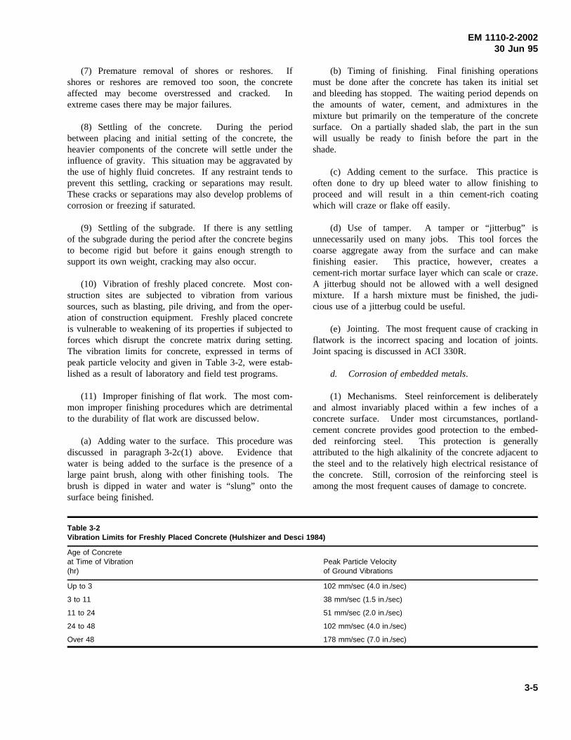
EM 1110-2-200230 Jun 95
(7) Premature removal of shores or reshores. Ifshores or reshores are removed too soon, the concreteaffected may become overstressed and cracked. Inextreme cases there may be major failures.
(8) Settling of the concrete. During the periodbetween placing and initial setting of the concrete, theheavier components of the concrete will settle under theinfluence of gravity. This situation may be aggravated bythe use of highly fluid concretes. If any restraint tends toprevent this settling, cracking or separations may result.These cracks or separations may also develop problems ofcorrosion or freezing if saturated.
(9) Settling of the subgrade. If there is any settlingof the subgrade during the period after the concrete beginsto become rigid but before it gains enough strength tosupport its own weight, cracking may also occur.
(10) Vibration of freshly placed concrete. Most con-struction sites are subjected to vibration from varioussources, such as blasting, pile driving, and from the oper-ation of construction equipment. Freshly placed concreteis vulnerable to weakening of its properties if subjected toforces which disrupt the concrete matrix during setting.The vibration limits for concrete, expressed in terms ofpeak particle velocity and given in Table 3-2, were estab-lished as a result of laboratory and field test programs.
(11) Improper finishing of flat work. The most com-mon improper finishing procedures which are detrimentalto the durability of flat work are discussed below.
(a) Adding water to the surface. This procedure wasdiscussed in paragraph 3-2c(1) above. Evidence thatwater is being added to the surface is the presence of alarge paint brush, along with other finishing tools. Thebrush is dipped in water and water is “slung” onto thesurface being finished.
(b) Timing of finishing. Final finishing operationsmust be done after the concrete has taken its initial setand bleeding has stopped. The waiting period depends onthe amounts of water, cement, and admixtures in themixture but primarily on the temperature of the concretesurface. On a partially shaded slab, the part in the sunwill usually be ready to finish before the part in theshade.
(c) Adding cement to the surface. This practice isoften done to dry up bleed water to allow finishing toproceed and will result in a thin cement-rich coatingwhich will craze or flake off easily.
(d) Use of tamper. A tamper or “jitterbug” isunnecessarily used on many jobs. This tool forces thecoarse aggregate away from the surface and can makefinishing easier. This practice, however, creates acement-rich mortar surface layer which can scale or craze.A jitterbug should not be allowed with a well designedmixture. If a harsh mixture must be finished, the judi-cious use of a jitterbug could be useful.
(e) Jointing. The most frequent cause of cracking inflatwork is the incorrect spacing and location of joints.Joint spacing is discussed in ACI 330R.
d. Corrosion of embedded metals.
(1) Mechanisms. Steel reinforcement is deliberatelyand almost invariably placed within a few inches of aconcrete surface. Under most circumstances, portland-cement concrete provides good protection to the embed-ded reinforcing steel. This protection is generallyattributed to the high alkalinity of the concrete adjacent tothe steel and to the relatively high electrical resistance ofthe concrete. Still, corrosion of the reinforcing steel isamong the most frequent causes of damage to concrete.
Table 3-2Vibration Limits for Freshly Placed Concrete (Hulshizer and Desci 1984)
Age of Concreteat Time of Vibration(hr)
Peak Particle Velocityof Ground Vibrations
Up to 3 102 mm/sec (4.0 in./sec)
3 to 11 38 mm/sec (1.5 in./sec)
11 to 24 51 mm/sec (2.0 in./sec)
24 to 48 102 mm/sec (4.0 in./sec)
Over 48 178 mm/sec (7.0 in./sec)
3-5
EM 1110-2-200230 Jun 95
(a) High alkalinity and electrical resistivity of theconcrete. The high alkalinity of the concrete pore solu-tion can be reduced over a long period of time by car-bonation. The electrical resistivity can be decreased bythe presence of chemicals in the concrete. The chemicalmost commonly applied to concrete is chloride salts in theform of deicers. As the chloride ions penetrate the con-crete, the capability of the concrete to carry an electricalcurrent is increased significantly. If there are differenceswithin the concrete such as moisture content, chloridecontent, oxygen content, or if dissimilar metals are incontact, electrical potential differences will occur and acorrosion cell may be established. The anodes will exper-ience corrosion while the cathodes will be undamaged.On an individual reinforcing bar there may be manyanodes and cathodes, some adjacent, and some widelyspaced.
(b) Corrosion-enhanced reduction in load-carryingcapacity of concrete. As the corrosion progresses, twothings occur: First, the cross-sectional area of the rein-forcement is reduced, which in turn reduces the load-carrying capacity of the steel. Second, the products of thecorrosion, iron oxide (rust), expand since they occupyabout eight times the volume of the original material.This increase in volume leads to cracking and ultimatelyspalling of the concrete. For mild steel reinforcing, thedamage to the concrete will become evident long beforethe capacity of the steel is reduced enough to affect itsload-carrying capacity. However, for prestressing steel,slight reductions in section can lead to catastrophicfailure.
(c) Other mechanisms for corrosion of embeddedmetals. In addition to the development of an electrolyticcell, corrosion may be developed under several othersituations. The first of these is corrosion produced by thepresence of a stray electrical current. In this case, thecurrent necessary for the corrosion reaction is providedfrom an outside source. A second additional source ofcorrosion is that produced by chemicals that may be ableto act directly on the reinforcing steel. Since this sectionhas dealt only with the corrosion of steel embedded inconcrete, for information on the behavior of other metalsin concrete, see ACI 201.2R and ACI 222R.
(2) Symptoms. Visual examination will typicallyreveal rust staining of the concrete. This staining will befollowed by cracking. Cracks produced by corrosiongenerally run in straight, parallel lines at uniform intervalscorresponding to the spacing of the reinforcement. Asdeterioration continues, spalling of the concrete over thereinforcing steel will occur with the reinforcing bars
becoming visible (Figure 2-27). One area where labora-tory analysis may be beneficial is the determination of thechloride contents in the concrete. This procedure may beused to determine the amount of concrete to be removedduring a rehabilitation project.
(3) Prevention. ACI 201.2R describes the considera-tions for protecting reinforcing steel in concrete: use ofconcrete with low permeability; use of properly propor-tioned concrete having a low w/c; use of as low a con-crete slump as practical; use of good workmanship inplacing the concrete; curing the concrete properly; provid-ing adequate concrete cover over the reinforcing steel;providing good drainage to prevent water from standingon the concrete; limiting chlorides in the concrete mix-ture; and paying careful attention to protruding items suchas bolts or other anchors.
e. Design errors. Design errors may be dividedinto two general types: those resulting from inadequatestructural design and those resulting from lack of attentionto relatively minor design details. Each of the two typesof design errors is discussed below.
(1) Inadequate structural design.
(a) Mechanism. The failure mechanism is simple--the concrete is exposed to greater stress than it is capableof carrying or it sustains greater strain than its straincapacity.
(b) Symptoms. Visual examinations of failuresresulting from inadequate structural design will usuallyshow one of two symptoms. First, errors in design result-ing in excessively high compressive stresses will result inspalling. Similarly, high torsion or shear stresses mayalso result in spalling or cracking. Second, high tensilestresses will result in cracking. To identify inadequatedesign as a cause of damage, the locations of the damageshould be compared to the types of stresses that should bepresent in the concrete. For example, if spalls are presenton the underside of a simple-supported beam, high com-pressive stresses are not present and inadequate designmay be eliminated as a cause. However, if the type andlocation of the damage and the probable stress are inagreement, a detailed stress analysis will be required todetermine whether inadequate design is the cause. Labo-ratory analysis is generally not applicable in the case ofsuspected inadequate design. However, for rehabilitationprojects, thorough petrographic analysis and strength test-ing of concrete from elements to be reused will benecessary.
3-6
EM 1110-2-200230 Jun 95
(c) Prevention. Inadequate design is best preventedby thorough and careful review of all design calculations.Any rehabilitation method that makes use of existingconcrete structural members must be carefully reviewed.
(2) Poor design details. While a structure may beadequately designed to meet loadings and other overallrequirements, poor detailing may result in localized con-centrations of high stresses in otherwise satisfactory con-crete. These high stresses may result in cracking thatallows water or chemicals access to the concrete. In othercases, poor design detailing may simply allow water topond on a structure, resulting in saturated concrete. Ingeneral, poor detailing does not lead directly to concretefailure; rather, it contributes to the action of one of theother causes of concrete deterioration described in thischapter. Several specific types of poor detailing and theirpossible effects on a structure are described in the fol-lowing paragraphs. In general, all of these problems canbe prevented by a thorough and careful review of plansand specifications for the project. In the case of existingstructures, problems resulting from poor detailing shouldbe handled by correcting the detailing and not by simplyresponding to the symptoms.
(a) Abrupt changes in section. Abrupt changes insection may cause stress concentrations that may result incracking. Typical examples would include the use ofrelatively thin sections such as bridge decks rigidly tiedinto massive abutments or patches and replacement con-crete that are not uniform in plan dimensions.
(b) Insufficient reinforcement at reentrant corners andopenings. Reentrant corners and openings also tend tocause stress concentrations that may cause cracking. Inthis case, the best prevention is to provide additionalreinforcement in areas where stress concentrations areexpected to occur.
(c) Inadequate provision for deflection. Deflectionsin excess of those anticipated may result in loading ofmembers or sections beyond the capacities for which theywere designed. Typically, these loadings will be inducedin walls or partitions, resulting in cracking.
(d) Inadequate provision for drainage. Poor attentionto the details of draining a structure may result in theponding of water. This ponding may result in leakage orsaturation of concrete. Leakage may result in damage tothe interior of the structure or in staining and encrus-tations on the structure. Saturation may result in severelydamaged concrete if the structure is in an area that issubjected to freezing and thawing.
(e) Insufficient travel in expansion joints. Inade-quately designed expansion joints may result in spallingof concrete adjacent to the joints. The full range of pos-sible temperature differentials that a concrete may beexpected to experience should be taken into account in thespecification for expansion joints. There is no singleexpansion joint that will work for all cases of temperaturedifferential.
(f) Incompatibility of materials. The use of mate-rials with different properties (modulus of elasticity orcoefficient of thermal expansion) adjacent to one anothermay result in cracking or spalling as the structure isloaded or as it is subjected to daily or annual temperaturevariations.
(g) Neglect of creep effect. Neglect of creep mayhave similar effects as noted earlier for inadequate provi-sion for deflections (paragraph 3-2e(2)(c)). Additionally,neglect of creep in prestressed concrete members maylead to excessive prestress loss that in turn results incracking as loads are applied.
(h) Rigid joints between precast units. Designsutilizing precast elements must provide for movementbetween adjacent precast elements or between the precastelements and the supporting frame. Failure to provide forthis movement can result in cracking or spalling.
(i) Unanticipated shear stresses in piers, columns, orabutments. If, through lack of maintenance, expansionbearing assembles are allowed to become frozen, horizon-tal loading may be transferred to the concrete elementssupporting the bearings. The result will be cracking inthe concrete, usually compounded by other problemswhich will be caused by the entry of water into theconcrete.
(j) Inadequate joint spacing in slabs. This is one ofthe most frequent causes of cracking of slabs-on-grade.Guidance on joint spacing and depth of contraction jointsmay be found in ACI 332R.
f. Abrasion. Abrasion damage caused by water-borne debris and the techniques used to repair the damageon several Corps’ structures are described by McDonald(1980). Also, causes of abrasion-erosion damage andprocedures for repair and prevention of damage aredescribed in ACI 210R.
(1) Mechanism. Abrasion-erosion damage is causedby the action of debris rolling and grinding against aconcrete surface. In hydraulic structures, the areas most
3-7
EM 1110-2-200230 Jun 95
likely to be damaged are spillway aprons, stilling basinslabs, and lock culverts and laterals. The sources of thedebris include construction trash left in a structure, riprapbrought back into a basin by eddy currents because ofpoor hydraulic design or asymmetrical discharge, andriprap or other debris thrown into a basin by the public.Also barges and towboats impacting or scraping on lockwells and guide wells can cause abrasions erosiondamage.
(2) Symptoms. Concrete surfaces abraded by water-borne debris are generally smooth (Figure 2-20) and maycontain localized depressions. Most of the debris remain-ing in the structure will be spherical and smooth.Mechanical abrasion is usually characterized by longshallow grooves in the concrete surface and spalling alongmonolith joints. Armor plates is often torn away or bent.
(3) Prevention. The following measures should befollowed to prevent or minimize abrasion-erosion damageto concrete hydraulic structures (Liu 1980 and McDonald1980).
(a) Design. It appears that given appropriate flowconditions in the presence of debris, all of the construc-tion materials currently being used in hydraulic structuresare to some degree susceptible to erosion. Whileimprovements in materials should reduce the rate of con-crete damage caused by erosion, this improvement alonewill not solve the problem. Until the adverse hydraulicconditions that can cause abrasion-erosion damage areminimized or eliminated, it will be extremely difficult forany of the construction materials currently being used toavoid damage by erosion. Prior to construction or repairof major structures, hydraulic model studies of the struc-ture may be required to identify potential causes of ero-sion damage and to evaluate the effectiveness of variousmodifications in eliminating those undesirable hydraulicconditions. Many older structures have spillwaysdesigned with a vertical end-sill. This design is usuallyefficient in trapping the erosion-causing debris within thespillway. In some structures, a 45-deg fillet installed onthe upstream side of the end sill has resulted in a self-cleaning stilling basin. Recessing monolith joints in lockwalls and guide walls will minimize stilling basin spallingcaused by barge impact and abrasion (Seeparagraph 8-1e(2)(e)).
(b) Operation. In existing structures, balanced flowsshould be maintained into basins by using all gates toavoid discharge conditions where eddy action is prevalent.Substantial discharges that can provide a good hydraulicjump without creating eddy action should be releasedperiodically in an attempt to flush debris from the stilling
basin. Guidance as to discharge and tailwater relationsrequired for flushing should be developed through modeland prototype tests. Periodic inspections should berequired to determine the presence of debris in the stillingbasin and the extent of erosion. If the debris cannot beremoved by flushing operations, the basin should becleaned by other means.
(c) Materials. It is imperative that materials betested and evaluated, in accordance with ASTM C 1138(CRD-C 63), prior to use in the repair of abrasion-erosiondamaged hydraulic structures. Abrasion-resistant concreteshould include the maximum amount of the hardest coarseaggregate that is available and the lowest practical w/c.In some cases where hard aggregate was not available,high-range water-reducing admixtures (HRWRA) andcondensed silica fume have been used to develop highcompressive strength concrete 97 MPa (14,000 psi) toovercome problems of unsatisfactory aggregate (Holland1983). Apparently, at these high compressive strengthsthe hardened cement paste assumes a greater role inresisting abrasion-erosion damage, and as such, theaggregate quality becomes correspondingly less important.The abrasion-erosion resistance of vacuum-treated con-crete, polymer concrete, polymer-impregnated concrete,and polymer portland-cement concrete is significantlysuperior to that of comparable conventional concrete thatcan also be attributed to a stronger cement matrix. Theincreased costs associated with materials, production, andplacing of these and any other special concretes in com-parison with conventional concrete should be consideredduring the evaluation process. While the addition of steelfibers would be expected to increase the impact resistanceof concrete, fiber-reinforced concrete is consistently lessresistant to abrasion-erosion than conventional concrete.Therefore, fiber-reinforced concrete should not be usedfor repair of stilling basins or other hydraulic structureswhere abrasion-erosion is of major concern. Severaltypes of surface coatings have exhibited good abrasion-erosion resistance during laboratory tests. These includepolyurethanes, epoxy-resin mortar, furan-resin mortar,acrylic mortar, and iron aggregate toppings. However,some difficulties have been reported in field applicationsof surface coatings, primarily the result of improper sur-face preparation and thermal incompatibility betweencoatings and concrete.
g. Cavitation. Cavitation-erosion is the result ofrelatively complex flow characteristics of water overconcrete surfaces (ACI 210R).
(1) Mechanism. There is little evidence to show thatwater flowing over concrete surfaces at velocities less
3-8
EM 1110-2-200230 Jun 95
than 12.2 m/sec (40 ft/sec) causes any cavitation damageto the concrete. However, when the flow is fast enough(greater than 12.2 m/sec) and where there is surface irreg-ularity in the concrete, cavitation damage may occur.Whenever there is surface irregularity, the flowing waterwill separate from the concrete surface. In the area ofseparation from the concrete, vapor bubbles will developbecause of the lowered vapor pressure in the region. Asthese bubbles are carried downstream, they will soonreach areas of normal pressure. These bubbles will col-lapse with an almost instantaneous reduction in volume.This collapse, or implosion, creates a shock wave which,upon reaching a concrete surface, induces very highstresses over a small area. The repeated collapse of vaporbubbles on or near the concrete surface will cause pitting.Concrete spillways and outlet works of many high damshave been severely damaged by cavitation.
(2) Symptoms. Concrete that has been damaged willbe severely pitted and extremely rough (Figure 2-21). Asthe damage progresses, the roughness of the damaged areamay induce additional cavitation.
(3) Prevention.
(a) Hydraulic design. Even the strongest materialscannot withstand the forces of cavitation indefinitely.Therefore, proper hydraulic design and the use of aerationto reduce or eliminate the parameters that trigger cavita-tion are extremely important (ACI 210R). Since thesetopics are beyond the scope of this manual, hydraulicengineers and appropriate hydraulic design manualsshould be consulted.
(b) Conventional materials. While proper materialselection can increase the cavitation resistance of concrete,the only totally effective solution is to reduce or eliminatethe causes of cavitation. However, it is recognized that inthe case of existing structures in need of repair, the reduc-tion or elimination of cavitation may be difficult andcostly. The next best solution is to replace the damagedconcrete with more cavitation-resistant materials. Cavita-tion resistance of concrete can be increased by use of aproperly designed low w/c, high-strength concrete. Theuse of no larger than 38-mm (1-1/2-in.) nominal maxi-mum size aggregate is beneficial. Furthermore, methodswhich have reduced the unit water content of the mixture,such as use of a water-reducing admixture, are also bene-ficial. Vital to increased cavitation resistance are the useof hard, dense aggregate particles and a good aggregate-to-mortar bond. Typically, cement-based materials exhibitsignificantly lower resistance to cavitation compared topolymer-based materials.
(c) Other cavitation-resistant materials. Cavitation-damaged areas have been successfully repaired with steel-fiber concrete and polymer concrete (Houghton, Borge,and Paxton 1978). Some coatings, such as neoprene andpolyurethane, have reduced cavitation damage to concrete,but since near-perfect adhesion to the concrete is critical,the use of the coatings is not common. Once a tear or achip in the coating occurs, the entire coating is likely tobe peeled off.
(d) Construction practices. Construction practicesare of paramount importance when concrete surfaces areexposed to high-velocity flow, particularly if aerationdevices are not incorporated in the design. Such surfacesmust be as smooth as can be obtained under practicalconditions. Accordingly, good construction practices asgiven in EM 1110-2-2000 should be followed whether theconstruction is new or is a repair. Formed and unformedsurfaces should be carefully checked during each con-struction operation to confirm that they are within speci-fied tolerances. More restrictive tolerances on surfacesshould be avoided since they become highly expensive toconstruct and often impractical to achieve, despite the useof modern equipment and good construction practices.Where possible, transverse joints in concrete conduits orchutes should be minimized. These joints are generally ina location where the greatest problem exists in maintain-ing a continuously smooth hydraulic surface. One con-struction technique which has proven satisfactory inplacement of reasonably smooth hydraulic surfaces is thetraveling slipform screed. This technique can be appliedto tunnel inverts and to spillway chute slabs. Hurd (1989)provides information on the slipform screed. Since sur-face hardness improves cavitation resistance, proper cur-ing of these surfaces is essential.
h. Freezing and thawing.
(1) Mechanism. As the temperature of a criticallysaturated concrete is lowered during cold weather, thefreezable water held in the capillary pores of the cementpaste and aggregates expands upon freezing. If subse-quent thawing is followed by refreezing, the concrete isfurther expanded, so that repeated cycles of freezing andthawing have a cumulative effect. By their very nature,concrete hydraulic structures are particularly vulnerable tofreezing and thawing simply because there is ampleopportunity for portions of these structures to becomecritically saturated. Concrete is especially vulnerable inareas of fluctuating water levels or under spraying condi-tions. Exposure in such areas as the tops of walls, piers,parapets, and slabs enhances the vulnerability of concreteto the harmful effects of repeated cycles of freezing and
3-9
EM 1110-2-200230 Jun 95
thawing. The use of deicing chemicals on concrete sur-faces may also accelerate damage caused by freezing andthawing and may lead to pitting and scaling. ACI 201.2Rdescribes the action as physical. It involves the develop-ment of osmotic and hydraulic pressures during freezing,principally in the paste, similar to ordinary frost action.
(2) Symptoms. Visual examination of concrete dam-aged by freezing and thawing may reveal symptoms rang-ing from surface scaling to extensive disintegration(Figure 2-10). Laboratory examination of cores takenfrom structures that show surficial effects of freezing andthawing will often show a series of cracks parallel to thesurface of the structure.
(3) Prevention. The following preventive measuresare recommended by ACI 201.2R for concrete that will beexposed to freezing and thawing while saturated:
(a) Designing the structure to minimize the exposureto moisture. For example, providing positive drainagerather than flat surfaces whenever possible.
(b) Using a concrete with a low w/c.
(c) Using adequate entrained air to provide a satisfac-tory air-void system in the concrete, i.e., a bubble spacingfactor of 0.20 mm (0.008 in.) or less, which will provideprotection for the anticipated service conditions andaggregate size. EM 1110-2-2000 provides information onthe recommended amount of entrained air.
(d) Selecting suitable materials, particularly aggre-gates that perform well in properly proportioned concrete.
(e) Providing adequate curing to ensure that the com-pressive strength of the concrete is at least 24 MPa(3,500 psi) before the concrete is allowed to freeze in asaturated state.
i. Settlement and movement.
(1) Mechanisms.
(a) Differential movement. Situations in which thevarious elements of a structure are moving with respect toone another are caused by differential movements. Sinceconcrete structures are typically very rigid, they can toler-ate very little differential movement. As the differentialmovement increases, concrete members can be expectedto be subjected to an overstressed condition. Ultimately,the members will crack or spall.
(b) Subsidence. Situations in which an entire struc-ture is moving or a single element of a structure, such asa monolith, is moving with respect to the remainder of thestructure are caused by subsidence. In these cases, theconcerns are not overcracking or spalling but rather stabil-ity against overturning or sliding. Whether portions of asingle structural element are moving with respect to oneanother or whether entire elements are moving, the under-lying cause is more than likely to be a failure of the foun-dation material. This failure may be attributed tolong-term consolidations, new loading conditions, or to awide variety of other mechanisms. In situations in whichstructural movement is diagnosed as a cause of concretedeterioration, a thorough geotechnical investigation shouldbe conducted.
(2) Symptoms. Visual examination of structuresundergoing settlement or movement will usually revealcracking or spalling or faulty alignment of structuralmembers. Very often, movement will be apparent innonstructural members such as block or brick masonrywalls. Another good indication of structural movement isan increase in the amount of water leaking into the struc-ture. Since differential settlement of the foundation of astructure is usually a long-term phenomenon, review ofinstrumentation data will be helpful in determiningwhether apparent movement is real. Review by structuraland geotechnical engineering specialists will be required.
(3) Prevention. Prevention of settlements and move-ments or corrective measures are beyond the scope of thismanual. Appropriate structural and geotechnical engi-neering manuals should be consulted for guidance.
j. Shrinkage. Shrinkage is caused by the loss ofmoisture from concrete. It may be divided into two gen-eral categories: that which occurs before setting (plasticshrinkage) and that which occurs after setting (dryingshrinkage). Each of these types of shrinkage is discussedin this section.
(1) Plastic shrinkage.
(a) Mechanism. During the period between placingand setting, most concrete will exhibit bleeding to somedegree. Bleeding is the appearance of moisture on thesurface of the concrete; it is caused by the settling of theheavier components of the mixture. Usually, the bleedwater evaporates slowly from the concrete surface. Ifenvironmental conditions are such that evaporation isoccurring faster than water is being supplied to the sur-face by bleeding, high tensile stresses can develop. These
3-10
EM 1110-2-200230 Jun 95
stresses can lead to the development of cracks on theconcrete surface.
(b) Symptoms. Cracking caused by plastic shrinkagewill be seen within a few hours of concrete placement.Typically, the cracks are isolated rather than patterned.These cracks are generally wide and shallow.
(c) Prevention. Determination of whether the weatherconditions on the day of the placement are conducive toplastic shrinkage cracking is necessary. If the predictedevaporation rate is high according to ACI 305R, appropri-ate actions such as erecting windbreaks, erecting shadeover the placement, cooling the concrete, and mistingshould be taken after placement. Additionally, it will bebeneficial to minimize the loss of moisture from the con-crete surface between placing and finishing. Finally,curing should be started as soon as is practical. If crack-ing caused by plastic shrinkage does occur and if it isdetected early enough, revibration and refinishing of thecracked area will resolve the immediate problem of thecracks. Other measures as described above will berequired to prevent additional occurrences.
(2) Drying shrinkage.
(a) Mechanism. Drying shrinkage is the long-termchange in volume of concrete caused by the loss of mois-ture. If this shrinkage could take place without anyrestraint, there would be no damage to the concrete.However, the concrete in a structure is always subject tosome degree of restraint by either the foundation, byanother part of the structure, or by the difference inshrinkage between the concrete at the surface and that inthe interior of a member. This restraint may also beattributed to purely physical conditions such as the place-ment of a footing on a rough foundation or to chemicalbonding of new concrete to earlier placements or to both.The combination of shrinkage and restraints cause tensilestresses that can ultimately lead to cracking.
(b) Symptoms. Visual examination will typicallyshow cracks that are characterized by their fineness andabsence of any indication of movement. They are usuallyshallow, a few inches in depth. The crack pattern is typi-cally orthogonal or blocky. This type of surface crackingshould not be confused with thermally induced deepcracking which occurs when dimensional change isrestrained in newly placed concrete by rigid foundationsor by old lifts of concrete.
(c) Prevention. In general, the approach is either toreduce the tendency of the concrete, to shrink or to reduce
the restraint, or both. The following will help to reducethe tendency to shrink: use of less water in the concrete;use of larger aggregate to minimize paste content; placingthe concrete at as low a temperature as practical; dam-pening the subgrade and the forms; dampening aggregatesif they are dry and absorptive; and providing an adequateamount of reinforcement to distribute and reduce the sizeof cracks that do occur. Restraint can be reduced byproviding adequate contraction joints.
k. Temperature changes.Changes in temperaturecause a corresponding change in the volume of concrete.As was true for moisture-induced volume change (dryingshrinkage), temperature-induced volume changes must becombined with restraint before damage can occur. Basi-cally, there are three temperature change phenomena thatmay cause damage to concrete. First, there are the tem-perature changes that are generated internally by the heatof hydration of cement in large placements. Second, thereare the temperature changes generated by variations inclimatic conditions. Finally, there is a special case ofexternally generated temperature change--fire damage.Internally and externally generated temperature changesare discussed in subsequent paragraphs. Because of theinfrequent nature of its occurrence in civil works struc-tures, fire damage is not included in this manual.
(1) Internally generated temperature differences.
(a) Mechanism. The hydration of portland cement isan exothermic chemical reaction. In large volume place-ments, significant amounts of heat may be generated andthe temperature of the concrete may be raised by morethan 38 °C (100 °F) over the concrete temperature atplacement. Usually, this temperature rise is not uniformthroughout the mass of the concrete, and steep tempera-ture gradients may develop. These temperature gradientsgive rise to a situation known as internal restraint--theouter portions of the concrete may be losing heat whilethe inner portions are gaining (heat). If the differential isgreat, cracking may occur. Simultaneously with thedevelopment of this internal restraint condition, as theconcrete mass begins to cool, a reduction in volume takesplace. If the reduction in volume is prevented by externalconditions (such as by chemical bonding, by mechanicalinterlock, or by piles or dowels extending into the con-crete), the concrete is externally restrained. If the strainsinduced by the external restraint are great enough, crack-ing may occur. There is increasing evidence, particularlyfor rehabilitation work, that relatively minor temperaturedifferences in thin, highly restrained overlays can lead tocracking. Such cracking has been seen repeatedly in lockwall resurfacing (Figure 2-5) and in stilling basin
3-11
EM 1110-2-200230 Jun 95
overlays. Measured temperature differentials have typi-cally been much below those normally associated withthermally induced cracking.
(b) Symptoms. Cracking resulting from internalrestraint will be relatively shallow and isolated. Crackingresulting from external restraint will usually extendthrough the full section. Thermally induced cracking maybe expected to be regularly spaced and perpendicular tothe larger dimensions of the concrete.
(c) Prevention. An in-depth discussion of tempera-ture and cracking predictions for massive placements canbe found in ACI 207.1R and ACI 207.2R. In general, thefollowing may be beneficial: using as low a cement con-tent as possible; using a low-heat cement or combinationof cement and pozzolans; placing the concrete at theminimum practical temperature; selecting aggregates withlow moduli of elasticity and low coefficients of thermalexpansion; cooling internally or insulating the placementas appropriate to minimizing temperature differentials; andminimizing the effects of stress concentrators that mayinstigate cracking.
(2) Externally generated temperature differences.
(a) Mechanism. The basic failure mechanism in thiscase is the same as that for internally generated tempera-ture differences--the tensile strength of the concrete isexceeded. In this case the temperature change leading tothe concrete volume change is caused by external factors,usually changing climatic conditions. This cause of deter-ioration is best described by the following examples:First, a pavement slab cast in the summer. As the air andground temperatures drop in the fall and winter, the slabmay undergo a temperature drop of 27 °C (80 °F), ormore. Typical parameters for such a temperature drop(coefficient of thermal expansion of 10.8 × 10⁻⁶/°C (6 ×10⁻⁶/°F) indicate a 30-m (98-ft) slab would experience ashortening of more than 13 mm (1/2 in.). If the slab wererestrained, such movement would certainly lead to crack-ing. Second, a foundation or retaining wall that is cast inthe summer. In this case, as the weather cools, the con-crete may cool at different rates--exposed concrete willcool faster than that insulated by soil or other backfill.The restraint provided by this differential cooling maylead to cracking if adequate contraction joints have notbeen provided. Third, concrete that experiences sig-nificant expansion during the warmer portions of the year.Spalling may occur if there are no adequate expansionjoints. In severe cases, pavement slabs may be lifted outof alignment, resulting in so-called blowups. Fourth,concretes that have been repaired or overlayed with
materials that do not have the same coefficient of thermalexpansion as the underlying material. Annual heating andcooling may lead to cracking or debonding of the twomaterials.
(b) Symptoms. Visual examination will show regu-larly spaced cracking in the case of restrained contraction.Similarly, spalling at expansion joints will be seen in thecase of restrained expansion. Problems resulting fromexpansion-contraction caused by thermal differences willbe seen as pattern cracking, individual cracking, orspalling.
(c) Prevention. The best prevention is obviously tomake provision for the use of contraction and expansionjoints. Providing reinforcing steel (temperature steel) willhelp to distribute cracks and minimize the size of thosethat do occur. Careful review of the properties of allrepair materials will help to eliminate problems caused bytemperature changes.
l. Weathering. Weathering is frequently referred toas a cause of concrete deterioration. ACI 116R definesweathering as “Changes in color, texture, strength, chemi-cal composition, or other properties of a natural orartificial material due to the action of the weather.” How-ever, since all of these effects may be more correctlyattributed to other causes of concrete deteriorationdescribed in this chapter, weathering itself is not con-sidered to be a specific cause of deterioration.
3-3. Relating Symptoms to Causesof Distress and Deterioration
Given a detailed report of the condition of the concrete ina structure and a basic understanding of the various mech-anisms that can cause concrete deterioration, the problembecomes one of relating the observations or symptoms tothe underlying causes. When many of the differentcauses of deterioration produce the same symptoms, thetask of relating symptoms to causes is more difficult thanit first appears. One procedure to consider is based uponthat described by Johnson (1965). This procedure isobviously idealized and makes no attempt to deal withmore than one cause that may be active at any one time.Although there will usually be a combination of causesresponsible for the damage detected on a structure, thisprocedure should provide a starting point for an analysis.
a. Evaluate structure design to determine adequacy.First consider what types of stress could have caused theobserved symptoms. For example, tension will causecracking, while compression will cause spalling. Torsion
3-12
EM 1110-2-200230 Jun 95
or shear will usually result in both cracking and spalling.If the basic symptom is disintegration, then overstressmay be eliminated as a cause. Second, attempt to relatethe probable types of stress causing the damage noted tothe locations of the damage. For example, if crackingresulting from excessive tensile stress is suspected, itwould not be consistent to find that type of damage in anarea that is under compression. Next, if the damageseems appropriate for the location, attempt to relate thespecific orientation of the damage to the stress pattern.Tension cracks should be roughly perpendicular to theline of externally induced stress. Shear usually causesfailure by diagonal tension, in which the cracks will rundiagonally in the concrete section. Visualizing the basicstress patterns in the structure will aid in this phase of theevaluation. If no inconsistency is encountered during thisevaluation, then overstress may be the cause of theobserved damage. A thorough stress analysis is warrantedto confirm this finding. If an inconsistency has beendetected, such as cracking in a compression zone, the nextstep in the procedure should be followed.
b. Relate the symptoms to potential causes.For thisstep, Table 3-3 will be of benefit. Depending upon thesymptom, it may be possible to eliminate several possiblecauses. For example, if the symptom is disintegration orerosion, several potential causes may be eliminated by thisprocedure.
c. Eliminate the readily identifiable causes.Fromthe list of possible causes remaining after symptoms havebeen related to potential causes, it may be possible toeliminate two causes very quickly since they are relativelyeasy to identify. The first of these is corrosion ofembedded metals. It will be easy to verify whether thecracking and spalling noted are a result of corrosion. Thesecond cause that is readily identified is accidental load-ing, since personnel at the structure should be able torelate the observed symptoms to a specific incident.
d. Analyze the available clues.If no solution hasbeen reached at this stage, all of the evidences generatedby field and laboratory investigations should be carefullyreviewed. Attention should be paid to the followingpoints:
(1) If the basic symptom is that of disintegration ofthe concrete surface, then essentially three possible causesremain: chemical attack, erosion, and freezing and thaw-ing. Attempts should be made to relate the nature andtype of the damage to the location in the structure and tothe environment of the concrete in determining which of
the three possibilities is the most likely to be the cause ofthe damage.
(2) If there is evidence of swelling of the concrete,then there are two possibilities: chemical reactions andtemperature changes. Destructive chemical reactions suchas alkali-silica or alkali-carbonate attack that cause swel-ling will have been identified during the laboratory inves-tigation. Temperature-induced swelling should be ruledout unless there is additional evidence such as spalling atjoints.
(3) If the evidence is spalling and corrosion andaccidental loadings have been eliminated earlier, the majorcauses of spalling remaining are construction errors, poordetailing, freezing and thawing, and externally generatedtemperature changes. Examination of the structure shouldhave provided evidence as to the location and generalnature of the spalling that will allow identification of theexact cause.
(4) If the evidence is cracking, then constructionerrors, shrinkage, temperature changes, settlement andmovement, chemical reactions, and poor design detailsremain as possible causes of distress and deterioration ofconcrete. Each of these possibilities will have to bereviewed in light of the available laboratory and fieldobservations to establish which is responsible.
(5) If the evidence is seepage and it has not beenrelated to a detrimental internal chemical reaction by thistime, then it is probably the result of design errors orconstruction errors, such as improper location or installa-tion of a waterstop.
e. Determine why the deterioration has occurred.Once the basic cause or causes of the damage have beenestablished, there remains one final requirement: tounderstand how the causal agent acted upon the concrete.For example, if the symptoms were cracking and spallingand the cause was corrosion of the reinforcing steel, whatfacilitated the corrosion? Was there chloride in the con-crete? Was there inadequate cover over the reinforcingsteel? Another example to consider is concrete damagecaused by freezing and thawing. Did the damage occurbecause the concrete did not contain an adequate air-voidsystem, or did the damage occur because the concreteused was not expected to be saturated but, for whateverreason, was saturated? Only when the cause and its modeof action are completely understood should the next stepof selecting a repair material be attempted.
3-13
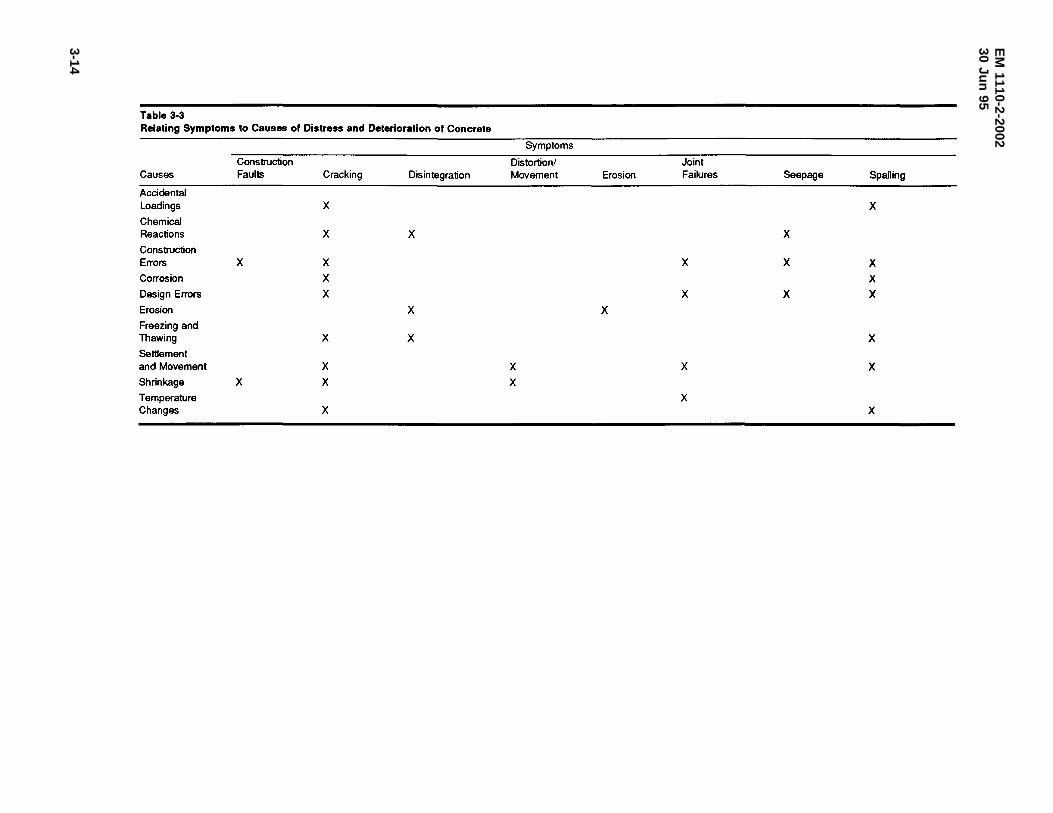
EM
1110-2-200230
Jun95
3-14
Table 3-3 Relating Symptoms to Causes of Distress and Deterioration of Concrete
Symptoms
Construction Distortion/ Joint Causes Faults Cracking Disintegration Movement Erosion Failures Seepage Spalling
Accidental Loadings X X Chemical Reactions X X X
Construction Errors X X X X X Corrosion X X Design Errors X X X X Erosion X X Freezing and Thawing X X X Settlement and Movement X X X X Shrinkage X X X Temperature X Changes X X
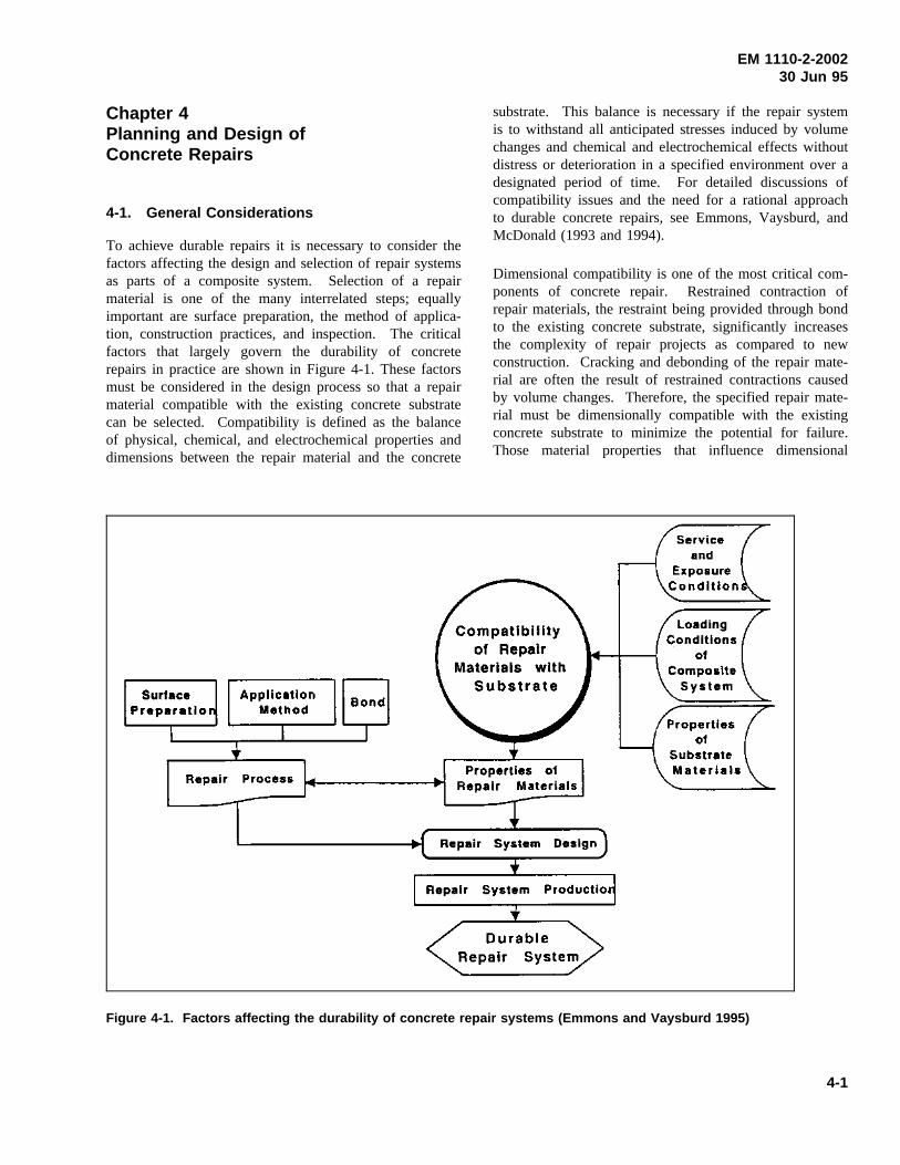
EM 1110-2-200230 Jun 95
Chapter 4Planning and Design ofConcrete Repairs
4-1. General Considerations
To achieve durable repairs it is necessary to consider thefactors affecting the design and selection of repair systemsas parts of a composite system. Selection of a repairmaterial is one of the many interrelated steps; equallyimportant are surface preparation, the method of applica-tion, construction practices, and inspection. The criticalfactors that largely govern the durability of concreterepairs in practice are shown in Figure 4-1. These factorsmust be considered in the design process so that a repairmaterial compatible with the existing concrete substratecan be selected. Compatibility is defined as the balanceof physical, chemical, and electrochemical properties anddimensions between the repair material and the concrete
substrate. This balance is necessary if the repair systemis to withstand all anticipated stresses induced by volumechanges and chemical and electrochemical effects withoutdistress or deterioration in a specified environment over adesignated period of time. For detailed discussions ofcompatibility issues and the need for a rational approachto durable concrete repairs, see Emmons, Vaysburd, andMcDonald (1993 and 1994).
Dimensional compatibility is one of the most critical com-ponents of concrete repair. Restrained contraction ofrepair materials, the restraint being provided through bondto the existing concrete substrate, significantly increasesthe complexity of repair projects as compared to newconstruction. Cracking and debonding of the repair mate-rial are often the result of restrained contractions causedby volume changes. Therefore, the specified repair mate-rial must be dimensionally compatible with the existingconcrete substrate to minimize the potential for failure.Those material properties that influence dimensional
Figure 4-1. Factors affecting the durability of concrete repair systems (Emmons and Vaysburd 1995)
4-1
EM 1110-2-200230 Jun 95
compatibility include drying shrinkage, thermal expansion,modulus of elasticity, and creep.
4-2. Properties of Repair Materials
In addition to conventional portland-cement concrete andmortar, there are hundreds of proprietary repair materialson the market, and new materials are continually beingintroduced. This wide variety of both specialty and con-ventional repair materials provides a greater opportunityto match material properties with specific project require-ments; however, it can also increase the chances of select-ing an inappropriate material. No matter how carefully arepair is made, use of the wrong material will likely leadto early repair failure (Warner 1984). Some of the mate-rial properties and their relative importance to durablerepairs are discussed in the following text. These proper-ties should be considered before any material is selectedfor use on a repair or rehabilitation project.
a. Compressive strength. Although there is somecontroversy over the required structural performance formany repairs, it is generally accepted that the repair mate-rial should have a compressive strength similar to that ofthe existing concrete substrate. Assuming the need forrepair is not necessitated by inadequate strength, there isusually little advantage to be gained from repair materialswith compressive strengths greater than that of the con-crete substrate. In fact, significantly higher strengths ofcementitious materials may indicate an excessive cementcontent which can contribute to higher heat of hydrationand increased drying shrinkage. Repair of erosion-damaged concrete is one area in which increased strength(and corresponding higher erosion resistance) of the repairmaterial is desirable.
b. Modulus of elasticity. Modulus of elasticity is ameasure of stiffness with higher modulus materialsexhibiting less deformation under load compared to lowmodulus materials. In simple engineering terms, themodulus of elasticity of a repair material should be sim-ilar to that of the concrete substrate to achieve uniformload transfer across the repaired section. A repair mate-rial with a lower modulus of elasticity will exhibit lowerinternal stresses thus reducing the potential for crackingand delamination of the repair.
c. Coefficient of thermal expansion. All materialsexpand and contract with changes in temperature. For agiven change in temperature, the amount of expansion orcontraction depends on the coefficient of thermal expan-sion for the material. Although the coefficient of expan-sion of conventional concrete will vary somewhat,
depending on the type of aggregate, it is usually assumedto be about 10.8 millionths per degree C (6 millionths perdegree F). Using repair materials such as polymers, withhigher coefficients of expansion, will often result incracking, spalling, or delamination of the repair.
(1) Depending on the type of polymer, the coeffi-cient of expansion for unfilled polymers is 6 to 14 timesgreater than that for concrete. Adding fillers or aggregateto polymers will improve the situation, but the coefficientof expansion for the polymer-aggregate combinations willstill be one and one-half to five times that of concrete.As a result, the polymer repair material attempts toexpand or contract more than the concrete substrate. Thismovement, when restrained through bond to the existingconcrete, induces stresses that can cause cracking as therepair material attempts to contract or buckling and spall-ing when the repair material attempts to expand.
(2) While thermal compatibility is most important inenvironments that are frequently subject to large tempera-ture changes, it should also be considered in environmentsin which temperature changes are not as frequent. Also,thermal compatibility is especially important in largerepairs and/or overlays.
d. Adhesion/bond. In most cases, good bondbetween the repair material and the existing concrete sub-strate is a primary requirement for a successful repair.Bond strengths determined by slant-shear tests (ASTM C882) are often reported by material suppliers. However,these values are highly dependent on the compressivestrength of the substrate portion of the test cylinder. Thetest procedure requires only a minimum compressivestrength of 31 MPa (4,500 psi) with no maximumstrength. Therefore, these values have little or no value incomparing alternate materials unless the tests were con-ducted with equal substrate strengths.
(1) Bond is best specified as a surface preparationrequirement. The direct tensile bond test described inACI 503R is an excellent technique for evaluating mater-ials, surface preparation, and placement procedures. Aproperly prepared, sound concrete substrate will almostalways provide sufficient bond strength. In many cases,bond failures between repair materials and a properlyprepared concrete substrate are a result of differentialthermal strains or drying shrinkage and are not a result ofinadequate bond strengths.
(2) According to ACI 503.5R, polymer adhesivesprovide a better bond of plastic concrete to hardenedconcrete than can be obtained with a cement slurry or the
4-2
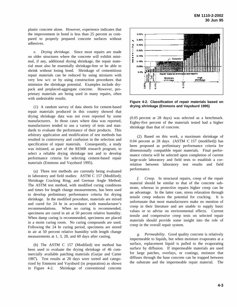
EM 1110-2-200230 Jun 95
plastic concrete alone. However, experience indicates thatthe improvement in bond is less than 25 percent as com-pared to properly prepared concrete surfaces withoutadhesives.
e. Drying shrinkage. Since most repairs are madeon older structures where the concrete will exhibit mini-mal, if any, additional drying shrinkage, the repair mate-rial must also be essentially shrinkage-free or be able toshrink without losing bond. Shrinkage of cementitiousrepair materials can be reduced by using mixtures withvery low w/c or by using construction procedures thatminimize the shrinkage potential. Examples include dry-pack and preplaced-aggregate concrete. However, pro-prietary materials are being used in many repairs, oftenwith undesirable results.
(1) A random survey of data sheets for cement-basedrepair materials produced in this country showed thatdrying shrinkage data was not even reported by somemanufacturers. In those cases where data was reported,manufacturers tended to use a variety of tests and stan-dards to evaluate the performance of their products. Thisarbitrary application and modification of test methods hasresulted in controversy and confusion in the selection andspecification of repair materials. Consequently, a studywas initiated, as part of the REMR research program, toselect a reliable drying shrinkage test and to developperformance criteria for selecting cement-based repairmaterials (Emmons and Vaysburd 1995).
(a) Three test methods are currently being evaluatedin laboratory and field studies: ASTM C 157 (Modified);Shrinkage Cracking Ring; and German Angle Method.The ASTM test method, with modified curing conditionsand times for length change measurements, has been usedto develop preliminary performance criteria for dryingshrinkage. In the modified procedure, materials are mixedand cured for 24 hr in accordance with manufacturer’srecommendations. When no curing is recommended,specimens are cured in air at 50 percent relative humidity.When damp curing is recommended, specimens are placedin a moist curing room. No curing compounds are used.Following the 24 hr curing period, specimens are storedin air at 50 percent relative humidity with length changemeasurements at 1, 3, 28, and 60 days after casting.
(b) The ASTM C 157 (Modified) test method hasbeen used to evaluate the drying shrinkage of 46 com-mercially available patching materials (Gurjar and Carter1987). Test results at 28 days were sorted and catego-rized by Emmons and Vaysburd (in preparation) as shownin Figure 4-2. Shrinkage of conventional concrete
Figure 4-2. Classification of repair materials based ondrying shrinkage (Emmons and Vaysburd 1995)
(0.05 percent at 28 days) was selected as a benchmark.Eighty-five percent of the materials tested had a highershrinkage than that of concrete.
(2) Based on this work, a maximum shrinkage of0.04 percent at 28 days (ASTM C 157 (modified)) hasbeen proposed as preliminary performance criteria fordimensionally compatible repair materials. Final perfor-mance criteria will be selected upon completion of currentlarge-scale laboratory and field tests to establish a cor-relation between laboratory test results and fieldperformance.
f. Creep. In structural repairs, creep of the repairmaterial should be similar to that of the concrete sub-strate, whereas in protective repairs higher creep can bean advantage. In the latter case, stress relaxation throughtensile creep reduces the potential for cracking. It isunfortunate that most manufacturers make no mention ofcreep in their literature and are unable to supply basicvalues or to advise on environmental effects. Currenttensile and compressive creep tests on selected repairmaterials should provide some insight into the role ofcreep in the overall repair system.
g. Permeability. Good quality concrete is relativelyimpermeable to liquids, but when moisture evaporates at asurface, replacement liquid is pulled to the evaporatingsurface by diffusion. If impermeable materials are usedfor large patches, overlays, or coatings, moisture thatdiffuses through the base concrete can be trapped betweenthe substrate and the impermeable repair material. The
4-3
EM 1110-2-200230 Jun 95
entrapped moisture can cause failure at the bond line orcritically saturate the substrate and, in the case ofnonair-entrained concrete, can cause the substrate to fail ifit is subjected to repeated cycles of freezing and thawing.Entrapped moisture can be a particularly troublesomeproblem with Corps hydraulic structures that are subjectto freezing and thawing. Materials with low waterabsorption and high water vapor transmission characteris-tics are desirable for most repairs.
4-3. Application and Service Conditions
The conditions under which the repair material will beplaced and the anticipated service or exposure conditionscan have a major impact on design of a repair and selec-tion of the repair material. The following factors shouldbe considered in planning a repair strategy (Warner 1984).
a. Application conditions.
(1) Geometry. The depth and orientation of a repairsection can influence selection of the repair material. Inthick sections, heat generated during curing of somerepair materials can result in unacceptable thermal stres-ses. Also, some materials shrink excessively when placedin thick layers. Some materials, particularly cementitiousmaterials, will spall if placed in very thin layers. In con-trast, some polymer-based materials can be placed in verythin sections. The maximum size of aggregate that can beused will be dictated by the minimum thickness of therepair. The repair material must be capable of adheringto the substrate without sagging when placed on verticalor overhead surfaces without forming.
(2) Temperature. Portland-cement hydration ceases ator near freezing temperatures, and latex emulsions willnot coalesce to form films at temperature below about7 oC (45 °F). Other materials may be used at tempera-tures well below freezing, although setting times may beincreased. High temperatures will make many repairmaterials set faster, decrease their working life, or pre-clude their use entirely.
(3) Moisture. A condition peculiar to hydraulic struc-tures is the presence of moisture or flowing water in therepair area. Generally, flowing water must be stopped bygrouting, external waterproofing techniques, or drainagesystems prior to repair. Some epoxy and polymer mate-rials will not cure properly in the presence of moisturewhile others are moisture insensitive. Materials suitablefor spall repair of wet concrete surfaces have been iden-tified by Best and McDonald (1990a).
(4) Location. Limited access to the repair site mayrestrict the type of equipment, and thus the type ofmaterial that can be used for repair. Also, components ofsome repair materials are odorous, toxic, or combustible.Obviously, such materials should not be used in poorlyventilated areas or in areas where flammable materialsaren’t permitted.
b. Service conditions.
(1) Downtime. Materials with rapid strength gaincharacteristics that can be easily placed with minimalwaste should be used when the repaired structure must bereturned to service in a short period of time. Severaltypes of rapid-hardening cements and patching materialsare described in REMR Technical Note CS-MR-7.3(USAEWES 1985g).
(2) Traffic. If the repair will be subject to heavyvehicular traffic, a high-strength material with good abra-sion and skid resistance is necessary.
(3) Temperature. A material with a coefficient ofthermal expansion similar to that of the concrete substrateshould be used for repairs subject to wide fluctuations intemperature. High-service temperatures may adverselyaffect the performance of some polymer materials. Resis-tance to cycles of freezing and thawing will be veryimportant in many applications.
(4) Chemical attack. Acids and sulfates will causedeterioration in cement-based materials while polymersare resistant to such chemical attack. However, strongsolvents may attack some polymers. Soft water is cor-rosive to portland-cement materials.
(5) Appearance. If it is necessary to match the colorand texture of the original concrete, many, if not most, ofthe available repair materials will be unsuitable. Portland-cement mixtures with materials and proportions similar tothose used in the original construction are necessarywhere appearance is a major consideration. Proceduresfor repair of architectural concrete are described byDobrowolski and Scanlon (1984).
(6) Service life. The function and remaining servicelife of the structure requiring repair should be consideredin selection of a repair material. An extended service liferequirement may dictate the choice of repair materialregardless of cost. On the other hand, perhaps a lowercost, less durable, or more easily applied material can beused if the repair is only temporary.
4-4
EM 1110-2-200230 Jun 95
4-4. Material Selection
Most repair projects will have unique conditions andspecial requirements that must be thoroughly examinedbefore the final repair material criteria can be established.Once the criteria for a dimensionally compatible repairhave been established, materials with the properties neces-sary to meet these criteria should be identified. A varietyof repair materials have been formulated to provide awide range of properties. Since these properties willaffect the performance of a repair, selecting the correctmaterial for a specific application requires careful study.Properties of the materials under consideration for a givenrepair may be obtained from manufacturer’s data sheets,the REMR Repair Materials Database andThe REMRNotebook(USAEWES 1985), evaluation reports, contactwith suppliers, or by conducting tests.
a. Material properties.
(1) Manufacturer’s data. Values for compressivestrength, tensile strength, slant-shear bond, and modulusof elasticity are frequently reported in material data sheetsprovided by suppliers. However, other material propertiesof equal or greater importance, such as drying shrinkage,tensile bond strength, creep, absorption, and water vaportransmission, may not be reported.
(a) Experience indicates that the material propertiesreported in manufacturer’s data sheets are generally accur-ate for the conditions under which they were determined.However, the designer should beware of those situationsin which data on a pertinent material property is notreported. Unfavorable material characteristics are seldomreported.
(b) Material properties pertinent to a given repairshould be requested from manufacturers if they are notincluded in the data sheets provided. General descriptionsof materials, such as compatible, nonshrink, low shrink-age, etc., should be disregarded unless they are supportedby data determined in accordance with standardized testmethods. Material properties determined in accordancewith “modified” standard tests should be viewed withcaution, particularly if the modifications are not described.
(2) Repair Material Database. The REMR RepairMaterials Database is described in Section 4-5. The com-puterized database provides rapid access to the results oftests conducted by the Corps and others; however, lessthan 25 percent of the available repair materials have beenevaluated to date.The REMR Notebookcurrently contains128 Material Data Sheets that include material
descriptions, uses and limitations, available specifications,manufacturer’s test results, and Corps test results. Inaddition, The REMR Notebookcontains a number ofTechnical Notes that describe materials and proceduresthat can be used for maintenance and repair of concrete.
(3) Material suppliers. Reputable material supplierscan assist in identifying those materials and associatedproperties that have proven successful in previous repairsprovided they are made aware of the conditions underwhich the material will be applied and the anticipatedservice conditions.
(4) Conduct tests. The formulations for commer-cially available materials are subject to frequent modifi-cations for a number of reasons including changes inownership, changes in raw materials, and new technology.Sometimes these modifications result in changes in mate-rial properties without corresponding changes to the man-ufacturer’s data sheets or notification by the materialsupplier. Consequently, testing of the repair material isrecommended to ensure compliance with design criteria ifdurability of the repair is of major importance, or thevolume of repair is large (Krauss 1994).
b. Selection considerations. Concrete repair mate-rials have been formulated to provide a wide range ofproperties; therefore, it is likely that more than one typeof material will satisfy the design criteria for durablerepair of a specific structure. In this case, other factorssuch as ease of application, cost, and available labor skillsand equipment should be considered in selection of therepair material. To match the properties of the concretesubstrate as closely as possible, portland-cement concreteor similar cementitious materials are frequently the bestchoices for repair. There are some obvious exceptionssuch as repairs that must be resistant to chemical attack.However, an arbitrary decision to repair like with like willnot necessarily ensure a durable repair: The new repairmaterial must be dimensionally compatible with the exist-ing substrate, which has often been in place for manyyears.
4-5. Repair Materials Database
The Corps of Engineers Repair Material Database wasdeveloped to provide technology transfer of results fromevaluations of commercial repair products performedunder the REMR Research Program. The database con-tains manufacturer’s information on uses, applicationprocedures, limitations and technical data for approxi-mately 1,860 commercially available repair products. Inaddition, Corps of Engineers test results are included for
4-5
EM 1110-2-200230 Jun 95
280 products and test results from other sources for 120products. Results of material evaluations performed bythe Corps of Engineers are added to the database asreports are published. Database organization and accessprocedures are described in detail by Stowe and Campbell(1989) and summarized in the following.
a. Access. The database is maintained on a hostcomputer that can be accessed by telephone via a modemusing the following communication parameters:
Baud Rate: 1,200 to 9,600 Emulation: VT-100Data Bits: 8 Stop Bits: 1Phone No.: (601) 634-4223 Parity: None
b. Operation.
(1) The database is menu driven and has help win-dows to facilitate its use. The products in the databaseare identified as either end-use or additive. An end-useproduct is a material that is used as purchased to make arepair, whereas an additive product is a material used incombination with other materials to produce an end-useproduct. The end-use products portion of the databasecontains products for maintenance and repair of concrete,steel, or both. The additive products portion of the data-base contains products that are portland-cement admix-tures, binders, fibers, or special filler materials.
(2) For end-use products, product categories identifythe basic type of material of which the product is com-posed, and for additive products, the type of end-useproduct for which the product is an ingredient or additive.The product uses identify the type use(s) for which theproduct is applicable. Keywords for searching categoryand use fields can be listed through the program helpscreens along with their definitions. Once the user selectsthe end-use or additive database, searches can be made bymanufacturer’s name, product name, product category,product use, or both category and use.
c. Assistance. For assistance or additional infor-mation regarding the database contact:
CEWES-SC-CA3909 Halls Ferry RoadVicksburg, MS 39180-6199Phone: (601) 634-2814
4-6. General Categorization of Repair Approach
For ease of selecting repair methods and materials, it ishelpful to divide the possible approaches into two general
categories: those more suited for cracking or those moresuited for spalling and disintegration. This categorizationrequires that some of the symptoms that were listed inTable 2-1 be regrouped as follows to facilitate selection ofa repair approach:
Cracking Spalling and DisintegrationRepair Approaches Repair Approaches
Construction faults (some) Construction faults (some)Cracking DisintegrationSeepage Erosion
Spalling
Note that distortion or movement and joint sealant fail-ures, which were listed in Table 2-1, are not included inthese categories. These are special cases that must behandled outside the process to be outlined in this chapter.Joint repair and maintenance are covered in Chapter 7.Distortion and movement are usually indications of settle-ment or of chemical reactions causing expansion of con-crete such as severe alkali-aggregate reaction. Repairs forthese conditions are beyond the scope of this manual.Materials and methods more suited for crack repairs aredescribed in Section 4-7, while those more suited forspalling and disintegration repairs are described inSection 4-8.
4-7. Repair of Cracking
The wide variety of types of cracking described in Chap-ter 2 suggests that there is no single repair method thatwill work in all instances. A repair method that is appro-priate in one instance may be ineffective or even detri-mental in another. For example, if a cracked sectionrequires tensile reinforcement or posttensioning to be ableto carry imposed loads, routing and sealing the crackswith a sealer would be ineffective. On the other hand, ifa concrete section has cracked because of incorrect spac-ing of contraction joints, filling the cracks with ahigh-strength material such as epoxy will only cause newcracking to occur as the concrete goes through its nextcontraction cycle.
a. Considerations in selecting materials andmethods. Prior to the selection of the appropriate materialand method for repair of cracking, the following questionsshould be answered (Johnson 1965):
(1) What is the nature of the cracking? Are thecracks in pattern or isolated? What is the depth of thecracking? Are the cracks open or closed? What is theextent of the cracking?
4-6
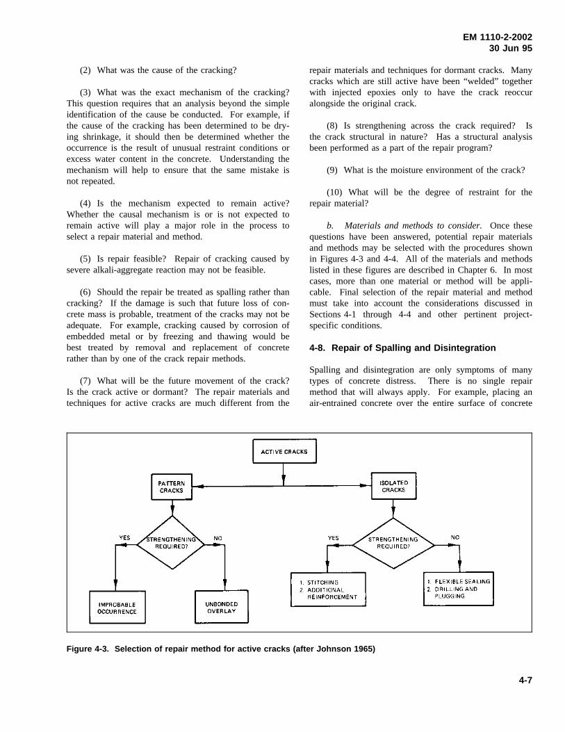
EM 1110-2-200230 Jun 95
(2) What was the cause of the cracking?
(3) What was the exact mechanism of the cracking?This question requires that an analysis beyond the simpleidentification of the cause be conducted. For example, ifthe cause of the cracking has been determined to be dry-ing shrinkage, it should then be determined whether theoccurrence is the result of unusual restraint conditions orexcess water content in the concrete. Understanding themechanism will help to ensure that the same mistake isnot repeated.
(4) Is the mechanism expected to remain active?Whether the causal mechanism is or is not expected toremain active will play a major role in the process toselect a repair material and method.
(5) Is repair feasible? Repair of cracking caused bysevere alkali-aggregate reaction may not be feasible.
(6) Should the repair be treated as spalling rather thancracking? If the damage is such that future loss of con-crete mass is probable, treatment of the cracks may not beadequate. For example, cracking caused by corrosion ofembedded metal or by freezing and thawing would bebest treated by removal and replacement of concreterather than by one of the crack repair methods.
(7) What will be the future movement of the crack?Is the crack active or dormant? The repair materials andtechniques for active cracks are much different from the
repair materials and techniques for dormant cracks. Manycracks which are still active have been “welded” togetherwith injected epoxies only to have the crack reoccuralongside the original crack.
(8) Is strengthening across the crack required? Isthe crack structural in nature? Has a structural analysisbeen performed as a part of the repair program?
(9) What is the moisture environment of the crack?
(10) What will be the degree of restraint for therepair material?
b. Materials and methods to consider.Once thesequestions have been answered, potential repair materialsand methods may be selected with the procedures shownin Figures 4-3 and 4-4. All of the materials and methodslisted in these figures are described in Chapter 6. In mostcases, more than one material or method will be appli-cable. Final selection of the repair material and methodmust take into account the considerations discussed inSections 4-1 through 4-4 and other pertinent project-specific conditions.
4-8. Repair of Spalling and Disintegration
Spalling and disintegration are only symptoms of manytypes of concrete distress. There is no single repairmethod that will always apply. For example, placing anair-entrained concrete over the entire surface of concrete
Figure 4-3. Selection of repair method for active cracks (after Johnson 1965)
4-7
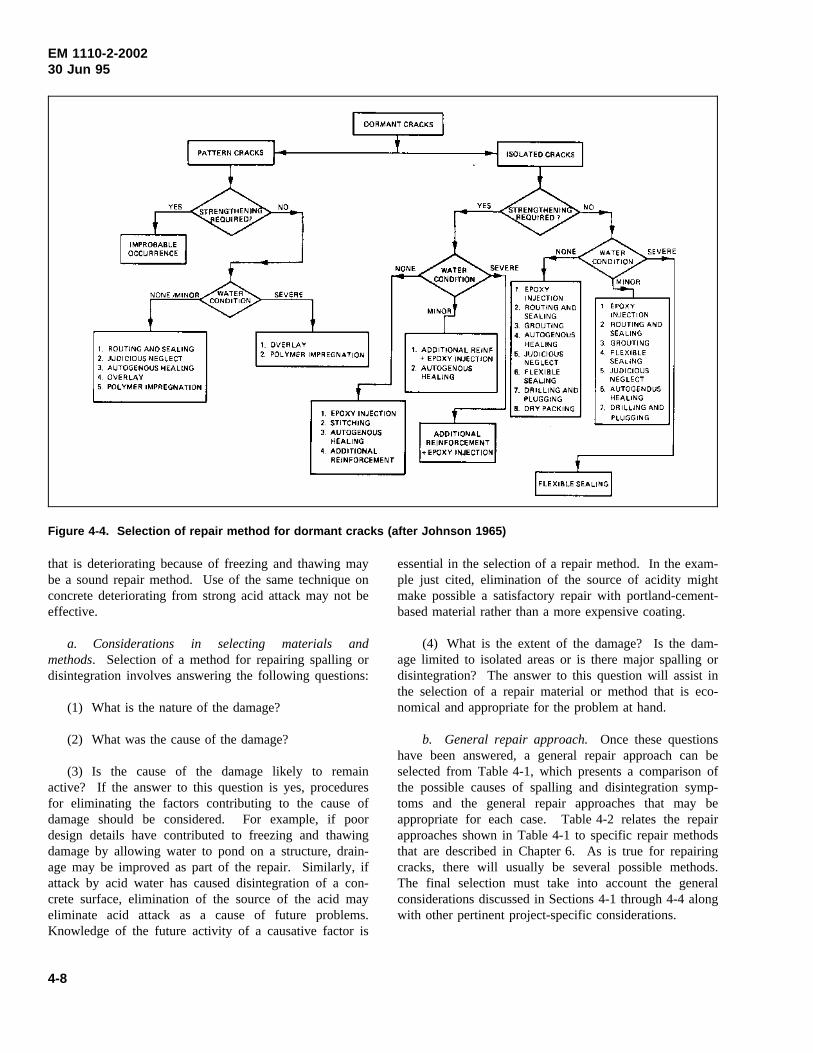
EM 1110-2-200230 Jun 95
Figure 4-4. Selection of repair method for dormant cracks (after Johnson 1965)
that is deteriorating because of freezing and thawing maybe a sound repair method. Use of the same technique onconcrete deteriorating from strong acid attack may not beeffective.
a. Considerations in selecting materials andmethods. Selection of a method for repairing spalling ordisintegration involves answering the following questions:
(1) What is the nature of the damage?
(2) What was the cause of the damage?
(3) Is the cause of the damage likely to remainactive? If the answer to this question is yes, proceduresfor eliminating the factors contributing to the cause ofdamage should be considered. For example, if poordesign details have contributed to freezing and thawingdamage by allowing water to pond on a structure, drain-age may be improved as part of the repair. Similarly, ifattack by acid water has caused disintegration of a con-crete surface, elimination of the source of the acid mayeliminate acid attack as a cause of future problems.Knowledge of the future activity of a causative factor is
essential in the selection of a repair method. In the exam-ple just cited, elimination of the source of acidity mightmake possible a satisfactory repair with portland-cement-based material rather than a more expensive coating.
(4) What is the extent of the damage? Is the dam-age limited to isolated areas or is there major spalling ordisintegration? The answer to this question will assist inthe selection of a repair material or method that is eco-nomical and appropriate for the problem at hand.
b. General repair approach.Once these questionshave been answered, a general repair approach can beselected from Table 4-1, which presents a comparison ofthe possible causes of spalling and disintegration symp-toms and the general repair approaches that may beappropriate for each case. Table 4-2 relates the repairapproaches shown in Table 4-1 to specific repair methodsthat are described in Chapter 6. As is true for repairingcracks, there will usually be several possible methods.The final selection must take into account the generalconsiderations discussed in Sections 4-1 through 4-4 alongwith other pertinent project-specific considerations.
4-8
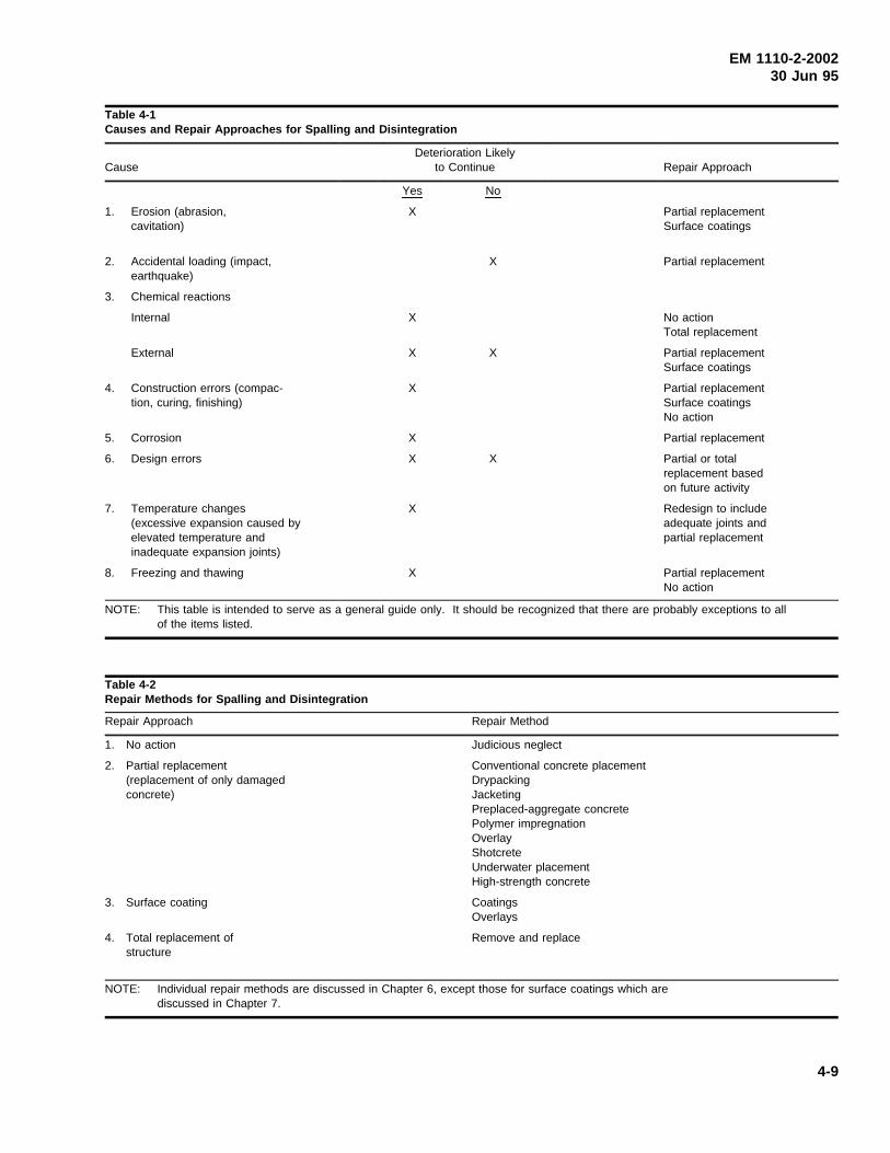
EM 1110-2-200230 Jun 95
Table 4-1Causes and Repair Approaches for Spalling and Disintegration
CauseDeterioration Likely
to Continue Repair Approach
Yes No
1. Erosion (abrasion,cavitation)
X Partial replacementSurface coatings
2. Accidental loading (impact,earthquake)
X Partial replacement
3. Chemical reactions
Internal X No actionTotal replacement
External X X Partial replacementSurface coatings
4. Construction errors (compac-tion, curing, finishing)
X Partial replacementSurface coatingsNo action
5. Corrosion X Partial replacement
6. Design errors X X Partial or totalreplacement basedon future activity
7. Temperature changes(excessive expansion caused byelevated temperature andinadequate expansion joints)
X Redesign to includeadequate joints andpartial replacement
8. Freezing and thawing X Partial replacementNo action
NOTE: This table is intended to serve as a general guide only. It should be recognized that there are probably exceptions to allof the items listed.
Table 4-2Repair Methods for Spalling and Disintegration
Repair Approach Repair Method
1. No action Judicious neglect
2. Partial replacement(replacement of only damagedconcrete)
Conventional concrete placementDrypackingJacketingPreplaced-aggregate concretePolymer impregnationOverlayShotcreteUnderwater placementHigh-strength concrete
3. Surface coating CoatingsOverlays
4. Total replacement ofstructure
Remove and replace
NOTE: Individual repair methods are discussed in Chapter 6, except those for surface coatings which arediscussed in Chapter 7.
4-9
EM 1110-2-200230 Jun 95
Chapter 5Concrete Removal and Preparationfor Repair
5-1. Introduction
Most repair projects involve removal of distressed ordeteriorated concrete. This chapter discusses removal ofconcrete, preparation of concrete surfaces for further worksuch as overlays, preparation and replacement of reinforc-ing steel that has been exposed during concrete removal,and anchorage systems. Regardless of the cost or com-plexity of the repair method or of the material selected,the care with which deteriorated concrete is removed andwith which a concrete surface is prepared will oftendetermine whether a repair project will be successful.
5-2. Concrete Removal
a. Alternatives. Repair techniques requiring noconcrete removal should be considered for situationswhere the deteriorated and damaged concrete does notthreaten the integrity of the member or structure. Thecost of concrete removal was saved in the rehabilitation ofthe tops of lock walls at Dashields Locks, U.S. ArmyEngineer District, Pittsburgh, by placement of anunbonded concrete overlay without removal of the deteri-orated concrete. Similarly, the cost of concrete removalwas saved by installation of precast concrete panels overdeteriorated concrete on the backside of river walls atLockport Lock in the U.S. Army Engineer District, RockIsland, and Troy Lock in the U.S. Army Engineer District,New York.
b. Environment. An evaluation to assess the impactof concrete removal debris entering a river, stream, orwaterway is required before a contract is awarded. Theimpact varies from project to project and depends to agreat extent on the size and environmental condition ofthe waterway and on the quantity of removal debris enter-ing the waterway. The coarse-aggregate portion of thedebris is sometimes a natural river gravel that is beingreturned to its place of origin and therefore its impact onthe waterway is generally considered negligible. Whendebris fragments are of sufficient size, debris can beplaced in open water to construct a fish attractor reef asan means of disposal. Recycling of concrete debrisshould be considered as an alternative to landfill disposal.
c. Contract work. If work is to be contracted, theinformation describing the condition and properties of the
concrete must be made available at the time of invitationfor bids to reduce the potential for claims by the contrac-tor of “differing site conditions.” Information providedmay include type and range of deterioration, nominalmaximum size and type of coarse aggregate, percentageof reinforcing steel, compressive and splitting-tensilestrengths of concrete, and other pertinent information.When uncertainties exist regarding the condition of theconcrete or the performance of the removal technique(s),an onsite demonstration should be implemented to testproduction rates and ensure acceptable results before workis begun.
d. General considerations. Several general con-siderations should be kept in mind in the selection of aconcrete removal method:
(1) Usually, a repair or rehabilitation project willinvolve removal of deteriorated concrete. However, formany maintenance and repair projects, concrete isremoved to a fixed depth to ensure that the bulk of deteri-orated concrete is removed or to accommodate a specificrepair technique. For some projects, this requirementwould cause a significant amount of sound concrete to beremoved and, thereby, a change in removal method(s),since some methods are more cost effective for soundconcrete than others.
(2) Selected concrete removal methods should besafe and economical and should have as little effect aspossible on concrete remaining in place. Selection of aproper removal method may have a significant effect onthe length of time that a structure must be out of service.Some methods permit a significant portion of the work tobe accomplished without removing the structure fromservice. For example, drilling of boreholes in a lock wallin conjunction with removal of concrete by blasting maybe done while the lock is operational.
(3) The same removal method may not be suited forall portions of a given structure. The most appropriatemethod for each portion of the structure should be selec-ted and specified.
(4) More than one removal method may be requiredfor a particular area. For example, a presplitting methodmay be used to fracture and weaken the concrete to beremoved, while an impacting method is used to completethe removal for the same location.
(5) In some instances, a combination of removalmethods may be used to limit damage to concrete that isnot being removed. For example, a cutting method may
5-1
EM 1110-2-200230 Jun 95
be used to delineate an area in which an impactingmethod is to be used as the primary means of removal.
(6) Field tests of various removal methods are verywell suited for demonstration projects done during thedesign phase of a major repair or rehabilitation project.
(7) The cost of removal and repair should be com-pared to the cost of total demolition and replacement ofthe member or structure if the damage is extensive.
(8) Care should be taken to avoid embedded itemssuch as electrical conduits and gate anchorage’s. Dimen-sions and locations of embedded items documented in theas-built drawings should not be taken for granted.
e. Classification of concrete removal methods.Removal methods may be categorized by the way inwhich the process acts on the concrete. These categoriesare blasting, crushing, cutting, impacting, milling, andpresplitting. Table 5-1 provides a general description ofthese categories and lists the specific removal methodswithin each category. Table 5-2 provides a summary ofinformation on each method. These methods are dis-cussed in detail in the following. See Campbell (1982)for additional information.
f. Blasting methods. Blasting methods employrapidly expanding gas confined within a series of bore-holes to produce controlled fracture and removal of con-crete (Figure-5-1). Explosive blasting, the only blastingmethod commercially available in the United States, isapplicable for concrete removal from mass concrete struc-tures where 250 mm (10 in.) or more of face is to beremoved and the volume of removal is significant.Explosive blasting is considered to be the most expedientand, in many cases, the most cost-effective means ofremoval from mass concrete structures. Its primary disad-vantage is its potential for damage to the remaining con-crete and adjacent structures. Blasting plans typicallyinclude drilling holes along removal boundary andemploying controlled and sequential blasting methods forthe removal. A commonly employed, controlled blastingtechnique, smooth blasting, uses detonating cord to distri-bute the blast energy throughout the hole, thereby, avoid-ing energy concentrations that might damage the concretethat remains. Cushion blasting, a more protective but lessused control, is the same as smooth blasting except wetsand is used to fill holes and cushion against the blasteffect. The use of saw cuts along removal perimeters isrecommended to reduce overbreakage. For removal ofvertical faces, a full-depth cut is recommended along thebottom boundary. Sequential blasting techniques allow
more delays to be employed per firing. They are recom-mended for optimizing the amount of explosive detonatedper firing while maintaining air-blast pressures, groundvibrations, and fly rock at acceptable levels. When uncer-tainties regarding the blast plan exist, a pilot test programis recommended to evaluate parameters and ensure accept-able results. Because of dangers inherent in handling andusing explosives, all phases of the blasting project shouldbe performed and monitored for compliance withEM 385-1-1.
g. Crushing methods. Crushing methods employhydraulically powered jaws to crush and remove theconcrete.
(1) Boom-mounted mechanical crushers. Boom-mounted crushers (Figure 5-2) are applicable for removingconcrete from decks, walls, columns, and other concretemembers where the shearing plane depth is 1.8 m (6 ft) orless. This method is typically more applicable for totaldemolition of a member(s) than for partial removal forrehabilitation or repair. Pulverizing jaw attachments thatcrush and debond the concrete from the reinforcing steelto facilitate their separation for recycling are available.The major limitations are that the removal boundary mustbe saw cut to reduce overbreakage, crushing must bestarted from a free edge or hole made by hand-heldbreakers or other means, and the exposed reinforcing isdamaged beyond reuse. Care must be taken to avoiddamaging members that are to support the repair.
(2) Portable mechanical crushers. Portable crushersare applicable for removing concrete from decks, walls,columns, and other concrete members where the shearingplane depth is 300 mm (12 in.) or less. The crusherweighs approximately 45 kg (100 lb) and requires twomen to handle. The major limitations are that theremoval boundary must be saw cut to reduce overbreak-age, crushing must be started from a free edge or holemade by hand-held breakers or other means, and theexposed reinforcing is damaged beyond reuse.
h. Cutting methods. Cutting methods employ fulldepth perimeter cuts to disjoint concrete for removal as aunit(s). The maximum size of the unit(s) is determinedby the load carrying capacities of available lifting andtransporting equipment. Cutting methods include abrasivewater jets, diamond saws, stitch drilling, and thermaltools.
(1) Abrasive-water-jet cutting. Water-jet systemsthat include abrasives are applicable for making cutoutsthrough slabs, walls, and other concrete members where
5-2
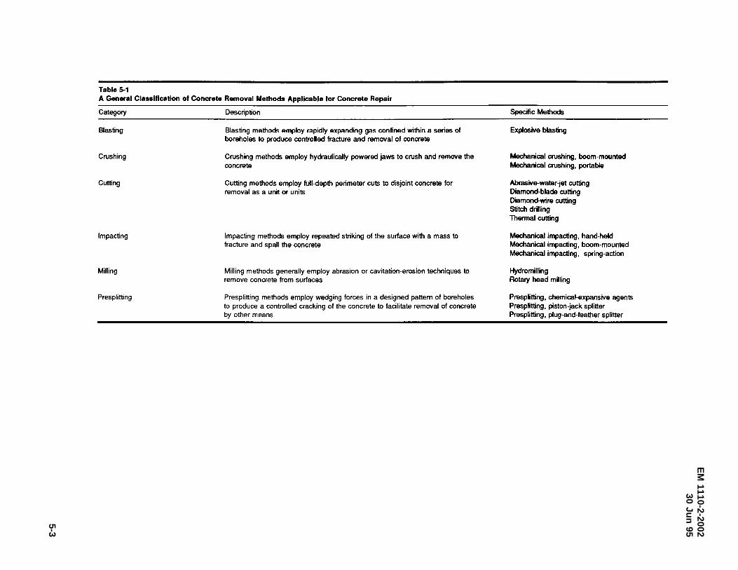
EM
1110-2-200230
Jun95
5-3
Table 5-1 A General Classification of Concrete Removal Methods Applicable for Concrete Repair
Category
Blasting
Crushing
Cutting
Impacting
Milling
Presplitting
Description
Blasting methods employ rapidly expanding gas confined within a series of boreholes to produce controlled fracture and removal of concrete
Crushing methods employ hydraulically powered jaws to crush and remove the concrete
Cutting methods employ full-depth perimeter cuts to disjoint concrete for removal as a unit or units
Impacting methods employ repeated striking of the surface with a mass to fracture and spall the concrete
Milling methods generally employ abrasion or cavitation-erosion techniques to remove concrete from surfaces
Presplitting methods employ wedging forces in a designed pattern of boreholes to produce a controlled cracking of the concrete to facilitate removal of concrete by other means
Specific Methods
Explosive blasting
Mechanical crushing, boom-mounted Mechanical crushing, portable
Abrasive-water-jet cutting Diamond-blade cutting Diamond-wire cutting Stitch drilling Thermal cutting
Mechanical impacting, hand-held Mechanical impacting, boom-mounted Mechanical impacting, spring-action
Hydromilling Rotary head milling
Presplitting, chemical-expansive agents Presplitting, piston-jack splitter Presplitting, plug-and-feather splitter
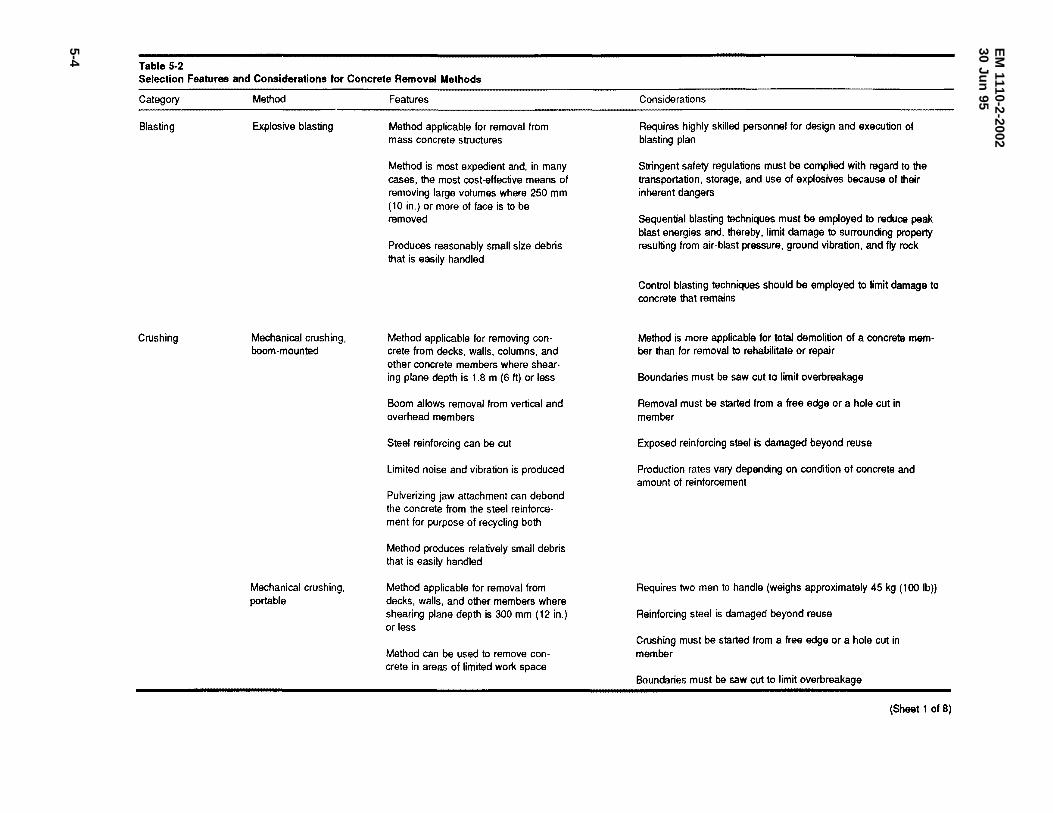
EM
1110-2-200230
Jun95
5-4
Table 5-2 Selection Features and Considerations for Concrete Removal Methods
Category
Blasting
Crushing
Method
Explosive blasting
Mechanical crushing, boom-mounted
Mechanical crushing, portable
Features
Method applicable for removal from mass concrete structures
Method is most expedient and, in many cases, the most cost-effective means of removing large volumes where 250 mm (10 in.) or more of face is to be removed
Produces reasonably small size debris that is easily handled
Method applicable for removing concrete from decks, walls, columns, and other concrete members where shearing plane depth is 1.8 m (6 ft) or less
Boom allows removal from vertical and overhead members
Steel reinforcing can be cut
Limited noise and vibration is produced
Pulverizing jaw attachment can debond the concrete from the steel reinforcement for purpose of recycling both
Method produces relatively small debris that is easily handled
Method applicable for removal from decks, walls, and other members where shearing plane depth is 300 mm (12 in.) or less
Method can be used to remove con· crete in areas of limited work space
Considerations
Requires highly skilled personnel for design and execution of blasting plan
Stringent safety regulations must be complied with regard to the transportation, storage, and use of explosives because of their inherent dangers
Sequential blasting techniques must be employed to reduce peak blast energies and, thereby, limit damage to surrounding property resulting from air-blast pressure, ground vibration, and fly rock
Control blasting techniques should be employed to limit damage to concrete that remains
Method is more applicable for total demolition of a concrete member than for removal to rehabilitate or repair
Boundaries must be saw cut to limit overbreakage
Removal must be started from a free edge or a hole cut in member
Exposed reinforcing steel is damaged beyond reuse
Production rates vary depending on condition of concrete and amount of reinforcement
Requires two men to handle (weighs approximately 45 kg (100 lb))
Reinforcing steel is damaged beyond reuse
Crushing must be started from a free edge or a hole cut in member
Boundaries must be saw cut to limit overbreakage
(Sheet 1 of 8)
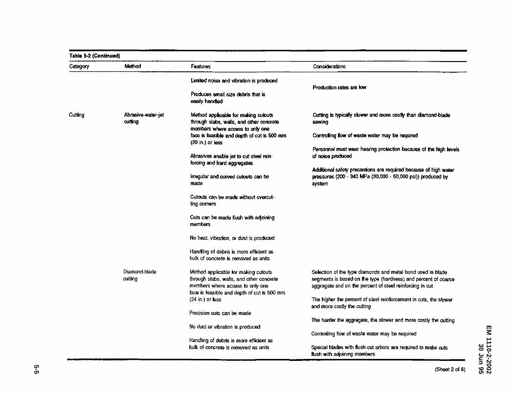
EM
1110-2-200230
Jun95
5-5
Table 5-2 (Continued)
Category
Cutting
Method
Abrasive-water -jet cutting
Diamond-blade cutting
Features
Umited noise and vibration is produced
Produoes small size debris that is easilyhanc:led
Method applicable for making cutouts through slabs, walls, and other concrete members where access to only one face is feasible and depth of cut is 500 mm (20 in.) or less
Abrasives enable jet to cut steel reinforcing and hard aggregates
Irregular and curved cutouts can be made
Cutouts can be made without overcutting corners
Cuts can be made flush with adjoining members
No heat, vibration, or dust is produced
Handling of debris is more efficient as bulk of concrete is removed as units
Method applicable for making cutouts through slabs, walls, and other concrete members where access to only one face is feasible and depth of cut is 600 mm (24 in.) or less
Precision cuts can be made
No dust or vibration is produced
Handling of debris is more efficient as bulk of concrete is removed as units
Considerations
Production rates are low
Cutting is typically slower and more costly than diamond-blade sawing
Controlling ftow of waste water may be required
Personnel must wear hearing protection because of the high levels of noise produced
Additional safety precautions are required because of high water pressures (200 • 340 MPa (30,000 - 50,000 psi)) produced by system
Selection of the type diamonds and metal bond used in blade segments is based on the type (hardness) and percent of coarse aggregate and on the percent of steel reinforcing in cut
The higher the percent of steel reinforcement in cuts, the slower and more costly the cutting
The harder the aggregate, the slower and more costly the cutting
Controlling ftow of waste water may be required
Special blades with ftush-cut arbors are required to make cuts ftush with adjoining members
(Sheet 2 of 8)
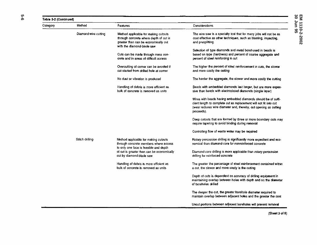
EM
1110-2-200230
Jun95
5-6
Table 5-2 (Continued)
Category Method
Diamond-wire cutting
Stitch drilling
Features
Method applicable tor making cutouts through concrete where depth of cut is greater than can be economically cut with the diamond-blade saw
Cuts can be made through mass con· crete and in areas of difficult access
Overcutting of comer can be avoided if cut started from drilled hole at comer
No dust or vibration is produced
Handling of debris is more efficient as bulk of concrete is removed as units
Method applicable for making cutouts through concrete members where access to only one face is feasible and depth of cut is greater than can be economically cut by diamond-blade saw
Handling of debris is more efficient as bulk of concrete is removed as units
Considerations
The wire saw is a specialty tool that tor many jobs will not be as cost effective as other techniques, such as blasting, impacting, and presplitting.
Selection of type diamonds and metal bond used in beads is based on type (hardness) and percent of coarse aggregate and percent of steel reinforcing in cut
The higher the percent of steel reinforcement in cuts, the slower and more costly the cutting
The harder the aggregate, the slower and more costly the cutting
Beads with embedded diamonds last longer, but are more expen· sive than beads with electroplated diamonds (single layer)
Wires with beads having embedded diamonds should be of suffi· cient length to complete cut as replacement will not fit into cut (wear reduces wire diameter and, thereby, cut opening as cutting proceeds).
Deep cutouts that are formed by three or more boundary cuts may require tapering to avoid binding during removal
Controlling flow of waste water may be required
Rotary-percussion drilling is significantly more expedient and eco· nomical than diamond·core for nonreinforced concrete
Diamond-core drilling is more applicable than rotary-percussion drilling for reinforced concrete
The greater the percentage of steel reinforcement contained within a cut, the slower and more costly is the cutting
Depth of cuts is dependent on accuracy of drilling equipment in maintaining overlap between holes with depth and on the diameter of boreholes drilled
The deeper the cut, the greater borehole diameter required to maintain overlap between adjacent holes and the greater the cost
Uncut portions between adjacent boreholes will prevent removal
(Sheet 3 of 8)
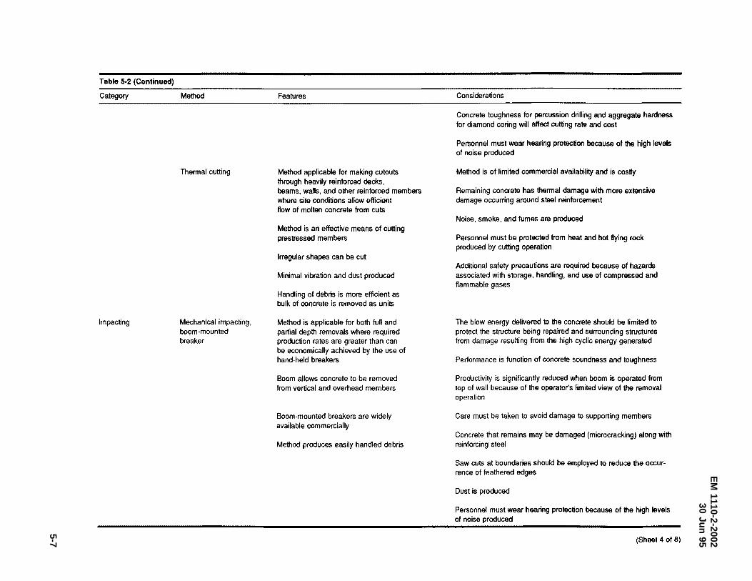
EM
1110-2-200230
Jun95
5-7
Table 5-2 (Continued)
Category
Impacting
Method
Thermal cutting
Mechanical impacting, boom-mounted breaker
Features
Method applicable for making cutouts through heavily reinforced decks, beams, walls, and other reinforced members where site conditions allow efficient flow of molten concrete from cuts
Method is an effective means of cutting prestressed members
Irregular shapes can be cut
Minimal vibration and dust produced
Handling of debris is more efficient as bulk of concrete is removed as units
Method is applicable for both full and partial depth removals where required production rates are greater than can be economically achieved by the use of hand-held breakers
Boom allows concrete to be removed from vertical and overhead members
Boom-mounted breakers are widely available commercially
Method produces easily handled debris
Considerations
Concrete toughness for percussion drilling and aggregate hardness for diamond coring will affect cutting rate and cost
Personnel must wear hearing protection because of the high levels of noise produced
Method is of limited commercial availability and is costly
Remaining concrete has thermal damage with more extensive damage occurring around steel reinforcement
Noise, smoke, and fumes are produced
Personnel must be protected from heat and hot flying rock produced by cutting operation
Additional safety precautions are required because of hazards associated with storage. handling, and use of compressed and flammable gases
The blow energy delivered to the concrete should be limited to protect the structure being repaired and surrounding structures from damage resulting from the high cyclic energy generated
Performance is function of concrete soundness and toughness
Productivity is significantly reduced when boom is operated from top of wall because of the operator's limited view of the removal operation
Care must be taken to avoid damage to supporting members
Concrete that remains may be damaged (microcracking) along with reinforcing steel
Saw cuts at boundaries should be employed to reduce the occurrence of feathered edges
Dust is produced
Personnel must wear hearing protection because of the high levels of noise produced
(Sheet 4 of 8)
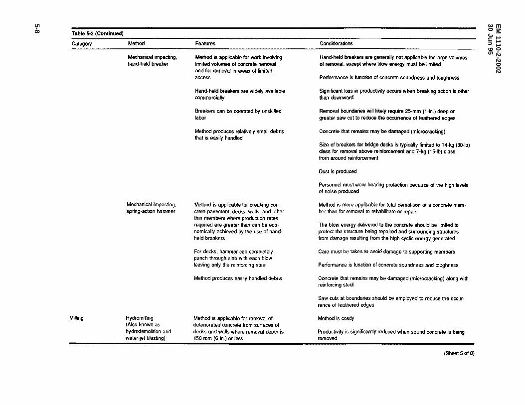
EM
1110-2-200230
Jun95
5-8
Table S.2 (Continued)
Category
Milling
Method
Mechanical impacting, hand-held breaker
Mechanical impacting, spring-action hammer
Hydromilling (Also known as hydrodemolition and water-jet blasting)
Features
Method is applicable for work involving limited volumes of conaete removal and for removal in areas of limited access
Hand-held breakers are widely available oommercially
Breakers can be operated by unskilled labor
Method produces relatively small debris that is easily handled
Method is applicable for breaking oon· crete pavement, decks, walls, and other thin members where production rates required are greater than can be economically achieved by the use of handheld breakers
For decks, hammer can completely punch through slab with each blow leaving only the reinforcing steel
Method produces easily handled debris
Method is applicable for removal of deteriorated concrete from surfaces of decks and walls where removal depth is 150 mm (6 in.) or less
Considerations
Hand-held breakers are generally not applicable for large volumes of removal, except where blow energy must be limited
Performance is function of concrete soundness and toughness
Significant loss in productivity occurs when breaking action is other than downward
Removal boundaries will likely require 25-mm (1-in.) deep or greater saw cut to reduce the occurrence of feathered edges
Concrete that remains may be damaged (microcracking)
Size of breakers for bridge decks is typically limited to 14-kg (30-lb) class for removal above reinforcement and 7-kg (15-lb) class from around reinforcement
Dust is produced
Personnel must wear hearing protection because of the high levels of noise produced
Method is more applicable for total demolition of a concrete member than for removal to rehabilitate or repair
The blow energy delivered to the concrete should be limited to protect the structure being repaired and surrounding structures from damage resulting from the high cyclic energy generated
Care must be taken to avoid damage to supporting members
Performance is function of concrete soundness and toughness
Concrete that remains may be damaged (microcracking) along with reinforcing steel
Saw cuts at boundaries should be employed to reduce the occurrence of feathered edges
Method is costly
Productivity is significantly reduced when sound concrete is being removed
(Sheet 5 of 8)
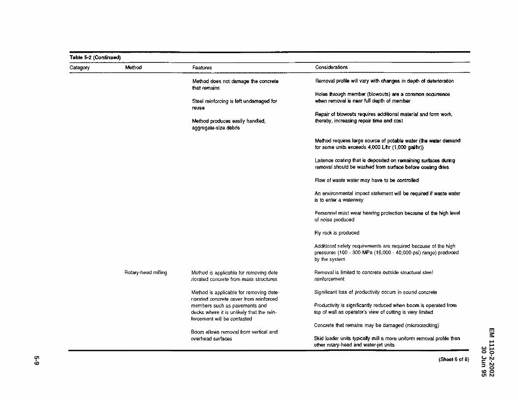
EM
1110-2-200230
Jun95
5-9
Table 5-2 (Continued)
Category Method
Rotary-head milling
Features
Method does not damage the concrete that remains
Steel reinforcing is left undamaged for reuse
Method produces easily handled, aggregate-size debris
Method is applicable for removing dele· riorated concrete from mass structures
Method is applicable for removing deteriorated concrete cover from reinforced members such as pavements and decks where it is unlikely that the reinforcement will be contacted
Boom allows removal from vertical and overhead surfaces
Considerations
Removal profile will vary with changes in depth of deterioration
Holes through member (blowouts) are a common occull'9nce when removal is near full depth of member
Repair of blowouts requires additional material and form work, thereby, increasing repair time and cost
Method requires large source of potable water (the water demand for some units exceeds 4,000 Llhr (1 ,000 gallhr))
Laitence coating that is deposited on remaining surfaces during removal should be washed from surface before coating dries
Flow of waste water may have to be controlled
An environmental impact statement will be required if waste water is to enter a waterway
Personnel must wear hearing protection because of the high level of noise produced
Fly rock is produced
Additional safety requirements are required because of the high pressures (100- 300-MPa (16,000 · 40,000-psi) range) produced by the system
Removal is limited to concrete outside structural steel reinforcement
Significant loss of productivity occurs in sound concrete
Productivity is significantly reduced when boom is operated from top of wall as operator's view of cutting is very limited
Concrete that remains may be damaged (microcracking)
Skid loader units typically mill a more uniform removal profile than other rotary-head and water-jet units
(Sheet 6 of 8)
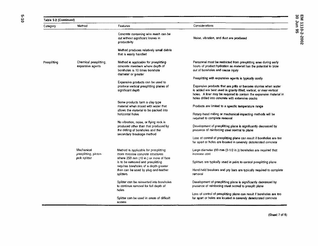
EM
1110-2-200230
Jun95
5-10 Table 5·2 (Continued)
Category
Presplitting
Method
Chemical presplitting, expansive agents
Mechanical presplitting, pistonjack splitter
Features
Concrete containing wire mesh can be cut without significant losses in productivity
Method produces relatively small debris that is easily handled
Method is applicable for presplitting concrete members where depth of boreholes is 10 times borehole diameter or greater
Expansive products can be used to produce vertical presplitting planes of significant depth
Some products form a clay-type material when mixed with water that allows the material to be packed into horizontal holes
No vibration, noise, or flying rock is produced other than that produced by the drilling of boreholes and the secondary breakage method
Method is applicable for presplitting more massive concrete structures where 250 mm (10 in.) or more of face is to be removed and presplitting requires boreholes of a depth greater than can be used by plug-and-feather splitters
Splitter can be reinserted into boreholes to continue removal for full depth of holes
Splitter can be used in areas of difficult access
Considerations
Noise, vibration, and dust are produced
Personnel must be restricted from presplitting area during early hours of product hydration as material has the potential to blow out of boreholes and cause injury
Presplitting with expansive agents is typically costly
Expansive products that are prills or become slurries when water is added are best used in gravity-filled, vertical, or near-vertical holes. A liner may be required to contain the expansive material in holes drilled into concrete with extensive cracks
Products are limited to a specific temperature range
Rotary-head milling or mechanical-impacting methods will be required to complete removal
Development of presplitting plane is significantly decreased by presence of reinforcing steel nonmal to plane
Loss of control of presplitting plane can result if boreholes are too far apart or holes are located in severely deteriorated concrete
Large-diameter (90-mm (3-1/2-in.)) boreholes are required that increase cost
Splitters are typically used in pairs to control presplitting plane
Hand-held breakers and pry bars are typically required to complete removal
Development of presplitting plane is significantly decreased by presence of reinforcing steel nonmal to presplit plane
Loss of control of presplitting plane can result if boreholes are too far apart or holes are located in severely deteriorated concrete
(Sheet 7 of 8)
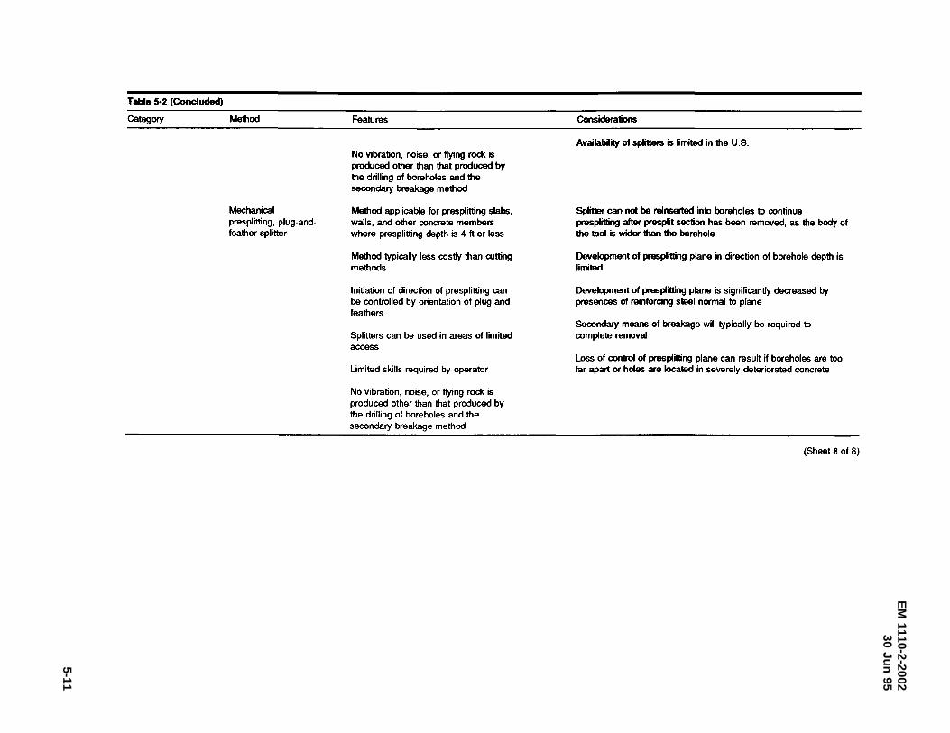
EM
1110-2-200230
Jun95
5-11
Table 5·2 (Concluded)
Category Method
Mechanical presplitting, plug-andfeather splitter
Features
No vibration, noise, or flying rock is produced other lhan that produced by the drilling of boreholes and the secondary breakage method
Method applicable for presplitting slabs, walls, and other concrete members where presplitting depth is 4 ft or less
Method typically less costly than cutting methods
Initiation of direction of presplitting can be controlled by orientation of plug and feathers
Splitters can be used in areas of limited access
Umited skills required by operator
No vibration, noise, or flying rock is produced other than that produced by the drilling of boreholes and the secondary breakage method
Considerations
Availabiity of splitters is limited in the U.S.
Splitter can not be reinserted into boreholes to continue presplitting after presplit section has been removed, as the body of the tool is wider than the borehole
Development of presplitting plane in direction of borehole depth is limited
Development of presplitting plane is significantly decreased by presences of reinforcing steel normal to plane
Secondary means of breakage will typically be required to complete removal
loss of control of presplitting plane can result if boreholes are too far apart or holes are located in severely deteriorated concrete
(Sheet 8 of 8)
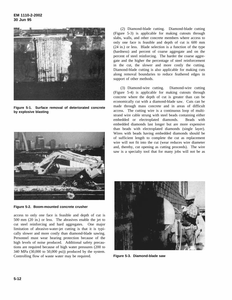
EM 1110-2-200230 Jun 95
Figure 5-1. Surface removal of deteriorated concreteby explosive blasting
access to only one face is feasible and depth of cut is
Figure 5-2. Boom-mounted concrete crusher
500 mm (20 in.) or less. The abrasives enable the jet tocut steel reinforcing and hard aggregates. One majorlimitation of abrasive-water-jet cutting is that it is typi-cally slower and more costly than diamond-blade sawing.Personnel must wear hearing protection because of thehigh levels of noise produced. Additional safety precau-tions are required because of high water pressures (200 to340 MPa (30,000 to 50,000 psi)) produced by the system.Controlling flow of waste water may be required.
(2) Diamond-blade cutting. Diamond-blade cutting(Figure 5-3) is applicable for making cutouts throughslabs, walls, and other concrete members where access toonly one face is feasible and depth of cut is 600 mm(24 in.) or less. Blade selection is a function of the type(hardness) and percent of coarse aggregate and on thepercent of steel reinforcing. The harder the coarse aggre-gate and the higher the percentage of steel reinforcementin the cut, the slower and more costly the cutting.Diamond-blade cutting is also applicable for making cutsalong removal boundaries to reduce feathered edges insupport of other methods.
(3) Diamond-wire cutting. Diamond-wire cutting(Figure 5-4) is applicable for making cutouts throughconcrete where the depth of cut is greater than can beeconomically cut with a diamond-blade saw. Cuts can bemade through mass concrete and in areas of difficultaccess. The cutting wire is a continuous loop of multi-strand wire cable strung with steel beads containing eitherembedded or electroplated diamonds. Beads withembedded diamonds last longer but are more expensivethan beads with electroplated diamonds (single layer).Wires with beads having embedded diamonds should beof sufficient length to complete the cut as replacementwire will not fit into the cut (wear reduces wire diameterand, thereby, cut opening as cutting proceeds). The wiresaw is a specialty tool that for many jobs will not be as
Figure 5-3. Diamond-blade saw
5-12
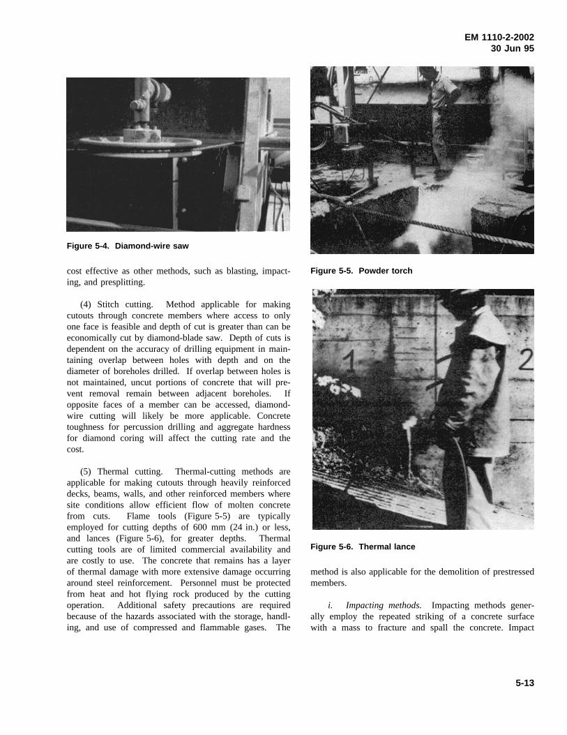
EM 1110-2-200230 Jun 95
Figure 5-4. Diamond-wire saw
cost effective as other methods, such as blasting, impact-ing, and presplitting.
(4) Stitch cutting. Method applicable for makingcutouts through concrete members where access to onlyone face is feasible and depth of cut is greater than can beeconomically cut by diamond-blade saw. Depth of cuts isdependent on the accuracy of drilling equipment in main-taining overlap between holes with depth and on thediameter of boreholes drilled. If overlap between holes isnot maintained, uncut portions of concrete that will pre-vent removal remain between adjacent boreholes. Ifopposite faces of a member can be accessed, diamond-wire cutting will likely be more applicable. Concretetoughness for percussion drilling and aggregate hardnessfor diamond coring will affect the cutting rate and thecost.
(5) Thermal cutting. Thermal-cutting methods areapplicable for making cutouts through heavily reinforceddecks, beams, walls, and other reinforced members wheresite conditions allow efficient flow of molten concretefrom cuts. Flame tools (Figure 5-5) are typicallyemployed for cutting depths of 600 mm (24 in.) or less,and lances (Figure 5-6), for greater depths. Thermalcutting tools are of limited commercial availability andare costly to use. The concrete that remains has a layerof thermal damage with more extensive damage occurringaround steel reinforcement. Personnel must be protectedfrom heat and hot flying rock produced by the cuttingoperation. Additional safety precautions are requiredbecause of the hazards associated with the storage, handl-ing, and use of compressed and flammable gases. The
Figure 5-5. Powder torch
Figure 5-6. Thermal lance
method is also applicable for the demolition of prestressedmembers.
i. Impacting methods. Impacting methods gener-ally employ the repeated striking of a concrete surfacewith a mass to fracture and spall the concrete. Impact
5-13
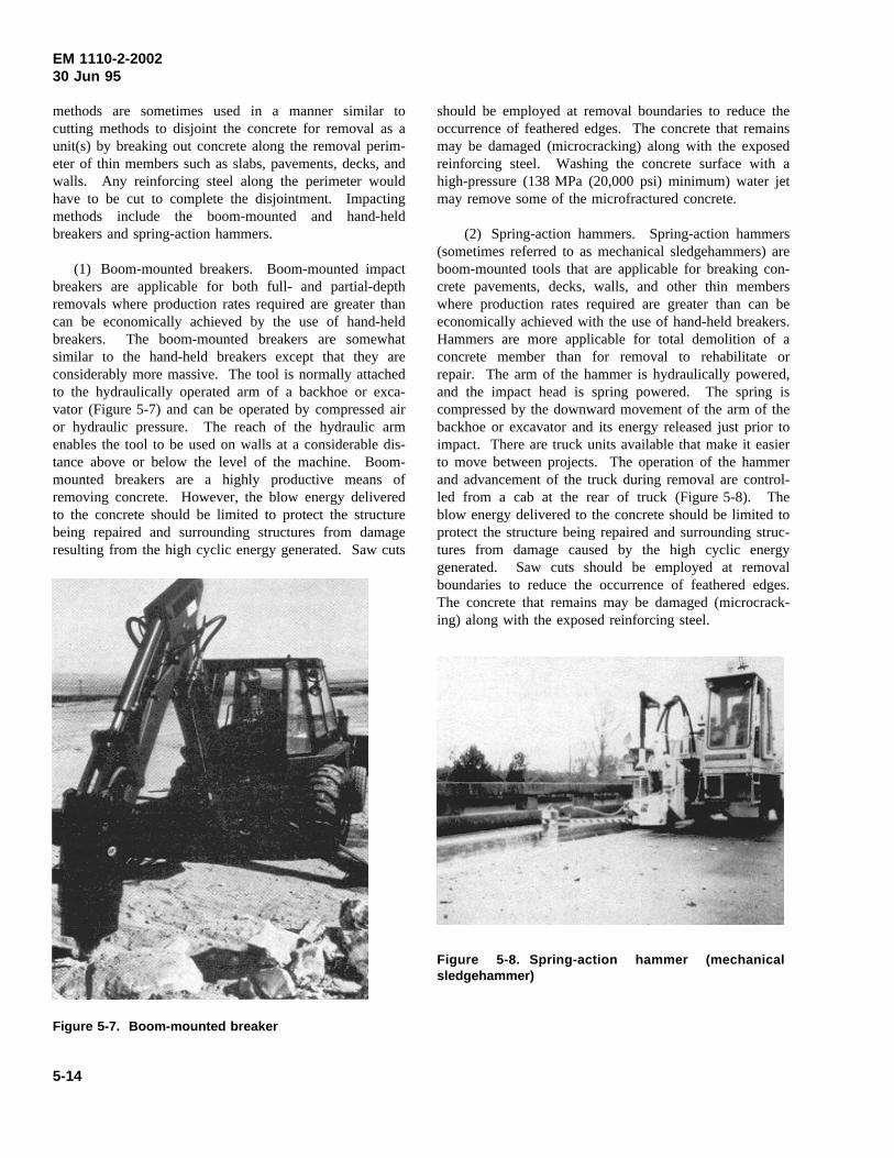
EM 1110-2-200230 Jun 95
methods are sometimes used in a manner similar tocutting methods to disjoint the concrete for removal as aunit(s) by breaking out concrete along the removal perim-eter of thin members such as slabs, pavements, decks, andwalls. Any reinforcing steel along the perimeter wouldhave to be cut to complete the disjointment. Impactingmethods include the boom-mounted and hand-heldbreakers and spring-action hammers.
(1) Boom-mounted breakers. Boom-mounted impactbreakers are applicable for both full- and partial-depthremovals where production rates required are greater thancan be economically achieved by the use of hand-heldbreakers. The boom-mounted breakers are somewhatsimilar to the hand-held breakers except that they areconsiderably more massive. The tool is normally attachedto the hydraulically operated arm of a backhoe or exca-vator (Figure 5-7) and can be operated by compressed airor hydraulic pressure. The reach of the hydraulic armenables the tool to be used on walls at a considerable dis-tance above or below the level of the machine. Boom-mounted breakers are a highly productive means ofremoving concrete. However, the blow energy deliveredto the concrete should be limited to protect the structurebeing repaired and surrounding structures from damageresulting from the high cyclic energy generated. Saw cuts
Figure 5-7. Boom-mounted breaker
should be employed at removal boundaries to reduce theoccurrence of feathered edges. The concrete that remainsmay be damaged (microcracking) along with the exposedreinforcing steel. Washing the concrete surface with ahigh-pressure (138 MPa (20,000 psi) minimum) water jetmay remove some of the microfractured concrete.
(2) Spring-action hammers. Spring-action hammers(sometimes referred to as mechanical sledgehammers) areboom-mounted tools that are applicable for breaking con-crete pavements, decks, walls, and other thin memberswhere production rates required are greater than can beeconomically achieved with the use of hand-held breakers.Hammers are more applicable for total demolition of aconcrete member than for removal to rehabilitate orrepair. The arm of the hammer is hydraulically powered,and the impact head is spring powered. The spring iscompressed by the downward movement of the arm of thebackhoe or excavator and its energy released just prior toimpact. There are truck units available that make it easierto move between projects. The operation of the hammerand advancement of the truck during removal are control-led from a cab at the rear of truck (Figure 5-8). Theblow energy delivered to the concrete should be limited toprotect the structure being repaired and surrounding struc-tures from damage caused by the high cyclic energygenerated. Saw cuts should be employed at removalboundaries to reduce the occurrence of feathered edges.The concrete that remains may be damaged (microcrack-ing) along with the exposed reinforcing steel.
Figure 5-8. Spring-action hammer (mechanicalsledgehammer)
5-14
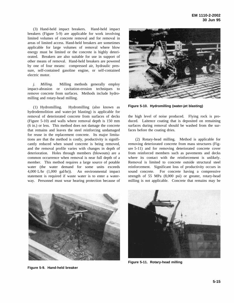
EM 1110-2-200230 Jun 95
(3) Hand-held impact breakers. Hand-held impactbreakers (Figure 5-9) are applicable for work involvinglimited volumes of concrete removal and for removal inareas of limited access. Hand-held breakers are sometimesapplicable for large volumes of removal where blowenergy must be limited or the concrete is highly deteri-orated. Breakers are also suitable for use in support ofother means of removal. Hand-held breakers are poweredby one of four means: compressed air, hydraulic pres-sure, self-contained gasoline engine, or self-containedelectric motor.
j. Milling. Milling methods generally employimpact-abrasion or cavitation-erosion techniques toremove concrete from surfaces. Methods include hydro-milling and rotary-head milling.
(1) Hydromilling. Hydromilling (also known ashydrodemolition and water-jet blasting) is applicable forremoval of deteriorated concrete from surfaces of decks(Figure 5-10) and walls where removal depth is 150 mm(6 in.) or less. This method does not damage the concretethat remains and leaves the steel reinforcing undamagedfor reuse in the replacement concrete. Its major limita-tions are that the method is costly, productivity is signifi-cantly reduced when sound concrete is being removed,and the removal profile varies with changes in depth ofdeterioration. Holes through members (blowouts) are acommon occurrence when removal is near full depth of amember. This method requires a large source of potablewater (the water demand for some units exceeds4,000 L/hr (1,000 gal/hr)). An environmental impactstatement is required if waste water is to enter a water-way. Personnel must wear hearing protection because of
Figure 5-9. Hand-held breaker
Figure 5-10. Hydromilling (water-jet blasting)
the high level of noise produced. Flying rock is pro-duced. Laitence coating that is deposited on remainingsurfaces during removal should be washed from the sur-faces before the coating dries.
(2) Rotary-head milling. Method is applicable forremoving deteriorated concrete from mass structures (Fig-ure 5-11) and for removing deteriorated concrete coverfrom reinforced members such as pavements and deckswhere its contact with the reinforcement is unlikely.Removal is limited to concrete outside structural steelreinforcement. Significant loss of productivity occurs insound concrete. For concrete having a compressivestrength of 55 MPa (8,000 psi) or greater, rotary-headmilling is not applicable. Concrete that remains may be
Figure 5-11. Rotary-head milling
5-15
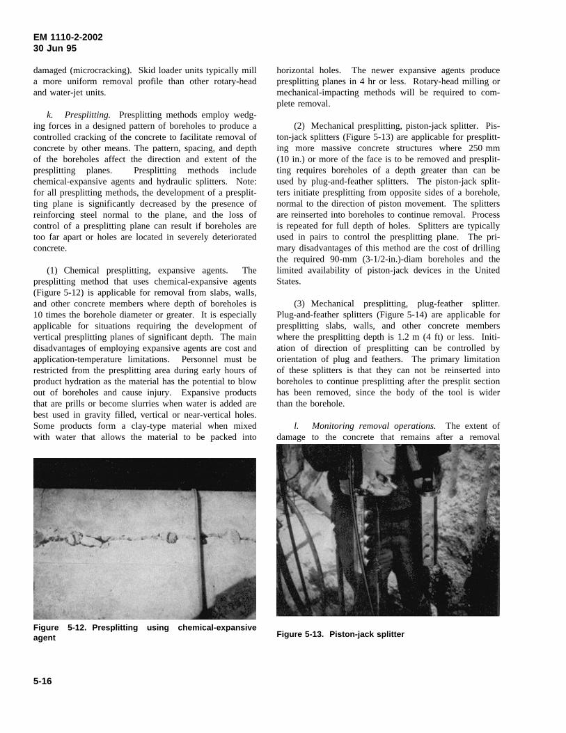
EM 1110-2-200230 Jun 95
damaged (microcracking). Skid loader units typically milla more uniform removal profile than other rotary-headand water-jet units.
k. Presplitting. Presplitting methods employ wedg-ing forces in a designed pattern of boreholes to produce acontrolled cracking of the concrete to facilitate removal ofconcrete by other means. The pattern, spacing, and depthof the boreholes affect the direction and extent of thepresplitting planes. Presplitting methods includechemical-expansive agents and hydraulic splitters. Note:for all presplitting methods, the development of a presplit-ting plane is significantly decreased by the presence ofreinforcing steel normal to the plane, and the loss ofcontrol of a presplitting plane can result if boreholes aretoo far apart or holes are located in severely deterioratedconcrete.
(1) Chemical presplitting, expansive agents. Thepresplitting method that uses chemical-expansive agents(Figure 5-12) is applicable for removal from slabs, walls,and other concrete members where depth of boreholes is10 times the borehole diameter or greater. It is especiallyapplicable for situations requiring the development ofvertical presplitting planes of significant depth. The maindisadvantages of employing expansive agents are cost andapplication-temperature limitations. Personnel must berestricted from the presplitting area during early hours ofproduct hydration as the material has the potential to blowout of boreholes and cause injury. Expansive productsthat are prills or become slurries when water is added arebest used in gravity filled, vertical or near-vertical holes.Some products form a clay-type material when mixedwith water that allows the material to be packed into
Figure 5-12. Presplitting using chemical-expansiveagent
horizontal holes. The newer expansive agents producepresplitting planes in 4 hr or less. Rotary-head milling ormechanical-impacting methods will be required to com-plete removal.
(2) Mechanical presplitting, piston-jack splitter. Pis-ton-jack splitters (Figure 5-13) are applicable for presplitt-ing more massive concrete structures where 250 mm(10 in.) or more of the face is to be removed and presplit-ting requires boreholes of a depth greater than can beused by plug-and-feather splitters. The piston-jack split-ters initiate presplitting from opposite sides of a borehole,normal to the direction of piston movement. The splittersare reinserted into boreholes to continue removal. Processis repeated for full depth of holes. Splitters are typicallyused in pairs to control the presplitting plane. The pri-mary disadvantages of this method are the cost of drillingthe required 90-mm (3-1/2-in.)-diam boreholes and thelimited availability of piston-jack devices in the UnitedStates.
(3) Mechanical presplitting, plug-feather splitter.Plug-and-feather splitters (Figure 5-14) are applicable forpresplitting slabs, walls, and other concrete memberswhere the presplitting depth is 1.2 m (4 ft) or less. Initi-ation of direction of presplitting can be controlled byorientation of plug and feathers. The primary limitationof these splitters is that they can not be reinserted intoboreholes to continue presplitting after the presplit sectionhas been removed, since the body of the tool is widerthan the borehole.
l. Monitoring removal operations. The extent ofdamage to the concrete that remains after a removal
Figure 5-13. Piston-jack splitter
5-16
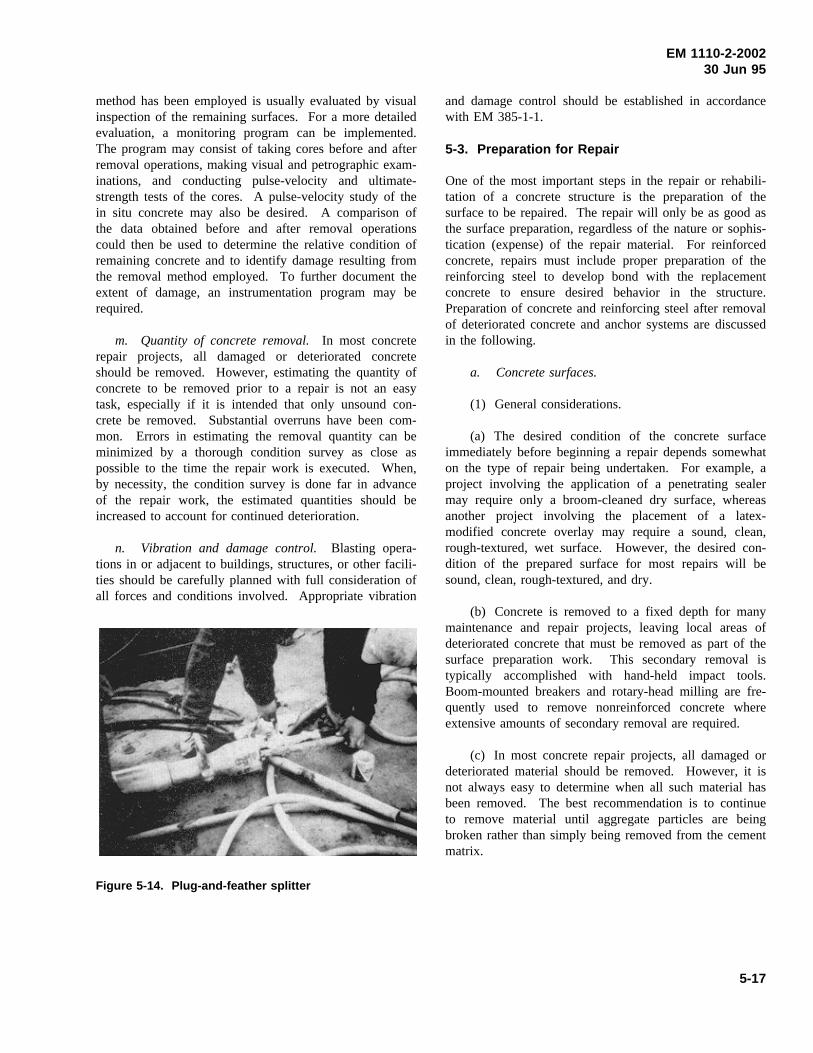
EM 1110-2-200230 Jun 95
method has been employed is usually evaluated by visualinspection of the remaining surfaces. For a more detailedevaluation, a monitoring program can be implemented.The program may consist of taking cores before and afterremoval operations, making visual and petrographic exam-inations, and conducting pulse-velocity and ultimate-strength tests of the cores. A pulse-velocity study of thein situ concrete may also be desired. A comparison ofthe data obtained before and after removal operationscould then be used to determine the relative condition ofremaining concrete and to identify damage resulting fromthe removal method employed. To further document theextent of damage, an instrumentation program may berequired.
m. Quantity of concrete removal.In most concreterepair projects, all damaged or deteriorated concreteshould be removed. However, estimating the quantity ofconcrete to be removed prior to a repair is not an easytask, especially if it is intended that only unsound con-crete be removed. Substantial overruns have been com-mon. Errors in estimating the removal quantity can beminimized by a thorough condition survey as close aspossible to the time the repair work is executed. When,by necessity, the condition survey is done far in advanceof the repair work, the estimated quantities should beincreased to account for continued deterioration.
n. Vibration and damage control.Blasting opera-tions in or adjacent to buildings, structures, or other facili-ties should be carefully planned with full consideration ofall forces and conditions involved. Appropriate vibration
Figure 5-14. Plug-and-feather splitter
and damage control should be established in accordancewith EM 385-1-1.
5-3. Preparation for Repair
One of the most important steps in the repair or rehabili-tation of a concrete structure is the preparation of thesurface to be repaired. The repair will only be as good asthe surface preparation, regardless of the nature or sophis-tication (expense) of the repair material. For reinforcedconcrete, repairs must include proper preparation of thereinforcing steel to develop bond with the replacementconcrete to ensure desired behavior in the structure.Preparation of concrete and reinforcing steel after removalof deteriorated concrete and anchor systems are discussedin the following.
a. Concrete surfaces.
(1) General considerations.
(a) The desired condition of the concrete surfaceimmediately before beginning a repair depends somewhaton the type of repair being undertaken. For example, aproject involving the application of a penetrating sealermay require only a broom-cleaned dry surface, whereasanother project involving the placement of a latex-modified concrete overlay may require a sound, clean,rough-textured, wet surface. However, the desired con-dition of the prepared surface for most repairs will besound, clean, rough-textured, and dry.
(b) Concrete is removed to a fixed depth for manymaintenance and repair projects, leaving local areas ofdeteriorated concrete that must be removed as part of thesurface preparation work. This secondary removal istypically accomplished with hand-held impact tools.Boom-mounted breakers and rotary-head milling are fre-quently used to remove nonreinforced concrete whereextensive amounts of secondary removal are required.
(c) In most concrete repair projects, all damaged ordeteriorated material should be removed. However, it isnot always easy to determine when all such material hasbeen removed. The best recommendation is to continueto remove material until aggregate particles are beingbroken rather than simply being removed from the cementmatrix.
5-17
EM 1110-2-200230 Jun 95
(d) Whenever concrete is removed with impact toolsor by rotary-head milling, there is the potential for verysmall-scale damage to the surface of the concrete left inplace. Unless this damaged layer is removed, the replace-ment material will suffer what appears to be a bond fail-ure. Thus, a perfectly sound and acceptable replacementmaterial may fail because of improper surface preparation.
(e) Following secondary removal, all exposed sur-faces should be prepared with dry or wet sandblasting orwater-jet blasting to remove any damaged surface mate-rial. Surfaces that were exposed by water-jet blasting willtypically not require this surface preparation.
(2) Methods of surface preparation.
(a) Chemical cleaning. In cases in which concrete iscontaminated with oil, grease, or dirt, these contaminantsmust be removed prior to placement of repair materials.Detergents, trisodium phosphate, and various other pro-prietary concrete cleaners are available for this work. Itis also important that all traces of the cleaning agent beremoved after the contaminating material is removed.Solvents should not be used to clean concrete since theydissolve the contaminants and carry them deeper into theconcrete. Muriatic acid, commonly used to etch concretesurfaces, is relatively ineffective for removing grease oroil.
(b) Mechanical cleaning. There is a variety ofmechanical devices available for cleaning concrete sur-faces. These devices include scabblers, scarifiers, andimpact tools. Depending upon the hammer heads used orthe nature of the abrasive material, a variety of degrees ofsurface preparation may be achieved. After use of one ofthese methods, it may be necessary to use another means(waterjetting or wet sandblasting) for final cleaning of thesurface.
(c) Shot blasting. Steel shot blasting produces anearly uniform profile that is ideally suited for thin over-lay repairs. It can produce light-brush blasting to 6-mm(1/4-in.)-depth removal depending on the size shot selec-ted and the duration of the removal effort. The debris isvacuumed up and retained by the unit. Steel shot blastingleaves the surface dry for immediate application of abonding agent, coating, or overlay.
(d) Blast cleaning. Blast cleaning includes wet anddry sandblasting, and water jetting. When sandblasting isused, the air source must be equipped with an effectiveoil trap to prevent contamination of the concrete surfaceduring the cleaning operation. Water-jetting equipment
with operating pressures of 40 to 70 MPa (6,000 to10,000 psi) is commercially available for cleaning con-crete. This equipment is very effective when used as thefinal step in surface preparation.
(e) Acid etching. Acid etching of concrete surfaceshas long been used to remove laitance and normalamounts of dirt. The acid will remove enough cementpaste to provide a roughened surface which will improvethe bond of replacement materials. ACI 515.1R recom-mends that acid etching be used only when no alternativemeans of surface preparation can be used. The prepara-tion methods described earlier are believed to be moreeffective than acid treatment. If acid is used, the surfaceshould be cleaned of grease and oil with appropriateagents, and the cleaning agents should be rinsed off thesurface before the acid is added. Acid is then added at arate of approximately 1 L/sq m (1 qt/sq yd), and it shouldbe worked into the concrete surface with a stiff brush orbroom. When the foaming stops (3 to 5 min), the acidshould be rinsed off, and brooms should be used toremove reaction products and any loosened particles. Thesurface should be checked with litmus or pH paper todetermine that all acid has been removed.
(f) Bonding agents. The general guidance is thatsmall thin patches (less than 50 mm (2 in.) thick) shouldreceive a bonding coat while thicker replacements prob-ably do not require any bonding agent. Excellent bond offresh-to-hardened concrete can be achieved with propersurface preparation and without the use of bonding agents.The most common bonding agents are simply grout mix-tures of cement slurry or equal volumes of portlandcement and fine aggregate mixed with water to the consis-tency of thick cream. The grout must be worked into thesurface with stiff brooms or brushes. The grout shouldnot be allowed to dry out before the concrete is placed.A maximum distance of 1.5 m (5 ft) or a period of10 min ahead of the concrete placement are typical fig-ures used in the specification. There is a wide variety ofepoxy and other polymer bonding agents available. If oneof these products is used, the manufacturer’s recommen-dations must be followed. Improperly applied bondingagents can actually reduce bond.
b. Reinforcing steel.
(1) General considerations.
(a) By far, the most frequent cause of damage toreinforcing steel is corrosion. Other possible causes ofdamage are fire and chemical attack. The same basic
5-18
EM 1110-2-200230 Jun 95
preparation and repair procedures may be used for all ofthese causes of damage.
(b) Once the cause and the magnitude of the damagehave been determined, it remains to expose the steel,evaluate its structural condition, and prepare the reinforce-ment for the placement of the repair material. Propersteps to prepare the reinforcement will ensure that therepair method is a permanent solution rather than atemporary solution that will deteriorate in a short periodof time.
(2) Removal of concrete surrounding reinforcingsteel. The first step in preparing reinforcing steel forrepair is the removal of the deteriorated concrete sur-rounding the steel. Usually, the deteriorated concreteabove the top reinforcement can be removed with a jack-hammer. For this purpose, a light (14-kg (30-lb)) ham-mer should be sufficient and should not significantlydamage sound concrete at the periphery of the damagedarea. Extreme care should be exercised to ensure thatfurther damage to the reinforcing steel is not inflicted inthe process of removing the deteriorated concrete. Jack-hammers can heavily damage reinforcing steel if thehammer is used without knowledge of the location of thesteel. For this reason, a copy of the structural drawingsshould be used to determine where the reinforcement islocated and its size, and a pathometer should be used todetermine the depth of the steel in the concrete. Once thelarger pieces of the damaged concrete have been removed,a (7-kg (15-lb)) chipping hammer should be used toremove the concrete in the vicinity of the reinforcement.Water-jet blasting may also be used for removal of con-crete surrounding the reinforcing steel.
(3) How much concrete to remove. Obviously, allweak, damaged, and easily removable concrete should bechipped away. If more than one-half of the perimeter ofthe bar has been exposed during removal of deterioratedconcrete, then concrete removal should continue to give aclear space behind the reinforcing steel of 6 mm (1/4 in.)plus the dimension of the maximum size aggregate. Ifless than one-half of the perimeter of a bar is exposedafter concrete removal, the bar should be inspected,cleaned as necessary, and then repairs should proceedwithout further concrete removal. However, if inspectionindicates that a bar or bars must be replaced, concretemust be removed to give the clear space indicated above.
(4) Inspection of reinforcing steel. Once deterioratedconcrete has been removed, reinforcing steel should becarefully inspected. If the cross-sectional area of a barhas been significantly reduced by corrosion or other
means, the steel may have to be replaced. If there is anyquestion concerning the ability of the steel to perform asdesigned, a structural engineer should be consulted. Proj-ect specifications should include a provision wherebydecisions concerning repair versus replacement of rein-forcing steel can be made during the project as the steel isexposed.
(5) Replacing reinforcing steel. The easiest methodof replacing reinforcement is to cut out the damaged areaand splice in replacement bars. A conventional lap spliceis preferred. The requirements for length of lap shouldconform to the requirements of ACI 318. If mechanicalsplices are considered, their use should be approved by astructural engineer. If a welded splice is used, it shouldalso be performed in accordance with ACI 318. Buttwelding should be avoided because of the high degree ofskill required to perform a full penetration weld. High-strength steel should not be welded.
(6) Cleaning reinforcing steel.
(a) When it has been determined that the steel doesnot need replacing, the steel should be thoroughly cleanedof all loose rust and foreign matter before the replacementconcrete is placed. For limited areas, wire brushing orother hand methods of cleaning are acceptable. For largerareas, dry sandblasting is the preferred method. Thesandblasting must remove all the rust from the undersideof the reinforcing bars. Normally, the underside is notdirectly hit by the high-pressure sand particles and mustrely on rebound force as the sand comes off the substrateconcrete surface. The operator must be suited with arespiratory device because of the health hazard associatedwith dry blasting.
(b) The type of air compressor used in conjunctionwith sandblasting is important. When the steel is cleanedand loose particles are blown out of the patch area aftercleaning, it is important that neither the reinforcing steelnor the concrete substrate surface be contaminated withoil from the compressor. For this reason, either anoil-free compressor or one that has a good oil trap mustbe used.
(c) Alternative methods of cleaning the steel are wetsandblasting or water-jet blasting. These methods are notas good as dry sandblasting, because they provide thewater and oxygen necessary to begin the corrosion pro-cess again once the steel has been cleaned.
(d) There is always the possibility that freshlycleaned reinforcing steel will rust between the time it is
5-19
EM 1110-2-200230 Jun 95
cleaned and the time that the next concrete is placed. Ifthe rust that forms is tightly bonded to the steel, there isno need to take further action. If the rust is looselybonded or in any other way may inhibit bonding betweenthe steel and the concrete, the reinforcing bars must becleaned again immediately before concrete placement.
c. Anchors. Dowels may be required in some situa-tions to anchor the repair material to the existing concretesubstrate. ACI 355.1R summarizes anchor types andprovides an overview of anchor performance and failuremodes under various loading conditions. It also coversdesign and construction considerations and summarizesexisting requirements in codes and specifications. Designcriteria for anchoring relatively thin sections (less than0.8 m (2.5 ft)) of cast-in-place concrete are described inSection 8-1. Anchor installation underwater is discussedin Section 8-6. Most of the anchors used in repair areinstalled in holes drilled in the concrete substrate and canbe classified as either bonded or expansion anchors.
(1) Drilling. Anchor holes should be drilled withrotary carbide-tipped or diamond-studded bits or hand-hammered star drill bits. Drilling with a jackhammer isnot recommended because of the damage that resultsimmediately around the hole from the impact. Holesshould be cleaned with compressed air and plugged with arag or other suitable material until time for anchor instal-lation. Holes should be inspected for proper location,diameter, depth, and cleanliness prior to installation ofanchors.
(2) Bonded anchors. Bonded anchors are headed orheadless bolts, threaded rods, or deformed reinforcingbars. Bonded anchors are classified as either groutedanchors or chemical anchors.
(a) Grouted anchors are embedded in predrilled holeswith neat portland cement, portland cement and sand, orother commercially available premixed grout. An expan-sive grout additive and accelerator are commonly usedwith cementitious grouts.
(b) Chemical anchors are embedded in predrilledholes with two-component polyesters, vinylesters, orepoxies. The chemicals are available in four forms: glasscapsules, plastic cartridges, tubes (“sausages”), or bulk.Following insertion into the hole, the glass capsules andtubes are both broken and their contents mixed by inser-tion and spinning of the anchor. The plastic cartridgesare used with a dispenser and a static mixing nozzle tomix the two components as they are placed in the drillhole. Bulk systems are predominately epoxies which aremixed in a pot, or pumped through a mixer and injectedinto the hole after which the anchor is immediatelyinserted.
(c) Some chemical grouts creep under sustainedloading, and some lose their strength when exposed totemperatures over 50 °C (120 °F). Creep tests were con-ducted, as part of the REMR Research Program, by sub-jecting anchors to sustained loads of 60 percent of theiryield strength for 6 months. The slippage exhibited byanchors embedded in polyester resin was approximately30 times higher than that of anchors embedded inportland-cement (Best and McDonald 1990b).
(3) Expansion anchors. Expansion anchors aredesigned to be inserted into predrilled holes and thenexpanded by either tightening a nut, hammering theanchor, or expanding into an undercut in the concrete.Expansion anchors that rely on side point contact to createfrictional resistance should not be used where anchors aresubjected to vibratory loads. Some wedge-type anchorsperform poorly when subjected to impact loads. Undercutanchors are suitable for dynamic and impact loads.
(4) Load tests. Following installation, randomlyselected anchors should be tested to ensure compliancewith the specifications. In some field tests, anchors haveexhibited significant slippage prior to achieving thedesired tensile capacity. Therefore, it may be desirable tospecify a maximum displacement in addition to the mini-mum load capacity.
5-20
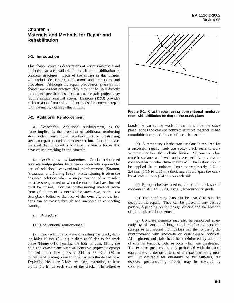
EM 1110-2-200230 Jun 95
Chapter 6Materials and Methods for Repair andRehabilitation
6-1. Introduction
This chapter contains descriptions of various materials andmethods that are available for repair or rehabilitation ofconcrete structures. Each of the entries in this chapterwill include description, applications and limitations, andprocedure. Although the repair procedures given in thischapter are current practice, they may not be used directlyin project specifications because each repair project mayrequire unique remedial action. Emmons (1993) providesa discussion of materials and methods for concrete repairwith extensive, detailed illustrations.
6-2. Additional Reinforcement
a. Description. Additional reinforcement, as thename implies, is the provision of additional reinforcingsteel, either conventional reinforcement or prestressingsteel, to repair a cracked concrete section. In either case,the steel that is added is to carry the tensile forces thathave caused cracking in the concrete.
b. Applications and limitations.Cracked reinforcedconcrete bridge girders have been successfully repaired byuse of additional conventional reinforcement (Stratton,Alexander, and Nolting 1982). Posttensioning is often thedesirable solution when a major portion of a membermust be strengthened or when the cracks that have formedmust be closed. For the posttensioning method, someform of abutment is needed for anchorage, such as astrongback bolted to the face of the concrete, or the ten-dons can be passed through and anchored in connectingframing.
c. Procedure.
(1) Conventional reinforcement.
(a) This technique consists of sealing the crack, drill-ing holes 19 mm (3/4 in.) in diam at 90 deg to the crackplane (Figure 6-1), cleaning the hole of dust, filling thehole and crack plane with an adhesive (typically epoxy)pumped under low pressure 344 to 552 KPa (50 to80 psi), and placing a reinforcing bar into the drilled hole.Typically, No. 4 or 5 bars are used, extending at least0.5 m (1.6 ft) on each side of the crack. The adhesive
Figure 6-1. Crack repair using conventional reinforce-ment with drillholes 90 deg to the crack plane
bonds the bar to the walls of the hole, fills the crackplane, bonds the cracked concrete surfaces together in onemonolithic form, and thus reinforces the section.
(b) A temporary elastic crack sealant is required fora successful repair. Gel-type epoxy crack sealants workvery well within their elastic limits. Silicone or elas-tomeric sealants work well and are especially attractive incold weather or when time is limited. The sealant shouldbe applied in a uniform layer approximately 1.6 to2.4 mm (1/16 to 3/32 in.) thick and should span the crackby at least 19 mm (3/4 in.) on each side.
(c) Epoxy adhesives used to rebond the crack shouldconform to ASTM C 881, Type I, low-viscosity grade.
(d) The reinforcing bars can be spaced to suit theneeds of the repair. They can be placed in any desiredpattern, depending on the design criteria and the locationof the in-place reinforcement.
(e) Concrete elements may also be reinforced exter-nally by placement of longitudinal reinforcing bars andstirrups or ties around the members and then encasing thereinforcement with shotcrete or cast-in-place concrete.Also, girders and slabs have been reinforced by additionof external tendons, rods, or bolts which are prestressed.The exterior posttensioning is performed with the sameequipment and design criteria of any posttensioning proj-ect. If desirable for durability or for esthetics, theexposed posttensioning strands may be covered byconcrete.
6-1
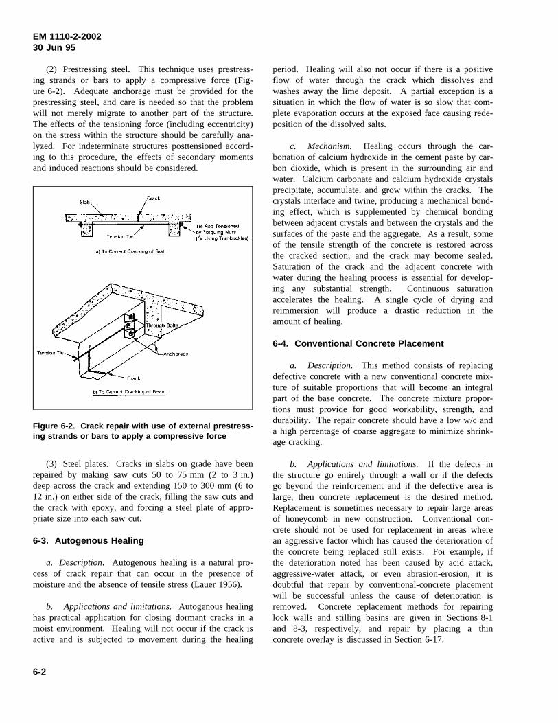
EM 1110-2-200230 Jun 95
(2) Prestressing steel. This technique uses prestress-ing strands or bars to apply a compressive force (Fig-ure 6-2). Adequate anchorage must be provided for theprestressing steel, and care is needed so that the problemwill not merely migrate to another part of the structure.The effects of the tensioning force (including eccentricity)on the stress within the structure should be carefully ana-lyzed. For indeterminate structures posttensioned accord-ing to this procedure, the effects of secondary momentsand induced reactions should be considered.
Figure 6-2. Crack repair with use of external prestress-ing strands or bars to apply a compressive force
(3) Steel plates. Cracks in slabs on grade have beenrepaired by making saw cuts 50 to 75 mm (2 to 3 in.)deep across the crack and extending 150 to 300 mm (6 to12 in.) on either side of the crack, filling the saw cuts andthe crack with epoxy, and forcing a steel plate of appro-priate size into each saw cut.
6-3. Autogenous Healing
a. Description. Autogenous healing is a natural pro-cess of crack repair that can occur in the presence ofmoisture and the absence of tensile stress (Lauer 1956).
b. Applications and limitations.Autogenous healinghas practical application for closing dormant cracks in amoist environment. Healing will not occur if the crack isactive and is subjected to movement during the healing
period. Healing will also not occur if there is a positiveflow of water through the crack which dissolves andwashes away the lime deposit. A partial exception is asituation in which the flow of water is so slow that com-plete evaporation occurs at the exposed face causing rede-position of the dissolved salts.
c. Mechanism. Healing occurs through the car-bonation of calcium hydroxide in the cement paste by car-bon dioxide, which is present in the surrounding air andwater. Calcium carbonate and calcium hydroxide crystalsprecipitate, accumulate, and grow within the cracks. Thecrystals interlace and twine, producing a mechanical bond-ing effect, which is supplemented by chemical bondingbetween adjacent crystals and between the crystals and thesurfaces of the paste and the aggregate. As a result, someof the tensile strength of the concrete is restored acrossthe cracked section, and the crack may become sealed.Saturation of the crack and the adjacent concrete withwater during the healing process is essential for develop-ing any substantial strength. Continuous saturationaccelerates the healing. A single cycle of drying andreimmersion will produce a drastic reduction in theamount of healing.
6-4. Conventional Concrete Placement
a. Description. This method consists of replacingdefective concrete with a new conventional concrete mix-ture of suitable proportions that will become an integralpart of the base concrete. The concrete mixture propor-tions must provide for good workability, strength, anddurability. The repair concrete should have a low w/c anda high percentage of coarse aggregate to minimize shrink-age cracking.
b. Applications and limitations. If the defects inthe structure go entirely through a wall or if the defectsgo beyond the reinforcement and if the defective area islarge, then concrete replacement is the desired method.Replacement is sometimes necessary to repair large areasof honeycomb in new construction. Conventional con-crete should not be used for replacement in areas wherean aggressive factor which has caused the deterioration ofthe concrete being replaced still exists. For example, ifthe deterioration noted has been caused by acid attack,aggressive-water attack, or even abrasion-erosion, it isdoubtful that repair by conventional-concrete placementwill be successful unless the cause of deterioration isremoved. Concrete replacement methods for repairinglock walls and stilling basins are given in Sections 8-1and 8-3, respectively, and repair by placing a thinconcrete overlay is discussed in Section 6-17.
6-2
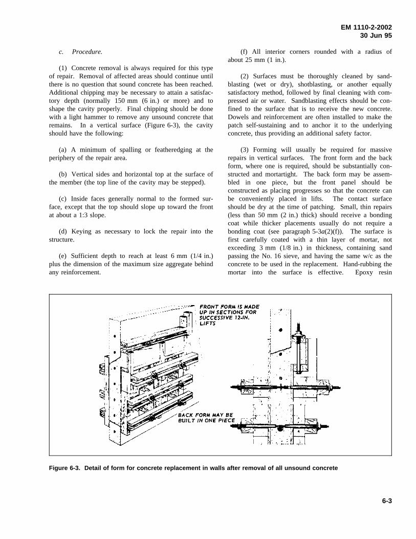
EM 1110-2-200230 Jun 95
c. Procedure.
(1) Concrete removal is always required for this typeof repair. Removal of affected areas should continue untilthere is no question that sound concrete has been reached.Additional chipping may be necessary to attain a satisfac-tory depth (normally 150 mm (6 in.) or more) and toshape the cavity properly. Final chipping should be donewith a light hammer to remove any unsound concrete thatremains. In a vertical surface (Figure 6-3), the cavityshould have the following:
(a) A minimum of spalling or featheredging at theperiphery of the repair area.
(b) Vertical sides and horizontal top at the surface ofthe member (the top line of the cavity may be stepped).
(c) Inside faces generally normal to the formed sur-face, except that the top should slope up toward the frontat about a 1:3 slope.
(d) Keying as necessary to lock the repair into thestructure.
(e) Sufficient depth to reach at least 6 mm (1/4 in.)plus the dimension of the maximum size aggregate behindany reinforcement.
(f) All interior corners rounded with a radius ofabout 25 mm (1 in.).
(2) Surfaces must be thoroughly cleaned by sand-blasting (wet or dry), shotblasting, or another equallysatisfactory method, followed by final cleaning with com-pressed air or water. Sandblasting effects should be con-fined to the surface that is to receive the new concrete.Dowels and reinforcement are often installed to make thepatch self-sustaining and to anchor it to the underlyingconcrete, thus providing an additional safety factor.
(3) Forming will usually be required for massiverepairs in vertical surfaces. The front form and the backform, where one is required, should be substantially con-structed and mortartight. The back form may be assem-bled in one piece, but the front panel should beconstructed as placing progresses so that the concrete canbe conveniently placed in lifts. The contact surfaceshould be dry at the time of patching. Small, thin repairs(less than 50 mm (2 in.) thick) should receive a bondingcoat while thicker placements usually do not require abonding coat (see paragraph 5-3a(2)(f)). The surface isfirst carefully coated with a thin layer of mortar, notexceeding 3 mm (1/8 in.) in thickness, containing sandpassing the No. 16 sieve, and having the same w/c as theconcrete to be used in the replacement. Hand-rubbing themortar into the surface is effective. Epoxy resin
Figure 6-3. Detail of form for concrete replacement in walls after removal of all unsound concrete
6-3
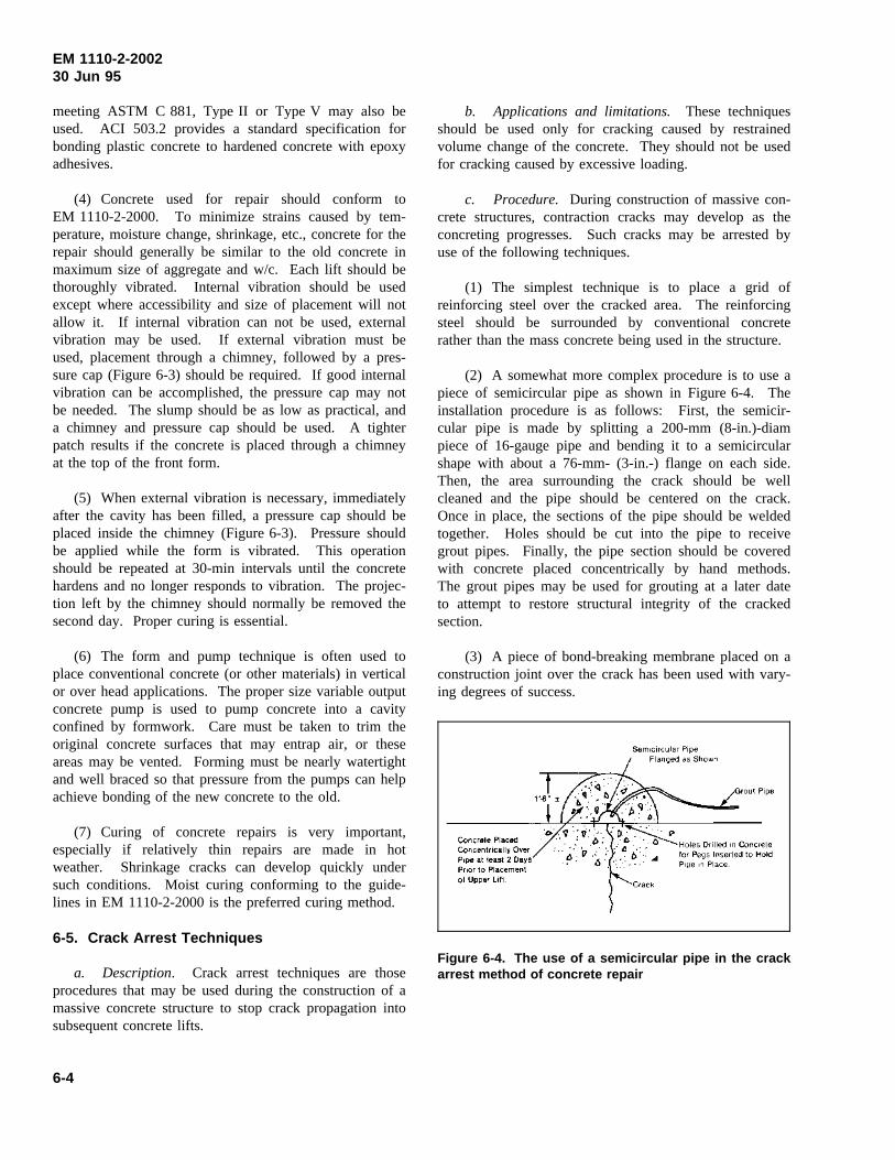
EM 1110-2-200230 Jun 95
meeting ASTM C 881, Type II or Type V may also beused. ACI 503.2 provides a standard specification forbonding plastic concrete to hardened concrete with epoxyadhesives.
(4) Concrete used for repair should conform toEM 1110-2-2000. To minimize strains caused by tem-perature, moisture change, shrinkage, etc., concrete for therepair should generally be similar to the old concrete inmaximum size of aggregate and w/c. Each lift should bethoroughly vibrated. Internal vibration should be usedexcept where accessibility and size of placement will notallow it. If internal vibration can not be used, externalvibration may be used. If external vibration must beused, placement through a chimney, followed by a pres-sure cap (Figure 6-3) should be required. If good internalvibration can be accomplished, the pressure cap may notbe needed. The slump should be as low as practical, anda chimney and pressure cap should be used. A tighterpatch results if the concrete is placed through a chimneyat the top of the front form.
(5) When external vibration is necessary, immediatelyafter the cavity has been filled, a pressure cap should beplaced inside the chimney (Figure 6-3). Pressure shouldbe applied while the form is vibrated. This operationshould be repeated at 30-min intervals until the concretehardens and no longer responds to vibration. The projec-tion left by the chimney should normally be removed thesecond day. Proper curing is essential.
(6) The form and pump technique is often used toplace conventional concrete (or other materials) in verticalor over head applications. The proper size variable outputconcrete pump is used to pump concrete into a cavityconfined by formwork. Care must be taken to trim theoriginal concrete surfaces that may entrap air, or theseareas may be vented. Forming must be nearly watertightand well braced so that pressure from the pumps can helpachieve bonding of the new concrete to the old.
(7) Curing of concrete repairs is very important,especially if relatively thin repairs are made in hotweather. Shrinkage cracks can develop quickly undersuch conditions. Moist curing conforming to the guide-lines in EM 1110-2-2000 is the preferred curing method.
6-5. Crack Arrest Techniques
a. Description. Crack arrest techniques are thoseprocedures that may be used during the construction of amassive concrete structure to stop crack propagation intosubsequent concrete lifts.
b. Applications and limitations. These techniquesshould be used only for cracking caused by restrainedvolume change of the concrete. They should not be usedfor cracking caused by excessive loading.
c. Procedure. During construction of massive con-crete structures, contraction cracks may develop as theconcreting progresses. Such cracks may be arrested byuse of the following techniques.
(1) The simplest technique is to place a grid ofreinforcing steel over the cracked area. The reinforcingsteel should be surrounded by conventional concreterather than the mass concrete being used in the structure.
(2) A somewhat more complex procedure is to use apiece of semicircular pipe as shown in Figure 6-4. Theinstallation procedure is as follows: First, the semicir-cular pipe is made by splitting a 200-mm (8-in.)-diampiece of 16-gauge pipe and bending it to a semicircularshape with about a 76-mm- (3-in.-) flange on each side.Then, the area surrounding the crack should be wellcleaned and the pipe should be centered on the crack.Once in place, the sections of the pipe should be weldedtogether. Holes should be cut into the pipe to receivegrout pipes. Finally, the pipe section should be coveredwith concrete placed concentrically by hand methods.The grout pipes may be used for grouting at a later dateto attempt to restore structural integrity of the crackedsection.
(3) A piece of bond-breaking membrane placed on aconstruction joint over the crack has been used with vary-ing degrees of success.
Figure 6-4. The use of a semicircular pipe in the crackarrest method of concrete repair
6-4
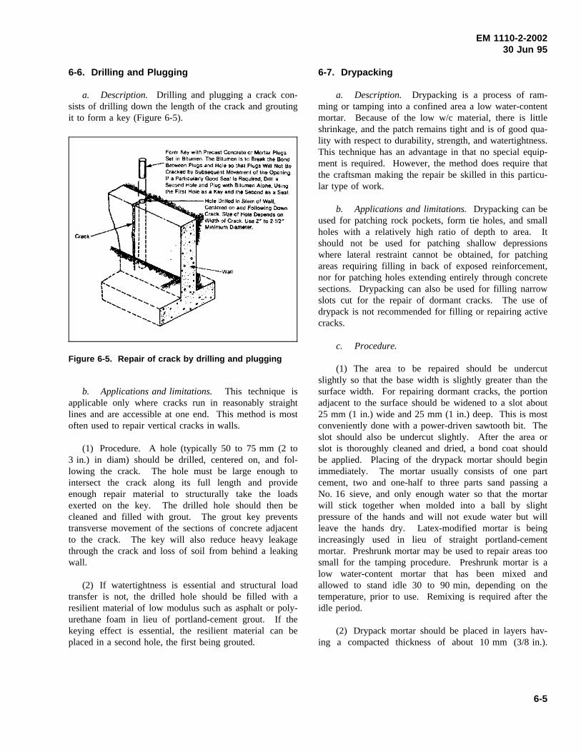
EM 1110-2-200230 Jun 95
6-6. Drilling and Plugging
a. Description. Drilling and plugging a crack con-sists of drilling down the length of the crack and groutingit to form a key (Figure 6-5).
Figure 6-5. Repair of crack by drilling and plugging
b. Applications and limitations. This technique isapplicable only where cracks run in reasonably straightlines and are accessible at one end. This method is mostoften used to repair vertical cracks in walls.
(1) Procedure. A hole (typically 50 to 75 mm (2 to3 in.) in diam) should be drilled, centered on, and fol-lowing the crack. The hole must be large enough tointersect the crack along its full length and provideenough repair material to structurally take the loadsexerted on the key. The drilled hole should then becleaned and filled with grout. The grout key preventstransverse movement of the sections of concrete adjacentto the crack. The key will also reduce heavy leakagethrough the crack and loss of soil from behind a leakingwall.
(2) If watertightness is essential and structural loadtransfer is not, the drilled hole should be filled with aresilient material of low modulus such as asphalt or poly-urethane foam in lieu of portland-cement grout. If thekeying effect is essential, the resilient material can beplaced in a second hole, the first being grouted.
6-7. Drypacking
a. Description. Drypacking is a process of ram-ming or tamping into a confined area a low water-contentmortar. Because of the low w/c material, there is littleshrinkage, and the patch remains tight and is of good qua-lity with respect to durability, strength, and watertightness.This technique has an advantage in that no special equip-ment is required. However, the method does require thatthe craftsman making the repair be skilled in this particu-lar type of work.
b. Applications and limitations.Drypacking can beused for patching rock pockets, form tie holes, and smallholes with a relatively high ratio of depth to area. Itshould not be used for patching shallow depressionswhere lateral restraint cannot be obtained, for patchingareas requiring filling in back of exposed reinforcement,nor for patching holes extending entirely through concretesections. Drypacking can also be used for filling narrowslots cut for the repair of dormant cracks. The use ofdrypack is not recommended for filling or repairing activecracks.
c. Procedure.
(1) The area to be repaired should be undercutslightly so that the base width is slightly greater than thesurface width. For repairing dormant cracks, the portionadjacent to the surface should be widened to a slot about25 mm (1 in.) wide and 25 mm (1 in.) deep. This is mostconveniently done with a power-driven sawtooth bit. Theslot should also be undercut slightly. After the area orslot is thoroughly cleaned and dried, a bond coat shouldbe applied. Placing of the drypack mortar should beginimmediately. The mortar usually consists of one partcement, two and one-half to three parts sand passing aNo. 16 sieve, and only enough water so that the mortarwill stick together when molded into a ball by slightpressure of the hands and will not exude water but willleave the hands dry. Latex-modified mortar is beingincreasingly used in lieu of straight portland-cementmortar. Preshrunk mortar may be used to repair areas toosmall for the tamping procedure. Preshrunk mortar is alow water-content mortar that has been mixed andallowed to stand idle 30 to 90 min, depending on thetemperature, prior to use. Remixing is required after theidle period.
(2) Drypack mortar should be placed in layers hav-ing a compacted thickness of about 10 mm (3/8 in.).
6-5
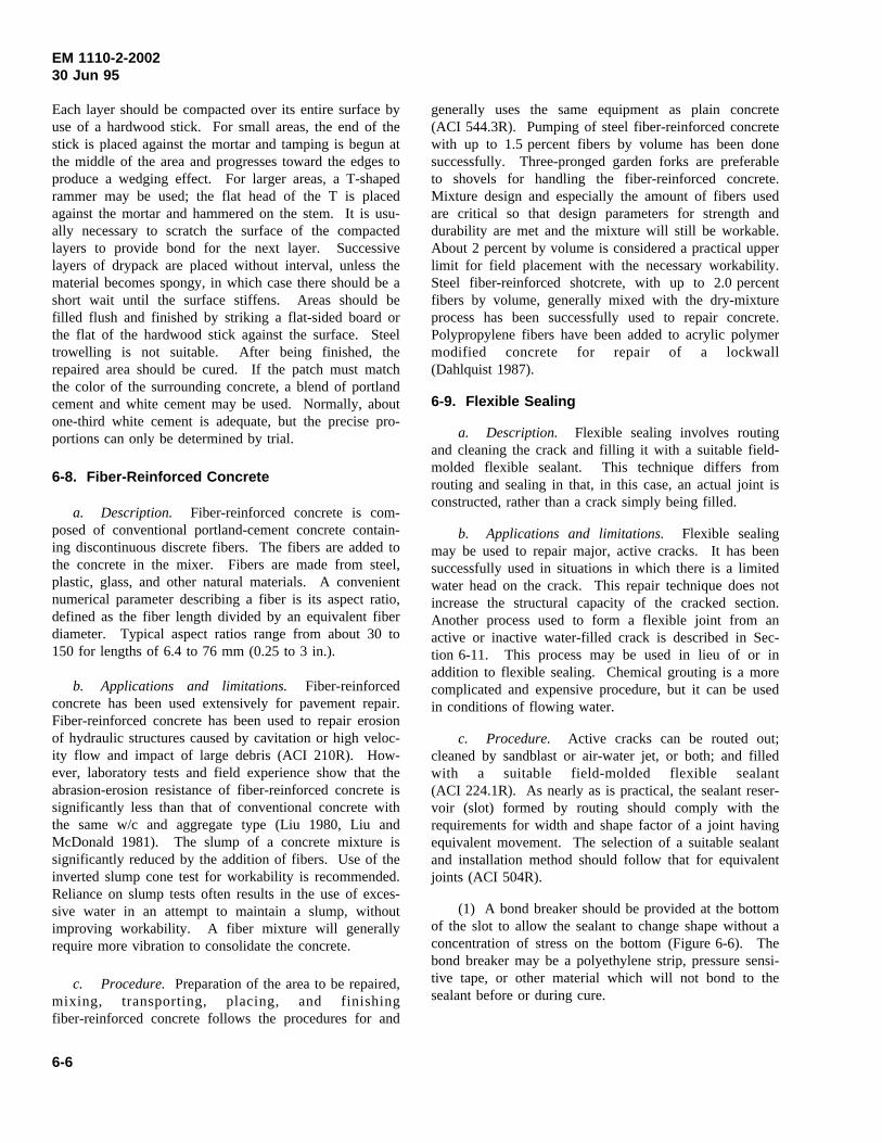
EM 1110-2-200230 Jun 95
Each layer should be compacted over its entire surface byuse of a hardwood stick. For small areas, the end of thestick is placed against the mortar and tamping is begun atthe middle of the area and progresses toward the edges toproduce a wedging effect. For larger areas, a T-shapedrammer may be used; the flat head of the T is placedagainst the mortar and hammered on the stem. It is usu-ally necessary to scratch the surface of the compactedlayers to provide bond for the next layer. Successivelayers of drypack are placed without interval, unless thematerial becomes spongy, in which case there should be ashort wait until the surface stiffens. Areas should befilled flush and finished by striking a flat-sided board orthe flat of the hardwood stick against the surface. Steeltrowelling is not suitable. After being finished, therepaired area should be cured. If the patch must matchthe color of the surrounding concrete, a blend of portlandcement and white cement may be used. Normally, aboutone-third white cement is adequate, but the precise pro-portions can only be determined by trial.
6-8. Fiber-Reinforced Concrete
a. Description. Fiber-reinforced concrete is com-posed of conventional portland-cement concrete contain-ing discontinuous discrete fibers. The fibers are added tothe concrete in the mixer. Fibers are made from steel,plastic, glass, and other natural materials. A convenientnumerical parameter describing a fiber is its aspect ratio,defined as the fiber length divided by an equivalent fiberdiameter. Typical aspect ratios range from about 30 to150 for lengths of 6.4 to 76 mm (0.25 to 3 in.).
b. Applications and limitations. Fiber-reinforcedconcrete has been used extensively for pavement repair.Fiber-reinforced concrete has been used to repair erosionof hydraulic structures caused by cavitation or high veloc-ity flow and impact of large debris (ACI 210R). How-ever, laboratory tests and field experience show that theabrasion-erosion resistance of fiber-reinforced concrete issignificantly less than that of conventional concrete withthe same w/c and aggregate type (Liu 1980, Liu andMcDonald 1981). The slump of a concrete mixture issignificantly reduced by the addition of fibers. Use of theinverted slump cone test for workability is recommended.Reliance on slump tests often results in the use of exces-sive water in an attempt to maintain a slump, withoutimproving workability. A fiber mixture will generallyrequire more vibration to consolidate the concrete.
c. Procedure. Preparation of the area to be repaired,mixing, transporting, placing, and finishingfiber-reinforced concrete follows the procedures for and
generally uses the same equipment as plain concrete(ACI 544.3R). Pumping of steel fiber-reinforced concretewith up to 1.5 percent fibers by volume has been donesuccessfully. Three-pronged garden forks are preferableto shovels for handling the fiber-reinforced concrete.Mixture design and especially the amount of fibers usedare critical so that design parameters for strength anddurability are met and the mixture will still be workable.About 2 percent by volume is considered a practical upperlimit for field placement with the necessary workability.Steel fiber-reinforced shotcrete, with up to 2.0 percentfibers by volume, generally mixed with the dry-mixtureprocess has been successfully used to repair concrete.Polypropylene fibers have been added to acrylic polymermodified concrete for repair of a lockwall(Dahlquist 1987).
6-9. Flexible Sealing
a. Description. Flexible sealing involves routingand cleaning the crack and filling it with a suitable field-molded flexible sealant. This technique differs fromrouting and sealing in that, in this case, an actual joint isconstructed, rather than a crack simply being filled.
b. Applications and limitations. Flexible sealingmay be used to repair major, active cracks. It has beensuccessfully used in situations in which there is a limitedwater head on the crack. This repair technique does notincrease the structural capacity of the cracked section.Another process used to form a flexible joint from anactive or inactive water-filled crack is described in Sec-tion 6-11. This process may be used in lieu of or inaddition to flexible sealing. Chemical grouting is a morecomplicated and expensive procedure, but it can be usedin conditions of flowing water.
c. Procedure. Active cracks can be routed out;cleaned by sandblast or air-water jet, or both; and filledwith a suitable field-molded flexible sealant(ACI 224.1R). As nearly as is practical, the sealant reser-voir (slot) formed by routing should comply with therequirements for width and shape factor of a joint havingequivalent movement. The selection of a suitable sealantand installation method should follow that for equivalentjoints (ACI 504R).
(1) A bond breaker should be provided at the bottomof the slot to allow the sealant to change shape without aconcentration of stress on the bottom (Figure 6-6). Thebond breaker may be a polyethylene strip, pressure sensi-tive tape, or other material which will not bond to thesealant before or during cure.
6-6
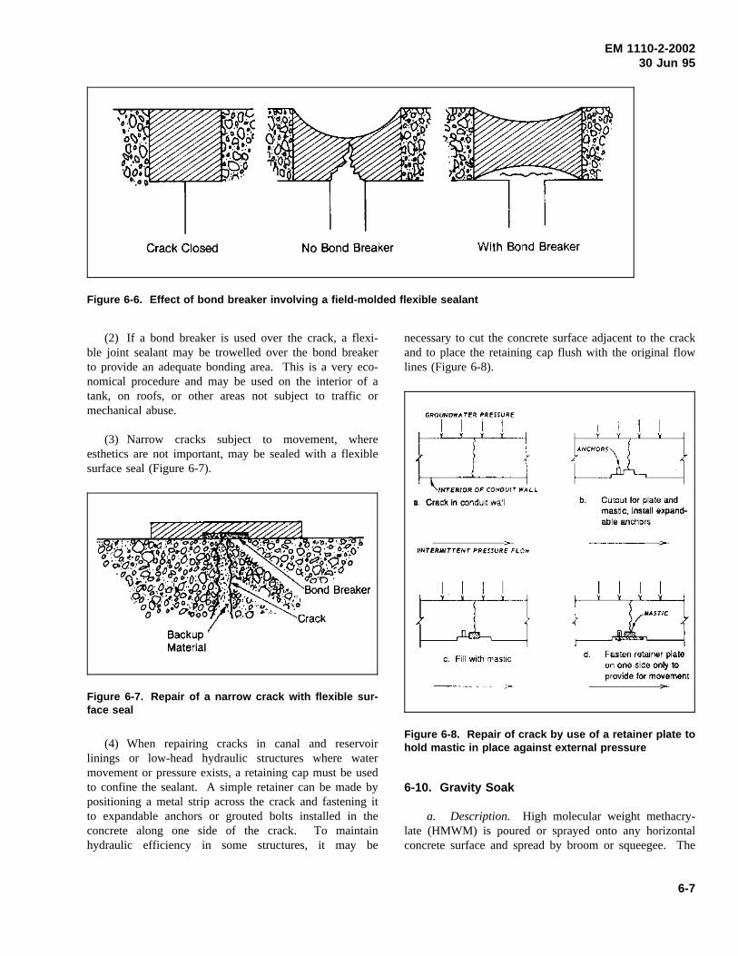
EM 1110-2-200230 Jun 95
Figure 6-6. Effect of bond breaker involving a field-molded flexible sealant
(2) If a bond breaker is used over the crack, a flexi-ble joint sealant may be trowelled over the bond breakerto provide an adequate bonding area. This is a very eco-nomical procedure and may be used on the interior of atank, on roofs, or other areas not subject to traffic ormechanical abuse.
(3) Narrow cracks subject to movement, whereesthetics are not important, may be sealed with a flexiblesurface seal (Figure 6-7).
Figure 6-7. Repair of a narrow crack with flexible sur-face seal
(4) When repairing cracks in canal and reservoirlinings or low-head hydraulic structures where watermovement or pressure exists, a retaining cap must be usedto confine the sealant. A simple retainer can be made bypositioning a metal strip across the crack and fastening itto expandable anchors or grouted bolts installed in theconcrete along one side of the crack. To maintainhydraulic efficiency in some structures, it may be
necessary to cut the concrete surface adjacent to the crackand to place the retaining cap flush with the original flowlines (Figure 6-8).
Figure 6-8. Repair of crack by use of a retainer plate tohold mastic in place against external pressure
6-10. Gravity Soak
a. Description. High molecular weight methacry-late (HMWM) is poured or sprayed onto any horizontalconcrete surface and spread by broom or squeegee. The
6-7
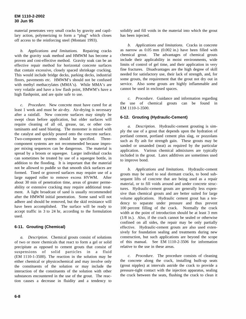
EM 1110-2-200230 Jun 95
material penetrates very small cracks by gravity and capil-lary action, polymerizing to form a “plug” which closesoff access to the reinforcing steel (Montani 1993).
b. Applications and limitations. Repairing crackswith the gravity soak method and HMWM has become aproven and cost-effective method. Gravity soak can be aneffective repair method for horizontal concrete surfacesthat contain excessive, closely spaced shrinkage cracking.This would include bridge decks, parking decks, industrialfloors, pavements etc. HMWM’s should not be confusedwith methyl methacrylates (MMA’s). While MMA’s arevery volatile and have a low flash point, HMWM’s have ahigh flashpoint, and are quite safe to use.
c. Procedure. New concrete must have cured for atleast 1 week and must be air-dry. Air-drying is necessaryafter a rainfall. New concrete surfaces may simply beswept clean before application, but older surfaces willrequire cleaning of all oil, grease, tar, or other con-taminants and sand blasting. The monomer is mixed withthe catalyst and quickly poured onto the concrete surface.Two-component systems should be specified. Three-component systems are not recommended because impro-per mixing sequences can be dangerous. The material isspread by a broom or squeegee. Larger individual crackscan sometimes be treated by use of a squeegee bottle, inaddition to the flooding. It is important that the materialnot be allowed to puddle so that smooth slick surfaces areformed. Tined or grooved surfaces may require use of alarge napped roller to remove excess HVWM. Afterabout 30 min of penetration time, areas of greater perme-ability or extensive cracking may require additional treat-ment. A light broadcast of sand is usually recommendedafter the HMWM initial penetration. Some sand will notadhere and should be removed, but the skid resistance willhave been accomplished. The surface will be ready toaccept traffic in 3 to 24 hr, according to the formulationused.
6-11. Grouting (Chemical)
a. Description. Chemical grouts consist of solutionsof two or more chemicals that react to form a gel or solidprecipitate as opposed to cement grouts that consist ofsuspensions of solid particles in a fluid(EM 1110-1-3500). The reaction in the solution may beeither chemical or physicochemical and may involve onlythe constituents of the solution or may include theinteraction of the constituents of the solution with othersubstances encountered in the use of the grout. The reac-tion causes a decrease in fluidity and a tendency to
solidify and fill voids in the material into which the grouthas been injected.
b. Applications and limitations.Cracks in concreteas narrow as 0.05 mm (0.002 in.) have been filled withchemical grout. The advantages of chemical groutsinclude their applicability in moist environments, widelimits of control of gel time, and their application in veryfine fractures. Disadvantages are the high degree of skillneeded for satisfactory use, their lack of strength, and, forsome grouts, the requirement that the grout not dry out inservice. Also some grouts are highly inflammable andcannot be used in enclosed spaces.
c. Procedure. Guidance and information regardingthe use of chemical grouts can be found inEM 1110-1-3500.
6-12. Grouting (Hydraulic-Cement)
a. Description. Hydraulic-cement grouting is sim-ply the use of a grout that depends upon the hydration ofportland cement, portland cement plus slag, or pozzolanssuch as fly ash for strength gain. These grouts may besanded or unsanded (neat) as required by the particularapplication. Various chemical admixtures are typicallyincluded in the grout. Latex additives are sometimes usedto improve bond.
b. Applications and limitations. Hydraulic-cementgrouts may be used to seal dormant cracks, to bond sub-sequent lifts of concrete that are being used as a repairmaterial, or to fill voids around and under concrete struc-tures. Hydraulic-cement grouts are generally less expen-sive than chemical grouts and are better suited for largevolume applications. Hydraulic cement grout has a ten-dency to separate under pressure and thus prevent100 percent filling of the crack. Normally the crackwidth at the point of introduction should be at least 3 mm(1/8 in.). Also, if the crack cannot be sealed or otherwiseconfined on all sides, the repair may be only partiallyeffective. Hydraulic-cement grouts are also used exten-sively for foundation sealing and treatments during newconstruction, but such applications are beyond the scopeof this manual. See EM 1110-2-3506 for informationrelative to the use in these areas.
c. Procedure. The procedure consists of cleaningthe concrete along the crack, installing built-up seats(grout nipples) at intervals astride the crack to provide apressure-tight contact with the injection apparatus, sealingthe crack between the seats, flushing the crack to clean it
6-8
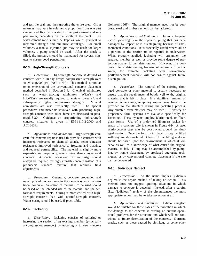
EM 1110-2-200230 Jun 95
and test the seal, and then grouting the entire area. Groutmixtures may vary in volumetric proportion from one partcement and five parts water to one part cement and onepart water, depending on the width of the crack. Thewater-cement ratio should be kept as low as practical tomaximize strength and minimize shrinkage. For smallvolumes, a manual injection gun may be used; for largervolumes, a pump should be used. After the crack isfilled, the pressure should be maintained for several min-utes to ensure good penetration.
6-13. High-Strength Concrete
a. Description. High-strength concrete is defined asconcrete with a 28-day design compressive strength over41 MPa (6,000 psi) (ACI 116R). This method is similarto an extension of the conventional concrete placementmethod described in Section 6-4. Chemical admixturessuch as water-reducing admixtures (WRA’s) andHRWRA’s are usually required to achieve lower w/c andsubsequently higher compressive strengths. Mineraladmixtures are also frequently used. The specialprocedures and materials involved with producing high-strength concrete with silica fume are discussed in para-graph 6-30. Guidance on proportioning high-strengthconcrete mixtures is given in EM 1110-2-2000 andACI 363R.
b. Applications and limitations. High-strength con-crete for concrete repair is used to provide a concrete withimproved resistance to chemical attack, better abrasionresistance, improved resistance to freezing and thawing,and reduced permeability. The material is slightly moreexpensive and requires greater control than conventionalconcrete. A special laboratory mixture design shouldalways be required for high-strength concrete instead of aproducers’ standard mixture that requires fieldadjustments.
c. Procedure. Generally, concrete production andrepair procedures are done in the same way as a conven-tional concrete. Selection of materials to be used shouldbe based on the intended use of the material and the per-formance requirements. Curing is more critical with high-strength concrete than with normal-strength concrete.Water curing should be used, if practicable.
6-14. Jacketing
a. Description. Jacketing consists of restoring orincreasing the section of an existing member (principallya compression member) by encasing it in new concrete
(Johnson 1965). The original member need not be con-crete; steel and timber sections can be jacketed.
b. Applications and limitations.The most frequentuse of jacketing is in the repair of piling that has beendamaged by impact or is disintegrating because of envi-ronmental conditions. It is especially useful where all ora portion of the section to be repaired is underwater.When properly applied, jacketing will strengthen therepaired member as well as provide some degree of pro-tection against further deterioration. However, if a con-crete pile is deteriorating because of exposure to acidicwater, for example, jacketing with conventionalportland-cement concrete will not ensure against futuredisintegration.
c. Procedure. The removal of the existing dam-aged concrete or other material is usually necessary toensure that the repair material bonds well to the originalmaterial that is left in place. If a significant amount ofremoval is necessary, temporary support may have to beprovided to the structure during the jacketing process.Any suitable form material may be used. A variety ofproprietary form systems are available specifically forjacketing. These systems employ fabric, steel, or fiber-glass forms. Use of a preformed fiberglass jacket forrepair of a concrete pile is shown in Figure 6-9. A steelreinforcement cage may be constructed around the dam-aged section. Once the form is in place, it may be filledwith any suitable material. Choice of the filling materialshould be based upon the environment in which it willserve as well as a knowledge of what caused the originalmaterial to fail. Filling may be accomplished by pump-ing, by tremie placement, by preplaced aggregate tech-niques, or by conventional concrete placement if the sitecan be dewatered.
6-15. Judicious Neglect
a. Description. As the name implies, judiciousneglect is the repair method of taking no action. Thismethod does not suggest ignoring situations in whichdamage to concrete is detected. Instead, after a careful(i.e., “judicious”) review of the circumstances the mostappropriate action may be to take no action at all.
b. Applications and limitations. Judicious neglectwould be suitable for those cases of deterioration in whichthe damage to the concrete is causing no current opera-tional problems for the structure and which will not con-tribute to future deterioration of the concrete. Dormantcracks, such as those caused by shrinkage or some other
6-9
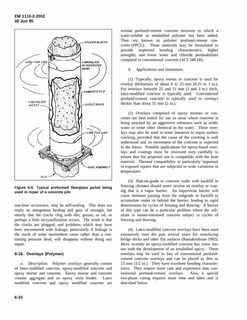
EM 1110-2-200230 Jun 95
Figure 6-9. Typical preformed fiberglass jacket beingused in repair of a concrete pile
one-time occurrence, may be self-sealing. This does notimply an autogenous healing and gain of strength, butmerely that the cracks clog with dirt, grease, or oil, orperhaps a little recrystallization occurs. The result is thatthe cracks are plugged, and problems which may havebeen encountered with leakage, particularly if leakage isthe result of some intermittent cause rather than a con-tinuing pressure head, will disappear without doing anyrepair.
6-16. Overlays (Polymer)
a. Description. Polymer overlays generally consistof latex-modified concrete, epoxy-modified concrete andepoxy mortar and concrete. Epoxy mortar and concretecontain aggregate and an epoxy resin binder. Latexmodified concrete and epoxy modified concrete are
normal portland-cement concrete mixtures to which awater-soluble or emulsified polymer has been added.They are known as polymer portland-cement con-cretes (PPCC). These materials may be formulated toprovide improved bonding characteristics, higherstrengths, and lower water and chloride permeabilitiescompared to conventional concrete (ACI 548.1R).
b. Applications and limitations.
(1) Typically, epoxy mortar or concrete is used foroverlay thicknesses of about 6 to 25 mm (0.25 to 1 in.).For overlays between 25 and 51 mm (1 and 2 in.) thick,latex-modified concrete is typically used. Conventionalportland-cement concrete is typically used in overlaysthicker than about 51 mm (2 in.).
(2) Overlays composed of epoxy mortars or con-cretes are best suited for use in areas where concrete isbeing attacked by an aggressive substance such as acidicwater or some other chemical in the water. These over-lays may also be used in some instances to repair surfacecracking, provided that the cause of the cracking is wellunderstood and no movement of the concrete is expectedin the future. Possible applications for epoxy-based over-lays and coatings must be reviewed very carefully toensure that the proposed use is compatible with the basematerial. Thermal compatibility is particularly importantin exposed repairs that are subjected to wide variations intemperature.
(3) Slab-on-grade or concrete walls with backfill infreezing climates should never receive an overlay or coat-ing that is a vapor barrier. An impervious barrier willcause moisture passing from the subgrade or backfill toaccumulate under or behind the barrier, leading to rapiddeterioration by cycles of freezing and thawing. A barrierof this type can be a particular problem where the sub-strate is nonair-entrained concrete subject to cycles offreezing and thawing.
(4) Latex-modified concrete overlays have been usedextensively over the past several years for resurfacingbridge decks and other flat surfaces (Ramakrishnan 1992).More recently an epoxy-modified concrete has come intouse with the development of an emulsified epoxy. Theseoverlays may be used in lieu of conventional portland-cement concrete overlays and can be placed as thin as13 mm (1/2 in.). They have excellent bonding character-istics. They require more care and experience than con-ventional portland-cement overlays. Also, a specialtwo-phase curing requires more time and labor and isdescribed below.
6-10
EM 1110-2-200230 Jun 95
c. Procedure.
(1) Epoxy overlays. Repair of deteriorated concretewith epoxy overlays will involve the use of epoxy con-crete or epoxy mortar. Epoxy resin systems conformingto ASTM C 881 (CRD C 595) are suitable.
(a) Generally, aggregates suitable for portland-cementmixtures are suitable for epoxy-resin mixtures. Aggre-gates are added to the system for economy and improvedperformance in patching applications and floor toppings.Aggregates should be clean and dry at the time of use andconditioned to a temperature within the range at which theepoxy-resin mortar or concrete is to be mixed. The grad-ing should be uniform with the smallest size passing theNo. 100 sieve and the maximum size not to exceedone-third of the mean depth of the patch or opening to befilled. However, the recommended maximum aggregatesize for epoxy-resin concrete is 25 mm (1 in.), whereasthe maximum size aggregate commonly used forepoxy-resin mortar corresponds to material that will passa No. 8 sieve.
(b) Aggregates should be used in the amount neces-sary to ensure complete wetting of the aggregate surfaces.The aggregate-resin proportions will therefore vary withthe type and grading of the aggregates. Up to seven partsby weight of the fine aggregate can be mixed with onepart of epoxy resin, but a three-to-one proportion is theusual proportion to use for most fine aggregates in mak-ing epoxy mortar. For epoxy concrete, the proportion ofaggregate to the mixed resin may be as high as 12 to 1 byweight for aggregates in the specific gravity range of 2.50to 2.80. The aggregate-epoxy proportions also depend onthe viscosity of the mixed epoxy system. Since tempera-ture affects the viscosity of the system, the proportionsalso are dependent on the temperature at which the systemis mixed. The trial batches should be made at the temper-ature of mixing to establish the optimum proportions forthe aggregates.
(c) Machine mixing of the epoxy-resin components ismandatory except for mixing volumes of 0.5L (1 pint) orless. Epoxy mortar or concrete may be machine- or hand-mixed after the epoxy components have been mixed.Small drum mechanical mixers have been used success-fully but are difficult to clean properly. Large commer-cial dough or masonry mortar mixers have been widelyand successfully used and present less difficulty in clean-ing. Hand-mixing may be performed in metal pans withappropriate tools. When epoxy mortar is hand-mixed, themixed epoxy system is transferred to the pan, and the fineaggregate is gradually added during mixing. Regardless
of how the epoxy concrete is mixed, the fine aggregate isadded first and then the coarse aggregate. This procedurepermits proper wetting of the fine aggregate particles bythe mixed epoxy system and produces a slightly “wet”mixture to which the coarse aggregate is added.
(d) Prior to placement, a single prime coat of epoxyshould be worked into the cleaned substrate by brushing,trowelling, or any other method that will thoroughly wetthe substrate. The epoxy mortar or concrete must beapplied while the prime coat is in a tacky condition. Ifthe depth of the patch is greater than 500 mm (2 in.),placement should be accomplished in lifts or layers of lessthan 50 mm (2 in.) with some delay between lifts to per-mit as much heat dissipation as possible. The delayshould not extend beyond the setting time of the epoxyformulation. Hand tampers should be used to consolidatethe epoxy concrete, taking great care to trowel the mortaror concrete onto the sides and into the corners of thepatch. Because of the relatively short pot life of epoxysystems, the placing, consolidating, and finishing opera-tions must be performed without delay.
(e) In final finishing, excess material should not bemanipulated onto concrete adjacent to the patch becausethe carryover material is difficult to clean up. In finishingoperations, proper surface smoothness must be achieved.The epoxy mixture tends to build up on the finishingtools, requiring frequent cleaning with an appropriatesolvent. After each cleaning, the tool surfaces must bewiped free of excess solvent.
(f) The materials used in the two epoxy systems andthe solvents used for cleanup do not ordinarily present ahealth hazard except to hypersensitive individuals. Thematerials may be handled safely if adequate precautionarymeasures are observed. Safety and health precautions foruse with epoxies are given in TM 5-822-9, Repair ofRigid Pavements Using Epoxy-Resin Grout, Mortars, andConcrete.
(2) Latex-modified overlays. Styrene-butadiene isthe most commonly used latex for concrete overlays(Clear and Chollar 1978).
(a) The materials and mixing procedures for latex-modified mortar and concrete are similar to those forconventional concrete portland-cement mortar and con-crete. Latexes in a dispersed form are simply used inlarger quantities in comparison to other chemicaladmixtures. The construction procedure for latex-modified concrete overlays parallels that for conventionalconcrete overlays except that (1) the mixing equipment
6-11
EM 1110-2-200230 Jun 95
must have a means of storing and dispensing the latexinto the mixture, (2) the latex-modified concrete has ahigh slump (typically 125 ± 25 mm (5 ± 1 in.)) and is notair-entrained, and (3) a combination of wet and dry curingis required.
(b) Latex-modified concrete has been producedalmost exclusively in mobile, continuous mixers fittedwith an additional storage tank for the latex. The latexmodifier should always be maintained between 7 and30 °C (45 and 85 °F). Maintaining the correct tempera-ture may present serious difficulties, especially during thesummer months, and may necessitate night placing opera-tions. Hot weather also causes rapid drying of the latex-modified concrete, which promotes shrinkage cracks.
(c) The bond coat consisting of the mortar fraction ofthe latex-modified concrete is usually produced directlyfrom the continuous mixer by eliminating the coarseaggregate from the mixture. The slurry is broomed intothe concrete surface.
(d) Placing operations are straightforward. Finishingmachines with conventional vibratory or oscillatingscreeds may be used, though a rotating cylindrical drum ispreferred. Hand finishing is comparable to conventionalconcrete overlays.
(e) Wet burlap must be applied to the concrete assoon as it will be supported without damage. After 1 to2 days, the burlap is removed and the overlay should bepermitted to air dry for a period of not less than 72 hr.The initial period of wet curing is necessary for thehydration of the portland cement and to prevent the for-mation of shrinkage cracks; the period of air drying isnecessary to permit the latex to dry out and the latex tocoalesce and form a continuous film. The film formationwithin the concrete gives the concrete good bond, flexuralstrength, and low permeability. The film-forming proper-ties of the latex are temperature sensitive and developvery slowly at temperatures lower than 13 °C (55 °F).Placing and curing should not be done at temperatureslower than 7 °C (45 °F).
(f) See ACI 548.4 for a standard specification forlatex-modified concrete overlays. Case histories ofrepairs with polymer-modified concrete overlays aredescribed by Campbell (1994).
6-17. Overlays (Portland-Cement)
a. Description. Overlays are simply layers of con-crete (usually horizontal) placed over a properly prepared
existing concrete surface to restore a spalled or disinte-grated surface or increase the load-carrying capacity ofthe underlying concrete. The overlay thickness typicallyranges from 102 to 610 mm (4 to 24 in.), depending uponthe purpose it is intended to serve. However, overlays asthin as 38 mm (1-1/2 in.) have been placed. For informa-tion on polymer-based overlays see Section 6-16.
b. Applications and limitations.
(1) A portland-cement-concrete overlay may besuitable for a wide variety of applications, such as resur-facing spalled or cracked concrete surfaces on bridgedecks or lock walls, increasing cover over reinforcingsteel, or leveling floors or slabs. Other applications ofoverlays include repair of concrete surfaces which aredamaged by abrasion-erosion and the repair of deteriora-ted pavements (TM 5-822-6).
(2) Portland-cement-concrete overlays should not beused in applications in which the original damage wascaused by aggressive chemical attack that would beexpected to act against the portland cement in the overlay.Bonded overlays should not be used in situations in whichthere is active cracking or structural movement since theexisting cracks can be reflected through the overlay or themovement can induce cracks in the overlay; unbondedoverlays should be used in these situations.
c. Procedure. The general procedure for applyingoverlays is as follows: removal of the existing deterio-rated concrete; preparation of the concrete surface, includ-ing sand- or waterblasting the concrete surface andapplying a bonding agent to the surface, if necessary; andplacing, consolidating, and curing the overlay. Casehistories of repairs with a variety of concrete overlays aredescribed by Campbell (1994).
(1) The guidance given in Chapter 5 should be fol-lowed for removal of deteriorated concrete and for pre-paring the concrete surface. For a bonded overlay toperform properly, the surface to which it is to be bondedmust be clean, dry, rough, and dust-free.
(2) The potential for cracking of restrained concreteoverlays should be recognized. Any variations in concretematerials, mixture proportions, and construction practicesthat will minimize shrinkage or reduce concrete tempera-ture differentials should be considered for bonded over-lays. Reduced cracking in resurfacing of lock walls hasbeen attributed to lower cement content, larger maximumsize coarse aggregate, lower placing and curing tempera-tures, smaller volumes of placement, and close attention
6-12
EM 1110-2-200230 Jun 95
to curing (Wickersham 1987). Preformed contractionjoints 1.5 m (5 ft) on center have been effective in con-trolling cracking in vertical and horizontal overlays. Thecritical timing of saw cutting necessary for proper jointpreparation is such that this procedure is not recom-mended for concrete overlays. Where structural consid-erations permit, an unbonded overlay may be used tominimize cracking caused by restrained contraction of theconcrete overlay.
(3) Placing, consolidating, and curing of conventionalconcrete overlays should follow the guidance given inEM 1110 -2-2000.
6-18. Polymer Coatings
a. Description. Polymer coatings, if the right mate-rial for the job condition is selected and properly applied,can be an effective protective coating to help protect theconcrete from abrasion, chemical attack, or freeze andthaw damage. Epoxy resins are widely used for concretecoatings. Other polymer coatings include polyester resinsand polyurethane resins (ACI 503R and ACI 515.1R).
b. Applications and limitations.
(1) Epoxy resin is used as a protective coatingbecause of its impermeability to water and resistance tochemical attack. It is important that any polymer coatingbe selected from material designed specifically for theintended application. Some formulations will adhere todamp surfaces and even underwater but many require acompletely dry surface. Mixing and applying polymersbelow 16 °C (60 °F) and above 32 °C (89 °F) will requirespecial caution and procedures. Special sharp sand mustbe broadcast on the fresh surface if foot traffic is expectedon the finished surface. Because of their high exothermand higher shrinkage values, a neat epoxy in thicker sec-tions is likely to crack.
(2) Slab-on-grade, concrete walls with backfills, orany slab not completely protected from rainwater andsubject to freezing and thawing should never receive acoating that will form a vapor barrier. Moisture passingthrough the subgrade, backfill, or from rain water canaccumulate under the coating which will be disrupted byfreezing and thawing.
c. Procedure. See applicable portions ofSection 6-16.
6-19. Polymer Concrete/Mortar
a. Description. Polymer concrete (PC) is a com-posite material in which the aggregate is bound togetherin a dense matrix with a polymer binder (ACI 548.1R).A variety of polymers are being used; the best knownand most widely used is epoxy resin (ACI 503R). Someof the other most widely used monomers for PC patchingmaterials include unsaturated polyester resins, a styrene,MMA, and vinylesters. Polymer concrete is quickersetting, has good bond characteristics, good chemicalresistance, and high tensile, flexural, and compressivestrength compared to conventional concrete. Epoxy resinsshould meet the requirements of ASTM C 881(CRD-C 595). The correct type, grade, and class to fitthe job should be specified. REMR Technical NoteCS-MR-7.1 (USAEWES 1985e) provides general infor-mation on eight different types of polymer systems andtypical application in maintenance and repair of concretestructures.
b. Applications and limitations.
(1) Epoxy resins can be formulated for a wide rangeof physical and chemical properties. Some epoxies mustbe used on dry concrete while others are formulated foruse on damp concrete and even underwater. Epoxy hard-ening is very temperature dependent, and epoxies resinsare difficult to apply at temperatures lower than about16 °C (60 °F). Below 10 °C (50 °F) artificial heating ofthe material and the substrate must be employed. It isimportant that epoxy resin or other polymers be selectedfrom material designed specifically for the intended use.Thermosetting polymers, such as polyester and epoxy,exhibit shrinkage during hardening. The shrinkage can bereduced by increasing the amount of aggregate filler.
(2) Other polymers including acrylic polymers(MMA’s, HMWM’s) and polyesters are being used tomake PC. A number of commercial companies nowmarket acrylic-polymer concrete and polyester-polymerconcrete used for patching concrete and for overlays. Thepolyester PC is more widely available because of mod-erate cost. Polyester resins are more sensitive to moisturethan epoxy resins and must be applied on dry concrete.
c. Procedure. Epoxy resins should meet therequirements of ASTM C 881 (CRD-C 595), Type III.For procedures see Section 6-16.
6-13
EM 1110-2-200230 Jun 95
6-20. Polymer Portland-Cement Concrete
a. Description. Polymer portland-cement concrete(PPCC) mixtures are normal portland-cement concretemixtures to which a water-soluble or emulsified polymerhas been added during the mixing process (ACI 548.1R).PPCC has at times been called polymer-modified con-crete. The addition of a polymer to portland-cementconcrete or mortar can improve strength and adhesiveproperties. Also, these materials have excellent resistanceto damage by freezing and thawing, a high degree ofpermeability, and improved resistance to chemicals, abra-sion, and impact. Latex polymers have been most widelyused and accepted. They include styrene butadiene, acryl-ics, polyvinyl chlorides, and polyvinyl acetates.
b. Applications and limitations.PPCC has superioradhesive properties and can be used in thinner patchesand overlays than conventional portland-cement concrete;however, they should not be featheredged. Properties oflatexes used in concrete vary considerably so that careshould be taken to choose the material best suited for jobconditions. Polyvinyl acetates will reemulsify in waterand should not be used if the repair will be in continuouscontact with water. Ambient temperature can greatlyeffect the working life for many polymers. PPCC shouldnot be placed at temperatures below 7 °C (45 °F).
c. Procedures. Mixing and handling procedures forPPCC are similar to those used for conventional concreteand mortar; however, curing is different. The film-forming feature of PPCC is such that 1 to 2 days of moistcuring followed by air curing is usually sufficient(ACI 548.3R). See Ramakrishnan (1992) for constructionpractices and specifications for latex-modified concrete.
6-21. Polymer Impregnation
a. Description. Polymer impregnated concrete (PIC)is a portland-cement concrete that is subsequently poly-merized (ACI 548.1R). This technique requires use of amonomer system, which is a liquid that consists of smallorganic molecules capable of combining to form a solidplastic. Monomers have varying degrees of volatility,toxicity, and flammability and do not mix with water.They are very fluid and will soak into dry concrete andfill the cracks. Monomer systems used for impregnationcontain a catalyst or initiator and the basic monomer (ordifferent isomers of the same monomer). The systemsmay also contain a cross-linking agent. When heated, themonomers join together, or polymerize to become atough, strong, durable plastic, which in concrete greatlyenhances a number of the properties of the concrete.
b. Applications and limitations. Polymer impreg-nation can be used for repair of cracks (ACI 224.1R). Ifa cracked concrete surface is dried, flooded with themonomer, and polymerized in place, the cracks will befilled and structurally repaired. However, if the crackscontain moisture, the monomer will not soak into theconcrete and, consequently, the repair will be unsatisfac-tory. If a volatile monomer evaporates before polymer-ization, it will be ineffective. Polymer impregnation hasnot been used successfully to repair fine cracks. Use ofthis system requires experienced personnel and somespecial equipment.
c. Procedure. Badly fractured beams have beenrepaired with polymer impregnation by drying the frac-ture, temporarily encasing it in a watertight (monomerproof) band of sheet metal, soaking the fractures with amonomer, and polymerizing the monomer. Large voidsor broken areas in compression zones can be filled withfine and coarse aggregate before flooding them with themonomer, providing a polymer-concrete repair. Adetailed discussion of polymer impregnation is given inACI 548.1R. See also the gravity soak proceduredescribed in Section 6-10.
6-22. Polymer Injection
a. Description. Polymers commonly used to repaircracks or joints by injection may be generally categorizedas either rigid or flexible systems. Epoxies are the mostcommon rigid systems used for structural repair or “weld-ing” of cracks to form a monolithic structure. Flexiblepolyurethane systems are most often used for stoppingwater flow and sealing active cracks. Cracks as narrowas 0.05 mm (0.002 in.) can be bonded by the injection ofepoxy (ACI 224.1R). The technique generally consists ofdrilling holes at close intervals along the cracks, in somecases installing entry ports, and injecting the epoxy underpressure. Although the majority of the injection projectshave been accomplished with high-pressure injection,some successful work has been done with low pressures.
b. Applications and limitations.
(1) Rigid repairs. Epoxy injection has been suc-cessfully used in the repair of cracks in buildings, bridges,dams, and other types of concrete structures. However,unless the crack is dormant (or the cause of cracking isremoved, thereby making the crack dormant), crackingwill probably recur, and structural repair by injectionshould not be used. With the exception of certain special-ized epoxies, this technique is not applicable if the cracksare actively leaking and cannot be dried out. While moist
6-14
EM 1110-2-200230 Jun 95
cracks can be injected, contaminants in the crack (includ-ing water) will reduce the effectiveness of the epoxy tostructurally repair the crack. Epoxy injection can also beused in the repair of delaminations in bridge decks.
(2) Flexible repairs. If the cracks are active and it isdesired to seal them while allowing continued movementat these locations, it is necessary to use a grout thatallows the filled crack to act as a joint. This is accom-plished by using a polymer which cures into a closed-cellfoam. Water-activated polyurethane grouts, both hydro-phobic and hydrophilic, are commonly used for sealingleaking cracks. Solomon and Jaques (1994) provide anexcellent discussion of materials and methods for injectingleaking cracks. Applications of water-activated polyure-thanes in repair of waterstop failures are discussed inSection 8-2. Also, see Section 6-11.
(3) Polymer injection generally requires a high degreeof skill for satisfactory execution, and application of thetechnique may be limited by ambient temperature.
c. High-pressure injection procedure.The majorityof injection projects are accomplished with high-pressureinjection (350 KPa (50 psi) or higher). The general stepsinvolved in epoxy injection are as follows (ACI 224.1R).
(1) Clean the cracks. The first step is to clean thecracks that have been contaminated. Oil, grease, dirt, orfine particles of concrete prevent epoxy penetration andbonding. Preferably, contamination should be removed byflushing with water or, if the crack is dry, some otherspecially effective solvent. The solvent is then blown outwith compressed air, or adequate time is allowed for airdrying.
(2) Seal the surfaces. Surface cracks should besealed to keep the polymer from leaking out before it hasgelled. Where the crack face cannot be reached butwhere there is backfill or where a slab-on-grade is beingrepaired, the backfill material or subbase material is oftenan adequate seal. A surface can be sealed by brushing anepoxy along the surface of the crack and allowing it toharden. If extremely high injection pressures are needed,the crack should be cut out to a depth of 13 mm (1/2 in.)and width of about 20 mm (3/4 in.) in a V-shape, filledwith an epoxy, and struck off flush with the surface. If apermanent glossy appearance along the crack is objec-tionable and if high injection pressure is not required, astrippable plastic may be applied along the crack.
(3) Install the entry ports. Three methods are ingeneral use:
(a) Drilled holes--fittings inserted. Historically, thismethod was the first to be used and is often used in con-junction with V-grooving of the cracks. The methodentails drilling a hole into the crack, approximately19 mm (3/4 in.) in diam and 13 to 25 mm (1/2 to 1 in.)below the apex of the V-grooved section, into which a fit-ting such as a pipe nipple or tire valve stem is bondedwith an epoxy adhesive. A vacuum chuck and bit areuseful in preventing the cracks from being plugged withdrilling dust. Hydrostatic pressure tests showed thatmolded injection ports mounted within a drilled port holecan withstand pressures of 1.4 to 1.9 MPa (200 to275 psi) before leaks begin to develop. In comparison,surface-mounted ports withstood pressures between 0.3and 1.0 MPa (50 and 150 psi), depending on the type ofport (Webster, Kukacka, and Elling 1990).
(b) Bonded flush fitting. When the cracks are notV-grooved, a method frequently used to provide an entryport is to bond a fitting flush with the concrete face overthe crack. This flush fitting has a hat-like cross sectionwith an opening at the top for the adhesive to enter.
(c) Interruption in seal. Another system of providingentry is to omit the seal from a portion of the crack. Thismethod can be used when special gasket devices areavailable that cover the unsealed portion of the crack andallow injection of the adhesive directly into the crackwithout leaking.
(4) Mix the epoxy. Epoxy systems should conformto ASTM C 881 (CRD-C 595), Type I, low-viscositygrade. Mixing is done either by batch or continuousmethods. In batch mixing, the adhesive components arepremixed according to the manufacturer’s instructions,usually with the use of a mechanical stirrer, such as apaint-mixing paddle. Care must be taken to mix only theamount of adhesive that can be used prior to commence-ment of gelling of the material. When the adhesive mate-rial begins to gel, its flow characteristics begin to change,and pressure injection becomes more and more difficult.In the continuous mixing system, the two liquid adhesivecomponents pass through metering and driving pumpsprior to passing through an automatic mixing head. Thecontinuous mixing system allows the use of fast-settingadhesives that have a short working life.
(5) Inject the epoxy. Hydraulic pumps, paint pres-sure pots, or air actuated caulking guns can be used. Thepressure used for injection must be carefully selected.Increased pressure often does little to accelerate the rateof injection. In fact, the use of excessive pressure canpropagate the existing cracks, causing additional damage.
6-15
EM 1110-2-200230 Jun 95
If the crack is vertical, the injection process should beginby pumping into the entry port at the lowest elevationuntil the epoxy level reaches the entry port above. Thelower injection port is then capped, and the process isrepeated at successively higher ports until the crack hasbeen completely filled and all ports have been capped.For horizontal cracks, the injection should proceed fromone end of the crack to the other in the same manner.The crack is full if the pressure can be maintained. If thepressure cannot be maintained, the epoxy is still flowinginto unfilled portions or leaking out of the crack.
(6) Remove the surface seal. After the injectedepoxy has cured, the surface seal should be removed bygrinding or other means, as appropriate. Fittings andholes at entry ports should be painted with an epoxypatching compound.
d. Alternate high-pressure procedure. To developalternatives to concrete removal and replacement in repairof mass concrete hydraulic structures, a study was initi-ated, as part of the REMR Research Program, to evaluatein situ repair procedures.
(1) Eight injection adhesives were experimentallyevaluated to determine their effectiveness in the repair ofair-dried and water-saturated cracked concrete. The adhe-sives were three epoxies, an emulsifiable polyester resin,furfuryl alcohol, a furan resin, a high-molecular-weightmethacrylate, and a polyurethane. Because of their lowbond strength to water-saturated concrete, the furan resin,furfuryl alcohol, and the polyurethane were not consideredfurther as injection adhesives. The remaining adhesiveswere used to repair both air-dried and water-saturatedconcrete slabs by conventional injection. The most pro-mising adhesive was a two-component, very low-viscosityepoxy system designed specifically for pressure injectionrepairs (Webster and Kukacka 1988).
(2) A field test was performed on a tainter gate pierstem at Dam 20, Mississippi River, to demonstrate, underactual field conditions, the procedures developed in thelaboratory and to evaluate the effectiveness of the mate-rials and equipment selected for use (Webster, Kukacka,and Elling 1989). Problem areas identified during thefield test were addressed in development of a modifiedrepair procedure. Modifications included a better methodfor attaching the injection ports to the concrete and drill-ing small-diameter holes into the concrete to facilitateepoxy penetration into the multiple, interconnectingcracks. The modified procedure was demonstrated atDam 13 on the Mississippi River near Fulton, Illinois(Webster, Kukacka, and Elling 1990).
(3) The first step in this repair procedure is to cleanthe concrete surfaces by sandblasting. Next, injectionholes are drilled. These holes, 13 mm in (1/2 in.) diamand 152 m (6 in.) deep, are wet drilled to flush fines fromthe holes as they occur. After injection ports areinstalled, the entire surface of the repair area is sealedwith epoxy. After the seal has cured, injection is begun.
(4) Visual examinations of cores taken after injectionindicate that a crack network within 152 to 254 mm (6 to10 in.) of the surface can be filled with epoxy. Theseexaminations indicate that the special injection procedureworks very well and laboratory tests substantiate thisconclusion. For example, splitting tensile strengths of therepaired cores average more than twice that of theunrepaired cores and only 10 percent less than thestrength of the uncracked concrete.
e. Low-pressure injection. Similar results areattainable with either low-pressure or high-pressure injec-tion procedures. For example, results achieved through aninjection pressure of 2 MPa (300 psi) for 3 min are repor-tedly duplicated at a pressure of only 0.03 MPa (5 psi) orless for a period of 1 hr, presuming a low-viscosity, longpot life resin is used (Trout 1994). Generally, anythingthat can be injected with high pressure can be injectedwith low pressure; it just takes longer, which accounts forthe selection of high-pressure systems for most largeprojects. However, there are situations where low-pressure injection has distinct advantages.
(1) Low injection pressures allow the use of easilyremovable materials for sealing the surface of the crack,whereas high-pressure injection normally requires anepoxy seal and aggressive removal procedures. Seals thatare easily removed minimize the potential for surfaceblemishes which is particularly important for architecturalconcrete. Some units designed specifically for low pres-sure use can maintain pressures of less than 0.01 MPa(1 psi) for delicate projects such as repair of murals andmosaics.
(2) Low-pressure systems are portable, easy to mobi-lize, require little support from other construction equip-ment, and their initial cost is about one-tenth the cost of ahigh-pressure system.
(3) Low-pressure injection is less hazardous, and theuse of skilled or experienced labor is seldom critical.Typically, low-pressure systems use prebatched resinrather than metering dispensers. Once the resin is mixed,it is pressurized by air or springs within capsules,inflatable syringe-like devices, that are left in place until
6-16
EM 1110-2-200230 Jun 95
the resin has gelled. The use of long pot life resins isessential for successful low-pressure injection: a gel timeof 1 hr at 22 °C (72 °F) is recommended.
6-23. Precast Concrete
a. Description. Precast concrete is concrete castelsewhere than its final position. The use of precast con-crete in repair and replacement of structures has increasedsignificantly in recent years and the trend is expected tocontinue. Compared with cast-in-place concrete, precast-ing offers a number of advantages including ease of con-struction, rapid construction, high quality, durability, andeconomy.
b. Applications and limitations.Typical applicationsof precast concrete in repair or replacement of civil worksstructures include navigation locks, dams, channels, flood-walls, levees, coastal structures, marine structures,bridges, culverts, tunnels, retaining walls, noise barriers,and highway pavement.
c. Procedures. Procedures for use of precast con-crete in repair of a wide variety of structures aredescribed in detail by McDonald and Curtis (in prepara-tion). Case histories describing the use of precast con-crete in repair of navigation lock walls are described inSection 8-1. Selected case histories of additional precastconcrete applications are summarized in Section 8-5.
6-24. Preplaced-Aggregate Concrete
a. Description. Preplaced-aggregate concrete isproduced by placing coarse aggregate in a form and thenlater injecting a portland-cement-sand grout, usually withadmixtures, to fill the voids. As the grout is pumped intothe forms, it will fill the voids, displacing any water, andform a concrete mass.
b. Applications and limitations. Typically,preplaced-aggregate concrete is used on large repair proj-ects, particularly where underwater concrete placement isrequired or when conventional placing of concrete wouldbe difficult. Typical applications have included under-water repair of stilling basins, bridge piers, abutments,and footings. Applications of preplaced-aggregate con-crete in repair of navigation lock walls are described inSection 8-1. The advantages of using preplaced-aggregateconcrete include low shrinkage because of the point-to-point aggregate contact, ability to displace water fromforms as the grout is being placed, and the capability towork around a large number of blockouts in the place-ment area.
c. Procedure. Guidance on materials, mixtureproportioning, and construction procedures for preplaced-aggregate concrete can be found in EM 1110-2-2000 andin ACI 304.1R.
6-25. Rapid-Hardening Cements
a. Description. Rapid-hardening cements aredefined as those that can develop a minimum compressivestrength of 20 MPa (3,000 psi) within 8 hr or less. Thetypes of rapid-hardening cements and patching materialsavailable and their properties are described in REMRTechnical Note CS-MR-7.3 (USAEWES 1985g). A spec-ification for prepackaged, dry, rapid-hardening materials isgiven in ASTM C 928.
b. Applications and limitations.
(1) Magnesium-phosphate cement (MPC). Thismaterial can attain a compressive strength of several thou-sand pounds per square inch in 1 hr. MPC is useful forcold-weather embedments and anchoring and for patchingapplications where a short downtime can justify the addi-tional expense. Finishing must be performed quicklybecause of the rapid set. MPC must be used with non-calcareous aggregates. MPC has low, long-term shrinkageand is nonreactive to sulphates. MPC is air-cured in amanner similar to the way epoxy concrete is cured. Adamp substrate will adversely affect hardening.
(2) High alumina cements (HAC). The 24-hrstrength of HAC is approximately equivalent to the28-day strength of portland-cement concrete. The initialset however is reported to be up to 3 hr, which may bebeneficial for transportation of the mixed concrete. HACis more stable at high temperature than portland cement,providing aggregates that resist the high temperatures areused. A disadvantage is that when high alumina cementis subjected to in-service conditions of high humidity andelevated temperatures greater than 20 °C (68 °F) there isa “conversion reaction” which can cause a drastic strengthloss (Mailvaganam 1992).
(3) Regulated-set portland cement. The initial settime is 15-20 min, but the set may be retarded by the useof citric acid. Regulated-set portland cement is notrecommended for use in concrete exposed to sulphatesoils or water.
(4) Gypsum cements. Gypsum cements are fast-setting and can obtain compressive strengths of as muchas 21 m MPa (3,000 psi) in 30 min. For the most part,however, they are not as durable as portland-cement
6-17
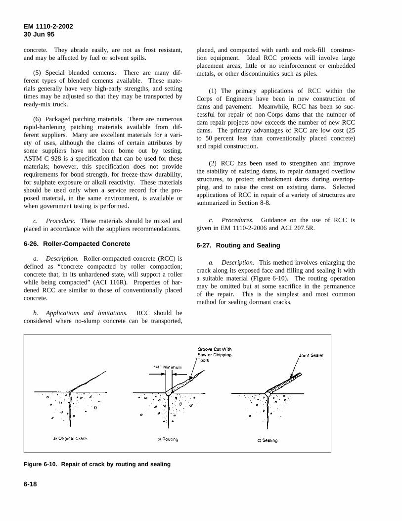
EM 1110-2-200230 Jun 95
concrete. They abrade easily, are not as frost resistant,and may be affected by fuel or solvent spills.
(5) Special blended cements. There are many dif-ferent types of blended cements available. These mate-rials generally have very high-early strengths, and settingtimes may be adjusted so that they may be transported byready-mix truck.
(6) Packaged patching materials. There are numerousrapid-hardening patching materials available from dif-ferent suppliers. Many are excellent materials for a vari-ety of uses, although the claims of certain attributes bysome suppliers have not been borne out by testing.ASTM C 928 is a specification that can be used for thesematerials; however, this specification does not providerequirements for bond strength, for freeze-thaw durability,for sulphate exposure or alkali reactivity. These materialsshould be used only when a service record for the pro-posed material, in the same environment, is available orwhen government testing is performed.
c. Procedure. These materials should be mixed andplaced in accordance with the suppliers recommendations.
6-26. Roller-Compacted Concrete
a. Description. Roller-compacted concrete (RCC) isdefined as “concrete compacted by roller compaction;concrete that, in its unhardened state, will support a rollerwhile being compacted” (ACI 116R). Properties of har-dened RCC are similar to those of conventionally placedconcrete.
b. Applications and limitations. RCC should beconsidered where no-slump concrete can be transported,
placed, and compacted with earth and rock-fill construc-tion equipment. Ideal RCC projects will involve largeplacement areas, little or no reinforcement or embeddedmetals, or other discontinuities such as piles.
(1) The primary applications of RCC within theCorps of Engineers have been in new construction ofdams and pavement. Meanwhile, RCC has been so suc-cessful for repair of non-Corps dams that the number ofdam repair projects now exceeds the number of new RCCdams. The primary advantages of RCC are low cost (25to 50 percent less than conventionally placed concrete)and rapid construction.
(2) RCC has been used to strengthen and improvethe stability of existing dams, to repair damaged overflowstructures, to protect embankment dams during overtop-ping, and to raise the crest on existing dams. Selectedapplications of RCC in repair of a variety of structures aresummarized in Section 8-8.
c. Procedures. Guidance on the use of RCC isgiven in EM 1110-2-2006 and ACI 207.5R.
6-27. Routing and Sealing
a. Description. This method involves enlarging thecrack along its exposed face and filling and sealing it witha suitable material (Figure 6-10). The routing operationmay be omitted but at some sacrifice in the permanenceof the repair. This is the simplest and most commonmethod for sealing dormant cracks.
Figure 6-10. Repair of crack by routing and sealing
6-18
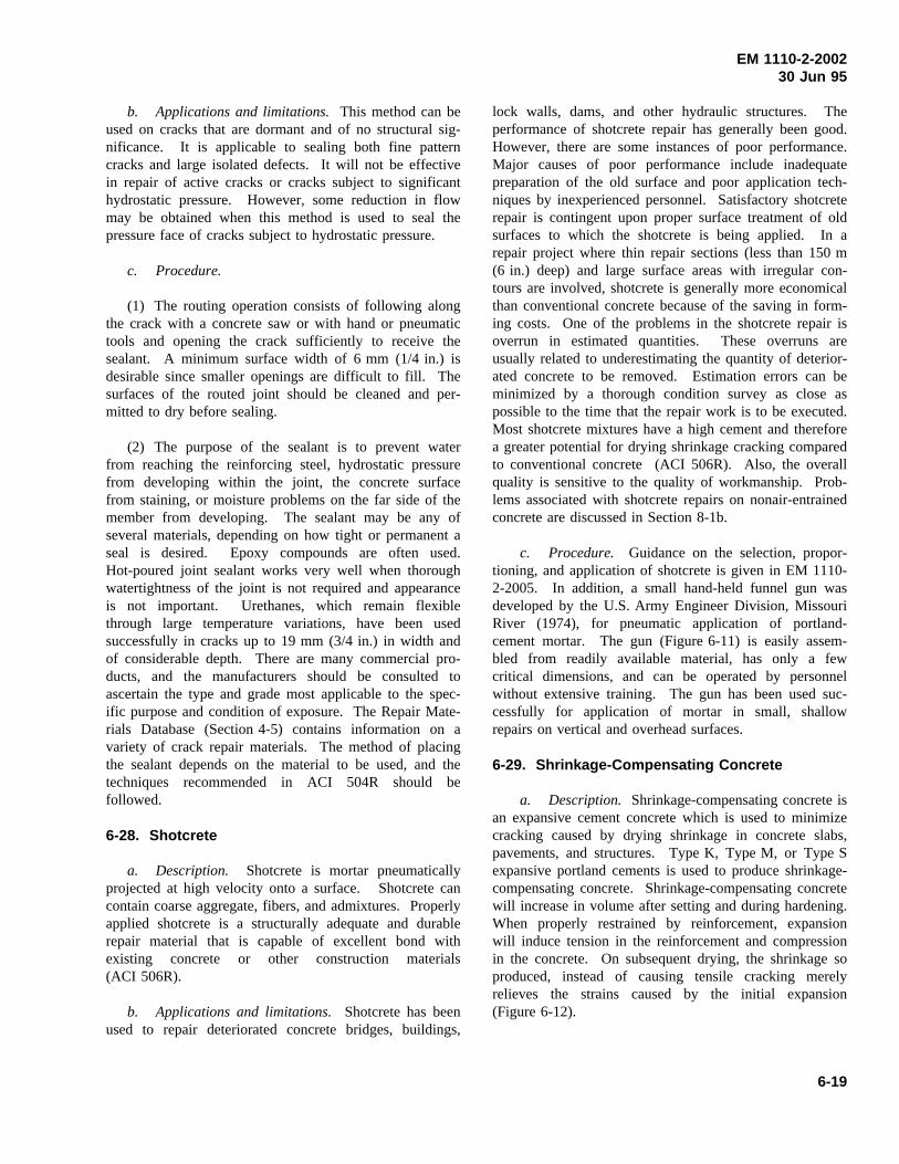
EM 1110-2-200230 Jun 95
b. Applications and limitations.This method can beused on cracks that are dormant and of no structural sig-nificance. It is applicable to sealing both fine patterncracks and large isolated defects. It will not be effectivein repair of active cracks or cracks subject to significanthydrostatic pressure. However, some reduction in flowmay be obtained when this method is used to seal thepressure face of cracks subject to hydrostatic pressure.
c. Procedure.
(1) The routing operation consists of following alongthe crack with a concrete saw or with hand or pneumatictools and opening the crack sufficiently to receive thesealant. A minimum surface width of 6 mm (1/4 in.) isdesirable since smaller openings are difficult to fill. Thesurfaces of the routed joint should be cleaned and per-mitted to dry before sealing.
(2) The purpose of the sealant is to prevent waterfrom reaching the reinforcing steel, hydrostatic pressurefrom developing within the joint, the concrete surfacefrom staining, or moisture problems on the far side of themember from developing. The sealant may be any ofseveral materials, depending on how tight or permanent aseal is desired. Epoxy compounds are often used.Hot-poured joint sealant works very well when thoroughwatertightness of the joint is not required and appearanceis not important. Urethanes, which remain flexiblethrough large temperature variations, have been usedsuccessfully in cracks up to 19 mm (3/4 in.) in width andof considerable depth. There are many commercial pro-ducts, and the manufacturers should be consulted toascertain the type and grade most applicable to the spec-ific purpose and condition of exposure. The Repair Mate-rials Database (Section 4-5) contains information on avariety of crack repair materials. The method of placingthe sealant depends on the material to be used, and thetechniques recommended in ACI 504R should befollowed.
6-28. Shotcrete
a. Description. Shotcrete is mortar pneumaticallyprojected at high velocity onto a surface. Shotcrete cancontain coarse aggregate, fibers, and admixtures. Properlyapplied shotcrete is a structurally adequate and durablerepair material that is capable of excellent bond withexisting concrete or other construction materials(ACI 506R).
b. Applications and limitations.Shotcrete has beenused to repair deteriorated concrete bridges, buildings,
lock walls, dams, and other hydraulic structures. Theperformance of shotcrete repair has generally been good.However, there are some instances of poor performance.Major causes of poor performance include inadequatepreparation of the old surface and poor application tech-niques by inexperienced personnel. Satisfactory shotcreterepair is contingent upon proper surface treatment of oldsurfaces to which the shotcrete is being applied. In arepair project where thin repair sections (less than 150 m(6 in.) deep) and large surface areas with irregular con-tours are involved, shotcrete is generally more economicalthan conventional concrete because of the saving in form-ing costs. One of the problems in the shotcrete repair isoverrun in estimated quantities. These overruns areusually related to underestimating the quantity of deterior-ated concrete to be removed. Estimation errors can beminimized by a thorough condition survey as close aspossible to the time that the repair work is to be executed.Most shotcrete mixtures have a high cement and thereforea greater potential for drying shrinkage cracking comparedto conventional concrete (ACI 506R). Also, the overallquality is sensitive to the quality of workmanship. Prob-lems associated with shotcrete repairs on nonair-entrainedconcrete are discussed in Section 8-1b.
c. Procedure. Guidance on the selection, propor-tioning, and application of shotcrete is given in EM 1110-2-2005. In addition, a small hand-held funnel gun wasdeveloped by the U.S. Army Engineer Division, MissouriRiver (1974), for pneumatic application of portland-cement mortar. The gun (Figure 6-11) is easily assem-bled from readily available material, has only a fewcritical dimensions, and can be operated by personnelwithout extensive training. The gun has been used suc-cessfully for application of mortar in small, shallowrepairs on vertical and overhead surfaces.
6-29. Shrinkage-Compensating Concrete
a. Description. Shrinkage-compensating concrete isan expansive cement concrete which is used to minimizecracking caused by drying shrinkage in concrete slabs,pavements, and structures. Type K, Type M, or Type Sexpansive portland cements is used to produce shrinkage-compensating concrete. Shrinkage-compensating concretewill increase in volume after setting and during hardening.When properly restrained by reinforcement, expansionwill induce tension in the reinforcement and compressionin the concrete. On subsequent drying, the shrinkage soproduced, instead of causing tensile cracking merelyrelieves the strains caused by the initial expansion(Figure 6-12).
6-19
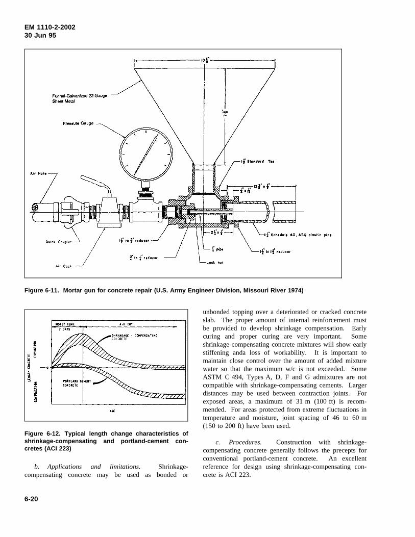
EM 1110-2-200230 Jun 95
Figure 6-11. Mortar gun for concrete repair (U.S. Army Engineer Division, Missouri River 1974)
Figure 6-12. Typical length change characteristics ofshrinkage-compensating and portland-cement con-cretes (ACI 223)
b. Applications and limitations. Shrinkage-compensating concrete may be used as bonded or
unbonded topping over a deteriorated or cracked concreteslab. The proper amount of internal reinforcement mustbe provided to develop shrinkage compensation. Earlycuring and proper curing are very important. Someshrinkage-compensating concrete mixtures will show earlystiffening anda loss of workability. It is important tomaintain close control over the amount of added mixturewater so that the maximum w/c is not exceeded. SomeASTM C 494, Types A, D, F and G admixtures are notcompatible with shrinkage-compensating cements. Largerdistances may be used between contraction joints. Forexposed areas, a maximum of 31 m (100 ft) is recom-mended. For areas protected from extreme fluctuations intemperature and moisture, joint spacing of 46 to 60 m(150 to 200 ft) have been used.
c. Procedures. Construction with shrinkage-compensating concrete generally follows the precepts forconventional portland-cement concrete. An excellentreference for design using shrinkage-compensating con-crete is ACI 223.
6-20
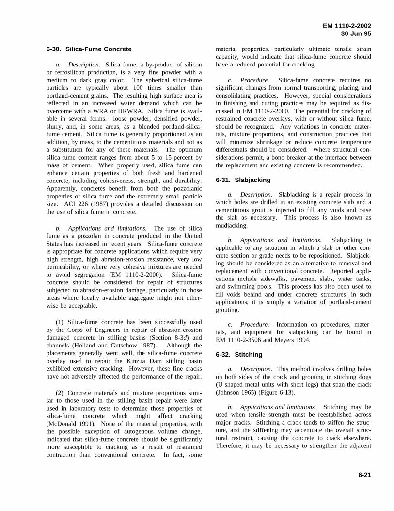
EM 1110-2-200230 Jun 95
6-30. Silica-Fume Concrete
a. Description. Silica fume, a by-product of siliconor ferrosilicon production, is a very fine powder with amedium to dark gray color. The spherical silica-fumeparticles are typically about 100 times smaller thanportland-cement grains. The resulting high surface area isreflected in an increased water demand which can beovercome with a WRA or HRWRA. Silica fume is avail-able in several forms: loose powder, densified powder,slurry, and, in some areas, as a blended portland-silica-fume cement. Silica fume is generally proportioned as anaddition, by mass, to the cementitious materials and not asa substitution for any of these materials. The optimumsilica-fume content ranges from about 5 to 15 percent bymass of cement. When properly used, silica fume canenhance certain properties of both fresh and hardenedconcrete, including cohesiveness, strength, and durability.Apparently, concretes benefit from both the pozzolanicproperties of silica fume and the extremely small particlesize. ACI 226 (1987) provides a detailed discussion onthe use of silica fume in concrete.
b. Applications and limitations. The use of silicafume as a pozzolan in concrete produced in the UnitedStates has increased in recent years. Silica-fume concreteis appropriate for concrete applications which require veryhigh strength, high abrasion-erosion resistance, very lowpermeability, or where very cohesive mixtures are neededto avoid segregation (EM 1110-2-2000). Silica-fumeconcrete should be considered for repair of structuressubjected to abrasion-erosion damage, particularly in thoseareas where locally available aggregate might not other-wise be acceptable.
(1) Silica-fume concrete has been successfully usedby the Corps of Engineers in repair of abrasion-erosiondamaged concrete in stilling basins (Section 8-3d) andchannels (Holland and Gutschow 1987). Although theplacements generally went well, the silica-fume concreteoverlay used to repair the Kinzua Dam stilling basinexhibited extensive cracking. However, these fine crackshave not adversely affected the performance of the repair.
(2) Concrete materials and mixture proportions simi-lar to those used in the stilling basin repair were laterused in laboratory tests to determine those properties ofsilica-fume concrete which might affect cracking(McDonald 1991). None of the material properties, withthe possible exception of autogenous volume change,indicated that silica-fume concrete should be significantlymore susceptible to cracking as a result of restrainedcontraction than conventional concrete. In fact, some
material properties, particularly ultimate tensile straincapacity, would indicate that silica-fume concrete shouldhave a reduced potential for cracking.
c. Procedure. Silica-fume concrete requires nosignificant changes from normal transporting, placing, andconsolidating practices. However, special considerationsin finishing and curing practices may be required as dis-cussed in EM 1110-2-2000. The potential for cracking ofrestrained concrete overlays, with or without silica fume,should be recognized. Any variations in concrete mater-ials, mixture proportions, and construction practices thatwill minimize shrinkage or reduce concrete temperaturedifferentials should be considered. Where structural con-siderations permit, a bond breaker at the interface betweenthe replacement and existing concrete is recommended.
6-31. Slabjacking
a. Description. Slabjacking is a repair process inwhich holes are drilled in an existing concrete slab and acementitious grout is injected to fill any voids and raisethe slab as necessary. This process is also known asmudjacking.
b. Applications and limitations. Slabjacking isapplicable to any situation in which a slab or other con-crete section or grade needs to be repositioned. Slabjack-ing should be considered as an alternative to removal andreplacement with conventional concrete. Reported appli-cations include sidewalks, pavement slabs, water tanks,and swimming pools. This process has also been used tofill voids behind and under concrete structures; in suchapplications, it is simply a variation of portland-cementgrouting.
c. Procedure. Information on procedures, mater-ials, and equipment for slabjacking can be found inEM 1110-2-3506 and Meyers 1994.
6-32. Stitching
a. Description. This method involves drilling holeson both sides of the crack and grouting in stitching dogs(U-shaped metal units with short legs) that span the crack(Johnson 1965) (Figure 6-13).
b. Applications and limitations. Stitching may beused when tensile strength must be reestablished acrossmajor cracks. Stitching a crack tends to stiffen the struc-ture, and the stiffening may accentuate the overall struc-tural restraint, causing the concrete to crack elsewhere.Therefore, it may be necessary to strengthen the adjacent
6-21
EM 1110-2-200230 Jun 95
Figure 6-13. Repair of a crack by stitching
section with external reinforcement embedded in a suit-able overlay.
c. Procedure.
(1) The stitching procedure consists of drilling holeson both sides of the crack, cleaning the holes, and anchor-ing the legs of the dogs in the holes, with either a non-shrink grout or an epoxy-resin-based bonding system.The stitching dogs should be variable in length and orien-tation or both, and they should be located so that thetension transmitted across the crack is not applied to asingle plane within the section but is spread over an area.
(2) Spacing of the stitching dogs should be reduced atthe end of cracks. In addition, consideration should begiven to drilling a hole at each end of the crack to blunt itand relieve the concentration of stress.
(3) Where possible, both sides of the concrete sectionshould be stitched so that further movement of the struc-ture will not pry or bend the dogs. In bending members,it is possible to stitch one side of the crack only. Stitch-ing should be done on the tension face, where movementis occurring. If the member is in a state of axial tension,then the dogs must be placed symmetrically, even if exca-vation or demolition is required to gain access to oppositesides of the section.
(4) Stitching will not close a crack but can prevent itfrom propagating further. Where there is a waterproblem, the crack should be made watertight as well asstitched to protect the dogs from corrosion. This repairshould be completed before stitching begins. In the caseof active cracks, the flexible sealing method (Section 6-9)may be used in conjunction with the stitching techniques.
(5) The dogs are relatively thin and long and cannottake much compressive force. Accordingly, if there is atendency for the crack to close as well as to open, thedogs must be stiffened and strengthened, for example, byencasement in an overlay.
6-33. Underwater Concrete Placement
a. Description. Underwater concrete placement issimply placing fresh concrete underwater with a numberof well recognized techniques and precautions to ensurethe integrity of the concrete in place. Concrete is typi-cally placed underwater by use of a tremie or a pump.The quality of cost-in-place concrete can be enhanced bythe addition of an antiwashout admixture which increasesthe cohesiveness of the concrete. The special case inwhich the concrete is actually manufactured underwater,the preplaced-aggregate technique, is described in Sec-tion 6-24. Flat and durable concrete surfaces within-place strengths and densities essentially the same asthose of concrete cast and consolidated above water canbe obtained with proper mixture proportioning and under-water placement procedures.
b. Applicability and limitations.
(1) Placing concrete underwater is a suitable repairmethod for filling voids around and under concrete struc-tures. Voids ranging from a few cubic yards to thousandsof cubic yards have been filled with tremie concrete.Concrete pumped underwater or placed by tremie has alsobeen used to repair abrasion-erosion damage on severalstructures (McDonald 1980). Another specialized use ofconcrete placed underwater is in the construction of apositive cutoff wall through an earthfill dam. This pro-cess is discussed in Section 8-4.
(2) There are two significant limitations on the useof concrete placed underwater. First, the flow of waterthrough the placement site should be minimized while theconcrete is being placed and is gaining enough strength toresist being washed out of place or segregated. Oneapproach that may be used to protect small areas is to usetop form plates under which concrete may be pumped.The designer, contractor, and inspectors must all be
6-22
EM 1110-2-200230 Jun 95
thoroughly familiar with underwater placements. Placingconcrete underwater is not a procedure that all contractorsand inspectors are routinely familiar with since it is notdone as frequently as other placement techniques. Theonly way to prevent problems and to ensure a successfulplacement is to review, in detail, all aspects of the place-ment (concrete proportions, placing equipment, placingprocedures, and inspection plans) well before commencingthe placement.
c. Procedures.Guidance on proportioning concretemixtures for underwater placement is given in EM 1110-2-2000. ACI 304R provides additional information onconcrete placed underwater. Underwater repair of con-crete is discussed in Section 8-6.
6-23
EM 1110-2-200230 Jun 95
Chapter 7Maintenance of Concrete
7-1. General
Preventing concrete deterioration is much easier and moreeconomical than repairing deteriorated concrete. Prevent-ing concrete deterioration should actually begin with theselection of proper materials, mixture proportions, andplacement and curing procedures. If additional protectionagainst deterioration is required, the need should berecognized and provided for during design of the struc-ture. Of course, all potential hazards to concrete cannotalways be predicted, and some well-engineered techniquesand procedures may prove unsuccessful. Thus, there isgenerally a need for follow-up maintenance action. Theprimary types of maintenance for concrete include timelyrepair of cracks and spalls, cleaning of concrete to removeunsightly material, surface protection, and joint restora-tion. Materials and procedures for repair of concretecracking and spalling have been described in previouschapters. Materials and procedures appropriate for clean-ing and protecting concrete surfaces and joint maintenanceare described in the following.
7-2. Cleaning
Stains seldom affect the service life of a structure,although they are often unsightly, especially on architec-tural concrete finishes. Some of the more common stainsare iron rust, oil, grease, dirt, mildew, asphalt, efflores-cence, soot, and graffiti. Stains often penetrate theexposed surface because concrete is porous and absorbent.Therefore, stains should be removed as soon as possibleto prevent deeper migration into the concrete. Also,stains tend to bind more tightly to the concrete with time,and some undergo chemical changes that make removalmore difficult. Almost all stains can be removed if thetype of stain can be identified and the correct removalmethod is selected (REMR Technical Note CS-MR-4.4(USAEWES 1985d)).
a. Identification. The first step in the removalprocess is to identify the stain and then select a cleaningagent and method accordingly. If the stain is impossibleto identify, potential cleaning materials should be tested inan inconspicuous area in the following order: organicsolvents, oxidizing bleaches, reducing bleaches, and acids.
b. Stain removal. Stains can be removed with sev-eral methods including brushing and washing, steam
cleaning, water blasting, abrasive blasting, flame cleaning,mechanical cleaning, and chemical cleaning (ConcreteRepair Digest1993). Since there is usually more thanone method that can be used to remove a given stain, theadvantages and limitations of each potential methodshould be considered in making a final selection.
(1) Removal methods.
(a) Water washing. A fine mist spray is recom-mended, as excessive water pressure can drive the stainfarther into the concrete. Washing should be done fromthe top of the structure down. If the water alone is notcleaning the concrete, it can be used in conjunction withthe following in the order listed: a soft brush, a mildsoap, a stronger soap, ammonia, or vinegar.
(b) Steam cleaning. Steam is generally good forremoving dirt and chewing gum; however, in most appli-cations it is relatively expensive.
(c) Water blasting. Water blasting removes lesssurface material than sandblasting because no abrasive isused; however, a test section to determine the effect ofthis method on surface texture is recommended.
(d) Abrasive blasting. Abrasive blasting tends toremove some of the concrete resulting in a nonuniformsurface. The nozzle should be held farther from the sur-face than normal in any kind of blasting to minimizeabrasion.
(e) Flame cleaning. Flame cleaning will removeorganic materials that do not respond to solvents. How-ever, this method can cause scaling of the concrete sur-face and may produce objectionable fumes.
(f) Mechanical cleaning. Power tools (grinders,buffers, chisels, brushes) may be required to remove themore stubborn stains from concrete. These tools candamage thin sections or remove more concrete than isdesirable. Chiselling or grinding can be an effectivecleaning method provided a roughened or uneven surfaceis acceptable.
(g) Chemical cleaning. Organic solvents can usuallybe used with little dilution. Inorganic solvents such asammonium hydroxide, sodium hypochlorite, and hydrogenperoxide can be purchased in ready-mixed solutions; otherorganic solvents can be purchased as solids and thenmixed with water according to manufacturer’s directions.It may be desirable to mix the solvent to be used with an
7-1
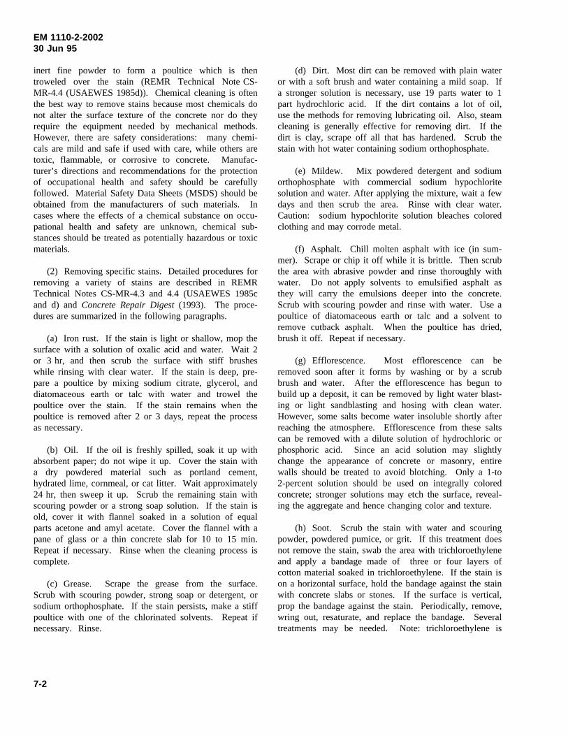
EM 1110-2-200230 Jun 95
inert fine powder to form a poultice which is thentroweled over the stain (REMR Technical Note CS-MR-4.4 (USAEWES 1985d)). Chemical cleaning is oftenthe best way to remove stains because most chemicals donot alter the surface texture of the concrete nor do theyrequire the equipment needed by mechanical methods.However, there are safety considerations: many chemi-cals are mild and safe if used with care, while others aretoxic, flammable, or corrosive to concrete. Manufac-turer’s directions and recommendations for the protectionof occupational health and safety should be carefullyfollowed. Material Safety Data Sheets (MSDS) should beobtained from the manufacturers of such materials. Incases where the effects of a chemical substance on occu-pational health and safety are unknown, chemical sub-stances should be treated as potentially hazardous or toxicmaterials.
(2) Removing specific stains. Detailed procedures forremoving a variety of stains are described in REMRTechnical Notes CS-MR-4.3 and 4.4 (USAEWES 1985cand d) andConcrete Repair Digest(1993). The proce-dures are summarized in the following paragraphs.
(a) Iron rust. If the stain is light or shallow, mop thesurface with a solution of oxalic acid and water. Wait 2or 3 hr, and then scrub the surface with stiff brusheswhile rinsing with clear water. If the stain is deep, pre-pare a poultice by mixing sodium citrate, glycerol, anddiatomaceous earth or talc with water and trowel thepoultice over the stain. If the stain remains when thepoultice is removed after 2 or 3 days, repeat the processas necessary.
(b) Oil. If the oil is freshly spilled, soak it up withabsorbent paper; do not wipe it up. Cover the stain witha dry powdered material such as portland cement,hydrated lime, cornmeal, or cat litter. Wait approximately24 hr, then sweep it up. Scrub the remaining stain withscouring powder or a strong soap solution. If the stain isold, cover it with flannel soaked in a solution of equalparts acetone and amyl acetate. Cover the flannel with apane of glass or a thin concrete slab for 10 to 15 min.Repeat if necessary. Rinse when the cleaning process iscomplete.
(c) Grease. Scrape the grease from the surface.Scrub with scouring powder, strong soap or detergent, orsodium orthophosphate. If the stain persists, make a stiffpoultice with one of the chlorinated solvents. Repeat ifnecessary. Rinse.
(d) Dirt. Most dirt can be removed with plain wateror with a soft brush and water containing a mild soap. Ifa stronger solution is necessary, use 19 parts water to 1part hydrochloric acid. If the dirt contains a lot of oil,use the methods for removing lubricating oil. Also, steamcleaning is generally effective for removing dirt. If thedirt is clay, scrape off all that has hardened. Scrub thestain with hot water containing sodium orthophosphate.
(e) Mildew. Mix powdered detergent and sodiumorthophosphate with commercial sodium hypochloritesolution and water. After applying the mixture, wait a fewdays and then scrub the area. Rinse with clear water.Caution: sodium hypochlorite solution bleaches coloredclothing and may corrode metal.
(f) Asphalt. Chill molten asphalt with ice (in sum-mer). Scrape or chip it off while it is brittle. Then scrubthe area with abrasive powder and rinse thoroughly withwater. Do not apply solvents to emulsified asphalt asthey will carry the emulsions deeper into the concrete.Scrub with scouring powder and rinse with water. Use apoultice of diatomaceous earth or talc and a solvent toremove cutback asphalt. When the poultice has dried,brush it off. Repeat if necessary.
(g) Efflorescence. Most efflorescence can beremoved soon after it forms by washing or by a scrubbrush and water. After the efflorescence has begun tobuild up a deposit, it can be removed by light water blast-ing or light sandblasting and hosing with clean water.However, some salts become water insoluble shortly afterreaching the atmosphere. Efflorescence from these saltscan be removed with a dilute solution of hydrochloric orphosphoric acid. Since an acid solution may slightlychange the appearance of concrete or masonry, entirewalls should be treated to avoid blotching. Only a 1-to2-percent solution should be used on integrally coloredconcrete; stronger solutions may etch the surface, reveal-ing the aggregate and hence changing color and texture.
(h) Soot. Scrub the stain with water and scouringpowder, powdered pumice, or grit. If this treatment doesnot remove the stain, swab the area with trichloroethyleneand apply a bandage made of three or four layers ofcotton material soaked in trichloroethylene. If the stain ison a horizontal surface, hold the bandage against the stainwith concrete slabs or stones. If the surface is vertical,prop the bandage against the stain. Periodically, remove,wring out, resaturate, and replace the bandage. Severaltreatments may be needed. Note: trichloroethylene is
7-2
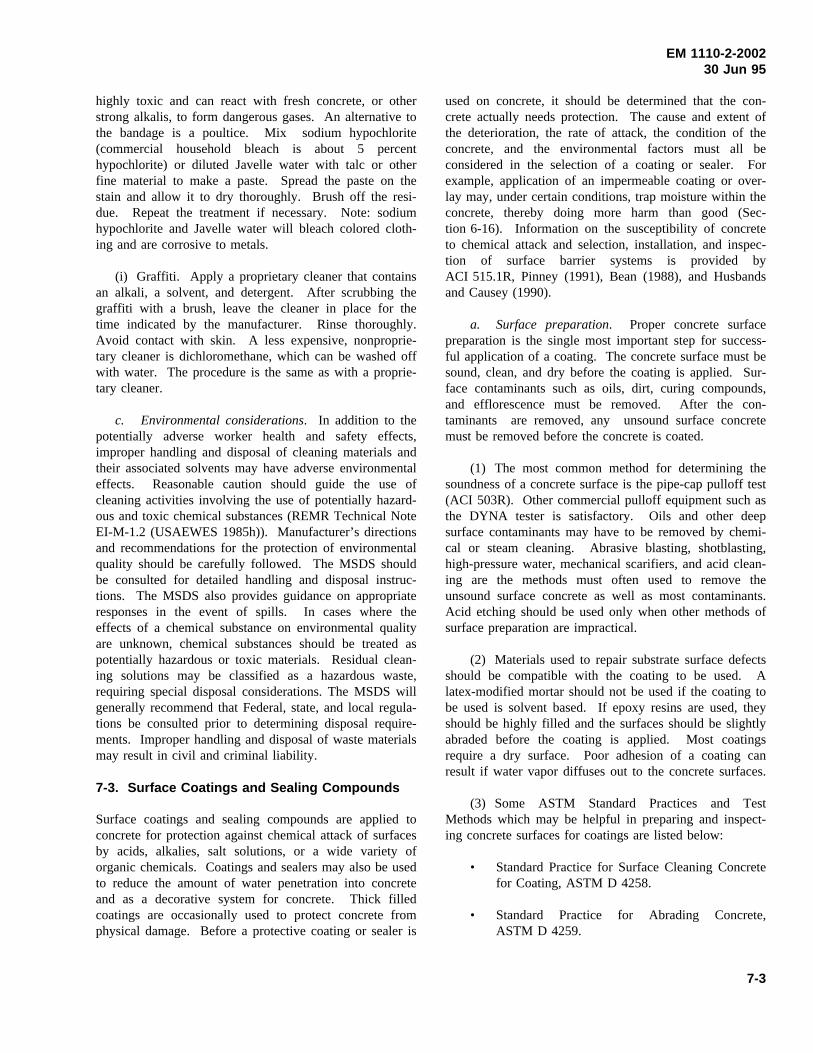
EM 1110-2-200230 Jun 95
highly toxic and can react with fresh concrete, or otherstrong alkalis, to form dangerous gases. An alternative tothe bandage is a poultice. Mix sodium hypochlorite(commercial household bleach is about 5 percenthypochlorite) or diluted Javelle water with talc or otherfine material to make a paste. Spread the paste on thestain and allow it to dry thoroughly. Brush off the resi-due. Repeat the treatment if necessary. Note: sodiumhypochlorite and Javelle water will bleach colored cloth-ing and are corrosive to metals.
(i) Graffiti. Apply a proprietary cleaner that containsan alkali, a solvent, and detergent. After scrubbing thegraffiti with a brush, leave the cleaner in place for thetime indicated by the manufacturer. Rinse thoroughly.Avoid contact with skin. A less expensive, nonproprie-tary cleaner is dichloromethane, which can be washed offwith water. The procedure is the same as with a proprie-tary cleaner.
c. Environmental considerations. In addition to thepotentially adverse worker health and safety effects,improper handling and disposal of cleaning materials andtheir associated solvents may have adverse environmentaleffects. Reasonable caution should guide the use ofcleaning activities involving the use of potentially hazard-ous and toxic chemical substances (REMR Technical NoteEI-M-1.2 (USAEWES 1985h)). Manufacturer’s directionsand recommendations for the protection of environmentalquality should be carefully followed. The MSDS shouldbe consulted for detailed handling and disposal instruc-tions. The MSDS also provides guidance on appropriateresponses in the event of spills. In cases where theeffects of a chemical substance on environmental qualityare unknown, chemical substances should be treated aspotentially hazardous or toxic materials. Residual clean-ing solutions may be classified as a hazardous waste,requiring special disposal considerations. The MSDS willgenerally recommend that Federal, state, and local regula-tions be consulted prior to determining disposal require-ments. Improper handling and disposal of waste materialsmay result in civil and criminal liability.
7-3. Surface Coatings and Sealing Compounds
Surface coatings and sealing compounds are applied toconcrete for protection against chemical attack of surfacesby acids, alkalies, salt solutions, or a wide variety oforganic chemicals. Coatings and sealers may also be usedto reduce the amount of water penetration into concreteand as a decorative system for concrete. Thick filledcoatings are occasionally used to protect concrete fromphysical damage. Before a protective coating or sealer is
used on concrete, it should be determined that the con-crete actually needs protection. The cause and extent ofthe deterioration, the rate of attack, the condition of theconcrete, and the environmental factors must all beconsidered in the selection of a coating or sealer. Forexample, application of an impermeable coating or over-lay may, under certain conditions, trap moisture within theconcrete, thereby doing more harm than good (Sec-tion 6-16). Information on the susceptibility of concreteto chemical attack and selection, installation, and inspec-tion of surface barrier systems is provided byACI 515.1R, Pinney (1991), Bean (1988), and Husbandsand Causey (1990).
a. Surface preparation. Proper concrete surfacepreparation is the single most important step for success-ful application of a coating. The concrete surface must besound, clean, and dry before the coating is applied. Sur-face contaminants such as oils, dirt, curing compounds,and efflorescence must be removed. After the con-taminants are removed, any unsound surface concretemust be removed before the concrete is coated.
(1) The most common method for determining thesoundness of a concrete surface is the pipe-cap pulloff test(ACI 503R). Other commercial pulloff equipment such asthe DYNA tester is satisfactory. Oils and other deepsurface contaminants may have to be removed by chemi-cal or steam cleaning. Abrasive blasting, shotblasting,high-pressure water, mechanical scarifiers, and acid clean-ing are the methods must often used to remove theunsound surface concrete as well as most contaminants.Acid etching should be used only when other methods ofsurface preparation are impractical.
(2) Materials used to repair substrate surface defectsshould be compatible with the coating to be used. Alatex-modified mortar should not be used if the coating tobe used is solvent based. If epoxy resins are used, theyshould be highly filled and the surfaces should be slightlyabraded before the coating is applied. Most coatingsrequire a dry surface. Poor adhesion of a coating canresult if water vapor diffuses out to the concrete surfaces.
(3) Some ASTM Standard Practices and TestMethods which may be helpful in preparing and inspect-ing concrete surfaces for coatings are listed below:
• Standard Practice for Surface Cleaning Concretefor Coating, ASTM D 4258.
• Standard Practice for Abrading Concrete,ASTM D 4259.
7-3
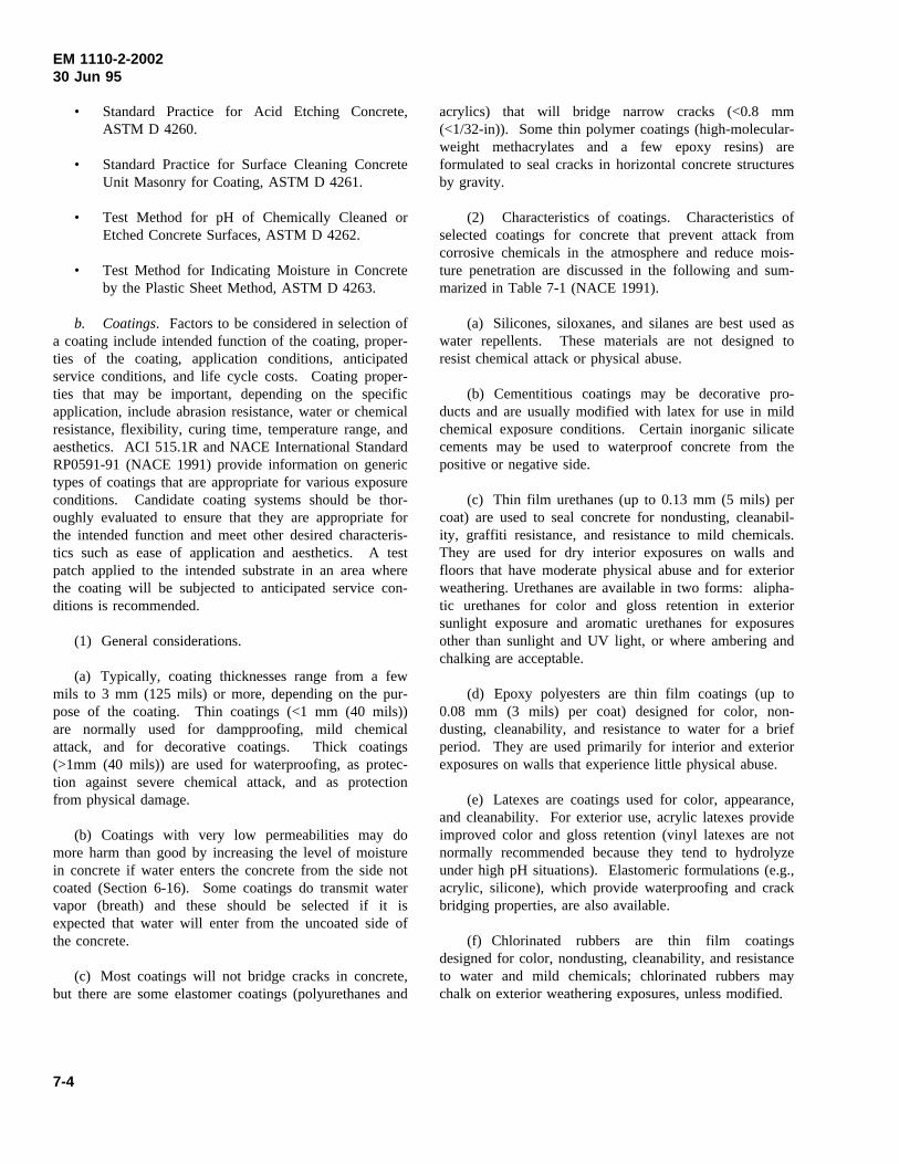
EM 1110-2-200230 Jun 95
• Standard Practice for Acid Etching Concrete,ASTM D 4260.
• Standard Practice for Surface Cleaning ConcreteUnit Masonry for Coating, ASTM D 4261.
• Test Method for pH of Chemically Cleaned orEtched Concrete Surfaces, ASTM D 4262.
• Test Method for Indicating Moisture in Concreteby the Plastic Sheet Method, ASTM D 4263.
b. Coatings. Factors to be considered in selection ofa coating include intended function of the coating, proper-ties of the coating, application conditions, anticipatedservice conditions, and life cycle costs. Coating proper-ties that may be important, depending on the specificapplication, include abrasion resistance, water or chemicalresistance, flexibility, curing time, temperature range, andaesthetics. ACI 515.1R and NACE International StandardRP0591-91 (NACE 1991) provide information on generictypes of coatings that are appropriate for various exposureconditions. Candidate coating systems should be thor-oughly evaluated to ensure that they are appropriate forthe intended function and meet other desired characteris-tics such as ease of application and aesthetics. A testpatch applied to the intended substrate in an area wherethe coating will be subjected to anticipated service con-ditions is recommended.
(1) General considerations.
(a) Typically, coating thicknesses range from a fewmils to 3 mm (125 mils) or more, depending on the pur-pose of the coating. Thin coatings (<1 mm (40 mils))are normally used for dampproofing, mild chemicalattack, and for decorative coatings. Thick coatings(>1mm (40 mils)) are used for waterproofing, as protec-tion against severe chemical attack, and as protectionfrom physical damage.
(b) Coatings with very low permeabilities may domore harm than good by increasing the level of moisturein concrete if water enters the concrete from the side notcoated (Section 6-16). Some coatings do transmit watervapor (breath) and these should be selected if it isexpected that water will enter from the uncoated side ofthe concrete.
(c) Most coatings will not bridge cracks in concrete,but there are some elastomer coatings (polyurethanes and
acrylics) that will bridge narrow cracks (<0.8 mm(<1/32-in)). Some thin polymer coatings (high-molecular-weight methacrylates and a few epoxy resins) areformulated to seal cracks in horizontal concrete structuresby gravity.
(2) Characteristics of coatings. Characteristics ofselected coatings for concrete that prevent attack fromcorrosive chemicals in the atmosphere and reduce mois-ture penetration are discussed in the following and sum-marized in Table 7-1 (NACE 1991).
(a) Silicones, siloxanes, and silanes are best used aswater repellents. These materials are not designed toresist chemical attack or physical abuse.
(b) Cementitious coatings may be decorative pro-ducts and are usually modified with latex for use in mildchemical exposure conditions. Certain inorganic silicatecements may be used to waterproof concrete from thepositive or negative side.
(c) Thin film urethanes (up to 0.13 mm (5 mils) percoat) are used to seal concrete for nondusting, cleanabil-ity, graffiti resistance, and resistance to mild chemicals.They are used for dry interior exposures on walls andfloors that have moderate physical abuse and for exteriorweathering. Urethanes are available in two forms: alipha-tic urethanes for color and gloss retention in exteriorsunlight exposure and aromatic urethanes for exposuresother than sunlight and UV light, or where ambering andchalking are acceptable.
(d) Epoxy polyesters are thin film coatings (up to0.08 mm (3 mils) per coat) designed for color, non-dusting, cleanability, and resistance to water for a briefperiod. They are used primarily for interior and exteriorexposures on walls that experience little physical abuse.
(e) Latexes are coatings used for color, appearance,and cleanability. For exterior use, acrylic latexes provideimproved color and gloss retention (vinyl latexes are notnormally recommended because they tend to hydrolyzeunder high pH situations). Elastomeric formulations (e.g.,acrylic, silicone), which provide waterproofing and crackbridging properties, are also available.
(f) Chlorinated rubbers are thin film coatingsdesigned for color, nondusting, cleanability, and resistanceto water and mild chemicals; chlorinated rubbers maychalk on exterior weathering exposures, unless modified.
7-4
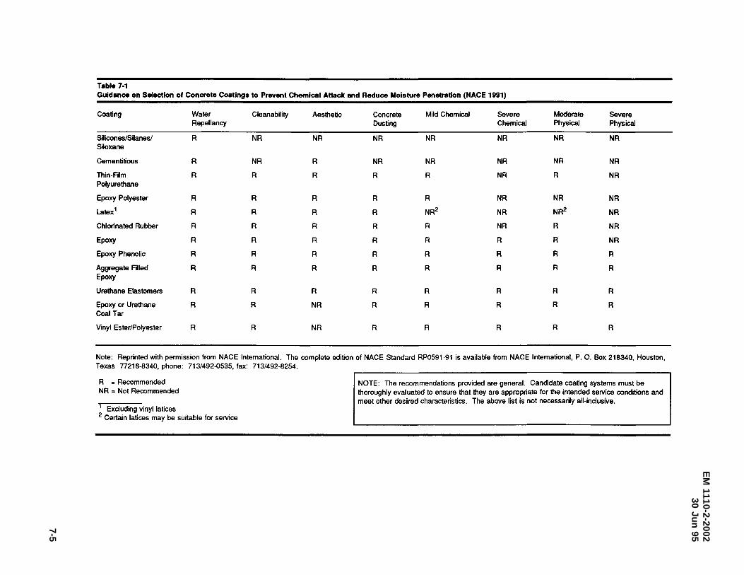
EM
1110-2-200230
Jun95
7-5
Table 7·1 Guidance on Selection of Concrete Coatings to Prevent Chemical Attack and Reduce Moisture Penetration (NACE 1991)
Coating Water Clean ability Aesthetic Concrete Mild Chemical Severe Moderate Severe Repellancy Dusting Chemical Physical Physical
Silicones/Silanes/ R NR NR NR NR NR NR NR Siloxane
Cementitious R NR R NR NR NR NR NR
Thin-Film R R R R R NR R NR Polyurethane
Epoxy Polyester R R R R R NR NR NR
Latex 1 R R R R NR2 NR NR2 NR
Chlorinated Rubber R R R R R NR R NR
Epoxy R R R R R R R NR
Epoxy Phenolic R R R R R R R R
Aggregate Filled R R R R R R R R Epoxy
Urethane Elastomers R R R R R R R R
Epoxy or Urethane R R NR R R R R R Coal Tar
Vinyl Ester/Polyester R R NR R R R R R
Note: Reprinted with permission from NACE International. The complete edition of NACE Standard RP0591-91 is available from NACE International, P. 0. Box 218340, Houston, Texas n218-8340, phone: 713/492-0535, fax: 713/492-8254.
R = Recommended NR = Not Recommended
1 Excluding vinyl latices 2 Certain latices may be suitable for service
NOTE: The recommendations provided are general. Candidate coating systems must be thoroughly evaluated to ensure that they are appropriate for the intended service conditions and meet other desired characteristics. The above list is not necessarily all-inclusive.
EM 1110-2-200230 Jun 95
(g) Epoxies are two component products that areavailable in thin film (less than 0.25 mm (10 mils)) andthick film (0.25 to 1.27 mm (10 to 50 mils)) coatings.Epoxies have excellent adhesion to dry concrete, andepoxies have the ability to seal porous concrete and bugholes. Epoxies also exhibit good chemical resistance,hardness, and abrasion resistance. Epoxies are typicallyused for interior chemical and physical abuse conditions,because they tend to chalk and fade in atmospheric andsunlight exposure. Epoxy formulations that develop goodadhesion to wet surfaces are also available.
(h) Epoxy phenolics are two component productssimilar to epoxies. They are phenolic modified toimprove their chemical resistance. They are normallyused for severe chemical environments and as floorcoatings.
(i) Aggregate-filled epoxies are thick film coatings(3.18 mm (125 mils) or more thickness) that are usuallyapplied by spray, trowel, or aggregate broadcast methods.Normally used in areas of severe physical abuse, theseepoxies are still resistant to mild and severe chemicals.They are excellent floor coatings for areas of severe phy-sical abuse. Floor toppings can be made aestheticallypleasing through selection of the appropriate color andtype of aggregate.
(j) Thick film elastomers (up to 3.18 mm (125 mils)),such as urethane (ASTM D 16 Type V) and polysulfide,are normally applied by spray, trowel, or self-levelingmethods. Normally used in areas of severe physicalabuse that require a flexible coating, the rubber-like filmdisplays excellent resistance to impact damage and theability to bridge hairline cracks in concrete.
(k) Epoxy- or urethane-coal tars are moderately thickcoatings (0.38 to 0.76 mm (15 to 30 mils)) with excellentwater and good chemical resistance that are normallyapplied with a sprayer. The black color may restrict theirusage for aesthetic reasons.
(l) Vinylesters and polyesters are moderately thickcoatings (0.76 to 1.27 mm (30 to 50 mils)) with excellentresistance to acids and strong oxidizers that are applied byspray or trowel. Thicker films may be obtained withsilica floor fillers and reinforcing fabric or mat.
(m) Coatings, such as inorganic silicate cementitiousproducts, sulphur concrete, polysulfide elastomers, epoxypolysulfides, and others, also offer protection to concreteexposed to atmospheric and aggressive environments suchas secondary containment structures.
(3) Application.
(a) The manufacturer’s recommended applicationrate and method of application should be followed when acoating is applied to concrete. The surface profile andporosity will have an effect on the application rate. A testpatch is useful in determining the surface preparation,application rate, and appearance of a particular concretecoating.
(b) The temperature of the concrete should be con-stant or dropping when some coatings are applied to avoidblisters or pin holes caused by the expansion of gasesinside of the concrete. The temperature of the concreteshould be above the dewpoint while the coating is curingto prevent water condensation on the coating.
c. Sealers. Sealers are thin, nonfilled liquids thatpenetrate or form a thin film (less than 0.13 mm (5 mils))on concrete. Sealers are used for water repellency whenthere is no hydrostatic pressure, for dust control, and forreducing the amount of water soluble salts that enter intoconcrete. Penetrating sealers, such as the silanes andsiloxanes, are recommended for areas subjected to traffic.Some sealers do not change the appearance of the con-crete, but others may darken the surface. Some sealersare slightly volatile, and high winds and temperaturesduring application may affect their performance. Con-crete sealers that have not been approved for the type ofconcrete masonry units (CMU) in service should not beused on CMU. Liquid surface treatments known as hard-eners should be used only as emergency measures fortreatment of deficiencies in hardened concrete floor slabs.They are not intended to provide additional wear resis-tance in new, well designed, well constructed, and curedfloors (ACI 302.1R).
Pfeifer and Scali (1981) have provided what is probablythe most comprehensive report on the sealer propertiesthat are relevant for bridge concrete. The basic findingsof this study were confirmed in subsequent work byKottke (1987) and Husbands and Causey (1990). A per-formance-based specification for concrete sealers onbridges was developed by Carter (1993).
7-4. Joint Maintenance
Little maintenance is required for buried sealants such aswaterstops because they are not exposed to weatheringand other deteriorating influences. Most field-moldedsealants will, however, require periodic maintenance if aneffective seal is to be maintained and deterioration of the
7-6
EM 1110-2-200230 Jun 95
structure is to be avoided. The necessity for joint main-tenance is determined by service conditions and by thetype of material used.
Minor touchups of small gaps and soft or hard spots infield-molded sealants can usually be made with the samesealant. However, where the failure is extensive, it isusually necessary to remove the sealant and replace it. Asealant that has generally failed but has not come out ofthe sealing groove should be removed by hand tools or,on large projects, by routing or plowing with suitable
tools. To improve the shape factor, the sealant reservoirmay be enlarged by sawing. After proper preparation hasbeen made to ensure clean joint faces and additionalmeasures designed to improve sealant performance, suchas improvement of shape factor, provision of backupmaterial, and possible selection of a better type of sealant,have been accomplished, the joint may be resealed. Foradditional information on joint sealant materials, jointdesign, and installation of sealants, see EM 1110-2-2102,and ACI 504R.
7-7
EM 1110-2-200230 Jun 95
Chapter 8Specialized Repairs
8-1. Lock Wall Rehabilitation
Approximately one-half of the Corps’ navigation lockchambers were built prior to 1940. Consequently, theconcrete in these structures does not contain intentionallyentrained air and is therefore susceptible to deteriorationby freezing and thawing. Since more than 75 percent ofthese older structures are located in the U.S. Army Engi-neer Divisions, North Central and Ohio River, areas ofrelatively severe exposure to freezing and thawing, it isnot surprising that many of these structures exhibit signifi-cant concrete deterioration. Depending upon exposureconditions, depths of concrete deterioration can rangefrom surface scaling to several feet. The generalapproach in lock wall rehabilitation has been to remove0.3 to 0.9 m (1 to 3 ft) of concrete from the face of thelock wall and replace it with new portland-cement con-crete using conventional concrete forming and placingtechniques (McDonald 1987b). Other approaches thathave been used include shotcrete, preplaced-aggregateconcrete, and precast concrete stay-in-place forms. Also,a variety of thin overlays have been applied to lock walls.
a. Cast-in-place concrete.The economics of con-ventional cast-in-place concrete replacement compared toother rehabilitation techniques usually depends on thethickness of the concrete section to be replaced. Forsections in the range of 152 to 305 mm (6 to 12 in.), bothformed and nonformed techniques such as shotcrete areeconomically competitive. When the thickness of thereplacement section exceeds 305 mm (12 in.), conven-tional formwork and concrete replacement are generallymore economical. Conventional cast-in-place concrete hasseveral advantages over other rehabilitation materials. Itcan be proportioned to simulate the existing concretesubstrate, thus minimizing strains due to material incom-patibility; proper air entrainment in the replacement con-crete can be obtained by use of admixtures to ensureresistance to cycles of freezing and thawing; and mate-rials, equipment, and personnel with experience in con-ventional concrete application are readily available inmost areas.
(1) Surface preparation. Removal of deterioratedconcrete is usually accomplished by drilling a line ofsmall-diameter holes along the top of the lock wall paral-lel to the removal face, loading the holes with lightcharges of explosive (usually detonating cord), cushioningthe charges by stemming the holes, and detonating the
explosive with electric blasting caps. Blasting plans(holes spacing, size of charges, necessity for delays indetonation of charges, etc.) are developed based on resultsof previous work or test blasts. After the existing con-crete is removed, the lock walls are sounded to locate anyareas of loose or deteriorated concrete extending beyondthe removal line. Such concrete is removed by chipping,grinding, or water blasting. The bonding surface must beclean and free of materials that could inhibit bond.
(2) Concrete anchors. Dowels are normally used toanchor the new concrete facing to the existing concretewalls and to position vertical and horizontal reinforcingsteel in the concrete facing. Design criteria for use indesign of dowels for anchoring relatively thin sections(less than 0.8 m (2.5 ft)) of cast-in-place concrete facingwere developed based on laboratory and field tests (Liuand Holland 1981).
(a) Dowels should be No. 6 deformed reinforcingbars conforming to ASTM A 615. Typical dowel spacingis 1.2 m (4 ft) center to center in both directions, exceptthat a maximum dowel spacing of 0.6 m (2 ft) center tocenter may be specified in the vicinity of local openingsand recesses, and along the perimeters of monoliths. Theband width of this dowelling should be at least 0.6 m(2 ft).
(b) If the average compressive strength of threedrilled cores obtained from the existing concrete as deter-mined in accordance with ASTM C 42 (CRD-C 27) isless than 21 MPa (3,000 psi), the embedment lengthshould be determined by conducting field pullout tests.For existing concrete with an average compressivestrength equal to or greater than 21 MPa (3,000 psi),dowel embedment length should be a minimum of15 times the nominal diameter of the dowel unless ashorter embeddment length can be justified through fieldpullout tests. Dowels should be embedded in holes drilledwith rotary-percussive equipment. The drill holes must beclean and free of materials that can inhibit bond. Either anonshrink grout conforming to ASTM C 1107(CRD-C 621) or an epoxy resin-based bonding systemconforming to ASTM C 881 (CRD-C 595), Type I, orother approved bonding systems should be used as thebonding agent. The embeddment length for dowels in thenew concrete facing should be determined in accordancewith ACI 318.
(c) A minimum of 3 dowels per 1,000 to be installedshould be field tested with the testing dispersed over theentire surface area to receive dowels. Test proceduresshould be similar to those described by Liu and Holland
8-1
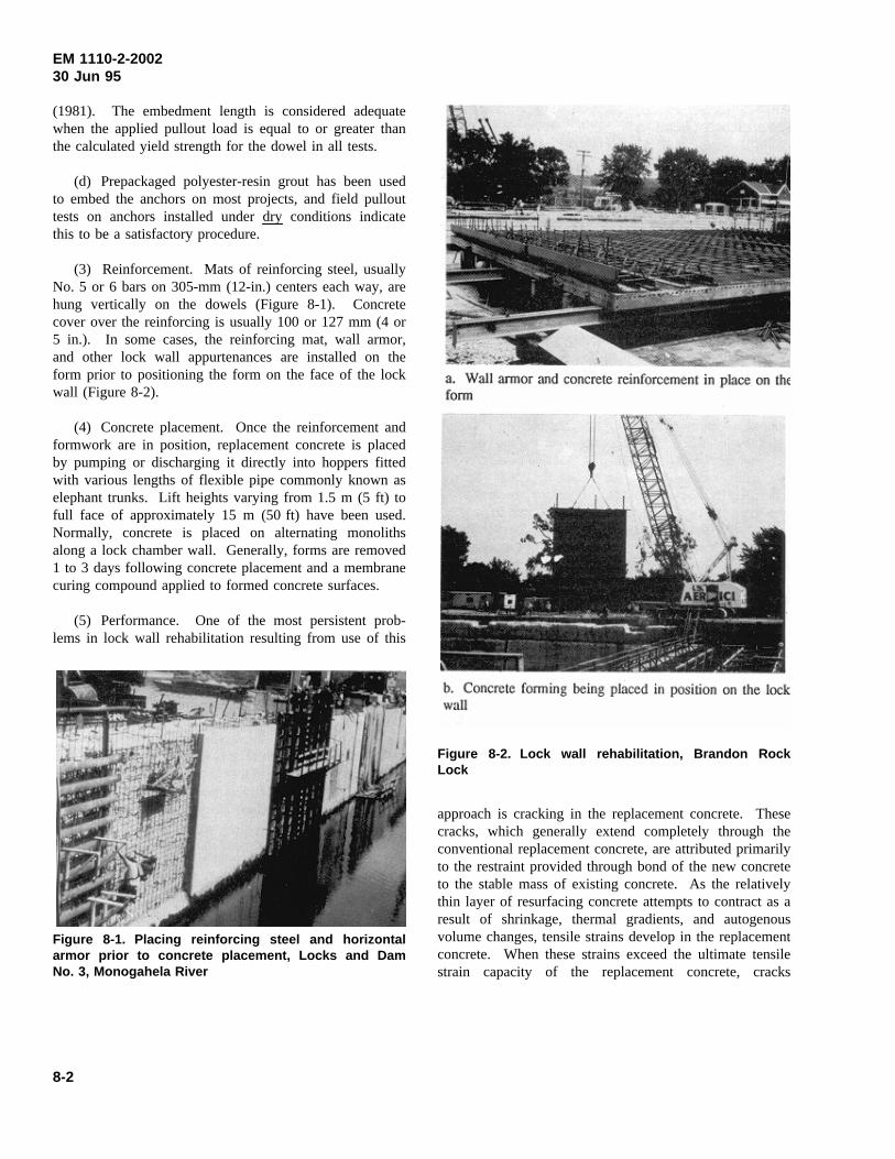
EM 1110-2-200230 Jun 95
(1981). The embedment length is considered adequatewhen the applied pullout load is equal to or greater thanthe calculated yield strength for the dowel in all tests.
(d) Prepackaged polyester-resin grout has been usedto embed the anchors on most projects, and field pullouttests on anchors installed under dryconditions indicatethis to be a satisfactory procedure.
(3) Reinforcement. Mats of reinforcing steel, usuallyNo. 5 or 6 bars on 305-mm (12-in.) centers each way, arehung vertically on the dowels (Figure 8-1). Concretecover over the reinforcing is usually 100 or 127 mm (4 or5 in.). In some cases, the reinforcing mat, wall armor,and other lock wall appurtenances are installed on theform prior to positioning the form on the face of the lockwall (Figure 8-2).
(4) Concrete placement. Once the reinforcement andformwork are in position, replacement concrete is placedby pumping or discharging it directly into hoppers fittedwith various lengths of flexible pipe commonly known aselephant trunks. Lift heights varying from 1.5 m (5 ft) tofull face of approximately 15 m (50 ft) have been used.Normally, concrete is placed on alternating monolithsalong a lock chamber wall. Generally, forms are removed1 to 3 days following concrete placement and a membranecuring compound applied to formed concrete surfaces.
(5) Performance. One of the most persistent prob-lems in lock wall rehabilitation resulting from use of this
Figure 8-1. Placing reinforcing steel and horizontalarmor prior to concrete placement, Locks and DamNo. 3, Monogahela River
Figure 8-2. Lock wall rehabilitation, Brandon RockLock
approach is cracking in the replacement concrete. Thesecracks, which generally extend completely through theconventional replacement concrete, are attributed primarilyto the restraint provided through bond of the new concreteto the stable mass of existing concrete. As the relativelythin layer of resurfacing concrete attempts to contract as aresult of shrinkage, thermal gradients, and autogenousvolume changes, tensile strains develop in the replacementconcrete. When these strains exceed the ultimate tensilestrain capacity of the replacement concrete, cracks
8-2
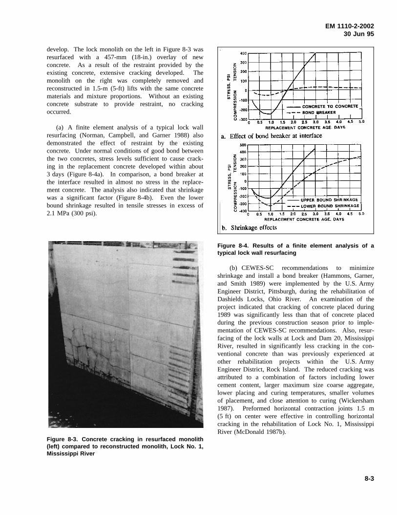
EM 1110-2-200230 Jun 95
develop. The lock monolith on the left in Figure 8-3 wasresurfaced with a 457-mm (18-in.) overlay of newconcrete. As a result of the restraint provided by theexisting concrete, extensive cracking developed. Themonolith on the right was completely removed andreconstructed in 1.5-m (5-ft) lifts with the same concretematerials and mixture proportions. Without an existingconcrete substrate to provide restraint, no crackingoccurred.
(a) A finite element analysis of a typical lock wallresurfacing (Norman, Campbell, and Garner 1988) alsodemonstrated the effect of restraint by the existingconcrete. Under normal conditions of good bond betweenthe two concretes, stress levels sufficient to cause crack-ing in the replacement concrete developed within about3 days (Figure 8-4a). In comparison, a bond breaker atthe interface resulted in almost no stress in the replace-ment concrete. The analysis also indicated that shrinkagewas a significant factor (Figure 8-4b). Even the lowerbound shrinkage resulted in tensile stresses in excess of2.1 MPa (300 psi).
Figure 8-3. Concrete cracking in resurfaced monolith(left) compared to reconstructed monolith, Lock No. 1,Mississippi River
Figure 8-4. Results of a finite element analysis of atypical lock wall resurfacing
(b) CEWES-SC recommendations to minimizeshrinkage and install a bond breaker (Hammons, Garner,and Smith 1989) were implemented by the U.S. ArmyEngineer District, Pittsburgh, during the rehabilitation ofDashields Locks, Ohio River. An examination of theproject indicated that cracking of concrete placed during1989 was significantly less than that of concrete placedduring the previous construction season prior to imple-mentation of CEWES-SC recommendations. Also, resur-facing of the lock walls at Lock and Dam 20, MississippiRiver, resulted in significantly less cracking in the con-ventional concrete than was previously experienced atother rehabilitation projects within the U.S. ArmyEngineer District, Rock Island. The reduced cracking wasattributed to a combination of factors including lowercement content, larger maximum size coarse aggregate,lower placing and curing temperatures, smaller volumesof placement, and close attention to curing (Wickersham1987). Preformed horizontal contraction joints 1.5 m(5 ft) on center were effective in controlling horizontalcracking in the rehabilitation of Lock No. 1, MississippiRiver (McDonald 1987b).
8-3
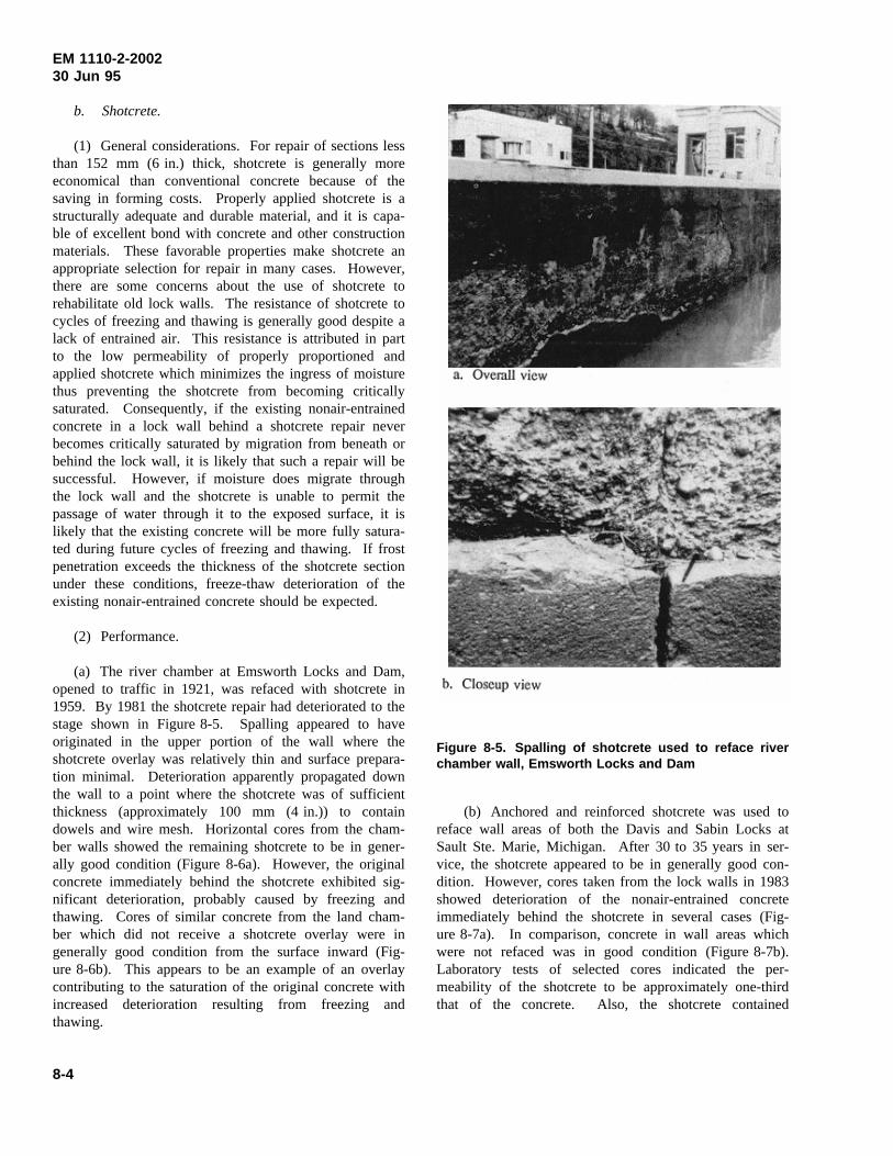
EM 1110-2-200230 Jun 95
b. Shotcrete.
(1) General considerations. For repair of sections lessthan 152 mm (6 in.) thick, shotcrete is generally moreeconomical than conventional concrete because of thesaving in forming costs. Properly applied shotcrete is astructurally adequate and durable material, and it is capa-ble of excellent bond with concrete and other constructionmaterials. These favorable properties make shotcrete anappropriate selection for repair in many cases. However,there are some concerns about the use of shotcrete torehabilitate old lock walls. The resistance of shotcrete tocycles of freezing and thawing is generally good despite alack of entrained air. This resistance is attributed in partto the low permeability of properly proportioned andapplied shotcrete which minimizes the ingress of moisturethus preventing the shotcrete from becoming criticallysaturated. Consequently, if the existing nonair-entrainedconcrete in a lock wall behind a shotcrete repair neverbecomes critically saturated by migration from beneath orbehind the lock wall, it is likely that such a repair will besuccessful. However, if moisture does migrate throughthe lock wall and the shotcrete is unable to permit thepassage of water through it to the exposed surface, it islikely that the existing concrete will be more fully satura-ted during future cycles of freezing and thawing. If frostpenetration exceeds the thickness of the shotcrete sectionunder these conditions, freeze-thaw deterioration of theexisting nonair-entrained concrete should be expected.
(2) Performance.
(a) The river chamber at Emsworth Locks and Dam,opened to traffic in 1921, was refaced with shotcrete in1959. By 1981 the shotcrete repair had deteriorated to thestage shown in Figure 8-5. Spalling appeared to haveoriginated in the upper portion of the wall where theshotcrete overlay was relatively thin and surface prepara-tion minimal. Deterioration apparently propagated downthe wall to a point where the shotcrete was of sufficientthickness (approximately 100 mm (4 in.)) to containdowels and wire mesh. Horizontal cores from the cham-ber walls showed the remaining shotcrete to be in gener-ally good condition (Figure 8-6a). However, the originalconcrete immediately behind the shotcrete exhibited sig-nificant deterioration, probably caused by freezing andthawing. Cores of similar concrete from the land cham-ber which did not receive a shotcrete overlay were ingenerally good condition from the surface inward (Fig-ure 8-6b). This appears to be an example of an overlaycontributing to the saturation of the original concrete withincreased deterioration resulting from freezing andthawing.
Figure 8-5. Spalling of shotcrete used to reface riverchamber wall, Emsworth Locks and Dam
(b) Anchored and reinforced shotcrete was used toreface wall areas of both the Davis and Sabin Locks atSault Ste. Marie, Michigan. After 30 to 35 years in ser-vice, the shotcrete appeared to be in generally good con-dition. However, cores taken from the lock walls in 1983showed deterioration of the nonair-entrained concreteimmediately behind the shotcrete in several cases (Fig-ure 8-7a). In comparison, concrete in wall areas whichwere not refaced was in good condition (Figure 8-7b).Laboratory tests of selected cores indicated the per-meability of the shotcrete to be approximately one-thirdthat of the concrete. Also, the shotcrete contained
8-4
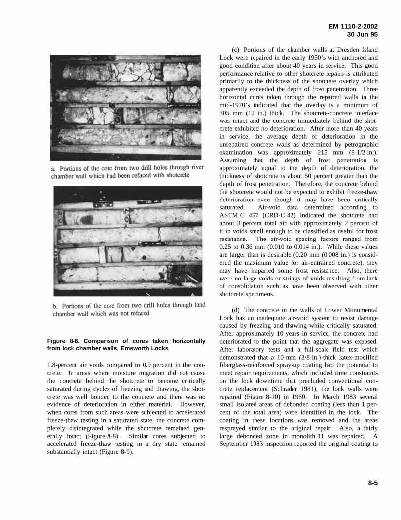
EM 1110-2-200230 Jun 95
Figure 8-6. Comparison of cores taken horizontallyfrom lock chamber walls, Emsworth Locks
1.8-percent air voids compared to 0.9 percent in the con-crete. In areas where moisture migration did not causethe concrete behind the shotcrete to become criticallysaturated during cycles of freezing and thawing, the shot-crete was well bonded to the concrete and there was noevidence of deterioration in either material. However,when cores from such areas were subjected to acceleratedfreeze-thaw testing in a saturated state, the concrete com-pletely disintegrated while the shotcrete remained gen-erally intact (Figure 8-8). Similar cores subjected toaccelerated freeze-thaw testing in a dry state remainedsubstantially intact (Figure 8-9).
(c) Portions of the chamber walls at Dresden IslandLock were repaired in the early 1950’s with anchored andgood condition after about 40 years in service. This goodperformance relative to other shotcrete repairs is attributedprimarily to the thickness of the shotcrete overlay whichapparently exceeded the depth of frost penetration. Threehorizontal cores taken through the repaired walls in themid-1970’s indicated that the overlay is a minimum of305 mm (12 in.) thick. The shotcrete-concrete interfacewas intact and the concrete immediately behind the shot-crete exhibited no deterioration. After more than 40 yearsin service, the average depth of deterioration in theunrepaired concrete walls as determined by petrographicexamination was approximately 215 mm (8-1/2 in.).Assuming that the depth of frost penetration isapproximately equal to the depth of deterioration, thethickness of shotcrete is about 50 percent greater than thedepth of frost penetration. Therefore, the concrete behindthe shotcrete would not be expected to exhibit freeze-thawdeterioration even though it may have been criticallysaturated. Air-void data determined according toASTM C 457 (CRD-C 42) indicated the shotcrete hadabout 3 percent total air with approximately 2 percent ofit in voids small enough to be classified as useful for frostresistance. The air-void spacing factors ranged from0.25 to 0.36 mm (0.010 to 0.014 in.). While these valuesare larger than is desirable (0.20 mm (0.008 in.) is consid-ered the maximum value for air-entrained concrete), theymay have imparted some frost resistance. Also, therewere no large voids or strings of voids resulting from lackof consolidation such as have been observed with othershotcrete specimens.
(d) The concrete in the walls of Lower MonumentalLock has an inadequate air-void system to resist damagecaused by freezing and thawing while critically saturated.After approximately 10 years in service, the concrete haddeteriorated to the point that the aggregate was exposed.After laboratory tests and a full-scale field test whichdemonstrated that a 10-mm (3/8-in.)-thick latex-modifiedfiberglass-reinforced spray-up coating had the potential tomeet repair requirements, which included time constraintson the lock downtime that precluded conventional con-crete replacement (Schrader 1981), the lock walls wererepaired (Figure 8-10) in 1980. In March 1983 severalsmall isolated areas of debonded coating (less than 1 per-cent of the total area) were identified in the lock. Thecoating in these locations was removed and the areasresprayed similar to the original repair. Also, a fairlylarge debonded zone in monolith 11 was repaired. ASeptember 1983 inspection reported the original coating to
8-5
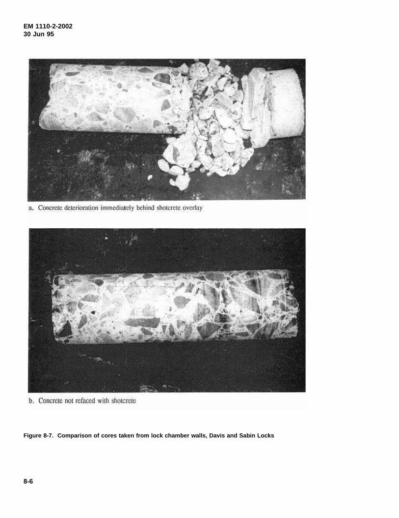
EM 1110-2-200230 Jun 95
Figure 8-7. Comparison of cores taken from lock chamber walls, Davis and Sabin Locks
8-6
a. Concrete deterioration immediately behind shotcrctc overlay
b. Concrete not refaced with shotcrete
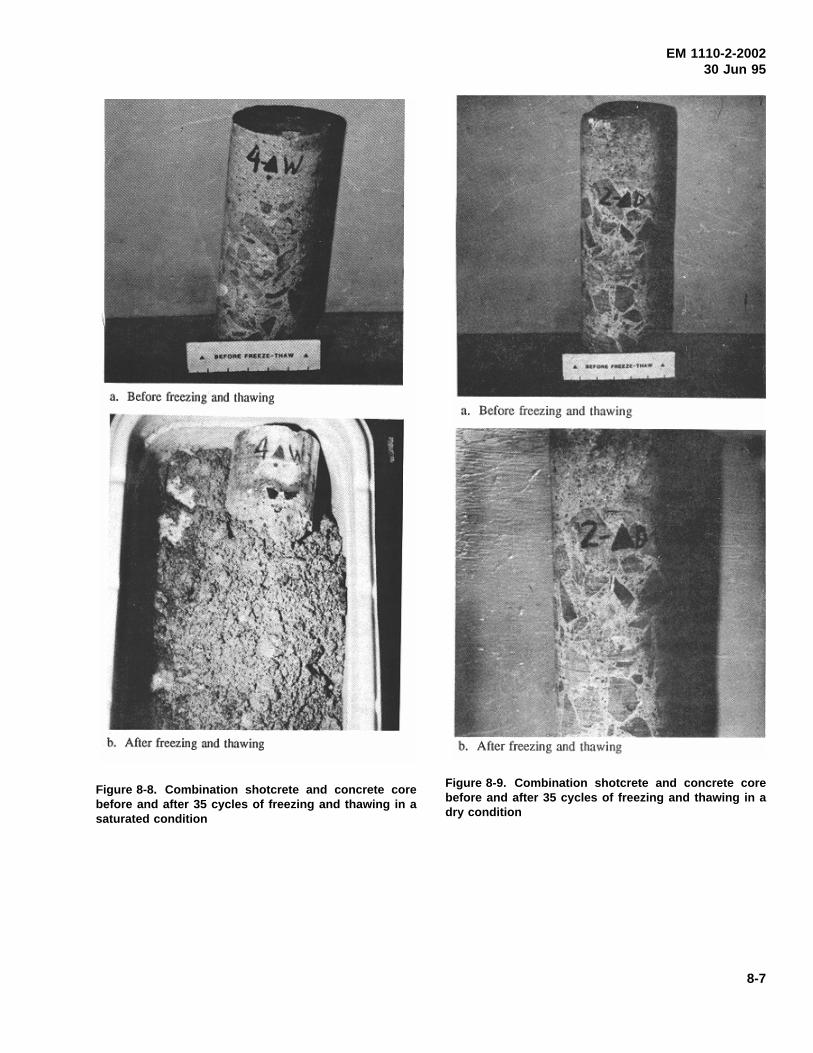
EM 1110-2-200230 Jun 95
Figure 8-8. Combination shotcrete and concrete corebefore and after 35 cycles of freezing and thawing in asaturated condition
Figure 8-9. Combination shotcrete and concrete corebefore and after 35 cycles of freezing and thawing in adry condition
8-7
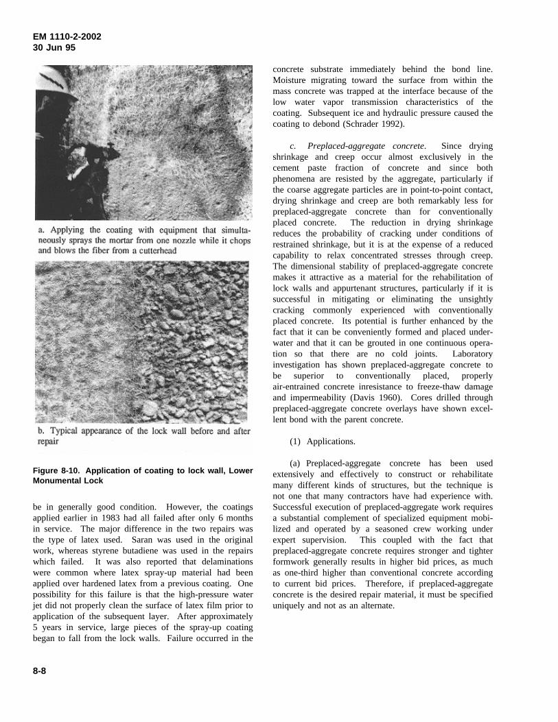
EM 1110-2-200230 Jun 95
Figure 8-10. Application of coating to lock wall, LowerMonumental Lock
be in generally good condition. However, the coatingsapplied earlier in 1983 had all failed after only 6 monthsin service. The major difference in the two repairs wasthe type of latex used. Saran was used in the originalwork, whereas styrene butadiene was used in the repairswhich failed. It was also reported that delaminationswere common where latex spray-up material had beenapplied over hardened latex from a previous coating. Onepossibility for this failure is that the high-pressure waterjet did not properly clean the surface of latex film prior toapplication of the subsequent layer. After approximately5 years in service, large pieces of the spray-up coatingbegan to fall from the lock walls. Failure occurred in the
concrete substrate immediately behind the bond line.Moisture migrating toward the surface from within themass concrete was trapped at the interface because of thelow water vapor transmission characteristics of thecoating. Subsequent ice and hydraulic pressure caused thecoating to debond (Schrader 1992).
c. Preplaced-aggregate concrete. Since dryingshrinkage and creep occur almost exclusively in thecement paste fraction of concrete and since bothphenomena are resisted by the aggregate, particularly ifthe coarse aggregate particles are in point-to-point contact,drying shrinkage and creep are both remarkably less forpreplaced-aggregate concrete than for conventionallyplaced concrete. The reduction in drying shrinkagereduces the probability of cracking under conditions ofrestrained shrinkage, but it is at the expense of a reducedcapability to relax concentrated stresses through creep.The dimensional stability of preplaced-aggregate concretemakes it attractive as a material for the rehabilitation oflock walls and appurtenant structures, particularly if it issuccessful in mitigating or eliminating the unsightlycracking commonly experienced with conventionallyplaced concrete. Its potential is further enhanced by thefact that it can be conveniently formed and placed under-water and that it can be grouted in one continuous opera-tion so that there are no cold joints. Laboratoryinvestigation has shown preplaced-aggregate concrete tobe superior to conventionally placed, properlyair-entrained concrete inresistance to freeze-thaw damageand impermeability (Davis 1960). Cores drilled throughpreplaced-aggregate concrete overlays have shown excel-lent bond with the parent concrete.
(1) Applications.
(a) Preplaced-aggregate concrete has been usedextensively and effectively to construct or rehabilitatemany different kinds of structures, but the technique isnot one that many contractors have had experience with.Successful execution of preplaced-aggregate work requiresa substantial complement of specialized equipment mobi-lized and operated by a seasoned crew working underexpert supervision. This coupled with the fact thatpreplaced-aggregate concrete requires stronger and tighterformwork generally results in higher bid prices, as muchas one-third higher than conventional concrete accordingto current bid prices. Therefore, if preplaced-aggregateconcrete is the desired repair material, it must be specifieduniquely and not as an alternate.
8-8
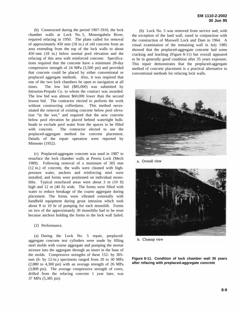
EM 1110-2-200230 Jun 95
(b) Constructed during the period 1907-1910, the lockchamber walls at Lock No. 5, Monongahela River,required refacing in 1950. The plans called for removalof approximately 450 mm (18 in.) of old concrete from anarea extending from the top of the lock walls to about450 mm (18 in.) below normal pool elevation and therefacing of this area with reinforced concrete. Specifica-tions required that the concrete have a minimum 28-daycompressive strength of 24 MPa (3,500 psi) and providedthat concrete could be placed by either conventional orpreplaced aggregate methods. Also, it was required thatone of the two lock chambers be open to navigation at alltimes. The low bid ($85,000) was submitted byIntrusion-Prepakt Co. to whom the contract was awarded.The low bid was almost $60,000 lower than the secondlowest bid. The contractor elected to perform the workwithout constructing cofferdams. This method neces-sitated the removal of existing concrete below pool eleva-tion “in the wet,” and required that the new concretebelow pool elevation be placed behind watertight bulk-heads to exclude pool water from the spaces to be filledwith concrete. The contractor elected to use thepreplaced-aggregate method for concrete placement.Details of the repair operation were reported byMinnotte (1952).
(c) Preplaced-aggregate concrete was used in 1987 toresurface the lock chamber walls at Peoria Lock (Mech1989). Following removal of a minimum of 305 mm(12 in.) of concrete, the walls were cleaned with high-pressure water, anchors and reinforcing steel wereinstalled, and forms were positioned on individual mono-liths. Typical resurfaced areas were about 3 m (10 ft)high and 12 m (40 ft) wide. The forms were filled withwater to reduce breakage of the coarse aggregate duringplacement. The forms were vibrated externally withhandheld equipment during grout intrusion which tookabout 8 to 10 hr of pumping for each monolith. Formson two of the approximately 30 monoliths had to be resetbecause anchors holding the forms to the lock wall failed.
(2) Performance.
(a) During the Lock No. 5 repair, preplaced-aggregate concrete test cylinders were made by fillingsteel molds with coarse aggregate and pumping the mortarmixture into the aggregate through an insert in the base ofthe molds. Compressive strengths of these 152- by 305-mm (6- by 12-in.) specimens ranged from 20 to 30 MPa(2,880 to 4,300 psi) with an average strength of 26 MPa(3,800 psi). The average compressive strength of cores,drilled from the refacing concrete 1 year later, was37 MPa (5,385 psi).
(b) Lock No. 5 was removed from service and, withthe exception of the land wall, razed in conjunction withthe construction of Maxwell Lock and Dam in 1964. Avisual examination of the remaining wall in July 1985showed that the preplaced-aggregate concrete had somecracking and leaching (Figure 8-11) but overall appearedto be in generally good condition after 35 years exposure.This repair demonstrates that the preplaced-aggregatemethod of concrete placement is a practical alternative toconventional methods for refacing lock walls.
Figure 8-11. Condition of lock chamber wall 35 yearsafter refacing with preplaced-aggregate concrete
8-9
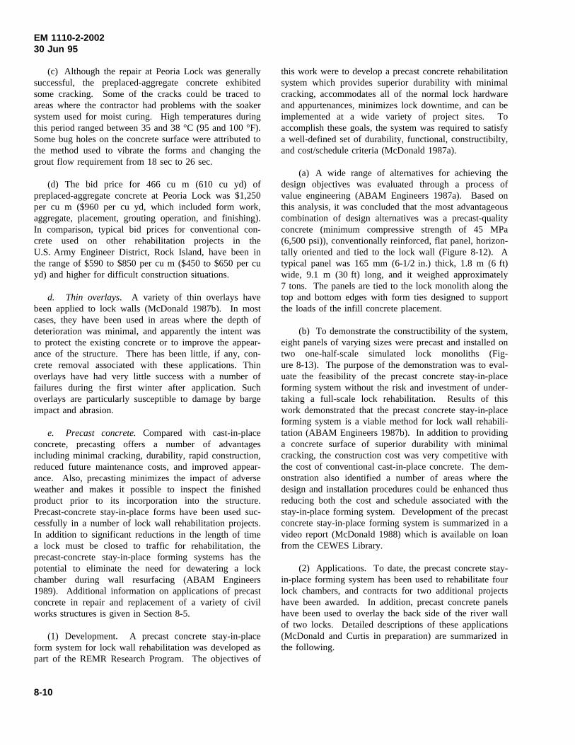
EM 1110-2-200230 Jun 95
(c) Although the repair at Peoria Lock was generallysuccessful, the preplaced-aggregate concrete exhibitedsome cracking. Some of the cracks could be traced toareas where the contractor had problems with the soakersystem used for moist curing. High temperatures duringthis period ranged between 35 and 38 °C (95 and 100 °F).Some bug holes on the concrete surface were attributed tothe method used to vibrate the forms and changing thegrout flow requirement from 18 sec to 26 sec.
(d) The bid price for 466 cu m (610 cu yd) ofpreplaced-aggregate concrete at Peoria Lock was $1,250per cu m ($960 per cu yd, which included form work,aggregate, placement, grouting operation, and finishing).In comparison, typical bid prices for conventional con-crete used on other rehabilitation projects in theU.S. Army Engineer District, Rock Island, have been inthe range of $590 to $850 per cu m ($450 to $650 per cuyd) and higher for difficult construction situations.
d. Thin overlays. A variety of thin overlays havebeen applied to lock walls (McDonald 1987b). In mostcases, they have been used in areas where the depth ofdeterioration was minimal, and apparently the intent wasto protect the existing concrete or to improve the appear-ance of the structure. There has been little, if any, con-crete removal associated with these applications. Thinoverlays have had very little success with a number offailures during the first winter after application. Suchoverlays are particularly susceptible to damage by bargeimpact and abrasion.
e. Precast concrete.Compared with cast-in-placeconcrete, precasting offers a number of advantagesincluding minimal cracking, durability, rapid construction,reduced future maintenance costs, and improved appear-ance. Also, precasting minimizes the impact of adverseweather and makes it possible to inspect the finishedproduct prior to its incorporation into the structure.Precast-concrete stay-in-place forms have been used suc-cessfully in a number of lock wall rehabilitation projects.In addition to significant reductions in the length of timea lock must be closed to traffic for rehabilitation, theprecast-concrete stay-in-place forming systems has thepotential to eliminate the need for dewatering a lockchamber during wall resurfacing (ABAM Engineers1989). Additional information on applications of precastconcrete in repair and replacement of a variety of civilworks structures is given in Section 8-5.
(1) Development. A precast concrete stay-in-placeform system for lock wall rehabilitation was developed aspart of the REMR Research Program. The objectives of
this work were to develop a precast concrete rehabilitationsystem which provides superior durability with minimalcracking, accommodates all of the normal lock hardwareand appurtenances, minimizes lock downtime, and can beimplemented at a wide variety of project sites. Toaccomplish these goals, the system was required to satisfya well-defined set of durability, functional, constructibilty,and cost/schedule criteria (McDonald 1987a).
(a) A wide range of alternatives for achieving thedesign objectives was evaluated through a process ofvalue engineering (ABAM Engineers 1987a). Based onthis analysis, it was concluded that the most advantageouscombination of design alternatives was a precast-qualityconcrete (minimum compressive strength of 45 MPa(6,500 psi)), conventionally reinforced, flat panel, horizon-tally oriented and tied to the lock wall (Figure 8-12). Atypical panel was 165 mm (6-1/2 in.) thick, 1.8 m (6 ft)wide, 9.1 m (30 ft) long, and it weighed approximately7 tons. The panels are tied to the lock monolith along thetop and bottom edges with form ties designed to supportthe loads of the infill concrete placement.
(b) To demonstrate the constructibility of the system,eight panels of varying sizes were precast and installed ontwo one-half-scale simulated lock monoliths (Fig-ure 8-13). The purpose of the demonstration was to eval-uate the feasibility of the precast concrete stay-in-placeforming system without the risk and investment of under-taking a full-scale lock rehabilitation. Results of thiswork demonstrated that the precast concrete stay-in-placeforming system is a viable method for lock wall rehabili-tation (ABAM Engineers 1987b). In addition to providinga concrete surface of superior durability with minimalcracking, the construction cost was very competitive withthe cost of conventional cast-in-place concrete. The dem-onstration also identified a number of areas where thedesign and installation procedures could be enhanced thusreducing both the cost and schedule associated with thestay-in-place forming system. Development of the precastconcrete stay-in-place forming system is summarized in avideo report (McDonald 1988) which is available on loanfrom the CEWES Library.
(2) Applications. To date, the precast concrete stay-in-place forming system has been used to rehabilitate fourlock chambers, and contracts for two additional projectshave been awarded. In addition, precast concrete panelshave been used to overlay the back side of the river wallof two locks. Detailed descriptions of these applications(McDonald and Curtis in preparation) are summarized inthe following.
8-10
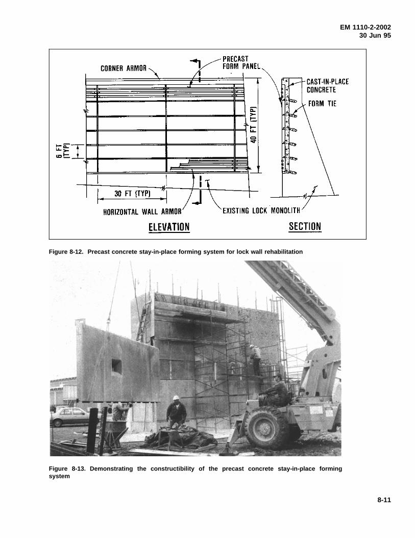
EM 1110-2-200230 Jun 95
Figure 8-12. Precast concrete stay-in-place forming system for lock wall rehabilitation
Figure 8-13. Demonstrating the constructibility of the precast concrete stay-in-place formingsystem
8-11
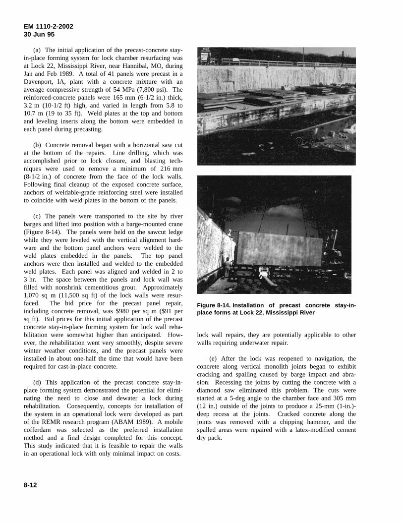
EM 1110-2-200230 Jun 95
(a) The initial application of the precast-concrete stay-in-place forming system for lock chamber resurfacing wasat Lock 22, Mississippi River, near Hannibal, MO, duringJan and Feb 1989. A total of 41 panels were precast in aDavenport, IA, plant with a concrete mixture with anaverage compressive strength of 54 MPa (7,800 psi). Thereinforced-concrete panels were 165 mm (6-1/2 in.) thick,3.2 m (10-1/2 ft) high, and varied in length from 5.8 to10.7 m (19 to 35 ft). Weld plates at the top and bottomand leveling inserts along the bottom were embedded ineach panel during precasting.
(b) Concrete removal began with a horizontal saw cutat the bottom of the repairs. Line drilling, which wasaccomplished prior to lock closure, and blasting tech-niques were used to remove a minimum of 216 mm(8-1/2 in.) of concrete from the face of the lock walls.Following final cleanup of the exposed concrete surface,anchors of weldable-grade reinforcing steel were installedto coincide with weld plates in the bottom of the panels.
(c) The panels were transported to the site by riverbarges and lifted into position with a barge-mounted crane(Figure 8-14). The panels were held on the sawcut ledgewhile they were leveled with the vertical alignment hard-ware and the bottom panel anchors were welded to theweld plates embedded in the panels. The top panelanchors were then installed and welded to the embeddedweld plates. Each panel was aligned and welded in 2 to3 hr. The space between the panels and lock wall wasfilled with nonshrink cementitious grout. Approximately1,070 sq m (11,500 sq ft) of the lock walls were resur-faced. The bid price for the precast panel repair,including concrete removal, was $980 per sq m ($91 persq ft). Bid prices for this initial application of the precastconcrete stay-in-place forming system for lock wall reha-bilitation were somewhat higher than anticipated. How-ever, the rehabilitation went very smoothly, despite severewinter weather conditions, and the precast panels wereinstalled in about one-half the time that would have beenrequired for cast-in-place concrete.
(d) This application of the precast concrete stay-in-place forming system demonstrated the potential for elimi-nating the need to close and dewater a lock duringrehabilitation. Consequently, concepts for installation ofthe system in an operational lock were developed as partof the REMR research program (ABAM 1989). A mobilecofferdam was selected as the preferred installationmethod and a final design completed for this concept.This study indicated that it is feasible to repair the wallsin an operational lock with only minimal impact on costs.
Figure 8-14. Installation of precast concrete stay-in-place forms at Lock 22, Mississippi River
lock wall repairs, they are potentially applicable to otherwalls requiring underwater repair.
(e) After the lock was reopened to navigation, theconcrete along vertical monolith joints began to exhibitcracking and spalling caused by barge impact and abra-sion. Recessing the joints by cutting the concrete with adiamond saw eliminated this problem. The cuts werestarted at a 5-deg angle to the chamber face and 305 mm(12 in.) outside of the joints to produce a 25-mm (1-in.)-deep recess at the joints. Cracked concrete along thejoints was removed with a chipping hammer, and thespalled areas were repaired with a latex-modified cementdry pack.
8-12
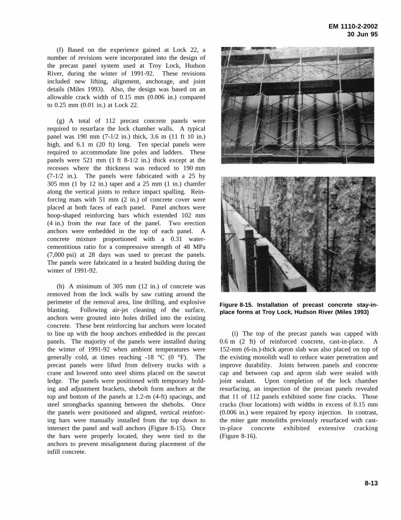
EM 1110-2-200230 Jun 95
(f) Based on the experience gained at Lock 22, anumber of revisions were incorporated into the design ofthe precast panel system used at Troy Lock, HudsonRiver, during the winter of 1991-92. These revisionsincluded new lifting, alignment, anchorage, and jointdetails (Miles 1993). Also, the design was based on anallowable crack width of 0.15 mm (0.006 in.) comparedto 0.25 mm (0.01 in.) at Lock 22.
(g) A total of 112 precast concrete panels wererequired to resurface the lock chamber walls. A typicalpanel was 190 mm (7-1/2 in.) thick, 3.6 m (11 ft 10 in.)high, and 6.1 m (20 ft) long. Ten special panels wererequired to accommodate line poles and ladders. Thesepanels were 521 mm (1 ft 8-1/2 in.) thick except at therecesses where the thickness was reduced to 190 mm(7-1/2 in.). The panels were fabricated with a 25 by305 mm (1 by 12 in.) taper and a 25 mm (1 in.) chamferalong the vertical joints to reduce impact spalling. Rein-forcing mats with 51 mm (2 in.) of concrete cover wereplaced at both faces of each panel. Panel anchors werehoop-shaped reinforcing bars which extended 102 mm(4 in.) from the rear face of the panel. Two erectionanchors were embedded in the top of each panel. Aconcrete mixture proportioned with a 0.31 water-cementitious ratio for a compressive strength of 48 MPa(7,000 psi) at 28 days was used to precast the panels.The panels were fabricated in a heated building during thewinter of 1991-92.
(h) A minimum of 305 mm (12 in.) of concrete wasremoved from the lock walls by saw cutting around theperimeter of the removal area, line drilling, and explosiveblasting. Following air-jet cleaning of the surface,anchors were grouted into holes drilled into the existingconcrete. These bent reinforcing bar anchors were locatedto line up with the hoop anchors embedded in the precastpanels. The majority of the panels were installed duringthe winter of 1991-92 when ambient temperatures weregenerally cold, at times reaching -18 °C (0 °F). Theprecast panels were lifted from delivery trucks with acrane and lowered onto steel shims placed on the sawcutledge. The panels were positioned with temporary hold-ing and adjustment brackets, shebolt form anchors at thetop and bottom of the panels at 1.2-m (4-ft) spacings, andsteel strongbacks spanning between the shebolts. Oncethe panels were positioned and aligned, vertical reinforc-ing bars were manually installed from the top down tointersect the panel and wall anchors (Figure 8-15). Oncethe bars were properly located, they were tied to theanchors to prevent misalignment during placement of theinfill concrete.
Figure 8-15. Installation of precast concrete stay-in-place forms at Troy Lock, Hudson River (Miles 1993)
(i) The top of the precast panels was capped with0.6 m (2 ft) of reinforced concrete, cast-in-place. A152-mm (6-in.)-thick apron slab was also placed on top ofthe existing monolith wall to reduce water penetration andimprove durability. Joints between panels and concretecap and between cap and apron slab were sealed withjoint sealant. Upon completion of the lock chamberresurfacing, an inspection of the precast panels revealedthat 11 of 112 panels exhibited some fine cracks. Thosecracks (four locations) with widths in excess of 0.15 mm(0.006 in.) were repaired by epoxy injection. In contrast,the miter gate monoliths previously resurfaced with cast-in-place concrete exhibited extensive cracking(Figure 8-16).
8-13
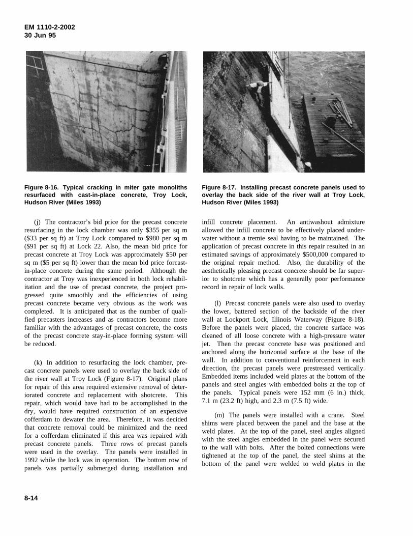
EM 1110-2-200230 Jun 95
Figure 8-16. Typical cracking in miter gate monolithsresurfaced with cast-in-place concrete, Troy Lock,Hudson River (Miles 1993)
(j) The contractor’s bid price for the precast concreteresurfacing in the lock chamber was only $355 per sq m($33 per sq ft) at Troy Lock compared to $980 per sq m($91 per sq ft) at Lock 22. Also, the mean bid price forprecast concrete at Troy Lock was approximately $50 persq m ($5 per sq ft) lower than the mean bid price forcast-in-place concrete during the same period. Although thecontractor at Troy was inexperienced in both lock rehabil-itation and the use of precast concrete, the project pro-gressed quite smoothly and the efficiencies of usingprecast concrete became very obvious as the work wascompleted. It is anticipated that as the number of quali-fied precasters increases and as contractors become morefamiliar with the advantages of precast concrete, the costsof the precast concrete stay-in-place forming system willbe reduced.
(k) In addition to resurfacing the lock chamber, pre-cast concrete panels were used to overlay the back side ofthe river wall at Troy Lock (Figure 8-17). Original plansfor repair of this area required extensive removal of deter-iorated concrete and replacement with shotcrete. Thisrepair, which would have had to be accomplished in thedry, would have required construction of an expensivecofferdam to dewater the area. Therefore, it was decidedthat concrete removal could be minimized and the needfor a cofferdam eliminated if this area was repaired withprecast concrete panels. Three rows of precast panelswere used in the overlay. The panels were installed in1992 while the lock was in operation. The bottom row ofpanels was partially submerged during installation and
Figure 8-17. Installing precast concrete panels used tooverlay the back side of the river wall at Troy Lock,Hudson River (Miles 1993)
infill concrete placement. An antiwashout admixtureallowed the infill concrete to be effectively placed under-water without a tremie seal having to be maintained. Theapplication of precast concrete in this repair resulted in anestimated savings of approximately $500,000 compared tothe original repair method. Also, the durability of theaesthetically pleasing precast concrete should be far super-ior to shotcrete which has a generally poor performancerecord in repair of lock walls.
(l) Precast concrete panels were also used to overlaythe lower, battered section of the backside of the riverwall at Lockport Lock, Illinois Waterway (Figure 8-18).Before the panels were placed, the concrete surface wascleaned of all loose concrete with a high-pressure waterjet. Then the precast concrete base was positioned andanchored along the horizontal surface at the base of thewall. In addition to conventional reinforcement in eachdirection, the precast panels were prestressed vertically.Embedded items included weld plates at the bottom of thepanels and steel angles with embedded bolts at the top ofthe panels. Typical panels were 152 mm (6 in.) thick,7.1 m (23.2 ft) high, and 2.3 m (7.5 ft) wide.
(m) The panels were installed with a crane. Steelshims were placed between the panel and the base at theweld plates. At the top of the panel, steel angles alignedwith the steel angles embedded in the panel were securedto the wall with bolts. After the bolted connections weretightened at the top of the panel, the steel shims at thebottom of the panel were welded to weld plates in the
8-14
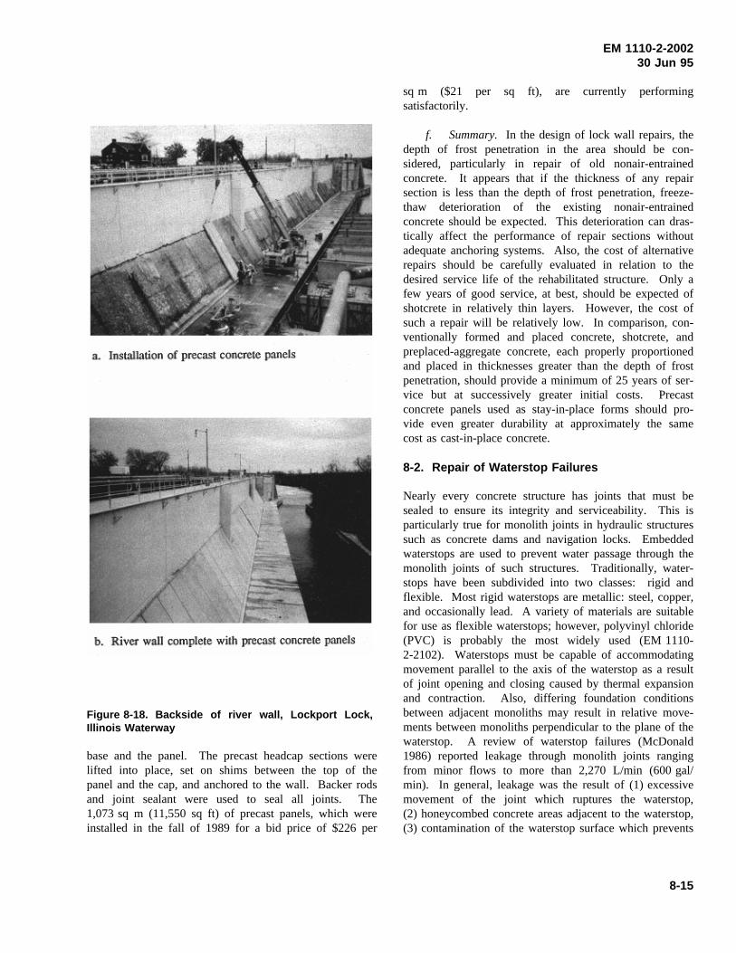
EM 1110-2-200230 Jun 95
Figure 8-18. Backside of river wall, Lockport Lock,Illinois Waterway
base and the panel. The precast headcap sections werelifted into place, set on shims between the top of thepanel and the cap, and anchored to the wall. Backer rodsand joint sealant were used to seal all joints. The1,073 sq m (11,550 sq ft) of precast panels, which wereinstalled in the fall of 1989 for a bid price of $226 per
sq m ($21 per sq ft), are currently performingsatisfactorily.
f. Summary. In the design of lock wall repairs, thedepth of frost penetration in the area should be con-sidered, particularly in repair of old nonair-entrainedconcrete. It appears that if the thickness of any repairsection is less than the depth of frost penetration, freeze-thaw deterioration of the existing nonair-entrainedconcrete should be expected. This deterioration can dras-tically affect the performance of repair sections withoutadequate anchoring systems. Also, the cost of alternativerepairs should be carefully evaluated in relation to thedesired service life of the rehabilitated structure. Only afew years of good service, at best, should be expected ofshotcrete in relatively thin layers. However, the cost ofsuch a repair will be relatively low. In comparison, con-ventionally formed and placed concrete, shotcrete, andpreplaced-aggregate concrete, each properly proportionedand placed in thicknesses greater than the depth of frostpenetration, should provide a minimum of 25 years of ser-vice but at successively greater initial costs. Precastconcrete panels used as stay-in-place forms should pro-vide even greater durability at approximately the samecost as cast-in-place concrete.
8-2. Repair of Waterstop Failures
Nearly every concrete structure has joints that must besealed to ensure its integrity and serviceability. This isparticularly true for monolith joints in hydraulic structuressuch as concrete dams and navigation locks. Embeddedwaterstops are used to prevent water passage through themonolith joints of such structures. Traditionally, water-stops have been subdivided into two classes: rigid andflexible. Most rigid waterstops are metallic: steel, copper,and occasionally lead. A variety of materials are suitablefor use as flexible waterstops; however, polyvinyl chloride(PVC) is probably the most widely used (EM 1110-2-2102). Waterstops must be capable of accommodatingmovement parallel to the axis of the waterstop as a resultof joint opening and closing caused by thermal expansionand contraction. Also, differing foundation conditionsbetween adjacent monoliths may result in relative move-ments between monoliths perpendicular to the plane of thewaterstop. A review of waterstop failures (McDonald1986) reported leakage through monolith joints rangingfrom minor flows to more than 2,270 L/min (600 gal/min). In general, leakage was the result of (1) excessivemovement of the joint which ruptures the waterstop,(2) honeycombed concrete areas adjacent to the waterstop,(3) contamination of the waterstop surface which prevents
8-15
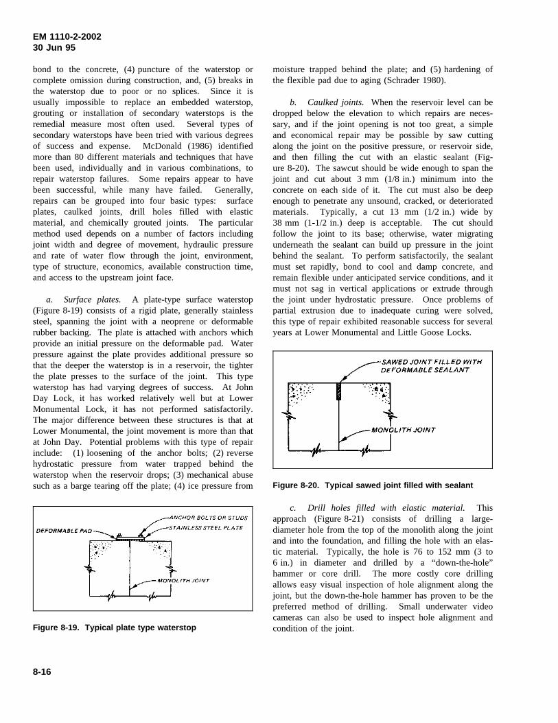
EM 1110-2-200230 Jun 95
bond to the concrete, (4) puncture of the waterstop orcomplete omission during construction, and, (5) breaks inthe waterstop due to poor or no splices. Since it isusually impossible to replace an embedded waterstop,grouting or installation of secondary waterstops is theremedial measure most often used. Several types ofsecondary waterstops have been tried with various degreesof success and expense. McDonald (1986) identifiedmore than 80 different materials and techniques that havebeen used, individually and in various combinations, torepair waterstop failures. Some repairs appear to havebeen successful, while many have failed. Generally,repairs can be grouped into four basic types: surfaceplates, caulked joints, drill holes filled with elasticmaterial, and chemically grouted joints. The particularmethod used depends on a number of factors includingjoint width and degree of movement, hydraulic pressureand rate of water flow through the joint, environment,type of structure, economics, available construction time,and access to the upstream joint face.
a. Surface plates. A plate-type surface waterstop(Figure 8-19) consists of a rigid plate, generally stainlesssteel, spanning the joint with a neoprene or deformablerubber backing. The plate is attached with anchors whichprovide an initial pressure on the deformable pad. Waterpressure against the plate provides additional pressure sothat the deeper the waterstop is in a reservoir, the tighterthe plate presses to the surface of the joint. This typewaterstop has had varying degrees of success. At JohnDay Lock, it has worked relatively well but at LowerMonumental Lock, it has not performed satisfactorily.The major difference between these structures is that atLower Monumental, the joint movement is more than thatat John Day. Potential problems with this type of repairinclude: (1) loosening of the anchor bolts; (2) reversehydrostatic pressure from water trapped behind thewaterstop when the reservoir drops; (3) mechanical abusesuch as a barge tearing off the plate; (4) ice pressure from
Figure 8-19. Typical plate type waterstop
moisture trapped behind the plate; and (5) hardening ofthe flexible pad due to aging (Schrader 1980).
b. Caulked joints. When the reservoir level can bedropped below the elevation to which repairs are neces-sary, and if the joint opening is not too great, a simpleand economical repair may be possible by saw cuttingalong the joint on the positive pressure, or reservoir side,and then filling the cut with an elastic sealant (Fig-ure 8-20). The sawcut should be wide enough to span thejoint and cut about 3 mm (1/8 in.) minimum into theconcrete on each side of it. The cut must also be deepenough to penetrate any unsound, cracked, or deterioratedmaterials. Typically, a cut 13 mm (1/2 in.) wide by38 mm (1-1/2 in.) deep is acceptable. The cut shouldfollow the joint to its base; otherwise, water migratingunderneath the sealant can build up pressure in the jointbehind the sealant. To perform satisfactorily, the sealantmust set rapidly, bond to cool and damp concrete, andremain flexible under anticipated service conditions, and itmust not sag in vertical applications or extrude throughthe joint under hydrostatic pressure. Once problems ofpartial extrusion due to inadequate curing were solved,this type of repair exhibited reasonable success for severalyears at Lower Monumental and Little Goose Locks.
Figure 8-20. Typical sawed joint filled with sealant
c. Drill holes filled with elastic material. Thisapproach (Figure 8-21) consists of drilling a large-diameter hole from the top of the monolith along the jointand into the foundation, and filling the hole with an elas-tic material. Typically, the hole is 76 to 152 mm (3 to6 in.) in diameter and drilled by a “down-the-hole”hammer or core drill. The more costly core drillingallows easy visual inspection of hole alignment along thejoint, but the down-the-hole hammer has proven to be thepreferred method of drilling. Small underwater videocameras can also be used to inspect hole alignment andcondition of the joint.
8-16
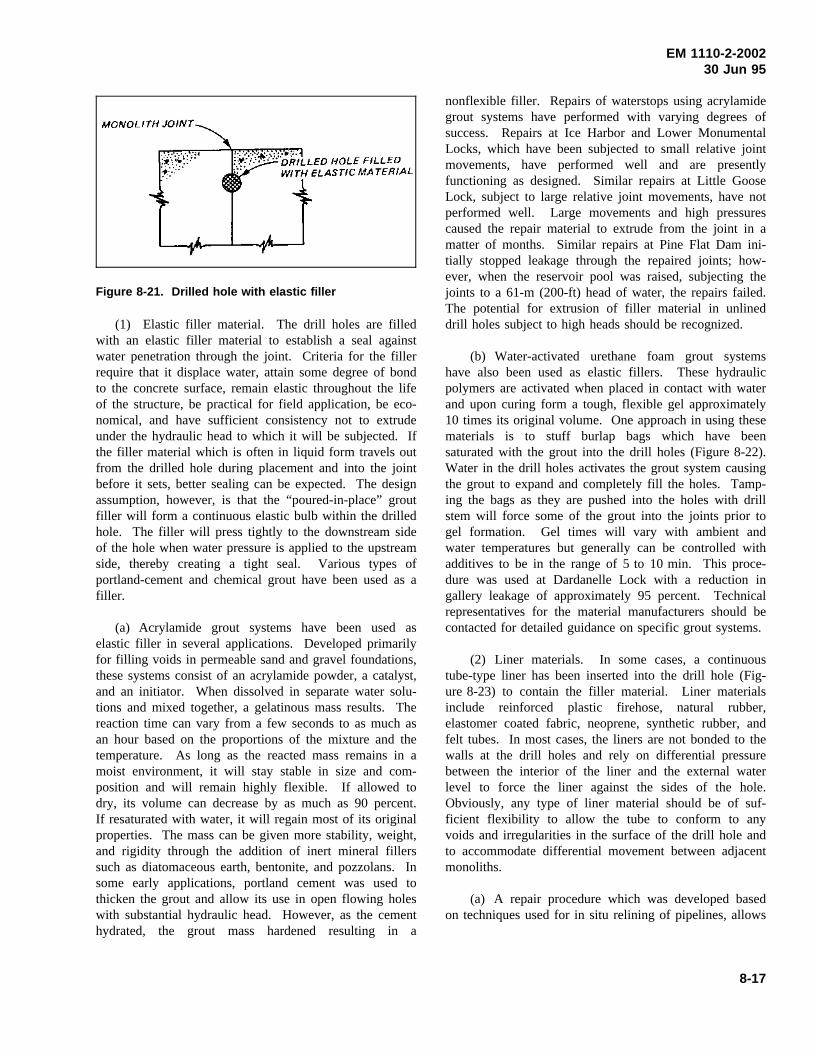
EM 1110-2-200230 Jun 95
Figure 8-21. Drilled hole with elastic filler
(1) Elastic filler material. The drill holes are filledwith an elastic filler material to establish a seal againstwater penetration through the joint. Criteria for the fillerrequire that it displace water, attain some degree of bondto the concrete surface, remain elastic throughout the lifeof the structure, be practical for field application, be eco-nomical, and have sufficient consistency not to extrudeunder the hydraulic head to which it will be subjected. Ifthe filler material which is often in liquid form travels outfrom the drilled hole during placement and into the jointbefore it sets, better sealing can be expected. The designassumption, however, is that the “poured-in-place” groutfiller will form a continuous elastic bulb within the drilledhole. The filler will press tightly to the downstream sideof the hole when water pressure is applied to the upstreamside, thereby creating a tight seal. Various types ofportland-cement and chemical grout have been used as afiller.
(a) Acrylamide grout systems have been used aselastic filler in several applications. Developed primarilyfor filling voids in permeable sand and gravel foundations,these systems consist of an acrylamide powder, a catalyst,and an initiator. When dissolved in separate water solu-tions and mixed together, a gelatinous mass results. Thereaction time can vary from a few seconds to as much asan hour based on the proportions of the mixture and thetemperature. As long as the reacted mass remains in amoist environment, it will stay stable in size and com-position and will remain highly flexible. If allowed todry, its volume can decrease by as much as 90 percent.If resaturated with water, it will regain most of its originalproperties. The mass can be given more stability, weight,and rigidity through the addition of inert mineral fillerssuch as diatomaceous earth, bentonite, and pozzolans. Insome early applications, portland cement was used tothicken the grout and allow its use in open flowing holeswith substantial hydraulic head. However, as the cementhydrated, the grout mass hardened resulting in a
nonflexible filler. Repairs of waterstops using acrylamidegrout systems have performed with varying degrees ofsuccess. Repairs at Ice Harbor and Lower MonumentalLocks, which have been subjected to small relative jointmovements, have performed well and are presentlyfunctioning as designed. Similar repairs at Little GooseLock, subject to large relative joint movements, have notperformed well. Large movements and high pressurescaused the repair material to extrude from the joint in amatter of months. Similar repairs at Pine Flat Dam ini-tially stopped leakage through the repaired joints; how-ever, when the reservoir pool was raised, subjecting thejoints to a 61-m (200-ft) head of water, the repairs failed.The potential for extrusion of filler material in unlineddrill holes subject to high heads should be recognized.
(b) Water-activated urethane foam grout systemshave also been used as elastic fillers. These hydraulicpolymers are activated when placed in contact with waterand upon curing form a tough, flexible gel approximately10 times its original volume. One approach in using thesematerials is to stuff burlap bags which have beensaturated with the grout into the drill holes (Figure 8-22).Water in the drill holes activates the grout system causingthe grout to expand and completely fill the holes. Tamp-ing the bags as they are pushed into the holes with drillstem will force some of the grout into the joints prior togel formation. Gel times will vary with ambient andwater temperatures but generally can be controlled withadditives to be in the range of 5 to 10 min. This proce-dure was used at Dardanelle Lock with a reduction ingallery leakage of approximately 95 percent. Technicalrepresentatives for the material manufacturers should becontacted for detailed guidance on specific grout systems.
(2) Liner materials. In some cases, a continuoustube-type liner has been inserted into the drill hole (Fig-ure 8-23) to contain the filler material. Liner materialsinclude reinforced plastic firehose, natural rubber,elastomer coated fabric, neoprene, synthetic rubber, andfelt tubes. In most cases, the liners are not bonded to thewalls at the drill holes and rely on differential pressurebetween the interior of the liner and the external waterlevel to force the liner against the sides of the hole.Obviously, any type of liner material should be of suf-ficient flexibility to allow the tube to conform to anyvoids and irregularities in the surface of the drill hole andto accommodate differential movement between adjacentmonoliths.
(a) A repair procedure which was developed basedon techniques used for in situ relining of pipelines, allows
8-17
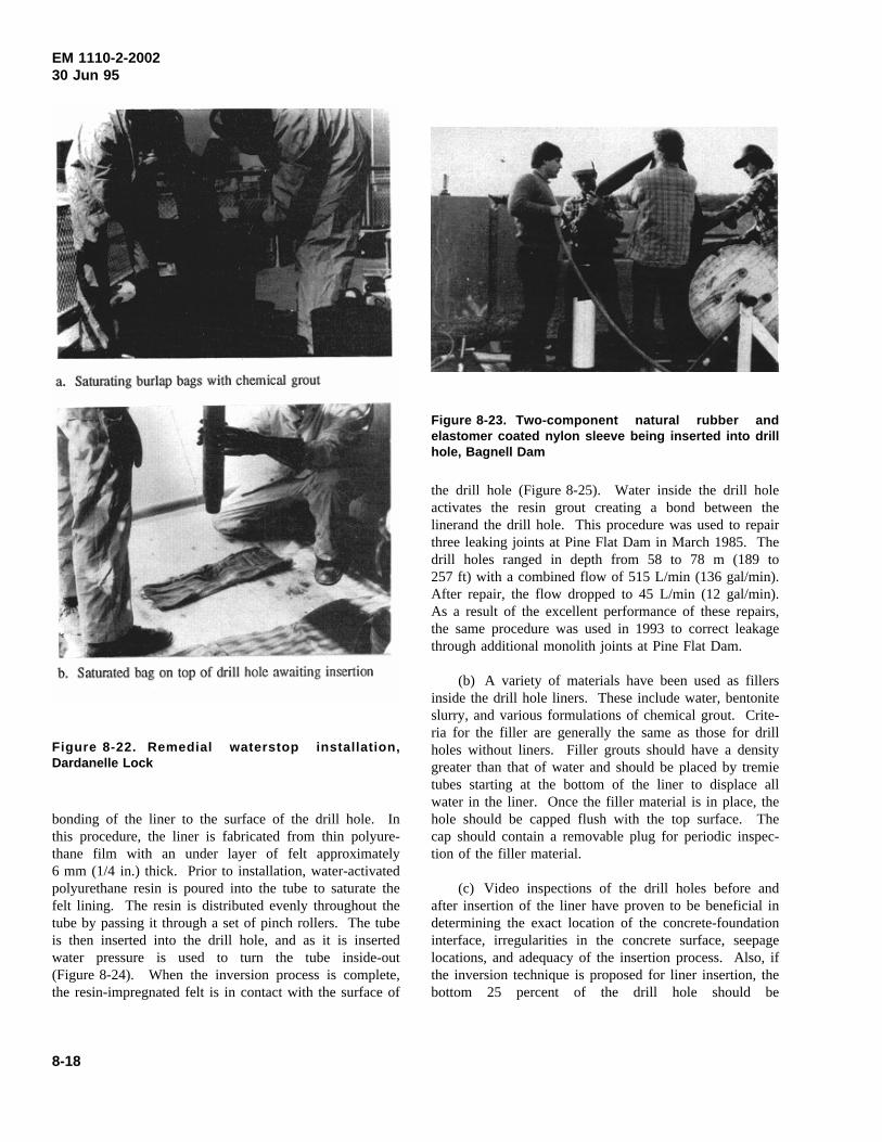
EM 1110-2-200230 Jun 95
Figure 8-22. Remedial waterstop installation,Dardanelle Lock
bonding of the liner to the surface of the drill hole. Inthis procedure, the liner is fabricated from thin polyure-thane film with an under layer of felt approximately6 mm (1/4 in.) thick. Prior to installation, water-activatedpolyurethane resin is poured into the tube to saturate thefelt lining. The resin is distributed evenly throughout thetube by passing it through a set of pinch rollers. The tubeis then inserted into the drill hole, and as it is insertedwater pressure is used to turn the tube inside-out(Figure 8-24). When the inversion process is complete,the resin-impregnated felt is in contact with the surface of
Figure 8-23. Two-component natural rubber andelastomer coated nylon sleeve being inserted into drillhole, Bagnell Dam
the drill hole (Figure 8-25). Water inside the drill holeactivates the resin grout creating a bond between thelinerand the drill hole. This procedure was used to repairthree leaking joints at Pine Flat Dam in March 1985. Thedrill holes ranged in depth from 58 to 78 m (189 to257 ft) with a combined flow of 515 L/min (136 gal/min).After repair, the flow dropped to 45 L/min (12 gal/min).As a result of the excellent performance of these repairs,the same procedure was used in 1993 to correct leakagethrough additional monolith joints at Pine Flat Dam.
(b) A variety of materials have been used as fillersinside the drill hole liners. These include water, bentoniteslurry, and various formulations of chemical grout. Crite-ria for the filler are generally the same as those for drillholes without liners. Filler grouts should have a densitygreater than that of water and should be placed by tremietubes starting at the bottom of the liner to displace allwater in the liner. Once the filler material is in place, thehole should be capped flush with the top surface. Thecap should contain a removable plug for periodic inspec-tion of the filler material.
(c) Video inspections of the drill holes before andafter insertion of the liner have proven to be beneficial indetermining the exact location of the concrete-foundationinterface, irregularities in the concrete surface, seepagelocations, and adequacy of the insertion process. Also, ifthe inversion technique is proposed for liner insertion, thebottom 25 percent of the drill hole should be
8-18
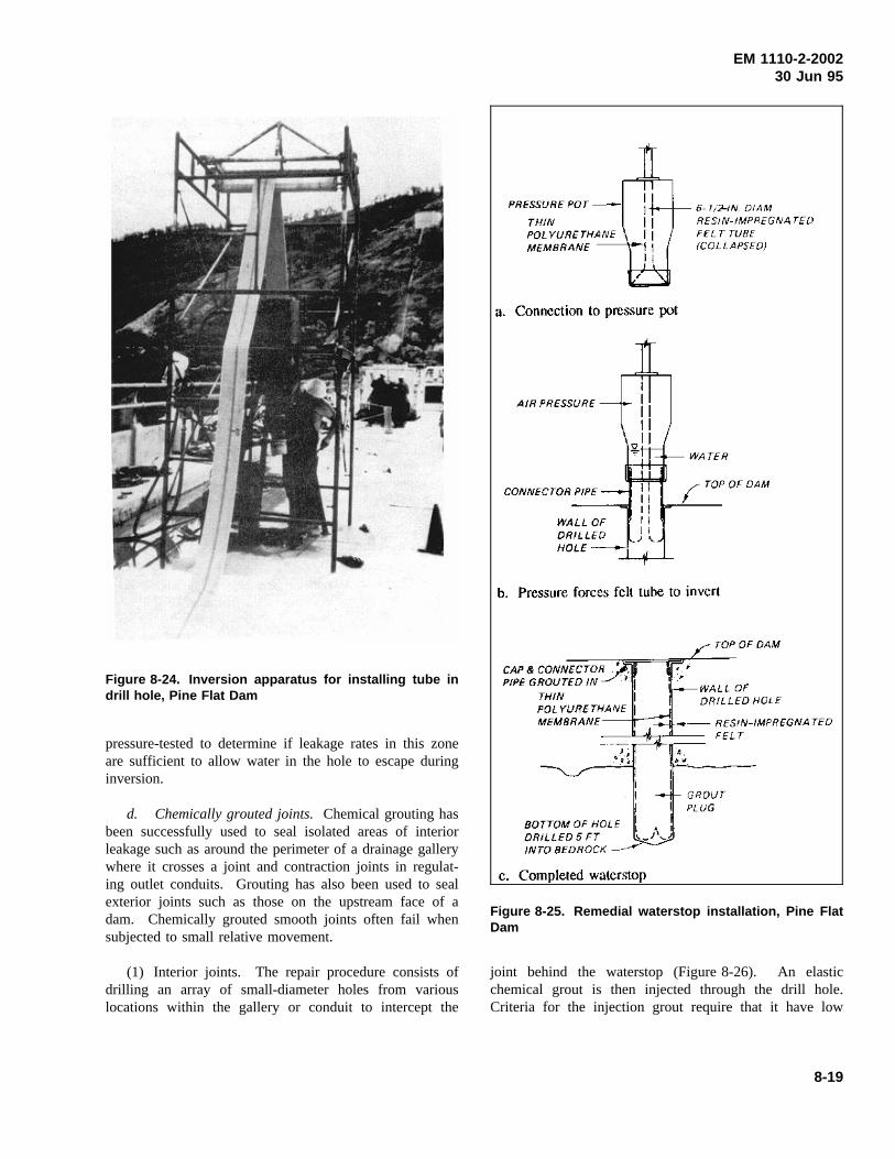
EM 1110-2-200230 Jun 95
Figure 8-24. Inversion apparatus for installing tube indrill hole, Pine Flat Dam
pressure-tested to determine if leakage rates in this zoneare sufficient to allow water in the hole to escape duringinversion.
d. Chemically grouted joints.Chemical grouting hasbeen successfully used to seal isolated areas of interiorleakage such as around the perimeter of a drainage gallerywhere it crosses a joint and contraction joints in regulat-ing outlet conduits. Grouting has also been used to sealexterior joints such as those on the upstream face of adam. Chemically grouted smooth joints often fail whensubjected to small relative movement.
(1) Interior joints. The repair procedure consists ofdrilling an array of small-diameter holes from variouslocations within the gallery or conduit to intercept the
Figure 8-25. Remedial waterstop installation, Pine FlatDam
joint behind the waterstop (Figure 8-26). An elasticchemical grout is then injected through the drill hole.Criteria for the injection grout require that it have low
8-19
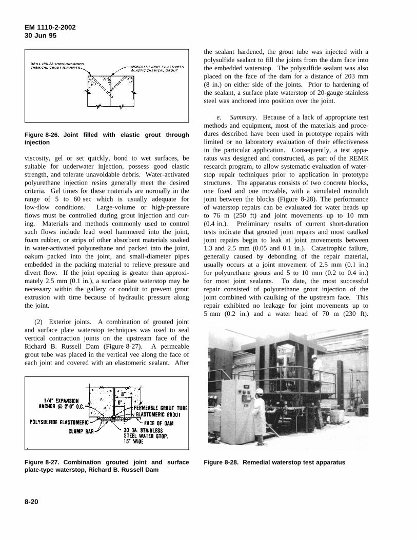
EM 1110-2-200230 Jun 95
Figure 8-26. Joint filled with elastic grout throughinjection
viscosity, gel or set quickly, bond to wet surfaces, besuitable for underwater injection, possess good elasticstrength, and tolerate unavoidable debris. Water-activatedpolyurethane injection resins generally meet the desiredcriteria. Gel times for these materials are normally in therange of 5 to 60 sec which is usually adequate forlow-flow conditions. Large-volume or high-pressureflows must be controlled during grout injection and cur-ing. Materials and methods commonly used to controlsuch flows include lead wool hammered into the joint,foam rubber, or strips of other absorbent materials soakedin water-activated polyurethane and packed into the joint,oakum packed into the joint, and small-diameter pipesembedded in the packing material to relieve pressure anddivert flow. If the joint opening is greater than approxi-mately 2.5 mm (0.1 in.), a surface plate waterstop may benecessary within the gallery or conduit to prevent groutextrusion with time because of hydraulic pressure alongthe joint.
(2) Exterior joints. A combination of grouted jointand surface plate waterstop techniques was used to sealvertical contraction joints on the upstream face of theRichard B. Russell Dam (Figure 8-27). A permeablegrout tube was placed in the vertical vee along the face ofeach joint and covered with an elastomeric sealant. After
Figure 8-27. Combination grouted joint and surfaceplate-type waterstop, Richard B. Russell Dam
the sealant hardened, the grout tube was injected with apolysulfide sealant to fill the joints from the dam face intothe embedded waterstop. The polysulfide sealant was alsoplaced on the face of the dam for a distance of 203 mm(8 in.) on either side of the joints. Prior to hardening ofthe sealant, a surface plate waterstop of 20-gauge stainlesssteel was anchored into position over the joint.
e. Summary. Because of a lack of appropriate testmethods and equipment, most of the materials and proce-dures described have been used in prototype repairs withlimited or no laboratory evaluation of their effectivenessin the particular application. Consequently, a test appa-ratus was designed and constructed, as part of the REMRresearch program, to allow systematic evaluation of water-stop repair techniques prior to application in prototypestructures. The apparatus consists of two concrete blocks,one fixed and one movable, with a simulated monolithjoint between the blocks (Figure 8-28). The performanceof waterstop repairs can be evaluated for water heads upto 76 m (250 ft) and joint movements up to 10 mm(0.4 in.). Preliminary results of current short-durationtests indicate that grouted joint repairs and most caulkedjoint repairs begin to leak at joint movements between1.3 and 2.5 mm (0.05 and 0.1 in.). Catastrophic failure,generally caused by debonding of the repair material,usually occurs at a joint movement of 2.5 mm (0.1 in.)for polyurethane grouts and 5 to 10 mm (0.2 to 0.4 in.)for most joint sealants. To date, the most successfulrepair consisted of polyurethane grout injection of thejoint combined with caulking of the upstream face. Thisrepair exhibited no leakage for joint movements up to5 mm (0.2 in.) and a water head of 70 m (230 ft).
Figure 8-28. Remedial waterstop test apparatus
8-20
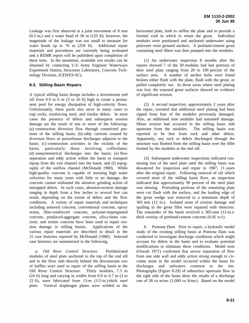
EM 1110-2-200230 Jun 95
Leakage was first observed at a joint movement of 8 mm(0.3 in.) and a water head of 38 m (125 ft); however, themagnitude of the leakage was too small to measure forwater heads up to 76 m (250 ft). Additional repairmaterials and procedures are currently being evaluatedand a REMR report will be published upon completion ofthese tests. In the meantime, available test results can beobtained by contacting U.S. Army Engineer WaterwaysExperiment Station, Structures Laboratory, Concrete Tech-nology Division, (CEWES-SC).
8-3. Stilling Basin Repairs
A typical stilling basin design includes a downstream endsill from 0.9 to 6 m (3 to 20 ft)high to create a perma-nent pool for energy dissipation of high-velocity flows.Unfortunately, these pools also serve in many cases totrap rocks, reinforcing steel, and similar debris. In mostcases the presence of debris and subsequent erosiondamage are the result of one or more of the following:(a) construction diversion flow through constricted por-tions of the stilling basin; (b) eddy currents created bydiversion flows or powerhouse discharges adjacent to thebasin; (c) construction activities in the vicinity of thebasin, particularly those involving cofferdams;(d) nonsymmetrical discharges into the basin; (e) flowseparation and eddy action within the basin to transportriprap from the exit channel into the basin, and (f) topog-raphy of the outflow channel (McDonald 1980). Whilehigh-quality concrete is capable of resisting high watervelocities for many years with little or no damage, theconcrete cannot withstand the abrasive grinding action ofentrapped debris. In such cases, abrasion-erosion damageranging in depth from a few inches to several feet canresult, depending on the extent of debris and the flowconditions. A variety of repair materials and techniquesincluding armored concrete, conventional concrete, epoxyresins, fiber-reinforced concrete, polymer-impregnatedconcrete, preplaced-aggregate concrete, silica-fume con-crete, and tremie concrete have been used to repair ero-sion damage in stilling basins. Applications of thevarious repair materials are described in detail in the31 case histories reported by McDonald (1980). Selectedcase histories are summarized in the following.
a. Old River Control Structure. Prefabricatedmodules of steel plate anchored to the top of the end silland to the floor slab directly behind the downstream rowof baffles were used in repair of the stilling basin at theOld River Control Structure. Thirty modules, 7.3 m(24 ft) long and varying in widths from 0.9 to 6.7 m (3 to22 ft), were fabricated from 13-m (1/2-in.)-thick steelplate. Vertical diaphragm plates were welded to the
horizontal plate, both to stiffen the plate and to provide aformed void in which to retain the grout. Individualmodules were positioned and anchored underwater usingpolyester resin grouted anchors. A portland-cement groutcontaining steel fibers was then pumped into the modules.
(1) An underwater inspection 8 months after therepairs showed 7 of the 30 modules had lost portions oftheir steel plate ranging from 20 to 100 percent of thesurface area. A number of anchor bolts were foundbroken either flush with the plate, flush with the grout, orpulled completely out. In those areas where steel platingwas lost, the exposed grout surfaces showed no evidenceof significant erosion.
(2) A second inspection, approximately 2 years afterthe repair, revealed that additional steel plating had beenripped from four of the modules previously damaged.Also, an additional nine modules had sustained damage.Minor erosion had occurred in the stilling basin slabupstream from the modules. The stilling basin wasreported to be free from rock and other debris.Apparently, any rock or debris discharged through thestructure was flushed from the stilling basin over the filletformed by the modules at the end sill.
(3) Subsequent underwater inspections indicated con-tinuing loss of the steel plate until the stilling basin wasdewatered for inspection and repair in 1987, 11 yearsafter the original repair. Following removal of silt whichcovered most of the stilling basin floor, an inspectionindicated that approximately 90 percent of the steel platewas missing. Protruding portions of the remaining platewere cut flush with the surface, and the leading edge ofthe grout wedge was removed to a minimum depth of305 mm (12 in.). Isolated areas of erosion damage andspalling in the grout fillet were repaired with shotcrete.The remainder of the basin received a 305-mm (12-in.)-thick overlay of portland-cement concrete (0.45 w/c).
b. Pomona Dam. Prior to repair, a hydraulic modelstudy of the existing stilling basin at Pomona Dam wasconducted to investigate discharge conditions which mightaccount for debris in the basin and to evaluate potentialmodifications to eliminate these conditions. Model tests(Oswalt 1971) confirmed that severe separation of flowfrom one side wall and eddy action strong enough to cir-culate stone in the model occurred within the basin fordischarges and tailwaters common to the site.Photographs (Figure 8-29) of subsurface upstream flow inthe right side of the basin show the results of a dischargerate of 28 cu m/sec (1,000 cu ft/sec). Based on the model
8-21
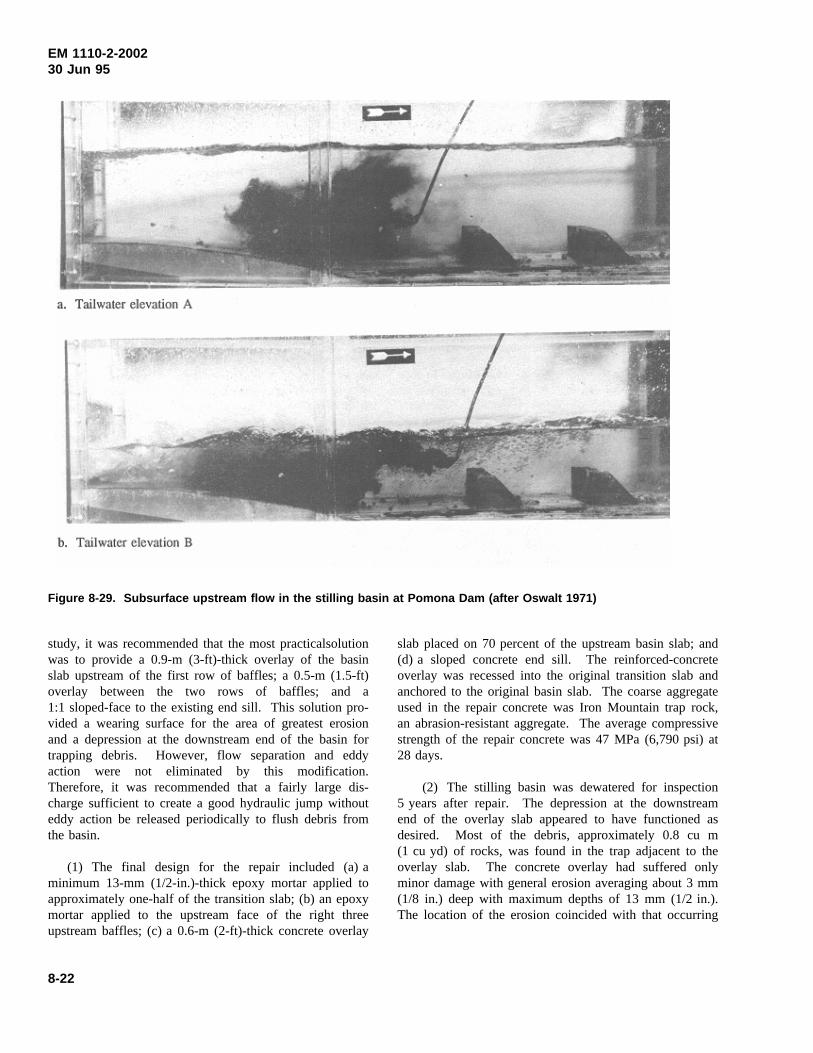
EM 1110-2-200230 Jun 95
Figure 8-29. Subsurface upstream flow in the stilling basin at Pomona Dam (after Oswalt 1971)
study, it was recommended that the most practicalsolutionwas to provide a 0.9-m (3-ft)-thick overlay of the basinslab upstream of the first row of baffles; a 0.5-m (1.5-ft)overlay between the two rows of baffles; and a1:1 sloped-face to the existing end sill. This solution pro-vided a wearing surface for the area of greatest erosionand a depression at the downstream end of the basin fortrapping debris. However, flow separation and eddyaction were not eliminated by this modification.Therefore, it was recommended that a fairly large dis-charge sufficient to create a good hydraulic jump withouteddy action be released periodically to flush debris fromthe basin.
(1) The final design for the repair included (a) aminimum 13-mm (1/2-in.)-thick epoxy mortar applied toapproximately one-half of the transition slab; (b) an epoxymortar applied to the upstream face of the right threeupstream baffles; (c) a 0.6-m (2-ft)-thick concrete overlay
slab placed on 70 percent of the upstream basin slab; and(d) a sloped concrete end sill. The reinforced-concreteoverlay was recessed into the original transition slab andanchored to the original basin slab. The coarse aggregateused in the repair concrete was Iron Mountain trap rock,an abrasion-resistant aggregate. The average compressivestrength of the repair concrete was 47 MPa (6,790 psi) at28 days.
(2) The stilling basin was dewatered for inspection5 years after repair. The depression at the downstreamend of the overlay slab appeared to have functioned asdesired. Most of the debris, approximately 0.8 cu m(1 cu yd) of rocks, was found in the trap adjacent to theoverlay slab. The concrete overlay had suffered onlyminor damage with general erosion averaging about 3 mm(1/8 in.) deep with maximum depths of 13 mm (1/2 in.).The location of the erosion coincided with that occurring
8-22
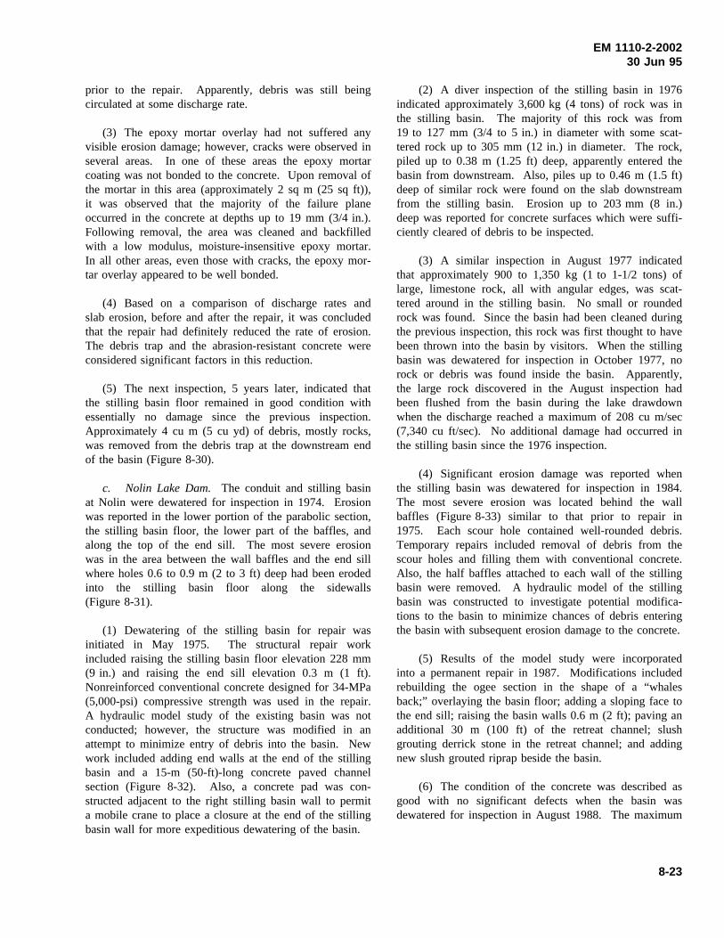
EM 1110-2-200230 Jun 95
prior to the repair. Apparently, debris was still beingcirculated at some discharge rate.
(3) The epoxy mortar overlay had not suffered anyvisible erosion damage; however, cracks were observed inseveral areas. In one of these areas the epoxy mortarcoating was not bonded to the concrete. Upon removal ofthe mortar in this area (approximately 2 sq m (25 sq ft)),it was observed that the majority of the failure planeoccurred in the concrete at depths up to 19 mm (3/4 in.).Following removal, the area was cleaned and backfilledwith a low modulus, moisture-insensitive epoxy mortar.In all other areas, even those with cracks, the epoxy mor-tar overlay appeared to be well bonded.
(4) Based on a comparison of discharge rates andslab erosion, before and after the repair, it was concludedthat the repair had definitely reduced the rate of erosion.The debris trap and the abrasion-resistant concrete wereconsidered significant factors in this reduction.
(5) The next inspection, 5 years later, indicated thatthe stilling basin floor remained in good condition withessentially no damage since the previous inspection.Approximately 4 cu m (5 cu yd) of debris, mostly rocks,was removed from the debris trap at the downstream endof the basin (Figure 8-30).
c. Nolin Lake Dam. The conduit and stilling basinat Nolin were dewatered for inspection in 1974. Erosionwas reported in the lower portion of the parabolic section,the stilling basin floor, the lower part of the baffles, andalong the top of the end sill. The most severe erosionwas in the area between the wall baffles and the end sillwhere holes 0.6 to 0.9 m (2 to 3 ft) deep had been erodedinto the stilling basin floor along the sidewalls(Figure 8-31).
(1) Dewatering of the stilling basin for repair wasinitiated in May 1975. The structural repair workincluded raising the stilling basin floor elevation 228 mm(9 in.) and raising the end sill elevation 0.3 m (1 ft).Nonreinforced conventional concrete designed for 34-MPa(5,000-psi) compressive strength was used in the repair.A hydraulic model study of the existing basin was notconducted; however, the structure was modified in anattempt to minimize entry of debris into the basin. Newwork included adding end walls at the end of the stillingbasin and a 15-m (50-ft)-long concrete paved channelsection (Figure 8-32). Also, a concrete pad was con-structed adjacent to the right stilling basin wall to permita mobile crane to place a closure at the end of the stillingbasin wall for more expeditious dewatering of the basin.
(2) A diver inspection of the stilling basin in 1976indicated approximately 3,600 kg (4 tons) of rock was inthe stilling basin. The majority of this rock was from19 to 127 mm (3/4 to 5 in.) in diameter with some scat-tered rock up to 305 mm (12 in.) in diameter. The rock,piled up to 0.38 m (1.25 ft) deep, apparently entered thebasin from downstream. Also, piles up to 0.46 m (1.5 ft)deep of similar rock were found on the slab downstreamfrom the stilling basin. Erosion up to 203 mm (8 in.)deep was reported for concrete surfaces which were suffi-ciently cleared of debris to be inspected.
(3) A similar inspection in August 1977 indicatedthat approximately 900 to 1,350 kg (1 to 1-1/2 tons) oflarge, limestone rock, all with angular edges, was scat-tered around in the stilling basin. No small or roundedrock was found. Since the basin had been cleaned duringthe previous inspection, this rock was first thought to havebeen thrown into the basin by visitors. When the stillingbasin was dewatered for inspection in October 1977, norock or debris was found inside the basin. Apparently,the large rock discovered in the August inspection hadbeen flushed from the basin during the lake drawdownwhen the discharge reached a maximum of 208 cu m/sec(7,340 cu ft/sec). No additional damage had occurred inthe stilling basin since the 1976 inspection.
(4) Significant erosion damage was reported whenthe stilling basin was dewatered for inspection in 1984.The most severe erosion was located behind the wallbaffles (Figure 8-33) similar to that prior to repair in1975. Each scour hole contained well-rounded debris.Temporary repairs included removal of debris from thescour holes and filling them with conventional concrete.Also, the half baffles attached to each wall of the stillingbasin were removed. A hydraulic model of the stillingbasin was constructed to investigate potential modifica-tions to the basin to minimize chances of debris enteringthe basin with subsequent erosion damage to the concrete.
(5) Results of the model study were incorporatedinto a permanent repair in 1987. Modifications includedrebuilding the ogee section in the shape of a “whalesback;” overlaying the basin floor; adding a sloping face tothe end sill; raising the basin walls 0.6 m (2 ft); paving anadditional 30 m (100 ft) of the retreat channel; slushgrouting derrick stone in the retreat channel; and addingnew slush grouted riprap beside the basin.
(6) The condition of the concrete was described asgood with no significant defects when the basin wasdewatered for inspection in August 1988. The maximum
8-23
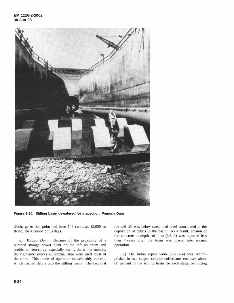
EM 1110-2-200230 Jun 95
Figure 8-30. Stilling basin dewatered for inspection, Pomona Dam
discharge to that point had been 143 cu m/sec (5,050 cuft/sec) for a period of 13 days.
d. Kinzua Dam. Because of the proximity of apumped storage power plant on the left abutment andproblems from spray, especially during the winter months,the right-side sluices at Kinzua Dam were used most ofthe time. This mode of operation caused eddy currentswhich carried debris into the stilling basin. The fact that
the end sill was below streambed level contributed to thedeposition of debris in the basin. As a result, erosion ofthe concrete to depths of 1 m (3.5 ft) was reported lessthan 4 years after the basin was placed into normaloperation.
(1) The initial repair work (1973-74) was accom-plished in two stages; cellular cofferdams enclosed about60 percent of the stilling basin for each stage, permitting
8-24
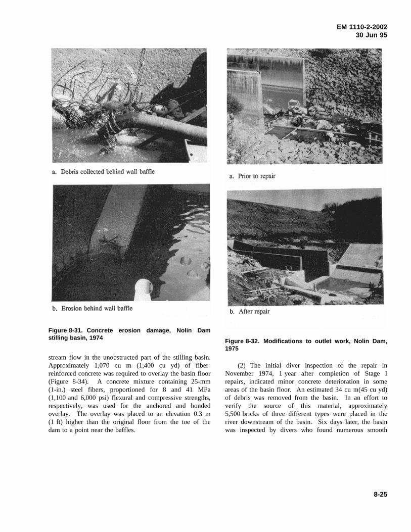
EM 1110-2-200230 Jun 95
Figure 8-31. Concrete erosion damage, Nolin Damstilling basin, 1974
stream flow in the unobstructed part of the stilling basin.Approximately 1,070 cu m (1,400 cu yd) of fiber-reinforced concrete was required to overlay the basin floor(Figure 8-34). A concrete mixture containing 25-mm(1-in.) steel fibers, proportioned for 8 and 41 MPa(1,100 and 6,000 psi) flexural and compressive strengths,respectively, was used for the anchored and bondedoverlay. The overlay was placed to an elevation 0.3 m(1 ft) higher than the original floor from the toe of thedam to a point near the baffles.
Figure 8-32. Modifications to outlet work, Nolin Dam,1975
(2) The initial diver inspection of the repair inNovember 1974, 1 year after completion of Stage Irepairs, indicated minor concrete deterioration in someareas of the basin floor. An estimated 34 cu m(45 cu yd)of debris was removed from the basin. In an effort toverify the source of this material, approximately5,500 bricks of three different types were placed in theriver downstream of the basin. Six days later, the basinwas inspected by divers who found numerous smooth
8-25
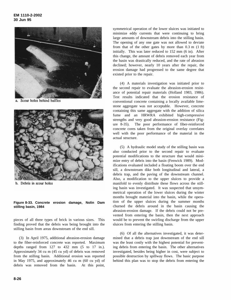
EM 1110-2-200230 Jun 95
Figure 8-33. Concrete erosion damage, Nolin Damstilling basin, 1984
pieces of all three types of brick in various sizes. Thisfinding proved that the debris was being brought into thestilling basin from areas downstream of the end sill.
(3) In April 1975, additional abrasion-erosion damageto the fiber-reinforced concrete was reported. Maximumdepths ranged from 127 to 432 mm (5 to 17 in.).Approximately 34 cu m (45 cu yd) of debris was removedfrom the stilling basin. Additional erosion was reportedin May 1975, and approximately 46 cu m (60 cu yd) ofdebris was removed from the basin. At this point,
symmetrical operation of the lower sluices was initiated tominimize eddy currents that were continuing to bringlarge amounts of downstream debris into the stilling basin.The opening of any one gate was not allowed to deviatefrom that of the other gates by more than 0.3 m (1 ft)initially. This was later reduced to 152 mm (6 in). Afterthis change, the amount of debris removed each year fromthe basin was drastically reduced, and the rate of abrasiondeclined; however, nearly 10 years after the repair, theerosion damage had progressed to the same degree thatexisted prior to the repair.
(4) A materials investigation was initiated prior tothe second repair to evaluate the abrasion-erosion resist-ance of potential repair materials (Holland 1983, 1986).Test results indicated that the erosion resistance ofconventional concrete containing a locally available lime-stone aggregate was not acceptable. However, concretecontaining this same aggregate with the addition of silicafume and an HRWRA exhibited high-compressivestrengths and very good abrasion-erosion resistance (Fig-ure 8-35). The poor performance of fiber-reinforcedconcrete cores taken from the original overlay correlateswell with the poor performance of the material in theactual structure.
(5) A hydraulic model study of the stilling basin wasalso conducted prior to the second repair to evaluatepotential modifications to the structure that would mini-mize entry of debris into the basin (Fenwick 1989). Mod-ifications evaluated included a floating boom over the endsill, a downstream dike both longitudinal and lateral, adebris trap, and the paving of the downstream channel.Also, a modification to the upper sluices to provide amanifold to evenly distribute these flows across the still-ing basin was investigated. It was suspected that unsym-metrical operation of the lower sluices during the wintermonths brought material into the basin, while the opera-tion of the upper sluices during the summer monthschurned the debris around in the basin causing theabrasion-erosion damage. If the debris could not be pre-vented from entering the basin, then the next approachwould be to prevent the swirling discharge from the uppersluices from entering the stilling basin.
(6) Of all the alternatives investigated, it was deter-mined that a debris trap just downstream of the end sillwas the least costly with the highest potential for prevent-ing debris from entering the basin. The other alternativesinvestigated, besides being higher in cost, were subject topossible destruction by spillway flows. The basic purposebehind this plan was to stop the debris from entering the
8-26
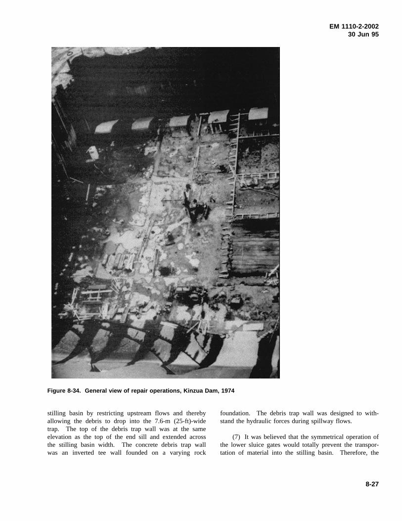
EM 1110-2-200230 Jun 95
Figure 8-34. General view of repair operations, Kinzua Dam, 1974
stilling basin by restricting upstream flows and therebyallowing the debris to drop into the 7.6-m (25-ft)-widetrap. The top of the debris trap wall was at the sameelevation as the top of the end sill and extended acrossthe stilling basin width. The concrete debris trap wallwas an inverted tee wall founded on a varying rock
foundation. The debris trap wall was designed to with-stand the hydraulic forces during spillway flows.
(7) It was believed that the symmetrical operation ofthe lower sluice gates would totally prevent the transpor-tation of material into the stilling basin. Therefore, the
8-27
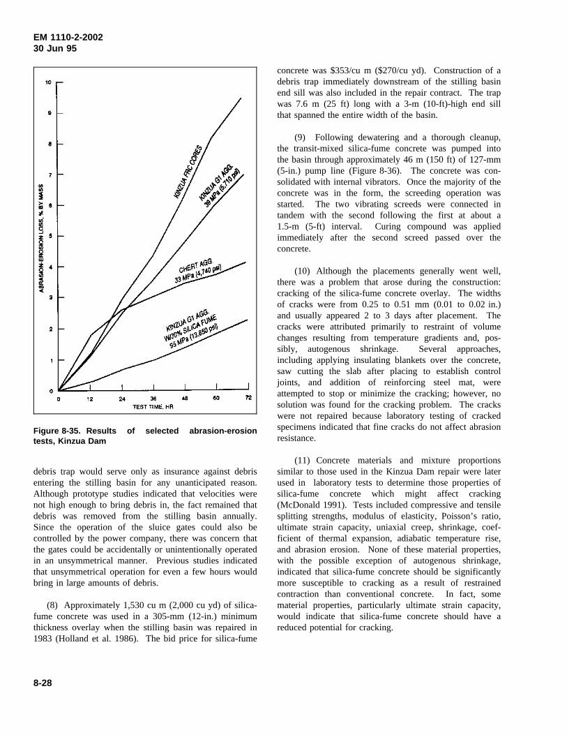
EM 1110-2-200230 Jun 95
Figure 8-35. Results of selected abrasion-erosiontests, Kinzua Dam
debris trap would serve only as insurance against debrisentering the stilling basin for any unanticipated reason.Although prototype studies indicated that velocities werenot high enough to bring debris in, the fact remained thatdebris was removed from the stilling basin annually.Since the operation of the sluice gates could also becontrolled by the power company, there was concern thatthe gates could be accidentally or unintentionally operatedin an unsymmetrical manner. Previous studies indicatedthat unsymmetrical operation for even a few hours wouldbring in large amounts of debris.
(8) Approximately 1,530 cu m (2,000 cu yd) of silica-fume concrete was used in a 305-mm (12-in.) minimumthickness overlay when the stilling basin was repaired in1983 (Holland et al. 1986). The bid price for silica-fume
concrete was $353/cu m ($270/cu yd). Construction of adebris trap immediately downstream of the stilling basinend sill was also included in the repair contract. The trapwas 7.6 m (25 ft) long with a 3-m (10-ft)-high end sillthat spanned the entire width of the basin.
(9) Following dewatering and a thorough cleanup,the transit-mixed silica-fume concrete was pumped intothe basin through approximately 46 m (150 ft) of 127-mm(5-in.) pump line (Figure 8-36). The concrete was con-solidated with internal vibrators. Once the majority of theconcrete was in the form, the screeding operation wasstarted. The two vibrating screeds were connected intandem with the second following the first at about a1.5-m (5-ft) interval. Curing compound was appliedimmediately after the second screed passed over theconcrete.
(10) Although the placements generally went well,there was a problem that arose during the construction:cracking of the silica-fume concrete overlay. The widthsof cracks were from 0.25 to 0.51 mm (0.01 to 0.02 in.)and usually appeared 2 to 3 days after placement. Thecracks were attributed primarily to restraint of volumechanges resulting from temperature gradients and, pos-sibly, autogenous shrinkage. Several approaches,including applying insulating blankets over the concrete,saw cutting the slab after placing to establish controljoints, and addition of reinforcing steel mat, wereattempted to stop or minimize the cracking; however, nosolution was found for the cracking problem. The crackswere not repaired because laboratory testing of crackedspecimens indicated that fine cracks do not affect abrasionresistance.
(11) Concrete materials and mixture proportionssimilar to those used in the Kinzua Dam repair were laterused in laboratory tests to determine those properties ofsilica-fume concrete which might affect cracking(McDonald 1991). Tests included compressive and tensilesplitting strengths, modulus of elasticity, Poisson’s ratio,ultimate strain capacity, uniaxial creep, shrinkage, coef-ficient of thermal expansion, adiabatic temperature rise,and abrasion erosion. None of these material properties,with the possible exception of autogenous shrinkage,indicated that silica-fume concrete should be significantlymore susceptible to cracking as a result of restrainedcontraction than conventional concrete. In fact, somematerial properties, particularly ultimate strain capacity,would indicate that silica-fume concrete should have areduced potential for cracking.
8-28
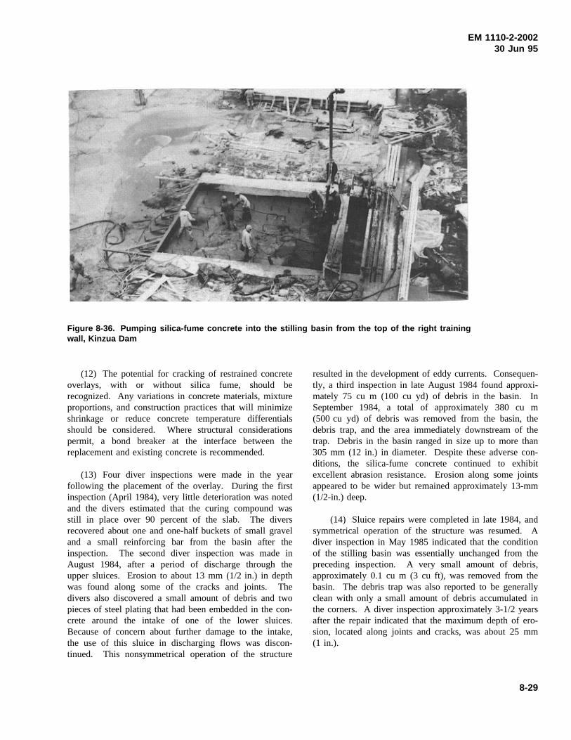
EM 1110-2-200230 Jun 95
Figure 8-36. Pumping silica-fume concrete into the stilling basin from the top of the right trainingwall, Kinzua Dam
(12) The potential for cracking of restrained concreteoverlays, with or without silica fume, should berecognized. Any variations in concrete materials, mixtureproportions, and construction practices that will minimizeshrinkage or reduce concrete temperature differentialsshould be considered. Where structural considerationspermit, a bond breaker at the interface between thereplacement and existing concrete is recommended.
(13) Four diver inspections were made in the yearfollowing the placement of the overlay. During the firstinspection (April 1984), very little deterioration was notedand the divers estimated that the curing compound wasstill in place over 90 percent of the slab. The diversrecovered about one and one-half buckets of small graveland a small reinforcing bar from the basin after theinspection. The second diver inspection was made inAugust 1984, after a period of discharge through theupper sluices. Erosion to about 13 mm (1/2 in.) in depthwas found along some of the cracks and joints. Thedivers also discovered a small amount of debris and twopieces of steel plating that had been embedded in the con-crete around the intake of one of the lower sluices.Because of concern about further damage to the intake,the use of this sluice in discharging flows was discon-tinued. This nonsymmetrical operation of the structure
resulted in the development of eddy currents. Consequen-tly, a third inspection in late August 1984 found approxi-mately 75 cu m (100 cu yd) of debris in the basin. InSeptember 1984, a total of approximately 380 cu m(500 cu yd) of debris was removed from the basin, thedebris trap, and the area immediately downstream of thetrap. Debris in the basin ranged in size up to more than305 mm (12 in.) in diameter. Despite these adverse con-ditions, the silica-fume concrete continued to exhibitexcellent abrasion resistance. Erosion along some jointsappeared to be wider but remained approximately 13-mm(1/2-in.) deep.
(14) Sluice repairs were completed in late 1984, andsymmetrical operation of the structure was resumed. Adiver inspection in May 1985 indicated that the conditionof the stilling basin was essentially unchanged from thepreceding inspection. A very small amount of debris,approximately 0.1 cu m (3 cu ft), was removed from thebasin. The debris trap was also reported to be generallyclean with only a small amount of debris accumulated inthe corners. A diver inspection approximately 3-1/2 yearsafter the repair indicated that the maximum depth of ero-sion, located along joints and cracks, was about 25 mm(1 in.).
8-29
EM 1110-2-200230 Jun 95
e. Dworshak Dam. A diver inspection in May 1973,about 2 years after the basin became operational, indicatedthat rubble and materials from construction of the damhad entered the stilling basin and had caused severedamage to the concrete. An inspection in June 1975indicated that erosion had progressed completely throughthe 3-m (10-ft)-thick floor slab in some areas. It was esti-mated that approximately 1,530 cu m (2,000 cu yd) ofconcrete had been eroded from the stilling basin. Thisextensive damage was attributed to two factors: (1) largeamounts of construction debris deposited in the basinprior to and during initial operation, and (2) unbalancedflow into the basin because of inoperable or faulty gatesin the spillway and outlet works.
(1) The stilling basin was dewatered for repair in1975. An anchored overlay of fiber-reinforced concrete(381-mm (15-in.) minimum thickness) was applied to thebasin floor. Flexural and compressive strengths of thefiber concrete mixture were approximately 6 and 55 MPa(860 and 8,000 psi), respectively, at 28 days. Followingcompletion of the overlay, the concrete in the right half ofthe basin was impregnated with methyl methacrylatemonomer (Schrader and Kaden 1976).
(2) In areas where erosion of the original concretewas less than the 381 mm (15-in.) minimum depth speci-fied for the overlay, the design called for removal of theexisting concrete to this depth. However, one section ofthe stilling basin floor and the lower portion of the spill-way exhibited only minimal erosion to a maximum depthof about 100 mm (4 in.). Therefore, it was decided torepair both sections, totaling approximately 475 sq m(5,100 sq ft), with an epoxy mortar topping. Severaltypes of epoxy mortar were used to complete this work;the primary one was a stress-relieving material which wasslow curing and had a low exotherm. Several problemswhich were primarily the result of workmanship, weatherconditions, and failure to enclose the work area occurredwith the epoxy during application. Under the cool con-ditions that existed, the epoxy mortar probably did notreceive full cure before the stilling basin was put backinto service.
(3) During the 7 months between completion ofrepairs and the initial diver inspection, the basin wassubjected to a total of 53 days usage (9 days from thespillway gates and 44 days from the regulating outlets).The spillway and outlet gates were operated symmetri-cally (or very close to it) for all spills. Total flows variedbetween 59 and 566 cu m/sec (2,100 and 20,000 cuft/sec), with the majority being on the order of 85 to283 cu m/sec (3,000 to 10,000 cu ft/sec).
(4) The underwater inspection of the stilling basinby diver identified isolated accumulations of gravel, rebar,and other debris at a number of locations throughout thebasin. Since the stilling basin had been completelycleaned following repair and current erosion was notsufficient to expose reinforcement or produce large-sizegravel, it was concluded that the material was entering thebasin from downstream of the end sill. The inspectionindicated no major erosion or damage. The stilling basinwalls had a small amount of surface erosion (less than25 mm (1 in.)). There were several areas at the junctionbetween the floor and wall with erosion up to 76-mm(3-in.) deep. An estimated 25 percent of the surface areaof the epoxy mortar had experienced some degree offailure ranging up to 102-mm (4-in.) depths. The fiber-reinforced concrete (both polymerized and non-polymerized) was generally in good condition. In general,the polymer-impregnated side was probably a little betterthan the nonpolymerized side. There were several areasof erosion in the center of the basin to depths of about25 mm (1 in.) deep. Joints and open cracks in the entirebasin (including the fiber-reinforced concrete) were themost susceptible to damage. Typical joints and opencracks in the fiber concrete had eroded up to about25-mm (1-in.) deep at the joint and tapered out to theoriginal floor surface within a foot of the joint. Becauseof the moisture in the joints and cracks during the repair,concrete at joints and cracks was not impregnated.
(5) Four months later (Nov 1976), after some addi-tional usage of the stilling basin, a diver was employed toclean the debris from the basin and provide more infor-mation on the condition of the floor. Significant com-ments resulting from this inspection were that there werelarge areas of the concrete surface near the center of thebasin with grooves 51 to 76 mm (2 to 3 in.) deep. Thesegrooves, in both the polymerized and nonpolymerizedfiber-reinforced concrete, were oriented in the direction offlow.
(6) The next diver inspection of the stilling basin inOctober 1977 indicated that the basin remained clear ofdebris. Since there had been no spill between inspections,it was concluded that operation of the powerhouse adja-cent to the stilling basin would not in itself cause debristo enter the basin. At this point, a hydraulic model studyof the stilling basin was initiated.
(7) The 1:50-scale model demonstrated that debrismoved upstream into the stilling basin area as a result offlow conditions at the end of the structure when the spill-way was in use (U.S. Army Engineer District, WallaWalla 1979). Eddy action at the edges of the outflow
8-30
EM 1110-2-200230 Jun 95
flume moved 16- to 254-mm (5/8- to 10-in.) gravel andcobble near the basin into the runout excavation along theends of the basin walls only. This material was carried tothe upstream edge of the end sill by the roller beneath theflow separating from the sill. Occasionally, the highlyturbulent flow lifted from the edge of the sill and thebottom roller swept material into the basin. With time,sizeable amounts of debris accumulated in the basin. Thetendency was that the higher the discharge, the greater themovement of material into the basin.
(8) A 6.1-m (20-ft)-high, 1.5-m (5-ft)-thick sill acrossthe basin 3 m (10 ft) upstream from the existing end sillof the same height formed a rock trap that effectivelyconfined debris coming into the basin. Sills of lowerheights were investigated but were unsatisfactory. Lowwalls that extended downstream from the basin walls werealso effective in stopping movement of debris into thebasin. Sheet-pile walls that were 4 m (13 ft) higher thanthe downstream channel and extended 15 m (50 ft) down-stream, 1.8 m (6 ft) beyond the end of the runout excava-tion, blocked the movement of debris at the ends of thebasin walls. However, a check of prototype site con-ditions revealed that the area was in rock and thereforeunsuited for sheet piles. A second wall-extension planhad low fills 7.6 m (25 ft) long and a minimum of 1.2 m(4 ft) high (Figure 8-37), which might be constructed oftremie concrete. Although lower and shorter, the fillswere as effective as the sheet-pile walls in stopping debrismovement and confining the bottom roller. The fills wererecommended as the best plan for debris control.
(9) Extension of the right training wall was completedin February 1980. The stilling basin was inspected inSeptember 1981 by use of an underwater televisioncamera. No additional damage was observed during theinspection. The stilling basin was generally clean exceptfor a thin skiff of fine material which had settled on thebottom since the spillway was last used in the spring of1981.
(10) Inspection of the stilling basin was performed bydivers with an underwater video camera in October 1983.Several small areas of apparent erosion were identified onthe upstream left side of the basin floor. It was difficultto determine whether these areas were, in fact, erosion ofthe concrete or remnants from previous stilling basinrepairs. During past polymerization of concrete surfaces,thin layers of sand adhered to the surface, resulting in arough texture. This may explain what appeared to beminor erosion damage.
f. Chief Joseph Dam. The stilling basin at ChiefJoseph Dam is approximately 280 m (920 ft) wide and67 m (220 ft) long and is divided into four rows of con-crete slabs approximately 20 m (65 ft) wide, 15 m (50 ft)long, and 1.5 m (5 ft) thick. Extensive areas of erodedconcrete were discovered in the stilling basin during anunderwater inspection in March 1957, 2 years after theproject became operative. By 1966, erosion had pro-gressed to maximum depths of approximately 1.8 m (6 ft),with the most severe erosion located in areas between therow of baffles and the end sill. Because of the high costof dewatering, it was decided to repair the basin slabsunderwater using preplaced-aggregate concrete andpumped concrete.
(1) In the preplaced-aggregate concrete operations,concrete buckets containing the coarse aggregate wereguided into position and dumped by a diver. Screeds onpreset edge forms were then used by the divers for level-ing the aggregate to the proper grade before placing thetop form panels. Grout pipes were driven the full depthof the coarse aggregate. The grout mixer and pumpswere set up on a training wall and grout was first pumpedthrough grout pipes in the deepest area of the placementuntil a return appeared through the vent pipes surroundingthat area. These were plugged with corks when goodsanded grout appeared. When grout appeared in the nextrow of vent pipes, the grout hose was moved to an adja-cent pipe and the grout hole plugged. This procedure wascontinued until the entire form had been pumped.Approximately 61 cu m (80 cu yd) of preplaced-aggregateconcrete was required in the repair.
(2) In the pumped concrete operations, concrete wasbatched at a local supplier and delivered to the site intransit mixers. At the site, the material was placed in acollection hopper on a training wall and delivered fromthis point through a 254-mm (10-in.) pipe into concretebuckets on a barge for ferrying to the pump sites. Fromthis point the concrete was pumped through a 76-mm(3-in.) hose. The last 0.6 m (2 ft) of this hose was fittedwith a metal tube to allow ready insertion of the conduitinto the concrete when the surface leveled off. A clampwas located just above the metal tube to provide therequired valve action and allow the placement to be con-trolled by the diver. The concrete mixture produced aworkable material that was easily placed and produced asmooth even surface. Surface slopes estimated at 12:1were achieved. The measured surface area of pumpedconcrete was 367 sq m (439 sq yd).
8-31
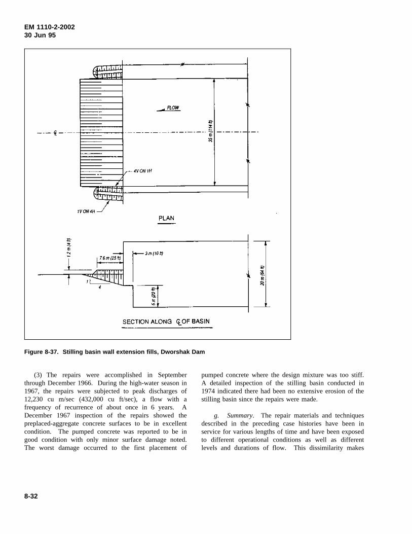
EM 1110-2-200230 Jun 95
Figure 8-37. Stilling basin wall extension fills, Dworshak Dam
(3) The repairs were accomplished in Septemberthrough December 1966. During the high-water season in1967, the repairs were subjected to peak discharges of12,230 cu m/sec (432,000 cu ft/sec), a flow with afrequency of recurrence of about once in 6 years. ADecember 1967 inspection of the repairs showed thepreplaced-aggregate concrete surfaces to be in excellentcondition. The pumped concrete was reported to be ingood condition with only minor surface damage noted.The worst damage occurred to the first placement of
pumped concrete where the design mixture was too stiff.A detailed inspection of the stilling basin conducted in1974 indicated there had been no extensive erosion of thestilling basin since the repairs were made.
g. Summary. The repair materials and techniquesdescribed in the preceding case histories have been inservice for various lengths of time and have been exposedto different operational conditions as well as differentlevels and durations of flow. This dissimilarity makes
8-32
EM 1110-2-200230 Jun 95
any comparison of the relative merits of the various sys-tems difficult at best; however, a number of generaltrends are apparent.
(1) Materials.
(a) The resistance of steel plate to abrasion erosion iswell established; however, it must be sufficiently anchoredto the underlying concrete to resist the uplift forces andvibrations created by flowing water. Welding of anchorsystems as nearly flush with the plate surface as possibleappears more desirable than raised-bolt connections. Inany case, the ability of the anchor system, including anyembedment material, to perform satisfactorily under theexposure conditions, particularly creep and fatigue, shouldbe evaluated during design of the repair.
(b) It is feasible to use prefabricated panels or cast-in-place concrete in underwater repair of stilling basins.The inherent advantages of each procedure should beconsidered in those cases where it is extremely difficultand expensive to dewater a structure to make repairsunder dry conditions. Prefabricated elements forunderwater repair of stilling basins were investigated aspart of the REMR research program (Rail andHaynes 1991). Guidance on underwater repair of con-crete is given in Section 8-6.
(c) Minimal erosion of the fiber-reinforced grout atOld River Low Sill Structure has been reported. How-ever, the location of this material on a 1-in-7 slope at theend sill should significantly reduce the potential for thepresence of abrasive debris on surface of the repair mate-rial. The fiber-reinforced concrete failed under the severeabrasion condition at Kinzua Dam. Also, the poor perfor-mance of fiber-reinforced concrete cores in abrasion-erosion tests correlated well with the poor performance ofthe material in the actual structure. After 1-year exposureto limited discharges at Dworshak Dam, fiber-reinforcedconcrete (both polymerized and nonpolymerized) waseroded to maximum depths of 51 to 76 mm (2 to 3 in.).
(d) An estimated 25 percent of the epoxy mortar atDworshak Dam had failed, probably because of workman-ship, weather conditions, and lack of sufficient curingduring construction. No erosion damage to the epoxymortar was visible at Pomona Dam; however, there wereseveral areas of cracking and loss of bond attributed toimproper curing and thermal incompatibility with existingconcrete.
(e) Conventional concrete proportioned for 34-MPa(5,000-psi) compressive strength exhibited erosion up to
203 mm (8 in.) deep after less than 1-year exposure atNolin Lake Dam. In comparison, conventional concretecontaining abrasion-resistant trap rock aggregate hadgeneral erosion of only 3 to 13 mm (1/8 to 1/2 in.) after10 years exposure at Pomona Dam. The abrasion resis-tance of conventional concrete containing the limestoneaggregate locally available at Kinzua Dam was unaccept-able. However, concrete containing this same aggregatewith the addition of silica fume and an HRWRA hasexhibited excellent abrasion-erosion resistance. Unlikeconcretes containing or impregnated with polymers, con-cretes containing silica fume are economical and are read-ily transportable and placeable using conventionalmethods.
(2) Revised Configuration.
(a) The steel modules anchored to the stilling basinslab and the top of the end sill at Old River Low SillStructure essentially created a sloping end sill. Appar-ently, any debris discharged through the structure is beingflushed from the basin over this fillet, since diver inspec-tions have reported the basin to be free from debris.When the stilling basin at Pomona Dam was dewatered5 and 10 years after repair, minimal amounts of debriswere found in the stilling basin. However, it is difficultto determine if these relatively small amounts of debriswere influenced by the addition of a sloping end sill.
(b) A debris trap was provided in the Pomona Damstilling basin by eliminating the 0.6-m (2-ft)-thick repairoverlay in an area between the downstream baffles andthe end sill. The debris trap appears to have functionedas planned because most of the debris found in subse-quent inspections was located in the trap adjacent to theraised overlay slab. Strong circulatory currents within thestilling basin appear to have negated any effect of theshallow debris trap incorporated into the original repair atKinzua Dam. Following the adoption of symmetricaldischarges, the small amounts of debris present in thestilling basin were located in areas of erosion throughoutthe basin. The debris trap with a 3-m (10-ft)-high end sillincluded in the second repair was also unable to preventdownstream debris from entering the basin under thesevere hydraulic conditions at Kinzua Dam.
(c) The stilling basin at Nolin Lake Dam was modi-fied during both repairs. In the second repair, modifica-tions were based on the results of a hydraulic modelstudy. These modifications appear to have eliminatedprevious erosion problems. The extension of the trainingwall at Dworshak Dam appears to have enhanced theperformance of the stilling basin.
8-33
EM 1110-2-200230 Jun 95
(3) Operations.
(a) Model tests of the stilling basin at Pomona Damverified that severe separation of flow from one sidewalland eddy action within the basin occurred for dischargeand tailwater conditions common to the prototype. Also,these tests revealed that the eddy within the basin wascapable of generating considerable reverse flow from theexit channel with the potential to transport riprap from thechannel into the basin. Based on the model tests, guid-ance as to the discharge and tailwater relations required toflush debris from the basin was developed. Followingimplementation of the most practical material and hydrau-lic modifications, the stilling basin is performing quitewell.
(b) Because of the proximity of a pumped-storagepower plant on the left abutment and problems fromspray, especially during the winter months, the right-sidesluices at Kinzua Dam were used most of the time. Thisusage caused a circulatory current that carried debris fromdownstream over the end sill, which is below streambedlevel, into the stilling basin. Under these conditions, anaverage of 39 cu m (50 cu yd) of debris was removedfrom the basin during each of three inspections within the7 months following completion of repairs. At this point apolicy of symmetrical sluice operation was initiated, andbased on prototype experiments, a table outlining sluiceoperating procedure for a range of outflow was prepared.Subsequent to the adoption of this revised sluice operationpolicy, a minimum of debris was removed from the basinand the rate of erosion decreased.
(c) Upon completion of inspection or repair of adewatered stilling basin, the basin should be flooded insuch a manner to prevent material from temporary accessroads, cofferdams, etc., from being washed back into thebasin.
h. Conclusions.
(a) Conventional concrete with the lowest practicalw/c ratio and hard, abrasion-resistant coarse aggregate isrecommended for repair of structures subjected to abra-sion-erosion damage. Also, silica-fume concrete appearsto be an economical solution to abrasion-erosion prob-lems, particularly in those areas where locally availableaggregate otherwise might not be acceptable. The abra-sion-erosion resistance of repair materials should beevaluated in accordance with ASTM C 1138 prior toapplication.
(b) In many cases, underwater repair of stillingbasins with prefabricated elements, preplaced-aggregateconcrete, pumped concrete, or tremie concrete is an eco-nomical alternative to dewatering a stilling basin forrepairs under dry conditions. Even when a stilling basinis dewatered, it is often difficult to dry existing concretesurfaces because of leaking cracks and joints. Materialssuitable for repair of wet concrete surfaces were identifiedand evaluated as part of the REMR research program(Best and McDonald 1990b).
(c) Additional improvements in materials shouldcontinue to reduce the rate of concrete damage caused byerosion. However, until the adverse hydraulic conditionsthat caused the original damage are minimized or elimi-nated, it will be difficult for many of the materials cur-rently being used in repair to perform in the desiredmanner. Prior to major repairs, model studies of theexisting stilling basin and exit channel should be con-ducted to verify the cause(s) of erosion damage and toevaluate the effectiveness of various modifications ineliminating undesirable hydraulic conditions.
(d) In existing structures, releases should be control-led to avoid discharge conditions where flow separationand eddy action are prevalent. Substantial discharges thatcan provide a good hydraulic jump without creating eddyaction should be released periodically in an attempt toflush debris from the stilling basin. Guidance as to dis-charge and tailwater relations required for flushing mustbe developed through model/prototype tests. Periodicinspections should be required to determine the presenceof debris in the stilling basin and the extent of erosion.
8-4. Concrete Cutoff Walls
Concrete cutoff walls, sometimes referred to as diaphragmwalls, are cast-in-place structures used to provide a posi-tive cutoff of the flow of water under or around a hydrau-lic structure. The decision to construct a concrete cutoffwall is usually not made as a result of deterioration of theconcrete in a structure but rather because of flows underor around the structure. Therefore, the decision to con-struct such a wall should only be made after a thoroughprogram of geotechnical monitoring and review.
a. Application. Concrete cutoff walls have beenused in several instances at structures to reduce or elimi-nate potentially dangerous flows through foundation mate-rials. The walls are typically unreinforced, approximately0.6 to 0.9 m (2 to 3 ft) thick and are as deep and as long
8-34
EM 1110-2-200230 Jun 95
as required by site conditions. At Wolf Creek Dam inKentucky, the wall was 683 m (2,240 ft) long and con-tained elements as deep as 85 m (278 ft). In some cases,a cutoff wall has been constructed only after attempts atgrouting have been unsuccessful or have not given assur-ances of completely eliminating flows.
b. Procedure. In general, cutoff walls are con-structed as summarized in the following steps. Kahl,Kauschinger, and Perry (1991), Holland and Turner(1980), and Xanthakos (1979) provide additional infor-mation on construction of concrete cutoff walls.
(1) A concrete-lined guide trench is constructed alongthe axis of the wall. This trench is usually only a fewfeet deep. The concrete provides a working surface onboth sides of the wall, helps to maintain the alignment ofthe wall, and prevents the shoulders of the excavationfrom caving into the trench.
(2) The excavation is accomplished with appropriateequipment for the site conditions. Usually, the excavationis done as a series of discontinuous segments with theproject specifications limiting the amount of excavationthat can be open at any time. As segments are excavatedand backfilled with concrete, intervening segments areconstructed. Excavation equipment includes clam shells,rock drills, and specialty bucket excavators. The excavat-ing is usually done through bentonite slurry to keep theholes open. Slurry preparation, handling, and cleaning arecritical aspects of the project. Careful control must beexercised during the excavation of each segment to main-tain verticality. If a segment is out of vertical alignment,the next adjacent segment to be placed may not contactthe first segment for its entire depth and a gap may existin the wall.
(3) Concrete is placed in the segments using tremies.(See Section 6-33 for a general description of tremieplacement.) Since the wall is expected to provide acomplete cutoff, any discontinuities in the concrete maycause serious problems in the performance of the wall.Problems that have been reported have included zones orportions of the wall containing poorly or completely unce-mented aggregates. These problems are usually attribu-table to an improperly proportioned concrete mixture or topoor placement practices. It is extremely important thatproject personnel be familiar with the required proceduresfor these placements and that specifications be strictlyenforced. The concrete mixture itself is very important,as it is for any tremie placement. The specifications forthe concrete should not be based upon a required com-pressive strength. Instead, the flowability and cohesion of
the concrete are critical. Concrete with the proper charac-teristics may be proportioned using a minimum cementcontent of 386 to 415 kg/cu m (650 to 700 lb/cu yd) anda maximum w/c of 0.45. Testing as outlined inCRD-C 32 will be of benefit while developing a suitableconcrete mixture.
(4) Core drilling should be specified throughout theproject as a means of determining the quality of the con-crete in place in the wall.
(5) It is an extremely beneficial practice for theseprojects to require the contractor to place several testpanels outside the actual wall area or in noncritical por-tions of the wall. These test panels will allow forthorough review of the proposed procedures, concretemixture, and equipment.
8-5. Precast Concrete Applications
The use of precast concrete in repair and replacement ofcivil works structures has increased significantly in recentyears and the trend is expected to continue. Case his-tories of precast concrete applications in repair orreplacement of a wide variety of structures includingnavigation locks, dams, channels, floodwalls, levees,coastal structures, marine structures, bridges, culverts,tunnels, retaining walls, noise barriers, and highway pave-ment are described in detail by McDonald and Curtis(1995). Applications of precast concrete in repair of navi-gation lock walls are described in Section 8-1. Selectedcase histories of additional precast concrete applicationsare summarized in the following.
a. Barker Dam. One of the earliest applications ofprecast concrete panels as stay-in-place forms was atBarker Dam, a cyclopean concrete, gravity structurelocated near Boulder, CO. The dam is approximately53 m (175 ft) high with a crest length of 219 m (720 ft).The dam underwent major rehabilitation in 1947 toreplace the deteriorated concrete in the upstream face, tocorrect leakage problems, and to improve the stability ofthe dam. Deterioration of the concrete on the upstreamface of the dam was caused by exposure to approximately36 years of cycles of freezing and thawing. The reser-voir, which is filled in the spring and early summer pri-marily by melting snow, is drawn down during the winterleaving the upstream face of the dam exposed.
(1) Rehabilitation of the upstream face of the damconsisted of removing the deteriorated concrete, installingprecast reinforced-concrete panels over the entire
8-35
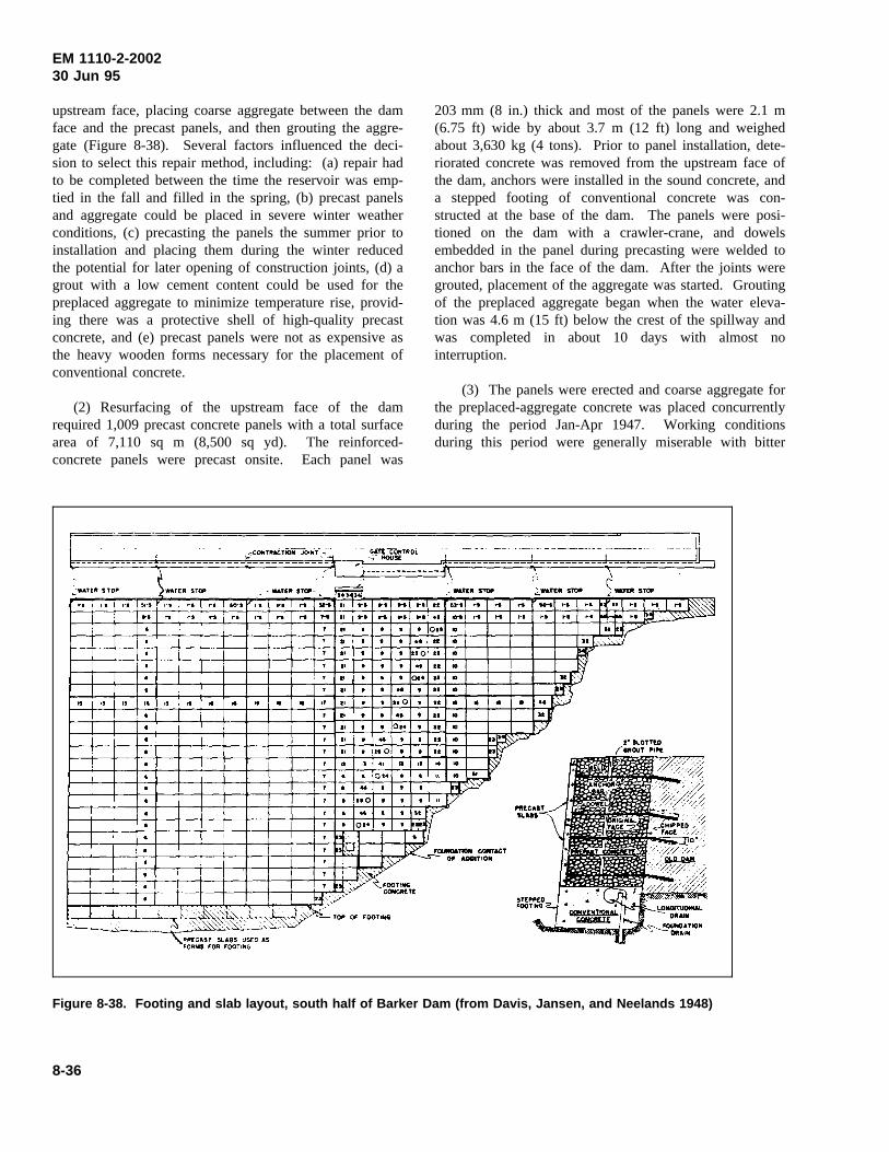
EM 1110-2-200230 Jun 95
upstream face, placing coarse aggregate between the damface and the precast panels, and then grouting the aggre-gate (Figure 8-38). Several factors influenced the deci-sion to select this repair method, including: (a) repair hadto be completed between the time the reservoir was emp-tied in the fall and filled in the spring, (b) precast panelsand aggregate could be placed in severe winter weatherconditions, (c) precasting the panels the summer prior toinstallation and placing them during the winter reducedthe potential for later opening of construction joints, (d) agrout with a low cement content could be used for thepreplaced aggregate to minimize temperature rise, provid-ing there was a protective shell of high-quality precastconcrete, and (e) precast panels were not as expensive asthe heavy wooden forms necessary for the placement ofconventional concrete.
(2) Resurfacing of the upstream face of the damrequired 1,009 precast concrete panels with a total surfacearea of 7,110 sq m (8,500 sq yd). The reinforced-concrete panels were precast onsite. Each panel was
203 mm (8 in.) thick and most of the panels were 2.1 m(6.75 ft) wide by about 3.7 m (12 ft) long and weighedabout 3,630 kg (4 tons). Prior to panel installation, dete-riorated concrete was removed from the upstream face ofthe dam, anchors were installed in the sound concrete, anda stepped footing of conventional concrete was con-structed at the base of the dam. The panels were posi-tioned on the dam with a crawler-crane, and dowelsembedded in the panel during precasting were welded toanchor bars in the face of the dam. After the joints weregrouted, placement of the aggregate was started. Groutingof the preplaced aggregate began when the water eleva-tion was 4.6 m (15 ft) below the crest of the spillway andwas completed in about 10 days with almost nointerruption.
(3) The panels were erected and coarse aggregate forthe preplaced-aggregate concrete was placed concurrentlyduring the period Jan-Apr 1947. Working conditionsduring this period were generally miserable with bitter
Figure 8-38. Footing and slab layout, south half of Barker Dam (from Davis, Jansen, and Neelands 1948)
8-36
EM 1110-2-200230 Jun 95
cold and high wind velocities. Concrete construction withconventional methods would have been impractical duringthis period because of the severe weather conditions. Thedegree of severity of the weather was reflected in ratherlarge daily variations in the rate of panel erection; theaverage rate was about 12 panels per day with a maxi-mum of 27 panels erected in 1 day.
(4) The quality of the work at Barker Dam is con-sidered to be excellent and the objectives of the rehabilita-tion program were achieved; however, it is believed thatprecast panels of much larger size would have resulted inadditional economies. With heavy construction equip-ment, panels up to four times the area could be handledwithout difficulty and erected at about the same rate asthe smaller panels. In addition to reducing the cost ofpanel erection, larger panels would significantly reducethe total length of joints between panels with a corre-sponding reduction in the cost of joint treatments.
b. Gavins Point Dam. Concrete spalling along thesouth retaining wall downstream of the powerhouse atGavins Point Dam was discovered during a diverinspection. Subsequent inspections, which indicated thatthe spalling was increasing in area and depth, causedconcern that the tailrace slab was being undermined. Arepair in the dry would have required construction of acofferdam; however, the cost of building a cofferdam plusthe lengthy powerplant outage during construction was toogreat. Therefore, it was decided that the repairs would bemade underwater by divers, working at a depth of approx-imately 15 m (50 ft).
(1) After the spalled concrete surfaces were cleaned,the voids were filled with preplaced aggregate, covered byprecast concrete panels, and grouted (Figure 8-39). Theprecast concrete stay-in-place forms were anchored tosound concrete to resist uplift caused by the pressuregrouting and to improve stability during power plantoperation.
(2) The contract specified that the underwater repairwas to be completed during a period of 14 consecutivedays when the power units were shut down. Thecontractor used several diving crews so work could con-tinue 24 hours a day. Also, each step of the repair wasreviewed on land before being done underwater. As aresult, the project was satisfactorily completed 3-1/2 daysearly.
c. C-1 Dam. Lock and Dam C-1 is located on theChamplain Canal near Troy, NY. A two-stage rehabilita-tion of the dam’s seven tainter gate piers was initiated in
1993. In stage I, a cellular cofferdam was constructed toenclose piers 5, 6, and 7. Following dewatering, thecounterweights for each tainter gate were removed andplaced on temporary supports immediately downstream ofthe gates. The steel tainter gates were then removed forrefurbishing and the existing concrete gate piers wereremoved down to the original foundation. Precast conreteunits were used to reconstruct the gate piers(Figure 8-40).
(1) The concrete mixture used in precasting wasproportioned with 13-mm (1/2-in.) maximum size aggre-gate for a 28-day compressive strength of 48 MPa(7,000 psi). The panels were reinforced with Grade 60,epoxy-coated reinforcing steel. The nose and butt unitswere cast as individual panels and the remaining pierunits consisted of three or four integrated panels. Fabri-cation tolerances for lengths of the units were 13 mm(1/2 in.), plus or minus, or 3 mm (1/8 in.) per 3 m (10 ft)of length, whichever was greater. Panel thickness andunit width tolerances were 6 mm (1/4 in.).
(2) The precast pier units were transported viatractor-trailer rigs to a launch ramp near the dam. At thispoint, the loaded rigs were driven onto a barge for trans-portation to the construction site in the river. The pierunits were offloaded with a crane located on the coffer-dam. A second crane inside the cofferdam was used toposition the pier units. After each tier of units was pro-perly proportioned and aligned, the vertical and horizontaljoints were grouted, reinforcement was installed inside theunits, and the units were filled with conventional concrete.Eighteen precast units were used in each gate pier. Thecompleted piers are 2.4 m (8 ft) wide, 18.7 m (61.5 ft)long, and 8.7 m (28.5 ft) high. Following completion ofthe gate piers, the reconditioned tainter gates were rein-stalled (Figure 8-41). A similar procedure is currentlybeing used to reconstruct the four remaining gate piers.
d. Chauncy Run Checkdams. As part of the overallrehabilitation of the Hornell Local Flood Protection Proj-ect, two checkdams were constructed on Chauncy Run.The original plan was to use cast-in-place concrete gravitydams with fully paved stilling basins. However, costestimates in the 30-percent design submission indicatedthe use of precast concrete could decrease the cost of thedams by 50 percent. In addition, precasting under con-trolled plant conditions would assure high quality mate-rials. Precast concrete crib units were used to form theabutments which were then filled with gravel. The check-dams are specially designed precast concrete planks sup-ported by precast concrete posts embedded in the rock
8-37
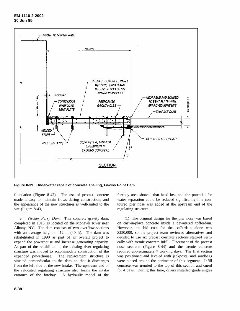
EM 1110-2-200230 Jun 95
Figure 8-39. Underwater repair of concrete spalling, Gavins Point Dam
foundation (Figure 8-42). The use of precast concretemade it easy to maintain flows during construction, andthe appearance of the new structures is well-suited to thesite (Figure 8-43).
e. Vischer Ferry Dam. This concrete gravity dam,completed in 1913, is located on the Mohawk River nearAlbany, NY. The dam consists of two overflow sectionswith an average height of 12 m (40 ft). The dam wasrehabilitated in 1990 as part of an overall project toexpand the powerhouse and increase generating capacity.As part of the rehabilitation, the existing river regulatingstructure was moved to accommodate construction of theexpanded powerhouse. The replacement structure issituated perpendicular to the dam so that it dischargesfrom the left side of the new intake. The upstream end ofthe relocated regulating structure also forms the intakeentrance of the forebay. A hydraulic model of the
forebay area showed that head loss and the potential forwater separation could be reduced significantly if a con-toured pier nose was added at the upstream end of theregulating structure.
(1) The original design for the pier nose was basedon cast-in-place concrete inside a dewatered cofferdam.However, the bid cost for the cofferdam alone was$250,000, so the project team reviewed alternatives anddecided to use six precast concrete sections stacked verti-cally with tremie concrete infill. Placement of the precastnose sections (Figure 8-44) and the tremie concreterequired approximately 7 working days. The first sectionwas positioned and leveled with jackposts, and sandbagswere placed around the perimeter of this segment. Infillconcrete was tremied to the top of this section and curedfor 4 days. During this time, divers installed guide angles
8-38
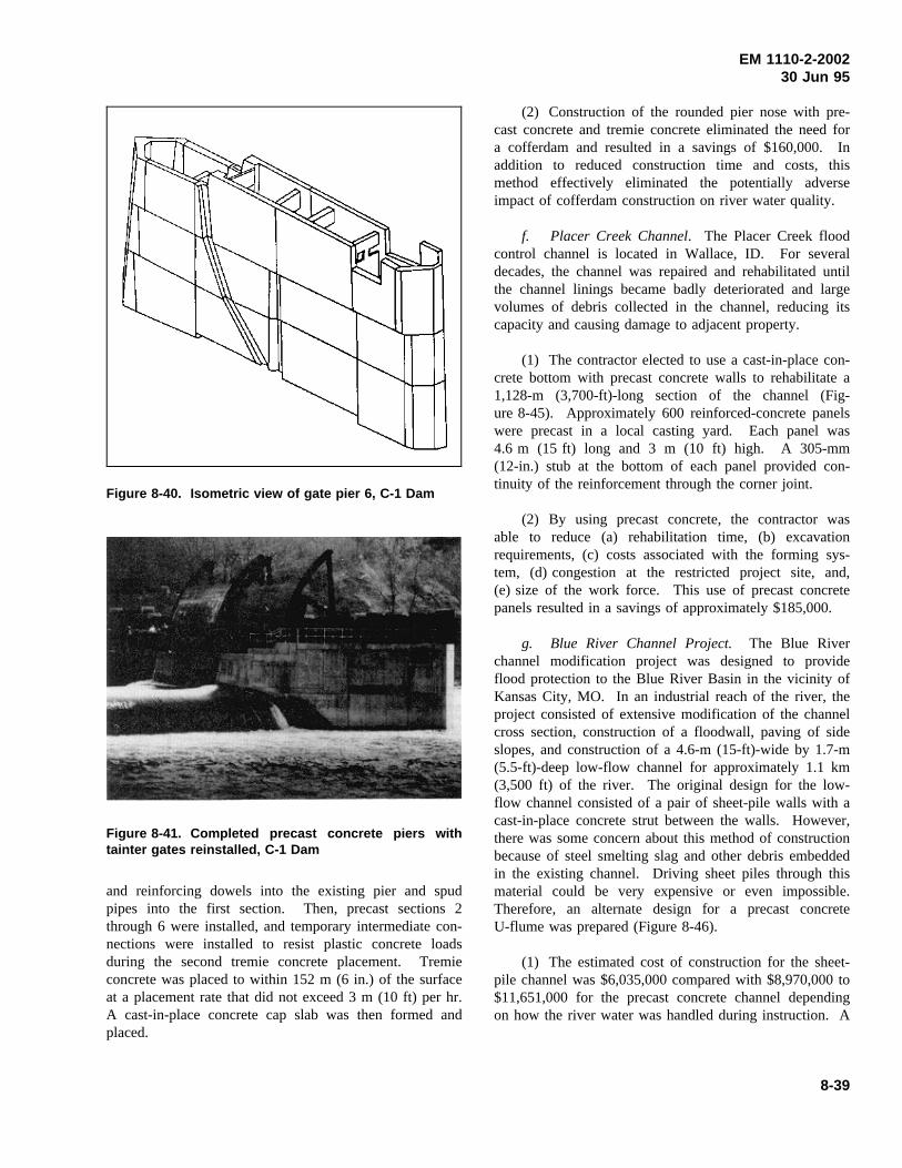
EM 1110-2-200230 Jun 95
Figure 8-40. Isometric view of gate pier 6, C-1 Dam
Figure 8-41. Completed precast concrete piers withtainter gates reinstalled, C-1 Dam
and reinforcing dowels into the existing pier and spudpipes into the first section. Then, precast sections 2through 6 were installed, and temporary intermediate con-nections were installed to resist plastic concrete loadsduring the second tremie concrete placement. Tremieconcrete was placed to within 152 m (6 in.) of the surfaceat a placement rate that did not exceed 3 m (10 ft) per hr.A cast-in-place concrete cap slab was then formed andplaced.
(2) Construction of the rounded pier nose with pre-cast concrete and tremie concrete eliminated the need fora cofferdam and resulted in a savings of $160,000. Inaddition to reduced construction time and costs, thismethod effectively eliminated the potentially adverseimpact of cofferdam construction on river water quality.
f. Placer Creek Channel. The Placer Creek floodcontrol channel is located in Wallace, ID. For severaldecades, the channel was repaired and rehabilitated untilthe channel linings became badly deteriorated and largevolumes of debris collected in the channel, reducing itscapacity and causing damage to adjacent property.
(1) The contractor elected to use a cast-in-place con-crete bottom with precast concrete walls to rehabilitate a1,128-m (3,700-ft)-long section of the channel (Fig-ure 8-45). Approximately 600 reinforced-concrete panelswere precast in a local casting yard. Each panel was4.6 m (15 ft) long and 3 m (10 ft) high. A 305-mm(12-in.) stub at the bottom of each panel provided con-tinuity of the reinforcement through the corner joint.
(2) By using precast concrete, the contractor wasable to reduce (a) rehabilitation time, (b) excavationrequirements, (c) costs associated with the forming sys-tem, (d) congestion at the restricted project site, and,(e) size of the work force. This use of precast concretepanels resulted in a savings of approximately $185,000.
g. Blue River Channel Project. The Blue Riverchannel modification project was designed to provideflood protection to the Blue River Basin in the vicinity ofKansas City, MO. In an industrial reach of the river, theproject consisted of extensive modification of the channelcross section, construction of a floodwall, paving of sideslopes, and construction of a 4.6-m (15-ft)-wide by 1.7-m(5.5-ft)-deep low-flow channel for approximately 1.1 km(3,500 ft) of the river. The original design for the low-flow channel consisted of a pair of sheet-pile walls with acast-in-place concrete strut between the walls. However,there was some concern about this method of constructionbecause of steel smelting slag and other debris embeddedin the existing channel. Driving sheet piles through thismaterial could be very expensive or even impossible.Therefore, an alternate design for a precast concreteU-flume was prepared (Figure 8-46).
(1) The estimated cost of construction for the sheet-pile channel was $6,035,000 compared with $8,970,000 to$11,651,000 for the precast concrete channel dependingon how the river water was handled during instruction. A
8-39
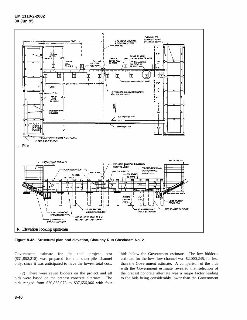
EM 1110-2-200230 Jun 95
Figure 8-42. Structural plan and elevation, Chauncy Run Checkdam No. 2
Government estimate for the total project cost($31,852,218) was prepared for the sheet-pile channelonly, since it was anticipated to have the lowest total cost.
(2) There were seven bidders on the project and allbids were based on the precast concrete alternate. Thebids ranged from $20,835,073 to $37,656,066 with four
bids below the Government estimate. The low bidder’sestimate for the low-flow channel was $2,000,245, far lessthan the Government estimate. A comparison of the bidswith the Government estimate revealed that selection ofthe precast concrete alternate was a major factor leadingto the bids being considerably lower than the Government
8-40
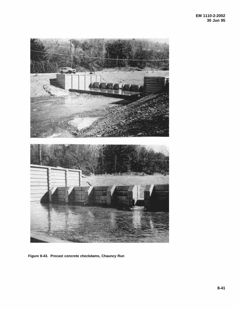
EM 1110-2-200230 Jun 95
Figure 8-43. Precast concrete checkdams, Chauncy Run
8-41
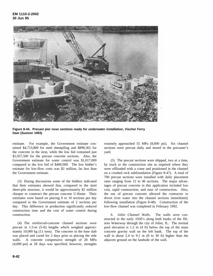
EM 1110-2-200230 Jun 95
Figure 8-44. Precast pier nose sections ready for underwater installation, Vischer FerryDam (Sumner 1993)
estimate. For example, the Government estimate con-tained $4,753,800 for steel sheetpiling and $898,365 forthe concrete in the strut, while the low bid contained just$1,057,500 for the precast concrete sections. Also, theGovernment estimate for water control was $1,017,000compared to the low bid of $400,000. The low bidder’sestimate for low-flow costs was $2 million, far less thanthe Government estimate.
(3) During discussions some of the bidders indicatedthat their estimates showed that, compared to the steelsheet-pile structure, it would be approximately $2 millioncheaper to construct the precast concrete U-flume. Theirestimates were based on placing 8 to 10 sections per daycompared to the Government estimate of 2 sections perday. This difference in production significantly reducedconstruction time and the cost of water control duringconstruction.
(4) The reinforced-concrete channel sections wereprecast in 1.5-m (5-ft) lengths which weighed approxi-mately 10,000 kg (11 tons). The concrete in the base slabwas placed and cured for 2 days prior to placing the sidewalls. A concrete compressive strength of 28 MPa(4,000 psi) at 28 days was specified; however, strengths
routinely approached 55 MPa (8,000 psi). Six channelsections were precast daily and stored in the precaster’syard.
(5) The precast sections were shipped, two at a time,by truck to the construction site as required where theywere offloaded with a crane and positioned in the channelon a crushed rock subfoundation (Figure 8-47). A total of700 precast sections were installed with daily placementrates ranging from 12 to 46 sections. The major advan-tages of precast concrete in this application included lowcost, rapid construction, and ease of construction. Also,the use of precast concrete allowed the contractor todivert river water into the channel sections immediatelyfollowing installation (Figure 8-48). Construction of thelow-flow channel was completed in February 1992.
h. Joliet Channel Walls. The walls were con-structed in the early 1930’s along both banks of the Illi-nois Waterway through the city of Joliet, IL. The normalpool elevation is 1.2 m (4 ft) below the top of the massconcrete gravity wall on the left bank. The top of thewall is about 2.4 to 9.1 m (8 to 30 ft) higher than theadjacent ground on the landside of the wall.
8-42
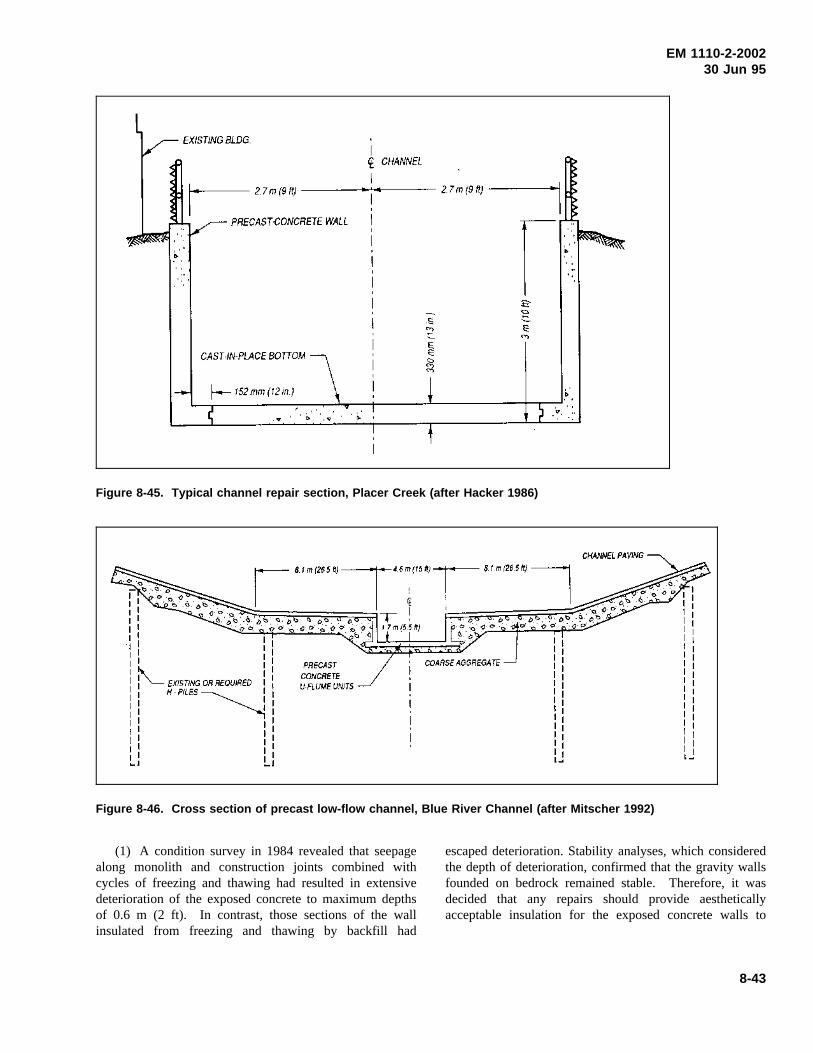
EM 1110-2-200230 Jun 95
Figure 8-45. Typical channel repair section, Placer Creek (after Hacker 1986)
Figure 8-46. Cross section of precast low-flow channel, Blue River Channel (after Mitscher 1992)
(1) A condition survey in 1984 revealed that seepagealong monolith and construction joints combined withcycles of freezing and thawing had resulted in extensivedeterioration of the exposed concrete to maximum depthsof 0.6 m (2 ft). In contrast, those sections of the wallinsulated from freezing and thawing by backfill had
escaped deterioration. Stability analyses, which consideredthe depth of deterioration, confirmed that the gravity wallsfounded on bedrock remained stable. Therefore, it wasdecided that any repairs should provide aestheticallyacceptable insulation for the exposed concrete walls to
8-43
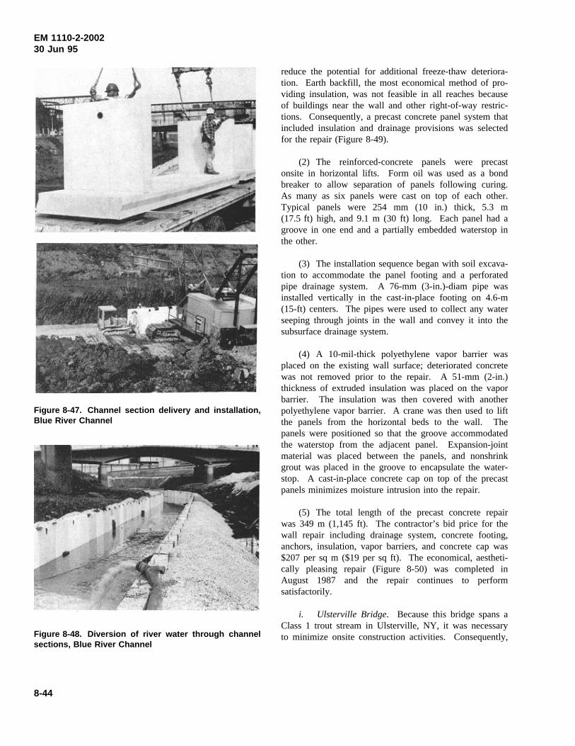
EM 1110-2-200230 Jun 95
Figure 8-47. Channel section delivery and installation,Blue River Channel
Figure 8-48. Diversion of river water through channelsections, Blue River Channel
reduce the potential for additional freeze-thaw deteriora-tion. Earth backfill, the most economical method of pro-viding insulation, was not feasible in all reaches becauseof buildings near the wall and other right-of-way restric-tions. Consequently, a precast concrete panel system thatincluded insulation and drainage provisions was selectedfor the repair (Figure 8-49).
(2) The reinforced-concrete panels were precastonsite in horizontal lifts. Form oil was used as a bondbreaker to allow separation of panels following curing.As many as six panels were cast on top of each other.Typical panels were 254 mm (10 in.) thick, 5.3 m(17.5 ft) high, and 9.1 m (30 ft) long. Each panel had agroove in one end and a partially embedded waterstop inthe other.
(3) The installation sequence began with soil excava-tion to accommodate the panel footing and a perforatedpipe drainage system. A 76-mm (3-in.)-diam pipe wasinstalled vertically in the cast-in-place footing on 4.6-m(15-ft) centers. The pipes were used to collect any waterseeping through joints in the wall and convey it into thesubsurface drainage system.
(4) A 10-mil-thick polyethylene vapor barrier wasplaced on the existing wall surface; deteriorated concretewas not removed prior to the repair. A 51-mm (2-in.)thickness of extruded insulation was placed on the vaporbarrier. The insulation was then covered with anotherpolyethylene vapor barrier. A crane was then used to liftthe panels from the horizontal beds to the wall. Thepanels were positioned so that the groove accommodatedthe waterstop from the adjacent panel. Expansion-jointmaterial was placed between the panels, and nonshrinkgrout was placed in the groove to encapsulate the water-stop. A cast-in-place concrete cap on top of the precastpanels minimizes moisture intrusion into the repair.
(5) The total length of the precast concrete repairwas 349 m (1,145 ft). The contractor’s bid price for thewall repair including drainage system, concrete footing,anchors, insulation, vapor barriers, and concrete cap was$207 per sq m ($19 per sq ft). The economical, aestheti-cally pleasing repair (Figure 8-50) was completed inAugust 1987 and the repair continues to performsatisfactorily.
i. Ulsterville Bridge. Because this bridge spans aClass 1 trout stream in Ulsterville, NY, it was necessaryto minimize onsite construction activities. Consequently,
8-44
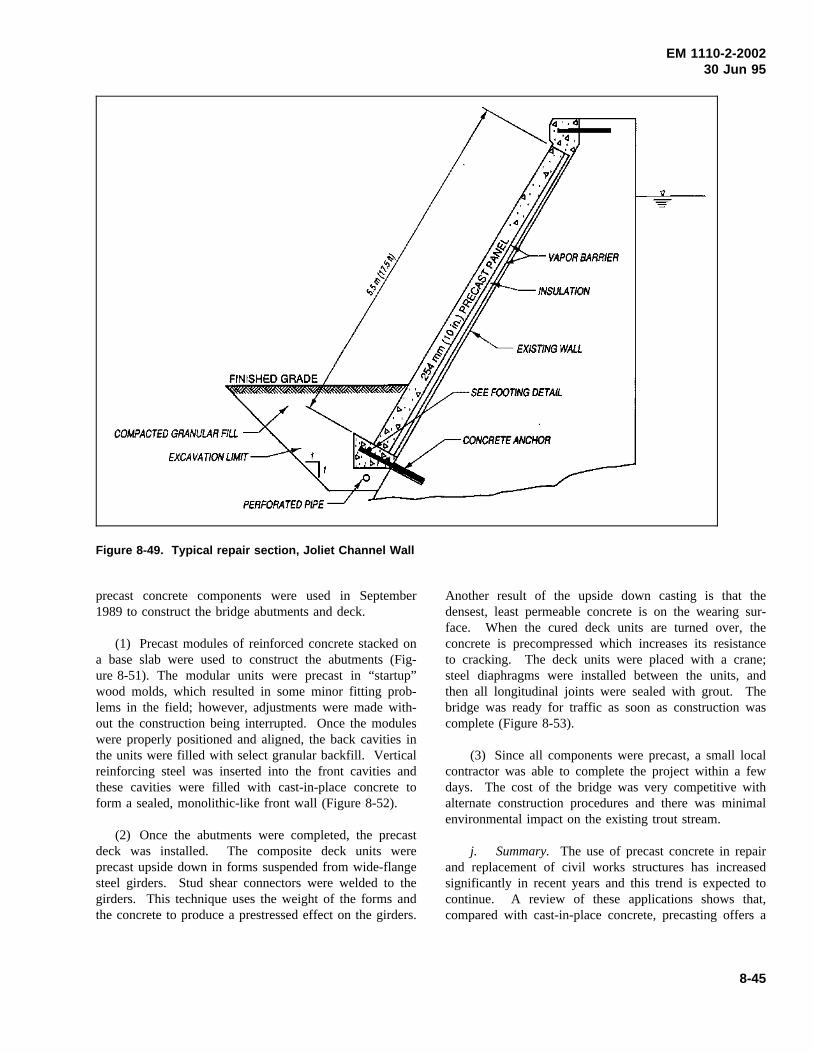
EM 1110-2-200230 Jun 95
Figure 8-49. Typical repair section, Joliet Channel Wall
precast concrete components were used in September1989 to construct the bridge abutments and deck.
(1) Precast modules of reinforced concrete stacked ona base slab were used to construct the abutments (Fig-ure 8-51). The modular units were precast in “startup”wood molds, which resulted in some minor fitting prob-lems in the field; however, adjustments were made with-out the construction being interrupted. Once the moduleswere properly positioned and aligned, the back cavities inthe units were filled with select granular backfill. Verticalreinforcing steel was inserted into the front cavities andthese cavities were filled with cast-in-place concrete toform a sealed, monolithic-like front wall (Figure 8-52).
(2) Once the abutments were completed, the precastdeck was installed. The composite deck units wereprecast upside down in forms suspended from wide-flangesteel girders. Stud shear connectors were welded to thegirders. This technique uses the weight of the forms andthe concrete to produce a prestressed effect on the girders.
Another result of the upside down casting is that thedensest, least permeable concrete is on the wearing sur-face. When the cured deck units are turned over, theconcrete is precompressed which increases its resistanceto cracking. The deck units were placed with a crane;steel diaphragms were installed between the units, andthen all longitudinal joints were sealed with grout. Thebridge was ready for traffic as soon as construction wascomplete (Figure 8-53).
(3) Since all components were precast, a small localcontractor was able to complete the project within a fewdays. The cost of the bridge was very competitive withalternate construction procedures and there was minimalenvironmental impact on the existing trout stream.
j. Summary. The use of precast concrete in repairand replacement of civil works structures has increasedsignificantly in recent years and this trend is expected tocontinue. A review of these applications shows that,compared with cast-in-place concrete, precasting offers a
8-45
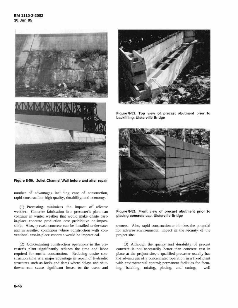
EM 1110-2-200230 Jun 95
Figure 8-50. Joliet Channel Wall before and after repair
number of advantages including ease of construction,rapid construction, high quality, durability, and economy.
(1) Precasting minimizes the impact of adverseweather. Concrete fabrication in a precaster’s plant cancontinue in winter weather that would make onsite cast-in-place concrete production cost prohibitive or impos-sible. Also, precast concrete can be installed underwaterand in weather conditions where construction with con-ventional cast-in-place concrete would be impractical.
(2) Concentrating construction operations in the pre-caster’s plant significantly reduces the time and laborrequired for onsite construction. Reducing onsite con-struction time is a major advantage in repair of hydraulicstructures such as locks and dams where delays and shut-downs can cause significant losses to the users and
Figure 8-51. Top view of precast abutment prior tobackfilling, Ulsterville Bridge
Figure 8-52. Front view of precast abutment prior toplacing concrete cap, Ulsterville Bridge
owners. Also, rapid construction minimizes the potentialfor adverse environmental impact in the vicinity of theproject site.
(3) Although the quality and durability of precastconcrete is not necessarily better than concrete cast inplace at the project site, a qualified precaster usually hasthe advantages of a concentrated operation in a fixed plantwith environmental control; permanent facilities for form-ing, batching, mixing, placing, and curing; well
8-46
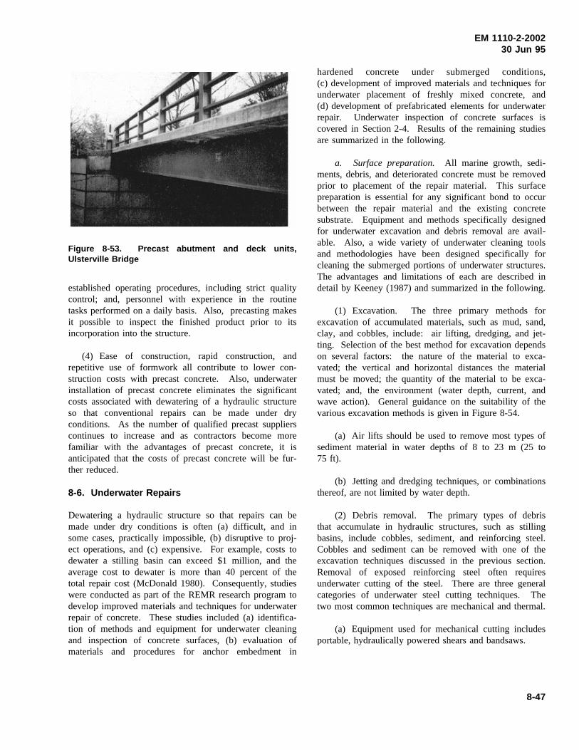
EM 1110-2-200230 Jun 95
Figure 8-53. Precast abutment and deck units,Ulsterville Bridge
established operating procedures, including strict qualitycontrol; and, personnel with experience in the routinetasks performed on a daily basis. Also, precasting makesit possible to inspect the finished product prior to itsincorporation into the structure.
(4) Ease of construction, rapid construction, andrepetitive use of formwork all contribute to lower con-struction costs with precast concrete. Also, underwaterinstallation of precast concrete eliminates the significantcosts associated with dewatering of a hydraulic structureso that conventional repairs can be made under dryconditions. As the number of qualified precast supplierscontinues to increase and as contractors become morefamiliar with the advantages of precast concrete, it isanticipated that the costs of precast concrete will be fur-ther reduced.
8-6. Underwater Repairs
Dewatering a hydraulic structure so that repairs can bemade under dry conditions is often (a) difficult, and insome cases, practically impossible, (b) disruptive to proj-ect operations, and (c) expensive. For example, costs todewater a stilling basin can exceed $1 million, and theaverage cost to dewater is more than 40 percent of thetotal repair cost (McDonald 1980). Consequently, studieswere conducted as part of the REMR research program todevelop improved materials and techniques for underwaterrepair of concrete. These studies included (a) identifica-tion of methods and equipment for underwater cleaningand inspection of concrete surfaces, (b) evaluation ofmaterials and procedures for anchor embedment in
hardened concrete under submerged conditions,(c) development of improved materials and techniques forunderwater placement of freshly mixed concrete, and(d) development of prefabricated elements for underwaterrepair. Underwater inspection of concrete surfaces iscovered in Section 2-4. Results of the remaining studiesare summarized in the following.
a. Surface preparation. All marine growth, sedi-ments, debris, and deteriorated concrete must be removedprior to placement of the repair material. This surfacepreparation is essential for any significant bond to occurbetween the repair material and the existing concretesubstrate. Equipment and methods specifically designedfor underwater excavation and debris removal are avail-able. Also, a wide variety of underwater cleaning toolsand methodologies have been designed specifically forcleaning the submerged portions of underwater structures.The advantages and limitations of each are described indetail by Keeney (1987) and summarized in the following.
(1) Excavation. The three primary methods forexcavation of accumulated materials, such as mud, sand,clay, and cobbles, include: air lifting, dredging, and jet-ting. Selection of the best method for excavation dependson several factors: the nature of the material to exca-vated; the vertical and horizontal distances the materialmust be moved; the quantity of the material to be exca-vated; and, the environment (water depth, current, andwave action). General guidance on the suitability of thevarious excavation methods is given in Figure 8-54.
(a) Air lifts should be used to remove most types ofsediment material in water depths of 8 to 23 m (25 to75 ft).
(b) Jetting and dredging techniques, or combinationsthereof, are not limited by water depth.
(2) Debris removal. The primary types of debristhat accumulate in hydraulic structures, such as stillingbasins, include cobbles, sediment, and reinforcing steel.Cobbles and sediment can be removed with one of theexcavation techniques discussed in the previous section.Removal of exposed reinforcing steel often requiresunderwater cutting of the steel. There are three generalcategories of underwater steel cutting techniques. Thetwo most common techniques are mechanical and thermal.
(a) Equipment used for mechanical cutting includesportable, hydraulically powered shears and bandsaws.
8-47
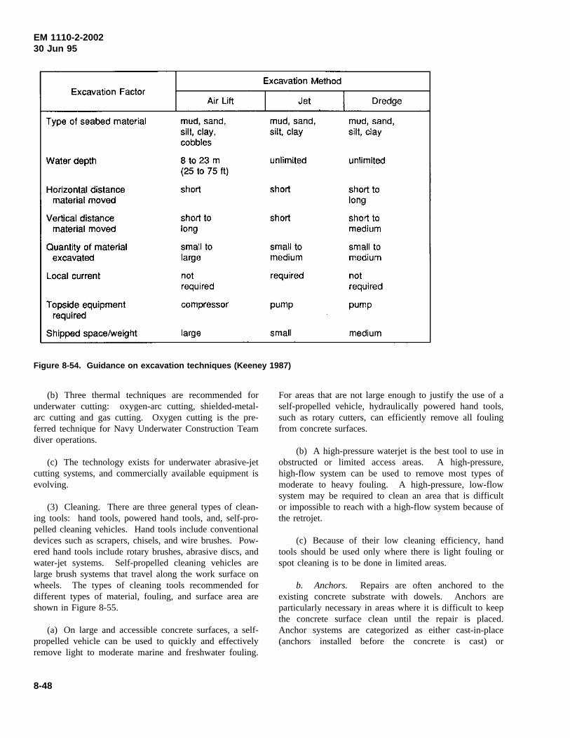
EM 1110-2-200230 Jun 95
Figure 8-54. Guidance on excavation techniques (Keeney 1987)
(b) Three thermal techniques are recommended forunderwater cutting: oxygen-arc cutting, shielded-metal-arc cutting and gas cutting. Oxygen cutting is the pre-ferred technique for Navy Underwater Construction Teamdiver operations.
(c) The technology exists for underwater abrasive-jetcutting systems, and commercially available equipment isevolving.
(3) Cleaning. There are three general types of clean-ing tools: hand tools, powered hand tools, and, self-pro-pelled cleaning vehicles. Hand tools include conventionaldevices such as scrapers, chisels, and wire brushes. Pow-ered hand tools include rotary brushes, abrasive discs, andwater-jet systems. Self-propelled cleaning vehicles arelarge brush systems that travel along the work surface onwheels. The types of cleaning tools recommended fordifferent types of material, fouling, and surface area areshown in Figure 8-55.
(a) On large and accessible concrete surfaces, a self-propelled vehicle can be used to quickly and effectivelyremove light to moderate marine and freshwater fouling.
For areas that are not large enough to justify the use of aself-propelled vehicle, hydraulically powered hand tools,such as rotary cutters, can efficiently remove all foulingfrom concrete surfaces.
(b) A high-pressure waterjet is the best tool to use inobstructed or limited access areas. A high-pressure,high-flow system can be used to remove most types ofmoderate to heavy fouling. A high-pressure, low-flowsystem may be required to clean an area that is difficultor impossible to reach with a high-flow system because ofthe retrojet.
(c) Because of their low cleaning efficiency, handtools should be used only where there is light fouling orspot cleaning is to be done in limited areas.
b. Anchors. Repairs are often anchored to theexisting concrete substrate with dowels. Anchors areparticularly necessary in areas where it is difficult to keepthe concrete surface clean until the repair is placed.Anchor systems are categorized as either cast-in-place(anchors installed before the concrete is cast) or
8-48
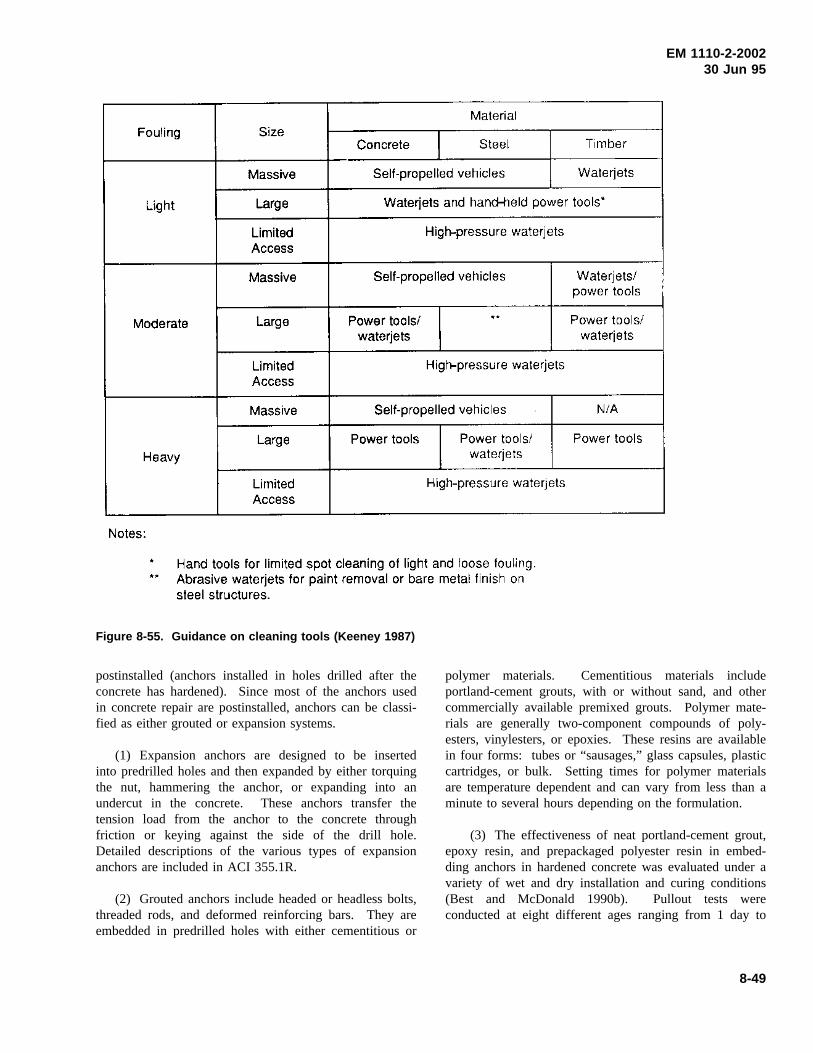
EM 1110-2-200230 Jun 95
Figure 8-55. Guidance on cleaning tools (Keeney 1987)
postinstalled (anchors installed in holes drilled after theconcrete has hardened). Since most of the anchors usedin concrete repair are postinstalled, anchors can be classi-fied as either grouted or expansion systems.
(1) Expansion anchors are designed to be insertedinto predrilled holes and then expanded by either torquingthe nut, hammering the anchor, or expanding into anundercut in the concrete. These anchors transfer thetension load from the anchor to the concrete throughfriction or keying against the side of the drill hole.Detailed descriptions of the various types of expansionanchors are included in ACI 355.1R.
(2) Grouted anchors include headed or headless bolts,threaded rods, and deformed reinforcing bars. They areembedded in predrilled holes with either cementitious or
polymer materials. Cementitious materials includeportland-cement grouts, with or without sand, and othercommercially available premixed grouts. Polymer mate-rials are generally two-component compounds of poly-esters, vinylesters, or epoxies. These resins are availablein four forms: tubes or “sausages,” glass capsules, plasticcartridges, or bulk. Setting times for polymer materialsare temperature dependent and can vary from less than aminute to several hours depending on the formulation.
(3) The effectiveness of neat portland-cement grout,epoxy resin, and prepackaged polyester resin in embed-ding anchors in hardened concrete was evaluated under avariety of wet and dry installation and curing conditions(Best and McDonald 1990b). Pullout tests wereconducted at eight different ages ranging from 1 day to
8-49
EM 1110-2-200230 Jun 95
32 months. Creep and durability tests were alsoconducted.
(a) Beyond 1 day, all pullout strengths were approxi-mately equal to the ultimate strength of the reinforcing-bar anchor when the anchors were installed under dryconditions, regardless of the type of embedment materialor curing conditions. With the exception of the anchorsembedded in polyester resin under submerged conditions,pullout strengths were essentially equal to the ultimatestrength of the anchor when the anchors were installedunder wet or submerged conditions. The overall averagepullout strength of anchors embedded in polyester resinunder submerged conditions was 35 percent less than thestrength of similar anchors installed and cured under dryconditions. The largest reductions in pullout strength,approximately 50 percent, occurred at ages of 6 and16 months. Although the epoxy resin performed well inthese tests when placed in wet holes, it should be notedthat the manufacturer does not recommend placementunder submerged conditions.
(b) Creep tests were conducted by subjecting pulloutspecimens to a sustained load of 60 percent of the anchor-yield strength and periodically measuring anchor slippageat the end of the specimen opposite the loaded end. After6 months under load, anchors embedded in portland-cement grout and epoxy resin that were installed andtested under wet conditions exhibited low anchor slippage,averaging 0.071 and 0.084 mm (0.0028 and 0.0033 in.),respectively, or two to four times higher than resultsunder dry conditions. Anchors embedded in polyesterresin, installed and cured under submerged conditions,exhibited significant slippage; in fact, in one case theanchor pulled completely out of the concrete after 14 daysunder load. After 6 months under load, the tworemaining specimens exhibited an average anchor slippageof 2.09 mm (0.0822 in.), approximately 30 times higherthan anchors embedded in portland-cement grout underthe same conditions.
(c) Long-term durability of the embedment materialswas evaluated by periodic compressive strength tests on51-mm (2-in.) cubes stored both submerged and in labora-tory air. After 32 months, the average compressivestrength of polyester-resin and epoxy-resin specimensstored in water was 37 and 26 percent less, respectively,than that of companion specimens stored in air. Thestrength of portland-cement grout cubes stored in wateraveraged 5 percent higher than that of companion speci-mens stored in air during the same period.
(4) The performance of anchors embedded in vinyl-ester resin, prepackaged in glass capsules, was also evalu-ated under dry and submerged conditions(McDonald 1989). Pullout tests were conducted atfour different ages ranging from 1 to 28 days. The tensilecapacity of anchors embedded under submergedconditions was approximately one-third that of similaranchors embedded in dry holes.
(5) The reduced tensile capacity of anchorsembedded in concrete under submerged conditions withprepackaged polyester-resin and vinylester-resin cartridgesis primarily attributed to the anchor installation procedure.Resin extruded from dry holes during anchor installationwas very cohesive, and a significant effort was required toobtain the full embedment depth. In comparison, anchorinstallation required significantly less effort under sub-merged conditions. Also, the extruded resin was muchmore fluid under wet conditions, and the creamy colorcontrasted with the black resin extruded under dry con-ditions. Although insertion of the adhesive capsule orcartridge into the drill hole displaces the majority of thewater in the hole, water will remain between the walls ofthe adhesive container and the drill hole. Insertion of theanchor traps this water in the drill hole and causes it tobecome mixed with the adhesive, resulting in an anchorwith reduced tensile capacity. An anchor-installationprocedure that eliminates the problem of resin and watermixing in the drill hole is described by McDonald (1990).
(a) In the revised installation procedure (Fig-ure 8-56), a small volume of adhesive was injected intothe bottom of the drill hole in bulk form prior to insertionof the adhesive capsule. This injection was easily accom-plished with recently developed paired plastic cartridges(Figure 8-57) which contained the vinylester resin and ahardener. The cartridges were inserted into a tool similarto a caulking gun which automatically dispensed the pro-per material proportions through a static mixing tubedirectly into the drill hole. Once the injection was com-pleted, insertion of a prepackaged vinylester-resin capsuledisplaced the remainder of the water in the drill hole priorto anchor insertion and spinning.
(b) Anchors installed with the revised procedureexhibited essentially the same tensile capacity under dryand submerged conditions. At 3-mm (0.1-in.) displace-ment, the tensile capacity of vertical anchors installedwith the revised procedure under submerged conditionsaveraged more than three times greater than that of simi-lar anchors installed with the original procedure. The
8-50
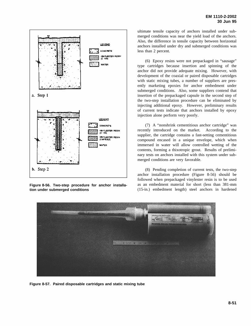
EM 1110-2-200230 Jun 95
Figure 8-56. Two-step procedure for anchor installa-tion under submerged conditions
ultimate tensile capacity of anchors installed under sub-merged conditions was near the yield load of the anchors.Also, the difference in tensile capacity between horizontalanchors installed under dry and submerged conditions wasless than 2 percent.
(6) Epoxy resins were not prepackaged in “sausage”type cartridges because insertion and spinning of theanchor did not provide adequate mixing. However, withdevelopment of the coaxial or paired disposable cartridgeswith static mixing tubes, a number of suppliers are pres-ently marketing epoxies for anchor embedment undersubmerged conditions. Also, some suppliers contend thatinsertion of the prepackaged capsule in the second step ofthe two-step installation procedure can be eliminated byinjecting additional epoxy. However, preliminary resultsof current tests indicate that anchors installed by epoxyinjection alone perform very poorly.
(7) A “nonshrink cementitious anchor cartridge” wasrecently introduced on the market. According to thesupplier, the cartridge contains a fast-setting cementitiouscompound encased in a unique envelope, which whenimmersed in water will allow controlled wetting of thecontents, forming a thixotropic grout. Results of prelimi-nary tests on anchors installed with this system under sub-merged conditions are very favorable.
(8) Pending completion of current tests, the two-stepanchor installation procedure (Figure 8-56) should befollowed when prepackaged vinylester resin is to be usedas an embedment material for short (less than 381-mm(15-in.) embedment length) steel anchors in hardened
Figure 8-57. Paired disposable cartridges and static mixing tube
8-51
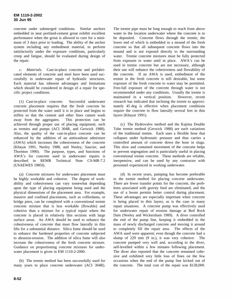
EM 1110-2-200230 Jun 95
concrete under submerged conditions. Similar anchorsembedded in neat portland-cement grout exhibit excellentperformance when the grout is allowed to cure for a mini-mum of 3 days prior to loading. The ability of the anchorsystem including any embedment material, to performsatisfactorily under the exposure conditions, particularlycreep and fatigue, should be evaluated during design ofthe repair.
c. Materials. Cast-in-place concrete and prefabri-cated elements of concrete and steel have been used suc-cessfully in underwater repair of hydraulic structures.Each material has inherent advantages and limitationswhich should be considered in design of a repair for spe-cific project conditions.
(1) Cast-in-place concrete. Successful underwaterconcrete placement requires that the fresh concrete beprotected from the water until it is in place and begins tostiffen so that the cement and other fines cannot washaway from the aggregates. This protection can beachieved through proper use of placing equipment, suchas tremies and pumps (ACI 304R, and Gerwick 1988).Also, the quality of the cast-in-place concrete can beenhanced by the addition of an antiwashout admixture(AWA) which increases the cohesiveness of the concrete(Khayat 1991, Neeley 1988, and Neeley, Saucier, andThornton 1990). The purpose, types, and functions ofAWA’s for concrete used in underwater repairs isdescribed in REMR Technical Note CS-MR-7.2(USAEWES 1985f).
(a) Concrete mixtures for underwater placement mustbe highly workable and cohesive. The degree of work-ability and cohesiveness can vary somewhat dependingupon the type of placing equipment being used and thephysical dimensions of the placement area. For example,massive and confined placements, such as cofferdams, orbridge piers, can be completed with a conventional tremieconcrete mixture that is less workable (flowable) andcohesive than a mixture for a typical repair where theconcrete is placed in relatively thin sections with largesurface areas. An AWA should be used to enhance thecohesiveness of concrete that must flow laterally in thinlifts for a substantial distance. Silica fume should be usedto enhance the hardened properties of concrete subjectedto abrasion-erosion. The addition of silica fume will alsoincrease the cohesiveness of the fresh concrete mixture.Guidance on proportioning concrete mixtures for under-water placement is given in EM 1110-2-2000.
(b) The tremie method has been successfully used formany years to place concrete underwater (ACI 304R).
The tremie pipe must be long enough to reach from abovewater to the location underwater where the concrete is tobe deposited. Concrete flows through the tremie, thelower end of which is embedded in a mound of the freshconcrete so that all subsequent concrete flows into themound and is not exposed directly to the surroundingwater. Tremie concrete mixtures must be fully protectedfrom exposure to water until in place. AWA’s can beused in tremie concrete but are not necessary, althoughtheir use will enhance the cohesiveness and flowability ofthe concrete. If an AWA is used, embedment of thetremie in the fresh concrete is still desirable, but someexposure of the fresh concrete to water may be permitted.Free-fall exposure of the concrete through water is notrecommended under any conditions. Usually the tremie ismaintained in a vertical position. However, recentresearch has indicated that inclining the tremie to approxi-mately 45 deg is effective when placement conditionsrequire the concrete to flow laterally several feet in thinlayers (Khayat 1991).
(c) The Hydrovalve method and the Kajima DoubleTube tremie method (Gerwick 1988) are each variationsof the traditional tremie. Each uses a flexible hose thatcollapses under hydrostatic pressure and thus carries acontrolled amount of concrete down the hose in slugs.This slow and contained movement of the concrete helpsto prevent segregation and is particularly useful in placingconventional tremie concrete. These methods are reliable,inexpensive, and can be used by any contractor withpersonnel experienced in working underwater.
(d) In recent years, pumping has become preferableto the tremie method for placing concrete underwater.There are fewer transfer points for the concrete, the prob-lems associated with gravity feed are eliminated, and theuse of a boom permits better control during placement.These advantages are especially important when concreteis being placed in thin layers, as is the case in manyrepair situations. A concrete pump was effectively usedfor underwater repair of erosion damage at Red RockDam (Neeley and Wickersham 1989). A diver controlledthe end of the pump line, keeping it embedded in themass of newly discharged concrete and moving it aroundto completely fill the repair area. The effects of theAWA used were apparent; even though the concrete had aslump of 229 mm (9 in.), it was very cohesive. Theconcrete pumped very well and, according to the diver,self-levelled within a few minutes following placement.The diver also reported that the concrete remained cohe-sive and exhibited very little loss of fines on the fewoccasions when the end of the pump line kicked out ofthe concrete. The total cost of the repair was $128,000.
8-52
EM 1110-2-200230 Jun 95
In comparison, estimated costs to dewater alone for aconventional repair ranged from $1/2 to $3/4 million.
(e) Pneumatic valves attached to the end of a concretepump line permit better control of concrete flow throughthe lines and even allow termination of the flow to protectthe concrete within the lines and to prevent excessivefouling of the water while the boom is being moved.Some units incorporate a level detector to monitor theconcrete placement. This method is considered to be oneof the most effective for placing concrete underwater(Gerwick 1988). Guidance on pumped concrete is givenin EM 1110-2-2000. Also, ACI 304.2R is an excellentreference.
(f) Preplaced-aggregate concrete is an effectivemethod for repairing large void areas underwater. Thecoarse aggregate is enclosed in forms, and grout is theninjected from the bottom of the preplaced aggregate. Toprevent loss of fines and cement at the top of the repair,venting forms have a permeable fabric next to theconcrete, backed with a wire mesh, and supported by astronger backing of perforated steel and plywood. Thepressure generated by the grout beneath the formsnecessitates doweling to hold down the forms. The groutmust have a high fluidity to ensure complete filling ofvoids. Use of an AWA will lessen the need for the pro-tective top form. Guidance on preplaced-aggregate con-crete is given in EM 1110-2-2000 and ACI 304.1R.
(g) Some techniques have been developed, such asbuckets, skips, and tilting pallet barges, to place stiff,highly cohesive concrete by dropping the concrete throughseveral feet of water, thus requiring the use of a largeamount of AWA. However, until these methods havebeen fully developed and proved effective, there is asubstantial risk that the end result will be a poor qualityconcrete placement. Therefore, placing concrete byallowing it to free-fall through several feet of water is notrecommended.
(2) Prefabricated elements. Precast concrete panelsand modular sections have been successfully used inunderwater repair of lock walls (Section 8-1), stillingbasins, and dams (Section 8-5). Prefabricated steel panelshave been used underwater as temporary and permanenttop forms for preplaced-aggregate concrete. Also, prefab-ricated steel modules have been used in underwater repairof erosion damage. Rail and Haynes (1991) concludedthat it is feasible to use prefabricated steel, precast con-crete, or composite steel-concrete panels in underwaterrepair of stilling basins. Each material has inherent
advantages, and the following factors should be con-sidered in designing panels for a specific project.
(a) Abrasion resistance. It is the opinion of Rail andHaynes (1991) that the abrasion resistance of steel is farsuperior to that of concrete; however, no data were givento substantiate this claim. Recent tests by Simons (1992)indicate that the widths and depths of abrasion of concretemixtures with an average compressive strength of 75 MPa(10,915 psi) at 28 days were 1.6 and 2.3 times higher,respectively, compared to abrasion-resistant steel.However, when the depths of abrasion were compared asa percentage of the thickness for typical panels of eachmaterial, it was concluded that the durability of thehigh-strength concrete was equivalent to that of theabrasion-resistant steel. Guidance on proportioning ofhigh-strength concrete mixtures is given in EM 1110-2-2000. A thorough discussion of high-strength concrete isgiven in ACI 363R.
(b) Uplift. Uplift forces caused by high-velocitywater flowing over the panel surface is a concern in repairof hydraulic structures, particularly stilling basins. TheOld River Low Sill Control Structure demonstrated theproblem of uplift of steel panels (McDonald 1980).Thirty modules, 7.3 m (24 ft) long and ranging in widthfrom 0.9 to 6.7 m (3 to 22 ft), were prefabricated from13-mm (1/2-in.)-thick steel plate for the stilling basinrepair. After the modules were installed and anchoredunderwater, the voids between the steel plate and theexisting concrete slab were filled with grout. Additionalanchors were installed in holes drilled through the groutedmodules and into the basin slab to a depth of 0.9 m (3 ft).An underwater inspection of the basin 8 months after therepairs showed that 7 of the 30 modules had lost portionsof their steel plate, ranging from 20 to 100 percent of thesurface area. A number of anchor bolts were foundbroken flush with the surface plate or the grout or pulledcompletely out of the substrate. A second inspection,approximately 2 years after repair, revealed that additionalsteel plate had been ripped from four of the modulespreviously damaged, and an additional nine modules hadsustained damage. There were only a few remnants ofthe steel plates when the basin was dewatered 11 yearsafter the repairs. Precast concrete panels, with a mini-mum thickness of about 100 mm (4 in.), should be lesssusceptible to these problems. The increased panelstiffness, damping, and bond to the infill concrete willreduce uplift problems.
(c) Anchors. The design of the anchor systemshould ensure that the prefabricated panels are adequately
8-53
EM 1110-2-200230 Jun 95
anchored to the existing concrete to resist the uplift forcesand vibrations created by flowing water. Welding ofanchor systems as nearly flush with the prefabricated steelplate surface as possible appears more desirable thanraised bolted connections. Preformed, recessed holes foranchors were easily incorporated during precasting of theconcrete panels used in underwater repairs at Gavins PointDam (Section 8-5). The ability of the anchor system,including any embedment material, to perform satisfac-torily under the exposure conditions, particularly creepand fatigue, should be evaluated during design of therepair.
(d) Joints. Joint details are important design consid-erations because once a panel fails and is displaced, adja-cent panels are more susceptible to failure as a result oftheir exposed edges. Consequently, each panel should bedesigned as an individual repair unit and should not relyon adjacent panels for protection. The vulnerability ofjoints can be reduced by providing stiffened and recessedpanel edges. The joint between the existing concrete andthe leading edge of the upstream panels should bedesigned to provide a smooth transition to the repair sec-tion. A general design philosophy should be to minimizethe number of joints by using the largest panels practical.
(e) Weight. Panels are usually installed with a barge-mounted crane. Therefore, panel weight can be impor-tant, depending on the lifting capacity of available cranes.For panels of a given area, the weight of concrete panelsin air will be about four times the weight of steel panels.
(f) Panel supports. Panel supports are bottom-installed platforms or seats which may be required toensure that panels are placed at the desired elevation andare properly aligned. Rail and Haynes (1991) presentseveral concepts for panel supports, some of whichinclude a means to attach and anchor the panel to resistuplift forces. The potential of these concepts should beevaluated based on specific project requirements.
(g) Infill placement. The physical dimensions of theplacement area dictate whether portland-cement grout orconcrete is used as the infill material. Grout should beused in those applications that require the infill to flowsubstantial distances in very thin lifts, whereas pumpedconcrete or preplaced-aggregate concrete should be usedto fill larger voids.
d. Inspection. Inspection of the work as it pro-gresses is important, and there are a number of techniquesand procedures for underwater inspection described inSection 2-4. The selection of inspection techniques will
be affected by type, size, location, and environmentalconditions of a particular job, along with technical capa-bilities and limitations and monetary constraints. Visualinspection is usually the first technique considered forunderwater inspection. Low-light video is an alternativeto the diver-inspector. A diver with two-way communica-tion can position the video camera as directed by theinspector who views the video from the surface. Aremotely operated vehicle (ROV) with a video camera canalso be used where water currents and turbulence permituse of an ROV. More sophisticated techniques such asecho sounders, side-scan sonar, radar, laser mapping, andhigh-resolution acoustic mapping are also available. Thehigh-resolution acoustic mapping system appears to beideal for inspection of underwater repairs.
e. Support personnel/equipment. A qualified divingteam is required for underwater repairs. Personnel shouldbe skilled in the operation of construction and inspectionequipment to be used during the repair. All personnelshould have a thorough understanding of proper workingprocedures to minimize the risk of an accident. Personnelsafety should be given a high priority.
8-7. Geomembrane Applications
Many of the Corps’ structures exhibit significant concretecracking which allows water intrusion into or through thestructure. These cracks are the result of a variety ofphenomena, including restrained concrete shrinkage,thermal gradients, cycles of freezing and thawing, alkali-aggregate reaction, and differential settlement of the foun-dation. Water leakage through hydraulic structures canalso result from poor concrete consolidation during con-struction, improperly prepared lift or construction joints,and waterstop failures. When leakage rates becomeunacceptable, repairs are made. Conventional repairmethods generally consist of localized sealing of cracksand defective joints by cementitious and chemical grout-ing, epoxy injection, or surface treatments. Even thoughlocalized sealing of leaking cracks and defective jointswith conventional methods has been successful in someapplications, in many cases some type of overall repair isstill required after a few years. Consequently, the poten-tial for geomembranes in such repairs was evaluated aspart of the REMR Research Program.
a. Background. Various configurations of geo-membranes have been used as impervious syntheticbarriers in dams for more than 30 years. Generally,membranes are placed within an embankment or rockfilldam as part of the impervious core or at the upstreamface of embankment, rockfill, and concrete gravity dams.
8-54
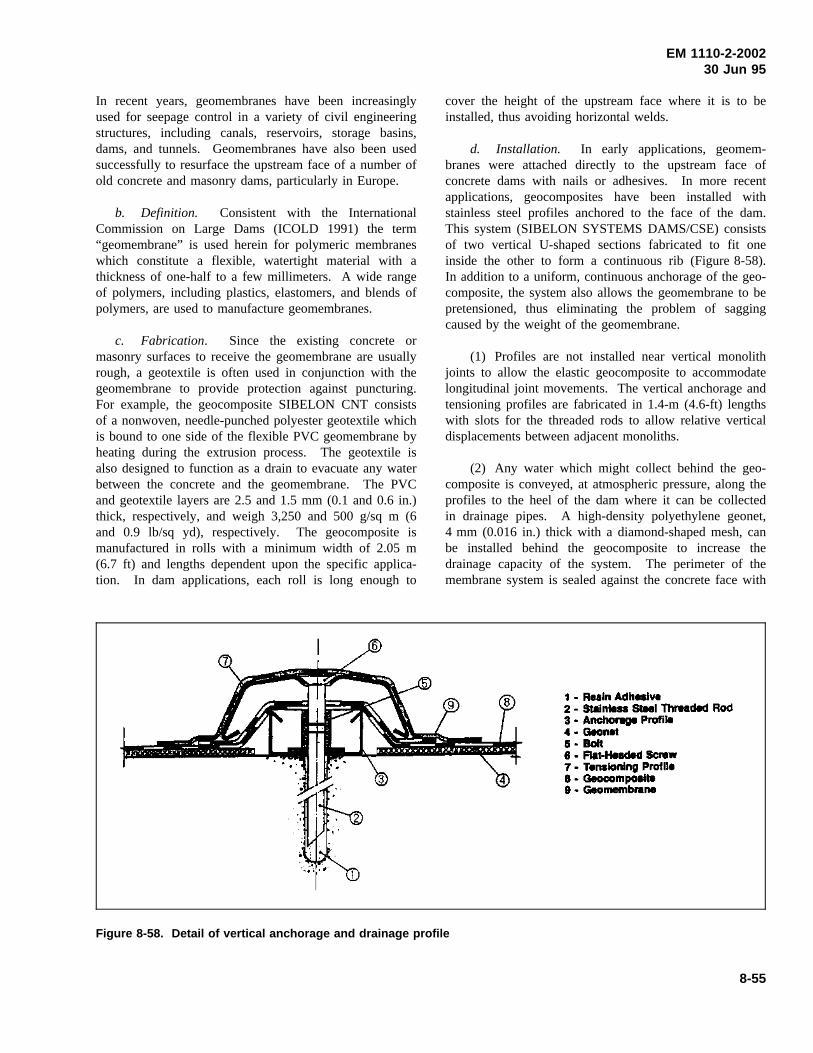
EM 1110-2-200230 Jun 95
In recent years, geomembranes have been increasinglyused for seepage control in a variety of civil engineeringstructures, including canals, reservoirs, storage basins,dams, and tunnels. Geomembranes have also been usedsuccessfully to resurface the upstream face of a number ofold concrete and masonry dams, particularly in Europe.
b. Definition. Consistent with the InternationalCommission on Large Dams (ICOLD 1991) the term“geomembrane” is used herein for polymeric membraneswhich constitute a flexible, watertight material with athickness of one-half to a few millimeters. A wide rangeof polymers, including plastics, elastomers, and blends ofpolymers, are used to manufacture geomembranes.
c. Fabrication. Since the existing concrete ormasonry surfaces to receive the geomembrane are usuallyrough, a geotextile is often used in conjunction with thegeomembrane to provide protection against puncturing.For example, the geocomposite SIBELON CNT consistsof a nonwoven, needle-punched polyester geotextile whichis bound to one side of the flexible PVC geomembrane byheating during the extrusion process. The geotextile isalso designed to function as a drain to evacuate any waterbetween the concrete and the geomembrane. The PVCand geotextile layers are 2.5 and 1.5 mm (0.1 and 0.6 in.)thick, respectively, and weigh 3,250 and 500 g/sq m (6and 0.9 lb/sq yd), respectively. The geocomposite ismanufactured in rolls with a minimum width of 2.05 m(6.7 ft) and lengths dependent upon the specific applica-tion. In dam applications, each roll is long enough to
cover the height of the upstream face where it is to beinstalled, thus avoiding horizontal welds.
d. Installation. In early applications, geomem-branes were attached directly to the upstream face ofconcrete dams with nails or adhesives. In more recentapplications, geocomposites have been installed withstainless steel profiles anchored to the face of the dam.This system (SIBELON SYSTEMS DAMS/CSE) consistsof two vertical U-shaped sections fabricated to fit oneinside the other to form a continuous rib (Figure 8-58).In addition to a uniform, continuous anchorage of the geo-composite, the system also allows the geomembrane to bepretensioned, thus eliminating the problem of saggingcaused by the weight of the geomembrane.
(1) Profiles are not installed near vertical monolithjoints to allow the elastic geocomposite to accommodatelongitudinal joint movements. The vertical anchorage andtensioning profiles are fabricated in 1.4-m (4.6-ft) lengthswith slots for the threaded rods to allow relative verticaldisplacements between adjacent monoliths.
(2) Any water which might collect behind the geo-composite is conveyed, at atmospheric pressure, along theprofiles to the heel of the dam where it can be collectedin drainage pipes. A high-density polyethylene geonet,4 mm (0.016 in.) thick with a diamond-shaped mesh, canbe installed behind the geocomposite to increase thedrainage capacity of the system. The perimeter of themembrane system is sealed against the concrete face with
Figure 8-58. Detail of vertical anchorage and drainage profile
8-55
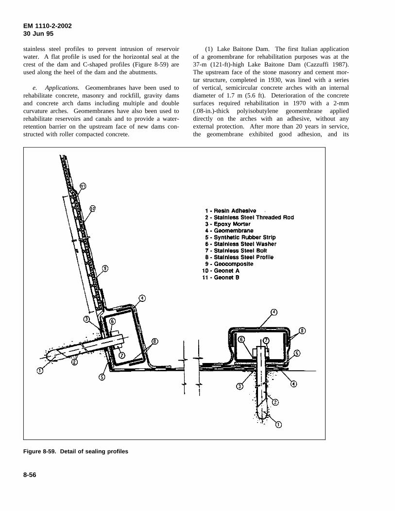
EM 1110-2-200230 Jun 95
stainless steel profiles to prevent intrusion of reservoirwater. A flat profile is used for the horizontal seal at thecrest of the dam and C-shaped profiles (Figure 8-59) areused along the heel of the dam and the abutments.
e. Applications. Geomembranes have been used torehabilitate concrete, masonry and rockfill, gravity damsand concrete arch dams including multiple and doublecurvature arches. Geomembranes have also been used torehabilitate reservoirs and canals and to provide a water-retention barrier on the upstream face of new dams con-structed with roller compacted concrete.
(1) Lake Baitone Dam. The first Italian applicationof a geomembrane for rehabilitation purposes was at the37-m (121-ft)-high Lake Baitone Dam (Cazzuffi 1987).The upstream face of the stone masonry and cement mor-tar structure, completed in 1930, was lined with a seriesof vertical, semicircular concrete arches with an internaldiameter of 1.7 m (5.6 ft). Deterioration of the concretesurfaces required rehabilitation in 1970 with a 2-mm(.08-in.)-thick polyisobutylene geomembrane applieddirectly on the arches with an adhesive, without anyexternal protection. After more than 20 years in service,the geomembrane exhibited good adhesion, and its
Figure 8-59. Detail of sealing profiles
8-56
EM 1110-2-200230 Jun 95
performance was considered to be satisfactory, althoughthere had been some damage caused by heavy ice forma-tion which was quickly and easily repaired. However,when similar repairs were later made on concrete gravitydams, the results were clearly negative (Monari andScuero 1991). This difference in performance was attrib-uted to the extensive network of cracks in the thin archeswhich provided for natural drainage of vapor pressure incontrast to the limited drainage associated with the thickergravity sections with minimal cracking. This experienceand subsequent laboratory tests led to the conclusion thatgeomembrane repair systems should be mechanicallyanchored and must permit drainage of any water whichmight be present behind the geomembrane.
(2) Lake Nero Dam. This 40-m (131-ft)-high con-crete gravity dam with a crest length of 146 m (479 ft)was completed in 1929 near Bergamo, Italy. Over theyears, various repairs, including grouting of the bedrockand shotcreting of the upstream face were conducted.However, these attempts to eliminate leakage through thedam and foundation and deterioration of the concretecaused by aggressive water and cycles of freezing andthawing proved to be temporary or inadequate.
(a) In 1980, a geocomposite was installed on theupstream face of the dam and anchored with steel profiles(Monari 1984). Self-hoisting platforms secured to thedam’s crest were used in the installation (Figure 8-60)which required 90 days to complete. The geocompositewas unrolled from the top of the dam down to the base.Adjacent sheets were overlapped and the vertical jointswere welded prior to horizontal prestressing. The lowerends of the sheets were anchored to the base of the damwith metal plates.
(b) Installation of the geocomposite reduced leakagefrom 50 l/sec to 0.27 l/sec with only 14 percent of theleakage through the geocomposite. After 10 years inservice, the geocomposite had required no maintenancenor had the lining lost no of its original efficiency(Monari and Scuero 1991).
(3) Cignana Dam. This 58-m (190 ft)-high concretegravity dam with a crest length of 402 m (1,319 ft) wascompleted in 1928. Located at an elevation of 2,173 m(7,129 ft) above sea level, the concrete exhibited evidenceof considerable freeze-thaw degradation. Also, the damhad major leakage problems despite extensive mainte-nance efforts, including application of paint-on resinmembranes. A 2.5-mm (0.1-in.)-thick geocomposite was
used to rehabilitate the dam in 1987. The repair wassimilar to that of Lake Nero Dam except that the verticalsteel profiles were embedded in a layer of reinforcedshotcrete used to resurface the upstream face of the dam.After removal of deteriorated concrete, a layer of shot-crete was applied, vertical profiles were installed, and thesurface between adjacent profiles was made level byfilling with a second layer of shotcrete (Figure 8-61).
(4) Pracana Dam. This 65-m (213-ft)-high concretebuttress dam with a crest length of 240 m (787 ft) islocated on the Ocreza River in Portugal. Crackingoccurred soon after construction, causing leakage at thedownstream face. An attempt to reduce leakage by grout-ing the cracks did not result in a durable solution to theproblem; therefore, a comprehensive rehabilitation wasinitiated in 1992. Application of a geocomposite to theupstream face of the dam was a major component of therehabilitation.
(a) A high-density polyethylene geonet was attachedto the upstream face to increase the capacity of thegeomembrane system to drain moisture from the concreteand any leakage through the geocomposite. An additionalgeonet was installed for a height of about 1 m (3 ft)above the heel of the dam to assist in conveying the waterto drainage pipes. Ten near-horizontal holes were drilledfrom the heel of the dam to the downstream face toaccommodate the drainage pipes. The geomembranesystem was divided into six independent compartmentsfrom which water is piped to the downstream face forvolumetric measurements. This design provides improvedmonitoring of the drainage behind the geomembrane.
(b) Approximately 8,000 sq m (9,600 sq yd) of geo-composite were installed with steel profiles shown inFigures 8-58 and 8-59. Vertical joints between rolls ofthe geocomposite and geomembrane strips covering theprofiles (Figure 8-62) were welded to provide a con-tinuous water barrier on the upstream face of the dam. Ahot-air jet was used to melt the plastic, and the twosurfaces were then welded together by hand pressure on asmall roller.
(c) A wire system was installed behind the geocom-posite to aid in future monitoring and maintenance of thegeomembrane. A sensor sliding on the surface of thegeomembrane can detect any anomalies in the electricalfield thus locating any discontinuities in thegeomembrane.
8-57
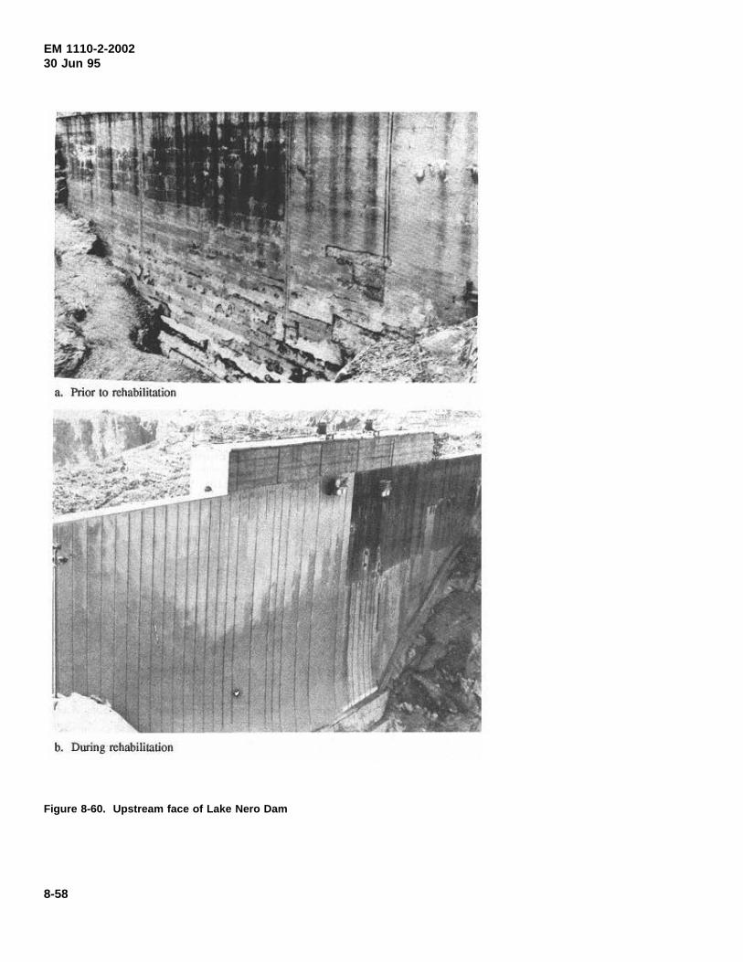
EM 1110-2-200230 Jun 95
Figure 8-60. Upstream face of Lake Nero Dam
8-58
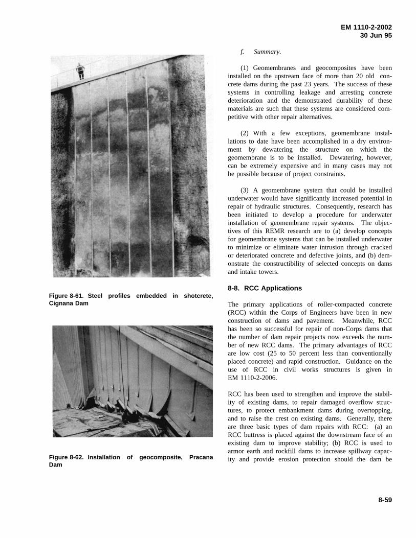
EM 1110-2-200230 Jun 95
Figure 8-61. Steel profiles embedded in shotcrete,Cignana Dam
Figure 8-62. Installation of geocomposite, PracanaDam
f. Summary.
(1) Geomembranes and geocomposites have beeninstalled on the upstream face of more than 20 old con-crete dams during the past 23 years. The success of thesesystems in controlling leakage and arresting concretedeterioration and the demonstrated durability of thesematerials are such that these systems are considered com-petitive with other repair alternatives.
(2) With a few exceptions, geomembrane instal-lations to date have been accomplished in a dry environ-ment by dewatering the structure on which thegeomembrane is to be installed. Dewatering, however,can be extremely expensive and in many cases may notbe possible because of project constraints.
(3) A geomembrane system that could be installedunderwater would have significantly increased potential inrepair of hydraulic structures. Consequently, research hasbeen initiated to develop a procedure for underwaterinstallation of geomembrane repair systems. The objec-tives of this REMR research are to (a) develop conceptsfor geomembrane systems that can be installed underwaterto minimize or eliminate water intrusion through crackedor deteriorated concrete and defective joints, and (b) dem-onstrate the constructibility of selected concepts on damsand intake towers.
8-8. RCC Applications
The primary applications of roller-compacted concrete(RCC) within the Corps of Engineers have been in newconstruction of dams and pavement. Meanwhile, RCChas been so successful for repair of non-Corps dams thatthe number of dam repair projects now exceeds the num-ber of new RCC dams. The primary advantages of RCCare low cost (25 to 50 percent less than conventionallyplaced concrete) and rapid construction. Guidance on theuse of RCC in civil works structures is given inEM 1110-2-2006.
RCC has been used to strengthen and improve the stabil-ity of existing dams, to repair damaged overflow struc-tures, to protect embankment dams during overtopping,and to raise the crest on existing dams. Generally, thereare three basic types of dam repairs with RCC: (a) anRCC buttress is placed against the downstream face of anexisting dam to improve stability; (b) RCC is used toarmor earth and rockfill dams to increase spillway capac-ity and provide erosion protection should the dam be
8-59
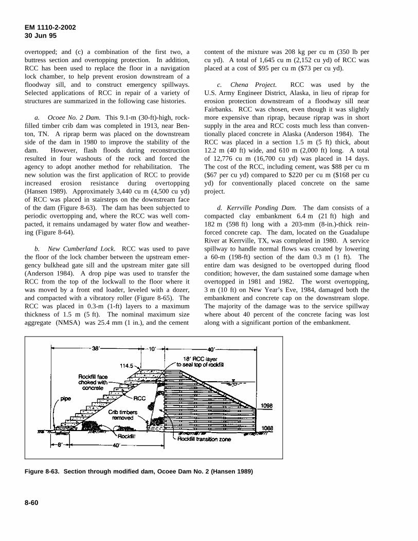
EM 1110-2-200230 Jun 95
overtopped; and (c) a combination of the first two, abuttress section and overtopping protection. In addition,RCC has been used to replace the floor in a navigationlock chamber, to help prevent erosion downstream of afloodway sill, and to construct emergency spillways.Selected applications of RCC in repair of a variety ofstructures are summarized in the following case histories.
a. Ocoee No. 2 Dam.This 9.1-m (30-ft)-high, rock-filled timber crib dam was completed in 1913, near Ben-ton, TN. A riprap berm was placed on the downstreamside of the dam in 1980 to improve the stability of thedam. However, flash floods during reconstructionresulted in four washouts of the rock and forced theagency to adopt another method for rehabilitation. Thenew solution was the first application of RCC to provideincreased erosion resistance during overtopping(Hansen 1989). Approximately 3,440 cu m (4,500 cu yd)of RCC was placed in stairsteps on the downstream faceof the dam (Figure 8-63). The dam has been subjected toperiodic overtopping and, where the RCC was well com-pacted, it remains undamaged by water flow and weather-ing (Figure 8-64).
b. New Cumberland Lock. RCC was used to pavethe floor of the lock chamber between the upstream emer-gency bulkhead gate sill and the upstream miter gate sill(Anderson 1984). A drop pipe was used to transfer theRCC from the top of the lockwall to the floor where itwas moved by a front end loader, leveled with a dozer,and compacted with a vibratory roller (Figure 8-65). TheRCC was placed in 0.3-m (1-ft) layers to a maximumthickness of 1.5 m (5 ft). The nominal maximum sizeaggregate (NMSA) was 25.4 mm (1 in.), and the cement
content of the mixture was 208 kg per cu m (350 lb percu yd). A total of 1,645 cu m (2,152 cu yd) of RCC wasplaced at a cost of $95 per cu m ($73 per cu yd).
c. Chena Project. RCC was used by theU.S. Army Engineer District, Alaska, in lieu of riprap forerosion protection downstream of a floodway sill nearFairbanks. RCC was chosen, even though it was slightlymore expensive than riprap, because riprap was in shortsupply in the area and RCC costs much less than conven-tionally placed concrete in Alaska (Anderson 1984). TheRCC was placed in a section 1.5 m (5 ft) thick, about12.2 m (40 ft) wide, and 610 m (2,000 ft) long. A totalof 12,776 cu m (16,700 cu yd) was placed in 14 days.The cost of the RCC, including cement, was $88 per cu m($67 per cu yd) compared to $220 per cu m ($168 per cuyd) for conventionally placed concrete on the sameproject.
d. Kerrville Ponding Dam. The dam consists of acompacted clay embankment 6.4 m (21 ft) high and182 m (598 ft) long with a 203-mm (8-in.)-thick rein-forced concrete cap. The dam, located on the GuadalupeRiver at Kerrville, TX, was completed in 1980. A servicespillway to handle normal flows was created by loweringa 60-m (198-ft) section of the dam 0.3 m (1 ft). Theentire dam was designed to be overtopped during floodcondition; however, the dam sustained some damage whenovertopped in 1981 and 1982. The worst overtopping,3 m (10 ft) on New Year’s Eve, 1984, damaged both theembankment and concrete cap on the downstream slope.The majority of the damage was to the service spillwaywhere about 40 percent of the concrete facing was lostalong with a significant portion of the embankment.
Figure 8-63. Section through modified dam, Ocoee Dam No. 2 (Hansen 1989)
8-60
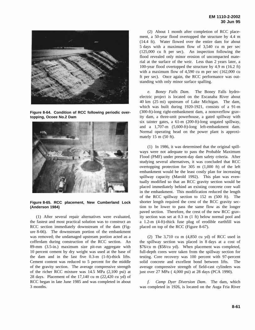
EM 1110-2-200230 Jun 95
Figure 8-64. Condition of RCC following periodic over-topping, Ocoee No.2 Dam
Figure 8-65. RCC placement, New Cumberland Lock(Anderson 1984)
(1) After several repair alternatives were evaluated,the fastest and most practical solution was to construct anRCC section immediately downstream of the dam (Fig-ure 8-66). The downstream portion of the embankmentwas removed; the undamaged upstream portion acted as acofferdam during construction of the RCC section. An89-mm (3.5-in.) maximum size pit-run aggregate with10 percent cement by dry weight was used at the base ofthe dam and in the last five 0.3-m (1-ft)-thick lifts.Cement content was reduced to 5 percent for the middleof the gravity section. The average compressive strengthof the richer RCC mixture was 14.5 MPa (2,100 psi) at28 days. Placement of the 17,140 cu m (22,420 cu yd) ofRCC began in late June 1985 and was completed in about3 months.
(2) About 1 month after completion of RCC place-ment, a 50-year flood overtopped the structure by 4.4 m(14.4 ft). Water flowed over the entire dam for about5 days with a maximum flow of 3,540 cu m per sec(125,000 cu ft per sec). An inspection following theflood revealed only minor erosion of uncompacted mate-rial at the surface of the weir. Less than 2 years later, a100-year flood overtopped the structure by 4.9 m (16.2 ft)with a maximum flow of 4,590 cu m per sec (162,000 cuft per sec). Once again, the RCC performance was out-standing with only minor surface spalling.
e. Boney Falls Dam. The Boney Falls hydro-electric project is located on the Escanaba River about40 km (25 mi) upstream of Lake Michigan. The dam,which was built during 1920-1921, consists of a 91-m(300-ft)-long right-embankment dam, a nonoverflow grav-ity dam, a three-unit powerhouse, a gated spillway withsix tainter gates, a 61-m (200-ft)-long ungated spillway,and a 1,707-m (5,600-ft)-long left-embankment dam.Normal operating head on the power plant is approxi-mately 15 m (50 ft).
(1) In 1986, it was determined that the original spill-ways were not adequate to pass the Probable MaximumFlood (PMF) under present-day dam safety criteria. Afterstudying several alternatives, it was concluded that RCCovertopping protection for 305 m (1,000 ft) of the leftembankment would be the least costly plan for increasingspillway capacity (Marold 1992). This plan was even-tually modified so that an RCC gravity section would beplaced immediately behind an existing concrete core wallin the embankment. This modification reduced the lengthof the RCC spillway section to 152 m (500 ft). Theshorter length required the crest of the RCC gravity sec-tion to be lower to pass the same flow as the longerpaved section. Therefore, the crest of the new RCC grav-ity section was set at 0.3 m (1 ft) below normal pool anda 1.2-m (4-ft)-thick fuse plug of erodible earthfill wasplaced on top of the RCC (Figure 8-67).
(2) The 3,710 cu m (4,850 cu yd) of RCC used inthe spillway section was placed in 8 days at a cost of$76/cu m ($58/cu yd). When placement was completed,full-depth cores were taken from the spillway section fortesting. Core recovery was 100 percent with 97-percentsolid concrete and excellent bond between lifts. Theaverage compressive strength of field-cast cylinders wasjust over 27 MPa ( 4,000 psi) at 28 days (PCA 1990).
f. Camp Dyer Diversion Dam. The dam, whichwas completed in 1926, is located on the Auga Fria River
8-61
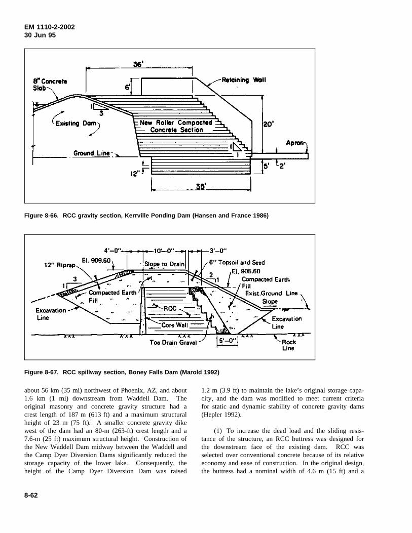
EM 1110-2-200230 Jun 95
Figure 8-66. RCC gravity section, Kerrville Ponding Dam (Hansen and France 1986)
Figure 8-67. RCC spillway section, Boney Falls Dam (Marold 1992)
about 56 km (35 mi) northwest of Phoenix, AZ, and about1.6 km (1 mi) downstream from Waddell Dam. Theoriginal masonry and concrete gravity structure had acrest length of 187 m (613 ft) and a maximum structuralheight of 23 m (75 ft). A smaller concrete gravity dikewest of the dam had an 80-m (263-ft) crest length and a7.6-m (25 ft) maximum structural height. Construction ofthe New Waddell Dam midway between the Waddell andthe Camp Dyer Diversion Dams significantly reduced thestorage capacity of the lower lake. Consequently, theheight of the Camp Dyer Diversion Dam was raised
1.2 m (3.9 ft) to maintain the lake’s original storage capa-city, and the dam was modified to meet current criteriafor static and dynamic stability of concrete gravity dams(Hepler 1992).
(1) To increase the dead load and the sliding resis-tance of the structure, an RCC buttress was designed forthe downstream face of the existing dam. RCC wasselected over conventional concrete because of its relativeeconomy and ease of construction. In the original design,the buttress had a nominal width of 4.6 m (15 ft) and a
8-62
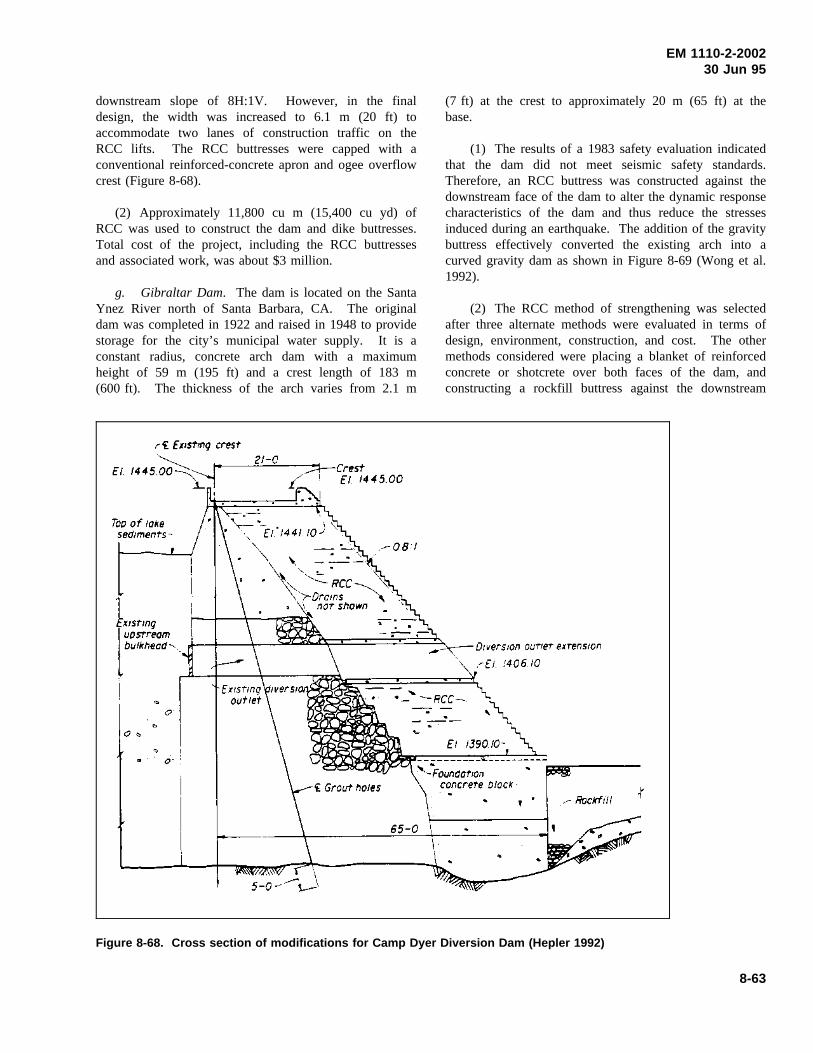
EM 1110-2-200230 Jun 95
downstream slope of 8H:1V. However, in the finaldesign, the width was increased to 6.1 m (20 ft) toaccommodate two lanes of construction traffic on theRCC lifts. The RCC buttresses were capped with aconventional reinforced-concrete apron and ogee overflowcrest (Figure 8-68).
(2) Approximately 11,800 cu m (15,400 cu yd) ofRCC was used to construct the dam and dike buttresses.Total cost of the project, including the RCC buttressesand associated work, was about $3 million.
g. Gibraltar Dam. The dam is located on the SantaYnez River north of Santa Barbara, CA. The originaldam was completed in 1922 and raised in 1948 to providestorage for the city’s municipal water supply. It is aconstant radius, concrete arch dam with a maximumheight of 59 m (195 ft) and a crest length of 183 m(600 ft). The thickness of the arch varies from 2.1 m
(7 ft) at the crest to approximately 20 m (65 ft) at thebase.
(1) The results of a 1983 safety evaluation indicatedthat the dam did not meet seismic safety standards.Therefore, an RCC buttress was constructed against thedownstream face of the dam to alter the dynamic responsecharacteristics of the dam and thus reduce the stressesinduced during an earthquake. The addition of the gravitybuttress effectively converted the existing arch into acurved gravity dam as shown in Figure 8-69 (Wong et al.1992).
(2) The RCC method of strengthening was selectedafter three alternate methods were evaluated in terms ofdesign, environment, construction, and cost. The othermethods considered were placing a blanket of reinforcedconcrete or shotcrete over both faces of the dam, andconstructing a rockfill buttress against the downstream
Figure 8-68. Cross section of modifications for Camp Dyer Diversion Dam (Hepler 1992)
8-63
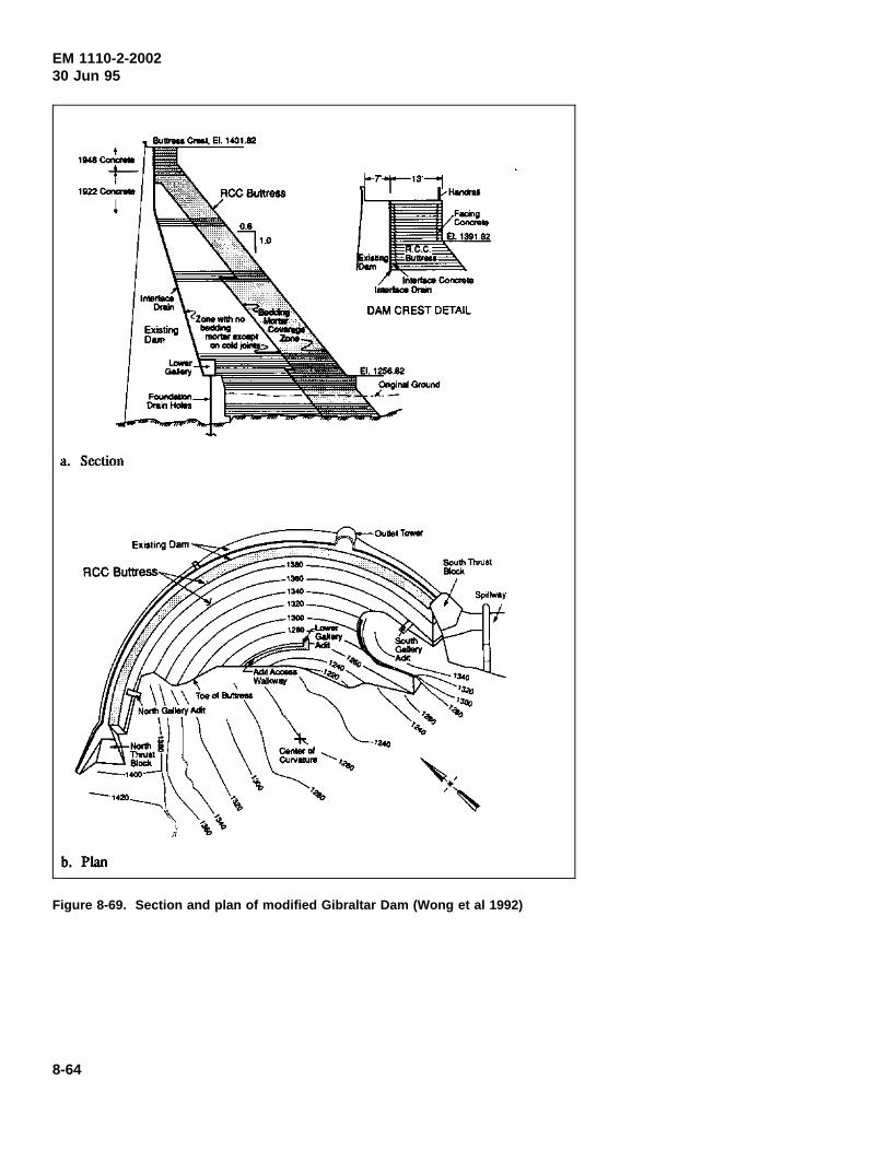
EM 1110-2-200230 Jun 95
Figure 8-69. Section and plan of modified Gibraltar Dam (Wong et al 1992)
8-64
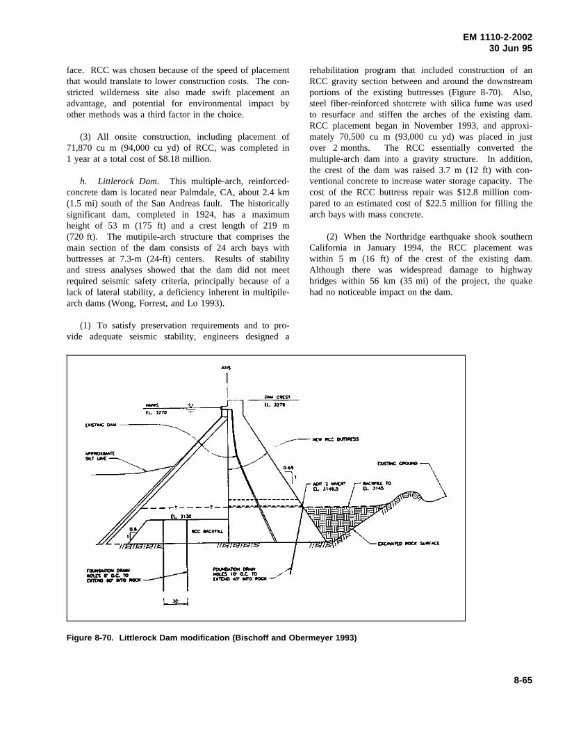
EM 1110-2-200230 Jun 95
face. RCC was chosen because of the speed of placementthat would translate to lower construction costs. The con-stricted wilderness site also made swift placement anadvantage, and potential for environmental impact byother methods was a third factor in the choice.
(3) All onsite construction, including placement of71,870 cu m (94,000 cu yd) of RCC, was completed in1 year at a total cost of $8.18 million.
h. Littlerock Dam. This multiple-arch, reinforced-concrete dam is located near Palmdale, CA, about 2.4 km(1.5 mi) south of the San Andreas fault. The historicallysignificant dam, completed in 1924, has a maximumheight of 53 m (175 ft) and a crest length of 219 m(720 ft). The mutipile-arch structure that comprises themain section of the dam consists of 24 arch bays withbuttresses at 7.3-m (24-ft) centers. Results of stabilityand stress analyses showed that the dam did not meetrequired seismic safety criteria, principally because of alack of lateral stability, a deficiency inherent in multipile-arch dams (Wong, Forrest, and Lo 1993).
(1) To satisfy preservation requirements and to pro-vide adequate seismic stability, engineers designed a
rehabilitation program that included construction of anRCC gravity section between and around the downstreamportions of the existing buttresses (Figure 8-70). Also,steel fiber-reinforced shotcrete with silica fume was usedto resurface and stiffen the arches of the existing dam.RCC placement began in November 1993, and approxi-mately 70,500 cu m (93,000 cu yd) was placed in justover 2 months. The RCC essentially converted themultiple-arch dam into a gravity structure. In addition,the crest of the dam was raised 3.7 m (12 ft) with con-ventional concrete to increase water storage capacity. Thecost of the RCC buttress repair was $12.8 million com-pared to an estimated cost of $22.5 million for filling thearch bays with mass concrete.
(2) When the Northridge earthquake shook southernCalifornia in January 1994, the RCC placement waswithin 5 m (16 ft) of the crest of the existing dam.Although there was widespread damage to highwaybridges within 56 km (35 mi) of the project, the quakehad no noticeable impact on the dam.
Figure 8-70. Littlerock Dam modification (Bischoff and Obermeyer 1993)
8-65
EM 1110-2-200230 Jun 95
Chapter 9Concrete Investigation Reports
9-1. General
When required by a major rehabilitation project, a con-crete materials design memorandum, in the form of aseparate report or a part of The Rehabilitation EvaluationReport, will be prepared. The need for repairs can varyfrom such minor problems as shrinkage cracks and pop-outs to major damage resulting from severe cavitation orabrasion or from structural failure. Therefore, the scopeof the investigation will also vary, depending on the criti-cality of the project. For minor (noncritical) repair ofconcrete structures in moderate climates, the investigationmay be limited to determining the availability of satisfac-tory repair materials. Examples of such repairs includepatching small spalls and sealing dormant cracks in south-ern states. If the environment of the project is known tobe deleterious to concrete, such as cycles of freezing andthawing, sulfate attack, or acid attack, the investigationmust address the measures to be taken to mitigate deterio-ration, regardless of the quantity of repair materialsinvolved. A more detailed investigation will normally berequired for rehabilitation of structures such as locks,dams, large pumping stations, and power plants.
9-2. Concrete Materials Design Memorandum
In general, a design memorandum will include informa-tion as required in Appendix C of EM 1110-2-2000. Inaddition, for all repair or rehabilitation projects other thanminor repairs, the design memorandum will also includethe following:
(1) Description of the existing conditions and typesof deterioration.
(2) Detailed discussion of the causes of deterioration.
(3) Proposed method(s) of removal of damaged anddeteriorated concrete.
(4) Proposed repair materials and detailed repairprocedures.
If epoxy or other polymer materials are to be used in therepair, detailed discussion of the materials and justifica-tions for using such materials should also be given.Chapter 4 provides more detailed planning and designconsiderations. Although the requirements for a materialsdesign memorandum may appear to be unnecessary detailfor a project involving only a small quantity of repairmaterials, experience has repeatedly demonstrated that nostep in a repair operation can be omitted or carelesslyperformed without detriment to the serviceability of thework. Inadequate investigation into the causes of theproblem and inadequate workmanship, procedures, ormaterials will result in inferior repairs which ultimatelywill fail.
9-3. Concrete Repair Report
At the conclusion of any unique concrete repair project,an as-built concrete repair report should be prepared.Unique repair projects are those on which unusual con-crete repair materials and techniques are used. The con-crete repair report should include discussions of problemsencountered in each phase of the repair work, effec-tiveness of the repair materials and techniques, and resultsof the follow-up evaluation program, if available.
9-1
EM 1110-2-200230 Jun 95
Appendix AReferences
A-1. Required Publications
TM 5-822-6/AFM 88-7, Chapter 1Rapid Pavements for Roads, Streets, Walks, and OpenStorage Areas
TM 5-822-9/AFM 88-6, Chapter 10Repair of Rigid Pavements Using Epoxy-Resin Grouts,Mortars, and Concrete
EP 1110-1-10Borehole Viewing Systems
EM 385-1-1Safety and Health Requirements Manual
EM 1110-1-3500Chemical Grouting
EM 1110-2-2000Standard Practice for Concrete
EM 1110-2-2005Standard Practice for Shotcrete
EM 1110-2-2006Roller-Compacted Concrete
EM 1110-2-2102Waterstops and Other Joint Materials
EM 1110-2-3506Grouting Technology
EM 1110-2-4300Instrumentation for Concrete Structures CH1
U.S. Army Engineer Waterways ExperimentStation 1949U.S. Army Engineer Waterways Experiment Station.1949 (Aug). Handbook for Concrete and Cement, withquarterly supplements (all CRD-C designations), Vicks-burg, MS. Note: Use latest edition of all designations.
U.S. Army Engineer Waterways ExperimentStation 1985U.S. Army Engineer Waterways Experiment Station.1985. The REMR Notebook, with periodic supplements,Vicksburg, MS, including:
a. “Video Systems for Underwater Inspection ofStructures,” REMR Technical Note CS-ES-2.6
b. “Underwater Cameras for Inspection of Struc-tures in Turbid Water,” REMR Technical Note CS-ES-3.2
c. “Removal and Prevention of Efflorescence onConcrete and Masonry Building Surfaces,” REMR Tech-nical Note CS-MR-4.3
d. “Cleaning Concrete Surfaces,” REMR TechnicalNote CS-MR-4.4
e. “General Information of Polymer Materials,”REMR Technical Note CS-MR-7.1
f. “Antiwashout Admixtures for Underwater Con-crete,” REMR Technical Note CS-MR-7.2
g. “Rapid-Hardening Cements and Patching Mate-rials,” REMR Technical Note CS-MR-7.3
h. “Handling and Disposal of Construction Resi-due,” REMR Technical Note EI-M-1.2
Handbooks and reports published by the WaterwaysExperiment Station may be obtained from: U.S. ArmyEngineer Waterways Experiment Station, 3909 HallsFerry Road, Vicksburg, MS 39180-6199.
American Concrete Institute (Annual)American Concrete Institute. Annual.Manual of Con-crete Practice, Five Parts, Detroit, MI, including:
“Cement and Concrete Terminology,” ACI 116R
“Guide for Making a Condition Survey of Concrete inService,” ACI 201.lR
“Guide to Durable Concrete,” ACI 201.2R
“Mass Concrete,” ACI 207.lR
“Effect of Restraint, Volume Change, and Reinforcementon Cracking of Mass Concrete,” ACI 207.2R
“Practices for Evaluation of Concrete in Existing MassiveStructures for Service Conditions,” ACI 207.3R
“Roller Compacted Mass Concrete,” ACI 207.5R
“Erosion of Concrete in Hydraulic Structures,” ACI 210R
A-1
EM 1110-2-200230 Jun 95
“Corrosion of Metals in Concrete,” ACI 222R
“Standard Practice for the Use of Shrinkage-Compen-sating Concrete,” ACI 223
“Causes, Evaluation, and Repair of Cracks in ConcreteStructures,” ACI 224.1R
“Guide for Concrete Floor and Slab Construction,”ACI 302.1R
“Guide for Measuring, Mixing, Transporting, and PlacingConcrete,” ACI 304R
“Guide for the Use of Preplaced Aggregate Concrete forStructural and Mass Concrete Applications,” ACI 304.1R
“Placing Concrete by Pumping Methods,” ACI 304.2R
“Hot Weather Concreting,” ACI 305R
“Building Code Requirements for Reinforced Concrete,”ACI 318
“Guide for the Design and Construction of Concrete Park-ing Lots,” ACI 330R
“Guide to Residential Cast-in-Place Concrete Construc-tion,” ACI 332R
“State-of-the-Art Report on Anchorage to Concrete,”ACI 355.1R
“State-of-the-Art Report on High-Strength Concrete,”ACI 363R
“Guide for Evaluation of Concrete Structures Prior toRehabilitation,” ACI 364.1R
“Use of Epoxy Compounds with Concrete,” ACI 503R
“Standard Specification for Bonding Plastic Concrete toHardened Concrete With a Multi-Component EpoxyAdhesive,” ACI 503.2
“Guide for the Selection of Polymer Adhesives with Con-crete,” ACI 503.5R
“Guide to Sealing Joints in Concrete Structures,”ACI 504R
“Guide to Shotcrete,” ACI 506R
“A Guide to the Use of Waterproofing, Dampproofing,Protective, and Decorative Barrier Systems for Concrete,”ACI 515.lR
“Guide for Specifying, Proportioning, Mixing, Placing,and Finishing Steel,” ACI 544.3R
“Guide for the Use of Polymers in Concrete,”ACI 548.1R
“State-of-the-Art Report on Polymer-Modified Concrete,”ACI 548.3R
“Standard Specification for Latex-Modified Concrete(LMC) Overlays,” ACI 548.4
ACI 226 1987ACI Committee 226. 1987 (Mar-Apr). “Silica Fume inConcrete,”ACI Materials Journal, Vol 84, No. 2, pp 158-166.
ACI publications may be obtained from: American Con-crete Institute, Member/Customer Services Department,Box 19150, Detroit, MI 48219-0150.
American Society for Testing and Materials (Annual)American Society for Testing and Materials. Annual.Annual Book of ASTM Standards, Philadelphia, PA.Note: Use the latest available issue of each ASTMstandard.
ASTM Standards and Publications may be obtained from:American Society for Testing and Materials, 1916 RaceStreet, Philadelphia, PA 19103.
A-2. Related Publications
ABAM Engineers 1987aABAM Engineers, Inc. 1987a (Jul). “Design of a PrecastConcrete Stay-in-Place Forming System for Lock WallRehabilitation,” Technical Report REMR-CS-7,U.S. Army Engineer Waterways Experiment Station,Vicksburg, MS.
ABAM Engineers 1987bABAM Engineers, Inc. 1987b (Dec). “A Demonstrationof the Constructibility of a Precast Concrete Stay-in-PlaceForming System for Lock Wall Rehabilitation,” TechnicalReport REMR-CS-14, U.S. Army Engineer WaterwaysExperiment Station, Vicksburg, MS.
A-2
EM 1110-2-200230 Jun 95
ABAM Engineers 1989ABAM Engineers, Inc. 1989 (Dec). “Concepts forInstallation of the Precast Concrete Stay-in-Place FormingSystem for Lock Wall Rehabilitation in an OperationalLock,” Technical Report REMR-CS-28, U.S. Army Engi-neer Waterways Experiment Station, Vicksburg, MS.
Ahmad and Haskins 1993Ahmad, Falih H., and Haskins, Richard. 1993 (Sep).“Use of Ground-Penetrating Radar in NondestructiveTesting for Voids and Cracks in Concrete,” The REMRBulletin, Vol 10, No. 3, pp 11-15.
Alexander 1980Alexander, A. M. 1980 (Apr). “Development of Pro-cedures for Nondestructive Testing of Concrete Structures;Report 2, Feasibility of Sonic Pulse-Echo Technique,”Miscellaneous Paper C-77-11, U.S. Army EngineerWaterways Experiment Station, Vicksburg, MS.
Alexander 1993Alexander, A. Michel. 1993 (Apr). “Impacts on a Sourceof Acoustic Pulse-Echo Energy for Nondestructive Testingof Concrete Structures,” Technical Report REMR-CS-40,U.S. Army Engineer Waterways Experiment Station,Vicksburg, MS.
Alexander and Thornton 1988Alexander, A. M., and Thornton, H. T., Jr. 1988.“Developments in Ultrasonic Pitch-Catch and Pulse-Echofor Measurements in Concrete,” SP-112, American Con-crete Institute, Detroit, MI.
Alongi, Cantor, Kneeter, Alongi 1982Alongi, A. V., Cantor, T. R., Kneeter, C. P., and Alongi,A., Jr. 1982. “Concrete Evaluation by Radar TheoreticalAnalysis,” Concrete Analysis and Deterioration,Transpor-tation Research Board, Washington, DC.
Anderson 1984Anderson, Fred A. 1984 (May). “RCC Does More,”Concrete International, American Concrete Institute,Vol 6, No. 5, pp 35-37.
Bach and Isen 1968Bache, H. H., and Isen, J. C. 1968 (Jun). “Model Deter-mination of Concrete Resistance to Popout Formation,”Journal of the American Concrete Institute, Proceedings,Vol 65, pp 445-450.
Bean 1988Bean, Dennis L. 1988 (Apr). “Surface Treatments toMinimize Concrete Deterioration; Report 1, Survey of
Field and Laboratory Application and Available Pro-ducts,” Technical Report REMR-CS-17, U.S. Army Engi-neer Waterways Experiment Station, Vicksburg, MS.
Best and McDonald 1990aBest, J. Floyd, and McDonald, James E. 1990 (Jan).“Spall Repair of Wet Concrete Surfaces,” TechnicalReport REMR-CS-25, U.S. Army Engineer WaterwaysExperiment Station, Vicksburg, MS.
Best and McDonald 1990bBest, J. Floyd, and McDonald, James E. 1990 (Jan).“Evaluation of Polyester Resin, Epoxy, and CementGrouts for Embedding Reinforcing Steel Bars in HardenedConcrete,” Technical Report REMR-CS-23, U.S. ArmyEngineer Waterways Experiment Station, Vicksburg, MS.
Bischoff and Obermeyer 1993Bischoff, John A., and Obermeyer, James R. 1993 (Apr).“Design Considerations for Raising Existing Dams forIncreased Storage,”Geotechnical Practice in Dam Reha-bilitation, American Society of Civil Engineers, pp 174-187.
Bryant and Mlakar 1991Bryant, Larry M., and Mlakar, Paul F. 1991 (Mar).“Predicting Concrete Service Life in Cases of Deteriora-tion Due to Freezing and Thawing,” Technical ReportREMR-CS-35, U.S. Army Engineer Waterways Experi-ment Station, Vicksburg, MS.
Busby Associates, Inc. 1987Busby Associates, Inc. 1987. “Undersea Vehicles Direc-tory,” Arlington, TX.
Campbell 1982Campbell, Roy L., Sr. 1982 (Apr). “A Review ofMethods for Concrete Removal,” Technical ReportSL-82-3, U.S. Army Engineer Waterways Experiment Sta-tion, Vicksburg, MS.
Campbell 1994Campbell, Roy L., Sr. 1994 (Feb). “Overlays on Hori-zontal Concrete Surfaces: Case Histories,” TechnicalReport REMR-CS-42, U.S. Army Engineer WaterwaysExperiment Station, Vicksburg, MS.
Carino 1992Carino, Nicholas J. 1992 (Jan). “Recent Developmentsin Nondestructive Testing of Concrete,”Advances inConcrete Technology, Canada Center for Mineral andEnergy Technology, Ottawa, Canada, pp 281-328.
A-3
EM 1110-2-200230 Jun 95
Carter 1993Carter, Paul. 1993 (Jan). “Developing a Performance-Based Specification for Concrete Sealers on Bridges,”Journal of Protective Coatings & Linings, pp 36-44.
Cazzuffi 1987Cazzuffi, D. 1987 (Mar). “The Use of Geomembranes inItalian Dams,”Water Power & Dam Construction.
Clausner and Pope 1988Clausner, J. E., and Pope, J. 1988 (Nov.) “Side-ScanSonar Applications for Evaluating Coastal Structures,”Technical Report CERC-88-16, U.S. Army EngineerWaterways Experiment Station, Vicksburg, MS.
Clear and Chollar 1978Clear, K. C., and Choller, B. H. 1978 (Apr). “Styrene-Butadiene Latex Modifiers for Bridge Peak Overlay Con-crete,” Report No. FHWA-RD-35, Federal HighwayAdministration, Washington, DC.
Clifton 1991Clifton, James R. 1991 (Nov). “Predicting the Remain-ing Service Life of Concrete,” Report NISTIR 4712,National Institute of Standards Technology, Gaithersburg,MD.
Concrete Repair Digest 1993Concrete Repair Digest. 1993 (Feb/Mar). “RemovingSome Common Stains from Concrete.”
Dahlquist 1987Dahlquist, M. S. 1987 (Oct). REMR Bulletin, Vol 4,No. 2, U.S. Army Engineer Waterways Experiment Sta-tion, Vicksburg, MS.
Davis 1960Davis, R. E., “Prepakt Method of Concrete Repair,”ACIJournal, Vol 32, pp 155-1752.
Davis, Jansen, and Neelands 1948Davis, R. E., Jansen, E. C., and Neelands, W. T. 1948(Apr). “Restoration of Barker Dam,”ACI Journal,Vol 19, No. 8, pp 633-688.
Dobrowolski and Scanlon 1984Dobrowolski, Joseph A., and Scanlon, John M. 1984(Jun). “How to Avoid Deficiencies in Architectural Con-crete Construction,” Technical Report SL-84-9,U.S. Army Engineer Waterways Experiment Station,Vicksburg, MS.
Emmons 1993Emmons, Peter H. 1993.Concrete Repair and Main-tenance Illustrated, R. S. Means Co., Inc., Kingston, MA,295 pp.
Emmons and Vaysburd 1995Emmons, Peter H., and Vaysburd, Alexander M. 1995(Mar). “Performance Criteria for Concrete Repair Mate-rials, Phase I,” Technical Report REMR-CS-47,U.S. Army Engineer Waterways Experiment Station,Vicksburg, MS.
Emmons, Vaysburd, and McDonald 1993Emmons, Peter H., Vaysburd, Alexander M., andMcDonald, James E. 1993 (Sep). “A Rational Approachto Durable Concrete Repairs,”Concrete International,Vol 15, No. 9, pp 40-45.
Emmons, Vaysburd, and McDonald 1994Emmons, P. H., Vaysburd, A. M., and McDonald, J. E.1994 (Mar). “Concrete Repair in The Future Turn OfThe Century - Any Problems?,”Concrete International,Vol 16, No. 3, pp 42-49.
Fenwick 1989Fenwick, W. B. 1989 (Aug). “Kinzua Dam, AlleghenyRiver, Pennsylvania and New York; Hydraulic ModelInvestigation,” Technical Report HL-89-17, U.S. ArmyEngineer Waterways Experiment Station, Vicksburg, MS.
Gerwick 1988Gerwick, B. C. 1988 (Sep). “Review of the State of theArt for Underwater Repair Using Abrasion-ResistantConcrete,” Technical Report REMR-CS-19, U.S. ArmyEngineer Waterways Experiment Station, Vicksburg, MS.
Gurjar and Carter 1987Gurjar, Suresh, and Carter, Paul. 1987 (Mar). “AlbertaConcrete Patch Evaluation Program,” Report No.ABTR/RD/RR-87/05, Alberta Transportation & Utilities,Edmonton, Alberta, Canada.
Hacker 1986Hacker, Kathy. 1986 (Dec). “Precast Panels SpeedRehabilitation of Placer Creek Channel,”The REMRBulletin, Vol 3, No. 3, U.S. Army Engineer WaterwaysExperiment Station, Vicksburg, MS.
Hammonds, Garner, and Smith 1989Hammons, M. I., Garner, S. B., and Smith, D. M. 1989(Jun). “Thermal Stress Analysis of Lock Wall, Dashields
A-4
EM 1110-2-200230 Jun 95
Locks, Ohio River,” Technical Report SL-89-6,U.S. Army Engineer Waterways Experiment Station,Vicksburg, MS.
Hansen 1989Hansen, Kenneth D. 1989 (Oct). “Performance ofRoller-Compacted Concrete Dam Rehabilitations,”Pro-ceedings from the 6th ASDSO Annual Conference, Associ-ation of State Dam Safety Officials, pp 21-26.
Hansen and France 1986Hansen, Kenneth D., and France, John W. 1986 (Sep).“RCC: A Dam Rehab Solution Unearthed,”Civil Engineer-ing, American Society of Civil Engineers, Vol 56, No. 9,pp 60-63.
Hepler 1992Hepler, Thomas E. 1992. “RCC Buttress Constructionfor Camp Dyer Diversion Dam,”Proceedings from the9th ASDSO Annual Conference, Association of State DamSafety Officials, pp 21-26.
Holland 1983Holland, T. C. 1983 (Sep). “Abrasion-Erosion Evalua-tion of Concrete Mixtures for Stilling Basin Repairs,Kinzua Dam, Pennsylvania,” Miscellaneous PaperSL-83-16, U.S. Army Engineer Waterways ExperimentStation, Vicksburg, MS.
Holland 1986Holland, T. C. 1986 (Sep). “Abrasion-Erosion Evalua-tion of Concrete Mixtures for Stilling Basin Repairs,Kinzua Dam, Pennsylvania,” Miscellaneous Paper SL-86-14, U.S. Army Engineer Waterways Experiment Station,Vicksburg, MS.
Holland and Gutschow 1987Holland, Terence C., and Gutschow, Richard A. 1987(Mar). “Erosion Resistance with Silica-Fume Concrete,”Concrete International, Vol 9, No. 3, pp 32-40.
Holland, Husbands, Buck, and Wong 1980Holland, T. C., Husbands, T. B., Buck, A. D., and Wong,G. S. 1980 (Dec). “Concrete Deterioration in SpillwayWarm-Water Chute, Raystown Dam, Pennsylvania,” Mis-cellaneous Paper SL-80-19, U.S. Army Engineer Water-ways Experiment Station, Vicksburg, MS.
Holland, Krysa, Luther, and Liu 1986Holland, T. C., Krysa, A., Luther, M. D., and Liu, T. C.1986. “Use of Silica-Fume Concrete to Repair Abrasion-Erosion Damage in the Kinzua Dam Stilling Basin,”FlyAsh, Silica Fume, Slag, and Natural Pozzolans in
Concrete, SP-91, Vol 2, American Concrete Institute,Detroit, MI.
Holland and Turner 1980Holland, T. C., and Turner, J. R. 1980 (Sep). “Construc-tion of Tremie Concrete Cutoff Wall, Wolf Creek Dam,Kentucky,” Miscellaneous Paper SL-80-10, U.S. ArmyEngineer Waterways Experiment Station, Vicksburg, MS.
Houghton, Borge, and Paxton 1978Houghton, D. L., Borge, O. E., and Paxton, J. H. 1978(Dec). “Cavitation Resistance of Some Special Con-cretes,”ACI Journal,Vol 75, No. 12, pp 664-667.
Hulshizer and Desai 1984Hulshizer, A. J., and Desai, A. J. 1984 (Jun). “ShockVibration Effects on Freshly Placed Concrete,”ASCEJournal of Construction Engineering and Management,Vol 110, No. 2, pp 266-285.
Hurd 1989Hurd, M. K. 1989. “Formwork for Concrete,” 5th Edi-tion, SP-4, American Concrete Institute, Detroit, MI.
Husbands and Causey 1990Husbands, Tony B., and Causey, Fred E. 1990 (Sep).“Surface Treatments to Minimize Concrete Deterioration;Report 2, Laboratory Evaluation of Surface TreatmentMaterials,” Technical Report REMR-CS-17, U.S. ArmyEngineer Waterways Experiment Station, Vicksburg, MS.
ICOLD 1991ICOLD. 1991. Watertight Geomembranes for Dams -State of the Art,Bulletin 78, International Commission onLarge Dams, Paris.
Johnson 1965Johnson, S. M. 1965.Deterioration, Maintenance, andRepair of Structures,McGraw-Hill, New York.
Kahl, Kauschinger, and Perry 1991Kahl, Thomas W., Kauschinger, Joseph L., and Perry,Edward B. 1991 (Mar). “Plastic Concrete Cutoff Wallsfor Earth Dams,” Technical Report REMR-GT-15,U.S. Army Engineer Waterways Experiment Station,Vicksburg, MS.
Keeney 1987Keeney, C. A. 1987 (Nov). “Procedures and Devices forUnderwater Cleaning of Civil Works Structures,” Tech-nical Report REMR-CS-8, U.S. Army Engineer Water-ways Experiment Station, Vicksburg, MS.
A-5
EM 1110-2-200230 Jun 95
Khayat 1991Khayat, K. H. 1991. “Underwater Repair of ConcreteDamaged by Abrasion-Erosion,” Technical ReportREMR-CS-37, U.S. Army Engineer Waterways Experi-ment Station, Vicksburg, MS.
Kottke 1987Kottke, Edgar. 1987 (Aug). “Evaluation of Sealers forConcrete Bridge Elements,” Alberta Transportation andUtilities, Alberta, Canada.
Krauss 1994Krauss, P. D. 1994 (Mar). “Repair Materials and Tech-niques for Concrete Structures in Nuclear Power Plants,”ORNL/NRC/LTR-93/28, Oak Ridge National Laboratory,Oak Ridge, TN.
Kucharski and Clausner 1990Kucharski, W. M., and Clausner, J. E. 1990 (Feb).“Underwater Inspection of Coastal Structures Using Com-mercially Available Sonars,” Technical Report REMR-CO-11, U.S. Army Engineer Waterways ExperimentStation, Vicksburg, MS.
Langelier 1936Langelier, W. F. 1936 (Oct). “The Analytical Control ofAnti-Corrosion Water Treatment,”Journal of the Ameri-can Water Works Association,Vol 28, No. 10,pp 1500-1521.
Lanigan 1992Lanigan, Carl, A. 1992. “Continuous Deformation Moni-toring System (CDMS),” Technical Report REMR-CS-39,U.S. Army Engineer Waterways Experiment Station,Vicksburg, MS.
Lauer 1956Lauer, K. R., and Slate, F. O. 1956 (Jun). “AutogenousHealing of Cement Paste,”ACI Journal, Proceedings,Vol 27, No. 10, pp 1083-1098.
Liu 1980Liu, T. C. 1980 (Jul). “Maintenance and Preservation ofConcrete Structures; Report 3, Abrasion-Erosion Resis-tance of Concrete,” Technical Report C-78-4, U.S. ArmyEngineer Waterways Experiment Station, Vicksburg, MS.
Liu and Holland 1981Liu, T. C., and Holland, T. C. 1981 (Mar). “Design ofDowels for Anchoring Replacement Concrete to VerticalLock Walls,” Technical Report SL-81-1, U.S. Army Engi-neer Waterways Experiment Station, Vicksburg, MS.
Liu and McDonald 1981Liu, T. C., and McDonald, J. E. 1981.“Abrasion-Erosion Resistance of Fiber-Reinforced Con-crete,”Cement, Concrete, and Aggregates,Vol 3, No. 2.
Mailvaganam 1992Mailvaganam, Noel P. 1992. “Repair and Protection ofConcrete Structures,” CRC Press, London.
Malhotra 1976Malhotra, V. M. 1976. “Testing Hardened Concrete:Nondestructive Methods,” ACI Monograph No. 9, Detroit,MI.
Marold 1992Marold, W. J. 1992 (Feb). “Design of the Boney FallsRCC Emergency Spillway,”Roller Compacted ConcreteIII , American Society of Civil Engineers, pp 476-490.
McDonald 1980McDonald, J. E. 1980 (Apr). “Maintenance and Preser-vation of Concrete Structures; Report 2, Repair ofErosion-Damaged Structures,” Technical Report C-78-4,U.S. Army Engineer Waterways Experiment Station,Vicksburg, MS.
McDonald 1986McDonald, James E. 1986 (Nov). “Repair of WaterstopFailures: Case Histories,” Technical Report REMR-CS-4,U.S. Army Engineer Waterways Experiment Station,Vicksburg, MS.
McDonald 1987aMcDonald, James E. 1987 (Jul). “Precast Concrete Stay-in-Place Forming System for Lock Wall Rehabilitation,”The REMR Bulletin, Vol 4, No. 1, U.S. Army EngineerWaterways Experiment Station, Vicksburg, MS.
McDonald 1987bMcDonald, J. E. 1987b (Dec). “Rehabilitation of Navi-gation Lock Walls: Case Histories,” Technical ReportREMR-CS-13, U.S. Army Engineer Waterways Experi-ment Station, Vicksburg, MS.
McDonald 1988McDonald, J. E. 1988 (Jul). “A Precast Stay-in-PlaceForming System for Lock Wall Rehabilitation,” VideoReport REMR-CS-1, U.S. Army Engineer WaterwaysExperiment Station, Vicksburg, MS.
A-6
EM 1110-2-200230 Jun 95
McDonald 1989McDonald, J. E. 1989 (Feb). “Evaluation of VinylesterResin for Anchor Embedment in Concrete,” TechnicalReport REMR-CS-20, U.S. Army Engineer WaterwaysExperiment Station, Vicksburg, MS.
McDonald 1990McDonald, J. E. 1990 (Oct). “Anchor Embedment inHardened Concrete Under Submerged Conditions,” Tech-nical Report REMR-CS-33, U.S. Army Engineer Water-ways Experiment Station, Vicksburg, MS.
McDonald 1991McDonald, James E. 1991 (Mar). “Properties of Silica-Fume Concrete,” Technical Report REMR-CS-32,U.S. Army Engineer Waterways Experiment Station,Vicksburg, MS.
McDonald and Curtis 1995McDonald, J. E, and Curtis, N. 1995 (Apr). “Applica-tions of Precast Concrete in Repair of Civil Works Struc-tures.” Technical Report (REMR-CS-48), U.S. ArmyEngineer Waterways Experiment Station, Vicksburg, MS.
Mech 1989Mech, George J. 1989 (Oct). “Rehabilitation of PeoriaLock Using Preplaced-Aggregate Concrete,”The REMRBulletin, Vol 6, No. 4, U.S. Army Engineer WaterwaysExperiment Station, Vicksburg, MS.
Meyers 1994Meyers, John G. 1994 (Aug/Sep). “Slabjacking SunkenConcrete,” Concrete Repair Digest, Vol 6, No. 4, TheAberdeen Group, Addison, Il.
Miles 1993Miles, William R. 1993 (Oct). “Comparison of Cast-in-Place Concrete Versus Precast Concrete Stay-in-PlaceForming Systems for Lock Wall Rehabilitation,” Tech-nical Report REMR-CS-41, U.S. Army Engineer Water-ways Experiment Station, Vicksburg, MS.
Minnotte 1952Minnotte, J. S. 1952 (Oct). “Lock No. 5 MonongahelaRiver Refaced by Grout Intrusion Method,”Civil Engi-neering,Vol 22, pp 872-875.
Mitscher 1992Mitscher, Kurt A. 1992 (Dec). “Sheet-Pile and PrecastConcrete U-Flume Low-Flow Channels for the Blue RiverPaved Reach Project,” 1991 Corps of Engineer StructuralEngineering Conference, pp 471-480.
Monari 1984Monari, F. 1984. “Waterproof Covering for theUpstream of the Lago Nero Dam,”Proceedings,International Conference on Geomembranes, Denver, CO,pp 105-110.
Monari and Scuero 1991Monari, F., and Scuero, A. M. 1991. “Aging of Con-crete Dams: The Use of Geocomposites for Repair andFuture Protection,” International Commission on LargeDams, 17th Congress, June 17-21.
Montani 1993Montani, Rick. 1993 (May/Jun). “High MolecularWeight Methacrylates,”Concrete Repair Bulletin,Vol 6,No. 3, pp 6-9.
Morang 1987Morang, A. 1987 (Dec). “Side-Scan Sonar Investigationof Breakwaters at Calumet and Burns Harbors on South-ern Lake Michigan,” Miscellaneous Paper CERC-87-20,U.S. Army Engineer Waterways Experiment Station,Vicksburg, MS.
Morey 1974Morey, R. M. 1974 (Mar). “Application of DownwardLooking Impulse Radar,”Proceedings of 13th AnnualCanadian Hydrographic Conference,Canada Center forInland Waters, Burlington, Ontario.
NACE International 1991National Association of Corrosion Engineers. 1991 (Oct).“Coatings for Concrete Surfaces in Non-Immersion andAtmospheric Services,” Standard Recommended PracticeRP0591-91, Houston,TX.
Neeley 1988Neeley, B. D. 1988 (Apr). “Evaluation of ConcreteMixtures for Use in Underwater Repairs,” TechnicalReport REMR-CS-18, U.S. Army Engineer WaterwaysExperiment Station, Vicksburg, MS.
Neeley and Wickersham 1989Neeley, B. D., and Wickersham, J. 1989 (Oct). “Repairof Red Rock Dam,”Concrete International: Design andConstruction,Vol 11, No. 10, American Concrete Insti-tute, Detroit, MI.
Neeley, Saucier, and Thornton 1990Neeley, B. D., Saucier, K. L., and Thornton, H. T., Jr.1990 (Nov). “Laboratory Evaluation of Concrete Mix-tures and Techniques for Underwater Repairs,” Technical
A-7
EM 1110-2-200230 Jun 95
Report REMR-CS-34, U.S. Army Engineer WaterwaysExperiment Station, Vicksburg, MS.
Norman, Campbell, and Garner 1988Norman, C. D., Campbell, R. L., Jr., and Garner, S. 1988(Aug). “Analysis of Concrete Cracking in Lock WallResurfacing,” Technical Report REMR-CS-15, U.S. ArmyEngineer Waterways Experiment Station, Vicksburg, MS.
Oswalt 1971Oswalt, N. R. 1971. “Pomona Dam Outlet Stilling BasinModifications,” Memorandum Report, U.S. Army Engi-neer Waterways Experiment Station, Vicksburg, MS.
PCA 1990“Upper Michigan Dam Rehabilitated with RCC.” 1990(Spring/Summer). RCC Newsletter, Vol 5, No. 1, Port-land Cement Association, Skokie, IL.
Pfeifer and Scali 1981Pfeifer, D. W., and Scali, M. J. 1981 (Dec). “ConcreteSealers for Protection of Bridge Structures,” NationalCooperative Highway Research Program Report No. 244,Transportation Research Board, Washington, DC.
Pinney 1991Pinney, Stephen G. 1991 (Feb). “Preparation, Applica-tion and Inspection of Coatings for Concrete,”REMRBulletin, Vol 8, No. 1, Vicksburg, MS.
Popovics and McDonald 1989Popovics, S., and McDonald, W. E. 1989 (Apr).“Inspection of the Engineering Condition of UnderwaterConcrete Structures,” Technical Report REMR-CS-9, U.S.Army Engineer Waterways Experiment Station, Vicks-burg, MS.
Rail and Haynes 1991Rail, R. D., and Haynes, H, H. 1991 (Dec). “UnderwaterStilling Basin Repair Techniques Using Precast orPrefabricated Elements,” Technical Report REMR-CS-38,U.S. Army Engineer Waterways Experiment Station,Vicksburg, MS.
Ramakrishnan 1992Ramakrishnan, V. 1992 (Aug). “Latex-Modified Con-cretes and Mortars,” National Cooperative HighwayResearch Program, Synthesis of Highway Practice 179,Transportation Research Board, Washington, DC.
Schrader 1980Schrader, E. K. 1980 (Oct). “Repair of Waterstop Fail-ures,” ASCE Journal of the Energy Division,Vol 106,No. EY2, pp 155-163.
Schrader 1981Schrader, E. K. 1981 (Jun). “Deterioration and Repair ofConcrete in the Lower Monumental Navigation LockWall,” Miscellaneous Paper SL-81-9, U.S. Army EngineerWaterways Experiment Station, Vicksburg, MS.
Schrader 1992Schrader, Ernest K. 1992 (Dec). “Mistakes, Misconcep-tions, and Controversial Issues Concerning Concrete andConcrete Repairs,” Concrete International, AmericanConcrete Institute, Vol 14, No. 11, pp 54-59.
Schrader and Kaden 1976Schrader, E. K., and Kaden, R. A. 1976 (Jul-Aug).“Stilling Basin Repairs at Dworshak Dam,”The MilitaryEngineer, Vol 68, No. 444, Alexandria, VA.
Simons 1992Simons, B. P. 1992 (Mar). “Abrasion Testing for Sus-pended Sediment Loads,”Concrete International, Vol 14,No. 3, pp.
Smith 1987Smith, A. P. 1987 (Apr). “New Tools and Techniquesfor the Underwater Inspection of Waterfront Structures,OTC 5390,19th Annual Offshore Technology Conference,Houston, TX.
Solomon and Jaques 1994Solomon, Joseph, and Jaques, Mike. 1994 (Jun-Jul).“Stopping Leaks With Polyurethane Grouts,”ConcreteRepair Digest, Vol 5, No. 3, pp 180-185.
SONEX 1983SONEX, LTD. 1983 (Sep). “Sonic Inspection of IceHarbor Dam Spillway Stilling Basin,” prepared for U.S.Army Corps of Engineers, U.S. Army Engineer District,Walla Walla, Walla Walla, WA, under ContractDACW39-83-M-3397, revised Feb 1984.
SONEX 1984SONEX, LTD. 1984 (Jan). “Final Report: High Resolu-tion Acoustic Survey, Folsom Dam Stilling Basin Floor,”prepared for U.S. Army Engineer Waterways Experiment
A-8
EM 1110-2-200230 Jun 95
Station, Vicksburg, MS, under Purchase Order DACW39-83-M-4340.
Stowe and Thornton 1984Stowe, R. L., and Thornton, H. T., Jr. 1984 (Sep).“Engineering Condition Survey of Concrete in Service,”Technical Report REMR-CS-1, U.S. Army EngineerWaterways Experiment Station, Vicksburg, MS.
Stowe and Campbell 1989Stowe, R. L., and Campbell, R. L., Sr. 1989. “User’sGuide: Maintenance and Repair Materials Database forConcrete and Steel Structures,” Technical Report REMR-CS-27, U.S. Army Corps of Engineers, Waterways Exper-iment Station, Vicksburg, MS.
Stratton, Alexander, and Nolting 1982Stratton, F. W., Alexander, R., and Nolting, W. 1982(May). “Development and Implementation of ConcreteGirder Repair by Post-Reinforcement,” ReportNo. FHWA-KS-82-1, Kansas Department of Transpor-tation, Topeka, 31 pp.
Sumner 1993Sumner, Andrew C. 1993. “Rehabilitation of Crescentand Vischer Ferry Dams, Construction Techniques &Problem Solutions,” Geotechnical Practice in DamRehabilitation, American Society of Civil Engineers, NewYork, NY.
Thornton 1985Thornton, H. T., Jr. 1985 (Mar). “Corps-BuRec EffortResults in High-Resolution Acoustic Mapping System,”The REMR Bulletin,Vol 2, No. 1, U.S. Army EngineerWaterways Experiment Station, Vicksburg, MS.
Thornton and Alexander 1987Thornton, H. T., and Alexander, A. M. 1987 (Dec).“Development of Nondestructive Testing Systems for InSitu Evaluation of Concrete Structures,” TechnicalReport REMR-CS-10, U.S. Army Engineer WaterwaysExperiment Station, Vicksburg, MS.
Thornton and Alexander 1988Thornton, H. T., Jr., and Alexander, A. M. 1988 (Mar).“Ultrasonic Pulse-Echo Measurements of the Concrete SeaWall at Marina Del Rey, Los Angeles County, Califor-nia,” The REMR Bulletin,Vol 5, No. 1, U.S. Army Engi-neer Waterways Experiment Station, Vicksburg, MS.
Trout 1994Trout, John. 1994 (Mar-Apr). “Comparing High Pressureand Low Pressure Injection,”Concrete Repair Bulletin,Vol 7, No. 2, pp 20-21.
U.S. Army Engineer District, Walla Walla 1979U.S. Army Engineer District, Walla Walla. 1979 (Jan).“Dworshak Dam and Reservoir, Inspection Report No. 6,”Walla Walla, WA.
U.S. Army Engineer Division, Missouri River 1974U.S. Army Engineer Division, Missouri River. 1974(Apr). “Development of Equipment and Techniques forPneumatic Application of Portland Cement Mortar inShallow Patches,” Omaha, NE.
U.S. Department of Transportation 1989U.S. Department of Transportation. 1989 (Nov). “Under-water Inspection of Bridges,” Report No. FHWA-DP-80-1, Federal Highway Administration, Washington, DC.
Warner 1984Warner, J. 1984 (Oct). “Selecting Repair Materials,”Concrete Construction,Vol 29, No. 10, pp 865-871.
Webster and Kukacka 1988Webster, R. P., and Kukacka, L. E. 1988 (Jan). “In SituRepair of Deteriorated Concrete in Hydraulic Structures:Laboratory Study,” Technical Report REMR-CS-11,U.S. Army Engineer Waterways Experiment Station,Vicksburg, MS.
Webster, Kakacka, and Elling 1989Webster, R. P., Kukacka, L. E., and Elling, D. 1989(Apr). “In Situ Repair of Deteriorated Concrete inHydraulic Structures: A Field Study,” Technical ReportREMR-CS-21, U.S. Army Engineer Waterways Experi-ment Station, Vicksburg, MS.
Webster, Kakacka, and Elling 1990Webster, R. P., Kukacka, L. E., and Elling, D. 1990(Sep). “In Situ Repair of Deteriorated Concrete inHydraulic Structures: Epoxy Injection Repair of a BridgePier,” Technical Report REMR-CS-30, U.S. Army Engi-neer Waterways Experiment Station, Vicksburg, MS.
Wickersham 1987Wickersham, J. 1987 (Dec). “Concrete Rehabilitation atLock and Dam No. 20, Mississippi River,”The REMR
A-9
EM 1110-2-200230 Jun 95
Bulletin, Vol 4, No. 4, U.S. Army Engineer WaterwaysExperiment Station, Vicksburg, MS.
Wong, Feldsher, Wright, and Johnson 1992Wong, Noel C., Feldsher, Theodore B., Wright, Robert S.,and Johnson, David H. 1992 (Feb). “Final Design andConstruction of Gibraltar Dam Strengthening,”RollerCompacted Concrete III, American Society of Civil Engi-neers, pp 440-458.
Wong, Forrest, and Lo 1993Wong, Noel C., Forrest, Michael P., and Lo, Sze-Hang.1993 (Sep). “Littlerock Dam Rehabilitation: Another
RCC Innovation,” Proceedings from the 10th ASDSOAnnual Conference, Association of State Dam SafetyOfficials, pp 303-314.
Xanthakos 1979Xanthakos, P. P. 1979.Slurry Walls,McGraw-Hill BookCo., New York.
A-10
EM 1110-2-200230 Jun 95
Appendix BGlossary
Terms related to evaluation and repair of con-crete structures as used herein are defined asfollows:
Abrasion resistanceAbility of a surface to resist being worn away by rubbingand friction.
Acrylic resinOne of a group of thermoplastic resins formed by poly-merizing the esters or amides of acrylic acid; used inconcrete construction as a bonding agent or surface sealer.
AdhesivesThe group of materials used to join or bond similar ordissimilar materials; for example, in concrete work, theepoxy resins.
Air-water jetA high-velocity jet of air and water mixed at the nozzle;used in cleanup of surfaces of rock or concrete such ashorizontal construction joints.
Alkali-aggregate reactionChemical reaction in mortar or concrete between alkalies(sodium and potassium) from portland cement or othersources and certain constituents of some aggregates; undercertain conditions, deleterious expansion of the concreteor mortar may result.
Alkali-carbonate rock reactionThe reaction between the alkalies (sodium and potassium)in portland cement and certain carbonate rocks, particu-larly calcitic dolomite and dolomitic limestones, present insome aggregates; the products of the reaction may causeabnormal expansion and cracking of concrete in service.
Alkali reactivity (of aggregate)Susceptibility of aggregate to alkali-aggregate reaction.
Alkali-silica reactionThe reaction between the alkalies (sodium and potassium)in portland cement and certain siliceous rocks or minerals,such as opaline chert and acidic volcanic glass, present insome aggregates; the products of the reaction may causeabnormal expansion and cracking of concrete in service.
Autogenous healingA natural process of closing and filling of cracks in con-crete or mortar when kept damp.
Bacterial corrosionThe destruction of a material by chemical processesbrought about by the activity of certain bacteria whichmay produce substances such as hydrogen sulfide,ammonia, and sulfuric acid.
BlisteringThe irregular raising of a thin layer at the surface ofplaced mortar or concrete during or soon after completionof the finishing operation, or in the case of pipe afterspinning; also bulging of the finish plaster coat as it sep-arates and draws away from the base coat.
Bug holesSmall regular or irregular cavities, usually not exceeding15 mm in diam, resulting from entrapment of air bubblesin the surface of formed concrete during placement andcompaction.
Butyl stearateA colorless oleaginous, practically odorless material(C17H35COOC4H9) used as an admixture for concrete toprovide dampproofing.
Cavitation damagePitting of concrete caused by implosion; i.e., the collapseof vapor bubbles in flowing water which form in areas oflow pressure and collapse as they enter areas of higherpressure.
ChalkingFormation of a loose powder resulting from the disinte-gration of the surface of concrete or an applied coatingsuch as cement paint.
CheckingDevelopment of shallow cracks at closely spaced, butirregular, intervals on the surface of plaster, cement paste,mortar, or concrete.
Cold-joint linesVisible lines on the surfaces of formed concrete indicatingthe presence of joints where one layer of concrete hadhardened before subsequent concrete was placed.
B-1
EM 1110-2-200230 Jun 95
Concrete, preplaced-aggregateConcrete produced by placing coarse aggregate in a formand later injecting a portland-cement-sand grout, usuallywith admixtures, to fill the voids.
CorrosionDestruction of metal by chemical, electrochemical, orelectrolytic reaction with its environment.
Cracks, active*Those cracks for which the mechanism causing the crack-ing is still at work. Any crack that is still moving.
Cracks, dormant*Those cracks not currently moving or which the move-ment is of such magnitude that the repair material will notbe affected.
Craze cracksFine, random cracks or fissures in a surface of plaster,cement paste, mortar, or concrete.
CrazingThe development of craze cracks; the pattern of crazecracks existing in a surface. (See also Checking.)
DampproofingTreatment of concrete or mortar to retard the passage orabsorption of water or water vapor, either by applicationof a suitable coating to exposed surfaces or by use of asuitable admixture, treated cement, or preformed filmssuch as polyethylene sheets under slabs on grade. (Seealso Vapor barrier.)
D-crackingA series of cracks in concrete near and roughly parallel tojoints, edges, and structural cracks.
DelaminationA separation along a plane parallel to a surface as in theseparation of a coating from a substrate or the layers of acoating from each other, or in the case of a concrete slab,a horizontal splitting, cracking, or separation of a slab in aplane roughly parallel to, and generally near, the uppersurface; found most frequently in bridge decks and causedby the corrosion of reinforcing steel or freezing and thaw-ing; similar to spalling, scaling, or peeling except thatdelamination affects large areas and can often be detectedonly by tapping.
* All definitions are in accordance with ACI 116R exceptthose denoted by an asterisk.
DeteriorationDecomposition of material during testing or exposure toservice. (See also Disintegration.)
Diagonal crackIn a flexural member, an inclined crack caused by shearstress, usually at about 45 deg to the neutral axis of aconcrete member; a crack in a slab, not parallel to thelateral or longitudinal directions.
DiscolorationDeparture of color from that which is normal or desired.
DisintegrationReduction into small fragments and subsequently intoparticles.
Dry-mix shotcreteShotcrete in which most of the mixing water is added atthe nozzle.
DrypackingPlacing of zero slump, or near zero slump, concrete, mor-tar, or grout by ramming it into a confined space.
DurabilityThe ability of concrete to resist weathering action, chemi-cal attack, abrasion, and other conditions of service.
DustingThe development of a powdered material at the surface ofhardened concrete.
EfflorescenceA deposit of salts, usually white, formed on a surface, thesubstance having emerged in solution from within con-crete or masonry and subsequently having been precipi-tated by evaporation.
Epoxy concreteA mixture of epoxy resin, catalyst, fine aggregate, andcoarse aggregate. (See also Epoxy mortar, Epoxy resin,and Polymer concrete.)
Epoxy mortarA mixture of epoxy resin, catalyst, and fine aggregate.(See also Epoxy resin.)
Epoxy resinA class of organic chemical bonding systems used in thepreparation of special coatings or adhesives for concreteor as binders in epoxy resin mortars and concretes.
B-2
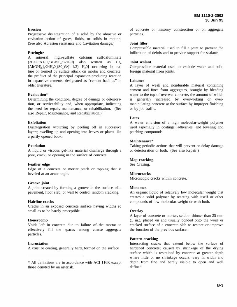
EM 1110-2-200230 Jun 95
ErosionProgressive disintegration of a solid by the abrasive orcavitation action of gases, fluids, or solids in motion.(See also Abrasion resistance and Cavitation damage.)
EttringiteA mineral, high-sulfate calcium sulfoaluminate(3CaO A1203 3CaS04 32H20) also written as Ca6[Al(OH)6]2 24H20[(S04)3 (1-1/2) H20] occurring in na-ture or formed by sulfate attack on mortar and concrete;the product of the principal expansion-producing reactionin expansive cements; designated as “cement bacillus” inolder literature.
Evaluation*Determining the condition, degree of damage or deteriora-tion, or serviceability and, when appropriate, indicatingthe need for repair, maintenance, or rehabilitation. (Seealso Repair, Maintenance, and Rehabilitation.)
ExfoliationDisintegration occurring by peeling off in successivelayers; swelling up and opening into leaves or plates likea partly opened book.
ExudationA liquid or viscous gel-like material discharge through apore, crack, or opening in the surface of concrete.
Feather edgeEdge of a concrete or mortar patch or topping that isbeveled at an acute angle.
Groove jointA joint created by forming a groove in the surface of apavement, floor slab, or wall to control random cracking.
Hairline cracksCracks in an exposed concrete surface having widths sosmall as to be barely preceptible.
HoneycombVoids left in concrete due to failure of the mortar toeffectively fill the spaces among coarse aggregateparticles.
IncrustationA crust or coating, generally hard, formed on the surface
* All definitions are in accordance with ACI 116R exceptthose denoted by an asterisk.
of concrete or masonry construction or on aggregateparticles.
Joint fillerCompressible material used to fill a joint to prevent theinfiltration of debris and to provide support for sealants.
Joint sealantCompressible material used to exclude water and solidforeign material from joints.
LaitanceA layer of weak and nondurable material containingcement and fines from aggregates, brought by bleedingwater to the top of overwet concrete, the amount of whichis generally increased by overworking or over-manipulating concrete at the surface by improper finishingor by job traffic.
LatexA water emulsion of a high molecular-weight polymerused especially in coatings, adhesives, and leveling andpatching compounds.
Maintenance*Taking periodic actions that will prevent or delay damageor deterioration or both. (See also Repair.)
Map crackingSee Crazing.
MicrocracksMicroscopic cracks within concrete.
MonomerAn organic liquid of relatively low molecular weight thatcreates a solid polymer by reacting with itself or othercompounds of low molecular weight or with both.
OverlayA layer of concrete or mortar, seldom thinner than 25 mm(1 in.), placed on and usually bonded onto the worn orcracked surface of a concrete slab to restore or improvethe function of the previous surface.
Pattern crackingIntersecting cracks that extend below the surface ofhardened concrete; caused by shrinkage of the dryingsurface which is restrained by concrete at greater depthwhere little or no shrinkage occurs; vary in width anddepth from fine and barely visible to open and welldefined.
B-3
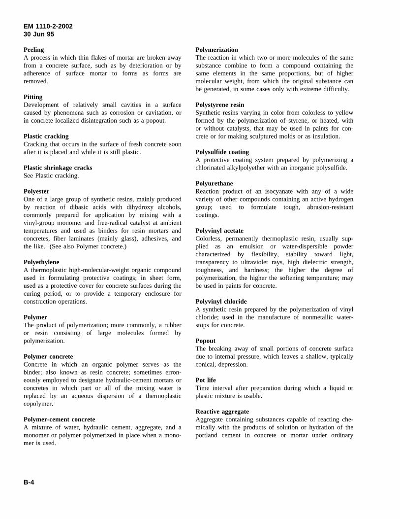
EM 1110-2-200230 Jun 95
PeelingA process in which thin flakes of mortar are broken awayfrom a concrete surface, such as by deterioration or byadherence of surface mortar to forms as forms areremoved.
PittingDevelopment of relatively small cavities in a surfacecaused by phenomena such as corrosion or cavitation, orin concrete localized disintegration such as a popout.
Plastic crackingCracking that occurs in the surface of fresh concrete soonafter it is placed and while it is still plastic.
Plastic shrinkage cracksSee Plastic cracking.
PolyesterOne of a large group of synthetic resins, mainly producedby reaction of dibasic acids with dihydroxy alcohols,commonly prepared for application by mixing with avinyl-group monomer and free-radical catalyst at ambienttemperatures and used as binders for resin mortars andconcretes, fiber laminates (mainly glass), adhesives, andthe like. (See also Polymer concrete.)
PolyethyleneA thermoplastic high-molecular-weight organic compoundused in formulating protective coatings; in sheet form,used as a protective cover for concrete surfaces during thecuring period, or to provide a temporary enclosure forconstruction operations.
PolymerThe product of polymerization; more commonly, a rubberor resin consisting of large molecules formed bypolymerization.
Polymer concreteConcrete in which an organic polymer serves as thebinder; also known as resin concrete; sometimes erron-eously employed to designate hydraulic-cement mortars orconcretes in which part or all of the mixing water isreplaced by an aqueous dispersion of a thermoplasticcopolymer.
Polymer-cement concreteA mixture of water, hydraulic cement, aggregate, and amonomer or polymer polymerized in place when a mono-mer is used.
PolymerizationThe reaction in which two or more molecules of the samesubstance combine to form a compound containing thesame elements in the same proportions, but of highermolecular weight, from which the original substance canbe generated, in some cases only with extreme difficulty.
Polystyrene resinSynthetic resins varying in color from colorless to yellowformed by the polymerization of styrene, or heated, withor without catalysts, that may be used in paints for con-crete or for making sculptured molds or as insulation.
Polysulfide coatingA protective coating system prepared by polymerizing achlorinated alkylpolyether with an inorganic polysulfide.
PolyurethaneReaction product of an isocyanate with any of a widevariety of other compounds containing an active hydrogengroup; used to formulate tough, abrasion-resistantcoatings.
Polyvinyl acetateColorless, permanently thermoplastic resin, usually sup-plied as an emulsion or water-dispersible powdercharacterized by flexibility, stability toward light,transparency to ultraviolet rays, high dielectric strength,toughness, and hardness; the higher the degree ofpolymerization, the higher the softening temperature; maybe used in paints for concrete.
Polyvinyl chlorideA synthetic resin prepared by the polymerization of vinylchloride; used in the manufacture of nonmetallic water-stops for concrete.
PopoutThe breaking away of small portions of concrete surfacedue to internal pressure, which leaves a shallow, typicallyconical, depression.
Pot lifeTime interval after preparation during which a liquid orplastic mixture is usable.
Reactive aggregateAggregate containing substances capable of reacting che-mically with the products of solution or hydration of theportland cement in concrete or mortar under ordinary
B-4
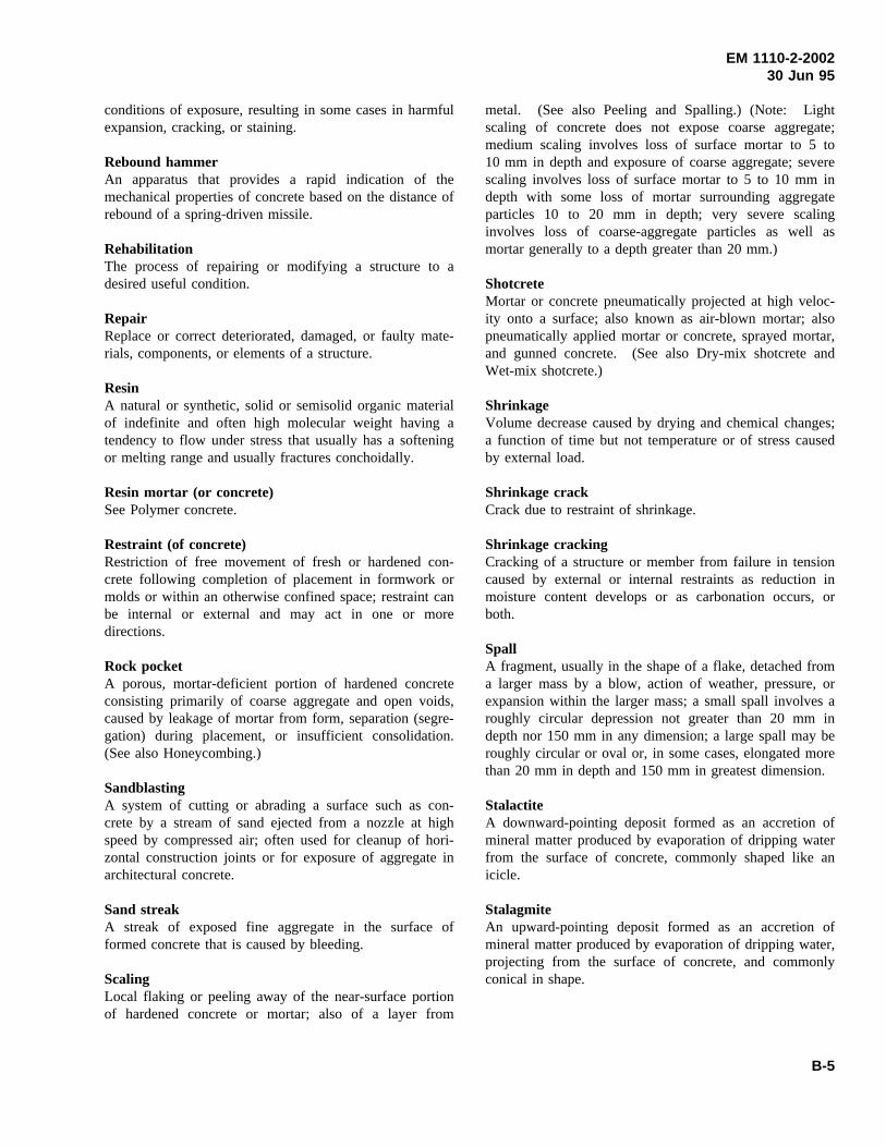
EM 1110-2-200230 Jun 95
conditions of exposure, resulting in some cases in harmfulexpansion, cracking, or staining.
Rebound hammerAn apparatus that provides a rapid indication of themechanical properties of concrete based on the distance ofrebound of a spring-driven missile.
RehabilitationThe process of repairing or modifying a structure to adesired useful condition.
RepairReplace or correct deteriorated, damaged, or faulty mate-rials, components, or elements of a structure.
ResinA natural or synthetic, solid or semisolid organic materialof indefinite and often high molecular weight having atendency to flow under stress that usually has a softeningor melting range and usually fractures conchoidally.
Resin mortar (or concrete)See Polymer concrete.
Restraint (of concrete)Restriction of free movement of fresh or hardened con-crete following completion of placement in formwork ormolds or within an otherwise confined space; restraint canbe internal or external and may act in one or moredirections.
Rock pocketA porous, mortar-deficient portion of hardened concreteconsisting primarily of coarse aggregate and open voids,caused by leakage of mortar from form, separation (segre-gation) during placement, or insufficient consolidation.(See also Honeycombing.)
SandblastingA system of cutting or abrading a surface such as con-crete by a stream of sand ejected from a nozzle at highspeed by compressed air; often used for cleanup of hori-zontal construction joints or for exposure of aggregate inarchitectural concrete.
Sand streakA streak of exposed fine aggregate in the surface offormed concrete that is caused by bleeding.
ScalingLocal flaking or peeling away of the near-surface portionof hardened concrete or mortar; also of a layer from
metal. (See also Peeling and Spalling.) (Note: Lightscaling of concrete does not expose coarse aggregate;medium scaling involves loss of surface mortar to 5 to10 mm in depth and exposure of coarse aggregate; severescaling involves loss of surface mortar to 5 to 10 mm indepth with some loss of mortar surrounding aggregateparticles 10 to 20 mm in depth; very severe scalinginvolves loss of coarse-aggregate particles as well asmortar generally to a depth greater than 20 mm.)
ShotcreteMortar or concrete pneumatically projected at high veloc-ity onto a surface; also known as air-blown mortar; alsopneumatically applied mortar or concrete, sprayed mortar,and gunned concrete. (See also Dry-mix shotcrete andWet-mix shotcrete.)
ShrinkageVolume decrease caused by drying and chemical changes;a function of time but not temperature or of stress causedby external load.
Shrinkage crackCrack due to restraint of shrinkage.
Shrinkage crackingCracking of a structure or member from failure in tensioncaused by external or internal restraints as reduction inmoisture content develops or as carbonation occurs, orboth.
SpallA fragment, usually in the shape of a flake, detached froma larger mass by a blow, action of weather, pressure, orexpansion within the larger mass; a small spall involves aroughly circular depression not greater than 20 mm indepth nor 150 mm in any dimension; a large spall may beroughly circular or oval or, in some cases, elongated morethan 20 mm in depth and 150 mm in greatest dimension.
StalactiteA downward-pointing deposit formed as an accretion ofmineral matter produced by evaporation of dripping waterfrom the surface of concrete, commonly shaped like anicicle.
StalagmiteAn upward-pointing deposit formed as an accretion ofmineral matter produced by evaporation of dripping water,projecting from the surface of concrete, and commonlyconical in shape.
B-5
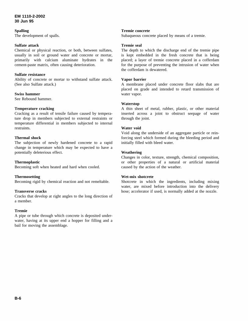
EM 1110-2-200230 Jun 95
SpallingThe development of spalls.
Sulfate attackChemical or physical reaction, or both, between sulfates,usually in soil or ground water and concrete or mortar,primarily with calcium aluminate hydrates in thecement-paste matrix, often causing deterioration.
Sulfate resistanceAbility of concrete or mortar to withstand sulfate attack.(See also Sulfate attack.)
Swiss hammerSee Rebound hammer.
Temperature crackingCracking as a result of tensile failure caused by tempera-ture drop in members subjected to external restraints ortemperature differential in members subjected to internalrestraints.
Thermal shockThe subjection of newly hardened concrete to a rapidchange in temperature which may be expected to have apotentially deleterious effect.
ThermoplasticBecoming soft when heated and hard when cooled.
ThermosettingBecoming rigid by chemical reaction and not remeltable.
Transverse cracksCracks that develop at right angles to the long direction ofa member.
TremieA pipe or tube through which concrete is deposited under-water, having at its upper end a hopper for filling and abail for moving the assemblage.
Tremie concreteSubaqueous concrete placed by means of a tremie.
Tremie sealThe depth to which the discharge end of the tremie pipeis kept embedded in the fresh concrete that is beingplaced; a layer of tremie concrete placed in a cofferdamfor the purpose of preventing the intrusion of water whenthe cofferdam is dewatered.
Vapor barrierA membrane placed under concrete floor slabs that areplaced on grade and intended to retard transmission ofwater vapor.
WaterstopA thin sheet of metal, rubber, plastic, or other materialinserted across a joint to obstruct seepage of waterthrough the joint.
Water voidVoid along the underside of an aggregate particle or rein-forcing steel which formed during the bleeding period andinitially filled with bleed water.
WeatheringChanges in color, texture, strength, chemical composition,or other properties of a natural or artificial materialcaused by the action of the weather.
Wet-mix shotcreteShotcrete in which the ingredients, including mixingwater, are mixed before introduction into the deliveryhose; accelerator if used, is normally added at the nozzle.
B-6
EM 1110-2-200230 Jun 95
Appendix CAbbreviations
ACI American Concrete Institute
ASTM American Society for Testing and Materials
AWA antiwashout admixture
CDMS Continuous Deformation Monitoring System
CE Corps of Engineers
CERC Coastal Engineering Research Center
CEWES-SC U.S. Army Engineer Waterways ExperimentStation, Structures Laboratory, ConcreteTechnology Division
CMU concrete masonry units
CRD Concrete Research Division, Handbook forConcrete and Cement
EM Engineer Manual
EP Engineer Pamplet
ER Engineer Regulation
FHWA Federal Highway Administration
GPS Global Positioning System
HAC high alumina cement
HMWM high molecular weight methacrylate
HQUSACE Headquarters, U.S. Army Corps ofEngineers
HRWRA high-range water-reducing admixture
ICOLD International Commission on Large Dams
MPC magnesium phosphate cement
MSA maximum size aggregate
MSDS Manufacturer’s Safety Data Sheet
NACE National Association of Corrosion Engineers
NAVSTAR Navigation Satellite Timing and Ranging
NCHRP National Cooperative Highway ResearchProgram
NDT nondestructive testing
OCE Office, Chief of Engineers
PC polymer concrete
PCA Portland Cement Association
PIC polymer-impregnated concrete
PPCC polymer portland-cement concrete
PMF Probable Maximum Flood
PVC polyvinyl chloride
R-values rebound readings
RCC roller-compacted concrete
REMR Repair, Evaluation, Maintenance, andRehabilitation Research Program
ROV remotely operated vehicle
TM Technical Manual
TOA time of arrival
UPE ultrasonic pulse-echo
UV ultraviolet
w/c water-cement ratio
WES Waterways Experiment Station
WRA water-reducing admixture
C-1


