Embed Size (px)
Citation preview
Slide 18-1
Chapter 18Fluids
© 2015 Pearson Education, Inc.
Slide 18-2© 2015 Pearson Education, Inc.
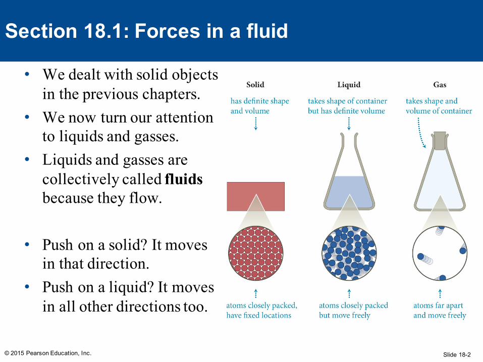
Section 18.1: Forces in a fluid
• We dealt with solid objects in the previous chapters.
• We now turn our attention to liquids and gasses.
• Liquids and gasses are collectively called fluidsbecause they flow.
• Push on a solid? It moves in that direction.
• Push on a liquid? It moves in all other directions too.
Slide 18-3© 2015 Pearson Education, Inc.
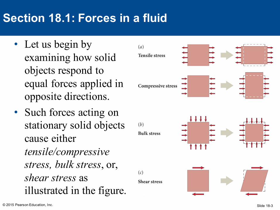
Section 18.1: Forces in a fluid
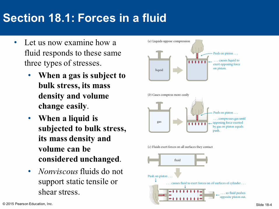
• Let us begin by examining how solid objects respond to equal forces applied in opposite directions.
• Such forces acting on stationary solid objects cause either tensile/compressive stress, bulk stress, or, shear stress as illustrated in the figure.
Slide 18-4© 2015 Pearson Education, Inc.
Section 18.1: Forces in a fluid
• Let us now examine how a fluid responds to these same three types of stresses. • When a gas is subject to
bulk stress, its mass density and volume change easily.
• When a liquid is subjected to bulk stress, its mass density and volume can be considered unchanged.
• Nonviscous fluids do not support static tensile or shear stress.
Slide 18-5
• When a liquid is subjected to bulk stress, its mass density and volume can be considered unchanged.• This is roughly true – the change in density and volume is
incredibly small. For most situations, negligible.• It cannot be completely true, however. Nothing is really
incompressible – a force can’t just do nothing at all• How do you hear anything underwater?
• Nonviscous fluids do not support static tensile or shear stress.• Only liquid helium near absolute zero actually does this (and it
is awesome)• Ignoring viscosity amounts to a theory of ‘dry water’, but it is
still very useful
© 2015 Pearson Education, Inc.
Wait. An aside.
Slide 18-6
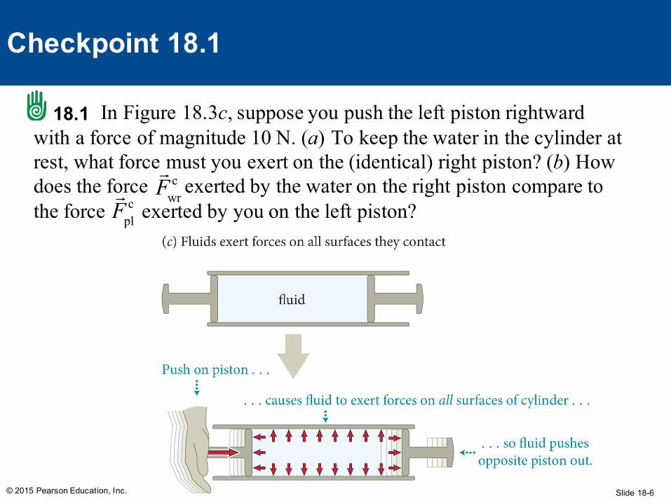
In Figure 18.3c, suppose you push the left piston rightward with a force of magnitude 10 N. (a) To keep the water in the cylinder at rest, what force must you exert on the (identical) right piston? (b) How does the force exerted by the water on the right piston compare to the force exerted by you on the left piston?
© 2015 Pearson Education, Inc.
Checkpoint 18.1
18.1
Fpl
c Fwr
c
Slide 18-7© 2015 Pearson Education, Inc.
Checkpoint 18.1
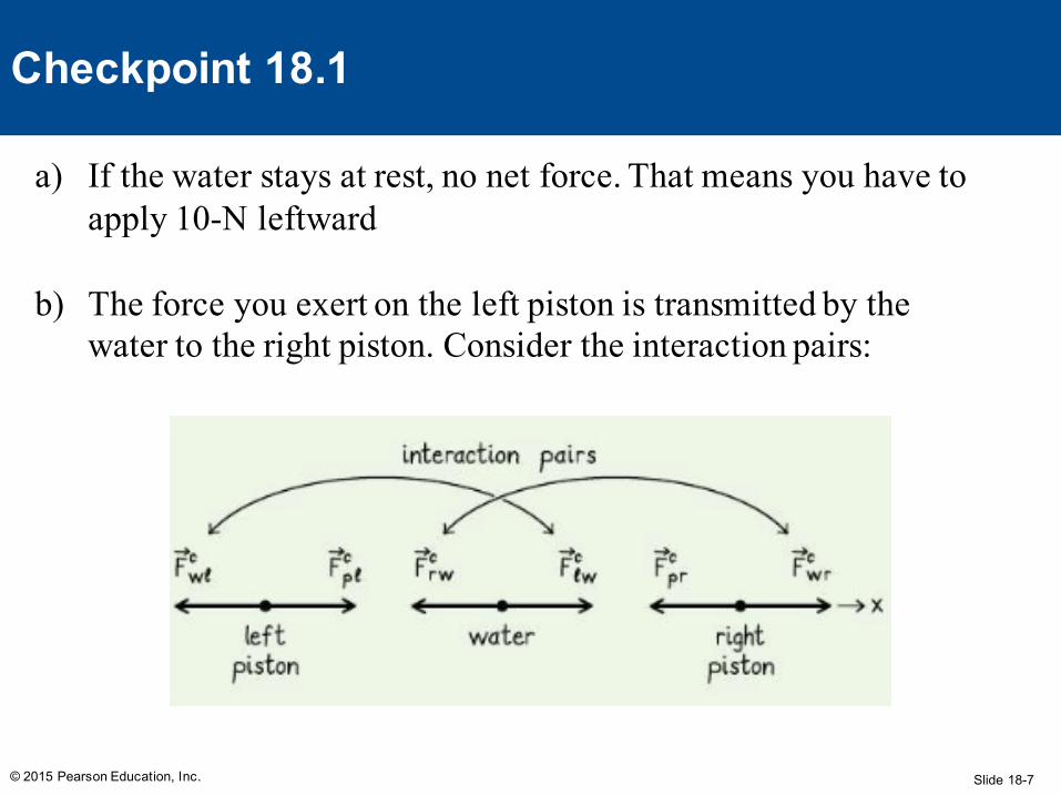
a) If the water stays at rest, no net force. That means you have to apply 10-N leftward
b) The force you exert on the left piston is transmitted by the water to the right piston. Consider the interaction pairs:
Slide 18-8
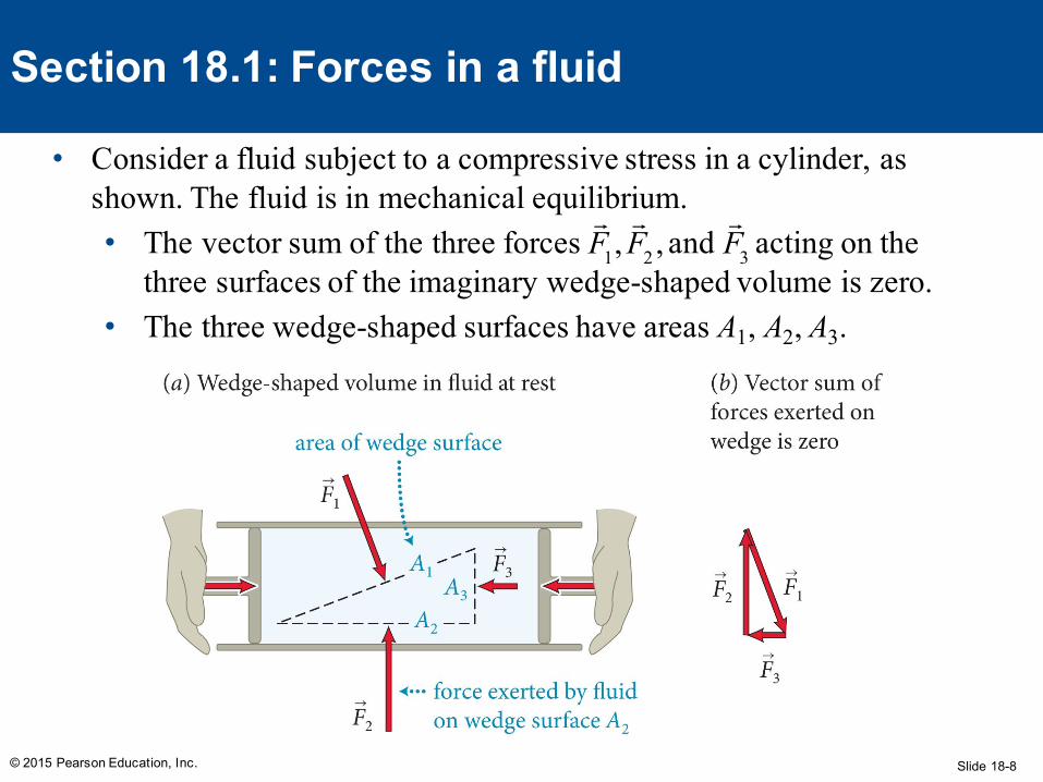
• Consider a fluid subject to a compressive stress in a cylinder, as shown. The fluid is in mechanical equilibrium.• The vector sum of the three forces and acting on the
three surfaces of the imaginary wedge-shaped volume is zero. • The three wedge-shaped surfaces have areas A1, A2, A3.
© 2015 Pearson Education, Inc.
Section 18.1: Forces in a fluid
F1,F2 ,
F3
Slide 18-9
• We can show that F1/A1 = F2/A2 = F3/A3. • This ratio of the force to the area on which the force
is exerted is called the pressure P, or P = F/A. • Pressure is a scalar quantity and has SI units: N/m2. • Because of the mobility of the particles in a fluid,
pressure is transmitted in all directions to all parts of the fluid.
(If it were not? The net force on one parcel of fluid would cause it to move to a spot with lower force, which would even out the pressure anyway.)
© 2015 Pearson Education, Inc.
Section 18.1: Forces in a fluid
Slide 18-10© 2015 Pearson Education, Inc.
Section 18.1: Forces in a fluid
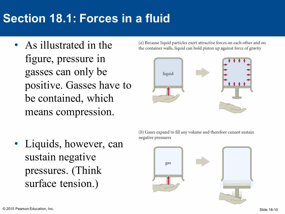
• As illustrated in the figure, pressure in gasses can only be positive. Gasses have to be contained, which means compression.
• Liquids, however, can sustain negative pressures. (Think surface tension.)
Slide 18-11
Consider a plastic cup full of water. (a) Is the water exerting a force on the bottom of the cup? (b) On the sides of the cup? (c) Is the water pressure negative, zero, or positive?
a) Yes – the water is at rest, and something must be balancing its weight
b) Yes – if the cup weren’t there, the water would move radially outward
c) Positive – because water pushes outward, surfaces have to push inward, which puts it under compression. Compression means positive pressure
© 2015 Pearson Education, Inc.
Checkpoint 18.2
18.2
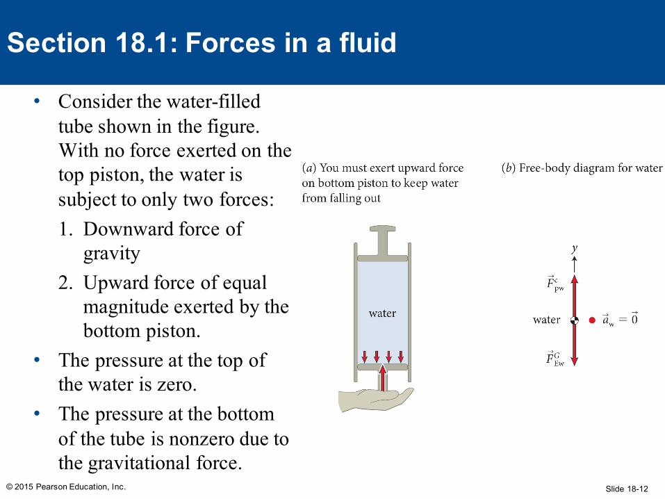
Slide 18-12© 2015 Pearson Education, Inc.
Section 18.1: Forces in a fluid
• Consider the water-filled tube shown in the figure. With no force exerted on the top piston, the water is subject to only two forces: 1. Downward force of
gravity2. Upward force of equal
magnitude exerted by the bottom piston.
• The pressure at the top of the water is zero.
• The pressure at the bottom of the tube is nonzero due to the gravitational force.
Slide 18-13© 2015 Pearson Education, Inc.
Section 18.1: Forces in a fluid
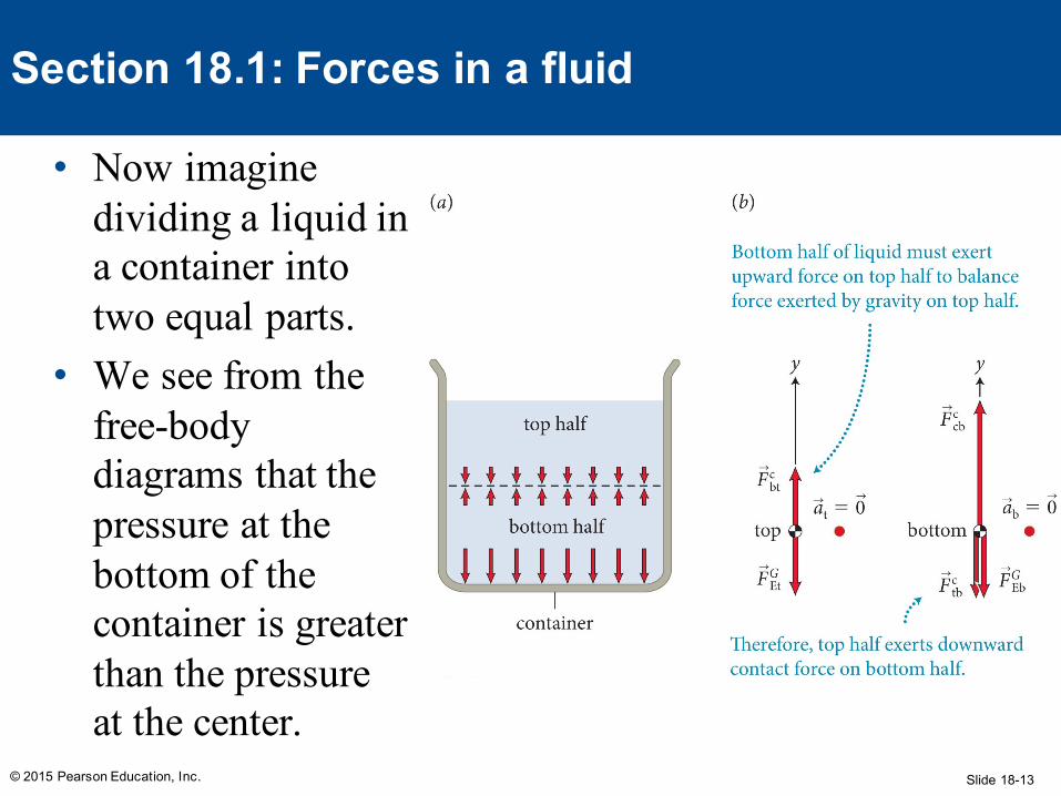
• Now imagine dividing a liquid in a container into two equal parts.
• We see from the free-body diagrams that the pressure at the bottom of the container is greater than the pressure at the center.
Slide 18-14© 2015 Pearson Education, Inc.
Section 18.1: Forces in a fluid
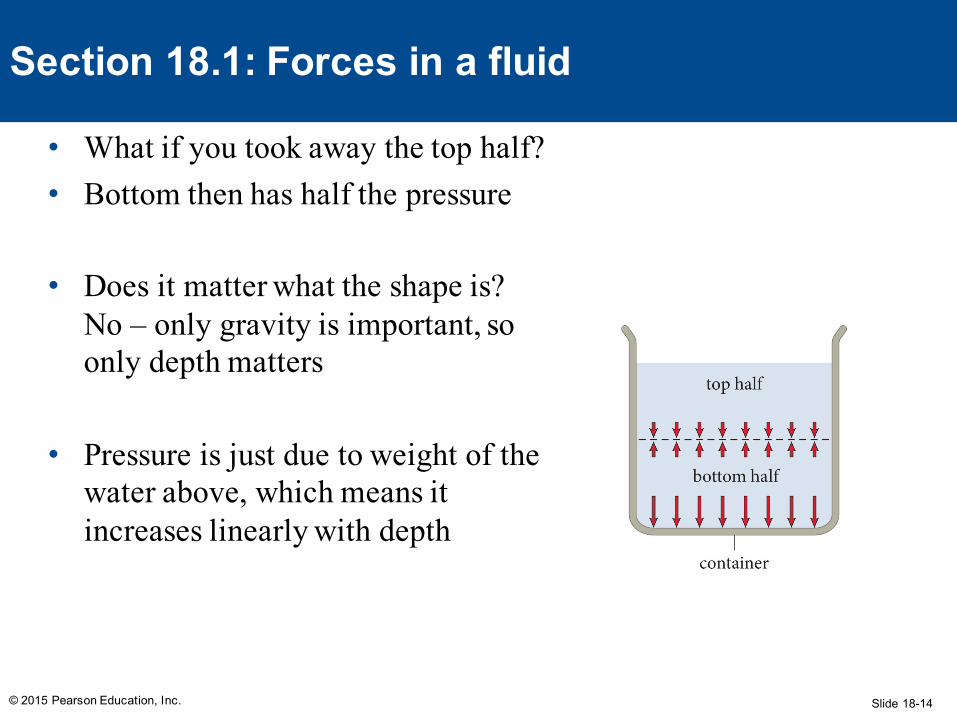
• What if you took away the top half?• Bottom then has half the pressure
• Does it matter what the shape is? No – only gravity is important, so only depth matters
• Pressure is just due to weight of the water above, which means it increases linearly with depth
Slide 18-15
• This leads us to an important conclusion: • The pressure in a liquid at rest in a container decreases
linearly with height, regardless of the shape of the container.
• We saw previously that any force exerted at one point in a liquid is transmitted to any other part of the liquid.
• This leads us to Pascal’s principle:• A pressure change applied to an enclosed liquid is
transmitted undiminished to every part of the liquid and to the wall of the container in contact with the liquid.
© 2015 Pearson Education, Inc.
Section 18.1: Forces in a fluid
Slide 18-16
Example 18.1 Water and air pressure
© 2015 Pearson Education, Inc.
Section 18.1: Forces in a fluid
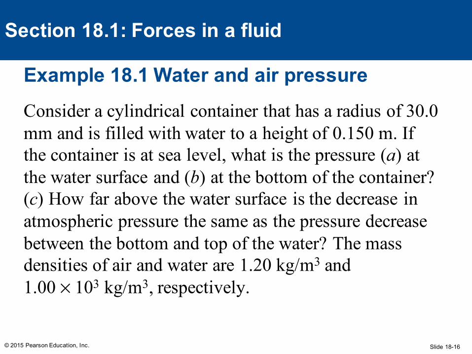
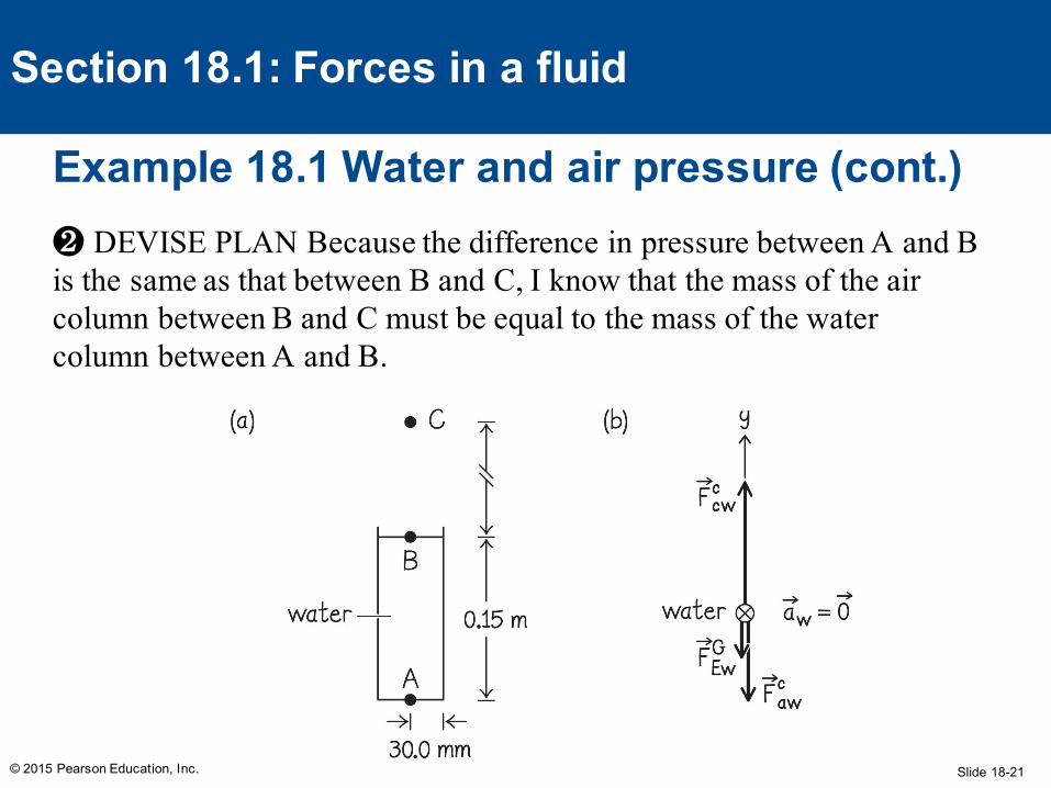
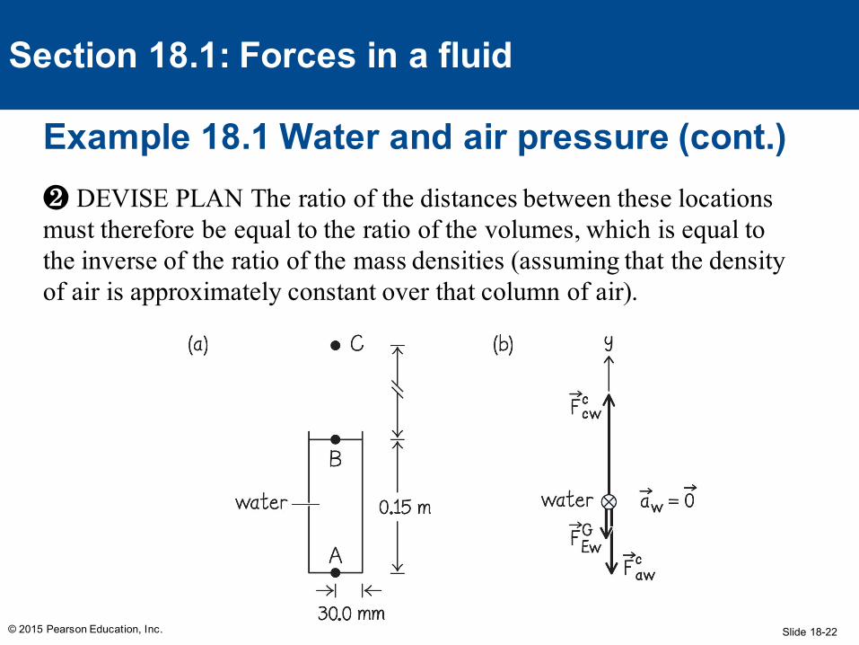
Consider a cylindrical container that has a radius of 30.0 mm and is filled with water to a height of 0.150 m. If the container is at sea level, what is the pressure (a) at the water surface and (b) at the bottom of the container? (c) How far above the water surface is the decrease in atmospheric pressure the same as the pressure decrease between the bottom and top of the water? The mass densities of air and water are 1.20 kg/m3 and 1.00 × 10³ kg/m3, respectively.
Slide 18-17© 2015 Pearson Education, Inc.
Section 18.1: Forces in a fluid
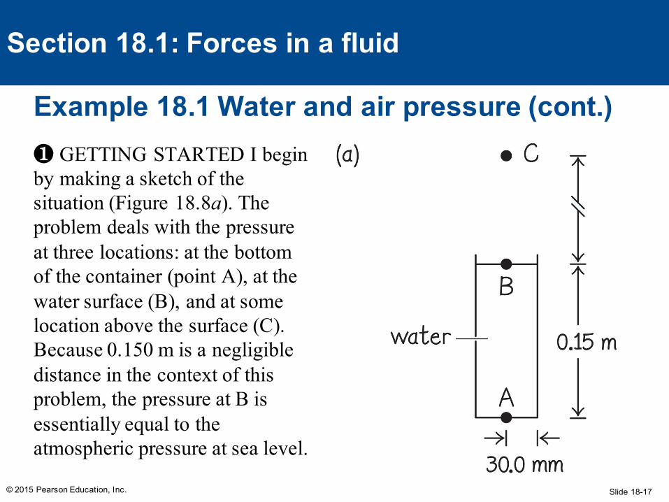
Example 18.1 Water and air pressure (cont.)❶ GETTING STARTED I begin by making a sketch of the situation (Figure 18.8a). The problem deals with the pressure at three locations: at the bottom of the container (point A), at the water surface (B), and at some location above the surface (C). Because 0.150 m is a negligible distance in the context of this problem, the pressure at B is essentially equal to the atmospheric pressure at sea level.
Slide 18-18© 2015 Pearson Education, Inc.
Section 18.1: Forces in a fluid
Example 18.1 Water and air pressure (cont.)❶ GETTING STARTED At A the pressure should be greater than at B because of the force of gravity exerted on the water. At C the pressure should be smaller than at B because the volume of air above C pressing down on C is smaller than the volume of air above B pressing down on B.
Slide 18-19© 2015 Pearson Education, Inc.
Section 18.1: Forces in a fluid
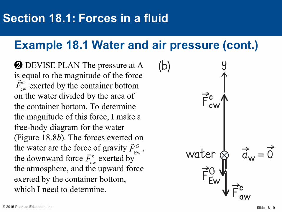
Example 18.1 Water and air pressure (cont.)❷ DEVISE PLAN The pressure at A is equal to the magnitude of the force
exerted by the container bottom on the water divided by the area of the container bottom. To determine the magnitude of this force, I make a free-body diagram for the water (Figure 18.8b). The forces exerted on the water are the force of gravity , the downward force exerted by the atmosphere, and the upward force exerted by the container bottom, which I need to determine.
Fcw
c
FEw
G
Faw
c
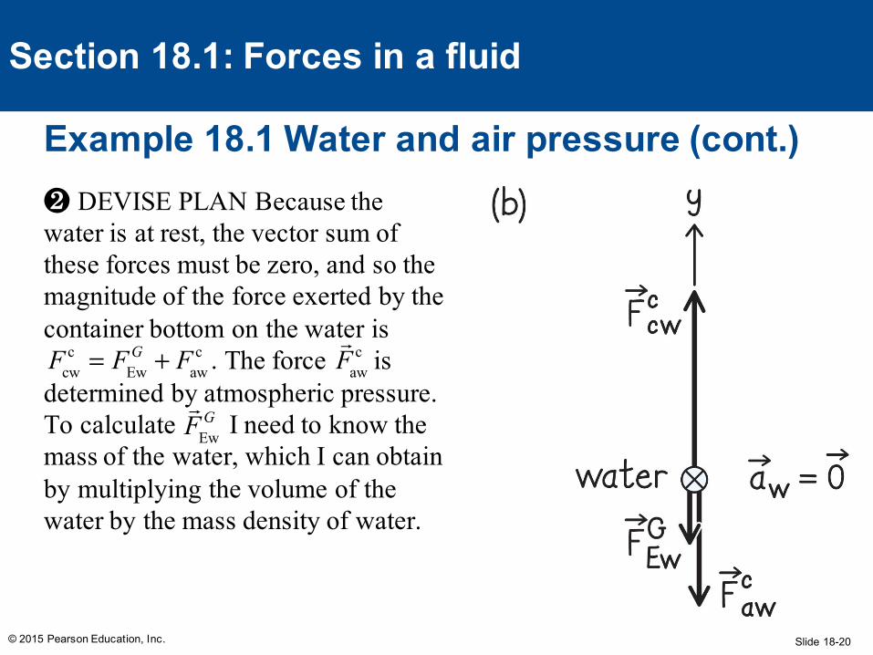
Slide 18-20© 2015 Pearson Education, Inc.
Section 18.1: Forces in a fluid
Example 18.1 Water and air pressure (cont.)❷ DEVISE PLAN Because the water is at rest, the vector sum of these forces must be zero, and so the magnitude of the force exerted by the container bottom on the water is
The force is determined by atmospheric pressure. To calculate I need to know the mass of the water, which I can obtain by multiplying the volume of the water by the mass density of water.
Fcwc = FEw
G + Fawc .
Faw
c
FEw
G
Slide 18-21
Example 18.1 Water and air pressure (cont.)
© 2015 Pearson Education, Inc.
Section 18.1: Forces in a fluid
❷ DEVISE PLAN Because the difference in pressure between A and B is the same as that between B and C, I know that the mass of the air column between B and C must be equal to the mass of the water column between A and B.
Slide 18-22
Example 18.1 Water and air pressure (cont.)
© 2015 Pearson Education, Inc.
Section 18.1: Forces in a fluid
❷ DEVISE PLAN The ratio of the distances between these locations must therefore be equal to the ratio of the volumes, which is equal to the inverse of the ratio of the mass densities (assuming that the density of air is approximately constant over that column of air).
Slide 18-23
Example 18.1 Water and air pressure (cont.)
© 2015 Pearson Education, Inc.
Section 18.1: Forces in a fluid
❸ EXECUTE PLAN (a) The pressure at B is essentially equal to atmospheric pressure at sea level, which I can look up: PB = 1.01325 × 10⁵ N/m2. ✔
Slide 18-24
Example 18.1 Water and air pressure (cont.)
© 2015 Pearson Education, Inc.
Section 18.1: Forces in a fluid
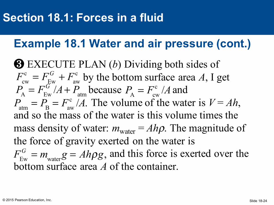
❸ EXECUTE PLAN (b) Dividing both sides of by the bottom surface area A, I get because and The volume of the water is V = Ah,
and so the mass of the water is this volume times the mass density of water: mwater = Ahρ. The magnitude of the force of gravity exerted on the water is
and this force is exerted over the bottom surface area A of the container.
Fcwc = FEw
G + Fawc
PA = FEwG /A+ Patm PA = Fcw
c /A Patm = PB = Faw
c /A.
FEwG = mwater g = Ahρg,
Slide 18-25
Example 18.1 Water and air pressure (cont.)
© 2015 Pearson Education, Inc.
Section 18.1: Forces in a fluid
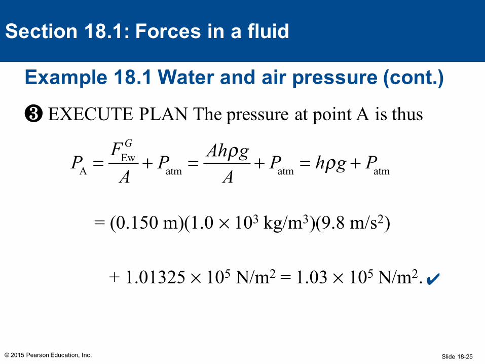
❸ EXECUTE PLAN The pressure at point A is thus
= (0.150 m)(1.0 × 10³ kg/m3)(9.8 m/s2)
+ 1.01325 × 10⁵ N/m2 = 1.03 × 10⁵ N/m2.
PA =
FEwG
A+ Patm = Ahρg
A+ Patm = hρg + Patm
✔
Slide 18-26
Example 18.1 Water and air pressure (cont.)
© 2015 Pearson Education, Inc.
Section 18.1: Forces in a fluid
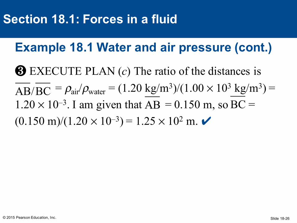
❸ EXECUTE PLAN (c) The ratio of the distances is = ρair/ρwater = (1.20 kg/m3)/(1.00 × 103 kg/m3) =
1.20 × 10⁻³. I am given that = 0.150 m, so = (0.150 m)/(1.20 × 10–3) = 1.25 × 10² m. ✔
AB/BC AB BC
Slide 18-27
Example 18.1 Water and air pressure (cont.)
© 2015 Pearson Education, Inc.
Section 18.1: Forces in a fluid
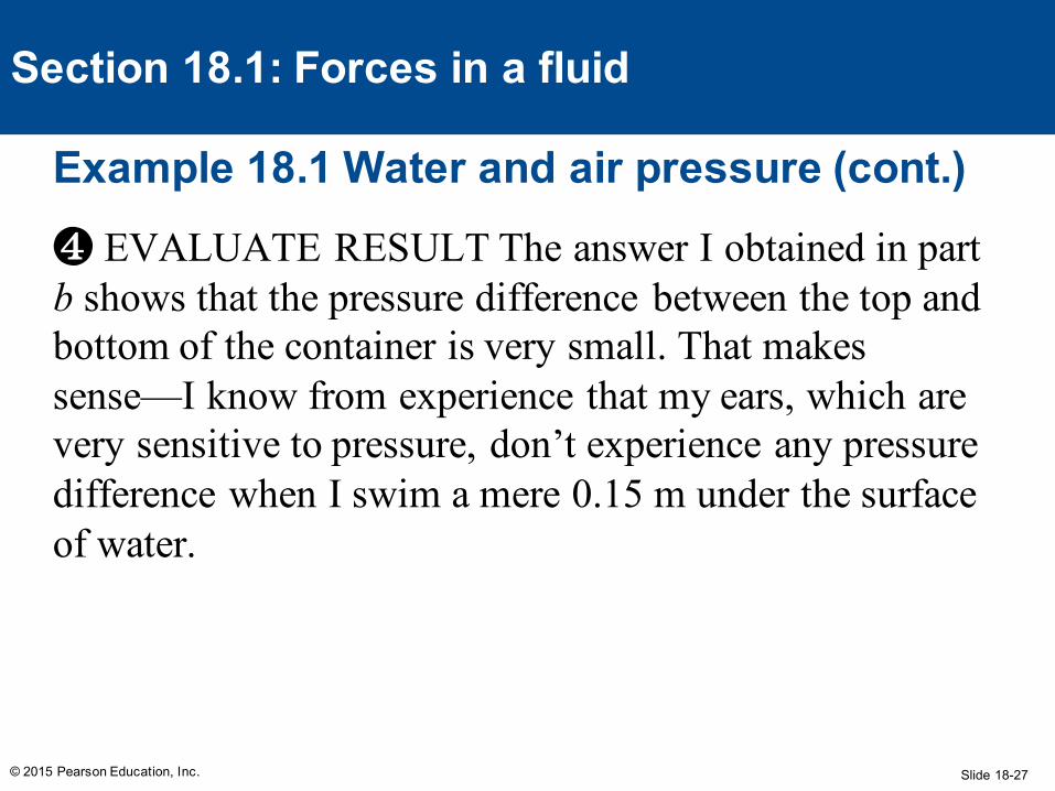
❹ EVALUATE RESULT The answer I obtained in part b shows that the pressure difference between the top and bottom of the container is very small. That makes sense—I know from experience that my ears, which are very sensitive to pressure, don’t experience any pressure difference when I swim a mere 0.15 m under the surface of water.
Slide 18-28
Example 18.1 Water and air pressure (cont.)
© 2015 Pearson Education, Inc.
Section 18.1: Forces in a fluid
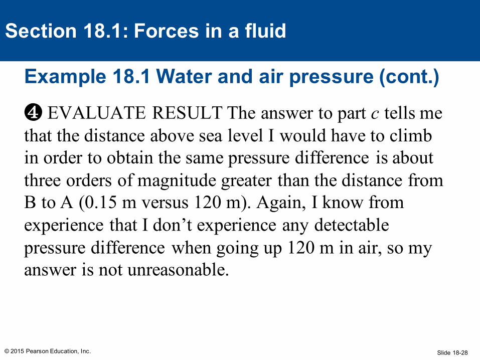
❹ EVALUATE RESULT The answer to part c tells me that the distance above sea level I would have to climb in order to obtain the same pressure difference is about three orders of magnitude greater than the distance from B to A (0.15 m versus 120 m). Again, I know from experience that I don’t experience any detectable pressure difference when going up 120 m in air, so my answer is not unreasonable.
Slide 18-29
How does a pressure change applied to the top of a column of liquid held in a closed container affect the pressure throughout the liquid?
1. It does not affect it since the pressure in the fluid is due to the fluid only.
2. It increases the pressure only at the air/liquid interface.
3. It increases the pressure throughout the fluid.4. It decreases the pressure throughout the fluid.
© 2015 Pearson Education, Inc.
Section 18.1Question 1
Slide 18-30
How does a pressure change applied to the top of a column of liquid held in a closed container affect the pressure throughout the liquid?
1. It does not affect it since the pressure in the fluid is due to the fluid only.
2. It increases the pressure only at the air/liquid interface.
3. It increases the pressure throughout the fluid.4. It decreases the pressure throughout the fluid.
© 2015 Pearson Education, Inc.
Section 18.1Question 1
Slide 18-31
Section Goals
© 2015 Pearson Education, Inc.
Section 18.2: Buoyancy
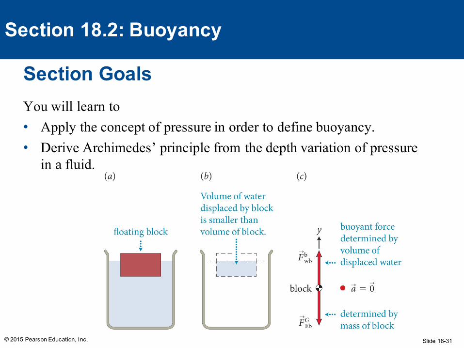
You will learn to• Apply the concept of pressure in order to define buoyancy.• Derive Archimedes’ principle from the depth variation of pressure
in a fluid.
Slide 18-32
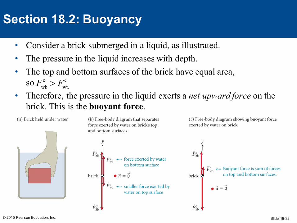
• Consider a brick submerged in a liquid, as illustrated.• The pressure in the liquid increases with depth.• The top and bottom surfaces of the brick have equal area,
so • Therefore, the pressure in the liquid exerts a net upward force on the
brick. This is the buoyant force.
© 2015 Pearson Education, Inc.
Section 18.2: Buoyancy
Fwbc > Fwt.
c
Slide 18-33
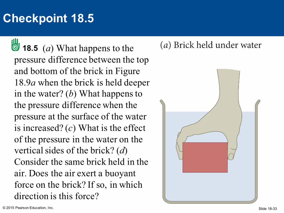
(a) What happens to the pressure difference between the top and bottom of the brick in Figure 18.9a when the brick is held deeper in the water? (b) What happens to the pressure difference when the pressure at the surface of the water is increased? (c) What is the effect of the pressure in the water on the vertical sides of the brick? (d) Consider the same brick held in the air. Does the air exert a buoyant force on the brick? If so, in which direction is this force?
© 2015 Pearson Education, Inc.
Checkpoint 18.5
18.5
Slide 18-34
• a) Nothing – since pressure increases linearly with depth, the difference between top and bottom is always the same
• b) Nothing – the pressure change applied is transmitted undiminished to every part of the fluid, so the top and bottom change by the same amount
• c) No effect, pressure on the sides causes equal and opposite forces
• d) Yes – the pressure in the atmosphere also decreases with height, though less than in water. The force is also upward.
© 2015 Pearson Education, Inc.
Checkpoint 18.5
Slide 18-35
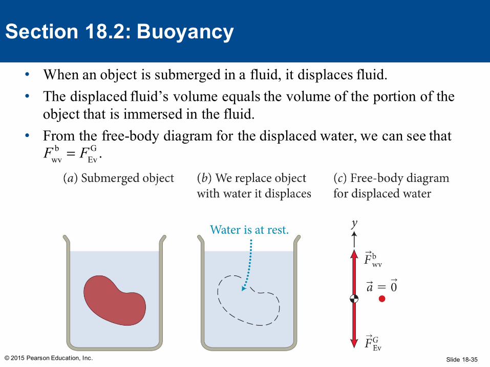
• When an object is submerged in a fluid, it displaces fluid.• The displaced fluid’s volume equals the volume of the portion of the
object that is immersed in the fluid.• From the free-body diagram for the displaced water, we can see that
© 2015 Pearson Education, Inc.
Section 18.2: Buoyancy
Fwvb = FEv
G .
Slide 18-36
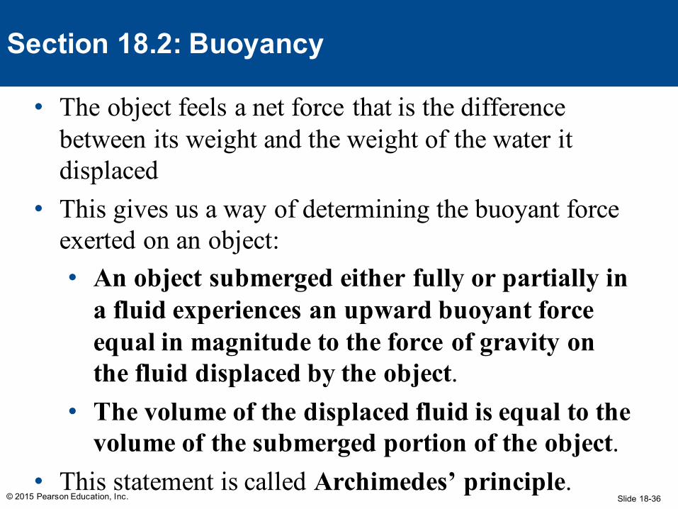
• The object feels a net force that is the difference between its weight and the weight of the water it displaced
• This gives us a way of determining the buoyant force exerted on an object:• An object submerged either fully or partially in
a fluid experiences an upward buoyant force equal in magnitude to the force of gravity on the fluid displaced by the object.
• The volume of the displaced fluid is equal to the volume of the submerged portion of the object.
• This statement is called Archimedes’ principle.© 2015 Pearson Education, Inc.
Section 18.2: Buoyancy
Slide 18-37
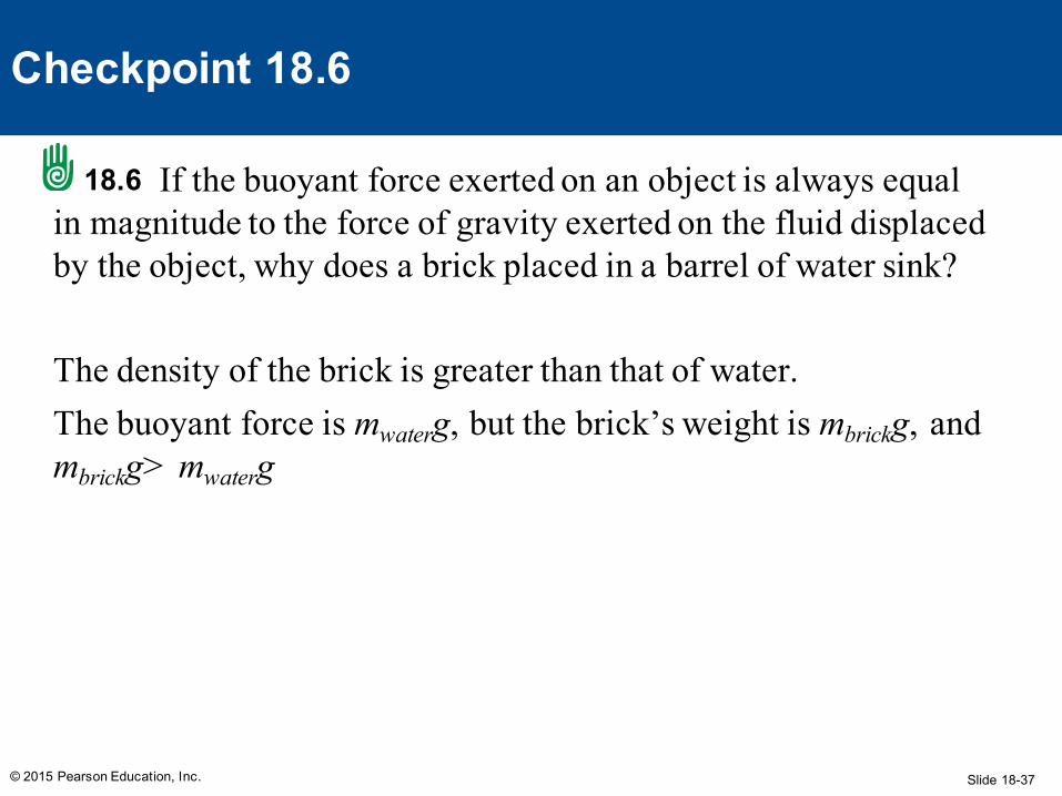
If the buoyant force exerted on an object is always equal in magnitude to the force of gravity exerted on the fluid displaced by the object, why does a brick placed in a barrel of water sink?
The density of the brick is greater than that of water. The buoyant force is mwaterg, but the brick’s weight is mbrickg, and mbrickg> mwaterg
© 2015 Pearson Education, Inc.
Checkpoint 18.6
18.6
Slide 18-38
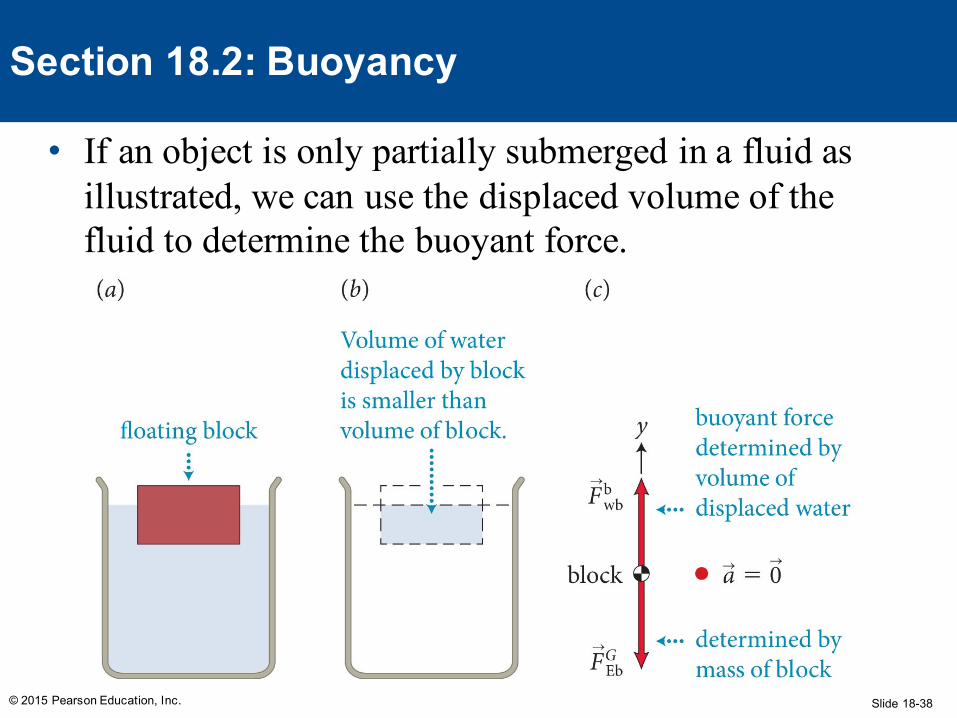
• If an object is only partially submerged in a fluid as illustrated, we can use the displaced volume of the fluid to determine the buoyant force.
© 2015 Pearson Education, Inc.
Section 18.2: Buoyancy
Slide 18-39
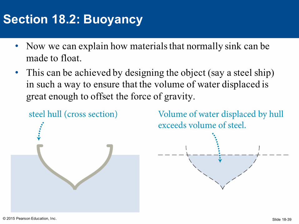
• Now we can explain how materials that normally sink can be made to float.
• This can be achieved by designing the object (say a steel ship) in such a way to ensure that the volume of water displaced is great enough to offset the force of gravity.
© 2015 Pearson Education, Inc.
Section 18.2: Buoyancy
Slide 18-40
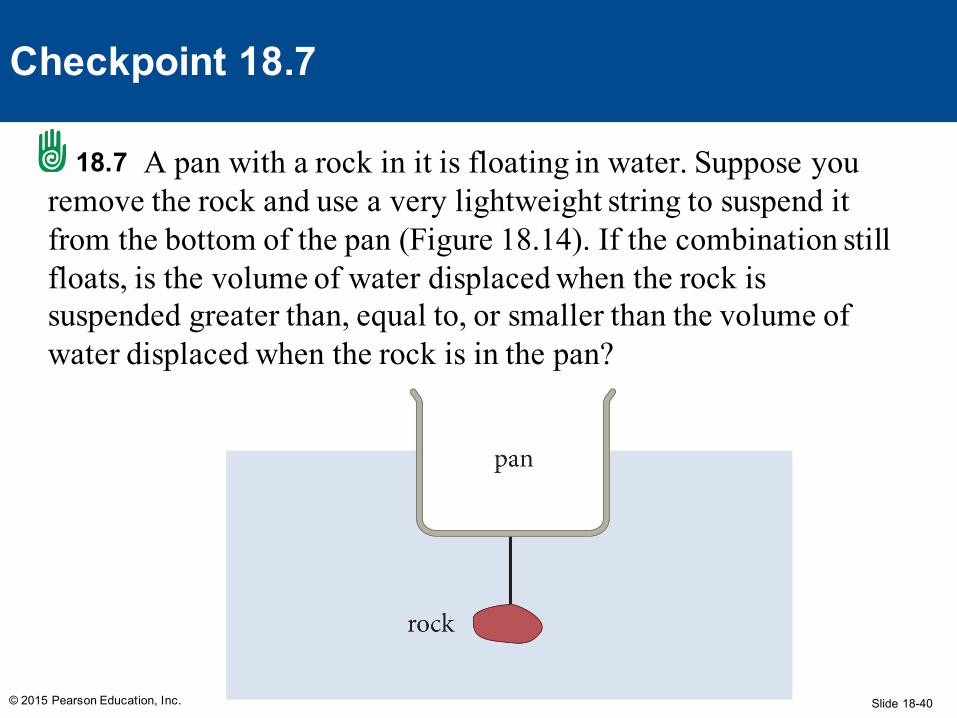
A pan with a rock in it is floating in water. Suppose you remove the rock and use a very lightweight string to suspend it from the bottom of the pan (Figure 18.14). If the combination still floats, is the volume of water displaced when the rock is suspended greater than, equal to, or smaller than the volume of water displaced when the rock is in the pan?
© 2015 Pearson Education, Inc.
Checkpoint 18.7
18.7
Slide 18-41
• Equal.
• The pan-rock combination floats in both cases, to the buoyant force in both cases must be equal to the force of gravity exerted on the displaced water.
• The buoyant force must also equal the weight of the combination since it remains at rest.
• The mass doesn’t change when you rearrange the combination, so the volume of water displaced doesn’t change either
© 2015 Pearson Education, Inc.
Checkpoint 18.7
Slide 18-42
Imagine holding two bricks under water. Brick A is just beneath the surface of the water, while brick B is at a greater depth. The force needed to hold brick B in place is
1. larger than2. the same as3. smaller than
the force required to hold brick A in place.
© 2015 Pearson Education, Inc.
Section 18.2Question 2
Slide 18-43
Imagine holding two bricks under water. Brick A is just beneath the surface of the water, while brick B is at a greater depth. The force needed to hold brick B in place is
1. larger than2. the same as3. smaller than
the force required to hold brick A in place.
© 2015 Pearson Education, Inc.
Section 18.2Question 2
Slide 18-44
A lead weight is fastened on top of a large solid piece of Styrofoam that floats in a container of water. Because of the weight of the lead, the water line is flush with the top surface of the Styrofoam. If the piece of Styrofoam is turned upside down so that the weight is now suspended underneath it,
1. the arrangement sinks.2. the water line is below the top surface of the
Styrofoam.3. the water line is still flush with the top surface of the
Styrofoam.
© 2015 Pearson Education, Inc.
Section 18.2Question 3
Slide 18-45
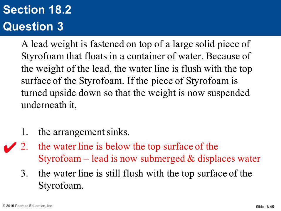
A lead weight is fastened on top of a large solid piece of Styrofoam that floats in a container of water. Because of the weight of the lead, the water line is flush with the top surface of the Styrofoam. If the piece of Styrofoam is turned upside down so that the weight is now suspended underneath it,
1. the arrangement sinks.2. the water line is below the top surface of the
Styrofoam – lead is now submerged & displaces water3. the water line is still flush with the top surface of the
Styrofoam.
© 2015 Pearson Education, Inc.
Section 18.2Question 3
Slide 18-46
Section Goals
© 2015 Pearson Education, Inc.
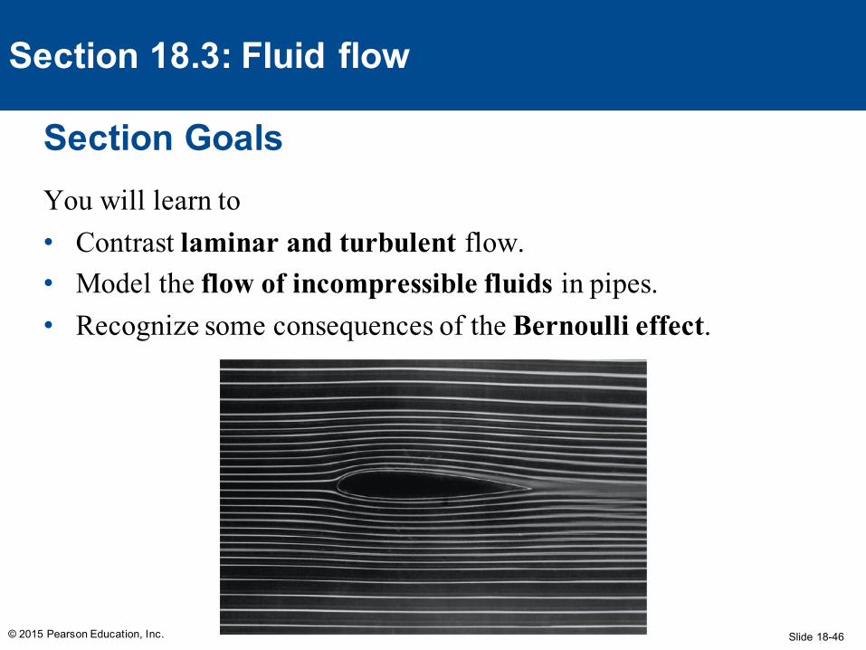
Section 18.3: Fluid flow
You will learn to• Contrast laminar and turbulent flow.• Model the flow of incompressible fluids in pipes.• Recognize some consequences of the Bernoulli effect.
Slide 18-47
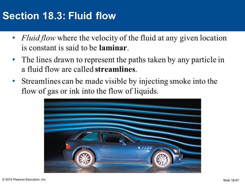
• Fluid flow where the velocity of the fluid at any given location is constant is said to be laminar.
• The lines drawn to represent the paths taken by any particle in a fluid flow are called streamlines.
• Streamlines can be made visible by injecting smoke into the flow of gas or ink into the flow of liquids.
© 2015 Pearson Education, Inc.
Section 18.3: Fluid flow
Slide 18-48© 2015 Pearson Education, Inc.
Section 18.3: Fluid flow
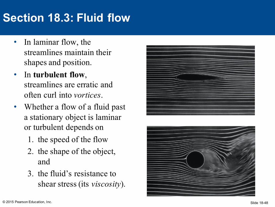
• In laminar flow, the streamlines maintain their shapes and position.
• In turbulent flow, streamlines are erratic and often curl into vortices.
• Whether a flow of a fluid past a stationary object is laminar or turbulent depends on1. the speed of the flow2. the shape of the object,
and3. the fluid’s resistance to
shear stress (its viscosity).
Slide 18-49
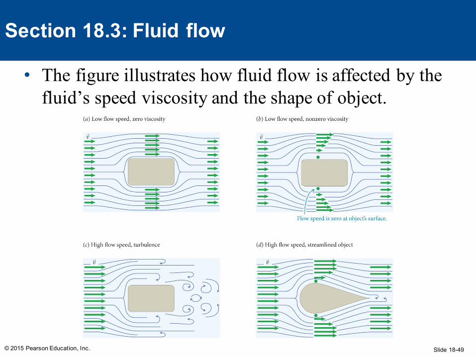
• The figure illustrates how fluid flow is affected by the fluid’s speed viscosity and the shape of object.
© 2015 Pearson Education, Inc.
Section 18.3: Fluid flow
Slide 18-50
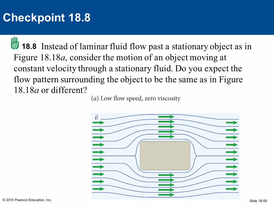
Instead of laminar fluid flow past a stationary object as in Figure 18.18a, consider the motion of an object moving at constant velocity through a stationary fluid. Do you expect the flow pattern surrounding the object to be the same as in Figure 18.18a or different?
© 2015 Pearson Education, Inc.
Checkpoint 18.8
18.8
Slide 18-51
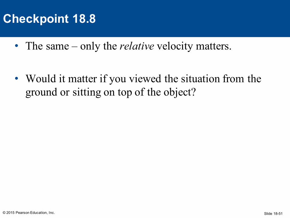
• The same – only the relative velocity matters.
• Would it matter if you viewed the situation from the ground or sitting on top of the object?
© 2015 Pearson Education, Inc.
Checkpoint 18.8
Slide 18-52
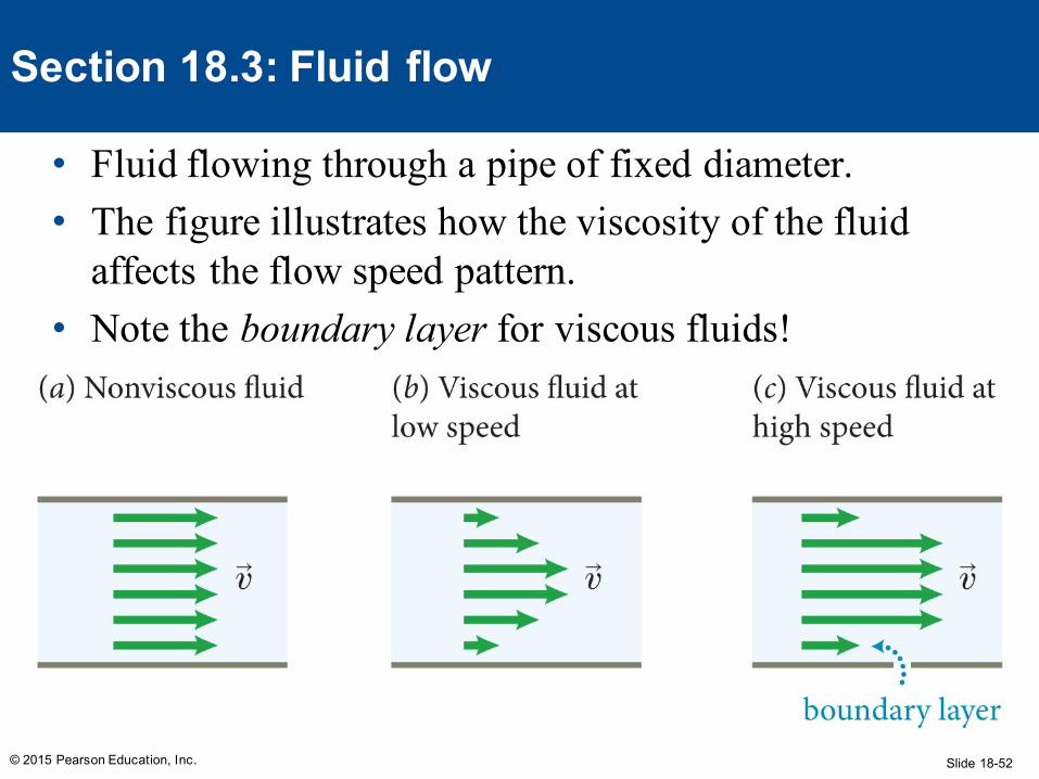
• Fluid flowing through a pipe of fixed diameter. • The figure illustrates how the viscosity of the fluid
affects the flow speed pattern.• Note the boundary layer for viscous fluids!
© 2015 Pearson Education, Inc.
Section 18.3: Fluid flow
Slide 18-53© 2015 Pearson Education, Inc.
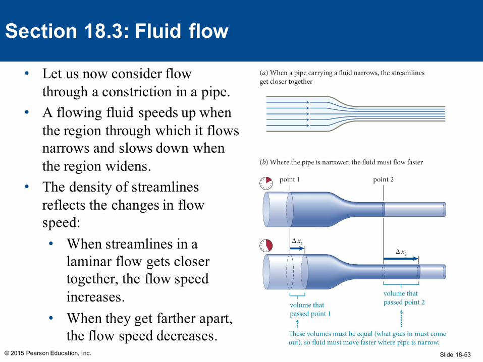
Section 18.3: Fluid flow
• Let us now consider flow through a constriction in a pipe.
• A flowing fluid speeds up when the region through which it flows narrows and slows down when the region widens.
• The density of streamlines reflects the changes in flow speed:• When streamlines in a
laminar flow gets closer together, the flow speed increases.
• When they get farther apart, the flow speed decreases.
Slide 18-54© 2015 Pearson Education, Inc.
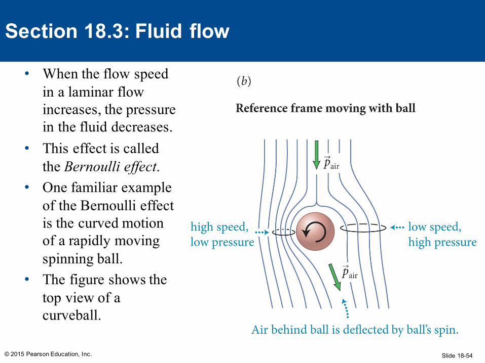
Section 18.3: Fluid flow
• When the flow speed in a laminar flow increases, the pressure in the fluid decreases.
• This effect is called the Bernoulli effect.
• One familiar example of the Bernoulli effect is the curved motion of a rapidly moving spinning ball.
• The figure shows the top view of a curveball.
Slide 18-55
Example 18.3 Magic pull
© 2015 Pearson Education, Inc.
Section 18.3: Fluid flow
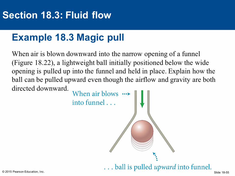
When air is blown downward into the narrow opening of a funnel (Figure 18.22), a lightweight ball initially positioned below the wide opening is pulled up into the funnel and held in place. Explain how the ball can be pulled upward even though the airflow and gravity are both directed downward.
Slide 18-56
Example 18.3 Magic pull (cont.)
© 2015 Pearson Education, Inc.
Section 18.3: Fluid flow
❶ GETTING STARTED I know that if I were to blow against the ball, it would move away from me. So I reason that to pull the ball upward, there must be exerted on it an upward force that is greater than the combined effect of the downward gravitational and airflow forces.
Slide 18-57
Example 18.3 Magic pull (cont.)
© 2015 Pearson Education, Inc.
Section 18.3: Fluid flow
❶ GETTING STARTED The ball is subject to an upward buoyant force, but I know this force is smaller than that of gravity alone because a ball—even a lightweight one—does not float in air. So there must be an additional force pulling the ball upward. Because this force is absent when no air flows past the ball, that flow must be causing the upward force.
Slide 18-58
Example 18.3 Magic pull (cont.)
© 2015 Pearson Education, Inc.
Section 18.3: Fluid flow
❷ DEVISE PLAN To understand the effects of the flowing air, I should sketch the streamlines (I assume laminar flow). The density of the streamlines tells me how the speed of the flow varies, and from this information I can determine how the air pressure varies around the ball, which in turn tells me in which direction the air exerts a force on the ball.
Slide 18-59
Example 18.3 Magic pull (cont.)
© 2015 Pearson Education, Inc.
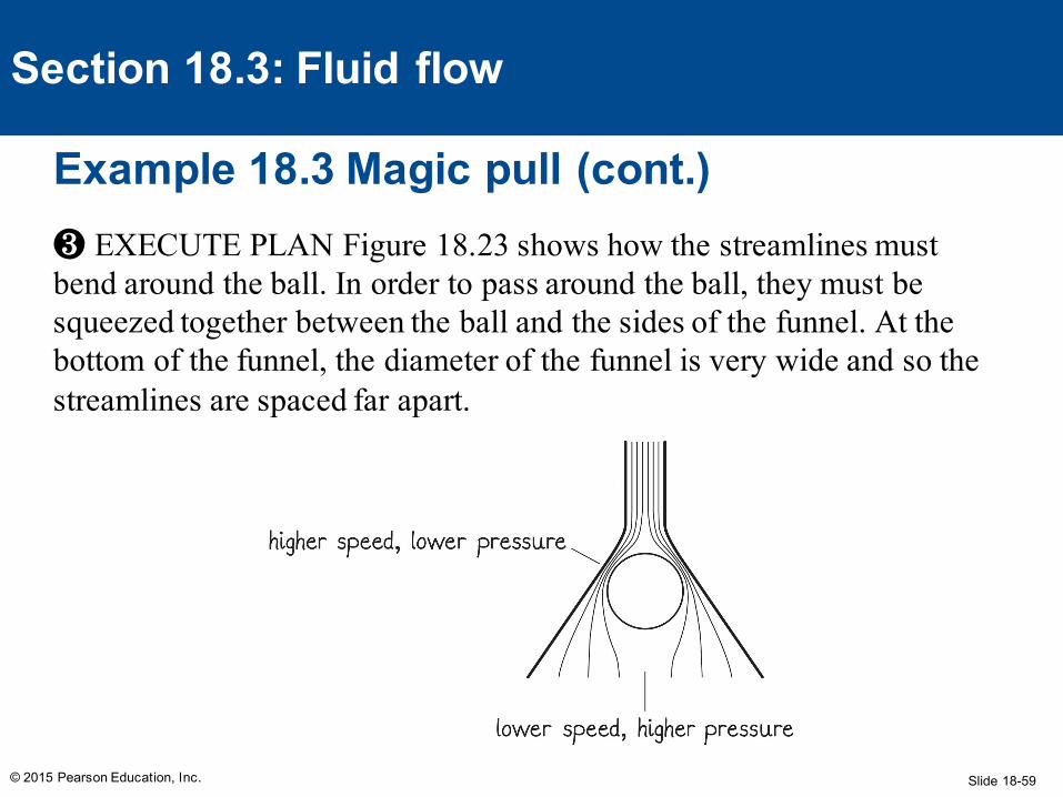
Section 18.3: Fluid flow
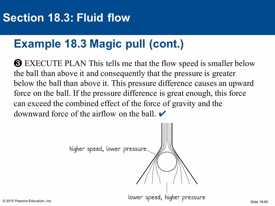
❸ EXECUTE PLAN Figure 18.23 shows how the streamlines must bend around the ball. In order to pass around the ball, they must be squeezed together between the ball and the sides of the funnel. At the bottom of the funnel, the diameter of the funnel is very wide and so the streamlines are spaced far apart.
Slide 18-60
Example 18.3 Magic pull (cont.)
© 2015 Pearson Education, Inc.
Section 18.3: Fluid flow
❸ EXECUTE PLAN This tells me that the flow speed is smaller below the ball than above it and consequently that the pressure is greater below the ball than above it. This pressure difference causes an upward force on the ball. If the pressure difference is great enough, this force can exceed the combined effect of the force of gravity and the downward force of the airflow on the ball. ✔
Slide 18-61
Example 18.3 Magic pull (cont.)
© 2015 Pearson Education, Inc.
Section 18.3: Fluid flow
❹ EVALUATE RESULT My answer is consistent with the observation given in the problem statement, even though the ball’s being pulled upward by a downward flow of air seems nothing short of magic! I assumed the flow to be laminar, which may not be entirely correct for an object like a ball (which is not streamlined). However, because air is a gas and because gases have very low viscosity, the assumption that the flow remains laminar is not unreasonable.
Slide 18-62
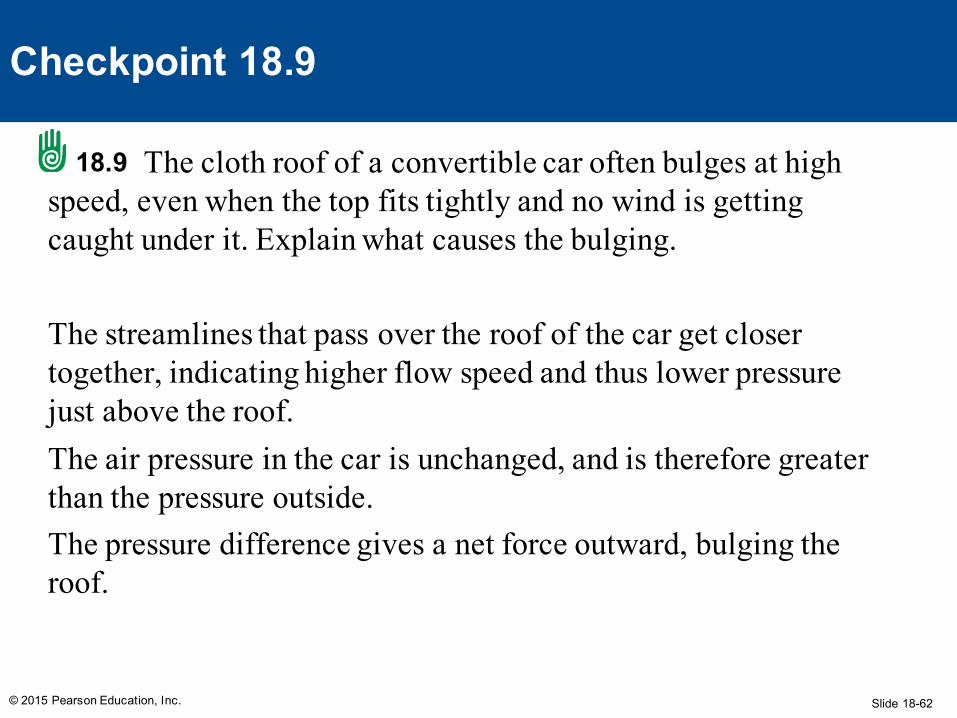
The cloth roof of a convertible car often bulges at high speed, even when the top fits tightly and no wind is getting caught under it. Explain what causes the bulging.
The streamlines that pass over the roof of the car get closer together, indicating higher flow speed and thus lower pressure just above the roof.The air pressure in the car is unchanged, and is therefore greater than the pressure outside.The pressure difference gives a net force outward, bulging the roof.
© 2015 Pearson Education, Inc.
Checkpoint 18.9
18.9
Slide 18-63
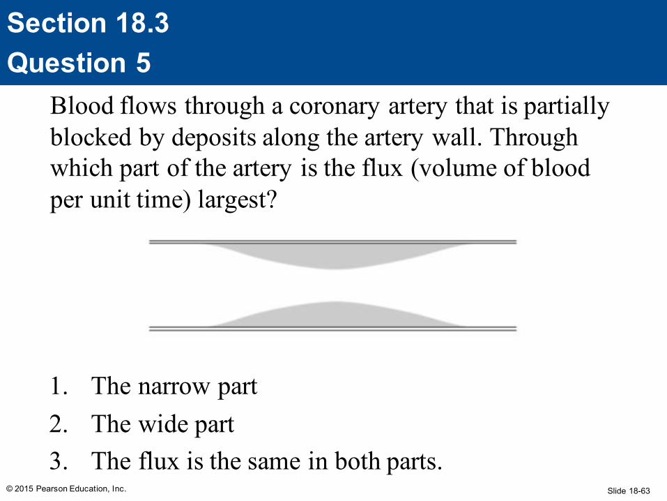
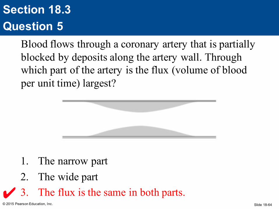
Blood flows through a coronary artery that is partially blocked by deposits along the artery wall. Through which part of the artery is the flux (volume of blood per unit time) largest?
1. The narrow part2. The wide part3. The flux is the same in both parts.
© 2015 Pearson Education, Inc.
Section 18.3Question 5
Slide 18-64
Blood flows through a coronary artery that is partially blocked by deposits along the artery wall. Through which part of the artery is the flux (volume of blood per unit time) largest?
1. The narrow part2. The wide part3. The flux is the same in both parts.
© 2015 Pearson Education, Inc.
Section 18.3Question 5
Slide 18-65
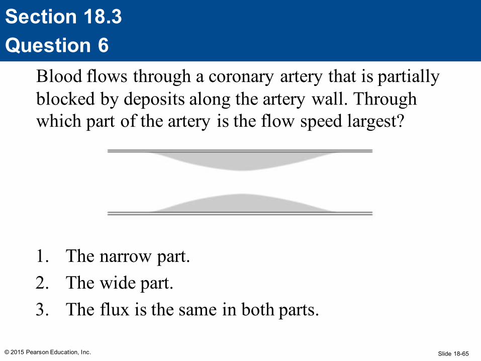
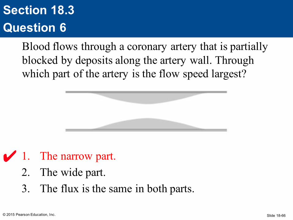
Blood flows through a coronary artery that is partially blocked by deposits along the artery wall. Through which part of the artery is the flow speed largest?
1. The narrow part.2. The wide part.3. The flux is the same in both parts.
© 2015 Pearson Education, Inc.
Section 18.3Question 6
Slide 18-66
Blood flows through a coronary artery that is partially blocked by deposits along the artery wall. Through which part of the artery is the flow speed largest?
1. The narrow part.2. The wide part.3. The flux is the same in both parts.
© 2015 Pearson Education, Inc.
Section 18.3Question 6
Slide 18-67
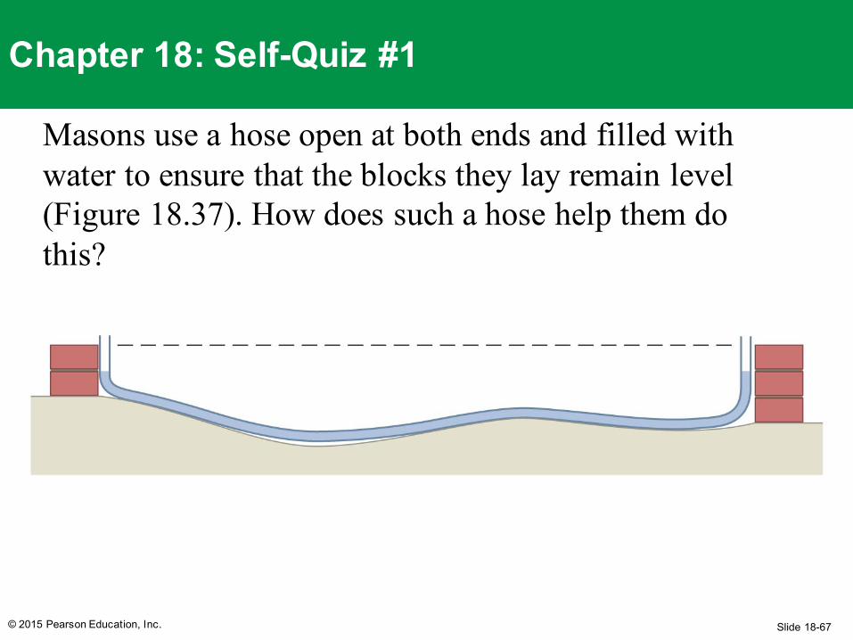
Masons use a hose open at both ends and filled with water to ensure that the blocks they lay remain level (Figure 18.37). How does such a hose help them do this?
© 2015 Pearson Education, Inc.
Chapter 18: Self-Quiz #1
Slide 18-68
AnswerThe air pressure at both water surfaces is atmospheric pressure. Therefore the height of the water surface at the left end of the hose must be the same as the height of the water surface at the right end, in order to balance the pressure throughout the water. If the masons align the two ends of the hose with the two ends of a row of blocks and no water bubbles out of either end of the hose, the two ends of the wall are at the same height, meaning the row is level.
© 2015 Pearson Education, Inc.
Chapter 18: Self-Quiz #1
Slide 18-69
(a) Imagine a rock and a balloon of the same volume completely submerged in water. How do the buoyant forces exerted on them compare? (b) How do the buoyant forces compare when the balloon volume is half the rock volume? (c) Which object floats and which sinks in part a and in part b?
© 2015 Pearson Education, Inc.
Chapter 18: Self-Quiz #2
Slide 18-70
Answer(a) Because the rock and balloon occupy the same volume, they displace the same volume of water, and so the surrounding water exerts equal buoyant forces on them. (b) The smaller volume of the balloon displaces a smaller volume of water, and so the buoyant force exerted on the balloon is half the buoyant force exerted on the rock. (c) In either case, the balloon rises and the rock sinks. The buoyant force on a rock is always smaller than the force of gravity exerted on it. Likewise the buoyant force on a balloon is always greater than the force of gravity exerted on it, regardless of the volume of the balloon.
© 2015 Pearson Education, Inc.
Chapter 18: Self-Quiz #2
Slide 18-71
For a thrown ball to rise, what type of spin should the thrower place on it?
© 2015 Pearson Education, Inc.
Chapter 18: Self-Quiz #3
Slide 18-72
AnswerThe thrower needs to place a “backspin” on the ball, which is a spin in which the top of the ball moves toward the thrower. This direction of spin causes the speed of the air relative to the surface of the ball to be greater at the top of the ball than at the bottom. Consequently the air pressure is smaller at the top of the ball than at the bottom. As a result, the ball is subject to an upward force due to this pressure difference.
© 2015 Pearson Education, Inc.
Chapter 18: Self-Quiz #3
Slide 18-73© 2015 Pearson Education, Inc.
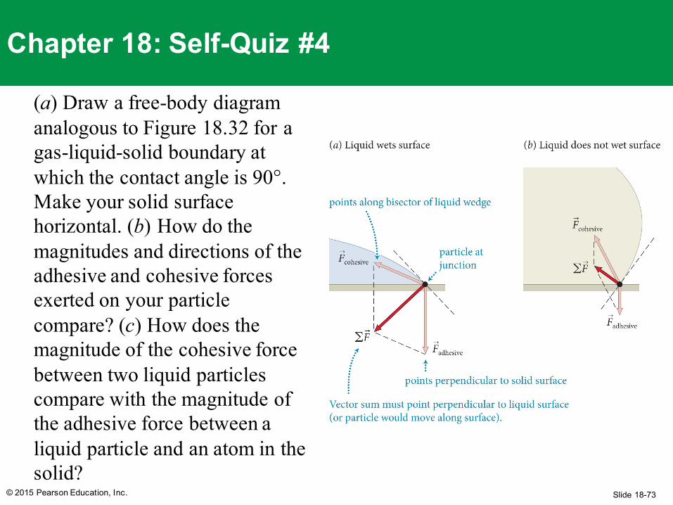
Chapter 18: Self-Quiz #4
(a) Draw a free-body diagram analogous to Figure 18.32 for a gas-liquid-solid boundary at which the contact angle is 90°. Make your solid surface horizontal. (b) How do the magnitudes and directions of the adhesive and cohesive forces exerted on your particle compare? (c) How does the magnitude of the cohesive force between two liquid particles compare with the magnitude of the adhesive force between a liquid particle and an atom in the solid?
Slide 18-74© 2015 Pearson Education, Inc.
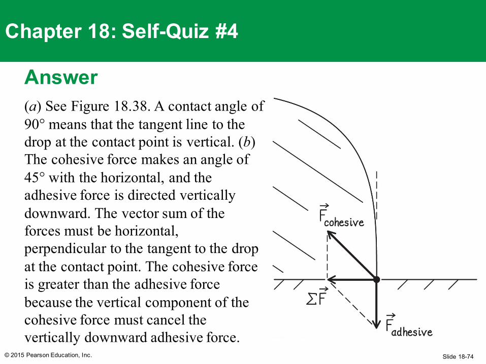
Chapter 18: Self-Quiz #4
Answer(a) See Figure 18.38. A contact angle of 90° means that the tangent line to the drop at the contact point is vertical. (b) The cohesive force makes an angle of 45° with the horizontal, and the adhesive force is directed vertically downward. The vector sum of the forces must be horizontal, perpendicular to the tangent to the drop at the contact point. The cohesive force is greater than the adhesive force because the vertical component of the cohesive force must cancel the vertically downward adhesive force.
Slide 18-75© 2015 Pearson Education, Inc.
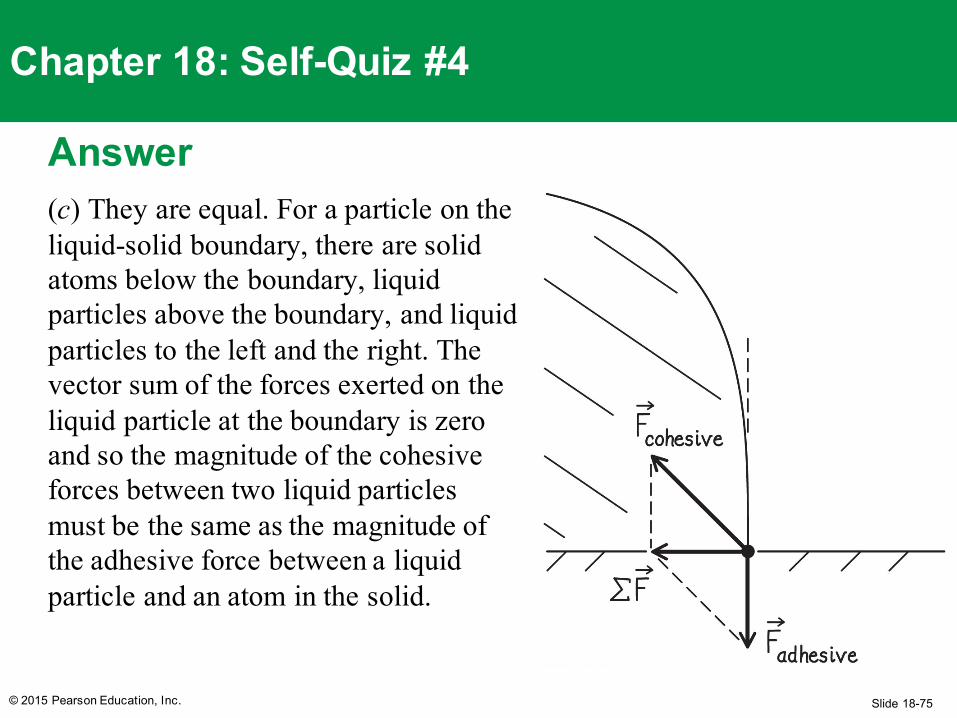
Chapter 18: Self-Quiz #4
Answer(c) They are equal. For a particle on the liquid-solid boundary, there are solid atoms below the boundary, liquid particles above the boundary, and liquid particles to the left and the right. The vector sum of the forces exerted on the liquid particle at the boundary is zero and so the magnitude of the cohesive forces between two liquid particles must be the same as the magnitude of the adhesive force between a liquid particle and an atom in the solid.
Slide 18-76
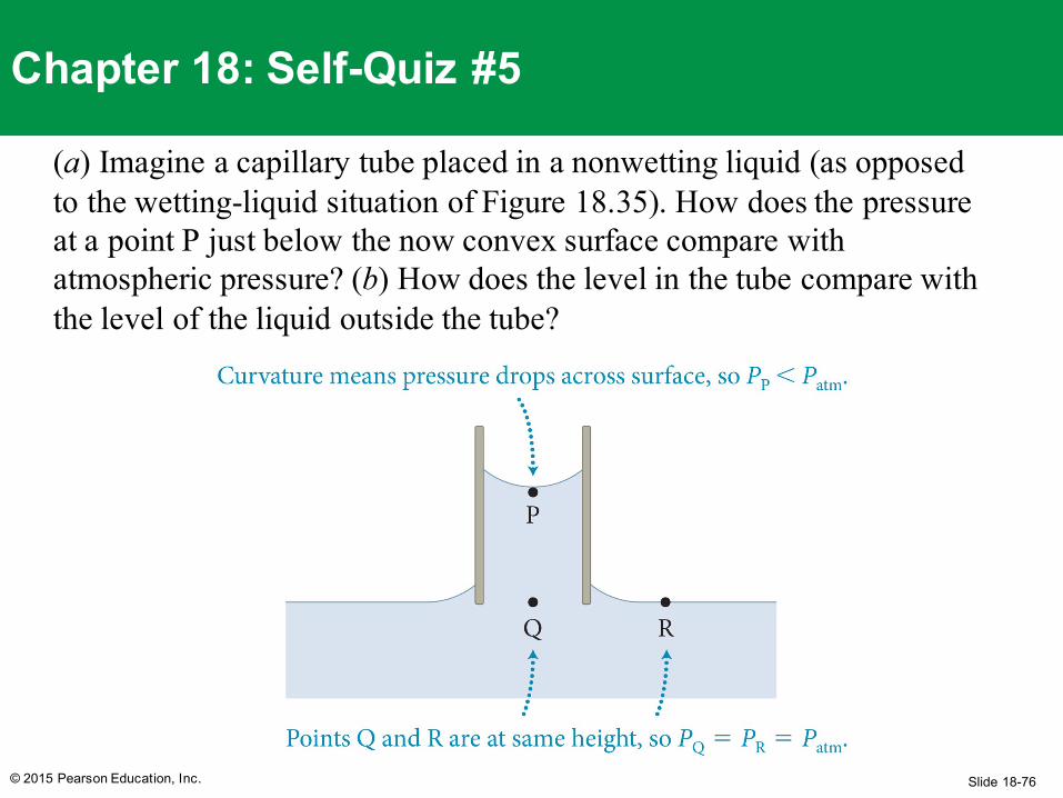
(a) Imagine a capillary tube placed in a nonwetting liquid (as opposed to the wetting-liquid situation of Figure 18.35). How does the pressure at a point P just below the now convex surface compare with atmospheric pressure? (b) How does the level in the tube compare with the level of the liquid outside the tube?
© 2015 Pearson Education, Inc.
Chapter 18: Self-Quiz #5
Slide 18-77
Answer(a) Because the surface is convex, the pressure at P is greater than atmospheric pressure. (b) Because the pressure at R is still atmospheric pressure, the difference in pressure causes a downward force on the liquid in the tube and a resulting capillary fall.
© 2015 Pearson Education, Inc.
Chapter 18: Self-Quiz #5
Slide 18-78
Quantitative Tools
© 2015 Pearson Education, Inc.
Chapter 18: Fluids
Slide 18-79
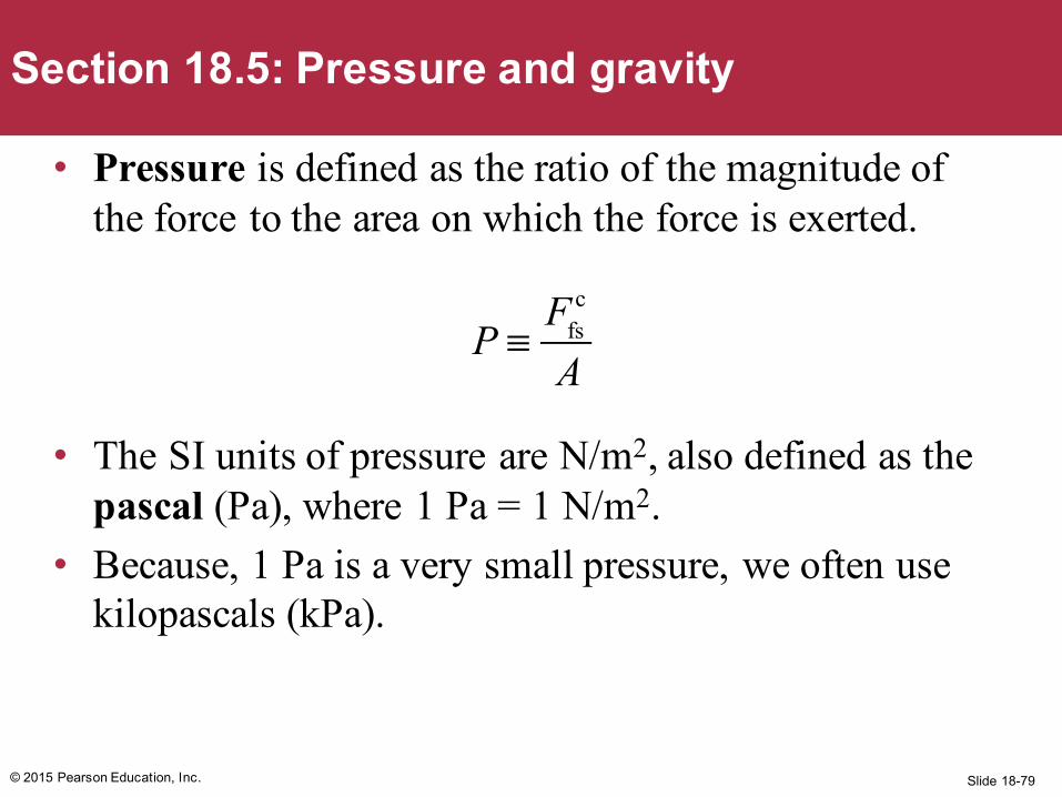
• Pressure is defined as the ratio of the magnitude of the force to the area on which the force is exerted.
• The SI units of pressure are N/m2, also defined as the pascal (Pa), where 1 Pa = 1 N/m2.
• Because, 1 Pa is a very small pressure, we often use kilopascals (kPa).
© 2015 Pearson Education, Inc.
Section 18.5: Pressure and gravity
P ≡
Ffsc
A
Slide 18-80© 2015 Pearson Education, Inc.
Section 18.5: Pressure and gravity
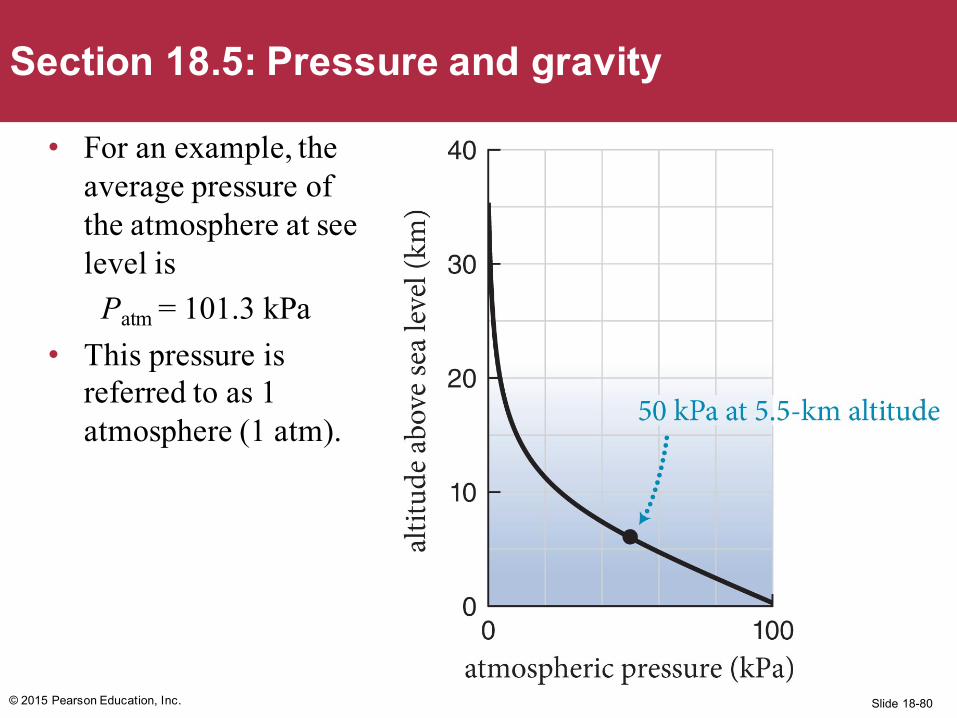
• For an example, the average pressure of the atmosphere at see level is
Patm = 101.3 kPa• This pressure is
referred to as 1 atmosphere (1 atm).
Slide 18-81© 2015 Pearson Education, Inc.
Checkpoint 18.13
Consider a book lying on a table at sea level with the front cover facing up. The book is 0.28 m tall, 0.22 m wide, and 50 mm thick; its mass is 3.0 kg. How does the force exerted by the atmosphere on the front cover compare with the force of gravity exerted on the book?
18.13
Slide 18-82
• The force exerted by the air on the cover isFac
c = PatmA = (101 kPa)(1000 Pa/1 kPa)(0.28m)(0.22m) = 6200 N
• The force of gravity isFEb
G = (3.0 kg)(9.8 m/s2) = 29 N
• The force exerted by the atmosphere is about 200 times greater than the gravitational force
© 2015 Pearson Education, Inc.
Checkpoint 18.13
Slide 18-83© 2015 Pearson Education, Inc.
Checkpoint 18.14
A dart that has a suction cup at one end sticks to a ceiling. Describe what force holds the dart against the ceiling.
As the suction cup hits the ceiling, the bowl of the cup collapses, forcing out the air that was initially in the bowl. The pressure in the space between the cup and ceiling decreases, and is then lower than the atmosphere.
The air in the room then exerts an upward force greater than the downward force exerted by the air still inside the cup, which holds the dart up against the ceiling.
18.14
Slide 18-84© 2015 Pearson Education, Inc.
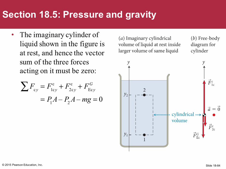
Section 18.5: Pressure and gravity
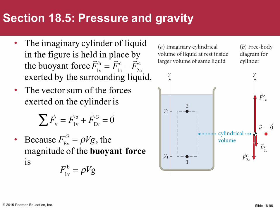
• The imaginary cylinder of liquid shown in the figure is at rest, and hence the vector sum of the three forces acting on it must be zero:
Fc y∑ = F1c yc + F2c y
c + FEc yG
= P1A – P2 A – mg = 0
Slide 18-85© 2015 Pearson Education, Inc.
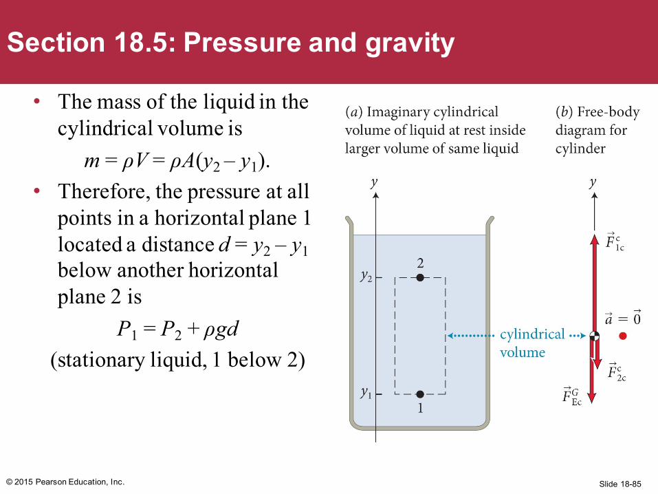
Section 18.5: Pressure and gravity
• The mass of the liquid in the cylindrical volume is
m = ρV = ρA(y2 – y1).• Therefore, the pressure at all
points in a horizontal plane 1 located a distance d = y2 – y1below another horizontal plane 2 is
P1 = P2 + ρgd(stationary liquid, 1 below 2)
Slide 18-86© 2015 Pearson Education, Inc.
Section 18.5: Pressure and gravity
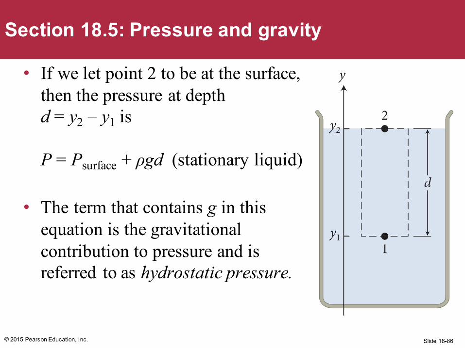
• If we let point 2 to be at the surface, then the pressure at depth d = y2 – y1 is
P = Psurface + ρgd (stationary liquid)
• The term that contains g in this equation is the gravitational contribution to pressure and is referred to as hydrostatic pressure.
Slide 18-87© 2015 Pearson Education, Inc.
Section 18.5: Pressure and gravity
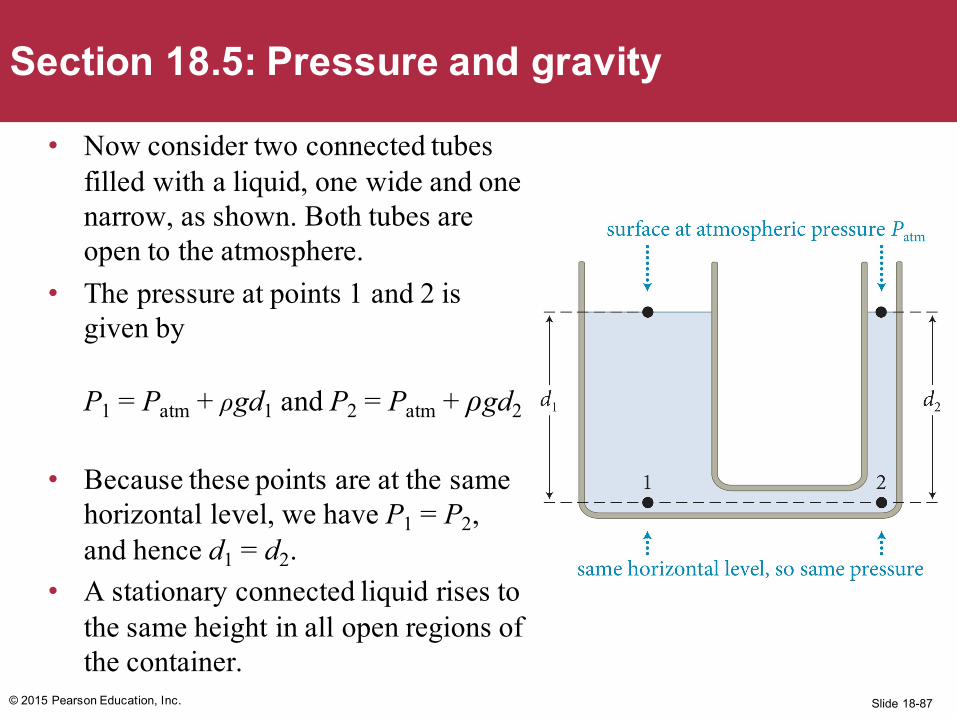
• Now consider two connected tubes filled with a liquid, one wide and one narrow, as shown. Both tubes are open to the atmosphere.
• The pressure at points 1 and 2 is given by
P1 = Patm + ρgd1 and P2 = Patm + ρgd2
• Because these points are at the same horizontal level, we have P1 = P2, and hence d1 = d2.
• A stationary connected liquid rises to the same height in all open regions of the container.
Slide 18-88
Example 18.6 DamA dam of horizontal length ℓ holds water of mass density ρ to a height h. What is the magnitude of the force exerted by the water on the dam?
© 2015 Pearson Education, Inc.
Section 18.5: Pressure and gravity
Slide 18-89© 2015 Pearson Education, Inc.
Section 18.5: Pressure and gravity
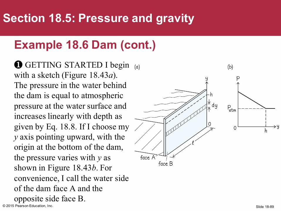
Example 18.6 Dam (cont.)❶ GETTING STARTED I begin with a sketch (Figure 18.43a). The pressure in the water behind the dam is equal to atmospheric pressure at the water surface and increases linearly with depth as given by Eq. 18.8. If I choose my y axis pointing upward, with the origin at the bottom of the dam, the pressure varies with y as shown in Figure 18.43b. For convenience, I call the water side of the dam face A and the opposite side face B.
Slide 18-90© 2015 Pearson Education, Inc.
Section 18.5: Pressure and gravity
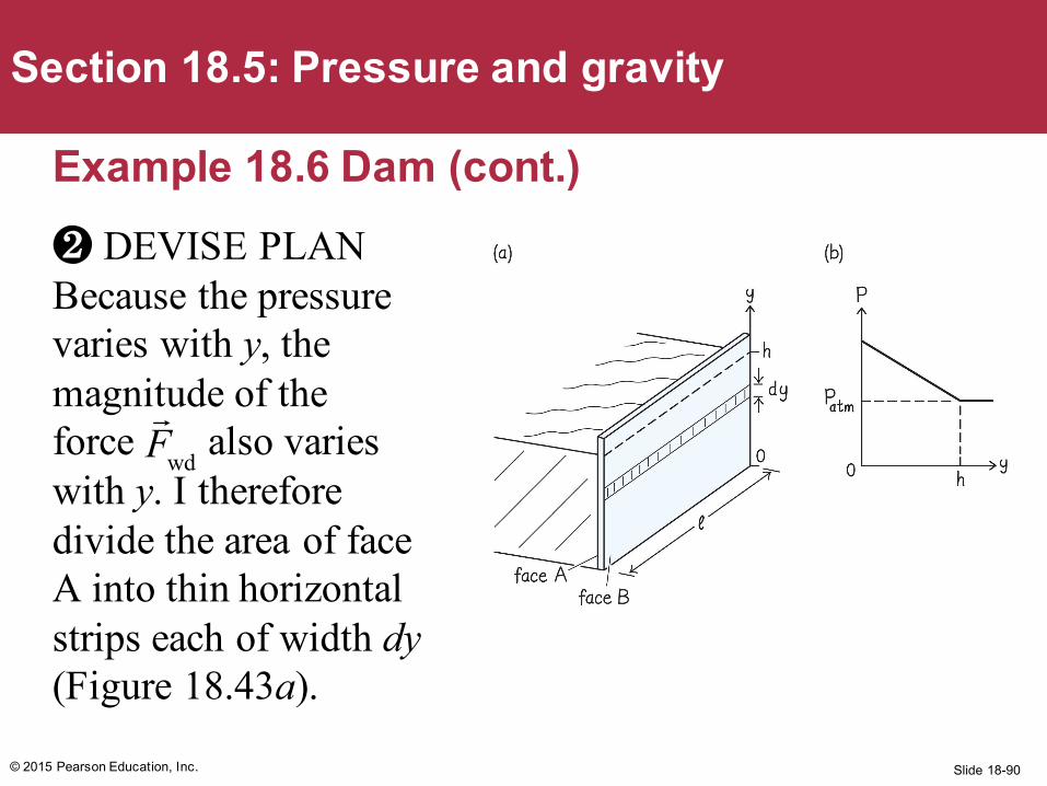
Example 18.6 Dam (cont.)❷ DEVISE PLAN Because the pressure varies with y, the magnitude of the force also varies with y. I therefore divide the area of face A into thin horizontal strips each of width dy(Figure 18.43a).
Fwd
Slide 18-91© 2015 Pearson Education, Inc.
Section 18.5: Pressure and gravity
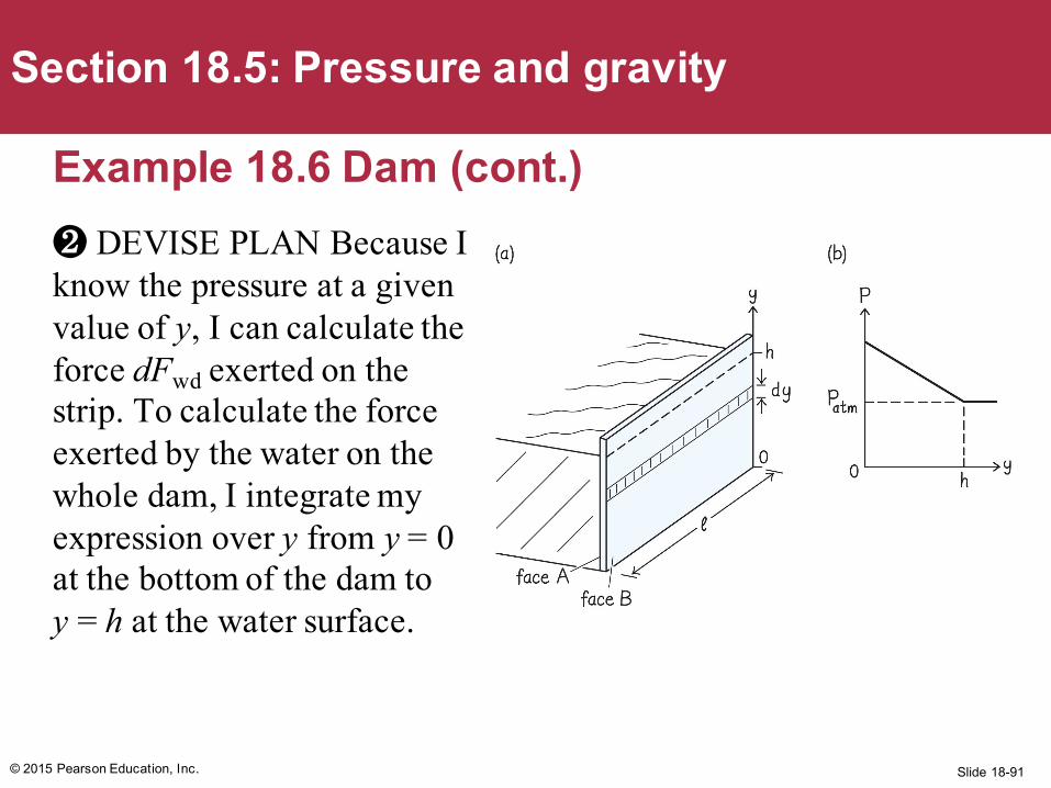
Example 18.6 Dam (cont.)❷ DEVISE PLAN Because I know the pressure at a given value of y, I can calculate the force dFwd exerted on the strip. To calculate the force exerted by the water on the whole dam, I integrate my expression over y from y = 0 at the bottom of the dam to y = h at the water surface.
Slide 18-92
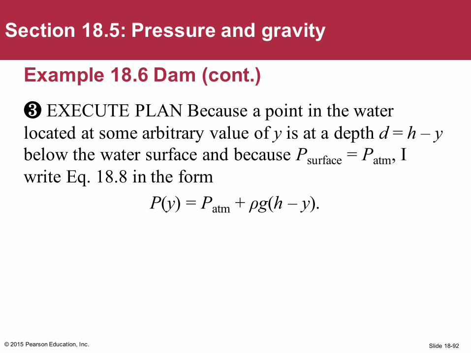
Example 18.6 Dam (cont.)❸ EXECUTE PLAN Because a point in the water located at some arbitrary value of y is at a depth d = h – ybelow the water surface and because Psurface = Patm, I write Eq. 18.8 in the form
P(y) = Patm + ρg(h – y).
© 2015 Pearson Education, Inc.
Section 18.5: Pressure and gravity
Slide 18-93
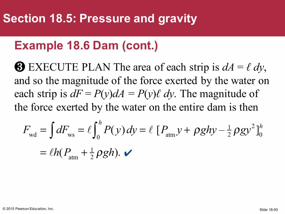
Example 18.6 Dam (cont.)❸ EXECUTE PLAN The area of each strip is dA = ℓ dy, and so the magnitude of the force exerted by the water on each strip is dF = P(y)dA = P(y)ℓ dy. The magnitude of the force exerted by the water on the entire dam is then
© 2015 Pearson Education, Inc.
Section 18.5: Pressure and gravity
Fwd = dFws∫ = P( y)dy = [Patm y +0
h
∫ ρghy – 12 ρgy2]0
h
= h(Patm + 12 ρgh).✔
Slide 18-94
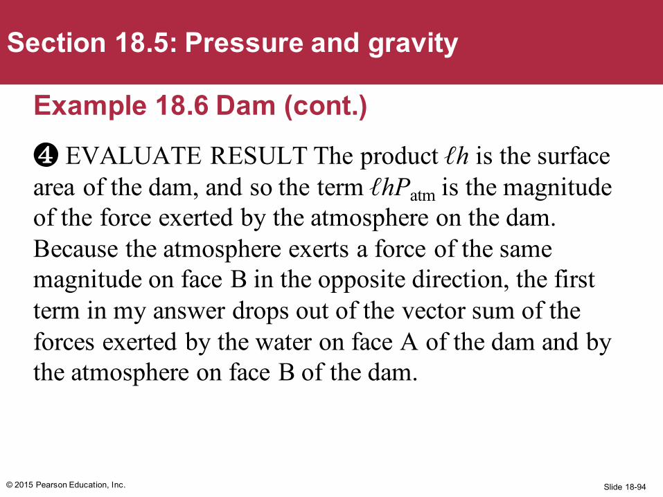
Example 18.6 Dam (cont.)❹ EVALUATE RESULT The product ℓh is the surface area of the dam, and so the term ℓhPatm is the magnitude of the force exerted by the atmosphere on the dam. Because the atmosphere exerts a force of the same magnitude on face B in the opposite direction, the first term in my answer drops out of the vector sum of the forces exerted by the water on face A of the dam and by the atmosphere on face B of the dam.
© 2015 Pearson Education, Inc.
Section 18.5: Pressure and gravity
Slide 18-95
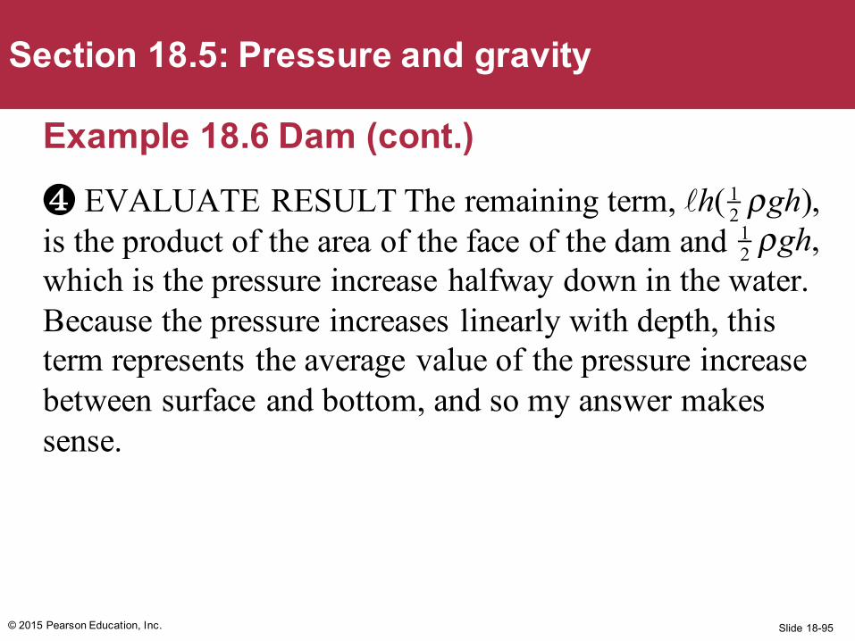
Example 18.6 Dam (cont.)❹ EVALUATE RESULT The remaining term, is the product of the area of the face of the dam and which is the pressure increase halfway down in the water. Because the pressure increases linearly with depth, this term represents the average value of the pressure increase between surface and bottom, and so my answer makes sense.
© 2015 Pearson Education, Inc.
Section 18.5: Pressure and gravity
h( 12 ρgh), 12 ρgh,
Slide 18-96© 2015 Pearson Education, Inc.
Section 18.5: Pressure and gravity
• The imaginary cylinder of liquid in the figure is held in place by the buoyant force exerted by the surrounding liquid.
• The vector sum of the forces exerted on the cylinder is
• Because the magnitude of the buoyant forceis
F1v
b =F1c
c –F2c
c
Fv∑ =
F1v
b +FEv
G =0
FEvG = ρVg,
F1vb = ρVg
Slide 18-97
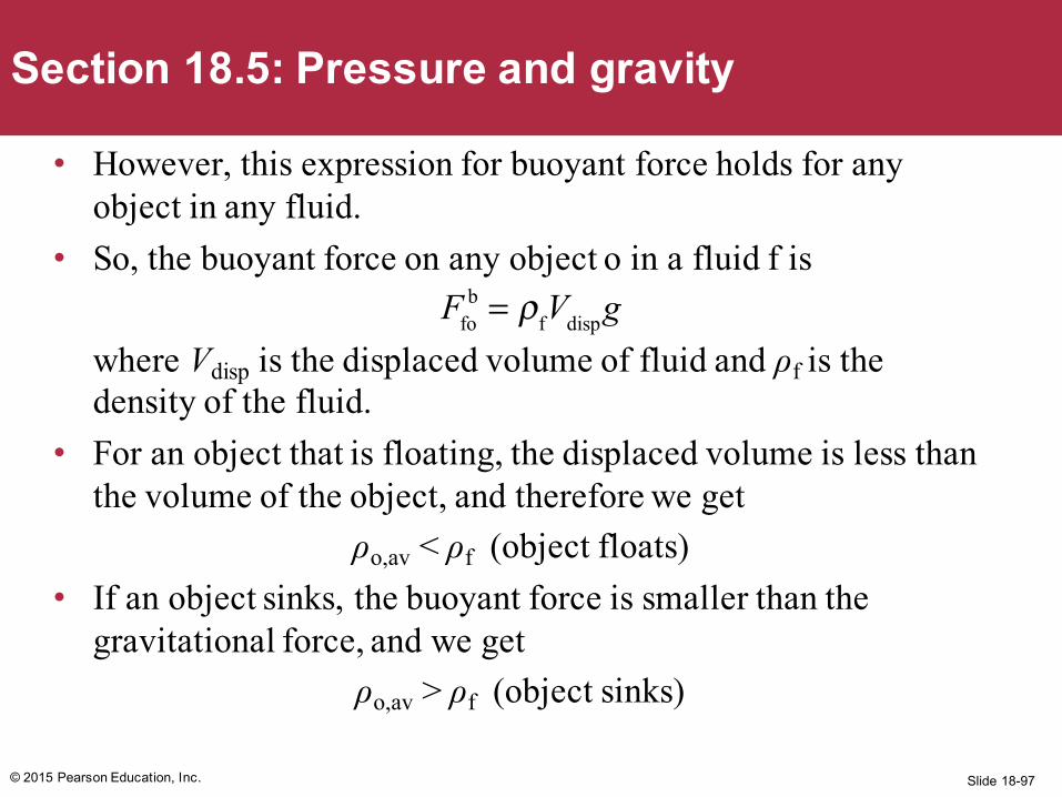
• However, this expression for buoyant force holds for any object in any fluid.
• So, the buoyant force on any object o in a fluid f is
where Vdisp is the displaced volume of fluid and ρf is the density of the fluid.
• For an object that is floating, the displaced volume is less than the volume of the object, and therefore we get
ρo,av < ρf (object floats)• If an object sinks, the buoyant force is smaller than the
gravitational force, and we getρo,av > ρf (object sinks)
© 2015 Pearson Education, Inc.
Section 18.5: Pressure and gravity
Ffob = ρfVdispg
Slide 18-98© 2015 Pearson Education, Inc.
Section 18.5Question 8
Which of the following effects contributes to the pressure in a liquid but not in a gas?
1. Gravitational force2. Motion of the fluid3. Collisions4. Surface tension
Slide 18-99© 2015 Pearson Education, Inc.
Section 18.5Question 8
Which of the following effects contributes to the pressure in a liquid but not in a gas?
1. Gravitational force2. Motion of the fluid3. Collisions4. Surface tension
Slide 18-100© 2015 Pearson Education, Inc.

Slide 18-101© 2015 Pearson Education, Inc.
Checkpoint 18.15
An object floats with 80% of its volume submerged in water. How does the average mass density of the object compare with that of water?
Buoyant force: weight of water displacedB = 0.8 x (object volume) x (liquid density) x g
Weight of object:mg = (object volume) x (object density) x g
In equilibrium, B – mg = 0, so (object density) = 0.8 x (liquid density)
18.15
Slide 18-102© 2015 Pearson Education, Inc.
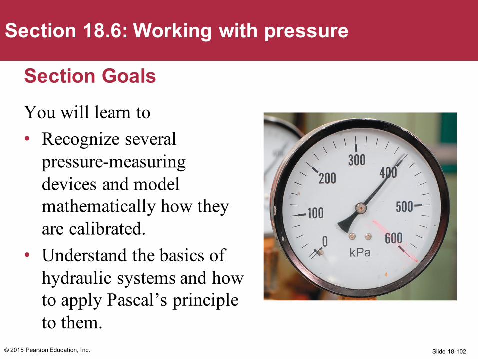
Section 18.6: Working with pressure
Section GoalsYou will learn to• Recognize several
pressure-measuring devices and model mathematically how they are calibrated.
• Understand the basics of hydraulic systems and how to apply Pascal’s principle to them.
Slide 18-103
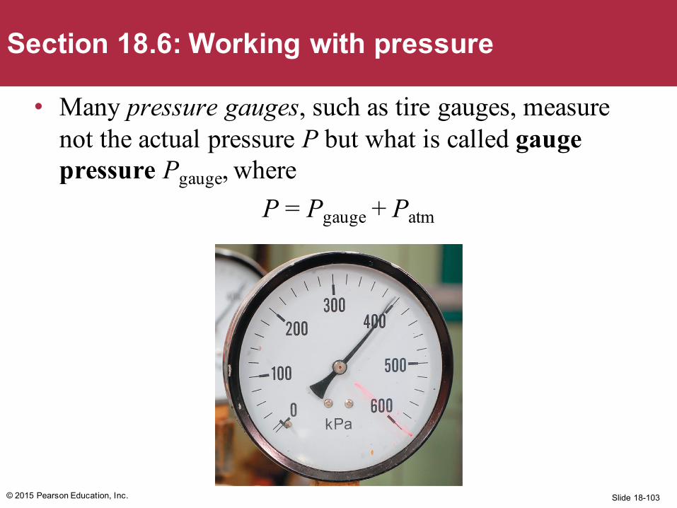
• Many pressure gauges, such as tire gauges, measure not the actual pressure P but what is called gauge pressure Pgauge, where
P = Pgauge + Patm
© 2015 Pearson Education, Inc.
Section 18.6: Working with pressure
Slide 18-104© 2015 Pearson Education, Inc.
Section 18.6: Working with pressure
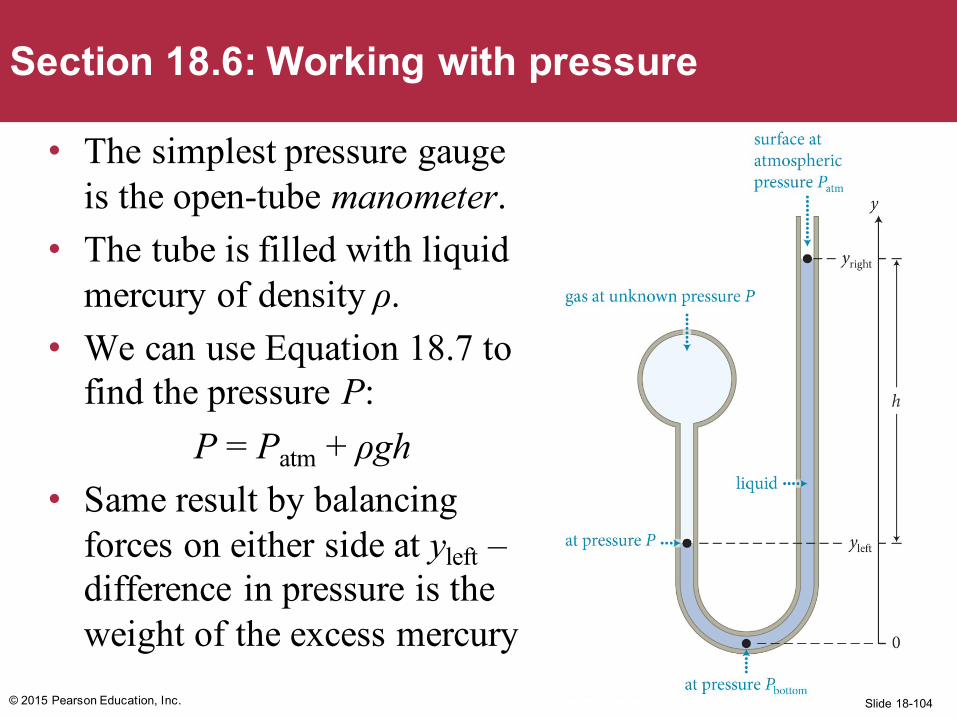
• The simplest pressure gauge is the open-tube manometer.
• The tube is filled with liquid mercury of density ρ.
• We can use Equation 18.7 to find the pressure P:
P = Patm + ρgh• Same result by balancing
forces on either side at yleft –difference in pressure is the weight of the excess mercury
Slide 18-105© 2015 Pearson Education, Inc.
Section 18.6: Working with pressure
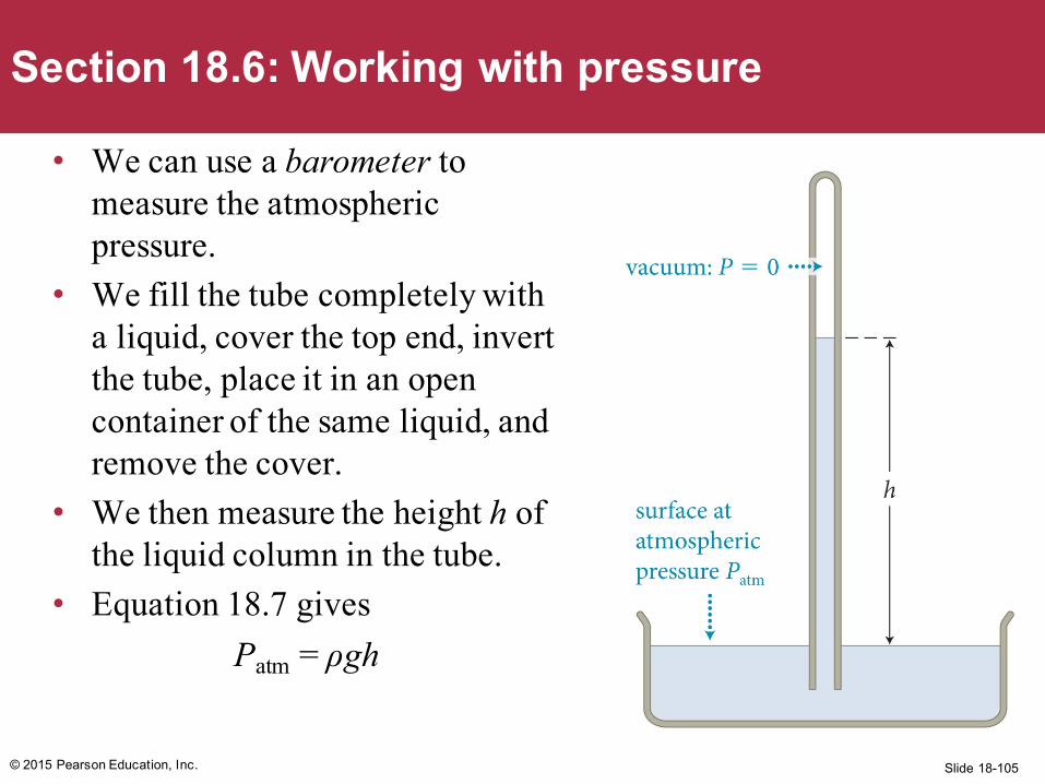
• We can use a barometer to measure the atmospheric pressure.
• We fill the tube completely with a liquid, cover the top end, invert the tube, place it in an open container of the same liquid, and remove the cover.
• We then measure the height h of the liquid column in the tube.
• Equation 18.7 givesPatm = ρgh
Slide 18-106
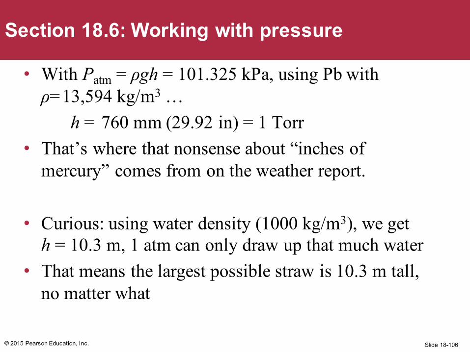
• With Patm = ρgh = 101.325 kPa, using Pb with ρ=13,594 kg/m3 …
h = 760 mm (29.92 in) = 1 Torr• That’s where that nonsense about “inches of
mercury” comes from on the weather report.
• Curious: using water density (1000 kg/m3), we get h = 10.3 m, 1 atm can only draw up that much water
• That means the largest possible straw is 10.3 m tall, no matter what
© 2015 Pearson Education, Inc.
Section 18.6: Working with pressure
Slide 18-107
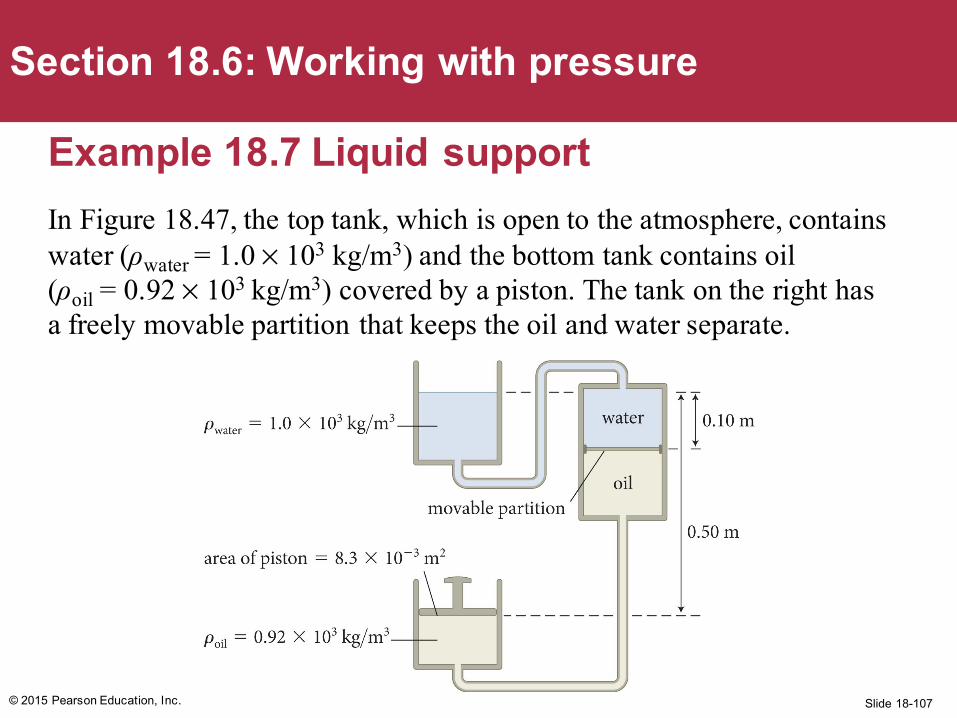
Example 18.7 Liquid supportIn Figure 18.47, the top tank, which is open to the atmosphere, contains water (ρwater = 1.0 × 10³ kg/m3) and the bottom tank contains oil (ρoil = 0.92 × 10³ kg/m3) covered by a piston. The tank on the right has a freely movable partition that keeps the oil and water separate.
© 2015 Pearson Education, Inc.
Section 18.6: Working with pressure
Slide 18-108
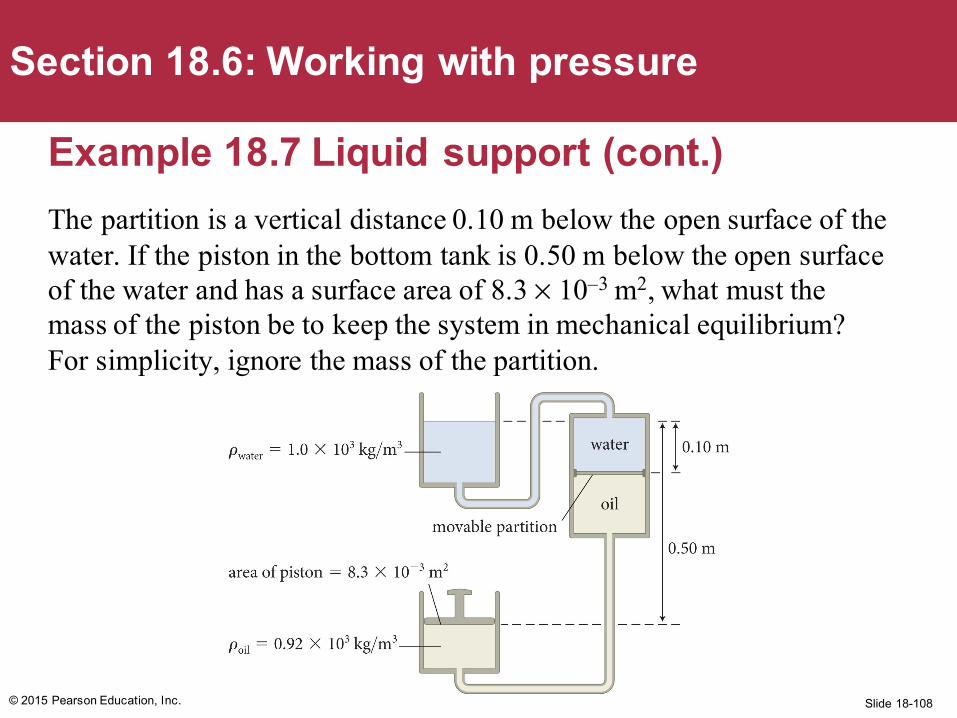
Example 18.7 Liquid support (cont.)The partition is a vertical distance 0.10 m below the open surface of the water. If the piston in the bottom tank is 0.50 m below the open surface of the water and has a surface area of 8.3 × 10⁻³ m2, what must the mass of the piston be to keep the system in mechanical equilibrium? For simplicity, ignore the mass of the partition.
© 2015 Pearson Education, Inc.
Section 18.6: Working with pressure
Slide 18-109© 2015 Pearson Education, Inc.
Section 18.6: Working with pressure
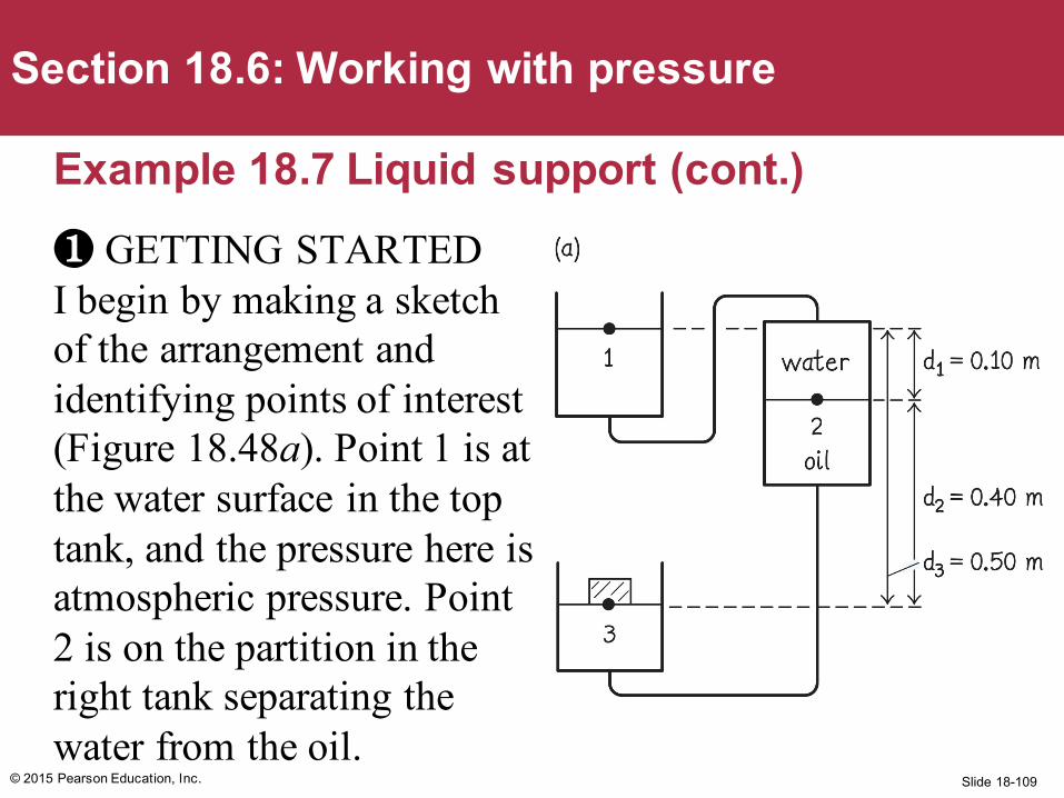
Example 18.7 Liquid support (cont.)❶ GETTING STARTED I begin by making a sketch of the arrangement and identifying points of interest (Figure 18.48a). Point 1 is at the water surface in the top tank, and the pressure here is atmospheric pressure. Point 2 is on the partition in the right tank separating the water from the oil.
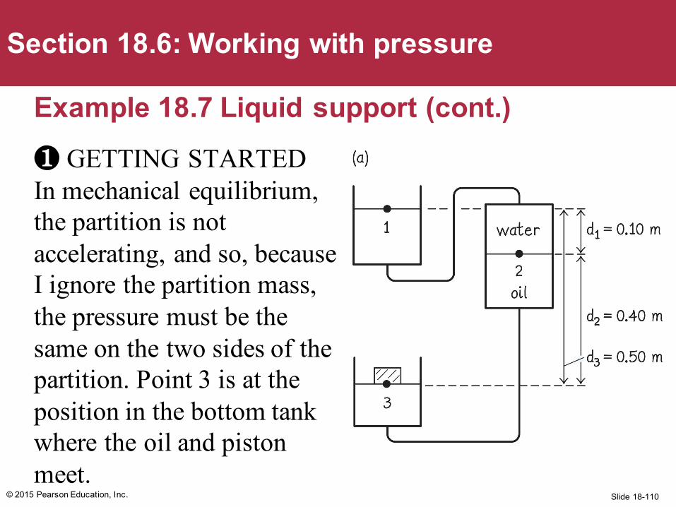
Slide 18-110© 2015 Pearson Education, Inc.
Section 18.6: Working with pressure
Example 18.7 Liquid support (cont.)❶ GETTING STARTED In mechanical equilibrium, the partition is not accelerating, and so, because I ignore the partition mass, the pressure must be the same on the two sides of the partition. Point 3 is at the position in the bottom tank where the oil and piston meet.
Slide 18-111© 2015 Pearson Education, Inc.
Section 18.6: Working with pressure
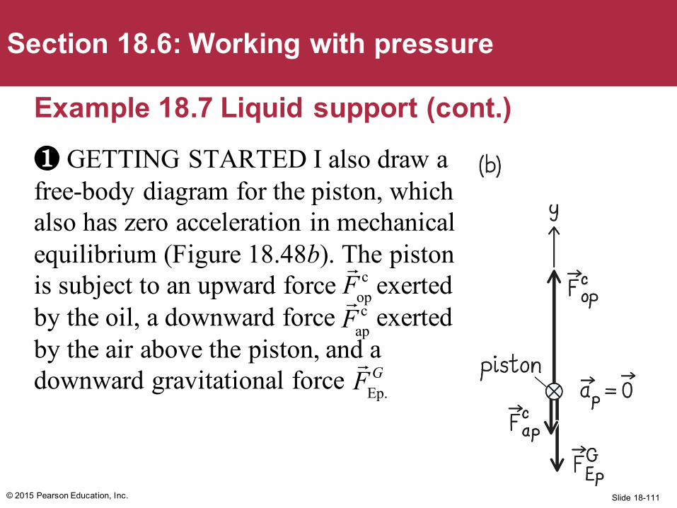
Example 18.7 Liquid support (cont.)❶ GETTING STARTED I also draw a free-body diagram for the piston, which also has zero acceleration in mechanical equilibrium (Figure 18.48b). The piston is subject to an upward force exerted by the oil, a downward force exerted by the air above the piston, and a downward gravitational force
Fop
c
Fap
c
FEp.
G
Slide 18-112
Example 18.7 Liquid support (cont.)❷ DEVISE PLAN When the system is in mechanical equilibrium, the piston is stationary. Therefore the vector sum of the forces exerted on it must be zero. From my free-body diagram, I see that the magnitude of the upward force exerted by the oil on the piston is equal in magnitude to the sum of the downward gravitational force exerted on the piston and the downward force exerted by the air on the piston:
© 2015 Pearson Education, Inc.
Section 18.6: Working with pressure
Fopc = FEp
G + Fapc = mpg + Fap
c .
Slide 18-113
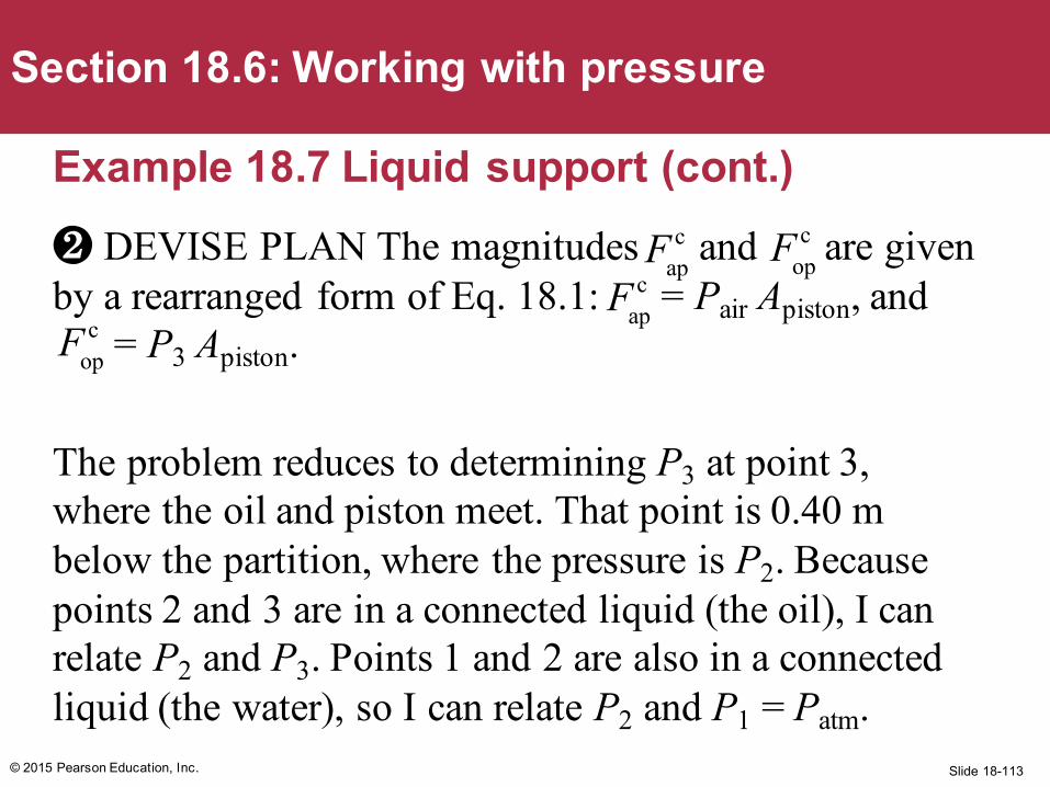
Example 18.7 Liquid support (cont.)❷ DEVISE PLAN The magnitudes and are given by a rearranged form of Eq. 18.1: = Pair Apiston, and
= P3 Apiston.
The problem reduces to determining P3 at point 3, where the oil and piston meet. That point is 0.40 m below the partition, where the pressure is P2. Because points 2 and 3 are in a connected liquid (the oil), I can relate P2 and P3. Points 1 and 2 are also in a connected liquid (the water), so I can relate P2 and P1 = Patm.
© 2015 Pearson Education, Inc.
Section 18.6: Working with pressure
Fopc
Fapc
Fapc
Fopc
Slide 18-114
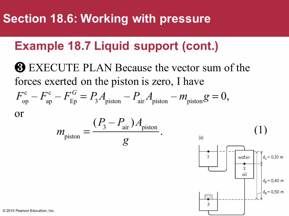
Example 18.7 Liquid support (cont.)❸ EXECUTE PLAN Because the vector sum of the forces exerted on the piston is zero, I have
or(1)
© 2015 Pearson Education, Inc.
Section 18.6: Working with pressure
Fopc – Fap
c – FEpG = P3 Apiston – Pair Apiston – mpistong = 0,
mpiston =
(P3 – Pair )Apiston
g.
Slide 18-115
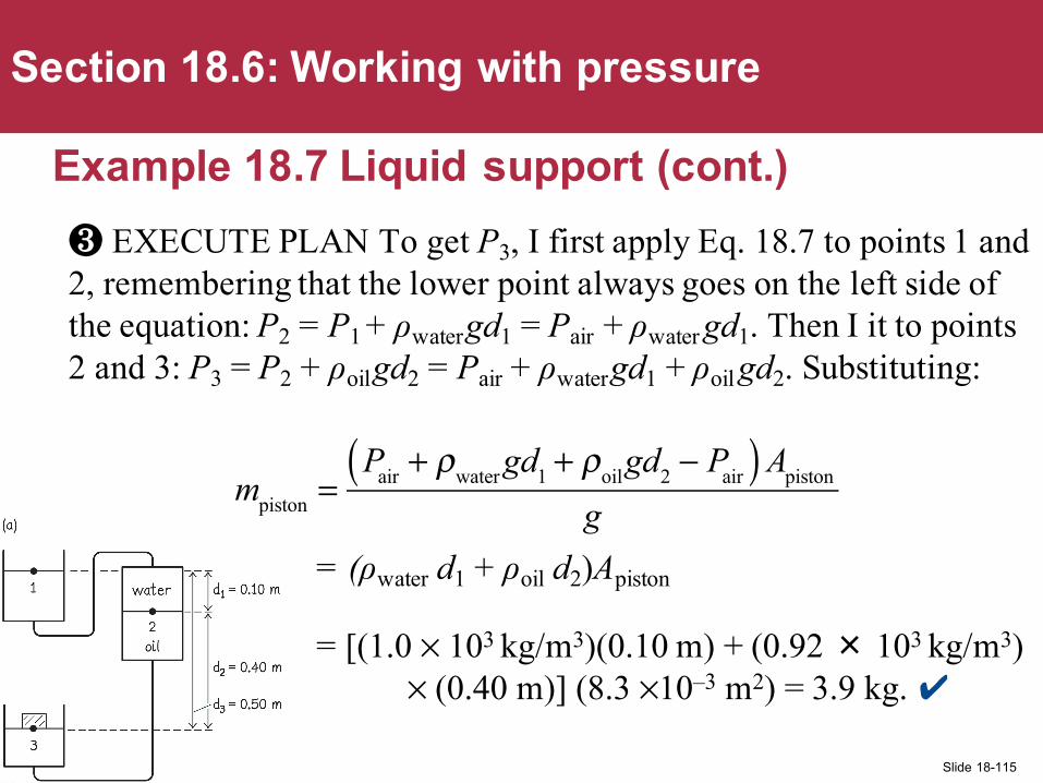
Example 18.7 Liquid support (cont.)❸ EXECUTE PLAN To get P3, I first apply Eq. 18.7 to points 1 and 2, remembering that the lower point always goes on the left side of the equation: P2 = P1 + ρwatergd1 = Pair + ρwater gd1. Then I it to points 2 and 3: P3 = P2 + ρoilgd2 = Pair + ρwatergd1 + ρoil gd2. Substituting:
= (ρwater d1 + ρoil d2)Apiston
= [(1.0 × 10³ kg/m3)(0.10 m) + (0.92 × 10³ kg/m3)× (0.40 m)] (8.3 ×10⁻³ m2) = 3.9 kg. ✔
© 2015 Pearson Education, Inc.
Section 18.6: Working with pressure
mpiston =
Pair + ρwater gd1 + ρoilgd2 − Pair( )Apiston
g
Slide 18-116
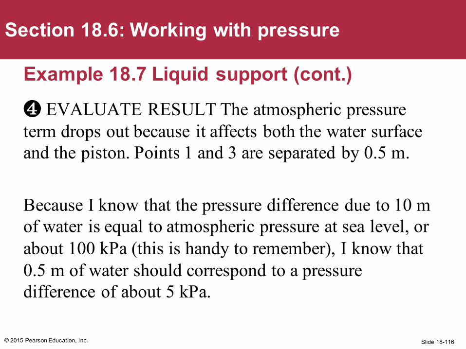
Example 18.7 Liquid support (cont.)❹ EVALUATE RESULT The atmospheric pressure term drops out because it affects both the water surface and the piston. Points 1 and 3 are separated by 0.5 m.
Because I know that the pressure difference due to 10 m of water is equal to atmospheric pressure at sea level, or about 100 kPa (this is handy to remember), I know that 0.5 m of water should correspond to a pressure difference of about 5 kPa.
© 2015 Pearson Education, Inc.
Section 18.6: Working with pressure
Slide 18-117
Example 18.7 Liquid support (cont.)❹ EVALUATE RESULT The mass density of oil is a bit smaller than that of water, but I can ignore the difference. The surface area of the piston is about 10–2 m2, and so the force giving rise to the 5-kPa pressure difference is about 50 N, which is equal to the gravitational force exerted on a mass of 5 kg, which is close to the answer I obtained.
© 2015 Pearson Education, Inc.
Section 18.6: Working with pressure
Slide 18-118
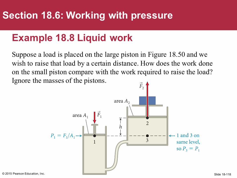
Example 18.8 Liquid workSuppose a load is placed on the large piston in Figure 18.50 and we wish to raise that load by a certain distance. How does the work done on the small piston compare with the work required to raise the load? Ignore the masses of the pistons.
© 2015 Pearson Education, Inc.
Section 18.6: Working with pressure
Slide 18-119
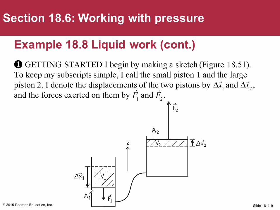
Example 18.8 Liquid work (cont.)❶ GETTING STARTED I begin by making a sketch (Figure 18.51). To keep my subscripts simple, I call the small piston 1 and the large piston 2. I denote the displacements of the two pistons by and and the forces exerted on them by and
© 2015 Pearson Education, Inc.
Section 18.6: Working with pressure
Δx1 Δ
x2 ,
F1
F2.
Slide 18-120
Example 18.8 Liquid work (cont.)❷ DEVISE PLAN We know P1 = P2 and thus F1/A1 = F2/A2, which gives F1 = (A1/A2)F2.
Each force does an amount of work given by the scalar product of the force and the force displacement, which is equal to the displacement of the piston on which the force is exerted.
Both forces do positive work because the direction of each force is the same as the direction of the force displacement.
© 2015 Pearson Education, Inc.
Section 18.6: Working with pressure
Slide 18-121
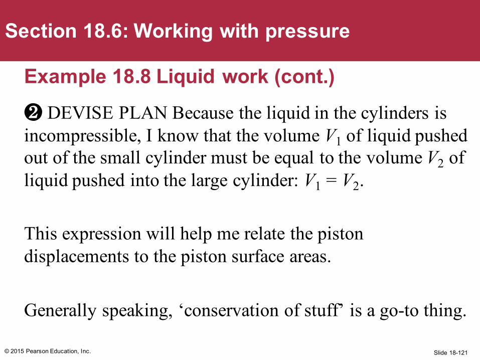
Example 18.8 Liquid work (cont.)❷ DEVISE PLAN Because the liquid in the cylinders is incompressible, I know that the volume V1 of liquid pushed out of the small cylinder must be equal to the volume V2 of liquid pushed into the large cylinder: V1 = V2.
This expression will help me relate the piston displacements to the piston surface areas.
Generally speaking, ‘conservation of stuff’ is a go-to thing.
© 2015 Pearson Education, Inc.
Section 18.6: Working with pressure
Slide 18-122
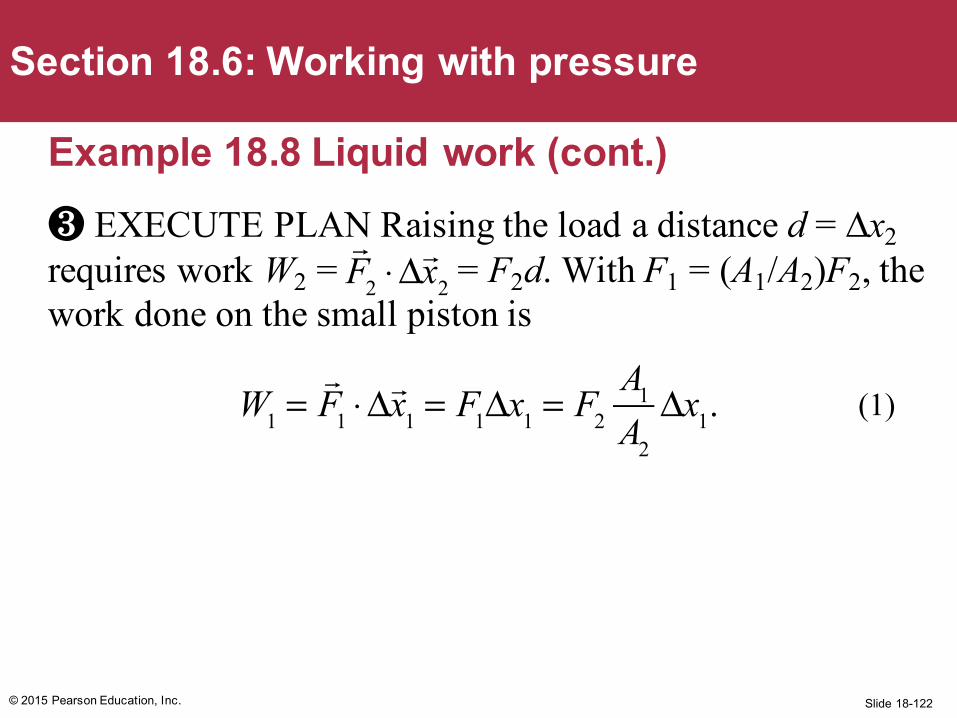
Example 18.8 Liquid work (cont.)❸ EXECUTE PLAN Raising the load a distance d = Δx2requires work W2 = = F2d. With F1 = (A1/A2)F2, the work done on the small piston is
© 2015 Pearson Education, Inc.
Section 18.6: Working with pressure
W1 =
F1 ⋅ Δx1 = F1Δx1 = F2
A1
A2
Δx1.
F2 ⋅ Δ
x2
(1)
Slide 18-123
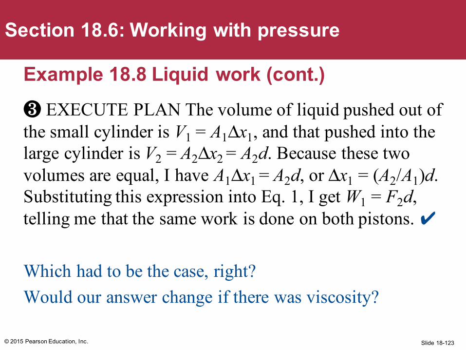
Example 18.8 Liquid work (cont.)❸ EXECUTE PLAN The volume of liquid pushed out of the small cylinder is V1 = A1Δx1, and that pushed into the large cylinder is V2 = A2Δx2 = A2d. Because these two volumes are equal, I have A1Δx1 = A2d, or Δx1 = (A2/A1)d. Substituting this expression into Eq. 1, I get W1 = F2d, telling me that the same work is done on both pistons. ✔
Which had to be the case, right?Would our answer change if there was viscosity?
© 2015 Pearson Education, Inc.
Section 18.6: Working with pressure
Slide 18-124
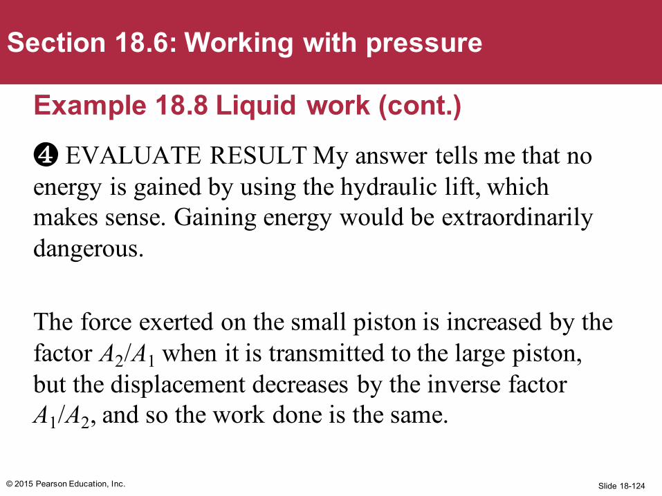
Example 18.8 Liquid work (cont.)❹ EVALUATE RESULT My answer tells me that no energy is gained by using the hydraulic lift, which makes sense. Gaining energy would be extraordinarily dangerous.
The force exerted on the small piston is increased by the factor A2/A1 when it is transmitted to the large piston, but the displacement decreases by the inverse factor A1/A2, and so the work done is the same.
© 2015 Pearson Education, Inc.
Section 18.6: Working with pressure
Slide 18-125
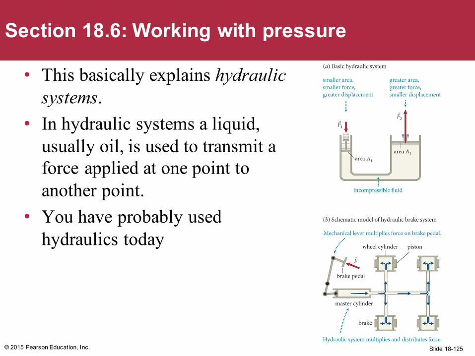
• This basically explains hydraulic systems.
• In hydraulic systems a liquid, usually oil, is used to transmit a force applied at one point to another point.
• You have probably used hydraulics today
© 2015 Pearson Education, Inc.
Section 18.6: Working with pressure
Slide 18-126
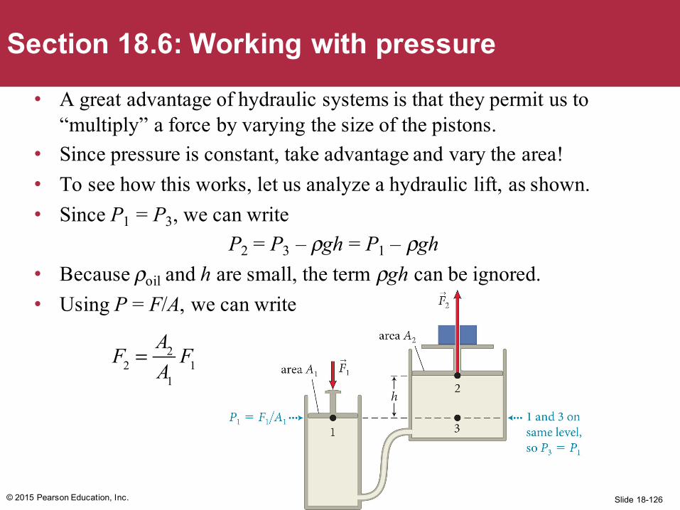
• A great advantage of hydraulic systems is that they permit us to “multiply” a force by varying the size of the pistons.
• Since pressure is constant, take advantage and vary the area!• To see how this works, let us analyze a hydraulic lift, as shown.• Since P1 = P3, we can write
P2 = P3 – ρgh = P1 – ρgh• Because ρoil and h are small, the term ρgh can be ignored. • Using P = F/A, we can write
© 2015 Pearson Education, Inc.
Section 18.6: Working with pressure
F2 =
A2
A1
F1
Slide 18-127
Procedure: Working with pressure in liquids at restThe branch of physics that deals with pressure in a liquid at rest is called hydrostatics. The pressure in a liquid at rest is determined by gravity and by what happens at the boundary of the liquid. To determine the pressure in such liquids:
1. Begin by making a sketch showing all the boundaries and identifying all the factors that affect pressure: pistons, gases at surfaces open to the atmosphere, and so on. Note the known vertical heights of liquid surfaces, the areas of these surfaces, the surface areas of pistons, and the liquid mass densities.
© 2015 Pearson Education, Inc.
Section 18.6: Working with pressure
Slide 18-128
Procedure: Working with pressure in liquids at rest2. Determine the pressure at each surface. The pressure at a
liquid surface open to the air is equal to atmospheric pressure Patm. The pressure at a liquid surface bordering a vacuum is zero: P = 0. The pressure at a liquid surface open to a gas other than the atmosphere is equal to the pressure in the gas: P = Pgas. The pressure at a liquid surface that is in contact with a solid, such as a piston, is P = Fc
sl/A, where Fcsl is the
magnitude of the force exerted by the solid on the liquid and A is the area over which that force is exerted.
© 2015 Pearson Education, Inc.
Section 18.6: Working with pressure
Slide 18-129
Procedure: Working with pressure in liquids at rest
3. Use horizontal planes. The pressure is the same at all points on a horizontal plane in a connected liquid. The pressure difference between two horizontal planes 1 and 2 is given by P1 = P2 + ρgd(Eq. 18.7), where d is the vertical distance between the horizontal planes and 1 is below 2.
© 2015 Pearson Education, Inc.
Section 18.6: Working with pressure
Slide 18-130
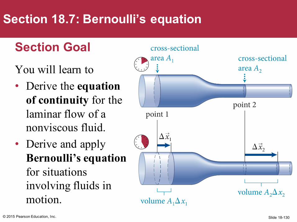
Section GoalYou will learn to• Derive the equation
of continuity for the laminar flow of a nonviscous fluid.
• Derive and apply Bernoulli’s equation for situations involving fluids in motion.
© 2015 Pearson Education, Inc.
Section 18.7: Bernoulli’s equation
Slide 18-131
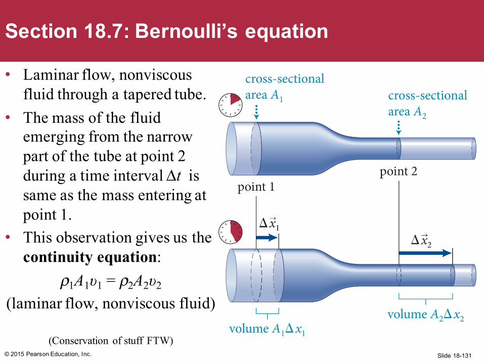
• Laminar flow, nonviscousfluid through a tapered tube.
• The mass of the fluid emerging from the narrow part of the tube at point 2 during a time interval Δt is same as the mass entering at point 1.
• This observation gives us the continuity equation:
ρ1A1υ1 = ρ2A2υ2
(laminar flow, nonviscous fluid)
(Conservation of stuff FTW)© 2015 Pearson Education, Inc.
Section 18.7: Bernoulli’s equation
Slide 18-132
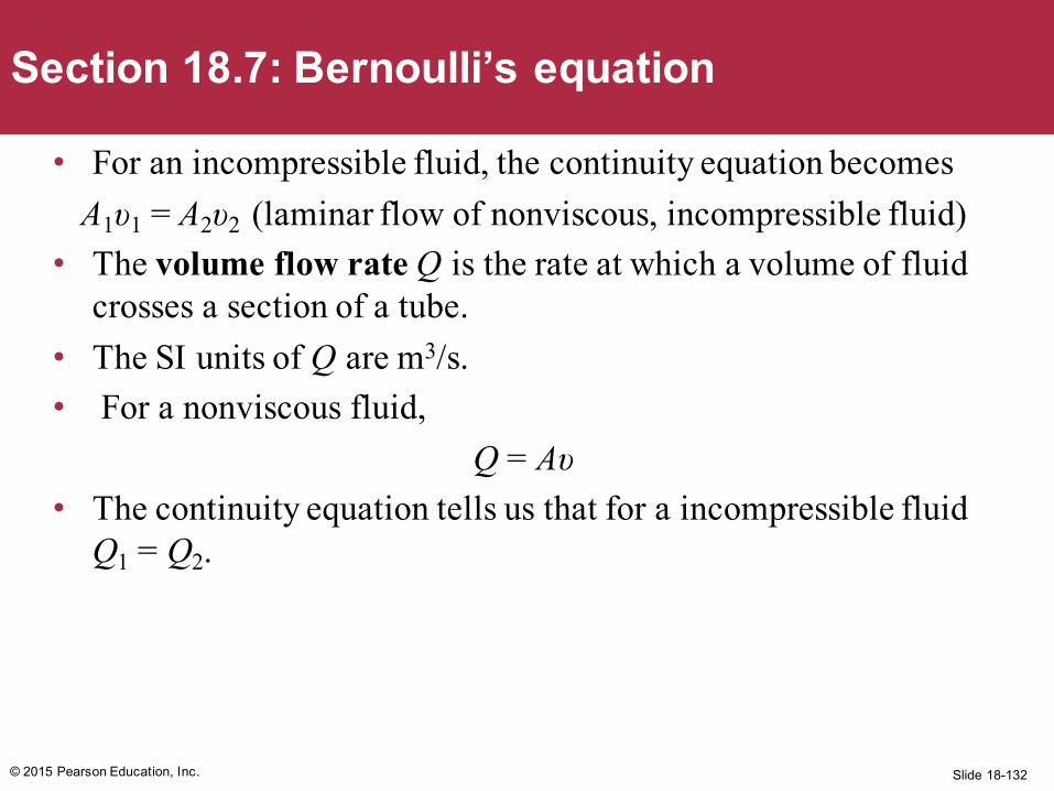
• For an incompressible fluid, the continuity equation becomesA1υ1 = A2υ2 (laminar flow of nonviscous, incompressible fluid)
• The volume flow rate Q is the rate at which a volume of fluid crosses a section of a tube.
• The SI units of Q are m3/s.• For a nonviscous fluid,
Q = Aυ• The continuity equation tells us that for a incompressible fluid
Q1 = Q2.
© 2015 Pearson Education, Inc.
Section 18.7: Bernoulli’s equation
Slide 18-133
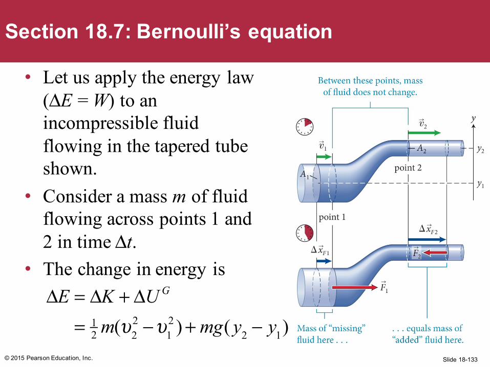
• Let us apply the energy law (ΔE = W) to an incompressible fluid flowing in the tapered tube shown.
• Consider a mass m of fluid flowing across points 1 and 2 in time Δt.
• The change in energy is
© 2015 Pearson Education, Inc.
Section 18.7: Bernoulli’s equation
ΔE = ΔK + ΔU G
= 12 m(υ2
2 −υ12 )+ mg( y2 − y1)
Slide 18-134
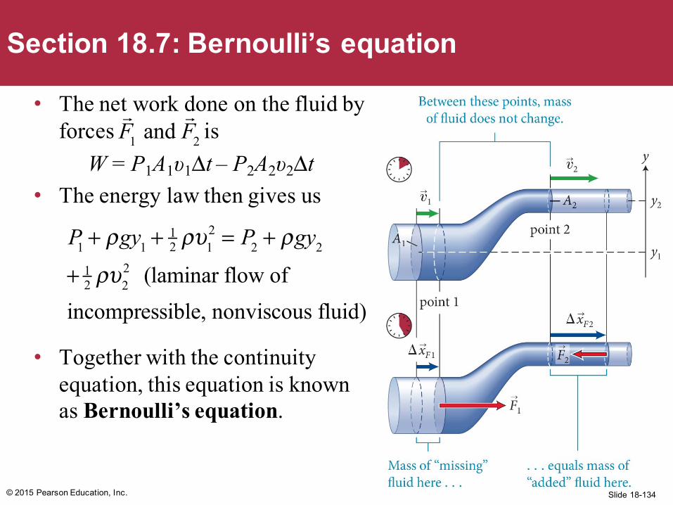
• The net work done on the fluid by forces is
W = P1A1υ1Δt – P2A2υ2Δt• The energy law then gives us
• Together with the continuity equation, this equation is known as Bernoulli’s equation.
© 2015 Pearson Education, Inc.
Section 18.7: Bernoulli’s equation
P1 + ρgy1 +12 ρυ1
2 = P2 + ρgy2
+ 12 ρυ2
2 (laminar flow of
incompressible, nonviscous fluid)
F1 and
F2
Slide 18-135
Example 18.9 Leaky bucketWater leaks out of a small hole in the side of a bucket. The hole is a distance d below the surface of the water, and the cross section of the hole is much smaller than the diameter of the bucket. At what speed does the water emerge from the hole?
© 2015 Pearson Education, Inc.
Section 18.7: Bernoulli’s equation
Slide 18-136© 2015 Pearson Education, Inc.
Section 18.7: Bernoulli’s equation
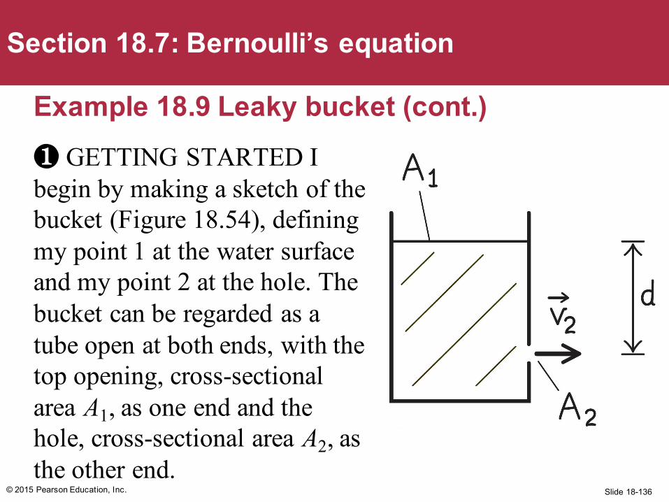
Example 18.9 Leaky bucket (cont.)❶ GETTING STARTED I begin by making a sketch of the bucket (Figure 18.54), defining my point 1 at the water surface and my point 2 at the hole. The bucket can be regarded as a tube open at both ends, with the top opening, cross-sectional area A1, as one end and the hole, cross-sectional area A2, as the other end.
Δx1 Δ
x2 ,
Slide 18-137
Example 18.9 Leaky bucket (cont.)❷ DEVISE PLAN Because A1 >> A2, the continuity equation (ρ1A1υ1 = ρ2A2υ2) tells me that the speed υ1 at which the surface of the water moves downward is much smaller than the speed υ2 at which the water emerges from the hole, υ1 << υ2. For all practical purposes, therefore, I can assume υ1 ≈ 0.
I also know that the pressure both at the water surface and at the hole is equal to atmospheric pressure. I can then use Bernoulli’s equation to determine υ2.
© 2015 Pearson Education, Inc.
Section 18.7: Bernoulli’s equation
Slide 18-138
Example 18.9 Leaky bucket (cont.)❸ EXECUTE PLAN Because P1 = P2 = Patm, Bernoulli’s equation reduces toDividing through by setting υ1 = 0, and bringing the terms containing y to the left side, I get
and so . ✔
Which is familiar. Right?
© 2015 Pearson Education, Inc.
Section 18.7: Bernoulli’s equation
ρgy1 +12 ρυ1
2 = ρgy2 +12 ρυ2
2.
12 ρ,
υ22 = 2g y1 − y2( ) = 2gd , υ2 = 2gd
Slide 18-139
Example 18.9 Leaky bucket (cont.)❹ EVALUATE RESULT My answer is equal to the speed acquired over a vertical distance d by a freely falling object starting from rest. Because the Earth-object system is closed, ΔK + ΔUG = and so υ2 = 2gd.
My result makes sense: For each water drop that emerges from the hole, the water at the surface is reduced by an equal amount and the kinetic energy of the emerging drop must be equal to the decrease in potential energy.
© 2015 Pearson Education, Inc.
Section 18.7: Bernoulli’s equation
12 mυ 2 − mgd = 0,
Slide 18-140
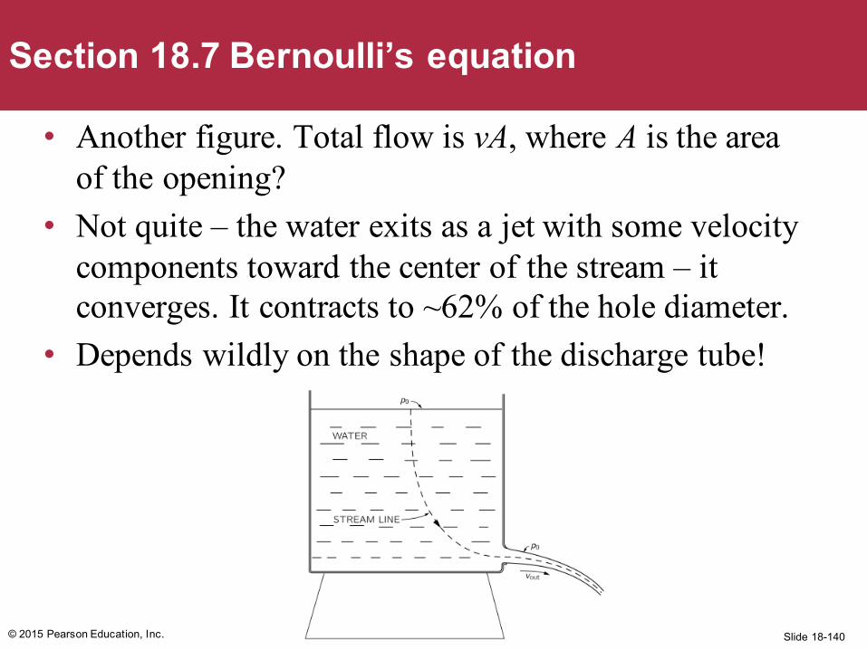
• Another figure. Total flow is vA, where A is the area of the opening?
• Not quite – the water exits as a jet with some velocity components toward the center of the stream – it converges. It contracts to ~62% of the hole diameter.
• Depends wildly on the shape of the discharge tube!
© 2015 Pearson Education, Inc.
Section 18.7 Bernoulli’s equation
Slide 18-141
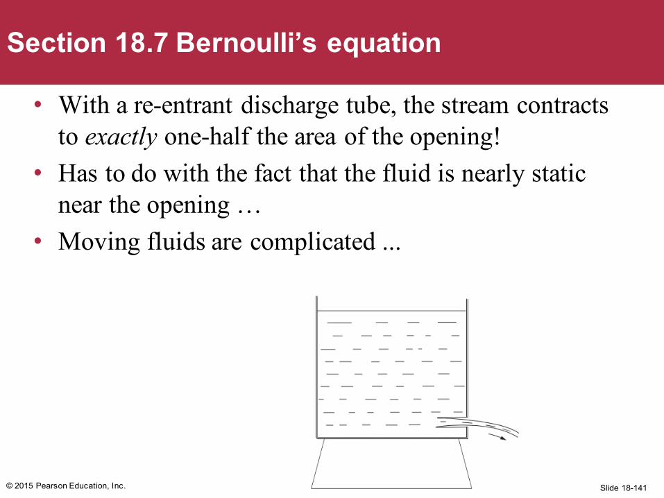
• With a re-entrant discharge tube, the stream contracts to exactly one-half the area of the opening!
• Has to do with the fact that the fluid is nearly static near the opening …
• Moving fluids are complicated ...
© 2015 Pearson Education, Inc.
Section 18.7 Bernoulli’s equation
Slide 18-142
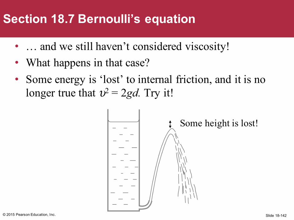
• … and we still haven’t considered viscosity!• What happens in that case? • Some energy is ‘lost’ to internal friction, and it is no
longer true that υ2 = 2gd. Try it!
© 2015 Pearson Education, Inc.
Section 18.7 Bernoulli’s equation
Some height is lost!
Slide 18-143
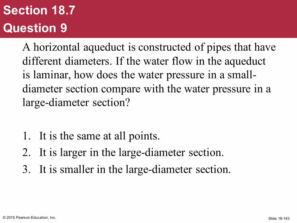
A horizontal aqueduct is constructed of pipes that have different diameters. If the water flow in the aqueduct is laminar, how does the water pressure in a small-diameter section compare with the water pressure in a large-diameter section?
1. It is the same at all points.2. It is larger in the large-diameter section. 3. It is smaller in the large-diameter section.
© 2015 Pearson Education, Inc.
Section 18.7Question 9
Slide 18-144
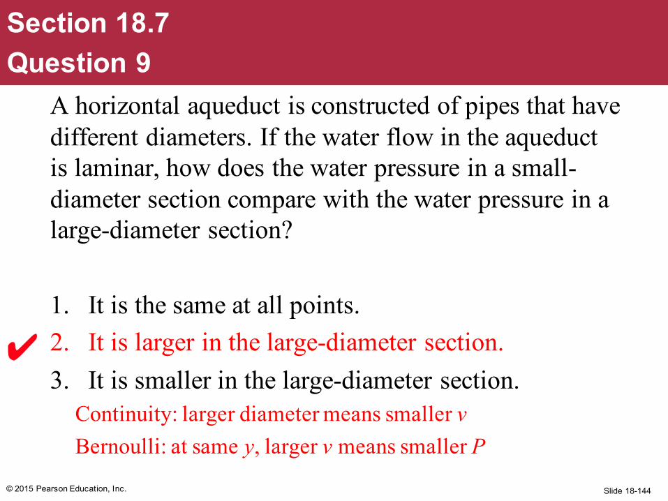
A horizontal aqueduct is constructed of pipes that have different diameters. If the water flow in the aqueduct is laminar, how does the water pressure in a small-diameter section compare with the water pressure in a large-diameter section?
1. It is the same at all points.2. It is larger in the large-diameter section.3. It is smaller in the large-diameter section.
Continuity: larger diameter means smaller vBernoulli: at same y, larger v means smaller P
© 2015 Pearson Education, Inc.
Section 18.7Question 9
Slide 18-145© 2015 Pearson Education, Inc.
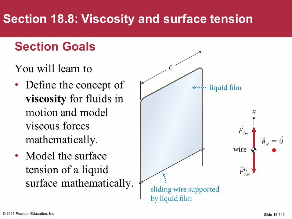
Section 18.8: Viscosity and surface tension
Section GoalsYou will learn to• Define the concept of
viscosity for fluids in motion and model viscous forces mathematically.
• Model the surface tension of a liquid surface mathematically.
Slide 18-146
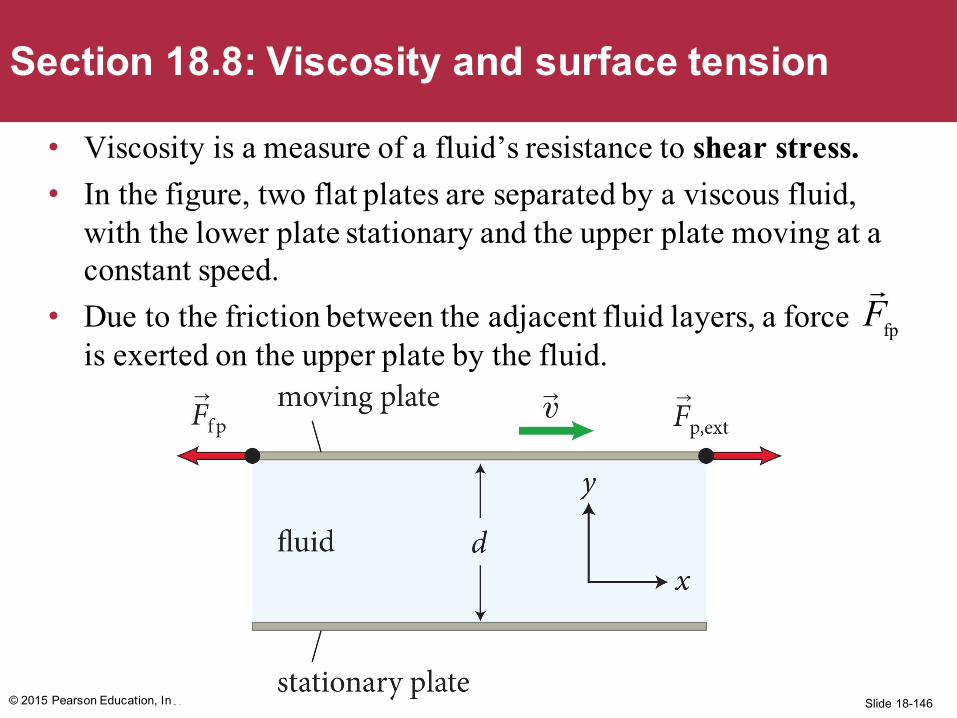
• Viscosity is a measure of a fluid’s resistance to shear stress.• In the figure, two flat plates are separated by a viscous fluid,
with the lower plate stationary and the upper plate moving at a constant speed.
• Due to the friction between the adjacent fluid layers, a force is exerted on the upper plate by the fluid.
© 2015 Pearson Education, Inc.
Section 18.8: Viscosity and surface tension
Ffp
Slide 18-147© 2015 Pearson Education, Inc.
Section 18.8: Viscosity and surface tension
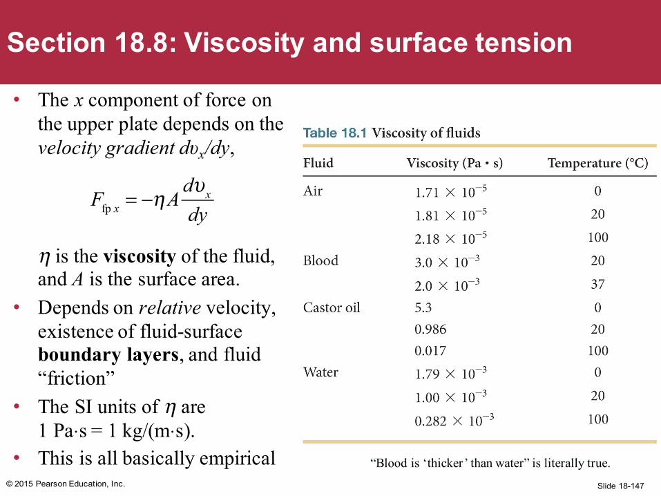
• The x component of force on the upper plate depends on the velocity gradient dυx/dy,
η is the viscosity of the fluid, and A is the surface area.
• Depends on relative velocity, existence of fluid-surface boundary layers, and fluid “friction”
• The SI units of η are 1 Pa⋅s = 1 kg/(m⋅s).
• This is all basically empirical
Ffp x = −ηA
dυx
dy
“Blood is ‘thicker’ than water” is literally true.
Slide 18-148© 2015 Pearson Education, Inc.
Section 18.8: Viscosity and surface tension
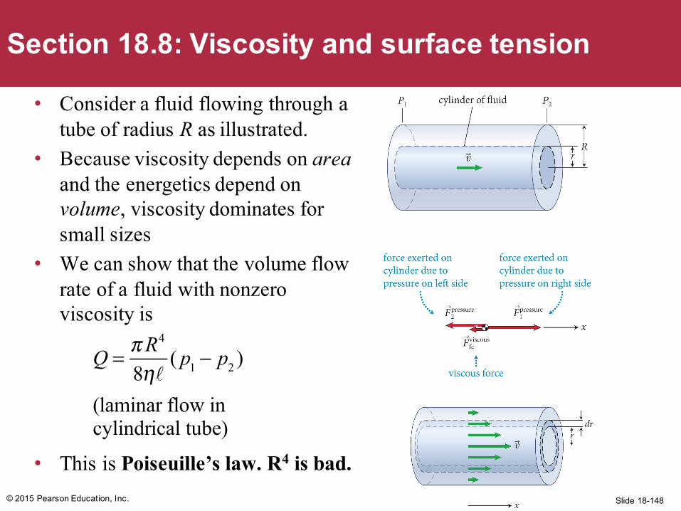
• Consider a fluid flowing through a tube of radius R as illustrated.
• Because viscosity depends on areaand the energetics depend on volume, viscosity dominates for small sizes
• We can show that the volume flow rate of a fluid with nonzero viscosity is
• This is Poiseuille’s law. R4 is bad.
Q = πR4
8η( p1 − p2 )
(laminar flow incylindrical tube)
Slide 18-149
• E.M. Purcell, “Life at Low Reynolds Number”• http://www.biotec.tu-dresden.de/fileadmin/groups/guck/Seminar/1977_Purcell_life_at_low_reynolds_number.pdf
• Written by a brilliant, Nobel-winning physicist, it is all about how stuff like bacteria experience life very differently due to the scaling of viscous vs inertial forces with size.
• If you want to understand fluids, or are a ME major, it is worth your time.
© 2015 Pearson Education, Inc.
For later: an interesting article
Slide 18-150
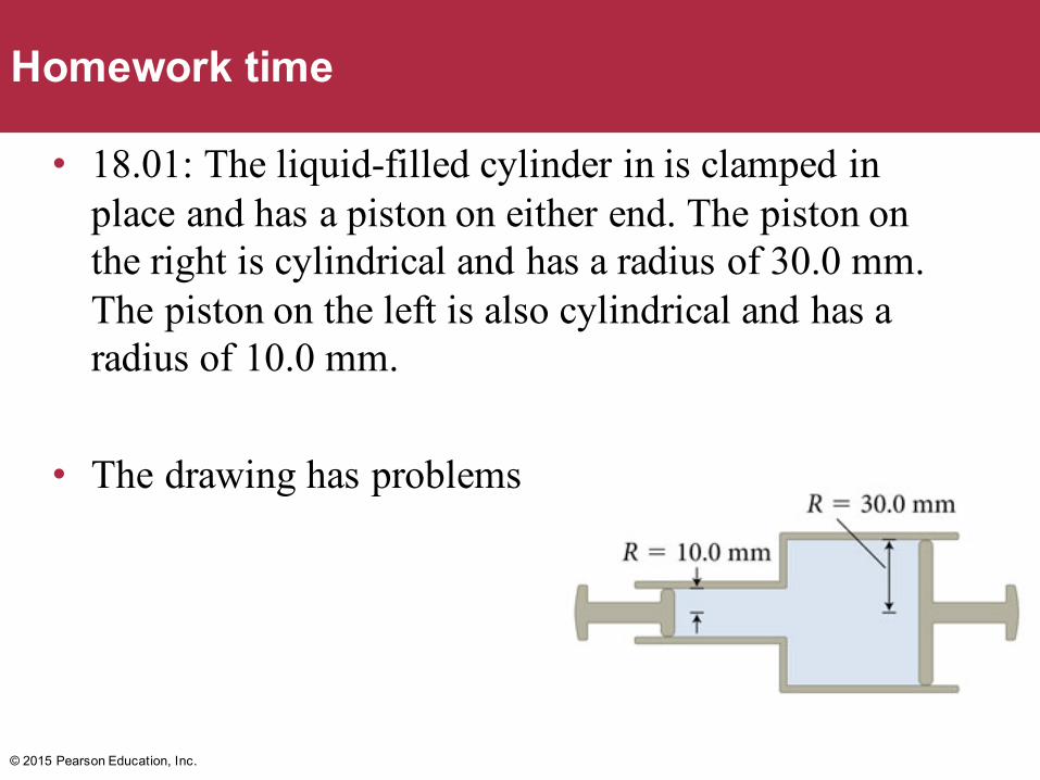
• 18.01: The liquid-filled cylinder in is clamped in place and has a piston on either end. The piston on the right is cylindrical and has a radius of 30.0 mm. The piston on the left is also cylindrical and has a radius of 10.0 mm.
• The drawing has problems
© 2015 Pearson Education, Inc.
Homework time
Slide 18-151
• Pressure on each side is the same
• That means Fl/Al = Fr/Ar
• Given A ~ r2, rr2Fl=rl
2Fr2 or Fl=(rl/rr)2Fr
© 2015 Pearson Education, Inc.
18.01
Slide 18-152
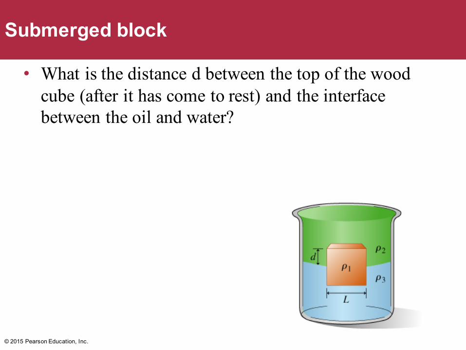
• What is the distance d between the top of the wood cube (after it has come to rest) and the interface between the oil and water?
© 2015 Pearson Education, Inc.
Submerged block
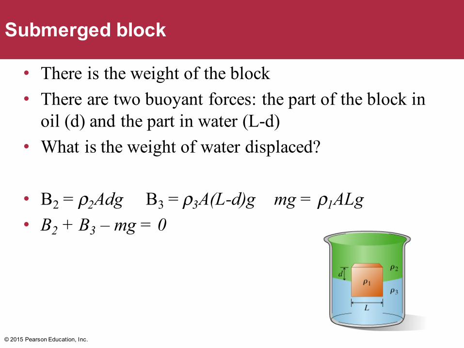
Slide 18-153
• There is the weight of the block• There are two buoyant forces: the part of the block in
oil (d) and the part in water (L-d)• What is the weight of water displaced?
• B2 = ρ2Adg B3 = ρ3A(L-d)g mg = ρ1ALg• B2 + B3 – mg = 0
© 2015 Pearson Education, Inc.
Submerged block
Slide 18-154
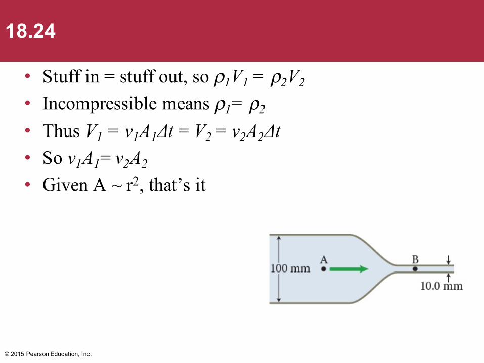
• Stuff in = stuff out, so ρ1V1 = ρ2V2
• Incompressible means ρ1= ρ2
• Thus V1 = v1A1Δt = V2 = v2A2Δt• So v1A1= v2A2
• Given A ~ r2, that’s it
© 2015 Pearson Education, Inc.
18.24
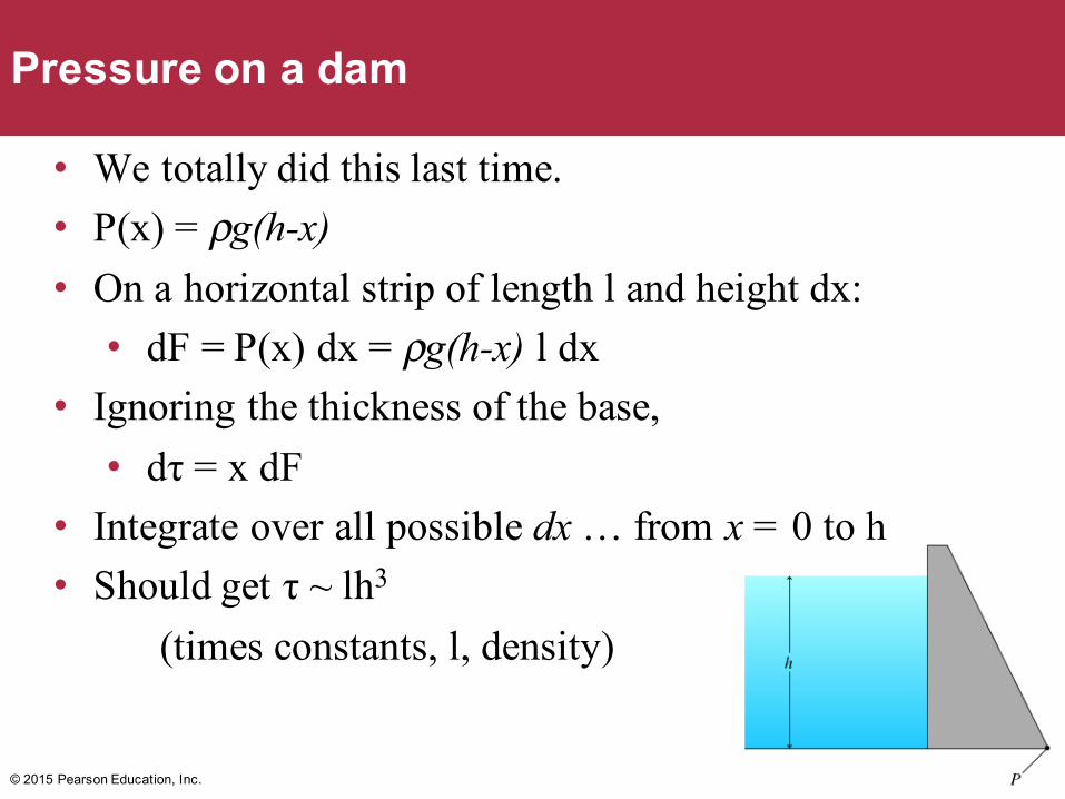
Slide 18-155
• We totally did this last time.• P(x) = ρg(h-x)• On a horizontal strip of length l and height dx:
• dF = P(x) dx = ρg(h-x) l dx• Ignoring the thickness of the base,
• dτ = x dF• Integrate over all possible dx … from x = 0 to h• Should get τ ~ lh3
(times constants, l, density)
© 2015 Pearson Education, Inc.
Pressure on a dam
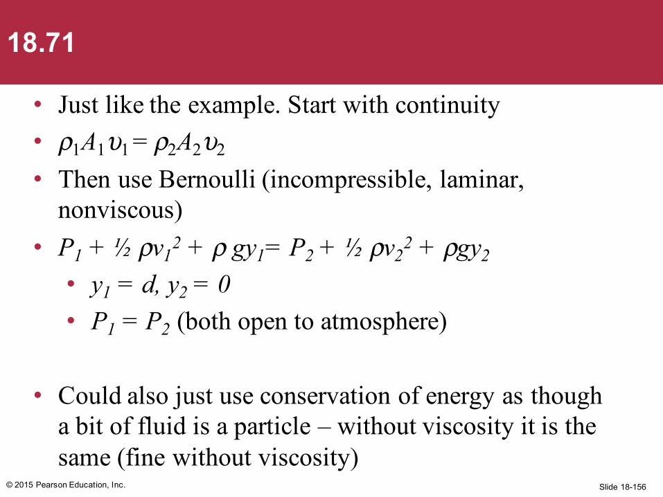
Slide 18-156
• Just like the example. Start with continuity• ρ1A1υ1 = ρ2A2υ2
• Then use Bernoulli (incompressible, laminar, nonviscous)
• P1 + ½ ρv12 + ρ gy1= P2 + ½ ρv2
2 + ρgy2
• y1 = d, y2 = 0• P1 = P2 (both open to atmosphere)
• Could also just use conservation of energy as though a bit of fluid is a particle – without viscosity it is the same (fine without viscosity)
© 2015 Pearson Education, Inc.
18.71
Slide 18-157
• A small, smooth cube made of wood that has a mass density of 850 kg/m3 is dropped from rest 9.00 m above the surface of a lake. Determine the maximum depth the cube reaches.
• Conservation of energy• ΔUG = ΔK to get velocity just before striking water• ΔK = W = Fnetd = (Fbuoy - Fweight)
• Find net force, work against it (over distance d) has to equal the kinetic energy just before hitting the surface. Depends on the difference in densities …
• The result should only depend on d/h and the ratio of the densities
© 2015 Pearson Education, Inc.
18.66
Slide 18-158
• Time? Kinematics, more than one way.
• Kinematics: Fnet/m = a, vf = 0 = vi + at• Given vi from conservation of energy in part A,
solve for t• This is the time to get to the deepest depth, the
total time underwater is twice that much• Use m = ρV to get rid of the unknown V
• Or, d = ½at2, and you know a. Here t is again the time to max depth, so double it.
© 2015 Pearson Education, Inc.
18.66
Slide 18-159
Concepts: Pressure due to a fluid• A fluid is a substance that has no fixed shape and the
ability to flow. A nonviscous fluid is one that has no resistance to deformation by shear stress.
• Pascal’s principle states that a pressure change applied to an enclosed liquid is transmitted undiminished to every part of the liquid and to the walls of the container.
© 2015 Pearson Education, Inc.
Chapter 18: Summary
Slide 18-160
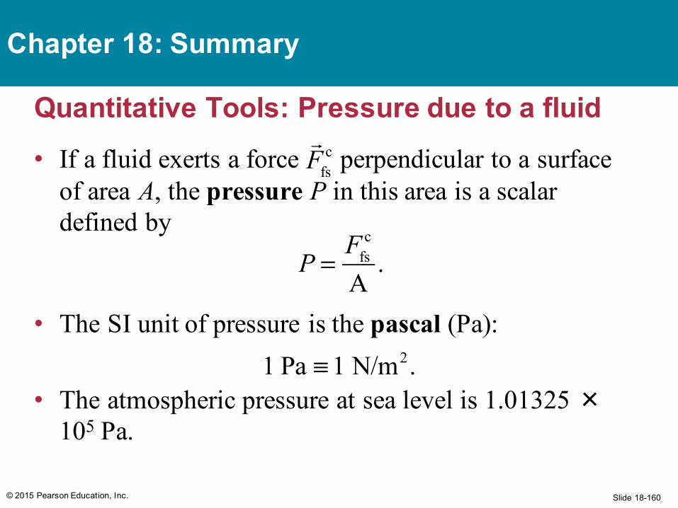
Quantitative Tools: Pressure due to a fluid• If a fluid exerts a force perpendicular to a surface
of area A, the pressure P in this area is a scalar defined by
• The SI unit of pressure is the pascal (Pa):
• The atmospheric pressure at sea level is 1.01325 ×10⁵ Pa.
© 2015 Pearson Education, Inc.
Chapter 18: Summary
P =
Ffsc
A.
Ffs
c
1 Pa ≡ 1 N/m2.
Slide 18-161
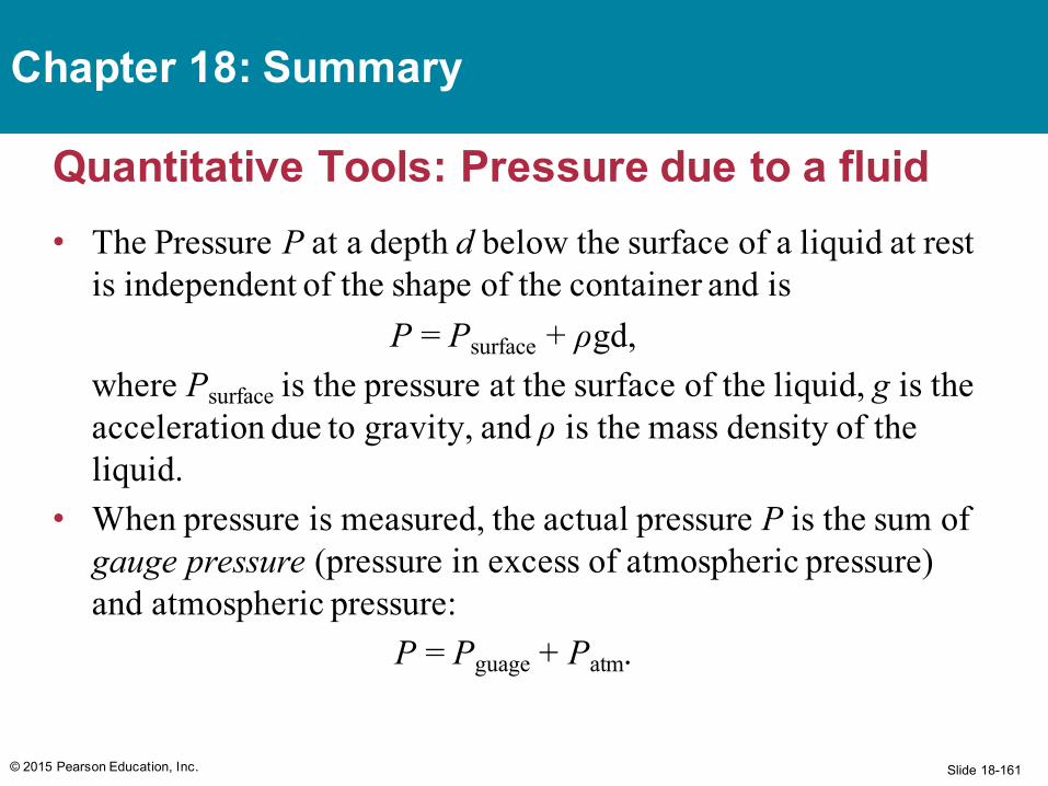
Quantitative Tools: Pressure due to a fluid• The Pressure P at a depth d below the surface of a liquid at rest
is independent of the shape of the container and isP = Psurface + ρgd,
where Psurface is the pressure at the surface of the liquid, g is the acceleration due to gravity, and ρ is the mass density of the liquid.
• When pressure is measured, the actual pressure P is the sum of gauge pressure (pressure in excess of atmospheric pressure) and atmospheric pressure:
P = Pguage + Patm.
© 2015 Pearson Education, Inc.
Chapter 18: Summary
Slide 18-162
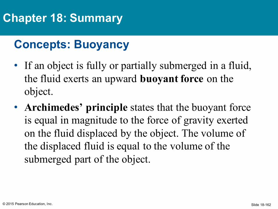
Concepts: Buoyancy• If an object is fully or partially submerged in a fluid,
the fluid exerts an upward buoyant force on the object.
• Archimedes’ principle states that the buoyant force is equal in magnitude to the force of gravity exerted on the fluid displaced by the object. The volume of the displaced fluid is equal to the volume of the submerged part of the object.
© 2015 Pearson Education, Inc.
Chapter 18: Summary
Slide 18-163
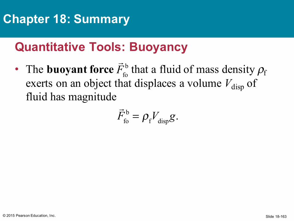
Quantitative Tools: Buoyancy• The buoyant force that a fluid of mass density ρf
exerts on an object that displaces a volume Vdisp of fluid has magnitude
© 2015 Pearson Education, Inc.
Chapter 18: Summary
Ffo
b
Ffo
b = ρfVdispg.
Slide 18-164
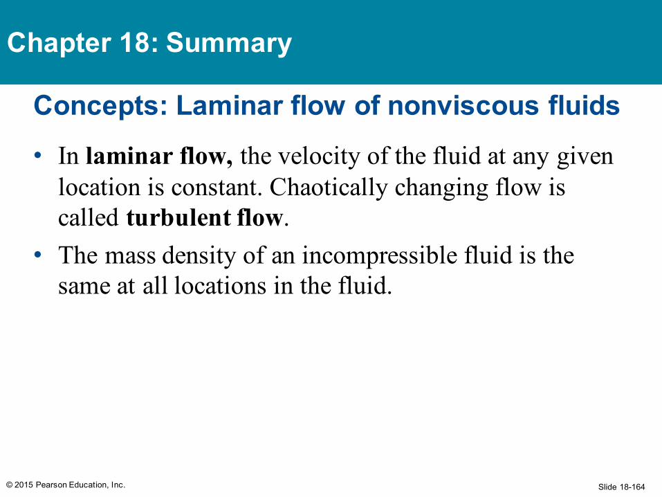
Concepts: Laminar flow of nonviscous fluids• In laminar flow, the velocity of the fluid at any given
location is constant. Chaotically changing flow is called turbulent flow.
• The mass density of an incompressible fluid is the same at all locations in the fluid.
© 2015 Pearson Education, Inc.
Chapter 18: Summary
Slide 18-165
Quantitative Tools: Laminar flow of nonviscous fluids
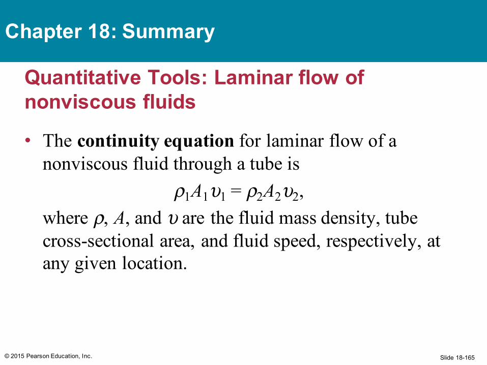
• The continuity equation for laminar flow of a nonviscous fluid through a tube is
ρ1A1υ1 = ρ2A2υ2,where ρ, A, and υ are the fluid mass density, tube cross-sectional area, and fluid speed, respectively, at any given location.
© 2015 Pearson Education, Inc.
Chapter 18: Summary
Slide 18-166
Quantitative Tools: Laminar flow of nonviscous fluids
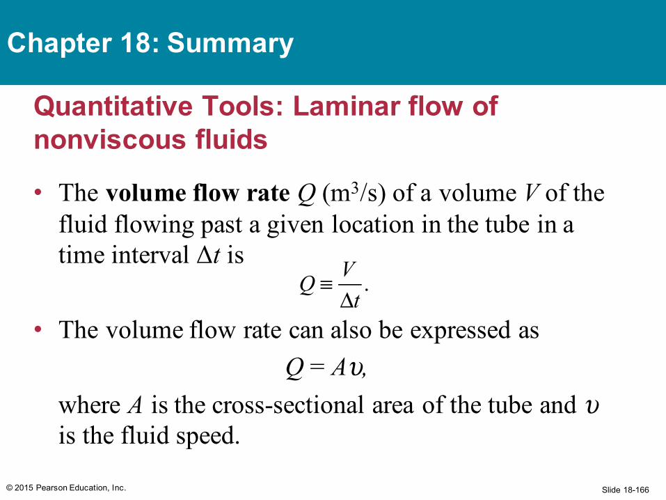
• The volume flow rate Q (m3/s) of a volume V of the fluid flowing past a given location in the tube in a time interval Δt is
• The volume flow rate can also be expressed asQ = Aυ,
where A is the cross-sectional area of the tube and υis the fluid speed.
© 2015 Pearson Education, Inc.
Chapter 18: Summary
Q ≡ V
Δt.
Slide 18-167
Quantitative Tools: Laminar flow of nonviscous fluids
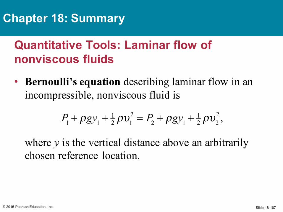
• Bernoulli’s equation describing laminar flow in an incompressible, nonviscous fluid is
where y is the vertical distance above an arbitrarily chosen reference location.
© 2015 Pearson Education, Inc.
Chapter 18: Summary
P1 + ρgy1 +12 ρυ1
2 = P2 + ρgy1 +12 ρυ2
2 ,
Slide 18-168
Concepts: Viscosity and surface tension• Viscosity is a scalar measure of a fluid’s resistance to
shear deformation.• Surface tension is a scalar that gives the magnitude
of the force per unit length exerted by a liquid surface on the perimeter of the surface.
© 2015 Pearson Education, Inc.
Chapter 18: Summary
Slide 18-169
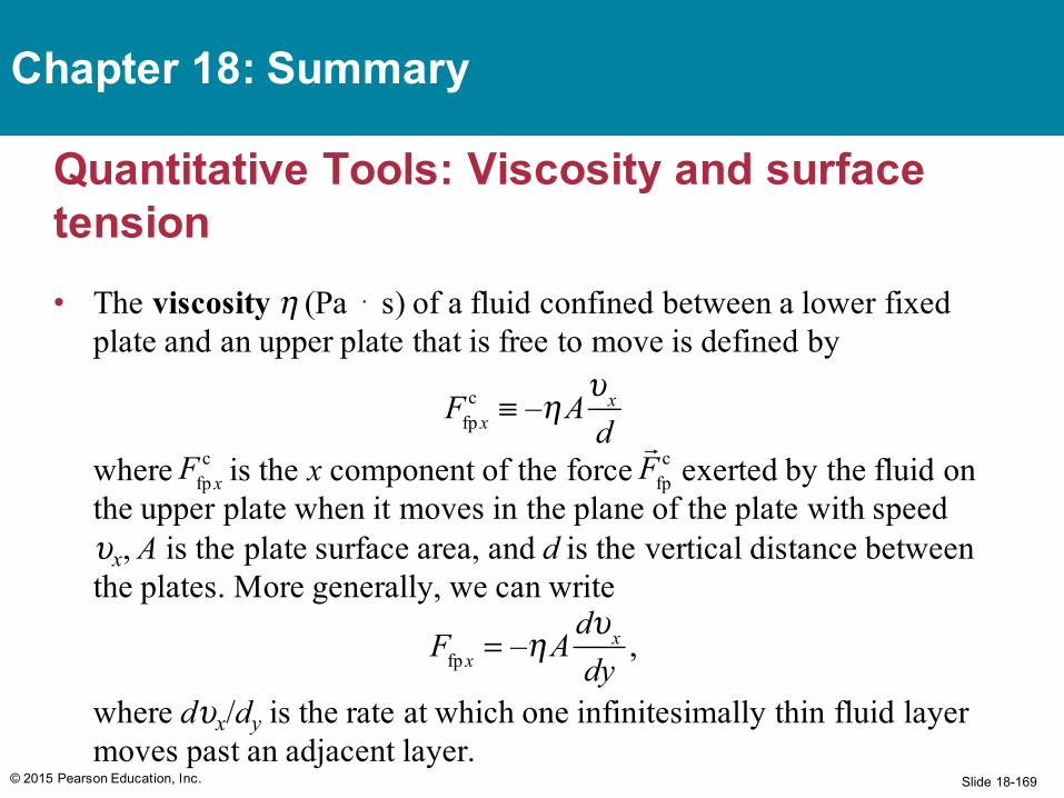
Quantitative Tools: Viscosity and surface tension• The viscosity η (Pa ⋅ s) of a fluid confined between a lower fixed
plate and an upper plate that is free to move is defined by
where is the x component of the force exerted by the fluid on the upper plate when it moves in the plane of the plate with speed υx, A is the plate surface area, and d is the vertical distance between the plates. More generally, we can write
where dυx/dy is the rate at which one infinitesimally thin fluid layer moves past an adjacent layer.
© 2015 Pearson Education, Inc.
Chapter 18: Summary
Ffp x
c ≡ –ηAυx
d
Ffp xc
Ffp
c
Ffp x = –ηA
dυx
dy,
Slide 18-170
Quantitative Tools: Viscosity and surface tension
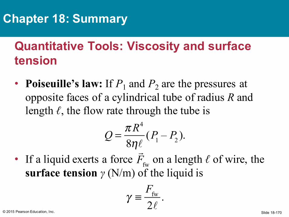
• Poiseuille’s law: If P1 and P2 are the pressures at opposite faces of a cylindrical tube of radius R and length ℓ, the flow rate through the tube is
• If a liquid exerts a force on a length ℓ of wire, the surface tension γ (N/m) of the liquid is
© 2015 Pearson Education, Inc.
Chapter 18: Summary
Ffw
Q = πR4
8η(P1 – P2 ).
γ ≡
Ffw
2.
Slide 18-171
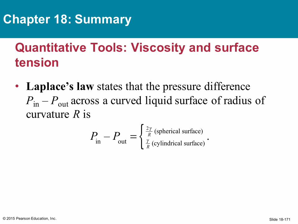
Quantitative Tools: Viscosity and surface tension
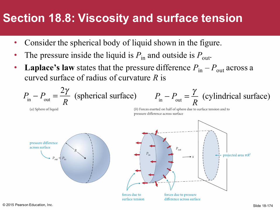
• Laplace’s law states that the pressure difference Pin – Pout across a curved liquid surface of radius of curvature R is
© 2015 Pearson Education, Inc.
Chapter 18: Summary
Pin – Pout = γ
R (cylindrical surface)
2γR (spherical surface){ .
Slide 18-172© 2015 Pearson Education, Inc.
Extra Slides
Slide 18-173© 2015 Pearson Education, Inc.
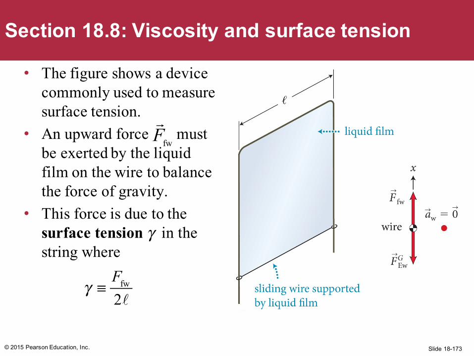
Section 18.8: Viscosity and surface tension
• The figure shows a device commonly used to measure surface tension.
• An upward force must be exerted by the liquid film on the wire to balance the force of gravity.
• This force is due to the surface tension γ in the string where
Ffw
γ ≡
Ffw
2
Slide 18-174
• Consider the spherical body of liquid shown in the figure. • The pressure inside the liquid is Pin and outside is Pout. • Laplace’s law states that the pressure difference Pin – Pout across a
curved surface of radius of curvature R is
© 2015 Pearson Education, Inc.
Section 18.8: Viscosity and surface tension
Pin − Pout =
2γR
(spherical surface) Pin − Pout =
γR
(cylindrical surface)

Slide 18-175© 2015 Pearson Education, Inc.
Section 18.4: Surface effects
Section GoalsYou will learn to• Model the microscopic
interactions at the surfaces of liquids using the concept of cohesive forces.
• Define surface tension and understand its physical causes.
• Differentiate the appearances of liquids that wet and do not wet solid surfaces.
Slide 18-176© 2015 Pearson Education, Inc.
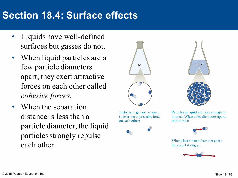
Section 18.4: Surface effects
• Liquids have well-defined surfaces but gasses do not.
• When liquid particles are a few particle diameters apart, they exert attractive forces on each other called cohesive forces.
• When the separation distance is less than a particle diameter, the liquid particles strongly repulse each other.
Slide 18-177© 2015 Pearson Education, Inc.
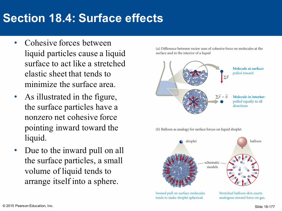
Section 18.4: Surface effects
• Cohesive forces between liquid particles cause a liquid surface to act like a stretched elastic sheet that tends to minimize the surface area.
• As illustrated in the figure, the surface particles have a nonzero net cohesive force pointing inward toward the liquid.
• Due to the inward pull on all the surface particles, a small volume of liquid tends to arrange itself into a sphere.
Slide 18-178
Exercise 18.4 Scaling a drop
© 2015 Pearson Education, Inc.
Section 18.4: Surface effects
Suppose surface tension increases in direct proportion to surface area (an oversimplification!). How does the ratio of surface tension to the force of gravity exerted on a drop change as the drop diameter increases tenfold?
Slide 18-179
Exercise 18.4 Scaling a drop (cont.)
© 2015 Pearson Education, Inc.
Section 18.4: Surface effects
SOLUTION The force of gravity is proportional to the mass of each drop, which is proportional to each drop’s volume. The ratio of surface tension to the force of gravity on each drop is therefore proportional to the surface-area-to-volume ratio. For simplicity, I approximate the smaller drop as a sphere with diameter d. This means that I should compare the surface-area-to- volume ratio of this sphere with the surface-area-to-volume ratio of a sphere of diameter 10d.
Slide 18-180
Exercise 18.4 Scaling a drop (cont.)
© 2015 Pearson Education, Inc.
Section 18.4: Surface effects
SOLUTION The surface area of a sphere of radius is 4πR2 = πd2, and its volume is and so the surface-area-to-volume ratio of a sphere is
The surface-area-to-volume ratio thus decreases by a factor of 10 as the diameter of the drop increases by a factor of 10. Surface effects are more important for smaller things drops! ✔
R = 12 d
43πR3 = 4
3π (d /2)3 = 16πd 3,
(πd 2 )/( 16πd 3) = 6/a.
Slide 18-181
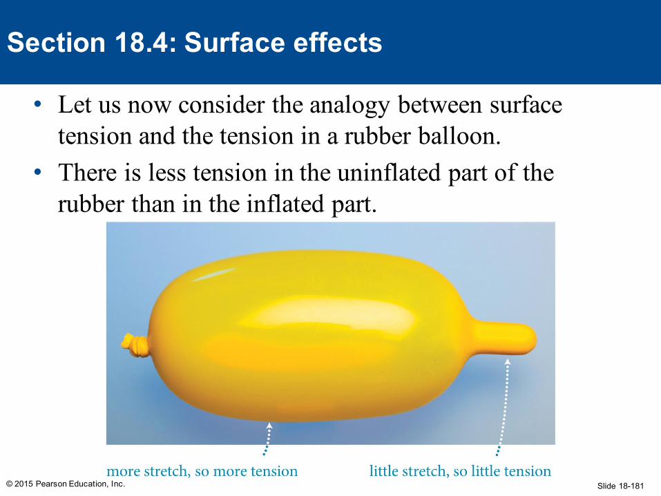
• Let us now consider the analogy between surface tension and the tension in a rubber balloon.
• There is less tension in the uninflated part of the rubber than in the inflated part.
© 2015 Pearson Education, Inc.
Section 18.4: Surface effects
Slide 18-182
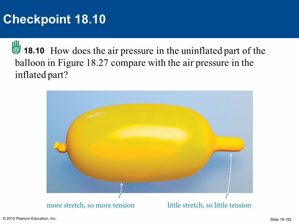
How does the air pressure in the uninflated part of the balloon in Figure 18.27 compare with the air pressure in the inflated part?
© 2015 Pearson Education, Inc.
Checkpoint 18.10
18.10
Slide 18-183© 2015 Pearson Education, Inc.
Section 18.4: Surface effects
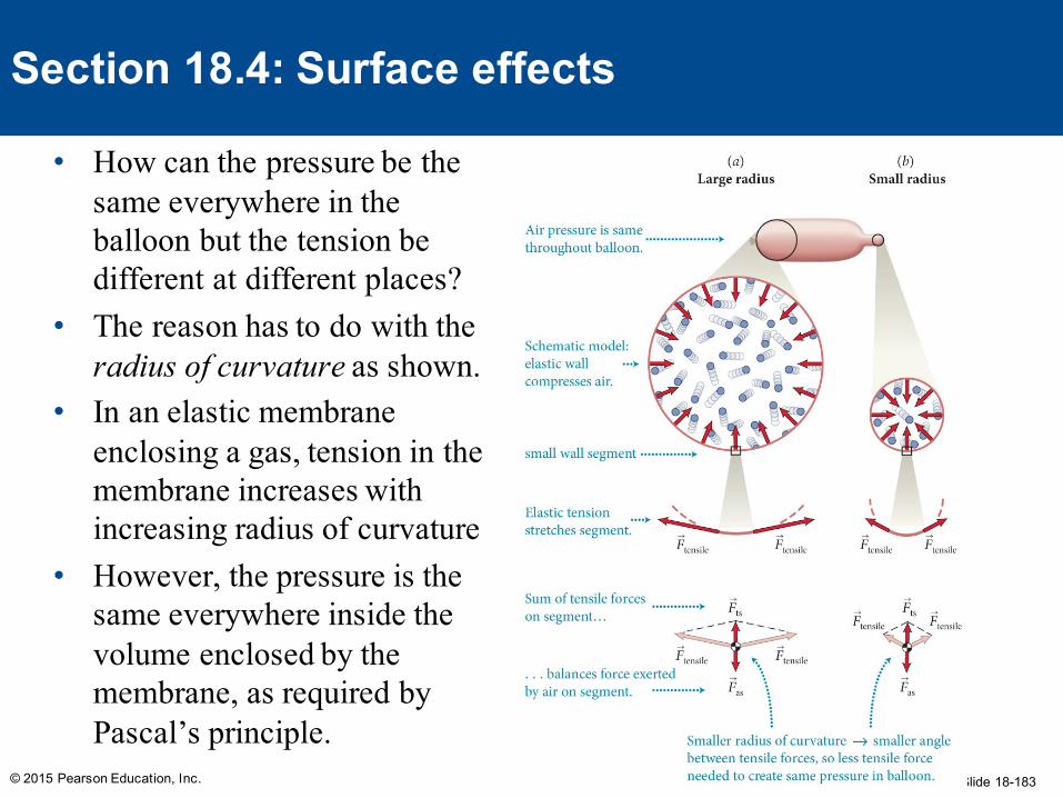
• How can the pressure be the same everywhere in the balloon but the tension be different at different places?
• The reason has to do with the radius of curvature as shown.
• In an elastic membrane enclosing a gas, tension in the membrane increases with increasing radius of curvature
• However, the pressure is the same everywhere inside the volume enclosed by the membrane, as required by Pascal’s principle.
Slide 18-184© 2015 Pearson Education, Inc.
Section 18.4: Surface effects
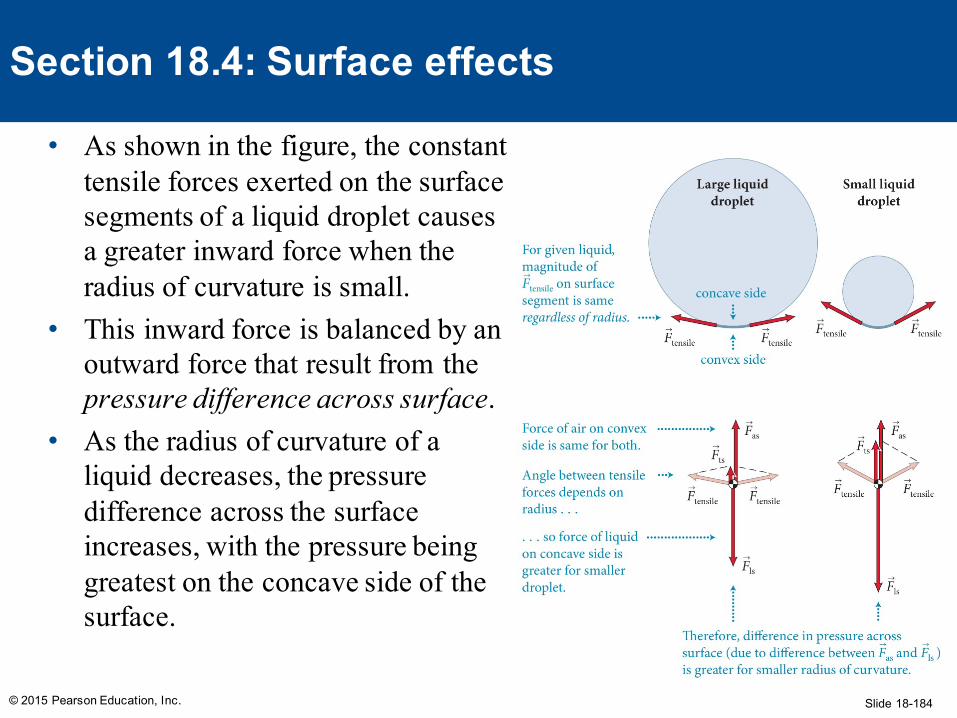
• As shown in the figure, the constant tensile forces exerted on the surface segments of a liquid droplet causes a greater inward force when the radius of curvature is small.
• This inward force is balanced by an outward force that result from the pressure difference across surface.
• As the radius of curvature of a liquid decreases, the pressure difference across the surface increases, with the pressure being greatest on the concave side of the surface.
Slide 18-185
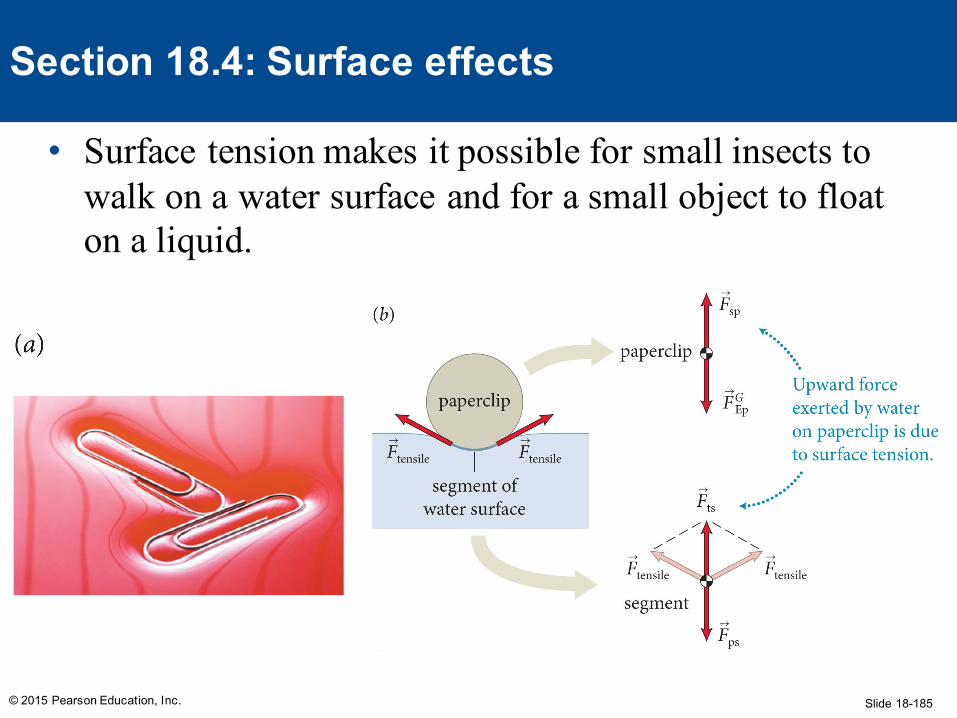
• Surface tension makes it possible for small insects to walk on a water surface and for a small object to float on a liquid.
© 2015 Pearson Education, Inc.
Section 18.4: Surface effects
Slide 18-186
(a) What is the difference between the pressure just below the water surface in a pool and the pressure in the air just above it? (b) Is the pressure inside a raindrop greater than, equal to, or smaller than the pressure in the surrounding air? (c) How does the pressure inside a small raindrop compare with the pressure inside a larger raindrop?
© 2015 Pearson Education, Inc.
Checkpoint 18.11
18.11
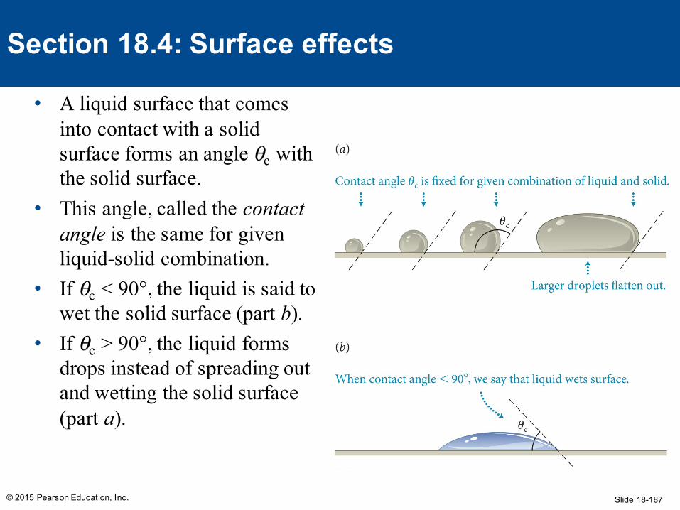
Slide 18-187© 2015 Pearson Education, Inc.
Section 18.4: Surface effects
• A liquid surface that comes into contact with a solid surface forms an angle θc with the solid surface.
• This angle, called the contact angle is the same for given liquid-solid combination.
• If θc < 90°, the liquid is said to wet the solid surface (part b).
• If θc > 90°, the liquid forms drops instead of spreading out and wetting the solid surface (part a).
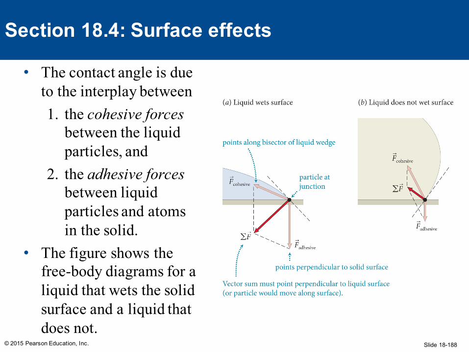
Slide 18-188© 2015 Pearson Education, Inc.
Section 18.4: Surface effects
• The contact angle is due to the interplay between1. the cohesive forces
between the liquid particles, and
2. the adhesive forcesbetween liquid particles and atoms in the solid.
• The figure shows the free-body diagrams for a liquid that wets the solid surface and a liquid that does not.
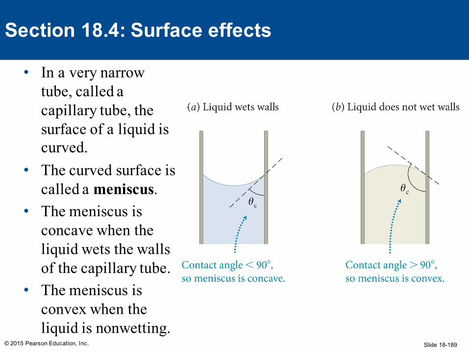
Slide 18-189© 2015 Pearson Education, Inc.
Section 18.4: Surface effects
• In a very narrow tube, called a capillary tube, the surface of a liquid is curved.
• The curved surface is called a meniscus.
• The meniscus is concave when the liquid wets the walls of the capillary tube.
• The meniscus is convex when the liquid is nonwetting.
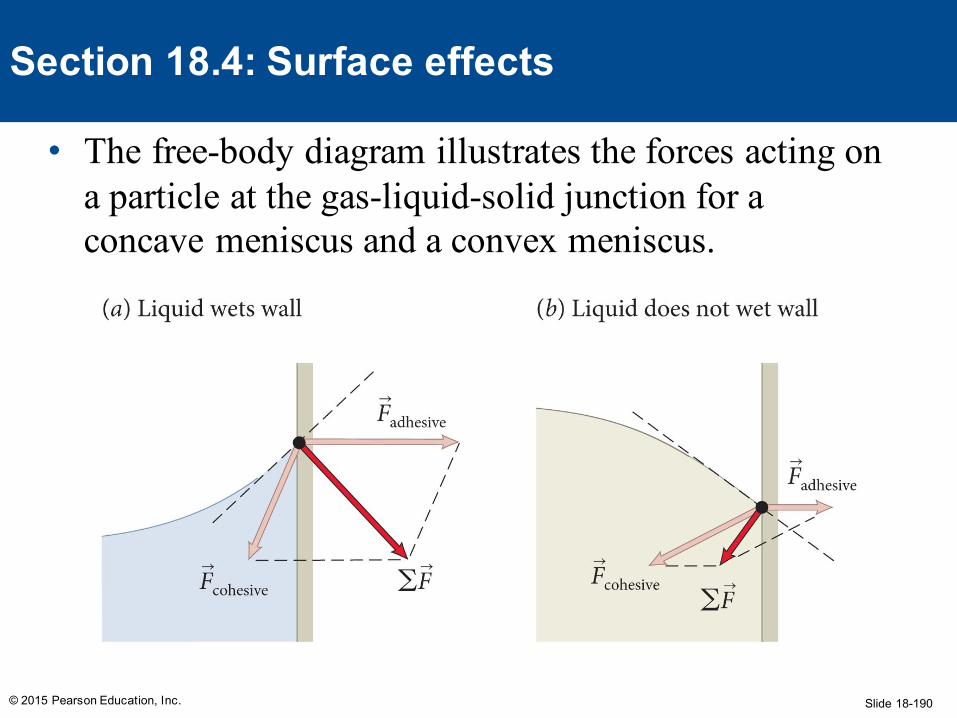
Slide 18-190
• The free-body diagram illustrates the forces acting on a particle at the gas-liquid-solid junction for a concave meniscus and a convex meniscus.
© 2015 Pearson Education, Inc.
Section 18.4: Surface effects
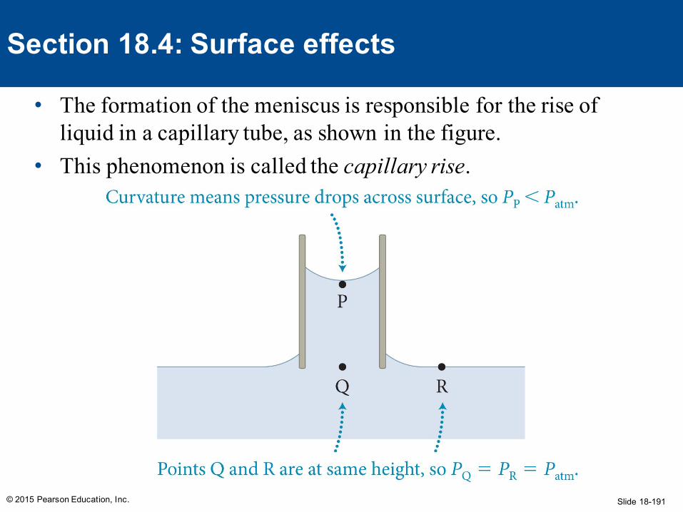
Slide 18-191
• The formation of the meniscus is responsible for the rise of liquid in a capillary tube, as shown in the figure.
• This phenomenon is called the capillary rise.
© 2015 Pearson Education, Inc.
Section 18.4: Surface effects
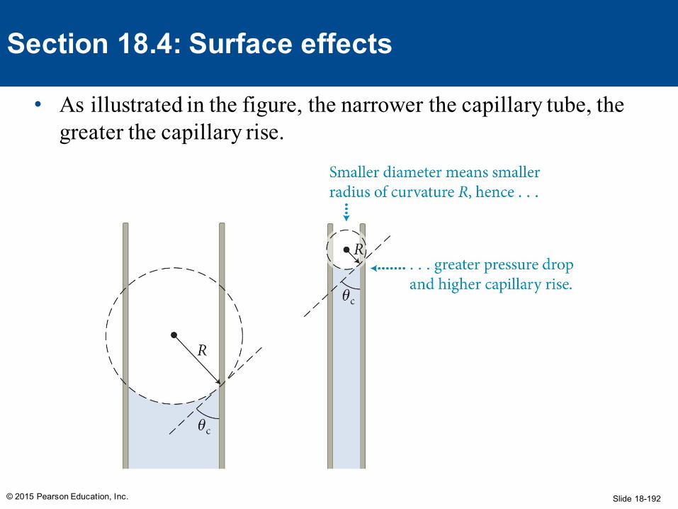
Slide 18-192
• As illustrated in the figure, the narrower the capillary tube, the greater the capillary rise.
© 2015 Pearson Education, Inc.
Section 18.4: Surface effects