Embed Size (px)
Citation preview
Introduction
Magnetorheological fluids (MRF) are magnetic suspen-sions made of particles with high permeability dispersedin a viscous or viscoelastic nonmagnetizable medium.Their flow in an external magnetic field undergoes acompetition between magnetic and hydrodynamic forces.This competition gives rise to original rheological prop-erties with creation of an apparent yield stress, thereforeof a rapid and reversible liquid-solid transition, useful inmany applications such as clutches which has been firstdescribed by Rabinow (1948), damping devices, pumps,antiseismic protection, etc. Despite these potentialapplications, there are only few commercially availabledevices due to the lack of suitable fluids. GoodMR fluids
should be stable against settling and should have a highmagnetic saturation. However their major drawback isthe particle erosion dues to frictions between particles inmovement. Actually carbonyl iron particles have onionlike structure and thus they can easily be peeled byshocks or frictions. This erosion makes the suspension tothicken irreversibly and thus decreases its performance.Surface treatments are currently investigated by makersin order to improve the life time of theirs MR fluids.
The flow modification is usually called the MR effect.It is attributed to the field-induced magnetization of thedisperse phase relative to the continuous phase. At a firstapproximation, one particle can be made of one singlemagnetic domain and therefore is assimilated as onemagnetic dipole. Klingenberg (1989) made some refine-
Jerome Claracq
Jerome Sarrazin
Jean-Pierre Montfort
Viscoelastic properties of magnetorheologicalfluids
Received: 4 November 2002Accepted: 23 June 2003Published online: 2 December 2003� Springer-Verlag 2003
Abstract We have studied the rheo-logical properties of some magneto-rheological fluids (MRF). MRF areknown to exhibit original rheologicalproperties when an external mag-netic field is applied, useful in manyapplications such as clutches, damp-ing devices, pumps, antiseismic pro-tections, etc. While exploitingparameters such as magnetic fieldintensity, particle concentration andthe viscosity of the suspending fluid,we highlighted the importance ofeach one of these parameters onrheology in the presence of a mag-netic field. We made this study byconducting rheological experimentsin dynamic mode at very low strainwhich facilitates the comprehensionof the influence of the structure on
MRF rheology. Our results con-firmed the link between the magneticforces which ensure the cohesion ofthe particles in aggregates, and theelastic modulus. Moreover, we foundthat the loss modulus varies with thefrequency in a similar manner thanthe elastic modulus. The system, evenwith the smallest deformations, wasthus not purely elastic but dissipatesalso much energy. Moreover, wedemonstrated that this dissipation ofenergy was not due to the matrixviscosity. Actually, we attributedviscous losses to particle movementswithin aggregates.
Keywords Magnetorheology ÆViscoelasticity Æ Yield stress ÆMagnetic suspension Æ Rheology
Rheol Acta (2004) 43: 38–49DOI 10.1007/s00397-003-0318-7 ORIGINAL CONTRIBUTION
J. ClaracqDow Benelux NV, PO Box 48,4530 AA Terneuzen, The Netherlands
J. Sarrazin Æ J.-P. Montfort (&)Laboratoire de Physico-Chimie desPolymeres UMR-CNRS 5067,Universite de Pau et des Pays de l�Adour,BP 1155, 64013 Pau, FranceE-mail: [email protected]
ments to the calculus of the electrostatic force. Trans-lated into magnetostatic, his expression for the magneticforce F may be written as shown in Eq. (1):
F ¼ 3lf a2b2H2f
with
f ¼ a4r4 2f== cos
2 h� f? sin2 h
� �er þ fC sin 2heh
� �ð1Þ
with lpthe particle permeability, lf the fluid permeabil-ity, b ¼ lp�lf
lpþ2lf¼ a�1
aþ2, r distance between sphere center tocenter and a particle diameter. fk, f’, and fG are numericterms which are function of ratios a and r/a.
In both limit cases when a fi 1 and a/r fi 0,parameters fk, f’, fG fi 1 which correspond to thedipolar approximation. These parameters have beencalculated for various a values (Klingenberg 1989;Clercx and Bossis 1993). Electrostatic forces increasetremendously while particles are coming closer upbecause of the divergence of the electrostatic field in thegap between sphere surfaces. In a same way, magneticforce between two magnetic spheres can also becomevery high up to the magnetization saturation.
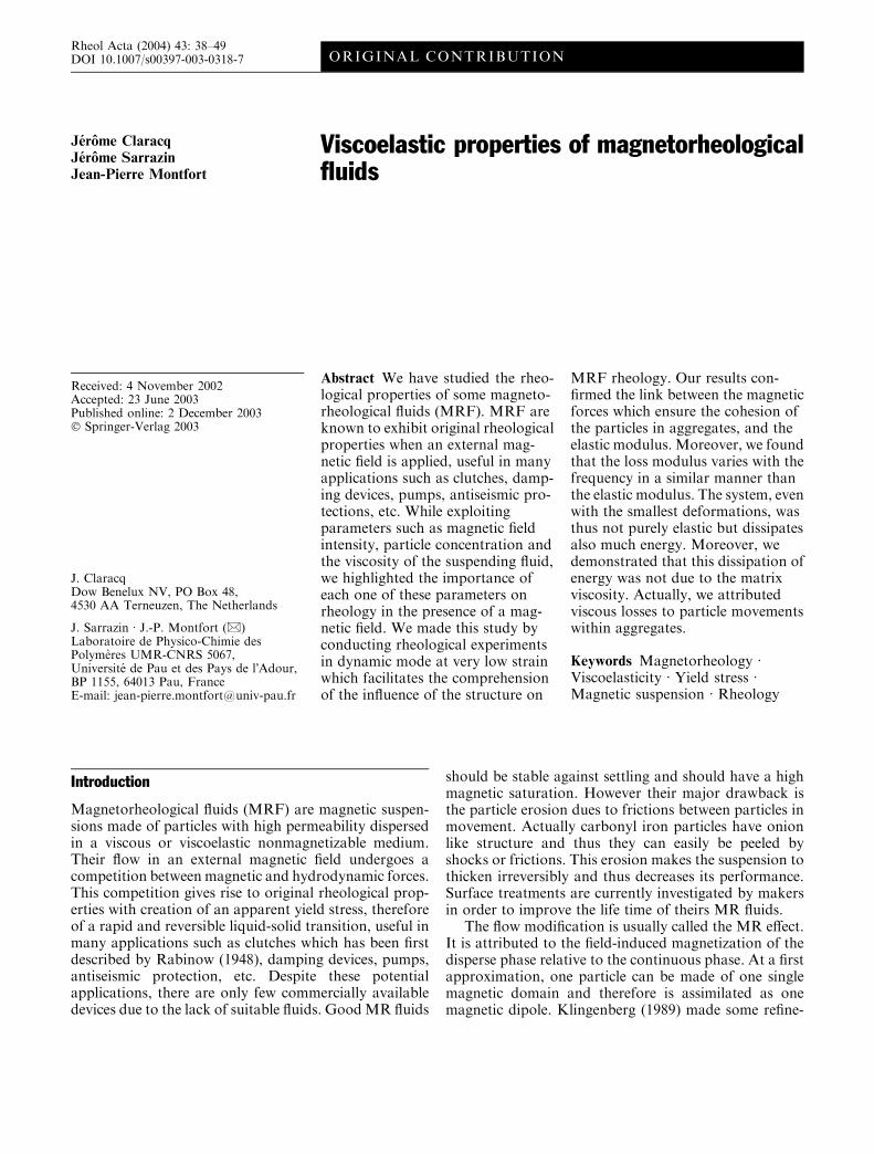
Because this force has two components along theradial and the orthoradial axis, a force momentumaligns particles into and head to tail configuration in thedirection of the applied magnetic field (Fig. 1). Thiscreates the experimentally observed fibrous structure.
It has been reported by numerous publications thatthis structure must be broken in order to make thesuspension flow. The force required to break these col-umns defines the yield stress sy. In steady state rheology,this type of flow is commonly modeled as a Binghamfluid (Eq. 2) (Bingham 1922) with a magnetic-fielddependent yield stress sy(H):
s _c;Hð Þ ¼ sy Hð Þ þ g _c for s>sy
_c ¼ 0 for s\syð2Þ
where s is the shear stress and g is the viscosity at highshear rate. More models using a non-Newtonian shearcan also be proposed as Eq. (3) (Casson 1959) or Eq. (4)(Hershel-Buckley 1926) which take into account thecurve shape of the shear stress versus shear rate func-tion:
s12 _c;Hð Þ ¼ s
12y Hð Þ þ g _cð Þ
12 ð3Þ
s _c;Hð Þ ¼ sy Hð Þ þ K _cð Þp ð4Þ
where parameter p is strictly positive and K calledconsistency is a viscosity-like parameter. Howeverphysical information drawn from such models is ratherpoor compared to what can be get from spectrome-chanical analysis. Indeed spectromechanical analysis hasproven to be a very rich experimental method in polymerscience because it makes it possible to separate theelastic and the viscous contribution of the material. Thusit can reveal all the different relaxation phenomena re-lated to the microstructure.
That is why the main feature of this review will beabout spectromechanical analysis and the influence ofphysical parameters like the magnetic field intensity H,the matrix viscosity g0, the particle volume fraction F,and the shear strain c.
Literature review
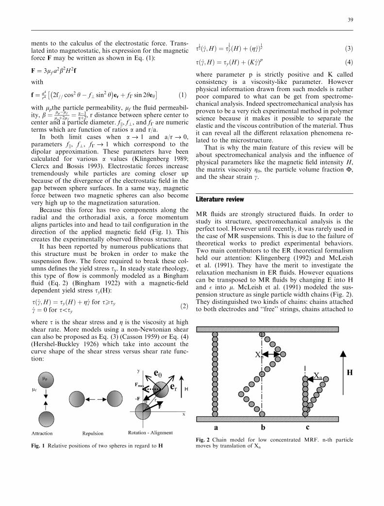
MR fluids are strongly structured fluids. In order tostudy its structure, spectromechanical analysis is theperfect tool. However until recently, it was rarely used inthe case of MR suspensions. This is due to the failure oftheoretical works to predict experimental behaviors.Two main contributors to the ER theoretical formalismheld our attention: Klingenberg (1992) and McLeishet al. (1991). They have the merit to investigate therelaxation mechanism in ER fluids. However equationscan be transposed to MR fluids by changing E into Hand � into l. McLeish et al. (1991) modeled the sus-pension structure as single particle width chains (Fig. 2).They distinguished two kinds of chains: chains attachedto both electrodes and ‘‘free’’ strings, chains attached to
Fig. 1 Relative positions of two spheres in regard to HFig. 2 Chain model for low concentrated MRF. n-th particlemoves by translation of Xn
39
at most one electrode free. Under small amplitudeoscillatory shear, attached chains deform affinely at alloscillation frequencies, producing no relaxation. As thestorage modulus, G¢, is a function of the magnetic ten-sion within a string, it scales up with the squared fieldstrength but is independent of the oscillation frequency(Eq. 5). For very small deformation and for the linearregime McLeish proposed the following expressions:
G0 ffi TqN2a 1� fð Þ
G ffi 2TqN2a f
P
qodd
2 1�cos q0ð Þix�4 1�cos q0ð Þ2þx�2
: sin q0=2ð Þ2 1�cos q0ð Þ
8<
:ð5Þ
where T(H2) is the tension in a chain, N particle numberper chain and q volume fraction of particles in suspen-sion, f free chain fraction, non-dimensional pulsationx*=xs with s=t(T/(6pg0a
2)), a= particle diameter,q�=pq/N where q is the number of modes.
The loss modulus, G¢¢, arises essentially from themotion of the ‘‘free’’ chains, which may deform non-affinely depending of the frequency.
This model is interesting as it predicts at intermediatefrequencies a plateau for G¢¢ in increasing the number ofmodes. Moreover both moduli scale up with the squaredmagnetic intensity. However, it predicts a Newtonianbehavior at low oscillatory frequency and leads to avariation of G¢¢ inversely proportional with the pulsa-tion at high frequency which seems to be in contradic-tion with our observations. Their theory seems to matchtheir experimental data but to our knowledge, it has notbeen successfully applied by others since then.
Klingenberg (1992) employed a similar model.However, the suspension structure was determined bycomputational simulation. At moderate to large parti-cles concentration, the structure mainly consists ofthick clusters as opposed to single particle chains. Therelaxation process is associated to a frequency depen-dent dynamic structure within the cluster. As forMcLeish, G¢ scales up with the squared field intensity,but it varies between a low plateau for small value ofthe dimensionless frequency and a higher plateau atlarger ones. G¢¢ passes through a maximum near thetransition between the small and large frequency re-gimes. This transition is defined by a characteristic times which allowed Klingenberg to define a propertycalled time-field strength superposition, similar to thetime-temperature superposition in polymer rheology.Thus, when scaled with the magnetic field strengthsquared, the complex shear modulus (G*) is onlyfunction of the frequency scaled by the magnetic fieldstrength squared for a particular suspension at a givenconcentration:
G316 pl0lcb
2H20
¼ f16gCx
316 pl0lcb
2H20
!
¼ f xsð Þ: ð6Þ
Both models are based on linear viscoelastic rules.However, experimentally, linear viscoelastic behavior isoften limited to very small strain amplitudes (Otsubo1991; Ginder and Davis 1993; Parthasarathy et al. 1994;Yen and Achorn 1991). Several authors report forelectrorheological fluids a very narrow linear domainand above that a strong decrease in the modulus values(Jordan et al. 1992; Otsubo et al. 1992) due to the breakof the chain structure. Jordan et al. (1992) examined theviscoelastic behavior of a commercial ER fluid. Theyobserved linear behavior for strain amplitudes belowabout 3%. Then, G¢ and G¢¢ decreased with furtherincreases in strain amplitude. Otsubo et al. (1992)investigated the dynamic ER properties of silica particlesin silicone oil. Linear viscoelastic behavior was observedfor strain amplitudes below 1% for all field strengthsinvestigated. G¢ was found to decrease with further in-creases in strain amplitude, while G¢¢ plotted againstfrequency passed through a maximum which shifted tosmaller frequencies with increasing strain amplitude.Gamota and Filisko (1991) and Gamota et al. (1993)studied the dynamic properties of aluminosilicate parti-cles in paraffin oil, focusing attention on the Fouriertransform of the oscillatory shear flow response. Linearviscoelastic behavior was observed for sufficiently smallstrain amplitudes and field strengths, where at constantfrequency, G¢ and G¢¢ increased with field strength.Experiments were performed by varying the electric fieldstrength at constant strain amplitude (0.1 and 0.5) andfrequency (1 Hz). The response was linear at small fieldstrengths as determined by observing only a funda-mental harmonic in the Fourier transform of the stressresponse. However, at large field strengths, higher orderharmonies appeared, demonstrating that nonlinearitymay be induced by other parameters other than thestrain amplitude. Recently, Chin et al. (2001) havestudied magnetic particles and carbonyl iron suspendedin silicon oil. They could not reach small enoughamplitude to reach the linear zone which was under astrain of 0.03% as both G¢ and G¢¢ were found todecrease with further increases in strain amplitude.Rankin et al. (1999) investigated the rheological prop-erties of suspensions of iron particles in viscoplasticmedia. They concluded that carbonyl iron suspensionshave a nonlinear MR response and that the field-dependence of the storage modulus reflects changes inthe suspension structure. The mechanisms responsiblefor the onset of nonlinearity at very small strain ampli-tudes are not very well understood. Yen and Achorn(1991) associate the onset of nonlinearity with yieldingat strains of 1%. Jordan et al. (1992) expect the transi-tion to correspond to the breaking of chain linkagesbeyond their elastic limit which they view as the yieldpoint of the material. However, Parthasarathy andKlingenberg (1995a, 1995b), while investigating by
40
simulations the transition from linear to non linear at aparticle-level, found that the slight rearrangementswithin structures as opposed to the column rupturescontrol the transition from linear to nonlinear rheolog-ical behavior at small deformation rates. For largerstrains, the nonlinear behavior is attributed to break-downs of percolating structures. Their conclusions arethat any slight instability of the local magnetic field orany infinitesimal change of particle localization caninduce a nonlinear rheological response.
Thus, it is not sure that true linearity can be reachedin real experiment whatever the rheometer sensibility is,as local magnetic field is metastable.
This may explain why there are only few papersabout ER fluids (McLeish et al. 1991; Jordan et al. 1992;Otsubo et al. 1992; Yen and Achorn 1991; Kim et al.2001) and about MR fluids (Chin et al. 2001; Gans et al.2000; Larrondo and van de Ven 1992) which show thefrequency dependence of both storage and loss modulus.Results of spectromechanical analysis may look some-times quite confusing. However, it is a consequence ofthe complex structure in such fluids. Even so, a tendencyseems to appear in recent papers as people possess moreprecise tools. Actually, Kim et al. (2001) analyzing theelectrorheological characteristics of a phosphate cellu-lose-based suspension at different electric field strengthsand at a strain of 0.002 found that G¢ and G¢¢ are eitherconstant or increase slightly above 10 Hz. G¢ was foundto be more affected by the electric field strength than G¢¢whereas G¢¢ was more sensitive to the frequency. Theyconcluded to a rubber-like behavior in the linear region.Studying an inverse ferrofluid, Gans et al. (2000)observed also such behavior for the G¢ but their G¢¢showed an increase at low frequencies. They found thatG¢ scales up with the particle concentration and thesquare of the magnetic saturation (Ms). Thus, theyproposed a normalization of G¢ by (u.Ms) in order tobuild a master curve. Recently, Chin et al. (2001) mea-sured a G¢ which also increases slightly with the fre-quency and a G¢¢ which presents a plateau. Both moduliwere found to be proportional to the applied magneticfield intensity (H0) and the G¢¢ was much more superiorto the viscous contribution of the matrix. From all ofthese, it seems that each ER or MR material has its ownviscoelastic behavior. Thus we find some interest todeeply study the viscoelastic properties of the most usedand simple MR fluid, a carbonyl iron suspension.
Experimental
Preparation of MR fluids Usually magnetorheological fluids aresuspensions of thin colloidal ferromagnetic or ferromagnetic par-ticles dispersed in a very fluid medium: magnetic latex made ofpolystyrene particles with inclusions of magnetite (Lemaire et al.1992); suspensions of polymer-coated nano-sized ferrite particles inpolar solvent (Kormann et al. 1996) and meso-scale carbonyl iron
and nickel-zinc ferrites (Phulle and Ginder 1999), carbonyl ironstabilized by small aerosol particles (Volkova et al. 2000; Tang andConrad 1996), by small magnetic particles (Chin et al. 2001), or byviscoplastic media (Rankin et al. 1999). From all of these systems,only carbonyl iron based suspensions have already enough per-formance to be used in magnetic devices such as dampers. As thiskind of suspension is widely used, it seemed interesting to studythem. We needed good magnetic properties which can only beprovided by large particles. Carbonyl iron was chosen because ofits high magnetic permeability and its low coercivity. It is suitablefor reversible systems. These are characteristics of magnetic softmaterials. Thus, we used 99% pure carbonyl iron particles fromGoodFellow with a size of 7±1 lm and a density of 7.8 g/cm3. Theshape of the particle is nearly spherical as seen by optical micros-copy. Silicon oils from Rhodia (47V10000 and 47V500000 grades)with a density of 0.93 g/cm3 were used as received for the contin-uous phase of suspensions. Their Newtonian viscosities have beenmeasured respectively equal to 13 Pa (47V10000) and 606 Pa(47V500000). They were high enough to slow down any settlingduring measurement time. Thus, we did not try to stabilize more byany means the dispersion.
Suspensions were prepared by first weighting a quantity ofpowder in a beaker. Then, the right mass of silicon oil was addedon top of it. The suspensions were homogenized by the agitation ofa mechanical stirrer at 200 rpm for several hours depending of theconcentration until MR fluids got a homogeneous aspect. Theobtained MR fluids were immediately frozen into liquid nitrogen toinsure conservation without settling until use. In the case of themost viscous oil, we had to dissolve it with cyclohexane for aproper mixing. The solvent was then removed by cryo-distillationunder vacuum. We used the following normalization for suspensionnames shown in Table 1.
Magnetic properties Magnetic properties were measured by ahysterisimeter. The magnetic field was produced by a large custom-built single coil powered by a stabilized d.c. supply. This coil allowsa maximum magnetic intensity of 3.104 A/m far from the satura-tion magnetization. Indeed, it is important to note that the mag-netic field remains in the linear magnetic domain of carbonyl ironparticles where Rayleigh�s law can be applied. From this one candeduce the relative permeability of the suspensions (Fig. 3) byformulae:
J ¼ l0
ll0
� 1
� �H ð7Þ
Thus, in our experiments relative permeabilities could be con-sidered as constants. But these are average suspension permeabil-ities ls. In order to use theoretical models, we need to know the realparticle permeabilities lp which is different from the average sus-pension permeability. One method to link the average permeabilityto the particle permeability is the Maxwell-Garnett (1906) theorybased on the conservation of the magnetization in an effectivemedium. Thus, the total magnetization is the summation of eachspecies weighted by their volume fraction. As a consequence, each
Table 1 Table of samples
Sample Content of magneticmaterial [vol.%]
Grade of silicon oil
05V5e5 5 47V50000010V5e5 10 47V50000015V5e5 15 47V50000010V1e4 10 47V1000015V1e4 15 47V1000030V1e4 30 47V10000
41
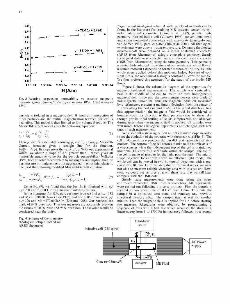
particle is isolated in a magnetic field H from any interaction ofother particles and the mutual magnetization between particles isnegligible. This model is then limited to low volume fractions. TheMaxwell-Garnett model gives the following equation:
ls � lf
ls þ 2lf¼ /
lp � lf
lp þ 2lfð8Þ
Then lp can be calculated knowing ls and lf. If lf@l0, Maxwell-Garnett formulae gives a straight line for the function,ls�l0
lsþ2l0¼ f /ð Þ. Its slope gives the value of lp. With our experimental
values, we obtain a slope of 2.3, greater than 1 which gives animpossible negative value for the particle permeability. Volkova(1998) tried to solve this problem bymaking the assumption that theparticles are not independent but aggregated in ellipsoidal clusters.She used the following modified Maxwell-Garnett equation:
ls
l0
¼1þ /b==
1� /n==b==with b== ¼
lp
�l0 � 1
1þ n== lp
�l0 � 1
� � ð9Þ
Using Eq. (9), we found that the best fit is obtained with lp/l0=200 and n//=0.1 for all magnetic intensity values.
In the literature, for 98% pure carbonyl iron we find li/l0=132and Ms=1,990,000A/m (Jiles 1995) and for 100% pure iron, li/l0=320 and Ms=270,000kA/m (Durand 1968). Our particles aremade of 99% pure iron. Thus our measures are accurately betweenthe values of 100% pure and 98% pure iron. The b value would beconsidered near the unity.
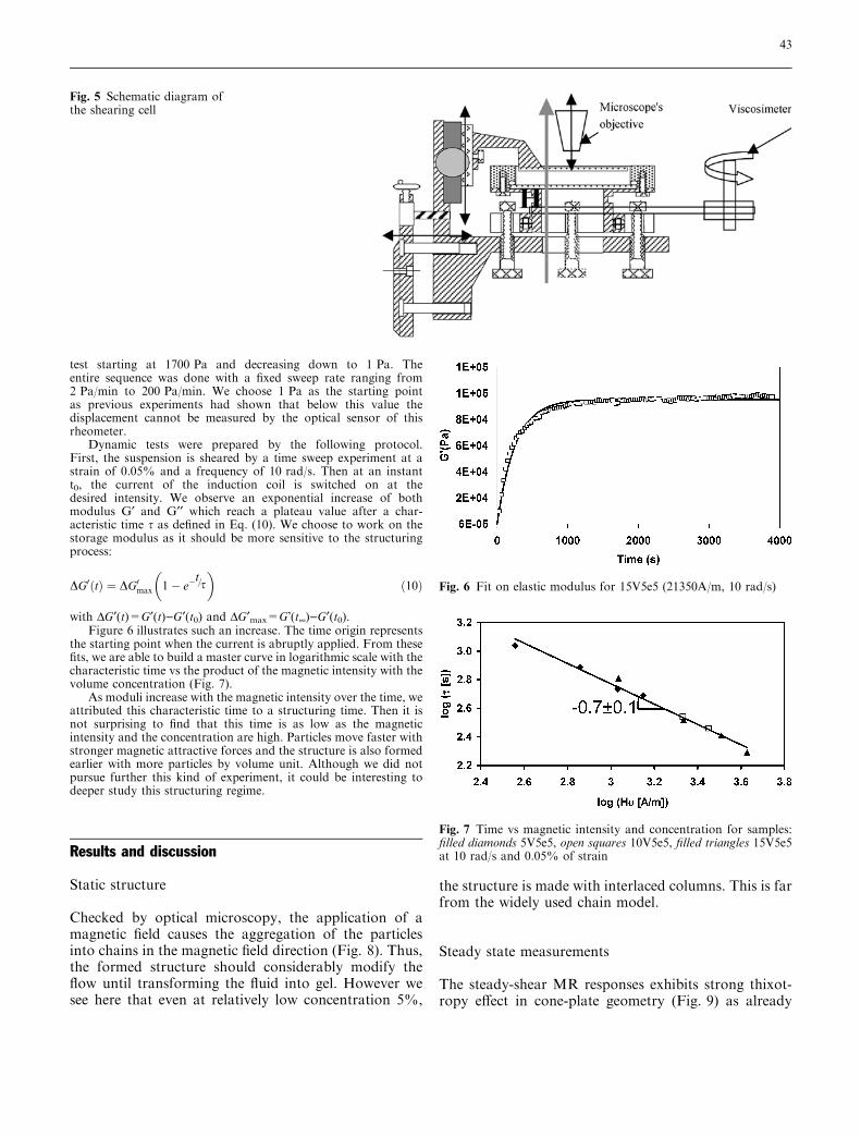
Experimental rheological set-up A wide variety of methods can befound in the literature for studying MR systems: concentric cyl-inder rotational viscometer (Laun et al. 1992), parallel plategeometry inserted into a coil (Volkova 1998), conventional stressand strain controlled rheometers with cone-plate (Larrondo andvan de Ven 1992), parallel plate (Chin et al. 2001). All rheologicalexperiments were done at room temperature. Dynamic rheologicalmeasurements were obtained on a strain controlled rheometer(ARES from Rheometrics) using a cone plate geometry. Steadyrheological data were collected on a stress controlled rheometer(DSR from Rheometrics) using the same geometry. This geometryis particularly adapted to the study of our substances whose flow ata certain moment t depends on former mechanical history, i.e., thewhole stress applied before this moment. Indeed because of con-stant stress, the mechanical history is constant all over the sample.We thus preferred this geometry for the study of our model MRfluids.
Figure 4 shows the schematic diagram of the apparatus formagnetorheological measurements. The sample was centered atbest in the middle of the coil to insure the most homogeneousmagnetic field inside and the measurement devices were made ofnon-magnetic aluminum. Thus, the magnetic induction, measuredby a teslameter, presents a maximum deviation from the center of±0.5% along the coil axis and ±6% in the radial direction. In afirst approximation, the magnetic field would be considered ashomogeneous. Its direction is then perpendicular to shear. Al-though gravitational settling of MRF samples was not observedduring tests when the magnetic field is applied, all samples werewell mixed before rheological experiments and changed with newones at each measurement.
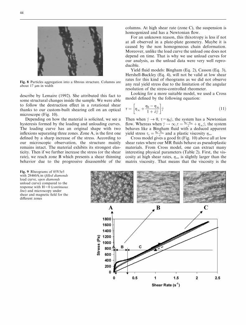
We also built a shearing cell on an optical microscope in orderto see the evolution of the structure with the shear rate (Fig. 5). Thecell is designed to reproduce the parallel plate geometry of rhe-ometers. The bottom of the cell rotates thanks to the mobile axis ofa viscosimeter while the independent top of the cell is maintainedimmobile. This creates a shear rate within the sample. The top ofthe cell is made of glass to let the light pass through. The micro-scope objective looks from above in reflective light mode. Thewhole cell can be moved in two horizontal directions with a pre-cision of 0.01 mm. Unfortunately due to technical issues, we werenot able to measure reliable viscosity data with this set-up. How-ever, we could get pictures at given shear rate that we will latercompare with the DSR data.
Steady state measurements were done using the stresscontrolled rheometer, DSR from Rheometrics. All experimentswere carried out following a precise protocol. First the sample issheared at low shear rate of 0.1 s-1 over 1 min. This puts thesample in a so called zero state and removes any previousstructural memory effect. The sample stays at rest for anotherminute. Then the magnetic field is applied for 1 h before startingthe measure. Rheograms were obtained by programming asequence of tests with a first test which increases the stress in alinear sweep from 1 to 1700 Pa immediately followed by a second
Fig. 3 Relative suspension permeability vs exterior magneticintensity (filled diamonds 5%, open squares 10%, filled triangles15%)
Fig. 4 Scheme of the magneto-rheological setup attached onARES rheometer
42
test starting at 1700 Pa and decreasing down to 1 Pa. Theentire sequence was done with a fixed sweep rate ranging from2 Pa/min to 200 Pa/min. We choose 1 Pa as the starting pointas previous experiments had shown that below this value thedisplacement cannot be measured by the optical sensor of thisrheometer.
Dynamic tests were prepared by the following protocol.First, the suspension is sheared by a time sweep experiment at astrain of 0.05% and a frequency of 10 rad/s. Then at an instantt0, the current of the induction coil is switched on at thedesired intensity. We observe an exponential increase of bothmodulus G¢ and G¢¢ which reach a plateau value after a char-acteristic time s as defined in Eq. (10). We choose to work on thestorage modulus as it should be more sensitive to the structuringprocess:
DG0 tð Þ ¼ DG0max 1� e�t=s
� �ð10Þ
with DG¢(t)=G¢(t))G¢(t0) and DG¢max=G�(t¥))G¢(t0).Figure 6 illustrates such an increase. The time origin represents
the starting point when the current is abruptly applied. From thesefits, we are able to build a master curve in logarithmic scale with thecharacteristic time vs the product of the magnetic intensity with thevolume concentration (Fig. 7).
As moduli increase with the magnetic intensity over the time, weattributed this characteristic time to a structuring time. Then it isnot surprising to find that this time is as low as the magneticintensity and the concentration are high. Particles move faster withstronger magnetic attractive forces and the structure is also formedearlier with more particles by volume unit. Although we did notpursue further this kind of experiment, it could be interesting todeeper study this structuring regime.
Results and discussion
Static structure
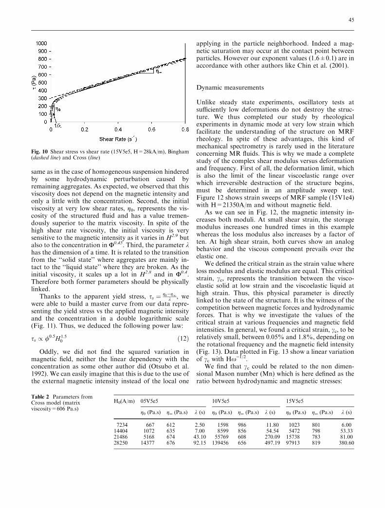
Checked by optical microscopy, the application of amagnetic field causes the aggregation of the particlesinto chains in the magnetic field direction (Fig. 8). Thus,the formed structure should considerably modify theflow until transforming the fluid into gel. However wesee here that even at relatively low concentration 5%,
the structure is made with interlaced columns. This is farfrom the widely used chain model.
Steady state measurements
The steady-shear MR responses exhibits strong thixot-ropy effect in cone-plate geometry (Fig. 9) as already
Fig. 5 Schematic diagram ofthe shearing cell
Fig. 6 Fit on elastic modulus for 15V5e5 (21350A/m, 10 rad/s)
Fig. 7 Time vs magnetic intensity and concentration for samples:filled diamonds 5V5e5, open squares 10V5e5, filled triangles 15V5e5at 10 rad/s and 0.05% of strain
43
describe by Lemaire (1992). She attributed this fact tosome structural changes inside the sample. We were ableto follow the destruction effect in a rotational shearthanks to our custom-built shearing cell on an opticalmicroscope (Fig. 10).
Depending on how the material is solicited, we see ahysteresis formed by the loading and unloading curves.The loading curve has an original shape with twoinflexions separating three zones. Zone A, is the first onedefined by a sharp increase of the stress. According toour microscopic observation, the structure mainlyremains intact. The material exhibits its strongest elas-ticity. Then if we further increase the stress (or the shearrate), we reach zone B which presents a shear thinningbehavior due to the progressive disassemble of the
columns. At high shear rate (zone C), the suspension ishomogenized and has a Newtonian flow.
For an unknown reason, this thixotropy is less if notat all observed in a plate-plate geometry. Maybe it iscaused by the non homogeneous chain deformation.Moreover, unlike the load curve the unload one does notdepend on time. That is why we use unload curves forour analysis, as the unload data were very well repro-ducible.
Yield fluid models: Bingham (Eq. 2), Casson (Eq. 3),Hershell-Buckley (Eq. 4), will not be valid at low shearrates for this kind of rheograms as we did not observeany real yield stress due to the limitation of the angularresolution of the stress-controlled rheometer.
Looking for a more suitable model, we used a Crossmodel defined by the following equation:
s ¼ g1 þg0 � g11þ k _c
� _c ð11Þ
Then when c_ fi 0, s=g0c_, the system has a Newtonianflow. Whereas when _c!1;s ¼ g0�g1
k þ g1 _c, the systembehaves like a Bingham fluid with a deduced apparentyield stress ss ¼ g0�g1
k and a plastic viscosity g¥.Cross model gives a good fit (Fig. 10) above all at low
shear rates where our MR fluids behave as pseudoplasticmaterials. From Cross model, one can extract manyinteresting physical parameters (Table 2). First, the vis-cosity at high shear rates, g¥, is slightly larger than thematrix viscosity. That means that the viscosity is the
Fig. 8 Particles aggregation into a fibrous structure. Columns areabout 17 lm in width
Fig. 9 Rheograms of 05V5e5with 28460A/m (filled diamondsload curve, open diamondsunload curve) compared to theresponse with H=0 (continuousline) and microscopy undershear and magnetic field for thedifferent zones
44
same as in the case of homogeneous suspension hinderedby some hydrodynamic perturbation caused byremaining aggregates. As expected, we observed that thisviscosity does not depend on the magnetic intensity andonly a little with the concentration. Second, the initialviscosity at very low shear rates, g0, represents the vis-cosity of the structured fluid and has a value tremen-dously superior to the matrix viscosity. In spite of thehigh shear rate viscosity, the initial viscosity is verysensitive to the magnetic intensity as it varies in H2.9 butalso to the concentration in F0.45. Third, the parameter khas the dimension of a time. It is related to the transitionfrom the ‘‘solid state’’ where aggregates are mainly in-tact to the ‘‘liquid state’’ where they are broken. As theinitial viscosity, it scales up a lot in H2.8 and in F0.4.Therefore both former parameters should be physicallylinked.
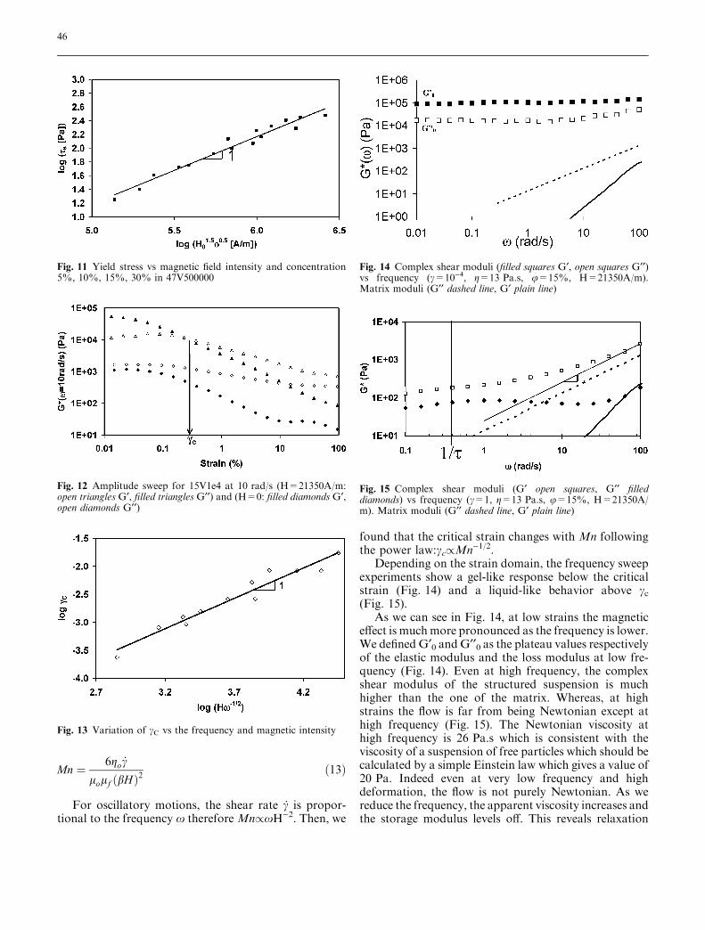
Thanks to the apparent yield stress, ss ¼ g0�g1k , we
were able to build a master curve from our data repre-senting the yield stress vs the applied magnetic intensityand the concentration in a double logarithmic scale(Fig. 11). Thus, we deduced the following power law:
ss / /0:5H1:50 ð12Þ
Oddly, we did not find the squared variation inmagnetic field, neither the linear dependency with theconcentration as some other author did (Otsubo et al.1992). We can easily imagine that this is due to the use ofthe external magnetic intensity instead of the local one
applying in the particle neighborhood. Indeed a mag-netic saturation may occur at the contact point betweenparticles. However our exponent values (1.6±0.1) are inaccordance with other authors like Chin et al. (2001).
Dynamic measurements
Unlike steady state experiments, oscillatory tests atsufficiently low deformations do not destroy the struc-ture. We thus completed our study by rheologicalexperiments in dynamic mode at very low strain whichfacilitate the understanding of the structure on MRFrheology. In spite of these advantages, this kind ofmechanical spectrometry is rarely used in the literatureconcerning MR fluids. This is why we made a completestudy of the complex shear modulus versus deformationand frequency. First of all, the deformation limit, whichis also the limit of the linear viscoelastic range overwhich irreversible destruction of the structure begins,must be determined in an amplitude sweep test.Figure 12 shows strain sweeps of MRF sample (15V1e4)with H=21350A/m and without magnetic field.
As we can see in Fig. 12, the magnetic intensity in-creases both moduli. At small shear strain, the storagemodulus increases one hundred times in this examplewhereas the loss modulus also increases by a factor often. At high shear strain, both curves show an analogbehavior and the viscous component prevails over theelastic one.
We defined the critical strain as the strain value whereloss modulus and elastic modulus are equal. This criticalstrain, cc, represents the transition between the visco-elastic solid at low strain and the viscoelastic liquid athigh strain. Thus, this physical parameter is directlylinked to the state of the structure. It is the witness of thecompetition between magnetic forces and hydrodynamicforces. That is why we investigate the values of thecritical strain at various frequencies and magnetic fieldintensities. In general, we found a critical strain, cc, to berelatively small, between 0.05% and 1.8%, depending onthe rotational frequency and the magnetic field intensity(Fig. 13). Data plotted in Fig. 13 show a linear variationof cc with Hx)1/2.
We find that cc could be related to the non dimen-sional Mason number (Mn) which is here defined as theratio between hydrodynamic and magnetic stresses:
Fig. 10 Shear stress vs shear rate (15V5e5, H=28kA/m), Bingham(dashed line) and Cross (line)
Table 2 Parameters fromCross model (matrixviscosity=606 Pa.s)
H0(A/m) 05V5e5 10V5e5 15V5e5
g0 (Pa.s) g¥ (Pa.s) k (s) g0 (Pa.s) g¥ (Pa.s) k (s) g0 (Pa.s) g¥ (Pa.s) k (s)
7234 667 612 2.50 1598 986 11.80 1023 801 6.0014404 1072 635 7.00 8599 856 54.54 5472 798 53.3321486 5168 674 43.10 55769 608 270.09 15738 783 81.0028250 14377 676 92.15 139456 656 497.19 97913 819 380.60
45
Mn ¼ 6go _c
lolf ðbHÞ2ð13Þ
For oscillatory motions, the shear rate c_ is propor-tional to the frequency x therefore Mn/xH)2. Then, we
found that the critical strain changes with Mn followingthe power law:cc/Mn)1/2.
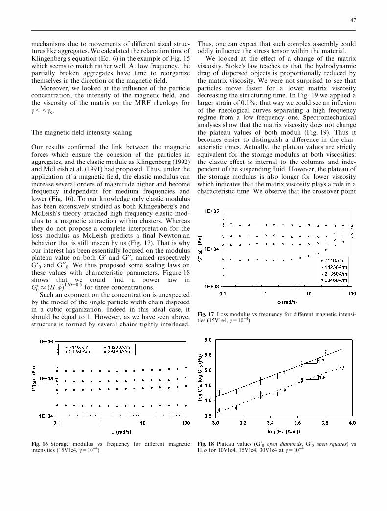
Depending on the strain domain, the frequency sweepexperiments show a gel-like response below the criticalstrain (Fig. 14) and a liquid-like behavior above cc(Fig. 15).
As we can see in Fig. 14, at low strains the magneticeffect is muchmore pronounced as the frequency is lower.We defined G¢0 and G¢¢0 as the plateau values respectivelyof the elastic modulus and the loss modulus at low fre-quency (Fig. 14). Even at high frequency, the complexshear modulus of the structured suspension is muchhigher than the one of the matrix. Whereas, at highstrains the flow is far from being Newtonian except athigh frequency (Fig. 15). The Newtonian viscosity athigh frequency is 26 Pa.s which is consistent with theviscosity of a suspension of free particles which should becalculated by a simple Einstein law which gives a value of20 Pa. Indeed even at very low frequency and highdeformation, the flow is not purely Newtonian. As wereduce the frequency, the apparent viscosity increases andthe storage modulus levels off. This reveals relaxation
Fig. 11 Yield stress vs magnetic field intensity and concentration5%, 10%, 15%, 30% in 47V500000
Fig. 12 Amplitude sweep for 15V1e4 at 10 rad/s (H=21350A/m:open triangles G¢, filled triangles G¢¢) and (H=0: filled diamonds G¢,open diamonds G¢¢)
Fig. 13 Variation of cC vs the frequency and magnetic intensity
Fig. 14 Complex shear moduli (filled squares G¢, open squares G¢¢)vs frequency (c=10)4, g=13 Pa.s, u=15%, H=21350A/m).Matrix moduli (G¢¢ dashed line, G¢ plain line)
Fig. 15 Complex shear moduli (G¢ open squares, G¢¢ filleddiamonds) vs frequency (c=1, g=13 Pa.s, u=15%, H=21350A/m). Matrix moduli (G¢¢ dashed line, G¢ plain line)
46
mechanisms due to movements of different sized struc-tures like aggregates. We calculated the relaxation time ofKlingenberg s equation (Eq. 6) in the example of Fig. 15which seems to match rather well. At low frequency, thepartially broken aggregates have time to reorganizethemselves in the direction of the magnetic field.
Moreover, we looked at the influence of the particleconcentration, the intensity of the magnetic field, andthe viscosity of the matrix on the MRF rheology forc<<cc.
The magnetic field intensity scaling
Our results confirmed the link between the magneticforces which ensure the cohesion of the particles inaggregates, and the elastic module as Klingenberg (1992)and McLeish et al. (1991) had proposed. Thus, under theapplication of a magnetic field, the elastic modulus canincrease several orders of magnitude higher and becomefrequency independent for medium frequencies andlower (Fig. 16). To our knowledge only elastic modulushas been extensively studied as both Klingenberg�s andMcLeish�s theory attached high frequency elastic mod-ulus to a magnetic attraction within clusters. Whereasthey do not propose a complete interpretation for theloss modulus as McLeish predicts a final Newtonianbehavior that is still unseen by us (Fig. 17). That is whyour interest has been essentially focused on the modulusplateau value on both G¢ and G¢¢, named respectivelyG¢0 and G¢¢0. We thus proposed some scaling laws onthese values with characteristic parameters. Figure 18shows that we could find a power law inG�0 � H :/ð Þ1:65�0:5 for three concentrations.
Such an exponent on the concentration is unexpectedby the model of the single particle width chain disposedin a cubic organization. Indeed in this ideal case, itshould be equal to 1. However, as we have seen above,structure is formed by several chains tightly interlaced.
Thus, one can expect that such complex assembly couldoddly influence the stress tensor within the material.
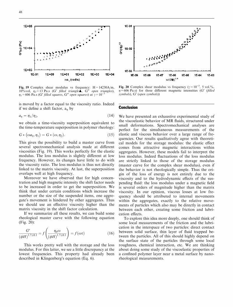
We looked at the effect of a change of the matrixviscosity. Stoke�s law teaches us that the hydrodynamicdrag of dispersed objects is proportionally reduced bythe matrix viscosity. We were not surprised to see thatparticles move faster for a lower matrix viscositydecreasing the structuring time. In Fig. 19 we applied alarger strain of 0.1%; that way we could see an inflexionof the rheological curves separating a high frequencyregime from a low frequency one. Spectromechanicalanalyses show that the matrix viscosity does not changethe plateau values of both moduli (Fig. 19). Thus itbecomes easier to distinguish a difference in the char-acteristic times. Actually, the plateau values are strictlyequivalent for the storage modulus at both viscosities:the elastic effect is internal to the columns and inde-pendent of the suspending fluid. However, the plateau ofthe storage modulus is also longer for lower viscositywhich indicates that the matrix viscosity plays a role in acharacteristic time. We observe that the crossover point
Fig. 16 Storage modulus vs frequency for different magneticintensities (15V1e4, c=10)4)
Fig. 17 Loss modulus vs frequency for different magnetic intensi-ties (15V1e4, c=10)4)
Fig. 18 Plateau values (G¢0 open diamonds, G¢0 open squares) vsH.u for 10V1e4, 15V1e4, 30V1e4 at c=10)4
47
is moved by a factor equal to the viscosity ratio. Indeedif we define a shift factor, ag by
ag ¼ g1=g2; ð14Þ
we obtain a time-viscosity superposition equivalent tothe time-temperature superposition in polymer rheology:
G � xag; g1� �
¼ G � x; g2ð Þ: ð15Þ
This gives the possibility to build a master curve fromseveral spectromechanical analysis made at differentviscosities (Fig. 19). This works perfectly for the elasticmodulus. The loss modulus is slightly different at lowfrequency. However, its changes have little to do withthe viscosity ratio. The loss modulus is thus not directlylinked to the matrix viscosity. At last, the superpositionoverlaps well at high frequency.
Moreover we have observed that for high concen-tration and high magnetic intensity the shift factor needsto be increased in order to get the superposition. Wethink that under certain conditions which increase thenumber or the size of the suspended items, one aggre-gate�s movement is hindered by other aggregates. Thuswe should use an effective viscosity higher than thematrix viscosity in the shift factor calculation.
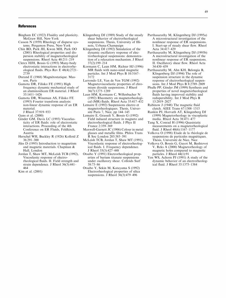
If we summarize all these results, we can build somerheological master curve with the following equation(Fig. 20):
G�
/Hð Þ1:7�0:1¼ f
g0x
/Hð Þ1:7�0:1
!
¼ f xsð Þ ð16Þ
This works pretty well with the storage and the lossmodulus. For this latter, we see a little discrepancy at thelowest frequencies. This property had already beendescribed in Klingenberg�s equation (Eq. 6).
Conclusion
We have presented an exhaustive experimental study ofthe viscoelastic behavior of MR fluids, structured undersmall deformations. Spectromechanical analyses areperfect for the simultaneous measurements of theelastic and viscous behavior over a large range of fre-quencies. Our results qualitatively agree with theoreti-cal models for the storage modulus: the elastic effectcomes from attractive magnetic interactions withinaggregates. However, these models fail to interpret theloss modulus. Indeed fluctuations of the loss modulusare strictly linked to those of the storage modulus(master curve for the complex shear modulus), even ifthe behavior is not rheologically simple. Thus the ori-gin of the loss of energy is not entirely due to theviscosity and to the hydrodynamic effects of the sus-pending fluid: the loss modulus under a magnetic fieldis several orders of magnitude higher than the matrixviscosity. In our opinion, viscous losses at low fre-quency should be attributed to internal movementswithin the aggregates, exactly to the relative move-ments of particles which also may be directly in contactbetween each other, creating some friction and lubri-cation effects.
To explore this idea more deeply, one should think ofsome local measurements of the friction and the lubri-cation in the interspace of two particles: direct contactbetween solid surface, thin layer of fluid trapped be-tween the particles. All of this should highly depend onthe surface state of the particles through some localroughness, chemical interaction, etc. We are thinkingabout doing some study of the viscoelastic properties ofa confined polymer layer near a metal surface by nano-rheological measurements.
Fig. 19 Complex shear modulus vs frequency: H=14230A/m,10%vol, g2=13 Pa.s (G¢ filled trianglem, G¢¢ open triangles),g1=606 Pa.s (G¢ filled squares, G¢¢ open squares) at c=10)3
Fig. 20 Complex shear modulus vs frequency (c=10)3, 5 vol.%,g=606 Pa.s) for three different magnetic intensities (G¢ (filledsymbols), G¢ (open symbols))
48
References
Bingham EC (1922) Fluidity and plasticity.McGraw Hill, New-York
Casson N (1959) Rheology of disperse sys-tems. Pergamon Press, New-York
Chin BD, Park JH, Kwon MH, Park OO(2001) Rheological properties and dis-persion stability of magnetorheologicalsuspensions. Rheol Acta 40:211–219
Clercx HJH, Bossis G (1993) Many-bodyelectrostatic interactions in electrorhe-ological fluids. Phys Rev E 48(4):2721–2739
Durand E (1968) Magnetostatique. Mas-son, Paris
Gamota DR, Filisko FE (1991) Highfrequency dynamic mechanical study ofan aluminosilicate ER material. J Rheol35:1411–1426
Gamota DR, Wineman AS, Filisko FE(1993) Fourier transform analysis:non-linear dynamic response of an ERmaterial.J Rheol 37:919–933
Gans et al. (2000)Ginder GM, Davis LC (1993) Viscoelas-
ticity of ER fluids: role of electrostaticinteractions. Proceeding of the 4thConference on ER Fluids, Feldkirch,Austria
Herschel WH, Buckley R (1926) Kolloid Z36:291–300
Jiles D (1995) Introduction to magnetismand magnetic materials. Chapman &Hall, London
Jordan T, Shaw MT, McLeish TCB (1992),Viscoelastic response of electro-rheological fluids. II. Field strength andstrain dependence. J Rheol 36(3):441–464
Kim et al. (2001)
Klingenberg DJ (1989) Study of the steadyshear behavior of electrorheologicalsuspensions. Thesis, University of Illi-nois, Urbana-Champaign
Klingenberg DJ (1992) Simulation of thedynamic oscillatory response of elec-trorheological suspensions: demonstra-tion of a relaxation mechanism. J Rheol37(2):199–214
Kormann C, Laun HM, Richter HJ (1996)MR fluids with nano-sized magneticparticles. Int J Mod Phys B 10:3167–3172
Larrondo LE, Van de Ven TGM (1992)Magnetoviscoelastic properties of chro-mium dioxide suspensions. J Rheol36(7):1275–1289
Laun HM, Kormann C, Willenbacher N(1992) Rheometry on magnetorheologi-cal (MR) fluids. Rheol Acta 35:417–432
Lemaire E (1992) Suspensions electro etmagnetorheologiques. Thesis, Univer-site Paris 7, Nice, pp 144–145
Lemaire E, Grasseli Y, Bossis G (1992)Field induced structure in magneto andelectrorheological fluids. J Phys IIFrance 2:359–369
Maxwell-Garnett JC (1906) Colour in metalglasses and metallic films. Philos TransR Soc London 203:385–391
McLeish TCB, Jordan T, Shaw MT (1991),Viscoelastic response of electrorheolog-ical fluids. I. Frequency dependence.J Rheol 35(3):427–448
Otsubo Y (1991) Electrorheological prop-erties of barium titanate suspensionsunder oscillatory shear. Colloids Surf58:73–86
Otsubo Y, Sekin M, Katayama S (1992)Electrorheological properties of silicasuspensions. J Rheol 36(3):479–496
Parthasarathy M, Klingenberg DJ (1995a)A microstructural investigation of thenonlinear response of ER suspensions.I. Start-up of steady shear flow. RheolActa 34:417–429
Parthasarathy M, Klingenberg DJ (1995b)A microstructural investigation of thenonlinear response of ER suspensions.II. Oscillatory shear flow. Rheol Acta34:430–439
Parthasarathy M, Ahn KH, Belongia B,Klingenberg DJ (1994) The role ofsuspension structure in the dynamicresponse of electrorheological suspen-sions. Int J Mod Phys B 8:2789–2809
Phulle PP, Ginder JM (1999) Synthesis andproperties of novel magnetorheologicalfluids having improved stability andredispersibility. Int J Mod Phys B13:2019–2027
Rabinow J (1948) The magnetic fluidclutch. AIEE Trans 67:1308–1315
Rankin PJ, Horvath AT, Klingenberg DJ(1999) Magnetorheology in viscoplasticmedia. Rheol Acta 38:471–477
Tang X, Conrad H (1996) Quasistaticmeasurements on a magnetorheologicalfluid. J Rheol 40(6):1167–1177
Volkova O (1998) Etude de la rheologie desuspensions de particules magnetiques.Thesis, Universite de Nice, Nice
Volkova O, Bossis G, Guyot M, BashtovoiV, Reks A (2000) Magnetorheology ofmagnetic holes compared to magneticparticles. J Rheol 44(1):91
Yen WS, Achorn PJ (1991) A study of thedynamic behavior of an electrorheolog-ical fluid. J Rheol 35:1375–1384
49


