Embed Size (px)
Citation preview
104
CHAPTER SIX
Fuel Metering For Diesel Engine
6.1. General:
The basic difference between S.I.E and D.E. is the means by which the fuel
and air are mixed and burned. In S.I.E, the fuel and air are mixed external to the
cylinder volume; during intake a fuel-air mixture is inducted through the intake valve
into the cylinder. In diesel engine, fuel and air are mixed internally; during intake
only air is inducted into the cylinder.
Diesel e engines are able to operate at higher compression ratios than gasoline
engines, because the fuel is mixed with air at the time of combustion is to commence.
The compression ratio is deliberately selected to be high enough so that the gases
near the end of the compression stroke are hot enough so that the fuel auto-ignites
very soon after injection starts. The remaining fuel to be injected can then burn no
faster than it is injected. The period between the start of injection and auto-ignition is
called ignition delay. Its duration depends upon the design of engine and the fuel
type.
The usual compression ratios for diesel engines vary from (12:1 to 20:1) or can
be to (30:1), the corresponding pressure and temperature at the end of compression
stroke being (28 2/ cmkg f to 100 2/ cmkg f ) and (500 C to 900 C ) respectively.
6.2. Mixture Formation:
In diesel engine, the mixture is formed at the end of compression stroke during
a short and very brief interval of time corresponding to (20 to 60 ) of crank travel.
Thus, the process takes place during combustion. This condition makes the mixture
formation difficult, because of:
1) Short time injection and mixture formation
2) Greater viscosity of diesel fuel
The energy used to distribute fuel throughout the combustion chamber (this
energy consists of kinetic energy of fuel jet and kinetic energy of air, "air charges
105
energy"), depends on the method of mixture employed and the shape of
combustion chamber.
The mixture formation consists of a number of physical processes:
1) Splitting of spray into droplets
2) Heating and evaporation of fuel
3) Distribution throughout the combustion chamber (those take place inside the
cylinder).
Most of these processes take place simultaneously. There are three principle
methods of mixture formation employed in modern automotive diesel engines, these
methods are:
A) Volumetric Method:
A jet of fuel is issued from the nozzle of the injector, broken into droplets (5-40
micron) in size and mixing with air and rapid combustion. The stream of fuel is
broken up into droplets by:
1) The forces of aerodynamic resistance of air medium into which fuel is
injected.
2) The internal disturbances appearing when the fuel moves in the nozzle
duct.
B) Film Method:
The idea of this method is to allow a minimum amount of fuel to evaporate and
mix with air during the ignition lag. This is done by directed the fuel to the wall of
combustion chamber at an acute angle so that the droplets are not reflected, but
spread over the surface in the form of a thin film (0.012 to 0.014 mm) thick. The path
of the fuel spray from the orifice nozzle to the wall should be as short as possible to
reduce the quantity of fuel vaporized as the stream moves in the combustion
chamber.
The advantages of this method:
1) The engine operates satisfactory with various fuel (multi-fuel operation)
2) Lower maximum combustion pressure
3) Lower fuel consumption
106
The disadvantages of this method:
1) It needs a special heater for starting the engine from cold
2) High temperature is needed to evaporate the fuel, this ensures by piston crown,
therefore, piston crown needs cooling with oil (for supercharging engine), and
otherwise increasing the piston temperature beyond the safe limit is not advice.
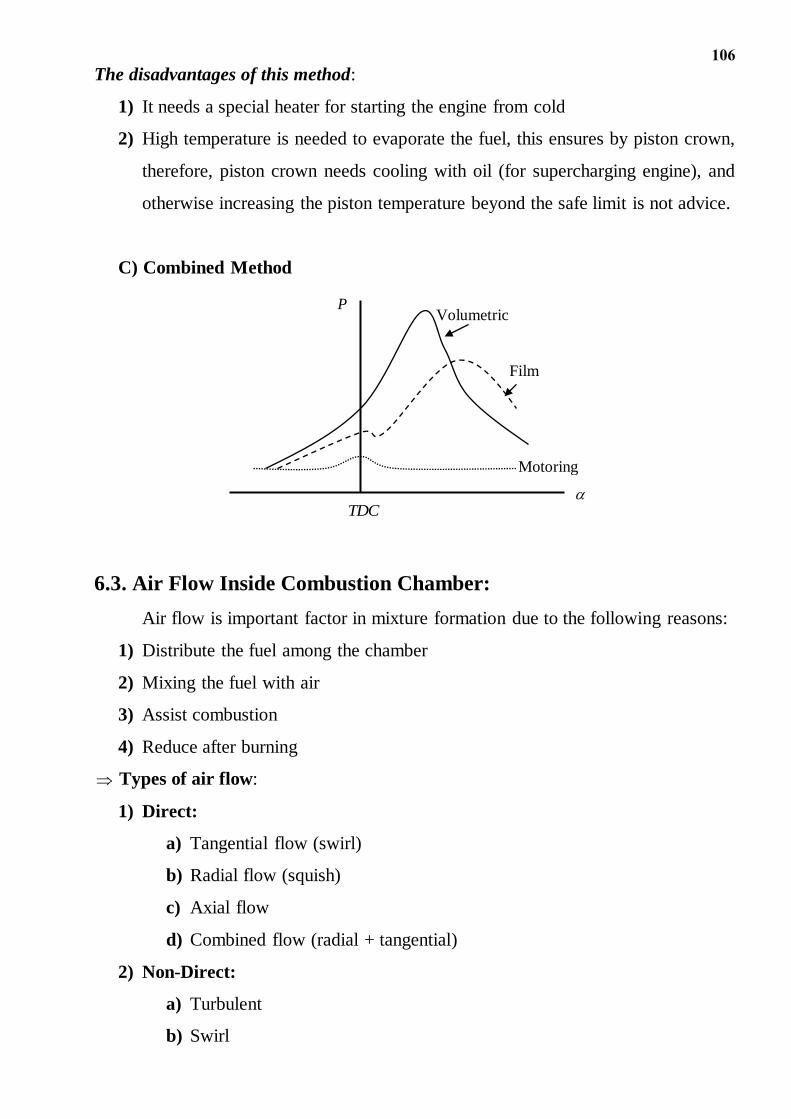
C) Combined Method
6.3. Air Flow Inside Combustion Chamber:
Air flow is important factor in mixture formation due to the following reasons:
1) Distribute the fuel among the chamber
2) Mixing the fuel with air
3) Assist combustion
4) Reduce after burning
Types of air flow:
1) Direct:
a) Tangential flow (swirl)
b) Radial flow (squish)
c) Axial flow
d) Combined flow (radial + tangential)
2) Non-Direct:
a) Turbulent
b) Swirl
P
TDC
Volumetric
Film
Motoring
107
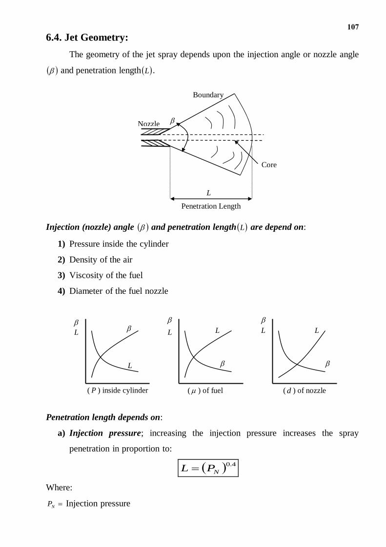
6.4. Jet Geometry:
The geometry of the jet spray depends upon the injection angle or nozzle angle
and penetration length L .
Injection (nozzle) angle and penetration length L are depend on:
1) Pressure inside the cylinder
2) Density of the air
3) Viscosity of the fuel
4) Diameter of the fuel nozzle
Penetration length depends on:
a) Injection pressure; increasing the injection pressure increases the spray
penetration in proportion to:
4.0
NPL
Where:
NP Injection pressure
L
Nozzle
Boundary
Penetration Length
Core
L
( P ) inside cylinder ( ) of fuel ( d ) of nozzle
L L
L
L L
108
Above a certain pressure, the spray becomes finely atomized and has insufficient
momentum to penetration as far.
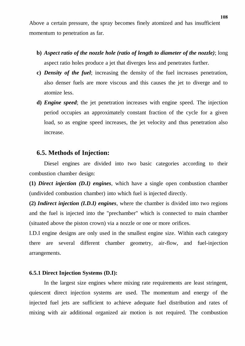
b) Aspect ratio of the nozzle hole (ratio of length to diameter of the nozzle); long
aspect ratio holes produce a jet that diverges less and penetrates further.
c) Density of the fuel; increasing the density of the fuel increases penetration,
also denser fuels are more viscous and this causes the jet to diverge and to
atomize less.
d) Engine speed; the jet penetration increases with engine speed. The injection
period occupies an approximately constant fraction of the cycle for a given
load, so as engine speed increases, the jet velocity and thus penetration also
increase.
6.5. Methods of Injection:
Diesel engines are divided into two basic categories according to their
combustion chamber design:
(1) Direct injection (D.I) engines, which have a single open combustion chamber
(undivided combustion chamber) into which fuel is injected directly.
(2) Indirect injection (I.D.I) engines, where the chamber is divided into two regions
and the fuel is injected into the "prechamber" which is connected to main chamber
(situated above the piston crown) via a nozzle or one or more orifices.
I.D.I engine designs are only used in the smallest engine size. Within each category
there are several different chamber geometry, air-flow, and fuel-injection
arrangements.
6.5.1 Direct Injection Systems (D.I):
In the largest size engines where mixing rate requirements are least stringent,
quiescent direct injection systems are used. The momentum and energy of the
injected fuel jets are sufficient to achieve adequate fuel distribution and rates of
mixing with air additional organized air motion is not required. The combustion
109
chamber shape is usually a shallow bowl in the crown of the piston, and a central
multi-hole injector is used. This type could be divided into:
a) Semi quiescent and low swirl open chamber
b) Medium swirl open chamber
c) High swirl open chamber
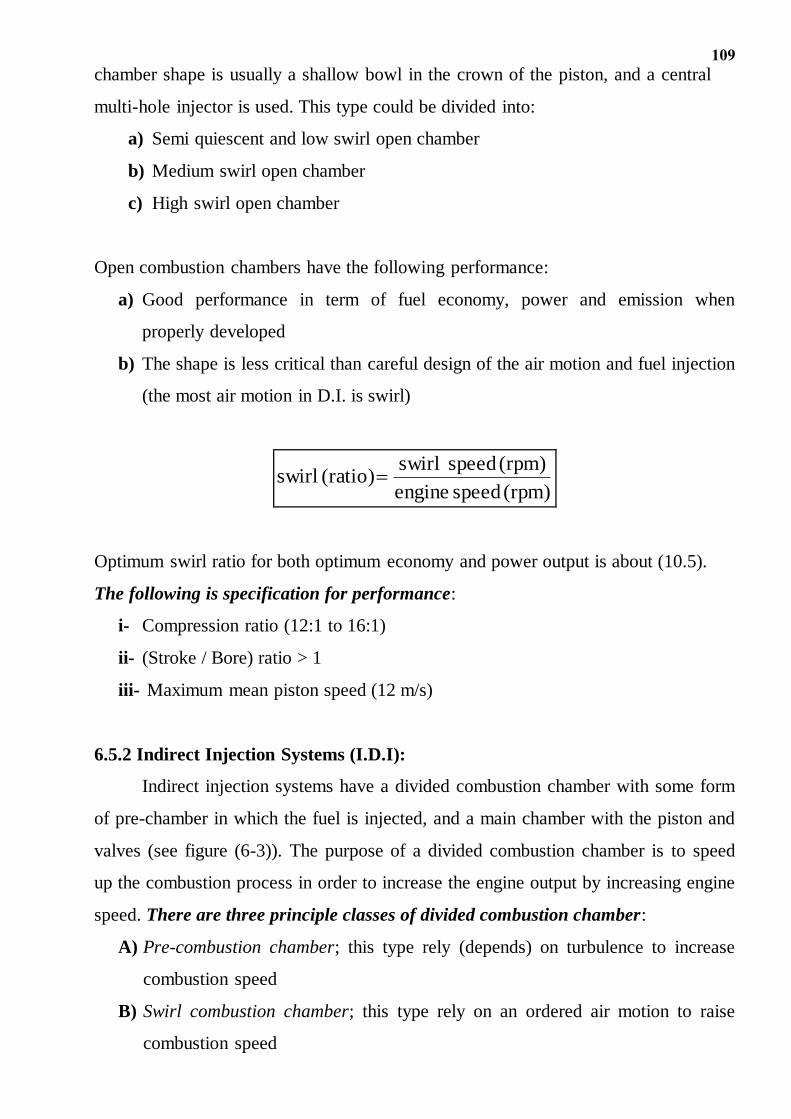
Open combustion chambers have the following performance:
a) Good performance in term of fuel economy, power and emission when
properly developed
b) The shape is less critical than careful design of the air motion and fuel injection
(the most air motion in D.I. is swirl)
(rpm) speed engine
(rpm) speed swirl (ratio) swirl
Optimum swirl ratio for both optimum economy and power output is about (10.5).
The following is specification for performance:
i- Compression ratio (12:1 to 16:1)
ii- (Stroke / Bore) ratio > 1
iii- Maximum mean piston speed (12 m/s)
6.5.2 Indirect Injection Systems (I.D.I):
Indirect injection systems have a divided combustion chamber with some form
of pre-chamber in which the fuel is injected, and a main chamber with the piston and
valves (see figure (6-3)). The purpose of a divided combustion chamber is to speed
up the combustion process in order to increase the engine output by increasing engine
speed. There are three principle classes of divided combustion chamber:
A) Pre-combustion chamber; this type rely (depends) on turbulence to increase
combustion speed
B) Swirl combustion chamber; this type rely on an ordered air motion to raise
combustion speed
110
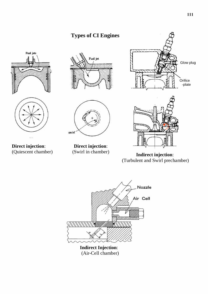
C) Air-Cell and Energy Cell; fuel is injected into the main chamber and
ignites. As combustion proceeds, fuel and air will be forced into secondary
chamber or air cell, so producing turbulence. As the expansion, stroke
continuous the air, fuel and combustion products will flow out of the air cell,
so generally further turbulence.
Advantages of divided combustion chamber:
a) This type giving a high (bmep – brake mean effective pressure)
b) The fuel injection requirements is less sever and lower fuel injection pressure
are satisfactory. A single orifice in the nozzle is sufficient, but the spray
direction should be into the air for good starting and on the chamber wall for
good running
c) The delay period (or ignition delay) is reduced, therefore great air utilization
and faster combustion; also lower quality fuel can be used. These conditions
permit small engines to run at higher speed with larger output.
Disadvantages of divided combustion chamber:
a) Smoke emission
b) During compression, the high gas velocities into the pre-chamber cause high
heat transfer coefficient that reduce the air temperature. This means that
compression ratios in the range (18:1 to 24:1) have to use to ensure reliable
ignition when starting.
c) The high heat transfer coefficient in swirl chamber can cause problems with
injectors, if temperature rise above 14 C carbonization of fuel can occur.
d) Complicated combustion chamber design, also there is a loss of (5% to 15%)
of fuel economy than other types.
111
105
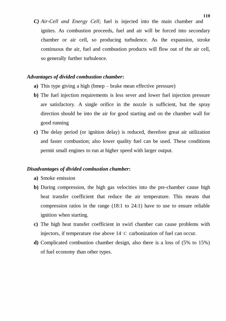
Types of CI Engines
Direct injection:
(Quiescent chamber)
Direct injection:
(Swirl in chamber) Indirect injection:
(Turbulent and Swirl prechamber)
Orifice -plate
Glow plug
Indirect Injection:
(Air-Cell chamber)
112
6.6 Cold Starting of Diesel Engines (D.E.):
Starting compression ignition engines from cold is a problem due to the
following means:
a) Poor quantity fuel
b) Low temperature
c) Poorly seated valves
d) Leakage past the piston ring
e) Low starting speed
The following are various methods for starting the engine from cold:
A) Various aids for starting can be fitted to fuel injection system:
a) Excess fuel injection; this method is beneficial for the following reasons:
1) Its bulk raises the compression ratio
2) Un-burnt fuel helps to seal the piston rings and valves
3) Increases the probability of combustion starting
b) Late injection (Retarded injection timing); means that fuel is injected when
the temperature and pressure are higher. It is better to have an auxiliary
nozzle in the injector in order to direct a spray of the fuel in the air than
impinges the fuel spray on the combustion chamber surface.
c) Extra nozzles in the injector
B) Introducing with air a volatile liquid which self-ignites readily
C) Heaters in combustion chamber; air in combustion chamber can be heated
electrically by:
(a) Heater plugs, especially in divided combustion chambers, heater
plugs are either exposed loops of thick resistance wire or finer multi-turned wire
insulated by a refractory material and then sheathed.
(b) High voltage surface discharge plug
D) Variable compression ratio pistons; in these pistons the distance between the
top of the piston (the crown) and the gudgeon pin (little end) can be varied
hydraulically. Ignition in D.E. relies on both high temperature and a high
pressure.
113
6.7 Fuel Metering:
The injection system of C.I. engine should fulfill the following objectives
consistently:
1) Meter the quantity of fuel demanded by the speed and load of the engine
2) Inject the fuel at correct time in the cycle
3) Distribute the metered fuel equally among the cylinders
4) Inject the fuel at correct rate
5) Inject the fuel with the spray pattern and atomization demanded by the design
of the combustion chamber
6) Begin and end the injection sharply without dribbling or after injection.
To accomplish these objectives, a number of functional elements are required:
A) Pumping elements: to move the fuel from fuel tank to cylinders. The pumping
element consists of:
(a) Low pressure pump; to lift the fuel from fuel tank and provides a constant
pressure of about (0.75 bar) to injector pump.
(b) High pressure pump (injection pump); fuel injection pressure in the rang
(200 to 1700 bars) are provide by this pump. This pressure depends on the engine
size and the type of combustion chamber.
(c) Fuel filters and low-high piping
B) Metering and controls elements to measure and adjust the fuel flow rate
demanded by engine speed and load
C) Distributing elements to divide the metered fuel equally among the cylinders
D) Timing controls to adjust the start and the stop of injection
E) Mixing elements to atomize and distribute the fuel within the combustion
chamber.
114
6.8 Types of Injection Systems:
A) Air Injection – absolute duo to size, cost and power required
B) Solid or Mechanical Injection; every solid injection system should have:
a) Pressurizing unit (high pressure pump)
b) Atomizing unit (injector and its nozzle)
The difference types of solid injection system vary only in the manner of operation
and control of these two basic elements. The main types of solid injection are:
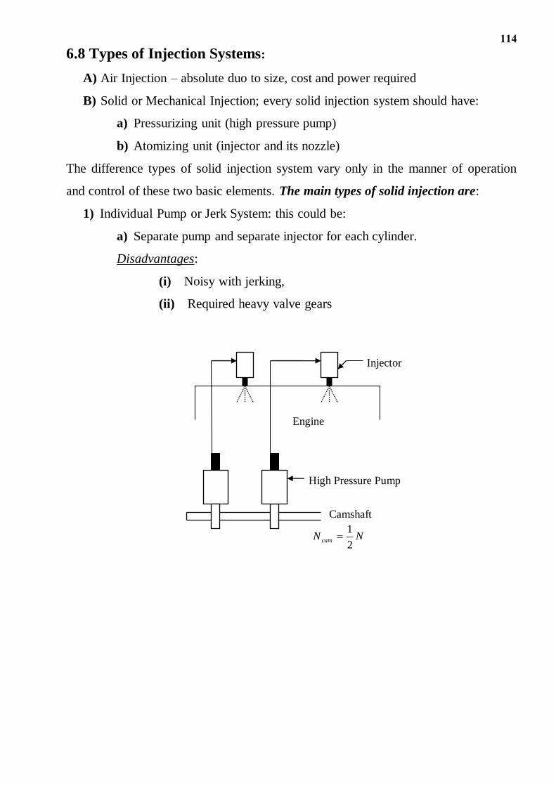
1) Individual Pump or Jerk System: this could be:
a) Separate pump and separate injector for each cylinder.
Disadvantages:
(i) Noisy with jerking,
(ii) Required heavy valve gears
Camshaft
NN cam2
1
High Pressure Pump
Engine
Injector
115
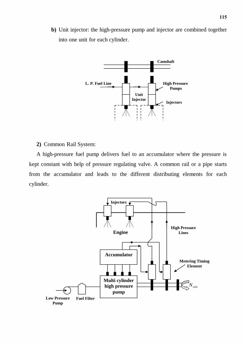
b) Unit injector: the high-pressure pump and injector are combined together
into one unit for each cylinder.
2) Common Rail System:
A high-pressure fuel pump delivers fuel to an accumulator where the pressure is
kept constant with help of pressure regulating valve. A common rail or a pipe starts
from the accumulator and leads to the different distributing elements for each
cylinder.
Multi cylinder
high pressure
pump
Accumulator
Engine
Injectors
camN
High Pressure
Lines
Metering Timing
Element
Fuel Filter Low Pressure
Pump
L. P. Fuel Line High Pressure
Pumps
Injectors
Camshaft
Unit
Injector
116
For each cylinder, there is a separate metering and timing element, which is
connected to an automatic injector.
The main disadvantages of the common rail system are that in case of injection
needle sticking in an open position, an excess amount of fuel may be injected into
cylinder.
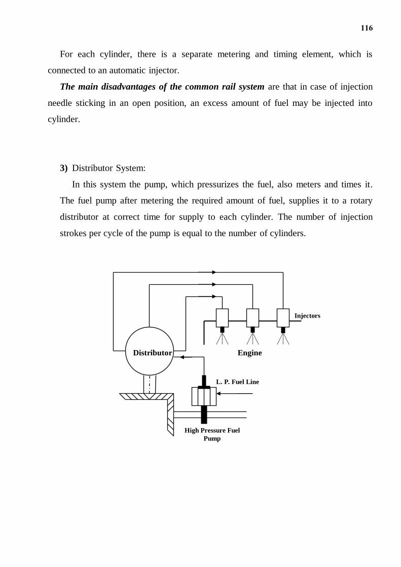
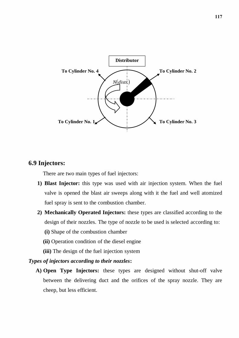
3) Distributor System:
In this system the pump, which pressurizes the fuel, also meters and times it.
The fuel pump after metering the required amount of fuel, supplies it to a rotary
distributor at correct time for supply to each cylinder. The number of injection
strokes per cycle of the pump is equal to the number of cylinders.
Engine
Injectors
L. P. Fuel Line
Distributor
High Pressure Fuel
Pump
117
6.9 Injectors:
There are two main types of fuel injectors:
1) Blast Injector: this type was used with air injection system. When the fuel
valve is opened the blast air sweeps along with it the fuel and well atomized
fuel spray is sent to the combustion chamber.
2) Mechanically Operated Injectors: these types are classified according to the
design of their nozzles. The type of nozzle to be used is selected according to:
(i) Shape of the combustion chamber
(ii) Operation condition of the diesel engine
(iii) The design of the fuel injection system
Types of injectors according to their nozzles:
A) Open Type Injectors: these types are designed without shut-off valve
between the delivering duct and the orifices of the spray nozzle. They are
cheep, but less efficient.
To Cylinder No. 1
To Cylinder No. 2
To Cylinder No. 3
To Cylinder No. 4
Distributor
.distrN
118
P
NP
NP
CP N
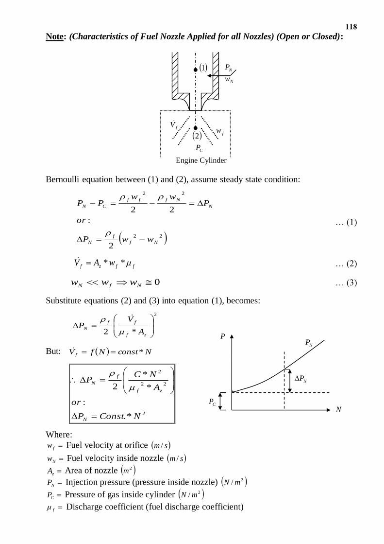
Note: (Characteristics of Fuel Nozzle Applied for all Nozzles) (Open or Closed):
Bernoulli equation between (1) and (2), assume steady state condition:
22
22
2
:
22
Nf
f
N
N
Nfff
CN
wwP
or
Pww
PP
… (1)
ffzf wAV ** … (2)
0 NfN www … (3)
Substitute equations (2) and (3) into equation (1), becomes:
2
*2
zf
ff
NA
VP
But: NconstNfV f *
2
22
2
*.
:
*
*
2
NConstP
or
A
NCP
N
zf
f
N
Where:
fw Fuel velocity at orifice sm /
Nw Fuel velocity inside nozzle sm /
zA Area of nozzle 2m
NP Injection pressure (pressure inside nozzle) 2/ mN
CP Pressure of gas inside cylinder 2/ mN
f Discharge coefficient (fuel discharge coefficient)
1
2
fV
NP
Nw
CP
fw
Engine Cylinder
119
B) Closed Type Injectors: these types are provided with a spring loaded
needle valve in their nozzle.
Advantages of this type:
i) Avoidance of pressure drops
ii) Control of injection pressure
The following are the main types of nozzles used with closed injectors:
a) Single Hole Nozzle: single-hole nozzles are used in open (undivided) combustion
chamber. The size of the hole is usually larger than (0.2 mm). The hole may be
drilled centrally or at angle to the centerline of the nozzle. The disadvantages of the
single-hole nozzles are:
1) Very high injection pressure is needed
2) Single-hole has a tendency to dribble
3) The spray angle is very narrow (usually about 15 ) and this dose not facilitate
good mixing unless higher air velocities are provided
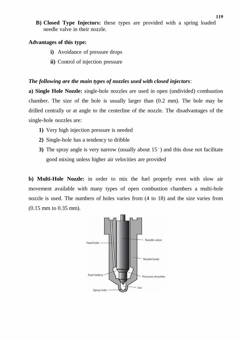
b) Multi-Hole Nozzle: in order to mix the fuel properly even with slow air
movement available with many types of open combustion chambers a multi-hole
nozzle is used. The numbers of holes varies from (4 to 18) and the size varies from
(0.15 mm to 0.35 mm).
120
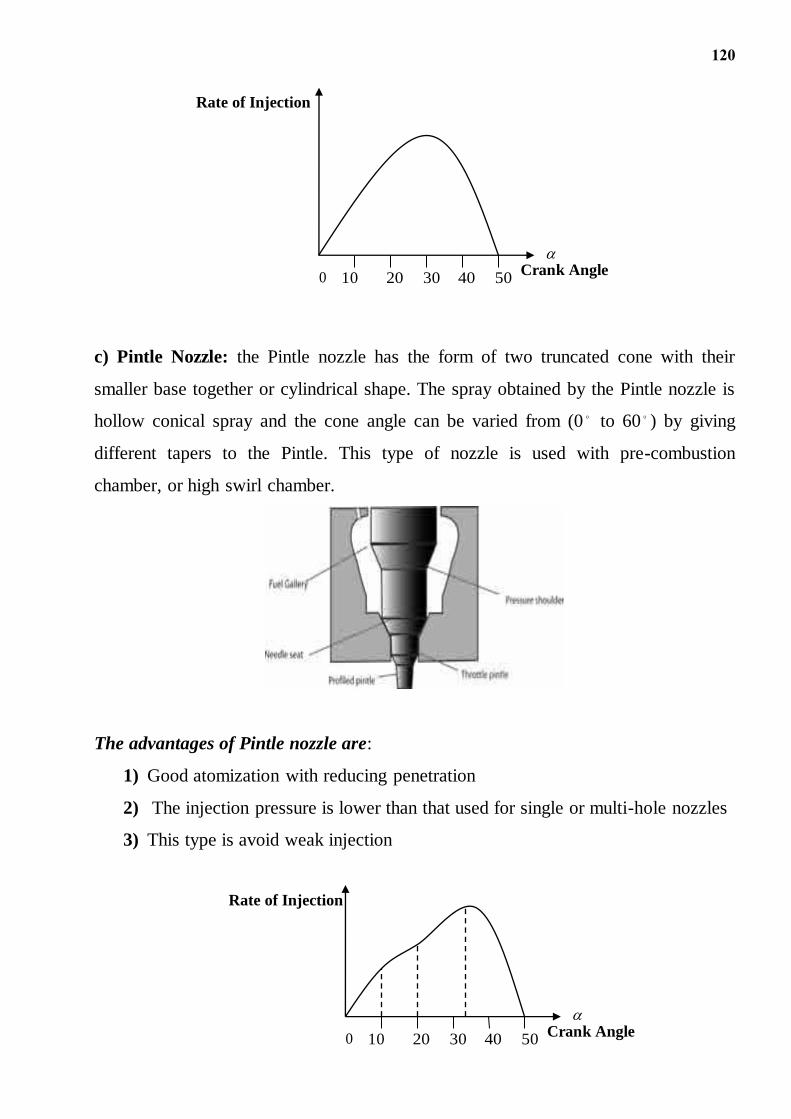
c) Pintle Nozzle: the Pintle nozzle has the form of two truncated cone with their
smaller base together or cylindrical shape. The spray obtained by the Pintle nozzle is
hollow conical spray and the cone angle can be varied from (0 to 60 ) by giving
different tapers to the Pintle. This type of nozzle is used with pre-combustion
chamber, or high swirl chamber.
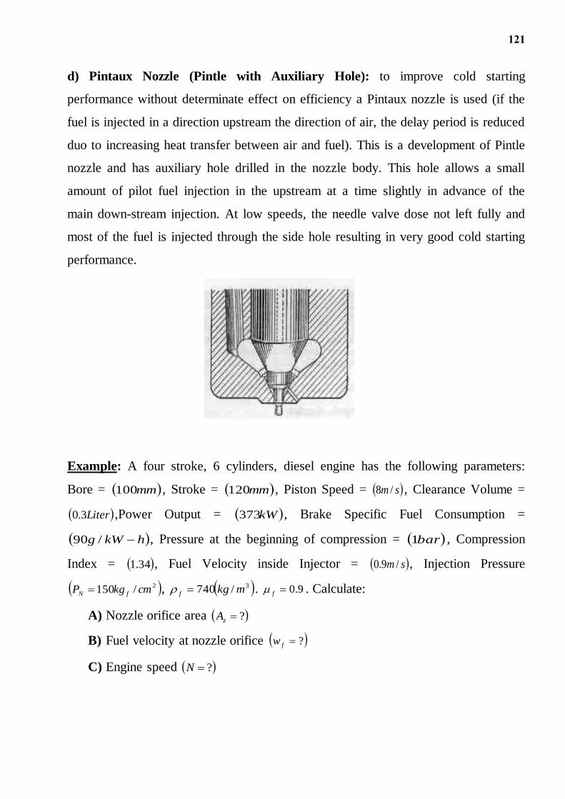
The advantages of Pintle nozzle are:
1) Good atomization with reducing penetration
2) The injection pressure is lower than that used for single or multi-hole nozzles
3) This type is avoid weak injection
0 10 20 30 40 50
Rate of Injection
Crank Angle
0 10 20 30 40 50
Rate of Injection
Crank Angle
121
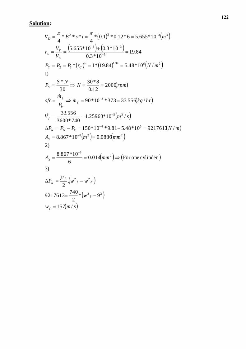
d) Pintaux Nozzle (Pintle with Auxiliary Hole): to improve cold starting
performance without determinate effect on efficiency a Pintaux nozzle is used (if the
fuel is injected in a direction upstream the direction of air, the delay period is reduced
duo to increasing heat transfer between air and fuel). This is a development of Pintle
nozzle and has auxiliary hole drilled in the nozzle body. This hole allows a small
amount of pilot fuel injection in the upstream at a time slightly in advance of the
main down-stream injection. At low speeds, the needle valve dose not left fully and
most of the fuel is injected through the side hole resulting in very good cold starting
performance.
Example: A four stroke, 6 cylinders, diesel engine has the following parameters:
Bore = mm100 , Stroke = mm120 , Piston Speed = sm /8 , Clearance Volume =
Liter3.0 ,Power Output = kW373 , Brake Specific Fuel Consumption =
hkWg /90 , Pressure at the beginning of compression = bar1 , Compression
Index = 34.1 , Fuel Velocity inside Injector = sm /9.0 , Injection Pressure
2/150 cmkgP fN , 3/740 mkgf . 9.0f . Calculate:
A) Nozzle orifice area ?zA
B) Fuel velocity at nozzle orifice ?fw
C) Engine speed ?N
122
Solution:
smw
w
wwP
mmA
mmmA
mNPPP
smV
hrkgmP
msfc
rpmNNS
P
mNrPPP
V
Vr
misBV
f
f
Nff
N
z
z
CNN
f
f
b
f
S
k
CC
C
TC
D
/157
9*2
7409217613
.2
)3
cylinder oneFor 014.06
10*867.8
)2
0886.010*867.8
/921761310*48.581.9*10*150
/10*25963.1740*3600
556.33
/556.33373*10*90
200012.0
8*30
30
*
)1
/10*48.584.19*1*
84.1910*3.0
10*3.010*655.5
10*655.56*12.0*1.0*4
***4
22
22
28
228
64
35
3
2634.1
12
3
33
3322