Embed Size (px)
Citation preview
METERING REQUIREMENTS for 13.8 kV & 27.6 kV CUSTOMER-OWNED SUBSTATIONS
Conditions of Service, Section 6 - Reference #7
INDEX
Page
SECTION 1.0: SCOPE 1
1.1 Toronto Hydro Requirements 1
1.2 Ontario Electrical Safety Code 1
SECTION 2.0: PURPOSE 1
SECTION 3.0: DEFINITIONS AND THE INTERNATIONAL SYSTEM OF UNITS 1
3.1 Definitions 1
3.2 The International System of Units 3
SECTION 4.0: METERING CHARGES 3
SECTION 5.0: PROCEDURE FOR OBTAINING TORONTO HYDRO APPROVAL 3
5.1 Drawings 3
5.2 Additional Drawings 3
5.3 Manufacture of Equipment – Drawing Approval 3
5.4 Inspection of Equipment Prior to Shipment 3
5.5 Compliance with Requirements 3
5.6 Metering Equipment Delivery 3
SECTION 6.0: ENGINEERING DRAWINGS AND SPECIFICATIONS 4
6.1 Drawings Required for Acceptance 4
6.2 Drawing Revisions 4
SECTION 7.0: SUBSTATION REQUIREMENTS
7.1 Exits and Doors 4
7.1.1 Miscellaneous Requirements 4
SECTION 8.0: SAFE WORKING SPACE
8.1 Minimum Space Requirements 4
8.2 Side and Rear Access Panel 4
8.3 Aisle Space 5
8.4 Blocking of Exit Route 5
8.5 Illumination of Equipment 5
8.6 Accessibility for Maintenance 5
8.7 Access to Substation by Toronto Hydro 5
METERING REQUIREMENTS for 13.8 kV & 27.6 kV CUSTOMER-OWNED SUBSTATIONS
Conditions of Service, Section 6 - Reference #7
SECTION 9.0: EQUIPMENT REQUIREMENTS 5
9.1 Enclosures 5
9.1.1 Sheet Steel Enclosures 5
9.1.2 Enclosure Interiors 6
9.1.3 Mimic Bus 6
9.1.4 Name Plates 6
9.2 Metering Compartments – 13.8 kV Switchgear 6
9.3 Metering Compartment – 27.7 kV Switchgear 6
9.4 Compartment and Openings 6
9.5 Primary Connections between Compartments 6
9.6 Access Doors – 13.8 kV Switchgear 6
9.7 Access Doors – 27.6 kV Switchgear 7
9.8 Hinged Access Doors 7
9.8.1 Stops on Access Doors 7
9.9 Padlock Hasps 7
9.10 Securing Access Doors 7
9.11 Barriers – 13.8 kV Switchgear 7
9.11.1 Requirements for Barriers 7
9.11.2 Type of Barriers 7
9.12 Electrical Clearances 8
9.12.1 Bare Conductors 8
9.12.2 Connection Clearances 8
SECTION 10.0: TORONTO HYDRO METERING REQUIREMENTS 8
10.1 General Information 8
10.1.1 Supply of Metering Equipment for Switchgear Assembles 8
10.1.2 Connections 8
10.1.3 Equipment Mounting 8
10.1.4 Internal Conduit and Fittings –13.8 kV Switchgear 9
10.1.5 Internal Conduit and Fittings – 27.6 kV Switchgear 9
10.2 Current Transformers 9
10.2.1 Number of Current Transformers 9
10.2.2 Clearance and Spacing 9
10.2.3 Polarity and Mounting Arrangement 9
METERING REQUIREMENTS for 13.8 kV & 27.6 kV CUSTOMER-OWNED SUBSTATIONS
Conditions of Service, Section 6 - Reference #7
10.3 Voltage Transformers, Fuse Supports and Fuses 9
10.3.1 Fuse Supports and Fuse 9
10.3.2 Voltage Transformer Connections – 13.8 kV Switchgear 10
10.3.3 Voltage Transformer Connections – 27.6 kV Switchgear 10
10.3.4 Mounting Arrangements – 13.8 kV Switchgear 10
10.3.5 Mounting Arrangements – 27.6 kV Switchgear 10
10.4 Meter Cabinet and Conduit Installation 11
10.4.1 Meter Cabinet 11
10.4.2 Cabinet Size and Construction 11
10.4.3 Metering Conduit 12
10.5 Remote Metering (RIMS) – Services 50 kW and Greater 12
10.6 Pole/Structure Mounted 27.6 kV Outdoor Substations 13
SECTION 11.0: DIAGRAMS 13
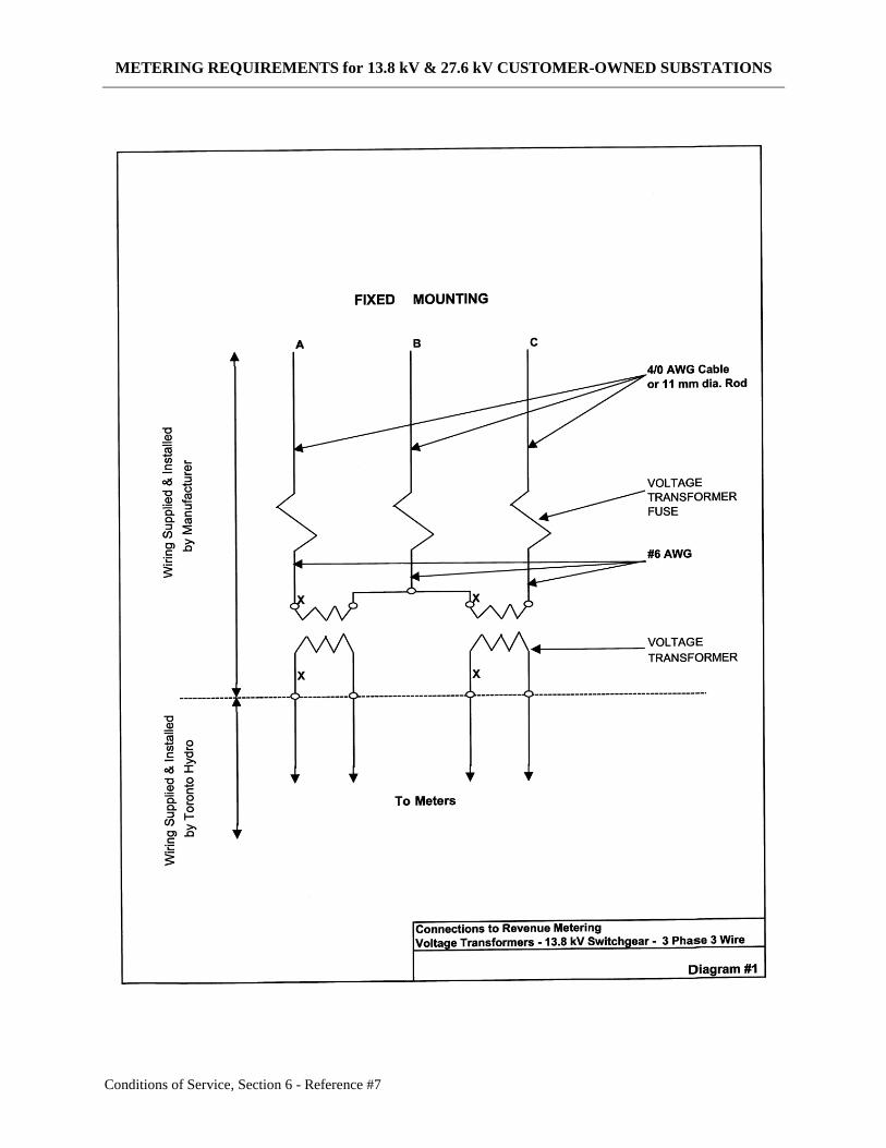
Diagram #1 – Connections to Revenue Metering Voltage Transformers – 13.8 kV Switchgear
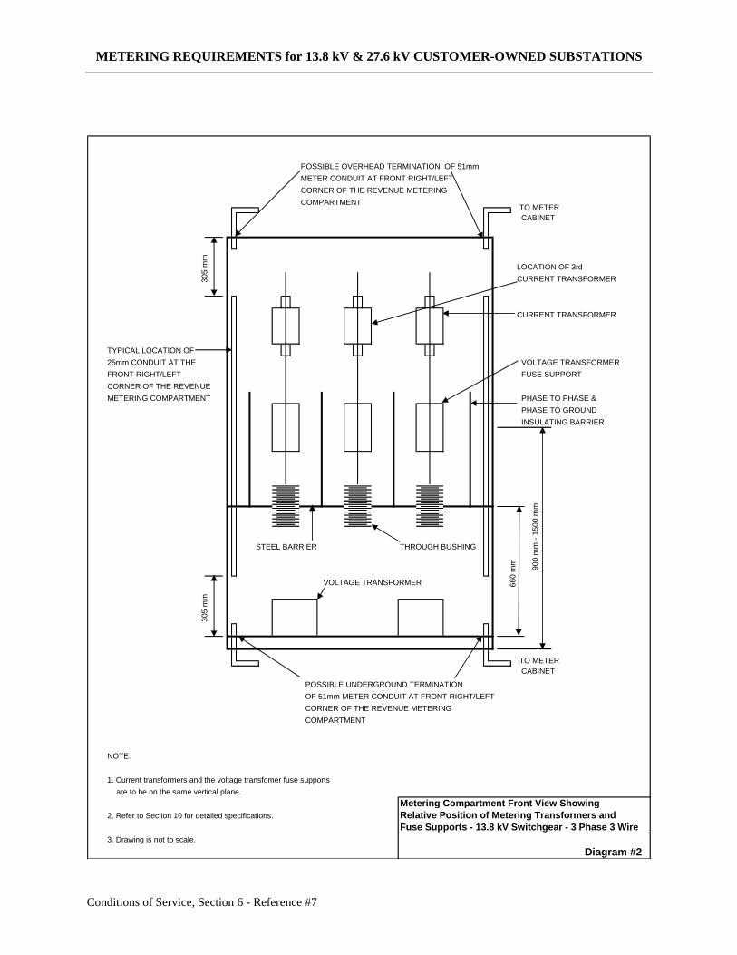
Diagram #2 – Metering Compartment Front View Showing Relative Position of Metering
Transformers and Fuse Supports – 13.8 kV Switchgear
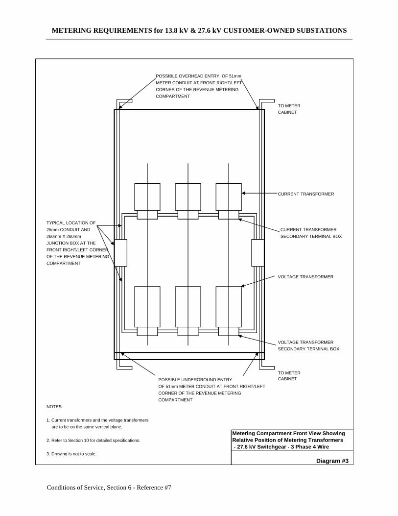
Diagram #3 – Metering Compartment Front View Showing Relative Position of Metering
Transformers – 27.6 kV Switchgear
METERING REQUIREMENTS for 13.8 kV & 27.6 kV CUSTOMER-OWNED SUBSTATIONS
Conditions of Service, Section 6 - Reference #7 1
1.0 SCOPE
1.1 Toronto Hydro Requirements
This publication covers the metering requirements for Toronto Hydro customers.
They apply to both permanent and temporary services. These requirements are in
addition to those of the “Supply Authority” stated in the Ontario Electrical Safety
Code for service entrance, connection, and metering of electrical energy.
1.2 Ontario Electrical Safety Code
Nothing contained in these requirements shall prejudice or supersede any
requirements of the Ontario Electrical Safety Code or affect regulations of existing
building codes, unless specifically stated herein.
Some requirements identified by the latest edition of the Ontario Electrical Safety
Code have been included for convenience and reference purposes, even though they
may be under the Electrical Safety Authority (ESA) jurisdiction.
2.0 PURPOSE
This document is intended to provide guidance to Toronto Hydro customers and their
agents in the design, preparation of plans, and construction of the proposed service
installation with respect to revenue metering. These requirements apply to all new,
rearranged or upgraded services, both permanent and temporary, and are intended to
provide an efficient and safe supply of electrical energy with respect to revenue metering.
It shall be the responsibility of the customer to conform to the latest edition of these
requirements, the Toronto Hydro Conditions of Service, and the Ontario Electrical
Safety Code.
3.0 DEFINITIONS AND THE INTERNATIONAL SYSTEM OF UNITS
3.1 Definitions
In addition to the definitions stated in Section “O” of the Electrical Safety Code, the
following meanings have been ascribed to the terms defined below.
Acceptable Meets Toronto Hydro requirements.
Accessible The equipment is not guarded by locked doors, elevation or other
effective means.
Approval Approval of drawings and customers’ equipment is limited to the
approval of Toronto Hydro’s metering requirements and does not
METERING REQUIREMENTS for 13.8 kV & 27.6 kV CUSTOMER-OWNED SUBSTATIONS
Conditions of Service, Section 6 - Reference #7 2
construe acceptance of liability arising from substandard design or
workmanship.
Compartment A subdivision of a unit.
Customer Means a person that has contracted for or intends to contract for
connection of a building or an embedded generation facility. This
includes developers of residential or commercial sub-divisions.
Customer-owned A customer-owned civil structure accommodating customer-
Substation owned electrical equipment connected to Toronto Hydro 13.8 kV
or 27.6 kV system.
Exit A path of travel, which leads from a floor area to a separate
building, an open public thoroughfare or an exterior open space,
which is protected from fire exposure from the building and has
access to an open public thoroughfare.
High Voltage In this document, high voltage means 13.8 kV or 27.6 kV.
MSG Manufacturer’s Standard Gauge for uncoated steel.
Readily Capable of being reached quickly for operation, removal or
Accessible inspection, without requiring climbing over or removing of
obstacles or resorting to the use of portable ladders, chairs, etc.
Unit A full height and full depth module of a switchgear assembly. It is
(Switchgear) sometimes referred to as “cell”, “cubicle” “section” or “enclosure”.
METERING REQUIREMENTS for 13.8 kV & 27.6 kV CUSTOMER-OWNED SUBSTATIONS
Conditions of Service, Section 6 - Reference #7 3
3.2 The International System of Units
Measurements and weights used in this publication are expressed in SI units. The
metric units have been rounded as close as possible to the previously used units.
Equipment or materials not available in metric units shall be equal to or larger than
the units specified in this publication. Equivalent measurements will be accepted if
equipment or materials are not manufactured in metric units.
4.0 METERING CHARGES
Metering charges will apply to all 13.8 kV and 27.6 kV primary metering. Costs will be
determined by Toronto Hydro.
5.0 PROCEDURE FOR OBTAINING TORONTO HYDRO APPROVAL
Following acceptance of a customer’s application for a primary metered service or a
proposal to modify an existing primary metered service, the following procedure shall
apply.
5.1 Drawings
The customer shall submit drawings for Toronto Hydro approval in accordance with
Section 6.
5.2 Additional Drawings
If the drawings or information do not meet the Toronto Hydro requirements or are not
sufficiently clear, then revised or additional drawings and information must be
submitted when requested by Toronto Hydro.
5.3 Manufacture of Equipment – Drawing Approval
Manufacture of equipment should not start until all drawings and information have
been approved. This will avoid costly changes to completed equipment. Final
revision of all drawings must be delivered to Toronto Hydro as least four weeks prior
to the delivery of the switchgear to the service site.
5.4 Inspection of Equipment Prior to Shipment
Toronto Hydro reserves the right to inspect the completed equipment at the
manufacturer’s plant, prior to shipment.
5.5 Compliance with Requirements
When the installation of the equipment has been completed, Toronto Hydro will
inspect the equipment to ensure it complies with these requirements.
5.6 Metering Equipment Delivery
Metering equipment delivery may take up to 16 weeks after the switchgear drawings
have been approved.
METERING REQUIREMENTS for 13.8 kV & 27.6 kV CUSTOMER-OWNED SUBSTATIONS
Conditions of Service, Section 6 - Reference #7 4
6.0 ENGINEERING DRAWINGS AND SPECIFICATIONS
6.1 Drawings Required for Acceptance
Fully dimensioned and scaled drawings submitted for Toronto Hydro’s review and
acceptance shall include but not be limited to those listed below. The minimum
number of drawings required is indicated in brackets. The published requirements
may change without notice. Additional drawings may be requested.
(a) Electrical substation layout drawing showing the location of the electrical
switchgear and all revenue metering (meter cabinets). (2)
(b) Single line distribution diagram. (2)
(c) Manufacturer’s or shop drawings of the proposed switchgear with a utility
compartment detail drawing. (2).
6.2 DRAWING REVISIONS
If any drawings require revision, Toronto Hydro will determine the number of copies of
each drawing to be re-submitted for further review and acceptance.
7.0 SUBSTATION REQUIREMENTS
7.1 Exits and Doors
7.1.1 Miscellaneous Requirements
Two exits, one at each opposite end of the substation, are required. The exit
doors shall open in the direction of exit travel and shall be equipped with panic
type hardware. The doors shall be fitted with a keyed cylinder lock and handle
on the opposite side of the door from the bar, all to be acceptable to Toronto
Hydro.
8. 0 SAFE WORKING SPACE
Safe working space in vicinity of service entrance equipment including metering shall be
in accordance with the Electrical Safety Code Rule 2-308 (Working Space About
Electrical Equipment) and shall include the requirements in sections 8.1 – 8.7 below.
8.1 Minimum Space Requirement
A minimum of 1.5 metres shall be provided in front of all doors giving access to
switchgear components and where Toronto Hydro is required to work.
8.2 Side or Rear Access Panels
Side or rear access panels are not acceptable for metering transformer installations.
METERING REQUIREMENTS for 13.8 kV & 27.6 kV CUSTOMER-OWNED SUBSTATIONS
Conditions of Service, Section 6 - Reference #7 5
8.3 Aisle Space
A clear passageway at least 0.9 metres wide and 2.2 metres high shall be maintained
as an exit route from all service entrance equipment. This headroom must also be
maintained in the working space in the vicinity of the service entrance equipment.
8.4 Blocking of Exit Route
Where the compartment hinged doors or draw-out components would block the exit
route, a clear minimum space of 0.6 metres must be maintained from the edge of the
access door or components in their fully open position.
8.5 Illumination of Equipment
Adequate illumination shall be provided in accordance with Electrical Safety Code
Rule 2-314 (Illumination of Equipment) to allow for proper operation and
maintenance of electrical equipment. The lighting shall be controlled by wall
switches located at the entrances to these areas.
8.6 Accessibility for Maintenance
Passageways and working space around electrical equipment shall not be used for
storage and shall be kept clear of obstructions and so arranged as to give authorized
persons ready access to all parts requiring attention in accordance with Electrical
Safety Code Rule 2-312 (Accessibility for Maintenance).
8.7 Access to Substation by Toronto Hydro
Immediate access to the substation must be provided on a 24-hour basis for Toronto
Hydro personnel. A door, equipped with a Toronto Hydro lock, giving direct access
to the substation from the outside shall be provided where practicable. Alternatively,
the doors along the route leading to the substation must be equipped with Toronto
Hydro locks.
If Toronto Hydro locks are not practical, the customer shall provide Toronto Hydro
the appropriate access keys or magnetic cards to enable entry from street to the
substation.
9.0 EQUIPMENT REQUIREMENTS
9.1 Enclosures
9.1.1 Sheet Steel Enclosures
All enclosures including barriers between compartments containing high
voltage components shall be of sheet steel not less than #11 MSG and all other
covers, barriers, panels and doors shall not be less than #14 MSG.
METERING REQUIREMENTS for 13.8 kV & 27.6 kV CUSTOMER-OWNED SUBSTATIONS
Conditions of Service, Section 6 - Reference #7 6
9.1.2 Enclosure Interiors
Interiors of enclosures shall be finished in white enamel.
9.1.3 Mimic Bus
A mimic bus on the front door of the switchgear compartment with no rear
access shall indicate the internal electrical arrangement of equipment in each
compartment. The mimic bus shall be securely fastened to the panel. For
switchgear with rear access doors, all components, both front and rear, shall
be marked and labeled similarly.
9.1.4 Name Plates
Switchgear data nameplates shall be engraved or stamped type and mounted
in accessible location. Photographic imprinting is not acceptable. Where
weatherproof switchgear is installed the nameplates shall bear the CSA
designation “C22.2 No. 94” and type of enclosures.
9.2 Metering Compartments – 13.8 kV Switchgear
The following switchgear components shall be installed within separate
compartments formed by sheet steel barriers:
(a) Each set of metering current transformers and each set of metering voltage
transformer fuses.
(b) Each set of voltage transformers.
9.3 Metering Compartment – 27.6 kV Switchgear
The current transformers and voltage transformers can be installed in the same
compartment. Barriers and fuses for the voltage transformers are not required.
9.4 Compartments and Openings
There shall be no openings whatsoever in compartment walls, which will permit the
flow of ionized gases or flames into adjacent compartments.
9.5 Primary Connections between Compartments
Where the primary connections pass from one compartment to another compartment,
the through-bushings installed in metallic barriers shall be rated fully at the same
insulation level as the switchgear. Insulating material between compartments is not
permitted.
9.6 Access Doors – 13.8 kV Switchgear
Individual hinged access doors are required to provide access to the following
compartments:
METERING REQUIREMENTS for 13.8 kV & 27.6 kV CUSTOMER-OWNED SUBSTATIONS
Conditions of Service, Section 6 - Reference #7 7
(a) Each set of metering current transformers and each set of voltage
transformer fuses.
(b) Each set of voltage transformers.
9.7 Access Doors – 27.6 kV Switchgear
A single hinged access door is required to give access to the current transformers and
voltage transformers.
9.8 Hinged Access Doors
All hinged outer access doors shall open at least 135 and all hinged inner doors shall
open at least 90.
9.8.1 Stops on Access Doors
Access doors shall have stops to hold the door in their fully open position.
9.9 Padlock Hasps
Access doors shall be equipped with padlock hasps measuring at least 30 mm wide by
5 mm thick capable of accepting a standard Toronto Hydro padlock with an 8 mm
shackle.
9.10 Securing Access Doors
Access doors shall be adequately secured with either 25 mm knurled head captive
bolts, which require no tools to unscrew, or handles with at least three latching points.
9.11 Barriers – 13.8 kV Switchgear
9.11.1 Requirement for Barriers
Phase to phase and phase to ground barriers shall be installed on each set of
fixed metering voltage transformer fuses.
Such barriers shall extend from the base of the insulator supports to a point
50 mm beyond the fuse ferrules.
9.11.2 Type of Barriers
The barriers must be white, flame retardant insulating material meeting the
National Electrical Manufacturers Association (N.E.M.A.) requirements for
grade GPO-3 and be minimum 5 mm thick.
Barriers are not required on 27.6 kV switchgear.
METERING REQUIREMENTS for 13.8 kV & 27.6 kV CUSTOMER-OWNED SUBSTATIONS
Conditions of Service, Section 6 - Reference #7 8
9.12 Electrical Clearances
9.12.1 Bare Conductors
The phase to phase and phase to ground clearances of bare conductors and
other current carrying parts shall be in accordance with the requirements of
CSA Standard C22.2 No. 31.
9.12.2 Connection Clearances
Where 13.8 kV connections are made to any components supplied or installed
by Toronto Hydro (e.g. current and voltage transformers and/or fuses), such
connections shall be assumed to be bare and full CSA through air clearances
shall be maintained.
10.0 TORONTO HYDRO METERING REQUIREMENTS
10.1 General Information
10.1.1 Supply of Metering Equipment For Switchgear Assemblies
Toronto Hydro will supply to the switchgear manufacturer current
transformers, voltage transformers and/or primary fuse supports, of a type
determined by Toronto Hydro, for installation and connection by the
manufacturer during the construction of the switchgear. The switchgear
manufacturers shall at no time disassemble and/or change in any manner the
Toronto Hydro equipment sent to them. Meters, fuses, test blocks, secondary
wiring and associated equipment required for Toronto Hydro revenue
metering will be supplied and installed by Toronto Hydro after installation of
the switchgear at the service site.
The switchgear manufacturer and or electrical contractor is to make all
primary connections in the revenue metering compartment of the switchgear
including the appropriate ground connections (#2/0) to the metering
transformers whenever a ground lug is provided on the base of the metering
transformers.
10.1.2 Connections
The voltage transformers shall be connected on the line side of the current
transformers. Customers’ instrumentation shall be connected on the load side
of the Toronto Hydro metering, unless special approval is obtained.
10.1.3 Equipment Mounting
Metering transformers and/or primary fuse supports shall be mounted in an
arrangement acceptable to Toronto Hydro. They must be capable of being
easily installed or removed without access to other compartments and be
readily accessible with readily accessible secondary terminals.
METERING REQUIREMENTS for 13.8 kV & 27.6 kV CUSTOMER-OWNED SUBSTATIONS
Conditions of Service, Section 6 - Reference #7 9
(Refer to sections 9.2 and 9.3 for compartment requirements. Also, see
diagram #2 for 13.8 kV switchgear and diagram #3 for 27.6 kV switchgear in
section 11.0 below)
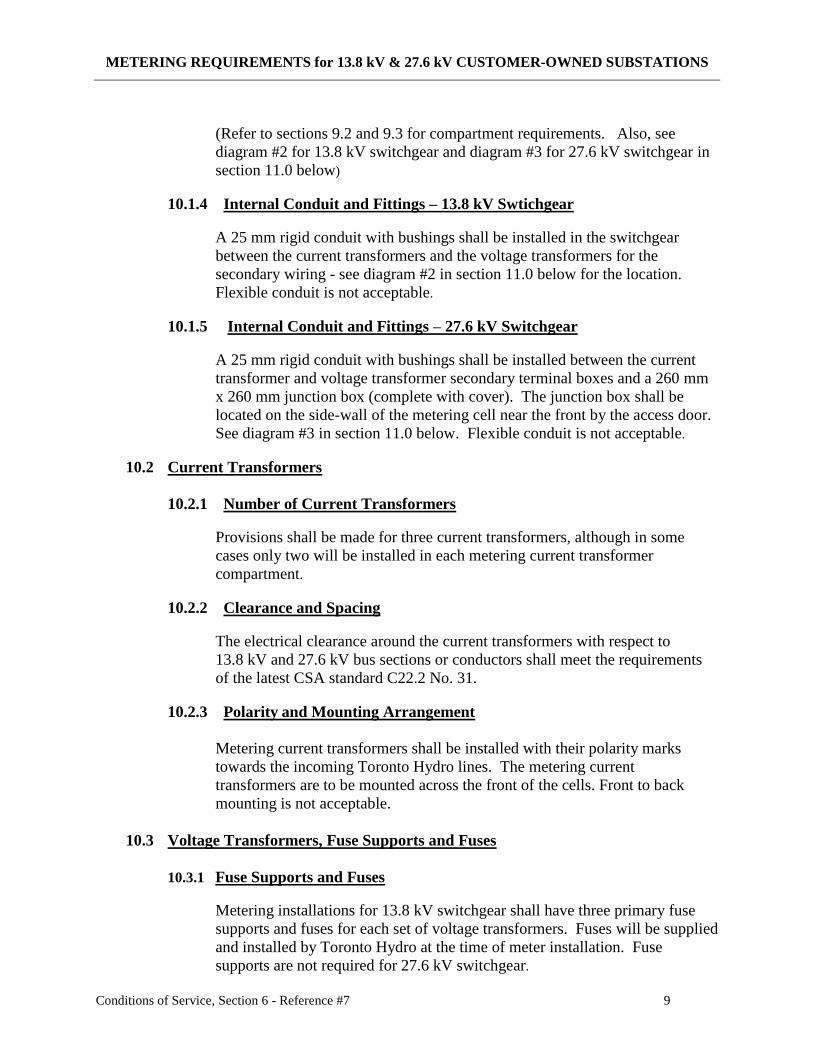
10.1.4 Internal Conduit and Fittings – 13.8 kV Swtichgear
A 25 mm rigid conduit with bushings shall be installed in the switchgear
between the current transformers and the voltage transformers for the
secondary wiring - see diagram #2 in section 11.0 below for the location.
Flexible conduit is not acceptable.
10.1.5 Internal Conduit and Fittings – 27.6 kV Switchgear
A 25 mm rigid conduit with bushings shall be installed between the current
transformer and voltage transformer secondary terminal boxes and a 260 mm
x 260 mm junction box (complete with cover). The junction box shall be
located on the side-wall of the metering cell near the front by the access door.
See diagram #3 in section 11.0 below. Flexible conduit is not acceptable.
10.2 Current Transformers
10.2.1 Number of Current Transformers
Provisions shall be made for three current transformers, although in some
cases only two will be installed in each metering current transformer
compartment.
10.2.2 Clearance and Spacing
The electrical clearance around the current transformers with respect to
13.8 kV and 27.6 kV bus sections or conductors shall meet the requirements
of the latest CSA standard C22.2 No. 31.
10.2.3 Polarity and Mounting Arrangement
Metering current transformers shall be installed with their polarity marks
towards the incoming Toronto Hydro lines. The metering current
transformers are to be mounted across the front of the cells. Front to back
mounting is not acceptable.
10.3 Voltage Transformers, Fuse Supports and Fuses
10.3.1 Fuse Supports and Fuses
Metering installations for 13.8 kV switchgear shall have three primary fuse
supports and fuses for each set of voltage transformers. Fuses will be supplied
and installed by Toronto Hydro at the time of meter installation. Fuse
supports are not required for 27.6 kV switchgear.
METERING REQUIREMENTS for 13.8 kV & 27.6 kV CUSTOMER-OWNED SUBSTATIONS
Conditions of Service, Section 6 - Reference #7 10
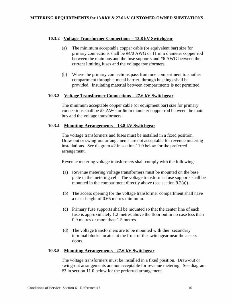
10.3.2 Voltage Transformer Connections – 13.8 kV Switchgear
(a) The minimum acceptable copper cable (or equivalent bar) size for
primary connections shall be #4/0 AWG or 11 mm diameter copper rod
between the main bus and the fuse supports and #6 AWG between the
current limiting fuses and the voltage transformers.
(b) Where the primary connections pass from one compartment to another
compartment through a metal barrier, through bushings shall be
provided. Insulating material between compartments is not permitted.
10.3.3 Voltage Transformer Connections – 27.6 kV Switchgear
The minimum acceptable copper cable (or equipment bar) size for primary
connections shall be #2 AWG or 6mm diameter copper rod between the main
bus and the voltage transformers.
10.3.4 Mounting Arrangements – 13.8 kV Switchgear
The voltage transformers and fuses must be installed in a fixed position.
Draw-out or swing-out arrangements are not acceptable for revenue metering
installations. See diagram #2 in section 11.0 below for the preferred
arrangement.
Revenue metering voltage transformers shall comply with the following:
(a) Revenue metering voltage transformers must be mounted on the base
plate in the metering cell. The voltage transformer fuse supports shall be
mounted in the compartment directly above (see section 9.2(a)).
(b) The access opening for the voltage transformer compartment shall have
a clear height of 0.66 metres minimum.
(c) Primary fuse supports shall be mounted so that the center line of each
fuse is approximately 1.2 metres above the floor but in no case less than
0.9 metres or more than 1.5 metres.
(d) The voltage transformers are to be mounted with their secondary
terminal blocks located at the front of the switchgear near the access
doors.
10.3.5 Mounting Arrangements - 27.6 kV Switchgear
The voltage transformers must be installed in a fixed position. Draw-out or
swing-out arrangements are not acceptable for revenue metering. See diagram
#3 in section 11.0 below for the preferred arrangement.
METERING REQUIREMENTS for 13.8 kV & 27.6 kV CUSTOMER-OWNED SUBSTATIONS
Conditions of Service, Section 6 - Reference #7 11
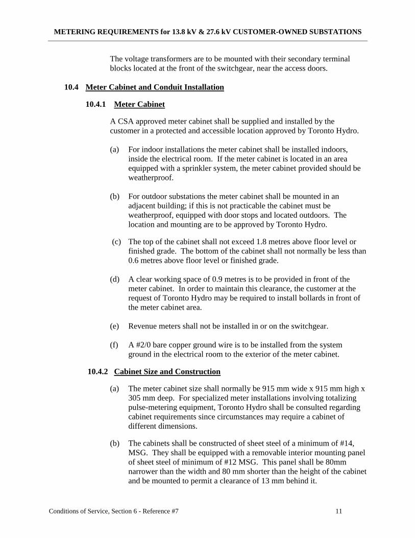
The voltage transformers are to be mounted with their secondary terminal
blocks located at the front of the switchgear, near the access doors.
10.4 Meter Cabinet and Conduit Installation
10.4.1 Meter Cabinet
A CSA approved meter cabinet shall be supplied and installed by the
customer in a protected and accessible location approved by Toronto Hydro.
(a) For indoor installations the meter cabinet shall be installed indoors,
inside the electrical room. If the meter cabinet is located in an area
equipped with a sprinkler system, the meter cabinet provided should be
weatherproof.
(b) For outdoor substations the meter cabinet shall be mounted in an
adjacent building; if this is not practicable the cabinet must be
weatherproof, equipped with door stops and located outdoors. The
location and mounting are to be approved by Toronto Hydro.
(c) The top of the cabinet shall not exceed 1.8 metres above floor level or
finished grade. The bottom of the cabinet shall not normally be less than
0.6 metres above floor level or finished grade.
(d) A clear working space of 0.9 metres is to be provided in front of the
meter cabinet. In order to maintain this clearance, the customer at the
request of Toronto Hydro may be required to install bollards in front of
the meter cabinet area.
(e) Revenue meters shall not be installed in or on the switchgear.
(f) A #2/0 bare copper ground wire is to be installed from the system
ground in the electrical room to the exterior of the meter cabinet.
10.4.2 Cabinet Size and Construction
(a) The meter cabinet size shall normally be 915 mm wide x 915 mm high x
305 mm deep. For specialized meter installations involving totalizing
pulse-metering equipment, Toronto Hydro shall be consulted regarding
cabinet requirements since circumstances may require a cabinet of
different dimensions.
(b) The cabinets shall be constructed of sheet steel of a minimum of #14,
MSG. They shall be equipped with a removable interior mounting panel
of sheet steel of minimum of #12 MSG. This panel shall be 80mm
narrower than the width and 80 mm shorter than the height of the cabinet
and be mounted to permit a clearance of 13 mm behind it.
METERING REQUIREMENTS for 13.8 kV & 27.6 kV CUSTOMER-OWNED SUBSTATIONS
Conditions of Service, Section 6 - Reference #7 12
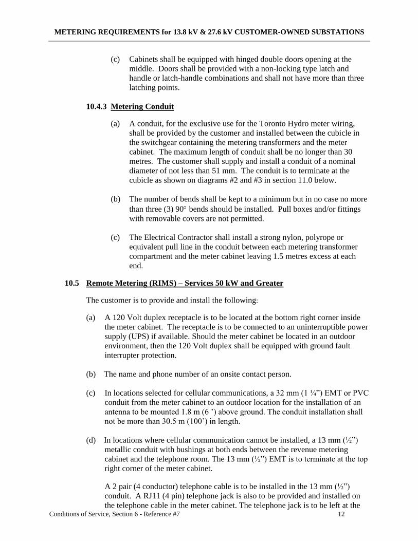
(c) Cabinets shall be equipped with hinged double doors opening at the
middle. Doors shall be provided with a non-locking type latch and
handle or latch-handle combinations and shall not have more than three
latching points.
10.4.3 Metering Conduit
(a) A conduit, for the exclusive use for the Toronto Hydro meter wiring,
shall be provided by the customer and installed between the cubicle in
the switchgear containing the metering transformers and the meter
cabinet. The maximum length of conduit shall be no longer than 30
metres. The customer shall supply and install a conduit of a nominal
diameter of not less than 51 mm. The conduit is to terminate at the
cubicle as shown on diagrams #2 and #3 in section 11.0 below.
(b) The number of bends shall be kept to a minimum but in no case no more
than three (3) 90 bends should be installed. Pull boxes and/or fittings
with removable covers are not permitted.
(c) The Electrical Contractor shall install a strong nylon, polyrope or
equivalent pull line in the conduit between each metering transformer
compartment and the meter cabinet leaving 1.5 metres excess at each
end.
10.5 Remote Metering (RIMS) – Services 50 kW and Greater
The customer is to provide and install the following:
(a) A 120 Volt duplex receptacle is to be located at the bottom right corner inside
the meter cabinet. The receptacle is to be connected to an uninterruptible power
supply (UPS) if available. Should the meter cabinet be located in an outdoor
environment, then the 120 Volt duplex shall be equipped with ground fault
interrupter protection.
(b) The name and phone number of an onsite contact person.
(c) In locations selected for cellular communications, a 32 mm (1 ¼”) EMT or PVC
conduit from the meter cabinet to an outdoor location for the installation of an
antenna to be mounted 1.8 m (6 ’) above ground. The conduit installation shall
not be more than 30.5 m (100’) in length.
(d) In locations where cellular communication cannot be installed, a 13 mm (½”)
metallic conduit with bushings at both ends between the revenue metering
cabinet and the telephone room. The 13 mm (½”) EMT is to terminate at the top
right corner of the meter cabinet.
A 2 pair (4 conductor) telephone cable is to be installed in the 13 mm (½”)
conduit. A RJ11 (4 pin) telephone jack is also to be provided and installed on
the telephone cable in the meter cabinet. The telephone jack is to be left at the
METERING REQUIREMENTS for 13.8 kV & 27.6 kV CUSTOMER-OWNED SUBSTATIONS
Conditions of Service, Section 6 - Reference #7 13
bottom of the meter cabinet with enough telephone cable to allow mounting the
jack anywhere in the cabinet. The telephone cable terminating in the telephone
room is to be clearly labeled “TORONTO HYDRO METERING”.
Toronto Hydro will arrange to have the telephone line activated. Customer
owned telephone lines or customer shared telephone lines are not acceptable.
10.6 Pole/Structure Mounted 27.6 kV Outdoor Substations
The customer shall provide facilities for mounting revenue metering transformers and
or meters on the pole or structure. This type of arrangement will be approved on an
individual basis as a special installation.
11.0 DIAGRAMS
METERING REQUIREMENTS for 13.8 kV & 27.6 kV CUSTOMER-OWNED SUBSTATIONS
Conditions of Service, Section 6 - Reference #7
METERING REQUIREMENTS for 13.8 kV & 27.6 kV CUSTOMER-OWNED SUBSTATIONS
Conditions of Service, Section 6 - Reference #7
POSSIBLE OVERHEAD TERMINATION OF 51mm
METER CONDUIT AT FRONT RIGHT/LEFT
CORNER OF THE REVENUE METERING
COMPARTMENT
CABINET
LOCATION OF 3rd
CURRENT TRANSFORMER
CURRENT TRANSFORMER
TYPICAL LOCATION OF
25mm CONDUIT AT THE VOLTAGE TRANSFORMER
FRONT RIGHT/LEFT FUSE SUPPORT
CORNER OF THE REVENUE
METERING COMPARTMENT PHASE TO PHASE &
PHASE TO GROUND
INSULATING BARRIER
STEEL BARRIER THROUGH BUSHING
VOLTAGE TRANSFORMER
CABINET
POSSIBLE UNDERGROUND TERMINATION
OF 51mm METER CONDUIT AT FRONT RIGHT/LEFT
CORNER OF THE REVENUE METERING
COMPARTMENT
NOTE:
1. Current transformers and the voltage transfomer fuse supports
are to be on the same vertical plane.
Metering Compartment Front View Showing
2. Refer to Section 10 for detailed specifications. Relative Position of Metering Transformers and
Fuse Supports - 13.8 kV Switchgear - 3 Phase 3 Wire
3. Drawing is not to scale.
Diagram #2
660 m
m
TO METER
TO METER
900 m
m -
1500 m
m
305 m
m305 m
m
METERING REQUIREMENTS for 13.8 kV & 27.6 kV CUSTOMER-OWNED SUBSTATIONS
Conditions of Service, Section 6 - Reference #7
POSSIBLE OVERHEAD ENTRY OF 51mm
METER CONDUIT AT FRONT RIGHT/LEFT
CORNER OF THE REVENUE METERING
COMPARTMENT
TO METER
CABINET
CURRENT TRANSFORMER
TYPICAL LOCATION OF
25mm CONDUIT AND CURRENT TRANSFORMER
260mm X 260mm SECONDARY TERMINAL BOX
JUNCTION BOX AT THE
FRONT RIGHT/LEFT CORNER
OF THE REVENUE METERING
COMPARTMENT
VOLTAGE TRANSFORMER
VOLTAGE TRANSFORMER
SECONDARY TERMINAL BOX
TO METER
POSSIBLE UNDERGROUND ENTRY CABINET
OF 51mm METER CONDUIT AT FRONT RIGHT/LEFT
CORNER OF THE REVENUE METERING
COMPARTMENT
NOTES:
1. Current transformers and the voltage transformers
are to be on the same vertical plane.
Metering Compartment Front View Showing
2. Refer to Section 10 for detailed specifications. Relative Position of Metering Transformers
- 27.6 kV Switchgear - 3 Phase 4 Wire
3. Drawing is not to scale.
Diagram #3


