Embed Size (px)
Citation preview
City of Kalamazoo, Michigan
Water Reclamation Facility Improvements
Contract 74
2018
Technical Specifications
Administration
James Ritsema – City Manager
James J. Baker, PE – Director of Public Services and City Engineer
Jim Cornell – Wastewater Division Manager
Ryan Stoughton, PE – Assistant City Engineer - Wastewater
Ron Janssen – Wastewater Operations Manager
Members of City Commission
Bobby J. Hopewell – Mayor
Erin Knott – Vice Mayor
Jack Urban David Anderson
Don Cooney Shannon Sykes
Eric Cunningham
Jones & Henry Engineers, Ltd.
Toledo, Ohio & Kalamazoo, Michigan

TABLE OF CONTENTS
PART C
Specifications - Foreword C
Section Title DIVISION 1 - GENERAL REQUIREMENTS 01010 Definition of Contract Items 01010-1 - 01010-6 01043 Coordination and Control of the Work 01043-1 - 01043-6 01300 Submittals 01300-1 - 01300-6 01310 Construction Schedules and Documentation 01310-1 - 01310-6 01320 Electronic Project Management System (EPMS) 01320-1 - 01320-4 01350 Common Product Requirements 01350-1 - 01350-2 01410 Laboratory Services 01410-1 - 01410-4 01568 Pollution Control 01568-1 - 01568-2 01580 Project Sign 01580-1 - 01580-4 01590 Field Office 01590-1 - 01590-4 01800 Construction Survey Work 01800-1 - 01800-4
DIVISION 2 - UNDERGROUND, PAVEMENT, AND SITE WORK 02110 Removal of Structures and Obstructions 02110-1 - 02110-4 02552 Precast Concrete Manholes 02552-1 - 02552-6 02800 Sodding, Seeding, and Mulching 02800-1 - 02800-4
DIVISION 3 - CONCRETE 03100 Concrete Formwork 03100-1 - 03100-4 03200 Concrete Reinforcement 03200-1 - 03200-6 03300 Cast-in-Place Concrete 03300-1 - 03300-22 03310 Grout 03310-1 - 03310-4 03710 Concrete Restoration 03710-1 - 03710-6
DIVISION 4 - MASONRY 04200 Unit Masonry 04200-1 - 04200-14
DIVISION 5 - METALS 05120 Structural Steel 05120-1 - 05120-8 05500 Metal Fabrications 05500-1 - 05500-12 05510 Metal Stairs 05510-1 - 05510-4 05520 Metal Pipe Railing 05520-1 - 05520-4 05530 Metal Bar Grating 05530-1 - 05530-4 05540 Iron Castings 05540-1 - 05540-2
DIVISION 6 -WOOD AND PLASTICS 06690 Plastic Strip Curtin 06690-1 - 06690-2

DIVISION 7 - THERMAL AND MOISTURE PROTECTION 07520 Urethane Foam Insulation 07520-1 - 07520-8 07532 Adhered Rubber Membrane Roofing System 07532-1 - 07532-4 07900 Caulking and Sealants 07900-1 - 07900-4
DIVISION 8 - DOORS AND WINDOWS 08125 Heavy-Duty Aluminum Doors and Frames 08125-1 - 08125-2 08572 Fiberglass Windows 08572-1 - 08572-4
DIVISION 9 - FINISHES 09880 Protective Coating for Concrete 09880-1 - 09880-2 09900 Painting 09900-1 - 09900-20
DIVISION 11 - EQUIPMENT AND SYSTEMS 11050 Common Equipment Requirements 11050-1 - 11050-8 11135 Chain and Rake Bar Screen 11135-1 - 11135-10 11137 Centrifuge 11137-1 - 11137-16 11233 Liquid Polymer Equipment 11233-1 - 11233-8 11735 Pumping Equipment 11735-1 - 11735-12 11739 Sludge Cake Pump Equipment 11739-1 - 11739-10
DIVISION 14 - CONVEYING SYSTEMS 14300 Hoists and Cranes 14300-1 - 14300-6 14552 Centrifuge Shaftless Screw Conveyors 14552-1 - 14552-4
DIVISION 15 - MECHANICAL 15010 General Mechanical Provisions 15010-1 - 15010-6 15210 Piping 15210-1 - 15210-14 15211 Small Piping and Valves 15211-1 - 15211-14 15250 Valves 15250-1 - 15250-18 15260 Slide Gates 15260-1 - 15260-10 15400 Plumbing 15400-1 - 15400-8 15500 Heating, Ventilating, and Air Conditioning 15500-1 - 15500-18 15502 Testing, Adjusting, & Balancing of HVAC Systems 15502-1 - 15502-4 15503 Fans 15503-1 - 15503-6 15504 Mechanical Systems Insulation 15504-1 - 15504-8 15505 Curbs For Roof Penetrations 15505-1 - 15505-2 15506 Ductwork 15506-1 - 15506-8 15510 Carbon Scrubber 15510-1 - 15510-6 15511 Fine Screen Dumpster Cover 15511-1 - 15511-8 15620 Makeup Air Unit Direct Fired 15620-1 - 15620-4
DIVISION 16 - ELECTRICAL 16010 General Electrical Provisions 16010-1 - 16010-4 16020 Grounding and Bonding 16020-1 - 16020-6 16030 Electrical Identification 16030-1 - 16030-4 16050 Electrical Testing 16050-1 - 16050-4 16060 Hangers and Supports 16060-1 - 16060-2 16120 Conductors and Cables (600 Volts and Less) 16120-1 - 16120-6 16121 Control and Signal Conductor and Cables 16121-1 - 16121-6 16130 Conduit, Surface Metal Raceways and Accessories 16130-1 - 16130-10 16131 Cable Trays and Wire Ways 16131-1 - 16131-6 16132 Accessories 16132-1 - 16132-4 16230 Variable Frequency Drive (VFD) 16230-1 - 16230-4 16410 Panelboards 16410-1 - 16410-6 16421 Motor Control Center 16421-1 - 16421-6 16422 Motor Starters and Contactors 16422-1 - 16422-6 16430 Disconnect Switches 16430-1 - 16430-4 16431 Circuit Breakers 16431-1 - 16431-6 16450 Distribution Transformers 16450-1 - 16450-4 16510 Lighting 16510-1 - 16510-4 16901 Monitoring and Control System 16901-1 - 16901-10 16902 Metering and Control Equipment 16902-1 - 16902-16 16903 Control Panels 16903-1 - 16903-8 16905 Programmable Controller System 16905-1 - 16905-8
DIVISION 102 - EXISTING CONDITIONS
SECTION 1024119 - SELECTIVE DEMOLITION DIVISION 103 - CONCRETE
SECTION 1033000 - CAST-IN-PLACE CONCRETE
DIVISION 104 - MASONRY
SECTION 1042200 - CONCRETE UNIT MASONRY
DIVISION 105 - METALS
SECTION 1053100 - STEEL DECKING SECTION 1055000 - METAL FABRICATIONS
DIVISION 106 - WOOD, PLASTICS, AND COMPOSITES
SECTION 1061053 - MISCELLANEOUS ROUGH CARPENTRY SECTION 1066400 - PLASTIC PANELING
DIVISION 107 - THERMAL AND MOISTURE PROTECTION
SECTION 1075323 - ETHYLENE-PROPYLENE-DIENE-MONOMER (EPDM) ROOFING SECTION 1079200 - JOINT SEALANTS
DIVISION 108 - OPENINGS
SECTION 1081113 - HOLLOW METAL DOORS AND FRAMES SECTION 1085113 - ALUMINUM WINDOWS SECTION 1087100 - DOOR HARDWARE SECTION 1088000 - GLAZING
DIVISION 109 - FINISHES
SECTION 1092216 - NON-STRUCTURAL METAL FRAMING SECTION 1092900 - GYPSUM BOARD SECTION 1095123 - ACOUSTICAL TILE CEILINGS SECTION 1096723 - RESINOUS FLOORING SECTION 1099123 - INTERIOR PAINTING
DIVISION 111 - EQUIPMENT
SECTION 1115313 - LABORATORY FUME HOODS DIVISION 112 - FURNISHINGS
SECTION 1123553.13 - METAL LABORATORY CASEWORK SECTION 1123553.23 - SOLID PLASTIC LAB CASEWORK
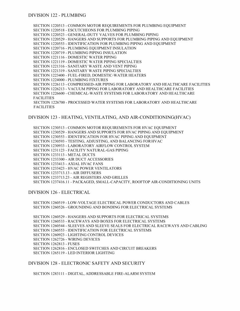
DIVISION 122 - PLUMBING
SECTION 1220513 - COMMON MOTOR REQUIREMENTS FOR PLUMBING EQUIPMENT SECTION 1220518 - ESCUTCHEONS FOR PLUMBING PIPING SECTION 1220523 - GENERAL-DUTY VALVES FOR PLUMBING PIPING SECTION 1220529 - HANGERS AND SUPPORTS FOR PLUMBING PIPING AND EQUIPMENT SECTION 1220553 - IDENTIFICATION FOR PLUMBING PIPING AND EQUIPMENT SECTION 1220716 - PLUMBING EQUIPMENT INSULATION SECTION 1220719 - PLUMBING PIPING INSULATION SECTION 1221116 - DOMESTIC WATER PIPING SECTION 1221119 - DOMESTIC WATER PIPING SPECIALTIES SECTION 1221316 - SANITARY WASTE AND VENT PIPING SECTION 1221319 - SANITARY WASTE PIPING SPECIALTIES SECTION 1223400 - FUEL-FIRED, DOMESTIC-WATER HEATERS SECTION 1224000 - PLUMBING FIXTURES SECTION 1226113 - COMPRESSED-AIR PIPING FOR LABORATORY AND HEALTHCARE FACILITIES SECTION 1226213 - VACUUM PIPING FOR LABORATORY AND HEALTHCARE FACILITIES SECTION 1226600 - CHEMICAL-WASTE SYSTEMS FOR LABORATORY AND HEALTHCARE FACILITIES SECTION 1226700 - PROCESSED WATER SYSTEMS FOR LABORATORY AND HEALTHCARE FACILITIES
DIVISION 123 - HEATING, VENTILATING, AND AIR-CONDITIONING(HVAC)
SECTION 1230513 - COMMON MOTOR REQUIREMENTS FOR HVAC EQUIPMENT SECTION 1230529 - HANGERS AND SUPPORTS FOR HVAC PIPING AND EQUIPMENT SECTION 1230553 - IDENTIFICATION FOR HVAC PIPING AND EQUIPMENT SECTION 1230593 - TESTING, ADJUSTING, AND BALANCING FOR HVAC SECTION 1230933 - LABORATORY AIRFLOW CONTROL SYSTEM SECTION 1231123 - FACILITY NATURAL-GAS PIPING SECTION 1233113 - METAL DUCTS SECTION 1233300 - AIR DUCT ACCESSORIES SECTION 1233413 - AXIAL HVAC FANS SECTION 1233423 - HVAC POWER VENTILATORS SECTION 1233713.13 - AIR DIFFUSERS SECTION 1233713.23 - AIR REGISTERS AND GRILLES SECTION 1237416.11 - PACKAGED, SMALL-CAPACITY, ROOFTOP AIR-CONDITIONING UNITS
DIVISION 126 - ELECTRICAL
SECTION 1260519 - LOW-VOLTAGE ELECTRICAL POWER CONDUCTORS AND CABLES SECTION 1260526 - GROUNDING AND BONDING FOR ELECTRICAL SYSTEMS
SECTION 1260529 - HANGERS AND SUPPORTS FOR ELECTRICAL SYSTEMS SECTION 1260533 - RACEWAYS AND BOXES FOR ELECTRICAL SYSTEMS SECTION 1260544 - SLEEVES AND SLEEVE SEALS FOR ELECTRICAL RACEWAYS AND CABLING SECTION 1260553 - IDENTIFICATION FOR ELECTRICAL SYSTEMS SECTION 1260923 - LIGHTING CONTROL DEVICES SECTION 1262726 - WIRING DEVICES SECTION 1262813 - FUSES SECTION 1262816 - ENCLOSED SWITCHES AND CIRCUIT BREAKERS SECTION 1265119 - LED INTERIOR LIGHTING
DIVISION 128 - ELECTRONIC SAFETY AND SECURITY
SECTION 1283111 - DIGITAL, ADDRESSABLE FIRE-ALARM SYSTEM

DIVISION 133 - UTILITIES
SECTION 1334100 - STORM UTILITY DRAINAGE PIPING
IF ANY OF THE PAGES OR SECTIONS LISTED ABOVE ARE NOT INCLUDED IN THESE CONTRACT DOCUMENTS, PLEASE ADVISE.
Water Rec Facility Imp/017-7244.001
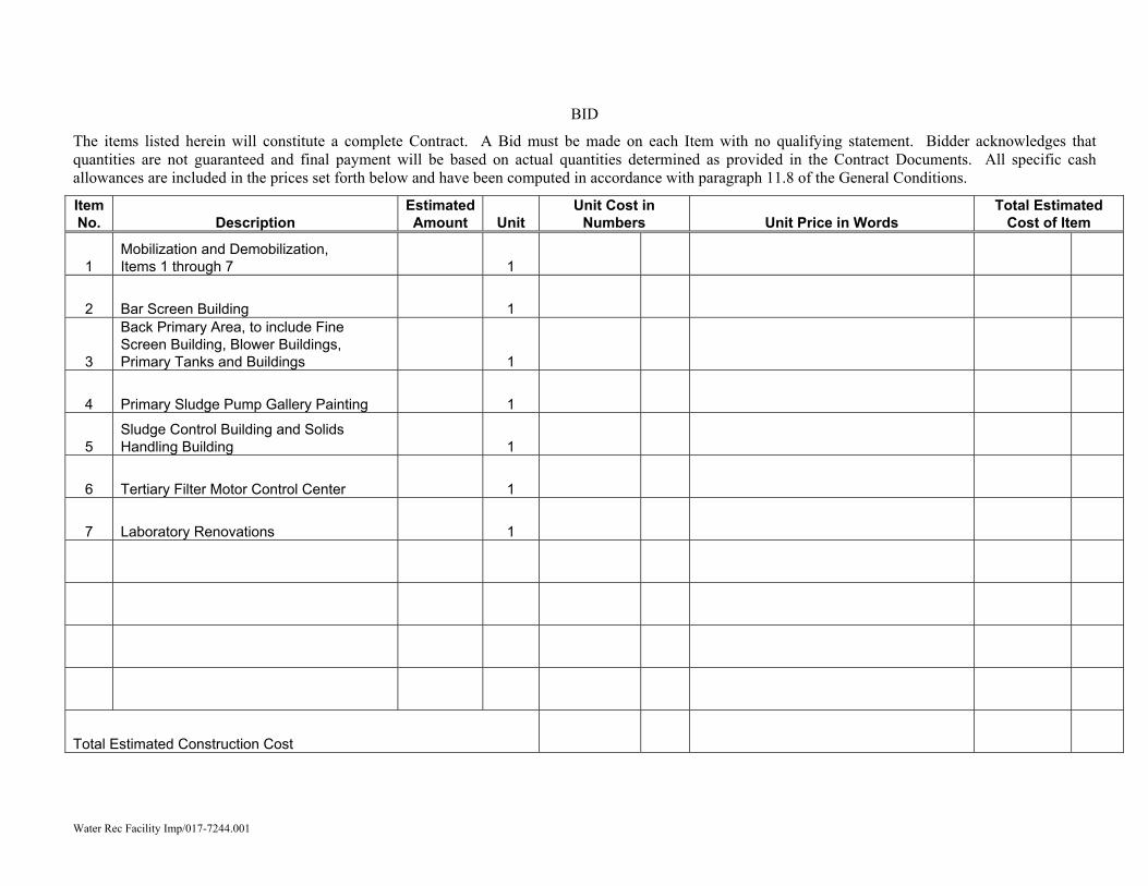
BID
The items listed herein will constitute a complete Contract. A Bid must be made on each Item with no qualifying statement. Bidder acknowledges that quantities are not guaranteed and final payment will be based on actual quantities determined as provided in the Contract Documents. All specific cash allowances are included in the prices set forth below and have been computed in accordance with paragraph 11.8 of the General Conditions.
Item No. Description
Estimated Amount Unit
Unit Cost in Numbers Unit Price in Words
Total Estimated Cost of Item
1 Mobilization and Demobilization, Items 1 through 7 1
2 Bar Screen Building 1
3
Back Primary Area, to include Fine Screen Building, Blower Buildings, Primary Tanks and Buildings 1
4 Primary Sludge Pump Gallery Painting 1
5 Sludge Control Building and Solids Handling Building 1
6 Tertiary Filter Motor Control Center 1
7 Laboratory Renovations 1
Total Estimated Construction Cost

This page was intentionally left blank.
Water Rec Facility Imp/017-7244.001
4A. LISTED "OR-EQUAL" OR SUBSTITUTIONS
a. The name or make of any piece of equipment or material of construction specified in Part C of the Contract Documents and identified on the Bid Substitution List shall be used in determining the base bid price. Where two or more Equipment or Product Manufacturers are named, bidders may use any of the named. Bidder may offer "Or-Equal" or substitutions for specified Equipment or Product Manufacturer, provided they name on the Bid Substitution List the "Or-Equal" or substitute offered together with the total amount to be added to, or deducted from the amount of their base bid for the corresponding project item.
b. All provisions for review and acceptance of an offered substitute shall comply with the Contract Documents. Owner reserves the right to accept or reject any offered substitute.
c. If the bidder names no substitute on his "Bid Substitution List" the specified Equipment or Product Manufacturers shall be used. No additional substitutes may be offered for items on the "Bid Substitution List" subsequent to the award of the Contract.
d. Contract award shall be determined by base bid.

This page was intentionally left blank.
Water Rec Facility Imp/017-7244.001
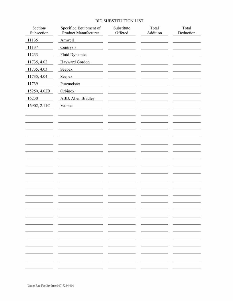
BID SUBSTITUTION LIST
Section/ Subsection
Specified Equipment of Product Manufacturer
Substitute Offered
Total Addition
Total Deduction
11135 Amwell
11137 Centrysis
11233 Fluid Dynamics
11735, 4.02 Hayward Gordon
11735, 4.03 Seepex
11735, 4.04 Seepex
11739 Putzmeister
15250, 4.02B Orbinox
16230 ABB, Allen Bradley
16902, 2.11C Valmet

This page was intentionally left blank.
Water Rec Facility Imp/017-7244.001 Section 01010 - 1 Definition of Contract Items
SECTION 01010
DEFINITION OF CONTRACT ITEMS PART 1 GENERAL
1.01 FOREWORD
A. This Section describes the various Contract Items listed in the Bid.
1.02 WORK INCLUDED
A. Under each Item the Contractor shall furnish all labor, materials, tools, plant equipment, supplies, maintenance of equipment, heating, lighting and power, insurance and bonds, coordination, and all work that may be specifically described and included under the respective Items and necessary to complete the work in accordance with the obvious or expressed intent of the Contract Documents.
1.03 WORKMANSHIP AND MATERIALS
A. The quality of workmanship and materials entering into any and all of the Items and the work included shall conform to pertinent sections, paragraphs, sentences, and clauses, both directly and indirectly applicable thereto, contained in the Contract Documents, whether or not direct reference to such occurs under each Item in this Section.
1.04 PAYMENT
A. The lump sum and unit prices stated in the Bid shall be payment in full for the completion of all work specified and described or required to be included in the Contract, complete, and ready for use.
PART 2 PRODUCTS
None.
PART 3 EXECUTION
None.
PART 4 SPECIAL PROVISIONS
4.01 CONTRACT ITEMS
A. The Contract Items are defined on the following pages.
Definition of Contract Items Section 01010 - 2 Water Rec Facility Imp/017-7244.001
ITEM 1 MOBILIZATION AND DEMOBILIZATION, ITEMS 1 THROUGH 7
1.01 DESCRIPTION
A. Under this Item, the Contractor shall furnish all materials, equipment, labor, supervision, and coordination as specified, shown on the Drawings, or otherwise required to complete and place in operation the work detailed in 1.01 C below
B. This Item is intended to pay non-recurring cost to the Contractor not recovered under other pay Items of the Contract.
C. This Item shall include, but not be limited to, the cost for moving equipment in and out, performance and payment bonds, insurance, permits, utility connection cost, Electronic Project Management System fees and other expenses associated with preparation for construction in accordance with the requirements of the Contract Documents.
1.02 WORK NOT INCLUDED
A. Any work specifically included under other Bid Items.
1.03 DEFINITION OF ITEM
A. Item 1 - Includes Mobilization and Demobilization, Items 1 through 7.
1.04 PAYMENT
A. The lump sum stated in the Bid shall be full compensation for all work required under Item 1.
ITEM 2
BAR SCREEN BUILDING
2.01 DESCRIPTION
A. Under this Item, the Contractor shall furnish all materials, equipment, labor, supervision, and coordination as specified, shown on the Drawings, or otherwise required to complete and place in operation the work detailed in 2.01 C below.
B. This Item is intended to pay non-recurring cost to the Contractor not recovered under other pay Items of the Contract.
C. This Item includes, but is not limited to, removal and disposal of existing bar screen 1, bar screen 4, screenings belt conveyor, foul air ductwork and HVAC equipment, and piping; and furnishing and installation of new bar screen 1, screenings screw conveyor, foul air ductwork, exhaust hood and carbon scrubber, HVAC and ductwork as detailed in specification Division 15, associated equipment and reconnection of the new equipment.
2.02 WORK NOT INCLUDED
B. Any work specifically included under other Bid Items.
2.03 DEFINITION OF ITEM
B. Item 2 – Bar Screen Building.
2.04 PAYMENT
B. The lump sum stated in the Bid shall be full compensation for all work required under Item 2.
Water Rec Facility Imp/017-7244.001 Section 01010 - 3 Definition of Contract Items
ITEM 3 BACK PRIMARY AREA
3.01 DESCRIPTION
A. Under this Item, the Contractor shall furnish all materials, equipment, labor, supervision, and coordination as specified, shown on the Drawings, or otherwise required to complete and place in operation the work detailed in 3.01 C below.
B. This Item is intended to pay non-recurring cost to the Contractor not recovered under other pay Items of the Contract.
C. This Item includes, but is not limited to, removal and disposal of the existing foul air ductwork, HVAC equipment and louvers associated with the grit tank, fine screen building and primary effluent/skimmer building; and furnishing and installation of new HVAC and foul air systems including ductwork and scrubbers for fine screen building and for primary tanks and primary effluent building, foul air covers for dumpsters in fine screen building and electrical and control equipment.
3.02 WORK NOT INCLUDED
A. Any work specifically included under other Bid Items.
3.03 DEFINITION OF ITEM
A. Item 3 – Back Primary Area.
3.04 PAYMENT
A. The lump sum stated in the Bid shall be full compensation for all work required under Item 3.
ITEM 4
PRIMARY SLUDGE PUMP GALLERY PAINTING
4.01 DESCRIPTION
A. Under this Item, the Contractor shall furnish all materials, equipment, labor, supervision and coordination as specified, shown on the Drawings, or otherwise required to complete and place in operation the work detailed in 4.01 C below.
B. This Item is intended to pay non-recurring cost to the Contractor not recovered under other pay Items of the Contract.
C. This Item includes, but is not limited to, removal and disposal of paint on walls and ceiling of primary sludge pump gallery and all piping and ductwork contained therein and repainting of said items.
4.02 WORK NOT INCLUDED
A. Any work specifically included under other Bid Items.
4.03 DEFINITION OF ITEM
A. Item 4 – Primary Sludge Pump Gallery Painting.
4.04 PAYMENT
A. The lump sum stated in the Bid shall be full compensation for all work required under Item 4.
Definition of Contract Items Section 01010 - 4 Water Rec Facility Imp/017-7244.001
ITEM 5 SLUDGE CONTROL BUILDING AND SOLIDS HANDLING BUILDING
5.01 DESCRIPTION
A. Under this Item, the Contractor shall furnish all materials, equipment, labor, supervision, and coordination as specified, shown on the Drawings, or otherwise required to complete and place in operation the work detailed in 5.01 C below.
B. This Item is intended to pay non-recurring cost to the Contractor not recovered under other pay Items of the Contract.
C. This Item includes, but is not limited to:
1. Sludge Control Building
Removal and disposal of thickened sludge transfer pumps, piping and valves, roofing, windows and doors, internal plumbing, HVAC and foul air systems, and associated electrical equipment; and furnishing and installation of thickened sludge transfer pumps, piping and valves, internal plumbing, interior painting, electrical and control equipment and HVAC and foul air systems.
2. Solids Handling Building
Removal and disposal of belt filter press feed pumps, belt transfer conveyors and support framing, pasteurization and thermal heating units, associated platforms, walkways and stairs, and associated electrical equipment; and furnishing and installation of centrifuge feed pumps, centrifuges and associated steelwork, transfer screw conveyors, transfer pumps, high pressure piping, hydraulic knife gate valves, hydraulic power units, electrical and control equipment, and HVAC and foul air systems.
5.02 WORK NOT INCLUDED
A. Any work specifically included under other Bid Items.
5.03 DEFINITION OF ITEM
A. Item 5 – Sludge Control Building and Solids Handling Building.
5.04 PAYMENT
A. The lump sum stated in the Bid shall be full compensation for all work required under Item 5.
ITEM 6
TERTIARY FILTER MOTOR CONTROL CENTER
6.01 DESCRIPTION
A. Under this Item, the Contractor shall furnish all materials, equipment, labor, supervision and coordination as specified, shown on the Drawings, or otherwise required to complete and place in operation the work detailed in 6.01 C below.
B. This Item is intended to pay non-recurring cost to the Contractor not recovered under other pay Items of the Contract.
C. This Item includes, but is not limited to, removal of the existing motor starter panel MSP-18, relocation of existing loads associated with MSP-13 to MCC-18 located on the floor above and addition of three additional sections to MCC-18 as detailed in specification Division 16.
Water Rec Facility Imp/017-7244.001 Section 01010 - 5 Definition of Contract Items
6.02 WORK NOT INCLUDED
A. Any work specifically included under other Bid Items.
6.03 DEFINITION OF ITEM
A. Item 6 – Tertiary Filter Motor Control Center.
6.04 PAYMENT
A. The lump sum stated in the Bid shall be full compensation for all work required under Item 6.
ITEM 7
LABORATORY RENOVATIONS
7.01 DESCRIPTION
A. Under this Item, the Contractor shall furnish all materials, equipment, labor, supervision and coordination as specified, shown on the Drawings, or otherwise required to complete and place in operation the work detailed in 7.01 C below.
B. This Item is intended to pay non-recurring cost to the Contractor not recovered under other pay Items of the Contract.
C. This Item includes, but is not limited to, removal and disposal of existing equipment and installation of equipment including, but not limited to, new HVAC and lightning systems, walls and doors, laboratory storage, fixtures and fittings and all associated plumbing and electrical work.
7.02 WORK NOT INCLUDED
A. Any work specifically included under other Bid Items.
7.03 DEFINITION OF ITEM
A. Item 7 – Laboratory Renovations.
7.04 PAYMENT
A. The lump sum stated in the Bid shall be full compensation for all work required under Item 7.
END OF SECTION

Definition of Contract Items Section 01010 - 6 Water Rec Facility Imp/017-7244.001
This page was intentionally left blank.
Water Rec Facility Imp/017-7244.001 Section 01043 - 1 Coordination and Control of the Work
SECTION 01043
COORDINATION AND CONTROL OF THE WORK
GENERAL
1.01 SCOPE
A. This Section includes coordination and control of the work.
1.02 SUBMITTALS
A. Submittals shall be in accordance with all requirements of Section 01300 and shall include:
1. Information for the Record:
a. Bypass Pumping plan and procedures.
b. Haul routes to and from project site.
c. Plan and procedures for any shut downs and bypass pumping.
d. Coordination drawings shall include, but not be limited to, all process piping including, but not limited to, bill of material, laying length, embedded conduit runs, and embedded plumbing lines.
1.03 LINES AND GRADES
A. All work under this Contract shall be built in accordance with the lines and grades shown on the Drawings or as altered or modified by authority of the Owner and Engineer.
1.04 EXISTING STRUCTURES SHOWN ON DRAWINGS
A. Where underground and surface structures are shown on the Drawings, the location, depth, and dimensions of such structures are believed to be reasonably correct but are not guaranteed.
B. Such structures are shown for the information of the Contractor, but information so given is not to be construed as a representation that such structures will in all cases be found or encountered just where shown, or that they represent all the structures which may be encountered.
1.05 COOPERATION OF CONTRACTOR
A. The Contractor shall conduct his operations so as to interfere as little as possible with those of the Owner, other contractors, utilities, or any public authority on or near the Work.
B. The Owner reserves the right to perform other work by contract or otherwise, and to permit other public bodies, public utility companies, and others to do work on or near the project during progress of the Work. If a conflict arises, the Owner will determine when and how the work shall proceed.
C. Claims for delay or inconvenience due to operations of such other parties on work specified, shown on the Drawings, as directed or which can be reasonably expected to be encountered by the nature and location of the Work will not be considered.
D. Operations entailing the use of construction equipment and lights outside the hours or 8:00 am and 5:00 pm or outside the hours allowed for construction by local ordinances or regulations.
E. Closing off clear access to any public alley, street, road, avenue or boulevard without the prior consent of municipal officials and the Engineer.
Coordination and Control of the Work Section 01043 - 2 Water Rec Facility Imp/017-7244.001
1.06 MAINTENANCE OF SANITARY SYSTEM DURING CONSTRUCTION
A. All construction which requires interruption of treatment plant flow shall be executed during periods designated by the Owner. Bypassing of untreated or partially-treated wastewater to the receiving stream is prohibited.
B. The Contractor shall be responsible for adverse environmental effects, or compliance violations at the existing treatment facilities which occur as a result of the Contractor’s noncompliance with the requirements and constraints included in the Contract Documents.
C. The Contractor shall be responsible for sampling and testing, and penalties resulting from the non-performance of the Contractor’s work.
1.07 PERMANENT PAVEMENT AND FINAL RESTORATION
A. When sewer construction is being done between April 15 and November 15, the final pavement restoration work shall be no more than lineal feet behind the main pipeline laying operation.
B. Pavement restoration shall include, but not limited to, replacement of pavement, driveways, and sidewalks.
C. The fine grading, topsoil, and seeding operation shall be no further behind the pavement restoration than lineal feet.
D. If at any time the pavement restoration and the fine grading, topsoil, and seeding operation does not meet the above conditions, no further mainline pipe laying will be permitted until the Contractor is in compliance.
E. In order to comply with the above conditions, the Contractor shall complete the pipeline and all appurtenances including, but not limited to, testing, in order to begin final pavement restoration and the fine grading, topsoil, and seeding operation.
F. When sewer construction is being done between November 15 and April 15, the Contractor shall install the main pipeline and all appurtenances and complete the testing. On April, 15, final pavement restoration and the fine grading, topsoil, and seeding operation shall begin, and two months later on June 15, the final pavement restoration shall be no more than lineal feet behind the mainline pipe laying operation and the fine grading, topsoil, and seeding operation shall be no more than lineal feet behind the pavement restoration or mainline sewer laying shall be stopped until these conditions are met.
1.08 TEMPORARY PAVEMENT RESTORATION
A. The Contractor shall maintain the treatment plant access roads for operating personnel, deliveries of operating supplies, normal plant maintenance vehicles, and other equipment incidental to the operation and maintenance of the treatment facility.
1.09 TEMPORARY PARKING FACILITIES
A. Parking spaces for the Contractor’s personnel shall be provided and maintained in usable condition by the Contractor at all times. Provisions shall be made so that sediment is not tracked onto paved roadways from the vehicles operated by the Contractor’s personnel. The parking areas shall consist of temporary parking areas or new permanent parking areas shown on the Drawings. Temporary parking areas are to be located in the area designated by the Owner and Engineer. At the completion of the project, temporary parking areas shall be removed and the surface restored as specified, shown on the Drawings, as directed or to its original condition.
B. The Contractor’s personnel shall not utilize existing permanent parking areas unless specifically noted otherwise on the Drawings.
Water Rec Facility Imp/017-7244.001 Section 01043 - 3 Coordination and Control of the Work
1.10 TEMPORARY WATER, HEATING, LIGHTING, AND POWER
A. The Contractor shall provide all water, heat, lighting, and power required to construct and protect the work, or portions thereof, until Final Completion.
B. The source for temporary power shall be from the electric utility or portable power source.
C. The source for temporary water can be from the water utility if available. The Contractor shall furnish all backflow prevention devices, flow meter and appurtenances as may be required by the water utility. Should the water utility impose a charge for furnishing, to the Contractor, the meter or appurtenances the Contractor shall pay all the fees. The Contractor shall pay all charges for the water metered.
1. If a water utility is not available, the Contractor shall be responsible for furnishing water and all cost associated including, but not limited to, procurement, hauling, pumping equipment, and appurtenances.
D. The Contractor shall pay for all significant amounts of electric power utilized by the Contractor in the construction of the facility. All electric power used for such significant uses as pumping groundwater and heating shall be separately metered and paid for by the Contractor.
E. The installation for electric power shall meet the requirements of federal, state, and local authorities and regulatory agencies.
1.11 DISPOSAL OF DEBRIS
A. All debris resulting from construction operations, i.e., packaging, waste materials, damaged equipment, etc., shall be trucked from the site by the Contractor and disposed of at spoil sites.
B. The Contractor shall police the hauling of debris to ensure that all spillage from haul trucks is promptly and completely removed from public or private rights-of-way.
C. All debris shall be disposed of in accordance with federal, state, and local laws and regulations.CONTROL OF NOISE
A. The Contractor shall eliminate noise to as great an extent as possible at all times. Air compressors shall be equipped with silencers and the exhaust of all gasoline motors and other power equipment shall be provided with mufflers. In the vicinity of hospitals, libraries, and schools, precautions shall be taken to avoid noise and other nuisance, and the Contractor shall require strict observances of all pertinent ordinances and regulations. Any blasting permitted in such locations shall be done with reduced charges.
1.13 SMOKE PREVENTION
A. Strict compliance with all ordinances regulating the production and emission of smoke will be required, and the Contractor shall accept full responsibility for all damage that may occur to property as a result of negligence in providing required control.
1.14 DEBRIS AND DUST CONTROL
A. The Contractor shall apply water, dust palliative, or both, for the alleviation or prevention of dust nuisance caused by his operations. Dust control operations shall be performed by the Contractor as site conditions dictate or as order by the Owner and Engineer.
B. The Contractor shall utilize mechanical equipment to remove all debris from all streets, drives and walks to the satisfaction of the Owner and Engineer. Cleaning shall be performed at a minimum of daily and as directed by the Owner and Engineer.
C. The cost of the all debris and dust control methods shall be the responsibility of the Contractor.
Coordination and Control of the Work Section 01043 - 4 Water Rec Facility Imp/017-7244.001
1.15 RESERVED
1.16 USE OF EXPLOSIVES
A. When the use of explosives is authorized for the prosecution of the Work, the Contractor shall use the highest degree of care so as not to endanger life or property. The Contractor shall be responsible for any and all damage resulting from use of explosives.
B. The Contractor agrees and warrants that he will observe state laws and local ordinances and regulations relative to the use and storing of such explosives as may be kept on the job and all such storage places shall be marked clearly, “DANGER -- EXPLOSIVES”.
1.17 EMERGENCY MAINTENANCE SUPERVISOR
A. The Contractor shall submit to the Engineer the names, addresses, and telephone numbers of two employees responsible for performing emergency maintenance and repairs when the Contractor is not working. These employees shall be designated in writing by the Contractor to act as his representative and shall have full authority to act on his behalf as specified in GC 6.2 of the General Conditions.
B. Contractor shall post at job site, in a conspicuous location, the emergency numbers for the project.
C. Contractor shall be responsible for contacting the local fire, police, and emergency response personnel and organizations in advance of the work. The Contractor shall be responsible for the coordination and compliance with emergency response plans, whether developed by the governing agency, laws, or the Contractor for the project.
D. At least one of the designated employees shall be available for a telephone call any time an emergency arises.
1.18 PUBLIC SERVICE STRUCTURES
A. Public service structures shall be understood to include all poles, tracks, pipes, wires, conduits, house-service connections, vaults, manholes, and other appurtenances, whether owned or controlled by the Owner or other public bodies or by privately-owned corporations, used to supply the public with transportation, heating, electric, telephone, gas, water, sewer, or other services.
B. At least a week in advance of breaking ground, the Contractor shall notify the registered underground protection service, all public bodies, and other owners of such facilities of the proposed location of his operations, advising them that their property may be affected and that such measures as they may deem necessary should be promptly taken to protect, adjust, remove, or build them.
C. In developed residential and commercial areas, the Contractor shall assume each building and dwelling has water and sewer services and that they shall be protected and repaired as needed as part of the pipeline installation. No additional payment will be made for work associated with supporting or repairs of such services.
D. Three conditions which may be encountered will be dealt with as follows:
1. Structures which are adjacent to but not included within the limits of an excavation required for performance of the Work shall be protected, supported, and maintained in service by the Contractor at his expense.
2. Structures within the limits of the Work which can be satisfactorily supported and maintained in service and which do not require removal and rebuilding in the judgment of the Engineer shall be thus supported by the Contractor at his expense, including cost of repair of damage incident to his operations.
a. Supports for water and gas mains, sewers, conduits, and similar structures shall be constructed of timber or other acceptable materials;
Water Rec Facility Imp/017-7244.001 Section 01043 - 5 Coordination and Control of the Work
shall be supported from undisturbed foundations, and shall be sufficiently substantial to ensure against settlement when pipe trenches or other excavations are backfilled. In all cases where permits or inspection fees are required by utilities in connection with changes to or temporary support of their conduits, the Contractor shall secure such permits and pay all permit and inspection fees.
b. The Contractor shall assume full responsibility for maintaining all public service structures in service and shall support and protect, or remove and rebuild them at his own expense. Such services shall not be interrupted without permission of the owner of the public service structure.
3. In case relocation of pipelines or other utility structures is required because of direct interference, as determined jointly by the Owner, Engineer, and Contractor, with the installation of the Work, the Contractor shall notify the Owners of the utility structure involved.
a. The Contractor will not be reimbursed for the cost of the relocation if the interference is shown on the Drawings, described in the Specifications, apparent on visual inspection, or specifically included in the Work to be performed by the Contractor.
b. The Contractor will not be paid for time lost because of such direct interference. Where it is the policy of any utility owner to perform such work with his own forces, the Contractor shall cooperate to the fullest extent with such utility owner.
1.19 UNAUTHORIZED WORK
A. Work done beyond the lines shown on the Drawings or ordered, work done without required inspection, except as herein provided, or any Extra Work done without authority will be considered as unauthorized and will not be paid for under the provisions of the Contract. Work so done may be ordered removed at the Contractor’s expense. Work done without lines and grades being given shall be considered as unauthorized and subject to rejection.
1.20 DRAINING OF TANKS AND PIPELINES
A. Unless otherwise indicated, tanks, pipelines, and other similar structures that are to be removed from service, to complete the work will be initially drained by the Owner.
B. Draining will be by gravity or by a permanently installed pump, if available.
C. After the tank has been drained by the Owner to the lowest level possible with existing means for drainage, the Contractor shall remove and dispose of remaining liquid and accumulated solids, as required to complete the work.
PRODUCTS
None.
EXECUTION
None.
SPECIAL PROVISIONS
4.01 MAINTAINING FLOW IN EXISTING SEWERS
A. Flow in existing storm, sanitary and private sewers shall be maintained at all times during construction of this project. The Contractor shall furnish and install all necessary
Coordination and Control of the Work Section 01043 - 6 Water Rec Facility Imp/017-7244.001
temporary facilities required to maintain the flow in existing sewers including bulkheads, plugs, stop planks, flumes, coffer dams, pumping equipment, valves, etc.
4.02 POTENTIALLY HAZARDOUS ENVIRONMENT
A. The environment in portions of the project site is rated as Class I Division 1 or 2 or some areas of the project site are designated as permitted Confined Spaces. As a minimum, whenever the Contractor is performing work in these areas, the Contractor shall provide Factory Mutual- and UL-approved continuous monitoring of the atmosphere for the presence of hydrogen sulfides, of low oxygen concentration, and of explosive gases (both lighter and heavier than air). The Contractor shall evacuate all personnel from the areas whenever the detection system registers hydrogen sulfide levels of greater than 20 ppm, oxygen levels less than 19.5 percent or combustible gas levels of greater than 10 percent of the LEL. In addition, whenever the Contractor is using tools producing open flames or sparks, such as cutting torches, saws, and grinders, the Contractor shall provide for the forced air exhaust ducted from the immediate area of the work.
4.03 REQUIRED SAFETY DOCUMENTATION TO BE SUBMITTED
A. On all projects that require the Contractor’s or subcontractor’s personnel to occupy permitted confined spaces and/or hazardous atmospheres on the project site, the Contractor shall submit to the Owner, a written proposed safety program. The safety program shall comply with all Federal, State, and local requirements. If the Owner has a safety plan that is more stringent than the Federal and State requirements, it will be made available to the Contractor for review. The submittal of the proposed safety program to the Owner shall be made well in advance of the start of construction at the project site. The submittal shall include a written Safety Management Plan including Confined Space Entry procedures. The Contractor shall be responsible to maintain documentation that anyone employed by the Contractor, subcontractors, or suppliers of any tier to the Contractor occupying such hazardous locations has received the appropriate confined space entry training and other applicable training. The Contractor is also responsible to maintain completed confined space entry permits.
4.04 MAINTAINING CRITICAL OPERATIONS
A. All work requiring any portion of the chlorine contact tank or chlorination and dechlorination systems to be out of service must be performed between November 1st and the following February 25th. From any March 1st through the following October 31st, either the existing disinfection system shall be in full operation or the new UV disinfection system shall be fully operational, including the required supplier representative installation certification and training.
B. The Contractor shall closely coordinate any needed equipment shutdowns with the Owner. Except for the disinfection system which is addressed above, the Contractor shall not take out of service more than one piece of process equipment at a time.
C. Any work that requires any plant equipment to be unavailable for use by the plant staff must be scheduled one week in advance of the planned outage.
END OF SECTION
Water Rec Facility Imp/017-7244.001 Section 01090 - 1 Reference Standards
SECTION 01090
REFERENCE STANDARDS
GENERAL
1.01 SCOPE
A. This Section includes reference standards.
1.02 DESIGNATION OF ASSOCIATIONS, INSTITUTIONS, SOCIETIES & STANDARDS
A. Whenever in these Specifications reference is made to Associations, Institutions, Societies, or Standards, they will be designated as follows:
AA - Aluminum Association AAMA - Architectural Aluminum Manufacturers Association AASHTO - American Association of State Highway and Transportation
Officials ACI - American Concrete Institute ADAAG - Americans with Disabilities Act Accessibility Guidelines AFBMA - Anti-Friction Bearing Manufacturers Association AFI - Air Filter Institute AGA - American Gas Association AGMA - American Gear Manufacturers Association AIHA - American Industrial Hygiene Association AISC - American Institute of Steel Construction AISI - American Iron & Steel Institute AITC - American Institute of Timber Construction AMCA - Air Moving and Conditioning Association ANSI - American National Standards Institute API - American Petroleum Institute ARI - Air Conditioning and Refrigeration Institute ASA - American Standards Association ASHRAE - American Society of Heating, Refrigerating, and Air
Conditioning Engineers ASME - American Society of Mechanical Engineers ASTM - American Society for Testing Materials AWS - American Welding Society AWWA - American Water Works Association BLS - Bureau of Labor Standards CISPI - Cast Iron Soil Pipe Institute FS - Federal Specifications IBR - Institute of Boiler and Radiator Manufacturers IEEE - Institute of Electrical and Electronic Engineers ISA - Instrument Society of America JIC - Joint Industrial Council MDOT - Michigan Department of Transportation NBS - National Bureau of Standards NEC - National Electrical Code NEMA - National Electrical Manufacturers Association NFPA - National Fire Protection Association NSF - National Sanitation Foundation OSHA - Occupational Safety and Health Act SMACNA - Sheet Metal and Air Conditioning Contractors National
Association, Inc. SSPC - Steel Structures Painting Council
Reference Standards Section 01090 - 2 Water Rec Facility Imp/017-7244.001
MBC - Michigan Building Code IBC - International Building Code UBC - Uniform Building Code UL - Underwriters Laboratories, Inc. USBM - United States Bureau of Mines
B. Wherever specific standard numbers are indicated, i.e., ASTM C 150, it shall be understood to mean the latest revision thereof.
PRODUCTS
None.
EXECUTION
None.
SPECIAL PROVISIONS
None.
END OF SECTION
Water Rec Facility Imp/017-7244.001 Section 01300 - 1 Submittals
SECTION 01300
SUBMITTALS
GENERAL
1.01 SCOPE
A. This Section includes requirements for submittals.
B. Contractor shall adhere to the submittal schedule as submitted under the provisions of the General Conditions. Contractor shall modify the schedule as required to allow sufficient time for submittal review based on current construction schedule.
C. Owner, Contractor and Engineer shall utilize the electronic project management system EPMS as specified in Section 01320 for the central repository of project-related documents including but not limited to submittals, information for the record and O&M Manuals.
1.02 COORDINATION OF SUBMITTALS
A. The Contractor shall be responsible for the coordination of submittals and field verifications as required for the various parts of the work.
B. All submittals to the Engineer, unless otherwise specified, shall be made only by the Contractor. Direct submittals from subcontractors or suppliers will not be accepted.
C. All submittals shall reference the Specification item that it covers, the Contractor’s name, the Contract title and location, and the date of submission. Submittal shall also indicate whether the information is for the Engineer’s review and approval, for record purposes, or for the fulfillment of the operation and maintenance requirements.
PRODUCTS
2.01 GENERAL
A. Two categories of information are normally required:
1. Shop Drawings for review.
2. Information for record.
a. Operation and Maintenance Manuals (O&M).
2.02 SHOP DRAWINGS FOR REVIEW
A. Shop Drawings:
1. The Contractor shall submit Shop Drawings in accordance with the General Conditions, as required by individual Sections, shown on the Drawings or as directed.
2. The Contractor shall indicate all variances from the requirements of the Contract Documents in accordance with the General Conditions.
3. The Contractor shall clearly indicate quantities and the exact intended use of the equipment or material contained in the submittal.
4. All Submittals shall be tailored to the project by high-lighting appropriate information and deleting or crossing out nonapplicable information or where applicable the Contractor shall provide a data sheet with all necessary information to correctly identify the applicable Sections of the manuals for the actual material or equipment furnished. All options furnished shall be indicated.
Submittals Section 01300 - 2 Water Rec Facility Imp/017-7244.001
5. Color charts or samples shall be included for all submittals where a color selection by the Owner is required. Original Color Charts (not Color Copies) and samples shall be delivered to the project site, Engineer’s RPR or Owner as required. The Engineer shall be copied on the transmittal letter for record purposes.
B. Samples shall be provided as required in the individual Sections. Samples shall be of the precise material proposed to be furnished. The number of samples and sample size shall be the industry standard unless otherwise stated in the individual Sections.
2.03 INFORMATION FOR RECORD
A. Material certificates shall be submitted for materials as indicated in the individual Sections. The certificate shall state that the products have been sampled and tested in accordance with the proper industrial and governmental standards and meet the requirements of the Specifications. Certificates shall be signed by an authorized agent of the manufacturer.
B. Licenses and Permits - The Contractor shall submit copies of all licenses and permits required by Local, State, and Federal laws.
C. Installation and calibration certificates shall be submitted for equipment as indicated in the individual Sections. These certificates shall indicate manufacturer’s satisfaction with the installation, the accuracy of calibration and alignment, and the operation of the equipment. Such certificates must be signed by an authorized agent of the manufacturer.
D. Progress Schedules shall be submitted in accordance with the General Conditions and Section 01310.
E. Schedule of Shop Drawings and Sample Submittals shall be submitted in accordance with the General Conditions.
F. Schedule of Values shall be submitted in accordance with the General Conditions.
G. Copy of programming for all PLC’s and computers on the project.
2.04 OPERATION AND MAINTENANCE INFORMATION
A. Operation and Maintenance Manuals (a.k.a. O&M or Manuals) shall be submitted as information for the record.
B. O&M Manuals shall be submitted as electronic documents prior to the printing of the record copy.
1. Contractor shall provide one electronic copy of the manuals for preliminary review.
2. The final accepted manuals shall be provided as one electronic copy of the manual and one printed copy as specified below.
C. Electronic manuals shall be in Portable Document Format (PDF) as generated by Adobe Professional Version 7.0 or newer. The PDF file shall be fully indexed using the table of contents, searchable with thumbnails generated. PDF documents shall have bookmark created in the navigation frame for each major entry (Section, Chapter, Tab) in the table of contents. PDF images shall be at a readable resolution typically 300 dpi or higher. Optical Character Recognition (OCR) capture shall be performed on these images text can be searched, selected and copied from the PDF file.
1. The opening view of each PDF document shall be the bookmarks to the left and cover page or table of contents.
2. The PDF file name shall include the Name of Owner, Project title, Contract Number, and Specification Section. Commonly used abbreviations acceptable to the Owner may be used to minimize length of file name.
Water Rec Facility Imp/017-7244.001 Section 01300 - 3 Submittals
3. The Contractors Name shall be the electronic “Author” of the PDF document.
D. This information will be reviewed only if properly identified with Specification Section Numbers and only after revised, where necessary, to conform to the Engineer’s notes on previous submittals that have been marked “Make Corrections Noted.” Manuals shall be tailored to suit the specific equipment provided.
E. Submittals shall include but not limited to the following:
1. Descriptive literature, bulletins, or other data covering equipment or system.
2. Complete list of equipment and appurtenances included with system, complete with manufacturer serial number and model number.
3. Utility requirements.
4. General arrangement drawing.
5. Sectional assembly.
6. Dimension print.
7. Materials of construction.
8. Certified performance curve.
9. Parts list with assembly drawings.
10. Recommended spare parts list with part and catalog number.
11. Lubrication recommendations and instructions.
12. Schematic wiring diagrams.
13. Schematic piping diagrams.
14. Description of associated instrumentation.
15. Drive dimensions and data.
16. Operating instructions.
17. Maintenance instructions including trouble-shooting guidelines, lubrication, and preventive maintenance instructions with task schedule.
18. Special tools and equipment required for operation and maintenance.
19. Description of equipment controls.
20. Pump seal data.
21. Assembly, installation, alignment, adjustment, and checking instructions.
22. Confirmation of all corrections noted on Shop Drawings marked “Make Corrections Noted.”
23. Manufacturer’s name, address, and telephone number along with manufacturers job number and Purchase Order number.
24. Manufacturer’s local sales representative, address, telephone number.
25. All installation instructions that were provided to Contractor for use to install equipment.
F. All manuals shall be tailored to the project by high-lighting appropriate information and deleting or crossing out nonapplicable information or the Contractor shall provide a data sheet with all necessary information to correctly identify the applicable Sections of the manuals for the actual equipment furnished. All options furnished shall be indicated.
Submittals Section 01300 - 4 Water Rec Facility Imp/017-7244.001
G. Manuals shall be printed on 8-1/2 by 11-inch size with standard three-hole punching. Large manuals shall be submitted in three-ring binders. Small manuals shall be submitted in folders with metal fasteners. Index tabs shall be furnished for all manuals containing data for three or more items of equipment. All manuals shall have a title label on the cover stating the specification item number and item name. A table of contents shall be included in all manuals.
H. Drawings shall be reduced to 8-1/2 by 11 inch or 11 by 17 inch. Where reduction is not possible, larger drawings shall be folded separately and placed in envelopes which are bound into the manual.
I. Equipment installations shall not be considered substantially complete until all associated O&M submittals are accepted by the Engineer.
J. Field modifications to equipment during installation shall be included in the manual so that the manual reflects as-built conditions. Revisions to the manual may be submitted for incorporation into the manual where appropriate. However, the Engineer reserves the right to return all six manuals for revision to reflect as-built conditions.
EXECUTION
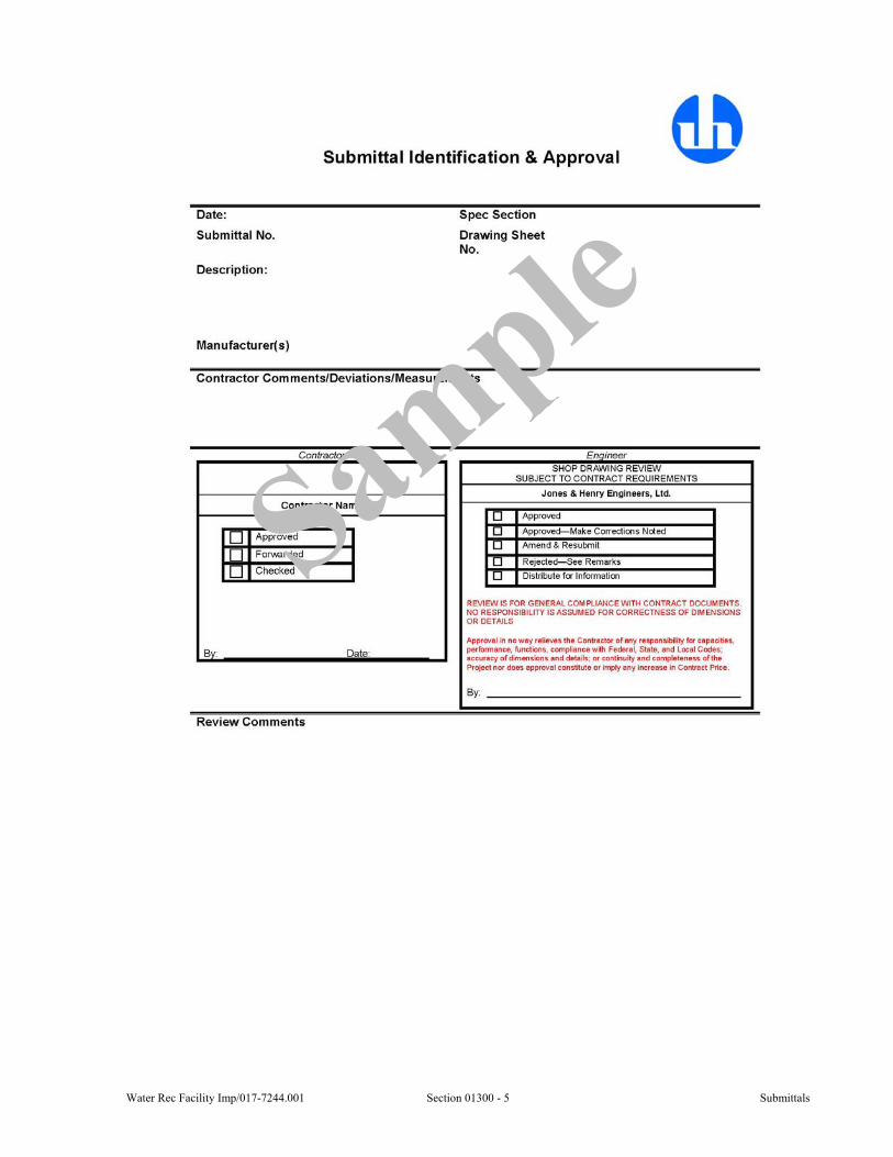
3.01 IDENTIFICATION OF SUBMITTALS
A. All submittals shall be given a consecutive number when they are entered into the Electronic Project Management System (EPMS), See Section 01320.
B. Resubmittals shall be entered into EPMS as resubmittals.
C. Submittals to satisfy the Operation and Maintenance information requirements shall be entered into the EPMS as a submittal. The description shall have the prefix “OM”.
3.02 PRINTING AND DISTRIBUTION
A. Contractor shall provide printed copies of approved submittals and deliver them to the Owner and Engineers RPR at the project site.
B. Contractor shall provide one printed copy of the approved O&M Manual and the electronic copy on portable electronic media device to the Owner.
C. Contractor shall provide printed copies of submittals, project information or documents required to satisfy the building permit and inspections as may be required by the governing agency.
1. The Engineer will provide the stamped/sealed Contract Drawings for the initial filing of the building permit applications.
SPECIAL PROVISIONS
None.
END OF SECTION
Water Rec Facility Imp/017-7244.001 Section 01300 - 5 Submittals

Submittals Section 01300 - 6 Water Rec Facility Imp/017-7244.001
This page was intentionally left blank.
Water Rec Facility Imp/017-7244.001 Section 01310 - 1 Construction Schedules & Documentation
SECTION 01310
CONSTRUCTION SCHEDULES & DOCUMENTATION
GENERAL
1.01 SCOPE
A. This Section includes the requirements for construction schedules and construction sequences.
B. This Section includes the requirements for the tracking and documentation of the progress and activities driving the completion of the work as specified, shown on the Drawings and as directed.
1.02 SUBMITTALS
A. Submittals shall be in accordance with all the requirements of Section 01300 and shall include:
1. Information for the Record:
a. Preliminary Construction Schedule.
b. Contractor’s Construction Schedule and monthly updates.
c. Submittals Schedule.
B. Contractor shall submit three copies of the 24-inch by 36-inch construction schedule, unless approved otherwise by the Engineer.
1.03 QUALITY ASSURANCE
A. Scheduling conference shall be held prior to the commencement of the construction to discuss the following including, but not limited to:
1. Construction sequencing.
2. Contractor’s coordination of subcontractors.
3. Coordination with the Owner’s operations.
4. Coordination with other Contractor’s or other work.
5. Project milestones.
6. Owner’s partial utilization.
PRODUCTS
2.01 PRELIMINARY CONSTRUCTION SCHEDULE
A. Preliminary construction schedule shall be completed in accordance with the General Conditions and prior to the scheduling conference.
B. The preliminary schedule shall outline the Contractor’s sequencing of tasks, activities, milestones, and all critical path items within the contract time.
2.02 CONSTRUCTION SCHEDULE
A. The Contractor’s submission of the construction schedule will not change the contract completion date, whether reviewed by the Owner and Engineer or not. The Contractor shall incorporate all approved change orders that have resulted in a contract time extension.
Construction Schedules & Documentation Section 01310 - 2 Water Rec Facility Imp/017-7244.001
B. The Contractor shall require all subcontractors engaged in the work to submit to the Contractor construction schedules, as specified herein, for incorporation into the Contractor’s construction schedule.
C. The construction schedule shall include, but not limited to, the following dates:
1. Notice to Proceed.
2. Substantial Completion and Final Completion.
3. Commencement of on-site operations.
4. Milestones as specified, shown on the Drawings, and as directed.
5. Ordering, submittals, fabrication, delivery, startup, and training time of major equipment items.
6. Submittal schedule per the General Conditions.
D. The Contractor shall incorporate into the construction schedule all constraints and work restrictions specified or otherwise required by the Contractor’s operations, including, but not limited to, the following:
1. Construction sequencing.
2. Contractor’s coordination of subcontractors.
3. Coordination with the Owner’s operations.
4. Coordination with other Contractor’s or other work.
5. Project milestones.
6. Owner’s partial utilization.
2.03 UPDATING CONSTRUCTION SCHEDULE
A. The Contractor shall keep the construction schedule current to the progress of the work continually through closeout of the project. The construction schedule shall be submitted monthly for the Engineer’s review.
2.04 WEEKLY CONSTRUCTION SCHEDULE
A. The Contractor shall submit a schedule of his work for each week. This schedule shall identify the foreman of each work crew and the location and type of work the crew will be doing each day. It shall be delivered no later than 4:00 p.m. of the next to last regular workday of the preceding week to the Resident Project Representative’s office.
EXECUTION
3.01 COORDINATION
A. All phases of the Work requiring interference with normal operations of the existing facilities shall be scheduled in accordance with agreements among the Contractor, Owner, and Engineer. The Contractor shall notify the Owner at least one week before such work is to begin.
SPECIAL PROVISIONS
4.01 SCHEDULED NON-WORK DAYS
A. The Contractor shall restrict work to Monday through Friday and consider the following list of holidays as mandatory non-work days, all of which shall be incorporated into the construction schedule:
1. New Year’s Day.
Water Rec Facility Imp/017-7244.001 Section 01310 - 3 Construction Schedules & Documentation
2. President’s Day.
3. Good Friday.
4. Memorial Day.
5. Fourth of July.
6. Labor Day.
7. Thanksgiving Day.
8. Day after Thanksgiving Day.
9. Christmas Eve day.
10. Christmas Day.
4.02 SEQUENCING
A. The Contractor shall provide for the following sequencing during the development of the construction schedules for the Sludge Control Building and Solids Handling Building.
B. Sludge Control Building
1. Major construction is divided into Phase 1 and Phase 2.
2. Sequencing events within each phase are as follows
a. Phase 1
1) Demolition and removal shall occur for six of the eight existing thickened sludge pumps and associated pipe work. The two southern most pumps are to remain. Installation of new pumps and pipework shall take place.
b. Phase 2
1) Switchover between remaining two existing sludge pumps and six new pumps. Removal of two remaining pumps.
C. Solids Handling Building
1. Major construction is divided into Phase 1 and Phase 2.
2. Sequencing events within each phase are as follows
a. Phase 1
1) Demolition and removal shall occur for the west conveyor train in Stabilization and Storage Buildings including belt conveyors, Thermoblender unit and supports, lime transfer conveyors and associated odor ductwork in Stabilization Building.
2) Holes shall be punched in the slab of the recessed pit and a portion of the north end of the pit shall be filled to match the elevation of the slab of the surrounding building. The stair in the northeast corner of the pit shall be removed and the drainage sump re-formed. Access to the remaining southern portion of the pit shall be provided with a temporary ladder. Temporary pumping shall be provided.
3) Demolition of floor and installation of footers for centrifuge platform. Re-routing of floor pit drain piping.
4) Demolition of access ramp in northwest corner of Stabilization Building and construction of new.
Construction Schedules & Documentation Section 01310 - 4 Water Rec Facility Imp/017-7244.001
5) Demolition and removal of the staircase running north-south connecting first floor to platform to west of Control Room.
6) Relocation of southern plant water booster set to west of northern booster set and reconnection. A number of additional connections shall be made to the plant water system under this Contract.
7) Removal of polymer dosing systems and replacement with new.
8) Installation of sludge cake pump 1, associated hydraulic power unit and discharge pressure piping. Installation of sludge cake pump 1 cross-conveyor.
9) Installation of 30-inch foul air ductwork from east wall of Stabilization Building to reducer on west edge of lime silos.
10) Installation of valves and hydraulic actuators in sludge storage area and valve actuator hydraulic power unit.
11) Construction of bridge crane framing, centrifuge platform and stairs to connect to existing platform in southeast corner. Temporary access ladder in southwest corner.
12) Partial installation of centrifuge platform grating.
13) Installation of centrifuges, centrate piping, centrifuge screw conveyors.
14) Installation of centrifuge feed pumps, piping and accessories.
15) Installation of centrifuge area foul air ductwork.
b. Phase 2
1) Demolition and removal shall occur for the east conveyor train in Stabilization and Storage Buildings including belt conveyors and supports, Thermoblender and pasteurization unit and associated odor ductwork. Demolition and removal shall also occur for north belt press feed pump 1 and south belt press feed pump 1.
2) Demolition and removal shall occur of the platform and associated stairs and supports running along the west wall of the Stabilization Building with the exception of the section to the south of Column line F-F and to the east of Column line C-C to the east of the western-most lime silo. Where new handrailing is required, it shall be installed.
3) Demolition and removal shall occur for make-up air units (MAU) 1 and 2 and the associated platform in the north east corner of the building and north belt press feed pump 2.
4) Filling of remainder of the recessed pit to the southeast of the lime silos.
5) Installation of MAU platform on west wall of Stabilization Building. Installation of MAU 1,2 and 3 and remaining ductwork. Blocking up and installation of HVAC louvers.
6) Installation of sludge cake pump 2 and hydraulic power unit.
7) Installation of cake pump 2 discharge pressure piping, valves and hydraulic cylinders. Installation of sludge cake pump 2 cross-conveyor.
Water Rec Facility Imp/017-7244.001 Section 01310 - 5 Construction Schedules & Documentation
8) Installation of remaining centrifuge platform steelwork and grating.
4.03 SHUTDOWNS
A. Electrical Modifications
1. All electrical shutdowns shall be less than 8 hours in duration, and a shutdown shall not occur within 48 hours of another shutdown.
2. Electrical shutdowns shall be coordinated with equipment installation and other work so shutdowns occur concurrently.
B. Sludge Control Building
1. Pipe modifications within the sludge control building which completely stop any sludge flow out of the building to the ground sludge storage tank shall be restricted to 4 hours within any 24 hour period.
C. Valve Replacement
1. Valve replacements associated with the West Holding Tanks will be done with outages of less than 8 hours within a 48-hour period and shall be restricted to two of the four West Holding Tanks at a time.
D. PLC MODIFICATIONS
1. PLC shall remain operational during the Work except outages are allowed as follows:
a. Bar Screen PLC: 8 hours
b. Back Primary PLC: 12 hours
c. Dewatering PLC: 8 hours
d. Solids Handling PLC: 8 hours
E. DCU MODIFICATIONS
1. DCU shall remain operational during the Work except outages are allowed as follows:
a. Bar Screen RAP-A DCU: 2 hours
b. Back Primary DCU-B: 4 hours
c. Sludge Control DCU-K: 6 hours
END OF SECTION

Construction Schedules & Documentation Section 01310 - 6 Water Rec Facility Imp/017-7244.001
This page was intentionally left blank.
Water Rec Facility Imp/017-7244.001 Section 01320 - 1 Submittal Procedures EPMS
SECTION 01320
ELECTRONIC PROJECT MANAGEMENT SYSTEM (EPMS)
GENERAL
1.01 SCOPE
A. This section describes the requirements for the Electronic Project Management System (EPMS) which will be required on this project.
B. The Contractor shall be responsible for including the cost of the EPMS of $9,340.00. The Contractor shall be responsible for paying the cost as a onetime payment to Eastern Engineering within 30 days of the Notice to Proceed and will be considered part of the project mobilization on the schedule of values.
1. The EPMS shall be provided through eCommunication by Eastern Engineering, 866-884-4115; www.easternengineering.com .
C. Engineer will implement an internet/web site based Electronic Project Management System (EPMS) for the administration of the Contract on this project. Owner, Contractors and Engineer shall be responsible to interface with EPMS and collaborating via the EPMS on this project. The EPMS is intended to supplement the Contract Documents and the provisions of the Contract Documents shall not be superseded by the EPMS.
1. The EPMS is intended to provide a mode of communication which is electronic and to reduce the reliance upon printed documents. Printed documents transmitted will not be reviewed, and electronic documents emailed outside of the EPMS will not be reviewed. The Owner, Contractor and Engineer will collaborate on unique situations or circumstances in order to preserve the project electronic records.
D. The Owner, Contractor and Engineer shall be required to provide project related information/documents via EPMS. In general, the EPMS will receive information via uploaded documents as PDF documents, in their native format (when permitted or required), or other electronic formats designated or required for functionality. The EPMS shall be a central repository for information to all project team members. The EPMS will provide viewing, printing, up/down loading of various information/documents.
E. In general the following is a partial list of information/documents which shall be tracked through the EPMS:
1. Drawings, Specifications and Addendums (included revisions as necessary).
2. Insurance
3. General Project Communication, Emails, Letters, Correspondence and Collaboration or any other document any participant wishes to make part of the project records.
4. Request for Information (RFI)
5. Submittals (Shop Drawings, O&M manuals, color selections etc.)
6. Work Change Directives, Change Request and Change Orders
7. Schedule of Values, Pay Requests and Certified Payroll Reports
8. Reports And Photos (daily, monthly, etc.)
9. Schedules (project, weekly and monthly)
10. Meeting Agendas and Minutes
Submittal Procedures EPMS Section 01320 - 2 Water Rec Facility Imp/017-7244.001
11. Permits and Special Inspections Reports
12. Laboratory Services (testing and reporting)
13. Closeout procedures (deficiency list, warranty, substantial completion)
14. Record Drawings
F. In an effort to protect proprietary information and prohibit unauthorized use or modifications, levels of access security will be assigned in order to provide safe and secure access to information with respects to involvement and responsibility on the project. The Owner, Contractor and Engineer shall establish these levels of access and rights which are appropriate for this project.
G. Owner, Contractor and Engineer shall utilize the mark-up tool integral within the EMPS or have a PDF review software that includes the ability to mark up and apply electronic stamps (such as Adobe Acrobat, or Bluebeam PDF Revu).
H. A high speed internet connection is required.
I. The EPMS will provide notifications regarding new or updated documents through an existing Email account outside of the EPMS.
PRODUCTS
None.
EXECUTION
3.01 CONTRACT REQUIREMENTS
A. All provisions of the Contract Documents are in full effect and enforcement. The submittal procedures specified in the Contract Documents are applicable with the understanding that they will be electronic documents and submitted via the EPMS.
3.02 PRINTING, REPRODUCTION AND DISTRIBUTION
A. The Engineer will not be responsible for printing reproduction or preparation of any hard copy documents, or the cost of doing so.
B. Contractor shall produce printed copies of all submittals as required in section 01300 and in the Contract Documents.
3.03 TRAINING
A. One training session by the Engineer and Eastern Engineering, Inc. will be provided to the team members at the beginning of the EPMS implementation. Training will be coordinated with the Preconstruction meeting and held at the same location. There are many tutorials, help features and technical support options located on the Eastern Engineering web site.
B. Engineer will provide project related support as needed within their ability to provide it. Technical support will be available to all project team members from Eastern Engineering, Inc.
3.04 OPERATION
A. Contractor and all Subcontractors shall maintain a Windows-based computer system including high speed internet access and ability to create/mark-up documents using Adobe Acrobat (pdf) and to scan documents.
B. Engineer will facilitate the implementation and overall operation of the EPMS with Eastern Engineering. Eastern Engineering will provide and maintain the EPMS server and will backup the information.
Water Rec Facility Imp/017-7244.001 Section 01320 - 3 Submittal Procedures EPMS
3.05 ARCHIVE PROJECT CLOSE OUT
A. All files on the EPMS web site will be archived at the end of the project. These archives will be made available to the Owner, Contractors and Engineer for download over the internet, at the end of the warranty period.
SPECIAL PROVISIONS
None.
END OF SECTION

Submittal Procedures EPMS Section 01320 - 4 Water Rec Facility Imp/017-7244.001
This page was intentionally left blank.
Water Rec Facility Imp/017-7244.001 Section 01350 - 1 Common Product Requirements
SECTION 01350
COMMON PRODUCT REQUIREMENTS
GENERAL
1.01 SCOPE
A. This Section includes general requirements for all materials, equipment and systems furnished or installed under this project.
B. Additional specific requirements included under a particular Section shall take precedence.
C. This Section includes, but is not limited to, the following procedural and administrative requirements:
1. Product Delivery Storage and Handling.
2. Warranties.
3. Quality Assurance and Control.
1.02 SUBMITTALS
A. Submittals shall be in accordance with section 01300 and related specification sections.
B. The specification Sections and Drawings contain the specific submittal requirements.
1.03 QUALITY ASSURANCE
A. Where Contractor is required to provide design services or certification of the design, the specified product, equipment or system shall comply with the specified criteria.
1. Contractor shall submit a written request for clarification when specified criteria is incomplete or insufficient.
B. Manufacturer’s name, make, model number and other designations provided in the contract documents are to establish the significant characteristics, including but not limited to, type, function, dimensions and physical properties, performance, and appearance for the purpose of evaluating comparable products. Contractor shall verify product, equipment or system proposed meets or exceeds the requirements as specified or shown on the Drawings.
1.04 PROJECT HANDLING
A. Schedule delivery to minimize the time goods are kept in storage.
B. Deliver goods to project site in manufacturer’s original packaging.
C. Inspect the goods to determine if there is visible damage to the packaging.
1. The packaging shall be removed in a manner that will allow resealing for storage.
2. If packaging cannot be removed and reused, the goods shall be repackaged per the manufacturer’s recommendations.
D. Goods that are susceptible to damage by the environmental or project conditions, including but not limited to, switchgear, motor control centers, panelboards, instrument control panels, fixtures shall be stored in a controlled environment per the manufacturer’s recommendations. If no such area is available at the time such equipment is received, such space shall be provided by the Contractor at no expense to the Owner.
E. Where construction is in roads or streets, that portion of the right-of-way not required for public travel may be used for temporary storage purposes unless otherwise prohibited. Materials shall not be stored in areas where such storage creates a hazard. Any other
Common Product Requirements Section 01350 - 2 Water Rec Facility Imp/017-7244.001
additional space required for construction or storage of materials and equipment shall be obtained by the Contractor at his expense.
F. The Contractor shall confine his equipment, the storage of materials and equipment, and the operations of his workers to areas permitted by law, ordinances, permits, and the requirements of the Contract Documents, and shall not unreasonably encumber the premises with materials or equipment.
1.05 GUARANTEE
A. Manufacturer’s warranty, extending beyond one-year after substantial completion for the specified product, equipment or system shall be provided to the Owner and endorsed by the manufacturer.
B. Requirements for warranties extending beyond one-year after substantial completion are described in individual Sections of these specifications.
C. Manufacturer’s limitations and disclaimers shall not relieve the Contractor from warranty obligations under the Contract Documents.
PRODUCTS
2.01 SHOP PAINTING
A. Non-galvanized ferrous surface shall be painted.
B. Shop painting of ferrous surfaces shall be as follows:
1. Surfaces shall be thoroughly cleaned of dirt, grease, oil, rust, scale, or other foreign substances. All metal surfaces shall, as a minimum, be abrasive blasted in accordance with SSPC-SP6, Commercial Blast Cleaning. More stringent surface preparation shall be provided where required by Section 09900.
2. Surfaces shall receive a shop coat of a primer compatible with the finish coating to be used by the Contractor and specified in Section 09900.
2.02 GALVANIZING
A. Where galvanized metal is indicated, unless otherwise specified, galvanizing shall conform to ASTM A-123 (Hot Dip Galvanized). Threaded parts and hardware shall be galvanized in conformance with ASTM A-153.
2.03 REGULATORY REQUIREMENTS
A. Materials, equipment, coatings, and chemicals in contact with potable water or water being treated for potable water use shall comply with the applicable NSF Standards.
EXECUTION
3.01 INSTALLATION
A. Products shall be installed in accordance with the manufacturer’s instructions and Contract Documents.
B. Required appurtenances including but not limited to, anchors, grout, and leveling shims, shall be provided.
SPECIAL PROVISIONS
None.
END OF SECTION
Water Rec Facility Imp/017-7244.001 Section 01410 - 1 Laboratory Services
SECTION 01410
LABORATORY SERVICES
GENERAL
1.01 SCOPE
A. The Contractor shall retain an independent laboratory.
B. Testing, inspection(s) and quality control are required to certify compliance with the Contract Documents.
1. The laboratory services do not relieve the Contractor from the responsibility of compliance with the Contract Documents
2. Any test required by the Owner shall not relieve the Contractor from the responsibility of compliance with the Contract Documents.
3. Any test required by the Owner shall not relieve the Contractor from the responsibility of supplying certificates from manufacturers or suppliers to demonstrate compliance with the Specifications.
C. Specific testing, inspection(s) and quality control requirements are specified in the individual Sections of the specifications.
D. Specific testing, inspection(s) and quality control requirements of any Federal, State or Local authorities are specified in the related sections of work.
E. Testing of materials or equipment for compliance with various national or technical society standards and ordinarily performed by manufacturers, and shop and field tests of equipment are not included under this Section but shall be performed by the Contractor or his supplier as specified elsewhere.
F. Contractor may conduct material or field test(s), inspection(s) and quality control as they deem necessary.
1. Should the Contractor, at any time, desire the Owner to consider the results of such testing, inspection(s), and quality control, such results shall be certified by an independent testing laboratory acceptable to the Owner. Any testing of this nature shall be conducted at the Contractor’s expense.
1.02 SUBMITTALS
A. Submittals of all required field and laboratory test results shall be made by the independent laboratory as soon as they are available to the Owner and Engineer directly.
1. Statement of Compliance per 1.03.
1.03 QUALITY ASSURANCE
A. The laboratory shall be a recognized and independent commercial laboratory with experience in conducting the required tests.
B. Laboratory shall certify compliance with ASTM E 548, ASTM E 329, and ASTM C 1093 when masonry construction is part of the project scope. In lieu of ASTM certification, the laboratory may submit written documentation demonstrating experience and training relevant to the inspections to be performed. The documentation shall demonstrate experience with projects of similar complexity and quantity of inspections as the project herein.
C. Testing, inspection(s) and quality control shall be certified by a professional engineer specialized in the related field and in the state where the project site is located.
Laboratory Services Section 01410 - 2 Water Rec Facility Imp/017-7244.001
PRODUCTS
2.01 TESTS
A. Aggregates, Bedding Material, and Special Backfill - For each type of material, the laboratory shall perform an ASTM C-136 sieve and screen analysis to determine compliance with the contract documents.
1. Retests shall be performed until the Specifications are met.
2. Retest shall be performed each time the source of material is changed.
B. Selected Backfill - At the discretion of the Engineer, but in no case more than one test for each 1,000 cubic yards or portion thereof, the laboratory shall perform an ASTM C-136 sieve and screen analysis to determine whether the material is suitable for backfilling purposes.
C. Mix Designs:
1. For each type of controlled density fill, concrete, and asphalt, the laboratory shall review, perform test(s).
2. Review, perform test(s) and approve change in source of materials.
3. The asphalt design shall be made in accordance with ASTM D-1559, the Marshall Method of Mix Design and as specified.
4. Approved mix designs shall include sieve analyses and suppliers’ certificates for materials incorporated in the mix.
D. Compaction Tests:
1. For each type of backfill material, the laboratory shall determine the moisture-density curve according to ASTM D-698.
2. Using ASTM D-2922 test methods, the laboratory shall determine the density of placed backfill.
3. Retests shall be performed if the compaction requirements stated in the individual Sections are not met.
4. The Engineer may at his discretion require the sand cone (ASTM D-1556) or the balloon (ASTM D-2167) tests for density and compaction to verify questionable results of the ASTM D-2922 tests.
E. The independent testing laboratory shall test and report the soil bearing capacity under all foundations and slabs on grade. The testing shall be conducted at regular intervals in all directions. The independent testing laboratory shall immediately notify both the Contractor and Engineer of any such test not meeting the presumed soil bearing capacity contained in the Structural Design Data on the Drawings.
F. Asphalt and Concrete Quality Control Testing - Perform tests as indicated in Sections 02600 and 03300.
G. Miscellaneous Tests - Perform all other tests requested in the individual Sections of the Specifications.
2.02 PLANT INSPECTIONS
A. Inspect and certify asphalt and concrete plants as indicated in Sections 02600 and 03300, respectively.
2.03 EQUIPMENT
A. Provide all necessary equipment to extract and store samples and perform the required tests.
Water Rec Facility Imp/017-7244.001 Section 01410 - 3 Laboratory Services
EXECUTION
3.01 COORDINATION
A. The Contractor shall provide the source of all materials requiring testing and shall arrange access for the independent laboratory to obtain representative samples and perform required tests at the material source. The information shall be supplied in advance to allow time for testing and reporting. Concrete information shall be supplied at least 45 days prior to the first concrete placement.
B. Contractor shall coordinate activities to accommodate the required quality assurance/ control.
1. Contractor shall not compromise the requirement for quality assurance /control in order to maintain the schedule.
C. The laboratory shall conduct tests on materials and in locations as directed by the Resident Project Representative.
D. All tests shall be performed in accordance with the proper test methods mentioned above and in the individual Sections. Results shall be compared to the required values included in the individual Sections.
3.02 PREPARATION
A. Contractor shall prepare all work to be tested in accordance with the testing procedures as directed and required by independent laboratory, regulatory agency, or Owner and Owner’s representative.
3.03 PROTECTION
A. Contractor shall at the completion of testing, repair damage to construction in accordance with these specifications.
B. Contractor shall be responsible for the protection regardless of the responsibility for quality assurance/control.
SPECIAL PROVISIONS
None.
END OF SECTION

Laboratory Services Section 01410 - 4 Water Rec Facility Imp/017-7244.001
This page was intentionally left blank.
Water Rec Facility Imp/017-7244.001 Section 01568 - 1 Pollution Control
SECTION 01568
POLLUTION CONTROL
GENERAL
1.01 SCOPE
A. This Section includes the requirements for pollution control.
PRODUCTS
2.01 GENERAL
A. Dust palliatives shall conform to MDOT Item 922.08.
EXECUTION
3.01 MICHIGAN GENERAL REQUIREMENTS
A. The Contractor is responsible to obtain and pay for NPDES Permit for storm water discharge.
B. The Contractor is responsible for following an erosion control plan in accordance with permits required under Act 451, Part 91, as amended (Soil Erosion and Sedimentation Control), Part 303 (Wetland Protection, formerly Act 203), Part 301 (Inland Lakes and Streams, formerly Act 346), Part 31, (Water Resources Protection, Floodplain Regulatory Authority, formerly Act 245 as amended by Act 167), and Part 31 (Water Resources Protection), National Pollutant Discharge Elimination System (NPDES). Secure Federal Section 404, Clean Water Act of 1972, permits, if required. Provide temporary and permanent erosion and sedimentation controls according to the permits.
C. It shall be the responsibility of the Contractor to prevent or limit pollution of air and water resulting from his operations.
D. The Contractor shall perform work required to prevent soil from eroding or otherwise entering onto all paved areas and into natural watercourses, ditches, and public sewer systems, and to prevent dust attributable to his operations from entering the atmosphere.
E. Water containing suspended material from any part of the Contractor’s operations shall be clarified before discharging to drains or streams.
F. No fill, topsoil, or heavy equipment shall be stored within 200-feet of a stream bank or within the drip line of a treed area.
G. Excess soil that is stockpiled shall be removed or regraded within 15 days of the completion of construction.
3.02 STREETS, SIDEWALKS, AND DRIVEWAYS
A. Streets, haul roads, and detours and bypass roads shall be swept by automatic self-contained sweepers.
B. Excessive dirt on pavements shall be removed by means of hand shoveling or appropriate mechanical equipment and the area swept as directed above.
C. Sidewalks and driveways shall be cleaned by means of shovels and hand brooms or appropriate mechanical equipment.
D. Dust on unsurfaced streets or parking areas and any remaining dust on surfaced streets shall be controlled with calcium chloride dust palliative.
Pollution Control Section 01568 - 2 Water Rec Facility Imp/017-7244.001
E. The Contractor shall comply with the above requirements on a daily basis. If the Contractor fails to perform the above work in a satisfactory manner, all work, except cleanup operations, shall be stopped until the Contractor has complied with the above requirement.
3.03 RESERVED
3.04 RESERVED
3.05 RESERVED
3.06 RESERVED
3.07 PROHIBITED CONSTRUCTION ACTIVITIES
A. Disposing of excess or unsuitable excavated material in wetlands or floodplains, even with the permission of the property owner.
B. Locating stockpile storage areas in environmentally sensitive areas.
C. Indiscriminate, arbitrary, or capricious operation of equipment in any stream corridors, any wetlands, any surface waters, or outside the easement limits.
D. Pumping of sediment-laden water from trenches or other excavations directly into any surface waters, any stream corridors, any wetlands, or storm sewers; all such water will be properly filtered or settled to remove silt prior to release.
E. Discharging pollutants such as chemicals, fuels, lubricants, bituminous materials, raw sewage and other harmful waste into or alongside of rivers, streams, impoundments, or into natural or man-made channels leading thereto.
F. Permanent or unspecified alteration of the flow line of any stream.
G. Damaging vegetation outside of the construction area.
H. Disposal of trees, brush, and other debris in any stream corridors, any wetlands, any surface waters, or at unspecified locations.
I. Open burning of project debris without a permit.
J. Discharging injurious silica dust concentrations into the atmosphere resulting from breaking, cutting, chipping, drilling, buffing, grinding, polishing, shaping or surfacing closer than 200 feet to places of residences or places of human occupation.
K. Storing construction equipment and vehicles and/or stockpiling construction materials on property, public or private, not previously specified on the Drawings or not authorized by the Owner or Engineer for such purpose.
L. Running well point or pump discharge lines through private property or public property and rights-of-way without the written permission of the property owner and the consent of the Engineer.
SPECIAL PROVISIONS
None.
END OF SECTION
Water Rec Facility Imp/017-7244.001 Section 01580 - 1 Project Sign
SECTION 01580
PROJECT SIGN
GENERAL
1.01 SCOPE
A. This Section includes the requirements of a project sign.
B. The Contractor shall provide and erect a project sign readable from both sides at a location designated by the Owner or Engineer.
1.02 SUBMITTALS
A. Submittals shall be in accordance with all requirements of Section 01300 and shall include:
1. Shop Drawings for Review:
a. The detailed dimensional drawing(s).
b. Project sign lettering, logos, and information layout.
PRODUCTS
2.01 SIGN MATERIALS
A. The sign shall be of 3/8-inch exterior-type, high-density, overlaid plywood approximately 8 feet wide by 4 feet high.
B. The sign shall be bordered with 2 inch by 6 inch studs with mitered corners. The border shall have 3/4-inch deep groove in its interior face for mounting of the plywood.
C. Sign shall be supported above grade with nominal 4-inch by 4-inch wolmanized posts. The height of the sign and post shall be as shown on the drawings.
D. The sign and posts shall have one coat primer and two finish coats, white, as background. Border and lettering shall be royal blue.
E. The sign shall resemble and provide the information shown on the Drawings. The information shown on the Drawings, for the project sign, is subject to change. Contractor shall coordinate with the Owner and Engineer for correct information.
EXECUTION
3.01 INSTALLATION
A. The Contractor shall install the sign at a location designated by the Owner.
B. Contractor shall ensure that the sign is not creating any traffic hazard or obstruction motor vehicles and pedestrians.
C. Installation shall be in accordance with all federal, state, and local codes and ordinances.
D. Project sign shall be removed upon substantial completion unless otherwise directed by the Owner.
E. Project sign shall be removed without destroying or compromising the integrity, information, and supports. Project sign shall be delivered to the Owner upon removal, unless otherwise directed.
Project Sign Section 01580 - 2 Water Rec Facility Imp/017-7244.001
SPECIAL PROVISIONS
4.01 PROJECT SIGN LAYOUT
A. Project sign information layout shall be as shown on the following page and as directed.
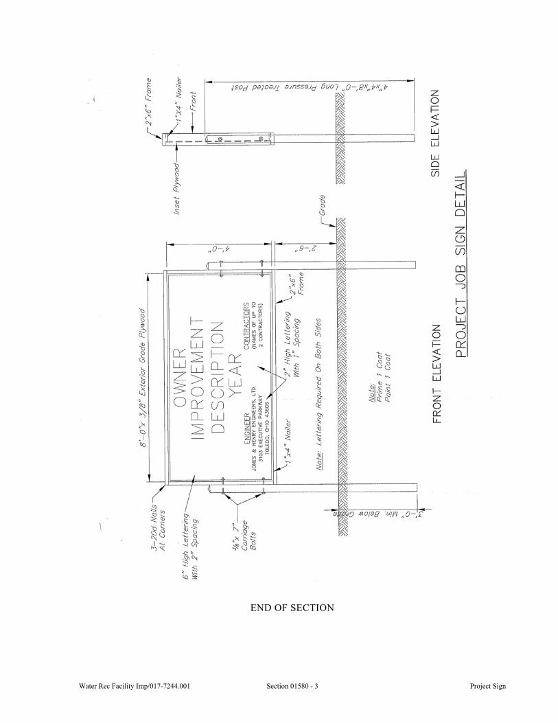
Water Rec Facility Imp/017-7244.001 Section 01580 - 3 Project Sign
END OF SECTION

Project Sign Section 01580 - 4 Water Rec Facility Imp/017-7244.001
This page was intentionally left blank.
Water Rec Facility Imp/017-7244.001 Section 01590 - 1 Field Office
SECTION 01590
FIELD OFFICE
GENERAL
1.01 SCOPE
A. This Section includes the requirements of field offices for the Resident Project Representative and other representatives of the Owner.
B. The Contractor shall provide, furnish, and maintain until the completion and acceptance of the Work, a separate field office and appurtenant facilities for the exclusive use of the project representative and other representatives of the Owner. Joint occupancy with other activities will not be permitted. The office shall be placed at a location approved by the Engineer with parking area, sanitary sewers, and water available.
C. Contractor shall provide and maintain the following including, but not limited to, access, drives, parking areas, walks, sanitary sewers, potable water, HVAC, security of office, and cleaning services.
D. The offices shall be installed and ready for use with all equipment and services before the commencement of any work on the project site. No progress payment will be made until field office has been approved by the Owner and Engineer.
E. The office, including equipment and furnishings, shall be new or in good used condition acceptable to the Owner and Engineer.
PRODUCTS
2.01 STRUCTURE
A. The office shall be an office trailer or a separate building. If a separate building is provided, it shall have concrete or solid wood floors and shall be weathertight.
1. The office shall be a minimum of 400 square feet.
B. The structure shall have two doors minimum and adequate window area. All doors shall be fitted with identical cylinder locks for one-key operation. Windows shall be operable and fitted with insect screens, Venetian blinds, and 1-inch mesh, No. 12 wire (minimum) security screens.
C. The office shall be equipped with, but not limited to, the following:
1. Central air conditioning and heating or individual units for each room.
2. Electric lighting.
3. Clothes closet.
4. Lavatory and flush-type toilet connected to City utilities.
D. Where water and sewage facilities are not available, the Contractor shall provide and maintain a portable chemical toilet.
2.02 PARKING FACILITIES
A. The Contractor shall provide at least two parking spaces 10-feet by 20-feet for the exclusive use of the Resident Project Representatives.
B. Parking spaces shall be 8 inches of compacted aggregate over a compacted subgrade. Parking shall not allow ponding of water.
Field Office Section 01590 - 2 Water Rec Facility Imp/017-7244.001
C. Contractor shall maintain parking area free of snow, ice, and provide positive drainage. Where trailer is placed on or adjacent to existing asphalt surfaces to be used for parking facilities, Contractor shall also maintain asphalt.
2.03 OFFICE EQUIPMENT
A. The Contractor shall provide the following furniture for use in the Resident Project Representative’s Field Office:
2 desks 1 plan racks 8 chairs (folding type) 1 drafting stools 1 drafting tables 1 four-drawer letter filing cabinet 1 bookcases (36-inch by 30-inch by 10-inch each) 2 wastepaper baskets 2 conference tables (approximately 4-feet by 6-feet) 1 metal two-door storage cabinet (approximately 3-feet by 2-feet by 6-feet-6-inch
with lock) 1 Color laser jet, multi-function printer capable of printing 11” x 17” paper.
Contractor shall be responsible for software necessary, to be installed on Engineer’s computer.
1 Fully equipped, wall mounted first aid kit. Restock first aid supplies monthly.
1 3.1 cubic feet refrigerator/freezer.
1 0.9 cubic feet microwave oven.
B. Cost of supplies and maintenance for printer/scanner/copier/fax shall be the responsibility of the Contractor.
C. Identifying exterior sign acceptable to the Engineer, at least 24 inches by 36 inches in size. Sign shall be white with light blue lettering and contain Engineer’s logo. Text shall be 4 inches high, Arial font, unless otherwise approve by the Engineer. At minimum, the sign shall read:
Field Office Jones & Henry Engineers, Ltd.
2.04 INTERNET
A. High speed internet connection shall be provided, by either wireless, satellite, or DSL. Service shall be unlimited access and the cost of internet service paid by the Contractor.
EXECUTION
3.01 SERVICES
A. All fuel, electricity, and telephone/internet service shall be paid by the Contractor.
B. The Contractor shall supply weekly janitorial services to maintain the office in a clean condition. If a toilet and lavatory are provided, these services shall include, but not limited to, paper towels, toilet paper, hand soap, disinfecting cleaners and handheld air fresheners.
C. The field office shall be maintained by the Contractor until the Work is complete. Earlier removal shall not be done without prior written approval of the Owner and Engineer. Field office removal and restoration of the area shall be the Contractor’s responsibility.
Water Rec Facility Imp/017-7244.001 Section 01590 - 3 Field Office
3.02 SECURITY
A. Contractor shall provide and maintain security equipment, procedures for the protection of the trailer, and trailer contents.
B. Contractor shall be responsible for the security of the field office trailer including, but not limited to, the following:
1. Interior and exterior security lighting.
2. Perimeter fencing of field office site.
3. Door latch guards and window security bars or screens.
C. Contractor shall supply to Engineer two sets of door keys for the field office.
3.03 LOCATION
A. Field office shall be located to provide access by Owner and Engineer and visitors without having to traverse the project site.
B. Field office shall be located where it will cause as little interference with the Work as possible. Relocating of the field office during the course of the project shall not be permitted.
C. Field office location shall be coordinated with and approved by the Owner and Engineer.
SPECIAL PROVISIONS
None.
END OF SECTION

Field Office Section 01590 - 4 Water Rec Facility Imp/017-7244.001
This page was intentionally left blank.
Water Rec Facility Imp/017-7244.001 Section 01800 - 1 Construction Survey Work
SECTION 01800
CONSTRUCTION SURVEY WORK
GENERAL
1.01 SCOPE
A. This Section includes the furnishing of all labor, materials, equipment, and services necessary for the completion of Construction Survey Work in accordance with the Contract Documents.
B. This Work consists of the layout of all lines and grades shown on the Drawings or as altered or modified by the Engineer, control survey and of miscellaneous survey work related to construction of the project.
1.02 PROJECTION
A. The Contractor shall protect and preserve the established reference points and monuments.
B. Whenever monuments are encountered in the line of work, whether shown on the Drawings or not, the Contractor shall notify the Engineer in writing at least 24 hours in advance of moving same, and under no circumstances is such a stone or other monument to be removed or disturbed by the Contractor or by any of his men without a written order of the Engineer and only when a registered surveyor representative of the Owner is present.
1.03 REPLACEMENT OF LOST SURVEY POINTS
A. Whenever a reference point or monument is lost or destroyed or requires relocation, the Contractor shall, at his own expense, accurately relocate and replace all such points so lost, destroyed, and moved.
1.04 SUBMITTALS
A. Submittals shall be in accordance with the requirements of Section 01300 and shall include:
1. Information for the Record:
a. Layout Sheets including, but not limited to, Benchmarks both temporary and permanent and Pipeline layout staking.
b. Field Notes and survey log.
B. Contractor shall provide the Engineer and Resident Project Representative, no later than five working days prior to installation, all Logs, reports, field notes, drawings and documentation as specified shown on the Drawings or directed
C. No pipeline or related work shall be considered for payment until all logs, reports field notes drawings and documentation as specified, shown on the Drawings or directed has been submitted to the Engineer or Engineers representative.
PRODUCTS
2.01 CONSTRUCTION STAKING
A. All construction points shall be marked with a wooden hub and nail or a PK nails in concrete and asphalt pavements and walks.
B. All points located in areas of heavy underbrush, inaccessible or limited site distance shall be identified with a wood lath extending a minimum of 3 feet above the ground.
Construction Survey Work Section 01800 - 2 Water Rec Facility Imp/017-7244.001
C. All points located in paved surfaces shall be clearly marked with paint. Contractor shall obtain written permission from owner to use paint for marking.
EXECUTION
3.01 COORDINATION
A. The Contractor shall provide field forces necessary to lay out the location, alignment, elevation, and grade of the Work shown on the Drawings and in conformance with the control points and benchmarks shown on the Drawings.
B. The Contractor shall use competent personnel and suitable equipment for the layout of the work required. If the layout work involves more than a few simple distance and elevations from established reference points, the Contractor shall employ a Registered Surveyor to supervise the layout work.
C. Contractor shall furnish the necessary labor to assist the Engineer in checking the installation, if required.
3.02 EXISTING CONNECTION POINTS
A. The Contractor shall verify critical elevation points of the existing utilities prior to commencing installation of work. Critical points shall include all points where new work connects to existing utilities and existing utilities that could be conflicts with work. All data shall be provided to the Engineer before commencing work.
3.03 RIGHTS-OF-WAY AND EASEMENTS
A. Rights-of-way or easement(s) shall be staked at points along the boundaries so that at least two stakes can be seen distinctly from any point along the boundary line. The staking shall not exceed 200-feet in any direction. All points of change in width or direction of the rights-of-way or easement(s) boundary line shall be staked.
B. When the Contractor performs construction and the zone of influence is within 10-feet of a rights-of-way or easement(s) boundary line, they shall place stakes properly identifying points of change in width or direction of the boundary line and at points along the boundary line not to exceed 25-feet.
3.04 RESERVED
3.05 RESERVED
3.06 RESERVED
3.07 RESERVED
3.08 LOCATION OF STRUCTURES AND UNDERGROUND PIPING
A. The location of new structures and underground utilities shall be based on the dimensions, coordinates, and requirements shown on the Drawings or specified.
B. If it is stated on the Drawings or specified that the location and/or elevation of the new structure or underground piping shall depend on the location of existing underground or otherwise hidden facilities, those existing underground or hidden facilities shall be located by the Contractor prior to his determination of the location and/or elevation of the new facilities. This requirement shall override any other specific location dimensions or coordinates shown on the Drawings for that structure or piping.
C. If the location or elevation determined by the Contractor, in accordance with the above requirements, appears to cause conflicts with existing structures or utilities or appears to potentially cause functional issues with either the existing or new structures or utilities, the Contractor shall notify the Engineer immediately.

Water Rec Facility Imp/017-7244.001 Section 01800 - 3 Construction Survey Work
D. In no case shall coordinates or other location information be extracted or interpolated from the electronic CAD files that may be provided to the Contractor by the Owner or Engineer without the specific approval of the Engineer.
SPECIAL PROVISIONS
None. END OF SECTION

Construction Survey Work Section 01800 - 4 Water Rec Facility Imp/017-7244.001
This page was intentionally left blank.
Water Rec Facility Imp/017-7244.001 Section 02110 - 1 Removal of Structures and Obstructions
SECTION 02110
REMOVAL OF STRUCTURES AND OBSTRUCTIONS
GENERAL
1.01 SCOPE
A. This Section includes demolition of existing structures and removal of pavement, piping, and equipment necessary to clear space for new construction and/or to rehabilitate existing construction.
1.02 SUBMITTALS
A. Submittals shall be in accordance with all requirements of Section 01300 and shall include:
1. Information for the Record:
a. The Contractor shall submit, as specified, a copy of a signed permit from the owner of the property upon which the debris, removed under this Section, will be disposed.
b. Dust and noise control measures.
c. Inventory and documentation list for removed and salvaged materials for the Owner.
1.03 QUALITY ASSURANCE
A. Contractor shall execute the work in compliance with all federal, state, and local codes. Any removal or demolition shall not leave the Owner in violation of any such regulations or codes unless approved by the Owner and Engineer.
1.04 PROTECTION
A. Structures shall be removed in such a manner as not to damage any portions of the existing structure which are to remain in place.
PRODUCTS
2.01 FILL MATERIAL
A. Fill material shall be in accordance with Section 02200.
B. Temporary installations shall allow the plant to operate without impeding the operations of the plant and shall be approved by the Owner prior to use.
EXECUTION
3.01 COORDINATION
A. Demolition work extending beyond the limits as specified, shown on the Drawings, or as required, will be considered unauthorized. The Contractor, at no additional cost to the Owner, shall repair said damage to a condition equal to or better than existed prior to commencement of the Work.
B. Existing structures and equipment which are damaged in appearance or function by performance of demolition work shall be replaced or repaired, at Owner’s discretion and to an approved condition, by the Contractor at no increase in Contract Price.
Removal of Structures and Obstructions Section 02110 - 2 Water Rec Facility Imp/017-7244.001
3.02 PAVEMENTS, SIDEWALKS, CURBING, AND SIMILAR STRUCTURES
A. Removal of existing pavements, sidewalks, curbing, and similar structures shall end at an existing joint or a sawed joint. Sawed joints shall be straight, neat, and free from chipped or damaged edges.
B. For removal of non-reinforced concrete, the minimum depth of saw cut shall be 3 inches.
C. For removal of reinforced concrete, the depth of saw cut shall be sufficient to cut the steel unless specified otherwise.
D. If the concrete is coated with a bituminous surface or other material, the depth shall be sufficient to cut into the concrete, not including the coating depth, as specified above.
3.03 EXCAVATION OF RIGID PAVEMENT
A. The Contractor shall excavate rigid pavement, consisting of concrete or concrete base with a wearing surface of brick or bituminous concrete, wherever such excavation is required for the purposes of this Contract.
3.04 MANHOLES, CATCH BASINS, INLETS, AND SIMILAR STRUCTURES
A. Existing manholes, catch basins, inlets, and similar structures designated to be removed shall be completely removed.
B. Manholes, catch basins, inlets, and similar structures designated to be abandoned shall be removed to an elevation of at least 3 feet below the finished subgrade or ground surface. The remaining void shall be filled with special backfill material compacted to 100 percent optimum density per ASTM D-698 or controlled density fill, CDF if permitted by the Engineer. All sewer openings in manholes located on sewer lines that are not to be filled, shall be plugged with 8 inch minimum thickness masonry plug.
C. Sewers designated to remain in service and connected to structures indicated to be removed or abandoned shall be rebuilt through the area with new pipe. Sewer flow shall be maintained between removal and replacement operations. Abandoned sewers shall be sealed and made watertight with approved precast stoppers or masonry bulkheads.
D. All castings or hydrants salvaged from abandoned or removed structures shall remain the property of the Owner, if requested by the Owner, and shall be cleaned and transported by the Contractor to a site designated by the Owner or incorporated in the work where called for on the Drawings, scheduled, or so directed. If Owner decides salvaged materials are not wanted, the Contractor shall dispose of them at no additional cost to the Owner.
3.05 GROUT-FILLED ABANDONMENT OF PIPE, CONDUIT, AND SIMILAR STRUCTURES
A. Ends of sewer designated to be abandoned shall be sealed with approved masonry bulkheads or factory caps and plugs.
B. Contractor shall determine and modify, as necessary, the mix of the flowable fill material to satisfactorily fill the entire abandoned sewers and structures. ACI 229R-99 Table 5.1 provides examples of acceptable mix designs.
C. Quantities of flowable fill material used to fill the conduits shall be monitored continuously during the placement.
D. Bulkheads shall be installed as shown on plans and as needed by the Contractor’s method to completely fill the abandoned sewers.
E. Sites disturbed by the grout-filled abandonment work shall be restored as part of this work.
Water Rec Facility Imp/017-7244.001 Section 02110 - 3 Removal of Structures and Obstructions
3.06 GUARDRAIL AND FENCE
A. Where so required by the Drawings, existing guardrail and fence shall be carefully dismantled and stored for reuse or for salvage by the Owner.
B. Wood posts and other materials not considered salvageable by the Owner shall be disposed of by the Contractor.
3.07 SUPERSTRUCTURES, TANKS, CHAMBERS, AND SIMILAR STRUCTURES
A. Care shall be used in demolishing structural elements which are continuous with structural elements remaining in service. Unless otherwise permitted by the Owner, concrete and masonry shall be cut through entirely with a masonry or concrete saw before removing the unwanted portions.
B. Methods and equipment used in demolition work shall be chosen so the structural integrity and water tightness of both new construction and existing plant structures remain unimpaired by the performance of the demolition work.
C. Portions of underground structures which are in the way of new sewers, piping, and structures shall be removed from the area of conflict to a distance not less than 6 inches from any point of the new construction.
D. Care shall be used when removing existing concrete from around reinforcing steel which must be used for securing new concrete. If this reinforcing steel is damaged, the Contractor shall remove additional existing concrete until sufficient existing reinforcing steel is exposed to provide adequate embedment length in the new concrete, as approved by the Engineer.
3.08 EQUIPMENT REMOVAL
A. All equipment, valves, piping, fittings, and miscellaneous steel structures that are removed shall remain the property of the Owner and shall be stored at a site selected by the Owner. The Owner reserves the right to require the Contractor to dispose of certain unwanted portions of removed equipment and materials. The Owner shall have the right to reject any or all materials removed during construction, and the Contractor shall haul away and dispose of these materials in a suitable manner at no additional cost to the Owner.
B. See Section 16010 for Removal of Electrical Equipment & Appurtenances.
C. The Contractor shall replace, at no cost to the Owner, equipment designated to be turned over to the Owner that is lost or damaged.
3.09 RESERVED
3.10 DISPOSAL OF DEBRIS
A. All debris resulting from demolition operations; i.e., broken concrete, masonry, pipe, miscellaneous metal, trees and brush, equipment, etc., shall be trucked from the work site by the Contractor and disposed of at spoil sites in a legal manner, in full compliance with applicable codes and ordinances.
B. The Contractor shall police the hauling of debris to ensure that all spillage from haul trucks is promptly and completely cleaned up.
3.11 BACKFILLING
A. All trenches, holes, and pits resulting from the removal and abandonment of any structure or obstruction shall be backfilled and compacted in accordance with the requirements of Section 02200, Excavation and Backfill.
Removal of Structures and Obstructions Section 02110 - 4 Water Rec Facility Imp/017-7244.001
3.12 MAINTAINING OF PLANT OPERATIONS
A. Demolition shall be scheduled and performed in strict conformance with these Specifications and in a manner which results in no interruption of treatment operations beyond that provided for and approved by the Owner and regulatory agencies. The date and time of commencing the separate items of demolition work shall be submitted to the Engineer for review, and no demolition work shall commence until the Engineer’s approval of date and time is given.
B. All equipment, labor, and material costs which are made necessary by the requirements of the Sequence Plan, shall be borne by the Contractor.
3.13 USE OF EXPLOSIVES
A. The use of explosives for the work of removal of structures and obstructions is PROHIBITED.
3.14 PIPING REMOVAL
A. At the location where pipe removal stops, the remaining pipe end shall be capped. The cap must be pressure tight and restrained from movement due to pressures inside the pipe.
B. Piping removal includes, but not limited to, all hangers, stands, and anchoring devices.
3.15 OPENINGS AND PATCHING
A. The Contractor shall fill all openings created by equipment, piping, and conduit removals.
B. The Contractor shall patch any marred surfaces created by equipment and piping removals.
C. All filling and patching work shall be performed in accordance with the specifications.
D. All anchor bolts shall be removed and holes filled or cut off flush.
SPECIAL PROVISIONS
None.
END OF SECTION
Water Rec Facility Imp/017-7244.001 Section 02552 - 1 Precast Concrete Manholes
SECTION 02552
PRECAST CONCRETE MANHOLES
GENERAL
1.01 SCOPE
A. This Section includes furnishing and installing precast concrete manholes, including drops and manhole stacks of types and at locations shown on the Drawings and scheduled.
B. This Section includes removing existing structures, additional excavation to widen and deepen trenches for manhole construction, furnishing and installing concrete of classes called for, portland cement mortar, reinforcing steel, precast concrete pipe integral base sections, bottom riser sections, transition sections, and riser sections, eccentric cones, flat slab tops and grade rings, flexible manhole connections, pipe for drop connections, manhole steps, manhole frames and covers, plugging lifting holes, pointing joints, joint wrap installing, forming channels through manhole bottoms, making watertight connections to new and existing sewers, and other work incidental to manhole construction and testing.
C. Additional product requirements are specified in Section 01350.
1.02 SUBMITTALS
A. Submittals shall be in accordance with all requirements of Section 01300 and shall include:
1. Shop drawings for review:
a. Manufacturer’s Shop Drawings indicating physical dimensions, pipe openings, precast section arrangement, adjusting rings, castings, and joint details for each size and type of manhole components furnished for the project. Shop Drawing shall incorporate the planned elevations and details.
b. Manufacturer’s certification indicating that the manhole components and joints meet specifications for each production run for each size and type furnished.
2. Information for the record:
a. The Engineer may request test results to verify certification. Certification documents shall be according to the Source Quality Control of this Section.
PRODUCTS
2.01 MATERIALS
A. Type of Manhole Sections:
1. Manhole Stacks - Manhole stacks shall mean 4-feet diameter manholes used for access to reinforced concrete manhole chambers and precast manhole riser tee sections.
2. Type I Manholes - Type I manholes shall mean 4-feet diameter manholes with precast integral base sections for sanitary sewers and either precast integral base sections or precast bottoms for storm sewers. Pipe connections to manholes shall be made with flexible water tight joints. Type I manholes are intended for installation of pipes 18-inch diameter and smaller unless noted otherwise.
Precast Concrete Manholes Section 02552 - 2 Water Rec Facility Imp/017-7244.001
3. Type II Manholes - Type II manholes shall mean manholes with 5-feet diameter precast integral base sections. Pipe connections to manholes shall be made with flexible water tight joints. Type II manholes are intended for installation of 21-inch through 30-inch diameter pipes unless noted otherwise.
B. Precast concrete pipe manhole sections, integral base sections, transition sections, eccentric cones, flat slab tops, and adjusting rings shall conform to ASTM C-478. Reinforcing in transition sections shall be equal to that specified for wall sections of the larger diameter.
C. Joints shall be tongue and groove type with a gasketed seal type conforming to ASTM C-443.
D. The standard length of riser sections shall be 48-inch. Lengths of 32-inch or 16-inch shall be used to meet required dimensions and as specified.
E. Openings for connecting pipes in riser sections, bottom riser sections, and integral base sections, and for access in flat slabs shall be pre-formed or cored by the manufacturer, except “cut-out” openings may be made in bottom riser sections for Type IV manholes. Cut-out openings shall be made immediately after the pipe is removed from the casting form. All cored openings for sewer pipe connections shall have flexible joints.
F. Precast integral base sections shall be of monolithic construction. Base flat slab floors or integral floors shall have a minimum thickness of 6-inch for risers up to and including 48-inch in diameter and 8-inch for larger diameters. A layer of reinforcement shall be placed above the midpoint, and shall have a minimum area of 0.12 square inch/linear feet in both directions.
G. Manhole sections shall be constructed with no pipe connection within 6 inches of a joint in the structure.
H. Manhole sections shall be clearly marked and identified with the manhole number, section placement order, casting date, trademark, name of the manufacturer, and location of the production plant.
2.02 ACCESSORIES
A. Manhole Steps - Manhole steps shall be of polypropylene plastic reinforced with a 1/2-inch No. 60 grade reinforcing rod. Steps shall be M. A. Industries Model PS-1, or equal.
1. Specified manhole steps shall be factory installed to provide a continuous ladder of 16-inch Center-to-Center rung spacing. Steps shall be placed in the forms and cast in pipe wall or placed immediately after the pipe is removed from casting and carefully mortared in place with nonshrink mortar to ensure a watertight joint. Manhole step installation shall be in compliance with OSHA regulations. If the outer surface of the pipe wall is pierced the patch shall be completely covered with a bituminous sealer.
B. Manhole frames and covers shall be as shown on the Drawings and in conformance with requirements of Section 05540.
1. Where pressure tight manhole frames and covers are called for, threaded inserts shall be cast in eccentric cones or flat slab tops and holes formed or cored in adjusting rings to match bolt size and spacing specified for manhole casting.
C. Mortar:
1. Mortar used for the structures herein specified shall conform to ASTM C-270 Type S, containing no masonry cement. The mortar shall be composed of one part portland cement to two parts sand by volume.
2. Nonshrinking Mortar - Materials for nonshrinking mortar shall be Sauereisen F-100, Five-Star, or equal.
Water Rec Facility Imp/017-7244.001 Section 02552 - 3 Precast Concrete Manholes
D. Cast-in-Place Concrete:
1. All cast-in-place concrete used for concrete bases and for forming channels in manhole bottoms shall be Class A as specified in Section 03300.
2. All concrete used for supporting precast concrete manhole bases shall be Class B as specified in Section 03300.
E. Reinforcing Steel - Reinforcing steel used in cast-in-place concrete shall meet the requirements of Section 03200.
F. Flexible Joints - Joints for precast pipe openings shall be “A-LOK X-CEL” as manufactured by A-LOK Products, Inc., “Kor-n-seal” as manufactured by National Pollution Control Systems, Inc., or equal in accordance with ASTM C-923.
G. Pipe for Manhole Drops - Pipe for manhole drops shall conform to specifications of Section 15210 for the required size and type shown on the Drawings.
H. Joint Wrap - Polyolefin backed exterior joint wrap used to cover the exterior side of joints shall be ConSeal CS212; Riser Wrap by Pipeline Seal & Insulator, Inc. or equal. Minimum width shall be 12 inch. Joint wrap shall include the use of brush or roller applied adhesive surface primer formulated for use with joint wrap. Seal shall meet the requirements of ASTM E-1745, C-877, and ASTM C-990.
I. Chimney seal shall be applied to the exterior of all manholes and shall cover the joint at iron casting, adjusting ring and lap over manhole riser/top section. Seal shall be HDPE heat shrink as manufactured by Pipeline Seal & Insulator, Inc. (Riser-Wrap) and CCI Pipeline System (Wrapid Seal), or equal.
J. Chimney seals which are installed on the interior of manholes will not be acceptable.
EXECUTION
3.01 COORDINATION
A. Location and type of manholes installed shall be as shown on the Drawings or directed.
B. Construction shall be in conformance with details shown on the Drawings and as specified.
C. Excavation for manhole construction shall be prepared as directed in applicable paragraphs of Sections 02200.
3.02 INSTALLATION OF INTEGRAL BASE SECTIONS
A. The manhole base may be placed on 6 inches compacted granular bedding material.
3.03 INSTALLATION OF BOTTOM RISER SECTIONS (WITHOUT INTEGRAL BASE)
A. Unless otherwise called for on the Drawings or directed, precast bottom riser sections shall be placed with cast-in-place reinforced concrete bases.
B. The base shall be of Class A concrete 12-inch thick minimum placed on undisturbed earth or a minimum 6-inch-thick aggregate stone cushion. Reinforcing shall be as shown on the Drawings.
C. The cut-out riser section shall be blocked in place above the pipe and the concrete base poured in place. Concrete shall be extended above the lower rim of the riser wall as required to provide a watertight seal around the entire circumference of the riser section. The sewer pipe shall be bedded in concrete monolithic with the base to the first joint each way from the manholes.
D. On straight runs the Contractor may carry the pipe through the manhole and break out the top half after the fill concrete has set. In all cases the pipe shall extend through the manhole wall to the inside face.
Precast Concrete Manholes Section 02552 - 4 Water Rec Facility Imp/017-7244.001
3.04 CHANNELING MANHOLE BOTTOMS
A. The bottoms of all manholes shall be channeled to conduct flow in the planned direction. The channel walls shall be formed or shaped to the full height of the crown of the outlet sewer in such a manner to not obstruct maintenance of flow in the sewers and shall match inverts of connection pipe at the manhole wall.
B. Manholes which do not have integral base or channels precast with base section, as approved by Engineer, shall have channels formed and placed in the field with Class A concrete.
3.05 PRECAST CONCRETE RISER SECTIONS
A. The shortest length of riser section to be incorporated into the manhole shall be installed immediately below the eccentric cone section or the flat slab top.
B. Riser section joints shall be pointed and lifting holes filled with nonshrinking mortar.
C. Riser section exterior joints shall be wrapped and sealed with joint wrap as specified herein. Concrete shall be primed a minimum of two times. The first coat shall be allowed to fill concrete depressions and bug holes. Contractor shall follow manufacturer recommendations.
D. Contractor shall protect joint wrap from damage during back filling and other related work.
3.06 INSTALLATION OF MANHOLE FRAMES
A. Manhole frames and covers shall be installed to grades shown on the Drawings or as directed.
B. Adjustment of manhole castings shall be made using specified precast grade rings and portland cement mortar joints or preferred bitumen seals.
C. Each manhole casting shall be anchored in place using four 5/8-inch stainless steel bolts with nuts as detailed on the Drawings or directed.
D. The maximum depth of adjustment below any manhole casting shall be 16 inches and the minimum depth of adjustment shall be 4 inches.
E. In concrete pavement, separate frame from pavement with 1/2-inch thick premolded mastic joint material extending from the base of the frame to the top of the frame.
F. Manhole castings located in pavement areas shall be installed with the top of the casting 1/4 inch below the finished grade of the adjacent pavement surface.
3.07 CHIMNEY SEAL
A. Installation of chimney seal shall be after casting has been adjusted to final grade. Chimney seal shall cover all joints at manhole top including, but not limited to, iron casting, adjusting rings and manhole riser.
B. Chimney seal shall be installed per manufacturer recommendations. Chimney seal shall provide a water tight seal.
3.08 MANHOLE TESTING
A. Each manhole shall be tested in accordance with ASTM C-1244 ‘Standard Test Method for Concrete Sewer Manholes by the Negative Air Pressure (Vacuum) Test Prior to Backfill.’ in the presence of the Engineer
B. All lift holes shall be plugged with an approved non-shrink grout before testing.
C. All pipes entering the manhole shall be plugged and braced to prevent being drawn into the manhole.
D. Testing shall be by drawing a vacuum on the manhole using equipment specifically designed for such testing. A test head with necessary gauges and connections shall be
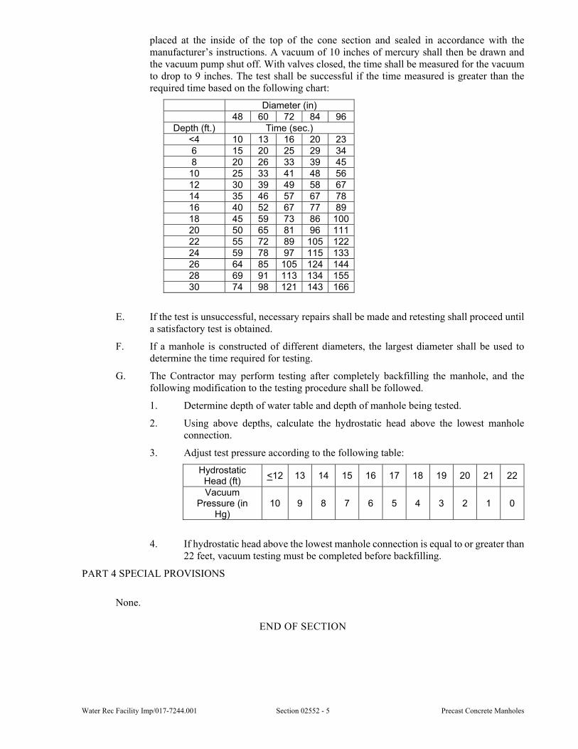
Water Rec Facility Imp/017-7244.001 Section 02552 - 5 Precast Concrete Manholes
placed at the inside of the top of the cone section and sealed in accordance with the manufacturer’s instructions. A vacuum of 10 inches of mercury shall then be drawn and the vacuum pump shut off. With valves closed, the time shall be measured for the vacuum to drop to 9 inches. The test shall be successful if the time measured is greater than the required time based on the following chart:
Diameter (in) 48 60 72 84 96
Depth (ft.) Time (sec.) <4 10 13 16 20 23 6 15 20 25 29 34 8 20 26 33 39 45 10 25 33 41 48 56 12 30 39 49 58 67 14 35 46 57 67 78 16 40 52 67 77 89 18 45 59 73 86 10020 50 65 81 96 11122 55 72 89 105 12224 59 78 97 115 13326 64 85 105 124 14428 69 91 113 134 15530 74 98 121 143 166
E. If the test is unsuccessful, necessary repairs shall be made and retesting shall proceed until a satisfactory test is obtained.
F. If a manhole is constructed of different diameters, the largest diameter shall be used to determine the time required for testing.
G. The Contractor may perform testing after completely backfilling the manhole, and the following modification to the testing procedure shall be followed.
1. Determine depth of water table and depth of manhole being tested.
2. Using above depths, calculate the hydrostatic head above the lowest manhole connection.
3. Adjust test pressure according to the following table:
Hydrostatic Head (ft)
<12 13 14 15 16 17 18 19 20 21 22
Vacuum Pressure (in
Hg) 10 9 8 7 6 5 4 3 2 1 0
4. If hydrostatic head above the lowest manhole connection is equal to or greater than 22 feet, vacuum testing must be completed before backfilling.
SPECIAL PROVISIONS
None.
END OF SECTION

Precast Concrete Manholes Section 02552 - 6 Water Rec Facility Imp/017-7244.001
This page was intentionally left blank.
Water Rec Facility Imp/017-7244.001 Section 02800 - 1 Sodding, Seeding, and Mulching
SECTION 02800
SODDING, SEEDING, AND MULCHING
GENERAL
1.01 SCOPE
A. This Section includes fine grading, placing sod, and seeding and mulching areas designated on the Drawings, specified, or ordered.
B. The work consists of fine grading, furnishing and placing topsoil; sod; seed; mulching material; and fertilizer; and watering seeded or sodded areas until growth is established.
C. The Contractor shall restore all grass areas damaged by his operations.
D. Unless otherwise specified herein or directed, work shall be in conformance with MDOT Section 816, Turf Establishment.
1.02 SUBMITTALS
A. Submittals shall be in accordance with the requirements of Section 01300 and shall include:
1. Shop Drawings for Review:
a. Manufacturer's project information for materials.
2. Information for the Record:
a. Submit to Resident Project Representative:
1) Invoices indicating the weight, brand, and composite analysis of fertilizer used on the project.
2) Bag tickets indicating weight and composition of all seed used on the project.
PRODUCTS
2.01 SOD
A. Sod shall conform to MDOT 917.13, unless otherwise specified in Special Provisions.
2.02 SEED
A. Seed mixtures shall be in conformance with the requirements of MDOT Tables 816-1 and 917-1, Mixture TUF, unless otherwise specified in the Special Provisions.
2.03 FERTILIZER
A. Commercial fertilizers shall be from a dealer or manufacturer whose brands and grades are registered or licensed by the State of Michigan, Department of Agriculture. The content of nutrients shall be 12-12-12, unless otherwise approved by Engineer.
2.04 MULCHING MATERIAL
A. Mulching material shall be straw, wood fiber or compost reasonably free of weed seed, and other foreign materials, conforming to MDOT Section 917.15A.
2.05 MATTING MATERIAL
A. Matting material shall be in conformance with the requirements of MDOT Section 917.14B, unless otherwise specified in the Special Provisions.
Sodding, Seeding, and Mulching Section 02800 - 2 Water Rec Facility Imp/017-7244.001
2.06 TOPSOIL
A. Topsoil furnished by the Contractor shall be as specified in Section 02200.
EXECUTION
3.01 FURNISHING AND PLACING TOPSOIL
A. Areas from which the top layer of soil has been removed or disturbed shall be recovered with a minimum of 4 inches of recompacted topsoil placed in conformance with Section 02200 or MDOT Section 816.03A.
3.02 PREPARATION
A. The operating of finish grading and sowing shall not be performed when the ground is frozen or muddy.
B. Areas to be Sodded:
1. Preparation of areas to be sodded shall be in conformance with MDOT Section 816.03D.
C. Areas to be Seeded:
1. Unless otherwise shown on the Drawings or specified in Part 4, all areas of disturbed soil on the project site shall be seeded.
2. The area to be seeded shall be prepared in accordance with Section 02200.
3. Fertilizer shall be applied at a rate which will provide 240 pounds per acre of chemical fertilizer nutrients in equal proportions of Nitrogen, Phosphoric Acid, and Potash. Either dry or liquid fertilizer may be used and shall be distributed in an even pattern over the specified area, then thoroughly disked, harrowed, or raked into the soil to a depth of not less than 1 inch.
3.03 INSTALLATION
A. Sodding:
1. Sod shall be placed in conformance with MDOT Section 816.03D.
2. No sod shall be placed when the temperature is below 32 degrees F. No frozen sod shall be placed nor shall any sod be placed upon frozen soil. When sod is placed between the dates of June 1 and October 15, it shall be covered immediately with a straw mulch 1-inch-thick, loose measurement.
B. Seeding:
1. The seed shall be mixed thoroughly and sown evenly at a rate specified by MDOT. The seed mixture may be sown dry or hydraulically unless directed otherwise in Part 4 of this Section.
2. The seed mixture shall be applied when the soil is in a workable condition and shall be raked into a depth of approximately 1/4 inch.
3. Seed shall be sown only between the dates of May 1 and October 15, unless otherwise permitted by the Engineer.
C. Mulching:
1. Within 24 hours after an area has been seeded it shall be mulched in conformance with one of the following specified methods as designated in Part 4:
2. Mulch:
a. Mulching with hay or straw shall be in conformance with mulching requirements of MDOT Sections 816.03E, F, and G except that in front of
Water Rec Facility Imp/017-7244.001 Section 02800 - 3 Sodding, Seeding, and Mulching
residences the mulching material shall be kept in place by an approved nontracking adhesive or other approved method in lieu of the specified asphalt emulsion.
b. Matting shall be used on all slopes greater than 10:1. Matting used for mulching shall be placed in conformance with MDOT Section 816.03H.
D. Seeded and sodded areas shall be watered and maintained as specified below until they are established.
1. The seed bed shall be thoroughly watered, as soon as the seed is covered.
2. Water shall be applied by a hydro-seeder or water tank under pressure with a nozzle producing a spray that will not dislodge the mulching material.
3. Water applications shall be made at least once a week, provided significant rainfall has not occurred within the weekly period.
4. The rate of application shall be 240 gallons per 1,000 square feet
5. The Contractor shall keep all sodded areas, including the subgrade, thoroughly moist for two weeks after sodding. After the two-week period, the Contractor shall water the sod as specified above.
6. Mulch and matting areas shall be maintained until all work on the Contract has been completed and accepted.
7. The seeded area shall be mowed once at an approximate height of 6 inch as directed by the Engineer to control excess growth, including weeds.
8. Maintenance shall consist of the repair of areas damaged by erosion, wind, fire, or other causes. The soil in these damaged seeded areas shall be restored to the condition and grade existing prior to application of mulch or matting, and restored areas shall be relimed, refertilized, and reseeded. Where necessary, the mulch or matting shall be completely replaced. Damaged sod shall be replaced with new sod.
SPECIAL PROVISIONS
None.
END OF SECTION

Sodding, Seeding, and Mulching Section 02800 - 4 Water Rec Facility Imp/017-7244.001
This page was intentionally left blank.
Water Rec Facility Imp/017-7244.001 Section 03100 - 1 Concrete Formwork
SECTION 03100
CONCRETE FORMWORK
GENERAL
1.01 SCOPE
A. This Section includes formwork for cast-in-place concrete.
1.02 SUBMITTALS
A. None required.
1.03 QUALITY ASSURANCE
A. Design, engineering, erection, bracing, and shoring of formwork shall be the responsibility of the Contractor.
B. Formwork shall comply with pertinent provisions of the following codes, standards, and specifications:
1. “Guide to Formwork for Concrete (ACI 347R),” American Concrete Institute.
2. “Standard Tolerances for Concrete Construction and Materials (ACI 117),” American Concrete Institute.
3. “Formwork for Concrete, SP-4”. “American Concrete Institute.”
C. Formwork shall be designed in accordance with requirements of governmental agencies having jurisdiction, pertinent requirements of local building codes, “Building Code Requirements for Structural Concrete (ACI 318) and Commentary (ACI 318R),” and “Specifications for Structural Concrete (ACI-301),” American Concrete Institute.
D. Formwork for liquid retaining structures shall also satisfy the requirements of “Environmental Engineering Concrete Structures (ACI-350),” American Concrete Institute.
E. Formwork shall be constructed to tolerances specified in ACI 117.
F. Regardless of specified tolerances, no portion of a structure shall extend beyond legal boundary of project.
PRODUCTS
2.01 MATERIALS
A. Form facing material shall be “new or undamaged” condition and may be plyform, tempered concrete-form-grade hardboard, metal, plastic, or other material capable of producing the specified finish. Select the grade or class of material to satisfy the requirements of strength, stiffness and surface smoothness to produce the specified finish.
B. Form Release shall be manufactured from Dayton Superior “Clean Strip J1EF”, W.R. Meadows, Inc. “Duogard or Duogard II”, L&M Construction Chemicals “Debond Form Coating”, or equal.
C. Arrangement of facing material shall be orderly and symmetrical, with number of seams kept to practical minimum.
D. Facing material shall be supported by studs or other backing capable of preventing excessive deflection. Maximum deflection of facing material shall be 1/240 of span between supports but shall not exceed specified tolerances.
Concrete Formwork Section 03100 - 2 Water Rec Facility Imp/017-7244.001
E. Material with raised grain, torn surfaces, worn edges, patches, dents, or other defects shall not be used.
F. Architectural Concrete: Maximum deflection of facing material between studs and deflection of studs and walls shall not exceed 1/400 of span between supports, but shall not exceed specified tolerances.
2.02 PERFORMANCE REQUIREMENTS
A. Formwork shall be designed to safely support vertical and lateral loads, until such loads can be safely supported by concrete structure. Loads shall be carried to ground by formwork and in-place construction of adequate strength.
B. Formwork shall be designed for dead and live loads, weight of concrete, wind, construction loads including impact, and other loads which act or might act on formwork together with appropriate safety factors and load multipliers as recommended by ACI-347.
C. Formwork shall be designed for pressure of concrete giving due consideration to rate of concrete placement, method of placement, method of consolidation, concrete mix design, temperature, and other factors pertinent to formwork design.
D. Forms shall have sufficient strength and rigidity to maintain specified tolerances.
EXECUTION
3.01 COORDINATION
A. Forms shall be used to confine concrete and shape it to required dimensions, alignment, elevation, and position.
B. Earth cuts shall not be used as forms for vertical surfaces unless specifically shown on the Drawings.
C. Runways for moving equipment and materials shall be supported directly on formwork or structural member, and shall not rest on reinforcing steel.
D. Openings shall be provided in formwork to accommodate work of other trades. Openings shall be accurately located and cut.
3.02 PREPARATION OF FORM SURFACE
A. Surfaces of forms and embedded materials shall be cleaned of accumulated concrete or mortar from previous concreting. Foreign material and contaminants shall be removed before concrete is placed.
B. Before placing reinforcement or concrete, surfaces of forms shall be covered with acceptable coating material that prevents bond with concrete, VOC compliant, and does not stain concrete surface. No coating material shall be used if form liner is used.
C. Form coating material shall not stand in puddles in forms, and shall not come in contact with reinforcement or hardened concrete against which fresh concrete is to be placed.
3.03 ERECTION
A. Forms shall be sufficiently tight to prevent loss of mortar from concrete.
B. Formwork shall be cambered to compensate for anticipated deflections from weight of fresh concrete and construction loads.
C. Shores and struts shall be provided with positive means of adjustment capable of taking-up formwork settlement during concrete placement, using wedges or jacks.
D. Formwork shall be securely braced and anchored against deflection and displacement.
Water Rec Facility Imp/017-7244.001 Section 03100 - 3 Concrete Formwork
E. Wedges used for final adjustment of formwork shall be fastened in position prior to beginning concrete placement.
F. Temporary openings shall be provided at base of column forms and wall forms and at other points where necessary to facilitate cleaning and observation immediately before concrete is placed.
G. Wood forms for wall openings shall be constructed to facilitate loosening, if necessary, to counteract swelling of forms. Wood inserts for keyways, reglets, recesses and similar uses shall be kerfed to counteract swelling.
H. At construction joints, form facing material shall overlap hardened concrete of previous placement by not more than 1 inch. Forms shall be held tight against hardened concrete to prevent offsets or loss of mortar, and to maintain true surface.
I. Insert vibrator as needed to properly consolidate concrete. Provide openings in forms as needed to insert vibrators.
J. Form Ties and Accessories:
1. Form ties and accessories to be partially or wholly embedded in concrete shall be of commercially manufactured type. Nonfabricated wire is not permitted.
2. Form ties shall be constructed so that ends can be removed to minimum depth of 1-1/2 inch without significant spalling of concrete. Form tie assemblies shall provide cone-shaped depressions 1-1/2 inch deep and at least 1 inch in diameter at concrete surface to permit filling and patching.
3. Ties shall be tight fitting or tie holes in forms shall be sealed to prevent leakage.
4. Single rod ties shall be furnished with tightly fitted washer at midpoint to prevent leakage along tie. Multiple rod ties do not require washers.
5. When tapered ties are used, large end shall be placed on liquid side of tanks and water-retaining structures. Tapered ties shall be completely removed. The Contractor shall submit the methods and materials to be used to fill the voids thus formed for Engineer’s review and approval.
K. Chamfer strips shall be placed in corners of forms and at all exposed edges to produce a beveled edge on permanently exposed surfaces. Chamfers shall be 3/4 inch or as noted on Drawings. Chamfer strips shall be wood, metal, PVC, or rubber and shall be fabricated and installed to produce uniformly smooth and straight lines. Chamfer strips shall be mitered at changes in direction.
L. Control joints shall be located and constructed as shown on Drawings.
3.04 REMOVAL OF FORMS GENERAL
A. When repair of surface defects or finishing is required at early age, forms shall be removed as soon as concrete has hardened sufficiently to resist damage from removal operations.
B. Top forms on sloping concrete surfaces shall be removed as soon as concrete has attained sufficient stiffness to prevent sagging.
C. Wood forms for wall openings shall be loosened as soon as can be accomplished without damage to concrete.
D. Ties shall be removed.
3.05 MINIMUM CONCRETE STRENGTH REQUIREMENTS FOR REMOVAL OF FORMS AND SHORING
A. Formwork for columns, walls, sides of beams and other elements not supporting the weight of concrete may be removed after curing for 24 hours.
Concrete Formwork Section 03100 - 4 Water Rec Facility Imp/017-7244.001
B. Formwork for columns, walls, sides of beams and other elements supporting the weight of concrete joists, elevated slabs and other elements may be removed after curing for seven days. These forms may be removed after three days of curing if concrete has attained 80 percent of the specified design compressive strength.
C. Formwork and shoring used to support the weight of concrete beams, elevated slabs or other similar horizontal elements may be removed after 14 days of curing if concrete has attained 90 percent of the specified design compressive strength. Otherwise, these forms shall remain in place until either this strength is attained or 21 days have elapsed.
D. Removal strength shall be determined by testing specimens field cured along with concrete they represent. Testing laboratory shall perform strength tests as specified in Section 03300. All concrete testing performed for the purpose determining the timing of formwork removal shall be accomplished at the Contractor’s expense.
E. Contractor is responsible for maintaining stability of the structure during construction when it is subjected to construction loads, wind loads and other loads after the forms have been removed.
F. Concrete structures shall not be filled with water, backfilled against or subjected to their design loads until 28 days after the commencement of curing or until field cured test cylinder specimens have reached the specified design compression strength. In no case shall concrete structures be loaded prior to curing for their specified minimum curing periods.
SPECIAL PROVISIONS
None.
END OF SECTION
Water Rec Facility Imp/017-7244.001 Section 03200 - 1 Concrete Reinforcement
SECTION 03200
CONCRETE REINFORCEMENT
GENERAL
1.01 SCOPE
A. This Section includes reinforcing steel, load transfer dowels, and accessories.
B. Additional product requirements are specified in Section 01350.
1.02 SUBMITTALS
A. Submittals shall be in accordance with requirements of Section 01300 and shall include:
1. Shop Drawings for Review:
a. Placing drawings shall indicate:
1) Construction joints, splice locations, and splice lengths.
2) Bending schedules.
3) Accessories.
b. Product literature for mechanical splices and adhesives.
2. Information for the Record:
a. Mill certificates.
1.03 QUALITY ASSURANCE
A. Reinforcement shall be detailed, fabricated, and placed in accordance with following codes, standards, and specifications.
1. “Details and Detailing of Concrete Reinforcement (ACI 315)”, American Concrete Institute, and “Reinforcing Bar Detailing,” Concrete Reinforcing Steel Institute (CRSI).
2. “Manual of Standard Practice”, Concrete Reinforcing Steel Institute.
3. “Standard Tolerances for Concrete Construction and Materials (ACI 117)”, American Concrete Institute.
B. Concrete reinforcement shall be in accordance with “Building Code Requirements for Structure Concrete (ACI 318) and Commentary (ACI 318R)”, American Concrete Institute, and “Specifications for Structural Concrete for Buildings” (ACI-301).
C. All placing of reinforcing bars in the form shall follow the CRSI “Placing Reinforcing Bars.”
D. Concrete reinforcement for environmental engineering concrete structures (liquid retaining structures) shall also be in accordance with “Environmental Engineering Concrete Structures (ACI-350),” American Concrete Institute.
1.04 DETAILING
A. When splices are not indicated on Drawings, reinforcement shall be furnished so as to minimize splices. Horizontal rebar shall be spliced within the limits of adjacent pours to be poured later to allow for unrestrained shrinkage movements. Splice locations shall be subject to Engineer’s approval. Contractor shall give sufficient advance notice satisfactory to Engineer’s representative for his inspection upon completion of installation.
B. When slab or wall reinforcement is interrupted by openings or embedments, additional reinforcement shall be furnished as shown on Drawings.
Concrete Reinforcement Section 03200 - 2 Water Rec Facility Imp/017-7244.001
1.05 DELIVERY, STORAGE, AND HANDLING
A. Bundles of reinforcing bars shall be tagged with weatherproof tags indicating quantity, grade, size, and Shop Drawing designation.
B. Bundles of welded wire fabric shall be tagged with weatherproof tags indicating quantity, style designation, width and length.
C. Reinforcement shall be stored off ground and shall be protected from oil, mud, and other deleterious substances.
PRODUCTS
2.01 MATERIALS
A. Reinforcing bars shall be grade 60 deformed bars conforming to ASTM A615 or ASTM A996.
B. Reinforcement to be welded shall be grade 60 bars conforming to ASTM A706.
C. Welded wire fabric shall be fabricated from underformed wire and shall conform to ASTM A185, except welded intersections shall be spaced not farther apart than 12-inch welded wire fabric shall be furnished in flat sheets.
D. Load-transfer dowels shall conform to ASTM A36 and shall be fitted with expansion sleeve. Dowel size shall be as indicated on Drawings.
2.02 BAR SUPPORTS
A. Bar supports in contact with forms shall be Class 1, maximum-protection, plastic-coated wire supports. Other bar supports may be Class 3, no-protection, wire supports.
B. Bar supports on grade shall be precast concrete blocks not less than 4 inches by 4 inches wired in place. Blocks shall have compressive strength not less than the specified compressive strength of concrete being placed.
C. Form spacers shall be all-plastic, snap-on devices, specifically designed to position reinforcing bars in concrete.
2.03 MECHANICAL SPLICE
A. Threaded mechanical splices and dowel bar replacements (DBR) shall be furnished where shown or otherwise permitted.
B. Mechanical splice and dowel bar replacement shall develop 125 percent of the specified reinforcement yield strength. The next larger size coupler shall be furnished at no additional cost to Owner when required to develop specified strength.
C. When dowel bar replacements are provided to facilitate future expansion, epoxy coated rebar couplers shall be used. Rebar couplers shall be greased and capped with threaded plastic plugs to make a watertight seal.
D. Mechanical splices and dowel bar replacements shall be as manufactured by Dayton Superior, Lenton, Bar Splice Products, Inc., or equal.
2.04 ADHESIVE
A. Adhesive for embedding reinforcement in existing structures shall be 100 percent solids, 100 percent reactive, epoxy conforming to ASTM C-881, Type IV, Grade 3, Classes B & C. The adhesive shall be formulated to withstand the maximum allowable published loads permanently without creep or failure.
B. Bond strength to concrete per ASTM C882 shall be 1800 psi minimum at 7 days.
C. Adhesive shall be mixed in accordance with manufacturer’s instructions.
Water Rec Facility Imp/017-7244.001 Section 03200 - 3 Concrete Reinforcement
D. The adhesive shall be type “HIT-RE-500-V3” manufactured by Hilti or equal. The “fast set” formulation of the “Power-Fast Epoxy” as manufactured by Powers/Rawl shall not be used.
2.05 FABRICATION
A. Reinforcement shall be accurately fabricated to dimensions shown on approved Shop Drawings. Bend dimensions shall conform to CRSI Manual of Standard Practice.
B. Bends shall be shop formed unless otherwise indicated. Radial fabrication (Type 9 Bars) may be furnished straight and sprung to fit when permitted by CRSI Manual of Standard Practice.
C. Reinforcement shall be cold bent, and shall not be bent or straightened in injurious manner.
EXECUTION
3.01 COORDINATION
A. Reinforcement shall be accurately placed, supported, and tied prior to concrete placement. Reinforcement shall be subject to review of Resident Project Representative prior to placing concrete.
3.02 PREPARATION
A. Grade shall be leveled such that specified concrete cover is maintained.
B. When ground is too soft to support reinforcement, Contractor shall over excavate and construct concrete mud mat at no additional cost to Owner. Mud mat shall be minimum of 3 inches thick, unless noted otherwise.
3.03 ERECTION AND INSTALLATION
A. Reinforcement shall be placed in accordance with approved Shop Drawings.
B. Reinforcement and dowels shall be adequately supported and fastened before concrete is placed and shall be secured against displacement. Supports shall be placed at minimum of 4-feet centers.
C. Concrete cover for wall and column reinforcement shall be accurately maintained by use of form spacers or Class 1 bar supports.
D. Templates shall be furnished for placement of column dowels.
E. Load-transfer dowels shall be accurately aligned perpendicular to joint. Placing cages shall be used to ensure proper alignment.
F. Reinforcement shall be placed within the tolerances specified in ACI 117, but the required number of bars shall not be reduced. When it is necessary to move reinforcement to avoid interference with other reinforcement, conduits, or embedded items exceeding specified tolerances, the resulting arrangement of bars shall be subject to Engineer’s approval.
G. Driving or forcing reinforcement into concrete is prohibited.
H. Field bending or straightening of reinforcement is prohibited, except as specifically shown on Drawings. Bars with kinks or bends not shown on Shop Drawings are not permitted.
I. Welding of reinforcement is prohibited except as specifically shown on Drawings.
J. Unless specifically noted otherwise, welded wire fabric shall be installed near the top in slabs on grade (2 inches from the top of slab). Fabric should extend to within 2 inches of the joints and the edges of the slab. When used for temperature reinforcement in structurally reinforced elevated slabs, welded wire fabric shall be placed 3/4 inches down from the top surface of the slab, unless otherwise shown, and shall extend into supporting beams and walls for anchorage unless an expansion joint is called for.
Concrete Reinforcement Section 03200 - 4 Water Rec Facility Imp/017-7244.001
3.04 CONCRETE COVER
A. Concrete cover shall be as indicated on Drawings. If drawings do not specify concrete cover for reinforcement, it shall be in accordance with the requirements of ACI-301 and/or ACI-350 as applicable.
B. Allowable Tolerances in Concrete Cover shall be:
1. To formed surfaces: plus 1/4 inch
2. To unformed top surface: minus 1/4, plus 1/2 inch
3.05 LAP SPLICES
A. Splices shall be located as shown on approved Shop Drawings.
B. Bar lap splice shall be Class B splices and their lengths shall be as shown on Drawings.
C. Welded wire fabric shall be lapped a minimum of 2 cross wire spacings, but not less than 8 inches.
3.06 MECHANICAL SPLICES
A. Mechanical splices and dowel bar replacements shall be installed in accordance with the manufacturer’s instructions.
3.07 WELDING
A. When welding of reinforcement is shown on Drawings, welding shall conform to “Structural Welding Code - Reinforcing Steel”, (AWS D1.4), American Welding Society.
B. Tack welding and other welding not specifically shown on Drawings is prohibited.
3.08 FIELD BENDING
A. When bending or straightening of reinforcement partially embedded in concrete is shown:
1. Inside bend diameter shall be minimum of 6 bar diameters.
2. Beginning of bend shall not be closer to concrete surface than 6 bar diameters.
3. No. 5 bars and smaller may be cold bent the first time only when temperature is above 32 degrees F. Bars shall be preheated for subsequent bending or straightening.
4. Bars larger than No. 5 shall be preheated.
B. Preheating of Reinforcement shall be as follows:
1. Preheat shall be applied to length of bar equal to a minimum of 5 bar diameters each way from center of bend. Preheat shall not extend below surface of concrete. The temperature of the bar at concrete interface shall not exceed 500 degrees F.
2. Preheat temperature shall be 1,100 degrees to 1,200 degrees F. Temperature shall be maintained until bending or straightening is completed. Preheat temperature shall be measured by temperature measurement crayons or other acceptable method.
3. Reinforcement shall not be artificially cooled, until the material temperature is less than 600 degrees F.
C. Bending or straightening of bars other than specifically shown on Drawings is prohibited.
3.09 DOWELING TO EXISTING STRUCTURE
A. Dowels shall be embedded into existing concrete where shown on Drawings. Unsound concrete shall be reported to Engineer.
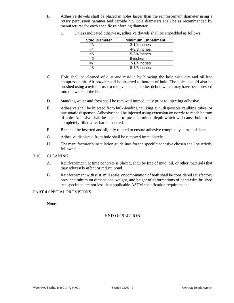
Water Rec Facility Imp/017-7244.001 Section 03200 - 5 Concrete Reinforcement
B. Adhesive dowels shall be placed in holes larger than the reinforcement diameter using a rotary percussion hammer and carbide bit. Hole diameters shall be as recommended by manufacturer for each specific reinforcing diameter.
1. Unless indicated otherwise, adhesive dowels shall be embedded as follows:
Stud Diameter Minimum Embedment #3 3-1/4 inches #4 4-3/8 inches #5 5-3/4 inches #6 6 inches #7 7-1/4 inches #8 8-7/8 inches
C. Hole shall be cleaned of dust and residue by blowing the hole with dry and oil-free compressed air. Air nozzle shall be inserted to bottom of hole. The holes should also be brushed using a nylon brush to remove dust and other debris which may have been pressed into the walls of the hole.
D. Standing water and frost shall be removed immediately prior to injecting adhesive.
E. Adhesive shall be injected from bulk-loading caulking gun, disposable caulking tubes, or pneumatic dispenser. Adhesive shall be injected using extension on nozzle to reach bottom of hole. Adhesive shall be injected to pre-determined depth which will cause hole to be completely filled after bar is inserted.
F. Bar shall be inserted and slightly rotated to ensure adhesive completely surrounds bar.
G. Adhesive displaced from hole shall be removed immediately.
H. The manufacturer’s installation guidelines for the specific adhesive chosen shall be strictly followed.
3.10 CLEANING
A. Reinforcement, at time concrete is placed, shall be free of mud, oil, or other materials that may adversely affect or reduce bond.
B. Reinforcement with rust, mill scale, or combination of both shall be considered satisfactory provided minimum dimensions, weight, and height of deformations of hand-wire-brushed test specimen are not less than applicable ASTM specification requirement.
SPECIAL PROVISIONS
None.
END OF SECTION

Concrete Reinforcement Section 03200 - 6 Water Rec Facility Imp/017-7244.001
This page was intentionally left blank.
Water Rec Facility Imp/017-7244.001 Section 03300 - 1 Cast-in-Place Concrete
SECTION 03300
CAST-IN-PLACE CONCRETE
GENERAL
1.01 SCOPE
A. This Section includes furnishing, placing, finishing, and curing cast-in-place concrete. Miscellaneous materials required for concrete construction are included.
B. Anchor bolts and other cast-in items are furnished under other Sections.
C. The Contractor, before commencing work, shall examine all adjoining work on which this work is dependent for proper installation and workmanship according to the intent of this specification, and shall report to the Engineer any condition which prevents this Contractor from performing first class work.
D. Laboratory services for quality control shall be furnished in accordance with requirements of Section 01410.
E. Additional product requirements are specified in Section 01350.
1.02 SUBMITTALS
A. Submittals shall be in accordance with requirements of Section 01300 and shall include:
1. Shop Drawings for Review:
a. Concrete mix designs including substantiating data and test records. Concrete Mix Design, Proportioning.
b. Product literature for admixtures, curing compounds, and miscellaneous materials.
c. Locations of construction and control joints not shown on Drawings, and proposed changes in locations.
d. Material certifications.
e. Aggregate gradation and percentages of deleterious substances.
f. Batch plant certification.
2. Information for the Record:
a. Manufacturer’s application instructions for miscellaneous materials.
b. Quality control test reports.
c. Slab profile report.
B. Copy of concrete delivery ticket shall be presented to Resident Project Representative for each batch. Delivery ticket shall indicate:
1. Name of ready-mixed company and plant designation.
2. Truck number.
3. Concrete class.
4. Quantity of concrete.
5. Date.
6. Time when batch was loaded.
7. Type and name of admixtures.
Cast-in-Place Concrete Section 03300 - 2 Water Rec Facility Imp/017-7244.001
8. Actual batch weights of cement, fly ash, aggregates, and water.
9. Location of pour and time of unloading shall be added to the ticket at site.
1.03 QUALITY ASSURANCE
A. Batch Plant:
1. Batch plant shall be central batch plant with automatic or semi-automatic control. Concrete may be mixed using either central-mixed, shrink-mixed, or truck-mixed methods. If concrete is shrink-mixed or truck-mixed, the truck and concrete shall conform to ASTM C-94.
2. Batch plant shall be certified by the Department of Transportation, National Ready Mixed Concrete Association (NRMCA) or an independent certification using NRMCA “Check list for Certification of Ready Mixed Concrete Production Facilities” executed and certified by independent Professional Engineer registered in state of project site. Evidence of current certification shall be submitted.
B. Pre-installation Conferences:
1. Before beginning concrete work, Contractor shall hold a meeting to review detailed requirements for preparing concrete mix designs and to determine proper procedures for concrete construction. A representative of Contractor, testing laboratory, concrete producer, concrete pumping contractor, and Engineer shall be in attendance.
2. Contractor shall submit for Engineer review a plan showing the locations of all proposed construction and control joints, which are not shown on the construction Drawings, and a schedule that incorporates the alternating pour sequences required to allow for strength gain and control of volumetric shrinkage changes.
C. Concrete work shall be in accordance with the current edition of the following codes, standards and specifications:
1. American Concrete Institute (ACI).
2. “Manual of Standard Practice”, Concrete Reinforcing Steel Institute (CRSI).
1.04 DELIVERY AND HANDLING
A. Concrete shall be delivered in accordance with ASTM C94 except the time limit for discharging of concrete during hot weather shall be reduced as specified.
B. Concrete shall be delivered in agitating trucks or in mixing trucks operating at agitating speed.
1.05 ENVIRONMENTAL CONDITIONS
A. Unless adequate protection is provided, concrete shall not be placed during rain, sleet, or snow, or when inclement weather is imminent.
B. Cold Weather:
1. Cold weather concreting procedures per “Cold Weather Concreting,” ACI 306R, shall be followed whenever any one of the following conditions occur or are expected to occur:
a. The air temperature is below 40 degrees F at the time of concrete placement.
b. The average daily air temperature is below 40 degrees F for three consecutive days immediately prior to the day of concrete placement.
Water Rec Facility Imp/017-7244.001 Section 03300 - 3 Cast-in-Place Concrete
c. An average daily air temperature below 40 degrees F is foreseen or occurs during any day of the specified concrete curing period.
2. For purposes of the paragraphs above, the average daily temperature is defined as the arithmetic mean of the highest and lowest temperature during the period from midnight to midnight. All air temperatures are to be measured at the project site.
C. Hot Weather:
1. Hot weather concreting procedures per “Hot Weather Concreting,” ACI 305R, shall be followed whenever any one of the following conditions occur or are expected to occur:
a. The air temperature is above 90 degrees F at the time of concrete placement.
b. Whenever conditions of concrete temperature, air temperature, wind velocity, and relative humidity combine to cause flash set, excessively low slump, cold joints, plastic shrinkage cracking, or otherwise impair the quality of concrete,
2. When the evaporation rate of bleed water exceeds 0.1 pounds per square foot per hour, steps shall be taken to prevent plastic shrinkage cracking. Evaporation rate shall be determined by the method presented in “Hot Weather Concreting,” ACI 305R.
PRODUCTS
2.01 MATERIALS
A. Cement - ASTM C150 Type I or II, unless indicated otherwise. All cement shall be from the same mill. Cement for Class A-2 concrete shall contain less than 8 percent tricalcium-aluminate (C3A).
B. Coarse Aggregate - Aggregates for normal weight concrete shall be crushed limestone conforming to ASTM C33, Class 4S. Aggregates for lightweight concrete shall meet the requirements of ASTM C330. Aggregates shall satisfy all quality requirements specified therein (i.e. grading, limits on deleterious substances, etc.).
C. Fine Aggregate - ASTM C33.
D. Fly Ash - ASTM C618, Class C or Class F, including supplementary chemical requirements and supplementary physical requirements, except loss-on-ignition shall be less than 5 percent. The use of fly ash shall be in accordance with “Use of Fly Ash in Cement (ACI-232.2R”).
E. Silica Fume - ASTM C1240.
F. Ground Granulated Blast Furnace (GGBF) slag shall be in accordance with ASTM C989 Grade 100 or 120. Slag for Class A-1 concrete shall contain less than 12 percent tricalcium-aluminate (C3A) and slag for Class A-2 concrete shall contain less than 8 percent tricalcium-aluminate (C3A).
G. Admixtures - The use of all admixtures shall be in accordance with “Chemical Admixtures for Concrete (ACI 212.3R”), and “Guide for the Use of High Range Water Reducing Admixtures in Concrete (ACI 212.4R).”
1. Air entraining - ASTM C260.
2. Water-reducing - ASTM C494.
3. Accelerator - ASTM C494, Type C or E, admixture shall be non-corrosive as verified by long-term accelerated corrosion testing by an independent laboratory.
Cast-in-Place Concrete Section 03300 - 4 Water Rec Facility Imp/017-7244.001
4. Anti-washout admixture - Master Builders “Rheomac UW450”, or equal.
5. Only those admixtures expressly stated by the manufacturer as being chloride-free shall be used.
6. The maximum water-soluble chloride ion content, expressed as a percentage by weight of the cement, contributed from all concrete ingredients shall not exceed 0.10 percent for non-prestressed concrete structures. Written certification of chloride ion content shall be submitted. Testing for Chloride Ion content shall conform to ASTM C1218.
7. If more than one admixture is used, the admixtures shall be compatible with each other and shall be incorporated into the concrete mix in correct sequence and timing so that desired effects of all admixtures are realized and harmful effects are avoided.
8. Air-entraining and chemical admixtures shall be incorporated into the concrete mix in a water solution. The water so included shall be considered to be a portion of the allowed mixing water.
H. Water shall conform to ASTM C94. Mixing water, including that contributed by aggregates and admixtures, shall be clean, and free from injurious amounts of oils, acids, alkalis, organic materials, chloride ions, or other substances that are deleterious to concrete or reinforcement. Non-potable water shall not be used.
2.02 ACCESSORIES
A. Curing Compound - Compound shall be membrane-forming, liquid applied, non-yellowing, VOC-compliant, water-based acrylic polymer resin conforming to ASTM C309, Type 1 and ASTM C1315, Type 1, Class A. The compound shall include sealing and dustproofing properties. Minimum solids content shall be 25 percent. Compound shall not permit a moisture loss in excess of 0.40 kilograms per square meter (0.082 pounds per square feet) in 72 hours. Sodium silicate based products are not acceptable. Compound shall be Dayton Superior “Cure & Seal 1315 J22WB”, SpecChem, LLC. “Cure & Seal WB 25”, L&M Construction Chemicals, Inc. “Lumiseal WB Plus” or equal. Curing compound in potable water treatment plant construction shall be non-toxic and free of taste and odor.
B. Bonding Adhesive for Cracks, etc. - ASTM C-881 100 percent solids, 100 percent reactive two component epoxy bonding adhesive. Sika Corporation, “Sikadur 32, Hi-Mod”, Dayton Superior “Sure Bond (J-58)”, The Euclid Co. “Dural 452 Gel”, Master Builders “MasterEmaco ADH326”, or equal.
C. Bonding Adhesive for Vertical Joints - Non-vapor barrier forming, solvent-free, moisture insensitive, epoxy modified cementitious product Sika Corporation “Sika Armatec 110 Epocem”, Euclid Co. “Duralprep A.C.” or equal.
D. Bonding Grout - Identical concrete mix as approved for each concrete Class, except that an identical quantity of the fine aggregate shall be substituted for all coarse aggregate.
E. Liquid Floor Hardener – A VOC compliant, Non-yellowing, dust proofing, liquid applied hardener with non-slip properties that dies to a clear finish. L&M Construction Chemicals “Seal Hard”, W.R. Meadows “Liqui-Hard”, ChemMasters “Chemisil Plus”, or equal. Apply after concrete has cured as recommended by the manufacturer.
F. Bond Breaker - Bond breaker shall be non-staining type which will provide a positive bond prevention, such as SpecChem “SpecTilt 100”, Nox-crete “Silcoseal Classic”; or equal.
Water Rec Facility Imp/017-7244.001 Section 03300 - 5 Cast-in-Place Concrete
G. Premolded Expansion Joint Fillers:
1. Exterior Walks and Pavements - Asphalt impregnated cellular fibers securely bonded together, in conformance with ASTM D1751. W. R. Meadows “Fibre Expansion Joint”, J D Russell Company “Fiberflex”, or equal.
2. Other Locations - Self expanding cork type in conformance with ASTM D1752, Type III. W.R. Meadows, Inc. “Sealtight - Self-Expanding Cork Joint Filler”, Masco “Self Expanding Cork”, or equal.
H. Isolation Joints - Flexible foam expansion joint filler, W.R. Meadows “Sealtight - Ceramar”, or equal.
I. Compressible Material - Rigid extruded polystyrene from Board Foamular 150 (15psi) by Owens Corning Company or compressible fill material by Plasti-Fab or equal. Provide foam board, unless noted otherwise.
J. Epoxy Joint Filler - Two component, 100 percent solids, flexible epoxy filler with minimum Shore D hardness of 50. The Euclid Chemical Company “Euco 700”, Sika Corporation “Sikadur 51 SL”, W.R. Meadows, Inc “Rezi-Weld Flex”, or equal. Only to be used to fill interior non-moving saw cut or tooled construction or control joints and shrinkage cracks. Not suitable for constant immersion.
K. Non-slip Aggregate Floor Treatment - Aluminum oxide or emery grit. BASF chemical company “Master Top 120SR”, Dayton Superior “Emery Non-slip”, or equal.
L. Vapor Barrier - 6 mil polyethylene, ASTM D 2103.
2.03 RESERVED
2.04 RESERVED
2.05 CONCRETE MIXES
A. Contractor shall design and be responsible for the performance of all concrete mixes. Mixes shall have the required quality, consistency, and workability to permit concrete to be readily worked into forms and around reinforcement without segregation or excessive bleeding. Hardened concrete shall develop all characteristics required by Contract Documents
B. Proportioning:
1. Concrete mixes shall be proportioned to maximize durability and water tightness. To this end the total water content shall be reduced to the lowest practical amount that is consistent with placing and consolidation methods. Water reducing and high range water reducing admixtures shall be used as required to maintain workability. Specified water/cementitious ratio shall not be exceeded.
2. Concrete proportions shall comply with ACI 211.1, ACI 301, ACI 318 and for the environmental components of the work ACI 350.
a. Proposed mix designs proportioned by field test data or trail mixes shall be accompanied by a complete standard deviation analysis and calculations for the required average compression strength F`cr. Test records used for determining standard deviation and average strength shall have been made within the past 12 months. These test records must represent materials, quality control procedures and conditions similar to those expected, and changes in materials and proportions within the test records shall not have been more restricted than those for the proposed work.
b. Proportioning by empirical methods on basis of water/cement ratio is not permitted.
Cast-in-Place Concrete Section 03300 - 6 Water Rec Facility Imp/017-7244.001
c. Concrete mix proportions are subject to Engineer’s approval.
C. Design mixes shall have following requirements:
1. Three normal weight concrete mixes are generally required; Class A-1, A-2and Class B. Concrete mixes shall be as follows:
Class A-1 Class A-2 (wastewater)
Class B
28-Day Compressive Strength f′c (psi) 4500 4500 3000
Maximum Water/Cementitious Ratio: 0.44 0.42 .66
Minimum Cementitious Content (Lbs/CY) 600 650 480
Maximum Cementitious Content (Lbs/CY) 800 800 650
Slump (Inches) See below See below See below
For calculating water/cementitious ratio of the mix, the weight of the water shall be that of the total free water in the mix, which includes the mixing water, the water in any admixture solutions, and any water in the aggregates in excess of that needed to reach a saturated surface dry condition.
2. Concrete placed under water shall contain an approved anti-washout admixture and shall contain a minimum of 600 pounds of cement per cubic yard. Fly ash or GGBF slag shall not be used in the concrete mix.
D. Slump:
1. When superplasticizer is not included in the mix, slump shall be 2-4 inches.
2. When superplasticizer is included in the mix, the maximum slump measured upon delivery to the construction site shall be 3 inches. Superplasticizer shall be added at the site after verification of slump to increase slump to the desired amount.
3. Tolerance of 1 inch above the maximum specified slump will be permitted for one batch in any five consecutive batches.
4. Concrete of lower slump than specified may be used provided it is properly placed and consolidated. Field adjustment of slump by addition of water is not permitted.
E. Air Content:
1. All concrete shall be air entrained unless specified or noted otherwise on the Drawings.
2. Concrete to be air-entrained shall have an air content as schedule below, unless specified otherwise:
Nominal maximum size of coarse aggregate (inch)
ASTM C-33 Aggregate Size
number Total air content
percent by volume 3/8 8 7.5 1/2 7 7.0 3/4 67 6.0 1 57 6.0
1-1/2 467 5.5
3. Allowable deviation from specified air content is plus or minus 1 percent.
4. Interior floor slab specified to receive a trowel finish shall not be air entrained. Maximum air content shall be 3 percent.
5. Floors receiving dry-shake hardeners or heavy-duty topping shall not be air-entrained. Maximum air content shall be 3 percent.
Water Rec Facility Imp/017-7244.001 Section 03300 - 7 Cast-in-Place Concrete
6. Air entrainment is not required for Class B concrete.
F. Coarse Aggregate Size:
1. Nominal maximum size of aggregate shall not be more than one-fifth of narrowest dimension between side forms, one-third of depth of slabs, nor three-fourths of minimum clear spacing between reinforcing bars.
2. Coarse aggregate shall be largest size consistent with placing methods and specified constraints. Minimum coarse aggregate shall be Size Number 57, unless smaller size is required by dimensional or reinforcement spacing constraints.
G. Cementitious Material:
1. The cementitious mixture shall contain cement and either fly ash or GGBF slag, but not both.
2. When fly ash is used in the concrete mixture, it shall comprise between 15 to 25 percent of the total cementitious mixture. When slag is used in the concrete mixture, it shall comprise between 25 to 50 percent of the total cementitious mixture. The percentages are based on weight of the total cementitious mixture.
3. For concrete in contact with wastewater, Class A-2, the cementitious design mixture shall consist of ASTM C150 Type II cement and slag or ASTM C150 Type II cement and Class F fly ash. Alternately, ASTM C150 Type I cement and Class C fly ash may be used provided the design cementitious mixture is tested per ASTM C1012 to have 0.10 percent or less expansion in 6 months. The test results shall be submitted with the proposed concrete mix design.
4. Air content for concrete containing fly ash shall be closely monitored and the dosage of air-entraining admixture shall be modified as required.
2.06 CONCRETE PRODUCTION
A. Ready-mixed concrete is to be used unless otherwise specified. It shall be batched, mixed, and transported in accordance with ASTM C94.
B. Admixtures other than air-entraining admixture shall not be added without Engineer’s written approval.
C. Admixtures shall be charged into mixer as solutions and shall be measured by means of acceptable dispensing device. If two or more admixtures are used, they shall be added separately. Admixtures shall be used in accordance with manufacturer’s instructions.
D. During cold or hot weather conditions, special precautions, as specified in ACI 306R or ACI 305R, respectively, shall be taken during batching, mixing, and curing.
2.07 STORAGE OF MATERIALS
A. Cement shall be stored in weathertight containers.
B. Aggregate stockpiles shall be arranged to avoid excessive segregation and to prevent contamination with other materials or with other sizes of like aggregates. Frozen or partially frozen aggregates shall not be used.
C. Sand stockpiles shall be allowed to drain to ensure a relatively uniform moisture content throughout the stockpile.
D. Admixtures shall be stored in a manner to prevent contamination, evaporation, freezing, or damage. Admixtures in the form of suspensions or nonstable solutions shall be agitated to assure thorough distribution of ingredients. Liquid admixtures shall be protected from freezing and from temperature changes which would adversely affect their characteristics.
Cast-in-Place Concrete Section 03300 - 8 Water Rec Facility Imp/017-7244.001
EXECUTION
3.01 COORDINATION
A. Reinforcement, sleeves, inserts, anchors, and embedded items shall be accurately placed, supported, and tied prior to concrete placement. Other trades and contractors required to furnish embedded items shall be given ample notice of concrete placement. Reinforcement and embedded items shall be subject to review of Resident Project Representative prior to placing concrete.
B. Contractor shall notify Resident Project Representative a minimum of 24 hours before placing concrete, excluding non-working days.
C. Concrete shall be placed only between hours of 8:00 a.m. and 6:00 p.m. unless otherwise permitted. Concrete shall not be placed after 12:00 noon on last working day of week.
3.02 PREPARATION
A. Hardened concrete and foreign materials shall be removed from inner surfaces of conveying equipment.
B. Waterstop shall be secured in place to ensure that it cannot bend to form cavities during concreting.
C. Formwork shall be completed and snow, ice, and water shall be removed from forms. Before placing reinforcing steel or concrete, the surfaces of the forms shall be covered with an acceptable coating material, or form liner may be used.
D. The space to receive concrete shall be free of laitance, dirt, and other debris. Laitance shall be removed by wire brushing.
E. Reinforcement and embedded items shall be checked for proper placement and adequate support. All reinforcement at the time concrete is placed, shall be free of mud, oil, or other materials that may adversely affect or reduce the bond. Aluminum conduits or pipes shall not be embedded in concrete unless approved by the Engineer and effectively coated to prevent aluminum-concrete reaction.
F. Preparation of grade shall be as specified for slabs. Concrete shall not be placed on frozen ground. There shall be no standing water on the subgrade, nor any muddy or soft spots when the concrete is placed.
G. A final detailed inspection of the foundation, construction joints, forms, waterstops, embedments, reinforcements, and other items of the placement shall be made immediately before the concrete is placed.
3.03 PLACING CONCRETE
A. Conveying:
1. Concrete shall be handled from mixer to place of final deposit as rapidly as practicable by methods which will prevent segregation or loss of ingredients and in a manner which will ensure that required quality of concrete is maintained. Conveying systems shall not impair the strength, slump, or air content of the concrete. Concrete shall be placed and consolidated prior to initial set, and in no case more than 1-1/2 hours after the cement is added to the mix.
2. Chutes shall be metal (except aluminum), or wood with metal lining and shall have a slope not exceeding 1 vertical to 2 horizontal and not less than 1 vertical to 3 horizontal. Chutes more than 20-feet long and chutes not meeting slope requirements may be used provided they discharge into a hopper before distribution.
Water Rec Facility Imp/017-7244.001 Section 03300 - 9 Cast-in-Place Concrete
3. Pumping or pneumatic conveying equipment shall be of suitable kind with adequate pumping capacity. Pneumatic placement shall be controlled to prevent segregation. Loss of slump in pumping or pneumatic conveying equipment shall not exceed 1-1/2 inch.
4. Concrete shall not be permitted to drop more than 4 feet freely, or through a cage of reinforcing steel, from conveying device. Concrete shall be deposited through drop chutes, elephant-trunks, or tremies as required. Temporary openings in wall or column forms may be used to limit the free fall of concrete to less than four feet. The openings should be spaced no more than six to eight feet apart.
5. Concrete shall not be conveyed through pipes made of aluminum or aluminum alloy.
B. Depositing:
1. Concrete shall be deposited continuously or in layers of such thickness that no concrete will be deposited which has hardened sufficiently to cause planes of weakness within the sections. No interruption in concrete placement shall exceed 30 minutes to avoid cold joints in the structural elements being placed. Alternate placing equipment shall be immediately available for use in the event that the primary placing equipment or system breaks down.
2. Placing shall proceed at such a rate that concrete which is being integrated with fresh concrete is still plastic.
3. Concrete which has partially hardened or has been contaminated shall not be deposited.
4. Placing of concrete for supported elements, such as beams and elevated slabs, shall not begin until supporting elements, such as columns and walls, have cured for a minimum of 7 days, unless the concrete has attained 80 percent of the specified design compression strength or the shoring for the supporting elements has been designed to carry the weight of the supported elements and their construction load.
5. Concrete shall be placed continuously between construction, isolation, and expansion joints. Where joints are spaced greater than 25 feet apart the placing of concrete adjacent to previously placed concrete shall not begin until 48 hours after completion of previous placement, unless otherwise noted. Concrete shall be deposited as nearly as practical in its final position and shall be carried up evenly in forms to avoid segregation due to rehandling or flowing. Layers shall not exceed 24 inches. Concrete shall not be permitted to flow laterally in forms.
6. The temperature of the concrete mixture immediately before placement shall be between 50 degrees F and 90 degrees F, except as provided under cold weather and hot weather concreting.
C. Consolidating:
1. Concrete shall be consolidated by vibrating, so that concrete is thoroughly worked around reinforcement and embedded items, and into corners and angles of forms, eliminating air and stone pockets. Vibrators shall extend into underlying layers to bond two layers together. To avoid excessive pressure on the forms, the vibrator should penetrate no more than two feet into the underlying layer.
2. Vibrators shall be the largest size and most powerful that can be used properly in the work, as described in “Recommended Practice for Consolidation of Concrete” (ACI 309R). A minimum of one spare operable vibrator shall be available on site. Mechanical high frequency vibrators with a minimum
Cast-in-Place Concrete Section 03300 - 10 Water Rec Facility Imp/017-7244.001
frequency of 8,000 revolutions per minute are preferred for consolidation of concrete within the forms.
3. Vibrators shall not be used to transport or drag concrete within forms. Vibrators shall be inserted and withdrawn from the concrete slowly.
4. Vibrators shall be inserted in the fresh concrete at points approximately 18 inches apart or as recommended by the vibrator manufacturer. The vibration shall be of sufficient duration and intensity to thoroughly consolidate the concrete, but shall not be continued so as to cause segregation. Vibration shall not be continued at any one point to the extent that localized areas of grout are formed.
D. Under Water Concreting:
1. Concrete shall not be placed under water unless otherwise indicated or permitted. The recommendations given for concrete placed under water in Chapter 8 of ACI 304 shall be followed subject to the requirements specified herein.
2. Concrete shall be deposited by tremie or other acceptable method such that fresh concrete enters mass of previously placed concrete from within, causing water to be displaced with minimum disturbance at the surface of the concrete.
3. Concrete shall not be disturbed after placement.
E. Defective Concrete:
1. Defective concrete is defined as concrete in place which does not conform to specified design strength, required percent air, shapes, alignments and elevations, as shown on the Drawings and/or which presents faulty surface areas. Evaluation and acceptance of concrete shall conform to ACI 318 and as determined by Engineer.
2. All defective concrete shall be removed and replaced in a manner meeting with the Engineer’s approval. Should surface imperfections occur, they may be patched at the discretion of, and in a manner satisfactory to the Engineer. The Engineer reserves the right to require complete removal and replacement of such defective Work should the patching fail to satisfactorily restore the required quality and appearance of the Work. All such Work shall be performed at the Contractor’s expense, without extension of time.
3. If for any reason, in the opinion of the Engineer, the testing of any section of the completed structure is necessary, a superimposed load shall be applied by the Contractor and the test conducted in accordance with the current Building Code at the Contractor’s expense irrespective of the results of such tests. In cases where failure is declared, the Engineer shall have the authority to order the defective construction removed. All expense of removing such defective construction and substituting new construction, including expense of removing and replacing the Work of others, or protecting and repairing the Work of others, shall be borne by this Contractor.
3.04 JOINT INSTALLATION
A. Construction Joints:
1. Construction joints shall not be spaced further apart than 60 feet, unless noted otherwise. Where construction joint spacing exceeds 25 feet concrete placement shall be alternated so that adjacent sections are placed a minimum of 48 hours apart to allow for volumetric change of adjacent pours due to shrinkage and to help minimize cracks. Joints shall be located where they will least impair the strength, watertightness, and architectural design of the finished structure. Joint types and locations shall be subject to Engineer’s approval. Construction joints
Water Rec Facility Imp/017-7244.001 Section 03300 - 11 Cast-in-Place Concrete
shall not be located less than 5 feet from any other joint to which they are parallel.
2. Joints in walls and columns shall be placed at the tops of footings and mat foundations, unless shown otherwise. Joints should be made perpendicular to the main reinforcement where practical.
3. Joints shall be constructed straight by means of a temporary straight edge or rustication strip placed in forms. Joints shall be perpendicular to reinforcement.
4. Reinforcement shall be continuous across construction joints unless otherwise indicated. Unless otherwise specified or shown on Drawings, longitudinal keys at least 1-1/2 inches deep by 3-1/2 inches wide shall be provided in all joints in walls, and between walls and slabs or footings.
5. Surface of concrete shall be thoroughly cleaned and laitance shall be removed by wire brushing prior to placing adjoining concrete.
6. At all vertical joints in new concrete and in new against previously existing concrete, and wherever else called for on the Drawings, bonding adhesive paste shall be applied per the manufacturer’s directions.
7. At all horizontal joints in new concrete and in new against previously existing concrete, and wherever else called for on the Drawings, bonding grout shall be applied in a 2-inch-thick layer.
B. Expansion and Isolation Joints:
1. Expansion and isolation joints shall be located and constructed as shown. Generally, joints shall be located at the perimeter of slabs-on-grades and other locations shown. These joints shall have filler material and have exposed faces sealed.
2. Reinforcement and other embedded metal items shall not extend continuously through expansion or isolation joints unless shown otherwise.
3. Unless polystyrene foam boards are called for on Drawings, premolded type joint fillers shall be installed for expansion joints in accordance with manufacturer’s instructions. Joint filler shall be accurately placed and secured. Fillers for each joint shall consist of as few pieces of material as possible. Pourable or non-sag joint sealants per specification Section 07900 shall be placed in top or face of joints, as applicable, per manufacturer’s instructions. All joints in tanks and within buildings shall be sealed unless otherwise shown. Where called for on the Drawings, exterior joints in or around walks and pavement shall be sealed.
C. Control Joints:
1. Unless indicated otherwise on the Drawings, control joints in slabs shall be located at a maximum spacing of 30 times the slab thickness in both directions with a maximum aspect ratio not to exceed 2 to 1. These joints shall preferably be located on column lines with joints also located between column lines if required to satisfy maximum spacing. Driveways and sidewalks shall have control joints spaced at intervals approximately equal to the slab width. Drives and walks wider than 12-feet shall have longitudinal and transverse joints at 12-feet maximum spacing. All control joints shall be continuous, not staggered or offset. Control joints shall not be located in liquid containing or conveying structures, such as tank, channels and etc.
3.05 FINISHING OF FORMED SURFACES
A. Surface defects shall be patched. Patching procedures shall be as follows:
Cast-in-Place Concrete Section 03300 - 12 Water Rec Facility Imp/017-7244.001
1. Honeycombed and other defective concrete shall be removed to sound concrete. Cut or chip edges perpendicular to surface or slightly undercut; featheredging is not permitted. Area to be patched and surrounding area within at least 6 inches shall be dampened to prevent absorption of water from patching mortar.
2. Bonding grout consisting of 1-part cement and 1-part fine sand passing a No. 30 mesh sieve mixed to the consistency of a thick cream, shall be thoroughly brushed into surface immediately prior to applying patching mixture.
3. Patching mixture shall be composed of same proportions as used for concrete except that coarse aggregate shall be omitted and mixture shall not consist of more than 1-part cement to 2-1/2 parts sand by damp loose volume. Mixing water shall be no more than necessary for handling and placing. Patching mixture shall be prepared in advance and allowed to prehydrate with frequent manipulation with trowel, until stiffest consistency that will permit placement is obtained.
4. Where concrete is exposed to view, color of patching mixture shall be adjusted to match surrounding concrete by substituting appropriate amount of white cement for gray cement. Proper color shall be determined by trial patches.
5. Patching mixture shall be applied before bond coat begins to lose water sheen. Patching mixture shall be thoroughly consolidated and struck off so as to leave patch slightly higher than surrounding surface. Patch shall be left undisturbed for one hour after which time it shall be finished with metal tools. Patched area shall be moist cured for not less than 7 days.
B. Tie holes shall be patched as follows:
1. The holes shall be plugged, unless stainless steel noncorrosive or acceptably coated ties are used, as approved by Engineer.
2. Tie holes shall be cleaned and dampened prior to patching with a non-metallic, non-shrink grout. Patching material shall be packed solid into hole.
3. Contractor may substitute alternate materials and procedures subject to the approval of Engineer. These materials shall be applied in accordance with manufacturer’s written recommendations wherever applicable.
C. Stains, rust, efflorescence, and surface deposits on exposed concrete shall be removed by methods acceptable to Engineer.
D. After removal of forms, the surface of concrete shall be given one or more of the finishes specified below as scheduled in the Finishing Schedule of this specification.
1. Rough Form Finish - Fins exceeding 1/8 inch in height shall be removed. Otherwise surfaces shall be left with texture imparted by forms.
2. Smooth Form Finish - The form facing material with or without form-liner shall produce a smooth, hard, uniform texture in the concrete. The type of facing material or form-liner selected is dependent upon the type of smooth finish desired and shall be approved by the Engineer. Tie holes and defects shall be patched. All fins shall be completely removed.
3. Special Architectural Finishes - This shall be produced in accordance with Section 6 of ACI 301R.
4. Smooth Rubbed Finish - The smooth rubbed finish shall be produced on a concrete with smooth form finish as specified above.
a. Forms shall have been removed and patching completed as soon after placement as possible without damaging or jeopardizing structure.
Water Rec Facility Imp/017-7244.001 Section 03300 - 13 Cast-in-Place Concrete
b. Finishing shall be performed no later than the day following form removal.
c. Surfaces shall be thoroughly wetted and rubbed with carborundum brick or other abrasive until form marks, fins, and irregularities are removed and uniform color and texture are produced. Cement grout shall not be used.
5. Grout Cleaned Finish - The grout cleaned finish shall be produced on a concrete with smooth form finish as specified above.
a. Cleaning shall not begin until all contiguous surfaces to be finished are completed and accessible. Finishing as the work progresses is not permitted. Finishing of an area shall be completed on day it is started.
b. Finishing grout shall consist of 1-part cement and 1-1/2 parts fine sand with sufficient water to produce consistency of thick paint. Where concrete is exposed to view, color of grout shall be adjusted to match surrounding concrete by substituting appropriate amount of white cement for gray cement. Proper color shall be determined by trial patches.
c. Wet surface sufficiently to prevent absorption of water from grout and apply grout uniformly with brushes or spray gun. Scrub surface vigorously with cork float to coat surface and fill air bubbles and holes. While grout is still plastic, remove excess grout with rubber float or burlap. After surface whitens from drying, rub vigorously with clean burlap. Finish shall be kept damp for minimum of 36 hours after final rubbing.
E. Finishing of Related Unformed Surfaces:
1. Tops of walls, horizontal offsets, and similar unformed surfaces occurring adjacent to formed surfaces shall be struck smooth after placement and shall be floated to texture consistent with that of adjacent formed surface. Where smooth rubbed finish or grout cleaned finish is specified, finish shall continue uniformly across unformed surfaces.
3.06 SLAB INSTALLATION
A. Floor construction shall comply with ACI 302R. Floors shall be Class 5 except floors with heavy-duty topping shall be Class 7.
B. Preparation - Subgrade supporting slabs shall be well drained and of adequate and uniform load bearing capacity. Subgrade shall be free of frost before concrete is placed. Subgrade shall be moist at time of placement. Ground may be dampened with water, but there shall be no standing water on subgrade, nor muddy spots.
C. Vapor barriers shall be installed in all occupied spaces or where shown on Drawings. A minimum 4-inch layer of granular, self-draining compactable fill, shall be placed under the vapor barrier. Joints shall be lapped 6 inch minimum. Caution shall be taken during construction not to tear or otherwise damage the vapor barrier. Damaged vapor barriers shall be patched or replaced.
D. Floors and slabs shall be sloped to drains as shown maintaining thickness shown on Drawings as a minimum. When formwork is cambered, screeds shall be set to like camber to maintain proper concrete thickness.
E. A minimum of 1/4 inch per foot slope shall be provided for exterior slabs, driveways, and walks. Driveways and walks can be pitched to one side or crowned along the longitudinal centerline with drainage to both sides as most suitable to surrounding drainage pattern.
Cast-in-Place Concrete Section 03300 - 14 Water Rec Facility Imp/017-7244.001
F. Concrete shall not be deposited more rapidly than it can be spread, straight-edged, and darby or bull-floated. These later operations shall be completed before bleed water collects on surface. Rakes shall not be used for spreading concrete to avoid segregation. Slabs shall be consolidated by internal vibrators of high frequency and low amplitude, or vibrating screeds.
G. Placement of large slab areas shall be sequenced to reduce initial shrinkage cracks. Such slabs can be poured in a series of long strips separated by similar long strips poured at another time. The adjacent pours shall be at least 48 hours apart. Placing sequence and number of pours are subject to the approval of Engineer.
H. Construction joints shall not be spaced further apart than 60 foot in both directions. Where construction joint spacing exceeds 25 feet concrete placement shall be alternated, in a strip or checkered fashion, so that adjacent sections can be placed a minimum of 48 hours apart to allow for volumetric change of adjacent pours due to shrinkage and to help minimize cracks.
I. Control joints in slabs shall be located at a maximum spacing of 30 times the slab thickness, in both directions, with a maximum aspect ratio not to exceed 2 to 1, unless noted otherwise. These joints shall be located on column lines where practical. Driveways and sidewalks shall have control joints spaced at intervals approximately equal to the slab width. Drives and walks wider than 12-feet shall have longitudinal and transverse joints at 12-feet maximum spacing. All control joints shall be continuous, not staggered or offset, where practical. Saw-cutting of control joints shall be performed with “Soff-Cut” saw after final finishing as soon as the concrete surface is firm enough not be torn or damaged by the blades and prior to the application of curing compound. In any case, saw-cutting of joints shall be done within two hours after final finishing. Control joint shall be 1/8-inch-wide by one inch deep. Control joints shall not be located in liquid containing or conveying structures, such as tank, channels and etc.
J. Finishes:
1. Scratched Finish - After concrete has been placed, consolidated, struck off, and leveled, but prior to final set, surface shall be roughened with rakes.
2. Floated Finish - After concrete has been placed, consolidated, struck off, and leveled, surface shall not be worked further until ready for floating. Floating shall begin when bleed water sheen disappears and surface has stiffened sufficiently. Floating shall be performed with wood hand float or power float. During first floating, high spots shall be cut down and low spots shall be filled. Slab shall be refloated immediately to uniform sandy texture.
3. Troweled Finish - Surface shall first be float finished, followed by power trowel, and then hand troweled. Additional trowelings shall be performed after surface has hardened sufficiently. Final troweling shall be done when ringing sound is produced as trowel is moved over surface. Finished surface shall be free of trowel marks and uniformly smooth and hard. Dusting surface with cement is not permitted.
4. Broom Finish - Surface shall first be float finished and then given coarse texture by drawing broom over surface.
5. Non-Slip Finish - Non-slip abrasive aggregate shall be applied in accordance with manufacturer’s instructions.
K. Finishing Tolerances:
1. Floor flatness (FF) and floor levelness (FL) tolerance for slabs on grade with trowel finish shall be FF25/FL20. Minimum local tolerance over 2 bay shall be 2/3 of specified tolerance.
Water Rec Facility Imp/017-7244.001 Section 03300 - 15 Cast-in-Place Concrete
2. Floated finish surfaces shall be constructed to tolerance of FF 20/FL17.
3. FL shall not apply to slabs where slope is shown or specified.
L. Liquid hardener shall be applied to interior exposed concrete floors which do not receive paint, dry-shake hardener, or other coating, or floor coverings. Material shall be applied in accordance with manufacturer’s instructions. Remove curing, sealer and dustproofing compounds prior to placing the liquid hardener.
M. Construction and control joints shall be filled with epoxy joint filler where shown. Joint filler shall be applied not sooner than 3 months after slab construction is completed and shall be installed in accordance with manufacturer’s instructions.
N. Expansion and isolation joints shall be sealed using moisture insensitive and movement tolerating joint sealants per Specification Section 07900.
3.07 CURING
A. Beginning immediately after placement, concrete curing shall be initiated to protect the concrete from moisture loss and premature drying. Concrete shall be continuously cured for a minimum of 7 days. Tanks and other liquid-retaining structures shall be cured for minimum of 10 days. Elevated slabs, joists, and beams shall be cured for at least 14 days and as many additional days as necessary for tests to verify that the concrete has attained 90 percent of its specified design strength up to a maximum of 21 days. For the entire duration of the curing period, the concrete shall be protected from detrimental weather conditions as specified elsewhere in this Section.
B. Curing procedures for each type of concrete section shall be submitted and shall be in accordance with ACI 308, “Standard Practice for Curing Concrete,” subject to the additional requirements specified herein.
C. Concrete surfaces not in contact with forms shall be cured by one of following procedures:
1. Ponding, fog spraying, or continuous sprinkling with water. Care shall be taken to avoid thermal shock from use of cold curing water or excessive evaporation rates. Alternate drying and re-wetting of slabs during curing shall be avoided to avoid hairline cracks at the surface.
2. Application of burlap or absorptive mats kept continuously wet.
a. Burlap shall be clean and thoroughly rinsed in water before it is used.
b. Burlap and absorptive mats shall be soaked as frequently as required to maintain continuously wet surface.
c. Burlap and absorptive mats shall remain in place unwetted for minimum of 3 days after end of curing period to permit concrete to dry slowly.
3. Application of waterproof sheet material conforming to ASTM C171.
a. Sheet material shall be placed over the wet surface of fresh concrete as soon as possible without marring surface. Material shall be placed flat without wrinkles.
b. Sheet material shall cover all exposed surfaces and shall extend beyond edges of slab a distance of at least twice the thickness of the slab.
c. Sheet material shall be lapped a minimum of 6 inches. Windrows of earth or wood shall be placed along edges and laps to seal joints and secure material from displacement by wind.
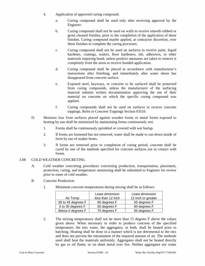
Cast-in-Place Concrete Section 03300 - 16 Water Rec Facility Imp/017-7244.001
4. Application of approved curing compound.
a. Curing compound shall be used only after receiving approval by the Engineer.
b. Curing compound shall not be used on walls to receive smooth rubbed or grout cleaned finishes, prior to the completion of the application of these finishes. Curing compound maybe applied, at contractor discretion, over these finishes to complete the curing processes.
c. Curing compound shall not be used on surfaces to receive paint, liquid hardener, coatings, sealers, floor hardeners, tile, adhesives, or other materials requiring bond, unless positive measures are taken to remove it completely from the areas to receive bonded application.
d. Curing compound shall be placed in accordance with manufacturer’s instructions after finishing, and immediately after water sheen has disappeared from concrete surface.
e. Exposed steel, keyways, or concrete to be surfaced shall be protected from curing compounds, unless the manufacturer of the surfacing material submits written documentation approving the use of their material on concrete on which the specific curing compound was applied.
f. Curing compounds shall not be used on surfaces to receive concrete toppings. Refer to Concrete Toppings Section 03510.
D. Moisture loss from surfaces placed against wooden forms or metal forms exposed to heating by sun shall be minimized by maintaining forms continuously wet.
1. Forms shall be continuously sprinkled or covered with wet burlap.
2. If forms are loosened but not removed, water shall be made to run down inside of form by use of soaker hoses.
3. If forms are removed prior to completion of curing period, concrete shall be cured by one of the methods specified for concrete surfaces not in contact with forms.
3.08 COLD WEATHER CONCRETING
A. Cold weather concreting procedures concerning production, transportation, placement, protection, curing, and temperature monitoring shall be submitted to Engineer for review prior to onset of cold weather.
B. Concrete Production:
1. Minimum concrete temperatures during mixing shall be as follows:
Air Temp Least dimension less than 12 inch
Least dimension 12 inch or greater
30 to 45 degrees F 60 degrees F 55 degrees F
0 to 30 degrees F 65 degrees F 60 degrees F
Below 0 degrees F 70 degrees F 65 degrees F
2. The mixing temperatures shall not be more than 15 degrees F above the values given above. When necessary in order to produce concrete of the specified temperature, the mix water, the aggregates, or both, shall be heated prior to batching. Heating shall be done in a manner which is not detrimental to the mix and does not prevent the entrainment of the required amount of air. The methods used shall heat the materials uniformly. Aggregates shall not be heated directly by gas or oil flame, or on sheet metal over fire. Neither aggregates nor water
Water Rec Facility Imp/017-7244.001 Section 03300 - 17 Cast-in-Place Concrete
shall be heated to over 150 degrees F. If either are heated to over 100 degrees F, they shall be mixed together prior to the addition of the cement so that cement does not come into contact with materials which are in excess of 100 degrees F.
C. Preparation - All snow, ice, and frost shall be removed from the surfaces, including reinforcement, against which the concrete is to be placed. Concrete shall not be placed around any embedment which is at 32 degrees F or less and is sufficiently massive as to cause the adjacent concrete to freeze.
D. Placing - Minimum concrete temperatures at the time of placement shall be 55 degrees F for sections with smallest dimension less than 12 inches, and 50 degrees F for larger sections. Maximum concrete temperature shall not exceed 20 degrees F above the minimum required temperatures at the time of placement.
E. Protection:
1. Protection shall be provided and shall be adequate to prevent the surface temperature of the concrete from falling below 50 degrees F for the duration of the specified curing period. During this period, the concrete surface shall not be exposed to heated air that is more than 20 degrees F above this minimum value. At the end of the protection period, concrete shall be allowed to cool gradually. Maximum decrease in surface temperature shall be 5 degrees F in a one-hour period and 40 degrees F in a 24-hour period.
2. At the time of placement, Contractor shall keep a record of the date, time, outside air temperature, temperature of concrete, and weather conditions (calm, windy, clear, cloudy, etc.). After placement, the Contractor shall keep a record of the date, time, outside air temperature, inside enclosure air temperatures, concrete surface temperatures and weather conditions for the duration of the specified curing period. These conditions shall be recorded at regular intervals, but not less than twice per each 24-hour period, with no period exceeding 16 hours without recorded conditions. The concrete surface temperatures shall be recorded at several locations on the placed section including interior, edge and corner locations and their corresponding enclosure air temperatures at these locations where applicable. These records shall be submitted to the Engineer or resident field representative weekly. The Contractor shall place a sufficient number of thermometers on the concrete surfaces throughout the work to allow monitoring of concrete surface temperatures representative of all the work. The Contractor shall place a minimum of two thermometers, each capable of recording the high and low temperature.
3. Materials and equipment required for protection shall be available at project site before cold weather concreting commences.
4. Heated Enclosure:
a. Enclosure shall be strong enough to be wind-resistant and weather-tight and ample space shall be provided between concrete and enclosure to permit free circulation of the warmed air.
b. Maximum air temperature within enclosure shall be 70 degrees F.
c. Heaters shall be indirect fired type and shall be vented outside of enclosure. Combustion products shall not be permitted to come in contact with protected concrete.
d. Heaters and ducts shall be arranged so as not to cause areas of overheating or drying of concrete surface.
Cast-in-Place Concrete Section 03300 - 18 Water Rec Facility Imp/017-7244.001
5. Insulation:
a. Slabs not less than 12 inches thick placed on ground, elevated slabs, and walls may be protected by insulated forms and insulation blankets. Insulation shall be wind resistant and weather-tight.
b. Insulation type and thickness shall be selected with due regard for concrete temperature, air temperature, and length of protection period in accordance with “Cold Weather Concreting” (ACI 306R). Special care shall be taken at corners and edges of structure. Insulation type, thickness, and “R” value shall be as indicated in cold weather concreting procedures.
c. When minimum concrete temperature is not maintained, insulation shall be removed and immediately replaced by a heated enclosure. A sufficient number of surface thermometers shall be furnished and installed as directed by Resident Project Representative.
F. Curing - If water curing is used, it shall be terminated at least 24 hours before concrete is exposed to freezing temperatures. Curing period shall be completed by non-water curing methods.
3.09 HOT WEATHER CONCRETING
A. Hot weather concreting procedures including production, transportation, placement, protection, and curing shall be submitted for Engineer’s review prior to onset of hot weather.
B. Concrete Production and Delivery - The temperature of the concrete at time of placement shall be maintained within specified temperature by any combination of the following:
1. Type III cement is prohibited.
2. The temperature of the aggregates shall be kept low by shading the aggregate piles or sprinkling the aggregate with water.
3. Concrete ingredients shall be cooled before mixing or flake ice shall be substituted for all or part of mixing water as required to reduce concrete temperature. Mixing shall continue until ice is completely melted.
4. Delivery of concrete shall be scheduled so that concrete is deposited as soon as practicable. Concrete shall be completely discharged within 1 hour after introduction of mixing water to cement.
5. Water reducing or retarding admixtures with shrinkage compensating cement shall be used in such quantities as recommended by the manufacturer.
C. Preparation - Steel forms, reinforcement, and embedments shall be cooled to below 90 degrees F by means of spraying with water or other approved methods immediately prior to concrete placement.
D. Placing - Concrete shall be placed at lowest practicable temperature. Temperature of concrete as placed shall not cause difficulty from loss of slump, flash set, or cold joints and shall be between 75 degrees F and 90 degrees F and in no case shall exceed 90 degrees F.
E. Protection:
1. During hot weather conditions prior to the application of curing materials, the concrete being placed and finished shall be protected from damage due to rapid evaporation. Such protection shall be adequate to prevent premature crusting of surface or an increase in drying shrinkage and cracking. Such protection shall be provided by raising the humidity of the surrounding air by fog spraying, the use
Water Rec Facility Imp/017-7244.001 Section 03300 - 19 Cast-in-Place Concrete
of wind breaks or sun shades, additionally reducing of the temperature of the concrete, scheduling placement during the cooler times of days or nights, reducing time between placement of concrete and start of curing, or any combination thereof.
2. Forms shall be covered and kept moist.
F. Curing:
1. Curing shall be performed by water methods only unless approved otherwise.
2. When the use of waterproof sheet material is approved for hot weather concreting, the material shall be pigmented white.
3. Forms shall be loosened as soon as practicable and water curing shall be used as specified.
3.10 MASS CONCRETE
A. Concrete sections with minimum dimension larger than 36 inches shall be treated as mass concrete.
B. Concrete Production:
1. Type III cement and accelerating admixtures are prohibited.
2. Cement content shall be reduced by substitution of fly ash within specified limit.
3. Concrete ingredients shall be cooled before mixing or flake ice shall be substituted for all or part of mixing water as required to reduce concrete temperature. Mixing shall continue until ice is completely melted.
C. Placing:
1. The temperature of concrete when deposited shall be between 50 degrees F and 70 degrees F.
2. Concrete shall be placed in layers approximately 18 inches thick. Vibrator shall extend into previously placed layer.
D. Curing:
1. The curing period for mass concrete shall be a minimum of 14 days.
2. When the surrounding air temperature exceeds 40 degrees F, forms and exposed concrete shall be kept continuously wet for the first 48 hours after placing. Concrete shall be cured by any acceptable method after the first 48 hours, except when surrounding air temperature exceeds 90 degrees F, water curing methods shall be used exclusively. When cold weather concreting provisions apply, continuous wetting during first 48 hours is not required.
3. During and at conclusion of the curing period, the temperature of the air immediately adjacent to concrete shall not fall more than 3 degrees F in any 1 hour, nor 30 degrees F in any 24 hours.
3.11 TESTING
A. Concrete materials and operations shall be tested as the work progresses.
B. Duties of testing laboratory shall be as follows:
1. Review, check, and test proposed materials for compliance with Specifications before the start of the work.
2. Sample aggregates from concrete production stockpiles, at least once a month, during the placement of concrete and test for compliance with the
Cast-in-Place Concrete Section 03300 - 20 Water Rec Facility Imp/017-7244.001
specifications. The moisture content of each sample shall be measured and recorded.
3. Review and test proposed mixture design when required by Engineer.
4. Randomly sample concrete during construction in accordance with ASTM C172 and perform scheduled tests.
C. Test Schedule:
1. Strength:
a. One strength test shall be made for each 50 cubic yards, or fraction thereof, of each class of concrete placed on any one day. Frequency of testing shall not provide less than 5 strength tests for each class of concrete.
b. Concrete strength test shall consist of three specimens from each sample molded and cured in accordance with the section of ASTM C31, “Curing Specimens for Checking the Adequacy of Mixture Proportions for Strength or as the Basis for Acceptance or Quality Control”.
c. Specimens shall be tested in accordance with ASTM C39. Two specimens shall be tested at 28 days for acceptance and one shall be tested at 7 days for information. Strength test result shall be average of strengths of 28-day specimens. If one specimen shows evidence of improper molding, handling, or testing, it shall be discarded and remaining specimen shall be considered as strength test result. Should both specimens in a test show any of the above defects, the entire test shall be discarded.
2. Cold Weather Concreting and Form Removal:
a. When cold weather concreting procedures apply or when form removal provisions of Section 03100 apply, field cured specimens shall be made to determine when protection procedures may be terminated or when forms may be removed. These field cured specimens shall be in addition to strength tests and shall be made at same time as strength specimens.
b. Specimens shall be molded and cured in accordance with the section of ASTM C31, “Curing for Determining Form Removal Time or When a Structure May be Put into Service”. Contractor shall determine number of specimens required, but number of specimens shall not be less than three.
c. Specimens shall be tested in accordance with ASTM C39. Age-at-test of specimens shall be selected by Contractor.
3. Slump shall be measured for first batch of each concrete class delivered in morning and afternoon, for each strength test, and whenever consistency of concrete appears to vary. Slump shall be measured in accordance with ASTM C143. In the event that a batch fails to comply with specified requirements, the slump shall be measured on each successive batch until three batches meet the specified requirements.
4. Air content shall be determined for first batch of each concrete class delivered in morning and afternoon, for each strength test, and as required by field representative. Air content shall be measured in accordance with ASTM C231, ASTM C173, or ASTM C138. When concrete is placed by pumping, air content and slump shall be measured before pump and also at pump discharge. In the event that a batch fails to comply with specified requirements, the air content
Water Rec Facility Imp/017-7244.001 Section 03300 - 21 Cast-in-Place Concrete
shall be measured on each successive batch until three batches meet the specified requirements.
5. Temperature of concrete sample shall be measured for each strength test.
6. If the measured slump or air content falls outside the specified limits, make additional tests immediately. Test all succeeding trucks for both slump and air until three in succession pass the slump and air tests.
3.12 EVALUATION OF STRENGTH
A. Contractor shall perform concrete mix work and produce concrete structures in full compliance with Specifications.
B. Concrete strength will be considered satisfactory if the average of three consecutive strength test results equals or exceeds the specified strength, and no individual strength test result falls below specified strength by more than 500 psi.
3.13 CONCRETE SCHEDULE
A. Unless indicated otherwise on the Drawings or specified, concrete shall be furnished as follows:
Class A-1: For all structures not defined under Class A-2 or Class B concrete.
Class A-2: For structures that cover, convey or store wastewater such as channels and tanks, and their attached auxiliary structures, and all other concrete that will be submerged or exposed to wastewater.
Class B: Pipe saddle supports, Pipe pier supports, buried electrical duck banks, equipment pads, housekeeping pads and mudmats, unless noted otherwise. The above items shall not be exposed to weather and shall not be submerged in liquids; otherwise they shall be of Class A concrete as specified above.
3.14 CONCRETE FINISHING SCHEDULE
A. Concrete shall be finished as follows unless indicated otherwise:
1. Building Interior:Floors intended as walking surfaces or to receive a floor covering, bases, and curbs: Troweled finish.Other slabs intended to receive roofing, water-proofing membrane or sand bed terrazzo: Float finish.Exposed formed surfaces: Smooth-rubbed finish.Other formed surfaces: Rough form finish.
2. Building Exterior: Slabs, drives, and walks: Broom finish.Exposed formed surfaces: Smooth-rubbed finish to
6-in below grade.Other formed surfaces: Rough form finish.
3. Pedestrian Ramps and Exterior Stairs: Non-slip finish.
4. Tanks and Other Liquid Retaining Structures:Slabs: Float finish.Interior formed surfaces: Grout-cleaned finish.Exterior formed surfaces: Grout-cleaned finish to 6-
in below grade.Other formed surfaces: Rough form finish.
Cast-in-Place Concrete Section 03300 - 22 Water Rec Facility Imp/017-7244.001
3.15 ELECTRICAL CONDUITS AND LIQUID PIPE EMBEDMENTS
A. Prior to placing concrete with embedded conduits and pipes the contractor shall submit a layout plan drawing that includes the locations, quantity and size of these items. The layout plan shall be submitted to the Engineer at least 14 days prior to placement for approval.
B. Conduits, pipes and sleeves passing through slabs, walls or beams shall not impair significantly the strength of construction. Conduits and pipes shall not be embedded in columns or beams without the approval of the engineer.
C. Conduits and pipes embedded within slabs and walls shall not be larger in outside dimension than one-third the overall thickness of the slab or wall that they are embedded in.
D. Conduits and pipes embedded within slabs and walls shall not be spaced closer than 3 diameters on center.
E. Concrete cover over conduits, pipes and fittings shall not be less than 2 inches.
3.16 HOUSEKEEPING PADS
A. Unreinforced concrete housekeeping pads shall be installed under all floor-mounted items such as motor control centers, electrical panels, control panels, transformers, process equipment, and HVAC equipment unless otherwise specified or detailed on the Drawings. Housekeeping pads shall be Class A concrete 4 inches high with chamfered edges and a troweled finish.
B. Reinforced concrete equipment pads shall be installed under all generators, pumps, motors, blowers, drives or other pieces of equipment that require support greater than 4 inches above the floor. Refer to typical pad details given on the drawings.
SPECIAL PROVISIONS
None.
END OF SECTION
Water Rec Facility Imp/017-7244.001 Section 03310 - 1 Grout
SECTION 03310
GROUT
GENERAL
1.01 SCOPE
A. This Section includes non-shrink cementitious and epoxy grouts.
B. Masonry grout and bonding grout are specified in other Sections.
C. Additional product requirements are specified in Section 01350.
1.02 SUBMITTALS
A. Submittals shall be in accordance with requirements of Section 01300 and shall include:
1. Shop Drawings for Review:
a. Contractor shall indicate variances from requirements of Contract Documents.
b. Product literature.
c. Material certifications of ASTM standard and grade.
d. Laboratory test reports for grout compressive strength tests.
2. Information for the Record:
a. Manufacturer’s mixing, placing, and curing instructions.
1.03 PRODUCT HANDLING
A. Environmental limitations specified by manufacturer shall be observed. Heated enclosures shall be provided as required.
PRODUCTS
2.01 NON-SHRINK GROUT
A. Grout shall be prepackaged, nonmetallic, noncorrosive, non-staining cementitious grout. Grout shall remain volume stable in both dry and wet conditions and provide a minimum of 95 percent effective bearing area.
B. Grout shall conform to ASTM C 1107 Grade C when tested at fluid consistency of 25 seconds or more per ASTM C 939 at temperature extremes of 45 degree F and 90 degree F and a working time of 30 minutes. Metallic grouts are prohibited.
C. Non-shrink property shall not be based on any gas generating additives such as aluminum oxide.
D. Minimum compressive strength: 1 day 3,500 psi
(2-inch cube cured at 70 degrees F) 7 day 5,500 psi
28 day 7,500 psi
E. Non-shrink grout shall be Five Star “Fluid Grout 100”, Master Builders “Masterflow 928 Grout”, or equal.
2.02 EPOXY GROUT
A. Grout shall be non-shrink prepackaged epoxy grout which will achieve a minimum effective bearing area of 95 percent.
Grout Section 03310 - 2 Water Rec Facility Imp/017-7244.001
B. Max unrestrained linear shrinkage: 0.0005 inch per inch (ASTM C-531)
Max coefficient of expansion: 27 x 10-6 inch/inch/degree F
Minimum compressive strength: 7 day 11,500 psi
(2-inch cube cured at 70 degrees F)
C. Epoxy grout shall be Five Star “HP Epoxy Grout”, Master Builders “Masterflow 648”, or equal.
2.03 MIXING
A. Grout shall be mixed with mechanical mixers in accordance with manufacturer’s written instructions. A mortar mixer with moving blades shall be used to thoroughly blend the potable water into the mix.
B. Water used to mix non-shrink cementitious grout shall be potable. Water shall be added in just sufficient quantity to obtain desired consistency, but shall not exceed manufacturer’s maximum recommendations. Grout shall be used in as stiff a consistency as possible. Grout shall not be retempered by addition of water. Grout manufacturer shall be consulted when additional flowability is required.
C. Materials other than those supplied by grout manufacturer shall not be added to grout.
D. Cementitious grout shall be mixed close to its placement site, and transportation and placement time shall be limited to less than 15 minutes. Mixed grout temperature shall be held between 45 degrees F and 70 degrees F using ice or hot water as required.
E. Epoxy Grouts - ingredients are prepackaged and pre-measured and shall be completely mixed in accordance with the manufacturer’s instructions.
EXECUTION
3.01 PREPARATION
A. Concrete to receive grout shall have minimum compressive strength of 3000 psi. New concrete shall be cured as specified prior to placing grout.
B. Defective or deteriorated concrete shall be removed. Laitance, grease, oil, and other substances which prevent bond shall be removed. Concrete shall be roughened by chipping, sand-blasting, or other mechanical means to assure the bond of the grout to the existing concrete.
C. Oil, grease, and dirt shall be removed from the underside of base plates and bearing plates. Air relief holes shall be provided in base plates to eliminate air entrapment.
D. Concrete to receive non-shrink cementitious grout shall be saturated with water for 24 hours prior to grout placement. Concrete to receive epoxy grout shall be dry.
E. Forms shall be constructed of coated wood or steel. Forms shall be constructed and anchored to resist hydraulic head of grout and shall be leak-tight when fluid grouts are used.
F. Unless otherwise specified, non-shrink, cementitious grout shall be used under column and equipment bases. Equipment such as stamping machines, compressors, crushers, etc., involving high impact or vibration, and applications requiring chemical resistance, shall use non-shrink epoxy grouts.
G. When placing more than 5.0 cubic feet of epoxy grout, contact the manufacturer for recommendations.
3.02 PLACING
A. Grout shall be placed in accordance with manufacturer’s instructions.
Water Rec Facility Imp/017-7244.001 Section 03310 - 3 Grout
B. Grout shall be placed from only one side of form to avoid air entrapment. Grout shall be placed in a continuous operation to avoid cold joints under base plates. Spaces and cavities below top of baseplate shall be completely filled without voids or air pockets.
C. Grout shall be rodded or vibrated to remove entrapped air.
D. Grout exposed to view shall be finished smooth after initial set.
E. Unless otherwise shown, cementitious grouts shall be placed in minimum 1 inch thickness and epoxy grouts shall be placed in minimum 2 inch thickness. Manufacturer’s recommendations for minimum thicknesses required for specific situations shall override these specified minimum values.
F. If the grout extends up the side of a baseplate, it must be cut back to the lower level of the baseplate to avoid cracking of the grout due to possible movement of the baseplate caused by temperature changes, vibrations, etc.
3.03 CURING
A. Grout shall be cured and protected in accordance with manufacturer’s instructions.
B. Non-shrink cementitious grout shall be wet cured for minimum of 7 days.
SPECIAL PROVISIONS
None.
END OF SECTION

Grout Section 03310 - 4 Water Rec Facility Imp/017-7244.001
This page was intentionally left blank.
Water Rec Facility Imp/017-7244.001 Section 03710 - 1 Concrete Restoration
SECTION 03710
CONCRETE RESTORATION
GENERAL
1.01 SCOPE
A. This Section covers the furnishing of all labor, equipment, and materials required to repair, rehabilitate or reconstruct spalled, deteriorated or structurally damaged concrete. Depth of repairs shall be adequate to restore concrete member or slab to original dimensions after proper preparation to sound concrete.
B. Additional product requirements are specified in Section 01350 and 03300.
1.02 SUBMITTALS
A. Submittals shall be in accordance with requirements of Section 01300 and shall include:
1. Shop Drawings for Review:
a. Concrete mix design.
b. Product literature for proprietary patching materials, admixtures, bonding adhesive, and anchors.
2. Information for the Record:
a. Material certifications.
b. Contractor qualification certification.
c. Product manufacturer’s surface preparation, mixing, application, and curing instructions.
d. Cold weather and hot weather procedures.
e. Test reports.
1.03 REFERENCES
A. “Guide to Repair of Concrete” - ACI 546R-96.
B. “Specifications for Repairing Concrete with Epoxy Mortars” - ACI 503.4-92.
1.04 PREBID INSPECTION
A. The repair areas shown on the Drawings or specified for repair are based on a general survey. The Contractor shall visit the site prior to bid submittal to determine the extent of the required repairs.
1.05 QUALITY ASSURANCE
A. Contractor Qualifications - Contractor shall have experience and proficiency specific to the repair type and shall be approved by the manufacturer of repair material. Certification from manufacturer shall be submitted.
1.06 ENVIRONMENTAL CONDITIONS
A. Unless adequate protection is provided, patches shall not be placed during rain, sleet, or snow, or when inclement weather is imminent. When temperature is less than 40 degrees F or when the temperature is expected to fall below 40 degrees F during the curing period, cold weather procedures shall apply. Patching material shall not be applied to frozen surfaces.
Concrete Restoration Section 03710 - 2 Water Rec Facility Imp/017-7244.001
B. When conditions of material temperature, air temperature, wind velocity, and relative humidity combine to cause plastic shrinkage cracking, flash set, or otherwise impair the quality of patch, hot weather procedures shall apply.
C. All materials used for the repair work must be VOC compliant.
1.07 DELIVERY, STORAGE, AND HANDLING
A. Product shall be delivered in original, unopened containers with manufacturer’s name, labels, product identification, and batch numbers clearly discernible.
B. Materials shall be stored and conditioned in accordance with manufacturer’s written instructions.
PRODUCTS
2.01 POLYMER-MODIFIED MORTAR - For repairs 1/8 inch to 3 inch deep.
A. Patching mortars shall be latex-modified cementitious mortar. Material shall be thermally compatible with base substrate and shall not produce vapor barrier.
B. 28-day compressive strength (ASTM C109) -6000 psi minimum
28-day flexural strength (ASTM C348) - 1500 psi minimum
28-day bond strength (ASTM C882) - 2000 psi minimum
C. Material shall not contain asbestos, chlorides, nitrates, added gypsum, added lime, or high aluminum cements and shall be suitable for wet environments.
D. Material shall be supplied in factory proportioned unit.
E. Color of cured material shall be concrete-gray.
F. Coefficient of thermal expansion of patching mortar shall be compatible with coefficient of thermal expansion of concrete.
G. Schedule:
1. Horizontal Repairs 1/8-inch to 1-inch Deep - Material shall be trowel grade. Sika Corporation “SikaTop 122 Plus” neat, or equal.
2. Horizontal Repairs 1-inch to 3-inches Deep – Material shall be polymer-modified, cementitious, screed mortar. Sika Corporation “SikaTop 111 Plus” extended with 3/8-inch aggregate, or equal.
3. Unformed Vertical/Overhead Repairs 1/8-inch to 3-inches Deep (Lifts not to exceed 1-1/2 inches) – Material shall be fast-setting and non-sagging. Sika Corporation “SikaTop 123 Plus”, or equal.
4. Formed Vertical/Overhead Repairs 1/8-inch to 1-inch Deep – Material shall be fast-setting and free-flowing mortar suitable for pouring or pumping. Sika Corporation “SikaTop 111 Plus” neat, or equal.
5. Formed Vertical/Overhead Repairs 1-inch to 3-inches Deep – Material shall be fast-setting and free-flowing mortar suitable for pouring or pumping. Sika Corporation “SikaTop 111 Plus” extended with 3/8-inch aggregate, or equal.
H. Mixing:
1. Materials shall be mixed in accordance with manufacturer’s written instructions.
2. Material shall be mechanically mixed to uniform consistency, but shall not be overmixed.
Water Rec Facility Imp/017-7244.001 Section 03710 - 3 Concrete Restoration
3. Aggregate may be added for thick patches when approved by manufacturer. Quantity, type, size, and gradation of aggregate shall be in accordance with manufacturer’s written instructions.
4. The temperature of latex modified mortar as placed shall be between 55 degrees F and 85 degrees F.
2.02 LOW-SLUMP CONCRETE - For repairs greater than 3 inches deep, or repairs over large areas.
A. Materials:
1. Cement - ASTM C150 Type I/II
2. Aggregate - ASTM C33, Class 4S.
3. Fly Ash - ASTM C618, Class F.
4. Ground Granulated Blast Furnace (GGBF), ASTM C989 Grade 100 or 120.
5. Admixtures:
a. Air Entraining - ASTM C260
b. Only admixtures certified by their manufacturer as chloride ion-free shall be used.
6. Water shall conform to ASTM C94.
B. Mix Proportions:
1. Concrete shall be proportioned to maximize durability and to minimize shrinkage.
2. Water/Cement Ratio - 0.40 maximum, minimum 28-days compressive strength equals 5,000 psi.
3. Slump - Horizontal patches - 1-inch maximum.
4. Formed vertical/overhead patches - 3-inch maximum.
5. Concrete exposed to freezing while in moist condition shall be air entrained for severe exposure.
6. Nominal maximum aggregate size shall not be more than 1/3 of patch depth, nor 3/4 of minimum clear spacing between reinforcing bars.
C. Mixing - Concrete shall be mixed in batch mixer capable of thoroughly combining aggregates, cement, and water. Concrete shall be mixed until uniform consistency is obtained.
2.03 BONDING ADHESIVE
A. Bonding adhesive shall be polyamine epoxy/portland cement adhesive and shall not form vapor barrier.
B. Bonding adhesive shall be Sika Corporation “Armatec 110”, or equal.
2.04 REINFORCEMENT
A. Reinforcing bars shall be grade 60 deformed bars conforming to ASTM A615 or ASTM A616 including supplementary requirements S1.
2.05 ANCHORS
A. Anchors shall be 1/4-inch diameter T-shaped rods of 304 stainless steel. Hohmann & Barnard, Inc. “#423 Stone Anchors” or equal.
Concrete Restoration Section 03710 - 4 Water Rec Facility Imp/017-7244.001
EXECUTION
3.01 TEMPORARY SHORING
A. Temporary shoring shall be installed when shown or when otherwise required to prevent deflection, cracking, and other damage to structure. Shoring shall be maintained in-place until patches have gained sufficient strength. Design of temporary shoring shall be responsibility of Contractor.
B. Construction loads shall be minimized on members requiring patching so that structural damage is prevented.
C. Engineer shall be notified immediately when:
1. Patch depth exceeds 15 percent of least dimension of column or beam.
2. Patch depth exceeds 15 percent of thickness of wall or slab and patch width exceeds 4 times wall or slab thickness.
3.02 FORMWORK
A. Formwork shall comply with pertinent provisions of “Guide to Formwork for Concrete (ACI 347R),” American Concrete Institute, and shall comply with requirements of governmental agencies having jurisdiction.
B. Forms shall be provided on under or back side of full-depth patches and shall be provided on face of overhead or vertical patches in excess of 4-feet wide.
C. Forms shall be mortar-tight and shall be clean. Release agent shall be applied to forms before they are positioned. Prepared concrete surface shall not be contaminated with form release agent.
D. Forms may be removed as soon as patch has hardened sufficiently to resist damage from removal operations.
3.03 PREPARATION
A. Perimeter:
1. Perimeter of patch shall be approximately rectangular and shall be within limits determined by Resident Project Representative. Resident Project Representative shall be notified when unsound concrete is discovered beyond predesignated limits of patch.
2. Perimeter of patch shall be undercut slightly to a minimum depth of 1/2 inch, but reinforcement shall not be cut. Saw kerf shall not extend past perimeter of patch. Avoid feather edges.
B. Selective Removal and Surface Preparation:
1. Loose and deteriorated concrete shall be removed to sound substrate. Depth of patch shall be approximately uniform.
2. Where more than half of diameter of reinforcing bar is exposed or if bar with active corrosion is encountered, concrete behind bar shall be chipped out to depth of 3 times maximum aggregate size, but not less than 3/4 inch.
3. Concrete substrate shall be chipped to surface profile of 1/8 inch with new-fractured aggregate surface.
4. Chipping hammers shall be hand-held type weighing not more than 30 pounds and shall use gad point. Chisel points are prohibited. Use of scabbler is not permitted. Scarifier shall be of type which cuts on up-stroke.
Water Rec Facility Imp/017-7244.001 Section 03710 - 5 Concrete Restoration
C. Contaminated surfaces shall be detergent washed or steam cleaned in accordance with ASTM D4258. Water used in detergent washing shall be approximately 180 degrees F.
D. Surface shall be sweep blasted with coarse, hard, and angular abrasive. Abrasive shall be Black Beauty High Grade Sand. Air stream shall be free of oil.
E. Acid etching is not permitted.
F. Cracks in substrate in area of patch shall be repaired as directed by Engineer.
G. Control and expansion joints in existing structure shall be extended through patch.
H. Immediately prior to applying patch, surface shall be vacuum cleaned with heavy-duty industrial vacuum.
3.04 REINFORCEMENT
A. Reinforcement with active corrosion shall be uncovered to point where bar is well bonded to concrete.
B. Corrosion product shall be removed by abrasive blasting.
C. Engineer shall be notified if any one bar has lost more than 15 percent of its original cross-section. Engineer will specify method of repairing corroded reinforcement.
3.05 ANCHORS
A. Anchors shall be placed where depth of patch exceeds 3 inches or where shown on drawings. Anchors shall be spaced at 12-inch center to center, each way, unless noted otherwise. Anchors shall have 1-1/2-inch minimum concrete cover.
B. Anchors shall be epoxied 3 inches into existing concrete. Epoxy shall be Hilti HIT Re-500 or equal.
3.06 PATCHING
A. Substrate shall be saturated for one hour prior to patching. At time of patching, substrate shall be saturated surface dry (SSD), with no standing water.
B. Patches more than 3 inches deep shall be made with low-slump concrete. Patches less than 3 inches deep shall be made with latex-modified patching mortar, unless noted otherwise.
C. Bonding adhesive shall be applied to substrate when patch is made with low-slump concrete. Bonding adhesive shall be applied in accordance with manufacturer’s recommendations.
D. Unformed Patch:
1. Mortar shall be scrubbed into substrate and previous lifts to fill pores and voids.
2. While scrub coat is still plastic, patching material shall be pressed onto substrate with trowel. Patching shall start at edges of patch and work towards center.
3. Material shall be compacted into corners and around reinforcement and other embedments by tamping and internal vibration.
4. Vertical/overhead patching shall be performed in lifts approximately 1-1/2 inches thick. Surface of each lift shall be intentionally roughened. Preceding lift shall reach final set before additional material is applied.
E. Formed Patch:
1. Material shall be pumped or poured into form in manner to prevent air entrapment.
2. Form shall be vibrated during placement to achieve flow and compaction. Internal vibration shall be used in thick patches when practicable.
F. Patch shall be finished to match surrounding concrete.
Concrete Restoration Section 03710 - 6 Water Rec Facility Imp/017-7244.001
3.07 CURING
A. Latex-modified material shall be cured in accordance with manufacturer’s written instructions.
B. Low-slump concrete shall be cured minimum of 7-days. Concrete shall be cured by wet burlap covered with plastic sheeting conforming to ASTM C171 unless specified otherwise. Burlap shall be dampened during curing period as required.
3.08 COLD WEATHER
A. Snow, ice, and frost shall be removed from reinforcement and substrate against which patch is to be placed. Patch shall not be applied to frozen substrate.
B. Temperature of patching material shall be within 50 degrees and 85 degrees F, but shall not vary more than 10 degrees F from substrate temperature.
C. Patch shall be protected by heated enclosure for minimum of 3 days, beginning immediately after placement. Air temperature within enclosure shall be 50 degrees - 70 degrees F.
D. Low-slump Concrete shall not be cured by wet curing methods.
3.09 HOT WEATHER
A. Substrate shall be cooled by saturating with water two-hours prior to patching. Temperature of patching material shall not vary more than 10 degrees F from substrate temperature.
B. Wind and sun screens shall be erected during and after patching to prevent plastic shrinkage cracking.
C. Latex-modified patching material and low-slump concrete shall be cured by wet curing method as specified.
SPECIAL PROVISIONS
None.
END OF SECTION
Water Rec Facility Imp/017-7244.001 Section 04200 - 1 Unit Masonry
SECTION 04200
UNIT MASONRY
GENERAL
1.01 SCOPE
A. This Section includes furnishing, all labor, materials, equipment, and appliances required to complete the masonry work, including the following:
1. Furnishing and placing masonry units, grout, mortar, masonry lintels, sills, copings, through-wall flashing, and connectors.
2. Furnishing and setting of the steel reinforcement as indicated on the Drawings and as herein specified or necessary.
3. Furnishing, erecting, and maintaining bracing, forming, scaffolding, rigging, and shoring.
4. Furnishing and installing other equipment for constructing masonry.
5. Cleaning masonry and removing surplus material and waste.
6. Installing steel lintels, nailing blocks, all bolts, anchors, inserts, window and door frames, connectors, and construction items to be built in to the masonry, and building in vent pipes, conduits, and other items furnished and located by other trades.
B. Products installed but not furnished under this section include the following:
1. Steel lintels for unit masonry specified in Section 05500, “Metal Fabrications.”
2. Frames for masonry openings specified in Division 8.
C. Laboratory services shall be furnished in accordance with requirements of Section 01410.
1.02 SUBMITTALS
A. Submittals shall be in accordance with the requirements of Section 01300 and shall include:
1. Shop Drawings for Review:
a. Reinforcement placing drawings. The drawings shall show the location of reinforcement in plan, elevation and section views, and include bending schedules.
b. Product literature for joint reinforcement, anchors and ties, premolded joint fillers, and accessory materials.
c. Mortar and grout mix proportions.
d. Manufacturer’s color selection kit for each type of masonry and mortar.
e. Samples of each type of facing brick and architectural concrete masonry units showing range of colors, textures, finishes and dimensions.
f. Product Certifications - Results of tests of mortar, grout mixes, and masonry units attesting compliance with applicable ASTM Standards.
2. Information for the Record:
a. Manufacturer’s installation instructions.
Unit Masonry Section 04200 - 2 Water Rec Facility Imp/017-7244.001
b. Results of tests on components of mortar, grout, and masonry units to provide evidence that they conform to applicable ASTM specification requirements.
1.03 QUALITY
A. Preconstruction Verifications - The Contractor shall submit the following information prior to the start of construction. The Contractor shall pay for independent laboratory services if required to obtain the following information. Current tests and certificates issued by the manufacturer will be accepted in lieu of laboratory test results.
1. Test indicating that clay masonry units conform to ASTM C62, ASTM C216 or ASTM C652 and that concrete masonry units conform to ASTM C55 or ASTM C90. Manufacturer’s certificates stating that the supplied units conform to these tests will be accepted.
2. Grout mix designs indicating type and proportions of materials conforming to the proportion specification of ASTM C476, Table 1. Grout mix component material certificates stating conformance with applicable materials listed in ASTM C476.
3. Mortar mix designs indicating type and proportions of materials conforming to the proportion specification of ASTM C270, Table 1. Mortar mix component material certificates stating conformance with allowable materials listed the Mortar specification section herein.
B. Single-Source Responsibility for Masonry Units - Obtain exposed masonry units of a uniform texture and color, or a uniform blend within the ranges accepted for these characteristics, from one source and by a single manufacturer for each different product required.
C. Single-Source Responsibility for Mortar Materials - Obtain mortar ingredients of a uniform quality, including color for exposed masonry, from one manufacturer for each cementitious component and from one source or producer for each aggregate.
D. Masonry construction and materials shall conform to all requirements of the following codes and standards:
1. “Building Code Requirements for Masonry Structures” (ACI 530/ASCE 5/TMS 402), American Concrete Institute, American Society of Civil Engineers, The Masonry Society.
2. “Details and Detailing of Concrete Reinforcement” (ACI 315), American Concrete Institute.
3. “Michigan Building Code”.
1.04 DELIVERY, STORAGE, AND HANDLING
A. Deliver masonry units to job site in undamaged condition. Deliver and handle units to prevent chipping, breaking, or other damage.
B. Store masonry units on elevated platforms, under cover, and in a dry location to prevent their deterioration or damage due to moisture, temperature changes, contaminants, and other causes. If units become wet, do not install until they are in an air-dried condition.
C. Store cementitious materials on elevated platforms, under cover, and in a dry location.
D. Store aggregates where grading and other required characteristics can be maintained and contamination avoided.
E. Store masonry accessories, including metal items, to prevent corrosion and accumulation of dirt and oil. Protect from bending and other damage.
Water Rec Facility Imp/017-7244.001 Section 04200 - 3 Unit Masonry
PRODUCTS
2.01 MASONRY UNITS
A. Units shall be sized as shown or specified. Provide or cut special shapes for corners, jambs, lintels, or other areas as required. Special units shall match color and texture of standard units. Units shall be sound, dry, clean, free of cracks, and shall have reached the specified moisture content and compressive strength prior to placing in the structure.
B. Facing Brick shall conform to ASTM C652 or ASTM C216, Grade SW (severe weathering), Type FBS (standard). Nominal dimensions shall be 4-inch thick by 8-inch long. Coordinating height shall be 3 courses to 8-inch used for exposed areas where appearance is an important design criteria. Color and texture shall be the same as approved wall sample constructed at the job site. Color and texture of the units are to be approved by the Owner.
C. Common Brick (not intended as facing units) shall conform to ASTM C62, Grade SW (severe weathering), Type FBS. Nominal dimensions shall be 4-inch thick by 8-inch long. Coordinating height shall be 3 courses to 8-inch. The color shall be terra cotta red unless otherwise specified and approved.
D. Structural Glazed Facing Tile (SGFT) shall conform to ASTM C126, Grade SS (select sized), Type I (single faced), 6T or 8W series and shall be of load-bearing quality. Thickness shall be as shown. Color will be selected by Owner from manufacturer’s standards. For exposed exterior applications, the tile body shall also meet the durability requirements per ASTM C652, Grade SW hollow brick units. Exterior applications shall be limited to vertical cell tiles, since horizontal cells can trap moisture in the wall. Tiles shall be supplied by The Thomas Brick Company, or approved equal.
E. Concrete Masonry Unit (CMU) shall conform to ASTM C90, Type I. Nominal dimensions of standard unit shall be 8-inch high by 16-inch long. Thickness shall be as shown. Unless otherwise specified, units shall be normal weight. When CMU units are used for exterior walls add the following:
1. Units shall contain integral polymer water repellant admixture. Admixture shall be W. R. Grace “Dry-Block Water Repellent Admixture”, Euclid Chemical Company “Eucon Blocktite” or equal. Admixture shall be used in accordance with manufacturer’s instructions.
2. Where required in Part 4, units shall be integrally colored with mineral oxide pigments. Color will be selected by Owner from manufacturer’s standards.
2.02 MORTAR
A. Mortar mix shall conform to ASTM C270, Type S, proportion specification. Required Applicable specifications for mortar material components are: Masonry Cement (ASTM C-91), Mortar Cement (ASTM C1329), portland cement (ASTM C150, Type I), hydrated lime (ASTM C207, Type S) and sand (ASTM C144).
B. Mortar for exterior masonry units shall contain integral polymer water repellant admixture. Admixture shall be W.R. Grace “Dry-Block Mortar Admixture”, “Dry-Brick Mortar Admixture”, or equal.
C. Calcium chloride and other admixtures containing chloride ion are prohibited.
D. Mortar shall be used as soon as possible after mixing. Mortar which has begun to stiffen or is not used within two hours after initial mixing shall be discarded. Mortar that cannot regain original plasticity after single retempering shall be discarded.
Unit Masonry Section 04200 - 4 Water Rec Facility Imp/017-7244.001
2.03 GROUT
A. Grout mix components and mixing procedures shall conform to ASTM C476. Admixtures shall not be used without written permission of Engineer.
B. Grout shall be proportioned in accordance with ASTM C476, Table 1. The grout shall be mixed to a slump of between 8 and 12 inches. Aggregate for grout shall conform to ASTM C404.
2.04 MASONRY STRENGTH
A. Net area compressive strength (f`m) of concrete and brick masonry at 28 days, in each wythe and grouted collar joint, shall be not less than 1500 psi.
B. Net area compressive strength of clay masonry units shall not be less than 3350 psi.
C. Net area compressive strength of concrete masonry units shall not be less than 1900 psi.
2.05 BAR REINFORCEMENT
A. Reinforcement shall be grade 60 deformed bars conforming to ASTM A615.
B. Reinforcement to be welded shall be grade 60 and conform to ASTM A706.
C. Bars shall be fabricated in conformance with CRSI Manual of Standard Practice.
D. Reinforcement shall be cold bent, where bending is specifically shown, but shall not be bent or straightened in injurious manner.
2.06 JOINT REINFORCEMENT
A. Joint reinforcement shall be manufactured with wire conforming to ASTM A82, size number W1.7 (9 gauge) for both longitudinal and cross wires. Longitudinal wires shall be deformed in conformance with requirements of ACI 530.1/ASCE 6/TMS 602.
B. Joint reinforcement shall be fabricated in truss or ladder configurations.
1. Ladder type reinforcement shall have three longitudinal wires weld-connected to perpendicular cross rods to form a ladder design. Two wires shall reinforce back-up wythe and third wire shall act as tie and reinforcement for facing wythe. Cross wires shall be spaced at 15-inch centers and shall not have moisture drip. Hohmann & Barnard, Inc. “230 Ladder-Tri-Mesh or 220 Ladder-Mesh”, Blok-Lok “BL-11 Ladder Reinforcement”, Wire-Bond “Series 200 Ladder Mesh (3 Wire System)”, or equal.
2. Truss-type reinforcement shall have two longitudinal deformed wires welded to a continuous diagonally oriented cross wire which forms a truss design. Cross wire intersections shall be located at 16-inch maximum centers., Hohmann & Barnard, Inc. “120 Truss-Mesh”, Blok-Lok “BL-30 Truss Reinforcement”, Wire-Bond “Series 300 Truss Mesh”, or equal.
C. Corners and intersections shall be factory fabricated.
D. Joint reinforcement shall be hot dip galvanized in accordance with ASTM A153, Class B-1 or B-2.
E. Plate, header, and bent bar anchors shall conform to ASTM A36.
F. Sheet metal anchors and ties shall conform to ASTM A1008.
G. Wire ties and anchors shall conform to ASTM A82.
2.07 PREMOLDED JOINT MATERIAL
A. Expansion Joint Filler for Face Brick - Highly compressible extrusion of four connected rubber tubes. Material shall conform to ASTM D1056, Grade 2A1 or 2B1. Williams
Water Rec Facility Imp/017-7244.001 Section 04200 - 5 Unit Masonry
Products, Inc. “Everlastic 1056 Joint Filler”, Hohmann & Barnard “NS – Closed Cell Neoprene Sponge” or equal.
B. Shear Keys - Designated to provide lateral stability to masonry walls at expansion and control joints: Rubber conforming to ASTM D2000, 2AA-805 with minimum durometer hardness of 80, or PVC conforming to ASTM D2287, Type PVC 654-4 with minimum durometer hardness of 85. Hohmann & Barnard “RS Series – Rubber Control Joints” or equal.
C. Control Joint Compressible Filler for Concrete Masonry - Expanded neoprene conforming to ASTM D1056 Grade 2A1. Thickness shall be as shown. Williams Products, Inc. “Williams Neoprene Everlastic NN-1 1040 Series”, or equal.
D. Isolation Gasket - Expanded PVC conforming to ASTM D1056 Grade 2A1 and ASTM D1667, Grade VE41. Williams Products, Inc. “Everlastic Vinyl Type U 1000 Series”, or equal.
2.08 ANCHORS AND TIES
A. Weld On Ties - Anchor shall be 1/4-inch wire or 14 gauge sheet metal designed to weld to steel frame, with adjustable 3/16 wire tie. Anchor shall be mill galvanized and tie shall be hot dip galvanized. Hohmann & Barnard, Inc. “359 Weld-On Tie” or “359-FH Weld-On Tie” with “VBT Vee Byna Tie” or “301W Column Web Tie”or equal.
B. Corrugated Wall Ties - 7/8-inch wide by 22 gauge, hot dip galvanized steel. Hohmann & Barnard “CWT-Corrugated Wall Tie” or equal.
C. Corrugated Wall Ties - 7/8-inch wide by 22 gauge, mill-galvanized steel. Hohmann & Barnard “CWT-Corrugated Wall Tie,” or equal.
2.09 ACCESSORIES
A. Weepholes shall be 3/8-inch O.D. by 4-inch long medium density polyethylene, white or clear in color, with two cotton wicks per weephole. Hohmann & Barnard, Inc. Model No. 341, or equal.
B. Hardware cloth shall be corrosion proof, biologically inert, and shall not reduce bond in mortar joint. Hohmann & Barnard “MGS-Mortar/Grout Screen” or equal.
C. Through-wall flashing for double wythe exterior walls shall be a two-piece system consisting of a stainless steel drip-edge flashing and a fully adhered flexible concealed flashing. The drip-edge flashing shall have a minimum 1/2-inch lip and shall be the nominal width of the exterior wythe, not including the dripedge. The drip edge shall be 26 gauge, Type 304, stainless steel. Fully adhered flexible concealed flashing shall be Hohmann & Barnard “Textroflash Flashing”, or equal.
D. Insulation retainer shall be Blok-Lok “Wedge-Lok”, CTP “Insulation Retainer Plate”, or equal.
E. Mortar dropping control device shall be used in all cavity wall construction. Mortar dropping control device shall be manufactured from an inert open weave plastic mesh, MortarNet Solutions “Mortar Net, Hohmann & Barnard, Inc. “Mortar Trap” or equal.
2.10 MASONRY CLEANERS
A. Solution of 2 cup dry measure tetrasodium polyphosphate and two cup dry measure laundry detergent dissolved in one gallon of water.
Unit Masonry Section 04200 - 6 Water Rec Facility Imp/017-7244.001
EXECUTION
3.01 COORDINATION
A. Cold weather construction requirements apply when ambient temperature is below 40 degrees F or temperature of masonry units is below 40 degrees F.
B. Hot weather construction requirements apply when ambient air temperature exceeds 100 degrees F, or ambient temperature exceeds 90 degrees F and wind velocity exceeds 8 mph.
C. Prior to beginning masonry work, Contractor shall inspect and verify that foundations are constructed within specified tolerances. Contractor shall notify the Engineer when such inspections are scheduled.
D. Contractor shall notify Engineer when foundations are not suitable for masonry construction.
E. The Contractor shall attend to walling-inch at their proper position all steel beams, steel columns, bar joists, lintels, openings, window and door frames, anchors, anchor bolts, cutout boxes, electric conduits, downspouts, pipe sleeves, and all similar work, and shall form all flues, ventilating shafts, leader shafts, recesses, and openings in the walls for the complete performance of the other work of the Contract.
3.02 PERFORMANCE REQUIREMENTS
A. Masonry shall be constructed within following tolerances (measured in inches) from dimensions shown:
1. Dimension of Elements:
a. In cross section or elevation -1/4, +1/2
b. Mortar joint thickness + 1/8
c. Grout space and cavity width -1/4, +3/8
2. Elements:
a. Variation from level + 1/4 in 10-feet
+ 1/2 maximum
b. Variation from plumb + 1/4 in 10-feet
and true to a line + 3/8 in 20-feet
+ 1/2 maximum
3. Location of Elements:
a. Indicated in plan + 1/2 in 20-feet
+ 3/4 maximum
b. Indicated in elevation + 1/4 in story height
+ 3/4 maximum
4. Placing of Reinforcement:
a. Location relative to face of masonry + 1/2
b. Location along length of wall + 2
B. Regardless of specified tolerances, no portion of a structure shall extend beyond legal boundary of project.
Water Rec Facility Imp/017-7244.001 Section 04200 - 7 Unit Masonry
3.03 PREPARATION
A. Laitance, loose aggregate, dirt, and other substances deleterious to bond shall be removed from foundation prior to laying masonry.
B. Concrete masonry shall not be wetted before laying.
C. Clay masonry having initial absorption rate exceeding one gram per minute, per square inch, when measured in accordance with ASTM C67 shall be wetted sufficiently to reduce absorption prior to use. Wetted units shall be laid when surface is dry. Allow units to absorb the water so they are damp but not wet at the time of laying.
D. The coursing of brick work must be predetermined to ensure the location of sills, lintels, etc., at their proper elevation without the use of any half courses or brick pinners. Interior masonry shall be laid to minimize the need for units of less than half a unit at masonry openings. Any adjustments in location of vertical joints shall be made at inside corners.
E. Opening frames and hollow metal door frames shall be installed square and plumb and without distortions. Frames shall be rigidly anchored to masonry. Space between masonry and steel frames shall be filled with mortar as units are laid.
F. All aluminum materials inserted in masonry shall have the contact surface coated with mastic or coal tar paint.
G. When new masonry is specified to match existing, this is to mean color, texture, size, grade, and type specifications. Laying new units to match existing includes laying units in running bond, window sills, soldier courses, and other feature courses as required.
H. Cut masonry units with motor-driven saws to provide clean, sharp, unchipped edges. Cut units as required to provide continuous pattern and to fit adjoining construction. Use full-size units without cutting, where possible. Allow units cut with water-cooled saws to dry before placing, unless wetting of units is required. Install cut units with cut surfaces and edges concealed where possible.
I. Mix units for exposed unit masonry from several pallets or cubes as they are placed to produce uniform blend of colors and textures.
3.04 LAYING UNITS
A. Placing Units:
1. Build cavity and composite walls and other masonry construction to the full thickness shown on the Drawings. Build single-wythe walls to the actual thickness of the masonry units, using units of thickness shown on the Drawings.
2. Units shall be laid in a full bed of mortar.
3. Unless shown otherwise, construct masonry in 1/2 running bond. (Vertical joints in each course centered on units in courses above and below).
4. Courses shall be carried up level with no section of wall extended more than three feet above an adjacent section. When specifically permitted or required, in certain locations, courses shall be stepped as directed.
5. Place units such that exposed faces or edges of masonry are unaltered manufactured surfaces. Cores, cells, and frogs shall not be exposed to view.
6. Units shall be placed while mortar is soft and plastic. Units disturbed to extent that initial bond is broken after initial positioning, shall be removed and relaid in fresh mortar.
7. Contaminated or damaged units shall not be used.
Unit Masonry Section 04200 - 8 Water Rec Facility Imp/017-7244.001
8. Fill cores in hollow concrete masonry units under bearing plates, beams, lintels, posts, and similar items. Unless shown otherwise, grout shall extend a minimum 24-inch deep and 24-inch on each side of the bearing plates.
9. Build nonload-bearing interior partition walls full height of story, unless shown otherwise, to underside of solid floor or roof structure above and install compressible filler in joints between top of wall and underside of structure.
B. Bed and Head Joints:
1. Unless specified otherwise bed and head joints shall be 3/8-inch thick except at foundation. Bed joint of starting course shall be not less than 1/4-inch and not more than 3/4-inch thick.
2. Structural glazed facing tile shall be constructed with 1/4-inch bed and head joints.
3. Line pin holes shall be filled.
4. Joints shall be tooled with round jointer when mortar is thumbprint hard.
5. Mortar protrusions extending 1/2-inch or more into cavity of cavity wall construction or into cells or cavities to be grouted shall be removed.
C. Collar joints less than 3/4-inch wide shall be filled with mortar as work progresses.
D. Hollow Units:
1. Face shells of bed joints shall be fully mortared.
2. Webs shall be fully mortared in piers, columns, and pilasters. Webs shall be fully mortared in starting course on foundation and where adjacent cells or cavities are to be grouted.
3. Head joints shall be mortared minimum distance from each face equal to face shell thickness.
4. Vertical cells shall be aligned.
5. Maintain joint width of 3/8-inch, except for minor variations required to maintain bond alignment.
E. Solid Units:
1. Bed and head joints shall be solidly filled. Bed joints shall not be furrowed.
2. Head joints shall not be filled by slushing with mortar.
3. Head joints shall be constructed by shoving mortar tight against adjoining unit. Closure units shall be rocked into place pushing mortar against adjacent units.
F. In glazed tile walls, all outside corners, joints, and lintels shall be square unless noted otherwise on the Drawings. Sills shall be bullnosed. Glazed tile walls shall be provided with a structural glazed tile coved wall base unless noted otherwise on the Drawings.
3.05 EMBEDDED ITEMS
A. Embedded items and accessories shall be installed and secured as units are laid. Embedded items shall be installed as shown.
B. Chases shall be constructed as units are laid.
C. Pipes and conduits passing through masonry shall be installed in sleeves as shown. Embedded aluminum conduits, pipes, and accessories shall be heavily coated with mastic or coal tar paint.
D. Through-wall Flashing:
Water Rec Facility Imp/017-7244.001 Section 04200 - 9 Unit Masonry
1. Flashing shall be installed in double wythe walls, and as shown on the Drawings, in continuous runs with all seams and joints lapped 6-inch minimum and sealed with adhesive in accordance with manufacturer’s instructions. Flashing over openings shall extend a minimum of 4-inch beyond the ends of lintel. Discontinuous ends of flashing shall be folded-up 2-inch to form a dam.
2. When flashing is not shown on the Drawings, it shall be installed at the top of parapet walls under the coping, at the base of all walls, above and below all wall openings, and at other obstructions to the downward flow of water in the wall.
3. Metal flashing shall be brought out beyond the wall face and turned down to form a drip. Flexible flashing shall be held back an inch from the exterior face of wall.
4. Thoroughly adhere drip edge flashing to substrate with adhesive that is compatible with both the substrate and the drip edge materials. Install flexible flashing above the drip edge flashing.
5. Concealed flexible through-wall flashing shall be installed so it begins at the midpoint of the interior wythe, extends down the wall, then out to lap the drip edge flashing a minimum of 4-inches. Drip-edge flashing and flexible flashing shall be kept clean to maximize adhesion. Through-wall flashing shall be installed as specified in conjunction with manufacturer’s recommendations.
E. Weepholes:
1. Install weepholes in the head joints in exterior wythes of the first course of masonry immediately above all through-wall flashing. Mortar droppings and debris shall be prevented from blocking weephole.
2. Unless shown otherwise on the Drawings, weepholes shall be installed at 16-inch on center above wall openings in cavity walls. Trim weephole material flush with outside face of wall.
F. Embedded anchor bolts shall be accurately placed, secured against displacement, and grouted in place.
G. Anchors, ties, and rigid straps shall be installed as shown or specified. Ends of anchors and ties shall be embedded in mortar joints. Ties and anchors shall be embedded minimum of 1/2-inch into outer face shell of hollow units and 1-1/2-inch into bed joint of solid masonry unit or solid grouted hollow unit. Anchors, ties, and rigid straps shall not be field bent.
H. Premolded joint materials shall be installed as soon as units are laid. Mortar droppings and debris shall be prevented from entering joints.
I. Wood nailers shall be installed and secured in locations shown or as otherwise required.
J. Lintels shall be of the type and size indicated on the Drawings or as required, and shall be acceptable to the Engineer. Lintels shall extend at least 4-inch beyond each side of the opening unless otherwise indicated on the Drawings.
K. Unless otherwise detailed on the Drawings, structural steel shall be isolated from masonry walls by minimum 3/8-inch thick isolation gasket.
L. Where masonry walls abut or cover concrete columns, walls, or other concrete construction, the masonry shall be anchored to the concrete by means of dovetail anchor slots cast in the concrete and dovetail anchors. Anchor slots shall be installed at a minimum horizontal spacing of 24-inch center to center. Dovetail anchors shall be installed at a minimum vertical spacing of 16-inch center to center. Vertical cells of hollow masonry units at each anchor shall be filled with mortar.
M. Insulation retainers shall be installed in cavity walls receiving rigid insulation. The retainers shall hold the rigid board insulation tight against interior wythe. The retainers shall be installed at all horizontal insulation joints on each cross wire.
Unit Masonry Section 04200 - 10 Water Rec Facility Imp/017-7244.001
N. Mortar dropping control device shall be placed in the cavity between multi-wythe walls in the bed joints at approximately 16-inch and 32-inch above through wall flashing. The devices shall be placed at a horizontal spacing of 12-inch center to center alternating between the 16-inch and 32-inch bed joints as recommended by the manufacturer.
O. Anchors shall be installed to tie new masonry veneer to existing masonry or concrete. The anchors shall be installed at a maximum horizontal spacing of 24-inch center to center and a maximum vertical spacing of 16-inch center to center. Anchors shall be embedded a minimum of 2-inch and maintain at least 5/8-inch mortar cover. Vertical cells of hollow masonry units at each anchor shall be filled with mortar.
3.06 PROTECTION
A. Design, provide, and install bracing according to the guidelines in the “Standard Practice for Bracing Masonry Walls Under Construction” by the Council for Masonry Wall Bracing, 1999.
3.07 BAR REINFORCEMENT
A. Reinforcement shall be cleaned of mud, oil, and other materials which adversely affect bond. Reinforcement with rust, mill scale, or combination of both shall be considered satisfactory provided minimum dimensions, weight, and height of deformations of hand-wire-brushed test specimen are not less than applicable ASTM specification requirements.
B. Reinforcement shall be accurately placed as shown on approved Shop Drawings and secured against displacements before grouting. Wire bar positioners shall be used to position and secure reinforcement.
C. When it is necessary to move reinforcement to avoid interference with other reinforcement, conduits, or embedded items, the resulting arrangement of bars shall be subject to Engineer’s approval.
D. Unless shown otherwise on the Drawings, clear distance between reinforcing bars and masonry surface shall not be less than 1/2-inch
E. Bar reinforcement shall be lapped a minimum of 48 bar diameters unless shown otherwise.
F. Field bending or straightening of reinforcement is prohibited except as specifically shown.
3.08 JOINT REINFORCEMENT
A. Joint reinforcement shall be placed so that longitudinal wires are embedded in mortar with 5/8-inch minimum cover.
B. Joint reinforcement shall be lapped in a minimum of 12-inch.
C. Block walls shall have ladder type reinforcement. Multi-wythe walls or walls with mortar-filled collar joints shall have truss type reinforcement. Unless otherwise shown on the drawings, reinforcement shall be placed in horizontal joints at 16-inch center to center vertically. An additional joint shall be reinforced above and below openings, and shall extend at least 2-feet. beyond the edges of the openings.
D. Veneer masonry shall be horizontally reinforced in joints at 16 inches on center and shall be tied to backup support wall at 24” on center horizontally.
E. Intersecting masonry walls shall be tied together with factory fabricated wire reinforcing tees unless shown otherwise. Reinforcing tees shall be installed in same horizontal joints as other common wall wire reinforcing.
3.09 CONTROL JOINTS AND EXPANSION JOINTS
A. Vertical masonry control and expansion joints shall be spaced at 20-feet maximum on center, unless shown otherwise on the Drawings. The joint spacing shall include the distance measured around building corners to the next joint.
Water Rec Facility Imp/017-7244.001 Section 04200 - 11 Unit Masonry
3.10 INSTALLATION OF REINFORCED UNIT MASONRY
A. Temporary Formwork and Shores - Construct formwork and shores as needed to support reinforced masonry elements during construction.
1. Construct formwork to conform to shape, line, and dimensions shown. Make sufficiently tight to prevent leakage of mortar and grout. Brace, tie, and support forms to maintain position and shape during construction and curing of reinforced masonry.
2. Do not remove forms and shores until reinforced masonry members have hardened sufficiently to carry their own weight and other temporary loads that may be placed on them during construction.
B. Grouting:
1. Do not place grout until entire height of masonry to be grouted has attained sufficient strength to resist grout pressure. Grout spaces shall be free of mortar droppings, debris, loose aggregate and other materials deleterious to masonry grout.
2. A grout pour is defined as the height of masonry to be grouted before additional height of masonry can be added. A grout pour can consist of one or several grout lifts.
3. Cleanouts:
a. Provide cleanouts in bottom course of masonry for each grout pour when the grout pour exceeds 5-feet in height. Cleanouts shall be constructed at each vertical bar. In solid grouted masonry, cleanouts shall be spaced at 32-inch maximum centers.
b. Cleanouts shall have opening of sufficient size to permit removal of debris. Minimum opening dimension shall be 3-inch.
c. After cleaning, cleanouts shall be closed and closures shall be braced against grout pressure.
4. Grout shall be placed within 1-1/2 hours after water is introduced to mixture and prior to initial set.
5. Grout shall be confined to areas shown. Hardware cloth shall be used to prevent grout from flowing into areas not intended to be grouted.
6. Contractor shall provide fine or coarse grout as required to meet the required pour height per the following table.
7. Maximum grout pour height and grout space dimension shall be as follows:
Grout Type Maximum Grout Pour Height (ft.)
Minimum Width of Grout Space (in.)
Minimum Grout Space Dimensions for Grouting Cells of Hollow Units, (in.
x in.)
Fine 1 3/4 1-1/2 x 2 5 2 2 x 3
12 2-1/2 2-1/2 x 3
Coarse 1 1-1/2 1-1/2 x 3 5 2 2-1/2 x 3
12 2-1/2 3 x 3
8. Grout lifts shall not exceed five feet unless masonry to be grouted has cured for at least 4 hours.
Unit Masonry Section 04200 - 12 Water Rec Facility Imp/017-7244.001
9. Grout lifts shall not exceed the maximum pour height. When intermediate bond beams are present grout lifts shall not exceed the distance between bond beam and floor, the distance between adjacent bond beams or the maximum gout pour height, whichever is smaller.
10. Grout shall be consolidated by mechanical vibration as it is placed. Grout pours exceeding 1-feet in height shall be reconsolidated by mechanical vibration after initial water loss and settlement have occurred.
3.11 CURING
A. Moist curing methods similar to those used in concrete construction shall be used to prevent premature masonry dryouts. Periodic wetting of the finished masonry with a fine water spray shall be used to ensure that adequate moisture is available for curing, strength development, and good bond. The Contractor may use alternate methods of curing, subject to the approval of Engineer, such as covering the walls with polyethylene sheets to create a greenhouse effect to aid in moist curing.
3.12 COLD-WEATHER CONSTRUCTION
A. Implement the following requirements when the ambient temperature falls below 40 degrees F or the temperature of masonry units is below 40 degrees F.
1. Preparation:
a. Remove visible ice and snow form the surface of existing foundations and masonry to receive new construction. Heat these surfaces above freezing.
b. Remove visible ice and snow from units before unit is laid. Units having temperature below 32 degrees F shall not be used. Units which ordinarily require wetting shall be sprinkled with warm of hot water immediately prior to laying.
2. Construction:
a. When ambient temperature is between 40 degrees F and 32 degrees F, mortar sand or mixing water shall be heated to produce mortar temperatures between 40 degrees F and 120 degrees F at time of mixing. Mortar temperature shall be maintained above 40 degrees F. Grout materials need not be heated provided they are above 32 degrees F.
b. When ambient temperature is between 32 degrees F and 25 degrees F, mortar shall comply with the previous requirements. Heat grout aggregates and mixing water to produce grout temperature between 70 degrees F and 120 degrees F at time of mixing. Grout temperature shall be above 70 degrees F at time of placement.
c. When ambient temperature is between 25 degrees F and 20 degrees F, mortar and grout shall comply with the previous requirements and the following. Heat masonry surfaces under construction to 40 degrees F. Use wind breaks if the wind speed exceeds 15 mph. Heat masonry to 40 degrees F minimum prior to grouting.
d. When ambient temperature is below 20 degrees F, mortar and grout shall comply with the previous requirements and the following. Provide an enclosure and maintain air temperature in the enclosure above 32 degrees F.
3. Protection - Protection is to be based on the anticipated minimum daily temperature.
Water Rec Facility Imp/017-7244.001 Section 04200 - 13 Unit Masonry
a. When the minimum daily temperature is between 40 degrees F and 25 degrees F complete masonry shall be protected by covering with weather resistive membrane for 24 hours after construction.
b. When the minimum daily temperature is between 25 degrees F and 20 degrees F, completed masonry shall be protected with weather resistive insulating blankets, or equal protection, for 24 hours after construction. The protection period shall be 48 hours for grouted masonry.
c. When the minimum daily temperature is below 20 degrees F, completed masonry temperature shall be maintained above 32 degrees F for at least 24 hours by using heated enclosures. The protection period shall be 48 hours for grouted masonry.
3.13 HOT WEATHER CONSTRUCTION
A. High temperature, low humidity, and wind adversely affect performance of the masonry. When ambient temperature is above 100 degrees F or above 90 degrees F with wind velocities greater than 8 mph, protection measures shall be taken to assure continue hydration, strength, and maximum bond.
1. Mortar beds shall not be spread more than four feet ahead of masonry units.
2. Units shall be laid within one minute of spreading mortar.
3. Flush mixer, mortar board, etc. with cool water before they come in contact with mortar or mortar ingredients.
4. Temperature of mortar and grout shall be below 120 degrees F.
5. Mortar shall be used within 1-1/2 hours after initial mixing.
6. When wind speed exceeds 10 mph, wind breaks shall be installed.
7. Install sunshade or schedule work during cooler parts of the day.
8. Materials shall be stored in a shaded location and aggregate stockpiles shall be covered with plastic sheets to retard moisture evaporation.
3.14 PROTECTION
A. During erection, cover tops of walls, projections, and sills with waterproof sheeting at end of each day’s work. Cover partially-completed masonry when construction is not in progress.
1. Extend cover a minimum of 24-inch down both sides and hold cover securely in place.
B. Do not apply any loads for at least three days after building masonry walls.
C. Stain Prevention - Prevent grout, mortar, and soil from staining the face of masonry to be left exposed or painted. Immediately remove grout, mortar, and soil that come in contact with such masonry.
1. Protect floor and base of walls from mortar splatter by coverings spread on the floor and over wall surface.
2. Protect sills, ledges, and projections from mortar droppings.
D. Protect surfaces of window and door frames, as well as similar products with painted and integral finishes, from mortar droppings.
3.15 REPAIRING, POINTING, AND CLEANING
A. Remove and replace masonry units that are loose, chipped, broken, stained, or otherwise damaged or if units do not match adjoining units. Install new units to match adjoining units; install in fresh mortar or grout, pointed to eliminate evidence of replacement.
Unit Masonry Section 04200 - 14 Water Rec Facility Imp/017-7244.001
B. Pointing - During the tooling of joints, enlarge voids and holes, except weep holes, and completely fill with mortar. Point-up joints, including corners, openings, and adjacent construction, to provide a neat, uniform appearance. Prepare joints for application of sealants.
C. In-Progress Cleaning - Clean unit masonry as work progresses by dry brushing to remove mortar fins and smears prior to tooling joints.
D. Final Cleaning - After mortar is thoroughly set and cured, clean exposed masonry as follows:
1. Remove large mortar particles by hand with wooden paddles and nonmetallic scrape hoes or chisels.
2. Test cleaning methods on sample wall panel; leave one-half of panel uncleaned for comparison purposes. Obtain Owner’s approval of sample cleaning before proceeding with cleaning of masonry.
3. Protect adjacent stone and nonmasonry surfaces from contact with cleaner by covering them with liquid strippable masking agent, polyethylene film, or waterproof masking tape.
4. Wet wall surfaces with water prior to application of cleaners; remove cleaners promptly by rinsing thoroughly with clear water.
5. Clean brick by bucket and brush hand-cleaning method described in BIA Technical Note No. 20 Revised, using the following masonry cleaner:
a. Job-mixed detergent solution.
6. Clean concrete masonry by cleaning method indicated in NCMA TEK 8-2 applicable to type of stain present on exposed surfaces.
3.16 PENETRATIONS
A. All penetrations through masonry walls from any element that interrupts the integrity of the masonry wall, whether in part or in whole, shall be sealed such that it’s structural integrity and weatherproof performance and longevity equals or exceeds that of the masonry wall system itself.
3.17 MASONRY WASTE DISPOSAL
A. Recycling - Undamaged, excess masonry materials are Contractor’s property and shall be removed from the Project site for his use.
B. Excess Masonry Waste - Remove excess, clean masonry waste that cannot be recycled and legally disposed of off Owner’s property.
SPECIAL PROVISIONS
None.
END OF SECTION
Water Rec Facility Imp/017-7244.001 Section 05120 - 1 Structural Steel
SECTION 05120
STRUCTURAL STEEL
GENERAL
1.01 SCOPE
A. This Section includes furnishing, detailing, fabricating, shop coating, delivering, erecting and/or installing structural steel as shown on Drawings and specified herein. Structural steel generally includes:
1. Roof, floor, and wall framing elements of standard structural shapes or built-up sections.
2. Base, cap, and bearing plates.
3. Beams, girders, purlins, girts, columns and posts.
4. Bracing.
5. Hangers, struts, tie rods, and sag rods.
6. Anchor bolts for structural steel.
7. Connecting materials including shear connectors.
1.02 SUBMITTALS
A. Submittals shall be in accordance with requirements of Section 01300 and shall include:
1. Shop Drawings for Review:
a. Shop Drawings shall indicate:
1) Materials of construction.
2) Connection details.
3) AWS weld designations and welding procedure.
4) Surface preparation and shop coatings.
5) Accessory materials.
6) Required field measurements.
7) Material certification verifying conformance to applicable specifications of ASTM serial designation.
b. Product data for each type of product specified.
2. Information for the Record:
a. Welder qualification certificates.
b. Inspection reports and test certificates.
1.03 QUALITY ASSURANCE
A. Standards - Structural steel shall be designed, fabricated, and installed in accordance with following standards.
1. “Structural Welding Code D1.1”, American Welding Society.
2. “Specification For Structural Steel Building” as approved by American Institute of Steel Construction.
Structural Steel Section 05120 - 2 Water Rec Facility Imp/017-7244.001
3. “Code of Standard Practice for Steel Buildings and Bridges”, as approved by American Institute of Steel Construction.
4. “Specification for Structural Joints Using ASTM A325 or A490 Bolts” as approved by the Research Council on Structural Connections of the Engineering Foundation.
5. “Specification for the Design of Cold-Formed Steel Structural Members”, American Iron & Steel Institute.
6. “Surface Preparation Specification”, Steel Structuring Painting Council.
1.04 DELIVERY, STORAGE, AND HANDLING
A. Contractor shall use special care in unloading, handling, and erecting steel to avoid bending, twisting, or otherwise distorting the members. Material shall be handled in such a way to minimize damage to shop coatings.
B. Store materials to permit easy access for inspection and identification. Keep steel members off ground by using pallets, platforms, or other supports.
C. Materials to be embedded in concrete or masonry shall be delivered in sufficient time to permit proper placement.
D. Fastening materials shall be delivered and stored in unopened boxes with labels clearly identifying fastener material, grade, and manufacturer. Only those fasteners which can be installed in the same day shall be removed from storage. Clean and relubricate bolts and nuts that become rusty before use.
1.05 PROJECT CONDITIONS
A. Prior to fabrication, Contractor shall field measure structures when required for proper fit.
PRODUCTS
2.01 MATERIALS
A. Wide Flange Shapes - ASTM A992.
B. Other Rolled Shapes, Plate, and Bar - ASTM A36 or ASTM A572 Grade 50 as indicated on the Drawings. Where no indication is given, use ASTM A-36.
C. Tube - ASTM A500 Grade B.
D. Pipe - ASTM A53, type E or S, grade B.
E. Shear connectors, where required, shall be stud type and shall conform to ASTM A108 with minimum tensile strength = 60 ksi, and minimum yield strength = 50 ksi
F. Galvanizing - ASTM A123.
2.02 ASSEMBLY AND ERECTION FASTENERS
A. Bolts and Nuts:
1. High strength bolts - ASTM A325, Type 1 or ASTM A490, Type 1. When no indication is given, ASTM A325 shall be used.
2. High strength and alloy bolts shall bear a distinctive head marking identifying bolt grade.
3. Nuts shall be heavy hex type ASTM A563 Grade C for plain A325 high strength bolts and DH for galvanized bolts. For 490 bolts, heavy hex nuts conforming to ASTM A194 Grade 2H, or ASTM A563 Grade DH or DH3, shall be used.
B. Washers - ASTM F436 plain with plain bolts and galvanized with galvanized bolts.
Water Rec Facility Imp/017-7244.001 Section 05120 - 3 Structural Steel
2.03 ANCHOR RODS
A. Bolt and Stud Material:
1. Carbon Steel - ASTM F1554, Grade 55.
2. Threaded Rods - ASTM A36.
3. Stainless Steel - ASTM F593, AISI Type 304.
4. Pipe Sleeves - Steel - ASTM A501, ASTM A120, ASTM A53.
5. Anchor Rod Sleeves - Plastic - Wilson Ankor Shield or equal.
B. Nuts and washers of same material as bolts shall be furnished.
C. Sufficient thread length shall be provided to permit installation of nut on both sides of concrete form or template. Anchor length shall be sufficient to include 1-1/2-inch grout space beneath column base plates, or as shown on Drawings.
D. Anchor embedment and hook dimension shall be as shown on Drawings.
2.04 WELDING
A. Welders, welding operators, and tack welders shall be qualified by tests as prescribed in AWS Structural Welding Code.
B. Welding shall be performed using only prequalified joint details in accordance with AWS Structural Welding Code.
C. Welding electrode shall conform to the requirements of AWS D1.1 and Table 3.1 therein.
D. Butt joints shall be made with full penetration welds. Minimum size of fillet welds shall be 3/16 inch, except as otherwise required.
E. Rough welds shall be ground to remove sharp edges, undercuts, pinholes and other irregularities. Overgrinding, which would result in decreasing metal thickness or integrity of weld beyond limits of good welding practice, shall be avoided.
F. Details and sizes of fillet, plug, and slot welds shall conform to provisions stated in Section 2 of AWS D1.1.
G. All weld connections shall comply with AWS D1.1 for procedures, appearance, and quality of welds and methods used in correcting welding work.
2.05 CONNECTION DETAILS
A. Shop connections may be welded or bolted. Field connections shall be bolted unless shown otherwise. At least one full thread of all bolts shall project beyond the nut of all tightened connections.
B. Bolted connections shall be designed using 3/4 inch ASTM A325 bolts in Snug-Tightened condition, unless noted otherwise. Bolt thread condition shall be Type N or Type X. Where connection details are not shown and end reactions are not indicated on the Drawings, member connections shall be designed and detailed by fabricator. These connections shall support 50 percent of the total uniform load for the member span as given by the “Maximum Total Uniform load, kips” table of the latest edition of the Steel Construction Manual as published by AISC.
C. Provide Pretensioned or Slip-Critical bolted joint connections where specified or indicated on the Drawings.
2.06 FABRICATION
A. Structural steel shall be fabricated as shown on approved Shop Drawings. Work shall be straight and true, free from warps, deformations, unauthorized splices, and unauthorized
Structural Steel Section 05120 - 4 Water Rec Facility Imp/017-7244.001
bends. The as-fabricated tolerances of exposed members shall not exceed one-half of the standard camber and sweep tolerances specified in ASTM A6.
B. Structural steel shall be fabricated and assembled in the shop to the greatest extent practicable. Members shall be fabricated to proper length, so that use of fillers and shims is avoided. Minimum thickness for all gusset plates, stiffeners, etc. shall be 3/8-inch, unless shown otherwise.
C. Unless shown otherwise, bracing connections shall be detailed such that the gravity axis of the connected members intersects at a common work point.
D. Sharp edges shall be removed by power grinding. Projecting corners shall be clipped at a 45 degree angle.
E. Holes and other provisions for field connections shall be accurately located. Connections shall be shop checked for proper fit. Connection materials shall be match-marked when required for proper erection.
F. Provide holes for securing other work to structural steel and for passage of other work through structural steel as shown on Drawings.
G. Holes produced by flame cutting shall be ground smooth.
H. Surfaces to be coated shall have gouges, handling marks, deep scratches, metal stamp marks, slivered steel and other surface flaws repaired. Surface flaws shall be repaired by welding and grinding as required.
2.07 SHOP COATING
A. Structural steel wholly embedded in concrete or masonry and with a minimum of 2 inches of concrete cover shall be abrasive blasted in accordance with SSPC SP-6, but shall not be coated. Exposed portions of partially embedded structural steel shall be shop coated to a point 4 inches below the concrete surface.
B. Galvanized structural steel shall be hot dip galvanized after fabrication in conformance with ASTM A123. Threaded parts and hardware shall be galvanized in conformance with ASTM A153 or zinc plated in conformance with ASTM B695. The galvanized faying surfaces of Slip-Critical bolted connections shall be Class C.
C. Painting - Unless specified otherwise, all structural steel, unless galvanized, shall be shop primed in accordance with the requirements of Section 09900.
1. Where bolted connections are indicated to be Slip-Critical, primer shall be minimum of Class A when tested in accordance with “Test Method to Determine the Slip Coefficient for Coatings Used in Bolted Joints” as adopted by Research Council on Structural Connections. Manufacturer’s certification shall include a certified copy of test report.
2. Surfaces which will be inaccessible for field painting after installation shall receive two coats of primer.
D. Contractor shall ensure primer is compatible with specified field coatings.
EXECUTION
3.01 ERECTION
A. Structural steel shall be assembled accurately to the lines and elevations shown on Drawings. Erection of structural steel shall conform to AISC standards.
B. Columns shall be leveled with leveling nuts. Leveling plates are not permitted. After column is leveled and plumbed, the base plate shall be set in non-shrink grout in accordance with Section 03310.
Water Rec Facility Imp/017-7244.001 Section 05120 - 5 Structural Steel
C. Light drifting is permitted to draw parts together, but drifting to match unfair holes is not permitted. Where holes do not match, holes may be reamed slightly using a tapered reamer. Enlarging holes by electric arc or gas torch burning is prohibited.
D. Faying surfaces of connections shall be free of loose scale, dirt, burrs, oil, grease, and other contaminants.
E. Altering structural steel in field by electric arc or gas torch burning is prohibited.
F. Galvanized steel shall not be field bent, cut, welded, or otherwise altered. Material so altered will be considered defective.
G. Install and connect all permanent bracing concurrently with the main structural steel erection before construction loads are applied.
H. Comply with AISC specifications for bearing, adequacy of temporary connections, alignment, and removal of paint on surfaces adjacent to field welds.
I. Tighten anchor rods after supported members have been positioned and plumbed. Do not remove wedges or shims, but if protruding, cut off flush with edge of base or bearing plate prior to placing grout.
3.02 ASSEMBLY AND ERECTION FASTENER INSTALLATION
A. Hardened washers shall be installed under turned element of bolts. Beveled washers shall be installed when bearing surface of the bolted parts have a slope of 1:20 or greater with respect to the bolt axis.
B. Fastener threads which have been contaminated with dirt shall be cleaned and lubricated.
C. Bolts shall be tightened progressing systematically from stiffest part of connection toward free edges.
D. Bolted connections shall be Snug-Tightened-Joints, unless specified or noted otherwise.
E. Slip-Critical and Pretensioned joint connection bolts shall be pre-tensioned to the value given by Table 8.1 of Section 16.2 of the Specifications for Structural Joints Using ASTM A325 or A490 Bolts as prepared by RCSC.
F. Bolts in Slip-Critical and Pretensioned joint connections shall be tightened by one of the following methods: “Turn-of-Nut” with match-marking, Twist-Off-Type Tension-Control Bolt Pretensioning or Direct-Tension-Indicator Pretensioning in accordance with “Specification for Structural Joints Using ASTM A325 or A490 Bolts” as approved by the Research Council on Structural Connections. The Turn-of-Nut Method will not be approved without match-marking of the nut and protruding end of the bolt after snug-tightening.
G. All connected steel plies shall be free of dirt, oil, lacquer and burrs, and shall be in firm contact prior to bolting. The faying surface shall be uncoated, coated or galvanized in accordance with Section 3 of the Specification for Structural Joints Using ASTM A325 or A490 Bolts as approved by the RCSC. When connection is designated as Slip-Critical uncoated and coated faying surfaces shall be Class A, and galvanized faying surfaces shall be Class C.
H. Bolts shall not be reused once tightened beyond snug-tight.
3.03 FASTENER AND ANCHOR SCHEDULE
A. Unless shown or specified otherwise, fasteners and anchors shall be as follows:
1. Stainless steel and aluminum structures shall have stainless steel fasteners.
2. Galvanized structural steel structures shall have galvanized or zinc-plated fasteners.
Structural Steel Section 05120 - 6 Water Rec Facility Imp/017-7244.001
3. Other Structural Steel - Anchors and fasteners shall be uncoated.
3.04 FIELD WELDING
A. Field welding when shown, specified, or otherwise permitted by Engineer shall be performed in strict accordance with the requirements specified for shop welding.
B. Areas adjacent to field welds shall not be shop primed. Primer shall be applied after welding.
3.05 COATING REPAIR
A. Field welds, bolts, and other areas where shop coat is discontinuous or has been damaged during erection, shall be cleaned in accordance with SSPC Standard SP3 and shall receive one coat of prime paint to match the original coating.
B. Repair of minor scratches or defects in galvanized coating may be repaired with zinc-rich paint in accordance with ASTM A780 at Engineer’s discretion.
3.06 DISSIMILAR MATERIALS
A. Where dissimilar materials come into contact, use neoprene washers, spacers, gaskets or other Engineer approved materials between them to provide insulation against electrolytic action.
3.07 QUALITY CONTROL INSPECTION AND TESTING
A. The Contractor shall employ a laboratory to perform the following inspections and testing verifications:
1. At the start of work the inspector at the site of the project shall:
a. Verify that the material identification markings for structural members, high strength bolts, nuts and washers correspond to the appropriate ASTM designations.
b. Verify that on site welders designated by the Contractor are certified to perform welding.
c. Verify that the proper welding electrodes, equipment and procedures are being utilized.
d. Verify the calibration of the tension calibrator and observe the pre-installation testing of Pretensioned and Slip-Critical bolts. The pre-installation verification shall be performed according to section 7, to obtain a pretension greater than 1.05 times that specified in Table 8.1 of the Specification for Structural Joints Using ASTM A325 or A490 bolts as approved by RCSC. This verification shall be performed for each building of the project and for every six months of any one building’s construction.
2. Periodic Inspections:
a. Verify that the material identification markings for structural members correspond to the appropriate ASTM designations. This verification shall be performed for each building of the project and for every six months of any one building’s construction.
b. Verify that material identification markings for high strength bolts, nuts and washers correspond to the appropriate ASTM designations. This verification shall be performed every 400 bolts.
c. Verify that connection details for beam, columns and braces comply with construction drawings. Inspect every 10th connection joint or portion thereof.
Water Rec Facility Imp/017-7244.001 Section 05120 - 7 Structural Steel
d. Observe that Snug-Tightened-Joints are being properly connected per section 9 of the Specification for Structural Joints Using ASTM A325 or A490 bolts as approved by RCSC. Verify connection plies are free of burrs and are in firm contact with each other. Verify connections have the correct number of bolts with the correct type of nuts and washers. Inspect every 10th connection joint or portion thereof.
e. Inspect the surface condition and verify the appropriate Class of the faying surface of Slip-Critical-Joints. Inspect every 10th connection joint or portion thereof.
f. Observe that Pretensioned and Slip-Critical-Joints bolts are being properly installed per the requirements of section 9 of the Specification for Structural Joints Using ASTM A325 or A490 bolts as approved by RCSC. Inspect every 10th connection joint or portion thereof.
g. Verify that the proper welding electrodes, equipment and procedures are being utilized. Perform this verification once each month of construction.
h. Visually inspect all welded connections using AWS D1.1, Table 6.1 acceptance criteria, except as modified by section J2 of the ANSI/AISC 360-5 Specification for Structural Steel Buildings, prior to project completion. Observe the welding work in progress once a week of the following types:
1) Single-pass fillet welds not exceeding 5/16 inch in size.
2) Welding of stairs and handrails.
3. Continuous Inspections:
a. Visually inspect all welded connections using AWS D1.1, Table 6.1 acceptance criteria, except as modified by section J2 of the ANSI/AISC 360-5 Specification for Structural Steel Buildings. Continuously observe the welding work in progress of the following types:
1) Complete and partial joint penetration grove welds.
2) Multi-pass fillet welds.
3) Single-pass fillet welds greater than 5/16 inch in size.
4) Plug and slot welds.
5) Welds of reinforcing bars to structural.
B. If inspections determine that a specific item does not comply with the Contract Documents the contractor shall make corrections until the item passes the inspection. The cost of corrections and additional inspections shall be paid for by the Contractor.
SPECIAL PROVISIONS
4.01 CRITERIA FOR BASE METAL REPAIR OF STRUCTURAL STEEL
A. This criteria shall cover damage induced to existing structural steel during or subsequent to installation of steel. Injurious imperfections, such as voids and gouges, shall herein be defined as a base metal discontinuity which results in a reduction of the cross-sectional area of a member, and which exceeds the limiting depths specified below for various thicknesses of material. Except for discontinuities of 1/32 inch and less in depth which are acceptable without any repair, base metal shall be conditioned for the removal of discontinuities by chipping and/or grinding. Weld repair is not required, provided the excavated area is well faired without abrupt changes in contour and the depression does not extend below the rolled surface by more than:
Structural Steel Section 05120 - 8 Water Rec Facility Imp/017-7244.001
1. 1/32 inch for material less than 3/8 inch thick,
2. 1/16 inch for material 3/8 inch to 2 inches (inclusive) thick; or,
3. 1/8 inch for material over 2 inch thick.
B. Voids and gouges greater in depth than the limits given above and all cracks and tears are considered injurious and shall be weld repaired using the methods given below; however, in no case shall the depth of excavations exceed 30 percent of the base metal thickness without written approval of the Engineers. Prior to welding, the excavations shall be visually (and for cracks and tears, magnetic particle or liquid penetrant) examined to insure complete removal of defects. Excavations shall have a minimum root radius of 1/8 inch, a minimum included angle of 45 degrees on the cross section, and shall be gradually tapered up to the base metal surface at the ends. Repair welding shall be performed in accordance with the parameters of an AWS D1.1 qualified backing bar weld procedure. Completed surfaces of all repair welds shall be visually examined to the acceptance criteria of AWS D1.1 Section 8.15.
4.02 CRITERIA FOR REPAIR OF WELD DEFECTS AND DAMAGED WELDS
A. Repair of damage or discontinuities in previously completed welds shall be in accordance with the criteria outlined below. In conjunction with the requirements outlined in weld procedure W200A, defects in welds shall be removed by chipping, arc-gouging, or grinding until sound metal is reached. Removal of indications such as cracks or tears, shall be verified by Magnetic Particle or Liquid Penetrant examination. Removal of other indications and/or damaged areas such as nicks, gouges or undercuts, shall be verified by visual examination. Oxygen gouging, where required, is acceptable providing welding preheat is applied. Rewelding shall be performed in accordance with the procedure originally used to make the weld, or an alternate procedure approved in writing by the Engineers. Removal of attachment welds, when required, shall avoid removal of base material. Any remaining rough edges shall be ground flush with the surrounding surface and visually inspected to insure soundness.
4.03 FABRICATOR APPROVAL
A. The fabricator of structural load bearing members and assemblies furnished under this specification Section, shall be registered and approved to fabricate these products without special inspections per the requirements of the current Building Code Section 1704. The approved fabricator shall submit evidence of such registration at the time that Shop Drawings are submitted. At the completion of production, the approved fabricator shall submit a certificate of compliance to the local building code official stating that the fabrication was performed in accordance with the Contract Documents and the approved Shop Drawings.
END OF SECTION
Water Rec Facility Imp/017-7244.001 Section 05500 - 1 Metal Fabrications
SECTION 05500
METAL FABRICATIONS
GENERAL
1.01 SCOPE
A. This Section includes furnishing, shop detailing, shop coating, fabricating, delivering, and installing all miscellaneous metals and accessories needed to complete installations as shown on the Drawings, whether or not specifically listed herein, except those items specified in other sections.
1.02 SUBMITTALS
A. Submittals shall be in accordance with requirements of Section 01300 and shall include:
1. Shop Drawings for Review:
a. Shop Drawings shall indicate:
1) Types of materials with ASTM designations.
2) Connection details.
3) AWS weld designations and welding procedure.
4) Surface preparation and shop coatings.
5) Accessory materials.
b. Product literature for all materials and accessories required to complete the installation of the items covered in this Section.
c. Samples representative of materials and finished products or requested by the Engineer.
2. Information for the Record:
a. Welder qualification certificates.
b. Inspection Reports and test certificates.
c. Required field measurements.
d. Manufacturer’s installation instructions.
1.03 QUALITY ASSURANCE
A. Standards - Metal fabrications shall be designed, fabricated, and installed in accordance with following standards.
1. “Structural Welding Code D1.1”, American Welding Society.
2. “Specifications for Structural Steel Buildings” as approved by American Institute of Steel Construction.
3. “Specifications for the Design of Cold-Formed Steel Structural Members”, American Iron and Steel Institute.
4. “Specification for the Design of Cold-Formed Stainless Steel Structural Members”, ASCE 8.
5. “Code of Standard Practice for Steel Buildings and Bridges”, as approved by American Institute of Steel Construction.
6. “Specification for Aluminum Structures”, Aluminum Association.
Metal Fabrications Section 05500 - 2 Water Rec Facility Imp/017-7244.001
7. “Specification for Structural Joints Using ASTM A325 or A490 Bolts” as approved by the Research Council on Structural Connections of the Engineering Foundation.
8. “Surface Preparation Specification,” Steel Structures Painting Council (SSPC).
B. Welders, welding operators, and tack welders shall be qualified by tests as prescribed in AWS Structural Welding Code.
1.04 DELIVERY, STORAGE, AND HANDLING
A. Contractor shall exercise particular care in handling materials to prevent damage to shop applied finishes and coatings.
B. Material shall be stored in a manner to prevent bending or warping. Material shall be stored away from uncured concrete and masonry.
C. Materials to be embedded in concrete or masonry shall be delivered in sufficient time to permit proper placement.
D. Fastening materials shall be delivered and stored in unopened boxes with labels clearly identifying fastener material, grade, and manufacturer. Only those fasteners which can be installed in same day shall be removed from storage.
1.05 PROJECT CONDITIONS
A. Prior to fabrication, Contractor shall field measure new and existing structures when required for proper fit.
PRODUCTS
2.01 MATERIALS
A. Steel (Carbon Steel):
1. Wide Flange Shapes - ASTM A992.
2. Other Rolled Shapes, Plate, and Bar - ASTM A36 or ASTM A572, Grade 50 as indicated on the Drawings. Where no indication is given, use ASTM A36.
3. Sheets - ASTM A570, Grade 36.
4. Tube - ASTM A500, Grade B.
5. Pipe - ASTM A53, type E or S, Grade B.
6. Floor and Tread Plate - ASTM A786 using ASTM A36 steel.
B. Stainless Steel:
1. Unless indicated otherwise stainless steel shall be AISI Type 304, except AISI Type 304L shall be used for welded construction.
2. Sheet, Strip, Plate, and Flat Bar - ASTM A666, annealed.
3. Round Bar and Structural Shape - ASTM A276, condition A.
4. Pipe and Tube - ASTM A312 or ASTM A554, annealed.
5. Floor and Tread Plate - ASTM A793.
C. Aluminum:
1. Unless specified otherwise aluminum shall be alloy 6061-T6.
2. Sheet and Plate - ASTM B209.
3. Rod and Bar - ASTM B211 or B221.
Water Rec Facility Imp/017-7244.001 Section 05500 - 3 Metal Fabrications
4. Pipe and Tube - ASTM B210 or ASTM B429.
5. Floor and Tread Plate - ASTM B632.
2.02 ASSEMBLY AND ERECTION FASTENERS
A. Bolts and Nuts:
1. High strength bolts - ASTM A325, Type 1 or ASTM A490, Type 1. When no indication is given, ASTM A325 shall be used.
2. Stainless Steel - ASTM F593, AISI Type 304.
3. High strength and stainless steel bolts shall bear a distinctive head marking identifying bolt grade or material.
4. Nuts - Heavy hex style, ASTM A563, Grade C, for plain A325 high-strength fasteners and DH for galvanized bolts. For A490 bolts, heavy hex nuts conforming to ASTM A194 for Grade 2H, or ASTM A563 Grades DH or DH3.
B. Lock Nut - Prevailing torque type, IFI 100, Grade A.
C. Carbon Steel Washers - ASTM F436 plain with plain bolts and galvanized with galvanized bolts.
D. Lock Washer - Spring type of same material and coating as bolt.
E. Headed Studs - ASTM A108, Grade 1010 through 1020, and AWS D1.1, Section IV.
F. Screws:
1. Carbon Steel - SAE Grade 2, zinc plated.
2. Stainless Steel - IFI 104, Grade 304.
2.03 ANCHOR BOLTS
A. General Requirements:
1. Bolt and Stud Material:
Carbon Steel - ASTM F1554 Grade 36, unless noted otherwise.
Stainless Steel - ASTM F593, AISI Type 304.
2. Heavy hex nuts and washers of same material and coating as anchor shall be furnished. Where lock nut is indicated, prevailing torque type lock nut shall be furnished in addition to standard nut.
3. Anchor Bolt Sleeves:
Steel Pipe - ASTM A501, ASTM A120, or ASTM A53.
Plastic - Wilson “Ankor Shield” or equal.
B. Cast-In Anchor Bolt (Type A):
1. Sufficient thread length shall be provided to permit installation of nuts on both sides of concrete form or template.
2. Anchor embedment, and hook dimension shall be as shown on Drawings.
3. Where sleeve is shown, sleeve shall be fabricated from material indicated above.
C. Adhesive Anchor (Type B):
1. Adhesive - 100 percent solids, 100 percent reactive epoxy (ester-based resins are not permitted) in conformance with ASTM C881, Type IV, Grade 3, Class B and C. Minimum bond strength to concrete, per ASTM C882, shall be 1800 psi at 7 days. Adhesive shall be mixed in accordance with manufacturer’s
Metal Fabrications Section 05500 - 4 Water Rec Facility Imp/017-7244.001
recommendations. The adhesive shall be formulated to withstand the maximum allowable published load permanently without creep or failure.
2. Where adhesive anchor is installed in hollow masonry, stainless steel screen tubes shall be furnished to contain adhesive until stud is inserted.
3. The anchor rods shall be threaded for entire length. Carbon steel rods shall conform to ASTM A193 B7 (high strength) and stainless steel rods shall conform to AISI 304.
4. Stud shall be threaded full length.
5. Adhesive anchors shall be type “HIT-RE-500-V3” manufactured by Hilti, or equal. All formulations of the “Power-Fast Epoxy” as manufactured by Powers/ Rawl shall not be used.
D. Expansion Anchor (Type C):
1. Wedge Type Anchors - Federal Specification A-A 1923A, Type 4.
2. All components shall be of same material.
3. Expansion anchors shall be type “Kwik Bolt 3” manufactured by Hilti, or equal.
E. Sleeve Masonry Anchor (Type D):
1. Sleeve Type Anchors - Federal Specification FF-S-325, Group II, Type 3, zinc plated carbon steel.
2.04 RESERVED
2.05 GASKETS
A. Where gaskets are required for the assembly or installation of metal fabrications, oil and gas resistant neoprene shall be furnished. Hardness of gasket shall be as appropriate for specific application.
2.06 WELDING
A. Carbon Steel:
1. Welders, welding operators, and tack welders shall be qualified by tests as prescribed in AWS Structural Welding Code.
2. Welding shall be performed using only prequalified joint details in accordance with AWS Structural Welding Code.
3. Welding electrode shall conform to the requirements of AWS D1.1 and table 3.1 therein.
4. Welded fabrications which will be exposed to weather, submerged, or subject to sewage spray shall be continuously welded.
5. All welding processes and procedures and joint details shall be in accordance with the requirements of AWS D1.1. Weld quality shall conform to Section 8 of AWS D1.1.
B. Stainless Steel:
1. Stainless steel shall be welded with inert gas shielded process (GTAW, GMAW, or PAW). Inert gas protection shall be provided to top and under or backside of weld to ensure protection from atmospheric contamination.
2. Filler metal shall be extra low carbon (ELC) of appropriate type for base material being welded.
3. Residue, oxide, and heat stain in heat affected zone shall be removed.
Water Rec Facility Imp/017-7244.001 Section 05500 - 5 Metal Fabrications
C. Aluminum:
1. Aluminum shall be welded by process which does not require the use of welding flux.
2. Filler metal shall be as recommended by AA and AWS for base material and welding process used. Filler metal shall be selected to minimize crack sensitivity of weldment and to minimize discoloration of weldment on items to be anodized.
D. Welding shall be performed in such a manner to prevent warping and distortion.
E. Butt joints shall be made with full penetration welds. Weld reinforcement on back side shall be smooth, uniform, and no more than 1/16 inch in height.
F. Rough welds shall be ground to remove sharp edges, undercuts, pinholes and other irregularities. Chipping is permitted to remove sharp edges if followed by welding. Overgrinding, which would result in decreasing metal thickness or integrity of weld beyond limits of good welding practice shall be avoided.
G. Weld spatter shall be removed by chipping and grinding as required. Use of an anti-spatter coating applied adjacent to weld area prior to welding is permitted.
2.07 FABRICATION
A. Work shall be fabricated straight and true, free from warpage or other defects and assembled in a first class workmanlike manner. Joints, copes, miters, and corners shall be accurately cut, machined, filed, and fitted with best methods as required for fabrication.
B. Work shall be fabricated as shown on approved Shop Drawings. Removable parts or members shall be carefully fitted and secured by screw fastenings or other methods as may be required.
C. Work shall be fabricated in as large as sections as practicable to minimize field connections. Field connections shall be designed and constructed in most practical locations for strength, appearance, and ease of installation. Field connections shall be mechanically fastened unless field welding is shown, specified, or permitted by Engineer.
D. Holes and other provisions for field connections shall be accurately located. Connections shall be shop checked for proper fit. Connection materials shall be match-marked when required for proper installation.
E. Holes produced by flame cutting shall be ground smooth.
F. Sharp edges of flame cut or sheared carbon steel fabrications shall be removed by power grinding.
G. Carbon steel surfaces to be coated or galvanized shall have gouges, handling marks, deep scratches, metal stamp marks, slivered steel and other surface flaws repaired. Surface flaws shall be repaired by welding and grinding as required.
2.08 SHOP COATING
A. Aluminum:
1. Anodizing - Where specified, provide Architectural Class I anodic coating, applied after fabrication.
2. Surfaces which will be in contact with concrete, masonry, or dissimilar metals shall receive a heavy coat of coal tar paint, Bitumastic Super Service Black, or equal.
B. Carbon Steel:
1. Steel fabrications wholly embedded in concrete or masonry and with a minimum of 2 inches of concrete cover shall be abrasive blasted in accordance with SSPC
Metal Fabrications Section 05500 - 6 Water Rec Facility Imp/017-7244.001
SP-6, but shall not be coated. Exposed portions of partially embedded steel shall be shop coated to a point 4 inches below the concrete surface.
2. Galvanizing - Component shall be hot dip galvanized after fabrication in conformance with ASTM A123. Threaded parts and hardware shall be galvanized in conformance with ASTM A153 or zinc-plated in conformance with ASTM B695.
3. Painting - Unless specified otherwise, non-galvanized fabrications shall be shop primed per Section 09900.
a. Surfaces which will be inaccessible for field painting after installation shall receive two coats of primer.
b. Contractor shall ensure primer is compatible with specified field coatings.
2.09 RESERVED
2.10 FLOOR AND TRENCH GRATING FRAMES
A. Floor and trench grating frames shall be fabricated from materials indicated on Drawings. Frame shall be installed level and such that walking surface does not rock.
B. Type A frames shall be all-welded construction. Welds on exposed surfaces shall be ground flush.
C. Corners of Type B frames shall be mitered but not shop welded.
2.11 LADDERS
1. Ladders shall be fabricated from material indicated on Drawings using all-welded construction. Safety cages shall be furnished when shown or otherwise required. Ladders shall meet requirements of MIOSHA and governing building code.
B. Edges of stringers shall be ground to remove burrs and sharp edges.
2.12 OPENING FRAMES
A. Members forming opening frames shall be selected for trueness of section and straightness.
B. Frames for wall opening shall be fabricated from carbon steel structural shapes or plates as shown on Drawings. All-welded construction shall be used unless shown otherwise. Welds on exposed surfaces shall be continuous and ground flush.
C. Furnish fasteners and anchors of type shown.
D. Where structural lintel is shown, lintel shall be welded to frame.
2.13 RESERVED
2.14 CATWALKS, WALKWAYS, AND PLATFORMS
A. Support members of metal catwalks, walkways, and platforms shall be fabricated from carbon steel, unless shown otherwise.
B. Shop connections may be bolted or welded. Field connections shall be bolted, unless shown otherwise. Where connection details are not shown and end reactions are not indicated on the Drawings, member connections shall be designed and detailed by fabricator. These connections shall support 50 percent of the total uniform load for the member span as given by the “Maximum Total Uniform load, kips table of the latest edition of the Steel Construction Manual as published by AISC.
C. Bolted connections shall be designed using 3/4"-inch ASTM A325 bolts in Snug-Tightened condition, unless noted otherwise. Bolt thread condition shall be Type N or Type X. Provide a minimum of two 3/4 inch bolts per connection.
Water Rec Facility Imp/017-7244.001 Section 05500 - 7 Metal Fabrications
D. Provide Pretensioned or Slip-Critical bolted joint connections where specified or indicated on the Drawings. Refer to specification 05120 for additional joint requirements.
E. Walking surface shall be as indicated on Drawings:
1. Tread plate shall be secured with 3/8 inch countersunk bolts or screws. Plates shall be secured at each corner as a minimum.
2. Grating shall be secured with 3/8 inch minimum bolts and grating clips as specified in Section 05530. Grating panels shall be secured at each corner as a minimum.
3. Fasteners for aluminum plate and grating shall be stainless steel and fasteners for steel plate and grating shall be galvanized or zinc-plated carbon steel.
F. Holes for attachment of metal stairs, metal pipe railings, and other equipment shall be provided where required.
G. Where walking surface serves as top step in flight of stairs, nosing shall be furnished to match stair treads.
H. Exterior steel framing and steel framing over tanks and channels shall be galvanized.
2.15 RESERVED
2.16 RESERVED
2.17 RESERVED
2.18 RESERVED
2.19 PIPR BOLLARDS
A. Metal pipe bollards shall be constructed as shown on the Drawings.
B. Metal pipe shall be shop primed or galvanized as specified herein and shown on the Drawings.
C. Plastic bollard guards shall be provided as specified in Part 4.
EXECUTION
3.01 ERECTION
A. Metal fabrications shall be installed in accordance with manufacturer’s instructions and as shown on Drawings.
B. Fabrications shall be installed level and plumb or as otherwise shown on Drawings. Shims shall be furnished when required.
C. Components shall be assembled as indicated on Drawings. Light drifting is permitted to draw parts together, but drifting to match unfair holes is not permitted. Where holes do not match, holes may be reamed slightly using a tapered reamer. Enlarging holes by burning is prohibited.
D. Contact surfaces between members and areas adjacent to bolt holes shall be free of dirt, oil, loose scale, burrs, pits, and other defects that would prevent proper seating and connection of the members.
E. Galvanized or anodized material shall not be field bent, cut, welded, or otherwise altered. Material so altered will be considered defective.
3.02 ASSEMBLY AND ERECTION FASTENER INSTALLATION
A. Washers shall be installed under turned element of bolts. Hardened washers shall be used for high strength and alloy bolts. Beveled washers shall be installed when bearing surface of the bolted parts have a slope of 1:20 or greater with respect to the bolt axis.
Metal Fabrications Section 05500 - 8 Water Rec Facility Imp/017-7244.001
B. Fastener threads which have been contaminated with dirt shall be cleaned and lubricated.
C. Stainless Steel - Anti-seizing lubricant shall be applied to threads prior to installation.
D. Bolts shall be tightened progressing systematically from stiffest part of connection toward free edges.
E. Bolted connections shall be Snug-Tightened-Joints in accordance with “Specification for Structural Joints Using ASTM A325 or A490 Bolts” as approved by the Research Council on Structural Connections of the Engineering Foundation. All connected steel plies shall be free of dirt, oil, lacquer and burrs, and shall be in firm contact prior to bolting.
F. High strength and alloy bolts shall not be reused once tightened beyond snug-tight.
3.03 ANCHOR BOLT INSTALLATION
A. Non cast-in type anchors shall be installed in predrilled holes of size specified or as recommended by manufacturer. Anchors shall be embedded to depth indicated below unless shown otherwise on the Drawings.
B. Anchor bolted connections shall be Snug-Tightened- in accordance with “Specification for Structural Joints Using ASTM A325 or A490 Bolts” as approved by the Research Council on Structural Connections of the Engineering Foundation or as otherwise specified by anchor manufacturer.
C. Expansion Anchor:
1. Unless indicated otherwise, expansion anchors shall be embedded as follows:
Stud Diameter Minimum Embedment 1/4 inch 2 inches 3/8 inch 2-1/2 inches 1/2 inch 3-1/2 inches 5/8 inch 4 inches 3/4 inch 4-3/4 inches 1 inch 6 inches
2. Unless indicated otherwise, expansion anchors shall be spaced as follows:
Minimum center to center spacing: 2 times embedment.
Minimum edge distance: 3 times embedment.
3. Unsound concrete shall be reported to Engineer.
D. Adhesive Anchor:
1. Adhesive anchors shall be placed in holes larger than stud diameter using a rotary percussion hammer and carbide bit. Hole diameters shall be as recommended by manufacturer for each specific anchor diameter.
2. Unless indicated otherwise, Adhesive anchors shall be embedded as follows:
Stud Diameter Minimum Embedment 3/8 inch 3-3/8 inches 1/2 inch 4-1/2 inches 5/8 inch 5 5/8 inches 3/4 inch 6-3/4 inches 7/8 inch 7-7/8 inches 1 inch 9 inches
Water Rec Facility Imp/017-7244.001 Section 05500 - 9 Metal Fabrications
3. Preparation Procedure:
a. Hole shall be cleaned of dust and residue by blasting with dry and oil-free compressed air. Air nozzle shall be inserted to bottom of hole.
b. Sides of hole shall be cleaned with a nylon bristle brush.
c. Compressed air blast shall be repeated.
4. Standing water and frost shall be removed immediately prior to injecting adhesive.
5. Adhesive shall be injected from bulk-loading caulking gun, disposable caulking tubes, or pneumatic dispenser. Adhesive shall be injected using extension on nozzle to reach bottom of drilled hole.
Anchoring to Concrete - Nozzle shall be inserted to back of hole and adhesive dispensed while slowly withdrawing nozzle. Hole shall be filled to pre-determined depth which will cause hole to be completely filled after stud is inserted.
Anchoring to Masonry - Screen tube shall be filled with adhesive while slowly withdrawing nozzle. Screen tube shall be carefully inserted into drilled hole.
6. Stud shall be pushed into adhesive with gentle, uniform pressure while slightly rotated to ensure adhesive completely surrounds stud. Stud shall be inserted to full depth of hole.
7. Adhesive displaced from hole shall be removed immediately. Adhesive which has hardened on projecting portion of stud or on concrete surfaces shall be removed.
8. Nut shall not be tightened nor load applied until adhesive has fully cured as recommended by manufacturer.
3.04 FASTENER AND ANCHOR SCHEDULE
A. Unless shown or specified otherwise, fasteners and anchors shall be as follows:
Base Metal Fastener Metal and CoatingStainless steel Stainless Steel Aluminum Stainless Steel Galvanized steel Galvanized or zinc plated carbon steel Field painted or uncoated carbon steel Unfinished or zinc plated carbon steel
B. Where a connection involves dissimilar base metals, fastener shall be as required for most corrosion resistant base metal in connection, or dielectric material shall be installed.
C. Anchors bolts and fasteners in submerged applications shall be stainless steel.
D. Where anchor type is not shown or specified, anchor furnished shall be suitable for substrate material and specific application. Adhesive anchors are not permitted for anchoring to vertical or overhead surfaces inside of buildings or other fire rated locations.
Substrate Material Suitable Anchor Type
Concrete A, B, C
Solid or Grouted Masonry A, B, D Hollow Masonry B, D
3.05 FIELD WELDING
A. Field welding when shown, specified, or otherwise permitted by Engineer shall be performed in accordance with the requirements specified for shop welding.
Metal Fabrications Section 05500 - 10 Water Rec Facility Imp/017-7244.001
B. Areas adjacent to field welds shall not be shop primed. Primer shall be applied after welding.
3.06 COATING REPAIR
A. Welds, bolts, and damage to shop applied coatings shall be touched-up with same or equivalent materials used in original coating.
B. Minor scratches or defects in galvanized coating may be repaired with zinc-rich paint in accordance with ASTM A780 at Engineer’s discretion.
C. Repair of anodized coatings in field is not permitted. Damaged materials shall be removed and re-anodized.
3.07 CLEANING
A. Metal fabrications shall be cleaned with mild detergents prior to final acceptance. Steel wool, harsh abrasives, or alkaline or acid cleaners are not permitted.
3.08 QUALITY CONTROL INSPECTION AND TESTING
A. The Contractor shall employ a laboratory to perform the following inspections and testing verifications: Where Pretensioned or Slip Critical connections are indicated refer to specification 05120 for additional inspection requirements.
1. At the start of work, the inspector at the site of the project shall:
a. Verify that the material identification markings for structural members, high strength bolts, nuts and washers correspond to the appropriate ASTM designations.
b. Verify that on-site welders designated by the Contractor are certified to perform welding.
c. Verify that the proper welding electrodes, equipment and procedures are being utilized.
2. Periodic Inspections:
a. Verify that the material identification markings for structural members correspond to the appropriate ASTM designations. This verification shall be performed for each building of the project and for every six months of any one building’s construction.
b. Verify that material identification markings for high strength bolts, nuts and washers correspond to the appropriate ASTM designations. This verification shall be performed every 400 bolts.
c. Verify that connection details for beam, columns and braces comply with construction drawings. Inspect every 10th connection joint or portion thereof.
d. Observe that Snug-Tightened-Joints are being properly connected per section 9 of the Specification for Structural Joints Using ASTM A325 or A490 bolts as approved by RCSC. Verify connection plies are free of burrs and are in firm contact with each other. Verify connections have the correct number of bolts with the correct type of nuts and washers. Inspect every 10th connection joint or portion thereof.
e. Verify that the proper welding electrodes, equipment and procedures are being utilized. Perform this verification once each month of construction.
f. Visually inspect all welded connections using AWS D1.1, Table 6.1 acceptance criteria, except as modified by section J2 of the ANSI/AISC 360-5 Specification for Structural Steel Buildings, prior to project
Water Rec Facility Imp/017-7244.001 Section 05500 - 11 Metal Fabrications
completion. Observe the welding work in progress once a week of the following types:
1) Single-pass fillet welds not exceeding 5/16 inch in size.
2) Welding of stairs and handrails.
3. Continuous Inspections:
a. Visually inspect all welded connections using AWS D1.1, Table 6.1 acceptance criteria, except as modified by section J2 of the ANSI/AISC 360-5 Specification for Structural Steel Buildings. Continuously observe the welding work in progress of the following types:
1) Complete and partial joint penetration grove welds.
2) Multi-pass fillet welds.
3) Single-pass fillet welds greater than 5/16 inch in size.
4) Plug and slot welds.
5) Welds of reinforcing bars to structural.
4. If inspections determine that a specific item does not comply with the Contract Documents the contractor shall make corrections until the item passes the inspection. The cost of corrections and additional inspections shall be paid for by the Contractor.
SPECIAL PROVISIONS
4.01 DISSIMILAR MATERIALS
A. Where dissimilar materials come into contact, use neoprene washers, spacers, gaskets or other Engineer approved materials between them to provide insulation against electrolytic action.
4.02 CRITERIA FOR BASE METAL REPAIR OF STRUCTURAL STEEL
A. This criteria shall cover damage induced to existing structural steel during or subsequent to installation of steel. Injurious imperfections, such as voids and gouges, shall herein be defined as a base metal discontinuity which results in a reduction of the cross-sectional area of a member, and which exceeds the limiting depths specified below for various thicknesses of material. Except for discontinuities of 1/32-inch and less in depth which are acceptable without any repair, base metal shall be conditioned for the removal of discontinuities by chipping or grinding. Weld repair is not required, provided the excavated area is well faired without abrupt changes in contour and the depression does not extend below the rolled surface by more than:
1. 1/32 inch for material less than 3/8 inch thick,
2. 1/16 inch for material 3/8 inch to 2 inches (inclusive) thick; or,
3. 1/8 inch for material over 2 inches thick.
B. Voids and gouges greater in depth than the limits given above and all cracks and tears are considered injurious and shall be weld repaired using the methods given below; however, in no case shall the depth of excavations exceed 30 percent of the base metal thickness without written approval of the Engineers. Prior to welding, the excavations shall be visually (and for cracks and tears, magnetic particle or liquid penetrant) examined to insure complete removal of defects. Excavations shall have a minimum root radius of 1/8 inch, a minimum included angle of 45 degrees F on the cross section, and shall be gradually tapered up to the base metal surface at the ends. Repair welding shall be performed in accordance with the parameters of an AWS D1.1 qualified backing bar weld
Metal Fabrications Section 05500 - 12 Water Rec Facility Imp/017-7244.001
procedure. Completed surfaces of all repair welds shall be visually examined to the acceptance criteria of AWS D1.1 Section 8.15.
4.03 CRITERIA FOR REPAIR OF WELD DEFECTS AND DAMAGED WELDS
A. Repair of damage or discontinuities in previously completed welds shall be in accordance with the criteria outlined below. In conjunction with the requirements outlined in weld procedure W200A, defects in welds shall be removed by chipping, arc-gouging, or grinding until sound metal is reached. Removal of indications such as cracks or tears, shall be verified by Magnetic Particle or Liquid Penetrant examination. Removal of other indications or damaged areas such as nicks, gouges or undercuts, shall be verified by visual examination. Oxygen gouging, where required, is acceptable providing welding preheat is applied. Rewelding shall be performed in accordance with the procedure originally used to make the weld, or an alternate procedure approved in writing by the Engineer. Removal of attachment welds, when required, shall avoid removal of base material. Any remaining rough edges shall be ground flush with the surrounding surface and visually inspected to assure soundness.
4.04 FABRICATOR APPROVAL
A. The fabricator of structural load bearing members and assemblies furnished under this specification Section, shall be registered and approved to fabricate these products without special inspections per the requirements of the current Building Code Section 1704. The approved fabricator shall submit evidence of such registration at the time that Shop Drawings are submitted. At the completion of production, the approved fabricator shall submit a certificate of compliance to the local building code official stating that the fabrication was performed in accordance with the Contract Documents and the approved Shop Drawings.
4.05 PLASTIC BOLLARD GUARDS
A. Pipe bollards cover shall be a closed top, 1/8-inch-thick HDPE with UV inhibitors and rated for outdoor environment. The bollard cover shall be integrally colored; Owner shall select color. A reflective striping, as specified, shown or required shall be a 3M #680 reflective self-adhesive tape which is compatible with the HDPE cover and exterior rated. The striping pattern and colors, shall be as specified, shown or as required. HDPE covers shall provide for a uniform height of bollards. Contractor shall coordinate bollard cover size with the metal pipe bollard as shown on the Drawings.
END OF SECTION
Water Rec Facility Imp/017-7244.001 Section 05510 - 1 Metal Stairs
SECTION 05510
METAL STAIRS
GENERAL
1.01 SCOPE
A. This Section includes furnishing, shop-detailing, pre-engineering, shop coating, delivering, and installing metal grating stairs, checkered plate stairs and steel pan stairs, including stringers, treads, etc.
B. Railing is specified in Section 05520.
1.02 SUBMITTALS
A. Submittals shall be in accordance with requirements of Section 01300 and shall include:
1. Shop Drawings for Review:
a. Shall Indicate:
1) Materials of construction and structural member sizes.
2) Stair dimensions, locations and connection details.
3) AWS weld designations and welding procedure.
4) Surface preparation and shop coatings.
5) Accessory materials.
6) Required field measurements.
7) Design loads and end reactions.
8) Bear seal of professional engineer, in locality of project, responsible for structural design where stairs are indicated to be pre-engineered.
2. Information for the Record:
a. Welding qualifications.
b. Material certification.
1.03 QUALITY ASSURANCE
A. Standards - Metal stairs shall be designed, fabricated, and installed in accordance with following standards:
1. “Metal Stairs Manual”, National Association of Architectural Metal Manufacturers.
2. “Structural Welding Code”, American Welding Society.
3. “Specifications for Structural Steel Buildings”, American Institute of Steel Construction.
B. Welders, welding operators, and tack welders shall be qualified by tests as prescribed in AWS Structural Welding Code.
C. All stairs, treads and landings shall be designed to support a live load of 100 pounds per square feet and a concentrated load of 300 pounds, unless designated as Heavy Duty.
D. Where stairs are designed as Heavy Duty, the stairs, treads and landings shall be designed to support a live load of 250 pound per square feet or a moving concentrated load of 1,000 pounds, whichever results in a stronger stair.
Metal Stairs Section 05510 - 2 Water Rec Facility Imp/017-7244.001
E. Sizes and thicknesses of stair components given in this specification are minimums. All components shall be sized as required for the above-specified design loads.
F. Stair configurations and accessories shall meet the requirements of OSHA and local building codes, unless more stringent requirements are noted.
G. Stair framing shall be limited to a deflection of Span/360.
H. Stair treads and landings shall be limited to a deflection of Span/240, with 1/4-inch maximum deflection.
2.01 DELIVERY, STORAGE, AND HANDLING
A. Contractor shall exercise particular care in handling materials to prevent damage to shop applied coatings.
B. Material shall be stored in a manner to prevent bending or warping. Material shall be stored away from uncured concrete and masonry.
C. Materials to be embedded in concrete or masonry shall be delivered in sufficient time to permit proper placement.
D. Fastening materials shall be delivered and stored in unopened boxes with labels clearly identifying fastener material, grade, and manufacturer. Only those fasteners which can be installed in same day shall be removed from storage.
PRODUCTS
2.01 MATERIALS
A. Rolled Shape, Plate, and Bar - ASTM A36.
B. Sheets - ASTM A570, grade 36.
C. Pipe and Tube - ASTM A501 or ASTM A53, Type E or S, grade B.
2.02 FASTENERS AND ANCHOR BOLTS
A. Fasteners and anchor bolts shall be furnished and installed in accordance with Section 05500.
2.03 STRINGERS
A. Stringers shall be minimum C10 x 15.3 channels with end closures. Unless shown otherwise, stringers and related carbon steel components shall be galvanized.
2.04 TREADS AND LANDINGS
A. All metal stairs shall be grating type.
B. Tread widths shall be approximately 1-inch greater than nose to nose tread dimensions shown on Drawings.
C. Where landing platforms serve as the top step in a flight of stairs, they shall be furnished with nosings to match treads.
D. Grating for landing platforms shall be steel or aluminum as shown on the Drawings, and shall be as specified under Section 05530. Bearing bars shall be welded to minimum 3/16-inch thick carrier plates which shall be attached to stringers with 3/8-inch bolts.
E. Grating treads shall be pre-manufactured from steel or aluminum by Brown-Campbell, McNichols Co., or equal. Minimum steel grating landing and tread depth shall be 1-inch and minimum aluminum tread depth shall be 1 1/2-inch minimum.
2.05 NOSINGS
A. Treads shall have non-slip noising.
Water Rec Facility Imp/017-7244.001 Section 05510 - 3 Metal Stairs
2.06 RAILING
A. Provide railing in accordance with the requirements of Section 05520.
2.07 FABRICATION
A. Stairs shall be shop fabricated in as large of sections as practicable, and in accordance with approved Shop Drawings. Stairs shall be accurately framed, true to line and slope, accurately mitered and joined and securely and rigidly supported.
B. Shop connections may be bolted or welded. Field connections shall be bolted, unless shown otherwise. Where connection details are not shown, stringer and stair support connections shall be designed to develop 75 percent of the maximum allowable uniform beam load obtained from AISC tables.
C. Bolted stringer and support connection shall use high strength bolts; minimum of two bolts per connection. Minimum bolt size shall be 3/4-inch. Bolted connections in the travel path shall be made with countersunk fasteners.
D. Holes and other provisions for field connections shall be accurate and shop checked for proper fit in the field. Holes produced by flame cutting shall be ground smooth.
E. Welding electrode shall be E70XX. Welded joints which are exposed shall be continuous, smooth, and flush. Weld spatter and burrs shall be removed by grinding after fabrication.
F. Surfaces to be coated shall have gouges, handling marks, deep scratches, metal stamp marks, slivered steel and other surface flaws repaired. Surface flaws shall be repaired by welding and grinding as required. Sharp edges of flame cut or sheared steel shall be removed by power grinding.
2.08 SHOP COATING
A. Galvanizing - Steel components shall be hot dip galvanized after fabrication in conformance with ASTM A123. Threaded parts and hardware shall be galvanized in conformance with ASTM A153 or zinc-plated in conformance with ASTM B695.
B. Painting - Non-galvanized steel components shall be shop primed and field painted per Section 09900.
EXECUTION
3.01 COORDINATION
A. Prior to fabrication, Contractor shall field measure structures when required for proper fit of stairs.
3.02 INSTALLATION
A. Stairs shall be erected true to line and slope, rigidly supported and shall be braced and tightened against movement. Treads shall be level and shall be aligned and spaced accurately.
B. Components shall be assembled as shown on approved Shop Drawings. Light drifting is permitted to draw parts together, but drifting to match unfair holes is not allowed. Where holes do not match, holes may be reamed slightly using a tapered reamer. Enlarging holes by burning is prohibited.
C. Contact surfaces between members and areas adjacent to bolt holes shall be free of dirt, oil, loose scale, burrs, pits, and other defects that would prevent proper seating and connection of members.
D. Galvanized material shall not be field bent, cut, welded, or otherwise altered. Material so altered will be considered defective.
Metal Stairs Section 05510 - 4 Water Rec Facility Imp/017-7244.001
E. Comply with AISC specifications for bearing, adequacy of temporary connections, alignment, and removal of paint on surface adjacent to field weld.
F. Whenever dissimilar metals come into contact, use neoprene washers, spacers, gaskets or other approved material between them to provide insulation against electrolytication.
3.03 COATING REPAIR
A. Welds, bolts, and damage to shop applied coatings shall be touched-up with same or equivalent materials used in original coating.
B. Minor scratches or defects in galvanized coating may be repaired with zinc-rich paint in accordance with ASTM A780 at Engineer’s discretion.
3.04 CLEANING
A. Stairs shall be cleaned with mild detergents prior to final acceptance. Steel wool, harsh abrasives, or alkaline or acid cleaners are not permitted.
SPECIAL PROVISIONS
None.
END OF SECTION
Water Rec Facility Imp/017-7244.001 Section 05520 - 1 Metal Pipe Railing
SECTION 05520
METAL PIPE RAILING
GENERAL
1.01 SCOPE
A. This Section includes furnishing, shop detailing, fabricating, shop coating, and installing of metal pipe railing systems.
1.02 SUBMITTALS
A. Submittals shall be in accordance with requirements of Section 01300 and shall include:
1. Shop Drawings for Review:
a. Shop Drawings shall indicate:
1) Layouts and typical sections.
2) Materials of construction.
3) Connection details.
4) AWS weld designations and welding procedure.
5) Surface preparation and shop coatings.
6) Accessory materials.
7) Required field measurements.
8) Design certification for connection of mechanically connected railing systems.
b. Product literature.
c. Sample of railing showing typical welds and required finish.
2. Information for the Record:
a. Welding qualifications.
b. Material certification.
c. Manufacturer’s installation instructions.
1.03 QUALITY ASSURANCE
A. Standards - Railing shall be fabricated, and erected in accordance with following standards.
1. “Metal Railing Manual”, National Association of Architectural Metal Manufacturers.
2. “Specifications for Structural Steel Buildings”, American Institute of Steel Construction.
3. “Specification for Aluminum Structures”, Aluminum Association.
4. “Structural Welding Code”, American Welding Society.
B. Regulatory Requirements - Railing shall be fabricated, and erected to comply with MIOSHA and Michigan Building Code.
C. Welders, Welding Operators, and Tack Welders shall be qualified by tests as prescribed in AWS Structural Welding Code.
Metal Pipe Railing Section 05520 - 2 Water Rec Facility Imp/017-7244.001
1.04 DELIVERY, STORAGE, AND HANDLING
A. Railing shall be handled in manner to prevent damage to shop applied coatings.
B. Railing shall be stored in manner to prevent bending or warping. Material shall be stored away from uncured concrete and masonry.
C. Materials to be embedded in concrete or masonry shall be delivered in sufficient time to permit proper placement.
PART 2 PRODUCTS
2.01 ALUMINUM RAILING
A. Plate - ASTM B209, alloy 6061-T6.
B. Structural Shape - ASTM B308, alloy 6061-T6.
C. Rod and Bar - ASTM B211 or B221, alloy 6061-T6.
D. Pipe and Tube - ASTM B429, alloy 6063-T6 or 6005-T6.
E. Connector Fitting for Mechanical Railing System:
1. Fitting shall be cast aluminum magnesium alloy conforming to ASTM B26 with minimum ultimate strength of 40 ksi, and minimum yield strength of 20 ksi.
2. Fitting shall be internal double tang type activated by 3/8-inch stainless steel knurled cup socket setscrew, externally connected to rail or post by means of aluminum tubular rivet nut and stainless steel socket head cap screw.
3. Railing system shall be Interna-Rail as manufactured by The Hollaender Mfg. Co., or equal.
F. Railing Post Base Support Fittings:
1. All aluminum railing post support fittings, facia brackets, wall brackets, floor flanges, etc. shall be cast, extruded, or fabricated using aluminum alloys as follows:
a. Extruded aluminum fittings shall be made of 6063-T6 alloy.
b. Cast fittings shall be made from aluminum-magnesium alloy conforming to ASTM B26 with minimum ultimate strength of 40 ksi and minimum yield strength of 20 ksi.
c. Railing post base support fittings shall be as manufactured by the Hollaender Mfg. Co., or equal.
2.02 RESERVED
2.03 RESERVED
2.04 FASTENERS AND ANCHOR BOLTS
A. Fasteners and anchor bolts shall be furnished and installed in accordance with Section 05500.
B. Hardware for aluminum and stainless steel railing shall be stainless steel. Hardware for carbon steel railing shall be galvanized or zinc-plated carbon steel.
2.05 RAILING SYSTEM
A. Railings shall be shop fabricated using mechanical connections in as large of sections as practicable. Holes required for field erection shall be shop drilled.
B. Field splices shall be made with an internal sleeve and steel screws. Splices shall be located within 6 inches of post.
Water Rec Facility Imp/017-7244.001 Section 05520 - 3 Metal Pipe Railing
C. Expansion Joints:
1. Expansion joints shall be provided in straight runs of railing in excess of 40-feet and at structural expansion joints.
2. Expansion joints shall have internal sleeve extending 2-inch beyond joint on each side.
D. Unless otherwise specified on the Drawings, posts and rails shall be 1-1/2-inch pipe, schedule 40 minimum. Railing system shall consist of top rail, intermediate rail or rails and posts with 4-inch high toe plate stiff enough to resist warping due to temperature changes.
E. Where shown on Drawings, posts shall be reinforced with a 1.6-inch diameter solid round stud or a 1.6-inch outside diameter by 0.175-inch-thick pipe of the same material. Pipe shall be manufactured or lathe turn down to specified diameter. Reinforcing studs shall extend from the bottom of the post to a point 17-inch above the walking surface. Studs shall be welded to bottom of posts. Studs shall be turn down to fit tight inside posts.
F. Post spacing shall not exceed the maximum spacing shown on the Drawings.
G. Handrail bracket spacing for wall mounted railings shall not exceed 4-feet.
H. Openings in railings shall be provided where shown on the Drawings. Openings shall be spanned with 3/16-inch stainless steel chain with snap hook and stainless steel eyebolts.
I. Wall mounted handrail shall be furnished with returns to wall.
2.06 PERFORMANCE REQUIREMENTS
A. Railing system shall be detailed and installed as shown on Drawings and capable of supporting the following loads without exceeding the allowable design working stresses of the materials, anchorages, and connecting devices utilized. The allowable working stresses shall be as defined by the applicable industry codes and standards. Each load shall be applied so as to produce the maximum stress in each of the respective components. Load cases shall be considered separately, unless specified otherwise.
1. Concentrated Loads - 200 pounds applied in any direction at any point along top rail.
200 pounds horizontal applied at any point along intermediate rail.
2. Uniform Load - 50 pounds per foot horizontal.
2.07 FABRICATION
A. The railing system shall be fabricated as specified herein and as shown on the Drawings.
B. Rail-to-end post and rail-to-corner post connections shall be formed with accurately mitered joints. Other changes in rail direction shall be formed by radius bends.
C. Elbow bends and wall returns shall be formed to uniform radius, free from buckles and twists, with smooth finished surfaces.
D. Exposed ends of pipe and tube shall be closed with welded metal closures or prefabricated fittings.
E. Burrs, sharp edges, and other projections shall be removed. Exposed cut edges shall be blunted by grinder.
F. Joints shall be fabricated so as to exclude water. Weep holes shall be provided in locations where water may accumulate.
2.08 SHOP COATING
A. Aluminum:
Metal Pipe Railing Section 05520 - 4 Water Rec Facility Imp/017-7244.001
1. Aluminum railing shall have Architectural Class I, anodic coating applied after fabrication.
2. Surfaces which will be in contact with concrete or masonry or dissimilar metals shall receive heavy coat of coal tar paint, Bitumastic Super Service Black, or equal.
B. Carbon steel railing shall be hot dip galvanized after fabrication in conformance with ASTM A123.
EXECUTION
3.01 COORDINATION
A. Prior to fabrication, Contractor shall field measure structures to which railing is attached.
3.02 INSTALLATION
A. Railing shall be installed in accordance with manufacturer’s instructions. Railing shall be installed straight and level or parallel to rake of steps and ramps as required.
B. Type V handrail shall be installed 34 inches above the leading edge of the stair treads in locations shown on Drawings.
C. Components shall be assembled as indicated on Drawings. Light drifting is permitted to draw parts together, but drifting to match unfair holes is not permitted. Enlarging holes by burning is prohibited.
D. Field bending, cutting, welding, or other altering of galvanized or anodized material is not permitted. Railing so altered will be considered defective.
3.03 COATING REPAIR
A. Welds, bolts, and damage to shop applied coatings shall be touched-up with same or equivalent materials used in original coating.
B. Minor scratches or defects in galvanized coating may be repaired with zinc-rich paint in accordance with ASTM A780 at Engineer’s discretion.
C. Repair of anodized coatings in the field is not permitted. Damaged railing shall be removed and re-anodized.
3.04 CLEANING
A. Railing shall be cleaned as it is installed using ordinary wax cleaners, soaps, or mild detergents. Steel wool, harsh abrasives, or alkaline or acid cleaners are not permitted.
SPECIAL PROVISIONS
None.
END OF SECTION
Water Rec Facility Imp/017-7244.001 Section 05530 - 1 Metal Bar Grating
SECTION 05530
METAL BAR GRATING
GENERAL
1.01 SCOPE
A. This Section includes furnishing, shop detailing, fabricating, shop coating, and installing grating as shown on the Drawings and specified herein.
1.02 SUBMITTALS
A. Submittals shall be in accordance with the requirements of Section 01300 and shall include:
1. Shop Drawings for Review.
1.03 QUALITY ASSURANCE
A. Standards - Grating shall be designed, fabricated, and installed in accordance with the following standards.
1. “Metal Bar Grating Manuals” MBG531 (Aluminum and Light Duty Steel Grating) and MBG532 (Heavy-Duty Steel Grating), National Association of Architectural Metal Manufacturers (NAAMM).
1.04 DELIVERY, STORAGE, AND HANDLING
A. Contractor shall exercise particular care in handling materials to prevent damage to shop applied coatings.
B. Material shall be stored in a manner to prevent bending or warping. Material shall be stored away from uncured concrete and masonry.
PRODUCTS
2.01 RESERVED
2.02 ALUMINUM GRATING
A. Bearing Bars - 3/16-inch thick alloy 6061-T6 or 6063-T6 conforming to ASTM B221, rectangular in cross-section and spaced at 1-3/16-inch centers. Where accessible grating is indicated, bearing bars shall be spaced at 11/16-inch centers. The depth of bearing bars shall satisfy loading, span, and deflection requirements but shall not be less than shown on the Drawings.
B. Banding Bars - 1/4-inch thick alloy 6061-T6 or 6063-T6 conforming to ASTM B221.
C. Cross bars shall be spaced at 4-inch maximum. Bearing bars shall be punched to receive cross bars. Cross bars shall be inserted through punched holes in bearing bar and swage-locked to prevent turning, twisting, or loosening.
D. Surface of grating shall be plain unless other surface types are shown on the Drawings.
2.03 RESERVED
2.04 FASTENERS
A. Where Fastening of Grating is Shown or Specified:
1. Grating less than 2-1/2-inch deep shall be secured with saddle type grating clips. Clips for aluminum grating shall be stainless steel. Clips for steel grating shall be galvanized.
Metal Bar Grating Section 05530 - 2 Water Rec Facility Imp/017-7244.001
2. Grating 2-1/2-inch and deeper shall be secured by means of anchor blocks welded between bearing bars.
2.05 PERFORMANCE REQUIREMENTS
A. Grating shall be capable of supporting uniform live load of 100 pound per square feet or a moving concentrated load of 300 pounds, whichever results in a stronger design, unless noted otherwise.
B. Deflection shall not exceed 1/4-inch for the required span and specified loads.
C. Unit stress in bending for steel grating shall not exceed 20,000 psi. Steel shall conform to ASTM A36.
D. Unit-stress in bending for aluminum grating shall not exceed 12,000 psi. Grating shall be made of aluminum alloy 6061-T6 or 6063-T6 conforming to ASTM B221.
E. All grating shall comply with OSHA General Industry Regulations, latest edition.
2.06 FABRICATION
A. Bearing bar shall be rectangular in cross section. Depth shall be as shown or specified, but not less than that required to meet specified loading and deflection criteria. Minimum depth shall be 1-inch
B. Notching, cutting, or slotting top or bottom of bearing bars is prohibited.
C. Grating panels shall bear a minimum of 1-inch on structural supports or grating frame.
D. Ends of grating panels shall be finished with trim banding bars. Depth of trim banding shall be 1/4-inch less than depth of bearing bar. Trim banding shall be attached flush to the walking surface and welded to bearing bars at 5-inch maximum spacing.
E. Holes and cutouts shall be shop cut and banded. Banding bars shall be full depth of grating and shall be welded to each bearing bar.
2.07 SHOP COATING
A. Aluminum Grating - Surfaces which will be in contact with concrete, masonry, or dissimilar metal shall receive heavy coat of coal tar paint, Bitumastic Super Service Black, or equal.
EXECUTION
3.01 COORDINATION
A. Contractor shall field measure grating frames and openings and locate obstructions which will pass through grating prior to fabricating grating.
B. Contractor shall coordinate size and locations of openings in grating with other work.
3.02 INSTALLATION
A. Grating shall be installed in accordance with manufacturer’s instructions. Cross bars shall be on top.
B. Grating shall be set flush with surrounding surface and shall not rock during use. Bearing bars shall not be notched nor shimmed to maintain proper elevation or to eliminate rocking.
C. Grating shall not be field bent, cut, welded, or otherwise altered. Grating so altered will be considered defective.
D. Grating shall be removable unless noted otherwise. Grating that is indicated as being fastened shall be secured to frame or other supporting members as specified herein.
E. Platforms, landings, catwalks and walkways shall be fastened to supporting structure.
Water Rec Facility Imp/017-7244.001 Section 05530 - 3 Metal Bar Grating
3.03 COATING REPAIR
A. Shop applied coatings which have been damaged shall be repaired with the same or equivalent materials used in original coating.
B. Repair of minor scratches or defects in galvanized coating may be repaired with zinc-rich paint in accordance with ASTM A-780 at Engineer’s discretion.
3.04 CLEANING
A. Grating shall be cleaned with mild detergents prior to final acceptance. Steel wool, harsh abrasives, or alkaline or acid cleaners are not permitted.
SPECIAL PROVISIONS
4.01 FABRICATOR APPROVAL
A. The fabricator of structural load bearing members and assemblies furnished under this specification Section, shall be registered and approved to fabricate these products without special inspections per the requirements of the current Building Code Section 1704. The approved fabricator shall submit evidence of such registration at the time that Shop Drawings are submitted. At the completion of production, the approved fabricator shall submit a certificate of compliance to the local building code official stating that the fabrication was performed in accordance with the Contract Documents and the approved Shop Drawings.
END OF SECTION

Metal Bar Grating Section 05530 - 4 Water Rec Facility Imp/017-7244.001
This page was intentionally left blank.
Water Rec Facility Imp/017-7244.001 Section 05540 - 1 Iron Castings
SECTION 05540
IRON CASTINGS
GENERAL
1.01 SCOPE
A. This Section includes manhole covers and frames, inlet grates and frames, stop plank grooves, and other iron castings shown on Drawings.
1.02 SUBMITTALS
A. Submittals shall be in accordance with requirements of Section 01300 and shall include:
1. Shop Drawings for Review:
a. Product literature that shall be included; General Specifications, Surface Coating, Anchor Bolts, Machine Bearing Surface.
b. An independent Shop Drawings shall be submitted for the Frame and the Cover.
c. A Submittal of a casting schedule that clearly notes either the structure number or in what circumstances the casting is intended to be installed, shall be included, i.e., roadway.
d. All dimensions for both the Frame and the Cover/Grate shall be included.
2. Information for the Record:
a. Material certification.
b. Proof-load test data.
c. Manufacturer’s installation instructions.
d. Manufacturing Capabilities and Quality Control Measures.
1.03 PRODUCT HANDLING
A. Castings shall be delivered in sufficient time to permit proper placement in pavement and slabs.
B. Castings shall be stored in such a way as to prevent warping prior to installation.
C. Additional product handling requirements are specified in Section 01350.
PRODUCTS
2.01 MANUFACTURERS
A. Castings shall be manufactured by Neenah Foundry Company, East Jordan Iron Works, Inc., or equal.
2.02 MANHOLE COVER AND FRAME
A. Castings located in roadways, driveways, or other areas subject to vehicular traffic shall be suitable for heavy-duty service. Other castings shall be suitable for light-duty service.
B. Unless indicated otherwise, sewer manhole shall have a minimum access opening of 24 inches.
C. Unless indicated otherwise, heavy duty manhole cover and frame shall be East Jordan No. 1045, Type A Cover.
Iron Castings Section 05540 - 2 Water Rec Facility Imp/017-7244.001
2.03 INLET GRATE AND FRAME
A. Castings shall be suitable for heavy duty service.
B. Unless indicated otherwise, inlet grate and frame shall be East Jordan No. 7045.
2.04 STOP PLANK GROOVES
A. Stop plank grooves shall be as specified, shown on Drawings or as directed.
2.05 PERFORMANCE REQUIREMENTS
A. Castings shall be gray iron conforming to ASTM A-48, Class 35.
2.06 FABRICATION
A. Castings shall be free from pouring faults, sponginess, cracks, blowholes, blisters, shrinkage strains, and other defects. Plugging of defective castings is not permitted.
B. Castings shall be true to pattern in form and dimension. Weight of castings shall not vary by more than 5 percent from published weight. Contractor shall submit invoices showing actual weight of casting as certified by manufacturer.
C. Castings shall have machined bearing surfaces.
D. All Castings shall be coated with a non-toxic, nonflammable, water-based, asphalt paint.
E. Lettering shall be cast on covers. Unless indicated otherwise, the manufacturer’s name shall be cast in cover.
F. Covers for sanitary sewer manhole shall be solid lids and labeled “Sanitary Sewer.”
G. Castings for Storm Sewer Structures shall include the phrases “DUMP NO WASTE” and “DRAINS TO WATERWAYS” with the “eco-fish” symbol. All storm sewer manhole covers shall be vented.
H. Covers shall be furnished with bolts, locks, hinges, perforations, lifting rings, and pick holes as specified, shown on Drawings, or as directed.
EXECUTION
3.01 PREPARATION
A. Contractor shall examine surfaces to receive castings and shall report unacceptable conditions to Engineer before proceeding with the Work.
3.02 ERECTION & INSTALLATION
A. Castings shall be accurately set, aligned, and anchored as shown on Drawings.
B. Castings shall be installed in accordance with manufacturer’s instructions or shown on the drawings. If any discrepancies exist, then the more stringent requirements shall take precedence.
SPECIAL PROVISIONS
None.
END OF SECTION
Water Rec Facility Imp/017-7244.001 Section 06690- 1 Plastic Strip Curtain
SECTION 06690
PLASTIC STRIP CURTAIN
GENERAL
1.01 SCOPE
A. This Section includes furnishing all labor and materials to install a plastic strip curtain and all accessories for the exhaust hood in the bar screen building.
B. Accessories shall be provided as per the following schedule and/or required drawings.
C. Additional product requirements are specified in Section 01350.
1.02 SUBMITTALS
A. Submittals shall be in accordance with the requirements of Section 01300 and shall include:
1. Shop Drawings for Review:
a. The Contractor shall indicate all variances from the requirements of the Contract Documents.
b. Manufacturer’s catalog data.
PRODUCTS
2.01 EQUIPMENT
A. Strip Curtain:
1. Curtains shall be made of PVC in sections, each 4 inches wide, 0.060-inch thick with a 1-inch overlap between sections. Curtain shall be suitable for outdoor conditions at temperatures between minus 20 degrees F and 100 degrees F.
B. Wall Mounting:
1 Curtains shall be supported from a face-mounted bracket fixed to the exterior face of the four sides of the Exhaust hood in the Dumpster Room of the Bar Screen Building.
EXECUTION
3.01 INSTALLATION
A. Installation shall be complete and in accordance with the equipment manufacturer’s recommendations.
SPECIAL PROVISIONS
None.
END OF SECTION

Plastic Strip Curtain Section 06690 - 2 Water Rec Facility Imp/017-7244.001
This page was intentionally left blank.
Water Rec Facility Imp/017-7244.001 Section 07520 - 1 Urethane Foam Insulation and Coating System
SECTION 07520
URETHANE FOAM INSULATION AND COATING SYSTEM
GENERAL
1.01 SCOPE
A. Under this Section, the Contractor shall furnish and install all materials and perform any other incidental work required for a complete installation of the insulation and coating system.
B. The materials include but are not limited to the vapor barrier, primer, polyurethane foam insulation, urethane coating and non-skid walkways.
C. All work performed under this Section shall comply and be in accordance with all approved trade practices and manufacturer’s recommendations.
1.02 SUBMITTALS
A. Submittals shall be in accordance with the requirements of Section 01300 and shall include:
1. Shop Drawings for Review:
a. Manufacturer’s literature for all components.
2. Information for the Record:
a. Manufacturer’s installation instructions.
b. Evidence that the Applicator is licensed by the coating system manufacturer to install the product.
c. Certification that all components are compatible and warranted by the roofing manufacturer.
d. Performance agreement (upon substantial completion of the roof).
e. Manufacturer’s guarantee.
f. Wind velocity is above 20 mph, unless proper wind-screening precautions are in use, or rollers are to be used for applying.
g. The dew point is less than 5 degrees F above the surface temperature of the application.
B. Protection:
1. Precautions should be taken to avoid damage to any surfaces near the work zone due to overspray or drift.
C. Monitoring Rates of Coating Application:
1. The Contractor shall submit a minimum gallonage to be applied to meet the specified mileage.
2. During application the film thickness shall be measured by the use of “Milshims” or “Optical Comparators”.
3. The Contractor shall maintain records including batch numbers, quantity of material applied, date of application, and thickness applied.
1.03 GUARANTEE
A. The Contractor or the roofing subcontractor shall submit the following Performance Agreement to the Owner on his letterhead, upon completion of the project:
Urethane Foam Insulation and Coating System Section 07520 - 2 Water Rec Facility Imp/017-7244.001
“For a five-year period, from date of final acceptance, we will inspect and make emergency repairs to defects and leaks in the roof system including flashing within 24 hours of receipt of notice from the Owner. As soon as weather permits, we will restore the affected areas to the standard of the contract requirements or documents (without cost to the Owner, except if it is determined that such leaks and defects were caused by abuse, or by lightning, hurricane, tornado, hail storm, or other unusual natural phenomena or failure of related work installed by others not party to the Contract).
Roofing Contractor’s Authorized Signature Date
Firm Name Firm Address
State of )ss: County of
Before me, a Notary Public for the State of , appeared , who acknowledged that he/she signed the foregoing instrument and that the signing was his/her free act.
In Testimony Whereof, I have hereunto affixed my name and official seal this day of , 20 .
My commission expires , 20
Notary Public (SEAL)”
B. The Contractor shall provide a manufacturer’s guarantee in addition to the Performance Agreement.
C. The guarantee period shall be five (5) years and include an annual free inspection of the coating system and the option for renewal shall be for a period of five (5) years.
D. The initial five (5) year guarantee shall contain no limit to the manufacturer’s liability.
PRODUCTS
2.01 GENERAL
A. All coating system components shall be certified by the manufacturer as compatible with the environmental conditions and materials to be coated.
B. The coating system shall be a product of Johns Manville, Inc., BASF Corporation or equal.
C. The Applicator shall be approved by the manufacturer of the coating system.
D. The coating system shall be applied to be underside of the ceiling of the lower level of the sludge cake storage area at the south end of the Solids Handling Facility.
E. Due to the material handled in the building, high humidity and moisture may be present throughout the application process.
2.02 VAPOR BARRIER/PRIMER
A. Where specified in Part 4 or shown on the Drawings, a two-component urethane elastomer primer shall be applied as a vapor barrier under polyurethane foam insulation at a minimum thickness of 15 mils. If no vapor barrier is required, the primer shall be applied as specified in Part 3.
Water Rec Facility Imp/017-7244.001 Section 07520 - 3 Urethane Foam Insulation and Coating System
2.03 SPRAYED-IN-PLACE POLYURETHANE FOAM INSULATION.
A. Foam insulation shall be a two-component, medium-density, Class 1 rated, closed cell foam insulation. Closed cell content shall be a minimum 90%.
B. Insulation shall be applied by spraying foam insulation into an open ceiling space where it shall expand to provide a foam blanket, filling building cavities and sealing cracks and crevices.
C. Foam shall be able to be applied between 20°F and 120°F. Multiple immediate passes, with no wait time, may be applied
D. The in-place density of the polyurethane foam shall be a minimum of 2.0 pounds per cubic feet.
E. The minimum compressive strength of the in-place foam shall be 35 psi at 1 inch.
F. The thermal conductivity K-factor shall not exceed 0.12 Btu per hour per degree F per inch of thickness per square feet area.
G. The polyurethane’s burning characteristics, as defined in ASTM E-84, shall include in-place flame spread rating less than 2 and smoke development less than 450.
H. Insulation shall meet ASTM C1338 for no fungus growth.
I. The polyurethane insulation shall be Johns Manville Corbond III or equal.
J. The insulation thickness shall be a minimum of 1-1/2-inch unless otherwise shown on the Drawings or specified in Part 4.
K. The insulation shall be placed in a minimum of two layers. Subsequent layer of insulation shall be applied within 48 hours of the previous. No insulation shall be left exposed to the atmosphere for more than 48 hours.
L. Insulation shall contain no PBDE’s.
2.04 SPRAYED-IN-PLACE URETHANE COATING
A. The urethane coating shall be ultraviolet, weather, and water resistant. The urethane coating shall be resistant to impact and abrasion. It shall be compatible with the insulation material and applied in strict accordance with the manufacturer’s written instructions.
B. The polyurethane foam insulation and protective coating system shall achieve a Class A roofing system in accordance with UL 790 testing.
C. The urethane coating shall be a two-coat spray applied system.
1. Base coat shall be a rapid curing 100 percent solids two-component urethane elastomer with the following physical characteristics:
Tensile Strength (ASTM D-412) 1850 psi +10 percent Elongation (ASTM D-412) 300 percent +25 percent Permeability (ASTM E-96-72 Procedure E) 50 mils .97 perms Water Absorption (ASTM D-471) 1.5 percent Hardness (Shore A, ASTM D-2240-70) 80
*Minimum thickness of the base coat shall be 35.0 dry mils unless otherwise shown on the Drawings or specified in Part 4.
2. Top coat shall be a high solid, two-component aliphatic-aromatic urethane elastomer with the following physical characteristics:
Tensile Strength (ASTM D-412) 2700 psi +10 percent Elongation (ASTM D-412) 275 percent +25 percent Permeability (ASTM E-96-72 Procedure B) 30 mils 0.01 perm inch
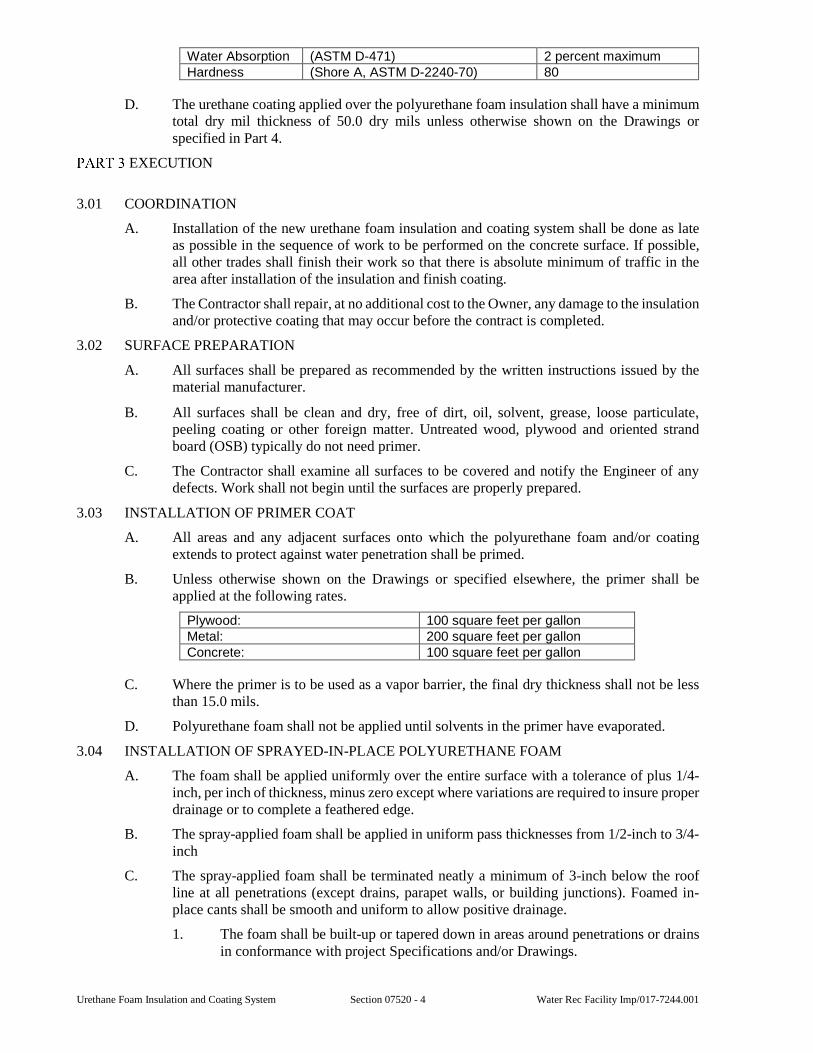
Urethane Foam Insulation and Coating System Section 07520 - 4 Water Rec Facility Imp/017-7244.001
Water Absorption (ASTM D-471) 2 percent maximum Hardness (Shore A, ASTM D-2240-70) 80
D. The urethane coating applied over the polyurethane foam insulation shall have a minimum total dry mil thickness of 50.0 dry mils unless otherwise shown on the Drawings or specified in Part 4.
EXECUTION
3.01 COORDINATION
A. Installation of the new urethane foam insulation and coating system shall be done as late as possible in the sequence of work to be performed on the concrete surface. If possible, all other trades shall finish their work so that there is absolute minimum of traffic in the area after installation of the insulation and finish coating.
B. The Contractor shall repair, at no additional cost to the Owner, any damage to the insulation and/or protective coating that may occur before the contract is completed.
3.02 SURFACE PREPARATION
A. All surfaces shall be prepared as recommended by the written instructions issued by the material manufacturer.
B. All surfaces shall be clean and dry, free of dirt, oil, solvent, grease, loose particulate, peeling coating or other foreign matter. Untreated wood, plywood and oriented strand board (OSB) typically do not need primer.
C. The Contractor shall examine all surfaces to be covered and notify the Engineer of any defects. Work shall not begin until the surfaces are properly prepared.
3.03 INSTALLATION OF PRIMER COAT
A. All areas and any adjacent surfaces onto which the polyurethane foam and/or coating extends to protect against water penetration shall be primed.
B. Unless otherwise shown on the Drawings or specified elsewhere, the primer shall be applied at the following rates.
Plywood: 100 square feet per gallon Metal: 200 square feet per gallon Concrete: 100 square feet per gallon
C. Where the primer is to be used as a vapor barrier, the final dry thickness shall not be less than 15.0 mils.
D. Polyurethane foam shall not be applied until solvents in the primer have evaporated.
3.04 INSTALLATION OF SPRAYED-IN-PLACE POLYURETHANE FOAM
A. The foam shall be applied uniformly over the entire surface with a tolerance of plus 1/4-inch, per inch of thickness, minus zero except where variations are required to insure proper drainage or to complete a feathered edge.
B. The spray-applied foam shall be applied in uniform pass thicknesses from 1/2-inch to 3/4-inch
C. The spray-applied foam shall be terminated neatly a minimum of 3-inch below the roof line at all penetrations (except drains, parapet walls, or building junctions). Foamed in-place cants shall be smooth and uniform to allow positive drainage.
1. The foam shall be built-up or tapered down in areas around penetrations or drains in conformance with project Specifications and/or Drawings.
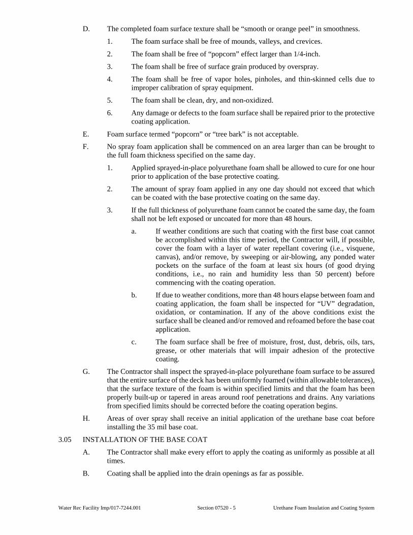
Water Rec Facility Imp/017-7244.001 Section 07520 - 5 Urethane Foam Insulation and Coating System
D. The completed foam surface texture shall be “smooth or orange peel” in smoothness.
1. The foam surface shall be free of mounds, valleys, and crevices.
2. The foam shall be free of “popcorn” effect larger than 1/4-inch.
3. The foam shall be free of surface grain produced by overspray.
4. The foam shall be free of vapor holes, pinholes, and thin-skinned cells due to improper calibration of spray equipment.
5. The foam shall be clean, dry, and non-oxidized.
6. Any damage or defects to the foam surface shall be repaired prior to the protective coating application.
E. Foam surface termed “popcorn” or “tree bark” is not acceptable.
F. No spray foam application shall be commenced on an area larger than can be brought to the full foam thickness specified on the same day.
1. Applied sprayed-in-place polyurethane foam shall be allowed to cure for one hour prior to application of the base protective coating.
2. The amount of spray foam applied in any one day should not exceed that which can be coated with the base protective coating on the same day.
3. If the full thickness of polyurethane foam cannot be coated the same day, the foam shall not be left exposed or uncoated for more than 48 hours.
a. If weather conditions are such that coating with the first base coat cannot be accomplished within this time period, the Contractor will, if possible, cover the foam with a layer of water repellant covering (i.e., visquene, canvas), and/or remove, by sweeping or air-blowing, any ponded water pockets on the surface of the foam at least six hours (of good drying conditions, i.e., no rain and humidity less than 50 percent) before commencing with the coating operation.
b. If due to weather conditions, more than 48 hours elapse between foam and coating application, the foam shall be inspected for “UV” degradation, oxidation, or contamination. If any of the above conditions exist the surface shall be cleaned and/or removed and refoamed before the base coat application.
c. The foam surface shall be free of moisture, frost, dust, debris, oils, tars, grease, or other materials that will impair adhesion of the protective coating.
G. The Contractor shall inspect the sprayed-in-place polyurethane foam surface to be assured that the entire surface of the deck has been uniformly foamed (within allowable tolerances), that the surface texture of the foam is within specified limits and that the foam has been properly built-up or tapered in areas around roof penetrations and drains. Any variations from specified limits should be corrected before the coating operation begins.
H. Areas of over spray shall receive an initial application of the urethane base coat before installing the 35 mil base coat.
3.05 INSTALLATION OF THE BASE COAT
A. The Contractor shall make every effort to apply the coating as uniformly as possible at all times.
B. Coating shall be applied into the drain openings as far as possible.
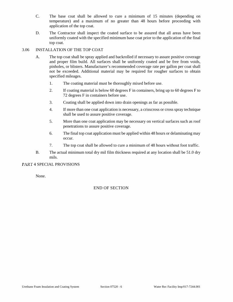
Urethane Foam Insulation and Coating System Section 07520 - 6 Water Rec Facility Imp/017-7244.001
C. The base coat shall be allowed to cure a minimum of 15 minutes (depending on temperature) and a maximum of no greater than 48 hours before proceeding with application of the top coat.
D. The Contractor shall inspect the coated surface to be assured that all areas have been uniformly coated with the specified minimum base coat prior to the application of the final top coat.
3.06 INSTALLATION OF THE TOP COAT
A. The top coat shall be spray applied and backrolled if necessary to assure positive coverage and proper film build. All surfaces shall be uniformly coated and be free from voids, pinholes, or blisters. Manufacturer’s recommended coverage rate per gallon per coat shall not be exceeded. Additional material may be required for rougher surfaces to obtain specified mileages.
1. The coating material must be thoroughly mixed before use.
2. If coating material is below 60 degrees F in containers, bring up to 60 degrees F to 72 degrees F in containers before use.
3. Coating shall be applied down into drain openings as far as possible.
4. If more than one coat application is necessary, a crisscross or cross spray technique shall be used to assure positive coverage.
5. More than one coat application may be necessary on vertical surfaces such as roof penetrations to assure positive coverage.
6. The final top coat application must be applied within 48 hours or delaminating may occur.
7. The top coat shall be allowed to cure a minimum of 48 hours without foot traffic.
B. The actual minimum total dry mil film thickness required at any location shall be 51.0 dry mils.
SPECIAL PROVISIONS
None.
END OF SECTION
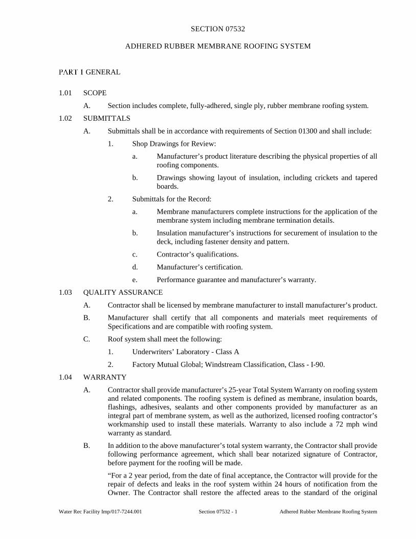
Water Rec Facility Imp/017-7244.001 Section 07532 - 1 Adhered Rubber Membrane Roofing System
SECTION 07532
ADHERED RUBBER MEMBRANE ROOFING SYSTEM
GENERAL
1.01 SCOPE
A. Section includes complete, fully-adhered, single ply, rubber membrane roofing system.
1.02 SUBMITTALS
A. Submittals shall be in accordance with requirements of Section 01300 and shall include:
1. Shop Drawings for Review:
a. Manufacturer’s product literature describing the physical properties of all roofing components.
b. Drawings showing layout of insulation, including crickets and tapered boards.
2. Submittals for the Record:
a. Membrane manufacturers complete instructions for the application of the membrane system including membrane termination details.
b. Insulation manufacturer’s instructions for securement of insulation to the deck, including fastener density and pattern.
c. Contractor’s qualifications.
d. Manufacturer’s certification.
e. Performance guarantee and manufacturer’s warranty.
1.03 QUALITY ASSURANCE
A. Contractor shall be licensed by membrane manufacturer to install manufacturer’s product.
B. Manufacturer shall certify that all components and materials meet requirements of Specifications and are compatible with roofing system.
C. Roof system shall meet the following:
1. Underwriters’ Laboratory - Class A
2. Factory Mutual Global; Windstream Classification, Class - I-90.
1.04 WARRANTY
A. Contractor shall provide manufacturer’s 25-year Total System Warranty on roofing system and related components. The roofing system is defined as membrane, insulation boards, flashings, adhesives, sealants and other components provided by manufacturer as an integral part of membrane system, as well as the authorized, licensed roofing contractor’s workmanship used to install these materials. Warranty to also include a 72 mph wind warranty as standard.
B. In addition to the above manufacturer’s total system warranty, the Contractor shall provide following performance agreement, which shall bear notarized signature of Contractor, before payment for the roofing will be made.
“For a 2 year period, from the date of final acceptance, the Contractor will provide for the repair of defects and leaks in the roof system within 24 hours of notification from the Owner. The Contractor shall restore the affected areas to the standard of the original
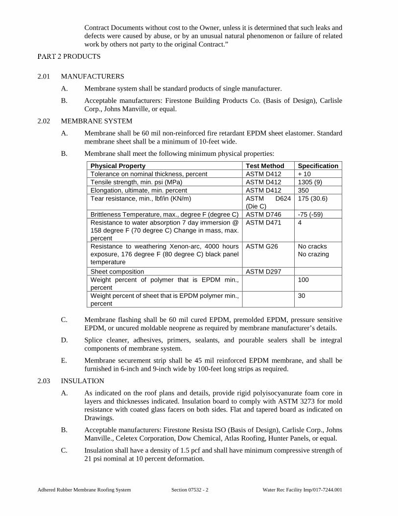
Adhered Rubber Membrane Roofing System Section 07532 - 2 Water Rec Facility Imp/017-7244.001
Contract Documents without cost to the Owner, unless it is determined that such leaks and defects were caused by abuse, or by an unusual natural phenomenon or failure of related work by others not party to the original Contract.”
PRODUCTS
2.01 MANUFACTURERS
A. Membrane system shall be standard products of single manufacturer.
B. Acceptable manufacturers: Firestone Building Products Co. (Basis of Design), Carlisle Corp., Johns Manville, or equal.
2.02 MEMBRANE SYSTEM
A. Membrane shall be 60 mil non-reinforced fire retardant EPDM sheet elastomer. Standard membrane sheet shall be a minimum of 10-feet wide.
B. Membrane shall meet the following minimum physical properties:
Physical Property Test Method Specification
Tolerance on nominal thickness, percent ASTM D412 + 10
Tensile strength, min. psi (MPa) ASTM D412 1305 (9)
Elongation, ultimate, min. percent ASTM D412 350
Tear resistance, min., lbf/in (KN/m) ASTM D624 (Die C)
175 (30.6)
Brittleness Temperature, max., degree F (degree C) ASTM D746 -75 (-59)
Resistance to water absorption 7 day immersion @ 158 degree F (70 degree C) Change in mass, max. percent
ASTM D471 4
Resistance to weathering Xenon-arc, 4000 hours exposure, 176 degree F (80 degree C) black panel temperature
ASTM G26 No cracks No crazing
Sheet composition ASTM D297
Weight percent of polymer that is EPDM min., percent
100
Weight percent of sheet that is EPDM polymer min., percent
30
C. Membrane flashing shall be 60 mil cured EPDM, premolded EPDM, pressure sensitive EPDM, or uncured moldable neoprene as required by membrane manufacturer’s details.
D. Splice cleaner, adhesives, primers, sealants, and pourable sealers shall be integral components of membrane system.
E. Membrane securement strip shall be 45 mil reinforced EPDM membrane, and shall be furnished in 6-inch and 9-inch wide by 100-feet long strips as required.
2.03 INSULATION
A. As indicated on the roof plans and details, provide rigid polyisocyanurate foam core in layers and thicknesses indicated. Insulation board to comply with ASTM 3273 for mold resistance with coated glass facers on both sides. Flat and tapered board as indicated on Drawings.
B. Acceptable manufacturers: Firestone Resista ISO (Basis of Design), Carlisle Corp., Johns Manville., Celetex Corporation, Dow Chemical, Atlas Roofing, Hunter Panels, or equal.
C. Insulation shall have a density of 1.5 pcf and shall have minimum compressive strength of 21 psi nominal at 10 percent deformation.
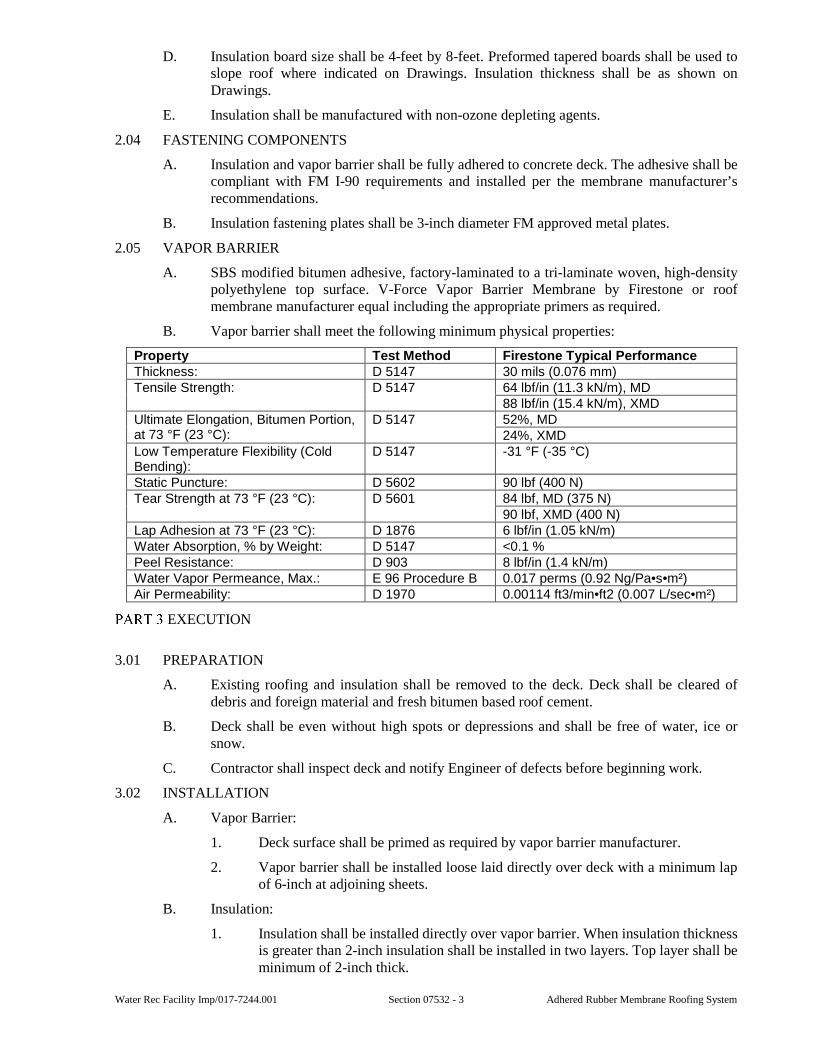
Water Rec Facility Imp/017-7244.001 Section 07532 - 3 Adhered Rubber Membrane Roofing System
D. Insulation board size shall be 4-feet by 8-feet. Preformed tapered boards shall be used to slope roof where indicated on Drawings. Insulation thickness shall be as shown on Drawings.
E. Insulation shall be manufactured with non-ozone depleting agents.
2.04 FASTENING COMPONENTS
A. Insulation and vapor barrier shall be fully adhered to concrete deck. The adhesive shall be compliant with FM I-90 requirements and installed per the membrane manufacturer’s recommendations.
B. Insulation fastening plates shall be 3-inch diameter FM approved metal plates.
2.05 VAPOR BARRIER
A. SBS modified bitumen adhesive, factory-laminated to a tri-laminate woven, high-density polyethylene top surface. V-Force Vapor Barrier Membrane by Firestone or roof membrane manufacturer equal including the appropriate primers as required.
B. Vapor barrier shall meet the following minimum physical properties:
Property Test Method Firestone Typical Performance Thickness: D 5147 30 mils (0.076 mm) Tensile Strength: D 5147 64 lbf/in (11.3 kN/m), MD
88 lbf/in (15.4 kN/m), XMD Ultimate Elongation, Bitumen Portion, at 73 °F (23 °C):
D 5147 52%, MD 24%, XMD
Low Temperature Flexibility (Cold Bending):
D 5147 -31 °F (-35 °C)
Static Puncture: D 5602 90 lbf (400 N) Tear Strength at 73 °F (23 °C): D 5601 84 lbf, MD (375 N)
90 lbf, XMD (400 N) Lap Adhesion at 73 °F (23 °C): D 1876 6 lbf/in (1.05 kN/m) Water Absorption, % by Weight: D 5147 <0.1 % Peel Resistance: D 903 8 lbf/in (1.4 kN/m) Water Vapor Permeance, Max.: E 96 Procedure B 0.017 perms (0.92 Ng/Pa•s•m²) Air Permeability: D 1970 0.00114 ft3/min•ft2 (0.007 L/sec•m²)
EXECUTION
3.01 PREPARATION
A. Existing roofing and insulation shall be removed to the deck. Deck shall be cleared of debris and foreign material and fresh bitumen based roof cement.
B. Deck shall be even without high spots or depressions and shall be free of water, ice or snow.
C. Contractor shall inspect deck and notify Engineer of defects before beginning work.
3.02 INSTALLATION
A. Vapor Barrier:
1. Deck surface shall be primed as required by vapor barrier manufacturer.
2. Vapor barrier shall be installed loose laid directly over deck with a minimum lap of 6-inch at adjoining sheets.
B. Insulation:
1. Insulation shall be installed directly over vapor barrier. When insulation thickness is greater than 2-inch insulation shall be installed in two layers. Top layer shall be minimum of 2-inch thick.
Adhered Rubber Membrane Roofing System Section 07532 - 4 Water Rec Facility Imp/017-7244.001
2. Insulation boards shall be butted together with no gaps greater than 1/4-inch.
3. Joints between layers of insulation shall be staggered minimum of 12-inch.
4. On metal decks, after placement of top layer, insulation shall be secured to deck with insulation fasteners and plates. Fastener pattern and density shall be as required by the insulation manufacturer.
5. On concrete decks, install the boards with end joints staggered. When installing two layers of insulation boards, ensure that the joints of both layers do not coincide. Adhere the boards, with (restricted) dimensions, using an adhesive system and pattern as advised and approved by manufacturer, all in accordance with national wind uplift standards. Install fully in accordance with manufacturer’s instructions.
C. Membrane System:
1. Membrane shall be installed, spliced, and secured in accordance with manufacturer’s written instructions and details.
2. Position membrane over insulation without stretching.
3. Allow membrane to relax 1/2 hour before bonding to insulation.
4. Lap splices shall be minimum of 6-inch wide.
5. Additional membrane securement shall be provided at perimeter of each roof level, roof section, expansion joint, curb, skylight, interior wall, penthouse, angle change greater than 2-inch in one horizontal foot, and at other penetrations where recommended by membrane manufacturer.
6. Penetrations and walls shall be flashed with cured EPDM membrane or prefabricated accessories (pre-molded and pressure-sensitive products such as pipe boots, pourable sealer pockets, inside/outside corners) that are standard products of membrane manufacturer. Where use of cured membrane or prefabricated accessories is not practical, uncured moldable neoprene shall be used. Membrane flashing shall be installed and terminated in accordance with the membrane manufacturer’s written instructions and details.
D. Daily Seal - When completion of flashings and terminations is not completed by end of work day, loose edges of membrane shall be temporarily sealed in accordance with membrane manufacturer’s written instructions and details.
SPECIAL PROVISIONS
None.
END OF SECTION
Water Rec Facility Imp/017-7244.001 Section 07900 - 1 Caulking and Sealants
SECTION 07900
CAULKING AND SEALANTS
GENERAL
1.01 SCOPE
A. This Section includes caulking and sealants.
1.02 SUBMITTALS
A. Submittal shall be in accordance with requirements of Section 01300 and shall include:
1. Shop Drawings for Review:
a. Contractor shall indicate variances from requirements of Contract Documents.
b. Product literature.
c. Manufacturer’s standard color chart.
2. Information for the Record:
a. Manufacturer’s surface preparation and installation instructions.
b. Written guarantee.
1.03 QUALITY ASSURANCE
A. Contractor shall have minimum of five years’ experience installing sealants.
1.04 GUARANTEES
A. Contractor shall guarantee sealant joints against adhesive and cohesive failure of sealant and against water penetration through joint for five years.
PRODUCTS
2.01 CAULKING AND SEALANTS
A. Type A:
1. Sealant shall be two component, polyurethane sealant, conforming to ASTM C920, Type M, Class 25, Type I, and either Grade NS or Grade P as appropriate. Sealant shall have Shore A hardness of 20-40 and minimum elongation of 500 percent.
2. Sealant shall be suitable for continuous immersion service in water and sewage.
3. Sealant shall be Sika Corporation “Sikaflex-2c NS/SL”, Polymeric Systems, Inc. “PSI 501/551”, or equal.
B. Type B:
1. Sealant shall be one component neutral or acetoxy cure silicone sealant conforming to ASTM C920, Type S, Class 25, Grade NS with Shore A hardness of 25-30.
C. Type C:
1. Sealant shall be one component, non-sag mildew resistant silicone sealant conforming to ASTM C-920, Type S, Class 25, Grade NS, with Shore A hardness of 25-30.
Caulking and Sealants Section 07900 - 2 Water Rec Facility Imp/017-7244.001
D. Type D:
1. Sealant shall be one component acrylic latex caulk conforming to ASTM C834. Material shall be suitable for painting.
E. Type E:
1. Two component, coal-tar extended, fuel resistant polyurethane sealant conforming to ASTM C-920, Type M, Class 25, Grade NS or Grade P as appropriate, with Shore A hardness of 15-35.
2.02 ACCESSORIES
A. Primer shall be sealant manufacturer’s recommended primer for intended substrates and intended service conditions. Primer shall be non-staining.
B. Backer rod shall be closed cell polyethylene or polyurethane as recommended by sealant manufacturer. Materials impregnated with oils, asphalt, or solvents are not acceptable. Backer rod shall be minimum of 33 percent oversized.
C. Bond breaker tape shall be polyethylene or similar type material which does not bond to sealant.
EXECUTION
3.01 COORDINATION
A. Manufacturer’s recommendations for proper temperature and humidity conditions for installation shall be followed. Sealants shall not be installed when the ambient temperature is below 40 degrees F.
B. Substrate surface shall be inspected to ensure that no bond breaking materials contaminate surfaces to which sealant is to adhere.
C. Joint dimensions shall be verified prior to installing sealant to ensure that dimensions are within tolerances specified in sealant manufacturer’s literature.
3.02 PREPARATION
A. Surfaces shall be prepared in accordance with manufacturer’s recommendations to ensure maximum adhesion. Surfaces shall be dry, sound, and free of oil, grease, dust, dirt, curing agents, temporary protective coatings, and other materials deleterious to bond.
B. Adjacent surfaces which are not to receive sealant shall be masked before primer and sealant is applied. Masking shall be removed immediately after sealant has been installed and tooled.
C. Primer shall be applied prior to installation of backer rod or bond breaker tape.
3.03 INSTALLATION
A. Backer rod shall be installed using only blunt or rounded tools designed to ensure uniform depth of backer rod without puncturing the material. Backer rod shall not be stretched, twisted or braided.
B. Where joint depth does not permit use of backer rod, bond breaker tape shall be installed to prevent three-sided adhesion.
C. Sealants shall be prepared, mixed, and installed in accordance with manufacturer’s instructions using equipment recommended by sealant manufacturer. Sealant shall be installed as shown.
D. Sealants shall be tooled to uniformly smooth, slightly concave surface as shown on Drawings.
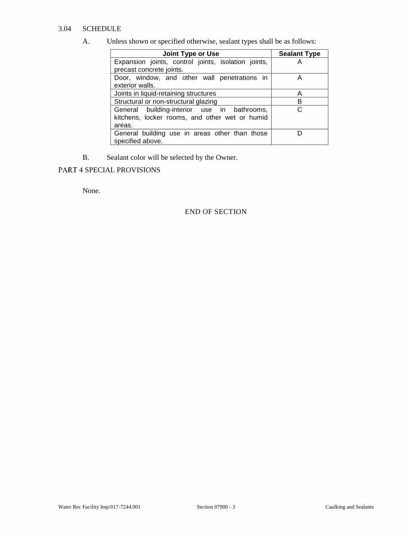
Water Rec Facility Imp/017-7244.001 Section 07900 - 3 Caulking and Sealants
3.04 SCHEDULE
A. Unless shown or specified otherwise, sealant types shall be as follows:
Joint Type or Use Sealant TypeExpansion joints, control joints, isolation joints, precast concrete joints.
A
Door, window, and other wall penetrations in exterior walls.
A
Joints in liquid-retaining structures A Structural or non-structural glazing B General building-interior use in bathrooms, kitchens, locker rooms, and other wet or humid areas.
C
General building use in areas other than those specified above.
D
B. Sealant color will be selected by the Owner.
SPECIAL PROVISIONS
None.
END OF SECTION

Caulking and Sealants Section 07900 - 4 Water Rec Facility Imp/017-7244.001
This page was intentionally left blank.
Water Rec Facility Imp/017-7244.001 Section 08125 - 1 Heavy Duty Aluminum Doors and Frames
SECTION 08125
HEAVY DUTY ALUMINUM DOORS AND FRAMES
GENERAL
1.01 SCOPE
A. This Section includes furnishing and installing heavy duty aluminum doors, frames, required fasteners, and other accessories required for completion of the Work.
B. Additional product requirements are specified in Section 01350.
1.02 SUBMITTALS
A. Submittals shall be in accordance with the requirements of Section 01300 and shall include:
1. Shop Drawings for Review:
a. Door Schedule.
b. Dimensional Drawing.
c. Manufacturer’s literature.
d. Samples - When requested by the Engineer.
1) Samples of finish, frame corner construction, door construction, and glazing frame.
2) Samples shall be clearly identified as to location and type of finish.
PRODUCTS
2.01 GENERAL
A. Aluminum doors shall be as manufactured by Cross Aluminum Products, or equal.
B. Products furnished for use in this Section shall be of one manufacturer unless specifically shown otherwise or approved by the Engineer.
2.02 DOORS
A. Door sections to be 4-inch tubular shapes of 6063-T5 alloy.
B. Joinery shall be steel tie rod bolted through stiles, where applicable a minimum of three 3/8-inch diameter cadmium plated steel rods a door.
C. The finish of doors and door parts shall be free of scratches, defects, die lines, and blemishes and shall have a natural anodized finish in conformance with AA Specification M12C22A41.
D. Minimum wall thickness 0.100-inch with 0.187-inch minimum at lock and hinge stiles.
E. Door sections are to interlock a minimum of 3/8-inch and form a 1/4-inch thick vertical reinforcement every 4 inches.
F. Exterior doors to be installed with urethane boardstock.
G. Glass stops to be extruded glazing channels, which are easily removed from the inside. Minimum wall thickness 0.080-inch.
H. Fluted No. 10 pattern extruded in door section.
I. Exterior doors shall be fully weather-stripped.
Heavy Duty Aluminum Doors and Frames Section 08125 - 2 Water Rec Facility Imp/017-7244.001
J. All double doors shall have a continuous astragal of the same material and color as the doors and installed on the exterior of the active leaf to cover the gap between doors. Each door shall have non-ferrous lever handles in place of knobs on the passing slide of the astragal or as called for on the hardware schedule. The assembly shall contain a booster spring to ensure the lever returning to a horizontal position.
2.03 ALUMINUM FRAMES
A. All sections of frames shall be fabricated from aluminum alloy 6063 and T-6 temper with a minimum thickness of 0.125-inch. Screws shall be 18-8 stainless steel.
B. All framing members shall be accurately milled with flush hairline joints. Frames shall be closed back or open back as detailed on the Drawings.
C. Door frame corner members shall be heavily reinforced with channel type corner gussets fastened with concealed stainless steel screws.
D. Frames shall be reinforced in the areas to receive locks, hinges, and door closers.
E. Door frame finish shall match that of the door. The finished product shall be free of scratches, defects, and blemishes.
F. Door stops shall be attached to the frame with concealed fastenings with vinyl inserts for weatherproofing and silencing.
EXECUTION
3.01 DELIVERY, HANDLING, AND STORAGE
A. Delivery, handling, and storage shall be in accordance with the requirements of Section 01350.
3.02 INSTALLATION OF FRAMES
A. Set frames to maintain scheduled dimensions, hold head level, and set jambs plumb and square.
B. Secure anchorages and provide connections to adjacent construction.
C. Apply protective coating of bituminous paint to backs of frame to separate aluminum from contact with masonry, concrete, or other galvanically incompatible materials.
D. Frame shall be set with a minimum of eight anchors.
3.03 INSTALLATION OF DOORS
A. Comply with manufacturer’s instructions for installation of door hardware, operators, and other components.
B. Adjust hinges so doors operate smoothly and fit properly when closed.
C. Adjust and lubricate locks, operators, and hinges.
D. Clean aluminum surfaces and remove protective tape and excess caulking sealants.
E. Thresholds are to be provided at exterior doors. Bottom, head, and jamb weather-strips shall be adjusted to fit correctly.
SPECIAL PROVISIONS
None.
END OF SECTION
Water Rec Facility Imp/017-7244.001 Section 08572 - 1 Fiberglass Windows
SECTION 08572
FIBERGLASS WINDOWS
PART 1 GENERAL
1.01 SCOPE
A. This Section includes furnishing and installing fiberglass windows, and all anchors, bolts, screws, shims, nails, screens, and other accessories required for complete installation.
B. Additional product requirements are specified in Section 01350.
1.02 SUBMITTALS
A. Submittals shall be in accordance with the requirements of Section 01300 and shall include:
1. Shop Drawings for Review:
a. The Contractor shall indicate all variances from the requirements for the Contract Documents.
b. Manufacturer's literature.
c. Dimensional Drawing.
d. Samples - When requested by the Engineer.
1) Corner assembly of each type window to be used on the project.
2) Samples shall be clearly identified as to location and type of finish.
2. Operation and maintenance information.
1.03 PERFORMANCE REQUIREMENTS
A. Window Air Leakage, ASTM E 283:
1. Window air leakage when tested at 1.57 psf (25 mph) shall be 0.25 cfm/ft2 of frame or less.
B. Window Water Penetration, ASTM E 547:
1. No water penetration through window when tested under static pressure of 4.5 psf (42 mph) after 4 cycles of 5 minutes each, with water being applied at a rate of 5 gallons per hour per square foot.
1.04 SUBMITTALS
A. Submit in accordance with Section 01300.
B. Product Data:
1. Submit manufacturer's product data, including installation instructions.
C. Shop Drawings:
1. Submit manufacturer's shop drawings, indicating dimensions, construction, component connections and locations, anchorage methods and locations, hardware locations and installation details.
D. Samples:
1. Submit full-size or partial full-size sample of window illustrating glazing system, quality of construction and color of finish.
Fiberglass Windows Section 08572 - 2 Water Rec Facility Imp/017-7244.001
1.05 DELIVERY, STORAGE AND HANDLING
A. Delivery:
1. Deliver materials to site undamaged in manufacturer’s or sales branch’s original, unopened containers and packaging, with labels clearly identifying manufacturer and product name. Include installation instructions.
B. Storage:
1. Store materials in accordance with manufacturer’s instructions.
2. Store materials off ground and under cover.
3. Protect materials from weather, direct sunlight and construction activities.
C. Handling:
1. Protect materials and finish during handling and installation to prevent damage.
PART 2 PRODUCTS
2.01 MANUFACTURER
A. Windows shall be Pella Impervia, or equal.
2.02 FIBERGLASS WINDOWS
A. Windows:
1. Factory-assembled window.
2. Frame Material: 5-Layer, pultruded-fiberglass material, reinforced with interlocking mat.
B. Frame:
1. Type:
a. New construction frame.
2. Overall Frame Depth:
a. 3 inches.
3. Nominal Wall Thickness of Fiberglass Members:
a. 0.050 inch to 0.070 inch.
4. Frame Corners:
a. Mitered.
b. Joined and bonded with thermoset polyurethane adhesive, nylon corner lock, and mechanically fastened.
5. Sill:
a. Fitted with weep valve assemblies.
C. Glazing:
1. Float Glass:
a. ASTM C 1036, Quality 1.
2. Type:
a. 11/16-inch thick, insulating glass, clear.
Water Rec Facility Imp/017-7244.001 Section 08572 - 3 Fiberglass Windows
2.03 ACCESSORIES
A. Grilles:
1. Insulating Glass:
a. Contain 3/4-inch, contoured, aluminum grilles between the glass.
2. Finish:
a. Factory-finished. Match window frame.
B. Insect Screens:
1. Compliance:
a. ASTM D 3656 and SMA 1201.
2. Screen Cloth:
a. Half-size with black, vinyl-coated, 18/16 mesh, fiberglass screen cloth set in aluminum frame fitted to outside of window.
3. Complete with necessary hardware.
4. Screen Frame Finish:
a. Baked enamel.
b. Color:
1) Match window exterior.
2.04 TOLERANCES
A. Windows shall accommodate the following tolerances:
1. Horizontal dimensions between high and low points:
a. Plus 1/4 inch, minus 0 inch.
2. Width Dimensions:
a. Plus 1/4 inch, minus 0 inch.
3. Building columns or masonry openings:
a. Plus or minus 1/4 inch from plumb.
2.05 FINISH
A. Exterior and Interior factory-applied powder-coat paint, comply with AAMA 613.
1. Color:
a. Brown.
2.06 INSTALLATION ACCESSORIES
A. Flashing/Sealant Tape:
1. Aluminum-foil-backed butyl window and door flashing tape.
2. Maximum Total Thickness:
a. 0.013 inch.
3. UV resistant.
4. Verify sealant compatibility with sealant manufacturer.
B. Exterior Perimeter Sealant:
1. Geocel Proflex Tripolymer Sealant.
Fiberglass Windows Section 08572 - 4 Water Rec Facility Imp/017-7244.001
C. Insulating-Foam Sealant:
1. Dow Chemical Great Stuff Window and Door Insulating Foam Sealant.
2. Low-pressure, polyurethane window and door insulating-foam sealant.
PART 3 EXECUTION
3.01 EXAMINATION
A. Examine areas to receive windows. Notify Engineer/Architect of conditions that would adversely affect installation or subsequent use. Do not proceed with installation until unsatisfactory conditions are corrected.
3.02 INSTALLATION
A. Install windows in accordance with manufacturer's instructions.
B. Install windows to be weather-tight.
C. Maintain alignment with adjacent work.
D. Secure assembly to framed openings, plumb and square, with no distortion.
E. Integrate window system installation with exterior water-resistant barrier using flashing/ sealant tape. Apply and integrate flashing/sealant tape with water-resistant barrier using watershed principles in accordance with window manufacturer's instructions.
F. Place interior seal around window perimeter to maintain continuity of building thermal and air barrier using insulating foam sealant.
G. Seal window to exterior wall cladding with sealant and related backing materials at perimeter of assembly.
H. Leave windows closed and locked.
3.03 CLEANING
A. Clean window frames and glass in accordance with Division 1 requirements.
B. Do not use harsh cleaning materials or methods that would damage finish or glass.
C. Remove labels and visible markings.
3.04 PROTECTION
A. Protect installed windows to ensure that, except for normal weathering, windows will be without damage or deterioration at time of substantial completion.
PART 4 SPECIAL PROVISIONS
None.
END OF SECTION
Water Rec Facility Imp/017-7244.001 Section 09880 - 1 Protective Coating for Concrete
SECTION 09880
PROTECTIVE COATING FOR CONCRETE
GENERAL
1.01 SCOPE
A. This Section includes protective coating for concrete.
B. Additional product requirements are specified in Section 01350.
1.02 SUBMITTALS
A. Submittals shall be in accordance with the requirements of Section 01300 and shall include:
1. Shop Drawings for Review:
a. Contractor shall indicate variances from requirements of Contract Documents.
b. Product literature.
2. Information for the Record:
a. Material certification.
b. Manufacturer’s surface preparation, mixing, application, and curing instructions.
1.03 DELIVERY, STORAGE, AND HANDLING
A. Materials shall be stored in enclosed, dry space protected from weather and out of direct sunlight. Temperature of storage area shall be maintained between 40 degrees F and 90 degrees F.
1.04 PROJECT CONDITIONS
A. Surfaces to receive coating shall have temperature between 50 degrees F and 90 degrees F. Coating shall not be applied when surface temperature is less than 5 degrees F above dew point.
1.05 SCHEDULING AND SEQUENCING
A. Surfaces shall be allowed to cure minimum of 28 days prior to application of coating.
PRODUCTS
2.01 COATING SYSTEM
A. Coating shall be one-part, self-priming, high-build, cold-applied, polymer-based coating. Minimum solids content shall be 68 percent by volume. Tnemec “Series 1028 Endura tone”, Spectra shield, or equal.
EXECUTION
3.01 SURFACE PREPARATION
A. Surfaces to receive membrane shall be dry and free of oil, form release agents, curing compounds, grease, laitance, and loose material. Protrusions shall be removed.
B. Surfaces shall be abrasive blasted in accordance with ASTM D4259. Surface texture shall be equivalent to medium grit sand paper.
Protective Coating for Concrete Section 09880 - 2 Water Rec Facility Imp/017-7244.001
C. Bugholes and surface defects shall be patched.
D. Contractor shall verify dryness of concrete by plastic sheet method in accordance with D4263.
3.02 APPLICATION
A. Coating shall be applied in accordance with manufacturer’s written instructions.
B. Coating shall be applied in two coats. Dry film thickness of each coat shall be 13-16 mils.
C. Each coat shall be cured in accordance with manufacturer’s recommendations. Final coat shall be cured minimum of 14 days prior to immersion.
SPECIAL PROVISIONS
4.01 SCHEDULE
A. New concrete and concrete masonry surfaces of following structures which are immersed in sewage or exposed to sewage fumes shall receive protective coating:
1. Foul air manhole MH-1.
END OF SECTION
Water Rec Facility Imp/017-7244.001 Section 09900 - 1 Painting
SECTION 09900
PAINTING
GENERAL
1.01 SCOPE
A. This Section includes furnishing and application of protective coatings to all wood, concrete, and metal surfaces as specified or as shown on the Drawings.
B. Included in this Section is surface preparation, shop application inspection, and field touch up work as required to provide a complete protective coating system.
C. In general, the work shall include the field painting of the following:
1. All exposed interior cast-in-place concrete (except floors) above ground floor.
2. All exposed concrete blocks and hollow core precast slabs.
3. All exposed plaster.
4. All exposed wood.
5. All exposed pipe insulation.
6. All exposed piping, including fittings, valves, couplings, flanges, and other in-line accessories.
7. All machinery, pumps, and equipment.
8. All metal surfaces except the following:
a. Bronze surfaces.
b. Stainless steel surfaces.
c. Aluminum or galvanized steel not requiring color coding or otherwise specified to be coated.
D. Additional product requirements are specified in Section 01350.
E. A Coating Schedule appears in Part 4 of this Section.
1.02 SUBMITTALS
A. Submittals shall be in accordance with the requirements of Section 01300 and shall include:
1. Shop Drawings for Review:
a. Coating manufacturer’s product data and technical literature including:
1) Catalog number.
2) General classification.
3) Coating material analysis.
4) Detailed surface preparation guidelines.
5) Mixing, thinning, and application instructions for each material.
6) Induction time, pot life, viscosity, and drying and curing times for acceptable ranges of temperature and humidity.
b. Abrasive manufacturer’s information including:
1) Name, address, and phone number of manufacturer and local supplier.
Painting Section 09900 - 2 Water Rec Facility Imp/017-7244.001
2) Bulk density.
3) Mohs ranking.
4) Sieve analysis.
5) Chemical analysis including impurities.
6) Free silica content.
7) Grain shape (roundness).
c. Submittals of coatings by a manufacturer not named in these specifications shall include performance criteria on abrasion, adhesion, exterior exposure, hardness, humidity exposure, salt spray (fog), impact, immersion, etc., as applicable, per the appropriate ASTM standards. If requested by the Engineer, the Contractor shall submit manufacturers complete formula for the coatings which are proposed to be furnished. The Engineer may also require the submission, at the Contractor’s expense, of test reports from private laboratories showing results of comparable tests on the coatings proposed and the coatings specified.
d. Details of application equipment and procedures.
e. Samples of manufacturer’s standard colors.
2. Information for the Record:
a. Certification that materials meet or exceed Specifications and that coating systems are suitable for intended use.
b. Certification that coating systems are compatible with substrate, specified surface preparation, prime coats, sealants and existing finishes.
c. Safety Data Sheets (SDS) for coating materials, thinners, diluents, abrasives, cleansers, and other materials.
d. Schedule of coating work showing each phase and step of work.
1.03 QUALITY ASSURANCE
A. Standards - Surface preparation, coating, and patching work performed under this Section shall conform to the applicable provisions and recommendations of the following standards.
1. SSPC Steel Structures Painting Manual, Volume 1, “Good Painting Practice.”
2. SSPC Steel Structures Painting Manual, Volume 2, “Systems and Specifications.”
3. SSPC Vis. 1 & 2, visual standards and written guidelines.
4. NACE Coatings and Linings Handbook.
5. Applicable NACE standards and recommended practices including RP0178 and RP0184.
1.04 DELIVERY, STORAGE, AND HANDLING
A. Delivery, storage, and handling shall be in accordance with Section 01350.
B. Include the following information on container labels or packing slips:
1. Manufacturer’s name.
2. Name or title of material.
3. Batch numbers.
4. Stock number and date of manufacture.
Water Rec Facility Imp/017-7244.001 Section 09900 - 3 Painting
5. Shelf life or expiration date.
6. Contents by volume of pigment, binder, and vehicle.
7. Thinning instructions when recommended.
8. Application instructions.
9. Color name and number.
10. Safety Data Sheets (SDS).
C. Provide controlled storage for coating materials and abrasives. Store coating materials in environmentally controlled enclosure with minimum ambient temperature of 55 degrees F. Store abrasives in dry area.
D. Maintain inventory of coating materials, solvents, and cleaners.
1.05 SCHEDULING AND SEQUENCING
A. Notify Engineer two weeks in advance of surface preparation and coating application.
B. Work systematically in accordance with submitted schedule.
C. Sequence and coordinate abrasive blasting and coating application with work of other Sections. Do not interrupt plant process or interfere with Owner’s operations.
D. Coordinate coating work with installation of sealants specified in Section 07900.
E. Furnish specified testing and inspection equipment to Owner a minimum of two weeks prior to beginning surface preparation and coating work.
1.06 MANUFACTURER’S RECOMMENDATIONS
A. Apply coatings in strict compliance with manufacturer’s recommendations and instructions as to environmental conditions, surface preparation, mixing, application, and curing. Where Specifications are more stringent than manufacturer’s recommendations, Specifications shall prevail.
B. Resolve conflicts between Specifications and manufacturer’s recommendations and instructions by obtaining written agreement between Engineer and coating manufacturer prior to beginning work.
1.07 DESCRIPTION
A. Shop Painting - Shop painting shall be performed to the extent and as required under Section 01350 and the various individual Sections of the Specifications. All metal surfaces shall be given a protective shop coat of primer compatible with the field coating. Shop primer color shall be beige where available. If a prime coat has not been applied in the shop, then a prime coat shall be applied in the field after proper surface preparation and prior to the application of the finish coats.
B. Compatibility - The Contractor shall ensure the primer or finish coating applied in the shop is compatible with the specified field coatings. If the coatings are incompatible, the shop coatings shall be removed by abrasive blasting and coatings applied in conformance with this Section.
PRODUCTS
2.01 MATERIALS
A. The products shall be as specified in the Coating Schedule. Materials selected for each coating system shall be the product of one manufacturer. The Contractor shall be responsible for the compatibility of all components of each coating system including primer, thinner, and solvents.
Painting Section 09900 - 4 Water Rec Facility Imp/017-7244.001
2.02 COATING SCHEDULE
A. The Coating Schedule included in Part 4 of this Section identifies the areas to be painted, the required materials, and number of coats required.
EXECUTION
3.01 ENVIRONMENTAL REQUIREMENTS
A. Environmental Conditions:
1. Perform work of this Section under the following environmental conditions.
a. Abrasive blast only when surface contamination can be prevented. Abrasive blast only when surface temperature is more than 5 degrees F above dew point and relative humidity is less than 85 percent.
b. No coating shall be applied when the air temperature, as measured in the shade, is below 40 degrees F or above 90 degrees F. No coating shall be applied when the temperature of the surface to be painted is below 35 degrees F or as recommended by the paint manufacturer, whichever is greater. Coatings shall not be applied to wet or damp surfaces, when the relative humidity exceeds 85 percent, or when the surface to be painted is less than 5 degrees F above the dew point.
2. Coating work may proceed during inclement weather in environmentally controlled enclosures. Environment within enclosure shall comply with Specifications and manufacturer’s recommendations. Provide adequate ventilation and illumination. Minimum illumination shall be 150 foot candles.
B. Interior Painting may be done only when the building has been thoroughly dried, by natural or artificial heat, and when the work area is properly heated and ventilated, clean, and as nearly dust free as possible. Room temperature shall be maintained within the manufacturer’s recommendations during application and until coatings are dry.
C. Dust - Coating shall not be applied in areas where dust is being generated.
3.02 PROTECTION
A. During the construction period, all electrical and mechanical equipment and other equipment and apparatus shall be protected from paint drippings by means of tarpaulins, burlap, wooden housings, or other protection.
B. Finished work of other trades, surfaces not being painted concurrently or not to be painted, and factory finished lockers, toilet partitions, etc., that will not require field painting shall be protected at all times from paint spots and damage to the finish.
C. Perform cleaning and coating operation in manner which prevents dust and contaminants from falling in newly applied coating.
D. Protect portions of work which are partially or entirely completed and which are adjacent to surfaces being prepared by abrasive blasting.
E. Protect completed work from solvents, contaminants, or other substances which may damage coating.
F. Prominently display “Wet Paint” signs in sufficient number to protect newly applied coating.
3.03 PREPARATION OF SURFACES
A. General - All surfaces, of whatever material, which are to be painted shall be thoroughly cleaned of dirt, grease, rust scale, or other injurious substance, and, at the time of application of the coating, shall be clean and dry.
Water Rec Facility Imp/017-7244.001 Section 09900 - 5 Painting
B. Metal Surfaces:
1. Remove weld spatter and other projections. Grind sharp edges to a minimum radius of 1/8-inch. Grind rough welds smooth. Grinding shall be in accordance with SSPC Surface Preparation Commentary. Surfaces shall be smooth and contoured in compliance with SSPC-SP 12.
2. Surfaces which have not been shop coated shall be abrasive blasted prior to any prime coats. Abrasive blasting shall be done in accordance with the Coating Schedule.
3. Shop primed surfaces shall receive a field sweep blast prior to the application of subsequent coats.
4. Abrasions or defects on shop coated surfaces shall be spot primed.
5. Surfaces which are to receive a high heat coating shall be Near White Blast Cleaned (SSPC, SP-10) and painted within eight hours; or, if recommended by the manufacturer of the approved high heat coating, the surfaces may be thoroughly cleaned to bare metal and given wash coats or a cold phosphatizing treatment as recommended by the manufacturer and as approved by the Engineer.
C. Concrete and Masonry Surfaces:
1. New concrete and masonry surfaces shall be allowed to become completely cured for at least 30 days at a temperature of 75 degrees F and, immediately prior to treatment, shall be thoroughly cleaned of all dirt, grease, form release agents and stains. Curing compounds shall be removed.
2. Concrete surfaces shall be pressure washed with solution of trisodium phosphate (4 ounce per gallon) and detergent in hot water. Water temperature shall be approximately 180 degrees F. Immediately flush surface with clean potable water until pH of surface meets acceptance criteria of ASTM D4262.
3. If recommended by the coating manufacturer, on concrete surfaces less than six months old, one coat of zinc sulfate solution shall be uniformly applied and allowed to dry before application of the coating.
4. Concrete surfaces shall be abrasive blasted with coarse, hard, and angular abrasive after cleaning. Air stream shall be free of moisture and oil.
5. Acid etching is not permitted.
D. Wood Surfaces shall be sanded smooth and filled with an approved paste or liquid grain filler, and cracks and crevices shall be filled with a nonshrinking, elastic composition especially prepared for this purpose. Wood surfaces to be varnished shall be rubbed smooth with pumice and oil.
E. Clean up all debris from the surface preparation operation.
3.04 ABRASIVE BLASTING
A. Abrasives shall be expendable coal slag or aluminum oxide, free of silica, or a steel shot/grit mixture. Maintain abrasives free from dust, salts, and other impurities. Select the type and size of abrasive to yield a surface as specified in the Coatings Schedule.
B. Provide moisture and oil separators or traps of adequate size in compressed air system to provide dry and clean air supply. Drain traps automatically during blasting operation. Remove oil and moisture accumulated in air receiver by regular purging.
C. Remove weld splatter, slivers, laminations, and underlying mill scale which become visible after abrasive blasting, by grinding in accordance SSPC SP-3 and NACE RP0178. Follow grinding by final abrasive blast.
Painting Section 09900 - 6 Water Rec Facility Imp/017-7244.001
D. Surfaces which cannot be properly cleaned by abrasive blasting because of their location may be prepared by power tool cleaning in accordance with SSPC SP-11 (Power Tool Clean to Bare Metal) in lieu of abrasive blasting, subject to Engineer’s approval.
E. After surface preparation but prior to priming inspect surface for corrosion. Remove corrosion products which become visible when viewed without magnification by reblasting.
F. Remove dust and blasting residue by blowing with clean, dry air, and vacuum cleaning with clean tools.
3.05 MIXING AND THINNING
A. All mixing shall be performed by mechanical paint shakers or mixers in strict accordance with the manufacturer’s printed instructions.
B. Do not use coating material which has livered, gelled, or otherwise deteriorated during storage. Thixotropic materials which obtain normal consistency when stirred are acceptable. Where a skin has formed in container, cut skin loose from sides of container and discard prior to mixing.
C. Each component of multi-component materials shall be mixed individually before use. The material shall be mixed in a manner which will insure the break-up of all lumps, complete dispersion of pigment, and a uniform composition. Materials shall be inspected after mixing for uniformity and to verify that no unmixed pigment remains at the bottom of the container.
D. The individual parts shall be mixed together in the proportions recommended by the manufacturer. The materials shall be mixed thoroughly before use and shall be agitated often enough during application to ensure a uniform composition.
E. Mixed coatings shall be strained after mixing unless the application equipment is provided with strainers. Strainers shall be of a type to remove skins and undesirable matter without removing pigment.
F. Thinner shall not be added unless required for proper application. Thinning shall be in strict accordance with the manufacturer’s recommendations.
G. Mixed coatings shall have pot life stated on label and indicated in approved Shop Drawing. When pot life limit is reached, discard material, clean equipment, and mix and induct new material.
H. Store materials not in actual use in tightly covered containers. Maintain containers and equipment used in storage, mixing, and application in clean condition, free of foreign materials and residue.
3.06 COATING APPLICATION
A. Apply prime coat within eight hours of completion of surface preparation. If surface is degraded, contaminated, or wet by rain or moisture subsequent to surface preparation and prior to coating, restore surface in accordance with Specifications.
B. Prior to applying each coat, remove dust with industrial vacuum cleaner using new filters, clean tools, and clean hopper. Remove residue or foreign matter on coating before applying additional coats by pressure rinsing with 1,800 to 2,000 psi water, when required by Engineer’s representative.
C. Apply coatings in accordance with applicable provisions of SSPC Paint Application Specification PA 1. Use equipment best suited for the coating material.
D. Cloudiness, spotting, laps, brush marks, roller marks, runs, sags, drips, ropiness, voids, discontinuities, pinholes, and other surface imperfections are unacceptable.
Water Rec Facility Imp/017-7244.001 Section 09900 - 7 Painting
E. When spray application is approved by Engineer. Spare fittings, gun tips, gun parts, and other spray equipment shall be acceptable to Engineer.
F. Stripe coat edges, welds, corners, crevices, and other surfaces difficult to coat before applying full coat in accordance with SSPC-PA 1.
G. Coverage shall be in conformance with the manufacturer’s instructions. The dry mil thickness of coatings shall be as specified in the Coating Schedule.
3.07 APPLICATION BY SPRAYING
A. Application of coatings by spraying may be permitted in locations and on surfaces approved by the Engineer. The Contractor must submit for approval a written request giving the proposed locations and the coating manufacturer’s instructions for spray application. Applicator and equipment must conform to the following paragraphs:
1. Spraying shall conform to the manufacturer’s recommendations.
2. Equipment:
a. The spray equipment used shall be suitable for the intended purpose, capable of properly atomizing the coating, and equipped with suitable pressure regulators and gages. The equipment shall be in good working order.
b. Spray equipment shall be kept sufficiently clean so that dirt, dried coating, and other foreign substances are not deposited with the coating.
c. All solvents used in cleaning the equipment shall be completely removed before use.
d. The equipment manufacturer’s instructions for proper use shall be strictly followed.
3. Air Spray:
a. Air caps, nozzles, and needles shall be those recommended by the manufacturers of the coating system and spray equipment being used.
b. Moisture and oil separators or traps shall be used in the compressed air system to provide a dry and clean air supply. The traps or separators must be of adequate size and must be drained periodically during the coating application.
4. Airless Spray:
a. Fluid tips shall be of the proper orifice size and fan angle, and the fluid control gun of proper construction, as recommended by the manufacturer of the coating system and the spray equipment being used.
3.08 CURING
A. Each coat shall be in a proper state of cure or dryness prior to the placement of the succeeding coat. Coating shall be considered sufficiently dry for recoating when an additional coat can be applied without the development of any detrimental film irregularities such as lifting, wrinkling, or loss of adhesion of the undercoat. Where an overcoat will not properly adhere to an overly cured undercoat, it shall be applied within the time period recommended by the manufacturer.
B. The curing times for the coatings shall conform to the coating manufacturer’s recommendations considering ambient temperature and relative humidity.
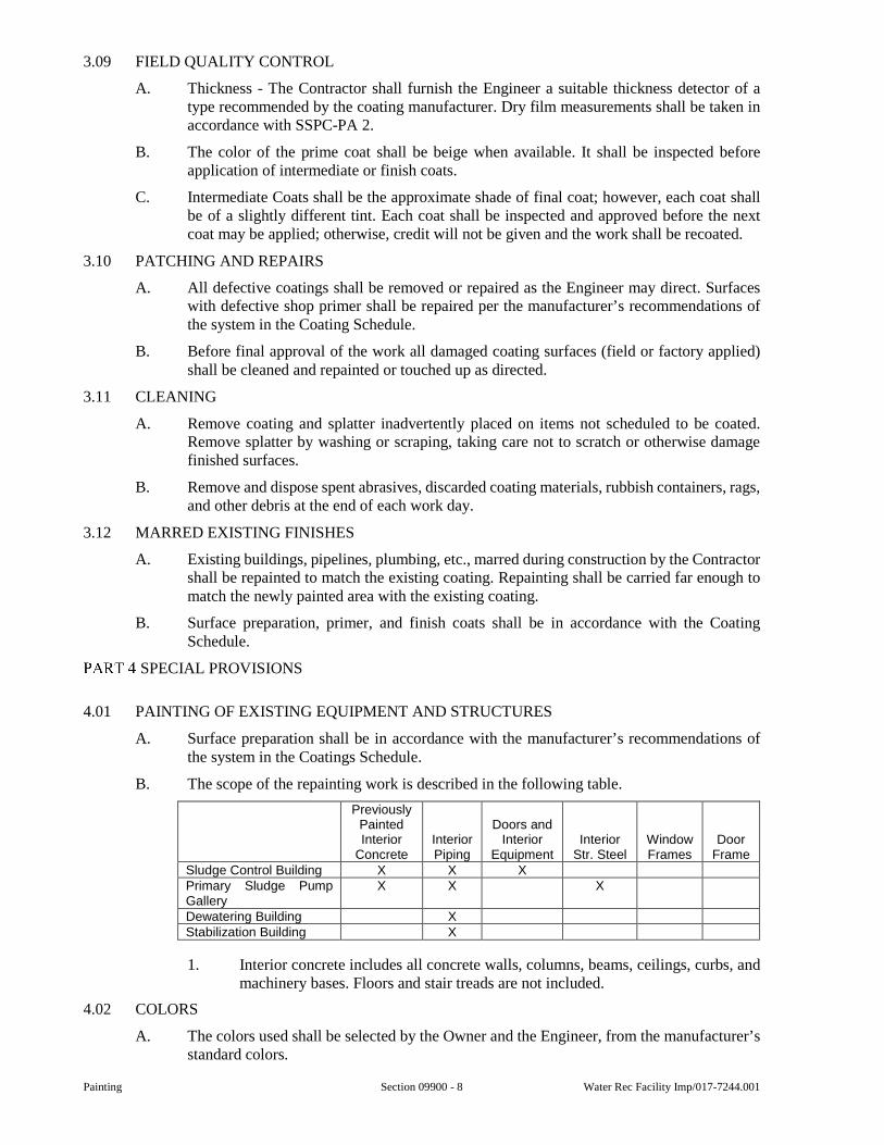
Painting Section 09900 - 8 Water Rec Facility Imp/017-7244.001
3.09 FIELD QUALITY CONTROL
A. Thickness - The Contractor shall furnish the Engineer a suitable thickness detector of a type recommended by the coating manufacturer. Dry film measurements shall be taken in accordance with SSPC-PA 2.
B. The color of the prime coat shall be beige when available. It shall be inspected before application of intermediate or finish coats.
C. Intermediate Coats shall be the approximate shade of final coat; however, each coat shall be of a slightly different tint. Each coat shall be inspected and approved before the next coat may be applied; otherwise, credit will not be given and the work shall be recoated.
3.10 PATCHING AND REPAIRS
A. All defective coatings shall be removed or repaired as the Engineer may direct. Surfaces with defective shop primer shall be repaired per the manufacturer’s recommendations of the system in the Coating Schedule.
B. Before final approval of the work all damaged coating surfaces (field or factory applied) shall be cleaned and repainted or touched up as directed.
3.11 CLEANING
A. Remove coating and splatter inadvertently placed on items not scheduled to be coated. Remove splatter by washing or scraping, taking care not to scratch or otherwise damage finished surfaces.
B. Remove and dispose spent abrasives, discarded coating materials, rubbish containers, rags, and other debris at the end of each work day.
3.12 MARRED EXISTING FINISHES
A. Existing buildings, pipelines, plumbing, etc., marred during construction by the Contractor shall be repainted to match the existing coating. Repainting shall be carried far enough to match the newly painted area with the existing coating.
B. Surface preparation, primer, and finish coats shall be in accordance with the Coating Schedule.
SPECIAL PROVISIONS
4.01 PAINTING OF EXISTING EQUIPMENT AND STRUCTURES
A. Surface preparation shall be in accordance with the manufacturer’s recommendations of the system in the Coatings Schedule.
B. The scope of the repainting work is described in the following table.
Previously Painted Interior
Concrete Interior Piping
Doors and Interior
Equipment Interior
Str. Steel Window Frames
Door Frame
Sludge Control Building X X X Primary Sludge Pump Gallery
X X X
Dewatering Building X Stabilization Building X
1. Interior concrete includes all concrete walls, columns, beams, ceilings, curbs, and machinery bases. Floors and stair treads are not included.
4.02 COLORS
A. The colors used shall be selected by the Owner and the Engineer, from the manufacturer’s standard colors.
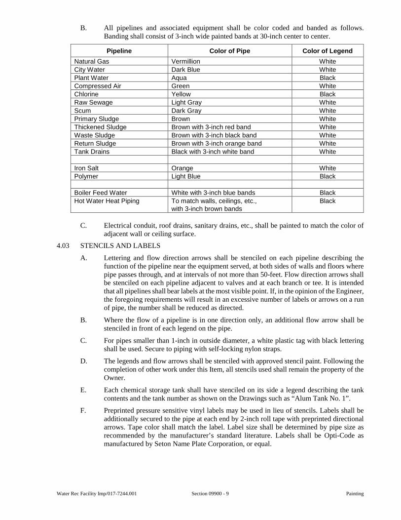
Water Rec Facility Imp/017-7244.001 Section 09900 - 9 Painting
B. All pipelines and associated equipment shall be color coded and banded as follows. Banding shall consist of 3-inch wide painted bands at 30-inch center to center.
Pipeline Color of Pipe Color of Legend
Natural Gas Vermillion White
City Water Dark Blue White
Plant Water Aqua Black
Compressed Air Green White
Chlorine Yellow Black
Raw Sewage Light Gray White
Scum Dark Gray White
Primary Sludge Brown White
Thickened Sludge Brown with 3-inch red band White
Waste Sludge Brown with 3-inch black band White
Return Sludge Brown with 3-inch orange band White
Tank Drains Black with 3-inch white band White
Iron Salt Orange White
Polymer Light Blue Black
Boiler Feed Water White with 3-inch blue bands Black
Hot Water Heat Piping To match walls, ceilings, etc., with 3-inch brown bands
Black
C. Electrical conduit, roof drains, sanitary drains, etc., shall be painted to match the color of adjacent wall or ceiling surface.
4.03 STENCILS AND LABELS
A. Lettering and flow direction arrows shall be stenciled on each pipeline describing the function of the pipeline near the equipment served, at both sides of walls and floors where pipe passes through, and at intervals of not more than 50-feet. Flow direction arrows shall be stenciled on each pipeline adjacent to valves and at each branch or tee. It is intended that all pipelines shall bear labels at the most visible point. If, in the opinion of the Engineer, the foregoing requirements will result in an excessive number of labels or arrows on a run of pipe, the number shall be reduced as directed.
B. Where the flow of a pipeline is in one direction only, an additional flow arrow shall be stenciled in front of each legend on the pipe.
C. For pipes smaller than 1-inch in outside diameter, a white plastic tag with black lettering shall be used. Secure to piping with self-locking nylon straps.
D. The legends and flow arrows shall be stenciled with approved stencil paint. Following the completion of other work under this Item, all stencils used shall remain the property of the Owner.
E. Each chemical storage tank shall have stenciled on its side a legend describing the tank contents and the tank number as shown on the Drawings such as “Alum Tank No. 1”.
F. Preprinted pressure sensitive vinyl labels may be used in lieu of stencils. Labels shall be additionally secured to the pipe at each end by 2-inch roll tape with preprinted directional arrows. Tape color shall match the label. Label size shall be determined by pipe size as recommended by the manufacturer’s standard literature. Labels shall be Opti-Code as manufactured by Seton Name Plate Corporation, or equal.

Painting Section 09900 - 10 Water Rec Facility Imp/017-7244.001
This page was intentionally left blank.
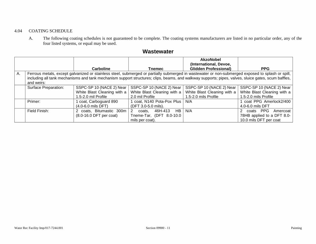
Water Rec Facility Imp/017-7244.001 Section 09900 - 11 Painting
4.04 COATING SCHEDULE
A. The following coating schedules is not guaranteed to be complete. The coating systems manufacturers are listed in no particular order, any of the four listed systems, or equal may be used.
Wastewater
Carboline Tnemec
AkzoNobel (International, Devoe, Glidden Professional) PPG
A. Ferrous metals, except galvanized or stainless steel, submerged or partially submerged in wastewater or non-submerged exposed to splash or spill, including all tank mechanisms and tank mechanism support structures; clips, beams, and walkway supports; pipes, valves, sluice gates, scum baffles, and weirs: Surface Preparation: SSPC-SP 10 (NACE 2) Near
White Blast Cleaning with a 1.5-2.0 mil Profile
SSPC-SP 10 (NACE 2) Near White Blast Cleaning with a 2.0 mil Profile
SSPC-SP 10 (NACE 2) Near White Blast Cleaning with a 1.5-2.0 mils Profile
SSPC-SP 10 (NACE 2) Near White Blast Cleaning with a 1.5-2.0 mils Profile
Primer: 1 coat, Carboguard 890 (4.0-6.0 mils DFT)
1 coat, N140 Pota-Pox Plus (DFT 3.0-5.0 mils).
N/A 1 coat PPG Amerlock2/400 4.0-6.0 mils DFT
Field Finish: 2 coats, Bitumastic 300m (8.0-16.0 DFT per coat)
2 coats, 46H-413 HB Tneme-Tar, (DFT 8.0-10.0 mils per coat).
N/A 2 coats PPG Amercoat 78HB applied to a DFT 8.0-10.0 mils DFT per coat
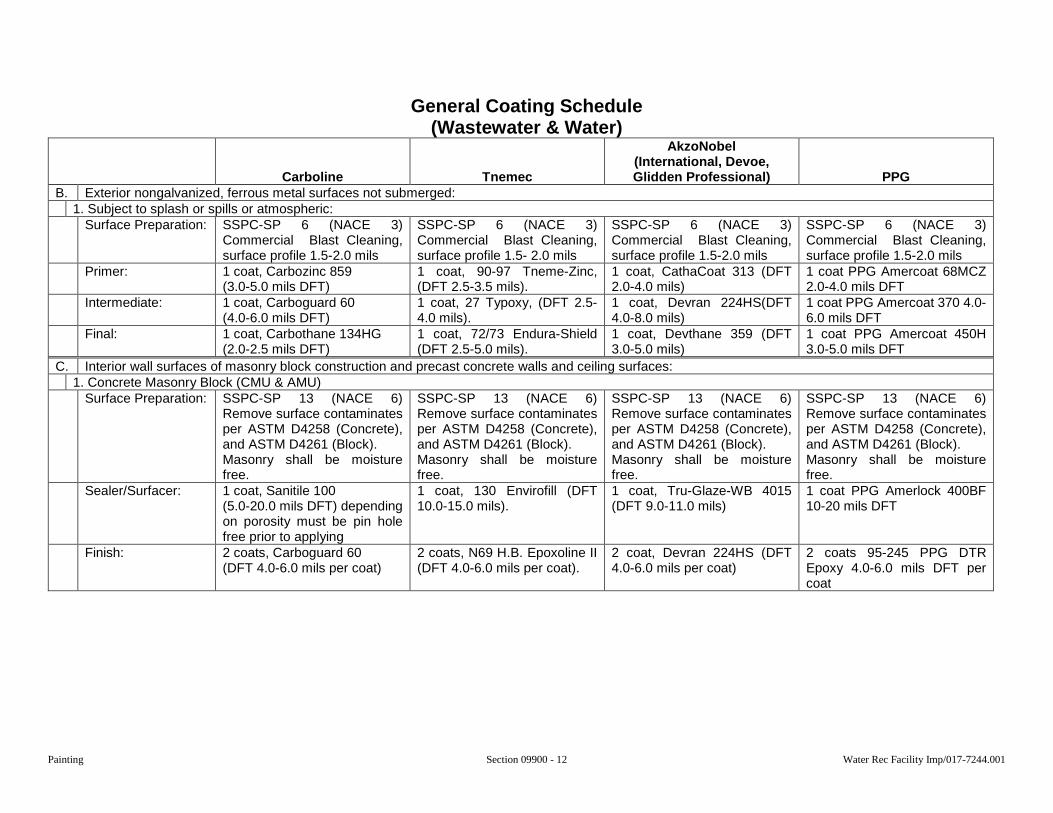
Painting Section 09900 - 12 Water Rec Facility Imp/017-7244.001
General Coating Schedule (Wastewater & Water)
Carboline Tnemec
AkzoNobel (International, Devoe, Glidden Professional) PPG
B. Exterior nongalvanized, ferrous metal surfaces not submerged: 1. Subject to splash or spills or atmospheric:
Surface Preparation: SSPC-SP 6 (NACE 3) Commercial Blast Cleaning, surface profile 1.5-2.0 mils
SSPC-SP 6 (NACE 3) Commercial Blast Cleaning, surface profile 1.5- 2.0 mils
SSPC-SP 6 (NACE 3) Commercial Blast Cleaning, surface profile 1.5-2.0 mils
SSPC-SP 6 (NACE 3) Commercial Blast Cleaning, surface profile 1.5-2.0 mils
Primer: 1 coat, Carbozinc 859 (3.0-5.0 mils DFT)
1 coat, 90-97 Tneme-Zinc, (DFT 2.5-3.5 mils).
1 coat, CathaCoat 313 (DFT 2.0-4.0 mils)
1 coat PPG Amercoat 68MCZ 2.0-4.0 mils DFT
Intermediate: 1 coat, Carboguard 60 (4.0-6.0 mils DFT)
1 coat, 27 Typoxy, (DFT 2.5-4.0 mils).
1 coat, Devran 224HS(DFT 4.0-8.0 mils)
1 coat PPG Amercoat 370 4.0-6.0 mils DFT
Final: 1 coat, Carbothane 134HG (2.0-2.5 mils DFT)
1 coat, 72/73 Endura-Shield (DFT 2.5-5.0 mils).
1 coat, Devthane 359 (DFT 3.0-5.0 mils)
1 coat PPG Amercoat 450H 3.0-5.0 mils DFT
C. Interior wall surfaces of masonry block construction and precast concrete walls and ceiling surfaces: 1. Concrete Masonry Block (CMU & AMU)
Surface Preparation: SSPC-SP 13 (NACE 6) Remove surface contaminates per ASTM D4258 (Concrete), and ASTM D4261 (Block). Masonry shall be moisture free.
SSPC-SP 13 (NACE 6) Remove surface contaminates per ASTM D4258 (Concrete), and ASTM D4261 (Block). Masonry shall be moisture free.
SSPC-SP 13 (NACE 6) Remove surface contaminates per ASTM D4258 (Concrete), and ASTM D4261 (Block). Masonry shall be moisture free.
SSPC-SP 13 (NACE 6) Remove surface contaminates per ASTM D4258 (Concrete), and ASTM D4261 (Block). Masonry shall be moisture free.
Sealer/Surfacer: 1 coat, Sanitile 100 (5.0-20.0 mils DFT) depending on porosity must be pin hole free prior to applying
1 coat, 130 Envirofill (DFT 10.0-15.0 mils).
1 coat, Tru-Glaze-WB 4015 (DFT 9.0-11.0 mils)
1 coat PPG Amerlock 400BF 10-20 mils DFT
Finish: 2 coats, Carboguard 60 (DFT 4.0-6.0 mils per coat)
2 coats, N69 H.B. Epoxoline II (DFT 4.0-6.0 mils per coat).
2 coat, Devran 224HS (DFT 4.0-6.0 mils per coat)
2 coats 95-245 PPG DTR Epoxy 4.0-6.0 mils DFT per coat
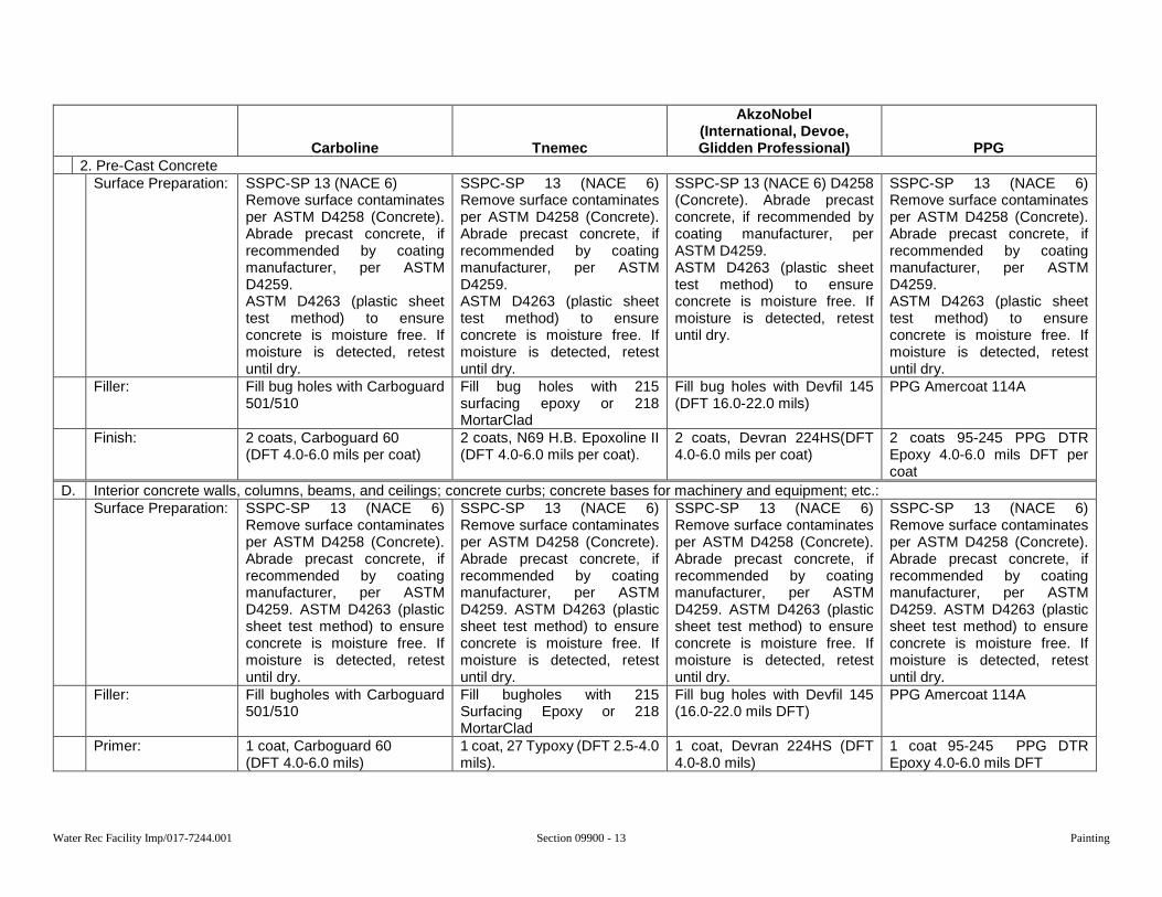
Water Rec Facility Imp/017-7244.001 Section 09900 - 13 Painting
Carboline Tnemec
AkzoNobel (International, Devoe, Glidden Professional) PPG
2. Pre-Cast Concrete Surface Preparation: SSPC-SP 13 (NACE 6)
Remove surface contaminates per ASTM D4258 (Concrete). Abrade precast concrete, if recommended by coating manufacturer, per ASTM D4259. ASTM D4263 (plastic sheet test method) to ensure concrete is moisture free. If moisture is detected, retest until dry.
SSPC-SP 13 (NACE 6) Remove surface contaminates per ASTM D4258 (Concrete). Abrade precast concrete, if recommended by coating manufacturer, per ASTM D4259. ASTM D4263 (plastic sheet test method) to ensure concrete is moisture free. If moisture is detected, retest until dry.
SSPC-SP 13 (NACE 6) D4258 (Concrete). Abrade precast concrete, if recommended by coating manufacturer, per ASTM D4259. ASTM D4263 (plastic sheet test method) to ensure concrete is moisture free. If moisture is detected, retest until dry.
SSPC-SP 13 (NACE 6) Remove surface contaminates per ASTM D4258 (Concrete). Abrade precast concrete, if recommended by coating manufacturer, per ASTM D4259. ASTM D4263 (plastic sheet test method) to ensure concrete is moisture free. If moisture is detected, retest until dry.
Filler: Fill bug holes with Carboguard 501/510
Fill bug holes with 215 surfacing epoxy or 218 MortarClad
Fill bug holes with Devfil 145 (DFT 16.0-22.0 mils)
PPG Amercoat 114A
Finish: 2 coats, Carboguard 60 (DFT 4.0-6.0 mils per coat)
2 coats, N69 H.B. Epoxoline II (DFT 4.0-6.0 mils per coat).
2 coats, Devran 224HS(DFT 4.0-6.0 mils per coat)
2 coats 95-245 PPG DTR Epoxy 4.0-6.0 mils DFT per coat
D. Interior concrete walls, columns, beams, and ceilings; concrete curbs; concrete bases for machinery and equipment; etc.: Surface Preparation: SSPC-SP 13 (NACE 6)
Remove surface contaminates per ASTM D4258 (Concrete). Abrade precast concrete, if recommended by coating manufacturer, per ASTM D4259. ASTM D4263 (plastic sheet test method) to ensure concrete is moisture free. If moisture is detected, retest until dry.
SSPC-SP 13 (NACE 6) Remove surface contaminates per ASTM D4258 (Concrete). Abrade precast concrete, if recommended by coating manufacturer, per ASTM D4259. ASTM D4263 (plastic sheet test method) to ensure concrete is moisture free. If moisture is detected, retest until dry.
SSPC-SP 13 (NACE 6) Remove surface contaminates per ASTM D4258 (Concrete). Abrade precast concrete, if recommended by coating manufacturer, per ASTM D4259. ASTM D4263 (plastic sheet test method) to ensure concrete is moisture free. If moisture is detected, retest until dry.
SSPC-SP 13 (NACE 6) Remove surface contaminates per ASTM D4258 (Concrete). Abrade precast concrete, if recommended by coating manufacturer, per ASTM D4259. ASTM D4263 (plastic sheet test method) to ensure concrete is moisture free. If moisture is detected, retest until dry.
Filler: Fill bugholes with Carboguard 501/510
Fill bugholes with 215 Surfacing Epoxy or 218 MortarClad
Fill bug holes with Devfil 145 (16.0-22.0 mils DFT)
PPG Amercoat 114A
Primer: 1 coat, Carboguard 60 (DFT 4.0-6.0 mils)
1 coat, 27 Typoxy (DFT 2.5-4.0 mils).
1 coat, Devran 224HS (DFT 4.0-8.0 mils)
1 coat 95-245 PPG DTR Epoxy 4.0-6.0 mils DFT
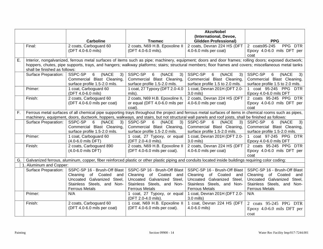
Painting Section 09900 - 14 Water Rec Facility Imp/017-7244.001
Carboline Tnemec
AkzoNobel (International, Devoe, Glidden Professional) PPG
Final: 2 coats, Carboguard 60 (DFT 4.0-6.0 mils)
2 coats, N69 H.B. Epoxoline II (DFT 4.0-6.0 mils).
2 coats, Devran 224 HS (DFT 4.0-6.0 mils per coat)
2 coats95-245 PPG DTR Epoxy 4.0-6.0 mils DFT per coat
E. Interior, nongalvanized, ferrous metal surfaces of items such as pipe; machinery, equipment; doors and door frames; rolling doors; exposed ductwork; hoppers, chutes, pipe supports, trays, and hangers; walkway platforms; stairs; structural members; floor frames and covers; miscellaneous metal tanks shall be finished as follows: Surface Preparation: SSPC-SP 6 (NACE 3)
Commercial Blast Cleaning, surface profile 1.5-2.0 mils.
SSPC-SP 6 (NACE 3) Commercial Blast Cleaning, surface profile 1.5-2.0 mils.
SSPC-SP 6 (NACE 3) Commercial Blast Cleaning, surface profile 1.5 to 2.0 mils.
SSPC-SP 6 (NACE 3) Commercial Blast Cleaning, surface profile 1.5 to 2.0 mils.
Primer: 1 coat, Carboguard 60 (DFT 4.0-6.0 mils)
1 coat, 27 Typoxy (DFT 2.0-4.0 mils).
1 coat, Devran 201H (DFT 2.0-3.0 mils)
1 coat 95-245 PPG DTR Epoxy 4.0-6.0 mils DFT
Finish: 2 coats, Carboguard 60 (DFT 4.0-6.0 mils per coat)
2 coats, N69 H.B. Epoxoline II, or equal (DFT 4.0-6.0 mils per coat).
2 coats, Devran 224 HS (DFT 4.0-6.0 mils per coat)
2 coats 95-245 PPG DTR Epoxy 4.0-6.0 mils DFT per coat
F. Ferrous metal surfaces of all chemical pipe supporting trays throughout the project and ferrous metal surfaces of items in chemical rooms such as pipes, machinery, equipment, doors, ductwork, hoppers, walkways, and stairs, but not structural wall panels and roof joists, shall be finished as follows: Surface Preparation: SSPC-SP 6 (NACE 3)
Commercial Blast Cleaning, surface profile 1.5-2.0 mils.
SSPC-SP 6 (NACE 3) Commercial Blast Cleaning, surface profile 1.5-2.0 mils.
SSPC-SP 6 (NACE 3) Commercial Blast Cleaning, surface profile 1.5-2.0 mils.
SSPC-SP 6 (NACE 3) Commercial Blast Cleaning, surface profile 1.5-2.0 mils.
Primer: 1 coat, Carboguard 60 (4.0-6.0 mils DFT)
1 coat, 27 Typoxy, or equal (DFT 2.0-4.0 mils).
1 coat, Devran 201H (DFT 2.0-3.0 mils)
1 coat 97-245 PPG DTR Epoxy 4.0-6.0 mils DFT
Finish: 2 coats, Carboguard 890 (4.0-6.0 mils DFT)
2 coats, N69 H.B. Epoxoline II (DFT 4.0-6.0 mils per coat).
2 coats, Devran 224 HS (DFT 4.0-6.0 mils per coat)
2 coats 95-245 PPG DTR Epoxy 4.0-6.0 mils DFT per coat
G. Galvanized ferrous, aluminum, copper, fiber reinforced plastic or other plastic piping and conduits located inside buildings requiring color coding: 1. Aluminum and Copper:
Surface Preparation: SSPC-SP 16 - Brush-Off Blast Cleaning of Coated and Uncoated Galvanized Steel, Stainless Steels, and Non-Ferrous Metals
SSPC-SP 16 - Brush-Off Blast Cleaning of Coated and Uncoated Galvanized Steel, Stainless Steels, and Non-Ferrous Metals
SSPC-SP 16 - Brush-Off Blast Cleaning of Coated and Uncoated Galvanized Steel, Stainless Steels, and Non-Ferrous Metals
SSPC-SP 16 - Brush-Off Blast Cleaning of Coated and Uncoated Galvanized Steel, Stainless Steels, and Non-Ferrous Metals
Primer: N/A 1 coat, 27 Typoxy, or equal (DFT 2.0-4.0 mils).
1 coat, Devran 201H (DFT 2.0-3.0 mills)
N/A
Finish: 2 coats, Carboguard 60 (DFT 4.0-6.0 mils per coat)
1 coat, N69 H.B. Epoxoline II (DFT 4.0-6.0 mils per coat).
1 coat, Devran 224 HS (DFT 4.0-6.0 mils)
2 coats 95-245 PPG DTR Epoxy 4.0-6.0 mils DFT per coat
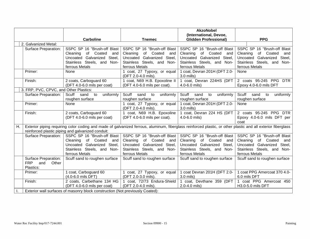
Water Rec Facility Imp/017-7244.001 Section 09900 - 15 Painting
Carboline Tnemec
AkzoNobel (International, Devoe, Glidden Professional) PPG
2. Galvanized Metal: Surface Preparation: SSPC SP 16 "Brush-off Blast
Cleaning of Coated and Uncoated Galvanized Steel, Stainless Steels, and Non-ferrous Metals
SSPC SP 16 "Brush-off Blast Cleaning of Coated and Uncoated Galvanized Steel, Stainless Steels, and Non-ferrous Metals
SSPC SP 16 "Brush-off Blast Cleaning of Coated and Uncoated Galvanized Steel, Stainless Steels, and Non-ferrous Metals
SSPC SP 16 "Brush-off Blast Cleaning of Coated and Uncoated Galvanized Steel, Stainless Steels, and Non-ferrous Metals
Primer: None 1 coat, 27 Typoxy, or equal (DFT 2.0-4.0 mils).
1 coat, Devran 201H (DFT 2.0-3.0 mills)
None
Finish: 2 coats, Carboguard 60 (DFT 4.0-6.0 mils per coat)
1 coat, N69 H.B. Epoxoline II (DFT 4.0-6.0 mils per coat).
1 coat, Devran 224HS (DFT 4.0-6.0 mils)
2 coats 95-245 PPG DTR Epoxy 4.0-6.0 mils DFT
3. FRP, PVC, CPVC, and Other Plastics: Surface Preparation: Scuff sand to uniformly
roughen surface Scuff sand to uniformly roughen surface
Scuff sand to uniformly roughen surface
Scuff sand to uniformly roughen surface
Primer: None 1 coat, 27 Typoxy, or equal (DFT 2.0-4.0 mils).
1 coat, Devran 201H (DFT 2.0-3.0 mills)
None
Finish: 2 coats, Carboguard 60 (DFT 4.0-6.0 mils per coat)
1 coat, N69 H.B. Epoxoline (DFT 4.0-6.0 mils per coat).
1 coat, Devran 224 HS (DFT 4.0-6.0 mils)
2 coats 95-245 PPG DTR Epoxy 4.0-6.0 mils DFT per coat
H. Exterior piping requiring color coding and made of galvanized ferrous, aluminum, fiberglass reinforced plastic, or other plastic and all exterior fiberglass reinforced plastic piping and galvanized conduit: Surface Preparation: SSPC SP 16 "Brush-off Blast
Cleaning of Coated and Uncoated Galvanized Steel, Stainless Steels, and Non-ferrous Metals
SSPC SP 16 "Brush-off Blast Cleaning of Coated and Uncoated Galvanized Steel, Stainless Steels, and Non-ferrous Metals
SSPC SP 16 "Brush-off Blast Cleaning of Coated and Uncoated Galvanized Steel, Stainless Steels, and Non-ferrous Metals
SSPC SP 16 "Brush-off Blast Cleaning of Coated and Uncoated Galvanized Steel, Stainless Steels, and Non-ferrous Metals
Surface Preparation: FRP and Other Plastics:
Scuff sand to roughen surface Scuff sand to roughen surface Scuff sand to roughen surface Scuff sand to roughen surface
Primer: 1 coat, Carboguard 60 (4.0-6.0 mils DFT)
1 coat, 27 Typoxy, or equal (DFT 2.0-3.0 mils).
1 coat Devran 201H (DFT 2.0-3.0 mils)
1 coat PPG Amercoat 370 4.0-6.0 mils DFT
Finish: 2 coats, Carbethane 134 HG (DFT 4.0-6.0 mils per coat)
1 coat, 72/73 Endura-Shield (DFT 2.0-4.0 mils).
1 coat, Devthane 359 (DFT 2.0-4.0 mils)
1 coat PPG Amercoat 450 H3.0-5.0 mils DFT
I. Exterior wall surfaces of masonry block construction (Not previously Coated):
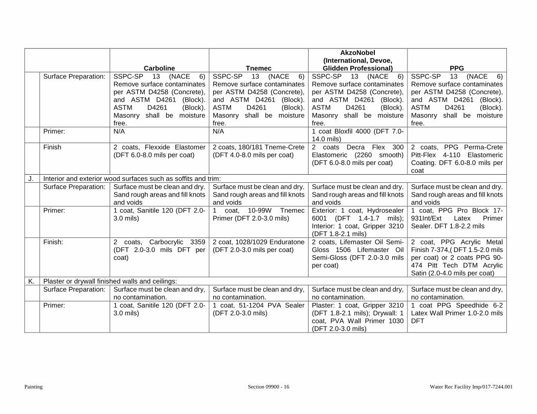
Painting Section 09900 - 16 Water Rec Facility Imp/017-7244.001
Carboline Tnemec
AkzoNobel (International, Devoe, Glidden Professional) PPG
Surface Preparation: SSPC-SP 13 (NACE 6) Remove surface contaminates per ASTM D4258 (Concrete), and ASTM D4261 (Block). ASTM D4261 (Block). Masonry shall be moisture free.
SSPC-SP 13 (NACE 6) Remove surface contaminates per ASTM D4258 (Concrete), and ASTM D4261 (Block). ASTM D4261 (Block). Masonry shall be moisture free.
SSPC-SP 13 (NACE 6) Remove surface contaminates per ASTM D4258 (Concrete), and ASTM D4261 (Block). ASTM D4261 (Block). Masonry shall be moisture free.
SSPC-SP 13 (NACE 6) Remove surface contaminates per ASTM D4258 (Concrete), and ASTM D4261 (Block). ASTM D4261 (Block). Masonry shall be moisture free.
Primer: N/A N/A 1 coat Bloxfil 4000 (DFT 7.0-14.0 mils)
Finish 2 coats, Flexxide Elastomer (DFT 6.0-8.0 mils per coat)
2 coats, 180/181 Tneme-Crete (DFT 4.0-8.0 mils per coat)
2 coats Decra Flex 300 Elastomeric (2260 smooth) (DFT 6.0-8.0 mils per coat)
2 coats, PPG Perma-Crete Pitt-Flex 4-110 Elastomeric Coating. DFT 6.0-8.0 mils per coat
J. Interior and exterior wood surfaces such as soffits and trim: Surface Preparation: Surface must be clean and dry.
Sand rough areas and fill knots and voids
Surface must be clean and dry. Sand rough areas and fill knots and voids
Surface must be clean and dry. Sand rough areas and fill knots and voids
Surface must be clean and dry. Sand rough areas and fill knots and voids
Primer: 1 coat, Sanitile 120 (DFT 2.0-3.0 mils)
1 coat, 10-99W Tnemec Primer (DFT 2.0-3.0 mils)
Exterior: 1 coat, Hydrosealer 6001 (DFT 1.4-1.7 mils); Interior: 1 coat, Gripper 3210 (DFT 1.8-2.1 mils)
1 coat, PPG Pro Block 17-931Int/Ext Latex Primer Sealer. DFT 1.8-2.2 mils
Finish: 2 coats, Carbocrylic 3359 (DFT 2.0-3.0 mils DFT per coat)
2 coat, 1028/1029 Enduratone (DFT 2.0-3.0 mils per coat)
2 coats, Lifemaster Oil Semi-Gloss 1506 Lifemaster Oil Semi-Gloss (DFT 2.0-3.0 mils per coat)
2 coat, PPG Acrylic Metal Finish 7-374,( DFT 1.5-2.0 mils per coat) or 2 coats PPG 90-474 Pitt Tech DTM Acrylic Satin (2.0-4.0 mils per coat)
K. Plaster or drywall finished walls and ceilings: Surface Preparation: Surface must be clean and dry,
no contamination. Surface must be clean and dry, no contamination.
Surface must be clean and dry, no contamination.
Surface must be clean and dry, no contamination.
Primer: 1 coat, Sanitile 120 (DFT 2.0-3.0 mils)
1 coat, 51-1204 PVA Sealer (DFT 2.0-3.0 mils)
Plaster: 1 coat, Gripper 3210 (DFT 1.8-2.1 mils); Drywall: 1 coat, PVA Wall Primer 1030 (DFT 2.0-3.0 mils)
1 coat PPG Speedhide 6-2 Latex Wall Primer 1.0-2.0 mils DFT
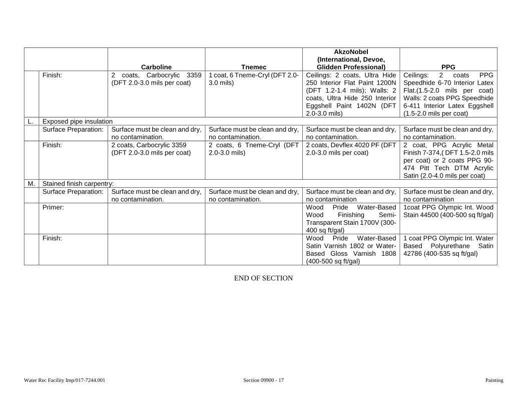
Water Rec Facility Imp/017-7244.001 Section 09900 - 17 Painting
Carboline Tnemec
AkzoNobel (International, Devoe, Glidden Professional) PPG
Finish: 2 coats, Carbocrylic 3359 (DFT 2.0-3.0 mils per coat)
1 coat, 6 Tneme-Cryl (DFT 2.0-3.0 mils)
Ceilings: 2 coats, Ultra Hide 250 Interior Flat Paint 1200N (DFT 1.2-1.4 mils); Walls: 2 coats, Ultra Hide 250 Interior Eggshell Paint 1402N (DFT 2.0-3.0 mils)
Ceilings: 2 coats PPG Speedhide 6-70 Interior Latex Flat.(1.5-2.0 mils per coat) Walls: 2 coats PPG Speedhide 6-411 Interior Latex Eggshell (1.5-2.0 mils per coat)
L. Exposed pipe insulation Surface Preparation: Surface must be clean and dry,
no contamination. Surface must be clean and dry, no contamination.
Surface must be clean and dry, no contamination.
Surface must be clean and dry, no contamination.
Finish: 2 coats, Carbocrylic 3359 (DFT 2.0-3.0 mils per coat)
2 coats, 6 Tneme-Cryl (DFT 2.0-3.0 mils)
2 coats, Devflex 4020 PF (DFT 2.0-3.0 mils per coat)
2 coat, PPG Acrylic Metal Finish 7-374,( DFT 1.5-2.0 mils per coat) or 2 coats PPG 90-474 Pitt Tech DTM Acrylic Satin (2.0-4.0 mils per coat)
M. Stained finish carpentry: Surface Preparation: Surface must be clean and dry,
no contamination. Surface must be clean and dry, no contamination.
Surface must be clean and dry, no contamination
Surface must be clean and dry, no contamination
Primer: Wood Pride Water-Based Wood Finishing Semi-Transparent Stain 1700V (300-400 sq ft/gal)
1coat PPG Olympic Int. Wood Stain 44500 (400-500 sq ft/gal)
Finish: Wood Pride Water-Based Satin Varnish 1802 or Water-Based Gloss Varnish 1808 (400-500 sq ft/gal)
1 coat PPG Olympic Int. Water Based Polyurethane Satin 42786 (400-535 sq ft/gal)
END OF SECTION

Painting Section 09900 - 18 Water Rec Facility Imp/017-7244.001
This page was intentionally left blank.
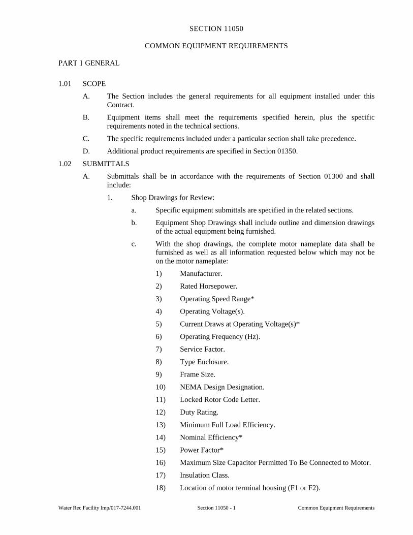
Water Rec Facility Imp/017-7244.001 Section 11050 - 1 Common Equipment Requirements
SECTION 11050
COMMON EQUIPMENT REQUIREMENTS
GENERAL
1.01 SCOPE
A. The Section includes the general requirements for all equipment installed under this Contract.
B. Equipment items shall meet the requirements specified herein, plus the specific requirements noted in the technical sections.
C. The specific requirements included under a particular section shall take precedence.
D. Additional product requirements are specified in Section 01350.
1.02 SUBMITTALS
A. Submittals shall be in accordance with the requirements of Section 01300 and shall include:
1. Shop Drawings for Review:
a. Specific equipment submittals are specified in the related sections.
b. Equipment Shop Drawings shall include outline and dimension drawings of the actual equipment being furnished.
c. With the shop drawings, the complete motor nameplate data shall be furnished as well as all information requested below which may not be on the motor nameplate:
1) Manufacturer.
2) Rated Horsepower.
3) Operating Speed Range*
4) Operating Voltage(s).
5) Current Draws at Operating Voltage(s)*
6) Operating Frequency (Hz).
7) Service Factor.
8) Type Enclosure.
9) Frame Size.
10) NEMA Design Designation.
11) Locked Rotor Code Letter.
12) Duty Rating.
13) Minimum Full Load Efficiency.
14) Nominal Efficiency*
15) Power Factor*
16) Maximum Size Capacitor Permitted To Be Connected to Motor.
17) Insulation Class.
18) Location of motor terminal housing (F1 or F2).
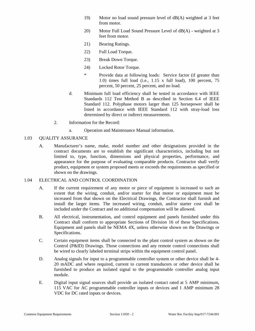
Common Equipment Requirements Section 11050 - 2 Water Rec Facility Imp/017-7244.001
19) Motor no load sound pressure level of dB(A) weighted at 3 feet from motor.
20) Motor Full Load Sound Pressure Level of dB(A) - weighted at 3 feet from motor.
21) Bearing Ratings.
22) Full Load Torque.
23) Break Down Torque.
24) Locked Rotor Torque.
* Provide data at following loads: Service factor (if greater than 1.0) times full load (i.e., 1.15 x full load), 100 percent, 75 percent, 50 percent, 25 percent, and no load.
d. Minimum full load efficiency shall be tested in accordance with IEEE Standards 112 Test Method B as described in Section 6.4 of IEEE Standard 112. Polyphase motors larger than 125 horsepower shall be listed in accordance with IEEE Standard 112 with stray-load loss determined by direct or indirect measurements.
2. Information for the Record:
a. Operation and Maintenance Manual information.
1.03 QUALITY ASSURANCE
A. Manufacturer’s name, make, model number and other designations provided in the contract documents are to establish the significant characteristics, including but not limited to, type, function, dimensions and physical properties, performance, and appearance for the purpose of evaluating comparable products. Contractor shall verify product, equipment or system proposed meets or exceeds the requirements as specified or shown on the drawings.
1.04 ELECTRICAL AND CONTROL COORDINATION
A. If the current requirement of any motor or piece of equipment is increased to such an extent that the wiring, conduit, and/or starter for that motor or equipment must be increased from that shown on the Electrical Drawings, the Contractor shall furnish and install the larger items. The increased wiring, conduit, and/or starter cost shall be included under the Contract and no additional compensation will be allowed.
B. All electrical, instrumentation, and control equipment and panels furnished under this Contract shall conform to appropriate Sections of Division 16 of these Specifications. Equipment and panels shall be NEMA 4X, unless otherwise shown on the Drawings or Specifications.
C. Certain equipment items shall be connected to the plant control system as shown on the Control (P&ID) Drawings. Those connections and any remote control connections shall be wired to clearly labeled terminal strips within the equipment control panel.
D. Analog signals for input to a programmable controller system or other device shall be 4-20 mADC and where required, current to current transducers or other device shall be furnished to produce an isolated signal to the programmable controller analog input module.
E. Digital input signal sources shall provide an isolated contact rated at 5 AMP minimum, 115 VAC for AC programmable controller inputs or devices and 1 AMP minimum 28 VDC for DC rated inputs or devices.
Water Rec Facility Imp/017-7244.001 Section 11050 - 3 Common Equipment Requirements
1.05 PRODUCT HANDLING
A. Unless otherwise specified in the individual Sections, the Contractor shall deliver, handle, store, and maintain materials and equipment in accordance with the requirements of the manufacturer.
B. Materials, equipment, and articles to be incorporated into the Work shall be stored so as to facilitate inspection and inventory and in such manner as to ensure the preservation of their quality and fitness for the Work. Stocked materials shall be subject to test and shall meet the requirements of the Specifications at the time of substantial completion of the Work.
C. Where construction is in roads or streets, that portion of the right-of-way not required for public travel may be used for temporary storage purposes unless otherwise prohibited. Materials shall not be stored in areas where such storage creates a hazard. Any other additional space required for construction or storage of materials and equipment shall be obtained by the Contractor at his expense.
D. The Contractor shall confine his equipment, the storage of materials and equipment, and the operations of his workers to areas permitted by law, ordinances, permits, and the requirements of the Contract Documents, and shall not unreasonably encumber the premises with materials or equipment.
E. Switchgear, motor control centers, panelboards, instrument control panels, fixtures, and like equipment shall be received and stored in a dry, clean, dust-free, heated area. If no such area is available at the time such equipment is received, such space shall be provided by the Contractor at no expense to the Owner. If equipment is stored in an area conducive to the formation of condensation, heaters shall be provided to prevent condensation. Once the equipment is installed in its final position, suitable protection shall be provided to prevent damage by falling material, dust, paint, dirt, and moisture.
PRODUCTS
2.01 GENERAL
A. AC motor(s) shall conform to the latest applicable NEMA, IEEE, and ANSI standards.
B. Motor installation shall not exceed 88 dB (A) weighted maximum level at 3 feet from the motor throughout the entire speed range and load range.
C. Motor bearings shall be antifriction type, grease lubricated with a minimum L-10 rating of 17,500 hours for belted duty and 100,000 hours for direct coupled duty.
1. Thrust bearings in vertical motors shall be adequate for the loading encountered.
2. Belt-driven power systems with jackshafts, and couplings, to isolate the belt loadings from the motor bearings shall be regarded as direct coupled duty.
D. Motor conduit boxes shall be sized with capacity to meet the requirements of the National Electrical Code. Motors shall be furnished in an “F1” terminal housing assembly (facing connection box, motor shaft extension is to the right) unless otherwise shown on Drawings or specified.
E. Motor frames shall be cast iron construction with corrosion resistant hardware.
F. Each motor shall be continuous duty rated NEMA Design B with normal starting torque, unless otherwise shown or specified.
G. Output torque and speed characteristics of each motor shall be suitable to operate the connected load over the full range of operating speeds and load conditions without exceeding the nameplate current rating or temperature rise on a continuous duty basis.
H. Insulation shall be class F or class H.
Common Equipment Requirements Section 11050 - 4 Water Rec Facility Imp/017-7244.001
I. Each polyphase squirrel-cage induction motor shall meet or exceed minimum and nominal efficiencies listed in NEMA MG-1, Table 12-10.
2.02 AC MOTORS UNDER 1 HP
A. Unless otherwise shown or specified, each fractional motor under 1/2 hp shall be designed for single phase, 115 and 230 volt, 60 Hz service.
B. Unless otherwise shown or specified, each fractional motor 1/2 through 3/4 hp shall be designed for 3 phase, 208, 230, and 460 volt, 60 Hz service.
2.03 INTEGRAL AC MOTORS
A. AC motor(s) 1 hp and larger shall have a 1.15 service factor at a 40 degrees C ambient temperature. Motor shall be capable of operating at the 1.15 service factor rating on a continuous basis per NEMA MG1-12.42 Item 1b.
B. Motor enclosure types shall be as specified in the equipment specifications and shall be of one of the following designations.
1. Open drip-proof protected (ODP).
2. Totally enclosed non-ventilated (TENV), or totally enclosed fan cooled (TEFC).
3. Explosion proof Class 1, Division 1, Group D.
4. Submersible water cooled.
C. Multi-speed motors shall have the energy efficient design designated for the high speed winding operation.
2.04 SPECIAL APPLICATION MOTOR(S)
A. Special application motor(s) are defined as those used on such devices as appliances, tools, unit heaters, door operators, refrigeration units and sump pumps.
B. Manufacturer’s standard motor may be approved by the Engineer where a redesign of the unit would be required to furnish energy efficient motors.
2.05 DEFINITE PURPOSE MOTORS
A. Equipment requiring a motor drive with unusual characteristics shall be equipped with a definite purpose motor to meet the necessary requirements.
1. Definite purpose motors are hermetic refrigeration compressors, jet pumps, shaft mounted fans and blowers, submersible deep well pumps, submersible mixers, elevator, crane, close coupled pumps, and torque motors.
2. If available, an energy efficient design motor shall be furnished on this application.
2.06 MOTORS ON VARIABLE FREQUENCY DRIVES
A. Motors for use with a Variable Frequency Drive (VFD) shall be TENV, TEFC, or submersible, water cooled.
1. Design to meet or exceed the efficiencies listed in NEMA MG-1, Table 12-10.
2. Motor shall be “Inverter Duty Rated”, and so stamped on the nameplate.
3. Motor shall have an insulation system that meets or exceeds the requirements of NEMA MG-1, Part 31.40.4.2, and is rated at 1600 volts peak to ensure that the motor is rated for operation with non-sinusoidal waveforms at 1.0 service factor.
4. Bearings in motors greater than NEMA Frame size of 300 and controlled by variable frequency drives must be guaranteed against premature bearing failure caused by discharge current. All such motors shall be provided with a shaft grounding device.
Water Rec Facility Imp/017-7244.001 Section 11050 - 5 Common Equipment Requirements
B. AC motor used with a VFD shall have internal thermal protectors guaranteed by the motor manufacturer to protect the motors against overheating from stalled or slow turning due to lack of adequate cooling at low motor speeds.
1. Thermal protection devices shall be imbedded within the motor windings with normally closed contacts to be used in series with the coil of the motor’s magnetic bypass starter and the stop circuit on the VFD.
2. Thermal protection devices shall all be provided and housed within the motor housing, unless otherwise specified.
C. Explosion proof motors shall use thermal protectors required by UL as covered by 2.08, and meet the requirements of 2.06 preceding, and shall be rated and labeled for “Inverter Duty”.
D. Tachometer generators when required by the Specifications or the P&ID Drawings shall be D.C. Generators of the enclosure required for the particular motor location.
2.07 DIRECT CURRENT MOTORS ON VARIABLE SPEED DRIVES (VSD)
A. Each motor shall be equipped with internal thermal protectors as covered in 2.06. Permanent magnet field DC motors are not acceptable.
B. Motors and tachometer generators shall be in totally enclosed non-ventilated or totally enclosed fan cooled enclosures except where required to be explosion proof motors.
2.08 EXPLOSION PROOF MOTORS
A. AC motors for use in a Class I, Division 1, Group D location shall meet the requirements of paragraph 2.01 above.
B. Explosion proof motors 3 hp and larger shall have a 1.15 service factor. Such motors shall be capable of operating at the 1.15 service factor rating on a continuous basis per NEMA MG1-12.42 Item 1b.
C. Each motor shall be furnished with internal thermal protectors with normally closed contacts that will open should the safe operating motor temperature be exceeded per UL requirements. These contacts shall be placed in series with each other and with the coil of the magnetic motor starter, and/or the VFD enable circuit if used with a VFD, on all applications.
2.09 MOTOR SPACE HEATERS
A. Space heaters as specified or shown on the Drawings shall be factory installed by the motor manufacturer.
2.10 V-BELT DRIVES
A. Belts for V-belt drives shall be provided with a minimum service factor of 2.0.
B. Drives shall be submitted with manufacturer’s data supporting the horsepower rating of the V-Belt drives being used.
C. Assembled cog belts and other assembled belt drives are not acceptable.
D. V-Belts on multiple V-Belt drives shall be provided in matched sets.
E. The Contractor shall provide one spare belt or one spare matched set of drive belts, whichever is applicable, for all belt-driven equipment supplied under this Contract. The spare belts shall be the same size, type, and quality as supplied by the equipment manufacturer.
2.11 COUPLED DRIVES
A. Coupled drives shall have the service factor recommended by the coupling manufacturer.
Common Equipment Requirements Section 11050 - 6 Water Rec Facility Imp/017-7244.001
B. Coupled drives shall be submitted with Engineering Data supporting the horsepower rating of each coupling.
2.12 SAFETY GUARDS
A. Installed equipment shall be equipped with all guards, shields, and devices to meet OSHA requirements.
B. Chain and belt guards shall be totally enclosed steel construction, 14 gauge minimum for guards up to 60-inch center distance and 12 gauge minimum for larger guards.
C. Guards shall include expanded metal inspection panels. Removable access panels shall be provided to perform routine maintenance.
2.13 MANUFACTURER’S NAMEPLATE
A. Equipment shall be identified by permanently attached nameplate of corrosion-resistant metal. Plates shall bear the following information:
1. Manufacturer’s name.
2. Serial and model numbers.
3. Rated capacity.
4. Temperature, pressure, or other limitations.
2.14 ANCHOR BOLTS
A. Equipment anchor bolts shall be as specified in Section 05500.
EXECUTION
3.01 INSTALLATION
A. Equipment shall be installed in accordance with the manufacturer’s instructions and Contract Documents. Required anchors, grout, and leveling shims shall be provided by the Contractor.
B. Alignment procedures and acceptable runout tolerances on couplings shall be submitted.
3.02 ROTATING EQUIPMENT ALIGNMENT
A. To aid in the field alignment of all equipment base plate mounted rotating equipment, push bolts (jacking bolts) shall be furnished and welded to the base plate.
B. All rotating equipment shall be field checked for alignment after installation and initial operation. The equipment shall be at operating temperature. The minimum method of indicating alignment will be the “16-point” method. Other proposed methods must be submitted for approval to the Engineer.
C. The alignment results are to be submitted for record. They are to include the final set of indicator readings and a plan view sketch of the motor and driven machine base, and the thickness of shims for each shimmed anchor bolt. The thickness of shims shall not exceed 0.25 inches.
3.03 INITIAL LUBRICATION
A. Initial lubrication required for start-up, field test operation, and normal operation prior to substantial completion shall be furnished and applied in accordance with the manufacturer’s recommendations.
B. Where lubricating points are not easily accessible, provide extensions as required for easy access with normal grease gun.
Water Rec Facility Imp/017-7244.001 Section 11050 - 7 Common Equipment Requirements
3.04 PACKING
A. Each shaft containing a packing gland shall be checked for condition by backing the packing gland off and examining for proper grade, amount, and type of packing as recommended by the manufacturer.
3.05 MAINTENANCE
A. The Contractor shall perform and log all preventive maintenance tasks as recommended by the manufacturer while the equipment is in storage and after installation until the equipment has been accepted by the Owner.
3.06 TROUBLESHOOTING
A. Should a problem occur before acceptance, the Contractor shall determine the cause and recommend corrective actions to the Engineer. The Contractor shall correct equipment and installation deficiencies.
SPECIAL PROVISIONS
None.
END OF SECTION

Common Equipment Requirements Section 11050 - 8 Water Rec Facility Imp/017-7244.001
This page was intentionally left blank.
Water Rec Facility Imp/017-7244.001 Section 11135 - 1 Chain and Rake Bar Screen
SECTION 11135
CHAIN AND RAKE BAR SCREEN
PART 1 GENERAL
1.01 SCOPE
A. The Section includes furnishing and installing new chain and rake bar screens.
B. The screens shall consist of a screening unit for influent particle capture and transport to the discharge, and a controller for operation and control.
C. The Contractor shall have the responsibility to coordinate the installation of the equipment. The equipment shall be installed as shown on the Drawings, as recommended by the supplier, and as required to comply with all OSHA, local, state and federal codes and regulations.
1.02 SUBMITTALS
A. Submittals shall be in accordance with all requirements of Sections 01300, 01350, and 11050 and shall include:
1. Shop Drawings for Review:
a. Contractor shall clearly indicate all variances from the requirements of the Contract Documents.
b. Descriptive literature, bulletins, and other data describing the features of the equipment.
c. Complete list of equipment and appurtenances included, complete with manufacturer’s name and model number.
d. General arrangement and dimensional drawings.
e. Sectional assembly drawings.
f. Materials of construction.
g. Wiring schematic.
2. Information for the Record:
a. Operation and maintenance manual.
1.03 QUALITY ASSURANCE
A. The bar screen manufacturer shall have manufactured at least five chain and rake screens of a similar design as proposed for this project and of at least 5-feet wide and/or 30-feet deep (operating floor to screen channel floor) that have been in continuous service in municipal wastewater applications for at least five years.
B. The bar screen manufacturer shall warrant all components to be free of defects caused by faulty materials or workmanship for a period of five years from the date of substantial completion. The warranty shall cover all components of the bar screen, except the motor and speed reducer.
PART 2 PRODUCTS
2.01 SCREENING UNITS
A. General:
1. The screen shall be a self-contained, screening system to capture and transport wastewater debris to the discharge point. The controller shall provide independent control of the screen. The screen shall consist of rectangular bars,
Chain and Rake Bar Screen Section 11135 - 2 Water Rec Facility Imp/017-7244.001
spaced to create a fabricated and stiffened grid which is carried on supports spanning the channel. The screen shall be front cleaned with multiple cleaning rakes designed to pass through and completely clear the bar rack.
2. The bar rack shall extend from the invert of the channel to 1.0 feet above the maximum specified water level where it shall be connected to a debris or dead plate on which the screenings shall be lifted to the discharge apex prior to them dropping across the apron plate into a screening handling system.
3. The screenings shall be mechanically removed from the bar rack by rakes with tine plates mounted on carriers attached to the links of the roller chains on each side of the screen. The complete screen shall be constructed such that it forms a strong and rigid integral structure which is secured to the support beams which span the width of the chamber.
4. The chains shall run over stainless steel drive sprockets keyed to the main headshaft which shall be mounted in bearings and driven by a shaft mounted motorized gear unit.
5. All metal components shall be 316, 17-4pH, 15-5pH, or 400 series stainless steel, unless otherwise specified or shown on the Drawings.
6. The screen shall be designed to be grouted in existing wall and bottom recesses as shown on the Drawings. The frame shall be designed to eliminate the passage of wastewater without passing through the openings in the bar rack.
7. All electrical components installed in the Screen Room and screen channels shall be rated for use in Class 1, Division 1, Group D atmospheres.
8. Screen shall be Amwell Model FC Duromax, or equal.
B. Components:
1. Side Frames:
a. The side frames shall be constructed of 316 stainless steel, a minimum 3/16 inch thick and at least 28 inches wide or a minimum of 5/16 inch thick and at least 20 inches wide and braced as required. Side frames shall be anchored to the channel sides with 316 stainless steel anchor bolts.
b. The side frame shall have a stainless steel tracking or guide system.
c. A chain guide on the side frame shall run the full height of chain travel and shall not protrude into the flow. The minimum thickness of the chain guide material shall be 3/16-inch stainless steel.
d. The tracking system in the bottom shall be minimum 9/16 inch stainless steel inner ring with, in the case of the roller chain option, a 3/8-inch minimum thickness stainless steel outer ring.
e. The frame shall be supplied as three flanged structural sections of approximately equal lengths, designed to bolt together in the field with stainless steel bolts, nuts, and washers. The frame shall be designed so it can be brought into the Screen Room through a nominal 10 foot wide by 12 foot high door and installed in existing channels as shown on the Drawings.
2. Shaft, Chains, and Sprockets:
a. Chain shall either be 316 stainless steel roller chains driven by stainless steel sprockets mounted on the stainless steel drive shaft or stainless steel offset pintle chain driven by polymeric segmental sprockets with stainless steel hubs mounted on 17-4 pH stainless steel drive shaft.
Water Rec Facility Imp/017-7244.001 Section 11135 - 3 Chain and Rake Bar Screen
b. The stainless steel roller chains shall have a 6-inch pitch with a minimum ultimate strength of 31,000 pounds. Side bars shall be a minimum of 1-1/2-inch wide by 0.20 inch thick 316 stainless steel. The 1-7/8-inch diameter rollers and 15/16 inch bushings shall be 431 S29 stainless steel hardened and tempered. The chain shall not require lubrication. The chain shall track in the stainless steel guide system mounted in each side frame.
c. The cast stainless steel pintle chain shall be CS720S series 15-5 pH cast stainless steel having 6 inch pitch, 1.5 inch diameter barrels, minimum 1/4 inch thick and 1.5 inch deep sidebars, 3/8 inch thick by 3/8 inch high reinforcing rib along the sidebars, and 5/8 inch thick and 1.5 inch deep sidebars at the pin boss. The chain shall have a rated working load of 8,000 pounds. Chain pins shall be 3/4 inch diameter 17-4 pH and shall be designed to be inserted into the sidebars without mechanical force. Chain links and pins shall be heat treated to 40 Rc. Each link of the chain shall be individually removable. All attachment hardware shall be stainless steel.
d. As an alternative, the chain shall be heat treated 403 stainless steel having an average ultimate strength of 33,000 pounds, Hitachi SAV715, 6-inch pitch and 9/16 inch diameter 403 stainless steel pins.
e. The drive shaft shall be solid 316 or heat treated 17-4 pH stainless steel and shall be supported on each side by grease lubricated take-up bearing assemblies. A stainless steel screw shall be used to adjust the position of the take-up assembly and thus the tension on the roller chains. The headshaft bearings shall be double row tapered self-aligning sealed roller bearings with a minimum B-10/L-10 life of 200,000 hours continuous duty rating and maximum design load.
f. With roller chain, the upper sprocket shall be solid single piece stainless steel with a minimum pitch of 6 inches and minimum tooth width of 1 inch. With pintle chain, the segmented headshaft sprockets with split fabricated stainless steel hubs shall have chain saver rims, and teeth shall be manufactured of either 75 Shore D polyurethane or ultra-high, molecular-weight polyethylene.
g. With roller chain, the lower stub shaft shall be solid 316 stainless steel and the lower sprockets shall be solid single piece 316 stainless steel of the same minimum dimensions as the upper sprockets. Bearings for the lower shaft shall be self-lubricating non-metallic or Stoody bearings and requiring no maintenance. In the case of the non-metallic bearing, the stub shaft within the bearing shall have a ceramic collar. With pintle chain, the lower stub shaft shall be solid 2-15/16 inch diameter of 17-4 pH heat treated stainless steel and the sprockets the same material and size as the headshaft sprockets. Sprockets and stub shaft shall be fitted with centrifugally cast cobalt based chromium tungsten nickel alloy bushings and sleeves of similar but different materials with a hardness range of 40 to 49 Rc for the bushings and 50-56 for the sleeves. Bushings and sleeves shall be minimum 1/4 inch thickness equal to Stoody bearing manufactured by Deloro-Stellite, Inc.
3. Access Covers:
a. The portion of the screen above the operating floor level shall have easily removable clear impact resistant polycarbonate or 316 stainless steel covers.
Chain and Rake Bar Screen Section 11135 - 4 Water Rec Facility Imp/017-7244.001
b. The guards shall provide quick access panels for equipment maintenance. The side frames on each side of the screen shall contain bolted chain access doors of sufficient size to remove and install a single roller chain segment.
4. Drive Assemblies:
a. The screen drive assembly shall be a shaft-mounted or feet-mounted reducer with an explosion-proof electric motor, 460 volts, 3 phase, 60 hertz. The motor shall be inverter duty rated for service with a VFD. Maximum motor speed shall be 1,800 rpm at 60 hertz. The drive assembly shall have a rated torque Equivalent to a total lift of 6000 pounds measured at the sprocket pitch centerline at the point the loaded chain engage the headshaft sprockets. Drive unit shall conform to AGMA rating for moderate to severe shock loads and a B-10/L-10 life of 200,000 hours at full operating load with a minimum service factor of 1.5.
b. The rake speeds shall be such that the cleaning interval is about 0.5 to 1 minute for the roller chain and 2 minutes for the pintle chain when the motor is running at full speed.
5. Discharge Chute:
a. An enclosed discharge chute of 3/16-inch minimum 316 stainless steel shall direct the discharged screenings to the existing screenings conveyor. The enclosure shall contain an easily removable clear impact-resistant polycarbonate or 316 stainless steel access cover approximately 1.5 foot by 1 foot.
b. The chute shall be sized and arranged to discharge onto the existing conveyor belt which has side skirts at a height of 3 feet above the operating floor.
6. Scraper Mechanism:
a. Screenings transported to the top of the dead plate shall be removed by a scraper mechanism to the discharge chute. The scraper mechanism shall be completely housed within the screen enclosure. The scraper mechanism shall be 316 stainless steel, pivoting and be easily adjustable.
b. The scraper mechanism act with sufficient pressure on the rakes to clean screenings from the rake. Pressure shall be applied by either a spring or by gravity, but in either case, after completing the wiping operation the mechanism shall return to the starting position in a smooth and controlled motion.
c. The scraper mechanism shall have a replaceable UHMW wiper blade.
d. The scraper mechanism shall allow the rakes to travel in reverse direction without causing damage to any components of the screen. As an alternate, means shall be provided to allow the scraper mechanism to be easily manually disengaged and repositioned to allow rake travel in reverse direction.
7. Bar Rack:
a. Bars shall be 1-1/2 by 5/16 tapered 316 stainless steel.
b. The bars shall be spaced to create 1.0 inch spacing between each bar at the upstream surface and be supported as required.
c. The bar rack shall be bolted to the frame and made in sections.
Water Rec Facility Imp/017-7244.001 Section 11135 - 5 Chain and Rake Bar Screen
8. Rakes:
a. Rakes shall approach the screen channel invert from the upstream side of the screen and run upward along the upstream side of the bars with rake tines between the bars. Rake tines shall be mechanically engaged into the screen bars at the screen channel invert.
b. The rakes shall be 316 stainless steel and bolted to the stainless steel chain on each side. The tines of the rake shall be of sufficient depth and shall be adequately guided to ensure they fully penetrate the opening between adjacent bars. The tines shall be of sufficient thickness and section to provide sufficient stiffness and strength for their intended service. The rakes shall provide at least 6-3/4 inches of solid shelf width to carry screenings.
c. The 316 stainless steel rake frame shall be made of a minimum of 3 by 3 by 3/8-inch or 3 by 5 by ½-inch angle.
d. The 316 stainless steel rake tines shall be a minimum of 3/8 inch thick and machined in sections and bolted to the rake frame. Maximum distance between rakes on the chain is 14 feet.
9. Apron and Dead Plate:
a. The apron and dead plate will be minimum 3/16-inch thick 316 stainless steel. The dead plate shall be flat to allow a close clearance between the rake tines and plate during the cleaning cycle. The apron and dead plate shall be supplied in sections to coordinate with the frame sections.
10. Top of Screen:
a. The top of the screen shall be fully enclosed with minimum 11 gauge 316 stainless steel bolted to the front and back of the screen frame and bent to overlap the side frames.
b. Zerk fittings for all lubrication points in all screen components shall be located at one central easily accessible lubrication station for each screen.
2.02 LEVEL SENSORS
A. General:
1. The screening system shall be provided with ultrasonic level sensors. The level sensors shall initiate screen operation based on channel head differential and the parameters set in the operator interface.
2. The PLC logic shall determine channel head differential levels using signals from two separately-mounted ultrasonic transducers.
3. The first transducer shall be installed upstream of the screen. The second transducer shall be installed downstream of the screen.
B. Components:
1. The ultrasonic transducers shall perform non-contacting liquid level measurements with signal outputs of 4 to 20 mA to the controller.
2. The ultrasonic transducers shall be explosion-proof and rated for the installation environment.
2.03 MOTOR CONTROLLER
A. General:
Chain and Rake Bar Screen Section 11135 - 6 Water Rec Facility Imp/017-7244.001
1. Controller shall be the supplier's standard and UL listed.
2. The controller shall operate on 460 volts, 3 phase, 60 hertz power.
B. Operation:
1. A local pushbutton station shall be mounted on or adjacent to the screen frame. The enclosure shall be NEMA 7 rated and corrosion resistant stainless steel construction. The enclosure shall contain pushbuttons for START, STOP, REVERSE JOG, and REMOTE. The pushbutton station shall contain an Emergency Stop mushroom pushbutton.
2. The screen control station shall be equipped with a LEVEL-OFF/RESET-LEVEL REMOTE three position selector switch. Screen operation shall be enabled in the LEVEL/ REMOTE mode only when the corresponding level sensor indicates an upstream water level that is greater than an operator entered minimum water level. In the OFF/RESET mode the screen shall not run. In the LOCAL mode the screen shall be controlled by a local START/STOP/REVERSE pushbutton station. In the LEVEL/REMOTE position, the screen shall run when initiated by the ultrasonic level sensors or the Level Sensors Backup Timer. The screen shall also accept a run signal from the plant control system in this mode. The screen shall be reset only by switching the SCREEN LOCAL-OFF/RESET-LEVEL/REMOTE switch to the OFF/RESET position. This panel shall be NEMA 4X stainless steel, shall contain the PLC, and shall be designed for floor mounting.
3. Controls for setting the Screen Run Frequency as initiated by the ultrasonic level sensors shall be included in the PLC and accessed by the operator interface. The Screen Run Frequency settings for starting the screen shall be operator adjustable.
4. The controller shall be equipped with a programmable Level Sensors Backup Timer. The Level Sensors Backup Timer shall start the screen if the ultrasonic sensors fail to start the screen within an operator selected interval of 0 to 999 minutes. The Level Sensors Backup Timer shall be disabled when the timer is set to 0.
C. Safety Features:
1. If a screen jam condition occurs while the screen is in the LOCAL or LEVEL/ REMOTE mode, the controller shall stop the screen motor and activate the screen FAIL indicator and relay. If a power failure occurs while screen is running, operation shall resume when power is restored.
2. If a power failure occurs while the screen is in a FAIL condition, the fail indicator shall reactivate when power is restored.
3. The controller shall provide current overload protection for the motors through an overload relay mounted directly on the motor starters.
4. Short-circuit protection requires that a properly-sized circuit breaker or fuses be installed by others.
5. Controller reset shall be initiated from the local panel controls only.
D. Components:
1. Enclosure:
a. All enclosures in the Screen Room shall be NEMA 7. The local pushbutton station shall be mounted on the screen frame. All enclosures outside the Screen Room shall be NEMA 4X stainless steel. The NEMA 4X screen control station enclosure shall be floor mounted in an adjacent
Water Rec Facility Imp/017-7244.001 Section 11135 - 7 Chain and Rake Bar Screen
room as shown on the Drawings. Doors shall have stainless steel hinges and latches. Enclosures shall house the control devices, relays, terminal blocks and VFDs.
b. The main screen control panel shall have a lockable disconnect switch.
2. Control Devices:
a. Pilot devices shall be mounted on the enclosure front panel door.
b. The controller enclosure shall include indicator lights for SCREEN RUN, and FAIL.
c. Indicator lights shall be of an integral-transformer type with 6 volt lamps. Lamps and the selector switches shall be heavy duty NEMA type.
d. Control transformer shall be protected by two primary fuses and one secondary fuse. The 120 volt secondary shall have one leg grounded.
e. Relay contacts shall be included for SCREEN RUN, and FAIL signal outputs. The contacts shall be rated for 10 ampere, 240 VAC, resistive load.
3. Variable Frequency Drives:
a. Screen drives shall be variable frequency drives (VFDs) without bypass starters and shall meet the requirements of Section 16230.
b. VFDs shall be Allen-Bradley Series 40/400 or ABB.
4. PLC:
a. PLCs shall be an Allen-Bradley PLC 5/04 with data highway plus communication capability.
2.04 SOURCE QUALITY CONTROL
A. Each screen and controller shall be factory tested to ensure satisfactory operation. Evidence of the satisfactory factory test shall be submitted to the Engineer prior to shipment of the equipment to the project site.
PART 3 EXECUTION
3.01 GENERAL
A. Installation shall be performed in strict accordance with contract documents and requirements of the manufacturer’s written instructions and shop drawings. It is the Contractor’s responsibility to verify the accuracy of all necessary dimensions in the field to ensure compatibility with the specifications and equipment.
3.02 EQUIPMENT TESTING
A. The screen shall be factory assembled and tested for a minimum of 8 hours prior to delivery, and shall be delivered to the site fully assembled (other than motor unit and discharge chute and flanged frame joints). The screen shall be capable of being set in place and field erected by the Contractor with minimal field assembly. Contractor shall lubricate the screen as recommended by the manufacturer.
B. Upon completion of installation by the Contractor and startup of the equipment by the manufacturer’s field service representative, the equipment shall be operated under the supervision of the Contractor for a minimum of 24-hours for each screen to ensure that all clearances, vibrations, tracking, and motor operating characteristics are within acceptable limits.
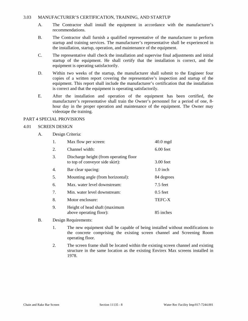
Chain and Rake Bar Screen Section 11135 - 8 Water Rec Facility Imp/017-7244.001
3.03 MANUFACTURER’S CERTIFICATION, TRAINING, AND STARTUP
A. The Contractor shall install the equipment in accordance with the manufacturer’s recommendations.
B. The Contractor shall furnish a qualified representative of the manufacturer to perform startup and training services. The manufacturer’s representative shall be experienced in the installation, startup, operation, and maintenance of the equipment.
C. The representative shall check the installation and supervise final adjustments and initial startup of the equipment. He shall certify that the installation is correct, and the equipment is operating satisfactorily.
D. Within two weeks of the startup, the manufacturer shall submit to the Engineer four copies of a written report covering the representative’s inspection and startup of the equipment. This report shall include the manufacturer’s certification that the installation is correct and that the equipment is operating satisfactorily.
E. After the installation and operation of the equipment has been certified, the manufacturer’s representative shall train the Owner’s personnel for a period of one, 8-hour day in the proper operation and maintenance of the equipment. The Owner may videotape the training.
PART 4 SPECIAL PROVISIONS
4.01 SCREEN DESIGN
A. Design Criteria:
1. Max flow per screen: 40.0 mgd
2. Channel width: 6.00 feet
3. Discharge height (from operating floor to top of conveyor side skirt): 3.00 feet
4. Bar clear spacing: 1.0 inch
5. Mounting angle (from horizontal): 84 degrees
6. Max. water level downstream: 7.5 feet
7. Min. water level downstream: 0.5 feet
8. Motor enclosure: TEFC-X
9. Height of head shaft (maximum above operating floor): 85 inches
B. Design Requirements:
1. The new equipment shall be capable of being installed without modifications to the concrete comprising the existing screen channel and Screening Room operating floor.
2. The screen frame shall be located within the existing screen channel and existing structure in the same location as the existing Envirex Max screens installed in 1978.
Water Rec Facility Imp/017-7244.001 Section 11135 - 9 Chain and Rake Bar Screen
4.02 SPARE PARTS
A. Furnish the following spare parts for each screen:
1. Two complete rake frame and tine assemblies with hardware for attaching to the chain.
2. Ten feet of chain and pins (assembled).
3. Two wiper blades.
END OF SECTION

Chain and Rake Bar Screen Section 11135 - 10 Water Rec Facility Imp/017-7244.001
This page was intentionally left blank.
Water Rec Facility Imp/017-7244.001 Section 11137 - 1 Dewatering Decanter Centrifuge
SECTION 11137
DEWATERING DECANTER CENTRIFUGE
GENERAL
1.01 SCOPE
A. Furnish and test centrifuge with control panel and all other required accessories for satisfactory operation of centrifugal dewatering equipment and appurtenances as indicated and as specified.
B. The centrifuge manufacturer will be responsible for providing a complete centrifuge system, as described herein, and for delivering the equipment to the project site.
C. The drawings and specifications direct attention to certain features of the equipment, but do not purport to cover all details entering into the design and construction of the equipment, controls, or appurtenances.
D. Each centrifuge shall be coordinated for functionality and operation with the following, furnished and installed by others:
E. Two magnetic flow meters.
F. Wash water supply to the centrifuges.
G. Polymer feed system.
H. Centrate drain piping.
I. Sludge cake conveyance.
J. Piping as indicated on the Drawings and in the Specifications.
K. Power, instrumentation, and control wiring.
L. Additional product requirements are specified in Section 01350.
1.02 SUBMITTALS
A. Submittals shall be in accordance with all the requirements of Section 01300 and shall include:
1. Shop Drawings for Review:
a. The Contractor shall indicate all variances from the requirements of the Contract Documents.
b. Scaled dimensional drawings.
c. Wiring schematics with termination point identification.
d. Piping schematics.
e. Materials of construction.
f. Manufacturer's catalog data.
g. General arrangement drawings.
h. Motor information per Section 11050.
2. Operation and Maintenance Manual information.
3. Wiring diagrams for all control panels and field connections with identification of all terminations and connections between panels, junction boxes, equipment items, instrument devices, and the like.
Dewatering Decanter Centrifuge Section 11137 - 2 Water Rec Facility Imp/017-7244.001
4. A Manufacturer's Certificate of Satisfactory Installation is required for the installation.
B. Information for the Record:
1. Documentation for manufacturer-supplied, programmable logic controller programming and operator interface (HMI) programming.
1.03 QUALITY ASSURANCE
A. The centrifuge manufacturing facility shall be ISO 9001:2008 certified.
B. All parts of the equipment provided to be designed and manufactured for long, continuous and uninterrupted service. All materials to be used are of best quality and entirely suitable for service required.
C. Provisions to be made for easy lubrication, adjustment or replacement of all serviceable parts. A minimum clearance of three feet around all sides of the equipment is required for proper maintenance.
D. Centrifuge assembly shall be designed to assure easy disassembly of the unit, including removal of the rotating assembly vertically, within the space and headroom provided.
E. The corresponding parts of multiple units if applicable shall be interchangeable.
1.04 WARRANTY
A. The centrifuge manufacturer shall warrant all equipment supplied to be free of defects in material and workmanship for a period of one year from Substantial Completion of centrifuge. Warranty shall cover all labor and material necessary for repairs for all system components and controls furnished by the centrifuge manufacturer.
B. The Contractor shall guarantee all Work for a period of one year from Construction Acceptance of centrifuge as defined above. The Contractor shall furnish at his sole expense, all labor, material, and equipment necessary to correct any defect in material, equipment, installation, and/or workmanship which becomes evident within one year of Construction Acceptance for centrifuge.
1.05 DELIVERY, STORAGE, AND HANDLING
A. Items shall be shipped as complete assemblies, except where partial disassembly is required by transportation regulations or for protection of components.
B. Spare Parts shall be:
1. Packed in containers bearing labels clearly designating contents and pieces of equipment for which the part is intended. Each part shall be identified with a tag bearing its part number and a part description.
2. Delivered with equipment.
PRODUCTS
2.01 GENERAL
A. The Equipment specified herein shall be furnished by sludge dewatering equipment manufacturer, who shall assume complete responsibility for conformance to the design documents.
B. Like items of equipment shall be the product of one manufacturer to achieve standardization of operation, spare parts, maintenance and manufacturer's service.
C. Manufacturer's standard equipment sizes shall be used unless otherwise specified. The equipment provided shall be complete in all respects including, but not limited to, initial
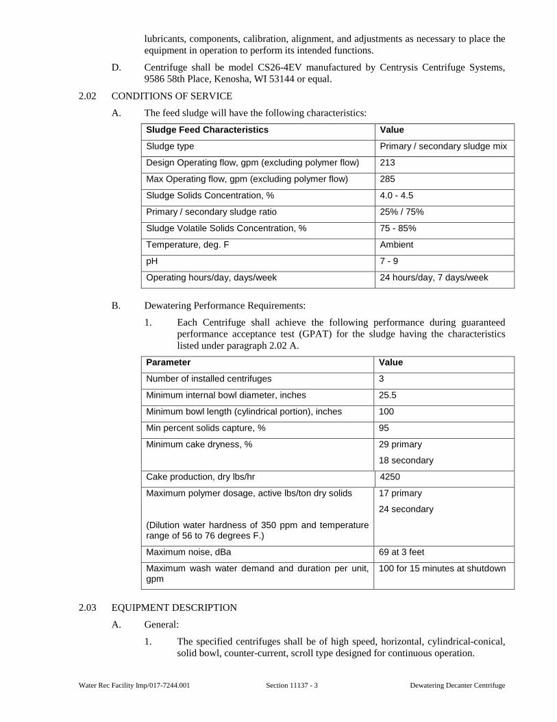
Water Rec Facility Imp/017-7244.001 Section 11137 - 3 Dewatering Decanter Centrifuge
lubricants, components, calibration, alignment, and adjustments as necessary to place the equipment in operation to perform its intended functions.
D. Centrifuge shall be model CS26-4EV manufactured by Centrysis Centrifuge Systems, 9586 58th Place, Kenosha, WI 53144 or equal.
2.02 CONDITIONS OF SERVICE
A. The feed sludge will have the following characteristics:
Sludge Feed Characteristics Value
Sludge type Primary / secondary sludge mix
Design Operating flow, gpm (excluding polymer flow) 213
Max Operating flow, gpm (excluding polymer flow) 285
Sludge Solids Concentration, % 4.0 - 4.5
Primary / secondary sludge ratio 25% / 75%
Sludge Volatile Solids Concentration, % 75 - 85%
Temperature, deg. F Ambient
pH 7 - 9
Operating hours/day, days/week 24 hours/day, 7 days/week
B. Dewatering Performance Requirements:
1. Each Centrifuge shall achieve the following performance during guaranteed performance acceptance test (GPAT) for the sludge having the characteristics listed under paragraph 2.02 A.
Parameter Value
Number of installed centrifuges 3
Minimum internal bowl diameter, inches 25.5
Minimum bowl length (cylindrical portion), inches 100
Min percent solids capture, % 95
Minimum cake dryness, % 29 primary
18 secondary
Cake production, dry lbs/hr 4250
Maximum polymer dosage, active lbs/ton dry solids
(Dilution water hardness of 350 ppm and temperature range of 56 to 76 degrees F.)
17 primary
24 secondary
Maximum noise, dBa 69 at 3 feet
Maximum wash water demand and duration per unit, gpm
100 for 15 minutes at shutdown
2.03 EQUIPMENT DESCRIPTION
A. General:
1. The specified centrifuges shall be of high speed, horizontal, cylindrical-conical, solid bowl, counter-current, scroll type designed for continuous operation.
Dewatering Decanter Centrifuge Section 11137 - 4 Water Rec Facility Imp/017-7244.001
2. The centrifuges shall be capable of performing in accordance with the requirements set forth in these specifications. In order to be assured of meeting the required performance, the centrifuges shall be capable of operating at a speed of 2850 rpm and a G force of 3000. Speed control shall be provided by a solid-state variable frequency drive (frequency inverter).
B. Components and Appurtenances:
1. All equipment shall be furnished by the manufacturer of the sludge dewatering units; however, all equipment need not be manufactured by a single manufacturer.
2. All components, including but not limited to the following, shall be considered as part of the sludge dewatering package and become the responsibility of the sludge dewatering equipment manufacturer:
a. Centrifuge Assembly.
b. Main Drive Motor with variable frequency drive.
c. Hydraulic Backdrive System.
d. Diverter Valve.
e. Lubrication System.
f. Control Panel and Wiring.
g. Motor Starters and Appurtenant Enclosures.
h. Dewatered Sludge and Centrate Chutes with Flexible Connectors.
i. Spare Parts and Special Tools.
j. All equipment, components and appurtenant items shall be furnished and installed as complete assemblies. The interconnecting wiring, conduit, piping shall be furnished by others.
2.04 MATERIALS OF CONSTRUCTION
A. General:
1. Unless otherwise specified all parts of the centrifuge in contact with the sludge shall be made of 304 stainless steel, except O-ring, seals or abrasion resistant materials.
2. The O-ring and seals shall be manufactured of the following:
a. O-ring: Viton
b. Lip Type Seals: Viton
3. All guards shall be constructed of 304 stainless steel.
2.05 CENTRIFUGE COMPONENTS
A. Centrifuge Bowl Assembly:
1. Bowl:
a. The bowl shall consist of a horizontal cylindrical-conical assembly. Solids are discharged at the small end of the conical section. The bowl shall have a minimum length: diameter ratio of 4:1 and beach angle of 15 degrees. It shall be supported by roller bearings mounted in pillow blocks. Beach angles that are less or more than 15 degrees shall not be acceptable.
b. The bowl shall be designed to operate at a minimum of 3,000 Gs at the bowl wall for maximum process flexibility and reliability and to withstand
Water Rec Facility Imp/017-7244.001 Section 11137 - 5 Dewatering Decanter Centrifuge
all centrifugal forces encountered at design operating speed with adequate safety factors.
c. Submit test results with factory test results.
d. The G-volume of the centrifuge shall be a minimum of 400,000 when calculated at the maximum recommended operating speed. The G-Volume shall be calculated using the following equation:
1) G - Volume = (π /4 (Dicyl2 - Disdd
2) x Lcyl) x (6.13X10⁻⁸ x N2 x Dicyl) where
2) Dicyl - Maximum bowl diameter, inches
3) Disdd - Solids discharge diameter, inches
4) Lcyl - Length of the cylinder, inches
5) N - Bowl operating speed, rpm
6) G - Volume shall be calculated with the centrifuge maximum recommended operating bowl speed.
7) Definitions and calculations of G-Volume other than those specified will not be accepted.
e. The centrifuge bowl shall be centrifugally cast from duplex stainless steel with a minimum tensile strength of 100,000 psi. Material shall be A890 or 1.4470. Rolled, forged, welded or static cast bowls are not acceptable. All centrifugal castings shall be inspected for cracks, shrinkage, porosity or other defects, by means of liquid dye penetrate test.
f. The minimum acceptable thickness for the cylindrical and conical sections of the bowl wall shall be 0.9 inches.
g. The liquid pool depth in the bowl shall be adjustable through the use of weir plates at the large diameter end of the bowl where liquid is discharged. Solids shall be discharged from the small diameter end of the bowl. The plate dams shall be manufactured from 304 stainless steel.
h. The bowl wall, both cylindrical and conical, shall be protected by longitudinal wear strips which cause formation of protective feed solids layer so that the solids slip on the scroll flights and adhere to the bowl wall for proper transportation. Machined grooves, that can cause accelerated wear, require conical machining or replacement when worn or Astro turf that often comes loose is not acceptable.
i. The solids discharge ports shall be protected by specially designed raised inserts hard surfaced with tungsten carbide.
j. Sludge feed shall be introduced into the centrifuge feed zone by means of a 304L stainless steel feed pipe from the solids end. Feed design from the liquid end is not acceptable. The feed shall be uniformly distributed into the centrifuge and the feed zone.
2. Scroll Conveyor:
a. The centrifuge shall include a horizontal cylindrical-conical scroll conveyor supported by grease lubricated cylindrical roller bearings and grease lubricated angular contact anti-thrust ball bearings and equipped with helical flights independently mounted concentrically within the centrifuge bowl. The conveyor hub shall be cast 316 Stainless Steel and shall be inspected for cracks, shrinkage, porosity or other defects, by means of liquid dye penetrant test. Fabricated hubs are not acceptable.
Dewatering Decanter Centrifuge Section 11137 - 6 Water Rec Facility Imp/017-7244.001
b. The scroll shaft shall be Type 316 Stainless Steel and flights shall be Type 304 Stainless Steel.
c. Conveyor bearings shall be protected by seals and shall be manually lubricated by means of a manual grease lubrication system.
d. The cylindrical section of the scroll conveyor shall be of the quasi axial flow design. Solid helical screw conveyors shall not be accepted.
e. The scroll shall utilize a differential speed to convey solids from the cylindrical section to the conical section and out of the bowl with a minimum disturbance to the pool.
f. The feed chamber shall have a minimum of 16 feed ports to assure uniform introduction of feed into liquid pool with lowest velocity and therefore least disturbance of settled solids. The ports shall be raised to minimize wear and shall be protected from abrasion by tungsten carbide coating and self-generated sludge liner. The feed nozzles or ports shall be protected by tungsten carbide.
g. The edge and face of the conveyor flights shall be protected against abrasion with Eutalloy hard surfacing material, from the feed zone to the liquid discharge end. The hard surfacing shall be guaranteed against failure for 15,000 hours of operation.
h. The edge and face of the conveyor flights shall be protected against abrasion with tungsten carbide tiles, from the feed zone to the solid discharge. The tiles shall be guaranteed against failure for 15,000 hours of operation.
i. Centrifuge should be able to operate both leading and lagging for better operation and reduction of wear and longer life of bowl and scroll wear protection.
3. Casing:
a. The centrifuge casing shall consist of a 304 Stainless Steel lower casing and a one piece upper casing. The purpose of the case shall be to contain and direct the solids and liquid discharge from the centrifuge, to act as a protective guard and to provide a complete enclosure for noise reduction. Stainless lined fiberglass or fiberglass covers and guards are not acceptable.
b. The lower casing shall be constructed with all process contact material of 304 stainless steel. The upper casing shall be manufactured of 304 stainless steel.
c. Casing shall be a single piece to cover the entire rotating assembly and shall be manufactured of stainless steel.
d. A system will be provided as specified to limit the noise generated by the centrifuge to 88 dBA or less 3 feet from the centrifuge frame.
e. The centrifuge case shall be vented as recommended by the manufacturer. Lifting hooks shall be provided for lifting the casing.
f. To limit splashing and air leakage, the casing shall be provided with labyrinth seals where the bowl hubs intersect the casing and a gasket on the machine flanges where the upper and lower casings join.
Water Rec Facility Imp/017-7244.001 Section 11137 - 7 Dewatering Decanter Centrifuge
4. Base:
a. The centrifuge shall be supported on a fabricated carbon steel base fusion bonded powder coat finish and 304 stainless steel wetted parts. The base shall be mounted on vibration isolators.
b. Machined surfaces shall be provided at all points where support loads are transferred to the base. The bottom portion of the base shall be provided with machined outlets for the attachment of the solids and centrate flexible connectors and chutes and other appurtenant connections.
c. Lifting hooks or solid lifting bars shall be provided for lifting the base.
5. Main Bearings:
a. The main bearing shall be pillow block ball type. The bearings shall have an L-10 life of 100,000 hours minimum at 24 hours per day service.
b. The main bearings shall be lubricated by an automatic air-oil lubrication system.
B. Main Drive Motor:
1. The main drive motor shall be designed, manufactured and tested in accordance with the latest NEMA, IEEE, and ANSI standards and have the following characteristics:
a. Type: Squirrel-Cage, Single-Speed, Rated for Inverter Duty
b. Max Horsepower: 125
c. Synchronous Speed: 3,600 rpm
d. Mounting: Horizontal
e. Enclosure: TEFC
f. Duty Cycle: Continuous
g. Voltage: 460 volts
h. Phase: 3-phase
i. Service Factor: 1.15
j. NEMA Design: B
k. Insulation Class: F or H
l. Code Letter: G
m. Ambient Temperature Rating: 40 degrees C
n. Maximum Temperature Rating: 120 degrees C
o. Starting Method: Reduced voltage
p. Bearing Life: 100,000 Hrs. as defined by AFBMA B-10 Standards.
q. Full Load: Not less than 94 percent
r. Efficiency: Power factor of 0.88
2. The motor shall be equipped with a VFD and thermal protection system to protect the motor from temperatures damaging the stator windings resulting from motor overload, frequent starting locked-rotor current.
Dewatering Decanter Centrifuge Section 11137 - 8 Water Rec Facility Imp/017-7244.001
C. Backdrive System:
1. A Hydraulic Backdrive system shall be supplied with each centrifuge to provide speed variation between the conveyor and the bowl.
2. The differential speed between the centrifuge bowl and scroll conveyor shall be produced by maximum 25 HP, water cooled hydraulic system which shall independently drive the scroll conveyor. The hydraulic scroll conveyor drive system shall be designed such that no mechanical gear reducer is required in the scroll conveyor drive train. The hydraulic drive system shall be capable of operating in either a manual or automatic mode.
a. In the manual mode it shall provide for operation at a specific, adjustable scroll differential speed with internal torque allowed to vary up to the maximum allowable scroll shaft torque.
b. In the automatic mode it shall continuously monitor changes in internal torque created by variations in influent feed solids and automatically maintain a proper filling level by allowing the differential speed and torque to vary. The hydraulic drive shall operate in a manner such that, as the reactive torque of scroll shaft increases due to an increase in solids inventory in the bowl, the scroll differential speed shall gradually increase and, conversely, as the inventory of solids in the bowl and resultant reactive torque decreases, the scroll differential speed shall decrease. The net effect of this system, when operated in the automatic mode, shall be to maximize the time that cake solids are under the influence of accelerated gravitational force to ensure that the driest possible dewatered cake product is produced without plugging the centrifuge.
3. Water for the hydraulic cooling system shall be supplied at 5 gpm at a minimum 50 psi pressure. For systems using cooling water with total dissolved solids content, centrifuge supplier shall provide strainer and filter prior to the cooling system to minimize heat exchanger fouling.
4. The system shall use a hydraulic pumping group and hydraulic motor. Torque-based adjustment shall be a function of input to the driven unit. The maximum torque input and rate of change of scroll differential speed shall be adjustable.
5. The system shall be designed such that automatic centrifuge shutdown is initiated in the event that excessive torque is detected. Two sets of contacts shall be provided.
6. In the event that torque exceeds the normal operating range, the sludge feed pump shall be automatically stopped to allow the centrifuge to clear itself and shall automatically restart when the torque drops to the normal operating range. In the event that the torque approaches the limit of the drive, the second set of contacts shall automatically initiate shutdown of both the feed pump and centrifuge. In this instance manual reset of the alarm is required before the centrifuge can be restarted
7. In case of a high torque shutdown, the backdrive shall not trip but maintain full torque for the entire shutdown so that the machine clears itself while under reduced G-force, therefore it is clean when coming to a complete stop.
8. Backdrives shall be designed such that if needed, they shall be replaced without removing and dismantling the rotor.
9. No mechanical gear reducers such as planetary or cyclo gears are to be used in the scroll conveyor drive train.
10. Scroll drive system shall be designed to offer cleaning capabilities while the centrifuge bowl is at a standstill.
Water Rec Facility Imp/017-7244.001 Section 11137 - 9 Dewatering Decanter Centrifuge
11. Maximum torque and maximum differential speed shall be available with the bowl at a standstill.
12. After power failure, with machine fully loaded with solids, backdrive system shall be capable of maintaining differential speed without accelerating the bowl.
13. Backdrive system shall be able to run the scroll only without input from the maindrive in plugged conditions. Systems with gear boxes shall require bowl locking devices
2.06 VIBRATION ISOLATORS
A. The equipment manufacturer shall furnish vibration isolators which shall be capable of dampening vibration in all directions created during normal and emergency operation of the equipment.
B. The vibration isolators shall be provided for the centrifuge assembly.
2.07 CHUTES AND CONNECTIONS
A. All piping and discharge chute connections to the centrifuge assembly, main drive motor and lubrication system, including but not limited to the feed sludge, wash water, polymer, drain, centrate, discharge sludge discharge and power and control connections, shall be equipped with flexible connections.
B. The flexible connections shall isolate the equipment from fixed rigid piping, chutes or other connections.
C. No exterior loads are to be transferred to any of the equipment.
D. The centrate discharge chute shall be rectangular with a top flange matching the flange of the flexible liquid discharge connection. The chute shall include a flanged connection for a vent as shown on the Drawings. It shall also contain a hose connection for flushing and a sample port. The chute shall maintain the shape of the centrifuge casing discharge connection. The chute shall be manufactured from 304 stainless steel of a minimum thickness of 3/16 inch.
E. The dewatered sludge discharge chute shall be rectangular with a top flange which matches the flange of the solids flexible discharge connection. The chute is to maintain the shape of the centrifuge casing discharge connection and is to have sides as straight as possible to prevent solids from bridging or hanging up. The chute shall be manufactured of 304 stainless steel of a minimum thickness of 3/16 inch. The chute shall contain a hinged access door, a sample port, and a vent connection all as shown on the Drawings.
2.08 DIVERTER GATE
A. A diverter gate shall be provided with each centrifuge assembly, located under the solids discharge chute. Each gate shall have two positions. When the gate is closed, centrifuge product is discharged to drain. When the gate is open, centrifuge product is discharged to the solids transfer system.
B. The gate shall be complete with all necessary appurtenances that are required for proper operation and completion of the work included under this section. The electric actuated gate shall consist of a gate body, wedge gate blade design, wheels, travel assembly with electric actuator, fasteners, and structural steel frame.
C. The structural steel frame and body shall be custom manufactured by the centrifuge manufacturer to properly mate to the sludge discharge chute or an extension of the discharge chute of the centrifuge. Other components, including the electric actuator may be manufactured by others.
D. The bin gate shall be fabricated and contain components adequate to meet the following capacity and service:
Dewatering Decanter Centrifuge Section 11137 - 10 Water Rec Facility Imp/017-7244.001
1. Material: Mixed Primary and Waste Activated Sludge.
2. Maximum Bulk Density: 120 pounds per cubic foot.
3. Maximum Static Head: 6 feet.
4. Openings/Closings per day: 3 cycles.
5. Minimum Speed of Travel: 2.5 inches per second.
E. Gate shall provide an open area at least as large as the opening of the solids discharge chute. The supplier shall verify the dimensions of the chute and shall be fully responsible for the proper interface between the gate and top chute and the gate and bottom chute
F. Gate shall be supported by the centrifuge steel platform frame and chute extension. Design platform frame and gate to meet this requirement. Provide water-tight connections between centrifuge and gate
G. Frame:
1. Gate frame shall be 304 stainless steel, minimum 3/16-inch plate thickness, of the general shapes indicated on the drawings. Minimum stringer thickness shall be 3/16-inch. Frame shall extend in one continuous piece for the total travel of the blade. Frame Deflection shall not exceed L/360 under any condition.
2. Frame shall be designed and supported in conjunction with the discharge chute and shall include any reinforcements needed to support the pneumatic/electric operator entirely from the gate frame.
3. Regreasable Rollers with needle bearings and seals with an L-10 rating of 10,000 hours shall provide and maintain positive blade/seal contact on all four sides and shall be located out of the material flow.
4. Frame shall provide flanged connections with bolt holes drilled to match the bottom of the connection to the centrifuge and chute extension. Nuts shall be self-locking, 304 stainless steel. A 1/4-inch closed cell neoprene gasket shall be provided on each flange around the entire frame to seal the connections. Connection pieces to the centrifuge shall be either stainless steel or neoprene
5. Frame shall provide a displacement pocket so that material on the end of the blade does not interfere with closing.
6. Two 1-inch male NPT flushing ports and one 8-inch flanged drain fitting shall be provided on the frame about the sliding gate, so that dewatered sludge can drain when the gate is closed.
7. A chute extension between the centrifuge and diverter gate shall be provided based on the final centrifuge layout.
H. Seals and Blade:
1. Blade and seal arrangement shall be of an adjustable labyrinth design to prevent direct flow through the seal and with stainless steel vertical sidewalls to restrict and direct seepage to the drainage trough.
2. The gate shall be equipped with heavy-duty 1/2-inch thick minimum one-piece hot vulcanized molded neoprene rubber seals with 1/2-inch diameter contact area. The seals shall be retained by bolted 304 stainless steel bars.
3. The blade shall be a wedge design so that the seal is not in full sliding contact with the blade during travel and shall "wedge" against the seal only at full closure. Gate shall be water tight.
4. The blade (sliding member) shall be one piece minimum 1/4-inch thick Type 304 stainless steel plate. Thickness shall be sufficient to percent jamming due to
Water Rec Facility Imp/017-7244.001 Section 11137 - 11 Dewatering Decanter Centrifuge
deflection and design calculations shall demonstrate that maximum deflection shall be L/360 under all operating conditions.
I. Gate Operator:
1. Operator shall be completely supported by the gate frame.
2. Operator shall permit the gate to be stopped or reversed at any partially open position.
3. Operator shall conform to AWWA C504 and C540 except as modified herein.
4. Electric screw actuator shall be used for opening and closing of the diverter gate.
5. The gate operator shall comply with the requirements for valve operators as contained in Section 15250.
J. Electrical:
1. The gate manufacturer shall furnish and assemble all electrical equipment on the gate including solenoid valves, limit switches and conduit.
2. Gate shall be provided with two single pole, double-throw limit switches rated at 5 amps at 120 volts AC, for remote indication of fully opened and fully closed positions. Limit switches shall be provided in NEMA 4X enclosure.
2.09 CONTROLS
A. The motor starter/control panel shall be a stainless steel NEMA 4X enclosure. Included with the enclosure shall be the main circuit breaker, control circuit voltage transformer, a VFD to run the centrifuge main bowl motor, scroll drive motor starter and Allan Bradley control system PLC with operator interface unit. Through the interface, the operator shall be capable of verifying sludge and polymer actual flow rates from flow meters.
B. The control panel shall be provided with centrifuge feed pump start/stop speed control; polymer feed pump start/stop speed control, backdrive start/stop control and centrifuge conveyor start/stop control. Also included shall be bowl drive amp feedback and elapsed time. Pilot lights, pushbuttons, scroll drive starter and alarm system shall be mounted in the door.
C. All components in the control panel shall be completely factory wired. All external control connection points shall terminate on a terminal strip with a minimum of 10 percent spare terminal connections supplied. All pushbuttons and pilot lights shall be watertight, corrosion resistant and in accordance with current plant standards.
D. Auxiliary system operation shall be controlled automatically upon starting a centrifuge or manually with individual pushbuttons. Control logic shall be CompactLogix PLC based with ladder logic programming. The system shall provide separate outputs for remote indication of centrifuge running. Three polymer feed pumps shall be controlled by remote PLCs. Polymer pumps are to be selected from the operator interface terminal in the centrifuge panel via ethernet. The polymer feed system shall be interlocked against low level, high-pressure low pressure and low polymer. Additionally, the following equipment shall be interlocked with the centrifuge as a permissive for centrifuge operation via ethernet:
1. Centrifuge discharge conveyor gate
2. Sludge transfer conveyor 1 or 2
3. Sludge cake pump 1 or 2
4. Sludge storage valve hydraulic power unit
E. Controls for the diverter gate shall be coordinated with the centrifuge manufacturer so that signals from the centrifuge control panel open and close the gate. Confirmation signals
Dewatering Decanter Centrifuge Section 11137 - 12 Water Rec Facility Imp/017-7244.001
back to the PLC confirming gate fully opened and gate fully closed positions shall be provided.
F. The PLC shall be as manufactured by Allen Bradley. A PanelView Plus 1000 OIT shall be provided.
2.10 MONITORING SYSTEM
A. The minimum inputs and Shutdown Alarm indications shall be as follows:
1. Excessive main drive motor overload.
2. Excessive backdrive drive motor overload.
3. Backdrive drive malfunction.
4. Main Drive malfunction.
5. High-high hydraulic pressure at hydraulic cooling water pump.
6. High-high scroll conveyor torque.
7. Centrifuge bowl overspeed.
8. E-Stop.
9. High-high vibration at liquid end.
10. High-high main bearing temperature at solids end.
11. High-high main bearing temperature at liquid end.
12. Control Panel high temperature.
13. Lubrication Fault.
B. The following I/O Points shall be available at the Centrifuge PLC, but shall not shut down the centrifuge:
1. Feed pump
a. In Service input
b. In PLC control
c. Running input
d. VFD Fault input
e. E-Stop pushed input
f. Start/Stop output
g. VFD Speed input (4-20mA)
h. VFD Speed output (4-20mA)
i. Seal water pressure available
j. Discharge pressure high.
2. Diverter gate (I/O determined by Centrifuge supplier).
3. Hydraulic cooling system (I/O determined by Centrifuge supplier)
4. High scroll conveyor torque.
5. High vibration.
6. Centrifuge discharge conveyor
a. In auto input
Water Rec Facility Imp/017-7244.001 Section 11137 - 13 Dewatering Decanter Centrifuge
b. Running input
c. Fault input
d. In service input
e. Start/stop output
C. The following inputs and Shutdown Alarm indications can be available for optional equipment at the PLC:
1. Main drive motor temperature.
2. Back drive motor temperature.
3. Hydraulic cooling Fan aux fault.
D. Interlocks from remote PLCs shall be available for the following equipment at the centrifuge PLC via ethernet:
1. Polymer system – selection and operation from centrifuge control panel via ethernet. Polymer pumps in use will be prevented from being selected for use by other centrifuges.
2. Sludge cake pump transfer conveyor running.
3. Sludge cake pump running.
4. Sludge storage bunker selected for discharge at valve hydraulic power unit
5. Other equipment as required.
2.11 PAINTING
A. Shop and field painting to be manufacturers standard except where indicated otherwise in specifications.
B. 304 Stainless Steel skid members should not be painted.
2.12 SPARE PARTS
A. The following spare parts shall be furnished with the centrifuges and back drive systems:
1. One set - bearings and seals.
2. One set - O-rings and seals.
3. One set - matched drive belts.
4. One year supply of lubricants.
5. One year supply of filters.
6. One spare programmed memory card for PLC.
7. One each spare analog input, analog output, discrete input and discrete output card.
8. One pre-programmed memory card with backup copies of the program.
2.13 SPECIAL TOOLS
A. One set of the following tools will be furnished:
1. Set wrenches.
2. Bowl lifter.
3. Bearing puller.
Dewatering Decanter Centrifuge Section 11137 - 14 Water Rec Facility Imp/017-7244.001
EXECUTION
3.01 COORDINATION
A. Installation shall be complete and in accordance with the centrifuge manufacturer's recommendation, Engineer's instructions, and Contract Documents.
B. Initial start-up and instruction of Owner's personnel in equipment operation shall be provided by the equipment manufacturer.
3.02 FACTORY TEST
A. Supplier to conduct in-factory functional testing of assembled unit.
B. Supplier to submit protocol for factory test for owner review.
C. Supplier to submit factory test results report for review by Owner prior to shipment of the assembled unit to the jobsite.
D. Test shall include the following at the minimum.
1. Power skid unit with 480VAC, 60Hz, 3 phase power.
2. Test rotation of all motors and drive units.
3. Simulate operation conditions and modes to confirm function.
4. Simulate all alarm input conditions to verify appropriate alarm indication and shutdown functions.
E. Witnessed Testing:
1. Supplier to provide four weeks advance notice to Owner of factory test.
2. Supplier to allow Owner, at Owners option and cost, to visit suppliers' factory test.
3.03 DELIVERY OF EQUIPMENT
A. Equipment supplied under this Section shall not be delivered to the site until construction has progressed to the point where installation may properly commence.
B. Protect all equipment per Manufacturer's instructions.
C. Replace any equipment damaged after receipt of equipment at Contractor's expense.
3.04 INSTALLATION
A. Installation to be in strict accordance with the Manufacturer's instruction and recommendations in the locations shown on the Drawings.
B. All equipment, components, piping and appurtenances shall be installed true to alignment and rigidly supported. Any damage to the above items shall be repaired or replaced by the Contractor to its original condition
C. Interconnecting piping supplied by the Contractor to be hydrostatically tested by the Contractor.
D. During installation, the centrifuge system Manufacturer or representative shall provide the following services:
1. Provide general assistance regarding handling, assembly and installation requirements for complete installation by Contractor.
2. Be present during placement and connection of the unit to power and liquid connections to instruct and observe installation.
3. Inspect the installation prior to startup in order to verify that the equipment has been properly installed.
Water Rec Facility Imp/017-7244.001 Section 11137 - 15 Dewatering Decanter Centrifuge
4. Verify all equipment installed per manufacturer's recommendations and literature and the Drawings.
5. Calibrate the equipment with the Owner's operator present after installation but prior to startup.
6. Provide installation instruction manuals for Contractor's assistance at least 30 days prior to shipment of factory assembled treatment units.
3.05 FIELD QUALITY CONTROL
A. Service:
1. Qualified service personnel must be available on a 24-hour-a-day basis.
2. The personnel must be completely familiar with the items supplied so as to return inoperative equipment to service in the shortest possible time.
3. The submitted information is to include the following:
a. Name, educational background and years of service experience for all service personnel.
B. Tests:
1. Field testing and checking of installation to be approved by Manufacturer's field representative.
2. Test under full load conditions.
3. Verify that all control system functions, including alarms, perform as specified.
4. Any spare parts furnished as specified but used during startup must be replaced prior to final acceptance.
5. Manufacturers field representative to perform field test.
C. Manufacturers Field Services:
1. Qualified factory-trained representative to provide startup and operator training services. Representative to be available within two weeks of request for services. Representative to provide following services:
a. Equipment installation review and certification of proper installation: Provide one trip; minimum of eight hours on site for initial visit to checkout installation and verify that centrifuge system is ready to operate.
b. Startup and operator training: Provide one trip of minimum two, 8-hour on site days to provide classroom training of operating personnel in the operation of centrifuge system and to provide "hands-on" training for operation of equipment.
c. Six-month performance review and post startup training: One trip of 8-hours on site minimum to make operating adjustments and provide additional instruction to Owners personnel within 6 months after final acceptance of equipment.
3.06 TESTING, MAINTENANCE, AND SERVICE
A. Shop Test:
1. Upon completion of manufacture of centrifuge and appurtenances to be installed on this project, conduct shop tests which shall be performed and may be witnessed by the Engineer as outlined below:
a. Running test: Each machine, shall conduct a dry run for a minimum of 8 hours of continuous operation at proposed design operating speed.
Dewatering Decanter Centrifuge Section 11137 - 16 Water Rec Facility Imp/017-7244.001
b. Demonstrate that all equipment is capable of continuous operation in satisfactory manner without mechanical defects or operational difficulties. Measure and record vibrations and temperature of the main bearings.
c. If necessary, tests repeated until satisfactory results are obtained.
d. All defects or defective equipment revealed by or noted during tests to be corrected or replaced promptly at no additional compensation.
B. Services of Manufacturer's Representative:
1. Provide services of factory-trained Service Engineer, specifically trained on type of equipment specified. Submit qualifications of Service Engineer for approval. Man-day requirements listed are exclusive of travel time, and do not relieve Contractor of obligation to provide sufficient service to place equipment in satisfactory operation.
a. Installation:
1) To assist in location of anchor bolts; setting, leveling, field erection, etc.; coordination of piping, electrical, miscellaneous utility connections: 2 man-days.
b. Start-up, testing and calibration: 2 man-days.
c. Operation and maintenance instruction: 1 man-days.
C. Service Centers:
1. Centrifuge manufacturer must have at least two currently operating service centers located within the United States.
2. Centrifuge manufacturer must have at least two service technicians based at the United States service center, who has been trained specifically on the centrifuge system required for this project, and who would be available for a field service call at the wastewater reclamation facility (WRF) within 48 hours of written notice.
3. Centrifuge manufacturer's service center must be capable of delivering spare parts, excluding bowls and scrolls, to the WRF within 48 hours of notice.
SPECIAL PROVISIONS
4.01 VARIABLE FREQUENCY DRIVES
A. Variable frequency drives shall meet the requirements of Section 16230 and provide the necessary functions to meet the control and drive requirements stated in this Section.
END OF SECTION
Water Rec Facility Imp/017-7244.001 Section 11233 - 1 Liquid Polymer Equipment
SECTION 11233
LIQUID POLYMER EQUIPMENT
GENERAL
1.01 SCOPE
A. The Contractor shall furnish and install three liquid polymer blending units. The equipment is to be supplied by a single equipment supplier for installation by the Contractor in accordance with the manufacturer's drawings and instructions.
B. Major components of the liquid polymer blending unit to be supplied under this section shall include, but not be limited to, the following:
1. Liquid polymer blending unit.
2. Spare parts and accessories.
3. Start-up and training services.
C. Additional product requirements are specified in Section 01350.
1.02 SUBMITTALS
A. Submittals shall be in accordance with Section 01300 and shall include the following information:
1. Shop Drawings for Review:
a. Dimensional drawings as required for the installation.
b. Electrical wiring diagrams as required for the installation.
c. Sufficient information on each component to show that the equipment meets this specification.
2. Information for the Record:
a. Operation and Maintenance information.
b. Installation instructions.
1.03 QUALITY ASSURANCE
A. Components and installation shall comply with the Uniform, Standard and National Building and Fire Codes.
B. Pre-assemble and factory test system to ensure compliance with pressure and operational requirements.
C. The Contractor shall submit, upon request, a list of ten installations, each at least five years in operation, which support the system’s ability to meet the specified requirements.
D. The Contractor shall include in the bid, and shall be responsible for, the costs of any changes to accommodate other equipment, including but not limited to structural, mechanical and electrical work. The Contractor shall also pay additional costs necessary for revisions necessary to achieve the specified requirements.
1.04 WARRANTY REQUIREMENTS
A. The polymer blending system shall be covered by a two-year warranty. The mixing chamber shall be covered by a lifetime warranty covering the repair or replacement of the mixing chamber or any part of the mixing chamber which fails for any reason, excluding weather related or over-pressure failures. In addition, the mixing chamber shall be warranted against plugging for any reason. If plugging occurs the mixing chamber shall
Liquid Polymer Equipment Section 11233 - 2 Water Rec Facility Imp/017-7244.001
be repaired or replaced at no cost to the Owner. Metering pumps, options and accessories shall be covered by a warranty for one year following Substantial Completion. The full warranty shall be valid regardless of whether potable or non-potable dilution water having high solids content is used.
1.05 DELIVERY, STORAGE, AND HANDLING
A. Items to be shipped as complete assemblies except where partial disassembly is required by transportation regulations or for protection of components.
B. Spare parts belts to be shipped separately.
C. Spare Parts:
1. Pack in containers bearing labels clearly designating contents and pieces of equipment for which the part is intended. Each part shall be identified with a tag bearing its part number and a part description.
PRODUCTS
2.01 MANUFACTURER
A. Provide a dynaBlend liquid polymer blending and feed system as manufactured by Fluid Dynamics, Inc., or equal.
2.02 DESIGN CRITERIA
A. The liquid polymer dilution/blending system shall be capable of automatically metering, diluting, activating and feeding liquid polymer with water.
B. The polymer dilution/blending system unit shall be capable of producing polymer solution with polymer-to-water solution concentrations between 0.25 percent and 1.0 percent.
2.03 PERFORMANCE REQUIREMENTS
A. The liquid polymer blending unit shall automatically meter, mix and blend concentrated liquid polymers with dilution water.
B. The polymer input capacity of each unit shall be: 60 to 180 pounds per hour of concentrated polymer using a liquid concentrate pump.
C. Dilution water range shall be: 700 to 8,400 gph.
2.04 SERVICE CONDITIONS
A. Dilution Water supply pressure shall be a minimum of 65 psi.
B. Backpressure from the point of application on the polymer system shall be a maximum of 30 psi.
C. Control Panel supply voltage shall be: 120 VAC.
2.05 PREPARATION EQUIPMENT
A. Multi-Zone Mixing Chamber:
1. A non-mechanical hydrodynamic blending device specifically designed to dilute and activate emulsion, dispersion and solution type polymer with viscosities up to 75,000 cps. and active contents up to 75 percent shall be provided. Systems without experience with types of polymers described above will not be considered.
2. The liquid polymer activation chamber's mixing energy shall be staged such that it provides for high, non-damaging mixing energy over the full operating range of the system which then dissipates through concentric chambers. The integral
Water Rec Facility Imp/017-7244.001 Section 11233 - 3 Liquid Polymer Equipment
water control device, which shall also produce mixing energy by creating a pressure drop across its orifice, shall be constructed of stainless steel and brass and shall be designed to allow orifice replacement without disassembly of any other part of the system. The system shall be designed for use with either potable or non-potable dilution water.
3. A mixing chamber drain valve with 1/2-inch fitting shall be provided and plumbed to the nearest floor drain. The mixing chamber shall have a maximum rated pressure of 150 psi.
4. Provide a bronze, adjustable-range pressure relief valve on mixing chamber with a range of 50 to 175 psi.
B. Check Valve:
1. Provide a neat polymer check valve specifically designed to isolate neat polymer from dilution water. The valve shall be designed with an open, unobstructed path to the valve seat. The valve body shall be constructed of Teflon and the ball shall be stainless steel. The valve shall be readily accessible for cleaning and shall be easily disassembled. Conventional check valves, and or check valves that are installed inside the mixing chamber, or which require mixing chamber disassembly for servicing will not be accepted.
C. Dilution Water Control:
1. The dilution water flow rate shall be monitored by a Rotameter type flow meter. Unions shall be provided on the inlet and outlet of the Rotameter to allow easy removal for cleaning.
a. Rotameter accuracy shall be plus 4 percent of full-scale flow.
b. Materials of Construction:
1) Metering Tube: Machined Cast Acrylic
2) Internal Components: 316L Stainless Steel
3) Fitting: PVC
4) Elastomers: Buna-N
2. Unit shall have an electric solenoid valve Brass body, NBR Seal for on/off control of total dilution water flow.
3. The dilution water flow rate shall be manually adjusted through a flow control valve connected directly to the mixing chamber. Valve shall be constructed of PVC body, SS needle, and SS seat.
4. Dilution water differential pressure shall be monitored by an industrial duty differential pressure switch rated NEMA 4X with a range of 0 to 90 psig. Differential pressure switch shall be United Electric model J21K-16074, or equal.
D. Pump:
1. Unit shall have a neat polymer metering pump. Pump shall be a minimum two stage positive displacement, progressing cavity type. Rotor shall be 316 SS. Stator shall be fluoroelastomer. Pump shall have a packing seal.
2. Pump shall be driven by a 1/4 Hp (minimum), TEFC, 0 to 90 volt DC motor. Variable speed capability shall be provided by an SCR controller. Maximum speed of the pump shall not exceed 450 rpm.
3. Provide a metering pump calibration assembly rigidly mounted to the system frame and sized to provide a one-minute drawdown at 100 percent pump
Liquid Polymer Equipment Section 11233 - 4 Water Rec Facility Imp/017-7244.001
capacity. The column shall be graduated in increments of 0.1 gallons/10 mL. Supporting the calibration column with the polymer piping is not acceptable.
4. Provide a non-intrusive type loss of polymer flow sensor.
E. Controls:
1. A control panel affixed to the system's frame shall be provided, rated NEMA 4X and constructed of FRP. The control panel shall consist of all switches, relays, indicator lights, digital displays, and controllers as required herein. The control panel components shall be NEMA 4X. All skid-mounted electrical components interconnected to control panel shall terminate on terminal blocks. Terminal blocks shall be sized for 14 gauge wire with terminal block numbers and a legend. Wires shall be neatly run through wire race-way and numbered with adhesive type labels.
2. Control Devices:
a. Main Power/System LOCAL-OFF-REMOTE selector switch.
b. NEMA 4X, panel-mounted, 10-turn potentiometer for LOCAL control of pump speed.
3. Neat Polymer Pump SCR Controller:
a. Input Voltage: 115/230 VAC.
b. Output Voltage: 0 to 90 VDC or 0 to 180 VDC.
c. HP Rating: 1/8-1 at 90 VDC, 1/4-2 at 180 VDC.
d. Signal Input: 4-20mA or 0-10VDC, selectable.
e. Max Output Current: 10 Amps.
f. Adjustable min speed, max speed, current limit, IR compensation and signal input adjust.
g. Three percent linearity through 60:1 speed range.
4. The control panel shall include a panel-mounted ratio control module. The ratio control module consists of a graphic interface display with membrane numeric and functions keys as required and an integral fixed logic controller. The ratio control module shall be capable of maintaining a precise solution concentration while following the manually adjusted water flow rate as follows:
a. Local Manual:
1) Water and metering pump feed rates are set manually.
b. Local Auto:
1) Desired dilution water flow rate is adjusted manually.
2) Desired solution concentration set point is entered manually.
3) The ratio control module will automatically adjust the pump flow rate as required to maintain the desired set point and solution concentration.
c. Remote Auto:
1) Desired solution concentration set point is received as a 4-20 mAdc analog signal. Desired dilution water flow rate is adjusted manually, and polymer pump follows a remote-control signal.
2) Desired dilution water flow rate is adjusted manually, and polymer pump follows a remote-control signal.
Water Rec Facility Imp/017-7244.001 Section 11233 - 5 Liquid Polymer Equipment
5. Indicators:
a. System Running Indicator: white full voltage pilot light.
b. Low water differential pressure alarm.
c. LCD display of pump rate.
d. Polymer pump low flow alarm.
6. Inputs:
a. 4-20mA metering pump pacing signal from centrifuge PLC.
b. Contact Closure (maintained) for remote starting/stopping of polymer system.
7. Outputs:
a. System "Running" status output, dry contact.
b. System in "Remote mode" status output, dry contact.
c. Low Water Pressure Alarm, dry contact.
d. 4-20mA metering pump flow feedback signal.
8. Alarms:
a. Loss of Dilution Water Pressure Alarm, Differential Pressure Type. Metering pump goes to stand-by mode when low dilution water pressure occurs. The pump automatically restarts when pressure returns.
2.06 MAINTENANCE
A. Unit shall be open frame design to allow easy access to all components.
B. Mixing chamber shall be easily disassembled and reassembled to allow access to all parts exposed to neat polymer.
C. Polymer check valve shall be readily accessible. Check valves installed inside mixing chamber shall not be acceptable.
2.07 MATERIAL SPECIFICATIONS
A. Connections - Plumbing:
1. Dilution water inlet, 1 inch FNPT.
2. Neat polymer inlet, 1 inch FNPT.
3. Solution discharge, 1 inch FNPT.
B. Connections - Electrical:
1. Standard, grounded male plug - 120/1/60, 15 amps max.
2. Terminal blocks for interconnecting all skid-mounted electrical devices.
3. Terminal blocks for all remote input and output signals.
C. Dimensions:
1. Frame, 24 inches wide by 24 inches deep by 68 inches high.
D. Materials of Construction:
1. The system's frame shall be of rugged 304 stainless steel construction. No mild steel shall be used. The skid shall be constructed of 3/16-inch minimum 304 stainless steel. The frame shall be constructed of 3/16 inch angle or structural stainless steel tubing. The panel supporting the control panel shall be a minimum
Liquid Polymer Equipment Section 11233 - 6 Water Rec Facility Imp/017-7244.001
of 12 gauge. Vertical frame members shall be gusseted. All pipe supports shall be stainless steel. The skid shall be designed for fork-lifting and shall have holes for mounting to concrete pad. The systems frame shall be designed for an integral dilution water booster pump in the event the plants water system is incapable of providing sufficient dilution water pressure. Maximum system dimensions shall be per schedule above. Control panel shall be mounted in vertical position and at 60-inch high. Pump suction shall not exceed 18 inches from the skid base.
2. Piping and valves shall be mounted with rigid pipe clamps. Fasteners required to mount components to system frame shall be minimum 1/4-20. Water plumbing shall be schedule 80 PVC. Hose shall be braided vinyl. Hose fittings shall be schedule 80 PVC. No nylon fittings shall be used.
3. Mixing Chamber - 304 stainless steel with PVC top cap.
2.08 SPARE PARTS
A. Supply the following spare parts:
1. One neat polymer pump spare parts kit to include packing, stator, and rotor.
2. One polymer check valve.
EXECUTION
3.01 COORDINATION
A. Installation shall be complete and in accordance with the manufacturer's recommendations, Engineer's instructions, and Contract Documents.
3.02 INSTALLATION
A. The Contractor shall install the liquid polymer blending units in accordance with the manufacturer's requirements.
3.03 INSPECTION, STARTUP AND TRAINING
A. Minimum Service Requirements:
1. Certify proper installation.
2. One eight-hour day on site for start-up and testing.
3. One eight-hour day on site for operator training.
B. Initial start-up and instruction of the Owner's personnel in equipment operation shall be provided by the equipment manufacturer or manufacturer’s representative.
SPECIAL PROVISIONS
4.01 LIQUID POLYMER CONTAINER SPILL CONTAINMENT
A. Two spill container structures with 535 gallons sump volume each shall be provided by the liquid polymer equipment supplier, sized to accept two 330-gallon IBC’s. Containment sump shall be of polyethylene construction.
B. IBCs shall sit on top of containment sump on a suitably-sized and reinforced grating. Grating shall be easily removable.
C. Containment sump shall be equipped with a drain and valve.
D. Containment sump shall be Item 1144 as manufactured by UltraTech International, Inc., Jacksonville, Florida, or equal.
Water Rec Facility Imp/017-7244.001 Section 11233 - 7 Liquid Polymer Equipment
4.02 FLEXIBLE HOSE
A. Two 2-inch flexible hoses shall be supplied to connect the totes and shall consist of 316 stainless steel HYDRAFLEX 3400 SERIES Hose by Hose Master Inc., 1-800-221-2319 Cleveland, Ohio or equal. The chemical connections to the tote and to the rigid PVC polymer piping shall terminate with a 2-inch stainless steel male adapter with cap as manufactured by Andrews, OPW Kamlok, or equal.
END OF SECTION

Liquid Polymer Equipment Section 11233 - 8 Water Rec Facility Imp/017-7244.001
This page was intentionally left blank.
Water Rec Facility Imp/017-7244.001 Section 11735 - 1 Pumping Equipment
SECTION 11735
PUMPING EQUIPMENT
GENERAL
1.01 SCOPE
A. This Section includes the furnishing and installing of pumping equipment as shown on the Drawings, as scheduled in Part 4, and as specified herein.
B. The pumping equipment shall be furnished with all drives, drive shafts, couplings, steady bearings, belts, drive shaft and belt guards, drive bases, pump bases, anchor bolts, anchor bolt sleeves, and other appurtenances as specified or required for a complete installation and satisfactory operation.
C. All work performed under this Section shall be in accordance with all approved trade practices and manufacturers’ recommendations.
1.02 SUBMITTALS
A. Submittals shall be in accordance with the requirements of Section 01300 and shall include:
1. Shop Drawings for Review:
a. Manufacturer’s warranty.
b. Manufacturer certification/affidavit.
c. Manufacturer’s literature.
d. Manufacturer’s certified test curves (computer model printouts are not acceptable).
e. Information and data concerning the materials of construction, salient components and details of construction of equipment and components.
f. Motor data in accordance with Section 11050.
2. Information for the Record:
a. Manufacturer’s installation instructions.
b. Manufacturer’s operation and maintenance manuals.
c. Manufacturer’s certification of installation.
1.03 QUALITY ASSURANCE
A. Manufacturer Warranty and Service Packages:
1. Warranty Submittals - At the time of shop drawing submittal, the Contractor shall submit a written warranty from the manufacturer(s) covering workmanship and materials on those pumps with drive motors of 7-1/2 hp or larger when used as intended for this installation. Warranty period shall be one-year, unless specified otherwise. The warranty period shall commence on the date of Substantial Completion. Under terms of this warranty, the manufacturer shall furnish and install all replacement parts for any defective component at no cost to the Owner. The provisions of this warranty shall not be construed as relieving or reducing the obligations of the Contractor outlined in the General Conditions of these Specifications.
2. Owner shall have the option to purchase additional manufacturer warranty options and service package plans, for a cost. Contractor shall provide, upon request, the warranty and service plan information and their respective cost.
Pumping Equipment Section 11735 - 2 Water Rec Facility Imp/017-7244.001
3. Warranty options should include, but not be limited to:
a. Prorated warranties, terms and conditions, and length of time.
b. A full replacement (non-prorated) warranty, terms and conditions, for time frames up to 5 years.
c. Service package plans.
B. Manufacturer Certification/Affidavit:
1. Manufacturer shall provide affidavit certifying that:
a. Manufacturer has examined the Contract Documents, including but not limited to the Drawings and specifications.
b. Understand the installation and parameters specified herein and shown on the Drawings.
c. The equipment specified is suitable for this application.
d. Notified Owner and Engineer of any modifications required to the system or the equipment in this application.
PRODUCTS
2.01 PUMPS
A. General:
1. Each pump shall be designed and furnished to meet the operating conditions specified in Part 4 of this Section. The type of pump for each service is given in the Schedule in Part 4.
2. Each pump shall be of the manufacturer and model listed in Part 4 or equal. All pumps used for one type of service shall be of the same manufacturer.
3. Each pump shall be shop tested in accordance with standards of the Hydraulic Institute. Six copies of certified test curves indicating capacity, head, efficiency, brake horsepower, and speed shall be submitted to the Engineer for approval. No pump shall be shipped to the job site until the test curves have been approved by the Engineer.
4. No point on the centrifugal pump performance curve shall require more than the nameplate horsepower of the drive motor.
B. Centrifugal Pumps:
1. Centrifugal pumps shall be in accordance with the requirements described in the following paragraphs and in Part 4 of this Section. Pumps shall be either horizontal or vertical as indicated in Part 4.
2. The pump casing shall be of the one-piece, volute type with integral ANSI 125-pound discharge flange and arranged as shown on the Drawings. It shall be made of ductile iron, unless specified otherwise in Part 4, of sufficient strength, weight, and thickness to provide accurate alignment and prevent excessive deflection. The casing shall be designed to permit the removal of the rotating assembly without disturbing the suction or discharge connections and provided with a large handhole to permit inspection and cleaning of the pump interior. The handhole cover shall be bolted and its inner contour shall match the contour of the casing. Lifting eyes shall be furnished to facilitate handling. The discharge nozzle shall be tapped for gauge connection and shall have 125-pound flanges. The casing shall have vent and drain connections.
Water Rec Facility Imp/017-7244.001 Section 11735 - 3 Pumping Equipment
3. Each pump shall have a suction head of ductile iron unless specified otherwise in Part 4 and designed to provide equal flow distribution to the impeller eye. It shall be provided with an ANSI 125 pound suction flange, a hand hole with removable cover and tapped gauge connection. The suction head on vertical pumps shall be either an elbow integrally cast with a pump support base or a straight nozzle integrally cast with a pump base as specified in Part 4.
4. The impeller shall be single-stage end suction mixed flow enclosed type with a minimum number of vanes and shall be designed to prevent clogging and to pass 3-inch diameter solids, unless specified otherwise in Part 4; trash; and stringy materials contained in sewage. The impellers shall be made of ductile iron, unless specified otherwise in Part 4, accurately machined and polished to remove hollows or projections which might encourage cavitation. Each impeller shall be statically and dynamically balanced prior to assembly. The impeller shall be secured to the shaft with a key and contoured lock nut, which in turn is secured by a locking screw. The arrangement shall be such that the impeller cannot be loosened by torque from either forward or reverse rotation.
5. Wear rings of dissimilar material and a means of maintaining pump efficiency shall be provided.
6. Pump shafts shall be of heat treated alloy steel of sufficient size to transmit the full driver horsepower with a liberal safety factor and shall be accurately machined over the entire length. The shafts shall be protected from wear in the stuffing box by a removable hardened 13 percent chrome steel shaft sleeve sealed to prevent leakage between the sleeve and the shaft.
7. The stuffing box shall be cast integrally with the stuffing box head, designed for packing, and suitable for clear water sealing. The stuffing box shall be readily accessible. The stuffing box head shall be tapped for a 3/4-inch drain connection. The packing gland shall be of the material specified in Part 4.
8. Bearings shall be of the cylindrical roller or tapered roller type as required, mounted in a removable cast iron frame. The bearings shall be arranged to eliminate all radial play and designed for a minimum B-10 life of 100,000 hours in accordance with AFBMA. The bearings shall be oil or grease lubricated as indicated in Part 4. Grease lubricated bearings shall have alemite fittings. Suitable seals shall be provided in the bearing covers to prevent the entrance of contaminants.
9. Each horizontal pump shall have a flexible type coupling and shall be mounted on a common cast iron or steel base with its drive unit.
10. Vertical pumps shall be direct coupled or shall have intermediate shaft as indicated on the Drawings.
a. Each direct coupled pump shall have a driver pedestal. The driver pedestal shall be of sufficient size, strength, and rigidity to support the driver and prevent excessive vibration. It shall be made of fabricated steel and provide for easy access to stuffing box, bearing frame, and coupling for maintenance. An expanded metal coupling guard shall be provided. This guard shall be positioned to protect against contact with coupling end to shaft and coupling, but still allow easy access to bearing lubrication fittings and stuffing box connections. Pedestal shall be designed to allow the complete pump rotor consisting of bearing frame shaft, stuffing box, and impeller to be removed as a unit without disturbing suction and discharge piping, driver, or pedestal.
b. Shafting and steady bearings as necessary shall be provided between pumps and drivers on pumps with intermediate shafts. The pump
Pumping Equipment Section 11735 - 4 Water Rec Facility Imp/017-7244.001
manufacturer shall provide with each pump, a pump mounted safety cage around pump drive shafting. The safety cage shall meet OSHA requirements and extend a minimum of 8-feet above the operating floor. The cage shall be so designed that it will not interfere with servicing of the pump. The pump manufacture shall also provide with each pump a safety cage meeting the same requirements for each floor through which the shafting passes.
C. Progressing Cavity Pumps:
1. Progressing cavity pumps shall be in accordance with the requirements described in the following paragraphs and Part 4 of this Section.
2. Each pump casing shall be cast iron. Suction and discharge ports shall be tapped for gauge connections and shall have ANSI 125-pound flanges. Casing shall be tapped for drain and shall have a large inspection port.
3. Unless specified otherwise in Part 4, internal parts including the rotor shall be tool steel. The rotor shall be chromium plated.
4. Unless specified otherwise in Part 4, the stator shall be Hycar Buna “N” synthetic rubber or equal.
5. The pump drive shaft shall be machined steel of sufficient size to transmit the full driver horsepower without transmitting radial loads to the stuffing box area.
6. Seals shall be teflon fiber impregnated with graphite stuffing. Packing shall be for water flush. The packing gland shall be of the split type.
7. Bearings shall be grease lubricated ball type. The bearings shall be designed for a minimum AFBMA B-10 life of 30,000 hours.
8. Universal joint shall be gear type, completely sealed from process fluids.
9. Each pump and drive shall be mounted on a common steel base. Bases shall be fabricated steel provided with sump located under stuffing boxes and furnished with 1-inch tapped drain opening.
D. Plunger Pumps:
1. Plunger pumps shall be in accordance with the requirements described in the following paragraphs and in Part 4 of this Section.
2. Shop testing and certified test curves are not required for plunger pumps.
3. Each pump and driver shall be mounted on a common welded steel drip-rim base with a 1-inch minimum threaded drain connections.
4. Each pump shall be heavy cast construction designed to deliver its maximum rated capacity and head on a continuous basis. It shall be hydrostatically tested at 200 psi in accordance with the Hydraulic Institute’s Standard Test Code.
5. Power transmission shall be by means of a separate gear reducer enclosed in a dustproof and oil-tight cast iron or welded steel housing. Gears shall comply with the requirements of the AGMA for Class 3 with a service factor of 1.5. The low speed shaft of the reducer shall be directly connected through a flexible coupling to the main shaft of the pump. The high speed shaft of the reducer shall be connected to the motor by means of a heavy duty flexible coupling.
6. Pump eccentric shaft shall be not less than 2-3/16-inch diameter with a minimum tensile strength of 140,000 psi.
7. The eccentric shall be cast iron, not less than 10-inch diameter and shall be supported on each face with heavy flanges with hubs not less than 3-1/2-inch in
Water Rec Facility Imp/017-7244.001 Section 11735 - 5 Pumping Equipment
length so that plunger thrust shall be distributed over approximately 8-5/8-inch of the main shaft. The eccentric shall be provided with index pin overload release, adjustable to at least 11 positions for varying stroke length, each position to be fitted with a hardened steel bushing.
8. The connecting rod eccentric bearing shall be lined with Marine grade Babbitt and lubricated by sight feed oiler. The maximum eccentric bearing load shall not exceed 3 psi for an 11-inch diameter plunger for each 1 psi of working pressure. The maximum connecting rod wrist pin bearing load shall not exceed 14 psi for an 11-inch diameter plunger for each 1 psi of working pressure.
9. Main shaft bearings shall be self-aligning, grease lubricated, pillow block mounted roller bearings.
10. Pump shall have sectionalized construction such that stuffing box, pump body, valve bodies and air chamber adapters are all separate castings and independently removable. It shall permit removal of stuffing box, plunger and connecting rod without disturbing the pump body, valve chambers, manifolds, piping, or eccentric shaft.
11. Valves shall be of the ball type, at least 5-1/8-inch diameter, lead impregnated neoprene rubber. Valve chambers shall be provided with ball guide ribs beveled top and bottom to prevent clogging. Valve seats shall be independent, fully machined plates of 316 stainless steel construction, capable of being replaced without disturbing valve bodies or piping.
12. Plungers shall be of chrome oxide coated cast iron construction with a plugged drain hole in bottom which shall be accessible through the top of plunger.
13. Stuffing box shall be of heavy cast iron construction independent of pump body casting, provided with circular drain-lip and 1-inch threaded drain connection. Stuffing box shall contain not less than 5 rings of 1/2-inch square minimum, graphite impregnated flax, braided packing.
14. Air chambers of adequate capacity shall be provided on both suction and discharge sides of all pumps. The air chambers shall have a capacity and the area at entrance as specified in Part 4.
15. Discharge side of the pump shall be provided with a 2-inch quick opening sampling valve.
16. Each pump shall be provided with the following:
a. Six figure revolution counter.
b. Anchor bolts.
c. Engineer wrenches.
d. Solenoid operated sight feed oiler.
e. Pressure gauge, range 0 to 100 psi; 4-1/2-inch diameter with diaphragm seal.
f. Vacuum gauges, compound 0-30-inch Hg 0-15, psi, 4-1/2-inch diameter dial with diaphragm seal.
g. 1-inch diameter capped hose valve on suction side for flushing.
E. Submersible Pump:
1. Submersible centrifugal pumps shall be in accordance with the requirements described in the following paragraphs and in Part 4 of this Section.
Pumping Equipment Section 11735 - 6 Water Rec Facility Imp/017-7244.001
2. Unless specified otherwise in Part 4, the motor shall be explosion proof and conform with paragraph 2.07 of Section 11050.
3. The pump shall be easily removed from its chamber to ground level for inspection or service without requiring dewatering of the chamber. This shall be accomplished by utilizing a sliding guide bracket attached to the pump, two guide bars adequately braced, a cadmium pull chain reaching ground level, and a specially formed discharge flange that will automatically and firmly connect and disconnect with the discharge pipe without bolts, nuts, fasteners, or extreme force.
4. Major pump components shall be of ASTM A-48, Class 30 cast iron with smooth surfaces. Where watertight sealing is required, O-rings made of nitrile rubber shall be fitted into machined surfaces so that metal to metal contact is maintained. All exposed nuts and bolts shall be 304 stainless steel.
5. The impeller shall be coated with PVC epoxy and dynamically balanced. The fit between the impeller and the shaft shall be a sliding fit with one key. The volute shall be of single piece design.
6. A wearing ring system shall be installed to provide efficient sealing between the volute and impeller. The wear ring shall consist of a stationary ring made of nitrite rubber molded with a steel ring insert which is drive fitted to the volute inlet and a rotating 304 stainless steel ring which is drive fitted to the impeller eye.
7. Each pump shall be provided with a tandem mechanical rotating shaft seal arrangement running in an oil reservoir. The lower seal unit between the pump and oil chamber shall contain one stationary and one positively driven rotating tungsten-carbide ring. The upper seal unit shall have one positively driven carbon ring and one tungsten-carbide stationary ring. The seals shall require neither maintenance nor adjustment, but shall be readily inspected and replaced. The oil chamber shall be designed to assure that air is left in the oil chamber to absorb the expansion of the oil due to temperature variations.
8. Each unit shall be provided with an adequately designed cooling system consisting of a water jacket which encircles the stator housing. The water jacket shall be provided with a separate circulation of the pumped liquid. Cooling media channels and ports shall be nonclogging by virtue of their dimensions. Provision for external cooling and flushing shall also be provided.
9. Thermal sensors shall be used to monitor stator temperatures. The stator shall be equipped with three thermal switches, embedded in the end coils of the stator winding (one switch in each stator phase). These shall be used in conjunction with and supplemental to external motor overload protection and wired to the control panel.
10. Unless otherwise noted in Part 4, the pumping units shall be furnished complete with sliding brackets, guide bars, cadmium plated pull chain, aluminum access doors, power cables, permanently installed discharge connection elbows, and all other necessary appurtenances.
a. Sliding bracket shall be integral with the pump and shall be of cast iron.
b. A minimum of two guide bars shall be provided with each installation for guiding the pump unit to and from its operational position. The bars shall be of stainless steel pipe of the size recommended by the manufacturer. Bars at no time shall carry any of the pumps’ weight. Bracing for guide bars shall be spaced at a maximum of 8-feet.
c. Cadmium plated pull chain shall be of adequate length and size to lift pump to ground level from operating position.
Water Rec Facility Imp/017-7244.001 Section 11735 - 7 Pumping Equipment
d. Aluminum access doors shall meet OSHA requirements, be skid proof, and provide guide bar holders and cable holders.
e. Power cable shall be hypalon jacketed SPC cable.
f. The discharge elbow shall be of cast iron and shall support the pump when the pump is in its operational position.
2.02 VARIABLE SPEED DRIVES AND CONTROLS
A. Mechanical Variable Speed Drive:
1. Each mechanical variable speed drive shall consist of motor, variable speed sheave mechanism, and gear case, all designed and constructed as an integral unit. Units shall incorporate special features for extended component life with wastewater treatment plant duty, such as: epoxy painted external surfaces, cadmium-plated hardware, motor bearings sized for a minimum 30,000 hours B-10 life, and sheaves of 200 BHN surface hardness. The unit shall be sized to deliver required torque and power at start-up and over the entire speed range of the pump. The unit shall have a minimum service factor of 1.5.
2. Drive motor shall be as specified in Subpart 2.03.
3. Unless specified otherwise in Part 4, each drive shall be equipped for electric remote speed control with one reversible, heavy duty gearmotor suitable for 115 volt, 60 Hz, single phase operation. Gearmotor shall be enclosed in a NEMA 4 housing with automatic reset thermal protection. Each drive shall be provided with separate reversing controller designed for remote operation.
4. A tachometer generator shall be mounted on each mechanical variable speed drive. These generators shall include a transducer capable of transmitting an isolated 4-20 maDC signal proportional to the speed of the pump into the plant control system.
5. Mechanical variable speed drives shall be vertical “C” flow mounting as manufactured by U.S. Motors, Reliance Electric, or equal.
B. Variable Frequency Drive:
1. Variable frequency drives shall include a combination fused-disconnect starter, controller, controller enclosure, and motor.
2. The controller and motor shall be standard products, furnished as matched components, by a single manufacturer.
3. The controller input and output current shall be three-phase, 460 volt, ungrounded, and 60 Hz. All drive components shall be sized to operate the pump at any point on the family of speed curves from 25 percent to 100 percent of the pump base speed without exceeding the nameplate rating of the motor and controller, and without requiring external cooling.
4. In addition to the standard controller features, the following accessories (mounted and wired) shall be provided:
a. Plug-in tester card for use during start-up and for simplified trouble shooting. The tester card shall allow monitoring the different signals within the controller.
b. A through-the-door incoming line circuit breaker.
c. An output contactor.
d. A process controller interface to allow remote speed control from a process controller.
Pumping Equipment Section 11735 - 8 Water Rec Facility Imp/017-7244.001
e. Operator Control Devices:
1) Start-stop push-buttons.
2) Speed adjustment.
3) Local-Remote selector switch for selection of speed control. In the remote position, provide a separate contact block for a signal to the Plant Control System.
4) Pilot light push to test type (running).
f. Auxiliary contacts to provide signals to a remote panel of the following occurrences:
1) Fault condition (IET trip).
2) Motor running.
3) Motor stopped.
4) Out of service (auxiliary contact on circuit breaker).
5) Speed control selector switch in remote position.
g. Voltage to current transducer to provide an isolated 4-20 mA speed signal for remote monitoring.
h. Control transformer of sufficient capacity to operate all furnished accessories plus an additional capacity of 100 VA for external use.
i. All connections for the remote panel shall be wired to terminal blocks with positive identification of the function.
5. The controller and all accessories shall be mounted in a floor standing NEMA 12 enclosure.
6. It is intended to control the speed of the motors remotely. The converter signal circuits shall be isolated from the power circuits and designed to accept a speed signal from the future process controller. The signal shall control the motor speed between adjustable minimum and maximum speed settings. Maximum speed shall be field adjustable to 100percent of rated speed. A motorized reversible potentiometer (or equivalent) with adjustable speed control shall be provided to accept separate increase and decrease speed control signals from the proceeds controller. All equipment and devices necessary to interface the variable speed control with the process controller shall be furnished and installed. A 4-20 mA signal, proportional to speed, shall also be provided.
2.03 MOTORS
A. Motors shall conform to the requirements of Section 11050.
2.04 ACCESSORIES
A. Each pump shall be provided with easily identifiable terminal points to facilitate the exchange of the central control functions between the pumps and the process control system as indicated on the Contract Drawings.
B. Pressure Gauges and Connections:
1. Pump suction and discharge flanges shall be tapped for gauge connections as indicated in Part 4 of the Specifications.
2. Gauge connections shall be 1/2-inch in diameter.
Water Rec Facility Imp/017-7244.001 Section 11735 - 9 Pumping Equipment
3. Each connection shall include a shutoff needle valve and necessary lengths of pipe to allow the mounting of a pressure gauge. The open end on the gauge connection shall be plugged to prevent the accumulation of debris.
4. Each pump or set of pumps used for one application shall be supplied with two pressure gauges. One gauge shall be adequately sized to indicate discharge pressure while the other shall be adequately sized to indicate the suction conditions. The gauges shall be properly installed on the pump suction and discharge lines. Gauges shall be a product of H. O. Trerice, Ashcroft, or equal as specified in Section 15400.
5. Submersible pumps shall be supplied with a discharge gauge only. Gauge shall be located in the discharge piping at a location easy to access.
C. Each set of pumps shall be provided with one set of special tools required for complete service and maintenance.
2.05 CERAMIC COATING
A. Pumps specified in Part 4 to have ceramic coating shall have their wetted parts and shaft sleeves ceramic coated.
B. The manufacturer of the pumps shall measure all critical clearances upon reassembly of the coated parts and reaffirm all warranties on the pumps. Pumps shall be tested for performance after reassembly.
C. The ceramic coating system shall consist of sand or shot blast cleaning of the metal; application of a bond coat to the parent metal and application of a flame sprayed ceramic coating which shall be a combination of aluminum oxide and titanium oxide. The temperature of the parent metal during application shall not exceed 250 degrees F.
D. The thickness shall be approximately 0.015-inch; the texture as sprayed shall be 250-300 micro inches; ground finishes shall be 20 micro inches; the macro hardness shall be 60 Rc; the dielectric strength (volts/mil) shall be 300 and the density (g/cc) shall be 3.5.
E. The coating shall be resistant to heat up to 500 degrees F and resistant to abrasion and cavitation.
F. Ceramic coatings shall be as provided by Douglas Corp., Tekonsha, Michigan; Sturm Co., Barbersville, West Virginia; or equal.
2.06 SHOP PAINTING
A. Shop painting shall be in accordance with the requirements of Section 01350.
EXECUTION
3.01 ERECTION
A. The equipment shall be erected in accordance with the manufacturer’s recommendations. Required grout and leveling shims shall be provided by the Contractor.
B. All stuffing boxes, seals, packing glands shall be piped to the nearest drain with 1/2-inch Schedule 40 PVC pipe.
3.02 INITIAL LUBRICATION
A. Initial lubrication required for start-up and field test operation shall be furnished and applied in accordance with the manufacturer’s recommendations.
3.03 INSPECTION, START-UP, AND TESTING
A. The Contractor shall furnish a qualified representative of the manufacturer to perform inspection, start-up, and training services. The manufacturer’s representative shall be experienced in the installation, start-up, operation, and maintenance of the equipment.
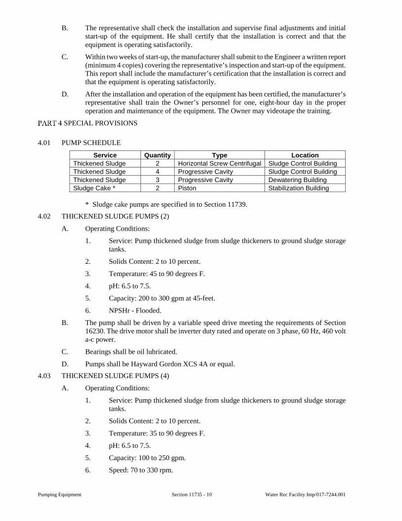
Pumping Equipment Section 11735 - 10 Water Rec Facility Imp/017-7244.001
B. The representative shall check the installation and supervise final adjustments and initial start-up of the equipment. He shall certify that the installation is correct and that the equipment is operating satisfactorily.
C. Within two weeks of start-up, the manufacturer shall submit to the Engineer a written report (minimum 4 copies) covering the representative’s inspection and start-up of the equipment. This report shall include the manufacturer’s certification that the installation is correct and that the equipment is operating satisfactorily.
D. After the installation and operation of the equipment has been certified, the manufacturer’s representative shall train the Owner’s personnel for one, eight-hour day in the proper operation and maintenance of the equipment. The Owner may videotape the training.
SPECIAL PROVISIONS
4.01 PUMP SCHEDULE
Service Quantity Type Location
Thickened Sludge 2 Horizontal Screw Centrifugal Sludge Control Building
Thickened Sludge 4 Progressive Cavity Sludge Control Building
Thickened Sludge 3 Progressive Cavity Dewatering Building
Sludge Cake * 2 Piston Stabilization Building
* Sludge cake pumps are specified in to Section 11739.
4.02 THICKENED SLUDGE PUMPS (2)
A. Operating Conditions:
1. Service: Pump thickened sludge from sludge thickeners to ground sludge storage tanks.
2. Solids Content: 2 to 10 percent.
3. Temperature: 45 to 90 degrees F.
4. pH: 6.5 to 7.5.
5. Capacity: 200 to 300 gpm at 45-feet.
6. NPSHr - Flooded.
B. The pump shall be driven by a variable speed drive meeting the requirements of Section 16230. The drive motor shall be inverter duty rated and operate on 3 phase, 60 Hz, 460 volt a-c power.
C. Bearings shall be oil lubricated.
D. Pumps shall be Hayward Gordon XCS 4A or equal.
4.03 THICKENED SLUDGE PUMPS (4)
A. Operating Conditions:
1. Service: Pump thickened sludge from sludge thickeners to ground sludge storage tanks.
2. Solids Content: 2 to 10 percent.
3. Temperature: 35 to 90 degrees F.
4. pH: 6.5 to 7.5.
5. Capacity: 100 to 250 gpm.
6. Speed: 70 to 330 rpm.
Water Rec Facility Imp/017-7244.001 Section 11735 - 11 Pumping Equipment
7. Head: 30 psi maximum.
8. Suction Conditions: NPSHr - 17-feet.
B. The pump shall be driven by a variable speed drive meeting the requirements of Section 16230. The drive motor shall be inverter duty rated and operate on 3 phase, 60 Hz, 460 volt a-c power.
C. Pumps shall be Seepex SCT BN 70 or equal.
4.04 THICKENED SLUDGE PUMP (3)
A. Operating Conditions:
1. Service: Pump thickened sludge from ground sludge storage tanks to centrifuges.
2. Solids Content: 2 to 10 percent.
3. Temperature: 35 to 140 degrees F.
4. pH: 6.5 to 7.5.
5. Capacity: 80 to 250 gpm.
6. Speed: 100 to 330 rpm.
7. Head: 30 psi maximum.
8. Suction Conditions: Flooded.
B. The pump shall be driven by a variable speed drive meeting the requirements of Section 16230. The drive motor shall be inverter duty rated and operate on 3 phase, 60 hertz, 460 volt AC power.
C. Pumps shall be Seepex SCT BN 70 or equal.
4.05 SEAL WATER CONNECTIONS
A. See Section 15211 for seal water connections.
END OF SECTION

Pumping Equipment Section 11735 - 12 Water Rec Facility Imp/017-7244.001
This page was intentionally left blank.
Water Rec Facility Imp/017-7244.001 Section 11739 - 1 Sludge Cake Pumping Equipment
SECTION 11739
SLUDGE CAKE PUMPING EQUIPMENT
GENERAL
1.01 SCOPE
A. This Section includes design, fabrication, shipping, handling, and installing two sludge cake pumping systems, consisting of:
a. Hydraulically driven twin cylinder piston pumps.
b. Hydraulic power units.
c. Twin auger screw conveyor feeder with hoppers.
d. Control panels.
2. Equipment complete with hydraulic drives driven by electrical motors and appurtenance, as specified.
3. Additional product requirements are specified in Section 01350.
B. The pumping equipment shall be furnished with all drives, drive shafts, couplings, steady bearings, belts, drive shaft and belt guards, drive bases, pump bases, anchor bolts, anchor bolt sleeves, and other appurtenances as specified or required for a complete installation and satisfactory operation.
C. All work performed under this Section shall be in accordance with all approved trade practices and manufacturers’ recommendations.
1.02 SUBMITTALS
A. Submittals shall be in accordance with the requirements of Section 01300 and shall include:
a. Shop Drawings: Manufacturer’s warranty.
b. Manufacturer’s literature including performance information.
c. Information and data concerning the materials of construction, salient components and details of construction of equipment and components.
d. Motor data in accordance with Section 11050.
e. General dimensions drawings.
f. Manufacturer certification/affidavit.
g. Manufacturer’s certified test curves (computer model printouts are not acceptable).
2. Information for the Record:
a. Manufacturer’s installation instructions.
b. Manufacturer’s operation and maintenance manuals.
c. Manufacturer’s certification of installation.
1.03 QUALITY ASSURANCE
A. Manufacturer Warranty and Service Packages:
1. Warranty Submittals:
a. At the time of shop drawing submittal, the Contractor shall submit a written warranty from the manufacturer(s) covering workmanship and materials on the pumps when used as intended for this installation.
Sludge Cake Pumping Equipment Section 11739 - 2 Water Rec Facility Imp/017-7244.001
Warranty period shall be two years. The warranty period shall commence on the date of Substantial Completion. Under terms of this warranty, the manufacturer shall furnish and install all replacement parts for any defective component at no cost to the Owner. The provisions of this warranty shall not be construed as relieving or reducing the obligations of the Contractor outlined in the General Conditions of these Specifications.
2. Owner shall have the option to purchase additional manufacturer warranty options and service package plans, for a cost. Contractor shall provide, upon request, the warranty and service plan information and their respective cost.
3. Warranty options should include, but not be limited to:
a. Pro-rated warranties, terms and conditions, and length of time.
b. A full replacement (non-prorated) warranty, terms and conditions, for time frames up to 5 years.
c. Service package plans.
B. Manufacturer Certification/Affidavit:
1. Manufacturer shall provide affidavit certifying that:
a. Manufacturer has examined the Contract Documents, including but not limited to the Drawings and specifications.
b. Understand the installation and parameters specified herein and shown on the Drawings.
c. The equipment specified is suitable for this application.
d. Notified Owner and Engineer of any modifications required to the system or the equipment in this application.
PRODUCTS
2.01 PUMPS
A. General:
1. Each pump shall be designed and furnished to meet the operating conditions specified in this Section. Each pump shall be of the manufacturer listed in this Section. All pumps used for one type of service shall be of the same manufacturer.
2. Each pump shall be shop tested in accordance with standards of the Hydraulic Institute. Certified test curves indicating capacity, head, efficiency, brake horsepower, and speed shall be submitted to the Engineer for approval. No pump shall be shipped to the job site until the test curves have been approved by the Engineer.
3. No point on the pump performance curve shall require more than the nameplate horsepower of the drive motor.
4. Subject to compliance with the Contract Documents, the following manufacturers are acceptable:
a. Putzmeister America, Inc., Schwing Bioset, Inc., or equal.
5. Performance and Configuration Requirements:
a. Sludge Cake Pumps:
1) Quantity: Two.
2) Pump Type: Twin-cylinder reciprocating piston pump.
Water Rec Facility Imp/017-7244.001 Section 11739 - 3 Sludge Cake Pumping Equipment
3) Design Operating Pressure: 1,000 psi.
4) Pumping Stroke Length: 63 inches.
5) Material Cylinder Diameter: 9 inches
6) Cake Pumping Conditions:
i) Sludge Cake:
i. Biosolids Concentration: 22-27 percent DS.
ii. Design Flowrate: 50 gpm.
iii. Maximum Flowrate: 120 gpm.
b. Twin Auger Screw Feeder:
1) Quantity: Two.
c. Hydraulic Power Unit:
1) Quantity: Two.
2) Reservoir Size: 315 gallons minimum.
3) Motor Size: 200 hp maximum.
d. Control Panel:
1) Quantity: Two.
2) Material: 304 Stainless Steel.
3) Rating: NEMA 4X.
B. Sludge Pumps:
1. Two self-priming twin-cylinder, reciprocating piston pumps of carbon steel construction, suitable for pumping dewatered biosolids, with near continuous delivery rate, equipped with the following components:
a. Twin pumping cylinders.
b. Water box.
c. Twin hydraulic power cylinders.
d. Pistons.
e. Two each suction and discharge poppet valves.
f. Four hydraulic valve cylinders.
g. Hydraulic valve block.
h. 3-position control valve.
i. Sludge Flow Measuring System.
2. Delivery Cylinder:
a. Provide steel delivery cylinders with inner hard-chrome plated surface and honed for low friction losses.
b. The delivery and differential cylinders are to be separated by a water box through which water can be flushed to clean and cool the delivery cylinders.
c. Material cylinders shall be positioned one above the other in a vertical plane configuration to facilitate feeding the pump from the side.
Sludge Cake Pumping Equipment Section 11739 - 4 Water Rec Facility Imp/017-7244.001
d. Provide easily replaceable piston heads made of BUNA-N or suitable material for the application.
3. Poppet Valve Assembly:
a. Transfer of the pumped product from the suction side via the material cylinder to the conveying line is achieved by a poppet valve assembly. The poppet valve assembly shall consist of two valve discs and seats housed in either a suction valve chamber or a pressure valve chamber. The valve shall be opened and closed by means of a hydraulic valve chamber. Poppet valve discs and seats shall have a minimum hardness of 55 RC.
b. At the end of a pumping stroke, reversal of the valves takes place in such a manner that the formerly open valve is closed and the closed valve is reopened. This opening cannot occur until there is a greater pressure on the cone side of the poppet valve. The sequence of valve operation shall insure that no back flow of pumped material from the pressurised discharge side to the low pressure suction side can occur, thereby eliminating shock introduction into the pump, pipeline and support system.
c. The poppet valve must be designed to have sacrificial poppet valve discs and seats that are easily replaced. Pump valve designs which allow the compressed biosolids in the discharge pipeline to flow in reverse (backflow) into the pump at the moment when valves shift from one cylinder to the other are not acceptable (i.e., rock valves, swing tube valves, ball check, or other designs are not acceptable).
4. Water Box:
a. A water box, with watertight cover and safety screen, shall provide cooling water for the piston rod and lubrication of the piston head while it is reciprocating. A water box reservoir extension shall be supplied to accept water displaced on the suction stroke. Water inlet and discharge connections shall be provided.
b. Water box shall include water connections for feed and drain. The fill connection shall be located near the top of the Water box and shall be a one inch NPT connection. The Water box drain shall be located at the bottom of the Water box and shall be a 1-1/2 inch NPT connection. Water box connections shall be easily accessible.
5. Control Block:
a. A main control block shall control material piston and poppet valve position. The main control block shall consist of no more than three control valves.
1) S-1:
a) A three-position forward, neutral, and reverse lever operated.
2) S-2:
a) A two-position directional spool to direct oil flow to the hydraulic piston, pilot pressure operated.
3) S-3:
a) A two-position directional spool to direct oil flow to the poppet valves, pilot pressure operated. Hydraulic valve
Water Rec Facility Imp/017-7244.001 Section 11739 - 5 Sludge Cake Pumping Equipment
blocks that utilize more than three control valves are not acceptable.
b. Hydraulically activated switching of all moving components shall be required insuring positive shifting at all times and eliminating the need for stroke adjustment.
c. The design of the hydraulic controls shall make require three connection lines between the power unit and the pump necessary. The lines shall provide for hydraulic feed, return, and a hydraulic overflow drip line. Positioning of poppet valves with the use of solenoids, magnetic position sensors or limit switches is not acceptable.
6. Mounting:
a. The pumping unit is mounted on a steel base equipped with wheels to allow for pumping unit removal and maintenance.
b. Pump suction and discharge components shall be accessible for maintenance and replacement. Pump discharge connection shall be hinged
2.02 SLUDGE FLOW METERING SYSTEM
A. The pump manufacturer shall supply a sludge flow measurement system for each pump that shall accurately measure to minus or plus 5 percent, as required by EPA regulation 503 subpart ‘O’, the amount of material that is being conveyed by the pump unit.
1. The volume flow measuring system shall measure the time T1 (the time from the beginning of the pumping stroke until the time that pressure has built up to a point where the pressure of the biosolids overcomes the discharge pressure, so that the discharge poppet opens and allows the material to be pumped) and time T2 (the total time during which the material is being pumped out of the material cylinder).
2. The filling efficiency shall be determined with every stroke of the pump by the ratio of T2/(T1 + T2). When this efficiency is compared with the fixed volume of the pump material cylinder, the volumetric measure of the pumped material shall be determined accurately on every stroke.
3. The volume flow measuring system shall be composed of poppet valve pressure sensors and a programmable logic controller (PLC) with a built-in clock. The PLC shall be located within the piston pump system control panel.
4. A poppet valve pressure sensor shall sense when the discharge poppet valves open and close during the pumping stroke based on pressure and each shall deliver a signal to the PLC. All wiring between pump components and PLC shall be furnished and installed.
5. The PLC shall receive the information signals from the pressure sensors and shall determine the filling efficiency – in percent, total accumulated volume pumped for any selected time variable, instantaneous pumping rate and average pumping rate. These parameters shall be displayed on the respective piston pump system control panel.
6. Magnetic flow meters and stroke counters will not be considered as an equivalent flow measuring system.
7. The PLC shall be capable of having the density of material pumped manually inputed and a wet weight of material conveyed computed. PLC shall allow an infinite number of density inputs and shall use the most current value in the calculation.
Sludge Cake Pumping Equipment Section 11739 - 6 Water Rec Facility Imp/017-7244.001
8. PLC shall have a 4-20 mAmp output for connection to the DCS for inputed density, volume of material pumped and wet weight of material pumped.
2.03 SLUDGE PUMP TWIN AUGER SCREW CONVEYOR FEEDER
A. Provide one self-cleaning twin screw auger feeder, hydraulic motor, gear box, and bearings to feed each piston pump. Inlet opening shall be approximately 24 inches by 120 inches.
1. The screw feeder shall be provided with casters and a jacking mechanism to mate the flanges at the top or lower the whole conveyor as a unit to enable it to be moved to an open area for maintenance.
2. The screw feeder shall be a combination of two intermeshing full flight augers with a minimum flight thickness of 1/4-inch and 14-inch nominal diameter. The screw feeder flights shall be continuously welded to a pipe shaft. The screw feeder shall be a single fabricated unit designed to convey biosolids continuously into the biosolids pump inlet housing. The unit shall be constructed of ASTM A36 steel. A minimum of one and one half pitch lengths of the twin screws must be completely contour shrouded in the suction housing to the biosolids pump. Material cylinders shall be positioned one above the other in a vertical plane for side feed of the pump. Alternate feed configurations are not acceptable and will not be considered.
3. The screw feeder shall be supported at the drive end by grease lubricated bearings installed in the screw feeder gear box and at the tail end by outboard grease lubricated bearings. The entire rotating assembly shall be designed to provide continuous duty under all anticipated load conditions. The hydraulic drive motor shall be coupled directly to the gear box.
4. An automatic grease system shall be provided for the twin screw feeder to feed grease to the bearings at timed intervals. Automatic grease system shall be a QLS401 as manufactured by Lincoln.
5. The hydraulic power unit shall drive the twin screw auger. The auger feeder shall be equipped with a hydraulic motor, necessary control equipment and three position actuating lever for auger control (forward/stop/reverse). Lever shall be located on the screw feeder.
6. The screw feeder shall be bolted to the pump casing flanged connection. The faces of the screw feeder and the pump at the point of connection shall be machined and furnished with O-rings.
7. Screw feeder housing screws and shafts shall be constructed of A36 steel.
8. The screw feeder shall be mounted on a base frame, at the same horizontal level as the pump. Minimum thickness of screw conveyor tub and transition shall be 1/4-inch.
9. Transition housing of screw feeder shall be equipped with a strain gauge style pressure sensor with a one inch ceramic sensing surface configured for 0 to 30 psi service. Sensor shall transmit a 4-20 mA signal back to the pump control panel. When set in an Auto control mode, the screw shall vary speed to maintain a constant transition pressure as read by the sensor.
10. One hopper shall be provided per pump and each pair of screw feeders shall feed the hopper as detailed on the Drawings. Hopper shall be of stainless steel construction and be equipped with radar level detection to control pump output. Hoppers shall have removable covers of the same material. Minimum total hopper volume shall be 225 cubic feet.
Water Rec Facility Imp/017-7244.001 Section 11739 - 7 Sludge Cake Pumping Equipment
2.04 HYDRAULIC POWER UNIT
A. The hydraulic power unit for driving the piston pump, poppet valve actuation and twin screw auger shall be a completely self-contained, factory assembled unit. The frame shall be made of welded steel construction adequate to support all components and designed to be anchored to a suitable base.
1. The hydraulic power units shall contain the following items:
a. Electric motor - TEFC squirrel cage induction motor suitable for 480 V, 3-phase, 60 Hz.
b. Hydraulic system consisting of the following:
1) Main hydraulic pump, with infinitely variable displacement volume, to power the biosolids pump.
2) Auxiliary hydraulic pump, with infinitely variable displacement volume, to power the screw conveyor for the Biosolids Pumps.
3) Water / oil cooler.
4) Oil reservoir (minimum volume – 1,100 liters), hydraulic piping, hoses, and control valves.
5) Return oil filter and adjustable relief valve.
6) Oil pressure gauges.
7) Oil reservoir fill connection.
8) Initial fill of hydraulic oil (Texaco-Rando 46).
9) One clean out cover, one oil temperature and level indicator, one 3/4-inch reservoir drain with shut-off valve, and one filter-breather assembly.
10) High temperature switch.
11) Oil reservoir shall be baffled in two sections.
c. Output is controlled by a hydraulic compensator with proportional solenoid.
d. Control panel complete with electrical control equipment such as transformers, auxiliary switches, relays and programmable logic controller (PLC).
e. Motor power factor correction capacitor.
f. All hydraulic lines required to connect the hydraulic power unit to the pumping assembly and feeder shall be provided by the pump manufacturer. Hydraulic lines shall be seamless carbon steel hydraulic tubing with flexible hose connections having ball valves to permit connection and disconnection at the unit. Tubing shall be rated for 5,000 psig continuous operation.
g. Positioning of differential cylinders and poppet valves shall be accomplished hydraulically. The use of proximity switches to control their position is not acceptable.
h. The power unit shall be mounted on a carbon steel frame.
2. Flexible hose from the hydraulic power unit from the pump shall be provided by the pump manufacturer. Manufacturer shall provide 30 feet of hose in both locations. Manufacturer shall provide a drip tray under all elevated sections of hydraulic hose connected to a central drain.
Sludge Cake Pumping Equipment Section 11739 - 8 Water Rec Facility Imp/017-7244.001
2.05 MAIN CONTROL PANEL
A. One NEMA 4X panel enclosure to control the twin screw feeder, piston pump, hydraulic power unit shall be provided for each pump. Panel enclosure shall be factory mounted to the hydraulic power unit.
B. Panel shall be suitable for connection to a 480 volt, 3-phase, 60 Hertz power. A front mounted breaker disconnect with handle shall be provided.
C. One power transformer for 120 volt, 1-phase, 60 Hertz Auxiliary control power.
D. The PLC shall be an Allen Bradley Micrologix with a Panelview 1000 color touch screen operator.
E. Interface with Plant control via Ethernet protocol.
F. Panel shall include UL approval.
G. Operator interface shall include the following functions.
1. Power Unit OFF / ON.
2. Local/Off/Remote selector for the pumping unit. In the Remote mode, the pump and auger feeder will operate from OWNER’s operating SCADA system. In Local mode, it will be controlled at the equipment control panel.
3. Pump flow set point mode, LOCAL / REMOTE.
4. Pump flow set point.
5. Screw feeder operating mode: MANUAL / AUTO.
6. LOAD / BYPASS selector.
7. Alarm Reset.
8. INCREASE / DECREASE Pump speed control.
9. INCREASE / DECREASE Screw Feeder speed control.
H. Operator interface shall have Imperial units of feet, inches, degrees Fahrenheit, pounds, pounds per square inch.
I. Date format shall be MM/DD/YYYY.
J. The control panel will include the following indicators:
1. Motor OFF / ON.
2. Pump status: BYPASS / PUMPING.
3. Motor overheat shutdown.
4. Motor over-current indication.
5. Low oil level indication
6. High oil temperature indication.
7. High oil pressure indication for Pump and Screw Feeder.
8. Dirty oil indication.
9. Panel power ON.
10. Screw Feeder speed, 0 to 100 percent.
11. Screw Feeder transition pressure, 0 to 30 psi.
12. Pump output, 0 to 120 gpm.
13. Elapsed time meter.
Water Rec Facility Imp/017-7244.001 Section 11739 - 9 Sludge Cake Pumping Equipment
14. Ammeter.
15. Audible alarm.
K. A copy of the program shall be turned over to the City at the start of commissioning. This program copy shall allow the City to edit parameters and re-load the software as required. Any alteration to the programming by the City shall void the entire equipment warranty.
2.06 LUBRICATION SYSTEM
A. A triplex plunger pump with cast body shall be provided with each pump. Suction and discharge of the plunger pump shall have dual ball check valves and 1/2-inch NPT connections.
B. Plunger pump motor shall be TEFC, 480 V, 3-phase, 60 Hz, a minimum of 1 horsepower and a Mill and Chemical duty premium efficient motor.
C. Pump shall be provided with the following accessories: Suction side piping with a sight flow indicator and a bronze body wye strainer with 20 mesh screen. Discharge piping to include a ductile iron body, adjustable pressure relief valve, back pressure valve, pulsation dampener and an oil filled, 2-inch, 0 to 2,000 psig pressure gauge. Relief valve to be set at 1,000 psig. Back pressure valve to prevent water from flowing through the pump head when the pipeline is at low pressure, back pressure valve will be set at 110 psig. Pulsation dampener will be bladder type with an elastomeric bladder. Dampener will be pre-charged to 485 psig with nitrogen. Suction side piping will also include valved connections for the calibration column. Field piping connections will include unions, flanges, and/or hoses to facilitate maintenance.
D. One calibration column shall be supplied with each lubrication system.
E. Lubrication pump shall receive a SSPC-SP6 commercial sandblast, conforming to Section 2.08.
F. Injection ring shall be two piece 304 stainless steel, spool type, full ported with O-ring seals and equipped with a steel lifting handle. Fluid will enter the 360 degree annular opening via a minimum of three entry ports. Each entry port to be equipped with a check valve to prevent back-flow of the lubricant. Hoses, fittings, valves, piping and ring shall be rated for a continuous working pressure of 1,500 psig.
G. The lubrication system to be controlled by a Manual-Auto selector switch on the main pump control panel. In a manual mode, the lube pump will be started and stopped by start-stop push-buttons. In an Auto mode, the lubrication pump will automatically start on high pipeline pressure setting and stop on low pipeline pressure setting. High and low pipeline pressure settings may be accessed through a service menu on the lubrication system master control panel, Human-Machine Interface. Speed control of the lube pump will be set manually.
H. Pressure sensors shall be provided to be located immediately downstream of the pipeline lubrication rings. Transducers will have a ceramic sensing surface. Sensors will send a 4-20 mA signal back to the lubrication control panel. Sensors in the biosolids line will be configured to transmit a 0 to 1,500 psig signal; screw feeder sensors will transmit 0 to 450 psig.
I. A NEMA 4X control panel shall be included to provide control functions for both lubrication systems.
J. All materials and tubing for connections shall be provided by the manufacturer.
2.07 MATERIALS
A. Hydraulically Driven Piston Pump:
1. Housing; Carbon Steel, ASTM 36.
Sludge Cake Pumping Equipment Section 11739 - 10 Water Rec Facility Imp/017-7244.001
2. Piston pump delivery cylinder; Hard Chrome Plated Steel.
a. Chrome plating shall be 0.4 mm minimum thickness.
3. Anchor bolts, nuts and washers; type AISI 304 SS.
B. Twin Screw Feeder:
1. Housing (trough): Carbon Steel, ASTM 36.
2. Screw feeder shafts; Carbon Steel, ASTM 36.
3. Screw feeder chute; AISI 304 SS.
C. Manufacturer’s standard assembly and anchor bolts, nuts, and washers: Stainless steel, AISI 304.
D. Shop painting shall be in accordance with the requirements of Section 01350.
2.08 PAINTING
A. Surface Preparation – Sandblast SSPC-SP6.
B. 1st Coat – Red oxide primer, 2-3 mils DFT.
C. 2nd Coat – Tnemec series 135 polyamide epoxy, 2-4 mils DFT.
D. 3rd Coat – Tnemec series N69 polyamide epoxy, 2-4 mils DFT.
2.09 SPARE PARTS
A. Furnish the following extra parts:
1. Two sets of hydraulic oil filters (The original oil filters shall be replaced after 50 hours of service.)
2. Two sets of poppet valve discs and seats.
3. Two sets of material rams.
EXECUTION
3.01 OTHER DUTIES
A. Manufacturer shall provide manpower for the following duties:
1. Installation supervision.
2. Startup assistance.
3. Training.
4. Service interval training
a. Training at the end of the 12 month service interval shall be carried out by the Manufacturer or Manufacturer’s representative. The City reserves the right to record this service training for internal use.
SPECIAL PROVISIONS
None.
END OF SECTION
Water Rec Facility Imp/017-7244.001 Section 14300 - 1 Hoists and Cranes
SECTION 14300
HOISTS AND CRANES
GENERAL
1.01 SCOPE
A. This Section includes the furnishing and installation of cranes and hoisting equipment, track systems, and associated equipment.
B. All installations shall be complete and comply with manufacturer’s erection details and applicable OSHA regulations.
C. Additional product requirements are specified in Section 01350.
1.02 QUALITY ASSURANCE
A. Suppliers of cranes, hoists, and monorails shall be nationally recognized manufacturers specializing in these products.
B. Design loads and fabrication of all structural members shall be in accordance with the latest recommendations of the Crane Manufacturers Association of America (CMAA) and Monorail Manufacturers Association (MMA).
1.03 SUBMITTALS
A. Submittals shall be in accordance with the requirements of Section 01300 and shall include:
1. Shop Drawings for Review:
a. The Contractor shall indicate all variances from the requirements of the Contract Documents.
2. Operation and Maintenance information.
PRODUCTS
2.01 RUNWAY AND MONORAIL TRACK SYSTEM
A. Track shall be standard structural shape of size indicated on Drawings. Bottom flange shall be straight and true, and projections shall be ground smooth.
B. Holes shall be shop punched or drilled. Cutting holes with electric arc or gas torch is prohibited.
C. Splices shall be made with bolted splice plates. Maximum gap between track sections shall be 1/16-inch.
D. End stops shall be of bolted design. End stops shall be suitably located to prevent hoist or crane from contacting structure, piping, or other equipment.
E. Unless shown otherwise, track shall be attached to supporting structure with standard suspension fittings spaced as shown on Drawings. Clamps, hanger, rods, bolts, washers, and other accessories shall be furnished as required for a complete system.
1. Fittings shall allow for 1-inch vertical adjustment of track before and after system has been put into operation.
2. Fittings shall permit a 5 degree movement in all directions. Track shall be laterally and longitudinally braced to prevent excessive sway.
3. Hanger rod shall be furnished with spherical nuts and spherical seats. Nuts shall have set screw or other means to prevent nut from backing off rod.
Hoists and Cranes Section 14300 - 2 Water Rec Facility Imp/017-7244.001
4. Bolts shall conform to ASTM A325, Type 1 with heavy hex nuts.
2.02 RESERVED
2.03 CARRIERS OR TROLLEYS
A. Carrier yokes shall be of the swiveling type. Wheels shall be drop forged or rolled steel with heat treated treads and flanges or cast iron with chilled tread and shall have a minimum tread hardness of 425 Brinell.
B. Wheel bearings shall be single or double row, combination radial and thrust, anti-friction precision type. Bearings shall be prelubricated and sealed or provided with fittings and seals for pressure lubrication.
C. Bearings shall be selected to provide a minimum B-10 life of 5,000 hours for moderate service - Class C, and 10,000 hours for heavy duty service - Class D, as called for on the crane schedule in Part 4 of this Section.
D. Motor propelled carriers shall be driven by a driving head mounted on the load bar of the load carrying member with traction dependent on the wheel load of the driving heads.
E. All gearing shall be made from material of adequate strength or durability to meet the requirements for the intended service class. All gearing except the final reduction at wheels shall run in oil or be splash lubricated.
F. Stops shall be provided at the ends of the carrier and crane travel. Stops shall be provided to resist impact forces of a fully loaded carrier or crane traveling at a normal walking speed or at 50 percent of the rated full load speed, if the carrier or crane is motor driven.
2.04 CRANES - UNDERHUNG
A. Cranes shall be manually or motor propelled, and operate on two runways.
B. Crane girders shall be designed in accordance with MMA Specifications - Section 2, except the ratio of crane span to top flange width of 60 to 1 is not applicable to girders for cranes where the top flange of the girders is braced.
C. Wheel yokes shall be of the swiveling type. End truck load bars shall be cradled in yokes.
D. Lugs shall be provided on end trucks to limit drop of the end truck to 1-inch or less in the event of wheel or axle failures. Lugs shall be located on both sides of the track load carrying flange to provide central loading of the track about the vertical axis if failure occurs.
E. Ratio of crane span to end truck wheelbase shall not exceed 10:1.
F. Motor propelled cranes shall be driven by individual driving heads of tractor drives mounted on or attached to two or more end trucks. Drives shall be in accordance with the provisions of Subsection 2.02.
2.05 BRAKES
A. Hoisting brakes shall be in accordance with Hoist Manufacturers Institute Specifications Section 100-4.9 and ANSI B30.16 Safety Code for Overhead Hoists.
B. If brakes are supplied for carrier and crane travel, they may be applied by mechanical, electrical, pneumatic, hydraulic, or gravity means. Brakes shall be provided with adjustment to compensate for wear.
2.06 ELECTRICAL EQUIPMENT
A. Wiring and equipment shall comply with the provisions of Article 610, ANSI C-1 National Electric Code, current edition.
B. Power for motors shall be 460 volts, 3 phase, 60 Hz.
C. Power for control circuits shall not exceed 120 volts, single phase, 60 Hz.
Water Rec Facility Imp/017-7244.001 Section 14300 - 3 Hoists and Cranes
D. Unless otherwise specified, all functions on floor operated equipment shall be from a common pendent pushbutton station. The pushbutton station shall be suspended approximately 4-feet above the operating floor in a manner that will protect the electrical conductors against strain. Functions on cab controlled equipment shall be from master switches or pushbuttons.
E. Motors shall be rated on not less than a 30-minute basis with temperature rise in accordance with the latest NEMA standards for the class of insulation and enclosure used, unless otherwise specified.
F. Motors shall be of the type suitable for crane and hoist service and shall be provided with anti-friction bearings.
G. Control systems may be magnetic, solid state, static, or in combination as specified. Crane and carrier controls shall be plain reversing unless otherwise specified. All reversing contactors shall be mechanically and electrically interlocked. Unless otherwise specified, controls shall be mounted in NEMA Type 1 general purpose enclosures.
H. Magnetic control shall have contactors of sufficient size for crane and hoist duty consistent with the horsepower and voltage of the motor or motors with which they are used.
I. Solid state power components such as thyristors, diodes, etc., shall be rated in accordance with the horsepower, voltage, and time ratings of the motor or motors with which they are used.
J. Static power components such as rectifiers, reactors, etc., as required, shall be rated in accordance with the horsepower, voltage, and time ratings of the motor or motors with which they are used.
K. Carriers and cranes with squirrel cage motors and single speed control should be provided with reduced torque starting through the use of solid state devices, autotransformers, resistors, or fluid couplings.
L. Carriers and cranes with squirrel cage motors and multi-speed control should be provided with reduced torque in starting and changing from one speed to the other. Reduced torque may be provided through the use of solid state devices, autotransformers, resistors, or fluid couplings.
M. Controls for carriers and cranes with wound rotor motors shall have a minimum of two acceleration contactors and a minimum of three speed points.
N. Carriers and cranes with DC motors shall have single speed or variable speed control in accordance with the provisions of Sections 12.6.4 and 12.6.6 of MMA Specifications.
O. Where more than one motor is employed on a crane, each motor shall have individual over current protection except that where two or more motors operate a single carrier or crane and are controlled as a unit by one controller, the motors with their leads may be protected by a single over current device.
P. A motor-circuit switch or circuit breaker shall be provided in the leads from the runway contact conductors on all electrically powered cranes. Where this disconnecting means is not readily accessible from the crane operating station, means shall be provided at the crane operating station to open the power circuit to the crane motors except as specified in the current edition, Article 610 of ANSI C-1 National Electric Code.
Q. The continuous ampacity of the motor-circuit switch or circuit breaker required by Section 12.7 of the MMA Specifications shall be not less than 50 percent of the combined short-time ampacities of the motors, nor less than 75 percent of the sum of the short-time ampacities of the motors required for any single crane operation.
Hoists and Cranes Section 14300 - 4 Water Rec Facility Imp/017-7244.001
R. All cranes using a lifting magnet shall have a magnet circuit switch of the enclosed type with provisions for locking in the open position. Means for discharging the inductive load of the magnet shall be provided.
2.07 ELECTRIFICATION
A. Where electrical equipment operates on a system, power shall be supplied by means of enclosed rigid type contact conductors mounted parallel to the track. Conductors shall comply with the provisions of Article 610, ANSI C-1 National Electric Code. Flexible cable may be used in lieu of rigid type contact conductors when specified.
B. Ampacity of contact conductors shall be sized to carry the required current to the crane, or cranes, when operating with rated load.
C. Collectors shall be of the shoe type and shall be designed to reduce to a minimum sparking between shoe and the contact conductor.
2.08 HOISTS
A. All hoists are specified in Part 4.
EXECUTION
3.01 ERECTION
A. The cranes and hoisting equipment and controls shall be erected in accordance with the manufacturer’s recommendations.
3.02 INITIAL LUBRICATION
A. Initial lubrication required for start-up and field test operation shall be furnished and applied in accordance with the manufacturer’s recommendations.
3.03 RESERVED
3.04 INSPECTION, START-UP, AND TRAINING
A. The Contractor shall furnish a qualified representative of the manufacturer to perform inspection, start-up, and training services. The manufacturer’s representative shall be experienced in the installation, start-up, operation, and maintenance of the equipment.
B. The representative shall check the installation and supervise initial start-up of the equipment. He shall certify that the installation is correct and that the equipment has operated satisfactorily. This service shall be a minimum period of one trip and one day.
C. After installation is complete, all new, reinstalled, altered, repaired, or modified equipment shall be tested as follows:
1. Underhung Cranes shall be tested in accordance with the provisions of ANSI B30.2.0 Safety Standards for Overhead and Gantry Cranes.
2. Hoists shall be tested in accordance with the provisions of ANSI B30.16 Safety Standards for Overhead Hoists.
D. Within two weeks of start-up, the manufacturer shall submit to the Engineer a written report (minimum 4 copies) covering the representative’s inspection and start-up of the equipment. This report shall include the manufacturer’s certification that the installation is correct and that the equipment is operating satisfactorily.
E. After the installation and operation of the equipment has been tested and certified, the manufacturer’s representative shall train the Owner’s personnel for one eight-hour day in the proper operation and maintenance of the equipment. The Owner may video tape the training.
Water Rec Facility Imp/017-7244.001 Section 14300 - 5 Hoists and Cranes
SPECIAL PROVISIONS
4.01 CRANE SCHEDULE
A. With the exception of the capacity indicated, dimensions and elevations provided below are approximate and shall be used only in preparation of the bid. Field measurements shall be used to determine the actual dimensions.
B. Fine Screen Building:
1. One 1/4-ton Capacity Single Girder Underhung Crane.
2. Span: See Drawings.
3. Manual Bridge and Trolley.
4. Manual Hoist.
5. Class C.
C. Stabilization Facility:
1. One 10-ton Capacity Single Girder Underhung Crane.
2. Span: 17-feet-0-inch.
3. Motorized Bridge and Trolley.
4. Motorized Hoist at 24 fpm.
5. Power from Cable Reel - Pendent Pushbutton Control Station.
6. Class C.
END OF SECTION

Hoists and Cranes Section 14300 - 6 Water Rec Facility Imp/017-7244.001
This page was intentionally left blank.
Water Rec Facility Imp/017-7244.001 Section 14552 - 1 Centrifuge Shaftless Screw Conveyors
SECTION 14552
SHAFTLESS SCREW CONVEYORS
GENERAL
1.01 SCOPE
A. This Section includes design, fabrication, shipping, handling, and installing of six shaftless screw conveyors, complete as shown on the Drawings and specified herein.
B. Five screw conveyors shall be installed in the Stabilization Building to transfer centrifuged, dewatered solids. One screw conveyor shall be installed in the Bar Screen Building to transfer screenings.
C. Each screw conveyor unit shall consist essentially of flighting, trough, trough ends, bearings, seals, inlet and discharge ports, drive, gates and supporting steel together with any other items required for a complete conveying system.
D. Additional product requirements are specified in Section 01350.
1.02 SUBMITTALS
A. Submittals shall be in accordance with the requirements of Section 01300 and shall include:
1. Shop Drawings:
a. All information submitted with Bid with corrections.
b. Fabrication drawings.
c. The Contractor shall indicate all variances from the requirements of the Contract Documents.
d. Plan and Elevation Drawings.
e. List of accessories and appurtenances.
f. Motor data in accordance with Section 11050.
2. Information for the Record:
a. Installation certificate.
b. Operation and Maintenance Manual information.
1.03 QUALITY ASSURANCE
A. Manufacturer:
1. It is the intention of the specifications to cover minimum acceptable quality equipment for a complete installation.
2. The conveyors shall be as manufactured by Jim Myers & Sons, Inc., KWS Manufacturing Company Ltd., Custom Conveyors or equal.
B. Warranty:
1. The shaftless screw liner and spiral shall be warranted for a period of three years from factory start-up against wear.
a. Liner:
1) For a wear indicator (two color) liner, excessive wear shall be indicated by appearance of the bottom indicator layer (second color) along more than 30 percent of the conveyors length during the first three years of service. If these wear indications occur the
Centrifuge Shaftless Screw Conveyors Section 14552 - 2 Water Rec Facility Imp/017-7244.001
conveyors supplier shall provide new formed and banded liner to replace all the liner in the conveyors that has excessive wear.
b. Screw:
1) Excessive wear on the screw shall be indicated by loss of more than 50 percent of the height of the main outer screw section over 30 percent of the total length of the screw. If excessive screw wear is found the conveyors supplier shall provide new screw to replace the screw in the conveyors that has excessive wear.
PRODUCTS
2.01 DESIGN CRITERIA
A. General:
1. Conveyors shall be a minimum of 14-inch diameter, shaftless flight, U-trough design.
2. Five conveyors shall be designed to handle dewatered sludge containing 18 to 25 percent dry solids from centrifuges. to the cake pump live bottom hoppers. Three shall be designed to handle cake at a rate of 618 total cake pounds per minute. Two cross conveyors shall be designed to handle cake at a rate of 1,236 pounds per minute. The single screenings conveyor shall be designed to handle 600 pounds per minute of screenings.
3. The conveyors shall operate at a speed of no more than 25 rpm.
2.02 DESCRIPTION OF EQUIPMENT
A. Shaftless Flighting:
1. The screw conveyors shall incorporate 12-inch minimum diameter shaftless flighting formed from 3/4-inch thick by 2-1/2 inches wide chrome alloy steel bars having minimum 200 Brinell hardness. Sectional flighting formed from plate shall not be permitted.
2. The flighting shall be capable of conveying the product capacity and all horsepower and torque loadings without deflection or compression exceeding 0.01-inch per foot.
3. The flighting sections shall require field welding, by the installation contractor, with full penetration welds as recommended by the conveyors manufacturer.
4. The flighting shall include a bolted connection to the drive shaft.
B. Drive:
1. The conveyors shall be driven by a 480 volt, 3 phase, 60 Hz, 1800 RPM, TEFC severe duty motor with 1.15 SF and class F insulation. AC motor(s) shall conform to the latest applicable NEMA, IEEE, and ANSI standards. The drive shall be sized to handle the listed conveyor design capacity,
2. The drive motor shall be direct connected to an adapter mounted, AGMA Class II, helical gear reducer with high capacity roller bearings provided at the conveyors trough end.
3. The drive shall be connected to the spiral with a bolted connection to a C-1045 drive shaft. A flanged gland seal with Teflon coated packing rings shall be provided at the trough end of the shaft penetration.
4. The drive package is to operate the conveyors at speeds determined by the system manufacturer to meet the specified capacity.
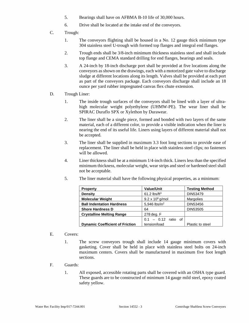
Water Rec Facility Imp/017-7244.001 Section 14552 - 3 Centrifuge Shaftless Screw Conveyors
5. Bearings shall have on AFBMA B-10 life of 30,000 hours.
6. Drive shall be located at the intake end of the conveyors.
C. Trough:
1. The conveyors flighting shall be housed in a No. 12 gauge thick minimum type 304 stainless steel U-trough with formed top flanges and integral end flanges.
2. Trough ends shall be 3/8-inch minimum thickness stainless steel and shall include top flange and CEMA standard drilling for end flanges, bearings and seals.
3. A 24-inch by 18-inch discharge port shall be provided at five locations along the conveyors as shown on the drawings, each with a motorized gate valve to discharge sludge at different locations along its length. Valves shall be provided at each port as part of the conveyors package. Each conveyors discharge shall include an 18 ounce per yard rubber impregnated canvas flex chute extension.
D. Trough Liner:
1. The inside trough surfaces of the conveyors shall be lined with a layer of ultra-high molecular weight polyethylene (UHMW-PE). The wear liner shall be SPIRAC Duraflo SPX or Xylethon by Durawear.
2. The liner shall be a single piece, formed and bonded with two layers of the same material, each of a different color, to provide a visible indication when the liner is nearing the end of its useful life. Liners using layers of different material shall not be accepted.
3. The liner shall be supplied in maximum 3.3 foot long sections to provide ease of replacement. The liner shall be held in place with stainless steel clips; no fasteners will be allowed.
4. Liner thickness shall be at a minimum 1/4-inch thick. Liners less than the specified minimum thickness, molecular weight, wear strips and steel or hardened steel shall not be acceptable.
5. The liner material shall have the following physical properties, as a minimum:
Property Value/Unit Testing Method
Density 61.2 lbs/ft3 DIN53479
Molecular Weight 9.2 x 10⁶ g/mol Margolies
Ball Indentation Hardness 5,946 lbs/in2 DIN53456
Shore Hardness D 64 DIN53505
Crystalline Melting Range 278 deg. F
Dynamic Coefficient of Friction
0.1 – 0.12 ratio of
tension/load Plastic to steel
E. Covers:
1. The screw conveyors trough shall include 14 gauge minimum covers with gasketing. Cover shall be held in place with stainless steel bolts on 24-inch maximum centers. Covers shall be manufactured in maximum five foot length sections.
F. Guards:
1. All exposed, accessible rotating parts shall be covered with an OSHA type guard. These guards are to be constructed of minimum 14 gauge mild steel, epoxy coated safety yellow.
Centrifuge Shaftless Screw Conveyors Section 14552 - 4 Water Rec Facility Imp/017-7244.001
G. Safety Stop Switch:
1. The conveyors shall be provided with a NEMA-4, 115 V., safety pull cord stop switch. A continuous orange vinyl coated galvanized cable shall fully surround the conveyors. The cable shall be supported from the conveyors frame on 10-foot maximum centers.
H. Electronic Motor Overload Trip Relay:
1. The conveyors system manufacturer shall include an electronic motor overload trip relay. The relay shall connect directly to the motor cable and first measure the motor input power and then compensate for the internal losses in the motor to ensure that power readings under supply voltage variation conditions are automatically compensated for by the overload trip relay.
2. The normal load level for the conveyors motor is to be set by an alarm level control. If the set load level is exceeded, the internal relay will change state. The output relay contact will be used for alarm and shut-down of the conveyors and for other equipment in the process. The speed of trip on sensing an overload condition shall be adjustable between the range of 0.1 to 3.0 seconds.
I. Zero Speed Switch:
1. The conveyors shall be provided with a non-contacting probe and relay type zero speed indication switch. The probe shall be a Milltronics MSP-12 or equal with stainless steel mounting hardware. The relay shall be Milltronics MFA-4P, or equal, with stainless steel mounting hardware. Switch shall operate from 120v AC supply.
J. Hopper:
1. The conveyor manufacturer shall provide two stainless steel hoppers, to fully catch all sludge cake from belt conveyor discharges. One hopper shall be provided for each drop.
2. Hoppers shall be fabricated from No. 12 gauge, Type 304 stainless steel with dimensions as shown on the drawings.
EXECUTION
3.01 CONSTRUCTION
A. The screw conveyors trough, flighting, covers, and trough ends shall be type 304 stainless steel construction. The supports shall be fabricated from hot dip galvanized mild steel.
B. All welding to be in accordance with the latest AWS standards.
C. All component items shall be provided with manufacturer's standard finish. Shafting and other exposed machined surfaces shall be coated with a rust inhibitive compound.
D. All nuts, bolts and washers used for assembly to be furnished by the conveyors manufacturer and shall be stainless steel.
E. Oversee installation, startup, and training.
3.02 OTHER DUTIES
A. Manufacturer shall provide manpower for the following duties:
1. Installation supervision.
2. Startup assistance.
3. Training.
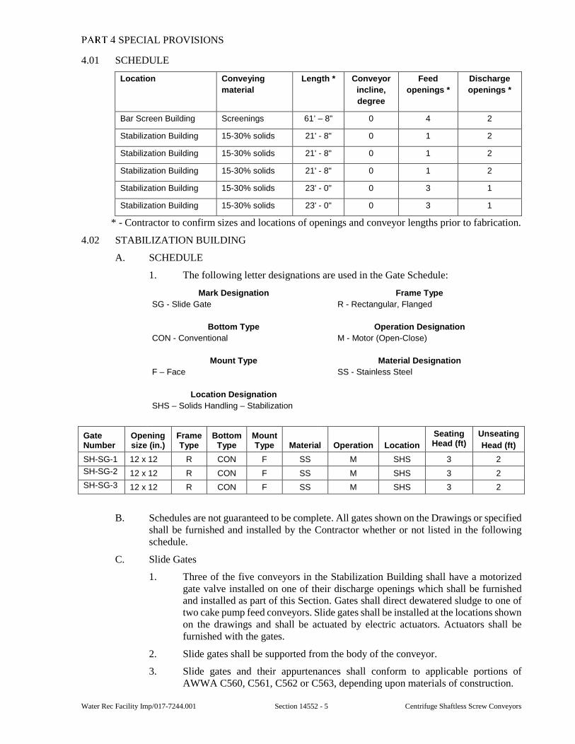
Water Rec Facility Imp/017-7244.001 Section 14552 - 5 Centrifuge Shaftless Screw Conveyors
SPECIAL PROVISIONS
4.01 SCHEDULE
Location Conveying
material
Length * Conveyor
incline,
degree
Feed
openings *
Discharge
openings *
Bar Screen Building Screenings 61’ – 8” 0 4 2
Stabilization Building 15-30% solids 21' - 8" 0 1 2
Stabilization Building 15-30% solids 21' - 8" 0 1 2
Stabilization Building 15-30% solids 21' - 8" 0 1 2
Stabilization Building 15-30% solids 23' - 0" 0 3 1
Stabilization Building 15-30% solids 23' - 0" 0 3 1
* - Contractor to confirm sizes and locations of openings and conveyor lengths prior to fabrication.
4.02 STABILIZATION BUILDING
A. SCHEDULE
1. The following letter designations are used in the Gate Schedule:
Mark Designation
SG - Slide Gate
Frame Type
R - Rectangular, Flanged
Bottom Type
CON - Conventional
Operation Designation
M - Motor (Open-Close)
Mount Type
F – Face
Material Designation
SS - Stainless Steel
Location Designation
SHS – Solids Handling – Stabilization
Gate Number
Opening size (in.)
Frame Type
Bottom Type
Mount Type Material Operation Location
Seating Head (ft)
Unseating
Head (ft)
SH-SG-1 12 x 12 R CON F SS M SHS 3 2
SH-SG-2 12 x 12 R CON F SS M SHS 3 2
SH-SG-3 12 x 12 R CON F SS M SHS 3 2
B. Schedules are not guaranteed to be complete. All gates shown on the Drawings or specified shall be furnished and installed by the Contractor whether or not listed in the following schedule.
C. Slide Gates
1. Three of the five conveyors in the Stabilization Building shall have a motorized gate valve installed on one of their discharge openings which shall be furnished and installed as part of this Section. Gates shall direct dewatered sludge to one of two cake pump feed conveyors. Slide gates shall be installed at the locations shown on the drawings and shall be actuated by electric actuators. Actuators shall be furnished with the gates.
2. Slide gates shall be supported from the body of the conveyor.
3. Slide gates and their appurtenances shall conform to applicable portions of AWWA C560, C561, C562 or C563, depending upon materials of construction.
Centrifuge Shaftless Screw Conveyors Section 14552 - 6 Water Rec Facility Imp/017-7244.001
4. Gate seat and angle frame shall be an integral unit of steel structural shapes, assembled by welding or bolting, to form the waterway opening. Side angles, filler bars, and cover bars shall form guides for the slide and holes shall be provided for mounting on anchor bolts. Slide gates shall be designed and constructed for the operating seating head and unseating head shown in the Schedule. Allowable leakage shall not exceed 0.1 gallons per minute per foot of submerged perimeter.
5. Gate slide shall be fabricated from plate having 3/8-inch minimum thickness type 304 stainless steel and shall be reinforced with structural shapes sized to withstand the specified seating and unseating heads with a maximum deflection of 1/360 of the gate span. The slide shall be provided with a pocket for attaching the stem. This pocket shall be attached to the slide by welding and shall be capable of taking the full thrust developed during normal gate operation.
6. The gates and frames shall be fabricated entirely of Type 304 stainless steel formed shapes and plates.
7. The slide blade shall be guided and supported by UHMWP or guide bars and shall be designed to prevent binding.
8. The gate shall operate at a speed of not less than 2-inches per second. The actuators shall include adjustable position indication switches.
9. Unless otherwise specified in Part 4, gates with screw stems shall open by turning counterclockwise, the direction being indicated by an arrow cast where easily visible to operator.
10. Slide gates shall be manufactured by Whipps, Rodney Hunt, Hydro Gate, or equal
D. Accessories
1. Operating stems and extensions shall be shall be minimum 1.5 inch solid bar ASTM A-276 stainless steel with high finish corrosion-resistant restraint threads and shall operate without binding or jamming in the lift nut. Stems shall be of sufficient cross section to withstand the normal forces created during gate operation.
E. All fasteners and hardware for mounting shall be 304 stainless steel Shop painting shall be in accordance with the requirements of Section 01350.
F. Installation shall be as shown on the Drawings and in conformance with AWWA C561 for fabricated stainless steel slide gates.
G. After installation the Contractor shall test each gate for satisfactory operation and water tightness against maximum operating pressure insofar as practicable.
4.03 BAR SCREEN BUILDING
A. Slide Plate
1. The conveyor in the Bar Screen Building shall have hardware suitable to accept a slide plate to isolate one of the discharge openings as shown on the Drawings. The contractor shall not supply the slide plate.
END OF SECTION
Water Rec Facility Imp/017-7244.001 Section 15010 - 1 General Mechanical Provisions
SECTION 15010
GENERAL MECHANICAL PROVISIONS
GENERAL
1.01 SCOPE
A. This Section includes furnishing and installing mechanical accessories and requirements necessary for the completion of the Work whether or not specifically shown or specified.
B. Items include, but are not limited to:
1. Piping Hangers and Supports.
2. Insulation Fire Retardant Requirement.
3. Accessibility and Access Panels.
4. Power Actuated Anchors.
5. Rotating Equipment Alignment.
C. Additional requirements are specified in Sections 01350 and 11050.
1.02 SUBMITTALS
A. Submittals shall be in accordance with requirements of Section 01300 and shall include:
1. Shop Drawings for Review:
a. Descriptive information on all mechanical items.
b. Drawings locating anchors, inserts, and supports for piping, including vendor data for each component.
2. Information for the Record:
a. Alignment procedures and acceptable runout tolerances for each piece of connected equipment.
b. Shaft and bore sizes and tolerances for couplings and instructions for coupling installation.
c. A report of coupling alignment readings for each coupling and driven machine combination, and sizes of all anchor bolt or equipment base shims.
PRODUCTS
2.01 PIPING HANGERS AND SUPPORTS
A. The manufacturer’s names and catalog numbers shown in the following paragraphs have been used as a guide to type, style, and materials of construction only. Anvill, Unistrut, or equal.
B. Contractor shall furnish and install all pipe supports, hangers, harnessing, expansion joints, expansion loops, and inserts required to support the piping and valves. Supports shall be designed and spaced to secure pipe in place without sag or undue stress on any pipe, fitting, equipment, or valve. Piping that is close to the floor may be supported on concrete piers. Piping near walls may be supported by wall brackets. Piping at equipment and valves, etc., shall be supported so that the equipment and valves can be removed without additional pipe supports. Piping shall not introduce any strains or distortion to connected equipment. Overhead lines shall be installed directly on supports, or suspended by hangers or hanger rods. Where piping is supported from the ceiling, inserts shall be poured in the concrete
General Mechanical Provisions Section 15010 - 2 Water Rec Facility Imp/017-7244.001
slab flush with the bottom of the slab. Adequate lateral support shall be provided to prevent noticeable lateral movement of the piping either during operation, or from a lateral load of 300 pounds applied at any point. All hanger design, anchoring, support, etc. shall be the responsibility of the Contractor. Design loads shall not exceed the manufacturer’s recommended loads.
C. Types of Supports:
1. All horizontal piping 4-inch and larger with inverts 2-feet or less from a finished floor shall be supported by steel saddle supports, unless otherwise specified in Part 4 of this Section.
2. Beam clamps shall be used where piping is supported from steel structure of building. Clamps shall be selected on basis of load to be supported. Beam clamps shall be malleable iron with bolt, nut, and pocket threaded for rod connection as required to fit beams. C-clamp type shall only be hung from truss panel points unless otherwise approved by the Engineer.
3. In precast slab areas supports shall be hung from tabs. Tabs shall not be overloaded. Contractor shall not drill into precast slabs unless approved by the Engineer.
4. Cast-in inserts shall be used for suspending hangers from concrete. For heavier loads, Insert shall be ceiling type, individual inserts; Anvill CB - Universal concrete inserts, Figure 282, or equal. For lighter loads, inserts shall be Unistrut P-3200 series, or equal. The preformed channel members shall be 1-5/8-inch by 1-3/8-inch with a 12 gauge (0.105 inch) material thickness. Anchors shall be at 4-inch on center maximum, and extend into concrete a minimum of 2-3/4-inch. End caps and/or end cap anchors shall be provided to prevent concrete seepage into channels. All channels shall have a pre-galvanized finish, and all accessories shall be electro-galvanized. Insert shall not be overloaded.
5. Vertical piping shall be supported at base by hanger placed in horizontal line near riser, or by base fitting set on pedestal or foundation. Risers shall be laterally supported at intermediate points with riser clamps with two point bearing as required to make rigid. Riser clamps shall be wrought steel, with extension lugs, bolt, and nuts; Anvill Figure 261, or equal. Offset pipe clamps, Anvill Figure 103, or equal, may also be used. Use only in unfinished areas where approved by the Engineer. Anvill Figure CT-121, or equal, shall be used for copper pipe.
6. Unless otherwise noted, hangers shall be as follows:
a. Uninsulated piping 2-inch and smaller, Anvill Figure 97, or equal malleable iron adjustable nut and steel band.
b. Uninsulated piping 2-inch and larger, Anvill Figure 260, or equal, galvanized steel adjustable clevis type.
c. Uninsulated copper tubing, Anvill Figure CT-69, or equal, carbon steel ring and knurled swivel iron adjusting nut completely copper plated.
d. Insulated piping, Anvill Figure 260, Elcen, or equal, clevis hangers. An insulation protection shield, Anvill Figure 167, or equal, shall be installed over the insulation in 180 degree segment, minimum 12-inch long. The shield shall be galvanized steel and shall vary in thickness from 18 gauge to 12 gauge, according to pipe size, as required to prevent crushing of the insulation. Anchors and guides shall be installed as required. Where roller supports are required due to expansion or contraction, Anvill Figure 171 roller hangers, Anvill Figure 175 roller chairs, Anvill Figure 271 pipe roll stands, or equal shall be used.
Water Rec Facility Imp/017-7244.001 Section 15010 - 3 General Mechanical Provisions
7. Trapeze Hangers and Brackets:
a. Where several pipes occur at the same elevation, trapeze type hangers or other equivalent types may be used.
b. For heavier loads, trapeze hangers shall be structural steel channels suspended from threaded rods. Channels shall be galvanized and sized for specific loads. For 12-inch piping and larger, short pieces of angle (1/4-inch minimum thickness) shall be welded to the channel such that pipe circumference will be supported at 3 points approximately 30 degree apart. Fabricated saddles supporting a 60 degree minimum segment of the pipe may also be used. Standard black carbon steel “U”-bolts, Anvill Figure 137, or equal, shall be used to secure piping up to 36-inch diameter to structural channels. For lighter loads, trapeze hangers shall be preformed channels. Channel members shall be 1-5/8-inch by 1-5/8-inch with a 12 gauge (0.105) material thickness. They shall be Unistrut Series P-1000, or equal, with a pre-galvanized finish. All fittings, spring nuts, nuts, and bolts shall be electrogalvanized. Steel threaded rod hangers shall be galvanized.
c. Brackets shall be Anvill Figure 195, or equal, as required for weight of pipe. Brackets for use with preformed Unistrut or equal channels shall be fabricated from 12 gauge material, compatible with the 1-5/8-inch square channel members. Unistrut or equal brackets shall be galvanized. All fabricated steel brackets used to support piping in or above tanks, channels, and flumes shall be hot dip galvanized after fabrication and all fasteners shall be galvanized.
d. The following general rules shall be followed for attachments:
1) Uninsulated steel piping, use Unistrut Series P-1109 through P-1126, or equal clamps.
2) For copper tubing, use Unistrut Series P-2024CC through P-2070CC clamps, or equal.
3) Insulated piping 2-inch and smaller, use Anvill Figure 167, 18 gauge galvanized steel shield over the insulation, in 180 degree segments minimum 12-inch long with Anvill Figure 271, or equal, clamps.
4) Insulated piping 2-1/2-inch and larger, use a protection saddle, Anvill Figure 160 through 166, or equal, with Anvill Figure 271, or equal, roller supports.
8. In tunnels, pipe galleries, and where piping is racked on multiple hangers, supported with the use of prefabricated structural support channels, the piping attachments shall be as specified for Trapeze Hangers.
D. Anchorage shall be provided to resist thrust due to temperature changes, changes in diameter or direction, or dead ending. Anchors shall be located as required to force expansion and contraction movement to occur at expansion joints, loops or elbows, and as required to prevent excessive bending stresses and opening of mechanical couplings. Anchors shall be suitable for the location of installation and shall be designed to withstand not less than five times the anchor load. Vertical pipes shall be anchored by means of clamps welded around pipes and secured to wall or floor construction. Anchorage for temperature changes shall be centered between elbows and mechanical joints used as expansion joints. Anchorage for bellow type expansion joints may be located adjacent to the joint.
1. Pipe guides shall be provided adjacent to bellows type expansion joints. Guides shall be placed on both sides of expansion joints except where anchors are adjacent
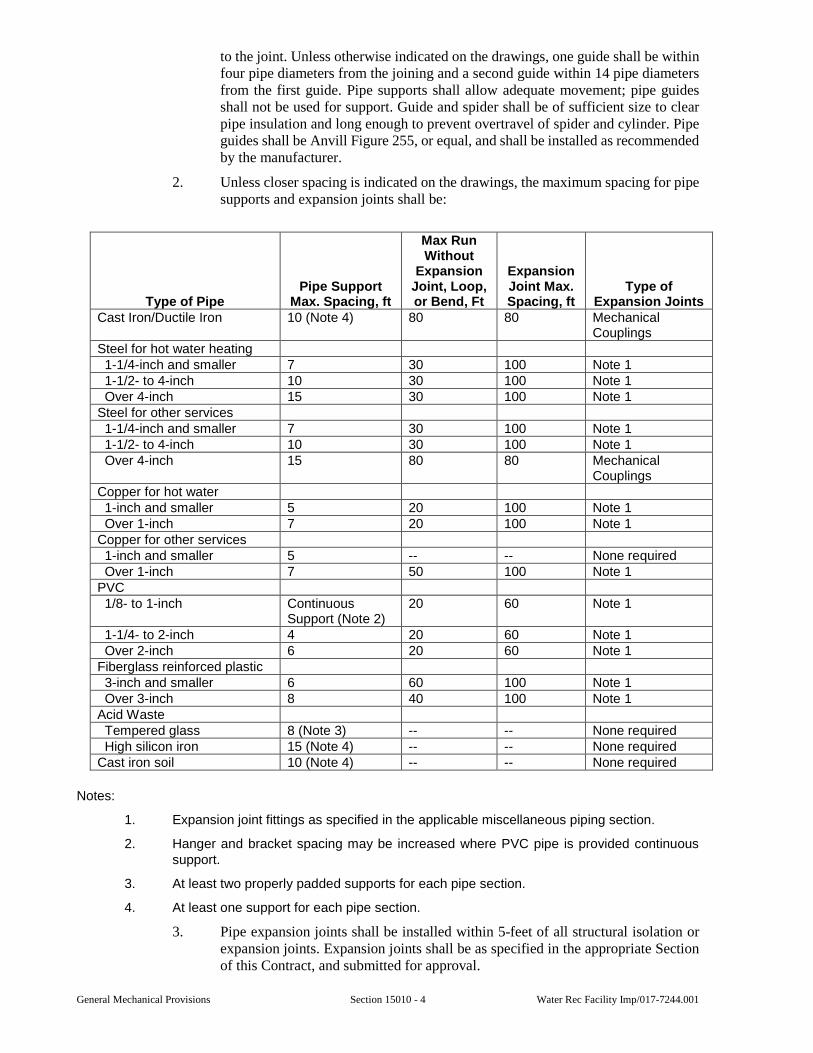
General Mechanical Provisions Section 15010 - 4 Water Rec Facility Imp/017-7244.001
to the joint. Unless otherwise indicated on the drawings, one guide shall be within four pipe diameters from the joining and a second guide within 14 pipe diameters from the first guide. Pipe supports shall allow adequate movement; pipe guides shall not be used for support. Guide and spider shall be of sufficient size to clear pipe insulation and long enough to prevent overtravel of spider and cylinder. Pipe guides shall be Anvill Figure 255, or equal, and shall be installed as recommended by the manufacturer.
2. Unless closer spacing is indicated on the drawings, the maximum spacing for pipe supports and expansion joints shall be:
Type of PipePipe Support
Max. Spacing, ft
Max Run Without
Expansion Joint, Loop, or Bend, Ft
Expansion Joint Max. Spacing, ft
Type of Expansion Joints
Cast Iron/Ductile Iron 10 (Note 4) 80 80 Mechanical Couplings
Steel for hot water heating 1-1/4-inch and smaller 7 30 100 Note 1 1-1/2- to 4-inch 10 30 100 Note 1 Over 4-inch 15 30 100 Note 1 Steel for other services 1-1/4-inch and smaller 7 30 100 Note 1 1-1/2- to 4-inch 10 30 100 Note 1 Over 4-inch 15 80 80 Mechanical
Couplings Copper for hot water 1-inch and smaller 5 20 100 Note 1 Over 1-inch 7 20 100 Note 1 Copper for other services 1-inch and smaller 5 -- -- None required Over 1-inch 7 50 100 Note 1 PVC 1/8- to 1-inch Continuous
Support (Note 2) 20 60 Note 1
1-1/4- to 2-inch 4 20 60 Note 1 Over 2-inch 6 20 60 Note 1 Fiberglass reinforced plastic 3-inch and smaller 6 60 100 Note 1 Over 3-inch 8 40 100 Note 1 Acid Waste Tempered glass 8 (Note 3) -- -- None required High silicon iron 15 (Note 4) -- -- None required Cast iron soil 10 (Note 4) -- -- None required
Notes:
1. Expansion joint fittings as specified in the applicable miscellaneous piping section.
2. Hanger and bracket spacing may be increased where PVC pipe is provided continuous support.
3. At least two properly padded supports for each pipe section.
4. At least one support for each pipe section.
3. Pipe expansion joints shall be installed within 5-feet of all structural isolation or expansion joints. Expansion joints shall be as specified in the appropriate Section of this Contract, and submitted for approval.
Water Rec Facility Imp/017-7244.001 Section 15010 - 5 General Mechanical Provisions
E. Expansion Loops - Where fabricated expansion loops are shown on the drawings or deemed by the Contractor to control the system, expansion loops shall be designed by the Contractor and submitted for approval.
F. Use correct size hanger to allow for increased diameters of line caused by pipe covering. The Contractor will not be allowed to cut or reduce specified covering to allow application of hangers, unless otherwise specified.
G. Galvanic Protection - A dielectric material shall be placed between pipe and supports when dissimilar metals are used. A flexible elastomer material, Unistrut unicushion P-2600, or equal, may be used. A thermoplastic elastomer cushion, the Unistrut Cush-A-Clamp or equal, may also be used. In general, if galvanized supports are used, all accessories shall be galvanized. If carbon steel supports are used, all accessories shall be carbon steel.
H. Support mechanical coupling pipe at each joint.
I. Other means of pipe supports not be used unless approved by the Engineer.
J. Pipe supports shown on the Drawings shall be provided and do not relieve the Contractor of any of the requirements in this Section.
2.02 FIRE RETARDANT INSULATIONS
A. All insulation material (insulation, jackets, adhesives, cements, mastics, sealers, coatings, and finishes) shall have composite Fire and Smoke Hazard ratings as tested under ASTM E-84, NFPA 255, and UL 723, not exceeding as follows: (unless noted otherwise in UBC).
Flame Spread 25 Smoke Developed 50
B. All surfaces shall be clean, dry, and free of oil and grease before insulation, adhesives, or mastics are applied.
C. All joints shall be tight with insulation lengths and segments tightly butted against each other. Where lengths or segments are cut, cuts must be smooth and square. All insulation shall be continuous through wall and ceiling openings. Insulation shall be continuous through pipe hangers. At pipe hangers, use rigid pipe covering finished the same as the adjacent pipe covering.
D. Where vapor barrier jackets are used on cold surfaces, insulation must be applied with vapor seal integrity maintained throughout the entire system.
E. All pipe insulation shall be premolded, and be split ready for application.
EXECUTION
3.01 ACCESSIBILITY AND ACCESS PANELS
A. Install work to be readily accessible for operation, maintenance, and repair. Minor deviations from Drawings may be made; however, major changes shall not be made without approval of the Engineer.
B. Where valves, traps, or other specialties are concealed in the construction or behind a wall or ceiling surface, the Contractor shall furnish and install an access panel of adequate size to permit adjustment or service of concealed device. Panels shall be of a design suitable for installation in the material forming the finished surface in which each is mounted. Provide access doors in ductwork and equipment housing and wherever required for access to internals. Minimum door size shall be 24-inch by 24-inch unless duct is less than 24-inch wide, then door size to be same as duct width.
C. Wherever practical, the Contractor shall group valves, traps, dampers, etc., in such a way as to be accessible from a single panel and eliminate as many access panels as possible.
General Mechanical Provisions Section 15010 - 6 Water Rec Facility Imp/017-7244.001
D. Ceiling access shall be required in gypsum wallboard, plaster, and other ceilings, etc., and in all locations as required to gain access or service mechanical components. Frames shall be constructed of 16 gauge steel. Panels shall be of the material used in the ceiling construction in which they are installed.
E. Access doors in insulated walls, floors, or ceilings shall be insulated equally to their surroundings.
3.02 POWER ACTUATED ANCHORS
A. Power actuated anchoring devices shall not be used at floors, columns, beams, precast concrete, where so using causes cracking, spalling, or other deformation to these members. In no case will such anchors be used less than 4-inch from any corner nor change in direction of concrete surface to which anchor is attached.
3.03 ROTATING EQUIPMENT ALIGNMENT
A. To aid in the field alignment of all equipment base plate mounted rotating equipment, push bolts (jacking bolts) shall be furnished and welded to the base plate.
B. All rotating equipment shall be field checked for alignment after installation and initial operation. The equipment shall be at operating temperature. The minimum method of indicating alignment will be the “16-point” method. Other proposed methods must be submitted for approval to the Engineer.
C. The alignment results are to be submitted for record. They are to include the final set of indicator readings and a plan view sketch of the motor and driven machine base, and the thickness of shims for each shimmed anchor bolt. The thickness of shims shall not exceed 0.25 inches.
SPECIAL PROVISIONS
4.01 SUPPORT MATERIAL SCHEDULE
A. Exterior – All exterior supports shall be 304 Stainless Steel.
B. Coarse Screen Room, Screen Area Below Screen Room, Container Area – All supports shall be 304 Stainless Steel.
END OF SECTION
Water Rec Facility Imp/017-7244.001 Section 15210 - 1 Piping
SECTION 15210
PIPING
GENERAL
1.01 SCOPE
A. This Section includes the furnishing and installing of all pipelines 4-inch diameter and larger shown on the Drawings or as required to complete the Work.
B. Piping less than 4-inch diameter, will be included under other Sections unless otherwise specified.
C. Material to be furnished and installed, but not limited to:
1. All pipe, fittings, specials, bends, beveled pipe, adapters, bulkheads, stoppers, plugs, joint restraints, joints and jointing materials.
2. Pipe supports other than those specified in Section 15010.
3. Granular material for bedding and encasement of pipelines.
4. Class B concrete as specified in Section 03300 for blocking and encasement of pipelines.
5. Make connections to all existing and/or new facilities and provide temporary services.
6. Install temporary plugs and/or stoppers and harnessing.
7. Test and clean pipelines.
8. Sterilize water mains.
D. The Contractor shall make adequate field measurements before new piping is fabricated.
E. All wall, floor, and roof penetrations and any building modifications which are required for the installation of the work under this Section shall be included in this Section.
F. Instruments which are to be located in pipelines 4-inch in diameter and larger shall be furnished under Division 16 and installed under this Section.
1.02 QUALITY CONTROL
A. Laboratory Services - Laboratory testing services shall be provided as specified under Section 01410 of the Specifications.
B. Field Inspection:
1. All pipe sections, specials, and jointing materials shall be carefully examined for defects and no piece shall be laid that is known to be defective. Any defective piece discovered installed shall be removed and replaced with a sound one in a manner satisfactory to the Resident Project Representative at the Contractor’s expense.
2. Defective material shall be marked with lumber crayon and removed from the job site before the end of the following day.
C. Field Testing:
1. All materials, process of manufacturing, and finished pipe shall be subject to inspection and approval.
2. The Resident Project Representative may select one sample of pipe on the job site of each production run of each size and type of pipe to be tested by the laboratory. The Contractor shall furnish the first test piece or pipe core and any additional
Piping Section 15210 - 2 Water Rec Facility Imp/017-7244.001
samples required because of failures. Should the sample fail to meet specifications, retests shall be conducted by the laboratory in conformance with the specifications.
D. To assure uniformity and compatibility of piping components in grooved piping systems, all grooved products utilized shall be supplied by a single manufacturer. Grooving tools shall be supplied by the same manufacturer as the grooved components.
1.03 SUBMITTALS
A. Submit shop drawings in accordance with Section 01300 showing: layout plan and dimensions, schedule of pipe fittings and specials, materials and class for each size and type of pipe, joint details, and any special provisions required for assembly.
B. Shop drawings shall be drawn to not less than 1/4-inch scale and show the laying length and piece mark for each section of pipe and fitting.
C. Drawings shall show the position and elevation of valves, pumps, and/or other equipment served by the various pipe systems.
D. The concrete pipe manufacturer’s certificate shall state that the materials have been sampled and tested in accordance with the provision for and meet the requirements of the designated specification. The certificate shall be signed by an authorized agent of the manufacturer.
E. If directed by the Engineer, each certificate shall be accompanied by a report showing test results compared to specification requirements. Test specimens shall be selected in conformance with the designated specification, except that no less than two tests shall be made for each production run of each size, type, and class of pipe furnished, and further, that in case tests are unsatisfactory, additional tests shall be made to the maximum number in the referenced ASTM Specification.
F. Before fabrication of any concrete pressure pipe, fittings, or specials, the Contractor shall furnish to the Engineer at least six copies of the design calculations for the pipe showing the calculations to arrive at the gross wrapping stress in wire; initial and resultant stresses in concrete, cylinder, and wire; internal pressure when compression in concrete is zero; compression strength of concrete at time of wrapping; and calculations to show stress, conditions, and the core and steel when the pipe is simultaneously subjected to the design pressure and external loads. The Contractor shall also furnish the full details of all pipe, specials, and fittings, and a laying schedule showing dimensions, details, and specifications of all pieces.
G. Submit a schedule of all proposed pipe escutcheons.
H. Other submittals may appear in Part 4 of this Section.
I. Any proposed grooved joint couplings and fittings shall be shown on drawings and product submittals, and shall be specifically identified with the applicable style or series number.
PRODUCTS
2.01 RESERVED
2.02 RESERVED
2.03 PROCESS AND PRESSURE PIPE
A. Ductile Iron Pressure Pipe (DIP):
1. Ductile Iron Pressure Pipe (DIP) shall conform to ANSI A-21.51 or AWWA C-151 and shall be pressure class 350 psi for sizes 12-inch and below, and pressure class 300 psi for larger sizes unless otherwise specified herein. Mechanical joint fittings shall be ductile iron and conform to ANSI A-21.10 or AWWA C110 and ANSI A-21.53 or AWWA C-153. Flanged fittings shall be ductile iron and
Water Rec Facility Imp/017-7244.001 Section 15210 - 3 Piping
conform to ANSI A-21.15 or AWWA C115. All fittings shall have a pressure rating of 250 psi for all pipe sizes unless otherwise specified.
2. Ductile iron pipe buried underground, unless otherwise specified or shown, shall have rubber gasket (slip-on) type joints in straight runs and mechanical joints with retainer glands each way from bends as shown on the Drawings. The gasket shall be a single molded rubber ring fitted into a specially shaped recess in the bell forming a pressure tight seal. The spigot end of each pipe shall be marked to indicate when the pipe is “home.” Fittings shall have mechanical joints with retainer glands unless otherwise specified or shown. Retainer glands shall be ductile iron. The restraining mechanism shall impart multiple wedging action against the pipe. Restraining devices shall be of heat treated ductile iron. Twist-off nuts shall be used to ensure proper actuation of the restraining device. The mechanical joint retainer gland shall be Ebaa Iron, Inc., Series 1100 Megalug, or equal.
3. Ductile Iron pipe inside buildings or structures shall be joined with flanged, or mechanical joints as shown on the Drawings, or as indicated in the pipe schedule. All mechanical joints shall have retainer glands. Flanges shall comply with ANSI 21.15 or AWWA C-115 and shall be ANSI 125 pound drilling, unless otherwise specified. Flanged joints shall have full face 1/8-inch rubber gaskets or of thickness and type approved by the Engineer. The pipe shall not be threaded or flanged in the field. Flanges shall be firmly bolted with machine, stud, or tap bolts of the proper size and number. Within buildings the bolts and nuts shall be of the best quality mild steel, with true threads, meeting the requirements of ANSI B16.1.
4. Flange adapters for plain end pipe (not fittings), where specified, shown on Drawings, or approved by Engineer shall be a restrained flange adapter. The restraining mechanism shall be multiple gripping wedges set against the pipe wall. Twist off nuts shall be used to ensure proper actuation of the restraining device. The restrained flange adapter shall be Series 2100 Megaflange by Ebaa Iron, Inc., or equal.
5. Wherever specified or shown, mechanical joints shall conform to ANSI A21.11 (AWWA C111), except as specified under Subsection Process and Pressure Pipe Nuts and Bolts.
6. Couplings, if required or permitted, shall be Dresser Style 38, Rockwell, or equal. Restrained coupling shall be Dresser Style 167 Lock Coupling, Rockwell, or equal.
B. Steel Pipe:
1. Steel pipe shall be designed, fabricated, and installed in accordance with these Specifications, the applicable “Good Practice” outlined in AWWA Design and Installation of Steel Water Pipe, and applicable AWWA C-200, C-203, and C-205, and ASTM A-53 Grade B for pipe less than 24-inch in diameter and API-5L for pipe greater than 24-inch diameter.
2. Pipe shall be manufactured of materials conforming to ASTM A-53 Grade B in accordance with the applicable AWWA Standards quoted above. It shall be supplied in nominal lengths approved by the Engineer. Not more than two circumferential welds per joint will be permitted.
3. Specials shall be fabricated of steel plate and designed for the same conditions as the pipe. Collars, stiffeners, and other reinforcement shall be used as required to obtain the necessary strength in all parts of the specials. A plate collar shall be welded around all outlet connections.
4. Minimum wall thickness shall be as follows:
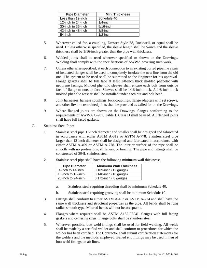
Piping Section 15210 - 4 Water Rec Facility Imp/017-7244.001
Pipe Diameter Min. ThicknessLess than 12-inch Schedule 40 12-inch to 24-inch 1/4-inch 30-inch to 36-inch 5/16-inch 42-inch to 48-inch 3/8-inch 54-inch 1/2-inch
5. Wherever called for, a coupling, Dresser Style 38, Rockwell, or equal shall be used. Unless otherwise specified, the sleeve length shall be 5-inch and the sleeve thickness shall be 1/16-inch greater than the pipe wall thickness.
6. Welded joints shall be used wherever specified or shown on the Drawings. Welding shall comply with the specifications of AWWA covering such work.
7. Unless otherwise specified, at each connection to an existing buried pipeline a pair of insulated flanges shall be used to completely insulate the new line from the old one. The system to be used shall be submitted to the Engineer for his approval. Flange gaskets shall be full face at least 1/8-inch thick molded phenolic with neoprene facings. Molded phenolic sleeves shall encase each bolt from outside face of flange to outside face. Sleeves shall be 1/16-inch thick. A 1/8-inch thick molded phenolic washer shall be installed under each nut and bolt head.
8. Joint harnesses, harness couplings, lock couplings, flange adapters with set screws, and other flexible restrained joints shall be provided as called for on the Drawings.
9. Where flanged joints are shown on the Drawings, flanges conforming to the requirements of AWWA C-207, Table 1, Class D shall be used. All flanged joints shall have full faced gaskets.
C. Stainless Steel Pipe:
1. Stainless steel pipe 12-inch diameter and smaller shall be designed and fabricated in accordance with either ASTM A-312 or ASTM A-778. Stainless steel pipe larger than 12-inch diameter shall be designed and fabricated in accordance with either ASTM A-409 or ASTM A-778. The interior surface of the pipe shall be smooth with no protrusions, stiffeners, or bracing. The pipe and fittings shall be constructed of 304L stainless steel.
2. Stainless steel pipe shall have the following minimum wall thickness:
Pipe Diameter Minimum Wall Thickness 4-inch to 14-inch 0.109-inch (12 gauge) 16-inch to 18-inch 0.140-inch (10 gauge) 20-inch to 24-inch 0.172-inch ( 8 gauge)
a. Stainless steel requiring threading shall be minimum Schedule 40.
b. Stainless steel requiring grooving shall be minimum Schedule 10.
3. Fittings shall conform to either ASTM A-403 or ASTM A-774 and shall have the same wall thickness and structural properties as the pipe. All bends shall be long radius smooth type. Mitered bends will not be acceptable.
4. Flanges where required shall be ASTM A182-F304L flanges with full facing gaskets and centering rings. Flange bolts shall be stainless steel.
5. Wherever possible, butt weld fittings shall be used for field welding. All welds shall be made by a certified welder and shall conform to procedures for which the welder has been certified. The Contractor shall submit certification statements for the welders and the methods employed. Belled end fittings may be used in lieu of butt weld fittings on air lines.
Water Rec Facility Imp/017-7244.001 Section 15210 - 5 Piping
6. All welds shall have full penetration and be smooth and without protrusions on the interior of the pipe. Weld metal shall be equal to or greater than the parent metal. Any cracks or blow holes appearing on the surface of a welding bead shall be ground away before depositing the next bead.
7. All stainless steel surfaces shall be passivated by the following procedures:
a. All outside weld areas shall be wire brushed to remove weld splatter. Brushes shall be stainless steel and used only on stainless steel.
b. All stainless steel assemblies and parts shall be completely immersed in a pickling solution of 6 percent nitric acid and 3 percent hydrofluoric acid at 140 degrees Fahrenheit for a minimum of 15 minutes. Parts shall be free of iron particles or other foreign material after this procedure.
c. Previously pickled parts shall be neutralized by immersion in a tap water.
D. Polyvinyl Chloride Pipe (PVC):
1. Pipe shall meet the requirements of AWWA C-900, and unless otherwise specified shall be Class 235, and have a standard thermoplastic pipe dimension ratio (D.R.) of 18.0.
2. All fittings and specials shall be as specified for ductile iron pressure pipe.
3. Polyvinyl chloride pipe joints shall be integral bell push-on type meeting the requirements of ASTM D-3139. Gaskets shall be rubber ring type meeting the requirements of ASTM F-477. Where called for on the Drawings, flanged joints shall be used. Flanged joints shall be supplied with 1/16-inch thick full-faced gaskets of suitable material for the application. Flange bolts and nuts shall be stainless steel.
2.04 PROCESS AND PRESSURE PIPE NUTS AND BOLTS
A. Nuts and bolts used on buried pressure pipe and fittings in contact with earth shall be Cor-Blue coated low alloy steel and have a minimum yield strength of 45,000 psi complying with ANSI A21.11 and AWWAC-111.
B. Nuts and bolts encased in grout on concrete pressure pipe shall conform to recommendations of the pipe manufacturer.
C. All other nuts and bolts shall be low carbon steel in conformance with the chemical and mechanical requirements of ASTM A-307, Grade B. Higher strength bolts will be acceptable.
2.05 PIPE HANGERS AND SUPPORTS
A. Pipe hangers and supports shall be as specified in Section 15010.
2.06 COATINGS AND LININGS OF PROCESS AND PRESSURE PIPE
A. Coatings and linings where required shall conform to the following requirements unless otherwise indicated in Part 4 of this Section or on the Drawings.
B. Ductile Iron Pipe:
1. Ductile iron pipe, and fittings unless otherwise specified, shall be lined on the interior with a standard thickness cement lining meeting ANSI Specification A-21.4 and AWWA C-104. A seal coat of bituminous material shall be applied in conformance with the above Specifications. Piping used for compressed air shall not receive a cement lining.
2. All pipe buried underground shall be coated on the outside with a standard coating of coal tar or asphalt, 1 mil thick unless otherwise specified. The finished coating shall be continuous, smooth, neither brittle when cold nor sticky when exposed to
Piping Section 15210 - 6 Water Rec Facility Imp/017-7244.001
the sun, and shall be strongly adherent to the pipe. The coating materials, after drying 48 hours, shall impart no objectionable color, odor, or taste to water standing in contact with the coating for a minimum of 48 hours.
3. Where approved, the bituminous material used for an interior seal coat may be used for exterior coating of pipe buried underground.
4. All pipe used within buildings and structures and which are to receive field coats of paint shall not be coated with any black bituminous paint. Such pipe, after proper cleaning, shall be painted with one coat of primer paint that is compatible with the field coats. Painting specifications shall be followed for cleaning and painting.
C. Prestressed Concrete Pipe and Asbestos-Cement Pipe:
1. Prestressed concrete pipe and asbestos-cement pipe require no special interior or exterior lining or coating, unless otherwise specified.
D. Steel Pipe:
1. Steel pipe shall be shop lined on the inside with centrifugally spun cement mortar lining or field applied-in-place cement lining, in accordance with AWWA C205 and C602. If pipe is field lined, it shall be given an inside shop coat of bituminous primer after sandblasting before shipment to the site.
2. The outside of all buried steel pipe shall receive a coat of an approved bituminous primer, followed by a coat of coal tar enamel into which shall be bonded a single layer of felt wrap, and finished with a single wrap of craft paper unless otherwise specified. All materials and application procedures to be in full accordance with the pertinent sections of AWWA C203. Protective coatings are to be shop applied.
3. The outside of steel pipe inside of buildings and structures, and exposed exterior shall be properly cleaned and shop painted with one coat of primer that is compatible with field coats.
2.07 BEDDING MATERIAL
A. Unless otherwise shown on the Drawings or specified herein, all pipe bedding material shall be in conformance with Section 02200.
B. Concrete bedding and encasement in lieu of standard bedding material shall be installed as shown on the Drawings or specified.
C. All underdrain pipe shall be bedded in MDOT No. 64 aggregate in lieu of the standard bedding material to a depth shown on the Drawings.
2.08 PIPE ESCUTCHEONS
A. Split-type escutcheons shall be used for piping passing through finished wall, floors, or ceiling. Escutcheons shall be brass plated or chromium plated Model 3A by Ritter, Model 284 by Fee & Mason, or equal.
2.09 WALL PIPE AND SLEEVES
A. Type A Wall Pipe:
1. Cast iron wall pipe shall be used where noted on the Drawings.
2. Wall pipe shall be cast in place with joints as indicated on the Drawings.
3. Where wall pipe is flush with wall, bolt holes shall be tapped for studs.
B. Type B Sleeve:
1. Type B sleeves are for use in exterior walls.
Water Rec Facility Imp/017-7244.001 Section 15210 - 7 Piping
2. Type B sleeves consist of casting in place a cast iron sleeve two sizes larger than the service pipe with couplings on both ends of the sleeve.
3. Service pipe shall be caulked in place with oakum. The oakum shall be covered with a minimum of 1-inch of lead wool on both ends.
C. Type C Sleeve:
1. Type C sleeves are used in exterior walls and other walls as designated on the Drawings.
2. Type C shall be a modular mechanical type seal of interlocking synthetic rubber links.
3. Unless otherwise indicated, the seal shall be suitable for corrosive service in a temperature range of minus 40 degrees F to 250 degrees F. The pressure plates shall be of delrin plastic for good resistance to organic compounds. The bolts and nuts shall be of 18-8 stainless steel. The sealing elements shall be of EPDM rubber which has high resistance to most organic and inorganic materials.
D. Type D Floor Sleeve:
1. Type D sleeves are used for pipes passing through floors.
2. Type D sleeves consist of casting in place a Schedule 40 steel sleeve with four anchors in the floor slab. The sleeve shall be one size larger than the service pipe or 1-inch larger than the flange on the service pipe. The sleeve shall extend 1-inch above the finish floor surface.
E. Type E Sleeve:
1. Type E wall sleeves shall be used where noted on the Drawings.
2. Type E sleeves consist of casting in place a mechanical joint, cast iron wall sleeves meeting the requirements of AWWA C110 and C111.
3. Each Type E sleeve shall be sealed using a plain rubber gaskets, follower glands, and mechanical joint studs meeting the requirements of AWWA C111 on both ends.
F. Type F Sleeve:
1. Type F sleeves shall be used for passing through existing masonry walls.
2. Type F sleeves shall be constructed as detailed on the Drawings using 15-pound felt paper and sealant.
G. Type G Sleeve:
1. Type G sleeves used for passing through gastight floors shall be similar to Type C sleeves with the addition of nonshrink grout as shown on the Drawings.
H. Type H Sleeve:
1. Type H sleeves shall be similar to Type G sleeves and used for passing through gastight walls.
2. Type H sleeves shall be as detailed on the Drawings.
I. All wall pipes and sleeves shall be coated or lined in accordance with the appropriate materials for its service.
2.10 EXPANSION JOINTS
A. Expansion joints as specified below shall be installed as per Section 15010.
B. Expansion joint construction shall include a neoprene inner tube extending through the bore to the outside edge of both flanges. The inner tube shall be covered with a flexible
Piping Section 15210 - 8 Water Rec Facility Imp/017-7244.001
multiple layer fabric carcass of high strength rubber impregnated synthetic fibers with steel wire or reinforcement rings integral with the fabric to assure sufficient rigidity for vacuum service and high pressure. An outer cover coated with hypalon paint shall cover the carcass and provide full protection against ozone and weathering.
C. Flange faces shall be neoprene covered and drilled to match drilling in mating flanges. Flange faces shall also be backed by split steel flange retaining rings.
D. All expansion joints shall be suitable for service temperatures of 225 degrees F.
E. All expansion joints used for vacuum service shall be capable of withstanding a 30-inch Hg vacuum.
F. Expansion joints shall have recommended working pressures compatible with the service for which they are installed.
G. All expansion joints shall be equipped with control units to restrict excess axial compression and elongation. Control units shall consist of plates bolted to pipe flanges on each end of the expansion joint and long control bolts extending between pipe flanges.
H. Expansion joints on pipes used for digester gas service shall be the open arch type.
I. Expansion joints on sludge piping shall be of filled arch construction to prevent solids accumulation at the joint.
J. Expansion joints on pipes used for fuel oil and digester gas service shall have Buna-N tubes.
K. For those locations where expansion joints are used to replace valves, spool pieces, or other short sections, standard single arch expansion joints may be of insufficient length. At these locations double, triple, and quad arch expansion joints shall be used as required.
L. Expansion joints shall be Mercer Rubber Company Style 500-700 or equal.
EXECUTION
3.01 PRODUCT HANDLING
A. Care shall be taken in handling and transporting to avoid damaging pipes and their coatings. Loading and unloading shall be accomplished with the pipe under control at all times and under no circumstances shall the pipe be dropped. Pipe shall be securely wedged and restrained during transportation and supported on blocks when stored in the shop or field.
B. Store all pipe on a flat surface so as to support the barrel evenly. It is not recommended that pipe be stacked higher than 4-feet. Plastic pipe, if stored outside, shall be covered with an opaque material to protect it from the sun’s rays.
3.02 PREPARATION OF TRENCH
A. Trench excavation shall conform to requirements of Section 02200.
B. Unless otherwise specified or called for on the Drawings, the width of trench at the top of pipe 24-inch in diameter or less shall not exceed the outside diameter of the pipe or encasement, plus 9-inch on each side of the pipe measured to the face of the trench or to the back of the sheeting when used. For pipe having a diameter greater than 24-inch, the width of trenches at the top of the pipe shall not exceed the outside diameter of the pipe or encasement, plus 15-inch on each side of the pipe measured as specified above.
C. Unless otherwise directed or called for on the Drawings, all pipe trenches shall be excavated below the proposed pipe invert as required to accommodate the depths of pipe bedding material as scheduled on the Drawings.
3.03 PIPE INSTALLATION
A. General:
Water Rec Facility Imp/017-7244.001 Section 15210 - 9 Piping
1. All loose dirt shall be removed from the bottom and the trench backfilled with specified bedding material to pipe laying grade as detailed on the Drawings. Bell holes shall be dug in the bedding where necessary and the pipe shall be placed and supported on bedding material the full length of the barrel. Bedding material shall then be placed 4-inch maximum depth along both sides of the pipe and tamped firmly under the pipe haunches. Additional bedding material shall be placed and compacted in 6-inch layers to the height shown on the Drawings or as directed. A mechanical tamper shall be used when installing bedding material for pipe 24-inch diameter and larger. The remainder of the trench shall be backfilled as specified and called for on the Drawings.
2. All pipe shall be laid to lines and grades in conformance with Section 01800.
3. Wherever piping passes through walls or floors, a wall casting pipe or sleeve of the type indicated on the Drawings shall be installed. Escutcheons shall be provided for pipe passing through finished walls, floors, or ceilings.
4. Pipe Anchoring:
a. Disjointing hydrostatic pressure at bends, valves, plugs, tees, and wyes shall be counteracted by restrained joints or reinforced concrete anchorage as directed on the Drawings or specified.
b. Thrust blocks shall be installed only where directed or specifically called for on the Drawings, unless otherwise specified. Installation shall be in conformance with Drawings.
c. Approved joint restraints shall be installed for the distance from each side of each bend, valve, plug, tee, or wye in locations shown or scheduled on the Drawings.
d. Reinforced concrete joint anchorage shall be installed in conformance with the Drawings.
5. Unless shown otherwise on the Drawings, all buried pipe carrying liquids shall be installed with a minimum cover of 5-feet. Pressure piping which carries gases shall be installed with a minimum cover of 4-feet. When new piping crosses existing utilities and other obstructions which force a change in elevation or horizontal alignment, the Contractor shall install the new piping at a deeper elevation, or new alignment to avoid the obstructions unless otherwise instructed by the Engineer. Such changes in elevation or alignment shall be made either by installing fittings or by deflecting joints in accordance with the pipe manufacturer’s recommendations. Such work shall be performed at no additional cost to the Owner. To the extent possible, pressure and process piping shall be installed at a constant grade. All changes in grade and alignment shall be approved by the Engineer.
B. Process and Pressure Pipe:
1. Pipe and appurtenances shall be installed true to line, grade, and location; with joints centered, spigots home; pipe properly supported and restrained against movement; and all valve stems plumb.
2. All elbows, tees, plugs, etc., shall be properly anchored, blocked, or otherwise restrained to prevent movement of the pipe in the joints due to internal or external pressure.
3. The open ends of all pipes and special castings shall be plugged or otherwise closed with a watertight plug to the approval of the Resident Project Representative before leaving the work for the night, and at other times of interruption of the work. All
Piping Section 15210 - 10 Water Rec Facility Imp/017-7244.001
pipe ends which are to be permanently closed shall be plugged or capped and restrained against internal pressure.
4. Where new or existing pipe requires cutting in the field it shall be done in a manner to leave a smooth end at right angles to the pipe centerline. The finished cut must be approved by the Resident Project Representative.
5. Joints:
a. Gaskets - Just prior to joining the pipes, the surfaces of the joint rings shall be wiped clean and the joint rings and rubber gaskets shall be liberally lubricated with an approved type of vegetable oil soap. The spigot end, with the gasket placed in the groove, shall be entered into the bell of the pipe already laid, making sure that both pipes are properly aligned. Before the joint is fully “home,” the position of the gasket in the joint shall be determined by means of a suitable feeler gauge supplied by the pipe manufacturer. If the gasket is found not to be in proper position, the pipes shall be separated and the damaged gasket replaced. The pipe is then forced “home” firmly and fully. In its final position, the joint between the pipes shall not be deflected more than 1/2-inch at any point.
b. Concrete Pressure Pipe Diapers - A band at least 5-1/2-inch wide shall be placed around the outside of concrete pressure pipe, over each joint as recommended by and available from the pipe manufacturer. This band shall serve as a form for placing a 1:2 cement mortar grout in the external recess formed by the face of the bell and the shoulder of the spigot. If the air temperature is below 40 degrees the spigot, bell, and mortar shall be heated. If a reinforced paper joint band is used, it shall be drawn up tight around the pipe and backfill tamped against it up to the springline before pouring the grout. If a cloth band is used, it shall be wired around the outside of the pipe and the grout poured before backfilling.
c. Concrete Pressure Pipe Interior Joints - The interior joint recess of pipe 24-inch and larger shall be pointed using a non-shrinking mortar specified in Subsection 2.01. The inside surface shall be struck off smooth with the pipe interior. On pipe 20-inch and smaller a rope type mastic or trowellable mastic shall be affixed to the concrete face of the bell socket just prior to pushing the spigot into the bell, such that the mastic material squeezes to fill the internal joint recess. Mastics that are detrimental to rubber gaskets shall not be used. Similarly, primers to be used in conjunction with rope type mastics must be kept off gaskets and sealing surfaces of joint rings.
d. Bell and Spigot Lead Joints - If used, the spigot of each pipe shall be fully seated in the bell of the adjoining pipe, adjusted to form a uniform annular space which shall be caulked with sterilized premolded rubber, forming a solid packing against which molten lead shall be poured and caulked. Lead, after caulking, shall have a depth of at least 2-inch for pipes 14-inch or less in diameter, and 2-1/2-inch for larger pipe. The melting pot shall be kept near the joint which shall be made by one pouring. Dross shall not be allowed to accumulate in the pot. All work shall be performed by skilled workmen.
e. Electrical Continuity - Where specified, electrical continuity shall be provided in concrete and steel pressure pipes by welding an insulated #4RR copper cable across joints. The cable shall be welded to the steel of bell and spigot of concrete pressure pipe and across joints including each piece of coupling on jointed steel pipes.
Water Rec Facility Imp/017-7244.001 Section 15210 - 11 Piping
f. Where new piping is to be connected into an existing joint, said joint shall be cleaned sufficiently to result in a liquid- or gastight seal. If applicable, a new gasket shall be supplied and installed.
3.04 SLEEVES AND WALL PIPE
A. Type A wall pipes shall be provided for all pipes passing through the exterior walls unless other sleeve types or wall pipes are designated on the Drawings. Type C sleeves shall be provided in interior walls unless designated otherwise on the Drawings.
B. At all points where piping passes through floors, Type D sleeves shall be provided, unless otherwise designated on the Drawings.
C. Other sleeve types and wall pipe shall be provided as indicated on the Drawings.
D. All wall pipes and sleeves shall be coated or lined in accordance with the appropriate materials for its service.
3.05 RESERVED
3.06 RESERVED
3.07 RESERVED
3.08 PRESSURE AND LEAKAGE TESTS FOR PROCESS AND PRESSURE PIPE
A. The Contractor shall furnish the pump, pipe connections, taps, gauges, auxiliary water container, bulkheads, plugs, and other necessary equipment and make pressure and leakage tests of all lines including the joint between existing and new pipes unless otherwise directed by the Engineer.
B. Tests shall be conducted on all pipelines or valved sections thereof as directed by the Resident Project Representative. Testing of pipelines laid in excavation or bedded in concrete shall be done prior to backfilling or placing concrete cover, except restrained sections of pipe which shall be backfilling prior to testing, unless otherwise permitted by the Engineer. Tests on lines anchored or blocked by concrete shall not be conducted until the concrete has taken permanent set.
C. The line or section thereof to be tested shall be filled slowly with water to expel all air. Hydrostatic pressure shall be applied by pumping water from an auxiliary supply. The test pressure shall be maintained two hours minimum and additional time as required for thorough inspection to find any leaks or defects in the force main and appurtenances. Unless indicated otherwise in Part 4, the test pressure shall be 100 pounds per square inch or 50 percent above the normal operating pressure, whichever is greater. Should the pipe section fail to pass the tests, the Contractor shall find and correct failures and repeat the tests until satisfactory results are obtained.
D. Leakage tests shall be made simultaneously with or following completion of pressure tests of all lines or valved sections thereof. Leakage is defined as the quantity of water added to the pipe under test to maintain the required test pressure for a specified time. The leakage test pressure shall be not less than the maximum operating pressure of the section under test. The duration of the leakage test shall be not less than two hours. Allowable leakage for buried piping shall not exceed 9 gallons per inch of pipe diameter per mile of pipe in 24 hours. For piping not buried, any leakage during the test is unacceptable.
3.09 DISINFECTION OF POTABLE WATER MAINS
A. After the pressure test and prior to disinfecting, the lines shall be thoroughly flushed through hydrants, fixtures or by other means as approved by the Engineer.
B. The Contractor shall furnish required materials and apparatus and perform the work of disinfections. All temporary and permanent materials, apparatus and appurtenances shall have the same NSF 61 approval as the installed work.
Piping Section 15210 - 12 Water Rec Facility Imp/017-7244.001
C. All water lines shall be cleaned and disinfected in accordance with federal, state, and local codes and AWWA C-651 as follows:
1. Liquid sodium hypochlorite by means of a suitable solution feed machine or pump. Sodium hypochlorite storage conditions and durations shall be controlled to minimize deterioration.
2. Calcium hypochlorite as tablets, powder. Tablets or powder shall be placed in the water line during construction. The water line shall be filled, carefully, with potable water to produce a uniform solution.
3. Calcium hypochlorite as a water mixture. The calcium hypochlorite powder shall be mixed with water to form a paste and then thinned to a slurry, to be introduced into the pipe by pumping.
D. The dosage of chlorinating agent shall be of the amount to produce a minimum chlorine residual of 50 parts of chlorine per million. Tests with the DPD method shall be made at selected points to determine the residual.
E. Treated water shall be retained in the lines for sufficient time to accomplish the desired disinfection but not less than 24 hours. Valves in the line shall be operated during the retention period.
F. Following disinfection, all treated water shall be flushed from the lines at their extremities until the replacement water throughout the lines shall, upon test, be chemically and bacteriologically acceptable.
1. Two or more successive sets of samples taken at 24-hour intervals shall indicate microbiologically satisfactory water before the lines are placed into service.
2. Should the initial treatment prove ineffective, the disinfection shall be repeated until the test shows acceptable results.
G. All testing shall be done by a laboratory acceptable to the public authority having jurisdiction, and all costs shall be paid for by the Contractor.
H. The disposal of heavily chlorinated water shall be coordinated with the Owner and regulatory agencies. The heavily chlorinated water may require the addition of a dechlorinating chemical prior to release to a storm sewer or to the environment. The dechlorinating method shall be approved by the Owner and Engineer. The heavily chlorinated water shall not be released to sanitary sewers without permission from the Owner of the sanitary sewer system.
3.10 INSTRUMENTATION CONNECTIONS
A. The Contractor shall make all necessary allowances for and install all controls and instrumentation furnished under any Contract Division and which require in-line connection to process and pressure piping.
B. The Contractor shall provide all necessary mounting bosses, pipe and boss taps, plugs, tees, and any miscellaneous appurtenances to allow connection of Instrumentation and Controls and their associated piping to process and pressure piping.
C. Thermowells complete with all appurtenances listed in Division 16 shall be furnished and installed under that Division. Thermowells complete with all appurtenances which are not included in the list in Division 16 and are to be installed in piping under this Section, shall be furnished and installed under this Section.
D. Instrumentation and Controls are furnished and specified under various Sections including Section 16902. Any schedules shown in Section 16902 are not guaranteed to be complete.
Water Rec Facility Imp/017-7244.001 Section 15210 - 13 Piping
SPECIAL PROVISIONS
4.01 PIPING SCHEDULE
A. The following letter designations are used in the Piping Schedule:
Material Designation:
DIP - Ductile Iron Pipe VCP - Vitrified Clay Pipe PVC - Polyvinyl Chloride PPVC - Perforated Polyvinyl Chloride FRP - Fiberglass Steel - Steel SWS - Spiral Welded Steel CPP - Concrete Pressure Pipe RCP - Reinforced Concrete Pipe CPT - Corrugated Polyethylene Tubing
B. Schedule:
Service Size Material Remarks Sanitary All PVC or DIP Thickened Sludge All DIP Centrate All PVC or DIP Sludge Cake All Unlined Welded Steel Design Pressure 1,000 psig
C. Schedules are not guaranteed to be complete. All piping shown on the Drawings or specified shall be furnished and installed by the Contractor whether or not listed in the above schedule.
END OF SECTION

Piping Section 15210 - 14 Water Rec Facility Imp/017-7244.001
This page was intentionally left blank.
Water Rec Facility Imp/017-7244.001 Section 15211 - 1 Small Piping and Valves
SECTION 15211
SMALL PIPING AND VALVES
GENERAL
1.01 SCOPE
A. This Section includes furnishing and installing all pipelines and valves less than 4-inch in diameter as shown on the Drawings or as required for a complete piping system for each service or combination of services except the piping and valves included in Section 15400 - Plumbing and Section 15500 - Heating, Ventilation, and Air Conditioning.
B. Each piping system shall be adequate to conduct and control the flow of process water, plant water, non-potable water, instrument air, compressed air, vacuum, natural gas, sewage gas, propane, fuel oil, chemicals, sewage, sludge, sampling or other uses as specified or shown on the Drawings.
C. This Section includes, but is not limited to:
1. Securing and bearing the cost of all permits, certificates, and inspection as required by local regulations and state codes.
2. All pipe, fittings, and connections for plant water supply to equipment and waste to drains.
3. Valves less than 4-inch in diameter, control devices, pipe hangers, anchors, supports, and sleeves for the piping systems covered under this Section.
4. Hose bibbs, sill cocks, and hydrants.
5. Plant water supply, drain lines, and connections to boilers, pump priming systems, pump gland seals, valve operating cylinders, or other equipment requiring these services.
D. The Contractor shall remove all existing pipelines and valves less than 4-inch in diameter that are indicated on the Drawings to be removed except piping and valves included in Section 15400 and Section 15500. Removals shall be done in accordance with the requirements of Section 02110.
E. The Contractor shall relocate existing piping and valves less than 4-inch in diameter, except piping and valves included in Section 15400 and Section 15500, which interfere with work under this Section or any Section of the Specifications.
F. The Contractor shall furnish, install, and remove all temporary piping and valves that are required to maintain processes in operation during construction.
G. All wall, floor, and roof penetration and any building modifications which are required for the installation of the work under this Section shall be included in this Section.
H. Instruments which are to be located in pipelines to be furnished under Division 16 shall be installed under this Section.
1.02 SUBMITTALS
A. Submittals shall be in accordance with the requirements of Section 01300 and shall include:
1. Shop Drawings for Review:
a. Drawings shall include plan dimensions to and elevations of sleeves, inserts, and anchors, the size and location of each run of pipe, and the location of valves and unions.
Small Piping and Valves Section 15211 - 2 Water Rec Facility Imp/017-7244.001
b. Manufacturer’s literature, catalog data, specifications, and illustrations shall be bound in a brochure which includes a complete bill of materials.
2. Information for the Record:
a. Operation and maintenance information.
PRODUCTS
2.01 PIPING MATERIALS
A. Copper Pipe and Tubing shall be manufactured in accordance with ASTM B-88. Type L hard temper shall be used above ground and inside of structures for compressed air, hot and cold potable water, plant water, vacuum, and other services unless another type of pipe is specifically called for. Type K soft temper shall be used where underground piping is installed. Fittings and unions shall be solder joint fittings of cast bronze manufactured in accordance with ASTM B-62 and with ends complying to ANSI B 16.18 or wrought copper manufactured in accordance with ASTM B-75 and with ends complying to ANSI B 16.22. Unions shall be cast bronze and shall be installed adjacent to valves and equipment and as required to assemble the piping but not less than one union shall be included in each run. Threaded adapters shall be installed on each side of valves in copper lines. Where joints are made between pipes of different materials, dielectric couplings shall be installed. Pipe nipples shall be standard weight seamless red brass pipe ASTM B-43. Solder joints shall be made in conformance with ASTM B-828 Flux conforming to ASTM B-813 shall be applied. Materials used for solder joints in all potable water services shall contain less than 0.2 percent lead and comply with ASTM B32.
B. Steel Pipe, unless otherwise noted, shall be used for all aboveground natural gas. Pipe shall be ASTM A-53 Schedule 40, unless otherwise noted or where code requirements differ, with standard weld or malleable iron fittings. Unions shall comply with ANSI B-16.3.
1. Steel piping installed above ground, unless otherwise noted, shall be Schedule 40 pipe with standard malleable iron screwed fittings. Unions shall be 250 pound screwed malleable iron with iron to iron seats. On pipes 2-inch and larger, ASTM A-105 companion flanges shall be used in lieu of unions. For natural gas through 2-inch, fittings shall be 3,000 pound forged steel socket weld. For natural gas, digester gas, and fuel oil, pipe 2-1/2-inch and larger, ASTM A-234 weld fittings and ASTM A-105 flanges shall be used.
2. Steel piping installed underground, unless otherwise noted, shall be Schedule 40 plastic coated at the factory with Scotchkote 212 by 3M or equal. Pipe fittings through 1-1/2-inch shall be 3000 pound forged steel socket weld, and 2-inch and larger shall be ASTM A-234 weld fittings. Joints shall be welded, primed, and wrapped double the manufacturer’s recommended thickness with Tapecoat TC Primer and Tapecoat CT, or equal.
3. Where couplings are called for on gas piping, they shall be Dresser Style 38, or equal. The couplings shall be specifically designed for digester or natural gas, middle ring width shall be 5-inch long.
C. Stainless Steel Pipe:
1. Stainless steel pipe less than 4-inch in diameter shall be designed and fabricated in accordance with ASTM A-312. The interior surface of the pipe shall be smooth with no protrusions, stiffeners, or bracing. The pipe and fittings shall be constructed of 304L stainless steel, or as specified on the Drawings.
2. Stainless steel pipe shall be minimum Schedule 40S, unless otherwise noted on the Drawings.
Water Rec Facility Imp/017-7244.001 Section 15211 - 3 Small Piping and Valves
3. Fittings shall conform to ASTM A-403 and shall have the same wall thickness and structural properties as the pipe. All bends shall be long radius smooth type. Mitered bends will not be acceptable.
4. Flanges where required shall be ASTM A182-F304L flanges with full facing gaskets and centering rings. Flange bolts shall be stainless steel.
5. Wherever possible, butt weld fittings shall be used for field welding. All welds shall be made by a certified welder and shall conform to procedures for which the welder has been certified. The Contractor shall submit certification statements for the welders and the methods employed. Belled end fittings may be used in lieu of butt weld fittings on air lines.
6. All welds shall have full penetration and be smooth and without protrusions on the interior of the pipe. Weld metal shall be equal to or greater than the parent metal. Any cracks or blow holes appearing on the surface of a welding bead shall be ground away before depositing the next bead.
7. All stainless steel surfaces shall be passivated by the following procedures:
a. All outside weld areas shall be wire brushed to remove weld splatter. Brushes shall be stainless steel and used only on stainless steel.
b. All stainless steel assemblies and parts shall be completely immersed in a pickling solution of 6 percent nitric acid and 3 percent hydrofluoric acid at 140 degrees F for a minimum of 15 minutes. Parts shall be free of iron particles or other foreign material after this procedure.
c. Previously pickled parts shall be neutralized by immersion in a trisodium phosphate rinse.
D. PVC Pipe and fittings shall be composed of Class 12454-B rigid PVC compound in conformance with ASTM D-1784 (formerly classified Type I, Grade 1). Pipe shall be Schedule 80 with a design stress of 2000 psi in conformance with ASTM D-1785. All joints, unless otherwise shown on the Drawings, shall be solvent welded in conformance with ASTM D-2855. Joint solvent shall be as recommended by the pipe manufacturer and shall comply with ASTM D-2564. In pressure or vacuum lines and in gravity drains 1-inch diameter and less, the fittings shall be Schedule 80 and shall conform to ASTM D-2467. For gravity drains greater than 1-inch diameter, the fittings shall conform to the requirements of ASTM D-2665. PVC pipe shall be used for all lines carrying chemicals unless otherwise shown on the Drawings or specified.
E. Polyethylene Pipe with heat fusion joints and compression type metal fittings shall be used for underground natural gas service lines service lines except within five feet of buildings.
1. Piping shall be installed underground only and comply with ASTM D-2513, ANSI B-31.8, and A.G.A. standards.
2. Fittings shall be approved plastic for making heat fusion joints complying with ASTM D-2513, D-2683, D-3197, D-3261, D-3350. When applicable, compression fittings shall be Dresser 401 plastic.
3. Outside risers shall be flexible steel casing or rigid noncorrosive steel encased plastic and shall be coated and cathodically protected.
4. All underground pipe shall be traced with No. 12 insulated wire taped and installed as required by the governing authority.
5. Polyethylene Pipe shall be SDR 11 with a working pressure of 100 psi and shall be Phillips Driscopipe 8000, or equal.
Small Piping and Valves Section 15211 - 4 Water Rec Facility Imp/017-7244.001
2.02 VALVES
A. Unless otherwise specified or shown on drawings, valves installed in pipelines 3-1/2-inch diameter and smaller for process water lines shall be gate valves; for compressed air and vacuum, globe valves; for natural and sewage gas lines, lubricated plug or eccentric nonlubricated plug valves; and for gas lines less than 2-inch diameter tapered nonlubricated plug cocks; for fuel oil, ball valves; for sludge, eccentric nonlubricated plug valves. Valves for other types of services when required will be specified under that Section.
B. Gate Valves shall be 150 pound, all bronze, rising stem, solid wedge disc furnished with screwed or flanged ends as required. Gate valves shall be Crane No. 431, Jenkins No. 47-U, Powell No. 514/515, or equal.
C. Globe Valves shall be 150 pound, all bronze body with renewable plug-type disc of 500 Brinell Hardness Stainless Steel. The seat ring shall be screwed-in and of the same material as the disc. Globe valves shall be Powell No. 2600, Crane No. 14-1/2P, Jenkins No. 2032, or equal.
D. Ball Valves through 2-inch shall be screwed end bronze, two piece, 125 psi, Teflon seats, bronze trim, and blowout-proof stem, Nibco No. T-580-BR-Y-20, or equal.
E. Butterfly Valves shall be AWWA, Class 150 B, wafer body equipped for ANSI 125 pound flanges. Butterfly valves shall provide bubble-tight shutoff to 150 psig cold water pressure. The valve body shall be made from ASTM A-126, Grade B cast iron or equal. The valve disc shall be made with nickel-coated cast iron, bronze, or equal. Valve shall have bronze shaft bearings, O-ring shaft seals, and EPDM valve body seat Keystone Figure 239, or equal. Valves shall be hand lever actuated.
F. Check Valves shall be 200 pound, all bronze body with bronze disc, y-pattern, with flanged or screwed ends as required. The check valves shall be Crane No. 36, Powell 560-Y/561-Y, Jenkins 762-A, or equal. Non-slam check valves shall be used on all pipelines operating at 25 psig or higher pressure and shall be Valve and Primer Corporation, Series 300 or equal.
G. Nonlubricated Plug Valves shall be 150 pound, all bronze body and plug, with synthetic rubber faced plugs and have screwed or flanged ends as required. They shall be DeZurik Figure 120, or equal. Valves shall operate with nonremovable lever type handles.
H. Sampling Cocks shall be Ernest Gage Co. Fig. 29, Conbeaco, or equal.
I. Pressure Regulator shall be Watts U5HP, or equal.
J. Corporation Stops shall be brass and comply with AWWA Standard C-800 as manufactured by Ford Meter Box Co., Inc. or equal. Corporation stops shall be provided with inserts, saddles, and curb boxes as required. Saddles shall be brass with double straps and be placed over a molded rubber gasket.
2.03 PVC VALVES
A. PVC Ball Valves shall be used in all PVC lines under this Section. Ball valves shall be PVC body, Nibco Chemtrol True Union Ball Valve, TU or DE; Corro-Flo; or equal.
B. PVC Butterfly Valves:
1. Butterfly Valves shall be made of Class 23447-B rigid PVC compound in conformance with ASTM D-1/84 (formerly classified Type IV, Grade 1).
2. Shaft shall be 316 Stainless Steel. Seats and secondary seals shall be Viton.
3. Bearings shall be glass filled Teflon. Butterfly valves shall have a pressure rating of 150 psi at 70 degrees F.
4. Valve bodies shall be the wafer type compatible with 150 pound ANSI flanges.
Water Rec Facility Imp/017-7244.001 Section 15211 - 5 Small Piping and Valves
5. Valves which are scheduled to be motor operated shall be furnished with mounting saddle. Manually operated valves shall be furnished with lever operators.
C. Check Valves:
1. Check Valves shall be made of Class 12454-B rigid PVC compound in conformance with ASTM D-1784 (formerly classified Type I, Grade 1).
2. All check valves shall have Viton seals.
3. Check valves 4-inch size and smaller shall be true union ball checks.
D. PVC Pressure Relief Valves shall be Wallace & Tiernan No. U-23655, Fischer & Porter, or equal, with 1-inch female NPT BPV connections. These shall not be used on chlorination systems.
2.04 RESERVED
2.05 RESERVED
2.06 HOSE BIBBS
A. Hose bibbs inside buildings shall be all bronze angle hose valves with 3/4 by 11-1/2 threads per inch American (National) or Chicago Standard Hose Threads, Mueller Brass Co. No. V-1016, or equal. Hose bibbs shall have nonremovable type vacuum breaker, Watts No. 8A, or equal. Hose bibbs shall be located 3-feet above the floor.
B. Sludge Control Building: Provide 2-1/2-inch diameter hose bibbs where shown on the Drawings.
1. Manufacturer: Elkhart Brass Manufacturing Company U-25 with 2-1/2-inch NPT outlet and handwheel operator.
2.07 RESERVED
2.08 ELECTRIC VALVE OPERATORS (OPEN-CLOSE)
A. Electric operators shall be sized and geared to meet the torques required at a valve opening and closing speed of 2 to 8 seconds per 90-degree rotation. The operator shall be rated for 25 percent duty cycle at maximum rate output.
B. Operators shall be powered by 115 v, single phase, 60 Hz current and shall operate in any mounting attitude.
C. Operators shall have thermal overload protection, reversing magnetic starter, and a NEMA 4 enclosure for all electrical components. The starter shall be capable of receiving contact closures from remote sources to actuate the operator in either direction. The operating motor shall be provided with surge suppression to limit voltage transients. The surge suppression device shall be equal to Electrocube Part No. RC1782, sized as required to suit the motor characteristics.
D. Adjustable limit switches shall be provided. Two limit switches shall be used for de-energizing operator once the fully open position or fully closed position of the valve is reached. Two limit switches shall be used for remote indication of end positions. Limit switches shall be single pole double throw snap acting totally enclosed and rated at 250 v AC.
E. Each operator shall be equipped with a manual override feature with manual lockout switch to prevent electrical operation when in the manual mode. Upon completion of manual operation, the operator will automatically return to the electrical mode.
F. Each operator shall be supplied with local indicator for visual valve position and an electro-mechanical brake to minimize overrun.
Small Piping and Valves Section 15211 - 6 Water Rec Facility Imp/017-7244.001
G. Electric motor valve operators that are to be supplied with butterfly valves shall be sized for 1-1/2 times the valves rated torque or a minimum of 400-inch-pound, whichever is greater.
H. The operators shall be a product of Raymond Control Systems, Worcester Control, or equal. Operators shall have easily identifiable terminal blocks for all external power and control connections.
2.09 STRAINERS
A. Strainers shall be provided where shown on the Drawings and as required to meet local and State codes. Strainers shall also be provided in all water lines ahead of all solenoid valves, pressure regulators, and pilot valves.
B. Unless otherwise specified or required by code, strainers shall be Leslie Model 7000, Mueller Muessco Model 11, or equal. Strainer shall have a Y-pattern cast iron body and a 40 mesh stainless steel screen.
C. The Contractor shall provide a plug cock for blow-off purposes.
2.10 BACKFLOW PREVENTERS
A. Reduced pressure type backflow preventers shall conform to ASSE Standard 1013 or AWWA C511. Preventers shall be Watts No. 909 with strainer, or equal. Relief valve shall be provided with an air gap, Watts Series AG or equal, piped to drain.
B. All backflow preventers are to include an in-line strainer between the stop valves.
2.11 SLEEVES
A. Type B Sleeve:
1. Type B sleeves are for use in exterior walls.
2. Type B sleeves consist of casting in place a black wrought iron sleeve two sizes larger than the service pipe with couplings on both ends of the sleeve.
3. Service pipe shall be caulked in place with oakum. The oakum shall be covered with a minimum of 1-inch of lead wool on both ends.
B. Type C Sleeve:
1. Type C sleeves are used in exterior walls and other walls as designated on the Drawings.
2. Type C shall be a modular mechanical type seal of interlocking synthetic rubber links by Link-Seal, or equal.
3. Unless otherwise indicated, the seal shall be suitable for corrosive service in a temperature range of minus 40 degrees F to 250 degrees F. The pressure plates shall be of delrin plastic for good resistance to organic compounds. The bolts and nuts shall be of 18-8 Stainless Steel. The sealing elements shall be of EPDM rubber which has high resistance to most organic and inorganic materials.
C. Type D Floor Sleeve - Type D sleeves consist of casting in place a steel sleeve with four anchors in the floor slab. The sleeve shall be one size larger than the service pipe or 1-inch larger than the flange on the service pipe. The sleeve shall extend 1-inch above the finish floor surface.
D. Type E Sleeve:
1. Type E wall sleeves shall be used where noted on the Drawings.
2. Type E sleeves consist of casting in place mechanical joint, cast iron wall sleeves meeting the requirements of AWWA C-110 and C-111.
Water Rec Facility Imp/017-7244.001 Section 15211 - 7 Small Piping and Valves
3. Each Type E sleeve shall be sealed using plain rubber gaskets, follower glands, and mechanical joint studs meeting all requirements of AWWA C-111 on both ends.
E. Type F Sleeve:
1. Type F sleeves shall be used for passing through masonry walls, except as otherwise noted on the Drawings.
2. Type F sleeves shall be constructed as detailed on the Drawings using 15-pound. felt paper and sealant.
F. Type G Sleeve - Type G sleeves used for passing through gastight floors shall be similar to Type C sleeves with the addition of nonshrink grout as shown on the Drawings.
2.12 PIPE ESCUTCHEONS
A. Split-type escutcheons shall be used for piping through finished walls, floors, or ceilings. Escutcheons shall be of brass or chromium plated Model 3A by Ritter or equal.
2.13 AUTOMATIC TRAP PRIMER
A. Automatic trap primers shall be furnished and installed as shown on the Drawings.
B. Automatic trap primers shall prevent the traps from drying out by adding water to the traps to keep the water at a constant level.
C. Automatic trap primers shall have bronze bodies with integral vacuum breaker, non-liming internal operating assemblies with strainers and gasketed bronze covers.
D. Automatic trap primers shall be Zurn Z-1022, Sani-Gard, automatic trap primers or equal.
2.14 TAPPED SADDLES
A. Where specifically called for on the Drawings, service saddles shall be installed to provide a simple, positive, bubble tight tapping connection.
B. Saddles shall be rated for 150 psi working pressure and be constructed of corrosion resistant materials for long life, and of heavy proportions to withstand the strains of the tapping operations, and to support the service pipe after tapping.
C. Saddle gasket shall be made of neoprene rubber and assure a positive leak proof service connection.
D. Tapped saddles shall be Clow Corporation, Style 3408; Dresser Style 91 (double strap); or equal.
EXECUTION
3.01 INSTALLATION
A. Cutting of all pipe shall be done with sharp tools. The ends of each pipe shall be reamed until all burrs or fins are removed. Full tapered threads shall be used throughout and threaded joints shall turn up perfectly tight without the use of filling substances. A standard pipe joint paste or tape suitable to use of pipe shall be used on the male threads only, and none shall be allowed to accumulate on the inside of the pipes. All connections between pipe, pipe hangers, and equipment shall be made with an approved dielectric insulating material. Dielectric unions or insulated couplings shall be installed between any dissimilar metallic piping materials or at connections between dissimilar metallic pipes and equipment, tanks, etc.
B. Pipe joints shall conform to respective industry standards.
C. Expansion and contraction of the piping system shall be provided for by the use of swing joints, right angle loops, or approved expansion joints. Branch connections shall have three
Small Piping and Valves Section 15211 - 8 Water Rec Facility Imp/017-7244.001
elbow spring pieces to allow for movement. Unless specified in Part 4, the piping system shall provide for the expansion as required in Section 15010. An expansion joint is also required at all building isolation or expansion joints.
D. Interior and exterior pipelines shall be installed and graded in accordance with State and/or Local Codes. Interior pipes shall run at right angles or parallel to building walls, placed as close as practicable to the ceiling and/or walls, and supported according to Section 15010. Drain valves shall be installed at all low points.
E. Pipe groups shall be run parallel with pipes of other trades, and wherever practicable, all piping shall be supported on common group hangers unless pitch of pipe as hereinbefore mentioned is required.
F. The piping shall be installed in a workmanlike manner and shall avoid interference with columns, beams, equipment, and other piping or fixed construction. A minimum of 7-feet of headroom shall be maintained at any point including stairs.
G. Type C wall sleeves shall be provided for all pipes passing through exterior walls unless other sleeve types are noted on the Drawings. Type C sleeves shall also be provided in interior walls where indicated on the Drawings, Type D floor sleeves shall be used where piping passes through floor. Other sleeve types shall be used where shown on the Drawings.
H. Buried pipe shall be firmly bedded the full length with the exception where bell holes are required. Buried piping located less than 3-feet below a building slab or footing shall be encased in concrete. Where unstable soil conditions occur under buildings, support shall be made from the underside of the structural slab by an approved type hanging device embedded in the concrete.
I. Unless shown otherwise on the Drawings, all buried pipe carrying liquids shall be installed with a minimum cover of 42-inch. Pressure piping which carries gases shall be installed with a minimum cover of 3-feet. When new piping crosses existing utilities and other obstructions which force a change in elevation or horizontal alignment, the Contractor shall install the new piping at a deeper elevation or new alignment to avoid the obstructions unless otherwise instructed by the Engineer. Such changes in elevation or alignment shall be made either by installing fittings or by deflecting joints in accordance with the pipe manufacturer’s recommendations. Such work shall be performed at no additional cost to the Owner. To the extent possible, pressure and process piping shall be installed at a constant grade. All changes in grade shall be approved by the Engineer.
J. Where PVC piping is laid in a trench, the bottom of the trench shall be well graded and compacted to insure even bearing for the full length of the pipe and the pipe shall be snaked at approximate 50-foot intervals to provide for expansion or contraction. Prior to testing the pipe, the pipe shall be center loaded with backfill between joints before testing to prevent the pipe from arching or whipping under pressure. During backfill the line shall be pressurized to 25 psi to minimize impact damage.
K. All valves shall be installed with their stems horizontal or above. As far as possible, all valves of the same type shall be of the same manufacturer.
L. Solenoid operated valves shall be installed in horizontal lines with the solenoid mounted vertically and upright.
M. The T-drill method manufacturing tees in continuous copper tubing is not acceptable.
N. Install hydraulic shock absorbers where needed to prevent water hammer including at hose bibbs, other quick closing valves, and at long dead end runs.
Water Rec Facility Imp/017-7244.001 Section 15211 - 9 Small Piping and Valves
3.02 EQUIPMENT CONNECTIONS
A. The Contractor shall make all connections where required between the various piping systems and all pieces of equipment. This shall include adapters, traps, backwater valves, or other fittings required when not furnished with the equipment.
B. Unions - Provide a union or flange in piping connections to each valve, device, or item of equipment, and elsewhere as required to makeup or disconnect piping. Each union shall be so installed as to permit the removal of parts and equipment for inspection and cleaning, and shall be installed in a position which will permit the valve device or part to be removed without disconnection of any piping except unions. Union and flange shall be installed in such a position as will be accessible for disconnection items which are to be screwed. All ground joint unions on copper lines shall be cast brass or bronze. Wrought copper unions are not to be used. All unions, where possible, shall be brass to MPT type.
3.03 INSTRUMENTATION CONNECTIONS
A. The Contractor shall make all necessary allowances for and install all controls and instrumentation furnished under any Contract Division and which require in-line connection to process and pressure piping.
B. The Contractor shall provide all necessary mounting bosses, pipe and boss taps, plugs, tees, and any miscellaneous appurtenances to allow connection of Instrumentation and Controls and their associated piping to process and pressure piping.
C. Thermowells complete with all appurtenances listed in Division 16 shall be furnished and installed under that Division. Thermowells complete with all appurtenances which are not included in the list in Division 16 and are to be installed in piping under this Section, shall be furnished and installed under this Section.
D. Instrumentation and Controls are furnished and specified under various Sections including Section 16902. Any schedules shown in Section 16902 are not guaranteed to be complete.
3.04 PRESSURE AND LEAKAGE TESTS FOR (LIQUID) PROCESS AND PRESSURE PIPE
A. The Contractor shall furnish the pump, pipe connections, taps, gauges, auxiliary water container, bulkheads, plugs, and other necessary equipment and make pressure and leakage tests of all liquid conducting lines unless otherwise directed by the Engineer.
B. Tests shall be conducted on all liquid conducting pipelines or valved sections thereof as directed by the Resident Engineer. Testing of pipelines laid in excavation or bedded in concrete shall be done prior to backfilling or placing concrete cover, except restrained sections of pipe which shall be backfilled prior to testing, unless otherwise permitted by the Engineer. Tests on lines anchored or blocked by concrete shall not be conducted until the concrete has taken permanent set.
C. The line or section thereof to be tested shall be filled slowly with water to expel all air. Hydrostatic pressure shall be applied by pumping water from an auxiliary supply. The test pressure shall be maintained two hours minimum and additional time as required for thorough inspection to find any leaks or defects in the force main and appurtenances. Unless indicated otherwise in Part 4, the test pressure shall be 100 pounds per square inch or 50 percent above the normal operating pressure, whichever is greater. Should the pipe section fail to pass the tests, the Contractor shall find and correct failures and repeat the tests until satisfactory results are obtained.
D. Leakage tests shall be made simultaneously with or following completion of pressure tests of all lines or valved sections thereof. Leakage is defined as the quantity of water added to the pipe under test to maintain the required test pressure for a specified time. The leakage test pressure shall be not less than the maximum operating pressure of the section under test. The duration of the leakage test shall be not less than two hours. Allowable leakage
Small Piping and Valves Section 15211 - 10 Water Rec Facility Imp/017-7244.001
for buried piping shall not exceed 50 gallons per inch of pipe diameter per mile of pipe in 24 hours. For piping not buried, any leakage during the test is unacceptable.
3.05 PRESSURE TESTING FOR (GAS) PROCESS AND PRESSURE PIPE
A. All new and reused pipelines conducting gases shall be tested for tightness by the Contractor before final approval. All testing shall be witnessed by the Resident Engineer. Testing of natural gas lines shall meet the requirements of this section or the governing authority.
B. All gas conducting pipelines shall be tested at 100 psig or 150 percent of the normal operating pressure, whichever is greater.
C. The test medium shall be air or an inert gas such as nitrogen or carbon dioxide. Oxygen, water, and/or natural gas are not to be used. Testing for leaks shall be done with an approved leak detector, or by brushing a soap solution or equivalent on each joint while the system is under pressure.
3.06 DISINFECTION OF WATER MAINS
A. After the pressure test and prior to disinfecting, the lines shall be thoroughly flushed through hydrants fixtures or by other means as approved by the Engineer.
B. The Contractor shall furnish required materials and apparatus and perform the work of disinfection. Temporary and permanent materials, apparatus and appurtenances shall have the same NSF 61 approval and the installed work.
C. All water lines shall be cleaned and disinfected in accordance with federal, state and local codes; and AWWA C-651, generally outline as follows.
1. Liquid sodium hypochlorite applied means of a suitable solution feed machine or pump. Sodium hypochlorite storage conditions and durations shall be controlled to minimize deterioration.
2. Calcium hypochlorite applied tablets, powder. Tablets or powder shall be placed in the water line during construction. The water line shall be filled, carefully, with potable water to produce a uniform solution.
3. Calcium hypochlorite applied as a water mixture. The calcium hypochlorite powder shall be mixed with water to form a paste and then thinned to a slurry, to be introduced into the pipe by pumping.
D. The dosage of chlorinating agent shall be of the amount to produce a minimum chlorine residual of 50 parts of chlorine per million. Tests with the DPD drop dilution method shall be made at selected points to determine the residual.
E. Treated water shall be retained in the lines for sufficient time to accomplish the desired disinfection but not less than 24 hours. Valves in the line shall be operated during the retention period.
F. Following disinfection, all treated water shall be flushed from the lines at their extremities until the replacement water throughout the lines shall, upon testing, be chemically and bacteriologically acceptable.
1. Two or more successive sets of samples taken at 24-hour intervals shall indicate microbiologically satisfactory water before the lines are placed into service.
2. Should the initial treatment prove ineffective, the disinfection shall be repeated until the test shows acceptable results.
G. All testing shall be done by a laboratory acceptable to the public authority having jurisdiction, and all costs shall be paid for by the Contractor.
Water Rec Facility Imp/017-7244.001 Section 15211 - 11 Small Piping and Valves
3.07 EQUIPMENT DRAINS
A. Seal chamber, base plate drains, and equipment drains shall be piped to the nearest floor or equipment drain with copper lines as directed by the Engineer. All discharges shall provide a 2-inch minimum air gap above the drain.
SPECIAL PROVISIONS
4.01 SEAL WATER CONNECTIONS
A. Each seal water connection shall consist, as a minimum, of a globe valve, solenoid valve strainer, and pressure regulator. If shown on the Drawings, a sight flow indicator or pressure switch or both, shall be added to each seal water connection.
B. Piping, globe valves, and strainers shall be as specified in this Section. The water pressure regulator shall be a 1/2-inch Fisher Control Type 75A, or equal.
C. The in-line sight flow indicator shall contain a Teflon spinner behind a clear window enclosed in a bronze body with 1/8-inch NPTF connections. The spinner shall rotate to indicate flow. The indicator shall be Model AB-1/2 SFR as manufactured by Penberthy Houdaille or equal.
D. The pressure switch shall be as specified in Section 16902. The pressure switch shall not allow the pump to operate if there is no seal water pressure.
E. Seal chamber and base plate drains shall be piped to the nearest floor drain with copper lines as directed by the Engineer.
4.02 WATER HOSES AND ACCESSORIES
A. Water hoses shall be general purpose industrial grade with radial belted reinforcement of synthetic yarns. The hose shall have a minimum water pressure rating of 250 psi. End fittings shall be heavy duty 2-1/12 by 11-1/2 threads per inch American (National) or Chicago Standard Hose Threads.
B. 2-1/2-inch diameter and 50-feet long hoses shall be furnished. A threaded brass hand operated control nozzle shall be provided for each hose.
C. Hose racks shall be provided and mounted at the locations as designated by the Engineer. Each rack shall have a minimum capacity of 50-feet of 2-1/2-inch hose. Racks shall be heavy duty steel construction. Provide one rack per hose. Racks shall be a Dura-Loop Utility Caddy by TFC, Inc. or equal.
4.03 POLYETHYLENE PRESSURE TUBING
A. Polyethylene pressure tubing shall be furnished and installed in the Plant Effluent Sampling Station as shown on the Drawings.
B. Tubing shall meet the requirements of ASTM D-2737 and AWWA C-901, latest revisions.
C. Specifications of and marking on the tubing shall be the following with markings spaced at intervals of not more than 5-feet:
1. Nominal tubing size = 2-inch.
2. Plastic tubing type = PE2305.
3. Pressure rating for water at 73 degree F = 160 psig.
4. Designation ASTM D-2737 or AWWA C-901, with which the tubing complies.
5. The Manufacturer’s name (or trademark).
6. Testing agency seal.
Small Piping and Valves Section 15211 - 12 Water Rec Facility Imp/017-7244.001
4.04 PIPING SERVICE MATERIAL REQUIREMENTS
A. The following are the material classifications to be used for the piping service identified.
Service Piping GasketsPlant Water in Buildings Type L Copper N/A Plant Water Buried Type K Copper N/A Compressed Air Type L Copper N/A CO2 Prior to Pressure Reduction Outside Building Type K Copper N/A CO2 Prior to Pressure Reduction Inside Building Type L Copper N/A CO2 After Pressure Reduction Schedule 80 PVCFerric Chloride Schedule 80 PVCCarbon Slurry Stainless Steel
Schedule 80 PVCChlorine Gas Schedule 80 PVCChlorine Solution Schedule 80 PVCChlorine Dioxide Solution Schedule 80 PVCSodium Chlorite Schedule 80 PVCPotassium Permanganate Schedule 80 PVCPolyphosphate Schedule 80 PVCFluoride Schedule 80 PVCLime Slurry Hose Soda Ash Hose
4.05 SAMPLE SINK
A. Provide a single basin sink constructed of polyethylene with steel angle legs finished with baked enamel and equipped with leveling devices and 4-inch ledge for faucet.
B. Dimensions: 19-inches wide, 19-inchs deep, and 15-inches deep basin with 20-inch high support legs.
C. Faucet: Chrome plated with swing spout, aerator, and hose adaptor.
D. Drain provide with P-trap.
E. Manufacturer: Fiat Products TAT 1 or equal.
4.06 SPARE PARTS
A. The Contractor shall furnish enough valve washers and strainers to replace all the originals on the project one time and include one set of wrenches required to do the work.
4.07 MISCELLANEOUS PRODUCTS
A. Solenoid Operated Valves - Packless type, 150 pound, screwed brass body, with soft discs, encapsulated Class B insulation, continuous duty, NEMA 4 or 7 enclosure as indicated on the Drawings, 115-volt coil, ASCO, JD Gould, or equal. Solenoid operated valves shall operate properly in both vertical and horizontal installations.
B. Shock Absorbers - Zurn “Shoktrol” Josam, or equal. Unit shall conform with ASSE 1010.
C. Relief Valves - All brass, Crane No. 2606, Kennedy, or equal, unless noted; pipe to floor.
4.08 PRESSURE GAUGES
A. Pressure gauges shall be 4-1/2-inch in size with fiberglass reinforced polypropylene case, phosphor bronze bourdon tube, 6-inch or 4-1/2-inch dial faces with black lettering, micrometer type pointers and an accuracy of 1 percent of scale range. Pressure gauge shall be H.O. Trerice No. 450 series, Ashcroft 2462 series, or equal.
B. Pressure gauges shall read in pressure or compound as required by use.
C. All pressure gauges unless otherwise directed shall include a brass pressure snubber and a needle type shut-off valve.
Water Rec Facility Imp/017-7244.001 Section 15211 - 13 Small Piping and Valves
D. Where directed, pressure gauges shall have diaphragm seals. The gauges, seals, and snubber shall be factory assembled and filled with a stainless steel housing. Diaphragm seal shall be an Ashcroft 101 series, H.O. Trerice 877-2 series, or equal.
E. Pressure gauges shall be installed at each chorine ejector installation and elsewhere as shown on the Drawings and specified under other Sections.
4.09 EXPANSION JOINTS
A. For pipe sizes 1/2-inch to 3/4-inch use an Arch Type, Holz Rubber Co., Model 300 or equal.
B. Joints shall be single arch type with control rods and plates. Joints shall have a one-piece elastomer leak free tube compatible with the process fluid. The manufacturer shall select the tube material.
C. For pipe sizes 2-inch up to 4-inch use a Mercer style 500 or equal. Joints shall be a single arch type with control rods and plates. Joints shall have a one-piece elastomer leak free tube compatible with the process fluid. The manufacturer shall select the tube material.
4.10 INSULATION FOR PIPES
A. Pipe insulation shall be as specified in Section 15504.
END OF SECTION

Small Piping and Valves Section 15211 - 14 Water Rec Facility Imp/017-7244.001
This page was intentionally left blank.
Water Rec Facility Imp/017-7244.001 Section 15250 - 1 Valves
SECTION 15250
VALVES
GENERAL
1.01 SCOPE
A. This Section includes the furnishing and installing valves, flap gates, and shear gates 4-inch and larger.
B. Floor stands, floor boxes; valve boxes; gears, manual, hydraulic, and electric operators; extension stems; stem guides and supports; brackets; gaskets; bolts and nuts; and other accessories shall be provided as necessary to complete the Work.
1.02 SUBMITTALS
A. Submittals shall be in accordance with the requirements of Section 01300 and shall include:
1. Shop Drawings for Review:
a. The Contractor shall indicate all variances from the requirements of the Contract Documents.
b. Scaled dimensional drawings.
c. Wiring schematics with termination point identification.
d. Piping schematics.
e. Materials of construction.
f. Manufacturer’s catalog data.
g. General Arrangement Drawings.
h. Motor information per 11050.
2. Information for the Record:
a. Operation and maintenance information.
PRODUCTS
2.01 GENERAL
A. All valves and appurtenances shall be of standard make approved by the Engineer and shall have the name, monogram, or initials of the manufacturer cast thereon. They shall be built and equipped for the type of operation shown on the Drawings, specified herein, or as directed by the Engineer.
B. Opening Direction - Unless otherwise specified in Part 4, valves with screw stems shall open by turning counterclockwise, the direction being indicated by an arrow cast where easily visible to operator.
C. Connections - Valves shall be provided with hubs, spigots, flanges, mechanical groove-type, screw, or other connections compatible with the pipe in which they are installed or scheduled in Part 4.
D. Unless otherwise specified, a stuffing box packed with O-ring seals shall be used to seal the stem of the valve. The seal system used shall be replaceable without removing bonnet or rotating element. Gaskets shall be of either Buna or a rubber composition.
E. Bolts and nuts on buried valves shall be a low alloy steel cathodic to the valve body and having a minimum yield strength of 45,000 psi. All other nuts and bolts shall be low carbon
Valves Section 15250 - 2 Water Rec Facility Imp/017-7244.001
steel conforming with the mechanical and chemical requirements of ASTM A-307, Grade B.
2.02 GATE VALVES
A. Except as modified herein, gate valves and appurtenances shall conform to the requirements of AWWA Standard C509 covering iron-body, bronze mounted, non-rising stem gate valves 4-inch through 12-inch diameter and AWWA standard C500 covering iron body, bronze mounted, non-risingstem gate valves 14-inch through 48-inch diameter.
B. Rising stem gate valves shall also conform to the above Standard.
C. Valves, 16-inch and larger, when installed at an angle from vertical in horizontal pipelines, shall be equipped with bronze tracks, rollers, and scrapers; when installed in vertical pipelines shall be equipped with hard babbitt tracks to support lower discs.
D. Valve types shall be as follows for the intended use and service:
1. Throttling Service - Gate valves used for throttling service shall be square bottom type.
2. Hydraulic Operation - Double disc valves shall be provided when hydraulic operation is specified.
3. Sewage Service - Valves used for sewage service shall be resilient wedge type unless otherwise specified.
4. Water Service - Valves used for water service shall be resilient seat gate valves unless specified otherwise.
2.03 CHECK VALVES
A. Check valves, unless otherwise noted, shall be standard swing type, quiet closing, and constructed for 150-pounds working pressure. They shall be iron body, bronze mounted, with outside lever and adjustable weights, flanged connections, and have hinge pins of hardened corrosion-resistant alloy. Discs on sizes smaller than 6-inch shall be solid bronze, and on larger sizes shall be cast iron with bronze facing.
B. Applicable specifications under gate valves, as to materials and character of construction, shall apply to check valves.
2.04 RESERVED
2.05 PLUG VALVES
A. Unless otherwise shown on the Drawings or called for in the Valve Schedule, plug valves shall be the nonlubricated eccentric type valve providing dead tight shut-off.
B. Port area of valves 20-inch and smaller shall be not less than 80 percent of the nominal pipe area. Valves 24-inch and larger shall have port area of not less than 70 percent of the nominal pipe area.
C. The valve body bonnet and rotating element shall be semi-steel (ASTM A126, Class B). The bonnet shall be held in position with bolts and designed with a recessed tongue and groove or dowel pinned connection to the valve body to insure proper alignment of the body and bonnet bushings.
D. Corrosion-resistant bushings of the permanently lubricated type shall be provided in the body and the bonnet to support the rotating element trunnions. Bushings shall be stainless steel, bronze, or metal-jacketed fusion-bonded Nylon 11 suitable for sewage service. Valves 24-inch and larger shall have bronze bearings and stainless steel sleeves. Tape, sprayed, or roll-on type bushings or sleeves are not acceptable.
E. The valve body seat contacting the rotating element shall be welded in overlay of not less than 90 percent pure nickel or fusion-bonded Nylon 11 coating. The seating surface of the
Water Rec Facility Imp/017-7244.001 Section 15250 - 3 Valves
rotating element shall be Hycar, Buna-N, neoprene or other material recommended by the manufacturer for the liquid handled.
F. Valves and actuators shall have seals on all shafts and gaskets on covers to prevent leakage of liquid out of or the entry of dirt or liquid into the valve.
G. For buried or submerged service, actuator and mounting bracket shall be completely enclosed to prevent entry of dirt or liquid.
H. Manual gear actuators shall be rated for bi-directional shutoff at the valves design pressure rating.
I. Grit seals are required on both the upper and lower plug shafts.
2.06 KNIFE GATE VALVES
A. Unless otherwise noted, knife gates shall be wafer style and shall be suitable for 900 psig working and shutoff pressure. Valves shall be rated to 1,500 psig.
B. The gate, stem, body lining, and all other wetted parts shall be 304 stainless steel. The valve body shall be 304 stainless steel.
C. Valves shall be enclosed within a pressure retaining bonnet.
D. Flanges shall be raised face with spiral serrated finished stainless steel gasket surface. Flange drilling shall be in accordance with ASME B16.5 class 600.
E. The valve yoke shall be of heavy-duty construction, designed to support the operator and resist twisting.
F. The valve shall be designed so that all required lubrication can be completed externally with the valve installed in the pipeline.
G. The packing system shall allow packing to be replaced under pressure without disassembling the valve or removing the actuator. The packing gland shall be machined on the bottom to mate with the machined stem Back-Seat ring. The packing gland and the packing follower shall be Type 304 stainless steel. The fasteners shall be stainless steel.
H. All valves shall be motor operated as noted in Part 4.
I. Materials:
1. Body:
a. Bonnet shall be pressure-retaining type that fully encloses the gate. The bonnet shall be rated at the same pressure as the valve body and shall not include any type of internal gate packing or gate wiper. All parts of the body and bonnet shall be Type 304 stainless steel, including fasteners. Valve inside port diameter shall conform to MSS SP-81 requirements.
2. Gate:
a. Shall be ground and polished to a minimum surface finish of 32 micro-inch RMS. The gate shall be guided over the full stroke. The gate shall be fully wedged at the top and bottom of the port.
3. Seat:
a. The valve seats and stem shall be 304 SS. Stem shall be with Acme threads.
4. Stem Nut:
a. The stem nut shall be of acid-resisting Bronze.
Valves Section 15250 - 4 Water Rec Facility Imp/017-7244.001
5. Packing:
a. The packing shall be Teflon-impregnated synthetic fiber, without asbestos. The packing shall be replaceable without disassembling the valve or removing the valve from the pipeline. The Contractor shall provide additional packing to re-build each valve twice.
J. Valves shall be knife gate, uni-directional metal seated, bonneted with a top mounted packing system to provide a tight stem seal and a Back-Seat ring to allow repacking the valve under pressure. Valves shall be H-200-B150C-ST304 as manufactured by Hilton Valve of Redmond, WA., or equal.
2.07 RESERVED
2.08 RESERVED
2.09 RESERVED
2.10 RESERVED
2.11 RESERVED
2.12 RESERVED
A. Tapping valves shall be Mueller T-2360 Resilient Wedge Gate Valves. Tapping gate valves shall be designed for mechanical joint connections. All nuts, bolts and other metal hardware used on tapping sleeves and valves shall be 316 stainless steel.
B. Tapping sleeves shall be Mueller H-304SS stainless steel tapping sleeves with a 3/4-inch NPT test plug.
2.13 RESERVED
2.14 VALVE BOXES
A. All buried valves shall be provided with valve boxes. Valve boxes shall be standard, three-piece screw type, cast iron adjustable boxes, with tops of boxes set flush to finished grade. Valve boxes shall not be less than 5-inch in diameter and shall have a minimum thickness at any point of 3/16-inch. The cover shall have cast thereon an appropriate name for the kind of service for which the valve is used.
B. A valve box shall be provided for each curb stop. A key shall be furnished to operate curb stops.
C. All parts of valve boxes, bases, and covers shall be coated by dipping in bituminous varnish.
D. Extension stems shall be provided for buried valves when the operating nut is 3-feet or more below finished grade. Extension stem shall extend operating nut to within 16-inches of the ground surface, shall be provided with spacers which will center the stem in the valve box, and shall be equipped with 2-inch square wrench nut. Extension stems shall meet the requirements of this Section.
2.15 FLOOR BOXES AND STANDS
A. Wherever a valve is located directly below a concrete slab or where shown on the Drawings, the valve shall be equipped with a floor box or floor stand with an extension stem.
B. Floor boxes for access to operating nuts of valves and gates shall be cast iron cover and body with bronze bushing, and shall be of length equal to the thickness of the concrete slab in which they are installed.
C. Floor stands shall be made of cast iron and shall extend to a level where hand wheel or other operator is easily operated. Floor stands shall be shop primed and field painted
Water Rec Facility Imp/017-7244.001 Section 15250 - 5 Valves
according to the Painting Specifications. Stands shall be anchored to the concrete slab with stainless steel bolts. Floor stands shall have bronze bushings for maintaining proper extension stem alignment.
D. Extension stems meeting the requirements of this Section shall be furnished and installed for use with all floor boxes and floor stands. The extension stems shall be of sufficient length to extend from the valve to the floor box or floor stand.
2.16 RESERVED
2.17 RESERVED
2.18 MANUAL OPERATION
A. Valves shall be equipped with nut, hand wheel crank, chain, gears, floor stand, and other appurtenances as required for manual operation as specified or scheduled. Operators shall be in accordance with AWWA specifications except as modified herein.
B. Each valve with a manual operator within a building which is more than 5-feet-6-inch above the floor to the rim of the manual operator shall have a chain wheel with galvanized chain looping 3-feet-6-inch from the floor. The valve shall be oriented to permit chain wheel operation or intermediate pulleys shall be installed to facilitate chain operation.
C. Operation shall be designed so that the effort required to operate the hand wheel, lever, or chain shall not exceed 25 pounds applied at the extremity of the wheel or lever. The hand wheels on valves 4-inch and larger shall not be less than 12-inch in diameter.
D. Gears for valve operation shall be installed in such a manner that the stuffing box will be accessible for packing.
2.19 RESERVED
2.20 ELECTRIC VALVE OPERATOR
A. General:
1. The operator shall be a helical and worm gear type drive by an electric motor.
2. The operator shall be suitable for use on a 460 volt, 3 phase, 60 Hertz power supply and are to incorporate, integral reversing starter, local control facilities, and terminals for remote control and indication connections.
3. The operator shall include a device to ensure that the motor runs with the correct rotation for the required direction of valve travel with either phase sequence of the 3-phase power supply connected to the actuator.
4. It shall be possible to carry out the setting of the torque, turns, and configurations of the indication contacts without the necessity to remove any electrical compartment covers.
5. The operator shall be capable of functioning in an ambient temperature ranging from minus 10 degrees F to 120 degrees F.
6. The operators shall be Rotork Controls, Inc. Model IQM or Limitorque MX or QX for modulating service and Model IQ or Limitorque MX or QX for open-close service or equal.
B. Operator Sizing - The operator shall be sized to guarantee valve closure at the specified differential pressure. The safety margin of motor power available for seating and unseating the valve shall be sufficient to ensure torque switch trip at maximum valve torque with the supply voltage 10 percent below nominal. The operating speed shall be such as to give valve closing and opening at approximately 60 seconds unless otherwise stated in the specifications.
Valves Section 15250 - 6 Water Rec Facility Imp/017-7244.001
C. Motor:
1. The electric motor for modulating service shall be Class F insulated and the motor for open-close service shall be Class-F insulated. The motor shall be a suitable rated 4-poled motor.
2. Electrical and mechanical disconnection of the motor should be possible without draining or loss of the lubricant from the actuator gearcase. Plugs and sockets are not acceptable as a means of electrical connection for the motor.
3. Protection shall be provided for the motor as follows:
a. The motor shall be de-energized in the event of stall when attempting to unseat a jammed valve.
b. Motor temperature shall be sensed by a thermostat to protect against overheating.
c. Single phasing protection.
D. Gearing:
1. The operator gearing shall be totally enclosed in an oil-filled gearcase suitable for operation at any angle. All main drive gearing must be of metal construction. For modulating applications the hammer blow backlash shall be omitted from the output gear train. For rising spindle valves, the output shaft shall be hollow to accept a rising stem and incorporate thrust bearings of the ball or roller type at the base of the actuator, and the design should be such as to permit the gearcase to be opened for inspection or disassembled without releasing the stem thrust or taking the valve out of service.
2. Standard gear oil shall be used to lubricate the gearcase. Special or exotic lubricants shall not be used as they may be difficult to source in remote locations.
E. Hand Operation:
1. A hand wheel shall be provided for emergency operation engaged when the motor is declutched by a lever or similar means; the drive being restored to power automatically by starting the motor. The hand/auto selection lever should be padlockable in both “Hand” and “Auto” positions. It should be possible to select hand operation while the actuator is running or start the actuator motor while the hand/auto selection lever is locked in “Hand” without damage to the drive train.
2. The hand wheel drive must be mechanically independent of the motor drive, and any gearing should be such as to permit emergency manual operation in a reasonable time. Clockwise operation of the hand wheel shall give closing movement of the valve unless otherwise stated in the job specifications.
F. Drive Bushing - The operator shall be furnished with a drive bushing easily detachable for machining to suit the valve stem or gearbox input shaft. Normally the drive bush shall be positioned in a detachable base of the actuator. Thrust bearings, when housed in a separate thrust base, should be of the sealed-for-life type.
G. Torque and Turns and Positional Accuracy:
1. Torque and turns limitation to be adjustable as follows:
2. Position setting range - 0.5 to 10,000 turns, with resolution to 15 degrees of operator output.
3. Torque setting - 40 percent to 100 percent rated torque.
4. “Latching” to be provided for the torque sensing system to inhibit torque off during unseating or during mid-travel against high inertia loads.
Water Rec Facility Imp/017-7244.001 Section 15250 - 7 Valves
5. With analogue inputs via the modulating controller, overall accuracy (actuator mechanical output/demand shall be 0.5 percent.
6. The electric circuit diagram of the actuator should not vary with valve type remaining identical regardless of whether the valve is to open or close on torque or position limit.
H. Remote Valve Position/Operator Status Indication:
1. The operator must provide an Absolute Position Encoder which provides continuous monitoring of valve position during motor or hand wheel operation even when the power supply is not present without the use of a battery to maintain the memory.
2. In the event of a (main) power (supply) loss or failure, the position Encoder must continue to monitor position.
3. If the actuator is not provided with an Absolute Position Encoder, a battery back-up power source must be provided in the actuator to ensure correct remote indication should the actuator be moved manually when the power supply is interrupted. The manufacturer shall provide a recommended maintenance interval schedule on replacement of the battery(s) and associated training for site personnel at no additional cost to the site.
4. The position of the actuator and valve must be stored or updated contemporaneously, even when the power supply is not present.
5. Four contacts shall be provided which can be selected to indicate any position of the valve with each contact selectable as normally open or normally closed. The contacts shall be rated at 5A, 250V AC, 30V DC.
6. As an alternative to providing valve position, any of the four above contacts shall be selectable to signal one of the following:
a. Valve Opening or Closing.
b. Valve Moving (Continuous or Pulsing).
c. Motor Tripped on Torque in Mid-Travel.
d. Motor Stalled.
e. Actuator Being Operated by Handwheel.
I. Local Position Indication:
1. The operator shall include a digital position indicator with a display from fully open to fully closed in 1 percent increments. Red, green, and yellow lights corresponding to Open, Closed, and Intermediate positions shall be included on the actuator. The digital display shall be maintained or stored even when the power to the actuator is isolated.
2. The local display should be large enough to be viewed from a distance of six feet when the actuator is powered up.
3. Operators for modulating service shall have a contactless transmitter to give a 4-20mA analog signal corresponding to valve travel for remote indication. Operators for open-close service shall transmit an open or closed discrete signal.
J. Integral Starter and Transformer:
1. The reversing starter, control transformer, and local controls shall be integral with the valve actuator, suitably housed to prevent breathing and condensation buildup. For Open-Close service, this starter shall be electromechanical type suitable for 60 starts per hour and of rating appropriate to motor size. For modulating duty,
Valves Section 15250 - 8 Water Rec Facility Imp/017-7244.001
the starter shall be solid state and suitable for up to a maximum of 1,200 starts per hour or as required by the application. The modulating service the actuator shall also include dynamic braking. The controls supply transformer shall be from two of the incoming three phases. It shall have the necessary tappings and be adequately rated to power for the following functions:
a. 120V AC energization of the contactor coils
b. 24V DC output where required for remote controls
c. Supply for all the internal electrical circuits
2. The primary and secondary windings shall be protected by easily replaceable fuses.
K. Integral Push-buttons and Selector:
1. Integral to the operator shall be local controls for Open, Close, and Stop, and a local/remote selector switch padlockable in any one of the following three positions:
a. Local Control Only
b. Off (No Electrical Operation)
c. Remote Control plus Local Stop Only
2. It shall be possible to select maintained or non-maintained local control.
3. The local controls shall be arranged so that the direction of valve travel can be reversed without the necessity of stopping the actuator.
L. Control Facilities:
1. The necessary wiring and terminals shall be provided in the operator for the following control functions:
a. Removable links for substitution by external interlocks to inhibit valve opening and/or closing.
b. Connections for external remote controls fed from an internal 24V DC supply and/or from an external supply of (minimum 12V, maximum 120V) to be suitable for any one or more of the following methods of control:
1) Open, Close, and Stop.
2) Open and Close.
3) Overriding Emergency, Shutdown to Close (or Open) Valve from a “Make” Contact.
4) Two-Wire Control, Energize to Close (or Open), De-Energize to Open (or Close).
c. Selection of maintained or push-to-run control for modes (A) and (B) above shall be provided and it shall be possible to reverse valve travel without the necessity of stopping the actuator. The starter contactors shall be protected from excessive current surges during travel reversal by an automatic time delay on energization of approximately 300 ms.
d. The internal circuits associated with the remote control and monitoring functions are to be designed to withstand simulated lightning impulses of up to 1.1 kV.
Water Rec Facility Imp/017-7244.001 Section 15250 - 9 Valves
M. Monitoring & Diagnostics Facilities:
1. Facilities shall be provided for monitoring operator operation and availability as follows:
2. Monitor (availability) relay, having one change-over contact, the relay being energized from the control transformer only when the Local/Off/Remote selector is in the “Remote” position to indicate that the actuator is available for remote (control room) operation.
3. Where required, it shall be possible to provide indication of thermostat trip and “Remote” selected as discreet signals.
4. A non-intrusive hand-held computer or software and cables capable of running on a standard laptop PC, capable of duplex communicator for uploading and downloading all variables for the actuator as well as performing detailed diagnostics shall be provided.
5. Provision shall be made for the addition of diagnostic module which will store and enable download of historical actuator data to permit analysis of changes in operator or valve performance.
6. Diagnostic status screens must be provided to show multiple functions simultaneously so troubleshooting can be affected rapidly and efficiently. All diagnostic information should be contained on no more than seven or eight screens so multiple functions can be checked simultaneously.
N. Wiring and Terminals:
1. Internal wiring shall be of tropical grade PVC insulated stranded cable of appropriate size for the control and three-phase power. Each wire shall be clearly identified at each end.
2. The terminals shall be embedded in a terminal block of high tracking resistance compound.
3. The terminal compartment shall be separated from the inner electrical components of the actuator by means of a watertight seal.
4. The terminal compartment of the operator shall be provided with a minimum of three threaded cable entries.
5. All wiring supplied as part of the operator to be contained within the main enclosure for physical and environmental protection. External conduit connections between components are not acceptable.
6. Control logic circuit boards and relay boards must be mounted on plastic mounts to comply with double insulated standards. No more than a single primary size fuse shall be provided to minimize the need to remove single covers for replacement.
7. A durable terminal identification card showing plan of terminals shall be provided attached to the inside of terminal box cover indicating:
a. Serial Number.
b. External Voltage Values.
c. Wiring Diagram Number.
d. Terminal Layout.
8. This must be suitable for the Contractor to inscribe cable core identification beside terminal numbers.
Valves Section 15250 - 10 Water Rec Facility Imp/017-7244.001
O. Enclosure:
1. Operator shall be “O-ring sealed, watertight to NEMA 6 minimum, and shall at the same time have an inner watertight and dustproof “O-ring seal between the terminal compartment and the internal electrical elements of the operator fully protecting the motor and all other internal electrical elements of the operator from ingress of moisture and dust when the terminal cover is removed on site for cabling.
2. Enclosure must allow for temporary site storage without the need for electrical supply connection.
3. All external fasteners should be of stainless steel.
4. Operator for explosion/hazardous applications shall in addition be certified flameproof for Zones 1 and 2 (Divisions 1 and 2) Group gases.
P. Startup Kit - Each operator shall be supplied with a startup kit comprising installation instruction, electrical wiring diagram, and sufficient spare cover screws and seals to make good any site losses during the commissioning period.
Q. Performance Test Certificate:
1. Each operator must be performance tested and individual test certificates shall be supplied free-of-charge. The test equipment should simulate a typical valve load and the following parameters should be recorded:
a. Current at maximum torque setting.
b. Torque at maximum torque setting.
c. Flash Test Voltage.
d. Actuator Output Speed or Operating Time.
2. In addition, the test certificate should record details of specification, such as gear ratios for both manual and automatic drive, closing direction, and wiring diagram code number.
R. Warranty - Each operator shall be warranted for a minimum of 24 months of operation up to a maximum of 36 months from shipment.
2.21 SHOP PAINTING
A. All iron parts shall be painted before leaving the shop.
B. Unless otherwise specified, all internal ferrous surfaces of each valve except finished or bearing surfaces shall be shop painted with two coats of an asphalt varnish.
C. Unless otherwise specified, all exterior ferrous surfaces of each valve except finished or bearing surfaces shall be shop painted with two coats of a universally compatible primer or in the case of valves buried or submerged, with two coats of an asphalt varnish.
2.22 SOURCE QUALITY CONTROL
A. Each check, gate, butterfly, and ball valve shall be submitted to operation and hydrostatic tests at the manufacturer’s plant as specified in applicable AWWA Standards.
B. Other valves shall be tested in conformance with applicable specifications in Part 4 of this Section.
Water Rec Facility Imp/017-7244.001 Section 15250 - 11 Valves
EXECUTION
3.01 INSTALLATION
A. All valves shall be carefully installed in their respective positions free from distortion and stress. Connecting joints shall conform to applicable requirements of Section 15210.
B. Stem guides shall be accurately aligned.
C. Double disc gate valves shall not be installed with the bonnet more than 90 degrees from an upright position.
D. Accessories:
1. Valve Boxes shall be installed in a plumb position and in alignment with the operating nut.
2. Extensions stems and stem guides shall be in alignment with operating nut and prevent binding and stresses on connecting pins.
3. When there is a change to the grade elevation, valve boxes new and existing shall be adjusted to the new grade elevation.
3.02 RESERVED
3.03 TESTING
A. All valves shall be tested in place by the Contractor as far as practicable under the conditions for the pipelines in which they are placed, and defects revealed in valves or connections under test shall be corrected at the expense of the Contractor to the satisfaction of the Project Field Representative.
SPECIAL PROVISIONS
4.01 VALVE SCHEDULE
A. The following letter designations are used in the Valve Schedule:
Type Designation
CV – Check Valve
KGV – Knife Gate Valve
PV – Plug Valve
Connection Designation
F – Flanged
MJ – Mechanical Joint
PE – Plain End
Operator Designation
TW – Tee Wrench
C – Chain
H – Hydraulic
HW – Handwheel
L – Lever
M – Motor
Use Designation
DS – Dewatered Sludge
GS – Ground Sludge
PW – Plant Water
TS – Thickened Sludge
WW – Washwater
Service Designation
M – Modulation
O-C – Open - Close
Location Designation
DWT – Solids Handling –
Dewatering
STB – Solids Handling –
Stabilization
SC – Sludge Control Building
STO – Solids Handling – Storage
TF – Tertiary Filters
B. The Schedule is as follows:
Valve Number
Size (in.) Type Connection Operator Use Service Location
CV-SC-001 6 PV F TS O-C SC
CV-SC-002 6 PV F TS O-C SC
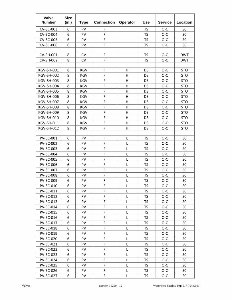
Valves Section 15250 - 12 Water Rec Facility Imp/017-7244.001
Valve Number
Size (in.) Type Connection Operator Use Service Location
CV-SC-003 6 PV F TS O-C SC
CV-SC-004 6 PV F TS O-C SC
CV-SC-005 6 PV F TS O-C SC
CV-SC-006 6 PV F TS O-C SC
CV-SH-001 8 CV F TS O-C DWT
CV-SH-002 8 CV F TS O-C DWT
KGV-SH-001 8 KGV F H DS O-C STO
KGV-SH-002 8 KGV F H DS O-C STO
KGV-SH-003 8 KGV F H DS O-C STO
KGV-SH-004 8 KGV F H DS O-C STO
KGV-SH-005 8 KGV F H DS O-C STO
KGV-SH-006 8 KGV F H DS O-C STO
KGV-SH-007 8 KGV F H DS O-C STO
KGV-SH-008 8 KGV F H DS O-C STO
KGV-SH-009 8 KGV F H DS O-C STO
KGV-SH-010 8 KGV F H DS O-C STO
KGV-SH-011 8 KGV F H DS O-C STO
KGV-SH-012 8 KGV F H DS O-C STO
PV-SC-001 6 PV F L TS O-C SC
PV-SC-002 6 PV F L TS O-C SC
PV-SC-003 6 PV F L TS O-C SC
PV-SC-004 6 PV F L TS O-C SC
PV-SC-005 6 PV F L TS O-C SC
PV-SC-006 6 PV F L TS O-C SC
PV-SC-007 6 PV F L TS O-C SC
PV-SC-008 6 PV F L TS O-C SC
PV-SC-009 6 PV F L TS O-C SC
PV-SC-010 6 PV F L TS O-C SC
PV-SC-011 6 PV F L TS O-C SC
PV-SC-012 6 PV F L TS O-C SC
PV-SC-013 6 PV F L TS O-C SC
PV-SC-014 6 PV F L TS O-C SC
PV-SC-015 6 PV F L TS O-C SC
PV-SC-016 6 PV F L TS O-C SC
PV-SC-017 6 PV F L TS O-C SC
PV-SC-018 6 PV F L TS O-C SC
PV-SC-019 6 PV F L TS O-C SC
PV-SC-020 6 PV F L TS O-C SC
PV-SC-021 6 PV F L TS O-C SC
PV-SC-022 6 PV F L TS O-C SC
PV-SC-023 6 PV F L TS O-C SC
PV-SC-024 6 PV F L TS O-C SC
PV-SC-025 6 PV F L TS O-C SC
PV-SC-026 6 PV F L TS O-C SC
PV-SC-027 6 PV F L TS O-C SC
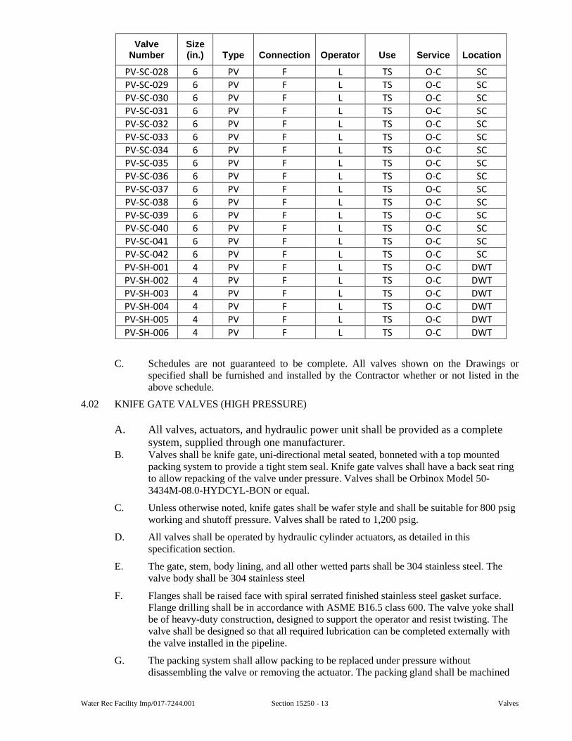
Water Rec Facility Imp/017-7244.001 Section 15250 - 13 Valves
Valve Number
Size (in.) Type Connection Operator Use Service Location
PV-SC-028 6 PV F L TS O-C SC
PV-SC-029 6 PV F L TS O-C SC
PV-SC-030 6 PV F L TS O-C SC
PV-SC-031 6 PV F L TS O-C SC
PV-SC-032 6 PV F L TS O-C SC
PV-SC-033 6 PV F L TS O-C SC
PV-SC-034 6 PV F L TS O-C SC
PV-SC-035 6 PV F L TS O-C SC
PV-SC-036 6 PV F L TS O-C SC
PV-SC-037 6 PV F L TS O-C SC
PV-SC-038 6 PV F L TS O-C SC
PV-SC-039 6 PV F L TS O-C SC
PV-SC-040 6 PV F L TS O-C SC
PV-SC-041 6 PV F L TS O-C SC
PV-SC-042 6 PV F L TS O-C SC
PV-SH-001 4 PV F L TS O-C DWT
PV-SH-002 4 PV F L TS O-C DWT
PV-SH-003 4 PV F L TS O-C DWT
PV-SH-004 4 PV F L TS O-C DWT
PV-SH-005 4 PV F L TS O-C DWT
PV-SH-006 4 PV F L TS O-C DWT
C. Schedules are not guaranteed to be complete. All valves shown on the Drawings or specified shall be furnished and installed by the Contractor whether or not listed in the above schedule.
4.02 KNIFE GATE VALVES (HIGH PRESSURE)
A. All valves, actuators, and hydraulic power unit shall be provided as a complete system, supplied through one manufacturer.
B. Valves shall be knife gate, uni-directional metal seated, bonneted with a top mounted packing system to provide a tight stem seal. Knife gate valves shall have a back seat ring to allow repacking of the valve under pressure. Valves shall be Orbinox Model 50-3434M-08.0-HYDCYL-BON or equal.
C. Unless otherwise noted, knife gates shall be wafer style and shall be suitable for 800 psig working and shutoff pressure. Valves shall be rated to 1,200 psig.
D. All valves shall be operated by hydraulic cylinder actuators, as detailed in this specification section.
E. The gate, stem, body lining, and all other wetted parts shall be 304 stainless steel. The valve body shall be 304 stainless steel
F. Flanges shall be raised face with spiral serrated finished stainless steel gasket surface. Flange drilling shall be in accordance with ASME B16.5 class 600. The valve yoke shall be of heavy-duty construction, designed to support the operator and resist twisting. The valve shall be designed so that all required lubrication can be completed externally with the valve installed in the pipeline.
G. The packing system shall allow packing to be replaced under pressure without disassembling the valve or removing the actuator. The packing gland shall be machined
Valves Section 15250 - 14 Water Rec Facility Imp/017-7244.001
on the bottom to mate with the machined stem back seat ring. The packing gland and the packing follower shall be Type 304 stainless steel. The fasteners shall be stainless steel.
H. Valves shall be enclosed within a pressure retaining bonnet that fully encloses the gate. The bonnet shall be rated at the same pressure as the valve body and shall not include any type of internal gate packing or gate wiper. Valve inside port diameter shall conform to MSS SP-81 requirements.
I. Gate shall be ground and polished to a minimum surface finish of 32 micro-inch RMS. The gate shall be guided over the full stroke and shall be fully wedged at the top and bottom of the port.
J. The packing shall be replaceable without disassembling the valve or removing the valve from the pipeline. The Contractor shall provide additional packing to re-build each valve twice.
K. Materials
1. All parts of the body and bonnet shall be Type 304 stainless steel, including fasteners.
2. The valve seats shall be 304 SS. Stem shall be with Acme threads.
3. The stem nut shall be of acid-resisting Bronze.
4. The packing shall be Teflon-impregnated synthetic fiber, without asbestos
L. Unless otherwise noted, knife gates shall be wafer style and shall be suitable for 900 psig working and shutoff pressure. Valves shall be rated to 1,500 psig.
M. The gate, stem, body lining, and all other wetted parts shall be 304 stainless steel. The valve body shall be 304 stainless steel.
N. Valves shall be enclosed within a pressure retaining bonnet.
O. Flanges shall be raised face with spiral serrated finished stainless steel gasket surface. Flange drilling shall be in accordance with ASME B16.5 Class 600.
P. The valve yoke shall be of heavy-duty construction, designed to support the operator and resist twisting.
Q. The valve shall be designed so that all required lubrication can be completed externally with the valve installed in the pipeline.
R. The packing system shall allow packing to be replaced under pressure without disassembling the valve or removing the actuator. The packing gland shall be machined on the bottom to mate with the machined stem Back-Seat ring. The packing gland and the packing follower shall be Type 304 stainless steel. The fasteners shall be stainless steel.
S. Materials:
1. Body:
a. Bonnet shall be pressure-retaining type that fully encloses the gate. The bonnet shall be rated at the same pressure as the valve body and shall not include any type of internal gate packing or gate wiper. All parts of the body and bonnet shall be Type 304 stainless steel, including fasteners. Valve inside port diameter shall conform to MSS SP-81 requirements.
Water Rec Facility Imp/017-7244.001 Section 15250 - 15 Valves
2. Gate:
a. Gate shall be ground and polished to a minimum surface finish of 32 micro-inch RMS. The gate shall be guided over the full stroke. The gate shall be fully wedged at the top and bottom of the port
3. Seat:
a. Valve seats and stem shall be Type 304 stainless steel. Stem shall be with Acme threads
4. Stem Nut:
a. Stem nut shall be of acid-resisting Bronze.
5. Packing:
a. Packing shall be Teflon-impregnated synthetic fiber, without asbestos. The packing shall be replaceable without disassembling the valve or removing the valve from the pipeline. The Contractor shall provide additional packing to re-build each valve twice.
T. Valves shall be knife gate, uni-directional metal seated, bonneted with a top mounted packing system to provide a tight stem seal and a Back-Seat ring to allow repacking the valve under pressure. Valves shall be H-200-B150C-ST304 as manufactured by Hilton Valve of Redmond, WA., or equal.
U. Hydraulic Actuator:
1. Actuators shall be provided by, mounted, and tested by the Valve Manufacturer. Hydraulic actuators shall be heavy duty, 3,000PSI, double acting type.
2. Minimum Cylinder requirements shall be as follows:
a. Bore Size: 6"
b. Rod Size: 2 ½”
c. Stroke length: 9.00”
d. Cylinder performance at 2,000 psi supply: break to close torque = 56,548 pounds, break to open torque = 46,731 pounds
e. Cylinder displacement volume: 254 cubic inch per stroke
f. Rod End: Small female rod end KK=1 7/8"-12 with 4 wrench flats
g. Materials of Construction:
i. Head & Cap: Carbon Steel
ii. Barrel: Honed Seamless Carbon Steel
iii. Piston: Ductile Iron
iv. Piston Rod: SAE 1045 Stressproof Steel, Chrome Plated
v. Gland: SAE 660 Bronze
vi. Tie-Rods: SAE 1045 Stressproof Steel
h. Safety Integrity Level: SIL3 Capable Certification
i. Cushioning: No cushions
j. Seals: Standard seals (-40 F to 221 F)
k. Piston seals: Standard High Load Bidirectional Piston Seal, PTFE with Nitrile energizer
Valves Section 15250 - 16 Water Rec Facility Imp/017-7244.001
l. Wear rings: High Strength Nylon
m. Gland: Cartridge type
n. Gland seals: Standard GT3 Triple Seal Configuration with dual wiper
o. Buffer seal: Low-friction Long-Life Nitrile-energized PTFE
p. Primary Seal: Heavy Duty Polyurethane U-Cup with built-in wiper
q. Rod Wiper: Encased Polyurethane U-Cup
r. Piston-to-rod joint: oversized to match piston-rod diameter
s. Ports: #16 SAE
t. Ports Location: 1 both ends (Std)
u. Mounting Pattern: ME5 mount, Head rectangular
V. Hydraulic Power Unit (HPU):
1. The HPU shall be a completely self-contained, factory assembled unit. The frame shall be made of welded carbon steel construction adequate to support all components and designed to be anchored to a suitable base. It shall be designed for use in Water/Wastewater treatment facilities with SCADA enabled logic controller activated from a third party control center located 150 ft from the HPU. HPU shall be provided by the Valve Manufacturer.
2. The HPU shall be fitted with an ethernet-compatible Control System to respond to SCADA commands to operate hydraulic actuators according to predefined logic (Start/Stop, East Cake Pump, West Cake Pump, and 6 discharge points (bunker 1 east, bunker 1 west…bunker 3 east, bunker 3 west) determined by analysis of actuator position sensor feedback. The control system shall also include alarm and fault signal management in order to provide emergency shut-down of the HPU and cooling system.
3. The HPU shall be sized to operate 12 double-acting hydraulic actuators, each mounted on one knife gate valve.
4. A dual pumping system shall be provided. The main pump sized to operate one only hydraulic actuator at once. Combined with the secondary pump, two hydraulic actuators can be operated simultaneously without compromising the operating speed of either actuator provided no unaccounted restrictions or external forces are observed. Pump capacity selected to allow approximate stroke speed of 0.5 inches/second of the installed hydraulic actuator.
5. HPU shall integrate an automatic timer-based Loop Flushing System local to each actuator in order to allow all hydraulic fluid to be recirculated through the HPU filtration system. Actuators must be in fully extended position in order to initiate Loop Flush.
6. Flexible hose from the HPU to the pump shall be provided by the pump manufacturer. Manufacturer shall provide 30 feet of hose in both locations.
7. Hydraulic lines shall be seamless carbon steel hydraulic tubing with flexible hose connections having ball valves to permit connection and disconnection at the unit. Tubing shall be rated for 1,500 psig continuous operation.
8. Minimum Requirements:
a. Pump: Dual, 4 GPM, Tandem configuration
b. Pump Motor: Maximum 15 HP, 460 VAC/3Ph/60Hz
c. Reservoir: 30 Gallons with retention basin
Water Rec Facility Imp/017-7244.001 Section 15250 - 17 Valves
d. Main Manifold Block: 14 hydraulic solenoid valves: 12 for actuators with manual override and 2 for pump recirculation without manual override.
e. Cooling System: with independent 1/3 HP motor, 460/3Ph/60Hz
f. Operating Temperature Range: 40 F to 100 F
g. Manual Override: Hand Pump
h. Filtration System: 10 micron upon return to reservoir
i. Hydraulic Fluid Type: ISO VG 32
j. Electronic Sensors: Level, temperature, low level
k. Loop Flush System: Local to actuator. Automatic timer based
l. Loop Flush Manifold Block: 12 hydraulic solenoid valves. 120 VAC
9. Welding and Painting according to Manufacturers’ standard procedures.
10. Logicon Control System includes:
a. Main Control Panel and terminal box (double cabinet), Stainless Steel, CSA/UL with AB Micro 850 PLC
b. 12 GREEN lights to indicate valve open position, 12 RED lights to indicate valve closed position
c. Lights for alarms and faults as follows
i. Clogged Filter alarm
ii. High Temperature alarm
iii. Low Level alarm
iv. System running with blinking alarm code
v. System stopped with blinking alarm code
vi. Automatic Loop Flush running
vii. Cabinet LED lighting
d. Main Power Panel and terminal box, Stainless Steel, CSA/UL
e. Emergency Stop pushbutton
f. Fusible Disconnect Switch, 60A
g. Pump Motor Starter and contactor
h. Cooling system Motor Starter and contactor
i. Control Transformer, 3000 VA
j. 24 VDC Power block
11. All hydraulic lines required to connect the HPU to the valve actuators shall be provided by the CONTRACTOR.
END OF SECTION

Valves Section 15250 - 18 Water Rec Facility Imp/017-7244.001
This page was intentionally left blank.
Water Rec Facility Imp/017-7244.001 Section 15260 - 1 Slide Gates
SECTION 15260
SLIDE GATES
GENERAL
1.01 SCOPE
A. This Section includes wall thimbles, gate frames, slide gates, floor stands, extension stems, stem guides, operating devices, position indicators, wall brackets, floor boxes, anchors, and all appurtenances.
B. Motors and electrical work incidental to installation and operation of the gates shall be included herewith unless specified otherwise.
1.02 SUBMITTALS
A. Submittals shall be in accordance with the requirements of Section 01300 and shall include:
1. Shop Drawings for Review:
a. Scaled dimensional drawings.
b. Wiring schematics with termination point identification.
c. Materials of construction.
d. Manufacturer’s catalog data.
e. Motor information per Section 11050.
2. Information for the Record:
a. Operation and Maintenance Manual information.
1.03 QUALITY ASSURANCE
A. Slide gates and their appurtenances shall conform to applicable portions of AWWA C560, C561, C562 or C563, depending upon materials of construction.
PRODUCTS
2.01 MATERIALS
A. Slide Gates (Stainless Steel):
1. All slide gates shown on the Drawings or listed in the specifications shall conform in all respects to the latest version of AWWA C561, with the noted changes and additions. Materials used in construction of slide gates and appurtenances shall conform to the following specifications:
a. Frame, Slide, Yoke, and Reinforcing: Stainless Steel, ASTM A240/A240M, Type 304L, or ASTM A240/A240M, Type 316L.
b. Stainless Steel for stems: ASTM A-276, Type 304.
c. Stainless Steel for fasteners: F-593/F-594, Alloy Group 1, 2 (SS304, SS316).
d. Invert seals and compression load pad: Neopreone, ASTM D2000, 60 Durometer, with a stainless steel ASTM A276, Type 304L, or Type 316L retainer bar.
e. Side Seals: Ultra High Molecular Weight (UHMW) Polymer, ASTM D4040.
Slide Gates Section 15260 - 2 Water Rec Facility Imp/017-7244.001
f. Top Wedges: Type 316 Stainless Steel ASTM A351-CF8M.
2. The gate frame shall be an integral unit of structural shapes, rigidly assembled to form the waterway opening. The head channels shall be welded or bolted to the gate frame. The channels shall be sufficiently spaced to allow removal of the gate slide. The primary slot of the frame shall contain polymer guide liner retained in grooves, to prevent metal-to-metal contact between slide and frame.
3. Gate slide shall be not less than ¼-inch thickness and shall be reinforced such that deflection under full head shall be limited to 1/720 of the span. Gates over 24 inches wide shall have adjustable top wedges in order to prevent deflection in the slide resulting from over closure.
4. Slide gates where required shall incorporate a flush-bottom seal of neoprene that is mechanically fastened to the bottom frame invert member.
5. Side seals of UHMW polymer shall be provided. Seals shall be securely fastened to the frame with non-corrosive retainers and shall be replaceable and adjustable without removing the gate from the installed position. A compression device shall be set behind the UHMW seal to allow for a self-adjusting seal system.
6. The operating stem shall be of a size to safely withstand, without buckling or permanent distortion, the stresses resulting from at least two times the rated output of the floor stand or bench stand with a 40-pound effort on the crank or handwheel. The threaded portion of the stem shall have cold rolled threads. Stainless steel couplings, threaded and keyed to the stems, shall join stems of more than one section. Manually operated, rising stem type gates will be provided with an adjustable stop collar on the stem to prevent over-opening of the gate.
7. On slide gates with a width greater than twice the height and the width is greater than 48 inches, a tandem stem arrangement shall be used.
8. Gate lifts shall be handwheel or geared crank type as shown on the Drawings. Lifts shall operate the gate with a maximum pull of 40 pounds on the handwheel or crank, the center of which shall be located approximately 36 inches above the operating floor. All lifts shall have thrust bearings, bronze lift nuts, and an aluminum stop nut to limit the downward travel of the stem and slide. All geared lifts shall have cast or ductile iron housings and pedestals. All lifts shall be rising stem type. Stem covers made of clear polycarbonate with position indication shall be furnished for all lifts. Lifts shall be grease lubricated through grease zerk fittings.
9. Where indicated on the Drawings or specified, motorized gate operators shall be furnished and installed.
2.02 LIFT ASSEMBLIES
A. Floor stands shall be of the enclosed gear pedestal lift type with single or double gears as required, and with thrust bearings above and below the flange on the bronze lifting nut. Bevel and pinion gears shall be steel with cut teeth, and spur gear shall be cast iron with cut teeth. Bearings for the gear and pinion shaft shall be bronze brushed. The lift shall operate on a 40-pound pull on the crank. A heavy-duty translucent PVC pipe stem cover shall be provided.
B. The guides on self-contained gates shall extend above the operating floor. They shall be sufficiently strong so that additional reinforcing is not necessary. The yoke to support the operating bench stand will be formed by two channels across the top of the guides. They shall be sufficiently spaced to allow removal of the gate slide. All lifts shall have thrust bearings, bronze lift nut, and a stop nut.
Water Rec Facility Imp/017-7244.001 Section 15260 - 3 Slide Gates
2.03 ELECTRIC GATE OPERATOR
A. General:
1. The operator shall be a helical and worm gear type drive by an electric motor.
2. The operator shall be suitable for use on a 460 volt, 3 phase, 60 Hertz power supply and are to incorporate, integral reversing starter, local control facilities, and terminals for remote control and indication connections.
3. The operator shall include a device to ensure that the motor runs with the correct rotation for the required direction of valve travel with either phase sequence of the 3-phase power supply connected to the actuator.
4. It shall be possible to carry out the setting of the torque, turns, and configurations of the indication contacts without the necessity to remove any electrical compartment covers.
5. The operator shall be capable of functioning in an ambient temperature ranging from minus 10 degrees F to 120 degrees F.
6. The operators shall be Rotork Controls, Inc. Model IQM or Limitorque MX or QX for modulating service and Model IQ or Limitorque MX or QX for open-close service or equal.
B. Operator Sizing - The operator shall be sized to guarantee valve closure at the specified differential pressure. The safety margin of motor power available for seating and unseating the valve shall be sufficient to ensure torque switch trip at maximum valve torque with the supply voltage 10 percent below nominal. The operating speed shall be such as to give valve closing and opening at approximately 60 seconds unless otherwise stated in the specifications.
C. Motor:
1. The electric motor for modulating service shall be Class F insulated and the motor for open-close service shall be Class-F insulated. The motor shall be a suitable rated 4-poled motor.
2. Electrical and mechanical disconnection of the motor should be possible without draining or loss of the lubricant from the actuator gearcase. Plugs and sockets are not acceptable as a means of electrical connection for the motor.
3. Protection shall be provided for the motor as follows:
a. The motor shall be de-energized in the event of stall when attempting to unseat a jammed valve.
b. Motor temperature shall be sensed by a thermostat to protect against overheating.
c. Single phasing protection.
D. Gearing:
1. The operator gearing shall be totally enclosed in an oil-filled gearcase suitable for operation at any angle. All main drive gearing must be of metal construction. For modulating applications the hammer blow backlash shall be omitted from the output gear train. For rising spindle valves, the output shaft shall be hollow to accept a rising stem and incorporate thrust bearings of the ball or roller type at the base of the actuator, and the design should be such as to permit the gearcase to be opened for inspection or disassembled without releasing the stem thrust or taking the valve out of service.
Slide Gates Section 15260 - 4 Water Rec Facility Imp/017-7244.001
2. Standard gear oil shall be used to lubricate the gearcase. Special or exotic lubricants shall not be used as they may be difficult to source in remote locations.
E. Hand Operation:
1. A hand wheel shall be provided for emergency operation engaged when the motor is declutched by a lever or similar means; the drive being restored to power automatically by starting the motor. The hand/auto selection lever should be padlockable in both “Hand” and “Auto” positions. It should be possible to select hand operation while the actuator is running or start the actuator motor while the hand/auto selection lever is locked in “Hand” without damage to the drive train.
2. The hand wheel drive must be mechanically independent of the motor drive, and any gearing should be such as to permit emergency manual operation in a reasonable time. Clockwise operation of the hand wheel shall give closing movement of the valve unless otherwise stated in the job specifications.
F. Drive Bushing - The operator shall be furnished with a drive bushing easily detachable for machining to suit the valve stem or gearbox input shaft. Normally the drive bush shall be positioned in a detachable base of the actuator. Thrust bearings, when housed in a separate thrust base, should be of the sealed-for-life type.
G. Torque and Turns and Positional Accuracy:
1. Torque and turns limitation to be adjustable as follows:
2. Position setting range - 0.5 to 10,000 turns, with resolution to 15 degrees of operator output.
3. Torque setting - 40 percent to 100 percent rated torque.
4. “Latching” to be provided for the torque sensing system to inhibit torque off during unseating or during mid-travel against high inertia loads.
5. With analogue inputs via the modulating controller, overall accuracy (actuator mechanical output/demand shall be 0.5 percent.
6. The electric circuit diagram of the actuator should not vary with valve type remaining identical regardless of whether the valve is to open or close on torque or position limit.
H. Remote Valve Position/Operator Status Indication:
1. The operator must provide an Absolute Position Encoder which provides continuous monitoring of valve position during motor or hand wheel operation even when the power supply is not present without the use of a battery to maintain the memory.
2. In the event of a (main) power (supply) loss or failure, the position Encoder must continue to monitor position.
3. If the actuator is not provided with an Absolute Position Encoder, a battery back-up power source must be provided in the actuator to ensure correct remote indication should the actuator be moved manually when the power supply is interrupted. The manufacturer shall provide a recommended maintenance interval schedule on replacement of the battery(s) and associated training for site personnel at no additional cost to the site.
4. The position of the actuator and valve must be stored or updated contemporaneously, even when the power supply is not present.
5. Four contacts shall be provided which can be selected to indicate any position of the valve with each contact selectable as normally open or normally closed. The contacts shall be rated at 5A, 250V AC, 30V DC.
Water Rec Facility Imp/017-7244.001 Section 15260 - 5 Slide Gates
6. As an alternative to providing valve position, any of the four above contacts shall be selectable to signal one of the following:
a. Valve Opening or Closing.
b. Valve Moving (Continuous or Pulsing).
c. Motor Tripped on Torque in Mid-Travel.
d. Motor Stalled.
e. Actuator Being Operated by Handwheel.
I. Local Position Indication:
1. The operator shall include a digital position indicator with a display from fully open to fully closed in 1 percent increments. Red, green, and yellow lights corresponding to Open, Closed, and Intermediate positions shall be included on the actuator. The digital display shall be maintained or stored even when the power to the actuator is isolated.
2. The local display should be large enough to be viewed from a distance of six feet when the actuator is powered up.
3. Operators for modulating service shall have a contactless transmitter to give a 4-20mA analog signal corresponding to valve travel for remote indication. Operators for open-close service shall transmit an open or closed discrete signal.
J. Integral Starter and Transformer:
1. The reversing starter, control transformer, and local controls shall be integral with the valve actuator, suitably housed to prevent breathing and condensation buildup. For Open-Close service, this starter shall be electromechanical type suitable for 60 starts per hour and of rating appropriate to motor size. For modulating duty, the starter shall be solid state and suitable for up to a maximum of 1,200 starts per hour or as required by the application. The modulating service the actuator shall also include dynamic braking. The controls supply transformer shall be from two of the incoming three phases. It shall have the necessary tappings and be adequately rated to power for the following functions:
a. 120V AC energization of the contactor coils.
b. 24V DC output where required for remote controls.
c. Supply for all the internal electrical circuits.
2. The primary and secondary windings shall be protected by easily replaceable fuses.
K. Integral Push-buttons and Selector:
1. Integral to the operator shall be local controls for Open, Close, and Stop, and a local/remote selector switch padlockable in any one of the following three positions:
a. Local Control Only.
b. Off (No Electrical Operation).
c. Remote Control plus Local Stop Only.
2. It shall be possible to select maintained or non-maintained local control.
3. The local controls shall be arranged so that the direction of valve travel can be reversed without the necessity of stopping the actuator.
Slide Gates Section 15260 - 6 Water Rec Facility Imp/017-7244.001
L. Control Facilities:
1. The necessary wiring and terminals shall be provided in the operator for the following control functions:
a. Removable links for substitution by external interlocks to inhibit valve opening and/or closing.
b. Connections for external remote controls fed from an internal 24V DC supply and/or from an external supply of (minimum 12V, maximum 120V) to be suitable for any one or more of the following methods of control:
1) Open, Close, and Stop.
2) Open and Close.
3) Overriding Emergency, Shutdown to Close (or Open) Valve from a “Make” Contact.
4) Two-Wire Control, Energize to Close (or Open), De-Energize to Open (or Close).
c. Selection of maintained or push-to-run control for modes (A) and (B) above shall be provided and it shall be possible to reverse valve travel without the necessity of stopping the actuator. The starter contactors shall be protected from excessive current surges during travel reversal by an automatic time delay on energization of approximately 300 ms.
d. The internal circuits associated with the remote control and monitoring functions are to be designed to withstand simulated lightning impulses of up to 1.1 kV.
M. Monitoring & Diagnostics Facilities:
1. Facilities shall be provided for monitoring operator operation and availability as follows:
2. Monitor (availability) relay, having one change-over contact, the relay being energized from the control transformer only when the Local/Off/Remote selector is in the “Remote” position to indicate that the actuator is available for remote (control room) operation.
3. Where required, it shall be possible to provide indication of thermostat trip and “Remote” selected as discreet signals.
4. A non-intrusive hand-held computer or software and cables capable of running on a standard laptop PC, capable of duplex communicator for uploading and downloading all variables for the actuator as well as performing detailed diagnostics shall be provided.
5. Provision shall be made for the addition of diagnostic module which will store and enable download of historical actuator data to permit analysis of changes in operator or valve performance.
6. Diagnostic status screens must be provided to show multiple functions simultaneously so troubleshooting can be affected rapidly and efficiently. All diagnostic information should be contained on no more than seven or eight screens so multiple functions can be checked simultaneously.
Water Rec Facility Imp/017-7244.001 Section 15260 - 7 Slide Gates
N. Wiring and Terminals:
1. Internal wiring shall be of tropical grade PVC insulated stranded cable of appropriate size for the control and three-phase power. Each wire shall be clearly identified at each end.
2. The terminals shall be embedded in a terminal block of high tracking resistance compound.
3. The terminal compartment shall be separated from the inner electrical components of the actuator by means of a watertight seal.
4. The terminal compartment of the operator shall be provided with a minimum of three threaded cable entries.
5. All wiring supplied as part of the operator to be contained within the main enclosure for physical and environmental protection. External conduit connections between components are not acceptable.
6. Control logic circuit boards and relay boards must be mounted on plastic mounts to comply with double insulated standards. No more than a single primary size fuse shall be provided to minimize the need to remove single covers for replacement.
7. A durable terminal identification card showing plan of terminals shall be provided attached to the inside of terminal box cover indicating:
a. Serial Number.
b. External Voltage Values.
c. Wiring Diagram Number.
d. Terminal Layout.
8. This must be suitable for the Contractor to inscribe cable core identification beside terminal numbers.
O. Enclosure:
1. Operator shall be “O-ring sealed, watertight to NEMA 6 minimum, and shall at the same time have an inner watertight and dustproof “O-ring seal between the terminal compartment and the internal electrical elements of the operator fully protecting the motor and all other internal electrical elements of the operator from ingress of moisture and dust when the terminal cover is removed on site for cabling.
2. Enclosure must allow for temporary site storage without the need for electrical supply connection.
3. All external fasteners should be of stainless steel.
4. Operator for explosion/hazardous applications shall in addition be certified flameproof for Zones 1 and 2 (Divisions 1 and 2) Group gases.
P. Startup Kit - Each operator shall be supplied with a startup kit comprising installation instruction, electrical wiring diagram, and sufficient spare cover screws and seals to make good any site losses during the commissioning period.
Q. Performance Test Certificate:
1. Each operator must be performance tested and individual test certificates shall be supplied free-of-charge. The test equipment should simulate a typical valve load and the following parameters should be recorded:
a. Current at maximum torque setting.
b. Torque at maximum torque setting.
Slide Gates Section 15260 - 8 Water Rec Facility Imp/017-7244.001
c. Flash Test Voltage.
d. Actuator Output Speed or Operating Time.
2. In addition, the test certificate should record details of specification, such as gear ratios for both manual and automatic drive, closing direction, and wiring diagram code number.
R. Warranty - Each operator shall be warranted for a minimum of 24 months of operation up to a maximum of 36 months from shipment.
2.04 GATE OPERATION
A. Opening Direction - Unless otherwise specified in Part 4, gates with screw stems shall open by turning counterclockwise, the direction being indicated by an arrow cast where easily visible to operator.
2.05 ACCESSORIES
A. Operating stems and extensions shall be ASTM A-276 stainless steel with high finish corrosion-resistant restraint threads and shall operate without binding or jamming in the lift nut. Stems shall be of sufficient cross section to withstand the normal forces created during gate operation.
B. Adjustable cast iron stem guides with bronze bushings shall be provided at the spacing recommended by the manufacturer.
C. All gates which are to be operated by T-wrench shall have 2-inch square operating nut at the top of the extension stem. Where the operating nut extends through a concrete slab, a cast iron floor box with bronze bushing shall be cast in the concrete.
D. All fasteners and hardware for mounting shall be 304 stainless steel.
2.06 SHOP PAINTING
A. Shop painting shall be in accordance with the requirements of Section 01350.
EXECUTION
3.01 INSTALLATION
A. Installation shall be as shown on the Drawings and in conformance with AWWA C560 for cast iron slide gates, AWWA C561 for fabricated stainless steel slide gates, AWWA C562 for fabricated aluminum slide gates or AWWA C563 for fabricated composite slide gates.
3.02 TESTING
A. After installation the Contractor shall test each gate for satisfactory operation and water tightness against maximum operating pressure insofar as practicable.
SPECIAL PROVISIONS
4.01 REPAIRS TO EXISTING SLUICE GATES
A. Repairs shall be made to eight existing sluice gates located in channels upstream and downstream of each of the four coarse screen channels in the Bar Screen Building. The sluice gates are Rodney Hunt Cast Iron Series HY-Q-240 and are 60 inches by 72 inches. They were provided on Order No. 82447 in 1979 to Associated Mechanical Services, Inc.
B. The repairs shall consist of removing and furnishing and installing new stems, couplings, thrust nuts, stem guides and motorized actuators. The stems are 2 inches in diameter, fabricated from 303 stainless steel.
C. Stems shall consist of two segments with the upper segment 14 feet-0 inches long with 79 inches of left hand Acme threads. The threaded portion shall be installed in the existing
Water Rec Facility Imp/017-7244.001 Section 15260 - 9 Slide Gates
operating stand with new electric actuator. The bottom segment is 15 feet-6 inches long. A bronze thrust nut shall be attached to the bottom segment. The stem coupling shall be bronze.
D. Three new stem guides shall be provided for each new stem. The stem guides shall be split type of cast iron with bronze bushing. They shall be adjustable for stem centerlines from 7-7/8 inches to 13-3/4 inches from the wall. They shall be attached to existing ¾-inch diameter stainless steel anchor bolts with new stainless steel washers and nuts. The bolt holes shall be 7/8 inches in diameter and slotted horizontally 1-1/2 inches long.
E. The existing materials and dimensions shall be verified in the field by the Contractor prior to ordering the replacement parts.
F. The sluice gates upstream of the screens shall be accessed by installing a temporary bulkhead in existing cast iron stop plank grooves. The grooves are 2-1/4 inches wide and span a 5 feet-0 inch wide channel. The upstream water depth will need to be coordinated with the WRF staff but may be in the range of 6 to 7 feet deep. The bulkhead will provide a working space of about 5 to 6 feet in front of the sluice gate. The Contractor shall be responsible to dewater the space behind the bulkhead and handle the leakage past the bulkhead by pumping into an adjacent screen channel.
G. The Owner shall close the upstream and downstream sluice gates in each screen channel and will initially dewater the area between the upstream and downstream sluice gates. This will allow access to the downstream sluice gates in each channel. The Contractor shall be responsible to handle the reasonable leakage past the sluice gates while performing work in the screen channels.
END OF SECTION

Slide Gates Section 15260 - 10 Water Rec Facility Imp/017-7244.001
This page was intentionally left blank.
Water Rec Facility Imp/017-7244.001 Section 15400 - 1 Plumbing
SECTION 15400
PLUMBING
GENERAL
1.01 SCOPE
A. This Section includes furnishing and installing all necessary plumbing components, connecting piping, and accessories, and a complete plumbing system for each service or combination of services.
B. Each system shall be adequate to conduct and control the flow of hot and cold potable water, sanitary lines, vents, roof drains, or other uses as specified or shown on the Drawings.
C. Plumbing is defined to include all potable water and all building sanitary drainage and vents and all building storm drainage of every size located in all buildings and up to a point, 5-feet - 0-inch outside each building.
D. Work includes, but is not limited to:
1. Securing and bearing the cost of all permits, certificates, and inspection as required by local regulations and state plumbing codes.
2. All pipe, fittings, and connections to sanitary fixtures for potable water supply and waste, including vents, roof drains, floor drains, equipment drains, traps, cleanouts, and backwater valves.
3. Pressure gauges, thermometers, control devices, pipe hangers, anchors, supports, hose bibbs, sill cocks, and sleeves.
4. Potable water supply to boiler makeup water stop valves, or other equipment requiring these services.
5. Pipe insulation complete with jacket as required by Section 15504.
6. Sanitary fixtures, sinks, lavatories, backflow preventer valves, water coolers, acid neutralizing basins, oil and grease separators, and water heaters.
E. Additional product requirements are specified in Section 01350.
F. All equipment, materials, and work shall comply with Federal, State, and local plumbing codes. Equipment materials and work specifically required by Federal, State, or local plumbing codes whether or not shown on the Drawings or specified shall be provided by the Contractor at no change in Contract Price.
1.02 SUBMITTALS
A. Submittals shall be in accordance with the requirements of Section 01300 and shall include:
1. Shop Drawings for Review:
a. Manufacturer’s literature.
2. Information for the Record:
a. Material certificates.
b. Licenses and permits.
c. Operation and Maintenance Manual.
Plumbing Section 15400 - 2 Water Rec Facility Imp/017-7244.001
1.03 CONTRACT DRAWINGS
A. All Drawings are diagrammatic and are intended to show the approximate location of equipment and piping.
B. The exact location of apparatus, fixtures, equipment, and piping shall be ascertained by the Contractor in the field, and the work shall be laid out accordingly. Should the Contractor fail to ascertain such locations, the work shall be changed at his own expense when so ordered by the Engineer. The Engineer reserves the right to make minor changes in the location of piping and equipment up to the time of installation without additional cost to Owner.
1.04 PROTECTION FROM DAMAGE
A. Delivery, Handling, and Storage:
1. Material delivery, handling, and storage shall meet the requirements of Section 01350.
2. All valves, toilet fixtures, and appurtenances shall be crated before shipment.
3. All plastic fixtures and pipe, if stored outside, shall be covered with an opaque material to protect them from the sun’s rays.
B. After Installation:
1. Suitable covers and guardrails shall be placed to protect against chipping enamel or denting the surfaces of any equipment after it is installed and during the final days of construction.
2. Before acceptance, all covers and protective material shall be removed and the fixtures and equipment cleaned and ready for use.
PRODUCTS
2.01 PIPING MATERIALS
A. Copper Pipe and Tubing shall be manufactured in accordance with ASTM B-88. Type L hard temper shall be used above ground and inside of structures for hot and cold potable water and other services unless another type of pipe is specifically called for. Type K soft temper shall be used where underground piping is installed. Fittings shall be cast bronze or wrought copper with solder joints. Unions shall be cast bronze solder joint fittings manufactured in accordance with ASTM B-62 and with ends complying to ANSI B16.18. Unions shall be installed adjacent to valves and equipment and as required to assemble the piping but not less than one union shall be included in each run. Threaded adapters shall be installed on each side of valves in copper lines. Where joints are made between pipes of different materials, dielectric couplings shall be installed. Pipe nipples shall be standard weight seamless red brass pipe ASTM B-43. Solder joints shall be made in conformance with ASTM B-828 Flux conforming to ASTM B-813 shall be applied. Materials used for solder joints in all potable water services shall contain less than 0.2 percent lead and comply with ASTM B-32.
B. Polypropylene Pipe - The polypropylene homopolymer used in the manufacturing of flame retardant piping components shall be cell classification PP110-B66362 as described in ASTM D-4101. Flame retardant polypropylene materials are classified as self-extinguishing by ASTM D-635, UL - 94 and Federal Aviation Regulation FAR 25.853. Test results, conforming to ASTM E-84 and UL 723 procedures for flame spread and smoke density, resulted in a flame spread value of 12 or less, with a smoke density rating of 85 of less. Joints shall be electronically fused. Chemtrol Chem-fuse or Equal.
1. Pipe shall be iron pipe size (IPS) type in 10 - foot lengths with dimensions conforming to the requirements of ASTM D-1785 for Schedule 40 pipe. Fitting
Water Rec Facility Imp/017-7244.001 Section 15400 - 3 Plumbing
patterns shall conform to ASTM standard D-3311 for drain, waste and vent (DWV) configurations. Pipe and fitting dimensions shall be measured in accordance with ASTM D-2122. Pipe and fittings shall be tan and marked with nominal size. All materials shall be made in the U.S.A.
2. Fusion coils shall be constructed from No. 29 AWG copper magnet wire. Coil wire shall have a polypropylene coating with no gaps.
C. PVC Pipe and fittings shall be composed of Class 12454-B rigid PVC compound in conformance with ASTM D-1784 (formerly Type I, Grade 1). Pipe shall be Schedule 80 in conformance with ASTM D-1785. All joints, unless otherwise shown on the Drawings, shall be solvent welded in conformance with ASTM D-2855. Joint solvent shall be as recommended by the pipe manufacturer and shall conform to ASTM D-2564. In pressure or vacuum lines and in gravity drains 1-inch diameter and less, the fittings shall be Schedule 80 and shall conform to ASTM D-2467. For gravity drains greater than 1-inch diameter, the fittings shall conform to the requirements of ASTM D-2665.
D. CPVC Pipe shall be composed of Class CPVC 23447-B plastic as defined in ASTM D-1784 (formerly Type IV, Grade 1). Pipe shall be Schedule 80 chlorinated polyvinyl chloride pipe in accordance with ASTM F-441. Fittings shall be Schedule 80 and shall conform to ASTM F-439. All joints, unless otherwise shown on the Drawings, shall be solvent welded in conformance with ASTM D-2846. Joint solvent shall be as recommended by pipe manufacturer and shall conform to ASTM F-493. CPVC pipe shall be used where designated in Part 4 or on the Drawings.
2.02 VALVES
A. Unless otherwise specified, valves installed in pipelines 3-1/2-inch diameter and smaller for potable water lines shall be gate valves.
B. Gate valves shall be 150 pounds, all bronze, rising stem, solid wedge disc furnished with screwed or flanged ends as required. Gate valves shall be Crane No. 431, Jenkins No. 47, Powell No. 514, or equal.
C. Check valves shall be 200 pounds, all bronze body with bronze disc, y-pattern, with flanged or screwed ends as required. The check valves shall be Crane No. 36, Powell 560-Y, Jenkins 762-A, or equal. Nonslam check valve shall be used on all pipelines with 25 psi or more pressure and shall be Valve and Primer Corporation, Series 300, or equal.
D. Ball valves through 2-inch shall be screwed end bronze, two-piece, 125 psi, Teflon seats, bronze trim, and blowout-proof stem, Nibco T-580-BR-Y-20, or equal.
2.03 HOSE BIBBS
A. Hose bibbs inside buildings shall be all bronze angle hose valves Zurn Z-1341-BFP or equal, with 3/4-inch standard threaded hose connections and integral non-freeze vacuum breaker.
2.04 RESERVED
2.05 RESERVED
2.06 RESERVED
2.07 FLOOR, EQUIPMENT, AND AREA DRAINS
A. Type “A” drains with discharge piping in the slab or below slabs on grade shall be furnished with dura-coated cast iron body, round heavy duty 9-inch diameter cast iron slotted grate, sediment bucket, and integral cleanout. A backwater valve shall be furnished with the drain unless otherwise called for on the Drawings. They shall be Zurn Type Z-730, Zurn Z-550 V and P-trap, Zurn Z-742, Josam 38000-60, or equal as required by local authority. Follow Drawings for sizes and include trap primer connections as called for on the Drawings or required to finish the Work.
Plumbing Section 15400 - 4 Water Rec Facility Imp/017-7244.001
B. Type “B” drains with discharge piping below the slab shall be furnished with a dura-coated cast iron body and round heavy duty 9-inch diameter cast iron slotted grate. A backwater valve shall be furnished with the drain unless otherwise called for on the Drawings. A deep seal trap and adjustable cleanout shall be provided. Drain shall be a Zurn 540-Y-V, Josam 36100-60, or equal. Trap and cleanout shall be a Zurn Z-1012-2, Josam 88030, or equal. Follow Drawing for sizes and include trap primer connections as called for on the Drawings or required to finish the Work.
C. Exterior area of drains and area drains in unheated areas shall be provided as shown on the Drawings. Such drains shall be Zurn Type Z-509; Wade Type W-1710MS or W-1430; or equal. In-line traps with cleanouts shall be provided as shown on the Drawings.
D. Floor drainage systems shall be vented.
E. Floor sinks shall be 12-inch square rim with one-half nickel brass or bronze grate and aluminum dome strainer. They shall be Wade W-2534F, Zurn ZN-1800, or equal. A deep seal trap and adjustable cleanout shall be provided. Trap and cleanout shall be Zurn Z-1012-2, Josam 88030, or equal.
F. Cleanouts for vertical stacks shall be Zurn Supreme CO tee No. ZN-1446 or equal with cadmium plated, cast iron, countersink, plug with round, smooth, 7-inch diameter stainless steel cover.
G. Cleanouts located in poured concrete floors or slabs shall be Zurn Heavy Duty CO No. Z-1400 or equal with round, scoriated, cast iron, non-tilt adjustable height top.
H. Type “F” floor drain shall be PVC sized as required on the drawings, Ohio Plastic Oddities, RGP, or equal.
I. All PVC sanitary line components shall be as provided by Plastic Oddities, Shelby, NC, or equal.
J. Type “G” floor drains shall be, Zurn Z-610-Y, or equal, non-clog with 12-inch diameter sediment bucket. Provide trap and cleanout for each drain.
K. Type “H” floor drains shall be Zurn Z 456 or equal deep seal trap drain with floor cleanout with 5-inch diameter strainer.
L. Type “T” floor trench shall be Zurn Permatrench Z-886 or Z-882 or Polydrain or equal. Provide drain slopes, grating, end caps, catch basins, trash buckets drain sizes, and traps as required on the drawings.
2.08 PRESSURE GAUGES
A. Pressure gauges shall be 4-1/2-inch in size with fiberglass reinforced polypropylene case, phosphor bronze bourdon tube, 6-inch or 4-1/2-inch dial faces with black lettering, micrometer type pointers and an accuracy of plus 1 percent of scale range. Pressure gauge shall be H.O. Trerice No. 450 series, Ashcroft 2462 series, or equal.
B. Pressure gauges shall read in pressure or compound as required by use.
C. All pressure gauges unless otherwise directed shall include a brass pressure snubber and a needle type shut-off valve.
D. Where directed, pressure gauges shall have diaphragm seals. The gauges, seals, and snubber shall be factory assembled and filled with fluid. The diaphragm seal shall be Type 316 stainless steel with a stainless steel housing. Diaphragm seal shall be an Ashcroft 101 series, H.O. Trerice 877-2 series, or equal.
E. Pressure gauges shall be installed as shown on the Drawings.
2.09 SLEEVES
A. Type B Sleeve:
Water Rec Facility Imp/017-7244.001 Section 15400 - 5 Plumbing
1. Type B sleeves are for use in exterior walls.
2. Type B sleeves consist of casting in place a black wrought iron sleeve two sizes larger than the service pipe with couplings on both ends of the sleeve.
3. Service pipe shall be caulked in place with oakum. The oakum shall be covered with a minimum of 1-inch of lead wool on both ends.
B. Type C Sleeve:
1. Type C sleeves are used in exterior walls and other walls as designated on the Drawings.
2. Type C shall be a modular mechanical type seal of interlocking synthetic rubber links.
3. Unless otherwise indicated, the seal shall be suitable for corrosive service in a temperature range of 40 degree F to 250 degree F. The pressure plates shall be of delrin plastic for good resistance to organic compounds. The bolts and nuts shall be of 18-8 stainless steel. The sealing elements shall be of EPDM rubber which has high resistance to most organic and inorganic materials.
C. Type D Floor Sleeve - Type D sleeves consist of casting in place a Schedule 40 steel sleeve with four anchors in the floor slab. The sleeve shall be one size larger than the service pipe or 1-inch larger than the flange on the service pipe. The sleeve shall extend 1-inch above the finish floor surface.
D. Type E Sleeve:
1. Type E wall sleeves shall be used where noted on the Drawings.
2. Type E sleeves consist of casting in place mechanical joint, cast iron wall sleeves meeting the requirements of AWWA C110 and C111.
3. Each Type E sleeve shall be sealed using plain rubber gaskets, follower glands, and mechanical joint studs meeting all requirements of AWWA C111 on both ends.
E. Type F Sleeve:
1. Type F sleeves shall be used for passing through masonry walls.
2. Type F sleeves shall be constructed as detailed on the Drawings using 15-pound felt paper and sealant.
2.10 MISCELLANEOUS PRODUCTS
A. Shock Absorbers - Josam “Absorbotron,” Zurn Z-1700, or equal, as noted on the Drawings.
B. Relief Valves - All brass, Wilkins TP-1100A Crane No. 2606, Kennedy, or equal; pipe to floor.
C. Pipe Escutcheons - Split-type escutcheons shall be used for piping through finished walls, floors, or ceilings. Escutcheons shall be of brass or chromium plated.
D. Cleanouts - Zurn ZS-1460, Josam 5810 with 58600 cover, or equal, for wall mount. Zurn Z-1400HD, Josam 5858, or equal, for floor mount.
E. Vent Stack Sleeve - Zurn Z-196, Josam, or equal.
2.11 BACKFLOW PREVENTERS
A. Reduced pressure type backflow preventers shall conform to AWWA C-511, or ASSE Standard 1013.
B. All backflow preventers are to include an inline strainer up stream in accordance with the manufacturer’s recommendations and air gap fitting.
Plumbing Section 15400 - 6 Water Rec Facility Imp/017-7244.001
2.12 RESERVED
2.13 RESERVED
2.14 RESERVED
2.15 RESERVED
2.16 RESERVED
2.17 RESERVED
2.18 EXTRA STOCK
A. Furnish enough valve washers and strainers to replace all the originals on the project one time and include one set of wrenches required to do the work.
2.19 BARRIER-FREE INSULATION
A. Handicap lavatory P-trap and angle valve assemblies shall be insulated with the fully molded, Truebro, Ellington, CT model No. 102, light gray color with 3-piece interlocking trap assembly and 2-piece interlocking angle valve assemblies with fasteners.
EXECUTION
3.01 INSTALLATION
A. Cutting of all pipe shall be done with sharp tools. The ends of each pipe shall be reamed until all burrs or fins are removed. Full tapered threads shall be used throughout and threaded joints shall turn up perfectly tight without the use of filling substances. A standard pipe joint paste shall be used on the male threads only, and none shall be allowed to accumulate on the inside of the pipes. All connections between pipe, pipe hangers, and equipment shall be made with an approved dielectric insulating material.
B. Pipe joints shall conform to respective industry standards.
C. Expansion and contraction of the piping system shall be provided for by the use of swing joints, right angle loops, or approved expansion joints.
D. Interior and exterior pipelines shall be installed and graded in accordance with State and/or Local Plumbing Codes. Interior pipes shall run at right angles or parallel to building walls, placed as close as practicable to the ceiling and/or walls, and supported by hangers or brackets. All hangers and inserts or other approved method of pipe supports shall be provided. The inserts or anchor bolts shall be located according to Drawings and Specifications and installed in the concrete at the time it is placed.
E. Drain valves shall be installed at all low points. Vent valves shall be installed at all high points.
F. Pipe groups for plumbing shall be run parallel with pipes of other trades, and wherever practicable, all piping shall be supported on common group hangers unless pitch of pipe as hereinbefore mentioned is required.
G. The piping shall be installed in a workmanlike manner and shall avoid interference with columns, beams, equipment, and other piping or fixed construction. A minimum of 7-feet of headroom shall be maintained at any point including stairs.
H. Type C wall sleeves shall be provided for all pipes passing through exterior walls unless other sleeve types are noted on the Drawings. Type C sleeves shall also be provided in interior walls where indicated on the Drawings, Type D floor sleeves shall be used where piping passes through floor. Other sleeve types shall be used where shown on the Drawings.
I. Provide a system of vents from each plumbing fixture and drain, extended to drain at the bottom, and through the roof, providing equalized pressure on every trap. As a minimum
Water Rec Facility Imp/017-7244.001 Section 15400 - 7 Plumbing
the system shall be as indicated on the Drawings, but in no case shall the complete system be less than required by the State and local Plumbing Codes.
J. Sanitary waste and vent piping indicated may, in some instances, exceed the code requirements. If Drawings indicate individual wastes for each fixture, then the Drawings and Specifications shall hold precedence over the code even though it exceeds the prescribed waste and vent code minimum.
K. Each vent stack shall be carried through the roof whether in combination with its parallel soil stack or in multiple combination with other vent stacks. Each vent or stack shall be increased one pipe size before passing through roof, but in no case shall a vent through the roof be less than 4-inch.
L. All vents through the roof less than 18-inch from an outside wall shall be offset by means of 1/4 bends to permit proper flashing.
M. Stacks enclosed in wall chases in finished rooms shall have extension pieces placed in tees set to bring the cleanout plugs just back of the finished wall line, and finished at the wall line with stainless steel cleanouts, Zurn No. 1440-1, Josam, or equal.
N. Buried pipe shall be firmly bedded the full length with the exception where bell holes are required. Unless shown otherwise on the Drawings, all pipelines shall be installed with a minimum cover of 5-feet. Where unstable soil conditions occur under buildings, support shall be made from the underside of the structural slab by an approved type hanging device embedded in the concrete.
O. Unless shown otherwise on the Drawings, all buried pipe carrying liquids shall be installed with a minimum cover of 5-feet. Pressure piping which carries gases shall be installed with a minimum cover of 4-feet. When new piping crosses existing utilities and other obstructions which force a change in elevation, the Contractor shall install the new piping at a deeper elevation to avoid the obstructions unless otherwise instructed by the Engineer. Such changes in elevation shall be made either by installing fittings or by deflecting joints in accordance with the pipe manufacturer’s recommendations. Such work shall be performed at no additional cost to the Owner. To the extent possible, pressure and process piping shall be installed at a constant grade. All changes in grade shall be approved by the Engineer.
P. Extend downspout laterals from each roof drain and riser to storm drainage system. Make direction changes with TY fittings or Y fittings and 1/8 bends as required. Install cleanouts at each direction change, and the base of each riser, and at 50-foot intervals in horizontal straight runs.
Q. Horizontal piping shall be suspended to a grade of not less than 1/8-inch per-feet wherever possible, and as close to construction as practicable to insure maintenance of schedule ceiling heights and avoid interferences. Direction changes, junctions, etc., shall be made with TY fittings or Y fittings and 1/8 bends as required. Provide cleanouts at all directions, changes, dead ends, and at 50-foot intervals on straight runs.
R. Install cleanout fittings at the base of each vertical pipe used for sanitary drains, roof conductors, or vent stacks, and at each change of direction of the building drain greater than 45 degrees F.
S. The ends of all horizontal drain lines shall be extended to cleanouts as specified above with top of plug set level with the finished floor.
T. Underground traps, except “P” traps, into which floor drains with removable strainers discharge, shall be provided with accessible and removable cleanouts.
U. Where PVC piping is laid in a trench, the bottom of the trench shall be well graded and compacted to insure even bearing for the full length of the pipe and the pipe shall be snaked at approximate 50-foot intervals to provide for expansion or contraction. Prior to testing
Plumbing Section 15400 - 8 Water Rec Facility Imp/017-7244.001
the pipe, the pipe shall be center loaded with backfill between joints before testing to prevent the pipe from arching or whipping under pressure. During backfill the line shall be pressurized to 25 psi to minimize impact damage.
V. All valves shall be installed with their stems horizontal or above. As far as possible, all valves of the same type shall be of the same manufacturer.
W. The T-drill method of manufacturing tees in continuous copper tubing is not acceptable.
X. Polypropylene pipe installation for laboratory use shall be in accordance with contract drawings, the manufacture’s recommendations, and the local plumbing code. Entire system shall be installed free of stress and in proper alignment without strain. Horizontal supports shall be split ring or clevis type hanger spaced in accordance with manufacturer’s recommendations. Vertical supports shall be standard riser clamps at each floor. Piping components shall be fused electronically with a Chem-Fuse power unit. Output voltage and fusion time shall be automatically controlled by the power unit. Connections between Chem-Fuse and other types of piping materials shall be made with Chem-Fuse adapters. Contractor shall provide, at no additional cost, on-site training for installation/maintenance personnel. Installation shall be in accordance with the manufacturer’s printed instructions, system design drawings, and applicable local codes. System testing shall be in accordance with local plumbing codes. Air or compressed gas is not recommended and should not be used as a media for testing Chem-Fuse piping systems.
Y. Install hydraulic shock absorbers where needed to prevent water hammer including at quick closing valves, flush valves, and at long dead end runs.
3.02 RESERVED
3.03 PRESSURE GAUGES AND THERMOMETER
A. Pressure gauges and thermometers shall be installed under this Section as indicated on the Drawings or specified.
3.04 TESTING AND ACCEPTANCE
A. Each pressure pipe system shall be tested hydrostatically at 150 percent of its operating pressure, unless otherwise stated in the Code. Test pressures and durations will be set by the Engineer and each test will be approved only after he has witnessed satisfactory pressures at the end of each test run.
B. The drains and vent lines shall be tested by filling the entire system with water to the highest point of overflow. After the pipes have stood full for 15 minutes, all joints and connections to fixtures shall be observed.
C. After all leaks have been repaired and approved, the lines and plumbing fixtures shall be flushed clean with hot water and left in a sanitary condition. The outside surfaces of pipes and equipment shall be cleaned of grease and dirt by a cleaning compound, then washed with water and allowed to dry.
D. The working temperature and pressure conditions shall be imposed on piping systems for a sufficient length of time to insure that flanges and bolts or studs have reached a point of constant temperature and have attained such changes in dimensions as will take place, after which all flanged joints and fittings on all equipment shall be retightened by the Contractor.
E. Where system operating temperature is above 200 degrees F, joints shall be retightened after 200 hours of service at operating conditions.
3.05 DISINFECTION OF WATER MAINS
A. After the pressure test and prior to disinfecting the lines shall be thoroughly flushed through hydrants, fixtures, or by other means as approved by the Engineer.
Water Rec Facility Imp/017-7244.001 Section 15400 - 9 Plumbing
B. The Contractor shall furnish required materials and apparatus and perform the work of disinfection. All temporary and permanent materials and apparatus and appurtenances shall have the same NSF61 approval as the installed work.
C. All water lines shall be cleaned and disinfected in accordance with Federal, State, and Local Codes and AWWA C-651 as follows:
1. Liquid sodium hypochlorite applied by means of a suitable solution feed machine or pump. Sodium hypochlorite storage conditions and durations shall be controlled to minimize deterioration.
2. Calcium hypochlorite applied as tablets, or powder. Tablets or powder shall be placed in the water line during construction. The water line shall be filled carefully, with potable water to produce a uniform solution.
3. Calcium hypochlorite applied as a water mixture. The calcium hypochlorite powder shall be mixed with water to form a paste and then thinned to a slurry, to be introduced into the pipe by pumping.
D. The dosage of chlorinating agent shall be of the amount to produce a minimum chlorine residual of 50 parts of chlorine per million. Tests with the DPD drop dilution method shall be made at selected points to determine the residual.
E. Treated water shall be retained in the lines for sufficient time to accomplish the desired disinfection but not less than 24 hours. Valves in the line shall be operated during the retention period.
F. Following disinfection, all treated water shall be flushed from the lines at their extremities until the replacement water throughout the lines shall, upon testing, be chemically and bacteriologically acceptable.
1. Two or more successive sets of samples taken at 24-hour intervals shall indicate microbiologically satisfactory water before the lines are placed into service.
2. Should the initial treatment prove ineffective, the disinfection shall be repeated until the test shows acceptable results.
G. All testing shall be done by a laboratory acceptable to the public authority having jurisdiction, and all costs shall be paid for by the Contractor.
SPECIAL PROVISIONS
4.01 SUMP PUMPS
A. Sludge Control Building:
1. Pump - Replace the existing duplex sumps in the sludge control building with two submersible non-clog sewage pumps each rated to deliver 20 GPM against a TDH of 40 feet at 3,450 RPM. Pump to be complete with cast iron casing, cast iron impeller and stainless steel shaft. Unit to be furnished with 2-inch vertical discharge pipe.
a. Pump to be directly connected by means of a rigid coupling to a 1-1/2 HP., three phase, 460 volt, 60 hertz, 3450 RPM TEFC electric motor.
b. Pump shall be designed for a sump depth of 4 feet.
2. Pumps shall be automatically controlled by motor mounted float switches complete with float, float rod, and rod buttons. Pumps shall be completely wired and furnished with 10-feet of three conductor power cable and moulded grounding plug. Furnish one automatic control panel with NEMA 12 enclosure to alternate operation between both units on each successive cycle and operate both units when

Plumbing Section 15400 - 10 Water Rec Facility Imp/017-7244.001
one unit cannot handle the hydraulic load and operate both pumps when the lead pump stays on past a timed interval, adjustable from 1 to 20 minutes.
END OF SECTION
Water Rec Facility Imp/017-7244.001 Section 15500 - 1 Heating, Ventilating, and Air Conditioning
SECTION 15500
HEATING, VENTILATING, AND AIR CONDITIONING
GENERAL
1.01 SCOPE
A. This Section includes furnishing all materials, equipment, labor, and supervision related to the heating, ventilating, air conditioning, and foul air conveyance systems and control necessary for the completion of the Work in accordance with the Contract Documents.
B. Section included controls, control wiring, and control wiring conduit for HVAC equipment less than 115 volts. Power wiring, power electrical conduit, power distribution panels, and circuit breakers, for HVAC equipment 115 volts and greater is included in Division 16.
C. Buildings to be served include the following:
1. Bar Screen Building
2. Fine Screen Building
3. Primary Effluent Building
4. Sludge Control Building
5. Solids Handling Building
D. All work performed under this Section shall comply and be in accordance with all approved trade practices and manufacturer’s recommendations.
E. This Section shall include but not limited to, all equipment, piping, ductwork, insulation, sleeves, plates, inserts, hangers, brackets, supports required for complete installation.
F. All wall, roof, and floor penetrations for any building modifications which are required for the installation of the work under this Section shall be provided by this Section. Sleeves for penetrations for new work shall be provided by this Section and installed by others.
G. Equipment with a suitable factory finish shall not be painted unless the finish is damaged or the color does not match that of adjacent equipment. If the finish is damaged or the color does not match, the equipment shall be field painted under this Section in accordance with the requirements of Section 09900.
H. Certain electrical starters, disconnects, and wiring will be provided and connected to the electric motors and equipment under Division 16. The Contractor shall refer to the Electrical Drawings and Specifications for work included under Division 16. All control wiring shall be included in this Section and shall be installed as required in Division 16.
I. Concrete curbs and bases required for equipment specified herein will be provided under this Section and installed by procedures in Sections 03200, 03300, 03310, and as detailed on the Drawings.
J. Prefabricated roof curbs and prefabricated duct supports shall be furnished and installed under this Section. Flashing and roofing to be under Section 07800 and/or Section 07600.
K. Hangers, anchors, and supports provided by this Section shall be in accordance with Section 15010.
L. Additional equipment and installation requirements in Division 15 as included shall be provided by this Contract.
M. Provide and install all equipment specified within this Section. The Contractor shall perform all electrical installation for all voltages less than 115 volts.
Heating, Ventilating, and Air Conditioning Section 15500 - 2 Water Rec Facility Imp/017-7244.001
N. All electrical work for all voltages, 115 volts and greater, shall be performed under Division 16, including but not limited to, motor operated dampers, motor operated valves, control panels, and line voltage thermostats provided by this Contractor.
O. Certain equipment furnished under this Section shall be connected to the plant control system by others as shown on the P&ID Drawings. Those connections and any remote control connections shall be clearly labeled terminal strips within the equipment control panel.
P. Additional product requirements are specified in Section 01350.
1.02 DESCRIPTION OF SYSTEMS
A. Heating and ventilating systems for the screen room and dumpster room of the Bar Screen Building.
B. Heating and ventilating systems for the dumpster room of the Fine Screen Building.
C. Heating and ventilating systems for the Primary Effluent Building.
D. Heating and ventilating systems for the Sludge Control Building.
E. Heating and ventilating systems in the stabilization area of the Solids Handling Building.
1.03 GENERAL SCOPE
A. Contractor to provide all labor, material, apparatus, expendable equipment, and all other services required for the construction of complete systems as outlined above, herein, and within the Drawings.
B. Although a portion of the equipment described herein and on the Drawings may be installed by others, this Contractor shall be responsible for coordinating the work performed by others so that the system or systems described herein are complete and perform as intended.
C. The Drawings and Specifications are intended to describe the intent of the work, and each are both complementary and independent in presenting the work to be accomplished under this Contract.
1.04 PERMITS AND INSPECTION
A. The Contractor shall obtain all necessary permits including the HVAC Permit, shall have all work inspected by the proper authorities, and shall furnish such certificates of inspection and test as are required by local, State, and Federal regulations. Cost of such permits and inspections shall be included in this Section.
B. Unless otherwise specified, Contractor shall notify Owner’s representative of tests and inspections at least twenty-four hours in advance.
1.05 SUBMITTALS
A. Submittals shall be in accordance with the requirements of Section 01300 and shall include:
1. Shop Drawings for Review:
a. The Contractor shall indicate all variances from the requirements of the Contract Documents.
b. Descriptive information of all mechanical and electrical items used in providing a complete job.
c. Drawings locating anchors, inserts, and supports.
d. Complete list of accessories and appurtenances included with each item, complete with manufacturer’s name and model number.
e. General arrangement and dimension drawings.
f. Section assembly drawings.
Water Rec Facility Imp/017-7244.001 Section 15500 - 3 Heating, Ventilating, and Air Conditioning
g. Materials of construction.
h. Certified capacity data.
i. Schematic wiring diagrams and electrical load requirements.
j. Shop Drawings shall include data for all equipment, piping, and valves, controls, accessories, and electrical apparatus to be supplied with equipment.
2. Information for the Record:
a. (List material, installation, or calibration certificates).
b. (List any other information for the record).
c. Operation and Maintenance Manual information.
1.06 DRAWINGS
A. All Drawings are diagrammatic and are intended to show the approximate location of equipment and piping. Dimensions given on the Drawings shall take precedence over scaled dimensions and all dimensions whether in figures or scaled, shall be verified in the field.
B. The exact location of apparatus, fixtures, equipment, and piping shall be ascertained by the Contractor in the field, and the work shall be laid out accordingly. Should the Contractor fail to ascertain such locations, the work shall be changed at his own expense when so ordered by the Engineer. The Engineer reserves the right to make minor changes in the location of piping and equipment up to the time of installation without additional cost to Owner.
1.07 ELECTRICAL EQUIPMENT REQUIREMENTS
A. All equipment shall be powered electrically and wired as required in Division 16.
1.08 AUTOMATIC TEMPERATURE CONTROL
A. Automatic temperature control shall include electric or pneumatic temperature control for heating, ventilating, and air conditioning system. Controls shall include all necessary transformers, thermostats, motor operated dampers, switches, relays, motor operated valves, contactors, control and interlock wiring, conduit, junction boxes, and all required accessories.
B. All control wires wherever located on the project shall have wire identification on both ends of each control wire.
C. The Contractor shall perform all electrical work as required by the National Electric Code and Division 16000 of this Contract.
1.09 GENERAL REQUIREMENTS
A. Gas fired equipment shall be AGA certified.
B. Fans shall be AMCA certified.
C. Drawings show general location of ducts, grilles, and registers. Contractor shall check electrical, architectural, and piping drawings for possible interferences and shall coordinate installation with other contractors.
D. Equipment shall be as indicated in the Specifications and on the Drawings.
E. Gas trains shall meet IRI requirements.
F. Prefabricated roof curbs shall be Vent Products No. 8121, 12-inch high above roof insulation, 14 gauge, aluminum, insulated, with liner, and self-flashing. Concrete curbs are included in Sections 03200 and 03300.
Heating, Ventilating, and Air Conditioning Section 15500 - 4 Water Rec Facility Imp/017-7244.001
G. All coils shall be coated externally with a thermal setting, two coat, corrosive resistance to sulfides coating such as Liberty Plastics & Metals, Libcote-7, Heresite P-403 or equal. Coil to be completely degreased and free of paint and soft solder. Unit to be coated by a dip and baking operation and repeated for a 2 mil minimum thickness. Coating to reduce heat transfer rate by less than 5 percent with a thermal conductivity of 7000 Btuh/mil-SF. Application when finished must meet requirements of the USDA and FDA.
PRODUCTS
2.01 RESERVED
2.02 RESERVED
2.03 RESERVED
2.04 WALL LOUVERS AND DAMPERS
A. Aluminum wall louvers and dampers shall be Airolite, American, or equal, as shown on Drawings and specified below. Provide wall thimbles and mounting clips as required on the Drawings.
1. Stationary wall louvers (intake or exhaust) shall be Airolite Type K6774, American, or equal. Stationary louvers shall be 14 gauge extruded anodized aluminum all welded construction.
2. Combination stationary and adjustable wall louvers for general duty shall be Airolite Type K8406, American, or equal louver with concealed motor operator and blade connections. Adjustable louvers shall be all welded anodized extruded aluminum construction 14 gauge frames and 11 gauge blades. Blade edges shall have vinyl gaskets and jambs shall have rigid vinyl seals at blade ends.
B. Motor operators shall be U.L. listed, power-opening, spring-return, 120/1/60 units with thermal overload protection and limit switch.
C. Louver sizes indicated on Drawings are nominal wall opening sizes.
1. All wall louvers shall have removable 1/2-inch square mesh, .063-inch aluminum bird screen.
2. All materials shall be factory finished after assembly with a Kynar 500 coating in a color to be selected from manufacturer’s color chart.
3. Combination stationary louver and adjustable dampers for use with exhaust and supply fan operation shall be Type KN827 for intake air, or KX827 for exhaust air as manufactured by Airolite Company, Marietta, OH or equal. Blades and frames shall be 0.081-inch extruded aluminum, alloy 6063-T5. Blades shall pivot on 1/2-inch diameter aluminum pins in nylon bearings. Blade connecting arms shall be spot welded to the adjustable bales and attach to exposed operating linkage with stainless steel pivot sleeves. Louvers shall be fitted with 1/2-inch mesh 0.063-inch aluminum bird screen in a removable extruded aluminum frame.
D. Furnish and install where indicated on Drawings C/S extruded aluminum brick vents or block vents - Model M23 EX (15-5/8-inch by 8-1/16-inch, unless noted on the Drawings) with 60.2 square inches of free area, as manufactured by Construction Specialties, Inc., Cranford, NJ. All vents to be fabricated from extruded aluminum sections 6063-T52 alloy, minimum 0.125-inch thick, with 1/4-inch structural ribs. A die-formed 7 by 7 mesh 0.028 diameter wire aluminum insect screen is to be mechanically secured on interior face of vent. All units to have a clear anodize finish, a duct extension to match the wall thickness penetrated, and an interior register with interior opposed action valve for control.
Water Rec Facility Imp/017-7244.001 Section 15500 - 5 Heating, Ventilating, and Air Conditioning
E. Smoke Dampers:
1. Furnish and install where shown, AWV model BD-40 (Standard Duty) and/or BD-41 (Heavy Duty). Frames shall be 3-1/2-inch by 1-inch by 16 gauge galvanized steel hat channel; blades shall be 16 gauge aluminum. Axles shall be 1/2-inch diameter galvanized steel. Bearings shall be press fit flanged ball. The BD-41 shall have blade-to-blade linkage, consisting of plated steel blade clevis brackets, brass barrels, and 5/16-inch diameter galvanized steel rod. Damper blades shall be equipped with dual durometer vinyl seals. Jambs shall have EPT sponge seals.
F. Security Brick Vent:
1. Provide Anemostat aluminum security grill Model SGALI or equal. Unit to include welded components, tamperproof screws. Provide opposed blade volume damper, finish as required by the Owner, 10 gauge aluminum collar and frames. Unit(s) shall be nominal 16-inch by 8-inch. Depth to be as required.
G. Furnish and install, at locations shown on plans, fire dampers constructed and tested in accordance with UL Safety Standard 555. Each fire damper shall have a 1-1/2 hour fire protection rating, 212F fusible link, and shall include a UL label in accordance with established UL labeling procedures. Damper manufacturer’s literature submitted for approval prior to installation shall include comprehensive performance data developed from testing in accordance with AMCA Standard 500 and shall illustrate pressure drops for all sizes of dampers required at all anticipated air flow rates. Fire dampers shall be equipped for vertical or horizontal installation as required by the location shown. Fire dampers shall be installed in wall and floor openings utilizing steel sleeves, angles, other materials, and practices required to provide an installation equivalent to that utilized by the manufacturer when dampers were tested at UL. Installation shall be in accordance with the damper manufacturer’s instruction. Fire dampers shall be Ruskin type IBD.
H. Volume Control Dampers (D- ) shall be American Warming Model VC or equal as noted in the Schedules. Units shall have 16 gauge frames, 16 gauge blades, 1/2-inch diameter axles, and heavy-duty self-lubricating nylon bearing. Units shall have operators to meet the torque requirements as generated. Where required to be low leak style, blades shall be equipped with dual durometer vinyl seals and jambs shall have EPT wedge seals with dry adhesive. Materials of construction shall be galvanized steel, stainless steel, or aluminum, as required.
2.05 ROOF, RELIEF, EXHAUST, AND INTAKE HOODS
A. Roof hoods shall be welded extruded 0.75-inch thick aluminum, louvered type hoods with hinged top and throat size indicated on Drawings. Hood base and throat shall be 0.09-inch thick continuous welded aluminum.
B. Hoods shall have 1/2-inch square mesh 16 gauge aluminum bird screen.
C. Relief and exhaust hoods on roofs shall have built-in outboard, self-acting dampers, and prefabricated 12-inch high (above roof insulation) insulated roof curbs (welded 0.85-inch thick aluminum construction with cant). Relief and exhaust hoods where indicated shall also have motor operated dampers. Intake hoods shall have motor operated dampers only (no self-acting dampers).
D. Hoods and accessories shall be Acme “Skymaster”, Penn, Aerovent, or equal, with finish as indicated.
E. Motor operators shall be U.L. listed 120/1/60, power-open, spring, close, electric operator with thermal overload protection and limit switch.
Heating, Ventilating, and Air Conditioning Section 15500 - 6 Water Rec Facility Imp/017-7244.001
2.06 RESERVED
2.07 RESERVED
2.08 RESERVED
2.09 RESERVED
2.10 RESERVED
2.11 DIFFUSERS, GRILLES, AND REGISTERS
A. Diffusers, grilles, and registers shall be Airolite, or equal.
B. Supply air diffusers and registers shall have air distribution grids and dampers.
C. Return air registers shall have opposed blade dampers.
D. The Drawings show approximate location of grilles, diffusers, and registers. Carefully check electrical and architectural drawings for proper placing of grilles, diffusers, and registers and be responsible for exact location and size of openings required.
2.12 CONTROLS
A. Explosion proof thermostats shall be line voltage Chromolox WR8OEP or equal, to comply with NEC Class I, Division 1, Group D hazard location and NEMA and UL rated at or above the voltage and amperage required by the unit.
B. Single-stage thermostats shall be line voltage Mercoid Series 860 or equal and NEMA and UL rated at or above the voltage and amperage required by the unit.
C. Two-stage thermostats shall be line voltage Barer-Colman TC153 or equal and NEMA and UL rated at or above the voltage and amperage required by the unit.
D. An electrically operated damper modulates to control the rate of air removed from the room by the exhaust fan.
1. The system uses a pressure sensor (PT), a pressure indicator controller (PIC-), a NEMA 1 enclosure, and the damper/actuator assembly (VAV-Box).
2. The unit must be capable of 50 to 990 FPM and 0.0001 to 0.06-inch W.C. and be Environmental Control Technology, Bristol, CT 06010, Model 1660RPE; Triad Technologies, Norcross, GA, FMS-1500 Series; or equal.
3. Set system to operate the room at the negative or positive pressure as required.
E. Continuously modulating thermostats shall be Barber-Colman 8100 series requiring 20 Vdc power and producing 2-15 Vdc or 15-2 Vdc output to the actuators. Provide all accessories and options noted on the Drawings, in the specifications and/or necessary to provide a complete control system.
F. Three-way mixing or diverting valves shall be Barber-Colman VK-4-93xx Series with brass or iron bodies, bronze seat, stainless steel seat, brass or stainless steel plug, and spring loaded teflon cone packing. All valves shall be selected for 5 psig differential pressure plus or minus 10 percent at the flow shown on the Drawings or in the specifications at the full open position.
G. Two-way valves shall be Barber-Colman VP-92xx Series with brass or iron bodies, bronze seat, stainless steel seat, brass or stainless steel plug, and spring loaded Teflon cone packing. All valves shall be selected for 5 psig differential pressure plus or minus 10 percent at the flow shown on the Drawings or in the specifications at the full open position.
H. Actuators for the valves above shall be Barber-Colman MP-4xx Series, Valvcon, or equal with the mounting and linkage hardware necessary for valve fitted and which will operate with a 2-15 Vdc input. Provide all accessories and options noted on the Drawings, in the specifications and/or necessary to provide a complete control system.
Water Rec Facility Imp/017-7244.001 Section 15500 - 7 Heating, Ventilating, and Air Conditioning
2.13 RESERVED
2.14 RESERVED
2.15 RESERVED
2.16 RESERVED
2.17 RESERVED
2.18 RESERVED
2.19 RESERVED
2.20 RESERVED
2.21 RESERVED
2.22 RESERVED
2.23 RESERVED
2.24 RESERVED
2.25 RESERVED
2.26 ROOF PENETRATIONS
A. Individual pipe penetrations through roofs shall be installed using Pate Pipe Seal, or equal.
B. Multiple pipe penetrations through roofs shall be installed using Pate pipe curb assemblies, or equal.
C. Duct penetrations through roofs shall be installed using Pate roof curbs, or equal.
2.27 RESERVED
2.28 RESERVED
EXECUTION
3.01 INSTALLATION
A. Heating, ventilation, and air conditioning systems shall be installed complete as shown on the Drawings and as specified.
B. Details of material and equipment installation shall conform to manufacturer’s latest printed instructions, where not covered by the Drawings and Specifications.
3.02 PIPING INSTALLATION
A. The Drawings indicate the sizes and arrangement of piping. No deviation from such arrangements will be permitted except with written approval of the Engineer.
B. Supply, return, and drain connections to boilers, unit heaters, air units, and other equipment shall be full size of equipment connections.
C. Main supply and return piping shall be installed with a grade of at least 1/4-inch in 10-feet up in the direction of flow wherever practicable. Automatic air vents shall be installed at all high points and valved drains at all low points.
D. Reductions in size of main supply pipe shall be eccentric with top level.
E. Lateral supply and return arms or branches to upfeed risers shall be taken from top of main with a tee and a 90 degrees F elbow. Arms shall pitch up toward riser at least 1/4-inch in 10-feet.
F. Laterals from down-feed risers shall be taken from the bottom of the main with a tee and 90 degrees F elbow and pitch down toward riser.
Heating, Ventilating, and Air Conditioning Section 15500 - 8 Water Rec Facility Imp/017-7244.001
G. In the installation of all pipe runs, adequate provision shall be made for expansion by means of swing joints, expansion joints or pipe bends. Anchors of approved types shall be installed where required.
H. Horizontal piping shall be supported by adjustable expansion type pipe hangers securely fastened to ceiling, beam, or wall construction at intervals of not more than 6-feet for piping up through 1-1/2-inch and 10-feet for piping over 1-1/2-inch Hangers and support shall be included under this Section.
I. Where exposed pipes pass through walls, floors, ceilings, and partitions, they shall be fitted with neat, chrome-plated brass plates securely fastened to the pipe. Galvanized iron pipe sleeves shall be provided where pipes pass through concrete or masonry construction.
J. Cutting of all pipe shall be done with sharp tools. The ends of each pipe shall be reamed until burrs or fins are removed. Full tapered threads shall be used throughout and threaded joints shall turn up perfectly tight without the use of filling substances. A standard pipe joint paste shall be used on the male threads only, and none shall be allowed to accumulate on the inside of the pipes. All connections between pipe, pipe hangers, and equipment shall be made with an approved dielectric insulating material.
K. Pipe joints shall conform to respective industry standards.
L. Expansion and contraction of the piping system shall be provided for by the use of swing joints, right angle loops, cold cutting, or approved expansion joints as required by Section 15010 of this Contract.
M. Interior and exterior pipelines shall be installed and graded in accordance with State and/or Local Plumbing Codes. Interior pipes shall run at right angles or parallel to building walls, placed as close as practicable to the ceiling and/or walls, and supported by hangers or brackets. All hangers and inserts or other approved method of pipe supports shall be provided. The inserts or anchor bolts shall be located according to Drawings and Specifications and installed in the concrete at the time it is placed.
N. Provide test plugs for temperature and pressure measurements at the locations shown on the Drawings. Provide extensions as necessary to clear any required insulation.
O. Pipe groups for plumbing shall be run parallel with pipes of other trades, and wherever practicable, all piping shall be supported on common group hangers unless pitch of pipe as hereinbefore mentioned is required.
P. The piping shall be installed in a workmanlike manner and shall avoid interference with columns, beams, equipment, and other piping or fixed construction. A minimum of 7-feet of headroom shall be maintained at any point including stairs.
Q. Where PVC piping is laid in a trench, the bottom of the trench shall be well graded and compacted to insure even bearing for the full length of the pipe and the pipe shall be snaked at approximate 50-feet intervals to provide for expansion or contraction. Prior to testing the pipe, the pipe shall be center loaded with backfill between joints before testing to prevent the pipe from arching or whipping under pressure. During backfill the line shall be pressurized to 25 psi to minimize impact damage.
R. All valves shall be installed with their stems horizontal or vertical up. As far as possible, all valves of the same type shall be of the same manufacturer.
S. The T-drill method of manufacturing tees in continuous copper pipe is not acceptable.
T. Where dissimilar metals would normally come in contact with each other, an insulating material shall be provided to prevent galvanic action.
U. Where piping for roof top units are shown to be installed through the side of the roof curb, or directly through the base of the unit, the access passage through the ceiling for piping
Water Rec Facility Imp/017-7244.001 Section 15500 - 9 Heating, Ventilating, and Air Conditioning
shall be of sufficient size to allow for maintenance and repair of any joint that is located within the roof curb cavity.
V. All equipment drains shall be piped to an approved location, in an approved manner and vented as required by the approved plumbing authority and code for the area.
3.03 TESTING AND ADJUSTING
A. All piping shall be tested hydrostatically at 150 percent of operating pressure or as required by Code before covering is applied or before concealed work is enclosed. Test pressure shall be determined by the design working pressure piping is to carry. Test pressure shall be set by Engineer’s Field Representative who shall observe all tests.
B. When entire foul air, heating, ventilating, and air conditioning systems are complete and ready to be turned over and before final acceptance, Contractor shall run systems for the purpose of testing and adjusting. Forced hot water, steam, condensate, condenser water and air shall circulate freely and there shall be no evidence of leaks or air binding.
C. All equipment shall run at full capacity without undesirable singing, undue vibration, or objectionable noise. All equipment shall deliver specified capacities and Contractor shall deliver to Engineer complete data sheets covering results of tests.
D. Horizontal pipe shall be carefully retested with accurate spirit level for any alterations in pitch, and laterals and cross arms particularly shall be carefully inspected for pockets.
E. The working temperature and pressure conditions shall be imposed on piping systems for a sufficient length of time to ensure that flanges and bolts or studs have reached a point of constant temperature and have attained such changes in dimensions as will take place, after which all flanged joints shall be retightened by the Contractor.
F. Where system operating temperature is above 450 degrees F, joints shall be retightened after 200 hours of service at operating conditions.
G. After all leaks have been repaired and approved, the lines shall be flushed clean with hot water and left in a sanitary condition. The outside surfaces of pipes and equipment shall be cleaned of grease and dirt by a cleaning compound, then washed with water and allowed to dry.
H. Labor and materials, except fuel required for tests, shall be provided by Contractor.
3.04 CLEANING
A. Upon completion of installation, steam, condensate, hot water, and condenser water systems constructed of ferrous materials shall be thoroughly cleaned by circulating 10 percent caustic solution through systems for four hours after which systems shall be flushed out with clean water and repeated a second time.
B. Systems shall be washed out, as prescribed, a third time after operation for three weeks and repeated as many more times as may be necessary to remove all oil, dirt, and grease from systems.
C. Upon completion of installation of water-based systems constructed of copper and brass materials, the systems shall be thoroughly cleaned by circulating a non-corrosive chemical such as Mitco BL-5 furnished by Mitco Water Treatment of Grand Rapids, MI, 616-241-4684, or equal, partially drained and recharged, circulated for six hours, flushed until clear as required by the Vendor.
D. The system shall be refilled immediately with water and a corrosion inhibitor as prescribed by Mitco, or equal.
Heating, Ventilating, and Air Conditioning Section 15500 - 10 Water Rec Facility Imp/017-7244.001
3.05 EQUIPMENT CONNECTIONS
A. The Contractor shall make all connections where required between the various piping systems and all pieces of equipment. This shall include adapters, traps, or other fittings required when not furnished with the equipment.
B. Unions - Provide a union or flange in piping connections to each valve, device, or item of equipment, and elsewhere as required to makeup or disconnect piping. Each union shall be so installed as to permit the removal of parts and equipment for inspection and cleaning, and shall be installed in a position which will permit the valve device or part to be removed without disconnection of any piping except unions. Union and flange shall be installed in such a position as will be accessible for disconnection items which are to be screwed. All ground joint unions on copper unions shall be cast brass or bronze. Wrought copper unions are not to be used. All unions, where possible, shall be copper to MPT type.
3.06 PRESSURE GAUGES AND THERMOMETER
A. Pressure gauges and thermometers shall be installed under this Section as indicated on the Drawings or as specified.
3.07 BALANCING
A. Verify that all valves and dampers are open.
B. Verify that hydronic systems are properly filled, vented, and pressurized, and that all expansion tanks are filled to the proper level.
C. Verify that all traps are operating correctly.
D. Adjust all fan speeds to the required flow rate noted in the schedules.
E. Adjust all dampers to provide the required flow rate as noted in the grill and louver schedule.
F. Adjust all flow, temperature, and pressure control valves and hydronic balance valves to the required amounts in the schedules and/or on the Drawings.
G. Provide a report of all final readings of all adjustments.
H. Balancing shall be as specified in Section 15502.
3.08 TEMPORARY STRAINERS
A. Where strainers are not identified on the Drawings, the Contractor shall furnish a temporary cone strainer as shown on the Drawings. The strainer is to have 100 mesh lining. The installation shall include a spool piece as necessary for ease of removal. The strainer shall be installed and removed as noted herein.
B. If pressure gauges are not available as a part of the installation, the Contractor is to provide and install the minimum number of temporary gauges necessary to monitor each part of the fluid process in order to identify the pressure drop across each filter. Locations are to be approved by the Engineer. The system(s) are to be shut down, the strainer gaskets cleaned, and restarted until the system can operate for 4 to 8 hours as determined by the Engineer without having to stop and clean the strainer gasket. The Contractor may then remove the temporary strainer and install a new permanent gasket as specified.
3.09 OPERATING INSTRUCTIONS
A. Instruct Owner’s representative in proper operation and routine maintenance of equipment. Owner’s representative shall be present during equipment start-up and testing.
B. Mount under glass at locations in each building as directed by Engineer, temperature control and interlock wiring diagrams showing operating sequence.
Water Rec Facility Imp/017-7244.001 Section 15500 - 11 Heating, Ventilating, and Air Conditioning
3.10 ACCEPTANCE
A. The working temperature and pressure conditions shall be imposed on piping systems for a sufficient length of time to ensure that flanges and bolts or studs have reached a point of constant temperature and have attained such changes in dimensions as will take place, after which all flanged joints and fittings on all equipment shall be retightened by the Contractor.
B. Where system operating temperature is above 200 degrees F, joints shall be retightened after 200 hours of service at operating conditions.
3.11 PIPING, FUEL GASES
A. Goosenecks with moth screens are required on all natural and digester gas roof vents.
B. Gas piping is to be installed by local or state codes or the local authority, whichever is more stringent. Installation to conform to ANSI Z223.1 (1984) and subsequent revisions.
C. Plastic piping to be installed with No. 12 TW copper wire tapered to pipe as tracer wire.
3.12 HYDRONIC FREEZE PROTECTION
A. Before installing chemical freeze protection, piping system and all components shall be pressure tested, without leaks, insulated, cleaned and balanced.
B. Contractor shall chemically clean and flush the completed glycol piping system. As a minimum, the system shall be cleaned with a 1 to 2 percent solution of trisodium phosphate in water. The system shall be circulated for a minimum of 36 hours. If a heating system is being cleaned system should be circulated at design temperature. System should then be drained and flushed after cleaning. Flushing shall be done with clean water for a minimum of three hours.
C. For systems containing 1,000 gallons or more, glycol shall be mixed with deionized water.
D. For systems containing less than 1,000 gallons, glycol may be mixed with a good quality water. Note - Water should be determined good quality based on following criteria:
1. Less than 25 ppm of chloride and sulfate.
2. Less than 50 ppm of hard water ions (CA ++ MG ++)
Note: If good quality water is not available, deionized water will be required.
E. Contractor shall supply copy of testing agency water analysis to engineer prior to installation of glycol.
F. Seventy-two hours after glycol has been installed and system circulated through all components, a sample of glycol shall be taken. At this time, Contractor shall test and adjust, if necessary, the concentration to achieve the specified glycol percent by volume.
G. Twenty-four hours after field adjustment of glycol concentration, sample of glycol solution should be sent to glycol manufacturer for analysis. The analysis shall accurately report glycol concentration, freeze point temperature, inhibitor level, alkalinity, particulate and recommended additions of glycol inhibitor and buffers to ensure 20-year minimum life.
H. Manufacturer of glycol shall provide yearly laboratory testing of glycol as noted above at no charge to Owner.
I. For systems containing 1,000 gallons or more glycol solution Contractor shall provide one spare 55-gallon drum of glycol concentrate and one drum valve. For systems containing less than 1,000 gallons of glycol solution, contractor shall provide a minimum of 25 gallons of glycol concentrate, and one drum valve.
J. Freeze protection chemical shall be inhibited commercial ethylene glycol, Union Carbide, Dow, Dowtherm SR-1, Texaco or equal. Automotive antifreeze is unacceptable. Fluid must pass ASTM D1384.
Heating, Ventilating, and Air Conditioning Section 15500 - 12 Water Rec Facility Imp/017-7244.001
K. Test and adjust to provide freeze protection to (( ) degrees F) for the hot water, chilled water, and condenser water systems.
L. Under no circumstances shall an automatic city water connection be provided for system charged with glycol.
3.13 OPENINGS AND SLEEVES
A. All penetrations through an exterior surface above grade level shall be sealed and made watertight as shown on the Drawings. For metal panels, use a sealant around the penetration on both sides of the wall.
B. All penetrations through the fire resistance rated walls or floors shall be fire stopped as required by the NEC using the approved method as recommended by the manufacturer. Fire stops (e.g. caulk) shall have a 3-hour fire resistance rating and shall be made by the 3M Company or equal.
3.14 CONCRETE
A. The contractor shall furnish and install all concrete and reinforcing steel necessary to complete the electrical work, including foundations and all materials for concrete and reinforcing steel work wherever required. All concrete and concrete reinforcement used in the work shall conform in quality of ingredients, mixture, strength, method of installation and workmanship to the requirements specified in Section 03300 of specifications.
B. Concrete Slabs for Electrical Equipment - slabs shall be provided as shown. Unless otherwise indicated, slabs shall be of 12-inch thick, 3,000 psi concrete, project 3-inch above the highest-grade point, have No. 5 reinforcing bars 12-inch on center both ways top and bottom, and set on 12-inch of No. 67 selected stone fill on top of compacted soil.
C. Where shown on the Drawings, the Contractor shall provide a purchased concrete pad.
3.15 MOUNTING AND ATTACHMENT
A. The Contractor shall provide all devices and materials such as expansion bolts, foundation bolts, screws, channels, angles, and other attaching means required to fasten all equipment and materials to be installed on or in concrete bases or structures which are existing or provided under other sections of the Contract. Foundation bolts shall be set by using manufacturer’s templates.
SPECIAL PROVISIONS
4.01 TABLES AND SCHEDULES
A. The following schedules are included on Drawing MD-H-2 and are a part of this Contract:
1. Supply Air Grills (SAG- )
2. Louvers (IL- ) (EL- )
3. Dampers (D- )
4. Electric Unit Heaters (EUH- )
4.02 CONTROL PHILOSOPHY
A. Bar Screen Building (Class I Div. I area):
1. Screen/Influent Room:
a. Winter Heating Mode - Explosion-proof electric unit heaters EUH-BS-1, EUH-BS-2, and EUH-BS-3 shall operate as required to provide heat and shall each be controlled by adjustable individual, wall mounted, 24-volt thermostat set at 50-degrees F.
b. Ventilation:
Water Rec Facility Imp/017-7244.001 Section 15500 - 13 Heating, Ventilating, and Air Conditioning
1) Winter Unoccupied Mode (outside air temperature is under 50-degrees F) – Carbon Scrubber CS-BS-1 shall continuously ventilate the process area at 6 air changes per hour. Intake louvers IL-BS-3 and IL-BS-4 shall be manually opened (Chain pull operators). Heaters shall be cycled by space thermostats. Gas detectors shall override “Unoccupied” mode and activate “Occupied” mode with any gas alarm.
2) Winter Occupied Mode - This mode will be activated be a mechanical timer of 2 hours in length (If occupants are in the area longer than the 2-hour time, they must exit and reset the timer). Upon timer activation, EF-BS-1 shall continuously ventilate the process area for a total of 12 air changes per hour with Carbon Scrubber CS-BS-1 operating continuously, IL-BS-3 and IL-BS-4 remain open. IL-BS-1 and IL-BS-2 shall be interlocked to open when EF-BS-1 is activated. Heaters shall be cycled by the space thermostats.
3) Summer Mode (“normal mode”, outside air temperature reaches 50-degrees F or greater) – Carbon Scrubber CS-BS-1 shall operate continuously and EF-BS-1 shall ventilate the process area at 12 air changes per hour when the outside air thermostat reaches 50 degrees F or greater. Intake louvers IL-BS-3 and IL-BS-4 shall be manually opened (chain pull operators). IL-BS-1 and IL-BS-2 shall be interlocked to open while EF-BS-1 is in operation.
2. Dumpster Room:
a. Winter Heating Mode - Explosion-proof electric unit heaters EUH-BS-4 and EUH-BS-5 shall operate as required to provide heat and shall be controlled by an individual, wall mounted, 24-volt thermostat set at 50-degrees F.
b. Canopy Hood:
1) Ventilation – Carbon Scrubber CS-BS-1 Shall continuously ventilate the dumpster area.
B. Fine Screen Building (Class I Div. I area):
1. Winter Heating Mode – MAU-BP-1 shall circulate air throughout the room continuously with dampers positioned for CFM outside air to maintain a positive pressure on the room. MAU-BP-1 burner shall modulate heat as required by the vendor-supplied thermostat set at 50-degree F.
2. Ventilation:
a. Winter Unoccupied Mode (outside air temperature is under 50-degrees F) – MAU-BP-1 damper shall automatically position to continuously supply 100 percent outside air throughout the process area at 6 air changes per hour to maintain a positive pressure on the room of at least 0.10” WC. The burner shall modulate heat as above. Carbon Scrubber CS-BP-1 shall continuously ventilate the dumpsters at 30 air changes per hour, the band screen and grit channel areas at 6 air changes per hour to maintain a negative pressure and keep odors from entering the process area. Gas detectors shall override “Unoccupied” mode and activate “Occupied” mode with any gas alarm.
b. Winter Occupied Mode – This mode will be activated be a mechanical timer of 2 hours in length (If occupants are in the area longer than the 2-hour time, they must exit and reset the timer). Upon timer activation,
Heating, Ventilating, and Air Conditioning Section 15500 - 14 Water Rec Facility Imp/017-7244.001
MAU-BP-1 damper shall automatically position to continuously supply 100 percent outside air throughout the process area at 12 air changes per hour to maintain a positive pressure on the room of at least 0.10” WC. Exhaust Louver EL-BP-1 shall be interlocked to open when MAU-BP-1 goes into normal/occupied mode. The burner shall modulate heat as above and existing electric unit heaters should be used as a secondary heating source when MAU-BP-1 is unable to maintain 50-degrees F in the process area. Carbon Scrubber CS-BP-1 shall continuously ventilate the dumpsters at 30 air changes per hour, the band screen and grit channel areas at 6 air changes per hour to maintain a negative pressure and keep odors from entering the process area.
c. Summer Mode (“normal mode”, outside air temperature reaches 50-degrees F or greater) – MAU-BP-1 damper shall automatically position to continuously supply 100 percent outside air throughout the process area at 12 air changes per hour to maintain a positive pressure on the room of at least 0.10” WC. Exhaust Louver EL-BP-1 shall be interlocked to open when MAU-BP-1 goes into normal/occupied mode. Carbon Scrubber CS-BP-1 shall continuously ventilate the dumpsters at 30 air changes per hour, the band screen and grit channel areas at 6 air changes per hour to maintain a negative pressure and keep odors from entering the process area.
C. Primary Effluent Building (Class I Div. I area):
1. Winter Heating Mode – MAU-BP-2 shall circulate air throughout the building continuously with dampers positioned for CFM outside air to maintain a positive pressure on the room. MAU-BP-2 burner shall modulate heat as required by the vendor-supplied heating thermostat set at 50-degree F.
2. Ventilation:
a. Winter Unoccupied Mode (outside air temperature is under 50-degrees F) – MAU-BP-2 damper shall automatically position to continuously supply 100 percent outside air throughout the process area at 6 air changes per hour to maintain a positive pressure on the room of at least 0.10” WC. The burner shall modulate heat as above. Carbon Scrubber CS-BP-2 shall continuously ventilate the primary tanks and effluent channel areas at 6 air changes per hour to maintain a negative pressure and keep odors from entering the process area. Gas detectors shall override “Unoccupied” mode and activate “Occupied” mode with any gas alarm.
b. Winter Occupied Mode – This mode will be activated be a mechanical timer of 2 hours in length (If occupants are in the area longer than the 2-hour time, they must exit and reset the timer). Upon timer activation, MAU-BP-2 damper shall automatically position to continuously supply 100 percent outside air throughout the process area at 12 air changes per hour to maintain a positive pressure on the room of at least 0.10” WC. Exhaust Louvers EL-BP-2 and EL-BP-3 shall be interlocked to open when MAU-BP-2 goes into normal/occupied mode. The burner shall modulate heat as above and existing electric unit heater should be used as a secondary heating source when MAU-BP-2 is unable to maintain 50-degrees F in the process area. Carbon Scrubber CS-BP-2 shall continuously ventilate the primary tanks and effluent channel areas at 6 air changes per hour to maintain a negative pressure and keep odors from entering the process area.
c. Summer Mode (“normal mode”, outside air temperature reaches 50-degrees F or greater) – MAU-BP-2 damper shall automatically position to continuously supply 100 percent outside air throughout the process area at
Water Rec Facility Imp/017-7244.001 Section 15500 - 15 Heating, Ventilating, and Air Conditioning
12 air changes per hour to maintain a positive pressure on the room of at least 0.10” WC. Exhaust Louvers EF-BP-2 and EF-BP-3 shall be interlocked to open when MAU-BP-2 goes into normal/occupied mode. Carbon Scrubber CS-BP-2 shall continuously ventilate primary tanks and effluent channel areas at 6 air changes per hour to maintain a negative pressure and keep odors from entering the process area.
D. Sludge Control Building (Unclassified)
1. Heating:
a. MAU-SC-1 shall circulate air throughout the building continuously with dampers positioned for CFM outside air to maintain a positive pressure on the room. MAU-SC-1 burner shall modulate heat as required by the vendor-supplied thermostat set at 50-degree F.
2. Ventilation:
a. Make-up Air Unit MAU-SC-1 shall continuously ventilate the process area at 6 air changes per hour to maintain a positive pressure on the room of at least 0.10” WC. Exhaust Fan EF-SC-1 shall be interlocked to turn on when MAU-SC-1 is activated. Heat shall be cycled by space thermostats.
3. Odor Control
a. CS-SH-1 shall continuously ventilate primary sludge tank 1 & 2, secondary sludge tank 1 &2, and splitter box to maintain a negative pressure and keep odors from entering the process area.
E. Solids Handling (Unclassified)
1. Dewatering Room
a. Heating:
1) MAU-SH-2 shall circulate air throughout the building continuously with dampers positioned for CFM outside air to maintain a positive pressure on the room. MAU-SH-2 burner shall modulate heat as required by the vendor-supplied thermostat set at 50-degree F.
b. Ventilation:
1) Make-up Air Unit MAU-SH-2 shall continuously ventilate the process area at 6 air changes per hour to maintain a positive pressure on the room of at least 0.10” WC. Existing exhaust fans shall be turned on when MAU-SH-2 is activated.
c. Odor Control
1) CS-SH-1 shall continuously ventilate north belt press 1 & 2 to maintain a negative pressure and keep odors from entering the process area. When south belt press 1 or 2 are activated, the existing motorized control damper associated with press shall open and keep odors from entering the process area.
2. Stabilization Room:
a. Heating:
1) MAU-SH-1 shall circulate air throughout the building continuously with dampers positioned for CFM outside air to maintain a positive pressure on the room. MAU-SH-1 burner shall
Heating, Ventilating, and Air Conditioning Section 15500 - 16 Water Rec Facility Imp/017-7244.001
modulate heat as required by the vendor-supplied thermostat set at 50-degree F.
b. Ventilation:
1) Make-up Air Unit MAU-SH-1 shall continuously ventilate the process area at 6 air changes per hour to maintain a positive pressure on the room of at least 0.10” WC. Exhaust louver EL-SH-1 shall be manually opened (Chain pull operators) and existing exhaust fans shall be turned on when MAU-SH-1 is activated.
2) Destratification Fans CF-SH-1 and CF-SH-2 shall be activated by manufacture supplied “Smart Sense” controller with the following selectable user modes.
(i) Winter Mode – Automatically adjusts the fan’s speed to minimize the temperature differential between floor and ceiling levels.
(ii) Summer Mode – Automatically increases fan speed as the temperature rises, providing a cooling effect at floor level.
(iii) Manual Mode – Provides full control over every aspect of fan operation.
c. Odor Control
1) CS-SH-1 shall continuously ventilate centrifuges, centrate drain, floor drain, and cake pumps to maintain a negative pressure and keep odors from entering the process area.
3. Mezzanine Over Sludge Storage Bunkers:
a. Heating:
1) MAU-SH-3 shall circulate air throughout the building continuously with dampers positioned for CFM outside air to maintain a positive pressure on the room. MAU-SH-3 burner shall modulate heat as required by the vendor-supplied thermostat set at 50-degree F.
b. Ventilation:
1) Make-up Air Unit MAU-SH-3 shall continuously ventilate the process area at 6 air changes per hour to maintain a positive pressure on the room of at least 0.10” WC. Exhaust louver EL-SH-2 shall be manually opened (hand crank operator) when MAU-SH-3 is activated.
4.03 EXPLOSION-PROOF ELECTRIC UNIT HEATER
A. The Contractor shall furnish and install UL Listed unit heaters with voltage, phase, number of steps, heating and air delivery capacities as scheduled. Unit shall be suitable for a Class 1, Division1, Groups C and D electrical hazard area.
B. Unit heater shall be draw-thru design to provide uniform temperature across heater element and forced air cooling of motor with ambient air.
C. The heat exchanger shall be a fluid-to-air type consisting of steel tubes with aluminum fins, all corrosion protected with a Heresite coating proven resistant to hydrogen sulfide fumes. Provide automatic reset thermal cutout to protect from over temperatures.
Water Rec Facility Imp/017-7244.001 Section 15500 - 17 Heating, Ventilating, and Air Conditioning
D. All motors shall have permanently lubricated bearings, built-in thermal protection and shall be explosion-proof suitable for continuous duty, 1/4 Hp motors shall have ball bearings. Separate motor supply circuits shall not be required.
E. All units to have single supply circuit with fuses as required by NEC for element and motor protection.
F. Swivel mounting bracket shall be furnished for wall mounting where shown on heater schedule.
G. Thermostats shall be provided to match number of heater control steps.
H. Fans shall be aluminum to prevent sparking All metal surfaces of the cabinet shall be protected by Heresite finish.
I. Other provisions shall include:
1. 120V Control.
2. Interlocked Nonfused Disconnect Switch.
3. Wall Mounted Explosion-Proof Thermostat.
4. NEMA 7 or 9 Terminal and Control Box Enclosure including heating, contactor, fan motor starter, and all transformers.
J. Manufacturer – Chromalox, or equal.
4.04 CORROSION-RESISTANT ELECTRIC UNIT HEATERS
B. Heater elements shall be corrosion-protected, stainless steel plate fin type with watertight seals between elements and junction box. Provide automatic reset thermal cutout.
C. All motors shall be epoxy painted for moisture and corrosion protection.
D. Fans shall be aluminum with epoxy coating, directly connected to the fan motor. Epoxy sealed thermal fan delay to remove residual heat from heater cabinet and recirculate ambient air until temperature drops to 90 degree F for maximum energy savings. All metal surfaces of the cabinet shall be stainless steel.
E. Stainless steel swivel brackets shall be furnished for wall (or ceiling) mounting where shown on heater schedule.
4.05 FINISH
A. A corrosion resistant finish suitable for continuous exposure to sunlight and Hydrogen Sulfide Fumes shall be provided.
END OF SECTION

Heating, Ventilating, and Air Conditioning Section 15500 - 18 Water Rec Facility Imp/017-7244.001
This page was intentionally left blank.
Water Rec Facility Imp/017-7244.001 Section 15502 - 1 Testing, Adjusting, and Balancing of HVAC Systems
SECTION 15502
TESTING, ADJUSTING, AND BALANCING OF HVAC SYSTEMS
GENERAL
1.01 SCOPE
A. This Section includes furnishing all materials, equipment, labor, and supervision to test, adjust, and balance all heating, ventilating, air conditioning, and foul air conveyance systems necessary for the completion of the Work in accordance with the Contract Documents.
B. All work performed under this Section shall comply and be in accordance with all approved trade practices and manufacturer’s recommendations.
1.02 ADJUSTMENTS AND BALANCING
A. General:
1. The Contractor shall engage the services of an independent test and balance agency, hereinafter called the Balancing Subcontractor, that specializes in and whose business is limited to the testing and balancing of heating, ventilating, and air conditioning systems. The agency selected shall be a fully certified member of the Associated Air Balance Council (AABC), or an independent firm whose principals are registered Professional Engineers.
2. Testing and balancing of all air conditioning and refrigeration systems shall be performed in complete accordance with the AABC “Standards and Instrumentations Form No. 81226, Volume I” as published by the AABC, including all current revisions thereto and/or ANSI/ASHRAE 110.
B. Workmanship:
1. All work shall be done by technicians skilled in the particular field involved under the direct supervision of a Registered Professional Engineer and with the best modern practices and equipment.
2. All instruments used for measurement shall be accurate and calibration for each instrument shall be available for examination. The Engineer may request instrument recalibration, or the use of other instruments, where accuracy of readings is questionable.
3. The Balancing Subcontractor shall consult all drawings, construction details, job site, and confer and cooperate with others to avoid interference.
4. The Balancing Subcontractor shall check all control interlocks and cooperate with the control Subcontractor in adjusting and calibration of control equipment.
5. Any ceiling tile that is damaged by the Balancing Subcontractor shall be replaced with new tile identical to that damaged.
1.03 RESPONSIBILITY FOR PROPER BALANCING AND TESTING
A. The final testing, adjusting, and balancing and the test and balance data shall be witnessed by the Engineer’s Project Representative if required by the Owner.
PRODUCTS
None.
Testing, Adjusting, and Balancing of HVAC Systems Section 15502 - 2 Water Rec Facility Imp/017-7244.001
EXECUTION
3.01 EVALUATION OF SYSTEM
A. The Balancing Subcontractor shall furnish all materials and equipment necessary to properly measure the air capacity of the system, the electrical voltage and current, fan speeds, static pressures, air velocity, water pressure drops, refrigeration pressures, and all other readings normally necessary to evaluate the performance of a system, adjust the quantities to those called for, and test the system.
3.02 COMPONENT IDENTIFICATION
A. The Contractor is responsible for the identification of the equipment.
3.03 TESTING ACCESSES
A. The Contractor shall provide and/or arrange for all labor and material such as valves, tap holes, and plugs in the location required to perform the work.
3.04 INITIAL BALANCING - AIR SYSTEMS
A. As soon as electrical power is available, the Balancing Subcontractor shall check all equipment for electrical problems, check rotation of motors, read voltage and current in each leg of each motor, heater, etc., and check the readings against the nameplate.
B. The Balancing Subcontractor shall operate all fan powered units (with filters in place) and adjust the units for maximum air supply by reading motor power supply. Supply outlets shall be adjusted to the required air quantity. If the air quantity at this point does not meet design requirements, the Contractor shall notify the Engineer.
C. The return air system shall then be adjusted to design capacity with the proper outside air.
D. Each exhaust system shall be checked and balanced to the design air quantity.
E. After supply and return air are in balance and the quantity correct, the outside air dampers shall be adjusted to the air quantity shown on the Drawings. If economizer control is specified, check for proper setting of the controls and for proper operation of the dampers (outside air and relief).
3.05 READINGS REQUIRED TO BE REPORTED
A. The following readings shall be made and reported to the Engineer after the building is balanced and all equipment is operating properly. Measurement shall be made with a cone with a calibrated outlet and velometer equal to Alnor.
B. All readings shall be recorded for each supply and return opening, including exhaust hoods and openings. All readings made shall be recorded, and if any readings are invalid, they shall be identified as such. Any invalid readings shall be explained by a note on the print.
C. Actual air quantity readings shall include:
1. Each supply and return outlet.
2. Each return or exhaust inlet.
3. Each hood, giving supply (if any) and exhaust.
4. Duct system losses based on the supply and the sum of the discharges. The equivalent losses are to be calculated for return duct in each system.
D. Temperature readings required as above are:
1. Outside air at equipment.
2. Return air at unit.
3. Supply air leaving unit.
Water Rec Facility Imp/017-7244.001 Section 15502 - 3 Testing, Adjusting, and Balancing of HVAC Systems
4. Mixture of outside and return air before entering the cooling or heating coil or heater. Readings 1, 2, and 4 allow the determination of the outside air/return air ratio.
E. Electrical readings required are:
1. Measured voltage and amps on each phase of each major motor (compressor), evaporator fan, condenser fan(s), roof exhaust fans, etc.) while the equipment is under maximum normal load.
2. The nameplate voltage and current for each of the above motors.
F. Refrigeration readings required are:
1. Suction and discharge pressure of each compressor or, in the case of packaged condensing units, the suction and liquid line pressure.
G. Water readings required are:
1. Water pressure on the inlet and outlet of each pump as close to the pump impeller as is possible.
2. Water pressure drop across the temporary cone strainer of each pump.
3. Water pressure drop across every coil, heating element, etc., using energy from the system.
4. The pressure drop calculations shall be applied against the manufacturers’ rating sheets to determine the actual flow through the system and the equipment.
5. Any flow-measuring devices in the system shall be read and reported.
6. Should any readings made above indicate that the flow in the system is above or below design; the Contractor shall determine the reason for the difference and correct the problem. Final readings shall be recorded and copies provided to the Owner.
3.06 CONTROL SEQUENCE
A. All control sequencing electrical interlocking shall be tested and verified. This work shall be accomplished with a representative of the heating, ventilating, and air conditioning Contractor and temperature control Contractor present and assisting.
SPECIAL PROVISIONS
4.01 BALANCE REQUIREMENTS
A. Balance HVAC-1 to amounts shown in Grill Schedule, Section 15500.
B. Balance fans to the amounts shown in balance schematic.
4.02 MISCELLANEOUS TESTS
A. The Balancing Subcontractor shall perform building pressure tests with outside temperature and wind velocity noted at points of typical location inside building on both lee and windward side of building. Tests to be made with all supply and exhaust systems in normal operation and with supply systems at minimum outside air at approximately nominal wind velocity outside.
B. The Balancing Subcontractor shall perform air curtain tests for all fume hoods as noted below. Tests are to be conducted per ANSI/ASHRAE 110.
END OF SECTION

Testing, Adjusting, and Balancing of HVAC Systems Section 15502 - 4 Water Rec Facility Imp/017-7244.001
This page was intentionally left blank.
Water Rec Facility Imp/017-7244.001 Section 15503 - 1 Fans
SECTION 15503
FANS
GENERAL
1.01 SCOPE
A. This Section includes furnishing and installing fans as shown on the Drawings, as scheduled in Part 4, and as specified herein.
B. The fans shall be furnished with all drives, belts, guards, support brackets, curbs, anchor bolts, vibration isolators, dampers, motor and temperature controls, and all other equipment as required on the Drawings and schedules in Part 4 of this Section.
C. All work performed under this Section shall comply with and be in accordance with all approved trade practices and manufacturer’s recommendations.
D. The fans required shall serve the systems as described in Section 15500.
E. Additional product requirements are specified in Section 01350.
1.02 SUBMITTALS
A. Submittals shall be in accordance with the requirements of Section 01300 and shall include:
1. Shop Drawings for Review:
a. The Contractor shall indicate all variances from the requirements of the Contract Documents.
b. Shop Drawings.
c. Certified fan curves.
d. Manufacturer’s literature.
2. Information for the Record:
a. Certification that units are licensed to carry the AMCA “A” Seal.
3. Operation and Maintenance Manual information.
1.03 MOTOR AND EQUIPMENT REQUIREMENTS - WIRING, CONDUIT, AND STARTER
A. All wiring, including factory prewired units, shall conform to NEC Standards.
B. Motors, controls, and disconnects shall be furnished as required in Part 4 of this Section.
C. All fans and motors required for explosion hazard areas shall be shipped prewired from the factory or shall be able to be connected in the field as required by the National Electrical Code for the NEMA class specified.
PRODUCTS
2.01 GENERAL REQUIREMENTS
A. Fan motor starters and wiring to fan motor and damper operators, including interlocks shall be installed as required under the Division 16.
B. Prefabricated curbs are to match fan requirements and are as specified in Section 15505.
C. Vibration isolators shall be provided for all supports.
D. Provide duct companion flanges for round duct connections to the unit. Provide back-draft dampers of the gravity type for units discharging to the outside or against any pressure from other sources.
Fans Section 15503 - 2 Water Rec Facility Imp/017-7244.001
E. Controls shall be installed as specified in Section 15500.
F. Units in exposed locations shall be provided with weather protection.
G. Motors required for explosion hazard areas shall meet Class 1, Division 1, Group D classification as required per the NEC.
H. All fans required for explosion hazard areas shall meet AMCA 99-0401-66, Type A construction.
2.02 PURGE, EXHAUST, FOUL AIR, AND DUCT FANS
A. Fans shall be as indicated in the schedule in Part 4 as manufactured by Penn, Hartzel or equal.
2.03 CEILING OR CABINET FANS
A. Ceiling or cabinet fans shall be Penn Zephyr fans, Acme or equal. Operational and power requirements shall be as required in the schedules of Part 4 of this Section. Accessories such as vibration hangers, wall caps, grilles, roof caps, brick vents, back draft damper, speed controls as noted in Part 4 shall be provided by the fan manufacturer.
2.04 POLYPROPYLENE CENTRIFUGAL FANS
A. Polypropylene centrifugal fans shall be IPF, Inc., Canton, Massachusetts.
1. Housing shall be PVC or Polypro vacuum formed and machine welded.
2. Impeller shall be polypropylene injection molded or polypropylene welded, dynamically and statically balanced. Hub shall be internal to impeller with no exposure to air stream.
3. Bearings shall be lubricated, self-aligning ball bearings with a L10 bearing life of 100,000 hours. Grease fittings shall be extended when covered.
4. Belts when required shall be nonstatic, multiple banded, oil resistant and selected for two times the fan brake horsepower, and shall be Woods Ultra-V V8 or equal. OSHA approved belt guard shall be provided.
5. All fan arrangements shall be Type No. 1 with rotatable housing and belt drive except where direct drive.
6. Pulleys to be cast iron with adjustable driver for balancing at the job site.
2.05 ALUMINUM AXIAL FLOW FANS
A. Axial flow fans shall be Penn Centrex Inliner fan or equal.
1. Housing shall be aluminum construction with fittings for round or square duct connections and spun inlet venturi.
2. Impeller shall be aluminum, spark proof and non-overloading.
3. Bearings shall be lubricated, self-aligning ball bearings with a L10 bearing life of 100,000 hours. Grease fittings shall be extended when covered.
4. Belts when required are to be nonstatic, multiple banded, oil resistant and selected for two times the fan brake horsepower, and shall be Woods Ultra-V V8 or equal. Provide OSHA approved belt guard.
5. Pulleys shall be cast iron with adjustable driver for balancing at the job site.
2.06 FIBERGLASS AXIAL FLOW FANS
A. Chlorine fan shall be wall mount or duct mount axial flow, centrifugal fan constructed of fiberglass such that it will resist effects of chorine gases. Chicago Fan, Glendale Heights, Illinois, Moffit Corp., Jacksonville, Florida, Aerovent, Piqua, Ohio, or equal.
Water Rec Facility Imp/017-7244.001 Section 15503 - 3 Fans
1. Housing and impeller shall be constructed of chlorine gas resistant fiberglass.
2. Motor shall be TEFC and placed out of the air stream.
3. Bearings shall be lubricated, self-aligning ball bearings with a L10 bearing life of 100,000 hours. Fittings shall be extended when covered.
4. Belts, when equipped, shall be nonstatic, multiple banded, oil resistent and selected for two times the fan brake horsepower, and shall be Woods Ultra-V V8, or equal. Provide OSHA approved belt guard.
5. Pulleys shall be cast iron with adjustable driver for balancing at the job site.
6. Unit shall be supplied with gravity operated fiberglass louver.
2.07 PADDLE FANS (RF-( ))
A. Paddle fans shall be ceiling or recirculating fans (RF-1) as supplied by Leading Edge, Inc., Miami, Florida, or equal.
1. Blades shall be curved aluminum with corrosion resistant, electrostatically applied epoxy, primer, and epoxy enamel paint.
2. Motor shall include permanently sealed and greased chrome steel ball bearings, automatic reset thermal protector, and must be sized as required in the tables.
3. Motor and blade assembly shall be balanced for wobble-free performance.
4. Unit submittal shall deliver volume and velocity as specified in Part 4.
5. Bearings shall be lubricated, self-aligning ball bearings with a L10 bearing life of 100,000 hours. Fittings shall be extended when covered.
6. Belts, when equipped, shall be nonstatic, multiple banded, oil resistant and selected to two times the fan brake horsepower, and shall be Woods Ultra-V V8, or equal. Provide OSHA approve belt guard.
7. Pulleys shall be cast iron with adjustable driver for balancing at the job site.
2.08 ALUMINUM EXHAUST FANS (EF-( ))
A. Roof or wall mounted fans shall be centrifugal fans for high velocity discharge, Penn Fumex model or ILG Model VBC, or equal.
1. Unit shall be supplied with roof curb when so mounted.
2. Unit shall be hinged to curb for easy maintenance.
3. Units shall be of all aluminum construction and spark resistant.
4. Cooling for motor shall be provided from outside ambient air.
2.09 ALUMINUM BACKWARD CURVED FANS
A. Type BC Fans shall be centrifugal fans with backwardly inclined flat blade for non-overloading. Unit shall be all aluminum construction, except for the rolled steel shaft and grease lubricated bearings as manufactured by Twin City, or equal.
1. Unit shall be arranged as required by the tables in Part 4 of this Specification.
2. Unit shall include access or clean out doors, inlet vane control dampers and controllers, outlet volume dampers, shaft cooler, non-asbestos seal, and high temperature bearings, as required in the schedules.
3. Both shaft bearings shall be out of the fluid stream, lubricated, self-aligning ball bearings with a L10 bearing life of 100,000 hours. Fittings shall be extended when bearings are covered.
Fans Section 15503 - 4 Water Rec Facility Imp/017-7244.001
4. Belts, when required, shall be nonstatic, multiple banded, oil resistant and selected for two times the fan brake horsepower, and shall be Woods Ultra-V V8, or equal. Provide OSHA approved belt guard.
5. Pulleys shall be cast iron with adjustable driver for balancing at the job site.
2.10 BREEZEWAY FANS
A. Breezeway fans shall be heavy duty propeller type fans, Penn type BC, Philadelphia, PA, or equal.
1. Blades shall be low speed, formed steel, statically and dynamically balanced.
2. Motor shall be continuous duty, non-overloading type with ball bearings.
3. Shaft bearings shall be greaseable, self-aligning pillowblock type bearings with L10 life of 100,000 hours. Fittings shall be extended when covered.
4. Belt shall be nonstatic, multiple banded, oil resistant and selected for two times the fan horsepower requirement.
5. Pulleys shall be cast iron.
6. Motor and/or motor base shall be adjustable for belt tension.
2.11 FIBERGLASS CENTRIFUGAL
A. Chlorine fan shall be wall mount or sleeve mount axial flow, centrifugal fan constructed of fiberglass such that it will resist effects of chlorine gases. Chicago Fan, Glendale Heights, Illinois, Moffit Corp., Jacksonville, Florida, Aerovent, Piqua, Ohio, or equal.
1. Housing and impeller shall be constructed of chlorine gas resist fiberglass.
2. Motor shall be TEFC and placed out of the air stream.
3. Bearings shall be lubricated, self-aligning ball bearings with a L10 bearing life of 100,000 hours. Fittings shall be extended when covered.
4. Belts, when equipped, shall be nonstatic, multiple banded, oil resistant and selected for two times the fan brake horsepower, and shall be Woods Ultra-V V8, or equal. Provide OSHA approved belt guard.
5. Pulleys shall be cast iron with adjustable driver for balancing at the job site.
6. Unit to be supplied with gravity operated fiberglass damper.
2.12 FIBERGLASS UPBLAST FANS
A. Fiberglass upblast fans shall be roof mounted, belt driven, centrifugal fan constructed of fiberglass such that it will resist effects of chorine gases. Moffit Corp., Jacksonville, Florida, or equal.
1. Housing and impeller shall be constructed of chlorine gas resistant fiberglass.
2. Motor shall be TEFC and placed out of the air stream.
3. Bearings shall be lubricated, self-aligning ball bearings with a L10 bearing life of 100,000 hours. Fittings shall be extended when covered.
4. Belts shall be nonstatic, multiple banded, oil resistent and selected for two times the fan brake horsepower, and shall be Woods Ultra-V V8, or equal. Provide OSHA approved belt guard.
5. Pulleys shall be cast iron with adjustable driver for balancing at the job site.
6. Unit shall include FRP blast dampers for weather proof operation and water tight seal during shut off.
Water Rec Facility Imp/017-7244.001 Section 15503 - 5 Fans
EXECUTION
3.01 INSTALLATION
A. Unit shall be installed as recommended by the manufacturer using the proper supports and isolators for quiet operation.
B. Proper rotation of the fan shall be verified.
C. Belts or speed control shall be adjusted to provide the design system air quantity at the system static pressure.
D. The current draw shall be measured and compared to the nameplate current shown.
E. The installation is not complete until the system has been balanced to provide the correct air quantity and has been tested to demonstrate the correct system performance. See Balancing and Testing, Section 15500.
SPECIAL PROVISIONS
4.01 DESTRATIFICATION FANS (CF-)
A. Destratification fans shall be ceiling fans (CF) as supplied by Big Ass Fan Company or approved equal.
1. Airfoils - Eight powerfoil airfloils (mill finish) with eight “AirFences”
2. Winglets – Powerfoil winglets eliminate wind noise (safety yellow).
3. Motor and Gearbox – IP55 motor and NitroSeal Drive gearbox (Stober); fully sealed drive enclosure to resist corrosion and reduces heat build for longer life.
a. Motor and blades assembly shall be balanced for wobble-free performance.
4. Onboard VFD – Housed in a ABS/PVC-based enclosure with built-in heatsink; eliminates RFI and EMI noise.
5. Mounting Options – Standard upper mount installs to I-beams and angle iron; optional kits to allow for mounting to large I-beams, solid beams, Z-purlins, and pitched roofs.
6. Control – All fans to include “SmarSense” technology controller with variable speed selector and all mounting brackets. Automatically adjusts fan speed based on user settings and a remote temperature sensor.
7. LED light - Each fan shall be supplied with an LED light with an output of at least 20,000 lumens. Lights shall:
a. have UL environmental certification for wet locations.
b. have been tested at a DLC approved laboratory and comply with the specified performance and energy efficiency criteria.
c. have L70 rating of 100,000 hours.
4.02 SCHEDULES
A. A schedule of fans is included on drawings MD-H-2.
END OF SECTION

Fans Section 15503 - 6 Water Rec Facility Imp/017-7244.001
This page was intentionally left blank.
Water Rec Facility Imp/017-7244.001 Section 15504 - 1 Mechanical Systems Insulation
SECTION 15504
MECHANICAL SYSTEMS INSULATION
GENERAL
1.01 SCOPE
A. This Section includes furnishing all materials, equipment, labor, and supervision to install insulation work including insulation, cements, mastics, adhesives, attachment pins, studs or clips, covering, lagging, jackets, hardware, flashing and finishes.
B. Work shall be complete, in full conformance with the material manufacturer’s requirements and recommendations, applicable national standards, the National Insulation Contractors Association, National Commercial, and the Industrial Insulation Standards.
C. All insulation as applied shall meet or exceed the requirements of this Section or ASHRAE/IES 90.1 whichever is greater.
D. Additional product requirements are specified in Section 01350.
1.02 SUBMITTALS
A. Submittals shall be in accordance with the requirements of Section 01300 and shall include:
1. Shop Drawings for Review:
a. The Contractor shall indicate all variances from the requirements of the Contract Documents.
b. A complete description of each insulation system.
c. Plate submittals for tanks and vessels as identified by NICA, Current Edition.
d. Vendor information and catalog data detailing each component of the system including the method of fastening.
e. Design information for fiberglass duct systems including size and spacing of reinforcement system proposed.
2. Information for the Record:
a. Substantiation of vendor compliance with codes, standards, or test methods noted herein.
PRODUCTS
2.01 GENERAL
A. Materials furnished under this specification shall be standard, catalogued products, new and commercially available, suitable for service requiring high performance and reliability with low maintenance, and free of all defects.
B. Materials include insulation materials, accessories (staples, bands, mesh, wire, clips, pins, tape, anchors, corner angles, and similar recommended accessories) and compounds (cements, adhesives, coatings, sealers, protective finishes, and similar items recommended for the applications indicated).
C. The Contractor, unless clearly otherwise stated, shall supply materials which meet the owner’s requirements with respect to the design criteria, thermal conductivity, and standards.
Mechanical Systems Insulation Section 15504 - 2 Water Rec Facility Imp/017-7244.001
D. The Contractor shall warrant that materials furnished and installed be free of defects for a period of one year from the time the system is completed.
E. If a defect occurs in materials, workmanship, or application within the stated time, the Contractor shall promptly repair or replace the defect. Damages caused by others shall be repaired at the expense of the damaging party.
F. Specified components of the insulation system, including facings, mastics, and adhesives should have a fire hazard rating not to exceed 25 for flame spread, and 50 smoke developed, as tested under ASTM E-84.
G. All accessories and materials (i.e. coatings, adhesives, sealers, etc.) are to be shipped to the job site in marked, unopened containers as received from the manufacturer.
H. Provide and install insulation, cements, mastics, adhesives, covering, lagging, flashing, and finishes in full conformance with the material manufacturer’s requirements and the recommendations, applicable national standards, the National Insulation Contractors Association, and the Industrial Insulations Standards.
2.02 PIPING SYSTEMS
A. Solid foamed closed cell (Insulation Class CG) shall be constructed of closed cell glass bubbles conforming to ASTM C-552, Pittsburgh Corning Foamglass, or equal. Conductivity shall be 0.33 Btu-inch per hour-square feet-degrees F.
B. Flexible foamed plastic closed cell (Insulating Class FP) shall conform to ASTM C-534, Armstrong Armaflex II, Manville Rubatex, or equal. Conductivity shall be 0.28 Btu-inch per hour-square feet-degrees F. Outside installation finish shall be two coats of Armaflex Finish or Rubatex 374. Insulation shall not be constructed of polystyrene, polyisocyanurate, or polyethylene/polyolefin materials.
C. Calcium Silicate (Insulation Class HT) shall conform to ASTM C-533, Manville, Owens Corning, Pittsburgh Corning, CertainTeed Manson, or equal. Conductivity shall be 0.45 Btu-inch per hour-square feet-degrees F at 500 degrees F.
D. Fiberglass (Insulating Class MT) shall conform to ASTM C-489, Owens Corning 25, CertainTeed or Manson, or equal. Insulation cement shall conform to ASTM C-193. Insulation and adhesives or cements, and finishes shall have composite smoke and fire ratings as tested under ASTM E-84, NFPA 255, and UL 723 not exceeding a flame spread of 25 and Smoke Developed rating of 50. Conductivity shall be 0.30 Btu-inch per hour-square feet-degrees F at 200 degrees F. The required jacket shall be ASJ, SSL, or FRJ as specified.
E. Fiberglass (Insulating Class LT) shall conform to CertainTeed Manson Alley-K Snap-On Fiber Glass Pipe insulation with factory applied all service jacket and self-sealing lap. The insulation shall be one-piece with a k value of 0.23 Btu-inch per hour-square feet-degrees F at 75 degrees F.
F. Duct insulation (Insulation Class DW3) shall conform to ASTM C-1136 and ASTM C612, 3 pounds per cubic foot density, CertainTeed Manson, Malvern, PA.; IB 300, Great Lakes Textiles, Walton Hills, OH; Rigid Wrap, or equal. Interior installations shall be faced with FSK. Conductivity shall be 0.23 Btu-inch per hour-square feet-degrees F at 75 degrees F.
G. Insulation thickness shall be as specified in Part 4.
H. Aluminum lagging shall be 0.016-inch thick with banding straps on minimum 18-inch centers and at each joint.
I. Plastic lagging or jacketing shall be Manville Zeston 2000 PVC, CertainTeed Manson, or equal.
Water Rec Facility Imp/017-7244.001 Section 15504 - 3 Mechanical Systems Insulation
2.03 HEATING, VENTILATION AND AIR CONDITIONING INSULATION
A. Unless noted on the Drawings, all ducts shall be covered with insulation.
B. Duct insulation (Insulation Class DW) shall be 1.5 pound per square foot, 3-inch thick fiberglass with reinforced foil vapor barrier facing, Owens Corning All Service Faced Duct Wrap, or equal. Thermal conductivity shall be 0.3 or less as measured by ASTM C-518.
C. Duct insulation (Insulation Class OA) shall be AP Armaflex or AP Armaflex SA and shall conform to ASTM C534, Type II--Sheet. The material shall have a water vapor transmission of 0.10 perm-inches or less. The exterior surface shall be finished with two coats of Armaflex WB or SB Armaflex finish. Thermal conductivity shall be a maximum of 0.27 Btu-inch per hour. Insulation shall not be constructed of polystyrene, polyisocyanurate, or polyethylene/polyolefin materials.
D. Duct insulation liner (Insulation Class ID) shall be Knauf Duct Liner EM or equal. Thermal conductivity shall be a maximum of 0.25 Btu-inch per square feet hour-degrees F.
E. Fiberglass duct systems (Insulation Class FG) shall be 1-inch thick rigid fiberglass board with aluminum foil facing, Owens Corning Duct System 475 or Knauf Air Duct System shall be reinforced to extent required by the maximum external static pressure of the system fan. Duct shall meet or exceed requirements of SMACNA Manual 15d, Fibrous Glass Duct Standards. Product shall be UL listed.
F. Duct insulation (Insulation Class DB) shall be CertainTeed Manson, Malvern, PA., type IB200, or equal and shall conform to ASTM C-518 and ASTM C 177. Material shall be 2 pounds per cubic foot destiny and shall have a maximum conductivity of 0.35 Btu-inch per square feet-hour-degrees F.
2.04 TANK AND EQUIPMENT INSULATION
A. Insulation shall be 100 percent closed-cell insulation, Pittsburgh Corning Foamglass, or equal. Insulation shall be completely non-absorptive, non-combustible, and shall have a compressive strength of 100 psi, a density of 8.5 pcf, and a thermal conductivity of 0.33 Btu-inch per hour, square feet degrees F at a mean temperature of 50 degrees F.
B. Support ring for top head insulation shall be aluminum.
C. Intermediate insulation support ring if required shall be flashed over with aluminum. This ring or rings installation shall be approved by the vessel manufacturer and submitted to the Engineer for review.
D. Jacketing shall be aluminum or plastic sheeting that is impervious to moisture and sunlight. Submittals shall include the method of attachment.
E. “S” clips shall be structurally sound with the jacket submitted. Centers and sizes shall be submitted by the Contractor.
F. Head and shell joints shall be flashed and caulked.
G. Nozzles shall be insulated, flashed, and caulked.
EXECUTION
3.01 GENERAL
A. All insulation work shall be performed by skilled mechanics regularly engaged in the insulation trade.
B. The Contractor shall be responsible for coordination and cooperation with the Owner and other trades so that the installation is performed with minimum interference and conflict.
C. The final appearance of the insulation work shall be a neat, workmanlike and attractive insulation system.
Mechanical Systems Insulation Section 15504 - 4 Water Rec Facility Imp/017-7244.001
D. Progressive testing of systems to be insulated shall have been completed, inspected, and approved by Owner’s representative before insulation is applied.
E. Insulation shall not be applied until all surfaces are clean, dry, free of dirt, dust, grease, frost, moisture, and other imperfections.
F. Suitable application temperature and conditions shall be provided by others.
G. Insulation shall be protected from moisture and weather during storage and installation. Applied insulation which has become wet shall be thoroughly dried before it is sealed or jacketed.
H. The Contractor shall not arc-weld brackets, clips, or other devices to ASME coded pressure vessels or piping. Insulation pins or studs shall be as specified and installed in accordance with acceptable standards.
I. Insulation, fabric, and jacketing shall be protected from mechanical damage during construction. Damage by the insulator shall be repaired without cost to the Owner.
J. Contractor is responsible for proper material storage at the work site.
K. Work performed prior to receipt of approved documents or submittals, which later proves to be incorrect or inappropriate, shall be promptly replaced by the Contractor without cost to the purchaser.
L. Insulation shall not be installed until adequate access and clearances at control mechanisms, dampers, sleeves, columns, and walls have been provided.
M. All insulation at handholes, access doors, or other openings, and adjacent to flanges and valves shall be neatly finished where exposed to view.
N. Where insulated pipes or ducts pass through sleeves or openings, the full specified thickness of the insulation shall pass through the sleeve or opening.
O. Vapor barriers shall be continuous through sleeves, hangers, etc. If pierced, vapor barriers shall be covered and suitably resealed.
3.02 INSTALLATION
A. Pipe insulation shall include all fittings, valves, (including bonnets) piping specialties, pumps, tanks, and heat exchangers.
B. Prior to insulating, all required inspections, examinations, and tests (such as hydrostatic tests, air pressure tests, and heat tracing tests) shall be successfully completed.
C. All insulation shall be well secured to the item being insulated, by means of wire, clips, studs or other proven fasteners.
D. All fittings, flanges and valves shall be insulated with block, preformed or sectional insulation of the same material as adjacent pipe material, except on sizes up to 3-inch, two or more layers cemented in place may be used to obtain the required thickness of insulation.
E. The insulation and its covering shall be applied free of gaps or voids. All joints, cracks and depressions shall be pointed with cement. When irregular or compound shapes require insulation be cut and fit, all gaps shall be filled. Cut and fit jacketing shall be free of jagged edges and shall provide complete coverage.
F. Insulation of any pipe line or any other item shall include insulation of all take-off connections (including those for instruments, controls, vents, drains or sampling) and all branch connections, up to and including the first valve in the take-off connection or branch connection.
G. Double layer insulation shall have staggered joints. Each layer shall be wired in place.
Water Rec Facility Imp/017-7244.001 Section 15504 - 5 Mechanical Systems Insulation
H. Insulation on vertical pipes shall have provisions which preclude eventual gaps in the insulation as a result of pipe expansion, settling, or shrinking of the insulation, or other causes. The provision may be intermediate supports, insulation “expansion joints” or other means approved by the Engineer.
I. All welding (including stud welding and other attachment on boiler, pressure vessels, piping systems and equipment) shall conform to applicable codes and standards.
J. At each pipe hanger or support, the insulation shall accommodate the hanger or supports and its anticipated movement.
K. Insulation work on all items (including boilers, pumps, vessels, etc.) shall conform to the requirements and recommendations of the respective manufacturers.
L. Insulation work of all of the following items shall be blankets which are designed to allow removal, reuse and replacement of the insulation work:
1. Flanges, 6-inch NPS or larger.
2. Manholes, handholes, and other access devices.
M. Insulation on heat traced pipe lines shall be such that the specified nominal thickness of insulation is uniformly maintained around the pipe.
N. The Contractor shall identify and insulate all Personnel Protection Areas and insulate as necessary in accordance with the following:
1. All points where personnel can easily come in contact with hot surfaces.
2. Areas are to include all hot surfaces within an elevation of 7-feet and with 2-feet of the sides of all access zones, walkways, platforms, working areas, or stairways and ladders.
O. Insulation Class DW shall be installed as noted in National Commercial & Industrial Insulation Standards - 1988, as published by Midwest Insulation Contractors Association. The method shown on plate 19 shall be used for interior ducts, and that shown on plate 20 shall be used for exterior ducts. Staple - stitching shall not be used.
P. Roof drain systems shall be insulated when located within any building.
Q. Ducts carrying 100 percent outside air from a conditioning unit within 20 feet of the building served are not required to be insulated.
R. All external lines insulated above ground shall be enclosed with Class CG insulation and aluminum lagging. All external insulated lines belowground shall be enclosed with Class CG insulation and coated with Pittcote 300 and Pitwrap SSII.
S. The insulation and its covering shall be applied free of gaps or voids. All joints, cracks, ends, and depressions shall be pointed with cement or mastic as recommended.
3.03 OWNER’S ACCEPTANCE
A. All materials, accessories, and methods of installation and fabrication are subject to the Owner’s inspection and approval during any phase of the work.
SPECIAL PROVISIONS
4.01 PIPE INSULATION SCHEDULE
A. The pipe insulation system requirements schedule is as follows:
4.02 PAINTING
A. All pipe, equipment, and tank insulation shall be painted as required by Section 09900 except in B. below.
Mechanical Systems Insulation Section 15504 - 6 Water Rec Facility Imp/017-7244.001
B. Pittcote 404 shall be installed by this Contractor with color selection by the Owner.
4.03 (ALTERNATE) JACKET
A. Class CG insulation when installed inside X Building(s) shall be jacketed with (all service jacket (ASJ) (And painted as required in Section 09900).
PIPE INSULATION SYSTEM REQUIREMENTS SCHEDULE Pipe Line Size Pipe
Class* Ins. Thickness
Lagging* Finish Comments
Steam & Condensate to 2” HT 2-1/2” Aluminum -- Steam & Condensate 1-1/2”-4” HT** 3” Aluminum -- Steam & Condensate 6”-10” HT** 3-1/2” Aluminum --
Hot Water System to 2” LT 1-1/2” Plastic Color by Owner Hot Water System 2-1/2”-4” LT 2” Plastic Color by Owner Hot Water System 6”-12” LT 3-1/2” Plastic Color by Owner
Chilled Water 40 degrees F to 55 degrees F
All Sizes LT 1” Plastic Color by Owner
Domestic & Nonpotable Water, Hot or Cold
to 2” FP 1” Plastic Color by Owner
Domestic & Nonpotable Water, Hot or Cold
2-1/2” & above
FP 1-1/2” Plastic Color by Owner
Freon All Sizes FP 1” Plastic Color by Owner
Note: * All external lines insulated above ground shall be enclosed with Class CG and Aluminum Lagging.
* All external insulated lines below ground shall be enclosed with Class CG with Pittcote 300 and Pittwrap SSII.
* Special conditions, in certain areas, may require a variance for insulation type, thickness, and lagging. Contractor to verify specific requirements on Drawings.
** This insulation system shall be used for four cycle engine exhaust systems.
All roof sumps and runouts to 6-feet-0-inch shall have Class FP, 1-inch thick with plastic lagging.
Drain and vent lines shall be insulated as noted on the drawings.
All heat traced lines shall be insulated as noted on the drawings.
PIPE INSULATION SYSTEM REQUIREMENTS SCHEDULE
Pipe Line Size Pipe
Class* Ins.
Thickness Lagging* Finish Comments Steam & Condensate to 2” HT 2-1/2” Aluminum -- Steam & Condensate 1-1/2”-4” HT** 3” Aluminum -- Steam & Condensate 6”-10” HT** 3-1/2” Aluminum --
Hot Water System to 2” LT 1-1/2” Plastic Color by Owner Hot Water System 2-1/2”-4” LT 2” Plastic Color by Owner Hot Water System 6”-12” LT 3-1/2” Plastic Color by Owner
Chilled Water 40 degrees F to 55 degrees F
All Sizes LT 1” Plastic Color by Owner
Domestic & Nonpotable Water, Hot or Cold
to 2” FP 1” Plastic Color by Owner
Domestic & Nonpotable Water, Hot or Cold
2-1/2” & above
FP 1-1/2” Plastic Color by Owner
Freon All Sizes FP 1” Plastic Color by Owner
Water Rec Facility Imp/017-7244.001 Section 15504 - 7 Mechanical Systems Insulation
PIPE INSULATION SYSTEM REQUIREMENTS SCHEDULE
Pipe Line Size Pipe
Class* Ins.
Thickness Lagging* Finish Comments Hot Water Recirculation Systems 105 degrees F to 140 degrees F Setpoint
to 5” FP 1” **** Paint Color by Owner
k=.24 to .28
(*Runouts up to 2”, Thickness = 1/2”)
5” & UP FP 1-1/2” **** Paint Color by Owner
k=.24 to .28
141 degrees F to 200 degrees F Set Point (*Runouts up to 2”, Thickness = 1/2”)
All Sizes FP 1-1/2” **** Paint Color by Owner
k=.25 to .29
201 degrees F to 250 degrees F Set Point (*Runouts up to 2”, Thickness = 1”)
to 2” FP 1-1/2” **** Paint Color by Owner
k=.27 to .30
2-1/2” to 6”
FP 2” **** Paint Color by Owner
k=.27 to .30
8” & Up FP 3-1/2” **** Paint Color by Owner
k=.27 to .30
Roof Drain Sumps & Drains to Floor on Grade or Exterior Wall
all Sizes FP 2” Plastic Paint Color by Owner
k=.27 to .30
Note: **** No lagging for interior. Exterior installations shall have overlapping aluminum lagging banded on 18-inchcenters.
END OF SECTION

Mechanical Systems Insulation Section 15504 - 8 Water Rec Facility Imp/017-7244.001
This page was intentionally left blank.
Water Rec Facility Imp/017-7244.001 Section 15505 - 1 Curbs for Roof Penetrations
SECTION 15505
CURBS FOR ROOF PENETRATIONS
GENERAL
1.01 SCOPE
A. This Section includes furnishing all materials, equipment, labor, and supervision related to the heating, ventilation, air conditioning, and foul air conveyance systems necessary for the completion of the Work in accordance with the Contract Drawings.
B. All work performed under this Section shall comply and be in accordance with all approved trade practices and manufacturer’s recommendations.
C. Additional product requirements are specified in Section 01350.
1.02 SUBMITTALS
A. Submittals shall be in accordance with the requirements of Section 01300 and shall include:
1. Shop Drawings for Review:
a. The Contractor shall indicate all variances from the requirements of the Contract Documents.
b. Shop Drawings.
c. Manufacturer’s Literature.
1.03 QUALITY ASSURANCE
A. Curbs and cones shall be as shown on the Drawings, as manufactured by the Pate Company, or equal.
PRODUCTS
2.01 ROOF CURBS
A. All services (ducts, pipes, supports, etc.) passing through the roof shall be provided with a curb or other means of weatherproofing the passage. See details on the Drawings. Pitch cups are not acceptable.
B. Ducts and other large items shall be provided with a curb, complete with cant and flat base, for sealing watertight into the roofing material. Flashing collar shall be properly sealed to the duct, as is standard with the industry standards, and shall be so arranged that water cannot penetrate the seal, even when driven by high wind. Provide counter flashing for the roofing as required by the roofer.
C. Round penetrations shall be provided with a curb for large penetrations, with a PVC curb cap and a stainless steel drawband to provide a watertight seal.
D. Pipe, conduit, and other small penetrations shall be provided with a curb or a tall flashing cone of heavy gauge galvanized metal. Provide a PVC cap and stainless steel drawband.
E. All curbs for roof installations shall be aluminum, 12-inch high and shall be Pate PC-1 or PC 3 as applicable, or equal, and are to be insulated per latest ASHRAE Standards.
F. All curbs for pad-mount at grade shall be aluminum and shall be Pate Model ES-2, or equal, with aluminum counter flashing 15-inch high.
Curbs for Roof Penetrations Section 15505 - 2 Water Rec Facility Imp/017-7244.001
EXECUTION
3.01 INSTALLATION
A. The curb base or the cone flashing shall be set into the roofing material as required for a complete weatherproof seal.
B. For flat or low slope roofs, the roofing material shall match the existing roofing products, unless installed at the time of roof application. Asphalt shall be used for asphalt roofs and pitch for pitch roofs.
C. Sloped roofs with shingles or metal covers shall have the curb or cone built into the roofing by a qualified roofer.
D. Install the cap around the penetrating material and secure to the curb or cone as directed by the manufacturer or as shown on the Drawings. Secure the upper edge of the cap for a permanent weatherproof seal.
E. Allow for expansion and contraction on all installations.
F. Curbs when installed on sloped roofs must provide for either level or horizontal installation as required by the unit to be mounted.
SPECIAL PROVISIONS
4.01 SCHEDULE
A. Curbs are required for the following roof penetrations:
1. SF-1.
B. Schedule is not guaranteed to be complete. All curbs for roof penetrations shown on the Drawings or specified shall be furnished and installed by the Contractor whether or not listed in the above schedule.
4.02 EXISTING
A. Reuse existing curb used for exhauster for installation of new Exhaust Fan EF-3.
END OF SECTION
Water Rec Facility Imp/017-7244.001 Section 15506 - 1 Ductwork
SECTION 15506
DUCTWORK
GENERAL
1.01 SCOPE
A. This Section includes furnishing and installing all materials, equipment, labor, and supervision related to the heating, ventilation, air conditioning, and foul air ductwork systems necessary for the completion of the Work in accordance with the Contract Drawings.
B. All work performed under this Section shall comply and be in accordance with all approved trade practices and manufacturer’s recommendations.
C. Additional product requirements are specified in Section 01350.
1.02 DESCRIPTION OF SYSTEMS
A. Systems shall be as shown on the Drawings.
1.03 DESIGN OF SYSTEM
A. The Contractor shall design the duct to meet the required operating pressure by means of duct material thickness, spacing of joints, and reinforcing and joint construction.
1.04 SUBMITTALS
A. Submittals shall be in accordance with the requirements of Section 01300 and shall include:
1. Shop Drawings for Review:
a. The Contractor shall indicate all variances from the requirements of the Contract Documents.
b. Descriptive literature, bulletins, or other data describing each item of equipment.
c. Complete list of accessories and appurtenances included with each item complete with manufacturer’s name and model number.
d. General arrangement and dimension drawings.
e. Sectional Assembly Drawings.
f. Materials of construction.
g. Submit sample of duct material, made up into an elbow with turning vanes.
h. Certified leak test as required by SMACNA HVAC Duct Leakage Test Manual.
2. Information for the Record:
a. Certified design capacity data for each section of duct.
3. Operation and Maintenance Manual information.
PRODUCTS
2.01 SHEET METAL - RECTANGULAR
A. Duct work, unless otherwise noted, shall be galvanized sheet metal, stainless steel, or aluminum and shall be built as required by HVAC Duct Construction Standards, Metal and
Ductwork Section 15506 - 2 Water Rec Facility Imp/017-7244.001
Flexible, latest edition as published by SMACNA and diagrammatically shown on the Drawings.
B. Duct work 18-inch width and over shall be cross-broken, or ribbed and stiffened, so that it will not “breathe,” rattle, vibrate, or sag.
C. Curved elbows shall have a throat radius equal to the duct width. Provide splitter or turning vane(s) in all elbows.
D. Square elbows shall have double-thickness turning vanes, unless single-thickness vanes are clearly identified on the Drawings.
E. Transitions in duct work shall be made with a slope not exceeding 1 to 5, preferably 1 to 7.
F. Supply duct splits shall be provided with splitter damper and adjustable locking quadrant. Splitter blade shall be 1.5 times the smaller split width.
G. Supply duct takeoffs shall include an adjustable air-turning device equal to Carnes No. 1250 Variturn Model 2, 3, or 4 or equal.
2.02 SHEET METAL - ROUND
A. Round sheet metal duct shall be constructed as required in HVAC Duct Construction Standards as published by SMACNA and referred to above. Low pressure duct may be shop fabricated, using good practice. Medium and high pressure duct shall be manufactured product by a firm regularly engaged in such work and with a catalog listing construction, weight, Specifications, and pressure losses. Flat oval shall be same as medium pressure duct above.
B. Round duct insulated internally shall be a product of a manufacturer engaged in such production and shall have an internal perforated liner equal to United Acoustic K-27.
C. Flat oval duct insulated internally shall be same as B. above. Flat oval duct may be used in place of round or rectangular duct, provided the insulation thickness specified, and diffuser neck shall be rectangular to match duct.
2.03 FIBROUS GLASS DUCT - RECTANGULAR
A. Rectangular duct may be constructed of standard duty duct board complying with UL Standard No. 181. Fiberglass duct shall be used only as allowed by local codes and NFPA 90A for Interior, low-temperature service for heating and air conditioning only, where static pressure will not exceed plus or minus 2 inches of water (plus or minus 500 Pa) and where velocity will not exceed 2,400 fpm (12 m/s). It shall not be used for kitchen hoods, fume hood exhaust, or under the floor slab, or exposed to moisture or to temperatures in excess of 250 degrees F (120 degrees C).
B. Ducts shall be constructed in accordance with SMACNA Fibrous Glass Duct Construction Standards, with all reinforcing recommended by that manual, both inside and outside. A copy of this manual shall be maintained at the job site for reference by the owner, architect, and engineer. There shall be no deviation from details shown in this Manual.
C. Joints shall be secured with staples and with metal tape. Tape shall be kept warm and shall be burnished down as recommended. In cold weather, the tape shall be burnished with a heated iron made for this purpose.
D. Duct shall have an aluminum outer jacket of medium gauge aluminum or shall be foil with scrim reinforcing.
2.04 INSULATED ROUND
A. Flexible air ducts shall have an inner core of two layers of polyester with an encapsulated steel wire helix, with 1.5-inch (38 mm) fiberglass insulation with a vapor proof jacket of metalized mylar. Provide a reinforced hanger strip designed to support the duct.
Water Rec Facility Imp/017-7244.001 Section 15506 - 3 Ductwork
B. Flexible air duct shall be UL 181 listed, Class 1, and shall meet all local codes. Pressure rating shall be for 1.25-inch WC negative to 6-inch WC positive as required.
C. Flexible duct required to be at higher pressure shall be designed for 10-inch WC and shall bear the UL label as tested under UL 181 and as required under NFPA 90A, OCF Valuflex or equal.
D. Adjustable stainless steel or nylon straps shall be used to secure duct fittings and equipment. A second band shall be applied over the jacket to maintain the vapor barrier.
E. Fittings to connect the flex duct to the trunk duct shall be designed to twist into the trunk duct and shall have a butterfly type volume damper. Fitting shall extend into the duct to provide some turn device for air flow.
F. Ducts shall be the product of Certain Teed (Model Centraflex 25), or equal.
2.05 DUCT CONSTRUCTION-POLYVINYL CHLORIDE
A. Material for all ductwork and major components shall be fabricated from laminated sheet, extruded seamless duct and pipe, available injection molded fittings and valves and extruded shapes as required. Compounds utilized in the manufacture of the base components shall conform to the PVC Materials Standard ASTM Standard D-1784. Base component products shall meet applicable established standards or manufacturers’ published standards.
B. Round ductwork larger than 24-inch shall be thermal formed on cylindrical mandrels, with longitudinal seams butt welded. Elbows and bevels shall have minimum centerline radius of 1-1/2 times the duct diameter. Elbows shall have at least five sections and bevels shall be pieced proportionately. Molded or formed elbows and bevels with 1-1/2 centerline radius also are acceptable. Transition pieces in mains and submains shall be tapered at a minimum of 15 degrees. All branches or tees shall enter or leave the main at the large end of the transition and at an angle not exceeding 45 degrees.
C. Rectangular or square duct sections thicknesses shall be a minimum of 1/8-inch for the maximum duct dimensions of up to 20-inch and 1/4-inch minimum for maximum duct dimensions of 21-inch or over. All corner construction shall be constructed with formed corners. Welded corners are not acceptable. Transitions and tapers shall have formed corners wherever practical. Elbows shall have welded corner construction and shall be fabricated with a centerline radius equal to at least 1-1/2 times the dimension of the elbow side. Branches and tapers shall enter or leave the main as described above.
D. Flanges may be thermal formed for round duct. Flanges for rectangular or square duct shall be made from PVC extruded angle or flat sheet and constructed with the step corner method rather than mitering. Flanges shall be continuously back welded with one or more passes. Rectangular ductwork shall be reinforced where necessary and shall be attached by continuous welding to the exterior surface around the full perimeter. Bolts and nuts shall be Type 316 stainless steel with Type 316 stainless steel washers placed beneath the head of the bolt and nut. Gasket material shall be fabricated from flexible plasticized PVC of suitable gauge to seal for the pressure required. Sleeve couplings may be thermal formed from flat PVC sheet of a gauge equal or greater than the duct thickness and thermal welded and ground.
E. Welding shall be done by the hot gas fusion welding method utilizing PVC filler rod. ASTM Standard 1789-65 test methods and welder certification is required for those systems as required in Part 4 of this Section.
F. Ducts shall be supported at intervals not exceeding 8 feet on center. In locations where hangers are exposed to corrosive atmosphere, hanger material shall be Type 316 stainless steel or FRP structural shapes must be used.
Ductwork Section 15506 - 4 Water Rec Facility Imp/017-7244.001
G. Dampers, blast gates and volume controls shall be constructed of PVC with Type 316 stainless steel fittings. Quadrants used for locking the damper shall be constructed of corrosion resistant material required for the application.
H. Drains where required shall be installed with Schedule 80 PVC pipe and PVC ball valves. Reinforcing plates or gussets shall be provided wherever necessary to insure a rigid connection.
I. Manufacturers include Plastic Piping Systems of Brooklyn Heights, Ohio, Corro-Flo, Inc., of Westerville, Ohio or equal.
2.06 FIBERGLASS REINFORCED PLASTIC (FRP) DUCT
A. Fiberglass reinforced plastic duct as manufactured by Viron International, Peabody Spunstrand or equal shall be used to convey and distribute air, backwash water, tank drainage, and miscellaneous services as shown on the Drawings.
B. Duct shall be filament wound rated at design pressures indicated. Minimum wall thickness shall be 0.125-inch for 2-inch through 20-inch diameter, 0.187-inch for 24-inch through 36-inch diameter, 0.250-inch for 42-inch through 60-inch diameter. Rectangular ductwork thickness shall be determined by substituting the long side dimension for the round equivalent diameter thickness. The grade shall be Type 1, Gard 2 RTRP polyester, Class E glass filaments, per ASTM D2310.
C. The resin used shall be selected to meet the exposures and temperatures of the air to be exhausted. Fillers other than those added for flame retardant when required, shall not be allowed. Fillers used for flame retardant shall not exceed 5 percent by weight.
D. Flexible connections, expansion joints, prevent connections, and fire sprinklers shall be provided by the installing contractor where shown on the drawings.
E. Where flanges are necessary, they shall be made by hand lay-up. The face of the flange shall be smooth with no projections or depressions greater than 1/32” and shall be perpendicular to the duct centerline within ½ degree. Machine facing of the back of the flanges is not acceptable. Flange thickness shall be in accordance with ASTM D 4097-88. Flange height shall be a minimum of 2 inches. The duct wall at the hub of the flange shall be a minimum of 1.5 times the nominal duct thickness and taper to the normal thickness over a distance of at least one flange width.
F. Drains shall be installed at locations indicated on the drawings. Drains shall be 1” diameter FRP ½ threaded couplings glassed into the bottom of the duct. The fitting shall be trimmed flush with the interior surface of the duct and the duct shall be recoated at the connection
G. Internal Corrosion-Resistant Surface
1. Corrosion liner shall consist of the inner surface layer containing a 100 mil thick minimum surface veil saturated with polyester resin consisting of approximately 90 percent resin and 10 percent glass content by weight. The surface veil shall be overlapped a minimum of 1-inch. The corrosion liner shall gel completely prior to continuing with the structural layer The interior liner in contact with the contaminated exhaust airstream shall be a minimum of 100 mil thick and constructed of materials resistant to the chemicals listed in the attached data sheets. The corrosion liner shall be layed-up as a separate corrosion barrier from the intermediate structural layers.
2. The internal liner shall be formed with a 10 mil C-glass veil for superior corrosion resistance. Two layers of 1.5 ounce per square foot chopped strand mat and spray-up chopped borosilicate glass shall make up the balance of the internal liner to achieve 100 mil total thickness.
3. Resin used for the internal corrosion-resistant liner shall be Reichhold Dion Ver 9300 FR or equal. Resin-to-glass ratios shall be 90% resin, 10% glass.
Water Rec Facility Imp/017-7244.001 Section 15506 - 5 Ductwork
4. The resin shall carry a flame spread rating of 25 or less, and smoke contribution rating of Unrated (in excess of 1000) with the addition of 3% antimony trioxide
H. Intermediate Structural Layer
1. The intermediate structural layer shall be filament wound of premium grade isophtalic polyester resin and glass as required for the specific working pressure, bedding conditions, and design conditions. The layer of duct wall thickness shall be fabricated by either filament wound or hand lay-up techniques to the dimensional thickness and strength as required by NBS PS 15-69 standards
I. External Layer
1. The exposed external surface of all FRP ductwork installed whether indoors, on grade or on the roof, shall provide protection against ultraviolet degradation and weather erosion. The duct shall carry a flame spread rating of 25 or less and a smoke contribution rating in excess of 1000 (unrated).
2. The exterior of pipe shall contain sufficient resin to insure a relatively smooth surface, free from exposed glass fibers or sharp projections, and shall contain an ultra-violet inhibiting agent. External duct protection shall be provided by an ultraviolet stabilizer added to the final coat of resin that also incorporates paraffinated wax curing elements and color pigment.
3. All ductwork shall be identified by a finished appearance in the gray color spectrum. Gel coat color shall be medium gray.
J. Standard lengths shall be in accordance with the manufacturers published product data sheets. Wall thickness of the duct furnished shall not, at any joint be less than 87.5 percent of the nominal wall thickness specified when measured in accordance with ASTM D 3567 Standard Method of Determining Dimensions of Reinforced Thermosetting Resin Pipe and Fittings.
K. The duct shall have sufficient strength to exhibit, without structural damage, a minimum pipe stiffness in accordance with AWWA C 950 and ASTM D 24112 for the pipe laying conditions as noted for the design conditions.
L. Duct manufactured with a composite structural wall containing siliceous sand or other granular fillers is not acceptable.
M. Fittings shall be similar to that for the ducting.
1. Bends shall either be formed over a removable mold or fabricated from straight duct with the following mitre segments:
a. Bends up to 30 degrees - 1 mitre/2 gore
b. 31 degrees to 60 degrees bend - 2 mitre/3 gore
c. 61 degrees to 90 degrees bend - 4 mitre/5 gore
2. Corrosion resistance and working pressure equal to that of the connecting duct.
N. Duct joints shall be the same material as the pipe and shall meet or exceed the hoop tensile and axial strength requirements of the duct.
O. Equipment isolation dampers, header separation manifold dampers, and exhaust branch duct balancing shall be manufactured using the same materials as the ductwork. Round dampers shall be single butterfly blade type, rectangular dampers shall be parallel blade type. All dampers shall be suitable for 13 inches WC pressure differential. Blade shaft shall be fiberglass with Teflon or neoprene shaft seals, glassed into the damper blade, such that the center portion of the blade is significantly thicker than the outer perimeter with a smooth, even taper from the center to perimeter. Manual dampers shall be equipped with manual stainless steel adjustable locking handles or worm gear operators. Automatically
Ductwork Section 15506 - 6 Water Rec Facility Imp/017-7244.001
controlled dampers shall be equipped with automatic electric or pneumatic actuators supplied by the controls contractor and installed by mechanical contractor. Dampers shall be supplied with 304SS hardware.
P. Flanges shall be filament wound socket type or hand lay-up per NBS PS 1569.
Q. Flange gaskets shall be suitable for 250 degrees F continuous piping and constructed of neoprene rubber.
2.07 AUXILIARY EQUIPMENT
A. Duct reinforcing and hangers shall be of the same material as the duct system.
B. At air handling units, provide flexible collars on all duct connections. Flexible materials to be “Ventglas” 30-ounce material, “Duronlon” 26-ounce material, or equal, and be rated for pressure service required.
C. Duct splitter dampers - Young Regulator Co., Barber Coleman, Carnes, Hart and Cooley, or equal.
D. Spiral duct - Young Regulator Co., United Sheet Metal Division, or equal.
E. Turning devices - Carnes, Barber Coleman, Hart and Cooley, or equal.
F. Turning devices and splitter damper hardware for fibrous glass duct - Duro Dyne Midwest, Evendale, Ohio 45241, or equal.
G. Mastics and Sealers - Foster Products, HB Fuller Co., Vadnais Heights, MN, United McGill, Columbus, Ohio, or equal.
EXECUTION
3.01 INSTALLATION OF DUCT SYSTEMS
A. Manufacture, install, seal, and insulate all duct work as shown on the Drawings and as required by SMACNA manuals.
B. Low pressure duct work and fittings shall be made tight for minimum air leakage. Large or noisy leaks will not be accepted. Duct tape shall not be used to seal joints, to make transitions, or for any other reason except on the outside of wrapped insulation. Duct tape shall not be used on sheet metal.
C. All duct work shall have all joints, seams, and laps sealed to Class “C” duct sealing requirements with mastic equal to Hardcast DT-5300 to ensure a completely airtight duct system.
D. All duct systems shall be at least 95 percent efficient in volumetric transfer. The Contractor shall demonstrate efficiency by testing.
E. Hangers for ductwork shall be in accordance with the SMACNA Standards, Plate Nos. 18 and 19, hanger for ducts and upper attachments. Hanger strap material and angles shall be galvanized. With bar joist and roof construction, use welded studs or C-clamp with retaining clip attached to the bar joist. In all cases, the maximum hanger spacing shall not be exceeded and the hangers shall be readily removable as required by SMACNA.
F. Ducts may be hung from the building construction by strap hangers fastened to the duct in not less than two places and rigidly braced against swaying. Do not fasten any hanger to metal roof decking. Strap material shall be aluminum, stainless steel, or galvanized in order to be compatible with the service requirements.
G. Where ducts pass through walls or floors, sheet metal closures shall be provided to close openings around ducts except where noted by specific detail. All passages shall be airtight to restrict air, moisture, and dust migration.
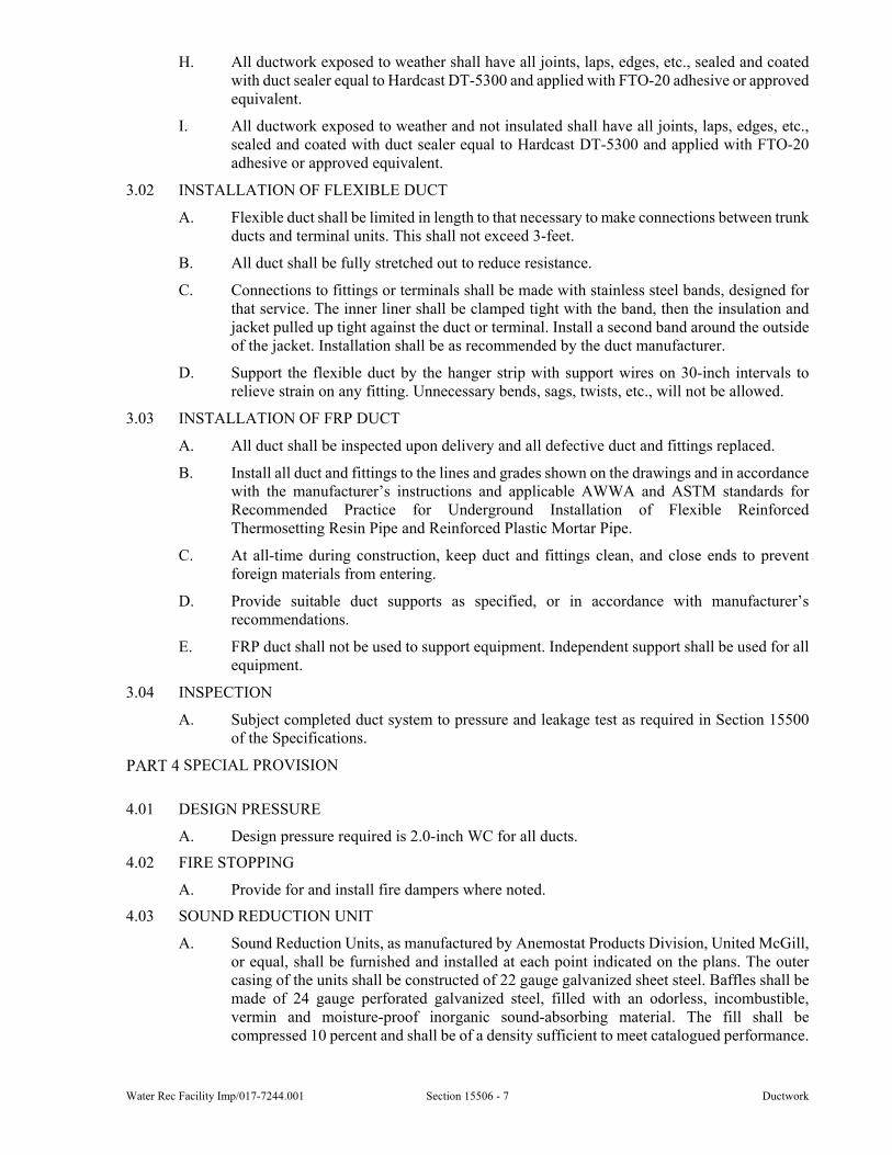
Water Rec Facility Imp/017-7244.001 Section 15506 - 7 Ductwork
H. All ductwork exposed to weather shall have all joints, laps, edges, etc., sealed and coated with duct sealer equal to Hardcast DT-5300 and applied with FTO-20 adhesive or approved equivalent.
I. All ductwork exposed to weather and not insulated shall have all joints, laps, edges, etc., sealed and coated with duct sealer equal to Hardcast DT-5300 and applied with FTO-20 adhesive or approved equivalent.
3.02 INSTALLATION OF FLEXIBLE DUCT
A. Flexible duct shall be limited in length to that necessary to make connections between trunk ducts and terminal units. This shall not exceed 3-feet.
B. All duct shall be fully stretched out to reduce resistance.
C. Connections to fittings or terminals shall be made with stainless steel bands, designed for that service. The inner liner shall be clamped tight with the band, then the insulation and jacket pulled up tight against the duct or terminal. Install a second band around the outside of the jacket. Installation shall be as recommended by the duct manufacturer.
D. Support the flexible duct by the hanger strip with support wires on 30-inch intervals to relieve strain on any fitting. Unnecessary bends, sags, twists, etc., will not be allowed.
3.03 INSTALLATION OF FRP DUCT
A. All duct shall be inspected upon delivery and all defective duct and fittings replaced.
B. Install all duct and fittings to the lines and grades shown on the drawings and in accordance with the manufacturer’s instructions and applicable AWWA and ASTM standards for Recommended Practice for Underground Installation of Flexible Reinforced Thermosetting Resin Pipe and Reinforced Plastic Mortar Pipe.
C. At all-time during construction, keep duct and fittings clean, and close ends to prevent foreign materials from entering.
D. Provide suitable duct supports as specified, or in accordance with manufacturer’s recommendations.
E. FRP duct shall not be used to support equipment. Independent support shall be used for all equipment.
3.04 INSPECTION
A. Subject completed duct system to pressure and leakage test as required in Section 15500 of the Specifications.
SPECIAL PROVISION
4.01 DESIGN PRESSURE
A. Design pressure required is 2.0-inch WC for all ducts.
4.02 FIRE STOPPING
A. Provide for and install fire dampers where noted.
4.03 SOUND REDUCTION UNIT
A. Sound Reduction Units, as manufactured by Anemostat Products Division, United McGill, or equal, shall be furnished and installed at each point indicated on the plans. The outer casing of the units shall be constructed of 22 gauge galvanized sheet steel. Baffles shall be made of 24 gauge perforated galvanized steel, filled with an odorless, incombustible, vermin and moisture-proof inorganic sound-absorbing material. The fill shall be compressed 10 percent and shall be of a density sufficient to meet catalogued performance.
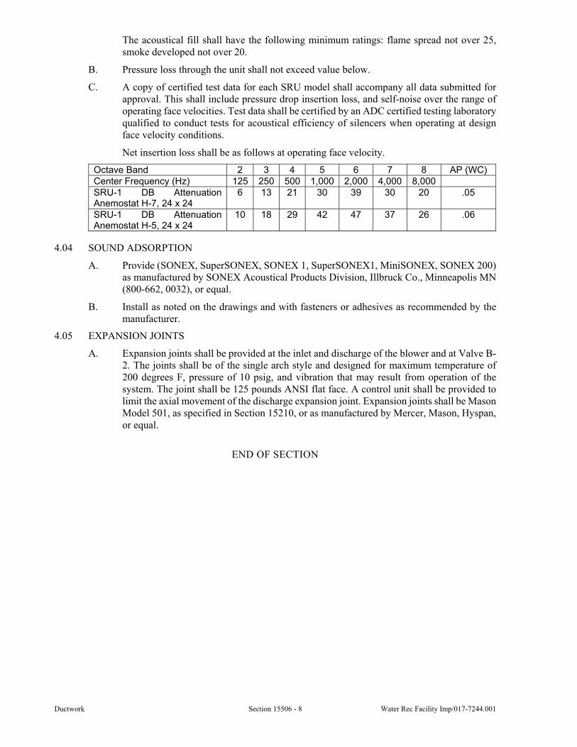
Ductwork Section 15506 - 8 Water Rec Facility Imp/017-7244.001
The acoustical fill shall have the following minimum ratings: flame spread not over 25, smoke developed not over 20.
B. Pressure loss through the unit shall not exceed value below.
C. A copy of certified test data for each SRU model shall accompany all data submitted for approval. This shall include pressure drop insertion loss, and self-noise over the range of operating face velocities. Test data shall be certified by an ADC certified testing laboratory qualified to conduct tests for acoustical efficiency of silencers when operating at design face velocity conditions.
Net insertion loss shall be as follows at operating face velocity.
Octave Band 2 3 4 5 6 7 8 AP (WC) Center Frequency (Hz) 125 250 500 1,000 2,000 4,000 8,000 SRU-1 DB Attenuation Anemostat H-7, 24 x 24
6 13 21 30 39 30 20 .05
SRU-1 DB Attenuation Anemostat H-5, 24 x 24
10 18 29 42 47 37 26 .06
4.04 SOUND ADSORPTION
A. Provide (SONEX, SuperSONEX, SONEX 1, SuperSONEX1, MiniSONEX, SONEX 200) as manufactured by SONEX Acoustical Products Division, Illbruck Co., Minneapolis MN (800-662, 0032), or equal.
B. Install as noted on the drawings and with fasteners or adhesives as recommended by the manufacturer.
4.05 EXPANSION JOINTS
A. Expansion joints shall be provided at the inlet and discharge of the blower and at Valve B-2. The joints shall be of the single arch style and designed for maximum temperature of 200 degrees F, pressure of 10 psig, and vibration that may result from operation of the system. The joint shall be 125 pounds ANSI flat face. A control unit shall be provided to limit the axial movement of the discharge expansion joint. Expansion joints shall be Mason Model 501, as specified in Section 15210, or as manufactured by Mercer, Mason, Hyspan, or equal.
END OF SECTION
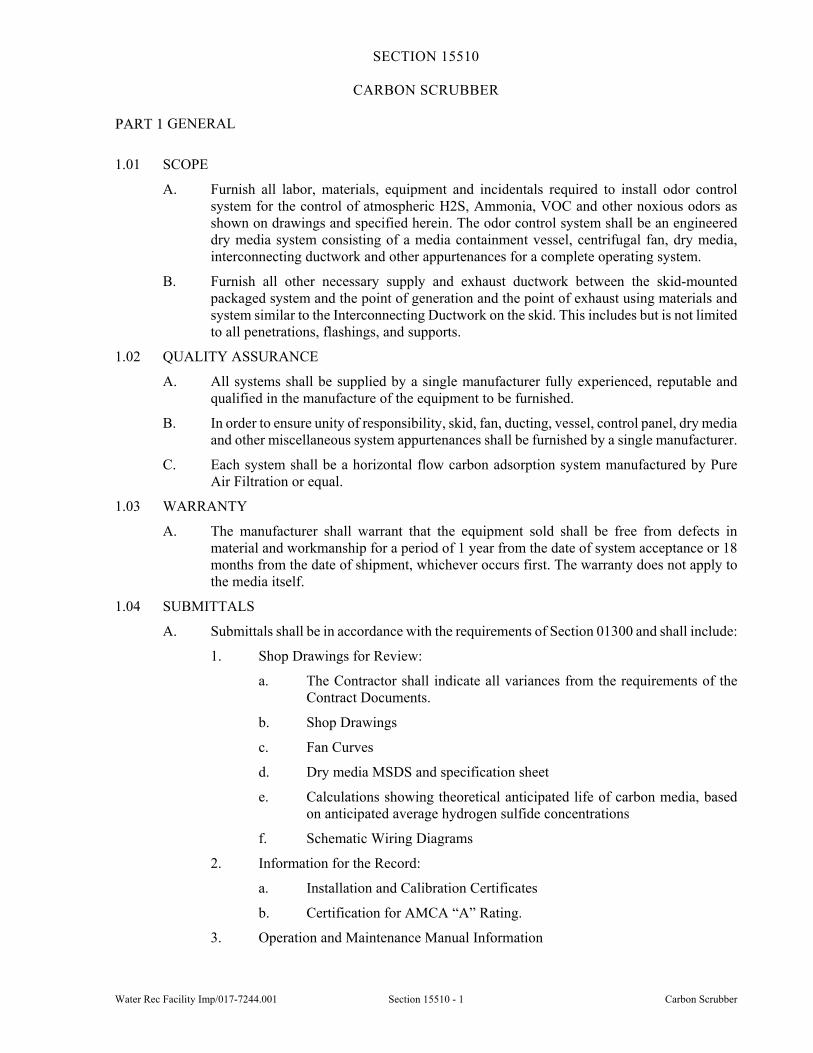
Water Rec Facility Imp/017-7244.001 Section 15510 - 1 Carbon Scrubber
SECTION 15510
CARBON SCRUBBER
GENERAL
1.01 SCOPE
A. Furnish all labor, materials, equipment and incidentals required to install odor control system for the control of atmospheric H2S, Ammonia, VOC and other noxious odors as shown on drawings and specified herein. The odor control system shall be an engineered dry media system consisting of a media containment vessel, centrifugal fan, dry media, interconnecting ductwork and other appurtenances for a complete operating system.
B. Furnish all other necessary supply and exhaust ductwork between the skid-mounted packaged system and the point of generation and the point of exhaust using materials and system similar to the Interconnecting Ductwork on the skid. This includes but is not limited to all penetrations, flashings, and supports.
1.02 QUALITY ASSURANCE
A. All systems shall be supplied by a single manufacturer fully experienced, reputable and qualified in the manufacture of the equipment to be furnished.
B. In order to ensure unity of responsibility, skid, fan, ducting, vessel, control panel, dry media and other miscellaneous system appurtenances shall be furnished by a single manufacturer.
C. Each system shall be a horizontal flow carbon adsorption system manufactured by Pure Air Filtration or equal.
1.03 WARRANTY
A. The manufacturer shall warrant that the equipment sold shall be free from defects in material and workmanship for a period of 1 year from the date of system acceptance or 18 months from the date of shipment, whichever occurs first. The warranty does not apply to the media itself.
1.04 SUBMITTALS
A. Submittals shall be in accordance with the requirements of Section 01300 and shall include:
1. Shop Drawings for Review:
a. The Contractor shall indicate all variances from the requirements of the Contract Documents.
b. Shop Drawings
c. Fan Curves
d. Dry media MSDS and specification sheet
e. Calculations showing theoretical anticipated life of carbon media, based on anticipated average hydrogen sulfide concentrations
f. Schematic Wiring Diagrams
2. Information for the Record:
a. Installation and Calibration Certificates
b. Certification for AMCA “A” Rating.
3. Operation and Maintenance Manual Information
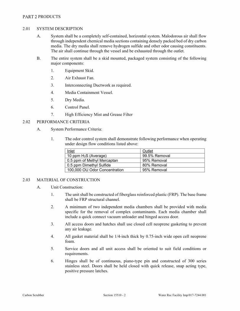
Carbon Scrubber Section 15510 - 2 Water Rec Facility Imp/017-7244.001
PRODUCTS
2.01 SYSTEM DESCRIPTION
A. System shall be a completely self-contained, horizontal system. Malodorous air shall flow through independent chemical media sections containing densely packed bed of dry carbon media. The dry media shall remove hydrogen sulfide and other odor causing constituents. The air shall continue through the vessel and be exhausted through the outlet.
B. The entire system shall be a skid mounted, packaged system consisting of the following major components:
1. Equipment Skid.
2. Air Exhaust Fan.
3. Interconnecting Ductwork as required.
4. Media Containment Vessel.
5. Dry Media.
6. Control Panel.
7. High Efficiency Mist and Grease Filter
2.02 PERFORMANCE CRITERIA
A. System Performance Criteria:
1. The odor control system shall demonstrate following performance when operating under design flow conditions listed above:
Inlet Outlet 10 ppm H2S (Average) 99.5% Removal 0.5 ppm of Methyl Mercaptan 95% Removal 0.5 ppm Dimethyl Sulfide 80% Removal100,000 OU Odor Concentration 95% Removal
2.03 MATERIAL OF CONSTRUCTION
A. Unit Construction:
1. The unit shall be constructed of fiberglass reinforced plastic (FRP). The base frame shall be FRP structural channel.
2. A minimum of two independent media chambers shall be provided with media specific for the removal of complex contaminants. Each media chamber shall include a quick connect vacuum unloader and hinged access door.
3. All access doors and hatches shall use closed cell neoprene gasketing to prevent any air leakage.
4. All gasket material shall be 1/4-inch thick by 0.75-inch wide open cell neoprene foam.
5. Service doors and all unit access shall be oriented to suit field conditions or requirements.
6. Hinges shall be of continuous, piano-type pin and constructed of 300 series stainless steel. Doors shall be held closed with quick release, snap acting type, positive pressure latches.
Water Rec Facility Imp/017-7244.001 Section 15510 - 3 Carbon Scrubber
2.04 SYSTEM ACCESSORIES
A. Mist and grease eliminator (3 stage, 99.95 percent removal rate) shall be provided to remove greases and mists. One spare pad shall be shipped with the unit.
1. The mist and grease eliminator must be the permanent washable type and retain a 99.95 percent removal rate after cleaning.
2. The eliminator is to be serviced through a side access door complete with heavy weight compression gaskets and quick release, snap acting type pressure latches. Bolted access panels are not acceptable.
B. Differential Pressure Gauges - A differential pressure gauge shall be provided to continuously monitor the pressure drop across the mist and grease eliminator and the carbon bed. The differential pressure gauges shall be mounted on the vessel.
C. Sample Ports - Each bed shall have one 1-inch diameter sample port which shall extend into the bed a minimum of twelve inches. The sample probes shall be blocked off with a cap constructed of PVC.
D. Real Time Media Life Rod - The carbon scrubber shall include an electronic carbon consumption monitor which will measure the actual carbon consumption in real time. The system shall provide consumption resolution of one percent. The carbon consumption shall be displayed on a local NEMA 4X panel at the odor control unit as well as provide SCADA remote alarm and communicate percent value of the carbon consumption. The monitoring system shall also have the capability to send monthly monitoring reports via SMS or wireless email which provide the following information at a minimum on a monthly basis:
1. Unit Identification/Location/Serial Number.
2. Carbon Install Date.
3. Carbon Consumption.
4. Predicted Carbon Depletion Date.
E. Equipment prequalification criteria shall include the successful implementation of ten installations of a qualifying device which have been in place for two life cycles of the carbon. Systems which rely on prediction of theoretical capacity & inlet concentration or do not actually measure actual carbon consumption shall not be considered. Systems which rely on break-through sampling of hydrogen sulfide shall not be considered.
F. Removable Lids - Each media section shall be supplied with a bulk loading access hatch. Access hatches shall be on the top of the unit and complete with quick release, snap acting type positive pressure latches with heavy weight compression gaskets. Bolted hatches are not acceptable.
G. Exhaust Stack - The system shall be provided with a straight outlet with rain cap, to prevent rain water from entering into the system.
H. Anchor Bolts - The system shall be provided with properly sized epoxy HILTI anchor system.
I. Equipment Tags - The vessel shall be provided with an I.D. Tag with the following minimum information: Media Type, Vessel Dimensions, Date of Manufacture, and Design Conditions.
2.05 DRY MEDIA
A. The system shall contain two types of media to provide complete removal of noxious odors. Single media type systems will not be accepted.
B. Hydrogen Sulfide (H2S) media shall have a capacity for H2S roughly 70 percent greater than any other product in the market.
Carbon Scrubber Section 15510 - 4 Water Rec Facility Imp/017-7244.001
1. Media shall have the following physical properties:
a. H2S Removal Capacity (by volume): 0.30 g/cc
b. Removal Capacity (by weight): 89 percent
c. CTC value: 70 percent min
d. Surface Area: 1050 square meter / gram
e. Density: 580 kg / cubic meter
f. Moisture Content: 15 percent
g. Hardness: 95 min
h. Ignition Temperature: 425 C
2. Pellets shall be spherical or cylindrical and porous, formed from a combination of powdered activated alumina and other binders, suitably impregnated with potassium permanganate to provide optimum adsorption, absorption, and oxidation of a wide variety of gaseous contaminants.
3. Media shall be UL Class 2 listed.
4. Media shall be capable of absorbing and removing odorous gases throughout the entire pellet.
C. Permanganate-based media shall have the following physical properties.
1. Removal Capacity:
a. Hydrogen Sulfide: 0.20 g/cc min (24 percent by weight)
b. Sulfur Dioxide: 0.11 g/cc min (12 percent by weight)
c. Nitric Oxide: 0.06 g/cc min (7.5 percent by weight)
d. Nitrogen Dioxide: 0.024 g/cc min (3.0 percent by weight)
e. Formaldehyde: 0.04 g/cc min (5.0 percent by weight)
2. Manufacturing Quality Assurance Standards:
a. Leach Test (indication of porosity) - 180 minute or less
b. Permanganate Content: 12 percent minimum
c. Moisture Content: 20 percent maximum
d. Crush Strength: 40 to 60 percent
e. Abrasion Loss: 3.0 percent maximum
f. Nominal Pellet Diameter: 1/8-inch (approximately 4 mm), 85 percent after screening
g. Nominal Density: 50 lbs/ft3 (0.80 g/cc)
3. Media shall be UL Class 1 listed.
4. Media shall be capable of absorbing and removing odorous gases throughout the entire pellet.
2.06 FAN
A. Each unit shall be furnished with a centrifugal, industrial fiberglass reinforced plastic fan. Fan shall be AMCA certified and licensed to bear an AMCA seal. Each fan shall be V-belt driven, equipped with undrilled inlet flange, outlet flange, Viton shaft seal, fan guard, and motor enclosure. Each fan and drive motor shall be mounted on a common base assembly
Water Rec Facility Imp/017-7244.001 Section 15510 - 5 Carbon Scrubber
designed for mounting on a concrete pad. Fan motor shall be high efficiency, TEFC, 460V, 3 phase, 60 Hz with a 1.15 service factor. Accommodation to accept a hand-held tachometer shall be available for each fan. Each fan shall have a drain with plug. Fan shall be enclosed in a sound attenuator.
B. The fan shall be a draw-through design and be selected to provide continuous reliable operation 24 hours a day, 365 days a year in a sewage odor stream environment.
C. Fan noise level shall not exceed 75dBA at 5 feet.
D. The fan shall be manufactured by NY Blower, Hartzell, PureAir or equal.
2.07 CONTROL PANEL
A. The system fan shall be factory wired to a FRP control panel of NEMA construction. The control panel shall have a fan control switch with a pilot lamp to indicate the fan running status. The power supplied to the panel shall be 460V, 3 phase, 60 Hz. The panel shall be provided with a power disconnect switch, motor starter and control transformer. The system will be equipped with an explosion proof selector switch mounted on the unit.
2.08 INTERCONNECTING DUCTWORK
A. The odor control system manufacturer shall provide the necessary ductwork between the fan and the carbon scrubber unit.
2.09 HARDWARE AND GASKETS
A. All hardware shall be 316 stainless steel. Gaskets shall be a minimum of 1/8" thick, full face, EPDM or neoprene suitable for the intended service.
2.10 FLEXIBLE CONNECTORS
A. A fan inlet flexible connector shall be included in the ductwork to dampen axial, lateral, and vibration duct movement. A flexible connector shall be installed at the fan outlet only if necessary and recommended by equipment supplier.
EXECUTION
3.01 INSTALLATION
A. Odor control system shall be furnished and installed in accordance with manufacturer's recommendations. The Contractor shall provide all utility connections, fan inlet ductwork, concrete pads, installation appurtenances, fencing and other items shown on the drawings not specified in this Section. The Contractor shall be responsible for providing a complete and operable system.
3.02 PERFORMANCE GUARANTEE
A. The system must be capable of removing organics, mercaptans and miscellaneous malodors from and have a total H2S removal capacity of as proven by an independent third party ASTM D6646 test procedure. Calculations and test data proving capacity removal shall be submitted during shop drawing submission.
3.03 MEDIA TESTING
A. The contractor shall send a random sample of the media delivered to site to an independent laboratory for testing. A sample of at least 8 ounces will be shipped in a non-porous container. Capacity testing will be performed according to ASTM D6646.
B. The testing shall be performed by Weck Laboratories, Inc., 14859 East Clark Avenue, City of Industry, CA, 91745-2139, Tel: (626) 336-2139, Fax: (626) 336-2634, E-mail: [email protected], Website:www.wecklabs.com.
C. All costs associated with the testing will be the responsibility of the Contractor. Should the carbon fail the initial testing, subsequent tests will be paid for by the carbon supplier.
Carbon Scrubber Section 15510 - 6 Water Rec Facility Imp/017-7244.001
3.04 START-UP AND SERVICE
A. The system shall have start-up supervision by a manufacturer’s trained representative and shall include semi-annual visits. Each visit shall include an equipment review and media test. The odor abatement supplier is responsible for providing enough media to top up the loading hoppers after the media has settled. The equipment supplier shall check the system 3 months after startup.
SPECIAL PROVISIONS
4.01 SCHEDULE
A. A schedule of carbon scrubbers can be found drawing MD-H-2.
END OF SECTION
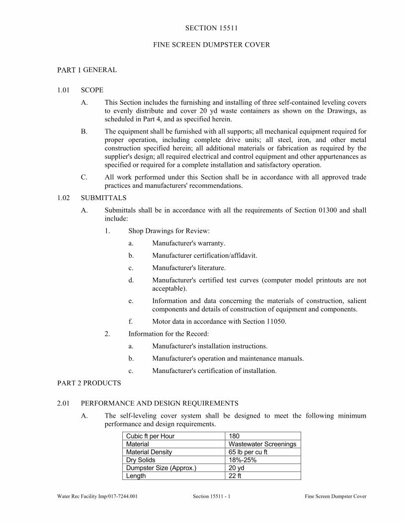
Water Rec Facility Imp/017-7244.001 Section 15511 - 1 Fine Screen Dumpster Cover
SECTION 15511
FINE SCREEN DUMPSTER COVER
GENERAL
1.01 SCOPE
A. This Section includes the furnishing and installing of three self-contained leveling covers to evenly distribute and cover 20 yd waste containers as shown on the Drawings, as scheduled in Part 4, and as specified herein.
B. The equipment shall be furnished with all supports; all mechanical equipment required for proper operation, including complete drive units; all steel, iron, and other metal construction specified herein; all additional materials or fabrication as required by the supplier's design; all required electrical and control equipment and other appurtenances as specified or required for a complete installation and satisfactory operation.
C. All work performed under this Section shall be in accordance with all approved trade practices and manufacturers' recommendations.
1.02 SUBMITTALS
A. Submittals shall be in accordance with all the requirements of Section 01300 and shall include:
1. Shop Drawings for Review:
a. Manufacturer's warranty.
b. Manufacturer certification/affidavit.
c. Manufacturer's literature.
d. Manufacturer's certified test curves (computer model printouts are not acceptable).
e. Information and data concerning the materials of construction, salient components and details of construction of equipment and components.
f. Motor data in accordance with Section 11050.
2. Information for the Record:
a. Manufacturer's installation instructions.
b. Manufacturer's operation and maintenance manuals.
c. Manufacturer's certification of installation.
PRODUCTS
2.01 PERFORMANCE AND DESIGN REQUIREMENTS
A. The self-leveling cover system shall be designed to meet the following minimum performance and design requirements.
Cubic ft per Hour 180 Material Wastewater Screenings Material Density 65 lb per cu ft Dry Solids 18%-25% Dumpster Size (Approx.) 20 yd Length 22 ft
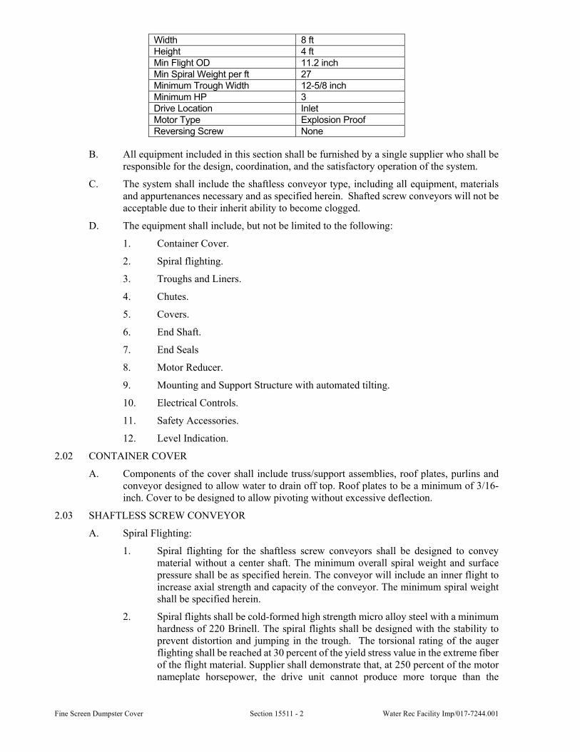
Fine Screen Dumpster Cover Section 15511 - 2 Water Rec Facility Imp/017-7244.001
Width 8 ft Height 4 ft Min Flight OD 11.2 inch Min Spiral Weight per ft 27 Minimum Trough Width 12-5/8 inch Minimum HP 3 Drive Location Inlet Motor Type Explosion Proof Reversing Screw None
B. All equipment included in this section shall be furnished by a single supplier who shall be responsible for the design, coordination, and the satisfactory operation of the system.
C. The system shall include the shaftless conveyor type, including all equipment, materials and appurtenances necessary and as specified herein. Shafted screw conveyors will not be acceptable due to their inherit ability to become clogged.
D. The equipment shall include, but not be limited to the following:
1. Container Cover.
2. Spiral flighting.
3. Troughs and Liners.
4. Chutes.
5. Covers.
6. End Shaft.
7. End Seals
8. Motor Reducer.
9. Mounting and Support Structure with automated tilting.
10. Electrical Controls.
11. Safety Accessories.
12. Level Indication.
2.02 CONTAINER COVER
A. Components of the cover shall include truss/support assemblies, roof plates, purlins and conveyor designed to allow water to drain off top. Roof plates to be a minimum of 3/16-inch. Cover to be designed to allow pivoting without excessive deflection.
2.03 SHAFTLESS SCREW CONVEYOR
A. Spiral Flighting:
1. Spiral flighting for the shaftless screw conveyors shall be designed to convey material without a center shaft. The minimum overall spiral weight and surface pressure shall be as specified herein. The conveyor will include an inner flight to increase axial strength and capacity of the conveyor. The minimum spiral weight shall be specified herein.
2. Spiral flights shall be cold-formed high strength micro alloy steel with a minimum hardness of 220 Brinell. The spiral flights shall be designed with the stability to prevent distortion and jumping in the trough. The torsional rating of the auger flighting shall be reached at 30 percent of the yield stress value in the extreme fiber of the flight material. Supplier shall demonstrate that, at 250 percent of the motor nameplate horsepower, the drive unit cannot produce more torque than the
Water Rec Facility Imp/017-7244.001 Section 15511 - 3 Fine Screen Dumpster Cover
torsional rating of the flighting, and that the "spring effect" of the spiral shall not exceed plus 0.8 mm per meter of length at maximum load conditions.
3. Spiral flight material, fabrication technique, strength, hardness, and overall quality are critical to the proper operation of the conveying system as herein designed. Spiral flights that do not meet the characteristics or herein specified are specifically not acceptable. Supplier shall provide certified written documentation that the spiral flights conform to the following:
a. Material: Micro Alloy Steel.
b. Hardness: 220 Brinell Minimum.
c. Concentricity: 2.0 mm plus or minus.
4. Supplier shall maintain a certified factory quality control program which shall include certification of spiral flighting as described herein.
5. The spiral flighting shall be formed in sections from one continuous flat bar and shall be concentric to within 2mm plus or minus. Sectional flighting formed from plate shall not be permitted.
6. Spiral flighting shall have full penetration welds at all splice connections. The flights shall be aligned to assure true alignment when assembled in the field and shall be made in accordance with the supplier's requirements. The spiral flights shall be coupled to the end shaft by a flanged, bolted connection.
7. The connection of the spiral to the drive system shall be through a flanged connection plate that is welded to the spiral forming a smooth and continuous transformation from the flange plate to the spiral. The drive shaft shall have a mating flange and shall be bolted to the spiral connection plate.
B. Trough:
1. Trough shall be similar to the dimensional standards of CEMA 300 and enclosure classification IIE. Each conveyor trough shall be U-shaped, fabricated from a minimum 1/8-inch stainless steel plate.
2. Stiffeners shall be placed across the top of the trough and fastened to both sides of the trough to maintain trough shape and act as a face seal for the covers; apply a continuous gasket, one half inch width, to the entire top face of the trough top flange and stiffeners.
3. Each unit shall be equipped with filling openings as required by the contract drawings. If required, each filling opening shall be flanged suitable for interconnection to other devices. Any interconnecting devices such as chutes and hoppers shall be fabricated from the same material as the troughs.
4. The portion of each trough that is not covered by the filling chute shall be covered by a bolted cover of a material identical to the trough. The covers shall be manufactured in maximum 4-foot length section to allow for access to the conveyors. To prevent unsafe access to the conveyors, quick opening covers will not be allowed.
C. Wear Liner (UHMW):
1. The wear liner for each conveyor shall be fabricated of ultra-high molecular weight polyethylene. The wear liner shall be furnished in maximum 4-foot sections to provide ease of replacement. The liner shall be held in place with clips; no fasteners will be allowed.
Fine Screen Dumpster Cover Section 15511 - 4 Water Rec Facility Imp/017-7244.001
D. Inlet Chutes:
1. Inlet chutes shall be provided by the conveyor supplier as shown on the drawings. All chutes shall be fabricated from the same material as the conveyor trough. Flexible boots shall be supplied between chute and inlet of dumpster cover to allow pivoting of unit.
E. Conveyor Supports:
1. Each dumpster cover shall be furnished complete with supports suitable for mounting as shown on the contract drawings and as required to allow unit to tilt up so dumpster can be removed and replaced. The supports shall be shop fabricated from structural steel shapes and plates, and shall be assembled and fitted to the cover prior to its delivery to the jobsite. Supports and conveyor segments shall be match marked and shipped to the jobsite for assembly by others.
F. Drive Units:
1. Each spiral conveyor shall be driven by a constant-speed integral gear reducer/motor drive unit mounted to an adapter flange mounted to the end plate of the conveyor. The adapter flange shall allow the leakage of any material from the conveyor trough to atmosphere rather than into the gear reducer/ motor drive unit. Direct coupling of the gear reducer/motor drive unit to the end flange of the conveyor will not be acceptable.
a. The drive unit shall be rigidly supported so there is no visible "wobble" movement under any operating condition. In the event of a prolonged power failure or emergency system shutdown the drive system shall be designed, at a minimum, to start the conveyor from a dead stop with the trough filled throughout its entire cross-sectional area and length with partially dried and hardened dewatered material.
b. Each motor shall be 460 volts, 60 Hz, 3 phase conforming to the General Equipment specifications, except as modified herein. Each motor shall be high efficiency, 40C ambient rated, 1.15 service factor and shall have Class F insulation. Motor shall have a explosion proof enclosure with Design B speed/torque characteristics.
2. All gears shall be AGMA Class II, single or double reduction, helical gear units with high capacity roller bearings. Bearings shall be designed for the thrust loads from the fully loaded startup condition and shall have a AFBMA B10 life of 30,000 hours. The reducer will be the standard air cooled unit with no auxiliary cooling. The gear reducer shall be sized with a torque service factor of 1.5 times the absorbed power or 1.1 times the motor nameplate, at the driven shaft speed, whichever is greater.
3. Motion Failure Alarm Unit:
a. Each conveyor drive unit shall be equipped with a motion failure alarm unit. The location and mounting details shall be as recommended by the conveyor manufacturer. Motion sensors shall be the non-contacting type using a probe with a pre-amplifier and main electronic assembly. The main electronic unit shall operate on 120 volts, single phase, 60 Hz power supply, and shall be suited for use in a Class I, Division 1 Environment. A 0 to 60 second time delay shall be provided for startup of the conveyor.
G. Radar Level Sensor:
1. Dumpster cover shall be supplied with one radar level sensor in the cover at the discharge end to indicate almost full and full condition. Sensor shall be a Vega model PULS 69 with a Vegadis 81 remote display suited for use in a Class I,
Water Rec Facility Imp/017-7244.001 Section 15511 - 5 Fine Screen Dumpster Cover
Division 1 Environment. Sensor shall be mounted to flanged opening in the cover. Vegator 142 signal conditioner shall be installed in the control panel for almost full and full condition indications.
H. Emergency Shutdown:
1. Each conveyor shall be furnished with an emergency trip cord and safety switch. The cord shall run the full length of each conveyor. The trip switch shall immediately stop all conveyors when the switch is actuated.
I. Controls:
1. The main control panel shall be NEMA 12 supplied by equipment manufacture for wall mounting by the contractor. Power supply shall be 480VAC, 3 phase, 60 Hertz. Panel shall have the following components as a minimum:
a. Main Circuit Breaker.
b. Disconnect Switch.
c. Motor Starters.
d. Control Transformer.
e. Conveyor Run Light.
f. Alarm Light.
g. Dumpster Full Light.
h. Alarm Horn.
i. Silence Button.
j. On/Off Switch for Electric Hoist Controls.
2. In addition, controls shall include relays and timers to form a complete operational system.
3. Provide contacts for remote wiring to/from the existing fine screen control panel PLC:
a. Dumpster Full.
b. Dumpster Almost Full.
c. Screw Conveyor Fault. (Over Torque/Zero Speed Shutdown/E-Stop Activated)
d. Screw Conveyor Running.
e. System in Auto.
f. Screw Conveyor Start/Stop.
4. Control panel shall have provisions for wiring to a remote H-O-A selector switch and stop/start pushbuttons.
J. Material:
1. Unless otherwise specified or permitted, the materials used in the fabrication of the equipment under this section shall conform to the following:
a. Cover A36 Carbon Steel (AISI 304, ASTM A167).
b. Troughs, End Plates, Covers AISI 304, ASTM A167, 18-8.
c. Supports AISI 304, ASTM A167, 18-8.
Fine Screen Dumpster Cover Section 15511 - 6 Water Rec Facility Imp/017-7244.001
d. Hoppers AISI 304, ASTM A167, 18-8.
e. Spiral Flighting Cold formed, High Strength Micro Alloy Carbon Steel with a minimum hardness of 220 Brinell.
f. Wear Liner Ultrahigh molecular weight polyethylene sintered with anti-wear filler and synthetic lubricants.
g. Bolts, Nuts, and Washers For Conveyor Supports AISI 316, ASTM A167, 18-8.
h. For Conveyor Supports For Conveyor Trough AISI 304, ASTM A167, 18-8.
2.04 ELECTRIC HOIST
A. 1.5-ton electric hoist shall be mounted on front end support. Hoist shall be mounted to support and installed as part of the dumpster cover.
1. General:
a. Arrange all working parts for convenient inspection, lubrication, adjustment, repair, or replacement. Assemble paint, test, and adjust the equipment, in the shop as far as practicable before shipment.
b. House the operating machinery and other exposed parts suitably, fabricate the exterior of the unit to have smooth surfaces or pleasing appearance.
c. Design the hoist with an overload limit device to prevent damage to the equipment or structure if loads in excess of the specified capacity of the hoist are applied.
d. Place a label, easily readable from the operating floor on each monorail beam showing the rated capacity of the equipment. Provide all appurtenances, caution markers, and appliances necessary to comply with applicable safety laws and codes.
e. Unless otherwise shown or specified, provide all hoisting equipment suitable for normal indoor and outdoor service as shown.
2. Gears:
a. Design all gearing to meet requirements of CMMA Specification No. 74 and AGMA Standards and of helical or spur type constructed of heat treated steel. Provide worm gears of bronze and with precision machined cut teeth. Provide all pinions of heat treated alloy steel. Enclose or guard gearing and provide either oil bath or splash lubrication.
b. Design the gear reducer or gear motor specifically for crane service with minimum classification of moderate shock service and with minimum service factor 1.0.
3. Brakes:
a. Equip each hand-operated hoist with a Weston or multiple disc type mechanical brake which will automatically hold the load indefinitely in any position and permit it to be lowered without acceleration under full control of the operator when the chain is pulled in the lowering direction.
Water Rec Facility Imp/017-7244.001 Section 15511 - 7 Fine Screen Dumpster Cover
4. Control:
a. Equip each hoist with a pendant-type push-button operator to raise and lower hoist. Operator shall be secured to hoist frame. Hoist operator shall have provisions for connections to a remote raise/lower control station
2.05 GUIDE RAILS
A. The container rollers shall be guided into position with floor guide rails, one on each side. The guide rails shall be constructed from 3/8-inch thick carbon steel angle with coped ends to aid with the container alignment.
1. A 1/2" carbon steel stop plate shall be supplied by the dumpster cover manufacture and anchored to the floor as per the manufactures recommendations.
2. The 2" high side guides rails shall be anchored to the concrete pad.
3. All carbon steel shall be factory primed only.
4. Anchor bolts shall be spaced on 24" centers minimum.
2.06 ELECTRICAL
A. Power Supply:
1. Power supply to the equipment will be 480 volts, 60 Hz, 3 phase. Power supply for controls shall be 120 volts, 60 Hz, single phase.
B. Electrical Equipment:
1. All electrical equipment shall conform to applicable standard of the National Electrical Manufactures Association (NEMA) and the National Electrical Code (NEC). Both power and control equipment shall be insulated for not less than 600 volts even though operating voltages may be lower.
2. All motors shall be totally enclosed, explosion proof. Dumpster cover mounted controls shall be NEMA 7, stainless steel.
2.07 STRUCTURAL DESIGN
A. All structural supporting members shall be designed such that the ratio of the unbraced length to least radius of gyration (slenderness ratio) shall not exceed 120 for any compression member and shall not exceed 240 for any tension member (of angles about Z-Z axis). In addition, all structural members and connections shall be designed so that the unit stresses will not exceed the American Institute of Steel Construction allowable stresses by more than 1/3 when subject to loading of twice the maximum design operating torque of the spiral conveyor drive motors.
EXECUTION
3.01 INSPECTION, START-UP AND TRAINING
A. Units shall be inspected and operated in the shop with the actual drive unit for this project in its entire length. Units longer then the required shipping lengths will have the screws tack welded together and tested in their entire length.
B. Units should be operated for a minimum of 15 minutes and observed for alignment and abnormal operation. Units shall be corrected as necessary. Prior to shipment the tack welds will be broken apart and conveyors suitably prepared for shipment.
C. A video of the test should be supplied on disk to the contractor to be forwarded on to the engineer for record purposes. Video must be received to get paid.
Fine Screen Dumpster Cover Section 15511 - 8 Water Rec Facility Imp/017-7244.001
3.02 MANUFACTURER'S FIELD SERVICES
A. After the equipment is installed the supplier shall provide a factory trained, experienced, competent, and authorized representative of the supplier to the jobsite to inspect, check, and approve the equipment installation supervise initial operation, and to train operating personnel in the proper operation and maintenance of the system. These services shall be performed by the supplier's representative at the jobsite for a minimum of one 8-hour day when the equipment is placed in service.
B. The supplier's representative shall furnish to the Owner, through the Engineer, a written report certifying that the equipment has been properly installed and lubricated, is in accurate alignment, is free from any undue stress imposed by connecting piping or anchorage, and has been operated under full load conditions and that it operates satisfactorily.
SPECIAL PROVISIONS
None.
END OF SECTION
Water Rec Facility Imp/017-7244.001 Section 15620 - 1 Markup Air Unit Direct Fired
SECTION 15620
MAKEUP AIR UNIT, DIRECT FIRED
GENERAL
1.01 SCOPE
A. This Section includes furnishing and installing direct fired makeup air unit(s) as shown on the Drawings, as scheduled in Part 4, and as specified herein.
B. The unit(s) shall be furnished with all auxiliary equipment as necessary to meet the requirements of the Drawings and the controls philosophy as required and referenced in Section 15500, in order to form a complete system.
C. All work performed under this Section shall coincide with the requirements of Section 15500 and shall comply and be in accordance with all approved trade practices and manufacturer’s recommendations.
D. Additional product requirements are specified in Section 01350.
1.02 SUBMITTALS
A. Submittals shall be in accordance with the requirements of Section 01300 and shall include:
1. Shop Drawings for Review:
a. The Contractor shall indicate all variances from the requirements of the Contract Documents.
b. Shop Drawings
c. Fan Curves
d. Schematic Wiring Diagrams
2. Information for the Record:
a. Installation and Calibration Certificates
b. Certification for AMCA “A” Rating.
3. Operation and Maintenance Manual Information
PRODUCTS
2.01 MAKEUP AIR UNIT (MAU-( ))
A. Provide self-contained direct gas-fired packaged heaters with 100 percent outside air that shall include the casing, modulating burner, non-overloading fan, fan motor & drives, variable frequency drive capable of 75% supply air reduction and automatic controls for temperature. Direct fired makeup air/heating unit(s) shall be built in conformance to NFPA-54 and ETL/AGA design and shall not exceed contaminant threshold limits for safe environment, as established by OSHA and/or ACGIH.
B. The unit shall be shipped in one piece from the factory completely wired and piped, with the exception of remote control devices, O/A weatherhoods, filter cabinets and roof curbs. Removable lifting lugs shall be provided from the factory for rigging the unit.
C. The cabinet shall be of double-wall construction with 1-1/2 inch, 1 pound density insulation welded to structural steel framing. The insulation shall comply with UL standard 181 for erosion and NFPA 90A for fire resistance. The construction material used shall be minimum 18-gauge aluminized steel for high corrosion resistance. All gas and electrical controls shall be mounted in fully weatherized control compartments with a minimum of
Markup Air Unit Direct Fired Section 15620 - 2 Water Rec Facility Imp/017-7244.001
(2) easy removable hinged doors. All access panels and doors shall have pocket handles for ease of handling. All access doors shall be painted on the interior as well as the exterior
D. Both interior and exterior structural steel shall be red or gray oxide primed. All exterior casing seams shall be weather resistant. All interior and exterior surfaces will be cleaned of all oil and grease. Painted exterior will consist of a high-quality prime coat and a finish coat of machine enamel with rust inhibitors. Color is selected by the owner and custom matched by the equipment manufacturer All exposed edges will be coated to eliminate erosion.
E. Fiberglass will be held in place with both adhesive and welded pins, per SMACNA standards. access doors with positive latching, watertight handles.
F. The unit shall be provided with a NEMA 4 fused disconnect switch. A 115 volt and 24 volt transformer shall be provided for gas, safety and electrical controls. All remote wiring and controls shall be 24 volt.
G. A motor with adjustable drive shall be included. Motors 1/2 through 3 hp shall be provided with internal overloads and a starter with 3 leg protection. All motors 5 hp and larger shall be provided with a motor starter with 3 leg protection. All electrical work shall be as required in Division 16.
H. Gas safety controls shall be provided to meet ANSI and FM requirements and will include a flame safeguard relay with ultraviolet flame sensing. Automatic and manual high temperature limits are to be provided at the discharge of the unit and a high temperature safety located at the burner.
I. The unit shall provide 100 percent outside air, constant volume. The velocity of air over the burner must always remain constant and at no time shall recirculated air pass over the burner. High and low air velocity safety pressure switches shall be provided to protect against low or high air flow over the burner.
J. The gas temperature controls shall be electronic with accuracy to plus 0.2 degrees F. The nominal turndown ratio shall be 25:1 with total control between high and low fire. The unit shall be provided with pre-purge time delay and arranged for positive low-fire start-up. The temperature controls shall be (discharge air control from 50 degrees to 90 degrees, 80 degrees to 120 degrees F, discharge air control 50 degrees to 90 degrees F with an adjustable space override, adjustable discharge air reset from space temperature. The system shall be resetable from a remote temperature selector mounted on the remote control console. An adjustable outside air controller shall be provided to sense the outdoor air temperature and shut-off the burner if the outdoor temperature exceeds the setpoint on the control.
K. The unit shall include burner, blower, and damper service switches in the electrical compartment to provide manual operation of the unit. A remote operating console shall be provided with a system switch, burner and blower lights, a safety alarm light and a remote temperature selector.
1. Burner shall be a direct-fired type gas burner which shall be specifically designed to burn natural or propane gas below the maximum non-contaminating levels required by ANSI. Burner shall have non-clogging, stainless steel baffles attached to a cast aluminum gas supply section with no moving parts. The burner shall be capable of a 30-to-1 turndown ratio and be designed for 100% thermal efficiency for the life of the equipment. The outdoor air velocity across the burner shall be constant and at an air velocity required for ANSI certification. The burner air velocity shall be constant at all times throughout the operation of the heater. No air from the indoor space shall be allowed to recirculate across the burner at any time. Service of and access to the burner igniter and flame rod shall be accomplished through an access door or panel.
Water Rec Facility Imp/017-7244.001 Section 15620 - 3 Markup Air Unit Direct Fired
2. Supply fan shall be a double-width, double-inlet, centrifugal design, belt driven for the required air capacity. The motor shall be 1750 rpm, standard NEMA frame, Totally Enclosed Fan Cooled (TEFC) mounted on an adjustable pivot base. The motor shall have a 1.15 service factor, suitable for continuous service at 120° F ambient temperature, and shall be wired for the specified voltage. The fan, motor, and drive shall be factory tested to ensure the specified air delivery (per ANSI standards) at the design total static pressure. The fan shaft shall be connected to the motor by a V-belt drive, capacity designed for 30% over the motor nameplate horsepower. The fan shaft shall be a turned, ground and polished solid shaft. A protective coating shall be applied to the shaft to minimize oxidation. Fan shall have ball bearings, and shall be designed for a minimum L10 life of 100,000 hours. Fan motor shall be as required in Section 11050
L. Provide a minimum of two hinged access doors with positive latching, watertight handles. All access doors shall be painted on the interior as well as the exterior, and hinged access doors shall include braces that lock in the open position during servicing.
M. All exterior casing seams shall be weather resistant. All interior and exterior surfaces will be cleaned of all oil and grease. Painted exterior will consist of a high-quality prime coat and a finish coat of machine enamel with rust inhibitors. Color is selected by the owner and custom matched by the equipment manufacturer.
N. Main Control Panel shall meet NEMA 1, 2, 3, 3R ,3S, 4, 5 & 12 requirements and contain all standard electrical components, such as non-fused disconnect switch; motor starter; 120-volt and 24-volt transformers; control circuit fuses; flame control relay and a number-coded terminal strip. The control panel shall have a burner flame safety circuit and components to lockout the burner flame in abnormal conditions. A remote flame reset button or switch shall allow personnel to reset the burner at the remote-control panel. The complete control and safety system as well as the burner and gas manifold shall be factory tested before shipment and evidence of the factory start up provided with the O&M manual.
O. A solid state discharge temperature control system, located inside the control panel includes a sensing thermistor located in the supply fan discharge opening. The thermistor senses and controls discharge temperature. The temperature control for adjusting the discharge air temperature is located on the main unit panel.
EXECUTION
3.01 INSTALLATION
A. Provide necessary structural supports for indoor units, or roof curb for units mounted on the roof or on a grade-mounted pad per manufacturer’s instructions.
B. Set the unit in place and connect all ductwork as shown.
C. Connect gas piping of the proper pressure required by the unit. Provide gas regulator in the supply if pressure is above the rating of the gas regulator on the unit.
D. Make electrical connections, taking care that these do not block access to any part of the equipment requiring service.
E. Mount under glass temperature control and interlock wiring diagrams showing operating sequence, at locations in each building as directed by the Engineer.
3.02 INSPECTION, STARTUP, AND TRAINING
A. The Contractor shall furnish a qualified representative of the manufacturer to perform inspection, start-up, and training services. The manufacturer’s representative shall be experienced in the installation, start-up, operation, and maintenance of the equipment.
Markup Air Unit Direct Fired Section 15620 - 4 Water Rec Facility Imp/017-7244.001
B. The representative shall check the installation and supervise final adjustments and initial start-up of the equipment. He shall certify that the installation is correct and that the equipment is operating satisfactorily. This service shall be for a minimum period of one trip and one day.
C. Within two weeks of start-up, the manufacturer shall submit to the engineer a written report (minimum 4 copies) covering the representative’s inspection and start-up of the equipment. This report shall include the manufacturer’s certification that the installation is correct and that the equipment is operating satisfactorily.
D. After the installation and operation of the equipment has been certified, the manufacturer’s representative shall train the Owner’s personnel for one eight-hour day in the proper operation and maintenance of the equipment. The Owner may video tape the training.
E. In addition to the initial training, the manufacturer shall provide one eight-hour day of training at the time requested by the Owner within the one-year maintenance and guarantee period. This service would be in addition to any warranty work.
3.03 BALANCING AND TESTING
A. Balance the air flows as required in Section 15502.
B. Operate the unit on heating and cooling and check for proper supply air quantity, noise, and correct operation as necessary.
SPECIAL PROVISIONS
4.01 SCHEDULE
A. A schedule of make up air units can be found on drawing MD-H-2.
END OF SECTION
Water Rec Facility Imp/017-7244.001 Section 16010 - 1 General Electrical Provisions
SECTION 16010
GENERAL ELECTRICAL PROVISIONS
GENERAL
1.01 SCOPE
A. This Section includes general administrative and procedural requirements in accordance with the Drawings and as specified herein.
B. The Contractor shall furnish and install all wire, conduit, disconnects, and related items, for HVAC equipment 120 volts or greater under Division 16. Controls, control wiring, and control conduit for HVAC equipment less than 120 volts shall be furnished and installed under Division 15.
C. Telephone system wires, cable, equipment, and instruments shall be furnished and installed under Division 16 unless specified otherwise in Part 4.
D. The responsibility for the following equipment items and work shall be as listed below:
1. Motors, unless indicated otherwise, shall be furnished and installed under other Sections, but shall be wired as indicated on the Drawings under Division 16.
2. Controls for motors on mechanical equipment unless indicated otherwise, will be furnished under other Sections, but shall be installed and wired under Division 16.
3. Unless otherwise indicated, all electrical and control equipment not furnished under Division 16 shall be installed and wired under Division 16.
4. Electrical and control equipment furnished under Division 16 but which is to be installed under other Sections, shall be wired under Division 16 as indicated on the Drawings and Specifications.
1.02 SUBMITTALS
A. Specific submittals will be identified in individual sections of Division 16.
1.03 QUALITY ASSURANCE
A. Work shall comply with the latest edition of the National Electric Code (NEC) as prepared by the National Fire Protection Association (NFPA), and the National Electric Safety Code (NESC).
B. Contractor shall comply with applicable local electrical code requirements, where provisions of local codes are modified or supplemented with NEC, the more stringent interpretation shall prevail.
C. Equipment and materials shall be new and, if of the same type as other performing parts of the same system, shall be the products of the same manufacturer.
D. The manufacturer of this equipment shall have produced similar electrical equipment for a minimum of five years.
E. Equipment, materials and installation shall comply with applicable requirements of National Electrical Manufacturers Association (NEMA), Institute of Electrical and Electronic Engineers (IEEE), and the American National Standards Institute (ANSI).
F. All electrical equipment shall be listed and labeled by Underwriters Laboratories, Inc. (UL).
G. Electrical enclosure requirements shall conform with area classifications, whether designated on the Drawings or not.
General Electrical Provisions Section 16010 - 2 Water Rec Facility Imp/017-7244.001
H. Contractor shall provide Owner with all certificates of final inspection from the agency of proper authority prior to receiving final payment.
1.04 ELECTRICAL CONTROL AND COORDINATION
A. Installation of electrical equipment shall be scheduled, sequenced, and positioned to efficiently coordinate the best flow of work for electrical systems and all other non-electrical construction activities.
1.05 PRODUCT HANDLING
A. Equipment shall be handled and stored in accordance with manufacturer’s instructions. A copy of these instructions shall be included with the equipment at the time of shipping.
B. Equipment damaged in shipment or storage shall not be installed and shall be replaced by the Contractor.
1.06 GUARANTEE
A. Provide complete warranty information for each item. Include the following information:
1. Date of beginning warranty period.
2. Duration of warranty.
3. Warranty options.
4. Name, address, phone numbers, and procedures for filing warranty claims.
B. The Contractor shall warrant the completed system wiring and equipment to be free from inherent mechanical and electrical defects for a period of one year from the date of substantial completion.
PRODUCTS
2.01 NEMA RATINGS
A. Equipment and panels shall be NEMA 4X stainless steel unless designated otherwise on the Drawings, or in the electrical or equipment specifications.
EXECUTION
3.01 COORDINATION
A. Coordinate electrical system, equipment, and materials installations with other building components and building trades.
B. If the current requirement of any motor or piece of equipment is increased to such an extent that the wiring, conduit, or starter for that motor or equipment must be increased from that shown on the Electrical Drawings, the Contractor shall furnish and install the larger items under the Section the equipment is specified. The increased wiring, conduit, and starter cost shall be included in the motor or equipment cost under the Section the equipment is specified and no additional compensation will be allowed.
C. Certain equipment furnished under the equipment Sections shall be connected to the plant control system as shown on the drawings. Mechanical and electrical components for these connections shall be furnished, under the equipment Sections, as required to provide control functions compatible with the plant control system. These connections and any remote control connections shall be furnished and wired to clearly labeled terminal strips within the equipment control panel.
D. If the electrical control requirements change from that specified or shown on the Electrical or P&ID drawings due to the requirements of the actual equipment furnished, the Contractor shall perform all necessary modifications under the equipment Section and no
Water Rec Facility Imp/017-7244.001 Section 16010 - 3 General Electrical Provisions
additional compensation will be allowed. The final installation shall meet the operational intent of that specified and shown on the drawings.
3.02 INSTALLATION
A. Verify dimensions by field measurements.
B. Coordinate building and wall penetrations with other construction activities.
C. Coordinate structural support devices and sleeves to be set in cast-in-place concrete and with other structural components as they are constructed.
D. Coordinate connection of electrical systems with existing overhead and underground systems or Utility Services. Comply with government regulations, Utility Company requirements and local codes.
E. Install electrical equipment to facilitate servicing, maintenance, ease of disconnection, and minimal interference with other installations.
F. Electrical penetrations, shown on the Drawings or not, through an exterior surface shall be sealed and made water-tight. For metal panels, use a sealant around the penetration on both sides of the wall.
G. Electrical penetrations, shown on the Drawings or not, through the fire resistance rated walls or floors shall be fire stopped as required by the (NEC) using the approved method as recommended by the manufacturer. Fire stops (e.g., caulk) shall have a 3-hour fire resistance rating, and shall be made by the 3M Company, or equal.
H. Electrical penetrations, shown on the Drawings or not, to hazardous areas shall be gas-tight and fire-stopped using “Link-Seal” FD or FS seals as manufactured by Thunderline Corporation, or equal.
I. Multiwire (shared neutral) branch circuits operating at 120 VAC are not acceptable.
3.03 CUTTING AND PATCHING
A. Perform cutting and patching of electrical equipment and materials required to:
1. Uncover work for the installation of ill-timed work.
2. Remove or replace defective or damaged work.
3. Remove or replace work not conforming to the contract or requiring specified testing.
3.04 DEMOLITION AND CLEANING
A. Electrical equipment, conduit, wire and appurtenances that are removed shall remain the property of the Owner and shall be stored at a site selected by the Owner. The Owner reserves the right to require the Contractor to dispose of certain unwanted portions of removed equipment and materials. The Owner shall have the right to reject any or all materials removed during construction, and the Contractor shall haul away and dispose of these materials in a suitable manner at no additional cost to the Owner.
B. Abandoned conduit and wiring, unless specified or marked as “spare”, shall be removed. Before any removal, consult with the Owner if materials are to be disposed of or reused. In situations where a portion of the conduit run back to its source remains in service, the abandoned conduit shall be removed back to the point where the conduit will remain in services. Resulting conduit stubs shall be plugged.
C. When all work is completed, tested, and accepted by the Engineer/Owner, the Contractor shall clean all light fixtures, equipment, and exposed surfaces affected by the work.
D. Contractor shall at all times keep the work area in an orderly and clean condition by periodic removal of excess and unused materials.
General Electrical Provisions Section 16010 - 4 Water Rec Facility Imp/017-7244.001
SPECIAL PROVISIONS
None.
END OF SECTION
Water Rec Facility Imp/017-7244.001 Section 16020 - 1 Grounding and Bonding
SECTION 16020
GROUNDING AND BONDING
GENERAL
1.01 SCOPE
A. This Section includes solid grounding of electrical systems and equipment. It includes basic requirements for grounding for protection of life, equipment, circuits, and systems.
1.02 SUBMITTALS
A. Submittals shall be in accordance with the requirements of Section 01300 and shall include:
1. Shop Drawings for Review:
a. Wiring schematics with wire termination points identified.
1) Manufacturer’s technical product sheets on each component to be furnished.
b. Field testing certificates, signed by the Contractor, certifying that the field tests comply with the requirements specified in Quality Assurance - Part 1.03.
c. Furnish manufacturer’s name(s) and catalog numbers.
d. Manufacturer’s recommended method of installation for the products to be furnished.
2. Information for the Record:
a. Manufacturer’s qualifications, including a list of similar installations.
1.03 QUALITY ASSURANCE
None.
1.04 ELECTRICAL AND CONTROL COORDINATION
A. Layout and installation of grounding system and accessories shall be coordinated with other installations.
1.05 PRODUCT HANDLING
A. Deliver ground wire properly packaged in factory fabricated type containers, or wound on NEMA specified type wire reels.
B. Store grounding materials and ground wire in a clean, dry space in original containers. Protect products from weather, damaging fumes, construction debris, and traffic.
C. Handle grounding wire carefully to avoid abrading, puncturing and tearing wire insulation. Ensure that dielectric resistance of the cable is maintained.
PRODUCTS
2.01 MATERIALS
A. Grounding materials shall be corrosion-resistant and chemically compatible with the materials with which they come in contact.
1. Conduit shall be as specified in Section 16130.
2. Conductors for equipment grounding shall be stranded THHN/THWN or XHHW-2, color-coded green. Equipment grounding conductor size shall not be less than
Grounding and Bonding Section 16020 - 2 Water Rec Facility Imp/017-7244.001
that provided in the latest edition of the NEC, or as shown on Drawings, whichever is larger.
B. Use of conduit system for the ground conductor shall not be permitted.
C. Ground rods shall be copper clad and not less than 3/4 inch in diameter and 10 feet long.
D. Connections:
1. In readily accessible locations, compression or bolted connectors of Burndy Engineering Company or equal shall be used.
2. In locations not readily accessible after installation, splices and connections of grounding cable shall be made by exothermic welding process equal to Cadweld.
E. Where an underground ground ring encircling a building or structure is used, it shall be bare, stranded, copper conductor not smaller than No. 4/0 AWG, unless specified or shown otherwise.
F. Ground Enhancement Material (GEM) shall be permanent, maintenance-free, and maintain its earth resistance with time. GEM in its set form shall have a resistance of not more than 20 ohm-centimeters. GEM shall be as manufactured by Erico Electrical Products, or equal.
EXECUTION
3.01 COORDINATION
A. Metallic water service pipe, metal frame of a building, concrete encased electrodes, and ground rings surrounding a structure shall be bonded together to form an effective grounding system.
3.02 INSTALLATION
A. System neutrals; secondaries of control power, instrument, metering and relaying transformers; noncurrent-carrying metallic equipment enclosures; exposed metal structures; and supports shall be effectively bonded to ground grids and busses provided under this Contract.
B. Noncurrent-carrying metallic parts, electrical equipment and systems including, but not limited to, transformers, motors, lighting, equipment, raceways, control panels, consoles, panelboards, and cable shields, as well as metallic structures, shall be effectively grounded.
C. Low-voltage electrical equipment, except as otherwise specified, shall be grounded by means of a separate conductor which shall be included in any multi-conductor cable.
D. Electrical continuity of equipment grounding circuits such as metallic raceways shall be assured by bonding where necessary; equipment grounding conductors passing through metallic raceways shall be bonded to the raceways where they enter and leave.
E. Particular care shall be taken to ensure good equipment ground continuity between the conduit system and equipment frames and enclosures. Where necessary, jumper wires shall be installed.
F. Conduits stubbed-up below a floor mounted electrical apparatus shall be fitted with insulated grounding bushings and connected to the electrical apparatus ground bus or structure. Boxes mounted below floor mounted electrical apparatus shall be bonded to the apparatus ground bus.
G. Insulated grounding bushings shall be used on the grounding of all conduits, 480 volts and higher, with copper grounding conductors.
H. Conduits and raceways, regardless of type and material, shall include a separate insulated equipment ground conductor, whether shown on the Drawings or not, sized no less than required by the latest edition of the NEC or by the Drawings, whichever is larger, and
Water Rec Facility Imp/017-7244.001 Section 16020 - 3 Grounding and Bonding
connected to the grounding grid. Each circuit grounding conductor shall be dedicated for that circuit.
I. Connections:
1. Exposed connections shall be made by means of approved grounding clamps. In readily accessible locations, compression or bolted connectors shall be used. Exposed connections between different metals shall be sealed with a synthetic base substance in which zinc particles are suspended such as Burndy Penetrox A-13, Thomas & Betts, (Blackburn) Contax or equal.
2. All buried connections shall be made by an exothermic welding process, “Cadweld”, or equal. The tops of all ground rods shall be at least 12 inches below grade.
3. Terminate insulated equipment grounding conductors for feeders and branch circuits with pressure type grounding lugs. Where metallic raceways terminate at metallic housings without mechanical and electrical connection to the housing, terminate each conduit with a grounding bushing. Connect grounding bushings with a bare grounding conductor to the ground bus in the housing. Bond electrically noncontinuous conduits at both entrances and exits with grounding bushings and bare grounding conductors.
4. Connections at Test Wells: Use compression type connectors on conductors and make bolted and clamped type connections between conductors and ground rods.
5. Compression Type Connections: Use hydraulic compression tools to provide the correct circumferential pressure for compression connectors. Use tools and dies recommended by the manufacturer of the connectors. Provide embossing die code or other standard method to make a visible indication that a connector has been adequately compressed on the ground conductor.
6. Insulated grounding conductors connected to ground rods or ground buses shall be insulated over the entire area of the connection and sealed against moisture penetration of the insulation and cable.
7. Ground rings shall be in direct contact with earth, buried at a depth of no less than 30 inches, and 20 feet long minimum, unless noted otherwise.
J. Underground Distribution System Grounding:
1. Manholes, Handholes, and Underground Pullboxes: Install a driven ground rod close to the wall and set the rod depth such that 4 inches will extend above the finished floor. Where necessary, install ground rod before the manhole is placed and provide a No. 1 AWG bare tinned copper conductor from the ground rod into the manhole through a waterproof sleeve in the manhole wall. Protect ground rods passing through concrete floor with a double wrapping of pressure sensitive tape or heat shrunk insulating sleeve from 2 inches above to 6 inches below the concrete. Seal floor opening with waterproof, nonshrink grout.
2. Connections at Manholes, Handholes, and Underground Pullboxes: Connect exposed metal parts, such as inserts, cable racks, pulling irons, ladders, and cable shields within each manhole or handhole to the ground rod or ground conductor. Connect circuit ground wire to ground rod. Make connections with minimum No. 4 AWG stranded hard drawn copper wire. Train conductors plumb or level around corners and fasten to manhole or handhole walls. Connect to cable armor and cable shields by means of tinned terminals soldered to the armor or shield, or as recommended by manufacturer of splicing and termination kits.
Grounding and Bonding Section 16020 - 4 Water Rec Facility Imp/017-7244.001
3. Grounding System: Ground noncurrent carrying metallic items associated with manholes, substations, and pad mounted equipment by connecting them to bare underground cable and grounding electrodes arranged as indicated.
4. Manholes, handholes and underground pullboxes shall have their metal parts bonded to the equipment grounding conductor of circuit(s) passing through them in accordance with NEC Article 250.
K. Isolated Signal Ground:
1. Where shown on the Drawings, provide a minimum No. 2 AWG stranded, tinned, insulated ground conductor from each control panel or remote I/O panel to a designated system ground point. Ground conductor shall be routed in 3/4-inch Schedule 80 PVC conduit from panel location to system ground connection point. Terminate ground conductor at an insulated, isolated ground bus and at system ground point. Connection at ground rods shall be via exothermic welds.
L. The metal parts of the following nonelectrical equipment shall be grounded: frames and tracks of electrically driven cranes; frames of nonelectrically driven elevator cars to which electric conductors are attached; hand operated metal shifting ropes or cables of electric elevators, and metal partitions, grill work, and similar metal enclosures around equipment of over 750 volts between conductors.
M. All non-current-carrying metal parts of portable equipment and fixed equipment including their associated fences, housings, enclosures, and supporting structures shall be grounded.
3.03 GROUNDING APPLICATIONS
A. Underground grounding conductors shall be bare, tinned, stranded copper except as otherwise indicated.
B. For telephone, alarm, and communication systems, provide a No. 4 AWG minimum green insulated copper conductor in raceway from the grounding electrode system to each terminal cabinet or central equipment location. All grounds in the telephone system shall be bonded together.
C. Separately derived systems required by the NEC to be grounded shall be grounded in accordance with the latest edition of the NEC.
D. Ground metal poles supporting outdoor lighting fixtures to a grounding electrode as indicated in addition to a separate equipment grounding conductor run with supply branch circuit.
E. For all other equipment grounding conductor applications, comply with NEC for sizes and quantities of equipment grounding conductors, except where larger sizes or more conductors are indicated. Use of conduit system for ground conductor shall not be allowed.
F. Bond the telecommunications grounding electrode to the power grounding electrode using No. 6 AWG copper wire minimum.
3.04 TESTING
A. Comply with Section 16050, “Electrical Testing.”
B. Testing shall be by independent electrical testing organization to perform tests described below and in Section 16050.
C. Perform a megger test on the completed grounding system at each location where a maximum ground resistance level is specified, at service disconnect enclosure ground terminals, and at ground test wells.
1. Measure ground resistance without the soil being moistened by any means other than natural precipitation or natural drainage or seepage and without chemical treatment or other artificial means of reducing natural ground resistance.
Water Rec Facility Imp/017-7244.001 Section 16020 - 5 Grounding and Bonding
2. Perform tests by the two-point method in accordance with IEEE 81, “Guide for Measuring Earth Resistivity, Ground Impedance and Earth Surface Potentials of a Grounding System.” Simple moisture addition is not acceptable.
SPECIAL PROVISIONS
None.
END OF SECTION

Grounding and Bonding Section 16020 - 6 Water Rec Facility Imp/017-7244.001
This page was intentionally left blank.
Water Rec Facility Imp/017-7244.001 Section 16030 - 1 Electrical Identification
SECTION 16030
ELECTRICAL IDENTIFICATION
GENERAL
1.01 SCOPE
A. This Section includes the provision of identification of electrical equipment and materials in accordance with the Drawings and as specified herein.
1.02 SUBMITTALS
A. Submittals shall be in accordance with the requirements of Section 01300 and shall include:
1. Shop Drawings for Review:
a. Product data for each type of identification product specified.
b. Manufacturer’s name(s) and catalog numbers.
c. Nameplate schedule.
1.03 QUALITY ASSURANCE
A. Applicable Standards:
1. Comply with requirements of ANSI Standard, “Scheme for the Identification of Piping Systems” and “Wiring and Equipment Identification” with regard to type and size of lettering for raceway and cable labels.
PRODUCTS
2.01 NAMEPLATES AND LEGENDS
A. New equipment shall be identified by means of a laminated phenolic nameplate. Modified equipment shall be identified in the same manner as was the original equipment. Equipment whose designation has been changed shall be relabeled as specified or directed.
B. Nameplates shall have white background with black engraved lettering identifying function or equipment designation.
C. Main nameplate on MCC, switchgear, control panel, and other panels shall be 2-inches high by 6-inches wide with 1-inch high letters. Individual nameplates shall be 1-inch high by 3-inches wide with 1/4-inch high letters.
D. Legends shall be completely worded without abbreviations except as approved by the Engineer.
E. Blank nameplates shall be included on all unused components.
F. Nameplates on electrical panels which are fed from a remote source shall include, in addition to their function, where the power originates from (e.g., scum pump panel - fed from MCC-1, MCC-1 fed from main SWG).
2.02 CONDUCTOR IDENTIFICATION
A. Wires and cables, except at lighting and 120 volts convenience outlets, shall be identified by means of tags describing circuit.
B. Tags shall be on all connections, splices, and terminations, and shall also be applied where entering and leaving common wireways.
Electrical Identification Section 16030 - 2 Water Rec Facility Imp/017-7244.001
C. Wire tags shall be equal to Thomas & Betts white, self-adhesive wrap or Panduit heat shrink type labels. Tags shall be vinyl, polyester or Polyolefin, resistant to excessive heat, water, cold, dirt, and grease.
D. The tag type-on-area shall be sufficiently sized to contain five numerals on each line. Wire numbers shall be typed on with Thomas & Betts E-Z Coder Printer, Panduit Dura-Mark Printer or equal.
E. Insulated conductors No. 8 AWG and larger shall be color coded at each end with a 2-inch wrap of suitable color tape as follows, if integral color is not utilized:
System Phase Conductors A, B, and C Neutral Conductors 120 volts, single-phase, 2-wire Black White 120/240 volts, single-phase, 3-wire Black and Red White 208 volts, 3-phase, 3-wire Black, Red, Blue -- 208Y/120 volts, 3-phase, 4-wire Black, Red, Blue White 480 volts, 3-phase, 3-wire Brown, Orange, Yellow -- 480Y/277 volts, 3-phase, 4-wire Brown, Orange, Yellow White 2400 volts, 3-phase, 3-wire Black, Red, Blue** -- 2400 volts, 3-phase, 4-wire Black, Red, blue ** White** 4160 volts, 3-phase, 3-wire Black, Red, Blue** -- 4160 volts, 3-phase, 4-wire Black, Red, Blue** White** 4800 volts, 3-phase, 3-wire Black, Red, Blue** -- 4800 volts, 3-phase, 4-wire Black, Red, Blue** White** Grounding Green
** Apply tape near termination on cable.
Tape shall be Scotch #35 in color required above as manufactured by 3M or equal.
F. Direct current conductors shall be identified by the following methods:
1. Provide self-sticking markers on each direct current conductor.
2. Marker colors shall be black letters on “alert orange” background.
3. Each marker shall designate circuit conductor polarity and voltage (e.g. 28 VDC).
4. Direct current control conductors shall be color-coded dark blue.
G. On a 4-wire delta-connected system where the midpoint of one phase winding is grounded to supply lighting and similar loads, the conductor or busbar having the higher phase voltage to ground shall be durably and permanently marked by an outer finish that is orange in color or by other effective means. Such identification shall be placed at each point on the system where a connection is made if the grounded conductor is also present.
EXECUTION
3.01 COORDINATION
A. Submit nameplate schedule for review and approval by the Engineer prior to fabrication of nameplates.
3.02 INSTALLATION
A. Contractor shall furnish and install equipment nameplates, typed panel rosters, wire and cable tags, stenciling, and other identification with text, lettering type, etc., as specified in this Section.
B. Nameplates shall be fastened by means of 3/16-inch diameter roundhead, stainless steel, self-tapping screws. UL 508 4X enclosure nameplates shall be secured with silicon adhesive.
Water Rec Facility Imp/017-7244.001 Section 16030 - 3 Electrical Identification
C. Pull, terminal, and junction boxes shall be identified by stenciling the names of the feeders and system wires and cables passing through them.
D. MCCs and power panels of NEMA 3R double-door construction shall have stenciled panel designation at the top and branch designations appropriately spaced in the outer doors. NEMA 4X lighting and power panels shall have designations appropriately placed on them.
SPECIAL PROVISIONS
None.
END OF SECTION

Electrical Identification Section 16030 - 4 Water Rec Facility Imp/017-7244.001
This page was intentionally left blank.
Water Rec Facility Imp/017-7244.001 Section 16050 - 1 Electrical Testing
SECTION 16050
ELECTRICAL TESTING
GENERAL
1.01 SCOPE
A. Contractor shall furnish all labor, tools, equipment, and materials necessary to perform electrical testing in accordance with the Drawings and as specified herein.
1.02 SUBMITTALS
A. Submittals shall be in accordance with the requirements of Section 01300 and Section 16010 and shall include:
1. Information for the Record:
a. Certified reports of field tests and observations.
1.03 QUALITY ASSURANCE
A. Testing shall be performed or supervised by the Contractor. Contractor shall be responsible for test records.
B. Contractor shall visually check equipment, wire, phase matching and rotation in preparation for testing.
C. Manufacturer’s recommended instructions for testing shall be used when applicable.
D. Testing shall be in compliance with accepted engineering practices, National Electrical Code, and IEEE Standards.
PRODUCTS
None.
EXECUTION
3.01 COORDINATION
A. Before conducting field tests, the Contractor shall submit to the Engineer a written outline of the methods of testing and equipment to be used.
3.02 FIELD TESTING
A. Required testing shall be completed and written report submitted to the Engineer for acceptance before the Contractor proceeds with subsequent work.
B. Written reports shall be required on tests. Careful records shall be kept of each test and results shall be submitted to the Engineer.
C. Final payment will not be released until all required written test reports are submitted and distributed for information.
D. Contractor shall be responsible for the procurement and installation of compatible components and equipment, and shall perform all work necessary for the proper operation and guarantee of the equipment.
E. Contractor shall make such tests as may be necessary to demonstrate that the work and equipment, as installed, comply with the Contract Documents. When required by the Engineer, such tests shall be performed in the Engineer’s presence.
Electrical Testing Section 16050 - 2 Water Rec Facility Imp/017-7244.001
F. Any system or equipment failing to meet the Contract requirements, or to function properly, shall be rectified at the Contractor’s expense by readjusting or by removing and replacing the faulty work or equipment, and the tests rerun until the requirements are met.
G. Engineer reserves the right to require the Contractor’s equipment be checked by an independent instrument tester.
3.03 CONDUIT TESTING
A. After conduit and accessories have been installed and all concreting operations completed, all conduit runs shall be satisfactorily cleared of all obstructions and foreign matter. Any defects that might damage cable upon installation shall be corrected.
B. Conduits shall be tested, in the presence of the Engineer if requested, by pulling through each conduit a flexible cylindrical mandrel having an outside diameter 1/4 inch less than the inside diameter of the conduit, followed by a stiff wire brush of the same diameter as the conduit. Where conduits installed under this Contract are connected to conduits installed by others, the entire runs between boxes, manholes, or other termination points shall be tested.
C. Contractor shall keep a record, by number, of all conduits tested clear, and shall submit written copies of such record to the Engineer.
D. Defects or stoppages in conduit runs installed by the Contractor shall be corrected. Defects or stoppages in conduit runs installed by others shall be reported to the Engineer, who shall determine the corrective measure to be taken.
3.04 GROUNDS
A. Contractor shall test the ground resistance of the systems.
B. Dry season resistance of each system shall not exceed 5 ohms. If such resistance cannot be obtained with the system as shown, provide additional grounding as directed by the Engineer.
C. Where multiple ground rods are required, they shall be 20 feet apart. The Contractor, in the presence of the Engineer if requested, shall test all made grounds for continuity and resistance. Ground resistance of more than 5 ohms shall be reduced to 5 ohms or less by the use of additional, and properly separated, ground rods, or deep driving of ground rods.
D. In addition, where necessary, Ground Enhancement Material (GEM) shall be used to provide low resistance and high conductivity. GEM shall be installed per manufacturer’s recommendations.
3.05 LOW VOLTAGE CIRCUIT BREAKERS
A. Each low-voltage circuit breaker shall be manually opened and closed five times before being energized.
B. Acceptance of each ground fault device will be only on an in-person trip and reset cycle demonstration for the Engineer or his representative - if the Engineer requests to be present. The Engineer shall be notified at least one week before scheduling this test.
3.06 LOW VOLTAGE SYSTEM (INSULATION RATED AT 600 VOLTS)
A. Contractor shall perform insulation resistance testing of 480 volt power feeder circuits with a 500-volt megger.
B. Written test reports of the results shall be submitted to the Engineer prior to final inspection. Equipment which may be damaged during this test shall be disconnected before the test and reconnected upon completion.
Water Rec Facility Imp/017-7244.001 Section 16050 - 3 Electrical Testing
C. Upon the completion of each electrical system rated 600 volts or less, but before wiring connections are made to equipment, the Contractor shall test each circuit and each piece of equipment for:
1. Continuity.
2. Grounds.
3. Insulation resistance, phase-to-phase and phase-to-ground, of 480 volts conductors and equipment with a 500-volt megohmmeter.
D. Discontinuities or grounds discovered in low voltage systems shall be corrected before the insulation resistance is measured.
E. Insulation resistance readings, lower than required by good practices or Code, shall be promptly repaired or replaced. Retesting shall be completed until acceptable readings are acquired.
F. Installed control cables and conductor terminations for instrumentation and controls shall be tested for properly grounded cable shields. Control cable shields shall be isolated from ground except at the grounding point. The Contractor shall remove all improper grounds at no additional cost to the Owner. This test shall be witnessed by the Engineer if requested.
G. Following satisfactory completion of circuit and equipment insulation resistance tests, connection of the wiring to equipment, but before it is energized; the tests specified above shall again be carried out.
H. Defective or improperly installed electrical equipment or wiring provided or installed and connected by the Contractor shall be repaired, replaced, or properly installed by the Contractor until it satisfactorily passes the field tests.
I. Irregularities or faulty equipment shall be immediately reported to the Engineer.
3.07 RESERVED
3.08 FIBER OPTIC CABLE TEST PROCEDURES
A. Visual and Mechanical Inspection:
1. Cables shall be inspected for physical damage and proper connection.
2. Splices and connectors shall be inspected for physical damage and proper connection.
B. Field Tests:
1. Contractor shall perform cable length measurement and detect fiber fractures, sharp bends, or other defects through analysis of the backscattering signal with an Optical Time Domain Reflectometer (OTDR).
2. Contractor shall perform a continuity test to detect splice fractures of other defects through analysis of the backscattering signal with an Optical Time Domain Reflectometer (OTDR).
3. Contractor shall perform attenuation measurement of the cable loss at a wavelength of 850 or 1,300 nanometers.
4. Contractor shall perform attenuation measurement of losses at each splice and connector at a wavelength of 850 or 1,300 nanometers.
SPECIAL PROVISIONS
None.
END OF SECTION

Electrical Testing Section 16050 - 4 Water Rec Facility Imp/017-7244.001
This page was intentionally left blank.
Water Rec Facility Imp/017-7244.001 Section 16060 - 1 Hangers and Supports
SECTION 16060
HANGERS AND SUPPORTS
GENERAL
1.01 SCOPE
A. Contractor shall furnish all labor, tools, equipment, and materials necessary to provide supporting devices in accordance with the Drawings and as specified herein.
1.02 SUBMITTALS
A. Submittals shall be in accordance with the requirements of Section 01300.
1. Shop Drawings for Review:
a. Manufacturer’s technical product sheets on each component to be furnished.
b. Submit a list of materials needed for construction, giving manufacturers’ names and catalog numbers.
2. Information for the Record:
a. Manufacturer’s qualifications.
b. Certified copies of factory test procedures and results.
c. Manufacturer’s recommended method of installation for the products to be furnished.
1.03 QUALITY ASSURANCE
A. Applicable Standards:
1. Manufacturer’s Standardization Society (MSS):
a. Comply with applicable MSS standard requirements pertaining to fabrication and installation practices for pipe hangers and supports.
2. National Electrical Code (NEC):
a. Comply with related sections of NEC requirements for equipment, conduit, and raceways.
PRODUCTS
2.01 MATERIALS
A. Mounting brackets, bolts, nuts, and washers for items of electrical equipment shall be provided with either an approved zinc plating process, be galvanized, be nonferrous, or be of a non-corrosive metal.
B. Carbon steel hangers, supports, fastenings, and other devices shall have an approved plating process. Manufactured channel sections shall be P-1000 Unistrut with hot dip galvanizing after fabrication, or equal.
C. “Shot-in-place” anchors and fastenings shall not be used. Perforated metal strap or wire is not acceptable for hangers or supports.
D. Unless shown or specified otherwise, fasteners and anchors shall be as follows:
Base Metal Fastener Metal and Coating Stainless steel Stainless Steel Aluminum Stainless Steel Galvanized steel Galvanized or zinc plated carbon steel Field painted or uncoated carbon steel Unfinished or zinc plated carbon steel
Hangers and Supports Section 16060 - 2 Water Rec Facility Imp/017-7244.001
E. Where a connection involves dissimilar base metals, fastener shall be as required for most corrosion resistant base metal in connection, or dielectric material shall be installed.
F. Anchor bolts and fasteners in submerged applications shall be stainless steel.
G. Non-metallic strut shall be made of pultruded fiberglass with an isophthalic polyester fire-retardant (FR-P) resin.
1. The composite material shall have an ultraviolet light inhibiting chemical additive and meet ASTM E-84 for flame spread. It shall have a complete Nexus Veil Coverage (outer surfacing fabric) to provide maximum chemical and UV protection.
2. Non-metallic strut shall be as manufactured by Enduro Composite Systems, or equal.
H. Hanger rod (all-thread) shall be 3/8-inch minimum diameter round steel rod.
EXECUTION
3.01 COORDINATION
A. Sequence and coordinate location of hangers and supports to facilitate equipment installation and future access for maintenance.
3.02 INSTALLATION
A. Contractor shall provide all devices and materials such as expansion bolts, foundation bolts, screws, channels, angles, and other attaching means required to fasten lighting stands, panelboards, transformers, conduits, and other electrical equipment and materials to be installed on, or in, concrete bases or structures which are existing, or provided under other sections of the Contract. Foundation bolts shall be set by using manufacturer’s templates.
B. Surface mounted equipment shall be installed in such a manner as to permit free circulation of air on all sides. A minimum space of 1/4 inch shall be maintained between the back of equipment and the mounting surface.
C. Wherever wall, columns, or like structural members are not available for mounting motor starters, push-button stations, and like equipment, hot dip galvanized structural steel sections shall be provided for such mounting, or as shown on the Drawings, shop prime coated, and epoxy finished per Section 09900.
D. Where galvanized or cadmium plated surfaces or materials are cut, drilled, reamed, or damaged during the course of installation, the exposed metal shall be brush-on coated with 95-percent zinc-enriched paint.
E. Cut ends of non-metallic strut, such as manufactured by Enduro or equal, shall be brush-on coated with the manufacturer’s recommended coating to prevent fibers from fraying.
SPECIAL PROVISIONS
4.01 SUPPORT MATERIAL SCHEDULE
A. All supports shall be 304 Stainless Steel.
END OF SECTION
Water Rec Facility Imp/017-7244.001 Section 16120 - 1 Conductors and Cables (600 Volts and Less)
SECTION 16120
CONDUCTORS AND CABLES (600 VOLTS AND LESS)
GENERAL
1.01 SCOPE
A. This Section includes 600 volt, single or multi-conductor power or control cable.
1.02 SUBMITTALS
A. Submittals shall be in accordance with the requirements of Section 01300 and shall include:
1. Shop Drawings for Review:
a. Manufacturer’s technical product sheets on each component to be furnished.
b. A list of materials needed for construction giving manufacturer’s names and catalog numbers.
2. Information for the Record:
a. Manufacturer’s recommended method of installation for the products to be furnished.
1.03 QUALITY ASSURANCE
A. Comply with the Insulated Cable Engineers Association (ICEA) and NEMA publications for “Non-shielded Power Cables rated 2000 Volts or Less.”
PRODUCTS
2.01 MATERIALS
A. Wires shall be identified by surface markings indicating manufacturer’s name, conductor size, conductor material, voltage rating, UL Symbol, type designations, and optional ratings.
B. Conductors shall be oil and gasoline resistant.
C. Single conductors for 600-volt power, lighting, and receptacle circuits shall be Type THHN/THWN dual-rated or XHHW-2 and as follows:
1. Conductors shall be stranded, soft-drawn, or annealed copper.
2. Single conductors for general use for power, lighting, and receptacles shall be a minimum size of No. 12 AWG stranded, unless otherwise noted on the Drawings.
3. Minimum wire size for controls shall be No. 14 AWG unless noted otherwise.
4. Single conductors, for power distribution, No. 4 AWG and larger, shall be Type XHHW-2.
5. Single conductors, for power distribution, smaller than No. 4 AWG for use in conduits and ducts shall be Type THHN/THWN dual-rated.
6. Single conductors, for power distribution where exposed to sunlight, shall be listed and marked as sunlight-resistant as manufactured by Okonite, “Okoguard-Okolon” Type RHH or RHW-2 or USE-2, VH-1, or equal.
D. Underground feeder and branch circuit cable for direct burial in earth shall be Type UF, RHW-2, or USE-2 for use in wet or dry locations. Cable shall include a ground wire and be listed and approved for such application.
Conductors and Cables (600 Volts and Less) Section 16120 - 2 Water Rec Facility Imp/017-7244.001
E. Interlocked Armored Cable (IAC):
1. Cable shall be suitable for aerial installation, direct burial, metal racks, open trays, troughs, or continuous rigid cable supports.
2. Cable shall include 3 stranded copper conductors, XLP insulation, bare ground copper conductor, aluminum armor, and PVC jacket.
3. Cable jacket shall be UL listed as sunlight resistant. IAC cable shall be capable of operating continuously at a maximum conductor temperature of 90 degrees Celsius in wet or dry locations. Cable shall be as manufactured by The Okonite Company, Pirelli Cables North America, Southwire Company, or equal.
F. Flexible power cords shall be 3 or 4 conductor including ground, No. 12 AWG minimum wire size, rubber insulated, hard service cord, meeting UL requirements for flexible cord. Flexible power cords shall be rated for 600 VAC and have oil resistant thermoset insulation for use in wet locations (Type SOOW). Ampacity shall be in accordance with NEC Table 400.5(A) and any pertinent derating factors.
G. Flexible control cords shall be 2, 3 or 4 conductor, No. 18 AWG minimum wire size, rubber insulated, hard service cord, meeting UL requirements for flexible cord. Flexible control cords shall be rated for 600 VAC and have oil resistant thermoset insulation for use in wet locations (Type SOOW).
H. All wire and cable insulation and all cable outer coverings shall be listed and approved for the conditions under which the wire or cable is to be used.
2.02 COMPONENTS AND ACCESSORIES
A. Splicing materials shall be as follows:
1. Plastic tape shall be 3M Scotch Electrical Tape No. 33+ or 88, or equal.
2. Neoprene tape shall be Okonite Company “Okoprene”, or equal.
3. Insulating putty shall be 3M “Scotchfill Electrical Putty”, or equal.
4. Tapes and other splicing materials shall be used only as recommended by the manufacturer, and only if their condition is such as to meet the manufacturer’s standards.
5. Heat-shrinkable tubing shall be Raychem or equal.
B. Connectors:
1. Wire connectors for No. 6 AWG and smaller wires shall have sharp internal threading which prevents pulling off, but are removable. Connectors shall be Type Y, Type R, Type G, or Type B, as manufactured by 3M Company or equal.
2. Indentor butt connectors shall be Burndy “Hylinks”, or equal.
3. Indentor pigtail connectors shall be Thomas & Betts “Sta-Kon” connectors, or equal, applied to the twisted conductors, and covered with a nylon cap of the same manufacturer.
4. Indentor or compression connectors shall be Thomas & Betts “Sta-Kon” connectors, or equal. The insulation of conductors No. 2 AWG and larger shall be penciled to the diameter of the conductor. Wires connected to screw terminal block points shall have fork tongue lug terminals.
5. Splices to uncut main runs shall be made with Burndy “Crimpits”, or equal, for cables No. 4/0 to No. 10 AWG, and Burndy “Hytaps”, or equal, for cables larger than No. 4/0 AWG.
Water Rec Facility Imp/017-7244.001 Section 16120 - 3 Conductors and Cables (600 Volts and Less)
6. Cable fittings for armored cable shall be Crouse-Hinds, or equal, and shall be compatible with the cable used as recommended by cable manufacturer.
7. Bus Bar Taps - Bus bars shall be tapped using one of the following connectors.
a. Two-hole, crimp-type lugs, 600V - 35 kV, sized as required to match bus bar width and conductor in use. Connector metal shall match bus metal. Connector shall be UL listed as manufactured by Thomas & Betts Catalog No. 542XX, or equal.
b. Heavy duty compression, 600V - 35 kV, sized as required to match conductor in use. Connector metal shall match bus metal. Connector shall be UL listed as manufactured by Thomas & Betts Catalog No. 251-31446-XX, or equal.
C. Power Blocks:
1. All power blocks whether in terminal boxes, motor control, and other locations, shall be equal to Allen-Bradley Bulletin 1492 UL-listed, 600V AC/DC, 3-pole suitable for copper conductors, and rated for 75 degrees Celsius, minimum.
2. Power blocks shall have sufficient current carrying capacity as required, and shall not be adjacent to control wiring terminal blocks.
D. Wire Pulling Lubricants - Pulling lubricants shall be American Polywater Corp. Type J, Ideal Yellow 77 Plus, Thomas & Betts Polymer Base, or equal. Follow manufacturer’s recommendations for compatibility with wire insulation, cable jacket, and conduit materials.
2.03 IDENTIFICATION
A. All wires and cables, except at lighting and 120 VAC convenience receptacles, shall be identified by means of tags with wire names. Tags shall be on all connections, splices, and terminations, and shall also be applied where entering and leaving common wireway and at a minimum of 30 foot centers within the wireway. Wire tags shall be as specified in Section 16030.
2.04 FACTORY TESTS
A. Wire shall be tested in accordance with:
1. UL Standard for type THHN/THWN wire and the optional Gasoline and Oil Resistant II listings.
2. UL Standard for Type XHHW-2.
3. UL and ICEA requirements for Type MC Cable.
EXECUTION
3.01 COORDINATION
A. Inspect raceways for compliance with specifications and Drawings. Do not proceed with installation until defective conditions have been corrected.
B. Conduit layouts shall provide for cable separation between various systems and between various signals within given systems. The combining of conductors of various systems within one conduit system shall not be permitted.
3.02 INSTALLATION
A. Wiring, above ground, 120 volts and higher, shall be in conduit, wireways, or cable trays.
Conductors and Cables (600 Volts and Less) Section 16120 - 4 Water Rec Facility Imp/017-7244.001
B. Extreme care shall be used to prevent any injury or damage to the wiring. The Contractor shall observe the installation instructions and precautions issued by the manufacturer of the wire and cable.
C. Cables shall be pulled through conduits in such a manner as not to overstress, stretch, score, cut, twist, or damage the protective covering or insulation of the conductor. If mechanical means are employed for pulling the cables or wires, a dynamometer shall be used.
D. The ends of low-voltage cables installed in damp or wet locations shall be carefully sealed until permanently connected or spliced. The Contractor shall be responsible for maintaining a dry condition while the cables are being pulled.
E. Underground circuit cables for direct burial in earth shall be installed per NEC and IEEE Standards, and as recommended by the cable manufacturer.
F. Keep rocks and rough materials away from direct buried cables.
G. Direct buried cable shall be backfilled with 6 inches of sand over the top of cable to prevent stone bruises and cuts to cable.
H. If single conductor cable is used, space cables evenly at least 6 inches between cable centers. Sand shall be used to fill around cables. Be certain there are no cable crossovers.
I. Cables emerging from the ground shall be installed in conduit from at least 18-in. below grade up to the termination point.
J. Spare conductors or cables shall be individually and uniquely numbered. They shall have sufficient length to reach the farthest termination point within the enclosure. They shall be coiled and stored in a neat and workmanlike manner. The coil shall be tagged to indicate the location of the other end of the spare conductors.
K. All 120 volt “home runs” in excess of 100 feet shall be No. 10 AWG minimum. All 120 volt branch circuits supplying heating, air conditioning, or lighting loads of 1500 Watts or more shall be No. 10 AWG minimum.
L. Conductors in vertical runs shall be adequately supported with approved conductor supports, as outlined in the National Electrical Code.
M. All underground feeder and branch circuit cables for direct burial in earth shall be installed per the National Electrical Code, National Electrical Safety Code Section 35, IEEE Standard 590, and as noted on the drawings and as recommended by the cable manufacturer. Cable shall be installed in an “S-Loop” to allow for ground movement. Backfill trench to provide 18 to 24 inches of cover above the top of the highest wire or cable. Place a 6-inch wide, foil-backed, yellow tape with black lettering reading “ELECTRIC LINE” in the trench, and then complete backfilling operations. Tape shall be Thomas & Betts “E-Z-CODE” NAF-0708, or equal.
N. Conductors No. 12 AWG and smaller shall not be in the same conduit with wires No. 6 AWG and larger.
O. Conductor Combination and Separation:
1. The combining of conductors of various systems within one raceway system shall not be permitted. Raceway layouts shall provide for the cable separation requirements between parallel raceways of various systems, and between various signals within given systems throughout Division 16 as required. Each of the following shall be maintained in a separate raceway system apart from the others.
a. Lighting and 120 VAC utility.
b. Power Distribution, 600 VAC or less.
c. Power Distribution, greater than 600 VAC.
Water Rec Facility Imp/017-7244.001 Section 16120 - 5 Conductors and Cables (600 Volts and Less)
d. Communications Systems (Telephone, Intercom, Ethernet).
e. Analog cables for Instrumentation and Control.
f. PLC Communications Systems (Data Highway, Modbus, etc.).
g. Intrinsically Safe Systems.
h. Motor Branch Circuits.
i. Class 3 Motor and Equipment Controls.
2. Where Motor Branch Circuit conductors are less than No. 4 AWG, they may be combined with related Class 3 motor and equipment control conductors.
3. Fiber Optic Cables may share raceways of other systems except where prohibited by the National Electrical Code.
3.03 SPLICES AND TERMINATIONS
A. Wire and cable lengths shall be continuous and without splices between the points of connection, except as otherwise specified or indicated on the Drawings.
B. Splices and terminations where specified or indicated on the Drawings shall be made in strict accordance with the conductor manufacturer’s recommendations.
C. Splices and connections shall have a conductivity and insulation resistance at least equal to that of the cable.
D. Terminated conductors shall be bundled and identified to match approved Contractor submitted drawings.
E. Owner and Engineer may inspect any and all joints before they are taped. If they are taped without being inspected, the tape may be ordered removed from any joint or joints, and the Contractor shall correct any defect found. After inspection and correction of any fault found, the Contractor shall properly re-tape the joints with new tape.
F. Splices:
1. Dry Locations - No. 6 AWG and Smaller, Single Conductor:
a. Using either an insulated spring or an indentor butt connector shall be followed by wrapping with two half-lapped layers of approved plastic tape extending a minimum distance of 1 inch from the connector.
2. Dry Locations - No. 4 AWG and Larger, Single Conductor:
a. No. 4 AWG conductor and larger shall be spliced using indentor or compression connectors, penciled to the diameter of the connector, and wrapped with two half-lapped layers of approved plastic tape extending a distance from the connector of twice the outside diameter of the larger conductor, or 1 inch, whichever is greater.
b. Splices to uncut main runs shall be made with “Crimpits”, or equal, for Cable Nos. 4/0 AWG to 10 AWG, and “Hytaps”, or equal, for cables larger than No. 4/0 AWG, and wrapped with two half-lapped layers of approved plastic tape.
c. Electrical insulating putty shall be used as filler before applying tape, where necessary, to provide a smooth taping surface.
3. Wet Locations:
a. Single-conductor, with nonmetallic covering, shall be spliced using either indentor (compression) or insulated butt connectors followed by wrapping with four half-lapped layers of approved plastic tape extending a distance
Conductors and Cables (600 Volts and Less) Section 16120 - 6 Water Rec Facility Imp/017-7244.001
from the connector of twice the outside diameter of the larger conductor or 1 inch, whichever is greater.
b. The insulation of Conductors No. 2 AWG and larger shall be penciled to the diameter of the conductor and wrapped with four half-lapped layers of approved plastic tape extending a distance from the connector of twice the outside diameter of the larger conductor or 1 inch, whichever is greater.
c. Splices in manholes shall only be permitted where specifically shown on Drawings. Where permitted, in manholes, splices No. 4 AWG and smaller shall be in submersible NEMA 6 terminal boxes within easy reach of ground level.
d. Electrical insulating putty shall be used as filler before applying tape, where necessary, to provide a smooth taping surface.
G. Terminations - When connecting conductors at terminals, the following methods shall be used, unless otherwise specified:
1. Indentor or compression terminals shall be applied to the conductor. Terminals shall be held in place at terminal posts or studs with approved locknuts or lock washers.
2. The shields of shielded, multi-conductor control and metering cables, unless otherwise specified by equipment manufacturers, shall be terminated at one end of the cable only.
3. Shield shall be stripped back, intact, applying a compression grounding terminal to the twisted shield, and securely fastening the terminal to the appropriate point on the equipment or device.
4. Shield at the non-terminated end of shielded cables shall be stripped back at least 2 inches beyond the stripped inner conductor’s cutoff, and the cable taped with two half-lapped layers of plastic tape where the shield emerges from the outer sheath.
5. Where dead-ending low-voltage wires and cables, the ends shall be insulated and sealed in a manner similar to a standard splice for the particular location and type of wire or cable.
6. All power system terminations shall be phased-out.
H. Where specified, bus bar tapping shall be in strict accordance with bus bar and connectors’ manufacturer’s recommendations.
SPECIAL PROVISIONS
None.
END OF SECTION
Water Rec Facility Imp/017-7244.001 Section 16121 - 1 Control and Signal Conductors and Cables
SECTION 16121
CONTROL AND SIGNAL CONDUCTORS AND CABLES
GENERAL
1.01 SCOPE
A. The Section includes the installation of all wire, cable, and terminators for a complete instrumentation and control package.
B. Work shall include but not be limited to the following major items:
1. Communications cable between programmable controller components, processors, graphic interface units, and printers.
2. Communications cable between PLC I/O Panels and programmable controller processors.
3. Programmable controller power supplies to processors and I/O chassis.
4. Analog signal wiring between controls, instruments, equipment, field devices, PLC I/O panels, annunciators, or other instrumentation and control components required to complete the Work.
5. Signal wiring, data highway, fiber optic, conduit materials, and installation not provided under Division 16.
1.02 SUBMITTALS
A. Submittals shall be in accordance with the requirements of Section 01300 and section 16010 and shall include:
1. Shop Drawings for Review:
a. A list of materials needed for construction giving manufacturer’s names and catalog numbers.
b. Manufacturer’s technical product sheets on each component to be furnished.
2. Information for the Record:
a. Manufacturer’s qualifications.
b. Certified copies of factory test procedures and results.
c. Manufacturer’s recommended method of installation for the products to be furnished.
d. Provide warranty for review; executed copies shall be submitted when completed with copies included in the operation and maintenance manuals.
1.03 QUALITY ASSURANCE
A. The installation of equipment and materials shall conform to the recommendations and instructions of the respective manufacturers of equipment and materials.
B. Fiber-optic cable terminations shall be by certified cable installers. The Contractor shall provide a documented listing of fiber optic cable installation experience.
Control and Signal Conductors and Cables Section 16121 - 2 Water Rec Facility Imp/017-7244.001
PRODUCTS
2.01 CONTROL CONDUCTORS
A. Control conductors shall, unless noted otherwise on the Drawings, be supplied as single conductor, No. 14 AWG, 19 stranded, 600 volts, 90 degree Celsius of Type THHN/THWN dual rated.
B. Wire shall be supplied in three different integral color codes as follows: brown, orange, and red.
C. Intrinsically safe wiring shall be color coded light blue.
D. Direct current control conductors shall be color coded dark blue.
E. Control wire circuits from external sources shall be color-coded yellow.
2.02 TRANSMITTER CABLE
A. Indoor Use:
1. Cable shall be 2-conductor, No. 16 AWG stranded tinned copper with minimum No. 18 AWG stranded tinned copper drain wire.
2. Cable shall have a 100 percent aluminum foil shield with PVC jacket, rated for 60 degrees Celsius and 600 volts.
3. Cable shall have maximum capacitance of 23 pF (picofarads) per foot between conductors.
4. Cable shall have nominal outside diameter of 0.313 inches.
5. Cable shall be Belden 8719, or equal.
B. Indoor, Outdoor, Transition between Indoor/Outdoor and where subject to damp or wet conditions:
1. Cable shall be 2-conductor, No. 16 AWG stranded, tinned copper with a drain wire. Insulation shall be PVC with a nylon overcoat.
2. Cable shall have a 100 percent aluminum foil shield with PVC jacket, rated for 90 degree Celsius and 600 volts. Jacket shall be sunlight resistant.
3. Cable shall be suitable for direct burial and outdoor applications.
4. Nominal outside diameter shall be 0.294 inches.
5. Cable shall be Belden 1118A, or equal.
C. Inside Control Panels and Connected to Analog I/O Modules:
1. Cable shall be 2-conductor, No. 22 AWG stranded tinned copper with polyethylene insulation, and No. 22 AWG stranded tinned copper drain wire. Color code: Black, Clear.
2. Cable shall have a 100 percent aluminum-polyester foil shield with PVC jacket, rated for 60 degrees Celsius and 300 volts.
3. Cable shall have maximum capacitance of 24 pF (picofarads) per foot between conductors.
4. Cable shall have nominal outside diameter of 0.175 inches.
5. Cable shall be Belden 8761.
D. Transmitter cable shall be identified by the initials “PR”.
2.03 COMMUNICATION CABLE (DATA HIGHWAY & REMOTE I/O CABLE)
A. Indoor Use:
Water Rec Facility Imp/017-7244.001 Section 16121 - 3 Control and Signal Conductors and Cables
1. Cable shall be 78 OHMS, 2 conductor No. 20 stranded tinned copper, twin axial transmission line cable, with 55 percent tinned copper braid, and 100 percent shield coverage with PVC jacket.
2. Cable shall be Belden 9463, or equal.
B. Direct burial applications, in below-grade conduits or when exposed in wet locations:
1. Cable shall be 78 OHMS, 2 conductor No. 20 stranded tinned per, twin axial transmission line cable, with gel-filled 55 percent tinned copper braid, and 100 percent shield coverage with LDPE jacket.
2. Cable shall be suitable for the specified programmable control system.
3. Cable shall be Belden 9463DB, or equal.
C. This cable shall be identified by the initials “DH+”.
D. Nominal O.D. shall be 0.240 inches.
2.04 FIBER-OPTIC CABLES
A. Cable shall be suitable for harsh industrial areas both indoor and outdoor.
B. Cable shall be UL listed for use as non-conductive optical fiber riser cable (OFN/OFNR).
C. Cable shall be suitable for operating temperature between minus 40 degrees Celsius to 75 degrees Celsius, 0 percent to 100 percent relative humidity.
D. Cable shall have PE jacket, 4-fibers 62.5/125/250 micron (core/clad/ buffer).
E. Connectors shall be provided as required and installed as recommended by cable and connector manufacturers. Connectors shall be compatible with equipment to which they will be connected. Connectors shall be as manufactured by 3M, AMP, Corning Cable Systems, Fiber Instrument Sales, Molex, Seiko, or equal.
F. Cable shall have the following characteristics:
1. Crush resistance of 500 pounds per square inch minimum.
2. Impact resistance of 3.3 foot-pounds, 25 impacts minimum.
3. Withstand 25 flexing cycles of 12 pounds and radius of 20 times the cable outside diameter, minimum.
4. Withstand 25 twists per bend cycles of 12 pounds and radius of 20 times the cable outside diameter.
G. Cable shall be Belden I100466, or equal.
2.05 CATEGORY 5 & 6 ETHERNET CABLE
A. The Ethernet cable shall be 23 AWG solid bare copper with polyolefin insulation, PVC jacketed, unshielded, four twisted pair.
B. DC resistance shall be 28.6 ohms per 1000 feet.
C. Capacitance shall be 15 pF (picofarads) per foot maximum.
D. Nominal velocity of propagation shall be 70 percent.
E. Cable shall be EIA/TIA 568-B.2-1 Category 6 verified.
F. Suitable Applications:
1. Industrial Ethernet Cable, harsh environments, 350 MHz Enhanced Category 6, Gigabit Ethernet, 100BaseTX, 100BaseVG ANYLAN, 155 ATM, 622 ATM, NTSC/PAL Component or Composite Video, AES/EBU Digital Video, RS-422, RJ-45 Compatible.
Control and Signal Conductors and Cables Section 16121 - 4 Water Rec Facility Imp/017-7244.001
G. Nominal O.D. shall be 0.475 by 0.265 inches.
H. Cable shall be Belden 11872A, or equal.
2.06 THREE CONDUCTOR SHIELDED CABLE
A. Indoor Use:
1. Cable shall be 3-conductor, No. 16 stranded, tinned copper with a minimum No. 18 stranded, tinned copper drain wire. Conductor insulation shall be polyethylene.
2. Cable shall have a 100 percent aluminum-polyester foil shield, PVC jacket, and be rated for 60 degrees Celsius, 600 volts.
3. Nominal outside diameter shall be 0.327 inches.
4. Cable shall be Belden 8618, or equal.
B. Indoor, outdoor, transition between indoor/outdoor, and where subject to damp or wet conditions:
1. Cable shall be 3-conductor, No. 16 stranded, tinned copper with a minimum No. 18 stranded, tinned copper drain wire. Conductor shall be PVC insulated with a nylon overcoat.
2. Cable shall have a 100 percent, aluminum-polyester, foil shield with PVC jacket and be rated for 600 volts, 75 degrees Celsius - wet and 90 degrees Celsius - dry. Jacket shall be sunlight resistant.
3. Cable shall be suitable for direct burial and outdoor applications.
4. Nominal O.D. shall be 0.317 inches.
5. Cable shall be Belden 1119A, or equal.
C. Three conductor shielded cable shall be identified as “Triad” or “Triplex.”
2.07 RESERVED
2.08 RESERVED
2.09 ACCESSORIES
A. Control Wiring Terminal Blocks:
1. Terminal blocks, whether in terminal boxes, motor control components, instrumentation, plant communication system, and other locations, shall be Allen-Bradley Bulletin 1492-W4, or equal, suitable for DIN Rail mounting.
2. Separate terminal strips shall be provided for analog and discrete signal wires, with the discrete terminal strip located on the left side of the enclosure.
3. Terminals shall be provided for cable shields.
4. Terminal blocks shall be identified in accordance with Section 16030.
2.10 SOURCE QUALITY CONTROL
A. Wire/cable shall meet IEEE flame test; UL 1581, “Vertical Tray Flame Test”; and ANSI/NFPA Standard 262-1985 (UL-910) “Horizontal Flame and Smoke Test” requirements.
EXECUTION
3.01 COORDINATION
A. Examine raceways and other elements receiving cables for compliance with requirements for installation tolerances and other conditions affecting performance of transmission media.
Water Rec Facility Imp/017-7244.001 Section 16121 - 5 Control and Signal Conductors and Cables
3.02 INSTALLATION
A. Control wiring shall be identified and tagged per Section 16030.
B. Each wire number shall be “solid”, preprinted, and not pieced from single or double digit tags.
C. Wire shall be installed with different color conductor in common conduit, for maximum convenience, with individual conductor identification, which shall be in addition to fiber tag identification as specified herein.
D. The Contractor shall observe the installation instructions and precautions issued by the manufacturer of the wire/cable.
E. Communication cable shall be installed in 1-inch rigid galvanized steel or PVC coated RGS conduit with one cable per conduit.
F. Analog signal cable shall be installed in galvanized rigid steel or PVC coated RGS conduit.
G. No mixing of signal conductors and alternating current voltage conductors shall be permitted within a single conduit.
H. Instrument cable, communication, and analog signal conduits shall be separated a minimum of 12 inches from any alternating current voltage source or conductor.
I. Instrument cable shields shall be grounded to a common ground terminal in the control panel unless device manufacturer recommends otherwise. Shields shall not be grounded at the field device or at any intermediate point.
J. Each programmable controller component shall be grounded to earth ground as well as the cable shield between them. Grounding field wiring shall be in accordance with the manufacturer’s recommendations. In no case shall the cable shield be grounded at both ends.
K. Each instrument cable wire shall be identified and terminated at marked terminal strips.
L. Analog instrument cables inside panels shall be justified right as described in Section 16903 and shall terminate at separate terminal strips.
M. Each instrument cable shall be installed in continuous lengths between terminations. No splicing shall be permitted.
N. Twenty percent spare twisted pairs shall be provided in each conduit run between panels where cables serve more than one device.
O. Conductors carrying high voltage and/or high current shall be installed in separate ducts from low power conductors and PLC component cables.
P. All cable (power, instrument, communication) in panels shall have the same physical properties as in the field, to minimize the possibilities of transients.
3.03 SPLICES AND TERMINATIONS
A. Spacing between adjacent terminal strips shall not be less than five inches as measured from the individual terminal block edges.
B. Wire and cable lengths shall be continuous and without splices between the points of connection, except as otherwise specified or indicated on the Drawings.
C. Splices and terminations where specified or indicated on the Drawings shall be made in strict accordance with the conductor manufacturer’s recommendations.
D. Splices and connections shall have a conductivity and insulation resistance at least equal to that of the cable.
E. Terminated conductors shall be bundled and identified to match approved Contractor submitted drawings.

Control and Signal Conductors and Cables Section 16121 - 6 Water Rec Facility Imp/017-7244.001
SPECIAL PROVISIONS
4.01 SPARE PARTS
A. Extra terminal block points shall be provided in the quantity of 30 percent over the quantity used.
END OF SECTION
Water Rec Facility Imp/017-7244.001 Section 16130 - 1 Conduit, Surface Metal Raceways, and Accessories
SECTION 16130
CONDUIT, SURFACE METAL RACEWAYS, AND ACCESSORIES
GENERAL
1.01 SCOPE
A. This Section includes all labor, tools, equipment, and materials necessary to provide conduits and surface metal raceways in accordance with the Drawings and as specified herein.
1.02 SUBMITTALS
A. Submittals shall be in accordance with the requirements of Section 01300 and Section 16010 and shall include:
1. Shop Drawings for Review:
a. Wiring schematics with wire termination points identified.
b. A list of materials needed for construction, manufacturer’s name and catalog numbers.
c. Provide conduit layout drawings. All conduit layouts shall show conduits and conduit types with anticipated number, size, and type of power, control or instrumentation conductors/cables, spares and grounds for each and every section of Division 16 requiring separate conduits. Location of floor and wall penetrations and separation between parallel conduits shall be dimensioned.
2. Information for the Record:
a. Manufacturer’s qualifications.
b. Manufacturer’s technical product sheets on each component to be furnished.
c. Certified copies of field test procedures and results.
d. Manufacturer’s recommended method of installation for the products to be furnished.
e. O & M manuals for equipment provided, including accessories, and maintenance instructions.
f. Manufacturer’s recommended spare parts list for the system components and accessories.
g. Provide warranty for review; executed copies shall be submitted when completed with copies included in the operation and maintenance manuals.
h. Conduit layouts shall consist of “as-installed” drawings showing the exact location and routing of all conduits and conduit duct banks that are installed in or under paved areas, concrete slabs, direct buried, or otherwise concealed.
i. Conduit layouts shall show conduits with number, size, and type of power, control or instrumentation conductors/cables, spares, and grounds for each and every section of Division 16 requiring separate conduits.
Conduit, Surface Metal Raceways, and Accessories Section 16130 - 2 Water Rec Facility Imp/017-7244.001
j. Copies of certificates issued by the manufacturer of PVC coated rigid galvanized steel conduit to installers who have successfully completed the manufacturer’s installation training program.
1.03 QUALITY ASSURANCE
A. Applicable Standards:
1. National Electrical Manufacturers Association (NEMA).
2. Underwriters Laboratories (UL).
3. American Society for Testing and Materials. (ASTM).
4. National Electrical Code (NEC).
5. National Fire Protection Association (NFPA).
1.04 PRODUCT HANDLING
A. Care shall be taken when handling materials. Deformed conduit and surface metal raceway materials shall not be installed. Conduits and surface metal raceways damaged during construction shall be replaced.
PRODUCTS
2.01 MATERIALS
A. Metallic Conduit:
1. Metallic conduit, including couplings, nipples, elbows, and bends shall conform to the Standard for Rigid Metallic Conduit of the Underwriters Laboratories, Inc. Accessories such as locknuts and connectors shall be zinc-coated for use with hot-dipped galvanized conduit.
2. Rigid galvanized steel conduit shall conform to Underwriters Laboratories UL-6 Specification, ANSI C80.1, and Federal Specification WW-C581E.
B. PVC Coated Conduit:
1. A plastic coating shall completely encapsulate metallic conduit to provide total protection against corrosion.
2. Conduit shall be galvanized inside and outside, including the threads.
3. Threads shall be coated with urethane over the galvanized threads. A minimum thickness of 40 mil PVC exterior coating shall be permanently fused to the galvanized rigid steel conduit.
4. A urethane or polyurethane interior coating shall be applied at a nominal 2 mil thickness to the interior of the conduit and over the galvanized threads.
5. The PVC coating on all form 8 fittings shall form a gasket-like flange covering the top of the fitting around the opening. All fittings shall have a minimum of 40 mils PVC coating even around the edge of covers.
6. GUA type boxes shall be supplied with WOD type covers. (Feraloy iron instead of aluminum to prevent corrosive reaction between dissimilar metals.)
7. Conduit fittings (couplings, elbows, etc.) shall be of the same material as the conduits and fittings to which they are attached.
8. PVC coated conduit shall be UL listed and conform to the same standards as metallic conduit.
Water Rec Facility Imp/017-7244.001 Section 16130 - 3 Conduit, Surface Metal Raceways, and Accessories
9. PVC coated conduit shall be “OCAL BLUE” as manufactured by OCAL, Inc., “Permacote,” “KorKap” or “Plasti-Bond” as manufactured by Robroy Industries, or equal.
10. Conduit shall be supported by corrosion resistant straps and clamps.
C. Polyvinyl Chloride (PVC) Conduit:
1. Conduit shall be a minimum of Schedule 40 for use only when encased in concrete.
2. Concrete encasement for conduits shall be Class B as specified in Section 03300.
3. Schedule 80 shall be used for direct-burial and exposed applications where shown on the Drawings.
4. PVC conduit systems shall conform to Federal specifications WC 1094A, ASTM 512, NEMA TC2 & TC3, and to UL 651 & 514 b. All components shall be “Sunlight resistant” and so marked.
D. Flexible Steel Conduit:
1. Flexible steel conduit shall be liquid tight Appleton Electric Company “Sealtite” or equal.
2. Flexible steel conduit fittings shall be Thomas & Betts, Appleton, O.Z./Gedney, or equal.
E. Flexible Metal Conduit - Flexible metal conduit (Greenfield) shall be used only where indicated on Drawings and approved by the Engineer.
F. Explosion-Proof Flexible Conduit:
1. Explosion-proof flexible conduit shall be rated for use in Class I Division 1 Group D or Class II Division 1 Groups E, F and G.
2. Explosion-proof flexible conduit shall be provided with two removable male nipples or with one removable male nipple and one removable male union.
G. Bituminous Coating - All rigid galvanized conduit buried underground shall be coated on the outside with a standard petroleum self-priming asphaltic coating. This material shall meet the requirements of Federal Specification TT-V-51F, Varnish: Asphalt. It shall be free of lead and chromate hazards. This material shall be lead and alkali resistant. PVC coated rigid galvanized conduit shall be exempt from bituminous coating requirement.
2.02 CONDUIT FITTINGS - GENERAL
A. Fittings shall be vapor proof, weatherproof, and explosion-proof where so shown on the Drawings and required by NEC.
B. Fittings for use with Greenfield shall be compatible with the type of conduit, and shall be of the same manufacturer.
2.03 CONDUIT FITTINGS - METALLIC
A. Bushings 1-1/4 inches and larger shall be Type B insulated bushings as manufactured by O.Z./Gedney, Thomas & Betts, or equal.
B. Ground bushings shall be Type BL bushings as manufactured by O.Z./Gedney, Thomas & Betts, or equal.
C. Conduit fittings for use with metallic conduit shall be standard threaded type of cast ferrous construction to suit the location and purpose. Fittings shall be Crouse-Hinds, Appleton Electric, or equal.
D. Covers shall be domed sheet metal, except in corrosive areas, where they shall be cast. All covers shall have gaskets.
Conduit, Surface Metal Raceways, and Accessories Section 16130 - 4 Water Rec Facility Imp/017-7244.001
E. Exposed fittings, junction boxes, outlet boxes, terminal boxes, etc., shall be cast ferrous material threaded-hub type.
F. Conduit in wash down areas shall have breather drains at the low point of each conduit run to prevent the build up of water inside conduits. Breather drains shall be Hoffman Bulletin No. HLY type or equal.
2.04 CONDUIT FITTINGS - PVC COATED
A. Fittings for use with PVC coated conduit shall be compatible with the type of the PVC coated conduit, and shall be of the same manufacturer.
2.05 CONDUIT FITTINGS - PLASTIC
A. Fittings for use with plastic conduit shall be compatible with the type of plastic conduit or duct used, and shall be of the same manufacturer.
B. Adhesives for use with plastic conduit shall be compatible with the type of plastic conduit or duct used and shall be approved by the conduit or duct manufacturer.
EXECUTION
3.01 COORDINATION
A. Coordinate with other work including metal and concrete deck work to interface installation of conduits, surface metal raceways, and support components.
B. Level and square conduits and surface metal raceways and install at proper elevations and heights.
C. Complete the installation of conduits and surface metal raceways before installing any cables or wires.
3.02 OPENINGS AND SLEEVES
A. Electrical penetrations through an exterior surface shall be sealed and made water-tight with a modular mechanical seal of rubber links as manufactured by Link-Seal, O.Z./Gedney, or equal.
B. Electrical penetrations through fire resistance rated walls or floors shall be fire stopped as required by the NEC using the approved method as recommended by the manufacturer. Fire stops (e.g. caulk) shall have a 3-hour, fire-resistance rating, and shall be made by the 3M Company, or equal.
C. Electrical penetrations to hazardous areas shall be gas-tight and fire-stopped using “Link-Seal” FD or FS seals as manufactured by Thunderline Corporation, or equal.
3.03 EXCAVATION AND BACKFILL
A. Excavation and backfill required for the installation of underground conduits shall be done in accordance with Section 02200.
B. Excavation shall not be done until immediately before installation of the specified appurtenances. Cuts shall be done in a workmanlike manner so as to cause the least possible damage.
C. After backfilling, the excavation shall be kept well filled and maintained in a smooth and well-drained condition until permanent surfaces are restored. All surplus excavated material shall be removed and properly disposed of by Contractor.
D. Direct-buried conduit shall be backfilled to provide 18 to 24 inches of cover above the top of the highest conduit.
Water Rec Facility Imp/017-7244.001 Section 16130 - 5 Conduit, Surface Metal Raceways, and Accessories
E. Place a 6 inch wide, yellow, foil-backed, yellow tape with black lettering reading “ELECTRIC LINE” in the trench, and then complete backfilling operations. Tape shall be Thomas & Betts “E-Z-CODE” NAF-0708, or equal.
F. Directional drilling shall be allowed only in areas known to be free of existing underground piping and electrical systems.
3.04 MOUNTING AND ATTACHMENT
A. Contractor shall provide all devices and materials such as expansion bolts, foundation bolts, screws, channels, angles, and other attaching means required to fasten conduits to concrete bases or structures which are existing, or provided under other sections of the Contract.
3.05 CONDUIT AND FITTINGS - GENERAL
A. Minimum size of conduit shall be 3/4 inch, except that concealed homeruns, underground, and embedded conduits shall not be less than 1 inch.
B. Conduits shall be located for protection from mechanical damage.
C. Conduits shall be sized in accordance with the NEC and based on 40 percent fill based on over two wires, or as shown on Drawings, whichever conduit size is larger.
D. Conduit stub-ups between underground or slab construction and exposed or concealed wall construction shall be elbows of rigid metallic conduit, and shall have an ample coating of asphaltic paint prior to the placement of concrete unless otherwise noted.
E. Conduits with free ends not containing conductors shall be threaded and provided with plumber’s caps or with couplings and plugs where flush terminations are required.
F. Flexible connections to all equipment subject to movement or vibration shall be made by means of liquid tight flexible steel conduit equal in length to approximately ten times the diameter of the conduit, but not exceeding 3 feet in length. Explosion-proof flexible couplings shall be used in place of liquid tight flexible steel conduit in Class I, Division 1 and Class II, Division 1 hazardous areas.
G. Conduit runs subject to motion in excess of the capacities of the fittings specified above shall be provided with other approved means of compensating for the motion. Unless otherwise specified or required, expansion fittings shall be installed at the midpoint of their extension.
H. Conduits to pumps or other equipment shall, unless otherwise shown on the Drawings, be routed through or below concrete floor slabs.
I. Runs on floor slabs are not permitted unless specifically shown as such on the Contract Drawings.
J. Conduits shall be concealed in all locations where walls are faced with glazed tile or ceilings are suspended and where called for on the Drawings. Wherever conduit is concealed in masonry of any type, it shall be the responsibility of the Contractor to maintain a clear passageway throughout the entire conduit system, and to clean the conduit system before installing the conductors.
K. Conduit runs in poured concrete structures containing expansion joints, approved expansion/deflection joints shall be provided in the conduit. All such expansion joints shall be made watertight. Similar expansion/deflection joints shall be installed wherever conduit crosses structural expansion joints, or is attached to two separate structures, or wherever the conduit run is more than 100 feet in straight length.
L. Where conduit bushings are constructed wholly of insulating material, a locknut shall be installed both inside and outside the enclosure to which the conduit is attached.
Conduit, Surface Metal Raceways, and Accessories Section 16130 - 6 Water Rec Facility Imp/017-7244.001
Ungrounded conductors of No. 4 AWG or larger shall be protected with insulated throat bushings or hubs where entering or leaving an enclosure in conduit systems.
M. Pulling distances shall be limited to a maximum of 200 feet so as not to exceed the wire manufacturer’s maximum pulling tensions, and suitable pull boxes, etc., shall be provided whether shown on the Drawings or not.
N. Unused openings in conduit bodies and cast enclosures shall be plugged using Appleton Cat. No. PL6, or equal.
O. The sum of the conduit bend angles between pull points shall not exceed 270 degrees. Bends in conduit containing medium voltage cables shall have a minimum radius of 36 inches.
P. In hazardous areas, all fittings, material, and equipment shall be rigid metallic steel or PVC coated rigid metallic steel.
Q. Conduits between hazardous and non-hazardous areas shall include seal-off fittings as required by the NEC and local codes, and the complete installation shall be in accordance with the requirements of such codes.
R. Seal-off fittings shall be exposed. Sealing compound shall be “Chico” by Crouse-Hinds, or equal. All components and installation in hazardous areas shall conform to the requirements of the National Electrical Code (NEC) and all local codes.
S. Conduits through which moisture may contact live energized parts shall be sealed or plugged at either or both ends per NEC 300.5(G) and 230.8. Spare or unused conduits shall also be sealed. Provide drains and breathers so moisture will not accumulate inside conduit.
T. Conduits subject to motion at right angles to the direction of the run and all conduits in concrete shall be equipped with O.Z./Gedney Type DX, Thomas & Betts, or equal expansion and deflection fittings.
U. Inside surfaces of all conduits shall be free from any imperfection likely to damage conductors or cables during installation.
V. During construction, open ends of conduits shall be capped or plugged to keep out debris. These caps or plugs shall remain in place until wires or cables are pulled through the conduit.
W. Spare conduits and those provided by the contractor for use by others shall have a pull string installed. Coil up at least 24 inches of extra string at each end.
3.06 CONDUIT AND FITTINGS - METALLIC
A. Exposed conduit shall be rigid metallic conduit unless otherwise noted.
B. Rigid metallic conduit shall be installed in true alignment and sloped for drainage wherever necessary; underground conduits shall be drained to manholes or pull boxes.
C. Rigid metallic conduit shall be reamed free from burrs and carefully cleaned before installation.
D. When required, conduit unions shall be provided. Running threads will not be permitted.
E. Conduit fastened directly to structures shall be held with one-hole, malleable iron clamps and clampbacks, or otherwise suitably spaced from concrete or masonry surfaces. Concealed rigid metallic conduit shall be installed in as direct a line as possible and shall be rigidly supported by approved methods and materials.
F. Exposed rigid metallic conduit shall be installed parallel with or at right angles to the lines of the structure, except as otherwise shown, and supported in an approved manner.
G. Conduits entering a NEMA 3R, 4, 4X, or 12 enclosures shall be installed using watertight fittings of die cast zinc material. Fittings shall be Appleton HUB-XXD, or equal.
Water Rec Facility Imp/017-7244.001 Section 16130 - 7 Conduit, Surface Metal Raceways, and Accessories
H. Expansion fittings shall be installed in all rigid metallic conduit runs which cross expansion joints, and shall be Type AX as manufactured by O.Z./Gedney or Thomas & Betts.
3.07 CONDUIT AND FITTINGS - PVC COATED GALVANIZED RIGID STEEL
A. Polyvinyl chloride (PVC) coated rigid galvanized steel (RGS) conduit shall be installed per the manufacturer’s instructions. Only tools approved by the manufacturer of the conduit shall be used.
B. Installers of PVC coated RGS conduit must be certified by the conduit manufacturer to install this type of conduit. Proof of certification shall be furnished to the Engineer.
C. PVC coated RGS conduit shall be used wherever shown on the Drawings by the notation “PVC/RGS”, and in all areas where highly corrosive or highly humid atmospheres can exist, whether shown on the Drawings or not. Such areas include, but are not limited to, chemical feed and storage areas, solids storage facilities, wet wells, near the surfaces of standing or running water such as in aeration tanks, digestion tanks, open channels, and clarifiers or settling tanks.
D. PVC coated galvanized rigid steel conduit shall only be used with threaded fittings. Threadless fittings shall not be used.
E. The installation of PVC coated rigid galvanized steel (PVC/RGS) conduit shall conform to the requirements for metallic conduit.
F. Before assembly, field-cut threads shall be coated with an electrically conductive compound approved by the conduit manufacturer.
3.08 UNDERGROUND CONDUIT
A. Underground non-concrete encased conduit shall be installed with a detectable warning tape. If the conduit contains a detectable wire, a warning tape shall still be provided. Underground conduit shall be concrete-encased where shown. The top of underground conduit shall be not less than 30 inches below grade unless otherwise specified. Concrete encasement shall provide a minimum cover of 6 inches on top and bottom, and 6 inches on the sides. Horizontal curves, where necessary, shall be drawn on radii of not less than 6 trade diameters of the largest conduit in the duct bank.
B. PVC conduit and fittings for use in underground duct banks shall be Schedule 40. PVC conduit shall be Schedule 80 where direct-buried.
C. Conduits for concrete-encased duct banks shall be securely held in place by approved window type spacer supports, and shall be laid with joints staggered.
D. The ends of each conduit run which is not to contain wiring under this Contract shall be plugged or capped with manufactured plugs or caps.
E. Conduits shall enter manholes and structures at right angles unless otherwise shown.
F. Conduits shall terminate with a bell end at each manhole entrance.
G. Under pavement conduit crossings shall have a 6 inch minimum concrete cover all around and be reinforced as detailed for a length extending 5 feet on each side of the pavement.
H. Slope for drainage away from building interiors shall be provided. Where inverted elevations are specified, they shall be adhered to, unless the Contractor obtains approval on an alternative layout.
I. Concrete for all underground conduit encased in concrete shall be mixed with five pounds of red dye for each cubic yard of concrete. Red topped concrete shall not be permitted instead of red dyed concrete.
Conduit, Surface Metal Raceways, and Accessories Section 16130 - 8 Water Rec Facility Imp/017-7244.001
3.09 RESERVED
3.10 EXPLOSION-PROOF CONDUIT FITTINGS
A. The cross-sectional area of the conductors permitted in a seal shall not exceed 25 percent of the cross-sectional area of a rigid metal conduit of the same trade size unless it is specifically listed for a higher percentage of fill.
B. Motors and other devices subject to vibration and movement located in Class I, Division 1 and Class II, Division 1 areas shall be connected using explosion-proof flexible couplings. Explosion-proof flexible couplings may also be used in place of rigid conduit in difficult bend situations.
3.11 BELOW-GRADE GALVANIZED CONDUIT
A. All rigid galvanized conduit buried underground shall be coated on the outside with a self-priming, standard petroleum asphaltic coating. This coating shall have a thickness when dry of at least 1 mil.
B. The asphaltic coating may be dipped, brushed or sprayed on the exterior surface of the conduit.
C. Before application, surface should be free of grease, oil, dirt, fingerprints, drawing compounds, any other contaminant, and surface passivation treatments to ensure optimum adhesion and coating performance properties.
SPECIAL PROVISIONS
4.01 CONDUIT LOCATION SCHEDULE
A. Exterior above grade – RGS/PVC.
B. Exterior below grade.
1. In duct bank – Sch40 PVC.
2. Direct bury – Sch 80 PVC.
C. Interior (unclassified) – RGS.
D. Interior (exposed to moisture or corrosives) – RGS/PVC.
E. Screen room – (explosion proof) RGS.
END OF SECTION
Water Rec Facility Imp/017-7244.001 Section 16131 - 1 Cable Trays and Wireways
SECTION 16131
CABLE TRAYS
GENERAL
1.01 SCOPE
A. This Section includes labor, tools, equipment, and materials necessary to provide cable trays and wireways in accordance with the Drawings and as specified herein.
1.02 SUBMITTALS
A. Submittals shall be in accordance with the requirements of Section 01300 and shall include:
1. Shop Drawings for Review:
a. Dimensional drawings of cable tray systems showing layout of cable trays with all fittings, hangers, spatial relationships to associated equipment, structures, and adjacent cable trays, piping, and duct systems.
b. Manufacturer’s technical product sheets on each component to be furnished.
c. Show connections to electrical panels and enclosures.
2. Information for the Record:
a. A list of materials for construction giving sizes, manufacturer’s name, and catalog numbers.
b. Certified copies of factory and field test procedures and results.
c. Manufacturer’s recommended method of installation for the products to be furnished.
d. O&M manuals for equipment provided, including accessories, and maintenance instructions.
e. Manufacturer’s recommended spare parts list for the system components and accessories.
f. Provide warranty for review; executed copies shall be submitted when completed with copies included in the operation and maintenance manuals.
1.03 QUALITY ASSURANCE
A. All items of the cable tray systems shall be listed as a product of a single manufacturer.
1.04 ELECTRICAL CONTROL AND COORDINATION
A. Contractor shall review cable tray routing to other installations and structures.
B. Final location of cable trays shall be approved by the Engineer.
1.05 PRODUCT STORAGE AND HANDLING
A. Store cable trays components in original packaging and protect from weather and construction traffic. Store indoors when possible.
PRODUCTS
2.01 MATERIALS
A. Cable tray systems shall be mesh type as called for on the Drawings. The system shall be manufactured by Cooper B-Line, or equal, and shall be stainless steel, or aluminum as indicated in the Drawings and Part 4 of these Specifications.
B. Materials and Finish:
Cable Trays and Wireways Section 16131 - 2 Water Rec Facility Imp/017-7244.001
1. Cable Trays:
a. Stainless Steel:
1) Straight section and fitting side rails and rungs shall be made of AISI Type 304 or Type 316 stainless steel.
2) Transverse members (rungs) or corrugated bottoms shall be welded to the side rails with Type 316 stainless steel welding wire.
C. General:
1. Except as otherwise indicated, provide metal cable trays of types, classes and sizes indicated; with splice plates, hangers, bolts, nuts and washers for connecting units.
2. Construct units with rounded edges and smooth surfaces; in compliance with applicable standards.
2.02 PERFORMANCE REQUIREMENTS
A. Cable Trays:
1. Cable trays shall have strength and rigidity to provide support for all contained wiring, fittings, and terminations as indicated on the Drawings and as specified.
2. Cable trays for outdoor installation shall be sized for an additional 20 pounds per square foot for snow and ice loading.
3. Cable trays and fittings shall be per NEMA Standards Publication VE-1. Inside depth and width shall be as indicated on the Drawings. Fittings shall have a maximum rung spacing of twelve inches, measured in a direction parallel to the cable tray.
2.03 COMPONENTS AND ACCESSORIES
A. Cable Trays:
1. Covers and accessories supplied by the manufacturer shall be installed where indicated on the Drawings and be of the same material and finish as the cable tray.
2. Supports shall be in conformance with NEMA standards and recommendations, and shall be capable of carrying the required cable loads, fittings, junction boxes, splices, conduit terminations, tray weight, plus 25 percent excess capacity for potential future loads. On vertical runs, the cable shall be held by supports against thrust external to the tray.
3. Support kits shall be supplied only by the manufacturer of the cable tray system and shall be of the same material and finish as the cable tray. Kits shall be installed per the manufacturer’s recommendations.
4. Provide only the manufacturer’s standard clamps, hangers, brackets, splice plates, reducer plates, blind ends barrier strips, connectors, and grounding straps as required.
5. Provide firestopping barriers per Section 07270 where tray passes through a wall into a classified area, outdoor area, or elsewhere as required.
6. Provide warning signs that shall have black letters 1-1/2 inches high on yellow background and labeled with “WARNING! NOT TO BE USED AS WALKWAY, LADDER, OR SUPPORT FOR LADDERS OR PERSONNEL.”
EXECUTION
3.01 COORDINATION
A. Field revised locations of cable trays shall be approved by the Engineer before installation.
Water Rec Facility Imp/017-7244.001 Section 16131 - 3 Cable Trays and Wireways
3.02 INSTALLATION
A. Cable Trays:
1. Installation shall be in accordance with equipment manufacturer’s instructions, and with recognized industry practices to ensure that cable tray equipment complies with requirements of NEC and applicable portions of NFPA 70B, Electrical Equipment Maintenance
2. Provide sufficient space encompassing cable trays to permit access for installing and maintaining cables.
3. Install barriers to separate cables of different systems, such as power, communications, and data processing; or of different insulation levels, such as 600; 5000; 15000 volts.
4. Support kits shall be installed per the manufacturer’s recommendations.
5. Cable tray fitting supports shall be located such that they meet the strength requirements of straight sections.
6. Install fitting supports per NEMA VE-2 guidelines, or in accordance with manufacturer’s instructions.
7. Cable trays installed adjacent to walls shall be supported on wall-mounted brackets as provided by the system manufacturer.
8. Metallic cable trays shall be grounded in accordance with NEC.
9. The entire system shall be grounded in compliance with the NEC, and shall not be used as a grounded circuit conductor or as an equipment grounding conductor.
10. Warning labels shall be installed in visible locations upon completion of cable tray installation.
11. Debris shall not be allowed to accumulate on the cables and trays at any time. At the conclusion of construction, the contractor shall be responsible for removing all debris that is on the cables and trays.
3.03 INSPECTION, START-UP, AND TRAINING
A. Test cable trays to ensure electrical continuity of bonding and grounding connections, and to demonstrate compliance with specified maximum grounding resistance.
B. Testing shall be conducted in accordance with NFPA 70B, Chapter 18.
SPECIAL PROVISIONS
4.01 CABLE TRAY SCHEDULE
A. Cable trays shall be identified as to their location and material construction as per the following schedule.
B. The following schedule is intended to aid the Contractor in identifying cable tray location and size. It is intended to supplement the Drawings and Specifications and is not guaranteed to be complete. All cable trays shown on the Drawings shall be furnished and installed by the Contractor whether or not listed in the schedules.
Location ID Tag Material/Finish Type Size Stabilization Bldg. Stainless Steel Mesh 16" W x 4" H Material/Finish Options:
GS – Galvanized Steel SS – Stainless Steel AL - Aluminum
END OF SECTION

Cable Trays and Wireways Section 16131 - 4 Water Rec Facility Imp/017-7244.001
This page was intentionally left blank.
Water Rec Facility Imp/017-7244.001 Section 16132 - 1 Accessories
SECTION 16132
ACCESSORIES
GENERAL
1.01 SCOPE
A. This Section includes all labor, tools, equipment, and materials necessary to provide electrical boxes and fittings in accordance with the Drawings and as specified herein.
1.02 SUBMITTALS
A. Submittals shall be in accordance with the requirements of Section 01300 and Section 16010 and shall include:
1. Shop Drawings for Review:
a. A list of materials needed for construction, giving quantities, manufacturer’s name and catalog numbers.
b. Manufacturer’s technical product sheets on each component to be furnished.
2. Information for the Record:
a. Manufacturer’s qualifications.
b. Certified copies of factory test procedures and results.
c. Manufacturer’s recommended method of installation for the products to be furnished.
d. O&M manuals for equipment provided, including accessories, and maintenance instructions.
e. Manufacturer’s recommended spare parts list for the system components and accessories.
f. Provide warranty for review; executed copies shall be submitted when completed with copies included in the operation and maintenance manuals.
1.03 QUALITY ASSURANCE
A. Applicable Standards:
1. Underwriters Laboratories (UL).
2. National Electrical Manufacturers Association (NEMA).
3. Federal Specification (FS).
4. National Electrical Code (NEC).
PRODUCTS
2.01 MATERIALS
A. Except as otherwise specified in non-corrosive areas, metallic outlet, device, terminal, junction, pullboxes and conduit fittings shall be appropriate to the related conduit specification.
1. Cast ferrous metal boxes shall be used with rigid galvanized conduit. Threaded openings shall have a minimum of 5 threads and neoprene-gasketed, cast covers held in place with stainless steel screws.
Accessories Section 16132 - 2 Water Rec Facility Imp/017-7244.001
2. Boxes whose weight in cast ferrous metal would exceed 75 pounds shall be made of sheet steel with 5-thread bosses and neoprene-gasketed covers held in place with stainless steel screws. Similarly, sheet aluminum boxes shall be provided in the larger sizes.
3. Boxes larger than 6-inch shall be equipped with cap screws and hinged covers.
B. In areas designated as NEMA 4X, outlet, device, terminal, junction and pullboxes shall be NEMA 4X of stainless steel or FRP. Sheet metal boxes where permitted above, shall be NEMA 4X watertight boxes made of 12-gauge stainless steel.
C. Terminal and junction boxes used for control, signal, or communication wiring shall be NEMA 4X stainless or FRP, except where located in a dry area or electric room, where they shall be NEMA 12. Terminal boxes shall have white-painted backplates, barriered terminal blocks of sufficient quantity for all field taps and for all spare deadends.
D. Cast boxes used indoors in non-corrosive locations not subject to flooding or hosing shall:
1. Be dust-tight equal to O.Z./Gedney Electrical Manufacturing Company Type YU flush boxes and Type YS surface boxes.
2. Include mounting lugs, with threaded openings having a minimum of 3 threads and neoprene-gasketed covers held in place with stainless steel screws.
E. Sheet-metal boxes where permitted, including junction boxes and pullboxes at motor control centers, shall be hot-dip galvanized NEMA 12 with neoprene-gasketed covers held in place with stainless steel screws.
F. In hazardous areas, NEMA 7 pull boxes and junction boxes shall meet all requirements of Class I, Division 1, Group D unless noted otherwise.
1. Enclosures shall have hinged covers and captive cover screws, multiple threaded for fast removal, and an O-ring added to make the enclosure watertight.
2. Enclosures shall be as manufactured by Killark Electric Manufacturing Company, or equal.
G. Checkered covers shall be provided for boxes in floors or sidewalks.
H. Concealed outlet and switchboxes for electric lights, wall switches, and receptacles, etc., shall consist of standard galvanized steel boxes and plaster rings where required. Boxes shall be National Steel City or equal.
I. Outlets in exterior locations or in exposed conduit shall be “FS” or “FD”, and PVC where used with PVC conduit.
J. Interior junction boxes and gutters shall conform to NEC thickness and dimensional requirements, minimum.
K. Cut edges or knockouts on all FRP boxes shall be sealed with a catalyzed resin compatible with the original resin and as recommended by the manufacturer. The sealing of the edges shall prevent premature fraying at the field cut edges.
2.02 RESERVED
EXECUTION
3.01 COORDINATION
A. Layout and installation of electrical cabinets, boxes, and fittings shall be coordinated with other installations.
Water Rec Facility Imp/017-7244.001 Section 16132 - 3 Accessories
3.02 INSTALLATION
A. Install electrical boxes and fittings as indicated, in accordance with manufacturer’s written instructions, applicable requirements of NEC and National Electrical Contractors Association (NECA) “Standard of Installation,” and in accordance with recognized industry practices to fulfill project requirements.
B. Install items where indicated and where required to suit code requirements and installation conditions.
1. Cap unused knockout hole where blanks have been removed and plug unused conduit hubs so as to maintain the NEMA rating of the box.
2. Install boxes in locations which ensure ready accessibility to enclosed electrical wiring and avoid installing boxes back to back in walls where there would be less than 6 inches (150 mm) separation. Fasten boxes firmly and rigidly to substrates or structural surfaces to which attached, or solidly embed electrical boxes in concrete or masonry.
3. Do not install aluminum products in concrete.
C. Outlet and device boxes for flush mounted installation shall be a minimum of 4 inch square or octagonal and positioned accurately to allow for surface finish thickness.
D. Junction boxes, pullboxes, and enclosures with hinged doors which are surface mounted shall utilize spacers to maintain 1/4-inch clearance from the wall.
E. Floor boxes shall be installed level and flush with finished flooring material.
F. Avoid using round boxes where conduit must enter box through side of box, which would result in difficult and secure connections when fastened with locknut or bushing on rounded surfaces.
G. Provide electrical connections for installed boxes.
3.03 GROUNDING
A. Upon completion of installation work, properly ground electrical boxes and demonstrate compliance with requirements.
3.04 CLEANING AND FINISH REPAIR
A. Upon completion of installation, inspect components, remove burrs, dirt, and construction debris, and repair damaged finish including chips, scratches, abrasions, and weld marks.
SPECIAL PROVISIONS
None.
END OF SECTION

Accessories Section 16132 - 4 Water Rec Facility Imp/017-7244.001
This page was intentionally left blank.
Water Rec Facility Imp/017-7244.001 Section 16230 - 1 Variable Frequency Drive (VFD)
SECTION 16230
VARIABLE FREQUENCY DRIVE (VFD)
GENERAL
1.01 SCOPE
A. This Section includes all labor, tools, equipment, and materials necessary to furnish and install VFDs in accordance with the Drawings and as specified herein.
1.02 SUBMITTALS
A. Submittals shall be in accordance with the requirements of Section 01300 and shall include:
1. Shop Drawings for Review:
a. A list of materials needed for construction, giving quantities, manufacturer’s names and catalog numbers.
b. Manufacturer’s technical product sheets on each component to be furnished.
c. Wiring schematics with wire termination points identified, along with factory wiring and external wiring.
d. Furnish motor lead lengths, recommended motors, and filters/ reactors.
2. Information for the Record:
a. Manufacturer’s qualifications, including a list of similar installations.
b. Certified copies of factory test procedures and results.
c. Manufacturer’s recommended method of installation for the products to be furnished.
d. Manufacturer’s recommended spare parts list for components and accessories.
e. O&M manuals for equipment provided, including accessories, wiring schematics, maintenance instructions, and drive settings, including hard copy and software to access and program drive.
f. Provide warranty for review; executed copies shall be submitted when completed with copies included in the operation and maintenance manuals.
1.03 QUALITY ASSURANCE
A. Applicable Standards:
1. Underwriters Laboratories (UL). Provide VFDs which are listed and labeled by UL and comply with applicable UL standards.
2. National Electrical Manufacturers Association (NEMA). Comply with all applicable NEMA standards and guidelines pertaining to VFDs.
3. Institute of Electrical and Electronics Engineers (IEEE). Comply with IEEE Standards for VFDs.
4. National Electrical Code (NEC). Comply with latest edition of the NEC Article 430 related to VFDs.
Variable Frequency Drive (VFD) Section 16230 - 2 Water Rec Facility Imp/017-7244.001
1.04 PRODUCT HANDLING
A. Handle VFDs and components carefully to avoid breakage, impacts, denting, and scratching units. Do not install damaged equipment. Do not store outdoors or without protection from the weather, unless rated for outdoor use.
1.05 GUARANTEE
A. VFDs shall be warranted by the manufacturer for a minimum of 2 years.
PRODUCTS
2.01 MATERIALS
A. VFD enclosures shall be industrial grade, totally enclosed, NEMA 12 rated, circuit breaker disconnecting means and rated 480V, 3-phase, and 60 Hertz unless otherwise noted.
B. The horsepower rating of the VFD shall be determined by the manufacturer and shall be sized to operate the motor to which it is connected at its nameplate full load amperage.
C. VFD shall have Human Interface Module to be able to check parameters, alarms, and setup. The Human Interface Module shall be visible and accessible from the front of the VFD enclosure.
D. VFD shall have remote control for start/stop/speed etc. as indicated on P&ID drawings or described in the Specifications Part 4.
E. VFD shall include an output contactor with input and output line reactors.
F. VFD shall have a 42,000 amp minimum interrupting capacity when used on a 480V system. Ampere and interrupting capacity ratings shall be as shown on the drawings.
G. VFD shall be horsepower rated as a minimum to handle motor size as shown.
H. VFD shall be totally factory assembled and tested before being shipped.
I. Status control shall be displayed by LEDs and/or by Human Interface Module.
J. VFD shall have speed control and torque characteristics to match load.
K. VFD(s) shall be ABB ACS 550 series or Allen Bradley Powerflex 753 series.
L. VFD shall accept a 4-20 mA DC current input for speed control.
M. VFD shall provide a 4-20 mA DC current output that is directly proportional to its output frequency.
2.02 ACCESSORIES
A. Provide each disconnect device with a padlockable handle. Each operating handle shall be padlockable with as many as three padlocks with a diameter of 3/8 inch.
B. Provide each disconnect switch with two Normally Open auxiliary contacts for remote indication. Auxiliary contacts must be indicative of the state of the switch itself. Therefore, the contacts shall be open when the circuit breaker is open or tripped and closed when the circuit breaker is closed. Contacts shall be wired to terminals for customer use.
C. Provide one 480-120 VAC control power transformer (CPT) with fuses in each primary leg and one secondary leg. The other secondary leg shall be grounded. The CPT shall be sized at least 100 VA larger than the manufacturer’s standard size.
D. Provide for connection to remote 3-position, maintained-action (H-O-A) selector switch with extra contact blocks wired to terminals for customer use. One set of extra contacts shall be closed when the switch is in the Hand position and one set of extra contacts shall be closed when the switch is in the PLC or Auto position.
Water Rec Facility Imp/017-7244.001 Section 16230 - 3 Variable Frequency Drive (VFD)
E. Provide a “Start” and a “Stop” pushbutton switch mounted on the front of the enclosure. The “Start” pushbutton shall be momentary action with Normally Open contacts and a flush head operator colored black or green. The “Stop” pushbutton shall be maintained action, push off/pull on, with a red mushroom head operator.
F. Provide a 2-position, maintained action “Auto/Manual” selector switch on the front of the enclosure. Also, provide a potentiometer on the front of the enclosure for adjusting the output frequency of the VFD when the switch is in the “Manual” position. If the function of this switch and potentiometer can be provided by the interface module provided with the VFD, then the switch and potentiometer will not be required.
G. Provide an auxiliary control relay with two SPDT contacts and 120 VAC coil. This relay shall be controlled by the Start/Stop pushbuttons mounted in the enclosure front and any similar field mounted devices when the 3-position selector switch is in the “Hand” position.
H. When the 2-position selector switch is in the “Auto” position the output frequency of the VFD shall be controlled by a 4-20 mA DC signal provided by the plant control system. The VFD shall also provide a 4-20 mA DC signal output for remote frequency verification.
I. The VFD shall provide contacts wired to terminals for customer use for the following signals: “VFD Running” and “VFD Fault”.
J. The VFD shall accept a “Start/Stop” contact closure signal from the Plant Control System to control its run status when the 3-position selector switch is in the “Auto” or “PLC” position.
K. Additional control relays and pilot lights shall be provided for interface with field devices as indicated on Drawings.
EXECUTION
3.01 COORDINATION
A. Fuses or circuit breaker shall be sized per manufacturer’s ratings. Contractor shall confirm drive size to match with equipment size before ordering. Contractor shall exercise caution when checking motor rotation (or bumping motor) so as to prevent nuisance fuse blowing or damage to the drive.
3.02 INSTALLATION
A. VFDs shall be wall/rack mounted or floor mounted depending on the size of the VFD and the mounting arrangement from the manufacturer. Mount VFD to allow access for incoming feeds, outgoing motor leads, and all equipment in the VFD. Follow manufacturer’s installation instructions.
B. VFDs shall be easily accessible to check fuses and other components for function and continuity.
C. All floor-mounted VFDs shall be mounted on 4-inch high concrete housekeeping pad provided by the Contractor.
3.03 TESTING
A. Prior to energizing VFDs, test wiring for electrical continuity and for short circuits. Ensure proper polarity of connections is maintained and that fuses are checked for continuity and installed properly. Check motor rotation after checking with Engineer for direction and motor coupling.
B. Check that grounding is properly installed in accordance with manufacturer’s recommendations and the NEC.
Variable Frequency Drive (VFD) Section 16230 - 4 Water Rec Facility Imp/017-7244.001
C. The setup and checking of the VFDs shall be included with the drive for the initial field startup, unless otherwise noted. This will include one trip for two days to set up and test drive and include at least 4 hours for training.
SPECIAL PROVISIONS
None.
END OF SECTION
Water Rec Facility Imp/017-7244.001 Section 16410 - 1 Panelboards
SECTION 16410
PANELBOARDS
GENERAL
1.01 SCOPE
A. This Section includes all labor, tools, equipment, and materials necessary to furnish and install panelboards in accordance with the Drawings and as specified herein.
1.02 SUBMITTALS
A. Submittals shall be in accordance with the requirements of Section 01300 and shall include:
1. Shop Drawings for Review:
a. Manufacturer’s technical product sheets on each component to be furnished. Submit shop drawings for each panelboard including dimensioned plans and elevations, component and device lists, a single line diagram showing main and branch bus current ratings, and short circuit ratings of panelboard.
b. Furnish manufacturer’s name(s) and catalog numbers.
2. Information for the Record:
a. Operation and Maintenance Manuals.
b. Upon completion of the installation and acceptance by the Owner and Engineer, all electrical (schematic) diagrams, interconnection diagrams, panel layouts, and related support materials shall be corrected and amended to reflect the installed system.
1.03 QUALITY ASSURANCE
A. Work shall be in compliance with applicable requirements of governing agencies having jurisdiction and in accordance with these drawings and specifications.
B. Equipment and materials shall be new and, if of the same type as other performing parts of the same system, shall be the products of the same manufacturer.
C. Equipment and material shall be furnished by manufacturer of panelboards whose products have been in satisfactory use in similar service for not less than five years.
D. Applicable Standards:
1. National Electrical Code (NEC):
a. Comply with NEC Article 408 as applicable to installation and construction of electrical panelboards and enclosures.
2. Underwriters Laboratories (UL):
a. Comply with applicable requirements of UL 67, “Standard for Panelboards,” and UL Numbers 50, 869A, 486A, 486B, and 1053 pertaining to panelboards, accessories and enclosures.
b. Provide panelboard units that are UL listed and labeled.
3. National Electrical Manufacturers Association (NEMA):
a. Comply with NEMA Standards Pub/No. 250, “Enclosures for Electrical Equipment (1,000 Volts Maximum),” Pub/No. PB 1, “Panelboards,” and
Panelboards Section 16410 - 2 Water Rec Facility Imp/017-7244.001
Pub/No. PB 1.1, “Instructions for Proper Installation, Operation and Maintenance of Panelboards Rated 600 Volts or Less.”
1.04 ELECTRICAL AND CONTROL COORDINATION
A. Layout and installation of panelboards shall be coordinated with other installations including loads that the panelboard feeds, clearances in front of and above panelboards, and ratings of the panelboard(s).
1.05 PRODUCT HANDLING
A. Deliver panelboards properly packaged in factory fabricated type containers or wrappings, which properly protect devices from damage.
B. Store panelboards in original packaging and protect from weather and construction traffic. Wherever possible, store indoors. Where necessary to store outdoors, store above grade and enclose with watertight wrapping.
C. Handle panelboards carefully to prevent physical damage. Do not install damaged switches or breakers, remove from site and replace damaged devices with new.
PRODUCTS
2.01 ENCLOSURES AND INTERIORS (208Y/120 & 120/240 VOLTS)
A. General - Except as otherwise specified, low-voltage panelboards shall be factory-finished, dead-front assemblies of individually removable, bolted circuit breakers and NEMA standard copper mains and busses, enclosed in code-gauge, surface-mounting steel cabinets. The backboxes shall be continuously welded and galvanized after fabrication. Panelboards shall not exceed 78-inches in height, and shall be so mounted that height of the top operating handle will not exceed 6-feet, 7-inches from the floor. Shorter panelboards shall be mounted proportionately lower.
B. Panelboards shall be Underwriters Laboratories listed and conform to Federal Specification W-P115, Type I, Class 1, and all applicable ANSI, IEEE, and NEMA standards.
C. Panelboards shall be shop tested in accordance with NEMA standards.
D. Lighting and Appliance Panelboards - Continuous main current ratings as indicated on associated Drawings, not to exceed 600 amperes maximum. Minimum Short Circuit Current Rating shall be 10,000 rms symmetrical interrupting capacity. Panelboards rated for 208Y/120 volts or 120/240 volts shall be Type NQOD as manufactured by Square D, or equal.
1. Interior:
a. Provide one copper continuous bus bar per phase. Each bus bar shall have sequentially phased branch circuit connectors suitable for bolt-on branch circuit breakers. The bussing shall be fully rated. Panelboards shall be suitable for use as Service Equipment.
b. All current carrying parts shall be insulated from ground and phase-to-phase.
c. Interior trim shall be of dead-front construction to shield user from energized parts.
d. Metal nameplates shall be secured to dead-front with rivets or screws. Nameplates shall contain system information, catalog number, and factory order number. Sticker or foil nameplates are not permitted. Interior wiring diagram, neutral wiring diagram, UL listed label and short circuit current rating shall be displayed on the interior.
Water Rec Facility Imp/017-7244.001 Section 16410 - 3 Panelboards
e. Interiors shall be field convertible for top or bottom incoming feed. Main and sub-feed circuit breakers shall be vertically mounted. Main lug interiors up to 400 amperes shall be field convertible to main breaker. Interior leveling provisions shall be provided for flush mounted applications.
f. Panelboards shall be equipped with hinged doors. Doors taller than 30-inches shall have three hinges and doors taller than 42 inches shall have 3-point catches. A directory frame with glass or approved plastic cover shall be provided on the inside of each door and shall contain a typewritten directory listing all active and inactive circuits. Each door shall be equipped with a stainless steel cylinder lock and hinges. The Contractor shall furnish two panelboard keys with tag identifications per panel to the Owner. Panel fronts shall not be removable with the door locked. Panelboards shall have a solid copper neutral and a separate copper ground bar.
2.02 MAIN CIRCUIT BREAKER IN LIGHTING AND POWER PANELBOARDS
A. Molded case circuit breakers shall have overcenter, trip-free, toggle mechanism which will provide quick-make, quick-break contact action. Circuit breakers shall have a permanent trip unit with thermal and magnetic trip elements in each pole.
B. Two and three pole circuit breakers shall have an internal common trip crossbar to provide simultaneous tripping. Circuit breakers frame sizes above 100 amperes shall have a single magnetic trip adjustment located on the front of the breaker which allows the user to simultaneously select the desired trip level of all poles. Ground Fault Circuit Interrupter (GFCI) and Equipment Protection Device (EPD) circuit breakers shall have “push-to-test” and “reset” devices for maintenance and testing purposes.
C. Breaker handle and faceplate shall indicate rated ampacity. Standard construction circuit breakers shall be UL listed for reverse connection without restrictive line or load markings.
2.03 BRANCH CIRCUIT BREAKERS IN LIGHTING AND POWER PANELBOARDS
A. Breakers shall be UL listed with amperage ratings and number of poles as indicated on the Drawings.
B. Molded case branch circuit breakers shall have bolt-on type bus connectors.
C. Circuit breakers shall have an overcenter toggle mechanism which will provide quick-make, quick-break contact action. Circuit breakers shall have thermal and magnetic trip elements in each pole. Two and three pole circuit breakers shall have an internal common trip crossbar to provide simultaneous tripping.
D. There shall be two forms of visible trip indication. The breaker handle shall be trip free and reside in a “TRIPPED” position between “ON” and “OFF”. In addition, there shall be a VISI-TRIP indicator appearing in the clear window of the circuit breaker housing.
E. In addition to standard ON/OFF markings, circuit breaker handle accessories shall provide provisions for locking handle in the “ON” or “OFF” position by rivet or bolt. Clip on means will not be permitted.
F. The exposed faceplates of all branch circuit breakers shall be flush with one another.
G. All circuit breakers for 120 volts, 277 volts, and fluorescent and HID lighting circuit shall be approved for switching duty, and shall be marked “SWD”.
H. Branch circuit breakers for 120/208/240/277-volt circuits shall be Type Q with 10,000-amp minimum interrupting capacity. Breakers shall be operable in any position, shall be
Panelboards Section 16410 - 4 Water Rec Facility Imp/017-7244.001
bolted to mains, and shall be removable from the front of the panelboard without disturbing adjacent units.
I. Ground Fault Circuit Interrupters (GFCI) shall be provided where listed in the panel schedules. GFCI shall be Class A, 4-6 mA.
J. Equipment protection circuit breakers (EPD) with UL Listed 30 mA equipment protection shall be provided where listed in the panel schedules.
K. GFCI and GFEPD branch circuit breakers shall have “push-to-trip” and “reset” devices for maintenance and testing purposes.
2.04 RESERVED
2.05 RESERVED
2.06 DISTRIBUTION PANELBOARD WITH FRONT ACCESS
A. Interior:
1. Interior shall be rated for 600 VAC.
2. Continuous main current rating shall be as indicated on the Drawings.
3. The panelboard bus material shall be plated copper running the entire length of the bus bar. The bus bars shall be fully rated to allow high ampacity switches to be mounted in any position from top to bottom.
4. Main lugs and solid neutral shall be mounted in the main compartment.
5. Main compartment shall be isolated by a bolted cover to shield user from energized parts.
6. Main lugs or main switch interiors shall be field convertible for top or bottom incoming feed.
7. A solidly bonded copper equipment ground bar shall be provided.
8. For service entrance applications, a solid neutral with full capacity bonding strap shall be provided.
B. Fusible Switches and Circuit Breakers:
1. Fusible switches and circuit breakers shall be provided as shown on the Drawings.
2. Operating handles shall be flange mounted and provided with On/Off indication. The operating handle shall also have lock-off means with provisions for three 0.375-inch diameter padlocks.
3. Switches and circuit breakers shall be secured to the bus bars with spring reinforced jaw assemblies.
4. Switches and circuit breakers shall have mechanical interlocks to prevent opening the cover when they are in the “On” position. The interlock shall also prevent the switch and circuit breaker from being turned on when the cover is open. A manual interlock override shall be provided for testing purposes.
5. Circuit breakers shall have a minimum interrupting capacity of 50,000 AIC.
6. Fusible switches shall be rated for 200,000 AIC. Switches rated up to 600 Amps shall be provided with Class R fuse clips that can be repositioned in order to use Class J fuses. Switches rated 601 through 800 Amps shall be provided with Class L fuse clips.
C. Enclosures:
1. Boxes shall be of galvanized steel constructed in accordance with UL 50.
Water Rec Facility Imp/017-7244.001 Section 16410 - 5 Panelboards
2. Paint shall be manufacturer’s standard type and color.
3. Wiring connections shall be front accessible.
4. Enclosures shall be rated NEMA 12 or 4X as note.
D. Manufacturer:
1. Power distribution panelboards shall be Square D I-Line, or equal.
2.07 RESERVED
2.08 LABELS
A. Provide products that are listed and labeled. The terms “listed” and “labeled” shall be defined as they are in the NEC, Article 100.
B. Install label inside enclosure identifying the type of circuit breaker installed, its overcurrent rating, its interrupt rating and the UL class. Where applicable, trip settings and time delays should be provided on permanent labels.
EXECUTION
3.01 INSTALLATION
A. Locate independently mounted circuit breakers and install in accordance with manufacturer’s written installation instructions.
B. Circuit breakers in distribution equipment shall be factory installed.
C. Install wiring between circuit breakers and load devices as specified in Section 16120 “Conductors and Cables.”
D. Check connectors, terminals, bus joints, and mountings for tightness. Tighten field-connected connectors and terminals, including screws and bolts, in accordance with equipment manufacturer’s published torque tightening values. Where manufacturer’s torquing requirements are not indicated, tighten connectors and terminals to comply with tightening torques specified in UL Standards 486A and UL 486B.
E. Provide equipment grounding connections for individually mounted units as indicated and as required by the NEC. Tighten connectors to comply with tightening torques specified in UL Standard 486A to assure permanent and effective grounding.
F. Upon completion of installation, inspect devices, and remove paint splatters, other spots, dirt, and debris. Touch up scratches and mars of finish to match original finish.
G. Dead-front trim shall have pre-formed twistouts or plastic inserts designed for the purpose covering unused mounting spaces.
H. Directory cards shall be typewritten and list all active circuits. Inactive circuits shall be labeled: “Spare”.
3.02 IDENTIFICATION
A. Identify components in accordance with Section 16030 “Electrical Identification.”
3.03 TESTING AND INSPECTION
A. Verify indicated ratings and settings to be appropriate for final system arrangement and parameters. Where discrepancies are found, test organization shall recommend final protective device ratings and settings. Use accepted revised ratings or settings to make the final system adjustments.
B. Inspect for defects and physical damage, Nationally Recognized Testing Laboratory (NRTL) labeling, and nameplate compliance with current single line diagram.
Panelboards Section 16410 - 6 Water Rec Facility Imp/017-7244.001
C. Exercise and perform operational tests of all mechanical components and other operable devices in accordance with manufacturer’s instruction manual.
D. Check tightness of electrical connections with calibrated torque wrench. Refer to manufacturer’s instructions for proper torque values.
SPECIAL PROVISIONS
None.
END OF SECTION
Water Rec Facility Imp/017-7244.001 Section 16421 - 1 Motor Control Center
SECTION 16421
MOTOR CONTROL CENTER
GENERAL
1.01 SCOPE
A. This Section includes all labor, tools, equipment, and materials necessary to furnish and install Motor Control Center(s) in accordance with the Drawings and as specified herein.
1.02 SUBMITTALS
A. Submittals shall be in accordance with the requirements of Section 01300 and shall include:
1. Shop Drawings for Review:
a. Furnish manufacturer’s product data, test reports, and materials certifications as required.
b. Wiring diagrams from manufacturer including single line, elementary control, and schematics showing internal and external wiring. All control schematics shall use ladder type diagram format incorporating line numbers, and format shall be as defined by NFPA 79, Annex D. Independent wire numbers shall be assigned for each circuit.
c. Time current characteristic curves for overcurrent protective devices including overloads, circuit breaker trip devices, and fuses.
d. Recommended overload device settings.
e. Footprint layout, including back to back units or front only arrangement with overall dimensions and weights. Also include dimensions for shipping splits and available conduit space.
f. Furnish manufacturer’s name(s) and catalog numbers.
g. Furnish manufacturer’s technical product sheets on each component to be furnished with voltage; continuous current and short circuit withstand ratings as applicable.
h. Name plate schedule.
2. Information for the Record:
a. Operation & Maintenance Manuals.
B. Upon completion of the installation all Drawings and related support material shall be corrected and amended to reflect the installed system. All final Drawings and electronic copy (CD) (AutoCAD format) shall be turned over to the Owner.
1.03 QUALITY ASSURANCE
A. Work shall be in compliance with applicable requirements of governing agencies having jurisdiction and in accordance with these Drawings and Specifications.
B. Equipment and materials shall be new and, if of the same type as other performing parts of the same system, shall be the products of the same manufacturer.
C. The manufacturer of this equipment shall have produced similar electrical equipment for a minimum of five years.
D. Applicable Standards:
1. National Electrical Code (NEC):
Motor Control Center Section 16421 - 2 Water Rec Facility Imp/017-7244.001
2. Underwriters Laboratories (UL):
3. National Electrical Manufacturers Association (NEMA):
1.04 PRODUCT HANDLING
A. Deliver Motor Control Centers properly packaged in factory fabricated type containers or wrappings, which properly protect devices from damage. Motor Control Center(s) shall be visually inspected upon delivery from factory. Damaged equipment shall be replaced at no additional cost to Owner.
B. Store Motor Control Centers in original packaging and protect from weather and construction traffic. Store indoors, above grade and enclose with watertight wrapping.
C. Handle Motor Control Centers carefully to prevent physical damage. Do not install damaged switches, circuit breakers or starters, remove from site, and replace damaged devices with new.
D. Follow manufacturer’s recommendations for handling and storage.
PRODUCTS
2.01 MAIN AND FEEDER DISCONNECTS
A. Main and feeder switches and circuit breakers shall have current rating that is shown on the Drawings or described in the Specifications.
B. Switch handles and faceplates shall indicate rated ampacity. Standard construction switches shall be UL listed.
C. In addition to standard ON/OFF markings, switch handle accessories shall provide provisions for locking handle in the “ON” and “OFF” position by safety lockout hasps and padlocks.
D. Provide a removable protective barrier to reduce the possibility of contact with the line terminals.
E. Main Disconnect:
1. The withstand rating of the main switch or circuit breaker shall be greater than or equal to the bus bracing for the MCC.
2. Provide lugs to accommodate the size and quantity of conductors per phase shown on the Drawings.
3. If no overcurrent protection is indicated, provide a main incoming lug compartment.
4. Main Fusible Disconnect as indicated on the Drawings:
a. Size fuses as shown on the Drawings. Provide dual element, time delay Class J or dual element, time delay, Class RK5 fuses through 600 Amps. Provide time delay Class L fuses above 600 Amps.
b. Provide one normally open and one normally closed auxiliary contact.
5. Main circuit breaker disconnect as indicated on the Drawings:
a. Size the circuit breaker frame and trip sizes as shown on the Drawings.
b. Provide a circuit breaker of either the thermal magnetic or solid state type.
c. Provide one normally open and one normally closed internal auxiliary contact.
Water Rec Facility Imp/017-7244.001 Section 16421 - 3 Motor Control Center
6. For circuit breakers rated 1,000 amps trip and greater, provide integrated ground fault protection with adjustable pick-up and adjustable time-delay as noted on the Drawings.
F. Feeder Disconnects and Transformer Disconnects:
1. The disconnecting means for feeders, integral MCC equipment, and transformers shall be thermal magnetic circuit breakers or fused disconnects as indicated on the Drawings.
2. The interrupting capacity rating shall be greater than or equal to the bus bracing requirement.
3. The minimum circuit breaker frame size shall be 150 amps.
4. Provide one internally mounted auxiliary contact. This contact shall be closed when the circuit breaker is “On” and open when the circuit breaker is “Off” or “Tripped”.
2.02 STARTERS
A. Starter primary overcurrent protective devices shall be adjustable, instantaneous only, motor circuit protectors (MCP) or fused disconnect switches with Class R or Class J current limiting fuses as indicated on the Drawings. All starter overcurrent fuses shall be furnished and installed by the Contractor as shown on the Drawings. Contractor shall verify equipment nameplate data and compare against drawing load information. Notify Engineer of any discrepancies.
B. In addition to standard “ON/OFF” markings, switch handle accessories shall provide provisions for locking handle in the “ON” or “OFF” position by safety lockout hasps and padlocks.
C. Combination across the line starters shall be NEMA Size 1 as a minimum. Starters shall be complete with:
1. Disconnecting means: motor circuit protector or fused disconnect switch as indicated on the drawings.
2. NEMA rated starter wired out to terminal blocks in the cubicle section.
3. Control power transformer with two primary and one secondary fuses shall be provided by Motor Control Center manufacturer unless noted otherwise on the Drawings. The transformer shall have sufficient capacity to serve the connected load and limit voltage variation to 10 percent during operation. Each transformer shall have an additional 100 VA capacity above the standard size for the respective starter. Therefore, no control power transformer shall have a capacity less than 150 VA.
4. Class 10, externally reset, solid state overloads with phase loss protection.
5. Transformer type, incandescent, push-to-test pilot lights as indicated on the Drawings.
6. Pushbuttons and selector switches, as indicated on the Drawings, wired out to terminal blocks in the cubicle section as indicated on the Drawings.
7. Low energy, interposing relay for size 3 starters and greater.
D. Schematics for each cubicle shall be provided, along with unique individual wire numbers.
E. Starters shall be listed for use as full voltage non-reversing (FVNR), full voltage reversing (FVR), two-speed, two winding (TS2W); or two-speed, single winding (TS1W).
F. Provide auxiliary contacts wired out to terminal blocks in starter cubicles for the following:
Motor Control Center Section 16421 - 4 Water Rec Facility Imp/017-7244.001
1. Unit disconnecting means for on/off/tripped indication (1 NO and 1 NC).
2. Starter Coil Energized for motor running indication (2 NO and 2 NC per coil).
3. Starter Coil Energized for Hold-in contact (1 NO per coil).
4. Reversing or Two Speed starter interlocking contacts (1 NC per coil).
G. Starters shall have replaceable power contacts.
H. Each starter and relay coil shall be provided with a transient suppressor.
I. Contactors used for control of loads other than motors shall meet all the above requirements for starters. However, overloads shall not be required for contactors unless noted otherwise on the Drawings.
2.03 RESERVED
2.04 RESERVED
2.05 RESERVED
2.06 RESERVED
2.07 RESERVED
2.08 GENERAL ASSEMBLY FOR MOTOR CONTROL CENTERS
A. Motor Control Centers shall be dead front, fully bussed, front accessible, with one or more vertical sections bolted together to form a rigid free standing assembly. Sections shall have covered, full width horizontal and full height vertical wireway. Sections containing full height units shall not require vertical wireways. Wireways shall be isolated from all bussing and unit interiors. Wiring shall be NEMA Type 1B as a minimum.
B. Enclosure shall be NEMA 12 rated for general indoor units unless noted otherwise and NEMA 4X for outdoor units. Indoor units in areas having open channel flow shall be NEMA 4X.
C. Bussing shall be 3 phase, 4 wire tin plated copper unless otherwise noted.
D. Motor Control Centers shall include tin plated copper ground bus, which is rated at a minimum per the main service feed to the unit.
E. Motor Control Centers shall have 42,000 amp minimum interrupting capacity when used on 480V systems. Ampere and interrupting capacity ratings shall be as shown on the Drawings.
F. Motor Control Centers shall be factory assembled and tested before being broken down into shipping splits. Maximum shipping split width shall be 60 inches.
G. Each unit primary disconnect shall employ an operating mechanism interlocked with the unit door that will prevent access unless the disconnect handle is in the “OFF” position. The operating mechanism shall be interlocked with the unit door to prevent switching disconnect operating handle to the “ON position while the door is open. A defeater mechanism shall be provided to bypass these interlocks.
H. The operating mechanism shall be interlocked with each unit such that the unit cannot be inserted or withdrawn while the disconnect handle is in the “ON” position. This interlock feature shall be non-defeatable.
I. Motor Control Centers shall be manufactured by Allen-Bradley, Square D, Cutler-Hammer, or equal.
2.09 LABELS
A. Provide products that are listed and labeled. The terms “listed” and “labeled” shall be defined as they are in the NEC, Article 100.
Water Rec Facility Imp/017-7244.001 Section 16421 - 5 Motor Control Center
B. Install label inside enclosure identifying the type and NEMA size of motor starter installed, its overcurrent rating, its interrupt rating and the UL class. Where applicable, trip settings and time delays should be provided on permanent labels.
C. Provide arc flash warning labels wherever live parts may be accessed.
EXECUTION
3.01 INSTALLATION
A. Layout of starters, breakers and switches shall be matched with the front layouts and single line diagrams on the Drawings or as specified and shall be coordinated with other equipment installations for size adjustments if required. This includes Contractor checking of motor horsepower, current and voltage ratings during installation to confirm actual size.
B. Locate shipping split sections and hardware to reassemble the Motor Control Centers and install in accordance with manufacturer’s written installation instructions. In the absence of specific manufacturer’s requirements install Motor Control Centers in accordance with NEMA publication Number ICS 2.3 “Instructions for the Handling, Installation, Operation and Maintenance of Motor Control Centers.”
C. All loose supplied equipment shall be installed in the Motor Control Centers and adjusted if necessary.
D. Check connectors, terminals, bus joints, and mountings for tightness. Tighten field-connected connectors and terminals, including screws and bolts, in accordance with equipment manufacturer’s published torque tightening values. Where manufacturer’s torquing requirements are not indicated, tighten connectors and terminals to comply with tightening torques specified in UL Standards 486A and UL 486B.
E. Provide equipment grounding connections for individually mounted units as indicated and as required by the NEC. Tighten connectors to comply with tightening torques specified in UL Standard 486A to assure permanent and effective grounding.
F. All Motor Control Centers shall be mounted on 4-inch high concrete housekeeping pads provided by the Contractor.
G. Upon completion of installation, inspect devices. Remove paint splatters and other spots, dirt, and debris. Touch up scratches and mars of finish to match original finish.
3.02 IDENTIFICATION
A. Identify components in accordance with Section 16030 “Electrical Identification.”
B. Individual nameplates shall be labeled to match single lines along with the main Motor Control Center nameplate.
3.03 TESTING AND INSPECTION
A. Verify indicated ratings and settings to be appropriate for final system arrangement and parameters. Where discrepancies are found, test organization shall recommend final protective device ratings and settings. Use accepted revised ratings or settings to make the final system adjustments.
B. Inspect for defects and physical damage, Nationally Recognized Testing Laboratory (NRTL) labeling, and nameplate compliance with current single line diagram.
C. Exercise and perform operational tests of all mechanical components and other operable devices in accordance with manufacturer’s instruction manual.
D. Check tightness of electrical connections with calibrated torque wrench. Refer to manufacturer’s instructions for proper torque values.
Motor Control Center Section 16421 - 6 Water Rec Facility Imp/017-7244.001
E. Prior to energization of Motor Control Center(s), check for phase-to-phase and phase-to-ground insulation resistance levels to be up to standards. Also, check for electrical continuity and any short circuits or grounded circuits.
F. Check all motors for correct rotation and change phases of motor leads as required to correct the rotation.
G. Perform pertinent tests and inspections listed in Specification 16050.
SPECIAL PROVISIONS
4.01 SPARE PARTS
A. Contractor shall provide a minimum of 10 percent spare fuses of each size installed with at least 3 of each size to be the minimum. This includes the control power transformer primary and secondary fuses.
B. Contractor shall provide at least 3 spare indicating lights of each type installed.
4.02 RESERVED
END OF SECTION
Water Rec Facility Imp/017-7244.001 Section 16422 - 1 Motor Starters and Contactors
SECTION 16422
MOTOR STARTERS AND CONTACTORS
GENERAL
1.01 SCOPE
A. This Section includes all labor, tools, equipment, and materials necessary to furnish and install motor controllers in accordance with the Drawings and as specified herein.
1.02 SUBMITTALS
A. Submittals shall be in accordance with the requirements of Section 01300 and shall include:
1. Shop Drawings for Review:
a. Furnish manufacturer’s product data, test reports, and materials certifications as required.
b. Wiring diagrams from manufacturer including single line, elementary control and schematics showing internal and external wiring. All control schematics shall use ladder type diagram format incorporating line numbers, and format shall be as defined by NFPA 79, Annex D. Independent wire numbers shall be assigned for each circuit.
c. Time current characteristic curves for overcurrent protective devices including motor circuit protector devices and fuses.
d. Footprint layout, including if wall or floor mount and overall dimensions and weights.
e. Furnish manufacturer’s name(s) and catalog numbers.
f. Furnish manufacturer’s technical product sheets on each component to be furnished.
2. Information for the Record:
a. Manufacturer’s Operation & Maintenance Manuals.
b. Upon completion of the installation and acceptance by the Owner and Engineer, all drawings and related support material shall be corrected and amended to reflect the installed system. All final drawings and electronic copy (CD) (AutoCAD format) shall be turned over to the Engineer and Owner.
1.03 QUALITY ASSURANCE
A. Work shall be in compliance with applicable requirements of governing agencies having jurisdiction and in accordance with these Drawings and specifications.
B. Equipment and materials shall be new and, if of the same type as other performing parts of the same system, shall be the products of the same manufacturer.
C. Equipment and material shall be furnished by a manufacturer of motor controls whose products have been in satisfactory use in similar service for not less than five years.
D. Applicable Standards:
1. National Electrical Code (NEC):
2. Underwriters Laboratories (UL):
3. National Electrical Manufacturers Association (NEMA):
Motor Starters and Contactors Section 16422 - 2 Water Rec Facility Imp/017-7244.001
1.04 ELECTRICAL AND CONTROL COORDINATION
A. Motor controllers shall be coordinated with other equipment installations for size adjustments if required. This includes checking motor horsepower, current and voltage rating during installation to confirm actual size.
1.05 PRODUCT HANDLING
A. Deliver motor controllers properly packaged in factory fabricated type containers or wrappings, which properly protect devices from damage.
B. Store motor controllers in original packaging and protect from weather and construction traffic. Wherever possible, store indoors. Where necessary to store outdoors, store above grade and enclose with watertight wrapping.
C. Handle motor controllers carefully to prevent physical damage. Do not install damaged switches, breakers, or starters. Remove damaged devices from site, and replace with new.
PRODUCTS
2.01 STARTERS AND SWITCHES IN MOTOR CONTROLLER
A. Switches shall be UL listed with amperage ratings and number of poles as indicated on the Drawings.
B. Overcurrent protective devices shall be in compliance with specifications sections 16431 and 16432 on circuit breakers and fuses respectively.
C. In addition to standard ON/OFF markings, switch handle accessories shall provide provisions for locking handle in the “ON” or “OFF” position by safety lockout hasps and/or padlocks.
D. Starters shall be NEMA rated, Size 1 as a minimum, and shall be complete with disconnecting means, motor circuit protector (MCP) or starter, control transformer (if required), overloads, pilot lights, pushbuttons and selector switches and wired out to terminal blocks in the panel. Schematics for each motor controller shall be provided, along with unique individual wire numbers. Starters shall be listed for use as full voltage non-reversing (FVNR), full voltage reversing (FVR), two-speed, two winding (TS2W), two speed single winding (TS1W), reduced voltage or manual starters.
E. All overloads and fuses shall be furnished and installed by the Contractor.
2.02 GENERAL ASSEMBLY FOR MOTOR CONTROLLERS AND CONTACTORS
A. Motor controllers and contactors shall be fully assembled, front accessible, with mounting feet and disconnect switch along with each starter unit.
B. Enclosures shall be NEMA 12 rated for general indoor units, NEMA 4X for outdoor units and wet/corrosive indoor units and NEMA 7 for explosion-proof (Class I, Division 1, Group C and D), unless otherwise noted.
C. Motor controllers and contactors shall have 42,000 amp minimum interrupting capacity when used on 480V systems. Ampere and interrupting capacity ratings shall be as shown on the Drawings.
D. Motor controllers and contactors shall be factory assembled and tested unless otherwise noted.
E. Full voltage starters for motors 10 horsepower and larger shall have terminals provided for power factor correction capacitors. These terminals shall be factory wired to the load side of the contactor so that capacitor current does not pass through the overload.
Water Rec Facility Imp/017-7244.001 Section 16422 - 3 Motor Starters and Contactors
F. Motor controllers and contactors shall match existing manufacturer or be compatible with manufacturer if replacing existing units in a Motor Control Center, or be manufactured by Allen-Bradley, Cutler-Hammer, Square D, or equal.
G. Pilot lights, pushbuttons, and selector switches shall fit in a 22 millimeter or larger diameter hole.
H. All pilot lights shall be transformer type, LED, Press-to-test type.
I. Each motor starter shall include a green pilot light with legend plate indicating “RUN”.
J. Each motor starter shall include NEMA rated, Trip Class 10 solid state overload protection for each pole/phase. Protective device shall be trip free with visual trip indication. Reset shall be manual.
K. For each motor starter, an overload reset pushbutton, mounted through the panel door, shall be provided to permit resetting the overload protective device without opening the panel door. However, this shall not apply to explosion-proof, NEMA 7 and 9 enclosures.
L. Each motor starter or contactor shall include a control power transformer with 120 volt secondary unless otherwise indicated. The transformer shall have sufficient capacity to serve the connected load and limit voltage variation to 10 percent during operation. Each control power transformer shall have an additional 100 VA capacity above the standard size for the respective starter. No control power transformers less than 150 VA capacity will be approved. Both legs of the primary; winding shall be fused. One leg of the secondary winding shall be fused and the other grounded.
M. Each motor starter or contactor shall include a three-position “HAND-OFF-AUTO” selector switch with appropriate legend plate. The AUTO position shall have an extra set of contacts that close when the switch is in that position. Other control operators shall be as shown on the drawings.
N. Each motor starter or contactor’s control wiring shall be according to Specification 16121.
O. Each magnetic motor starter or contactor, NEMA Size 3 or larger, shall include a low-energy interposing relay.
P. Each magnetic motor starter, contactor and relay shall include a transient suppressor across the coil.
Q. Provide auxiliary contacts wired to terminal blocks for the following:
1. Unit disconnecting means for ON/OFF/TRIPPED indication (1-NO and 1-NC).
2. Starter coil energized for motor running indication (2-NO and 2-NC).
3. Starter coil energized for hold-in contact (1-NO per coil).
4. Reversing and two speed starter interlocking contacts (1-NC per coil).
R. Starters and contactors shall have replaceable power contacts.
S. Each motor starter shall include an elapsed time meter. Meter shall be non-resettable, six digit minimum, with readout in hours and tenths of hours.
2.03 LABELS
A. Provide products that are listed and labeled. The terms “listed” and “labeled” shall be defined as they are in the NEC, Article 100.
B. Install label inside enclosure identifying the type of motor circuit protector installed, its overcurrent rating, its interrupt rating and the UL class. Where applicable, trip settings and time delays should be provided on permanent labels along with overload sizes.
C. Provide arc flash warning labels on all doors and access panels.
Motor Starters and Contactors Section 16422 - 4 Water Rec Facility Imp/017-7244.001
2.04 MOTOR CIRCUIT PROTECTORS
A. Motor Circuit Protectors (MCPs) shall be as manufactured by Cutler-Hammer, Square D, or equal.
B. The instantaneous trip setting of the MCP for all motors except Design E motors shall be at least 700 percent but not more than 1300 percent of the full load current shown on the motor’s nameplate. However, settings between 1100 and 1700 percent of the motor’s full load current are permitted for Design E motors.
C. The MCP shall have trip indication independent of the “ON” and “OFF” positions of the switch.
D. Each pole shall be provided with arc chutes and individual trip mechanisms.
E. MCPs shall have three poles with an internal common trip crossbar to provide simultaneous tripping.
F. MCPs shall be designed to comply with the applicable requirements of UL Standard 489.
G. Internal accessories shall be installed at the factory and the case shall be sealed. No internal maintenance, adjustments or replacement items are to be provided.
H. MCP input and output terminals shall be labeled “LINE” and “LOAD” respectively.
I. A minimum of one Normally Open (NO) auxiliary contact that closes when the MCP is closed shall be provided in each MCP. Indication of the operator position is not acceptable.
2.05 SOLID STATE OVERLOAD RELAYS
A. Solid state overload relays shall have adjustable current ratings with an approximate 3 to 1 ratio from highest to lowest setting.
B. Solid state overload relays shall have Class 10 trip settings unless noted otherwise on the drawings or in Part 4 of this specification. Solid state overload relays that have adjustable trip class settings shall include a setting for Class 10 protection.
C. Solid state overload relays shall have a means to be manually reset. If they include an automatic reset feature, it shall be possible to defeat the automatic reset capability. It shall be possible to manually reset the overload relay without opening the enclosure door except when the starter is enclosed in an explosion-proof enclosure.
D. Solid state overload relays shall provide phase loss protection for the motor. The relay shall trip in 2 seconds or less under phase loss condition when applied to a fully loaded motor.
E. Solid state overload relays shall compensate for the difference in ambient temperature between the motor and starter locations.
F. Solid state overload relays shall be self-powered.
G. Solid state overload relays shall have one NO and one NC auxiliary contact. Contacts shall be rated 5 amps at 250 VAC.
2.06 RESERVED
EXECUTION
3.01 INSTALLATION
A. Locate independently mounted motor controllers and contactors and install in accordance with manufacturer’s written installation instructions. This would include in existing panels, MCC, etc.
Water Rec Facility Imp/017-7244.001 Section 16422 - 5 Motor Starters and Contactors
B. Wall mounted motor controllers and contactors shall be bolted to the wall if it will support the unit or a frame made of channel shall be constructed to support the motor controller or contactor.
C. All floor mounted motor controllers and contactors without legs shall be mounted on a 4 inch high concrete housekeeping pad provided by the Contractor.
D. Check connectors, terminals, bus joints, and mountings for tightness. Tighten field-connected connectors and terminals, including screws and bolts, in accordance with equipment manufacturer’s published torque tightening values. Where manufacturer’s torquing requirements are not indicated, tighten connectors and terminals to comply with tightening torques specified in UL Standards 486A and UL 486B.
E. Provide equipment grounding connections for individually mounted units as indicated and as required by the NEC. Tighten connectors to comply with tightening torques specified in UL Standard 486A to assure permanent and effective grounding.
F. Upon completion of installation, inspect devices. Remove paint splatters and other spots, dirt, and debris. Touch up scratches and mars of finish to match original finish.
G. Doors of Motor Control Centers (MCC’s) and combination starter enclosures shall be interlocked with the disconnecting means operating handles to prevent opening when the operator is in the “ON” position. Provide a means to allow authorized personnel to release the interlock for inspection purposes when the switch is “ON”.
3.02 IDENTIFICATION
A. Identify components in accordance with Section 16030 “Electrical Identification.”
B. Individual nameplates shall be engraved to match the single line drawings.
3.03 TESTING AND INSPECTION
A. Verify indicated ratings and settings to be appropriate for final system arrangement and parameters. Where discrepancies are found, test organization shall recommend final protective device ratings and settings. Use accepted revised ratings or settings to make the final system adjustments.
B. Inspect for defects and physical damage, Nationally Recognized Testing Laboratory (NRTL) labeling, and nameplate compliance with current single line diagram.
C. Exercise and perform operational tests of all mechanical components and other operable devices in accordance with manufacturer’s instruction manual.
D. Check tightness of electrical connections with calibrated torque wrench. Refer to manufacturer’s instructions for proper torque values.
E. Prior to energization of motor controller equipment, check for phase-to-phase and phase-to-ground insulation resistance levels to be up to standards. Also, check for electrical continuity and any short circuits or grounded circuits.
F. Check all motors for correct rotation and change phases of motor leads as needed to correct the rotation.
3.04 MOTOR CIRCUIT PROTECTORS
A. The instantaneous trip setting of the MCP for all motors except Design E motors shall be at least 700 percent but not more than 1300 percent of the full load current shown on the motor’s nameplate. However, settings between 1100 and 1700 percent of the motor’s full load current are permitted for Design E motors.
B. Provide a means to lock the MCP in the “OFF” position with heavy-duty industrial type padlocks.
Motor Starters and Contactors Section 16422 - 6 Water Rec Facility Imp/017-7244.001
C. Doors of Motor Control Centers (MCC’s) and combination starter enclosures shall be interlocked with the MCP switch handles to prevent opening when the operator is in the “ON” position. Provide a means to allow authorized personnel to release the interlock for inspection purposes when the switch is “ON”.
D. Line conductors shall not be connected to Load terminals of MCPs.
SPECIAL PROVISIONS
4.01 SPARE PARTS
A. Contractor shall provide a minimum of 10 percent spare fuses of each size installed with at least 3 of each size to be the minimum.
B. Contractor shall provide at least 3 spare indicating lights of each type installed.
END OF SECTION
Water Rec Facility Imp/017-7244.001 Section 16430 - 1 Disconnect Switches
SECTION 16430
DISCONNECT SWITCHES
GENERAL
1.01 SCOPE
A. This Section defines the requirements necessary to furnish and install circuit and motor disconnect switches in accordance with the Drawings and as specified herein.
1.02 SUBMITTALS
A. Submittals shall be in accordance with the requirements of Section 01300 and shall include:
1. Shop Drawings for Review:
a. Manufacturer's technical product sheets on each component to be furnished.
b. Furnish manufacturer's name(s) and catalog numbers.
2. Information for the Record:
a. Manufacturer’s recommended method of installation for the products to be furnished.
b. Operation and Maintenance Manuals.
c. Manufacturer's recommended spare parts list for the components and accessories.
d. Provide warranty for review; executed copies shall be submitted when completed with copies included in the operation and maintenance manuals.
1.03 ELECTRICAL AND CONTROL COORDINATION
A. Layout and installation of disconnect switches and accessories shall be coordinated with other trades and with motor horsepower ratings.
1.04 PRODUCT HANDLING
A. Deliver disconnect switches properly packaged in factory fabricated type containers or wrappings, which properly protect devices from damage.
B. Store disconnect switches in original packaging and protect from weather and construction traffic. Wherever possible, store indoors. Where necessary to store outdoors, store above grade and enclose with watertight wrapping.
C. Handle disconnect switches carefully to prevent physical damage. Do not install damaged disconnect switches, remove from site and replace damaged devices with new.
PRODUCTS
2.01 FUSED SAFETY SWITCHES
A. Provide individual fused switches as specified, shown on the Drawings, or as directed.
B. Fused switches shall have a minimal short-circuit rating of 100,000 amps, rms symmetrical.
C. Where shown on the drawings, provide fused switches that lock in the "On" position. Field modifying to provide this feature shall not be permitted. Where the service disconnect is locked in the "On" position, branch circuit overcurrent devices shall be located in a readily
Disconnect Switches Section 16430 - 2 Water Rec Facility Imp/017-7244.001
accessible location and shall be of a lower ampere rating than the "Locked-On" service overcurrent device per the NEC.
D. Disconnect switches located outdoors, in process areas, damp locations, wet locations, and indoors below grade shall be NEMA 4X stainless steel unless noted otherwise on the Drawings. Disconnect switches located indoors in dry, non-process areas above grade shall be NEMA 12 unless noted otherwise on the Drawings. Provide switches that can be locked in the "Off" position. Enclosures shall be mechanically interlocked to prevent the opening of the cover with the switch in the "On" position.
E. Fused switches shall be quick-make, quick-break, motor-rated, load-break, heavy duty (HD) type having external marking clearly indicating "On" and "Off" positions.
F. Provide fuses of the current ratings indicated and types specified in Section 16432 on fuses. Utilize rejection fuse clips that accept only Class RK1/RK5 fuses.
G. Disconnect switches for motors driving process equipment shall have two normally open auxiliary contacts. One shall be wired to disable the motor controller when the switch is open. The other shall be wired to signal the Plant Control System (PCS) that the equipment is "In Service." Disconnect switches for motors driving utility equipment shall have one normally open auxiliary contact. It shall be wired to disable the motor controller when the switch is open.
H. Switches shall be UL listed and horsepower rated for 250 volts AC or DC or 600 volts AC as required. Lugs shall be UL listed for copper cable. All fused switches shall include equipment grounding bar.
I. Where required by the NEC, fused safety switches shall be rated for use as service entrance equipment.
J. Disconnect switches shall be Square D, Crouse-Hinds, Cutler-Hammer, or equal.
2.02 NONFUSED SAFETY SWITCHES
A. Provide non-fused switches with the same provisions as for fused switches but without fuse clips.
B. Disconnect switches for motors driving process equipment shall have two normally open auxiliary contacts. One shall be wired to disable the motor controller when the switch is open. The other shall be wired to signal the Plant Control System (PCS) that the equipment is "In Service." Disconnect switches for motors driving utility equipment shall have one normally open auxiliary contact. It shall be wired to disable the motor controller when the switch is open.
C. For applications in which all of the conditions listed in the following (1 thru 4) are met, the safety disconnect switch shall be a Crouse-Hinds NSSC manual motor starting switch, or equal, with a high-impact, fiberglass-reinforced polyester, corrosion-resistant, dust-tight, watertight, weatherproof enclosure rated NEMA 3, 4X, and 12 containing a two or three pole switch, as required by the application. Each switch shall have provisions to be pad locked in the off position. Each switch shall be UL listed and horsepower rated for 250 volts DC or AC, or 600 volts AC as required. Lugs shall be UL listed for copper cable. Each switch shall include an equipment grounding plate for 3/4-inch and 1-inch conduit.
1. Auxiliary contacts are not required for interlocking or remote monitoring.
2. The driven equipment is not process related; e.g., overhead door operator, electric hoist, HVAC equipment, etc.
3. The motor is three-phase rated 10 Hp or less at 460 VAC, 7-1/2 HP or less at 230 VAC, or single-phase rated at 2 Hp or less at 230 VAC, or 1 HP or less at 115 VAC.
Water Rec Facility Imp/017-7244.001 Section 16430 - 3 Disconnect Switches
4. Motor overload protection is not required, or is provided separately by a separate device in the motor circuit.
EXECUTION
3.01 INSTALLATION
A. Install disconnect switches for use with motor driven equipment, motors, and controllers, within sight of the motor position where indicated.
B. Provide suitable means for mounting disconnect switches.
3.02 TESTING
A. Subsequent to completion of installation of electrical disconnect switches, energize circuitry and demonstrate capability and compliance with requirements. Where possible, correct malfunctioning units at project site, then retest to demonstrate compliance; otherwise, remove and replace with new units and retest.
SPECIAL PROVISIONS
4.01 FUSES
A. Provide and install fuses for all fused disconnect switches along with a minimum of 3 spare fuses of each size supplied.
END OF SECTION

Disconnect Switches Section 16430 - 4 Water Rec Facility Imp/017-7244.001
This page was intentionally left blank.
Water Rec Facility Imp/017-7244.001 Section 16431 - 1 Circuit Breakers
SECTION 16431
CIRCUIT BREAKERS
GENERAL
1.01 SCOPE
A. This Section defines the requirements necessary to furnish and install circuit breakers in accordance with the Drawings and as specified herein.
1.02 SUBMITTALS
A. Submittals shall be in accordance with the requirements of Section 01300 and shall include:
1. Shop Drawings for Review:
a. Manufacturer’s technical product sheets on each component to be furnished showing dimensions and ratings for voltage, amperage and maximum interruption.
b. Furnish manufacturer’s name and catalog numbers.
2. Information for the Record:
a. Manufacturer’s recommended method of installation for the products to be furnished.
b. Operation and Maintenance Manuals.
c. Manufacturer’s recommended spare parts list for the components and accessories.
d. Manufacturer shall provide time/current characteristic trip curves (Ip and I2t let-through curves for true current limiting circuit breakers only) for each type of circuit breaker.
1.03 QUALITY ASSURANCE
A. Equipment and materials shall be new and, if of the same type as other performing parts of the same system, shall be the products of the same manufacturer.
B. The manufacturer of this equipment shall have produced similar electrical equipment for a minimum of five years.
C. Equipment shall meet applicable standards of NEC, NRTL, OSHA, UL, and NEMA.
PRODUCTS
2.01 MAIN CIRCUIT BREAKER IN LIGHTING AND POWER PANELBOARDS
A. Molded case circuit breakers shall have overcenter, trip-free, toggle mechanisms which will provide quick-make, quick-break contact action. Circuit breakers shall have a permanent trip unit with thermal and magnetic trip elements in each pole.
B. Two and three pole circuit breakers shall have an internal common trip crossbar to provide simultaneous tripping of all poles.
C. Breaker handle and faceplate shall indicate rated ampacity. Standard construction circuit breakers shall be UL listed for reverse connection without restrictive line or load markings.
D. Lugs shall be UL listed to accept solid or stranded copper conductors. Lugs shall be suitable for 75 degrees C rated wires. Lug body shall be bolted in place. Snap-in designs are not acceptable.
Circuit Breakers Section 16431 - 2 Water Rec Facility Imp/017-7244.001
2.02 BRANCH CIRCUIT BREAKERS IN LIGHTING AND POWER PANELBOARDS
A. Breakers shall be UL listed with amperage ratings and number of poles as indicated on the Drawings.
B. Plug-in type circuit breakers that are backfed and used as main circuit breakers in “Main Lugs Only” panelboards shall be secured in place by an additional fastener that requires other than a pull to release the device from the bus bar assembly.
C. Circuit breakers shall have an overcenter toggle mechanism which will provide quick-make, quick-break contact action. Circuit breakers shall have thermal and magnetic trip elements in each pole. Two and three pole circuit breakers shall have an internal common trip crossbar to provide simultaneous tripping.
D. There shall be visible trip indication. The breaker handle shall be trip free and reside in a “TRIPPED” position between “ON” and “OFF”.
E. In addition to standard ON/OFF markings, circuit breaker handle accessories shall provide provisions for locking handle in the “ON” or “OFF” position by rivet or bolt. Handle accessories shall be by the same manufacturer as the circuit breaker. Clip on locking means will not be permitted.
F. The exposed faceplates of all branch circuit breakers shall be flush with one another.
G. All circuit breakers for 120 volts, 277 volts, and fluorescent and HID lighting circuits shall be approved for switching duty, and shall be marked “SWD”.
H. Branch circuit breakers for 120/208/240/277-volt circuits shall have a minimum of 10,000-amp interrupting capacity. Breakers shall be operable in any position, and shall be removable from the front of the panelboard without disturbing adjacent units.
I. Ground Fault Circuit Interrupters (GFCI) shall be provided where listed in the panel schedules. GFCI shall be Class A, 4-6 mA.
J. Ground Fault Equipment Protection Devices (GFEPD) shall be provided where listed in the panel schedules. GFEPDs shall have a trip setting of 30 mA.
K. Arc Fault Circuit Interrupters (AFCI) shall be provided where listed in the panel schedules. AFCIs shall meet or exceed the requirements of UL Standard 1699. AFCIs shall trip if they detect a line to neutral arcing fault of 75 Amps or greater. They shall also trip for line to ground faults of 5 Amps or greater.
L. GFCI, AFCI, and GFEPD branch circuit breakers shall have a “push-to-trip” device for maintenance and testing purposes.
M. Lugs shall be UL listed to accept solid or stranded copper conductors. Lugs shall be suitable for 75 degrees C rated wire, unless noted otherwise.
2.03 CIRCUIT BREAKERS FOR 480V OR 480Y/277V PANELBOARDS
A. In addition to the above specifications, 480V circuit breakers shall meet the following criteria.
1. Circuit breakers shall be factory sealed and shall have a date code on the face of the circuit breaker. Poles shall be labeled with respective phase designations.
2. Standard construction circuit breakers shall be UL listed for reverse connection without restrictive line or load markings. Circuit breakers shall be suitable for mounting and operating in any position.
3. Circuit breakers shall not require any additional external mounting hardware. Circuit breakers shall be held in mounted position by a self-contained bracket secured to the mounting pan by fasteners.
Water Rec Facility Imp/017-7244.001 Section 16431 - 3 Circuit Breakers
4. Each individual circuit breaker shall be capable of being mounted independently. Circuit breakers of different frame sizes shall be capable of being mounted across from each other.
5. Circuit breakers shall have 25,000-amp minimum interrupting capacity. Ampere ratings shall be as shown on the Drawings.
6. Circuit breakers shall have a permanent trip unit with thermal and magnetic trip elements in each pole.
7. Two and three pole circuit breakers shall have an internal common trip crossbar to provide simultaneous tripping.
8. Circuit breaker frame sizes above 100 amperes shall have a single magnetic trip adjustment located on the front of the breaker which allows the user to simultaneously select the desired trip level of all poles.
9. Circuit breakers in distribution equipment shall be factory installed.
10. Single and two-pole circuit breakers installed in 480 volt panelboards shall be constructed in such a manner that they plug into the proper phase busbar(s) as shown on the drawings.
2.04 INDIVIDUALLY MOUNTED CIRCUIT BREAKERS FOR 480V OR 480Y/277V
A. In addition to the above specifications, 480V circuit breakers shall meet the following criteria:
1. Circuit breakers shall be factory sealed and shall have a date code on the face of the circuit breaker.
2. Standard construction circuit breakers shall be UL listed for reverse connection without restrictive line or load markings. Circuit breakers shall be suitable for mounting and operating vertically with the “On” position of the handle at the top or in either horizontal orientation.
3. Circuit breakers shall be held in mounted position by brackets or screws.
4. Each individual circuit breaker shall be capable of being mounted independently.
5. Circuit breakers shall have 25,000-amp minimum interrupting capacity. Ampere ratings shall be as shown on the Drawings.
6. Circuit breakers shall have a permanent trip unit with thermal and magnetic trip elements in each pole.
7. Two and three pole circuit breakers shall have an internal common trip crossbar to provide simultaneous tripping.
8. Circuit breaker frame sizes above 100 amperes shall have a single magnetic trip adjustment located on the front of the breaker which allows the user to simultaneously select the desired trip level of all poles.
2.05 MOTOR CIRCUIT PROTECTORS
A. Motor Circuit Protectors are intended for use in combination with motor starters with overload relays for the protection of motor circuits from short circuits. They also serve as the disconnecting means for the motor circuit.
B. Motor Circuit Protectors shall contain a magnetic trip element in each pole with the trip point adjustable from the front. There shall be a common adjustment screw or knob to set the trip point of all three poles with one operation.
Circuit Breakers Section 16431 - 4 Water Rec Facility Imp/017-7244.001
C. The magnetic trip point on the Motor Circuit Protector shall be adjustable from three to ten or eleven times the continuous current in at least eight steps to permit the motor to start without nuisance tripping due to inrush current.
D. Motor Circuit Protectors shall be recognized components under UL489 (Molded Case Circuit Breakers) and tested for short-circuit protection in equipment listed under UL508 (Industrial Control Equipment) and UL845 (Motor Control Centers).
E. Motor Circuit Protectors shall have a minimum of 65,000 Amperes Interrupting Rating at 480 VAC.
F. Motor Circuit Protectors shall be 3-pole devices with an internal common trip crossbar to provide simultaneous tripping of all three poles.
G. Select the ampere rating of the Motor Circuit Protector based on the full load current of the motor to be protected and the MCP manufacturer’s recommendations or sizing table.
H. Motor Circuit Protectors shall be as manufactured by Cutler-Hammer, Square D, or equal.
2.06 RESERVED
2.07 LABELS
A. Provide products that are listed and labeled. The terms “listed” and “labeled” shall be defined as they are in the NEC, Article 100.
2.08 IDENTIFICATION
A. Identify components in accordance with Section 16030 “Electrical Identification.”
2.09 MANUFACTURER
A. Circuit breakers shall be as manufactured by Square D, Cutler-Hammer, or equal.
EXECUTION
3.01 COORDINATION
A. Locate independently mounted circuit breakers and install in accordance with manufacturer’s written installation instructions.
B. Install wiring between circuit breakers and control/identification devices as specified in Section 16120 “Conductors and Cables.”
3.02 INSTALLATION
A. Check connectors, terminals, bus joints, and mountings for tightness. Tighten field-connected connectors and terminals, including screws and bolts, in accordance with equipment manufacturer’s published torque tightening values. Where manufacturer’s torquing requirements are not indicated, tighten connectors and terminals to comply with tightening torques specified in UL standards.
B. Provide equipment grounding connections for individually mounted units as indicated and as required by the NEC.
C. Tighten connectors to comply with tightening torques specified in UL standards to assure permanent and effective grounding.
D. Upon completion of installation, inspect devices. Remove paint splatters and other spots, dirt, and debris. Touch up scratches and mars of finish to match original finish.
E. Install labels inside enclosure identifying the type of circuit breaker installed, its overcurrent rating, its interrupt rating and the UL class. Where applicable, trip setting and time delay information shall be provided on permanent labels.
Water Rec Facility Imp/017-7244.001 Section 16431 - 5 Circuit Breakers
F. The Motor Circuit Protector (MCP) trip setting for all motors, except Design E motors, shall be at least 115 percent but not more than 1300 percent of the full load current shown on the motor’s nameplate. However, settings up to 1700 percent of the motor’s full load current are permitted for Design E motors.
3.03 INSPECTION, START-UP, AND TRAINING
A. On circuit breakers with adjustable trip settings, the contractor shall coordinate with the circuit breaker manufacturer, or their authorized agent, verification that the ratings and settings are appropriate for proper coordination with other system protection devices. All settings shall be identified and adjusted before circuit breaker is energized.
B. Where discrepancies are found, Contractor or the manufacturer’s representative shall recommend final protective device ratings for approval by the Owner and Engineer.
C. Inspect for defects and physical damage, Nationally Recognized Testing Laboratory (NRTL) labeling, and nameplate compliance with current single line diagram.
D. Exercise and perform operational tests of all mechanical components and other operable devices in accordance with manufacturer’s instruction manual.
E. Check tightness of electrical connections with calibrated torque wrench. Refer to manufacturer’s instructions for proper torque values.
3.04 PROTECTION
A. Panelboards and installed circuit breaker equipment shall be covered and protected from physical damage and construction dirt and debris until ready to be placed into service.
SPECIAL PROVISIONS
None.
END OF SECTION

Circuit Breakers Section 16431 - 6 Water Rec Facility Imp/017-7244.001
This page was intentionally left blank.
Water Rec Facility Imp/017-7244.001 Section 16450 - 1 Distribution Transformers
SECTION 16450
DISTRIBUTION TRANSFORMERS
GENERAL
1.01 SCOPE
A. This section includes furnishing and installing single phase and three phase general purpose individually mounted dry-type distribution transformers with primary voltages less than or equal to 600 VAC of the two-windings, self-cooled type, complete and in place, ready for service.
1.02 SUBMITTALS
A. Submittals shall be in accordance with the requirements of Section 01300 and shall include:
1. Shop Drawings for Review:
a. General arrangement drawings, kVA rating, primary and secondary voltage, impedance.
b. Wiring schematics and termination identifications
c. Manufacturer’s data sheets including all maintenance data, No-load sound level, Full-load sound level, temperature rise, No-load losses and Full-load losses.
2. Information for the Record:
a. Manufacturer’s qualifications
b. Manufacturer’s storage and handling requirements
c. Equipment acceptance test procedures
d. Certified factory test reports
e. Sound level test reports
f. Field test reports
g. Equipment warranty
h. O&M manuals
1.03 QUALITY ASSURANCE
A. Transformers shall be designed, constructed, rated, and tested in accordance with UL, NEMA, ANSI, IEEE, NFPA, and OSHA standards.
B. The manufacturer of this equipment shall have produced similar electrical equipment for a minimum period of five years.
C. Manufacturers shall be registered firms in accordance with ISO 9001:2000; which includes the design and manufacture of low voltage dry-type power, distribution, and specialty transformers.
D. Transformers and accessories described herein shall be furnished by a supplier who shall be responsible for the performance of the equipment in its entirety.
1.04 PRODUCT HANDLING
A. Equipment shall be handled and stored in accordance with manufacturer’s instructions. A copy of these instructions shall be included with the equipment at the time of shipping.
Distribution Transformers Section 16450 - 2 Water Rec Facility Imp/017-7244.001
1.05 GUARANTEE
A. Transformers shall be warranted against defects in materials, workmanship, and performance for five years after the date of substantial completion.
PRODUCTS
2.01 EQUIPMENT
A. Transformers smaller than 15 kVA shall be totally enclosed non-ventilated with continuously wound coils and shall be completely encapsulated in a polyester resin compound to provide a shock-resistant, moisture-proof, seal. Insulation temperature class shall be based on 180 degrees C system minimum.
B. Transformers 15 kVA and larger shall be a ventilated, dry-type with a UL listed 220 degrees C insulation system minimum.
C. Transformer cores shall be constructed with low hysteresis and eddy current losses. Magnetic flux densities shall be below the saturation point to prevent core overheating by harmonic voltage distortion and load current offset.
D. Cores for transformers greater than 600 kVA shall be clamped utilizing insulated bolts through the core laminations to provide proper pressure throughout the length of the core.
E. Completed core and coil shall be bolted to the base of the enclosure but isolated by means of rubber vibration-absorbing mounts. There shall be no metal-to-metal contact between the core and coil and the enclosure except for a flexible safety ground strap.
F. The core of the transformer shall be visibly grounded to the enclosure by means of a flexible grounding conductor sized in accordance with applicable UL and NEC standards.
G. Transformer enclosure shall be equipped with a wiring compartment suitable for conduit entry and large enough to allow convenient wiring.
H. Transformers shall be constructed of a rugged steel base suitable for lifting with a fork lift vehicle.
I. Transformers shall have a securely attached nameplate providing complete electrical ratings, wiring diagrams, tap connections and catalog numbers as applicable.
J. Indoor/outdoor transformers shall be dry-type, self-ventilated, 3-phase, 60 Hz with delta-connected primaries and 208Y/120-volts secondaries or single-phase primary and 120/240-volts secondary. Units located outdoors shall be rated NEMA 3R rain-tight and provided with weather shield kit. Ratings shall be kVA as indicated on the Drawings.
K. Transformers rated up to 15 kVA shall have provisions for wall mounting. Transformers rated 20 kVA and above shall be floor mounted.
L. Transformers shall be UL listed 506 or 1561.
M. Each transformer shall have a securely attached nameplate providing complete electrical ratings, wiring diagram, tap connections, and catalog number as applicable.
2.02 PERFORMANCE REQUIREMENTS
A. Transformers shall be supplied with NEMA standard taps in the high voltage windings. Exact voltages and taps to be designated in the transformer schedule of Part 4.
B. Transformer sound levels shall meet the requirements as established by NEMA ST-20:
1. Up to 9 kVA - 40 decibels
2. 10 to 50 kVA - 45 decibels
3. 51 to 150 kVA - 50 decibels
Water Rec Facility Imp/017-7244.001 Section 16450 - 3 Distribution Transformers
4. 151 to 300 kVA - 55 decibels
5. 301 to 500 kVA - 60 decibels
6. 501 to 700 kVA - 62 decibels
7. 701 to 1000 kVA - 64 decibels
8. 1001 to 1500 kVA - 65 decibels
C. Transformers shall be provided with high-voltage taps as follows:
Three-Phase 480 Volts Delta Primary – 208Y/120 Volts Secondary 0–9 kVA 2-5.0 percent of Full Capacity Below Normal 15 kVA 4-2.5 percent of Full Capacity, 2 Above and 2 Below Normal 30-300 kVA 6-2.5 percent of Full Capacity, 2 Above and 4 Below Normal 500 kVA 4-2.5 percent of Full Capacity, 2 Above and 2 Below Normal 750 kVA 4-3.5 percent of Full Capacity, 2 Above and 2 Below Normal 1000 kVA 2-5.0 percent of Full Capacity, 1 Above and 1 Below Normal
Single-Phase 480 Volts Primary – 120/240 Volts Secondary 0-25 kVA 2-5 percent of Full Capacity Below Normal
D. Transformers shall utilize the insulation system that has been temperature classified and approved by UL. Transformers shall be capable of operating at 100 percent of nameplate rating continuously in an ambient temperature of 40 degrees C.
The winding temperature rise shall be as follows:
Three-Phase 480 Volts Delta Primary – 208Y/120 Volts Secondary 0-15 kVA 115 degrees C 0-1000 kVA 150 degrees C
Single-Phase 480 Volts Primary – 120/240 Volts Secondary 0-25 kVA 115 degrees C
E. Dry-type transformers shall not exceed the sound pressure level of dB(A) over the load range measured 3 ft from the transformer as follows:
0-9 kVA 40 dB(A) 10-50 kVA 45 dB(A) 51-150 kVA 50 dB(A) 51-300 kVA 55 dB(A) 301-500 kVA 60 dB(A)
F. Transformer impedance shall be as high as possible for transformer size so as to reduce available short circuit current.
2.03 ACCESSORIES
A. Transformers located indoors subject to moisture conditions shall have weather shields.
B. Transformers located outdoors shall have NEMA 3R enclosures.
C. Transformers in corrosive areas indoors or outdoors shall have stainless steel enclosures.
EXECUTION
3.01 INSTALLATION
A. Floor-Mounted Units - Provide concrete housekeeping pad(s) for floor mounted units in accordance with Section 03300.
Distribution Transformers Section 16450 - 4 Water Rec Facility Imp/017-7244.001
B. Anchor transformer to floor with Type C expansion anchors in accordance with Section 05500.
C. Tighten all lugs to manufacturer’s specifications, and adjust transformer taps to provide secondary voltage to within 2 percent of nominal system rating.
D. Transformers, whether wall or floor mounted, shall be supported in a manner to reduce the noise level to a minimum. All wall mounted indoor transformers shall be mounted 6 in. minimum from the ceiling.
3.02 FIELD TESTING
A. Measure primary and secondary winding resistance for shorted or open windings.
B. Measure primary and secondary voltages for proper tap settings.
C. Measure impedance from neutral to ground.
D. Submit written report of test results to Engineer.
SPECIAL PROVISIONS
4.01 TRANSFORMER SCHEDULE:
A. Transformers shall be identified as to their location, size, voltages, enclosures, and accessories as per the following schedule.
B. The following schedule is intended to aid the Contractor in identifying transformer location and size. It is intended to supplement the Drawings and Specifications and is not guaranteed to be complete. All transformers shown on the drawings shall be furnished and installed by the Contractor whether or not listed in the schedule.
Location ID Tag
Indoor
Outdoor Size kVA
Primary
Voltage
Secondary
Voltage Accessories Enclosure
Tertiary
Filter
Building XFMR-B Indoor 10 kVA 480 V 240/120 WMB 4X
Sludge
Control
Building LP-SCB Indoor 15 kVA 480 V 240/120 WMB 4X
Accessories:
WS = Weather Shield
WMB = Wall Mounting Bracket
CMB = Ceiling Mounting Bracket
Enclosures:
1 = NEMA 1
3R = NEMA 3R
4X = Stainless Steel
END OF SECTION
Water Rec Facility Imp/017-7244.001 Section 16510 - 1 Lighting
SECTION 16510
LIGHTING
GENERAL
1.01 SCOPE
A. Under this Section, the Contractor shall provide all labor, material, services, and appurtenances necessary to make a complete operating lighting system.
B. The work specified in this Section includes but shall not be limited to, furnishing, installing, connecting, and testing lighting fixtures, lamps, hangers, structural supports, wiring, outlets, connections, and controls as shown on the Drawings or specifications.
C. All work, services, wiring, devices, equipment, and systems described herein shall conform to appropriate Sections of Division 16.
1.02 SUBMITTALS
A. Submittals shall be in accordance with the requirements of Section 01300 and shall include:
1. Shop Drawings for Review:
a. A list of materials giving manufacturer’s name and catalog numbers.
b. Manufacturer’s Literature on lighting photometrics.
2. Information for the Record:
a. Manufacturer’s recommended method of installation for the products to be furnished.
b. Operation and Maintenance Manual information.
c. Manufacturer’s recommended spare parts list for components and accessories.
d. Provide warranty for review; executed copies shall be submitted when completed with copies included in the operation and maintenance manuals.
PRODUCTS
2.01 LIGHTING FIXTURES
A. All lighting fixtures, exit lighting fixtures and emergency lighting fixtures shall be of the size and type designated in the “Lighting Fixture Schedule” and as indicated on the Drawings.
B. All lighting fixtures shall be equipped with accessories, special finishes, or modifications as required, and with hangers and end caps. Continuous rows of ceiling mounted or stem mounted lighting fixtures shall have couplers. Flush mounted lighting fixtures shall be furnished with all mounting accessories required for complete installation in the particular ceiling system involved.
C. LED fixture shall comply with UL Standard 8750 Light Emitting Diode Equipment for use in Lighting Products, IES Standard LM-79 Electrical and Photometric Measurements of Solid-State Lighting Products, IES Standard LM-80 Measuring Lumen Maintenance of LED Light Sources.
Lighting Section 16510 - 2 Water Rec Facility Imp/017-7244.001
1. Provide LED fixtures with a DesignLights Consortium® (DLC) listing, a U.S. Department of Energy (DOE) LED Lighting Facts label, or a U.S. Environmental Protection Agency (EPA) ENERGY STAR label, which have demonstrated third-party testing verification.
2. Recessed lighting fixtures shall be thermally protected.
3. LED fixtures shall be modular and allow for separate replacement of LED lamps and drivers.
4. Dimmable LED fixtures shall have either a 0-10 volt, 3-wire dimming driver, or a two-step (50 percent-100 percent) line voltage, two switch controlled dimming driver.
5. LED drivers shall be electronic-type, labeled as compliant with radio frequency interference (RFI) requirements of FCC Title 47 Part 15, and comply with NEMA SSL 1 Electronic Drivers for LED Devices, Arrays, or Systems. LED drivers shall have a sound rating of A, have a minimum efficiency of 85 percent, and be rated for a THD of less than 20 percent at all input voltages.
6. Dimmable LED drivers shall be 0-10V type. Dimmable LED drivers shall be capable of dimming without LED strobing or flicker across their full dimming range.
2.02 LAMPS
A. All lighting fixtures shall be provided with the proper number and types of new lamps of the correct size as shown on the Drawings, as specified, or as required for the particular fixture type. Only the number of lamps required to provide adequate lighting for work yet to be done in each area and acceptable temporary lighting elsewhere shall be installed at the time lighting fixtures are installed and tested. Remaining lamps are to be installed not more than 10 days prior to acceptance of the project by the Owner.
B. All lamps shall be in working order at the time of final acceptance of the work by the Owner. All defective lamps shall be replaced until the work is finally accepted.
C. LED lamps shall have a minimum color temperature of 4000 degrees K, CRI of 80 minimum, and a lumen maintenance L70 rating of 50,000 hours minimum.
2.03 LIGHTING CONTROL, GENERAL
A. In addition to the conduit and wiring, the lighting control systems for the exterior lighting systems, certain indoor lighting systems, entrance ways, vestibules and canopies shall consist of the following components:
1. 120 Volt separate mount photoelectric cell units shall be provided and wired as indicated or shown. Units shall be Contractor located for operation free of background light.
2. Photoelectric cell units shall:
a. Be weatherproof
b. Have light level adjustment
c. Have 1/2-inch stem mounting with swivel
d. Have contacts rated to handle 15 amps of incandescent light at 120 VAC and 8.3 amps of ballast load at 120 VAC
3. Photoelectric cell units shall be Intermatic K4221, or equal.
4. Exterior LED lighting shall have surge protective devices (SPD) for each luminaire. SPD shall be UL-1499 recognized for all phases.
Water Rec Facility Imp/017-7244.001 Section 16510 - 3 Lighting
2.04 RESERVED
2.05 RESERVED
EXECUTION
3.01 LIGHTING FIXTURES
A. All lighting fixtures shall be securely supported with hangers approved for the purpose and the particular ceiling involved. Fixture support methods shall meet the fixture manufacturer’s recommendations.
B. Box mounted fixtures shall be mounted directly to the mounting ears of the box.
C. Fixtures shall be supported from structural ceilings or structural supports, not suspended ceiling supports. Fixtures shall not be hung from metal deck.
D. Suspended fixtures shall be suspended by means of rigid conduit stems, not by chains or cords, unless noted otherwise. Wherever the stem length in hazardous locations exceeds 1 ft, lateral bracing shall be provided within 1 foot of the fixture.
E. Fixtures shall be installed with due regard for structural systems, doors, piping, ductwork, and other mechanical equipment and related work. Any fixture obscured with other work shall be relocated at the Contractor’s expense.
F. Unless the mounting height of fixtures is shown on the Drawings or designated in the Project Specifications, fixtures shall not be mounted less than 9 feet above the floor unless the ceiling height will not permit such height.
G. Jobsite Conditions: Surfaces and structures to, and on which products will be placed and installed shall be inspected before the work of this Section begins, and shall be capable of supporting the products. Surfaces which will be concealed by products shall be finished before products are installed. Sources of permanent power shall be connected to products only after the products have been installed, inspected, tested, and approved.
H. Emergency fixtures shall be wired to the same branch lighting circuit as normal fixtures in the same area, but to the line side of any switch or control device.
I. Multiwire, (shared neutral), branch circuits may be used for lighting fixtures containing ballasts when the fixture includes a switch capable of simultaneously opening all supply conductors to the fixture.
3.02 RESERVED
3.03 RESERVED
3.04 TESTS AND INSPECTIONS
A. General - This Section sets forth the electrical testing procedures required for the acceptance of electrical equipment as described in the sections that follow. The purpose of the specified tests and inspections is to determine that each piece of equipment is in satisfactory condition to successfully perform its intended function. It is the intent of these procedures to ensure that all workmanship, material, the manner and method of erection and installation conform to manufacturer’s instructions, IEEE and ANSI standards and the National Electrical Code, except as modified herein.
B. Responsibility - The Contractor shall perform and supervise all tests unless specifically noted otherwise herein or on the Drawings. The Contractor shall furnish all equipment required for the test performed by him and shall be responsible for providing such safety measures as are required for each test.
1. The Contractor shall schedule all testing with the Engineer and no testing of any kind shall be performed without the Engineer’s approval.
Lighting Section 16510 - 4 Water Rec Facility Imp/017-7244.001
2. The Contractor shall notify all involved parties other than the Engineer prior to test, advising them of the test to be performed and the schedule date and time.
3. The Contractor shall give manufacturers sufficient notice to allow the necessary arrangements to be made and to have their engineer or representative present at tests where their presence is required. Where the manufacturer’s responsibility includes both electrical and mechanical performance, the Contractor shall coordinate the tests with the others involved.
C. Circuits and Devices - The Contractor shall show by demonstration in service that all circuits and devices are in operating condition.
1. Tests shall be provided to determine that each item of control equipment will function not less than 5 times.
2. The Contractor shall test all 600 volt wiring to verify that no short-circuits or accidental grounds exist. Tests shall be made using an instrument that applies 500 volts between conductor and ground.
3. The conduit system shall be tested for continuity to ground.
3.05 CLEANING
A. Prior to requesting final payment, Contractor shall thoroughly clean lighting fixtures and lamps.
SPECIAL PROVISIONS
4.01 FIXTURE SCHEDULE
A. See Drawings for fixture schedule.
4.02 SPARE PARTS
A. Contractor shall furnish at least one spare lamp or lamp driver for each type of light fixture installed. If more than 10 units of a type of fixture are installed, an additional spare lamp shall be furnished for each additional 10 units, or portion thereof, installed.
END OF SECTION
Water Rec Facility Imp/017-7244.001 Section 16901 - 1 Monitoring and Control System
SECTION 16901
MONITORING AND CONTROL SYSTEM
GENERAL
1.01 SCOPE
A. Work under this Section and all subsequent Sections encompasses and governs the design, fabrication, installation, commissioning, and testing as required to place into operation the instrumentation and control systems for all facilities provided under this Contract. The instrumentation and control systems and Plant Control Systems (PCS) shall hereinafter be referred to as the monitoring and control system.
B. The requirements of this Section are complimentary to all Sections of this Division 16 and the requirements herein shall apply to all Sections of this Division 16.
C. Certain control components will be furnished and installed under other Sections. These components shall be wired and incorporated into the monitoring and control system. These components are described in the Contract Documents for the respective Sections and shall include but not be limited to the equipment in Division 11.
D. All piping and valves for connecting field instruments shall be furnished and installed as specified under Section 16902 or as required.
E. The Contractor shall be responsible for the detailed engineering design and furnishing and installation of all control components, as required so that the completed installation of the control system is in accordance with the performance and functional requirements of the Contract Documents.
F. All control components shall be installed, placed into service, and calibrated in accordance with the component manufacturer’s recommended application, installation, and operational procedures. The Contractor shall be responsible for providing control components and/or interface equipment to allow the control components to function as intended by their manufacturer.
1.02 SUBMITTALS
A. Submittals shall be in accordance with Section 01300 and shall include.
1. Shop Drawings for Review:
a. All Drawings, without exception, of all schematics, diagrams, and drawings for instrumentation and/or electrical control systems, shall be 17-inch-wide and 11-inch-high or 36-inch-wide and 24 inch high. All lettering shall be block type. Nomenclature describing the system shall be located in the lower right corner and immediately above the system description shall be left blank for routing and approval references by the Engineer. AutoCAD Version 2006 compatible electronic files of each drawing shall be provided upon approval of as-built drawings.
b. Electrical drawings including elementary (schematic) diagrams, field and panel interconnection diagrams, block diagrams, panel layouts, stock lists, and sequence of operation shall be prepared for all control circuits indicated on the Process and Instrumentation Drawings. The diagrams shall be in accordance with NFPA 79, Annex D. Additionally, all Contractor assigned ISA tag numbers must be shown in conjunction with device numbers. Each schematic shall be individually labeled. All instrumentation and control wires shall be individually labeled and conform to the terminal designations within their control panels.
Monitoring and Control System Section 16901 - 2 Water Rec Facility Imp/017-7244.001
Interconnecting wire number shall be coordinated by the Contractor. Where practical, wire numbers will be unique and continuous. If wire numbers change during interconnection of equipment to equipment, the individual equipment schematics will have both wire numbers and destinations noted at point of transition.
c. Instrument loop diagrams shall be prepared and submitted for all digital and analog control circuits of the control system. The loop diagrams shall be in accordance with Standard S5.4 as published by the Instrument Society of America. The instrument loop diagram format shall be as described in the Standard. The instrument loop diagram symbols shall be as described in the Standard except for the modifications shown on the Contract Drawings.
d. A loop and/or point identification numbering system shall be developed to best suit the total monitoring and control system documentation. The numbering system shall be subject to review and modification by the Engineer.
e. Submittals supplied by, though not created by, the Contractor shall conform to this Specification and shall bear evidence of the Contractor’s approval.
f. Manufacturer’s specifications complete with descriptive information indicating design data underscored to assist in verification that proposed equipment is equal to or exceeds the technical requirements and intent of these Specifications.
g. Dimensional outline drawings of all control and instrument enclosures, including designated conduit or wireway entrances, and internal equipment layout drawings including construction details necessary for fabrication, shall be prepared and submitted.
h. The Contractor shall provide the addressing of the Plant Control Systems Input/Output points to the programmable controller within 45 or 60 days of the Engineer’s approval of the Programmable Controller System. The addressing and wire numbers as approved by the Engineer shall be used as the basis of the Contractor’s wire and terminal numbering system.
2. Information for the Record:
a. Upon completion of the installation and acceptance by the Engineer, all electrical (schematic) diagrams, interconnection diagrams, panel layouts, instrument loop diagrams, and related support material shall be corrected and amended, as required, to reflect the installed system. A computer file on disk for each document listed above shall be provided to the Engineer in a format compatible with the latest version of AutoCAD, after having been accepted and corrected to reflect as-built conditions. A complete set of 24 inch by 36 inch plots of each document shall accompany the computer files.
b. A set of the Instrumentation and Control Drawings shall be marked to reflect the installed control system and shall include the programmable controller memory locations shown for each input/output point.
c. The Contractor shall submit Operation and Maintenance Manuals in accordance with Section 01300.
Water Rec Facility Imp/017-7244.001 Section 16901 - 3 Monitoring and Control System
1.03 GUARANTEE
A. The Contractor shall assume the primary responsibility for all equipment furnished and supplied under the Contract Documents and shall provide a written certification that the equipment items are:
1. Designed to be utilized for the operations described in the Contract Documents and vendor certified to perform the intended operations.
2. Guaranteed and warranted, without exception, for a period of not less than 12 months from the date of substantial completion.
PRODUCTS
2.01 GENERAL
A. Products for the monitoring and control system shall be as specified in Sections 16902, 16903 and 16905.
B. To minimize maintenance problems, spare parts inventory and to assure compatibility of control components with control system requirements all similar type of control components shall, to the extent possible, be acquired from a single manufacturer.
EXECUTION
3.01 COORDINATION
A. The execution of the plant control system shall consist of the installation and commissioning of all equipment included as part of the monitoring and control system.
B. Installation of the monitoring and control system shall be in accordance with the published Installation and Operation Manuals of the manufacturers, and as described elsewhere in these Specifications. Commissioning of the plant control system shall be as described below.
3.02 PRE-COMMISSIONING
A. The Contractor shall be responsible for all installation. After the equipment has been installed, the Contractor shall make all adjustments necessary to place the system in trouble-free operation and instruct the plant personnel in the proper service and operation of the equipment furnished.
B. The Contractor shall file with the Engineer a certificate stating that the equipment has been installed in accordance with the manufacturer’s recommendations and that trial operation is satisfactory prior to start of field testing.
C. When necessary to comply with the manufacturer’s installation requirements, the Contractor shall provide the services of the equipment manufacturer’s factory trained personnel for the supervision of installation, placing into service, and calibration of equipment.
D. Conduit and wiring for signal and control circuits between the programmable controller input/output systems and field devices, motor control centers, control panels, and process equipment shall be in accordance with Section 16010 - General Electrical Provisions.
E. The Contractor shall provide equipment to interface the programmable controller input/output systems with field devices, motor control centers, control panels, and process equipment whether existing or supplied under this or other Divisions of the work. All interface requirements shall be engineered, installed, tested, and documented by the Contractor.
F. The Contractor shall maintain a neatly marked set of record as-built drawings showing the installed location and routing, instrument tubing runs, instrumentation cable runs and,
Monitoring and Control System Section 16901 - 4 Water Rec Facility Imp/017-7244.001
where necessary, air supply piping back to nearest header. In addition, he shall show the locations of panels, field mounted instruments and panels, control valves, terminal boxes, junction boxes, and any other components for which he is responsible. Drawings shall be kept current with the work as it progresses and shall be subject to inspection by the Engineer at any time.
3.03 COMMISSIONING
A. The monitoring and control system commissioning effort shall be completed by the Contractor with the schedule approved by the Owner and Engineer. The Owner and Engineer shall have the option of witnessing the procedures if they prefer to. The Contractor shall, as a minimum, complete the following procedures as part of the commissioning effort:
1. Completely check all control loops in the presence of the Engineer/Owner. Loops shall be defined as, but not limited to:
a. Motor control center logic.
b. Local control logic.
c. Analog control logic.
d. Discrete input to the programmable controller.
e. Analog input to the programmable controller.
f. Discrete output from the programmable controller.
g. Analog output from the programmable controller.
h. All control loops shall be checked for ground fault potential.
2. Upon verification of wiring, the Contractor shall perform the following “hot tests”.
a. All analog devices shall be set and calibrated to the appropriate points. That is the zero, span, etc., shall be set and tuning pots sealed upon completion.
b. All analog devices shall be measured at all points of termination at the following ranges 0 percent, 25 percent, 50 percent, 75 percent, 100 percent, with actual measured value recorded in addition to calculated expected value.
c. All discrete switch points to be verified per selected settings including deadband resets.
d. All devices shall be checked that correct device, model number, range, etc., is provided.
e. All loops shall be measured for correct voltage AC and appropriate voltage level on DC power supply.
f. All local control logic shall be energized and checked by forcing process conditions to set points to assure proper shutdown by safety devices.
g. All local pushbutton stations shall be exercised to assure functioning of local devices.
h. All discrete indication to the programmable controller system and operator interface system shall be checked to appropriate I/O point and all indication of such points on all operator interface displays.
i. All analog systems shall be forced by process conditions through the range as specified to check response from the element through the programmable controller and operator interface system.
Water Rec Facility Imp/017-7244.001 Section 16901 - 5 Monitoring and Control System
j. Upon an incorrect or absent signal, either discrete or analog signal to the programmable controller/interface system, the Contractor shall measure the signal starting at the primary element and continuing through each junction to identify where loss of signal occurs.
k. All incoming analog signals and discrete signals to the programmable controller system shall be measured at the termination point in the programmable controller panel and the values recorded.
3. Programmable controller/operator interface outputs to field elements shall be tested in the following manner:
a. All discrete outputs shall be forced manually through the operator interface. Each field device shall be measured for correct voltage and fully motion checked. That is valves fully stroked, motors run to prove operation.
b. All discrete outputs shall be stopped by local stop button. Local stops shall be then reset to assure programmable controller logic properly reset and equipment does not self-restart.
c. All analog outputs shall be forced through the operator interface at each level 0 percent, 25 percent, 50 percent, 75 percent, and 100 percent. At each level, the signal shall be measured at each device in the loop and this measured value recorded through the final field element.
4. Documentation necessary at commissioning effort:
a. Complete elementary schematics for all control logic, MCC logic, P&IDs, etc.
b. Complete wiring diagrams for all control panels, MCC, etc.
c. Complete interconnect diagrams for all field wiring.
d. Complete loop diagrams for all analog loops in the Plant Control System.
e. Complete hardware O&M manuals for all elements in the Plant Control System.
f. Complete calibration sheets for all field and panel devices.
g. Complete sequence of operation manual as required per Specifications.
5. Hardware necessary for commissioning effort:
a. All field elements, panels, etc., installed and wired.
b. All necessary spare parts for the project on-site, accepted and inventoried.
c. Instruments as necessary to measure and debug systems to be supplied by Contractor including translation units, VOM multimeters, signal generators, etc.
d. The Contractor shall provide all necessary devices to force process conditions through the full range and set point of the primary element devices.
6. Personnel necessary for commissioning:
a. The Contractor shall provide adequate personnel to fully test and commission all points in detail as described.
b. The Engineer/Owner will provide adequate personnel to observe, monitor, and verify the commissioning effort of the Contractor.
Monitoring and Control System Section 16901 - 6 Water Rec Facility Imp/017-7244.001
c. It shall be the Contractor’s decision to suspend the commissioning effort to correct problems encountered. The Contractor shall notify the Engineer/Owner in writing 24 hours in advance of resumption of commissioning efforts.
7. Record maintenance of commissioning:
a. The acceptance of correct information shall be yellowed out on sets of documentation as previously described. All information or data found incorrect shall be identified on all documentation in red and yellowed out when verification has been completed.
b. The Contractor shall provide the following sets of documentation for the commissioning effort:
1) One set for the Owner’s personnel.
2) One set for the Engineer’s records.
3) Required number of sets for Contractor.
4) Two sets for field use.
c. At the conclusion of each day, the Contractor shall mark all sets of documentation to agree with the field sets to assure information is up to date. This shall be done in the presence of the Engineer/Owner.
d. All points shall be commissioned in the commissioning effort regardless of use by the Owner and so identified.
e. Completion and correction of all loops both discrete and analog of a given subsystem with satisfactory documentation completes the commissioning efforts for the subsystem. The commission effort for the monitoring and control system shall not be considered complete until all subsystems are completed.
f. Documentation of commissioning shall identify correctly all terminal numbers, wire numbers, device type, model, range, set points, measure responses, etc., on all appropriate drawings, forms, etc., whether information is a duplication or not. The final complete documentation of the commissioning effort shall form the basis of the as-built requirements for the contract documents.
8. Schedule for commissioning:
a. Commissioning can begin only when all required hardware, hard copy, and documentation is in place.
b. A schedule in detail for commissioning shall be submitted to the Engineer/Owner for review and comment prior to the commission effort.
c. The Contractor shall submit, for approval, the schedule for all training activities required by the Contract Documents. Individuals involved in commissioning and/or field testing cannot concurrently be involved in training activities, etc.
d. The Contractor’s commissioning efforts shall be organized to allow completion of systems in their whole form. This will eliminate returning to areas which can be completed.
Water Rec Facility Imp/017-7244.001 Section 16901 - 7 Monitoring and Control System
SPECIAL PROVISIONS
4.01 I.S.A. CODE (MODIFIED)
A. The instrument identification nomenclature shown on the Drawings shall be used in the development and coding of all devices shown on the Process and Instrumentation Diagrams (P&ID). The I.S.A. Code has been modified from the suggested standard for this facility and shall be strictly applied. When the “/” is used, it signifies that two letters from the same column are used (i.e., a current to current transmitter would be shown as I/IT).
B. The symbol identification shown on the Drawings shall be used in the development and coding of devices shown on the P&ID.
4.02 WIRE BY WIRE SWITCHOVER
A. The Contractor shall coordinate with the Owner, when disconnecting existing devices for connection to the new control system, to minimize disruption of plant/process operation.
END OF SECTION

Monitoring and Control System Section 16901 - 8 Water Rec Facility Imp/017-7244.001
This page was intentionally left blank.
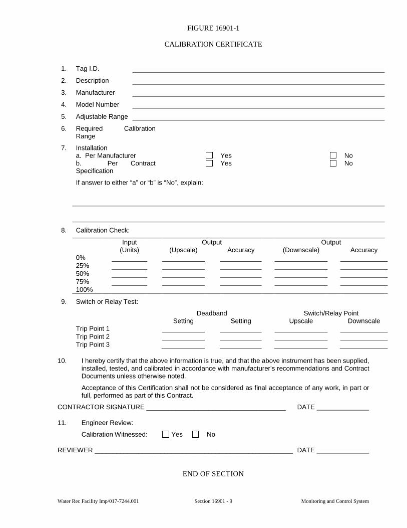
Water Rec Facility Imp/017-7244.001 Section 16901 - 9 Monitoring and Control System
FIGURE 16901-1
CALIBRATION CERTIFICATE
1. Tag I.D.
2. Description
3. Manufacturer
4. Model Number
5. Adjustable Range
6. Required Calibration Range
7. Installation a. Per Manufacturer Yes No b. Per Contract Specification
Yes No
If answer to either “a” or “b” is “No”, explain:
8. Calibration Check:
Input Output Output (Units) (Upscale) Accuracy (Downscale) Accuracy
0% 25% 50% 75% 100%
9. Switch or Relay Test:
Deadband Switch/Relay Point Setting Setting Upscale Downscale
Trip Point 1 Trip Point 2 Trip Point 3
10. I hereby certify that the above information is true, and that the above instrument has been supplied, installed, tested, and calibrated in accordance with manufacturer’s recommendations and Contract Documents unless otherwise noted.
Acceptance of this Certification shall not be considered as final acceptance of any work, in part or full, performed as part of this Contract.
CONTRACTOR SIGNATURE ______________________________________ DATE
11. Engineer Review:
Calibration Witnessed: Yes No
REVIEWER ______________________________________________________ DATE
END OF SECTION

Monitoring and Control System Section 16901 - 10 Water Rec Facility Imp/017-7244.001
This page was intentionally left blank.
Water Rec Facility Imp/017-7244.001 Section 16902 - 1 Metering and Control Equipment
SECTION 16902
METERING AND CONTROL EQUIPMENT
GENERAL
1.01 SCOPE
A. Work under this Section includes furnishing and installing all metering and control equipment which is part of the Plant Control System except the programmable controller system and the graphic user interface system.
B. All work performed shall comply and be in accordance with all approved trade practices and manufacturer’s recommendations.
1.02 SUBMITTALS
A. Submittals shall be in accordance with the requirements of Section 01300 and shall include:
1. Shop Drawings for Review:
a. Manufacturer’s literature including model number, type, size, materials, quantity, connections, equipment number, mounting hardware, and installation information.
2. Information for the Record:
a. Equipment suppliers report that equipment is properly installed and satisfactory operation is obtained.
b. Software, cables, etc. for configuration, programming or operation of meters or equipment, minimum of two each is required.
c. Operation and Maintenance information.
d. Schedule of Owner’s training for all new equipment.
PRODUCTS
2.01 PRODUCT REQUIREMENTS
A. All metering and control equipment shall be as indicated on the Drawings and as specified, and shall include, but not be limited to those devices hereinafter defined. Should additional devices be required, but not specifically indicated elsewhere, in order to affect the intent of the Contract Documents, such devices shall be furnished.
B. All metering and control equipment used for similar applications shall be the product of a single manufacturer.
C. All features and requirements listed in the individual instrument specifications are required.
D. All field instrument enclosures shall be NEMA 4X construction except in hazardous locations where the enclosures shall be NEMA 7 for Class I, Division 1, Group D service, unless otherwise noted. Equipment in hazardous locations shall indicate temperature rating as specified in the NEC.
E. All faces of panel mounted instruments shall be NEMA 4X construction except where the panel is located in a protected Control Room environment.
F. Whenever an “or equal” equipment item is proposed in lieu of that specified it will not be considered equal if it is of non-potted construction and the specified item is potted construction.
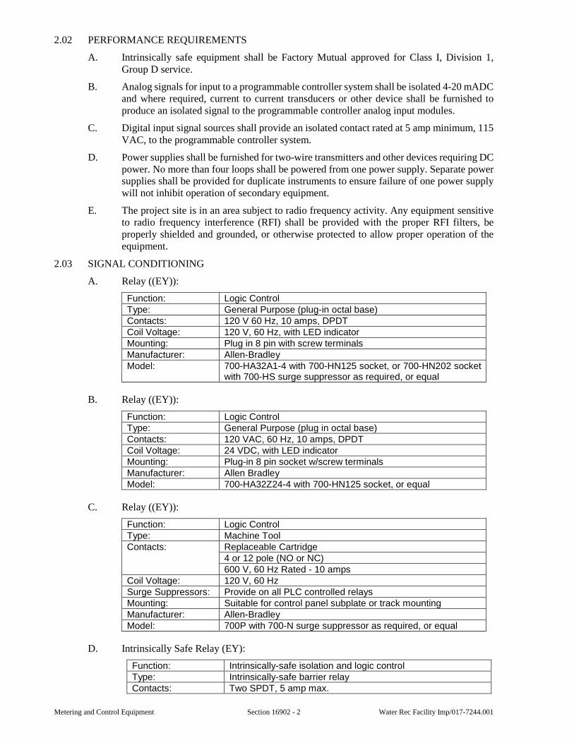
Metering and Control Equipment Section 16902 - 2 Water Rec Facility Imp/017-7244.001
2.02 PERFORMANCE REQUIREMENTS
A. Intrinsically safe equipment shall be Factory Mutual approved for Class I, Division 1, Group D service.
B. Analog signals for input to a programmable controller system shall be isolated 4-20 mADC and where required, current to current transducers or other device shall be furnished to produce an isolated signal to the programmable controller analog input modules.
C. Digital input signal sources shall provide an isolated contact rated at 5 amp minimum, 115 VAC, to the programmable controller system.
D. Power supplies shall be furnished for two-wire transmitters and other devices requiring DC power. No more than four loops shall be powered from one power supply. Separate power supplies shall be provided for duplicate instruments to ensure failure of one power supply will not inhibit operation of secondary equipment.
E. The project site is in an area subject to radio frequency activity. Any equipment sensitive to radio frequency interference (RFI) shall be provided with the proper RFI filters, be properly shielded and grounded, or otherwise protected to allow proper operation of the equipment.
2.03 SIGNAL CONDITIONING
A. Relay ((EY)):
Function: Logic Control Type: General Purpose (plug-in octal base) Contacts: 120 V 60 Hz, 10 amps, DPDT Coil Voltage: 120 V, 60 Hz, with LED indicator Mounting: Plug in 8 pin with screw terminals Manufacturer: Allen-Bradley Model: 700-HA32A1-4 with 700-HN125 socket, or 700-HN202 socket
with 700-HS surge suppressor as required, or equal
B. Relay ((EY)):
Function: Logic Control Type: General Purpose (plug in octal base) Contacts: 120 VAC, 60 Hz, 10 amps, DPDT Coil Voltage: 24 VDC, with LED indicator Mounting: Plug-in 8 pin socket w/screw terminals Manufacturer: Allen Bradley Model: 700-HA32Z24-4 with 700-HN125 socket, or equal
C. Relay ((EY)):
Function: Logic Control Type: Machine Tool Contacts: Replaceable Cartridge
4 or 12 pole (NO or NC) 600 V, 60 Hz Rated - 10 amps
Coil Voltage: 120 V, 60 Hz Surge Suppressors: Provide on all PLC controlled relays Mounting: Suitable for control panel subplate or track mounting Manufacturer: Allen-Bradley Model: 700P with 700-N surge suppressor as required, or equal
D. Intrinsically Safe Relay (EY):
Function: Intrinsically-safe isolation and logic control Type: Intrinsically-safe barrier relay Contacts: Two SPDT, 5 amp max.
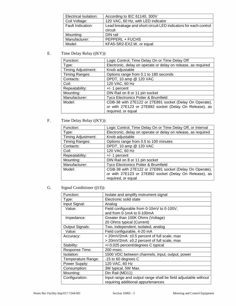
Water Rec Facility Imp/017-7244.001 Section 16902 - 3 Metering and Control Equipment
Electrical Isolation: According to IEC 61140, 300V Coil Voltage: 120 VAC, 60 Hz, with LED indicator Fault Indication: Lead breakage and short circuit LED indicators for each control
circuit Mounting: DIN rail Manufacturer: PEPPERL + FUCHS Model: KFA5-SR2-EX2.W, or equal
E. Time Delay Relay ((KY)):
Function: Logic Control, Time Delay On or Time Delay Off Type: Electronic, delay on operate or delay on release, as required Timing Adjustment: Knob adjustable Timing Ranges: Options range from 0.1 to 180 seconds Contacts: DPDT, 10 amp @ 120 VAC Coil: 120 VAC, 60 Hz Repeatability: +/- 1 percent Mounting: DIN Rail on 8 or 11 pin socket Manufacturer: Tyco Electronics Potter & Brumfield Model: CDB-38 with 27E122 or 27E891 socket (Delay On Operate),
or with 27E123 or 27E892 socket (Delay On Release), as required, or equal
F. Time Delay Relay ((KY)):
Function: Logic Control, Time Delay On or Time Delay Off, or Interval Type: Electronic, delay on operate or delay on release, as required Timing Adjustment: Knob adjustable Timing Ranges: Options range from 0.5 to 100 minutes Contacts: DPDT, 10 amp @ 120 VAC Coil: 120 VAC, 60 Hz Repeatability: +/- 1 percent Mounting: DIN Rail on 8 or 11 pin socket Manufacturer: Tyco Electronics Potter & Brumfield Model: CGB-38 with 27E122 or 27E891 socket (Delay On Operate),
or with 27E123 or 27E892 socket (Delay On Release), as required, or equal
G. Signal Conditioner ((I/I)):
Function: Isolate and amplify instrument signal Type: Electronic solid state Input Signal: Analog Value: Field configurable from 0-10mV to 0-100V,
and from 0-1mA to 0-100mA Impedance: Greater than 100K Ohms (Voltage)
20 Ohms typical (Current) Output Signals: Two, independent, isolated, analog Value: Field configurable, 4-20 mA Accuracy: < 20mV/2mA: ±0.5 percent of full scale, max
> 20mV/2mA: ±0.2 percent of full scale, max Stability: +/-0.025 percent/degrees C typical Response Time: 200 msec. Isolation: 1500 VDC between channels, input, output, power Temperature Range: -15 to 60 degrees C Power Supply: 120 VAC, 60 Hz Consumption: 3W typical, 5W Max. Mounting: Din Rail (MD11) Configuration: Input range and output range shall be field adjustable without
requiring additional appurtenances
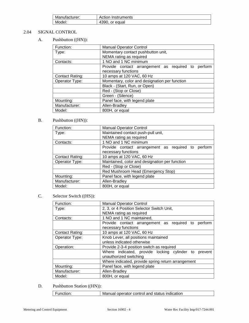
Metering and Control Equipment Section 16902 - 4 Water Rec Facility Imp/017-7244.001
Manufacturer: Action Instruments Model: 4390, or equal
2.04 SIGNAL CONTROL
A. Pushbutton ((HN)):
Function: Manual Operator Control Type: Momentary contact pushbutton unit,
NEMA rating as required Contacts: 1 NO and 1 NC minimum
Provide contact arrangement as required to perform necessary functions
Contact Rating: 10 amps at 120 VAC, 60 Hz Operator Type: Momentary, color and designation per function
Black - (Start, Run, or Open) Red - (Stop or Close) Green - (Silence)
Mounting: Panel face, with legend plate Manufacturer: Allen-Bradley Model: 800H, or equal
B. Pushbutton ((HN)):
Function: Manual Operator Control Type: Maintained contact push-pull unit,
NEMA rating as required Contacts: 1 NO and 1 NC minimum
Provide contact arrangement as required to perform necessary functions
Contact Rating: 10 amps at 120 VAC, 60 Hz Operator Type: Maintained, color and designation per function
Red - (Stop or Close) Red Mushroom Head (Emergency Stop)
Mounting: Panel face, with legend plate Manufacturer: Allen-Bradley Model: 800H, or equal
C. Selector Switch ((HS)):
Function: Manual Operator Control Type: 2, 3, or 4 Position Selector Switch Unit,
NEMA rating as required Contacts: 1 NO and 1 NC maintained,
Provide contact arrangement as required to perform necessary functions
Contact Rating: 10 amps at 120 VAC, 60 Hz Operator Type: Knob Lever, all positions maintained
unless indicated otherwise Operation: Provide 2-3-4 position switch as required
Where indicated, provide locking cylinder to prevent unauthorized switching Where indicated, provide spring return arrangement
Mounting: Panel face, with legend plate Manufacturer: Allen-Bradley Model: 800H, or equal
D. Pushbutton Station ((HN)):
Function: Manual operator control and status indication
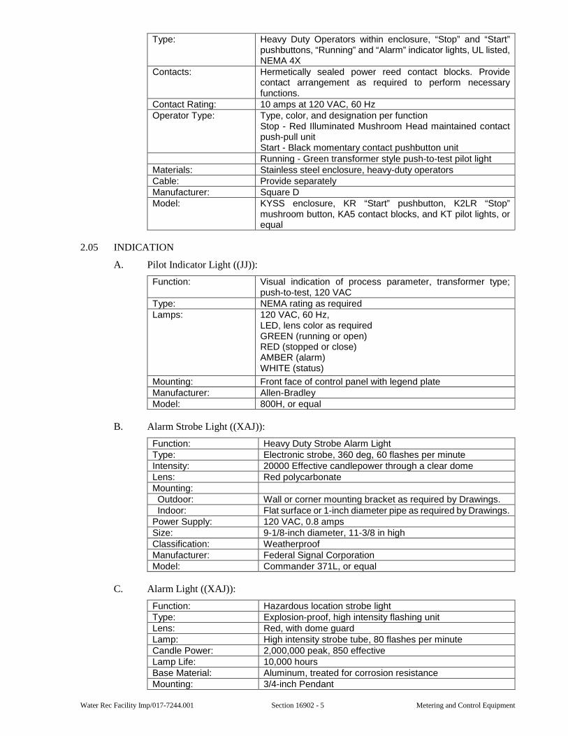
Water Rec Facility Imp/017-7244.001 Section 16902 - 5 Metering and Control Equipment
Type: Heavy Duty Operators within enclosure, “Stop” and “Start” pushbuttons, “Running” and “Alarm” indicator lights, UL listed, NEMA 4X
Contacts: Hermetically sealed power reed contact blocks. Provide contact arrangement as required to perform necessary functions.
Contact Rating: 10 amps at 120 VAC, 60 Hz Operator Type: Type, color, and designation per function
Stop - Red Illuminated Mushroom Head maintained contact push-pull unit Start - Black momentary contact pushbutton unit Running - Green transformer style push-to-test pilot light
Materials: Stainless steel enclosure, heavy-duty operators Cable: Provide separately Manufacturer: Square D Model: KYSS enclosure, KR “Start” pushbutton, K2LR “Stop”
mushroom button, KA5 contact blocks, and KT pilot lights, or equal
2.05 INDICATION
A. Pilot Indicator Light ((JJ)):
Function: Visual indication of process parameter, transformer type; push-to-test, 120 VAC
Type: NEMA rating as required Lamps: 120 VAC, 60 Hz,
LED, lens color as required GREEN (running or open) RED (stopped or close) AMBER (alarm) WHITE (status)
Mounting: Front face of control panel with legend plate Manufacturer: Allen-Bradley Model: 800H, or equal
B. Alarm Strobe Light ((XAJ)):
Function: Heavy Duty Strobe Alarm Light Type: Electronic strobe, 360 deg, 60 flashes per minute Intensity: 20000 Effective candlepower through a clear dome Lens: Red polycarbonate Mounting: Outdoor: Wall or corner mounting bracket as required by Drawings. Indoor: Flat surface or 1-inch diameter pipe as required by Drawings.Power Supply: 120 VAC, 0.8 amps Size: 9-1/8-inch diameter, 11-3/8 in high Classification: Weatherproof Manufacturer: Federal Signal Corporation Model: Commander 371L, or equal
C. Alarm Light ((XAJ)):
Function: Hazardous location strobe light Type: Explosion-proof, high intensity flashing unit Lens: Red, with dome guard Lamp: High intensity strobe tube, 80 flashes per minute Candle Power: 2,000,000 peak, 850 effective Lamp Life: 10,000 hours Base Material: Aluminum, treated for corrosion resistance Mounting: 3/4-inch Pendant
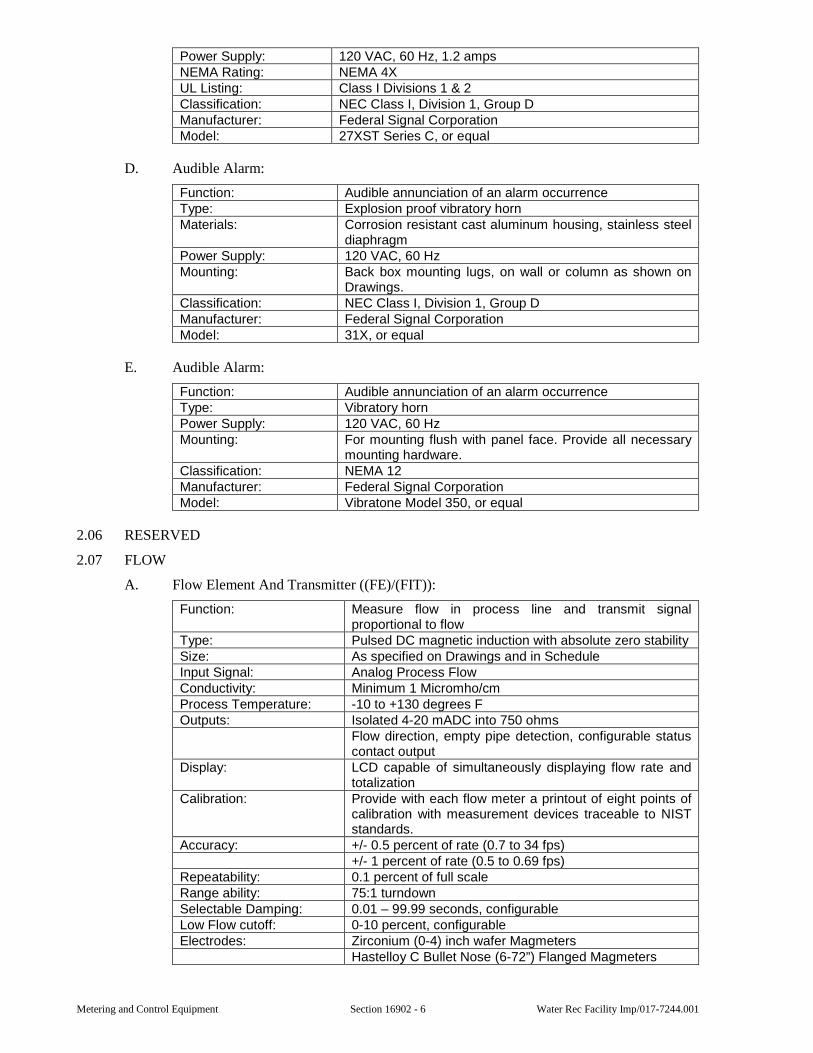
Metering and Control Equipment Section 16902 - 6 Water Rec Facility Imp/017-7244.001
Power Supply: 120 VAC, 60 Hz, 1.2 amps NEMA Rating: NEMA 4X UL Listing: Class I Divisions 1 & 2 Classification: NEC Class I, Division 1, Group D Manufacturer: Federal Signal Corporation Model: 27XST Series C, or equal
D. Audible Alarm:
Function: Audible annunciation of an alarm occurrence Type: Explosion proof vibratory horn Materials: Corrosion resistant cast aluminum housing, stainless steel
diaphragm Power Supply: 120 VAC, 60 Hz Mounting: Back box mounting lugs, on wall or column as shown on
Drawings. Classification: NEC Class I, Division 1, Group D Manufacturer: Federal Signal Corporation Model: 31X, or equal
E. Audible Alarm:
Function: Audible annunciation of an alarm occurrence Type: Vibratory horn Power Supply: 120 VAC, 60 Hz Mounting: For mounting flush with panel face. Provide all necessary
mounting hardware. Classification: NEMA 12 Manufacturer: Federal Signal Corporation Model: Vibratone Model 350, or equal
2.06 RESERVED
2.07 FLOW
A. Flow Element And Transmitter ((FE)/(FIT)):
Function: Measure flow in process line and transmit signal proportional to flow
Type: Pulsed DC magnetic induction with absolute zero stability Size: As specified on Drawings and in Schedule Input Signal: Analog Process Flow Conductivity: Minimum 1 Micromho/cm Process Temperature: -10 to +130 degrees F Outputs: Isolated 4-20 mADC into 750 ohms
Flow direction, empty pipe detection, configurable status contact output
Display: LCD capable of simultaneously displaying flow rate and totalization
Calibration: Provide with each flow meter a printout of eight points of calibration with measurement devices traceable to NIST standards.
Accuracy: +/- 0.5 percent of rate (0.7 to 34 fps) +/- 1 percent of rate (0.5 to 0.69 fps)
Repeatability: 0.1 percent of full scale Range ability: 75:1 turndown Selectable Damping: 0.01 – 99.99 seconds, configurable Low Flow cutoff: 0-10 percent, configurable Electrodes: Zirconium (0-4) inch wafer Magmeters
Hastelloy C Bullet Nose (6-72”) Flanged Magmeters
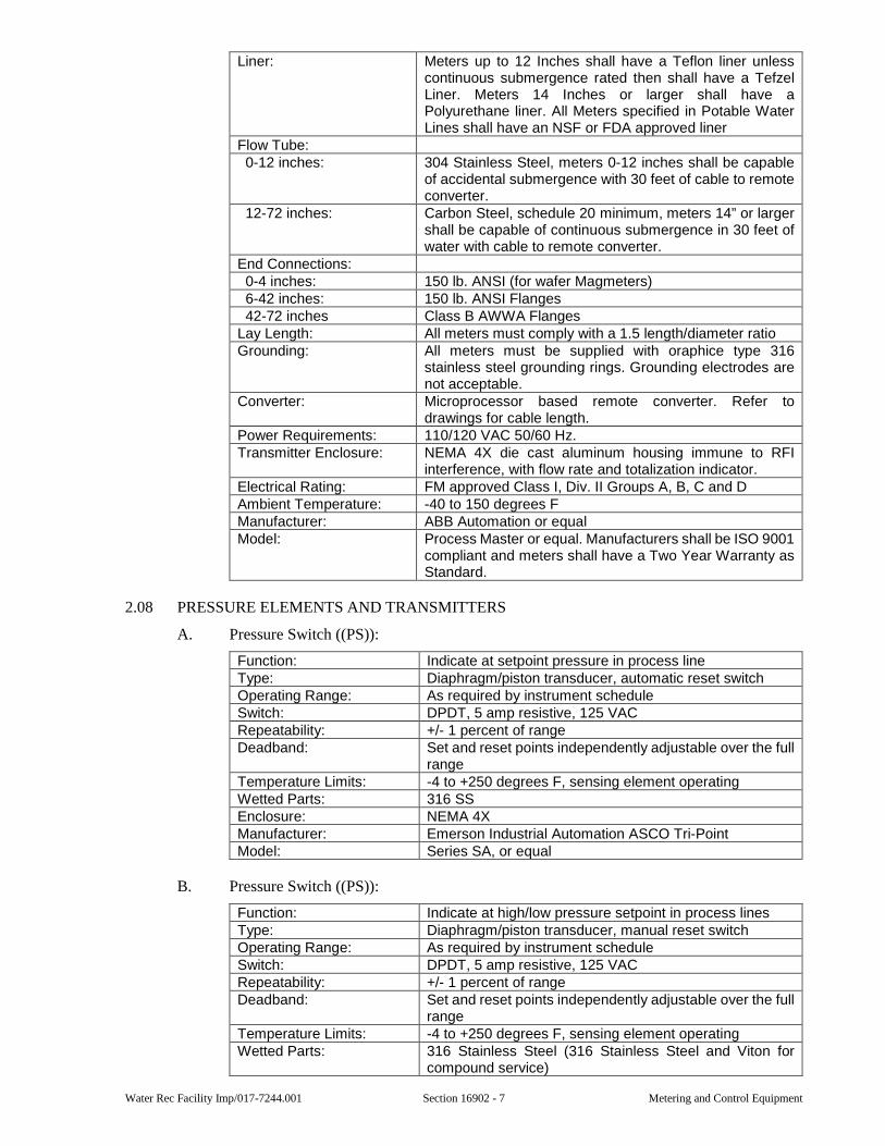
Water Rec Facility Imp/017-7244.001 Section 16902 - 7 Metering and Control Equipment
Liner: Meters up to 12 Inches shall have a Teflon liner unless continuous submergence rated then shall have a Tefzel Liner. Meters 14 Inches or larger shall have a Polyurethane liner. All Meters specified in Potable Water Lines shall have an NSF or FDA approved liner
Flow Tube: 0-12 inches: 304 Stainless Steel, meters 0-12 inches shall be capable
of accidental submergence with 30 feet of cable to remote converter.
12-72 inches: Carbon Steel, schedule 20 minimum, meters 14” or larger shall be capable of continuous submergence in 30 feet of water with cable to remote converter.
End Connections: 0-4 inches: 150 lb. ANSI (for wafer Magmeters) 6-42 inches: 150 lb. ANSI Flanges 42-72 inches Class B AWWA Flanges Lay Length: All meters must comply with a 1.5 length/diameter ratio Grounding: All meters must be supplied with oraphice type 316
stainless steel grounding rings. Grounding electrodes are not acceptable.
Converter: Microprocessor based remote converter. Refer to drawings for cable length.
Power Requirements: 110/120 VAC 50/60 Hz. Transmitter Enclosure: NEMA 4X die cast aluminum housing immune to RFI
interference, with flow rate and totalization indicator. Electrical Rating: FM approved Class I, Div. II Groups A, B, C and D Ambient Temperature: -40 to 150 degrees F Manufacturer: ABB Automation or equal Model: Process Master or equal. Manufacturers shall be ISO 9001
compliant and meters shall have a Two Year Warranty as Standard.
2.08 PRESSURE ELEMENTS AND TRANSMITTERS
A. Pressure Switch ((PS)):
Function: Indicate at setpoint pressure in process line Type: Diaphragm/piston transducer, automatic reset switch Operating Range: As required by instrument schedule Switch: DPDT, 5 amp resistive, 125 VAC Repeatability: +/- 1 percent of range Deadband: Set and reset points independently adjustable over the full
range Temperature Limits: -4 to +250 degrees F, sensing element operating Wetted Parts: 316 SS Enclosure: NEMA 4X Manufacturer: Emerson Industrial Automation ASCO Tri-Point Model: Series SA, or equal
B. Pressure Switch ((PS)):
Function: Indicate at high/low pressure setpoint in process lines Type: Diaphragm/piston transducer, manual reset switch Operating Range: As required by instrument schedule Switch: DPDT, 5 amp resistive, 125 VAC Repeatability: +/- 1 percent of range Deadband: Set and reset points independently adjustable over the full
range Temperature Limits: -4 to +250 degrees F, sensing element operating Wetted Parts: 316 Stainless Steel (316 Stainless Steel and Viton for
compound service)
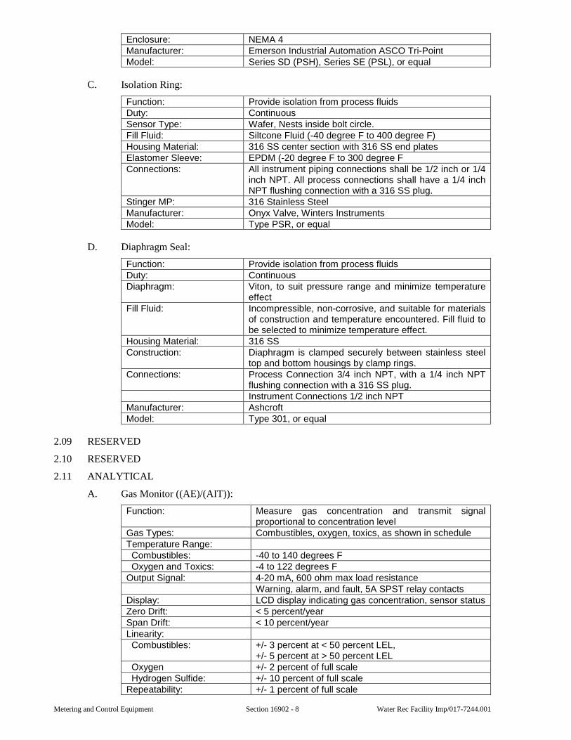
Metering and Control Equipment Section 16902 - 8 Water Rec Facility Imp/017-7244.001
Enclosure: NEMA 4 Manufacturer: Emerson Industrial Automation ASCO Tri-Point Model: Series SD (PSH), Series SE (PSL), or equal
C. Isolation Ring:
Function: Provide isolation from process fluids Duty: Continuous Sensor Type: Wafer, Nests inside bolt circle. Fill Fluid: Siltcone Fluid (-40 degree F to 400 degree F) Housing Material: 316 SS center section with 316 SS end plates Elastomer Sleeve: EPDM (-20 degree F to 300 degree F Connections: All instrument piping connections shall be 1/2 inch or 1/4
inch NPT. All process connections shall have a 1/4 inch NPT flushing connection with a 316 SS plug.
Stinger MP: 316 Stainless Steel Manufacturer: Onyx Valve, Winters Instruments Model: Type PSR, or equal
D. Diaphragm Seal:
Function: Provide isolation from process fluids Duty: Continuous Diaphragm: Viton, to suit pressure range and minimize temperature
effect Fill Fluid: Incompressible, non-corrosive, and suitable for materials
of construction and temperature encountered. Fill fluid to be selected to minimize temperature effect.
Housing Material: 316 SS Construction: Diaphragm is clamped securely between stainless steel
top and bottom housings by clamp rings. Connections: Process Connection 3/4 inch NPT, with a 1/4 inch NPT
flushing connection with a 316 SS plug. Instrument Connections 1/2 inch NPT
Manufacturer: Ashcroft Model: Type 301, or equal
2.09 RESERVED
2.10 RESERVED
2.11 ANALYTICAL
A. Gas Monitor ((AE)/(AIT)):
Function: Measure gas concentration and transmit signal proportional to concentration level
Gas Types: Combustibles, oxygen, toxics, as shown in schedule Temperature Range: Combustibles: -40 to 140 degrees F Oxygen and Toxics: -4 to 122 degrees F Output Signal: 4-20 mA, 600 ohm max load resistance
Warning, alarm, and fault, 5A SPST relay contacts Display: LCD display indicating gas concentration, sensor status Zero Drift: < 5 percent/year Span Drift: < 10 percent/year Linearity: Combustibles: +/- 3 percent at < 50 percent LEL,
+/- 5 percent at > 50 percent LEL Oxygen +/- 2 percent of full scale Hydrogen Sulfide: +/- 10 percent of full scale Repeatability: +/- 1 percent of full scale
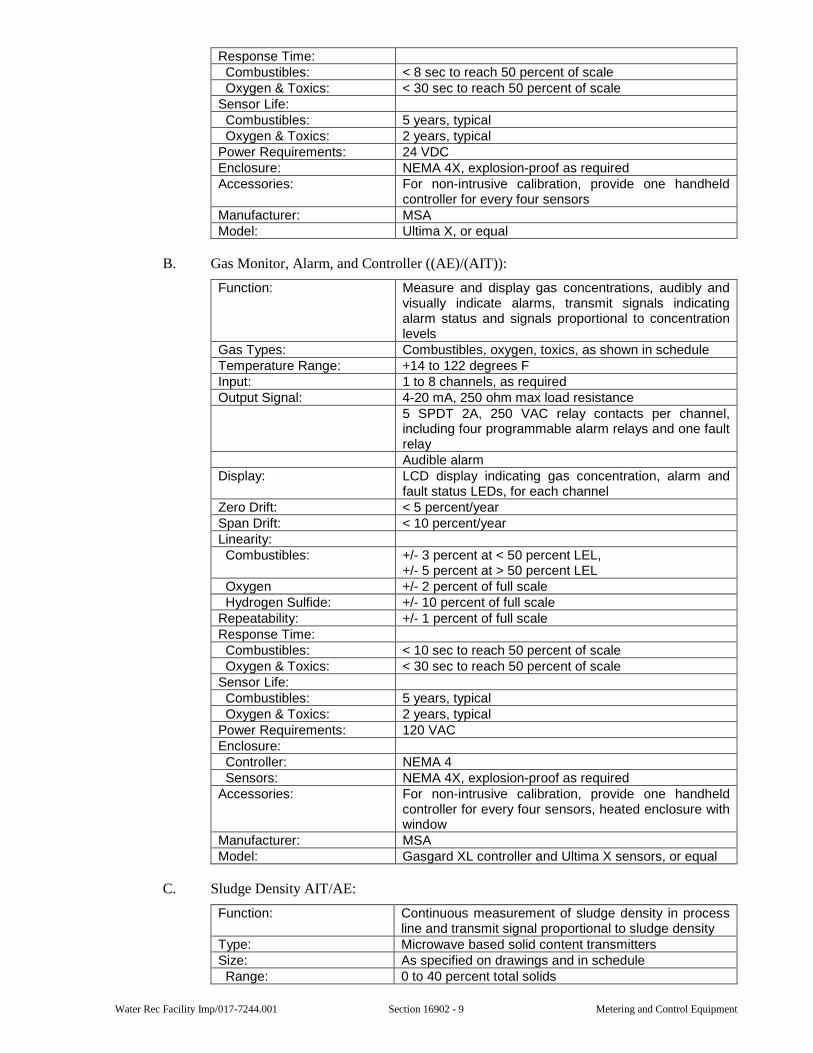
Water Rec Facility Imp/017-7244.001 Section 16902 - 9 Metering and Control Equipment
Response Time: Combustibles: < 8 sec to reach 50 percent of scale Oxygen & Toxics: < 30 sec to reach 50 percent of scale Sensor Life: Combustibles: 5 years, typical Oxygen & Toxics: 2 years, typical Power Requirements: 24 VDC Enclosure: NEMA 4X, explosion-proof as required Accessories: For non-intrusive calibration, provide one handheld
controller for every four sensors Manufacturer: MSA Model: Ultima X, or equal
B. Gas Monitor, Alarm, and Controller ((AE)/(AIT)):
Function: Measure and display gas concentrations, audibly and visually indicate alarms, transmit signals indicating alarm status and signals proportional to concentration levels
Gas Types: Combustibles, oxygen, toxics, as shown in schedule Temperature Range: +14 to 122 degrees F Input: 1 to 8 channels, as required Output Signal: 4-20 mA, 250 ohm max load resistance
5 SPDT 2A, 250 VAC relay contacts per channel, including four programmable alarm relays and one fault relay Audible alarm
Display: LCD display indicating gas concentration, alarm and fault status LEDs, for each channel
Zero Drift: < 5 percent/year Span Drift: < 10 percent/year Linearity: Combustibles: +/- 3 percent at < 50 percent LEL,
+/- 5 percent at > 50 percent LEL Oxygen +/- 2 percent of full scale Hydrogen Sulfide: +/- 10 percent of full scale Repeatability: +/- 1 percent of full scale Response Time: Combustibles: < 10 sec to reach 50 percent of scale Oxygen & Toxics: < 30 sec to reach 50 percent of scale Sensor Life: Combustibles: 5 years, typical Oxygen & Toxics: 2 years, typical Power Requirements: 120 VAC Enclosure: Controller: NEMA 4 Sensors: NEMA 4X, explosion-proof as required Accessories: For non-intrusive calibration, provide one handheld
controller for every four sensors, heated enclosure with window
Manufacturer: MSA Model: Gasgard XL controller and Ultima X sensors, or equal
C. Sludge Density AIT/AE:
Function: Continuous measurement of sludge density in process line and transmit signal proportional to sludge density
Type: Microwave based solid content transmitters Size: As specified on drawings and in schedule Range: 0 to 40 percent total solids
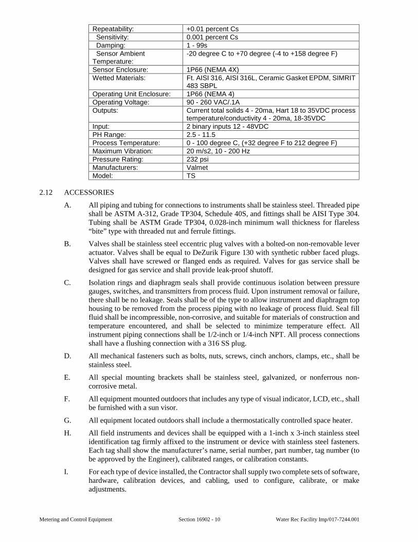
Metering and Control Equipment Section 16902 - 10 Water Rec Facility Imp/017-7244.001
Repeatability: +0.01 percent Cs Sensitivity: 0.001 percent Cs Damping: 1 - 99s Sensor Ambient Temperature:
-20 degree C to +70 degree (-4 to +158 degree F)
Sensor Enclosure: 1P66 (NEMA 4X) Wetted Materials: Ft. AISI 316, AISI 316L, Ceramic Gasket EPDM, SIMRIT
483 SBPL Operating Unit Enclosure: 1P66 (NEMA 4) Operating Voltage: 90 - 260 VAC/.1A Outputs: Current total solids 4 - 20ma, Hart 18 to 35VDC process
temperature/conductivity 4 - 20ma, 18-35VDC Input: 2 binary inputs 12 - 48VDC PH Range: 2.5 - 11.5 Process Temperature: 0 - 100 degree C, (+32 degree F to 212 degree F) Maximum Vibration: 20 m/s2, 10 - 200 Hz Pressure Rating: 232 psi Manufacturers: Valmet Model: TS
2.12 ACCESSORIES
A. All piping and tubing for connections to instruments shall be stainless steel. Threaded pipe shall be ASTM A-312, Grade TP304, Schedule 40S, and fittings shall be AISI Type 304. Tubing shall be ASTM Grade TP304, 0.028-inch minimum wall thickness for flareless “bite” type with threaded nut and ferrule fittings.
B. Valves shall be stainless steel eccentric plug valves with a bolted-on non-removable lever actuator. Valves shall be equal to DeZurik Figure 130 with synthetic rubber faced plugs. Valves shall have screwed or flanged ends as required. Valves for gas service shall be designed for gas service and shall provide leak-proof shutoff.
C. Isolation rings and diaphragm seals shall provide continuous isolation between pressure gauges, switches, and transmitters from process fluid. Upon instrument removal or failure, there shall be no leakage. Seals shall be of the type to allow instrument and diaphragm top housing to be removed from the process piping with no leakage of process fluid. Seal fill fluid shall be incompressible, non-corrosive, and suitable for materials of construction and temperature encountered, and shall be selected to minimize temperature effect. All instrument piping connections shall be 1/2-inch or 1/4-inch NPT. All process connections shall have a flushing connection with a 316 SS plug.
D. All mechanical fasteners such as bolts, nuts, screws, cinch anchors, clamps, etc., shall be stainless steel.
E. All special mounting brackets shall be stainless steel, galvanized, or nonferrous non-corrosive metal.
F. All equipment mounted outdoors that includes any type of visual indicator, LCD, etc., shall be furnished with a sun visor.
G. All equipment located outdoors shall include a thermostatically controlled space heater.
H. All field instruments and devices shall be equipped with a 1-inch x 3-inch stainless steel identification tag firmly affixed to the instrument or device with stainless steel fasteners. Each tag shall show the manufacturer’s name, serial number, part number, tag number (to be approved by the Engineer), calibrated ranges, or calibration constants.
I. For each type of device installed, the Contractor shall supply two complete sets of software, hardware, calibration devices, and cabling, used to configure, calibrate, or make adjustments.
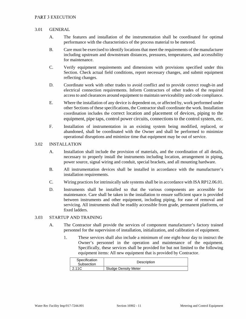
Water Rec Facility Imp/017-7244.001 Section 16902 - 11 Metering and Control Equipment
EXECUTION
3.01 GENERAL
A. The features and installation of the instrumentation shall be coordinated for optimal performance with the characteristics of the process material to be metered.
B. Care must be exercised to identify locations that meet the requirements of the manufacturer including upstream and downstream distances, pressures, temperatures, and accessibility for maintenance.
C. Verify equipment requirements and dimensions with provisions specified under this Section. Check actual field conditions, report necessary changes, and submit equipment reflecting changes.
D. Coordinate work with other trades to avoid conflict and to provide correct rough-in and electrical connection requirements. Inform Contractors of other trades of the required access to and clearances around equipment to maintain serviceability and code compliance.
E. Where the installation of any device is dependent on, or affected by, work performed under other Sections of these specifications, the Contractor shall coordinate the work. Installation coordination includes the correct location and placement of devices, piping to the equipment, pipe taps, control power circuits, connections to the control system, etc.
F. Installation of instrumentation in an existing system being modified, replaced, or abandoned, shall be coordinated with the Owner and shall be performed to minimize operational disruptions and minimize time that equipment may be out of service.
3.02 INSTALLATION
A. Installation shall include the provision of materials, and the coordination of all details, necessary to properly install the instruments including location, arrangement in piping, power source, signal wiring and conduit, special brackets, and all mounting hardware.
B. All instrumentation devices shall be installed in accordance with the manufacturer’s installation requirements.
C. Wiring practices for intrinsically safe systems shall be in accordance with ISA RP12.06.01.
D. Instruments shall be installed so that the various components are accessible for maintenance. Care shall be taken in the installation to ensure sufficient space is provided between instruments and other equipment, including piping, for ease of removal and servicing. All instruments shall be readily accessible from grade, permanent platforms, or fixed ladders.
3.03 STARTUP AND TRAINING
A. The Contractor shall provide the services of component manufacturer’s factory trained personnel for the supervision of installation, initialization, and calibration of equipment.
1. These services shall also include a minimum of one eight-hour day to instruct the Owner’s personnel in the operation and maintenance of the equipment. Specifically, these services shall be provided for but not limited to the following equipment items: All new equipment that is provided by Contractor.
Specification Subsection
Description
2.11C Sludge Density Meter
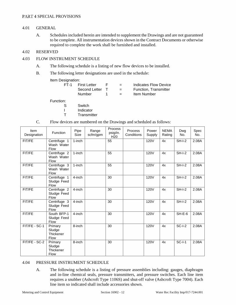
Metering and Control Equipment Section 16902 - 12 Water Rec Facility Imp/017-7244.001
SPECIAL PROVISIONS
4.01 GENERAL
A. Schedules included herein are intended to supplement the Drawings and are not guaranteed to be complete. All instrumentation devices shown in the Contract Documents or otherwise required to complete the work shall be furnished and installed.
4.02 RESERVED
4.03 FLOW INSTRUMENT SCHEDULE
A. The following schedule is a listing of new flow devices to be installed.
B. The following letter designations are used in the schedule:
Item Designation: FT-1 First Letter F = Indicates Flow Device
Second Letter T = Function, Transmitter Number 1 = Item Number
Function: S Switch I Indicator T Transmitter
C. Flow devices are numbered on the Drawings and scheduled as follows:
Item Designation
Function Pipe Size
Range scfm/gpm
Process psig/in.
H20
Process Conditions
Power Supply
NEMA Rating
Dwg No.
Spec No.
FIT/FE Centrifuge 1 Wash Water Flow
1-inch 55 120V 4x SH-I-2 2.08A
FIT/FE Centrifuge 2 Wash Water Flow
1-inch 55 120V 4x SH-I-2 2.08A
FIT/FE Centrifuge 3 Wash Water Flow
1-inch 55 120V 4x SH-I-2 2.08A
FIT/FE Centrifuge 1 Sludge Feed Flow
4-inch 30 120V 4x SH-I-2 2.08A
FIT/FE Centrifuge 2 Sludge Feed Flow
4-inch 30 120V 4x SH-I-2 2.08A
FIT/FE Centrifuge 3 Sludge Feed Flow
4-inch 30 120V 4x SH-I-2 2.08A
FIT/FE South BFP-1 Sludge Feed Flow
4-inch 30 120V 4x SH-E-6 2.08A
FIT/FE - SC-1 Primary Sludge Thickener Flow
8-inch 30 120V 4x SC-I-2 2.08A
FIT/FE - SC-2 Primary Sludge Thickener Flow
8-inch 30 120V 4x SC-I-1 2.08A
4.04 PRESSURE INSTRUMENT SCHEDULE
A. The following schedule is a listing of pressure assemblies including: gauges, diaphragm and in-line chemical seals, pressure transmitters, and pressure switches. Each line item requires a snubber (Ashcroft Type 1106S) and shut-off valve (Ashcroft Type 7004). Each line item so indicated shall include accessories shown.
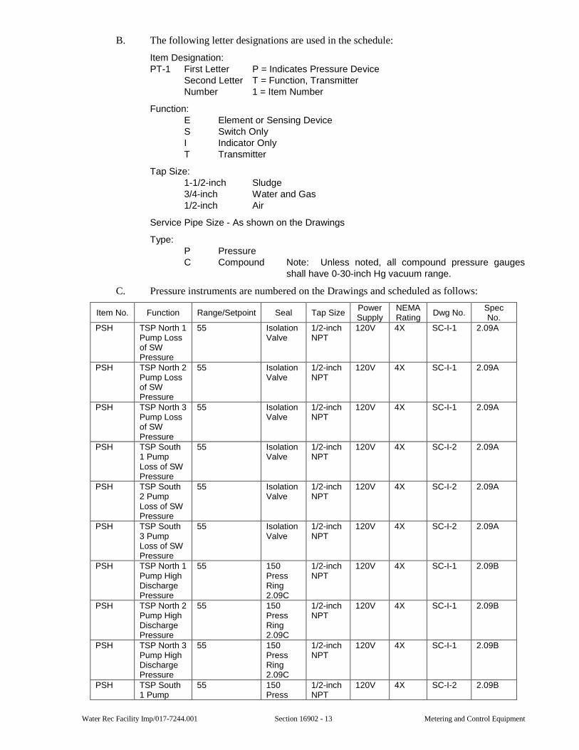
Water Rec Facility Imp/017-7244.001 Section 16902 - 13 Metering and Control Equipment
B. The following letter designations are used in the schedule:
Item Designation: PT-1 First Letter P = Indicates Pressure Device
Second Letter T = Function, Transmitter Number 1 = Item Number
Function: E Element or Sensing Device S Switch Only I Indicator Only T Transmitter
Tap Size: 1-1/2-inch Sludge 3/4-inch Water and Gas 1/2-inch Air
Service Pipe Size - As shown on the Drawings
Type: P Pressure C Compound Note: Unless noted, all compound pressure gauges
shall have 0-30-inch Hg vacuum range.
C. Pressure instruments are numbered on the Drawings and scheduled as follows:
Item No. Function Range/Setpoint Seal Tap Size Power Supply
NEMA Rating
Dwg No. Spec No.
PSH TSP North 1 Pump Loss of SW Pressure
55 Isolation Valve
1/2-inch NPT
120V 4X SC-I-1 2.09A
PSH TSP North 2 Pump Loss of SW Pressure
55 Isolation Valve
1/2-inch NPT
120V 4X SC-I-1 2.09A
PSH TSP North 3 Pump Loss of SW Pressure
55 Isolation Valve
1/2-inch NPT
120V 4X SC-I-1 2.09A
PSH TSP South 1 Pump Loss of SW Pressure
55 Isolation Valve
1/2-inch NPT
120V 4X SC-I-2 2.09A
PSH TSP South 2 Pump Loss of SW Pressure
55 Isolation Valve
1/2-inch NPT
120V 4X SC-I-2 2.09A
PSH TSP South 3 Pump Loss of SW Pressure
55 Isolation Valve
1/2-inch NPT
120V 4X SC-I-2 2.09A
PSH TSP North 1 Pump High Discharge Pressure
55 150 Press Ring 2.09C
1/2-inch NPT
120V 4X SC-I-1 2.09B
PSH TSP North 2 Pump High Discharge Pressure
55 150 Press Ring 2.09C
1/2-inch NPT
120V 4X SC-I-1 2.09B
PSH TSP North 3 Pump High Discharge Pressure
55 150 Press Ring 2.09C
1/2-inch NPT
120V 4X SC-I-1 2.09B
PSH TSP South 1 Pump
55 150 Press
1/2-inch NPT
120V 4X SC-I-2 2.09B
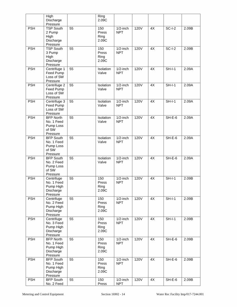
Metering and Control Equipment Section 16902 - 14 Water Rec Facility Imp/017-7244.001
High Discharge Pressure
Ring 2.09C
PSH TSP South 2 Pump High Discharge Pressure
55 150 Press Ring 2.09C
1/2-inch NPT
120V 4X SC-I-2 2.09B
PSH TSP South 3 Pump High Discharge Pressure
55 150 Press Ring 2.09C
1/2-inch NPT
120V 4X SC-I-2 2.09B
PSH Centrifuge 1 Feed Pump Loss of SW Pressure
55 Isolation Valve
1/2-inch NPT
120V 4X SH-I-1 2.09A
PSH Centrifuge 2 Feed Pump Loss of SW Pressure
55 Isolation Valve
1/2-inch NPT
120V 4X SH-I-1 2.09A
PSH Centrifuge 3 Feed Pump Loss of SW Pressure
55 Isolation Valve
1/2-inch NPT
120V 4X SH-I-1 2.09A
PSH BFP North No. 1 Feed Pump Loss of SW Pressure
55 Isolation Valve
1/2-inch NPT
120V 4X SH-E-6 2.09A
PSH BFP South No. 1 Feed Pump Loss of SW Pressure
55 Isolation Valve
1/2-inch NPT
120V 4X SH-E-6 2.09A
PSH BFP South No. 2 Feed Pump Loss of SW Pressure
55 Isolation Valve
1/2-inch NPT
120V 4X SH-E-6 2.09A
PSH Centrifuge No. 1 Feed Pump High Discharge Pressure
55 150 Press Ring 2.09C
1/2-inch NPT
120V 4X SH-I-1 2.09B
PSH Centrifuge No. 2 Feed Pump High Discharge Pressure
55 150 Press Ring 2.09C
1/2-inch NPT
120V 4X SH-I-1 2.09B
PSH Centrifuge No. 3 Feed Pump High Discharge Pressure
55 150 Press Ring 2.09C
1/2-inch NPT
120V 4X SH-I-1 2.09B
PSH BFP North No. 1 Feed Pump High Discharge Pressure
55 150 Press Ring 2.09C
1/2-inch NPT
120V 4X SH-E-6 2.09B
PSH BFP South No. 1 Feed Pump High Discharge Pressure
55 150 Press Ring 2.09C
1/2-inch NPT
120V 4X SH-E-6 2.09B
PSH BFP South No. 2 Feed
55 150 Press
1/2-inch NPT
120V 4X SH-E-6 2.09B
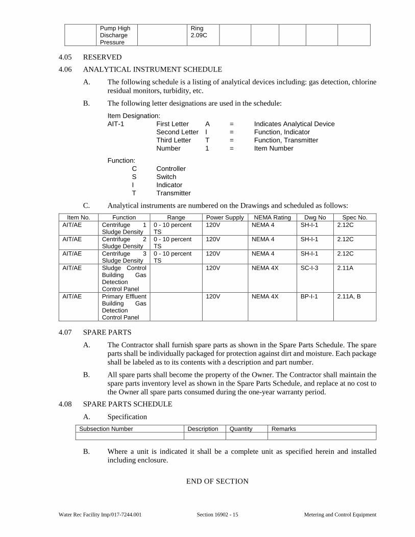
Water Rec Facility Imp/017-7244.001 Section 16902 - 15 Metering and Control Equipment
Pump High Discharge Pressure
Ring 2.09C
4.05 RESERVED
4.06 ANALYTICAL INSTRUMENT SCHEDULE
A. The following schedule is a listing of analytical devices including: gas detection, chlorine residual monitors, turbidity, etc.
B. The following letter designations are used in the schedule:
Item Designation: AIT-1 First Letter A = Indicates Analytical Device
Second Letter I = Function, Indicator Third Letter T = Function, Transmitter Number 1 = Item Number
Function: C Controller S Switch I Indicator T Transmitter
C. Analytical instruments are numbered on the Drawings and scheduled as follows:
Item No. Function Range Power Supply NEMA Rating Dwg No Spec No. AIT/AE Centrifuge 1
Sludge Density 0 - 10 percent TS
120V NEMA 4 SH-I-1 2.12C
AIT/AE Centrifuge 2 Sludge Density
0 - 10 percent TS
120V NEMA 4 SH-I-1 2.12C
AIT/AE Centrifuge 3 Sludge Density
0 - 10 percent TS
120V NEMA 4 SH-I-1 2.12C
AIT/AE Sludge Control Building Gas Detection Control Panel
120V NEMA 4X SC-I-3 2.11A
AIT/AE Primary Effluent Building Gas Detection Control Panel
120V NEMA 4X BP-I-1 2.11A, B
4.07 SPARE PARTS
A. The Contractor shall furnish spare parts as shown in the Spare Parts Schedule. The spare parts shall be individually packaged for protection against dirt and moisture. Each package shall be labeled as to its contents with a description and part number.
B. All spare parts shall become the property of the Owner. The Contractor shall maintain the spare parts inventory level as shown in the Spare Parts Schedule, and replace at no cost to the Owner all spare parts consumed during the one-year warranty period.
4.08 SPARE PARTS SCHEDULE
A. Specification
Subsection Number Description Quantity Remarks
B. Where a unit is indicated it shall be a complete unit as specified herein and installed including enclosure.
END OF SECTION

Metering and Control Equipment Section 16902 - 16 Water Rec Facility Imp/017-7244.001
This page was intentionally left blank.
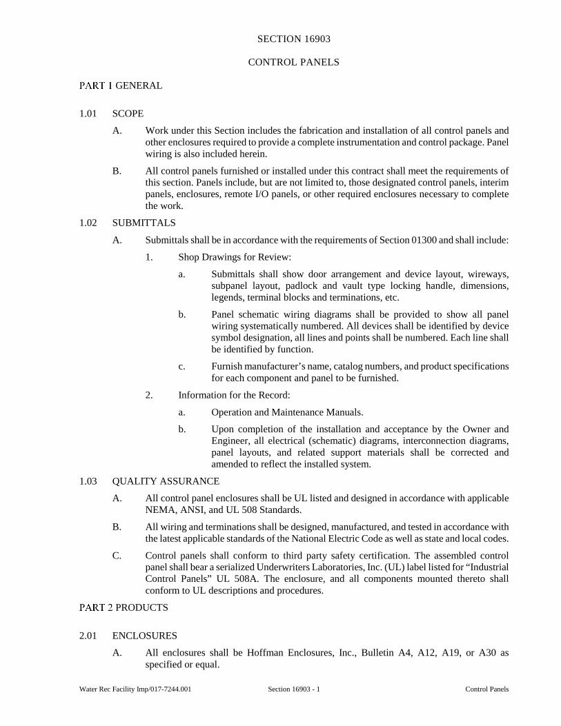
Water Rec Facility Imp/017-7244.001 Section 16903 - 1 Control Panels
SECTION 16903
CONTROL PANELS
GENERAL
1.01 SCOPE
A. Work under this Section includes the fabrication and installation of all control panels and other enclosures required to provide a complete instrumentation and control package. Panel wiring is also included herein.
B. All control panels furnished or installed under this contract shall meet the requirements of this section. Panels include, but are not limited to, those designated control panels, interim panels, enclosures, remote I/O panels, or other required enclosures necessary to complete the work.
1.02 SUBMITTALS
A. Submittals shall be in accordance with the requirements of Section 01300 and shall include:
1. Shop Drawings for Review:
a. Submittals shall show door arrangement and device layout, wireways, subpanel layout, padlock and vault type locking handle, dimensions, legends, terminal blocks and terminations, etc.
b. Panel schematic wiring diagrams shall be provided to show all panel wiring systematically numbered. All devices shall be identified by device symbol designation, all lines and points shall be numbered. Each line shall be identified by function.
c. Furnish manufacturer’s name, catalog numbers, and product specifications for each component and panel to be furnished.
2. Information for the Record:
a. Operation and Maintenance Manuals.
b. Upon completion of the installation and acceptance by the Owner and Engineer, all electrical (schematic) diagrams, interconnection diagrams, panel layouts, and related support materials shall be corrected and amended to reflect the installed system.
1.03 QUALITY ASSURANCE
A. All control panel enclosures shall be UL listed and designed in accordance with applicable NEMA, ANSI, and UL 508 Standards.
B. All wiring and terminations shall be designed, manufactured, and tested in accordance with the latest applicable standards of the National Electric Code as well as state and local codes.
C. Control panels shall conform to third party safety certification. The assembled control panel shall bear a serialized Underwriters Laboratories, Inc. (UL) label listed for “Industrial Control Panels” UL 508A. The enclosure, and all components mounted thereto shall conform to UL descriptions and procedures.
PRODUCTS
2.01 ENCLOSURES
A. All enclosures shall be Hoffman Enclosures, Inc., Bulletin A4, A12, A19, or A30 as specified or equal.
Control Panels Section 16903 - 2 Water Rec Facility Imp/017-7244.001
B. All equipment and controls shall be mounted in metal enclosures designed and manufactured in accordance with the applicable standards of NEMA, ANSI, and UL 508A Standards. Panels shall be floor-mounted, free standing or wall mounted (as determined by manufacturer’s mounting provisions for the size and type of panel).
C. Enclosures in a Control Room shall be NEMA 12 rated. Enclosures not located in a Control Room shall be NEMA 4X rated, nonventilated stainless steel unless noted otherwise.
D. Enclosures shall have a rolled lip around all sides of the opening so that a drip hood is not required.
E. Single door enclosures shall be hinged left with removable hinge pins. All NEMA 12 rated panel doors shall incorporate a vault type handle with 3-point latching mechanism for securing the door in closed position and door locks shall be keyed alike. NEMA 4X rated panel doors shall be furnished with padlock hasp and padlocks, all keyed alike. NEMA 4X rated panel doors shall be held closed with hardware certified compatible with the epoxy resin coating or stainless steel. Only smooth rubber gasket material shall be used for providing the door seal.
F. Double door enclosures shall have a removable center mullion and overlapping doors with three-point latching mechanisms with oil tight keyed locking handles, all keyed alike.
G. Removable “eye” bolts shall be provided to facilitate slinging and handling of enclosures. “Eye” bolts shall be mounted directly to and be part of the enclosure structural members so as to distribute the stresses and weight while slinging.
H. Panels shall have print pockets attached inside the door, as space permits.
I. Cover boxes, enclosures; etc. regardless of size with front mounted devices shall have a hinged door unless noted otherwise.
J. Panel layout and equipment spacing shall be sufficient to allow for device removal and maintenance without disassembly of adjacent devices. Additionally, ample panel gutter space (sides, top, and bottom) shall be provided for training wires and cables.
K. The Contractor shall properly size each enclosure, allowing 20 percent back panel spare space. Each enclosure shall be sized as specified herein or shown on the Drawings, or to suit the physical dimensions required for components and heat requirements of the components mounted within, whichever is the largest.
L. Control panel doors shall not exceed 36 inches in width.
M. Control panel depth shall not be less than 8 inches.
N. Floor mounted type enclosures shall be provided with floor stands. The legs of floor-mounted enclosures shall be at least 12 inches high.
2.02 PLC AND REMOTE I/O ENCLOSURES
A. Programmable controller system enclosures shall include, in addition to those general requirements previously listed:
1. Power supply and distribution equipment.
2. All input/output wiring from the modules, including spares, wired to terminal strips.
3. The main processor chassis, I/O chassis as required, power supplies and power strips.
4. A constant-voltage, filtered power supply shall be provided for all AC loads or an uninterruptible power supply.
5. Circuitry and devices for a “Power On” indicating light.
Water Rec Facility Imp/017-7244.001 Section 16903 - 3 Control Panels
6. A 15 amp, specification grade, duplex receptacle, and interior fluorescent lighting switched by a door operated switch, both powered from a circuit separate from the control voltage circuit.
B. All panel enclosures housing a PLC shall be of sufficient size to house any required analog output power supplies, properly sized wiring channel and wiring terminals sufficient in number to terminate all incoming and outgoing wiring of the enclosures, plus enough spares to wire all spare points in the I/O chassis assuming worst case conditions (all 120VAC inputs).
2.03 POWER, INSTRUMENTATION AND CONTROL WIRING
A. Panel interior control wiring shall be a minimum of 16 AWG-MTW, 2/64 PVC insulation, and 90 degrees C rated for AC connections. Nylon jacketed and/or TFFN wire will not be accepted. Thermoplastic wire cover shall be colored:
RED for AC wires DARK BLUE for DC wires CANARY YELLOW all foreign wiring inside the panel not being de-energized
by the panel feed circuit breaker GREEN all ground wire connections BLACK for power source WHITE for power neutral LIGHT BLUE intrinsically safe system
B. Signal conductors shall be as specified in Section 16121.
C. Power wiring shall be 600 volts and as specified in Section 16120. Conductors shall be stranded copper. No wire smaller than 12 AWG shall be used for power wiring.
D. All wire in control enclosures shall be identified at each terminal with wire identification tags as specified in Section 16030.
2.04 ENCLOSURE ACCESSORIES
A. Terminal blocks shall be Allen Bradley 1492 - W4 or equal. The Contractor shall allow 20 percent extra terminal connections in addition to those terminals required for the termination of spare control conductors and instrument cables.
B. Outdoor NEMA 4X rated enclosures shall have condensation protection and temperature control to maintain equipment manufacturer’s specified operating temperatures. Condensation protection and temperature control shall be typical for all such enclosures and shall be sized accordingly and thermostatically controlled. Condensation protection and temperature control shall be Hoffman Enclosures Inc. - Bulletin D85, or equal.
C. Plastic wireway shall be used to train wires in all control panels and enclosures. Wireway fill shall not exceed 20 percent and shall be run in continuous lengths with snap-on type covers.
D. Each panel shall have a panel grounding bus bonded to the panel enclosure and a braided grounding strap connecting the panel door(s) to the panel enclosure frame.
E. Nameplates and legends shall be per Section 16030.
2.05 FABRICATION
A. Equipment, controls, and devices specified elsewhere and shown on the Drawings shall be mounted in enclosures manufactured in accordance with applicable NEMA, ANSI, and UL 508A Standards. All devices shall be mounted in accordance with the component manufacturer’s recommendation. Devices shall be adequately supported and organized so that operation and maintenance access is unrestricted.
B. All necessary inner panels and supporting members shall be provided by the Contractor.
Control Panels Section 16903 - 4 Water Rec Facility Imp/017-7244.001
C. To minimize future maintenance problems, all panel enclosures shall be provided by one manufacturer to the extent that it is possible.
D. All panel wiring shall terminate at terminal blocks unless noted otherwise. Wire numbers shall be marked on an integral marker strip in numerical sequence for each individual block.
E. Instrumentation designs shall be such that analog signals that do not leave the enclosure shall be wired direct, without splices or terminals, from instrument to instrument unless accomplished in accordance with other provisions of these specifications.
F. Signal wiring shall be segregated and shielded from control and power wiring, grouped functionally, and arranged neatly to facilitate tracing of circuits.
G. No combination of analog, digital input, or control output wiring should be intermixed within the same bundle or duct. All analog wires shall be justified right while discrete 120 VAC wires shall be justified left.
H. Plastic wiring wraps shall be used to bundle wires, except within wiring ducts. The bundles shall be securely fastened to the steel structure at suitable intervals, not exceeding 12 inches.
I. Required device holes shall be provided by the panel manufacturer and punched prior to coating. No extra holes or field cut holes shall be permitted unless approved by Owner or Engineer.
J. Door or cover mounted panel devices shall not be located less than 30 inches above the finished floor. Door and cover mounted devices (i.e., pushbuttons, pilot lights, selector switches, meters, and etc.) mounted in NEMA 12 and 4X enclosures shall, in addition to standard gaskets, be sealed with silicone grease compound as manufactured by Dow-Corning (No. 732) or equal.
K. Panels containing 480 V power wiring contained within shall have a defeatable (disconnect switch) mounted on the panel front exterior to prevent opening the panel while the switch is in the “ON” position.
L. Panels containing 120 V power (except canary yellow foreign wiring powered elsewhere) shall have provided inside the enclosure a properly sized fused isolation switch or circuit breaker.
M. Floor mounted and free standing enclosures shall be equipped with an interior, 15 Amp, specification grade duplex receptacle and interior fluorescent lighting. A switch shall be provided to control the lighting unless noted otherwise in these specifications. The receptacle and light shall be powered from a circuit separate from the control voltage circuit.
N. Panel shall have sufficient structural reinforcement to ensure a flat plane surface, to limit vibration, and to provide rigidity during shipment, installation, and operation, without distortion or damage to the panel or damage to any instrument mounted thereon. Minimum thickness of panels shall be:
1. Single door wall mounted up to 48-inch high by 36-inch wide by 16-inch deep shall be a minimum of 14-gauge steel.
2. Floor-mounted, wall-mounted and free standing panels larger than the above shall be a minimum of 12-gauge steel with angle reinforcement.
O. Joined edges, corners, and seams shall be of a continuous bead weld (filler or dubbing shall not be permitted), and ground to a finish so as not to be detectable after painting. Spot welds shall be used only to connect flat metal surfaces to structural support bracing to provide rigidity. Panels with any warping due to welding procedures or any other cause shall be rejected.
Water Rec Facility Imp/017-7244.001 Section 16903 - 5 Control Panels
P. Panels shall be bonderized or cold phosphated before painting. NEMA 12 rated panel shall be primed and factory finished with two coats of ANSI color baked enamel. The color is to be selected by the Owner. NEMA 4X rated panels shall be primed and coated with a powdered resin, heat-cured, 100 percent solid thermosetting epoxy, unless the enclosure is stainless steel. Interior surfaces shall be hi-gloss white, and the exterior surfaces shall be a hi-gloss color to be selected by the Owner.
Q. The inner-mounting panel shall be a minimum of 12 gauge for single door enclosures and 10 gauge for double door enclosures. The panel shall be mounted with stainless steel fasteners and coated the same as panel interior.
R. Equipment mounted within free standing and floor-mounted control enclosures shall not be located such that it will be less than 18 inches above the mounting surface (floor, housekeeping pad, platform, etc.) after installation in the field.
S. Outdoor enclosures shall have their operator controls, (such as, but not limited to: pushbuttons and selector switches), mounted on a steel inner swing-out panel unless noted otherwise on the drawings. The swing-out panel mounted controls shall be accessible only after opening the lockable outer door.
T. Indicators and control operators mounted through the exterior of control enclosures shall be at least 30 inches above the walking surface (floor, housekeeping pad, platform, etc.) after installation in the field. The only exception to this rule will be alarm horns, speakers and similar audible devices.
EXECUTION
3.01 COORDINATION
A. Panel location and clearances shall be in compliance with the NEC.
3.02 INSTALLATION
A. Each conduit penetration of the panel shall be made in accordance with the manufacturer’s recommendations. Each panel penetration shall comply with requirements to maintain NEMA ratings specified. No remaining holes or knockouts will be permitted except for power wiring entrances, signal wiring entrances, and mounting hole for any future panel mounted device(s). Holes shall be covered with a plastic plate. Conduit entrances shall be from the bottom of the enclosure first; then if bottom is not practical, the sides of the enclosure will be used. All panel mounted equipment will be protected from metal shavings, moisture, and debris while working in enclosures.
B. Install wiring between panel mounted devices and field devices as specified in Section 16120 “Conductors and Cables.”
C. Check connectors, terminals, bus joints, and mountings for tightness. Tighten field-connected connectors and terminals, including screws and bolts, in accordance with equipment manufacturer’s published torque tightening values. Where manufacturer’s torquing requirements are not indicated, tighten connectors and terminals to comply with tightening torques specified in UL Standards 486A and UL 486B.
D. Provide equipment grounding connections for individually mounted units as indicated and as required by the NEC. Tighten connectors to comply with tightening torques specified in UL Standard 486A to assure permanent and effective grounding.
E. Upon completion of installation, inspect devices, and remove paint splatters, other spots, dirt, and debris. Touch up scratches and mars of finish to match original finish.
F. The bottom of wall-mounted control enclosures shall be at least 18 inches above the floor or platform. Use galvanized or aluminum unistrut when attaching control enclosures to
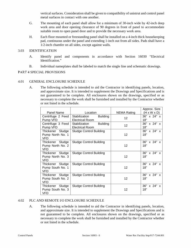
Control Panels Section 16903 - 6 Water Rec Facility Imp/017-7244.001
vertical surfaces. Consideration shall be given to compatibility of unistrut and control panel metal surfaces in contact with one another.
G. The mounting of each panel shall allow for a minimum of 30-inch wide by 42-inch deep work area and door opening clearance of 90 degrees in front of panel to accommodate suitable room to open panel door and to provide the necessary work area.
H. Each floor mounted or freestanding panel shall be installed on a 4-inch thick housekeeping pad, continuous under the panel and extending 1-inch out from all sides. Pads shall have a 1/2-inch chamfer on all sides, except against walls.
3.03 IDENTIFICATION
A. Identify panel and components in accordance with Section 16030 “Electrical Identification.”
B. Individual nameplates shall be labeled to match the single line and schematic drawings.
SPECIAL PROVISIONS
4.01 GENERAL ENCLOSURE SCHEDULE
A. The following schedule is intended to aid the Contractor in identifying panels, location, and approximate size. It is intended to supplement the Drawings and Specifications and is not guaranteed to be complete. All enclosures shown on the drawings, specified or as necessary to complete the work shall be furnished and installed by the Contractor whether or not listed in the schedule.
Panel Name Location NEMA Rating Approx. Size (H x W x D)
Centrifuge 2 Feed Pump VFD
Stabilization Building Electrical Room
12 36" x 24" x 18"
Centrifuge 3 Feed Pump VFD
Stabilization Building Electrical Room
12 36" x 24" x 18"
Thickener Sludge Pump North No. 1 VFD
Sludge Control Building 12
36" x 24" x 18"
Thickener Sludge Pump North No. 2 VFD
Sludge Control Building 12
36" x 24" x 18"
Thickener Sludge Pump North No. 3 VFD
Sludge Control Building 12
36" x 24" x 18"
Thickener Sludge Pump South No. 1 VFD
Sludge Control Building 12
36" x 24" x 18"
Thickener Sludge Pump South No. 2 VFD
Sludge Control Building 12
36" x 24" x 18"
Thickener Sludge Pump South No. 3 VFD
Sludge Control Building 12
36" x 24" x 18"
4.02 PLC AND REMOTE I/O ENCLOSURE SCHEDULE
A. The following schedule is intended to aid the Contractor in identifying panels, location, and approximate size. It is intended to supplement the Drawings and Specifications and is not guaranteed to be complete. All enclosures shown on the drawings, specified or as necessary to complete the work shall be furnished and installed by the Contractor whether or not listed in the schedule.
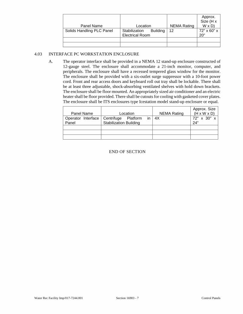
Water Rec Facility Imp/017-7244.001 Section 16903 - 7 Control Panels
Panel Name Location NEMA Rating
Approx. Size (H x W x D)
Solids Handling PLC Panel Stabilization Building Electrical Room
12 72" x 60" x 20"
4.03 INTERFACE PC WORKSTATION ENCLOSURE
A. The operator interface shall be provided in a NEMA 12 stand-up enclosure constructed of 12-gauge steel. The enclosure shall accommodate a 21-inch monitor, computer, and peripherals. The enclosure shall have a recessed tempered glass window for the monitor. The enclosure shall be provided with a six-outlet surge suppressor with a 10-foot power cord. Front and rear access doors and keyboard roll out tray shall be lockable. There shall be at least three adjustable, shock-absorbing ventilated shelves with hold down brackets. The enclosure shall be floor mounted. An appropriately sized air conditioner and an electric heater shall be floor provided. There shall be cutouts for cooling with gasketed cover plates. The enclosure shall be ITS enclosures type Icestation model stand-up enclosure or equal.
Panel Name Location NEMA Rating Approx. Size (H x W x D)
Operator Interface Panel
Centrifuge Platform in Stabilization Building
4X 72" x 30" x 24"
END OF SECTION

Control Panels Section 16903 - 8 Water Rec Facility Imp/017-7244.001
This page was intentionally left blank.
Water Rec Facility Imp/017-7244.001 Section 16905 - 1 Programmable Controller System
SECTION 16905
PROGRAMMABLE CONTROLLER SYSTEM
GENERAL
1.01 SCOPE
A. Work under this Section includes programmable controllers and accessories to be furnished and installed as part of the Programmable Controller System.
B. The programmable controller hardware installed shall perform process control and data acquisition.
C. The programmable controller (PLC) system shall consist of Ethernet compatible PLC’s, located in the control panels and as shown on the Drawings, including all component interconnections and network connections.
D. All programmable controllers provided as part of this work, including those provided under Division 11, shall meet the requirements of these specifications, and shall be directly integrated as a part of the plant control system Ethernet network without additional communication hardware or software communication drivers.
E. The Contractor shall furnish all labor, tools, equipment, and materials necessary to furnish and install the Programmable Controller System in accordance with the Drawings and as specified herein.
1.02 SUBMITTALS
A. Submittals shall be in accordance with requirements of Section 01300 and shall include:
1. Shop Drawings for Review:
a. Materials list identifying quantities, manufacturer’s name, and catalog number for each device.
b. Manufacturer’s data sheets for all equipment indicating model numbers, serial numbers, and a detail of each component.
c. Addressing of the Programmable Controller System input/output (I/O) points shall be provided within 60 days of the Engineer’s approval of the Programmable Controller system. The addressing and wire numbers, as approved by the Engineer, shall be used as the basis of the Contractor’s wire and terminal numbering system.
d. Wiring diagrams showing connections for all equipment furnished under this Section.
1) Control schematics for each I/O point shall identify the module, terminal designations, and individual wiring numbers.
2) A system block diagram shall be furnished and shall show hardware layout, all hardware interconnections, connection type and cabling.
3) Programmable controller control panel schematics shall include all internal device interconnections.
e. Scaled drawings for each control panel having programmable controller hardware installed within, showing layout of control panel interior and exterior, including overall dimensions, voltage rating within wire ducts, and panel mounting.
Programmable Controller System Section 16905 - 2 Water Rec Facility Imp/017-7244.001
2. Information for the Record:
a. Drawings revised and approved per the installed and tested system.
b. Manufacturer’s operation and maintenance manuals.
1.03 QUALITY ASSURANCE
A. Equipment and materials shall be new and, if of the same type as other performing parts of the same system, shall be the products of the same manufacturer.
B. Equipment and material shall be furnished by a manufacturer that has had an installed base of similar equipment for a minimum of the past five years. Equipment shall be of top quality construction and design, and shall be guaranteed to perform the service required.
C. Applicable Standards:
1. National Electrical Code (NEC).
2. Underwriter’s Laboratories (UL).
3. National Electrical Manufacturers’ Association (NEMA).
4. National Fire Protection Association (NFPA).
1.04 ELECTRICAL AND CONTROL COORDINATION
A. The provision and installation of programmable controller system hardware that interfaces with other devices not provided under this Section shall be coordinated to ensure compatibility between the control hardware and other devices. This includes checking signal type and device rating for existing and new instruments during installation to confirm actual connections. The coordinated installation shall include the provision of appropriate modules and ancillary devices recommended by the control hardware or device manufacturer.
B. The power source for the programmable controller system will be from power circuits shown on the Drawings. The Contractor shall be responsible for furnishing and installing a constant voltage filtering transformer of sufficient size for the programmable controller and its associated input devices and modules. The constant voltage transformer provided shall be in accordance with the uninterruptible power supply requirements described herein.
1.05 PRODUCT HANDLING
A. Deliver all programmable controller equipment installed in the enclosure(s) and properly packaged in manufacturer’s original containers, including wrappings, to properly protect devices from damage.
B. Store programmable controller equipment in manufacturer’s furnished packaging and protect from weather and construction traffic. Store indoors and within a temperature controlled area. Never store outdoors.
C. Handle programmable controller equipment carefully to prevent physical damage. Do not install damaged equipment. Damaged equipment shall be removed from site and replaced with new equipment.
PRODUCTS
2.01 MATERIALS
A. The programmable controller system shall be a complete operating system including: a central control processor, memory modules, main chassis, expansion chassis as required, appropriate interface and communication modules, input and output modules, power supplies, and interconnection cabling.
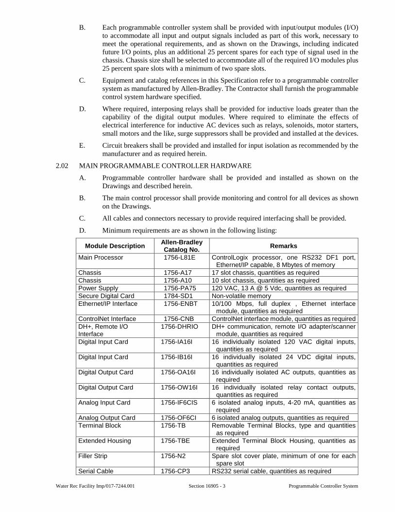
Water Rec Facility Imp/017-7244.001 Section 16905 - 3 Programmable Controller System
B. Each programmable controller system shall be provided with input/output modules (I/O) to accommodate all input and output signals included as part of this work, necessary to meet the operational requirements, and as shown on the Drawings, including indicated future I/O points, plus an additional 25 percent spares for each type of signal used in the chassis. Chassis size shall be selected to accommodate all of the required I/O modules plus 25 percent spare slots with a minimum of two spare slots.
C. Equipment and catalog references in this Specification refer to a programmable controller system as manufactured by Allen-Bradley. The Contractor shall furnish the programmable control system hardware specified.
D. Where required, interposing relays shall be provided for inductive loads greater than the capability of the digital output modules. Where required to eliminate the effects of electrical interference for inductive AC devices such as relays, solenoids, motor starters, small motors and the like, surge suppressors shall be provided and installed at the devices.
E. Circuit breakers shall be provided and installed for input isolation as recommended by the manufacturer and as required herein.
2.02 MAIN PROGRAMMABLE CONTROLLER HARDWARE
A. Programmable controller hardware shall be provided and installed as shown on the Drawings and described herein.
B. The main control processor shall provide monitoring and control for all devices as shown on the Drawings.
C. All cables and connectors necessary to provide required interfacing shall be provided.
D. Minimum requirements are as shown in the following listing:
Module Description Allen-Bradley Catalog No.
Remarks
Main Processor 1756-L81E ControlLogix processor, one RS232 DF1 port, Ethernet/IP capable, 8 Mbytes of memory
Chassis 1756-A17 17 slot chassis, quantities as required Chassis 1756-A10 10 slot chassis, quantities as required Power Supply 1756-PA75 120 VAC, 13 A @ 5 Vdc, quantities as required Secure Digital Card 1784-SD1 Non-volatile memory Ethernet/IP Interface 1756-ENBT 10/100 Mbps, full duplex , Ethernet interface
module, quantities as required ControlNet Interface 1756-CNB ControlNet interface module, quantities as requiredDH+, Remote I/O Interface
1756-DHRIO DH+ communication, remote I/O adapter/scanner module, quantities as required
Digital Input Card 1756-IA16I 16 individually isolated 120 VAC digital inputs, quantities as required
Digital Input Card 1756-IB16I 16 individually isolated 24 VDC digital inputs, quantities as required
Digital Output Card 1756-OA16I 16 individually isolated AC outputs, quantities as required
Digital Output Card 1756-OW16I 16 individually isolated relay contact outputs, quantities as required
Analog Input Card 1756-IF6CIS 6 isolated analog inputs, 4-20 mA, quantities as required
Analog Output Card 1756-OF6CI 6 isolated analog outputs, quantities as required Terminal Block 1756-TB Removable Terminal Blocks, type and quantities
as required Extended Housing 1756-TBE Extended Terminal Block Housing, quantities as
required Filler Strip 1756-N2 Spare slot cover plate, minimum of one for each
spare slot Serial Cable 1756-CP3 RS232 serial cable, quantities as required
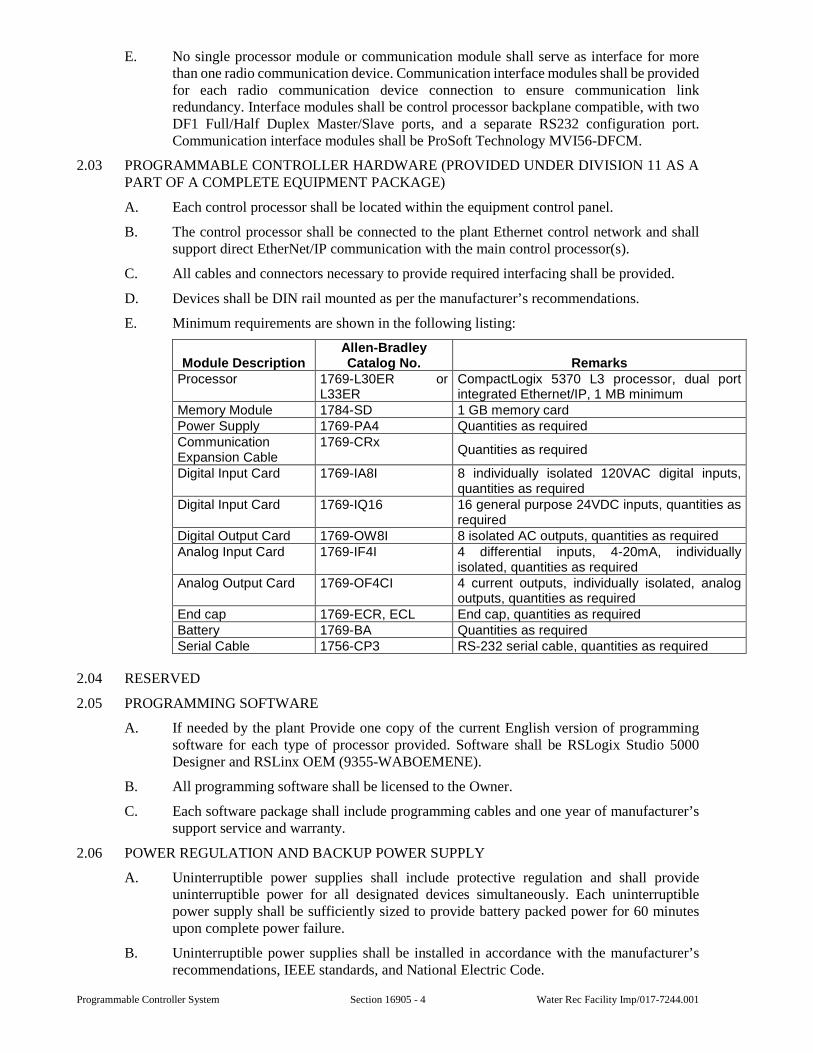
Programmable Controller System Section 16905 - 4 Water Rec Facility Imp/017-7244.001
E. No single processor module or communication module shall serve as interface for more than one radio communication device. Communication interface modules shall be provided for each radio communication device connection to ensure communication link redundancy. Interface modules shall be control processor backplane compatible, with two DF1 Full/Half Duplex Master/Slave ports, and a separate RS232 configuration port. Communication interface modules shall be ProSoft Technology MVI56-DFCM.
2.03 PROGRAMMABLE CONTROLLER HARDWARE (PROVIDED UNDER DIVISION 11 AS A PART OF A COMPLETE EQUIPMENT PACKAGE)
A. Each control processor shall be located within the equipment control panel.
B. The control processor shall be connected to the plant Ethernet control network and shall support direct EtherNet/IP communication with the main control processor(s).
C. All cables and connectors necessary to provide required interfacing shall be provided.
D. Devices shall be DIN rail mounted as per the manufacturer’s recommendations.
E. Minimum requirements are shown in the following listing:
Module DescriptionAllen-Bradley Catalog No. Remarks
Processor 1769-L30ER or L33ER
CompactLogix 5370 L3 processor, dual port integrated Ethernet/IP, 1 MB minimum
Memory Module 1784-SD 1 GB memory card Power Supply 1769-PA4 Quantities as required Communication Expansion Cable
1769-CRx Quantities as required
Digital Input Card 1769-IA8I 8 individually isolated 120VAC digital inputs, quantities as required
Digital Input Card 1769-IQ16 16 general purpose 24VDC inputs, quantities as required
Digital Output Card 1769-OW8I 8 isolated AC outputs, quantities as required Analog Input Card 1769-IF4I 4 differential inputs, 4-20mA, individually
isolated, quantities as required Analog Output Card 1769-OF4CI 4 current outputs, individually isolated, analog
outputs, quantities as required End cap 1769-ECR, ECL End cap, quantities as required Battery 1769-BA Quantities as required Serial Cable 1756-CP3 RS-232 serial cable, quantities as required
2.04 RESERVED
2.05 PROGRAMMING SOFTWARE
A. If needed by the plant Provide one copy of the current English version of programming software for each type of processor provided. Software shall be RSLogix Studio 5000 Designer and RSLinx OEM (9355-WABOEMENE).
B. All programming software shall be licensed to the Owner.
C. Each software package shall include programming cables and one year of manufacturer’s support service and warranty.
2.06 POWER REGULATION AND BACKUP POWER SUPPLY
A. Uninterruptible power supplies shall include protective regulation and shall provide uninterruptible power for all designated devices simultaneously. Each uninterruptible power supply shall be sufficiently sized to provide battery packed power for 60 minutes upon complete power failure.
B. Uninterruptible power supplies shall be installed in accordance with the manufacturer’s recommendations, IEEE standards, and National Electric Code.
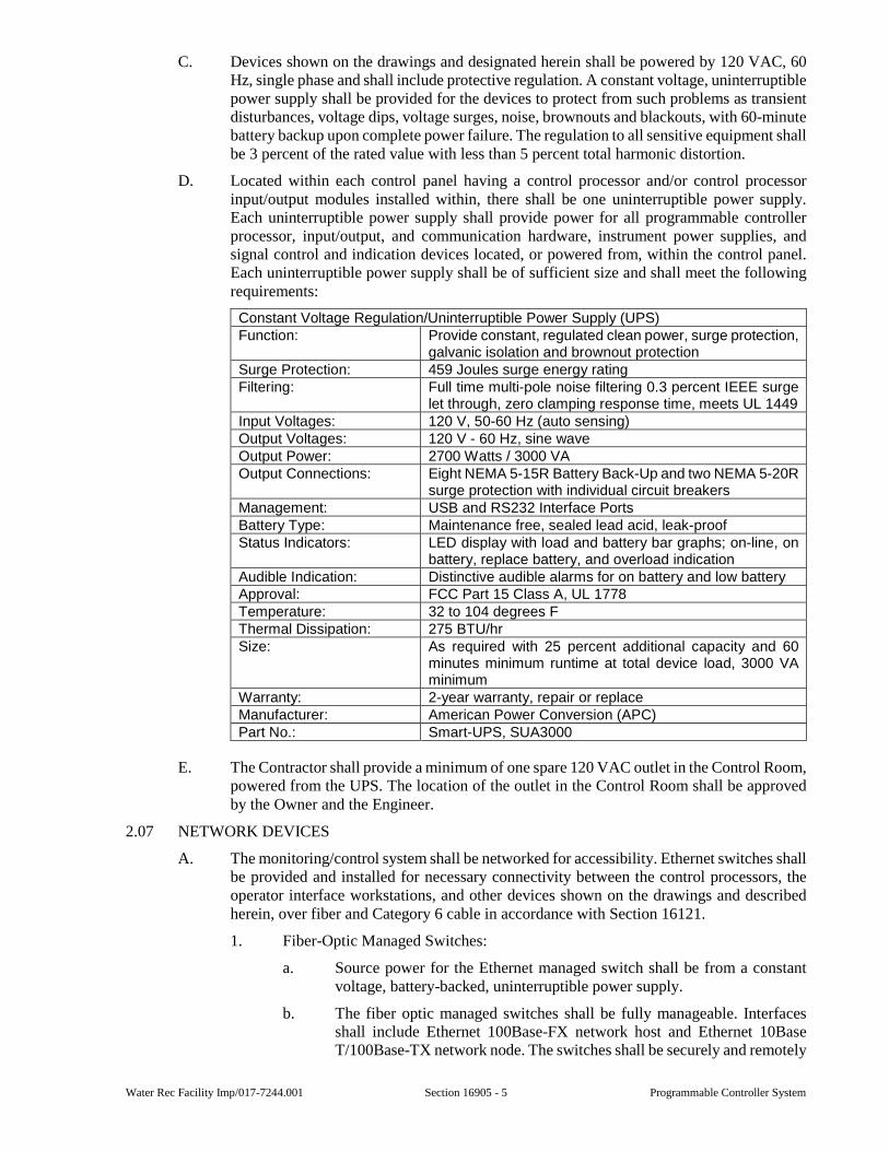
Water Rec Facility Imp/017-7244.001 Section 16905 - 5 Programmable Controller System
C. Devices shown on the drawings and designated herein shall be powered by 120 VAC, 60 Hz, single phase and shall include protective regulation. A constant voltage, uninterruptible power supply shall be provided for the devices to protect from such problems as transient disturbances, voltage dips, voltage surges, noise, brownouts and blackouts, with 60-minute battery backup upon complete power failure. The regulation to all sensitive equipment shall be 3 percent of the rated value with less than 5 percent total harmonic distortion.
D. Located within each control panel having a control processor and/or control processor input/output modules installed within, there shall be one uninterruptible power supply. Each uninterruptible power supply shall provide power for all programmable controller processor, input/output, and communication hardware, instrument power supplies, and signal control and indication devices located, or powered from, within the control panel. Each uninterruptible power supply shall be of sufficient size and shall meet the following requirements:
Constant Voltage Regulation/Uninterruptible Power Supply (UPS) Function: Provide constant, regulated clean power, surge protection,
galvanic isolation and brownout protection Surge Protection: 459 Joules surge energy rating Filtering: Full time multi-pole noise filtering 0.3 percent IEEE surge
let through, zero clamping response time, meets UL 1449 Input Voltages: 120 V, 50-60 Hz (auto sensing) Output Voltages: 120 V - 60 Hz, sine wave Output Power: 2700 Watts / 3000 VA Output Connections: Eight NEMA 5-15R Battery Back-Up and two NEMA 5-20R
surge protection with individual circuit breakers Management: USB and RS232 Interface Ports Battery Type: Maintenance free, sealed lead acid, leak-proof Status Indicators: LED display with load and battery bar graphs; on-line, on
battery, replace battery, and overload indication Audible Indication: Distinctive audible alarms for on battery and low battery Approval: FCC Part 15 Class A, UL 1778 Temperature: 32 to 104 degrees F Thermal Dissipation: 275 BTU/hr Size: As required with 25 percent additional capacity and 60
minutes minimum runtime at total device load, 3000 VA minimum
Warranty: 2-year warranty, repair or replace Manufacturer: American Power Conversion (APC) Part No.: Smart-UPS, SUA3000
E. The Contractor shall provide a minimum of one spare 120 VAC outlet in the Control Room, powered from the UPS. The location of the outlet in the Control Room shall be approved by the Owner and the Engineer.
2.07 NETWORK DEVICES
A. The monitoring/control system shall be networked for accessibility. Ethernet switches shall be provided and installed for necessary connectivity between the control processors, the operator interface workstations, and other devices shown on the drawings and described herein, over fiber and Category 6 cable in accordance with Section 16121.
1. Fiber-Optic Managed Switches:
a. Source power for the Ethernet managed switch shall be from a constant voltage, battery-backed, uninterruptible power supply.
b. The fiber optic managed switches shall be fully manageable. Interfaces shall include Ethernet 100Base-FX network host and Ethernet 10Base T/100Base-TX network node. The switches shall be securely and remotely
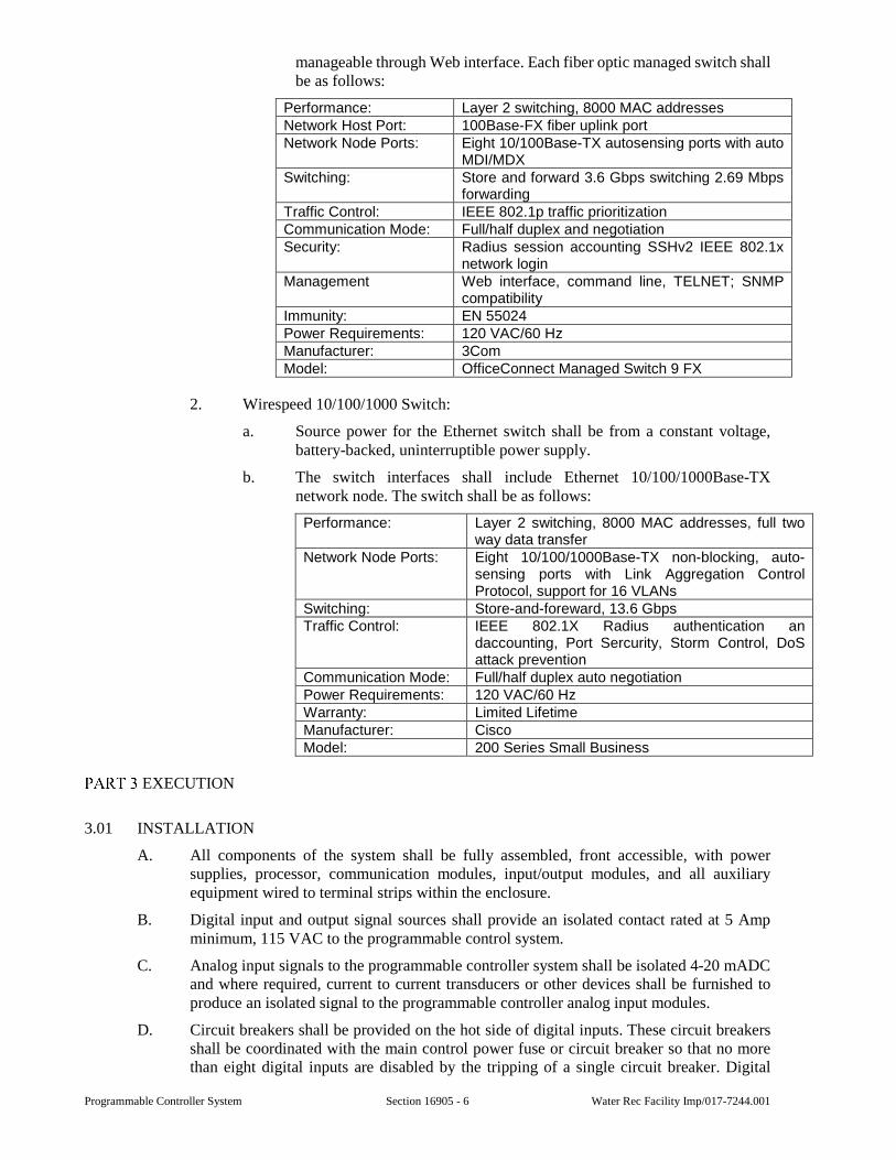
Programmable Controller System Section 16905 - 6 Water Rec Facility Imp/017-7244.001
manageable through Web interface. Each fiber optic managed switch shall be as follows:
Performance: Layer 2 switching, 8000 MAC addresses Network Host Port: 100Base-FX fiber uplink port Network Node Ports: Eight 10/100Base-TX autosensing ports with auto
MDI/MDX Switching: Store and forward 3.6 Gbps switching 2.69 Mbps
forwarding Traffic Control: IEEE 802.1p traffic prioritization Communication Mode: Full/half duplex and negotiation Security: Radius session accounting SSHv2 IEEE 802.1x
network login Management Web interface, command line, TELNET; SNMP
compatibility Immunity: EN 55024 Power Requirements: 120 VAC/60 Hz Manufacturer: 3Com Model: OfficeConnect Managed Switch 9 FX
2. Wirespeed 10/100/1000 Switch:
a. Source power for the Ethernet switch shall be from a constant voltage, battery-backed, uninterruptible power supply.
b. The switch interfaces shall include Ethernet 10/100/1000Base-TX network node. The switch shall be as follows:
Performance: Layer 2 switching, 8000 MAC addresses, full two way data transfer
Network Node Ports: Eight 10/100/1000Base-TX non-blocking, auto-sensing ports with Link Aggregation Control Protocol, support for 16 VLANs
Switching: Store-and-foreward, 13.6 Gbps Traffic Control: IEEE 802.1X Radius authentication an
daccounting, Port Sercurity, Storm Control, DoS attack prevention
Communication Mode: Full/half duplex auto negotiation Power Requirements: 120 VAC/60 Hz Warranty: Limited Lifetime Manufacturer: Cisco Model: 200 Series Small Business
EXECUTION
3.01 INSTALLATION
A. All components of the system shall be fully assembled, front accessible, with power supplies, processor, communication modules, input/output modules, and all auxiliary equipment wired to terminal strips within the enclosure.
B. Digital input and output signal sources shall provide an isolated contact rated at 5 Amp minimum, 115 VAC to the programmable control system.
C. Analog input signals to the programmable controller system shall be isolated 4-20 mADC and where required, current to current transducers or other devices shall be furnished to produce an isolated signal to the programmable controller analog input modules.
D. Circuit breakers shall be provided on the hot side of digital inputs. These circuit breakers shall be coordinated with the main control power fuse or circuit breaker so that no more than eight digital inputs are disabled by the tripping of a single circuit breaker. Digital
Water Rec Facility Imp/017-7244.001 Section 16905 - 7 Programmable Controller System
inputs shall be so arranged that the tripping of a single circuit breaker shall not disable inputs directly controlling more than one motor or other piece of machinery.
E. All programmable controller hardware shall be powered through a battery backed power supply having protective power regulation.
F. Tighten field-connected connectors and terminals, including screws and bolts, in accordance with equipment manufacturer’s published torque tightening values. Where manufacturer’s torquing requirements are not indicated, tighten connectors and terminals to comply with tightening torques specific in UL Standards 486A and UL 486B.
G. Provide equipment grounding connections for individually mounted units as indicated and as required by the NEC. Tighten connectors to comply with tightening torques specified in UL Standard 486A to assure permanent and effective grounding.
3.02 IDENTIFICATION
A. Identify components in accordance with Section 16030 - Electrical Identification.
B. Individual nameplates shall be labeled to match the single line and schematic Drawings.
3.03 TESTING AND INSPECTION
A. Verify network settings to be appropriate for final system arrangement and conditions. Where discrepancies are found, test organization shall recommend final network settings. Use accepted revised settings to make the final system adjustments.
B. Inspect for defects and physical damage, NRTL (Nationally Recognized Testing Laboratory) labeling, and nameplate compliance with single line and/or schematic diagrams.
C. Exercise and perform operational tests of all mechanical and electrical components and other operable devices in accordance with manufacturer’s instruction manual.
D. Check connector, terminals, modules, and mountings for tightness to ensure that all components are securely attached.
E. Check tightness of electrical connections by visually looking at wiring and pulling on wires for tightness in terminals. All wires shall be properly restrained.
F. Contractor shall check all I/O points from module to field device for proper operation and signal response verification.
G. Programming of unit(s) shall be based on standards given by Owner or listed within Programming Requirements document.
SPECIAL PROVISIONS
4.01 SPARE PARTS
A. The Contractor shall furnish spare parts as shown in the Spare Parts Schedule. The spare parts shall be individually packaged for protection against dirt and moisture. Each package shall be labeled as to its contents, including a description and part number.
B. All spare parts shall become the property of the Owner. The Contractor shall maintain the spare parts inventory level as shown in the Spare Parts Schedule, and replace at no cost to the Owner all spare parts consumed during the start-up procedures and during the one-year warranty period.
4.02 SPARE PARTS SCHEDULE
A. In addition to the requirements of 2.01, the Contractor shall provide a minimum of 10 percent spare modules for each type of module installed, with a minimum of one of each type. Contractor shall provide at least one spare programmable controller for each type installed.
Programmable Controller System Section 16905 - 8 Water Rec Facility Imp/017-7244.001
B. One spare lithium battery shall be provided for each control processor.
C. One spare Ethernet switch shall be provided. This spare switch shall have the same quantity and type of parts as the largest switch provided under this section.
END OF SECTION
Water Rec Facility Imp/017-7244.001 Section 16915 - 1 Interface Hardware/Software
SECTION 16915
INTERFACE HARDWARE/SOFTWARE
GENERAL
1.01 SCOPE
A. This section includes the provision and installation of hardware and software to comprise a complete, networked, operator interface system. The operator interface system shall enable Plant personnel to monitor the status and equipment operation of the Plant and any remote station(s).
B. The interface hardware and software along with network devices shall be adequate to enable interfacing, and support communication, with the monitoring and control system, as provided under other Sections of these Specifications, and other operator interface workstations.
C. This section includes, but is not limited to:
1. Provision and installation of the complete operator interface workstation hardware, interface software packages, network devices, and uninterruptible power supplies.
2. Provision of any additional software and hardware necessary to provide a complete operator interface workstation network as required under this Section.
3. Additional hardware not specified under any other Section and considered a minimum requirement by the software manufacturer for the proper operation of the interface software, or as required to fulfill the design intent as expressed in this Section.
1.02 SUBMITTALS
A. Submittals shall be in accordance with all requirements of Section 01300 and shall include:
1. Shop drawings for review
a. All manufacture's descriptive product information, specifications, installation, and diagnostic documentation.
b. Complete list of products provided including manufacturer's model numbers and serial numbers.
c. Type of Software keys needed and included.
2. Information for the record
a. A certified statement by the Contractor that the package has been properly installed and is ready for operation.
b. Operation and Maintenance Manuals
1) Maintenance instructions including trouble-shooting guidelines.
2) Manufacturer's name, address, and telephone number along with manufacturer's job number and purchase order number.
3) Manufacturer's local sales representative, address, and telephone number.
4) All software registration certification and two copies of each software package provided, on manufacture's media.
Interface Hardware/Software Section 16915 - 2 Water Rec Facility Imp/017-7244.001
1.03 QUALITY ASSURANCE
A. IEEE Standards
B. NEC (National Electric Code)
PRODUCTS
2.01 GENERAL
A. Each operator interface workstation shall be provided with operating system software, communication interface modules installed.
2.02 WORKSTATION
A. One complete operator interface workstation shall be provided and installed at each of the following locations:
Location Building AreaCentrifuge Platform Solids Processing Solids Processing Area
B. The HMI shall be an Allen-Bradley 2711P PanelView Plus Performance Terminal; 19” Color touch.
2.03 INTERFACE SOFTWARE
A. The operator interface software shall be a fully debugged human-machine interface application generator and permit on-line, real-time supervisory control, monitoring and data acquisition (SCADA).
B. The interface software shall be capable of communicating with the Allen-Bradley family of PLC controllers over Ethernet
C. The interface software shall be Factory Talk View utilizing RSLinx Enterprise.
EXECUTION
3.01 INSTALLATION
A. The interface hardware shall be installed as noted on the drawings, and described herein, no less than two weeks prior to commissioning (16901).
B. The operator interface station (hardware and software), located in the Solids Handling Building, shall be connected to the Ethernet network hardware in the new Solids Handling PLC Panel, located in the same building.
C. The power source for the interface hardware and network devices will be from power circuits shown on the Drawings. The Contractor shall be responsible for furnishing and installing the interface hardware and a power circuit of sufficient size for the interface hardware.
SPECIAL PROVISIONS
None.
END OF SECTION
City of Kalamazoo
HVAC Design and Lab Renovations
for Water Reclamation Plant
July 13, 2018
100% Construction Documents
B/A #16100348 SELECTIVE DEMOLITION 1024119-1
SECTION 1024119 - SELECTIVE DEMOLITION
PART 1 - GENERAL
1.1 SUMMARY
A. Section Includes:
1. Demolition and removal of selected portions of building or structure.
2. Salvage of existing items to be reused or recycled.
1.2 DEFINITIONS
A. Remove: Detach items from existing construction and legally dispose of them off-site unless
indicated to be removed and salvaged or removed and reinstalled.
B. Remove and Salvage: Carefully detach from existing construction, in a manner to prevent
damage, and deliver to Owner.
C. Remove and Reinstall: Detach items from existing construction, prepare for reuse, and
reinstall where indicated.
D. Existing to Remain: Existing items of construction that are not to be permanently removed
and that are not otherwise indicated to be removed, removed and salvaged, or removed and
reinstalled.
1.3 MATERIALS OWNERSHIP
A. Unless otherwise indicated, demolition waste becomes property of Contractor.
1.4 PREINSTALLATION MEETINGS
A. Predemolition Conference: Conduct conference at Project site.
1. Inspect and discuss condition of construction to be selectively demolished.
2. Review and finalize selective demolition schedule and verify availability of materials,
demolition personnel, equipment, and facilities needed to make progress and avoid
delays.
3. Review requirements of work performed by other trades that rely on substrates exposed
by selective demolition operations.
4. Review areas where existing construction is to remain and requires protection.
1.5 INFORMATIONAL SUBMITTALS
A. Proposed Protection Measures: Submit report, including drawings, that indicates the measures
proposed for protecting individuals and property , for dust control and , for noise control.
Indicate proposed locations and construction of barriers.
B. Schedule of Selective Demolition Activities: Indicate the following:
City of Kalamazoo
HVAC Design and Lab Renovations
for Water Reclamation Plant
July 13, 2018
100% Construction Documents
B/A #16100348 SELECTIVE DEMOLITION 1024119-2
1. Detailed sequence of selective demolition and removal work, with starting and ending
dates for each activity. Ensure Owner's building manager's on-site operations are
uninterrupted.
2. Interruption of utility services. Indicate how long utility services will be interrupted.
3. Coordination for shutoff, capping, and continuation of utility services.
4. Coordination of Owner's continuing occupancy of portions of existing building.
C. Inventory: Submit a list of items to be removed and salvaged and deliver to Owner prior to
start of demolition.
D. Predemolition Photographs: Submit before Work begins.
1.6 FIELD CONDITIONS
A. Owner will occupy portions of building immediately adjacent to selective demolition area.
Conduct selective demolition so Owner's operations will not be disrupted.
B. Conditions existing at time of inspection for bidding purpose will be maintained by Owner as
far as practical.
C. Notify Architect of discrepancies between existing conditions and Drawings before proceeding
with selective demolition.
D. Hazardous Materials: It is not expected that hazardous materials will be encountered in the
Work.
1. If suspected hazardous materials are encountered, do not disturb; immediately notify
Architect and Owner. Hazardous materials will be removed by Owner under a separate
contract.
E. Storage or sale of removed items or materials on-site is not permitted.
F. Utility Service: Maintain existing utilities indicated to remain in service and protect them
against damage during selective demolition operations.
1. Maintain fire-protection facilities in service during selective demolition operations.
PART 2 - PRODUCTS
2.1 PEFORMANCE REQUIREMENTS
A. Regulatory Requirements: Comply with governing EPA notification regulations before
beginning selective demolition. Comply with hauling and disposal regulations of authorities
having jurisdiction.
B. Standards: Comply with ANSI/ASSE A10.6 and NFPA 241.
City of Kalamazoo
HVAC Design and Lab Renovations
for Water Reclamation Plant
July 13, 2018
100% Construction Documents
B/A #16100348 SELECTIVE DEMOLITION 1024119-3
PART 3 - EXECUTION
3.1 EXAMINATION
A. Verify that utilities have been disconnected and capped before starting selective demolition
operations.
B. Review record documents of existing construction provided by Owner. Owner does not
guarantee that existing conditions are same as those indicated in record documents.
C. Survey existing conditions and correlate with requirements indicated to determine extent of
selective demolition required.
D. When unanticipated mechanical, electrical, or structural elements that conflict with intended
function or design are encountered, investigate and measure the nature and extent of conflict.
Promptly submit a written report to Architect.
E. Perform an engineering survey of condition of building to determine whether removing any
element might result in structural deficiency or unplanned collapse of any portion of structure
or adjacent structures during selective building demolition operations.
1. Perform surveys as the Work progresses to detect hazards resulting from selective
demolition activities.
F. Survey of Existing Conditions: Record existing conditions by use of preconstruction
photographs.
1. Inventory and record the condition of items to be removed and salvaged. Provide
photographs of conditions that might be misconstrued as damage caused by salvage
operations.
3.2 UTILITY SERVICES AND MECHANICAL/ELECTRICAL SYSTEMS
A. Existing Services/Systems to Remain: Maintain services/systems indicated to remain and
protect them against damage if needed.
B. Refrigerant: Remove refrigerant from mechanical equipment to be selectively demolished
according to 40 CFR 82 and regulations of authorities having jurisdiction.
3.3 SELECTIVE DEMOLITION, GENERAL
A. General: Demolish and remove existing construction only to the extent required by new
construction and as indicated. Use methods required to complete the Work within limitations
of governing regulations and as follows:
1. Neatly cut openings and holes plumb, square, and true to dimensions required. Use
cutting methods least likely to damage construction to remain or adjoining construction.
Use hand tools or small power tools designed for sawing or grinding, not hammering and
chopping, to minimize disturbance of adjacent surfaces. Temporarily cover openings to
remain.
City of Kalamazoo
HVAC Design and Lab Renovations
for Water Reclamation Plant
July 13, 2018
100% Construction Documents
B/A #16100348 SELECTIVE DEMOLITION 1024119-4
2. Cut or drill from the exposed or finished side into concealed surfaces to avoid marring
existing finished surfaces.
3. Do not use cutting torches until work area is cleared of flammable materials. At
concealed spaces, such as duct and pipe interiors, verify condition and contents of hidden
space before starting flame-cutting operations. Maintain portable fire-suppression
devices during flame-cutting operations.
4. Maintain adequate ventilation when using cutting torches.
5. Locate selective demolition equipment and remove debris and materials so as not to
impose excessive loads on supporting walls, floors, or framing.
6. Dispose of demolished items and materials promptly.
B. Reuse of Building Elements: Project has been designed to result in end-of-Project rates for
reuse of building elements as follows. Do not demolish building elements beyond what is
indicated on Drawings without Architect's approval.
C. Removed and Salvaged Items:
1. Clean salvaged items.
2. Pack or crate items after cleaning. Identify contents of containers.
3. Store items in a secure area until delivery to Owner.
4. Transport items to Owner's storage area on-site .
5. Protect items from damage during transport and storage.
D. Removed and Reinstalled Items:
1. Clean and repair items to functional condition adequate for intended reuse.
2. Pack or crate items after cleaning and repairing. Identify contents of containers.
3. Protect items from damage during transport and storage.
4. Reinstall items in locations indicated. Comply with installation requirements for new
materials and equipment. Provide connections, supports, and miscellaneous materials
necessary to make item functional for use indicated.
E. Existing Items to Remain: Protect construction indicated to remain against damage and soiling
during selective demolition. When permitted by Architect, items may be removed to a
suitable, protected storage location during selective demolition and cleaned and reinstalled in
their original locations after selective demolition operations are complete.
3.4 SELECTIVE DEMOLITION PROCEDURES FOR SPECIFIC MATERIALS
A. Masonry: Demolish in small sections. Cut masonry at junctures with construction to remain,
using power-driven saw, then remove masonry between saw cuts.
B. Concrete Slabs-on-Grade: Saw-cut perimeter of area to be demolished, then break up and
remove.
C. Resilient Floor Coverings: Remove floor coverings and adhesive according to
recommendations in RFCI's "Recommended Work Practices for the Removal of Resilient Floor
Coverings. Do not use methods requiring solvent-based adhesive strippers.
City of Kalamazoo
HVAC Design and Lab Renovations
for Water Reclamation Plant
July 13, 2018
100% Construction Documents
B/A #16100348 SELECTIVE DEMOLITION 1024119-5
3.5 DISPOSAL OF DEMOLISHED MATERIALS
A. General: Except for items or materials indicated to be recycled, reused, salvaged, reinstalled,
or otherwise indicated to remain Owner's property, remove demolished materials from Project
site and legally dispose of them in an EPA-approved landfill.
1. Do not allow demolished materials to accumulate on-site.
2. Remove and transport debris in a manner that will prevent spillage on adjacent surfaces
and areas.
3. Remove debris from elevated portions of building by chute, hoist, or other device that
will convey debris to grade level in a controlled descent.
B. Burning: Do not burn demolished materials.
C. Disposal: Transport demolished materials off Owner's property and legally dispose of them.
3.6 CLEANING
A. Clean adjacent structures and improvements of dust, dirt, and debris caused by selective
demolition operations. Return adjacent areas to condition existing before selective demolition
operations began.
END OF SECTION 1024119
City of Kalamazoo
HVAC Design and Lab Renovations
for Water Reclamation Plant
July 13, 2018
100% Construction Documents
B/A #16100348 CAST-IN-PLACE CONCRETE 1033000-1
SECTION 1033000 - CAST-IN-PLACE CONCRETE
PART 1 - GENERAL
1.1 RELATED DOCUMENTS
A. Drawings and general provisions of the Contract, including General and Supplementary
Conditions and Division 101 Specification Sections, apply to this Section.
1.2 SUMMARY
A. Section includes cast-in-place concrete, including formwork, reinforcement, concrete materials,
mixture design, placement procedures, and finishes.
1.3 DEFINITIONS
A. Cementitious Materials: Portland cement alone or in combination with one or more of the
following: blended hydraulic cement, fly ash, slag cement, other pozzolans, and silica fume;
materials subject to compliance with requirements.
B. W/C Ratio: The ratio by weight of water to cementitious materials.
1.4 INFORMATIONAL SUBMITTALS
A. Qualification Data: For manufacturer.
B. Material Certificates: For each of the following, signed by manufacturers:
1. Cementitious materials.
2. Admixtures.
3. Floor and slab treatments.
4. Vapor retarders.
5. Semirigid joint filler.
C. Material Test Reports: For the following, from a qualified testing agency:
1. Aggregates: Include service record data indicating absence of deleterious expansion of
concrete due to alkali aggregate reactivity.
1.5 QUALITY ASSURANCE
A. Installer Qualifications: A qualified installer who employs on Project personnel qualified as
ACI-certified Flatwork Technician and Finisher and a supervisor who is an ACI-certified
Concrete Flatwork Technician.
B. Manufacturer Qualifications: A firm experienced in manufacturing ready-mixed concrete
products and that complies with ASTM C 94/C 94M requirements for production facilities and
equipment.
City of Kalamazoo
HVAC Design and Lab Renovations
for Water Reclamation Plant
July 13, 2018
100% Construction Documents
B/A #16100348 CAST-IN-PLACE CONCRETE 1033000-2
1. Manufacturer certified according to NRMCA's "Certification of Ready Mixed Concrete
Production Facilities."
C. Testing Agency Qualifications: An independent agency, qualified according to ASTM C 1077
and ASTM E 329 for testing indicated.
1. Personnel conducting field tests shall be qualified as ACI Concrete Field Testing
Technician, Grade 1, according to ACI CP-1 or an equivalent certification program.
2. Personnel performing laboratory tests shall be ACI-certified Concrete Strength Testing
Technician and Concrete Laboratory Testing Technician, Grade I. Testing agency
laboratory supervisor shall be an ACI-certified Concrete Laboratory Testing Technician,
Grade II.
1.6 DELIVERY, STORAGE, AND HANDLING
A. Steel Reinforcement: Deliver, store, and handle steel reinforcement to prevent bending and
damage.
PART 2 - PRODUCTS
2.1 CONCRETE, GENERAL
A. ACI Publications: Comply with the following unless modified by requirements in the Contract
Documents:
1. ACI 301 (ACI 301M).
2. ACI 117 (ACI 117M).
2.2 FORM-FACING MATERIALS
A. Smooth-Formed Finished Concrete: Form-facing panels that provide continuous, true, and
smooth concrete surfaces. Furnish in largest practicable sizes to minimize number of joints.
1. Plywood, metal, or other approved panel materials.
B. Chamfer Strips: Wood, metal, PVC, or rubber strips, 3/4 by 3/4 inch (19 by 19 mm), minimum.
2.3 STEEL REINFORCEMENT
A. Reinforcing Bars: ASTM A 615/A 615M, Grade 60 (Grade 420), deformed.
B. Plain-Steel Welded-Wire Reinforcement: ASTM A 1064/A 1064M, plain, fabricated from
as-drawn steel wire into flat sheets.
2.4 REINFORCEMENT ACCESSORIES
A. Joint Dowel Bars: ASTM A 615/A 615M, Grade 60 (Grade 420), plain-steel bars, cut true to
length with ends square and free of burrs.
City of Kalamazoo
HVAC Design and Lab Renovations
for Water Reclamation Plant
July 13, 2018
100% Construction Documents
B/A #16100348 CAST-IN-PLACE CONCRETE 1033000-3
2.5 CONCRETE MATERIALS
A. Source Limitations: Obtain each type or class of cementitious material of the same brand from
the same manufacturer's plant, obtain aggregate from single source, and obtain admixtures from
single source from single manufacturer.
B. Cementitious Materials:
1. Portland Cement: ASTM C 150/C 150M, Type I, gray.
2. Fly Ash: ASTM C 618, Class F or C.
3. Slag Cement: ASTM C 989/C 989M, Grade 100 or 120.
C. Normal-Weight Aggregates: ASTM C 33/C 33M, Class 5 coarse aggregate or better, graded,
clean. Retain not less than 8% or more than 18% on each individual sieve. Provide
aggregates from a single source with documented service record data of at least 10 years'
satisfactory service in similar applications and service conditions using similar aggregates and
cementitious materials.
1. Maximum Coarse-Aggregate Size: 1-1/2 inch, size 467 (38 mm) for Slabs on Grade.
1 inch, size 57 or 1 1/2 inch for all other concrete. nominal.
2. Fine Aggregate: Free of materials with deleterious reactivity to alkali in cement.
D. Air-Entraining Admixture: ASTM C 260/C 260M.
E. Chemical Admixtures: Certified by manufacturer to be compatible with other admixtures and
that do not contribute water-soluble chloride ions exceeding those permitted in hardened
concrete. Do not use calcium chloride or admixtures containing calcium chloride.
1. Water-Reducing Admixture: ASTM C 494/C 494M, Type A.
F. Water: ASTM C 94/C 94M and potable.
2.6 VAPOR RETARDERS
A. Sheet Vapor Retarder: 15mil, ASTM E 1745, Class A, except with maximum water-vapor
permeance of 0.01. Include manufacturer's recommended adhesive or pressure-sensitive tape.
2.7 LIQUID FLOOR TREATMENTS
A. Penetrating Liquid Floor Treatment: Clear, chemically reactive, waterborne solution of
inorganic silicate or siliconate materials and proprietary components; odorless; that penetrates,
hardens, and densifies concrete surfaces.
1. Products: Subject to compliance with requirements, provide the following:
a. Euclid Chemical Company (The), an RPM company; Euco Diamond Hard.
2.8 CURING MATERIALS
A. Moisture-Retaining Cover: ASTM C 171, polyethylene film or white burlap-polyethylene
sheet.
B. Water: Potable.
City of Kalamazoo
HVAC Design and Lab Renovations
for Water Reclamation Plant
July 13, 2018
100% Construction Documents
B/A #16100348 CAST-IN-PLACE CONCRETE 1033000-4
2.9 RELATED MATERIALS
A. Expansion- and Isolation-Joint-Filler Strips: ASTM D 1751, asphalt-saturated cellulosic fiber.
B. Semirigid Joint Filler: Metzger Mcquire MM-80, install 90 days after slab placement.
Two-component, semirigid, 100 percent solids, according to ASTM D 2240.
2.10 CONCRETE MIXTURES, GENERAL
A. Prepare design mixtures for each type and strength of concrete, proportioned on the basis of
laboratory trial mixture or field test data, or both, according to ACI 301 (ACI 301M).
1. Use a qualified independent testing agency for preparing and reporting proposed mixture
designs based on laboratory trial mixtures.
B. Cementitious Materials: Limit percentage, by weight, of cementitious materials other than
portland cement in concrete as follows:
1. Slag Cement: 25 percent.
C. Limit water-soluble, chloride-ion content in hardened concrete to 0.06 percent by weight of
cement.
2.11 CONCRETE MIXTURES FOR BUILDING ELEMENTS
A. Slabs-on-Grade: Normal-weight concrete.
1. Minimum Compressive Strength: 4000 psi (27.6 MPa) at 28 days.
2. Maximum W/C Ratio: 0.45.
3. Minimum Cementitious Materials Content: 470 lb/cu. yd. (279 kg/cu. m).
4. Slump Limit: 4 inches (100 mm), plus or minus 1 inch (25 mm).
5. Air Content: Do not allow air content of trowel-finished floors to exceed 3 percent.
2.12 FABRICATING REINFORCEMENT
A. Fabricate steel reinforcement according to CRSI's "Manual of Standard Practice."
2.13 CONCRETE MIXING
A. Ready-Mixed Concrete: Measure, batch, mix, and deliver concrete according to ASTM C 94/C
94M and ASTM C 1116/C 1116M, and furnish batch ticket information.
1. When air temperature is between 85 and 90 deg F (30 and 32 deg C), reduce mixing and
delivery time from 1-1/2 hours to 75 minutes; when air temperature is above 90 deg F (32
deg C), reduce mixing and delivery time to 60 minutes.
City of Kalamazoo
HVAC Design and Lab Renovations
for Water Reclamation Plant
July 13, 2018
100% Construction Documents
B/A #16100348 CAST-IN-PLACE CONCRETE 1033000-5
PART 3 - EXECUTION
3.1 FORMWORK INSTALLATION
A. Design, erect, shore, brace, and maintain formwork, according to ACI 301 (ACI 301M), to
support vertical, lateral, static, and dynamic loads, and construction loads that might be applied,
until structure can support such loads.
B. Construct formwork so concrete members and structures are of size, shape, alignment,
elevation, and position indicated, within tolerance limits of ACI 117 (ACI 117M).
C. Construct forms tight enough to prevent loss of concrete mortar.
D. Construct forms for easy removal without hammering or prying against concrete surfaces.
Provide crush or wrecking plates where stripping may damage cast-concrete surfaces. Provide
top forms for inclined surfaces steeper than 1.5 horizontal to 1 vertical.
1. Install keyways, reglets, recesses, and the like, for easy removal.
2. Do not use rust-stained steel form-facing material.
E. Set edge forms, bulkheads, and intermediate screed strips for slabs to achieve required
elevations and slopes in finished concrete surfaces. Provide and secure units to support screed
strips; use strike-off templates or compacting-type screeds.
F. Provide temporary openings for cleanouts and inspection ports where interior area of formwork
is inaccessible. Close openings with panels tightly fitted to forms and securely braced to
prevent loss of concrete mortar. Locate temporary openings in forms at inconspicuous
locations.
G. Chamfer exterior corners and edges of permanently exposed concrete.
H. Form openings, chases, offsets, sinkages, keyways, reglets, blocking, screeds, and bulkheads
required in the Work. Determine sizes and locations from trades providing such items.
I. Clean forms and adjacent surfaces to receive concrete. Remove chips, wood, sawdust, dirt, and
other debris just before placing concrete.
J. Retighten forms and bracing before placing concrete, as required, to prevent mortar leaks and
maintain proper alignment.
K. Coat contact surfaces of forms with form-release agent, according to manufacturer's written
instructions, before placing reinforcement.
City of Kalamazoo
HVAC Design and Lab Renovations
for Water Reclamation Plant
July 13, 2018
100% Construction Documents
B/A #16100348 CAST-IN-PLACE CONCRETE 1033000-6
3.2 REMOVING AND REUSING FORMS
A. General: Formwork for sides of beams, walls, columns, and similar parts of the Work that does
not support weight of concrete may be removed after cumulatively curing at not less than 50
deg F (10 deg C) for 24 hours after placing concrete. Concrete has to be hard enough to not be
damaged by form-removal operations, and curing and protection operations need to be
maintained.
1. Leave formwork for beam soffits, joists, slabs, and other structural elements that support
weight of concrete in place until concrete has achieved at least 70 percent of its 28-day
design compressive strength.
2. Remove forms only if shores have been arranged to permit removal of forms without
loosening or disturbing shores.
B. Clean and repair surfaces of forms to be reused in the Work. Split, frayed, delaminated, or
otherwise damaged form-facing material are not acceptable for exposed surfaces. Apply new
form-release agent.
C. When forms are reused, clean surfaces, remove fins and laitance, and tighten to close joints.
Align and secure joints to avoid offsets. Do not use patched forms for exposed concrete
surfaces unless approved by Architect.
3.3 VAPOR-RETARDER INSTALLATION
A. Sheet Vapor Retarders: Place, protect, and repair sheet vapor retarder according to ASTM E
1643 and manufacturer's written instructions.
1. Lap joints 6 inches (150 mm) and seal with manufacturer's recommended tape.
3.4 STEEL REINFORCEMENT INSTALLATION
A. General: Comply with CRSI's "Manual of Standard Practice" for fabricating, placing, and
supporting reinforcement.
1. Do not cut or puncture vapor retarder. Repair damage and reseal vapor retarder before
placing concrete.
B. Clean reinforcement of loose rust and mill scale, earth, ice, and other foreign materials that
reduce bond to concrete.
C. Accurately position, support, and secure reinforcement against displacement. Locate and
support reinforcement with bar supports to maintain minimum concrete cover. Do not tack weld
crossing reinforcing bars.
1. Weld reinforcing bars according to AWS D1.4/D 1.4M, where indicated.
D. Set wire ties with ends directed into concrete, not toward exposed concrete surfaces.
E. Install welded-wire reinforcement in longest practicable lengths on bar supports spaced to
minimize sagging. Lap edges and ends of adjoining sheets at least one mesh spacing. Offset
laps of adjoining sheet widths to prevent continuous laps in either direction. Lace overlaps with
wire.
City of Kalamazoo
HVAC Design and Lab Renovations
for Water Reclamation Plant
July 13, 2018
100% Construction Documents
B/A #16100348 CAST-IN-PLACE CONCRETE 1033000-7
3.5 JOINTS
A. General: Construct joints true to line with faces perpendicular to surface plane of concrete.
B. Construction Joints: Install so strength and appearance of concrete are not impaired, at locations
indicated or as approved by Architect.
1. Place joints perpendicular to main reinforcement. Continue reinforcement across
construction joints unless otherwise indicated. Do not continue reinforcement through
sides of strip placements of floors and slabs.
C. Contraction Joints in Slabs-on-Grade: Form weakened-plane contraction joints, sectioning
concrete into areas as indicated. Construct contraction joints for a depth equal to at least
one-fourth of concrete thickness as follows:
1. Sawed Joints: Form contraction joints with power saws equipped with shatterproof
abrasive or diamond-rimmed blades. Cut 1/8-inch- (3.2-mm-) wide joints into concrete
when cutting action does not tear, abrade, or otherwise damage surface and before
concrete develops random contraction cracks.
D. Doweled Joints: Install dowel bars and support assemblies at joints where indicated. Lubricate
or asphalt coat one-half of dowel length to prevent concrete bonding to one side of joint.
3.6 CONCRETE PLACEMENT
A. Before placing concrete, verify that installation of formwork, reinforcement, and embedded
items is complete and that required inspections are completed.
B. Do not add water to concrete during delivery, at Project site, or during placement unless
approved by Architect.
C. Before test sampling and placing concrete, water may be added at Project site, subject to
limitations of ACI 301 (ACI 301M).
D. Deposit concrete continuously in one layer or in horizontal layers of such thickness that no new
concrete is placed on concrete that has hardened enough to cause seams or planes of weakness.
If a section cannot be placed continuously, provide construction joints as indicated. Deposit
concrete to avoid segregation.
1. Deposit concrete in horizontal layers of depth not to exceed formwork design pressures
and in a manner to avoid inclined construction joints.
2. Consolidate placed concrete with mechanical vibrating equipment according to ACI 301
(ACI 301M).
3. Do not use vibrators to transport concrete inside forms. Insert and withdraw vibrators
vertically at uniformly spaced locations to rapidly penetrate placed layer and at least 6
inches (150 mm) into preceding layer. Do not insert vibrators into lower layers of
concrete that have begun to lose plasticity. At each insertion, limit duration of vibration
to time necessary to consolidate concrete and complete embedment of reinforcement and
other embedded items without causing mixture constituents to segregate.
City of Kalamazoo
HVAC Design and Lab Renovations
for Water Reclamation Plant
July 13, 2018
100% Construction Documents
B/A #16100348 CAST-IN-PLACE CONCRETE 1033000-8
E. Deposit and consolidate concrete for floors and slabs in a continuous operation, within limits of
construction joints, until placement of a panel or section is complete.
1. Consolidate concrete during placement operations, so concrete is thoroughly worked
around reinforcement and other embedded items and into corners.
2. Maintain reinforcement in position on chairs during concrete placement.
3. Screed slab surfaces with a straightedge and strike off to correct elevations.
4. Slope surfaces uniformly to drains where required.
5. Begin initial floating using bull floats or darbies to form a uniform and open-textured
surface plane, before excess bleedwater appears on the surface. Do not further disturb
slab surfaces before starting finishing operations.
3.7 FINISHING FLOORS AND SLABS
A. General: Comply with ACI 302.1R recommendations for screeding, restraightening, and
finishing operations for concrete surfaces. Do not wet concrete surfaces.
B. Trowel Finish: After applying float finish, apply first troweling and consolidate concrete by
hand or power-driven trowel. Continue troweling passes and restraighten until surface is free of
trowel marks and uniform in texture and appearance. Grind smooth any surface defects that
would telegraph through applied coatings or floor coverings.
1. Apply a trowel finish to surfaces exposed to view or to be covered with resilient flooring,
carpet, ceramic or quarry tile set over a cleavage membrane, paint, or another
thin-film-finish coating system.
2. Finish surfaces to the following tolerances, according to ASTM E 1155 (ASTM E
1155M), for a randomly trafficked floor surface:
a. Specified overall values of flatness, F(F) 35; and of levelness, F(L) 25; with
minimum local values of flatness, F(F) 24; and of levelness, F(L) 17; for
slabs-on-grade.
3.8 MISCELLANEOUS CONCRETE ITEM INSTALLATION
A. Filling In: Fill in holes and openings left in concrete structures after work of other trades is in
place unless otherwise indicated. Mix, place, and cure concrete, as specified, to blend with
in-place construction. Provide other miscellaneous concrete filling indicated or required to
complete the Work.
3.9 CONCRETE PROTECTING AND CURING
A. General: Protect freshly placed concrete from premature drying and excessive cold or hot
temperatures. Comply with ACI 306.1 for cold-weather protection and ACI 301 (ACI 301M)
for hot-weather protection during curing.
B. Evaporation Retarder: Apply evaporation retarder to unformed concrete surfaces if hot, dry, or
windy conditions cause moisture loss approaching 0.2 lb/sq. ft. x h (1 kg/sq. m x h) before and
during finishing operations. Apply according to manufacturer's written instructions after
placing, screeding, and bull floating or darbying concrete, but before float finishing.
City of Kalamazoo
HVAC Design and Lab Renovations
for Water Reclamation Plant
July 13, 2018
100% Construction Documents
B/A #16100348 CAST-IN-PLACE CONCRETE 1033000-9
C. Formed Surfaces: Cure formed concrete surfaces, including underside of beams, supported
slabs, and other similar surfaces. If forms remain during curing period, moist cure after
loosening forms. If removing forms before end of curing period, continue curing for remainder
of curing period.
D. Unformed Surfaces: Begin curing immediately after finishing concrete. Cure unformed
surfaces, including floors and slabs, concrete floor toppings, and other surfaces.
E. Cure concrete according to ACI 308.1, by one or a combination of the following methods:
1. Moisture Curing: Keep surfaces continuously moist for not less than seven days with the
following materials:
a. Water.
b. Continuous water-fog spray.
c. Absorptive cover, water saturated, and kept continuously wet. Cover concrete
surfaces and edges with 12-inch (300-mm) lap over adjacent absorptive covers.
2. Moisture-Retaining-Cover Curing: Cover concrete surfaces with moisture-retaining cover
for curing concrete, placed in widest practicable width, with sides and ends lapped at
least 12 inches (300 mm), and sealed by waterproof tape or adhesive. Cure for not less
than seven days. Immediately repair any holes or tears during curing period, using cover
material and waterproof tape.
a. Moisture cure or use moisture-retaining covers to cure concrete surfaces to receive
floor coverings.
b. Moisture cure or use moisture-retaining covers to cure concrete surfaces to receive
penetrating liquid floor treatments.
3.10 LIQUID FLOOR TREATMENT APPLICATION
A. Penetrating Liquid Floor Treatment: Prepare, apply, and finish penetrating liquid floor
treatment according to manufacturer's written instructions.
3.11 CONCRETE SURFACE REPAIRS
A. Defective Concrete: Repair and patch defective areas when approved by Architect. Remove and
replace concrete that cannot be repaired and patched to Architect's approval.
B. Patching Mortar: Mix dry-pack patching mortar, consisting of 1 part portland cement to 2-1/2
parts fine aggregate passing a No. 16 (1.18-mm) sieve, using only enough water for handling
and placing.
C. Repairing Formed Surfaces: Surface defects include color and texture irregularities, cracks,
spalls, air bubbles, honeycombs, rock pockets, fins and other projections on the surface, and
stains and other discolorations that cannot be removed by cleaning.
1. Immediately after form removal, cut out honeycombs, rock pockets, and voids more than
1/2 inch (13 mm) in any dimension to solid concrete. Limit cut depth to 3/4 inch (19
mm). Make edges of cuts perpendicular to concrete surface. Clean, dampen with water,
and brush-coat holes and voids with bonding agent. Fill and compact with patching
mortar before bonding agent has dried. Fill form-tie voids with patching mortar or cone
plugs secured in place with bonding agent.
City of Kalamazoo
HVAC Design and Lab Renovations
for Water Reclamation Plant
July 13, 2018
100% Construction Documents
B/A #16100348 CAST-IN-PLACE CONCRETE 1033000-10
2. Repair defects on surfaces exposed to view by blending white portland cement and
standard portland cement so that, when dry, patching mortar matches surrounding color.
Patch a test area at inconspicuous locations to verify mixture and color match before
proceeding with patching. Compact mortar in place and strike off slightly higher than
surrounding surface.
3. Repair defects on concealed formed surfaces that affect concrete's durability and
structural performance as determined by Architect.
D. Repairing Unformed Surfaces: Test unformed surfaces, such as floors and slabs, for finish and
verify surface tolerances specified for each surface. Correct low and high areas. Test surfaces
sloped to drain for trueness of slope and smoothness; use a sloped template.
1. Repair finished surfaces containing defects. Surface defects include spalls, popouts,
honeycombs, rock pockets, crazing and cracks in excess of 0.01 inch (0.25 mm) wide or
that penetrate to reinforcement or completely through unreinforced sections regardless of
width, and other objectionable conditions.
2. After concrete has cured at least 14 days, correct high areas by grinding.
3. Correct localized low areas during or immediately after completing surface finishing
operations by cutting out low areas and replacing with patching mortar. Finish repaired
areas to blend into adjacent concrete.
4. Correct other low areas scheduled to receive floor coverings with a repair underlayment.
Prepare, mix, and apply repair underlayment and primer according to manufacturer's
written instructions to produce a smooth, uniform, plane, and level surface. Feather edges
to match adjacent floor elevations.
5. Correct other low areas scheduled to remain exposed with a repair topping. Cut out low
areas to ensure a minimum repair topping depth of 1/4 inch (6 mm) to match adjacent
floor elevations. Prepare, mix, and apply repair topping and primer according to
manufacturer's written instructions to produce a smooth, uniform, plane, and level
surface.
6. Repair defective areas, except random cracks and single holes 1 inch (25 mm) or less in
diameter, by cutting out and replacing with fresh concrete. Remove defective areas with
clean, square cuts and expose steel reinforcement with at least a 3/4-inch (19-mm)
clearance all around. Dampen concrete surfaces in contact with patching concrete and
apply bonding agent. Mix patching concrete of same materials and mixture as original
concrete, except without coarse aggregate. Place, compact, and finish to blend with
adjacent finished concrete. Cure in same manner as adjacent concrete.
7. Repair random cracks and single holes 1 inch (25 mm) or less in diameter with patching
mortar. Groove top of cracks and cut out holes to sound concrete and clean off dust, dirt,
and loose particles. Dampen cleaned concrete surfaces and apply bonding agent. Place
patching mortar before bonding agent has dried. Compact patching mortar and finish to
match adjacent concrete. Keep patched area continuously moist for at least 72 hours.
E. Perform structural repairs of concrete, subject to Architect's approval, using epoxy adhesive and
patching mortar.
F. Repair materials and installation not specified above may be used, subject to Architect's
approval.
City of Kalamazoo
HVAC Design and Lab Renovations
for Water Reclamation Plant
July 13, 2018
100% Construction Documents
B/A #16100348 CAST-IN-PLACE CONCRETE 1033000-11
3.12 FIELD QUALITY CONTROL
A. Testing Agency: Construction Manager will engage a qualified testing and inspecting agency to
perform tests and inspections and to submit reports.
B. Inspections:
1. Steel reinforcement placement.
2. Steel reinforcement welding.
3. Headed bolts and studs.
4. Verification of use of required design mixture.
5. Concrete placement, including conveying and depositing.
6. Curing procedures and maintenance of curing temperature.
C. Concrete Tests: Testing of composite samples of fresh concrete obtained according to ASTM C
172/C 172M shall be performed according to the following requirements:
1. Testing Frequency: Obtain at least one composite sample for each 100 cu. yd. (76 cu. m)
or fraction thereof of each concrete mixture placed each day.
a. When frequency of testing provides fewer than five compressive-strength tests for
each concrete mixture, testing shall be conducted from at least five randomly
selected batches or from each batch if fewer than five are used.
2. Slump: ASTM C 143/C 143M; one test at point of placement for each composite sample,
but not less than one test for each day's pour of each concrete mixture. Perform additional
tests when concrete consistency appears to change.
3. Air Content: ASTM C 231/C 231M, pressure method, for normal-weight concrete; one
test for each composite sample, but not less than one test for each day's pour of each
concrete mixture.
4. Concrete Temperature: ASTM C 1064/C 1064M; one test hourly when air temperature is
40 deg F (4.4 deg C) and below or 80 deg F (27 deg C) and above, and one test for each
composite sample.
5. Unit Weight: ASTM C 567/C 567M, fresh unit weight of structural lightweight concrete;
one test for each composite sample, but not less than one test for each day's pour of each
concrete mixture.
6. Compression Test Specimens: ASTM C 31/C 31M.
a. Cast and laboratory cure two sets of two standard cylinder specimens for each
composite sample.
7. Compressive-Strength Tests: ASTM C 39/C 39M; test one set of two laboratory-cured
specimens at 7 days and one set of two specimens at 28 days.
a. Test one set of two field-cured specimens at 7 days and one set of two specimens at
28 days.
8. When strength of field-cured cylinders is less than 85 percent of companion
laboratory-cured cylinders, Contractor shall evaluate operations and provide corrective
procedures for protecting and curing in-place concrete.
9. Test results shall be reported in writing to Architect, concrete manufacturer, and
Contractor within 48 hours of testing. Reports of compressive-strength tests shall contain
Project identification name and number, date of concrete placement, name of concrete
testing and inspecting agency, location of concrete batch in Work, design compressive
strength at 28 days, concrete mixture proportions and materials, compressive breaking
strength, and type of break for both 7- and 28-day tests.
City of Kalamazoo
HVAC Design and Lab Renovations
for Water Reclamation Plant
July 13, 2018
100% Construction Documents
B/A #16100348 CAST-IN-PLACE CONCRETE 1033000-12
10. Additional Tests: Testing and inspecting agency shall make additional tests of concrete
when test results indicate that slump, air entrainment, compressive strengths, or other
requirements have not been met, as directed by Architect. Testing and inspecting agency
may conduct tests to determine adequacy of concrete by cored cylinders complying with
ASTM C 42/C 42M or by other methods as directed by Architect.
11. Additional testing and inspecting, at Contractor's expense, will be performed to determine
compliance of replaced or additional work with specified requirements.
12. Correct deficiencies in the Work that test reports and inspections indicate do not comply
with the Contract Documents.
D. Measure floor and slab flatness and levelness according to ASTM E 1155 (ASTM E 1155M)
within 48 hours of finishing.
3.13 PROTECTION OF LIQUID FLOOR TREATMENTS
A. Protect liquid floor treatment from damage and wear during the remainder of construction
period. Use protective methods and materials, including temporary covering, recommended in
writing by liquid floor treatments installer.
END OF SECTION 1033000
City of Kalamazoo
HVAC Design and Lab Renovations
for Water Reclamation Plant
July 13, 2018
100% Construction Documents
B/A #16100348 CONCRETE UNIT MASONRY 1042200-1
SECTION 1042200 - CONCRETE UNIT MASONRY
PART 1 - GENERAL
1.1 RELATED DOCUMENTS
A. Drawings and general provisions of the Contract, including General and Supplementary
Conditions and Division 101 Specification Sections, apply to this Section.
1.2 SUMMARY
A. Section Includes:
1. Concrete masonry units.
2. Mortar and grout.
3. Steel reinforcing bars.
4. Masonry-joint reinforcement.
5. Miscellaneous masonry accessories.
1.3 DEFINITIONS
A. CMU(s): Concrete masonry unit(s).
B. Reinforced Masonry: Masonry containing reinforcing steel in grouted cells.
1.4 ACTION SUBMITTALS
A. Product Data: For each type of product.
1.5 INFORMATIONAL SUBMITTALS
A. Material Certificates: For each type and size of the following:
1. Masonry units.
2. Cementitious materials. Include name of manufacturer, brand name, and type.
3. Grout mixes. Include description of type and proportions of ingredients.
4. Reinforcing bars.
5. Joint reinforcement.
6. Anchors, ties, and metal accessories.
B. Mix Designs: For each type of mortar and grout. Include description of type and proportions of
ingredients.
C. Statement of Compressive Strength of Masonry: For each combination of masonry unit type
and mortar type, provide statement of average net-area compressive strength of masonry units,
mortar type, and resulting net-area compressive strength of masonry determined according to
TMS 602/ACI 530.1/ASCE 6.
City of Kalamazoo
HVAC Design and Lab Renovations
for Water Reclamation Plant
July 13, 2018
100% Construction Documents
B/A #16100348 CONCRETE UNIT MASONRY 1042200-2
D. Cold-Weather and Hot-Weather Procedures: Detailed description of methods, materials, and
equipment to be used to comply with requirements.
1.6 QUALITY ASSURANCE
A. Mockups: Build mockups to verify selections made under Sample submittals, to demonstrate
aesthetic effects, and to set quality standards for materials and execution.
1.7 DELIVERY, STORAGE, AND HANDLING
A. Store masonry units on elevated platforms in a dry location. If units are not stored in an
enclosed location, cover tops and sides of stacks with waterproof sheeting, securely tied. If
units become wet, do not install until they are dry.
B. Store cementitious materials on elevated platforms, under cover, and in a dry location. Do not
use cementitious materials that have become damp.
C. Store aggregates where grading and other required characteristics can be maintained and
contamination avoided.
D. Deliver preblended, dry mortar mix in moisture-resistant containers. Store preblended, dry
mortar mix in delivery containers on elevated platforms in a dry location or in covered
weatherproof dispensing silos.
E. Store masonry accessories, including metal items, to prevent corrosion and accumulation of dirt
and oil.
1.8 FIELD CONDITIONS
A. Protection of Masonry: During construction, cover tops of walls, projections, and sills with
waterproof sheeting at end of each day's work. Cover partially completed masonry when
construction is not in progress.
1. Extend cover a minimum of 24 inches (600 mm) down both sides of walls, and hold
cover securely in place.
B. Do not apply uniform floor or roof loads for at least 12 hours and concentrated loads for at least
three days after building masonry walls or columns.
C. Stain Prevention: Prevent grout, mortar, and soil from staining the face of masonry to be left
exposed or painted. Immediately remove grout, mortar, and soil that come in contact with such
masonry.
1. Protect base of walls from rain-splashed mud and from mortar splatter by spreading
coverings on ground and over wall surface.
2. Protect surfaces of window and door frames, as well as similar products with painted and
integral finishes, from mortar droppings.
City of Kalamazoo
HVAC Design and Lab Renovations
for Water Reclamation Plant
July 13, 2018
100% Construction Documents
B/A #16100348 CONCRETE UNIT MASONRY 1042200-3
D. Cold-Weather Requirements: Do not use frozen materials or materials mixed or coated with ice
or frost. Do not build on frozen substrates. Remove and replace unit masonry damaged by frost
or by freezing conditions. Comply with cold-weather construction requirements contained in
TMS 602/ACI 530.1/ASCE 6.
1. Cold-Weather Cleaning: Use liquid cleaning methods only when air temperature is 40
deg F (4 deg C) and higher and will remain so until masonry has dried, but not less than
seven days after completing cleaning.
E. Hot-Weather Requirements: Comply with hot-weather construction requirements contained in
TMS 602/ACI 530.1/ASCE 6.
PART 2 - PRODUCTS
2.1 MANUFACTURERS
A. Source Limitations for Masonry Units: Obtain exposed masonry units of a uniform texture and
color, or a uniform blend within the ranges accepted for these characteristics, from single
source from single manufacturer for each product required.
B. Source Limitations for Mortar Materials: Obtain mortar ingredients of a uniform quality,
including color for exposed masonry, from single manufacturer for each cementitious
component and from single source or producer for each aggregate.
2.2 PERFORMANCE REQUIREMENTS
A. Provide structural unit masonry that develops indicated net-area compressive strengths at 28
days.
1. Determine net-area compressive strength of masonry from average net-area compressive
strengths of masonry units and mortar types (unit-strength method) according to TMS
602/ACI 530.1/ASCE 6.
2.3 UNIT MASONRY, GENERAL
A. Masonry Standard: Comply with TMS 602/ACI 530.1/ASCE 6 except as modified by
requirements in the Contract Documents.
B. Defective Units: Referenced masonry unit standards may allow a certain percentage of units to
contain chips, cracks, or other defects exceeding limits stated. Do not use units where such
defects are exposed in the completed Work.
C. Fire-Resistance Ratings: Comply with requirements for fire-resistance-rated assembly designs
indicated.
2.4 CONCRETE MASONRY UNITS
A. Shapes: Provide shapes indicated and as follows, with exposed surfaces matching exposed
faces of adjacent units unless otherwise indicated.
City of Kalamazoo
HVAC Design and Lab Renovations
for Water Reclamation Plant
July 13, 2018
100% Construction Documents
B/A #16100348 CONCRETE UNIT MASONRY 1042200-4
1. Provide special shapes for lintels, corners, jambs, sashes, movement joints, headers,
bonding, and other special conditions.
2. Provide bullnose units for outside corners unless otherwise indicated.
B. CMUs: ASTM C 90.
1. Unit Compressive Strength: Provide units with minimum average net-area compressive
strength of 2150 psi (14.8 MPa).
2. Density Classification: Lightweight.
3. Size (Width): Manufactured to dimensions 3/8 inch (10 mm) less-than-nominal
dimensions.
4. Exposed Faces: Provide color and texture matching the range represented by Architect's
sample.
2.5 MORTAR AND GROUT MATERIALS
A. Portland Cement: ASTM C 150/C 150M, Type I or II, except Type III may be used for
cold-weather construction. Provide natural color or white cement as required to produce mortar
color indicated.
B. Hydrated Lime: ASTM C 207, Type S.
C. Portland Cement-Lime Mix: Packaged blend of portland cement and hydrated lime containing
no other ingredients.
D. Masonry Cement: ASTM C 91/C 91M.
1. Products: Subject to compliance with requirements, provide one of the following:
a. Holcim (US) Inc.; Mortamix Masonry Cement.
b. Lafarge North America Inc.; Lafarge Masonry Cement.
c. Lehigh Cement Company.; Lehigh Masonry Cement.
E. Mortar Cement: ASTM C 1329/C 1329M.
1. Products: Subject to compliance with requirements, provide one of the following:
a. Lafarge North America Inc.; Lafarge Mortar Cement.
b. CEMEX, Inc.; CEMEX mortar cement .
c. Holcim Inc.; Holcim Mortar Cement
F. Mortar Pigments: Natural and synthetic iron oxides and chromium oxides, compounded for use
in mortar mixes and complying with ASTM C 979/C 979M. Use only pigments with a record
of satisfactory performance in masonry mortar.
G. Aggregate for Mortar: ASTM C 144.
1. For mortar that is exposed to view, use washed aggregate consisting of natural sand or
crushed stone.
H. Aggregate for Grout: ASTM C 404.
I. Water: Potable.
City of Kalamazoo
HVAC Design and Lab Renovations
for Water Reclamation Plant
July 13, 2018
100% Construction Documents
B/A #16100348 CONCRETE UNIT MASONRY 1042200-5
2.6 REINFORCEMENT
A. Uncoated Steel Reinforcing Bars: ASTM A 615/A 615M or ASTM A 996/A 996M, Grade 60
(Grade 420).
B. Reinforcing Bar Positioners: Wire units designed to fit into mortar bed joints spanning masonry
unit cells and to hold reinforcing bars in center of cells. Units are formed from 0.148-inch
(3.77-mm) steel wire, hot-dip galvanized after fabrication. Provide units designed for number
of bars indicated.
1. Products: Subject to compliance with requirements, provide one of the following:
a. Heckmann Building Products Inc.; No. 376 Rebar Positioner.
b. Hohmann & Barnard, Inc.; #RB or #RB-Twin Rebar Positioner.
c. Wire-Bond; O-Ring or Double O-Ring Rebar Positioner.
C. Masonry-Joint Reinforcement, General: Ladder type complying with ASTM A 951/A 951M.
1. Interior Walls: Hot-dip galvanized carbon steel.
2. Exterior Walls: Hot-dip galvanized carbon steel.
3. Wire Size for Side Rods: 0.148-inch (3.77-mm) diameter.
4. Wire Size for Cross Rods: 0.148-inch (3.77-mm) diameter.
5. Spacing of Cross Rods: Not more than 16 inches (407 mm) o.c.
6. Provide in lengths of not less than 10 feet (3 m), with prefabricated corner units.
D. Multiple Wythe Joint Reinforcement: ASTM A951; ladder type; steel; adjustable type; 0.188
inch diameter side rods with 0.148 inch diameter cross ties; hot dip galvanized to ASTM A153
(1.5 oz/sqft) after fabrication. Number of side rods to match the number of mortar bed joints.
2.7 TIES AND ANCHORS
A. General: Ties and anchors shall extend at least 1-1/2 inches (38 mm) into masonry but with at
least a 5/8-inch (16-mm) cover on outside face.
B. Materials: Provide ties and anchors specified in this article that are made from materials that
comply with the following unless otherwise indicated:
1. Hot-Dip Galvanized, Carbon-Steel Wire: ASTM A 82/A 82M, with ASTM A 153/A
153M, Class B-2 coating.
C. Adjustable Anchors for Connecting to Structural Steel Framing: Provide anchors that allow
vertical or horizontal adjustment but resist tension and compression forces perpendicular to
plane of wall.
1. Anchor Section for Welding to Steel Frame: Crimped 1/4-inch- (6.35-mm-) diameter,
hot-dip galvanized steel wire.
2. Tie Section: Triangular-shaped wire tie made from 0.187-inch- (4.76-mm-) diameter,
hot-dip galvanized steel wire.
2.8 MISCELLANEOUS MASONRY ACCESSORIES
A. Bond-Breaker Strips: Asphalt-saturated felt complying with ASTM D 226/D 226M, Type I
(No. 15 asphalt felt).
City of Kalamazoo
HVAC Design and Lab Renovations
for Water Reclamation Plant
July 13, 2018
100% Construction Documents
B/A #16100348 CONCRETE UNIT MASONRY 1042200-6
B. Copper/Kraft paper Flashings: 3 oz/sq ft rolled sheet copper bonded to fiber reinforced asphalt
treated Kraft paper; "Cop-R-Tex" manufactured by Wesco or equal of AFCO, Hohmann &
Barnard, Sandell or York.
1. Mastic compatible with the flashing material, as approved by flashing manufacturer.
2. Drip edge: stainless steel with hemmed edge bent to form drip.
3. Termination bar: stainless steel with sealant lip at top.
C. Weeps: cotton rope.
D. Cavity vents: Molded polyvinyl chloride grilles; insect resistant, "Vinyl Bock Vent"
manufactured by Williams Products or Architect approved equal.
E. Cavity Drainage System: Mortar Net or others as approved by the architect.
2.9 MORTAR AND GROUT MIXES
A. General: Do not use admixtures, including pigments, air-entraining agents, accelerators,
retarders, water-repellent agents, antifreeze compounds, or other admixtures unless otherwise
indicated.
1. Do not use calcium chloride in mortar or grout.
2. Use portland cement-lime mortar unless otherwise indicated.
B. Preblended, Dry Mortar Mix: Furnish dry mortar ingredients in form of a preblended mix.
Measure quantities by weight to ensure accurate proportions, and thoroughly blend ingredients
before delivering to Project site.
C. Mortar for Unit Masonry: Comply with ASTM C 270, Property Specification. Provide the
following types of mortar for applications stated unless another type is indicated or needed to
provide required compressive strength of masonry.
1. For reinforced masonry, use Type S.
D. Grout for Unit Masonry: Comply with ASTM C 476.
1. Use grout of type indicated or, if not otherwise indicated, of type (fine or coarse) that will
comply with TMS 602/ACI 530.1/ASCE 6 for dimensions of grout spaces and pour
height.
2. Proportion grout in accordance with ASTM C 476, Table 1.
3. Provide grout with a slump of 8 to 11 inches (200 to 280 mm) as measured according to
ASTM C 143/C 143M.
PART 3 - EXECUTION
3.1 EXAMINATION
A. Examine conditions, with Installer present, for compliance with requirements for installation
tolerances and other conditions affecting performance of the Work.
1. For the record, prepare written report, endorsed by Installer, listing conditions detrimental
to performance of the Work.
2. Verify that foundations are within tolerances specified.
City of Kalamazoo
HVAC Design and Lab Renovations
for Water Reclamation Plant
July 13, 2018
100% Construction Documents
B/A #16100348 CONCRETE UNIT MASONRY 1042200-7
3. Verify that reinforcing dowels are properly placed.
4. Verify that substrates are free of substances that would impair mortar bond.
B. Before installation, examine rough-in and built-in construction for piping systems to verify
actual locations of piping.
C. Proceed with installation only after unsatisfactory conditions have been corrected.
3.2 INSTALLATION, GENERAL
A. Build chases and recesses to accommodate items specified in this and other Sections.
B. Leave openings for equipment to be installed before completing masonry. After installing
equipment, complete masonry to match construction immediately adjacent to opening.
C. Use full-size units without cutting if possible. If cutting is required to provide a continuous
pattern or to fit adjoining construction, cut units with motor-driven saws; provide clean, sharp,
unchipped edges. Allow units to dry before laying unless wetting of units is specified. Install
cut units with cut surfaces and, where possible, cut edges concealed.
3.3 TOLERANCES
A. Dimensions and Locations of Elements:
1. For dimensions in cross section or elevation, do not vary by more than plus 1/2 inch (12
mm) or minus 1/4 inch (6 mm).
2. For location of elements in plan, do not vary from that indicated by more than plus or
minus 1/2 inch (12 mm).
3. For location of elements in elevation, do not vary from that indicated by more than plus
or minus 1/4 inch (6 mm) in a story height or 1/2 inch (12 mm) total.
B. Lines and Levels:
1. For bed joints and top surfaces of bearing walls, do not vary from level by more than 1/4
inch in 10 feet (6 mm in 3 m), or 1/2-inch (12-mm) maximum.
2. For conspicuous horizontal lines, such as lintels, sills, parapets, and reveals, do not vary
from level by more than 1/8 inch in 10 feet (3 mm in 3 m), 1/4 inch in 20 feet (6 mm in 6
m), or 1/2-inch (12-mm) maximum.
3. For vertical lines and surfaces do not vary from plumb by more than 1/4 inch in 10 feet (6
mm in 3 m), 3/8 inch in 20 feet (9 mm in 6 m), or 1/2-inch (12-mm) maximum.
4. For conspicuous vertical lines, such as external corners, door jambs, reveals, and
expansion and control joints, do not vary from plumb by more than 1/8 inch in 10 feet (3
mm in 3 m), 1/4 inch in 20 feet (6 mm in 6 m), or 1/2-inch (12-mm) maximum.
5. For lines and surfaces, do not vary from straight by more than 1/4 inch in 10 feet (6 mm
in 3 m), 3/8 inch in 20 feet (9 mm in 6 m), or 1/2-inch (12-mm) maximum.
6. For vertical alignment of exposed head joints, do not vary from plumb by more than 1/4
inch in 10 feet (6 mm in 3 m), or 1/2-inch (12-mm) maximum.
7. For faces of adjacent exposed masonry units, do not vary from flush alignment by more
than 1/16 inch (1.5 mm).
City of Kalamazoo
HVAC Design and Lab Renovations
for Water Reclamation Plant
July 13, 2018
100% Construction Documents
B/A #16100348 CONCRETE UNIT MASONRY 1042200-8
C. Joints:
1. For bed joints, do not vary from thickness indicated by more than plus or minus 1/8 inch
(3 mm), with a maximum thickness limited to 1/2 inch (12 mm).
2. For exposed bed joints, do not vary from bed-joint thickness of adjacent courses by more
than 1/8 inch (3 mm).
3. For head and collar joints, do not vary from thickness indicated by more than plus 3/8
inch (9 mm) or minus 1/4 inch (6 mm).
4. For exposed head joints, do not vary from thickness indicated by more than plus or minus
1/8 inch (3 mm).
3.4 LAYING MASONRY WALLS
A. Lay out walls in advance for accurate spacing of surface bond patterns with uniform joint
thicknesses and for accurate location of openings, movement-type joints, returns, and offsets.
Avoid using less-than-half-size units, particularly at corners, jambs, and, where possible, at
other locations.
B. Bond Pattern for Exposed Masonry: Unless otherwise indicated, lay exposed masonry in
running bond; do not use units with less-than-nominal 4-inch (100-mm) horizontal face
dimensions at corners or jambs.
C. Stopping and Resuming Work: Stop work by stepping back units in each course from those in
course below; do not tooth. When resuming work, clean masonry surfaces that are to receive
mortar, remove loose masonry units and mortar, and wet brick if required before laying fresh
masonry.
D. Built-in Work: As construction progresses, build in items specified in this and other Sections.
Fill in solidly with masonry around built-in items.
E. Fill space between steel frames and masonry solidly with mortar unless otherwise indicated.
F. Fill cores in hollow CMUs with grout 24 inches (600 mm) under bearing plates, beams, lintels,
posts, and similar items unless otherwise indicated.
G. Intersecting walls shall be laid in an overlapping masonry bonding pattern, with alternate units
having a bearing of not less than 3 inches on the unit below.
H. Weeps and Vents: Furnish weeps at maximum 16 inches on center and vents maximum 24
inches on center horizontally in outer wythe directly above horizontal leg of through-wall
flashing above shelf angles and lintels, and at bottom of walls.
I. Cavity Wall: Do not permit mortar to drop or accumulate into cavity air space or to plug weeps.
Build inner wythe ahead of outer wythe to receive cavity insulation and air/vapor retarder
adhesive.
1. Install cavity drain material continuously at bottom of each cavity above through wall
flashing.
City of Kalamazoo
HVAC Design and Lab Renovations
for Water Reclamation Plant
July 13, 2018
100% Construction Documents
B/A #16100348 CONCRETE UNIT MASONRY 1042200-9
3.5 MORTAR BEDDING AND JOINTING
A. Lay hollow CMUs as follows:
1. Bed face shells in mortar and make head joints of depth equal to bed joints.
2. Bed webs in mortar in grouted masonry, including starting course on footings.
B. Tool exposed joints slightly concave when thumbprint hard, using a jointer larger than joint
thickness unless otherwise indicated.
3.6 MASONRY-JOINT REINFORCEMENT
A. General: Install entire length of longitudinal side rods in mortar with a minimum cover of 5/8
inch (16 mm) on exterior side of walls, 1/2 inch (13 mm) elsewhere. Lap reinforcement a
minimum of 6 inches (150 mm).
1. Space reinforcement not more than 16 inches (406 mm) o.c.
2. Space reinforcement not more than 8 inches (203 mm) o.c. in foundation walls and
parapet walls.
B. Interrupt joint reinforcement at control and expansion joints unless otherwise indicated.
C. Provide continuity at corners by using prefabricated L-shaped units.
D. Joint Reinforcement and Anchorages - Cavity Wall Masonry:
1. Install horizontal joint reinforcement 16 inches oc.
2. Place masonry joint reinforcement in first and second horizontal joints above and below
openings. Extend minimum 16 inches each side of opening.
3. Place joint reinforcement continuous in first and second joint below top of walls.
4. Lap joint reinforcement ends minimum 6 inches.
5. Embed anchors in grout. Attach to structural steel members. Embed anchorages in every
second block and sixth brick joint.
6. Reinforce joint corners and intersections with strap anchors 16 inches oc.
3.7 ANCHORING MASONRY TO STRUCTURAL STEEL AND CONCRETE
A. Anchor masonry to structural steel and concrete, where masonry abuts or faces structural steel
or concrete, to comply with the following:
1. Provide an open space not less than 1 inch (25 mm) wide between masonry and structural
steel or concrete unless otherwise indicated. Keep open space free of mortar and other
rigid materials.
2. Anchor masonry with anchors embedded in masonry joints and attached to structure.
3. Space anchors as indicated, but not more than 24 inches (610 mm) o.c. vertically and 36
inches (915 mm) o.c. horizontally.
3.8 CONTROL AND EXPANSION JOINTS
A. General: Install control- and expansion-joint materials in unit masonry as masonry progresses.
Do not allow materials to span control and expansion joints without provision to allow for
in-plane wall or partition movement.
City of Kalamazoo
HVAC Design and Lab Renovations
for Water Reclamation Plant
July 13, 2018
100% Construction Documents
B/A #16100348 CONCRETE UNIT MASONRY 1042200-10
B. Form control joints in concrete masonry using one of the following methods:
1. Fit bond-breaker strips into hollow contour in ends of CMUs on one side of control joint.
Fill resultant core with grout, and rake out joints in exposed faces for application of
sealant.
2. Install preformed control-joint gaskets designed to fit standard sash block.
3. Install interlocking units designed for control joints. Install bond-breaker strips at joint.
Keep head joints free and clear of mortar, or rake out joint for application of sealant.
4. Install temporary foam-plastic filler in head joints, and remove filler when unit masonry
is complete for application of sealant.
3.9 LINTELS
A. Provide masonry lintels where shown and where openings of more than 12 inches (305 mm) for
brick-size units and 24 inches (610 mm) for block-size units are shown without structural steel
or other supporting lintels.
B. Provide minimum bearing of 8 inches (200 mm) at each jamb unless otherwise indicated.
3.10 REINFORCED UNIT MASONRY INSTALLATION
A. Placing Reinforcement: Comply with requirements in TMS 602/ACI 530.1/ASCE 6.
B. Grouting: Do not place grout until entire height of masonry to be grouted has attained enough
strength to resist grout pressure.
1. Comply with requirements in TMS 602/ACI 530.1/ASCE 6 for cleanouts and for grout
placement, including minimum grout space and maximum pour height.
3.11 FIELD QUALITY CONTROL
A. Inspections: Special inspections according to Level B in TMS 402/ACI 530/ASCE 5.
1. Begin masonry construction only after inspectors have verified proportions of
site-prepared mortar.
2. Place grout only after inspectors have verified compliance of grout spaces and of grades,
sizes, and locations of reinforcement.
3. Place grout only after inspectors have verified proportions of site-prepared grout.
B. Testing Prior to Construction: One set of tests.
C. Testing Frequency: One set of tests for each 5000 sq. ft. (464 sq. m) of wall area or portion
thereof.
D. Concrete Masonry Unit Test: For each type of unit provided, according to ASTM C 140 for
compressive strength.
E. Mortar Aggregate Ratio Test (Proportion Specification): For each mix provided, according to
ASTM C 780.
City of Kalamazoo
HVAC Design and Lab Renovations
for Water Reclamation Plant
July 13, 2018
100% Construction Documents
B/A #16100348 CONCRETE UNIT MASONRY 1042200-11
F. Mortar Test (Property Specification): For each mix provided, according to ASTM C 780. Test
mortar for mortar air content and compressive strength.
G. Grout Test (Compressive Strength): For each mix provided, according to ASTM C 1019.
H. Prism Test: For each type of construction provided, according to ASTM C 1314 at 7 days and
at 28 days.
3.12 PARGING
A. Parge exterior faces of below-grade masonry walls, where indicated, in two uniform coats to a
total thickness of 3/4 inch (19 mm). Dampen wall before applying first coat, and scarify first
coat to ensure full bond to subsequent coat.
B. Use a steel-trowel finish to produce a smooth, flat, dense surface with a maximum surface
variation of 1/8 inch per foot (3 mm per 300 mm). Form a wash at top of parging and a cove at
bottom.
C. Damp-cure parging for at least 24 hours and protect parging until cured.
3.13 REPAIRING, POINTING, AND CLEANING
A. Remove and replace masonry units that are loose, chipped, broken, stained, or otherwise
damaged or that do not match adjoining units. Install new units to match adjoining units; install
in fresh mortar, pointed to eliminate evidence of replacement.
B. Pointing: During the tooling of joints, enlarge voids and holes, except weep holes, and
completely fill with mortar. Point up joints, including corners, openings, and adjacent
construction, to provide a neat, uniform appearance. Prepare joints for sealant application,
where indicated.
C. In-Progress Cleaning: Clean unit masonry as work progresses by dry brushing to remove
mortar fins and smears before tooling joints.
D. Final Cleaning: After mortar is thoroughly set and cured, clean exposed masonry as follows:
1. Remove large mortar particles by hand with wooden paddles and nonmetallic scrape hoes
or chisels.
2. Test cleaning methods on sample wall panel; leave one-half of panel uncleaned for
comparison purposes. Obtain Architect's approval of sample cleaning before proceeding
with cleaning of masonry.
3. Protect adjacent stone and nonmasonry surfaces from contact with cleaner by covering
them with liquid strippable masking agent or polyethylene film and waterproof masking
tape.
4. Wet wall surfaces with water before applying cleaners; remove cleaners promptly by
rinsing surfaces thoroughly with clear water.
5. Clean concrete masonry by applicable cleaning methods indicated in NCMA TEK 8-4A.
City of Kalamazoo
HVAC Design and Lab Renovations
for Water Reclamation Plant
July 13, 2018
100% Construction Documents
B/A #16100348 CONCRETE UNIT MASONRY 1042200-12
3.14 MASONRY WASTE DISPOSAL
A. Salvageable Materials: Unless otherwise indicated, excess masonry materials are Contractor's
property. At completion of unit masonry work, remove from Project site.
END OF SECTION 1042200
City of Kalamazoo
HVAC Design and Lab Renovations
for Water Reclamation Plant
July 13, 2018
100% Construction Documents
B/A #16100348 STEEL DECKING 1053100-1
SECTION 1053100 - STEEL DECKING
PART 1 - GENERAL
1.1 RELATED DOCUMENTS
A. Drawings and general provisions of the Contract, including General and Supplementary
Conditions and Division 101 Specification Sections, apply to this Section.
1.2 SUMMARY
A. Section Includes:
1. Roof deck.
B. Related Requirements:
1. Section 1055000 "Metal Fabrications" for framing deck openings with miscellaneous
steel shapes.
2. Section 1099123 "Interior Painting" for repair painting of primed deck and finish painting
of deck.
1.3 ACTION SUBMITTALS
A. Product Data: For each type of deck, accessory, and product indicated.
1.4 INFORMATIONAL SUBMITTALS
A. Welding certificates.
B. Product Certificates: For each type of steel deck.
1.5 QUALITY ASSURANCE
A. Welding Qualifications: Qualify procedures and personnel according to AWS D1.3,
"Structural Welding Code - Sheet Steel."
1.6 DELIVERY, STORAGE, AND HANDLING
A. Protect steel deck from corrosion, deformation, and other damage during delivery, storage, and
handling.
B. Stack steel deck on platforms or pallets and slope to provide drainage. Protect with a
waterproof covering and ventilate to avoid condensation.
City of Kalamazoo
HVAC Design and Lab Renovations
for Water Reclamation Plant
July 13, 2018
100% Construction Documents
B/A #16100348 STEEL DECKING 1053100-2
PART 2 - PRODUCTS
2.1 PERFORMANCE REQUIREMENTS
A. AISI Specifications: Comply with calculated structural characteristics of steel deck according
to AISI's "North American Specification for the Design of Cold-Formed Steel Structural
Members."
2.2 ROOF DECK
A. Manufacturers: Subject to compliance with requirements, provide products by the following:
1. Canam United States; Canam Group Inc.
2. New Millennium Building Systems, LLC.
3. Nucor Corp.; Vulcraft Group.
4. Wheeling Corrugating Company; Div. of Wheeling-Pittsburgh Steel Corporation.
B. Roof Deck: Fabricate panels, without top-flange stiffening grooves, to comply with "SDI
Specifications and Commentary for Steel Roof Deck," in SDI Publication No. 31, and with the
following:
1. Galvanized and Shop-Prime Painted Steel Sheet: ASTM A 653/A 653M, Structural
Steel (SS), Grade 33 (230), G90 (Z180) zinc coating; cleaned, pretreated, and primed
with manufacturer's standard baked-on, rust-inhibitive primer.
a. Color: White.
2. Deck Profile: Type NR, narrow rib.
3. Profile Depth: 1-1/2 inches (38 mm).
4. Design Uncoated-Steel Thickness: 0.0358 inch (0.91 mm).
5. Span Condition: Triple span or more.
6. Side Laps: Overlapped.
2.3 ACCESSORIES
A. General: Provide manufacturer's standard accessory materials for deck that comply with
requirements indicated.
B. Mechanical Fasteners: Corrosion-resistant, low-velocity, power-actuated or pneumatically
driven carbon-steel fasteners; or self-drilling, self-threading screws.
C. Side-Lap Fasteners: Corrosion-resistant, hexagonal washer head; self-drilling, carbon-steel
screws, No. 10 (4.8-mm) minimum diameter.
D. Flexible Closure Strips: Vulcanized, closed-cell, synthetic rubber.
E. Miscellaneous Sheet Metal Deck Accessories: Steel sheet, minimum yield strength of 33,000
psi (230 MPa), not less than 0.0359-inch (0.91-mm) design uncoated thickness, of same
material and finish as deck; of profile indicated or required for application.
F. Weld Washers: Uncoated steel sheet, shaped to fit deck rib, 0.0598 inch (1.52 mm) thick, with
factory-punched hole of 3/8-inch (9.5-mm) minimum diameter.
City of Kalamazoo
HVAC Design and Lab Renovations
for Water Reclamation Plant
July 13, 2018
100% Construction Documents
B/A #16100348 STEEL DECKING 1053100-3
G. Galvanizing Repair Paint: SSPC-Paint 20 or MIL-P-21035B, with dry film containing a
minimum of 94 percent zinc dust by weight.
H. Repair Paint: Manufacturer's standard rust-inhibitive primer of same color as primer.
PART 3 - EXECUTION
3.1 EXAMINATION
A. Examine supporting frame and field conditions for compliance with requirements for
installation tolerances and other conditions affecting performance.
B. Proceed with installation only after unsatisfactory conditions have been corrected.
3.2 INSTALLATION, GENERAL
A. Install deck panels and accessories according to applicable specifications and commentary in
SDI Publication No. 31, manufacturer's written instructions, and requirements in this Section.
B. Install temporary shoring before placing deck panels if required to meet deflection limitations.
C. Locate deck bundles to prevent overloading of supporting members.
D. Place deck panels flat and square and fasten to supporting frame without warp or deflection.
E. Cut and neatly fit deck panels and accessories around openings and other work projecting
through or adjacent to deck.
F. Provide additional reinforcement and closure pieces at openings as required for strength,
continuity of deck, and support of other work.
G. Comply with AWS requirements and procedures for manual shielded metal arc welding,
appearance and quality of welds, and methods used for correcting welding work.
H. Mechanical fasteners may be used in lieu of welding to fasten deck. Locate mechanical
fasteners and install according to deck manufacturer's written instructions.
3.3 ROOF-DECK INSTALLATION
A. Side-Lap and Perimeter Edge Fastening: Fasten side laps of panels between supports, 3 per
span,perimeter fastening @ 6", and as follows:
1. Mechanically fasten with self-drilling, No. 10 (4.8-mm-) diameter or larger, carbon-steel
screws.
B. End Bearing: Install deck ends over supporting frame with a minimum end bearing of 1-1/2
inches (38 mm), with end joints as follows:
1. End Joints: Lapped 2 inches (51 mm) minimum.
City of Kalamazoo
HVAC Design and Lab Renovations
for Water Reclamation Plant
July 13, 2018
100% Construction Documents
B/A #16100348 STEEL DECKING 1053100-4
C. Miscellaneous Roof-Deck Accessories: Install ridge and valley plates, finish strips, end
closures, and reinforcing channels according to deck manufacturer's written instructions. Weld
or mechanically fasten to substrate to provide a complete deck installation.
3.4 PROTECTION
A. Galvanizing Repairs: Prepare and repair damaged galvanized coatings on both surfaces of
deck with galvanized repair paint according to ASTM A 780 and manufacturer's written
instructions.
B. Repair Painting: Wire brush and clean rust spots, welds, and abraded areas on both surfaces of
prime-painted deck immediately after installation, and apply repair paint.
C. Provide final protection and maintain conditions to ensure that steel deck is without damage or
deterioration at time of Substantial Completion.
END OF SECTION 1053100
City of Kalamazoo
HVAC Design and Lab Renovations
for Water Reclamation Plant
July 13, 2018
100% Construction Documents
B/A #16100348 METAL FABRICATIONS 1055000-1
SECTION 1055000 - METAL FABRICATIONS
PART 1 - GENERAL
1.1 RELATED DOCUMENTS
A. Drawings and general provisions of the Contract, including General and Supplementary
Conditions and Division 101 Specification Sections, apply to this Section.
1.2 SUMMARY
A. Section Includes:
1. Steel framing and supports for mechanical and electrical equipment.
B. Products furnished, but not installed, under this Section include the following:
1. Loose steel lintels.
C. Related Requirements:
1. Section 1042000 "Unit Masonry" for installing loose lintels, anchor bolts, and other items
built into unit masonry.
1.3 COORDINATION
A. Coordinate selection of shop primers with topcoats to be applied over them. Comply with paint
and coating manufacturers' written recommendations to ensure that shop primers and topcoats
are compatible with one another.
1.4 FIELD CONDITIONS
A. Field Measurements: Verify actual locations of walls and other construction contiguous with
metal fabrications by field measurements before fabrication.
PART 2 - PRODUCTS
2.1 PERFORMANCE REQUIREMENTS
A. Thermal Movements: Allow for thermal movements from ambient and surface temperature
changes acting on exterior metal fabrications by preventing buckling, opening of joints,
overstressing of components, failure of connections, and other detrimental effects.
2.2 METALS
A. Metal Surfaces, General: Provide materials with smooth, flat surfaces unless otherwise
indicated. For metal fabrications exposed to view in the completed Work, provide materials
without seam marks, roller marks, rolled trade names, or blemishes.
B. Steel Plates, Shapes, and Bars: ASTM A 36/A 36M.
City of Kalamazoo
HVAC Design and Lab Renovations
for Water Reclamation Plant
July 13, 2018
100% Construction Documents
B/A #16100348 METAL FABRICATIONS 1055000-2
2.3 MISCELLANEOUS MATERIALS
A. Shop Primers: Provide primers that comply with Section 1099123 Interior Painting."
B. Universal Shop Primer: Fast-curing, lead- and chromate-free, universal modified-alkyd primer
complying with MPI#79 and compatible with topcoat.
1. Use primer containing pigments that make it easily distinguishable from zinc-rich primer.
C. Galvanizing Repair Paint: High-zinc-dust-content paint complying with SSPC-Paint 20 and
compatible with paints specified to be used over it.
D. Nonshrink, Nonmetallic Grout: Factory-packaged, nonstaining, noncorrosive, nongaseous grout
complying with ASTM C 1107/C 1107M. Provide grout specifically recommended by
manufacturer for interior and exterior applications.
2.4 FABRICATION, GENERAL
A. Shop Assembly: Preassemble items in the shop to greatest extent possible. Disassemble units
only as necessary for shipping and handling limitations. Use connections that maintain
structural value of joined pieces. Clearly mark units for reassembly and coordinated
installation.
B. Cut, drill, and punch metals cleanly and accurately. Remove burrs and ease edges to a radius of
approximately 1/32 inch (1 mm) unless otherwise indicated. Remove sharp or rough areas on
exposed surfaces.
C. Form bent-metal corners to smallest radius possible without causing grain separation or
otherwise impairing work.
D. Form exposed work with accurate angles and surfaces and straight edges.
E. Weld corners and seams continuously to comply with the following:
1. Use materials and methods that minimize distortion and develop strength and corrosion
resistance of base metals.
2. Obtain fusion without undercut or overlap.
3. Remove welding flux immediately.
4. At exposed connections, finish exposed welds and surfaces smooth and blended so no
roughness shows after finishing and contour of welded surface matches that of adjacent
surface.
F. Form exposed connections with hairline joints, flush and smooth, using concealed fasteners or
welds where possible. Where exposed fasteners are required, use Phillips flat-head
(countersunk) fasteners unless otherwise indicated. Locate joints where least conspicuous.
G. Fabricate seams and other connections that are exposed to weather in a manner to exclude
water. Provide weep holes where water may accumulate.
City of Kalamazoo
HVAC Design and Lab Renovations
for Water Reclamation Plant
July 13, 2018
100% Construction Documents
B/A #16100348 METAL FABRICATIONS 1055000-3
H. Cut, reinforce, drill, and tap metal fabrications as indicated to receive finish hardware, screws,
and similar items.
I. Provide for anchorage of type indicated; coordinate with supporting structure. Space anchoring
devices to secure metal fabrications rigidly in place and to support indicated loads.
J. Where units are indicated to be cast into concrete or built into masonry, equip with integrally
welded steel strap anchors, 1/8 by 1-1/2 inches (3.2 by 38 mm), with a minimum 6-inch
(150-mm) embedment and 2-inch (50-mm) hook, not less than 8 inches (200 mm) from ends
and corners of units and 24 inches (600 mm) o.c., unless otherwise indicated.
2.5 MISCELLANEOUS FRAMING AND SUPPORTS
A. General: Provide steel framing and supports not specified in other Sections as needed to
complete the Work.
B. Fabricate units from steel shapes, plates, and bars of welded construction unless otherwise
indicated. Fabricate to sizes, shapes, and profiles indicated and as necessary to receive adjacent
construction.
C. Galvanize miscellaneous framing and supports where indicated.
D. Prime miscellaneous framing and supports with zinc-rich primer where indicated.
2.6 LOOSE STEEL LINTELS
A. Fabricate loose steel lintels from steel angles and shapes of size indicated for openings and
recesses in masonry walls and partitions at locations indicated. Fabricate in single lengths for
each opening unless otherwise indicated. Weld adjoining members together to form a single
unit where indicated.
B. Size loose lintels to provide bearing length at each side of openings equal to 1/12 of clear span,
but not less than 8 inches (200 mm) unless otherwise indicated.
C. Galvanize loose steel lintels located in exterior walls.
D. Prime loose steel lintels located in exterior walls with zinc-rich primer.
2.7 FINISHES, GENERAL
A. Finish metal fabrications after assembly.
B. Finish exposed surfaces to remove tool and die marks and stretch lines, and to blend into
surrounding surface.
City of Kalamazoo
HVAC Design and Lab Renovations
for Water Reclamation Plant
July 13, 2018
100% Construction Documents
B/A #16100348 METAL FABRICATIONS 1055000-4
PART 3 - EXECUTION
3.1 INSTALLATION, GENERAL
A. Cutting, Fitting, and Placement: Perform cutting, drilling, and fitting required for installing
metal fabrications. Set metal fabrications accurately in location, alignment, and elevation; with
edges and surfaces level, plumb, true, and free of rack; and measured from established lines and
levels.
B. Fit exposed connections accurately together to form hairline joints. Weld connections that are
not to be left as exposed joints but cannot be shop welded because of shipping size limitations.
Do not weld, cut, or abrade surfaces of exterior units that have been hot-dip galvanized after
fabrication and are for bolted or screwed field connections.
C. Fastening to In-Place Construction: Provide anchorage devices and fasteners where metal
fabrications are required to be fastened to in-place construction. Provide threaded fasteners for
use with concrete and masonry inserts, toggle bolts, through bolts, lag screws, wood screws,
and other connectors.
D. Provide temporary bracing or anchors in formwork for items that are to be built into concrete,
masonry, or similar construction.
3.2 INSTALLING MISCELLANEOUS FRAMING AND SUPPORTS
A. General: Install framing and supports to comply with requirements of items being supported,
including manufacturers' written instructions and requirements indicated on Shop Drawings.
3.3 ADJUSTING AND CLEANING
A. Touchup Painting: Cleaning and touchup painting of field welds, bolted connections, and
abraded areas of shop paint are specified in Section 1099123 "Interior Painting."
B. Galvanized Surfaces: Clean field welds, bolted connections, and abraded areas and repair
galvanizing to comply with ASTM A 780/A 780M.
END OF SECTION 1055000
City of Kalamazoo
HVAC Design and Lab Renovations
for Water Reclamation Plant
July 13, 2018
100% Construction Documents
B/A #16100348 MISCELLANEOUS ROUGH
CARPENTRY
1061053-1
SECTION 1061053 - MISCELLANEOUS ROUGH CARPENTRY
PART 1 - GENERAL
1.1 SUMMARY
A. Section Includes:
1. Rooftop equipment bases and support curbs.
2. Wood blocking
PART 2 - PRODUCTS
2.1 WOOD PRODUCTS, GENERAL
A. Maximum Moisture Content of Lumber: 15 percent for 2-inch nominal (38-mm actual)
thickness or less, 19 percent for more than 2-inch nominal (38-mm actual) thickness unless
otherwise indicated.
2.2 WOOD-PRESERVATIVE-TREATED MATERIALS
A. Preservative Treatment by Pressure Process: AWPA U1; Use Category UC2 for interior
construction not in contact with ground, Use Category UC3b for exterior construction not in
contact with ground, and Use Category UC4a for items in contact with ground.
1. Preservative Chemicals: Acceptable to authorities having jurisdiction and containing no
arsenic or chromium.
B. Kiln-dry lumber after treatment to a maximum moisture content of 19 percent. Do not use
material that is warped or does not comply with requirements for untreated material.
C. Application: Treat items indicated on Drawings, and the following:
1. Wood nailers, curbs, equipment support bases, blocking, stripping, and similar members
in connection with roofing.
2.3 FIRE-RETARDANT-TREATED MATERIALS
A. Fire-Retardant-Treated Lumber and Plywood by Pressure Process: Products with a
flame-spread index of 25 or less when tested according to ASTM E 84, and with no evidence of
significant progressive combustion when the test is extended an additional 20 minutes, and with
the flame front not extending more than 10.5 feet (3.2 m) beyond the centerline of the burners
at any time during the test.
B. Kiln-dry lumber after treatment to a maximum moisture content of 19 percent.
C. Identify fire-retardant-treated wood with appropriate classification marking of qualified testing
agency.
D. Application: Treat items indicated on Drawings, and the following:
City of Kalamazoo
HVAC Design and Lab Renovations
for Water Reclamation Plant
July 13, 2018
100% Construction Documents
B/A #16100348 MISCELLANEOUS ROUGH
CARPENTRY
1061053-2
1. Concealed blocking.
2.4 MISCELLANEOUS LUMBER
A. General: Provide miscellaneous lumber indicated and lumber for support or attachment of other
construction, including the following:
1. Blocking.
2. Rooftop equipment bases and support curbs.
B. Dimension Lumber Items: Standard, Stud, or No. 3 grade lumber of any species.
C. Concealed Boards: 15 percent maximum moisture content of any of the following the following
species and grades:
1. Mixed southern pine or southern pine, No. 2 grade; SPIB.
2.5 PLYWOOD BACKING PANELS
A. Equipment Backing Panels: Plywood, DOC PS 1, Exterior, A-C , fire-retardant treated, in
thickness indicated or, if not indicated, not less than 3/4-inch (19-mm) nominal thickness.
2.6 FASTENERS
A. General: Provide fasteners of size and type indicated that comply with requirements specified
in this article for material and manufacture.
B. Screws for Fastening to Metal Framing: ASTM C 1002, length as recommended by screw
manufacturer for material being fastened.
C. Power-Driven Fasteners: Fastener systems with an evaluation report acceptable to authorities
having jurisdiction, based on ICC-ES AC70.
2.7 MISCELLANEOUS MATERIALS
A. Adhesives for Gluing Furring to Concrete or Masonry: Formulation complying with
ASTM D 3498 that is approved for use indicated by adhesive manufacturer.
B. Flexible Flashing: Composite, self-adhesive, flashing product consisting of a pliable, butyl
rubber or rubberized-asphalt compound, bonded to a high-density polyethylene film, aluminum
foil, or spunbonded polyolefin to produce an overall thickness of not less than 0.025 inch (0.6
mm).
PART 3 - EXECUTION
3.1 INSTALLATION, GENERAL
A. Set carpentry to required levels and lines, with members plumb, true to line, cut, and fitted. Fit
carpentry accurately to other construction. Locate nailers, blocking, and similar supports to
comply with requirements for attaching other construction.
City of Kalamazoo
HVAC Design and Lab Renovations
for Water Reclamation Plant
July 13, 2018
100% Construction Documents
B/A #16100348 MISCELLANEOUS ROUGH
CARPENTRY
1061053-3
B. Securely attach carpentry work to substrate by anchoring and fastening as indicated, complying
with the following:
1. Table 2304.9.1, "Fastening Schedule," in ICC's International Building Code.
END OF SECTION 1061053
City of Kalamazoo
HVAC Design and Lab Renovations
for Water Reclamation Plant
July 13, 2018
100% Construction Documents
B/A #16100348 PLASTIC PANELING 1066400-1
SECTION 1066400 - PLASTIC PANELING
PART 1 - GENERAL
1.1 SUMMARY
A. Section Includes:
1. Plastic sheet paneling.
B. Related Requirements:
1. Section 1061000 "Rough Carpentry" for wood furring for installing plastic paneling.
1.2 ACTION SUBMITTALS
A. Product Data: For each type of product.
B. Samples: For plastic paneling and trim accessories, in manufacturer's standard sizes.
1.3 PROJECT CONDITIONS
A. Environmental Limitations: Do not deliver or install plastic paneling until spaces are enclosed
and weathertight and temporary HVAC system is operating and maintaining ambient
temperature and humidity conditions at occupancy levels during the remainder of the
construction period.
PART 2 - PRODUCTS
2.1 MANUFACTURERS
A. Source Limitations: Obtain plastic paneling and trim accessories from single manufacturer.
2.2 PLASTIC SHEET PANELING
A. Glass-Fiber-Reinforced Plastic Paneling: Gelcoat-finished, glass-fiber-reinforced plastic
panels complying with ASTM D 5319.
1. Basis-of-Design Product: Subject to compliance with requirements, provide Refer to
Material Selection Schedule on drawings.
2. Surface Finish: Molded pebble texture.
3. Color: Refer to Material Selection Schedule.
2.3 ACCESSORIES
A. Trim Accessories: Manufacturer's standard vinyl extrusions designed to retain and cover
edges of panels. Provide division bars, inside corners, outside corners, and caps as needed to
conceal edges.
1. Color: As selected by Architect from manufacturer's full range.
City of Kalamazoo
HVAC Design and Lab Renovations
for Water Reclamation Plant
July 13, 2018
100% Construction Documents
B/A #16100348 PLASTIC PANELING 1066400-2
B. Exposed Fasteners: Nylon drive rivets recommended by panel manufacturer.
C. Concealed Mounting Splines: Continuous, H-shaped aluminum extrusions designed to fit into
grooves routed in edges of factory-laminated panels and to be fastened to substrate.
D. Adhesive: As recommended by plastic paneling manufacturer and with a VOC content of 50
g/L or less.
E. Sealant: sealant recommended by plastic paneling manufacturer and complying with
requirements in Section 1079200 "Joint Sealants."
1. Sealant shall have a VOC content of 250 g/L or less.
PART 3 - EXECUTION
3.1 EXAMINATION
A. Examine substrates and conditions, with Installer present, for compliance with requirements for
installation tolerances and other conditions affecting performance of the Work.
B. Proceed with installation only after unsatisfactory conditions have been corrected.
3.2 PREPARATION
A. Prepare substrate by sanding high spots and filling low spots as needed to provide flat, even
surface for panel installation.
B. Clean substrates of substances that could impair adhesive bond, including oil, grease, dirt, and
dust.
C. Condition panels by unpacking and placing in installation space before installation according to
manufacturer's written recommendations.
D. Lay out paneling before installing. Locate panel joints to provide equal panels at ends of walls
not less than half the width of full panels.
1. Mark plumb lines on substrate at trim accessory locations for accurate installation.
2. Locate trim accessories to allow clearance at panel edges according to manufacturer's
written instructions.
3.3 INSTALLATION
A. Install plastic paneling according to manufacturer's written instructions.
B. Install panels in a full spread of adhesive.
C. Install panels with fasteners. Layout fastener locations and mark on face of panels so that
fasteners are accurately aligned.
1. Drill oversized fastener holes in panels and center fasteners in holes.
2. Apply sealant to fastener holes before installing fasteners.
City of Kalamazoo
HVAC Design and Lab Renovations
for Water Reclamation Plant
July 13, 2018
100% Construction Documents
B/A #16100348 PLASTIC PANELING 1066400-3
D. Install factory-laminated panels using concealed mounting splines in panel joints.
E. Install trim accessories with adhesive and nails.
F. Fill grooves in trim accessories with sealant before installing panels, and bed inside corner trim
in a bead of sealant.
G. Maintain uniform space between panels and wall fixtures. Fill space with sealant.
H. Maintain uniform space between adjacent panels and between panels and floors, ceilings, and
fixtures. Fill space with sealant.
I. Remove excess sealant and smears as paneling is installed. Clean with solvent recommended
by sealant manufacturer and then wipe with clean dry cloths until no residue remains.
END OF SECTION 1066400
City of Kalamazoo
HVAC Design and Lab Renovations
for Water Reclamation Plant
July 13, 2018
100% Construction Documents
B/A #16100348 ETHYLENE-PROPYLENE-DIE
NE-MONOMER (EPDM)
ROOFING
1075323-1
SECTION 1075323 - ETHYLENE-PROPYLENE-DIENE-MONOMER (EPDM) ROOFING
PART 1 - GENERAL
1.1 SUMMARY
A. Section Includes:
1. Adhered ethylene-propylene-diene-terpolymer (EPDM) roofing system.
2. Substrate board.
3. Roof insulation.
4. Cover board.
1.2 PREINSTALLATION MEETINGS
A. Preliminary Conference: Conduct conference at Project site.
1.3 INFORMATIONAL SUBMITTALS
A. Manufacturer Certificates:
1. Special Warranty Certificate: Signed by roof membrane manufacturer, certifying that all
materials supplied under this Section are acceptable for special warranty.
1.4 CLOSEOUT SUBMITTALS
A. Maintenance data.
B. Certified statement from existing roof membrane manufacturer stating that existing roof
warranty has not been affected by Work performed under this Section.
1.5 WARRANTY
A. Special Warranty: Manufacturer agrees to repair or replace components of roofing system that
fail in materials or workmanship within specified warranty period.
1. Warranty Period: 30 years from Date of Substantial Completion.
PART 2 - PRODUCTS
2.1 PERFORMANCE REQUIREMENTS
A. Accelerated Weathering: Roof membrane shall withstand 2000 hours of exposure when tested
according to ASTM G 152, ASTM G 154, or ASTM G 155.
B. Impact Resistance: Roof membrane shall resist impact damage when tested according to
ASTM D 3746, ASTM D 4272, or the Resistance to Foot Traffic Test in FM Approvals 4470.
City of Kalamazoo
HVAC Design and Lab Renovations
for Water Reclamation Plant
July 13, 2018
100% Construction Documents
B/A #16100348 ETHYLENE-PROPYLENE-DIE
NE-MONOMER (EPDM)
ROOFING
1075323-2
2.2 ETHYLENE-PROPYLENE-DIENE-TERPOLYMER (EPDM) ROOFING
A. EPDM Sheet: ASTM D 4637/D 4637M, Type II, scrim or fabric internally reinforced, EPDM
sheet with factory-applied seam tape.
1. Basis-of-Design Product: Subject to compliance with requirements, provide Firestone
Building Products, RubberGard EPDM Platinum Systems or comparable product by one
of the following:
a. Carlisle SynTec Incorporated.
b. Firestone Building Products.
c. Johns Manville; a Berkshire Hathaway company.
d. Mule-Hide Products Co., Inc.
e. Roofing Products International, Inc.
f. Versico Incorporated.
2. Thickness: 90 mils (2.2 mm) Insert value, nominal.
3. Exposed Face Color: Black.
2.3 AUXILIARY ROOFING MATERIALS
A. General: Auxiliary materials recommended by roofing system manufacturer for intended use
and compatible with other roofing components.
B. Sheet Flashing: 60-mil- (1.5-mm-) thick EPDM, partially cured or cured, according to
application.
C. Protection Sheet: Epichlorohydrin or neoprene nonreinforced flexible sheet, 55 to 60 mils (1.4
to 1.5 mm) thick, recommended by EPDM manufacturer for resistance to hydrocarbons,
non-aromatic solvents, grease, and oil.
D. Bonding Adhesive: Manufacturer's standard, water based.
E. Seaming Material: Factory-applied seam tape, width as recommended by manufacturer.
F. Lap Sealant: Manufacturer's standard, single-component sealant, colored to match membrane
roofing.
G. Water Cutoff Mastic: Manufacturer's standard butyl mastic sealant.
H. Metal Termination Bars: Manufacturer's standard, predrilled stainless steel or aluminum bars,
approximately 1 by 1/8 inch (25 by 3 mm) thick; with anchors.
I. Fasteners: Factory-coated steel fasteners and metal or plastic plates complying with
corrosion-resistance provisions in FM Approvals 4470, designed for fastening components to
substrate, and acceptable to roofing system manufacturer.
City of Kalamazoo
HVAC Design and Lab Renovations
for Water Reclamation Plant
July 13, 2018
100% Construction Documents
B/A #16100348 ETHYLENE-PROPYLENE-DIE
NE-MONOMER (EPDM)
ROOFING
1075323-3
J. Miscellaneous Accessories: Provide pourable sealers, preformed cone and vent sheet flashings,
molded pipe boot flashings, preformed inside and outside corner sheet flashings, reinforced
EPDM securement strips, T-joint covers, in-seam sealants, termination reglets, cover strips, and
other accessories.
2.4 SUBSTRATE BOARDS
A. Substrate Board: ASTM C 1177/C 1177M, glass-mat, water-resistant gypsum board or
ASTM C 1278/C 1278M, fiber-reinforced gypsum board.
1. Products: Subject to compliance with requirements, provide one of the following:
a. CertainTeed Corporation: GlasRoc Roof Board.
b. Georgia-Pacific Building Products; Dens Deck.
c. National Gypsum Company; DEXcell FA Glass Mat Roof Board.
d. United States Gypsum Company; Securock Glass-Fiber Roof Board.
e. Insert manufacturer's name; product name or designation.
2. Thickness: 1/2 inch (13 mm).
3. Surface Finish: Factory primed.
B. Fasteners: Factory-coated steel fasteners and metal or plastic plates complying with
corrosion-resistance provisions in FM Approvals 4470, designed for fastening substrate panel
to roof deck.
2.5 ROOF INSULATION
A. Extruded-Polystyrene Board Insulation: ASTM C 578, Type IV, 1.45-lb/cu. ft.
(23-kg/cu. m)minimum density, 25-psi (173-kPa) minimum compressive strength Type V,
3.00-lb/cu. ft. (48-kg/cu. m) minimum density, 100-psi (690-kPa) minimum compressive
strength square edged.
1. Basis-of-Design Product: Subject to compliance with requirements, provide product
indicated on Drawings or comparable product by one of the following:
a. DiversiFoam Products.
b. Dow Chemical Company (The).
c. Kingspan Insulation.
d. Owens Corning.
2. Thermal Resistance: R-value of 5.0 perinch (25.4 mm).
3. Size: 48 by 48 inches (1219 by 1219 mm).
4. Thickness:
a. Base Layer: 1-1/2 inches (38 mm).
b. Upper Layer: 2".
B. Tapered Insulation: Provide factory-tapered insulation boards.
1. Material: Match roof insulation.
2. Minimum Thickness: 1/4 inch (6.35 mm).
3. Slope:
a. Roof Curbs: 1/4 inch per foot (1:48) unless otherwise indicated on Drawings.
City of Kalamazoo
HVAC Design and Lab Renovations
for Water Reclamation Plant
July 13, 2018
100% Construction Documents
B/A #16100348 ETHYLENE-PROPYLENE-DIE
NE-MONOMER (EPDM)
ROOFING
1075323-4
2.6 INSULATION ACCESSORIES
A. Insulation Adhesive: Insulation manufacturer's recommended adhesive formulated to attach
roof insulation to substrate or to another insulation layer as follows:
1. Bead-applied, low-rise, one-component or multicomponent urethane adhesive.
B. Cover Board: ASTM C 1177/C 1177M, glass-mat, water-resistant gypsum substrate, or
ASTM C 1278/C 1278M, fiber-reinforced gypsum board.
1. Products: Subject to compliance with requirements, provide one of the following:
a. CertainTeed Corporation; GlasRoc Roof Board.
b. Georgia-Pacific Building Products; Dens Deck Prime.
c. National Gypsum Company; DEXcell FA Glass Mat Roof Board.
d. United States Gypsum Company; Securock Glass-Fiber Roof Board.
2. Thickness: 1/2 inch (13 mm).
3. Surface Finish: Factory primed.
PART 3 - EXECUTION
3.1 EXAMINATION
A. Examine substrates, areas, and conditions, with Installer present, for compliance with
requirements and other conditions affecting performance of the Work.
3.2 ROOFING INSTALLATION, GENERAL
A. Install roofing system according to roofing system manufacturer's written instructions, FM
Approvals' RoofNav assembly requirements, and FM Global Property Loss Prevention Data
Sheet 1-29.
B. Complete terminations and base flashings and provide temporary seals to prevent water from
entering completed sections of roofing system at end of workday or when rain is forecast.
Remove and discard temporary seals before beginning work on adjoining roofing.
C. Install roof membrane and auxiliary materials to tie in to existing roofing to maintain
weathertightness of transition and to not void warranty for existing roofing system.
3.3 SUBSTRATE BOARD INSTALLATION
A. Install substrate board with long joints in continuous straight lines, with end joints staggered
not less than 24 inches (610 mm)in adjacent rows.
1. At steel roof decks, install substrate board at right angle to flutes of deck.
a. Locate end joints over crests of steel roof deck.
2. Tightly butt substrate boards together.
3. Cut substrate board to fit tight around penetrations and projections, and to fit tight to
intersecting sloping roof decks.
City of Kalamazoo
HVAC Design and Lab Renovations
for Water Reclamation Plant
July 13, 2018
100% Construction Documents
B/A #16100348 ETHYLENE-PROPYLENE-DIE
NE-MONOMER (EPDM)
ROOFING
1075323-5
4. Fasten substrate board to top flanges of steel deck to resist uplift pressure at corners,
perimeter, and field of roof according to roofing system manufacturers' written
instructions.
3.4 INSULATION INSTALLATION
A. Coordinate installing roofing system components so insulation is not exposed to precipitation or
left exposed at end of workday.
B. Comply with roofing system and insulation manufacturer's written instructions for installing
roof insulation.
C. Installation Over Metal Decking:
1. Install base layer of insulation with joints staggered not less than 24 inches (610 mm) in
adjacent rows.
a. Mechanically attach base layer of insulation and substrate board using mechanical
fasteners specifically designed and sized for fastening specified board-type roof
insulation to metal decks.
1) Fasten insulation to resist specified uplift pressure at corners, perimeter, and
field of roof.
2. Install upper layers of insulation and tapered insulation with joints of each layer offset not
less than 12 inches (305 mm) from previous layer of insulation.
a. Adhere each layer of insulation to substrate using adhesive according to FM
Approvals' RoofNav assembly requirements and FM Global Property Loss
Prevention Data Sheet 1-29 for specified Windstorm Resistance Classification, as
follows:
1) Set each layer of insulation in a uniform coverage of full-spread insulation
adhesive, firmly pressing and maintaining insulation in place.
3.5 INSTALLATION OF COVER BOARDS
A. Install cover boards over insulation with long joints in continuous straight lines with end joints
staggered between rows. Offset joints of insulation below a minimum of 6 inches (150 mm) in
each direction.
1. Trim cover board neatly to fit around penetrations and projections, and to fit tight to
intersecting sloping roof decks.
2. Cut and fit cover board tight to nailers, projections, and penetrations.
3. Adhere cover board to substrate using adhesive according to FM Approvals' RoofNav
assembly requirements and FM Global Property Loss Prevention Data Sheet 1-29 for
specified Windstorm Resistance Classification, as follows:
a. Set cover board in a uniform coverage of full-spread insulation adhesive, firmly
pressing and maintaining insulation in place.
3.6 ADHERED ROOFING INSTALLATION
A. Adhere roof membrane over area to receive roofing according to roofing system manufacturer's
written instructions.
City of Kalamazoo
HVAC Design and Lab Renovations
for Water Reclamation Plant
July 13, 2018
100% Construction Documents
B/A #16100348 ETHYLENE-PROPYLENE-DIE
NE-MONOMER (EPDM)
ROOFING
1075323-6
B. Unroll membrane roof membrane and allow to relax before installing.
C. Accurately align roof membrane, and maintain uniform side and end laps of minimum
dimensions required by manufacturer. Stagger end laps.
D. Bonding Adhesive: Apply to substrate and underside of roof membrane at rate required by
manufacturer, and allow to partially dry before installing roof membrane. Do not apply to splice
area of roof membrane.
E. In addition to adhering, mechanically fasten roof membrane securely at terminations,
penetrations, and perimeters.
F. Apply roof membrane with side laps shingled with slope of roof deck where possible.
G. Adhesive Seam Installation: Clean both faces of splice areas, apply splicing cement.
1. Firmly roll side and end laps of overlapping roof membrane to ensure a watertight seam
installation.
2. Apply lap sealant and seal exposed edges of roofing terminations.
3. Apply a continuous bead of in-seam sealant before closing splice if required by roofing
system manufacturer.
3.7 BASE FLASHING INSTALLATION
A. Install sheet flashings and preformed flashing accessories, and adhere to substrates according to
roofing system manufacturer's written instructions.
B. Apply bonding adhesive to substrate and underside of sheet flashing at required rate, and allow
to partially dry. Do not apply to seam area of flashing.
C. Flash penetrations and field-formed inside and outside corners with cured or uncured sheet
flashing.
D. Clean splice areas, apply splicing cement, and firmly roll side and end laps of overlapping
sheets to ensure a watertight seam installation. Apply lap sealant and seal exposed edges of
sheet flashing terminations.
E. Terminate and seal top of sheet flashings and mechanically anchor to substrate through
termination bars.
3.8 PROTECTING AND CLEANING
A. Correct deficiencies in or remove roofing system that does not comply with requirements,
repair substrates, and repair or reinstall roofing system to a condition free of damage and
deterioration at time of Substantial Completion and according to warranty requirements.
B. Clean overspray and spillage from adjacent construction using cleaning agents and procedures
recommended by manufacturer of affected construction.

City of Kalamazoo
HVAC Design and Lab Renovations
for Water Reclamation Plant
July 13, 2018
100% Construction Documents
B/A #16100348 ETHYLENE-PROPYLENE-DIE
NE-MONOMER (EPDM)
ROOFING
1075323-7
END OF SECTION 1075323
City of Kalamazoo
HVAC Design and Lab Renovations
for Water Reclamation Plant
July 13, 2018
100% Construction Documents
B/A #16100348 JOINT SEALANTS 1079200-1
SECTION 1079200 - JOINT SEALANTS
PART 1 - GENERAL
1.1 RELATED DOCUMENTS
A. Drawings and general provisions of the Contract, including General and Supplementary
Conditions and Division 101 Specification Sections, apply to this Section.
1.2 SUMMARY
A. Section Includes:
1. Silicone joint sealants.
2. Nonstaining silicone joint sealants.
3. Urethane joint sealants.
4. Mildew-resistant joint sealants.
5. Butyl joint sealants.
6. Latex joint sealants.
1.3 ACTION SUBMITTALS
A. Product Data: For each joint-sealant product.
B. Joint-Sealant Schedule: Include the following information:
1. Joint-sealant application, joint location, and designation.
2. Joint-sealant manufacturer and product name.
3. Joint-sealant formulation.
4. Joint-sealant color.
1.4 FIELD CONDITIONS
A. Do not proceed with installation of joint sealants under the following conditions:
1. When ambient and substrate temperature conditions are outside limits permitted by
joint-sealant manufacturer or are below 40 deg F (5 deg C).
2. When joint substrates are wet.
3. Where joint widths are less than those allowed by joint-sealant manufacturer for
applications indicated.
4. Where contaminants capable of interfering with adhesion have not yet been removed
from joint substrates.
PART 2 - PRODUCTS
2.1 JOINT SEALANTS, GENERAL
A. Compatibility: Provide joint sealants, backings, and other related materials that are compatible
with one another and with joint substrates under conditions of service and application, as
demonstrated by joint-sealant manufacturer, based on testing and field experience.
City of Kalamazoo
HVAC Design and Lab Renovations
for Water Reclamation Plant
July 13, 2018
100% Construction Documents
B/A #16100348 JOINT SEALANTS 1079200-2
B. Colors of Exposed Joint Sealants: As selected by Architect from manufacturer's full range.
2.2 SILICONE JOINT SEALANTS
A. Silicone, S, NS, 50, NT: Single-component, nonsag, plus 50 percent and minus 50 percent
movement capability, nontraffic-use, neutral-curing silicone joint sealant; ASTM C 920,
Type S, Grade NS, Class 50, Use NT.
1. Products: Subject to compliance with requirements, available products that may be
incorporated into the Work include, but are not limited to, the following:
a. Dow Corning Corporation; 791.
b. GE Construction Sealants; Momentive Performance Materials Inc;
SCS2000 SilPruf.
c. May National Associates, Inc., a subsidiary of Sika Corporation U.S.; Bondaflex
Sil 265 LTS.
d. Pecora Corporation; PCS.
e. Sika Corporation U.S.; .
2.3 NONSTAINING SILICONE JOINT SEALANTS
A. Silicone, Nonstaining, S, NS, 50, NT: Nonstaining, single-component, nonsag, plus 50 percent
and minus 50 percent movement capability, nontraffic-use, neutral-curing silicone joint sealant;
ASTM C 920, Type S, Grade NS, Class 50, Use NT.
1. Products: Subject to compliance with requirements, available products that may be
incorporated into the Work include, but are not limited to, the following:
a. Dow Corning Corporation; 756 SMS.
b. May National Associates, Inc., a subsidiary of Sika Corporation U.S.; Bondaflex
Sil 295 FPS NB.
c. Pecora Corporation; 864NST.
d. Tremco Incorporated; Spectrem 3.
2.4 URETHANE JOINT SEALANTS
A. Urethane, S, NS, 25, NT: Single-component, nonsag, nontraffic-use, plus 25 percent and
minus 25 percent movement capability, urethane joint sealant; ASTM C 920, Type S,
Grade NS, Class 25, Use NT.
1. Products: Subject to compliance with requirements, available products that may be
incorporated into the Work include, but are not limited to, the following:
a. BASF Construction Chemicals - Building Systems; Sonalastic TX1.
b. Bostik, Inc.; Chem-Calk GPS1.
c. Pecora Corporation; Dynatrol I-XL.
d. Sherwin-Williams Company (The); Stampede-1.
e. Sika Corporation U.S.; Sikaflex Textured Sealant.
f. Tremco Incorporated; Dymonic.
B. Urethane, S, NS, 100/50, T, NT: Single-component, nonsag, plus 100 percent and minus 50
percent movement capability, traffic- and nontraffic-use, urethane joint sealant; ASTM C 920,
Type S, Grade NS, Class 100/50, Uses T and NT.
City of Kalamazoo
HVAC Design and Lab Renovations
for Water Reclamation Plant
July 13, 2018
100% Construction Documents
B/A #16100348 JOINT SEALANTS 1079200-3
1. Products: Subject to compliance with requirements, available products that may be
incorporated into the Work include, but are not limited to, the following:
a. Sika Corporation U.S.; Sikaflex 15LM.
b. Tremco Incorporated; Vulkem 921.
2.5 MILDEW-RESISTANT JOINT SEALANTS
A. Mildew-Resistant Joint Sealants: Formulated for prolonged exposure to humidity with
fungicide to prevent mold and mildew growth.
B. Silicone, Mildew Resistant, Acid Curing, S, NS, 25, NT: Mildew-resistant, single-component,
nonsag, plus 25 percent and minus 25 percent movement capability, nontraffic-use, acid-curing
silicone joint sealant; ASTM C 920, Type S, Grade NS, Class 25, Use NT.
1. Products: Subject to compliance with requirements, available products that may be
incorporated into the Work include, but are not limited to, the following:
a. GE Construction Sealants; Momentive Performance Materials Inc.;
SCS1700 Sanitary.
b. May National Associates, Inc., a subsidiary of Sika Corporation U.S.; Bondaflex
Sil 100 WF.
c. Soudal USA; RTV GP.
d. Tremco Incorporated; Tremsil 200.
e. American Sealants Inc.; ASI 504.
2.6 BUTYL JOINT SEALANTS
A. Butyl-Rubber-Based Joint Sealants: ASTM C 1311.
1. Products: Subject to compliance with requirements, available products that may be
incorporated into the Work include, but are not limited to, the following:
a. Bostik, Inc.; Chem-Calk 300.
b. Pecora Corporation; BC-158.
c. Insert manufacturer's name; product name or designation.
2.7 LATEX JOINT SEALANTS
A. Acrylic Latex: Acrylic latex or siliconized acrylic latex, ASTM C 834, Type OP, Grade NF.
1. Products: Subject to compliance with requirements, available products that may be
incorporated into the Work include, but are not limited to, the following:
a. BASF Construction Chemicals - Building Systems; Sonolac.
b. May National Associates, Inc., a subsidiary of Sika Corporation U.S.; Bondaflex
Sil-A 700.
c. Sherwin-Williams Company (The); PowerHouse.
d. Tremco Incorporated; Tremflex 834.
2.8 JOINT-SEALANT BACKING
A. Sealant Backing Material, General: Nonstaining; compatible with joint substrates, sealants,
primers, and other joint fillers; and approved for applications indicated by sealant manufacturer
based on field experience and laboratory testing.
City of Kalamazoo
HVAC Design and Lab Renovations
for Water Reclamation Plant
July 13, 2018
100% Construction Documents
B/A #16100348 JOINT SEALANTS 1079200-4
1. Manufacturers: Subject to compliance with requirements, available manufacturers
offering products that may be incorporated into the Work include, but are not limited to,
the following:
a. BASF Construction Chemicals - Building Systems.
b. Construction Foam Products, a division of Nomaco, Inc.
B. Cylindrical Sealant Backings: ASTM C 1330, Type C (closed-cell material with a surface skin),
and of size and density to control sealant depth and otherwise contribute to producing optimum
sealant performance.
C. Bond-Breaker Tape: Polyethylene tape or other plastic tape recommended by sealant
manufacturer for preventing sealant from adhering to rigid, inflexible joint-filler materials or
joint surfaces at back of joint. Provide self-adhesive tape where applicable.
2.9 MISCELLANEOUS MATERIALS
A. Primer: Material recommended by joint-sealant manufacturer where required for adhesion of
sealant to joint substrates indicated, as determined from preconstruction joint-sealant-substrate
tests and field tests.
B. Cleaners for Nonporous Surfaces: Chemical cleaners acceptable to manufacturers of sealants
and sealant backing materials, free of oily residues or other substances capable of staining or
harming joint substrates and adjacent nonporous surfaces in any way, and formulated to
promote optimum adhesion of sealants to joint substrates.
C. Masking Tape: Nonstaining, nonabsorbent material compatible with joint sealants and surfaces
adjacent to joints.
PART 3 - EXECUTION
3.1 EXAMINATION
A. Examine joints indicated to receive joint sealants, with Installer present, for compliance with
requirements for joint configuration, installation tolerances, and other conditions affecting
performance of the Work.
B. Proceed with installation only after unsatisfactory conditions have been corrected.
3.2 PREPARATION
A. Surface Cleaning of Joints: Clean out joints immediately before installing joint sealants to
comply with joint-sealant manufacturer's written instructions and the following requirements:
1. Remove all foreign material from joint substrates that could interfere with adhesion of
joint sealant, including dust, paints (except for permanent, protective coatings tested and
approved for sealant adhesion and compatibility by sealant manufacturer), old joint
sealants, oil, grease, waterproofing, water repellents, water, surface dirt, and frost.
City of Kalamazoo
HVAC Design and Lab Renovations
for Water Reclamation Plant
July 13, 2018
100% Construction Documents
B/A #16100348 JOINT SEALANTS 1079200-5
2. Clean porous joint substrate surfaces by brushing, grinding, mechanical abrading, or a
combination of these methods to produce a clean, sound substrate capable of developing
optimum bond with joint sealants. Remove loose particles remaining after cleaning
operations above by vacuuming or blowing out joints with oil-free compressed air.
Porous joint substrates include the following:
a. Concrete.
b. Masonry.
c. Unglazed surfaces of ceramic tile.
3. Remove laitance and form-release agents from concrete.
4. Clean nonporous joint substrate surfaces with chemical cleaners or other means that do
not stain, harm substrates, or leave residues capable of interfering with adhesion of joint
sealants. Nonporous joint substrates include the following:
a. Metal.
b. Glass.
c. Porcelain enamel.
d. Glazed surfaces of ceramic tile.
B. Joint Priming: Prime joint substrates where recommended by joint-sealant manufacturer or as
indicated by preconstruction joint-sealant-substrate tests or prior experience. Apply primer to
comply with joint-sealant manufacturer's written instructions. Confine primers to areas of
joint-sealant bond; do not allow spillage or migration onto adjoining surfaces.
C. Masking Tape: Use masking tape where required to prevent contact of sealant or primer with
adjoining surfaces that otherwise would be permanently stained or damaged by such contact or
by cleaning methods required to remove sealant smears. Remove tape immediately after tooling
without disturbing joint seal.
3.3 INSTALLATION OF JOINT SEALANTS
A. General: Comply with joint-sealant manufacturer's written installation instructions for products
and applications indicated, unless more stringent requirements apply.
B. Sealant Installation Standard: Comply with recommendations in ASTM C 1193 for use of joint
sealants as applicable to materials, applications, and conditions indicated.
C. Install sealant backings of kind indicated to support sealants during application and at position
required to produce cross-sectional shapes and depths of installed sealants relative to joint
widths that allow optimum sealant movement capability.
1. Do not leave gaps between ends of sealant backings.
2. Do not stretch, twist, puncture, or tear sealant backings.
3. Remove absorbent sealant backings that have become wet before sealant application, and
replace them with dry materials.
D. Install bond-breaker tape behind sealants where sealant backings are not used between sealants
and backs of joints.
E. Install sealants using proven techniques that comply with the following and at the same time
backings are installed:
City of Kalamazoo
HVAC Design and Lab Renovations
for Water Reclamation Plant
July 13, 2018
100% Construction Documents
B/A #16100348 JOINT SEALANTS 1079200-6
1. Place sealants so they directly contact and fully wet joint substrates.
2. Completely fill recesses in each joint configuration.
3. Produce uniform, cross-sectional shapes and depths relative to joint widths that allow
optimum sealant movement capability.
F. Tooling of Nonsag Sealants: Immediately after sealant application and before skinning or
curing begins, tool sealants according to requirements specified in subparagraphs below to form
smooth, uniform beads of configuration indicated; to eliminate air pockets; and to ensure
contact and adhesion of sealant with sides of joint.
1. Remove excess sealant from surfaces adjacent to joints.
2. Use tooling agents that are approved in writing by sealant manufacturer and that do not
discolor sealants or adjacent surfaces.
3. Provide concave joint profile per Figure 8A in ASTM C 1193 unless otherwise indicated.
3.4 CLEANING
A. Clean off excess sealant or sealant smears adjacent to joints as the Work progresses by methods
and with cleaning materials approved in writing by manufacturers of joint sealants and of
products in which joints occur.
3.5 PROTECTION
A. Protect joint sealants during and after curing period from contact with contaminating substances
and from damage resulting from construction operations or other causes so sealants are without
deterioration or damage at time of Substantial Completion. If, despite such protection, damage
or deterioration occurs, cut out, remove, and repair damaged or deteriorated joint sealants
immediately so installations with repaired areas are indistinguishable from original work.
3.6 JOINT-SEALANT SCHEDULE
A. Joint-Sealant Application: Exterior joints in vertical surfaces and horizontal nontraffic surfaces.
1. Joint Locations:
a. Control and expansion joints in unit masonry.
b. Joints between metal panels.
c. Joints between different materials listed above.
d. Perimeter joints between materials listed above and frames of doors windowsand
louvers.
2. Joint Sealant: Silicone, nonstaining, S, NS, 50, NT.
3. Joint-Sealant Color: As selected by Architect from manufacturer's full range of colors.
B. Joint-Sealant Application: Interior joints in vertical surfaces and horizontal nontraffic surfaces.
1. Joint Locations:
a. Control and expansion joints on exposed interior surfaces of exterior walls.
b. Tile control and expansion joints.
c. Vertical joints on exposed surfaces of unit masonry .
2. Joint Sealant: Urethane, S, NS, 25, NT.
3. Joint-Sealant Color: As selected by Architect from manufacturer's full range of colors.
City of Kalamazoo
HVAC Design and Lab Renovations
for Water Reclamation Plant
July 13, 2018
100% Construction Documents
B/A #16100348 JOINT SEALANTS 1079200-7
C. Joint-Sealant Application: Interior joints in vertical surfaces and horizontal nontraffic surfaces
not subject to significant movement.
1. Joint Locations:
a. Control joints on exposed interior surfaces of exterior walls.
b. Perimeter joints between interior wall surfaces and frames of interior
doorswindows.
2. Joint Sealant: Acrylic latex.
3. Joint-Sealant Color: As selected by Architect from manufacturer's full range of colors.
D. Joint-Sealant Application: Mildew-resistant interior joints in vertical surfaces and horizontal
nontraffic surfaces.
1. Joint Locations:
a. Joints between plumbing fixtures and adjoining walls, floors, and counters.
b. Tile control and expansion joints where indicated.
2. Joint Sealant: Silicone, mildew resistant, acid curing, S, NS, 25, NT.
3. Joint-Sealant Color: As selected by Architect from manufacturer's full range of colors.
E. Joint-Sealant Application: Concealed mastics.
1. Joint Locations:
a. Aluminum thresholds.
b. Sill plates.
2. Joint Sealant: Butyl-rubber based.
3. Joint-Sealant Color: As selected by Architect from manufacturer's full range of colors.
END OF SECTION 1079200
City of Kalamazoo
HVAC Design and Lab Renovations
for Water Reclamation Plant
July 13, 2018
100% Construction Documents
B/A #16100348 HOLLOW METAL DOORS
AND FRAMES
1081113-1
SECTION 1081113 - HOLLOW METAL DOORS AND FRAMES
PART 1 - GENERAL
1.1 SUMMARY
A. Section includes:
1. Interior standard steel doors and frames.
1.2 ACTION SUBMITTALS
A. Product Data: For each type of product.
B. Shop Drawings: Include the following:
1. Elevations of each door type.
2. Details of doors, including vertical- and horizontal-edge details and metal thicknesses.
3. Frame details for each frame type, including dimensioned profiles and metal thicknesses.
C. Product Schedule: For hollow-metal doors and frames, prepared by or under the supervision of
supplier, using same reference numbers for details and openings as those on Drawings.
Coordinate with final door hardware schedule.
1.3 INFORMATIONAL SUBMITTALS
A. Product test reports.
B. Field quality control reports.
1.4 CLOSEOUT SUBMITTALS
A. Record Documents: For fire-rated doors, list of door numbers and applicable room name and
number to which door accesses.
PART 2 - PRODUCTS
2.1 MANUFACTURERS
A. Manufacturers: Subject to compliance with requirements, provide products by one of the
following:
1. Apex Industries, Inc.
2. Ceco Door; ASSA ABLOY.
3. Curries Company; ASSA ABLOY.
4. Karpen Steel Custom Doors & Frames.
5. National Custom Hollow Metal Doors & Frames.
6. Steelcraft; an Allegion brand.
City of Kalamazoo
HVAC Design and Lab Renovations
for Water Reclamation Plant
July 13, 2018
100% Construction Documents
B/A #16100348 HOLLOW METAL DOORS
AND FRAMES
1081113-2
2.2 INTERIOR STANDARD STEEL DOORS AND FRAMES
A. Construct hollow-metal doors and frames to comply with standards indicated for materials,
fabrication, hardware locations, hardware reinforcement, tolerances, and clearances, and as
specified.
B. Heavy-Duty Doors and Frames: SDI A250.8, Level 2; SDI A250.4, Level B. At locations
indicated in the Door and Frame Schedule.
1. Doors:
a. Type: As indicated in the Door and Frame Schedule.
b. Thickness: 1-3/4 inches (44.5 mm).
c. Face: Uncoated steel sheet, minimum thickness of 0.042 inch (1.0 mm).
d. Edge Construction: Model 2, Seamless.
e. Core: Manufacturer's standard.
2. Frames:
a. Materials: Metallic-coated steel sheet, minimum thickness of 0.053 inch (1.3 mm).
b. Sidelite Frames: Fabricated from same thickness material as adjacent door frame.
c. Construction: Full profile welded.
2.3 BORROWED LITES
A. Fabricate of uncoated metallic-coated steel sheet, minimum thickness of 0.053 inch (1.3 mm).
B. Construction: Full profile welded.
C. Fabricate in one piece except where handling and shipping limitations require multiple sections.
Where frames are fabricated in sections due to shipping or handling limitations, provide
alignment plates or angles at each joint, fabricated of metal of same or greater thickness as
metal as frames.
D. Provide countersunk, flat- or oval-head exposed screws and bolts for exposed fasteners unless
otherwise indicated.
2.4 FRAME ANCHORS
A. Jamb Anchors:
1. Type: Anchors of minimum size and type required by applicable door and frame
standard, and suitable for performance level indicated.
2. Quantity: Minimum of three anchors per jamb, with one additional anchor for frames
with no floor anchor. Provide one additional anchor for each 24 inches (610 mm) of
frame height above 7 feet (2.1 m).
2.5 MATERIALS
A. Cold-Rolled Steel Sheet: ASTM A 1008/A 1008M, Commercial Steel (CS), Type B; suitable
for exposed applications.
City of Kalamazoo
HVAC Design and Lab Renovations
for Water Reclamation Plant
July 13, 2018
100% Construction Documents
B/A #16100348 HOLLOW METAL DOORS
AND FRAMES
1081113-3
B. Hot-Rolled Steel Sheet: ASTM A 1011/A 1011M, Commercial Steel (CS), Type B; free of
scale, pitting, or surface defects; pickled and oiled.
C. Metallic-Coated Steel Sheet: ASTM A 653/A 653M, Commercial Steel (CS), Type B.
D. Inserts, Bolts, and Fasteners: Hot-dip galvanized according to ASTM A 153/A 153M.
E. Power-Actuated Fasteners in Concrete: Fastener system of type suitable for application
indicated, fabricated from corrosion-resistant materials, with clips or other accessory devices
for attaching hollow-metal frames of type indicated.
F. Mineral-Fiber Insulation: ASTM C 665, Type I (blankets without membrane facing); consisting
of fibers manufactured from slag or rock wool; with maximum flame-spread and
smoke-developed indexes of 25 and 50, respectively; passing ASTM E 136 for combustion
characteristics.
G. Glazing: Comply with requirements in Section 1088000 "Glazing."
2.6 FABRICATION
A. Hollow-Metal Frames: Fabricate in one piece except where handling and shipping limitations
require multiple sections. Where frames are fabricated in sections, provide alignment plates or
angles at each joint, fabricated of metal of same or greater thickness as frames.
1. Sidelite Frames: Provide closed tubular members with no visible face seams or joints,
fabricated from same material as door frame. Fasten members at crossings and to jambs
by welding.
2. Provide countersunk, flat- or oval-head exposed screws and bolts for exposed fasteners
unless otherwise indicated.
3. Door Silencers: Except on weather-stripped frames, drill stops to receive door silencers
as follows. Keep holes clear during construction.
a. Single-Door Frames: Drill stop in strike jamb to receive three door silencers.
B. Hardware Preparation: Factory prepare hollow-metal doors and frames to receive templated
mortised hardware, and electrical wiring; include cutouts, reinforcement, mortising, drilling,
and tapping according to SDI A250.6, the Door Hardware Schedule, and templates.
1. Reinforce doors and frames to receive nontemplated, mortised, and surface-mounted door
hardware.
2. Comply with BHMA A156.115 for preparing hollow-metal doors and frames for
hardware.
C. Glazed Lites: Provide stops and moldings around glazed lites where indicated. Form corners of
stops and moldings with mitered hairline joints.
1. Provide stops and moldings flush with face of door, and with beveled stops unless
otherwise indicated.
2. Provide fixed frame moldings on outside of exterior and on secure side of interior doors
and frames. Provide loose stops and moldings on inside of hollow-metal doors and
frames.
City of Kalamazoo
HVAC Design and Lab Renovations
for Water Reclamation Plant
July 13, 2018
100% Construction Documents
B/A #16100348 HOLLOW METAL DOORS
AND FRAMES
1081113-4
3. Coordinate rabbet width between fixed and removable stops with glazing and installation
types indicated.
4. Provide stops for installation with countersunk flat- or oval-head machine screws spaced
uniformly not more than 9 inches (230 mm) o.c. and not more than 2 inches (51 mm) o.c.
from each corner.
2.7 STEEL FINISHES
A. Prime Finish: Clean, pretreat, and apply manufacturer's standard primer.
1. Shop Primer: Manufacturer's standard, fast-curing, lead- and chromate-free primer
complying with SDI A250.10; recommended by primer manufacturer for substrate;
compatible with substrate and field-applied coatings despite prolonged exposure.
PART 3 - EXECUTION
3.1 PREPARATION
A. Remove welded-in shipping spreaders installed at factory. Restore exposed finish by grinding,
filling, and dressing, as required to make repaired area smooth, flush, and invisible on exposed
faces. Touch up factory-applied finishes where spreaders are removed.
B. Drill and tap doors and frames to receive nontemplated, mortised, and surface-mounted door
hardware.
3.2 INSTALLATION
A. Hollow-Metal Frames: Comply with SDI A250.11 or NAAMM-HMMA 840.
1. Set frames accurately in position; plumbed, aligned, and braced securely until permanent
anchors are set. After wall construction is complete, remove temporary braces without
damage to completed Work.
a. Where frames are fabricated in sections, field splice at approved locations by
welding face joint continuously; grind, fill, dress, and make splice smooth, flush,
and invisible on exposed faces. Touch-up finishes.
b. Install frames with removable stops located on secure side of opening.
2. Solidly pack mineral-fiber insulation inside frames.
3. Masonry Walls: Coordinate installation of frames to allow for solidly filling space
between frames and masonry with grout or mortar.
B. Hollow-Metal Doors: Fit and adjust hollow-metal doors accurately in frames, within clearances
specified below.
1. Non-Fire-Rated Steel Doors: Comply with SDI A250.8 orNAAMM-HMMA 841 and
NAAMM-HMMA guide specification indicated.
C. Glazing: Comply with installation requirements in Section 1088000 "Glazing" and with
hollow-metal manufacturer's written instructions.
City of Kalamazoo
HVAC Design and Lab Renovations
for Water Reclamation Plant
July 13, 2018
100% Construction Documents
B/A #16100348 HOLLOW METAL DOORS
AND FRAMES
1081113-5
3.3 CLEANING AND TOUCHUP
A. Prime-Coat Touchup: Immediately after erection, sand smooth rusted or damaged areas of
prime coat and apply touchup of compatible air-drying, rust-inhibitive primer.
B. Metallic-Coated Surface Touchup: Clean abraded areas and repair with galvanizing repair paint
according to manufacturer's written instructions.
C. Touchup Painting: Cleaning and touchup painting of abraded areas of paint are specified in
painting Sections.
END OF SECTION 1081113
City of Kalamazoo
HVAC Design and Lab Renovations
for Water Reclamation Plant
July 13, 2018
100% Construction Documents
B/A #16100348 ALUMINUM WINDOWS 1085113-1
SECTION 1085113 - ALUMINUM WINDOWS
PART 1 - GENERAL
1.1 SUMMARY
A. Section includes aluminum windows for exterior locations.
1.2 ACTION SUBMITTALS
A. Product Data: For each type of product.
1. Include construction details, material descriptions, glazing and fabrication methods,
dimensions of individual components and profiles, hardware, and finishes for aluminum
windows.
B. Shop Drawings: For aluminum windows.
1. Include plans, elevations, sections, hardware, accessories, insect screens, operational
clearances, and details of installation, including anchor, flashing, and sealant installation.
C. Product Schedule: For aluminum windows. Use same designations indicated on Drawings.
1.3 WARRANTY
A. Manufacturer's Warranty: Manufacturer agrees to repair or replace aluminum windows that fail
in materials or workmanship within specified warranty period.
1. Failures include, but are not limited to, the following:
a. Failure to meet performance requirements.
b. Structural failures including excessive deflection, water leakage, condensation, and
air infiltration.
c. Faulty operation of movable sash and hardware.
d. Deterioration of materials and finishes beyond normal weathering.
e. Failure of insulating glass.
2. Warranty Period:
a. Window: 10 years from date of Substantial Completion.
b. Aluminum Finish: 10 years from date of Substantial Completion.
PART 2 - PRODUCTS
2.1 MANUFACTURERS
A. Source Limitations: Obtain aluminum windows from single source from single manufacturer.
2.2 WINDOW PERFORMANCE REQUIREMENTS
A. Product Standard: Comply with AAMA/WDMA/CSA 101/I.S.2/A440 for definitions and
minimum standards of performance, materials, components, accessories, and fabrication unless
more stringent requirements are indicated.

City of Kalamazoo
HVAC Design and Lab Renovations
for Water Reclamation Plant
July 13, 2018
100% Construction Documents
B/A #16100348 ALUMINUM WINDOWS 1085113-2
B. Thermal Transmittance: NFRC 100 maximum whole-window U-factor of 0.50 Btu/sq. ft. x h x
deg F.
C. Solar Heat-Gain Coefficient (SHGC): NFRC 200 maximum whole-window SHGC of 0.40.
D. Condensation-Resistance Factor (CRF): Provide aluminum windows tested for thermal
performance according to AAMA 1503, showing a CRF of 60.
E. Thermal Movements: Provide aluminum windows, including anchorage, that allow for thermal
movements resulting from the following maximum change (range) in ambient and surface
temperatures by preventing buckling, opening of joints, overstressing of components, failure of
joint sealants, failure of connections, and other detrimental effects. Base engineering
calculation on surface temperatures of materials due to both solar heat gain and nighttime-sky
heat loss.
1. Temperature Change: 120 deg F (67 deg C) ambient; 180 deg F (100 deg C) material
surfaces.
F. Outside-Inside Transmission Class (OITC): Rated for not less than 30 OITC when tested for
laboratory sound transmission loss according to ASTM E 90 and determined by ASTM E 1332.
2.3 ALUMINUM WINDOWS
A. Manufacturers: Subject to compliance with requirements, provide products by one of the
following:
1. Kawneer North America, an Arconic company.
2. Thermal Windows, Inc.
3. YKK AP America Inc.
B. Operating Types: Provide the following operating types in locations indicated on Drawings:
1. Fixed.
C. Frames and Sashes: Aluminum extrusions complying with
AAMA/WDMA/CSA 101/I.S.2/A440.
1. Thermally Improved Construction: Fabricate frames, sashes, and muntins with an
integral, concealed, low-conductance thermal barrier located between exterior materials
and window members exposed on interior side in a manner that eliminates direct
metal-to-metal contact.
D. Insulating-Glass Units: ASTM E 2190.
1. Glass: ASTM C 1036, Type 1, Class 1, q3.
a. Tint: Clear.
2. Filling: Fill space between glass lites with argon.
E. Glazing System: Manufacturer's standard factory-glazing system that produces weathertight
seal.
1. Dual Glazing System:
a. Interior Lite: Glass.
b. Exterior Lite: Insulating-glass unit.
City of Kalamazoo
HVAC Design and Lab Renovations
for Water Reclamation Plant
July 13, 2018
100% Construction Documents
B/A #16100348 ALUMINUM WINDOWS 1085113-3
F. Weather Stripping: Provide full-perimeter weather stripping for each operable sash unless
otherwise indicated.
G. Fasteners: Noncorrosive and compatible with window members, trim, hardware, anchors, and
other components.
2.4 FABRICATION
A. Fabricate aluminum windows in sizes indicated. Include a complete system for assembling
components and anchoring windows.
B. Glaze aluminum windows in the factory.
C. Weep Holes: Provide weep holes and internal passages to conduct infiltrating water to exterior.
D. Provide water-shed members above side-hinged sashes and similar lines of natural water
penetration.
E. Complete fabrication, assembly, finishing, hardware application, and other work in the factory
to greatest extent possible. Disassemble components only as necessary for shipment and
installation.
2.5 GENERAL FINISH REQUIREMENTS
A. Comply with NAAMM's "Metal Finishes Manual" for recommendations for applying and
designating finishes.
B. Protect mechanical finishes on exposed surfaces from damage by applying a strippable,
temporary protective covering before shipping.
C. Appearance of Finished Work: Noticeable variations in same piece are not acceptable.
Variations in appearance of adjoining components are acceptable if they are within the range of
approved Samples and are assembled or installed to minimize contrast.
2.6 ALUMINUM FINISHES
A. Finish designations prefixed by AA comply with the system established by the Aluminum
Association for designating aluminum finishes.
B. Class II, Color Anodic Finish: AA-M12C22A32/A34 (Mechanical Finish: nonspecular as
fabricated; Chemical Finish: etched, medium matte; Anodic Coating: Architectural Class II,
integrally colored or electrolytically deposited color coating 0.010 mm or thicker) complying
with AAMA 611.
1. Color: Dark bronze.
City of Kalamazoo
HVAC Design and Lab Renovations
for Water Reclamation Plant
July 13, 2018
100% Construction Documents
B/A #16100348 ALUMINUM WINDOWS 1085113-4
PART 3 - EXECUTION
3.1 EXAMINATION
A. Examine openings, substrates, structural support, anchorage, and conditions, with Installer
present, for compliance with requirements for installation tolerances and other conditions
affecting performance of the Work.
B. Verify rough opening dimensions, levelness of sill plate, and operational clearances.
C. Examine wall flashings, vapor retarders, water and weather barriers, and other built-in
components to ensure weathertight window installation.
D. Proceed with installation only after unsatisfactory conditions have been corrected.
3.2 INSTALLATION
A. Comply with manufacturer's written instructions for installing windows, hardware, accessories,
and other components. For installation procedures and requirements not addressed in
manufacturer's written instructions, comply with installation requirements in ASTM E 2112.
B. Install windows level, plumb, square, true to line, without distortion or impeding thermal
movement, anchored securely in place to structural support, and in proper relation to wall
flashing and other adjacent construction to produce weathertight construction.
C. Install windows and components to drain condensation, water penetrating joints, and moisture
migrating within windows to the exterior.
D. Separate aluminum and other corrodible surfaces from sources of corrosion or electrolytic
action at points of contact with other materials.
3.3 ADJUSTING, CLEANING, AND PROTECTION
A. Adjust operating sashes and hardware for a tight fit at contact points and weather stripping for
smooth operation and weathertight closure.
B. Clean exposed surfaces immediately after installing windows. Avoid damaging protective
coatings and finishes. Remove excess sealants, glazing materials, dirt, and other substances.
1. Keep protective films and coverings in place until final cleaning.
C. Remove and replace glass that has been broken, chipped, cracked, abraded, or damaged during
construction period.
D. Protect window surfaces from contact with contaminating substances resulting from
construction operations. If contaminating substances do contact window surfaces, remove
contaminants immediately according to manufacturer's written instructions.
City of Kalamazoo
HVAC Design and Lab Renovations
for Water Reclamation Plant
July 13, 2018
100% Construction Documents
B/A #16100348 ALUMINUM WINDOWS 1085113-5
END OF SECTION 085113
City of Kalamazoo
HVAC Design and Lab Renovations
for Water Reclamation Plant
July 13, 2018
100% Construction Documents
B/A #16100348 DOOR HARDWARE 1087100-1
SECTION 1087100 - DOOR HARDWARE
PART 1 - GENERAL
1.1 SUMMARY
A. Section Includes:
1. Mechanical door hardware for the following:
a. Swinging doors.
2. Cylinders for door hardware specified in other Sections.
1.2 PREINSTALLATION MEETINGS
A. Keying Conference: Conduct conference at Project site.
1.3 ACTION SUBMITTALS
A. Product Data: For each type of product.
B. Shop Drawings: For electrified door hardware.
1. Include diagrams for power, signal, and control wiring.
C. Samples: For each exposed product in each finish specified.
D. Door hardware schedule.
E. Keying schedule.
1.4 INFORMATIONAL SUBMITTALS
A. Sample warranty.
1.5 CLOSEOUT SUBMITTALS
A. Maintenance data.
1.6 QUALITY ASSURANCE
A. Installer Qualifications: Supplier of products and an employer of workers trained and approved
by product manufacturers and of an Architectural Hardware Consultant who is available during
the course of the Work to consult Contractor, Architect, and Owner about door hardware and
keying.
1. Scheduling Responsibility: Preparation of door hardware and keying schedule.
1.7 WARRANTY
A. Special Warranty: Manufacturer agrees to repair or replace components of door hardware that
fail in materials or workmanship within specified warranty period.
City of Kalamazoo
HVAC Design and Lab Renovations
for Water Reclamation Plant
July 13, 2018
100% Construction Documents
B/A #16100348 DOOR HARDWARE 1087100-2
1. Warranty Period: Three years from date of Substantial Completion unless otherwise
indicated below:
a. Exit Devices: Two years from date of Substantial Completion.
b. Manual Closers: 10 years from date of Substantial Completion.
PART 2 - PRODUCTS
2.1 PERFORMANCE REQUIREMENTS
A. Means of Egress Doors: Latches do not require more than 15 lbf (67 N) to release the latch.
Locks do not require use of a key, tool, or special knowledge for operation.
B. Accessibility Requirements: For door hardware on doors in an accessible route, comply with
the DOJ's "2010 ADA Standards for Accessible Design" .
2.2 SCHEDULED DOOR HARDWARE
A. Provide products for each door that comply with requirements indicated in Part 2 and door
hardware schedule.
1. Door hardware is scheduled in Part 3.
2.3 HINGES
A. Hinges: BHMA A156.1. Provide template-produced hinges for hinges installed on
hollow-metal doors and hollow-metal frames.
1. Manufacturers: Subject to compliance with requirements, provide products as noted in
schedule or equal product by one of the following:
a. Allegion plc.
b. Baldwin Hardware Corporation.
c. Don-Jo Mfg., Inc.
d. Hager Companies.
e. INOX by Unison Hardware, Inc.
f. McKinney Products Company; an ASSA ABLOY Group company.
g. Stanley Commercial Hardware; a division of Stanley Security Solutions.
h. Insert manufacturer's name.
2.4 MECHANICAL LOCKS AND LATCHES
A. Lock Functions: As indicated in door hardware schedule.
B. Lock Throw: Comply with testing requirements for length of bolts required for labeled fire
doors, and as follows:
1. Deadbolts: Minimum 1-inch (25-mm) bolt throw.
C. Lock Backset: 2-3/4 inches (70 mm) unless otherwise indicated.
City of Kalamazoo
HVAC Design and Lab Renovations
for Water Reclamation Plant
July 13, 2018
100% Construction Documents
B/A #16100348 DOOR HARDWARE 1087100-3
D. Strikes: Provide manufacturer's standard strike for each lock bolt or latchbolt complying with
requirements indicated for applicable lock or latch and with strike box and curved lip extended
to protect frame; finished to match lock or latch.
2.5 EXIT DEVICES AND AUXILIARY ITEMS
A. Exit Devices and Auxiliary Items: BHMA A156.3.
1. Manufacturers: Subject to compliance with requirements, provide products as noted in
schedule or equal product by one of the following:
a. Adams Rite Manufacturing Co; an ASSA ABLOY Group company.
b. Allegion plc.
c. Detex Corporation.
d. DORMA USA, Inc.
e. Hager Companies.
f. Precision Hardware, Inc.; a Stanley company.
g. SARGENT Manufacturing Company; ASSA ABLOY.
h. Stanley Commercial Hardware; a division of Stanley Security Solutions.
i. Yale Security Inc; an ASSA ABLOY Group company.
2.6 LOCK CYLINDERS
A. Lock Cylinders: Tumbler type, constructed from brass or bronze, stainless steel, or nickel
silver.
1. Manufacturers: Subject to compliance with requirements, provide products by the
following:
a. Best Access Systems; Stanley Security Solutions, Inc.
B. Standard Lock Cylinders: BHMA A156.5; Grade 1A Grade 2 permanent cores; face finished to
match lockset.
1. Core Type: Removable.
2.7 KEYING
A. Keying System: Factory registered, complying with guidelines in BHMA A156.28, appendix.
Provide one extra key blank for each lock. Incorporate decisions made in keying conference.
1. Existing System:
a. Master key or grand master key locks to Owner's existing system.
b. Re-key Owner's existing master key system into new keying system.
B. Keys: Brass.
1. Stamping: Permanently inscribe each key with a visual key control number and include
the following notation:
a. Notation: Information to be furnished by Owner.
2.8 OPERATING TRIM
A. Operating Trim: BHMA A156.6; aluminum brass bronze stainless steel unless otherwise
indicated.
City of Kalamazoo
HVAC Design and Lab Renovations
for Water Reclamation Plant
July 13, 2018
100% Construction Documents
B/A #16100348 DOOR HARDWARE 1087100-4
1. Manufacturers: Subject to compliance with requirements, provide products as noted in
schedule or equal product by one of the following:
a. Allegion plc.
b. Burns Manufacturing Incorporated.
c. Don-Jo Mfg., Inc.
d. Forms+Surfaces.
e. Hager Companies.
f. Hiawatha, Inc; a division of the Activar Construction Products Group.
g. INOX by Unison Hardware, Inc.
h. Rockwood Manufacturing Company; an ASSA ABLOY Group company.
i. Trimco.
2.9 SURFACE CLOSERS
A. Surface Closers: BHMA A156.4; rack-and-pinion hydraulic type with adjustable sweep and
latch speeds controlled by key-operated valves and forged-steel main arm. Comply with
manufacturer's written instructions for size of door closers depending on size of door, exposure
to weather, and anticipated frequency of use. Provide factory-sized closers, adjustable to meet
field conditions and requirements for opening force.
1. Manufacturers: Subject to compliance with requirements, as noted in schedule or provide
equal products by one of the following:
a. Allegion plc.
b. DORMA USA, Inc.
c. SARGENT Manufacturing Company; ASSA ABLOY.
d. Stanley Commercial Hardware; a division of Stanley Security Solutions.
e. Yale Security Inc; an ASSA ABLOY Group company.
2.10 MECHANICAL STOPS AND HOLDERS
A. Wall- and Floor-Mounted Stops: BHMA A156.16.
1. Manufacturers: Subject to compliance with requirements, provide products as noted in
schedule or equal product by one of the following:
a. Allegion plc.
b. Architectural Builders Hardware Mfg., Inc.
c. Baldwin Hardware Corporation.
d. Don-Jo Mfg., Inc.
e. Door Controls International, Inc.
f. Hager Companies.
g. Rockwood Manufacturing Company; an ASSA ABLOY Group company.
h. Trimco.
2.11 FINISHES
A. Provide finishes complying with BHMA A156.18 as indicated in door hardware schedule.
City of Kalamazoo
HVAC Design and Lab Renovations
for Water Reclamation Plant
July 13, 2018
100% Construction Documents
B/A #16100348 DOOR HARDWARE 1087100-5
PART 3 - EXECUTION
3.1 INSTALLATION
A. Mounting Heights: Mount door hardware units at heights to comply with the following unless
otherwise indicated or required to comply with governing regulations.
1. Standard Steel Doors and Frames: ANSI/SDI A250.8.
B. Install each door hardware item to comply with manufacturer's written instructions. Where
cutting and fitting are required to install door hardware onto or into surfaces that are later to be
painted or finished in another way, coordinate removal, storage, and reinstallation of surface
protective trim units with finishing work. Do not install surface-mounted items until finishes
have been completed on substrates involved.
C. Hinges: Install types and in quantities indicated in door hardware schedule, but not fewer than
the number recommended by manufacturer for application indicated or one hinge for every 30
inches (750 mm) of door height, whichever is more stringent, unless other equivalent means of
support for door, such as spring hinges or pivots, are provided.
D. Lock Cylinders: Install construction cores to secure building and areas during construction
period.
E. Stops: Provide floor stops for doors unless wall or other type stops are indicated in door
hardware schedule. Do not mount floor stops where they will impede traffic.
3.2 ADJUSTING
A. Adjust and check each operating item of door hardware and each door to ensure proper
operation or function of every unit. Replace units that cannot be adjusted to operate as intended.
Adjust door control devices to compensate for final operation of heating and ventilating
equipment and to comply with referenced accessibility requirements.
3.3 DOOR HARDWARE SCHEDULE
A. Latch Set: Stanley Commercial Hardware, QCL, Standard Duty Interconnected Locks
1. 200 Series Grade 2, QC12 30 M 626 R4 NR8 118F BF 6 KA
B. Closer with hold open: Stanley Commercial Hardware, QDC, Heavy-duty Door Closer
1. QDC2 12 F 689
a. size as needed for width of door
b. Refer to Floor plan for hand
C. Deadbolt lock: Stanley Commercial Hardware, Standard Cores and Keys
1. Match Owner provided key and provide Best 6 pin core
2. Finish: 696
D. Hinges: Stanley Commercial Hardware, Full Mortise 4 1/2"x4 1/2"
1. CB168 4 1/2"x4 1/2"
City of Kalamazoo
HVAC Design and Lab Renovations
for Water Reclamation Plant
July 13, 2018
100% Construction Documents
B/A #16100348 DOOR HARDWARE 1087100-6
2. Finish: 696
E. Kick plate: Ives
1. Height: 8"
2. Width: Door width - 2"
3. Finish: 696
4. Location: Each side of door at base
F. Door stop: Hager, Concave Wall Stop
1. 251W
2. Color: Gray
END OF SECTION 1087100
City of Kalamazoo
HVAC Design and Lab Renovations
for Water Reclamation Plant
July 13, 2018
100% Construction Documents
B/A #16100348 GLAZING 1088000-1
SECTION 1088000 - GLAZING
PART 1 - GENERAL
1.1 SUMMARY
A. Section includes:
1. Glass for doors and interior borrowed lites.
2. Glazing sealants and accessories.
1.2 COORDINATION
A. Coordinate glazing channel dimensions to provide necessary bite on glass, minimum edge and
face clearances, and adequate sealant thicknesses, with reasonable tolerances.
1.3 ACTION SUBMITTALS
A. Product Data: For each type of product.
1.4 WARRANTY
A. Manufacturer's Special Warranty for Laminated Glass: Manufacturer agrees to replace
laminated-glass units that deteriorate within specified warranty period. Deterioration of
laminated glass is defined as defects developed from normal use that are not attributed to glass
breakage or to maintaining and cleaning laminated glass contrary to manufacturer's written
instructions. Defects include edge separation, delamination materially obstructing vision
through glass, and blemishes exceeding those allowed by referenced laminated-glass standard.
1. Warranty Period: Five years from date of Substantial Completion.
PART 2 - PRODUCTS
2.1 MANUFACTURERS
A. Manufacturers: Subject to compliance with requirements, provide products by one of the
following:
1. AGC Glass Company North America, Inc.
2. Guardian Glass; SunGuard.
3. Northwestern Industries, Inc.
4. Oldcastle BuildingEnvelope?.
5. Pilkington North America.
6. Schott North America, Inc.
7. Viracon, Inc.
8. Vitro.
9. Insert manufacturer's name.
City of Kalamazoo
HVAC Design and Lab Renovations
for Water Reclamation Plant
July 13, 2018
100% Construction Documents
B/A #16100348 GLAZING 1088000-2
2.2 PERFORMANCE REQUIREMENTS
A. Structural Performance: Glazing shall withstand the following design loads within limits and
under conditions indicated determined according to the International Building Code and
ASTM E 1300.
1. Design Wind Pressures: As indicated on Drawings.
B. Safety Glazing: Where safety glazing is indicated, provide glazing that complies with
16 CFR 1201, Category II.
2.3 GLASS PRODUCTS, GENERAL
A. Glazing Publications: Comply with published recommendations of glass product manufacturers
and organizations below unless more stringent requirements are indicated. See these
publications for glazing terms not otherwise defined in this Section or in referenced standards.
1. GANA Publications: "Laminated Glazing Reference Manual" and "Glazing Manual."
2. AAMA Publications: AAMA GDSG-1, "Glass Design for Sloped Glazing," and
AAMA TIR A7, "Sloped Glazing Guidelines."
3. IGMA Publication for Sloped Glazing: IGMA TB-3001, "Guidelines for Sloped
Glazing."
4. IGMA Publication for Insulating Glass: SIGMA TM-3000, "North American Glazing
Guidelines for Sealed Insulating Glass Units for Commercial and Residential Use."
B. Safety Glazing Labeling: Where safety glazing is indicated, permanently mark glazing with
certification label of the SGCC or another certification agency acceptable to authorities having
jurisdiction or manufacturer. Label shall indicate manufacturer's name, type of glass, thickness,
and safety glazing standard with which glass complies.
C. Thickness: Where glass thickness is indicated, it is a minimum. Provide glass that complies
with performance requirements and is not less than the thickness indicated.
2.4 GLASS PRODUCTS
A. Fully Tempered Float Glass: ASTM C 1048, Kind FT (fully tempered), Condition A (uncoated)
unless otherwise indicated, Type I, Class 1 (clear) or Class 2 (tinted) as indicated, Quality-Q3.
B. Ceramic-Coated Vision Glass: ASTM C 1048, Condition C, Type I, Class 1 (clear) or Class 2
(tinted) as indicated, Quality-Q3; and complying with Specification No. 95-1-31 in GANA's
"Engineering Standards Manual."
2.5 GLAZING SEALANTS
A. General:
1. Compatibility: Compatible with one another and with other materials they contact,
including glass products, seals of insulating-glass units, and glazing channel substrates,
under conditions of service and application, as demonstrated by sealant manufacturer
based on testing and field experience.
City of Kalamazoo
HVAC Design and Lab Renovations
for Water Reclamation Plant
July 13, 2018
100% Construction Documents
B/A #16100348 GLAZING 1088000-3
2. Suitability: Comply with sealant and glass manufacturers' written instructions for
selecting glazing sealants suitable for applications indicated and for conditions existing at
time of installation.
B. Glazing Sealant: Neutral-curing silicone glazing sealant complying with ASTM C 920, Type S,
Grade NS, Class 100/50, Use NT.
1. Manufacturers: Subject to compliance with requirements, provide products by one of the
following:
a. Dow Corning Corporation.
b. GE Construction Sealants; Momentive Performance Materials Inc.
c. May National Associates, Inc.; a subsidiary of Sika Corporation.
d. Pecora Corporation.
e. Sika Corporation.
f. Tremco Incorporated.
2.6 GLAZING TAPES
A. Back-Bedding Mastic Glazing Tapes: Preformed, butyl-based, 100 percent solids elastomeric
tape; nonstaining and nonmigrating in contact with nonporous surfaces; with or without spacer
rod as recommended in writing by tape and glass manufacturers for application indicated; and
complying with ASTM C 1281 and AAMA 800 for products indicated below:
1. AAMA 804.3 tape, where indicated.
2. AAMA 806.3 tape, for glazing applications in which tape is subject to continuous
pressure.
2.7 MISCELLANEOUS GLAZING MATERIALS
A. Cleaners, Primers, and Sealers: Types recommended by sealant or gasket manufacturer.
B. Setting Blocks:
1. Type recommended by sealant or glass manufacturer.
C. Spacers:
1. Type recommended by sealant or glass manufacturer.
D. Edge Blocks:
1. Type recommended by sealant or glass manufacturer.
PART 3 - EXECUTION
3.1 GLAZING, GENERAL
A. Comply with combined written instructions of manufacturers of glass, sealants, gaskets, and
other glazing materials, unless more stringent requirements are indicated, including those in
referenced glazing publications.
City of Kalamazoo
HVAC Design and Lab Renovations
for Water Reclamation Plant
July 13, 2018
100% Construction Documents
B/A #16100348 GLAZING 1088000-4
B. Protect glass edges from damage during handling and installation. Remove damaged glass from
Project site and legally dispose of off Project site. Damaged glass includes glass with edge
damage or other imperfections that, when installed, could weaken glass, impair performance, or
impair appearance.
C. Apply primers to joint surfaces where required for adhesion of sealants, as determined by
preconstruction testing.
D. Install setting blocks in sill rabbets, sized and located to comply with referenced glazing
publications, unless otherwise required by glass manufacturer. Set blocks in thin course of
compatible sealant suitable for heel bead.
E. Do not exceed edge pressures stipulated by glass manufacturers for installing glass lites.
F. Provide spacers for glass lites where length plus width is larger than 50 inches (1270 mm).
G. Provide edge blocking where indicated or needed to prevent glass lites from moving sideways
in glazing channel, as recommended in writing by glass manufacturer and according to
requirements in referenced glazing publications.
3.2 TAPE GLAZING
A. Position tapes on fixed stops so that, when compressed by glass, their exposed edges are flush
with or protrude slightly above sightline of stops.
B. Install tapes continuously, but not necessarily in one continuous length. Do not stretch tapes to
make them fit opening.
C. Cover vertical framing joints by applying tapes to heads and sills first, then to jambs. Cover
horizontal framing joints by applying tapes to jambs, then to heads and sills.
D. Place joints in tapes at corners of opening with adjoining lengths butted together, not lapped.
Seal joints in tapes with compatible sealant approved by tape manufacturer.
E. Apply heel bead of elastomeric sealant.
F. Center glass lites in openings on setting blocks, and press firmly against tape by inserting dense
compression gaskets formed and installed to lock in place against faces of removable stops.
Start gasket applications at corners and work toward centers of openings.
G. Apply cap bead of elastomeric sealant over exposed edge of tape.
City of Kalamazoo
HVAC Design and Lab Renovations
for Water Reclamation Plant
July 13, 2018
100% Construction Documents
B/A #16100348 GLAZING 1088000-5
3.3 SEALANT GLAZING (WET)
A. Install continuous spacers, or spacers combined with cylindrical sealant backing, between glass
lites and glazing stops to maintain glass face clearances and to prevent sealant from extruding
into glass channel and blocking weep systems until sealants cure. Secure spacers or spacers and
backings in place and in position to control depth of installed sealant relative to edge clearance
for optimum sealant performance.
B. Force sealants into glazing channels to eliminate voids and to ensure complete wetting or bond
of sealant to glass and channel surfaces.
C. Tool exposed surfaces of sealants to provide a substantial wash away from glass.
3.4 CLEANING AND PROTECTION
A. Immediately after installation remove nonpermanent labels and clean surfaces.
B. Protect glass from contact with contaminating substances resulting from construction
operations. Examine glass surfaces adjacent to or below exterior concrete and other masonry
surfaces at frequent intervals during construction, but not less than once a month, for buildup of
dirt, scum, alkaline deposits, or stains.
1. If, despite such protection, contaminating substances do come into contact with glass,
remove substances immediately as recommended in writing by glass manufacturer.
Remove and replace glass that cannot be cleaned without damage to coatings.
C. Remove and replace glass that is damaged during construction period.
END OF SECTION 1088000
City of Kalamazoo
HVAC Design and Lab Renovations
for Water Reclamation Plant
July 13, 2018
100% Construction Documents
B/A #16100348 NON-STRUCTURAL METAL
FRAMING
1092216-1
SECTION 1092216 - NON-STRUCTURAL METAL FRAMING
PART 1 - GENERAL
1.1 SUMMARY
A. Section Includes:
1. Non-load-bearing steel framing systems for interior partitions.
1.2 ACTION SUBMITTALS
A. Product Data: For each type of product.
PART 2 - PRODUCTS
2.1 FRAMING SYSTEMS
A. Framing Members, General: Comply with ASTM C 754 for conditions indicated.
1. Steel Sheet Components: Comply with ASTM C 645 requirements for metal unless
otherwise indicated.
2. Protective Coating: ASTM A 653/A 653M, G40 (Z120) , hot-dip galvanized unless
otherwise indicated.
B. Studs and Tracks: ASTM C 645.
1. Steel Studs and Tracks:
a. Minimum Base-Metal Thickness: As indicated on Drawings 0.0329 inch (0.836
mm).
b. Depth: As indicated on Drawings.
2. Embossed Steel Studs and Tracks: Roll-formed and embossed with surface deformations
to stiffen the framing members so that they are structurally equivalent to conventional
ASTM C 645 steel studs and tracks.
C. Slip-Type Head Joints: Where indicated, provide the following:
1. Double-Track System: ASTM C 645 top outer tracks, inside track with 2-inch-
(51-mm-) deep flanges in thickness not less than indicated for studs and fastened to studs,
and outer track sized to friction-fit over inner track.
2. Deflection Track: Steel sheet top track manufactured to prevent cracking of finishes
applied to interior partition framing resulting from deflection of structure above; in
thickness not less than indicated for studs and in width to accommodate depth of studs.
D. Firestop Tracks: Top track manufactured to allow partition heads to expand and contract with
movement of structure while maintaining continuity of fire-resistance-rated assembly indicated;
in thickness not less than indicated for studs and in width to accommodate depth of studs.
E. Flat Strap and Backing Plate: Steel sheet for blocking and bracing in length and width
indicated.
1. Minimum Base-Metal Thickness: 0.0329 inch (0.836 mm).
City of Kalamazoo
HVAC Design and Lab Renovations
for Water Reclamation Plant
July 13, 2018
100% Construction Documents
B/A #16100348 NON-STRUCTURAL METAL
FRAMING
1092216-2
F. Cold-Rolled Channel Bridging: Steel, 0.0538-inch (1.367-mm) minimum base-metal thickness,
with minimum 1/2-inch- (13-mm-) wide flanges.
1. Depth: As indicated on Drawings.
2. Clip Angle: Not less than 1-1/2 by 1-1/2 inches (38 by 38 mm), 0.068-inch- (1.72-mm-)
thick, galvanized steel.
2.2 AUXILIARY MATERIALS
A. General: Provide auxiliary materials that comply with referenced installation standards.
1. Fasteners for Steel Framing: Of type, material, size, corrosion resistance, holding power,
and other properties required to fasten steel members to substrates.
PART 3 - EXECUTION
3.1 EXAMINATION
A. Examine areas and substrates, with Installer present, and including welded hollow-metal
frames, cast-in anchors, and structural framing, for compliance with requirements and other
conditions affecting performance of the Work.
B. Proceed with installation only after unsatisfactory conditions have been corrected.
3.2 PREPARATION
A. Suspended Assemblies: Coordinate installation of suspension systems with installation of
overhead structure to ensure that inserts and other provisions for anchorages to building
structure have been installed to receive hangers at spacing required to support the Work and
that hangers will develop their full strength.
1. Furnish concrete inserts and other devices indicated to other trades for installation in
advance of time needed for coordination and construction.
3.3 INSTALLATION, GENERAL
A. Installation Standard: ASTM C 754.
1. Gypsum Board Assemblies: Also comply with requirements in ASTM C 840 that apply
to framing installation.
B. Install framing and accessories plumb, square, and true to line, with connections securely
fastened.
C. Install supplementary framing, and blocking to support fixtures, equipment services, heavy
trim, grab bars, toilet accessories, furnishings, or similar construction.
D. Install bracing at terminations in assemblies.
E. Do not bridge building control and expansion joints with non-load-bearing steel framing
members. Frame both sides of joints independently.
City of Kalamazoo
HVAC Design and Lab Renovations
for Water Reclamation Plant
July 13, 2018
100% Construction Documents
B/A #16100348 NON-STRUCTURAL METAL
FRAMING
1092216-3
3.4 INSTALLING FRAMED ASSEMBLIES
A. Install framing system components according to spacings indicated, but not greater than
spacings required by referenced installation standards for assembly types.
B. Where studs are installed directly against exterior masonry walls or dissimilar metals at exterior
walls, install isolation strip between studs and exterior wall.
C. Install studs so flanges within framing system point in same direction.
D. Install tracks at floors and overhead supports. Extend framing full height to structural supports
or substrates above suspended ceilings except where partitions are indicated to terminate at
suspended ceilings. Continue framing around ducts that penetrate partitions above ceiling.
1. Slip-Type Head Joints: Where framing extends to overhead structural supports, install to
produce joints at tops of framing systems that prevent axial loading of finished
assemblies.
2. Other Framed Openings: Frame openings other than door openings the same as required
for door openings unless otherwise indicated. Install framing below sills of openings to
match framing required above door heads.
END OF SECTION 1092216
City of Kalamazoo
HVAC Design and Lab Renovations
for Water Reclamation Plant
July 13, 2018
100% Construction Documents
B/A #16100348 GYPSUM BOARD 1092900-1
SECTION 1092900 - GYPSUM BOARD
PART 1 - GENERAL
1.1 SUMMARY
A. Section Includes:
1. Interior gypsum board.
1.2 ACTION SUBMITTALS
A. Product Data: For each type of product.
1.3 DELIVERY, STORAGE AND HANDLING
A. Store materials inside under cover and keep them dry and protected against weather,
condensation, direct sunlight, construction traffic, and other potential causes of damage. Stack
panels flat and supported on risers on a flat platform to prevent sagging.
1.4 FIELD CONDITIONS
A. Environmental Limitations: Comply with ASTM C 840 requirements or gypsum board
manufacturer's written instructions, whichever are more stringent.
B. Do not install panels that are wet, moisture damaged, and mold damaged.
1. Indications that panels are wet or moisture damaged include, but are not limited to,
discoloration, sagging, or irregular shape.
2. Indications that panels are mold damaged include, but are not limited to, fuzzy or
splotchy surface contamination and discoloration.
PART 2 - PRODUCTS
2.1 GYPSUM BOARD, GENERAL
A. Size: Provide maximum lengths and widths available that will minimize joints in each area and
that correspond with support system indicated.
2.2 INTERIOR GYPSUM BOARD
A. Gypsum Board, Type X: ASTM C 1396/C 1396M.
1. Thickness: 5/8 inch (15.9 mm).
2. Long Edges: Tapered.
2.3 TRIM ACCESSORIES
A. Interior Trim: ASTM C 1047.
City of Kalamazoo
HVAC Design and Lab Renovations
for Water Reclamation Plant
July 13, 2018
100% Construction Documents
B/A #16100348 GYPSUM BOARD 1092900-2
1. Material: Galvanized or aluminum-coated steel sheet, rolled zinc, plastic, or paper-faced
galvanized-steel sheet .
2. Shapes:
a. Cornerbead.
b. Bullnose bead.
c. LC-Bead: J-shaped; exposed long flange receives joint compound.
d. L-Bead: L-shaped; exposed long flange receives joint compound.
e. U-Bead: J-shaped; exposed short flange does not receive joint compound.
f. Expansion (control) joint.
2.4 JOINT TREATMENT MATERIALS
A. General: Comply with ASTM C 475/C 475M.
B. Joint Tape:
1. Interior Gypsum Board: Paper.
C. Joint Compound for Interior Gypsum Board: For each coat, use formulation that is compatible
with other compounds applied on previous or for successive coats.
1. Prefilling: At open joints, rounded or beveled panel edges, and damaged surface areas,
use setting-type taping compound.
2. Embedding and First Coat: For embedding tape and first coat on joints, fasteners, and
trim flanges, use drying-type, all-purpose compound.
a. Use setting-type compound for installing paper-faced metal trim accessories.
3. Fill Coat: For second coat, use drying-type, all-purpose compound.
4. Finish Coat: For third coat, use drying-type, all-purpose compound.
2.5 AUXILIARY MATERIALS
A. General: Provide auxiliary materials that comply with referenced installation standards and
manufacturer's written instructions.
B. Laminating Adhesive: Adhesive or joint compound recommended for directly adhering gypsum
panels to continuous substrate.
C. Steel Drill Screws: ASTM C 1002 unless otherwise indicated.
1. Use screws complying with ASTM C 954 for fastening panels to steel members from
0.033 to 0.112 inch (0.84 to 2.84 mm) thick.
D. Sound-Attenuation Blankets: ASTM C 665, Type I (blankets without membrane facing)
produced by combining thermosetting resins with mineral fibers manufactured from glass, slag
wool, or rock wool.
City of Kalamazoo
HVAC Design and Lab Renovations
for Water Reclamation Plant
July 13, 2018
100% Construction Documents
B/A #16100348 GYPSUM BOARD 1092900-3
PART 3 - EXECUTION
3.1 EXAMINATION
A. Examine areas and substrates including welded hollow-metal frames and support framing, with
Installer present, for compliance with requirements and other conditions affecting performance
of the Work.
B. Examine panels before installation. Reject panels that are wet, moisture damaged, and mold
damaged.
C. Proceed with installation only after unsatisfactory conditions have been corrected.
3.2 APPLYING AND FINISHING PANELS, GENERAL
A. Comply with ASTM C 840.
B. Install ceiling panels across framing to minimize the number of abutting end joints and to avoid
abutting end joints in central area of each ceiling. Stagger abutting end joints of adjacent panels
not less than one framing member.
C. Install panels with face side out. Butt panels together for a light contact at edges and ends with
not more than 1/16 inch (1.5 mm) of open space between panels. Do not force into place.
D. Locate edge and end joints over supports, except in ceiling applications where intermediate
supports or gypsum board back-blocking is provided behind end joints. Do not place tapered
edges against cut edges or ends. Stagger vertical joints on opposite sides of partitions. Do not
make joints other than control joints at corners of framed openings.
E. Form control and expansion joints with space between edges of adjoining gypsum panels.
F. Cover both faces of support framing with gypsum panels in concealed spaces (above ceilings,
etc.), except in chases braced internally.
1. Unless concealed application is indicated or required for sound, fire, air, or smoke
ratings, coverage may be accomplished with scraps of not less than 8 sq. ft. (0.7 sq. m) in
area.
2. Fit gypsum panels around ducts, pipes, and conduits.
3. Where partitions intersect structural members projecting below underside of floor/roof
slabs and decks, cut gypsum panels to fit profile formed by structural members; allow
1/4- to 3/8-inch- (6.4- to 9.5-mm-) wide joints to install sealant.
G. Isolate perimeter of gypsum board applied to non-load-bearing partitions at structural
abutments. Provide 1/4- to 1/2-inch- (6.4- to 12.7-mm-) wide spaces at these locations and trim
edges with edge trim where edges of panels are exposed. Seal joints between edges and
abutting structural surfaces with acoustical sealant.
H. Attachment to Steel Framing: Attach panels so leading edge or end of each panel is attached to
open (unsupported) edges of stud flanges first.
City of Kalamazoo
HVAC Design and Lab Renovations
for Water Reclamation Plant
July 13, 2018
100% Construction Documents
B/A #16100348 GYPSUM BOARD 1092900-4
3.3 APPLYING INTERIOR GYPSUM BOARD
A. Install interior gypsum board in the following locations:
1. Type X: Vertical surfaces unless otherwise indicated.
B. Single-Layer Application:
1. On partitions/walls, apply gypsum panels vertically (parallel to framing) unless otherwise
indicated or required by fire-resistance-rated assembly, and minimize end joints.
2. Fastening Methods: Apply gypsum panels to supports with steel drill screws.
C. Laminating to Substrate: Where gypsum panels are indicated as directly adhered to a substrate
(other than studs, joists, furring members, or base layer of gypsum board), comply with gypsum
board manufacturer's written instructions and temporarily brace or fasten gypsum panels until
fastening adhesive has set.
3.4 INSTALLING TRIM ACCESSORIES
A. General: For trim with back flanges intended for fasteners, attach to framing with same
fasteners used for panels. Otherwise, attach trim according to manufacturer's written
instructions.
B. Control Joints: Install control joints according to ASTM C 840 and in specific locations
approved by Architect for visual effect.
3.5 FINISHING GYPSUM BOARD
A. General: Treat gypsum board joints, interior angles, edge trim, control joints, penetrations,
fastener heads, surface defects, and elsewhere as required to prepare gypsum board surfaces for
decoration. Promptly remove residual joint compound from adjacent surfaces.
B. Prefill open joints, rounded or beveled edges, and damaged surface areas.
C. Apply joint tape over gypsum board joints, except for trim products specifically indicated as
not intended to receive tape.
D. Gypsum Board Finish Levels: Finish panels to levels indicated below and according to
ASTM C 840:
1. Level 1: Ceiling plenum areas, concealed areas, and where indicated.
3.6 PROTECTION
A. Protect adjacent surfaces from drywall compound and promptly remove from floors and other
non-drywall surfaces. Repair surfaces stained, marred, or otherwise damaged during drywall
application.
B. Protect installed products from damage from weather, condensation, direct sunlight,
construction, and other causes during remainder of the construction period.
City of Kalamazoo
HVAC Design and Lab Renovations
for Water Reclamation Plant
July 13, 2018
100% Construction Documents
B/A #16100348 GYPSUM BOARD 1092900-5
C. Remove and replace panels that are wet, moisture damaged, and mold damaged.
1. Indications that panels are wet or moisture damaged include, but are not limited to,
discoloration, sagging, or irregular shape.
2. Indications that panels are mold damaged include, but are not limited to, fuzzy or
splotchy surface contamination and discoloration.
END OF SECTION 1092900
City of Kalamazoo
HVAC Design and Lab Renovations
for Water Reclamation Plant
July 13, 2018
100% Construction Documents
B/A #16100348 ACOUSTICAL TILE CEILINGS 1095123-1
SECTION 1095123 - ACOUSTICAL TILE CEILINGS
PART 1 - GENERAL
1.1 SUMMARY
A. Section Includes:
1. Acoustical tiles for interior ceilings.
2. Fully concealed, direct-hung, suspension systems.
1.2 PREINSTALLATION MEETINGS
A. Preinstallation Conference: Conduct conference at Project site.
1.3 ACTION SUBMITTALS
A. Product Data: For each type of product.
B. Samples: For each exposed product and for each color and texture specified, 6 inches (150 mm)
in size.
1.4 INFORMATIONAL SUBMITTALS
A. Coordination Drawings: Reflected ceiling plans, drawn to scale, on which the following items
are shown and coordinated with each other, using input from installers of the items involved:
1. Ceiling suspension-system members.
2. Structural members to which suspension systems will be attached.
3. Carrying channels or other supplemental support for hanger-wire attachment where
conditions do not permit installation of hanger wires at required spacing.
4. Size and location of initial access modules for acoustical tile.
5. Items penetrating finished ceiling and ceiling-mounted items including the following:
a. Lighting fixtures.
b. Grilles.
c. Sprinklers.
1.5 CLOSEOUT SUBMITTALS
A. Maintenance Data: For finishes to include in maintenance manuals.
1.6 MAINTENANCE MATERIAL SUBMITTALS
A. Furnish extra materials, from the same product run, that match products installed and that are
packaged with protective covering for storage and identified with labels describing contents.
1. Acoustical Ceiling Units: Full-size tiles equal to 2 percent of quantity installed.
2. Suspension-System Components: Quantity of each concealed grid and exposed
component equal to 2 percent of quantity installed.
City of Kalamazoo
HVAC Design and Lab Renovations
for Water Reclamation Plant
July 13, 2018
100% Construction Documents
B/A #16100348 ACOUSTICAL TILE CEILINGS 1095123-2
1.7 DELIVERY, STORAGE, AND HANDLING
A. Deliver acoustical tiles, suspension-system components, and accessories to Project site and
store them in a fully enclosed, conditioned space where they will be protected against damage
from moisture, humidity, temperature extremes, direct sunlight, surface contamination, and
other causes.
PART 2 - PRODUCTS
2.1 MANUFACTURERS
A. Source Limitations:
1. Suspended Acoustical Tile Ceilings: Obtain each type of acoustical ceiling tile and its
suspension system from single source from single manufacturer.
2.2 ACOUSTICAL TILES ACT-1
A. Basis-of-Design Product: Subject to compliance with requirements, provide product indicated
on Drawings or comparable product by one of the following: (Refer to Material Selection
Schedule).
1. CertainTeed Corporation.
2. United States Gypsum Company.
B. Acoustical Tile Standard: Provide manufacturer's standard tiles of configuration indicated that
comply with ASTM E 1264 classifications as designated by type, form, pattern, acoustical
rating, and light reflectance unless otherwise indicated.
2.3 METAL SUSPENSION SYSTEM
A. Basis-of-Design Product:: Subject to compliance with requirements, provide product indicated
on Drawings. or comparable product by one of the following:(Refer to Material Selection
Schedule)
1. Armstrong World Industries, Inc.
2. United States Gypsum Company.
B. Metal Suspension-System Standard: Provide manufacturer's standard, direct-hung, fully
concealed, metal suspension system and accessories of type, structural classification, and finish
indicated that complies with applicable requirements in ASTM C 635/C 635M.
2.4 ACCESSORIES
A. Attachment Devices: Size for five times the design load indicated in ASTM C 635/C 635M,
Table 1, "Direct Hung," unless otherwise indicated.
B. Wire Hangers, Braces, and Ties: Provide wires as follows:
1. Zinc-Coated, Carbon-Steel Wire: ASTM A 641/A 641M, Class 1 zinc coating, soft
temper.
City of Kalamazoo
HVAC Design and Lab Renovations
for Water Reclamation Plant
July 13, 2018
100% Construction Documents
B/A #16100348 ACOUSTICAL TILE CEILINGS 1095123-3
2. Size: Wire diameter sufficient for its stress at three times hanger design load
(ASTM C 635/C 635M, Table 1, "Direct Hung") will be less than yield stress of wire,
but not less than 0.106-inch- (2.69-mm-) diameter wire.
C. Hanger Rods: Mild steel, zinc coated or protected with rust-inhibitive paint.
D. Flat Hangers: Mild steel, zinc coated or protected with rust-inhibitive paint.
E. Angle Hangers: Angles with legs not less than 7/8 inch (22 mm) wide; formed with 0.04-inch-
(1-mm-) thick, galvanized-steel sheet complying with ASTM A 653/A 653M, G90 (Z275)
coating designation; with bolted connections and 5/16-inch- (8-mm-) diameter bolts.
PART 3 - EXECUTION
3.1 EXAMINATION
A. Examine substrates, areas, and conditions, including structural framing and substrates to which
acoustical tile ceilings attach or abut, with Installer present, for compliance with requirements
specified in this and other Sections that affect ceiling installation and anchorage and for
compliance with requirements for installation tolerances and other conditions affecting
performance of the Work.
B. Examine acoustical tiles before installation. Reject acoustical tiles that are wet, moisture
damaged, or mold damaged.
C. Proceed with installation only after unsatisfactory conditions have been corrected.
3.2 PREPARATION
A. Measure each ceiling area and establish layout of acoustical tiles to balance border widths at
opposite edges of each ceiling. Avoid using less-than-half-width tiles at borders unless
otherwise indicated, and comply with layout shown on reflected ceiling plans.
B. Layout openings for penetrations centered on the penetrating items.
3.3 INSTALLATION OF SUSPENDED ACOUSTICAL TILE CEILINGS
A. Install suspended acoustical tile ceilings according to ASTM C 636/C 636M and
manufacturer's written instructions.
B. Suspend ceiling hangers from building's structural members and as follows:
1. Install hangers plumb and free from contact with insulation or other objects within ceiling
plenum that are not part of supporting structure or of ceiling suspension system.
2. Splay hangers only where required to miss obstructions; offset resulting horizontal forces
by bracing, countersplaying, or other equally effective means.
City of Kalamazoo
HVAC Design and Lab Renovations
for Water Reclamation Plant
July 13, 2018
100% Construction Documents
B/A #16100348 ACOUSTICAL TILE CEILINGS 1095123-4
3. Where width of ducts and other construction within ceiling plenum produces hanger
spacings that interfere with location of hangers at spacings required to support standard
suspension-system members, install supplemental suspension members and hangers in
form of trapezes or equivalent devices.
4. Secure wire hangers to ceiling suspension members and to supports above with a
minimum of three tight turns. Connect hangers directly to structure or to inserts, eye
screws, or other devices that are secure and appropriate for substrate and that will not
deteriorate or otherwise fail due to age, corrosion, or elevated temperatures.
5. Secure flat, angle, channel, and rod hangers to structure, including intermediate framing
members, by attaching to inserts, eye screws, or other devices that are secure and
appropriate for both the structure to which hangers are attached and the type of hanger
involved. Install hangers in a manner that will not cause them to deteriorate or fail due to
age, corrosion, or elevated temperatures.
6. Do not support ceilings directly from permanent metal forms or floor deck. Fasten
hangers to cast-in-place hanger inserts, postinstalled mechanical or adhesive anchors, or
power-actuated fasteners that extend through forms into concrete.
7. When steel framing does not permit installation of hanger wires at spacing required,
install carrying channels or other supplemental support for attachment of hanger wires.
8. Do not attach hangers to steel deck tabs.
9. Do not attach hangers to steel roof deck. Attach hangers to structural members.
10. Space hangers not more than 48 inches (1200 mm) o.c. along each member supported
directly from hangers unless otherwise indicated; provide hangers not more than 8 inches
(200 mm) from ends of each member.
11. Size supplemental suspension members and hangers to support ceiling loads within
performance limits established by referenced standards.
C. Secure bracing wires to ceiling suspension members and to supports with a minimum of four
tight turns. Suspend bracing from building's structural members as required for hangers without
attaching to permanent metal forms, steel deck, or steel deck tabs. Fasten bracing wires into
concrete with cast-in-place or postinstalled anchors.
D. Install acoustical tiles in coordination with suspension system and exposed moldings and trim.
Place splines or suspension-system flanges into kerfed edges of tiles so tile-to-tile joints are
interlocked.
1. Fit adjoining tiles to form flush, tight joints. Scribe and cut tiles for accurate fit at borders
and around penetrations through ceiling.
2. Hold tile field in compression by inserting leaf-type, spring-steel spacers between tiles
and moldings, spaced 12 inches (305 mm) o.c.
3.4 ERECTION TOLERANCES
A. Suspended Ceilings: Install main and cross runners level to a tolerance of 1/8 inch in 12 feet (3
mm in 3.6 m), non-cumulative.
3.5 ADJUSTING
A. Clean exposed surfaces of acoustical tile ceilings, including trim and edge moldings. Comply
with manufacturer's written instructions for cleaning and touchup of minor finish damage.
City of Kalamazoo
HVAC Design and Lab Renovations
for Water Reclamation Plant
July 13, 2018
100% Construction Documents
B/A #16100348 ACOUSTICAL TILE CEILINGS 1095123-5
B. Remove and replace tiles and other ceiling components that cannot be successfully cleaned and
repaired to permanently eliminate evidence of damage.
END OF SECTION 1095123
City of Kalamazoo
HVAC Design and Lab Renovations
for Water Reclamation Plant
July 13, 2018
100% Construction Documents
B/A #16100348 RESINOUS FLOORING 1096723-1
SECTION 1096723 - RESINOUS FLOORING
PART 1 - GENERAL
1.1 RELATED DOCUMENTS
A. Drawings and general provisions of the Contract, including General and Supplementary
Conditions and Division 101 Specification Sections, apply to this Section.
B. Furnish necessary material, labor, and equipment required to prepare designated areas and
install a Decorative Mosaic Epoxy Coating System.
1.2 SUMMARY
A. Section includes resinous flooring systems.
1.3 PREINSTALLATION MEETINGS
A. Preinstallation Conference: Conduct conference at Project site.
1.4 ACTION SUBMITTALS/ WARRANTY
A. Samples
1. Samples for Verification: For each resinous flooring system required, 6 inches (150 mm)
square, applied to a rigid backing by Installer for this Project.
B. The contractor and the manufacturer shall furnish a standard guarantee of the Decorative
Mosaic Epoxy Coating System for a period of one year after installation. The labor and material
guarantee shall include loss of bond and wear-through to the concrete substrate from normal
use. Not included in the warranty are damage due to structural design deficiencies including but
not limited to slab cracking from lateral, vertical or rotational movement, and gouging or other
damage due to fork lifts, other equipment, delamination caused by vapor transmission, Acts of
God, or other elements beyond the scope of protection of this system nor causes not related to
the system materials.
C. In case of a warranty claim, the owner will notify the manufacturer and contractor in writing
within 30 days of the first appearance of problems covered under this warranty. The owner will
provide free and unencumbered access to the area during normal working hours for warranty
rework. Property protection is also the owner's responsibility. Remedy is limited to direct repair
of the Decorative Mosaic Epoxy Coating System.
1.5 INFORMATIONAL SUBMITTALS
A. Installer Certificates: Signed by manufacturer certifying that installers comply with specified
requirements.
B. Material Certificates: For each resinous flooring component, from manufacturer.
C. Material Test Reports: For each resinous flooring system, by a qualified testing agency.
City of Kalamazoo
HVAC Design and Lab Renovations
for Water Reclamation Plant
July 13, 2018
100% Construction Documents
B/A #16100348 RESINOUS FLOORING 1096723-2
1.6 CLOSEOUT SUBMITTALS
A. Maintenance Data: For resinous flooring to include in maintenance manuals.
1.7 QUALITY ASSURANCE
A. Installer Qualifications: An authorized representative who is trained and approved by
manufacturer.
B. Engage an installer who is certified in writing by resinous flooring manufacturer as qualified to
apply resinous flooring systems indicated.
C. Manufacturer's Qualifications: Obtain Decorative Mosaic Epoxy Coating System materials
from a single manufacturer with a minimum of three (3) years verifiable experience providing
materials of the type specified in this section.
D. Contractor's Qualifications: Installation must be performed by a manufacturer approved
contractor with skilled mechanics having not less than three(3) satisfactory experience in the
installation of the type of system as specified in this section, and must be approved in writing
by the manufacturer of the Decorative Mosaic Epoxy Coating System.
E. Mockups: Build mockups to verify selections made under Sample submittals and to
demonstrate aesthetic effects and set quality standards for materials and execution.
1. Simulate finished lighting conditions for Architect's review of mockups.
2. Approval of mockups does not constitute approval of deviations from the Contract
Documents contained in mockups unless Architect specifically approves such deviations
in writing.
3. Subject to compliance with requirements, approved mockups may become part of the
completed Work if undisturbed at time of Substantial Completion.
1.8 DELIVERY, STORAGE, AND HANDLING
A. Deliver materials in original packages and containers, with seals unbroken, bearing
manufacturer's labels indicating brand name and directions for storage and mixing with other
components.
B. Provide equipment and personnel to handle the materials by methods which prevent damage.
C. The contractor shall promptly inspect direct jobsite material deliveries to assure that quantities
are correct, comply with requirements and are not damaged.
D. The contractor shall be responsible for materials furnished by him, and he shall replace, at his
own expense, such materials that are found to be defective in manufacture or that have become
damaged in transit, handling or storage.
E. Store material(s) in accordance with manufacturer's instructions, with seals and labels intact
and legible. Maintain temperatures within the required range. Do not use materials which
exceed the manufacturer's maximum recommended shelf life.
City of Kalamazoo
HVAC Design and Lab Renovations
for Water Reclamation Plant
July 13, 2018
100% Construction Documents
B/A #16100348 RESINOUS FLOORING 1096723-3
1.9 FIELD CONDITIONS
A. Environmental Limitations: Comply with resinous flooring manufacturer's written instructions
for substrate temperature, ambient temperature, moisture, ventilation, and other conditions
affecting resinous flooring application.
B. Lighting: Provide permanent lighting or, if permanent lighting is not in place, simulate
permanent lighting conditions during resinous flooring application.
C. Close spaces to traffic during resinous flooring application and for 24 hours after application
unless manufacturer recommends a longer period.
D. The contractor shall visit the jobsite prior to the installation of the Decorative Mosaic Epoxy
Coating System to evaluate substrate condition, including substrate moisture transmission,
quantity and severity of cracking, and the extent of repairs needed. Substrate imperfections
should be repaired only after mechanical preparation of the substrate. Surface preparation
reveals most imperfections requiring repair. Concrete substrates shall be tested to verify that the
moisture vapor transmission of the substrate does not exceed the Decorative Mosaic Epoxy
Coating System manufacturers' recommendations. Cost associated with repair, leveling and
remediation of the substrate are the responsibility of the provider of the substrate.
E. The contractor should exercise care during surface preparation and system installation to
protect surrounding substrates and surfaces, as well as in-place equipment. The contractor shall
prepare the substrate to remove laitance and open the surface. This shall be achieved by light
brush grit blasting. Surface profile achieved shall be similar to medium grit sandpaper and free
from bond-inhibiting contaminants. Costs incurred that are associated with damage from
negligence or inadequate protection shall be the sole responsibility of the contractor.
F. Each drain in the installation area must be working and raised or lowered to the actual finished
elevation of the Decorative Mosaic Epoxy Coating System.
G. System must be protected by the General Contractor or, as a separate bid item, by the installing
contractor until it is inspected and turned over to the owner.
H. The minimum slab temperature must be conditioned to 60 degrees F before commencing
installation, during installation, and for at least 72 hours after installation is complete. The
substrate temperature must be at least 5 degrees F above the dew point during installation.
I. Maintain lighting at a minimum uniform level of 50 or more foot candles in areas where the
Decorative Mosaic Epoxy Coating System is being installed. It is the recommendation of the
manufacturer that the permanent lighting be in place and working during the installation.
J. Leaks from pipes and other sources must be corrected prior to the installation of the Decorative
Mosaic Epoxy Coating System.
City of Kalamazoo
HVAC Design and Lab Renovations
for Water Reclamation Plant
July 13, 2018
100% Construction Documents
B/A #16100348 RESINOUS FLOORING 1096723-4
PART 2 - PRODUCTS
2.1 PERORMANCE REQUIREMENTS
A. Flammability: Self-extinguishing according to ASTM D 635.
2.2 MANUFACTURERS
A. Source Limitations: Obtain primary resinous flooring materials, including primers, resins,
hardening agents, grouting coats, and topcoats, from single source from single manufacturer.
Obtain secondary materials, including patching and fill material, joint sealant, and repair
materials, of type and from manufacturer recommended in writing by manufacturer of primary
materials.
2.3 RESINOUS FLOORING EP-1 / EPB-1
A. Resinous Flooring System: Abrasion-, impact-, and chemical-resistant, aggregate-filled, and
resin-based monolithic floor surfacing designed to produce a seamless floor and integral cove
base.
1. Basis-of-Design Product: Subject to compliance with requirements, provide: The
General Polymers Decorative Mosaic Epoxy Coating System as manufactured by
Sherwin-Williams consists of #3579 Standard Primer, #3745 Self-Leveling Epoxy as
base coat and #'s 6750/6755 Decorative Vinyl Chip Aggregate. Seal/Top Coat shall be
#4685 Poly-Cote Urethane or comparable products by one of the following:
a. Dur-A-Flex, Inc.
b. Sika Corporation U.S.
c. Stonhard, Inc.
B. System Characteristics:
1. Color and Pattern: As indicated on Material Selection Schedule in drawings.
2. Wearing Surface: Verify exact smoothness with Owner and Architect for incorporation
into product Mock Up for approval.
C. Primer: Type recommended by resinous flooring manufacturer for existing substrate conditions
and resinous flooring system indicated.
D. Waterproofing Membrane: Type recommended by resinous flooring manufacturer for existing
substrate conditions and resinous flooring system indicated.
E. Reinforcing Membrane: Flexible resin formulation that is recommended by resinous flooring
manufacturer for existing substrate conditions and resinous flooring system indicated and that
inhibits substrate cracks from reflecting through resinous flooring.
F. Patching and Fill Material: Resinous product of or approved by resinous flooring manufacturer
and recommended by manufacturer for application indicated.
City of Kalamazoo
HVAC Design and Lab Renovations
for Water Reclamation Plant
July 13, 2018
100% Construction Documents
B/A #16100348 RESINOUS FLOORING 1096723-5
PART 3 - EXECUTION
3.1 PREPARATION
A. Prepare and clean substrates according to resinous flooring manufacturer's written instructions
for substrate indicated. Provide clean, dry substrate for resinous flooring application.
B. Concrete Substrates: Provide sound concrete surfaces free of laitance, glaze, efflorescence,
curing compounds, form-release agents, dust, dirt, grease, oil, and other contaminants
incompatible with resinous flooring.
1. Roughen concrete substrates as follows:
a. Shot-blast surfaces with an apparatus that abrades the concrete surface, contains the
dispensed shot within the apparatus, and recirculates the shot by vacuum pickup.
b. Comply with ASTM C 811 requirements unless manufacturer's written instructions
are more stringent.
2. Repair damaged and deteriorated concrete according to resinous flooring manufacturer's
written instructions.
3. Verify that concrete substrates are dry and moisture-vapor emissions are within
acceptable levels according to manufacturer's written instructions.
C. Patching and Filling: Use patching and fill material to fill holes and depressions in substrates
according to manufacturer's written instructions.
1. Control Joint Treatment: Treat control joints and other nonmoving substrate cracks to
prevent cracks from reflecting through resinous flooring according to manufacturer's
written instructions.
D. Resinous Materials: Mix components and prepare materials according to resinous flooring
manufacturer's written instructions.
3.2 APPLICATION
A. Apply components of resinous flooring system according to manufacturer's written instructions
to produce a uniform, monolithic wearing surface of thickness indicated.
1. Coordinate application of components to provide optimum adhesion of resinous flooring
system to substrate, and optimum intercoat adhesion.
2. Cure resinous flooring components according to manufacturer's written instructions.
Prevent contamination during application and curing processes.
3. Expansion and Isolation Joint Treatment: At substrate expansion and isolation joints,
comply with resinous flooring manufacturer's written instructions.
B. Primer: Apply primer over prepared substrate at manufacturer's recommended spreading rate.
C. Integral Cove Base: Apply cove base mix to wall surfaces before applying flooring. Apply
according to manufacturer's written instructions and details, including those for taping, mixing,
priming, troweling, sanding, and topcoating of cove base. Round internal and external corners.
1. Integral Cove Base: 4 inches (100 mm) high.
City of Kalamazoo
HVAC Design and Lab Renovations
for Water Reclamation Plant
July 13, 2018
100% Construction Documents
B/A #16100348 RESINOUS FLOORING 1096723-6
D. Troweled or Screeded Body Coats: Apply troweled or screeded body coats in thickness
indicated for flooring system. Hand or power trowel and grout to fill voids. When body coats
are cured, remove trowel marks and roughness using method recommended by manufacturer.
E. Grout Coat: Apply grout coat, of type recommended by resinous flooring manufacturer, to fill
voids in surface of final body coat.
F. Topcoats: Apply topcoats in number indicated for flooring system and at spreading rates
recommended in writing by manufacturer and to produce wearing surface indicated.
G. General: Apply each component of the Decorative Mosaic Epoxy Coating System in
compliance with manufacturer's written installation instructions and strictly adhere to mixing
and installation methods, recoat windows, cure times and environmental restrictions. The
Decorative Mosaic Epoxy Coating System is to be installed directly over non-moving control
joints and cracks which have been treated with EPO-FLEX epoxy, and the Decorative Mosaic
Epoxy Coating System will terminate at the edge of isolation and expansion joints as
designated by the Architect, Engineer or Design Professional. Integral cove base shall be
installed where specified in the drawings.
H. Cracks: After preparation, evaluation of quantity and severity of cracks in concrete will
determine the needed repairs.
I. Isolation/Expansion and Other Joints Subject to Movement: All expansion joints must be
honored through the flooring system. For information pertaining to the above, consult
Manufacturer's publication, Concrete 105.
J. System Primer: 3579 Standard Primer
K. Base Coat: 3745 Self-Leveling Epoxy
L. Chip Broadcast: 6750/6755 Decorative Vinyl Chip Aggregate
M. Select Seal / Top Coat = 4685 Poly-Cote Urethane
3.3 PROTECTION
A. Protect resinous flooring from damage and wear during the remainder of construction period.
Use protective methods and materials, including temporary covering, recommended in writing
by resinous flooring manufacturer.
B. Cure the Decorative Mosaic Epoxy Coating System materials in compliance with
manufacturer's directions, taking care to prevent contamination during stages of the installation
and prior to completion of the curing process.
C. Protect the Decorative Mosaic Epoxy Coating System from damage and wear during other
phases of the construction operation, using temporary coverings as recommended by the
manufacturer, if required. Remove temporary covering just prior to final inspection.
City of Kalamazoo
HVAC Design and Lab Renovations
for Water Reclamation Plant
July 13, 2018
100% Construction Documents
B/A #16100348 RESINOUS FLOORING 1096723-7
D. Clean the Decorative Mosaic Epoxy Coating System just prior to final inspection, using
materials and procedures suitable to the system manufacturer.
E. Some cleaners will affect the color, gloss or texture of your polymer floor surfaces. To
determine how your cleaner will perform, first test each cleaner, in a small area, utilizing your
cleaning technique. This precaution will demonstrate the effect of your cleaner and technique.
If no deleterious effects are observed, continue with the procedure. If deleterious effects do
occur, modify the cleaning material and/or procedure. For recommendations regarding types of
cleaners, contact the Decorative Mosaic Epoxy Coating System manufacturer.
END OF SECTION 1096723
City of Kalamazoo
HVAC Design and Lab Renovations
for Water Reclamation Plant
July 13, 2018
100% Construction Documents
B/A #16100348 INTERIOR PAINTING 1099123-1
SECTION 1099123 - INTERIOR PAINTING
PART 1 - GENERAL
1.1 RELATED DOCUMENTS
A. Drawings and general provisions of the Contract, including General and Supplementary
Conditions and Division 101 Specification Sections, apply to this Section.
1.2 SUMMARY
A. Section includes surface preparation and the application of paint systems on the following
interior substrates:
1. Concrete masonry units (CMUs).
2. Steel and iron.
1.3 DEFINITIONS
A. MPI Gloss Level 1: Not more than five units at 60 degrees and 10 units at 85 degrees,
according to ASTM D 523.
B. MPI Gloss Level 2: Not more than 10 units at 60 degrees and 10 to 35 units at 85 degrees,
according to ASTM D 523.
C. MPI Gloss Level 3: 10 to 25 units at 60 degrees and 10 to 35 units at 85 degrees, according to
ASTM D 523.
D. MPI Gloss Level 4: 20 to 35 units at 60 degrees and not less than 35 units at 85 degrees,
according to ASTM D 523.
E. MPI Gloss Level 5: 35 to 70 units at 60 degrees, according to ASTM D 523.
F. MPI Gloss Level 6: 70 to 85 units at 60 degrees, according to ASTM D 523.
G. MPI Gloss Level 7: More than 85 units at 60 degrees, according to ASTM D 523.
1.4 ACTION SUBMITTALS
A. Product Data: For each type of product. Include preparation requirements and application
instructions.
1. Include Printout of current "MPI Approved Products List" for each product category
specified, with the proposed product highlighted.
2. Indicate VOC content.
B. Samples for Verification: For each type of paint system and in each color and gloss of topcoat.
1. Submit Samples on rigid backing, 8 inches (200 mm) square.
2. Label each coat of each Sample.
City of Kalamazoo
HVAC Design and Lab Renovations
for Water Reclamation Plant
July 13, 2018
100% Construction Documents
B/A #16100348 INTERIOR PAINTING 1099123-2
3. Label each Sample for location and application area.
C. Product List: Cross-reference to paint system and locations of application areas. Use same
designations indicated on Drawings and in schedules. Include color designations.
1.5 MAINTENANCE MATERIAL SUBMITTALS
A. Furnish extra materials, from the same product run, that match products installed and that are
packaged with protective covering for storage and identified with labels describing contents.
1. Paint: 5 percent, but not less than 1 gal. (3.8 L) of each material and color applied.
1.6 DELIVERY, STORAGE, AND HANDLING
A. Store materials not in use in tightly covered containers in well-ventilated areas with ambient
temperatures continuously maintained at not less than 45 deg F (7 deg C).
1. Maintain containers in clean condition, free of foreign materials and residue.
2. Remove rags and waste from storage areas daily.
1.7 FIELD CONDITIONS
A. Apply paints only when temperature of surfaces to be painted and ambient air temperatures are
between 50 and 95 deg F (10 and 35 deg C).
B. Do not apply paints when relative humidity exceeds 85 percent; at temperatures less than 5
deg F (3 deg C) above the dew point; or to damp or wet surfaces.
PART 2 - PRODUCTS
2.1 MANUFACTURERS
A. Products: Subject to compliance with requirements, provide product listed in the Interior
Painting Schedule and Material Selection Schedule for the paint category indicated.
2.2 PAINT, GENERAL
A. MPI Standards: Products shall comply with MPI standards indicated and shall be listed in its
"MPI Approved Products Lists."
B. Material Compatibility:
1. Materials for use within each paint system shall be compatible with one another and
substrates indicated, under conditions of service and application as demonstrated by
manufacturer, based on testing and field experience.
2. For each coat in a paint system, products shall be recommended in writing by topcoat
manufacturers for use in paint system and on substrate indicated.
C. VOC Content: For field applications that are inside the weatherproofing system, paints and
coatings shall comply with VOC content limits of authorities having jurisdiction and the
following VOC content limits:
City of Kalamazoo
HVAC Design and Lab Renovations
for Water Reclamation Plant
July 13, 2018
100% Construction Documents
B/A #16100348 INTERIOR PAINTING 1099123-3
1. Nonflat Paints and Coatings: 50 g/L.
2. Dry-Fog Coatings: 150 g/L.
D. Low-Emitting Materials: For field applications that are inside the weatherproofing system, 90
percent of paints and coatings shall comply with the requirements of the California Department
of Public Health's "Standard Method for the Testing and Evaluation of Volatile Organic
Chemical Emissions from Indoor Sources Using Environmental Chambers."
E. Colors: As indicated in Material Selection Schedule.
PART 3 - EXECUTION
3.1 EXAMINATION
A. Examine substrates and conditions, with Applicator present, for compliance with requirements
for maximum moisture content and other conditions affecting performance of the Work.
B. Maximum Moisture Content of Substrates: When measured with an electronic moisture meter
as follows:
1. Masonry (Clay and CMUs): 12 percent.
C. Verify suitability of substrates, including surface conditions and compatibility, with existing
finishes and primers.
D. Proceed with coating application only after unsatisfactory conditions have been corrected.
1. Application of coating indicates acceptance of surfaces and conditions.
3.2 PREPARATION
A. Comply with manufacturer's written instructions and recommendations in "MPI Architectural
Painting Specification Manual" applicable to substrates and paint systems indicated.
B. Remove hardware, covers, plates, and similar items already in place that are removable and are
not to be painted. If removal is impractical or impossible because of size or weight of item,
provide surface-applied protection before surface preparation and painting.
1. After completing painting operations, use workers skilled in the trades involved to
reinstall items that were removed. Remove surface-applied protection if any.
C. Clean substrates of substances that could impair bond of paints, including dust, dirt, oil, grease,
and incompatible paints and encapsulants.
1. Remove incompatible primers and reprime substrate with compatible primers or apply tie
coat as required to produce paint systems indicated.
D. Masonry Substrates: Remove efflorescence and chalk. Do not paint surfaces if moisture content
or alkalinity of surfaces or mortar joints exceeds that permitted in manufacturer's written
instructions.
City of Kalamazoo
HVAC Design and Lab Renovations
for Water Reclamation Plant
July 13, 2018
100% Construction Documents
B/A #16100348 INTERIOR PAINTING 1099123-4
E. Steel Substrates: Remove rust, loose mill scale, and shop primer, if any. Clean using methods
recommended in writing by paint manufacturer
F. Shop-Primed Steel Substrates: Clean field welds, bolted connections, and areas where shop
paint is abraded. Paint exposed areas with the same material as used for shop priming to
comply with SSPC-PA 1 for touching up shop-primed surfaces.
3.3 APPLICATION
A. Apply paints according to manufacturer's written instructions and to recommendations in "MPI
Manual."
1. Use applicators and techniques suited for paint and substrate indicated.
2. Paint surfaces behind movable equipment and furniture same as similar exposed surfaces.
Before final installation, paint surfaces behind permanently fixed equipment or furniture
with prime coat only.
3. Paint front and backsides of access panels, removable or hinged covers, and similar
hinged items to match exposed surfaces.
4. Do not paint over labels of independent testing agencies or equipment name,
identification, performance rating, or nomenclature plates.
5. Primers specified in painting schedules may be omitted on items that are factory primed
or factory finished if acceptable to topcoat manufacturers.
B. Tint each undercoat a lighter shade to facilitate identification of each coat if multiple coats of
same material are to be applied. Tint undercoats to match color of topcoat, but provide
sufficient difference in shade of undercoats to distinguish each separate coat.
C. If undercoats or other conditions show through topcoat, apply additional coats until cured film
has a uniform paint finish, color, and appearance.
D. Apply paints to produce surface films without cloudiness, spotting, holidays, laps, brush marks,
roller tracking, runs, sags, ropiness, or other surface imperfections. Cut in sharp lines and color
breaks.
E. Painting Plumbing, HVAC, Electrical, Communication, and Electronic Safety and Security
Work:
1. Paint the following work where exposed in equipment rooms:
a. Equipment, including panelboards and switch gear.
b. Pipe hangers and supports.
c. Metal conduit.
d. Plastic conduit.
2. Paint the following work where exposed in occupied spaces:
a. Equipment, including panelboards.
b. Uninsulated metal piping.
c. Uninsulated plastic piping.
d. Pipe hangers and supports.
e. Metal conduit.
f. Plastic conduit.
City of Kalamazoo
HVAC Design and Lab Renovations
for Water Reclamation Plant
July 13, 2018
100% Construction Documents
B/A #16100348 INTERIOR PAINTING 1099123-5
3. Paint portions of internal surfaces of metal ducts, without liner, behind air inlets and
outlets that are visible from occupied spaces.
3.4 CLEANING AND PROTECTION
A. At end of each workday, remove rubbish, empty cans, rags, and other discarded materials from
Project site.
B. After completing paint application, clean spattered surfaces. Remove spattered paints by
washing, scraping, or other methods. Do not scratch or damage adjacent finished surfaces.
C. Protect work of other trades against damage from paint application. Correct damage to work of
other trades by cleaning, repairing, replacing, and refinishing, as approved by Architect, and
leave in an undamaged condition.
D. At completion of construction activities of other trades, touch up and restore damaged or
defaced painted surfaces.
3.5 INTERIOR PAINTING SCHEDULE
A. CMU Substrates:
1. Latex System MPI INT 4.2A:
a. Block Filler: Block filler, latex, interior/exterior, MPI #4.
1) SW Loxon Conditioner, A24-100 Series.
b. Intermediate Coat: Latex, interior, matching topcoat.
1) Sherwin-Williams Loxon Block Surfacer, A24S200
c. Topcoat: Epoxy, interior, semi-gloss (MPI Gloss Level 5).
B. Sherwin-Williams Pro Industrial Waterborne Catalyzed Epoxy Steel Substrates:
1. Latex System, Alkyd Primer :
a. Prime Coat: Primer, alkyd, quick dry, for metal, MPI #76.
1) SW Kem Bond HS Metal Primer, B50 Series.
b. Intermediate Coat: Latex, interior, matching topcoat.
c. Topcoat: Latex, interior, semi-gloss (MPI Gloss Level 5).
1) SW Pro Industrial High Performance Acrylic Semi-Gloss, #B66-650 Series.
2. Water-Based Dry-Fall System MPI INT 5.1C:
a. Prime Coat: Primer, alkyd, quick dry, for metal, MPI #76.
1) Spot Prime exposed structure with SW Pro Industrial ProCryl metal Primer,
#B66W310..
b. Topcoat: Dry fall, latex, flat, MPI #118.
1) SW Pro Industrial WB Acrylic Dryfall Flat, #B42W81.
END OF SECTION 1099123
City of Kalamazoo
HVAC Design and Lab Renovations
for Water Reclamation Plant
July 13, 2018
100% Construction Documents
B/A #16100348 LABORATORY FUME HOODS 1115313-1
SECTION 1115313 - LABORATORY FUME HOODS
PART 1 - GENERAL
1.1 SUMMARY
A. Section Includes:
1. Bench-top laboratory fume hoods.
2. Piping and wiring within fume hoods for service fittings, light fixtures, fan switches, and
other electrical devices included with fume hoods.
3. Fume hood base cabinets.
4. Fume hood base stands.
5. Work tops within fume hoods.
6. Laboratory sinks and cup sinks in fume hoods.
7. Water, laboratory gas, and electrical service fittings in fume hoods.
1.2 ACTION SUBMITTALS
A. Product Data: For each type of product.
B. Shop Drawings: For laboratory fume hoods.
1. Include plans, elevations, sections, and attachment details.
2. Indicate details for anchoring fume hoods to permanent building construction including
locations of blocking and other supports.
3. Indicate locations and types of service fittings together with associated service supply
connection required.
4. Indicate duct connections, electrical connections, and locations of access panels.
5. Include roughing-in information for mechanical, plumbing, and electrical connections.
C. Samples: For fume hood exterior finishes interior lining epoxy work tops
andphenolic-composite work tops.
D. Delegated-Design Submittal: For fume hoods indicated to comply with seismic performance
requirements and design criteria.
1.3 INFORMATIONAL SUBMITTALS
A. Product Test Reports: Showing compliance with specified performance requirements for
as-manufactured containment and static pressure loss, based on evaluation of comprehensive
tests performed by manufacturer and witnessed by a qualified testing agency.
B. Field quality-control reports.
City of Kalamazoo
HVAC Design and Lab Renovations
for Water Reclamation Plant
July 13, 2018
100% Construction Documents
B/A #16100348 LABORATORY FUME HOODS 1115313-2
PART 2 - PRODUCTS
2.1 MANUFACTURERS
A. Constant Volume Fume Hoods with Steel Exterior:
1. Manufacturers: Subject to compliance with requirements, provide products by one of the
following:
a. Air Master Systems Corporation.
b. Bedcolab Ltd.
c. BMC Manufacturing.
d. Labconco Corporation.
e. Mott Manufacturing Ltd.
f. Hamilton Laboratory Solutions
B. Constant Volume Fume Hoods with VAV Control and Steel Exterior:
1. Manufacturers: Subject to compliance with requirements, provide products by one of the
following:
a. Air Master Systems Corporation.
b. Bedcolab Ltd.
c. BMC Manufacturing.
d. Labconco Corporation.
e. Mott Manufacturing Ltd.
f. Hamilton Laboratory Solutions
C. Product Designations: Drawings indicate sizes, types, and configurations of fume hoods by
referencing designated manufacturer's catalog numbers. Other manufacturers' fume hoods of
similar sizes, types, and configurations, and complying with the Specifications, may be
considered. See Section 1016000 "Product Requirements."
2.2 PERFORMANCE REQUIREMENTS
A. Containment: Provide fume hoods that comply with the following when tested according to
ASHRAE 110:
1. As-Manufactured (AM) Rating: AM 0.05 (0.05 ppm).
2. Average Face Velocity: 100 fpm (0.51 m/s) plus or minus 10 percent with sashes fully
open.
3. Face-Velocity Variation: Not more than 10 percent of average face velocity across the
face opening with sashes fully open.
B. Static-Pressure Loss: Not more than 1/2-inch wg (124 Pa) at 100-fpm (0.51-m/s) face velocity
with sash fully open when measured at four locations 90 degrees apart around the exhaust duct
and at least three duct diameters downstream from duct collar.
C. Delegated Design: Engage a qualified professional engineer, as defined in Section 1014000
"Quality Requirements," to design fume hoods for seismic performance.
D. Seismic Performance: Fume hoods, including attachments to other work, shall withstand the
effects of earthquake motions determined according to ASCE/SEI 7.
City of Kalamazoo
HVAC Design and Lab Renovations
for Water Reclamation Plant
July 13, 2018
100% Construction Documents
B/A #16100348 LABORATORY FUME HOODS 1115313-3
1. Component Importance Factor: 1.5.
2.3 FUME HOODS
A. Product Standards: Comply with SEFA 1, "Laboratory Fume Hoods - Recommended
Practices." Provide fume hoods UL listed and labeled for compliance with UL 1805.
B. Constant-Volume Fume Hoods: Provide constant-volume fume hoods without bypass where
indicated.
C. Bypass Fume Hoods: Provide bypass fume hoods where indicated. Compensating bypass above
the sash opens as sash is closed. Provide sufficient bypass capacity so that face velocity with
sash opening of 6 inches (150 mm) does not exceed 3 times the face velocity with sash fully
open.
D. Restricted-Bypass Fume Hoods: Provide restricted-bypass fume hoods where indicated. Partial
compensating bypass above the sash opens after sash is closed to less than 40 percent open.
Design partial bypass to maintain exhaust capacity of at least 25 cfm per sq. ft. (127 L/s per
sq. m) of work surface regardless of sash position.
E. VAV Control: Where indicated, equip Equip fume hoods with an electronic control unit with a
sensing device that monitors face velocity, and a motorized damper on the exhaust connection
that maintains a constant face velocity by controlling air volume in response to control unit.
Equip units with manual override switch that opens motorized damper to provide maximum
exhaust capacity regardless of sash position.
1. Provide output transmitter on electronic control unit that produces zero- to 10-V dc signal
proportional to fume hood exhaust volume for interface with building's HVAC control
system.
2.4 MATERIALS
A. Steel Sheet: Cold-rolled, commercial steel (CS) sheet, complying with
ASTM A 1008/A 1008M; matte finish; suitable for exposed applications.
B. Stainless Steel Sheet: ASTM A 240/A 240M or ASTM A 666, Type 304, stretcher-leveled
standard of flatness.
1. For perchloric acid fume hoods, use Type 316L instead of Type 304.
C. Glass-Fiber-Reinforced Polyester: Polyester laminate with a chemical-resistant gel coat on
exposed faces, and having a flame-spread index of 25 or less according to ASTM E 84.
D. Epoxy: Factory-molded, modified epoxy-resin formulation with smooth, nonspecular finish.
1. Physical Properties:
a. Flexural Strength: Not less than 10,000 psi (70 MPa).
b. Modulus of Elasticity: Not less than 2,000,000 psi (1400 MPa).
c. Hardness (Rockwell M): Not less than 100.
d. Water Absorption (24 Hours): Not more than 0.02 percent.
e. Heat Distortion Point: Not less than 260 deg F (127 deg C).
City of Kalamazoo
HVAC Design and Lab Renovations
for Water Reclamation Plant
July 13, 2018
100% Construction Documents
B/A #16100348 LABORATORY FUME HOODS 1115313-4
f. Flame-Spread Index: 25 or less according to ASTM E 84.
2. Chemical Resistance: As follows when tested with indicated reagents according to
NEMA LD 3, Test Procedure 3.4.5:
a. No Effect: Acetic acid (98 percent), acetone, ammonium hydroxide (28 percent),
benzene, carbon tetrachloride, dimethyl formamide, ethyl acetate, ethyl alcohol,
ethyl ether, methyl alcohol, nitric acid (70 percent), phenol, sulfuric acid (60
percent), and toluene.
b. Slight Effect: Chromic acid (60 percent) and sodium hydroxide (50 percent).
3. Color: Black.
E. Polypropylene: Unreinforced polypropylene complying with ASTM D 4101, Group 01,
Class 1, Grade 2.
F. Glass: Clear, laminated tempered glass complying with ASTM C 1172, Kind LT, Condition A,
Type I, Class I, Quality-Q3; with two plies not less than 3.0 mm thick and with clear, polyvinyl
butyral interlayer.
1. Permanently mark safety glass with certification label of the SGCC or another
certification agency acceptable to authorities having jurisdiction. Label shall indicate
manufacturer's name, type of glass, thickness, and safety glazing standard with which
glass complies.
G. Electrical Components, Devices, and Accessories: Listed and labeled as defined in NFPA 70,
by a qualified testing agency, and marked for intended location and application.
H. Fasteners: Provide stainless steel fasteners where exposed to fumes.
2.5 FABRICATION
A. General: Assemble fume hoods in factory to greatest extent possible. Disassemble fume hoods
only as necessary for shipping and handling limitations. Fume hoods shall be capable of being
partly disassembled as necessary to permit movement through a 35-by-79-inch
(889-by-2007-mm) door opening.
B. Steel Exterior: Fabricate from steel sheet, 0.048 inch (1.21 mm) thick, with component parts
screwed together to allow removal of end panels, front fascia, and airfoil and to allow access to
plumbing lines and service fittings. Apply chemical-resistant finish to interior and exterior
surfaces of component parts before assembly.
C. Fiberglass Exterior: Fabricate from glass-fiber-reinforced polyester components not less than
1/4 inch (6.35 mm) thick, bonded together to maximum extent practical. Trim edges of panels
with PVC extrusion. Limit removable parts to access panels, front fascia, and airfoil.
D. Product Option: Provide either steel or fiberglass exterior as specified above.
E. Ends: Fabricate with double-wall end panels without projecting corner posts or other
obstructions to interfere with smooth, even airflow. Close area between double walls at front of
fume hood and as needed to house sash counterbalance weights, utility lines, and
remote-control valves.
City of Kalamazoo
HVAC Design and Lab Renovations
for Water Reclamation Plant
July 13, 2018
100% Construction Documents
B/A #16100348 LABORATORY FUME HOODS 1115313-5
F. Splay top and sides of face opening to provide an aerodynamic shape to ensure smooth, even
flow of air into fume hood.
G. Interior Lining: Provide one of the following unless otherwise indicated:
1. Glass-fiber-reinforced polyester, not less than 3/16 inch (4.75 mm) thick.
2. Epoxy, not less than 1/4 inch (6.35 mm) thick.
3. Glass-fiber-reinforced epoxy, not less than 3/16 inch (4.75 mm) thick.
4. Stainless steel, not less than 0.050 inch (1.27 mm) thick with epoxy coating.
5. Phenolic composite, not less than 1/4 inch (6.35 mm) thick.
H. Lining Assembly: Unless otherwise indicated, assemble with stainless steel fasteners or epoxy
adhesive, concealed where possible. Seal joints by filling with chemical-resistant sealant during
assembly.
1. Fasten lining components together with stainless steel cleats or angles to form a rigid
assembly to which exterior panels are attached.
2. Fasten lining components to a rigid frame assembly fabricated from stainless steel and to
which exterior panels are attached.
3. Punch fume hood lining side panels to receive service fittings and remote controls.
Provide removable plug buttons for holes not used for indicated fittings.
I. Molded Glass-Fiber-Reinforced Polyester Lining: Molded unit consisting of end panels, back
panel, preset rear baffle, and top bonded together into a single piece; reinforced to form a rigid
assembly to which exterior is attached.
1. Punch fume hood lining side panels to receive service fittings and remote controls.
Provide removable plug buttons for holes not used for indicated fittings.
J. Stainless Steel Lining Assembly: Welded unit consisting of end panels, back panel, top, and
work top; reinforced to form a rigid assembly to which exterior is attached.
1. For perchloric acid and radioisotope fume hood linings, cove corners and weld seams
completely, and grind surfaces smooth and polish as needed to produce uniform,
directionally textured finish with no evidence of welds and free of cross scratches.
Passivate and rinse surfaces; remove embedded foreign matter and leave surfaces clean.
K. Rear Baffle: Unless otherwise indicated, provide baffle, of same material as fume hood lining,
at rear of hood with openings at top and bottom. Secure baffle to cleats at rear of hood with
stainless steel screws. Fabricate baffle for easy removal for cleaning behind baffle.
1. Provide preset baffles unless otherwise indicated.
2. Provide adjustable baffles with remote-control adjustment from outside front of fume
hood where indicated.
3. Provide epoxy-coated, stainless steel screen at bottom baffle opening to prevent paper
from being drawn into the exhaust plenum behind baffles.
L. Exhaust Plenum: Full width of fume hood and with adequate volume to provide uniform
airflow from hood, of same material as hood lining, and with duct stub for exhaust connection.
1. Duct-Stub Material: stainless steel.
2. Duct-Stub Material for Perchloric Acid Hoods: Stainless steel.
M. Bypass Grilles: Provide grilles at bypass openings of fume hoods.
City of Kalamazoo
HVAC Design and Lab Renovations
for Water Reclamation Plant
July 13, 2018
100% Construction Documents
B/A #16100348 LABORATORY FUME HOODS 1115313-6
N. Sashes: Provide operable sashes of type indicated.
1. Fabricate from 0.050-inch- (1.27-mm-) thick stainless steel. Form into four-sided frame
with bottom corners welded and finished smooth. Make top member removable for
glazing replacement. Set glazing in chemical-resistant, U-shaped gaskets.
2. Counterbalance vertical-sliding sash with sash weight and stainless steel cable system to
hold sash in place regardless of position. Provide ball-bearing sheaves, plastic glides in
stainless steel guides, and stainless steel lift handles. Provide rubber bumpers at top and
bottom of each sash unit.
3. Fabricate horizontal-sliding sashes hung from adjustable nylon-tired, ball-bearing
sheaves supported on an overhead stainless steel track. Provide a lower track for guiding
sashes only. Sashes shall bypass and be removable. Provide flush finger pulls and rubber
bumpers at both stiles of each sash.
O. Airfoil: Unless otherwise indicated, provide airfoil at bottom of fume hood face opening with
1-inch (25-mm) space between airfoil and work top. Sash closes on top of airfoil, leaving
1-inch (25-mm) opening for air intake. Airfoil directs airflow across work top to remove
heavier-than-air gases and to prevent reverse airflow.
1. Fabricate airfoil from stainless steel coated with polytetrafluoroethylene or
polyvinylidene fluoride.
P. Light Fixtures: Provide vaporproof, two-tube, rapid-start, fluorescent light fixtures, of longest
practicable length; complete with tubes at each fume hood. Shield tubes from hood interior with
1/4-inch- (6.35-mm-) thick laminated glass or 3-mm-thick tempered glass, sealed into hood
with chemical-resistant rubber gaskets. Provide units with fluorescent tubes easily replaceable
from outside of fume hood.
1. Provide fluorescent tubes with color temperature of 3500 K and minimum
color-rendering index of 85.
2. Provide vaporproof, acid-resistant, incandescent light fixtures complete with 100-W,
Type A, long-life bulbs instead of fluorescent fixtures at perchloric acid and radioisotope
fume hoods. Provide two fixtures for hoods up to 60 inches (1524 mm) long and one
fixture for every 24 inches (610 mm) of length for longer hoods.
Q. Perchloric Acid Fume Hood Washdown System: Provide perchloric acid fume hoods with
washdown system consisting of stainless steel spray nozzles, washdown valve, and associated
piping. Design system to thoroughly rinse all surfaces of fume hood interior, including areas
behind and above baffles, and to direct rinse water toward drain trough at rear of work top.
Provide T-fitting for extending system to additional spray nozzles in exhaust ducts.
R. Filler Strips: Provide as needed to close spaces between fume hoods or fume hood base
cabinets and adjacent building construction. Fabricate from same material and with same finish
as fume hoods or fume hood base cabinets, as applicable.
S. Ceiling Extensions: Provide filler panels matching fume hood exterior to enclose space above
fume hoods at front and sides of fume hoods and extending from tops of fume hoods to ceiling.
T. Finished Back Panels: Where rear surfaces of fume hoods are exposed to view, provide finished
back panels matching rest of fume hood enclosure.
City of Kalamazoo
HVAC Design and Lab Renovations
for Water Reclamation Plant
July 13, 2018
100% Construction Documents
B/A #16100348 LABORATORY FUME HOODS 1115313-7
U. Comply with requirements in other Sections for installing water and laboratory gas service
fittings, piping, electrical devices, and wiring. Install according to Shop Drawings. Securely
anchor fittings, piping, and conduit to fume hoods unless otherwise indicated.
2.6 FUME HOOD BASE CABINETS BASE STANDS WORK TOPS SINKS SERVICE
FITTINGS
A. Comply with Section 123553.13 "Metal Laboratory Casework."
B. Work Tops: Epoxy Stainless steel As indicated.
1. Work-Top Configuration: Raised (marine) edge with beveled rounded edge and corners.
2. Where epoxy sinks occur in epoxy work tops, provide integral sinks bonded to tops with
invisible joint line.
3. Where epoxy sinks occur in phenolic-composite work tops, provide drop-in sinks with
1/4-inch (6-mm) thick lip around perimeter of sink.
4. Where stainless steel sinks, cup sinks, or troughs occur in stainless steel tops, factory
weld into one integral unit.
5. For perchloric acid fume hoods, provide stainless steel work tops with 1/2-inch (13-mm)
raised front edge and integral drain trough at back of top with top sloped to trough.
C. Structural Performance of Radioisotope Fume Hood Components: Capable of withstanding the
following loads without permanent deformation, excessive deflection, or binding of cabinet
drawers and doors:
1. Work Tops: 200 lb/ft. (297 kg/m).
2. Base Cabinets: 75 lb/ft. (112 kg/m) within cabinets, 50-lb/ft. (74-kg/m) work top, 200
lb/ft. (297 kg/m) on work top, plus weight of hood.
D. Fume Hood Base Stands: Welded steel tubing legs, not less than 2 inches (50 mm) square with
channel stretchers and aprons. Weld or bolt stretchers to legs and cross-stretchers, and bolt legs
to aprons. Provide leveling device welded to bottom of each leg.
1. Knee Space: Provide clear floor space not less than 30 inches (760 mm) 36 inches (915
mm) wide by 25 inches (635 mm) deep by 27 inches (685 mm) high within fume hood
base stands unless otherwise indicated.
2.7 CHEMICAL-RESISTANT FINISH
A. Preparation: Clean steel surfaces, other than stainless steel, of mill scale, rust, oil, and other
contaminants. After cleaning, apply a conversion coating suited to the organic coating to be
applied over it.
B. Chemical-Resistant Finish: Immediately after cleaning and pretreating, apply fume hood
manufacturer's standard two-coat, chemical-resistant, baked-on finish consisting of prime coat
and thermosetting topcoat. Comply with coating manufacturer's written instructions for
applying and baking to achieve a minimum dry film thickness of 2 mils (0.05 mm).
1. Chemical and Physical Resistance of Finish System: Finish complies with acceptance
levels of cabinet surface finish tests in SEFA 8M. Acceptance level for chemical spot test
shall be no more than four Level 3 conditions.
City of Kalamazoo
HVAC Design and Lab Renovations
for Water Reclamation Plant
July 13, 2018
100% Construction Documents
B/A #16100348 LABORATORY FUME HOODS 1115313-8
2. Colors for Fume Hood Finish: As indicated by manufacturer's designations Match
Architect's samples As selected by Architect from manufacturer's full range.
2.8 ACCESSORIES
A. Airflow Indicator and Alarm: Provide each fume hood with manufacturer's standard airflow
indicator with audible and visual alarm that activates when airflow sensor reading is outside of
preset range.
B. Airflow Indicator: Provide each fume hood with airflow indicator of one of the following
type(s):
1. Indicator Type: Direct-reading aneroid (Magnehelic-type) gage that measures exhaust
duct static pressure of fume hood as an indication of airflow.
2. Indicator Type: Thermal anemometer that measures fume hood face velocity and
indicates whether it is below normal, normal, or above normal.
3. Indicator Type: Thermal anemometer that measures fume hood face velocity and displays
data as digital readout.
C. Airflow Alarm: Provide fume hoods with audible and visual alarm that activates when airflow
sensor reading is outside of preset range.
1. Provide with thermal-anemometer airflow sensor.
2. Provide with reset and test switches.
3. Provide with switch that silences audible alarm and automatically resets when airflow
returns to within preset range.
D. Sash Alarm: Provide fume hoods with audible and visual alarm that activates when sash is
opened beyond preset position.
1. Provide with silence and test switches.
E. Sash Stops: Provide fume hoods with sash stops to limit hood opening to 50 percent of sash
height. Sash stops can be manually released to open sash fully for cleaning fume hood and for
placing large apparatus within fume hood.
F. Bypass Grille Blank-off Panel: Provide fume hoods with blank-off panel on bypass grille
designed for use with sash stops to reduce exhaust air volume and provide design face velocity
with sash at 50 percent open position.
PART 3 - EXECUTION
3.1 INSTALLATION
A. General: Install fume hoods according to manufacturer's written instructions. Install level,
plumb, and true; shim as required, using concealed shims, and securely anchor to building and
adjacent laboratory casework. Securely attach access panels but provide for easy removal and
secure reattachment. Where fume hoods abut other finished work, apply filler strips and scribe
for accurate fit, with fasteners concealed where practical.
City of Kalamazoo
HVAC Design and Lab Renovations
for Water Reclamation Plant
July 13, 2018
100% Construction Documents
B/A #16100348 LABORATORY FUME HOODS 1115313-9
B. Comply with requirements in Section 123553.13 "Metal Laboratory Casework" for installing
fume hood base cabinets, work tops, and sinks.
C. Comply with requirements for installing water and laboratory gas service fittings and electrical
devices.
1. Install fittings according to Shop Drawings, installation requirements in SEFA 2.3, and
manufacturer's written instructions. Set bases and flanges of sink and work top-mounted
fittings in sealant recommended by manufacturer of sink or work-top material. Securely
anchor fittings to fume hoods unless otherwise indicated.
3.2 FIELD QUALITY CONTROL
A. Field test installed fume hoods according to "Flow Visualization and Velocity Procedure"
requirements in ASHRAE 110.
1. Test one installed fume hood, selected by Architect, for each type of hood installed,
according to ASHRAE 110. If tested hood fails to meet performance requirements, field
test additional hoods as directed by Architect.
B. Field test installed fume hoods according to ASHRAE 110 to verify compliance with
performance requirements.
1. Adjust fume hoods, hood exhaust fans, and building's HVAC system, or replace hoods
and make other corrections until tested hoods perform as specified.
2. After making corrections, retest fume hoods that failed to perform as specified.
END OF SECTION 1115313
City of Kalamazoo
HVAC Design and Lab Renovations
for Water Reclamation Plant
July 13, 2018
100% Construction Documents
B/A #16100348 METAL LABORATORY
CASEWORK
1123553.13-1
SECTION 1123553.13 - METAL LABORATORY CASEWORK
PART 1 - GENERAL
1.1 RELATED DOCUMENTS
A. Drawings and general provisions of the Contract, including General and Supplementary
Conditions and Division 101 Specification Sections, apply to this Section.
1.2 SUMMARY
A. Section Includes:
1. Metal laboratory casework.
2. Utility-space framing at backs of base cabinets.
3. Filler and closure panels.
4. Laboratory casework system that includes support and utility-space framing, filler and
closure panels, and modular countertops.
5. Laboratory countertops.
6. Tables.
7. Shelves.
8. Laboratory sinks and troughs.
9. Laboratory accessories.
10. Water, laboratory gas, and electrical service fittings.
B. Related Requirements:
1. Section 1115313 "Laboratory Fume Hoods" for fume hoods.
1.3 PREINSTALLATION MEETINGS
A. Preinstallation Conference: Conduct conference at Project site.
B. Keying Conference: Conduct conference at Project site. Incorporate keying conference
decisions into final keying requirements.
1.4 COORDINATION
A. Coordinate layout and installation of framing and reinforcements for support of laboratory
casework.
B. Coordinate installation of laboratory casework with installation of laboratory equipment.
1.5 ACTION SUBMITTALS
A. Product Data: For each type of product.
B. Shop Drawings: For laboratory casework.
City of Kalamazoo
HVAC Design and Lab Renovations
for Water Reclamation Plant
July 13, 2018
100% Construction Documents
B/A #16100348 METAL LABORATORY
CASEWORK
1123553.13-2
1. Include plans, elevations, sections, and attachments to other work including blocking and
reinforcements required for installation.
2. Indicate types and sizes of casework.
3. Indicate manufacturer's catalog numbers for casework.
4. Show fabrication details, including types and locations of hardware.
5. Indicate locations and types of service fittings.
6. Include details of utility spaces showing supports for conduits and piping.
7. Include details of exposed conduits, if required, for service fittings.
8. Indicate locations of and clearances from adjacent walls, doors, windows, other building
components, and laboratory equipment.
9. Include coordinated dimensions for laboratory equipment specified in other Sections.
C. Keying Schedule: Include schematic keying diagram, and index each key set to unique
designations that are coordinated with the Contract Documents.
D. Samples for Verification: For each type of casework, exposed-hardware, and
countertop-material finish, in manufacturer's standard sizes.
1.6 INFORMATIONAL SUBMITTALS
A. Qualification Data: For manufacturer.
B. Product Test Reports:
1. Casework: Based on evaluation of comprehensive tests performed by a qualified testing
agency, indicating compliance of laboratory casework with requirements of specified
product standard.
2. Countertop Surface Material: Based on evaluation of comprehensive tests performed by a
qualified testing agency, indicating compliance of laboratory countertop surface material
with requirements specified for chemical and physical resistance.
1.7 MAINTENANCE MATERIAL SUBMITTALS
A. Furnish complete touchup kit for each type and color of casework finish provided. Include
fillers, primers, paints, and other materials necessary to perform permanent repairs to damaged
laboratory casework finish.
B. Furnish extra materials that match products installed and that are packaged with protective
covering for storage and identified with labels describing contents.
1. Cabinet Mounting Clips and Related Hardware: Quantity equal to 5 percent of amount
installed, but no fewer than 20 of each type.
1.8 QUALITY ASSURANCE
A. Manufacturer Qualifications: A qualified manufacturer that produces casework of types
indicated for this Project that has been tested for compliance with SEFA 8 M.
City of Kalamazoo
HVAC Design and Lab Renovations
for Water Reclamation Plant
July 13, 2018
100% Construction Documents
B/A #16100348 METAL LABORATORY
CASEWORK
1123553.13-3
1.9 DELIVERY, STORAGE, AND HANDLING
A. Protect finished surfaces during handling and installation with protective covering of
polyethylene film or other suitable material.
1.10 FIELD CONDITIONS
A. Established Dimensions: Where laboratory casework is indicated to fit to other construction,
establish dimensions for areas where casework is to fit. Provide allowance for trimming at site,
and coordinate construction to ensure that actual dimensions correspond to established
dimensions.
B. Field Measurements: Where laboratory casework is indicated to fit to existing construction,
verify dimensions of existing construction by field measurements before fabrication and
indicate measurements on Shop Drawings. Provide fillers and scribes to allow for trimming and
fitting.
C. Locate concealed framing, blocking, and reinforcements that support casework by field
measurements before enclosing them, and indicate measurements on Shop Drawings.
PART 2 - PRODUCTS
2.1 MANUFACTURERS
A. Manufacturers: Subject to compliance with requirements, provide products as noted on Material
Selection Schedule by the following:
1. CIF Laboratory Solutions.
B. Source Limitations: Obtain laboratory casework from single source from single manufacturer
unless otherwise indicated.
C. Product Designations: Drawings indicate sizes and configurations of laboratory casework by
referencing designated manufacturer's catalog numbers. Other manufacturers' laboratory
casework of similar sizes and similar door and drawer configurations and complying with
Specifications may be considered.
2.2 PERFORMANCE REQUIREMENTS
A. System Structural Performance: Laboratory casework and support framing system shall
withstand the effects of the following gravity loads and stresses without permanent
deformation, excessive deflection, or binding of drawers and doors:
1. Support Framing System: 600 lb/ft. (900 kg/m).
2. Work Surfaces : 160 lb/ft. (240 kg/m).
3. Wall Cabinets (Upper Cabinets): 160 lb/ft. (240 kg/m).
4. Shelves: 40 lb/sq. ft. (200 kg/sq. m).
City of Kalamazoo
HVAC Design and Lab Renovations
for Water Reclamation Plant
July 13, 2018
100% Construction Documents
B/A #16100348 METAL LABORATORY
CASEWORK
1123553.13-4
2.3 CASEWORK, GENERAL
A. Casework Product Standard: Comply with SEFA 8 M, "Laboratory Grade Metal Casework."
B. Flammable Liquid Storage: Where cabinets are indicated for solvent or flammable liquid
storage, provide units that are listed and labeled as complying with requirements in NFPA 30
by a testing and inspecting agency acceptable to authorities having jurisdiction.
C. Electrical Components, Devices, and Accessories: Listed and labeled as defined in NFPA 70,
by a qualified testing agency, and marked for intended location and application.
2.4 METAL CASEWORK MATERIALS
A. Steel Sheet: Cold-rolled, commercial steel (CS) sheet, complying with
ASTM A 1008/A 1008M; matte finish; suitable for exposed applications.
B. Nominal Metal Thickness:
1. Sides, Ends, Fixed Backs, Bottoms, Tops, Soffits, and Items Not Otherwise Indicated:
0.048 inch (1.21 mm). Except for flammable liquid storage cabinets, bottoms may be
0.036 inch (0.91 mm) if reinforced.
2. Back Panels, Doors, Drawer Fronts and Bodies, and Shelves: 0.036 inch (0.91 mm)
except 0.048 inch (1.21 mm) for back panels and doors of flammable liquid storage
cabinets and for unreinforced shelves more than 36 inches (900 mm) long.
3. Intermediate Horizontal Rails, Table Aprons and Cross Rails, Center Posts, and Top
Gussets: 0.060 inch (1.52 mm).
4. Drawer Runners, Sink Supports, and Hinge Reinforcements: 0.075 inch (1.90 mm).
5. Leveling and Corner Gussets: 0.105 inch (2.66 mm).
2.5 AUXILIARY CABINET MATERIALS
A. Glass for Glazed Doors: Clear float glass complying with ASTM C 1036, Type I, Class 1,
Quality-Q3; not less than 5.0 mm thick.
B. Glass for Glazed Doors: Clear tempered glass complying with ASTM C 1048, Kind FT,
Condition A, Type I, Class 1, Quality-Q3; not less than 5.0 mm thick.
2.6 CABINET HARDWARE
A. General: Provide laboratory casework manufacturer's standard, commercial-quality, heavy-duty
hardware complying with requirements indicated for each type.
B. Hinges: Stainless -steel, European Style, concealed. . Provide two for doors 48 inches (1200
mm) high or less and three for doors more than 48 inches (1200 mm) high.
C. Hinged-Door and Drawer Pulls: , stainless-steel,, back-mounted pulls. Provide two pulls for
drawers more than 24 inches (600 mm) wide.
1. Design: As selected from manufacturer's full range.
2. Overall Size: As selected from manufacturer's full range.
City of Kalamazoo
HVAC Design and Lab Renovations
for Water Reclamation Plant
July 13, 2018
100% Construction Documents
B/A #16100348 METAL LABORATORY
CASEWORK
1123553.13-5
D. Sliding-Door Pulls: Stainless-steel recessed flush pulls.
1. Design and Size: As selected from manufacturer's full range.
E. Door Catches: Dual, self-aligning, permanent magnet catches. Provide two catches on doors
more than 48 inches (1200 mm) high.
F. Drawer Slides: Side mounted, epoxy-coated steel, self-closing; designed to prevent rebound
when drawers are closed; complying with BHMA A156.9, Type B05091.
1. Heavy Duty (Grade 1HD-100 and Grade 1HD-200): Full -extension, ball-bearing type.
G. Label Holders: Stainless steel, sized to receive standard label cards approximately 1 by 2
inches (25 by 50 mm), attached with screws or rivets. Provide where indicated or as directed by
Owner.
H. Locks: Cam or half-mortise type, brass with chrome-plated finish; complying with
BHMA A156.11, Type E07281, Type E07261, Type E07111, or Type E07021.
1. Tumbler: Disc.
2. Lock Locations: Provide on drawers and doors.
3. Keying: Key locks alike within each room; key each room separately.
a. Masterkey for up to 225 key changes.
4. Key Quantity: Minimum of two keys per lock.
5. Master Key System: Key locks to be operable by master key.
a. Master Keys: Provide two.
I. Sliding-Door Hardware Sets: Laboratory casework manufacturer's standard, to suit type and
size of sliding-door units.
2.7 COUNTERTOP SHELF AND SINK MATERIALS
A. Epoxy: Factory-molded, modified epoxy-resin formulation with smooth, nonspecular finish.
1. Manufacturers: Subject to compliance with requirements, provide products by the
following:
a. CIF Laboratory Solutions..
2. Physical Properties:
a. Flexural Strength: Not less than 10,000 psi (70 MPa).
b. Modulus of Elasticity: Not less than 2,000,000 psi (1400 MPa).
c. Hardness (Rockwell M): Not less than 100.
d. Water Absorption (24 Hours): Not more than 0.02 percent.
e. Heat Distortion Point: Not less than 260 deg F (127 deg C).
3. Chemical Resistance: Epoxy-resin material has the following ratings when tested with
indicated reagents according to NEMA LD 3, Test Procedure 3.4.5:
a. No Effect: Acetic acid (98 percent), acetone, ammonium hydroxide (28 percent),
benzene, carbon tetrachloride, dimethyl formamide, ethyl acetate, ethyl alcohol,
ethyl ether, methyl alcohol, nitric acid (70 percent), phenol, sulfuric acid (60
percent), and toluene.
b. Slight Effect: Chromic acid (60 percent) and sodium hydroxide (50 percent).
4. Color: As selected by Architect from epoxy manufacturer's full range.
City of Kalamazoo
HVAC Design and Lab Renovations
for Water Reclamation Plant
July 13, 2018
100% Construction Documents
B/A #16100348 METAL LABORATORY
CASEWORK
1123553.13-6
B.
2.8 METAL CABINETS
A. Fabrication: Assemble and finish units at point of manufacture. Use precision dies for
interchangeability of like-size drawers, doors, and similar parts. Perform assembly on precision
jigs to provide units that are square. Reinforce units with angles, gussets, and channels. Except
where otherwise specified, integrally frame and weld cabinet bodies to form dirt- and
vermin-resistant enclosures. Where applicable, reinforce base cabinets for sink support.
Maintain uniform clearance around door and drawer fronts of 1/16 to 3/32 inch (1.5 to 2.4 mm).
B. Flush Doors: Outer and inner pans that nest into box formation, with full-height channel
reinforcements at center of door. Fill doors with noncombustible, sound-deadening material.
C. Glazed Doors: Hollow-metal stiles and rails of similar construction as flush doors, with glass
held in resilient channels or gasket material.
D. Hinged Doors: Mortise for hinges and reinforce with angles welded inside inner pans at hinge
edge.
E. Drawers: Fronts made from outer and inner pans that nest into box formation, without raw
metal edges at top. Sides, back, and bottom fabricated in one piece with rolled or formed top of
sides for stiffening and comfortable grasp for drawer removal. Provide drawers with rubber
bumpers,and positive stops to prevent metal-to-metal contact or accidental removal.
F. Adjustable Shelves: Front, back, and ends formed down, with edges returned horizontally at
front and back to form reinforcing channels.
G. Toe Space: Fully enclosed, 4 inches (100 mm) high by 3 inches (75 mm) deep, with no open
gaps or pockets.
H. Utilities: Provide space, cutouts, and holes for pipes, conduits, and fittings in cabinet bodies to
accommodate utility services and their support-strut assemblies.
1. Provide base cabinets with removable backs for access to utility space.
I. Utility-Space Framing: Steel framing units consisting of two steel slotted channels complying
with MFMA-4, not less than 1-5/8 inches (41 mm) square by 0.105-inch (2.66-mm) nominal
thickness, that are connected at top and bottom by U-shaped brackets made from
1-1/4-by-1/4-inch (32-by-6-mm) steel flat bars. Framing units may be made by welding channel
material into rectangular frames instead of using U-shaped brackets.
J. Filler and Closure Panels: Provide where indicated and as needed to close spaces between
casework and walls, ceilings, and equipment. Fabricate from same material and with same
finish as casework and with hemmed or flanged edges unless otherwise indicated.
1. Provide knee-space panels (modesty panels) at spaces between base cabinets, where
cabinets are not installed against a wall or where space is not otherwise closed. Fabricate
from back-to-back panels or of hollow construction to eliminate exposed hemmed or
flanged edges.
City of Kalamazoo
HVAC Design and Lab Renovations
for Water Reclamation Plant
July 13, 2018
100% Construction Documents
B/A #16100348 METAL LABORATORY
CASEWORK
1123553.13-7
2. Provide utility-space closure panels at spaces between base cabinets where utility space
would otherwise be exposed, including spaces below countertops.
3. Provide closure panels at ends of utility spaces where utility space would otherwise be
exposed.
2.9 LABORATORY CASEWORK SYSTEM
A. Provide casework manufacturer's standard integrated system that includes support framing,
suspended modular cabinets, filler and closure panels, undercabinet task-lighting fixtures,
countertops, and fittings needed to assemble system. System includes hardware and fasteners
for securing support framing to permanent construction.
1. Cabinets can be removed and reinstalled without use of special tools for relocation within
system.
2. Base cabinets can be removed without providing temporary support for, or removing,
countertops.
3. Sinks are supported independent of base cabinets.
4. Support framing has provision for fastening pipe supports at utility space in not more
than 1-inch (25-mm) increments.
5. System includes filler and closure panels to close spaces between support framing,
cabinets, shelves, countertops, floors, and walls unless otherwise indicated. Fabricate
panels from same material and with same finish as metal cabinets and with hemmed or
flanged edges.
B. Countertops: Provide in modular lengths indicated, without seams.
2.10 METAL CABINET FINISH
A. General: Prepare, treat, and finish welded assemblies after assembling. Prepare, treat, and finish
components that are to be assembled with mechanical fasteners before assembling. Prepare,
treat, and finish concealed surfaces same as exposed surfaces.
B. Preparation: After assembly, clean surfaces of mill scale, rust, oil, and other contaminants.
After cleaning, apply a conversion coating suited to organic coating to be applied over it.
C. Chemical-Resistant Finish: Immediately after cleaning and pretreating, apply laboratory
casework manufacturer's standard two-coat, chemical-resistant, baked-on finish consisting of
prime coat and thermosetting topcoat. Comply with coating manufacturer's written instructions
for applying and baking to achieve a minimum dry film thickness of 2 mils (0.05 mm).
1. Chemical and Physical Resistance of Finish System: Finish complies with acceptance
levels of cabinet surface finish tests in SEFA 8 M. Acceptance level for chemical spot
test shall be no more than for Level 3 conditions.
2. Colors for Metal Laboratory Casework Finish: As selected by Architect from
manufacturer's full range.
City of Kalamazoo
HVAC Design and Lab Renovations
for Water Reclamation Plant
July 13, 2018
100% Construction Documents
B/A #16100348 METAL LABORATORY
CASEWORK
1123553.13-8
2.11 COUNTERTOPS, SHELVES AND SINKS
A. Countertops, General: Provide units with smooth surfaces in uniform plane, free of defects.
Make exposed edges and corners straight and uniformly beveled. Provide front and end
overhang of 1 inch (25 mm).
B. Sinks, General: Provide sizes indicated or laboratory casework manufacturer's closest standard
size of equal or greater volume, as approved by Architect.
1. Outlets: Provide with strainers and tailpieces, NPS 1-1/2 (DN 40), unless otherwise
indicated.
2. Overflows: Where indicated, provide overflow of standard beehive or open-top design
with separate strainer. Height 2 inches (50 mm) less than sink depth. Provide in same
material as strainer.
C. Epoxy Countertops and Sinks:
1. Countertop Fabrication: Fabricate with factory cutouts for sinks, holes for service fittings
and accessories, and butt joints assembled with epoxy adhesive and concealed metal
splines.
a. Flat Configuration: 1 inch (25 mm) thick with continuous drip groove on underside
1/2 inch (13 mm) from overhang edge.
1) Edges and Corners: Beveled.
2) Backsplash: Integral coved.
b. Marine-Edge Configuration: Provide in Acid Room, only. 1-inch (25-mm)
minimum thickness, with integral or applied raised edge.
1) Edges and Corners: Beveled.
2) Backsplash: Integral coved.
c. Construction: Uniform throughout full thickness.
2.
3. Sink Fabrication: Molded in one piece with smooth surfaces, coved corners, and bottom
sloped to outlet; 1/2-inch (13-mm) minimum thickness.
a. Provide with polypropylene strainers and tailpieces.
b. Provide integral sinks in epoxy countertops, bonded to countertops with invisible
joint line.
c. Provide sinks for drop-in installation in phenolic-composite countertops with
1/4-inch- (6-mm-) thick lip around perimeter of sink.
d. Provide sinks for underside installation with manufacturer's recommended
adjustable support system for table- and cabinet-type installations.
2.12 LABORATORY ACCESSORIES
A. Reagent Shelves: Provide as indicated, fabricated from same material as adjacent countertop
unless otherwise indicated.
B. Burette Rods: Aluminum or stainless-steel rods, 1/2 inch (13 mm) in diameter and 18 inches
(450 mm) long, threaded on one end to fit tapered plug adapter for flush socket receptacle.
Provide with tapered plug adapter and receptacle.
City of Kalamazoo
HVAC Design and Lab Renovations
for Water Reclamation Plant
July 13, 2018
100% Construction Documents
B/A #16100348 METAL LABORATORY
CASEWORK
1123553.13-9
C. Upright Rod Assembly and Metal Crossbar: Aluminum or stainless steel. Two vertical rods and
one horizontal crossbar, 3/4 inch (19 mm) in diameter and 36 inches (900 mm) long unless
otherwise indicated; two flush socket receptacles and two crossbar clamps. Ends of vertical
rods are tapered to fit receptacles; other rod ends are rounded.
D. Greenlaw Arm Assembly: Aluminum or stainless-steel vertical rod, tapered on one end to fit
flush socket receptacle. Adjustable crossbar of hardwood with black, acid-resistant finish,
secured to upright with adjustable clamp. Provide with receptacle.
E. Lattice Assembly: Aluminum or stainless-steel, vertical and horizontal rod lattice assembly
with 3/4-inch- (19-mm-) diameter rods at approximately 12 inches (300 mm) o.c. with two
flush socket receptacles for mounting.
1. Size: 36 inches (900 mm) wide by 24 inches (600 mm) high.
F. Pegboards: Polypropylene, epoxy, or phenolic-composite pegboards with removable
polypropylene pegs and stainless-steel drip troughs with drain outlet.
G. Pegboards: Stainless-steel pegboards with removable polypropylene pegs and stainless-steel
drip troughs with drain outlet.
2.13 WATER AND LABORATORY GAS SERVICE FITTINGS
A. Manufacturers: Subject to compliance with requirements, available manufacturers offering
products that may be incorporated into the Work include, but are not limited to, the following:
1. Broen A/S.
2. Chicago Faucets; Geberit Company.
3. WaterSaver Faucet Co.
B. Service Fittings: Provide units that comply with SEFA 7, "Recommended Practices for
Fixtures." Provide fittings complete with washers, locknuts, nipples, and other installation
accessories. Include wall and deck flanges, escutcheons, handle extension rods, and similar
items.
1. Provide units that comply with "Vandal-Resistant Faucets and Fixtures"
recommendations in SEFA 7.
C. Materials: Fabricated from cast or forged red brass unless otherwise indicated.
1. Reagent-Grade Water Service Fittings: Polypropylene, PVC, or PVDF for parts in
contact with water.
D. Finish: Chromium plated.
1. Provide chemical-resistant powder coating in laboratory casework manufacturer's
standard metallic brown, aluminum, white, or other color as approved by Architect.
E. Water Valves and Faucets: Provide units complying with ASME A112.18.1, with renewable
seats, designed for working pressure up to 80 psig (550 kPa).
1. Vacuum Breakers: Provide ASSE 1035 vacuum breakers on water fittings with serrated
outlets.
2. Aerators: Provide aerators on water fittings that do not have serrated outlets.
City of Kalamazoo
HVAC Design and Lab Renovations
for Water Reclamation Plant
July 13, 2018
100% Construction Documents
B/A #16100348 METAL LABORATORY
CASEWORK
1123553.13-10
3. Self-Closing Valves: Provide self-closing valves where indicated.
F. Ball Valves: Chrome-plated ball and PTFE seals. Handle requires no more than 5 lbf (22 N) to
operate. Provide units designed for working pressure up to 75 psig (520 kPa), with serrated
outlets.
1. Locking Safety Handles: Where ball valves are indicated for fuel-gas use, provide
handles that must be pushed in before being turned on.
G. Ground-Key Cocks: Tapered core and handle of one-piece forged brass, ground and lapped,
and held in place under constant spring pressure. Provide units designed for working pressure
up to 40 psig (280 kPa), with serrated outlets.
H. Steam Valves: Stainless-steel seat and PTFE seat disc. Provide units designed for steam
working pressure up to 20 psig (140 kPa), with serrated outlets.
I. Needle Valves: Provide units with renewable, self-centering, floating cones and renewable
seats of stainless steel or Monel metal, with removable serrated outlets.
1. Provide units designed for working pressure up to 100 psig (690 kPa) .
J. Hand of Fittings: Furnish right-hand fittings unless fitting designation is followed by "L."
K. Remote-Control Valves: Provide needle valves, straight-through or angle type as indicated for
fume hoods and where indicated.
L. Handles: Provide three- or four-arm, forged-brass handles for valves unless otherwise
indicated.
1. Provide lever-type handles for ground-key cocks. Lever handle aligns with outlet when
valve is closed and is perpendicular to outlet when valve is fully open.
2. Provide lever-type handles for ball valves unless otherwise indicated. Lever handle aligns
with outlet when valve is closed and is perpendicular to outlet when valve is fully open.
3. Provide heat-resistant plastic handles for steam valves.
4. Provide knurled, molded-plastic handles for needle valves.
M. Service-Outlet Identification: Provide color-coded plastic discs with embossed identification,
secured to each service-fitting handle to be tamper resistant. Comply with SEFA 7 for colors
and embossed identification.
2.14 ELECTRICAL AND COMMUNICATION SERVICE FITTINGS
A. Service Fittings, General: Provide units complete with metal housings, receptacles, data
communication outlets, cover plates, accessories, and gaskets required for mounting on
laboratory casework.
B. Electrical Wiring Devices: Comply with requirements in Section 1262726 "Wiring Devices" for
receptacles, switches, pilot lights, cover plates, and accessories.
C. Receptacles:
City of Kalamazoo
HVAC Design and Lab Renovations
for Water Reclamation Plant
July 13, 2018
100% Construction Documents
B/A #16100348 METAL LABORATORY
CASEWORK
1123553.13-11
1. Duplex GFCI Convenience Receptacles: 125 V, 20 A; NEMA WD 6,
Configuration 5-20R; non-feed-through type with integral LED indicator light.
a. Standards: Comply with NEMA WD 1, UL 498, UL 943 Class A, and
FS W-C-596.
2. Color of Receptacles: White unless otherwise indicated or required by NFPA 70.
D. Cover Plates: Provide satin-finish, Type 304, stainless-steel cover plates with formed, beveled
edges.
PART 3 - EXECUTION
3.1 EXAMINATION
A. Examine areas, with Installer present, for compliance with requirements for installation
tolerances, location of reinforcements, and other conditions affecting performance of the Work.
B. Proceed with installation only after unsatisfactory conditions have been corrected.
3.2 INSTALLATION OF CABINETS
A. Comply with installation requirements in SEFA 2. Install level, plumb, and true in line; shim as
required using concealed shims. Where laboratory casework abuts other finished work, apply
filler strips and scribe for accurate fit, with fasteners concealed where practical. Do not exceed
the following tolerances:
1. Variation of Tops of Base Cabinets from Level: 1/16 inch in 10 feet (1.5 mm in 3 m).
2. Variation of Bottoms of Upper Cabinets from Level: 1/8 inch in 10 feet (3 mm in 3 m).
3. Variation of Faces of Casework from a True Plane: 1/8 inch in 10 feet (3 mm in 3 m).
4. Variation of Adjacent Surfaces from a True Plane (Lippage): 1/32 inch (0.8 mm).
5. Variation in Alignment of Adjacent Door and Drawer Edges: 1/16 inch (1.5 mm).
B. Utility-Space Framing: Secure to floor with two fasteners at each frame. Fasten to partition
framing, wood blocking, or metal reinforcements in partitions and to base cabinets.
C. Base Cabinets: Fasten cabinets to utility-space framing, partition framing, wood blocking, or
reinforcements in partitions, with fasteners spaced not more than 16 inches (400 mm) o.c. Bolt
adjacent cabinets together with joints flush, tight, and uniform.
1. Where base cabinets are installed away from walls, fasten to floor at toe space at not
more than 24 inches (600 mm) o.c. and at sides of cabinets with not less than two
fasteners per side.
D. Wall Cabinets: Fasten to hanging strips, masonry, partition framing, blocking, or
reinforcements in partitions. Fasten each cabinet through back, near top, at not less than 16
inches (400 mm) o.c.
E. Install hardware uniformly and precisely.
City of Kalamazoo
HVAC Design and Lab Renovations
for Water Reclamation Plant
July 13, 2018
100% Construction Documents
B/A #16100348 METAL LABORATORY
CASEWORK
1123553.13-12
F. Adjust operating hardware so doors and drawers align and operate smoothly without warp or
bind and contact points meet accurately. Lubricate operating hardware as recommended by
manufacturer.
3.3 INSTALLATION OF COUNTERTOPS
A. Comply with installation requirements in SEFA 2. Abut top and edge surfaces true in plane
with flush hairline joints and with internal supports placed to prevent deflection. Locate joints
where indicated on Shop Drawings.
B. Field Jointing: Where possible, make in same manner as shop-made joints, using dowels,
splines, fasteners, adhesives, and sealants recommended by manufacturer. Shop prepare edges
for field-made joints.
1. .
C. Fastening:
1. Secure epoxy countertops to cabinets with epoxy cement, applied at each corner and
along perimeter edges at not more than 48 inches (1200 mm) o.c.
2. Where necessary to penetrate countertops with fasteners, countersink heads
approximately 1/8 inch (3 mm) and plug hole flush with material equal to countertop in
chemical resistance, hardness, and appearance.
D. Provide holes and cutouts required for service fittings.
E. Seal unfinished edges and cutouts in plastic-laminate countertops with heavy coat of
polyurethane varnish.
F. Provide scribe moldings for closures at junctures of countertop, curb, and splash with walls as
recommended by manufacturer for materials involved. Match materials and finish to adjacent
laboratory casework. Use chemical-resistant, permanently elastic sealing compound where
recommended by manufacturer.
G. Dress joints smooth, remove surface scratches, and clean entire surface.
3.4 INSTALLATION OF SINKS
A. Comply with installation requirements in SEFA 2.
B. Underside Installation of Epoxy Sinks: Use laboratory casework manufacturer's recommended
adjustable support system for table- and cabinet-type installations. Set top edge of sink unit in
sink and countertop manufacturers' recommended chemical-resistant sealing compound or
adhesive, and firmly secure to produce a tight and fully leakproof joint. Adjust sink and
securely support to prevent movement. Remove excess sealant or adhesive while still wet and
finish joint for neat appearance.
City of Kalamazoo
HVAC Design and Lab Renovations
for Water Reclamation Plant
July 13, 2018
100% Construction Documents
B/A #16100348 METAL LABORATORY
CASEWORK
1123553.13-13
3.5 INSTALLATION OF LABORATORY ACCESSORIES
A. Install accessories according to Shop Drawings, installation requirements in SEFA 2, and
manufacturer's written instructions.
B. Securely fasten adjustable shelving supports, stainless-steel shelves, and pegboards to partition
framing, wood blocking, or reinforcements in partitions.
C. Install shelf standards plumb and at heights to align shelf brackets for level shelves. Install
shelving level and straight, closely fitted to other work where indicated.
D. Securely fasten pegboards to partition framing, wood blocking, or reinforcements in partitions.
3.6 INSTALLATION OF SERVICE FITTINGS
A. Comply with requirements in other Sections for installing water and laboratory gas service
fittings and electrical devices.
B. Install fittings according to Shop Drawings, installation requirements in SEFA 2, and
manufacturer's written instructions. Set bases and flanges of sink- and countertop-mounted
fittings in sealant recommended by manufacturer of sink or countertop material. Securely
anchor fittings to laboratory casework unless otherwise indicated.
3.7 CLEANING AND PROTECTING
A. Clean finished surfaces, touch up as required, and remove or refinish damaged or soiled areas
to match original factory finish, as approved by Architect.
B. Protect countertop surfaces during construction with 6-mil (0.15-mm) plastic or other suitable
water-resistant covering. Tape to underside of countertop at a minimum of 48 inches (1200
mm) o.c.
3.8 SERVICE-FITTING SCHEDULE
A. Water Service Fitting, Type WF-[#]:
1. Fitting Type: Swing-spout mixing faucet.
2. Outlet: Vacuum breaker and removable serrated outlet.
3. Mounting: Deck mounted.
4. Additional Requirements: Self-closing valves.
B. Laboratory Gas Service Fitting, Type GF-[#]:
1. Service: Air Gas (fuel gas) Vacuum.
2. Fitting Type: Line mounted .
3. Outlets: Two, at 90 degrees.
4. Outlet Type: Angled.
5. Valve Type: Ball valve.
C. Electrical Service Fitting, Type EF-[#]:
City of Kalamazoo
HVAC Design and Lab Renovations
for Water Reclamation Plant
July 13, 2018
100% Construction Documents
B/A #16100348 METAL LABORATORY
CASEWORK
1123553.13-14
1. Fitting Type: Pedestal, double faced.
2. Device: Two duplex receptacles .
3. Additional Requirements: GFCI receptacles.
D. Communication Service Fitting, Type CF-[#]:
1. Fitting Type: Pedestal, double faced.
2. Device: One duplex communication receptacle.
END OF SECTION 1123553.13
City of Kalamazoo
HVAC Design and Lab Renovations
for Water Reclamation Plant
July 13, 2018
100% Construction Documents
B/A #16100348 SOLID PLASTIC LAB
CASEWORK
1123553.23-1
SECTION 1123553.23 - SOLID PLASTIC LAB CASEWORK
PART 1 - GENERAL
1.1 SUMMARY
A. Section Includes:
1. Solid-plastic, Polypropylene cabinetry.
2. Cabinet hardware and related accessories.
3. Work surfaces.
1.2 RELATED REQUIREMENTS
A. Drawings and general provisions of the Contract, including General and Supplementary
Conditions and Division 101 Specification Sections, apply to this Section.
B. Section 1115313 - Laboratory Fume Hoods: For casework-mounted chemical fume hood units.
C. Division 122 - Plumbing: Furnishing and installation of plumbing utilities and final
connections.
D. Division 126 - Electrical: Furnishing and installation of electrical utilities and final connections.
1.3 DEFINITIONS
A. Exposed Surfaces of Cabinets: Surfaces visible when doors and drawers are closed, including
visible surfaces in open cabinets or behind glazed doors.
B. Semi exposed Surfaces of Cabinets: Surfaces behind opaque doors or drawer fronts, including
interior faces of doors and interiors and sides of drawers, and bottoms of wall cabinets.
C. Concealed Surfaces of Cabinets: Surfaces not usually visible after installation, including
sleepers, web frames, dust panels, bottoms of drawers, ends of cabinets installed directly
against and completely concealed by walls or other cabinets, and tops of wall cabinets and
utility cabinets.
1.4 REFERENCES
A. ASTM International (ASTM)
1. ASTM C1048-04, Standard Specification for Heat-Treated Flat Glass--Kind HS, Kind FT
Coated and Uncoated Glass.
2. ASTM C1172-09e1, Standard Specification for Laminated Architectural Flat Glass
3. ASTM D570-98(2010)e1, Standard Test Method for Water Absorption of Plastics
4. ASTM D638-10, Standard Test Method for Tensile properties of Plastics
5. ASTM D695-10, Standard Test Method for Compressive Properties of Rigid Plastics
6. ASTM D790-10, Standard Test Methods for Flexural Properties of Unreinforced and
Reinforced Plastics and Electrical Insulating Materials
City of Kalamazoo
HVAC Design and Lab Renovations
for Water Reclamation Plant
July 13, 2018
100% Construction Documents
B/A #16100348 SOLID PLASTIC LAB
CASEWORK
1123553.23-2
7. ASTM D4101-10a, Standard Specification for Polypropylene Injection and Extrusion
Materials
8. ASTM E84-10b, Standard Test Method for Surface Burning Characteristics of Building
Materials
9. ASTM E162-09, Standard Test Method for Surface Flammability of Materials Using a
Radiant Heat Energy Source
B. Builders Hardware Manufacturers Association (BHMA)
C. US Consumer Product Safety Commission (CPSC)
1. 16 CFR Part 1201 (1-1-05 Edition) Safety Standards for Architectural Glazing Materials
D. The Scientific Equipment and Furniture Association (SEFA)
1. SEFA 8P-2010, Laboratory Grade Polypropylene Casework
E. Underwriters Laboratories, Inc. (UL)
1.5 ACTION AND INFORMATIONAL SUBMITTALS
A. Submit:
1. Product Data: For each product indicated, submit technical data. Include the following:
a. Manufacturer's model number.
b. Detailed specifications of construction.
c. Accessories and components that will be included for Project.
2. Shop Drawings: Include plans, elevations, and sections with dimensions, description of
materials and finishes, general construction roughing-in dimensions, component
connections, anchorage methods, hardware, utility service requirements, and attachments
to other work.
a. Include layout of units with relation to surrounding walls, doors, windows, show
plans, elevations, ends, cross-sections, service run spaces, location, and type of
service fixtures with required service connections. Show details and location of
anchorages and fittings to floors, walls, and base.
b. Indicate utility service connections for water, drainage, and power; include
roughing-in dimensions.
c. Show edge and backsplash profiles, methods of joining work surfaces, and cutouts
for plumbing fixtures
d. Coordinate shop drawings with other trades whose work affects installation of
casework and fume hoods.
3. Samples:
a. Not less than 4" square piece of cabinet material stock used in the general
construction of the casework, in color specified, if requested by the Architect.
b. Not less than 4" square piece of work surface material, in thickness, color, and
finish specified, if work surface material is not made from the same material as
cabinets.
c. One piece of each door and drawer hardware item indicated, in finish specified.
4. Qualification Statements: Written statement from casework manufacturer, that installer
meets the requirements specified in Article 1.07 QUALITY ASSURANCE.
City of Kalamazoo
HVAC Design and Lab Renovations
for Water Reclamation Plant
July 13, 2018
100% Construction Documents
B/A #16100348 SOLID PLASTIC LAB
CASEWORK
1123553.23-3
1.6 CLOSEOUT SUBMITTALS
1. Maintenance Data: Include detailed instructions for maintenance of casework.
1.7 QUALITY ASSURANCE
A. Compliance:
1. Comply with the provisions of the Building Code, these specifications, and standards
referenced in Article 1.4 REFERENCES, except where more stringent requirements are
shown on the Drawings or specified herein.
B. Manufacturer: A firm with undivided responsibility for the fabrication of casework and
performed at a single location.
C. Installer: The manufacturer or an installer authorized by the manufacturer to install laboratory
casework, with at least 10 years of successful experience in installing casework similar to that
specified.
D. Catalog Standards: Manufacturer's catalog numbers may be shown on Drawings for
convenience in identifying certain laboratory cabinet work. Unless modified by Drawings and
Specifications, catalog description for indicated number constitutes requirements for each such
cabinet.
1. The use of catalog numbers and specific requirements shown on the Drawings and
specified, are not intended to preclude the use of any other acceptable manufacturer's
products and procedures, but to establish standard of design and quality for materials,
construction, and workmanship.
E. Chemical and physical resistance of exterior finish of casework shall conform to SEFA
minimum standards.
1.8 DELIVERY, STORAGE, AND HANDLING
A. Deliver, store, and handle casework using means and methods that will prevent damage,
deterioration, and loss, including theft and vandalism. Comply with manufacturer's written
instructions.
1. Deliver casework to Project site in an undamaged condition in manufacturer's original
sealed containers or other packaging system, complete with labels and instructions for
handling, storing, unpacking, protecting, and installing.
2. Inspect casework on delivery to determine compliance with the Contract Documents and
to determine that products are undamaged and properly protected.
1.9 FIELD CONDITIONS
A. Established Dimensions: Where casework is indicated to fit to other construction, establish
dimensions for areas where casework is to fit. Coordinate construction to ensure that actual
dimensions correspond to established dimensions. Provide fillers and scribes to allow for
trimming and fitting.
City of Kalamazoo
HVAC Design and Lab Renovations
for Water Reclamation Plant
July 13, 2018
100% Construction Documents
B/A #16100348 SOLID PLASTIC LAB
CASEWORK
1123553.23-4
B. Field Measurements: Where casework is indicated to fit to existing construction, verify
dimensions of existing construction by field measurements before fabrication and indicate
measurements on Shop Drawings. Provide fillers and scribes to allow for trimming and fitting.
C. Field Measurements for Work Surfaces: Verify actual dimensions of work surfaces by field
measurements after base cabinets are installed but before fabrication of work surfaces is
complete.
1.10 COORDINATION
A. Coordinate layout and installation of blocking, plywood backing and reinforcement in light
gage steel-framed partitions for support of casework.
B. Coordinate locations of utilities that will penetrate work surfaces or backsplashes.
1.11 WARRANTY
A. Warranty: Manufacturer's standard form in which manufacturer agrees to repair or replace
casework that fail in materials or workmanship within specified warranty period.
1. Failures include, but are not limited to:
a. Manufacturer defects;
b. structural failure;
c. warping, and;
d. finish.
2. Failures do not include:
a. Damages caused by misuse, abuse, or modifications made by the Owner.
B. Warranty Period: One year s from the date of customer acceptance of completed installation
PART 2 - PRODUCTS
2.1 MATERIALS
A. Materials:
1. Casework: Polypropylene "ProtecTM PP" (Vycom Corporation) .
a. Physical Characteristics: Refer to manufacturer's chart at end of this Specification.
2. Work Surfaces:
a. Refer to Material Selection Schedule : Work Surfaces in Acid Room to have
Marine Edges.
3. Door Glazing:
a. Heat-Treated Float Glass: ASTM C1048; Type I; Quality-Q3; Class I unless
otherwise indicated; Kind FT fully tempered.
b. Laminated Safety Glass: Clear laminated glass complying with ASTM C1172 and
with testing requirements in 16 CFR 1201 for Category II materials.
1) Construction: Two plies of 1/8-inch thick tempered float glass, each
complying with ASTM C1048; Type I; Quality-Q3; Class I, and; separated
by a clear 0.030-inch polyvinyl butyral interlayer.
2) Overall Glass Thickness: 1/4-inch (nominal).
City of Kalamazoo
HVAC Design and Lab Renovations
for Water Reclamation Plant
July 13, 2018
100% Construction Documents
B/A #16100348 SOLID PLASTIC LAB
CASEWORK
1123553.23-5
3) Provide safety glazing labeling.]
4. Adhesives/Sealants: 100 percent silicone.
5. Fasteners: Manufacturer's standard fasteners to match casework material, unless
otherwise recommended by manufacturer.
2.2 STANDARD DOOR AND DRAWER HARDWARE
A. Door Hardware: Constructed of polypropylene, unless otherwise recommended by casework
manufacturer.
1. Hinges: Manufacturer's standard European Style, concealed.
a. Provide one pair for doors less than 4 feet high; 1-1/2 pair for doors over 4 feet
high.
2. Pulls: Manufacturer's standard recessed pulls, flush with door surface.
a. Provide one pull for each door.
3. Catches: Manufacturer's standard magnetic catches, recessed in door and mating cabinet
surface.
a. Provide one set for each door less than 4 feet high; 2 sets for doors over 4 feet high.
B. Drawer Hardware: Constructed of polypropylene, unless otherwise indicated or recommended
by casework manufacturer
1. Slides: UHMW (Ultra-high molecular weight) self-lubricating polyethylene slides.
2. Pulls: Manufacturer's standard recessed pulls, flush with drawer surface.
a. Provide one pull for each drawer; 2 pulls for drawers over 30 inches wide.
C. Locks:
1. .
2. Provide cam locks on each door and drawer.
3. Keying
a. Provide noncaptive operation; key may be removed in locked or unlocked position.
b. Provide 2 keys for each lock; key locks alike.
D. Miscellaneous:
E. Shelf Standards and Supports: Shelf pins front and rear at ends of each shelf; 1/4-inch
diameter on 2-inchcenters. Secure to bottom of shelves with screws.
1. Label Holders:
a. .
2.3 CASEWORK FABRICATION
A. General:
1. Fabricate laboratory casework to dimensions, profiles, and details shown.
2. Assemble individual units in the shop in as large components as practicable to minimize
field jointing.
3. Use all-welded joinery, unless otherwise specified herein.
B. Hardware: Install hardware uniformly and precisely prior to shipping insofar as practicable;
ship remainder of hardware loose, for installation in the field.
City of Kalamazoo
HVAC Design and Lab Renovations
for Water Reclamation Plant
July 13, 2018
100% Construction Documents
B/A #16100348 SOLID PLASTIC LAB
CASEWORK
1123553.23-6
1. Adjust and align hardware so that moving parts operate freely and contact points meet
accurately. Allow for final field adjustment after installation.
PART 3 - PART 3 - EXECUTION
3.1 EXAMINATION
A. Examine substrates, areas, and conditions, with installer present where indicated, for
compliance with requirements for installation tolerances and other conditions affecting
performance. Notify the Contractor of conditions detrimental to performance of the Work and
recommended corrections. Where the installation and its completion will be delayed due to
existing conditions, follow notification immediately with a written report. Proceed with
installation only after unsatisfactory conditions have been corrected.
3.2 INSTALLATION
A. General: Install casework plumb, level, true, and straight with no distortions. Shim as required,
using concealed shims. Where casework abuts other finished work, scribe, and apply filler
strips for accurate fit with fasteners concealed where practicable.
B. Base Cabinets: Set cabinets straight, plumb, and level. Adjust sub-tops within 1/16-inch of a
single plane. Fasten each individual cabinet to floor at toe space, with fasteners spaced 24
inches o.c. Bolt continuous cabinets together. Secure individual cabinets with not less than 2
fasteners into floor, where they do not adjoin other cabinets. Where required, assemble units
into one integral unit with joints flush, tight, and uniform. Align similar adjoining doors and
drawers to a tolerance of 1/16-inch.
C. Wall Cabinets: Securely fasten to solid supporting material, e.g. wood blocking in light gage
steel-framed walls, not plaster, lath, or gypsum board. Anchor, adjust, and align wall cabinets
as specified for base cabinets.
D. Work Surfaces:
1. General:
a. Fasten work surfaces by screwing through base units into underside of work
surfaces using manufacturer's recommended fasteners and practices.
b. Locate field joints as shown on final Shop Drawings, factory prepared so there is
no job site processing of top and edge surfaces.
c. Form seams to align adjacent surfaces flush, without evidence of joinery where
possible.
d. Provide cutouts for sinks and lavatories, including holes for faucets and
accessories.
e. Provide holes and cutouts required for mechanical and electrical service fixtures.
2. Workmanship:
a. Abut top and edge surfaces in one true plane, with internal supports placed to
prevent deflection. Provide flush hairline joints using clamping devices.
1) At stone-type material joints, use manufacturer's recommended adhesives
with holding devices to provide joint widths not more than 1/16-inch wide,
completely filled and flush with abutting edges.
City of Kalamazoo
HVAC Design and Lab Renovations
for Water Reclamation Plant
July 13, 2018
100% Construction Documents
B/A #16100348 SOLID PLASTIC LAB
CASEWORK
1123553.23-7
a) Where necessary to penetrate tops with fasteners, countersink heads
approximately
3. 1/8-inch and plug hole flush with material equal in chemical resistance, color, hardness,
and texture to top surface.
a. After installation, carefully dress joints smooth, remove surface scratches, clean,
and polish entire surface.
b. Provide scribe moldings for closures at junctures of top, curb, and splash with
walls, as recommended by manufacturer for materials involved. Except where
welding is utilized, use chemical resistant, permanently elastic sealing compound
where recommended by manufacturer.
E. Adjust casework and hardware so that doors and drawers operate smoothly without warp and
bind. Lubricate operating hardware as recommended by manufacturer.
F. Coordinate sequence of work with mechanical, plumbing, and electrical trades.
3.3 CLEANING AND PROTECTION
A. Clean casework immediately following completion of installation in accordance with
manufacturer's instructions and recommendations using liquids that will not harm finishes and
glazing.
1. Clean exposed, semi-exposed, and concealed surfaces (those behind doors, and behind
and within drawers), and glazing.
B. Final cleaning will be performed by others in a manner acceptable to manufacturer and
installer.
C. Advise Contractor of methods to protect casework until acceptance by the Owner. Protect
casework from damage due to other construction activity, during installation and after
acceptance.
END OF SECTION 1123553.23
City of Kalamazoo
HVAC Design and Lab Renovations
for Water Reclamation Plant
July 13, 2018
100% Construction Documents
B/A #16100348 COMMON MOTOR
REQUIREMENTS FOR
PLUMBING EQUIPMENT
1220513-1
SECTION 1220513 - COMMON MOTOR REQUIREMENTS FOR PLUMBING EQUIPMENT
PART 1 - GENERAL
1.1 SUMMARY
A. Section includes general requirements for single-phase and polyphase, general-purpose,
horizontal, small and medium, squirrel-cage induction motors for use on alternating-current
power systems up to 600 V and installed at equipment manufacturer's factory or shipped
separately by equipment manufacturer for field installation.
1.2 COORDINATION
A. Coordinate features of motors, installed units, and accessory devices to be compatible with the
following:
1. Motor controllers.
2. Torque, speed, and horsepower requirements of the load.
3. Ratings and characteristics of supply circuit and required control sequence.
4. Ambient and environmental conditions of installation location.
PART 2 - PRODUCTS
2.1 GENERAL MOTOR REQUIREMENTS
A. Comply with NEMA MG 1 unless otherwise indicated.
2.2 MOTOR CHARACTERISTICS
A. Duty: Continuous duty at ambient temperature of 40 deg C and at altitude of 3300 feet
(1000 m) above sea level.
B. Capacity and Torque Characteristics: Sufficient to start, accelerate, and operate connected loads
at designated speeds, at installed altitude and environment, with indicated operating sequence,
and without exceeding nameplate ratings or considering service factor.
PART 3 - EXECUTION (Not Applicable)
END OF SECTION 1220513
City of Kalamazoo
HVAC Design and Lab Renovations
for Water Reclamation Plant
July 13, 2018
100% Construction Documents
B/A #16100348 ESCUTCHEONS FOR
PLUMBING PIPING
1220518-1
SECTION 1220518 - ESCUTCHEONS FOR PLUMBING PIPING
PART 1 - GENERAL
1.1 SUMMARY
A. Section Includes:
1. Escutcheons.
2. Floor plates.
PART 2 - PRODUCTS
2.1 ESCUTCHEONS
A. One-Piece, Steel Type: With polished, chrome-plated finish and setscrew fastener.
B. One-Piece, Deep-Pattern Type: Deep-drawn, box-shaped steel with polished, chrome-plated
finish and spring-clip fasteners.
C. One-Piece, Stamped-Steel Type: With polished, chrome-plated finish and spring-clip fasteners.
D. Split-Plate, Stamped-Steel Type: With polished, chrome-plated finish; exposed-rivet hinge; and
spring-clip fasteners.
PART 3 - EXECUTION
3.1 INSTALLATION
A. Install escutcheons for piping penetrations of walls, ceilings, and finished floors.
B. Install escutcheons with ID to closely fit around pipe, tube, and insulation of insulated piping
and with OD that completely covers opening.
1. Escutcheons for New Piping and Relocated Existing Piping:
a. Piping with Fitting or Sleeve Protruding from Wall: One-piece, deep pattern.
b. Chrome-Plated Piping: One-piece steel with polished, chrome-plated finish.
c. Insulated Piping: One-piece steel with polished, chrome-plated finish.
d. Insulated Piping: One-piece stamped steel or split-plate, stamped steel with
concealed hinge with polished, chrome-plated finish.
e. Bare Piping at Wall and Floor Penetrations in Finished Spaces: One-piece steel
with polished, chrome-plated finish.
f. Bare Piping at Wall and Floor Penetrations in Finished Spaces: One-piece stamped
steel or split-plate, stamped steel with concealed hinge with polished,
chrome-plated finish.
g. Bare Piping at Ceiling Penetrations in Finished Spaces: One-piece steel with
polished, chrome-plated finish.
h. Bare Piping at Ceiling Penetrations in Finished Spaces: One-piece stamped steel or
split-plate, stamped steel with concealed hinge with polished, chrome-plated finish.
City of Kalamazoo
HVAC Design and Lab Renovations
for Water Reclamation Plant
July 13, 2018
100% Construction Documents
B/A #16100348 ESCUTCHEONS FOR
PLUMBING PIPING
1220518-2
C. Install floor plates for piping penetrations of equipment-room floors.
D. Install floor plates with ID to closely fit around pipe, tube, and insulation of piping and with
OD that completely covers opening.
1. New Piping : Split floor plate.
2. Existing Piping: Split floor plate.
END OF SECTION 1220518
City of Kalamazoo
HVAC Design and Lab Renovations
for Water Reclamation Plant
July 13, 2018
100% Construction Documents
B/A #16100348 GENERAL-DUTY VALVES
FOR PLUMBING PIPING
1220523-1
SECTION 1220523 - GENERAL-DUTY VALVES FOR PLUMBING PIPING
PART 1 - GENERAL
1.1 RELATED DOCUMENTS
A. Drawings and general provisions of the Contract, including General and Supplementary
Conditions and Division 101 Specification Sections, apply to this Section.
1.2 DEFINITIONS
A. CWP: Cold working pressure.
B. EPDM: Ethylene propylene copolymer rubber.
C. NBR: Acrylonitrile-butadiene, Buna-N, or nitrile rubber.
D. SWP: Steam working pressure.
1.3 DELIVERY, STORAGE, AND HANDLING
A. Prepare valves for shipping as follows:
1. Protect internal parts against rust and corrosion.
2. Protect threads, flange faces, grooves, and weld ends.
3. Set angle, gate, and globe valves closed to prevent rattling.
4. Set ball and plug valves open to minimize exposure of functional surfaces.
5. Set butterfly valves closed or slightly open.
6. Block check valves in either closed or open position.
B. Use the following precautions during storage:
1. Maintain valve end protection.
2. Store valves indoors and maintain at higher than ambient dew point temperature. If
outdoor storage is necessary, store valves off the ground in watertight enclosures.
PART 2 - PRODUCTS
2.1 GENERAL REQUIREMENTS FOR VALVES
A. Valve Pressure and Temperature Ratings: Not less than indicated and as required for system
pressures and temperatures.
B. Valve Sizes: Same as upstream piping unless otherwise indicated.
C. Valve Actuator Types:
1. Handlever: For quarter-turn valves NPS 6 (DN 150) and smaller.
D. Valves in Insulated Piping: With 2-inch (50-mm) stem extensions and the following features:
City of Kalamazoo
HVAC Design and Lab Renovations
for Water Reclamation Plant
July 13, 2018
100% Construction Documents
B/A #16100348 GENERAL-DUTY VALVES
FOR PLUMBING PIPING
1220523-2
1. Ball Valves: With extended operating handle of non-thermal-conductive material, and
protective sleeve that allows operation of valve without breaking the vapor seal or
disturbing insulation.
2. Butterfly Valves: With extended neck.
E. Valve-End Connections:
1. Flanged: With flanges according to ASME B16.1 for iron valves.
2. Solder Joint: With sockets according to ASME B16.18.
3. Threaded: With threads according to ASME B1.20.1.
2.2 BRONZE BALL VALVES
A. Two-Piece, Full-Port, Bronze Ball Valves with Bronze Trim:
1. Manufacturers: Subject to compliance with requirements, provide products by one of
the following:
a. Conbraco Industries, Inc.; Apollo Valves.
b. Hammond Valve.
c. Milwaukee Valve Company.
2. Description:
a. Standard: MSS SP-110.
b. SWP Rating: 150 psig (1035 kPa).
c. CWP Rating: 600 psig (4140 kPa).
d. Body Design: Two piece.
e. Body Material: Bronze.
f. Ends: Threaded.
g. Seats: PTFE or TFE.
h. Stem: Bronze.
i. Ball: Chrome-plated brass.
j. Port: Full.
2.3 IRON, SINGLE-FLANGE BUTTERFLY VALVES
A. 200 CWP, Iron, Single-Flange Butterfly Valves with EPDM Seat and Aluminum-Bronze Disc:
1. Manufacturers: Subject to compliance with requirements, provide products by one of
the following:
a. Conbraco Industries, Inc.; Apollo Valves.
b. Hammond Valve.
c. Milwaukee Valve Company.
2. Description:
a. Standard: MSS SP-67, Type I.
b. CWP Rating: 200 psig (1380 kPa).
c. Body Design: Lug type; suitable for bidirectional dead-end service at rated
pressure without use of downstream flange.
d. Body Material: ASTM A 126, cast iron or ASTM A 536, ductile iron.
e. Seat: EPDM.
f. Stem: One- or two-piece stainless steel.
g. Disc: Aluminum bronze.
City of Kalamazoo
HVAC Design and Lab Renovations
for Water Reclamation Plant
July 13, 2018
100% Construction Documents
B/A #16100348 GENERAL-DUTY VALVES
FOR PLUMBING PIPING
1220523-3
2.4 BRONZE SWING CHECK VALVES
A. Class 125, Bronze Swing Check Valves with Bronze Disc:
1. Manufacturers: Subject to compliance with requirements, provide products by one of
the following:
a. Conbraco Industries, Inc.; Apollo Valves.
b. Hammond Valve.
c. Milwaukee Valve Company.
2. Description:
a. Standard: MSS SP-80, Type 3.
b. CWP Rating: 200 psig (1380 kPa).
c. Body Design: Horizontal flow.
d. Body Material: ASTM B 62, bronze.
e. Ends: Threaded.
f. Disc: Bronze.
PART 3 - EXECUTION
3.1 EXAMINATION
A. Examine valve interior for cleanliness, freedom from foreign matter, and corrosion. Remove
special packing materials, such as blocks, used to prevent disc movement during shipping and
handling.
B. Operate valves in positions from fully open to fully closed. Examine guides and seats made
accessible by such operations.
C. Examine threads on valve and mating pipe for form and cleanliness.
D. Examine mating flange faces for conditions that might cause leakage. Check bolting for
proper size, length, and material. Verify that gasket is of proper size, that its material
composition is suitable for service, and that it is free from defects and damage.
E. Do not attempt to repair defective valves; replace with new valves.
3.2 VALVE INSTALLATION
A. Install valves with unions or flanges at each piece of equipment arranged to allow service,
maintenance, and equipment removal without system shutdown.
B. Locate valves for easy access and provide separate support where necessary.
C. Install valves in horizontal piping with stem at or above center of pipe.
D. Install valves in position to allow full stem movement.
E. Install check valves for proper direction of flow and as follows:
1. Swing Check Valves: In horizontal position with hinge pin level.
City of Kalamazoo
HVAC Design and Lab Renovations
for Water Reclamation Plant
July 13, 2018
100% Construction Documents
B/A #16100348 GENERAL-DUTY VALVES
FOR PLUMBING PIPING
1220523-4
2. Lift Check Valves: With stem upright and plumb.
3.3 ADJUSTING
A. Adjust or replace valve packing after piping systems have been tested and put into service but
before final adjusting and balancing. Replace valves if persistent leaking occurs.
3.4 DOMESTIC, HOT- AND COLD-WATER VALVE SCHEDULE
A. Pipe NPS 2 (DN 50) and Smaller:
1. Bronze Valves: May be provided with solder-joint ends instead of threaded ends.
B. Pipe NPS 2-1/2 (DN 65) and Larger:
1. Iron Valves, NPS 2-1/2 to NPS 4 (DN 65 to DN 100): May be provided with threaded
ends instead of flanged ends.
END OF SECTION 1220523
City of Kalamazoo HVAC Design and Lab Renovations
for Water Reclamation Plant July 13, 2018
100% Construction Documents
B/A #16100348 HANGERS AND SUPPORTS FOR PLUMBING PIPING AND
EQUIPMENT
1220529-1
SECTION 1220529 - HANGERS AND SUPPORTS FOR PLUMBING PIPING AND EQUIPMENT
PART 1 - GENERAL
PART 2 - PRODUCTS
2.1 PERFORMANCE REQUIREMENTS
A. Delegated Design: Engage a qualified professional engineer, as defined in Section 1014000 "Quality Requirements," to design trapeze pipe hangers and equipment supports.
B. Structural Performance: Hangers and supports for plumbing piping and equipment shall withstand the effects of gravity loads and stresses within limits and under conditions indicated according to ASCE/SEI 7. 1. Design supports for multiple pipes, including pipe stands, capable of supporting
combined weight of supported systems, system contents, and test water. 2. Design equipment supports capable of supporting combined operating weight of
supported equipment and connected systems and components. 3. Design seismic-restraint hangers and supports for piping and equipment and obtain
approval from authorities having jurisdiction.
2.2 METAL PIPE HANGERS AND SUPPORTS
A. Carbon-Steel Pipe Hangers and Supports: 1. Description: MSS SP-58, Types 1 through 58, factory-fabricated components. 2. Galvanized Metallic Coatings: Pregalvanized, hot-dip galvanized, or electro-galvanized. 3. Nonmetallic Coatings: Plastic coated or epoxy powder coated. 4. Padded Hangers: Hanger with fiberglass or other pipe insulation pad or cushion to
support bearing surface of piping. 5. Hanger Rods: Continuous-thread rod, nuts, and washer made of carbon steel.
2.3 FASTENER SYSTEMS
A. Powder-Actuated Fasteners: Threaded-steel stud, for use in hardened portland cement concrete, with pull-out, tension, and shear capacities appropriate for supported loads and building materials where used.
B. Mechanical-Expansion Anchors: Insert-wedge-type anchors, for use in hardened portland cement concrete, with pull-out, tension, and shear capacities appropriate for supported loads and building materials where used. 1. Indoor Applications: Zinc-coated or stainless steel. 2. Outdoor Applications: Stainless steel.
City of Kalamazoo HVAC Design and Lab Renovations
for Water Reclamation Plant July 13, 2018
100% Construction Documents
B/A #16100348 HANGERS AND SUPPORTS FOR PLUMBING PIPING AND
EQUIPMENT
1220529-2
2.4 PIPE-POSITIONING SYSTEMS
A. Description: IAPMO PS 42 positioning system composed of metal brackets, clips, and straps for positioning piping in pipe spaces; for plumbing fixtures in commercial applications.
2.5 EQUIPMENT SUPPORTS
A. Description: Welded, shop- or field-fabricated equipment support made from structural-carbon-steel shapes.
2.6 MATERIALS
A. Aluminum: ASTM B 221 (ASTM B 221M).
B. Carbon Steel: ASTM A 1011/A 1011M.
C. Structural Steel: ASTM A 36/A 36M carbon-steel plates, shapes, and bars; black and galvanized.
D. Stainless Steel: ASTM A 240/A 240M.
E. Grout: ASTM C 1107/C 1107M, factory-mixed and -packaged, dry, hydraulic-cement, nonshrink and nonmetallic grout; suitable for interior and exterior applications. 1. Properties: Nonstaining, noncorrosive, and nongaseous. 2. Design Mix: 5000-psi (34.5-MPa), 28-day compressive strength.
PART 3 - EXECUTION
3.1 HANGER AND SUPPORT INSTALLATION
A. Metal Pipe-Hanger Installation: Comply with MSS SP-58. Install hangers, supports, clamps, and attachments as required to properly support piping from building structure.
B. Thermal Hanger-Shield Installation: Install in pipe hanger or shield for insulated piping.
C. Fastener System Installation: 1. Install powder-actuated fasteners for use in lightweight concrete or concrete slabs less
than 4 inches (100 mm) thick in concrete, after concrete is placed and completely cured. Use operators that are licensed by powder-actuated tool manufacturer. Install fasteners according to powder-actuated tool manufacturer's operating manual.
2. Install mechanical-expansion anchors in concrete, after concrete is placed and completely cured. Install fasteners according to manufacturer's written instructions.
D. Install hangers and supports complete with necessary attachments, inserts, bolts, rods, nuts, washers, and other accessories.
City of Kalamazoo HVAC Design and Lab Renovations
for Water Reclamation Plant July 13, 2018
100% Construction Documents
B/A #16100348 HANGERS AND SUPPORTS FOR PLUMBING PIPING AND
EQUIPMENT
1220529-3
E. Install hangers and supports to allow controlled thermal and seismic movement of piping systems, to permit freedom of movement between pipe anchors, and to facilitate action of expansion joints, expansion loops, expansion bends, and similar units.
F. Install lateral bracing with pipe hangers and supports to prevent swaying.
G. Load Distribution: Install hangers and supports, so that piping live and dead loads and stresses from movement will not be transmitted to connected equipment.
H. Pipe Slopes: Install hangers and supports to provide indicated pipe slopes and to not exceed maximum pipe deflections allowed by ASME B31.9 for building services piping.
3.2 METAL FABRICATIONS
A. Cut, drill, and fit miscellaneous metal fabrications.
B. Fit exposed connections together to form hairline joints. Field weld connections that cannot be shop welded because of shipping size limitations.
C. Field Welding: Comply with AWS D1.1/D1.1M procedures for shielded, metal arc welding; appearance and quality of welds; and methods used in correcting welding work.
3.3 ADJUSTING
A. Hanger Adjustments: Adjust hangers to distribute loads equally on attachments and to achieve indicated slope of pipe.
B. Trim excess length of continuous-thread hanger and support rods to 1-1/2 inches (40 mm).
3.4 PAINTING
A. Touchup: Cleaning and touchup painting of field welds, bolted connections, and abraded, shop-painted areas on miscellaneous metal are specified in Galvanized Surfaces: Clean welds, bolted connections, and abraded areas, and apply galvanizing-repair paint to comply with ASTM A 780/A 780M.
3.5 HANGER AND SUPPORT SCHEDULE
A. Specific hanger and support requirements are in Sections specifying piping systems and equipment.
B. Comply with MSS SP-58 for pipe-hanger selections and applications that are not specified in piping system Sections.
C. Use hangers and supports with galvanized metallic coatings for piping and equipment that will not have field-applied finishes.
City of Kalamazoo HVAC Design and Lab Renovations
for Water Reclamation Plant July 13, 2018
100% Construction Documents
B/A #16100348 HANGERS AND SUPPORTS FOR PLUMBING PIPING AND
EQUIPMENT
1220529-4
D. Use nonmetallic coatings on attachments for electrolytic protection where attachments are in direct contact with copper tubing.
E. Use carbon-steel pipe hangers and supports and attachments for general service applications.
F. Use thermal hanger-shield inserts for insulated piping and tubing.
G. Use powder-actuated fasteners or mechanical-expansion anchors instead of building attachments where required in concrete construction.
END OF SECTION 1220529
City of Kalamazoo HVAC Design and Lab Renovations
for Water Reclamation Plant July 13, 2018
100% Construction Documents
B/A #16100348 IDENTIFICATION FOR PLUMBING PIPING AND
EQUIPMENT
1220553-1
SECTION 1220553 - IDENTIFICATION FOR PLUMBING PIPING AND EQUIPMENT
PART 1 - GENERAL
1.1 SUMMARY
A. Section Includes: 1. Equipment labels. 2. Warning signs and labels. 3. Pipe labels.
PART 2 - PRODUCTS
2.1 EQUIPMENT LABELS
A. Metal Labels for Equipment: 1. Basis-of-Design Product: Subject to compliance with requirements, provide product
indicated on Drawings or comparable product by one of the following: a. Brady Corporation. b. Brimar Industries, Inc. c. Carlton Industries, LP. d. Champion America. e. Craftmark Identification Systems. f. emedco. g. Kolbi Pipe Marker Co. h. LEM Products Inc. i. Marking Services Inc. j. Seton Identification Products.
2. Minimum Label Size: Length and width vary for required label content, but not less than 2-1/2 by 3/4 inch (64 by 19 mm).
3. Fasteners: Stainless-steel rivets or self-tapping screws.
B. Plastic Labels for Equipment: 1. Basis-of-Design Product: Subject to compliance with requirements, provide product
indicated on Drawings or comparable product by one of the following: a. Brady Corporation. b. Brimar Industries, Inc. c. Carlton Industries, LP. d. Champion America. e. Craftmark Identification Systems. f. emedco. g. Kolbi Pipe Marker Co. h. LEM Products Inc. i. Marking Services Inc. j. Seton Identification Products.
City of Kalamazoo HVAC Design and Lab Renovations
for Water Reclamation Plant July 13, 2018
100% Construction Documents
B/A #16100348 IDENTIFICATION FOR PLUMBING PIPING AND
EQUIPMENT
1220553-2
2. Minimum Letter Size: 1/4 inch (6.4 mm) for name of units if viewing distance is less than 24 inches (600 mm), 1/2 inch (13 mm) for viewing distances up to 72 inches (1830 mm), and proportionately larger lettering for greater viewing distances. Include secondary lettering two-thirds to three-quarters the size of principal lettering.
3. Fasteners: Stainless-steel rivets or self-tapping screws. 4. Adhesive: Contact-type permanent adhesive, compatible with label and with substrate.
C. Label Content: Include equipment's Drawing designation or unique equipment number, Drawing numbers where equipment is indicated (plans, details, and schedules), and the Specification Section number and title where equipment is specified.
D. Equipment Label Schedule: For each item of equipment to be labeled, on 8-1/2-by-11-inch (A4) bond paper. Tabulate equipment identification number, and identify Drawing numbers where equipment is indicated (plans, details, and schedules) and the Specification Section number and title where equipment is specified. Equipment schedule shall be included in operation and maintenance data.
2.2 WARNING SIGNS AND LABELS
A. Basis-of-Design Product: Subject to compliance with requirements, provide product indicated on Drawings or comparable product by one of the following: 1. Brady Corporation. 2. Brimar Industries, Inc. 3. Carlton Industries, LP. 4. Champion America. 5. Craftmark Identification Systems. 6. emedco. 7. LEM Products Inc. 8. Marking Services Inc. 9. NMC. 10. Seton Identification Products. 11. Stranco, Inc.
B. Minimum Label Size: Length and width vary for required label content, but not less than 2-1/2 by 3/4 inch (64 by 19 mm).
C. Minimum Letter Size: 1/4 inch (6.4 mm) for name of units if viewing distance is less than 24 inches (600 mm), 1/2 inch (13 mm) for viewing distances up to 72 inches (1830 mm), and proportionately larger lettering for greater viewing distances. Include secondary lettering two-thirds to three-quarters the size of principal lettering.
D. Fasteners: Stainless-steel rivets or self-tapping screws.
E. Adhesive: Contact-type permanent adhesive, compatible with label and with substrate.
F. Label Content: Include caution and warning information plus emergency notification instructions.
City of Kalamazoo HVAC Design and Lab Renovations
for Water Reclamation Plant July 13, 2018
100% Construction Documents
B/A #16100348 IDENTIFICATION FOR PLUMBING PIPING AND
EQUIPMENT
1220553-3
2.3 PIPE LABELS
A. Manufacturers: Subject to compliance with requirements, available manufacturers offering products that may be incorporated into the Work include, but are not limited to, the following:
B. Basis-of-Design Product: Subject to compliance with requirements, provide product indicated on Drawings or comparable product by one of the following: 1. Actioncraft Products, Inc. 2. Brady Corporation. 3. Brimar Industries, Inc. 4. Carlton Industries, LP. 5. Champion America. 6. Craftmark Identification Systems. 7. emedco. 8. Kolbi Pipe Marker Co. 9. LEM Products Inc. 10. Marking Services Inc. 11. Seton Identification Products.
C. General Requirements for Manufactured Pipe Labels: Preprinted, color-coded, with lettering indicating service, and showing flow direction.
D. Pretensioned Pipe Labels: Precoiled, semirigid plastic formed to partially cover circumference of pipe and to attach to pipe without fasteners or adhesive.
E. Self-Adhesive Pipe Labels: Printed plastic with contact-type, permanent-adhesive backing.
F. Pipe Label Contents: Include identification of piping service using same designations or abbreviations as used on Drawings; also include pipe size and an arrow indicating flow direction. 1. Flow-Direction Arrows: Integral with piping-system service lettering to accommodate
both directions or as separate unit on each pipe label to indicate flow direction. 2. Lettering Size: At least 1/2 inch (13 mm) for viewing distances up to 72 inches (1830
mm) and proportionately larger lettering for greater viewing distances.
PART 3 - EXECUTION
3.1 EQUIPMENT LABEL INSTALLATION
A. Install or permanently fasten labels on each major item of mechanical equipment.
B. Locate equipment labels where accessible and visible.
3.2 PIPE LABEL INSTALLATION
A. Pipe Label Color Schedule: 1. Low-Pressure Compressed Air Piping:
City of Kalamazoo HVAC Design and Lab Renovations
for Water Reclamation Plant July 13, 2018
100% Construction Documents
B/A #16100348 IDENTIFICATION FOR PLUMBING PIPING AND
EQUIPMENT
1220553-4
a. Background: Safety blue. b. Letter Colors: White.
2. Domestic Water Piping a. Background: Safety green. b. Letter Colors: White.
3. Sanitary Waste and Storm Drainage Piping: a. Background Color: Safety black . b. Letter Color: White.
END OF SECTION 1220553
City of Kalamazoo HVAC Design and Lab Renovations
for Water Reclamation Plant July 13, 2018
100% Construction Documents
B/A #16100348 PLUMBING EQUIPMENT INSULATION
1220716-1
SECTION 1220716 - PLUMBING EQUIPMENT INSULATION
PART 1 - GENERAL
1.1 SUMMARY
A. Section includes insulating the following plumbing equipment: 1. Domestic water converters.
PART 2 - PRODUCTS
2.1 INSULATION MATERIALS
A. Products shall not contain asbestos, lead, mercury, or mercury compounds.
B. Products that come in contact with stainless steel shall have a leachable chloride content of less than 50 ppm when tested according to ASTM C 871.
C. Flexible Elastomeric Insulation: Closed-cell, sponge- or expanded-rubber materials. Comply with ASTM C 534, Type I for tubular materials and Type II for sheet materials. 1. Manufacturers: Subject to compliance with requirements, available manufacturers
offering products that may be incorporated into the Work include, but are not limited to, the following: a. Aeroflex USA, Inc. b. Armacell LLC. c. K-Flex USA.
D. Mineral-Fiber, Pipe and Tank Insulation: Mineral or glass fibers bonded with a thermosetting resin. Semirigid board material with factory-applied ASJ complying with ASTM C 1393, Type II or Type IIIA Category 2, or with properties similar to ASTM C 612, Type IB. Nominal density is 2.5 lb/cu. ft. (40 kg/cu. m) or more. Thermal conductivity (k-value) at 100 deg F (55 deg C) is 0.29 Btu x in./h x sq. ft. x deg F (0.042 W/m x K) or less. Factory-applied jacket requirements are specified in "Factory-Applied Jackets" Article. 1. Manufacturers: Subject to compliance with requirements, available manufacturers
offering products that may be incorporated into the Work include, but are not limited to, the following: a. CertainTeed Corporation. b. Johns Manville; a Berkshire Hathaway company. c. Knauf Insulation. d. Manson Insulation Inc. e. Owens Corning.
2.2 ADHESIVES
A. Materials shall be compatible with insulation materials, jackets, and substrates and for bonding insulation to itself and to surfaces to be insulated unless otherwise indicated.
City of Kalamazoo HVAC Design and Lab Renovations
for Water Reclamation Plant July 13, 2018
100% Construction Documents
B/A #16100348 PLUMBING EQUIPMENT INSULATION
1220716-2
B. Flexible Elastomeric and Polyolefin Adhesive: Comply with MIL-A-24179A, Type II, Class I. 1. Adhesive: As recommended by flexible elastomeric and polyolefin manufacturer and
with a VOC content of 80 g/L or less.
C. Mineral-Fiber Adhesive: Comply with MIL-A-3316C, Class 2, Grade A. 1. Manufacturers: Subject to compliance with requirements, available manufacturers
offering products that may be incorporated into the Work include, but are not limited to, the following: a. Childers Brand; H. B. Fuller Construction Products. b. Eagle Bridges - Marathon Industries. c. Foster Brand; H. B. Fuller Construction Products. d. Mon-Eco Industries, Inc.
2. Adhesive: As recommended by mineral fiber manufacturer and with a VOC content of 80 g/L or less.
D. ASJ Adhesive, and FSK and PVDC Jacket Adhesive: Comply with MIL-A-3316C, Class 2, Grade A for bonding insulation jacket lap seams and joints. 1. Adhesives shall have a VOC content of 50 g/L or less.
E. PVC Jacket Adhesive: Compatible with PVC jacket. 1. Adhesive: As recommended by Adhesive - PVC Jacket manufacturer and with a VOC
content of 50 g/L or less.
2.3 MASTICS AND COATINGS
A. Materials shall be compatible with insulation materials, jackets, and substrates. 1. Mastics: As recommended by insulation manufacturer and with a VOC content of
50 g/L or less.
B. Vapor-Retarder Mastic: Water based; suitable for indoor use on below ambient services. 1. Water-Vapor Permeance: Comply with ASTM C 755, Section 7.2.2, Table 2, for
insulation type and service conditions. 2. Service Temperature Range: Minus 20 to plus 180 deg F (Minus 29 to plus 82 deg C).
C. Breather Mastic: Water based; suitable for indoor and outdoor use on above ambient services. 1. Water-Vapor Permeance: ASTM E 96, greater than 1.0 perm (0.66 metric perms) at
manufacturer's recommended dry film thickness. 2. Service Temperature Range: Minus 20 to plus 180 deg F (Minus 29 to plus 82 deg C). 3. Color: White.
2.4 SEALANTS
A. ASJ Flashing Sealants, and Vinyl, PVDC, and PVC Jacket Flashing Sealants: 1. Materials shall be compatible with insulation materials, jackets, and substrates. 2. Fire- and water-resistant, flexible, elastomeric sealant. 3. Service Temperature Range: Minus 40 to plus 250 deg F (Minus 40 to plus 121 deg C). 4. Color: White. 5. Sealant shall have a VOC content of 420 g/L or less.
City of Kalamazoo HVAC Design and Lab Renovations
for Water Reclamation Plant July 13, 2018
100% Construction Documents
B/A #16100348 PLUMBING EQUIPMENT INSULATION
1220716-3
2.5 FACTORY-APPLIED JACKETS
A. Insulation system schedules indicate factory-applied jackets on various applications. When factory-applied jackets are indicated, comply with the following: 1. ASJ: White, kraft-paper, fiberglass-reinforced scrim with aluminum-foil backing;
complying with ASTM C 1136, Type I. 2. ASJ-SSL: ASJ with self-sealing, pressure-sensitive, acrylic-based adhesive covered by a
removable protective strip; complying with ASTM C 1136, Type I. 3. FSK Jacket: Aluminum-foil, fiberglass-reinforced scrim with kraft-paper backing;
complying with ASTM C 1136, Type II.
2.6 FIELD-APPLIED FABRIC-REINFORCING MESH
A. Woven Polyester Fabric: Approximately 1 oz./sq. yd. (34 g/sq. m) with a thread count of 10 strands by 10 strands/sq. in. (4 strands by 4 strands/sq. mm), in a Leno weave, for equipment.
2.7 FIELD-APPLIED JACKETS
A. Field-applied jackets shall comply with ASTM C 921, Type I, unless otherwise indicated.
2.8 TAPES
A. ASJ Tape: White vapor-retarder tape matching factory-applied jacket with acrylic adhesive, complying with ASTM C 1136. 1. Width: 3 inches (75 mm). 2. Thickness: 11.5 mils (0.29 mm). 3. Adhesion: 90 ounces force/inch (1.0 N/mm) in width. 4. Elongation: 2 percent. 5. Tensile Strength: 40 lbf/inch (7.2 N/mm) in width. 6. ASJ Tape Disks and Squares: Precut disks or squares of ASJ tape.
B. FSK Tape: Foil-face, vapor-retarder tape matching factory-applied jacket with acrylic adhesive; complying with ASTM C 1136. 1. Width: 3 inches (75 mm). 2. Thickness: 6.5 mils (0.16 mm). 3. Adhesion: 90 ounces force/inch (1.0 N/mm) in width. 4. Elongation: 2 percent. 5. Tensile Strength: 40 lbf/inch (7.2 N/mm) in width. 6. FSK Tape Disks and Squares: Precut disks or squares of FSK tape.
C. PVC Tape: White vapor-retarder tape matching field-applied PVC jacket with acrylic adhesive; suitable for indoor and outdoor applications. 1. Width: 2 inches (50 mm). 2. Thickness: 6 mils (0.15 mm). 3. Adhesion: 64 ounces force/inch (0.7 N/mm) in width. 4. Elongation: 500 percent. 5. Tensile Strength: 18 lbf/inch (3.3 N/mm) in width.
City of Kalamazoo HVAC Design and Lab Renovations
for Water Reclamation Plant July 13, 2018
100% Construction Documents
B/A #16100348 PLUMBING EQUIPMENT INSULATION
1220716-4
D. Aluminum-Foil Tape: Vapor-retarder tape with acrylic adhesive. 1. Width: 2 inches (50 mm). 2. Thickness: 3.7 mils (0.093 mm). 3. Adhesion: 100 ounces force/inch (1.1 N/mm) in width. 4. Elongation: 5 percent. 5. Tensile Strength: 34 lbf/inch (6.2 N/mm) in width.
E. PVDC Tape: White vapor-retarder PVDC tape with acrylic adhesive. 1. Width: 3 inches (75 mm). 2. Film Thickness: 4 mils (0.10 mm). 3. Adhesive Thickness: 1.5 mils (0.04 mm). 4. Elongation at Break: 145 percent. 5. Tensile Strength: 55 lbf/inch (10.1 N/mm) in width.
2.9 SECUREMENTS
A. Insulation Pins and Hangers: 1. Metal, Adhesively Attached, Perforated-Base Insulation Hangers: Baseplate welded to
projecting spindle that is capable of holding insulation, of thickness indicated, securely in position indicated when self-locking washer is in place. a. Baseplate: Perforated, galvanized carbon-steel sheet, 0.030 inch (0.76 mm) thick by
2 inches (50 mm) square. b. Spindle: Aluminum, fully annealed, 0.106-inch- (2.6-mm-) diameter shank, length
to suit depth of insulation indicated.
2.10 CORNER ANGLES
A. PVC Corner Angles: 30 mils (0.8 mm) thick, minimum 1 by 1 inch (25 by 25 mm), PVC according to ASTM D 1784, Class 16354-C. White or color-coded to match adjacent surface.
B. Aluminum Corner Angles: 0.040 inch (1.0 mm) thick, minimum 1 by 1 inch (25 by 25 mm), aluminum according to ASTM B 209 (ASTM B 209M), Alloy 3003, 3005, 3105, or 5005; Temper H-14.
PART 3 - EXECUTION
3.1 PREPARATION
A. Surface Preparation: Clean and dry surfaces to receive insulation. Remove materials that will adversely affect insulation application.
B. Coordinate insulation installation with the trade installing heat tracing. Comply with requirements for heat tracing that apply to insulation.
C. Mix insulating cements with clean potable water; if insulating cements are to be in contact with stainless-steel surfaces, use demineralized water.
City of Kalamazoo HVAC Design and Lab Renovations
for Water Reclamation Plant July 13, 2018
100% Construction Documents
B/A #16100348 PLUMBING EQUIPMENT INSULATION
1220716-5
3.2 GENERAL INSTALLATION REQUIREMENTS
A. Install insulation materials, accessories, and finishes with smooth, straight, and even surfaces; free of voids throughout the length of equipment.
B. Install insulation materials, forms, vapor barriers or retarders, jackets, and thicknesses required for each item as specified in insulation system schedules.
C. Install accessories compatible with insulation materials and suitable for the service. Install accessories that do not corrode, soften, or otherwise attack insulation or jacket in either wet or dry state.
D. Install insulation with longitudinal seams at top and bottom of horizontal runs.
E. Install multiple layers of insulation with longitudinal and end seams staggered.
F. Keep insulation materials dry during application and finishing.
G. Install insulation with tight longitudinal seams and end joints. Bond seams and joints with adhesive recommended by insulation material manufacturer.
H. Install insulation with least number of joints practical.
I. Where vapor barrier is indicated, seal joints, seams, and penetrations in insulation at hangers, supports, anchors, and other projections with vapor-barrier mastic. 1. Install insulation continuously through hangers and around anchor attachments. 2. For insulation application where vapor barriers are indicated, extend insulation on anchor
legs from point of attachment to supported item to point of attachment to structure. Taper and seal ends at attachment to structure with vapor-barrier mastic.
3. Install insert materials and install insulation to tightly join the insert. Seal insulation to insulation inserts with adhesive or sealing compound recommended by insulation material manufacturer.
4. Cover inserts with jacket material matching adjacent pipe insulation. Install shields over jacket, arranged to protect jacket from tear or puncture by hanger, support, and shield.
J. Apply adhesives, mastics, and sealants at manufacturer's recommended coverage rate and wet and dry film thicknesses.
K. Install insulation with factory-applied jackets as follows: 1. Draw jacket tight and smooth. 2. Cover circumferential joints with 3-inch- (75-mm-) wide strips, of same material as
insulation jacket. Secure strips with adhesive and outward clinching staples along both edges of strip, spaced 4 inches (100 mm) o.c.
3. Overlap jacket longitudinal seams at least 1-1/2 inches (38 mm). Install insulation with longitudinal seams at bottom of pipe. Clean and dry surface to receive self-sealing lap. Staple laps with outward clinching staples along edge at 2 inches (50 mm) o.c. a. For below ambient services, apply vapor-barrier mastic over staples.
City of Kalamazoo HVAC Design and Lab Renovations
for Water Reclamation Plant July 13, 2018
100% Construction Documents
B/A #16100348 PLUMBING EQUIPMENT INSULATION
1220716-6
4. Cover joints and seams with tape, according to insulation material manufacturer's written instructions, to maintain vapor seal.
5. Where vapor barriers are indicated, apply vapor-barrier mastic on seams and joints.
L. Cut insulation in a manner to avoid compressing insulation more than 75 percent of its nominal thickness.
M. Finish installation with systems at operating conditions. Repair joint separations and cracking due to thermal movement.
N. Repair damaged insulation facings by applying same facing material over damaged areas. Extend patches at least 4 inches (100 mm) beyond damaged areas. Adhere, staple, and seal patches similar to butt joints.
O. For above ambient services, do not install insulation to the following: 1. Vibration-control devices. 2. Testing agency labels and stamps. 3. Nameplates and data plates. 4. Manholes. 5. Handholes. 6. Cleanouts.
3.3 FINISHES
A. Insulation with ASJ or Other Paintable Jacket Material: Paint jacket with paint system identified below and as specified in Section 1099113 "Exterior Painting" and Section 1099123 "Interior Painting." 1. Flat Acrylic Finish: Two finish coats over a primer that is compatible with jacket material
and finish coat paint. Add fungicidal agent to render fabric mildew proof. a. Finish Coat Material: Interior, flat, latex-emulsion size.
B. Flexible Elastomeric Thermal Insulation: After adhesive has fully cured, apply two coats of insulation manufacturer's recommended protective coating.
C. Color: Final color as selected by Architect. Vary first and second coats to allow visual inspection of the completed Work.
3.4 EQUIPMENT INSULATION SCHEDULE
A. Insulation materials and thicknesses are identified below. If more than one material is listed for a type of equipment, selection from materials listed is Contractor's option.
B. Insulate indoor and outdoor equipment that is not factory insulated.
C. Heat-Exchanger (Water-to-Water for Domestic Water Heating Service) Insulation: 1. Mineral-Fiber Pipe and Tank: 2 inches (50 mm) thick.
City of Kalamazoo HVAC Design and Lab Renovations
for Water Reclamation Plant July 13, 2018
100% Construction Documents
B/A #16100348 PLUMBING EQUIPMENT INSULATION
1220716-7
D. Domestic water, domestic chilled-water (potable), and domestic hot-water hydropneumatic tank insulation shall be one of the following: 1. Flexible Elastomeric: 1 inch (25 mm) thick. 2. Mineral-Fiber Pipe and Tank: 1 inch (25 mm) thick.
E. Domestic Hot-Water Storage Tank Insulation: 1. Mineral-Fiber Pipe and Tank: Of thickness to provide an R-value of 12.5.
F. Domestic Water Filter-Housing Insulation: 1. Mineral-Fiber Pipe and Tank: 2 inches (50 mm) thick.
3.5 INDOOR, FIELD-APPLIED JACKET SCHEDULE
A. Install jacket over insulation material. For insulation with factory-applied jacket, install the field-applied jacket over the factory-applied jacket.
B. Equipment, Concealed: 1. None.
C. Equipment, Exposed, up to 48 Inches (1200 mm) in Diameter or with Flat Surfaces up to 72 Inches (1800 mm): 1. PVC, Color-Coded by System: 20 mils (0.5 mm) thick.
3.6 OUTDOOR, FIELD-APPLIED JACKET SCHEDULE
A. Equipment, Concealed: 1. PVC, Color-Coded by System: 20 mils (0.5 mm) thick.
END OF SECTION 1220716
City of Kalamazoo HVAC Design and Lab Renovations
for Water Reclamation Plant July 13, 2018
100% Construction Documents
B/A #16100348 PLUMBING PIPING INSULATION
1220719-1
SECTION 1220719 - PLUMBING PIPING INSULATION
PART 1 - GENERAL
1.1 SUMMARY
A. Section includes insulating the following plumbing piping services: 1. Domestic hot-water piping. 2. Domestic recirculating hot-water piping. 3. Sanitary waste piping exposed to freezing conditions. 4. Storm-water piping exposed to freezing conditions. 5. Roof drains and rainwater leaders. 6. Supplies and drains for handicap-accessible lavatories and sinks.
PART 2 - PRODUCTS
2.1 INSULATION MATERIALS
A. Comply with requirements in "Piping Insulation Schedule, General," "Indoor Piping Insulation Schedule," "Outdoor, Aboveground Piping Insulation Schedule," and "Outdoor, Underground Piping Insulation Schedule" articles for where insulating materials shall be applied.
B. Products shall not contain asbestos, lead, mercury, or mercury compounds.
C. Products that come in contact with stainless steel shall have a leachable chloride content of less than 50 ppm when tested according to ASTM C 871.
D. Cellular Glass: Inorganic, incombustible, foamed or cellulated glass with annealed, rigid, hermetically sealed cells. Factory-applied jacket requirements are specified in "Factory-Applied Jackets" Article. 1. Manufacturers: Subject to compliance with requirements, available manufacturers
offering products that may be incorporated into the Work include, but are not limited to, the following: a. Pittsburgh Corning Corporation.
2. Special-Shaped Insulation: ASTM C 552, Type III. 3. Preformed Pipe Insulation without Jacket: Comply with ASTM C 552, Type II, Class 1. 4. Preformed Pipe Insulation with Factory-Applied ASJ: Comply with ASTM C 552,
Type II, Class 2. 5. Factory fabricate shapes according to ASTM C 450 and ASTM C 585.
E. Flexible Elastomeric Insulation: Closed-cell, sponge- or expanded-rubber materials. Comply with ASTM C 534, Type I for tubular materials. 1. Manufacturers: Subject to compliance with requirements, available manufacturers
offering products that may be incorporated into the Work include, but are not limited to, the following: a. Aeroflex USA, Inc. b. Armacell LLC.
City of Kalamazoo HVAC Design and Lab Renovations
for Water Reclamation Plant July 13, 2018
100% Construction Documents
B/A #16100348 PLUMBING PIPING INSULATION
1220719-2
c. K-Flex USA.
F. Mineral-Fiber, Preformed Pipe Insulation: 1. Manufacturers: Subject to compliance with requirements, available manufacturers
offering products that may be incorporated into the Work include, but are not limited to, the following: a. Johns Manville; a Berkshire Hathaway company. b. Knauf Insulation. c. Manson Insulation Inc. d. Owens Corning.
2. Type I, 850 Deg F (454 Deg C) Materials: Mineral or glass fibers bonded with a thermosetting resin. Comply with ASTM C 547, Type I, Grade A, with factory-applied ASJ. Factory-applied jacket requirements are specified in "Factory-Applied Jackets" Article.
2.2 INSULATING CEMENTS
A. Mineral-Fiber, Hydraulic-Setting Insulating and Finishing Cement: Comply with ASTM C 449.
2.3 ADHESIVES
A. Materials shall be compatible with insulation materials, jackets, and substrates and for bonding insulation to itself and to surfaces to be insulated, unless otherwise indicated.
B. Cellular-Glass Adhesive: Two-component, thermosetting urethane adhesive containing no flammable solvents, with a service temperature range of minus 100 to plus 200 deg F (minus 73 to plus 93 deg C).
C. Flexible Elastomeric and Polyolefin Adhesive: Comply with MIL-A-24179A, Type II, Class I. 1. Adhesive: As recommended by flexible elastomeric and polyolefin manufacturer and
with a VOC content of 80 g/L or less.
D. Mineral-Fiber Adhesive: Comply with MIL-A-3316C, Class 2, Grade A. 1. Adhesive: As recommended by mineral fiber manufacturer and with a VOC content of
80 g/L or less.
E. ASJ Adhesive, and FSK Jacket Adhesive: Comply with MIL-A-3316C, Class 2, Grade A for bonding insulation jacket lap seams and joints. 1. Adhesives shall have a VOC content of 80 g/L or less.
F. PVC Jacket Adhesive: Compatible with PVC jacket. 1. Adhesive: As recommended by Adhesive - PVC Jacket manufacturer and with a VOC
content of 50 g/L or less.
2.4 MASTICS AND COATINGS
A. Materials shall be compatible with insulation materials, jackets, and substrates.
City of Kalamazoo HVAC Design and Lab Renovations
for Water Reclamation Plant July 13, 2018
100% Construction Documents
B/A #16100348 PLUMBING PIPING INSULATION
1220719-3
1. Mastics: As recommended by insulation manufacturer and with a VOC content of 50 g/L or less.
B. Vapor-Retarder Mastic: Water based; suitable for indoor use on below-ambient services. 1. Water-Vapor Permeance: Comply with ASTM C 755, Section 7.2.2, Table 2, for
insulation type and service conditions. 2. Service Temperature Range: Minus 20 to plus 180 deg F (Minus 29 to plus 82 deg C).
C. Breather Mastic: Water based; suitable for indoor and outdoor use on above-ambient services. 1. Water-Vapor Permeance: ASTM E 96, greater than 1.0 perm (0.66 metric perms) at
manufacturer's recommended dry film thickness.
2.5 SEALANTS
A. Joint Sealants for Cellular-Glass Products: 1. Materials shall be compatible with insulation materials, jackets, and substrates. 2. Permanently flexible, elastomeric sealant. 3. Service Temperature Range: Minus 100 to plus 300 deg F (Minus 73 to plus 149 deg C).
B. FSK and Metal Jacket Flashing Sealants: 1. Materials shall be compatible with insulation materials, jackets, and substrates. 2. Fire- and water-resistant, flexible, elastomeric sealant. 3. Service Temperature Range: Minus 40 to plus 250 deg F (Minus 40 to plus 121 deg C).
2.6 FACTORY-APPLIED JACKETS
A. Insulation system schedules indicate factory-applied jackets on various applications. When factory-applied jackets are indicated, comply with the following: 1. ASJ: White, kraft-paper, fiberglass-reinforced scrim with aluminum-foil backing;
complying with ASTM C 1136, Type I. 2. ASJ-SSL: ASJ with self-sealing, pressure-sensitive, acrylic-based adhesive covered by a
removable protective strip; complying with ASTM C 1136, Type I. 3. FSK Jacket: Aluminum-foil, fiberglass-reinforced scrim with kraft-paper backing;
complying with ASTM C 1136, Type II.
2.7 FIELD-APPLIED FABRIC-REINFORCING MESH
A. Woven Polyester Fabric: Approximately 1 oz./sq. yd. (34 g/sq. m) with a thread count of 10 strands by 10 strands/sq. in. (4 strands by 4 strands/sq. mm), in a Leno weave, for pipe.
2.8 FIELD-APPLIED JACKETS
A. Field-applied jackets shall comply with ASTM C 921, Type I, unless otherwise indicated.
2.9 TAPES
A. ASJ Tape: White vapor-retarder tape matching factory-applied jacket with acrylic adhesive, complying with ASTM C 1136.
City of Kalamazoo HVAC Design and Lab Renovations
for Water Reclamation Plant July 13, 2018
100% Construction Documents
B/A #16100348 PLUMBING PIPING INSULATION
1220719-4
1. Width: 3 inches (75 mm). 2. Thickness: 11.5 mils (0.29 mm). 3. Adhesion: 90 ounces force/inch (1.0 N/mm) in width. 4. Elongation: 2 percent. 5. Tensile Strength: 40 lbf/inch (7.2 N/mm) in width. 6. ASJ Tape Disks and Squares: Precut disks or squares of ASJ tape.
B. FSK Tape: Foil-face, vapor-retarder tape matching factory-applied jacket with acrylic adhesive; complying with ASTM C 1136. 1. Width: 3 inches (75 mm). 2. Thickness: 6.5 mils (0.16 mm). 3. Adhesion: 90 ounces force/inch (1.0 N/mm) in width. 4. Elongation: 2 percent. 5. Tensile Strength: 40 lbf/inch (7.2 N/mm) in width. 6. FSK Tape Disks and Squares: Precut disks or squares of FSK tape.
C. PVC Tape: White vapor-retarder tape matching field-applied PVC jacket with acrylic adhesive; suitable for indoor and outdoor applications. 1. Width: 2 inches (50 mm). 2. Thickness: 6 mils (0.15 mm). 3. Adhesion: 64 ounces force/inch (0.7 N/mm) in width. 4. Elongation: 500 percent. 5. Tensile Strength: 18 lbf/inch (3.3 N/mm) in width.
D. Aluminum-Foil Tape: Vapor-retarder tape with acrylic adhesive. 1. Width: 2 inches (50 mm). 2. Thickness: 3.7 mils (0.093 mm). 3. Adhesion: 100 ounces force/inch (1.1 N/mm) in width. 4. Elongation: 5 percent. 5. Tensile Strength: 34 lbf/inch (6.2 N/mm) in width.
2.10 SECUREMENTS
A. Aluminum Bands: ASTM B 209 (ASTM B 209M), Alloy 3003, 3005, 3105, or 5005; Temper H-14, 0.020 inch (0.51 mm) thick, 1/2 inch (13 mm) wide with wing seal.
PART 3 - EXECUTION
3.1 PREPARATION
A. Surface Preparation: Clean and dry surfaces to receive insulation. Remove materials that will adversely affect insulation application.
B. Coordinate insulation installation with the trade installing heat tracing. Comply with requirements for heat tracing that apply to insulation.
C. Mix insulating cements with clean potable water; if insulating cements are to be in contact with stainless-steel surfaces, use demineralized water.
City of Kalamazoo HVAC Design and Lab Renovations
for Water Reclamation Plant July 13, 2018
100% Construction Documents
B/A #16100348 PLUMBING PIPING INSULATION
1220719-5
3.2 GENERAL INSTALLATION REQUIREMENTS
A. Install insulation materials, accessories, and finishes with smooth, straight, and even surfaces; free of voids throughout the length of piping including fittings, valves, and specialties.
B. Install insulation materials, forms, vapor barriers or retarders, jackets, and thicknesses required for each item of pipe system as specified in insulation system schedules.
C. Install accessories compatible with insulation materials and suitable for the service. Install accessories that do not corrode, soften, or otherwise attack insulation or jacket in either wet or dry state.
D. Install insulation with longitudinal seams at top and bottom of horizontal runs.
E. Install multiple layers of insulation with longitudinal and end seams staggered.
F. Do not weld brackets, clips, or other attachment devices to piping, fittings, and specialties.
G. Keep insulation materials dry during application and finishing.
H. Install insulation with tight longitudinal seams and end joints. Bond seams and joints with adhesive recommended by insulation material manufacturer.
I. Install insulation with least number of joints practical.
J. Where vapor barrier is indicated, seal joints, seams, and penetrations in insulation at hangers, supports, anchors, and other projections with vapor-barrier mastic. 1. Install insulation continuously through hangers and around anchor attachments. 2. For insulation application where vapor barriers are indicated, extend insulation on anchor
legs from point of attachment to supported item to point of attachment to structure. Taper and seal ends at attachment to structure with vapor-barrier mastic.
3. Install insert materials and install insulation to tightly join the insert. Seal insulation to insulation inserts with adhesive or sealing compound recommended by insulation material manufacturer.
4. Cover inserts with jacket material matching adjacent pipe insulation. Install shields over jacket, arranged to protect jacket from tear or puncture by hanger, support, and shield.
K. Apply adhesives, mastics, and sealants at manufacturer's recommended coverage rate and wet and dry film thicknesses.
L. Install insulation with factory-applied jackets as follows: 1. Draw jacket tight and smooth. 2. Cover circumferential joints with 3-inch- (75-mm-) wide strips, of same material as
insulation jacket. Secure strips with adhesive and outward clinching staples along both edges of strip, spaced 4 inches (100 mm) o.c.
3. Overlap jacket longitudinal seams at least 1-1/2 inches (38 mm). Install insulation with longitudinal seams at bottom of pipe. Clean and dry surface to receive self-sealing lap. Staple laps with outward clinching staples along edge at 2 inches (50 mm) o.c.
City of Kalamazoo HVAC Design and Lab Renovations
for Water Reclamation Plant July 13, 2018
100% Construction Documents
B/A #16100348 PLUMBING PIPING INSULATION
1220719-6
a. For below-ambient services, apply vapor-barrier mastic over staples. 4. Cover joints and seams with tape, according to insulation material manufacturer's written
instructions, to maintain vapor seal. 5. Where vapor barriers are indicated, apply vapor-barrier mastic on seams and joints and at
ends adjacent to pipe flanges and fittings.
M. Cut insulation in a manner to avoid compressing insulation more than 75 percent of its nominal thickness.
N. Finish installation with systems at operating conditions. Repair joint separations and cracking due to thermal movement.
O. Repair damaged insulation facings by applying same facing material over damaged areas. Extend patches at least 4 inches (100 mm) beyond damaged areas. Adhere, staple, and seal patches similar to butt joints.
P. For above-ambient services, do not install insulation to the following: 1. Vibration-control devices. 2. Testing agency labels and stamps. 3. Nameplates and data plates. 4. Cleanouts.
3.3 PENETRATIONS
A. Insulation Installation at Roof Penetrations: Install insulation continuously through roof penetrations. 1. Seal penetrations with flashing sealant. 2. For applications requiring only indoor insulation, terminate insulation above roof surface
and seal with joint sealant. For applications requiring indoor and outdoor insulation, install insulation for outdoor applications tightly joined to indoor insulation ends. Seal joint with joint sealant.
3. Extend jacket of outdoor insulation outside roof flashing at least 2 inches (50 mm) below top of roof flashing.
4. Seal jacket to roof flashing with flashing sealant.
B. Insulation Installation at Underground Exterior Wall Penetrations: Terminate insulation flush with sleeve seal. Seal terminations with flashing sealant.
C. Insulation Installation at Aboveground Exterior Wall Penetrations: Install insulation continuously through wall penetrations. 1. Seal penetrations with flashing sealant. 2. For applications requiring only indoor insulation, terminate insulation inside wall surface
and seal with joint sealant. For applications requiring indoor and outdoor insulation, install insulation for outdoor applications tightly joined to indoor insulation ends. Seal joint with joint sealant.
3. Extend jacket of outdoor insulation outside wall flashing and overlap wall flashing at least 2 inches (50 mm).
4. Seal jacket to wall flashing with flashing sealant.
City of Kalamazoo HVAC Design and Lab Renovations
for Water Reclamation Plant July 13, 2018
100% Construction Documents
B/A #16100348 PLUMBING PIPING INSULATION
1220719-7
D. Insulation Installation at Interior Wall and Partition Penetrations (That Are Not Fire Rated): Install insulation continuously through walls and partitions.
E. Insulation Installation at Fire-Rated Wall and Partition Penetrations: Install insulation continuously through penetrations of fire-rated walls and partitions. 1. Comply with requirements in Section 1078413 "Penetration Firestopping" for firestopping
and fire-resistive joint sealers.
F. Insulation Installation at Floor Penetrations: 1. Pipe: Install insulation continuously through floor penetrations. 2. Seal penetrations through fire-rated assemblies. Comply with requirements in
Section 1078413 "Penetration Firestopping."
3.4 GENERAL PIPE INSULATION INSTALLATION
A. Requirements in this article generally apply to all insulation materials except where more specific requirements are specified in various pipe insulation material installation articles.
B. Insulation Installation on Fittings, Valves, Strainers, Flanges, and Unions: 1. Install insulation over fittings, valves, strainers, flanges, unions, and other specialties with
continuous thermal and vapor-retarder integrity unless otherwise indicated. 2. Insulate pipe elbows using preformed fitting insulation or mitered fittings made from
same material and density as adjacent pipe insulation. Each piece shall be butted tightly against adjoining piece and bonded with adhesive. Fill joints, seams, voids, and irregular surfaces with insulating cement finished to a smooth, hard, and uniform contour that is uniform with adjoining pipe insulation.
3. Insulate tee fittings with preformed fitting insulation or sectional pipe insulation of same material and thickness as used for adjacent pipe. Cut sectional pipe insulation to fit. Butt each section closely to the next and hold in place with tie wire. Bond pieces with adhesive.
4. Insulate valves using preformed fitting insulation or sectional pipe insulation of same material, density, and thickness as used for adjacent pipe. Overlap adjoining pipe insulation by not less than two times the thickness of pipe insulation, or one pipe diameter, whichever is thicker. For valves, insulate up to and including the bonnets, valve stuffing-box studs, bolts, and nuts. Fill joints, seams, and irregular surfaces with insulating cement.
5. Insulate strainers using preformed fitting insulation or sectional pipe insulation of same material, density, and thickness as used for adjacent pipe. Overlap adjoining pipe insulation by not less than two times the thickness of pipe insulation, or one pipe diameter, whichever is thicker. Fill joints, seams, and irregular surfaces with insulating cement. Insulate strainers so strainer basket flange or plug can be easily removed and replaced without damaging the insulation and jacket. Provide a removable reusable insulation cover. For below-ambient services, provide a design that maintains vapor barrier.
6. Insulate flanges and unions using a section of oversized preformed pipe insulation. Overlap adjoining pipe insulation by not less than two times the thickness of pipe insulation, or one pipe diameter, whichever is thicker.
City of Kalamazoo HVAC Design and Lab Renovations
for Water Reclamation Plant July 13, 2018
100% Construction Documents
B/A #16100348 PLUMBING PIPING INSULATION
1220719-8
7. Cover segmented insulated surfaces with a layer of finishing cement and coat with a mastic. Install vapor-barrier mastic for below-ambient services and a breather mastic for above-ambient services. Reinforce the mastic with fabric-reinforcing mesh. Trowel the mastic to a smooth and well-shaped contour.
8. For services not specified to receive a field-applied jacket except for flexible elastomeric and polyolefin, install fitted PVC cover over elbows, tees, strainers, valves, flanges, and unions. Terminate ends with PVC end caps. Tape PVC covers to adjoining insulation facing using PVC tape.
9. Stencil or label the outside insulation jacket of each union with the word "union." Match size and color of pipe labels.
C. Insulate instrument connections for thermometers, pressure gages, pressure temperature taps, test connections, flow meters, sensors, switches, and transmitters on insulated pipes. Shape insulation at these connections by tapering it to and around the connection with insulating cement and finish with finishing cement, mastic, and flashing sealant.
D. Install removable insulation covers at locations indicated. Installation shall conform to the following: 1. Make removable flange and union insulation from sectional pipe insulation of same
thickness as that on adjoining pipe. Install same insulation jacket as adjoining pipe insulation.
2. When flange and union covers are made from sectional pipe insulation, extend insulation from flanges or union long at least two times the insulation thickness over adjacent pipe insulation on each side of flange or union. Secure flange cover in place with stainless-steel or aluminum bands. Select band material compatible with insulation and jacket.
3. Construct removable valve insulation covers in same manner as for flanges, except divide the two-part section on the vertical center line of valve body.
4. When covers are made from block insulation, make two halves, each consisting of mitered blocks wired to stainless-steel fabric. Secure this wire frame, with its attached insulation, to flanges with tie wire. Extend insulation at least 2 inches (50 mm) over adjacent pipe insulation on each side of valve. Fill space between flange or union cover and pipe insulation with insulating cement. Finish cover assembly with insulating cement applied in two coats. After first coat is dry, apply and trowel second coat to a smooth finish.
5. Unless a PVC jacket is indicated in field-applied jacket schedules, finish exposed surfaces with a metal jacket.
3.5 FIELD-APPLIED JACKET INSTALLATION
A. Where FSK jackets are indicated, install as follows: 1. Draw jacket material smooth and tight. 2. Install lap or joint strips with same material as jacket. 3. Secure jacket to insulation with manufacturer's recommended adhesive. 4. Install jacket with 1-1/2-inch (38-mm) laps at longitudinal seams and 3-inch- (75-mm-)
wide joint strips at end joints.
City of Kalamazoo HVAC Design and Lab Renovations
for Water Reclamation Plant July 13, 2018
100% Construction Documents
B/A #16100348 PLUMBING PIPING INSULATION
1220719-9
5. Seal openings, punctures, and breaks in vapor-retarder jackets and exposed insulation with vapor-barrier mastic.
3.6 FINISHES
A. Insulation with ASJ, Glass-Cloth, or Other Paintable Jacket Material: Paint jacket with paint system identified below and as specified in Section 1099113 "Exterior Painting" and Section 1099123 "Interior Painting." 1. Flat Acrylic Finish: Two finish coats over a primer that is compatible with jacket material
and finish coat paint. Add fungicidal agent to render fabric mildew proof. a. Finish Coat Material: Interior, flat, latex-emulsion size.
B. Flexible Elastomeric Thermal Insulation: After adhesive has fully cured, apply two coats of insulation manufacturer's recommended protective coating.
C. Color: Final color as selected by Architect. Vary first and second coats to allow visual inspection of the completed Work.
D. Do not field paint aluminum or stainless-steel jackets.
3.7 PIPING INSULATION SCHEDULE, GENERAL
A. Acceptable preformed pipe and tubular insulation materials and thicknesses are identified for each piping system and pipe size range. If more than one material is listed for a piping system, selection from materials listed is Contractor's option.
B. Items Not Insulated: Unless otherwise indicated, do not install insulation on the following: 1. Drainage piping located in crawl spaces. 2. Underground piping. 3. Chrome-plated pipes and fittings unless there is a potential for personnel injury.
3.8 INDOOR PIPING INSULATION SCHEDULE
A. Domestic Hot and Recirculated Hot Water: Insulation shall be one of the following: 1. Flexible Elastomeric: 1 inch (25 mm) thick. 2. Mineral-Fiber, Preformed Pipe Insulation, Type I: 1 inch (25 mm) thick.
B. Roof Drain and Overflow Drain Bodies: Insulation shall be one of the following: 1. Flexible Elastomeric: 1 inch (25 mm) thick. 2. Mineral-Fiber, Preformed Pipe Insulation, Type I: 1 inch (25 mm) thick.
C. Exposed Sanitary Drains, Domestic Water, Domestic Hot Water, and Stops for Plumbing Fixtures for People with Disabilities: Insulation shall be one of the following: 1. Flexible Elastomeric: 1 inch (25 mm) thick. 2. Mineral-Fiber, Preformed Pipe Insulation, Type I: 1 inch (25 mm) thick.
D. Sanitary Waste Piping Where Heat Tracing Is Installed: Mineral-fiber, preformed pipe insulation, Type I, 1-1/2 inches (38 mm) thick.
City of Kalamazoo HVAC Design and Lab Renovations
for Water Reclamation Plant July 13, 2018
100% Construction Documents
B/A #16100348 PLUMBING PIPING INSULATION
1220719-10
3.9 OUTDOOR, UNDERGROUND PIPING INSULATION SCHEDULE
A. Sanitary Waste Piping, All Sizes, Where Heat Tracing Is Installed: Cellular glass, 2 inches (50 mm) thick.
3.10 INDOOR, FIELD-APPLIED JACKET SCHEDULE
A. Install jacket over insulation material. For insulation with factory-applied jacket, install the field-applied jacket over the factory-applied jacket.
B. If more than one material is listed, selection from materials listed is Contractor's option.
C. Piping, Concealed: 1. None.
D. Piping, Exposed: 1. PVC, Color-Coded by System: 20 mils (0.5 mm) thick.
3.11 OUTDOOR, FIELD-APPLIED JACKET SCHEDULE
A. Install jacket over insulation material. For insulation with factory-applied jacket, install the field-applied jacket over the factory-applied jacket.
B. If more than one material is listed, selection from materials listed is Contractor's option.
C. Piping, Concealed: 1. None.
D. Piping, Exposed: 1. Painted Aluminum, Corrugated: 0.016 inch (0.41 mm) thick.
3.12 UNDERGROUND, FIELD-INSTALLED INSULATION JACKET
A. For underground direct-buried piping applications, install underground direct-buried jacket over insulation material.
END OF SECTION 1220719
City of Kalamazoo
HVAC Design and Lab Renovations
for Water Reclamation Plant
July 13, 2018
100% Construction Documents
B/A #16100348 DOMESTIC WATER PIPING 1221116-1
SECTION 1221116 - DOMESTIC WATER PIPING
PART 1 - GENERAL
1.1 SUMMARY
A. Section Includes:
1. PP pipe and fittings.
PART 2 - PRODUCTS
2.1 PIPING MATERIALS
A. Comply with requirements in "Piping Schedule" Article for applications of pipe, tube, fitting
materials, and joining methods for specific services, service locations, and pipe sizes.
2.2 COPPER TUBE AND FITTINGS
A. Hard Copper Tube: ASTM B 88, Type L (ASTM B 88M, Type B) water tube, drawn temper.
2.3 CPVC PIPING
A. CPVC Pipe: ASTM F 441/F 441M, Schedule 40.
1. CPVC Socket Fittings: ASTM F 438 for Schedule 40.
2. CPVC Threaded Fittings: ASTM F 437, Schedule 80.
B. CPVC Piping System: ASTM D 2846/D 2846M, SDR 11, pipe and socket fittings.
C. CPVC Tubing System: ASTM D 2846/D 2846M, SDR 11, tube and socket fittings.
2.4 PIPING JOINING MATERIALS
A. Pipe-Flange Gasket Materials:
1. AWWA C110/A21.10, rubber, flat face, 1/8 inch (3.2 mm) thick or ASME B16.21,
nonmetallic and asbestos free unless otherwise indicated.
2. Full-face or ring type unless otherwise indicated.
B. Metal, Pipe-Flange Bolts and Nuts: ASME B18.2.1, carbon steel unless otherwise indicated.
C. Solder Filler Metals: ASTM B 32, lead-free alloys.
D. Flux: ASTM B 813, water flushable.
2.5 TRANSITION FITTINGS
A. General Requirements:
1. Same size as pipes to be joined.
2. Pressure rating at least equal to pipes to be joined.
City of Kalamazoo
HVAC Design and Lab Renovations
for Water Reclamation Plant
July 13, 2018
100% Construction Documents
B/A #16100348 DOMESTIC WATER PIPING 1221116-2
3. End connections compatible with pipes to be joined.
2.6 DIELECTRIC FITTINGS
A. General Requirements: Assembly of copper alloy and ferrous materials with separating
nonconductive insulating material. Include end connections compatible with pipes to be joined.
PART 3 - EXECUTION
3.1 EARTHWORK
A. Comply with requirements in Section 1312000 "Earth Moving" for excavating, trenching, and
backfilling.
3.2 PIPING INSTALLATION
A. Drawing plans, schematics, and diagrams indicate general location and arrangement of
domestic water piping. Indicated locations and arrangements are used to size pipe and calculate
friction loss, expansion, and other design considerations. Install piping as indicated unless
deviations to layout are approved on coordination drawings.
B. Install copper tubing under building slab according to CDA's "Copper Tube Handbook."
C. Install ductile-iron piping under building slab with restrained joints according to AWWA C600
and AWWA M41.
D. Install shutoff valve, hose-end drain valve, strainer, pressure gage, and test tee with valve inside
the building at each domestic water-service entrance. Comply with requirements for pressure
gages in Section 1220519 "Meters and Gages for Plumbing Piping" and with requirements for
drain valves and strainers in Section 1221119 "Domestic Water Piping Specialties."
E. Install shutoff valve immediately upstream of each dielectric fitting.
F. Install water-pressure-reducing valves downstream from shutoff valves. Comply with
requirements for pressure-reducing valves in Section 1221119 "Domestic Water Piping
Specialties."
G. Install domestic water piping level with 0.25 percent slope downward toward drain and plumb.
H. Rough-in domestic water piping for water-meter installation according to utility company's
requirements.
I. Install seismic restraints on piping. Comply with requirements for seismic-restraint devices in
Section 1220548 "Vibration and Seismic Controls for Plumbing Piping and Equipment."
J. Install piping concealed from view and protected from physical contact by building occupants
unless otherwise indicated and except in equipment rooms and service areas.
City of Kalamazoo
HVAC Design and Lab Renovations
for Water Reclamation Plant
July 13, 2018
100% Construction Documents
B/A #16100348 DOMESTIC WATER PIPING 1221116-3
K. Install piping indicated to be exposed and piping in equipment rooms and service areas at right
angles or parallel to building walls. Diagonal runs are prohibited unless specifically indicated
otherwise.
L. Install piping above accessible ceilings to allow sufficient space for ceiling panel removal, and
coordinate with other services occupying that space.
M. Install piping to permit valve servicing.
N. Install nipples, unions, special fittings, and valves with pressure ratings the same as or higher
than the system pressure rating used in applications below unless otherwise indicated.
O. Install piping free of sags and bends.
P. Install fittings for changes in direction and branch connections.
Q. Install PEX tubing with loop at each change of direction of more than 90 degrees.
R. Install unions in copper tubing at final connection to each piece of equipment, machine, and
specialty.
S. Install pressure gages on suction and discharge piping for each plumbing pump and packaged
booster pump. Comply with requirements for pressure gages in Section 1220519 "Meters and
Gages for Plumbing Piping."
T. Install thermostats in hot-water circulation piping. Comply with requirements for thermostats in
Section 1221123 "Domestic Water Pumps."
U. Install thermometers on inlet and outlet piping from each water heater. Comply with
requirements for thermometers in Section 1220519 "Meters and Gages for Plumbing Piping."
V. Install sleeves for piping penetrations of walls, ceilings, and floors. Comply with requirements
for sleeves specified in Section 1220517 "Sleeves and Sleeve Seals for Plumbing Piping."
W. Install sleeve seals for piping penetrations of concrete walls and slabs. Comply with
requirements for sleeve seals specified in Section 1220517 "Sleeves and Sleeve Seals for
Plumbing Piping."
X. Install escutcheons for piping penetrations of walls, ceilings, and floors. Comply with
requirements for escutcheons specified in Section 1220518 "Escutcheons for Plumbing Piping."
3.3 JOINT CONSTRUCTION
A. Ream ends of pipes and tubes and remove burrs. Bevel plain ends of steel pipe.
B. Remove scale, slag, dirt, and debris from inside and outside of pipes, tubes, and fittings before
assembly.
City of Kalamazoo
HVAC Design and Lab Renovations
for Water Reclamation Plant
July 13, 2018
100% Construction Documents
B/A #16100348 DOMESTIC WATER PIPING 1221116-4
C. Threaded Joints: Thread pipe with tapered pipe threads according to ASME B1.20.1. Cut
threads full and clean using sharp dies. Ream threaded pipe ends to remove burrs and restore
full ID. Join pipe fittings and valves as follows:
1. Apply appropriate tape or thread compound to external pipe threads.
2. Damaged Threads: Do not use pipe or pipe fittings with threads that are corroded or
damaged.
D. Brazed Joints for Copper Tubing: Comply with CDA's "Copper Tube Handbook," "Brazed
Joints" chapter.
E. Soldered Joints for Copper Tubing: Apply ASTM B 813, water-flushable flux to end of tube.
Join copper tube and fittings according to ASTM B 828 or CDA's "Copper Tube Handbook."
F. Pressure-Sealed Joints for Copper Tubing: Join copper tube and pressure-seal fittings with tools
recommended by fitting manufacturer.
G. Flanged Joints: Select appropriate asbestos-free, nonmetallic gasket material in size, type, and
thickness suitable for domestic water service. Join flanges with gasket and bolts according to
ASME B31.9.
H. Joint Construction for Solvent-Cemented Plastic Piping: Clean and dry joining surfaces. Join
pipe and fittings according to the following:
1. Comply with ASTM F 402 for safe-handling practice of cleaners, primers, and solvent
cements. Apply primer.
I. Joints for Dissimilar-Material Piping: Make joints using adapters compatible with materials of
both piping systems.
3.4 HANGER AND SUPPORT INSTALLATION
A. Comply with requirements for seismic-restraint devices in Section 1220548 "Vibration and
Seismic Controls for Plumbing Piping and Equipment."
B. Comply with requirements for pipe hanger, support products, and installation in
Section 1220529 "Hangers and Supports for Plumbing Piping and Equipment."
1. Vertical Piping: MSS Type 8 or 42, clamps.
2. Individual, Straight, Horizontal Piping Runs:
a. 100 Feet (30 m) and Less: MSS Type 1, adjustable, steel clevis hangers.
b. Longer Than 100 Feet (30 m): MSS Type 43, adjustable roller hangers.
c. Longer Than 100 Feet (30 m) if Indicated: MSS Type 49, spring cushion rolls.
3. Multiple, Straight, Horizontal Piping Runs 100 Feet (30 m) or Longer: MSS Type 44,
pipe rolls. Support pipe rolls on trapeze.
4. Base of Vertical Piping: MSS Type 52, spring hangers.
C. Support vertical piping and tubing at base and at each floor.
D. Rod diameter may be reduced one size for double-rod hangers, to a minimum of 3/8 inch (10
mm).
City of Kalamazoo
HVAC Design and Lab Renovations
for Water Reclamation Plant
July 13, 2018
100% Construction Documents
B/A #16100348 DOMESTIC WATER PIPING 1221116-5
E. Install hangers for copper tubing with the following maximum horizontal spacing and minimum
rod diameters:
1. NPS 3/4 (DN 20) and Smaller: 60 inches (1500 mm) with 3/8-inch (10-mm) rod.
2. NPS 1 and NPS 1-1/4 (DN 25 and DN 32): 72 inches (1800 mm) with 3/8-inch (10-mm)
rod.
3. NPS 1-1/2 and NPS 2 (DN 40 and DN 50): 96 inches (2400 mm) with 3/8-inch (10-mm)
rod.
4. NPS 2-1/2 (DN 65): 108 inches (2700 mm) with 1/2-inch (13-mm) rod.
5. NPS 3 to NPS 5 (DN 80 to DN 125): 10 feet (3 m) with 1/2-inch (13-mm) rod.
6. NPS 6 (DN 150): 10 feet (3 m) with 5/8-inch (16-mm) rod.
7. NPS 8 (DN 200): 10 feet (3 m) with 3/4-inch (19-mm) rod.
F. Install supports for vertical copper tubing every 10 feet (3 m).
G. Install hangers for steel piping with the following maximum horizontal spacing and minimum
rod diameters:
1. NPS 1-1/4 (DN 32) and Smaller: 84 inches (2100 mm) with 3/8-inch (10-mm) rod.
2. NPS 1-1/2 (DN 40): 108 inches (2700 mm) with 3/8-inch (10-mm) rod.
3. NPS 2 (DN 50): 10 feet (3 m) with 3/8-inch (10-mm) rod.
4. NPS 2-1/2 (DN 65): 11 feet (3.4 m) with 1/2-inch (13-mm) rod.
5. NPS 3 and NPS 3-1/2 (DN 80 and DN 90): 12 feet (3.7 m) with 1/2-inch (13-mm) rod.
6. NPS 4 and NPS 5 (DN 100 and DN 125): 12 feet (3.7 m) with 5/8-inch (16-mm) rod.
7. NPS 6 (DN 150): 12 feet (3.7 m) with 3/4-inch (19-mm) rod.
8. NPS 8 to NPS 12 (DN 200 to DN 300): 12 feet (3.7 m) with 7/8-inch (22-mm) rod.
H. Install supports for vertical steel piping every 15 feet (4.5 m).
I. Install vinyl-coated hangers for CPVC piping with the following maximum horizontal spacing
and minimum rod diameters:
1. NPS 1 (DN 25) and Smaller: 36 inches (900 mm) with 3/8-inch (10-mm) rod.
2. NPS 1-1/4 to NPS 2 (DN 32 to DN 50): 48 inches (1200 mm) with 3/8-inch (10-mm) rod.
3. NPS 2-1/2 to NPS 3-1/2 (DN 65 to DN 90): 48 inches (1200 mm) with 1/2-inch (13-mm)
rod.
4. NPS 4 and NPS 5 (DN 100 and DN 125): 48 inches (1200 mm) with 5/8-inch (16-mm)
rod.
5. NPS 6 (DN 150): 48 inches (1200 mm) with 3/4-inch (19-mm) rod.
6. NPS 8 (DN 200): 48 inches (1200 mm) with 7/8-inch (22-mm) rod.
J. Install supports for vertical CPVC piping every 60 inches (1500 mm) for NPS 1 (DN 25) and
smaller, and every 72 inches (1800 mm) for NPS 1-1/4 (DN 32) and larger.
K. Install vinyl-coated hangers for PEX tubing with the following maximum horizontal spacing
and minimum rod diameters:
1. NPS 1 (DN 25) and Smaller: 32 inches (815 mm) with 3/8-inch (10-mm) rod.
L. Install hangers for vertical PEX tubing every 48 inches (1200 mm).
City of Kalamazoo
HVAC Design and Lab Renovations
for Water Reclamation Plant
July 13, 2018
100% Construction Documents
B/A #16100348 DOMESTIC WATER PIPING 1221116-6
M. Install vinyl-coated hangers for PVC piping with the following maximum horizontal spacing
and minimum rod diameters:
1. NPS 2 (DN 50) and Smaller: 48 inches (1200 mm) with 3/8-inch (10-mm) rod.
2. NPS 2-1/2 to NPS 3-1/2 (DN 65 to DN 90): 48 inches (1200 mm) with 1/2-inch (13-mm)
rod.
3. NPS 4 and NPS 5 (DN 100 and DN 125): 48 inches (1200 mm) with 5/8-inch (16-mm)
rod.
4. NPS 6 (DN 150): 48 inches (1200 mm) with 3/4-inch (19-mm) rod.
5. NPS 8 (DN 200): 48 inches (1200 mm) with 7/8-inch (22-mm) rod.
N. Install supports for vertical PVC piping every 48 inches (1200 mm).
O. Support piping and tubing not listed in this article according to MSS SP-58 and manufacturer's
written instructions.
3.5 CONNECTIONS
A. Drawings indicate general arrangement of piping, fittings, and specialties.
B. When installing piping adjacent to equipment and machines, allow space for service and
maintenance.
C. Connect domestic water piping to exterior water-service piping. Use transition fitting to join
dissimilar piping materials.
D. Connect domestic water piping to water-service piping with shutoff valve; extend and connect
to the following:
1. Domestic Water Booster Pumps: Cold-water suction and discharge piping.
2. Water Heaters: Cold-water inlet and hot-water outlet piping in sizes indicated, but not
smaller than sizes of water heater connections.
3. Plumbing Fixtures: Cold- and hot-water-supply piping in sizes indicated, but not smaller
than that required by plumbing code.
4. Equipment: Cold- and hot-water-supply piping as indicated, but not smaller than
equipment connections. Provide shutoff valve and union for each connection. Use flanges
instead of unions for NPS 2-1/2 (DN 65) and larger.
3.6 IDENTIFICATION
A. Identify system components. Comply with requirements for identification materials and
installation in Section 1220553 "Identification for Plumbing Piping and Equipment."
B. Label pressure piping with system operating pressure.
3.7 ADJUSTING
A. Perform the following adjustments before operation:
1. Close drain valves, hydrants, and hose bibbs.
2. Open shutoff valves to fully open position.
City of Kalamazoo
HVAC Design and Lab Renovations
for Water Reclamation Plant
July 13, 2018
100% Construction Documents
B/A #16100348 DOMESTIC WATER PIPING 1221116-7
3. Open throttling valves to proper setting.
4. Adjust balancing valves in hot-water-circulation return piping to provide adequate flow.
a. Manually adjust ball-type balancing valves in hot-water-circulation return piping to
provide hot-water flow in each branch.
b. Adjust calibrated balancing valves to flows indicated.
5. Remove plugs used during testing of piping and for temporary sealing of piping during
installation.
6. Remove and clean strainer screens. Close drain valves and replace drain plugs.
7. Remove filter cartridges from housings and verify that cartridges are as specified for
application where used and are clean and ready for use.
8. Check plumbing specialties and verify proper settings, adjustments, and operation.
3.8 CLEANING
A. Clean and disinfect potable domestic water piping as follows:
1. Purge new piping and parts of existing piping that have been altered, extended, or
repaired before using.
2. Use purging and disinfecting procedures prescribed by authorities having jurisdiction; if
methods are not prescribed, use procedures described in either AWWA C651 or
AWWA C652 or follow procedures described below:
a. Flush piping system with clean, potable water until dirty water does not appear at
outlets.
b. Fill and isolate system according to either of the following:
1) Fill system or part thereof with water/chlorine solution with at least 50 ppm
(50 mg/L) of chlorine. Isolate with valves and allow to stand for 24 hours.
2) Fill system or part thereof with water/chlorine solution with at least 200
ppm (200 mg/L) of chlorine. Isolate and allow to stand for three hours.
c. Flush system with clean, potable water until no chlorine is in water coming from
system after the standing time.
d. Repeat procedures if biological examination shows contamination.
e. Submit water samples in sterile bottles to authorities having jurisdiction.
B. Prepare and submit reports of purging and disinfecting activities. Include copies of
water-sample approvals from authorities having jurisdiction.
C. Clean interior of domestic water piping system. Remove dirt and debris as work progresses.
3.9 PIPING SCHEDULE
A. Transition and special fittings with pressure ratings at least equal to piping rating may be used
in applications below unless otherwise indicated.
B. Flanges and unions may be used for aboveground piping joints unless otherwise indicated.
C. Fitting Option: Extruded-tee connections and brazed joints may be used on aboveground copper
tubing.
City of Kalamazoo
HVAC Design and Lab Renovations
for Water Reclamation Plant
July 13, 2018
100% Construction Documents
B/A #16100348 DOMESTIC WATER PIPING 1221116-8
D. Under-building-slab, domestic water, building-service piping, NPS 3 (DN 80) and smaller,
shall be one of the following:
1. Soft copper tube, ASTM B 88, Type K (ASTM B 88M, Type A); wrought-copper,
solder-joint fittings; and brazed joints.
2. PVC, ; socket fittings; and solvent-cemented joints.
E. Under-building-slab, domestic water, building-service piping, NPS 4 to NPS 8 (DN 100 to
DN 200) and larger, shall be one of the following:
1. PVC, Schedule 40; socket fittings; and solvent-cemented joints.
F. Under-building-slab, domestic water piping, NPS 2 (DN 50) and smaller, shall be one of the
following:
1. PVC, Schedule 40; socket fittings; and solvent-cemented joints.
G. Aboveground domestic water piping, NPS 2 (DN 50) and smaller, shall be one of the
following:
1. Hard copper tube, ; copper pressure-seal-joint fittings; and pressure-sealed joints.
2. CPVC, ; socket fittings; and solvent-cemented joints.
3. PVC, ; socket fittings; and solvent-cemented joints.
H. Aboveground domestic water piping, NPS 2-1/2 to NPS 4 (DN 65 to DN 100), shall be one of
the following:
1. Hard copper tube, ; grooved-joint, copper-tube appurtenances; and grooved joints.
2. CPVC, ; socket fittings; and solvent-cemented joints.
3. PVC, ; socket fittings; and solvent-cemented joints.
I. Aboveground domestic water piping, NPS 5 to NPS 8 (DN 125 to DN 200), shall be one of the
following:
1. Hard copper tube, ; cast- copper, solder-joint fittings; and brazed joints.
2. Hard copper tube, ; grooved-joint, copper-tube appurtenances; and grooved joints.
3. CPVC, ; socket fittings; and solvent-cemented joints.
END OF SECTION 1221116
City of Kalamazoo
HVAC Design and Lab Renovations
for Water Reclamation Plant
July 13, 2018
100% Construction Documents
B/A #16100348 DOMESTIC WATER PIPING
SPECIALTIES
1221119-1
SECTION 1221119 - DOMESTIC WATER PIPING SPECIALTIES
PART 1 - GENERAL
1.1 RELATED DOCUMENTS
A. Drawings and general provisions of the Contract, including General and Supplementary
Conditions and Division 101 Specification Sections, apply to this Section.
1.2 SUMMARY
A. Section Includes:
1. Water-hammer arresters.
PART 2 - PRODUCTS
2.1 GENERAL REQUIREMENTS FOR PIPING SPECIALTIES
A. Potable-water piping and components shall comply with NSF 61 and NSF 14. Mark "NSF-pw"
on plastic piping components.
B. Comply with NSF 372 for low lead.
2.2 PERFORMANCE REQUIREMENTS
A. Minimum Working Pressure for Domestic Water Piping Specialties: 125 (860) psig (kPa)
unless otherwise indicated.
2.3 VACUUM BREAKERS
A. Pipe-Applied, Atmospheric-Type Vacuum Breakers :
1. Standard: ASSE 1001.
2. Size: NPS 1/4 to NPS 3 (DN 8 to DN 80), as required to match connected piping.
3. Body: Bronze.
4. Inlet and Outlet Connections: Threaded.
5. Finish: Rough bronze.
2.4 BACKFLOW PREVENTERS
A. Intermediate Atmospheric-Vent Backflow Preventers :
1. Standard: ASSE 1012.
2. Operation: Continuous-pressure applications.
3. Size: NPS 1/2 (DN 15).
4. Body: Bronze.
5. End Connections: Union, solder joint.
City of Kalamazoo
HVAC Design and Lab Renovations
for Water Reclamation Plant
July 13, 2018
100% Construction Documents
B/A #16100348 DOMESTIC WATER PIPING
SPECIALTIES
1221119-2
2.5 BALANCING VALVES
A. Memory-Stop Balancing Valves :
1. Standard: MSS SP-110 for two-piece, copper-alloy ball valves.
2. Pressure Rating: 400-psig (2760-kPa) minimum CWP.
3. Size: NPS 2 (DN 50) or smaller.
4. Body: Copper alloy.
5. Port: Standard or full port.
6. Ball: Chrome-plated brass.
7. Seats and Seals: Replaceable.
8. End Connections: Solder joint or threaded.
9. Handle: Vinyl-covered steel with memory-setting device.
2.6 TEMPERATURE-ACTUATED, WATER MIXING VALVES
A. Water-Temperature Limiting Devices :
1. Standard: ASSE 1017.
2. Pressure Rating: 125 psig (860 kPa).
3. Type: Thermostatically controlled, water mixing valve.
4. Material: Bronze body with corrosion-resistant interior components.
5. Connections: Threaded union inlets and outlet.
6. Accessories: Check stops on hot- and cold-water supplies, and adjustable,
temperature-control handle.
2.7 STRAINERS FOR DOMESTIC WATER PIPING
A. Y-Pattern Strainers :
1. Pressure Rating: 125 psig (860 kPa) minimum unless otherwise indicated.
2. Body: Bronze for NPS 2 (DN 50) and smaller; cast iron with interior lining that
complies with AWWA C550 or that is FDA approved, epoxy coated and for NPS 2-1/2
(DN 65) and larger.
3. End Connections: Threaded for NPS 2 (DN 50) and smaller; flanged for NPS 2-1/2
(DN 65) and larger.
4. Screen: Stainless steel with round perforations unless otherwise indicated.
5. Drain: Factory-installed, hose-end drain valve.
2.8 DRAIN VALVES
A. Ball-Valve-Type, Hose-End Drain Valves :
1. Standard: MSS SP-110 for standard-port, two-piece ball valves.
2. Pressure Rating: 400-psig (2760-kPa) minimum CWP.
3. Size: NPS 3/4 (DN 20).
4. Body: Copper alloy.
5. Ball: Chrome-plated brass.
6. Seats and Seals: Replaceable.
7. Handle: Vinyl-covered steel.
8. Inlet: Threaded or solder joint.
City of Kalamazoo
HVAC Design and Lab Renovations
for Water Reclamation Plant
July 13, 2018
100% Construction Documents
B/A #16100348 DOMESTIC WATER PIPING
SPECIALTIES
1221119-3
9. Outlet: Threaded, short nipple with garden-hose thread complying with ASME B1.20.7
and cap with brass chain.
2.9 TRAP-SEAL PRIMER DEVICE
A. Supply-Type, Trap-Seal Primer Device :
1. Standard: ASSE 1018.
2. Pressure Rating: 125 psig (860 kPa) minimum.
3. Body: Bronze.
4. Inlet and Outlet Connections: NPS 1/2 (DN 15) threaded, union, or solder joint.
5. Gravity Drain Outlet Connection: NPS 1/2 (DN 15) threaded or solder joint.
B. Drainage-Type, Trap-Seal Primer Device :
1. Standard: ASSE 1044, lavatory P-trap with NPS 3/8 (DN 10) minimum, trap makeup
connection.
2. Size: NPS 1-1/4 (DN 32) minimum.
3. Material: Chrome-plated, cast brass.
PART 3 - EXECUTION
3.1 INSTALLATION
A. Backflow Preventers: Install backflow preventers in each water supply to mechanical
equipment and systems and to other equipment and water systems that may be sources of
contamination. Comply with authorities having jurisdiction.
1. Locate backflow preventers in same room as connected equipment or system.
2. Install drain for backflow preventers with atmospheric-vent drain connection with air-gap
fitting, fixed air-gap fitting, or equivalent positive pipe separation of at least two pipe
diameters in drain piping and pipe-to-floor drain. Locate air-gap device attached to or
under backflow preventer. Simple air breaks are unacceptable for this application.
3. Do not install bypass piping around backflow preventers.
3.2 CONNECTIONS
A. Drawings indicate general arrangement of piping, fittings, and specialties.
B. When installing piping specialties adjacent to equipment and machines, allow space for service
and maintenance.
C. Comply with requirements for grounding equipment in Section 1260526 "Grounding and
Bonding for Electrical Systems."
3.3 IDENTIFICATION
A. Plastic Labels for Equipment: Install engraved plastic-laminate equipment nameplate or sign on
or near each of the following:
1. Pressure vacuum breakers.
2. Carbonated-beverage-machine backflow preventers.
City of Kalamazoo
HVAC Design and Lab Renovations
for Water Reclamation Plant
July 13, 2018
100% Construction Documents
B/A #16100348 DOMESTIC WATER PIPING
SPECIALTIES
1221119-4
3. Dual-check-valve backflow preventers.
4. Automatic water shutoff valves.
5. Calibrated balancing valves.
6. Manifold, thermostatic, water mixing-valve assemblies.
7. Photographic-process, thermostatic, water mixing-valve assemblies.
8. Primary water tempering valves.
9. Hose stations.
10. Trap-seal primer systems.
B. Distinguish among multiple units, inform operator of operational requirements, indicate safety
and emergency precautions, and warn of hazards and improper operations, in addition to
identifying unit. Nameplates and signs are specified in Section 1220553 "Identification for
Plumbing Piping and Equipment."
3.4 ADJUSTING
A. Set field-adjustable pressure set points of water pressure-reducing valves.
B. Set field-adjustable flow set points of balancing valves.
C. Set field-adjustable temperature set points of temperature-actuated, water mixing valves.
END OF SECTION 1221119
City of Kalamazoo
HVAC Design and Lab Renovations
for Water Reclamation Plant
July 13, 2018
100% Construction Documents
B/A #16100348 SANITARY WASTE AND
VENT PIPING
1221316-1
SECTION 1221316 - SANITARY WASTE AND VENT PIPING
PART 1 - GENERAL
PART 2 - PRODUCTS
2.1 PERFORMANCE REQUIREMENTS
A. Components and installation shall be capable of withstanding the following minimum working
pressure unless otherwise indicated:
1. Soil, Waste, and Vent Piping: 10-foot head of water (30 kPa).
B. Seismic Performance: Soil, waste, and vent piping and support and installation shall withstand
the effects of earthquake motions determined according to ASCE/SEI 7.
2.2 PIPING MATERIALS
A. Piping materials shall bear label, stamp, or other markings of specified testing agency.
B. Comply with requirements in "Piping Schedule" Article for applications of pipe, tube, fitting
materials, and joining methods for specific services, service locations, and pipe sizes.
2.3 HUB-AND-SPIGOT, CAST-IRON SOIL PIPE AND FITTINGS
A. Pipe and Fittings: ASTM A 74, Service class.
B. Gaskets: ASTM C 564, rubber.
C. Calking Materials: ASTM B 29, pure lead and oakum or hemp fiber.
2.4 PVC PIPE AND FITTINGS
A. Comply with NSF 14, "Plastics Piping Systems Components and Related Materials," for plastic
piping components. Include marking with "NSF-dwv" for plastic drain, waste, and vent piping
and "NSF-sewer" for plastic sewer piping.
B. Solid-Wall PVC Pipe: ASTM D 2665, drain, waste, and vent.
C. PVC Socket Fittings: ASTM D 2665, made to ASTM D 3311, drain, waste, and vent patterns
and to fit Schedule 40 pipe.
D. Adhesive Primer: ASTM F 656.
1. Adhesive primer shall have a VOC content of 550 g/L or less.
2. Adhesive primer shall comply with the testing and product requirements of the California
Department of Public Health's "Standard Method for the Testing and Evaluation of
Volatile Organic Chemical Emissions from Indoor Sources Using Environmental
Chambers."
City of Kalamazoo
HVAC Design and Lab Renovations
for Water Reclamation Plant
July 13, 2018
100% Construction Documents
B/A #16100348 SANITARY WASTE AND
VENT PIPING
1221316-2
3. Adhesive primer shall comply with the testing and product requirements of the California
Department of Public Health's "Standard Method for the Testing and Evaluation of
Volatile Organic Chemical Emissions from Indoor Sources Using Environmental
Chambers."
4. Adhesive primer shall comply with the testing and product requirements of the California
Department of Public Health's "Standard Method for the Testing and Evaluation of
Volatile Organic Chemical Emissions from Indoor Sources Using Environmental
Chambers." Formaldehyde emissions shall not exceed 9 mcg/cu. m or 7 ppb, whichever
is less.
5. Adhesive primer shall comply with the testing and product requirements of the California
Department of Public Health's "Standard Method for the Testing and Evaluation of
Volatile Organic Chemical Emissions from Indoor Sources Using Environmental
Chambers." The building concentration of formaldehyde shall not exceed half of the
indoor recommended exposure limit or 33 mcg/cu. m and that of acetaldehyde shall not
exceed 9 mcg/cu. m.
E. Solvent Cement: ASTM D 2564.
1. Solvent cement shall have a VOC content of 510 g/L or less.
2.5 SPECIALTY PIPE FITTINGS
A. Transition Couplings:
1. Fitting-Type Transition Couplings: Manufactured piping coupling or specified piping
system fitting.
PART 3 - EXECUTION
3.1 EARTH MOVING
A. Comply with requirements for excavating, trenching, and backfilling specified in
Section 1312000 "Earth Moving."
3.2 PIPING INSTALLATION
A. Drawing plans, schematics, and diagrams indicate general location and arrangement of piping
systems.
1. Indicated locations and arrangements were used to size pipe and calculate friction loss,
expansion, pump sizing, and other design considerations.
2. Install piping as indicated unless deviations to layout are approved on coordination
drawings.
B. Install piping in concealed locations unless otherwise indicated and except in equipment rooms
and service areas.
C. Install piping indicated to be exposed and piping in equipment rooms and service areas at right
angles or parallel to building walls. Diagonal runs are prohibited unless specifically indicated
otherwise.
City of Kalamazoo
HVAC Design and Lab Renovations
for Water Reclamation Plant
July 13, 2018
100% Construction Documents
B/A #16100348 SANITARY WASTE AND
VENT PIPING
1221316-3
D. Install piping above accessible ceilings to allow sufficient space for ceiling panel removal.
E. Install piping to permit valve servicing.
F. Install piping at indicated slopes.
G. Install piping free of sags and bends.
H. Install fittings for changes in direction and branch connections.
I. Install piping to allow application of insulation.
J. Install seismic restraints on piping. Comply with requirements for seismic-restraint devices
specified in Section 1220548 "Vibration and Seismic Controls for Plumbing Piping and
Equipment."
K. Make changes in direction for soil and waste drainage and vent piping using appropriate
branches, bends, and long-sweep bends.
1. Sanitary tees and short-sweep 1/4 bends may be used on vertical stacks if change in
direction of flow is from horizontal to vertical.
2. Use long-turn, double Y-branch and 1/8-bend fittings if two fixtures are installed back to
back or side by side with common drain pipe.
a. Straight tees, elbows, and crosses may be used on vent lines.
3. Do not change direction of flow more than 90 degrees.
4. Use proper size of standard increasers and reducers if pipes of different sizes are
connected.
a. Reducing size of waste piping in direction of flow is prohibited.
L. Lay buried building waste piping beginning at low point of each system.
1. Install true to grades and alignment indicated, with unbroken continuity of invert. Place
hub ends of piping upstream.
2. Install required gaskets according to manufacturer's written instructions for use of
lubricants, cements, and other installation requirements.
3. Maintain swab in piping and pull past each joint as completed.
M. Install soil and waste and vent piping at the following minimum slopes unless otherwise
indicated:
1. Building Sanitary Waste: 2 percent downward in direction of flow for piping NPS 3
(DN 80) and smaller; 2 percent downward in direction of flow for piping NPS 4
(DN 100) and larger.
2. Horizontal Sanitary Waste Piping: 2 percent downward in direction of flow.
3. Vent Piping: 1 percent down toward vertical fixture vent or toward vent stack.
N. Install cast-iron soil piping according to CISPI's "Cast Iron Soil Pipe and Fittings Handbook,"
Chapter IV, "Installation of Cast Iron Soil Pipe and Fittings."
O. Install aboveground copper tubing according to CDA's "Copper Tube Handbook."
City of Kalamazoo
HVAC Design and Lab Renovations
for Water Reclamation Plant
July 13, 2018
100% Construction Documents
B/A #16100348 SANITARY WASTE AND
VENT PIPING
1221316-4
P. Install aboveground ABS piping according to ASTM D 2661.
Q. Install aboveground PVC piping according to ASTM D 2665.
R. Install underground PVC piping according to ASTM D 2321.
S. Plumbing Specialties:
1. Install backwater valves in sanitary waster gravity-flow piping.
a. Comply with requirements for backwater valves specified in Section 1221319
"Sanitary Waste Piping Specialties."
2. Install cleanouts at grade and extend to where building sanitary drains connect to building
sanitary sewers in sanitary waste gravity-flow piping.
a. Comply with requirements for cleanouts specified in Section 1221319 "Sanitary
Waste Piping Specialties."
3. Install drains in sanitary waste gravity-flow piping.
a. Comply with requirements for drains specified in Section 1221319 "Sanitary Waste
Piping Specialties."
T. Do not enclose, cover, or put piping into operation until it is inspected and approved by
authorities having jurisdiction.
U. Install sleeves for piping penetrations of walls, ceilings, and floors.
1. Comply with requirements for sleeves specified in Section 1220517 "Sleeves and Sleeve
Seals for Plumbing Piping."
V. Install sleeve seals for piping penetrations of concrete walls and slabs.
1. Comply with requirements for sleeve seals specified in Section 1220517 "Sleeves and
Sleeve Seals for Plumbing Piping."
W. Install escutcheons for piping penetrations of walls, ceilings, and floors.
1. Comply with requirements for escutcheons specified in Section 1220518 "Escutcheons
for Plumbing Piping."
3.3 JOINT CONSTRUCTION
A. Join hub-and-spigot, cast-iron soil piping with gasket joints according to CISPI's "Cast Iron
Soil Pipe and Fittings Handbook" for compression joints.
B. Join copper tube and fittings with soldered joints according to ASTM B 828. Use ASTM B 813,
water-flushable, lead-free flux and ASTM B 32, lead-free-alloy solder.
C. Grooved Joints: Cut groove ends of pipe according to AWWA C606. Lubricate and install
gasket over ends of pipes or pipe and fitting. Install coupling housing sections, over gasket,
with keys seated in piping grooves. Install and tighten housing bolts.
D. Plastic, Nonpressure-Piping, Solvent-Cement Joints: Clean and dry joining surfaces. Join pipe
and fittings according to the following:
City of Kalamazoo
HVAC Design and Lab Renovations
for Water Reclamation Plant
July 13, 2018
100% Construction Documents
B/A #16100348 SANITARY WASTE AND
VENT PIPING
1221316-5
1. Comply with ASTM F 402 for safe-handling practice of cleaners, primers, and solvent
cements.
2. ABS Piping: Join according to ASTM D 2235 and ASTM D 2661 appendixes.
3. PVC Piping: Join according to ASTM D 2855 and ASTM D 2665 appendixes.
3.4 VALVE INSTALLATION
A. Comply with requirements in Section 1220523.12 "Ball Valves for Plumbing Piping,"
Section 1220523.13 "Butterfly Valves for Plumbing Piping," Section 1220523.14 "Check
Valves for Plumbing Piping," and Section 1220523.15 "Gate Valves for Plumbing Piping" for
general-duty valve installation requirements.
B. Shutoff Valves:
1. Install shutoff valve on each sewage pump discharge.
2. Install gate or full-port ball valve for piping NPS 2 (DN 50) and smaller.
3. Install gate valve for piping NPS 2-1/2 (DN 65) and larger.
C. Check Valves: Install swing check valve, between pump and shutoff valve, on each sewage
pump discharge.
D. Backwater Valves: Install backwater valves in piping subject to backflow.
1. Horizontal Piping: Horizontal backwater valves. Use normally closed type unless
otherwise indicated.
2. Floor Drains: Drain outlet backwater valves unless drain has integral backwater valve.
3. Install backwater valves in accessible locations.
4. Comply with requirements for backwater valve specified in Section 1221319 "Sanitary
Waste Piping Specialties."
3.5 HANGER AND SUPPORT INSTALLATION
A. Comply with requirements for seismic-restraint devices specified in Section 1220548
"Vibration and Seismic Controls for Plumbing Piping and Equipment."
B. Comply with requirements for pipe hanger and support devices and installation specified in
Section 1220529 "Hangers and Supports for Plumbing Piping and Equipment."
1. Install carbon-steel pipe hangers for horizontal piping in noncorrosive environments.
2. Install stainless-steel pipe hangers for horizontal piping in corrosive environments.
3. Install carbon-steel pipe support clamps for vertical piping in noncorrosive environments.
4. Install stainless-steel pipe support clamps for vertical piping in corrosive environments.
5. Vertical Piping: MSS Type 8 or Type 42, clamps.
6. Install individual, straight, horizontal piping runs:
a. 100 Feet (30 m) and Less: MSS Type 1, adjustable, steel clevis hangers.
b. Longer Than 100 Feet (30 m): MSS Type 43, adjustable roller hangers.
c. Longer Than 100 Feet (30 m) if Indicated: MSS Type 49, spring cushion rolls.
7. Multiple, Straight, Horizontal Piping Runs 100 Feet (30 m) or Longer: MSS Type 44,
pipe rolls. Support pipe rolls on trapeze.
8. Base of Vertical Piping: MSS Type 52, spring hangers.
City of Kalamazoo
HVAC Design and Lab Renovations
for Water Reclamation Plant
July 13, 2018
100% Construction Documents
B/A #16100348 SANITARY WASTE AND
VENT PIPING
1221316-6
C. Support horizontal piping and tubing within 12 inches (300 mm) of each fitting, valve, and
coupling.
D. Support vertical piping and tubing at base and at each floor.
E. Rod diameter may be reduced one size for double-rod hangers, with 3/8-inch (10-mm)
minimum rods.
F. Install hangers for cast-iron soil piping with the following maximum horizontal spacing and
minimum rod diameters:
1. NPS 1-1/2 and NPS 2 (DN 40 and DN 50): 60 inches (1500 mm) with 3/8-inch (10-mm)
rod.
2. NPS 3 (DN 80): 60 inches (1500 mm) with 1/2-inch (13-mm) rod.
3. NPS 4 and NPS 5 (DN 100 and DN 125): 60 inches (1500 mm) with 5/8-inch (16-mm)
rod.
4. NPS 6 and NPS 8 (DN 150 and DN 200): 60 inches (1500 mm) with 3/4-inch (19-mm)
rod.
5. NPS 10 and NPS 12 (DN 250 and DN 300): 60 inches (1500 mm) with 7/8-inch (22-mm)
rod.
6. Spacing for 10-foot (3-m) lengths may be increased to 10 feet (3 m). Spacing for fittings
is limited to 60 inches (1500 mm).
G. Install supports for vertical cast-iron soil piping every 15 feet (4.5 m).
H. Install hangers for steel piping with the following maximum horizontal spacing and minimum
rod diameters:
1. NPS 1-1/4 (DN 32): 84 inches (2100 mm) with 3/8-inch (10-mm) rod.
2. NPS 1-1/2 (DN 40): 108 inches (2700 mm) with 3/8-inch (10-mm) rod.
3. NPS 2 (DN 50): 10 feet (3 m) with 3/8-inch (10-mm) rod.
4. NPS 2-1/2 (DN 65): 11 feet (3.4 m) with 1/2-inch (13-mm) rod.
5. NPS 3 (DN 80): 12 feet (3.7 m) with 1/2-inch (13-mm) rod.
6. NPS 4 and NPS 5 (DN 100 and DN 125): SANITARY WASTE AND VENT PIPING
with 5/8-inch (16-mm) rod.
7. NPS 6 and NPS 8 (DN 150 and DN 200): 12 feet (3.7 m) with 3/4-inch (19-mm) rod.
8. NPS 10 and NPS 12 (DN 250 and DN 300): 12 feet (3.7 m) with 7/8-inch (22-mm) rod.
I. Install supports for vertical steel piping every 15 feet (4.5 m).
J. Install hangers for stainless-steel piping with the following maximum horizontal spacing and
minimum rod diameters:
1. NPS 2 (DN 50): 84 inches (2100 mm) with 3/8-inch (10-mm) rod.
2. NPS 3 (DN 80): 96 inches (2400 mm) with 1/2-inch (13-mm) rod.
3. NPS 4 (DN 100): 108 inches (2700 mm) with 1/2-inch (13-mm) rod.
4. NPS 6 (DN 150): 10 feet (3 m) with 5/8-inch (16-mm) rod.
K. Install supports for vertical stainless-steel piping every 10 feet (3 m).
City of Kalamazoo
HVAC Design and Lab Renovations
for Water Reclamation Plant
July 13, 2018
100% Construction Documents
B/A #16100348 SANITARY WASTE AND
VENT PIPING
1221316-7
L. Install hangers for copper tubing with the following maximum horizontal spacing and minimum
rod diameters:
1. NPS 1-1/4 (DN 32): 72 inches (1800 mm) with 3/8-inch (10-mm) rod.
2. NPS 1-1/2 and NPS 2 (DN 40 and DN 50): 96 inches (2400 mm) with 3/8-inch (10-mm)
rod.
3. NPS 2-1/2 (DN 65): 108 inches (2700 mm) with 1/2-inch (13-mm) rod.
4. NPS 3 and NPS 5 (DN 80 and DN 125): 10 feet (3 m) with 1/2-inch (13-mm) rod.
5. NPS 6 (DN 150): 10 feet (3 m) with 5/8-inch (16-mm) rod.
6. NPS 8 (DN 200): 10 feet (3 m) with 3/4-inch (19-mm) rod.
M. Install supports for vertical copper tubing every 10 feet (3 m).
N. Install supports for vertical PVC piping every 48 inches (1200 mm).
O. Support piping and tubing not listed above according to MSS SP-58 and manufacturer's written
instructions.
3.6 CONNECTIONS
A. Drawings indicate general arrangement of piping, fittings, and specialties.
B. Connect soil and waste piping to exterior sanitary sewerage piping. Use transition fitting to join
dissimilar piping materials.
C. Connect waste and vent piping to the following:
1. Plumbing Fixtures: Connect waste piping in sizes indicated, but not smaller than required
by plumbing code.
2. Plumbing Fixtures and Equipment: Connect atmospheric vent piping in sizes indicated,
but not smaller than required by authorities having jurisdiction.
3. Plumbing Specialties: Connect waste and vent piping in sizes indicated, but not smaller
than required by plumbing code.
4. Install test tees (wall cleanouts) in conductors near floor and floor cleanouts with cover
flush with floor.
5. Install horizontal backwater valves with cleanout cover flush with floor.
6. Comply with requirements for cleanouts specified in Section 1221319 "Sanitary Waste
Piping Specialties."
7. Equipment: Connect waste piping as indicated.
a. Provide shutoff valve if indicated and union for each connection.
b. Use flanges instead of unions for connections NPS 2-1/2 (DN 65) and larger.
D. Where installing piping adjacent to equipment, allow space for service and maintenance of
equipment.
E. Make connections according to the following unless otherwise indicated:
1. Install unions, in piping NPS 2 (DN 50) and smaller, adjacent to each valve and at final
connection to each piece of equipment.
2. Install flanges, in piping NPS 2-1/2 (DN 65) and larger, adjacent to flanged valves and at
final connection to each piece of equipment.
City of Kalamazoo
HVAC Design and Lab Renovations
for Water Reclamation Plant
July 13, 2018
100% Construction Documents
B/A #16100348 SANITARY WASTE AND
VENT PIPING
1221316-8
3.7 IDENTIFICATION
A. Identify exposed sanitary waste and vent piping.
B. Comply with requirements for identification specified in Section 1220553 "Identification for
Plumbing Piping and Equipment."
3.8 CLEANING AND PROTECTION
A. Clean interior of piping. Remove dirt and debris as work progresses.
B. Protect sanitary waste and vent piping during remainder of construction period to avoid
clogging with dirt and debris and to prevent damage from traffic and construction work.
C. Place plugs in ends of uncompleted piping at end of day and when work stops.
D. Exposed Piping: Protect plumbing vents exposed to sunlight with two coats of water-based
latex paint.
E. Repair damage to adjacent materials caused by waste and vent piping installation.
3.9 PIPING SCHEDULE
A. Flanges and unions may be used on aboveground pressure piping unless otherwise indicated.
B. Aboveground, soil and waste piping NPS 4 (DN 100) and smaller shall be any of the
following:
1. Solid-wall PVC pipe, PVC socket fittings, and solvent-cemented joints.
C. Aboveground, soil and waste piping NPS 5 (DN 125) and larger shall be any of the following:
1. PVC pipe, PVC socket fittings, and solvent-cemented joints.
D. Aboveground, vent piping NPS 4 (DN 100) and smaller shall be any of the following:
1. Solid-wall PVC pipe, PVC socket fittings, and solvent-cemented joints.
E. Aboveground, vent piping NPS 5 (DN 125) and larger shall be any of the following:
1. Dissimilar Pipe-Material Couplings: , nonpressure transition couplings.
F. Underground, soil and waste piping NPS 5 (DN 125) and larger shall be any of the following:
1. Dissimilar Pipe-Material Couplings: , nonpressure transition couplings.
END OF SECTION 1221316
City of Kalamazoo
HVAC Design and Lab Renovations
for Water Reclamation Plant
July 13, 2018
100% Construction Documents
B/A #16100348 SANITARY WASTE PIPING
SPECIALTIES
1221319-1
SECTION 1221319 - SANITARY WASTE PIPING SPECIALTIES
PART 1 - GENERAL
1.1 DEFINITIONS
A. ABS: Acrylonitrile-butadiene-styrene.
B. PVC: Polyvinyl chloride.
PART 2 - PRODUCTS
2.1 ASSEMBLY DESCRIPTIONS
A. Sanitary waste piping specialties shall bear label, stamp, or other markings of specified testing
agency.
B. Comply with NSF 14 for plastic sanitary waste piping specialty components.
2.2 BACKWATER VALVES
A. Horizontal, Cast-Iron Backwater Valves :
1. Standard: ASME A112.14.1.
2. Size: Same as connected piping.
3. Body: Cast iron.
4. Cover: Cast iron with bolted or threaded access check valve.
5. End Connections: Hub and spigot or hubless.
6. Type Check Valve: Removable, bronze, swing check, factory assembled or field
modified to hang closed.
7. Extension: ASTM A 74, Service class; full-size, cast-iron, soil-pipe extension to
field-installed cleanout at floor; replaces backwater valve cover.
B. Horizontal, Plastic Backwater Valves :
1. Size: Same as connected piping.
2. Body: PVC.
3. Cover: Same material as body with threaded access to check valve.
4. Check Valve: Removable swing check.
5. End Connections: Socket type.
2.3 CLEANOUTS
A. Cast-Iron Exposed Cleanouts :
1. Standard: ASME A112.36.2M for cast iron for cleanout test tee.
2. Size: Same as connected drainage piping
3. Body Material: Hub-and-spigot, cast-iron soil pipe T-branch as required to match
connected piping.
4. Closure: Countersunk, brass plug.
City of Kalamazoo
HVAC Design and Lab Renovations
for Water Reclamation Plant
July 13, 2018
100% Construction Documents
B/A #16100348 SANITARY WASTE PIPING
SPECIALTIES
1221319-2
5. Closure Plug Size: Same as or not more than one size smaller than cleanout size.
6. Closure: Stainless-steel plug with seal.
B. Plastic Floor Cleanouts :
1. Size: Same as connected branch.
2. Body: PVC.
3. Closure Plug: PVC.
4. Riser: Drainage pipe fitting and riser to cleanout of same material as drainage piping.
2.4 ROOF FLASHING ASSEMBLIES
A. Roof Flashing Assemblies :
1. Description: Manufactured assembly made of 4.0-lb/sq. ft. (20-kg/sq. m), 0.0625-inch-
(1.6-mm-) thick, lead flashing collar and skirt extending at least 6 inches (150 mm) from
pipe, with galvanized-steel boot reinforcement and counterflashing fitting.
a. Open-Top Vent Cap: Without cap.
b. Low-Silhouette Vent Cap: With vandal-proof vent cap.
c. Extended Vent Cap: With field-installed, vandal-proof vent cap.
2.5 MISCELLANEOUS SANITARY DRAINAGE PIPING SPECIALTIES
A. Deep-Seal Traps :
1. Description: Cast-iron or bronze casting, with inlet and outlet matching connected piping
and cleanout trap-seal primer valve connection.
2. Size: Same as connected waste piping.
a. NPS 2 (DN 50): 4-inch- (100-mm-) minimum water seal.
b. NPS 2-1/2 (DN 65) and Larger: 5-inch- (125-mm-) minimum water seal.
B. Floor-Drain, Trap-Seal Primer Fittings :
1. Description: Cast iron, with threaded inlet and threaded or spigot outlet, and trap-seal
primer valve connection.
2. Size: Same as floor drain outlet with NPS 1/2 (DN 15) side inlet.
C. Sleeve Flashing Device :
1. Description: Manufactured, cast-iron fitting, with clamping device that forms sleeve for
pipe floor penetrations of floor membrane. Include galvanized-steel pipe extension in top
of fitting that will extend 2 inches (51 mm) above finished floor and galvanized-steel pipe
extension in bottom of fitting that will extend through floor slab.
2. Size: As required for close fit to riser or stack piping.
D. Stack Flashing Fittings :
1. Description: Counterflashing-type, cast-iron fitting, with bottom recess for terminating
roof membrane, and with threaded or hub top for extending vent pipe.
2. Size: Same as connected stack vent or vent stack.
E. Vent Caps :
1. Description: Cast-iron body with threaded or hub inlet and vandal-proof design. Include
vented hood and setscrews to secure to vent pipe.
City of Kalamazoo
HVAC Design and Lab Renovations
for Water Reclamation Plant
July 13, 2018
100% Construction Documents
B/A #16100348 SANITARY WASTE PIPING
SPECIALTIES
1221319-3
2. Size: Same as connected stack vent or vent stack.
PART 3 - EXECUTION
3.1 INSTALLATION
A. Install backwater valves in building drain piping.
1. For interior installation, provide cleanout deck plate flush with floor and centered over
backwater valve cover, and of adequate size to remove valve cover for servicing.
B. Assemble open drain fittings and install with top of hub 2 inches (51 mm)above floor.
C. Install wood-blocking reinforcement for wall-mounting-type specialties.
D. Install traps on plumbing specialty drain outlets. Omit traps on indirect wastes unless trap is
indicated.
3.2 CONNECTIONS
A. Comply with requirements in Section 1221316 "Sanitary Waste and Vent Piping" for piping
installation requirements. Drawings indicate general arrangement of piping, fittings, and
specialties.
B. Install piping adjacent to equipment to allow service and maintenance.
C. Ground equipment according to Section 1260526 "Grounding and Bonding for Electrical
Systems."
D. Connect wiring according to Section 1260519 "Low-Voltage Electrical Power Conductors and
Cables."
3.3 LABELING AND IDENTIFYING
A. Distinguish among multiple units, inform operator of operational requirements, indicate safety
and emergency precautions, and warn of hazards and improper operations, in addition to
identifying unit.
1. Nameplates and signs are specified in Section 1220553 "Identification for Plumbing
Piping and Equipment."
3.4 PROTECTION
A. Protect drains during remainder of construction period to avoid clogging with dirt or debris and
to prevent damage from traffic or construction work.
B. Place plugs in ends of uncompleted piping at end of each day or when work stops.
END OF SECTION 1221319
City of Kalamazoo
HVAC Design and Lab Renovations
for Water Reclamation Plant
July 13, 2018
100% Construction Documents
B/A #16100348 FUEL-FIRED,
DOMESTIC-WATER
HEATERS
1223400-1
SECTION 1223400 - FUEL-FIRED, DOMESTIC-WATER HEATERS
PART 1 - GENERAL
1.1 PERFORMANCE REQUIREMENTS
A. Seismic Performance: Commercial domestic-water heaters shall withstand the effects of
earthquake motions determined according to ASCE/SEI 7.
1. The term "withstand" means "the unit will remain in place without separation of any parts
from the device when subjected to the seismic forces specified and the unit will be fully
operational after the seismic event."
1.2 ACTION SUBMITTALS
A. Shop Drawings:
1. Wiring Diagrams: For power, signal, and control wiring.
1.3 WARRANTY
A. Special Warranty: Manufacturer's standard form in which manufacturer agrees to repair or
replace components of fuel-fired, domestic-water heaters that fail in materials or workmanship
within specified warranty period.
1. Warranty Periods: From date of Substantial Completion.
a. Commercial, Gas-Fired, Storage, Domestic-Water Heaters:
1) Storage Tank: Three years.
2) Controls and Other Components: One year(s).
b. Commercial, Finned-Tube, Gas-Fired, Domestic-Water Heaters:
1) Heat Exchanger: Three years.
2) Controls and Other Components: One year(s).
3) Separate Hot-Water Storage Tanks: Three years.
c. Compression Tanks: Five years.
PART 2 - PRODUCTS
2.1 COMMERCIAL, FINNED-TUBE, GAS-FIRED, DOMESTIC-WATER HEATERS
A. Commercial, Grid-Type, Finned-Tube, Gas-Fired, Domestic-Water Heaters:
1. Manufacturers: Subject to compliance with requirements, available manufacturers
offering products that may be incorporated into the Work include, but are not limited to,
the following:
a. Bradford White Corporation.
b. CAMUS Hydronics Ltd.
c. HESco Industries, Inc.
d. Laars Heating Systems Company.
e. Lochinvar, LLC.
f. Raypak.
City of Kalamazoo
HVAC Design and Lab Renovations
for Water Reclamation Plant
July 13, 2018
100% Construction Documents
B/A #16100348 FUEL-FIRED,
DOMESTIC-WATER
HEATERS
1223400-2
g. RBI.
h. RECO USA.
i. Rheem Manufacturing Company.
j. Smith, A. O. Corporation.
2. Standard: ANSI Z21.13/CSA 4.9 for hot-water-supply boilers.
3. Description: Packaged unit with boiler, storage tank, pump, piping, and controls.
4. Boiler Construction: ASME code with 160-psig (1100-kPa) working-pressure rating for
hot-water-boiler-type, domestic-water heater.
a. Heat Exchanger: Horizontal, straight, finned-copper tubes with bronze headers.
b. Connections: Factory fabricated of materials compatible with boiler. Attach to
boiler before testing.
1) NPS 2 (DN 50) and Smaller: Threaded ends according to ASME B1.20.1.
2) NPS 2-1/2 (DN 65) and Larger: Flanged ends according to ASME B16.5
for steel and stainless-steel flanges and according to ASME B16.24 for
copper and copper-alloy flanges.
5. Boiler Appurtenances:
a. Insulation: Comply with ASHRAE/IESNA 90.1. Surround entire boiler except
connections and controls.
b. Jacket: Steel with enameled finish.
c. Burner: For use with grid-type, finned-tube, gas-fired, domestic-water heaters and
natural-gas fuel.
d. Automatic Ignition: ANSI Z21.20/CSA C22.2 No. 199, intermittent
electronic-ignition system.
e. Temperature Control: Adjustable, storage-tank temperature-control fitting and flow
switch, interlocked with circulator and burner.
f. Safety Control: Automatic, high-temperature-limit cutoff device or system.
6. Support: Steel base or skids.
7. Automatic Damper: ANSI Z21.66/CSA 6.14-M, electrically operated,
automatic-vent-damper device with size matching draft hood.
8. Hot-Water Storage Tank: Connected with piping to circulating pump and domestic-water
heater.
a. Construction: According to ASME Boiler and Pressure Vessel Code: Section VIII,
steel with 125-psig (860-kPa) working-pressure rating.
b. Tappings: Factory fabricated of materials compatible with tank. Attach tappings to
tank before testing.
1) NPS 2 (DN 50) and Smaller: Threaded ends according to ASME B1.20.1.
2) NPS 2-1/2 (DN 65) and Larger: Flanged ends according to ASME B16.5
for steel and stainless-steel flanges and according to ASME B16.24 for
copper and copper-alloy flanges.
c. Interior Finish: Comply with NSF 61 Annex G barrier materials for potable-water
tank linings, including extending finish into and through tank fittings and outlets.
9. Factory-Installed Storage-Tank Appurtenances:
a. Anode Rods: Factory installed, magnesium.
b. Drain Valve: Corrosion-resistant metal complying with ASSE 1005, factory
installed.
City of Kalamazoo
HVAC Design and Lab Renovations
for Water Reclamation Plant
July 13, 2018
100% Construction Documents
B/A #16100348 FUEL-FIRED,
DOMESTIC-WATER
HEATERS
1223400-3
c. Insulation: Comply with ASHRAE/IESNA 90.1. Surround entire storage tank
except connections and controls.
d. Jacket: Steel with enameled finish.
e. Combination Temperature-and-Pressure Relief Valves: ANSI Z21.22/CSA 4.4-M.
Include one or more relief valves with total relieving capacity at least as great as
heat input, and include pressure setting less than domestic-water heater
working-pressure rating. Select one relief valve with sensing element that extends
into storage tank.
10. Circulating Pump: UL 778, all-bronze, centrifugal, overhung-impeller, separately
coupled in-line pump as defined in HI 1.1-1.2 and HI 1.3. Include mechanical seals,
125-psig (860-kPa) minimum working-pressure rating, and 225 deg F (107 deg C)
continuous-water-temperature rating.
11. Piping: Copper tubing; copper, solder-joint fittings; and brazed or flanged joints.
12. Mounting: Domestic-water heater, tank, and accessories factory mounted on skids.
2.2 DOMESTIC-WATER HEATER ACCESSORIES
A. Heat-Trap Fittings: ASHRAE 90.2.
B. Gas Shutoff Valves: ANSI Z21.15/CSA 9.1-M, manually operated. Furnish for installation in
piping.
C. Gas Pressure Regulators: ANSI Z21.18/CSA 6.3, appliance type. Include 1/2-psig (3.5-kPa)
pressure rating as required to match gas supply.
PART 3 - EXECUTION
3.1 DOMESTIC-WATER HEATER INSTALLATION
A. Commercial, Domestic-Water Heater Mounting: Install commercial domestic-water heaters on
concrete base. Comply with requirements for concrete base specified in Section 1033000
"Cast-in-Place Concrete."
1. Exception: Omit concrete bases for commercial domestic-water heaters if installation on
stand, bracket, suspended platform, or directly on floor is indicated.
2. Maintain manufacturer's recommended clearances.
3. Arrange units so controls and devices that require servicing are accessible.
4. Install dowel rods to connect concrete base to concrete floor. Unless otherwise indicated,
install dowel rods on 18-inch (450-mm) centers around the full perimeter of concrete
base.
5. For supported equipment, install epoxy-coated anchor bolts that extend through concrete
base and anchor into structural concrete floor.
6. Place and secure anchorage devices. Use setting drawings, templates, diagrams,
instructions, and directions furnished with items to be embedded.
7. Install anchor bolts to elevations required for proper attachment to supported equipment.
8. Anchor domestic-water heaters to substrate.
City of Kalamazoo
HVAC Design and Lab Renovations
for Water Reclamation Plant
July 13, 2018
100% Construction Documents
B/A #16100348 FUEL-FIRED,
DOMESTIC-WATER
HEATERS
1223400-4
B. Install domestic-water heaters level and plumb, according to layout drawings, original design,
and referenced standards. Maintain manufacturer's recommended clearances. Arrange units so
controls and devices needing service are accessible.
1. Install shutoff valves on domestic-water-supply piping to domestic-water heaters and on
domestic-hot-water outlet piping. Comply with requirements for shutoff valves specified
in Section 1220523.12 "Ball Valves for Plumbing Piping," Section 1220523.13 "Butterfly
Valves for Plumbing Piping," and Section 1220523.15 "Gate Valves for Plumbing
Piping."
C. Install gas-fired, domestic-water heaters according to NFPA 54.
1. Install gas shutoff valves on gas supply piping to gas-fired, domestic-water heaters
without shutoff valves.
2. Install gas pressure regulators on gas supplies to gas-fired, domestic-water heaters
without gas pressure regulators if gas pressure regulators are required to reduce gas
pressure at burner.
3. Install automatic gas valves on gas supplies to gas-fired, domestic-water heaters if
required for operation of safety control.
4. Comply with requirements for gas shutoff valves, gas pressure regulators, and automatic
gas valves specified in Section 1231123 "Facility Natural-Gas Piping."
D. Install oil-fired, domestic-water heaters according to NFPA 31.
1. Install shutoff valves on fuel-oil supply piping to oil-fired water-heater burners without
shutoff valves. Comply with requirements for shutoff valves specified in
Section 1231113 "Facility Fuel-Oil Piping."
E. Install commercial domestic-water heaters with seismic-restraint devices. Comply with
requirements for seismic-restraint devices specified in Section 1220548 "Vibration and Seismic
Controls for Plumbing Piping and Equipment."
F. Install combination temperature-and-pressure relief valves in top portion of storage tanks. Use
relief valves with sensing elements that extend into tanks. Extend commercial-water-heater
relief-valve outlet, with drain piping same as domestic-water piping in continuous downward
pitch, and discharge by positive air gap onto closest floor drain.
G. Install combination temperature-and-pressure relief valves in water piping for domestic-water
heaters without storage. Extend commercial-water-heater relief-valve outlet, with drain piping
same as domestic-water piping in continuous downward pitch, and discharge by positive air gap
onto closest floor drain.
H. Install water-heater drain piping as indirect waste to spill by positive air gap into open drains or
over floor drains. Install hose-end drain valves at low points in water piping for domestic-water
heaters that do not have tank drains. Comply with requirements for hose-end drain valves
specified in Section 1221119 "Domestic Water Piping Specialties."
I. Install thermometer on outlet piping of domestic-water heaters. Comply with requirements for
thermometers specified in Section 1220519 "Meters and Gages for Plumbing Piping."
City of Kalamazoo
HVAC Design and Lab Renovations
for Water Reclamation Plant
July 13, 2018
100% Construction Documents
B/A #16100348 FUEL-FIRED,
DOMESTIC-WATER
HEATERS
1223400-5
J. Install piping-type heat traps on inlet and outlet piping of domestic-water heater storage tanks
without integral or fitting-type heat traps.
K. Fill domestic-water heaters with water.
L. Charge domestic-water compression tanks with air.
3.2 IDENTIFICATION
A. Identify system components. Comply with requirements for identification specified in
Section 1220553 "Identification for Plumbing Piping and Equipment."
3.3 FIELD QUALITY CONTROL
A. Perform tests and inspections.
1. Manufacturer's Field Service: Engage a factory-authorized service representative to
inspect components, assemblies, and equipment installations, including connections, and
to assist in testing.
2. Leak Test: After installation, charge system and test for leaks. Repair leaks and retest
until no leaks exist.
3. Operational Test: After electrical circuitry has been energized, start units to confirm
proper operation.
4. Test and adjust controls and safeties. Replace damaged and malfunctioning controls and
equipment.
B. Domestic-water heaters will be considered defective if they do not pass tests and inspections.
Comply with requirements in Section 1014000 "Quality Requirements" for retesting and
reinspecting requirements and Section 1017300 "Execution" for requirements for correcting the
Work.
C. Prepare test and inspection reports.
3.4 DEMONSTRATION
A. Engage a factory-authorized service representative to train Owner's maintenance personnel to
adjust, operate, and maintain commercial, gas-fired, storage, domestic-water heaters.
END OF SECTION 1223400
City of Kalamazoo
HVAC Design and Lab Renovations
for Water Reclamation Plant
July 13, 2018
100% Construction Documents
B/A #16100348 PLUMBING FIXTURES 1224000-1
SECTION 1224000 - PLUMBING FIXTURES
PART 1 - GENERAL
1.1 SUMMARY
A. Section Includes:
1. Sinks.
2. Showers.
3. Service sinks.
1.2 SUBMITTALS
A. Product Data: Submit manufacturer’s literature for plumbing fixtures.
1.3 CLOSEOUT SUBMITTALS
A. Operation and Maintenance Data: Submit literature and parts list.
1.4 QUALITY ASSURANCE
A. Maintain one copy of each document on site.
1.5 WARRANTY
A. Furnish five year manufacturer warranties.
PART 2 - PRODUCTS
2.1 LAVATORIES (L)
A. Manufacturers:
1. American Standard.
2. Crane.
3. Eljer.
4. Kohler.
5. Toto.
6. Substitutions: Permitted.
B. Lavatory Fixture: See Drawing Plumbing Fixture Schedule.
C. Trim: See Drawing Plumbing Fixture Schedule. Chrome plated supply fitting with open grid
strainer, water economy aerator. Chrome plated brass P-trap and arm with escutcheon.
Provide ADA trap, waste insulation, and ASSE 1070 mixing valve as required for ADA
compliance. Provide screw-driver check-stops.
City of Kalamazoo
HVAC Design and Lab Renovations
for Water Reclamation Plant
July 13, 2018
100% Construction Documents
B/A #16100348 PLUMBING FIXTURES 1224000-2
D. Wall Mounted Carrier (as required): Cast iron and steel frame with tubular legs, lugs for floor
and wall attachment, concealed arm supports, bearing plate and studs.
2.2 LAVATORY INSULATION KIT
A. Manufacturers:
1. Truebro.
2. Substitutions: Section 1016000 - Product Requirements.
B. Product Description: Where Lavatories require insulation for ADA compliance, furnish the
following: Safety Covers conforming to ANSI A177.1 and consisting of insulation kit of
molded closed cell vinyl construction, 3/16 inch thick, white color, for insulating tailpiece,
P-trap, valves, and supply piping. Furnish with weep hole and angle valve access covers.
2.3 SINKS (S)
A. Manufacturers:
1. Dayton
2. Elkay
3. Just.
4. Willoughby.
5. Substitutions: Section 1016000 - Product Requirements.
B. Bowl: See Drawing Plumbing Fixture Schedule.
C. Trim: See Drawing Plumbing Fixture Schedule. ASME A112.18.1; vandal resistant aerator,
Chrome plated 17 gage brass P-trap with clean-out plug and arm with escutcheon, screwdriver
stop, rigid supplies.
D. Provide ASSE 1070 mixing valve at the following locations:
1. Accessible sinks as required for ADA compliance.
2. Sinks receiving hot water over 120 degrees F.
2.4 HAND SINKS (HS)
A. Manufacturers:
1. Dayton
2. Elkay
3. Just.
4. Willoughby.
5. Substitutions: Section 1016000 - Product Requirements.
B. Fixture: See Drawing Plumbing Fixture Schedule.
C. Trim: See Drawing Plumbing Fixture Schedule. Chrome plated supply fitting with open grid
strainer, water economy aerator. Chrome plated brass P-trap and arm with escutcheon.
Provide ADA trap, waste insulation, and ASSE 1070 mixing valve as required for ADA
compliance. Provide screw-driver check-stops.
City of Kalamazoo
HVAC Design and Lab Renovations
for Water Reclamation Plant
July 13, 2018
100% Construction Documents
B/A #16100348 PLUMBING FIXTURES 1224000-3
2.5 SERVICE SINKS (SS)
A. Manufacturers:
1. Fiat
2. Mustee.
3. Substitutions: Section 1016000 - Product Requirements.
B. Bowl: See Drawing Plumbing Fixture Schedule.
C. Trim: See Drawing Plumbing Fixture Schedule.
D. Accessories: 5 feet of 1/2 inch diameter plain end reinforced rubber hose, hose clamp hanger,
mop hanger, stainless steel wall guards and bumper guards.
2.6 EMERGENCY COMBINATION SHOWER WITH EYE AND FACE WASH (ESE)
A. Manufacturers:
1. Bradley Corp..
2. Chicago Faucet Co..
3. Encon Safety Products.
4. Haws.
5. Speakman
6. Substitutions: Section 1016000 - Product Requirements.
B. Shower: ANSI Z358.1; See Drawing Plumbing Fixture Schedule
C. Eyewash: ANSI Z358.1; See Drawing Plumbing Fixture Schedule
D. Waste Piping: 1-1/4 inch powder-coated galvanized steel pipe pedestal with floor flange.
E. Furnish universal emergency sign.
F. Accessories: ASSE 1071 mixing valve.
PART 3 - EXECUTION
3.1 EXAMINATION
A. Verify adjacent construction is ready to receive rough-in work of this section.
B. Review millwork shop drawings. Confirm location and size of fixtures and openings before
rough in and installation.
3.2 INSTALLATION
A. Install each fixture with chrome plated rigid or flexible supplies with screwdriver stops,
reducers, and escutcheons.

City of Kalamazoo
HVAC Design and Lab Renovations
for Water Reclamation Plant
July 13, 2018
100% Construction Documents
B/A #16100348 PLUMBING FIXTURES 1224000-4
B. Adjust stops or valves for intended water flow rate to fixtures without splashing, noise, or
overflow.
END OF SECTION 1224000
City of Kalamazoo HVAC Design and Lab Renovations
for Water Reclamation Plant July 13, 2018
100% Construction Documents
B/A #16100348 VACUUM PIPING FOR LABORATORY AND
HEALTHCARE FACILITIES
1226213-1
SECTION 1226213 - VACUUM PIPING FOR LABORATORY AND HEALTHCARE FACILITIES
PART 1 - GENERAL
PART 2 - PRODUCTS
2.1 SYSTEM DESCRIPTION
A. WAGD operating at 15 in. Hg (380 mm Hg).
2.2 PIPES, TUBES, AND FITTINGS
A. Comply with NFPA 99 for medical vacuum piping materials.
B. Wrought-Copper Fittings: ASME B16.22, solder-joint pressure type that has been manufacturer cleaned, purged, and sealed for medical gas service or according to CGA G-4.1 for oxygen service.
C. Copper Unions: ASME B16.22 or MSS SP-123, wrought-copper or cast-copper alloy.
D. Cast-Copper-Alloy Flanges: ASME B16.24, Class 150. 1. Pipe-Flange Gasket Materials: ASME B16.21, nonmetallic, flat, asbestos-free, 1/8-inch
(3.2-mm) maximum thickness, full-face type. 2. Flange Bolts and Nuts: ASME B18.2.1, carbon steel.
E. Shape-Memory-Metal Couplings: 1. Manufacturers: Subject to compliance with requirements, available manufacturers
offering products that may be incorporated into the Work include, but are not limited to, the following: a. Aerofit, Inc. b. Smart Tap; Smart Technology, Inc..
2. Description: Cryogenic compression fitting made of nickel-titanium, shape-memory alloy, and that has been manufacturer cleaned, purged, and sealed for oxygen service according to CGA G-4.1.
F. Flexible Pipe Connectors: 1. Manufacturers: Subject to compliance with requirements, available manufacturers
offering products that may be incorporated into the Work include, but are not limited to, the following: a. Flex-Hose Co., Inc. b. Flexicraft Industries. c. Hyspan Precision Products, Inc. d. Mercer Rubber Co. e. Metraflex Company (The). f. Proco Products, Inc. g. Unaflex.
City of Kalamazoo HVAC Design and Lab Renovations
for Water Reclamation Plant July 13, 2018
100% Construction Documents
B/A #16100348 VACUUM PIPING FOR LABORATORY AND
HEALTHCARE FACILITIES
1226213-2
h. Universal Metal Hose. 2. Description: Corrugated-bronze tubing with bronze wire-braid covering and ends brazed
to inner tubing. a. Working-Pressure Rating: 200 psig (1380 kPa) minimum. b. End Connections: Plain-end copper tube.
2.3 JOINING MATERIALS
A. Brazing Filler Metals: AWS A5.8/A5.8M, BCuP Series, copper-phosphorus alloys.
B. Threaded-Joint Tape: PTFE.
2.4 VALVES
A. General Requirements for Valves: Manufacturer cleaned, purged, and bagged according to CGA G-4.1 for oxygen service. 1. Exception: Factory cleaning and bagging are not required for valves for WAGD service.
2.5 MEDICAL VACUUM SERVICE CONNECTIONS
A. Quick-Coupler Suction Service Connections: 1. Inlets for WAGD with noninterchangeable keyed indexing to prevent interchange
between services. 2. Constructed to permit one-handed connection and removal of equipment. 3. With positive-locking ring that retains equipment stem in valve during use.
PART 3 - EXECUTION
3.1 PREPARATION
A. Cleaning of Medical Gas Tubing: If manufacturer-cleaned and -capped fittings or tubing is not available or if precleaned fittings or tubing must be recleaned because of exposure, have supplier or separate agency acceptable to authorities having jurisdiction perform the following procedures: 1. Clean medical gas tube and fittings, valves, gages, and other components of oil, grease,
and other readily oxidizable materials as required for oxygen service according to CGA G-4.1.
2. Wash medical gas tubing and components in hot, alkaline-cleaner-water solution of sodium carbonate or trisodium phosphate in proportion of 1 lb (0.453 kg) of chemical to 3 gal. (11.3 L) of water. a. Scrub to ensure complete cleaning. b. Rinse with clean, hot water to remove cleaning solution.
City of Kalamazoo HVAC Design and Lab Renovations
for Water Reclamation Plant July 13, 2018
100% Construction Documents
B/A #16100348 VACUUM PIPING FOR LABORATORY AND
HEALTHCARE FACILITIES
1226213-3
3.2 PIPING INSTALLATION
A. Drawing plans, schematics, and diagrams indicate general location and arrangement of vacuum piping. Indicated locations and arrangements were used to size pipe and calculate friction loss, expansion, vacuum producer sizing, and other design considerations. Install piping as indicated unless deviations to layout are approved on coordination drawings.
B. Comply with NFPA 99 for installation of vacuum piping.
C. Install piping concealed from view and protected from physical contact by building occupants unless otherwise indicated and except in equipment rooms and service areas.
D. Install piping indicated to be exposed and piping in equipment rooms and service areas at right angles or parallel to building walls. Diagonal runs are prohibited unless specifically indicated otherwise.
E. Install piping above accessible ceilings to allow sufficient space for ceiling panel removal and coordinate with other services occupying that space.
F. Install piping adjacent to equipment and specialties to allow service and maintenance.
G. Install vacuum piping with 1 percent slope downward in direction of flow.
H. Install nipples, unions, special fittings, and valves with pressure ratings same as or higher than piping pressure rating used in applications specified in "Piping Schedule" Article unless otherwise indicated.
I. Install eccentric reducers, if available, where vacuum piping is reduced in direction of flow, with bottoms of both pipes and reducer fitting flush.
J. Provide drain leg and drain trap at end of each main and branch and at low points.
K. Install thermometer and vacuum gage on inlet piping to each vacuum producer and on each receiver and separator. Comply with requirements in Section 1220519 "Meters and Gages for Plumbing Piping."
L. Install piping to permit valve servicing.
M. Install piping free of sags and bends.
N. Install fittings for changes in direction and for branch connections.
O. Install medical vacuum piping from medical vacuum service connections specified in this Section, to equipment specified in Section 1226219 "Vacuum Equipment for Laboratory and Healthcare Facilities," and to equipment specified in other Sections requiring medical vacuum service.
City of Kalamazoo HVAC Design and Lab Renovations
for Water Reclamation Plant July 13, 2018
100% Construction Documents
B/A #16100348 VACUUM PIPING FOR LABORATORY AND
HEALTHCARE FACILITIES
1226213-4
P. Piping Restraint Installation: Install seismic restraints on vacuum piping. Seismic-restraint devices are specified in Section 1220548 "Vibration and Seismic Controls for Plumbing Piping and Equipment."
Q. Install medical vacuum service connections recessed in walls. Attach roughing-in assembly to substrate; attach finishing assembly to roughing-in assembly.
R. Install medical vacuum bottle bracket adjacent to each wall-mounted medical vacuum service connection suction inlet.
S. Connect vacuum piping to vacuum producers and to equipment requiring vacuum service.
T. Install unions in copper vacuum tubing adjacent to each valve and at final connection to each machine, specialty, and piece of equipment.
U. Install sleeves for piping penetrations of walls, ceilings, and floors. Comply with requirements for sleeves specified in Section 1220517 "Sleeves and Sleeve Seals for Plumbing Piping."
V. Install escutcheons for piping penetrations of walls, ceilings, and floors. Comply with requirements for escutcheons specified in Section 1220518 "Escutcheons for Plumbing Piping."
3.3 VALVE INSTALLATION
A. Install shutoff valve at each connection to and from vacuum equipment and specialties.
B. Install check valves to maintain correct direction of vacuum flow to vacuum-producing equipment.
C. Install valve boxes recessed in wall and anchored to substrate. Single boxes may be used for multiple valves that serve same area or function.
D. Install zone valves and gages in valve boxes. Rotate valves to angle that prevents closure of cover when valve is in closed position.
E. Install flexible pipe connectors in suction inlet piping to each vacuum producer.
3.4 JOINT CONSTRUCTION
A. Ream ends of pipes and tubes and remove burrs.
B. Remove scale, slag, dirt, and debris from outside of cleaned tubing and fittings before assembly.
C. Remove scale, slag, dirt, and debris from inside and outside of pipe and fittings before assembly.
D. Threaded Joints: Apply appropriate tape to external pipe threads.
City of Kalamazoo HVAC Design and Lab Renovations
for Water Reclamation Plant July 13, 2018
100% Construction Documents
B/A #16100348 VACUUM PIPING FOR LABORATORY AND
HEALTHCARE FACILITIES
1226213-5
E. Brazed Joints: Join copper tube and fittings according to CDA's "Copper Tube Handbook," "Brazed Joints" chapter. Do not use flux. Continuously purge joint with oil-free dry nitrogen during brazing.
F. Flanged Joints: 1. Copper Tubing: Install flange on copper tubes. Use pipe-flange gasket between flanges.
Join flanges with gasket and bolts according to ASME B31.9 for bolting procedure.
G. Shape-Memory-Metal Coupling Joints: Join new copper tube to existing tube according to procedures developed by fitting manufacturer for installation of shape-memory-metal coupling joints.
3.5 HANGER AND SUPPORT INSTALLATION
A. Comply with requirements in Section 1220548 "Vibration and Seismic Controls for Plumbing Piping and Equipment" for seismic-restraint devices.
B. Comply with requirements in Section 1220529 "Hangers and Supports for Plumbing Piping and Equipment" for pipe hanger and support devices.
C. Vertical Piping: MSS Type 8 or Type 42, clamps.
D. Individual, Straight, Horizontal Piping Runs: 1. 100 Feet (30 m) and Less: MSS Type 1, adjustable, steel, clevis hangers. 2. Longer Than 100 Feet (30 m): MSS Type 43, adjustable, roller hangers.
E. Multiple, Straight, Horizontal Piping Runs 100 Feet (30 m) or Longer: MSS Type 44, pipe rolls. Support pipe rolls on trapeze. Comply with requirements in Section 1220529 "Hangers and Supports for Plumbing Piping and Equipment" for trapeze hangers.
F. Base of Vertical Piping: MSS Type 52, spring hangers.
G. Support horizontal piping within 12 inches (300 mm) of each fitting and coupling.
H. Rod diameter may be reduced one size for double-rod hangers, with 3/8-inch- (10-mm-) minimum rods.
I. Install hangers for copper tubing with the following maximum horizontal spacing and minimum rod diameters: 1. NPS 1/4 (DN 8): 60 inches (1500 mm) with 3/8-inch (10-mm) rod. 2. NPS 3/8 and NPS 1/2 (DN 10 and DN 15): 72 inches (1800 mm) with 3/8-inch (10-mm)
rod. 3. NPS 3/4 (DN 20): 84 inches (2100 mm) with 3/8-inch (10-mm) rod. 4. NPS 1 (DN 25): 96 inches (2400 mm) with 3/8-inch (10-mm) rod. 5. NPS 1-1/4 (DN 32): 108 inches (2700 mm) with 3/8-inch (10-mm) rod. 6. NPS 1-1/2 (DN 40): 10 feet (3 m) with 3/8-inch (10-mm) rod. 7. NPS 2 (DN 50): 11 feet (3.4 m) with 3/8-inch (10-mm) rod.
City of Kalamazoo HVAC Design and Lab Renovations
for Water Reclamation Plant July 13, 2018
100% Construction Documents
B/A #16100348 VACUUM PIPING FOR LABORATORY AND
HEALTHCARE FACILITIES
1226213-6
8. NPS 2-1/2 (DN 65): 13 feet (4 m) with 1/2-inch (13-mm) rod. 9. NPS 3 (DN 80): 14 feet (4.3 m) with 1/2-inch (13-mm) rod. 10. NPS 3-1/2 (DN 90): 15 feet (4.6 m) with 1/2-inch (13-mm) rod. 11. NPS 4 (DN 100): 16 feet (4.9 m) with 1/2-inch (13-mm) rod. 12. NPS 5 (DN 125): 18 feet (5.5 m) with 1/2-inch (13-mm) rod.
J. Install supports for vertical copper tubing every 10 feet (3 m).
3.6 IDENTIFICATION
A. Install identifying labels and devices for valves and specialties. Comply with requirements in Section 1220553 "Identification for Plumbing Piping and Equipment."
3.7 PROTECTION
A. Protect tubing from damage.
B. Retain sealing plugs in tubing, fittings, and specialties until installation.
C. Clean tubing not properly sealed, and where sealing is damaged, according to "Preparation" Article.
3.8 PIPING SCHEDULE
A. Connect new copper tubing to existing copper tubing with memory-metal couplings.
B. Flanges may be used where connection to flanged equipment is required.
3.9 VALVE SCHEDULE
A. Shutoff Valves: 1. Copper Tubing: Copper-alloy ball valve with manufacturer-installed ASTM B 819,
copper-tube extensions.
B. Zone Valves: Copper-alloy ball valve with manufacturer-installed ASTM B 819, copper-tube extensions with pressure gage on one copper-tube extension.
END OF SECTION 1226213
City of Kalamazoo HVAC Design and Lab Renovations
for Water Reclamation Plant July 13, 2018
100% Construction Documents
B/A #16100348 CHEMICAL-WASTE SYSTEMS FOR
LABORATORY AND HEALTHCARE FACILITIES
1226600-1
SECTION 1226600 - CHEMICAL-WASTE SYSTEMS FOR LABORATORY AND HEALTHCARE FACILITIES
PART 1 - GENERAL
1.1 SUMMARY
A. Section Includes: 1. Single-wall piping. 2. Piping specialties.
PART 2 - PRODUCTS
2.1 SINGLE-WALL PIPE AND FITTINGS
A. PE Drainage Pipe and Fittings: Comply with ASTM D 4976. 1. Manufacturers: Subject to compliance with requirements, available manufacturers
offering products that may be incorporated into the Work include, but are not limited to, the following: a. Charlotte Pipe and Foundry Company. b. ISCO Industries, LLC. c. Performance Pipe. d. PolyPipe Brand; Dura-Line.
2. Pipe: ASTM F 1412, Schedule 40. 3. Fittings: ASTM F 1412, Schedule 40, socket-fusion, drainage pattern complying with
ASTM D 3311.
B. PP Drainage Pipe and Fittings: ASTM F 1412 pipe extruded and drainage-pattern fittings molded, with Schedule 40 dimensions and with fire-retardant additive complying with ASTM D 4101; with fusion- and mechanical -joint ends. 1. Exception: Pipe and fittings made from PP resin without fire-retardant additive may be
used for underground installation. 2. Manufacturers: Subject to compliance with requirements, available manufacturers
offering products that may be incorporated into the Work include, but are not limited to, the following: a. Georg Fischer Inc. b. IPEX USA LLC. c. Orion Fittings; a Watts Water Technologies company. d. Town & Country Plastics, Inc. e. Watts; a Watts Water Technologies company. f. Zurn Industries, LLC.
City of Kalamazoo HVAC Design and Lab Renovations
for Water Reclamation Plant July 13, 2018
100% Construction Documents
B/A #16100348 CHEMICAL-WASTE SYSTEMS FOR
LABORATORY AND HEALTHCARE FACILITIES
1226600-2
2.2 JOINING MATERIALS
A. Couplings: Assemblies with combinations of clamps, gaskets, sleeves, and threaded or flanged parts; compatible with piping and system liquid; and made by piping manufacturer for joining system piping.
B. Adapters and Transition Fittings: Assemblies with combinations of clamps, couplings, adapters, gaskets, and threaded or flanged parts; compatible with piping and system liquid; and made for joining different piping materials.
C. Flanges: Assemblies of companion flanges and gaskets complying with ASME B16.21 and compatible with system liquid, and bolts and nuts.
2.3 PIPING SPECIALTIES
A. Plastic Dilution Traps: 1. Manufacturers: Subject to compliance with requirements, available manufacturers
offering products that may be incorporated into the Work include, but are not limited to, the following: a. Georg Fischer Inc. b. IPEX USA LLC. c. Orion Fittings; a Watts Water Technologies company. d. Town & Country Plastics, Inc. e. Zurn Industries, LLC.
2. Material: Corrosion-resistant PP, with removable base. 3. End Connections: Mechanical joint. 4. Dilution Tanks: 1-gal. (3.8-L) capacity, with clear base unless colored base is indicated;
with two NPS 1-1/2 (DN 40) top inlets and one NPS 1-1/2 (DN 40) side outlet. 5. Small Dilution Jars: 1-pint (0.5-L) capacity, with clear base unless colored base is
indicated; with NPS 1-1/2 (DN 40) top inlet and NPS 1-1/2 (DN 40) side outlet. 6. Large Dilution Jars: 1-quart (1-L) capacity; with NPS 1-1/2 (DN 40) top inlet and
NPS 1-1/2 (DN 40) side outlet.
B. Corrosion-Resistant Traps: 1. Type: P-trap or drum trap. 2. Size: NPS 1-1/2 or NPS 2 (DN 40 or DN 50), as required to match connected piping. 3. High-Silicon Iron: ASTM A 861, with horizontal outlet and hub-and-plain or plain ends
to match connecting piping. 4. PP: ASTM D 4101, with mechanical-joint pipe connections. 5. PVDF: ASTM D 3222, with mechanical-joint pipe connections. 6. Glass: ASTM C 1053, with coupling pipe connections.
C. Description: NPS 1-1/2 (DN 40); with sink assembly of outlet, strainer, gasket, and locknut; overflow fitting of length indicated; and tailpiece assembly of borosilicate glass and locknut.
City of Kalamazoo HVAC Design and Lab Renovations
for Water Reclamation Plant July 13, 2018
100% Construction Documents
B/A #16100348 CHEMICAL-WASTE SYSTEMS FOR
LABORATORY AND HEALTHCARE FACILITIES
1226600-3
1. Manufacturers: Subject to compliance with requirements, available manufacturers offering products that may be incorporated into the Work include, but are not limited to, the following: a. SCHOTT Corporation.
2. Standard: ASTM C 1053 components for field assembly.
PART 3 - EXECUTION
3.1 PIPING INSTALLATION
A. Chemical-Waste Sewerage Outside the Building: 1. Locations and Arrangements: Drawing plans and details indicate general location and
arrangement of underground chemical-waste sewerage piping. Location and arrangement of piping layout take design considerations into account. Install piping as indicated, to extent practical. Where specific installation is not indicated, follow piping manufacturer's written instructions.
2. Install piping beginning at low point, true to grades and alignment indicated with unbroken continuity of invert. Place bell ends of piping facing upstream. Install gaskets, seals, sleeves, and couplings according to manufacturer's written instructions for using lubricants, cements, and other installation requirements.
3. Install proper size increasers, reducers, and couplings where different sizes or materials of pipes and fittings are connected. Reducing size of piping in direction of flow is prohibited.
4. Tunneling: Install pipe under streets or other obstructions that cannot be disturbed by tunneling, jacking, or combination of both.
5. Install drainage piping pitched down in direction of flow, at minimum slope of 2 percent unless otherwise indicated.
6. Install drainage piping with 48-inch (1200-mm) minimum cover. 7. Install PE drainage piping according to ASTM D 2321 and ASTM F 1668. 8. Install PVC drainage piping according to ASTM D 2321 and ASTM F 1668. 9. Clear interior of piping and structures of dirt and superfluous material as work
progresses. Maintain a swab or drag inside piping, and pull past each joint as it is completed. Place plug in end of incomplete piping at end of day and when work stops.
B. Chemical-Waste Piping Inside the Building: 1. Install piping next to equipment, accessories, and specialties to allow service and
maintenance. 2. Transition and special fittings with pressure ratings at least equal to piping pressure rating
may be used unless otherwise indicated. 3. Install piping in concealed locations unless otherwise indicated and except in equipment
rooms and service areas. 4. Install piping indicated to be exposed and piping in equipment rooms and service areas at
right angles or parallel to building walls. Diagonal runs are prohibited unless specifically indicated otherwise.
City of Kalamazoo HVAC Design and Lab Renovations
for Water Reclamation Plant July 13, 2018
100% Construction Documents
B/A #16100348 CHEMICAL-WASTE SYSTEMS FOR
LABORATORY AND HEALTHCARE FACILITIES
1226600-4
5. Install piping above accessible ceilings to allow sufficient space for ceiling panel removal.
6. Install piping at indicated slopes. 7. Install piping free of sags and bends. 8. Install fittings for changes in direction and branch connections. 9. Verify final equipment locations for roughing-in. 10. Install sleeves for piping penetrations of walls, ceilings, and floors. Comply with
requirements for sleeves specified in Section 1220517 "Sleeves and Sleeve Seals for Plumbing Piping."
11. Install sleeve seals for piping penetrations of concrete walls and slabs. Comply with requirements for sleeve seals specified in Section 1220517 "Sleeves and Sleeve Seals for Plumbing Piping."
12. Install escutcheons for piping penetrations of walls, ceilings, and floors. Comply with requirements for escutcheons specified in Section 1220518 "Escutcheons for Plumbing Piping."
3.2 PIPING SPECIALTY INSTALLATION
A. Embed floor drains in 4-inch (100-mm) minimum depth of concrete around bottom and sides. Comply with requirements in Section 1033000 "Cast-in-Place Concrete" for concrete.
B. Fasten grates to drains if indicated.
C. Set floor drains with tops flush with pavement surface.
D. Install cleanouts and riser extension from sewer pipe to cleanout at grade. Use fittings of same material as sewer pipe at branches for cleanouts and riser extensions to cleanouts. Install piping so cleanouts open in direction of flow in pipe. 1. Set cleanout bodies in earth in cast-in-place concrete block, 18 by 18 by 12 inches (450
by 450 by 300 mm) deep. Set with tops 1 inch (25 mm) above surrounding grade. Set cleanout plugs in concrete pavement, with tops flush with pavement surface. Comply with requirements in Section 1033000 "Cast-in-Place Concrete" for formwork, reinforcement, and concrete requirements.
E. Install backwater valves in horizontal position. Include riser to cleanout at grade.
3.3 JOINT CONSTRUCTION
A. Chemical-Waste Sewerage Outside the Building: 1. Plastic-Piping Fusion Joints: Make PP drainage-piping joints according to ASTM F 1290. 2. Join dissimilar pipe materials with adapters compatible with pipe materials being joined. 3. Join high-silicon-iron, hub-and-plain-end piping with calked joints using acid-resistant
packing and lead. 4. Join high-silicon-iron, mechanical-joint piping with coupled joints using clamps and
sleeves. 5. PVC Nonpressure Piping Joints: Join piping according to ASTM D 2665.
City of Kalamazoo HVAC Design and Lab Renovations
for Water Reclamation Plant July 13, 2018
100% Construction Documents
B/A #16100348 CHEMICAL-WASTE SYSTEMS FOR
LABORATORY AND HEALTHCARE FACILITIES
1226600-5
B. Chemical-Waste Piping Inside the Building: 1. Plastic-Piping Fusion Joints: Make PP drainage-piping joints according to ASTM F 1290. 2. Dissimilar-Material Piping Joints: Make joints using adapters compatible with both
system materials. 3. Join high-silicon-iron, hub-and-plain-end piping with calked joints, using acid-resistant
packing and lead. 4. Join high-silicon-iron, mechanical-joint piping with coupled joints, using clamps and
sleeves. 5. PVC Nonpressure Piping Joints: Join piping according to ASTM D 2665.
3.4 HANGER AND SUPPORT INSTALLATION
A. Comply with requirements in Section 1220548 "Vibration and Seismic Controls for Plumbing Piping and Equipment" for seismic-restraint devices.
B. Comply with requirements in Section 1220529 "Hangers and Supports for Plumbing Piping and Equipment" for pipe hanger and support devices. Install the following: 1. Vertical Piping: MSS Type 8 or MSS Type 42 riser clamps. 2. Individual, Straight, Horizontal Piping Runs:
a. 100 Feet (30 m) and Less: MSS Type 1, adjustable, steel clevis hangers. b. Longer Than 100 Feet (30 m): MSS Type 43, adjustable roller hangers. c. Longer Than 100 Feet (30 m), if Indicated: MSS Type 49, spring cushion rolls.
3. Multiple, Straight, Horizontal Piping Runs 100 Feet (30 m) or Longer: MSS Type 44, pipe rolls. Support pipe rolls on trapeze.
4. Base of Vertical Piping: MSS Type 52 spring hangers.
C. Comply with requirements in Section 1220529 "Hangers and Supports for Plumbing Piping and Equipment" for installation of supports.
D. Support horizontal piping and tubing within 12 inches (300 mm) of each fitting and coupling.
E. Support vertical piping and tubing at base and at each floor.
F. Rod diameter may be reduced one size for double-rod hangers, to minimum of 3/8 inch (10 mm).
G. Install vinyl-coated hangers for PP piping with the following maximum horizontal spacing and minimum rod diameters: 1. NPS 2 (DN 50): 33 inches (840 mm) with 3/8-inch (10-mm) rod. 2. NPS 2-1/2 and NPS 3 (DN 65 and DN 80): 42 inches (1067 mm) with 1/2-inch (13-mm)
rod. 3. NPS 4 and NPS 5 (DN 100 and DN 125): 48 inches (1220 mm) with 5/8-inch (16-mm)
rod. 4. NPS 6 (DN 150): 48 inches (1220 mm) with 3/4-inch (19-mm) rod. 5. NPS 8 (DN 200): 48 inches (1220 mm) with 7/8-inch (22-mm) rod.
City of Kalamazoo HVAC Design and Lab Renovations
for Water Reclamation Plant July 13, 2018
100% Construction Documents
B/A #16100348 CHEMICAL-WASTE SYSTEMS FOR
LABORATORY AND HEALTHCARE FACILITIES
1226600-6
H. Install supports for vertical PP piping every 72 inches (1830 mm).
I. Install vinyl-coated hangers for PVC piping with the following maximum horizontal spacing and minimum rod diameters: 1. NPS 1-1/4 (DN 32): 36 inches (910 mm) with 3/8-inch (10-mm) rod. 2. NPS 1-1/2 and NPS 2 (DN 40 and DN 50): 42 inches (1070 mm) with 3/8-inch (10-mm)
rod. 3. NPS 2-1/2 and NPS 3 (DN 65 and DN 80): 42 inches (1070 mm) with 1/2-inch (13-mm)
rod. 4. NPS 4 and NPS 5 (DN 100 and DN 125): 48 inches (1220 mm) with 5/8-inch (16-mm)
rod. 5. NPS 6 (DN 150): 48 inches (1220 mm) with 3/4-inch (19-mm) rod. 6. NPS 8 to NPS 12 (DN 200 to DN 300): 48 inches (1220 mm) with 7/8-inch (22-mm) rod.
J. Install supports for vertical PVC piping every 48 inches (1220 mm).
K. Install vinyl-coated hangers for PVC piping with the following maximum horizontal spacing and minimum rod diameters: 1. NPS 1-1/2 and NPS 2 (DN 40 and DN 50): 36 inches (910 mm) with 3/8-inch (10-mm)
rod. 2. NPS 2-1/2 and NPS 3 (DN 65 and DN 80): 42 inches (1070 mm) with 1/2-inch (13-mm)
rod. 3. NPS 4 and NPS 5 (DN 100 and DN 125): 48 inches (1220 mm) with 5/8-inch (16-mm)
rod. 4. NPS 6 (DN 150): 48 inches (1220 mm) with 3/4-inch (19-mm) rod. 5. NPS 8 to NPS 12 (DN 200 to DN 300): 48 inches (1220 mm) with 7/8-inch (22-mm) rod.
L. Install supports for vertical PVC piping every 48 inches (1220 mm).
M. Install supports for vertical CPVC piping every 48 inches (1220 mm).
N. Install vinyl-coated hangers for PVDF piping with the following maximum horizontal spacing and minimum rod diameters: 1. All Sizes: Install continuous support for piping with liquid waste at temperatures above
140 deg F (60 deg C). 2. NPS 1/2 (DN 15) and Smaller: 30 inches (760 mm) with 3/8-inch (10-mm) rod. 3. NPS 3/4 to NPS 1-1/2 (DN 20 to DN 40): 36 inches (910 mm) with 3/8-inch (10-mm)
rod. 4. NPS 2 (DN 50): 36 inches (910 mm) with 3/8-inch (10-mm) rod. 5. NPS 2-1/2 and NPS 3 (DN 65 and DN 80): 42 inches (1070 mm) with 1/2-inch (13-mm)
rod. 6. NPS 4 and NPS 5 (DN 100 and DN 125): 48 inches (1220 mm) with 5/8-inch (16-mm)
rod. 7. NPS 6 (DN 150): 48 inches (1220 mm) with 3/4-inch (19-mm) rod.
City of Kalamazoo HVAC Design and Lab Renovations
for Water Reclamation Plant July 13, 2018
100% Construction Documents
B/A #16100348 CHEMICAL-WASTE SYSTEMS FOR
LABORATORY AND HEALTHCARE FACILITIES
1226600-7
O. Install supports for vertical PVDF piping NPS 1-1/2 (DN 40) every 48 inches (1220 mm) and NPS 2 (DN 50) and larger every 72 inches (1830 mm).
P. Install hangers for high-silicon-iron piping with the following maximum horizontal spacing and minimum rod diameters: 1. NPS 1-1/2 and NPS 2 (DN 40 and DN 50): 60 inches (1520 mm) with 3/8-inch (10-mm)
rod. 2. NPS 3 (DN 80): 60 inches (1520 mm) with 1/2-inch (13-mm) rod. 3. NPS 4 and NPS 5 (DN 100 and DN 125): 60 inches (1520 mm) with 5/8-inch (16-mm)
rod. 4. NPS 6 (DN 150): 60 inches (1520 mm) with 3/4-inch (19-mm) rod. 5. NPS 8 to NPS 12 (DN 200 to DN 300): 60 inches (1520 mm) with 7/8-inch (22-mm) rod. 6. NPS 15 (DN 375): 60 inches (1520 mm) with 1-inch (25-mm) rod. 7. Spacing for horizontal pipe in 84-inch (2130-mm) lengths may be increased to 84 inches
(2130 mm). Spacing for fittings is limited to 60 inches (1520 mm).
Q. Install supports for vertical high-silicon-iron piping every 15 feet (4.5 m).
R. Install vinyl-coated hangers for glass piping with the following maximum horizontal spacing and minimum rod diameters: 1. NPS 1 and NPS 1-1/4 (DN 25 and DN 32): 72 inches (1830 mm) with 3/8-inch (10-mm)
rod. 2. NPS 1-1/2 and NPS 2 (DN 40 and DN 50): 96 inches (2440 mm) with 3/8-inch (10-mm)
rod. 3. NPS 3 (DN 80): 96 inches (2440 mm) with 1/2-inch (13-mm) rod. 4. NPS 4 and NPS 6 (DN 100 and DN 150): 96 inches (2440 mm) with 5/8-inch (16-mm)
rod.
S. Install supports for vertical glass piping every 96 inches (2440 mm).
T. Support piping and tubing not listed above according to MSS SP-58.
3.5 CONCRETE PLACEMENT
A. Comply with requirements in Section 1033000 "Cast-in-Place Concrete" for concrete supports.
B. Place cast-in-place concrete according to ACI 318/318R.
3.6 CONNECTIONS
A. Drawings indicate general arrangement of piping, fittings, and specialties.
B. Make connections to existing piping, so finished Work complies as nearly as practical with requirements specified for new Work.
City of Kalamazoo HVAC Design and Lab Renovations
for Water Reclamation Plant July 13, 2018
100% Construction Documents
B/A #16100348 CHEMICAL-WASTE SYSTEMS FOR
LABORATORY AND HEALTHCARE FACILITIES
1226600-8
C. Use commercially manufactured wye fittings for sewerage piping branch connections. Remove section of existing pipe; install wye fitting into existing piping; and encase entire wye fitting plus 6-inch (150-mm) overlap, with not less than 6 inches (150 mm) of concrete with 28-day compressive strength of 3000 psi (20.7 MPa).
D. Protect existing piping to prevent concrete or debris from entering while making connections. Remove debris or other extraneous material that may accumulate.
E. Install piping adjacent to equipment to allow service and maintenance.
3.7 LABELING AND IDENTIFICATION
A. Comply with requirements in Section 1220553 "Identification for Plumbing Piping and Equipment" for labeling of equipment and piping. 1. Use warning tape or detectable warning tape over ferrous piping. 2. Use detectable warning tape over nonferrous piping and over edges of underground
structures.
3.8 FIELD QUALITY CONTROL
A. Inspect interior of sewerage piping to determine whether line displacement or other damage has occurred. Inspect after approximately 24 inches (610 mm) of backfill is in place and again at completion of Project. 1. Defects requiring correction include the following:
a. Alignment: Less than full diameter of inside of pipe is visible between inspection points.
b. Deflection: Flexible piping with deflection that prevents passage of ball or cylinder of size not less than 92.5 percent of piping diameter.
c. Crushed, broken, cracked, or otherwise damaged piping. d. Hydrostatic Tests for Drainage Piping:
1) Allowable leakage is a maximum of 50 gal./inch of nominal pipe size per mile (4.6 L/mm of nominal pipe size per kilometer) of pipe during 24-hour period.
2) Close openings in system and fill with water. 3) Purge air and refill with water. 4) Disconnect water supply. 5) Test and inspect joints for leaks.
e. Air Tests for Drainage Piping: Comply with UNI-B-6. 2. Leaks and loss in test pressure constitute defects that must be repaired. 3. Submit separate reports for each test.
B. Replace leaking sewerage piping using new materials, and repeat testing until leakage is within allowances specified.
C. Chemical-waste piping will be considered defective if it does not pass tests and inspections.
City of Kalamazoo HVAC Design and Lab Renovations
for Water Reclamation Plant July 13, 2018
100% Construction Documents
B/A #16100348 CHEMICAL-WASTE SYSTEMS FOR
LABORATORY AND HEALTHCARE FACILITIES
1226600-9
D. Prepare test and inspection reports.
3.9 CLEANING
A. Use procedures prescribed by authorities having jurisdiction or, if not prescribed, use procedures described below: 1. Purge new piping and parts of existing piping that have been altered, extended, or
repaired before using. 2. Clean piping by flushing with potable water.
3.10 PIPING SCHEDULE
A. Transition and special fittings with pressure ratings at least equal to piping pressure rating may be used in applications below unless otherwise indicated.
B. Single-Wall, Chemical-Waste Sewerage Piping: Use any of the following piping materials for each size range: 1. NPS 1-1/2 to NPS 4 (DN 40 to DN 100): PE drainage pipe and fittings and fusion joints. 2. NPS 1-1/2 to NPS 4 (DN 40 to DN 100): PP drainage pipe and fittings and fusion joints. 3. NPS 6 (DN 150): PE drainage pipe and fittings and fusion joints. 4. NPS 6 (DN 150): PP drainage pipe and fittings and fusion joints.
C. Aboveground Chemical-Waste Piping: Use any of the following piping materials for each size range: 1. NPS 1-1/2 to NPS 6 (DN 40 to DN 150): PP drainage piping and joints. 2. NPS 1-1/2 to NPS 6 (DN 40 to DN 150): PVC drainage piping and solvent-cemented
joints.
D. Under Slab-on-Grade, Indoor, Chemical-Waste Piping: Use any of the following piping materials for each size range: 1. NPS 1-1/2 to NPS 6 (DN 40 to DN 150): PP drainage piping and fusion joints. 2. NPS 1-1/2 to NPS 6 (DN 40 to DN 150): PVC drainage piping and solvent-cemented
joints.
END OF SECTION 1226600
City of Kalamazoo HVAC Design and Lab Renovations
for Water Reclamation Plant July 13, 2018
100% Construction Documents
B/A #16100348 PROCESSED WATER SYSTEMS FOR
LABORATORY AND HEALTHCARE FACILITIES
1226700-1
SECTION 1226700 - PROCESSED WATER SYSTEMS FOR LABORATORY AND HEALTHCARE FACILITIES
PART 1 - GENERAL
1.1 SUMMARY
A. Section includes reverse-osmosis-water piping, fittings, and valves.
PART 2 - PRODUCTS
2.1 PERFORMANCE REQUIREMENTS
A. Minimum Working Pressure Ratings: 1. Reverse-Osmosis Water Piping: 100 psig (690 kPa) unless otherwise indicated.
2.2 PLASTIC PIPE AND FITTINGS
A. Standards: Comply with NSF 14, NSF 61, and NSF 372.
B. CPVC Pipe and Fittings, Schedule 40: ASTM F441/F 441M pipe; with plain ends for solvent-cemented joints and ASTM F438 socket-type fittings.
C. Solvent Cements for Joining CPVC Piping and Tubing: ASTM F493. 1. Solvent cement shall have a VOC content of 490 g/L or less.
D. PP Pipe and Fittings, Schedule 40: Schedule 40 or SDR 11 dimensions; with socket- or butt-fusion fittings matching pipe dimensions.
E. Solvent Cements for Joining PVC Piping: ASTM D2564. Include primer according to ASTM F656. 1. Solvent cement shall have a VOC content of 510 g/L or less.
2.3 TRANSITION FITTINGS
A. Couplings, flanges, or other manufactured fittings; same size as, with pressure rating at least equal to, and ends compatible with piping to be joined.
2.4 PP VALVES
A. PP Ball Valves: 1. Description:
a. Standard: MSS SP-122. b. Pressure Rating: 150 psig (1035 kPa) at 73 deg F (23 deg C)
City of Kalamazoo HVAC Design and Lab Renovations
for Water Reclamation Plant July 13, 2018
100% Construction Documents
B/A #16100348 PROCESSED WATER SYSTEMS FOR
LABORATORY AND HEALTHCARE FACILITIES
1226700-2
c. Body Material: ASTM D4101 PP resin. d. Body Design: Union type. e. End Connections: Detachable, butt or socket. f. Ball: ASTM D4101 PP resin. g. Port: Full. h. Seats: PTFE.
2.5 PVC VALVES
A. PVC Ball Valves: 1. Description:
a. Standards: Comply with MSS SP-122 and ASTM F1970. b. Pressure Rating: 150 psig (1035 kPa) at 73 deg F (23 deg C). c. Body Material: ASTM D1784 PVC compound. d. Body Design: Union type. e. End Connections: Detachable, socket. f. Ball: ASTM D1784 PVC compound. g. Port: Full.
PART 3 - EXECUTION
3.1 INSTALLATION OF PIPING
A. General Locations and Arrangements: Drawing plans and details indicate general location and arrangement of water piping. Location and arrangement of piping layout take design considerations into account. Install piping as indicated, to extent practical. Where specific installation is not indicated, follow piping manufacturer's written instructions.
B. Install seismic restraints on piping. Comply with requirements for seismic-restraint devices specified in Section 1220548 "Vibration and Seismic Controls for Plumbing Piping and Equipment."
C. Install piping concealed from view and protected from physical contact by building occupants unless otherwise indicated and except in equipment rooms and service areas.
D. Install piping indicated to be exposed and in equipment rooms and service areas at right angles or parallel to building walls. Diagonal runs are prohibited unless specifically indicated otherwise.
E. Install piping above accessible ceilings to allow sufficient space for removal of ceiling panel, and coordinate with other services occupying that space.
F. Where installing piping adjacent to equipment, allow space for service and maintenance of equipment.
G. Install piping to permit valve servicing.
City of Kalamazoo HVAC Design and Lab Renovations
for Water Reclamation Plant July 13, 2018
100% Construction Documents
B/A #16100348 PROCESSED WATER SYSTEMS FOR
LABORATORY AND HEALTHCARE FACILITIES
1226700-3
H. Install nipples, unions, special fittings, and valves with pressure ratings the same as or higher than system pressure ratings unless otherwise indicated.
I. Install piping free of sags and bends.
J. Install fittings for changes in direction and branch connections.
K. Install sleeves for piping penetrations of walls, ceilings, and floors. Comply with requirements for sleeves specified in Section 1220517 "Sleeves and Sleeve Seals for Plumbing Piping."
L. Install sleeve seals for piping penetrations of concrete walls and slabs. Comply with requirements for sleeve seals specified in Section 1220517 "Sleeves and Sleeve Seals for Plumbing Piping."
M. Install escutcheons for piping penetrations of walls, ceilings, and floors. Comply with requirements for escutcheons specified in Section 1220518 "Escutcheons for Plumbing Piping."
3.2 JOINT CONSTRUCTION
A. Where specific joint construction is not indicated, follow piping manufacturer's written instructions.
B. Join dissimilar pipe materials with transition fittings compatible with pipe materials being joined.
3.3 INSTALLATION OF VALVES
A. Install sectional valves close to mains on each branch and riser serving equipment.
B. Install shutoff valves with unions or flanges at each piece of equipment arranged to allow service, maintenance, and equipment removal without system shutdown.
C. Locate valves for easy access, and provide separate support where necessary.
D. Install valves of same size as the pipe or tube in which they are installed unless otherwise indicated.
E. Install plastic valves of the same material as the plastic pipe in which they are installed.
F. Install valves in horizontal piping with stem at or above center of pipe.
G. Install valves in position to allow full movement of stem and lever handle.
City of Kalamazoo HVAC Design and Lab Renovations
for Water Reclamation Plant July 13, 2018
100% Construction Documents
B/A #16100348 PROCESSED WATER SYSTEMS FOR
LABORATORY AND HEALTHCARE FACILITIES
1226700-4
3.4 INSTALLATION OF HANGERS AND SUPPORTS
A. Comply with requirements for seismic-restraint devices specified in Section 1220548 "Vibration and Seismic Controls for Plumbing Piping and Equipment."
B. Comply with requirements for pipe hanger and support devices and installation specified in Section 1220529 "Hangers and Supports for Plumbing Piping and Equipment." 1. Install carbon-steel pipe hangers for horizontal piping in noncorrosive environments. 2. Install stainless steel pipe hangers for horizontal piping in corrosive environments. 3. Install carbon-steel pipe support clamps for vertical piping in noncorrosive environments. 4. Install stainless steel pipe support clamps for vertical piping in corrosive environments. 5. Clamps for Vertical Piping: MSS Type 8 or Type 42. 6. Individual, Straight, Horizontal Piping Runs:
a. 100 Feet (30 m) and Less: MSS Type 1 adjustable clevis hangers. b. Longer Than 100 Feet (30 m): MSS Type 43 adjustable roller hangers. c. Longer Than 100 Feet (30 m) if Indicated: MSS Type 49 spring cushion rolls.
7. Multiple, Straight, Horizontal Piping Runs, 100 Feet (30 m) or Longer: MSS Type 44 pipe rolls. Support pipe rolls on trapeze.
8. Base of Vertical Piping: MSS Type 52 spring hangers.
C. Support horizontal piping and tubing within 12 inches (300 mm) of each fitting, valve, and coupling.
D. Support vertical piping and tubing at base and at each floor.
E. Rod diameter may be reduced one size for double-rod hangers, to minimum 3/8 inch (10 mm).
F. Install padded hangers for glass piping with the following maximum horizontal spacing and minimum rod diameters: 1. NPS 1 and NPS 1-1/4 (DN 25 and DN 32): 72 inches (1800 mm) with 3/8-inch (10-mm)
rod. 2. NPS 1-1/2 and NPS 2 (DN 40 and DN 50): 96 inches (2400 mm) with 3/8-inch (10-mm)
rod. 3. NPS 3 (DN 80): 96 inches (2400 mm) with 1/2-inch (13-mm) rod.
G. Install padded supports for vertical glass piping every 96 inches (2400 mm).
H. Install hangers for stainless steel tubing with the following maximum horizontal spacing and minimum rod diameters: 1. NPS 1 and NPS 1-1/4 (DN 25 and DN 32): 72 inches (1800 mm) with 3/8-inch (10-mm)
rod. 2. NPS 1-1/2 and NPS 2 (DN 40 and DN 50): 96 inches (2400 mm) with 3/8-inch (10-mm)
rod. 3. NPS 2-1/2 (DN 65): 108 inches (2700 mm) with 1/2-inch (13-mm) rod. 4. NPS 3 (DN 80): 10 feet (3 m) with 1/2-inch (13-mm) rod.
City of Kalamazoo HVAC Design and Lab Renovations
for Water Reclamation Plant July 13, 2018
100% Construction Documents
B/A #16100348 PROCESSED WATER SYSTEMS FOR
LABORATORY AND HEALTHCARE FACILITIES
1226700-5
I. Install supports for vertical stainless steel tubing every 10 feet (3 m).
J. Support piping and tubing not listed above according to MSS SP-58 and manufacturer's written instructions.
3.5 CONNECTIONS
A. Drawings indicate general arrangement of piping, fittings, and specialties.
B. Where installing piping adjacent to equipment, allow space for service and maintenance of equipment.
C. Connect reverse-osmosis-water piping to equipment and service outlets with unions or flanges.
3.6 IDENTIFICATION
A. Comply with requirements for identification specified in Section 1220553 "Identification for Plumbing Piping and Equipment."
3.7 CLEANING OF PIPING SERVING HEALTHCARE
A. Use procedures prescribed by authorities having jurisdiction or, if not prescribed, use procedures described below: 1. Cleaning of system as indicated or according to AWWA-C601. 2. Before using, purge new piping and parts of existing piping that have been altered,
extended, or repaired. 3. Remove flow indicators and flow-measuring devices before flushing. Replace after
cleaning is completed. 4. Clean piping by flushing at a sufficient velocity and quantity to dislodge sediment or dirt
with reverse-osmosis water mixture throughout the system. 5. After flushing, introduce chlorine or chlorine compound into the system with a dosage
sufficient to give an initial residual chlorine content of 50 ppm. 6. Open and close valves several times to collect samples from various fixtures throughout
the system during introduction of chlorine, to assure uniform distribution. 7. After 24- hour contact period, flush chlorinated water from system. 8. After flushing, provide evidence of effectiveness of disinfection by filing a report of
bacteriological tests on samples taken from the system with the Owner. The report shall include the number and locations of where the samples where taken.
9. If satisfaction is not achieved, repeat the above disinfection process until satisfactory results are obtained. And do not put the system online until this has been obtained.
3.8 CLEANING OF PIPING SERVING LABORATORIES
A. Use procedures prescribed by Owner or, if not prescribed, use procedures described below: 1. Before using, purge new piping and parts of existing piping that have been altered,
extended, or repaired.
City of Kalamazoo HVAC Design and Lab Renovations
for Water Reclamation Plant July 13, 2018
100% Construction Documents
B/A #16100348 PROCESSED WATER SYSTEMS FOR
LABORATORY AND HEALTHCARE FACILITIES
1226700-6
2. Remove flow indicators and flow-measuring devices before flushing. Replace after cleaning is completed.
3. Provide storage tank(s), heat exchanger(s) and pumping system(s) required for cleaning. 4. Clean piping by pumping at a sufficient velocity and quantity to dislodge sediment or dirt
with sodium hypochlorite and reverse-osmosis water mixture throughout the system. 5. Open all taps until cleaning solution is detected, then close taps. Retain solution in the
system at least four hours.
B. At the end of the retention period, open all faucets and taps to thoroughly flush with clean reverse-osmosis water until solution is drained from the system.
3.9 PIPING APPLICATION
A. Transition and special fittings with pressure ratings at least equal to piping, and of same or compatible material, may be used in applications below.
B. Pipe fittings shall be the same material as the piping to which it is connected.
C. Reverse-Osmosis-Water Piping: Use any of the following piping materials for each pipe size range: 1. NPS 2 (DN 50) and Smaller: PP pipe and fittings and heat-fusion joints. 2. NPS 2 (DN 50) and Smaller: PP pipe and fittings and electro-fusion joints.
3.10 VALVE SCHEDULE
A. Drawings indicate valve types to be used. Where specific valve types are not indicated, the following requirements apply: 1. Valves shall be the same material as the piping to which they are connected. 2. Shutoff Duty: Install ball valves in piping NPS 2 (DN 50) and smaller. 3. Throttling Duty: Install ball valves in piping NPS 2 (DN 50) and smaller.
END OF SECTION 1226700
City of Kalamazoo HVAC Design and Lab Renovations
for Water Reclamation Plant July 13, 2018
100% Construction Documents
B/A #16100348 COMMON MOTOR REQUIREMENTS FOR HVAC
EQUIPMENT
1230513-1
SECTION 1230513 - COMMON MOTOR REQUIREMENTS FOR HVAC EQUIPMENT
PART 1 - GENERAL
1.1 SUMMARY
A. Section includes general requirements for single-phase and polyphase, general-purpose, horizontal, small and medium, squirrel-cage induction motors for use on alternating-current power systems up to 600 V and installed at equipment manufacturer's factory or shipped separately by equipment manufacturer for field installation.
1.2 COORDINATION
A. Coordinate features of motors, installed units, and accessory devices to be compatible with the following: 1. Motor controllers. 2. Torque, speed, and horsepower requirements of the load. 3. Ratings and characteristics of supply circuit and required control sequence. 4. Ambient and environmental conditions of installation location.
PART 2 - PRODUCTS
2.1 GENERAL MOTOR REQUIREMENTS
A. Comply with NEMA MG 1 unless otherwise indicated.
2.2 MOTOR CHARACTERISTICS
A. Duty: Continuous duty at ambient temperature of 40 deg C and at altitude of 3300 feet (1000 m) above sea level.
B. Capacity and Torque Characteristics: Sufficient to start, accelerate, and operate connected loads at designated speeds, at installed altitude and environment, with indicated operating sequence, and without exceeding nameplate ratings or considering service factor.
2.3 POLYPHASE MOTORS
A. Description: NEMA MG 1, Design B, medium induction motor.
B. Efficiency: Premium efficient, as defined in NEMA MG 1.
C. Service Factor: 1.15.
D. Multispeed Motors: Variable torque. 1. For motors with 2:1 speed ratio, consequent pole, single winding. 2. For motors with other than 2:1 speed ratio, separate winding for each speed.
City of Kalamazoo HVAC Design and Lab Renovations
for Water Reclamation Plant July 13, 2018
100% Construction Documents
B/A #16100348 COMMON MOTOR REQUIREMENTS FOR HVAC
EQUIPMENT
1230513-2
E. Rotor: Random-wound, squirrel cage.
F. Bearings: Regreasable, shielded, antifriction ball bearings suitable for radial and thrust loading.
G. Temperature Rise: Match insulation rating.
H. Insulation: Class F.
I. Code Letter Designation: 1. Motors 15 HP and Larger: NEMA starting Code F or Code G. 2. Motors Smaller Than 15 HP: Manufacturer's standard starting characteristic.
J. Enclosure Material: Cast iron for motor frame sizes 324T and larger; rolled steel for motor frame sizes smaller than 324T.
2.4 SINGLE-PHASE MOTORS
A. Motors larger than 1/20 hp shall be one of the following, to suit starting torque and requirements of specific motor application: 1. Permanent-split capacitor. 2. Split phase. 3. Capacitor start, inductor run. 4. Capacitor start, capacitor run.
B. Multispeed Motors: Variable-torque, permanent-split-capacitor type.
C. Bearings: Prelubricated, antifriction ball bearings or sleeve bearings suitable for radial and thrust loading.
D. Motors 1/20 HP and Smaller: Shaded-pole type.
E. Thermal Protection: Internal protection to automatically open power supply circuit to motor when winding temperature exceeds a safe value calibrated to temperature rating of motor insulation. Thermal-protection device shall automatically reset when motor temperature returns to normal range.
PART 3 - EXECUTION (Not Applicable)
END OF SECTION 1230513
City of Kalamazoo HVAC Design and Lab Renovations
for Water Reclamation Plant July 13, 2018
100% Construction Documents
B/A #16100348 HANGERS AND SUPPORTS FOR HVAC PIPING AND
EQUIPMENT
1230529-1
SECTION 1230529 - HANGERS AND SUPPORTS FOR HVAC PIPING AND EQUIPMENT
PART 1 - GENERAL
1.1 SUMMARY
A. Section Includes: 1. Metal pipe hangers and supports. 2. Fastener systems. 3. Equipment supports.
PART 2 - PRODUCTS
2.1 PERFORMANCE REQUIREMENTS
A. Delegated Design: Engage a qualified professional engineer to design trapeze pipe hangers and equipment supports.
B. Structural Performance: Hangers and supports for HVAC piping and equipment shall withstand the effects of gravity loads and stresses within limits and under conditions indicated according to ASCE/SEI 7. 1. Design supports for multiple pipes, including pipe stands, capable of supporting
combined weight of supported systems, system contents, and test water. 2. Design equipment supports capable of supporting combined operating weight of
supported equipment and connected systems and components. 3. Design seismic-restraint hangers and supports for piping and equipment and obtain
approval from authorities having jurisdiction.
2.2 METAL PIPE HANGERS AND SUPPORTS
A. Carbon-Steel Pipe Hangers and Supports: 1. Description: MSS SP-58, Types 1 through 58, factory-fabricated components. 2. Galvanized Metallic Coatings: Pregalvanized, hot-dip galvanized, or electro-galvanized. 3. Nonmetallic Coatings: Plastic coated, or epoxy powder-coated. 4. Hanger Rods: Continuous-thread rod, nuts, and washer made of carbon steel stainless
steel.
2.3 FASTENER SYSTEMS
A. Powder-Actuated Fasteners: Threaded-steel stud, for use in hardened portland cement concrete with pull-out, tension, and shear capacities appropriate for supported loads and building materials where used. 1. Manufacturers: Subject to compliance with requirements, available manufacturers
offering products that may be incorporated into the Work include, but are not limited to, the following: a. Hilti, Inc.
City of Kalamazoo HVAC Design and Lab Renovations
for Water Reclamation Plant July 13, 2018
100% Construction Documents
B/A #16100348 HANGERS AND SUPPORTS FOR HVAC PIPING AND
EQUIPMENT
1230529-2
b. ITW Ramset/Red Head; Illinois Tool Works, Inc. c. MKT Fastening, LLC. d. Simpson Strong-Tie Co., Inc.
B. Mechanical-Expansion Anchors: Insert-wedge-type, zinc-coated steel anchors, for use in hardened portland cement concrete; with pull-out, tension, and shear capacities appropriate for supported loads and building materials where used. 1. Manufacturers: Subject to compliance with requirements, available manufacturers
offering products that may be incorporated into the Work include, but are not limited to, the following: a. B-line, an Eaton business. b. Empire Tool and Manufacturing Co., Inc. c. Hilti, Inc. d. ITW Ramset/Red Head; Illinois Tool Works, Inc. e. MKT Fastening, LLC.
2.4 EQUIPMENT SUPPORTS
A. Description: Welded, shop- or field-fabricated equipment support made from structural carbon-steel shapes.
2.5 MATERIALS
A. Aluminum: ASTM B 221 (ASTM B 221M).
B. Carbon Steel: ASTM A 1011/A 1011M.
C. Structural Steel: ASTM A 36/A 36M, carbon-steel plates, shapes, and bars; black and galvanized.
D. Stainless Steel: ASTM A 240/A 240M.
E. Grout: ASTM C 1107/C 1107M, factory-mixed and -packaged, dry, hydraulic-cement, nonshrink and nonmetallic grout; suitable for interior and exterior applications. 1. Properties: Nonstaining, noncorrosive, and nongaseous. 2. Design Mix: 5000-psi (34.5-MPa), 28-day compressive strength.
PART 3 - EXECUTION
3.1 APPLICATION
A. Comply with applicable requirements for firestopping materials and installation for penetrations through fire-rated walls, ceilings, and assemblies.
City of Kalamazoo HVAC Design and Lab Renovations
for Water Reclamation Plant July 13, 2018
100% Construction Documents
B/A #16100348 HANGERS AND SUPPORTS FOR HVAC PIPING AND
EQUIPMENT
1230529-3
B. Strength of Support Assemblies: Where not indicated, select sizes of components so strength will be adequate to carry present and future static loads within specified loading limits. Minimum static design load used for strength determination shall be weight of supported components plus 200 lb (90 kg).
3.2 HANGER AND SUPPORT INSTALLATION
A. Metal Pipe-Hanger Installation: Comply with MSS SP-58. Install hangers, supports, clamps, and attachments as required to properly support piping from the building structure.
B. Metal Framing System Installation: Arrange for grouping of parallel runs of piping, and support together on field-assembled strut systems.
C. Pipe Stand Installation: 1. Pipe Stand Types except Curb-Mounted Type: Assemble components and mount on
smooth roof surface. Do not penetrate roof membrane. 2. Curb-Mounted-Type Pipe Stands: Assemble components or fabricate pipe stand and
mount on permanent, stationary roof curb.
D. Install hangers and supports complete with necessary attachments, inserts, bolts, rods, nuts, washers, and other accessories.
E. Install hangers and supports to allow controlled thermal and seismic movement of piping systems, to permit freedom of movement between pipe anchors, and to facilitate action of expansion joints, expansion loops, expansion bends, and similar units.
F. Install lateral bracing with pipe hangers and supports to prevent swaying.
G. Install building attachments within concrete slabs or attach to structural steel. Install additional attachments at concentrated loads, including valves, flanges, and strainers, NPS 2-1/2 (DN 65) and larger and at changes in direction of piping. Install concrete inserts before concrete is placed; fasten inserts to forms and install reinforcing bars through openings at top of inserts.
H. Load Distribution: Install hangers and supports so that piping live and dead loads and stresses from movement will not be transmitted to connected equipment.
I. Pipe Slopes: Install hangers and supports to provide indicated pipe slopes and to not exceed maximum pipe deflections allowed by ASME B31.9 for building services piping.
3.3 EQUIPMENT SUPPORTS
A. Fabricate structural-steel stands to suspend equipment from structure overhead or to support equipment above floor.
B. Grouting: Place grout under supports for equipment and make bearing surface smooth.
C. Provide lateral bracing, to prevent swaying, for equipment supports.
City of Kalamazoo HVAC Design and Lab Renovations
for Water Reclamation Plant July 13, 2018
100% Construction Documents
B/A #16100348 HANGERS AND SUPPORTS FOR HVAC PIPING AND
EQUIPMENT
1230529-4
3.4 METAL FABRICATIONS
A. Cut, drill, and fit miscellaneous metal fabrications for trapeze pipe hangers and equipment supports.
B. Fit exposed connections together to form hairline joints. Field weld connections that cannot be shop welded because of shipping size limitations.
C. Field Welding: Comply with AWS D1.1/D1.1M procedures for shielded, metal arc welding; appearance and quality of welds; and methods used in correcting welding work; and with the following: 1. Use materials and methods that minimize distortion and develop strength and corrosion
resistance of base metals. 2. Obtain fusion without undercut or overlap. 3. Remove welding flux immediately. 4. Finish welds at exposed connections so no roughness shows after finishing and so
contours of welded surfaces match adjacent contours.
3.5 ADJUSTING
A. Hanger Adjustments: Adjust hangers to distribute loads equally on attachments and to achieve indicated slope of pipe.
B. Trim excess length of continuous-thread hanger and support rods to 1-1/2 inches (40 mm).
3.6 PAINTING
A. Touchup: Clean field welds and abraded areas of shop paint. Paint exposed areas immediately after erecting hangers and supports. Use same materials as used for shop painting. Comply with SSPC-PA 1 requirements for touching up field-painted surfaces. 1. Apply paint by brush or spray to provide a minimum dry film thickness of 2.0 mils (0.05
mm).
B. Galvanized Surfaces: Clean welds, bolted connections, and abraded areas and apply galvanizing-repair paint to comply with ASTM A 780/A 780M.
3.7 HANGER AND SUPPORT SCHEDULE
A. Specific hanger and support requirements are in Sections specifying piping systems and equipment.
B. Comply with MSS SP-58 for pipe-hanger selections and applications that are not specified in piping system Sections.
C. Use hangers and supports with galvanized metallic coatings for piping and equipment that will not have field-applied finish.
City of Kalamazoo HVAC Design and Lab Renovations
for Water Reclamation Plant July 13, 2018
100% Construction Documents
B/A #16100348 HANGERS AND SUPPORTS FOR HVAC PIPING AND
EQUIPMENT
1230529-5
D. Use nonmetallic coatings on attachments for electrolytic protection where attachments are in direct contact with copper tubing.
E. Use and stainless-steel or corrosion-resistant attachments for hostile environment applications.
F. Saddles and Shields: Unless otherwise indicated and except as specified in piping system Sections, install the following types: 1. Steel-Pipe-Covering Protection Saddles (MSS Type 39): To fill interior voids with
insulation that matches adjoining insulation. 2. Protection Shields (MSS Type 40): Of length recommended in writing by manufacturer
to prevent crushing insulation.
G. Spring Hangers and Supports: Unless otherwise indicated and except as specified in piping system Sections, install the following types: 1. Restraint-Control Devices (MSS Type 47): Where indicated to control piping movement. 2. Spring Cushions (MSS Type 48): For light loads if vertical movement does not exceed
1-1/4 inches (32 mm). 3. Spring-Cushion Roll Hangers (MSS Type 49): For equipping Type 41, roll hanger with
springs. 4. Spring Sway Braces (MSS Type 50): To retard sway, shock, vibration, or thermal
expansion in piping systems. 5. Variable-Spring Hangers (MSS Type 51): Preset to indicated load and limit variability
factor to 25 percent to allow expansion and contraction of piping system from hanger. 6. Variable-Spring Base Supports (MSS Type 52): Preset to indicated load and limit
variability factor to 25 percent to allow expansion and contraction of piping system from base support.
7. Variable-Spring Trapeze Hangers (MSS Type 53): Preset to indicated load and limit variability factor to 25 percent to allow expansion and contraction of piping system from trapeze support.
8. Constant Supports: For critical piping stress and if necessary to avoid transfer of stress from one support to another support, critical terminal, or connected equipment. Include auxiliary stops for erection, hydrostatic test, and load-adjustment capability. These supports include the following types: a. Horizontal (MSS Type 54): Mounted horizontally. b. Vertical (MSS Type 55): Mounted vertically. c. Trapeze (MSS Type 56): Two vertical-type supports and one trapeze member.
H. Comply with MSS SP-58 for trapeze pipe-hanger selections and applications that are not specified in piping system Sections.
END OF SECTION 1230529
City of Kalamazoo HVAC Design and Lab Renovations
for Water Reclamation Plant July 13, 2018
100% Construction Documents
B/A #16100348 IDENTIFICATION FOR HVAC PIPING AND EQUIPMENT
1230553-1
SECTION 1230553 - IDENTIFICATION FOR HVAC PIPING AND EQUIPMENT
PART 1 - GENERAL
PART 2 - PRODUCTS
2.1 EQUIPMENT LABELS
A. Metal Labels for Equipment: 1. Manufacturers: Subject to compliance with requirements, available manufacturers
offering products that may be incorporated into the Work include, but are not limited to, the following: a. Brady Corporation. b. Brimar Industries, Inc. c. Carlton Industries, LP. d. Champion America. e. Craftmark Identification Systems. f. emedco. g. Kolbi Pipe Marker Co. h. LEM Products Inc. i. Marking Services Inc. j. Seton Identification Products.
2. Material and Thickness: stainless steel, 0.025-inch (0.64-mm) minimum thickness, and having predrilled or stamped holes for attachment hardware.
3. Minimum Label Size: Length and width vary for required label content, but not less than 2-1/2 by 3/4 inch (64 by 19 mm).
4. Minimum Letter Size: 1/4 inch (6.4 mm) for name of units if viewing distance is less than 24 inches (600 mm), 1/2 inch (13 mm) for viewing distances up to 72 inches (1830 mm), and proportionately larger lettering for greater viewing distances. Include secondary lettering two-thirds to three-quarters the size of principal lettering.
5. Fasteners: Stainless-steel rivets or self-tapping screws. 6. Adhesive: Contact-type permanent adhesive, compatible with label and with substrate.
B. Plastic Labels for Equipment: 1. Manufacturers: Subject to compliance with requirements, available manufacturers
offering products that may be incorporated into the Work include, but are not limited to, the following: a. Brady Corporation. b. Brimar Industries, Inc. c. Carlton Industries, LP. d. Champion America. e. Craftmark Identification Systems. f. emedco. g. Kolbi Pipe Marker Co. h. LEM Products Inc. i. Marking Services Inc. j. Seton Identification Products.
City of Kalamazoo HVAC Design and Lab Renovations
for Water Reclamation Plant July 13, 2018
100% Construction Documents
B/A #16100348 IDENTIFICATION FOR HVAC PIPING AND EQUIPMENT
1230553-2
2. Material and Thickness: Multilayer, multicolor, plastic labels for mechanical engraving, [1/16 inch (1.6 mm)] [1/8 inch (3.2 mm)] <Insert dimension> thick, and having predrilled holes for attachment hardware.
3. Maximum Temperature: Able to withstand temperatures up to 160 deg F (71 deg C). 4. Minimum Label Size: Length and width vary for required label content, but not less than
2-1/2 by 3/4 inch (64 by 19 mm). 5. Fasteners: Stainless-steel rivets or self-tapping screws.
C. Label Content: Include equipment's Drawing designation or unique equipment number, Drawing numbers where equipment is indicated (plans, details, and schedules), and the Specification Section number and title where equipment is specified.
2.2 WARNING SIGNS AND LABELS
A. Material and Thickness: Multilayer, multicolor, plastic labels for mechanical engraving, 1/8 inch (3.2 mm) thick, and having predrilled holes for attachment hardware.
B. Fasteners: Stainless-steel rivets or self-tapping screws.
PART 3 - EXECUTION
3.1 PREPARATION
A. Clean piping and equipment surfaces of substances that could impair bond of identification devices, including dirt, oil, grease, release agents, and incompatible primers, paints, and encapsulants.
END OF SECTION 1230553
City of Kalamazoo HVAC Design and Lab Renovations
for Water Reclamation Plant July 13, 2018
100% Construction Documents
B/A #16100348 TESTING, ADJUSTING, AND BALANCING FOR HVAC
1230593-1
SECTION 1230593 - TESTING, ADJUSTING, AND BALANCING FOR HVAC
PART 1 - GENERAL
1.1 DEFINITIONS
A. AABC: Associated Air Balance Council.
B. NEBB: National Environmental Balancing Bureau.
C. TAB: Testing, adjusting, and balancing.
D. TABB: Testing, Adjusting, and Balancing Bureau.
E. TAB Specialist: An independent entity meeting qualifications to perform TAB work.
F. TDH: Total dynamic head.
PART 2 - PRODUCTS (Not Applicable)
PART 3 - EXECUTION
3.1 EXAMINATION
A. Examine the Contract Documents to become familiar with Project requirements and to discover conditions in systems designs that may preclude proper TAB of systems and equipment.
B. Examine installed systems for balancing devices, such as test ports, gage cocks, thermometer wells, flow-control devices, balancing valves and fittings, and manual volume dampers. Verify that locations of these balancing devices are applicable for intended purpose and are accessible.
C. Examine the approved submittals for HVAC systems and equipment.
D. Examine design data including HVAC system descriptions, statements of design assumptions for environmental conditions and systems output, and statements of philosophies and assumptions about HVAC system and equipment controls.
E. Examine ceiling plenums and underfloor air plenums used for supply, return, or relief air to verify that they are properly separated from adjacent areas. Verify that penetrations in plenum walls are sealed and fire-stopped if required.
F. Examine equipment performance data including fan and pump curves. 1. Relate performance data to Project conditions and requirements, including system effects
that can create undesired or unpredicted conditions that cause reduced capacities in all or part of a system.
City of Kalamazoo HVAC Design and Lab Renovations
for Water Reclamation Plant July 13, 2018
100% Construction Documents
B/A #16100348 TESTING, ADJUSTING, AND BALANCING FOR HVAC
1230593-2
2. Calculate system-effect factors to reduce performance ratings of HVAC equipment when installed under conditions different from the conditions used to rate equipment performance. To calculate system effects for air systems, use tables and charts found in AMCA 201, "Fans and Systems," or in SMACNA's "HVAC Systems - Duct Design." Compare results with the design data and installed conditions.
G. Examine system and equipment installations and verify that field quality-control testing, cleaning, and adjusting specified in individual Sections have been performed.
H. Examine test reports specified in individual system and equipment Sections.
I. Examine HVAC equipment and verify that bearings are greased, belts are aligned and tight, filters are clean, and equipment with functioning controls is ready for operation.
J. Examine terminal units, such as variable-air-volume boxes, and verify that they are accessible and their controls are connected and functioning.
K. Examine strainers. Verify that startup screens have been replaced by permanent screens with indicated perforations.
L. Examine control valves for proper installation for their intended function of throttling, diverting, or mixing fluid flows.
M. Examine heat-transfer coils for correct piping connections and for clean and straight fins.
N. Examine system pumps to ensure absence of entrained air in the suction piping.
O. Examine operating safety interlocks and controls on HVAC equipment.
P. Report deficiencies discovered before and during performance of TAB procedures. Observe and record system reactions to changes in conditions. Record default set points if different from indicated values.
3.2 PREPARATION
A. Prepare a TAB plan that includes strategies and step-by-step procedures for balancing the systems.
B. Perform system-readiness checks of HVAC systems and equipment to verify system readiness for TAB work. Include, at a minimum, the following: 1. Airside:
a. Duct systems are complete with terminals installed. b. Volume, smoke, and fire dampers are open and functional. c. Clean filters are installed. d. Fans are operating, free of vibration, and rotating in correct direction. e. Variable-frequency controllers' startup is complete and safeties are verified. f. Automatic temperature-control systems are operational. g. Ceilings are installed.
City of Kalamazoo HVAC Design and Lab Renovations
for Water Reclamation Plant July 13, 2018
100% Construction Documents
B/A #16100348 TESTING, ADJUSTING, AND BALANCING FOR HVAC
1230593-3
h. Windows and doors are installed. i. Suitable access to balancing devices and equipment is provided.
3.3 GENERAL PROCEDURES FOR TESTING AND BALANCING
A. Perform testing and balancing procedures on each system according to the procedures contained in AABC's "National Standards for Total System Balance" and in this Section.
B. Cut insulation, ducts, pipes, and equipment cabinets for installation of test probes to the minimum extent necessary for TAB procedures. 1. After testing and balancing, patch probe holes in ducts with same material and thickness
as used to construct ducts. 2. After testing and balancing, install test ports and duct access doors that comply with
requirements in Section 1233300 "Air Duct Accessories."
C. Mark equipment and balancing devices, including damper-control positions, valve position indicators, fan-speed-control levers, and similar controls and devices, with paint or other suitable, permanent identification material to show final settings.
D. Take and report testing and balancing measurements in inch-pound (IP) units.
3.4 GENERAL PROCEDURES FOR BALANCING AIR SYSTEMS
A. Prepare test reports for both fans and outlets. Obtain manufacturer's outlet factors and recommended testing procedures. Cross-check the summation of required outlet volumes with required fan volumes.
B. Prepare schematic diagrams of systems' "as-built" duct layouts.
C. For variable-air-volume systems, develop a plan to simulate diversity.
D. Determine the best locations in main and branch ducts for accurate duct-airflow measurements.
3.5 PROCEDURES FOR VARIABLE-AIR-VOLUME SYSTEMS
A. Adjust the variable-air-volume systems as follows: 1. Verify that the system static pressure sensor is located two-thirds of the distance down
the duct from the fan discharge. 2. Verify that the system is under static pressure control. 3. Select the terminal unit that is most critical to the supply-fan airflow. Measure inlet static
pressure, and adjust system static pressure control set point so the entering static pressure for the critical terminal unit is not less than the sum of the terminal-unit manufacturer's recommended minimum inlet static pressure plus the static pressure needed to overcome terminal-unit discharge system losses.
4. Calibrate and balance each terminal unit for maximum and minimum design airflow as follows:
City of Kalamazoo HVAC Design and Lab Renovations
for Water Reclamation Plant July 13, 2018
100% Construction Documents
B/A #16100348 TESTING, ADJUSTING, AND BALANCING FOR HVAC
1230593-4
a. Adjust controls so that terminal is calling for maximum airflow. Some controllers require starting with minimum airflow. Verify calibration procedure for specific project.
b. Measure airflow and adjust calibration factor as required for design maximum airflow. Record calibration factor.
c. When maximum airflow is correct, balance the air outlets downstream from terminal units.
d. Adjust controls so that terminal is calling for minimum airflow. e. Measure airflow and adjust calibration factor as required for design minimum
airflow. Record calibration factor. If no minimum calibration is available, note any deviation from design airflow.
f. When in full cooling or full heating, ensure that there is no mixing of hot-deck and cold-deck airstreams unless so designed.
g. On constant volume terminals, in critical areas where room pressure is to be maintained, verify that the airflow remains constant over the full range of full cooling to full heating. Note any deviation from design airflow or room pressure.
5. After terminals have been calibrated and balanced, test and adjust system for total airflow. Adjust fans to deliver total design airflows within the maximum allowable fan speed listed by fan manufacturer. a. Set outside-air, return-air, and relief-air dampers for proper position that simulates
minimum outdoor-air conditions. b. Set terminals for maximum airflow. If system design includes diversity, adjust
terminals for maximum and minimum airflow so that connected total matches fan selection and simulates actual load in the building.
c. Where duct conditions allow, measure airflow by Pitot-tube traverse. If necessary, perform multiple Pitot-tube traverses to obtain total airflow.
d. Where duct conditions are not suitable for Pitot-tube traverse measurements, a coil traverse may be acceptable.
e. If a reliable Pitot-tube traverse or coil traverse is not possible, measure airflow at terminals and calculate the total airflow.
6. Measure fan static pressures as follows: a. Measure static pressure directly at the fan outlet or through the flexible connection. b. Measure static pressure directly at the fan inlet or through the flexible connection. c. Measure static pressure across each component that makes up the air-handling
system. d. Report any artificial loading of filters at the time static pressures are measured.
7. Set final return and outside airflow to the fan while operating at maximum return airflow and minimum outdoor airflow. a. Balance the return-air ducts and inlets the same as described for constant-volume
air systems. b. Verify that terminal units are meeting design airflow under system maximum flow.
8. Re-measure the inlet static pressure at the most critical terminal unit and adjust the system static pressure set point to the most energy-efficient set point to maintain the optimum system static pressure. Record set point and give to controls contractor.
9. Verify final system conditions as follows: a. Re-measure and confirm that minimum outdoor, return, and relief airflows are
within design. Readjust to match design if necessary.
City of Kalamazoo HVAC Design and Lab Renovations
for Water Reclamation Plant July 13, 2018
100% Construction Documents
B/A #16100348 TESTING, ADJUSTING, AND BALANCING FOR HVAC
1230593-5
b. Re-measure and confirm that total airflow is within design. c. Re-measure final fan operating data, rpms, volts, amps, and static profile. d. Mark final settings. e. Test system in economizer mode. Verify proper operation and adjust if necessary.
Measure and record all operating data. f. Verify tracking between supply and return fans.
3.6 TOLERANCES
A. Set HVAC system's airflow rates and water flow rates within the following tolerances: 1. Air Outlets and Inlets: Plus or minus 10 percent.
B. Maintaining pressure relationships as designed shall have priority over the tolerances specified above.
3.7 FINAL REPORT
A. General: Prepare a certified written report; tabulate and divide the report into separate sections for tested systems and balanced systems. 1. Include a certification sheet at the front of the report's binder, signed and sealed by the
certified testing and balancing engineer. 2. Include a list of instruments used for procedures, along with proof of calibration. 3. Certify validity and accuracy of field data.
B. Final Report Contents: In addition to certified field-report data, include the following: 1. Pump curves. 2. Fan curves. 3. Manufacturers' test data. 4. Field test reports prepared by system and equipment installers. 5. Other information relative to equipment performance; do not include Shop Drawings and
Product Data.
C. General Report Data: In addition to form titles and entries, include the following data: 1. Title page. 2. Name and address of the TAB specialist. 3. Project name. 4. Project location. 5. Architect's name and address. 6. Engineer's name and address. 7. Contractor's name and address. 8. Report date. 9. Signature of TAB supervisor who certifies the report. 10. Table of Contents with the total number of pages defined for each section of the report.
Number each page in the report. 11. Summary of contents including the following:
a. Indicated versus final performance. b. Notable characteristics of systems. c. Description of system operation sequence if it varies from the Contract Documents.
City of Kalamazoo HVAC Design and Lab Renovations
for Water Reclamation Plant July 13, 2018
100% Construction Documents
B/A #16100348 TESTING, ADJUSTING, AND BALANCING FOR HVAC
1230593-6
12. Nomenclature sheets for each item of equipment. 13. Data for terminal units, including manufacturer's name, type, size, and fittings. 14. Notes to explain why certain final data in the body of reports vary from indicated values. 15. Test conditions for fans and pump performance forms including the following:
a. Settings for outdoor-, return-, and exhaust-air dampers. b. Conditions of filters. c. Cooling coil, wet- and dry-bulb conditions. d. Face and bypass damper settings at coils. e. Fan drive settings including settings and percentage of maximum pitch diameter. f. Inlet vane settings for variable-air-volume systems. g. Settings for supply-air, static-pressure controller. h. Other system operating conditions that affect performance.
D. Gas- and Oil-Fired Heat Apparatus Test Reports: In addition to manufacturer's factory startup equipment reports, include the following: 1. Unit Data:
a. System identification. b. Location. c. Make and type. d. Model number and unit size. e. Manufacturer's serial number. f. Fuel type in input data. g. Output capacity in Btu/h (kW). h. Ignition type. i. Burner-control types. j. Motor horsepower and rpm. k. Motor volts, phase, and hertz. l. Motor full-load amperage and service factor. m. Sheave make, size in inches (mm), and bore. n. Center-to-center dimensions of sheave and amount of adjustments in inches (mm).
2. Test Data (Indicated and Actual Values): a. Total airflow rate in cfm (L/s). b. Entering-air temperature in deg F (deg C). c. Leaving-air temperature in deg F (deg C). d. Air temperature differential in deg F (deg C). e. Entering-air static pressure in inches wg (Pa). f. Leaving-air static pressure in inches wg (Pa). g. Air static-pressure differential in inches wg (Pa). h. Low-fire fuel input in Btu/h (kW). i. High-fire fuel input in Btu/h (kW). j. Manifold pressure in psig (kPa). k. High-temperature-limit setting in deg F (deg C). l. Operating set point in Btu/h (kW). m. Motor voltage at each connection. n. Motor amperage for each phase. o. Heating value of fuel in Btu/h (kW).
City of Kalamazoo HVAC Design and Lab Renovations
for Water Reclamation Plant July 13, 2018
100% Construction Documents
B/A #16100348 TESTING, ADJUSTING, AND BALANCING FOR HVAC
1230593-7
E. Fan Test Reports: For supply, return, and exhaust fans, include the following: 1. Fan Data:
a. System identification. b. Location. c. Make and type. d. Model number and size. e. Manufacturer's serial number. f. Arrangement and class. g. Sheave make, size in inches (mm), and bore. h. Center-to-center dimensions of sheave and amount of adjustments in inches (mm).
2. Motor Data: a. Motor make, and frame type and size. b. Horsepower and rpm. c. Volts, phase, and hertz. d. Full-load amperage and service factor. e. Sheave make, size in inches (mm), and bore. f. Center-to-center dimensions of sheave, and amount of adjustments in inches (mm). g. Number, make, and size of belts.
3. Test Data (Indicated and Actual Values): a. Total airflow rate in cfm (L/s). b. Total system static pressure in inches wg (Pa). c. Fan rpm. d. Discharge static pressure in inches wg (Pa). e. Suction static pressure in inches wg (Pa).
F. Round, Flat-Oval, and Rectangular Duct Traverse Reports: Include a diagram with a grid representing the duct cross-section and record the following: 1. Report Data:
a. System and air-handling-unit number. b. Location and zone. c. Traverse air temperature in deg F (deg C). d. Duct static pressure in inches wg (Pa). e. Duct size in inches (mm). f. Duct area in sq. ft. (sq. m). g. Indicated airflow rate in cfm (L/s). h. Indicated velocity in fpm (m/s). i. Actual airflow rate in cfm (L/s). j. Actual average velocity in fpm (m/s). k. Barometric pressure in psig (Pa).
G. Air-Terminal-Device Reports: 1. Unit Data:
a. System and air-handling unit identification. b. Location and zone. c. Apparatus used for test. d. Area served. e. Make.
City of Kalamazoo HVAC Design and Lab Renovations
for Water Reclamation Plant July 13, 2018
100% Construction Documents
B/A #16100348 TESTING, ADJUSTING, AND BALANCING FOR HVAC
1230593-8
f. Number from system diagram. g. Type and model number. h. Size. i. Effective area in sq. ft. (sq. m).
2. Test Data (Indicated and Actual Values): a. Airflow rate in cfm (L/s). b. Air velocity in fpm (m/s). c. Preliminary airflow rate as needed in cfm (L/s). d. Preliminary velocity as needed in fpm (m/s). e. Final airflow rate in cfm (L/s). f. Final velocity in fpm (m/s). g. Space temperature in deg F (deg C).
H. Instrument Calibration Reports: 1. Report Data:
a. Instrument type and make. b. Serial number. c. Application. d. Dates of use. e. Dates of calibration.
3.8 VERIFICATION OF TAB REPORT
A. The TAB specialist's test and balance engineer shall conduct the inspection in the presence of Owner.
B. Owner shall randomly select measurements, documented in the final report, to be rechecked. Rechecking shall be limited to either 10 percent of the total measurements recorded or the extent of measurements that can be accomplished in a normal 8-hour business day.
C. If rechecks yield measurements that differ from the measurements documented in the final report by more than the tolerances allowed, the measurements shall be noted as "FAILED."
D. If the number of "FAILED" measurements is greater than 10 percent of the total measurements checked during the final inspection, the testing and balancing shall be considered incomplete and shall be rejected.
E. If TAB work fails, proceed as follows: 1. TAB specialists shall recheck all measurements and make adjustments. Revise the final
report and balancing device settings to include all changes; resubmit the final report and request a second final inspection.
2. If the second final inspection also fails, Owner may contract the services of another TAB specialist to complete TAB work according to the Contract Documents and deduct the cost of the services from the original TAB specialist's final payment.
3. If the second verification also fails, Owner may contact AABC Headquarters regarding the AABC National Performance Guaranty.
F. Prepare test and inspection reports.
City of Kalamazoo HVAC Design and Lab Renovations
for Water Reclamation Plant July 13, 2018
100% Construction Documents
B/A #16100348 TESTING, ADJUSTING, AND BALANCING FOR HVAC
1230593-9
3.9 ADDITIONAL TESTS
A. Within 90 days of completing TAB, perform additional TAB to verify that balanced conditions are being maintained throughout and to correct unusual conditions.
B. Seasonal Periods: If initial TAB procedures were not performed during near-peak summer and winter conditions, perform additional TAB during near-peak summer and winter conditions.
END OF SECTION 1230593
City of Kalamazoo HVAC Design and Lab Renovations
for Water Reclamation Plant July 13, 2018
100% Construction Documents
B/A #16100348 LABORATORY AIRFLOW CONTROL SYSTEM
1230933-1
SECTION 1230933 - LABORATORY AIRFLOW CONTROL SYSTEM
PART 1 - GENERAL
1.1 DESCRIPTION
A. A laboratory airflow control system shall be furnished and installed to control the airflow into and out of laboratory rooms. The exhaust flow rate of a laboratory fume hood shall be precisely controlled to maintain a constant average face velocity into the fume hood. It shall have the future capability to integrate either a standard/in-use or standby level based on an operator being present in front of the fume hood. The laboratory control system shall vary the amount of makeup/supply air into the room to operate the laboratories at the lowest possible airflow rates necessary to maintain temperature control, achieve minimum ventilation rates, and maintain laboratory pressurization in relation to adjacent spaces (negative). The laboratory airflow control system shall be standalone and be capable of interfacing to the BAS or be capable of becoming an integral part of the BAS by combining with the BAS controllers.
1.2 SCOPE
A. The entire Laboratory Control System shall be furnished, installed, and commissioned by the Environmental Control Contractor. (ECC: Note ECC and TCC - Temperature Control Contractor are used interchangeably). Refer to Section 1230900 of the Contract Specifications. All sections of 1230900 referring to requirements for installation of electrical wiring are made an integral part of this specification.
1.3 ACCEPTABLE MANUFACTURERS
A. The plans and specifications for the laboratory airflow control system are based on systems and equipment manufactured by Phoenix Controls Corporation.
1.4 PREVENTATIVE MAINTENANCE
A. The laboratory airflow control system supplier shall provide at no additional cost to the owner during and after the warranty period, five years of required preventive maintenance on all airflow sensors (e.g., pitot tube, flow cross, orifice ring, air bar, hot wire, vortex shedder, side wall sensors, etc.), and flow transducers provided under this section. Airflow sensors shall be removed, inspected, and cleaned annually during the five year period to prevent inaccuracies due to long term buildup from corrosion, lab tissues, wet or sticky particles, or other materials that foul the sensor. If impractical to remove the airflow sensors, the laboratory airflow control system supplier shall include in the proposal the cost of supplying and installing duct access doors, one for each sensor. The transducer shall be checked and recalibrated annually to insure long-term accuracy. Note that auto-zero recalibration of transducers is not acceptable as a substitute for annual recalibration.sensors, etc.), and flow transducers provided under this section. Airflow sensors shall be removed, inspected, and cleaned annually during the five year period to prevent inaccuracies due to long term buildup from corrosion, lab tissues, wet or sticky particles, or other materials that foul the sensor. If impractical to remove the airflow sensors, the laboratory airflow control system supplier shall include in the proposal the cost of
City of Kalamazoo HVAC Design and Lab Renovations
for Water Reclamation Plant July 13, 2018
100% Construction Documents
B/A #16100348 LABORATORY AIRFLOW CONTROL SYSTEM
1230933-2
supplying and installing duct access doors, one for each sensor. The transducer shall be checked and recalibrated annually to insure long-term accuracy. Note that auto-zero recalibration of transducers is not acceptable as a substitute for annual recalibration.
1.5 WARRANTY PERIOD
A. Warranty shall commence upon the date of system final acceptance and extend for a period of thirty-six (36) months from date of substantial completion whereupon any defects in materials or laboratory airflow control system performance shall be repaired by the supplier at no cost to the Owner.
1.6 SYSTEM STARTUP AND TRAINING
A. System start-up shall be provided by a factory-authorized representative of the laboratory airflow control system manufacturer. Start-up shall include calibrating the fume hood monitor and any combination sash sensing equipment as required. Start-up shall also provide electronic verification of airflow (fume hood exhaust, supply, make-up, general exhaust, or return), system programming.
B. The Balancing Contractor shall be responsible for final verification and reporting of all airflows.
C. The laboratory airflow control system supplier shall furnish a minimum of eight hours of owner training by factory trained and certified personnel. The training will provide an overview of the job specific airflow control components, verification of initial fume hood monitor calibration, general procedures for verifying airflows of air valves, and general troubleshooting procedures. Training shall be conducted during normal working hours and shall consist of both hands-on and classroom training at the job site.
D. Operation and maintenance manuals, including as-built wiring diagrams and component lists shall be provided for each training attendee.
PART 2 - PRODUCTS
2.1 AIRFLOW CONTROL SYSTEM DESCRIPTION
A. Each individual laboratory shall have a dedicated laboratory airflow control system. Each dedicated laboratory airflow control system shall support a minimum of twenty (20) network controlled devices.
B. The laboratory airflow control system shall employ individual average face velocity controllers that directly measure the area of the fume hood sash opening and proportionally control the hood's exhaust airflow to maintain a constant face velocity over a minimum range of 20 percent to 100 percent of sash travel. The corresponding minimum hood exhaust flow turndown ratio shall be 5 to 1.
City of Kalamazoo HVAC Design and Lab Renovations
for Water Reclamation Plant July 13, 2018
100% Construction Documents
B/A #16100348 LABORATORY AIRFLOW CONTROL SYSTEM
1230933-3
C. The hood exhaust airflow control device shall respond to the fume hood sash opening by achieving 90 percent of its commanded value within one second of the sash reaching 90 percent of its final position (with no more than 5 percent overshoot/undershoot) of required airflow. Rate of sash movement shall be between 1.0 to 1.5 feet per second.
D. The hood exhaust airflow control device shall automatically switch between in-use and standby levels based on an operator presence sensor installed immediately in front of the hood. A presence and motion sensor shall activate the switching. The airflow control device shall achieve the required commanded value in less than one second from moment of detection with no more than a 5% overshoot or undershoot.
E. The laboratory airflow control system shall maintain specific airflow (±5 percent of signal within one second of a change in duct static pressure) regardless of the magnitude of the pressure change airflow change or quantity of airflow control devices on the manifold (within 0.6" to 3.0" w.c.).
F. The laboratory airflow control system shall use volumetric offset control to maintain room pressurization. The system shall maintain proper room pressurization polarity (negative or positive) regardless of any change in room/system conditions, such as raising and lowering of any or all of the fumes hood sashes, or rapid changes in the duct static pressure. Systems using differential pressure measurement or velocity measurement are not acceptable.
G. The laboratory airflow control system shall maintain specific airflow (+/-5% of signal) with a minimum of 16 to 1 turndown to insure accurate pressurization at low airflow and guarantee the maximum system diversity and energy efficiency.
H. Airflow Control Sound Specifications 1. Unless otherwise specified the airflow control device shall not exceed the sound power
levels in Table 1, Table 2 and Table 3. 2. If the airflow control device cannot meet the sound power level specification, a properly
sized silencer or sound attenuator must be used. All silencers must be of a packless design (constructed of at least 18 gauge 316L stainless steel when used with fume hood exhaust) with a maximum pressure drop at the device¢s maximum rated flow rate not to exceed 0.20 inches of water.
3. All proposed airflow control devices shall include discharge, exhaust and radiated sound power level performance.
2.2 AIRFLOW CONTROL SOUND SPECIFICATIONS
A. Table 1: Exhaust Airflow Control Device Sound Power Level. Exhaust Sound Power Level in dB (re: 10-12 watts) Octave Band Number 2 3 4 5 6 7
Center Frequency in Hz 125 Hz 250Hz 500 Hz 1000 Hz 2000 Hz 4000 Hz
1000-50 CFM Device
800 CFM @ 0.6" w.c. 63 55 52 54 50 49
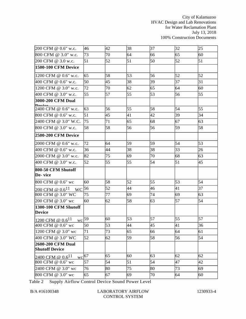
City of Kalamazoo HVAC Design and Lab Renovations
for Water Reclamation Plant July 13, 2018
100% Construction Documents
B/A #16100348 LABORATORY AIRFLOW CONTROL SYSTEM
1230933-4
200 CFM @ 0.6" w.c. 46 42 38 37 32 25 800 CFM @ 3.0" w.c. 73 70 64 66 65 60 200 CFM @ 3.0 w.c. 51 52 51 50 52 51 1500-100 CFM Device
1200 CFM @ 0.6" w.c. 65 58 53 56 52 52 400 CFM @ 0.6" w.c. 50 45 38 39 37 31 1200 CFM @ 3.0" w.c. 72 70 62 65 64 60 400 CFM @ 3.0" w.c. 55 57 55 53 56 55 3000-200 CFM Dual Device
2400 CFM @ 0.6" w.c. 63 56 55 58 54 55 800 CFM @ 0.6" w.c. 51 45 41 42 39 34 2400 CFM @ 3.0" W.C. 75 71 65 68 67 63 800 CFM @ 3.0" w.c. 58 58 56 56 59 58
2500-200 CFM Device
2000 CFM @ 0.6" w.c. 72 64 59 59 54 53 400 CFM @ 0.6" w.c. 36 44 38 38 33 26 2000 CFM @ 3.0" w.c. 82 75 69 70 68 63 400 CFM @ 3.0" w.c. 52 55 55 54 51 45
800-50 CFM Shutoff De- vice
800 CFM @ 0.6" wc 60 58 52 55 53 54
200 CFM @ 0.611 WC 56 52 44 46 41 37 800 CFM @ 3.0" WC 75 77 69 74 69 63 200 CFM @ 3.0" wc 60 62 58 63 57 54 1300-100 CFM Shutoff Device
1200 CFM @ 0.611 wc 59 60 53 57 55 57 400 CFM @ 0.6" wc 50 53 44 45 41 36 1200 CFM @ 3.0" wc 71 73 65 66 64 61 400 CFM @ 3.0" WC 52 62 59 58 56 54 2600-200 CFM Dual Shutoff Device
2400 CFM @ 0.611 wc 67 65 60 63 62 62 800 CFM @ 0.6" wc 57 54 51 54 47 42 2400 CFM @ 3.0" wc 76 80 75 80 73 69 800 CFM @ 3.0" wc 65 67 69 70 64 60
Table 2 Supply Airflow Control Device Sound Power Level
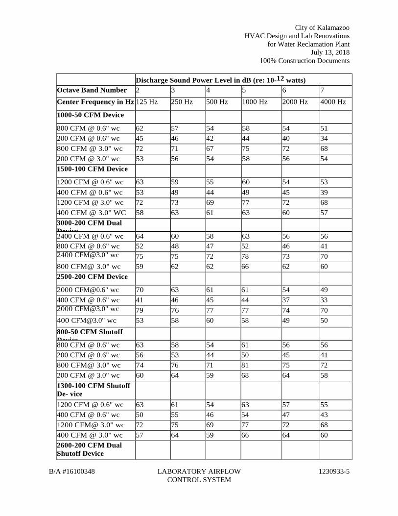
City of Kalamazoo HVAC Design and Lab Renovations
for Water Reclamation Plant July 13, 2018
100% Construction Documents
B/A #16100348 LABORATORY AIRFLOW CONTROL SYSTEM
1230933-5
Discharge Sound Power Level in dB (re: 10-12 watts) Octave Band Number 2 3 4 5 6 7 Center Frequency in Hz 125 Hz 250 Hz 500 Hz 1000 Hz 2000 Hz 4000 Hz
1000-50 CFM Device
800 CFM @ 0.6" wc 62 57 54 58 54 51 200 CFM @ 0.6" wc 45 46 42 44 40 34 800 CFM @ 3.0" wc 72 71 67 75 72 68 200 CFM @ 3.0" wc 53 56 54 58 56 54 1500-100 CFM Device
1200 CFM @ 0.6" wc 63 59 55 60 54 53 400 CFM @ 0.6" wc 53 49 44 49 45 39 1200 CFM @ 3.0" wc 72 73 69 77 72 68 400 CFM @ 3.0" WC 58 63 61 63 60 57 3000-200 CFM Dual Device
2400 CFM @ 0.6" wc 64 60 58 63 56 56 800 CFM @ 0.6" wc 52 48 47 52 46 41 2400 [email protected]" wc 75 75 72 78 73 70 800 CFM@ 3.0" wc 59 62 62 66 62 60 2500-200 CFM Device
2000 [email protected]" wc 70 63 61 61 54 49 400 CFM @ 0.6" wc 41 46 45 44 37 33 2000 [email protected]" wc 79 76 77 77 74 70 400 [email protected]" wc 53 58 60 58 49 50 800-50 CFM Shutoff Device
800 CFM @ 0.6" wc 63 58 54 61 56 56 200 CFM @ 0.6" wc 56 53 44 50 45 41 800 CFM@ 3.0" wc 74 76 71 81 75 72 200 CFM @ 3.0" wc 60 64 59 68 64 58 1300-100 CFM Shutoff De- vice
1200 CFM @ 0.6" wc 63 61 54 63 57 55 400 CFM @ 0.6" wc 50 55 46 54 47 43 1200 CFM@ 3.0" wc 72 75 69 77 72 68 400 CFM @ 3.0" wc 57 64 59 66 64 60 2600-200 CFM Dual Shutoff Device
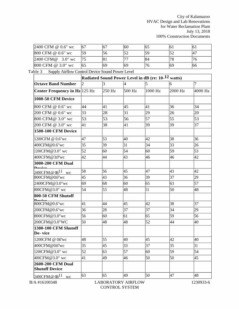
City of Kalamazoo HVAC Design and Lab Renovations
for Water Reclamation Plant July 13, 2018
100% Construction Documents
B/A #16100348 LABORATORY AIRFLOW CONTROL SYSTEM
1230933-6
2400 CFM @ 0.6" wc 67 67 60 65 61 61 800 CFM @ 0.6" wc 59 56 52 59 52 47 2400 CFM@ 3.0" wc 75 81 77 84 78 76 800 CFM @ 3.0" wc 65 69 69 76 69 66
Table 3 Supply Airflow Control Device Sound Power Level Radiated Sound Power Level in dB (re: 10-12 watts) Octave Band Number 2 3 4 5 6 7 Center Frequency in Hz 125 Hz 250 Hz 500 Hz 1000 Hz 2000 Hz 4000 Hz
1000-50 CFM Device
800 CFM @ 0.6" wc 44 41 45 41 36 34 200 CFM @ 0.6" wc 33 28 31 29 26 20 800 CFM@ 3.0" wc 53 53 56 57 55 53 200 CFM @ 3.0" wc 41 38 41 39 39 37 1500-100 CFM Device
1200 CFM @ 0.6" wc 47 53 40 42 38 36 400 CFM @ 0.6" wc 35 39 31 34 33 26 1200 [email protected]" wc 52 60 54 60 59 53 400 CFM @ 3.0" wc 42 44 43 46 46 42 3000-200 CFM Dual Device
2400 CFM @ 0.611 wc 58 56 45 47 43 42 800 CFM @ 0.6" wc 45 43 36 39 37 29 2400 [email protected]" wc 69 68 60 65 63 57 800 [email protected]" wc 54 53 48 51 50 48 800-50 CFM Shutoff Device
800 CFM @ 0.6" wc 41 44 45 42 38 37 200 CFM @ 0.6" wc 36 28 37 37 34 29 800 [email protected]" wc 56 60 61 65 59 56 200 [email protected]" WC 50 48 48 52 44 40 1300-100 CFM Shutoff De- vice
1200 CFM @ 0.6" wc 48 55 40 45 42 40 400 CFM @ 0.6" wc 35 45 33 37 35 31 1200 [email protected]" wc 52 63 57 60 59 54 400 [email protected]" wc 41 49 46 50 50 45 2600-200 CFM Dual Shutoff Device
2400 CFM @ 0.611 wc 63 65 49 50 47 48
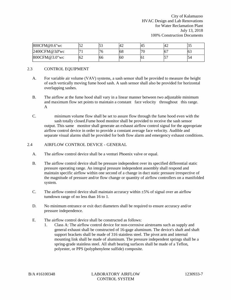
City of Kalamazoo HVAC Design and Lab Renovations
for Water Reclamation Plant July 13, 2018
100% Construction Documents
B/A #16100348 LABORATORY AIRFLOW CONTROL SYSTEM
1230933-7
800 CFM @ 0.6" wc 52 53 42 45 42 35 2400 CFM @ 3.0" wc 71 76 68 70 67 63 800 [email protected]" wc 62 66 60 61 57 54
2.3 CONTROL EQUIPMENT
A. For variable air volume (VAV) systems, a sash sensor shall be provided to measure the height of each vertically moving fume hood sash. A sash sensor shall also be provided for horizontal overlapping sashes.
B. The airflow at the fume hood shall vary in a linear manner between two adjustable minimum and maximum flow set points to maintain a constant face velocity throughout this range. A
C. minimum volume flow shall be set to assure flow through the fume hood even with the sash totally closed.Fume hood monitor shall be provided to receive the sash sensor output. This same monitor shall generate an exhaust airflow control signal for the appropriate airflow control device in order to provide a constant average face velocity. Audible and separate visual alarms shall be provided for both flow alarm and emergency exhaust conditions.
2.4 AIRFLOW CONTROL DEVICE - GENERAL
A. The airflow control device shall be a venturi Phoenix valve or equal.
B. The airflow control device shall be pressure independent over its specified differential static pressure operating range. An integral pressure independent assembly shall respond and maintain specific airflow within one second of a change in duct static pressure irrespective of the magnitude of pressure and/or flow change or quantity of airflow controllers on a manifolded system.
C. The airflow control device shall maintain accuracy within ±5% of signal over an airflow tumdown range of no less than 16 to 1.
D. No minimum entrance or exit duct diameters shall be required to ensure accuracy and/or pressure independence.
E. The airflow control device shall be constructed as follows: 1. Class A: The airflow control device for non-corrosive airstreams such as supply and
general exhaust shall be constructed of 16-gage aluminum. The device's shaft and shaft support brackets shall be made of 316 stainless steel. The pivot arm and internal mounting link shall be made of aluminum. The pressure independent springs shall be a spring-grade stainless steel. All shaft bearing surfaces shall be made of a Teflon, polyester, or PPS (polyphenylene sulfide) composite.
City of Kalamazoo HVAC Design and Lab Renovations
for Water Reclamation Plant July 13, 2018
100% Construction Documents
B/A #16100348 LABORATORY AIRFLOW CONTROL SYSTEM
1230933-8
2. Class B: The airflow control device for corrosive airstreams, such as fume hoods and biosafety cabinets, shall have a baked-on, corrosion-resistant phenolic coating. The device's shaft shall be made of 316 stainless steel with a Teflon coating. The shaft support brackets shall be made of 316 stainless steel. The pivot arm and internal "S" link shall be made of 316 or 303 stainless steel. The pressure independent springs shall be a spring-grade stainless steel. The internal nuts, bolts and rivets shall be stainless steel. All shaft bearing surfaces shall be made of PP (polypropylene) or PPS (polyphenylene sulfide) composite.
F. For VAV operation, an electric actuator shall be factory mounted to the valve. Loss of control power shall cause normally open valves to fail to maximum position, and normally closed valves to fail to minimum position. Electric actuators that fail in last position are not acceptable when used in fume hood and make-up air control applications.
G. The controller for the airflow control devices shall be microprocessor based and operate using a peer-to-peer control architecture. The room-level airflow control devices shall function as a stand-alone network.
H. There shall be no reliance on external or building-level control devices to perform room-level control functions. Each laboratory control system shall have the capability of performing; Fume hood control, Pressurization control, temperature control, and implement occupancy mode control schemes.
I. Constant Volume Airflow Control Device: 1. The airflow control device shall maintain a constant airflow setpoint. It shall be factory
characterized and set for the desire airflow. It shall also be capable of field adjustment for future changes in desired airflow.
2.5 EXHAUST AND SUPPLY AIRFLOW DEVICE CONTROLLER
A. The airflow control device shall be a microprocessor-based design and, shall use closed loop control to linearly regulate airflow based on a digital control signal. The device shall generate a digital feedback signal that represents its airflow.
B. The airflow control device shall store its control algorithms in non-volatile, re-writable memory. The device shall be able to stand-alone or to be networked with other room level digital airflow control devices using an industry standard protocol.
C. Room-level control functions shall be embedded in and carried out by the airflow device controller using a distributed control architecture. Critical control functions shall be implemented locally, no room-level controller shall be required.
D. The airflow control device shall use industry standard 24 VAC power.
E. The airflow control device shall have provisions to connect a notebook PC commissioning tool and every node on the network shall be accessible from any point in the system.
City of Kalamazoo HVAC Design and Lab Renovations
for Water Reclamation Plant July 13, 2018
100% Construction Documents
B/A #16100348 LABORATORY AIRFLOW CONTROL SYSTEM
1230933-9
F. The airflow control device shall have built-Input/Output connections, address, fume hood control, temperature control, humidity control, occupancy control, emergency control and non-network sensors, switches and control devices. At a minimum the airflow controller shall have. 1. Three (3) universal inputs, capable of accepting 0 to 10Vdc, 4 to 20mA, 0 to 65k ohms,
or Type 2 or Type 3 10k ohm @ 25 degree C thermistor temperature sensors. 2. One (1) digital input capable of accepting a dry contact or logic level signal input. 3. Two (2) analog outputs capable of developing either a Oto lOVdc, or 4 to 20mA linear
control signal. 4. One (1) Form C (SPDT) relay output capable of driving up to 1A @ 24 Vac/Vdc. 5. The airflow control device shall meet FCC Part 15, Subpart J Class A and be UL916
listed.
2.6 CONTROL FUNCTIONS
A. The airflow control devices shall utilize a peer-to-peer, distributed control architecture to perform room-level control functions. Control functions shall at a minimum include, pressurization, temperature, and respond to occupancy and emergency control commands.
B. Pressurization Control: 1. The laboratory control system shall control supply and auxiliary exhaust airflow devices
in order to maintain a volumetric offset (negative). Offset shall be maintained regardless of any change in flow or static pressure. This offset shall be field adjustable and represents the volume of air, which will enter the room from the corridor or adjacent spaces.
2. The pressurization control algorithm shall sum the flow values of all Supply and Exhaust airflow devices and command appropriate controlled devices to new set points to maintain the desired offset. The offset shall be adjustable.
3. The pressurization control algorithm shall consider both networked devices, as well as: a. Up to three (3) non-networked devices providing a linear analog flow signal.
4. Volumetric offset shall be the only acceptable means of controlling room pressurization. Systems that rely on differential pressure as a means of control shall provide documentation to demonstrate that space pressurization can be maintained if fume hood sashes are changed at the same time a door to the space is opened.
5. The pressurization control algorithm shall support the ability to regulate the distribution of total supply flow across multiple supply airflow control devices in order to optimize air distribution in the space.
C. Temperature Control: 1. The laboratory control system shall regulate the space temperature through a combination
of volumetric thermal override and control of reheat coils and/or auxiliary temperature control devices. Separate cooling and heating set points with the option of a local offset adjustment.
City of Kalamazoo HVAC Design and Lab Renovations
for Water Reclamation Plant July 13, 2018
100% Construction Documents
B/A #16100348 LABORATORY AIRFLOW CONTROL SYSTEM
1230933-10
2. Temperature control shall be implemented through the use of independent primary cooling and heating control functions, as well as an auxiliary temperature control function, which may be used for either supplemental cooling or heating. Cooling shall be provided as a function of thermal override of conditioned air with both supply and exhaust airflow devices responding simultaneously so as to maintain the desired offset. Heating shall be provided through modulating control of a properly sized reheat coil.
D. Occupancy Control: 1. The laboratory control system shall have the ability to change the minimum ventilation
and/or temperature control set points, based on the occupied state, in order to reduce energy consumption when the space is not occupied. The occupancy state may be set by either the CBAS, as a scheduled event, or through the use of a local occupancy sensor or switch. The laboratory control system shall support a local occupancy override button that allows a user to override the occupancy mode and set the space to occupied, for a predetermined interval. The override interval shall be configurable for 1 to 1,440 minutes. The local occupancy sensor/switch, or bypass button shall be given priority over a CBAS command.
E. Local Alarm Control:
F. The laboratory control system shall provide the means of summing selective alarm activity at the room-level network and generating a local alarm signal. The local alarm signal may be directed to any available output, as well as to the BMS. The alarm mask may be configured differently for each room-level system.Emergency Mode Control: 1. The laboratory control system shall provide a means of overriding temperature and
pressurization control in response to a command indicating an emergency condition exists and airflow control devices are to be driven to a specific flow set point. The system shall support up to four (4) emergency control modes. The emergency control modes may be initiated either by a local contact input, or CBAS command.
2. Once an Emergency mode is invoked, pressurization and temperature control are overridden for the period that the mode is active. Emergency modes shall have a priority scheme allowing a more critical mode to override a previously set condition.
G. Fume Hood Control: 1. Airflow devices intended to control the face velocity of a fume hood shall have the ability
to interface directly with the fume hood monitoring device. The airflow control device shall. a. Accept command inputs to regulate the flow accordingly and make this command
value available to the CBAS. b. Accept a sash position signal and make this value available to the CBAS. c. Provide a flow feedback signal to the fume hood monitor, which may be used for
calculating face velocity, or to confirm the airflow device has achieved the proper flow rate and make this value available.
City of Kalamazoo HVAC Design and Lab Renovations
for Water Reclamation Plant July 13, 2018
100% Construction Documents
B/A #16100348 LABORATORY AIRFLOW CONTROL SYSTEM
1230933-11
d. Provide alarm signals to the fume hood monitor in the event the airflow device is unable to achieve the proper flow rate or there is a loss of static pressure indicating improper fan operation, or that there is a loss of power to the airflow control device in order to provide a local alarm indication.
e. Fume hood hibernation, which commands the exhaust flow through the fume hood to the minimum allowed by the exhaust valve when the sash is fully closed and no chemicals are present in the hood. The mode shall be initiated by a pushbutton sequence on the fume hood monitor. When activated, the LED display will show "OFF" and the exhaust valve will move to its minimum position or shutoff position. Safety shall be built-in, whereby opening the fume hood sash will automatically return the fume hood exhaust to an in-use operating volume as determined by the sash sensor. Fume hood hibernation shall be a point that can be integrated to the BMS system.
2. The fume hood airflow control device shall respond to changes in sash position and user presence (where required by the design) within 1 second in order to provide a constant face velocity when the fume hood is in use.
H. The laboratory control system shall be segregated into individual sub nets to isolate network communications to insure room-level control functions. Each laboratory space or pressurization zone shall be its own sub net. Commercially available routers shall be used to provide this isolation.
I. All points shall be available for trending, archiving, graphics, alarm notification, and status reports. Laboratory airflow control system performance (speed, stability, and accuracy) shall be unaffected by the quantity of points being monitored, processed, or controlled.
PART 3 - EXECUTION
3.1 INSTALLATION
A. The laboratory airflow control system contractor shall install the sash sensors, interface boxes and fume hood monitor on the fume hood. Reel-type sash sensors and their stainless steel cables shall be hidden from view. Bar-type sash sensors shall be affixed to the individual sash panels. Sash interface boxes with interface cards shall be mounted in an accessible location.
B. The ECC Contractor shall install all routers and repeaters in an accessible location in or around the designated laboratory room.
C. The ECC shall install an appropriately sized and fused 24 VAC transformer suitable for NEC Class II wiring.
D. All cable shall be furnished and installed by the ECC contractor. The ECC contractor shall terminate and connect all cables as required. The ECC shall utilize cables specifically recommended by the laboratory airflow controls supplier.
E. The mechanical contractor shall install all airflow control devices in the ductwork and shall connect all airflow control valve linkages.
City of Kalamazoo HVAC Design and Lab Renovations
for Water Reclamation Plant July 13, 2018
100% Construction Documents
B/A #16100348 LABORATORY AIRFLOW CONTROL SYSTEM
1230933-12
F. The Mechanical Contractor shall provide and install all reheat coils.
G. The Electrical Contractor shall provide 120/60 power as noted on control schematics.
H. Each pressurization zone shall have either a dedicated, single-phase primary circuit or a secondary circuit disconnect.
I. The Laboratory Airflow Control System Contractor shall functionally check all controls prior to setup by the Test and Balance Contractor.
J. The Laboratory Airflow Control System Contractor shall assist the Test and Balance Contractor in adjusting the setpoints to meet the specified airflow, pressure and temperature setpoints.
3.2 BUILDING AUTOMATION SYSTEM INTERFACE
A. The laboratory airflow control systems shall digitally interface to the Central Building Automation System (BAS) as provided by the temperature control contractor. The laboratory airflow control contractor shall be responsible to provide an interface device between the Laboratory Airflow Controls and the BAS, including standardized communications protocol software for BACnet and data mapping tables as required by the BAS design.
B. The following lab control parameters shall be transferred digitally to the BAS: 1. Emergency status. 2. Unoccupied mode. 3. Sash position. 4. Calculated face velocity. 5. Hood exhaust airflow volume. 6. Hood exhaust airflow high alarm. 7. Hood exhaust airflow low alarm. 8. Supply airflow, CFM and setpoint. 9. General exhaust airflow, CFM and setpoint. 10. Airflow differential, CFM and setpoint. 11. Room temperature setpoint.
C. The temperature controls contractor shall be responsible to provide digital interface devices, drivers for interfacing with BACnet protocols, software indigenous to the BAS, and graphic displays for the laboratory airflow control systems at the central BAS station.
D. Hardwire interfacing of lab control systems to BAS shall only be acceptable if: 1. All parameters outlined in Paragraph B above shall be transferred to the BAS. 2. The lab control contractor shall provide, in their Bid price, all additional equipment
required on the part of the ATC for interface to the lab systems, including ATC control panels.
City of Kalamazoo HVAC Design and Lab Renovations
for Water Reclamation Plant July 13, 2018
100% Construction Documents
B/A #16100348 LABORATORY AIRFLOW CONTROL SYSTEM
1230933-13
3.3 STARTUP AND TESTING
A. System start-up shall be provided by a factory authorized representative of the laboratory airflow control system manufacturer. Start-up shall include calibrating the fume hood monitor and any combination sash sensing equipment as required. Start-up shall also provide electronic verification of airflow (fume hood exhaust, supply, make-up or general exhaust), system programming and integration to CBAS.
B. The balancing contractor shall be responsible for final verification and reporting of all airflows.
C. The laboratory airflow control system supplier shall furnish a minimum of eight hours of owner training, by factory trained and certified personnel. The training will provide an overview of the job specific airflow control components, verification of initial fume hood monitor calibration, general procedures for verifying airflows of air valves, and general troubleshooting procedures.
D. Operation and Maintenance manuals, including as-built wiring diagrams and component lists shall be provided for each training attendee.
E. The laboratory airflow control system contractor shall assist the test and balance contractor in adjusting the setpoints to meet the specified airflow, pressure and temperature setpoints.
F. It shall be the responsibility of the General Contractor to secure the room envelope sufficiently to maintain required pressure levels with the airflow volumes specified. The laboratory airflow control system contractor shall advise the General Contractor of any condition which might compromise the ability of the room to achieve the specified pressure levels.
G. The laboratory airflow control system contractor shall demonstrate to the Engineer and/or Commissioning Agent the ability of the controls to maintain setpoints in all modes of operation.
END OF SECTION 1230933
City of Kalamazoo HVAC Design and Lab Renovations
for Water Reclamation Plant July 13, 2018
100% Construction Documents
B/A #16100348 FACILITY NATURAL-GAS PIPING
1231123-1
SECTION 1231123 - FACILITY NATURAL-GAS PIPING
PART 1 - GENERAL
PART 2 - PRODUCTS
2.1 PERFORMANCE REQUIREMENTS
A. Minimum Operating-Pressure Ratings: 1. Piping and Valves: 100 psig (690 kPa) minimum unless otherwise indicated. 2. Service Regulators: 65 psig (450 kPa) minimum unless otherwise indicated.
B. Natural-Gas System Pressure within Buildings: More than 0.5 psig (3.45 kPa) but not more than 2 psig (13.8 kPa).
C. Natural-Gas System Pressures within Buildings: Two pressure ranges. Primary pressure is more than 0.5 psig (3.45 kPa) but not more than 2 psig (13.8 kPa), and is reduced to secondary pressure of 0.5 psig (3.45 kPa) or less.
D. Delegated Design: Design restraints and anchors for natural-gas piping and equipment, including comprehensive engineering analysis by a qualified professional engineer, using performance requirements and design criteria indicated.
2.2 PIPES, TUBES, AND FITTINGS
A. Steel Pipe: ASTM A 53/A 53M, black steel, Schedule 40, Type E or S, Grade B. 1. Malleable-Iron Threaded Fittings: ASME B16.3, Class 150, standard pattern. 2. Wrought-Steel Welding Fittings: ASTM A 234/A 234M for butt welding and socket
welding. 3. Unions: ASME B16.39, Class 150, malleable iron with brass-to-iron seat, ground joint,
and threaded ends. 4. Protective Coating for Underground Piping: Factory-applied, three-layer coating of
epoxy, adhesive, and PE. a. Joint Cover Kits: Epoxy paint, adhesive, and heat-shrink PE sleeves.
2.3 PIPING SPECIALTIES
A. Appliance Flexible Connectors: 1. Indoor, Fixed-Appliance Flexible Connectors: Comply with ANSI Z21.24. 2. Indoor, Movable-Appliance Flexible Connectors: Comply with ANSI Z21.69. 3. Outdoor, Appliance Flexible Connectors: Comply with ANSI Z21.75. 4. Corrugated stainless-steel tubing with polymer coating. 5. Operating-Pressure Rating: 0.5 psig (3.45 kPa). 6. End Fittings: Zinc-coated steel. 7. Threaded Ends: Comply with ASME B1.20.1. 8. Maximum Length: 72 inches (1830 mm.)
City of Kalamazoo HVAC Design and Lab Renovations
for Water Reclamation Plant July 13, 2018
100% Construction Documents
B/A #16100348 FACILITY NATURAL-GAS PIPING
1231123-2
B. Quick-Disconnect Devices: Comply with ANSI Z21.41. 1. Copper-alloy convenience outlet and matching plug connector. 2. Nitrile seals. 3. Hand operated with automatic shutoff when disconnected. 4. For indoor or outdoor applications. 5. Adjustable, retractable restraining cable.
C. Y-Pattern Strainers: 1. Body: ASTM A 126, Class B, cast iron with bolted cover and bottom drain connection. 2. End Connections: Threaded ends for NPS 2 (DN 50) and smaller. 3. Strainer Screen: 40 -mesh startup strainer, and perforated stainless-steel basket with 50
percent free area. 4. CWP Rating: 125 psig (862 kPa).
D. Weatherproof Vent Cap: Cast- or malleable-iron increaser fitting with corrosion-resistant wire screen, with free area at least equal to cross-sectional area of connecting pipe and threaded-end connection.
2.4 JOINING MATERIALS
A. Joint Compound and Tape: Suitable for natural gas.
B. Welding Filler Metals: Comply with AWS D10.12/D10.12M for welding materials appropriate for wall thickness and chemical analysis of steel pipe being welded.
2.5 MANUAL GAS SHUTOFF VALVES
A. General Requirements for Metallic Valves, NPS 2 (DN 50) and Smaller: Comply with ASME B16.33. 1. CWP Rating: 125 psig (862 kPa). 2. Threaded Ends: Comply with ASME B1.20.1. 3. Dryseal Threads on Flare Ends: Comply with ASME B1.20.3. 4. Tamperproof Feature: Locking feature for valves indicated in "Underground Manual Gas
Shutoff Valve Schedule" and "Aboveground Manual Gas Shutoff Valve Schedule" Articles.
5. Listing: Listed and labeled by an NRTL acceptable to authorities having jurisdiction for valves 1 inch (25 mm) and smaller.
6. Service Mark: Valves 1-1/4 inches (32 mm) to NPS 2 (DN 50) shall have initials "WOG" permanently marked on valve body.
B. One-Piece, Bronze Ball Valve with Bronze Trim: MSS SP-110. 1. Manufacturers: Subject to compliance with requirements, available manufacturers
offering products that may be incorporated into the Work include, but are not limited to, the following: a. Apollo Valves; Conbraco Industries, Inc. b. BrassCraft Manufacturing Co.; a Masco company. c. Lyall, R. W. & Company, Inc. d. Perfection Corporation.
City of Kalamazoo HVAC Design and Lab Renovations
for Water Reclamation Plant July 13, 2018
100% Construction Documents
B/A #16100348 FACILITY NATURAL-GAS PIPING
1231123-3
2. Body: Bronze, complying with ASTM B 584. 3. Ball: Chrome-plated brass. 4. Stem: Bronze; blowout proof. 5. Seats: Reinforced TFE; blowout proof. 6. Packing: Separate packnut with adjustable-stem packing threaded ends. 7. Ends: Threaded, flared, or socket as indicated in "Underground Manual Gas Shutoff
Valve Schedule" and "Aboveground Manual Gas Shutoff Valve Schedule" Articles. 8. CWP Rating: 600 psig (4140 kPa). 9. Listing: Valves NPS 1 (DN 25) and smaller shall be listed and labeled by an NRTL
acceptable to authorities having jurisdiction. 10. Service: Suitable for natural-gas service with "WOG" indicated on valve body.
C. Two-Piece, Full-Port, Bronze Ball Valves with Bronze Trim: MSS SP-110. 1. Manufacturers: Subject to compliance with requirements, available manufacturers
offering products that may be incorporated into the Work include, but are not limited to, the following: a. Apollo Valves; Conbraco Industries, Inc. b. BrassCraft Manufacturing Co.; a Masco company. c. Lyall, R. W. & Company, Inc. d. Perfection Corporation.
2. Body: Bronze, complying with ASTM B 584. 3. Ball: Chrome-plated bronze. 4. Stem: Bronze; blowout proof. 5. Seats: Reinforced TFE; blowout proof. 6. Packing: Threaded-body packnut design with adjustable-stem packing. 7. Ends: Threaded, flared, or socket as indicated in "Underground Manual Gas Shutoff
Valve Schedule" and "Aboveground Manual Gas Shutoff Valve Schedule" Articles. 8. CWP Rating: 600 psig (4140 kPa). 9. Listing: Valves NPS 1 (DN 25) and smaller shall be listed and labeled by an NRTL
acceptable to authorities having jurisdiction. 10. Service: Suitable for natural-gas service with "WOG" indicated on valve body.
D. Two-Piece, Regular-Port Bronze Ball Valves with Bronze Trim: MSS SP-110. 1. Manufacturers: Subject to compliance with requirements, available manufacturers
offering products that may be incorporated into the Work include, but are not limited to, the following: a. Apollo Valves; Conbraco Industries, Inc. b. BrassCraft Manufacturing Co.; a Masco company. c. Lyall, R. W. & Company, Inc. d. Perfection Corporation.
2. Body: Bronze, complying with ASTM B 584. 3. Ball: Chrome-plated bronze. 4. Stem: Bronze; blowout proof. 5. Seats: Reinforced TFE. 6. Packing: Threaded-body packnut design with adjustable-stem packing. 7. Ends: Threaded, flared, or socket as indicated in "Underground Manual Gas Shutoff
Valve Schedule" and "Aboveground Manual Gas Shutoff Valve Schedule" Articles.
City of Kalamazoo HVAC Design and Lab Renovations
for Water Reclamation Plant July 13, 2018
100% Construction Documents
B/A #16100348 FACILITY NATURAL-GAS PIPING
1231123-4
8. CWP Rating: 600 psig (4140 kPa). 9. Listing: Valves NPS 1 (DN 25) and smaller shall be listed and labeled by an NRTL
acceptable to authorities having jurisdiction. 10. Service: Suitable for natural-gas service with "WOG" indicated on valve body.
E. Bronze Plug Valves: MSS SP-78. 1. Manufacturers: Subject to compliance with requirements, available manufacturers
offering products that may be incorporated into the Work include, but are not limited to, the following: a. Lee Brass Company.
2. Body: Bronze, complying with ASTM B 584. 3. Plug: Bronze. 4. Ends: Threaded, socket, as indicated in "Underground Manual Gas Shutoff Valve
Schedule" and "Aboveground Manual Gas Shutoff Valve Schedule" Articles. 5. Operator: Square head or lug type with tamperproof feature where indicated. 6. Pressure Class: 125 psig (862 kPa). 7. Listing: Valves NPS 1 (DN 25) and smaller shall be listed and labeled by an NRTL
acceptable to authorities having jurisdiction. 8. Service: Suitable for natural-gas service with "WOG" indicated on valve body.
F. PE Ball Valves: Comply with ASME B16.40. 1. Manufacturers: Subject to compliance with requirements, available manufacturers
offering products that may be incorporated into the Work include, but are not limited to, the following: a. Kerotest Manufacturing Corp. b. Lyall, R. W. & Company, Inc. c. Perfection Corporation.
2. Body: PE. 3. Ball: PE. 4. Stem: Acetal. 5. Seats and Seals: Nitrile. 6. Ends: Plain or fusible to match piping. 7. CWP Rating: 80 psig (552 kPa). 8. Operating Temperature: Minus 20 to plus 140 deg F (Minus 29 to plus 60 deg C)
. 9. Operator: Nut or flat head for key operation. 10. Include plastic valve extension. 11. Include tamperproof locking feature for valves where indicated on Drawings.
G. Valve Boxes: 1. Cast-iron, two-section box. 2. Top section with cover with "GAS" lettering. 3. Bottom section with base to fit over valve and barrel a minimum of 5 inches (125 mm) in
diameter. 4. Adjustable cast-iron extensions of length required for depth of bury. 5. Include tee-handle, steel operating wrench with socket end fitting valve nut or flat head,
and with stem of length required to operate valve.
City of Kalamazoo HVAC Design and Lab Renovations
for Water Reclamation Plant July 13, 2018
100% Construction Documents
B/A #16100348 FACILITY NATURAL-GAS PIPING
1231123-5
2.6 PRESSURE REGULATORS
A. General Requirements: 1. Single stage and suitable for natural gas. 2. Steel jacket and corrosion-resistant components. 3. Elevation compensator. 4. End Connections: Threaded for regulators NPS 2 (DN 50) and smaller.
B. Line Pressure Regulators: Comply with ANSI Z21.80. 1. Manufacturers: Subject to compliance with requirements, available manufacturers
offering products that may be incorporated into the Work include, but are not limited to, the following: a. Actaris. b. American Meter Company. c. Eclipse Innovative Thermal Technologies. d. Fisher Control Valves & Instruments; a brand of Emerson Process Management. e. Invensys. f. Itron Gas. g. Maxitrol Company. h. Richards Industries.
2. Body and Diaphragm Case: Cast iron or die-cast aluminum. 3. Springs: Zinc-plated steel; interchangeable. 4. Diaphragm Plate: Zinc-plated steel. 5. Seat Disc: Nitrile rubber resistant to gas impurities, abrasion, and deformation at the
valve port. 6. Orifice: Aluminum; interchangeable. 7. Seal Plug: Ultraviolet-stabilized, mineral-filled nylon. 8. Single-port, self-contained regulator with orifice no larger than required at maximum
pressure inlet, and no pressure sensing piping external to the regulator. 9. Pressure regulator shall maintain discharge pressure setting downstream, and not exceed
150 percent of design discharge pressure at shutoff. 10. Overpressure Protection Device: Factory mounted on pressure regulator. 11. Atmospheric Vent: Factory- or field-installed, stainless-steel screen in opening if not
connected to vent piping. 12. Maximum Inlet Pressure: 5 psig (34.5 kPa) .
C. Appliance Pressure Regulators: Comply with ANSI Z21.18. 1. Manufacturers: Subject to compliance with requirements, available manufacturers
offering products that may be incorporated into the Work include, but are not limited to, the following: a. Eaton. b. Harper Wyman Co. c. Maxitrol Company. d. SCP, Inc.
2. Body and Diaphragm Case: Die-cast aluminum. 3. Springs: Zinc-plated steel; interchangeable. 4. Diaphragm Plate: Zinc-plated steel.
City of Kalamazoo HVAC Design and Lab Renovations
for Water Reclamation Plant July 13, 2018
100% Construction Documents
B/A #16100348 FACILITY NATURAL-GAS PIPING
1231123-6
5. Seat Disc: Nitrile rubber. 6. Seal Plug: Ultraviolet-stabilized, mineral-filled nylon. 7. Factory-Applied Finish: Minimum three-layer polyester and polyurethane paint finish. 8. Regulator may include vent limiting device, instead of vent connection, if approved by
authorities having jurisdiction. 9. Maximum Inlet Pressure: 5 psig (34.5 kPa).
2.7 DIELECTRIC UNIONS
A. Dielectric Unions: 1. Manufacturers: Subject to compliance with requirements, available manufacturers
offering products that may be incorporated into the Work include, but are not limited to, the following: a. Capitol Manufacturing Company. b. Central Plastics Company. c. HART Industrial Unions, LLC. d. Jomar Valve. e. Matco-Norca. f. Watts; a Watts Water Technologies company. g. Wilkins. h. Zurn Industries, LLC.
2. Description: a. Standard: ASSE 1079. b. Pressure Rating: 125 psig (860 kPa) minimum at 180 deg F (82 deg C). c. End Connections: Solder-joint copper alloy and threaded ferrous.
2.8 LABELING AND IDENTIFYING
A. Detectable Warning Tape: Acid- and alkali-resistant, PE film warning tape manufactured for marking and identifying underground utilities, a minimum of 6 inches (150 mm) wide and 4 mils (0.1 mm) thick, continuously inscribed with a description of utility, with metallic core encased in a protective jacket for corrosion protection, detectable by metal detector when tape is buried up to 30 inches (750 mm) deep; colored yellow.
PART 3 - EXECUTION
3.1 OUTDOOR PIPING INSTALLATION
A. Comply with the International Fuel Gas Code for installation and purging of natural-gas piping.
B. Steel Piping with Protective Coating: 1. Apply joint cover kits to pipe after joining to cover, seal, and protect joints. 2. Repair damage to PE coating on pipe as recommended in writing by protective coating
manufacturer. 3. Replace pipe having damaged PE coating with new pipe.
C. Install fittings for changes in direction and branch connections.
City of Kalamazoo HVAC Design and Lab Renovations
for Water Reclamation Plant July 13, 2018
100% Construction Documents
B/A #16100348 FACILITY NATURAL-GAS PIPING
1231123-7
3.2 INDOOR PIPING INSTALLATION
A. Comply with the International Fuel Gas Code for installation and purging of natural-gas piping.
B. Drawing plans, schematics, and diagrams indicate general location and arrangement of piping systems. Indicated locations and arrangements are used to size pipe and calculate friction loss, expansion, and other design considerations. Install piping as indicated unless deviations to layout are approved on Coordination Drawings.
C. Arrange for pipe spaces, chases, slots, sleeves, and openings in building structure during progress of construction, to allow for mechanical installations.
D. Locate valves for easy access.
E. Install natural-gas piping at uniform grade of 2 percent down toward drip and sediment traps.
F. Verify final equipment locations for roughing-in.
G. Drips and Sediment Traps: Install drips at points where condensate may collect, including service-meter outlets. Locate where accessible to permit cleaning and emptying. Do not install where condensate is subject to freezing. 1. Construct drips and sediment traps using tee fitting with bottom outlet plugged or capped.
Use nipple a minimum length of 3 pipe diameters, but not less than 3 inches (75 mm) long and same size as connected pipe. Install with space below bottom of drip to remove plug or cap.
H. Install unions in pipes NPS 2 (DN 50) and smaller, adjacent to each valve, at final connection to each piece of equipment.
I. Do not use natural-gas piping as grounding electrode.
J. Install strainer on inlet of each line-pressure regulator and automatic or electrically operated valve.
3.3 VALVE INSTALLATION
A. Install manual gas shutoff valve for each gas appliance ahead of corrugated stainless-steel tubing or copper connector.
B. Install underground valves with valve boxes.
C. Install regulators and overpressure protection devices with maintenance access space adequate for servicing and testing.
D. Install earthquake valves aboveground outside buildings according to listing.
E. Install anode for metallic valves in underground PE piping.
City of Kalamazoo HVAC Design and Lab Renovations
for Water Reclamation Plant July 13, 2018
100% Construction Documents
B/A #16100348 FACILITY NATURAL-GAS PIPING
1231123-8
3.4 PIPING JOINT CONSTRUCTION
A. Ream ends of pipes and tubes and remove burrs.
B. Remove scale, slag, dirt, and debris from inside and outside of pipe and fittings before assembly.
C. Threaded Joints: 1. Thread pipe with tapered pipe threads complying with ASME B1.20.1. 2. Cut threads full and clean using sharp dies. 3. Ream threaded pipe ends to remove burrs and restore full inside diameter of pipe. 4. Apply appropriate tape or thread compound to external pipe threads unless dryseal
threading is specified. 5. Damaged Threads: Do not use pipe or pipe fittings with threads that are corroded or
damaged. Do not use pipe sections that have cracked or open welds.
D. Welded Joints: 1. Construct joints according to AWS D10.12/D10.12M, using qualified processes and
welding operators. 2. Bevel plain ends of steel pipe. 3. Patch factory-applied protective coating as recommended by manufacturer at field welds
and where damage to coating occurs during construction.
E. Brazed Joints: Construct joints according to AWS's "Brazing Handbook," "Pipe and Tube" Chapter.
F. Flared Joints: Cut tubing with roll cutting tool. Flare tube end with tool to result in flare dimensions complying with SAE J513. Tighten finger tight, then use wrench. Do not overtighten.
G. PE Piping Heat-Fusion Joints: Clean and dry joining surfaces by wiping with clean cloth or paper towels. Join according to ASTM D 2657. 1. Plain-End Pipe and Fittings: Use butt fusion. 2. Plain-End Pipe and Socket Fittings: Use socket fusion.
3.5 HANGER AND SUPPORT INSTALLATION
A. Install seismic restraints on piping. Comply with requirements for seismic-restraint devices specified in Section 1230548 "Vibration and Seismic Controls for HVAC."
B. Comply with requirements for pipe hangers and supports specified in Section 1230529 "Hangers and Supports for HVAC Piping and Equipment."
C. Install hangers for horizontal steel piping with the following maximum spacing and minimum rod sizes: 1. NPS 1 (DN 25) and Smaller: Maximum span, 96 inches (2438 mm); minimum rod size,
3/8 inch (10 mm).
City of Kalamazoo HVAC Design and Lab Renovations
for Water Reclamation Plant July 13, 2018
100% Construction Documents
B/A #16100348 FACILITY NATURAL-GAS PIPING
1231123-9
2. NPS 1-1/4 (DN 32): Maximum span, 108 inches (2743 mm); minimum rod size, 3/8 inch (10 mm).
3. NPS 1-1/2 and NPS 2 (DN 40 and DN 50): Maximum span, 108 inches (2743 mm); minimum rod size, 3/8 inch (10 mm).
3.6 CONNECTIONS
A. Connect to utility's gas main according to utility's procedures and requirements.
B. Install natural-gas piping electrically continuous, and bonded to gas appliance equipment grounding conductor of the circuit powering the appliance according to NFPA 70.
C. Install piping adjacent to appliances to allow service and maintenance of appliances.
D. Connect piping to appliances using manual gas shutoff valves and unions. Install valve within 72 inches (1800 mm) of each gas-fired appliance and equipment. Install union between valve and appliances or equipment.
E. Sediment Traps: Install tee fitting with capped nipple in bottom to form drip, as close as practical to inlet of each appliance.
3.7 LABELING AND IDENTIFYING
A. Comply with requirements in Section 1230553 "Identification for HVAC Piping and Equipment" for piping and valve identification.
B. Install detectable warning tape directly above gas piping, 12 inches (300 mm) below finished grade, except 6 inches (150 mm) below subgrade under pavements and slabs.
3.8 OUTDOOR PIPING SCHEDULE
A. Underground natural-gas piping shall be one of the following: 1. PE pipe and fittings joined by heat fusion; service-line risers with tracer wire terminated
in an accessible location. 2. Steel pipe with wrought-steel fittings and welded joints. Coat pipe and fittings with
protective coating for steel piping.
B. Aboveground natural-gas piping shall be one of the following: 1. Steel pipe with malleable-iron fittings and threaded joints. 2. Steel pipe with wrought-steel fittings and welded joints. 3. Annealed-temper copper tube with wrought-copper fittings and brazed joints.
C. Branch Piping in Cast-in-Place Concrete to Single Appliance: Annealed-temper copper tube with wrought-copper fittings and brazed joints. Install piping embedded in concrete with no joints in concrete.
City of Kalamazoo HVAC Design and Lab Renovations
for Water Reclamation Plant July 13, 2018
100% Construction Documents
B/A #16100348 FACILITY NATURAL-GAS PIPING
1231123-10
3.9 INDOOR PIPING SCHEDULE
A. Aboveground, branch piping NPS 1 (DN 25) and smaller shall be one of the following: 1. Corrugated stainless-steel tubing with mechanical fittings having socket or threaded ends
to match adjacent piping. 2. Annealed-temper copper tube with wrought-copper fittings and brazed joints. 3. Steel pipe with malleable-iron fittings and threaded joints.
B. Aboveground, distribution piping shall be one of the following: 1. Steel pipe with malleable-iron fittings and threaded joints. 2. Steel pipe with wrought-steel fittings and welded joints.
3.10 ABOVEGROUND MANUAL GAS SHUTOFF VALVE SCHEDULE
A. Distribution piping valves for pipe sizes NPS 2 (DN 50) and smaller shall be one of the following: 1. One-piece, bronze ball valve with bronze trim. 2. Two-piece, full -port, bronze ball valves with bronze trim. 3. Bronze plug valve.
B. Valves in branch piping for single appliance shall be one of the following: 1. One-piece, bronze ball valve with bronze trim. 2. Two-piece, full -port, bronze ball valves with bronze trim. 3. Bronze plug valve.
END OF SECTION 1231123
City of Kalamazoo HVAC Design and Lab Renovations
for Water Reclamation Plant July 13, 2018
100% Construction Documents
B/A #16100348 METAL DUCTS 1233113-1
SECTION 1233113 - METAL DUCTS
PART 1 - GENERAL
1.1 RELATED DOCUMENTS
A. Drawings and general provisions of the Contract, including General and Supplementary Conditions and Division 101 Specification Sections, apply to this Section.
1.2 SUMMARY
A. Section Includes: 1. Single-wall rectangular ducts and fittings. 2. Single-wall round ducts and fittings. 3. Sheet metal materials. 4. Sealants and gaskets. 5. Hangers and supports.
PART 2 - PRODUCTS
2.1 PERFORMANCE REQUIREMENTS
A. Delegated Duct Design: Duct construction, including sheet metal thicknesses, seam and joint construction, reinforcements, and hangers and supports, shall comply with SMACNA's "HVAC Duct Construction Standards - Metal and Flexible" and with performance requirements and design criteria indicated in "Duct Schedule" Article.
B. Airstream Surfaces: Surfaces in contact with airstream shall comply with requirements in ASHRAE 62.1.
C. ASHRAE Compliance: Applicable requirements in ASHRAE 62.1, Section 5 - "Systems and Equipment," and Section 7 - "Construction and System Startup."
D. ASHRAE/IES Compliance: Applicable requirements in ASHRAE/IES 90.1, Section 6.4.4 - "HVAC System Construction and Insulation."
E. Duct Dimensions: Unless otherwise indicated, all duct dimensions indicated on Drawings are inside clear dimensions and do not include insulation or duct wall thickness.
2.2 SINGLE-WALL RECTANGULAR DUCTS AND FITTINGS
A. General Fabrication Requirements: Comply with SMACNA's "HVAC Duct Construction Standards - Metal and Flexible" based on indicated static-pressure class unless otherwise indicated. 1. Construct ducts of galvanized sheet steel unless otherwise indicated. 2. For ducts exposed to weather, construct of Type 304 stainless steel indicated by
manufacturer to be suitable for outdoor installation.
City of Kalamazoo HVAC Design and Lab Renovations
for Water Reclamation Plant July 13, 2018
100% Construction Documents
B/A #16100348 METAL DUCTS 1233113-2
B. Transverse Joints: Fabricate joints in accordance with SMACNA's "HVAC Duct Construction Standards - Metal and Flexible," Figure 2-1, "Rectangular Duct/Transverse Joints," for static-pressure class, applicable sealing requirements, materials involved, duct-support intervals, and other provisions in SMACNA's "HVAC Duct Construction Standards - Metal and Flexible." 1. For ducts with longest side less than 36 inches (914 mm), select joint types in accordance
with Figure 2-1. 2. For ducts with longest side 36 inches (914 mm) or greater, use flange joint connector
Type T-22, T-24, T-24A, T-25a, or T-25b. Factory-fabricated flanged duct connection system may be used if submitted and approved by engineer of record.
C. Longitudinal Seams: Select seam types and fabricate in accordance with SMACNA's "HVAC Duct Construction Standards - Metal and Flexible," Figure 2-2, "Rectangular Duct/Longitudinal Seams," for static-pressure class, applicable sealing requirements, materials involved, duct-support intervals, and other provisions in SMACNA's "HVAC Duct Construction Standards - Metal and Flexible." All longitudinal seams shall be Pittsburgh lock seams unless otherwise specified for specific application.
D. Elbows, Transitions, Offsets, Branch Connections, and Other Duct Construction: Select types and fabricate in accordance with SMACNA's "HVAC Duct Construction Standards - Metal and Flexible," Ch. 4, "Fittings and Other Construction," for static-pressure class, applicable sealing requirements, materials involved, duct-support intervals, and other provisions in SMACNA's "HVAC Duct Construction Standards - Metal and Flexible."
2.3 SINGLE-WALL ROUND DUCTS AND FITTINGS
A. General Fabrication Requirements: Comply with SMACNA's "HVAC Duct Construction Standards - Metal and Flexible," Ch. 3, "Round, Oval, and Flexible Duct," based on indicated static-pressure class unless otherwise indicated. 1. Construct ducts of galvanized sheet steel unless otherwise indicated. 2. For ducts exposed to weather, construct of Type 304 stainless steel indicated by
manufacturer to be suitable for outdoor installation. 3. Manufacturers: Subject to compliance with requirements, available manufacturers
offering products that may be incorporated into the Work include, but are not limited to, the following: a. Ductmate Industries, Inc. b. Elgen Manufacturing. c. Linx Industries (formerly Lindab). d. McGill AirFlow LLC. e. MKT Metal Manufacturing. f. SEMCO LLC. g. Set Duct Manufacturing. h. Stamped Fittings Inc.
B. Flat-Oval Ducts: Indicated dimensions are the duct width (major dimension) and diameter of the round sides connecting the flat portions of the duct (minor dimension).
City of Kalamazoo HVAC Design and Lab Renovations
for Water Reclamation Plant July 13, 2018
100% Construction Documents
B/A #16100348 METAL DUCTS 1233113-3
C. Transverse Joints: Select joint types and fabricate in accordance with SMACNA's "HVAC Duct Construction Standards - Metal and Flexible," Figure 3-1, "Round Duct Transverse Joints," for static-pressure class, applicable sealing requirements, materials involved, duct-support intervals, and other provisions in SMACNA's "HVAC Duct Construction Standards - Metal and Flexible." 1. Transverse Joints in Ducts Larger Than 60 (1524) Inches (mm) in Diameter: Flanged.
D. Longitudinal Seams: Select seam types and fabricate in accordance with SMACNA's "HVAC Duct Construction Standards - Metal and Flexible," Figure 3-2, "Round Duct Longitudinal Seams," for static-pressure class, applicable sealing requirements, materials involved, duct-support intervals, and other provisions in SMACNA's "HVAC Duct Construction Standards - Metal and Flexible." 1. Fabricate round ducts larger than 90 inches (2286 mm) in diameter with butt-welded
longitudinal seams. 2. Fabricate flat-oval ducts larger than 72 inches (1830 mm) in width (major dimension)
with butt-welded longitudinal seams.
E. Tees and Laterals: Select types and fabricate in accordance with SMACNA's "HVAC Duct Construction Standards - Metal and Flexible," Figure 3-5, "90 Degree Tees and Laterals," and Figure 3-6, "Conical Tees," for static-pressure class, applicable sealing requirements, materials involved, duct-support intervals, and other provisions in SMACNA's "HVAC Duct Construction Standards - Metal and Flexible."
2.4 SHEET METAL MATERIALS
A. General Material Requirements: Comply with SMACNA's "HVAC Duct Construction Standards - Metal and Flexible" for acceptable materials, material thicknesses, and duct construction methods unless otherwise indicated. Sheet metal materials shall be free of pitting, seam marks, roller marks, stains, discolorations, and other imperfections.
B. Galvanized Sheet Steel: Comply with ASTM A 653/A 653M. 1. Galvanized Coating Designation: G90 (Z275). 2. Finishes for Surfaces Exposed to View: Mill phosphatized.
C. Carbon-Steel Sheets: Comply with ASTM A 1008/A 1008M, with oiled, matte finish for exposed ducts.
D. Stainless-Steel Sheets: Comply with ASTM A 480/A 480M, Type 304 or 316, as indicated in "Duct Schedule" Article; cold rolled, annealed, sheet. Exposed surface finish shall be No. 2B, No. 2D, No. 3, or No. 4 as indicated in "Duct Schedule" Article.
E. Aluminum Sheets: Comply with ASTM B 209 (ASTM B 209M) Alloy 3003, H14 temper; with mill finish for concealed ducts, and standard, one-side bright finish for duct surfaces exposed to view.
F. Factory- or Shop-Applied Antimicrobial Coating: 1. Apply to the surface of sheet metal that will form the interior surface of the duct. An
untreated clear coating shall be applied to the exterior surface.
City of Kalamazoo HVAC Design and Lab Renovations
for Water Reclamation Plant July 13, 2018
100% Construction Documents
B/A #16100348 METAL DUCTS 1233113-4
2. Antimicrobial compound shall be tested for efficacy by an NRTL and registered by the EPA for use in HVAC systems.
3. Coating containing the antimicrobial compound shall have a hardness of 2H, minimum, when tested in accordance with ASTM D 3363.
4. Surface-Burning Characteristics: Maximum flame-spread index of 25 and maximum smoke-developed index of 50 when tested in accordance with UL 723; certified by an NRTL.
5. Shop-Applied Coating Color: Black. 6. Antimicrobial coating on sheet metal is not required for duct containing liner treated with
antimicrobial coating.
G. Reinforcement Shapes and Plates: ASTM A 36/A 36M, steel plates, shapes, and bars; black and galvanized. 1. Where black- and galvanized-steel shapes and plates are used to reinforce aluminum
ducts, isolate the different metals with butyl rubber, neoprene, or EPDM gasket materials.
H. Tie Rods: Galvanized steel, 1/4-inch- (6-mm-) minimum diameter for lengths 36 inches (900 mm) or less; 3/8-inch- (10-mm-) minimum diameter for lengths longer than 36 inches (900 mm).
2.5 SEALANT AND GASKETS
A. General Sealant and Gasket Requirements: Surface-burning characteristics for sealants and gaskets shall be a maximum flame-spread index of 25 and a maximum smoke-developed index of 50 when tested in accordance with UL 723; certified by an NRTL.
B. Two-Part Tape Sealing System: 1. Tape: Woven cotton fiber impregnated with mineral gypsum and modified
acrylic/silicone activator to react exothermically with tape to form hard, durable, airtight seal.
2. Tape Width: 3 inches (76 mm). 3. Sealant: Modified styrene acrylic. 4. Water resistant. 5. Mold and mildew resistant. 6. Maximum Static-Pressure Class: 10-inch wg (2500 Pa), positive and negative. 7. Service: Indoor and outdoor. 8. Service Temperature: Minus 40 to plus 200 deg F (Minus 40 to plus 93 deg C). 9. Substrate: Compatible with galvanized sheet steel (both PVC coated and bare), stainless
steel, or aluminum. 10. Sealant shall have a VOC content of 420 g/L or less. 11. Sealant shall comply with the testing and product requirements of the California
Department of Public Health's "Standard Method for the Testing and Evaluation of Volatile Organic Chemical Emissions from Indoor Sources Using Environmental Chambers."
C. Water-Based Joint and Seam Sealant: 1. Application Method: Brush on. 2. Solids Content: Minimum 65 percent.
City of Kalamazoo HVAC Design and Lab Renovations
for Water Reclamation Plant July 13, 2018
100% Construction Documents
B/A #16100348 METAL DUCTS 1233113-5
3. Shore A Hardness: Minimum 20. 4. Water resistant. 5. Mold and mildew resistant. 6. VOC: Maximum 75 g/L (less water). 7. Maximum Static-Pressure Class: 10-inch wg (2500 Pa), positive and negative. 8. Service: Indoor or outdoor. 9. Substrate: Compatible with galvanized sheet steel (both PVC coated and bare), stainless
steel, or aluminum sheets. 10. Sealant shall have a VOC content of 420 g/L or less. 11. Sealant shall comply with the testing and product requirements of the California
Department of Public Health's "Standard Method for the Testing and Evaluation of Volatile Organic Chemical Emissions from Indoor Sources Using Environmental Chambers."
12. Maximum Static-Pressure Class: 10-inch wg (2500 Pa), positive or negative. 13. Service: Indoor or outdoor. 14. Substrate: Compatible with galvanized sheet steel (both PVC coated and bare), stainless
steel, or aluminum sheets.
D. Flanged Joint Sealant: Comply with ASTM C 920. 1. General: Single-component, acid-curing, silicone, elastomeric. 2. Type: S. 3. Grade: NS. 4. Class: 25. 5. Use: O. 6. Sealant shall have a VOC content of 420 g/L or less. 7. Sealant shall comply with the testing and product requirements of the California
Department of Public Health's "Standard Method for the Testing and Evaluation of Volatile Organic Chemical Emissions from Indoor Sources Using Environmental Chambers."
E. Flange Gaskets: Butyl rubber, neoprene, or EPDM polymer with polyisobutylene plasticizer.
F. Round Duct Joint O-Ring Seals: 1. Seal shall provide maximum leakage class of 3 cfm/100 sq. ft. at 1-inch wg (0.14 L/s per
sq. m at 250 Pa) and shall be rated for10-inch wg (2500-Pa) static-pressure class, positive or negative.
2. EPDM O-ring to seal in concave bead in coupling or fitting spigot. 3. Double-lipped, EPDM O-ring seal, mechanically fastened to factory-fabricated couplings
and fitting spigots.
2.6 HANGERS AND SUPPORTS
A. Hanger Rods for Noncorrosive Environments: Galvanized-steel rods and nuts.
B. Hanger Rods for Corrosive Environments: Electrogalvanized, all-thread rods or galvanized rods with threads painted with zinc-chromate primer after installation.
City of Kalamazoo HVAC Design and Lab Renovations
for Water Reclamation Plant July 13, 2018
100% Construction Documents
B/A #16100348 METAL DUCTS 1233113-6
C. Strap and Rod Sizes: Comply with SMACNA's "HVAC Duct Construction Standards - Metal and Flexible," Table 5-1 (Table 5-1M), "Rectangular Duct Hangers Minimum Size," and Table 5-2, "Minimum Hanger Sizes for Round Duct."
D. Steel Cables for Galvanized-Steel Ducts: Galvanized steel complying with ASTM A 603.
E. Steel Cables for Stainless-Steel Ducts: Stainless steel complying with ASTM A 492.
F. Steel Cable End Connections: Galvanized-steel assemblies with brackets, swivel, and bolts designed for duct hanger service; with an automatic-locking and clamping device.
G. Duct Attachments: Sheet metal screws, blind rivets, or self-tapping metal screws; compatible with duct materials.
H. Trapeze and Riser Supports: 1. Supports for Galvanized-Steel Ducts: Galvanized-steel shapes and plates. 2. Supports for Stainless-Steel Ducts: Stainless-steel shapes and plates. 3. Supports for Aluminum Ducts: Aluminum or galvanized steel coated with zinc chromate.
PART 3 - EXECUTION
3.1 DUCT INSTALLATION
A. Drawing plans, schematics, and diagrams indicate general location and arrangement of duct system. Indicated duct locations, configurations, and arrangements were used to size ducts and calculate friction loss for air-handling equipment sizing and for other design considerations. Install duct systems as indicated unless deviations to layout are approved on Shop Drawings and coordination drawings.
B. Install ducts in accordance with SMACNA's "HVAC Duct Construction Standards - Metal and Flexible" unless otherwise indicated.
C. Install ducts in maximum practical lengths with fewest possible joints.
D. Install factory- or shop-fabricated fittings for changes in direction, size, and shape and for branch connections.
3.2 INSTALLATION OF EXPOSED DUCTWORK
A. Protect ducts exposed in finished spaces from being dented, scratched, or damaged.
B. Trim duct sealants flush with metal. Create a smooth and uniform exposed bead. Do not use two-part tape sealing system.
C. Grind welds to provide smooth surface free of burrs, sharp edges, and weld splatter. When welding stainless steel with a No. 3 or 4 finish, grind the welds flush, polish the exposed welds, and treat the welds to remove discoloration caused by welding.
City of Kalamazoo HVAC Design and Lab Renovations
for Water Reclamation Plant July 13, 2018
100% Construction Documents
B/A #16100348 METAL DUCTS 1233113-7
D. Maintain consistency, symmetry, and uniformity in arrangement and fabrication of fittings, hangers and supports, duct accessories, and air outlets.
E. Repair or replace damaged sections and finished work that does not comply with these requirements.
3.3 ADDITIONAL INSTALLATION REQUIREMENTS FOR TYPE 1 COMMERCIAL KITCHEN GREASE HOOD EXHAUST DUCT
A. Install ducts in accordance with NFPA 96, "Ventilation Control and Fire Protection of Commercial Cooking Operation"; SMACNA's "HVAC Duct Construction Standards - Metal and Flexible"; and SMACNA's "Kitchen Ventilation Systems and Food Service Equipment Fabrication and Installation Guidelines" unless otherwise indicated.
B. Install all ducts without dips and traps that may hold grease, and sloped a minimum of 2 percent to drain grease back to the hood.
C. All ducts exposed to view shall be constructed of stainless steel as per "Duct Schedule" Article. All ducts concealed from view shall be stainless steel as per "Duct Schedule" Article.
D. All joints shall be welded and shall be telescoping, bell, or flange joint as per NFPA 96.
E. Install fire-rated access panel assemblies at each change in direction and at maximum intervals of 20 (6) feet (m) in horizontal ducts, and at every floor for vertical ducts, or as indicated on Drawings.
F. Do not penetrate fire-rated assemblies except as allowed by applicable building codes and authorities having jurisdiction.
3.4 ADDITIONAL INSTALLATION REQUIREMENTS FOR EXHAUST DUCTS SERVING COMMERCIAL DISHWASHERS AND OTHER HIGH-HUMIDITY LOCATIONS
A. Install dishwasher exhaust ducts and other exhaust ducts from wet, high-humidity locations without dips and traps that may hold water. Slope ducts a minimum of 2 percent back to dishwasher or toward drain.
B. Provide a drain pocket at each low point and at the base of each riser with a 1-inch (25-mm)trapped copper drain from each drain pocket to open site floor drain.
C. Minimize number of transverse seams.
D. Do not locate longitudinal seams on bottom of duct.
3.5 ADDITIONAL INSTALLATION REQUIREMENTS FOR LABORATORY EXHAUST AND FUME HOOD EXHAUST DUCTS
A. Install ducts in accordance with NFPA 45, "Fire Protection for Laboratories Using Chemicals."
City of Kalamazoo HVAC Design and Lab Renovations
for Water Reclamation Plant July 13, 2018
100% Construction Documents
B/A #16100348 METAL DUCTS 1233113-8
B. Install exhaust ducts without dips and traps that may hold water. Slope ducts a minimum of 2 percent back to hood or inlet. Where indicated on Drawings, install trapped drain piping.
C. Connect duct to fan, fume hood, and other equipment indicated on Drawings.
3.6 DUCTWORK EXPOSED TO WEATHER
A. All external joints are to have secure watertight mechanical connections. Seal all openings to provide weatherproof construction.
B. Construct ductwork to resist external loads of wind, snow, ice, and other effects of weather. Provide necessary supporting structures.
3.7 DUCT SEALING
A. Seal ducts for duct static-pressure, seal classes, and leakage classes specified in "Duct Schedule" Article in accordance with SMACNA's "HVAC Duct Construction Standards - Metal and Flexible."
3.8 HANGER AND SUPPORT INSTALLATION
A. Comply with SMACNA's "HVAC Duct Construction Standards - Metal and Flexible," Chapter 5, "Hangers and Supports."
B. Building Attachments: Concrete inserts, powder-actuated fasteners, or structural-steel fasteners appropriate for construction materials to which hangers are being attached. 1. Where practical, install concrete inserts before placing concrete. 2. Install powder-actuated concrete fasteners after concrete is placed and completely cured. 3. Use powder-actuated concrete fasteners for standard-weight aggregate concretes or for
slabs more than 4 inches (100 mm) thick. 4. Do not use powder-actuated concrete fasteners for lightweight-aggregate concretes or for
slabs less than 4 inches (100 mm) thick. 5. Do not use powder-actuated concrete fasteners for seismic restraints.
3.9 CONNECTIONS
A. Make connections to equipment with flexible connectors complying with Section 1233300 "Air Duct Accessories."
B. Comply with SMACNA's "HVAC Duct Construction Standards - Metal and Flexible" for branch, outlet and inlet, and terminal unit connections.
3.10 PAINTING
A. Paint interior of metal ducts that are visible through registers and grilles and that do not have duct liner. Apply one coat of flat, black, latex paint over a compatible galvanized-steel primer. Paint materials and application requirements are specified in Section 1099113 "Exterior Painting" and Section 1099123 "Interior Painting."
City of Kalamazoo HVAC Design and Lab Renovations
for Water Reclamation Plant July 13, 2018
100% Construction Documents
B/A #16100348 METAL DUCTS 1233113-9
3.11 DUCT CLEANING
A. Clean new duct system(s) before testing, adjusting, and balancing.
B. For cleaning of existing ductwork, see Section 1230130.52 "Existing HVAC Air Distribution System Cleaning."
C. Use duct cleaning methodology as indicated in NADCA ACR.
D. Use service openings for entry and inspection. 1. Provide openings with access panels appropriate for duct static-pressure and leakage
class at dampers, coils, and any other locations where required for inspection and cleaning access. Provide insulated panels for insulated or lined duct. Patch insulation and liner as recommended by duct liner manufacturer. Comply with Section 1233300 "Air Duct Accessories" for access panels and doors.
2. Disconnect and reconnect flexible ducts as needed for cleaning and inspection. 3. Remove and reinstall ceiling to gain access during the cleaning process.
E. Particulate Collection and Odor Control: 1. When venting vacuuming system inside the building, use HEPA filtration with 99.97
percent collection efficiency for 0.3-micron-size (or larger) particles. 2. When venting vacuuming system to outdoors, use filter to collect debris removed from
HVAC system, and locate exhaust downwind and away from air intakes and other points of entry into building.
F. Clean the following components by removing surface contaminants and deposits: 1. Air outlets and inlets (registers, grilles, and diffusers). 2. Supply, return, and exhaust fans including fan housings, plenums (except ceiling supply
and return plenums), scrolls, blades or vanes, shafts, baffles, dampers, and drive assemblies.
3. Air-handling unit internal surfaces and components including mixing box, coil section, air wash systems, spray eliminators, condensate drain pans, humidifiers and dehumidifiers, filters and filter sections, and condensate collectors and drains.
4. Coils and related components. 5. Return-air ducts, dampers, actuators, and turning vanes except in ceiling plenums and
mechanical equipment rooms. 6. Supply-air ducts, dampers, actuators, and turning vanes. 7. Dedicated exhaust and ventilation components and makeup air systems.
G. Mechanical Cleaning Methodology: 1. Clean metal duct systems using mechanical cleaning methods that extract contaminants
from within duct systems and remove contaminants from building. 2. Use vacuum-collection devices that are operated continuously during cleaning. Connect
vacuum device to downstream end of duct sections so areas being cleaned are under negative pressure.
3. Use mechanical agitation to dislodge debris adhered to interior duct surfaces without damaging integrity of metal ducts, duct liner, or duct accessories.
City of Kalamazoo HVAC Design and Lab Renovations
for Water Reclamation Plant July 13, 2018
100% Construction Documents
B/A #16100348 METAL DUCTS 1233113-10
4. Clean fibrous-glass duct liner with HEPA vacuuming equipment; do not permit duct liner to get wet. Replace fibrous-glass duct liner that is damaged, deteriorated, or delaminated or that has friable material, mold, or fungus growth.
5. Clean coils and coil drain pans in accordance with NADCA ACR. Keep drain pan operational. Rinse coils with clean water to remove latent residues and cleaning materials; comb and straighten fins.
6. Provide drainage and cleanup for wash-down procedures. 7. Antimicrobial Agents and Coatings: Apply EPA-registered antimicrobial agents if fungus
is present. Apply antimicrobial agents in accordance with manufacturer's written instructions after removal of surface deposits and debris.
3.12 DUCT SCHEDULE
A. Fabricate ducts with galvanized sheet steel except as otherwise indicated and as follows: 1. Fabricate all ducts to achieve SMACNA pressure class, seal class, and leakage class as
indicated below.
B. Supply Ducts: 1. Ducts Connected to Variable-Air-Volume Air-Handling Units :
a. Pressure Class: Positive 3- (750) inch wg (Pa). b. Minimum SMACNA Seal Class: A. c. SMACNA Leakage Class for Rectangular: 2. d. SMACNA Leakage Class for Round and Flat Oval: 2.
2. Ducts Connected to Equipment Not Listed Above: a. Pressure Class: Positive 2- (500) inch wg (Pa). b. Minimum SMACNA Seal Class: A. c. SMACNA Leakage Class for Rectangular: 2. d. SMACNA Leakage Class for Round and Flat Oval: 2.
C. Exhaust Ducts: 1. Ducts Connected to Fans Exhausting (ASHRAE 62.1, Class 1 and 2) Air:
a. Pressure Class: Negative 3- (750) inch wg (Pa). b. Minimum SMACNA Seal Class: B if negative pressure, and A if positive pressure. c. SMACNA Leakage Class for Rectangular: 4. d. SMACNA Leakage Class for Round and Flat Oval: 4.
2. Ducts Connected to Fans Exhausting Fume Hood, Laboratory, and Process (ASHRAE 62.1, Class 3 and Class 4) Air: a. Type 304, stainless-steel sheet.
1) Exposed to View: No. 3 finish. 2) Concealed: No. 2D finish.
b. PVC-coated, galvanized sheet steel with thicker coating on duct interior. c. Pressure Class: Positive or negative 4- (1000) inch wg (Pa). d. Minimum SMACNA Seal Class A. e. SMACNA Leakage Class 2. f. Airtight/watertight.
3. Ducts Connected to Equipment Not Listed above: a. Pressure Class: Positive or negative 3- (750) inch wg (Pa). b. Minimum SMACNA Seal Class: A if negative pressure; A if positive pressure.
City of Kalamazoo HVAC Design and Lab Renovations
for Water Reclamation Plant July 13, 2018
100% Construction Documents
B/A #16100348 METAL DUCTS 1233113-11
c. SMACNA Leakage Class for Rectangular: 2. d. SMACNA Leakage Class for Round and Flat Oval: 2.
D. Intermediate Reinforcement: 1. Galvanized-Steel Ducts: Galvanized steel. 2. Stainless-Steel Ducts:
a. Exposed to Airstream: Match duct material. b. Not Exposed to Airstream: Galvanized.
3. Aluminum Ducts: Aluminum.
E. Elbow Configuration: 1. Rectangular Duct: Comply with SMACNA's "HVAC Duct Construction Standards -
Metal and Flexible," Figure 4-2, "Rectangular Elbows." a. Velocity 1000 fpm (5 m/s) or Lower:
1) Radius Type RE 1 with minimum 0.5 radius-to-diameter ratio. 2) Mitered Type RE 4 without vanes.
b. Velocity 1000 to 1500 fpm (5 to 7.6 m/s): 1) Radius Type RE 1 with minimum 1.0 radius-to-diameter ratio. 2) Radius Type RE 3 with minimum 0.5 radius-to-diameter ratio and two
vanes. 3) Mitered Type RE 2 with vanes complying with SMACNA's "HVAC Duct
Construction Standards - Metal and Flexible," Figure 4-3, "Vanes and Vane Runners," and Figure 4-4, "Vane Support in Elbows."
c. Velocity 1500 fpm (7.6 m/s) or Higher: 1) Radius Type RE 1 with minimum 1.5 radius-to-diameter ratio. 2) Radius Type RE 3 with minimum 1.0 radius-to-diameter ratio and two
vanes. 3) Mitered Type RE 2 with vanes complying with SMACNA's "HVAC Duct
Construction Standards - Metal and Flexible," Figure 4-3, "Vanes and Vane Runners," and Figure 4-4, "Vane Support in Elbows."
2. Rectangular Duct: Comply with SMACNA's "HVAC Duct Construction Standards - Metal and Flexible," Figure 4-2, "Rectangular Elbows." a. Radius Type RE 1 with minimum 1.5 radius-to-diameter ratio. b. Radius Type RE 3 with minimum 1.0 radius-to-diameter ratio and two vanes. c. Mitered Type RE 2 with vanes complying with SMACNA's "HVAC Duct
Construction Standards - Metal and Flexible," Figure 4-3, "Vanes and Vane Runners," and Figure 4-4, "Vane Support in Elbows."
3. Round Duct: Comply with SMACNA's "HVAC Duct Construction Standards - Metal and Flexible," Figure 3-4, "Round Duct Elbows." a. Minimum Radius-to-Diameter Ratio and Elbow Segments: Comply with
SMACNA's "HVAC Duct Construction Standards - Metal and Flexible," Table 3-1, "Mitered Elbows." Elbows with less than 90-degree change of direction have proportionately fewer segments. 1) Velocity 1000 fpm (5 m/s) or Lower: 0.5 radius-to-diameter ratio and three
segments for 90-degree elbow. 2) Velocity 1000 to 1500 fpm (5 to 7.6 m/s): 1.0 radius-to-diameter ratio and
four segments for 90-degree elbow.
City of Kalamazoo HVAC Design and Lab Renovations
for Water Reclamation Plant July 13, 2018
100% Construction Documents
B/A #16100348 METAL DUCTS 1233113-12
3) Velocity 1500 fpm (7.6 m/s) or Higher: 1.5 radius-to-diameter ratio and five segments for 90-degree elbow.
4) Radius-to Diameter Ratio: 1.5. b. Round Elbows, 12 (305) Inches (mm) and Smaller in Diameter: Stamped or
pleated. c. Round Elbows, 14 (356) Inches (mm) and Larger in Diameter: Standing seam.
F. Branch Configuration: 1. Rectangular Duct: Comply with SMACNA's "HVAC Duct Construction Standards -
Metal and Flexible," Figure 4-6, "Branch Connection." a. Rectangular Main to Rectangular Branch: 45-degree entry. b. Rectangular Main to Round Branch: Conical spin in.
2. Round and Flat Oval: Comply with SMACNA's "HVAC Duct Construction Standards - Metal and Flexible," Figure 3-5, "90 Degree Tees and Laterals," and Figure 3-6, "Conical Tees." Saddle taps are permitted in existing duct. a. Velocity 1000 fpm (5 m/s) or Lower: 90-degree tap. b. Velocity 1000 to 1500 fpm (5 to 7.6 m/s): Conical tap. c. Velocity 1500 fpm (7.6 m/s) or Higher: 45-degree lateral.
END OF SECTION 1233113
City of Kalamazoo HVAC Design and Lab Renovations
for Water Reclamation Plant July 13, 2018
100% Construction Documents
B/A #16100348 AIR DUCT ACCESSORIES 1233300-1
SECTION 1233300 - AIR DUCT ACCESSORIES
PART 1 - GENERAL
PART 2 - PRODUCTS
2.1 ASSEMBLY DESCRIPTION
A. Comply with NFPA 90A, "Installation of Air Conditioning and Ventilating Systems," and with NFPA 90B, "Installation of Warm Air Heating and Air Conditioning Systems."
B. Comply with SMACNA's "HVAC Duct Construction Standards - Metal and Flexible" for acceptable materials, material thicknesses, and duct construction methods unless otherwise indicated. Sheet metal materials shall be free of pitting, seam marks, roller marks, stains, discolorations, and other imperfections.
2.2 MATERIALS
A. Galvanized Sheet Steel: Comply with ASTM A 653/A 653M. 1. Galvanized Coating Designation: G90 (Z275). 2. Exposed-Surface Finish: Mill phosphatized.
B. Extruded Aluminum: Comply with ASTM B 221 (ASTM B 221M), Alloy 6063, Temper T6.
C. Reinforcement Shapes and Plates: Galvanized-steel reinforcement where installed on galvanized sheet metal ducts; compatible materials for aluminum and stainless-steel ducts.
D. Tie Rods: Galvanized steel, 1/4-inch (6-mm) minimum diameter for lengths 36 inches (900 mm) or less; 3/8-inch (10-mm) minimum diameter for lengths longer than 36 inches (900 mm).
2.3 BACKDRAFT AND PRESSURE RELIEF DAMPERS
A. Description: Gravity balanced.
B. Maximum Air Velocity: 1250 fpm (6.4 m/s).
C. Maximum System Pressure: 2-inch wg (0.5 kPa) .
D. Blade Action: Parallel.
E. Blade Seals: Neoprene, mechanically locked.
2.4 MANUAL VOLUME DAMPERS
A. Standard, Steel, Manual Volume Dampers:
City of Kalamazoo HVAC Design and Lab Renovations
for Water Reclamation Plant July 13, 2018
100% Construction Documents
B/A #16100348 AIR DUCT ACCESSORIES 1233300-2
1. Manufacturers: Subject to compliance with requirements, available manufacturers offering products that may be incorporated into the Work include, but are not limited to, the following: a. Aire Technologies. b. American Warming and Ventilating; a Mestek Architectural Group company. c. Flexmaster U.S.A., Inc. d. Flex-Tek Group. e. McGill AirFlow LLC. f. Nailor Industries Inc. g. Pottorff. h. Ruskin Company. i. Trox USA Inc. j. Vent Products Co., Inc.
2. Standard leakage rating, with linkage outside airstream. 3. Suitable for horizontal or vertical applications. 4. Frames:
a. Frame: Hat-shaped, 0.05-inch- (1.3-mm-) thick stainless steel. b. Mitered and welded corners. c. Flanges for attaching to walls and flangeless frames for installing in ducts.
5. Blades: a. Multiple or single blade. b. Parallel- or opposed-blade design. c. Stiffen damper blades for stability. d. Stainless-steel, 0.064 inch (1.62 mm) thick.
6. Blade Axles: Stainless steel. 7. Bearings:
a. Molded synthetic. b. Dampers in ducts with pressure classes of 3-inch wg (750 Pa) or less shall have
axles full length of damper blades and bearings at both ends of operating shaft. 8. Tie Bars and Brackets: Galvanized steel.
B. Jackshaft: 1. Size: 0.5-inch (13-mm) diameter. 2. Material: Galvanized-steel pipe rotating within pipe-bearing assembly mounted on
supports at each mullion and at each end of multiple-damper assemblies. 3. Length and Number of Mountings: As required to connect linkage of each damper in
multiple-damper assembly.
C. Damper Hardware: 1. Zinc-plated, die-cast core with dial and handle made of 3/32-inch- (2.4-mm-) thick
zinc-plated steel, and a 3/4-inch (19-mm) hexagon locking nut. 2. Include center hole to suit damper operating-rod size. 3. Include elevated platform for insulated duct mounting.
2.5 TURNING VANES
A. Manufactured Turning Vanes for Metal Ducts: Curved blades of galvanized sheet steel; support with bars perpendicular to blades set; set into vane runners suitable for duct mounting.
City of Kalamazoo HVAC Design and Lab Renovations
for Water Reclamation Plant July 13, 2018
100% Construction Documents
B/A #16100348 AIR DUCT ACCESSORIES 1233300-3
1. Acoustic Turning Vanes: Fabricate airfoil-shaped aluminum extrusions with perforated faces and fibrous-glass fill.
B. Manufactured Turning Vanes for Nonmetal Ducts: Fabricate curved blades of resin-bonded fiberglass with acrylic polymer coating; support with bars perpendicular to blades set; set into vane runners suitable for duct mounting.
C. General Requirements: Comply with SMACNA's "HVAC Duct Construction Standards - Metal and Flexible"; Figures 4-3, "Vanes and Vane Runners," and 4-4, "Vane Support in Elbows."
2.6 DUCT-MOUNTED ACCESS DOORS
A. Duct-Mounted Access Doors: Fabricate access panels according to SMACNA's "HVAC Duct Construction Standards - Metal and Flexible"; Figures 7-2 (7-2M), "Duct Access Doors and Panels," and 7-3, "Access Doors - Round Duct." 1. Door:
a. Double wall, rectangular. b. Galvanized sheet metal with insulation fill and thickness as indicated for duct
pressure class. c. Vision panel. d. Hinges and Latches: 1-by-1-inch (25-by-25-mm)butt or piano hinge and cam
latches. e. Fabricate doors airtight and suitable for duct pressure class.
2. Frame: Galvanized sheet steel, with bend-over tabs and foam gaskets. 3. Number of Hinges and Locks:
a. Access Doors Less Than 12 Inches (300 mm) Square: No hinges and two sash locks.
b. Access Doors up to 18 Inches (460 mm) Square: Two hinges and two sash locks. c. Access Doors up to 24 by 48 Inches (600 by 1200 mm): Continuous and two
compression latches with outside and inside handles. d. Access Doors Larger Than 24 by 48 Inches (600 by 1200 mm): Continuous and
two compression latches with outside and inside handles.
2.7 FLEXIBLE CONNECTORS
A. Materials: Flame-retardant or noncombustible fabrics.
B. Coatings and Adhesives: Comply with UL 181, Class 1.
C. Metal-Edged Connectors: Factory fabricated with a fabric strip 3-1/2 inches (89 mm) wide attached to two strips of 2-3/4-inch- (70-mm-) wide, 0.028-inch- (0.7-mm-) thick, galvanized sheet steel or 0.032-inch- (0.8-mm-) thick aluminum sheets. Provide metal compatible with connected ducts.
D. Indoor System, Flexible Connector Fabric: Glass fabric double coated with neoprene. 1. Minimum Weight: 26 oz./sq. yd. (880 g/sq. m). 2. Tensile Strength: 480 lbf/inch (84 N/mm) in the warp and 360 lbf/inch (63 N/mm) in the
filling.
City of Kalamazoo HVAC Design and Lab Renovations
for Water Reclamation Plant July 13, 2018
100% Construction Documents
B/A #16100348 AIR DUCT ACCESSORIES 1233300-4
3. Service Temperature: Minus 40 to plus 200 deg F (Minus 40 to plus 93 deg C).
2.8 DUCT ACCESSORY HARDWARE
A. Instrument Test Holes: Cast iron or cast aluminum to suit duct material, including screw cap and gasket. Size to allow insertion of pitot tube and other testing instruments and of length to suit duct-insulation thickness.
B. Adhesives: High strength, quick setting, neoprene based, waterproof, and resistant to gasoline and grease.
PART 3 - EXECUTION
3.1 INSTALLATION
A. Install duct accessories according to applicable details in SMACNA's "HVAC Duct Construction Standards - Metal and Flexible" for metal ducts and in NAIMA AH116, "Fibrous Glass Duct Construction Standards," for fibrous-glass ducts.
B. Install duct accessories of materials suited to duct materials; use galvanized-steel accessories in galvanized-steel and fibrous-glass ducts, stainless-steel accessories in stainless-steel ducts, and aluminum accessories in aluminum ducts.
C. Install dampers at inlet of exhaust fans or exhaust ducts as close as possible to exhaust fan unless otherwise indicated.
D. Install volume dampers at points on supply, return, and exhaust systems where branches extend from larger ducts. Where dampers are installed in ducts having duct liner, install dampers with hat channels of same depth as liner, and terminate liner with nosing at hat channel. 1. Install steel volume dampers in steel ducts. 2. Install aluminum volume dampers in aluminum ducts.
E. Set dampers to fully open position before testing, adjusting, and balancing.
F. Install test holes at fan inlets and outlets and elsewhere as indicated.
G. Install fire dampers according to UL listing.
H. Access Door Sizes: 1. One-Hand or Inspection Access: 8 by 5 inches (200 by 125 mm). 2. Two-Hand Access: 12 by 6 inches (300 by 150 mm). 3. Head and Hand Access: 18 by 10 inches (460 by 250 mm). 4. Head and Shoulders Access: 21 by 14 inches (530 by 355 mm). 5. Body Access: 25 by 14 inches (635 by 355 mm). 6. Body plus Ladder Access: 25 by 17 inches (635 by 430 mm).
I. Label access doors according to Section 1230553 "Identification for HVAC Piping and Equipment" to indicate the purpose of access door.
City of Kalamazoo HVAC Design and Lab Renovations
for Water Reclamation Plant July 13, 2018
100% Construction Documents
B/A #16100348 AIR DUCT ACCESSORIES 1233300-5
J. Install duct test holes where required for testing and balancing purposes.
END OF SECTION 1233300
City of Kalamazoo HVAC Design and Lab Renovations
for Water Reclamation Plant July 13, 2018
100% Construction Documents
B/A #16100348 AXIAL HVAC FANS 1233413-1
SECTION 1233413 - AXIAL HVAC FANS
PART 1 - GENERAL
PART 2 - PRODUCTS
2.1 PERFORMANCE REQUIREMENTS
A. Electrical Components, Devices, and Accessories: Listed and labeled as defined in NFPA 70, by a qualified testing agency, and marked for intended location and application.
B. NFPA Compliance: Comply with NFPA 90A for design, fabrication, and installation of unit components.
C. ASHRAE Compliance: 1. ASHRAE Compliance: Applicable requirements in ASHRAE 62.1, Section 5 - "Systems
and Equipment" and Section 7 - "Construction and Startup."
D. ASHRAE/IES 90.1 Compliance: Applicable requirements in ASHRAE/IES 90.1, Section 6 - "Heating, Ventilating, and Air-Conditioning."
E. Delegated Design: Engage a qualified professional engineer to design vibration isolation and seismic restraints, including comprehensive engineering analysis by a qualified professional engineer, using performance requirements and design criteria indicated.
PART 3 - EXECUTION
3.1 INSTALLATION
A. Install axial fans level and plumb.
B. Disassemble and reassemble units, as required for moving to the final location, in accordance with manufacturer's written instructions.
C. Lift and support units with manufacturer's designated lifting or supporting points.
D. Equipment Mounting: 1. Comply with requirements for vibration isolation and seismic-control devices specified in
Section 230548 "Vibration and Seismic Controls for HVAC." 2. Comply with requirements for vibration isolation devices specified in
Section 1230548.13 "Vibration Controls for HVAC."
E. Install units with adequate clearances for service and maintenance.
F. Label fans in accordance with requirements specified in Section 1230553 "Identification for HVAC Piping and Equipment."
City of Kalamazoo HVAC Design and Lab Renovations
for Water Reclamation Plant July 13, 2018
100% Construction Documents
B/A #16100348 AXIAL HVAC FANS 1233413-2
G. Drawings indicate general arrangement of ducts and duct accessories. Make final duct connections with flexible connectors. Flexible connectors are specified in Section 1233300 "Air Duct Accessories."
3.2 ELECTRICAL CONNECTIONS
A. Connect wiring in accordance with Section 1260519 "Low-Voltage Electrical Power Conductors and Cables."
B. Ground equipment in accordance with Section 1260526 "Grounding and Bonding for Electrical Systems."
C. Install electrical devices furnished by manufacturer, but not factory mounted, in accordance with NFPA 70 and NECA 1.
D. Install nameplate for each electrical connection, indicating electrical equipment designation and circuit number feeding connection. 1. Nameplate shall be laminated acrylic or melamine plastic signs, as specified in
Section 1260553 "Identification for Electrical Systems." 2. Nameplate shall be laminated acrylic or melamine plastic signs with a black background
and engraved white letters at least 1/2 inch (13 mm) high.
3.3 CONTROL CONNECTIONS
A. Install control and electrical power wiring to field-mounted control devices.
B. Connect wiring in accordance with Section 1260519 "Low-Voltage Electrical Power Conductors and Cables."
3.4 CLEANING
A. After completing system installation and testing, adjusting, and balancing and after completing startup service, clean fans internally to remove foreign material and construction dirt and dust.
END OF SECTION 1233413
City of Kalamazoo HVAC Design and Lab Renovations
for Water Reclamation Plant July 13, 2018
100% Construction Documents
B/A #16100348 HVAC POWER VENTILATORS
1233423-1
SECTION 1233423 - HVAC POWER VENTILATORS
PART 1 - GENERAL
1.1 RELATED DOCUMENTS
A. Drawings and general provisions of the Contract, including General and Supplementary Conditions and Division 101 Specification Sections, apply to this Section.
1.2 SUMMARY
A. Section Includes: 1. Centrifugal ventilators - roof upblast and sidewall.
PART 2 - PRODUCTS
2.1 PERFORMANCE REQUIREMENTS
A. Delegated Design: Engage a qualified professional engineer to design vibration isolation and seismic restraints, including comprehensive engineering analysis by a qualified professional engineer, using performance requirements and design criteria indicated.
2.2 CENTRIFUGAL VENTILATORS - ROOF UPBLAST OR SIDEWALL
A. Manufacturers: Subject to compliance with requirements, 1 available manufacturers offering products that may be incorporated into the Work include, but are not limited to, the following: 1. Acme Engineering & Manufacturing Corp. 2. Aerovent; a division of Twin City Fan Companies, Ltd. 3. Airmaster Fan Company. 4. American Coolair Corporation. 5. Carnes Company. 6. FloAire National. 7. Greenheck Fan Corporation. 8. JencoFan. 9. Loren Cook Company. 10. New York Blower Company (The). 11. PennBarry. 12. Quietaire Inc. 13. Rupp Air Management Systems. 14. S & P USA Ventilation Systems, LLC.
B. Configuration: Centrifugal sidewall ventilator.
C. Housing: Removable extruded-aluminum rectangular top; square, one-piece aluminum base with venturi inlet cone. 1. Upblast Units: Provide spun-aluminum discharge baffle to direct discharge air upward,
with rain and snow drains.
City of Kalamazoo HVAC Design and Lab Renovations
for Water Reclamation Plant July 13, 2018
100% Construction Documents
B/A #16100348 HVAC POWER VENTILATORS
1233423-2
D. Fan Wheels: Aluminum hub and wheel with backward-inclined blades[; sparkproof construction].
E. Belt Drives: 1. Resiliently mounted to housing. 2. Fan Shaft: Turned, ground, and polished steel; keyed to wheel hub. 3. Shaft Bearings: Permanently lubricated, permanently sealed, self-aligning ball bearings;
minimum ABMA9, L(10) of 100,000 hours. 4. Fan Pulleys: Cast iron or cast steel with split, tapered bushing; dynamically balanced at
factory. 5. Motor Pulleys: Adjustable pitch for use with motors through 5 hp. Select pulley so pitch
adjustment is at the middle of adjustment range at fan design conditions. Provide fixed pitch for use with motors larger than 5 hp.
6. Fan and motor isolated from exhaust airstream.
F. Accessories: 1. Variable-Frequency Motor Controller: Solid-state control to reduce speed from 100 to
less than 50 percent. 2. Disconnect Switch: Nonfusible type, with thermal-overload protection mounted inside
fan housing, factory wired through an internal aluminum conduit. 3. Bird Screens: Removable, 1/2-inch (13-mm) mesh, aluminum or brass wire. 4. Dampers: Counterbalanced, parallel-blade, backdraft dampers mounted in curb base;
factory set to close when fan stops. 5. Motorized Dampers: Parallel-blade dampers mounted in curb base with electric actuator;
wired to close when fan stops. 6. Spark-resistant, all-aluminum wheel construction. 7. Mounting Pedestal: Galvanized steel with removable access panel. 8. Wall Mount Adapter: Attach wall-mounted fan to wall. 9. Grease Hood Kitchen Exhaust: UL 762 listed for grease-laden air exhaust.
2.3 MOTORS
A. Comply with NEMA designation, temperature rating, service factor, and efficiency requirements for motors specified in Section 1230513 "Common Motor Requirements for HVAC Equipment." 1. Motor Sizes: Minimum size as indicated. If not indicated, large enough so driven load
will not require motor to operate in service factor range above 1.0.
PART 3 - EXECUTION
3.1 INSTALLATION OF HVAC POWER VENTILATORS
A. Install power ventilators level and plumb.
B. Equipment Mounting: 1. Install power ventilators on cast-in-place concrete equipment base(s). Comply with
requirements for equipment bases and foundations specified in Section 1033000 "Cast-in-Place Concrete."
City of Kalamazoo HVAC Design and Lab Renovations
for Water Reclamation Plant July 13, 2018
100% Construction Documents
B/A #16100348 HVAC POWER VENTILATORS
1233423-3
2. Comply with requirements for vibration isolation and seismic-control devices specified in Section 1230548 "Vibration and Seismic Controls for HVAC."
3. Comply with requirements for vibration isolation devices specified in Section 1230548.13 "Vibration Controls for HVAC."
C. Secure roof-mounted fans to roof curbs with zinc-plated hardware.
D. Ceiling Units: Suspend units from structure; use steel wire or metal straps.
E. Install units with clearances for service and maintenance.
F. Label units according to requirements specified in Section 1230553 "Identification for HVAC Piping and Equipment."
3.2 DUCTWORK CONNECTIONS
A. Drawings indicate general arrangement of ducts and duct accessories. Make final duct connections with flexible connectors. Flexible connectors are specified in Section 1233300 "Air Duct Accessories."
3.3 ELECTRICAL CONNECTIONS
A. Connect wiring according to Section 1260519 "Low-Voltage Electrical Power Conductors and Cables."
B. Ground equipment according to Section 1260526 "Grounding and Bonding for Electrical Systems."
C. Install electrical devices furnished by manufacturer, but not factory mounted, according to NFPA 70 and NECA 1. 1. Nameplate shall be laminated acrylic or melamine plastic signs, as specified in
Section 1260553 "Identification for Electrical Systems." 2. Nameplate shall be laminated acrylic or melamine plastic signs with a black background
and engraved white letters at least 1/2 inch (13 mm) high.
3.4 CONTROL CONNECTIONS
A. Install control and electrical power wiring to field-mounted control devices.
B. Connect control wiring according to Section 1260523 "Control-Voltage Electrical Power Cables."
3.5 ADJUSTING
A. Adjust damper linkages for proper damper operation.
B. Adjust belt tension.

City of Kalamazoo HVAC Design and Lab Renovations
for Water Reclamation Plant July 13, 2018
100% Construction Documents
B/A #16100348 HVAC POWER VENTILATORS
1233423-4
C. Comply with requirements in Section 1230593 "Testing, Adjusting, and Balancing for HVAC" for testing, adjusting, and balancing procedures.
D. Replace fan and motor pulleys as required to achieve design airflow.
E. Lubricate bearings.
END OF SECTION 1233423
City of Kalamazoo HVAC Design and Lab Renovations
for Water Reclamation Plant July 13, 2018
100% Construction Documents
B/A #16100348 AIR DIFFUSERS 1233713.13-1
SECTION 1233713.13 - AIR DIFFUSERS
PART 1 - GENERAL
1.1 SUMMARY
A. Section Includes: 1. Rectangular and square ceiling diffusers. 2. Perforated diffusers.
PART 2 - PRODUCTS
2.1 RECTANGULAR AND SQUARE CEILING DIFFUSERS
A. Manufacturers: Subject to compliance with requirements, 1 available manufacturers offering products that may be incorporated into the Work include, but are not limited to, the following: 1. A-J Manufacturing Co., Inc. 2. Anemostat Products; a Mestek company. 3. Carnes Company. 4. Hart & Cooley Inc. 5. Krueger. 6. METALAIRE, Inc. 7. Nailor Industries Inc. 8. Price Industries. 9. Shoemaker Mfg. Co. 10. Titus. 11. Tuttle & Bailey.
B. Devices shall be specifically designed for variable-air-volume flows.
C. Material: Aluminum.
D. Finish: Baked enamel, color selected by Architect.
E. Face Size: 24 by 24 inches (600 by 600 mm).
F. Face Style: Four cone.
G. Pattern: Fixed.
H. Accessories: 1. Equalizing grid. 2. Plaster ring. 3. Safety chain. 4. Wire guard. 5. Sectorizing baffles. 6. Operating rod extension.
City of Kalamazoo HVAC Design and Lab Renovations
for Water Reclamation Plant July 13, 2018
100% Construction Documents
B/A #16100348 AIR DIFFUSERS 1233713.13-2
2.2 PERFORATED DIFFUSERS
A. Manufacturers: Subject to compliance with requirements, available manufacturers offering products that may be incorporated into the Work include, but are not limited to, the following: 1. A-J Manufacturing Co., Inc. 2. Anemostat Products; a Mestek company. 3. Carnes Company. 4. Hart & Cooley Inc. 5. Kees, Inc. 6. Krueger. 7. METALAIRE, Inc. 8. Nailor Industries Inc. 9. Price Industries. 10. Shoemaker Mfg. Co. 11. Titus. 12. Tuttle & Bailey. 13. Warren Technology.
B. Devices shall be specifically designed for variable-air-volume flows.
C. Material: Steel backpan and pattern controllers, with aluminum face.
D. Finish: Baked enamel, color selected by Architect.
E. Duct Inlet: Round.
F. Accessories: 1. Equalizing grid. 2. Plaster ring. 3. Safety chain. 4. Wire guard. 5. Sectorizing baffles. 6. Operating rod extension.
PART 3 - EXECUTION
3.1 INSTALLATION
A. Install diffusers level and plumb.
B. Ceiling-Mounted Outlets and Inlets: Drawings indicate general arrangement of ducts, fittings, and accessories. Air outlet and inlet locations have been indicated to achieve design requirements for air volume, noise criteria, airflow pattern, throw, and pressure drop. Make final locations where indicated, as much as practical. For units installed in lay-in ceiling panels, locate units in the center of panel. Where architectural features or other items conflict with installation, notify Architect for a determination of final location.
City of Kalamazoo HVAC Design and Lab Renovations
for Water Reclamation Plant July 13, 2018
100% Construction Documents
B/A #16100348 AIR DIFFUSERS 1233713.13-3
C. Install diffusers with airtight connections to ducts and to allow service and maintenance of dampers, air extractors, and fire dampers.
3.2 ADJUSTING
A. After installation, adjust diffusers to air patterns indicated, or as directed, before starting air balancing.
END OF SECTION 1233713.13
City of Kalamazoo HVAC Design and Lab Renovations
for Water Reclamation Plant July 13, 2018
100% Construction Documents
B/A #16100348 AIR REGISTERS AND GRILLES
1233713.23-1
SECTION 1233713.23 - AIR REGISTERS AND GRILLES
PART 1 - GENERAL
1.1 SUMMARY
A. Section Includes: 1. Adjustable blade face . 2. Fixed face .
PART 2 - PRODUCTS
2.1 REGISTERS
A. Adjustable Blade Face Register : 1. Manufacturers: Subject to compliance with requirements, available manufacturers
offering products that may be incorporated into the Work include, but are not limited to, the following: a. A-J Manufacturing Co., Inc. b. Anemostat Products; a Mestek company. c. Carnes Company. d. Dayus Register & Grille Inc. e. Hart & Cooley Inc. f. Kees, Inc. g. Krueger. h. METALAIRE, Inc. i. Nailor Industries Inc. j. Price Industries. k. Titus. l. Tuttle & Bailey.
2. Material: Aluminum. 3. Finish: Baked enamel, color selected by Architect. 4. Frame: 1 inch (25 mm) wide.
B. Fixed Face Register : 1. Manufacturers: Subject to compliance with requirements, available manufacturers
offering products that may be incorporated into the Work include, but are not limited to, the following: a. A-J Manufacturing Co., Inc. b. Anemostat Products; a Mestek company. c. Carnes Company. d. Dayus Register & Grille Inc. e. Hart & Cooley Inc. f. Kees, Inc. g. Krueger. h. Nailor Industries Inc. i. Price Industries.
City of Kalamazoo HVAC Design and Lab Renovations
for Water Reclamation Plant July 13, 2018
100% Construction Documents
B/A #16100348 AIR REGISTERS AND GRILLES
1233713.23-2
j. Shoemaker Mfg. Co. k. Titus. l. Tuttle & Bailey.
2. Material: Aluminum. 3. Finish: Baked enamel, color selected by Architect.
2.2 GRILLES
A. Adjustable Blade Face Grille : 1. Manufacturers: Subject to compliance with requirements, available manufacturers
offering products that may be incorporated into the Work include, but are not limited to, the following: a. A-J Manufacturing Co., Inc. b. Anemostat Products; a Mestek company. c. Carnes Company. d. Dayus Register & Grille Inc. e. Hart & Cooley Inc. f. Kees, Inc. g. Krueger. h. METALAIRE, Inc. i. Nailor Industries Inc. j. Price Industries. k. Raymon-Donco. l. Shoemaker Mfg. Co. m. Titus. n. Tuttle & Bailey.
2. Material: Aluminum. 3. Finish: Baked enamel, color selected by Architect.
PART 3 - EXECUTION
3.1 INSTALLATION
A. Install registers and grilles level and plumb.
B. Outlets and Inlets Locations: Drawings indicate general arrangement of ducts, fittings, and accessories. Air outlet and inlet locations have been indicated to achieve design requirements for air volume, noise criteria, airflow pattern, throw, and pressure drop. Make final locations where indicated, as much as practical. For units installed in lay-in ceiling panels, locate units in the center of panel. Where architectural features or other items conflict with installation, notify Architect for a determination of final location.
C. Install registers and grilles with airtight connections to ducts and to allow service and maintenance of dampers, air extractors, and fire dampers.

City of Kalamazoo HVAC Design and Lab Renovations
for Water Reclamation Plant July 13, 2018
100% Construction Documents
B/A #16100348 AIR REGISTERS AND GRILLES
1233713.23-3
3.2 ADJUSTING
A. After installation, adjust registers and grilles to air patterns indicated, or as directed, before starting air balancing.
END OF SECTION 1233713.23
City of Kalamazoo HVAC Design and Lab Renovations
for Water Reclamation Plant July 13, 2018
100% Construction Documents
B/A #16100348 PACKAGED, SMALL-CAPACITY,
ROOFTOP AIR-CONDITIONING UNITS
1237416.11-1
SECTION 1237416.11 - PACKAGED, SMALL-CAPACITY, ROOFTOP AIR-CONDITIONING UNITS
PART 1 - GENERAL
PART 2 - PRODUCTS
2.1 DESCRIPTION
A. AHRI Compliance: 1. Comply with AHRI 210/240 for testing and rating energy efficiencies for RTUs. 2. Comply with AHRI 340/360 for testing and rating energy efficiencies for RTUs. 3. Comply with AHRI 270 for testing and rating sound performance for RTUs. 4. Comply with AHRI 1060 for testing and rating performance for air-to-air exchanger.
B. AMCA Compliance: 1. Comply with AMCA 11 and bear the AMCA-Certified Ratings Seal for air and sound
performance according to AMCA 211 and AMCA 311. 2. Damper leakage tested according to AMCA 500-D. 3. Operating Limits: Classify according to AMCA 99.
C. ASHRAE Compliance: 1. Comply with ASHRAE 15 for refrigeration system safety. 2. Comply with ASHRAE 33 for methods of testing cooling and heating coils. 3. Comply with applicable requirements in ASHRAE 62.1, Section 5 - "Systems and
Equipment" and Section 7 - "Construction and Startup."
D. ASHRAE/IES Compliance: Comply with applicable requirements in ASHRAE/IES 90.1, Section 6 - "Heating, Ventilating, and Air-Conditioning."
E. NFPA Compliance: Comply with NFPA 90A or NFPA 90B.
F. UL Compliance: Comply with UL 1995.
G. Electrical Components, Devices, and Accessories: Listed and labeled as defined in NFPA 70, by a qualified testing agency, and marked for intended location and application.
2.2 MANUFACTURERS
A. Manufacturers: Subject to compliance with requirements, provide products by one of the following: 1. AAON. 2. Carrier Corporation; a unit of United Technologies Corp. 3. Daikin Applied. 4. Trane.
City of Kalamazoo HVAC Design and Lab Renovations
for Water Reclamation Plant July 13, 2018
100% Construction Documents
B/A #16100348 PACKAGED, SMALL-CAPACITY,
ROOFTOP AIR-CONDITIONING UNITS
1237416.11-2
5. YORK; a Johnson Controls company.
2.3 PERFORMANCE REQUIREMENTS
A. Delegated Design: Engage a qualified professional engineer, to design mounting and restraints for RTUs, including comprehensive engineering analysis. 1. Design RTU supports to comply with wind performance requirements.
2.4 CAPACITIES AND CHARACTERISTICS
A. Dampers: 1. Outdoor-Air Damper: Linked damper blades, for zero to 25 percent outdoor air, with
motorized damper filter. 2. Outdoor- and Return-Air Mixing Dampers: Opposed-blade galvanized-steel dampers
mechanically fastened to cadmium plated for galvanized-steel operating rod in reinforced cabinet. Connect operating rods with common linkage or gears and interconnect so dampers operate simultaneously.
3. Relief-Air Damper: Gravity actuated or motorized, as required by ASHRAE/IES 90.1. 4. Barometric relief dampers.
2.5 CASINGS
A. General Fabrication Requirements for Casings: Formed and reinforced double-wall insulated panels, fabricated to allow removal for access to internal parts and components, with joints between sections sealed.
B. Double-Wall Construction: Fill space between walls with 2-inch (50-mm) foam insulation and seal moisture tight for R-13 performance.
C. Exterior Casing Material: Galvanized steel with factory-painted finish, with pitched roof panels and knockouts with grommet seals for electrical and piping connections and lifting lugs.
D. Inner Casing Fabrication Requirements: 1. Inside Casing: G-90-coated galvanized steel, 0.034 inch (0.86 mm) thick, perforated 40
percent free area.
E. Casing Insulation and Adhesive: Comply with NFPA 90A or NFPA 90B. 1. Materials: ASTM C 1071, Type I. 2. Thickness: 1/2 inch (13 mm). 3. Liner materials shall have airstream surface coated with erosion- and
temperature-resistant coating or faced with a plain or coated fibrous mat or fabric. 4. Liner Adhesive: Comply with ASTM C 916, Type I.
F. Condensate Drain Pans: Fabricated using stainless-steel sheet 0.025 inch (0.715 mm) thick, a minimum of 2 inches (50 mm) deep, and complying with ASHRAE 62.1 for design and construction of drain pans.
City of Kalamazoo HVAC Design and Lab Renovations
for Water Reclamation Plant July 13, 2018
100% Construction Documents
B/A #16100348 PACKAGED, SMALL-CAPACITY,
ROOFTOP AIR-CONDITIONING UNITS
1237416.11-3
1. Double-Wall Construction: Fill space between walls with foam insulation and seal moisture tight.
2. Drain Connections: Threaded nipple.
G. Airstream Surfaces: Surfaces in contact with the airstream shall comply with requirements in ASHRAE 62.1.
2.6 FANS
A. Supply-Air Fans: Aluminum or painted-steel wheels, and galvanized- or painted-steel fan scrolls. 1. Direct-Driven Supply-Air Fans: Motor shall be resiliently mounted in the fan inlet. 2. Belt-Driven Supply-Air Fans: Motors shall be installed on an adjustable fan base
resiliently mounted in the casing.
B. Condenser-Coil Fan: Variable-speed propeller, mounted on shaft of permanently lubricated multispeed motors.
2.7 MOTORS
A. Comply with Section 1230513 "Common Motor Requirements for HVAC Equipment" and the requirements of this Article.
B. Motor Sizes: Minimum size as indicated. If not indicated, large enough so driven load will not require motor to operate in service factor range above 1.0.
C. Service Factor: 1.15.
D. Efficiency: Premium efficient.
2.8 COILS
A. Supply-Air Refrigerant Coil: 1. Aluminum -plate fin and seamless internally grooved copper tube in steel casing with
equalizing-type vertical distributor. 2. Polymer strip shall prevent all copper coils from contacting steel coil frame or condensate
pan. 3. Coil Split: Interlaced. 4. Coated.
2.9 REFRIGERANT CIRCUIT COMPONENTS
A. Compressor: Hermetic, variable-speed scroll, mounted on vibration isolators; with internal overcurrent and high-temperature protection, internal pressure relief, and crankcase heater.
B. Refrigeration Specialties:
City of Kalamazoo HVAC Design and Lab Renovations
for Water Reclamation Plant July 13, 2018
100% Construction Documents
B/A #16100348 PACKAGED, SMALL-CAPACITY,
ROOFTOP AIR-CONDITIONING UNITS
1237416.11-4
1. Refrigerant: R-410A. 2. Expansion valve with replaceable thermostatic element. 3. Refrigerant filter/dryer. 4. Manual-reset high-pressure safety switch. 5. Automatic-reset low-pressure safety switch. 6. Minimum off-time relay. 7. Automatic-reset compressor motor thermal overload. 8. Brass service valves installed in compressor suction and liquid lines.
2.10 AIR FILTRATION
A. Minimum arrestance and MERV according to ASHRAE 52.2.
2.11 GAS FURNACE
A. Description: Factory assembled, piped, and wired; complying with ANSI Z21.47/CSA 2.3 and NFPA 54. 1. CSA Approval: Designed and certified by and bearing label of CSA.
B. Burners: Stainless steel. 1. Fuel: Natural gas. 2. Ignition: Electronically controlled electric spark or hot-surface igniter with flame sensor.
C. Heat-Exchanger and Drain Pan: Stainless steel.
D. Venting: Gravity vented.
E. Power Vent: Integral, motorized centrifugal fan interlocked with gas valve.
F. Gas Valve Train: Single-body, regulated, redundant, 24-V ac gas valve assembly containing pilot solenoid valve, pilot filter, pressure regulator, pilot shutoff, and manual shutoff.
2.12 DAMPERS
A. Leakage Rate: Comply with ASHRAE/IES 90.1.
B. Damper Motor: Modulating with adjustable minimum position.
2.13 ELECTRICAL POWER CONNECTIONS
A. RTU shall have a single connection of power to unit with unit-mounted disconnect switch accessible from outside unit and control-circuit transformer with built-in overcurrent protection.
City of Kalamazoo HVAC Design and Lab Renovations
for Water Reclamation Plant July 13, 2018
100% Construction Documents
B/A #16100348 PACKAGED, SMALL-CAPACITY,
ROOFTOP AIR-CONDITIONING UNITS
1237416.11-5
2.14 CONTROLS
A. Control equipment and sequence of operation are specified in Section 1230923 "Direct Digital Control (DDC) System for HVAC."
B. Basic Unit Controls: 1. Control-voltage transformer. 2. Wall-mounted thermostat or sensor with the following features:
a. Heat-cool-off switch. b. Fan on-auto switch. c. Fan-speed switch. d. Automatic changeover. e. Adjustable deadband. f. Exposed set point. g. Degree F indication. h. Unoccupied-period-override push button.
3. Wall-mounted humidistat or sensor with the following features: a. Exposed set point. b. Exposed indication.
4. Remote Wall -Mounted Annunciator Panel for Each Unit: a. Lights to indicate power on, cooling, heating, fan running, filter dirty, and unit
alarm or failure. b. DDC controller or programmable timer and interface with HVAC instrumentation
and control system. c. Digital display of outdoor-air temperature, supply-air temperature, return-air
temperature, economizer damper position, indoor-air quality, and control parameters.
2.15 ACCESSORIES
A. Duplex, 115-V, ground-fault-interrupter outlet with 15-A overcurrent protection. Include transformer if required. Outlet shall be energized even if the unit main disconnect is open.
B. Safeties: 1. Smoke detector. 2. Condensate overflow switch. 3. Phase-loss reversal protection. 4. High and low pressure control. 5. Gas furnace airflow-proving switch.
C. Outdoor-air intake weather hood with moisture eliminator.
2.16 ROOF CURBS
A. Roof curbs with vibration isolators and wind or seismic restraints are specified in Section 1230548 "Vibration and Seismic Controls for HVAC."
City of Kalamazoo HVAC Design and Lab Renovations
for Water Reclamation Plant July 13, 2018
100% Construction Documents
B/A #16100348 PACKAGED, SMALL-CAPACITY,
ROOFTOP AIR-CONDITIONING UNITS
1237416.11-6
PART 3 - EXECUTION
3.1 INSTALLATION
A. Roof Curb: Install on roof structure or concrete base, level and secure, according to NRCA's "NRCA Roofing Manual: Membrane Roof Systems." Install RTUs on curbs and coordinate roof penetrations and flashing with roof construction . Secure RTUs to upper curb rail, and secure curb base to roof framing with anchor bolts.
3.2 CONNECTIONS
A. Comply with duct installation requirements specified in other HVAC Sections. Drawings indicate general arrangement of ducts. The following are specific connection requirements: 1. Install ducts to termination at top of roof curb. 2. Remove roof decking only as required for passage of ducts. Do not cut out decking under
entire roof curb. 3. Connect supply ducts to RTUs with flexible duct connectors specified in
Section 1233300 "Air Duct Accessories." 4. Install return-air duct continuously through roof structure. 5. Install normal-weight, 3000-psi (20.7-MPa), compressive strength (28-day) concrete mix
inside roof curb, 4 inches (100 mm) thick. Concrete, formwork, and reinforcement are specified with concrete.
B. Install condensate drain, minimum connection size, with trap and indirect connection to nearest roof drain or area drain.
C. Where installing piping adjacent to RTUs, allow space for service and maintenance. 1. Gas Piping: Comply with applicable requirements in Section 1231123 "Facility
Natural-Gas Piping." Connect gas piping to burner, full size of gas train inlet, and connect with union and shutoff valve with sufficient clearance for burner removal and service.
D. Connect electrical wiring according to Section 1260519 "Low-Voltage Electrical Power Conductors and Cables."
E. Ground equipment according to Section 1260526 "Grounding and Bonding for Electrical Systems."
F. Install nameplate for each electrical connection indicating electrical equipment designation and circuit number feeding connection.
3.3 CLEANING AND ADJUSTING
A. Occupancy Adjustments: When requested within 12 months from date of Substantial Completion, provide on-site assistance in adjusting system to suit actual occupied conditions. Provide up to two visits to Project during other-than-normal occupancy hours for this purpose.
City of Kalamazoo HVAC Design and Lab Renovations
for Water Reclamation Plant July 13, 2018
100% Construction Documents
B/A #16100348 PACKAGED, SMALL-CAPACITY,
ROOFTOP AIR-CONDITIONING UNITS
1237416.11-7
B. After completing system installation and testing, adjusting, and balancing RTU and air-distribution systems, clean filter housings and install new filters.
3.4 DEMONSTRATION
A. Engage a factory-authorized service representative to train Owner's maintenance personnel to adjust, operate, and maintain RTUs.
END OF SECTION 1237416.11
City of Kalamazoo HVAC Design and Lab Renovations
for Water Reclamation Plant July 13, 2018
100% Construction Documents
B/A #16100348 LOW-VOLTAGE ELECTRICAL POWER
CONDUCTORS AND CABLES
1260519-1
SECTION 1260519 - LOW-VOLTAGE ELECTRICAL POWER CONDUCTORS AND CABLES
PART 1 - GENERAL
1.1 RELATED DOCUMENTS
A. Drawings and general provisions of the Contract, including General and Supplementary Conditions and Division 101 Specification Sections, apply to this Section.
1.2 SUMMARY
A. Section Includes: 1. Building wires and cables rated 600 V and less. 2. Connectors, splices, and terminations rated 600 V and less.
PART 2 - PRODUCTS
2.1 CONDUCTORS AND CABLES
A. Basis-of-Design Product: Subject to compliance with requirements, provide product by one of the following: 1. Alpha Wire. 2. Belden Inc. 3. Southwire Incorporated. 4. Essex Group, Inc 5. Diamond Wire & Cable Co.
B. Conductors: Comply with NEMA WC 70/ICEA S-95-658.
C. Conductor Insulation: Comply with NEMA WC 70/ICEA S-95-658 for .
D. Multiconductor Cable: Comply with NEMA WC 70/ICEA S-95-658 for with ground wire.
2.2 CONNECTORS AND SPLICES
A. Description: Factory-fabricated connectors and splices of size, ampacity rating, material, type, and class for application and service indicated.
2.3 SYSTEM DESCRIPTION
A. Electrical Components, Devices, and Accessories: Listed and labeled as defined in NFPA 70, by a qualified testing agency, and marked for intended location and application.
B. Comply with NFPA 70.
City of Kalamazoo HVAC Design and Lab Renovations
for Water Reclamation Plant July 13, 2018
100% Construction Documents
B/A #16100348 LOW-VOLTAGE ELECTRICAL POWER
CONDUCTORS AND CABLES
1260519-2
PART 3 - EXECUTION
3.1 CONDUCTOR MATERIAL APPLICATIONS
A. Feeders: Copper. Solid for No. 10 AWG and smaller; stranded for No. 8 AWG and larger.
B. Branch Circuits: Copper. Solid for No. 10 AWG and smaller; stranded for No. 8 AWG and larger. Minimum 12 AWG.
C. Control Circuits: Stranded conductors, minimum 16 AWG.
D. Utilize 10 AWG conductors for 20 ampere, branch circuits as follows. Voltage drop not to exceed 5% of system voltage at any device. 1. 120 volt circuits with conductors longer than 75 feet.
3.2 CONDUCTOR INSULATION AND MULTICONDUCTOR CABLE APPLICATIONS AND WIRING METHODS
A. Exposed Feeders: Type THHN-2-THWN-2, single conductors in raceway .
B. Feeders Concealed in Ceilings, Walls, Partitions, and Crawlspaces: Type THHN-2-THWN-2, single conductors in raceway .
C. Exposed Branch Circuits, Including in Crawlspaces: Type THHN-2-THWN-2, single conductors in raceway.
D. Branch Circuits Concealed in Ceilings, Walls, and Partitions: Type THHN-2-THWN-2, single conductors in raceway .
E. Cord Drops and Portable Appliance Connections: Type SO, hard service cord with stainless-steel, wire-mesh, strain relief device at terminations to suit application.
3.3 INSTALLATION OF CONDUCTORS AND CABLES
A. Conceal cables in finished walls, ceilings, and floors unless otherwise indicated.
B. Complete raceway installation between conductor and cable termination points according to Section 1260533 "Raceways and Boxes for Electrical Systems" prior to pulling conductors and cables.
C. Use manufacturer-approved pulling compound or lubricant where necessary; compound used must not deteriorate conductor or insulation. Do not exceed manufacturer's recommended maximum pulling tensions and sidewall pressure values.
D. Use pulling means, including fish tape, cable, rope, and basket-weave wire/cable grips, that will not damage cables or raceway.
City of Kalamazoo HVAC Design and Lab Renovations
for Water Reclamation Plant July 13, 2018
100% Construction Documents
B/A #16100348 LOW-VOLTAGE ELECTRICAL POWER
CONDUCTORS AND CABLES
1260519-3
E. Install exposed cables parallel and perpendicular to surfaces of exposed structural members, and follow surface contours where possible.
F. Support cables according to Section 1260529 "Hangers and Supports for Electrical Systems."
3.4 CONNECTIONS
A. Tighten electrical connectors and terminals according to manufacturer's published torque-tightening values. If manufacturer's torque values are not indicated, use those specified in UL 486A-486B.
B. Make splices, terminations, and taps that are compatible with conductor material and that possess equivalent or better mechanical strength and insulation ratings than unspliced conductors.
C. Wiring at Outlets: Install conductor at each outlet, with at least 6 inches (150 mm) of slack.
3.5 IDENTIFICATION
A. Identify and color-code conductors and cables according to Section 1260553 "Identification for Electrical Systems."
B. Identify each spare conductor at each end with identity number and location of other end of conductor, and identify as spare conductor.
3.6 SLEEVE AND SLEEVE-SEAL INSTALLATION FOR ELECTRICAL PENETRATIONS
A. Install sleeves and sleeve seals at penetrations of exterior floor and wall assemblies. Comply with requirements in Section 1260544 "Sleeves and Sleeve Seals for Electrical Raceways and Cabling."
3.7 FIRESTOPPING
A. Apply firestopping to electrical penetrations of fire-rated floor and wall assemblies to restore original fire-resistance rating of assembly according to Section 1078413 "Penetration Firestopping."
END OF SECTION 1260519
City of Kalamazoo HVAC Design and Lab Renovations
for Water Reclamation Plant July 13, 2018
100% Construction Documents
B/A #16100348 GROUNDING AND BONDING FOR ELECTRICAL SYSTEMS
1260526-1
SECTION 1260526 - GROUNDING AND BONDING FOR ELECTRICAL SYSTEMS
PART 1 - GENERAL
1.1 RELATED DOCUMENTS
A. Drawings and general provisions of the Contract, including General and Supplementary Conditions and Division 101 Specification Sections, apply to this Section.
1.2 SUMMARY
A. Section includes grounding and bonding systems and equipment.
1.3 QUALITY ASSURANCE
A. Electrical Components, Devices, and Accessories: Listed and labeled as defined in NFPA 70, by a qualified testing agency, and marked for intended location and application.
B. Comply with UL 467 for grounding and bonding materials and equipment.
PART 2 - PRODUCTS
2.1 MANUFACTURERS
A. Basis-of-Design Product: Subject to compliance with requirements, provide products by one of the following: 1. Burndy; Part of Hubbell Electrical Systems. 2. ERICO International Corporation. 3. O-Z/Gedney; A Brand of the EGS Electrical Group.
2.2 SYSTEM DESCRIPTION
A. Electrical Components, Devices, and Accessories: Listed and labeled as defined in NFPA 70, by a qualified testing agency, and marked for intended location and application.
B. Comply with UL 467 for grounding and bonding materials and equipment.
2.3 CONDUCTORS
A. Insulated Conductors: Copper wire, as shown on drawings, or cable insulated for 600 V unless otherwise required by applicable Code or authorities having jurisdiction.
B. Bare Copper Conductors: 1. Solid Conductors: ASTM B 3. 2. Stranded Conductors: ASTM B 8. 3. Bonding Cable: 28 kcmil, 14 strands of No. 17 AWG conductor, 1/4 inch (6 mm) in
diameter.
City of Kalamazoo HVAC Design and Lab Renovations
for Water Reclamation Plant July 13, 2018
100% Construction Documents
B/A #16100348 GROUNDING AND BONDING FOR ELECTRICAL SYSTEMS
1260526-2
4. Bonding Conductor: No. 4 or No. 6 AWG, stranded conductor. 5. Bonding Jumper: Copper tape, braided conductors terminated with copper ferrules;
1-5/8 inches (41 mm) wide and 1/16 inch (1.6 mm) thick. 6. Tinned Bonding Jumper: Tinned-copper tape, braided conductors terminated with
copper ferrules; 1-5/8 inches (41 mm) wide and 1/16 inch (1.6 mm) thick.
2.4 CONNECTORS
A. Listed and labeled by an NRTL acceptable to authorities having jurisdiction for applications in which used and for specific types, sizes, and combinations of conductors and other items connected.
B. Bolted Connectors for Conductors and Pipes: Copper or copper alloy.
C. Welded Connectors: Exothermic-welding kits of types recommended by kit manufacturer for materials being joined and installation conditions.
D. Bus-Bar Connectors: Mechanical type, cast silicon bronze, solderless-type wire terminals, and long-barrel, two-bolt connection to ground bus bar.
PART 3 - EXECUTION
3.1 APPLICATIONS
A. Conductors: Install solid conductor for No. 10 AWG and smaller, and stranded conductors for No. 8 AWG and larger unless otherwise indicated.
B. Conductor Terminations and Connections: 1. Pipe and Equipment Grounding Conductor Terminations: Bolted connectors. 2. Connections to Structural Steel: Welded connectors.
3.2 EQUIPMENT GROUNDING
A. Install insulated equipment grounding conductors with the following items, in addition to those required by NFPA 70: 1. Feeders. 2. Flexible raceway runs.
3.3 INSTALLATION
A. Grounding Conductors: Route along shortest and straightest paths possible unless otherwise indicated or required by Code. Avoid obstructing access or placing conductors where they may be subjected to strain, impact, or damage.
B. Bonding Straps and Jumpers: Install in locations accessible for inspection and maintenance except where routed through short lengths of conduit. 1. Bonding to Structure: Bond straps directly to basic structure, taking care not to penetrate
any adjacent parts.
City of Kalamazoo HVAC Design and Lab Renovations
for Water Reclamation Plant July 13, 2018
100% Construction Documents
B/A #16100348 GROUNDING AND BONDING FOR ELECTRICAL SYSTEMS
1260526-3
2. Bonding to Equipment Mounted on Vibration Isolation Hangers and Supports: Install bonding so vibration is not transmitted to rigidly mounted equipment.
3. Use exothermic-welded connectors for outdoor locations; if a disconnect-type connection is required, use a bolted clamp.
C. Grounding and Bonding for Piping: 1. Bond each aboveground portion of gas piping system downstream from equipment
shutoff valve.
D. Bonding Interior Metal Ducts: Bond metal air ducts to equipment grounding conductors of associated fans, blowers, electric heaters, and air cleaners. Install bonding jumper to bond across flexible duct connections to achieve continuity.
3.4 FIELD QUALITY CONTROL
A. Testing Agency: Engage a qualified testing agency to perform tests and inspections.
B. Tests and Inspections: 1. After installing grounding system but before permanent electrical circuits have been
energized, test for compliance with requirements. 2. Inspect physical and mechanical condition. Verify tightness of accessible, bolted,
electrical connections with a calibrated torque wrench according to manufacturer's written instructions.
C. Grounding system will be considered defective if it does not pass tests and inspections.
D. Report measured ground resistances that exceed the following values: 1. Power and Lighting Equipment or System with Capacity of 500 kVA and Less: 10
ohms.
E. Excessive Ground Resistance: If resistance to ground exceeds specified values, notify Engineer promptly and include recommendations to reduce ground resistance.
END OF SECTION 1260526
City of Kalamazoo HVAC Design and Lab Renovations
for Water Reclamation Plant July 13, 2018
100% Construction Documents
B/A #16100348 HANGERS AND SUPPORTS FOR ELECTRICAL SYSTEMS
1260529-1
SECTION 1260529 - HANGERS AND SUPPORTS FOR ELECTRICAL SYSTEMS
PART 1 - GENERAL
1.1 RELATED DOCUMENTS
A. Drawings and general provisions of the Contract, including General and Supplementary Conditions and Division 101 Specification Sections, apply to this Section.
1.2 SUMMARY
A. This Section includes the following: 1. Hangers and supports for electrical equipment and systems. 2. Construction requirements for concrete bases.
1.3 DEFINITIONS
A. EMT: Electrical metallic tubing.
B. RMC: Rigid metal conduit.
1.4 QUALITY ASSURANCE
A. Comply with NFPA 70.
1.5 COORDINATION
A. Coordinate size and location of concrete bases. Cast anchor-bolt inserts into bases. Concrete, reinforcement, and formwork requirements are specified together with concrete Specifications.
PART 2 - PRODUCTS
2.1 SUPPORT, ANCHORAGE, AND ATTACHMENT COMPONENTS
A. Steel Slotted Support Systems: Comply with MFMA-4, factory-fabricated components for field assembly. 1. Manufacturers: Subject to compliance with requirements, provide products by one of the
following: a. Allied Tube & Conduit. b. ERICO International Corporation. c. Thomas & Betts Corporation. d. Unistrut; Tyco International, Ltd.
2. Nonmetallic Coatings: Manufacturer's standard PVC, polyurethane, or polyester coating applied according to MFMA-4.
B. Raceway and Cable Supports: As described in NECA 1 and NECA 101.
City of Kalamazoo HVAC Design and Lab Renovations
for Water Reclamation Plant July 13, 2018
100% Construction Documents
B/A #16100348 HANGERS AND SUPPORTS FOR ELECTRICAL SYSTEMS
1260529-2
C. Conduit and Cable Support Devices: Steel hangers, clamps, and associated fittings, designed for types and sizes of raceway or cable to be supported.
D. Support for Conductors in Vertical Conduit: Factory-fabricated assembly consisting of threaded body and insulating wedging plug or plugs for non-armored electrical conductors or cables in riser conduits. Plugs shall have number, size, and shape of conductor gripping pieces as required to suit individual conductors or cables supported. Body shall be malleable iron.
E. Structural Steel for Fabricated Supports and Restraints: ASTM A 36/A 36M, steel plates, shapes, and bars; black and galvanized.
F. Mounting, Anchoring, and Attachment Components: Items for fastening electrical items or their supports to building surfaces include the following: 1. Mechanical-Expansion Anchors: Insert-wedge-type, zinc-coated steel, for use in
hardened portland cement concrete with tension, shear, and pullout capacities appropriate for supported loads and building materials in which used. a. Manufacturers: Subject to compliance with requirements, provide products by one
of the following: 1) Cooper B-Line, Inc.; a division of Cooper Industries. 2) Empire Tool and Manufacturing Co., Inc. 3) Hilti Inc. 4) ITW Ramset/Red Head; a division of Illinois Tool Works, Inc. 5) MKT Fastening, LLC.
2. Concrete Inserts: Steel or malleable-iron, slotted support system units similar to MSS Type 18; complying with MFMA-4 or MSS SP-58.
3. Clamps for Attachment to Steel Structural Elements: MSS SP-58, type suitable for attached structural element.
4. Through Bolts: Structural type, hex head, and high strength. Comply with ASTM A 325.
5. Toggle Bolts: All-steel springhead type. 6. Hanger Rods: Threaded steel.
2.2 FABRICATED METAL EQUIPMENT SUPPORT ASSEMBLIES
A. Description: Welded or bolted, structural-steel shapes, shop or field fabricated to fit dimensions of supported equipment.
B. Materials: Comply with requirements in Section 1055000 "Metal Fabrications" for steel shapes and plates.
PART 3 - EXECUTION
3.1 APPLICATION
A. Comply with NECA 1 and NECA 101 for application of hangers and supports for electrical equipment and systems except if requirements in this Section are stricter.
City of Kalamazoo HVAC Design and Lab Renovations
for Water Reclamation Plant July 13, 2018
100% Construction Documents
B/A #16100348 HANGERS AND SUPPORTS FOR ELECTRICAL SYSTEMS
1260529-3
B. Maximum Support Spacing and Minimum Hanger Rod Size for Raceway: Space supports for EMT and RMC as NFPA 70. Minimum rod size shall be 1/4 inch (6 mm) in diameter.
C. Multiple Raceways or Cables: Install trapeze-type supports fabricated with steel slotted support system, sized so capacity can be increased by at least percent in future without exceeding specified design load limits.
D. Spring-steel clamps designed for supporting single conduits without bolts may be used for 1-1/2-inch (38-mm) and smaller raceways serving branch circuits and communication systems above suspended ceilings and for fastening raceways to trapeze supports.
3.2 SUPPORT INSTALLATION
A. Comply with NECA 1 and NECA 101 for installation requirements except as specified in this Article.
B. Strength of Support Assemblies: Where not indicated, select sizes of components so strength will be adequate to carry present and future static loads within specified loading limits. Minimum static design load used for strength determination shall be weight of supported components plus 200 lb (90 kg).
C. Mounting and Anchorage of Surface-Mounted Equipment and Components: Anchor and fasten electrical items and their supports to building structural elements by the following methods unless otherwise indicated by code: 1. To Wood: Fasten with lag screws or through bolts. 2. To New Concrete: Bolt to concrete inserts. 3. To Masonry: Approved toggle-type bolts on hollow masonry units and expansion
anchor fasteners on solid masonry units. 4. To Existing Concrete: Expansion anchor fasteners. 5. To Steel: Beam clamps (MSS Type 19, 21, 23, 25, or 27) complying with MSS SP-69 or
Spring-tension clamps. 6. To Light Steel: Sheet metal screws. 7. Items Mounted on Hollow Walls and Nonstructural Building Surfaces: Mount cabinets,
panelboards, disconnect switches, control enclosures, pull and junction boxes, transformers, and other devices on slotted-channel racks attached to substrate.
D. Drill holes for expansion anchors in concrete at locations and to depths that avoid reinforcing bars.
3.3 INSTALLATION OF FABRICATED METAL SUPPORTS
A. Comply with installation requirements in Section 1055000 "Metal Fabrications" for site-fabricated metal supports.
B. Cut, fit, and place miscellaneous metal supports accurately in location, alignment, and elevation to support and anchor electrical materials and equipment.
C. Field Welding: Comply with AWS D1.1/D1.1M.
City of Kalamazoo HVAC Design and Lab Renovations
for Water Reclamation Plant July 13, 2018
100% Construction Documents
B/A #16100348 HANGERS AND SUPPORTS FOR ELECTRICAL SYSTEMS
1260529-4
3.4 PAINTING
A. Touchup: Clean field welds and abraded areas of shop paint. Paint exposed areas immediately after erecting hangers and supports. Use same materials as used for shop painting. Comply with SSPC-PA 1 requirements for touching up field-painted surfaces. 1. Apply paint by brush or spray to provide minimum dry film thickness of 2.0 mils (0.05
mm).
B. Galvanized Surfaces: Clean welds, bolted connections, and abraded areas and apply galvanizing-repair paint to comply with ASTM A 780.
END OF SECTION 1260529
City of Kalamazoo HVAC Design and Lab Renovations
for Water Reclamation Plant July 13, 2018
100% Construction Documents
B/A #16100348 RACEWAYS AND BOXES FOR ELECTRICAL SYSTEMS
1260533-1
SECTION 1260533 - RACEWAYS AND BOXES FOR ELECTRICAL SYSTEMS
PART 1 - GENERAL
1.1 RELATED DOCUMENTS
A. Drawings and general provisions of the Contract, including General and Supplementary Conditions and Division 101 Specification Sections, apply to this Section.
1.2 SUMMARY
A. Section Includes: 1. Metal conduits, tubing, and fittings. 2. Metal wireways and auxiliary gutters. 3. Surface raceways. 4. Boxes, enclosures, and cabinets.
1.3 DEFINITIONS
A. GRC: Galvanized rigid steel conduit.
B. EMT: Electrical Metallic Tubing.
PART 2 - PRODUCTS
2.1 METAL CONDUITS, TUBING, AND FITTINGS
A. Manufacturers: Subject to compliance with requirements, provide products by the following: 1. Allied Tube & Conduit; a Tyco International Ltd. Co. 2. O-Z/Gedney; a brand of EGS Electrical Group. 3. Southwire Company. 4. Thomas & Betts Corporation. 5. Western Tube and Conduit Corporation. 6. Wheatland Tube Company; a division of John Maneely Company.
B. Listing and Labeling: Metal conduits, tubing, and fittings shall be listed and labeled as defined in NFPA 70, by a qualified testing agency, and marked for intended location and application.
C. GRC: Comply with ANSI C80.1 and UL 6.
D. EMT: Comply with ANSI C80.3 and UL 797.
E. FMC: Comply with UL 1; zinc-coated steel.
F. LFMC: Flexible steel conduit with PVC jacket and complying with UL 360.
G. Fittings for Metal Conduit: Comply with NEMA FB 1 and UL 514B.
City of Kalamazoo HVAC Design and Lab Renovations
for Water Reclamation Plant July 13, 2018
100% Construction Documents
B/A #16100348 RACEWAYS AND BOXES FOR ELECTRICAL SYSTEMS
1260533-2
1. Fittings for EMT: a. Material: Steel. b. Type: Setscrew.
2. Expansion Fittings: PVC or steel to match conduit type, complying with UL 651, rated for environmental conditions where installed, and including flexible external bonding jumper.
2.2 BOXES, ENCLOSURES, AND CABINETS
A. Manufacturers: Subject to compliance with requirements, provide products by the following: 1. Adalet. 2. Cooper Technologies Company; Cooper Crouse-Hinds. 3. EGS/Appleton Electric. 4. Erickson Electrical Equipment Company. 5. FSR Inc. 6. Hoffman; a Pentair company. 7. Hubbell Incorporated; Killark Division. 8. Kraloy. 9. Milbank Manufacturing Co. 10. Mono-Systems, Inc. 11. O-Z/Gedney; a brand of EGS Electrical Group. 12. RACO; a Hubbell Company. 13. Robroy Industries. 14. Spring City Electrical Manufacturing Company. 15. Stahlin Non-Metallic Enclosures; a division of Robroy Industries. 16. Thomas & Betts Corporation. 17. Wiremold / Legrand.
B. General Requirements for Boxes, Enclosures, and Cabinets: Boxes, enclosures, and cabinets installed in wet locations shall be listed for use in wet locations.
C. Sheet Metal Outlet and Device Boxes: Comply with NEMA OS 1 and UL 514A.
D. Cast-Metal Outlet and Device Boxes: Comply with NEMA FB 1, aluminum, Type FD, with gasketed cover.
E. Luminaire Outlet Boxes: Nonadjustable, designed for attachment of luminaire weighing 50 lb (23 kg). Outlet boxes designed for attachment of luminaires weighing more than 50 lb (23 kg) shall be listed and marked for the maximum allowable weight.
F. Small Sheet Metal Pull and Junction Boxes: NEMA OS 1.
G. Cast-Metal Access, Pull, and Junction Boxes: Comply with NEMA FB 1 and UL 1773, cast aluminum with gasketed cover.
H. Box extensions used to accommodate new building finishes shall be of same material as recessed box.
City of Kalamazoo HVAC Design and Lab Renovations
for Water Reclamation Plant July 13, 2018
100% Construction Documents
B/A #16100348 RACEWAYS AND BOXES FOR ELECTRICAL SYSTEMS
1260533-3
I. Device Box Dimensions: 4 inches square by 2-1/8 inches deep (100 mm square by 60 mm deep).
J. Gangable boxes are allowed.
PART 3 - EXECUTION
3.1 RACEWAY APPLICATION
A. Outdoors: Apply raceway products as specified below unless otherwise indicated: 1. Exposed Conduit: GRC. 2. Concealed Conduit, Aboveground: GRC. 3. Connection to Vibrating Equipment (Including Transformers and Hydraulic, Pneumatic,
Electric Solenoid, or Motor-Driven Equipment): LFMC. 4. Boxes and Enclosures, Aboveground: NEMA 250, Type 3R.
B. Indoors: Apply raceway products as specified below unless otherwise indicated: 1. Exposed, Not Subject to Physical Damage: EMT. 2. Exposed, Not Subject to Severe Physical Damage: EMT identified for such use. 3. Concealed in Ceilings and Interior Walls and Partitions: EMT. 4. Connection to Vibrating Equipment (Including Transformers and Hydraulic, Pneumatic,
Electric Solenoid, or Motor-Driven Equipment): FMC, except use LFMC in damp or wet locations.
5. Damp or Wet Locations: GRC. 6. Boxes and Enclosures: NEMA 250, Type 1, except use NEMA 250, Type 4 nonmetallic
in damp or wet locations. 7. MC Cable is not acceptable.
C. Minimum Raceway Size: 3/4-inch (16-mm) trade size. 3/4-inch trade size for outdoors.
D. Install surface raceways only where indicated on Drawings.
3.2 INSTALLATION
A. Comply with NECA 1 and NECA 101 for installation requirements except where requirements on Drawings or in this article are stricter. Comply with NFPA 70 limitations for types of raceways allowed in specific occupancies and number of floors.
B. Route exposed raceway parallel and perpendicular to walls.
C. Route raceway installed above accessible ceilings parallel and perpendicular to walls.
D. Keep raceways at least 6 inches (150 mm) away from parallel runs of flues and steam or hot-water pipes. Install horizontal raceway runs above water and steam piping.
E. Complete raceway installation before starting conductor installation.
City of Kalamazoo HVAC Design and Lab Renovations
for Water Reclamation Plant July 13, 2018
100% Construction Documents
B/A #16100348 RACEWAYS AND BOXES FOR ELECTRICAL SYSTEMS
1260533-4
F. Comply with requirements in Section 1260529 "Hangers and Supports for Electrical Systems" for hangers and supports.
G. Install no more than the equivalent of three 90-degree bends in any conduit run except for control wiring conduits, for which fewer bends are allowed. Support within 12 inches (300 mm) of changes in direction.
H. Conceal conduit and EMT within finished walls, ceilings, and floors unless otherwise indicated. Install conduits parallel or perpendicular to building lines.
I. Support conduit within 12 inches (300 mm) of enclosures to which attached.
J. Stub-ups to Above Recessed Ceilings: 1. Use EMT for raceways. 2. Use a conduit bushing or insulated fitting to terminate stub-ups not terminated in hubs or
in an enclosure.
K. Threaded Conduit Joints, Exposed to Wet, Damp, Corrosive, or Outdoor Conditions: Apply listed compound to threads of raceway and fittings before making up joints. Follow compound manufacturer's written instructions.
L. Coat field-cut threads on PVC-coated raceway with a corrosion-preventing conductive compound prior to assembly.
M. Raceway Terminations at Locations Subject to Moisture or Vibration: Use insulating bushings to protect conductors including conductors smaller than No. 4 AWG. Terminate raceway into back or bottom of boxes.
N. Terminate threaded conduits into threaded hubs or with locknuts on inside and outside of boxes or cabinets. Install bushings on conduits up to 1-1/4-inch (35mm) trade size and insulated throat metal bushings on 1-1/2-inch (41-mm) trade size and larger conduits terminated with locknuts. Install insulated throat metal grounding bushings on service conduits.
O. Install raceways square to the enclosure and terminate at enclosures with locknuts. Install locknuts hand tight plus 1/4 turn more.
P. Do not rely on locknuts to penetrate nonconductive coatings on enclosures. Remove coatings in the locknut area prior to assembling conduit to enclosure to assure a continuous ground path.
Q. Cut conduit perpendicular to the length. For conduits 2-inch (53-mm) trade size and larger, use roll cutter or a guide to make cut straight and perpendicular to the length.
R. Install pull wires in empty raceways. Use polypropylene or monofilament plastic line with not less than 200-lb (90-kg) tensile strength. Leave at least 12 inches (300 mm) of slack at each end of pull wire. Cap underground raceways designated as spare above grade alongside raceways in use.
S. Surface Raceways:
City of Kalamazoo HVAC Design and Lab Renovations
for Water Reclamation Plant July 13, 2018
100% Construction Documents
B/A #16100348 RACEWAYS AND BOXES FOR ELECTRICAL SYSTEMS
1260533-5
1. Install surface raceway with a minimum 2-inch (50-mm) radius control at bend points. 2. Secure surface raceway with screws or other anchor-type devices at intervals not
exceeding 48 inches (1200 mm) and with no less than two supports per straight raceway section. Support surface raceway according to manufacturer's written instructions. Tape and glue are not acceptable support methods.
T. Install raceway sealing fittings at accessible locations according to NFPA 70 and fill them with listed sealing compound. For concealed raceways, install each fitting in a flush steel box with a blank cover plate having a finish similar to that of adjacent plates or surfaces. Install raceway sealing fittings according to NFPA 70.
U. Install devices to seal raceway interiors at accessible locations. Locate seals so no fittings or boxes are between the seal and the following changes of environments. Seal the interior of all raceways at the following points: 1. Where conduits pass from warm to cold locations, such as boundaries of refrigerated
spaces. 2. Where an underground service raceway enters a building or structure. 3. Where otherwise required by NFPA 70.
V. Flexible Conduit Connections: Comply with NEMA RV 3. Use a maximum of 72 inches (1830 mm) of flexible conduit for recessed and semirecessed luminaires, equipment subject to vibration, noise transmission, or movement; and for transformers and motors. 1. Use LFMC in damp or wet locations subject to severe physical damage. 2. Use LFMC in damp or wet locations not subject to severe physical damage.
W. Mount boxes at heights indicated on Drawings. If mounting heights of boxes are not individually indicated, give priority to ADA requirements. Install boxes with height measured to center of box unless otherwise indicated.
X. Recessed Boxes in Masonry Walls: Saw-cut opening for box in center of cell of masonry block, and install box flush with surface of wall. Prepare block surfaces to provide a flat surface for a raintight connection between box and cover plate or supported equipment and box.
Y. Horizontally separate boxes mounted on opposite sides of walls so they are not in the same vertical channel.
Z. Locate boxes so that cover or plate will not span different building finishes.
AA. Support boxes of three gangs or more from more than one side by spanning two framing members or mounting on brackets specifically designed for the purpose.
BB. Fasten junction and pull boxes to or support from building structure. Do not support boxes by conduits.
City of Kalamazoo HVAC Design and Lab Renovations
for Water Reclamation Plant July 13, 2018
100% Construction Documents
B/A #16100348 RACEWAYS AND BOXES FOR ELECTRICAL SYSTEMS
1260533-6
3.3 SLEEVE AND SLEEVE-SEAL INSTALLATION FOR ELECTRICAL PENETRATIONS
A. Install sleeves and sleeve seals at penetrations of exterior floor and wall assemblies. Comply with requirements in Section 1260544 "Sleeves and Sleeve Seals for Electrical Raceways and Cabling."
3.4 FIRESTOPPING
A. Install firestopping at penetrations of fire-rated floor and wall assemblies.
3.5 PROTECTION
A. Protect coatings, finishes, and cabinets from damage and deterioration. 1. Repair damage to galvanized finishes with zinc-rich paint recommended by
manufacturer. 2. Repair damage to PVC coatings or paint finishes with matching touchup coating
recommended by manufacturer.
END OF SECTION 1260533
City of Kalamazoo HVAC Design and Lab Renovations
for Water Reclamation Plant July 13, 2018
100% Construction Documents
B/A #16100348 SLEEVES AND SLEEVE SEALS FOR ELECTRICAL
RACEWAYS AND CABLING
1260544-1
SECTION 1260544 - SLEEVES AND SLEEVE SEALS FOR ELECTRICAL RACEWAYS AND CABLING
PART 1 - GENERAL
1.1 RELATED DOCUMENTS
A. Drawings and general provisions of the Contract, including General and Supplementary Conditions and Division 101 Specification Sections, apply to this Section.
1.2 SUMMARY
A. Section Includes: 1. Sleeves for raceway and cable penetration of non-fire-rated construction walls and floors. 2. Sleeve-seal systems. 3. Sleeve-seal fittings. 4. Grout. 5. Silicone sealants.
PART 2 - PRODUCTS
2.1 SLEEVES
A. Wall Sleeves: 1. Steel Pipe Sleeves: ASTM A 53/A 53M, Type E, Grade B, Schedule 40, zinc coated,
plain ends. 2. Cast-Iron Pipe Sleeves: Cast or fabricated "wall pipe," equivalent to ductile-iron
pressure pipe, with plain ends and integral waterstop unless otherwise indicated.
B. Sleeves for Conduits Penetrating Non-Fire-Rated Gypsum Board Assemblies: Galvanized-steel sheet; 0.0239-inch (0.6-mm) minimum thickness; round tube closed with welded longitudinal joint, with tabs for screw-fastening the sleeve to the board.
C. PVC-Pipe Sleeves: ASTM D 1785, Schedule 40.
D. Molded-PVC Sleeves: With nailing flange for attaching to wooden forms.
E. Molded-PE or -PP Sleeves: Removable, tapered-cup shaped, and smooth outer surface with nailing flange for attaching to wooden forms.
F. Sleeves for Rectangular Openings: 1. Material: Galvanized sheet steel. 2. Minimum Metal Thickness:
a. For sleeve cross-section rectangle perimeter less than 50 inches (1270 mm) and with no side larger than 16 inches (400 mm), thickness shall be 0.052 inch (1.3 mm).
City of Kalamazoo HVAC Design and Lab Renovations
for Water Reclamation Plant July 13, 2018
100% Construction Documents
B/A #16100348 SLEEVES AND SLEEVE SEALS FOR ELECTRICAL
RACEWAYS AND CABLING
1260544-2
b. For sleeve cross-section rectangle perimeter 50 inches (1270 mm) or more and one or more sides larger than 16 inches (400 mm), thickness shall be 0.138 inch (3.5 mm).
2.2 SLEEVE-SEAL SYSTEMS
A. Description: Modular sealing device, designed for field assembly, to fill annular space between sleeve and raceway or cable. 1. Basis-of-Design Product: Subject to compliance with requirements, provide product by
one of the following: a. Advance Products & Systems, Inc. b. CALPICO, Inc. c. Metraflex Company (The). d. Pipeline Seal and Insulator, Inc. e. Proco Products, Inc.
2. Sealing Elements: EPDM rubber interlocking links shaped to fit surface of pipe. Include type and number required for pipe material and size of pipe.
3. Pressure Plates: Carbon steel. 4. Connecting Bolts and Nuts: Carbon steel, with corrosion-resistant coating, of length
required to secure pressure plates to sealing elements.
2.3 SLEEVE-SEAL FITTINGS
A. Description: Manufactured plastic, sleeve-type, waterstop assembly made for embedding in concrete slab or wall. Unit shall have plastic or rubber waterstop collar with center opening to match piping OD. 1. Basis-of-Design Product: Subject to compliance with requirements, provide product by
one of the following: a. Presealed Systems.
2.4 GROUT
A. Description: Nonshrink; recommended for interior and exterior sealing openings in non-fire-rated walls or floors.
B. Standard: ASTM C 1107/C 1107M, Grade B, post-hardening and volume-adjusting, dry, hydraulic-cement grout.
C. Design Mix: 5000-psi (34.5-MPa), 28-day compressive strength.
D. Packaging: Premixed and factory packaged.
2.5 SILICONE SEALANTS
A. Silicone Sealants: Single-component, silicone-based, neutral-curing elastomeric sealants of grade indicated below.
City of Kalamazoo HVAC Design and Lab Renovations
for Water Reclamation Plant July 13, 2018
100% Construction Documents
B/A #16100348 SLEEVES AND SLEEVE SEALS FOR ELECTRICAL
RACEWAYS AND CABLING
1260544-3
1. Grade: Pourable (self-leveling) formulation for openings in floors and other horizontal surfaces that are not fire rated.
2. Sealant shall have VOC content of 250 g/L or less when calculated according to 40 CFR 59, Subpart D (EPA Method 24).
B. Silicone Foams: Multicomponent, silicone-based liquid elastomers that, when mixed, expand and cure in place to produce a flexible, nonshrinking foam.
PART 3 - EXECUTION
3.1 SLEEVE INSTALLATION FOR NON-FIRE-RATED ELECTRICAL PENETRATIONS
A. Comply with NECA 1.
B. Comply with NEMA VE 2 for cable penetrations.
C. Sleeves for Conduits Penetrating Above-Grade Non-Fire-Rated Concrete and Masonry-Unit Floors and Walls: 1. Interior Penetrations of Non-Fire-Rated Walls and Floors:
a. Seal annular space between sleeve and raceway or cable, using joint sealant appropriate for size, depth, and location of joint. Comply with requirements in Section 1079200 "Joint Sealants."
b. Seal space outside of sleeves with mortar or grout. Pack sealing material solidly between sleeve and wall so no voids remain. Tool exposed surfaces smooth; protect material while curing.
2. Use pipe sleeves unless penetration arrangement requires rectangular sleeved opening. 3. Size pipe sleeves to provide 1/4-inch (6.4-mm) annular clear space between sleeve and
raceway or cable unless sleeve seal is to be installed. 4. Install sleeves for wall penetrations unless core-drilled holes or formed openings are
used. Install sleeves during erection of walls. Cut sleeves to length for mounting flush with both surfaces of walls. Deburr after cutting.
5. Install sleeves for floor penetrations. Extend sleeves installed in floors 2 inches (50 mm) above finished floor level. Install sleeves during erection of floors.
D. Sleeves for Conduits Penetrating Non-Fire-Rated Gypsum Board Assemblies: 1. Use circular metal sleeves unless penetration arrangement requires rectangular sleeved
opening. 2. Seal space outside of sleeves with approved joint compound for gypsum board
assemblies.
E. Roof-Penetration Sleeves: Seal penetration of individual raceways and cables with flexible boot-type flashing units applied in coordination with roofing work.
F. Aboveground, Exterior-Wall Penetrations: Seal penetrations using steel pipe sleeves and mechanical sleeve seals. Select sleeve size to allow for 1-inch (25-mm) annular clear space between pipe and sleeve for installing mechanical sleeve seals.
City of Kalamazoo HVAC Design and Lab Renovations
for Water Reclamation Plant July 13, 2018
100% Construction Documents
B/A #16100348 SLEEVES AND SLEEVE SEALS FOR ELECTRICAL
RACEWAYS AND CABLING
1260544-4
3.2 SLEEVE-SEAL-SYSTEM INSTALLATION
A. Install sleeve-seal systems in sleeves in exterior concrete walls and slabs-on-grade at raceway entries into building.
B. Install type and number of sealing elements recommended by manufacturer for raceway or cable material and size. Position raceway or cable in center of sleeve. Assemble mechanical sleeve seals and install in annular space between raceway or cable and sleeve. Tighten bolts against pressure plates that cause sealing elements to expand and make watertight seal.
3.3 SLEEVE-SEAL-FITTING INSTALLATION
A. Install sleeve-seal fittings in new walls and slabs as they are constructed.
B. Assemble fitting components of length to be flush with both surfaces of concrete slabs and walls. Position waterstop flange to be centered in concrete slab or wall.
C. Secure nailing flanges to concrete forms.
D. Using grout, seal the space around outside of sleeve-seal fittings.
END OF SECTION 1260544
City of Kalamazoo HVAC Design and Lab Renovations
for Water Reclamation Plant July 13, 2018
100% Construction Documents
B/A #16100348 IDENTIFICATION FOR ELECTRICAL SYSTEMS
1260553-1
SECTION 1260553 - IDENTIFICATION FOR ELECTRICAL SYSTEMS
PART 1 - GENERAL
1.1 RELATED DOCUMENTS
A. Drawings and general provisions of the Contract, including General and Supplementary Conditions and Division 101 Specification Sections, apply to this Section.
1.2 SUMMARY
A. Section Includes: 1. Identification for raceways. 2. Identification of power and control cables. 3. Identification for conductors. 4. Equipment identification labels. 5. Miscellaneous identification products.
1.3 COORDINATION
A. Coordinate identification names, abbreviations, colors, and other features with requirements in other Sections requiring identification applications, Drawings, Shop Drawings, manufacturer's wiring diagrams, and the Operation and Maintenance Manual; and with those required by codes, standards, and 29 CFR 1910.145. Use consistent designations throughout Project.
B. Coordinate installation of identifying devices with completion of covering and painting of surfaces where devices are to be applied.
C. Coordinate installation of identifying devices with location of access panels and doors.
D. Install identifying devices before installing acoustical ceilings and similar concealment.
PART 2 - PRODUCTS
2.1 POWER AND CONTROL RACEWAY IDENTIFICATION MATERIALS
A. Comply with ANSI A13.1 for minimum size of letters for legend and for minimum length of color field for each raceway size.
B. Colors for Raceways Carrying Circuits at 600 V or Less: 1. White letters on a black field.. 2. Legend: Indicate voltage.
C. Metal Tags: Brass or aluminum, 2 by 2 by 0.05 inch (50 by 50 by 1.3 mm), with stamped legend, punched for use with self-locking cable tie fastener.
City of Kalamazoo HVAC Design and Lab Renovations
for Water Reclamation Plant July 13, 2018
100% Construction Documents
B/A #16100348 IDENTIFICATION FOR ELECTRICAL SYSTEMS
1260553-2
2.2 POWER AND CONTROL CABLE IDENTIFICATION MATERIALS
A. Comply with ANSI A13.1 for minimum size of letters for legend and for minimum length of color field for each cable size.
B. Metal Tags: Brass or aluminum, 2 by 2 by 0.05 inch (50 by 50 by 1.3 mm), with stamped legend, punched for use with self-locking cable tie fastener.
2.3 CONDUCTOR IDENTIFICATION MATERIALS
A. Color-Coding Conductor Tape: Colored, self-adhesive vinyl tape not less than 3 mils (0.08 mm)thick by 1 to 2 inches (25 to 50 mm) wide.
2.4 EQUIPMENT IDENTIFICATION LABELS
A. Engraved, Laminated Acrylic or Melamine Label: Punched or drilled for screw mounting. White letters on a dark-gray background. Minimum letter height shall be 3/8 inch (10 mm).
2.5 CABLE TIES
A. General-Purpose Cable Ties: Fungus inert, self extinguishing, one piece, self locking, Type 6/6 nylon. 1. Minimum Width: 3/16 inch (5 mm). 2. Tensile Strength at 73 deg F (23 deg C), According to ASTM D 638: 12,000 psi (82.7
MPa). 3. Temperature Range: Minus 40 to plus 185 deg F. 4. Color: Black except where used for color-coding.
B. UV-Stabilized Cable Ties: Fungus inert, designed for continuous exposure to exterior sunlight, self extinguishing, one piece, self locking, Type 6/6 nylon. 1. Minimum Width: 3/16 inch (5 mm). 2. Tensile Strength at 73 deg F (23 deg C), According to ASTM D 638: 12,000 psi (82.7
MPa). 3. Temperature Range: Minus 40 to plus 185 deg F. 4. Color: Black.
C. Plenum-Rated Cable Ties: Self extinguishing, UV stabilized, one piece, self locking. 1. Minimum Width: 3/16 inch (5 mm). 2. Tensile Strength at 73 deg F (23 deg C), According to ASTM D 638: 7000 psi (48.2
MPa). 3. UL 94 Flame Rating: 94V-0. 4. Temperature Range: Minus 50 to plus 284 deg F. 5. Color: Black.
City of Kalamazoo HVAC Design and Lab Renovations
for Water Reclamation Plant July 13, 2018
100% Construction Documents
B/A #16100348 IDENTIFICATION FOR ELECTRICAL SYSTEMS
1260553-3
2.6 MISCELLANEOUS IDENTIFICATION PRODUCTS
A. Paint: Comply with requirements in painting Sections for paint materials and application requirements. Select paint system applicable for surface material and location (exterior or interior).
B. Fasteners for Labels and Signs: Self-tapping, stainless-steel screws or stainless-steel machine screws with nuts and flat and lock washers.
PART 3 - EXECUTION
3.1 INSTALLATION
A. Verify identity of each item before installing identification products.
B. Location: Install identification materials and devices at locations for most convenient viewing without interference with operation and maintenance of equipment.
C. Apply identification devices to surfaces that require finish after completing finish work.
D. Attach signs and plastic labels that are not self-adhesive type with mechanical fasteners appropriate to the location and substrate.
E. System Identification Color-Coding Bands for Raceways and Cables: Each color-coding band shall completely encircle cable or conduit. Place adjacent bands of two-color markings in contact, side by side. Locate bands at changes in direction, at penetrations of walls and floors, at 50-foot (15-m)maximum intervals in straight runs, and at 25-foot (7.6-m)maximum intervals in congested areas.
F. Aluminum Wraparound Marker Labels and Metal Tags: Secure tight to surface of conductor or cable at a location with high visibility and accessibility.
G. Cable Ties: For attaching tags. Use general-purpose type, except as listed below: 1. Outdoors: UV-stabilized nylon. 2. In Spaces Handling Environmental Air: Plenum rated.
3.2 IDENTIFICATION SCHEDULE
A. Accessible Raceways and Cables within Buildings: Identify the covers of each junction and pull box of the following systems with self-adhesive vinyl labels with the wiring system legend and system voltage. System legends shall be as follows: 1. Power.
B. Power-Circuit Conductor Identification, 600 V or Less: For conductors in pull and junction boxes use color-coding conductor tape to identify the phase. 1. Color-Coding for Phase and Voltage Level Identification, 600 V or Less: Use colors
listed below for ungrounded service feeder and branch-circuit conductors. a. Color shall be factory applied.
City of Kalamazoo HVAC Design and Lab Renovations
for Water Reclamation Plant July 13, 2018
100% Construction Documents
B/A #16100348 IDENTIFICATION FOR ELECTRICAL SYSTEMS
1260553-4
b. Colors for 208Y/120-V Circuits: 1) Phase A: Black. 2) Phase B: Red. 3) Phase C: Blue.
c. Colors for 480Y/277-V Circuits: 1) Phase A: Brown. 2) Phase B: Orange. 3) Phase C: Yellow.
C. Control-Circuit Conductor Identification: For conductors and cables in pull and junction boxes use self-adhesive vinyl labels with the conductor or cable designation, origin, and destination.
D. Control-Circuit Conductor Termination Identification: For identification at terminations provide self-adhesive vinyl labels with the conductor designation.
E. Auxiliary Electrical Systems Conductor Identification: Identify field-installed alarm, control, and signal connections. 1. Identify conductors, cables, and terminals in enclosures and at junctions, terminals, and
pull points. Identify by system and circuit designation. 2. Use system of marker tape designations that is uniform and consistent with system used
by manufacturer for factory-installed connections. 3. Coordinate identification with Project Drawings, manufacturer's wiring diagrams, and the
Operation and Maintenance Manual.
F. Equipment Identification Labels: On each unit of equipment, install unique designation label that is consistent with wiring diagrams, schedules, and the Operation and Maintenance Manual. Apply labels to disconnect switches and protection equipment, central or master units, control panels, control stations, terminal cabinets, and racks of each system. Systems include power, lighting, control, communication, signal, monitoring, and alarm systems unless equipment is provided with its own identification. 1. Labeling Instructions:
a. Indoor Equipment: Engraved, laminated acrylic or melamine label. Unless otherwise indicated, provide a single line of text with 1/2-inch- (13-mm-)high letters on 1-1/2-inch- (38-mm-)high label; where two lines of text are required, use labels 2 inches (50 mm)high.
b. Outdoor Equipment: Engraved, laminated acrylic or melamine label. c. Elevated Components: Increase sizes of labels and letters to those appropriate for
viewing from the floor. d. Fasten labels with appropriate mechanical fasteners that do not change the NEMA
or NRTL rating of the enclosure. 2. Equipment to Be Labeled:
a. Panelboards: Typewritten directory of circuits in the location provided by panelboard manufacturer. Panelboard identification shall be engraved, laminated acrylic or melamine label.
b. Enclosures and electrical cabinets. c. Access doors and panels for concealed electrical items.
City of Kalamazoo HVAC Design and Lab Renovations
for Water Reclamation Plant July 13, 2018
100% Construction Documents
B/A #16100348 IDENTIFICATION FOR ELECTRICAL SYSTEMS
1260553-5
d. Enclosed switches. e. Enclosed circuit breakers. f. Enclosed controllers. g. Variable-speed controllers. h. Push-button stations. i. Contactors. j. Remote-controlled switches, dimmer modules, and control devices.
END OF SECTION 1260553
City of Kalamazoo HVAC Design and Lab Renovations
for Water Reclamation Plant July 13, 2018
100% Construction Documents
B/A #16100348 LIGHTING CONTROL DEVICES
1260923-1
SECTION 1260923 - LIGHTING CONTROL DEVICES
PART 1 - GENERAL
1.1 RELATED DOCUMENTS
A. Drawings and general provisions of the Contract, including General and Supplementary Conditions and Division 101 Specification Sections, apply to this Section.
1.2 SUMMARY
A. Section Includes: 1. Indoor vacancy sensors.
B. Related Requirements: 1. Section 1262726 "Wiring Devices" for wall-box dimmers, wall-switch occupancy
sensors, and manual light switches.
1.3 ACTION SUBMITTALS
A. Product Data: For each type of product.
B. Shop Drawings: Show installation details for occupancy and light-level sensors. 1. Interconnection diagrams showing field-installed wiring. 2. Include diagrams for power, signal, and control wiring.
1.4 CLOSEOUT SUBMITTALS
A. Operation and Maintenance Data: For each type of lighting control device to include in emergency, operation, and maintenance manuals.
PART 2 - PRODUCTS
2.1 INDOOR VACANCY SENSORS
A. Basis-of-Design Product: Subject to compliance with requirements, provide product by one of the following: 1. Bryant Electric; a Hubbell company. 2. Cooper Industries, Inc. 3. Hubbell Building Automation, Inc. 4. Leviton Mfg. Company Inc. 5. Lightolier Controls. 6. Lithonia Lighting; Acuity Lighting Group, Inc. 7. Lutron Electronics Co., Inc. 8. NSi Industries LLC; TORK Products. 9. RAB Lighting. 10. Sensor Switch, Inc.
City of Kalamazoo HVAC Design and Lab Renovations
for Water Reclamation Plant July 13, 2018
100% Construction Documents
B/A #16100348 LIGHTING CONTROL DEVICES
1260923-2
11. Square D; a brand of Schneider Electric. 12. Watt Stopper.
B. General Requirements for Sensors: Wall- or ceiling-mounted, solid-state indoor vacancy sensors with a separate power pack. 1. Listed and labeled as defined in NFPA 70, by a qualified testing agency, and marked for
intended location and application. 2. Operation: Unless otherwise indicated, turn lights on when low voltage light switch is
manually operated, and turn them off when coverage areas is unoccupied; with a time delay for turning lights off, adjustable over a minimum range of 1 to 15 minutes.
3. Sensor Output: Contacts rated to operate the connected relay, complying with UL 773A. Sensor is powered from the power pack.
4. Power Pack: Dry contacts rated for 20-A ballast load at 120- and 277-V ac, for 13-A tungsten at 120-V ac, and for 1 hp at 120-V ac. Sensor has 24-V dc, 150-mA, Class 2 power source, as defined by NFPA 70.
5. Mounting: a. Sensor: Suitable for mounting in any position on a standard outlet box. b. Relay: Externally mounted through a 1/2-inch (13-mm)knockout in a standard
electrical enclosure. c. Time-Delay and Sensitivity Adjustments: Recessed and concealed behind hinged
door. 6. Indicator: Digital display, to show when motion is detected during testing and normal
operation of sensor. 7. Bypass Switch: Override the "on" function in case of sensor failure.
C. Dual-Technology Type: Ceiling mounted; detect occupants in coverage area using PIR and ultrasonic detection methods. The particular technology or combination of technologies that control on-off functions is selectable in the field by operating controls on unit. 1. Sensitivity Adjustment: Separate for each sensing technology. 2. Detector Sensitivity: Detect occurrences of 6-inch- (150-mm-)minimum movement of
any portion of a human body that presents a target of not less than 36 sq. in. (232 sq. cm), and detect a person of average size and weight moving not less than 12 inches (305 mm)in either a horizontal or a vertical manner at an approximate speed of 12 inches/s (305 mm/s).
3. Detection Coverage (Standard Room): Detect occupancy anywhere within a circular area of 1000 sq. ft. (93 sq. m)when mounted on a 96-inch- (2440-mm-)high ceiling.
2.2 SWITCHBOX-MOUNTED VACANCY SENSORS
A. Basis-of-Design Product: Subject to compliance with requirements, provide product by one of the following: 1. Bryant Electric; a Hubbell company. 2. Cooper Industries, Inc. 3. Hubbell Building Automation, Inc. 4. Leviton Mfg. Company Inc. 5. Lightolier Controls. 6. Lithonia Lighting; Acuity Lighting Group, Inc.
City of Kalamazoo HVAC Design and Lab Renovations
for Water Reclamation Plant July 13, 2018
100% Construction Documents
B/A #16100348 LIGHTING CONTROL DEVICES
1260923-3
7. Lutron Electronics Co., Inc. 8. NSi Industries LLC; TORK Products. 9. RAB Lighting. 10. Sensor Switch, Inc. 11. Square D; a brand of Schneider Electric. 12. Watt Stopper.
B. General Requirements for Sensors: Automatic-wall-switch vacancy sensor, suitable for mounting in a single gang switchbox. 1. Listed and labeled as defined in NFPA 70, by a qualified testing agency, and marked for
intended location and application. 2. Operating Ambient Conditions: Dry interior conditions, 32 to 120 deg F (0 to 49 deg C). 3. Switch Rating: Not less than 800-VA fluorescent at 120 V, 1200-VA fluorescent at 277
V, and 800-W incandescent.
C. Wall-Switch Sensor: 1. Standard Range: 180-degree field of view, field adjustable from 180 to 40 degrees; with
a minimum coverage area of 900 sq. ft. (84 sq. m). 2. Sensing Technology: Dual technology - PIR and ultrasonic. 3. Switch Type: SP, field selectable automatic "on," or manual "on" automatic "off." 4. Voltage: Match the circuit voltage; dual-technology type. 5. Ambient-Light Override: Concealed, field-adjustable, light-level sensor from 10 to 150
fc (108 to 1600 lux). The switch prevents the lights from turning on when the light level is higher than the set point of the sensor.
6. Concealed, field-adjustable, "off" time-delay selector at up to 30 minutes. 7. Concealed "off" time-delay selector at 30 seconds, and 5, 10, and 20 minutes. 8. Adaptive Technology: Self-adjusting circuitry detects and memorizes usage patterns of
the space and helps eliminate false "off" switching.
2.3 CONDUCTORS AND CABLES
A. Power Wiring to Supply Side of Remote-Control Power Sources: Not smaller than No. 12 AWG. Comply with requirements in Section 1260519 "Low-Voltage Electrical Power Conductors and Cables."
B. Classes 2 and 3 Control Cable: Multiconductor cable with stranded-copper conductors not smaller than No. 18 AWG. Comply with requirements in Section 1260519 "Low-Voltage Electrical Power Conductors and Cables."
C. Class 1 Control Cable: Multiconductor cable with stranded-copper conductors not smaller than No. 14 AWG. Comply with requirements in Section 1260519 "Low-Voltage Electrical Power Conductors and Cables."
City of Kalamazoo HVAC Design and Lab Renovations
for Water Reclamation Plant July 13, 2018
100% Construction Documents
B/A #16100348 LIGHTING CONTROL DEVICES
1260923-4
PART 3 - EXECUTION
3.1 SENSOR INSTALLATION
A. Coordinate layout and installation of ceiling-mounted devices with other construction that penetrates ceilings or is supported by them, including light fixtures, HVAC equipment, smoke detectors, fire-suppression systems, and partition assemblies.
B. Install and aim sensors in locations to achieve not less than 90 percent coverage of areas indicated. Do not exceed coverage limits specified in manufacturer's written instructions.
3.2 WIRING INSTALLATION
A. Wiring Method: Comply with Section 1260519 "Low-Voltage Electrical Power Conductors and Cables.".
B. Wiring within Enclosures: Comply with NECA 1. Separate power-limited and nonpower-limited conductors according to conductor manufacturer's written instructions.
C. Size conductors according to lighting control device manufacturer's written instructions unless otherwise indicated.
D. Splices, Taps, and Terminations: Make connections only on numbered terminal strips in junction, pull, and outlet boxes; terminal cabinets; and equipment enclosures.
3.3 IDENTIFICATION
A. Identify components and power and control wiring according to Section 1260553 "Identification for Electrical Systems." 1. Identify controlled circuits in lighting contactors. 2. Identify circuits or luminaires controlled by vacancy sensors at each sensor.
3.4 FIELD QUALITY CONTROL
A. Testing Agency: Engage a qualified testing agency to evaluate lighting control devices and perform tests and inspections.
B. Manufacturer's Field Service: Engage a factory-authorized service representative to test and inspect components, assemblies, and equipment installations, including connections.
C. Perform the following tests and inspections with the assistance of a factory-authorized service representative: 1. Operational Test: After installing time switches and sensors, and after electrical
circuitry has been energized, start units to confirm proper unit operation. 2. Test and adjust controls and safeties. Replace damaged and malfunctioning controls and
equipment.
D. Lighting control devices will be considered defective if they do not pass tests and inspections.
City of Kalamazoo HVAC Design and Lab Renovations
for Water Reclamation Plant July 13, 2018
100% Construction Documents
B/A #16100348 LIGHTING CONTROL DEVICES
1260923-5
E. Prepare test and inspection reports.
3.5 ADJUSTING
A. Vacancy Adjustments: When requested within 12 months from date of Substantial Completion, provide on-site assistance in adjusting sensors to suit actual occupied conditions. Provide up to two visits to Project during other-than-normal occupancy hours for this purpose. 1. For vacancy and motion sensors, verify operation at outer limits of detector range. Set
time delay to suit Owner's operations.
END OF SECTION 1260923
City of Kalamazoo HVAC Design and Lab Renovations
for Water Reclamation Plant July 13, 2018
100% Construction Documents
B/A #16100348 WIRING DEVICES 1262726-1
SECTION 1262726 - WIRING DEVICES
PART 1 - GENERAL
1.1 RELATED DOCUMENTS
A. Drawings and general provisions of the Contract, including General and Supplementary Conditions and Division 101 Specification Sections, apply to this Section.
1.2 SUMMARY
A. Section Includes: 1. Receptacles, receptacles with integral GFCI, and associated device plates. 2. Momentary contact switches and wall-box dimmers. 3. Communications outlets. 4. Cord and plug sets.
1.3 DEFINITIONS
A. EMI: Electromagnetic interference.
B. GFCI: Ground-fault circuit interrupter.
C. Pigtail: Short lead used to connect a device to a branch-circuit conductor.
D. RFI: Radio-frequency interference.
E. UTP: Unshielded twisted pair.
1.4 ADMINISTRATIVE REQUIREMENTS
A. Coordination: 1. Receptacles for Owner-Furnished Equipment: Match plug configurations. 2. Cord and Plug Sets: Match equipment requirements.
PART 2 - PRODUCTS
2.1 MANUFACTURERS
A. Manufacturers' Names: Shortened versions (shown in parentheses) of the following manufacturers' names are used in other Part 2 articles: 1. Cooper Wiring Devices; Division of Cooper Industries, Inc. (Cooper). 2. Hubbell Incorporated; Wiring Device-Kellems (Hubbell). 3. Leviton Mfg. Company Inc. (Leviton). 4. Pass & Seymour/Legrand (Pass & Seymour).
City of Kalamazoo HVAC Design and Lab Renovations
for Water Reclamation Plant July 13, 2018
100% Construction Documents
B/A #16100348 WIRING DEVICES 1262726-2
B. Source Limitations: Obtain each type of wiring device and associated wall plate from single source from single manufacturer.
2.2 GENERAL WIRING-DEVICE REQUIREMENTS
A. Wiring Devices, Components, and Accessories: Listed and labeled as defined in NFPA 70, by a qualified testing agency, and marked for intended location and application.
B. Comply with NFPA 70.
C. Devices that are manufactured for use with modular plug-in connectors may be substituted under the following conditions: 1. Connectors shall comply with UL 2459 and shall be made with stranding building wire. 2. Devices shall comply with the requirements in this Section.
2.3 STRAIGHT-BLADE RECEPTACLES
A. Convenience Receptacles, 125 V, 20 A: Comply with NEMA WD 1, NEMA WD 6 Configuration 5-20R, UL 498, and FS W-C-596. 1. Products: Subject to compliance with requirements, provide one of the following
available products that may be incorporated into the Work include, but are not limited to, the following: a. Cooper; 5351 (single), CR5362 (duplex). b. Hubbell; HBL5351 (single), HBL5352 (duplex). c. Leviton; 5891 (single), 5352 (duplex). d. Pass & Seymour; 5361 (single), 5362 (duplex).
2.4 GFCI RECEPTACLES
A. General Description: 1. Straight blade, non-feed-through type. 2. Comply with NEMA WD 1, NEMA WD 6, UL 498, UL 943 Class A, and FS W-C-596. 3. Include indicator light that shows when the GFCI has malfunctioned and no longer
provides proper GFCI protection.
B. Duplex GFCI Convenience Receptacles, 125 V, 20 A: 1. Products: Subject to compliance with requirements, provide one of the following:
a. Cooper; VGF20. b. Hubbell; GFR5352L. c. Pass & Seymour; 2095. d. Leviton; 7590.
2.5 CORD AND PLUG SETS
A. Description: 1. Match voltage and current ratings and number of conductors to requirements of
equipment being connected.
City of Kalamazoo HVAC Design and Lab Renovations
for Water Reclamation Plant July 13, 2018
100% Construction Documents
B/A #16100348 WIRING DEVICES 1262726-3
2. Cord: Rubber-insulated, stranded-copper conductors, with Type SOW-A jacket; with green-insulated grounding conductor and ampacity of at least 130 percent of the equipment rating.
3. Plug: Nylon body and integral cable-clamping jaws. Match cord and receptacle type for connection.
2.6 TOGGLE SWITCHES
A. Comply with NEMA WD 1, UL 20, and FS W-S-896.
B. Switches, 120/277 V, 20 A: 1. Products: Subject to compliance with requirements, provide one of the following:
a. Single Pole: 1) Cooper; AH1221. 2) Hubbell; HBL1221. 3) Leviton; 1221-2. 4) Pass & Seymour; CSB20AC1.
b. Three Way: 1) Cooper; AH1223. 2) Hubbell; HBL1223. 3) Leviton; 1223-2. 4) Pass & Seymour; CSB20AC3.
c. Four Way: 1) Cooper; AH1224. 2) Hubbell; HBL1224. 3) Leviton; 1224-2. 4) Pass & Seymour; CSB20AC4.
2.7 WALL PLATES
A. Single and combination types shall match corresponding wiring devices. 1. Plate-Securing Screws: Metal with head color to match plate finish. 2. Material for Finished Spaces: 0.035-inch- (1-mm-) thick, satin-finished, Type 302
stainless steel. 3. Material for Unfinished Spaces: Galvanized steel. 4. Material for Damp Locations: Cast aluminum with spring-loaded lift cover, and listed
and labeled for use in wet and damp locations.
B. Wet-Location, Weatherproof Cover Plates: NEMA 250, complying with Type 3R, weather-resistant, die-cast aluminum thermoplastic with lockable cover.
2.8 FINISHES
A. Device Color: 1. Wiring Devices: White unless otherwise indicated or required by NFPA 70 or device
listing.
City of Kalamazoo HVAC Design and Lab Renovations
for Water Reclamation Plant July 13, 2018
100% Construction Documents
B/A #16100348 WIRING DEVICES 1262726-4
PART 3 - EXECUTION
3.1 INSTALLATION
A. Comply with NECA 1, including mounting heights listed in that standard, unless otherwise indicated.
B. Coordination with Other Trades: 1. Protect installed devices and their boxes. Do not place wall finish materials over device
boxes and do not cut holes for boxes with routers that are guided by riding against outside of boxes.
2. Keep outlet boxes free of plaster, drywall joint compound, mortar, cement, concrete, dust, paint, and other material that may contaminate the raceway system, conductors, and cables.
3. Install device boxes in brick or block walls so that the cover plate does not cross a joint unless the joint is troweled flush with the face of the wall.
4. Install wiring devices after all wall preparation, including painting, is complete.
C. Conductors: 1. Do not strip insulation from conductors until right before they are spliced or terminated
on devices. 2. Strip insulation evenly around the conductor using tools designed for the purpose.
Avoid scoring or nicking of solid wire or cutting strands from stranded wire. 3. The length of free conductors at outlets for devices shall meet provisions of NFPA 70,
Article 300, without pigtails. 4. Existing Conductors:
a. Cut back and pigtail, or replace all damaged conductors. b. Straighten conductors that remain and remove corrosion and foreign matter.
D. Device Installation: 1. Replace devices that have been in temporary use during construction and that were
installed before building finishing operations were complete. 2. Keep each wiring device in its package or otherwise protected until it is time to connect
conductors. 3. Do not remove surface protection, such as plastic film and smudge covers, until the last
possible moment. 4. Connect devices to branch circuits using pigtails that are not less than 6 inches (152 mm)
in length. 5. When there is a choice, use side wiring with binding-head screw terminals. Wrap solid
conductor tightly clockwise, two-thirds to three-fourths of the way around terminal screw.
6. Use a torque screwdriver when a torque is recommended or required by manufacturer. 7. When conductors larger than No. 12 AWG are installed on 15- or 20-A circuits, splice
No. 12 AWG pigtails for device connections. 8. Tighten unused terminal screws on the device. 9. When mounting into metal boxes, remove the fiber or plastic washers used to hold
device-mounting screws in yokes, allowing metal-to-metal contact.
City of Kalamazoo HVAC Design and Lab Renovations
for Water Reclamation Plant July 13, 2018
100% Construction Documents
B/A #16100348 WIRING DEVICES 1262726-5
E. Receptacle Orientation: 1. Install ground pin of vertically mounted receptacles down, and on horizontally mounted
receptacles to the right.
F. Device Plates: Do not use oversized or extra-deep plates. Repair wall finishes and remount outlet boxes when standard device plates do not fit flush or do not cover rough wall opening.
G. Arrangement of Devices: Unless otherwise indicated, mount flush, with long dimension vertical and with grounding terminal of receptacles on bottom. Group adjacent switches under single, multigang wall plates.
3.2 GFCI RECEPTACLES
A. Install non-feed-through-type GFCI receptacles where protection of downstream receptacles is not required.
3.3 IDENTIFICATION
A. Comply with Section 1260553 "Identification for Electrical Systems."
B. Identify each receptacle with panelboard identification and circuit number. Use hot, stamped, or engraved machine printing with black -filled lettering on face of plate, and durable wire markers or tags inside outlet boxes.
3.4 FIELD QUALITY CONTROL
A. Tests for Convenience Receptacles: 1. Line Voltage: Acceptable range is 105 to 132 V. 2. Percent Voltage Drop under 15-A Load: A value of greater than 5 percent is
unacceptable. 3. Ground Impedance: Values of up to 2 ohms are acceptable. 4. GFCI Trip: Test for tripping values specified in UL 1436 and UL 943. 5. Using the test plug, verify that the device and its outlet box are securely mounted. 6. Tests shall be diagnostic, indicating damaged conductors, high resistance at the circuit
breaker, poor connections, inadequate fault current path, defective devices, or similar problems. Correct circuit conditions, remove malfunctioning units and replace with new ones, and retest as specified above.
B. Test straight-blade receptacles for the retention force of the grounding blade according to NFPA 99. Retention force shall be not less than 4 oz. (115 g).
C. Wiring device will be considered defective if it does not pass tests and inspections.
D. Prepare test and inspection reports.
END OF SECTION 1262726
City of Kalamazoo HVAC Design and Lab Renovations
for Water Reclamation Plant July 13, 2018
100% Construction Documents
B/A #16100348 FUSES 1262813-1
SECTION 1262813 - FUSES
PART 1 - GENERAL
1.1 RELATED DOCUMENTS
A. Drawings and general provisions of the Contract, including General and Supplementary Conditions and Division 101 Specification Sections, apply to this Section.
1.2 SUMMARY
A. Section Includes: 1. Cartridge fuses rated 600-V ac and less for use in enclosed switches and enclosed
controllers. 2. Plug fuses rated 125-V ac and less for use in plug-fuse-type enclosed switches and
fuseholders.
1.3 QUALITY ASSURANCE
A. Source Limitations: Obtain fuses, for use within a specific product or circuit, from single source from single manufacturer.
B. Electrical Components, Devices, and Accessories: Listed and labeled as defined in NFPA 70, by a qualified testing agency, and marked for intended location and application.
C. Comply with NEMA FU 1 for cartridge fuses.
D. Comply with NFPA 70.
E. Comply with UL 248-11 for plug fuses.
1.4 COORDINATION
A. Coordinate fuse ratings with utilization equipment nameplate limitations of maximum fuse size and with system short-circuit current levels.
PART 2 - PRODUCTS
2.1 MANUFACTURERS
A. Manufacturers: Subject to compliance with requirements, provide products by one of the following: 1. Cooper Bussmann, Inc. 2. Edison Fuse, Inc. 3. Ferraz Shawmut, Inc. 4. Littelfuse, Inc.
City of Kalamazoo HVAC Design and Lab Renovations
for Water Reclamation Plant July 13, 2018
100% Construction Documents
B/A #16100348 FUSES 1262813-2
2.2 CARTRIDGE FUSES
A. Characteristics: NEMA FU 1, nonrenewable cartridge fuses with voltage ratings consistent with circuit voltages.
2.3 PLUG FUSES
A. Characteristics: UL 248-11, nonrenewable plug fuses; 125-V ac.
2.4 PLUG-FUSE ADAPTERS
A. Characteristics: Adapters for using Type S, rejection-base plug fuses in Edison-base fuseholders or sockets; ampere ratings matching fuse ratings; irremovable once installed.
PART 3 - EXECUTION
3.1 EXAMINATION
A. Examine fuses before installation. Reject fuses that are moisture damaged or physically damaged.
B. Examine holders to receive fuses for compliance with installation tolerances and other conditions affecting performance, such as rejection features.
C. Examine utilization equipment nameplates and installation instructions. Install fuses of sizes and with characteristics appropriate for each piece of equipment.
D. Proceed with installation only after unsatisfactory conditions have been corrected.
3.2 FUSE APPLICATIONS
A. Cartridge Fuses: 1. Feeders: Class RK1, fast acting . 2. Motor Branch Circuits: Class RK5, time delay. 3. Other Branch Circuits: Class RK1, time delay. 4. Control Circuits: Class CC, fast acting.
B. Plug Fuses: 1. Motor Branch Circuits: Type S, single-element time delay. 2. Other Branch Circuits: Type S, single-element time delay.
3.3 INSTALLATION
A. Install fuses in fusible devices. Arrange fuses so rating information is readable without removing fuse.
City of Kalamazoo HVAC Design and Lab Renovations
for Water Reclamation Plant July 13, 2018
100% Construction Documents
B/A #16100348 FUSES 1262813-3
3.4 IDENTIFICATION
A. Install labels complying with requirements for identification specified in Section 1260553 "Identification for Electrical Systems" and indicating fuse replacement information on inside door of each fused switch and adjacent to each fuse block, socket, and holder.
END OF SECTION 1262813
City of Kalamazoo HVAC Design and Lab Renovations
for Water Reclamation Plant July 13, 2018
100% Construction Documents
B/A #16100348 ENCLOSED SWITCHES AND CIRCUIT BREAKERS
1262816-1
SECTION 1262816 - ENCLOSED SWITCHES AND CIRCUIT BREAKERS
PART 1 - GENERAL
1.1 RELATED DOCUMENTS
A. Drawings and general provisions of the Contract, including General and Supplementary Conditions and other Division 101 Specification Sections, apply to this Section.
1.2 SUMMARY
A. Section Includes: 1. Fusible switches. 2. Molded-case circuit breakers (MCCBs). 3. Enclosures.
1.3 DEFINITIONS
A. NC: Normally closed.
B. NO: Normally open.
C. SPDT: Single pole, double throw.
1.4 ACTION SUBMITTALS
A. Product Data: For each type of enclosed switch, circuit breaker, accessory, and component indicated. Include dimensioned elevations, sections, weights, and manufacturers' technical data on features, performance, electrical characteristics, ratings, accessories, and finishes. 1. Enclosure types and details for types other than NEMA 250, Type 1. 2. Current and voltage ratings. 3. Short-circuit current ratings (interrupting and withstand, as appropriate). 4. Detail features, characteristics, ratings, and factory settings of individual overcurrent
protective devices, accessories, and auxiliary components.
B. Shop Drawings: For enclosed switches and circuit breakers. Include plans, elevations, sections, details, and attachments to other work. 1. Wiring Diagrams: For power, signal, and control wiring.
1.5 QUALITY ASSURANCE
A. Source Limitations: Obtain enclosed switches and circuit breakers, overcurrent protective devices, components, and accessories, within same product category, from single source from single manufacturer.
City of Kalamazoo HVAC Design and Lab Renovations
for Water Reclamation Plant July 13, 2018
100% Construction Documents
B/A #16100348 ENCLOSED SWITCHES AND CIRCUIT BREAKERS
1262816-2
B. Product Selection for Restricted Space: Drawings indicate maximum dimensions for enclosed switches and circuit breakers, including clearances between enclosures, and adjacent surfaces and other items. Comply with indicated maximum dimensions.
C. Electrical Components, Devices, and Accessories: Listed and labeled as defined in NFPA 70, by a qualified testing agency, and marked for intended location and application.
D. Comply with NFPA 70.
1.6 PROJECT CONDITIONS
A. Environmental Limitations: Rate equipment for continuous operation under the following conditions unless otherwise indicated: 1. Ambient Temperature: Not less than minus 22 deg F and not exceeding 104 deg F (40
deg C). 2. Altitude: Not exceeding 6600 feet (2010 m).
1.7 COORDINATION
A. Coordinate layout and installation of switches, circuit breakers, and components with equipment served and adjacent surfaces. Maintain required workspace clearances and required clearances for equipment access doors and panels.
PART 2 - PRODUCTS
2.1 FUSIBLE SWITCHES
A. Basis-of-Design Product: Subject to compliance with requirements, provide products by one of the following: 1. Eaton Electrical Inc.; Cutler-Hammer Business Unit. 2. General Electric Company; GE Consumer & Industrial - Electrical Distribution. 3. Siemens Energy & Automation, Inc. 4. Square D; a brand of Schneider Electric.
B. Type HD, Heavy Duty, Single Throw, 600V ac, 1200 A and Smaller: UL 98 and NEMA KS 1, horsepower rated, with clips or bolt pads to accommodate indicated fuses, lockable handle with capability to accept three padlocks, and interlocked with cover in closed position.
C. Accessories: 1. Equipment Ground Kit: Internally mounted and labeled for copper ground conductors. 2. Neutral Kit: Internally mounted; insulated, capable of being grounded and bonded;
labeled for copper neutral conductors. 3. Class R Fuse Kit: Provides rejection of other fuse types when Class R fuses are
specified. 4. Auxiliary Contact Kit: One NO/NC (Form "C") auxiliary contact(s), arranged to
activate before switch blades open. 5. Lugs: Mechanical type, suitable for number, size, and conductor material.
City of Kalamazoo HVAC Design and Lab Renovations
for Water Reclamation Plant July 13, 2018
100% Construction Documents
B/A #16100348 ENCLOSED SWITCHES AND CIRCUIT BREAKERS
1262816-3
2.2 ENCLOSURES
A. Enclosed Switches and Circuit Breakers: NEMA AB 1, NEMA KS 1, NEMA 250, and UL 50, to comply with environmental conditions at installed location. 1. Indoor, Dry and Clean Locations: NEMA 250, Type 1. 2. Outdoor Locations: NEMA 250, Type 3R. 3. Other Wet or Damp, Indoor Locations: NEMA 250, Type 4. 4. Indoor Locations Subject to Dust, Falling Dirt, and Dripping Noncorrosive Liquids:
NEMA 250, Type 12.
PART 3 - EXECUTION
3.1 EXAMINATION
A. Examine elements and surfaces to receive enclosed switches and circuit breakers for compliance with installation tolerances and other conditions affecting performance of the Work.
B. Proceed with installation only after unsatisfactory conditions have been corrected.
3.2 INSTALLATION
A. Install individual wall-mounted switches and circuit breakers with tops at uniform height unless otherwise indicated.
B. Temporary Lifting Provisions: Remove temporary lifting eyes, channels, and brackets and temporary blocking of moving parts from enclosures and components.
C. Install fuses in fusible devices.
D. Comply with NECA 1.
3.3 IDENTIFICATION
A. Comply with requirements in Section 1260553 "Identification for Electrical Systems." 1. Identify field-installed conductors, interconnecting wiring, and components; provide
warning signs. 2. Label each enclosure with engraved metal or laminated-plastic nameplate.
3.4 ADJUSTING
A. Adjust moving parts and operable components to function smoothly, and lubricate as recommended by manufacturer.
END OF SECTION 1262816
City of Kalamazoo HVAC Design and Lab Renovations
for Water Reclamation Plant July 13, 2018
100% Construction Documents
B/A #16100348 LED INTERIOR LIGHTING 1265119-1
SECTION 1265119 - LED INTERIOR LIGHTING
PART 1 - GENERAL
1.1 RELATED DOCUMENTS
A. Drawings and general provisions of the Contract, including General and Supplementary Conditions and Division 101 Specification Sections, apply to this Section.
1.2 SUMMARY
A. Section Includes: 1. Interior solid-state luminaires that use LED technology.
a. Lighting fixture supports.
1.3 STANDARDS
A. IESNA LM-79 - Electrical and Photometric Measurements of Solid-State Lighting Products
B. IESNA LM-80 - Approved Method for Measuring Lumen Maintenance of LED Light Sources.
C. IESNA TM-21 - Technical Memorandum. Specifies how to extrapolate the LM-80-08 lumen maintenance data to times beyond the LM-80 test time.
1.4 DEFINITIONS
A. CCT: Correlated color temperature. 1. CRI: Color Rendering Index. 2. Fixture: See "Luminaire." 3. IP: International Protection or Ingress Protection Rating. 4. LED: Light-emitting diode. 5. Lumen: Measured output of lamp and luminaire, or both. 6. Luminaire: Complete lighting unit including drivers, LED modules, reflector, and
housing.
1.5 SUBSTITUTIONS
A. Substitutions of lighting fixtures for those shown on Drawings may be made in accordance with the provisions of the Contract in Division 100.
B. A Lighting Fixture Substitution shall meet or exceed the following characteristics of Fixture Types shown on the Drawings: 1. Rated input power 2. Rated luminous flux 3. LED luminaire efficacy 4. Luminous intensity distribution 5. Photometric code
City of Kalamazoo HVAC Design and Lab Renovations
for Water Reclamation Plant July 13, 2018
100% Construction Documents
B/A #16100348 LED INTERIOR LIGHTING 1265119-2
6. Correlated Color Temperature (CCT). Color temperature to be 4000 degrees K or as shown on Drawings.
7. Rated Color Rendering Index (CRI). CRI to be a minimum of 70, or as shown on Drawings.
8. Rated chromaticity coordinate values both initial and maintained 9. Lumen maintenance code 10. Rated life (in h) of the LED module and the associated rated lumen maintenance (Lx).
Minimum rated life to be L70 at 50,000 hours tested according to LM79 and TM-21 or as shown on Drawings.
11. Failure fraction (Fy), corresponding to the rated life of the LED module in the luminaire. 12. Ambient temperature (tq) for a luminaire
1.6 ACTION SUBMITTALS
A. Product Data: For each type of product. 1. Arrange in order of luminaire designation.
a. Include data on features, accessories, and finishes. b. Include physical description and dimensions of luminaires. c. Include life, output (lumens, CCT, and CRI), and energy efficiency data. d. Photometric data. e. Rated input power.
1.7 DELIVERY, STORAGE, AND HANDLING
A. Protect finishes of exposed surfaces by applying a strippable, temporary protective covering before shipping.
1.8 WARRANTY
A. Warranty: Manufacturer and Installer agree to repair or replace components of luminaires that fail in materials or workmanship within specified warranty period. 1. Warranty Period: Five year(s) from date of Substantial Completion.
PART 2 - PRODUCTS
2.1 LUMINAIRE REQUIREMENTS
A. Electrical Components, Devices, and Accessories: Listed and labeled as defined in NFPA 70, by a qualified testing agency, and marked for intended location and application.
B. Basis-of-Design: Light fixture schedule on drawings.
City of Kalamazoo HVAC Design and Lab Renovations
for Water Reclamation Plant July 13, 2018
100% Construction Documents
B/A #16100348 LED INTERIOR LIGHTING 1265119-3
PART 3 - EXECUTION
3.1 EXAMINATION
A. Examine substrates, areas, and conditions, with Installer present, for compliance with requirements for installation tolerances and other conditions affecting performance of the Work. 1. Examine roughing-in for luminaire to verify actual locations of luminaire and electrical
connections before fixture installation. Proceed with installation only after unsatisfactory conditions have been corrected.
3.2 TEMPORARY LIGHTING
A. If approved by the Engineer, use selected permanent luminaires for temporary lighting. When construction is sufficiently complete, clean luminaires used for temporary lighting and install new lamps.
3.3 INSTALLATION
A. Comply with NECA 1. 1. Install luminaires level, plumb, and square with ceilings and walls unless otherwise
indicated. 2. Install lamps in each luminaire. 3. Supports:
a. Sized and rated for luminaire weight. 1) Able to maintain luminaire position after cleaning and relamping. 2) Provide support for luminaire without causing deflection of ceiling or wall. 3) Luminaire mounting devices shall be capable of supporting a horizontal
force of 100 percent of luminaire weight and vertical force of 400 percent of luminaire weight.
B. Ceiling-Mounted Luminaire Support: 1. Ceiling mount with two 5/32-inch- (4-mm-)diameter aircraft cable supports adjustable to
120 inches (6 m)in length.
C. Comply with requirements in Section 1260519 "Low-Voltage Electrical Power Conductors and Cables" for wiring connections.
3.4 IDENTIFICATION
A. Identify system components, wiring, cabling, and terminals. Comply with requirements for identification specified in Section 1260553 "Identification for Electrical Systems."
3.5 FIELD QUALITY CONTROL
A. Perform the following tests and inspections: 1. Operational Test: After installing luminaires, switches, and accessories, and after
electrical circuitry has been energized, test units to confirm proper operation.
City of Kalamazoo HVAC Design and Lab Renovations
for Water Reclamation Plant July 13, 2018
100% Construction Documents
B/A #16100348 LED INTERIOR LIGHTING 1265119-4
a. Test for Emergency Lighting: Interrupt power supply to demonstrate proper operation. Verify transfer from normal power to battery power and retransfer to normal.
B. Luminaire will be considered defective if it does not pass operation tests and inspections. 1. Prepare test and inspection reports.
3.6 ADJUSTING
A. Occupancy Adjustments: When requested within 6 months of date of Substantial Completion, provide on-site assistance in adjusting the direction of aim of luminaires to suit occupied conditions. Make up to two visits to Project during other-than-normal hours for this purpose. Some of this work may be required during hours of darkness. 1. During adjustment visits, inspect all luminaires. Replace lamps or luminaires that are
defective. a. Parts and supplies shall be manufacturer's authorized replacement parts and
supplies.
END OF SECTION 1265119
City of Kalamazoo HVAC Design and Lab Renovations
for Water Reclamation Plant July 13, 2018
100% Construction Documents
B/A #16100348 DIGITAL, ADDRESSABLE FIRE-ALARM SYSTEM
1283111-1
SECTION 1283111 - DIGITAL, ADDRESSABLE FIRE-ALARM SYSTEM
PART 1 - GENERAL
1.1 RELATED DOCUMENTS
A. Drawings and general provisions of the Contract, including General and Supplementary Conditions and Division 101 Specification Sections, apply to this Section.
1.2 SUMMARY
A. Section Includes: 1. Fire-alarm control unit. 2. Manual fire-alarm boxes. 3. System smoke detectors. 4. Air-sampling smoke detectors. 5. Heat detectors. 6. Notification appliances. 7. Addressable interface device. 8. Digital alarm communicator transmitter. 9. System printer.
1.3 DEFINITIONS
A. EMT: Electrical Metallic Tubing.
B. FACP: Fire Alarm Control Panel.
C. HLI: High Level Interface.
D. NICET: National Institute for Certification in Engineering Technologies.
E. PC: Personal computer.
1.4 ACTION SUBMITTALS
A. Product Data: For each type of product, including furnished options and accessories. 1. Include construction details, material descriptions, dimensions, profiles, and finishes. 2. Include rated capacities, operating characteristics, and electrical characteristics.
B. Shop Drawings: For fire-alarm system. 1. Comply with recommendations and requirements in the "Documentation" section of the
"Fundamentals" chapter in NFPA 72. 2. Include plans, elevations, sections, details, and attachments to other work.
City of Kalamazoo HVAC Design and Lab Renovations
for Water Reclamation Plant July 13, 2018
100% Construction Documents
B/A #16100348 DIGITAL, ADDRESSABLE FIRE-ALARM SYSTEM
1283111-2
3. Include details of equipment assemblies. Indicate dimensions, weights, loads, required clearances, method of field assembly, components, and locations. Indicate conductor sizes, indicate termination locations and requirements, and distinguish between factory and field wiring.
4. Detail assembly and support requirements. 5. Include voltage drop calculations for notification-appliance circuits. 6. Include battery-size calculations. 7. Include input/output matrix. 8. Include statement from manufacturer that all equipment and components have been tested
as a system and meet all requirements in this Specification and in NFPA 72. 9. Include performance parameters and installation details for each detector. 10. Verify that each duct detector is listed for complete range of air velocity, temperature,
and humidity possible when air-handling system is operating. 11. Provide program report showing that air-sampling detector pipe layout balances
pneumatically within the airflow range of the air-sampling detector. 12. Include plans, sections, and elevations of heating, ventilating, and air-conditioning ducts,
drawn to scale; coordinate location of duct smoke detectors and access to them. a. Show critical dimensions that relate to placement and support of sampling tubes,
detector housing, and remote status and alarm indicators. b. Show field wiring required for HVAC unit shutdown on alarm. c. Show field wiring and equipment required for HVAC unit shutdown on alarm and
override by firefighters' control system. d. Show field wiring and equipment required for HVAC unit shutdown on alarm and
override by firefighters' smoke-evacuation system. e. Locate detectors according to manufacturer's written recommendations. f. Show air-sampling detector pipe routing.
13. Include voice/alarm signaling-service equipment rack or console layout, grounding schematic, amplifier power calculation, and single-line connection diagram.
14. Include floor plans to indicate final outlet locations showing address of each addressable device. Show size and route of cable and conduits and point-to-point wiring diagrams.
C. General Submittal Requirements: 1. Submittals shall be approved by authorities having jurisdiction prior to submitting them
to Architect. 2. Shop Drawings shall be prepared by persons with the following qualifications:
a. Trained and certified by manufacturer in fire-alarm system design. b. NICET-certified, fire-alarm technician; Level III minimum. c. Licensed or certified by authorities having jurisdiction.
1.5 CLOSEOUT SUBMITTALS
A. Operation and Maintenance Data: For fire-alarm systems and components to include in emergency, operation, and maintenance manuals. 1. include the following:
a. Comply with the "Records" section of the "Inspection, Testing and Maintenance" chapter in NFPA 72.
City of Kalamazoo HVAC Design and Lab Renovations
for Water Reclamation Plant July 13, 2018
100% Construction Documents
B/A #16100348 DIGITAL, ADDRESSABLE FIRE-ALARM SYSTEM
1283111-3
b. Provide "Fire Alarm and Emergency Communications System Record of Completion Documents" according to the "Completion Documents" Article in the "Documentation" section of the "Fundamentals" chapter in NFPA 72.
c. Complete wiring diagrams showing connections between all devices and equipment. Each conductor shall be numbered at every junction point with indication of origination and termination points.
d. Riser diagram. e. Device addresses. f. Air-sampling system sample port locations and modeling program report showing
layout meets performance criteria. g. Record copy of site-specific software. h. Provide "Inspection and Testing Form" according to the "Inspection, Testing and
Maintenance" chapter in NFPA 72, and include the following: 1) Equipment tested. 2) Frequency of testing of installed components. 3) Frequency of inspection of installed components. 4) Requirements and recommendations related to results of maintenance. 5) Manufacturer's user training manuals.
i. Manufacturer's required maintenance related to system warranty requirements. j. Abbreviated operating instructions for mounting at fire-alarm control unit and each
annunciator unit.
B. Software and Firmware Operational Documentation: 1. Software operating and upgrade manuals. 2. Program Software Backup: On magnetic media or compact disk, complete with data
files. 3. Device address list. 4. Printout of software application and graphic screens.
1.6 QUALITY ASSURANCE
A. Installer Qualifications: Personnel shall be trained and certified by manufacturer for installation of units required for this Project.
B. Installer Qualifications: Installation shall be by personnel certified by NICET as fire-alarm Level III technician.
C. NFPA Certification: Obtain certification according to NFPA 72 by a UL-listed alarm company.
1.7 PROJECT CONDITIONS
A. Perform a full test of the existing system prior to starting work. Document any equipment or components not functioning as designed.
B. Use of Devices during Construction: Protect devices during construction.
City of Kalamazoo HVAC Design and Lab Renovations
for Water Reclamation Plant July 13, 2018
100% Construction Documents
B/A #16100348 DIGITAL, ADDRESSABLE FIRE-ALARM SYSTEM
1283111-4
1.8 WARRANTY
A. Special Warranty: Manufacturer agrees to repair or replace fire-alarm system equipment and components that fail in materials or workmanship within specified warranty period. 1. Warranty Extent: All equipment and components not covered in the Maintenance
Service Agreement. 2. Warranty Period: Five years from date of Substantial Completion.
PART 2 - PRODUCTS
2.1 SYSTEM DESCRIPTION
A. Source Limitations for Fire-Alarm System and Components: Components shall be compatible with, and operate as an extension of, existing system. Provide system manufacturer's certification that all components provided have been tested as, and will operate as, a system.
B. Noncoded, UL-certified addressable system, with multiplexed signal transmission and horn/strobe evacuation.
C. Automatic sensitivity control of certain smoke detectors.
D. All components provided shall be listed for use with the selected system.
E. Electrical Components, Devices, and Accessories: Listed and labeled as defined in NFPA 70, by a qualified testing agency, and marked for intended location and application.
2.2 SYSTEMS OPERATIONAL DESCRIPTION
A. Fire-alarm signal initiation shall be by one or more of the following devices and systems: 1. Manual stations. 2. Heat detectors. 3. Smoke detectors. 4. Duct smoke detectors. 5. Automatic sprinkler system water flow.
B. Fire-alarm signal shall initiate the following actions: 1. Continuously operate alarm notification appliances. 2. Identify alarm and specific initiating device at fire-alarm control unit. 3. Transmit an alarm signal to the remote alarm receiving station. 4. Unlock electric door locks in designated egress paths. 5. Switch heating, ventilating, and air-conditioning equipment controls to fire-alarm mode. 6. Record events in the system memory. 7. Record events by the system printer.
C. Supervisory signal initiation shall be by one or more of the following devices and actions: 1. Valve supervisory switch. 2. User disabling of zones or individual devices.
City of Kalamazoo HVAC Design and Lab Renovations
for Water Reclamation Plant July 13, 2018
100% Construction Documents
B/A #16100348 DIGITAL, ADDRESSABLE FIRE-ALARM SYSTEM
1283111-5
D. System trouble signal initiation shall be by one or more of the following devices and actions: 1. Open circuits, shorts, and grounds in designated circuits. 2. Opening, tampering with, or removing alarm-initiating and supervisory signal-initiating
devices. 3. Loss of communication with any addressable sensor, input module, relay, control
module, printer interface, or Ethernet module. 4. Loss of primary power at fire-alarm control unit. 5. Ground or a single break in internal circuits of fire-alarm control unit. 6. Abnormal ac voltage at fire-alarm control unit. 7. Break in standby battery circuitry. 8. Failure of battery charging. 9. Abnormal position of any switch at fire-alarm control unit or annunciator. 10. Hose cabinet door open.
E. System Supervisory Signal Actions: 1. Initiate notification appliances. 2. Identify specific device initiating the event at fire-alarm control unit and remote
annunciators. 3. Record the event on system printer. 4. After a time delay of 200 seconds, transmit a trouble or supervisory signal to the remote
alarm receiving station. 5. Transmit system status to building management system.
2.3 FIRE-ALARM CONTROL UNIT
A. Basis-of-Design Product: Subject to compliance with requirements, provide product by one of the following: 1. Faraday. 2. GAMEWELL. 3. Notifier. 4. Siemens Industry, Inc.; Fire Safety Division. 5. SimplexGrinnell LP.
B. General Requirements for Fire-Alarm Control Unit: 1. Field-programmable, microprocessor-based, modular, power-limited design with
electronic modules, complying with UL 864. a. System software and programs shall be held in nonvolatile flash, electrically
erasable, programmable, read-only memory, retaining the information through failure of primary and secondary power supplies.
b. Include a real-time clock for time annotation of events on the event recorder and printer.
c. Provide communication between the FACP and remote circuit interface panels, annunciators, and displays.
d. The FACP shall be listed for connection to a central-station signaling system service.
City of Kalamazoo HVAC Design and Lab Renovations
for Water Reclamation Plant July 13, 2018
100% Construction Documents
B/A #16100348 DIGITAL, ADDRESSABLE FIRE-ALARM SYSTEM
1283111-6
e. Provide nonvolatile memory for system database, logic, and operating system and event history. The system shall require no manual input to initialize in the event of a complete power down condition. The FACP shall provide a minimum 500-event history log.
2. Addressable Initiation Device Circuits: The FACP shall indicate which communication zones have been silenced and shall provide selective silencing of alarm notification appliance by building communication zone.
3. Addressable Control Circuits for Operation of Notification Appliances and Mechanical Equipment: The FACP shall be listed for releasing service.
C. Alphanumeric Display and System Controls: Arranged for interface between human operator at fire-alarm control unit and addressable system components including annunciation and supervision. Display alarm, supervisory, and component status messages and the programming and control menu. 1. Annunciator and Display: Liquid-crystal type, three line(s) of 80 characters, minimum. 2. Keypad: Arranged to permit entry and execution of programming, display, and control
commands and to indicate control commands to be entered into the system for control of smoke-detector sensitivity and other parameters.
D. Initiating-Device, Notification-Appliance, and Signaling-Line Circuits: 1. Pathway Class Designations: NFPA 72, Class B. 2. Pathway Survivability: Level 1. 3. Install no more than 50 addressable devices on each signaling-line circuit. 4. Serial Interfaces:
a. One dedicated RS 485 port for central-station operation using point ID DACT. b. One RS 485 port for remote annunciators, Ethernet module, or multi-interface
module (printer port). c. One USB port for PC configuration.
E. Smoke-Alarm Verification: 1. Initiate audible and visible indication of an "alarm-verification" signal at fire-alarm
control unit. 2. Activate an approved "alarm-verification" sequence at fire-alarm control unit and
detector. 3. Record events by the system printer. 4. Sound general alarm if the alarm is verified. 5. Cancel fire-alarm control unit indication and system reset if the alarm is not verified.
F. Notification-Appliance Circuit: 1. Audible appliances shall sound in a three-pulse temporal pattern, as defined in NFPA 72. 2. Visual alarm appliances shall flash in synchronization where multiple appliances are in
the same field of view, as defined in NFPA 72.
City of Kalamazoo HVAC Design and Lab Renovations
for Water Reclamation Plant July 13, 2018
100% Construction Documents
B/A #16100348 DIGITAL, ADDRESSABLE FIRE-ALARM SYSTEM
1283111-7
G. Remote Smoke-Detector Sensitivity Adjustment: Controls shall select specific addressable smoke detectors for adjustment, display their current status and sensitivity settings, and change those settings. Allow controls to be used to program repetitive, time-scheduled, and automated changes in sensitivity of specific detector groups. Record sensitivity adjustments and sensitivity-adjustment schedule changes in system memory, and print out the final adjusted values on system printer.
H. Printout of Events: On receipt of signal, print alarm, supervisory, and trouble events. Identify zone, device, and function. Include type of signal (alarm, supervisory, or trouble) and date and time of occurrence. Differentiate alarm signals from all other printed indications. Also print system reset event, including same information for device, location, date, and time. Commands initiate the printing of a list of existing alarm, supervisory, and trouble conditions in the system and a historical log of events.
I. Primary Power: 24-V dc obtained from 120-V ac service and a power-supply module. Initiating devices, notification appliances, signaling lines, trouble signals, supervisory signals supervisory and digital alarm communicator transmitters shall be powered by 24-V dc source. 1. Alarm current draw of entire fire-alarm system shall not exceed 80 percent of the
power-supply module rating.
J. Secondary Power: 24-V dc supply system with batteries, automatic battery charger, and automatic transfer switch. 1. Batteries: Sealed lead calcium.
K. Instructions: Computer printout or typewritten instruction card mounted behind a plastic or glass cover in a stainless-steel or aluminum frame. Include interpretation and describe appropriate response for displays and signals. Briefly describe the functional operation of the system under normal, alarm, and trouble conditions.
2.4 MANUAL FIRE-ALARM BOXES
A. Basis-of-Design Product: Subject to compliance with requirements, provide product by one of the following: 1. Cooper Wheelock. 2. Faraday. 3. Federal Signal Corporation. 4. GAMEWELL. 5. Notifier. 6. Siemens Industry, Inc.; Fire Safety Division. 7. SimplexGrinnell LP.
B. General Requirements for Manual Fire-Alarm Boxes: Comply with UL 38. Boxes shall be finished in red with molded, raised-letter operating instructions in contrasting color; shall show visible indication of operation; and shall be mounted on recessed outlet box. If indicated as surface mounted, provide manufacturer's surface back box. 1. Single-action mechanism, pull-lever type; with integral addressable module arranged to
communicate manual-station status (normal, alarm, or trouble) to fire-alarm control unit. 2. Station Reset: Key- or wrench-operated switch.
City of Kalamazoo HVAC Design and Lab Renovations
for Water Reclamation Plant July 13, 2018
100% Construction Documents
B/A #16100348 DIGITAL, ADDRESSABLE FIRE-ALARM SYSTEM
1283111-8
2.5 SYSTEM SMOKE DETECTORS
A. Basis-of-Design Product: Subject to compliance with requirements, provide product by one of the following: 1. Faraday. 2. GAMEWELL. 3. Notifier. 4. Siemens Industry, Inc.; Fire Safety Division. 5. SimplexGrinnell LP.
B. General Requirements for System Smoke Detectors: 1. Comply with UL 268; operating at 24-V dc, nominal. 2. Detectors shall be four -wire type. 3. Integral Addressable Module: Arranged to communicate detector status (normal, alarm,
or trouble) to fire-alarm control unit. 4. Base Mounting: Detector and associated electronic components shall be mounted in a
twist-lock module that connects to a fixed base. Provide terminals in the fixed base for connection to building wiring.
5. Self-Restoring: Detectors do not require resetting or readjustment after actuation to restore them to normal operation.
6. Integral Visual-Indicating Light: LED type, indicating detector has operated and power-on status.
7. Remote Control: Unless otherwise indicated, detectors shall be digital-addressable type, individually monitored at fire-alarm control unit for calibration, sensitivity, and alarm condition and individually adjustable for sensitivity by fire-alarm control unit. a. Rate-of-rise temperature characteristic of combination smoke- and heat-detection
units shall be selectable at fire-alarm control unit for 15 or 20 deg F (8 or 11 deg C)per minute.
b. Fixed-temperature sensing characteristic of combination smoke- and heat-detection units shall be independent of rate-of-rise sensing and shall be settable at fire-alarm control unit to operate at 135 or 155 deg F (57 or 68 deg C).
c. Multiple levels of detection sensitivity for each sensor. d. Sensitivity levels based on time of day.
C. Photoelectric Smoke Detectors: 1. Detector address shall be accessible from fire-alarm control unit and shall be able to
identify the detector's location within the system and its sensitivity setting. 2. An operator at fire-alarm control unit, having the designated access level, shall be able to
manually access the following for each detector: a. Primary status. b. Device type. c. Present average value. d. Present sensitivity selected. e. Sensor range (normal, dirty, etc.).
D. Duct Smoke Detectors: Photoelectric type complying with UL 268A.
City of Kalamazoo HVAC Design and Lab Renovations
for Water Reclamation Plant July 13, 2018
100% Construction Documents
B/A #16100348 DIGITAL, ADDRESSABLE FIRE-ALARM SYSTEM
1283111-9
1. Detector address shall be accessible from fire-alarm control unit and shall be able to identify the detector's location within the system and its sensitivity setting.
2. An operator at fire-alarm control unit, having the designated access level, shall be able to manually access the following for each detector: a. Primary status. b. Device type. c. Present average value. d. Present sensitivity selected. e. Sensor range (normal, dirty, etc.).
3. Weatherproof Duct Housing Enclosure: NEMA 250, Type 4X; NRTL listed for use with the supplied detector for smoke detection in HVAC system ducts.
4. Each sensor shall have multiple levels of detection sensitivity. 5. Sampling Tubes: Design and dimensions as recommended by manufacturer for specific
duct size, air velocity, and installation conditions where applied. 6. Relay Fan Shutdown: Fully programmable relay rated to interrupt fan motor-control
circuit.
2.6 HEAT DETECTORS
A. Basis-of-Design Product: Subject to compliance with requirements, provide product by one of the following: 1. Faraday. 2. GAMEWELL. 3. Notifier. 4. Siemens Industry, Inc.; Fire Safety Division. 5. SimplexGrinnell LP.
B. General Requirements for Heat Detectors: Comply with UL 521. 1. Temperature sensors shall test for and communicate the sensitivity range of the device.
C. Heat Detector, Combination Type: Actuated by either a fixed temperature of 135 deg F (57 deg C) or a rate of rise that exceeds 15 deg F (8 deg C) per minute unless otherwise indicated. 1. Mounting: Twist-lock base interchangeable with smoke-detector bases. 2. Integral Addressable Module: Arranged to communicate detector status (normal, alarm,
or trouble) to fire-alarm control unit.
2.7 NOTIFICATION APPLIANCES
A. Basis-of-Design Product: Subject to compliance with requirements, provide product by one of the following: 1. Cooper Wheelock. 2. Federal Signal Corporation. 3. Siemens Industry, Inc.; Fire Safety Division. 4. SimplexGrinnell LP.
B. General Requirements for Notification Appliances: Connected to notification-appliance signal circuits, zoned as indicated, equipped for mounting as indicated, and with screw terminals for system connections.
City of Kalamazoo HVAC Design and Lab Renovations
for Water Reclamation Plant July 13, 2018
100% Construction Documents
B/A #16100348 DIGITAL, ADDRESSABLE FIRE-ALARM SYSTEM
1283111-10
1. Combination Devices: Factory-integrated audible and visible devices in a single-mounting assembly, equipped for mounting as indicated, and with screw terminals for system connections.
C. Horns: Electric-vibrating-polarized type, 24-V dc; with provision for housing the operating mechanism behind a grille. Comply with UL 464. Horns shall produce a sound-pressure level of 90 dBA, measured 10 feet (3 m)from the horn, using the coded signal prescribed in UL 464 test protocol.
D. Visible Notification Appliances: Xenon strobe lights complying with UL 1971, with clear or nominal white polycarbonate lens mounted on an aluminum faceplate. The word "FIRE" is engraved in minimum 1-inch- (25-mm-)high letters on the lens. 1. Rated Light Output:
a. 15/30/75/110 cd, selectable in the field. b. 135/177/185 cd, selectable in the field.
2. Mounting: Wall mounted unless otherwise indicated. 3. For units with guards to prevent physical damage, light output ratings shall be determined
with guards in place. 4. Flashing shall be in a temporal pattern, synchronized with other units. 5. Strobe Leads: Factory connected to screw terminals. 6. Mounting Faceplate: Factory finished, red.
2.8 ADDRESSABLE INTERFACE DEVICE
A. General: 1. Include address-setting means on the module. 2. Store an internal identifying code for control panel use to identify the module type. 3. Listed for controlling HVAC fan motor controllers.
B. Monitor Module: Microelectronic module providing a system address for alarm-initiating devices for wired applications with normally open contacts.
C. Control Module: 1. Operate notification devices. 2. Operate solenoids for use in sprinkler service.
2.9 DIGITAL ALARM COMMUNICATOR TRANSMITTER
A. Digital alarm communicator transmitter shall be acceptable to the remote central station and shall comply with UL 632.
City of Kalamazoo HVAC Design and Lab Renovations
for Water Reclamation Plant July 13, 2018
100% Construction Documents
B/A #16100348 DIGITAL, ADDRESSABLE FIRE-ALARM SYSTEM
1283111-11
B. Functional Performance: Unit shall receive an alarm, supervisory, or trouble signal from fire-alarm control unit and automatically capture two telephone line(s) and dial a preset number for a remote central station. When contact is made with central station(s), signals shall be transmitted. If service on either line is interrupted for longer than 45 seconds, transmitter shall initiate a local trouble signal and transmit the signal indicating loss of telephone line to the remote alarm receiving station over the remaining line. Transmitter shall automatically report telephone service restoration to the central station. If service is lost on both telephone lines, transmitter shall initiate the local trouble signal.
C. Local functions and display at the digital alarm communicator transmitter shall include the following: 1. Verification that both telephone lines are available. 2. Programming device. 3. LED display. 4. Manual test report function and manual transmission clear indication. 5. Communications failure with the central station or fire-alarm control unit.
D. Digital data transmission shall include the following: 1. Address of the alarm-initiating device. 2. Address of the supervisory signal. 3. Address of the trouble-initiating device. 4. Loss of ac supply. 5. Loss of power. 6. Low battery. 7. Abnormal test signal. 8. Communication bus failure.
E. Secondary Power: Integral rechargeable battery and automatic charger.
F. Self-Test: Conducted automatically every 24 hours with report transmitted to central station.
2.10 SYSTEM PRINTER
A. Printer shall be listed and labeled as an integral part of fire-alarm system.
PART 3 - EXECUTION
3.1 EXAMINATION
A. Examine areas and conditions for compliance with requirements for ventilation, temperature, humidity, and other conditions affecting performance of the Work. 1. Verify that manufacturer's written instructions for environmental conditions have been
permanently established in spaces where equipment and wiring are installed, before installation begins.
B. Examine roughing-in for electrical connections to verify actual locations of connections before installation.
City of Kalamazoo HVAC Design and Lab Renovations
for Water Reclamation Plant July 13, 2018
100% Construction Documents
B/A #16100348 DIGITAL, ADDRESSABLE FIRE-ALARM SYSTEM
1283111-12
C. Proceed with installation only after unsatisfactory conditions have been corrected.
3.2 EQUIPMENT INSTALLATION
A. Comply with NFPA 72, NFPA 101, and requirements of authorities having jurisdiction for installation and testing of fire-alarm equipment. Install all electrical wiring to comply with requirements in NFPA 70 including, but not limited to, Article 760, "Fire Alarm Systems." 1. Devices placed in service before all other trades have completed cleanup shall be
replaced. 2. Devices installed but not yet placed in service shall be protected from construction dust,
debris, dirt, moisture, and damage according to manufacturer's written storage instructions.
B. Install wall-mounted equipment, with tops of cabinets not more than 78 inches (1980 mm)above the finished floor.
C. Manual Fire-Alarm Boxes: 1. Install manual fire-alarm box in the normal path of egress within 60 inches (1520 mm)of
the exit doorway. 2. Mount manual fire-alarm box on a background of a contrasting color. 3. The operable part of manual fire-alarm box shall be between 42 inches (1060 mm)and 48
inches (1220 mm)above floor level. All devices shall be mounted at the same height unless otherwise indicated.
D. Install a cover on each smoke detector that is not placed in service during construction. Cover shall remain in place except during system testing. Remove cover prior to system turnover.
E. Duct Smoke Detectors: Comply with NFPA 72 and NFPA 90A. Install sampling tubes so they extend the full width of duct. Tubes more than 36 inches (9100 mm)long shall be supported at both ends. 1. Do not install smoke detector in duct smoke-detector housing during construction.
Install detector only during system testing and prior to system turnover.
F. Audible Alarm-Indicating Devices: Install not less than 6 inches (150 mm)below the ceiling. Install bells and horns on flush-mounted back boxes with the device-operating mechanism concealed behind a grille. Install all devices at the same height unless otherwise indicated.
G. Visible Alarm-Indicating Devices: Install adjacent to each alarm bell or alarm horn and at least 6 inches (150 mm)below the ceiling. Install all devices at the same height unless otherwise indicated.
H. Device Location-Indicating Lights: Locate in public space near the device they monitor.
3.3 PATHWAYS
A. Pathways shall be installed in EMT.
B. Exposed EMT shall be painted red enamel.
City of Kalamazoo HVAC Design and Lab Renovations
for Water Reclamation Plant July 13, 2018
100% Construction Documents
B/A #16100348 DIGITAL, ADDRESSABLE FIRE-ALARM SYSTEM
1283111-13
3.4 CONNECTIONS
A. For fire-protection systems related to doors in fire-rated walls and partitions and to doors in smoke partitions, comply with requirements in Section 1087100 "Door Hardware." Connect hardware and devices to fire-alarm system. 1. Verify that hardware and devices are listed for use with installed fire-alarm system before
making connections.
B. Make addressable connections with a supervised interface device to the following devices and systems. Install the interface device less than 36 inches (910 mm)from the device controlled. Make an addressable confirmation connection when such feedback is available at the device or system being controlled. 1. Electronically locked doors and access gates. 2. Supervisory connections at valve supervisory switches. 3. Data communication circuits for connection to building management system.
3.5 IDENTIFICATION
A. Identify system components, wiring, cabling, and terminals. Comply with requirements for identification specified in Section 1260553 "Identification for Electrical Systems."
B. Install framed instructions in a location visible from fire-alarm control unit.
3.6 GROUNDING
A. Ground fire-alarm control unit and associated circuits; comply with IEEE 1100. Install a ground wire from main service ground to fire-alarm control unit.
B. Ground shielded cables at the control panel location only. Insulate shield at device location.
3.7 FIELD QUALITY CONTROL
A. Field tests shall be witnessed by authorities having jurisdiction.
B. Manufacturer's Field Service: Engage a factory-authorized service representative to test and inspect components, assemblies, and equipment installations, including connections.
C. Perform tests and inspections.
D. Perform the following tests and inspections with the assistance of a factory-authorized service representative: 1. Visual Inspection: Conduct visual inspection prior to testing.
a. Inspection shall be based on completed record Drawings and system documentation that is required by the "Completion Documents, Preparation" table in the "Documentation" section of the "Fundamentals" chapter in NFPA 72.
b. Comply with the "Visual Inspection Frequencies" table in the "Inspection" section of the "Inspection, Testing and Maintenance" chapter in NFPA 72; retain the "Initial/Reacceptance" column and list only the installed components.
City of Kalamazoo HVAC Design and Lab Renovations
for Water Reclamation Plant July 13, 2018
100% Construction Documents
B/A #16100348 DIGITAL, ADDRESSABLE FIRE-ALARM SYSTEM
1283111-14
2. System Testing: Comply with the "Test Methods" table in the "Testing" section of the "Inspection, Testing and Maintenance" chapter in NFPA 72.
3. Test audible appliances for the public operating mode according to manufacturer's written instructions. Perform the test using a portable sound-level meter complying with Type 2 requirements in ANSI S1.4.
4. Test visible appliances for the public operating mode according to manufacturer's written instructions.
5. Factory-authorized service representative shall prepare the "Fire Alarm System Record of Completion" in the "Documentation" section of the "Fundamentals" chapter in NFPA 72 and the "Inspection and Testing Form" in the "Records" section of the "Inspection, Testing and Maintenance" chapter in NFPA 72.
E. Reacceptance Testing: Perform reacceptance testing to verify the proper operation of added or replaced devices and appliances.
F. Fire-alarm system will be considered defective if it does not pass tests and inspections.
G. Prepare test and inspection reports.
H. Maintenance Test and Inspection: Perform tests and inspections listed for weekly, monthly, quarterly, and semi-annual periods. Use forms developed for initial tests and inspections.
I. Annual Test and Inspection: One year after date of Substantial Completion, test fire-alarm system complying with visual and testing inspection requirements in NFPA 72. Use forms developed for initial tests and inspections.
3.8 DEMONSTRATION
A. Train Owner's maintenance personnel to adjust, operate, and maintain fire-alarm system.
END OF SECTION 1283111
City of Kalamazoo HVAC Design and Lab Renovations
for Water Reclamation Plant July 13, 2018
100% Construction Documents
B/A #16100348 STORM UTILITY DRAINAGE PIPING
1334100-1
SECTION 1334100 - STORM UTILITY DRAINAGE PIPING
PART 1 - GENERAL
1.1 RELATED DOCUMENTS
A. Drawings and general provisions of the Contract, including General and Supplementary Conditions and Division 101 Specification Sections, apply to this Section.
1.2 SUMMARY
A. Section Includes: 1. Storm Drainage Piping 2. Joint Performance 3. Fittings 4. Storm Drainage Structures
1.3 ACTION SUBMITTALS
A. Submit Product Data for each type of drainage product indicated.
B. Provide Manufacturer Installation Instructions.
1.4 INFORMATIONAL SUBMITTALS
A. Coordination Drawings: Show pipe sizes, locations, and elevations. Show other piping in same trench and clearances from storm drainage system piping. Indicate interface and spatial relationship between manholes, piping, and proximate structures.
B. Product Certificates: For each type of cast-iron soil pipe and fitting, from manufacturer.
C. Field quality-control reports.
1.5 DELIVERY, STORAGE, AND HANDLING
A. Do not store plastic manholes, pipe, and fittings in direct sunlight.
B. Protect pipe, pipe fittings, and seals from dirt and damage.
C. Handle manholes according to manufacturer's written rigging instructions.
PART 2 - PRODUCTS
2.1 STORM DRAINAGE PIPING
A. ADS N-12® Dual Wall HDPE Perforated Pipe, in accordance with AASHTO Class II perforation patterns for HDPE pipe.
City of Kalamazoo HVAC Design and Lab Renovations
for Water Reclamation Plant July 13, 2018
100% Construction Documents
B/A #16100348 STORM UTILITY DRAINAGE PIPING
1334100-2
1. 1. Number of holes around circumference varies based on pipe diameter and region.
B. ADS N-12® ST IB HDPE pipe per ASTM F2648 with smooth interior and annular exterior corrugations. 1. 1. 4 – 60 inch diameter shall meet ASTM F2648 2. 2. Mannings ‘n’ value for u se in design shall be 0.012 3. 3. Materials for pipe production shall be an engineered compound of virgin and recycled
high density polyethylene conforming with the minimum requirements of cell classification per ASTM D3350 except that carbon black content shall not exceed 4%.
2.2 JOINT PERFORMANCE
A. Pipe shall be joined using bell & spigot joint meeting ASTM F2648. Joints shall be soil tight.
B. Gasketed connections, when applicable, shall be installed by the pipe manufacturer and covered with a removable wrap to ensure the gasket is free from debris. Gaskets shall satisfy requirements of ASTM F477. A joint lubricant supplied by the manufacturer shall be used on the gasket and bell during assembly.
2.3 FITTINGS
A. Fittings: Shall conform to AASHTO M252, AASHTO M294 or ASTM F2306. Bell and spigot connections shall utilize a spun-on or welded bell and valley or saddle gasket meeting the soil-tight joint performance requirements of ASTM F 2306.
2.4 STORM DRAINAGE STRUCTURES
A. Provide storm drainage structures as illustrated on construction plans and details.
PART 3 - EXECUTION
3.1 EARTHWORK
A. Excavation, trenching, and backfilling are specified in Section 1312000 "Earth Moving."
B. Backfill materials and compaction levels for pipe trenches shall be in compliance with pipe manufacturer's written installation instructions.
3.2 PIPING INSTALLATION
A. All pipe systems shall be installed in accordance with ASTM D2321, “standard practice for underground installation of thermoplastic pipe for sewers and other gravity flow applications’, latest edition.
B. Install in accordance with ASTM D2321 and manufacturer’s recommended installation guidelines, with the exception that minimum cover in trafficked areas (H-25 traffic load) for 4 – 48 inch diameters shall be one foot and for 54 - 60 inch diameters minimum cover shall be 2 ft in single run applications.
City of Kalamazoo HVAC Design and Lab Renovations
for Water Reclamation Plant July 13, 2018
100% Construction Documents
B/A #16100348 STORM UTILITY DRAINAGE PIPING
1334100-3
1. 1. Backfill for minimum cover situations shall consist of MDOT Class 1 (compacted) or Class 2 type (minimum 90% SPD) material.
C. Drawing plans and details indicate general location and arrangement of underground storm drainage piping. Location and arrangement of piping layout take into account design considerations. Install piping as indicated, to extent practical. Where specific installation is not indicated, follow piping manufacturer's written instruction. Install piping beginning at low point, true to grades and alignment indicated with unbroken continuity of invert. Place bell ends of piping facing upstream. Install gaskets, seals, sleeves, and couplings according to manufacturer's written instructions for use of lubricants, cements, and other installation requirements.
D. Install proper size increasers, reducers, and couplings where different sizes or materials of pipes and fittings are connected. Reducing size of piping in direction of flow is prohibited.
E. When installing pipe under streets or other obstructions that cannot be disturbed, use pipe-jacking process of micro-tunneling or other approved method of trenchless utility installation.
F. Foundation: where the trench bottom is unstable the contractor shall excavate to a depth required by the engineer and replace with suitable materials as specified by the engineer. 1. As an alternate, and only as approved by the engineer, the trench bottom can be stabilized
using a geotextile material.
3.3 CLEANOUT INSTALLATION
A. Install cleanouts and riser extensions from sewer pipes to cleanouts at grade. Use cast-iron soil pipe fittings in sewer pipes at branches for cleanouts and cast-iron soil pipe for riser extensions to cleanouts. Install piping so cleanouts open in direction of flow in sewer pipe.
B. Set cleanout frames and covers in concrete pavement and roads with tops flush with pavement surface.
3.4 CONCRETE PLACEMENT
A. Place cast-in-place concrete according to ACI 318.
3.5 CHANNEL DRAINAGE SYSTEM INSTALLATION
A. Install with top surfaces of components, except piping, flush with finished surface.
B. Assemble channel sections to form slope down toward drain outlets. Use sealants, adhesives, fasteners, and other materials recommended by system manufacturer.
C. Embed channel sections and drainage specialties in 4-inch minimum concrete around bottom and sides.
D. Fasten grates to channel sections if indicated.
City of Kalamazoo HVAC Design and Lab Renovations
for Water Reclamation Plant July 13, 2018
100% Construction Documents
B/A #16100348 STORM UTILITY DRAINAGE PIPING
1334100-4
E. Assemble channel sections with flanged or interlocking joints.
F. Embed channel sections in 4-inch minimum concrete around bottom and sides.
3.6 CONNECTIONS
A. Make connections to existing piping and underground manholes. 1. Use commercially manufactured wye fittings for piping branch connections. Remove
section of existing pipe; install wye fitting into existing piping; and encase entire wye fitting, plus 6-inch overlap, with not less than 6 inches of concrete with 28-day compressive strength of 3000 psi.
2. Make branch connections from side into existing piping, NPS 4 to NPS 20. Remove section of existing pipe, install wye fitting into existing piping, and encase entire wye with not less than 6 inches of concrete with 28-day compressive strength of 3000 psi.
3. Make branch connections from side into existing piping, NPS 21 or larger, or to underground manholes and structures by cutting into existing unit and creating an opening large enough to allow 3 inches of concrete to be packed around entering connection. Cut end of connection pipe passing through pipe or structure wall to conform to shape of and be flush with inside wall unless otherwise indicated. On outside of pipe, manhole, or structure wall, encase entering connection in 6 inches of concrete for minimum length of 12 inches to provide additional support of collar from connection to undisturbed ground. a. Use concrete that will attain a minimum 28-day compressive strength of 3000 psi
unless otherwise indicated. b. Use epoxy-bonding compound as interface between new and existing concrete and
piping materials. 4. Protect existing piping, manholes, and structures to prevent concrete or debris from
entering while making tap connections. Remove debris or other extraneous material that may accumulate.
3.7 IDENTIFICATION
A. Materials and their installation are specified in Section 1312000 "Earth Moving." Arrange for installation of green warning tape directly over piping and at outside edge of underground structures. 1. Use detectable warning tape over ferrous piping. 2. Use detectable warning tape over nonferrous piping and over edges of underground
structures.
3.8 FIELD QUALITY CONTROL
A. Inspect interior of piping to determine whether line displacement or other damage has occurred. Inspect after approximately 24 inches of backfill is in place, and again at completion of Project. 1. Submit separate reports for each system inspection. 2. Defects requiring correction include the following:
a. Alignment: Less than full diameter of inside of pipe is visible between structures. b. Deflection: Flexible piping with deflection that prevents passage of ball or cylinder
of size not less than 92.5 percent of piping diameter.
City of Kalamazoo HVAC Design and Lab Renovations
for Water Reclamation Plant July 13, 2018
100% Construction Documents
B/A #16100348 STORM UTILITY DRAINAGE PIPING
1334100-5
c. Damage: Crushed, broken, cracked, or otherwise damaged piping. d. Infiltration: Water leakage into piping. e. Exfiltration: Water leakage from or around piping.
3. Replace defective piping using new materials, and repeat inspections until defects are within allowances specified.
4. Re-inspect and repeat procedure until results are satisfactory.
B. Test new piping systems, and parts of existing systems that have been altered, extended, or repaired, for leaks and defects. 1. Do not enclose, cover, or put into service before inspection and approval. 2. Test completed piping systems according to requirements of authorities having
jurisdiction. 3. Schedule tests and inspections by authorities having jurisdiction with at least 24 hours'
advance notice. 4. Submit separate report for each test. 5. Gravity-Flow Storm Drainage Piping: Test according to requirements of authorities
having jurisdiction, UNI-B-6, and the following: a. Exception: Piping with soiltight joints unless required by authorities having
jurisdiction. b. Option: Test plastic piping according to ASTM F 1417. c. Option: Test concrete piping according to ASTM C 924.
C. Leaks and loss in test pressure constitute defects that must be repaired.
D. Replace leaking piping using new materials, and repeat testing until leakage is within allowances specified.
3.9 CLEANING
A. Clean interior of piping of dirt and superfluous materials.
END OF SECTION 1334100


