Embed Size (px)
Citation preview
Pl. Politechniki 1, 00-661 Warsaw, Poland
e-mail: [email protected]
Abstract. The paper presents a new method of CHRIS images filtering. The presented algorithm is based on mathematical morphology operations and allows to correct the main CHRIS images noise types, like missing pixels and vertical stripes caused by a malfunction-ing of the device. the algorithm is preceded by the brief discussion on the nature of the noise and the basis of mathematical morphol-ogy. The resulting images are compared to the results of application of other types of CHRIS-dedicated algorithms (Settle methods).
CHRIS/PROBA, image filtration, mathematical morphology
1. Introduction
This paper presents the author-made adaptive algorithm created to filter specific noise which occasionally occurs on CHRIS images. CHRIS (Compact High Resolution Im-aging Spectrometer) is a multi-angle hyperspectral spec-trometer placed on the PROBA (Project for On-Board Au-tonomy) satellite platform launched on 22 October 2001. CHRIS/PROBA mission, funded by European Space Agency (ESA) and British National Space Center (BNSC), which thanks to its flexibility (five different spatial and spectral resolution modes) and availability, became an im-portant source of data for land and environmental applica-
image errors, caused by a device imperfection, may occur. There are two main types of the mentioned errors: hori-zontal, one-pixel thin “bad lines”, comprising correct and bad pixels, intertwined, and vertical, bright or dark stripes
2010 et al.). There is a popular filter, developed by Settle (Cutter 2004; Garcia & Moreno 2004), allowing correction of some kinds of horizontal “bad lines”, and also, to sup-press the vertical noise. Usually the Settle method works
with a very high efficiency, though the most important ad-vantage of this filter is that it doesn’t cause any blur or detail suppression. However, sometimes the structure of the objects on an image, like “vertically” oriented (dark) rivers, or (bright) clouds may be mistreated as the spoken errors, leading to an image being corrupted instead of be-ing corrected. There are also other algorithms dedicated to CHRIS satellite images.
-gorithm which allows the elimination of all types of errors occurring on CHRIS images. It consists of 3 consecutive steps, dedicated to different error types: “black bad lines”, “bright bad lines” and erroneous vertical stripes. It is based on several, relatively simply morphological operations, which may be applied using free software (in this case – BlueNote), an open-source software, developed basing on the author design, dedicated to morphological operations). The filter has an adaptive character, which means, that first-ly, the occurrence of the noise is tested, and the result of the filtering operations is only applied on erroneous lines (hori-zontal or vertical), which eliminates or at least minimizes the filter influence on the correct parts of the image.
(3)
and closing as:
(4)
where and are opening and closing of a function (image) f using a structuring element
.Opening and closing operations are very often used
sequentially as so called alternate filters, combining their abilities to eliminate small dark (opening) and bright (closing) objects. Usually they are denoted as CO (clos-ing-opening) or OC (opening-closing) filters:
(5)
(6)
where and are, respective-ly, closing-opening and opening-closing filtration of func-tion (image) f using a structuring element B.
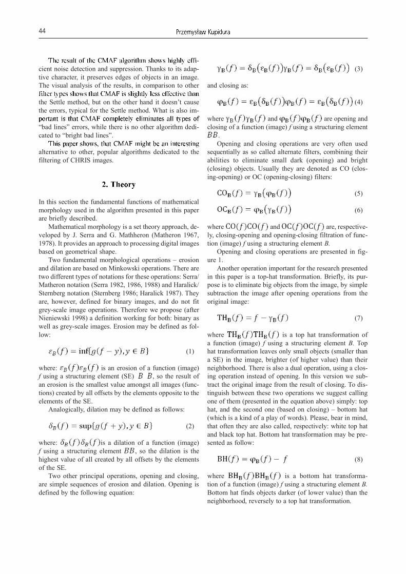
Opening and closing operations are presented in fig-ure 1.
Another operation important for the research presented in this paper is a top-hat transformation. Briefly, its pur-pose is to eliminate big objects from the image, by simple subtraction the image after opening operations from the original image:
(7)
where is a top hat transformation of a function (image) f using a structuring element B. Top hat transformation leaves only small objects (smaller than a SE) in the image, brighter (of higher value) than their neighborhood. There is also a dual operation, using a clos-ing operation instead of opening. In this version we sub-tract the original image from the result of closing. To dis-tinguish between these two operations we suggest calling one of them (presented in the equation above) simply: top hat, and the second one (based on closing) – bottom hat (which is a kind of a play of words). Please, bear in mind, that often they are also called, respectively: white top hat and black top hat. Bottom hat transformation may be pre-sented as follow:
(8)
where is a bottom hat transforma-tion of a function (image) f using a structuring element B. Bottom hat finds objects darker (of lower value) than the neighborhood, reversely to a top hat transformation.
-cient noise detection and suppression. Thanks to its adap-tive character, it preserves edges of objects in an image. The visual analysis of the results, in comparison to other
the Settle method, but on the other hand it doesn’t cause the errors, typical for the Settle method. What is also im-
“bad lines” errors, while there is no other algorithm dedi-cated to “bright bad lines”.
alternative to other, popular algorithms dedicated to the filtering of CHRIS images.
In this section the fundamental functions of mathematical morphology used in the algorithm presented in this paper are briefly described.
Mathematical morphology is a set theory approach, de-veloped by J. Serra and G. Mathheron (Matheron 1967, 1978). It provides an approach to processing digital images based on geometrical shape.
Two fundamental morphological operations – erosion and dilation are based on Minkowski operations. There are two different types of notations for these operations: Serra/Matheron notation (Serra 1982, 1986, 1988) and Haralick/Sternberg notation (Sternberg 1986; Haralick 1987). They are, however, defined for binary images, and do not fit grey-scale image operations. Therefore we propose (after Nieniewski 1998) a definition working for both: binary as well as grey-scale images. Erosion may be defined as fol-low:
(1)
where: is an erosion of a function (image) f using a structuring element (SE) , so the result of an erosion is the smallest value amongst all images (func-tions) created by all offsets by the elements opposite to the elements of the SE.
Analogically, dilation may be defined as follows:
(2)
where: is a dilation of a function (image) f using a structuring element , so the dilation is the highest value of all created by all offsets by the elements of the SE.
Two other principal operations, opening and closing, are simple sequences of erosion and dilation. Opening is defined by the following equation:
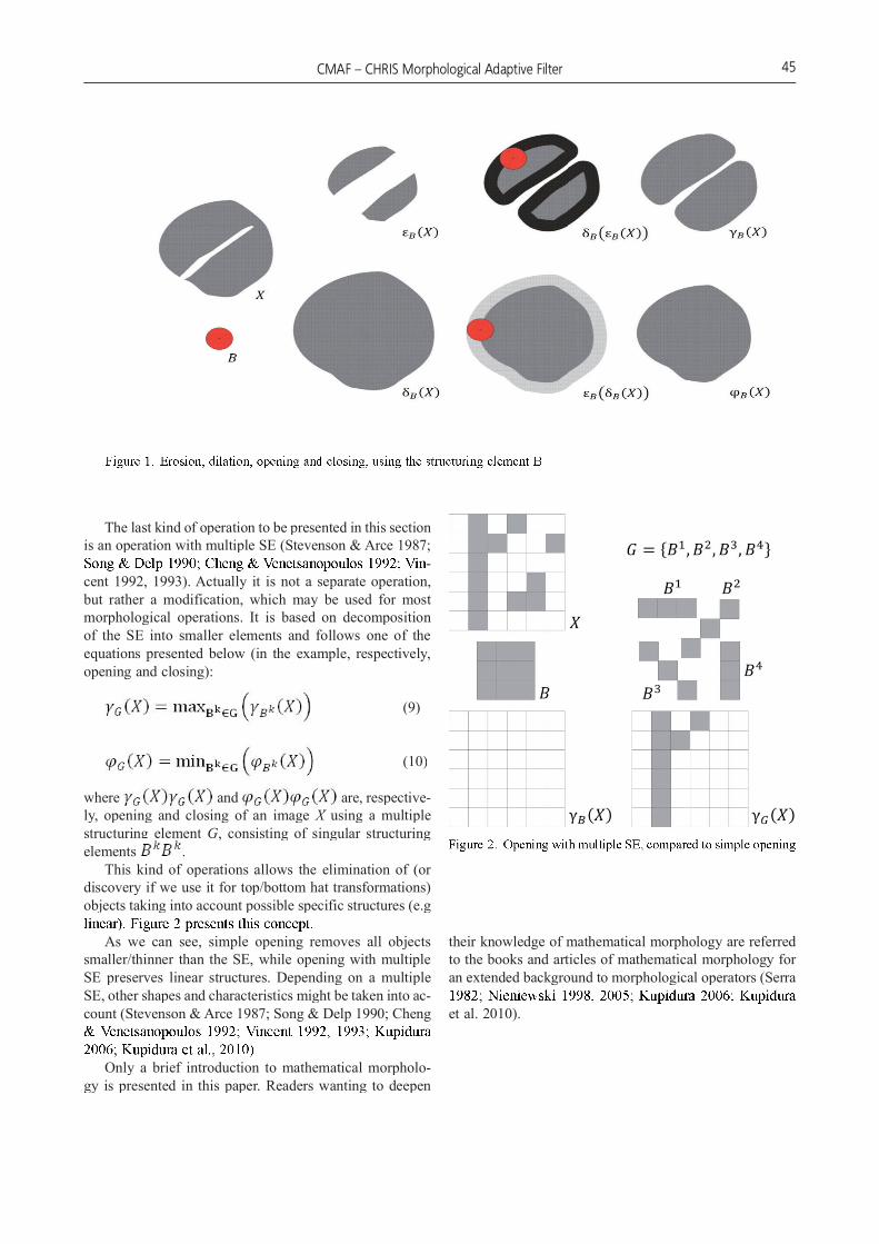
The last kind of operation to be presented in this section is an operation with multiple SE (Stevenson & Arce 1987;
-cent 1992, 1993). Actually it is not a separate operation, but rather a modification, which may be used for most morphological operations. It is based on decomposition of the SE into smaller elements and follows one of the equations presented below (in the example, respectively, opening and closing):
(9)
(10)
where and are, respective-ly, opening and closing of an image X using aX multiple structuring element G, consisting of singular structuring elements .
This kind of operations allows the elimination of (or discovery if we use it for top/bottom hat transformations) objects taking into account possible specific structures (e.g
As we can see, simple opening removes all objects smaller/thinner than the SE, while opening with multiple SE preserves linear structures. Depending on a multiple SE, other shapes and characteristics might be taken into ac-count (Stevenson & Arce 1987; Song & Delp 1990; Cheng
Only a brief introduction to mathematical morpholo-gy is presented in this paper. Readers wanting to deepen
their knowledge of mathematical morphology are referred to the books and articles of mathematical morphology for an extended background to morphological operators (Serra
et al. 2010).
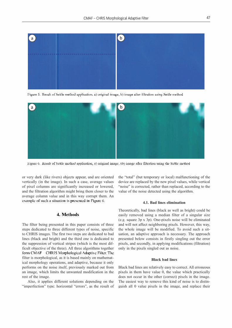
Different kind of the CHRIS images imperfections ap-pears as vertical stripes of different width and different brightness, and should be treated as noise, rather than an error, as it is caused by “normal” though “imperfect” de-vice functioning The example of such noise is presented
Here, also, the value of the stripes differ, so it is dif-ficult to mark them out. The different width of the stripes additionally hampers this task.
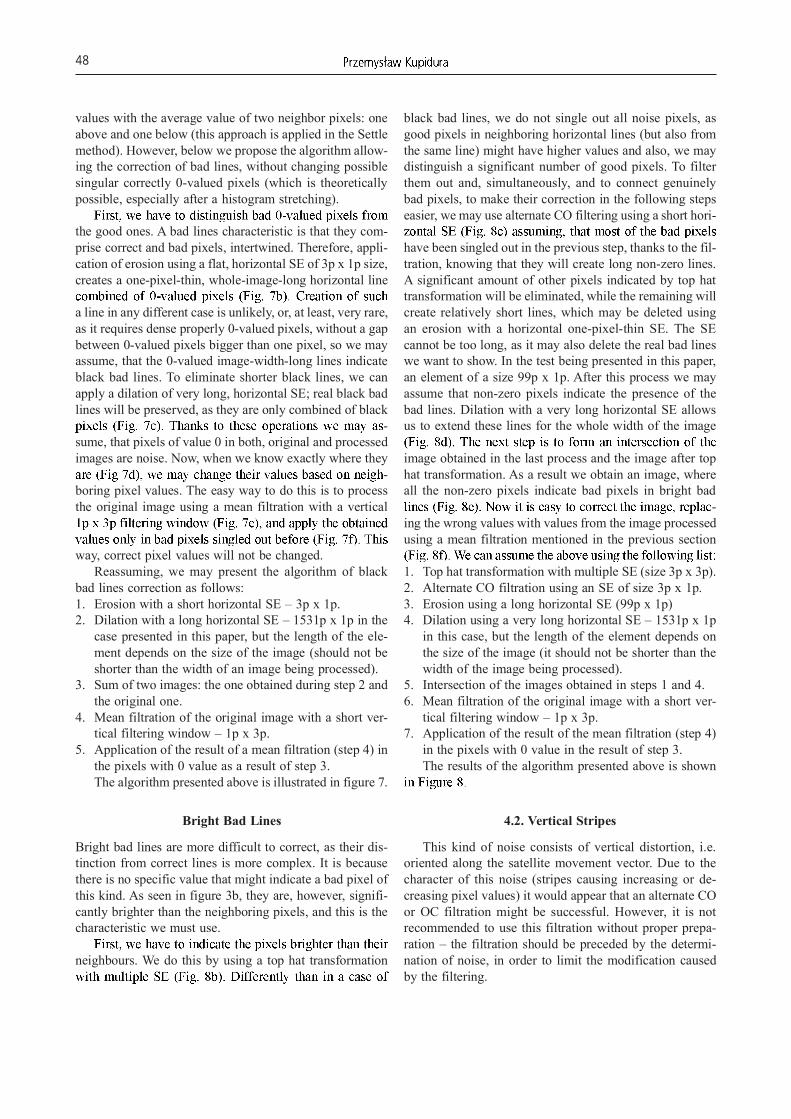
As mentioned in the introduction, the Settle method allows the elimination of at least some of the problems
it deals with vertical stripes, by analyzing all the vertical pixel columns, calculating their average values, and fil-tering the “chart” created this way (much more details in (Cutter 2004; Garcia & Moreno 2004)) which allows the elimination of errors appearing in such a chart as the av-erage values differing significantly from the values of the neighboring lines. In most cases, this method works very
a bright bad line left in the filtered image).Unfortunately, the Settle method might not work prop-
erly in some cases, when large, very bright (like clouds)
3. Problem
The CHRIS/PROBA mission is an important source of data for land and environmental applications. However, some CHRIS images are affected by noise and errors, caused by device imperfection.
There are two main types of the mentioned problems: horizontal, one-pixel thin “bad lines”, comprising correct and bad pixels, intertwined, and vertical, bright or dark stripes of varied thickness (from one to several pixels)
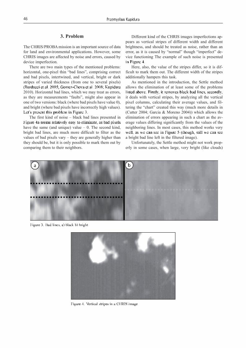
2010). Horizontal bad lines, which we may treat as errors, as they are measurements “faults”, might also appear in one of two versions: black (where bad pixels have value 0), and bright (where bad pixels have incorrectly high values).
The first kind of noise – black bad lines presented in
have the same (and unique) value – 0. The second kind, bright bad lines, are much more difficult to filter as the values of bad pixels vary – they are generally higher than they should be, but it is only possible to mark them out by comparing them to their neighbors.
or very dark (like rivers) objects appear, and are oriented vertically (in the image). In such a case, average values of pixel columns are significantly increased or lowered, and the filtration algorithm might bring them closer to the average column value and in this way corrupt them. An
The filter being presented in this paper consists of three steps dedicated to three different types of noise, specific to CHRIS images. The first two steps are dedicated to bad lines (black and bright) and the third one is dedicated to the suppression of vertical stripes (which is the most dif-the suppression of vertical stripes (which is the most difthe suppression of vertical stripes (which is the most difficult objective of the three). All three algorithms together
filter is morphological, as it is based mainly on mathemat-ical morphology operations, and adaptive, because it only performs on the noise itself, previously marked out from an image, which limits the unwanted modification in the rest of the image.
Also, it applies different solutions depending on the “imperfection” type: horizontal “errors”, as the result of
the “total” (but temporary or local) malfunctioning of the device are replaced by the new pixel values, while vertical “noise” is corrected, rather than replaced, according to the value of the noise detected using the algorithm.
4.1. Bad lines elimination
Theoretically, bad lines (black as well as bright) could be easily removed using a median filter of a singular size (e.g. square 3p x 3p). One-pixels noise will be eliminated and will not affect neighboring pixels. However, this way, the whole image will be modified. To avoid such a sit-uation, an adaptive approach is necessary. The approach presented below consists in firstly singling out the error pixels, and secondly, in applying modifications (filtration) only in the pixels singled out as noise.
Black bad lines
Black bad lines are relatively easy to correct. All erroneous pixels in them have value 0, the value which practically does not occur in the other (correct) pixels in the image. The easiest way to remove this kind of noise is to distin-guish all 0 value pixels in the image, and replace their
values with the average value of two neighbor pixels: one above and one below (this approach is applied in the Settle method). However, below we propose the algorithm allow-ing the correction of bad lines, without changing possible singular correctly 0-valued pixels (which is theoretically possible, especially after a histogram stretching).
the good ones. A bad lines characteristic is that they com-prise correct and bad pixels, intertwined. Therefore, appli-cation of erosion using a flat, horizontal SE of 3p x 1p size, creates a one-pixel-thin, whole-image-long horizontal line
a line in any different case is unlikely, or, at least, very rare, as it requires dense properly 0-valued pixels, without a gap between 0-valued pixels bigger than one pixel, so we may assume, that the 0-valued image-width-long lines indicate black bad lines. To eliminate shorter black lines, we can apply a dilation of very long, horizontal SE; real black bad lines will be preserved, as they are only combined of black
-sume, that pixels of value 0 in both, original and processed images are noise. Now, when we know exactly where they
-boring pixel values. The easy way to do this is to process the original image using a mean filtration with a vertical
way, correct pixel values will not be changed.Reassuming, we may present the algorithm of black
bad lines correction as follows:1. Erosion with a short horizontal SE – 3p x 1p.2. Dilation with a long horizontal SE – 1531p x 1p in the
case presented in this paper, but the length of the ele-ment depends on the size of the image (should not be shorter than the width of an image being processed).
3. Sum of two images: the one obtained during step 2 and the original one.
4. Mean filtration of the original image with a short ver-tical filtering window – 1p x 3p.
5. Application of the result of a mean filtration (step 4) in the pixels with 0 value as a result of step 3.The algorithm presented above is illustrated in figure 7.
Bright Bad Lines
Bright bad lines are more difficult to correct, as their dis-tinction from correct lines is more complex. It is because there is no specific value that might indicate a bad pixel of this kind. As seen in figure 3b, they are, however, signifi-cantly brighter than the neighboring pixels, and this is the characteristic we must use.
neighbours. We do this by using a top hat transformation
black bad lines, we do not single out all noise pixels, as good pixels in neighboring horizontal lines (but also from the same line) might have higher values and also, we may distinguish a significant number of good pixels. To filter them out and, simultaneously, and to connect genuinely bad pixels, to make their correction in the following steps easier, we may use alternate CO filtering using a short hori-
have been singled out in the previous step, thanks to the fil-tration, knowing that they will create long non-zero lines. A significant amount of other pixels indicated by top hat transformation will be eliminated, while the remaining will create relatively short lines, which may be deleted using an erosion with a horizontal one-pixel-thin SE. The SE cannot be too long, as it may also delete the real bad lines we want to show. In the test being presented in this paper, an element of a size 99p x 1p. After this process we may assume that non-zero pixels indicate the presence of the bad lines. Dilation with a very long horizontal SE allows us to extend these lines for the whole width of the image
image obtained in the last process and the image after top hat transformation. As a result we obtain an image, where all the non-zero pixels indicate bad pixels in bright bad
-ing the wrong values with values from the image processed using a mean filtration mentioned in the previous section
1. Top hat transformation with multiple SE (size 3p x 3p).2. Alternate CO filtration using an SE of size 3p x 1p.3. Erosion using a long horizontal SE (99p x 1p)4. Dilation using a very long horizontal SE – 1531p x 1p
in this case, but the length of the element depends on the size of the image (it should not be shorter than the width of the image being processed).
5. Intersection of the images obtained in steps 1 and 4.6. Mean filtration of the original image with a short ver-
tical filtering window – 1p x 3p.7. Application of the result of the mean filtration (step 4)
in the pixels with 0 value in the result of step 3.The results of the algorithm presented above is shown
4.2. Vertical Stripes
This kind of noise consists of vertical distortion, i.e. oriented along the satellite movement vector. Due to the character of this noise (stripes causing increasing or de-creasing pixel values) it would appear that an alternate CO or OC filtration might be successful. However, it is not recommended to use this filtration without proper prepa-ration – the filtration should be preceded by the determi-nation of noise, in order to limit the modification caused by the filtering.
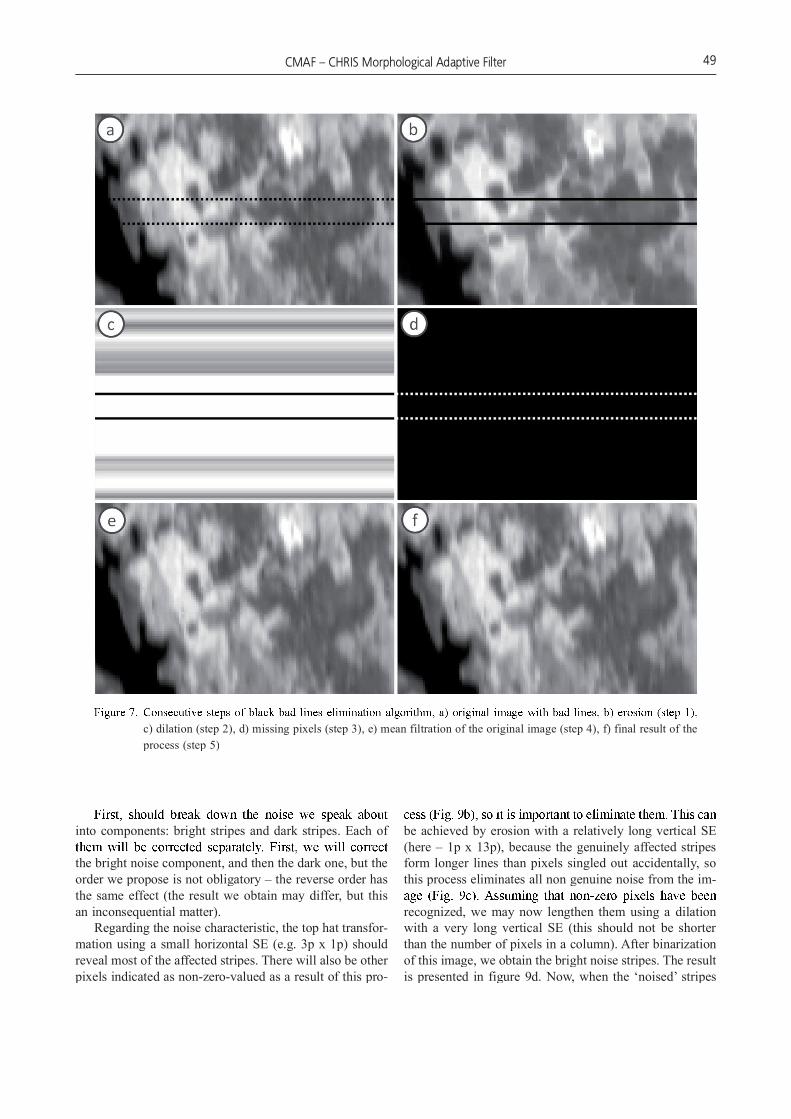
c) dilation (step 2), d) missing pixels (step 3), e) mean filtration of the original image (step 4), f) final result of the process (step 5)
into components: bright stripes and dark stripes. Each of
the bright noise component, and then the dark one, but the order we propose is not obligatory – the reverse order has the same effect (the result we obtain may differ, but this an inconsequential matter).
Regarding the noise characteristic, the top hat transfor-mation using a small horizontal SE (e.g. 3p x 1p) should reveal most of the affected stripes. There will also be other pixels indicated as non-zero-valued as a result of this pro-
be achieved by erosion with a relatively long vertical SE (here – 1p x 13p), because the genuinely affected stripes form longer lines than pixels singled out accidentally, so this process eliminates all non genuine noise from the im-
recognized, we may now lengthen them using a dilation with a very long vertical SE (this should not be shorter than the number of pixels in a column). After binarization of this image, we obtain the bright noise stripes. The result is presented in figure 9d. Now, when the ‘noised’ stripes
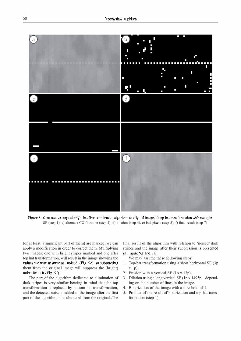
SE (step 1), c) alternate CO filtration (step 2), d) dilation (step 4), e) bad pixels (step 5), f) final result (step 7)
(or at least, a significant part of them) are marked, we can apply a modification in order to correct them. Multiplying two images: one with bright stripes marked and one after top hat transformation, will result in the image showing the
them from the original image will suppress the (bright)
The part of the algorithm dedicated to elimination of dark stripes is very similar bearing in mind that the top transformation is replaced by bottom hat transformation, and the detected noise is added to the image after the first part of the algorithm, not subtracted from the original..The
final result of the algorithm with relation to ‘noised’ dark stripes and the image after their suppression is presented
We may assume these following steps:1. Top-hat transformation using a short horizontal SE (3p
x 1p).2. Erosion with a vertical SE (1p x 13p).3. Dilation using a long vertical SE (1p x 1495p – depend-
ing on the number of lines in the image.4. Binarization of the image with a threshold of 1.5. Product of the result of binarization and top-hat trans-
formation (step 1).
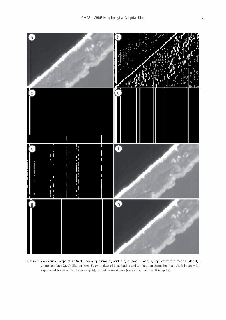
c) erosion (step 2), d) dilation (step 3), e) product of binarization and top-hat transformation (step 5), f) image with suppressed bright noise stripes (step 6), g) dark noise stripes (step 9), h) final result (step 12)
6. Subtracting the result from the original image.7. Bottom hat transformation using a short horizontal SE
(3p x 1p).8. Erosion using a vertical SE (1p x 13p).9. Dilation using a long vertical SE (1p x 1495p – depend-
ing on the number of lines in the image.10. Binarization with a threshold of 1.11. Product of the result of binarization and bottom-hat
transformation (step 7).12. Adding the result to the original image.
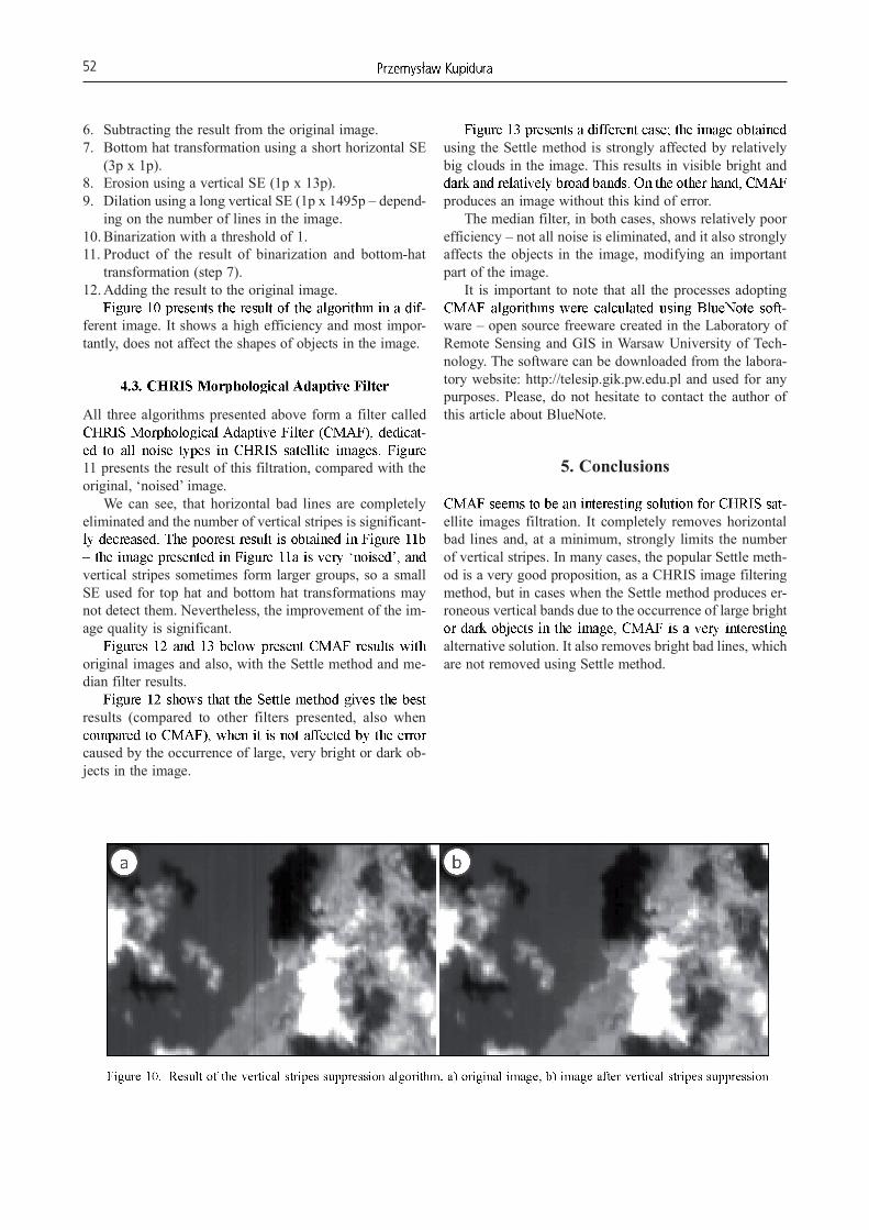
-ferent image. It shows a high efficiency and most impor-tantly, does not affect the shapes of objects in the image.
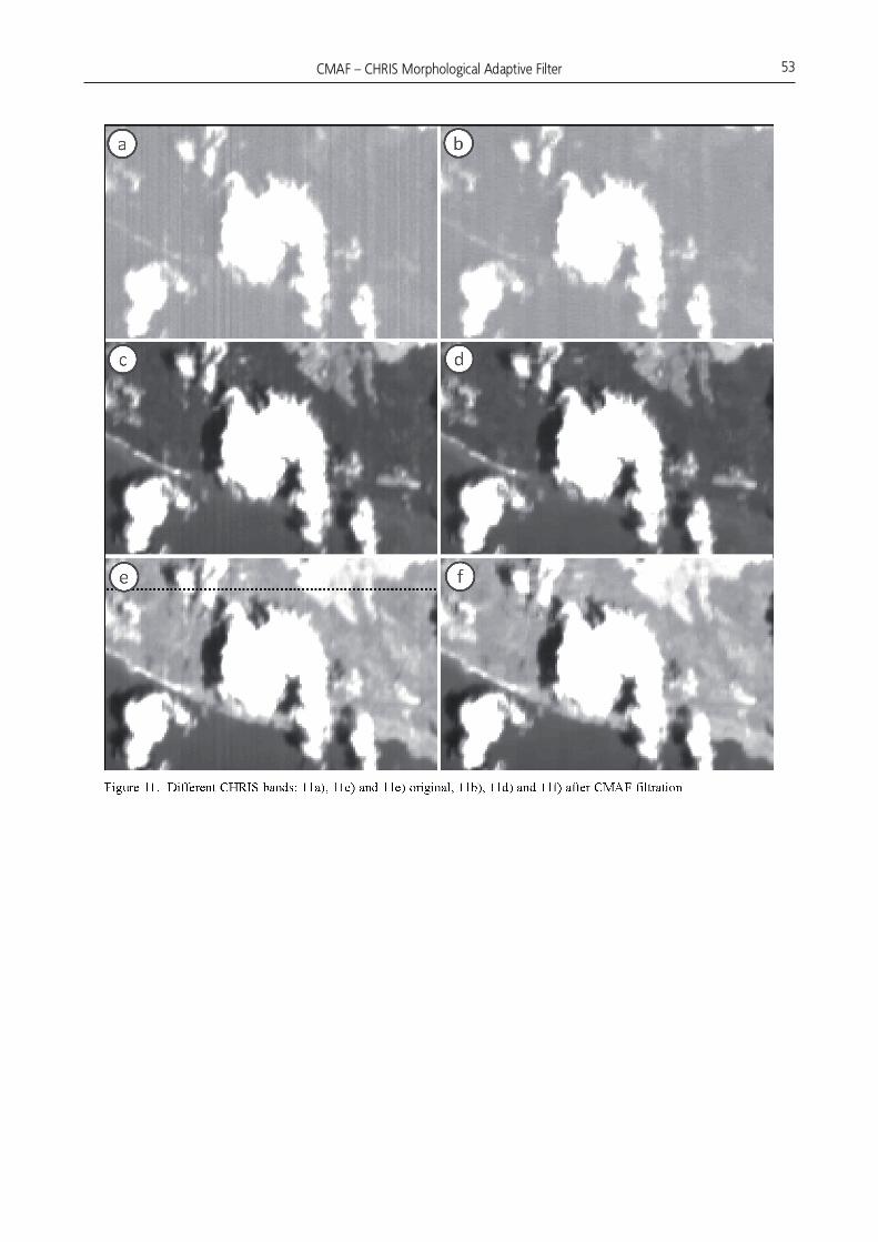
All three algorithms presented above form a filter called -
11 presents the result of this filtration, compared with the original, ‘noised’ image.
We can see, that horizontal bad lines are completely eliminated and the number of vertical stripes is significant-
vertical stripes sometimes form larger groups, so a small SE used for top hat and bottom hat transformations may not detect them. Nevertheless, the improvement of the im-age quality is significant.
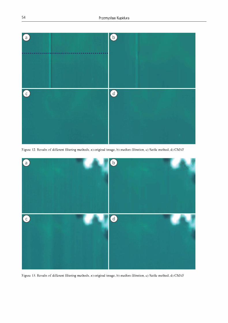
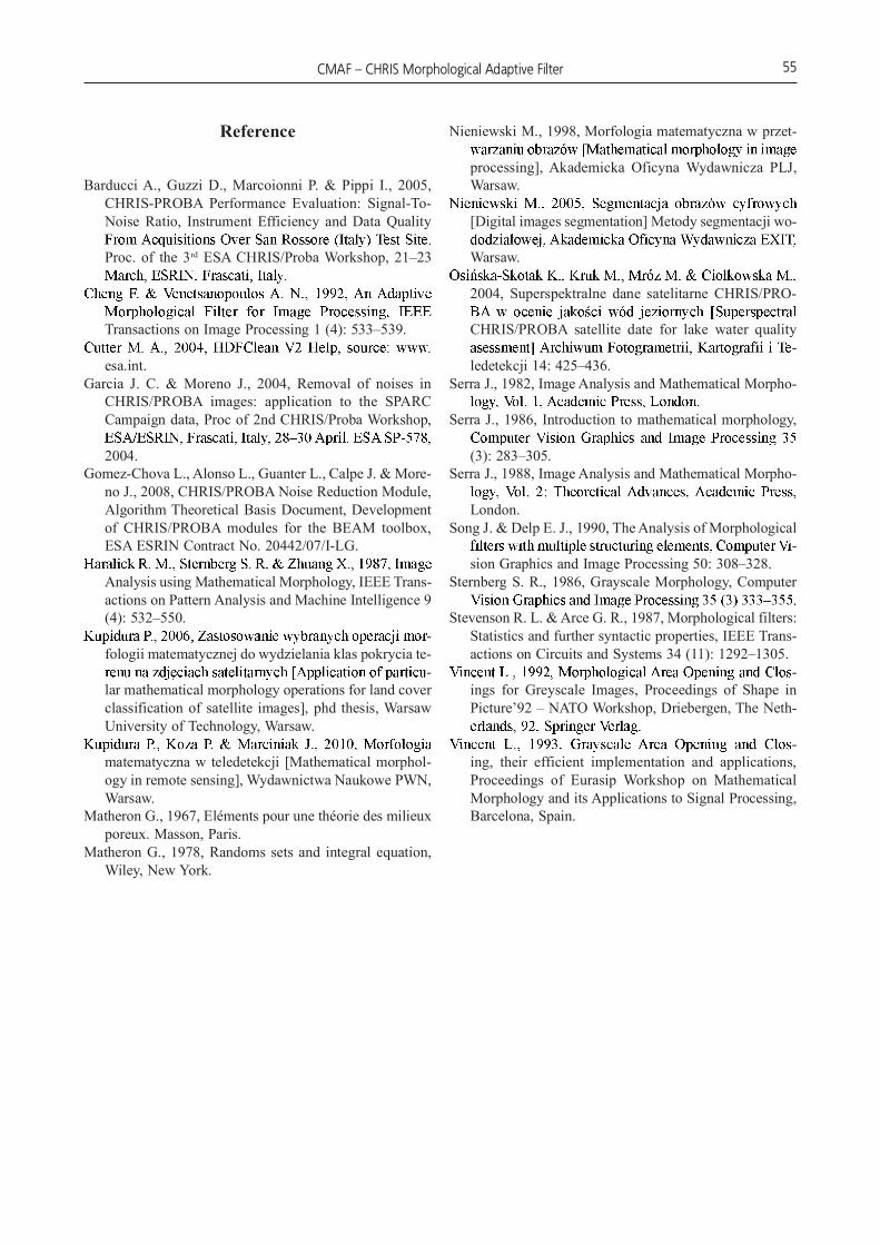
original images and also, with the Settle method and me-dian filter results.
results (compared to other filters presented, also when
caused by the occurrence of large, very bright or dark ob-jects in the image.
using the Settle method is strongly affected by relatively big clouds in the image. This results in visible bright and
produces an image without this kind of error.The median filter, in both cases, shows relatively poor
efficiency – not all noise is eliminated, and it also strongly affects the objects in the image, modifying an important part of the image.
It is important to note that all the processes adopting -
ware – open source freeware created in the Laboratory of Remote Sensing and GIS in Warsaw University of Tech-nology. The software can be downloaded from the labora-tory website: http://telesip.gik.pw.edu.pl and used for any purposes. Please, do not hesitate to contact the author of this article about BlueNote.
5. Conclusions
-ellite images filtration. It completely removes horizontal bad lines and, at a minimum, strongly limits the number of vertical stripes. In many cases, the popular Settle meth-od is a very good proposition, as a CHRIS image filtering method, but in cases when the Settle method produces er-roneous vertical bands due to the occurrence of large bright
alternative solution. It also removes bright bad lines, which are not removed using Settle method.
Reference
Barducci A., Guzzi D., Marcoionni P. & Pippi I., 2005, CHRIS-PROBA Performance Evaluation: Signal-To-Noise Ratio, Instrument Efficiency and Data Quality
Proc. of the 3rd ESA CHRIS/Proba Workshop, 21–23
Transactions on Image Processing 1 (4): 533–539.
esa.int.Garcia J. C. & Moreno J., 2004, Removal of noises in
CHRIS/PROBA images: application to the SPARC Campaign data, Proc of 2nd CHRIS/Proba Workshop,
2004.Gomez-Chova L., Alonso L., Guanter L., Calpe J. & More-
no J., 2008, CHRIS/PROBA Noise Reduction Module, Algorithm Theoretical Basis Document, Development of CHRIS/PROBA modules for the BEAM toolbox, ESA ESRIN Contract No. 20442/07/I-LG.
Analysis using Mathematical Morphology, IEEE Trans-actions on Pattern Analysis and Machine Intelligence 9 (4): 532–550.
-fologii matematycznej do wydzielania klas pokrycia te-
-lar mathematical morphology operations for land cover classification of satellite images], phd thesis, Warsaw University of Technology, Warsaw.
matematyczna w teledetekcji [Mathematical morphol-ogy in remote sensing], Wydawnictwa Naukowe PWN, Warsaw.
Matheron G., 1967, Eléments pour une théorie des milieux poreux. Masson, Paris.
Matheron G., 1978, Randoms sets and integral equation, Wiley, New York.
Nieniewski M., 1998, Morfologia matematyczna w przet-
processing], Akademicka Oficyna Wydawnicza PLJ, Warsaw.
[Digital images segmentation] Metody segmentacji wo-
Warsaw.
2004, Superspektralne dane satelitarne CHRIS/PRO-
CHRIS/PROBA satellite date for lake water quality -
ledetekcji 14: 425–436.Serra J., 1982, Image Analysis and Mathematical Morpho-
Serra J., 1986, Introduction to mathematical morphology,
(3): 283–305.Serra J., 1988, Image Analysis and Mathematical Morpho-
London.Song J. & Delp E. J., 1990, The Analysis of Morpho logical
-sion Graphics and Image Processing 50: 308–328.
Sternberg S. R., 1986, Grayscale Morphology, Computer
Stevenson R. L. & Arce G. R., 1987, Morphological filters: Statistics and further syntactic properties, IEEE Trans-actions on Circuits and Systems 34 (11): 1292–1305.
-ings for Greyscale Images, Proceedings of Shape in Picture’92 – NATO Workshop, Driebergen, The Neth-
-ing, their efficient implementation and applications, Proceedings of Eurasip Workshop on Mathematical Morpho logy and its Applications to Signal Processing, Barcelona, Spain.