Embed Size (px)
Citation preview
Comparisons of embedded and FPGA basedcurrent consumptions measurement device
R.Mahendar1 P.Prakash2
V.Anandh Kumar3
Department of ECE Department of EEEDepartment of ECE Sri Eshwar College of Engineering Easa College of EngineeringSri Eshwar College of Engineering [email protected] [email protected]@gmail.com
Abstract— To Design and develop an FPGAbased current consumption measurementdevice and comparing with embedded basedcurrent consumptions measurement systems.Analyze the uncertainty of themeasurement devices is based on thecurrent conversion to pulse width usingthe external to FPGA capacitor chargingcircuit and comparator. Before making theFPGA based device, simulations will bedone by using TINA-TI. Due to analyzingof both static and dynamic currentconsumption measurement, we have toreduce the dissipation of the externaldevice. A calibration procedure enablingto reduce the in uence of chargingflcircuit component manufacturingtolerances on measurement uncertainty isrecommended. The current measurementdevice is developed and tested by usingembedded system, FPGA based measurementdevice will be developed in future.Simulation of developing prototype deviceis to be checked by using Tina-TIsimulation tool. This simulation tool ishelping to calculate the node voltage,node current, noise calculations andfurther analysis for FPGA implementation.
Keywords— FPGA, TINA-TI, ES
I. INTRODUCTION The power consumption of an
embedded system (ES) is a key issuein today’s high-performance designsand battery-powered devices used forwireless, medical, utility metering,electronic infotainment, and mobilecommunication applications. The key
programmable components of a modernES are a microcontroller and/or aeld-programmable gate array (FPGA).fiThese components, power consumptiondepends on the executed program,operation mode (active or low power),con guration, and data processed.fiSoftware-related power is notconstant and may uctuations inflresponse to the running software orFPGA con guration. fi
Loosely defined as, this researchis to perform a current measurementuncertainty analysis for bothembedded and FPGA based currentmeasurement device. The uncertaintyis important when design team workingwith different instances of theEmbedded System need to compare theCurrent Consumption of their designs.The comparison of measured currentsonly makes sense when the measurementuncertainty is known. It is assumedthat the measurement setup cannot becalibrated using any referenceequipment,[3] and therefore, theuncertainty can be estimated usinginformation available frommanufacturers of components composingthe measurement setup and informationgained from simulation orexperimental measurements of thesetup. The motivation of thisproject is an accurate measurementfor low power embedded systems and
reduces power mismatching in overflowpower consumptions, because of usingFPGA. It is vital that engineeringpractice would adapt efforts tominimize the power consumption ofequipment in every design cycle topotentially save several hundreds ofmilliwatts per electronic unit. Thismeans that minimizing powerconsumption could equate toconsiderable energy savings on bothnational and international scales[6], [5]. To pave the road towardminimizing ES power consumptiondesign teams must be aware ofappropriate tools and solutions thatare inexpensive and convenientintegrated into standard design ow.flJ-Link Ultra is a tool highlyintegrated with the IAR ElectronicWorkbench development environment[3].The environment can display thepower consumption pro le with respectfito the software executed by theembedded microprocessor. Power Scaleoffers similar features and has anopen interface for use with variousdevelopment environments. However,none of these tools are intended forFPGA-based ES power consumptionmonitoring [9], [10]. Therefore, acomparison is required.II. EMBEDDED SYSTEM POWER CONSUMPTION
MEASUREMENTEstimation of embedded systems
(ES) power consumption is becoming astandard step in the developmentcycle of battery powered equipment.The importance of the powerconsumption is well realized by thevendors of integrated circuits,especially microprocessors and fieldprogrammable gate arrays (FPGA). Theissue is also targeted by thedesigners of ES development tools. Itis also covered in the researchpublications. Power consumption andtherefore its estimation is a keyissue in designing battery powereddevices in the field of wireless,medical, utility metering, etc.,applications [8]. The less power is
consumed by the electronics thelonger it will continue functioningwithout recharging or changing thebattery. This is not only improvesthe convenience of device user, butis also important from the ecologicalpoint of view. Herewith belowmicrowatts measurement is difficultto measure by using pure embeddedsystems. The development of ultra-lowpower electronics opened apossibility to create an absolutelynew class of ES scavenging anecessary energy for their operationfrom the ambient. In the largerenergy sector the key issue is theenergy dissipation of the integratedcircuits that leads to the need ofcooling equipment and expensivepackages.
The key component of today’s ESis microcontroller and/or FPGA. Bothare user programmable units and theirpower consumption depends upon theexecuted programs and data processed.Therefore, so called software relatedpower is widely considered Having inmind that most of modernmicrocontrollers and FPGAs aredesigned for run time switchingbetween active and low power modes,the software related power is thepart of the overall power consumptionbudget that can be optimized duringdevelopment of a system. To be ableto minimize power consumption methodsand tools for its estimation areneeded.
A. Approaches of Power Measurements In
Embedded System
There exist two main approachestowards estimation of the powerconsumption of ES containingprogrammable unit: simulation basedand measurement based. The simulationbased approach uses models relatingpower consumption and programminginstructions. This type of tools isbecoming a standard utility in theFPGA design packages like Altera
Power Play or Synopsys Power Compiler[2].
The second approach is based on
physical measurements of powerconsumption while running the systemunder development. While themeasurement based approach requiresmeasurement instruments and in mostof the cases, special setups insidethe Embedded system. It does notsuffer from the inadequacy or evenabsence of reliable models. To addmore, measurement approach is theonly way to verify correctness of thesimulation based approach. Therefore,measurement is important to validatethe power consumption models.
III. GENERALIZED POWER DELIVERY
MODEL
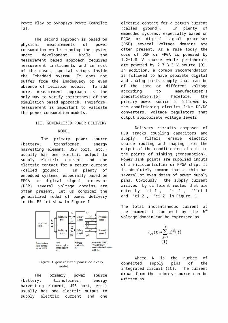
The primary power source(battery, transformer, energyharvesting element, USB port, etc.)usually has one electric output tosupply electric current and oneelectric contact for a return current(called ground). In plenty ofembedded systems, especially based onFPGA or digital signal processor(DSP) several voltage domains areoften present. Let us consider thegeneralized model of power deliveryin the ES let show in Figure 1
Figure 1 generalized power deliverymodel
The primary power source(battery, transformer, energyharvesting element, USB port, etc.)usually has one electric output tosupply electric current and one
electric contact for a return current(called ground). In plenty ofembedded systems, especially based onFPGA or digital signal processor(DSP) several voltage domains areoften present. As a rule today thecore of DSP or FPGA is powered by1.2−1.8 V source while peripheralsare powered by 2.7−3.3 V source [9].In addition, a common recommendationis followed to have separate digitaland analog parts supply that can beof the same or different voltageaccording to manufacturer’sspecification.[6] Therefore, theprimary power source is followed bythe conditioning circuits like DC/DCconverters, voltage regulators thatoutput appropriate voltage levels.
Delivery circuits composed ofPCB tracks coupling capacitors andsupply, filters ensure electricsource routing and shaping from theoutput of the conditioning circuit tothe points of sinking (consumption).Power sink points are supplied inputsof a microcontroller or FPGA chip. Itis absolutely common that a chip hasseveral or even dozen of power supplypins. Obviously the supply currentarrives by different routes that arenoted by 'ci 1 , ''ci 1 , '''ci 1and 'ci 2 , ''ci 2 in Figure. 1.
The total instantaneous current atthe moment t consumed by the kth
voltage domain can be expressed as
ick(t)=∑j=1
Nic
(j)(t)
(1)
Where N is the number ofconnected supply pins of theintegrated circuit (IC). The currentdrawn from the primary source can bewritten as
is (t )=∑k=1
kick(t)+icondk(t)
(2)
Where icondhk is the currentconsumed in the operation of theconditioning circuit (for examplevoltage regulator, DC/DC converter,etc.).
The instantaneous powerconsumption can be expressed, P(t)=is (t ). us(t)(3)
The total energy consumed from
the primary source in the timeinterval from t1 to t2 can beexpressed as
E=∫t1
t2
is(t).us (t ). dt
(4)Where us (t) is the
instantaneous voltage between thepoles of primary source. As powerunits nw are often used while μJ, NJor PJ is used in case of energycharacterization. Power units areusually estimated for long periodaveraged consumption, but energyunits are used to characterize shortevents like energy consumed toexecute an instruction of themicrocontroller.
IV. POWER CONSUMPTION
MEASUREMENT METHODS
Measurement approach is theonly way to verify correctness of thesimulation based approach. Therefore,measurement is important to validatethe power consumption models. Belowmodels can explain the variousmeasurement models. A. Current Shunt Method
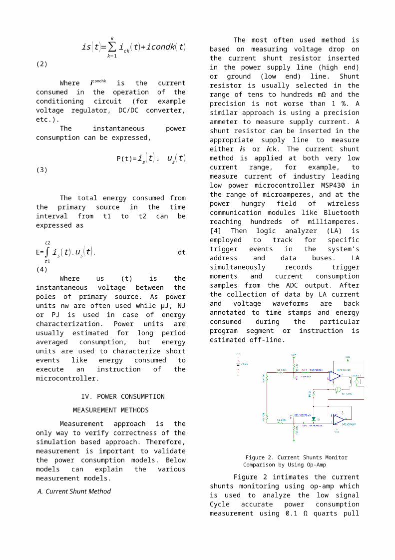
The most often used method isbased on measuring voltage drop onthe current shunt resistor insertedin the power supply line (high end)or ground (low end) line. Shuntresistor is usually selected in therange of tens to hundreds mΩ and theprecision is not worse than 1 %. Asimilar approach is using a precisionammeter to measure supply current. Ashunt resistor can be inserted in theappropriate supply line to measureeither is or ick. The current shuntmethod is applied at both very lowcurrent range, for example, tomeasure current of industry leadinglow power microcontroller MSP430 inthe range of microamperes, and at thepower hungry field of wirelesscommunication modules like Bluetoothreaching hundreds of milliamperes.[4] Then logic analyzer (LA) isemployed to track for specifictrigger events in the system’saddress and data buses. LAsimultaneously records triggermoments and current consumptionsamples from the ADC output. Afterthe collection of data by LA currentand voltage waveforms are backannotated to time stamps and energyconsumed during the particularprogram segment or instruction isestimated off-line.
Figure 2. Current Shunts MonitorComparison by Using Op-Amp
Figure 2 intimates the currentshunts monitoring using op-amp whichis used to analyze the low signalCycle accurate power consumptionmeasurement using 0.1 Ω quarts pull
shunt resistor followed by the 200 to500 MHz bandwidth differentialamplifier is described in reference.Sampling frequency of 80 MHz and 8bit ADC are used in the currentmeasurement setup. Software sourcecode is instrumented with specialtrigger points and is executed inreal time on the target processor.
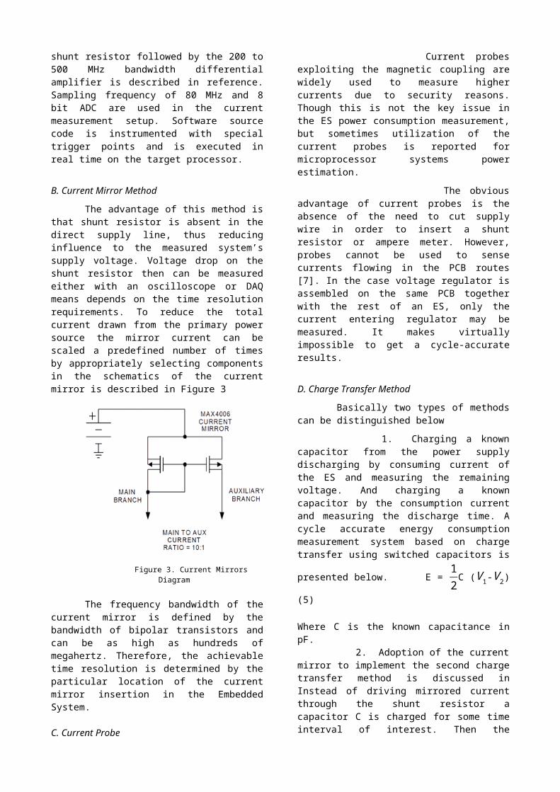
B. Current Mirror Method
The advantage of this method isthat shunt resistor is absent in thedirect supply line, thus reducinginfluence to the measured system’ssupply voltage. Voltage drop on theshunt resistor then can be measuredeither with an oscilloscope or DAQmeans depends on the time resolutionrequirements. To reduce the totalcurrent drawn from the primary powersource the mirror current can bescaled a predefined number of timesby appropriately selecting componentsin the schematics of the currentmirror is described in Figure 3
Figure 3. Current MirrorsDiagram
The frequency bandwidth of thecurrent mirror is defined by thebandwidth of bipolar transistors andcan be as high as hundreds ofmegahertz. Therefore, the achievabletime resolution is determined by theparticular location of the currentmirror insertion in the EmbeddedSystem.
C. Current Probe
Current probesexploiting the magnetic coupling arewidely used to measure highercurrents due to security reasons.Though this is not the key issue inthe ES power consumption measurement,but sometimes utilization of thecurrent probes is reported formicroprocessor systems powerestimation.
The obviousadvantage of current probes is theabsence of the need to cut supplywire in order to insert a shuntresistor or ampere meter. However,probes cannot be used to sensecurrents flowing in the PCB routes[7]. In the case voltage regulator isassembled on the same PCB togetherwith the rest of an ES, only thecurrent entering regulator may bemeasured. It makes virtuallyimpossible to get a cycle-accurateresults.
D. Charge Transfer Method
Basically two types of methodscan be distinguished below 1. Charging a knowncapacitor from the power supplydischarging by consuming current ofthe ES and measuring the remainingvoltage. And charging a knowncapacitor by the consumption currentand measuring the discharge time. Acycle accurate energy consumptionmeasurement system based on chargetransfer using switched capacitors is
presented below. E = 12C (
V1-V2)
(5)
Where C is the known capacitance inpF. 2. Adoption of the currentmirror to implement the second chargetransfer method is discussed inInstead of driving mirrored currentthrough the shunt resistor acapacitor C is charged for some timeinterval of interest. Then the
capacitor C is switched off from thecharging circuit and its dischargetime is measured. The discharge timeis proportional to the currentconsumed during the interval ofobservation. During the dischargephase of the capacitor C anothercapacitor is switched to be chargedby the mirror current. Chargetransfer methods are suitable forcycle-accurate power consumptionmeasurement, though they are morecomplex to implement compared to thecurrent measurement using shuntresistor.
V. SIMULATION TOOLS
TINA-TI
Tina-TI is a SPICE-Based AnalogSimulation Program is designed anddistributed by Design-Soft and TexasInstruments TINA is a Spice-basedcircuit simulator running in theMicrosoft Windows Operating system.It can do circuit DC, AC, Transient,Fourier, noise analysis. Theinterface of the TINA-TI SPICE-BasedAnalog Simulation Program is verynice and easy to use.
The Tina-TI simulator is basedon the industry standard SPICEsimulator and is freely distributedtogether with many simulation modelsfor components like the CSA andcomparator used in this work. Selectthe circuit components the TI analogIC’s using the tabs located thecomponents outlines. Once a componenthas been selected it’s just a matterof positioning it on the grid withthe mouse. The “spice macro” tabaccesses the library of Tina analogdevices: op-amps, different amps,differential amplifiers, andregulators, shunt, current monitors,etc... Additional Pspice models canalso be inserted in the circuit usingthe “macro insert” function found byclicking on the “insert”. In thisexample INA193 op-amp was insertedusing this macro function.
Xilinx Development Environment
The simulation tool is used aspart of the Quartus II CAD system,and is intended for students who aretaking a course in logic circuitdesign. This tutorial shows how touse the Simulation Waveform Editor toperform a simulation of a circuitspeci ed in Verilog HDL. Only a veryfibasic understanding of Verilog isneeded for this purpose. The PartialReconfiguration (PR) feature in theQuartus II software allows you torecon a portion of the FPGAdynamically, while the remainder ofthe device continues to operate. TheQuartus II software supports the PRfeature in the Altera®Stratix® Vdevice family.
Synthesis tools optimize HDLcode for both logic utilization andperformance; however, synthesis toolshave no information about the purposeor intent of the design. The bestoptimizations often require consciousinteraction with the designer Forstyle recommendations, options, orHDL attributes specific to yoursynthesis tool (including Quartus ®II integrated synthesis and other EDAtools). Altera providesparameterizable mega functions thatare optimized for Altera devicearchitectures. Using mega functionsinstead of coding your own logicsaves valuable design time.Additionally, the Altera-providedmega functions may offer a moreefficient logic synthesis and deviceimplementation. You can scale themega function’s size and specifyvarious options by settingparameters. Mega functions includethe library of parameterized modules(LPM) and Altera device-specific megafunctions.
VI. MEASUREMENT CIRCUIT
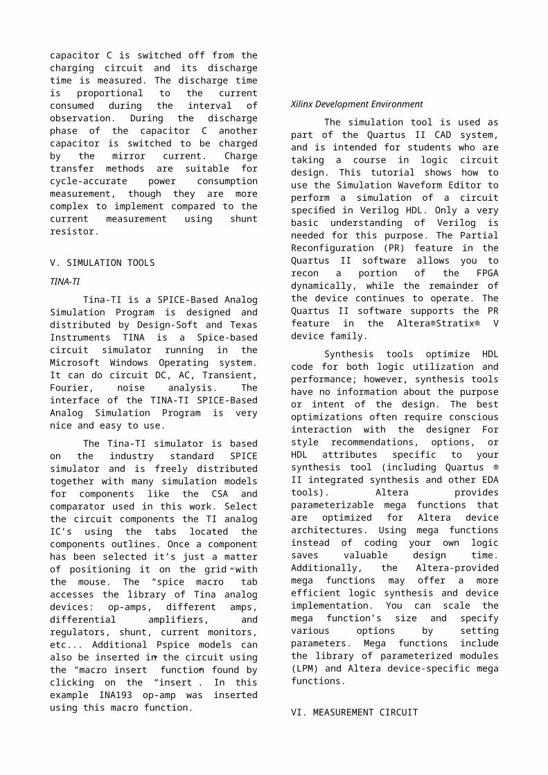
The most popular and leastexpensive current sensing methodutilizing a shunt resistor is usuallyimplemented using a current shuntampli er (CSA) or differentialfiampli er followed by an analog-to-fidigital converter is displayed inFigure 4. Since measurement circuitthe supply voltage of an ES with FPGAis usually kept constantly in anarrow range, for example, 1.20 ±0.05 V or 3.30 ± 0.05 V, then powerestimation mainly deals with theestimation of the current.
Power estimation techniquescan be separated into on-chip andexternal according to the placementof the measurement circuitry. On chiptechniques usually employ extrasemiconductor components manufacturedtogether with the main chip(microprocessor) at the siliconlevel.
A well suited technique thatrequires only an external shuntresistor, low-pin-count integratedampli er, comparator, and a fewfipassive components are proposed. Therest of the measurement circuit issynthesized from FPGA resources. Atypical current measurement setupcontains the current-sensing circuitand the analog voltage conversion todigital code. The conversion of theampli er output voltage to digitalficode can be done.
Figure 4: measurement circuit
VII SIMULATION RESULTS
A. Design of Current Consumption Measurement
Circuit
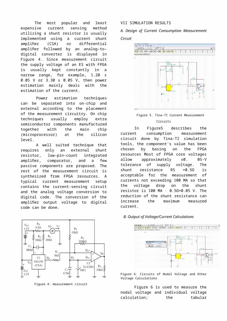
Figure 5. Tina-TI Current Measurement
Circuits
In Figure5 describes thecurrent consumption measurementcircuit done by Tina-TI simulationtools, the component's value has beenchosen by basing on the FPGAresources Most of FPGA core voltagesallow approximately ±0. 05-Vtolerance of supply voltage. Theshunt resistance RS =0.5Ω isacceptable for the measurement ofcurrents not exceeding 100 MA so thatthe voltage drop on the shuntresistor is 100 MA · 0.5Ω=0.05 V. Thereduction of the shunt resistance canincrease the maximum measuredcurrent.
B. Output of Voltage/Current Calculations
Figure 6. Circuits of Nodal Voltage and OtherVoltage Calculations
Figure 6 is used to measure thenodal voltage and individual voltagecalculation; the tabular
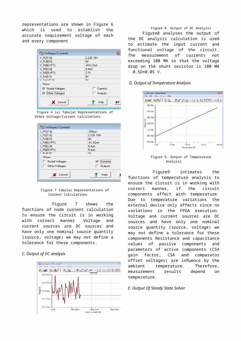
representations are shown in Figure 6which is used to establish theaccurate requirement voltage of eachand every component
Figure 6 (a) Tabular Representations ofOther Voltage/Current Calculations
Figure 7 Tabular Representations ofCurrent Calculations
Figure 7 shows thefunctions of node current calculationto ensure the circuit is in workingwith correct manner .Voltage andcurrent sources are DC sources andhave only one nominal source quantity(source, voltage) we may not define atolerance for these components.
C. Output of DC analysis
Figure 8. Output of DC AnalysisFigure8 analyses the output of
the DC analysis calculation is usedto estimate the input current andfunctional voltage of the circuit.The measurement of currents notexceeding 100 MA so that the voltagedrop on the shunt resistor is 100 MA· 0.5Ω=0.05 V.
D. Output of Temperature Analysis
Figure 9. Output of TemperatureAnalysis
Figure9 intimates thefunctions of temperature analysis toensure the circuit is in working withcorrect manner, if the circuitcomponents affect with temperature.Due to temperature variations theexternal device only affects since novariations in the FPGA execution.Voltage and current sources are DCsources and have only one nominalsource quantity (source, voltage) wemay not define a tolerance for thesecomponents Resistance and capacitancevalues of passive components andparameters of active components (CSAgain factor, CSA and comparatoroffset voltages) are in uence by theflambient temperature. Therefore,measurement results depend ontemperature.
E. Output Of Steady State Solver
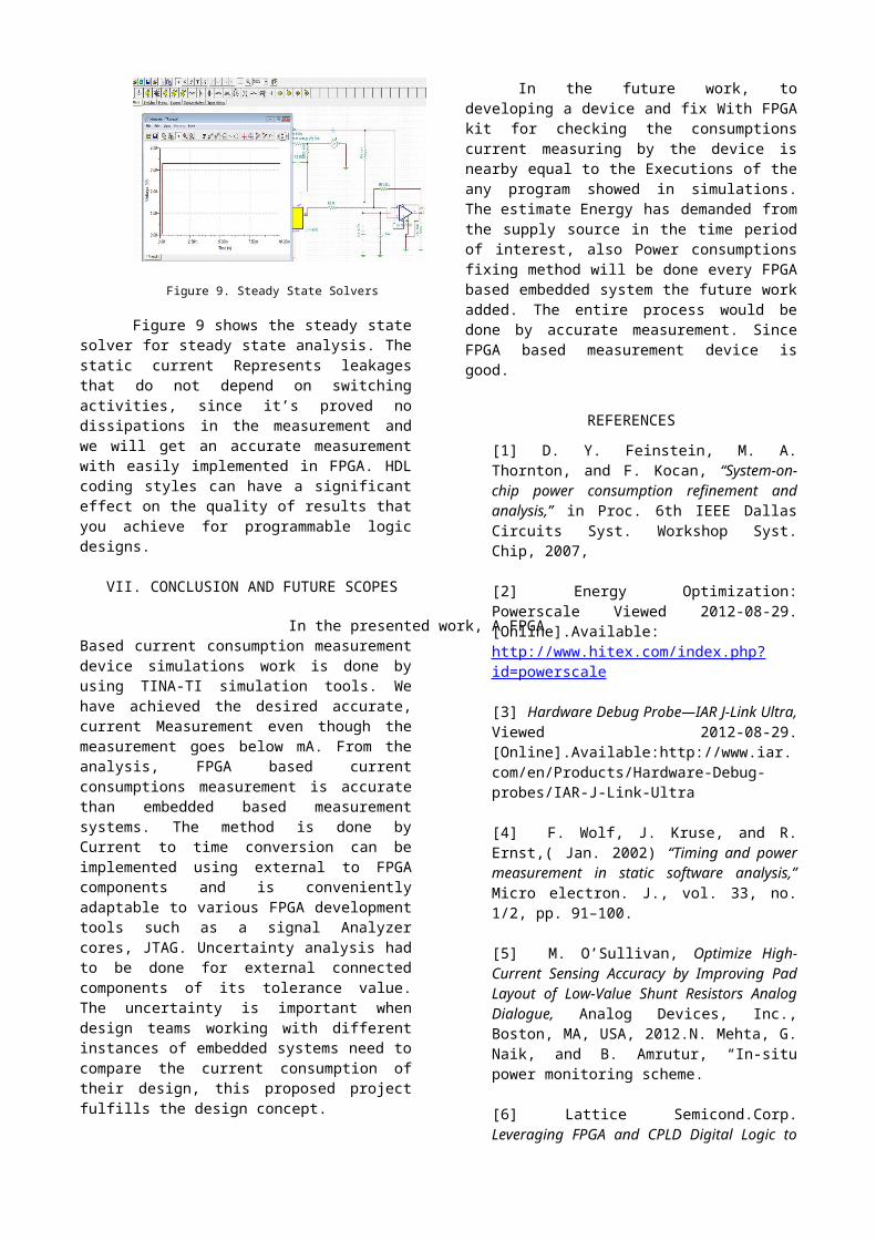
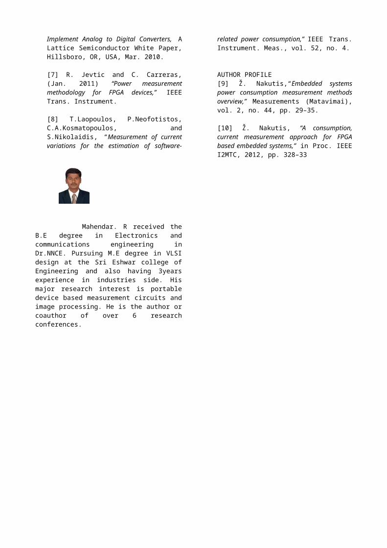
Figure 9. Steady State Solvers
Figure 9 shows the steady statesolver for steady state analysis. Thestatic current Represents leakagesthat do not depend on switchingactivities, since it’s proved nodissipations in the measurement andwe will get an accurate measurementwith easily implemented in FPGA. HDLcoding styles can have a significanteffect on the quality of results thatyou achieve for programmable logicdesigns.
VII. CONCLUSION AND FUTURE SCOPES
In the presented work, A FPGABased current consumption measurementdevice simulations work is done byusing TINA-TI simulation tools. Wehave achieved the desired accurate,current Measurement even though themeasurement goes below mA. From theanalysis, FPGA based currentconsumptions measurement is accuratethan embedded based measurementsystems. The method is done byCurrent to time conversion can beimplemented using external to FPGAcomponents and is convenientlyadaptable to various FPGA developmenttools such as a signal Analyzercores, JTAG. Uncertainty analysis hadto be done for external connectedcomponents of its tolerance value.The uncertainty is important whendesign teams working with differentinstances of embedded systems need tocompare the current consumption oftheir design, this proposed projectfulfills the design concept.
In the future work, todeveloping a device and fix With FPGAkit for checking the consumptionscurrent measuring by the device isnearby equal to the Executions of theany program showed in simulations.The estimate Energy has demanded fromthe supply source in the time periodof interest, also Power consumptionsfixing method will be done every FPGAbased embedded system the future workadded. The entire process would bedone by accurate measurement. SinceFPGA based measurement device isgood.
REFERENCES
[1] D. Y. Feinstein, M. A.Thornton, and F. Kocan, “System-on-chip power consumption refinement andanalysis,” in Proc. 6th IEEE DallasCircuits Syst. Workshop Syst.Chip, 2007,
[2] Energy Optimization:Powerscale Viewed 2012-08-29.[Online].Available:http://www.hitex.com/index.php?id=powerscale
[3] Hardware Debug Probe—IAR J-Link Ultra,Viewed 2012-08-29.[Online].Available:http://www.iar.com/en/Products/Hardware-Debug-probes/IAR-J-Link-Ultra
[4] F. Wolf, J. Kruse, and R.Ernst,( Jan. 2002) “Timing and powermeasurement in static software analysis,”Micro electron. J., vol. 33, no.1/2, pp. 91–100.
[5] M. O’Sullivan, Optimize High-Current Sensing Accuracy by Improving PadLayout of Low-Value Shunt Resistors AnalogDialogue, Analog Devices, Inc.,Boston, MA, USA, 2012.N. Mehta, G.Naik, and B. Amrutur, “In-situpower monitoring scheme.
[6] Lattice Semicond.Corp.Leveraging FPGA and CPLD Digital Logic to
Implement Analog to Digital Converters, ALattice Semiconductor White Paper,Hillsboro, OR, USA, Mar. 2010.
[7] R. Jevtic and C. Carreras,(Jan. 2011) “Power measurementmethodology for FPGA devices,” IEEETrans. Instrument.
[8] T.Laopoulos, P.Neofotistos,C.A.Kosmatopoulos, andS.Nikolaidis, “Measurement of currentvariations for the estimation of software-
related power consumption,” IEEE Trans.Instrument. Meas., vol. 52, no. 4.
AUTHOR PROFILE[9] Ž. Nakutis,“Embedded systemspower consumption measurement methodsoverview,” Measurements (Matavimai),vol. 2, no. 44, pp. 29–35.
[10] Ž. Nakutis, “A consumption,current measurement approach for FPGAbased embedded systems,” in Proc. IEEEI2MTC, 2012, pp. 328–33
Mahendar. R received theB.E degree in Electronics andcommunications engineering inDr.NNCE. Pursuing M.E degree in VLSIdesign at the Sri Eshwar college ofEngineering and also having 3yearsexperience in industries side. Hismajor research interest is portabledevice based measurement circuits andimage processing. He is the author orcoauthor of over 6 researchconferences.