Embed Size (px)
Citation preview
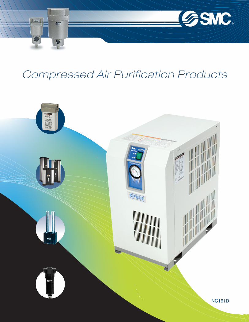
Compressed Air Purification Products
NC161D
Table of Contents
Quick Reference Guide
Model Selection Guide
Refrigerated Dryers
High Inlet Temperature Refrigerated Dryers
Membrane Air Dryers
Heatless Desiccant Compressed Air Dryers
Heatless Desiccant Air Dryers
Dew Point Conversion Chart
Compressed Air Filters
Large Capacity Compressed Air Filters
Related Products
Digital Pneumatic Products Builder
3
4,5
6, 7
8, 9
10, 11
12, 13
14
15
16 - 19
20, 21
22
23
1) Compressor hp ratings are provided for reference only and are based on commercially available sizes with nominal efficiencies, consult compressor manufacturer for actual ratings.2) Rated flow is at 37ºF pressure dew point at 100 psi. Performance is based on CAGI standard AF100 conditions: 100 psi inlet pressure, 100ºF inlet and ambient temperature.3) Pairing is based on dryer and filter flow ratings, not necessarily piping size.
1) Compressor hp ratings are provided for reference only and are based on commercially available sizes with nominal efficiencies, consult compressor manufacturer for actual ratings.2) Rated flow is at 50ºF pressure dew point at 100 psi. Performance is based on the following conditions: 100 psi inlet pressure, 180ºF inlet and 100ºF ambient temperature.3) Pairing is based on dryer and filter flow ratings, not necessarily piping size.4) Series AFF is limited to 140ºF inlet/ambient temperature, use series AFW for higher temperatures.
Quick Reference Guide for Air Purification Products• Shows standard combinations. The suffix numbers of the model indicate voltage, drain, indicators, etc. Refer to individual product info for details.• Pairings with compressors are provided for reference purposes only. Always confirm actual performance/ratings and operating conditions in making selections.• Combine filtration equipment as required for desired air quality• After-cooling can be accomplished with air or water cooled after coolers or other means to reduce the inlet air temperature to acceptable levels.
235
7.5101520305060
35
7.510152030506075
RotaryScrew
Air CompressorPower (hp)1) Dryer Air Flow
Capacity(scfm)2)
MainLine
Filter3)
MistSeparator3)
Micro MistSeparator
w/pre-filter3)
Micro MistSeparator3)
Super MistSeparator3)
OdorRemoval
Separator3)ReciprocatingAfter-cooling
Inlet airtemperature
must bereduced to100ºF forrated flow,max. 120ºF
Refrigerated Dryers
RefrigeratedAir Dryer
IDFB3E-IDFB4E-IDFB6E-IDFB8E-IDFB11E-IDFB15E-IDFB22E-IDFB37E-IDFB55E-IDFB75E-
AMH250C-N03AMH250C-N03AMH350C-N04AMH450C-N06AMH450C-N06AMH450C-N06AMH550C-N10AMH650-N14AMH850-N20AMH850-N20
AME250C-N03AME250C-N03AME350C-N04AME450C-N06AME450C-N06AME450C-N06AME550C-N10AME650-N14AME850-N20AME850-N20
4.26.18.614.321.930.937.547.8
5.78.311.719.429.742.050.964.9
RotaryScrew
Air CompressorPower (hp)1) Dryer Air Flow
Capacity(scfm)1)
MainLine
Filter4)
MistSeparator3)
Micro MistSeparator
w/pre-filter3),4)
Micro MistSeparator3)
Super MistSeparator3)
OdorRemoval
Separator3)ReciprocatingAfter-cooling
Inlet airtemperature
not to exceed180ºF
RefrigeratedAir Dryer
IDU6E-IDU8E-IDU11E-
IDU15E1-IDU22E-IDU37E-IDU55E-IDU75E-
AMH350C-N04AMH350C-N04AMH450C-N06AMH450C-N06AMH550C-N10AMH650-N14AMH650-N14AMH850-N20
AME350C-N04AME350C-N04AME450C-N06AME450C-N06AME550C-N10AME650-N14AME650-N14AME850-N20
High Inlet Temperature Refrigerated Dryers
0.81
1.5235
7.510101515202530505075
11.52
2.53510101515202530505075100
RotaryScrew
Dryer Air FlowCapacity(scfm)2)
HeatlessDesiccantAir Dryer
Main LineFilter3)
MistSeparator3)
Micro MistSeparator
w/pre-filter3)
Micro MistSeparator3)
Super MistSeparator3)
OdorRemoval
Separator3)ReciprocatingAfter-cooling
Inlet airtemperature
must be reducedto 100ºF for ratedflow, max. 120ºF
AM350C-N04AM450C-N06AM450C-N06AM550C-N10AM550C-N10AM650-N14AM650-N14AM850-N20AM850-N20AM850-N20
AMH450C-N06AMH450C-N06AMH450C-N06AMH550C-N10AMH550C-N10AMH650-N14AMH650-N14AMH850-N20AMH850-N20AMH850-N20
AFW30-N03-EA (provided with dryer)
AMD450C-N06AMD450C-N06AMD450C-N06AMD550C-N10AMD550C-N10AMD650-N14AMD650-N14AMD850-N20AMD850-N20AMD850-N20
AME150C-N02AME150C-N02AME250C-N03AME250C-N03AME250C-N03AME350C-N04AME350C-N04AME450C-N06AME450C-N06AME450C-N06AME550C-N10AME550C-N10AME650-N14AME650-N14AME850-N20AME850-N20AME850-N20
1) Compressor hp ratings are provided for reference only and are based on commercially available sizes with nominal efficiencies, consult compressor manufacturer for actual ratings.2) Rated flow is at -40ºF pressure dew point at 100 psi. Performance is based on CAGI standard AF100 conditions: 100 psi inlet pressure, 100ºF inlet and ambient temperature.3) Pairing is based on dryer and filter flow ratings, not necessarily piping size.
Heatless Regenerative DryersAir Compressor
Power (hp)1)
Quick Reference GuideTable of Contents
101525415971107161226300
AFF2C-N02AFF4C-N03AFF4C-N03AFF8C-N04AFF11C-N06AFF11C-N06AFF22C-N10AFF37B-N14AFF75B-N20AFF75B-N20
AM150C-N02AM250C-N03AM250C-N03AM350C-N04AM450C-N06AM450C-N06AM550C-N10AM650-N14AM850-N20AM850-N20
AMD250C-N03AMD250C-N03AMD350C-N04AMD450C-N06AMD450C-N06AMD450C-N06AMD550C-N10AMD650-N14AMD850-N20AMD850-N20
AMF250C-N03AMF250C-N03AMF350C-N04AMF450C-N06AMF450C-N06AMF450C-N06AMF550C-N10AMF650-N14AMF850-N20AMF850-N20
20294168104147178227
AFF4C-N03AFF8C-N04AFF8C-N04AFF11C-N06AFF22C-N06AFF37B-N14AFF37B-N14AFF75B-N20
AM250C-N03AM350C-N04AM350C-N04AM450C-N06AM550C-N10AM650-N14AM650-N14AM850-N20
AMD350C-N04AMD350C-N04AMD450C-N06AMD450C-N06AMD550C-N10AMD650-N14AMD650-N14AMD850-N20
AMF350C-N04AMF350C-N04AMF450C-N06AMF450C-N06AMF550C-N10AMF650-N14AMF650-N14AMF850-N20
4681015253545556585105135175215275365
AFF2C-N02AFF2C-N02AFF2C-N02AFF2C-N02AFF4C-N03AFF4C-N03AFF8C-N04AFF8C-N04AFF11C-N06AFF11C-N06AFF22C-N10AFF22C-N10AFF37B-N14AFF37B-N14AFF75B-N20AFF75B-N20AFF75B-N20
IDW04NIDW06NIDW08NIDW10NIDW15NIDW25NIDW35NIDW45NIDW55NIDW65NIDW85NIDW105NIDW135NIDW175NIDW215NIDW275NIDW365N
AMF150C-N02AMF150C-N02AMF250C-N03AMF250C-N03AMF250C-N03AMF350C-N04AMF350C-N04AMF450C-N06AMF450C-N06AMF450C-N06AMF550C-N10AMF550C-N10AMF650-N14AMF650-N14AMF850-N20AMF850-N20AMF850-N20
32
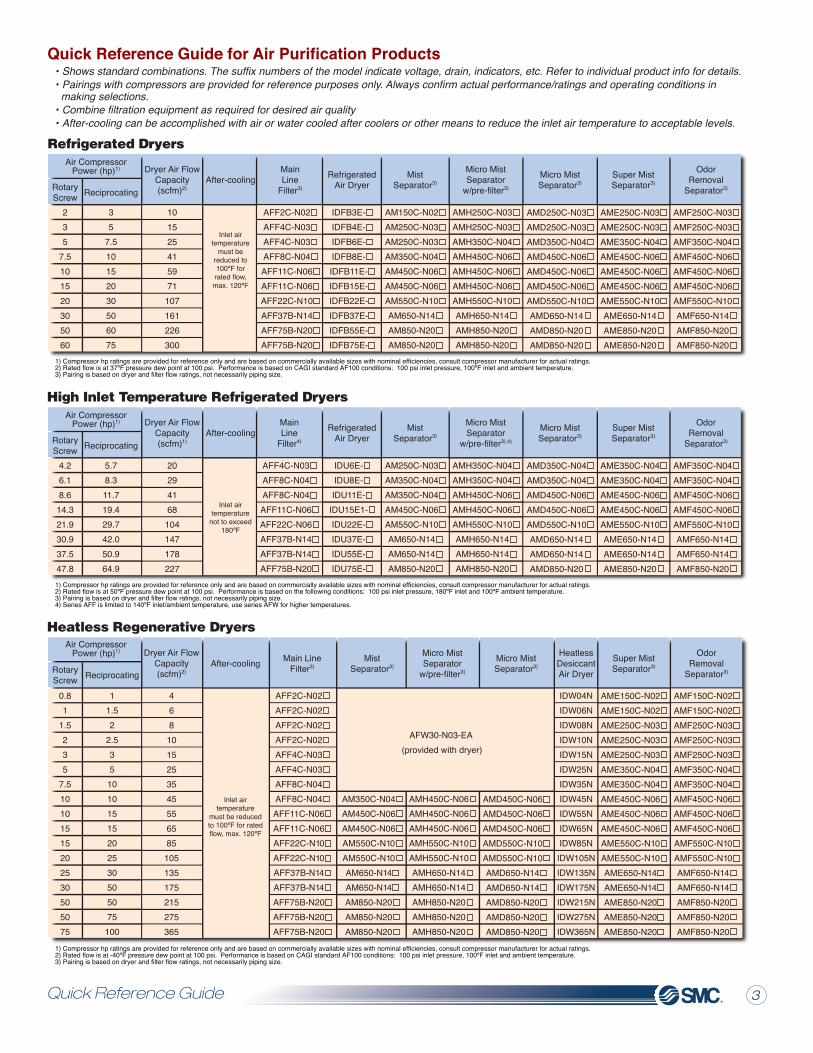
Table of Contents
Quick Reference Guide
Model Selection Guide
Refrigerated Dryers
High Inlet Temperature Refrigerated Dryers
Membrane Air Dryers
Heatless Desiccant Compressed Air Dryers
Heatless Desiccant Air Dryers
Dew Point Conversion Chart
Compressed Air Filters
Large Capacity Compressed Air Filters
Related Products
Digital Pneumatic Products Builder
3
4,5
6, 7
8, 9
10, 11
12, 13
14
15
16 - 19
20, 21
22
23
1) Compressor hp ratings are provided for reference only and are based on commercially available sizes with nominal efficiencies, consult compressor manufacturer for actual ratings.2) Rated flow is at 37ºF pressure dew point at 100 psi. Performance is based on CAGI standard AF100 conditions: 100 psi inlet pressure, 100ºF inlet and ambient temperature.3) Pairing is based on dryer and filter flow ratings, not necessarily piping size.
1) Compressor hp ratings are provided for reference only and are based on commercially available sizes with nominal efficiencies, consult compressor manufacturer for actual ratings.2) Rated flow is at 50ºF pressure dew point at 100 psi. Performance is based on the following conditions: 100 psi inlet pressure, 180ºF inlet and 100ºF ambient temperature.3) Pairing is based on dryer and filter flow ratings, not necessarily piping size.4) Series AFF is limited to 140ºF inlet/ambient temperature, use series AFW for higher temperatures.
Quick Reference Guide for Air Purification Products• Shows standard combinations. The suffix numbers of the model indicate voltage, drain, indicators, etc. Refer to individual product info for details.• Pairings with compressors are provided for reference purposes only. Always confirm actual performance/ratings and operating conditions in making selections.• Combine filtration equipment as required for desired air quality• After-cooling can be accomplished with air or water cooled after coolers or other means to reduce the inlet air temperature to acceptable levels.
235
7.5101520305060
35
7.510152030506075
RotaryScrew
Air CompressorPower (hp)1) Dryer Air Flow
Capacity(scfm)2)
MainLine
Filter3)
MistSeparator3)
Micro MistSeparator
w/pre-filter3)
Micro MistSeparator3)
Super MistSeparator3)
OdorRemoval
Separator3)ReciprocatingAfter-cooling
Inlet airtemperature
must bereduced to100ºF forrated flow,max. 120ºF
Refrigerated Dryers
RefrigeratedAir Dryer
IDFB3E-IDFB4E-IDFB6E-IDFB8E-IDFB11E-IDFB15E-IDFB22E-IDFB37E-IDFB55E-IDFB75E-
AMH250C-N03AMH250C-N03AMH350C-N04AMH450C-N06AMH450C-N06AMH450C-N06AMH550C-N10AMH650-N14AMH850-N20AMH850-N20
AME250C-N03AME250C-N03AME350C-N04AME450C-N06AME450C-N06AME450C-N06AME550C-N10AME650-N14AME850-N20AME850-N20
4.26.18.614.321.930.937.547.8
5.78.311.719.429.742.050.964.9
RotaryScrew
Air CompressorPower (hp)1) Dryer Air Flow
Capacity(scfm)1)
MainLine
Filter4)
MistSeparator3)
Micro MistSeparator
w/pre-filter3),4)
Micro MistSeparator3)
Super MistSeparator3)
OdorRemoval
Separator3)ReciprocatingAfter-cooling
Inlet airtemperature
not to exceed180ºF
RefrigeratedAir Dryer
IDU6E-IDU8E-IDU11E-
IDU15E1-IDU22E-IDU37E-IDU55E-IDU75E-
AMH350C-N04AMH350C-N04AMH450C-N06AMH450C-N06AMH550C-N10AMH650-N14AMH650-N14AMH850-N20
AME350C-N04AME350C-N04AME450C-N06AME450C-N06AME550C-N10AME650-N14AME650-N14AME850-N20
High Inlet Temperature Refrigerated Dryers
0.81
1.5235
7.510101515202530505075
11.52
2.535
10101515202530505075
100
RotaryScrew
Dryer Air FlowCapacity(scfm)2)
HeatlessDesiccantAir Dryer
Main LineFilter3)
MistSeparator3)
Micro MistSeparator
w/pre-filter3)
Micro MistSeparator3)
Super MistSeparator3)
OdorRemoval
Separator3)ReciprocatingAfter-cooling
Inlet airtemperature
must be reducedto 100ºF for ratedflow, max. 120ºF
AM350C-N04AM450C-N06AM450C-N06AM550C-N10AM550C-N10AM650-N14AM650-N14AM850-N20AM850-N20AM850-N20
AMH450C-N06AMH450C-N06AMH450C-N06AMH550C-N10AMH550C-N10AMH650-N14AMH650-N14AMH850-N20AMH850-N20AMH850-N20
AFW30-N03-EA (provided with dryer)
AMD450C-N06AMD450C-N06AMD450C-N06AMD550C-N10AMD550C-N10AMD650-N14AMD650-N14AMD850-N20AMD850-N20AMD850-N20
AME150C-N02AME150C-N02AME250C-N03AME250C-N03AME250C-N03AME350C-N04AME350C-N04AME450C-N06AME450C-N06AME450C-N06AME550C-N10AME550C-N10AME650-N14AME650-N14AME850-N20AME850-N20AME850-N20
1) Compressor hp ratings are provided for reference only and are based on commercially available sizes with nominal efficiencies, consult compressor manufacturer for actual ratings.2) Rated flow is at -40ºF pressure dew point at 100 psi. Performance is based on CAGI standard AF100 conditions: 100 psi inlet pressure, 100ºF inlet and ambient temperature.3) Pairing is based on dryer and filter flow ratings, not necessarily piping size.
Heatless Regenerative DryersAir Compressor
Power (hp)1)
Quick Reference GuideTable of Contents
101525415971
107161226300
AFF2C-N02AFF4C-N03AFF4C-N03AFF8C-N04AFF11C-N06AFF11C-N06AFF22C-N10AFF37B-N14AFF75B-N20AFF75B-N20
AM150C-N02AM250C-N03AM250C-N03AM350C-N04AM450C-N06AM450C-N06AM550C-N10AM650-N14AM850-N20AM850-N20
AMD250C-N03AMD250C-N03AMD350C-N04AMD450C-N06AMD450C-N06AMD450C-N06AMD550C-N10AMD650-N14AMD850-N20AMD850-N20
AMF250C-N03AMF250C-N03AMF350C-N04AMF450C-N06AMF450C-N06AMF450C-N06AMF550C-N10AMF650-N14AMF850-N20AMF850-N20
20294168
104147178227
AFF4C-N03AFF8C-N04AFF8C-N04AFF11C-N06AFF22C-N06AFF37B-N14AFF37B-N14AFF75B-N20
AM250C-N03AM350C-N04AM350C-N04AM450C-N06AM550C-N10AM650-N14AM650-N14AM850-N20
AMD350C-N04AMD350C-N04AMD450C-N06AMD450C-N06AMD550C-N10AMD650-N14AMD650-N14AMD850-N20
AMF350C-N04AMF350C-N04AMF450C-N06AMF450C-N06AMF550C-N10AMF650-N14AMF650-N14AMF850-N20
468
1015253545556585
105135175215275365
AFF2C-N02AFF2C-N02AFF2C-N02AFF2C-N02AFF4C-N03AFF4C-N03AFF8C-N04AFF8C-N04AFF11C-N06AFF11C-N06AFF22C-N10AFF22C-N10AFF37B-N14AFF37B-N14AFF75B-N20AFF75B-N20AFF75B-N20
IDW04NIDW06NIDW08NIDW10NIDW15NIDW25NIDW35NIDW45NIDW55NIDW65NIDW85N
IDW105NIDW135NIDW175NIDW215NIDW275NIDW365N
AMF150C-N02AMF150C-N02AMF250C-N03AMF250C-N03AMF250C-N03AMF350C-N04AMF350C-N04AMF450C-N06AMF450C-N06AMF450C-N06AMF550C-N10AMF550C-N10AMF650-N14AMF650-N14AMF850-N20AMF850-N20AMF850-N20
32
Model Selection Guide4 5
A
B
C
D
E
F
G
H
Separation
Deodorization
Water droplet sep.
Separation,Filtration
Separation,Filtration
Separation,Filtration
Dehumidification
Dehumidification
Dehumidification
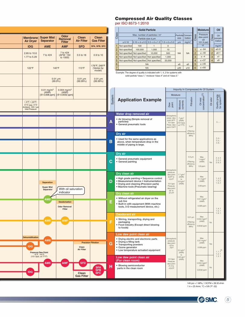
Compressed Air Purification System Series Selection Guide
Air tank is not required for screw compressors since pulsation is small, but required when it
is used to accumulate pressure.
Compressed Air Quality Classesper ISO 8573-1:2010
Application Example
Syst
em
(Filteringefficiency
99%)
3 µm
(Filteringefficiency
99%)
0.3 µm
(Filteringefficiency
99%)
0.01 µm
Max.1 mg/m3
(ANR)
0.8 ppm
Max.0.1 mg/m3
(ANR)
0.08 ppm
Max.0.01 mg/m3
(ANR)
0.008 ppm
Max.0.004 mg/m3
(ANR)
0.0032 ppm
Max.0.004 mg/m3
(ANR)
0.0032 ppm
Max.0.01 mg/m3
(ANR)
0.008 ppm
Yes
Yes
No
No
Moisture
Dew
poin
t
Moi
stur
eco
nten
ts
Atmosphericpress. dewpoint 42°F101.5psi
Press. dewpoint 104°F
Atmosphericpressuredew point6.8°F to–9.4°F
101.5psiPressuredew point
59 to 37.4°F
Atmosphericpressuredew point
–22 to–76°F
101.5psiPressuredew point
21.2 to–43.6°F
7 g/m3
(ANR)(101.5psi,at 77°F)
Impurity In Compressed Air Of System
1.7 g/m3
(ANR)to
0.8 g/m3
(ANR)
0.5 g/m3
(ANR)to
0.02 g/m3
(ANR)
Note 1) When inlet oil mist concentration (compressor discharge concentration) is approx. 30 mg/m3 (ANR) or less.Note 2) This describes the grade of compressed air quality based on ISO8573-1: 2010 (JIS B8392-1: 2003), which is the maximum quality grade for the system. It varies, however, depending on inlet air conditions.Note 3) Please contact SMC since this can be manufactured as a special order (depending on the operating conditions).
3, -, -
3, 4, -3, 5, -3, 6, -
2, 4, 32, 5, 32, 6, 3
1, 4, 21, 5, 21, 6, 2
1, 4, 11, 5, 11, 6, 1
1, 1, 11, 2, 11, 3, 1
(3)
1234
Oil
Oilconcen-tration
mg/m3
≤0.01≤0.1≤1≤5
123456
≤ –94≤ –40≤ –4
≤ +37≤ +45≤ +50
Pressuredew point
(at101.5 psi)
°F
Moisture
1234567
Not specifiedNot specifiedNot specifiedNot specifiedNot specified
100100,000
Not specifiedNot specifiedNot specified
11,000
10,000Not specifiedNot specified
010
5001,000
20,000
≤ 0.10 0.10 < d ≤ 0.5 0.5 < d ≤ 1.0 1.0 < d ≤ 5.0
Max. number of particles / m3
Particle size d µm
NANA
Solid Particle
Particlesize
Concen-tration
µm mg/m3
NA
≤5≤40
NA
≤5≤10
Example: The degree of quality is indicated with 1, 4, 2 for systems with solid particle “class 1,” moisture “class 4” and oil “class 2.”
Clas
s
Clas
s
Clas
sFi
ltrat
ion
Oil
odor
Qua
lity
grad
efo
r sys
tem
(2)
Oil m
istco
ncen
tratio
n(1)
SFA, SFB, SFCAME AMF
OdorRemoval
FilterSuper MistSeparator
CleanGas Filter
0.01 µm(99.99%)
0.01 µm(99.9%)
0.004 mg/m3
(ANR)[@ 0.0032 ppm]
0.01 mg/m3
(ANR)[@ 0.008 ppm]
176°F, 248°F(Varies by
model)140°F
7 to 4247 to 424
(AFW: 150to 1500)
0.9 to 10
SFD
CleanAir Filter
0.01 µm(99.99%)
113°F
3.5 to 18
CleanGas Filter
CleanAir Filter
Super Mist Separator
Odor Removal Filter
Pressure Dew Point–4°F, –44°F
(101.5psi, at 77°F)
145 psi = 1 MPa, 1 SCFM = 28.32 l/min1 in = 25.4mm, °C = 5/9 (°F -32)
ApplicableAir
Compressor:3 Hp To3000 Hp
Description
Capacity26 to
793 gal
Air Tank After-cooler
AT HAA, HAW IDFBAFF/AFW
Air Cooled After-cooler
or Water Cooled
After-cooler
Main Line Filter
Air Tank
Main LineFilter Refrigerated Air Dryer
Series
Max. Inlet AirTemperature
Filtration(Filtering
Efficiency)
Reciprocating Air
Compressor
RotaryScrew Air
Compressor
Outlet Oil MistConcentration
(Max.)(1)
PressureDew Point
212°F140°F(250ºFAFW)
140°F(250ºF AFW)
140°F(250ºF AFW)
3 µm(99%)
122°F
FlowCapacity
Scfm
35 to 201
10 to 635
158°F, 356°F(Varies by Model)
158°F
10 to 1500 10 to 300
IDU
RefrigeratedAir Dryer
(High Inlet AirTemperature
Type)
RefrigeratedAir Dryer
180°F
11 to 120
OutletAir Pressure
Dew Point37.4°F
(100psi at180°F inlet)
OutletAir Pressure
Dew Point37.4°F
(100psi at100°F inlet)
ApplicableAir
Compressor:3 hp to100 hp
ApplicableAir
Compressor:1 hp to100 hp
Main Line Sub Line Local Line
AMG AMH AMD IDG IDGAM ID
Water Separator
Mist Separator
Micro MistSeparator
Micro Mist Separator w/
Pre-filter
WaterSeparator
HeatlessAir Dryer
MistSeparator
Micro MistSeparator
w/ Pre-filterMicro MistSeparator
MembraneAir Dryer
MembraneAir Dryer
0.3 µm(99.9%)
0.01 µm(99.9%)
Water droplet removal ratio
99%
0.01 µm(With 0.3 mm
pre-filter)
1 mg/m3(ANR)[@ 0.8 ppm]
0.1 mg/m3 (ANR)[@ 0.08 ppm]
122°F, 131°F(Varies
by model)122°F
10 to 424(AFW: 150 to 1500) 2.82 to 27.54 7 to 424
7 to 424(AFW: 150to 1500)
0.35 to 35.31
Membrane Air Dryer
PressureDew Point
PressureDew Point
122°F
2.65 to 10.61.77 to 5.29
• Air blowing (Simple removal of particles)• General pneumatic tools
• Used for the same applications as above, when temperature drop in the middle of piping is large.
• General pneumatic equipment• General painting
• High grade painting • Sequence control• Measurement device • Instrumentation• Drying and cleaning (Precision parts)• Machine tools (Pneumatic bearing)
• Without refrigerated air dryer on the sub line• Built-in with equipment (With machine tools, 3-D measurement device, etc.)
• Stirring, transporting, drying and packaging• Food industry (Except direct blowing to foods)
• Drying electric and electronic parts• Drying a filling tank• Transporting powders• Ozone generator• Low temperature actuated equipment
• Blowing semiconductor parts in the clean room
-4°F -44°F+ 37.4°F100°F Inlet,
100°F Ambient100 psi Inlet
Pressure
77°F Inlet, 77°FAmbient, 105.1 psi
Inlet Pressure
180°F Inlet,100°F Ambient
100 psi InletPressure
HAA orHAW
Not required when integrated in an air compressor.
AFF
Our U.S. warranty states that the customer must
use an AFF filter or equivalent before refrigerated dryer.
AT AFF
IDFB
HAA orHAW
Not required when integrated in an air compressor.
+55°F77°F Inlet, 77°F
Ambient, 105.1 psiInlet Pressure
+43°F95°F Inlet, 95°F
Ambient, 105.1 psiInlet Pressure
+16.2°F+ 37.4°F -26.2°F
AM
AM
AM ID
IDAM
AMG
AMH
AMD
AMH
AMH
AMD16.2°F, –26.2°F
(101.5psi,at 95°F)
Water drop removed air
Dry air
Dry air
Dry clean air
Dry clean air
Deodorant air
Low dew point clean air
Low dew point clean air(For clean room)
AMEPrecision Filtration
AMD
IDG
43°F, 55°F(101.5psi,at 77°F)
With 0.3 µm pre-filter/Integrated AM + AMD
Separation,Filtration
PulsationAttenuation,
Accumulation,Cooling
IDG
AMFAME SFD
IDGIDU AMHSFASFBSFC
Cooling
AME
With oil saturation indicator
Heatless Air Dryer
Dehumidification
AM
AMH
AMD AME AMF
Model Selection Guide4 5
A
B
C
D
E
F
G
H
Separation
Deodorization
Water droplet sep.
Separation,Filtration
Separation,Filtration
Separation,Filtration
Dehumidification
Dehumidification
Dehumidification
Compressed Air Purification System Series Selection Guide
Air tank is not required for screw compressors since pulsation is small, but required when it
is used to accumulate pressure.
Compressed Air Quality Classesper ISO 8573-1:2010
Application Example
Syst
em
(Filteringefficiency
99%)
3 µm
(Filteringefficiency
99%)
0.3 µm
(Filteringefficiency
99%)
0.01 µm
Max.1 mg/m3
(ANR)
0.8 ppm
Max.0.1 mg/m3
(ANR)
0.08 ppm
Max.0.01 mg/m3
(ANR)
0.008 ppm
Max.0.004 mg/m3
(ANR)
0.0032 ppm
Max.0.004 mg/m3
(ANR)
0.0032 ppm
Max.0.01 mg/m3
(ANR)
0.008 ppm
Yes
Yes
No
No
Moisture
Dew
poin
t
Moi
stur
eco
nten
ts
Atmosphericpress. dewpoint 42°F101.5psi
Press. dewpoint 104°F
Atmosphericpressuredew point6.8°F to–9.4°F
101.5psiPressuredew point
59 to 37.4°F
Atmosphericpressuredew point
–22 to–76°F
101.5psiPressuredew point
21.2 to–43.6°F
7 g/m3
(ANR)(101.5psi,at 77°F)
Impurity In Compressed Air Of System
1.7 g/m3
(ANR)to
0.8 g/m3
(ANR)
0.5 g/m3
(ANR)to
0.02 g/m3
(ANR)
Note 1) When inlet oil mist concentration (compressor discharge concentration) is approx. 30 mg/m3 (ANR) or less.Note 2) This describes the grade of compressed air quality based on ISO8573-1: 2010 (JIS B8392-1: 2003), which is the maximum quality grade for the system. It varies, however, depending on inlet air conditions.Note 3) Please contact SMC since this can be manufactured as a special order (depending on the operating conditions).
3, -, -
3, 4, -3, 5, -3, 6, -
2, 4, 32, 5, 32, 6, 3
1, 4, 21, 5, 21, 6, 2
1, 4, 11, 5, 11, 6, 1
1, 1, 11, 2, 11, 3, 1
(3)
1234
Oil
Oilconcen-tration
mg/m3
≤0.01≤0.1≤1≤5
123456
≤ –94≤ –40≤ –4
≤ +37≤ +45≤ +50
Pressuredew point
(at101.5 psi)
°F
Moisture
1234567
Not specifiedNot specifiedNot specifiedNot specifiedNot specified
100100,000
Not specifiedNot specifiedNot specified
11,00010,000
Not specifiedNot specified
010500
1,00020,000
≤ 0.10 0.10 < d ≤ 0.5 0.5 < d ≤ 1.0 1.0 < d ≤ 5.0
Max. number of particles / m3
Particle size d µm
NANA
Solid Particle
Particlesize
Concen-tration
µm mg/m3
NA
≤5≤40
NA
≤5≤10
Example: The degree of quality is indicated with 1, 4, 2 for systems with solid particle “class 1,” moisture “class 4” and oil “class 2.”
Clas
s
Clas
s
Clas
sFi
ltrat
ion
Oil
odor
Qua
lity
grad
efo
r sys
tem
(2)
Oil m
istco
ncen
tratio
n(1)
SFA, SFB, SFCAME AMF
OdorRemoval
FilterSuper MistSeparator
CleanGas Filter
0.01 µm(99.99%)
0.01 µm(99.9%)
0.004 mg/m3
(ANR)[@ 0.0032 ppm]
0.01 mg/m3
(ANR)[@ 0.008 ppm]
176°F, 248°F(Varies by
model)140°F
7 to 4247 to 424
(AFW: 150to 1500)
0.9 to 10
SFD
CleanAir Filter
0.01 µm(99.99%)
113°F
3.5 to 18
CleanGas Filter
CleanAir Filter
Super Mist Separator
Odor Removal Filter
Pressure Dew Point–4°F, –44°F
(101.5psi, at 77°F)
145 psi = 1 MPa, 1 SCFM = 28.32 l/min1 in = 25.4mm, °C = 5/9 (°F -32)
ApplicableAir
Compressor:3 Hp To3000 Hp
Description
Capacity26 to
793 gal
Air Tank After-cooler
AT HAA, HAW IDFBAFF/AFW
Air Cooled After-cooler
or Water Cooled
After-cooler
Main Line Filter
Air Tank
Main LineFilter Refrigerated Air Dryer
Series
Max. Inlet AirTemperature
Filtration(Filtering
Efficiency)
Reciprocating Air
Compressor
RotaryScrew Air
Compressor
Outlet Oil MistConcentration
(Max.)(1)
PressureDew Point
212°F140°F(250ºFAFW)
140°F(250ºF AFW)
140°F(250ºF AFW)
3 µm(99%)
122°F
FlowCapacity
Scfm
35 to 201
10 to 635
158°F, 356°F(Varies by Model)
158°F
10 to 1500 10 to 300
IDU
RefrigeratedAir Dryer
(High Inlet AirTemperature
Type)
RefrigeratedAir Dryer
180°F
11 to 120
OutletAir Pressure
Dew Point37.4°F
(100psi at180°F inlet)
OutletAir Pressure
Dew Point37.4°F
(100psi at100°F inlet)
ApplicableAir
Compressor:3 hp to100 hp
ApplicableAir
Compressor:1 hp to100 hp
Main Line Sub Line Local Line
AMG AMH AMD IDG IDGAM ID
Water Separator
Mist Separator
Micro MistSeparator
Micro Mist Separator w/
Pre-filter
WaterSeparator
HeatlessAir Dryer
MistSeparator
Micro MistSeparator
w/ Pre-filterMicro MistSeparator
MembraneAir Dryer
MembraneAir Dryer
0.3 µm(99.9%)
0.01 µm(99.9%)
Water droplet removal ratio
99%
0.01 µm(With 0.3 mm
pre-filter)
1 mg/m3(ANR)[@ 0.8 ppm]
0.1 mg/m3 (ANR)[@ 0.08 ppm]
122°F, 131°F(Varies
by model)122°F
10 to 424(AFW: 150 to 1500) 2.82 to 27.54 7 to 424
7 to 424(AFW: 150to 1500)
0.35 to 35.31
Membrane Air Dryer
PressureDew Point
PressureDew Point
122°F
2.65 to 10.61.77 to 5.29
• Air blowing (Simple removal of particles)• General pneumatic tools
• Used for the same applications as above, when temperature drop in the middle of piping is large.
• General pneumatic equipment• General painting
• High grade painting • Sequence control• Measurement device • Instrumentation• Drying and cleaning (Precision parts)• Machine tools (Pneumatic bearing)
• Without refrigerated air dryer on the sub line• Built-in with equipment (With machine tools, 3-D measurement device, etc.)
• Stirring, transporting, drying and packaging• Food industry (Except direct blowing to foods)
• Drying electric and electronic parts• Drying a filling tank• Transporting powders• Ozone generator• Low temperature actuated equipment
• Blowing semiconductor parts in the clean room
-4°F -44°F+ 37.4°F100°F Inlet,
100°F Ambient100 psi Inlet
Pressure
77°F Inlet, 77°FAmbient, 105.1 psi
Inlet Pressure
180°F Inlet,100°F Ambient
100 psi InletPressure
HAA orHAW
Not required when integrated in an air compressor.
AFF
Our U.S. warranty states that the customer must
use an AFF filter or equivalent before refrigerated dryer.
AT AFF
IDFB
HAA orHAW
Not required when integrated in an air compressor.
+55°F77°F Inlet, 77°F
Ambient, 105.1 psiInlet Pressure
+43°F95°F Inlet, 95°F
Ambient, 105.1 psiInlet Pressure
+16.2°F+ 37.4°F -26.2°F
AM
AM
AM ID
IDAM
AMG
AMH
AMD
AMH
AMH
AMD16.2°F, –26.2°F
(101.5psi,at 95°F)
Water drop removed air
Dry air
Dry air
Dry clean air
Dry clean air
Deodorant air
Low dew point clean air
Low dew point clean air(For clean room)
AMEPrecision Filtration
AMD
IDG
43°F, 55°F(101.5psi,at 77°F)
With 0.3 µm pre-filter/Integrated AM + AMD
Separation,Filtration
PulsationAttenuation,
Accumulation,Cooling
IDG
AMFAME SFD
IDGIDU AMHSFASFBSFC
Cooling
AME
With oil saturation indicator
Heatless Air Dryer
Dehumidification
AM
AMH
AMD AME AMF
ModelFlow scfm at
pressure dewpoints1) Power supplyAC 60Hz
PowerConsumption
(KW) A B C
DimensionsInchesPort
Connections(NPT)3/8"1/2"
3/4"
1"
1-1/2"
2"
Weightlbs
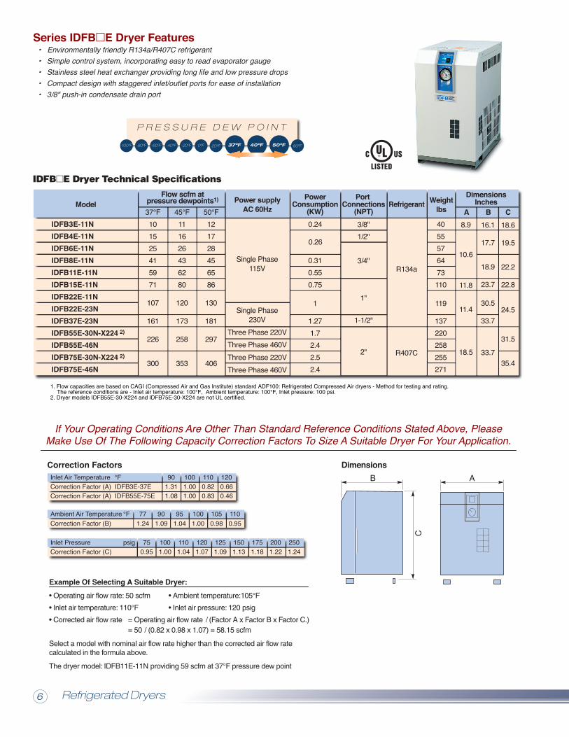
IDFB3E-11NIDFB4E-11NIDFB6E-11NIDFB8E-11NIDFB11E-11NIDFB15E-11NIDFB22E-11NIDFB22E-23NIDFB37E-23NIDFB55E-30N-X224 2)
IDFB55E-46NIDFB75E-30N-X224 2)
IDFB75E-46N
IDFB E Dryer Technical Specifications
Single Phase115V
Single Phase230V
Three Phase 220VThree Phase 460VThree Phase 220VThree Phase 460V
Refrigerant
Correction Factors
• Dust-protecting Filter System
Example Of Selecting A Suitable Dryer:
• Bypass piping kit consult factory
Dimensions
Dimensions
1. Flow capacities are based on CAGI (Compressed Air and Gas Institute) standard ADF100: Refrigerated Compressed Air dryers - Method for testing and rating. The reference conditions are - Inlet air temperature: 100°F, Ambient temperature: 100°F, Inlet pressure: 100 psi. 2. Dryer models IDFB55E-30-X224 and IDFB75E-30-X224 are not UL certified.
Series IDFB�E Dryer Features Common Optional Specifications• Environmentally friendly R134a/R407C refrigerant• Simple control system, incorporating easy to read evaporator gauge• Stainless steel heat exchanger providing long life and low pressure drops• Compact design with staggered inlet/outlet ports for ease of installation• 3/8" push-in condensate drain port
Inlet PressureCorrection Factor (C)
psig 1001.00
1201.07
1501.13
2001.22
Inlet Air TemperatureCorrection Factor (A) IDFB3E-37ECorrection Factor (A) IDFB55E-75E
°F 1001.001.00
1200.660.46
Ambient Air TemperatureCorrection Factor (B)
°F 901.09
1001.00
1100.95
AB
C
37°F101525415971
107
161
226
300
45°F111626436280
120
173
258
353
50°F121728456586
130
181
297
406
8.9
10.6
11.8
11.4
18.5
18.6
19.5
22.2
22.8
24.5
31.5
35.4
4055576473110
119
137220258255271
16.1
17.7
18.9
23.7
30.5
33.7
33.7
R134a
R407C
(IDF-FL209) (IDF-FL203 to 208, 213, 214)
Applicable Dryer
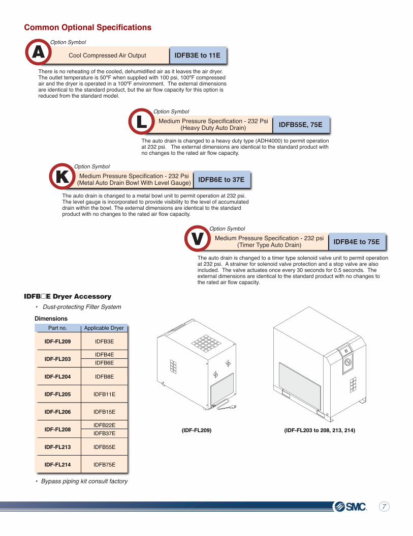
Option Symbol
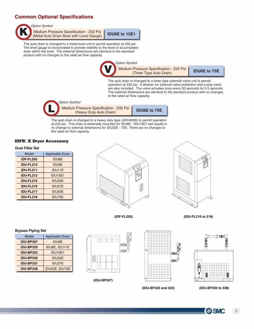
IDFB55E, 75ELThe auto drain is changed to a heavy duty type (ADH4000) to permit operation at 232 psi. The external dimensions are identical to the standard product with no changes to the rated air flow capacity.
Medium Pressure Specification - 232 Psi(Heavy Duty Auto Drain)
Option Symbol
IDFB6E to 37EKThe auto drain is changed to a metal bowl unit to permit operation at 232 psi.The level gauge is incorporated to provide visibility to the level of accumulateddrain within the bowl. The external dimensions are identical to the standard product with no changes to the rated air flow capacity.
Medium Pressure Specification - 232 Psi(Metal Auto Drain Bowl With Level Gauge)
Option Symbol
IDFB4E to 75EVThe auto drain is changed to a timer type solenoid valve unit to permit operation at 232 psi. A strainer for solenoid valve protection and a stop valve are also included. The valve actuates once every 30 seconds for 0.5 seconds. The external dimensions are identical to the standard product with no changes tothe rated air flow capacity.
Medium Pressure Specification - 232 psi(Timer Type Auto Drain)
Option Symbol
IDFB3E to 11EAThere is no reheating of the cooled, dehumidified air as it leaves the air dryer. The outlet temperature is 50ºF when supplied with 100 psi, 100ºF compressed air and the dryer is operated in a 100ºF environment. The external dimensions are identical to the standard product, but the air flow capacity for this option is reduced from the standard model.
Cool Compressed Air Output
If Your Operating Conditions Are Other Than Standard Reference Conditions Stated Above, Please Make Use Of The Following Capacity Correction Factors To Size A Suitable Dryer For Your Application.
IDFB E Dryer Accessory
-100ºF -80ºF -60ºF -40ºF -20ºF 0ºF 20ºF 60ºF
P R E S S U R E D E W P O I N T
37ºF 40ºF 50ºF
0.24
0.310.550.75
1
1.271.72.42.52.4
0.26
901.311.08
1100.820.83
771.24
951.04
1050.98
750.95
1101.04
1251.09
1751.18
2501.24
Part no.
IDF-FL209
IDF-FL203
IDF-FL204
IDF-FL205
IDF-FL206
IDF-FL208
IDF-FL213
IDF-FL214
IDFB3E
IDFB8E
IDFB11E
IDFB15E
IDFB55E
IDFB75E
IDFB4EIDFB6E
IDFB22EIDFB37E
Refrigerated Dryers6 7
ModelFlow scfm at
pressure dewpoints1) Power supplyAC 60Hz
PowerConsumption
(KW) A B C
DimensionsInchesPort
Connections(NPT)3/8"1/2"
3/4"
1"
1-1/2"
2"
Weightlbs
IDFB3E-11NIDFB4E-11NIDFB6E-11NIDFB8E-11NIDFB11E-11NIDFB15E-11NIDFB22E-11NIDFB22E-23NIDFB37E-23NIDFB55E-30N-X224 2)
IDFB55E-46NIDFB75E-30N-X224 2)
IDFB75E-46N
IDFB E Dryer Technical Specifications
Single Phase115V
Single Phase230V
Three Phase 220VThree Phase 460VThree Phase 220VThree Phase 460V
Refrigerant
Correction Factors
• Dust-protecting Filter System
Example Of Selecting A Suitable Dryer:
• Bypass piping kit consult factory
Dimensions
Dimensions
1. Flow capacities are based on CAGI (Compressed Air and Gas Institute) standard ADF100: Refrigerated Compressed Air dryers - Method for testing and rating. The reference conditions are - Inlet air temperature: 100°F, Ambient temperature: 100°F, Inlet pressure: 100 psi. 2. Dryer models IDFB55E-30-X224 and IDFB75E-30-X224 are not UL certified.
Series IDFB�E Dryer Features Common Optional Specifications• Environmentally friendly R134a/R407C refrigerant• Simple control system, incorporating easy to read evaporator gauge• Stainless steel heat exchanger providing long life and low pressure drops• Compact design with staggered inlet/outlet ports for ease of installation• 3/8" push-in condensate drain port
Inlet PressureCorrection Factor (C)
psig 1001.00
1201.07
1501.13
2001.22
Inlet Air TemperatureCorrection Factor (A) IDFB3E-37ECorrection Factor (A) IDFB55E-75E
°F 1001.001.00
1200.660.46
Ambient Air TemperatureCorrection Factor (B)
°F 901.09
1001.00
1100.95
AB
C
37°F101525415971
107
161
226
300
45°F111626436280
120
173
258
353
50°F121728456586
130
181
297
406
8.9
10.6
11.8
11.4
18.5
18.6
19.5
22.2
22.8
24.5
31.5
35.4
4055576473110
119
137220258255271
16.1
17.7
18.9
23.7
30.5
33.7
33.7
R134a
R407C
(IDF-FL209) (IDF-FL203 to 208, 213, 214)
Applicable Dryer
Option Symbol
IDFB55E, 75ELThe auto drain is changed to a heavy duty type (ADH4000) to permit operation at 232 psi. The external dimensions are identical to the standard product with no changes to the rated air flow capacity.
Medium Pressure Specification - 232 Psi(Heavy Duty Auto Drain)
Option Symbol
IDFB6E to 37EKThe auto drain is changed to a metal bowl unit to permit operation at 232 psi.The level gauge is incorporated to provide visibility to the level of accumulateddrain within the bowl. The external dimensions are identical to the standard product with no changes to the rated air flow capacity.
Medium Pressure Specification - 232 Psi(Metal Auto Drain Bowl With Level Gauge)
Option Symbol
IDFB4E to 75EVThe auto drain is changed to a timer type solenoid valve unit to permit operation at 232 psi. A strainer for solenoid valve protection and a stop valve are also included. The valve actuates once every 30 seconds for 0.5 seconds. The external dimensions are identical to the standard product with no changes tothe rated air flow capacity.
Medium Pressure Specification - 232 psi(Timer Type Auto Drain)
Option Symbol
IDFB3E to 11EAThere is no reheating of the cooled, dehumidified air as it leaves the air dryer. The outlet temperature is 50ºF when supplied with 100 psi, 100ºF compressed air and the dryer is operated in a 100ºF environment. The external dimensions are identical to the standard product, but the air flow capacity for this option is reduced from the standard model.
Cool Compressed Air Output
If Your Operating Conditions Are Other Than Standard Reference Conditions Stated Above, Please Make Use Of The Following Capacity Correction Factors To Size A Suitable Dryer For Your Application.
IDFB E Dryer Accessory
-100ºF -80ºF -60ºF -40ºF -20ºF 0ºF 20ºF 60ºF
P R E S S U R E D E W P O I N T
37ºF 40ºF 50ºF
0.24
0.310.550.75
1
1.271.72.42.52.4
0.26
901.311.08
1100.820.83
771.24
951.04
1050.98
750.95
1101.04
1251.09
1751.18
2501.24
Part no.
IDF-FL209
IDF-FL203
IDF-FL204
IDF-FL205
IDF-FL206
IDF-FL208
IDF-FL213
IDF-FL214
IDFB3E
IDFB8E
IDFB11E
IDFB15E
IDFB55E
IDFB75E
IDFB4EIDFB6E
IDFB22EIDFB37E
Refrigerated Dryers6 7
Inlet PressureCorrection Factor (C)
psi
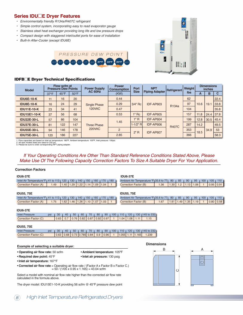
ModelFlow scfm at
Pressure Dew Points Power SupplyAC 60Hz
PortSize
PowerConsumption
A B C
Dimensionsinches
3/4" Rc
1" Rc1" R
1-1/2" R
2" R
IDF-AP603
IDF-AP605IDF-AP604IDF-AP606
IDF-AP607
10.6
11.812.814.2
18.5
22.433.835.837.845.449.553
58.3
6297104157199287353366
Weightlbs
IDU6E-10-KIDU8E-10-KIDU11E-10-KIDU15E1-10-KIDU22E-30-LIDU37E-30-LIDU55E-30-LIDU75E-30-L
Single Phase120VAC
Three Phase220VAC
Refrigerant
19.1
24.430.5
34.9
NPT Piping Adapter
Correction Factors
Inlet Air TemperatureCorrection Factor (A)
IDU6-37E°F 120
1.401401.22
1601.09
1801
Inlet Air TemperatureCorrection Factor (A)
°F 1201.62
1401.26
1601.07
1801
IDU55, 75E
Inlet PressureCorrection Factor (C)
psi 400.7
600.82
800.92
1001
1201.08
145 to 2321.15
400.68
600.785
800.9
1001
1201.11
145 to 2321.239
IDU55, 75E
IDU6-37E
IDU55, 75E
IDU6-37EAmbient Air TemperatureCorrection Factor (B)
°F 801.30
901.13
1001
1100.91
Ambient Air TemperatureCorrection Factor (B)
°F 801.61
901.35
1001
1100.58
Operating air flow rate: 50 scfm
DimensionsB
C
A
Series IDU�E Dryer Features• Environmentally friendly R134a/R407C refrigerant• Simple control system, incorporating easy to read evaporator gauge• Stainless steel heat exchanger providing long life and low pressure drops• Compact design with staggered inlet/outlet ports for ease of installation• Built-In After-Cooler (except IDU6E)
Example of selecting a suitable dryer:
Required dew point: 45°FAmbient temperature: 105ºFInlet air pressure: 130 psig
Inlet air temperature: 167°FCorrected air flow rate = Operating air flow rate / (Factor A x Factor B x Factor C.) = 50 / (1/05 x 0.95 x 1.165) = 43.04 scfm
If Your Operating Conditions Are Other Than Standard Reference Conditions Stated Above, Please Make Use Of The Following Capacity Correction Factors To Size A Suitable Dryer For Your Application.
1. Flow capacities are based on Inlet air temperature: 180ºF, Ambient temperature: 100ºF, Inlet pressure: 100psi. 2. All dyer models listed are rated for 232 psi.3. Please be sure to order corresponding NPT piping adapter.
37°F11162337578194120
50°F20294168104147178227
45°F1624345686122146186
The dryer model: IDU15E1-10-K providing 56 scfm @ 45°F pressure dew point
Select a model with nominal air flow rate higher than the corrected air flow ratecalculated in the formula above.
Common Optional Specifications
Option Symbol
IDU6E to 75EVThe auto drain is changed to a timer type solenoid valve unit to permit operation at 232 psi. A strainer for solenoid valve protection and a stop valve are also included. The valve actuates once every 30 seconds for 0.5 seconds. The external dimensions are identical to the standard product with no changes to the rated air flow capacity.
Medium Pressure Specification - 232 Psi(Timer Type Auto Drain)
Option Symbol
IDU6E to 75ELThe auto drain is changed to a heavy duty type (ADH4000) to permit operation at 232 psi. This drain is externally mounted for IDU6E - IDU15E1 but results in no change to external dimensions for IDU22E - 75E. There are no changes to the rated air flow capacity.
Medium Pressure Specification - 232 Psi(Heavy Duty Auto Drain)
Option Symbol
IDU6E to 15E1KThe auto drain is changed to a metal bowl unit to permit operation at 232 psi. The level gauge is incorporated to provide visibility to the level of accumulated drain within the bowl. The external dimensions are identical to the standard product with no changes to the rated air flow capacity.
Medium Pressure Specification - 232 Psi(Metal Auto Drain Bowl with Level Gauge)
(IDF-FL205)
(IDU-BP307)
(IDU-BP320 and 322) (IDU-BP336 to 338)
(IDU-FL210 to 218)
Dust Filter SetApplicable Dryer
IDU6EIDU8EIDU11EIDU15E1IDU22EIDU37EIDU55EIDU75E
ModelIDF-FL205IDU-FL210IDU-FL211IDU-FL212IDU-FL215IDU-FL216IDU-FL217IDU-FL218
Bypass Piping SetApplicable Dryer
IDU6EIDU8E, IDU11E
IDU15E1IDU22EIDU37E
IDU55E, IDU75E
ModelIDU-BP307IDU-BP320IDU-BP322IDU-BP336IDU-BP337IDU-BP338
IDFB E Dryer Accessory
IDFB E Dryer Technical Specifications
-100ºF -80ºF -60ºF -40ºF -20ºF 0ºF 20ºF 60ºF
P R E S S U R E D E W P O I N T
37ºF 40ºF 50ºF
(KW)0.440.290.470.53
1.45
22.85
R134a
R407C
41 to 1131.49
1301.29
1501.14
1701.04
41 to 1131.75
1301.46
1501.10
1701.03
300.63
500.76
700.87
900.97
1101.04
1301.11
300.63
500.73
700.84
900.96
1101.055
1301.165
35.6 to 771.36
851.2
951.06
1050.95
35.6 to 771.67
851.49
951.19
1050.80
High Inlet Temperature Refrigerated Dryers8 9
Inlet PressureCorrection Factor (C)
psi
ModelFlow scfm at
Pressure Dew Points Power SupplyAC 60Hz
PortSize
PowerConsumption
A B C
Dimensionsinches
3/4" Rc
1" Rc1" R
1-1/2" R
2" R
IDF-AP603
IDF-AP605IDF-AP604IDF-AP606
IDF-AP607
10.6
11.812.814.2
18.5
22.433.835.837.845.449.553
58.3
6297104157199287353366
Weightlbs
IDU6E-10-KIDU8E-10-KIDU11E-10-KIDU15E1-10-KIDU22E-30-LIDU37E-30-LIDU55E-30-LIDU75E-30-L
Single Phase120VAC
Three Phase220VAC
Refrigerant
19.1
24.430.5
34.9
NPT Piping Adapter
Correction Factors
Inlet Air TemperatureCorrection Factor (A)
IDU6-37E°F 120
1.401401.22
1601.09
1801
Inlet Air TemperatureCorrection Factor (A)
°F 1201.62
1401.26
1601.07
1801
IDU55, 75E
Inlet PressureCorrection Factor (C)
psi 400.7
600.82
800.92
1001
1201.08
145 to 2321.15
400.68
600.785
800.9
1001
1201.11
145 to 2321.239
IDU55, 75E
IDU6-37E
IDU55, 75E
IDU6-37EAmbient Air TemperatureCorrection Factor (B)
°F 801.30
901.13
1001
1100.91
Ambient Air TemperatureCorrection Factor (B)
°F 801.61
901.35
1001
1100.58
Operating air flow rate: 50 scfm
DimensionsB
C
A
Series IDU�E Dryer Features• Environmentally friendly R134a/R407C refrigerant• Simple control system, incorporating easy to read evaporator gauge• Stainless steel heat exchanger providing long life and low pressure drops• Compact design with staggered inlet/outlet ports for ease of installation• Built-In After-Cooler (except IDU6E)
Example of selecting a suitable dryer:
Required dew point: 45°FAmbient temperature: 105ºFInlet air pressure: 130 psig
Inlet air temperature: 167°FCorrected air flow rate = Operating air flow rate / (Factor A x Factor B x Factor C.) = 50 / (1/05 x 0.95 x 1.165) = 43.04 scfm
If Your Operating Conditions Are Other Than Standard Reference Conditions Stated Above, Please Make Use Of The Following Capacity Correction Factors To Size A Suitable Dryer For Your Application.
1. Flow capacities are based on Inlet air temperature: 180ºF, Ambient temperature: 100ºF, Inlet pressure: 100psi. 2. All dyer models listed are rated for 232 psi.3. Please be sure to order corresponding NPT piping adapter.
37°F11162337578194120
50°F20294168104147178227
45°F1624345686122146186
The dryer model: IDU15E1-10-K providing 56 scfm @ 45°F pressure dew point
Select a model with nominal air flow rate higher than the corrected air flow ratecalculated in the formula above.
Common Optional Specifications
Option Symbol
IDU6E to 75EVThe auto drain is changed to a timer type solenoid valve unit to permit operation at 232 psi. A strainer for solenoid valve protection and a stop valve are also included. The valve actuates once every 30 seconds for 0.5 seconds. The external dimensions are identical to the standard product with no changes to the rated air flow capacity.
Medium Pressure Specification - 232 Psi(Timer Type Auto Drain)
Option Symbol
IDU6E to 75ELThe auto drain is changed to a heavy duty type (ADH4000) to permit operation at 232 psi. This drain is externally mounted for IDU6E - IDU15E1 but results in no change to external dimensions for IDU22E - 75E. There are no changes to the rated air flow capacity.
Medium Pressure Specification - 232 Psi(Heavy Duty Auto Drain)
Option Symbol
IDU6E to 15E1KThe auto drain is changed to a metal bowl unit to permit operation at 232 psi. The level gauge is incorporated to provide visibility to the level of accumulated drain within the bowl. The external dimensions are identical to the standard product with no changes to the rated air flow capacity.
Medium Pressure Specification - 232 Psi(Metal Auto Drain Bowl with Level Gauge)
(IDF-FL205)
(IDU-BP307)
(IDU-BP320 and 322) (IDU-BP336 to 338)
(IDU-FL210 to 218)
Dust Filter SetApplicable Dryer
IDU6EIDU8EIDU11EIDU15E1IDU22EIDU37EIDU55EIDU75E
ModelIDF-FL205IDU-FL210IDU-FL211IDU-FL212IDU-FL215IDU-FL216IDU-FL217IDU-FL218
Bypass Piping SetApplicable Dryer
IDU6EIDU8E, IDU11E
IDU15E1IDU22EIDU37E
IDU55E, IDU75E
ModelIDU-BP307IDU-BP320IDU-BP322IDU-BP336IDU-BP337IDU-BP338
IDFB E Dryer Accessory
IDFB E Dryer Technical Specifications
-100ºF -80ºF -60ºF -40ºF -20ºF 0ºF 20ºF 60ºF
P R E S S U R E D E W P O I N T
37ºF 40ºF 50ºF
(KW)0.440.290.470.53
1.45
22.85
R134a
R407C
41 to 1131.49
1301.29
1501.14
1701.04
41 to 1131.75
1301.46
1501.10
1701.03
300.63
500.76
700.87
900.97
1101.04
1301.11
300.63
500.73
700.84
900.96
1101.055
1301.165
35.6 to 771.36
851.2
951.06
1050.95
35.6 to 771.67
851.49
951.19
1050.80
High Inlet Temperature Refrigerated Dryers8 9
Membrane Air Dryers10 11
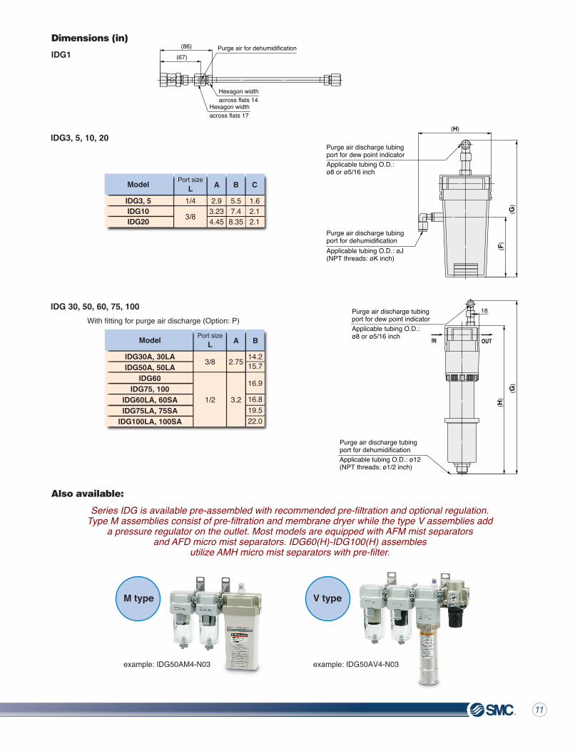
IDG 30, 50, 60, 75, 100
Dimensions (in)
IDG1
IDG3, 5, 10, 20
IDG3, 5IDG10IDG20
Model
3/8
Port sizeL A B C
1/4
IDG30A, 30LAIDG50A, 50LA
IDG60IDG75, 100
IDG60LA, 60SAIDG75LA, 75SA
IDG100LA, 100SA
Model Port sizeL A B
For details of how to order contact SMC or refer to catalog No. CAT ES30-7FSpecifications
Also available:
Series IDG Features
Series IDG is available pre-assembled with recommended pre-filtration and optional regulation.Type M assemblies consist of pre-filtration and membrane dryer while the type V assemblies add
a pressure regulator on the outlet. Most models are equipped with AFM mist separatorsand AFD micro mist separators. IDG60(H)-IDG100(H) assembles
utilize AMH micro mist separators with pre-filter.
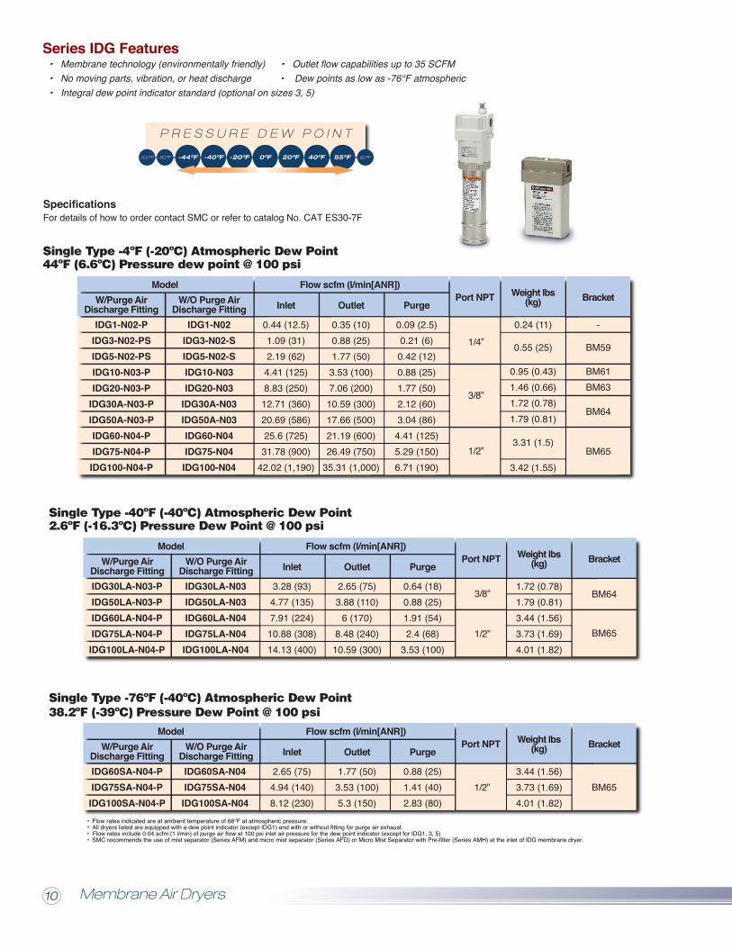
• Membrane technology (environmentally friendly) • Outlet flow capabilities up to 35 SCFM• No moving parts, vibration, or heat discharge • Dew points as low as -76°F atmospheric• Integral dew point indicator standard (optional on sizes 3, 5)
Single Type -4ºF (-20ºC) Atmospheric Dew Point44ºF (6.6ºC) Pressure dew point @ 100 psi
Single Type -40ºF (-40ºC) Atmospheric Dew Point2.6ºF (-16.3ºC) Pressure Dew Point @ 100 psi
Single Type -76ºF (-40ºC) Atmospheric Dew Point38.2ºF (-39ºC) Pressure Dew Point @ 100 psi
(86)
(67)Purge air for dehumidification
Hexagon widthacross flats 14
Hexagon widthacross flats 17
With fitting for purge air discharge (Option: P)
(H)
(G)
( F)
Purge air discharge tubingport for dew point indicatorApplicable tubing O.D.:ø8 or ø5/16 inch
Applicable tubing O.D.: øJ(NPT threads: øK inch)
Purge air discharge tubingport for dehumidification
IN OUT
(G)
(H)
18
Applicable tubing O.D.: ø12(NPT threads: ø1/2 inch)
Purge air discharge tubingport for dehumidification
Applicable tubing O.D.:ø8 or ø5/16 inch
Purge air discharge tubingport for dew point indicator
W/Purge AirDischarge Fitting
1/4”
IDF-AP606
Weightlbs
IDG1-N02-PIDG3-N02-PSIDG5-N02-PSIDG10-N03-PIDG20-N03-P
IDG30A-N03-PIDG50A-N03-PIDG60-N04-PIDG75-N04-PIDG100-N04-P
W/O Purge AirDischarge Fitting
IDG1-N02IDG3-N02-SIDG5-N02-SIDG10-N03IDG20-N03
IDG30A-N03IDG50A-N03IDG60-N04IDG75-N04IDG100-N04
RefrigerantPort NPT Weight lbs(kg)Inlet Outlet
Flow scfm (l/min[ANR])Model
PurgeBracket
-
BM59
BM61BM63
BM64
BM65
3/8”
1/2”
0.44 (12.5)1.09 (31)2.19 (62)4.41 (125)8.83 (250)12.71 (360)20.69 (586)25.6 (725)31.78 (900)
42.02 (1,190)
0.35 (10)0.88 (25)1.77 (50)3.53 (100)7.06 (200)10.59 (300)17.66 (500)21.19 (600)26.49 (750)
35.31 (1,000)
0.09 (2.5)0.21 (6)0.42 (12)0.88 (25)1.77 (50)2.12 (60)3.04 (86)4.41 (125)5.29 (150)6.71 (190)
0.24 (11)
0.55 (25)
0.95 (0.43)1.46 (0.66)1.72 (0.78)1.79 (0.81)
3.31 (1.5)
3.42 (1.55)
W/Purge AirDischarge Fitting
3/8”
Weightlbs
IDG30LA-N03-PIDG50LA-N03-PIDG60LA-N04-PIDG75LA-N04-PIDG100LA-N04-P
W/O Purge AirDischarge Fitting
IDG30LA-N03IDG50LA-N03IDG60LA-N04IDG75LA-N04IDG100LA-N04
RefrigerantPort NPT Weight lbs(kg)Inlet Outlet
Flow scfm (l/min[ANR])Model
PurgeBracket
BM64
BM651/2”
3.28 (93)4.77 (135)7.91 (224)10.88 (308)14.13 (400)
2.65 (75)3.88 (110)
6 (170)8.48 (240)10.59 (300)
0.64 (18)0.88 (25)1.91 (54)2.4 (68)
3.53 (100)
1.72 (0.78)1.79 (0.81)3.44 (1.56)3.73 (1.69)4.01 (1.82)
• Flow rates indicated are at ambient temperature of 68°F at atmospheric pressure.• All dryers listed are equipped with a dew point indicator (except IDG1) and with or without fitting for purge air exhaust.• Flow rates include 0.04 scfm (1 l/min) of purge air flow at 100 psi inlet air pressure for the dew point indicator (except for IDG1, 3, 5)• SMC recommends the use of mist separator (Series AFM) and micro mist separator (Series AFD) or Micro Mist Separator with Pre-filter (Series AMH) at the inlet of IDG membrane dryer.
W/Purge AirDischarge Fitting
1/2”
Weightlbs
IDG60SA-N04-PIDG75SA-N04-PIDG100SA-N04-P
W/O Purge AirDischarge Fitting
RefrigerantPort NPT Weight lbs(kg)Inlet Outlet
Flow scfm (l/min[ANR])Model
PurgeBracket
BM652.65 (75)4.94 (140)8.12 (230)
1.77 (50)3.53 (100)5.3 (150)
0.88 (25)1.41 (40)2.83 (80)
3.44 (1.56)3.73 (1.69)4.01 (1.82)
IDG60SA-N04IDG75SA-N04IDG100SA-N04
14.215.7
16.9
16.819.522.0
2.75
3.2
3/8
1/2
example: IDG50AV4-N03example: IDG50AM4-N03
V typeM type
-44ºF -40ºF -20ºF 0ºF 20ºF 40ºF 55ºF 60ºF-100ºF -80ºF
P R E S S U R E D E W P O I N T
2.93.234.45
1.62.12.1
5.57.48.35
Membrane Air Dryers10 11
IDG 30, 50, 60, 75, 100
Dimensions (in)
IDG1
IDG3, 5, 10, 20
IDG3, 5IDG10IDG20
Model
3/8
Port sizeL A B C
1/4
IDG30A, 30LAIDG50A, 50LA
IDG60IDG75, 100
IDG60LA, 60SAIDG75LA, 75SA
IDG100LA, 100SA
Model Port sizeL A B
For details of how to order contact SMC or refer to catalog No. CAT ES30-7FSpecifications
Also available:
Series IDG Features
Series IDG is available pre-assembled with recommended pre-filtration and optional regulation.Type M assemblies consist of pre-filtration and membrane dryer while the type V assemblies add
a pressure regulator on the outlet. Most models are equipped with AFM mist separatorsand AFD micro mist separators. IDG60(H)-IDG100(H) assembles
utilize AMH micro mist separators with pre-filter.
• Membrane technology (environmentally friendly) • Outlet flow capabilities up to 35 SCFM• No moving parts, vibration, or heat discharge • Dew points as low as -76°F atmospheric• Integral dew point indicator standard (optional on sizes 3, 5)
Single Type -4ºF (-20ºC) Atmospheric Dew Point44ºF (6.6ºC) Pressure dew point @ 100 psi
Single Type -40ºF (-40ºC) Atmospheric Dew Point2.6ºF (-16.3ºC) Pressure Dew Point @ 100 psi
Single Type -76ºF (-40ºC) Atmospheric Dew Point38.2ºF (-39ºC) Pressure Dew Point @ 100 psi
(86)
(67)Purge air for dehumidification
Hexagon widthacross flats 14
Hexagon widthacross flats 17
With fitting for purge air discharge (Option: P)
(H)
(G)
( F)
Purge air discharge tubingport for dew point indicatorApplicable tubing O.D.:ø8 or ø5/16 inch
Applicable tubing O.D.: øJ(NPT threads: øK inch)
Purge air discharge tubingport for dehumidification
IN OUT
(G)
(H)
18
Applicable tubing O.D.: ø12(NPT threads: ø1/2 inch)
Purge air discharge tubingport for dehumidification
Applicable tubing O.D.:ø8 or ø5/16 inch
Purge air discharge tubingport for dew point indicator
W/Purge AirDischarge Fitting
1/4”
IDF-AP606
Weightlbs
IDG1-N02-PIDG3-N02-PSIDG5-N02-PSIDG10-N03-PIDG20-N03-P
IDG30A-N03-PIDG50A-N03-PIDG60-N04-PIDG75-N04-PIDG100-N04-P
W/O Purge AirDischarge Fitting
IDG1-N02IDG3-N02-SIDG5-N02-SIDG10-N03IDG20-N03
IDG30A-N03IDG50A-N03IDG60-N04IDG75-N04IDG100-N04
RefrigerantPort NPT Weight lbs(kg)Inlet Outlet
Flow scfm (l/min[ANR])Model
PurgeBracket
-
BM59
BM61BM63
BM64
BM65
3/8”
1/2”
0.44 (12.5)1.09 (31)2.19 (62)4.41 (125)8.83 (250)12.71 (360)20.69 (586)25.6 (725)31.78 (900)
42.02 (1,190)
0.35 (10)0.88 (25)1.77 (50)3.53 (100)7.06 (200)10.59 (300)17.66 (500)21.19 (600)26.49 (750)
35.31 (1,000)
0.09 (2.5)0.21 (6)0.42 (12)0.88 (25)1.77 (50)2.12 (60)3.04 (86)4.41 (125)5.29 (150)6.71 (190)
0.24 (11)
0.55 (25)
0.95 (0.43)1.46 (0.66)1.72 (0.78)1.79 (0.81)
3.31 (1.5)
3.42 (1.55)
W/Purge AirDischarge Fitting
3/8”
Weightlbs
IDG30LA-N03-PIDG50LA-N03-PIDG60LA-N04-PIDG75LA-N04-PIDG100LA-N04-P
W/O Purge AirDischarge Fitting
IDG30LA-N03IDG50LA-N03IDG60LA-N04IDG75LA-N04IDG100LA-N04
RefrigerantPort NPT Weight lbs(kg)Inlet Outlet
Flow scfm (l/min[ANR])Model
PurgeBracket
BM64
BM651/2”
3.28 (93)4.77 (135)7.91 (224)10.88 (308)14.13 (400)
2.65 (75)3.88 (110)
6 (170)8.48 (240)10.59 (300)
0.64 (18)0.88 (25)1.91 (54)2.4 (68)
3.53 (100)
1.72 (0.78)1.79 (0.81)3.44 (1.56)3.73 (1.69)4.01 (1.82)
• Flow rates indicated are at ambient temperature of 68°F at atmospheric pressure.• All dryers listed are equipped with a dew point indicator (except IDG1) and with or without fitting for purge air exhaust.• Flow rates include 0.04 scfm (1 l/min) of purge air flow at 100 psi inlet air pressure for the dew point indicator (except for IDG1, 3, 5)• SMC recommends the use of mist separator (Series AFM) and micro mist separator (Series AFD) or Micro Mist Separator with Pre-filter (Series AMH) at the inlet of IDG membrane dryer.
W/Purge AirDischarge Fitting
1/2”
Weightlbs
IDG60SA-N04-PIDG75SA-N04-PIDG100SA-N04-P
W/O Purge AirDischarge Fitting
RefrigerantPort NPT Weight lbs(kg)Inlet Outlet
Flow scfm (l/min[ANR])Model
PurgeBracket
BM652.65 (75)4.94 (140)8.12 (230)
1.77 (50)3.53 (100)5.3 (150)
0.88 (25)1.41 (40)2.83 (80)
3.44 (1.56)3.73 (1.69)4.01 (1.82)
IDG60SA-N04IDG75SA-N04IDG100SA-N04
14.215.7
16.9
16.819.522.0
2.75
3.2
3/8
1/2
example: IDG50AV4-N03example: IDG50AM4-N03
V typeM type
-44ºF -40ºF -20ºF 0ºF 20ºF 40ºF 55ºF 60ºF-100ºF -80ºF
P R E S S U R E D E W P O I N T
2.93.234.45
1.62.12.1
5.57.48.35
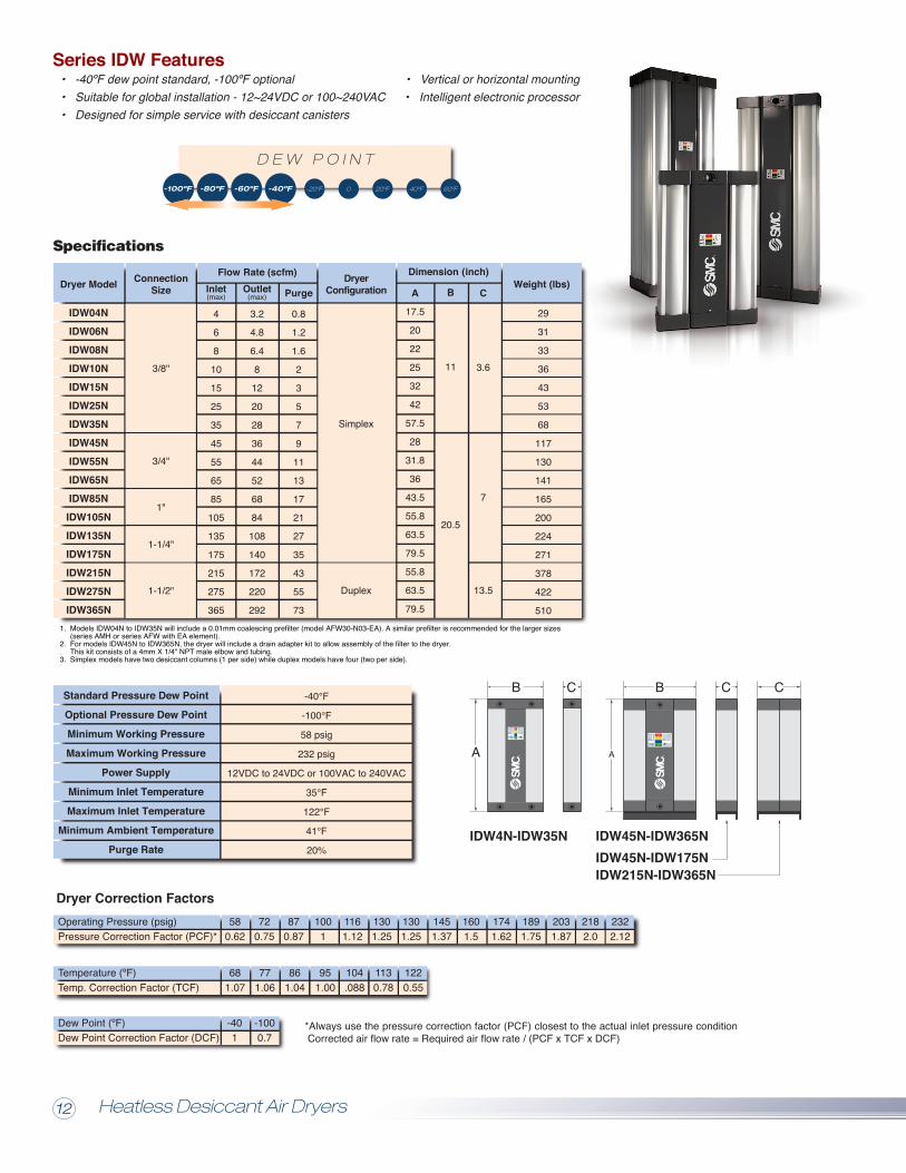
IDW4N-IDW35N
B B CC
A A
IDW45N-IDW365NIDW45N-IDW175NIDW215N-IDW365N
Specifications
1. Models IDW04N to IDW35N will include a 0.01mm coalescing prefilter (model AFW30-N03-EA). A similar prefilter is recommended for the larger sizes (series AMH or series AFW with EA element).2. For models IDW45N to IDW365N, the dryer will include a drain adapter kit to allow assembly of the filter to the dryer. This kit consists of a 4mm X 1/4" NPT male elbow and tubing.3. Simplex models have two desiccant columns (1 per side) while duplex models have four (two per side).
*Always use the pressure correction factor (PCF) closest to the actual inlet pressure condition Corrected air flow rate = Required air flow rate / (PCF x TCF x DCF)
Standard Pressure Dew Point
Optional Pressure Dew Point
Minimum Working Pressure
Maximum Working Pressure
Power Supply
Minimum Inlet Temperature
Maximum Inlet Temperature
Minimum Ambient Temperature
Purge Rate
-40°F
-100°F
58 psig
232 psig
12VDC to 24VDC or 100VAC to 240VAC
35°F
122°F
41°F
20%
C
Series IDW Features• -40ºF dew point standard, -100ºF optional • Vertical or horizontal mounting• Suitable for global installation - 12~24VDC or 100~240VAC • Intelligent electronic processor• Designed for simple service with desiccant canisters
Weight (lbs)
IDW04NIDW06NIDW08NIDW10NIDW15NIDW25NIDW35NIDW45NIDW55NIDW65NIDW85NIDW105NIDW135NIDW175NIDW215NIDW275NIDW365N
Flow Rate (scfm) Dimension (inch)
B
11
20.5
C
3.6
7
13.5
DryerConfigurationDryer Model
3/8"
3/4"
1"
1-1/4"
1-1/2"
29
31
33
36
43
53
68
117
130
141
165
200
224
271
378
422
510
Simplex
Duplex
Purge
0.8
1.2
1.6
2
3
5
7
9
11
13
17
21
27
35
43
55
73
Outlet(max)
3.2
4.8
6.4
8
12
20
28
36
44
52
68
84
108
140
172
220
292
Inlet(max)
4
6
8
10
15
25
35
45
55
65
85
105
135
175
215
275
365
ConnectionSize
3/8"
3/4"
1"
1-1/4"
1-1/2"
29
31
33
36
43
53
68
117
130
141
165
200
224
271
378
422
510
Simplex
Duplex
IDW04NIDW06NIDW08NIDW10NIDW15NIDW25NIDW35NIDW45NIDW55NIDW65NIDW85NIDW105NIDW135NIDW175NIDW215NIDW275NIDW365N
Dryer ModelPart Number Contents
Desiccantcartridges,
pack ofsealing
O-rings andwashers,reset cap,instruction
booklet
Part Number Contents
12,000 hourservice kit,
valve servicekit
Part Number
12,000 Hour Service Kit
IDWFB35IDWWB35IDWCD01
Part Number
ALL
IDW04N~35N
ApplicableModels
24,000 Hour Service Kit Valve Service Kit
Contents
Exhaustsolenoid valves,
diaphragms,shuttle valveand O-rings,
required seals(not included
in 12,000hour kits)
The energy management software CD enables the user to interfacewith the controller to work with the energy management settings.Each CD has unique information to a particular dryer and must bematched by serial number. If ordered at time of dryer order, theyshould be properly paired. If ordering CD by itself, please providethe dryer serial number so that the appropriate info can be loaded.Full software compatibility is not guaranteed if used with differentdryer units.
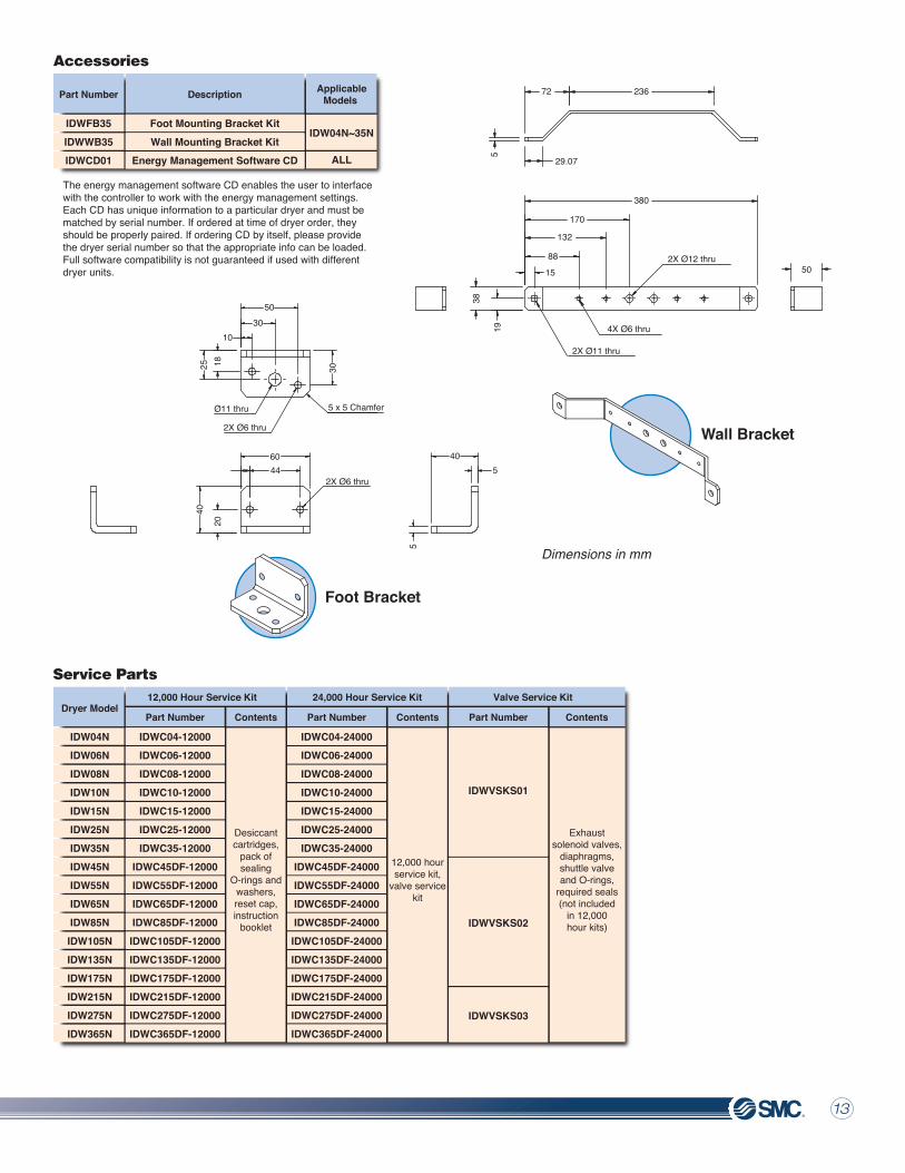
Accessories
Service Parts
Dryer Correction Factors
Temperature (ºF)Temp. Correction Factor (TCF)
771.06
951.00
1130.78
Dew Point (ºF)Dew Point Correction Factor (DCF)
-1000.7
Operating Pressure (psig)Pressure Correction Factor (PCF)*
720.75
1001
1301.25
1451.37
1741.62
2031.87
2322.12
Description
Foot Mounting Bracket KitWall Mounting Bracket Kit
Energy Management Software CD
IDWC04-12000IDWC06-12000IDWC08-12000IDWC10-12000IDWC15-12000IDWC25-12000IDWC35-12000
IDWC45DF-12000IDWC55DF-12000IDWC65DF-12000IDWC85DF-12000IDWC105DF-12000IDWC135DF-12000IDWC175DF-12000IDWC215DF-12000IDWC275DF-12000IDWC365DF-12000
IDWVSKS01
IDWVSKS02
IDWVSKS03
IDWC04-24000IDWC06-24000IDWC08-24000IDWC10-24000IDWC15-24000IDWC25-24000IDWC35-24000
IDWC45DF-24000IDWC55DF-24000IDWC65DF-24000IDWC85DF-24000IDWC105DF-24000IDWC135DF-24000IDWC175DF-24000IDWC215DF-24000IDWC275DF-24000IDWC365DF-24000
A
17.5
20
22
25
32
42
57.5
28
31.8
36
43.5
55.8
63.5
79.5
55.8
63.5
79.5
-100ºF -80ºF -60ºF -40ºF -20ºF 20ºF 40ºF 60ºF0
D E W P O I N T
Foot Bracket
Wall Bracket
50
50
380
170
132
88
15
23672
29.07
5
38
19
60 40544
3010
Ø11 thru
2X Ø6 thru
2X Ø11 thru
Dimensions in mm
4X Ø6 thru
2X Ø12 thru
2X Ø6 thru
5 x 5 Chamfer
1825 30
20
5
40
681.07
861.04
104.088
1220.55
-401
580.62
870.87
1161.12
1301.25
1601.5
1891.75
2182.0
Heatless Desiccant Air Dryers12 13
IDW4N-IDW35N
B B CC
A A
IDW45N-IDW365NIDW45N-IDW175NIDW215N-IDW365N
Specifications
1. Models IDW04N to IDW35N will include a 0.01mm coalescing prefilter (model AFW30-N03-EA). A similar prefilter is recommended for the larger sizes (series AMH or series AFW with EA element).2. For models IDW45N to IDW365N, the dryer will include a drain adapter kit to allow assembly of the filter to the dryer. This kit consists of a 4mm X 1/4" NPT male elbow and tubing.3. Simplex models have two desiccant columns (1 per side) while duplex models have four (two per side).
*Always use the pressure correction factor (PCF) closest to the actual inlet pressure condition Corrected air flow rate = Required air flow rate / (PCF x TCF x DCF)
Standard Pressure Dew Point
Optional Pressure Dew Point
Minimum Working Pressure
Maximum Working Pressure
Power Supply
Minimum Inlet Temperature
Maximum Inlet Temperature
Minimum Ambient Temperature
Purge Rate
-40°F
-100°F
58 psig
232 psig
12VDC to 24VDC or 100VAC to 240VAC
35°F
122°F
41°F
20%
C
Series IDW Features• -40ºF dew point standard, -100ºF optional • Vertical or horizontal mounting• Suitable for global installation - 12~24VDC or 100~240VAC • Intelligent electronic processor• Designed for simple service with desiccant canisters
Weight (lbs)
IDW04NIDW06NIDW08NIDW10NIDW15NIDW25NIDW35NIDW45NIDW55NIDW65NIDW85NIDW105NIDW135NIDW175NIDW215NIDW275NIDW365N
Flow Rate (scfm) Dimension (inch)
B
11
20.5
C
3.6
7
13.5
DryerConfigurationDryer Model
3/8"
3/4"
1"
1-1/4"
1-1/2"
29
31
33
36
43
53
68
117
130
141
165
200
224
271
378
422
510
Simplex
Duplex
Purge
0.8
1.2
1.6
2
3
5
7
9
11
13
17
21
27
35
43
55
73
Outlet(max)
3.2
4.8
6.4
8
12
20
28
36
44
52
68
84
108
140
172
220
292
Inlet(max)
4
6
8
10
15
25
35
45
55
65
85
105
135
175
215
275
365
ConnectionSize
3/8"
3/4"
1"
1-1/4"
1-1/2"
29
31
33
36
43
53
68
117
130
141
165
200
224
271
378
422
510
Simplex
Duplex
IDW04NIDW06NIDW08NIDW10NIDW15NIDW25NIDW35NIDW45NIDW55NIDW65NIDW85NIDW105NIDW135NIDW175NIDW215NIDW275NIDW365N
Dryer ModelPart Number Contents
Desiccantcartridges,
pack ofsealing
O-rings andwashers,reset cap,instruction
booklet
Part Number Contents
12,000 hourservice kit,
valve servicekit
Part Number
12,000 Hour Service Kit
IDWFB35IDWWB35IDWCD01
Part Number
ALL
IDW04N~35N
ApplicableModels
24,000 Hour Service Kit Valve Service Kit
Contents
Exhaustsolenoid valves,
diaphragms,shuttle valveand O-rings,
required seals(not included
in 12,000hour kits)
The energy management software CD enables the user to interfacewith the controller to work with the energy management settings.Each CD has unique information to a particular dryer and must bematched by serial number. If ordered at time of dryer order, theyshould be properly paired. If ordering CD by itself, please providethe dryer serial number so that the appropriate info can be loaded.Full software compatibility is not guaranteed if used with differentdryer units.
Accessories
Service Parts
Dryer Correction Factors
Temperature (ºF)Temp. Correction Factor (TCF)
771.06
951.00
1130.78
Dew Point (ºF)Dew Point Correction Factor (DCF)
-1000.7
Operating Pressure (psig)Pressure Correction Factor (PCF)*
720.75
1001
1301.25
1451.37
1741.62
2031.87
2322.12
Description
Foot Mounting Bracket KitWall Mounting Bracket Kit
Energy Management Software CD
IDWC04-12000IDWC06-12000IDWC08-12000IDWC10-12000IDWC15-12000IDWC25-12000IDWC35-12000
IDWC45DF-12000IDWC55DF-12000IDWC65DF-12000IDWC85DF-12000IDWC105DF-12000IDWC135DF-12000IDWC175DF-12000IDWC215DF-12000IDWC275DF-12000IDWC365DF-12000
IDWVSKS01
IDWVSKS02
IDWVSKS03
IDWC04-24000IDWC06-24000IDWC08-24000IDWC10-24000IDWC15-24000IDWC25-24000IDWC35-24000
IDWC45DF-24000IDWC55DF-24000IDWC65DF-24000IDWC85DF-24000IDWC105DF-24000IDWC135DF-24000IDWC175DF-24000IDWC215DF-24000IDWC275DF-24000IDWC365DF-24000
A
17.5
20
22
25
32
42
57.5
28
31.8
36
43.5
55.8
63.5
79.5
55.8
63.5
79.5
-100ºF -80ºF -60ºF -40ºF -20ºF 20ºF 40ºF 60ºF0
D E W P O I N T
Foot Bracket
Wall Bracket
50
50
380
170
132
88
15
23672
29.07
5
38
19
60 40544
3010
Ø11 thru
2X Ø6 thru
2X Ø11 thru
Dimensions in mm
4X Ø6 thru
2X Ø12 thru
2X Ø6 thru
5 x 5 Chamfer
1825 30
20
5
40
681.07
861.04
104.088
1220.55
-401
580.62
870.87
1161.12
1301.25
1601.5
1891.75
2182.0
Heatless Desiccant Air Dryers12 13
Specifications
Dimensions Operation Principle
Accessories
How to Use:
Series ID Features Dew Point Conversion Chart• Provides dry air at atmospheric dew point as low as -26.2ºF (-32.3ºC) Standard pressure dew point -16.2ºF (-8.8ºC)• Compact and light weight without heater and electric control board• Possible to check outlet dew point with an indicator
ID-200S
ID-300S
ID-400S
ID-600S
3.53
6.78
14.65
34.43
InletSCFM
2.82
5.47
11.65
27.54
OutletFlow
SCFMPurge Air
SCFM0.71
1.31
3
6.89
110VACSingle-Phase
60hz
Weight
15.4
18.7
40.8
55.1
lbs
6604113
660651
Model
ID200-N02
ID300-N04
ID400-N04
ID600-N06
Port size(NPT)
1/4"
1/2"
3/4"
Powersupply
Bracket MistSeparatorModel
ID200-N02
ID300-N04
ID400-N04
ID600-N06
Adsorbent Set for Standard Dew Point
AM150C-N02C-T
AM350C-N04C-T
AM450C-N06C-T
Adsorbent Set forSpecial Low Dew Point
ID-200Z
ID-300Z
ID-400Z
ID-600Z
Ainch20.524.233.537.8
Cinch
4.7
6.7
Binch
9.4
12.6
Dimensions
Add Z at the end of model no. for –26°F dew point.
The compressed air that flowed in from the IN side passes through the 4 way solenoid valve, and after it is dehumidified at adsorption cylinder T1, it turns into dry air and exits from the OUT side.Meanwhile, a portion of the dry air passes through orifice O2 to reactivate the adsorption agent at adsorption cylinder T2. This air, carrying moisture, passes through the solenoid valve and is released to the atmosphere.After an interval of time, the switching valve operates, and T1 becomes reactivated while T2 assumes the adsorption state.This process is repeated to continuously provide dry air.
To find the equivalent atmospheric dew point from a known pressure dew point, identify the pressure dew point on the verticalaxis. Follow the line horizontally to the associated pressure. From the intersection of the temperature and pressure lines, follow this vertically to the horizontal axis where the atmospheric dew point can be read.
Example: For a 40ºF pressure dew point (A) at 100 psig (B), the equivalent atmospheric dew point is ~ -3.5ºF (C)
To maximize the life of the adsorbent and performance of the unit, a mist separator should be installed prior to the dryer. A particulate filter is recommended downstream to capture possible desiccant fines that arise during normal operation of the dryer.
Pre
ssu
re D
ew
Po
int
ºF
-120 -100 -80 -60 -40 -20 0 20 40 60 80 100 120
0psig
20psig
60psig
100psig
150psig
300psig
10psig
40psig
80psig
125psig
200psig
-100ºF -80ºF -60ºF -40ºF 20ºF 40ºF 60ºF
P R E S S U R E D E W P O I N T
-20ºF-26ºF 0ºF 16ºF
Atomspheric Dew Point ºF
-120
-100
-80
-60
-40
-20
0
20
40
60
80
100
120
-120 -100 -80 -60 -40 -20 0 20 40 60 80 100 120
A B
C
Dew Point Conversion ChartHeatless Air Dryers 1514
Performance Correction Factors
Correction Factors
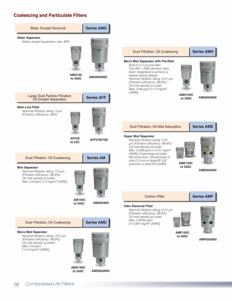
Coalescing and Particulate Filters
Example: AMD550C at 100 psi Flow = 131 scfm at 58 psi multiply 131 x .63 = 82.5 scfm (corrected capacity)Flow ratings shown for all filters are at 100 psi, please utilize correction factors for other operating pressures.
Super Mist Separator
Absorbing filters must not operate in oil or water saturated conditions. For optimal system performance, see system performance,see system table on pgs. 4 & 5 for combinations of filters to achieve desired air quality. At a minimum, AME and AMF filters shouldbe placed after a 0.01µm coalescing filter.
* Optional 232 psi maximum pressure rating available. Activated carbon filters will not remove carbon monoxide or carbon dioxide from compressed air.
AMF SeriesOdor Removal
Filter
AME SeriesSuper MistSeparator
AMEElement
AMFElement
Max.WorkingPressure
Flow (scfm) Port Size(NPT)
Max.Temperature
Max.Temperature
FlowRate(SCFM)
PortSize(NPT)
Max.WorkingPressure
AMElementAM Series
0.3 Micron RatingAFF
ElementAFF Series
3 Micron RatingAMG
Element
AMG150C-N02C
AMG250C-N03C
AMG350C-N04C
AMG450C-N06D
AMG550C-N10D
AMG650-N14D
AMG850-N20D
145 psi*
145 psi
10
26
53
78
123
212
424
AM150C-N02C-T
AM250C-N03C-T
AM350C-N04C-T
AM450C-N06D-T
AM550C-N10D-T
AM650-N14D-T
AM850-N20D-T
AFF2C-N02C-T
AFF4C-N03C-T
AFF8C-N04C-T
AFF11C-N06D-T
AFF22C-N10D-T
AFF37B-N14D-T
AFF75B-N20D-T
AMG SeriesWater Separator
140° F
1/4"
3/8"
1/2"
3/4"
1"
1-1/2"
2"
AM-EL150
AM-EL250
AM-EL350
AM-EL450
AM-EL550
AM-EL650
AM-EL850
AFF-EL2B
AFF-EL4B
AFF-EL8B
AFF-EL11B
AFF-EL22B
AFF-EL37B
AFF-EL75B
AMG-EL150
AMG-EL250
AMG-EL350
AMG-EL450
AMG-EL550
AMG-EL650
AMG-EL850
Filters with - T suffix comes with pop up indicator for element replacement. *Optional 232 psi maximum pressure rating available.
Max.Temperature
FlowRate(SCFM)
PortSize(NPT)
Max.WorkingPressure
AMHElementAMH Series
0.1 Micron RatingAMD
Element
AMD150C-N02C-T
AMD250C-N03C-T
AMD350C-N04C-T
AMD450C-N06D-T
AMD550C-N10D-T
AMD650-N14D-T
AMD850-N20D-T
145 psi*
145 psi
7
17
35
71
131
212
424
AMH150C-N02D-T
AMH250C-N03D-T
AMH350C-N04D-T
AMH450C-N06D-T
AMH550C-N10D-T
AMH650-N14D-T
AMH850-N20D-T
AMD Series0.01 Micron Rating
140° F
1/4"
3/8"
1/2"
3/4"
1"
1-1/2"
2"
AMH-EL150
AMH-EL250
AMH-EL350
AMH-EL450
AMH-EL550
AMH-EL650
AMH-EL850
AMD-EL150
AMD-EL250
AMD-EL350
AMD-EL450
AMD-EL550
AMD-EL650
AMD-EL850
To calculate the capacity of a filter at various pressure multiply its nominal flow by the correction factor.
• AME activated carbon filters are high efficiency adsorbing units for removal of oil vapors.• Color change indicates when the element is saturated.
Activated Carbon Filter• AMF activated carbon filters are high efficiency adsorbing units for removal hydrocarbon and organic vapors from compressed air.• Replace filter element every 6 months for optimal performance.
Specifications
AMF150Cto 550C
AMF650/850
Series AMF
Nominal filtration rating: 0.01 µm[Filtration efficiency: 99.9%] Oil mist density at outlet:Max. 0.0032 ppm[ 0.004 mg/m3 (ANR)]
Carbon Filter
Odor Removal Filter
AME150Cto 550C
AME650/850
Series AME
Nominal filtration rating: 0.01 µm [Filtration efficiency: 99.9%]Oil mist density at outlet:Max. 0.008 ppm [ 0.01 mg/m3
(ANR)] Cleanliness at outlet: Not more than 100 particles ofsize 0.3 mm or larger/ft3 (35 particles or less/10 (ANR))
Super Mist Separator
Dust Filtration, Oil Mist Adsorption
AMH150Cto 550C AMH650/850
Series AMH
Built-in 0.3 µm pre-filterThe AM + AMD element havebeen integrated to achieve a space-saving design.Nominal filtration rating: 0.01 µm[Filtration efficiency: 99.9%]Oil mist density at outlet:Max. 0.08 ppm [ 1.0 mg/m3 (ANR)]
Micro Mist Separator with Pre-filter
Dust Filtration, Oil Coalescing
AMG150 to 550C AMG650/850
Series AMG
Water droplet separation rate: 99%
Water Droplet Removal
Water Separator
AFF2Cto 22C
AFF37B/75B
Series AFF
Nominal filtration rating: 3 µm[Filtration efficiency: 99%]
Main Line Filter
Large Dust Particle FiltrationOil Droplet Separation
AM150Cto 550C AM650/850
Series AM
Nominal filtration rating: 0.3 µm[Filtration efficiency: 99.9%] Oil mist density at outlet:Max. 0.8 ppm (1.0 mg/m3 [ANR])
Dust Filtration, Oil Coalescing
Mist Separator
AMD150Cto 550C AMD650/850
Series AMD
Nominal filtration rating: 0.01 µm[Filtration efficiency: 99.9%] Oil mist density at outlet:Max. 0.8 ppm[ 1.0 mg/m3 (ANR)]
Dust Filtration, Oil Coalescing
Micro Mist Separator
7173571131212424
1/4"3/8"1/2"3/4"1"
1-1/2"2"
AME150C-N02AME250C-N03AME350C-N04AME450C-N06AME550C-N10AME650-N14AME850-N20
AME-EL150AME-EL250AME-EL350AME-EL450AME-EL550AME-EL650AME-EL850
AMF150C-N02AMF250C-N03AMF350C-N04AMF450C-N06AMF550C-N10AMF650-N14AMF850-N20
AMF-EL150AMF-EL250AMF-EL350AMF-EL450AMF-EL550AMF-EL650AMF-EL850
145 psi
145 psi*140ºF
Compressed Air Filters16 17
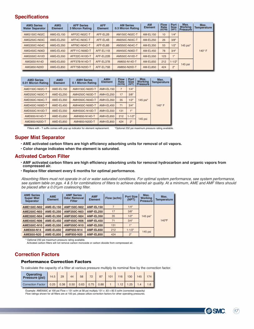
Performance Correction Factors
Correction Factors
Coalescing and Particulate Filters
Example: AMD550C at 100 psi Flow = 131 scfm at 58 psi multiply 131 x .63 = 82.5 scfm (corrected capacity)Flow ratings shown for all filters are at 100 psi, please utilize correction factors for other operating pressures.
Super Mist Separator
Absorbing filters must not operate in oil or water saturated conditions. For optimal system performance, see system performance,see system table on pgs. 4 & 5 for combinations of filters to achieve desired air quality. At a minimum, AME and AMF filters shouldbe placed after a 0.01µm coalescing filter.
* Optional 232 psi maximum pressure rating available. Activated carbon filters will not remove carbon monoxide or carbon dioxide from compressed air.
AMF SeriesOdor Removal
Filter
AME SeriesSuper MistSeparator
AMEElement
AMFElement
Max.WorkingPressure
Flow (scfm) Port Size(NPT)
Max.Temperature
Max.Temperature
FlowRate(SCFM)
PortSize(NPT)
Max.WorkingPressure
AMElementAM Series
0.3 Micron RatingAFF
ElementAFF Series
3 Micron RatingAMG
Element
AMG150C-N02C
AMG250C-N03C
AMG350C-N04C
AMG450C-N06D
AMG550C-N10D
AMG650-N14D
AMG850-N20D
145 psi*
145 psi
10
26
53
78
123
212
424
AM150C-N02C-T
AM250C-N03C-T
AM350C-N04C-T
AM450C-N06D-T
AM550C-N10D-T
AM650-N14D-T
AM850-N20D-T
AFF2C-N02C-T
AFF4C-N03C-T
AFF8C-N04C-T
AFF11C-N06D-T
AFF22C-N10D-T
AFF37B-N14D-T
AFF75B-N20D-T
AMG SeriesWater Separator
140° F
1/4"
3/8"
1/2"
3/4"
1"
1-1/2"
2"
AM-EL150
AM-EL250
AM-EL350
AM-EL450
AM-EL550
AM-EL650
AM-EL850
AFF-EL2B
AFF-EL4B
AFF-EL8B
AFF-EL11B
AFF-EL22B
AFF-EL37B
AFF-EL75B
AMG-EL150
AMG-EL250
AMG-EL350
AMG-EL450
AMG-EL550
AMG-EL650
AMG-EL850
Filters with - T suffix comes with pop up indicator for element replacement. *Optional 232 psi maximum pressure rating available.
Max.Temperature
FlowRate(SCFM)
PortSize(NPT)
Max.WorkingPressure
AMHElementAMH Series
0.1 Micron RatingAMD
Element
AMD150C-N02C-T
AMD250C-N03C-T
AMD350C-N04C-T
AMD450C-N06D-T
AMD550C-N10D-T
AMD650-N14D-T
AMD850-N20D-T
145 psi*
145 psi
7
17
35
71
131
212
424
AMH150C-N02D-T
AMH250C-N03D-T
AMH350C-N04D-T
AMH450C-N06D-T
AMH550C-N10D-T
AMH650-N14D-T
AMH850-N20D-T
AMD Series0.01 Micron Rating
140° F
1/4"
3/8"
1/2"
3/4"
1"
1-1/2"
2"
AMH-EL150
AMH-EL250
AMH-EL350
AMH-EL450
AMH-EL550
AMH-EL650
AMH-EL850
AMD-EL150
AMD-EL250
AMD-EL350
AMD-EL450
AMD-EL550
AMD-EL650
AMD-EL850
To calculate the capacity of a filter at various pressure multiply its nominal flow by the correction factor.
• AME activated carbon filters are high efficiency adsorbing units for removal of oil vapors.• Color change indicates when the element is saturated.
Activated Carbon Filter• AMF activated carbon filters are high efficiency adsorbing units for removal hydrocarbon and organic vapors from compressed air.• Replace filter element every 6 months for optimal performance.
Specifications
AMF150Cto 550C
AMF650/850
Series AMF
Nominal filtration rating: 0.01 µm[Filtration efficiency: 99.9%] Oil mist density at outlet:Max. 0.0032 ppm[ 0.004 mg/m3 (ANR)]
Carbon Filter
Odor Removal Filter
AME150Cto 550C
AME650/850
Series AME
Nominal filtration rating: 0.01 µm [Filtration efficiency: 99.9%]Oil mist density at outlet:Max. 0.008 ppm [ 0.01 mg/m3
(ANR)] Cleanliness at outlet: Not more than 100 particles ofsize 0.3 mm or larger/ft3 (35 particles or less/10 (ANR))
Super Mist Separator
Dust Filtration, Oil Mist Adsorption
AMH150Cto 550C AMH650/850
Series AMH
Built-in 0.3 µm pre-filterThe AM + AMD element havebeen integrated to achieve a space-saving design.Nominal filtration rating: 0.01 µm[Filtration efficiency: 99.9%]Oil mist density at outlet:Max. 0.08 ppm [ 1.0 mg/m3 (ANR)]
Micro Mist Separator with Pre-filter
Dust Filtration, Oil Coalescing
AMG150 to 550C AMG650/850
Series AMG
Water droplet separation rate: 99%
Water Droplet Removal
Water Separator
AFF2Cto 22C
AFF37B/75B
Series AFF
Nominal filtration rating: 3 µm[Filtration efficiency: 99%]
Main Line Filter
Large Dust Particle FiltrationOil Droplet Separation
AM150Cto 550C AM650/850
Series AM
Nominal filtration rating: 0.3 µm[Filtration efficiency: 99.9%] Oil mist density at outlet:Max. 0.8 ppm (1.0 mg/m3 [ANR])
Dust Filtration, Oil Coalescing
Mist Separator
AMD150Cto 550C AMD650/850
Series AMD
Nominal filtration rating: 0.01 µm[Filtration efficiency: 99.9%] Oil mist density at outlet:Max. 0.8 ppm[ 1.0 mg/m3 (ANR)]
Dust Filtration, Oil Coalescing
Micro Mist Separator
7173571
131212424
1/4"3/8"1/2"3/4"1"
1-1/2"2"
AME150C-N02AME250C-N03AME350C-N04AME450C-N06AME550C-N10AME650-N14AME850-N20
AME-EL150AME-EL250AME-EL350AME-EL450AME-EL550AME-EL650AME-EL850
AMF150C-N02AMF250C-N03AMF350C-N04AMF450C-N06AMF550C-N10AMF650-N14AMF850-N20
AMF-EL150AMF-EL250AMF-EL350AMF-EL450AMF-EL550AMF-EL650AMF-EL850
145 psi
145 psi*140ºF
Compressed Air Filters16 17
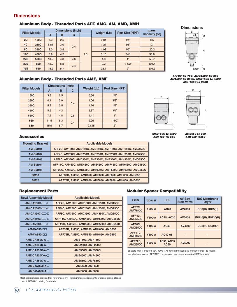
Option Symbol
F
O-ring and gasket material are changed from NBR to FKM for chemical compatibility
Option Symbol
T
Visual indication of differential pressure, facilitates element change prior to the recommended 15 psi(0.1 MPa).
Option Symbol
H
Max. operating pressure is increased from 145 psi(1 MPa) to 232 psi (1.6 MPa). Auto drain options are limited. For larger sizes (AFF37/75B, AM 650/850), please see AFW series when higher pressure is required
Option Symbol
V
Body/housing is degreasing washed. The lubrication grease for O-ring and gasket is changed to white vaseline.
Common Optional Specifications
Replacement Parts
Most part numbers provided for reference only. designates various configuration options, pleaseconsult AFF/AM* catalog for details.
Spacers with T brackets (ex. Y300 T-A) cannot be used due to interference. To mountmodularly connected AFF/AM* components, use one or more AM-BM* brackets.
Accessories
Aluminum Body - Threaded Ports AFF, AMG, AM, AMD, AMH
Aluminum Body - Threaded Ports AME, AMF
AM-CA150C- -
AM-CA250C- -
AM-CA350C- -
AM-CA450C- -
AM-CA550C- -
AM-CA650-
AM-CA850-
AME-CA150C-A-
AME-CA250C-A-
AME-CA350C-A-
AME-CA450C-A-
AME-CA550C-A-
AME-CA650-A
AME-CA850-A
AFF2C, AM150C, AMD150C, AMH150C, AMG150C
AFF4C, AM250C, AMD250C, AMH250C, AMG250C
AFF8C, AM350C, AMD350C, AMH350C, AMG350C
AFF11C, AM450C, AMD450C, AMH550C, AMG550C
AFF22C, AM550C, AMD550C, AMH550C, AMG550C
AFF37B, AM650, AMD650, AMH650, AMG650
AFF75B, AM850, AMD850, AMH850, AMG850
AME150C, AMF150C
AME250C, AMF250C
AME350C, AMF350C
AME450C, AMF450C
AME550C, AMF550C
AME650, AMF650
AME850, AMF850
AM-BM101
AM-BM102
AM-BM103
AM-BM104
AM-BM105
BM56
BM57
150C
250C
350C
450C
550C
650
850
0.66
1.06
1.76
2.87
4.41
9.26
23.15
AFF2C, AM150C, AMD150C, AME150C, AMF150C, AMH150C, AMG150C
AFF4C, AM250C, AMD250C, AME250C, AMF250C, AMH250C, AMG250C
AFF8C, AM350C, AMD350C, AME350C, AMF350C, AMH350C, AMG350C
AFF11C, AM450C, AMD450C, AME450C, AMF450C, AMH450C, AMG450C
AFF22C, AM550C, AMD550C, AMH550C, AMF550C, AMH550C, AMG550C
AFF37B, AM650, AMD650, AME650, AMF650, AMH650, AMG650
AFF75B, AM850, AMD850, AME850, AMF850, AMH850, AMG850
AME650 to 850AMF650 to850
AME150C to 550CAMF150 TO 550
AFF2C TO 75B, AMG150C TO 850AM150C TO 850C, AMD150C to 850C
AMH150C to 850C
Bowl Assembly Model Applicable Models
Mounting Bracket
Filter ModelsA B CDimensions (inch)
Weight (Lb) Port Size (NPT)
Filter ModelsA B C
Dimensions (inch) Weight (Lb) Port Size (NPT) BowlCapacity (oz)
Applicable Models
Dimensions
Modular Spacer Compatibility
AFF2C,AM 150C
AFF4C,AM 250C
AFF8C,AM 350C
AFF11C,AM 450C
AFF22C,AM 550C
0.841.211.983.104.69.2
23.1
8.510.120.333.850.7
101.4304.3
2C4C8C
11C22C37B75B
150C250C350C450C550C650850
3.3
4.1
5.2
5.6
7.4
11.5
15.9
2.5
3.0
3.5
4.2
4.8
6.3
8.7
IDG MembraneDryer
Made to Order Specifications
Option Code
X6
A differential pressure gauge (GD40-2-01) is installedon the filter to track filter life. This simplifies customerpiping and provides a compact design.
Option Code
X26
The external auto drain valve connection is changed from a One-touch fitting to a 1/4" female thread. N.C. type is not available on AFF37B and AM 650.
X37
Allows visual confirmation of differential pressure which indicates the element life. The built in contact enables remote signaling.
X12
Changes the grease for O-rings and gaskets to white vaseline.
Filter Spacer FRL AV SoftStart Valve
AC50, AC55AC60
AC20
AC25, AC30
AV2000
AV3000
IDG3(H), IDG5(H)
IDG10(H), IDG20(H)
AC40
AC40-06 -
AV4000 IDG30*~ IDG100*
AV5000
-
-
1/4”
3/8”
1/2”
3/4”
1”
1-1/2”
2”
0.6
0.4
0.4
2.53.03.54.24.86.38.7
6.36.818.08.9
10.212.218.2
0.6
0.4
0.4
1.5
1/4”3/8”1/2”3/4”1”
1-1/2”2”
Y200-A
Y300-A
Y400-A
Y500-A
Y600-A
Compressed Air Filters18 19
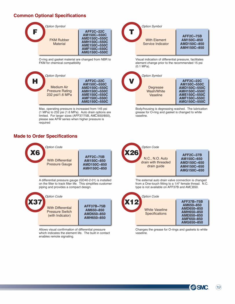
Option Symbol
F
O-ring and gasket material are changed from NBR to FKM for chemical compatibility
Option Symbol
T
Visual indication of differential pressure, facilitates element change prior to the recommended 15 psi(0.1 MPa).
Option Symbol
H
Max. operating pressure is increased from 145 psi(1 MPa) to 232 psi (1.6 MPa). Auto drain options are limited. For larger sizes (AFF37/75B, AM 650/850), please see AFW series when higher pressure is required
Option Symbol
V
Body/housing is degreasing washed. The lubrication grease for O-ring and gasket is changed to white vaseline.
Common Optional Specifications
Replacement Parts
Most part numbers provided for reference only. designates various configuration options, pleaseconsult AFF/AM* catalog for details.
Spacers with T brackets (ex. Y300 T-A) cannot be used due to interference. To mountmodularly connected AFF/AM* components, use one or more AM-BM* brackets.
Accessories
Aluminum Body - Threaded Ports AFF, AMG, AM, AMD, AMH
Aluminum Body - Threaded Ports AME, AMF
AM-CA150C- -
AM-CA250C- -
AM-CA350C- -
AM-CA450C- -
AM-CA550C- -
AM-CA650-
AM-CA850-
AME-CA150C-A-
AME-CA250C-A-
AME-CA350C-A-
AME-CA450C-A-
AME-CA550C-A-
AME-CA650-A
AME-CA850-A
AFF2C, AM150C, AMD150C, AMH150C, AMG150C
AFF4C, AM250C, AMD250C, AMH250C, AMG250C
AFF8C, AM350C, AMD350C, AMH350C, AMG350C
AFF11C, AM450C, AMD450C, AMH550C, AMG550C
AFF22C, AM550C, AMD550C, AMH550C, AMG550C
AFF37B, AM650, AMD650, AMH650, AMG650
AFF75B, AM850, AMD850, AMH850, AMG850
AME150C, AMF150C
AME250C, AMF250C
AME350C, AMF350C
AME450C, AMF450C
AME550C, AMF550C
AME650, AMF650
AME850, AMF850
AM-BM101
AM-BM102
AM-BM103
AM-BM104
AM-BM105
BM56
BM57
150C
250C
350C
450C
550C
650
850
0.66
1.06
1.76
2.87
4.41
9.26
23.15
AFF2C, AM150C, AMD150C, AME150C, AMF150C, AMH150C, AMG150C
AFF4C, AM250C, AMD250C, AME250C, AMF250C, AMH250C, AMG250C
AFF8C, AM350C, AMD350C, AME350C, AMF350C, AMH350C, AMG350C
AFF11C, AM450C, AMD450C, AME450C, AMF450C, AMH450C, AMG450C
AFF22C, AM550C, AMD550C, AMH550C, AMF550C, AMH550C, AMG550C
AFF37B, AM650, AMD650, AME650, AMF650, AMH650, AMG650
AFF75B, AM850, AMD850, AME850, AMF850, AMH850, AMG850
AME650 to 850AMF650 to850
AME150C to 550CAMF150 TO 550
AFF2C TO 75B, AMG150C TO 850AM150C TO 850C, AMD150C to 850C
AMH150C to 850C
Bowl Assembly Model Applicable Models
Mounting Bracket
Filter ModelsA B CDimensions (inch)
Weight (Lb) Port Size (NPT)
Filter ModelsA B C
Dimensions (inch) Weight (Lb) Port Size (NPT) BowlCapacity (oz)
Applicable Models
Dimensions
Modular Spacer Compatibility
AFF2C,AM 150C
AFF4C,AM 250C
AFF8C,AM 350C
AFF11C,AM 450C
AFF22C,AM 550C
0.841.211.983.104.69.2
23.1
8.510.120.333.850.7
101.4304.3
2C4C8C
11C22C37B75B
150C250C350C450C550C650850
3.3
4.1
5.2
5.6
7.4
11.5
15.9
2.5
3.0
3.5
4.2
4.8
6.3
8.7
IDG MembraneDryer
Made to Order Specifications
Option Code
X6
A differential pressure gauge (GD40-2-01) is installedon the filter to track filter life. This simplifies customerpiping and provides a compact design.
Option Code
X26
The external auto drain valve connection is changed from a One-touch fitting to a 1/4" female thread. N.C. type is not available on AFF37B and AM 650.
X37
Allows visual confirmation of differential pressure which indicates the element life. The built in contact enables remote signaling.
X12
Changes the grease for O-rings and gaskets to white vaseline.
Filter Spacer FRL AV SoftStart Valve
AC50, AC55AC60
AC20
AC25, AC30
AV2000
AV3000
IDG3(H), IDG5(H)
IDG10(H), IDG20(H)
AC40
AC40-06 -
AV4000 IDG30*~ IDG100*
AV5000
-
-
1/4”
3/8”
1/2”
3/4”
1”
1-1/2”
2”
0.6
0.4
0.4
2.53.03.54.24.86.38.7
6.36.818.08.9
10.212.218.2
0.6
0.4
0.4
1.5
1/4”3/8”1/2”3/4”1”
1-1/2”2”
Y200-A
Y300-A
Y400-A
Y500-A
Y600-A
Compressed Air Filters18 19
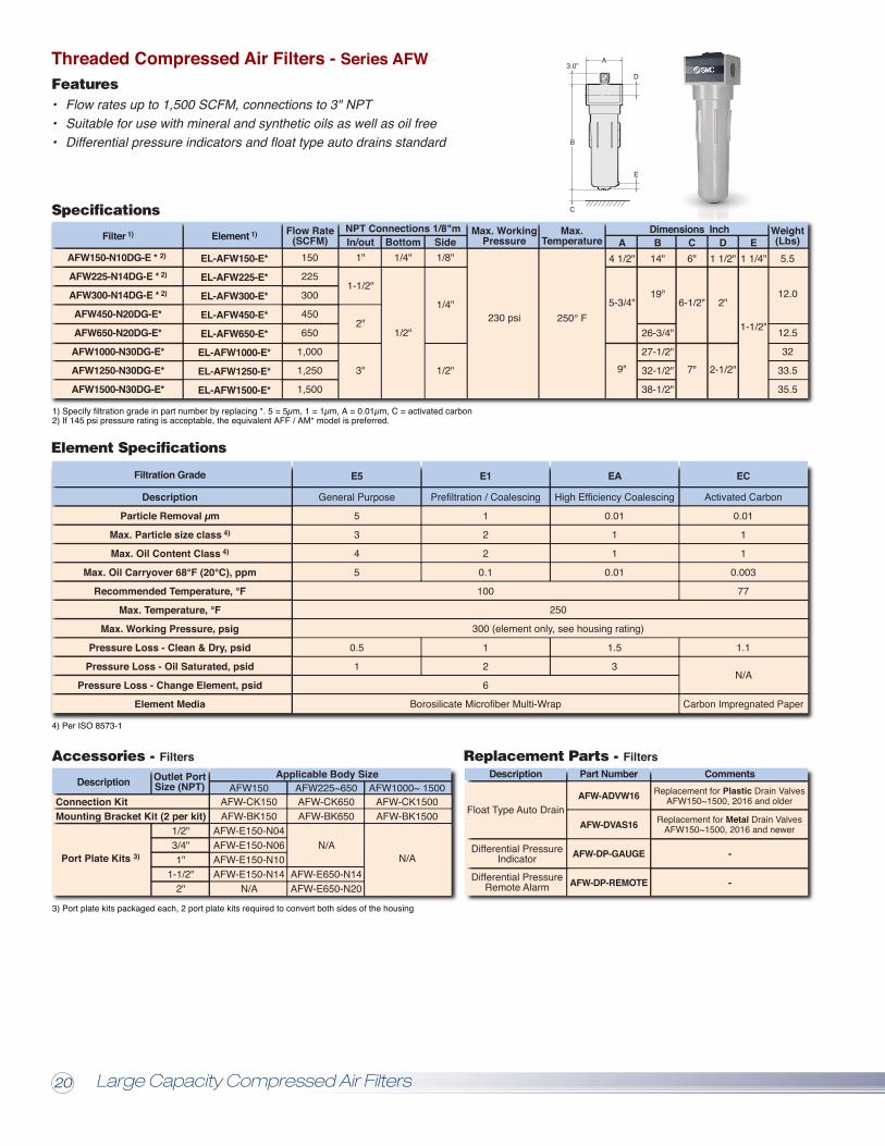
Dimensions InchSpecifications
AFW150-N10DG-E * 2)
AFW225-N14DG-E * 2)
AFW300-N14DG-E * 2)
AFW450-N20DG-E*
AFW650-N20DG-E*
AFW1000-N30DG-E*
AFW1250-N30DG-E*
AFW1500-N30DG-E*
Filter 1)
EL-AFW150-E*
EL-AFW225-E*
EL-AFW300-E*
EL-AFW450-E*
EL-AFW650-E*
EL-AFW1000-E*
EL-AFW1250-E*
EL-AFW1500-E*
Element 1)A
5-3/4"
4 1/2"
9"
14"B
19"
26-3/4"
27-1/2"
32-1/2"
38-1/2"
6"
6-1/2"
7"
C1 1/2"
2"
2-1/2"
D150
225
300
450
650
1,000
1,250
1,500
Flow Rate(SCFM)
5.5
12.0
12.5
32
33.5
35.5
Weight(Lbs)
1"
1-1/2"
2"
3"
In/out1/4"
1/2"
BottomNPT Connections 1/8"m
1/8"
1/4"
1/2"
Side
230 psi
Max. WorkingPressure
250° F
1 1/4"E
1-1/2"
Max.Temperature
1) Specify filtration grade in part number by replacing *. 5 = 5µm, 1 = 1µm, A = 0.01µm, C = activated carbon2) If 145 psi pressure rating is acceptable, the equivalent AFF / AM* model is preferred.
A
B
3.0”
C
D
E
• Flow rates up to 1,500 SCFM, connections to 3" NPT• Suitable for use with mineral and synthetic oils as well as oil free• Differential pressure indicators and float type auto drains standard
Correction FactorFor maximum flow rate, multiply model flow rate shown in the specification table by the correction factor shown below corresponding to the working pressure. This applies to all filtration grades as well as the water separator models.
Example: AFW650-N20-E1Rated flow = 650 SCFM, working pressure = 115 psiCorrection factor = 1.07 �� max flow = 650 x 1.07 = 696 SCFM
Operating Pressure (psi)
Correction Factor
Specifications - Centrifugal Water Separators (Threaded)
AFW175A-N10D-WSAFW275A-N12D-WSAFW400A-N14D-WSAFW700A-N20D-WSAFW850A-N25D-WSAFW1500A-N30D-WS
Model Number Flow Rate Connections Weight
3.75
10.80
17.64
LbsDimensions (in)
5.0
6.7
8.7
A1.3
2.1
2.8
B11.2
20.0
16.5
C3.1
3.9
D
Max. recommended operating temperatureMin. recommended operating temperatureTypical pressure loss at rated flowMax. working pressure
248°F (176ºF w/float drain)35°F0.7 psi 232 psig (300 psig w/manual drain)
• Flow rates up to 1,500 SCFM• Threaded connections to 3" NPT• Suitable for use with mineral and synthetic oils as well as oil free• Float type auto drains standard up to 1500 SCFM• Float and drain can be changed from outside bowl
Centrifugal Water Separators - Series AFW-WSFeatures
Threaded Compressed Air Filters - Series AFWFeatures
Consult Factory for Higher Flow Flanged Filter or Water Separator Units
Accessories - Water Separators
DescriptionApplicable Body Size Applicable Body Size (Old Style)
AFW-MBK175AFW175
AFW-MBK700AFW400~700
AFW-MBK325AFW275~325
AFW-MBK1500AFW850~ 1500
Element Specifications
Description
Particle Removal µm
Max. Particle size class 4)
Max. Oil Content Class 4)
Max. Oil Carryover 68°F (20°C), ppm
Recommended Temperature, °F
Max. Temperature, °F
Max. Working Pressure, psig
Pressure Loss - Clean & Dry, psid
Pressure Loss - Oil Saturated, psid
Pressure Loss - Change Element, psid
Element Media
Filtration Grade
4) Per ISO 8573-1
E5
General Purpose
5
3
4
5
0.5
1
250
300 (element only, see housing rating)
EC
Activated Carbon
0.01
1
1
0.003
77
1.1
N/A
Carbon Impregnated Paper
3/4” G(w/o auto
drain)1/8” NPT
(femaleconnections
on auto drain)
Bottom*1" NPT
1-1/4" NPT1-1/2" NPT
2" NPT2-1/2" NPT
3" NPT
In/Out
Accessories - Filters Replacement Parts - Filters
Connection KitMounting Bracket Kit (2 per kit)
Port Plate Kits 3)
DescriptionApplicable Body Size
1/2"3/4"1"
1-1/2"2"
Outlet PortSize (NPT)
3) Port plate kits packaged each, 2 port plate kits required to convert both sides of the housing
AFW-CK150AFW-BK150
AFW-E150-N04AFW-E150-N06AFW-E150-N10AFW-E150-N14
N/A
AFW150AFW-CK650AFW-BK650
N/A
AFW-E650-N14AFW-E650-N20
AFW225~650AFW-CK1500AFW-BK1500
N/A
AFW1000~ 1500Description Comments
-
-
Float Type Auto Drain
Differential PressureIndicator
Replacement for Plastic Drain ValvesAFW150~1500, 2016 and older
Replacement for Metal Drain ValvesAFW150~1500, 2016 and newer
Differential PressureRemote Alarm
Part Number
AFW-ADVW16
AFW-DVAS16
AFW-DP-GAUGE
AFW-DP-REMOTE
E1
Prefiltration / Coalescing
1
2
2
0.1
100
1
2
6
Borosilicate Microfiber Multi-Wrap
1752804007008501500
SCFM
A
B
C
D 42mmapprox.
Wall Mounting Bracket KitConnecting kit, 2 housingsConnecting kit, 3 housingsConnecting kit, 4 housings
AFW-MBK175AAFW-CK175-2AAFW-CK175-3AAFW-CK175-4A
AFW175AFW-MBK1500AAFW-CK1500-2AAFW-CK1500-3AAFW-CK1500-4A
AFW850A~1500AAFW-MBK700AAFW-CK700-2AAFW-CK700-3AAFW-CK700-4A
AFW400~700A
Replacement Parts - Water Separators
AFW-MBK325AFW275~325
Description
Float Type Auto Drain, N.O.
Manually operateddrain valve
Float Type Auto Drain, N.O.
Spinner
CommentsPart NumberAFW-ADVS16
AFW-ADVSE16AFW-MDV25
AFW-MDVE25
AFW-DVAS16
AFW-CM-059-108AFW-CM-128-159AFW-CM-159-208AFW-CM-254-340
Replacement for AFW175-WS, AFW175A-WS
Replacement for metal drain valves,AFW175~1500-WS (old style)
Replacement for AFW275~325-WS, AFW275A-WSReplacement for AFW400~700-WS, AFW400A~700A-WS
Replacement for AFW850~1500-WS, AFW850A~1500A-WS
Optional type for AFW175A~1500A-WSExternally accessible type, standard for AFW175A~1500A-WS
Optional type for AFW175A~1500A-WSExternally accessible type, for AFW175A~1500A-WS, 300 psi
*Bottom drain, with mechanical float drain.
EA
High Efficiency Coalescing
0.01
1
1
0.01
1.5
3
4
0.21
14.5
0.38
44
0.65
72
0.84
100
1.00
130
1.13
160
1.25
189
1.36
218
1.46
9
0.29
29
0.53
58
0.76
87
0.92
115
1.07
145
1.19
174
1.31
203
1.41
232
1.51
Large Capacity Compressed Air Filters20 21
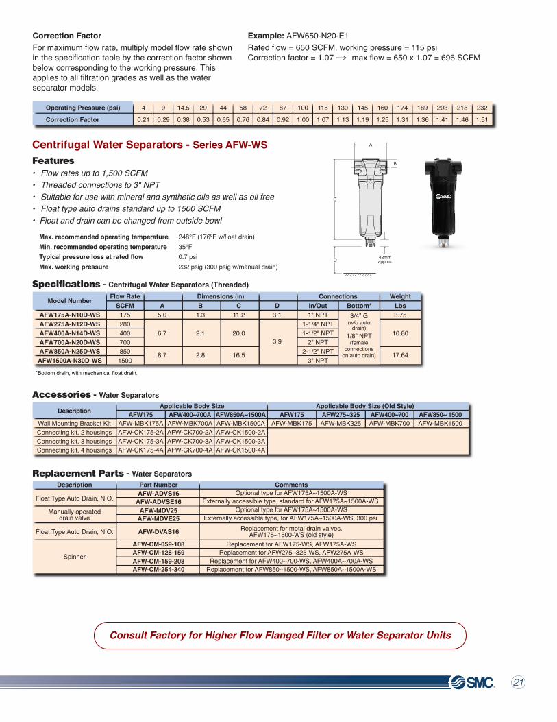
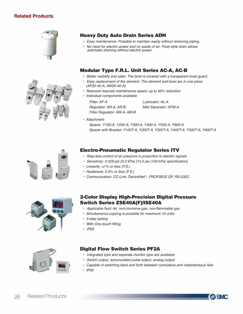
• Easy maintenance. Possible to maintain easily without removing piping.• No need for electric power and no waste of air. Float style drain allows automatic draining without electric power
Filter: AF-ARegulator: AR-A, AR-BFilter Regulator: AW-A. AW-B
Spacer: Y100-A, Y200-A, Y300-A, Y400-A, Y500-A, Y600-ASpacer with Bracket: Y100T-A, Y200T-A, Y300T-A, Y400T-A, Y500T-A, Y600T-A
Lubricator: AL-AMist Separator: AFM-A
Heavy Duty Auto Drain Series ADH
• Better visibility and safer. The bowl is covered with a transparent bowl guard.• Easy replacement of the element. The element and bowl are in one piece (AF20-40-A, AW20-40-A)• Reduced required maintenance space: up to 46% reduction• Individual components available
• Attachment
Modular Type F.R.L. Unit Series AC-A, AC-B
• Step-less control of air pressure in proportion to electric signals.• Sensitivity: 0.029 psi (0.2 kPa) [14.5 psi (100 kPa) specification]• Linearity: ±1% or less (F.S.)• Hysteresis: 0.5% or less (F.S.)• Communication: CC-Link, DeviceNetTM, PROFIBUS DP, RS-232C
Electro-Pneumatic Regulator Series ITV
• Integrated type and separate monitor type are available.• Switch output, accumulated pulse output, analog output• Capable of switching back and forth between cumulative and instantaneous flow• IP65
Digital Flow Switch Series PF2A
• 560,00 sq. ft. total manufacturing space and 571,000 sq. ft. of warehouse space• Additional investment in warehouse space to increase inventory levels• Incorporating FTZ are within the expanded warehouse reducing overseas delivery time
• View and Download 2D & 3D CAD Models.
• Files Available in Multiple Formats. Including Solidworks, Catia, and others. compatible with Virtually any CAD System.
• CAD Model will match the Specified Part you have Designed and Validated.
• CAD File can be Saved for Future Reference or Placed Directly into your Project Design.
Global Products / Local Support
Engineering/Innovation
• Applicable fluid: Air, non-corrosive gas, non-flammable gas• Simultaneous copying is possible for maximum 10 units.• 3-step setting• With One-touch fitting• IP65
2-Color Display High-Precision Digital PressureSwitch Series ZSE40A(F)/ISE40A
SMC North American Headquarters, Manufacturing and Central Distribution Facility
Related Products Digital Pneumatic Products Builder
The North American Manufacturing andCentral Warehouse expansion has positioned SMC to support sales andgrowth in the U.S. and Canada.
Create, View & Download 2D & 3D Models OnlineUpdate in Real-Time
Design & Save Parts into a Custom Parts List.
Point Your Browser to:
www.smcusa.com/cad/
Validate Your Part Number
Digital Pneumatic Products BuilderRelated Products 2322
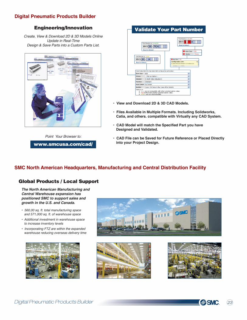
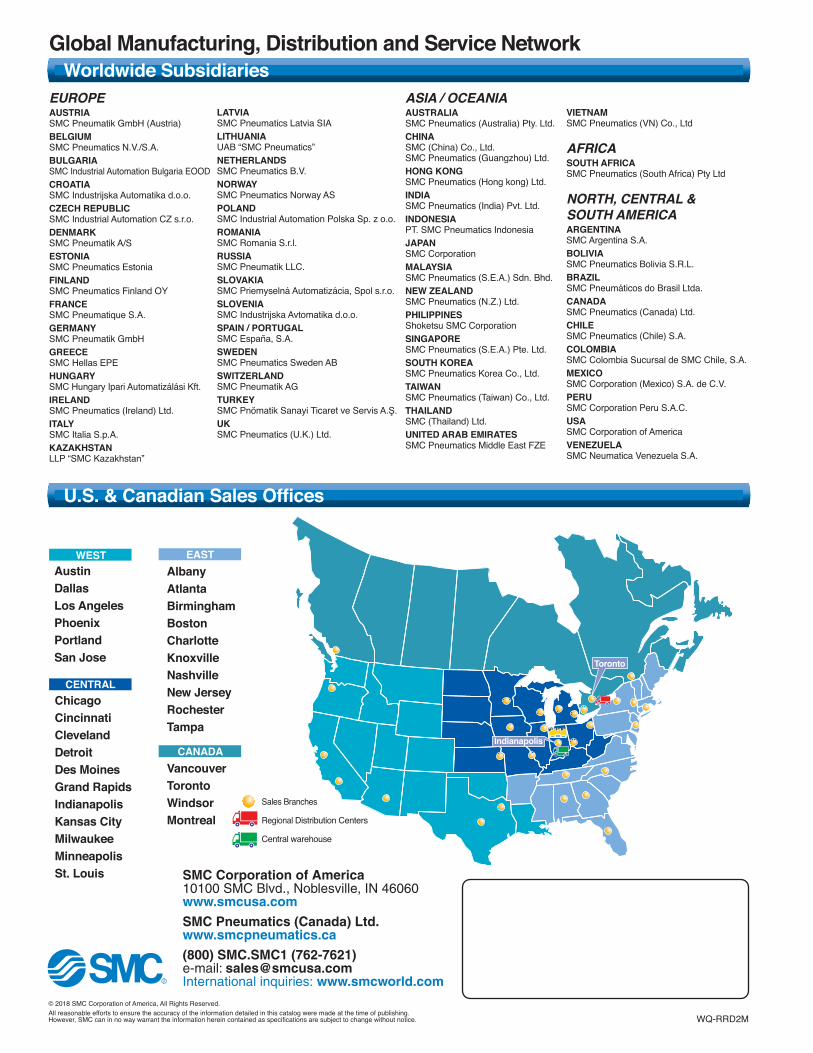
Global Manufacturing, Distribution and Service Network
AlbanyAtlantaBirminghamBostonCharlotteKnoxvilleNashvilleNew JerseyRochesterTampa
AustinDallasLos AngelesPhoenixPortlandSan Jose
ChicagoCincinnatiClevelandDetroitDes MoinesGrand RapidsIndianapolisKansas CityMilwaukeeMinneapolisSt. Louis
EAST
VancouverTorontoWindsorMontreal
CANADA
CENTRAL
WEST
© 2018 SMC Corporation of America, All Rights Reserved.All reasonable efforts to ensure the accuracy of the information detailed in this catalog were made at the time of publishing.However, SMC can in no way warrant the information herein contained as specifications are subject to change without notice.
Indianapolis
Toronto
Sales Branches
Regional Distribution Centers
Central warehouse
0WQ-RRD2M
Worldwide Subsidiaries
U.S. & Canadian Sales Offices
EUROPEAUSTRIASMC Pneumatik GmbH (Austria)BELGIUMSMC Pneumatics N.V./S.A.BULGARIASMC Industrial Automation Bulgaria EOODCROATIASMC Industrijska Automatika d.o.o.CZECH REPUBLICSMC Industrial Automation CZ s.r.o.DENMARKSMC Pneumatik A/SESTONIASMC Pneumatics EstoniaFINLANDSMC Pneumatics Finland OYFRANCESMC Pneumatique S.A.GERMANYSMC Pneumatik GmbHGREECESMC Hellas EPEHUNGARYSMC Hungary Ipari Automatizálási Kft.IRELANDSMC Pneumatics (Ireland) Ltd.ITALYSMC Italia S.p.A.KAZAKHSTANLLP “SMC Kazakhstan”
LATVIASMC Pneumatics Latvia SIALITHUANIAUAB “SMC Pneumatics”NETHERLANDSSMC Pneumatics B.V.NORWAYSMC Pneumatics Norway ASPOLANDSMC Industrial Automation Polska Sp. z o.o.ROMANIA SMC Romania S.r.l.RUSSIA SMC Pneumatik LLC.SLOVAKIASMC Priemyselná Automatizácia, Spol s.r.o.SLOVENIASMC Industrijska Avtomatika d.o.o.SPAIN / PORTUGALSMC España, S.A.SWEDENSMC Pneumatics Sweden ABSWITZERLANDSMC Pneumatik AGTURKEYSMC Pnömatik Sanayi Ticaret ve Servis A.Ş.UKSMC Pneumatics (U.K.) Ltd.
ASIA / OCEANIAAUSTRALIASMC Pneumatics (Australia) Pty. Ltd.CHINASMC (China) Co., Ltd.SMC Pneumatics (Guangzhou) Ltd.HONG KONGSMC Pneumatics (Hong kong) Ltd.INDIASMC Pneumatics (India) Pvt. Ltd.INDONESIAPT. SMC Pneumatics IndonesiaJAPANSMC CorporationMALAYSIASMC Pneumatics (S.E.A.) Sdn. Bhd.NEW ZEALANDSMC Pneumatics (N.Z.) Ltd.PHILIPPINESShoketsu SMC CorporationSINGAPORESMC Pneumatics (S.E.A.) Pte. Ltd.SOUTH KOREASMC Pneumatics Korea Co., Ltd.TAIWANSMC Pneumatics (Taiwan) Co., Ltd.THAILANDSMC (Thailand) Ltd.UNITED ARAB EMIRATESSMC Pneumatics Middle East FZE
VIETNAMSMC Pneumatics (VN) Co., Ltd
AFRICASOUTH AFRICASMC Pneumatics (South Africa) Pty Ltd
NORTH, CENTRAL &SOUTH AMERICAARGENTINASMC Argentina S.A.BOLIVIASMC Pneumatics Bolivia S.R.L.BRAZILSMC Pneumáticos do Brasil Ltda. CANADASMC Pneumatics (Canada) Ltd.CHILESMC Pneumatics (Chile) S.A.COLOMBIASMC Colombia Sucursal de SMC Chile, S.A.MEXICOSMC Corporation (Mexico) S.A. de C.V.PERUSMC Corporation Peru S.A.C.USASMC Corporation of AmericaVENEZUELASMC Neumatica Venezuela S.A.


