Embed Size (px)
Citation preview

Constitutive Modeling and Simulation of Perforationof Targets by Projectiles
George Z. Voyiadjis∗ and Rashid K. Abu Al-Rub†
Louisiana State University, Baton Rouge, Louisiana 70803
and
Anthony N. Palazotto‡
U.S. Air Force Institute of Technology, Wright–Patterson Air Force Base, Ohio 45433-7765
DOI: 10.2514/1.26011
The effective use of existing finite element codes in the direct simulation of hypervelocity impacts by projectiles is
limited by the dependence of the size of localized failure regions on the mesh size and alignment. This gives rise to a
nonphysical description of the penetration and perforation processes. A micromechanical constitutive model that
couples the anisotropic thermoviscodamage mechanism with the thermohypoelastoviscoplastic deformation is
presented here as a remedy to this situation. Explicit and implicit microstructural length-scale measures, which
preserve the well-posed nature of the differential equations, are introduced through the use of the viscosity and
gradient localization limiters. Simple and robust numerical algorithms for the integration of the constitutive
equations are also presented. The proposed unified integration algorithms are extensions of the classical rate-
independent return-mapping algorithms to the rate-dependent problems. A simple and direct computational
algorithm is also used for implementing the gradient-dependent equations. This algorithm canbe implemented in the
existing finite element codes without numerous modifications, compared with the current numerical approaches for
integrating gradient-dependent models.Model capabilities are preliminarily illustrated for the dynamic localization
of inelastic flow in adiabatic shear bands and the perforation of a 12-mm-thick Weldox 460E steel plate by a
deformable blunt projectile at various impact speeds.
Introduction
T HE recent advances in aerospace and war capabilities havemade necessary the modification of the design of structures so
that they can resist penetration and perforation by projectiles withmuch higher impact energies. In this respect, high-performancematerials need to be developed so that they can offer significantadvantages over the currently used materials. Specific mechanicalproperties are targeted by the aid of these newmaterials, such as highspecific strength, high stiffness, and low coefficient of thermalexpansion. Moreover, studies of hypervelocity impact phenomenaaremotivated by a variety of science and engineering applications [1]such as kinetic energy penetrators [2], engineering research on thedesign of spacecraft shielding [3], and equations of state [4].Therefore, the high-velocity impacting mechanism needs to beunderstood properly to be able to design materials of high ballistic-resistant response. However, the exact mechanism by which theimpacting target materials undergo fracture and ablation is arelatively complex process [5]. Generally, strong shock wave andmaterial interactions are generated and propagated along both theprojectile and the target, which can lead to fracture at low globalinelastic strains. Phenomenologically, as illustrated in Fig. 1, thepenetration can be viewed as a process to generate a cone-shapedmacrocrack in the material, in which the kinetic energy of thepenetrator is dissipated.
Considering the relatively high cost of conducting experiments [6]that may shed some light on the design of high-performancematerials under hypervelocity impacts and the wide range of designparameters requiring investigation [7], the development of improvedcomputer simulation tools as an adjunct to experimental work forsuch problems is of significant interest. Reference [1] shows that theuse of computer simulation in this field is increasing, such thatimprovements in numerical methods and computing power make itpossible to address problems of greater complexity and larger scale.Simulation work in this field has applied a number of differentnumerical methods based on continuum mechanics, particledynamics, or mixed kinematic schemes. Continuum methods [8]employ either an Eulerian hydrodynamic [9] or a Lagrangian finiteelement [10] approach, or some arbitrary Lagrangian–Eulerian(ALE)-based generalization of these techniques [11]. A largemajority of particle codes employ a smooth particle hydrodynamicstechnique [12,13]. Some disadvantages of pure continuum-based orpure particle-based methods have motivated the development ofmixed continuum–particle formulations [3,14–16]. However, theeffective use of existing computer codes in the direct simulation ofhypervelocity impacts is limited by the ability to obtaindiscretization-independent deformation results. During impactloading, large inelastic deformation associated with high strain ratesleads, for a broad class of brittle and ductile materials, to degradationand failure by strain localization (i.e., shear bands); therefore, as soonas material failure dominates a deformation process, the materialincreasingly displays strain-softening, and the finite elementcomputations are considerably affected by the mesh size andalignment when using the classical (local) continuum theories ofplasticity and damage. This gives rise to a nonphysical description ofthe material and structural failure. This can be attributed to theabsence of an intrinsic material-length-scale parameter in theconstitutive description of the plasticity and damage models, suchthat this length scale can improve the well-posed nature of the solved(initial) boundary-value problem. Therefore, the objective of thiswork is to present a novel microdamage constitutive model for high-speed-impact damage problems that possesses several materiallength scales. This model can be used to produce physically
Presented as Paper 2089 at the 47th AIAA/ASME/ASCE/AHS/ASCStructures, Structural Dynamics, and Materials Conference, Newport, RI, 1–4 May 2006; received 19 June 2006; revision received 7 December 2006;accepted for publication 8 December 2006. Copyright © 2007 by theAmerican Institute of Aeronautics and Astronautics, Inc. All rights reserved.Copies of this paper may be made for personal or internal use, on conditionthat the copier pay the $10.00 per-copy fee to theCopyright Clearance Center,Inc., 222RosewoodDrive,Danvers,MA01923; include the code 0001-1452/08 $10.00 in correspondence with the CCC.
∗Boyd Professor, Department of Civil and Environmental Engineering;[email protected]. Associate Fellow AIAA.
†Professional-in-Residence, Department of Civil and EnvironmentalEngineering; [email protected].
‡Professor, Department of Aeronautics and Astronautics. Fellow AIAA.
AIAA JOURNALVol. 46, No. 2, February 2008
304

meaningful and numerically converging results within strain
localization computations by finite element codes. Moreover, the
algorithmic aspects and numerical implementation of this model in
finite element codes are presented in this paper.The key role in the numerical simulation of the impact-damage-
related problems is the accurate modeling of the material behavior athigh strain rates and temperatures. Many researchers, therefore, haveinvestigated the material failure mechanism during high-velocity-impact conditions with the ultimate goal of developing amicromechanical constitutive model that can effectively simulatethe impact damage problem (see, for example, [17–26]). It is notedthat none of these constitutive models address the problem ofdescribing high shock compression and subsequent materialdegradation and failure, in which the latter is expressed as anevolving microflaw having a damage rate determined frommicromechanical analysis. Moreover, these models cannot considerthe actual sizes, shapes, and orientations of the individualmicrovoidsand microcracks, which may have a predominant influence on themechanical response of the material. The authors of this work haverecently recognized the need for a micromechanical damage model[27–30] that accounts for the nonlocal microscopic interactionsbetween material points (i.e., to take into account the influence of aninternal state variable at a point on its neighborhood) in thesimulation of metal impact problems. This nonlocal microdamagemodel is formulated based on the enhanced gradient-dependenttheory, which is successful in explaining the size effects encounteredat the micron scale and in preserving the well-posed nature of theinitial boundary-value problem that governs the solution of materialinstability triggering strain localization (see Voyiadjis et al. [27,28]and Abu Al-Rub and Voyiadjis [30] for details regarding the use ofthe gradient theory as a localization limiter, as well as an extensivelist of authors who used this approach).Moreover, the viscoplasticitytheory (rate dependency) allows the spatial difference operator in thegoverning equations to retain its ellipticity and, consequently, theinitial boundary-value problem is hence well-posed (see, forexample, [31–38]). However, the gradient-dependent theoriesenhance a stronger regularization of the localization problem than therate-dependent theory. Moreover, the rate-dependent theory cannotexplain the size effect of the microdamage zone (i.e., the void/cracksize and spacing) on the material failure, whereas the gradient theorycan address that.
In this study, a general theoretical framework for the analysis ofheterogeneous media that assesses a strong coupling between rate-dependent plasticity and anisotropic rate-dependent damage ispresented for high-velocity-impact-related problems. This frame-work is developed based on thermodynamic laws, nonlinearcontinuummechanics, and nonlocal gradient-dependent theory [27–30]. This model uses combined viscosity and nonlocal gradientlocalization limiters to regularize the dynamic strain localizationproblem. Material length scales are incorporated explicitly throughthe nonlocal gradient theory and implicitly through the rate-dependency (viscoplasticity). The proposed formulation includeshypoelastothermoviscoplasticity with anisotropic thermovisco-damage, a dynamic yield criterion, a dynamic damage growthcriterion, nonassociated flow rules, thermal softening, nonlinearstrain hardening, strain-rate hardening, strain-hardening gradients,strain-rate-hardening gradients, and an equation of state. The idea of
bridging length scales is made more general and complete byintroducing spatial higher-order gradients in the temporal evolutionequations of the internal state variables that describe hardening incoupled viscoplasticity and viscodamage models. The model ismainly developed to regularize the ill-posed problem caused bystrain-softening material behavior and to incorporate the size effect(size and spacing of microdefects) in material behavior for high-velocity-impact damage-related problems.
The development of computational algorithms that are consistentwith the proposed theoretical formulation is given in detail in thispaper. The problem of numerically integrating the constitutiveequations in the context of the finite element method is alsoaddressed. The standard return-mapping algorithms of rate-independent problems are extended to rate-dependent problems.Moreover, because the numerical implementation of the gradient-dependent constitutive equations is not a direct task (because of thehigher order of the governing equations), a direct and simplecomputational algorithm for the gradient approach is used. Thisalgorithm can be implemented in the existing finite element codeswithout numerous modifications, compared with the currentnumerical approaches for gradient-enhanced models (see Voyiadjiset al. [28]). Furthermore, a trivially incrementally objectiveintegration scheme is established for the rate constitutive relations.The proposed elastic predictor and coupled viscoplastic–visco-damage corrector algorithm allows for total uncoupling ofgeometrical and material nonlinearities. The nonlinear algebraicsystem of equations is solved by consistent linearization and theNewton–Raphson iteration. The proposed model is implemented inthe explicit finite element code ABAQUS via the user subroutineVUMAT [39]. In this work, complete details are presented for theimplementation of the proposed novel numerical algorithms.
Model capabilities are preliminarily illustrated for the dynamiclocalization of inelastic flow in adiabatic shear bands and comparedwith the experimental results of Borvik et al. [23] for the perforationof 12-mm-thick Weldox 460E steel plates by deformable bluntprojectiles at various impact speeds.
Microdamage Constitutive Model
Generally, three sets of equations are needed to simulate theimpact damage problems: a yield criterion (which incorporates thestrain rate and temperature effects on the material’s strength), anequation of state (which accounts for material pressure sensitivity),and a damagemodel (which is needed to simulate progressive failureand fracture). The coupled constitutive model of viscoplasticity andductile viscodamage (rate-dependent damage) used to predictmaterial behavior under dynamic loading conditions (which wasearlier derived based on the laws of thermodynamics [27–30])combines all these requirements. Only the main governingconstitutive equations will be given in the following. The model isbased on the nonlocal gradient plasticity and gradient damagetheories. It includes the nonlocal von Mises yield criterion, thenonassociated flow rules, isotropic and anisotropic strain hardening,strain-rate hardening, softening due to adiabatic heating andanisotropic damage evolution, and a path-dependent equation ofstate. The stress–strain rate relationship in the spatial and damagedconfiguration is given by
�r �C:�d � dvp � dvd� �A:�
r� C:�t _T1 (1)
with
C �M_ �1
: �C:M_ �1
and M_
� 2��1 � �_
� � 1� 1� �1 � �_
���1
(2)
where r indicates the corotational objective derivative; � is theKirchhoff stress tensor; d is the total rate of deformation; dvp is theviscoplastic rate of deformation; dvd is the viscodamage rate of
deformation; �C andC are the fourth-order undamaged and damagedelasticity tensors, respectively; �t is the thermal expansion
Existing Cracks and Voids as Damage Enhancement
Grain Translation and Rotation
Zones of High Irrecoverable Deformations as Shock Buffer, Interface
Shock Wave, Compression Wave is Reflected as Tensile Wave at Free Boundary
Shock Wave
Projectile
v(t) Target
Shear/Tension Zone
Fig. 1 Phenomenological illustration of the penetration process.
VOYIADJIS, ABU AL-RUB, AND PALAZOTTO 305

coefficient; _T is the rate of absolute temperature; and 1 is the second-order identity tensor.
The fourth-order tensors �C and A are given by the followingrelations:
�C� Ke1� 1� 2GeIdev
A� @M_ �1
@�_ :M
_
:��C:M_
:@M
_ �1
@�_ : �C�1:��� �t�T � Tr�1�
(3)
where Ke is the bulk modulus, Ge is the shear modulus, Tr is thereference temperature, and Idev is the deviatoric part of the fourth-order identity tensor I. In the undamaged configuration, Eq. (1) canbe written as follows:
��r� �C:� �d � �dvp� � �t _T1 (4)
Note that hereafter, (:) stands for tensor contraction, thesuperimposed dot �� indicates the differentiationwith respect to timet, the superimposed hat indicates a nonlocal quantity, thesuperimposed dash indicates a quantity in the undamaged (effective)configuration, and � denotes the dyadic product.
Materials with microstructure are nonlocal in behavior, due to theinterplay of characteristic lengths, including the sizes or spacing ofdefect clusters (e.g., microcracks, microvoids, and dislocations).Because traditional continuum mechanics does not containcharacteristic lengths, the use of the nonlocal concept is required toincorporate a microstructural length scale that introduces long-rangemicrostructural interactions in which the stress response at a materialpoint is assumed to depend on the state of its neighborhood inaddition to the state of the material point itself. Moreover, this lengthscale preserves the well-posed nature of the initial boundary-valueproblem governing the solution of material instability triggeringstrain localization. In the following, the nonlocality is incorporatedthrough the use the gradient-dependent theory, such that if� is some
“local” field in a domain V, the corresponding nonlocal field �_
isdefined as follows:
�_
� �� 12‘2r2� (5)
where ‘ is the internal material length scale, which weights eachcomponent of the gradient term identically, and r2 is the Laplacianoperator. The length scale ‘ should be obtained from gradient-dominant experiments such as indentation tests, bending tests, ortorsion tests [40–42]. The role of the material length scale in solvingthe impact damage problem and in preserving the objectivity of thecontinuum modeling and numerical simulation of the localizationproblem is the main concern of this paper. The first-order gradientsare disregarded because the isotropic nonlocal influence is assumed.
The viscoplastic rate of deformation dvp, the viscodamage rate ofdeformation dvd, the rate of the second-order damage tensor �, andthe viscoplastic rate of deformation in the undamaged configuration�dvp are given as follows:
dvp � _�vp @f
@�; dvd � _�
vd @g
@�
�r� _�
vp @f
@Y� _�
vd @g
@Y; �dvp � _�
vp @f
@ ��
(6)
where the potentials f and g are the nonlocal viscoplastic andviscodamage conditions given in the undamaged (effective)configuration, respectively, by
f����������������������������������������32� ��0 � �X
_
�:� ��0 � �X_
�r
� � �Yyp ��R_
� �p_��1� ��v _�p_�1=m�
�1 � �T=Tm�n� � 0 (7)
g���������������������������������������Y_
�H_
�:�Y_
�H_
�q
� �ro � K_
�r_���1� ��v_�p_�1=m�
�1 � �T=Tm�n� � 0 (8)
where ��0 is the effective deviatoric stress tensor; �Yyp is the initialyield strength (at zero absolute temperature, zero plastic strain, and
static strain rate);�R_
� �p_� is the nonlocal isotropic hardening function,�X_
is the nonlocal anisotropic (kinematic) hardening stress;
�p�Zt
0
������������������2
3�dvpij
�dvpij
rdt
is the effective accumulative viscoplastic strain;m and n are material
constants; �v is the relaxation time; the nonlocal damage forcesY_
and
K_
�r_� are, respectively, characterizing the energy release rate and thedamage isotropic hardening function; ro is the initial damage
threshold; r_�
����������_
:�_
qis the nonlocal damage accumulation; and Tm
is the melting temperature.
The viscoplastic and viscodamage multipliers _�vp
and _�vd
can beobtained in a nonlocal sense using the following generalized Kuhn–Tucker conditions for rate-dependent problems:
_� vp � 0; f � 0, _�vpf� 0 and _�
vd � 0;
g � 0, _�vdg� 0
(9)
The nonlocal evolution equations for the isotropic and kinematichardening in the undamaged configuration are given by
R
� _�R� 1
2‘2r2 _�R with _�R� a1 _�
vp
�1 � r_�2�1 � k1
�R_
� (10)
and
X
� �Xr
� 1
2‘2r2 �X
r
with �Xr
ijM_
:M_
:
�@f
@ ��� k2 �X
_�
(11)
The evolution equations for the nonlocal viscodamage isotropic andkinematic hardening functions are given by
_K_
� _K � 12‘2r2 _K with _K � a3 _�vd�1 � h1K
_
� (12)
and
H_r
�Hr� 1
2‘2r2H
rwith H
r� a4 _�vd
�@g
@Y� h2H
_�
(13)
The nonlocal strain energy release rate is given by
Y_
� 1
2�� � �t�T � Tr�1�:M
_
:@M
_ �1
@�_ :C�1:��� �t�T � Tr�1� (14)
where ki, hi, and ai (i� 1–4) are material constants that can beidentified from conventional tests (e.g., uniaxial tension test).
The thermodynamic pressure stress P for a shock compressedsolid is given as follows:
P��1� ��cvTig"e with Tig�Tr exp���� �r�=cv��1� "e����1�
expf�� � 1��1=�1� "e� � 1�g (15)
which gives the equation of state necessary for high-impact loading.The equation of state accounts for compressibility effects (changes indensity) and irreversible thermodynamic processes. The parameter� � cp=cv is the ratio of the specific heats, where cp and cv are thespecific heats at constant pressure and constant volume, respectively;"e � 1=Je � 1 is the nominal elastic volumetric strain, where Je �det�Fe� is the determinate of elastic deformation gradient Fe; Tig ischosen to have the formof ideal gas temperature; and � is the entropy,
306 VOYIADJIS, ABU AL-RUB, AND PALAZOTTO

which is expressed by
�� �r �3
�oKe�te
e:1� cp�T � Tr� (16)
In the preceding relation, �r is the reference entropy, �o is thereference density, and ee is the Eulerian elastic strain tensor.
To establish the actual heat generation that occurs during thehighly transient impact events of the thermomechanically coupledfinite element, the development of a heat equation is imperative.However, because the whole impact process lasts a few hundredthsof a�s, the effect of heat conduction is negligible over the domain ofthe specimen; therefore, an adiabatic condition is assumed, such thatthe increase in temperature is calculated by the following heatequation:
�ocp _T � ��0:�dvp � dvd� � JeP�de:1� (17)
where � is the heat fraction characterizing the fraction of heatdissipated during plastic and damage works.
In this development, one bases the failure criterion on the nonlocal
evolution of the accumulated microdamage internal state variable �_
and the equation of state for the thermodynamic pressure. It impliesthat for
k�_
k ��������������_
ij�_
ij
q� k�kc and=or P � Pcutoff (18)
the material loses its carrying capacity, where k�kc is the criticaldamage when catastrophic failure in the material takes place, andPcutoff is the pressure cutoff valuewhen tensile failure or compressivefailure occurs.
Many authors tend to use a constant value for the length-scaleparameter and neglect its variation with the state of loading. Forexample, the damage zone ahead of the crack tip or the meandislocation spacing will decrease with increasing strain rate andincrease with decreasing temperature (which, for small-scaleyielding, is of the order of microns. This causes the intrinsic materiallength scale to decrease with increasing strain rates and to increasewith temperature decrease [40,42]. However, opposite behavior isanticipated for the gradient term; that is, gradients are inverselyproportional to the length scale over which plastic and/or damagedeformations occur. Therefore, the strain-rate effect and temperaturevariation are crucial to the reliability of the proposed length-scaleparameters. Particularly, in dynamic problems, their inclusionbecomes more necessary. To the authors’ best knowledge, verylimited numerical investigations and experimental studies have beencarried out that incorporate the influence of strain-rate andtemperature variation on the gradient plasticity and damage, or morespecifically, on the size effect. Motivated by this crucial observation,Abu Al-Rub and Voyiadjis [40] formulated the following evolutionequation for the length-scale parameter based on dislocationmechanics of metallic materials, such that
_‘� ‘�o exp���Uo=kT�f1 � � = o �pgq� (19)
where �o is the fundamental vibration frequency of the dislocation,pand q are material constants, k is Boltzmann’s constant, Uo is thereferential activation energy, is the thermal stress, and o is thereference thermal stress.
Numerical Aspects
In this section, the numerical integration of the nonlocalgeometrically nonlinear thermoviscoinelastic model presented in theprevious section is developed. Let to; t1; . . . ; tn and tn�1 � tn ��t; . . . be convenient time instances along the time interval overwhich the dynamic response of the body is sought. Consider the timestep �t� tn�1 � tn at t� tn where all quantities are known, whichare the converged values of the previous step, and the solution mustbe computed at tn�1 for a given body load increment�b and surfaceload increment �t.
Let the dynamic evolution of a hypoelastic–thermoviscoplasticand thermoviscodamaged body of volume V and surface S begoverned at step timen� 1, by the constitutive relations presented inthe previous section, and by the following momentum, initial, andcompatibility relations:
L T�n�1��obn�1��o _n�1 in V; tn�1��n�1n on St (20)
u � uo; �� �o at t� to (21)
l n�1 � r�n�1 � C�n�1 in V (22)
u n�1 � ~u on Su; �n�1 � ~� on S; Tn�1 � ~T on ST
(23)
where ���n�1 � ���n ����� is the additive decomposition of eachof the internal variables. For algorithmic convenience, the authorshave shifted to matrix vector notation in this section. Equations (20)express the discrete dynamic motion in the volume V andequilibrium on the free part of the boundary St at n� 1.Viscohypoelasticity is not considered in this study; viscous dampingeffects are neglected. L is the differential operator; b and t are thebody force and the surface traction vectors, respectively; u is thethree-component displacement vector; and n denotes the outwardnormal to the surface S. The initial conditions on displacements andvelocities are given by Eqs. (21). Compatibility relation in volumeVis given by Eq. (22). The boundaries Su, S, and ST are parts of theboundary in which the displacement ~u, the velocity ~�, and the
temperature ~T is prescribed, respectively. It is clear that St [ Su [S [ ST � S and St \ Su � 0.
In the context of the finite element method, the discrete problemcan be obtained via a spatial displacement-based projection of thesemidiscrete (i.e., discrete in space and continuous in time) probleminto a finite dimensional subspace of admissible continuous shapefunctions. Consequently, in the following sections, the procedure forsolving the derived set of governing equations using the finiteelement method is described thoroughly. To integrate the set ofconstitutive equations, a return-mapping algorithm is developed inthe subsequent sections.
Return-Mapping Algorithm
Considering a given configuration of known set of positions X attime tn, the problem is now to update all state variables to a newconfiguration defined by its respective set of positions x (which aresupposed to be known) at time tn�1. This situation typically arises ina nonlinear finite element problem in which the new positions x aredetermined from the discretized version of the momentumequation (20).
In this section, a semi-implicit stress-integration algorithm forrate-dependent problems [43] is recalled. This stress updatealgorithm treats the rate-independent and rate-dependent problems ina unified way. It is unified in a sense that the same routines are able tointegrate both rate-independent and rate-dependent models bysimply setting the viscosity parameter �v in Eqs. (7) and (8) to zero.Moreover, in this paper, this algorithm is extended to fully nonlocalcoupled viscoplastic–viscodamage constitutive equations with atwo-step predictor-corrector structure: hypoelastic predictor andcoupled viscoplastic–viscodamage corrector [44]. In the modelpresented in this paper, there exists two coupled surfaces, f and g,and for each iteration, f and g should be corrected simultaneously(see Fig. 2). The different steps of the integration algorithm aredetailed next.
If the variables at iteration i, such as �i,X_
i,R_
i,�_
i,H_
i,K_
i, Y_
i, andTi are assumed to be determined and the values ofd and�t are given,then �i�1, which satisfies the discretized constitutive equations, canbe obtained. In the following, a hypoelastic predictor and coupled
VOYIADJIS, ABU AL-RUB, AND PALAZOTTO 307

viscoplastic–viscodamage corrector is proposed. In the first step, thehypoelastic predictor problem is solved with initial conditions thatare the converged values of the previous iteration i, while keeping theirreversible variables frozen. This produces a trial stress state tr�,which, if outside the viscoplastic surface f and the viscodamagesurface g, is taken as the initial conditions for the solution of theviscoplastic–viscodamage corrector problem. The scope of thissecond step is to restore the generalized consistency condition byreturning the trial stress to the viscoplastic surface f and theviscodamage surface g simultaneously, as conceptually representedin Fig. 2.
However, one of the major challenges when integrating theconstitutive equations in finite deformation context is to achieve theincremental objectivity (i.e., to maintain correct rotationaltransformation properties all along a finite time step). A procedurethat has now become very popular is to first rewrite the constitutiveequations in a corotational moving frame. Therefore, Voyiadjis et al.[43] showed that by assuming that the variables of the model atiteration i and the displacement field u� xi�1 � xi at iteration i� 1are known, the trial elastic stress can then be given in the corotationalframe by
tr�i�1 �R��i � Ci:E�RT (24)
whereR is the polar decomposition (F�R U) rotation matrix andE is the (incremental) logarithmic strain tensor between the referenceconfiguration and the current one, which is given by
E � ln U� 12ln U2 � 1
2ln �FTF� (25)
where F is the total deformation gradient and U is the right stretchtensor.
In the preceding procedure, it is essential to realize thatF�R Uare incremental tensors; in the case of rigid body motion, ln U� 0,thus the stress tensor will be exactly updated by the relation�n�1 �R�nRT , whatever the amplitude of the rotation. The rotationtensor R is directly and exactly computed from the polardecomposition andR only needs to be evaluated once per time step.All kinematic quantities are based on the deformation gradient Fover the considered time step, a quantity that is readily available innonlinear finite element codes.
Coupled Viscoplastic–Viscodamage Corrector
If f�tr�i�1;X_
i; R_
i;_p_
i; Ti;�_
i� � 0 and g�trY_
i�1;H_
i; K_
i;_p_
i;
Ti;�_
i� � 0, the process is clearly undamaged elastic and the trialstress is, in fact, the final state. On the other hand, if f > 0 and g > 0,the Kuhn–Tucker loading/unloading conditions (9) are violated bythe trial stress that now lies outside f and g (see Fig. 2). Consistencyis restored by a generalization of the classical return-mappingalgorithm to rate-dependent problems [43]. Because the objectiverates reduce to a simple time derivative due to the fact that the global
configuration is held fixed, the coupled viscoplastic–viscodamagecorrector problem may then be rephrased as
_���C:�dvp � dvd� �A: _�� C:�t _T1 (26)
The hypoelastic predictor and coupled viscoplastic–viscodamagecorrector step yields the final stress as
� i�1 � tr�i�1 � Ci:�dvp � dvd� �Ai: _� � Ci:�t _T1 (27)
where _T is calculated from the heat-balance equation (17), whereas_�vp
and _�vd
are calculated using the nonlocal computational
algorithm presented in [45,46]. In the following sequence, _�vp
and_�vd
that appear in Eqs. (6) are calculated using the nonlocalcomputational algorithm in [45] through the adiabatic heatingcondition (17), the generalized viscoplastic consistency condi-tion (7), and the generalized viscodamage consistency condition (8).
By making use of the evolution equations for dvp and dvd fromEqs. (6), respectively, into the adiabatic heat equation (17), thetemperature evolution can then be reduced to
_T � 1
�ocpJeP1:d�Qtp
1_�vp �Qtd
1_�vd
(28)
whereQtp1 andQtd
1 are obtained from the previous iteration i and aregiven by
Qtp1 �
1
�ocp��0:
@f
@�; Qtd
1 �1
�ocp��0:
@f
@Y(29)
Moreover, one requires the satisfaction of the generalized
viscoplasticity consistency condition _f [Eq. (7)] at the end ofiteration i� 1, such that
@f
@ ��: ��r� @f
@ �X_ :X
� @f
@ �R_R
� 1
�t
@f
@pp � @f
@T_T � 0 (30)
Because the local iteration process is applied within the time stept��t (i.e., at stepn� 1) and the updatedLagrangian formulation is
used, then p � p�t is used in obtaining Eq. (30). Substitution of the
stress-rate equation ��rfrom Eqs. (4), (10), (11), and (28) and into
Eq. (30) yields the following expression:
�@f
@�:C� Zp
�:d�Qp
1_�vp �Qp
2r2 _�vp �Qp
3_�vd �Qp
4r2 _�vd � 0
(31)
where Zp and Qpk (k� 1; . . . ; 4) are obtained from the previous i
iteration and are given by
Z p �� @f@T �JeP� T�t�1 (32)
Qp1 �Q
tp1 �
@f
@�:
�C:@f
@��A: @f
@Y
���@f
@p� 1
�t
@f
@ _p
��1� k1
�R_
�1� r_
��@f
@r2p� 1
�t
@f
@r2 _p
��r2r
�1� r_�2�1� k1
�R_
� � k1
1� r_r2 �R
�
� 1
a2
@f
@ �X:M_
:
�@f
@ �X� k2
�X_�� 2
a2‘2
@f
@r2 �X:
�r2M
_
:
�@f
@ �X� k2
�X_�
� k2M_
:r2 �X
�� @f@�
:@f
@Y(33)
0ig =
iττ1i+τ
1 0ig + =
0if =
1 0if + =
( )1
ki+τ
(1)1i+τ
1tr
i+τHypoelastic Predictor
Viscoplastic-Viscodamage Corrector
( )1
kig + = Constant
( )1k
if + = Constant
Fig. 2 Conceptual representation of the hypoelastic predictor and
coupled viscoplastic–viscodamage corrector algorithm.
308 VOYIADJIS, ABU AL-RUB, AND PALAZOTTO

Qp2 �
�@f
@r2p� 1
�t
@f
@r2 _p
��1 � k1
�R_
�1 � r_
� 2
a2‘2
@f
@r2 �X:M_
:
�@f
@ �X� k2
�X_�� @f
@r2�:@f
@Y(34)
Qp3 �Qtd
1 �@f
@�:
�C:@g
@��A: @g
@Y
�� @f@�
:@g
@Y(35)
Qp4 �
@f
@r2�:@g
@Y(36)
Similarly, the generalized viscodamage consistency condition _g[Eq. (8)] needs to be satisfied. Because the viscodamage driving
force Y_
is a function of � and �_
, one can then express _g as follows:
_g� @g@�
:�r � @g
@�_�
_r
� @g
@H_H
_r
� @g@K_K
_
� 1
�t
@f
@ �p_p
� @g@T
_T� 0 (37)
Substitution of the stress-rate equation �rfrom Eq. (1) along with
Eqs. (6), (12), (13), and (28) and into Eq. (37) yields the followingexpression:�@g
@�:C� Zd
�:d�Qd
1_�vp �Qd
2r2 _�vp �Qd
3_�vd �Qd
4r2 _�vd � 0
(38)
where Zd and Qdk (k� 1; . . . ; 4) are obtained from the previous i
iteration and are given by
Z d ���@g
@T� @g@�
:�t1
� �JeP� T�t�1 (39)
Qd1 �Q
tp1 �
@g
@�:
�C:@f
@��A: @f
@Y
�� @g@�
:@f
@Y(40)
Qd2 �
@g
@r2�:@f
@Y(41)
Qd3 �Q
tp1 �
@g
@�:
�C:@g
@��A: @g
@Y
�� @g@r�1 � h1K
_
�
� 2h1a3‘
2
@g
@r2rr2K � 1
�t
@g
@ _�p� 1
a4
@g
@H:
�@g
@H� h2H
_�
� 2h2a4‘
2
@g
@r2H:r2H
@g
@�:@g
@Y(42)
Qd4 �
@g
@r2r�1 � h1K
_
� � 1
�t
@g
@r2 _�p� 2h2a4‘
2
@g
@r2H
�@g
@H� h2H
_�
� @g
@r2�
����T @g
@Y(43)
Because of the higher order of the governing equations (31) and(38) in the inelastic region, considerable difficulties are experiencedwith their numerical implementation. The consistency condition ofinelasticity is no longer an algebraic equation but is a differential one
because ofr2 _�vpandr2 _�
vd, which needs to be calculated alongwith
_�vp
and _�vd. Another complication is the higher-order boundary
conditions that are necessary from the mathematical point of viewand have to be prescribed on the moving elastoinelastic boundary(Fig. 3). These internal boundaries are not always easy to interpretphysically. In the following, the robust numerical technique that was
developed in [45,46] is used to calculate the Laplacian terms r2 _�vp
and r2 _�vd.
Computation of the Laplacian of Viscoplasticity and Viscodamage
Multipliers
In the approach proposed by Abu Al-Rub and Voyiadjis [45],which is extended to finite strain inelasticity by Voyiadjis and AbuAl-Rub [46], the nonlocal consistency condition is transformed into alinear set of equations that depends on thematerial parameters and onthe current coordinates of the integration points. These sets of linearequations are solved by any numerical iterative method for the
inelasticmultipliers _�vpand _�
vdat the integration points that exist in a
global (nonlocal) superelement of eight adjacent local elements in a
nonlocal sense (Fig. 4). The gradient termsr2 _�vp
andr2 _�vdat each
integration point in the local element are evaluated from thederivatives of a polynomial that interpolates the value of the inelastic
multipliers _�vpand _�
vdin the superelement with classical integration
points. In addition, this procedure enforces the generalized
consistency conditions _f and _g in the sense of distributions (i.e., fand g are satisfied at the end of the loading step). However, in thisapproach, there in no need to consider the inelastic multipliers asadditional degrees of freedom. Therefore, by using this approach,one does not need to introduce high-order continuous shapefunctions (e.g., C1 class or penalty-enhanced Co class functions) forthe interpolation of the multiplier fields in the finite element context,as is usually adopted for the gradient-dependent models (see, forexample, [28,47,48]). In consequence, a straightforward one-fieldCo-continuous finite element implementation can be easily used.Furthermore, this algorithm has the major advantage that it avoidsboundary conditions on the moving elastoinelastic boundary,
S0vp vdλ λ= =0; 0f g< <
tS
t
0; 0vp vdλ λ> =0; 0f g= <
0; 0vp vdλ λ= >0; 0f g< =
0; 0vp vdλ λ> >
0; 0f g> >0vp vdλ λ= =0; 0f g< <
V
vpVλvdVλ
vpSλ
vdSλ
. .
.
..
.
.
..
.
Fig. 3 Schematic representation of elastic, viscoplastic, and visco-
damage boundaries.
AB
Superelement for point B
Superelement for point A
Fig. 4 Schematic illustration for the computation of the Laplacian
terms from a regular finite element mesh.
VOYIADJIS, ABU AL-RUB, AND PALAZOTTO 309

because the resulting partial deferential equations hold in the wholebody.
In classical inelasticity, the inelastic multipliers are calculated byrestoring the consistency condition iteratively. However, it is notpossible for the nonlocal formulation, because it depends on high-
order gradients. To evaluate the gradients r2 _�vp
and r2 _�vd
at
integration point m, the values of _�vp
and _�vd
at m, as well as thevalues at the neighboring points (nonlocality), are needed. Thegradient at m is evaluated from the derivatives of a polynomialfunction that interpolates the values of the inelastic multiplier at the
neighboring points. Therefore, the gradient terms r2 _�vp
and r2 _�vd
can be expressed in terms of _�vpn and _�
vdn withn 2 f1; . . . ; NGPg using
the following relations:
r2 _�vpm �
XNGP
n�1�gmn _�
vpn ; r2 _�
vdm �
XNGP
n�1�gmn _�
vdn (44)
where NGP is the number of Gauss integration points. Thecomputation of coefficients �gmn is explained in what follows.
Figure 4 shows a schematic illustration for the computation of the
Laplacian terms from a regular finite elementmesh, wherer2 _�vpand
r2 _�vdare needed at the integration points of each element. For two-
dimensional problems, a four-node element with nine integrationpoints (full integration) is assumed. Eight elements (superelement)
are used to compute r2 _�vp
and r2 _�vd
at each integration point;which means that 81 integration points are used to calculate thegradients at each integration point. Except for each corner andmidboundary elements, their nine integration points are used tocalculate the gradients. This illustration is valid for any element withany number of integration points. However, with more integrationpoints, higher accuracy is achieved. This illustration is valid for one-dimensional, as well as for three-dimensional, mesh discretizations.
To determine the coefficients �gmn, a complete second-orderpolynomial function is used to evaluate the inelastic multipliersaround point m, such that
_�� aTv (45)
where _� could be _�vp
or _�vd, a is the coefficients vector, and v is the
variables vector. For example, in two-dimensional problems, one hasthe following expressions fora andv:aT � ba1 a2 a3 a4 a5 a6c andvT � b1 x y xy x2 y2c.
To obtain the coefficients vectora, aminimizationmethod by leastsquares is used. Moreover, the interpolation is made in the globalcoordinate system �x; y; z� of the generated mesh with NGP
integration points. The coefficients vector a can be expressed in thefollowing form:
� �MTa (46)
For a two-dimensional mesh, the matrix M and the inelasticmultipliers vector � are defined by
M �
1 1 1
x1 x2 xNGP
y1 y2 yNGP
x1y1 x2y2 xNGPyNGP
x21 x22 x2NGP
y21 y22 y2NGP
26666664
37777775
(47)
and �� b _�1 _�2 _�NGPcT .
Multiplying both sides of Eq. (46) byM, one can write
M��Ha (48)
whereH�MMT is a symmetrical square matrix and can be writtenfor two-dimensional problems as
H �XNGP
n�1
1 xn yn xnyn x2n y2nx2n xnyn x2nyn x3n xny
2n
y2n xny2n x2nyn y3n
x2ny2n x3nyn xny
3n
symm x4n x2ny2n
y4n
26666664
37777775
(49)
It is obvious thatH needs to be updated at each loading increment forfinite deformation problems.
From Eqs. (45) and (48), one can then compute the inelasticmultiplier vector and its Laplacian, respectively, as follows:
_�� aTv� �H�1M��Tv��H�1
XNGP
n�1
_�nvn
�T
v (50)
r2 _���H�1
XNGP
n�1
_�nvn
�T
rv (51)
For the integration point m, one can write expressions for
r2 _�m �rxx _�m �ryy _�m �rzz _�m (52)
as follows
r2 _�m �XNGP
n�1�vTnH�1rxxvm � vTnH�1ryyvm � vTnH�1rzzvm� _�n
(53)
Comparing Eqs. (44) with Eq. (53), �gmn can be computed using thefollowing expression:
�g mn � vTnH�1rxxvm � vTnH�1ryyvm � vTnH�1rzzvm (54)
The coefficients �gmn depend only on the x, y, and z updatedcoordinates of the Gauss integration points. These coefficients arecomputed at each loading increment for finite deformations.
Using Eqs. (44) and (54), one can now nonlocally determine _�vp
and _�vdat each integration pointm from the generalized consistency
conditions (31) and (38). This is shown in the subsequentdevelopment.
Nonlocal Computational Algorithm
By substituting Eqs. (44) into Eqs. (31) and (38), one can rewritethe generalized viscoplasticity consistency condition (31) and thegeneralized viscodamage consistency condition (38) at eachintegration point m, respectively, as follows:
�@f
@��i��m�:C�i��m� � Z
p�i��m�
�:d�m� �Qp�i�
1�m�_�vp�m� �Q
p�i�2�m�
XNGP
n�1�g�mn� _�
vp�n� �Q
p�i�3�m�
_�vd�m� �Qp�i�
4�m�
XNGP
n�1�g�mn� _�
vd�n� � 0 (55)
�@g
@��i��m�:C�i��m� � Z
d�i��m�
�:d�m� �Qd�i�
1�m�_�vp�m� �Q
d�i�2�m�
XNGP
n�1�g�mn� _�
vp�n� �Q
d�i�3�m�
_�vd �Qd�i�
4�m�
XNGP
n�1�g�mn� _�
vd�n� � 0 (56)
Note that m indicates the integration point and i indicates theprevious iteration number.
Let us define the following expressions
R p�i��m� �
�@f
@��i��m�:C�i��m� � Z
p�i��m�
�:d�m� (57)
310 VOYIADJIS, ABU AL-RUB, AND PALAZOTTO

R d�i��m� �
�@g
@��i��m�:C�i��m� � Z
d�i��m�
�:d�m� (58)
G pp�i� �
Qp�i�1�1� �Q
p�i�2�1� �g11 Qp�i�
2�2� �g12 Qp�i�2�NGP� �g1NGP
Qp�i�2�2� �g21 Qp�i�
1�2� �Qp�i�2�2� �g22 Qp�i�
2�NGP� �g2NGP
..
. ... ..
. . .. ..
.
Qp�i�2�NGP� �gNGP1
Qp�i�2�NGP� �g2NGP
Qp�i�1�NGP� �Q
p�i�2�NGP� �gNGPNGP
266664
377775 (59)
G pd�i� �
Qp�i�3�1� �Q
p�i�4�1� �g11 Qp�i�
4�2� �g12 Qp�i�4�NGP� �g1NGP
Qp�i�4�2� �g21 Qp�i�
3�2� �Qp�i�4�2� �g22 Qp�i�
4�NGP� �g2NGP
..
. ... ..
. . .. ..
.
Qp�i�4�NGP� �gNGP1
Qp�i�4�NGP� �g2NGP
Qp�i�3�NGP� �Q
p�i�4�NGP� �gNGPNGP
266664
377775 (60)
G dp�i� �
Qd�i�1�1� �Q
d�i�2�1� �g11 Qd�i�
2�2� �g12 Qd�i�2�NGP� �g1NGP
Qd�i�2�2� �g21 Qd�i�
1�2� �Qd�i�2�2� �g22 Qd�i�
2�NGP� �g2NGP
..
. ... ..
. . .. ..
.
Qd�i�2�NGP� �gNGP1
Qd�i�2�NGP� �g2NGP
Qd�i�1�NGP� �Q
d�i�2�NGP� �gNGPNGP
266664
377775 (61)
G dd�i� �
Qd�i�3�1� �Q
d�i�4�1� �g11 Qd�i�
4�2� �g12 Qd�i�4�NGP� �g1NGP
Qd�i�4�2� �g21 Qd�i�
3�2� �Qd�i�4�2� �g22 Qd�i�
4�NGP� �g2NGP
..
. ... ..
. . .. ..
.
Qd�i�4�NGP� �gNGP1
Qd�i�4�NGP� �g2NGP
Qd�i�3�NGP� �Q
d�i�4�NGP� �gNGPNGP
266664
377775 (62)
� vp � b _�vp1 _�vp2 _�
vpNGPcT (63)
� vd � b _�vd1 _�vd2 _�
vdNGPcT (64)
R p�i� � bRp�i�1 Rp�i�
2 Rp�i�NGPcT (65)
R d�i� � bRd�i�1 Rd�i�
2 Rd�i�NGPcT (66)
One can then write Eqs. (55) and (56), respectively, as follows:
G pp�i��vp � Gpd�i��vd �Rp�i� (67)
G dp�i��vp �Gdd�i��vd � Rd�i� (68)
Combining Eqs. (67) and (68), one obtains
Gpp�i� Gpd�i�
Gdp�i� Gdd�i�
� ���vp
�vd
���Rp�i�
Rd�i�
�(69)
The preceding linear system of equations can be solved for �vp
and �vd using a numerical iterative scheme such as the Gauss–Jordan iterative method. The viscoplastic and viscodamagemultipliers are obtained when the viscoplasticity and viscodamageconditions f and g are fulfilled at the end of the loading step for asuitable tolerance, such that
XNGP
n�1fn � tol and
XNGP
n�1gn � tol (70)
where tol could be set to a very small value, on the order of 10�5.
Note that in the undamaged elastic elements _�vpm � 0 and _�
vdm � 0;
however, for spreading of the inelastic zone, it is important that the
numerical solution allows r2 _�vpm > 0 and r2 _�
vdm > 0 at the elastic–
inelastic boundary. If inelastic integration points appear in thestructure, then in the elastic integration points adjacent to the inelasticzone, one has nonzero� (Fig. 3). Therefore, the proposed algorithm
has a feature that these elastic integration points have _�vpm � 0 and
r2 _�vpm > 0 and/or _�
vdm � 0 and r2 _�
vdm > 0. As a result, the yield
strength is increased/decreased and the damage at these elastic pointsis delayed (hardening) or enters the softening region.
The preceding algorithm for gradient-dependent inelasticityappears to have several advantages over the standard algorithm by deBorst and his coworkers [47,48] with regard to the incorporation ofthe gradient-dependent model in a finite element code. The proposedcomputational algorithm can be implemented in the existing finiteelement codes without large modifications, compared with thecomputational approach of de Borst and his coworkers. In contrast to
VOYIADJIS, ABU AL-RUB, AND PALAZOTTO 311

the latter approach, for calculation of the gradient terms, one does notneed to introduce shape functions of the C1 class or penalty-enhanced Co class functions for the interpolation of the Laplacianterms. This is because the governing constitutive equations in theproposed approach are replaced directly by the difference equationsof thefield variables and no interpolation functions are needed for thegradient terms.
Numerical Applications
The current constitutive microdamage model and the proposednumerical integration algorithm is implemented in the explicitcommercial finite element code ABAQUS/Explicit [39] using theuser material subroutine VUMAT. The ABAQUS/Explicit is mainlyused for high transient dynamic problems and it uses explicitintegration algorithms.
The computational model presented in the previous sections isused here to model a blunt projectile impacting a target. Theobjective of this numerical example is to investigate if the proposedconstitutive equations are able to describe the structural response toprojectile impact damage when different failure modes are expectedto occur. This is done by conducting numerical simulation of theexperimental tests presented by Borvik et al. [23] for a bluntprojectile made of hardenedArne tool steel impacting a circular platemade ofWeldox 460E steel. Formore detailed information regardingthe numerical scheme, such as the contact-impact algorithm, theautomatic mesh generator, the ALE adaptive meshing, and theelement erosion algorithm, the reader is referred to the manuals ofABAQUS/Explicit [39].
For simplicity, the projectile is modeled as a bilinear elastic–plastic strain-rate-independent von Mises material with isotropichardening, which is already implemented in ABAQUS/Explicitcode. The model material constants of the target material of Weldox460E steel and the projectile material of hardened Arne tool steel arelisted in Table 1. These material constants are determined based onthe following considerations.
Although there has been a considerable work to understand thephysical role of the gradient theory, this research area is still in acritical state with controversy. This is to some extent due to thedifficulty in identifying the magnitude of the material length scale ‘associated with the gradient-dependent models. More important isthe difficulty of carrying out truly definitive experiments on criticalaspects of the evolution of the dislocation, crack, and void structures.Furthermore, the determination of ‘ should be based on informationfrom micromechanical gradient-dominant tests such as micro/nanoindentation tests, microbending tests, and microtorsion tests.Abu Al-Rub and Voyiadjis [40,41] presented a physically basedapproach for identification of the material length scales ‘ frommicroindentation, microbending, and/or microtorsion tests. There-fore, the values for ‘ listed in Table 1 are identified using thisapproach. The values for E, �, Tr, Tm, �t, �o, cv, cp,�, �v,m, n, and�ceq are as reported by Borvik et al. [23]. The material constants a1and k1 associated with the plasticity isotropic hardening areidentified from tensile tests [49], whereas the material constants a2and k2 associated with the plasticity kinematic hardening areidentified from a strain-control cyclic-hardening test [50]. Damageinitiation is assumed to occur at the beginning of loading, such that
r0 � 0. The damage isotropic and kinematic hardening is assumednegligible, such that a3 � a4 � 0 and h1 � h2 � 0, respectively.The material constants b1 and b2 are identified as b1 � 1
2a1‘
2 andb2 � 1
2a2‘
2. The material constants used for the hardened Arne toolsteel are the same as those reported in [23,24]. Thematerial constantslisted in Table 1 are used to conduct the following simulations.
In these simulations, a four-node 2-D axisymmetric element withone integration point and a stiffness based on hourglass control isused. A plot of the initial configuration, showing a part of the targetplate and the blunt projectile just before impact, is shown in Fig. 5.The target plate has a nominal thickness of 12 mm and a diameter of500 mm, whereas the nominal length and diameter of the hardenedprojectile are 80 and 20mm, respectively. In each run, the target plateis fully clamped at the support, whereas the projectile is given aninitial velocity similar to the one used in the correspondingexperiment conducted by Borvik et al. [23]. The initial size of thesmallest element in the impact region is 0:25 0:2 mm2 in allsimulations, giving a total of 60 elements over the target thickness.To reduce the computational time, which is affected both by theelement size and number, the mesh was somewhat coarsened towardthe boundary. Owing to this coarsening, the total number of elementsin the target plate is less than about 10,000 in the simulations. Contactwas modeled using an automatic 2-D single-surface penaltyformulation available in ABAQUS/Explicit [39]. A frictioncoefficient of 0.05 is assumed between the projectile and the target.Time increments of the order of 10�8 s are used to satisfy the stabilitycriteria.
Adaptive meshing techniques have received tremendous attentionduring the last decade to solve high-speed-impact damage problems.The coupled ALE is used to extend the domain of application in theLagrangian codes. The advantages of using adaptive meshing inhigh-speed-impact damage-penetration problems are many. Itenables the simulation of large inelastic flow in the Lagrangianframework. It may also include the possibility to obtain a solution ofcomparable accuracy using much fewer elements, and hence lesscomputational resources than with a fixed mesh. Also, it preventssevere mesh distortions and unacceptable small time steps in thesimulations. However, the major disadvantage of this method is thepossible introduction of inaccuracies and smoothening of the results
Table 1 Material constants for target and projectile materials
Target material of Weldox 460E steel
E� 200 GPa a1 � 400 MPa h1 � 0 r0 � 0v� 0:33 a2 � 20 GPa h2 � 0 � � 1:7�Yo � 490 MPa a3 � 0 � � 0:9 m� 0:94Tr � 295 K a4 � 0 ‘� 5 �m n� 1Tm � 1800 K k1 � 0:1 MPa�1 �t � 1:1 10�5=K �ceq � 0:30�o � 7850 kg=m3 k2 � 15 GPa�1 cp � 452 J=kg K Pcutoff � 160 GPa�v � 0:01 s �r � 0 cv � 266 J=kg K
Projectile material of hardened Arne tool steel
E� 204 GPa v� 0:33 �o � 7850 kg=m3 Yo � 1900 MPaEt � 15 GPa "f � 2:15%
Fig. 5 Finite element mesh plot of the axisymmetric initial
configuration just before impact.
312 VOYIADJIS, ABU AL-RUB, AND PALAZOTTO

duringmapping of the history variables. Adaptive meshing is used inthe following simulations, in which 10 adaptive refinements are usedin each run.
Borvik et al. [49] simulations indicated the problem involvingshear localization and plugging for blunt projectiles to be mesh-size-sensitive.However, the numerical solution using the presentmodel ismesh-size-independent and converges monotonically toward a limitsolution when the number of elements over the target thicknessbecomes sufficiently large. Therefore, the numerical results improveas the element size is reduced, until it stabilizes at somevalue (i.e., themesh size dependency is not pathological). This is expected becausethewidth of the shear band is known to be on the order of 10–100 �m[51].
A direct comparison between the numerical and experimentalresidual velocity curves for blunt projectiles is shown in Fig. 6a. As
seen, there is a good agreement with the experimental results.Moreover, Fig. 6b shows that the perforation times obtained from thedifferent numerical simulations are similar and close to theexperimental values estimated from high-speed-camera imagesobtained byBorvik et al. [23]. It is noteworthy that Fig. 6a cannot be adirect derivative of Fig. 6b, because the projectile is deformable andthe plasticity and damage interaction mechanisms (nonlinearity) inthe plate are considered.All these factors are affecting the perforationtime so that one cannot simply obtain the perforation time byknowing the initial and residual velocities of the projectile and thetarget thickness. For example, for 303:5 m=s impact velocity, theresidual velocity fromFig. 6a is 199:7 m=s. By linear kinematics andknowing that the target thickness is 12 mm, one can simply calculatethe perforation time to be 116 �s, whereas experimentally it isreported as 60 �s, which deviates from the calculated one.
High-speed-camera images of perforation of the target plate atimpact velocities close to the ballistic limit are shown in Fig. 7.Numerical plots of perforation of the target plate by a blunt projectileat impact velocity close to the ballistic limit of 210 m=s are shown inFig. 8. The contours of accumulated viscoinelastic strain are plottedon the deformed mesh. It can be seen that limited inelasticdeformation occurs outside the localized shear zone. These plotsclearly demonstrate that the numerical model qualitatively capturesthe overall physical behavior of the target during penetration andperforation. Notice also that in these plots, only a part of the completetarget plate is shown.
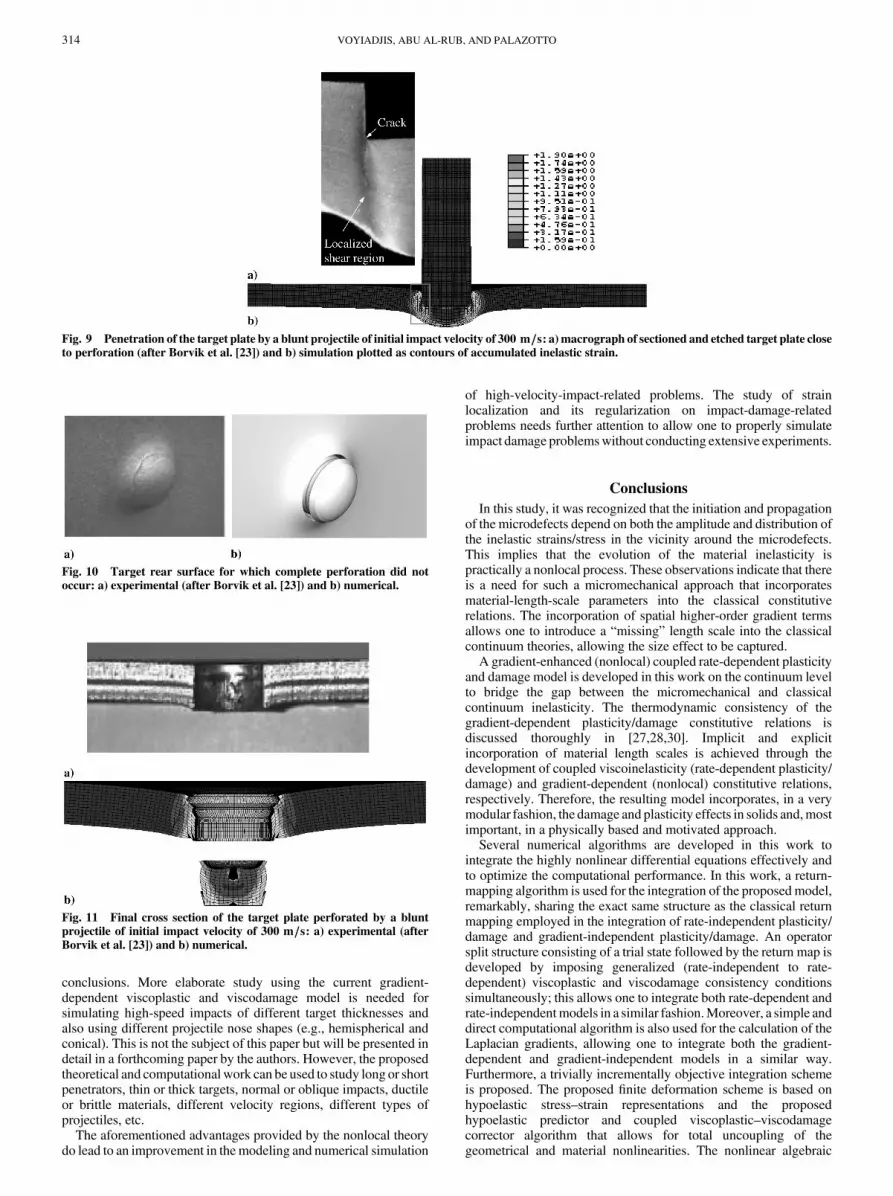
The elements in the impacted area are significantly distorted.However, stable results are nevertheless obtained. This delayed thedamage evolution process and, consequently, the erosion ofdamaged elements. However, the upper nodes in a critical element donot penetrate the lower nodes, giving a stable solution, and no errortermination is encountered in the code. Figure 9 shows the elementdistortion in the target plate just after impact. Figure 10 shows thetarget rear surface, for which complete perforation did not occur.
The final cross section of a target plate perforated by a bluntprojectile at an impact velocity close to the ballistic limit is shown inFig. 11, which is very similar to the experimental cross sectionobtained by Borvik et al. [23].
In general, it can be seen that close agreement between thenumerical and experimental results is achieved. Hence, thecomputational methodology presented in this paper works well forductile targets perforated by deformable blunt projectiles. However,different sets of experiments need to be simulated to draw solid
0
100
200
300
400
500
100 200 300 400 500 600
Initial Velocity (m/s)
Res
idu
al V
elo
city
(m
/s)
Numerical
Experimental (Borvik et al. [23])
a)
20
40
60
80
100
120
100 200 300 400 500 600
Initial Projectile Velocity (m/s)
Per
fora
tio
n T
ime
(s)
Numerical
Experimental (Borvik et al. [23])
b)
Fig. 6 Comparison between numerical and experimental results by ablunt projectile for a) the initial impact velocity vs residual projectile
velocity and b) perforation times vs initial impact velocities.
Fig. 7 High-speed-camera images showing perforation of the target
plate at impact velocities close to the ballistic limits with a blunt projectile(after Borvik et al. [23]).
Fig. 8 Perforation of the target plate by a blunt projectile of initial impact velocity of 210 m=s plotted as contours of accumulated inelastic strain and at
different times. The light-colored region indicates an accumulated damage between 0.25 and 0.30.
VOYIADJIS, ABU AL-RUB, AND PALAZOTTO 313
conclusions. More elaborate study using the current gradient-dependent viscoplastic and viscodamage model is needed forsimulating high-speed impacts of different target thicknesses andalso using different projectile nose shapes (e.g., hemispherical andconical). This is not the subject of this paper but will be presented indetail in a forthcoming paper by the authors. However, the proposedtheoretical and computational work can be used to study long or shortpenetrators, thin or thick targets, normal or oblique impacts, ductileor brittle materials, different velocity regions, different types ofprojectiles, etc.
The aforementioned advantages provided by the nonlocal theorydo lead to an improvement in themodeling and numerical simulation
of high-velocity-impact-related problems. The study of strainlocalization and its regularization on impact-damage-relatedproblems needs further attention to allow one to properly simulateimpact damage problemswithout conducting extensive experiments.
Conclusions
In this study, it was recognized that the initiation and propagationof the microdefects depend on both the amplitude and distribution ofthe inelastic strains/stress in the vicinity around the microdefects.This implies that the evolution of the material inelasticity ispractically a nonlocal process. These observations indicate that thereis a need for such a micromechanical approach that incorporatesmaterial-length-scale parameters into the classical constitutiverelations. The incorporation of spatial higher-order gradient termsallows one to introduce a “missing” length scale into the classicalcontinuum theories, allowing the size effect to be captured.
A gradient-enhanced (nonlocal) coupled rate-dependent plasticityand damage model is developed in this work on the continuum levelto bridge the gap between the micromechanical and classicalcontinuum inelasticity. The thermodynamic consistency of thegradient-dependent plasticity/damage constitutive relations isdiscussed thoroughly in [27,28,30]. Implicit and explicitincorporation of material length scales is achieved through thedevelopment of coupled viscoinelasticity (rate-dependent plasticity/damage) and gradient-dependent (nonlocal) constitutive relations,respectively. Therefore, the resulting model incorporates, in a verymodular fashion, the damage and plasticity effects in solids and,mostimportant, in a physically based and motivated approach.
Several numerical algorithms are developed in this work tointegrate the highly nonlinear differential equations effectively andto optimize the computational performance. In this work, a return-mapping algorithm is used for the integration of the proposed model,remarkably, sharing the exact same structure as the classical returnmapping employed in the integration of rate-independent plasticity/damage and gradient-independent plasticity/damage. An operatorsplit structure consisting of a trial state followed by the return map isdeveloped by imposing generalized (rate-independent to rate-dependent) viscoplastic and viscodamage consistency conditionssimultaneously; this allows one to integrate both rate-dependent andrate-independentmodels in a similar fashion.Moreover, a simple anddirect computational algorithm is also used for the calculation of theLaplacian gradients, allowing one to integrate both the gradient-dependent and gradient-independent models in a similar way.Furthermore, a trivially incrementally objective integration schemeis proposed. The proposed finite deformation scheme is based onhypoelastic stress–strain representations and the proposedhypoelastic predictor and coupled viscoplastic–viscodamagecorrector algorithm that allows for total uncoupling of thegeometrical and material nonlinearities. The nonlinear algebraic
Fig. 9 Penetration of the target plate by a blunt projectile of initial impact velocity of 300 m=s: a) macrograph of sectioned and etched target plate closeto perforation (after Borvik et al. [23]) and b) simulation plotted as contours of accumulated inelastic strain.
Fig. 10 Target rear surface for which complete perforation did notoccur: a) experimental (after Borvik et al. [23]) and b) numerical.
Fig. 11 Final cross section of the target plate perforated by a bluntprojectile of initial impact velocity of 300 m=s: a) experimental (after
Borvik et al. [23]) and b) numerical.
314 VOYIADJIS, ABU AL-RUB, AND PALAZOTTO

system of equations is solved by consistent linearization and the useof the Newton–Raphson iteration. The numerical implementationthen involves a series of coupled routines that provide the stressesand updates of the corresponding internal variables.
The constitutive model and numerical integration algorithms areimplemented in the well-known explicit finite element codeABAQUS/Explicit using the material subroutine VUMAT. In thispaper, the application of the proposed model to the numericalsimulation of localization and formation of shear bands in structuressubjected to high-speed-impact loading conditions is presented.Good agreement is obtained between the numerical simulations andexperimental results. Thematerial length scale proposed in this workhas the potential to predict the size effects in material failure.
It is noted that the material length parameter ‘ controls the initialyield strength, the hardening of the material, the softening behavior,and it slows down the damage evolution. More detailed parametricstudy for the effect of the material length scale will be presented in aforthcoming paper by the authors.
Acknowledgment
Financial support for this research has been provided by the U.S.Air Force Office of Scientific Research through the U.S. Air ForceInstitute of Technology at Wright–Patterson Air Force Base undergrant number F33601-01-P-0343.
References
[1] Anderson, C. E., “Proceedings of the 2003 Hypervelocity ImpactSymposium,” International Journal of Impact Engineering, Vol. 29,No. 1–10, 2003, pp. 1–867.
[2] Yatteau, J. D., Recht, G. W., and Edquits, K. T., “Transverse Loadingand Response of Long Rod Penetrators During High Velocity PlatePerforation,” International Journal of Impact Engineering, Vol. 23,1999, pp. 967–980.
[3] Hayhurst, C. J., Livingstone, I. H. G., Clegg, R. A., Destefanis, R., andFaraud, M., “Ballistic Limit Evaluation of Advanced Shielding UsingNumerical Simulations,” International Journal of Impact Engineering,Vol. 26, 2001, pp. 309–320.
[4] Knudson, M. D., Hall, C. A., Lemke, R., Deeney, C., and Asay, J. R.,“High Velocity Flyer Plate Launch Capability on the Sandia ZAccelerator,” International Journal of Impact Engineering, Vol. 29,2003, pp. 377–384.
[5] Zukas, J. A.,High Velocity Impact Dynamics, Wiley, NewYork, 1990.[6] Christiansen, E. L., and Friesen, L., “Penetration Equations for Thermal
Protection Materials,” International Journal of Impact Engineering,Vol. 20, 1997, pp. 153–164.
[7] Christiansen, E. L., and Kerr, J. H., “Projectile Shape Effects onShielding Performance at 7 km=s and 11 km=s,” International Journalof Impact Engineering, Vol. 20, 1997, pp. 165–172.
[8] Benson, D. J., “Computational Methods in Lagrangian and EulerianHydrocodes,” Computer Methods in Applied Mechanics and
Engineering, Vol. 99, 1992, pp. 235–394.[9] McGlaun, J. M., Thompson, S. L., and Elrick, M. G., “CTH: A Three
Dimensional Shock Wave Physics Code,” International Journal of
Impact Engineering, Vol. 10, 1990, pp. 351–360.[10] Hallquist, J. O., Theoretical Manual for DYNA3-D, Lawrence
Livermore National Lab., Livermore, CA, 1983.[11] Carroll, D. E., Hertel, E. S., and Trucano, T. G., “Simulation of Armor
Penetration by Tungsten Rods: ALEGRA Validation Report,” SandiaNational Labs., Rept. SAND97-2765, Albuquerque, NM, 1997.
[12] Stellingwerf, R. F., andWingate, C.A., “ImpactModelingwith SmoothParticle Hydrodynamics,” International Journal of Impact Engineer-
ing, Vol. 14, 1993, pp. 707–718.[13] Belytschko, T., Krongauz, Y., Organ, D., Fleming, M., and Krysl, P.,
“Meshless Methods: an Overview and Recent Developments,”Computer Methods in Applied Mechanics and Engineering, Vol. 139,1996, pp. 3–47.
[14] Fahrenthold, E. P., and Horban, B. A., “An Improved Hybrid Particle–Element Method for Hypervelocity Impact Simulation,” InternationalJournal of Impact Engineering, Vol. 26, 2001, pp. 169–178.
[15] Johnson, G. R., and Stryk, R. A., “Conversion of 3-D DistortedElements into Meshless Particles During Dynamic Deformation,”International Journal of Impact Engineering, Vol. 28, 2003, pp. 947–966.
[16] Park, Y.-K., and Fahrenthold, E. F., “A Kernel Free Particle-Finite
Element Method for Hypervelocity Impact Simulation,” InternationalJournal for Numerical Methods in Engineering, Vol. 63, 2005,pp. 737–759.
[17] Johnson, G. R., and Cook H. W., “Fracture Characteristics of ThreeMetals Subjected to Various Strains, Strain Rates, Temperature andPressures,” Engineering Fracture Mechanics, Vol. 21, No. 1, 1985,pp. 31–48.
[18] Curran, D. R., Seaman, L., and Shockey, D. A., “Dynamic Failure ofSolids,” Physics Reports, Vol. 147, 1987, pp. 253–388.
[19] Steinberg, D. J., and Lund, C. M., “A Constitutive Model for StrainRates from 10�4 to 106=s,” Journal of Applied Physics, Vol. 65, No. 4,1989, pp. 1528–1533.
[20] Zerilli, F. J., and Armstrong, R. W., “Dislocation-Mechanics-BasedConstitutive Relations forMaterial Dynamics Calculations,” Journal ofApplied Physics, Vol. 61, No. 5, 1987, pp. 445–459.
[21] Bammann,D. J., Chiesa,M. L.,McDonald, A., Kawahara,W.A., Dike,J. J., and Revelli, V. D. “Prediction of Ductile Failure in MetalStructures,” AMD, Vol. 107, 1990, pp. 7–12.
[22] Camacho, G. T., and Ortiz, M., “Adaptive Lagrangian Modeling ofBallistic Penetration of Metallic Targets,” Computer Methods in
Applied Mechanics and Engineering, Vol. 142, 1997, pp. 269–301.[23] Borvik, T., Langseth, M., Hopperstad, O. S., and Malo, K. A.,
“Perforation of 12 mm Thick Steel Plates by 20 mm DiameterProjectiles with Flat, Hemispherical and Conical Noses, Part 1:Experimental Study,” International Journal of Impact Engineering,Vol. 27, No. 1, 2002, pp. 19–35.
[24] Borvik, T., Clausen, A. H., Hopperstad, O. S., and Langseth, M.,“Perforation of AA5083-H116 Aluminum Plates with Conical-NoseSteel Projectiles-Experimental,” International Journal of Impact
Engineering, Vol. 30, 2004, pp. 367–384.[25] Eftis, J., Carrasco, C., and Osegueda, R. A., “A Constitutive-
Microdamage Model to Simulate Hypervelocity Projectile-TargetImpact, Material Damage and Fracture,” International Journal of
Plasticity, Vol. 19, 2003, pp. 1321–1354.[26] Voyiadjis, G. Z., and Abed, F. H., “Microstructural Based Models for
BCC and FCCMetals with Temperature and Strain Rate Dependency,”Mechanics of Materials, Vol. 37, 2005, pp. 355–378.
[27] Voyiadjis, G. Z., Abu Al-Rub, R. K., and Palazotto, A. N., “Non-LocalCoupling of Viscoplasticity and Anisotropic Viscodamage for ImpactProblems Using the Gradient Theory,” Archives of Mechanics, Vol. 55,No. 1, 2003, pp. 39–89.
[28] Voyiadjis, G. Z., Abu Al-Rub, R. K., and Palazotto, A. N.,“Thermodynamic Formulations for Non-Local Coupling of Viscoplas-ticity and Anisotropic Viscodamage for Dynamic LocalizationProblems Using Gradient Theory,” International Journal of Plasticity,Vol. 20, 2004, pp. 981–1038.
[29] Abu Al-Rub, R. K., Voyiadjis, G. Z., and Palazotto, A. N., “A Micro-Damage Model for High Velocity Impact Using Combined ViscosityandGradient Localization Limiters,”Proceedings of the ASMEApplied
Mechanics Division—2005, Vol. 256, American Society ofMechanicalEngineers, New York, 2005, pp. 123–130.
[30] Abu Al-Rub, R. K., and Voyiadjis, G. Z., “A Finite Strain Plastic-Damage Model for High Velocity Impacts Using Combined Viscosityand Gradient Localization Limiters, Part 1: Theoretical Formulation,”International Journal of Damage Mechanics, Vol. 15, No. 4, 2006,pp. 293–334.
[31] Needleman, A., “Material Rate Dependent and Mesh Sensitivity inLocalization Problems,”Computer Methods in Applied Mechanics and
Engineering, Vol. 67, No. 1, 1988, pp. 69–85.[32] Loret, B., and Prevost, H., “Dynamics Strain Localization in Elasto-
(Visco-)Plastic Solids, Part 1: General Formulation and One-Dimensional Examples,” Computer Methods in Applied Mechanics
and Engineering, Vol. 83, No. 3, 1990, pp. 247–273.[33] Sluys, L. J., “Wave Propagation, Localization and Dispersion in
Softening Solids,” Ph.D. Thesis, Delft Univ. of Technology, Delft, TheNetherlands, 1992.
[34] Wang, W. M., Sluys, L. J., and de Borst, R., “Interaction BetweenMaterial Length Scale and Imperfection Size for LocalizationPhenomena in Viscoplastic Media,” European Journal of Mechanics,
A/Solids, Vol. 15, No. 3, 1996, pp. 447–464.[35] Molinari, A., “Collective Behavior and Spacing of Adiabatic Shear
Bands,” Journal of theMechanics and Physics of Solids, Vol. 45, 1997,pp. 1551–1575.
[36] Batra, R. C., and Kim, C. H., “Adiabatic Shear Banding in Elastic-Viscoplastic Nonpolar andDipolarMaterials,” International Journal ofPlasticity, Vol. 6, 1990, pp. 127–141.
[37] Batra, R.C., andChen, L., “Shear BandSpacing inGradient-DependentThermoviscoplastic Materials,” Computational Mechanics, Vol. 23,1999, pp. 8–19.
VOYIADJIS, ABU AL-RUB, AND PALAZOTTO 315
[38] Batra, R. C., andWei, Z. G., “Shear Bands Due to Heat Flux Prescribedat Boundaries,” International Journal of Plasticity, Vol. 22, 2006,pp. 1–15.
[39] ABAQUS, Software Package, Ver. 6.3, Habbitt, Karlsson andSorensen, Inc., Providence, RI, 2003.
[40] Abu Al-Rub, R. K., and Voyiadjis, G. Z., “Determination of theMaterial Intrinsic Length Scale of Gradient Plasticity Theory,”International Journal of Multiscale Computational Engineering,Vol. 2, No. 3, 2004, pp. 377–400.
[41] AbuAl-Rub, R. K., andVoyiadjis, G. Z., “Analytical and ExperimentalDetermination of the Material Intrinsic Length Scale of Strain GradientPlasticity Theory from Micro- and Nano-Indentation Experiments,”International Journal of Plasticity, Vol. 20, No. 6, 2004, pp. 1139–1182.
[42] Voyiadjis, G. Z., and Abu Al-Rub, R. K., “Gradient Plasticity Theorywith a Variable Length Scale Parameter,” International Journal of
Solids and Structures, Vol. 42, No. 14, 2005, pp. 3998–4029.[43] Voyiadjis, G. Z., Abu Al-Rub, R. K., and Palazotto, A. N., “On the
Small and Finite Deformation Thermo-Elastoviscoplasticity Theory:Algorithmic and Computational Aspects,” European Journal of
Computational Mechanics (to be published).[44] Zhu, Y. Y., and Cescetto, S., “Fully Coupled Elasto-Visco Plastic
Damage Theory for Anisotropic Materials,” International Journal of
Solids and Structures, Vol. 32, 1995, pp. 1607–1641.[45] Abu Al-Rub, R. K., and Voyiadjis, G. Z., “A Direct Finite Element
Implementation of the Gradient Plasticity Theory,” International
Journal for Numerical Methods in Engineering, Vol. 63, No. 4, 2005,
pp. 603–629.[46] Voyiadjis, G. Z., and Abu Al-Rub, R. K. “A Finite Strain Plastic-
Damage Model for High Velocity Impacts Using Combined Viscosityand Gradient Localization Limiters, Part 2: Numerical Aspects andSimulations,” International Journal of Damage Mechanics, Vol. 15,No. 4, 2006, pp. 335–373.
[47] De Borst, R., and Mühlhaus, H.-B., “Gradient-Dependent PlasticityFormulation and Algorithmic Aspects,” International Journal for
Numerical Methods in Engineering, Vol. 35, 1992, pp. 521–539.[48] De Borst, R., and Pamin, J., “Some Novel Developments in Finite
Element Procedures for Gradient Dependent Plasticity,” InternationalJournal for Numerical Methods in Engineering, Vol. 39, 1996,pp. 2477–2505.
[49] Borvik, T., Hopperstad, O. S., Berstad, T., and Langseth, M.“Numerical Simulation of Plugging Failure in Ballistic Penetration,”International Journal of Solids and Structures, Vol. 38, 2001,pp. 6241–6264.
[50] Voyiadjis, G. Z., and Abu Al-Rub, R. K., “Thermodynamic BasedModel for the Evolution Equation of the Backstress in CyclicPlasticity,” International Journal of Plasticity, Vol. 19, 2003,pp. 2121–2147.
[51] Bai, Y., and Dodd, B., Adiabatic Shear Localization: Occurrence,
Theories and Applications, Pergamon, Oxford, 1992.
T. NicholasAssociate Editor
316 VOYIADJIS, ABU AL-RUB, AND PALAZOTTO


