Embed Size (px)
Citation preview
zerole
aka
ge
guara
nte
ed
wid
era
ngeabilit
y
10/0.1.0Rev. 0610
A
C
B
A
B
C
- 1 -
TABLE OF CONTENTSLINEAR
DKLO Series Control Valve ………………………………4
Lil’ Gator Type VLG Control Valve ………………………12
DLO(S)-2 Control Valve …………………………………22
Linear Valve Specification Form …………………………26
DBO(Y)(S)-3 Control Valve ………………………………28
Linear Valve Specification Form …………………………36
Digi Actuator ……………………………………………38
DOS Unbalanced Control Valve …………………………42
GTB Control Valve ………………………………………46
Aeroflow Control Valve ……………………………………58
Chesterton Packing …………………………………65
Aeroflow Valve Specification Form ………………………75
Leslie Temp Desuperheaters ………………………76
Standard Duty A.T. Model 38/48 ……………………79Heavy Duty A.T. Model 18/54 and 28/64 ……………80Standard Duty A.T.S.A. Model 24/34…………………81Heavy Duty Que Model 33/43 ………………………82Heavy Duty A.T. Model 13/23 …………………………83Small Pipe Inline Desuperheater (SPID) Model 88 …84Ven-Temp Desuperheater ……………………………87SPID Desuperheater Specification Form ……………89Model QT Steam Conditioning Specification Form …90Model AT Steam Conditioning Specification Form …91
ROTARY
K-MAX Control Valve ……………………………………94
Rotary Valve Specification Form ………………………104
THREE WAY
GTW Three Way Control Valve …………………………106
GTW Valve Specification Form …………………………117
RVK, RVB, RVD Three Way Rotary Valve ……………118
RV Three Way Valve Specification Form ………………121
DOT Three Way Control Valve …………………………122
3-Way Valve Specification Form ………………………127
ISOLATION VALVE
Steam Isolation Ball Valve …………………………130
ON–OFF
2500 Series Electrically Actuated Shutoff Valve ………134
2500 Series Valve Specification Form …………………140
Fire-Cide® Series Heat Actuated Shutoff Valve ………142
Fire-Cide® Series Valve Specification Form ……………145
NOISE REDUCTION
Noise Suppressor ………………………………………148
Les-Sonic Silencing Orifice ……………………………152
INSTRUMENTATION
PMC-1 Electro-Pneumatic Controller …………………156
PIII Pneumatic Controllers ………………………158
Leslie Thermocouple ……………………………………162
RTD Resistance Probe Thermometer …………………163
Electronic Pressure Transmitter ………………………164
Siemens Positioner ……………………………………165
ABB TZID-C Intelligent Positioner………………………166
ABB AV Series Intelligent Positioner……………………168
Type PDA/PRA Constant Pressure Control Pilot ……170
Type PDAP/PRAP Constant Pressure Control Pilot
with Adjustable Proportional Band …………………172
Type UDDV/UDDVP/UDRVP Differential Pressure and Vacuum Pilot Controllers ………………………174
LEVELMATIC Liquid Level Pilot Controller ……………176
PROP-MATIC® Temperature Pilot Controller …………180
Type S Transfer Valve …………………………………186
Airset Type AS-1 Series Adjustable Air Regulator ……188
AIRMATE® Type AFG-2 Air Loaders and Panels ……190
REFERENCE
Glossary of Terms ………………………………………194
Industry Standards ………………………………………195
Flange Standards ………………………………………196
Flow vs. Velocity Chart …………………………………197
Pressure to Vacuum ……………………………………198
Properties of Water………………………………………199
Pipe Data Tables…………………………………………200
Ratings for ASTM A216-WCB …………………………204
Ratings for ASTM A217-WC9 …………………………205
Ratings for A351 CF8M (316SS) ………………………206
FCI 70-2 Seat Leakage …………………………………207
Liquid Body Velocity Limitation …………………………208
Pressure Temperature Limits……………………………209
Material Selection Chart…………………………………210
Conversion Tables ………………………………………212
Steam Table ……………………………………………214
LESLIE CONTROLS has a policy of continuous product research and improvement and reserves the right to change design and specificationswithout notice. Responsibility for typographical errors is specifically disclaimed.
LIN
EAR
- 4 -
00 50 100 150 200 250 300 350 400 450
50
100
150
200
250
300
350
400
450
TEMPERATURE (°F)
ANSI/ASME B16.15 CLASS 250ANSI/ASME B16.1 CLASS 125SATURATED STEAM
PR
ES
SU
RE
(PS
I)
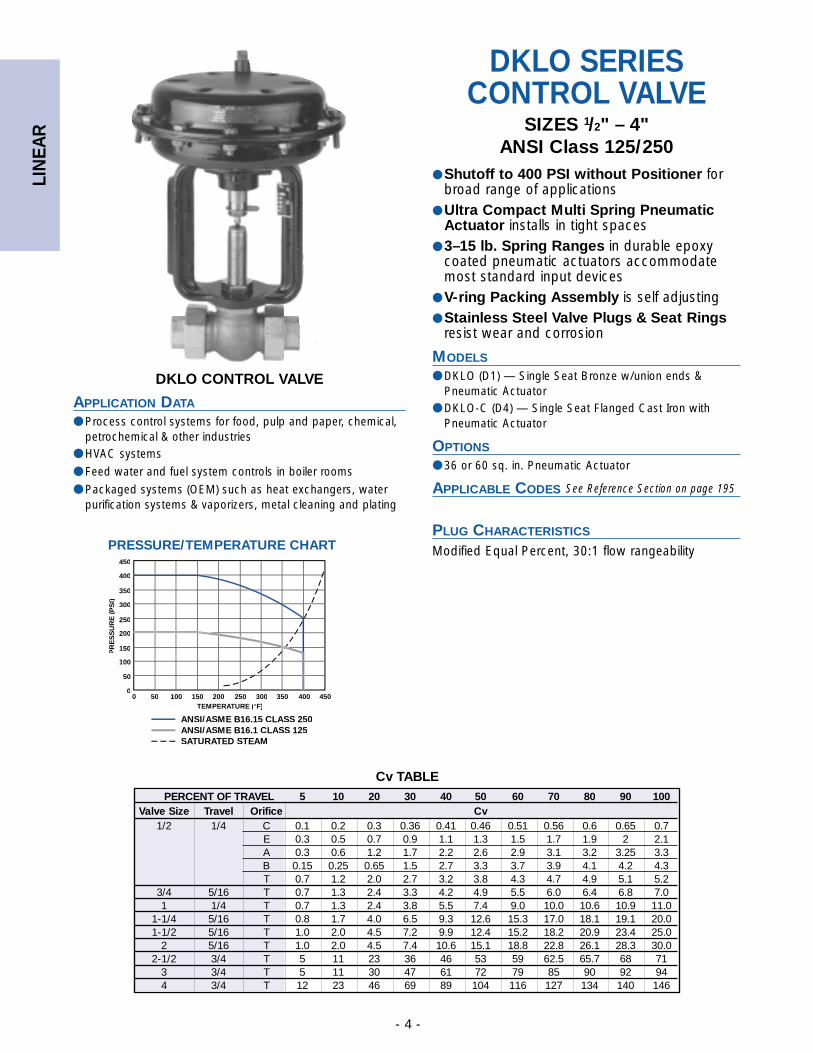
PRESSURE/TEMPERATURE CHART
DKLO CONTROL VALVE
APPLICATION DATA
● Process control systems for food, pulp and paper, chemical,petrochemical & other industries
● HVAC systems
● Feed water and fuel system controls in boiler rooms
● Packaged systems (OEM) such as heat exchangers, waterpurification systems & vaporizers, metal cleaning and plating
DKLO SERIESCONTROL VALVE
SIZES 1/2" – 4"ANSI Class 125/250
● Shutoff to 400 PSI without Positioner forbroad range of applications
● Ultra Compact Multi Spring PneumaticActuator installs in tight spaces
● 3–15 lb. Spring Ranges in durable epoxycoated pneumatic actuators accommodatemost standard input devices
● V-ring Packing Assembly is self adjusting● Stainless Steel Valve Plugs & Seat Rings
resist wear and corrosion
MODELS
● DKLO (D1) — Single Seat Bronze w/union ends &Pneumatic Actuator
● DKLO-C (D4) — Single Seat Flanged Cast Iron withPneumatic Actuator
OPTIONS
● 36 or 60 sq. in. Pneumatic Actuator
APPLICABLE CODES
PLUG CHARACTERISTICS
Modified Equal Percent, 30:1 flow rangeability
See Reference Section on page 195
PERCENT OF TRAVEL 5 10 20 30 40 50 60 70 80 90 100Valve Size Travel Orifice Cv
1/2 1/4 C 0.1 0.2 0.3 0.36 0.41 0.46 0.51 0.56 0.6 0.65 0.7E 0.3 0.5 0.7 0.9 1.1 1.3 1.5 1.7 1.9 2 2.1A 0.3 0.6 1.2 1.7 2.2 2.6 2.9 3.1 3.2 3.25 3.3B 0.15 0.25 0.65 1.5 2.7 3.3 3.7 3.9 4.1 4.2 4.3T 0.7 1.2 2.0 2.7 3.2 3.8 4.3 4.7 4.9 5.1 5.2
3/4 5/16 T 0.7 1.3 2.4 3.3 4.2 4.9 5.5 6.0 6.4 6.8 7.01 1/4 T 0.7 1.3 2.4 3.8 5.5 7.4 9.0 10.0 10.6 10.9 11.0
1-1/4 5/16 T 0.8 1.7 4.0 6.5 9.3 12.6 15.3 17.0 18.1 19.1 20.01-1/2 5/16 T 1.0 2.0 4.5 7.2 9.9 12.4 15.2 18.2 20.9 23.4 25.0
2 5/16 T 1.0 2.0 4.5 7.4 10.6 15.1 18.8 22.8 26.1 28.3 30.02-1/2 3/4 T 5 11 23 36 46 53 59 62.5 65.7 68 71
3 3/4 T 5 11 30 47 61 72 79 85 90 92 944 3/4 T 12 23 46 69 89 104 116 127 134 140 146
Cv TABLE
LIN
EAR
- 5 -
E F WeightA B CSize36 in2 60 in2 36 in2 60 in2 36 in2 60 in2
1⁄2-3⁄4 51⁄2 111⁄16 13⁄16 97⁄8 — 91⁄4 — 21 —(15)-(20) (140) (43) (30) (251) — (235) — (9.5) —
1 73⁄16 27⁄8 25⁄16 97⁄8 113⁄4 91⁄4 111⁄4 251⁄2 39 (25) (183) (74) (58) (251) (298) (235) (286) (12) (17)
11⁄4-11⁄2 87⁄8 31⁄8 27⁄8 97⁄8 113⁄4 91⁄4 111⁄4 311⁄2 45(32)-(40) (226) (79) (74) (251) (298) (235) (286) (14) (20)
2 87⁄8 31⁄8 27⁄8 97⁄8 113⁄4 91⁄4 111⁄4 331⁄2 47(50) (226) (79) (74) (251) (298) (235) (286) (15) (21)
21⁄2 93⁄8 51⁄4 45⁄8 — 117⁄8 — 111⁄4 — 72(65) (238) (133) (118) — (302) — (286) — (33)
3 10 61⁄8 53⁄8 — 117⁄8 — 111⁄4 — 84(80) (254) (155) (136) — (302) — (286) — (39)
4 117⁄8 71⁄8 73⁄8 — 117⁄8 — 111⁄4 — 145(100) (302) (181) (187) — (302) — (286) — (66)
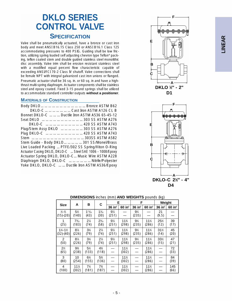
DIMENSIONS inches (mm) AND WEIGHTS pounds (kg)
DKLO 1⁄2" - 2"D1
DKLO-C 21⁄2" - 4"D4
DKLO SERIESCONTROL VALVE
SPECIFICATIONValve shall be pneumatically actuated, have a bronze or cast ironbody and meet ANSI B16.15 Class 250 or ANSI B16.1 Class 125accommodating pressures to 400 PSIG. Guiding shall be low fric-tion, utilizing spring loaded self adjusting chevron type Teflon® pack-ing, teflon coated stem and double guided stainless steel monolithicdisc assembly. Valve trim shall be erosion resistant stainless steelwith a modified equal percent flow characteristic capable ofexceeding ANSI/FCI 70-2 Class IV shutoff. Valve connections shallbe female NPT with integral galvanized cast iron unions or flanged.Pneumatic actuator shall be 36 sq. in. or 60 sq. in and have a high-thrust multi-spring diaphragm. Actuator components shall be stainlesssteel and epoxy coated. Fixed 3-15 pound springs shall be utilizedto accommodate standard controller outputs without a positioner.
MATERIALS OF CONSTRUCTION
Body DKLO………………………………Bronze ASTM B62DKLO-C …………………Cast Iron ASTM A126 CL B
Bonnet DKLO-C ………Ductile Iron ASTM A536 65-45-12Seat DKLO ……………………………303 SS ASTM A276
DKLO-C …………………………420 SS ASTM A743Plug/Stem Assy DKLO ………………303 SS ASTM A276Plug DKLO-C …………………………420 SS ASTM A743Stem ……………………………………303SS ASTM A582Stem Guide - Body DKLO……………301 SS/Monel/BrassLive Loaded Packing …PTFE/302 SS Spring/Viton O-RingActuator Casing DKLO, DKLO-C …Steel SAE 1006 - 1008/EpoxyActuator Spring DKLO, DKLO-C…Music Wire ASTM A228Diaphragm DKLO, DKLO-C ………………Nitrile/PolyesterYoke DKLO, DKLO-C ……Ductile Iron ASTM A536/Epoxy
C
A
B
F
E
C
A
B
F
E
LIN
EAR
- 6 -
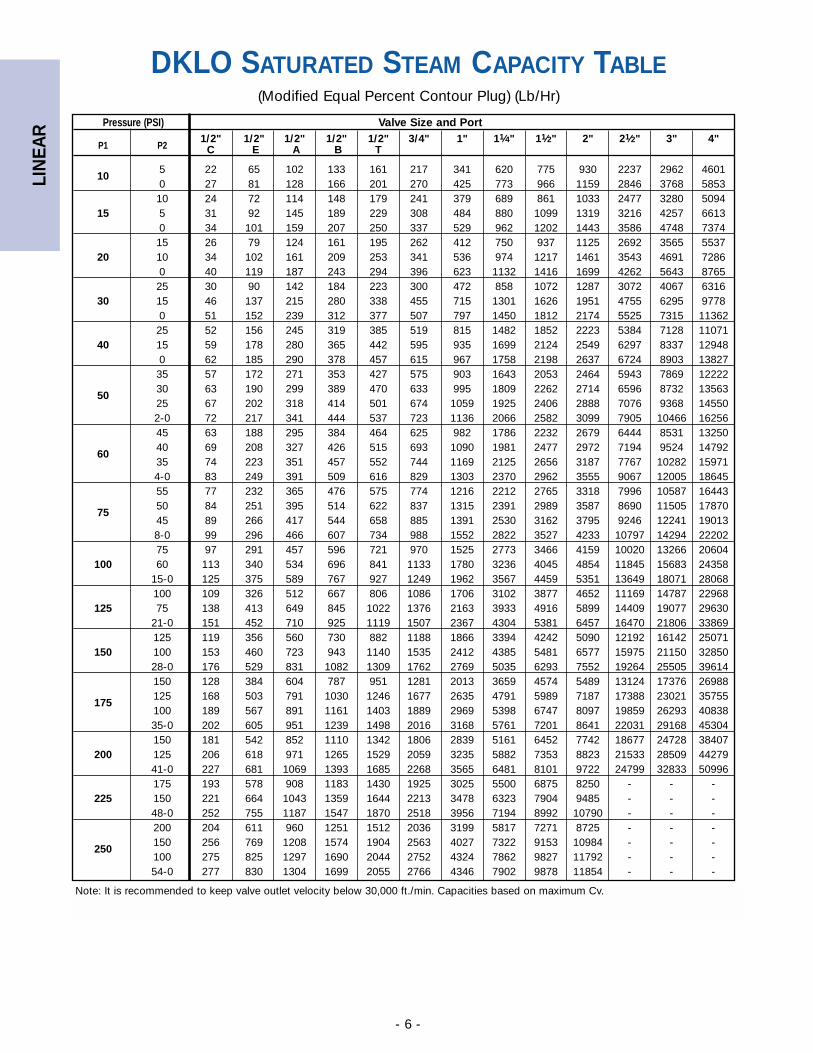
DKLO SATURATED STEAM CAPACITY TABLE(Modified Equal Percent Contour Plug) (Lb/Hr)
Note: It is recommended to keep valve outlet velocity below 30,000 ft./min. Capacities based on maximum Cv.
Pressure (PSI) Valve Size and Port
P1 P21/2" 1/2" 1/2" 1/2" 1/2" 3/4" 1" 11⁄4" 11⁄2" 2" 21⁄2" 3" 4"
C E A B T
105 22 65 102 133 161 217 341 620 775 930 2237 2962 46010 27 81 128 166 201 270 425 773 966 1159 2846 3768 585310 24 72 114 148 179 241 379 689 861 1033 2477 3280 5094
15 5 31 92 145 189 229 308 484 880 1099 1319 3216 4257 66130 34 101 159 207 250 337 529 962 1202 1443 3586 4748 737415 26 79 124 161 195 262 412 750 937 1125 2692 3565 5537
20 10 34 102 161 209 253 341 536 974 1217 1461 3543 4691 72860 40 119 187 243 294 396 623 1132 1416 1699 4262 5643 876525 30 90 142 184 223 300 472 858 1072 1287 3072 4067 6316
30 15 46 137 215 280 338 455 715 1301 1626 1951 4755 6295 97780 51 152 239 312 377 507 797 1450 1812 2174 5525 7315 1136225 52 156 245 319 385 519 815 1482 1852 2223 5384 7128 11071
40 15 59 178 280 365 442 595 935 1699 2124 2549 6297 8337 129480 62 185 290 378 457 615 967 1758 2198 2637 6724 8903 1382735 57 172 271 353 427 575 903 1643 2053 2464 5943 7869 12222
5030 63 190 299 389 470 633 995 1809 2262 2714 6596 8732 1356325 67 202 318 414 501 674 1059 1925 2406 2888 7076 9368 145502-0 72 217 341 444 537 723 1136 2066 2582 3099 7905 10466 1625645 63 188 295 384 464 625 982 1786 2232 2679 6444 8531 13250
6040 69 208 327 426 515 693 1090 1981 2477 2972 7194 9524 1479235 74 223 351 457 552 744 1169 2125 2656 3187 7767 10282 159714-0 83 249 391 509 616 829 1303 2370 2962 3555 9067 12005 1864555 77 232 365 476 575 774 1216 2212 2765 3318 7996 10587 16443
7550 84 251 395 514 622 837 1315 2391 2989 3587 8690 11505 1787045 89 266 417 544 658 885 1391 2530 3162 3795 9246 12241 190138-0 99 296 466 607 734 988 1552 2822 3527 4233 10797 14294 2220275 97 291 457 596 721 970 1525 2773 3466 4159 10020 13266 20604
100 60 113 340 534 696 841 1133 1780 3236 4045 4854 11845 15683 2435815-0 125 375 589 767 927 1249 1962 3567 4459 5351 13649 18071 28068100 109 326 512 667 806 1086 1706 3102 3877 4652 11169 14787 22968
125 75 138 413 649 845 1022 1376 2163 3933 4916 5899 14409 19077 2963021-0 151 452 710 925 1119 1507 2367 4304 5381 6457 16470 21806 33869125 119 356 560 730 882 1188 1866 3394 4242 5090 12192 16142 25071
150 100 153 460 723 943 1140 1535 2412 4385 5481 6577 15975 21150 3285028-0 176 529 831 1082 1309 1762 2769 5035 6293 7552 19264 25505 39614150 128 384 604 787 951 1281 2013 3659 4574 5489 13124 17376 26988
175125 168 503 791 1030 1246 1677 2635 4791 5989 7187 17388 23021 35755100 189 567 891 1161 1403 1889 2969 5398 6747 8097 19859 26293 4083835-0 202 605 951 1239 1498 2016 3168 5761 7201 8641 22031 29168 45304150 181 542 852 1110 1342 1806 2839 5161 6452 7742 18677 24728 38407
200 125 206 618 971 1265 1529 2059 3235 5882 7353 8823 21533 28509 4427941-0 227 681 1069 1393 1685 2268 3565 6481 8101 9722 24799 32833 50996175 193 578 908 1183 1430 1925 3025 5500 6875 8250 - - -
225 150 221 664 1043 1359 1644 2213 3478 6323 7904 9485 - - -48-0 252 755 1187 1547 1870 2518 3956 7194 8992 10790 - - -200 204 611 960 1251 1512 2036 3199 5817 7271 8725 - - -
250150 256 769 1208 1574 1904 2563 4027 7322 9153 10984 - - -100 275 825 1297 1690 2044 2752 4324 7862 9827 11792 - - -54-0 277 830 1304 1699 2055 2766 4346 7902 9878 11854 - - -
LIN
EAR
- 7 -
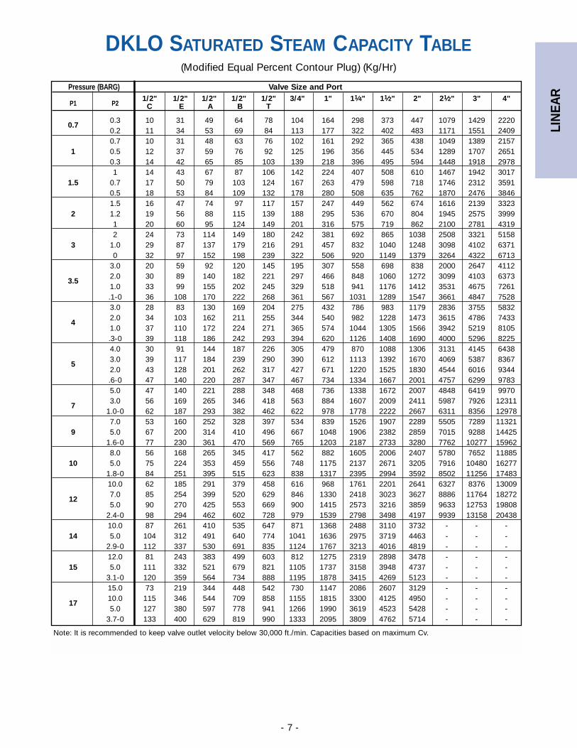
DKLO SATURATED STEAM CAPACITY TABLE(Modified Equal Percent Contour Plug) (Kg/Hr)
Note: It is recommended to keep valve outlet velocity below 30,000 ft./min. Capacities based on maximum Cv.
Pressure (BARG) Valve Size and Port
P1 P21/2" 1/2" 1/2" 1/2" 1/2" 3/4" 1" 11⁄4" 11⁄2" 2" 21⁄2" 3" 4"
C E A B T
0.70.3 10 31 49 64 78 104 164 298 373 447 1079 1429 22200.2 11 34 53 69 84 113 177 322 402 483 1171 1551 24090.7 10 31 48 63 76 102 161 292 365 438 1049 1389 2157
1 0.5 12 37 59 76 92 125 196 356 445 534 1289 1707 26510.3 14 42 65 85 103 139 218 396 495 594 1448 1918 29781 14 43 67 87 106 142 224 407 508 610 1467 1942 3017
1.5 0.7 17 50 79 103 124 167 263 479 598 718 1746 2312 35910.5 18 53 84 109 132 178 280 508 635 762 1870 2476 38461.5 16 47 74 97 117 157 247 449 562 674 1616 2139 3323
2 1.2 19 56 88 115 139 188 295 536 670 804 1945 2575 39991 20 60 95 124 149 201 316 575 719 862 2100 2781 43192 24 73 114 149 180 242 381 692 865 1038 2508 3321 5158
3 1.0 29 87 137 179 216 291 457 832 1040 1248 3098 4102 63710 32 97 152 198 239 322 506 920 1149 1379 3264 4322 6713
3.0 20 59 92 120 145 195 307 558 698 838 2000 2647 4112
3.52.0 30 89 140 182 221 297 466 848 1060 1272 3099 4103 63731.0 33 99 155 202 245 329 518 941 1176 1412 3531 4675 7261.1-0 36 108 170 222 268 361 567 1031 1289 1547 3661 4847 75283.0 28 83 130 169 204 275 432 786 983 1179 2836 3755 5832
42.0 34 103 162 211 255 344 540 982 1228 1473 3615 4786 74331.0 37 110 172 224 271 365 574 1044 1305 1566 3942 5219 8105.3-0 39 118 186 242 293 394 620 1126 1408 1690 4000 5296 82254.0 30 91 144 187 226 305 479 870 1088 1306 3131 4145 6438
53.0 39 117 184 239 290 390 612 1113 1392 1670 4069 5387 83672.0 43 128 201 262 317 427 671 1220 1525 1830 4544 6016 9344.6-0 47 140 220 287 347 467 734 1334 1667 2001 4757 6299 97835.0 47 140 221 288 348 468 736 1338 1672 2007 4848 6419 9970
73.0 56 169 265 346 418 563 884 1607 2009 2411 5987 7926 12311
1.0-0 62 187 293 382 462 622 978 1778 2222 2667 6311 8356 129787.0 53 160 252 328 397 534 839 1526 1907 2289 5505 7289 11321
9 5.0 67 200 314 410 496 667 1048 1906 2382 2859 7015 9288 144251.6-0 77 230 361 470 569 765 1203 2187 2733 3280 7762 10277 159628.0 56 168 265 345 417 562 882 1605 2006 2407 5780 7652 11885
10 5.0 75 224 353 459 556 748 1175 2137 2671 3205 7916 10480 162771.8-0 84 251 395 515 623 838 1317 2395 2994 3592 8502 11256 1748310.0 62 185 291 379 458 616 968 1761 2201 2641 6327 8376 13009
127.0 85 254 399 520 629 846 1330 2418 3023 3627 8886 11764 182725.0 90 270 425 553 669 900 1415 2573 3216 3859 9633 12753 19808
2.4-0 98 294 462 602 728 979 1539 2798 3498 4197 9939 13158 2043810.0 87 261 410 535 647 871 1368 2488 3110 3732 - - -
14 5.0 104 312 491 640 774 1041 1636 2975 3719 4463 - - -2.9-0 112 337 530 691 835 1124 1767 3213 4016 4819 - - -12.0 81 243 383 499 603 812 1275 2319 2898 3478 - - -
15 5.0 111 332 521 679 821 1105 1737 3158 3948 4737 - - -3.1-0 120 359 564 734 888 1195 1878 3415 4269 5123 - - -15.0 73 219 344 448 542 730 1147 2086 2607 3129 - - -
1710.0 115 346 544 709 858 1155 1815 3300 4125 4950 - - -5.0 127 380 597 778 941 1266 1990 3619 4523 5428 - - -
3.7-0 133 400 629 819 990 1333 2095 3809 4762 5714 - - -
LIN
EAR
- 8 -
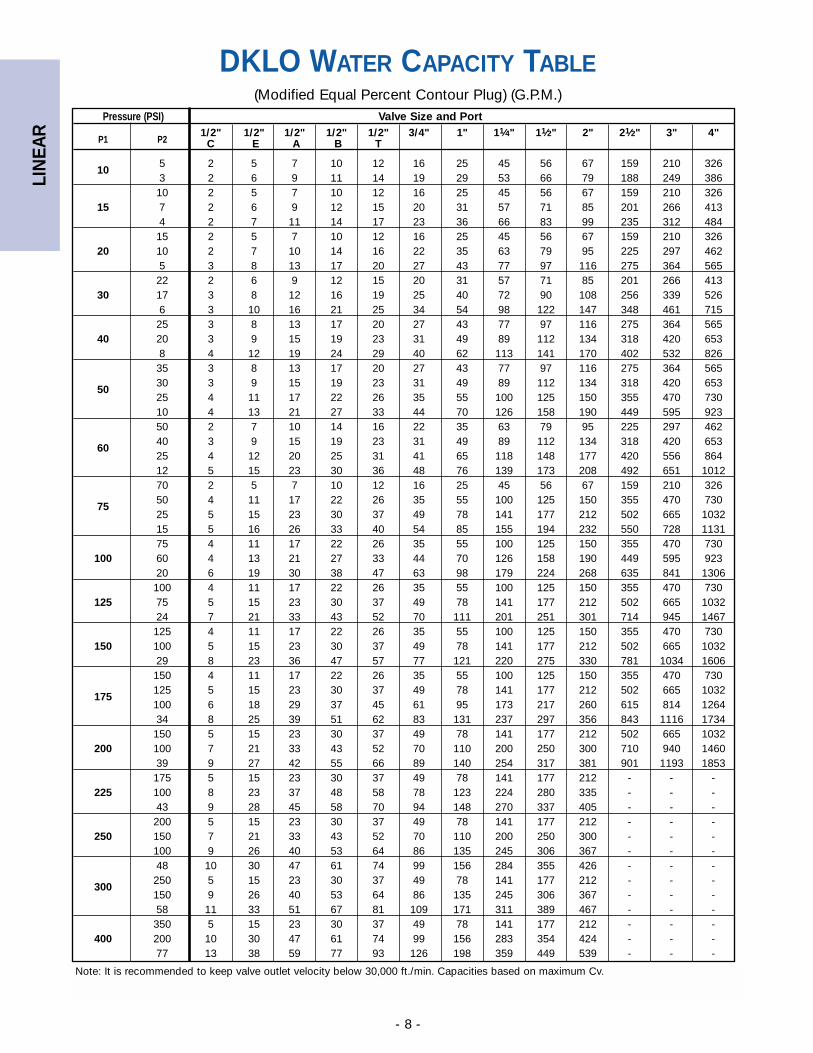
DKLO WATER CAPACITY TABLE(Modified Equal Percent Contour Plug) (G.P.M.)
Note: It is recommended to keep valve outlet velocity below 30,000 ft./min. Capacities based on maximum Cv.
Pressure (PSI) Valve Size and Port
P1 P21/2" 1/2" 1/2" 1/2" 1/2" 3/4" 1" 11⁄4" 11⁄2" 2" 21⁄2" 3" 4"
C E A B T
105 2 5 7 10 12 16 25 45 56 67 159 210 3263 2 6 9 11 14 19 29 53 66 79 188 249 38610 2 5 7 10 12 16 25 45 56 67 159 210 326
15 7 2 6 9 12 15 20 31 57 71 85 201 266 4134 2 7 11 14 17 23 36 66 83 99 235 312 48415 2 5 7 10 12 16 25 45 56 67 159 210 326
20 10 2 7 10 14 16 22 35 63 79 95 225 297 4625 3 8 13 17 20 27 43 77 97 116 275 364 56522 2 6 9 12 15 20 31 57 71 85 201 266 413
30 17 3 8 12 16 19 25 40 72 90 108 256 339 5266 3 10 16 21 25 34 54 98 122 147 348 461 71525 3 8 13 17 20 27 43 77 97 116 275 364 565
40 20 3 9 15 19 23 31 49 89 112 134 318 420 6538 4 12 19 24 29 40 62 113 141 170 402 532 82635 3 8 13 17 20 27 43 77 97 116 275 364 565
5030 3 9 15 19 23 31 49 89 112 134 318 420 65325 4 11 17 22 26 35 55 100 125 150 355 470 73010 4 13 21 27 33 44 70 126 158 190 449 595 92350 2 7 10 14 16 22 35 63 79 95 225 297 462
6040 3 9 15 19 23 31 49 89 112 134 318 420 65325 4 12 20 25 31 41 65 118 148 177 420 556 86412 5 15 23 30 36 48 76 139 173 208 492 651 101270 2 5 7 10 12 16 25 45 56 67 159 210 326
7550 4 11 17 22 26 35 55 100 125 150 355 470 73025 5 15 23 30 37 49 78 141 177 212 502 665 103215 5 16 26 33 40 54 85 155 194 232 550 728 113175 4 11 17 22 26 35 55 100 125 150 355 470 730
100 60 4 13 21 27 33 44 70 126 158 190 449 595 92320 6 19 30 38 47 63 98 179 224 268 635 841 1306100 4 11 17 22 26 35 55 100 125 150 355 470 730
125 75 5 15 23 30 37 49 78 141 177 212 502 665 103224 7 21 33 43 52 70 111 201 251 301 714 945 1467125 4 11 17 22 26 35 55 100 125 150 355 470 730
150 100 5 15 23 30 37 49 78 141 177 212 502 665 103229 8 23 36 47 57 77 121 220 275 330 781 1034 1606150 4 11 17 22 26 35 55 100 125 150 355 470 730
175125 5 15 23 30 37 49 78 141 177 212 502 665 1032100 6 18 29 37 45 61 95 173 217 260 615 814 126434 8 25 39 51 62 83 131 237 297 356 843 1116 1734150 5 15 23 30 37 49 78 141 177 212 502 665 1032
200 100 7 21 33 43 52 70 110 200 250 300 710 940 146039 9 27 42 55 66 89 140 254 317 381 901 1193 1853175 5 15 23 30 37 49 78 141 177 212 - - -
225 100 8 23 37 48 58 78 123 224 280 335 - - -43 9 28 45 58 70 94 148 270 337 405 - - -200 5 15 23 30 37 49 78 141 177 212 - - -
250 150 7 21 33 43 52 70 110 200 250 300 - - -100 9 26 40 53 64 86 135 245 306 367 - - -48 10 30 47 61 74 99 156 284 355 426 - - -
300250 5 15 23 30 37 49 78 141 177 212 - - -150 9 26 40 53 64 86 135 245 306 367 - - -58 11 33 51 67 81 109 171 311 389 467 - - -350 5 15 23 30 37 49 78 141 177 212 - - -
400 200 10 30 47 61 74 99 156 283 354 424 - - -77 13 38 59 77 93 126 198 359 449 539 - - -

LIN
EAR
- 9 -
DKLO WATER CAPACITY TABLE(Modified Equal Percent Contour Plug) (M3/Hr.)
Note: It is recommended to keep valve outlet velocity below 30,000 ft./min. Capacities based on maximum Cv.
Pressure (BARG) Valve Size and Port
P1 P21/2" 1/2" 1/2" 1/2" 1/2" 3/4" 1" 11⁄4" 11⁄2" 2" 21⁄2" 3" 4"
C E A B T
0.70.3 0.4 1.1 1.8 2.4 2.8 3.8 6.0 10.9 13.7 16.4 38.8 51.4 79.90.2 0.4 1.3 2.0 2.6 3.2 4.3 6.7 12.2 15.3 18.3 43.4 57.5 89.30.7 0.3 1.0 1.6 2.0 2.5 3.3 5.2 9.5 11.8 14.2 33.6 44.5 69.2
1 0.5 0.4 1.3 2.0 2.6 3.2 4.3 6.7 12.2 15.3 18.3 43.4 57.5 89.30.25 0.5 1.6 2.5 3.2 3.9 5.2 8.2 15.0 18.7 22.5 53.2 70.4 109.3
1 0.4 1.3 2.0 2.6 3.2 4.3 6.7 12.2 15.3 18.3 43.4 57.5 89.31.5 0.7 0.5 1.6 2.6 3.3 4.0 5.4 8.5 15.5 19.3 23.2 54.9 72.7 112.9
0.3 0.7 2.0 3.1 4.1 4.9 6.6 10.4 18.9 23.7 28.4 67.3 89.0 138.31.5 0.4 1.3 2.0 2.6 3.2 4.3 6.7 12.2 15.3 18.3 43.4 57.5 89.3
2 1 0.6 1.8 2.9 3.7 4.5 6.1 9.5 17.3 21.6 25.9 61.4 81.3 126.30.4 0.8 2.3 3.6 4.7 5.7 7.7 12.0 21.9 27.3 32.8 77.7 102.8 159.72 0.6 1.8 2.9 3.7 4.5 6.1 9.5 17.3 21.6 25.9 61.4 81.3 126.3
3 1.5 0.7 2.2 3.5 4.6 5.5 7.4 11.7 21.2 26.5 31.8 75.2 99.6 154.60.6 0.9 2.8 4.4 5.8 7.0 9.4 14.7 26.8 33.5 40.2 95.1 125.9 195.63 0.4 1.3 2.0 2.6 3.2 4.3 6.7 12.2 15.3 18.3 43.4 57.5 89.3
3.52 0.7 2.2 3.5 4.6 5.5 7.4 11.7 21.2 26.5 31.8 75.2 99.6 154.6
1.5 0.9 2.6 4.0 5.3 6.4 8.6 13.5 24.5 30.6 36.7 86.8 115.0 178.60.7 1.0 3.0 4.8 6.2 7.5 10.1 15.9 28.9 36.2 43.4 102.7 136.0 211.33.5 0.4 1.3 2.0 2.6 3.2 4.3 6.7 12.2 15.3 18.3 43.4 57.5 89.3
43 0.6 1.8 2.9 3.7 4.5 6.1 9.5 17.3 21.6 25.9 61.4 81.3 126.32 0.9 2.6 4.0 5.3 6.4 8.6 13.5 24.5 30.6 36.7 86.8 115.0 178.6
0.8 1.1 3.2 5.1 6.7 8.0 10.8 17.0 30.9 38.7 46.4 109.8 145.4 225.94 0.6 1.8 2.9 3.7 4.5 6.1 9.5 17.3 21.6 25.9 61.4 81.3 126.3
53 0.9 2.6 4.0 5.3 6.4 8.6 13.5 24.5 30.6 36.7 86.8 115.0 178.62 1.0 3.1 4.9 6.4 7.8 10.5 16.5 30.0 37.4 44.9 106.3 140.8 218.71 1.2 3.6 5.7 7.4 9.0 12.1 19.0 34.6 43.2 51.9 122.8 162.6 252.55 0.6 1.8 2.9 3.7 4.5 6.1 9.5 17.3 21.6 25.9 61.4 81.3 126.3
6 3 1.0 3.1 4.9 6.4 7.8 10.5 16.5 30.0 37.4 44.9 106.3 140.8 218.71.2 1.3 4.0 6.3 8.1 9.9 13.3 20.8 37.9 47.4 56.8 134.5 178.1 276.66 0.9 2.6 4.0 5.3 6.4 8.6 13.5 24.5 30.6 36.7 86.8 115.0 178.6
8 5 1.0 3.1 4.9 6.4 7.8 10.5 16.5 30.0 37.4 44.9 106.3 140.8 218.71.6 1.5 4.6 7.2 9.4 11.4 15.3 24.1 43.8 54.7 65.6 155.3 205.6 319.48 0.9 2.6 4.0 5.3 6.4 8.6 13.5 24.5 30.6 36.7 86.8 115.0 178.6
10 5 1.4 4.1 6.4 8.3 10.1 13.5 21.3 38.7 48.3 58.0 137.3 181.8 282.32 1.7 5.1 8.1 10.5 12.7 17.1 26.9 48.9 61.1 73.4 173.7 229.9 357.110 0.9 2.6 4.0 5.3 6.4 8.6 13.5 24.5 30.6 36.7 86.8 115.0 178.6
128 1.2 3.6 5.7 7.4 9.0 12.1 19.0 34.6 43.2 51.9 122.8 162.6 252.55 1.6 4.8 7.6 9.8 11.9 16.0 25.2 45.8 57.2 68.6 162.4 215.1 334.0
2.3 1.9 5.7 8.9 11.6 14.0 18.9 29.6 53.9 67.3 80.8 191.2 253.2 393.210 1.2 3.6 5.7 7.4 9.0 12.1 19.0 34.6 43.2 51.9 - - -
14 5 1.8 5.4 8.6 11.2 13.5 18.2 28.5 51.9 64.9 77.8 - - -2.7 2.0 6.1 9.6 12.5 15.1 20.3 32.0 58.1 72.7 87.2 - - -12 1.0 3.1 4.9 6.4 7.8 10.5 16.5 30.0 37.4 44.9 - - -
15 5 1.9 5.7 9.0 11.8 14.2 19.1 30.1 54.7 68.4 82.0 - - -2.9 2.1 6.3 9.9 12.9 15.6 21.1 33.1 60.2 75.2 90.2 - - -14 1.0 3.1 4.9 6.4 7.8 10.5 16.5 30.0 37.4 44.9 - - -
1710 1.6 4.8 7.6 9.8 11.9 16.0 25.2 45.8 57.2 68.6 - - -5 2.1 6.3 9.9 12.9 15.6 21.0 33.0 59.9 74.9 89.9 - - -
3.2 2.2 6.7 10.6 13.8 16.7 22.5 35.3 64.2 80.3 96.4 - - -17 1.0 3.1 4.9 6.4 7.8 10.5 16.5 30.0 37.4 44.9 - - -
20 14 1.5 4.4 7.0 9.1 11.0 14.8 23.3 42.4 53.0 63.5 - - -3.9 2.4 7.3 11.5 14.9 18.0 24.3 38.2 69.4 86.7 104.1 - - -24 1.0 3.1 4.9 6.4 7.8 10.5 16.5 30.0 37.4 44.9 - - -
27 20 1.6 4.8 7.6 9.8 11.9 16.0 25.2 45.8 57.2 68.6 - - -5.2 2.8 8.5 13.3 17.4 21.0 28.3 44.4 80.8 100.9 121.1 - - -
LIN
EAR
- 10 -
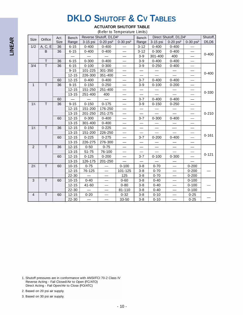
DKLO SHUTOFF & CV TABLES
(Refer to Temperature Limits)
Size Orifice Act. Bench Reverse Shutoff, D1,D41 Bench Direct Shutoff, D1,D41 Shutoff,Size Range 3-15 psi 0-20 psi2 0-30 psi3 Range 3-15 psi 0-20 psi2 0-30 psi3 D5,D6
1/2 A, C, E 36 6-15 0-400 0-400 — 3-12 0-400 0-400 —B 36 6-15 0-400 0-400 — 3-12 0-300 0-400 —
— — — — 3-9 301-400 400 — 0-400
T 36 6-15 0-300 0-400 — 3-9 0-400 0-400 —3/4 T 36 6-15 0-100 0-300 — 3-9 0-250 0-400 —
9-15 101-225 301-350 — — — — —12-15 226-300 351-400 — — — — — 0-400
60 12-15 0-400 0-400 — 3-7 0-400 0-400 —1 T 36 9-15 0-150 0-250 — 3-9 0-100 0-200 —
12-15 151-250 251-400 — — — — —13-15 251-400 400 — — — — — 0-330
60 — — — — 3-7 0-400 0-400 —11⁄4 T 36 9-15 0-150 0-175 — 3-9 0-150 0-250 —
12-15 151-200 176-250 — — — — —13-15 201-250 251-275 — — — — — 0-210
60 12-15 0-300 0-400 — 3-7 0-300 0-400 —13-15 301-400 0-400 — — — — —
11⁄2 T 36 12-15 0-150 0-225 — — — —- —13-15 151-200 226-250 — — — — —
60 12-15 0-225 0-275 — 3-7 0-200 0-400 — 0-161
13-15 226-275 276-300 — — — — —2 T 36 12-15 0-50 0-75 — — — — —
13-15 51-75 76-100 — — — — —60 12-15 0-125 0-200 — 3-7 0-100 0-300 — 0-121
13-15 126-175 201-250 — — — — —21⁄2 T 60 10-15 0-75 — 0-100 3-8 0-70 — 0-200
12-15 76-125 — 101-125 3-8 0-70 — 0-200 —22-30 — — 125 3-8 0-70 — 0-200
3 T 60 10-15 0-40 — 0-60 3-8 0-40 — 0-10012-15 41-60 — 0-80 3-8 0-40 — 0-100 —22-30 — — 81-110 3-8 0-40 — 0-100
4 T 60 12-15 0-20 — 0-32 3-8 0-10 — 0-2522-30 — — 33-50 3-8 0-10 — 0-25 —
1. Shutoff pressures are in conformance with ANSI/FCI 70-2 Class IVReverse Acting - Fail Closed/Air to Open (FC/ATO)Direct Acting - Fail Open/Air to Close (FO/ATC)
2. Based on 20 psi air supply.
3. Based on 30 psi air supply.
ACTUATOR SHUTOFF TABLE
LIN
EAR
- 11 -
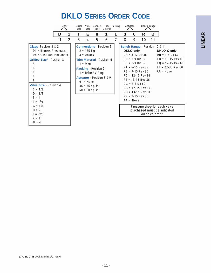
DKLO SERIES ORDER CODE
Pressure drop for each valve purchased must be indicated
on sales order.
D 1 T E 8 1 1 3 6 R B1 2 3 4 5 6 7 8 9 10 11
Class Orifice Valve Connec- Trim Packing Actuator Bench RangeSize Size tions Material
Connections - Position 52 = 125 Flg8 = Unions
Trim Material - Position 6 1 = Metal
Packing - Position 71 = Teflon® V-Ring
Actuator - Position 8 & 901 = None36 = 36 sq. in.60 = 60 sq. in.
Class -Position 1 & 2D1 = Bronze, PneumaticD4 = Cast Iron, Pneumatic
Orifice Size1 - Position 3ABCET
Valve Size - Position 4C = 1/2D = 3/4E = 1F = 11⁄4G = 11⁄2H = 2J = 21⁄2K = 3M = 4
Bench Range - Position 10 & 11DKLO only DKLO-C onlyDA = 3-12 Dir 36 DH = 3-8 Dir 60DB = 3-9 Dir 36 RH = 10-15 Rev 60DR = 3-9 Dir 36 RQ = 12-15 Rev 60RA = 6-15 Rev 36 RT = 22-30 Rev 60RB = 9-15 Rev 36 AA = NoneRC = 12-15 Rev 36RE = 13-15 Rev 36DG = 3-7 Dir 60RG = 12-15 Rev 60RH = 13-15 Rev 60RR = 9-15 Rev 36AA = None
1. A, B, C, E available in 1/2" only.
LIN
EAR
- 12 -
APPLICATION DATA
● Process control systems for food, pulp and paper, chemical,petrochemical & other industries
● HVAC systems
● Feed water and fuel system controls in boiler rooms
● Packaged systems (OEM) such as heat exchangers, waterpurification systems & vaporizer, metal cleaning and plating
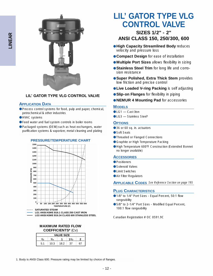
LIL’ GATOR TYPE VLGCONTROL VALVE
SIZES 1/2" - 2"ANSI CLASS 150, 250/300, 600
● High Capacity Streamlined Body reducesvelocity and pressure loss
● Compact Design for ease of installation
● Multiple Port Sizes allows flexibility in sizing
● Stainless Steel Trim for long life and corro-sion resistance
● Super Polished, Extra Thick Stem provideslow friction and precise control
● Live Loaded V-ring Packing is self adjusting
● Slip-on Flanges for flexibility in piping
● NEMUR 4 Mounting Pad for accessories
MODELS
● LG1 — Cast Iron
● LG3 — Stainless Steel1
OPTIONS
● 36 or 60 sq. in. actuators
● Soft Seats
● Threaded or Flanged Connections
● Graphite or High Temperature Packing
● High Temperature 600ºF Construction (Extended Bonnetno longer available)
ACCESSORIES
● Positioners
● Solenoid Valves
● Limit Switches
● Air Filter Regulators
APPLICABLE CODES
PLUG CHARACTERISTICS
● 1/8" to 1/4" Port Sizes - Equal Percent, 50:1 flow rangeability
● 5/8" to 2-1/4" Port Sizes - Modified Equal Percent,100:1 flow rangeability
Canadian Registration # OC 0591.9C
VALVE SIZE1/2 3/4 1 11/2 2
5.1 10.3 18.2 37 67
MAXIMUM RATED FLOWCOEFFICIENTS* (Cv)
1. Body is ANSI Class 600. Pressure rating may be limited by choice of flanges.
1500
1400
1300
1200
1100
1000
900
800
700
600
500
400
300
200
100
00 50 100 150 200 250 300 350 400 450 500 550 600
SATURATED STEAMLG1 ANSI/ASME B16.1 CLASS 250 CAST IRONLG3 ANSI/ASME B16.34 CLASS 600 STAINLESS STEEL
TEMPERATURE (F)
PR
ES
SU
RE
(PS
I)
PRESSURE/TEMPERATURE CHART
LIL’ GATOR TYPE VLG CONTROL VALVE
See Reference Section on page 195
LIN
EAR
- 13 -
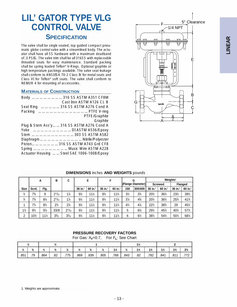
LIL’ GATOR TYPE VLGCONTROL VALVE
SPECIFICATIONThe valve shall be single seated, top guided compact pneu-matic globe control valve with a streamlined body. The actu-ator shall have all SS hardware with a maximum deadbandof .3 PSIG. The valve trim shall be all 316SS with replaceablethreaded seats for easy maintenance. Standard packingshall be spring loaded Teflon® V-Rings. Optional graphite orhigh temperature packings available. The valve seat leakageshall conform to ANSI/ISA 70-2 Class IV for metal seats andClass VI for Teflon® soft seats. The valve shall conform toNEMUR 4 for mounting of accessories.
MATERIALS OF CONSTRUCTION
Body ……………………316 SS ASTM A351 CF8MCast Iron ASTM A126 CL B
Seat Ring ……………316 SS ASTM A276 Cond APacking …………………………………PTFE V-ring
PTFE/GraphiteGraphite
Plug & Stem Ass’y……316 SS ASTM A276 Cond AYoke …………………………DI ASTM A536/EpoxyStem ……………………………303 SS ASTM A582Diaphragm……………………………Nitrile/PolyesterPiston…………………316 SS ASTM A743 Grd CF8Spring ………………………Music Wire ASTM A228Actuator Housing ……Steel SAE 1006-1008/Epoxy
AA
C
B
G
E
F 5" Clearance1/4 NPT
2
A B C E F G Weights1
(Flange Diameter) Screwed FlangedSize Scrd. Flg. 36 in.2 60 in.2 36 in.2 60 in.2 150 300/600 36 in.2 60 in.2 36 in.2 60 in.2
1⁄2 75⁄8 8 211⁄16 17⁄8 97⁄8 117⁄8 91⁄4 111⁄4 31⁄2 33⁄4 201⁄2 361⁄2 231⁄2 391⁄23⁄4 75⁄8 81⁄8 211⁄16 17⁄8 97⁄8 117⁄8 91⁄4 111⁄4 37⁄8 45⁄8 201⁄2 361⁄2 253⁄4 413⁄4
1 73⁄4 81⁄4 23⁄4 21⁄8 97⁄8 117⁄8 91⁄4 111⁄4 41⁄4 47⁄8 221⁄2 383⁄4 29 451⁄4
11⁄2 91⁄4 97⁄8 33/8 211⁄16 97⁄8 117⁄8 91⁄4 111⁄4 5 61⁄8 291⁄4 451⁄2 401⁄4 571⁄2
2 101⁄2 111⁄4 39⁄32 35⁄16 97⁄8 117⁄8 91⁄4 111⁄4 6 61⁄2 381⁄4 541⁄4 501⁄4 681⁄4
DIMENSIONS inches AND WEIGHTS pounds
1. Weights are approximate.
1⁄2 3⁄4 1 11⁄2 21⁄4 5⁄8 1⁄4 5⁄8 7⁄8 1⁄4 5⁄8 7⁄8 11⁄4 7⁄8 11⁄4 13⁄4 11⁄4 13⁄4 21⁄4
.851 .79 .864 .82 .775 .869 .839 .805 .768 .843 .82 .782 .841 .811 .772
PRESSURE RECOVERY FACTORS For Gas: XT=0.7, For FL: See Chart
LIN
EAR
- 14 -
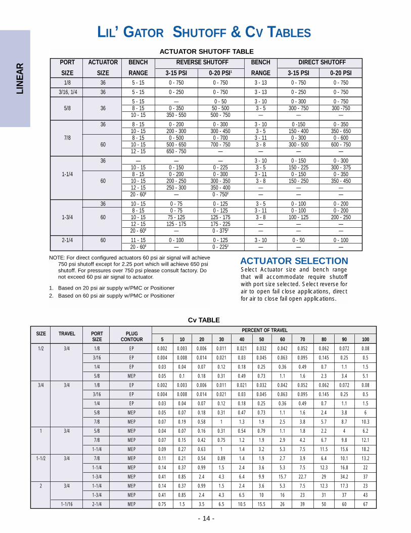
LIL’ GATOR SHUTOFF & CV TABLES
PORT ACTUATOR BENCH REVERSE SHUTOFF BENCH DIRECT SHUTOFF
SIZE SIZE RANGE 3-15 PSI 0-20 PSI1 RANGE 3-15 PSI 0-20 PSI1/8 36 5 - 15 0 - 750 0 - 750 3 - 13 0 - 750 0 - 750
3/16, 1/4 36 5 - 15 0 - 250 0 - 750 3 - 13 0 - 250 0 - 750
5 - 15 — 0 - 50 3 - 10 0 - 300 0 - 7505/8 36 8 - 15 0 - 350 50 - 500 3 - 5 300 - 750 300 -750
10 - 15 350 - 550 500 - 750 — — —
36 8 - 15 0 - 200 0 - 300 3 - 10 0 -150 0 - 35010 - 15 200 - 300 300 - 450 3 - 5 150 - 400 350 - 650
7/8 8 - 15 0 - 500 0 - 700 3 - 11 0 - 300 0 - 60060 10 - 15 500 - 650 700 - 750 3 - 8 300 - 500 600 - 750
12 - 15 650 - 750 — — — —
36 — — — 3 - 10 0 - 150 0 - 30010 - 15 0 - 150 0 - 225 3 - 5 150 - 225 300 - 375
1-1/4 8 - 15 0 - 200 0 - 300 3 - 11 0 - 150 0 - 35060 10 - 15 200 - 250 300 - 350 3 - 8 150 - 250 350 - 450
12 - 15 250 - 300 350 - 400 — — —20 - 602 — 0 - 7502 — — —
36 10 - 15 0 - 75 0 - 125 3 - 5 0 - 100 0 - 2008 - 15 0 - 75 0 - 125 3 - 11 0 - 100 0 - 200
1-3/4 60 10 - 15 75 - 125 125 - 175 3 - 8 100 - 125 200 - 25012 - 15 125 - 175 175 - 225 — — —20 - 602 — 0 - 3752 — — —
2-1/4 60 11 - 15 0 - 100 0 - 125 3 - 10 0 - 50 0 - 10020 - 602 — 0 - 2252 — — —
ACTUATOR SHUTOFF TABLE
NOTE: For direct configured actuators 60 psi air signal will achieve750 psi shutoff except for 2.25 port which will achieve 650 psishutoff. For pressures over 750 psi please consult factory. Do not exceed 60 psi air signal to actuator.
1. Based on 20 psi air supply w/PMC or Positioner2. Based on 60 psi air supply w/PMC or Positioner
ACTUATOR SELECTIONSelect Actuator size and bench rangethat will accommodate require shutoffwith port size selected. Select reverse forair to open fail close applications, directfor air to close fail open applications.
SIZE TRAVEL PORT PLUGPERCENT OF TRAVEL
SIZE CONTOUR 5 10 20 30 40 50 60 70 80 90 100
1/2 3/4 1/8 EP 0.002 0.003 0.006 0.011 0.021 0.032 0.042 0.052 0.062 0.072 0.08
3/16 EP 0.004 0.008 0.014 0.021 0.03 0.045 0.063 0.095 0.145 0.25 0.5
1/4 EP 0.03 0.04 0.07 0.12 0.18 0.25 0.36 0.49 0.7 1.1 1.5
5/8 MEP 0.05 0.1 0.18 0.31 0.49 0.73 1.1 1.6 2.3 3.4 5.1
3/4 3/4 1/8 EP 0.002 0.003 0.006 0.011 0.021 0.032 0.042 0.052 0.062 0.072 0.08
3/16 EP 0.004 0.008 0.014 0.021 0.03 0.045 0.063 0.095 0.145 0.25 0.5
1/4 EP 0.03 0.04 0.07 0.12 0.18 0.25 0.36 0.49 0.7 1.1 1.5
5/8 MEP 0.05 0.07 0.18 0.31 0.47 0.73 1.1 1.6 2.4 3.8 6
7/8 MEP 0.07 0.19 0.58 1 1.3 1.9 2.5 3.8 5.7 8.7 10.3
1 3/4 5/8 MEP 0.04 0.07 0.16 0.31 0.54 0.79 1.1 1.8 2.2 4 6.2
7/8 MEP 0.07 0.15 0.42 0.75 1.2 1.9 2.9 4.2 6.7 9.8 12.1
1-1/4 MEP 0.09 0.27 0.63 1 1.4 3.2 5.3 7.5 11.5 15.6 18.2
1-1/2 3/4 7/8 MEP 0.11 0.21 0.54 0.89 1.4 1.9 2.7 3.9 6.4 10.1 13.2
1-1/4 MEP 0.14 0.37 0.99 1.5 2.4 3.6 5.3 7.5 12.3 16.8 22
1-3/4 MEP 0.41 0.85 2.4 4.3 6.4 9.9 15.7 22.7 29 34.2 37
2 3/4 1-1/4 MEP 0.14 0.37 0.99 1.5 2.4 3.6 5.3 7.5 12.3 17.3 23
1-3/4 MEP 0.41 0.85 2.4 4.3 6.5 10 16 23 31 37 43
1-1/16 2-1/4 MEP 0.75 1.5 3.5 6.5 10.5 15.5 26 39 50 60 67
Cv TABLE
LIN
EAR
- 15 -
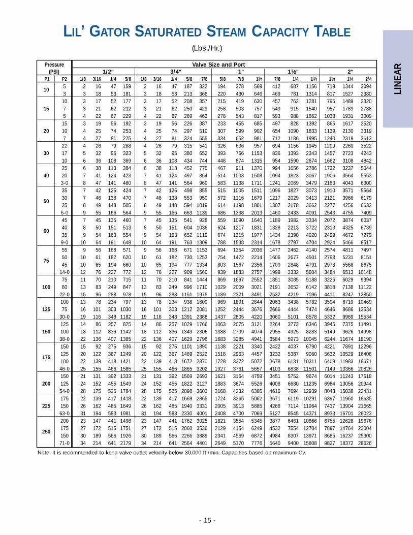
LIL’ GATOR SATURATED STEAM CAPACITY TABLE(Lbs./Hr.)
Note: It is recommended to keep valve outlet velocity below 30,000 ft./min. Capacities based on maximum Cv.
Pressure Valve Size and Port(PSI) 1/2" 3/4" 1" 11⁄2" 2"
P1 P2 1/8 3/16 1/4 5/8 1/8 3/16 1/4 5/8 7/8 5/8 7/8 11⁄4 7/8 11⁄4 13⁄4 11⁄4 13⁄4 21⁄4
105 2 16 47 159 2 16 47 187 322 194 378 569 412 687 1156 719 1344 20943 3 18 53 181 3 18 53 213 366 220 430 646 469 781 1314 817 1527 238010 3 17 52 177 3 17 52 208 357 215 419 630 457 762 1281 796 1489 2320
15 7 3 21 62 212 3 21 62 250 429 258 503 757 549 915 1540 957 1789 27885 4 22 67 229 4 22 67 269 463 278 543 817 593 988 1662 1033 1931 300915 3 19 56 192 3 19 56 226 387 233 455 685 497 828 1392 865 1617 2520
20 10 4 25 74 253 4 25 74 297 510 307 599 902 654 1090 1833 1139 2130 33197 4 27 81 275 4 27 81 324 555 334 652 981 712 1186 1995 1240 2319 361322 4 26 79 268 4 26 79 315 541 326 636 957 694 1156 1945 1209 2260 3522
30 17 5 32 95 323 5 32 95 380 652 393 766 1153 836 1393 2343 1457 2723 424310 6 36 108 369 6 36 108 434 744 448 874 1315 954 1590 2674 1662 3108 484225 6 38 113 384 6 38 113 452 775 467 911 1370 994 1656 2786 1732 3237 5044
40 20 7 41 124 423 7 41 124 497 854 514 1003 1508 1094 1823 3067 1906 3564 55533-0 8 47 141 480 8 47 141 564 969 583 1138 1711 1241 2069 3479 2163 4043 630035 7 42 125 424 7 42 125 498 855 515 1005 1511 1096 1827 3073 1910 3571 5564
5030 7 46 138 470 7 46 138 553 950 572 1116 1679 1217 2029 3413 2121 3966 617925 8 49 148 505 8 49 148 594 1019 614 1198 1801 1307 2178 3662 2277 4256 66326-0 9 55 166 564 9 55 166 663 1139 686 1338 2013 1460 2433 4091 2543 4755 740945 7 45 135 460 7 45 135 541 928 559 1090 1640 1189 1982 3334 2072 3874 6037
6040 8 50 151 513 8 50 151 604 1036 624 1217 1831 1328 2213 3722 2313 4325 673935 9 54 163 554 9 54 163 652 1119 674 1315 1977 1434 2390 4020 2499 4672 72799-0 10 64 191 648 10 64 191 763 1309 788 1538 2314 1678 2797 4704 2924 5466 851755 9 56 168 571 9 56 168 671 1153 694 1354 2036 1477 2462 4140 2574 4811 7497
7550 10 61 182 620 10 61 182 730 1253 754 1472 2214 1606 2677 4501 2798 5231 815145 10 65 194 660 10 65 194 777 1334 803 1567 2356 1709 2848 4791 2978 5568 8675
14-0 12 76 227 772 12 76 227 909 1560 939 1833 2757 1999 3332 5604 3484 6513 1014875 11 70 210 715 11 70 210 841 1444 869 1697 2552 1851 3085 5188 3225 6029 9394
100 60 13 83 249 847 13 83 249 996 1710 1029 2009 3021 2191 3652 6142 3818 7138 1112222-0 15 96 288 978 15 96 288 1151 1975 1189 2321 3491 2532 4219 7096 4411 8247 12850100 13 78 234 797 13 78 234 938 1609 969 1891 2844 2063 3438 5782 3594 6719 10469
125 75 16 101 303 1030 16 101 303 1212 2081 1252 2444 3676 2666 4444 7474 4646 8686 1353430-0 19 116 348 1182 19 116 348 1391 2388 1437 2805 4220 3060 5101 8578 5332 9969 15534125 14 86 257 875 14 86 257 1029 1766 1063 2075 3121 2264 3773 6346 3945 7375 11491
150 100 18 112 336 1142 18 112 336 1343 2306 1388 2709 4074 2955 4925 8283 5149 9626 1499838-0 22 136 407 1385 22 136 407 1629 2796 1683 3285 4941 3584 5973 10045 6244 11674 18190150 15 92 275 936 15 92 275 1101 1890 1138 2221 3340 2422 4037 6790 4221 7891 12296
175125 20 122 367 1249 20 122 367 1469 2522 1518 2963 4457 3232 5387 9060 5632 10529 16406100 22 139 418 1421 22 139 418 1672 2870 1728 3372 5072 3678 6131 10311 6409 11983 1867146-0 25 155 466 1585 25 155 466 1865 3202 1927 3761 5657 4103 6838 11501 7149 13366 20826150 21 131 392 1333 21 131 392 1569 2693 1621 3164 4759 3451 5752 9674 6014 11243 17518
200 125 24 152 455 1549 24 152 455 1822 3127 1883 3674 5526 4008 6680 11235 6984 13056 2034454-0 28 175 525 1784 28 175 525 2098 3602 2168 4232 6365 4616 7694 12939 8043 15038 23431175 22 139 417 1418 22 139 417 1669 2865 1724 3365 5062 3671 6119 10291 6397 11960 18635
225 150 26 162 485 1649 26 162 485 1940 3331 2005 3913 5885 4268 7114 11964 7437 13904 2166563-0 31 194 583 1981 31 194 583 2330 4001 2408 4700 7069 5127 8545 14371 8933 16701 26023200 23 147 441 1498 23 147 441 1762 3025 1821 3554 5345 3877 6461 10866 6755 12628 19676
250175 27 172 515 1751 27 172 515 2060 3536 2129 4154 6249 4532 7554 12704 7897 14764 23004150 30 189 566 1926 30 189 566 2266 3889 2341 4569 6872 4984 8307 13971 8685 16237 2530071-0 34 214 641 2179 34 214 641 2564 4401 2649 5170 7776 5640 9400 15808 9827 18372 28626
LIN
EAR
- 16 -
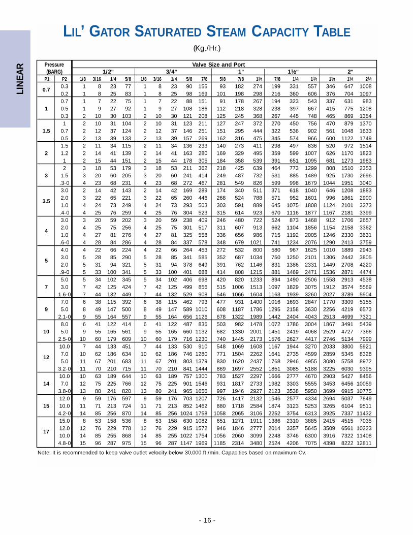
LIL’ GATOR SATURATED STEAM CAPACITY TABLE(Kg./Hr.)
Note: It is recommended to keep valve outlet velocity below 30,000 ft./min. Capacities based on maximum Cv.
Pressure Valve Size and Port(BARG) 1/2" 3/4" 1" 11⁄2" 2"
P1 P2 1/8 3/16 1/4 5/8 1/8 3/16 1/4 5/8 7/8 5/8 7/8 11⁄4 7/8 11⁄4 13⁄4 11⁄4 13⁄4 21⁄4
0.70.3 1 8 23 77 1 8 23 90 155 93 182 274 199 331 557 346 647 10080.2 1 8 25 83 1 8 25 98 169 101 198 298 216 360 606 376 704 10970.7 1 7 22 75 1 7 22 88 151 91 178 267 194 323 543 337 631 983
1 0.5 1 9 27 92 1 9 27 108 186 112 218 328 238 397 667 415 775 12080.3 2 10 30 103 2 10 30 121 208 125 245 368 267 445 748 465 869 13541 2 10 31 104 2 10 31 123 211 127 247 372 270 450 756 470 879 1370
1.5 0.7 2 12 37 124 2 12 37 146 251 151 295 444 322 536 902 561 1048 16330.5 2 13 39 133 2 13 39 157 269 162 316 475 345 574 966 600 1122 17491.5 2 11 34 115 2 11 34 136 233 140 273 411 298 497 836 520 972 1514
2 1.2 2 14 41 139 2 14 41 163 280 169 329 495 359 599 1007 626 1170 18231 2 15 44 151 2 15 44 178 305 184 358 539 391 651 1095 681 1273 19832 3 18 53 179 3 18 53 211 362 218 425 639 464 773 1299 808 1510 2353
3 1.5 3 20 60 205 3 20 60 241 414 249 487 732 531 885 1489 925 1730 2696.3-0 4 23 68 231 4 23 68 272 467 281 549 826 599 998 1679 1044 1951 3040 3.0 2 14 42 143 2 14 42 169 289 174 340 511 371 618 1040 646 1208 1883
3.52.0 3 22 65 221 3 22 65 260 446 268 524 788 571 952 1601 996 1861 29001.0 4 24 73 249 4 24 73 293 503 303 591 889 645 1075 1808 1124 2101 3273.4-0 4 25 76 259 4 25 76 304 523 315 614 923 670 1116 1877 1167 2181 33993.0 3 20 59 202 3 20 59 238 409 246 480 722 524 873 1468 912 1706 2657
42.0 4 25 75 256 4 25 75 301 517 311 607 913 662 1104 1856 1154 2158 33621.0 4 27 81 276 4 27 81 325 558 336 656 986 715 1192 2005 1246 2330 3631.6-0 4 28 84 286 4 28 84 337 578 348 679 1021 741 1234 2076 1290 2413 37594.0 4 22 66 224 4 22 66 264 453 272 532 800 580 967 1625 1010 1889 2943
53.0 5 28 85 290 5 28 85 341 585 352 687 1034 750 1250 2101 1306 2442 38052.0 5 31 94 321 5 31 94 378 649 391 762 1146 831 1386 2331 1449 2708 4220.9-0 5 33 100 341 5 33 100 401 688 414 808 1215 881 1469 2471 1536 2871 44745.0 5 34 102 345 5 34 102 406 698 420 820 1233 894 1490 2506 1558 2913 4538
7 3.0 7 42 125 424 7 42 125 499 856 515 1006 1513 1097 1829 3075 1912 3574 55691.6-0 7 44 132 449 7 44 132 529 908 546 1066 1604 1163 1939 3260 2027 3789 59047.0 6 38 115 392 6 38 115 462 793 477 931 1400 1016 1693 2847 1770 3309 5155
9 5.0 8 49 147 500 8 49 147 589 1010 608 1187 1786 1295 2158 3630 2256 4219 65732.1-0 9 55 164 557 9 55 164 656 1126 678 1322 1989 1442 2404 4043 2513 4699 73218.0 6 41 122 414 6 41 122 487 836 503 982 1478 1072 1786 3004 1867 3491 5439
10 5.0 9 55 165 561 9 55 165 660 1132 682 1330 2001 1451 2419 4068 2529 4727 73662.5-0 10 60 179 609 10 60 179 716 1230 740 1445 2173 1576 2627 4417 2746 5134 799910.0 7 44 133 451 7 44 133 530 910 548 1069 1608 1167 1944 3270 2033 3800 5921
127.0 10 62 186 634 10 62 186 746 1280 771 1504 2262 1641 2735 4599 2859 5345 83285.0 11 67 201 683 11 67 201 803 1379 830 1620 2437 1768 2946 4955 3080 5758 8972
3.2-0 11 70 210 715 11 70 210 841 1444 869 1697 2552 1851 3085 5188 3225 6030 939510.0 10 63 189 644 10 63 189 757 1300 783 1527 2297 1666 2777 4670 2903 5427 8456
14 7.0 12 75 225 766 12 75 225 901 1546 931 1817 2733 1982 3303 5555 3453 6456 100593.8-0 13 80 241 820 13 80 241 965 1656 997 1946 2927 2123 3538 5950 3699 6915 1077512.0 9 59 176 597 9 59 176 703 1207 726 1417 2132 1546 2577 4334 2694 5037 7849
15 10.0 11 71 213 724 11 71 213 852 1462 880 1718 2584 1874 3123 5253 3265 6104 95114.2-0 14 85 256 870 14 85 256 1024 1758 1058 2065 3106 2252 3754 6313 3925 7337 1143215.0 8 53 158 536 8 53 158 630 1082 651 1271 1911 1386 2310 3885 2415 4515 7035
1712.0 12 76 229 778 12 76 229 915 1572 946 1846 2777 2014 3357 5645 3509 6561 1022310.0 14 85 255 868 14 85 255 1022 1754 1056 2060 3099 2248 3746 6300 3916 7322 114084.8-0 15 96 287 975 15 96 287 1147 1969 1185 2314 3480 2524 4206 7075 4398 8222 12811
LIN
EAR
- 17 -
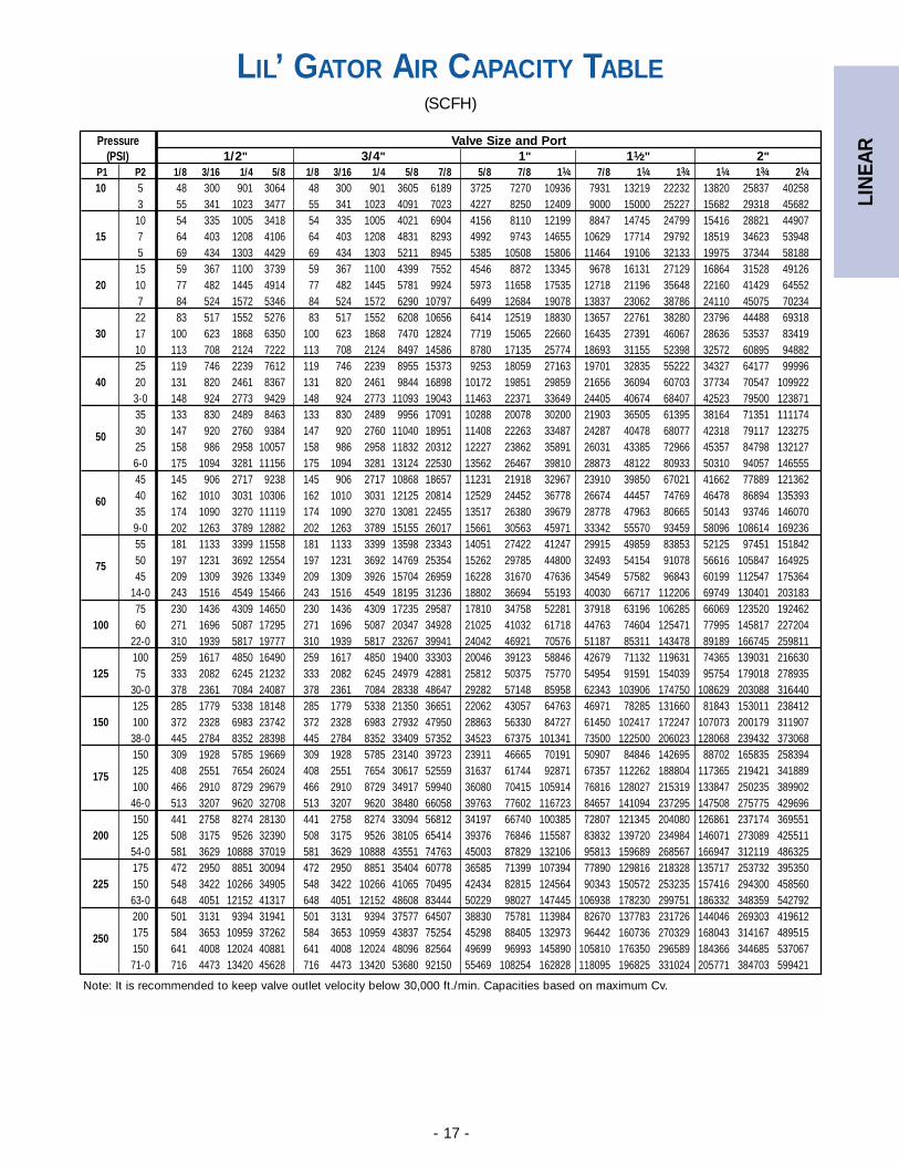
LIL’ GATOR AIR CAPACITY TABLE(SCFH)
Note: It is recommended to keep valve outlet velocity below 30,000 ft./min. Capacities based on maximum Cv.
Pressure Valve Size and Port(PSI) 1/2" 3/4" 1" 11⁄2" 2"
P1 P2 1/8 3/16 1/4 5/8 1/8 3/16 1/4 5/8 7/8 5/8 7/8 11⁄4 7/8 11⁄4 13⁄4 11⁄4 13⁄4 21⁄410 5 48 300 901 3064 48 300 901 3605 6189 3725 7270 10936 7931 13219 22232 13820 25837 40258
3 55 341 1023 3477 55 341 1023 4091 7023 4227 8250 12409 9000 15000 25227 15682 29318 4568210 54 335 1005 3418 54 335 1005 4021 6904 4156 8110 12199 8847 14745 24799 15416 28821 44907
15 7 64 403 1208 4106 64 403 1208 4831 8293 4992 9743 14655 10629 17714 29792 18519 34623 539485 69 434 1303 4429 69 434 1303 5211 8945 5385 10508 15806 11464 19106 32133 19975 37344 5818815 59 367 1100 3739 59 367 1100 4399 7552 4546 8872 13345 9678 16131 27129 16864 31528 49126
20 10 77 482 1445 4914 77 482 1445 5781 9924 5973 11658 17535 12718 21196 35648 22160 41429 645527 84 524 1572 5346 84 524 1572 6290 10797 6499 12684 19078 13837 23062 38786 24110 45075 7023422 83 517 1552 5276 83 517 1552 6208 10656 6414 12519 18830 13657 22761 38280 23796 44488 69318
30 17 100 623 1868 6350 100 623 1868 7470 12824 7719 15065 22660 16435 27391 46067 28636 53537 8341910 113 708 2124 7222 113 708 2124 8497 14586 8780 17135 25774 18693 31155 52398 32572 60895 9488225 119 746 2239 7612 119 746 2239 8955 15373 9253 18059 27163 19701 32835 55222 34327 64177 99996
40 20 131 820 2461 8367 131 820 2461 9844 16898 10172 19851 29859 21656 36094 60703 37734 70547 1099223-0 148 924 2773 9429 148 924 2773 11093 19043 11463 22371 33649 24405 40674 68407 42523 79500 12387135 133 830 2489 8463 133 830 2489 9956 17091 10288 20078 30200 21903 36505 61395 38164 71351 111174
50 30 147 920 2760 9384 147 920 2760 11040 18951 11408 22263 33487 24287 40478 68077 42318 79117 12327525 158 986 2958 10057 158 986 2958 11832 20312 12227 23862 35891 26031 43385 72966 45357 84798 1321276-0 175 1094 3281 11156 175 1094 3281 13124 22530 13562 26467 39810 28873 48122 80933 50310 94057 14655545 145 906 2717 9238 145 906 2717 10868 18657 11231 21918 32967 23910 39850 67021 41662 77889 121362
60 40 162 1010 3031 10306 162 1010 3031 12125 20814 12529 24452 36778 26674 44457 74769 46478 86894 13539335 174 1090 3270 11119 174 1090 3270 13081 22455 13517 26380 39679 28778 47963 80665 50143 93746 1460709-0 202 1263 3789 12882 202 1263 3789 15155 26017 15661 30563 45971 33342 55570 93459 58096 108614 16923655 181 1133 3399 11558 181 1133 3399 13598 23343 14051 27422 41247 29915 49859 83853 52125 97451 151842
75 50 197 1231 3692 12554 197 1231 3692 14769 25354 15262 29785 44800 32493 54154 91078 56616 105847 16492545 209 1309 3926 13349 209 1309 3926 15704 26959 16228 31670 47636 34549 57582 96843 60199 112547 175364
14-0 243 1516 4549 15466 243 1516 4549 18195 31236 18802 36694 55193 40030 66717 112206 69749 130401 20318375 230 1436 4309 14650 230 1436 4309 17235 29587 17810 34758 52281 37918 63196 106285 66069 123520 192462
100 60 271 1696 5087 17295 271 1696 5087 20347 34928 21025 41032 61718 44763 74604 125471 77995 145817 22720422-0 310 1939 5817 19777 310 1939 5817 23267 39941 24042 46921 70576 51187 85311 143478 89189 166745 259811100 259 1617 4850 16490 259 1617 4850 19400 33303 20046 39123 58846 42679 71132 119631 74365 139031 216630
125 75 333 2082 6245 21232 333 2082 6245 24979 42881 25812 50375 75770 54954 91591 154039 95754 179018 27893530-0 378 2361 7084 24087 378 2361 7084 28338 48647 29282 57148 85958 62343 103906 174750 108629 203088 316440125 285 1779 5338 18148 285 1779 5338 21350 36651 22062 43057 64763 46971 78285 131660 81843 153011 238412
150 100 372 2328 6983 23742 372 2328 6983 27932 47950 28863 56330 84727 61450 102417 172247 107073 200179 31190738-0 445 2784 8352 28398 445 2784 8352 33409 57352 34523 67375 101341 73500 122500 206023 128068 239432 373068150 309 1928 5785 19669 309 1928 5785 23140 39723 23911 46665 70191 50907 84846 142695 88702 165835 258394
175 125 408 2551 7654 26024 408 2551 7654 30617 52559 31637 61744 92871 67357 112262 188804 117365 219421 341889100 466 2910 8729 29679 466 2910 8729 34917 59940 36080 70415 105914 76816 128027 215319 133847 250235 38990246-0 513 3207 9620 32708 513 3207 9620 38480 66058 39763 77602 116723 84657 141094 237295 147508 275775 429696150 441 2758 8274 28130 441 2758 8274 33094 56812 34197 66740 100385 72807 121345 204080 126861 237174 369551
200 125 508 3175 9526 32390 508 3175 9526 38105 65414 39376 76846 115587 83832 139720 234984 146071 273089 42551154-0 581 3629 10888 37019 581 3629 10888 43551 74763 45003 87829 132106 95813 159689 268567 166947 312119 486325175 472 2950 8851 30094 472 2950 8851 35404 60778 36585 71399 107394 77890 129816 218328 135717 253732 395350
225 150 548 3422 10266 34905 548 3422 10266 41065 70495 42434 82815 124564 90343 150572 253235 157416 294300 45856063-0 648 4051 12152 41317 648 4051 12152 48608 83444 50229 98027 147445 106938 178230 299751 186332 348359 542792200 501 3131 9394 31941 501 3131 9394 37577 64507 38830 75781 113984 82670 137783 231726 144046 269303 419612
250 175 584 3653 10959 37262 584 3653 10959 43837 75254 45298 88405 132973 96442 160736 270329 168043 314167 489515150 641 4008 12024 40881 641 4008 12024 48096 82564 49699 96993 145890 105810 176350 296589 184366 344685 53706771-0 716 4473 13420 45628 716 4473 13420 53680 92150 55469 108254 162828 118095 196825 331024 205771 384703 599421
LIN
EAR
- 18 -
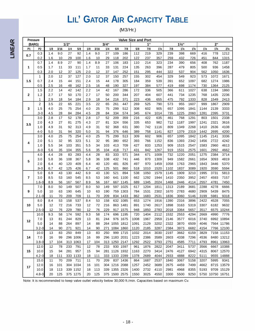
LIL’ GATOR AIR CAPACITY TABLE(M3/Hr.)
Note: It is recommended to keep valve outlet velocity below 30,000 ft./min. Capacities based on maximum Cv.
Pressure Valve Size and Port(BARG) 1/2" 3/4" 1" 11⁄2" 2"
P1 P2 1/8 3/16 1/4 5/8 1/8 3/16 1/4 5/8 7/8 5/8 7/8 11⁄4 7/8 11⁄4 13⁄4 11⁄4 13⁄4 21⁄4
0.70.3 1.4 9.0 27 92 1.4 9.0 27 109 186 112 219 329 239 398 669 416 778 12120.2 1.6 10 29 100 1.6 10 29 118 202 122 237 357 259 432 726 451 844 13150.7 1.4 8.9 27 90 1.4 8.9 27 106 183 110 214 323 234 390 656 408 762 1187
1 0.5 1.7 11 33 111 1.7 11 33 131 224 135 263 396 287 479 805 500 936 14580.3 2.0 12 37 125 2.0 12 37 147 252 151 295 444 322 537 904 562 1050 16361 2.0 12 37 127 2.0 12 37 150 257 155 302 454 329 549 923 573 1072 1671
1.5 0.7 2.4 15 44 151 2.4 15 44 178 305 184 359 539 391 652 1097 682 1274 19860.5 2.5 16 48 162 2.5 16 48 190 327 197 384 577 419 698 1174 730 1364 21251.5 2.2 14 42 142 2.2 14 42 167 286 172 336 505 366 611 1027 638 1194 1860
2 1.2 2.7 17 50 170 2.7 17 50 200 344 207 404 607 441 734 1235 768 1435 22361 2.9 18 54 184 2.9 18 54 216 371 223 436 655 475 792 1333 828 1549 24132 3.5 22 65 221 3.5 22 65 261 447 269 525 790 573 955 1607 999 1867 2909
3 1.5 4.0 25 75 254 4.0 25 75 299 512 308 602 905 657 1095 1841 1144 2139 3333.3-0 4.5 28 84 284 4.5 28 84 334 574 345 674 1014 735 1225 2060 1281 2395 37313.0 2.8 17 52 178 2.8 17 52 209 359 216 422 635 461 768 1291 803 1501 2338
3.52.0 4.3 27 81 275 4.3 27 81 324 556 335 653 982 712 1187 1997 1241 2321 36161.0 4.9 31 92 313 4.9 31 92 368 631 380 742 1116 809 1349 2268 1410 2636 41084-0 5.0 31 94 320 5.0 31 94 376 646 389 758 1141 827 1379 2319 1442 2695 42003.0 4.0 25 75 254 4.0 25 75 299 513 309 602 906 657 1095 1842 1145 2141 3336
42.0 5.1 32 95 323 5.1 32 95 380 652 393 766 1152 836 1393 2342 1456 2722 42421.0 5.5 34 103 351 5.5 34 103 413 709 427 833 1253 909 1515 2547 1583 2960 4613.6-0 5.6 35 104 355 5.6 35 104 418 717 431 842 1267 919 1531 2575 1601 2992 46624.0 4.4 28 83 283 4.4 28 83 333 571 344 671 1009 732 1220 2051 1275 2384 3714
53.0 5.8 36 108 367 5.8 36 108 432 741 446 870 1309 949 1582 2661 1654 3093 48192.0 6.4 40 120 409 6.4 40 120 481 826 497 970 1459 1058 1763 2965 1843 3446 5370.9-0 6.7 42 125 426 6.7 42 125 501 860 518 1010 1520 1102 1837 3089 1920 3590 55945.0 6.9 43 130 442 6.9 43 130 521 894 538 1050 1579 1145 1909 3210 1995 3731 5813
7 3.0 8.5 53 160 545 8.5 53 160 641 1100 662 1292 1944 1410 2350 3952 2457 4593 71571.6-0 8.9 56 167 567 8.9 56 167 667 1145 689 1345 2024 1468 2446 4114 2557 4781 74507.0 8.0 50 149 507 8.0 50 149 597 1025 617 1204 1811 1313 2189 3681 2288 4278 6666
9 5.0 10 63 190 645 10 63 190 759 1303 784 1531 2302 1670 2783 4680 2909 5439 84752.1-0 11 70 209 709 11 70 209 834 1433 862 1683 2531 1836 3060 5146 3199 5981 93188.0 8.4 53 158 537 8.4 53 158 632 1085 653 1274 1916 1390 2316 3896 2422 4528 7055
10 5.0 12 72 216 733 12 72 216 863 1481 891 1740 2617 1898 3163 5319 3307 6182 96322.5-0 12 76 229 780 12 76 229 917 1575 948 1850 2783 2018 3364 5657 3517 6575 1024410.0 9.3 58 174 592 9.3 58 174 696 1195 720 1404 2112 1532 2553 4294 2669 4990 7776
127.0 13 81 244 829 13 81 244 976 1675 1008 1967 2959 2146 3577 6016 3740 6992 108945.0 14 88 264 897 14 88 264 1055 1812 1091 2129 3202 2322 3870 6509 4046 7564 11786
3.2-0 14 90 271 921 14 90 271 1084 1860 1120 2185 3287 2384 3973 6682 4154 7766 1210010.0 13 83 250 849 13 83 250 999 1715 1032 2014 3030 2197 3662 6159 3829 7158 11153
14 7.0 16 99 296 1006 16 99 296 1183 2031 1223 2386 3589 2603 4338 7296 4536 8480 132123.8-0 17 104 313 1063 17 104 313 1250 2147 1292 2522 3793 2751 4585 7711 4793 8961 1396312.0 12 78 233 791 12 78 233 930 1597 961 1876 2822 2047 3411 5737 3566 6667 10388
15 10.0 15 94 281 957 15 94 281 1126 1932 1163 2270 3414 2476 4127 6942 4315 8067 125704.2-0 18 111 333 1133 18 111 333 1333 2289 1378 2689 4044 2933 4888 8222 5111 9555 1488815.0 11 70 209 711 11 70 209 837 1436 864 1687 2537 1840 3067 5158 3207 5995 9341
1712.0 16 101 304 1034 16 101 304 1216 2088 1257 2452 3689 2675 4459 7499 4662 8715 1357910.0 18 113 339 1152 18 113 339 1355 2326 1400 2732 4110 2981 4968 8355 5193 9709 151294.8-0 20 125 375 1275 20 125 375 1500 2575 1550 3025 4550 3300 5500 9250 5750 10750 16751
LIN
EAR
- 19 -
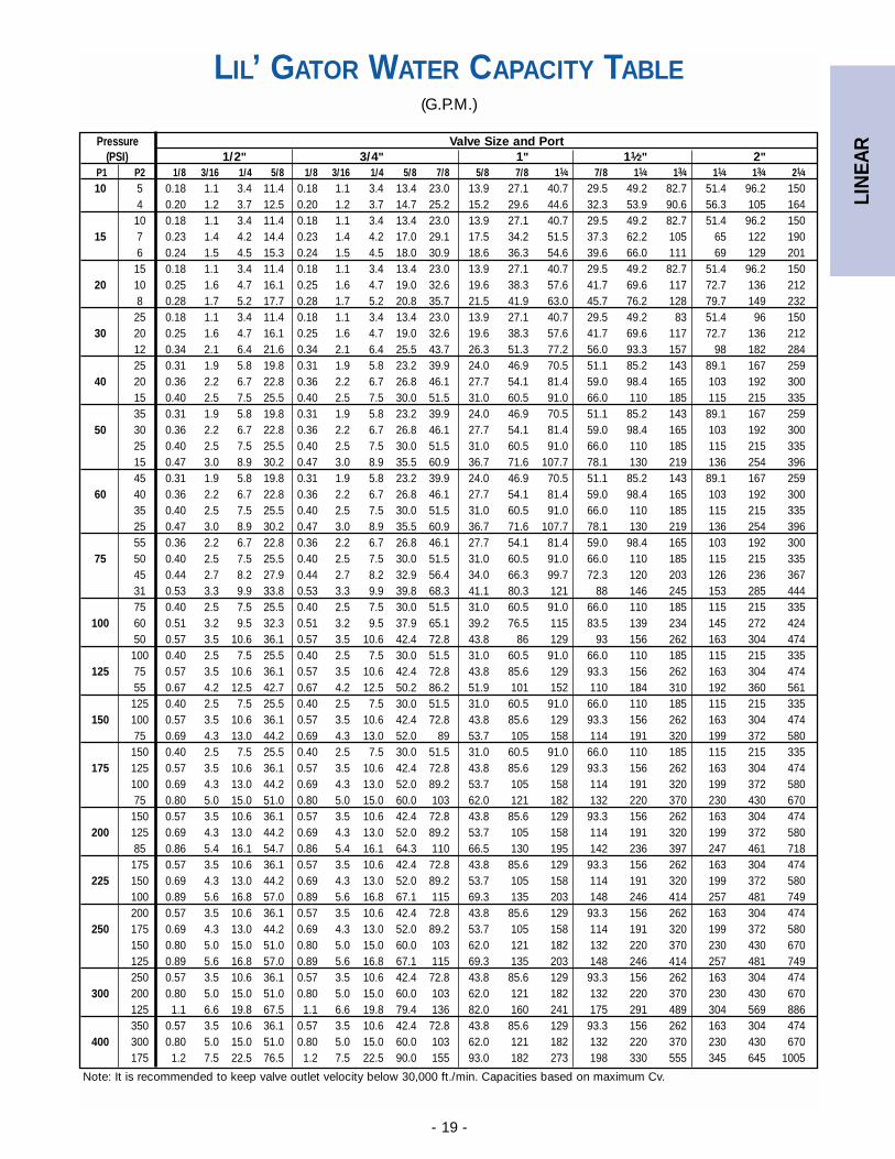
LIL’ GATOR WATER CAPACITY TABLE(G.P.M.)
Note: It is recommended to keep valve outlet velocity below 30,000 ft./min. Capacities based on maximum Cv.
Pressure Valve Size and Port(PSI) 1/2" 3/4" 1" 11⁄2" 2"
P1 P2 1/8 3/16 1/4 5/8 1/8 3/16 1/4 5/8 7/8 5/8 7/8 11⁄4 7/8 11⁄4 13⁄4 11⁄4 13⁄4 21⁄410 5 0.18 1.1 3.4 11.4 0.18 1.1 3.4 13.4 23.0 13.9 27.1 40.7 29.5 49.2 82.7 51.4 96.2 150
4 0.20 1.2 3.7 12.5 0.20 1.2 3.7 14.7 25.2 15.2 29.6 44.6 32.3 53.9 90.6 56.3 105 16410 0.18 1.1 3.4 11.4 0.18 1.1 3.4 13.4 23.0 13.9 27.1 40.7 29.5 49.2 82.7 51.4 96.2 150
15 7 0.23 1.4 4.2 14.4 0.23 1.4 4.2 17.0 29.1 17.5 34.2 51.5 37.3 62.2 105 65 122 1906 0.24 1.5 4.5 15.3 0.24 1.5 4.5 18.0 30.9 18.6 36.3 54.6 39.6 66.0 111 69 129 20115 0.18 1.1 3.4 11.4 0.18 1.1 3.4 13.4 23.0 13.9 27.1 40.7 29.5 49.2 82.7 51.4 96.2 150
20 10 0.25 1.6 4.7 16.1 0.25 1.6 4.7 19.0 32.6 19.6 38.3 57.6 41.7 69.6 117 72.7 136 2128 0.28 1.7 5.2 17.7 0.28 1.7 5.2 20.8 35.7 21.5 41.9 63.0 45.7 76.2 128 79.7 149 23225 0.18 1.1 3.4 11.4 0.18 1.1 3.4 13.4 23.0 13.9 27.1 40.7 29.5 49.2 83 51.4 96 150
30 20 0.25 1.6 4.7 16.1 0.25 1.6 4.7 19.0 32.6 19.6 38.3 57.6 41.7 69.6 117 72.7 136 21212 0.34 2.1 6.4 21.6 0.34 2.1 6.4 25.5 43.7 26.3 51.3 77.2 56.0 93.3 157 98 182 28425 0.31 1.9 5.8 19.8 0.31 1.9 5.8 23.2 39.9 24.0 46.9 70.5 51.1 85.2 143 89.1 167 259
40 20 0.36 2.2 6.7 22.8 0.36 2.2 6.7 26.8 46.1 27.7 54.1 81.4 59.0 98.4 165 103 192 30015 0.40 2.5 7.5 25.5 0.40 2.5 7.5 30.0 51.5 31.0 60.5 91.0 66.0 110 185 115 215 33535 0.31 1.9 5.8 19.8 0.31 1.9 5.8 23.2 39.9 24.0 46.9 70.5 51.1 85.2 143 89.1 167 259
50 30 0.36 2.2 6.7 22.8 0.36 2.2 6.7 26.8 46.1 27.7 54.1 81.4 59.0 98.4 165 103 192 30025 0.40 2.5 7.5 25.5 0.40 2.5 7.5 30.0 51.5 31.0 60.5 91.0 66.0 110 185 115 215 33515 0.47 3.0 8.9 30.2 0.47 3.0 8.9 35.5 60.9 36.7 71.6 107.7 78.1 130 219 136 254 39645 0.31 1.9 5.8 19.8 0.31 1.9 5.8 23.2 39.9 24.0 46.9 70.5 51.1 85.2 143 89.1 167 259
60 40 0.36 2.2 6.7 22.8 0.36 2.2 6.7 26.8 46.1 27.7 54.1 81.4 59.0 98.4 165 103 192 30035 0.40 2.5 7.5 25.5 0.40 2.5 7.5 30.0 51.5 31.0 60.5 91.0 66.0 110 185 115 215 33525 0.47 3.0 8.9 30.2 0.47 3.0 8.9 35.5 60.9 36.7 71.6 107.7 78.1 130 219 136 254 39655 0.36 2.2 6.7 22.8 0.36 2.2 6.7 26.8 46.1 27.7 54.1 81.4 59.0 98.4 165 103 192 300
75 50 0.40 2.5 7.5 25.5 0.40 2.5 7.5 30.0 51.5 31.0 60.5 91.0 66.0 110 185 115 215 33545 0.44 2.7 8.2 27.9 0.44 2.7 8.2 32.9 56.4 34.0 66.3 99.7 72.3 120 203 126 236 36731 0.53 3.3 9.9 33.8 0.53 3.3 9.9 39.8 68.3 41.1 80.3 121 88 146 245 153 285 44475 0.40 2.5 7.5 25.5 0.40 2.5 7.5 30.0 51.5 31.0 60.5 91.0 66.0 110 185 115 215 335
100 60 0.51 3.2 9.5 32.3 0.51 3.2 9.5 37.9 65.1 39.2 76.5 115 83.5 139 234 145 272 42450 0.57 3.5 10.6 36.1 0.57 3.5 10.6 42.4 72.8 43.8 86 129 93 156 262 163 304 474
100 0.40 2.5 7.5 25.5 0.40 2.5 7.5 30.0 51.5 31.0 60.5 91.0 66.0 110 185 115 215 335125 75 0.57 3.5 10.6 36.1 0.57 3.5 10.6 42.4 72.8 43.8 85.6 129 93.3 156 262 163 304 474
55 0.67 4.2 12.5 42.7 0.67 4.2 12.5 50.2 86.2 51.9 101 152 110 184 310 192 360 561125 0.40 2.5 7.5 25.5 0.40 2.5 7.5 30.0 51.5 31.0 60.5 91.0 66.0 110 185 115 215 335
150 100 0.57 3.5 10.6 36.1 0.57 3.5 10.6 42.4 72.8 43.8 85.6 129 93.3 156 262 163 304 47475 0.69 4.3 13.0 44.2 0.69 4.3 13.0 52.0 89 53.7 105 158 114 191 320 199 372 580
150 0.40 2.5 7.5 25.5 0.40 2.5 7.5 30.0 51.5 31.0 60.5 91.0 66.0 110 185 115 215 335175 125 0.57 3.5 10.6 36.1 0.57 3.5 10.6 42.4 72.8 43.8 85.6 129 93.3 156 262 163 304 474
100 0.69 4.3 13.0 44.2 0.69 4.3 13.0 52.0 89.2 53.7 105 158 114 191 320 199 372 58075 0.80 5.0 15.0 51.0 0.80 5.0 15.0 60.0 103 62.0 121 182 132 220 370 230 430 670
150 0.57 3.5 10.6 36.1 0.57 3.5 10.6 42.4 72.8 43.8 85.6 129 93.3 156 262 163 304 474200 125 0.69 4.3 13.0 44.2 0.69 4.3 13.0 52.0 89.2 53.7 105 158 114 191 320 199 372 580
85 0.86 5.4 16.1 54.7 0.86 5.4 16.1 64.3 110 66.5 130 195 142 236 397 247 461 718175 0.57 3.5 10.6 36.1 0.57 3.5 10.6 42.4 72.8 43.8 85.6 129 93.3 156 262 163 304 474
225 150 0.69 4.3 13.0 44.2 0.69 4.3 13.0 52.0 89.2 53.7 105 158 114 191 320 199 372 580100 0.89 5.6 16.8 57.0 0.89 5.6 16.8 67.1 115 69.3 135 203 148 246 414 257 481 749200 0.57 3.5 10.6 36.1 0.57 3.5 10.6 42.4 72.8 43.8 85.6 129 93.3 156 262 163 304 474
250 175 0.69 4.3 13.0 44.2 0.69 4.3 13.0 52.0 89.2 53.7 105 158 114 191 320 199 372 580150 0.80 5.0 15.0 51.0 0.80 5.0 15.0 60.0 103 62.0 121 182 132 220 370 230 430 670125 0.89 5.6 16.8 57.0 0.89 5.6 16.8 67.1 115 69.3 135 203 148 246 414 257 481 749250 0.57 3.5 10.6 36.1 0.57 3.5 10.6 42.4 72.8 43.8 85.6 129 93.3 156 262 163 304 474
300 200 0.80 5.0 15.0 51.0 0.80 5.0 15.0 60.0 103 62.0 121 182 132 220 370 230 430 670125 1.1 6.6 19.8 67.5 1.1 6.6 19.8 79.4 136 82.0 160 241 175 291 489 304 569 886350 0.57 3.5 10.6 36.1 0.57 3.5 10.6 42.4 72.8 43.8 85.6 129 93.3 156 262 163 304 474
400 300 0.80 5.0 15.0 51.0 0.80 5.0 15.0 60.0 103 62.0 121 182 132 220 370 230 430 670175 1.2 7.5 22.5 76.5 1.2 7.5 22.5 90.0 155 93.0 182 273 198 330 555 345 645 1005
LIN
EAR
- 20 -
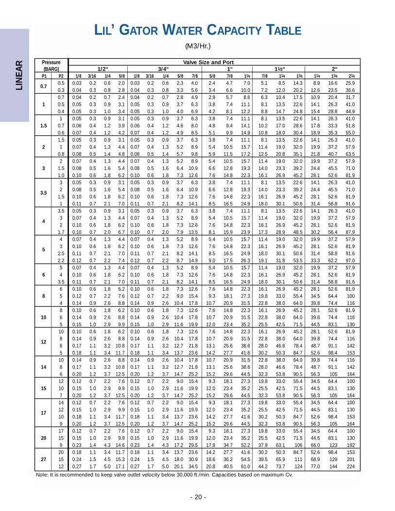
LIL’ GATOR WATER CAPACITY TABLE(M3/Hr.)
Note: It is recommended to keep valve outlet velocity below 30,000 ft./min. Capacities based on maximum Cv.
Pressure Valve Size and Port(BARG) 1/2" 3/4" 1" 11⁄2" 2"
P1 P2 1/8 3/16 1/4 5/8 1/8 3/16 1/4 5/8 7/8 5/8 7/8 11⁄4 7/8 11⁄4 13⁄4 11⁄4 13⁄4 21⁄4
0.70.5 0.03 0.2 0.6 2.0 0.03 0.2 0.6 2.3 4.0 2.4 4.7 7.0 5.1 8.5 14.3 8.9 16.6 25.90.3 0.04 0.3 0.8 2.8 0.04 0.3 0.8 3.3 5.6 3.4 6.6 10.0 7.2 12.0 20.2 12.6 23.5 36.60.7 0.04 0.2 0.7 2.4 0.04 0.2 0.7 2.8 4.9 2.9 5.7 8.6 6.3 10.4 17.5 10.9 20.4 31.7
1 0.5 0.05 0.3 0.9 3.1 0.05 0.3 0.9 3.7 6.3 3.8 7.4 11.1 8.1 13.5 22.6 14.1 26.3 41.00.4 0.05 0.3 1.0 3.4 0.05 0.3 1.0 4.0 6.9 4.2 8.1 12.2 8.8 14.7 24.8 15.4 28.8 44.91 0.05 0.3 0.9 3.1 0.05 0.3 0.9 3.7 6.3 3.8 7.4 11.1 8.1 13.5 22.6 14.1 26.3 41.0
1.5 0.7 0.06 0.4 1.2 3.9 0.06 0.4 1.2 4.6 8.0 4.8 9.4 14.1 10.2 17.0 28.6 17.8 33.3 51.80.6 0.07 0.4 1.2 4.2 0.07 0.4 1.2 4.9 8.5 5.1 9.9 14.9 10.8 18.0 30.4 18.9 35.3 55.01.5 0.05 0.3 0.9 3.1 0.05 0.3 0.9 3.7 6.3 3.8 7.4 11.1 8.1 13.5 22.6 14.1 26.3 41.0
2 1 0.07 0.4 1.3 4.4 0.07 0.4 1.3 5.2 8.9 5.4 10.5 15.7 11.4 19.0 32.0 19.9 37.2 57.90.8 0.08 0.5 1.4 4.8 0.08 0.5 1.4 5.7 9.8 5.9 11.5 17.2 12.5 20.8 35.1 21.8 40.7 63.52 0.07 0.4 1.3 4.4 0.07 0.4 1.3 5.2 8.9 5.4 10.5 15.7 11.4 19.0 32.0 19.9 37.2 57.9
3 1.5 0.08 0.5 1.6 5.4 0.08 0.5 1.6 6.4 10.9 6.6 12.8 19.3 14.0 23.3 39.2 24.4 45.5 71.01.0 0.10 0.6 1.8 6.2 0.10 0.6 1.8 7.3 12.6 7.6 14.8 22.3 16.1 26.9 45.2 28.1 52.6 81.93 0.05 0.3 0.9 3.1 0.05 0.3 0.9 3.7 6.3 3.8 7.4 11.1 8.1 13.5 22.6 14.1 26.3 41.0
3.52 0.08 0.5 1.6 5.4 0.08 0.5 1.6 6.4 10.9 6.6 12.8 19.3 14.0 23.3 39.2 24.4 45.5 71.0
1.5 0.10 0.6 1.8 6.2 0.10 0.6 1.8 7.3 12.6 7.6 14.8 22.3 16.1 26.9 45.2 28.1 52.6 81.91 0.11 0.7 2.1 7.0 0.11 0.7 2.1 8.2 14.1 8.5 16.5 24.9 18.0 30.1 50.6 31.4 58.8 91.6
3.5 0.05 0.3 0.9 3.1 0.05 0.3 0.9 3.7 6.3 3.8 7.4 11.1 8.1 13.5 22.6 14.1 26.3 41.0
43 0.07 0.4 1.3 4.4 0.07 0.4 1.3 5.2 8.9 5.4 10.5 15.7 11.4 19.0 32.0 19.9 37.2 57.92 0.10 0.6 1.8 6.2 0.10 0.6 1.8 7.3 12.6 7.6 14.8 22.3 16.1 26.9 45.2 28.1 52.6 81.9
1.7 0.10 0.7 2.0 6.7 0.10 0.7 2.0 7.9 13.5 8.1 15.9 23.9 17.3 28.9 48.5 30.2 56.4 87.94 0.07 0.4 1.3 4.4 0.07 0.4 1.3 5.2 8.9 5.4 10.5 15.7 11.4 19.0 32.0 19.9 37.2 57.9
53 0.10 0.6 1.8 6.2 0.10 0.6 1.8 7.3 12.6 7.6 14.8 22.3 16.1 26.9 45.2 28.1 52.6 81.9
2.5 0.11 0.7 2.1 7.0 0.11 0.7 2.1 8.2 14.1 8.5 16.5 24.9 18.0 30.1 50.6 31.4 58.8 91.62.2 0.12 0.7 2.2 7.4 0.12 0.7 2.2 8.7 14.9 9.0 17.5 26.3 19.1 31.8 53.5 33.3 62.2 97.05 0.07 0.4 1.3 4.4 0.07 0.4 1.3 5.2 8.9 5.4 10.5 15.7 11.4 19.0 32.0 19.9 37.2 57.9
6 4 0.10 0.6 1.8 6.2 0.10 0.6 1.8 7.3 12.6 7.6 14.8 22.3 16.1 26.9 45.2 28.1 52.6 81.93.5 0.11 0.7 2.1 7.0 0.11 0.7 2.1 8.2 14.1 8.5 16.5 24.9 18.0 30.1 50.6 31.4 58.8 91.66 0.10 0.6 1.8 6.2 0.10 0.6 1.8 7.3 12.6 7.6 14.8 22.3 16.1 26.9 45.2 28.1 52.6 81.9
8 5 0.12 0.7 2.2 7.6 0.12 0.7 2.2 9.0 15.4 9.3 18.1 27.3 19.8 33.0 55.4 34.5 64.4 1004 0.14 0.9 2.6 8.8 0.14 0.9 2.6 10.4 17.8 10.7 20.9 31.5 22.8 38.0 64.0 39.8 74.4 1168 0.10 0.6 1.8 6.2 0.10 0.6 1.8 7.3 12.6 7.6 14.8 22.3 16.1 26.9 45.2 28.1 52.6 81.9
10 6 0.14 0.9 2.6 8.8 0.14 0.9 2.6 10.4 17.8 10.7 20.9 31.5 22.8 38.0 64.0 39.8 74.4 1165 0.15 1.0 2.9 9.9 0.15 1.0 2.9 11.6 19.9 12.0 23.4 35.2 25.5 42.5 71.5 44.5 83.1 13010 0.10 0.6 1.8 6.2 0.10 0.6 1.8 7.3 12.6 7.6 14.8 22.3 16.1 26.9 45.2 28.1 52.6 81.9
128 0.14 0.9 2.6 8.8 0.14 0.9 2.6 10.4 17.8 10.7 20.9 31.5 22.8 38.0 64.0 39.8 74.4 1166 0.17 1.1 3.2 10.8 0.17 1.1 3.2 12.7 21.8 13.1 25.6 38.6 28.0 46.6 78.4 48.7 91.1 1425 0.18 1.1 3.4 11.7 0.18 1.1 3.4 13.7 23.6 14.2 27.7 41.6 30.2 50.3 84.7 52.6 98.4 15310 0.14 0.9 2.6 8.8 0.14 0.9 2.6 10.4 17.8 10.7 20.9 31.5 22.8 38.0 64.0 39.8 74.4 116
14 8 0.17 1.1 3.2 10.8 0.17 1.1 3.2 12.7 21.8 13.1 25.6 38.6 28.0 46.6 78.4 48.7 91.1 1426 0.20 1.2 3.7 12.5 0.20 1.2 3.7 14.7 25.2 15.2 29.6 44.5 32.3 53.8 90.5 56.3 105 16412 0.12 0.7 2.2 7.6 0.12 0.7 2.2 9.0 15.4 9.3 18.1 27.3 19.8 33.0 55.4 34.5 64.4 100
15 10 0.15 1.0 2.9 9.9 0.15 1.0 2.9 11.6 19.9 12.0 23.4 35.2 25.5 42.5 71.5 44.5 83.1 1307 0.20 1.2 3.7 12.5 0.20 1.2 3.7 14.7 25.2 15.2 29.6 44.5 32.3 53.8 90.5 56.3 105 16414 0.12 0.7 2.2 7.6 0.12 0.7 2.2 9.0 15.4 9.3 18.1 27.3 19.8 33.0 55.4 34.5 64.4 100
1712 0.15 1.0 2.9 9.9 0.15 1.0 2.9 11.6 19.9 12.0 23.4 35.2 25.5 42.5 71.5 44.5 83.1 13010 0.18 1.1 3.4 11.7 0.18 1.1 3.4 13.7 23.6 14.2 27.7 41.6 30.2 50.3 84.7 52.6 98.4 1539 0.20 1.2 3.7 12.5 0.20 1.2 3.7 14.7 25.2 15.2 29.6 44.5 32.3 53.8 90.5 56.3 105 16417 0.12 0.7 2.2 7.6 0.12 0.7 2.2 9.0 15.4 9.3 18.1 27.3 19.8 33.0 55.4 34.5 64.4 100
20 15 0.15 1.0 2.9 9.9 0.15 1.0 2.9 11.6 19.9 12.0 23.4 35.2 25.5 42.5 71.5 44.5 83.1 1309 0.23 1.4 4.3 14.6 0.23 1.4 4.3 17.2 29.5 17.8 34.7 52.2 37.9 63.1 106 66.0 123 19220 0.18 1.1 3.4 11.7 0.18 1.1 3.4 13.7 23.6 14.2 27.7 41.6 30.2 50.3 84.7 52.6 98.4 153
27 15 0.24 1.5 4.5 15.3 0.24 1.5 4.5 18.0 30.9 18.6 36.2 54.5 39.5 65.9 111 68.9 129 20112 0.27 1.7 5.0 17.1 0.27 1.7 5.0 20.1 34.5 20.8 40.5 61.0 44.2 73.7 124 77.0 144 224
LIN
EAR
- 21 -
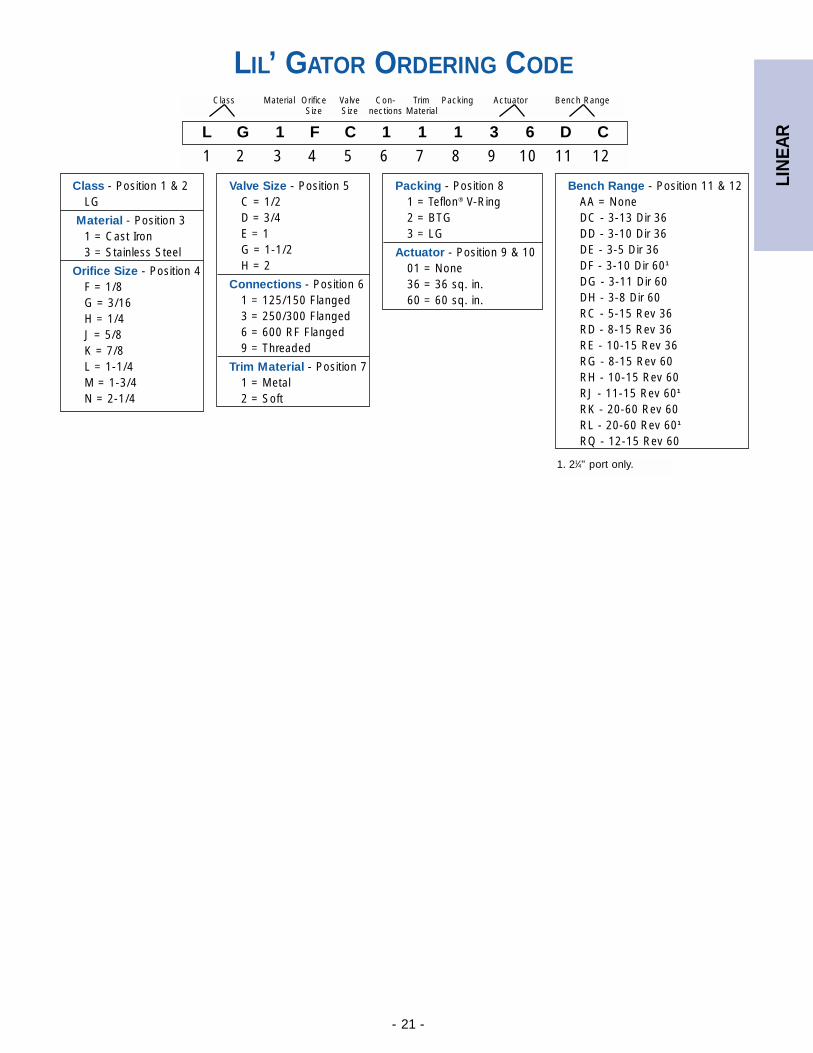
LIL’ GATOR ORDERING CODE
1. 21⁄4" port only.
L G 1 F C 1 1 1 3 6 D C
1 2 3 4 5 6 7 8 9 10 11 12
Class Material Orifice Valve Con- Trim Packing Actuator Bench RangeSize Size nections Material
Valve Size - Position 5C = 1/2D = 3/4E = 1G = 1-1/2H = 2
Connections - Position 61 = 125/150 Flanged3 = 250/300 Flanged6 = 600 RF Flanged9 = Threaded
Trim Material - Position 71 = Metal2 = Soft
Bench Range - Position 11 & 12AA = NoneDC - 3-13 Dir 36DD - 3-10 Dir 36DE - 3-5 Dir 36DF - 3-10 Dir 601
DG - 3-11 Dir 60DH - 3-8 Dir 60RC - 5-15 Rev 36RD - 8-15 Rev 36RE - 10-15 Rev 36RG - 8-15 Rev 60RH - 10-15 Rev 60RJ - 11-15 Rev 601
RK - 20-60 Rev 60RL - 20-60 Rev 601
RQ - 12-15 Rev 60
Packing - Position 81 = Teflon® V-Ring2 = BTG3 = LG
Actuator - Position 9 & 1001 = None36 = 36 sq. in.60 = 60 sq. in.
Class - Position 1 & 2LG
Material - Position 31 = Cast Iron3 = Stainless Steel
Orifice Size - Position 4F = 1/8G = 3/16H = 1/4J = 5/8K = 7/8L = 1-1/4M = 1-3/4N = 2-1/4
LIN
EAR
- 22 -
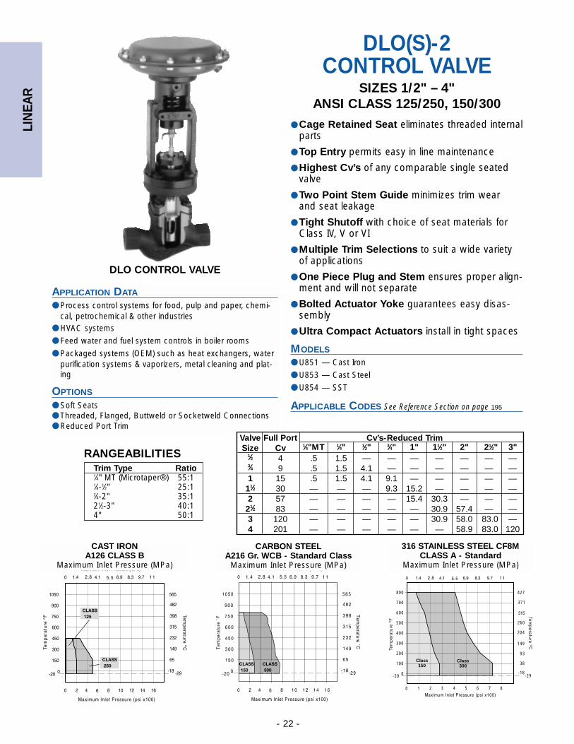
DLO CONTROL VALVE
APPLICATION DATA
● Process control systems for food, pulp and paper, chemi-cal, petrochemical & other industries
● HVAC systems
● Feed water and fuel system controls in boiler rooms
● Packaged systems (OEM) such as heat exchangers, waterpurification systems & vaporizers, metal cleaning and plat-ing
OPTIONS
● Soft Seats● Threaded, Flanged, Buttweld or Socketweld Connections● Reduced Port Trim
DLO(S)-2CONTROL VALVE
SIZES 1/2" – 4"ANSI CLASS 125/250, 150/300
● Cage Retained Seat eliminates threaded internalparts
● Top Entry permits easy in line maintenance
● Highest Cv’s of any comparable single seatedvalve
● Two Point Stem Guide minimizes trim wear and seat leakage
● Tight Shutoff with choice of seat materials forClass IV, V or VI
● Multiple Trim Selections to suit a wide varietyof applications
● One Piece Plug and Stem ensures proper align-ment and will not separate
● Bolted Actuator Yoke guarantees easy disas-sembly
● Ultra Compact Actuators install in tight spaces
MODELS
● U851 — Cast Iron
● U853 — Cast Steel
● U854 — SST
APPLICABLE CODES
Valve Full Port Cv’s-Reduced TrimSize Cv 1⁄4"MT 1⁄4" 1⁄2" 3⁄4" 1" 11⁄2" 2" 21⁄2" 3"
1⁄2 4 .5 1.5 — — — — — — —3⁄4 9 .5 1.5 4.1 — — — — — —1 15 .5 1.5 4.1 9.1 — — — — —
11⁄2 30 — — — 9.3 15.2 — — — —2 57 — — — — 15.4 30.3 — — —
21⁄2 83 — — — — — 30.9 57.4 — —3 120 — — — — — 30.9 58.0 83.0 —4 201 — — — — — — 58.9 83.0 120
See Reference Section on page 195
Trim Type Ratio1⁄4" MT (Microtaper®) 55:11⁄4-1⁄2" 25:13⁄4-2" 35:121⁄2-3" 40:14" 50:1
RANGEABILITIES
800
700
600
500
400
300
200
100
0
STAINLESS STEEL CF8M CLASS A - Standard
1 2 3 4 5 6 7 80
427
371
260
204
149
93
38
-18-29-20
Class150
Class300
CAST IRONA126 CLASS B
Maximum Inlet Pressure (MPa)
CARBON STEELA216 Gr. WCB - Standard Class
Maximum Inlet Pressure (MPa)
316 STAINLESS STEEL CF8MCLASS A - Standard
Maximum Inlet Pressure (MPa)
LIN
EAR
- 23 -
DLO(S)-2 CONTROL VALVESPECIFICATION
1. Threaded available in 1/2" to 2" only.
2. BWE same as 300# Flanged.
DIMENSIONS1 inches (mm) AND WEIGHTS pounds (kg)A B WEIGHT
SIZETHD,
125,150 CI CS C D THD 125 150 250 300250,3002
(ND25,40)(ND16) (ND16) (ND16) (ND25) (ND40)
1⁄2 73⁄4 — 23⁄8 — 511⁄16 123⁄8 54 — — — —(15) (197) — (60) — (145) (314) (23.6) — — — —
3⁄4 73⁄4 — 23⁄8 — 511⁄16 123⁄8 54 — — — —(20) (197) — (60) — (145) (314) (23.6) — — — —
1 73⁄4 71⁄4 21⁄4 21⁄4 511⁄16 123⁄8 54 54 54 56 65(25) (197) (184) (57) (57) (145) (314) (23.6) (28.6) (28.6) (25.4) (25.4)
11⁄2 91⁄4 83⁄4 23⁄8 23⁄8 73⁄8 123⁄8 63 70 70 70 72(40) (235) (222) (60) (60) (187) (314) (28.6) (31.8) (31.8) (32.7) (32.7)
2 101⁄2 10 3 3 75⁄8 151⁄4 70 91 91 95 95(50) (267) (254) (76) (76) (194) (387) (31.8) (41.3) (41.3) (43.2) (43.2)
21⁄2 111⁄2 107⁄8 35⁄8 37⁄8 8 151⁄4 — 108 107 114 115(65) (292) (276) (92) (98) (203) (387) — (59) (57.7) (51.7) (52.7)
3 121⁄2 113⁄4 37⁄8 37⁄8 83⁄8 151⁄4 — 130 127 141 138(80) (318) (298) (98) (98) (213) (387) — (64.1) (62.7)
4 141⁄2 137⁄8 5 43⁄4 103⁄16 195⁄8 — 231 271 248 236(100) (393) (385) (127) (123) (259) (499) — (104.8) (98.5) (112.5) (107.1)
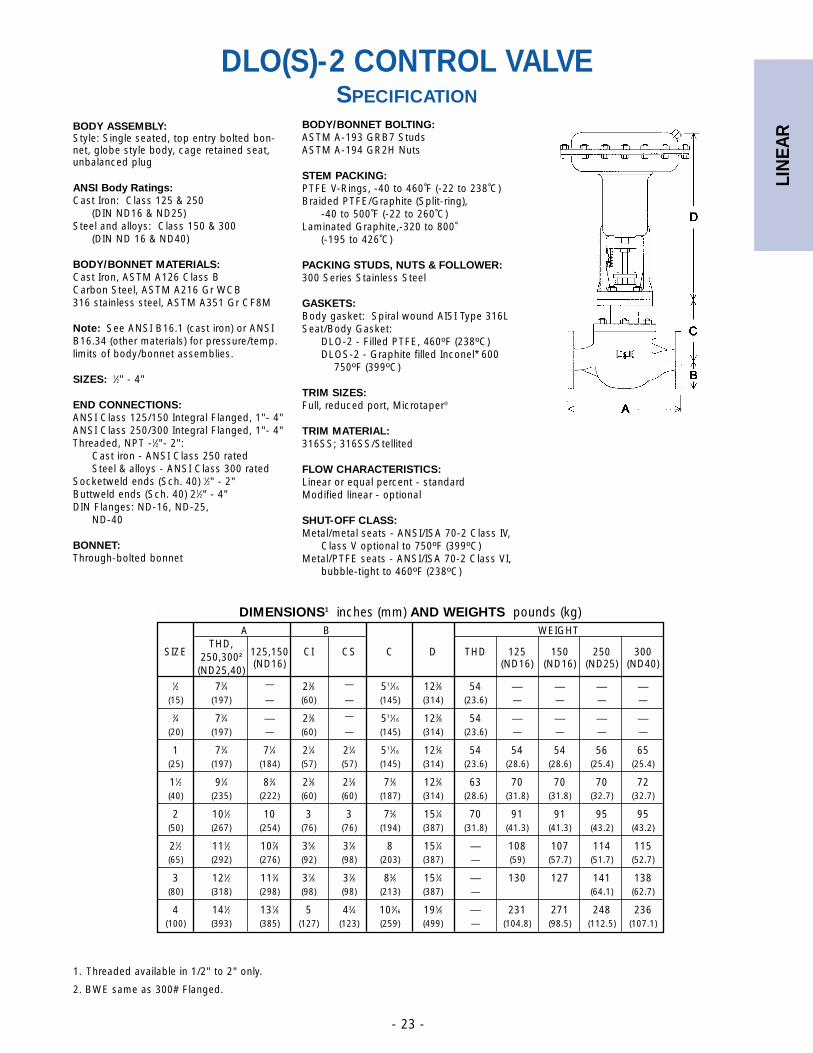
BODY ASSEMBLY:Style: Single seated, top entry bolted bon-net, globe style body, cage retained seat,unbalanced plug
ANSI Body Ratings:Cast Iron: Class 125 & 250
(DIN ND16 & ND25)Steel and alloys: Class 150 & 300
(DIN ND 16 & ND40)
BODY/BONNET MATERIALS:Cast Iron, ASTM A126 Class BCarbon Steel, ASTM A216 Gr WCB316 stainless steel, ASTM A351 Gr CF8M
Note: See ANSI B16.1 (cast iron) or ANSIB16.34 (other materials) for pressure/temp.limits of body/bonnet assemblies.
SIZES: 1⁄2" - 4"
END CONNECTIONS:ANSI Class 125/150 Integral Flanged, 1"- 4"ANSI Class 250/300 Integral Flanged, 1"- 4"Threaded, NPT -1⁄2"- 2":
Cast iron - ANSI Class 250 ratedSteel & alloys - ANSI Class 300 rated
Socketweld ends (Sch. 40) 1⁄2" - 2"Buttweld ends (Sch. 40) 21⁄2" - 4"DIN Flanges: ND-16, ND-25,
ND-40
BONNET:Through-bolted bonnet
BODY/BONNET BOLTING:ASTM A-193 GRB7 StudsASTM A-194 GR2H Nuts
STEM PACKING:PTFE V-Rings, -40 to 460˚F (-22 to 238˚C)Braided PTFE/Graphite (Split-ring),
-40 to 500˚F (-22 to 260˚C)Laminated Graphite,-320 to 800˚
(-195 to 426˚C)
PACKING STUDS, NUTS & FOLLOWER:300 Series Stainless Steel
GASKETS:Body gasket: Spiral wound AISI Type 316LSeat/Body Gasket:
DLO-2 - Filled PTFE, 460ºF (238ºC)DLOS-2 - Graphite filled Inconel* 600
750ºF (399ºC)
TRIM SIZES:Full, reduced port, Microtaper®
TRIM MATERIAL:316SS; 316SS/Stellited
FLOW CHARACTERISTICS:Linear or equal percent - standardModified linear - optional
SHUT-OFF CLASS:Metal/metal seats - ANSI/ISA 70-2 Class IV,
Class V optional to 750ºF (399ºC)Metal/PTFE seats - ANSI/ISA 70-2 Class VI,
bubble-tight to 460ºF (238ºC)
LIN
EAR
- 24 -
100
80
60
40
20
0 20 40 60 80 100
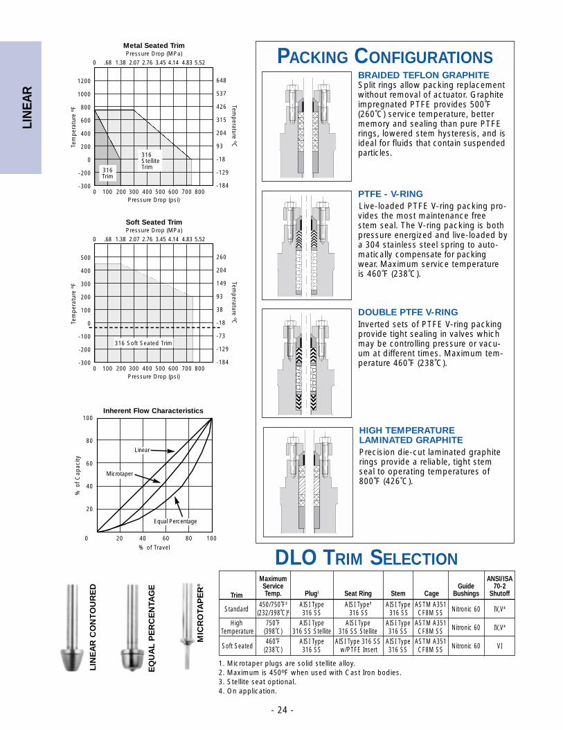
Inherent Flow Characteristics
% of Travel
% o
f C
apac
ity
Microtaper
Linear
Equal Percentage
DLO TRIM SELECTION
1200
1000
800
600
400
200
0
-200
-300
0 .68 1.38 2.07 2.76 3.45 4.14 4.83 5.52
0 100 200 300 400 500 600 700 800
Metal Seated TrimPressure Drop (MPa)
Pressure Drop (psi)
Tem
per
atur
e ºF
Temp
erature ºC
316Trim
316StelliteTrim
648
537
426
315
204
93
-18
-129
-184
500
400
300
200
100
0
-100
-200
-300
0 .68 1.38 2.07 2.76 3.45 4.14 4.83 5.52
0 100 200 300 400 500 600 700 800
Soft Seated TrimPressure Drop (MPa)
Pressure Drop (psi)
Tem
per
atur
e ºF
Temp
erature ºC
316 Soft Seated Trim
260
204
149
93
38
-18
-73
-129
-184
MIC
RO
TAP
ER
®
Maximum ANSI/ISAService Guide 70-2
Trim Temp. Plug1 Seat Ring Stem Cage Bushings Shutoff
Standard450/750˚F2 AISI Type AISI Type3 AISI Type ASTM A351
(232/398˚C)2 316 SS 316 SS 316 SS CF8M SS Nitronic 60 IV,V4
High 750˚F AISI Type AISI Type AISI Type ASTM A351Temperature (398˚C) 316 SS Stellite 316 SS Stellite 316 SS CF8M SS Nitronic 60 IV,V4
Soft Seated460˚F AISI Type AISI Type 316 SS AISI Type ASTM A351
(238˚C) 316 SS w/PTFE Insert 316 SS CF8M SS Nitronic 60 VI
PACKING CONFIGURATIONS
1. Microtaper plugs are solid stellite alloy. 2. Maximum is 450ºF when used with Cast Iron bodies.3. Stellite seat optional.4. On application.
LIN
EA
R C
ON
TO
UR
ED
BRAIDED TEFLON GRAPHITE Split rings allow packing replacementwithout removal of actuator. Graphiteimpregnated PTFE provides 500˚F(260˚C) service temperature, better memory and sealing than pure PTFErings, lowered stem hysteresis, and isideal for fluids that contain suspendedparticles.
PTFE - V-RINGLive-loaded PTFE V-ring packing pro-vides the most maintenance freestem seal. The V-ring packing is bothpressure energized and live-loaded bya 304 stainless steel spring to auto-matically compensate for packingwear. Maximum service temperatureis 460˚F (238˚C).
DOUBLE PTFE V-RING Inverted sets of PTFE V-ring packingprovide tight sealing in valves whichmay be controlling pressure or vacu-um at different times. Maximum tem-perature 460˚F (238˚C).
EQ
UA
L P
ER
CE
NTA
GE
HIGH TEMPERATURELAMINATED GRAPHITEPrecision die-cut laminated graphiterings provide a reliable, tight stemseal to operating temperatures of800˚F (426˚C).
LIN
EAR
- 25 -
DLO(S)-2 ORDER CODE
* Consult factory.
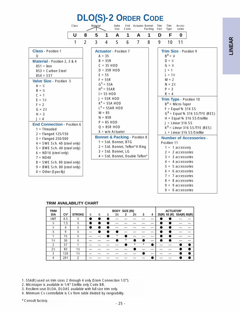
U 8 5 1 A 1 A 1 D F 0
1 2 3 4 5 6 7 8 9 10 11
Class Material Valve End Actuator Bonnet Trim Trim Acces-Size Conn. Packing Size Type sories
1. 55A(R) used on trim sizes 2 through 4 only (Stem Connection 1/2").2. Microtaper is available in 1/4" Stellite only Code BB.3. Resilient seat DLOA, DLOAS available with full size trim only.4. Minimum Cv controllable is Cv from table divided by rangeability.
TRIM AVAILABILITY CHART
Class - Position 1U
Material - Position 2, 3 & 4851 = Iron853 = Carbon Steel854 = SST
Valve Size - Position 5A = 1⁄2B = 3⁄4C = 1E = 11⁄2F = 2G = 21⁄2H = 3J = 4
End Connection - Position 61 = Threaded2 = Flanged 125/1503 = Flanged 250/3004 = SWE Sch. 40 (steel only)5 = BWE Sch. 40 (steel only)6 = ND16 (steel only)7 = ND408 = SWE Sch. 80 (steel only)9 = BWE Sch. 80 (steel only)0 = Other (Specify)
Actuator - Position 7A = 35B = 35RC = 35 HODD = 35R HODE = 55F = 55RG1 = 55AH1 = 55ARI = 55 HODJ = 55R HODK1 = 55A HODL1 = 55AR HODM = 85N = 85RP = 85 HODQ = 85R HODX = w/o Actuator
Bonnet & Packing - Position 81 = Std. Bonnet, BTG2 = Std. Bonnet, Teflon® V-Ring3 = Std. Bonnet, LG4 = Std. Bonnet, Double Teflon®
TRIM BODY SIZE (IN) ACTUATOR1
DIA CV4 STROKE 1⁄2 3⁄4 1 11⁄2 2 21⁄2 3 4 35(R) 55 (R) 55A(R) 85(R)1⁄4MT 0.5 3⁄4 ● ● ● — — — — — ● ● — —
1⁄4 1.5 3⁄4 ● ● ● — — — — — ● ● — —1⁄2 4 3⁄4 ● ● ● — — — — — ● ● — —3⁄4 9 3⁄4 — ● ● ● — — — — ● ● — —1 15 3⁄4 — — ● * ● — — — ● ● — —
11⁄2 30 3⁄4 — — — ● * ● ● — ● ● — —2 57 1 — — — — ● * * ● — — ● ●
21⁄2 83 11⁄4 — — — — — ● — — — — ● ●
3 120 11⁄2 — — — — — — ● — — — ● ●
4 201 2 — — — — — — — ● — — ● ●
Trim Size - Position 9B2 = 1⁄4D = 1⁄2G = 3⁄4J = 1L = 11⁄2M = 2N = 21⁄2P = 3R = 4
Trim Type - Position 10B2 = Micro-TaperF = Equal % 316 SSG3 = Equal % 316 SS/TFE (RES)H = Equal % 316 SS/StelliteJ = Linear 316 SSK3 = Linear 316 SS/TFE (RES)L = Linear 316 SS/Stellite
Number of Accessories -Position 11
1 = 1 accessory2 = 2 accessories3 = 3 accessories4 = 4 accessories5 = 5 accessories6 = 6 accessories7 = 7 accessories8 = 8 accessories9 = 9 accessories0 = 0 accessories
LIN
EAR
- 26 -
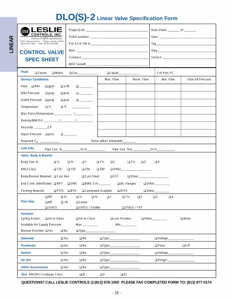
12501 Telecom Drive · Tampa, Florida 33637(813) 978-1000 · FAX: (813)-978-0984
DLO(S)-2 Linear Valve Specification Form
Project/Job _________________________________________ Data Sheet ________ of ________
Unit/Customer ______________________________________ Spec _____________________________________
P.O./LCO File #______________________________________ Tag_______________________________________
Item _______________________________________________ Dwg______________________________________
Contract____________________________________________ Service ___________________________________
MFR Serial# ________________________________________
Fluid ❏ Steam ❏ Water ❏ Gas______________ ❏ Liquid______________ Crit Pres PC
Service Conditions Max. Flow Norm. Flow Min. Flow Shut-off Pressure
Flow ❏ #/hr ❏ gpm ❏ scfh ❏ _________
Inlet Pressure ❏ psig ❏ psia ❏ _________
Outlet Pressure ❏ psig ❏ psia ❏ _________
Temperature ❏ °C ❏ °F ____________
Max Press/Temperature:____________ /____________
Density/MW/SG __________/__________/___________
Viscosity _________CP
Vapor Pressure ❏ psia ❏ _________
Required Cv _____________ Noise (dBA) Allowable_________
Line Info Pipe Size In____________/Sch____________ Pipe Size Out____________/Sch____________
Valve, Body & Bonnet
Body Size in. ❏ 1⁄2 ❏ 3⁄4 ❏ 1 ❏ 11⁄2 ❏ 2 ❏ 21⁄2 ❏ 3 ❏ 4
ANSI Class ❏ 125 ❏ 150 ❏ 250 ❏ 300 ❏ Other____________________
Body/Bonnet Material: ❏ Cast Iron ❏ Cast Steel ❏ SST ❏ Other____________________
End Conn. Inlet/Outlet: ❏ NPT ❏ SWE ❏ BWE Sch.________ ❏ Int. Flanges ❏ Other__________
Packing Material: ❏ PTFE ❏ BTG ❏ Laminated Graphite ❏ DTFE ❏ Other__________
❏ MT ❏ 1⁄4 ❏ 1⁄2 ❏ 3⁄4 ❏ 1 ❏ 11⁄2 ❏ 2 ❏ 3 ❏ 4
Trim Size ❏ MT ❏ =% ❏ Linear
❏ 316SS ❏ 316SS / Stellite ❏ 316SS / TFE
Actuator
Spring Action: ❏ Air to Open ❏ Air to Close ❏ Last Position ❏ Other__________ ❏ None
Available Air Supply Pressure: Max.__________ Min.__________
Manual Override: ❏ Yes ❏ No ❏ Type____________________
Solenoid ❏ Yes ❏ No ❏ Type____________________ ❏ Voltage_________________
Positioner ❏ Yes ❏ No ❏ Type____________________ ❏ Pneu ❏ E/P
Switch ❏ Yes ❏ No ❏ Type____________________ ❏ Voltage_________________
Air Set ❏ Yes ❏ No ❏ Type:___________________ ❏ Range:__________________
Other Accessories ❏ Yes ❏ No ❏ Type____________________
Test ANSI/FCI Leakage Class: ❏ IV ❏ V ❏ VI
CONTROL VALVE SPEC SHEET
QUESTIONS? CALL LESLIE CONTROLS @ (813) 978-1000 PLEASE FAX COMPLETED FORM TO: (813) 977-0174
LIN
EAR
- 28 -
APPLICATION DATA
● Control systems for food, pulp and paper, chemical, petro-chemical, power & other industries
● HVAC systems
● Feed water and fuel system controls in boiler rooms
● Packaged systems (OEM) such as heat exchangers, waterpurification systems & vaporizers, metal cleaning and plating
OPTIONS
● 35, 55, 85 or 135 sq. in. Actuator, Reverse or Direct
● Soft Seats
● Threaded, Socketweld, Flanged and Buttweld EndConnections
● Positioners
● Noise and Cavitation Reducing Trim
● Reduced Flow Cage
● Alternate Packings for Severe Service
● High Temperature Trim
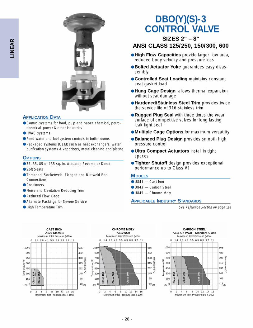
DBO(Y)(S)-3CONTROL VALVE
SIZES 2" – 8"ANSI CLASS 125/250, 150/300, 600
● High Flow Capacities provide larger flow area,reduced body velocity and pressure loss
● Bolted Actuator Yoke guarantees easy disas-sembly
● Controlled Seat Loading maintains constantseat gasket load
● Hung Cage Design allows thermal expansionwithout seat damage
● Hardened/Stainless Steel Trim provides twicethe service life of 316 stainless trim
● Rugged Plug Seal with three times the wearsurface of competitive valves for long lastingleak tight seal
● Multiple Cage Options for maximum versatility
● Balanced Plug Design provides smooth highpressure control
● Ultra Compact Actuators install in tightspaces
● Tighter Shutoff design provides exceptionalperformance up to Class VI
MODELS
● U841 — Cast Iron
● U843 — Carbon Steel
● U845 — Chrome Moly
APPLICABLE INDUSTRY STANDARDS
Temp
erature ºC
565
482
398
315
232
149
65
-18-29
0 1.4 2.8 4.1 5.5 6.9 8.3 9.7 11
1050
900
750
600
450
300
150
0-20
Maximum Inlet Pressure (psi x 100)2 4 6 8 10 12 14 160
Tem
per
atur
e ºF
Maximum Inlet Pressure (psi x 100)2 4 6 8 10 12 14 160
1050
900
750
600
450
300
150
0-20
Tem
per
atur
e ºF
Temp
erature ºC
565
482
398
315
232
149
65
-18-29
0 1.4 2.8 4.1 5.5 6.9 8.3 9.7 11
1050
900
750
600
450
300
150
0-20
Tem
per
atur
e ºF
Temp
erature ºC
565
482
398
315
232
149
65
-18-29
Maximum Inlet Pressure (psi x 100)2 4 6 8 10 12 14 160
C
lass
125
Cla
ss 2
50
0 1.4 2.8 4.1 5.5 6.9 8.3 9.7 11
Cla
ss 1
50
Cla
ss 3
00
Cla
ss 6
00
Cla
ss 1
50
Cla
ss 3
00
Cla
ss 6
00
See Reference Section on page 195
CAST IRONA126 Class B
Maximum Inlet Pressure (MPa)
CARBON STEELA216 Gr. WCB - Standard Class
Maximum Inlet Pressure (MPa)
CHROME MOLYA217WC9
Maximum Inlet Pressure (MPa)
LIN
EAR
- 29 -
604020 10080
StandardCage
ReducedTrim Cage
Inherent Flow Characteristics100
80
60
40
20
00
% of Travel
% o
f C
apac
ity
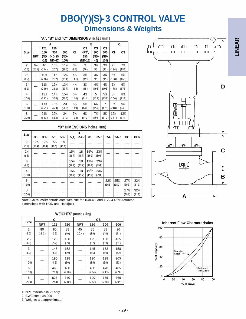
DBO(Y)(S)-3 CONTROL VALVEDimensions & Weights
A B C125, 250, CS CS CS
Size 150 300 600 CI NPT1, 300 600 CI CSNPT (ND (ND-252 (ND- 150 (ND- (ND-
-16) ND-40) 100) (ND-16) 40) 100)
2 91⁄4 10 101⁄2 111⁄4 33⁄4 3 31⁄4 31⁄4 71⁄4 71⁄8(50) (235) (254) (267) (286) (95) (76) (83) (83) (184) (181)
21⁄2 — 107⁄8 111⁄2 121⁄4 43⁄8 31⁄2 33⁄4 33⁄4 65⁄8 65⁄8(65) (276) (292) (311) (111) (89) (95) (95) (168) (168)
3 — 113⁄4 121⁄2 131⁄4 41⁄2 33⁄4 41⁄8 41⁄8 67⁄8 67⁄8(80) (299) (318) (337) (114) (95) (105) (105) (175) (175)
4 — 137⁄8 141⁄2 151⁄2 51⁄2 41⁄2 5 53⁄8 81⁄8 85⁄8(100) (352) (368) (394) (140) (114) (127) (137) (206) (219)
6 — 173⁄4 185⁄8 20 57⁄8 51⁄2 61⁄4 7 93⁄4 93⁄4(150) (451) (473) (508) (149) (140) (159) (178) (248) (248)
8 — 213⁄8 223⁄8 24 75⁄8 63⁄4 71⁄2 81⁄4 121⁄4 121⁄4(200) (543) (568) (610) (194) (172) (191) (210) (311) (311)
“A”, “B” and “C” DIMENSIONS inches (mm)
1. NPT available in 2" only.2. BWE same as 3003. Weights are approximate.
SizeCI CS
NPT 125 250 NPT 150 300 600
2 80 85 88 45 85 88 90(50) (36.3) (39) (40) (20.4) (39) (40) (41)
21⁄2 — 125 130 — 125 130 135(65) (57) (59) (57) (59) (61)
3 — 145 152 — 145 152 158(80) (66) (69) (66) (69) (72)
4 — 190 198 — 190 198 205(100) (86) (90) (86) (90) (93)
6 — 460 480 — 450 470 485(150) (209) (218) (204) (213) (220)
8 — 625 640 — 600 635 660(200) (284) (290) (272) (288) (299)
WEIGHTS3 pounds (kg)
D
C
B
A
DSize35 35R 55 55R 55(A) 55AR 85 85R 85A 85AR 135 135R
2 123⁄8 123⁄8 151⁄4 18 — — — — — — — —(50) (314) (314) (387) (457)
21⁄2 — — — — 151⁄4 18 195⁄8 231⁄4 — — — —(65) (387) (457) (499) (591)
3 — — — — 151⁄4 18 195⁄8 231⁄4 — — — —(80) (387) (457) (499) (591)
4 — — — — 151⁄4 18 195⁄8 231⁄4 — — — —(100) (387) (457) (499) (591)
6 — — — — — — — — 221⁄4 257⁄8 273⁄8 321⁄4(160) (565) (657) (695) (819)
8 — — — — — — — — — — 273⁄8 321⁄4(200) (695) (819)
“D” DIMENSIONS inches (mm)
Note: Go to lesliecontrols.com web site for 10/0.4.3 and 10/0.4.4 for Actuatordimensions with HOD and Handjack
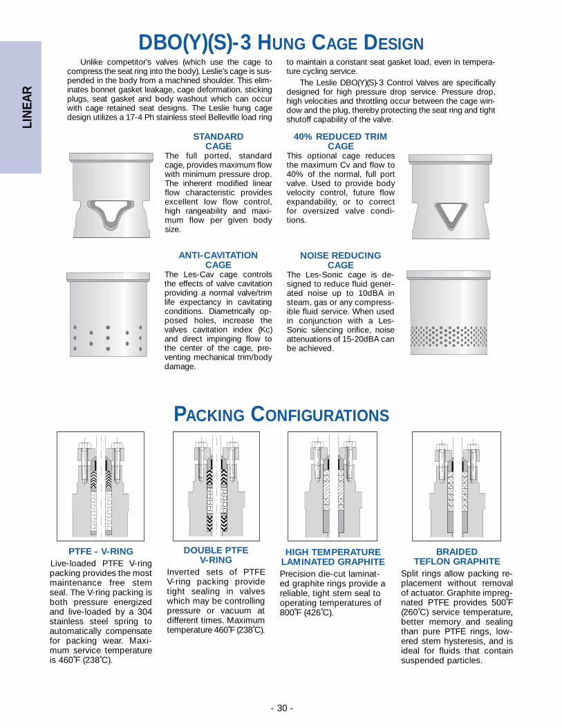
LIN
EAR
- 30 -
DBO(Y)(S)-3 HUNG CAGE DESIGN
PACKING CONFIGURATIONS
BRAIDED TEFLON GRAPHITE
Split rings allow packing re-placement without removalof actuator. Graphite impreg-nated PTFE provides 500˚F(260˚C) service temperature,better memory and sealingthan pure PTFE rings, low-ered stem hysteresis, and isideal for fluids that containsuspended particles.
PTFE - V-RINGLive-loaded PTFE V-ringpacking provides the mostmaintenance free stemseal. The V-ring packing isboth pressure energizedand live-loaded by a 304stainless steel spring toautomatically compensatefor packing wear. Maxi-mum service temperatureis 460˚F (238˚C).
DOUBLE PTFEV-RING
Inverted sets of PTFE V-ring packing providetight sealing in valveswhich may be controllingpressure or vacuum atdifferent times. Maximumtemperature 460˚F (238˚C).
Unlike competitor’s valves (which use the cage tocompress the seat ring into the body), Leslie’s cage is sus-pended in the body from a machined shoulder. This elim-inates bonnet gasket leakage, cage deformation, stickingplugs, seat gasket and body washout which can occurwith cage retained seat designs. The Leslie hung cagedesign utilizes a 17-4 Ph stainless steel Belleville load ring
STANDARDCAGE
The full ported, standardcage, provides maximum flowwith minimum pressure drop.The inherent modified linearflow characteristic providesexcellent low flow control,high rangeability and maxi-mum flow per given bodysize.
40% REDUCED TRIMCAGE
This optional cage reducesthe maximum Cv and flow to40% of the normal, full portvalve. Used to provide bodyvelocity control, future flowexpandability, or to correctfor oversized valve condi-tions.
ANTI-CAVITATIONCAGE
The Les-Cav cage controlsthe effects of valve cavitationproviding a normal valve/trimlife expectancy in cavitatingconditions. Diametrically op-posed holes, increase thevalves cavitation index (Kc)and direct impinging flow tothe center of the cage, pre-venting mechanical trim/bodydamage.
NOISE REDUCINGCAGE
The Les-Sonic cage is de-signed to reduce fluid gener-ated noise up to 10dBA insteam, gas or any compress-ible fluid service. When usedin conjunction with a Les-Sonic silencing orifice, noiseattenuations of 15-20dBA canbe achieved.
to maintain a constant seat gasket load, even in tempera-ture cycling service.
The Leslie DBO(Y)(S)-3 Control Valves are specificallydesigned for high pressure drop service. Pressure drop,high velocities and throttling occur between the cage win-dow and the plug, thereby protecting the seat ring and tightshutoff capability of the valve.
HIGH TEMPERATURELAMINATED GRAPHITEPrecision die-cut laminat-ed graphite rings provide areliable, tight stem seal tooperating temperatures of800˚F (426˚C).
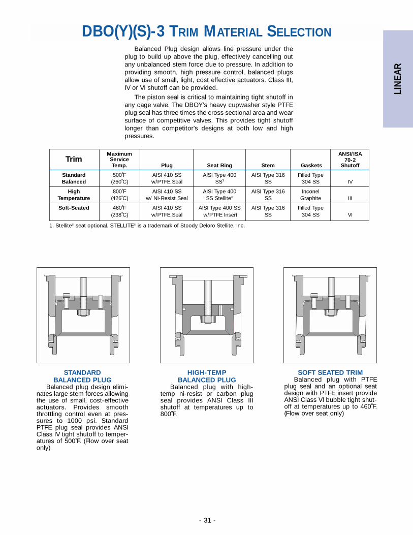
LIN
EAR
- 31 -
DBO(Y)(S)-3 TRIM MATERIAL SELECTION
Maximum ANSI/ISATrim Service 70-2
Temp. Plug Seat Ring Stem Gaskets Shutoff
Standard 500˚F AISI 410 SS AISI Type 400 AISI Type 316 Filled TypeBalanced (260˚C) w/PTFE Seal SS1 SS 304 SS IV
High 800˚F AISI 410 SS AISI Type 400 AISI Type 316 InconelTemperature (426˚C) w/ Ni-Resist Seal SS Stellite® SS Graphite III
Soft-Seated 460˚F AISI 410 SS AISI Type 400 SS AISI Type 316 Filled Type(238˚C) w/PTFE Seal w/PTFE Insert SS 304 SS VI
Balanced Plug design allows line pressure under theplug to build up above the plug, effectively cancelling outany unbalanced stem force due to pressure. In addition toproviding smooth, high pressure control, balanced plugsallow use of small, light, cost effective actuators. Class III,IV or VI shutoff can be provided.
The piston seal is critical to maintaining tight shutoff inany cage valve. The DBOY’s heavy cupwasher style PTFEplug seal has three times the cross sectional area and wearsurface of competitive valves. This provides tight shutofflonger than competitor’s designs at both low and highpressures.
1. Stellite® seat optional. STELLITE® is a trademark of Stoody Deloro Stellite, Inc.
SOFT SEATED TRIMBalanced plug with PTFE
plug seal and an optional seatdesign with PTFE insert provideANSI Class VI bubble tight shut-off at temperatures up to 460˚F.(Flow over seat only)
HIGH-TEMPBALANCED PLUG
Balanced plug with high-temp ni-resist or carbon plugseal provides ANSI Class IIIshutoff at temperatures up to800˚F.
STANDARD BALANCED PLUG
Balanced plug design elimi-nates large stem forces allowingthe use of small, cost-effectiveactuators. Provides smooththrottling control even at pres-sures to 1000 psi. StandardPTFE plug seal provides ANSIClass IV tight shutoff to temper-atures of 500˚F. (Flow over seatonly)
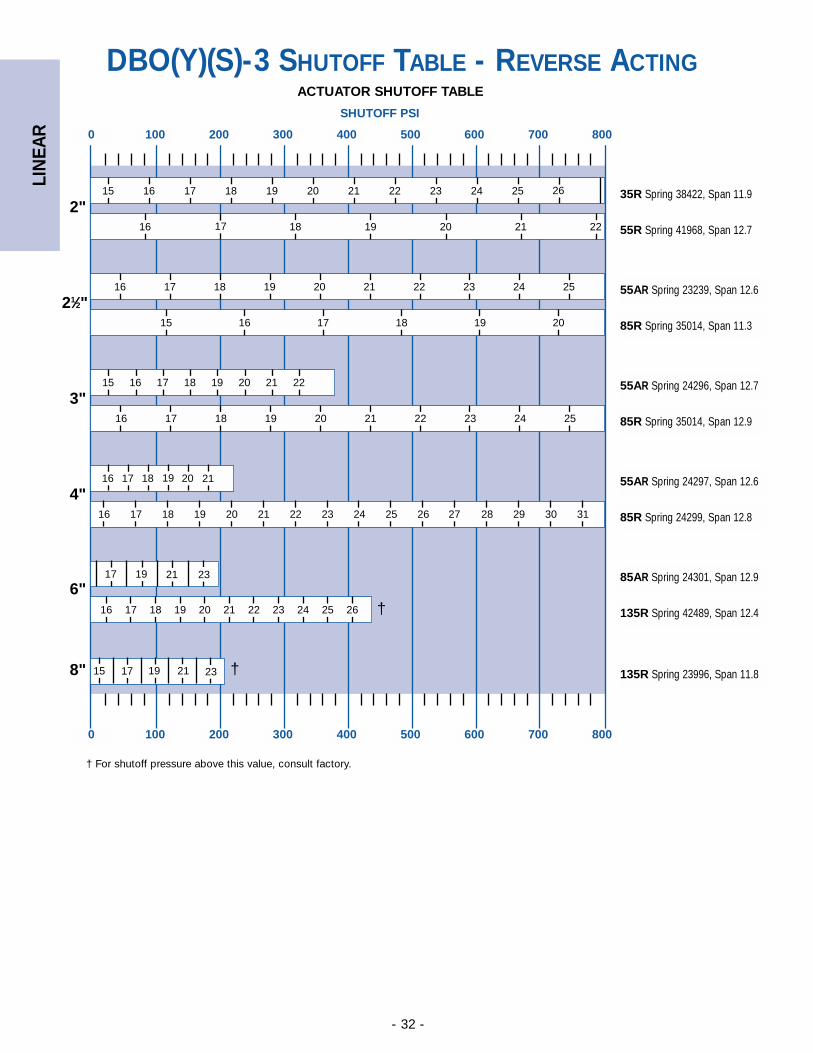
LIN
EAR
- 32 -
6"
0 100 200 300 400 500 600 700 800
0 100 200 300 400 500 600 700 800
SHUTOFF PSI
15
16
16
15 16 17 18 19 20
17 18 19 20 21 22 23 24 25
17 18 19 20 21 22
16 17 18 19 20 21 22 23 24 25 26
15 16 17 18 19 20 21 22
16 17 18 19 20 21 22 23 24 25
16
16 17 18 19 20 21 22 23 24 25 26 28 29 30 31
17 18 19 20 21
23211917
16 17 18 19 20 21 22 23 24 25 26
2117 1915 23
2"
21⁄2"
3"
4"
8"
35R Spring 38422, Span 11.9
55R Spring 41968, Span 12.7
55AR Spring 23239, Span 12.6
85R Spring 35014, Span 11.3
55AR Spring 24296, Span 12.7
85R Spring 35014, Span 12.9
55AR Spring 24297, Span 12.6
85R Spring 24299, Span 12.8
85AR Spring 24301, Span 12.9
135R Spring 42489, Span 12.4
135R Spring 23996, Span 11.8
DBO(Y)(S)-3 SHUTOFF TABLE - REVERSE ACTING
27
ACTUATOR SHUTOFF TABLE
†
†
† For shutoff pressure above this value, consult factory.
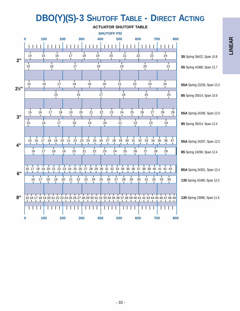
LIN
EAR
- 33 -
DBO(Y)(S)-3 SHUTOFF TABLE - DIRECT ACTING
6"
0 100 200 300 400 500 600 700 800
0 100 200 300 400 500 600 700 800
SHUTOFF PSI
14 15 16 17 18 19 20 21 22 23 24
15 16 17 18 19 20 21
15 16 17 18 19 20 21 22 23 24
15 16 17 18 19 20
15 16 17 18 19 20 21 22 23 24 25 26 27 28 29
15 16 17 18 19 20 21 22 23 24
15 16 17 18 19 20 21 22 23 24 25 26 27 28 29 30 31 32 33 34 35 36 37
16 17 18 19 20 21 22 23 24 25 26 27 28 29
16 17 18 19 20 21 22 23 24 25 26 27 28 29 30 31 32 33 34 35 36 37 38 39 40 41 42 43
16
15 16 17 18 19 20 21 22 23 24 25 26 27 28 29 30 31 32 33 34 35 36 37 38 39 40 41 42 43 44 45 46 47 48 49
2"
21⁄2"
3"
4"
8"
35 Spring 38422, Span 10.8
55 Spring 41968, Span 12.7
55A Spring 23239, Span 12.0
85 Spring 35014, Span 10.9
55A Spring 24296, Span 12.0
85 Spring 35014, Span 12.4
55A Spring 24297, Span 12.0
85 Spring 24299, Span 12.4
85A Spring 24301, Span 12.4
135 Spring 42489, Span 12.0
135 Spring 23996, Span 11.6
16 17 18 19 20 21 22 23 24 25 26 27 28 29 30 31 32 33 34
ACTUATOR SHUTOFF TABLE
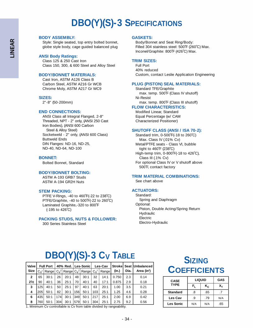
LIN
EAR
- 34 -
BODY ASSEMBLY:Style: Single seated, top entry bolted bonnet, globe style body, cage guided balanced plug
ANSI Body Ratings:Class 125 & 250 Cast IronClass 150, 300, & 600 Steel and Alloy Steel
BODY/BONNET MATERIALS:Cast Iron, ASTM A126 Class BCarbon Steel, ASTM A216 Gr WCBChrome Moly, ASTM A217 Gr WC9
SIZES:2"-8" (50-200mm)
END CONNECTIONS:ANSI Class all Integral Flanged, 2-8"Threaded, NPT - 2" only, (ANSI 250 Cast Iron Bodies), (ANSI 600 Carbon
Steel & Alloy Steel)Socketweld - 2" only, (ANSI 600 Class)Buttweld Ends DIN Flanges: ND-16, ND-25, ND-40, ND-64, ND-100
BONNET:Bolted Bonnet, Standard
BODY/BONNET BOLTING:ASTM A-193 GRB7 StudsASTM A-194 GR2H Nuts
STEM PACKING:PTFE V-Rings, -40 to 460˚F(-22 to 238˚C)PTFE/Graphite, -40 to 500˚F(-22 to 260˚C)Laminated Graphite,-320 to 800˚F
(-195 to 426˚C)
PACKING STUDS, NUTS & FOLLOWER:300 Series Stainless Steel
GASKETS:Body/Bonnet and Seat Ring/Body:Filled 304 stainless steel: 500˚F (260˚C) Max. Inconel/Graphite: 800˚F (426˚C) Max.
TRIM SIZES:Full Port40% reducedCustom, contact Leslie Application Engineering
PLUG (PISTON) SEAL MATERIALS:Standard TFE/Graphite
max. temp. 500˚F (Class IV shutoff)Ni-Resist
max. temp. 800˚F (Class III shutoff)FLOW CHARACTERISTICS:
Modified Linear, StandardEqual Percentage (w/ CAMCharacterized Positioner)
SHUTOFF CLASS (ANSI / ISA 70-2):Standard trim, 0-500˚F(-18 to 260˚C)
Max. Class IV (.01% Cv)Metal/PTFE seats - Class VI, bubble
tight to 460˚F (238˚C)High-temp trim, 0-800˚F(-18 to 426˚C),
Class III (.1% Cv)For optional Class IV or V shutoff above
500˚F, contact factory
TRIM MATERIAL COMBINATIONS:See chart above
ACTUATORS:Standard:
Spring and DiaphragmOptional:
Piston, Double Acting/Spring ReturnHydraulicElectricElectro-Hydraulic
DBO(Y)(S)-3 SPECIFICATIONS
Valve Full Port 40% Red. Les-Sonic Les-Cav Stroke Seat UnbalancedSize Cv1 Range Cv
1 Range Cv1 Range Cv
1 Range (in.) Dia. Area (in2)
2 65 30:1 26 20:1 48 30:1 32 14:1 0.750 2.3 0.14
21⁄2 90 40:1 36 25:1 70 40:1 40 17:1 0.875 2.9 0.18
3 125 40:1 50 25:1 97 40:1 63 20:1 1.00 3.5 0.21
4 205 50:1 82 30:1 156 50:1 103 25:1 1.25 4.6 0.28
6 435 50:1 174 30:1 349 50:1 217 25:1 2.00 6.9 0.42
8 760 50:1 304 30:1 579 50:1 304 25:1 2.75 9.2 0.56
DBO(Y)(S)-3 CV TABLE
CASE LIQUID GASTYPE FL KC XT
Standard .8 .65 .7
Les Cav .9 .79 N/A
Les Sonic N/A N/A .65
SIZINGCOEFFICIENTS
1. Minimum Cv controllable is Cv from table divided by rangeability.
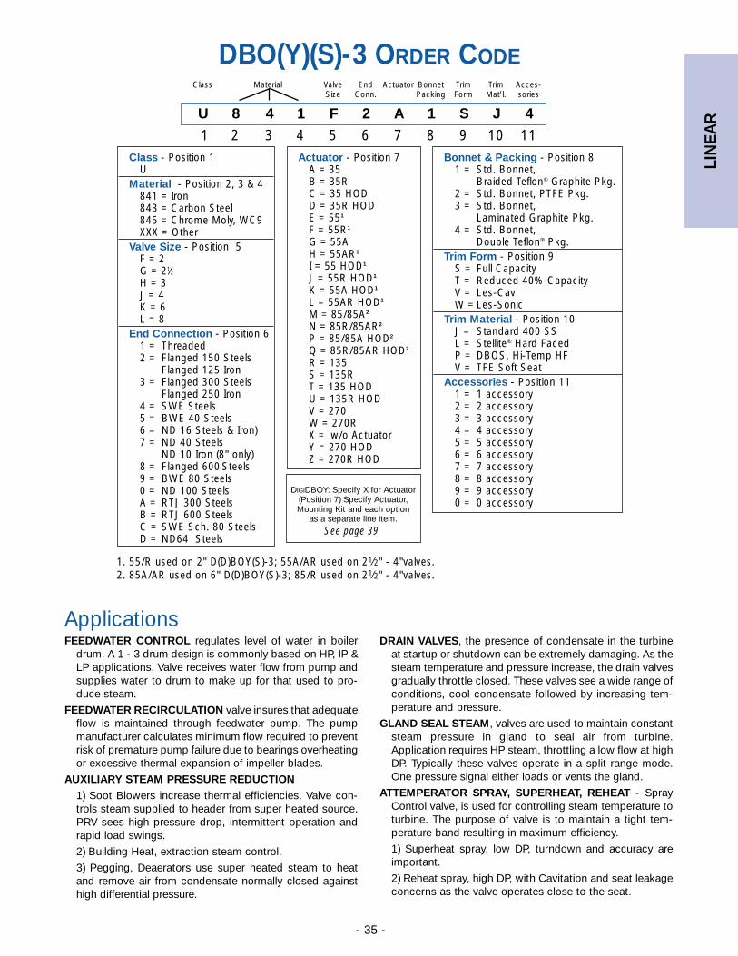
LIN
EAR
- 35 -
DRAIN VALVES, the presence of condensate in the turbineat startup or shutdown can be extremely damaging. As thesteam temperature and pressure increase, the drain valvesgradually throttle closed. These valves see a wide range ofconditions, cool condensate followed by increasing tem-perature and pressure.
GLAND SEAL STEAM, valves are used to maintain constantsteam pressure in gland to seal air from turbine.Application requires HP steam, throttling a low flow at highDP. Typically these valves operate in a split range mode.One pressure signal either loads or vents the gland.
ATTEMPERATOR SPRAY, SUPERHEAT, REHEAT - SprayControl valve, is used for controlling steam temperature toturbine. The purpose of valve is to maintain a tight tem-perature band resulting in maximum efficiency.
1) Superheat spray, low DP, turndown and accuracy areimportant.
2) Reheat spray, high DP, with Cavitation and seat leakageconcerns as the valve operates close to the seat.
ApplicationsFEEDWATER CONTROL regulates level of water in boiler
drum. A 1 - 3 drum design is commonly based on HP, IP &LP applications. Valve receives water flow from pump andsupplies water to drum to make up for that used to pro-duce steam.
FEEDWATER RECIRCULATION valve insures that adequateflow is maintained through feedwater pump. The pumpmanufacturer calculates minimum flow required to preventrisk of premature pump failure due to bearings overheatingor excessive thermal expansion of impeller blades.
AUXILIARY STEAM PRESSURE REDUCTION1) Soot Blowers increase thermal efficiencies. Valve con-trols steam supplied to header from super heated source.PRV sees high pressure drop, intermittent operation andrapid load swings.
2) Building Heat, extraction steam control.
3) Pegging, Deaerators use super heated steam to heatand remove air from condensate normally closed againsthigh differential pressure.
DBO(Y)(S)-3 ORDER CODE
U 8 4 1 F 2 A 1 S J 4
1 2 3 4 5 6 7 8 9 10 11
Class Material Valve End Actuator Bonnet Trim Trim Acces-Size Conn. Packing Form Mat’l. sories
1. 55/R used on 2" D(D)BOY(S)-3; 55A/AR used on 21⁄2" - 4"valves.2. 85A/AR used on 6" D(D)BOY(S)-3; 85/R used on 21⁄2" - 4"valves.
Class - Position 1U
Material - Position 2, 3 & 4841 = Iron843 = Carbon Steel845 = Chrome Moly, WC9XXX = Other
Valve Size - Position 5F = 2G = 21⁄2H = 3J = 4K = 6L = 8
End Connection - Position 6 1 = Threaded2 = Flanged 150 Steels
Flanged 125 Iron3 = Flanged 300 Steels
Flanged 250 Iron4 = SWE Steels5 = BWE 40 Steels6 = ND 16 Steels & Iron)7 = ND 40 Steels
ND 10 Iron (8" only)8 = Flanged 600 Steels9 = BWE 80 Steels0 = ND 100 SteelsA = RTJ 300 SteelsB = RTJ 600 SteelsC = SWE Sch. 80 SteelsD = ND64 Steels
Actuator - Position 7A = 35B = 35RC = 35 HODD = 35R HODE = 551
F = 55R1
G = 55AH = 55AR1
I = 55 HOD1
J = 55R HOD1
K = 55A HOD1
L = 55AR HOD1
M = 85/85A2
N = 85R/85AR2
P = 85/85A HOD2
Q = 85R/85AR HOD2
R = 135S = 135RT = 135 HODU = 135R HODV = 270W = 270RX = w/o ActuatorY = 270 HODZ = 270R HOD
Bonnet & Packing - Position 81 = Std. Bonnet,
Braided Teflon® Graphite Pkg. 2 = Std. Bonnet, PTFE Pkg.3 = Std. Bonnet,
Laminated Graphite Pkg.4 = Std. Bonnet,
Double Teflon® Pkg.Trim Form - Position 9
S = Full CapacityT = Reduced 40% CapacityV = Les-CavW = Les-Sonic
Trim Material - Position 10J = Standard 400 SSL = Stellite® Hard FacedP = DBOS, Hi-Temp HFV = TFE Soft Seat
Accessories - Position 111 = 1 accessory2 = 2 accessory3 = 3 accessory4 = 4 accessory5 = 5 accessory6 = 6 accessory7 = 7 accessory8 = 8 accessory9 = 9 accessory0 = 0 accessory
DIGIDBOY: Specify X for Actuator(Position 7) Specify Actuator,Mounting Kit and each option
as a separate line item.
See page 39
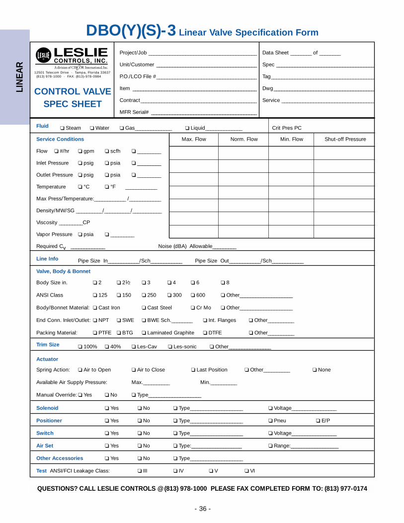
LIN
EAR
- 36 -
12501 Telecom Drive · Tampa, Florida 33637(813) 978-1000 · FAX: (813)-978-0984
DBO(Y)(S)-3 Linear Valve Specification Form
Project/Job _________________________________________ Data Sheet ________ of ________
Unit/Customer ______________________________________ Spec _____________________________________
P.O./LCO File #______________________________________ Tag_______________________________________
Item _______________________________________________ Dwg______________________________________
Contract____________________________________________ Service ___________________________________
MFR Serial# ________________________________________
Fluid ❏ Steam ❏ Water ❏ Gas______________ ❏ Liquid______________ Crit Pres PC
Service Conditions Max. Flow Norm. Flow Min. Flow Shut-off Pressure
Flow ❏ #/hr ❏ gpm ❏ scfh ❏ _________
Inlet Pressure ❏ psig ❏ psia ❏ _________
Outlet Pressure ❏ psig ❏ psia ❏ _________
Temperature ❏ °C ❏ °F ____________
Max Press/Temperature:____________ /____________
Density/MW/SG __________/__________/___________
Viscosity _________CP
Vapor Pressure ❏ psia ❏ _________
Required Cv _____________ Noise (dBA) Allowable_________
Line Info Pipe Size In____________/Sch____________ Pipe Size Out____________/Sch____________
Valve, Body & Bonnet
Body Size in. ❏ 2 ❏ 21⁄2 ❏ 3 ❏ 4 ❏ 6 ❏ 8
ANSI Class ❏ 125 ❏ 150 ❏ 250 ❏ 300 ❏ 600 ❏ Other____________________
Body/Bonnet Material: ❏ Cast Iron ❏ Cast Steel ❏ Cr Mo ❏ Other____________________
End Conn. Inlet/Outlet: ❏ NPT ❏ SWE ❏ BWE Sch.________ ❏ Int. Flanges ❏ Other__________
Packing Material: ❏ PTFE ❏ BTG ❏ Laminated Graphite ❏ DTFE ❏ Other__________
Trim Size ❏ 100% ❏ 40% ❏ Les-Cav ❏ Les-sonic ❏ Other________________
Actuator
Spring Action: ❏ Air to Open ❏ Air to Close ❏ Last Position ❏ Other__________ ❏ None
Available Air Supply Pressure: Max.__________ Min.__________
Manual Override: ❏ Yes ❏ No ❏ Type____________________
Solenoid ❏ Yes ❏ No ❏ Type____________________ ❏ Voltage_________________
Positioner ❏ Yes ❏ No ❏ Type____________________ ❏ Pneu ❏ E/P
Switch ❏ Yes ❏ No ❏ Type____________________ ❏ Voltage_________________
Air Set ❏ Yes ❏ No ❏ Type:___________________ ❏ Range:__________________
Other Accessories ❏ Yes ❏ No ❏ Type____________________
Test ANSI/FCI Leakage Class: ❏ III ❏ IV ❏ V ❏ VI
CONTROL VALVE SPEC SHEET
QUESTIONS? CALL LESLIE CONTROLS @ (813) 978-1000 PLEASE FAX COMPLETED FORM TO: (813) 977-0174
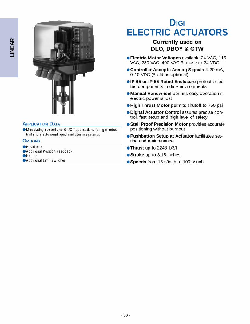
LIN
EAR
- 38 -
APPLICATION DATA
● Modulating control and On/Off applications for light indus-trial and institutional liquid and steam systems.
OPTIONS
● Positioner● Additional Position Feedback● Heater● Additional Limit Switches
DIGIELECTRIC ACTUATORS
Currently used onDLO, DBOY & GTW
● Electric Motor Voltages available 24 VAC, 115VAC, 230 VAC, 400 VAC 3 phase or 24 VDC
● Controller Accepts Analog Signals 4-20 mA, 0-10 VDC (Profibus optional)
● IP 65 or IP 55 Rated Enclosure protects elec-tric components in dirty environments
● Manual Handwheel permits easy operation ifelectric power is lost
● High Thrust Motor permits shutoff to 750 psi
● Digital Actuator Control assures precise con-trol, fast setup and high level of safety
● Stall Proof Precision Motor provides accuratepositioning without burnout
● Pushbutton Setup at Actuator facilitates set-ting and maintenance
● Thrust up to 2248 lb3/f
● Stroke up to 3.15 inches
● Speeds from 15 s/inch to 100 s/inch
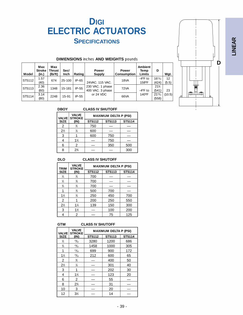
LIN
EAR
- 39 -
D
DIGIELECTRIC ACTUATORS
SPECIFICATIONS
VALVE MAXIMUM DELTA P (PSI)VALVE STROKESIZE (IN) ST5112 ST5113 ST5114
2 3⁄4 750 — —21⁄2 7⁄8 600 — —3 1 600 750 —4 11⁄4 — 750 —6 2 — 350 5008 23⁄4 — — 300
DBOY CLASS IV SHUTOFF
VALVE MAXIMUM DELTA P (PSI)TRIM STROKESIZE (IN) ST5112 ST5113 ST5114
1⁄4 3⁄4 700 — —1⁄2 3⁄4 700 — —3⁄4 3⁄4 700 — —1 3⁄4 500 700 —
11⁄2 3⁄4 250 450 7002 1 200 250 550
21⁄2 11⁄4 139 150 3003 11⁄2 — 100 2004 2 — 75 125
DLO CLASS IV SHUTOFF
VALVE MAXIMUM DELTA P (PSI)VALVE STROKESIZE (IN) ST5112 ST5113 ST5114
1⁄2 15⁄32 3280 1200 6863⁄4 15⁄32 1458 1000 3051 11⁄16 699 900 172
11⁄2 15⁄16 212 600 652 3⁄4 — 400 50
21⁄2 7⁄8 — 301 403 1 — 202 304 11⁄4 — 123 206 2 — 55 —8 23⁄4 — 31 —10 3 — 20 —12 31⁄2 — 14 —
GTW CLASS IV SHUTOFF
Max Max AmbientStroke Thrust Sec/ Power Power Temp D
Model (in.) (lb/ft) Inch Rating Supply Consumption Limits Wgt.
ST51121.57
674 25-100 IP-65 18VA-4ºF to 1611⁄16 12
(40) 24VAC. 115 VAC. 158ºF (424) (5.5)
ST51132.36
1348 15-181 IP-55230 VAC. 1 phase
72VA215⁄8
(60) 400 VAC. 3 phase -4ºF to (541) 23
ST51143.14
2248 15-91 IP-55or 24 VDC
66VA140ºF 2115⁄16 (10.5)
(80) (558)
DIMENSIONS inches AND WEIGHTS pounds
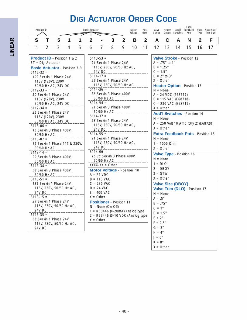
LIN
EAR
- 40 -
S T 5 1 1 2 - 3 2 B 2 A C A N 2 F
1 2 3 4 5 6 7 8 9 10 11 12 13 14 15 16 17
ExtraProduct ID Basic Actuator Motor Posi- Valve Heater Add’l Feedback Valve Valve Size/
Voltage tioner Stroke Option Switches Pots Type Trim Size
Product ID - Position 1 & 2ST = Digi ActuatorBasic Actuator - Position 3-95112-32 = 100 Sec/in 1 Phase 24V, 115V (120V), 230V 50/60 Hz AC, 24V DC
5112-33 = 50 Sec/in 1 Phase 24V, 115V (120V), 230V 50/60 Hz AC, 24V DC
5112-34 = 25 Sec/in 1 Phase 24V, 115V (120V), 230V 50/60 Hz AC, 24V DC
5113-06 = 15 Sec/in 3 Phase 400V,50/60 Hz AC
5113-07 = 15 Sec/in 1 Phase 115 & 230V,50/60 Hz AC
5113-14 =29 Sec/in 3 Phase 400V,50/60 Hz AC
5113-34 =58 Sec/in 3 Phase 400V,50/60 Hz AC
5113-51 =181 Sec/in 1 Phase 24V, 115V, 230V, 50/60 Hz AC, 24V DC
5113-15 =29 Sec/in 1 Phase 24V, 115V, 230V, 50/60 Hz AC, 24V DC
5113-35 =58 Sec/in 1 Phase 24V, 115V, 230V, 50/60 Hz AC, 24V DC
5113-53 =91 Sec/in 1 Phase 24V, 115V, 230V, 50/60 Hz AC, 24V DC
5114-17 =29 Sec/in 1 Phase 24V, 115V, 230V, 50/60 Hz AC
5114-36 =58 Sec/in 3 Phase 400V, 50/60 Hz AC
5114-54 =91 Sec/in 3 Phase 400V, 50/60 Hz AC
5114-37 =58 Sec/in 1 Phase 24V, 115V, 230V, 50/60 Hz AC, 24V DC
5114-55 =91 Sec/in 1 Phase 24V, 115V, 230V, 50/60 Hz AC, 24V DC
5114-06 =15.38 Sec/in 3 Phase 400V, 50/60 Hz AC
XXXX-XX = OtherMotor Voltage - Position 10A = 24 VDCB = 115 VACC = 230 VACD = 24 VACE = 400 VACX = OtherPositioner - Position 11N = None (On-Off)1 = RE3446 (4-20mA) Analog type2 = RE3446 (0-10 VDC) Analog typeX = Other
DIGI ACTUATOR ORDER CODE
Valve Stroke - Position 12A = .75" to 1"B = 1.25"C = 1.5"D = 2" to 3"X = OtherHeater Option - Position 13N = NoneA = 24 VDC (E68717)B = 115 VAC (E68718)C = 230 VAC (E68719)X = Other
Add’l Switches - Position 14N = NoneA = 250 Volt 10 Amp (Qty 2) (E68720)X = Other
Extra Feedback Pots - Position 15N = None1 = 1000 OhmX = Other
Valve Type - Position 16N = None1 = DLO2 = DBOY3 = GTWX = Other
Valve Size (DBOY)Valve Trim (DLO) - Position 17N = NoneA = .5"B = .75"C = 1"D = 1.5"E = 2"F = 2.5"G = 3"H = 4"J = 6"K = 8"X = Other
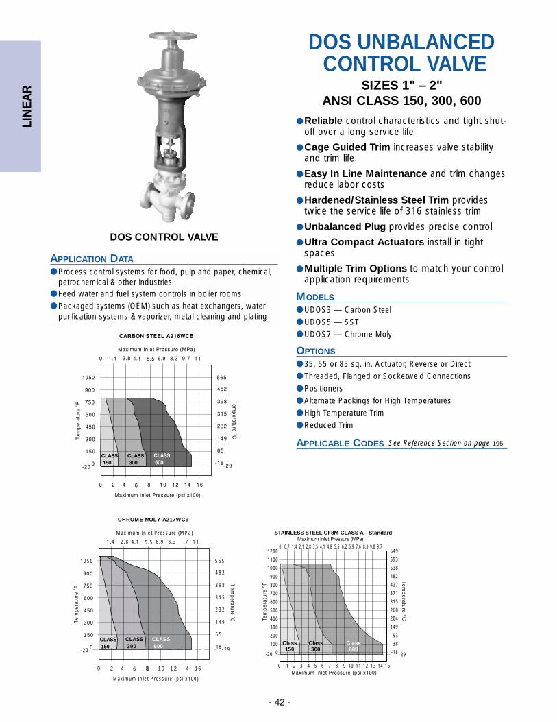
LIN
EAR
- 42 -
DOS CONTROL VALVE
APPLICATION DATA
● Process control systems for food, pulp and paper, chemical,petrochemical & other industries
● Feed water and fuel system controls in boiler rooms
● Packaged systems (OEM) such as heat exchangers, waterpurification systems & vaporizer, metal cleaning and plating
DOS UNBALANCEDCONTROL VALVE
SIZES 1" – 2"ANSI CLASS 150, 300, 600
● Reliable control characteristics and tight shut-off over a long service life
● Cage Guided Trim increases valve stabilityand trim life
● Easy In Line Maintenance and trim changesreduce labor costs
● Hardened/Stainless Steel Trim providestwice the service life of 316 stainless trim
● Unbalanced Plug provides precise control
● Ultra Compact Actuators install in tightspaces
● Multiple Trim Options to match your controlapplication requirements
MODELS
● UDOS3 — Carbon Steel
● UDOS5 — SST
● UDOS7 — Chrome Moly
OPTIONS
● 35, 55 or 85 sq. in. Actuator, Reverse or Direct
● Threaded, Flanged or Socketweld Connections
● Positioners
● Alternate Packings for High Temperatures
● High Temperature Trim
● Reduced Trim
APPLICABLE CODES
See Reference Section on page 195
900
750
600
450
300
150
0
1 21 086420 1 4 1 6
CHROME MOLY A217WC9
Te
mpe
ratu
re ˚
F
Maximum In let Pressure (psi x100)
8.36.95.54.12.81.4 .7 1 1
Maximum Inlet Pressure (MPa)
482
398
315
232
149
6 5
-18
Temperature ˚C
-20 - 29
10 50 565
CLASS 300
CLASS 150
CLASS 600
1200
1100
1000
900
800
700
600
500
400
300
200
100
0
STAINLESS STEEL CF8M CLASS A - Standard
1 2 3 4 5 6 7 80
-29-20
0 0.7 1.4 2.1 2.8 3.5 4.1 4.8 5.5649
593
538
482
427
371
315
260
204
149
93
38
-18
9 10 11 12 13 14 15
6.2 6.9 7.6 8.3 9.0 9.7
Class600
Class150
Class300
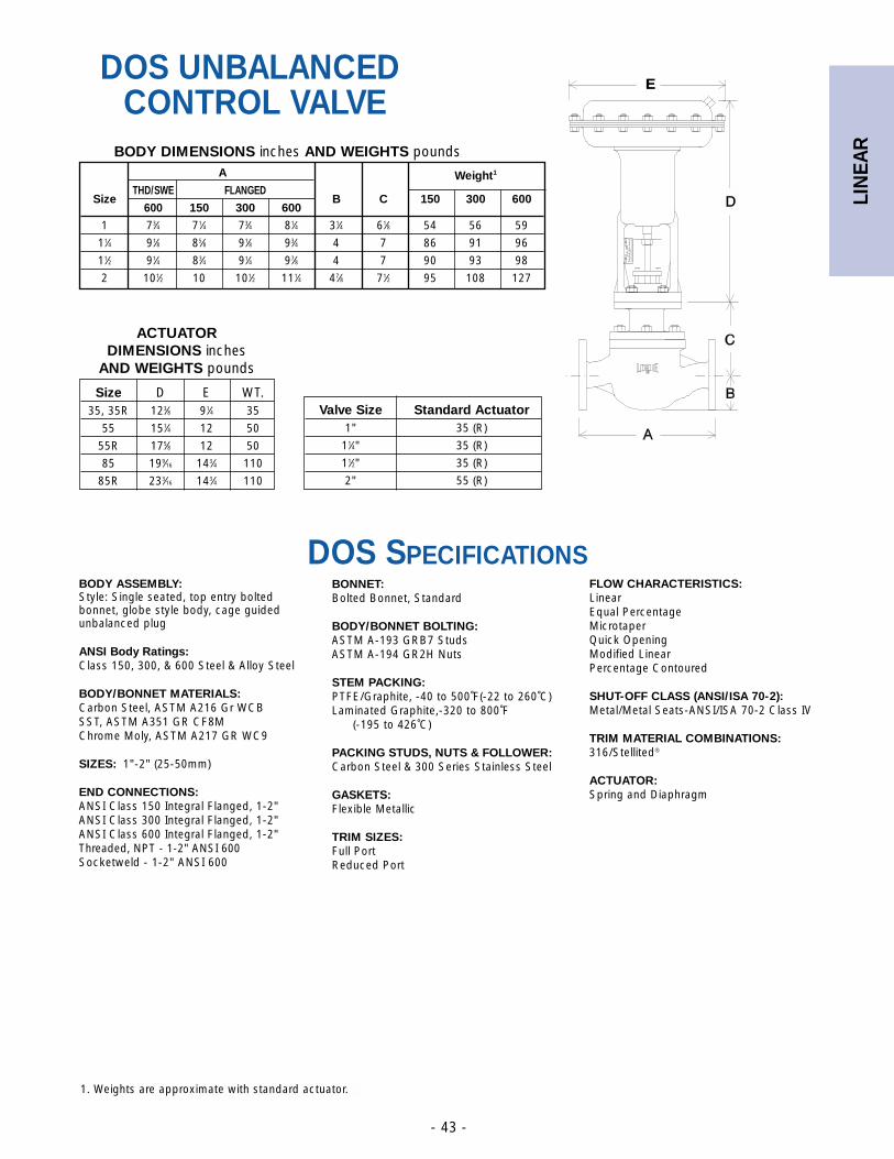
LIN
EAR
- 43 -
DOS UNBALANCEDCONTROL VALVE
A
SizeTHD/SWE FLANGED
B C
Weight1
600 150 300 600150 300 600
1 73⁄4 71⁄4 73⁄4 81⁄4 31⁄4 61⁄8 54 56 59
11⁄4 91⁄8 85⁄8 91⁄8 93⁄4 4 7 86 91 96
11⁄2 91⁄4 83⁄4 91⁄4 97⁄8 4 7 90 93 98
2 101⁄2 10 101⁄2 111⁄4 47⁄8 71⁄2 95 108 127
BODY DIMENSIONS inches AND WEIGHTS pounds
1. Weights are approximate with standard actuator.
BODY ASSEMBLY:Style: Single seated, top entry boltedbonnet, globe style body, cage guidedunbalanced plug
ANSI Body Ratings:Class 150, 300, & 600 Steel & Alloy Steel
BODY/BONNET MATERIALS:Carbon Steel, ASTM A216 Gr WCBSST, ASTM A351 GR CF8MChrome Moly, ASTM A217 GR WC9
SIZES: 1"-2" (25-50mm)
END CONNECTIONS:ANSI Class 150 Integral Flanged, 1-2"ANSI Class 300 Integral Flanged, 1-2"ANSI Class 600 Integral Flanged, 1-2"Threaded, NPT - 1-2" ANSI 600Socketweld - 1-2" ANSI 600
BONNET:Bolted Bonnet, Standard
BODY/BONNET BOLTING:ASTM A-193 GRB7 StudsASTM A-194 GR2H Nuts
STEM PACKING:PTFE/Graphite, -40 to 500˚F(-22 to 260˚C)Laminated Graphite,-320 to 800˚F
(-195 to 426˚C)
PACKING STUDS, NUTS & FOLLOWER:Carbon Steel & 300 Series Stainless Steel
GASKETS:Flexible Metallic
TRIM SIZES:Full PortReduced Port
FLOW CHARACTERISTICS:LinearEqual Percentage MicrotaperQuick OpeningModified LinearPercentage Contoured
SHUT-OFF CLASS (ANSI/ISA 70-2):Metal/Metal Seats-ANSI/ISA 70-2 Class IV
TRIM MATERIAL COMBINATIONS:316/Stellited®
ACTUATOR:Spring and Diaphragm
DOS SPECIFICATIONS
Size D E WT.35, 35R 123⁄8 91⁄4 35
55 151⁄4 12 50
55R 175⁄8 12 50
85 199⁄16 143⁄4 110
85R 233⁄16 143⁄4 110
ACTUATOR DIMENSIONS inches
AND WEIGHTS pounds
Valve Size Standard Actuator1" 35 (R)
11⁄4" 35 (R)
11⁄2" 35 (R)
2" 55 (R)
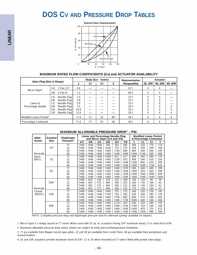
LIN
EAR
- 44 -
DOS CV AND PRESSURE DROP TABLES
Valve Plug (Size & Shape)Body Size - Inches Representative Actuator
1 11⁄4 11⁄2 2 Rangeability 35, 35R 55, 55R 85, 85R
Micro-Taper11/4 3 Flat 2.5º 0.6 — — — 67:1 X X —
3/8 4 Flat 4º 1.2 — — — 89:1 X X —
1/4 Needle Plug 1.5 — — — 25:1 X X —3/8 Needle Plug 3.0 — — — 25:1 X X —
Linear & 1/2 Needle Plug 5.0 — — — 25:1 X X —Percentage Needle 5/8 Needle Plug 7.5 — — — 30:1 X X X
3/4 Needle Plug 10.4 — — — 35:1 X X X7/8 Needle Plug 12.0 — — — 35:1 X X X
Modified Linear Ported4 11.5 17 23 404 30:1 X X X
Percentage Contoured 11.5 17 23 40 30:1 X X X
MAXIMUM RATED FLOW COEFFICIENTS (Cv) and ACTUATOR AVAILABILITY
Valve Actuator DiaphragmLinear and Percentage Needle-Plug Modified Linear Ported
Action Size Pressure3and Micro-Taper (1/4 and 3/8) & Percentage Contoured
1/4 3/8 1/2 5/8 3/4 7/8 1 11⁄4 11⁄2 217 1440 1440 1000 700 503 385 360 220 170 110
354 22 1440 1440 1440 1020 755 573 540 330 260 16030 1440 1440 1440 1440 1160 880 800 500 400 245
Normally 60 1440 1440 1440 1440 1440 1440 1440 1140 900 400Open 17 1440 1440 1440 1440 812 617 600 360 280 170(DOS) 55 22 1440 1440 1440 1440 1230 935 860 540 420 250
30 1440 1440 1440 1440 1440 1440 1300 840 620 39060 1440 1440 1440 1440 1440 1440 1440 1440 1160 92017 1440 1440 1440 1440 1440 1270 960 640 440 300
85 22 1440 1440 1440 1440 1440 1440 1400 920 660 44030 1440 1440 1440 1440 1440 1440 1400 1360 1000 66060 1440 1440 1440 1440 1440 1440 1440 1440 1440 144017 1440 820 530 370 263 200 185 120 90 58
35R4 22 1440 895 575 400 300 252 260 130 100 6230 1440 895 575 400 300 252 260 130 100 62
Normally 60 1440 895 575 400 300 252 270 130 100 62Closed 17 1440 1440 1440 1440 755 573 540 320 250 145(DDOS) 55R 22 1440 1440 1440 1140 765 582 620 360 285 145
30 1440 1440 1440 1440 1160 882 840 510 400 20560 1440 1440 1440 1440 1440 1140 1000 640 500 26017 1440 1440 1440 1440 1210 920 900 520 400 195
85R 22 1440 1440 1440 1440 1440 1250 1180 720 540 32030 1440 1440 1440 1440 1440 1440 1440 870 735 41560 1440 1440 1440 1440 1440 1440 1440 1030 980 560
MAXIMUM ALLOWABLE PRESSURE DROP 2 – PSI
1. Micro-Taper Cv ratings based on 1" travel. When used with 35 sq. in. actuators having 3/4" maximum travel, Cv is reduced to 67%.
2. Maximum allowable pressure drop values shown are subject to body pressure/temperature limitations.
3. 17 psi available from flapper nozzle type pilots. 22 and 30 psi available from Leslie Pilots. 60 psi available from positioners andmanual loaders.
4. 35 and 35R actuators provide maximum travel of 3/4". Cv is 35 when mounted on 2" valves fitted with ported valve plugs.
100
80
60
40
20
0 20 40 60 80 100
Inherent Flow Characteristics
% of Travel
% o
f C
apac
ity
Microtaper
Linear
Equal Percentage
NOTE: Complete pressure drop and diaphragm pressure data for alternate springs available on request.
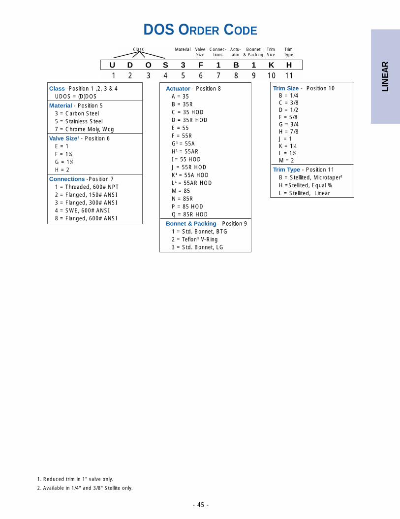
LIN
EAR
- 45 -
DOS ORDER CODE
U D O S 3 F 1 B 1 K H1 2 3 4 5 6 7 8 9 10 11
Class Material Valve Connec- Actu- Bonnet Trim TrimSize tions ator & Packing Size Type
Actuator - Position 8A = 35B = 35RC = 35 HODD = 35R HODE = 55F = 55RG1 = 55AH1 = 55ARI = 55 HODJ = 55R HODK1 = 55A HODL1 = 55AR HODM = 85N = 85RP = 85 HODQ = 85R HOD
Bonnet & Packing - Position 91 = Std. Bonnet, BTG 2 = Teflon® V-Ring3 = Std. Bonnet, LG
Class -Position 1 ,2, 3 & 4UDOS = (D)DOS
Material - Position 53 = Carbon Steel5 = Stainless Steel7 = Chrome Moly, Wcg
Valve Size1 - Position 6E = 1F = 11⁄4G = 11⁄2H = 2
Connections -Position 71 = Threaded, 600# NPT2 = Flanged, 150# ANSI3 = Flanged, 300# ANSI4 = SWE, 600# ANSI8 = Flanged, 600# ANSI
Trim Size - Position 10B = 1/4C = 3/8D = 1/2F = 5/8G = 3/4H = 7/8J = 1K = 11⁄4L = 11⁄2M = 2
Trim Type - Position 11B = Stellited, Microtaper2
H =Stellited, Equal % L = Stellited, Linear
1. Reduced trim in 1" valve only.
2. Available in 1/4" and 3/8" Stellite only.
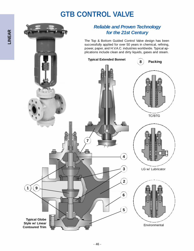
LIN
EAR
- 46 -
Reliable and Proven Technology for the 21st Century
The Top & Bottom Guided Control Valve design has beensuccessfully applied for over 50 years in chemical, refining,power, paper, and H.V.A.C. industries worldwide. Typical ap-plications include clean and dirty liquids, gases and steam.
Packing8
TC/BTG
LG w/ Lubricator
Environmental
GTB CONTROL VALVE
Typical Extended Bonnet
4
Typical GlobeStyle w/ Linear
Contoured Trim
1 9
3
2
5
6
7
LIN
EAR
- 47 -
1. Top & Bottom Stem GuidingThe valve plug is supported and rigidly guided by upper and lowerguide bushings. This two-point guiding provides for exceptionalstability and minimal valve plug deflection even under high pres-sure drop conditions, and allows for precise control and characteri-zation of fluid.
2. High Capacity Body DesignsThe body configuration incorporates large flow areas which maxi-mize the flow capacity of each size. This enlarged flow area main-tains acceptable fluid velocities in the valve body, which increasestrim life and provides for quieter operation.
3. Balanced Double Port DesignSince inlet pressure exerts force on the upper and lower plugs, theforces are balanced. This balancing effect reduces the net thrustof the actuator, allowing for smaller actuators to be used in higherpressure drop applications. The result is a lower overall installationcost and dimensional envelope.
4. Plug Throttling DesignPlug characterization, stem guiding, and balancing effect give thisdesign the combination best suited for handling dirty, sticky, anderosive applications in refinery plants where cage guided valveshave consistently failed.
5. Field Reversible TrimEQ% V-Port/ EQ%, Linear and Quick Opening Contoured plugsare easily reversed in the field so that either a fail open or closedaction can be obtained using the same actuator. This reduces theneed for parts inventory, and adds flexibility.
6. Sizes and End ConnectionsThe GTB valve is available in sizes 1” through 16” (25-400 mm).End connections include raised face, ring type joint flanges andthreaded ends.
7. Bonnet OptionsBonnet options include the standard bolted configuration andextension bonnet for temperatures below 32°F (0°C) and above450°F (232°C). The standard and extension bonnets are availablewith lubricator and oversized construction.
8. PackingTeflon® Chevron/Braided Teflon® Graphite (TC/BTG)Split rings allow packing replacement without removal of actuator.Graphite impregnated PTFE provides 500°F (260°C) service tem-perature, lowered stem hysteresis, better “memory” and sealingthan pure teflon rings, and is ideal for fluids that contain suspend-ed solids.
Laminated Braided Graphite (LBG)Precision die-cut laminated graphite rings in combination withbraided graphite rings provide a reliable, tight stem seal up tooperating temperatures of 1050°F (565°C).
9. Trim OptionsThe GTB design is available in double seat direct action (push-toclose) and reverse action (push-to-open) construction and isdesigned to meet the widest variety of applications.
Quick Opening Plug ContouredGenerally utilized for open and shut (on/off) service, or for appli-cations requiring rapid flow change for small load demandchanges. As this type of inner valve trim leaves the seating sur-faces, the open port area increases rapidly; maximum capacity isobtained at a relatively short valve lift.
Linear Plug ContouredPrimarily used for throttling applications where relatively quickchanges in opening are required with small load demandchanges. In linear contoured inner valves, the flow is directly pro-portional to travel.
Equal Percentage V-Port or Plug ContouredUsed for relatively long time lags and large load changes with alinear controller output. The equal percentage trim provides anequal percentage of flow change per unit of lift at a constantpressure drop. The solid contoured trim is more desirable forapplications involving suspended solids, viscous fluids, and cor-rosive or scale-forming fluids. The V-Port trim provides additionalguiding for high pressure drop applications, where noise andvibration are present.
Reduced TrimFor applications requiring accurate control of smaller flow rates,all valve sizes have two sizes of trim reductions available for alltrim characteristics.
Hardened TrimFor applications requiring trim with superior wear resistance. theThe complete size range is offered in three levels of hardenedtrims that utilize Alloy 6®.
• Partial Stellite® A is an overlay on the plug and seat ring sur-faces.
• Partial Stellite® B is an overlay on the guide bushings, plugposts and seating surfaces of the plug and seat ring.
• Full Stellite® is an overlay on the complete plug contour, plugposts, seat ring and plug seating surfaces, seat ring bore andguide bushings.
Solution-Engineered Features for Demanding Applications
STELLITE® is a trademark of Stoody Deloro Stellite, Inc.Teflon® and Kalrez® are a trademark of E.I. DuPont de Nemours & Co.
GTB CONTROL VALVE
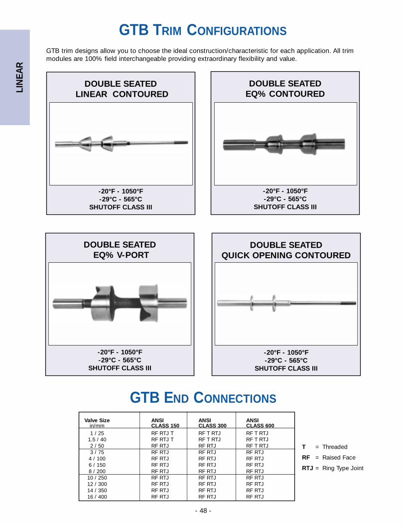
LIN
EAR
- 48 -
GTB END CONNECTIONS
Valve Size ANSI ANSI ANSIin/mm CLASS 150 CLASS 300 CLASS 6001 / 25 RF RTJ T RF T RTJ RF T RTJ
1.5 / 40 RF RTJ T RF T RTJ RF T RTJ2 / 50 RF RTJ RF RTJ RF T RTJ3 / 75 RF RTJ RF RTJ RF RTJ4 / 100 RF RTJ RF RTJ RF RTJ 6 / 150 RF RTJ RF RTJ RF RTJ8 / 200 RF RTJ RF RTJ RF RTJ10 / 250 RF RTJ RF RTJ RF RTJ12 / 300 RF RTJ RF RTJ RF RTJ14 / 350 RF RTJ RF RTJ RF RTJ16 / 400 RF RTJ RF RTJ RF RTJ
T = Threaded
RF = Raised Face
RTJ = Ring Type Joint
GTB trim designs allow you to choose the ideal construction/characteristic for each application. All trimmodules are 100% field interchangeable providing extraordinary flexibility and value.
DOUBLE SEATEDLINEAR CONTOURED
-20°F - 1050°F-29°C - 565°C
SHUTOFF CLASS III
DOUBLE SEATED EQ% CONTOURED
-20°F - 1050°F-29°C - 565°C
SHUTOFF CLASS III
DOUBLE SEATEDEQ% V-PORT
-20°F - 1050°F-29°C - 565°C
SHUTOFF CLASS III
DOUBLE SEATED QUICK OPENING CONTOURED
-20°F - 1050°F-29°C - 565°C
SHUTOFF CLASS III
GTB TRIM CONFIGURATIONS
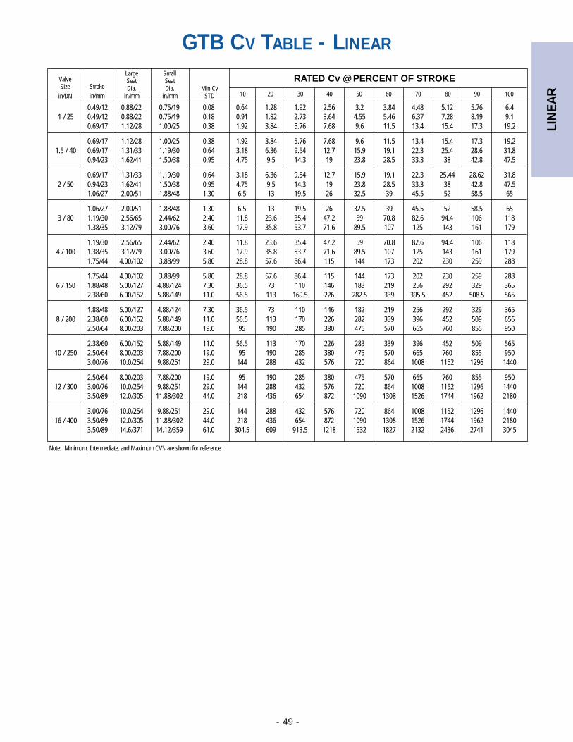
LIN
EAR
- 49 -
0.49/12 0.88/22 0.75/19 0.08 0.64 1.28 1.92 2.56 3.2 3.84 4.48 5.12 5.76 6.41 / 25 0.49/12 0.88/22 0.75/19 0.18 0.91 1.82 2.73 3.64 4.55 5.46 6.37 7.28 8.19 9.1
0.69/17 1.12/28 1.00/25 0.38 1.92 3.84 5.76 7.68 9.6 11.5 13.4 15.4 17.3 19.2
0.69/17 1.12/28 1.00/25 0.38 1.92 3.84 5.76 7.68 9.6 11.5 13.4 15.4 17.3 19.21.5 / 40 0.69/17 1.31/33 1.19/30 0.64 3.18 6.36 9.54 12.7 15.9 19.1 22.3 25.4 28.6 31.8
0.94/23 1.62/41 1.50/38 0.95 4.75 9.5 14.3 19 23.8 28.5 33.3 38 42.8 47.5
0.69/17 1.31/33 1.19/30 0.64 3.18 6.36 9.54 12.7 15.9 19.1 22.3 25.44 28.62 31.82 / 50 0.94/23 1.62/41 1.50/38 0.95 4.75 9.5 14.3 19 23.8 28.5 33.3 38 42.8 47.5
1.06/27 2.00/51 1.88/48 1.30 6.5 13 19.5 26 32.5 39 45.5 52 58.5 65
1.06/27 2.00/51 1.88/48 1.30 6.5 13 19.5 26 32.5 39 45.5 52 58.5 653 / 80 1.19/30 2.56/65 2.44/62 2.40 11.8 23.6 35.4 47.2 59 70.8 82.6 94.4 106 118
1.38/35 3.12/79 3.00/76 3.60 17.9 35.8 53.7 71.6 89.5 107 125 143 161 179
1.19/30 2.56/65 2.44/62 2.40 11.8 23.6 35.4 47.2 59 70.8 82.6 94.4 106 1184 / 100 1.38/35 3.12/79 3.00/76 3.60 17.9 35.8 53.7 71.6 89.5 107 125 143 161 179
1.75/44 4.00/102 3.88/99 5.80 28.8 57.6 86.4 115 144 173 202 230 259 288
1.75/44 4.00/102 3.88/99 5.80 28.8 57.6 86.4 115 144 173 202 230 259 2886 / 150 1.88/48 5.00/127 4.88/124 7.30 36.5 73 110 146 183 219 256 292 329 365
2.38/60 6.00/152 5.88/149 11.0 56.5 113 169.5 226 282.5 339 395.5 452 508.5 565
1.88/48 5.00/127 4.88/124 7.30 36.5 73 110 146 182 219 256 292 329 3658 / 200 2.38/60 6.00/152 5.88/149 11.0 56.5 113 170 226 282 339 396 452 509 656
2.50/64 8.00/203 7.88/200 19.0 95 190 285 380 475 570 665 760 855 950
2.38/60 6.00/152 5.88/149 11.0 56.5 113 170 226 283 339 396 452 509 56510 / 250 2.50/64 8.00/203 7.88/200 19.0 95 190 285 380 475 570 665 760 855 950
3.00/76 10.0/254 9.88/251 29.0 144 288 432 576 720 864 1008 1152 1296 1440
2.50/64 8.00/203 7.88/200 19.0 95 190 285 380 475 570 665 760 855 95012 / 300 3.00/76 10.0/254 9.88/251 29.0 144 288 432 576 720 864 1008 1152 1296 1440
3.50/89 12.0/305 11.88/302 44.0 218 436 654 872 1090 1308 1526 1744 1962 2180
3.00/76 10.0/254 9.88/251 29.0 144 288 432 576 720 864 1008 1152 1296 144016 / 400 3.50/89 12.0/305 11.88/302 44.0 218 436 654 872 1090 1308 1526 1744 1962 2180
3.50/89 14.6/371 14.12/359 61.0 304.5 609 913.5 1218 1532 1827 2132 2436 2741 3045
RATED Cv @ PERCENT OF STROKEValveSize
in/DNStrokein/mm
LargeSeatDia.
in/mm
SmallSeatDia.
in/mmMin Cv
STD 10 20 30 40 50 60 70 80 90 100
Note: Minimum, Intermediate, and Maximum CV’s are shown for reference
GTB CV TABLE - LINEAR
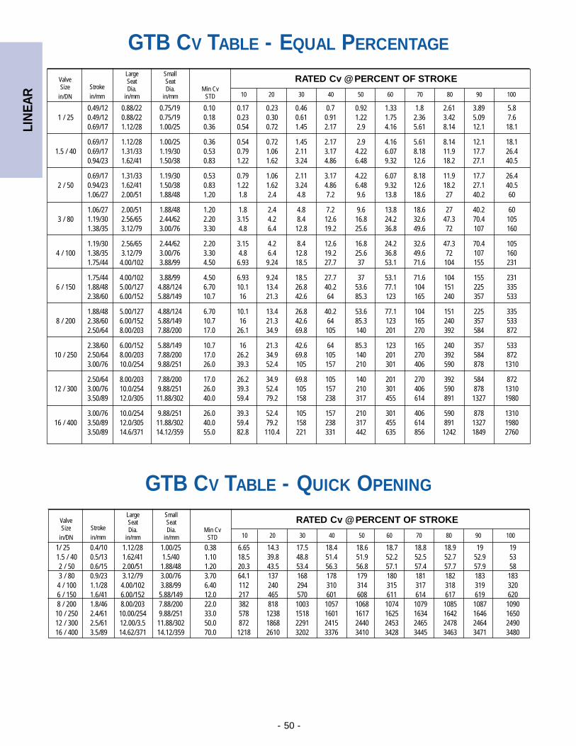
LIN
EAR
- 50 -
1/ 25 0.4/10 1.12/28 1.00/25 0.38 6.65 14.3 17.5 18.4 18.6 18.7 18.8 18.9 19 191.5 / 40 0.5/13 1.62/41 1.5/40 1.10 18.5 39.8 48.8 51.4 51.9 52.2 52.5 52.7 52.9 532 / 50 0.6/15 2.00/51 1.88/48 1.20 20.3 43.5 53.4 56.3 56.8 57.1 57.4 57.7 57.9 583 / 80 0.9/23 3.12/79 3.00/76 3.70 64.1 137 168 178 179 180 181 182 183 1834 / 100 1.1/28 4.00/102 3.88/99 6.40 112 240 294 310 314 315 317 318 319 3206 / 150 1.6/41 6.00/152 5.88/149 12.0 217 465 570 601 608 611 614 617 619 6208 / 200 1.8/46 8.00/203 7.88/200 22.0 382 818 1003 1057 1068 1074 1079 1085 1087 109010 / 250 2.4/61 10.00/254 9.88/251 33.0 578 1238 1518 1601 1617 1625 1634 1642 1646 165012 / 300 2.5/61 12.00/3.5 11.88/302 50.0 872 1868 2291 2415 2440 2453 2465 2478 2464 249016 / 400 3.5/89 14.62/371 14.12/359 70.0 1218 2610 3202 3376 3410 3428 3445 3463 3471 3480
RATED Cv @ PERCENT OF STROKEValveSize
in/DNStrokein/mm
LargeSeatDia.
in/mm
SmallSeatDia.
in/mmMin Cv
STD 10 20 30 40 50 60 70 80 90 100
0.49/12 0.88/22 0.75/19 0.10 0.17 0.23 0.46 0.7 0.92 1.33 1.8 2.61 3.89 5.81 / 25 0.49/12 0.88/22 0.75/19 0.18 0.23 0.30 0.61 0.91 1.22 1.75 2.36 3.42 5.09 7.6
0.69/17 1.12/28 1.00/25 0.36 0.54 0.72 1.45 2.17 2.9 4.16 5.61 8.14 12.1 18.1
0.69/17 1.12/28 1.00/25 0.36 0.54 0.72 1.45 2.17 2.9 4.16 5.61 8.14 12.1 18.11.5 / 40 0.69/17 1.31/33 1.19/30 0.53 0.79 1.06 2.11 3.17 4.22 6.07 8.18 11.9 17.7 26.4
0.94/23 1.62/41 1.50/38 0.83 1.22 1.62 3.24 4.86 6.48 9.32 12.6 18.2 27.1 40.5
0.69/17 1.31/33 1.19/30 0.53 0.79 1.06 2.11 3.17 4.22 6.07 8.18 11.9 17.7 26.42 / 50 0.94/23 1.62/41 1.50/38 0.83 1.22 1.62 3.24 4.86 6.48 9.32 12.6 18.2 27.1 40.5
1.06/27 2.00/51 1.88/48 1.20 1.8 2.4 4.8 7.2 9.6 13.8 18.6 27 40.2 60
1.06/27 2.00/51 1.88/48 1.20 1.8 2.4 4.8 7.2 9.6 13.8 18.6 27 40.2 603 / 80 1.19/30 2.56/65 2.44/62 2.20 3.15 4.2 8.4 12.6 16.8 24.2 32.6 47.3 70.4 105
1.38/35 3.12/79 3.00/76 3.30 4.8 6.4 12.8 19.2 25.6 36.8 49.6 72 107 160
1.19/30 2.56/65 2.44/62 2.20 3.15 4.2 8.4 12.6 16.8 24.2 32.6 47.3 70.4 1054 / 100 1.38/35 3.12/79 3.00/76 3.30 4.8 6.4 12.8 19.2 25.6 36.8 49.6 72 107 160
1.75/44 4.00/102 3.88/99 4.50 6.93 9.24 18.5 27.7 37 53.1 71.6 104 155 231
1.75/44 4.00/102 3.88/99 4.50 6.93 9.24 18.5 27.7 37 53.1 71.6 104 155 2316 / 150 1.88/48 5.00/127 4.88/124 6.70 10.1 13.4 26.8 40.2 53.6 77.1 104 151 225 335
2.38/60 6.00/152 5.88/149 10.7 16 21.3 42.6 64 85.3 123 165 240 357 533
1.88/48 5.00/127 4.88/124 6.70 10.1 13.4 26.8 40.2 53.6 77.1 104 151 225 3358 / 200 2.38/60 6.00/152 5.88/149 10.7 16 21.3 42.6 64 85.3 123 165 240 357 533
2.50/64 8.00/203 7.88/200 17.0 26.1 34.9 69.8 105 140 201 270 392 584 872
2.38/60 6.00/152 5.88/149 10.7 16 21.3 42.6 64 85.3 123 165 240 357 53310 / 250 2.50/64 8.00/203 7.88/200 17.0 26.2 34.9 69.8 105 140 201 270 392 584 872
3.00/76 10.0/254 9.88/251 26.0 39.3 52.4 105 157 210 301 406 590 878 1310
2.50/64 8.00/203 7.88/200 17.0 26.2 34.9 69.8 105 140 201 270 392 584 87212 / 300 3.00/76 10.0/254 9.88/251 26.0 39.3 52.4 105 157 210 301 406 590 878 1310
3.50/89 12.0/305 11.88/302 40.0 59.4 79.2 158 238 317 455 614 891 1327 1980
3.00/76 10.0/254 9.88/251 26.0 39.3 52.4 105 157 210 301 406 590 878 131016 / 400 3.50/89 12.0/305 11.88/302 40.0 59.4 79.2 158 238 317 455 614 891 1327 1980
3.50/89 14.6/371 14.12/359 55.0 82.8 110.4 221 331 442 635 856 1242 1849 2760
RATED Cv @ PERCENT OF STROKEValveSize
in/DNStrokein/mm
LargeSeatDia.
in/mm
SmallSeatDia.
in/mmMin Cv
STD 10 20 30 40 50 60 70 80 90 100
GTB CV TABLE - EQUAL PERCENTAGE
GTB CV TABLE - QUICK OPENING
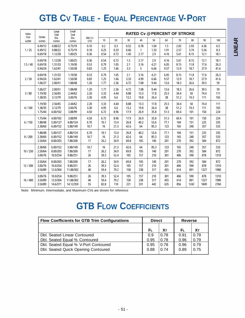
LIN
EAR
- 51 -
0.49/12 0.88/22 0.75/19 0.10 0.2 0.3 0.52 0.78 1.04 1.5 2.02 2.93 4.36 6.51 / 25 0.49/12 0.88/22 0.75/19 0.18 0.25 0.33 0.66 1 1.33 1.91 2.57 3.74 5.56 8.3
0.69/18 1.12/28 1.00/25 0.36 0.54 0.72 1.45 2.17 2.9 4.16 5.61 8.15 12.1 18.1
0.69/18 1.12/28 1.00/25 0.36 0.54 0.72 1.5 2.17 2.9 4.16 5.61 8.15 12.1 18.11.5 / 40 0.69/18 1.31/33 1.19/30 0.53 0.79 1.05 2.1 3.16 4.21 6.05 8.15 11.8 17.6 26.3
0.94/24 1.62/41 1.50/38 0.83 1.25 1.66 3.3 5 6.66 9.57 12.9 18.7 27.9 41.6
0.69/18 1.31/33 1.19/30 0.53 0.79 1.05 2.1 3.16 4.21 6.05 8.15 11.8 17.6 26.32 / 50 0.94/24 1.62/41 1.50/38 0.83 1.25 1.66 3.33 4.99 6.66 9.57 12.9 18.7 27.9 41.6
1.06/27 2.00/51 1.88/48 1.20 1.77 2.36 4.72 7.08 9.44 13.6 18.3 26.6 39.5 59
1.06/27 2.00/51 1.88/48 1.20 1.77 2.36 4.72 7.08 9.44 13.6 18.3 26.6 39.5 593 / 80 1.19/30 2.56/65 2.44/62 2.20 3.33 4.44 8.88 13.3 17.8 25.5 34.4 50 74.4 111
1.38/35 3.12/79 3.00/76 3.30 4.95 6.6 13.2 19.8 26.4 38 51.2 74.3 111 165
1.19/30 2.56/65 2.44/62 2.20 3.33 4.44 8.88 13.3 17.8 25.5 34.4 50 74.4 1114 / 100 1.38/35 3.12/79 3.00/76 3.30 4.95 6.6 13.2 19.8 26.4 38 51.2 74.3 111 165
1.75/44 4.00/102 3.88/99 4.50 6.72 8.96 17.9 26.9 35.8 51.5 69.4 101 150 224
1.75/44 4.00/102 3.88/99 4.50 6.72 8.96 17.9 26.9 35.8 51.5 69.4 101 150 2246 / 150 1.88/48 5.00/127 4.88/124 6.70 10.1 13.4 26.8 40.2 53.6 77.1 104 151 225 335
2.38/60 6.00/152 5.88/149 10.7 16 21.3 42.6 64 85.3 123 165 240 357 533
1.88/48 5.00/127 4.88/124 6.70 10.1 13.4 26.8 40.2 53.6 77.1 104 151 225 3358 / 200 2.38/60 6.00/152 5.88/149 10.7 16 21.3 42.6 64 85.3 123 165 240 357 533
2.50/64 8.00/203 7.88/200 17 26.2 34.9 69.8 105 140 201 270 392 584 872
2.38/60 6.00/152 5.88/149 10.7 16 21.3 42.6 64 85.3 123 165 240 357 53310 / 250 2.50/64 8.00/203 7.88/200 17 26.2 34.9 69.8 105 140 201 270 392 584 872
3.00/76 10.0/254 9.88/251 26 39.3 52.4 105 157 210 301 406 590 878 1310
2.50/64 8.00/203 7.88/200 17 26.2 34.9 69.8 105 140 201 270 392 584 87212 / 300 3.00/76 10.0/254 9.88/251 26 39.3 52.4 105 157 210 301 406 590 878 1310
3.50/89 12.0/304 11.88/302 40 59.4 79.2 158 238 317 455 614 891 1327 1980
3.00/76 10.0/254 9.88/251 26 39.3 52.4 105 157 210 301 406 590 878 131016 / 400 3.50/89 12.0/304 11.88/302 40 59.4 79.2 158 238 317 455 614 891 1327 1980
3.50/89 14.6/371 14.12/359 55 82.8 110 221 331 442 635 856 1242 1849 2760
RATED Cv @ PERCENT OF STROKEValveSize
in/DNStrokein/mm
LargeSeatDia.
in/mm
SmallSeatDia.
in/mmMin Cv
STD 10 20 30 40 50 60 70 80 90 100
Note: Minimum, Intermediate, and Maximum CVs are shown for reference
Flow Coefficients for GTB Trim Configurations Direct Reverse
FL XT FL XT
Dbl. Seated Linear Contoured 0.9 0.78 0.91 0.79Dbl. Seated Equal % Contoured 0.95 0.78 0.96 0.79Dbl. Seated Equal % V-Port Contoured 0.95 0.78 0.96 0.79Dbl. Seated Quick Opening Contoured 0.88 0.74 0.89 0.75
GTB CV TABLE - EQUAL PERCENTAGE V-PORT
GTB FLOW COEFFICIENTS
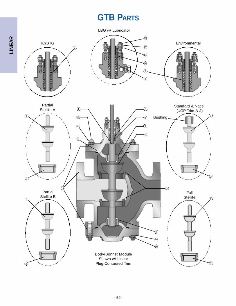
LIN
EAR
- 52 -
PartialStellite B
FullStellite
PartialStellite A
Standard & Nace(UOP Trim A-J)
LBG w/ Lubricator
Environmental
Body/Bonnet ModuleShown w/ Linear
Plug Contoured Trim
TC/BTG
Bushing
7
13
12
11
10
9
8
1
6
5
3
1
2
3
14
15
2
16
17
1
2
1
14
15
4
1
2
2
GTB PARTS
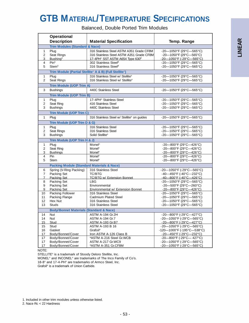
LIN
EAR
- 53 -
Balanced, Double Ported Trim Modules
NOTE:STELLITE® is a trademark of Stoody Deloro Stellite, Inc.MONEL® and INCONEL® are trademarks of The Inco Family of Co’s. 18-8® and 17-4-PH® are trademarks of Armco Steel, Inc.Grafoil® is a trademark of Union Carbide.
1. Included in other trim modules unless otherwise listed.2. Nace Rc < 22 Hardness
GTB MATERIAL/TEMPERATURE SPECIFICATIONS
OperationalDescription Material Specification Temp. RangeTrim Modules (Standard & Nace)
1 Plug 316 Stainless Steel ASTM A351 Grade CF8M -20—1050°F (29°C—565°C)2 Seat Rings 316 Stainless Steel ASTM A351 Grade CF8M -20—1050°F (29°C—565°C)3 Bushing1 17-4PH® SST ASTM A654 Type 6302 -20—1050°F (-29°C—565°C)4 Pin1 302 Stainless Steel2 -20—1050°F (29°C—565°C)5 Stem1 316 Stainless Steel2 -20—1050°F (29°C—565°C)
Trim Module (Partial Stellite® A & B) (Full Stellite®)1 Plug 316 Stainless Steel w/ Stellite® -20—1050°F (29°C—565°C)2 Seat Rings 316 Stainless Steel w/ Stellite® -20—1050°F (29°C—565°C)
Trim Module (UOP Trim A)3 Bushings 440C Stainless Steel -20—1050°F (29°C—565°C)
Trim Module (UOP Trim B)1 Plug 17-4PH® Stainless Steel -20—1050°F (29°C—565°C)2 Seat Ring 416 Stainless Steel -20—1050°F (29°C—565°C)3 Bushings 440C Stainless Steel -20—1050°F (29°C—565°C)
Trim Module (UOP Trim C)1 Plug 316 Stainless Steel w/ Stellite® on guides -20—1050°F (29°C—565°C)
Trim Module (UOP Trim D & G)1 Plug 316 Stainless Steel -20—1050°F (29°C—565°C)2 Seat Rings 316 Stainless Steel -20—1050°F (29°C—565°C)3 Bushings Solid Stellite® -20—1050°F (29°C—565°C)
Trim Module (UOP Trim H & J)1 Plug Monel® -20—800°F (29°C—426°C)2 Seat Ring Monel® -20—800°F (29°C—426°C)3 Bushings Monel® -20—800°F (29°C—426°C)4 Pin Monel® -20—800°F (29°C—426°C)5 Stem Monel® -20—800°F (29°C—426°C)
Packing Module (Standard Materials & Nace)6 Spring (V-Ring Packing) 316 Stainless Steel -20—1050°F (-29°C—565°C)7 Packing Set TC/BTG -40—450°F (-40°C—232°C)7 Packing Set TC/BTG w/ Extension Bonnet -40—800°F (-40°C—426°C)8 Packing Set LBG -20—1050°F (29°C—565°C)9 Packing Set Environmental -20—500°F (29°C—260°C)9 Packing Set Environmental w/ Extension Bonnet -20—800°F (29°C—426°C)
10 Packing Follower 316 Stainless Steel -20—1050°F (29°C—565°C)11 Packing Flange Cadmium Plated Steel -20—1050°F (29°C—565°C)12 Hex Nut 316 Stainless Steel -20—1050°F (29°C—565°C)13 Studs 316 Stainless Steel -20—1050°F (29°C—565°C)
Body/Bonnet Materials (Standard & Nace)14 Nut ASTM A-194 Gr.2H -20—800°F (-29°C—427°C)14 Nut ASTM A-194 Gr.7 -20—1050°F (-29°C—565°C)15 Stud ASTM A-193 Gr.B7 -20—800°F (-29°C—427°C)15 Stud ASTM A-193 B 16 -20—1050°F (-29°C—565°C)16 Gasket Grafoil® -120—1000°F (-195°C—538°C)17 Body/Bonnet/Cover Iron ASTM A-126 Class B -20—450°F (-29°C—232°C)17 Body/Bonnet/Cover *ASTM A-216 Steel Gr.WCB -20—800°F (-29°C— 427°C)17 Body/Bonnet/Cover ASTM A-217 Gr.WC9 -20—1050°F (-29°C—565°C)17 Body/Bonnet/Cover *ASTM A-351 Gr.CF8M -20—1050°F (-29°C—565°C)
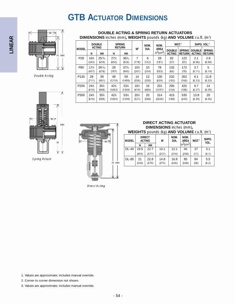
LIN
EAR
- 54 -
1. Values are approximate; includes manual override.
2. Corner to corner dimension not shown.
3. Values are approximate; includes manual override.
Direct Acting
Spring Return
Double Acting
HH
GTB ACTUATOR DIMENSIONS
DIRECT NOM. NOM.SHPG.MODEL ACTING W DIA. AREA WGT.3
VOL.H HH in2(cm2)
DL-40 19.5 22.7 10.1 12.1 40 37 3.1
(493) (577) (257) (310) (258) (17) (0.1)
DL-85 21 22.8 14.8 16.8 85 84 5.5(530) (579) (375) (426) (548) (38) (0.2)
DOUBLE SPRING NOM. NOM. WGT.1 SHPG. VOL.1
MODEL ACTING RETURN W2 DIA. AREA DOUBLE SPRING DOUBLE SPRINGH HH H HH in2(cm2) ACTING RETURN ACTING RETURN
P28 163⁄4 2515⁄16 271⁄4 367⁄16 7 6 28 82 122 2.1 2.8(343) (659) (692) (926) (178) (152) (181) (37) (55) (0.06) (0.08)
P80 171⁄2 2611⁄16 28 373⁄16 101⁄2 10 78 132 172 3.7 5(457) (678) (787) (945) (267) (254) (503) (60) (78) (0.11) (0.14)
P130 28 39 48 59 14 13 130 232 352 8.1 11.8(711) (991) (1219) (1499) (356) (330) (839) (105) (160) (0.23) (0.33)
P200 243⁄4 353⁄4 421⁄8 531⁄8 161⁄2 16 201 295 425 9.7 14(610) (908) (1003) (1349) (419) (406) (1297) (134) (188) (0.27) (0.39)
P300 243⁄4 353⁄4 421⁄8 531⁄8 201⁄2 20 314 415 535 13.8 20(610) (908) (1003) (1349) (521) (508) (2026) (188) (243) (0.39) (0.56)
DOUBLE ACTING & SPRING RETURN ACTUATORSDIMENSIONS inches (mm), WEIGHTS pounds (kg) AND VOLUME cu.ft. (m3)
DIRECT ACTING ACTUATOR DIMENSIONS inches (mm),
WEIGHTS pounds (kg) AND VOLUME cu.ft. (m3)
H
HH
H
HHH
W
W
W
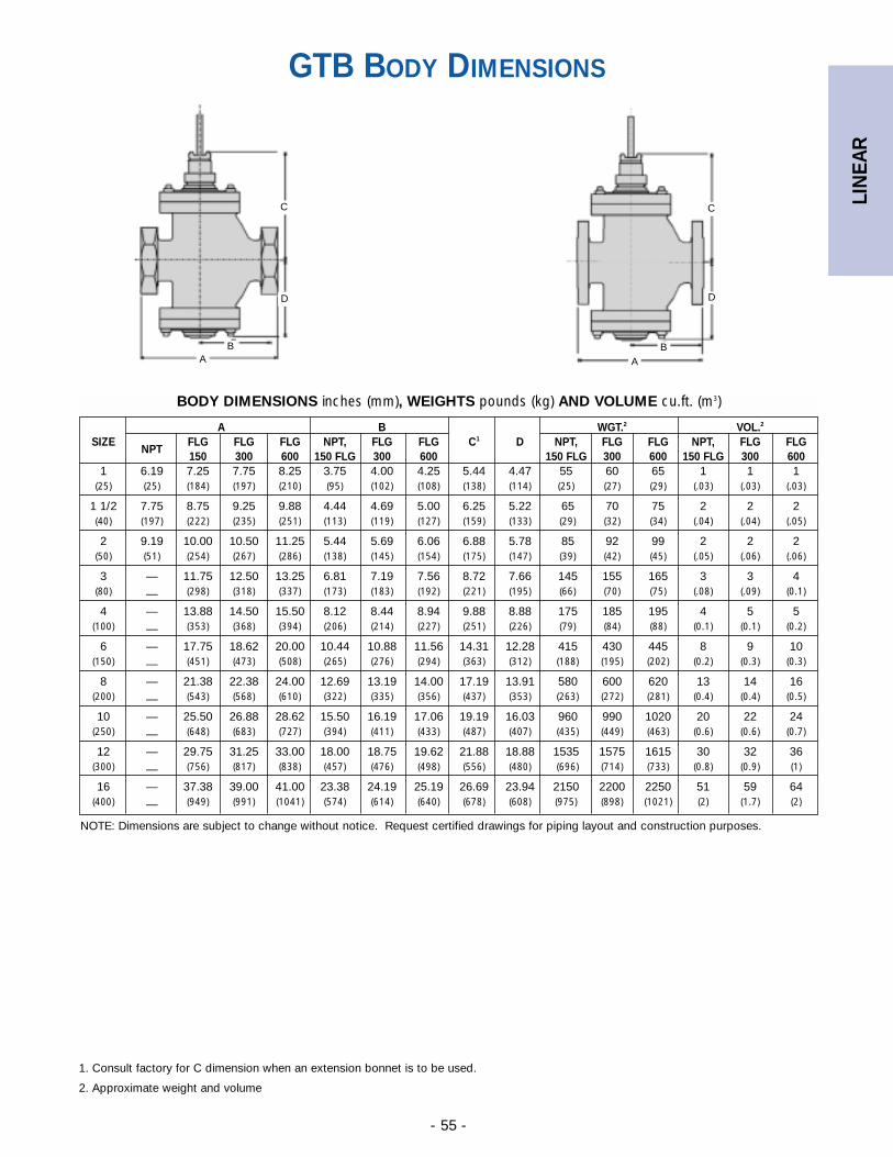
LIN
EAR
- 55 -
NOTE: Dimensions are subject to change without notice. Request certified drawings for piping layout and construction purposes.
GTB BODY DIMENSIONS
A B WGT.2 VOL.2
SIZENPT
FLG FLG FLG NPT, FLG FLG C1 D NPT, FLG FLG NPT, FLG FLG150 300 600 150 FLG 300 600 150 FLG 300 600 150 FLG 300 600
1 6.19 7.25 7.75 8.25 3.75 4.00 4.25 5.44 4.47 55 60 65 1 1 1(25) (25) (184) (197) (210) (95) (102) (108) (138) (114) (25) (27) (29) (.03) (.03) (.03)
1 1/2 7.75 8.75 9.25 9.88 4.44 4.69 5.00 6.25 5.22 65 70 75 2 2 2(40) (197) (222) (235) (251) (113) (119) (127) (159) (133) (29) (32) (34) (.04) (.04) (.05)
2 9.19 10.00 10.50 11.25 5.44 5.69 6.06 6.88 5.78 85 92 99 2 2 2(50) (51) (254) (267) (286) (138) (145) (154) (175) (147) (39) (42) (45) (.05) (.06) (.06)
3 — 11.75 12.50 13.25 6.81 7.19 7.56 8.72 7.66 145 155 165 3 3 4(80) — (298) (318) (337) (173) (183) (192) (221) (195) (66) (70) (75) (.08) (.09) (0.1)
4 — 13.88 14.50 15.50 8.12 8.44 8.94 9.88 8.88 175 185 195 4 5 5(100) — (353) (368) (394) (206) (214) (227) (251) (226) (79) (84) (88) (0.1) (0.1) (0.2)
6 — 17.75 18.62 20.00 10.44 10.88 11.56 14.31 12.28 415 430 445 8 9 10(150) — (451) (473) (508) (265) (276) (294) (363) (312) (188) (195) (202) (0.2) (0.3) (0.3)
8 — 21.38 22.38 24.00 12.69 13.19 14.00 17.19 13.91 580 600 620 13 14 16(200) — (543) (568) (610) (322) (335) (356) (437) (353) (263) (272) (281) (0.4) (0.4) (0.5)
10 — 25.50 26.88 28.62 15.50 16.19 17.06 19.19 16.03 960 990 1020 20 22 24(250) — (648) (683) (727) (394) (411) (433) (487) (407) (435) (449) (463) (0.6) (0.6) (0.7)
12 — 29.75 31.25 33.00 18.00 18.75 19.62 21.88 18.88 1535 1575 1615 30 32 36(300) — (756) (817) (838) (457) (476) (498) (556) (480) (696) (714) (733) (0.8) (0.9) (1)
16 — 37.38 39.00 41.00 23.38 24.19 25.19 26.69 23.94 2150 2200 2250 51 59 64(400) — (949) (991) (1041) (574) (614) (640) (678) (608) (975) (898) (1021) (2) (1.7) (2)
BODY DIMENSIONS inches (mm), WEIGHTS pounds (kg) AND VOLUME cu.ft. (m3)
D D
C
BAA
B
C
1. Consult factory for C dimension when an extension bonnet is to be used.
2. Approximate weight and volume
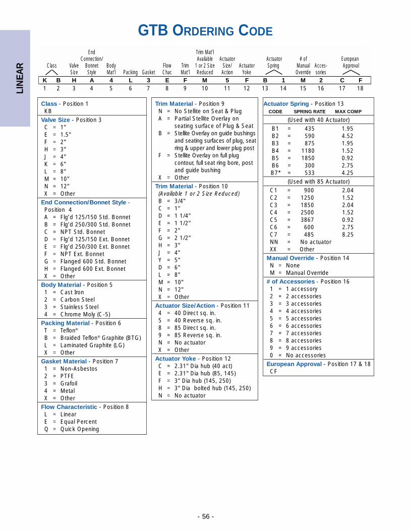
LIN
EAR
- 56 -
GTB ORDERING CODE
Class - Position 1KB
Valve Size - Position 3C = 1"E = 1.5"F = 2"H = 3"J = 4"K = 6"L = 8"M = 10"N = 12"X = Other
End Connection/Bonnet Style -Position 4A = Flg’d 125/150 Std. BonnetB = Flg’d 250/300 Std. BonnetC = NPT Std. BonnetD = Flg’d 125/150 Ext. BonnetE = Flg’d 250/300 Ext. BonnetF = NPT Ext. BonnetG = Flanged 600 Std. BonnetH = Flanged 600 Ext. BonnetX = Other
Body Material - Position 51 = Cast Iron2 = Carbon Steel3 = Stainless Steel4 = Chrome Moly (C-5)
Packing Material - Position 6T = Teflon®
B = Braided Teflon® Graphite (BTG)L = Laminated Graphite (LG)X = Other
Gasket Material - Position 71 = Non-Asbestos2 = PTFE3 = Grafoil4 = MetalX = Other
Flow Characteristic - Position 8L = LinearE = Equal PercentQ = Quick Opening
Trim Material - Position 9N = No Stellite on Seat & PlugA = Partial Stellite Overlay on
seating surface of Plug & Seat B = Stellite Overlay on guide bushings
and seating surfaces of plug, seat ring & upper and lower plug post
F = Stellite Overlay on full plug contour, full seat ring bore, post and guide bushing
X = OtherTrim Material - Position 10(Available 1 or 2 Size Reduced)B = 3/4" C = 1" D = 1 1/4" E = 1 1/2" F = 2" G = 2 1/2" H = 3" J = 4" Y = 5" D = 6" L = 8" M = 10" N = 12" X = Other
Actuator Size/Action - Position 114 = 40 Direct sq. in.5 = 40 Reverse sq. in.8 = 85 Direct sq. in.9 = 85 Reverse sq. in.N = No actuatorX = Other
Actuator Yoke - Position 12C = 2.31" Dia hub (40 act)E = 2.31" Dia hub (85, 145)F = 3" Dia hub (145, 250)H = 3" Dia bolted hub (145, 250)N = No actuator
End Trim Mat’lConnection/ Available Actuator Actuator # of European
Class Valve Bonnet Body Flow Trim 1 or 2 Size Size/ Actuator Spring Manual Acces- Approval Size Style Mat’l Packing Gasket Char. Mat’l Reduced Action Yoke Override sories
K B H A 4 L 3 E F M 5 F B 1 M 2 C F1 2 3 4 5 6 7 8 9 10 11 12 13 14 15 16 17 18
Actuator Spring - Position 13CODE SPRING RATE MAX COMP
(Used with 40 Actuator)B1 = 435 1.95B2 = 590 4.52B3 = 875 1.95B4 = 1180 1.52B5 = 1850 0.92B6 = 300 2.75B7* = 533 4.25
(Used with 85 Actuator)C1 = 900 2.04C2 = 1250 1.52C3 = 1850 2.04C4 = 2500 1.52C5 = 3867 0.92C6 = 600 2.75C7 = 485 8.25NN = No actuatorXX = Other
Manual Override - Position 14N = NoneM = Manual Override
# of Accessories - Position 161 = 1 accessory2 = 2 accessories3 = 3 accessories4 = 4 accessories5 = 5 accessories6 = 6 accessories7 = 7 accessories8 = 8 accessories9 = 9 accessories0 = No accessories
European Approval - Position 17 & 18CF
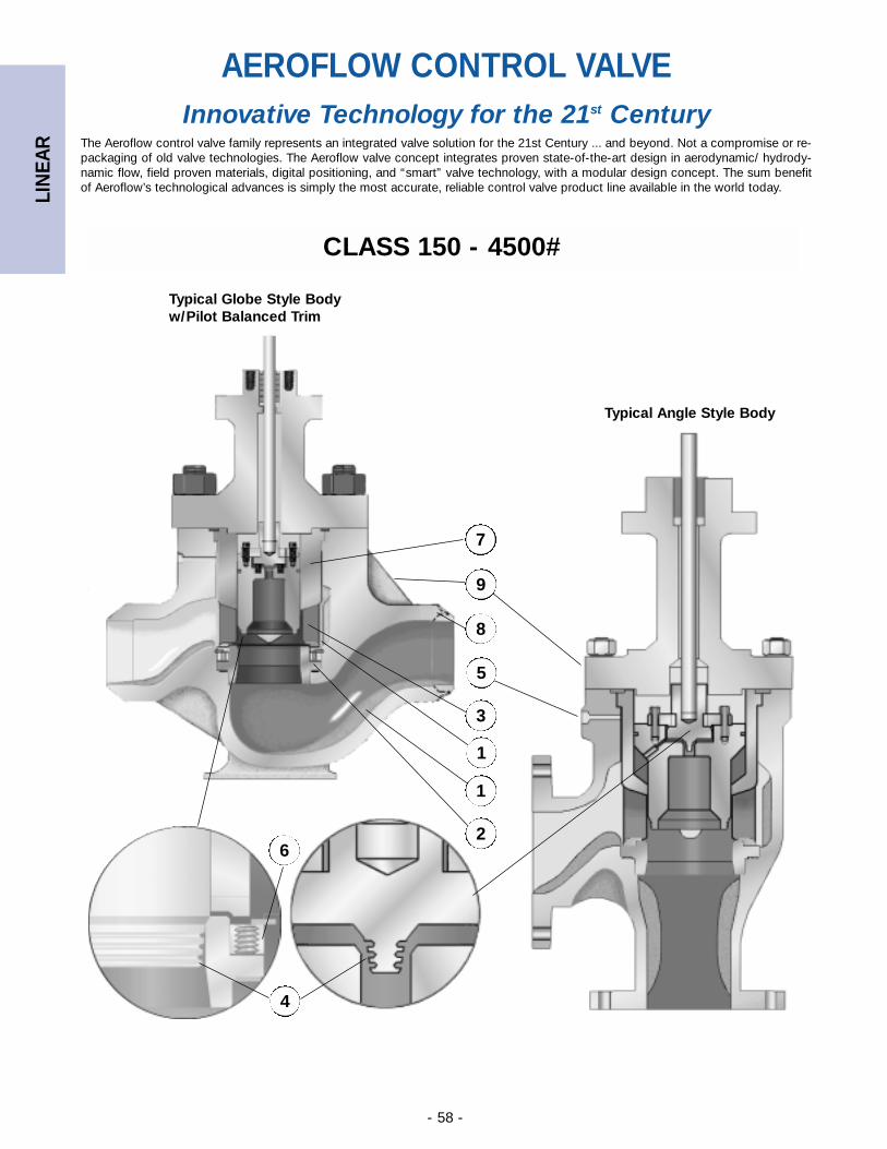
LIN
EAR
- 58 -
Innovative Technology for the 21st CenturyThe Aeroflow control valve family represents an integrated valve solution for the 21st Century ... and beyond. Not a compromise or re-packaging of old valve technologies. The Aeroflow valve concept integrates proven state-of-the-art design in aerodynamic/ hydrody-namic flow, field proven materials, digital positioning, and “smart” valve technology, with a modular design concept. The sum benefitof Aeroflow’s technological advances is simply the most accurate, reliable control valve product line available in the world today.
6
1
2
9
5
3
8
Typical Globe Style Bodyw/Pilot Balanced Trim
Typical Angle Style Body
4
1
AEROFLOW CONTROL VALVE
7
CLASS 150 - 4500#
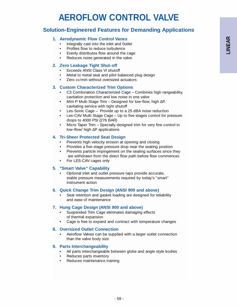
LIN
EAR
- 59 -
Solution-Engineered Features for Demanding Applications
1. Aerodynamic Flow Control Vanes• Integrally cast into the inlet and 0utlet• Profiles flow to reduce turbulence• Evenly distributes flow around the cage• Reduces noise generated in the valve
2. Zero Leakage Tight Shut-off• Exceeds ANSI Class VI shutoff• Metal to metal seat and pilot balanced plug design• Zero cc/min without oversized actuators
3. Custom Characterized Trim Options• C3 Combination Characterized Cage – Combines high rangeability,
cavitation protection and low noise in one valve• Mini P Multi Stage Trim – Designed for low-flow, high ∆P,
cavitating service with tight shutoff• Les-Sonic Cage – Provide up to a 25 dBA noise reduction• Les-CAV Multi Stage Cage – Up to five stages control for pressure
drops to 4000 PSI (276 BAR)• Micro Taper Trim – Specially designed trim for very fine control in
low-flow/ high ∆P applications
4. Tri-Sheer Protected Seat Design• Prevents high velocity erosion at opening and closing• Provides a five-stage pressure drop near the seating position• Prevents particle impingement on the seating surfaces since they
are withdrawn from the direct flow path before flow commences• For LES-CAV cages only
5. “Smart Valve” Capability• Optional inlet and outlet pressure taps provide accurate,
stable pressure measurements required by today’s “smart” instrument action
6. Quick Change Trim Design (ANSI 900 and above)• Seat retention and gasket loading are designed for reliability
and ease of maintenance
7. Hung Cage Design (ANSI 900 and above)• Suspended Trim Cage eliminates damaging effects
of thermal expansion• Cage is free to expand and contract with temperature changes
8. Oversized Outlet Connection• Aeroflow Valves can be supplied with a larger outlet connection
than the valve body size
9. Parts Interchangeability• All parts interchangeable between globe and angle style bodies• Reduces parts inventory• Reduces maintenance training
AEROFLOW CONTROL VALVE
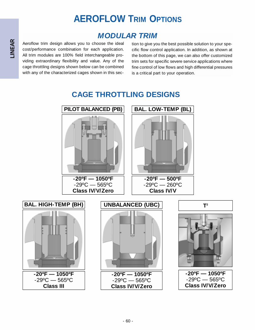
LIN
EAR
- 60 -
Aeroflow trim design allows you to choose the idealcost/performance combination for each application.All trim modules are 100% field interchangeable pro-viding extraordinary flexibility and value. Any of thecage throttling designs shown below can be combinedwith any of the characterized cages shown in this sec-
-20ºF — 1050ºF-29ºC — 565ºCClass IV/V/Zero
UNBALANCED (UBC)
-20ºF — 500ºF-29ºC — 260ºC
Class IV/V
BAL. LOW-TEMP (BL)
-20ºF — 1050ºF-29ºC — 565ºCClass IV/V/Zero
PILOT BALANCED (PB)
-20ºF — 1050ºF-29ºC — 565ºC
Class III
BAL. HIGH-TEMP (BH)
CAGE THROTTLING DESIGNS
T2
-20ºF — 1050ºF-29ºC — 565ºCClass IV/V/Zero
AEROFLOW TRIM OPTIONS
tion to give you the best possible solution to your spe-cific flow control application. In addition, as shown atthe bottom of this page, we can also offer customizedtrim sets for specific severe service applications wherefine control of low flows and high differential pressuresis a critical part to your operation.
MODULAR TRIM
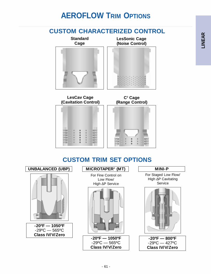
LIN
EAR
- 61 -
StandardCage
LesSonic Cage(Noise Control)
LesCav Cage(Cavitation Control)
C3 Cage(Range Control)
CUSTOM TRIM SET OPTIONS
CUSTOM CHARACTERIZED CONTROL
MINI-P
-20ºF — 800ºF-29ºC — 427ºCClass IV/V/Zero
MICROTAPER® (MT)
-20ºF — 1050ºF-29ºC — 565ºCClass IV/V/Zero
UNBALANCED (UBP)
-20ºF — 1050ºF-29ºC — 565ºCClass IV/V/Zero
For Fine Control onLow Flow/
High ∆P Service
For Staged Low Flow/High ∆P Cavitating
Service
AEROFLOW TRIM OPTIONS
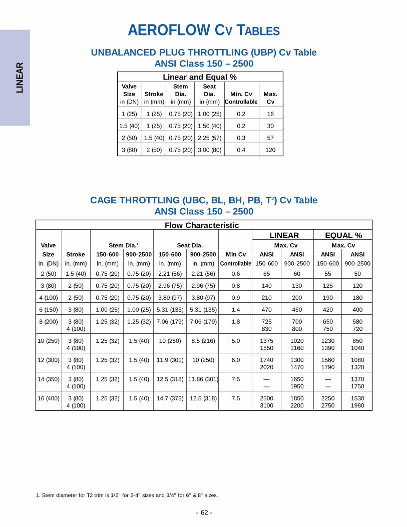
LIN
EAR
- 62 -
Flow CharacteristicLINEAR EQUAL %
Valve Stem Dia.1 Seat Dia. Max. Cv Max. Cv
Size Stroke 150-600 900-2500 150-600 900-2500 Min Cv ANSI ANSI ANSI ANSI
in. (DN) in. (mm) in. (mm) in. (mm) in. (mm) in. (mm) Controllable 150-600 900-2500 150-600 900-2500
2 (50) 1.5 (40) 0.75 (20) 0.75 (20) 2.21 (56) 2.21 (56) 0.6 65 60 55 50
3 (80) 2 (50) 0.75 (20) 0.75 (20) 2.96 (75) 2.96 (75) 0.8 140 130 125 120
4 (100) 2 (50) 0.75 (20) 0.75 (20) 3.80 (97) 3.80 (97) 0.9 210 200 190 180
6 (150) 3 (80) 1.00 (25) 1.00 (25) 5.31 (135) 5.31 (135) 1.4 470 450 420 400
8 (200) 3 (80) 1.25 (32) 1.25 (32) 7.06 (179) 7.06 (179) 1.8 725 700 650 5804 (100) 830 800 750 720
10 (250) 3 (80) 1.25 (32) 1.5 (40) 10 (250) 8.5 (216) 5.0 1375 1020 1230 8504 (100) 1550 1160 1390 1040
12 (300) 3 (80) 1.25 (32) 1.5 (40) 11.9 (301) 10 (250) 6.0 1740 1300 1560 10804 (100) 2020 1470 1790 1320
14 (350) 3 (80) 1.25 (32) 1.5 (40) 12.5 (318) 11.86 (301) 7.5 — 1650 — 13704 (100) — 1950 — 1750
16 (400) 3 (80) 1.25 (32) 1.5 (40) 14.7 (373) 12.5 (318) 7.5 2500 1850 2250 15304 (100) 3100 2200 2750 1980
UNBALANCED PLUG THROTTLING (UBP) Cv Table ANSI Class 150 – 2500
Linear and Equal %Valve Stem SeatSize Stroke Dia. Dia. Min. Cv Max.
in (DN) in (mm) in (mm) in (mm) Controllable Cv
1 (25) 1 (25) 0.75 (20) 1.00 (25) 0.2 16
1.5 (40) 1 (25) 0.75 (20) 1.50 (40) 0.2 30
2 (50) 1.5 (40) 0.75 (20) 2.25 (57) 0.3 57
3 (80) 2 (50) 0.75 (20) 3.00 (80) 0.4 120
CAGE THROTTLING (UBC, BL, BH, PB, T2) Cv Table ANSI Class 150 – 2500
AEROFLOW CV TABLES
1. Stem diameter for T2 trim is 1/2" for 2-4" sizes and 3/4" for 6" & 8" sizes.
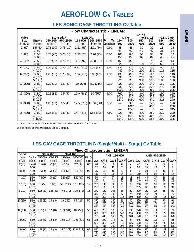
Flow Characteristic - LINEAR∆P/P1
Valve Stem Dia.1 Seat Dia. ≤ 0.6 >0.6 ≤ 0.8 >0.8 ≤ 0.992
Size Stroke 150-600 900-2500 150-600 900-2500 Min. Cv 150- 900- 150- 900- 150- 900-in (DN) in (mm) in (mm) in (mm) in (mm) in (mm) Controllable 600 2500 600 2500 600 25002 (50) 1.5 (40) 0.75 (20) 0.75 (20) 2.21 (56) 2.21 (56) 0.60 45 45 30 30 15 15
2 (50) 60 60 40 40 23 233 (80) 2 (50) 0.75 (20) 0.75 (20) 2.96 (75) 2.96 (75) 0.80 100 100 55 55 30 30
3 (80) 150 150 82 82 45 454 (100) 2 (50) 0.75 (20) 0.75 (20) 3.80 (97) 3.80 (97) 0.90 150 150 75 75 40 40
3 (80) 225 225 110 110 60 606 (150) 3 (80) 1.00 (25) 1.00 (25) 5.31 (135) 5.31 (135) 1.40 330 330 150 150 85 85
4 (100) 440 440 200 200 115 1158 (200) 3 (80) 1.25 (32) 1.25 (32) 7.06 (179) 7.06 (179) 1.80 430 430 200 200 110 110
4 (100) 530 530 265 265 150 1505 (125) 720 720 330 330 180 180
10 (250) 3 (80) 1.25 (32) 1.5 (40) 10 (250) 8.5 (216) 5.02 620 535 280 240 160 1354 (100) 830 720 375 320 210 1805 (125) 1030 890 470 400 270 225
12 (300) 3 (80) 1.25 (32) 1.5 (40) 11.9 (301) 10 (250) 6.00 760 620 340 280 190 1604 (100) 1010 830 450 375 250 2105 (125) 1270 1030 570 470 315 270
14 (350) 3 (80) 1.25 (32) 1.5 (40) 12.5 (318) 11.86 (301) 7.50 — 760 — 340 — 1904 (100) — 1010 — 450 — 2505 (125) — 1270 — 570 — 315
16 (400) 3 (80) 1.25 (32) 1.5 (40) 14.7 (373) 12.5 (318) 7.50 920 790 410 350 230 2004 (100) 1230 1060 550 465 310 2705 (125) 1540 1320 690 585 390 335
LIN
EAR
- 63 -
LES-CAV CAGE THROTTLING (Single/Multi - Stage) Cv TableFlow Characteristic - LINEAR
Valve Stem Dia.1 Seat Dia.Size Stroke 150-600 900-2500 150-600 900-2500 Min.Cv
ANSI 150-600 ANSI 900-2500
in (DN) in (mm) in (mm) in (mm) in (mm) in (mm) Contr. CAV I CAV II CAV III CAV IV CAV V CAV I CAV II CAV III CAV IV CAV V2 (50) 1.5 (40) .75 (20) .75 (20) 2.2 (56) 2.2 (56) 0.6 40 15 9 6 4 40 15 9 6 4
2 (50) 52 20 12 7 6 52 20 12 7 63 (80) 2 (50) .75 (20) .75 (20) 2.96 (75) 2.96 (75) 0.8 75 28 18 10 8 75 28 18 10 8
3 (80) 110 48 28 14 12 110 48 28 14 124 (100) 2 (50) .75 (20) .75 (20) 3.80 (97) 3.80 (97) 0.9 95 45 27 18 13 95 45 27 18 13
3 (80) 140 68 41 26 22 140 68 41 26 226 (150) 3 (80) 1 (25) 1 (25) 5.31 (135) 5.31 (135) 1.4 200 110 58 38 28 200 110 58 38 28
4 (100) 265 145 80 50 38 265 145 80 50 388 (200) 3 (80) 1.25 (32) 1.25 (32) 7.06 (179) 7.06 (179) 1.8 270 150 106 58 50 270 150 106 58 50
4 (100) 340 225 140 87 75 340 225 140 87 755 (125) 430 300 180 116 100 430 300 180 116 100
10 (250) 3 (80) 1.25 (32) 1.5 (40) 10 (250) 8.5 (216) 5.0 370 210 150 81 70 320 185 127 70 604 (100) 490 280 195 122 106 425 250 168 104 905 (125) 620 350 250 162 140 530 310 215 140 120
12 (300) 3 (80) 1.25 (32) 1.5 (40) 11.9 (301) 10 (250) 5.6 450 250 178 97 84 370 210 150 81 704 (100) 600 330 235 146 126 490 280 195 122 1065 (125) 750 415 300 195 168 620 350 250 162 140
14 (350) 3 (80) 1.25 (32) 1.5 (40) 12.5 (318) 11.86 (301) 6.6 345 250 178 97 84 345 250 178 97 844 (100) 580 330 235 146 126 580 330 235 146 1265 (125) 730 415 300 195 168 730 415 300 195 168
16 (400) 3 (80) 1.25 (32) 1.5 (40) 14.7 (373) 12.5 (318) 6.9 550 310 220 120 104 470 260 187 103 884 (100) 730 410 290 180 150 630 345 248 154 1335 (125) 910 515 370 240 200 780 430 320 205 177
LES-SONIC CAGE THROTTLING Cv Table
AEROFLOW CV TABLES
1. Stem diameter for T2 trim is 1/2" for 2-4" sizes and 3/4" for 6" size.
2. For ratios above .9 consult Leslie Controls.
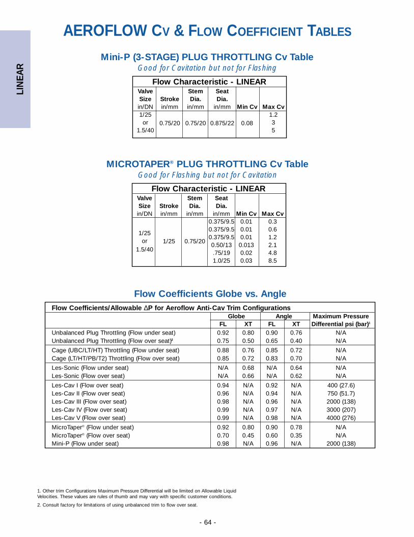
LIN
EAR
- 64 -
Mini-P (3-STAGE) PLUG THROTTLING Cv TableGood for Cavitation but not for Flashing
Flow Characteristic - LINEARValve Stem SeatSize Stroke Dia. Dia.in/DN in/mm in/mm in/mm Min Cv Max Cv1/25 1.2or 0.75/20 0.75/20 0.875/22 0.08 3
1.5/40 5
Flow Characteristic - LINEARValve Stem SeatSize Stroke Dia. Dia.in/DN in/mm in/mm in/mm Min Cv Max Cv
0.375/9.5 0.01 0.30.375/9.5 0.01 0.6
1/251/25 0.75/20
0.375/9.5 0.01 1.2or
0.50/13 0.013 2.11.5/40 .75/19 0.02 4.8
1.0/25 0.03 8.5
Flow Coefficients Globe vs. AngleFlow Coefficients/Allowable ∆P for Aeroflow Anti-Cav Trim Configurations
Globe Angle Maximum PressureFL XT FL XT Differential psi (bar)1
Unbalanced Plug Throttling (Flow under seat) 0.92 0.80 0.90 0.76 N/AUnbalanced Plug Throttling (Flow over seat)2 0.75 0.50 0.65 0.40 N/A
Cage (UBC/LT/HT) Throttling (Flow under seat) 0.88 0.76 0.85 0.72 N/ACage (LT/HT/PB/T2) Throttling (Flow over seat) 0.85 0.72 0.83 0.70 N/A
Les-Sonic (Flow under seat) N/A 0.68 N/A 0.64 N/ALes-Sonic (Flow over seat) N/A 0.66 N/A 0.62 N/A
Les-Cav I (Flow over seat) 0.94 N/A 0.92 N/A 400 (27.6)Les-Cav II (Flow over seat) 0.96 N/A 0.94 N/A 750 (51.7)Les-Cav III (Flow over seat) 0.98 N/A 0.96 N/A 2000 (138)Les-Cav IV (Flow over seat) 0.99 N/A 0.97 N/A 3000 (207)Les-Cav V (Flow over seat) 0.99 N/A 0.98 N/A 4000 (276)
MicroTaper® (Flow under seat) 0.92 0.80 0.90 0.78 N/AMicroTaper® (Flow over seat) 0.70 0.45 0.60 0.35 N/AMini-P (Flow under seat) 0.98 N/A 0.96 N/A 2000 (138)
1. Other trim Configurations Maximum Pressure Differential will be limited on Allowable LiquidVelocities. These values are rules of thumb and may vary with specific customer conditions.
2. Consult factory for limitations of using unbalanced trim to flow over seat.
MICROTAPER® PLUG THROTTLING Cv TableGood for Flashing but not for Cavitation
AEROFLOW CV & FLOW COEFFICIENT TABLES

LIN
EAR
- 65 -
WedgeSeal™ Packing SystemThe WedgeSeal packingsystem reduces stem friction and gland loads.The WedgeSeal arrange-ment transfers glandforce with predictableprecision. Patented,WedgeSeal sealing ringsare available in low fric-tion, PTFE mesh overgraphite construction orpure graphite. Both meet API 589 Fire Test requirements.
CHESTERTON WedgeSeal™ SOLUTIONS
MAXIMUM SEALABILITY• Transfers gland force efficiently to enhance sealing
• Packing volume loss and relaxation is minimized with low PTFE content
VALVE RESPONSIVENESS
• Combines the friction characteristics of PTFE with the physical characteristics of graphite for unmatched performance. Step response below 1% is typical to maximize process control
• Minimizes valve hunting and improves process quality and production yields
CONSISTENT PERFORMANCE
• Engineered sets ensure valve performance and repeatablility
• Wiper rings are available for abrasive service
MAINTENANCE FREE
• Valve live loading stores 800% more elastic energyto maintain optimized gland load
• Frequent valve adjustments are eliminated
Leslie Controls PROTECTS YOUR VALVE INVESTMENTwith a leak free WedgeSeal packing system
from Chesterton00
STANDARD PACKING CONFIGURATIONSLAMINATED GRAPHITE (LG)Precision die-cut laminated graphite rings provide a reliable, tightstem seal up to operating temperatures of 1050ºF (565ºC).
BRAIDED TEFLON GRAPHITE (BTG)Split rings allow packing replacement without removal of actuator.Graphite impregnated PTFE provides 500ºF (260ºC) service temper-ature, better “memory” and sealing than pure PTFE rings, loweredstem hysteresis, and is ideal for fluids that contain suspended parti-cles.
DOUBLE PTFE V-RINGAlso available.
LG BTG
WedgeSeal Packing System for temperatures
greater than 230ºC (450ºF)
1724E PTFESealing System for maximum
chemical compatability
COMMON AIR OPERATED VALVE CONCERNS
VALVE LEAKAGE• Frequent stem actuation can cause loss of packing
gland load that leads to stem leakage.
• PTFE v-rings will relax and wear in service. Braided packing will consolidate in-service and lose gland load.
POOR VALVE RESPONSIVENESS• Control valve responsiveness is critical to process
quality and control. High packing friction from graphiterings causes poor step response and process control, especially in lower temperature valves.
• Friction causes valves to constantly hunt for the correct position resulting in continuous stem actuation.
VARIATIONS IN VALVE PERFORMANCE• Variations in packing friction can cause unit start-up
problems. Inconsistent gland loading and sealing system designs can be factors.
FREQUENT VALVE ADJUSTMENTS• Tightening packing glands in the field to reduce valve
leakage can be all too common. Once tightened, uncontrolled packing friction can limit operability.
POOR VALVE RELIABILITY• Poor control valve reliability can have a dramatic affect
on production costs, even before it is removed from service. Removing control valves from service can be expensive.
Low overall PTFE content
increases thermal stability
1/4" Thick LesliePacking Box Ring
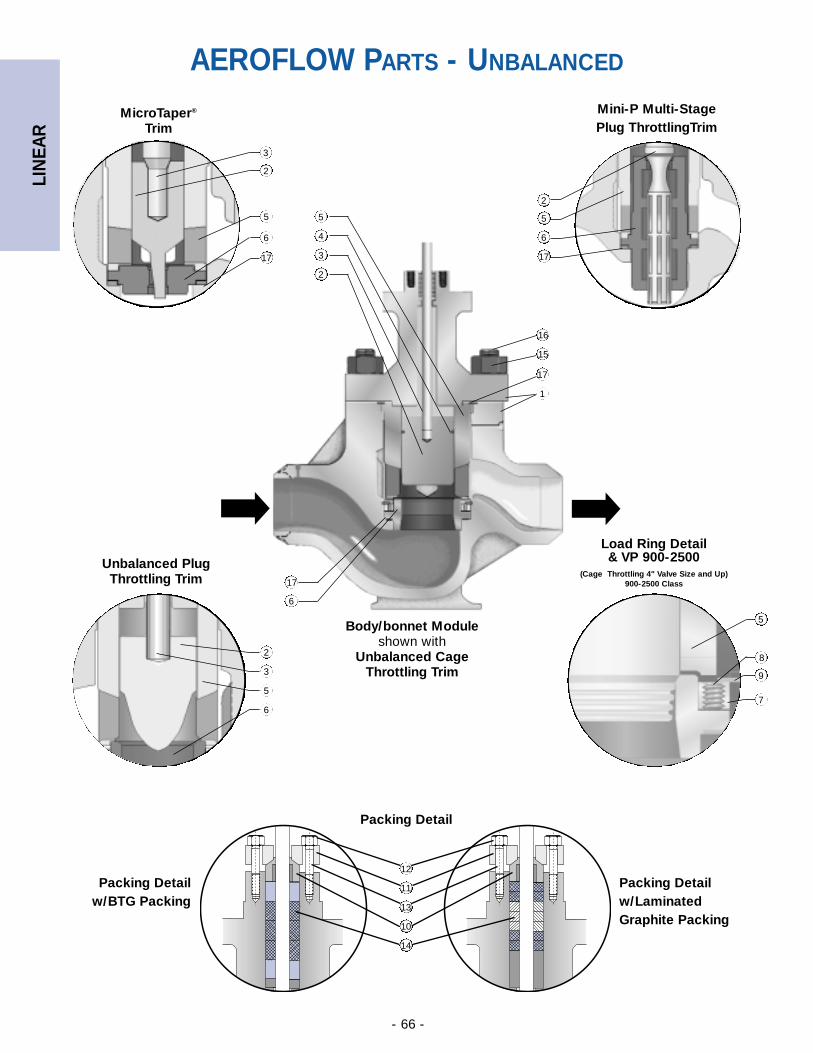
LIN
EAR
- 66 -
17
12
17
2
10
11
13
14
2
1
3
4
5
3
5
6
17
2
3
5
6
2
6
5
17
16
15
MicroTaper®
Trim
Packing Detail
Unbalanced Plug Throttling Trim
Body/bonnet Moduleshown with
Unbalanced CageThrottling Trim
Load Ring Detail& VP 900-2500
(Cage Throttling 4" Valve Size and Up)900-2500 Class
Mini-P Multi-StagePlug ThrottlingTrim
➡ ➡
6
AEROFLOW PARTS - UNBALANCED
Packing Detail w/BTG Packing
Packing Detail w/LaminatedGraphite Packing
8
9
5
7
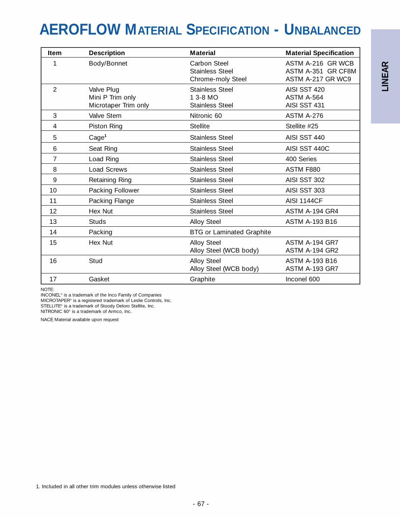
LIN
EAR
- 67 -
1. Included in all other trim modules unless otherwise listed
Item Description Material Material Specification
1 Body/Bonnet Carbon Steel ASTM A-216 GR WCBStainless Steel ASTM A-351 GR CF8MChrome-moly Steel ASTM A-217 GR WC9
2 Valve Plug Stainless Steel AISI SST 420Mini P Trim only 1 3-8 MO ASTM A-564Microtaper Trim only Stainless Steel AISI SST 431
3 Valve Stem Nitronic 60 ASTM A-276
4 Piston Ring Stellite Stellite #25
5 Cage1 Stainless Steel AISI SST 440
6 Seat Ring Stainless Steel AISI SST 440C
7 Load Ring Stainless Steel 400 Series
8 Load Screws Stainless Steel ASTM F880
9 Retaining Ring Stainless Steel AISI SST 302
10 Packing Follower Stainless Steel AISI SST 303
11 Packing Flange Stainless Steel AISI 1144CF
12 Hex Nut Stainless Steel ASTM A-194 GR4
13 Studs Alloy Steel ASTM A-193 B16
14 Packing BTG or Laminated Graphite
15 Hex Nut Alloy Steel ASTM A-194 GR7Alloy Steel (WCB body) ASTM A-194 GR2
16 Stud Alloy Steel ASTM A-193 B16Alloy Steel (WCB body) ASTM A-193 GR7
17 Gasket Graphite Inconel 600
AEROFLOW MATERIAL SPECIFICATION - UNBALANCED
NOTE:INCONEL® is a trademark of the Inco Family of CompaniesMICROTAPER® is a registered trademark of Leslie Controls, Inc.STELLITE® is a trademark of Stoody Deloro Stellite, Inc.NITRONIC 60® is a trademark of Armco, Inc.
NACE Material available upon request
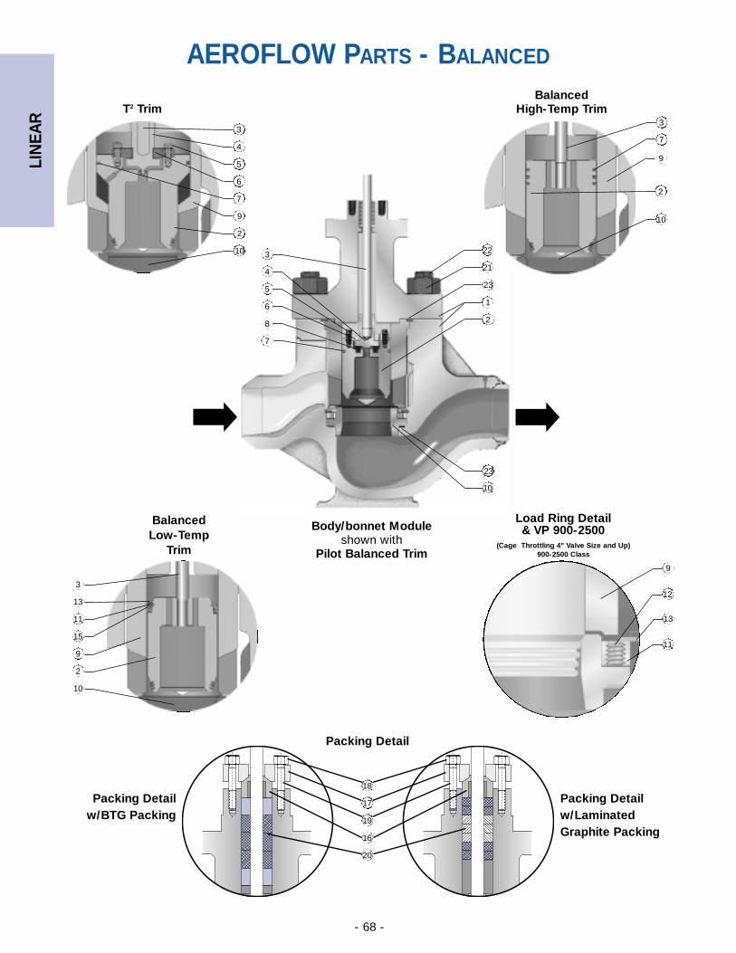
LIN
EAR
- 68 -
9
2
10
4
5
6
7
3
11
13
3
15
2
9
10
3
2
7
10
9
Balanced High-Temp Trim
Load Ring Detail& VP 900-2500
(Cage Throttling 4" Valve Size and Up)900-2500 Class
Body/bonnet Moduleshown with
Pilot Balanced Trim
T2 Trim
Balanced Low-Temp
Trim
13
23
10
12
9
23
22
21
28
7
1
5
6
3
4
➡➡
AEROFLOW PARTS - BALANCED
18
16
17
19
20
Packing Detail
Packing Detail w/BTG Packing
Packing Detail w/LaminatedGraphite Packing
11
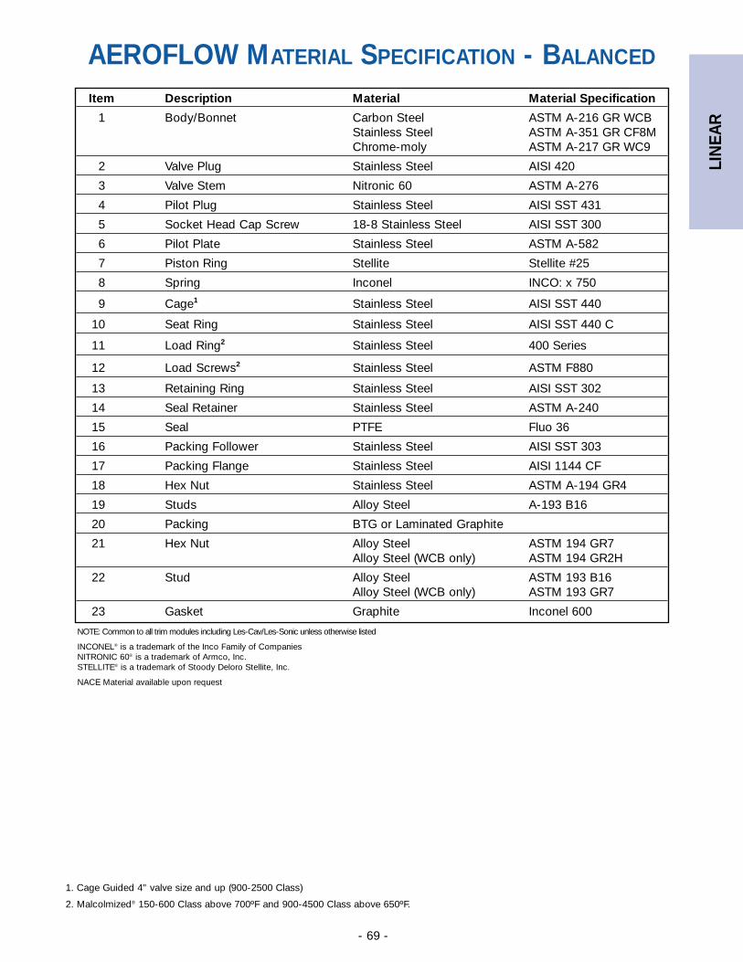
LIN
EAR
- 69 -
NOTE: Common to all trim modules including Les-Cav/Les-Sonic unless otherwise listed
INCONEL® is a trademark of the Inco Family of CompaniesNITRONIC 60® is a trademark of Armco, Inc.STELLITE® is a trademark of Stoody Deloro Stellite, Inc.
NACE Material available upon request
Item Description Material Material Specification
1 Body/Bonnet Carbon Steel ASTM A-216 GR WCBStainless Steel ASTM A-351 GR CF8MChrome-moly ASTM A-217 GR WC9
2 Valve Plug Stainless Steel AISI 420
3 Valve Stem Nitronic 60 ASTM A-276
4 Pilot Plug Stainless Steel AISI SST 431
5 Socket Head Cap Screw 18-8 Stainless Steel AISI SST 300
6 Pilot Plate Stainless Steel ASTM A-582
7 Piston Ring Stellite Stellite #25
8 Spring Inconel INCO: x 750
9 Cage1 Stainless Steel AISI SST 440
10 Seat Ring Stainless Steel AISI SST 440 C
11 Load Ring2 Stainless Steel 400 Series
12 Load Screws2 Stainless Steel ASTM F880
13 Retaining Ring Stainless Steel AISI SST 302
14 Seal Retainer Stainless Steel ASTM A-240
15 Seal PTFE Fluo 36
16 Packing Follower Stainless Steel AISI SST 303
17 Packing Flange Stainless Steel AISI 1144 CF
18 Hex Nut Stainless Steel ASTM A-194 GR4
19 Studs Alloy Steel A-193 B16
20 Packing BTG or Laminated Graphite
21 Hex Nut Alloy Steel ASTM 194 GR7Alloy Steel (WCB only) ASTM 194 GR2H
22 Stud Alloy Steel ASTM 193 B16Alloy Steel (WCB only) ASTM 193 GR7
23 Gasket Graphite Inconel 600
AEROFLOW MATERIAL SPECIFICATION - BALANCED
1. Cage Guided 4" valve size and up (900-2500 Class)
2. Malcolmized® 150-600 Class above 700ºF and 900-4500 Class above 650ºF.
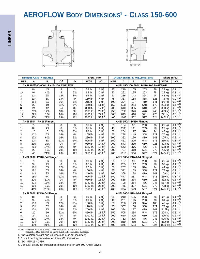
LIN
EAR
- 70 -
DIMENSIONS IN INCHES Shpg. Info.1 DIMENSIONS IN MILLIMETERS Shpg. Info.1
SIZE A B C2 D WGT. VOL. SIZE A B C2 D WGT. VOL.
1 81⁄4 41⁄8 8 3 53 lb. 2 ft3 25 210 105 203 76 24 kg 0.1 m3
11⁄2 97⁄8 415⁄16 8 31⁄16 63 lb. 2 ft3 40 251 125 203 78 29 kg 0.1 m3
2 111⁄4 55⁄8 123⁄4 311⁄16 94 lb. 3 ft3 50 286 143 324 94 43 kg 0.1 m3
3 131⁄4 65⁄8 141⁄2 43⁄4 160 lb. 4 ft3 75 337 168 368 121 73 kg 0.2 m3
4 151⁄2 73⁄4 161⁄2 59⁄16 215 lb. 6 ft3 100 394 197 419 141 98 kg 0.2 m3
6 20 10 219⁄16 613⁄16 450 lb. 11 ft3 150 508 254 548 173 204 kg 0.4 m3
8 24 12 24 87⁄8 860 lb. 17 ft3 200 610 305 610 225 390 kg 0.5 m3
10 295⁄8 1413⁄16 183⁄4 93⁄4 1100 lb. 22 ft3 250 752 376 476 248 499 kg 0.6 m3
12 321⁄4 161⁄8 201⁄2 103⁄4 1700 lb. 27 ft3 300 819 410 521 273 771 kg 0.8 m3
16 435⁄8 2113⁄16 231⁄2 123⁄4 3200 lb. 53 ft3 400 1108 552 597 324 1451 kg 1.5 m3
1 71⁄4 35⁄8 8 3 56 lb. 2 ft3 25 184 92 203 76 25 kg 0.1 m3
11⁄2 83⁄4 43⁄8 8 31⁄16 65 lb. 2 ft3 40 222 111 203 78 29 kg 0.1 m3
2 10 5 123⁄4 311⁄16 95 lb. 3 ft3 50 284 127 324 94 43 kg 0.1 m3
3 113⁄4 57⁄8 141⁄2 43⁄4 155 lb. 4 ft3 75 298 149 368 121 70 kg 0.1 m3
4 137⁄8 615⁄16 161⁄2 59⁄16 230 lb. 5 ft3 100 352 176 419 141 105 kg 0.3 m3
6 173⁄4 87⁄8 219⁄16 613⁄16 505 lb. 9 ft3 150 451 225 548 173 230 kg 0.3 m3
8 213⁄8 105⁄8 24 87⁄8 930 lb. 14 ft3 200 543 270 610 225 423 kg 0.4 m3
10 261⁄2 1413⁄16 183⁄4 93⁄4 1120 lb. 18 ft3 250 673 376 476 248 508 kg 0.5 m3
12 29 161⁄8 201⁄2 103⁄4 1730 lb. 23 ft3 300 737 410 521 273 785 kg 0.7 m3
16 40 2113⁄16 231⁄2 123⁄4 3250 lb. 46 ft3 400 1016 554 597 324 1474 kg 1.3 m3
1 73⁄4 37⁄8 8 3 58 lb. 2 ft3 25 197 98 203 76 26 kg 0.1 m3
11⁄2 91⁄4 45⁄8 8 31⁄16 67 lb. 2 ft3 40 235 117 203 78 30 kg 0.1 m3
2 101⁄2 51⁄4 123⁄4 311⁄16 97 lb. 3 ft3 50 267 133 324 94 44 kg 0.1 m3
3 121⁄2 61⁄4 141⁄2 43⁄4 160 lb. 4 ft3 75 311 159 368 121 73 kg 0.1 m3
4 141⁄2 71⁄4 161⁄2 59⁄16 240 lb. 6 ft3 100 368 184 419 141 109 kg 0.2 m3
6 185⁄8 95⁄16 219⁄16 613⁄16 525 lb. 10 ft3 150 473 237 548 173 239 kg 0.3 m3
8 223⁄8 113⁄16 24 87⁄8 950 lb. 15 ft3 200 568 284 610 225 432 kg 0.5 m3
10 277⁄8 1315⁄16 183⁄4 93⁄4 1140 lb. 20 ft3 250 708 354 476 248 517 kg 0.6 m3
12 301⁄2 151⁄4 201⁄2 103⁄4 1760 lb. 25 ft3 300 775 387 521 273 798 kg 0.7 m3
16 415⁄8 2013⁄16 231⁄2 123⁄4 3300 lb. 49 ft3 400 1057 529 597 324 1497 kg 1.4 m3
1 81⁄4 41⁄8 8 3 59 lb. 2 ft3 25 210 105 203 76 27 kg 0.1 m3
11⁄2 97⁄8 415⁄16 8 31⁄16 69 lb. 2 ft3 40 251 125 203 78 31 kg 0.1 m3
2 111⁄4 55⁄8 123⁄4 311⁄16 100 lb. 3 ft3 50 286 143 324 100 45 kg 0.1 m3
3 131⁄4 65⁄8 141⁄2 43⁄4 170 lb. 4 ft3 75 337 168 368 121 77 kg 0.2 m3
4 151⁄2 73⁄4 157⁄8 59⁄16 260 lb. 6 ft3 100 394 197 419 141 118kg 0.2 m3
6 20 10 219⁄16 613⁄16 450 lb. 11 ft3 150 508 254 548 173 204 kg 0.3 m3
8 24 12 24 87⁄8 1000 lb. 17 ft3 200 610 305 610 225 390 kg 0.5 m3
10 295⁄8 1413⁄16 183⁄4 93⁄4 1160 lb. 22 ft3 250 752 376 476 248 526 kg 0.6 m3
12 321⁄4 161⁄8 201⁄2 103⁄4 1740 lb. 28 ft3 300 819 410 521 273 812 kg 0.8 m3
16 435⁄8 2113⁄16 231⁄2 123⁄4 3350 lb. 53 ft3 400 1108 554 597 324 1520 kg 1.5 m3
NOTE: DIMENSIONS ARE SUBJECT TO CHANGE WITHOUT NOTICE. Request certified drawings for piping layout and construction purposes.
ANSI 150/300/600# PN16-100 BWE/SWE ANSI 150/300/600# PN16-100 BWE/SWE
ANSI 150# PN16 Flanged ANSI 150# PN16 Flanged
ANSI 300# PN40-64 Flanged ANSI 300# PN40-64 Flanged
ANSI 600# PN40-64 Flanged ANSI 600# PN40-64 Flanged
AEROFLOW BODY DIMENSIONS3 - CLASS 150-600
1. Approximate weight and volume (actuator not included)2. Consult factory for extended travel (C dimension)3. ISA - 575.15 - 19864. Consult Factory for installation dimensions for 150-600 Angle Valves
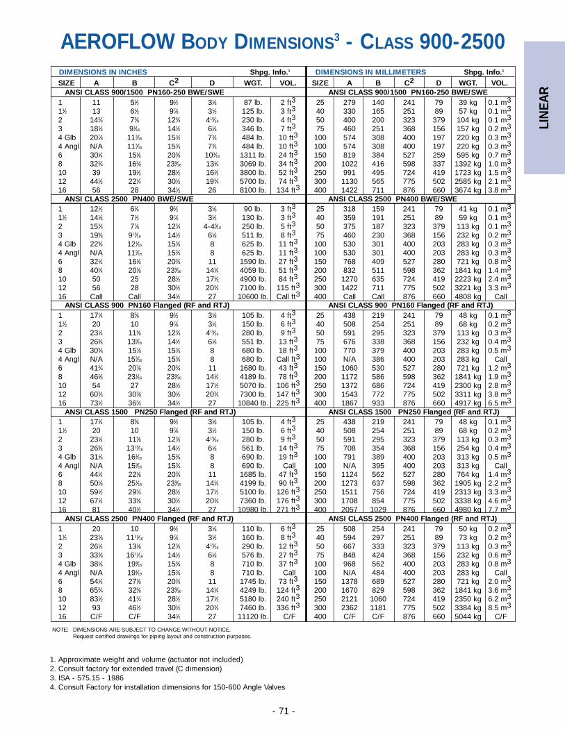
LIN
EAR
- 71 -
DIMENSIONS IN INCHES Shpg. Info.1 DIMENSIONS IN MILLIMETERS Shpg. Info.1
SIZE A B C2 D WGT. VOL. SIZE A B C2 D WGT. VOL.
1 11 51⁄2 91⁄2 31⁄8 87 lb. 2 ft3 25 279 140 241 79 39 kg 0.1 m3
11⁄2 13 61⁄2 97⁄8 31⁄2 125 lb. 3 ft3 40 330 165 251 89 57 kg 0.1 m3
2 143⁄4 73⁄8 123⁄4 415⁄16 230 lb. 4 ft3 50 400 200 323 379 104 kg 0.1 m3
3 181⁄8 91⁄16 141⁄2 61⁄8 346 lb. 7 ft3 75 460 251 368 156 157 kg 0.2 m3
4 Glb 207⁄8 113⁄16 153⁄4 73⁄4 484 lb. 10 ft3 100 574 308 400 197 220 kg 0.3 m3
4 Angl N/A 113⁄16 153⁄4 73⁄4 484 lb. 10 ft3 100 574 308 400 197 220 kg 0.3 m3
6 301⁄4 151⁄8 203⁄4 103⁄16 1311 lb. 24 ft3 150 819 384 527 259 595 kg 0.7 m3
8 323⁄4 163⁄8 239⁄16 131⁄4 3069 lb. 34 ft3 200 1022 416 598 337 1392 kg 1.0 m3
10 39 191⁄2 281⁄2 161⁄2 3800 lb. 52 ft3 250 991 495 724 419 1723 kg 1.5 m3
12 441⁄2 221⁄4 301⁄2 193⁄4 5700 lb. 74 ft3 300 1130 565 775 502 2585 kg 2.1 m3
16 56 28 341⁄2 26 8100 lb. 134 ft3 400 1422 711 876 660 3674 kg 3.8 m3
1 121⁄2 61⁄4 91⁄2 31⁄8 90 lb. 3 ft3 25 318 159 241 79 41 kg 0.1 m3
11⁄2 141⁄8 71⁄2 97⁄8 31⁄2 130 lb. 3 ft3 40 359 191 251 89 59 kg 0.1 m3
2 153⁄4 77⁄8 123⁄4 4-45⁄16 250 lb. 5 ft3 50 375 187 323 379 113 kg 0.1 m3
3 195⁄8 913⁄16 141⁄2 61⁄8 511 lb. 8 ft3 75 460 230 368 156 232 kg 0.2 m3
4 Glb 225⁄8 121⁄16 153⁄4 8 625 lb. 11 ft3 100 530 301 400 203 283 kg 0.3 m3
4 Angl N/A 115⁄16 153⁄4 8 625 lb. 11 ft3 100 530 301 400 203 283 kg 0.3 m3
6 321⁄4 161⁄8 203⁄4 11 1590 lb. 27 ft3 150 768 409 527 280 721 kg 0.8 m3
8 401⁄4 201⁄8 239⁄16 141⁄4 4059 lb. 51 ft3 200 832 511 598 362 1841 kg 1.4 m3
10 50 25 281⁄2 171⁄2 4900 lb. 84 ft3 250 1270 635 724 419 2223 kg 2.4 m3
12 56 28 301⁄2 203⁄4 7100 lb. 115 ft3 300 1422 711 775 502 3221 kg 3.3 m3
16 Call Call 341⁄2 27 10600 lb. Call ft3 400 Call Call 876 660 4808 kg Call
1 171⁄4 85⁄8 91⁄2 31⁄8 105 lb. 4 ft3 25 438 219 241 79 48 kg 0.1 m3
11⁄2 20 10 97⁄8 31⁄2 150 lb. 6 ft3 40 508 254 251 89 68 kg 0.2 m3
2 231⁄4 115⁄8 123⁄4 415⁄16 280 lb. 9 ft3 50 591 295 323 379 113 kg 0.3 m3
3 265⁄8 135⁄16 141⁄2 61⁄8 551 lb. 13 ft3 75 676 338 368 156 232 kg 0.4 m3
4 Glb 303⁄8 157⁄8 153⁄4 8 680 lb. 18 ft3 100 770 379 400 203 283 kg 0.5 m3
4 Angl N/A 153⁄16 153⁄4 8 680 lb. Call ft3 100 N/A 386 400 203 283 kg Call6 413⁄4 207⁄8 203⁄4 11 1680 lb. 43 ft3 150 1060 530 527 280 721 kg 1.2 m3
8 461⁄8 231⁄16 239⁄16 141⁄4 4189 lb. 78 ft3 200 1172 586 598 362 1841 kg 1.9 m3
10 54 27 281⁄2 171⁄2 5070 lb. 106 ft3 250 1372 686 724 419 2300 kg 2.8 m3
12 603⁄4 303⁄8 301⁄2 203⁄4 7300 lb. 147 ft3 300 1543 772 775 502 3311 kg 3.8 m3
16 731⁄2 363⁄4 341⁄2 27 10840 lb. 225 ft3 400 1867 933 876 660 4917 kg 6.5 m3
1 171⁄4 85⁄8 91⁄2 31⁄8 105 lb. 4 ft3 25 438 219 241 79 48 kg 0.1 m3
11⁄2 20 10 97⁄8 31⁄2 150 lb. 6 ft3 40 508 254 251 89 68 kg 0.2 m3
2 231⁄4 115⁄8 123⁄4 415⁄16 280 lb. 9 ft3 50 591 295 323 379 113 kg 0.3 m3
3 265⁄8 1315⁄16 141⁄2 61⁄8 561 lb. 14 ft3 75 708 354 368 156 254 kg 0.4 m3
4 Glb 311⁄8 161⁄16 153⁄4 8 690 lb. 19 ft3 100 791 389 400 203 313 kg 0.5 m3
4 Angl N/A 159⁄16 153⁄4 8 690 lb. Call 100 N/A 395 400 203 313 kg Call6 441⁄4 221⁄8 203⁄4 11 1685 lb. 47 ft3 150 1124 562 527 280 764 kg 1.4 m3
8 501⁄8 251⁄16 239⁄16 141⁄4 4199 lb. 90 ft3 200 1273 637 598 362 1905 kg 2.2 m3
10 591⁄2 293⁄4 281⁄2 171⁄2 5100 lb. 126 ft3 250 1511 756 724 419 2313 kg 3.3 m3
12 671⁄4 335⁄8 301⁄2 203⁄4 7360 lb. 176 ft3 300 1708 854 775 502 3338 kg 4.6 m3
16 81 401⁄2 341⁄2 27 10980 lb. 271 ft3 400 2057 1029 876 660 4980 kg 7.7 m3
1 20 10 91⁄2 31⁄8 110 lb. 6 ft3 25 508 254 241 79 50 kg 0.2 m3
11⁄2 233⁄8 1111⁄16 97⁄8 31⁄2 160 lb. 8 ft3 40 594 297 251 89 73 kg 0.2 m3
2 261⁄4 131⁄8 123⁄4 415⁄16 290 lb. 12 ft3 50 667 333 323 379 113 kg 0.3 m3
3 333⁄8 1611⁄16 141⁄2 61⁄8 576 lb. 27 ft3 75 848 424 368 156 232 kg 0.6 m3
4 Glb 381⁄8 199⁄16 153⁄4 8 710 lb. 37 ft3 100 968 562 400 203 283 kg 0.8 m3
4 Angl N/A 191⁄16 153⁄4 8 710 lb. Call 100 N/A 484 400 203 283 kg Call6 541⁄4 271⁄8 203⁄4 11 1745 lb. 73 ft3 150 1378 689 527 280 721 kg 2.0 m3
8 653⁄4 325⁄8 239⁄16 141⁄4 4249 lb. 124 ft3 200 1670 829 598 362 1841 kg 3.6 m3
10 831⁄2 413⁄4 281⁄2 171⁄2 5180 lb. 240 ft3 250 2121 1060 724 419 2350 kg 6.2 m3
12 93 461⁄2 301⁄2 203⁄4 7460 lb. 336 ft3 300 2362 1181 775 502 3384 kg 8.5 m3
16 C/F C/F 341⁄2 27 11120 lb. C/F 400 C/F C/F 876 660 5044 kg C/F
NOTE: DIMENSIONS ARE SUBJECT TO CHANGE WITHOUT NOTICE. Request certified drawings for piping layout and construction purposes.
ANSI CLASS 1500 PN250 Flanged (RF and RTJ) ANSI CLASS 1500 PN250 Flanged (RF and RTJ)
ANSI CLASS 2500 PN400 Flanged (RF and RTJ) ANSI CLASS 2500 PN400 Flanged (RF and RTJ)
ANSI CLASS 900 PN160 Flanged (RF and RTJ) ANSI CLASS 900 PN160 Flanged (RF and RTJ)
ANSI CLASS 2500 PN400 BWE/SWE ANSI CLASS 2500 PN400 BWE/SWE
ANSI CLASS 900/1500 PN160-250 BWE/SWE ANSI CLASS 900/1500 PN160-250 BWE/SWE
AEROFLOW BODY DIMENSIONS3 - CLASS 900-2500
1. Approximate weight and volume (actuator not included)2. Consult factory for extended travel (C dimension)3. ISA - 575.15 - 19864. Consult Factory for installation dimensions for 150-600 Angle Valves
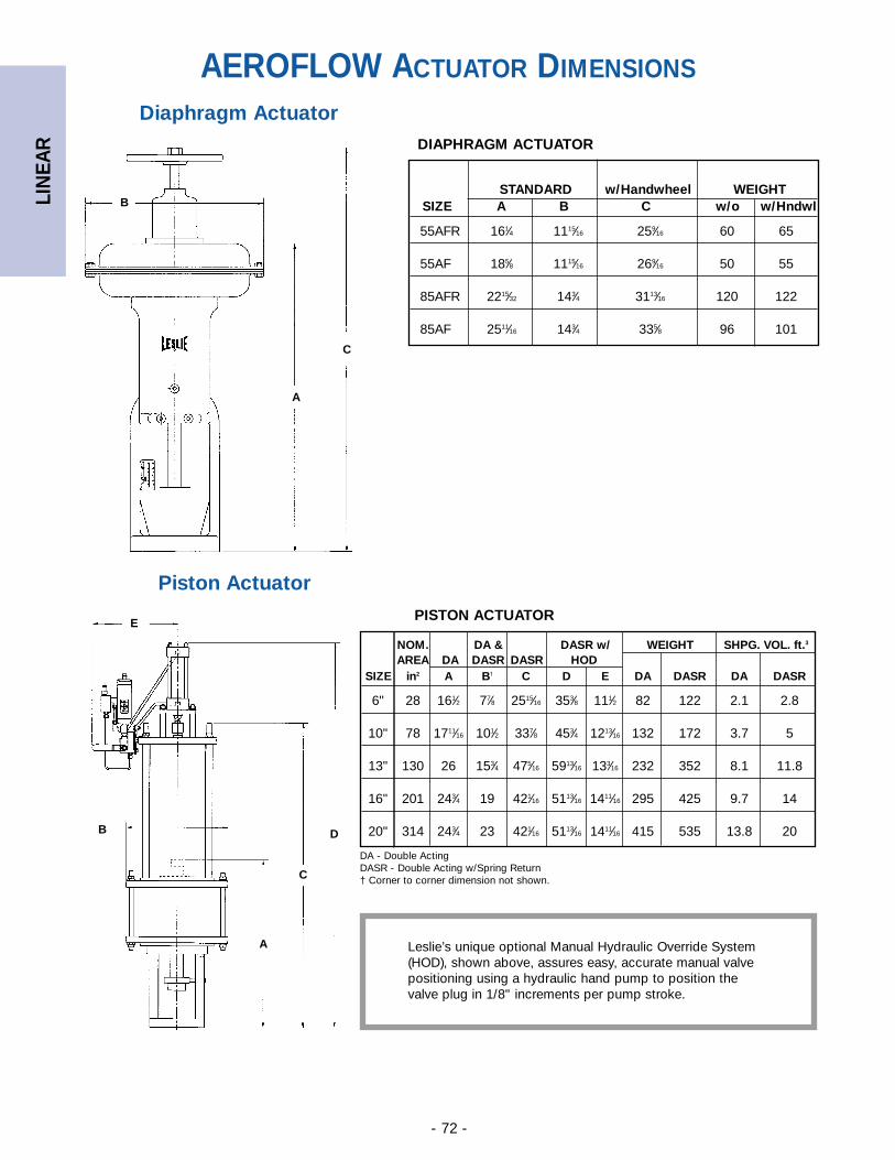
LIN
EAR
- 72 -
Diaphragm Actuator
Piston Actuator
STANDARD w/Handwheel WEIGHTSIZE A B C w/o w/Hndwl
55AFR 161⁄4 1115⁄16 259⁄16 60 65
55AF 185⁄8 1115⁄16 269⁄16 50 55
85AFR 2215⁄32 143⁄4 3113⁄16 120 122
85AF 2511⁄16 143⁄4 335⁄8 96 101
DIAPHRAGM ACTUATOR
NOM. DA & DASR w/ WEIGHT SHPG. VOL. ft.3
AREA DA DASR DASR HODSIZE in2 A B† C D E DA DASR DA DASR
6" 28 161⁄2 77⁄8 2515⁄16 353⁄8 111⁄2 82 122 2.1 2.8
10" 78 1711⁄16 101⁄2 337⁄8 453⁄4 1213⁄16 132 172 3.7 5
13" 130 26 153⁄4 475⁄16 5913⁄16 133⁄16 232 352 8.1 11.8
16" 201 243⁄4 19 421⁄16 5113⁄16 1411⁄16 295 425 9.7 14
20" 314 243⁄4 23 421⁄16 5113⁄16 1411⁄16 415 535 13.8 20
PISTON ACTUATOR
A
C
B
A
C
B D
E
Leslie’s unique optional Manual Hydraulic Override System(HOD), shown above, assures easy, accurate manual valvepositioning using a hydraulic hand pump to position thevalve plug in 1/8" increments per pump stroke.
DA - Double ActingDASR - Double Acting w/Spring Return† Corner to corner dimension not shown.
AEROFLOW ACTUATOR DIMENSIONS
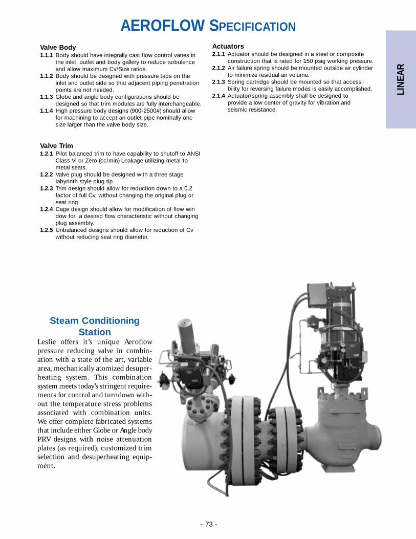
LIN
EAR
- 73 -
Valve Body1.1.1 Body should have integrally cast flow control vanes in
the inlet, outlet and body gallery to reduce turbulence and allow maximum Cv/Size ratios.
1.1.2 Body should be designed with pressure taps on the inlet and outlet side so that adjacent piping penetration points are not needed.
1.1.3 Globe and angle body configurations should be designed so that trim modules are fully interchangeable.
1.1.4 High pressure body designs (900-2500#) should allow for machining to accept an outlet pipe nominally one size larger than the valve body size.
Valve Trim1.2.1 Pilot balanced trim to have capability to shutoff to ANSI
Class Vl or Zero (cc/min) Leakage utilizing metal-to-metal seats.
1.2.2 Valve plug should be designed with a three stage labyrinth style plug tip.
1.2.3 Trim design should allow for reduction down to a 0.2 factor of full Cv, without changing the original plug or seat ring
1.2.4 Cage design should allow for modification of flow window for a desired flow characteristic without changing plug assembly.
1.2.5 Unbalanced designs should allow for reduction of Cv without reducing seat ring diameter.
Actuators2.1.1 Actuator should be designed in a steel or composite
construction that is rated for 150 psig working pressure.2.1.2 Air failure spring should be mounted outside air cylinder
to minimize residual air volume.2.1.3 Spring cartridge should be mounted so that accessi-
bility for reversing failure modes is easily accomplished.2.1.4 Actuator/spring assembly shall be designed to
provide a low center of gravity for vibration and seismic resistance.
Steam ConditioningStation
Leslie offers it’s unique Aeroflowpressure reducing valve in combin-ation with a state of the art, variablearea, mechanically atomized desuper-heating system. This combinationsystem meets today’s stringent require-ments for control and turndown with-out the temperature stress problemsassociated with combination units.We offer complete fabricated systemsthat include either Globe or Angle bodyPRV designs with noise attenuationplates (as required), customized trimselection and desuperheating equip-ment.
AEROFLOW SPECIFICATION
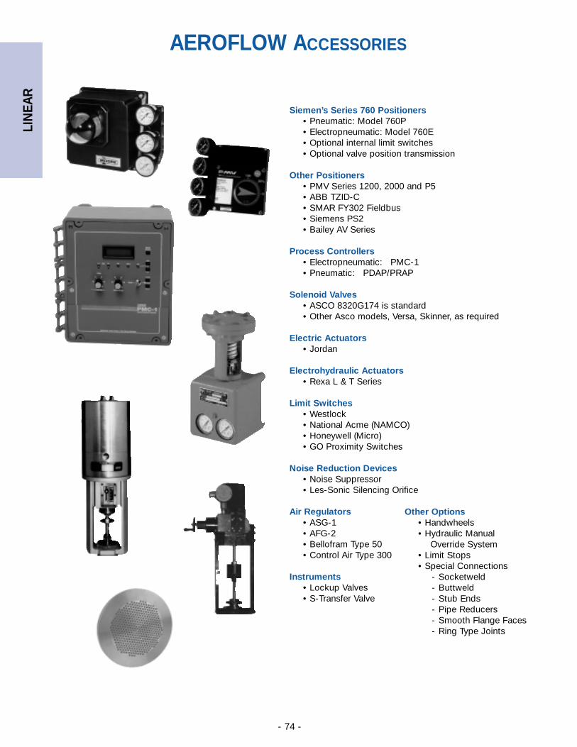
LIN
EAR
- 74 -
Siemen’s Series 760 Positioners• Pneumatic: Model 760P• Electropneumatic: Model 760E• Optional internal limit switches• Optional valve position transmission
Other Positioners• PMV Series 1200, 2000 and P5• ABB TZID-C• SMAR FY302 Fieldbus• Siemens PS2• Bailey AV Series
Process Controllers• Electropneumatic: PMC-1 • Pneumatic: PDAP/PRAP
Solenoid Valves• ASCO 8320G174 is standard• Other Asco models, Versa, Skinner, as required
Electric Actuators• Jordan
Electrohydraulic Actuators• Rexa L & T Series
Limit Switches• Westlock• National Acme (NAMCO)• Honeywell (Micro)• GO Proximity Switches
Noise Reduction Devices• Noise Suppressor• Les-Sonic Silencing Orifice
Air Regulators• ASG-1• AFG-2• Bellofram Type 50• Control Air Type 300
Instruments• Lockup Valves• S-Transfer Valve
Other Options• Handwheels• Hydraulic Manual
Override System• Limit Stops• Special Connections
- Socketweld- Buttweld- Stub Ends- Pipe Reducers- Smooth Flange Faces- Ring Type Joints
AEROFLOW ACCESSORIES
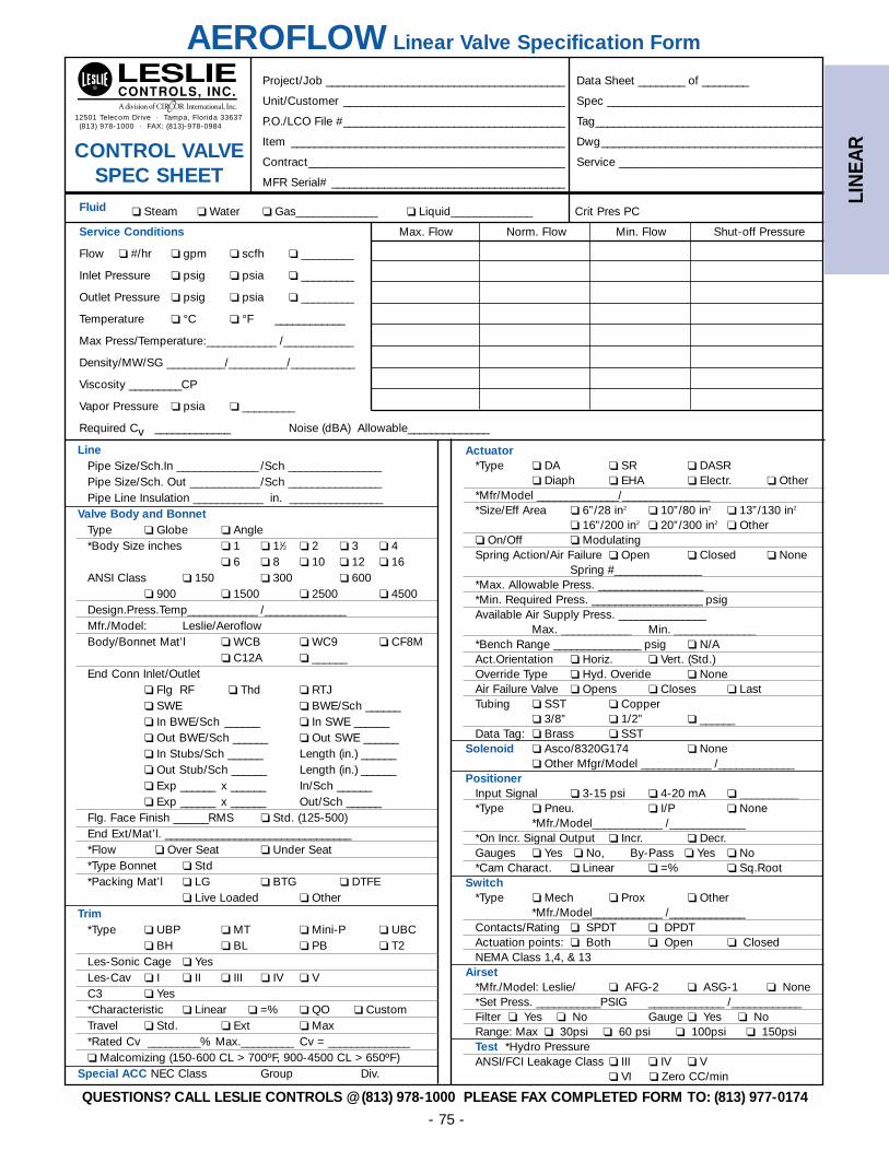
LIN
EAR
- 75 -
LinePipe Size/Sch.In ______________ /Sch ________________Pipe Size/Sch. Out ____________/Sch ________________Pipe Line Insulation ____________ in. ________________
Valve Body and BonnetType ❏ Globe ❏ Angle*Body Size inches ❏ 1 ❏ 11⁄2 ❏ 2 ❏ 3 ❏ 4
❏ 6 ❏ 8 ❏ 10 ❏ 12 ❏ 16ANSI Class ❏ 150 ❏ 300 ❏ 600
❏ 900 ❏ 1500 ❏ 2500 ❏ 4500Design.Press.Temp____________ /______________Mfr./Model: Leslie/AeroflowBody/Bonnet Mat’l ❏ WCB ❏ WC9 ❏ CF8M
❏ C12A ❏ ______End Conn Inlet/Outlet
❏ Flg RF ❏ Thd ❏ RTJ❏ SWE ❏ BWE/Sch ______❏ In BWE/Sch ______ ❏ In SWE ______❏ Out BWE/Sch ______ ❏ Out SWE ______❏ In Stubs/Sch ______ Length (in.) ______❏ Out Stub/Sch ______ Length (in.) ______❏ Exp ______ x ______ In/Sch ______❏ Exp ______ x ______ Out/Sch ______
Flg. Face Finish ______RMS ❏ Std. (125-500)End Ext/Mat’l. ________________________________*Flow ❏ Over Seat ❏ Under Seat*Type Bonnet ❏ Std*Packing Mat’l ❏ LG ❏ BTG ❏ DTFE
❏ Live Loaded ❏ OtherTrim
*Type ❏ UBP ❏ MT ❏ Mini-P ❏ UBC❏ BH ❏ BL ❏ PB ❏ T2
Les-Sonic Cage ❏ YesLes-Cav ❏ I ❏ II ❏ III ❏ IV ❏ VC3 ❏ Yes*Characteristic ❏ Linear ❏ =% ❏ QO ❏ CustomTravel ❏ Std. ❏ Ext ❏ Max*Rated Cv _________% Max._________ Cv = ______________❏ Malcomizing (150-600 CL > 700ºF, 900-4500 CL > 650ºF)
Special ACC NEC Class Group Div.
12501 Telecom Drive · Tampa, Florida 33637(813) 978-1000 · FAX: (813)-978-0984
AEROFLOW Linear Valve Specification Form
CONTROL VALVE SPEC SHEET
Actuator*Type ❏ DA ❏ SR ❏ DASR
❏ Diaph ❏ EHA ❏ Electr. ❏ Other*Mfr/Model ______________/_______________*Size/Eff Area ❏ 6”/28 in2 ❏ 10”/80 in2 ❏ 13”/130 in2
❏ 16”/200 in2 ❏ 20”/300 in2 ❏ Other❏ On/Off ❏ ModulatingSpring Action/Air Failure ❏ Open ❏ Closed ❏ None
Spring #_______________*Max. Allowable Press. __________________*Min. Required Press. ___________________ psigAvailable Air Supply Press. _______________
Max. ____________ Min. ______________*Bench Range _______________ psig ❏ N/AAct.Orientation ❏ Horiz. ❏ Vert. (Std.)Override Type ❏ Hyd. Overide ❏ NoneAir Failure Valve ❏ Opens ❏ Closes ❏ LastTubing ❏ SST ❏ Copper
❏ 3/8” ❏ 1/2” ❏ ______Data Tag: ❏ Brass ❏ SST
Solenoid ❏ Asco/8320G174 ❏ None❏ Other Mfgr/Model ____________ /_____________
PositionerInput Signal ❏ 3-15 psi ❏ 4-20 mA ❏ __________ *Type ❏ Pneu. ❏ I/P ❏ None
*Mfr./Model____________ /_____________*On Incr. Signal Output ❏ Incr. ❏ Decr.Gauges ❏ Yes ❏ No, By-Pass ❏ Yes ❏ No*Cam Charact. ❏ Linear ❏ =% ❏ Sq.Root
Switch*Type ❏ Mech ❏ Prox ❏ Other
*Mfr./Model____________ /_____________Contacts/Rating ❏ SPDT ❏ DPDTActuation points: ❏ Both ❏ Open ❏ ClosedNEMA Class 1,4, & 13
Airset*Mfr./Model: Leslie/ ❏ AFG-2 ❏ ASG-1 ❏ None*Set Press. ___________PSIG _____________ /____________Filter ❏ Yes ❏ No Gauge ❏ Yes ❏ NoRange: Max ❏ 30psi ❏ 60 psi ❏ 100psi ❏ 150psiTest *Hydro PressureANSI/FCI Leakage Class ❏ III ❏ IV ❏ V
❏ VI ❏ Zero CC/min
Project/Job _________________________________________ Data Sheet ________ of ________
Unit/Customer ______________________________________ Spec _____________________________________
P.O./LCO File #______________________________________ Tag_______________________________________
Item _______________________________________________ Dwg______________________________________
Contract____________________________________________ Service ___________________________________
MFR Serial# ________________________________________
Fluid ❏ Steam ❏ Water ❏ Gas______________ ❏ Liquid______________ Crit Pres PC
Service Conditions Max. Flow Norm. Flow Min. Flow Shut-off Pressure
Flow ❏ #/hr ❏ gpm ❏ scfh ❏ _________
Inlet Pressure ❏ psig ❏ psia ❏ _________
Outlet Pressure ❏ psig ❏ psia ❏ _________
Temperature ❏ °C ❏ °F ____________
Max Press/Temperature:____________ /____________
Density/MW/SG __________/__________/___________
Viscosity _________CP
Vapor Pressure ❏ psia ❏ _________
Required Cv _____________ Noise (dBA) Allowable______________
QUESTIONS? CALL LESLIE CONTROLS @ (813) 978-1000 PLEASE FAX COMPLETED FORM TO: (813) 977-0174
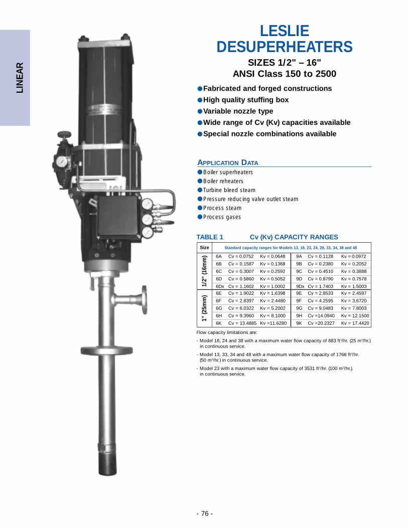
LIN
EAR
- 76 -
APPLICATION DATA
● Boiler superheaters
● Boiler reheaters
● Turbine bleed steam
● Pressure reducing valve outlet steam
● Process steam
● Process gases
LESLIEDESUPERHEATERS
SIZES 1/2" – 16"ANSI Class 150 to 2500
● Fabricated and forged constructions
● High quality stuffing box
● Variable nozzle type
● Wide range of Cv (Kv) capacities available
● Special nozzle combinations available
Size Standard capacity ranges for Models 13, 18, 23, 24, 28, 33, 34, 38 and 48
6A Cv = 0.0752 Kv = 0.0648 9A Cv = 0.1128 Kv = 0.0972
6B Cv = 0.1587 Kv = 0.1368 9B Cv = 0.2380 Kv = 0.2052
6C Cv = 0.3007 Kv = 0.2592 9C Cv = 0.4510 Kv = 0.3888
6D Cv = 0.5860 Kv = 0.5052 9D Cv = 0.8790 Kv = 0.7578
6Dx Cv = 1.1602 Kv = 1.0002 9Dx Cv = 1.7403 Kv = 1.5003
6E Cv = 1.9022 Kv = 1.6398 9E Cv = 2.8533 Kv = 2.4597
6F Cv = 2.8397 Kv = 2.4480 9F Cv = 4.2595 Kv = 3.6720
6G Cv = 6.0322 Kv = 5.2002 9G Cv = 9.0483 Kv = 7.8003
6H Cv = 9.3960 Kv = 8.1000 9H Cv =14.0940 Kv = 12.1500
6K Cv = 13.4885 Kv =11.6280 9K Cv =20.2327 Kv = 17.4420
Flow capacity limitations are:
- Model 18, 24 and 38 with a maximum water flow capacity of 883 ft3/hr. (25 m3/hr.) in continuous service.
- Model 13, 33, 34 and 48 with a maximum water flow capacity of 1766 ft3/hr. (50 m3/hr.) in continuous service.
- Model 23 with a maximum water flow capacity of 3531 ft3/hr. (100 m3/hr.). in continuous service.
TABLE 1 Cv (Kv) CAPACITY RANGES
1/2"
(16m
m)
1" (2
5mm
)
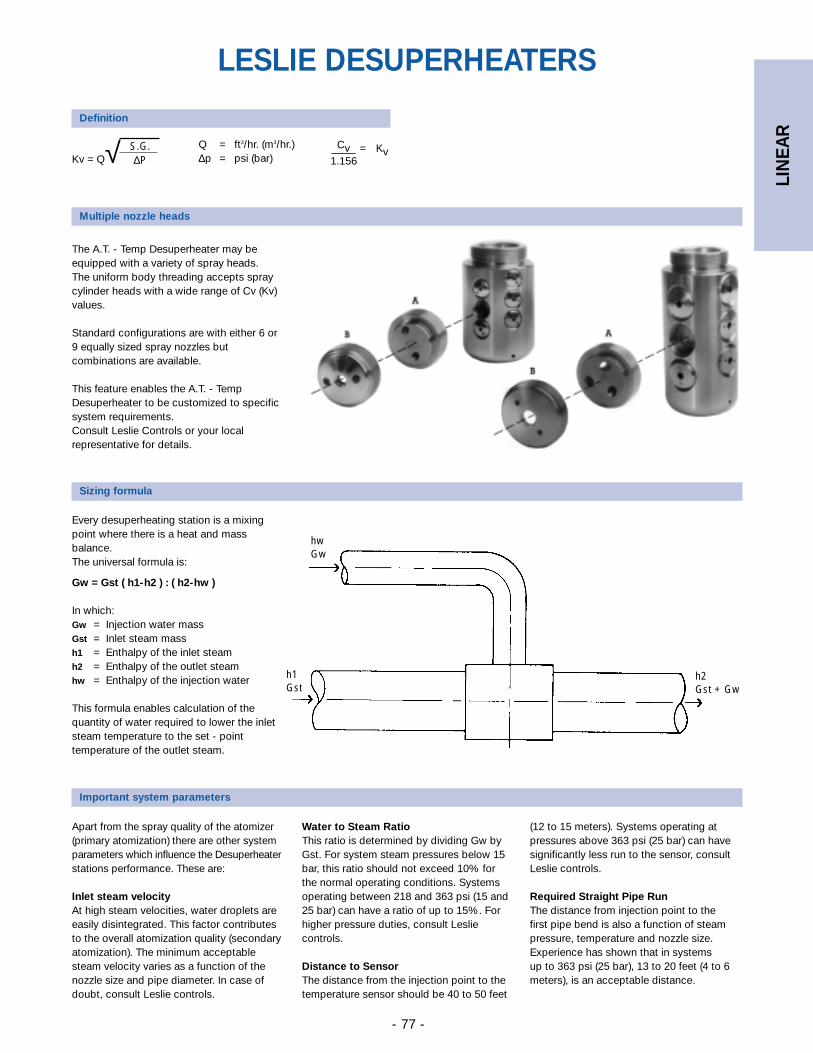
LIN
EAR
- 77 -
Definition
Kv = Q√ S.G.∆P
hwGw
Sizing formula
Important system parameters
LESLIE DESUPERHEATERS
Apart from the spray quality of the atomizer(primary atomization) there are other systemparameters which influence the Desuperheaterstations performance. These are:
Inlet steam velocityAt high steam velocities, water droplets areeasily disintegrated. This factor contributesto the overall atomization quality (secondaryatomization). The minimum acceptablesteam velocity varies as a function of thenozzle size and pipe diameter. In case ofdoubt, consult Leslie controls.
Water to Steam RatioThis ratio is determined by dividing Gw byGst. For system steam pressures below 15bar, this ratio should not exceed 10% forthe normal operating conditions. Systemsoperating between 218 and 363 psi (15 and25 bar) can have a ratio of up to 15%. Forhigher pressure duties, consult Lesliecontrols.
Distance to SensorThe distance from the injection point to thetemperature sensor should be 40 to 50 feet
(12 to 15 meters). Systems operating atpressures above 363 psi (25 bar) can havesignificantly less run to the sensor, consultLeslie controls.
Required Straight Pipe RunThe distance from injection point to the first pipe bend is also a function of steampressure, temperature and nozzle size.Experience has shown that in systems up to 363 psi (25 bar), 13 to 20 feet (4 to 6meters), is an acceptable distance.
Every desuperheating station is a mixingpoint where there is a heat and massbalance.The universal formula is:
Gw = Gst ( h1-h2 ) : ( h2-hw )
In which:Gw = Injection water massGst = Inlet steam massh1 = Enthalpy of the inlet steamh2 = Enthalpy of the outlet steamhw = Enthalpy of the injection water
This formula enables calculation of thequantity of water required to lower the inletsteam temperature to the set - pointtemperature of the outlet steam.
h2Gst + Gw
h1Gst
Multiple nozzle heads
The A.T. - Temp Desuperheater may beequipped with a variety of spray heads.The uniform body threading accepts spraycylinder heads with a wide range of Cv (Kv)values.
Standard configurations are with either 6 or9 equally sized spray nozzles butcombinations are available.
This feature enables the A.T. - TempDesuperheater to be customized to specificsystem requirements. Consult Leslie Controls or your localrepresentative for details.
Q = ft3/hr. (m3/hr.)∆p = psi (bar)
Cv = Kv1.156
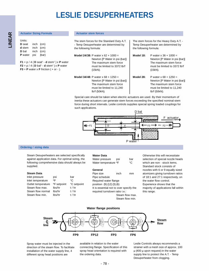
LIN
EAR
- 78 -
The stem forces for the Standard Duty A.T.- Temp Desuperheater are determined bythe following formula:
Model 24/38: P water x 62 + 1000 =Newton [P Water in psi (bar)]The maximum stem forcemust be limited to 3372 lb/f(15kN).
Model 34/48: P water x 68 + 1250 =Newton [P Water in psi (bar)]The maximum stem forcemust be limited to 11,240lb/f (50kN).
P water
D bal
F actuator
F1 D d F3 F2
Units:D seat inch (cm)d stem inch (cm)D bal inch (cm)P water psi (bar)
F1 = p / 4 ( D seat2 - d stem2 ) x P waterF2 = p / 4 ( D bal2 - d stem2 ) x P waterF3 = P water x F friction ( + or - ).
Ordering / sizing data
Water flange positions
Steamflow
FP9 FP12 FP3 FP6
Spray water must be injected in thedirection of the steam flow. To facilitateinstallation of the water supply line, 4different spray head positions are
Steam
line
LESLIE DESUPERHEATERS
Steam Desuperheaters are selected specificallyagainst application data. For optimal sizing, thefollowing comprehensive data should always besupplied.
Steam DataInlet pressure psi barInlet temperature ºF °COutlet temperature ºF setpoint °C setpoint Steam flow max. lbs/hr t / hrSteam flow normal lbs/hr t / hrSteam flow min. lbs/hr t / hr
Water DataWater pressure psi barWater temperature ºF °C
GeneralPipe size inch mmPipe scheduleRequired water flange position (9) (12) (3) (6)It is essential not to over specify therequired turndown ratio i.e.:
Steam flow max.Steam flow min.
Otherwise this will necessitateselection of special nozzle headswhich are non - stock items.Standard stock consists ofnozzles with 6 or 9 equally sizedatomizers giving turndown ratiosof 18:1 and 27:1 respectively, onthe water flow control.Experience shows that themajority of applications fall withinthis range.
available in relation to the waterconnecting flange. Specification of thisspray head orientation is required withthe ordering data.
Leslie Controls always recommends astrainer with a mesh size of approx. 100µ (400 µ upon request) in the watersupply line to protect the A.T. - TempDesuperheater from clogging.
Actuator stem forces
The stem forces for the Heavy Duty A.T. -Temp Desuperheater are determined bythe following formula:
Model 18: P water x 36 + 1000 =Newton [P Water in psi (bar)]The maximum stem forcemust be limited to 3372 lb/f(15kN).
Model 28: P water x 68 + 1250 =Newton [P Water in psi (bar)]The maximum stem forcemust be limited to 11,240lb/f (50kN).
Actuator Sizing Formula
Special care should be taken when electric actuators are used. By their momentum ofinertia these actuators can generate stem forces exceeding the specified nominal stemforce during short intervals. Leslie controls supplies special spring loaded couplings forsuch applications.
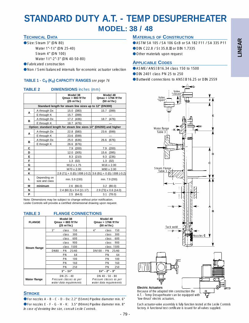
LIN
EAR
- 79 -
Model 38 Model 48Qmax = 883 ft3/hr Qmax = 1766 ft3/hr
(25 m3/hr.) (50 m3/hr.)
Standard length for steam line sizes up to 12" (DN300)
AA through Dx 15.0 (380) 15.7 (399)
E through K 15.7 (399) —
BA through Dx 17.2 (436) 18.7 (476)
E through K 18.7 (476) —Option: standard length for steam line sizes 14" (DN350) and higher
AA through Dx 22.8 (580) 23.6 (599)
E through K 23.6 (599) —
BA through Dx 25.0 (636) 26.6 (676)
E through K 26.6 (676) —
C 7.9 (200) 7.9 (200)
D 12.0 (305) 15.6 (395)
E 8.3 (210) 9.3 (236)
F 1.3 (32) 1.3 (32)
G M12 x 1.75 M16 x 2.00
H M70 x 2.00 M90 x 2.00
K 2.8 (71) + 0 (0) /.008 (-0.2) 3.6 (91) + 0 (0) /.008 (-0.2)
L Depending on size and class min. 5.9 (150) min. 7.9 (200)
M minimum 2.6 (66.0) 3.2 (80.0)
N 2.4 (60.3) x 0.4 (11.17) 2.9 (73) x 0.6 (14.0)
P 2.5 (64.0) 3.1 (78.0)
Note: Dimensions may be subject to change without prior notification. Leslie Controls will provide a certified dimensional drawing upon request.
Model 38 Model 48FLANGE Qmax = 883 ft3/hr Qmax = 1766 ft3/hr
(25 m3/hr.) (50 m3/hr.)
3" class 150 4" class 150class 300 class 300class 600 class 600class 900 class 900class 1500 class 1500Steam flange
DN80 - PN 25/40 DN100 - PN 25/40PN 64 PN 64PN 100 PN 100PN 160 PN 160PN 250 PN 250
1" - 11⁄2" 11⁄2" - 2" - 3"
DN 25 - 40 DN 40 - 50 - 80Water flange Pressure classes as per Pressure classes as per
water data requirements water data requirements
STROKE● For nozzles A - B - C - D - Dx: 2.2" (55mm) Pipeline diameter min. 6"
● For nozzles E - F - G - H - K: 3.5" (90mm) Pipeline diameter min. 8"In case of deviating line size, consult Leslie Controls.
Valve“closed”
Valve“open”
Water flangeTable 3
Steam FlangeTable 3
Tack weld
Str
oke
Nozzles
G
•
•
TABLE 2 DIMENSIONS inches (mm)
E
HK
D
C
L
M
N A
B
P
TABLE 3 FLANGE CONNECTIONS
MATERIALS OF CONSTRUCTION
● ASTM SA 105 / SA 106 Gr.B or SA 182 F11 / SA 335 P11
● DIN C22.8 / St 35.8.III or DIN 1.7335
● Other materials upon request
APPLICABLE CODES
● ASME/ ANSI B16.34 class 150 to 1500
● DIN 2401 class PN 25 to 250
● Buttweld connections to ANSI B16.25 or DIN 2559
STANDARD DUTY A.T. - TEMP DESUPERHEATERMODEL: 38 / 48
F
TECHNICAL DATA
● Size: Steam 3" (DN 80)
Water 1"-11⁄2" (DN 25-40)Steam 4" (DN 100)Water 11⁄2"-2"-3" (DN 40-50-80)
● Fabricated construction
● Non / Semi balanced internals for economic actuator selection
TABLE 1 - Cv (Kv) CAPACITY RANGES see page 76
Electric ActuatorsBecause of the adapted trim construction the A.T. - Temp Desuperheater can be equipped with ‘low-thrust’ electric actuators.
Each actuator-valve assembly is fully function tested at the Leslie Controlsfactory. A functional test certificate is issued for all valves supplied.
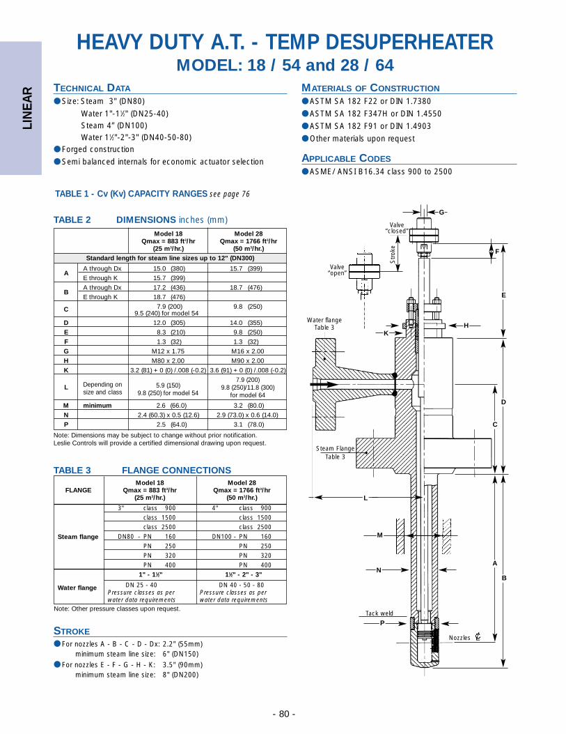
LIN
EAR
- 80 -
Model 18 Model 28Qmax = 883 ft3/hr Qmax = 1766 ft3/hr
(25 m3/hr.) (50 m3/hr.)Standard length for steam line sizes up to 12" (DN300)
AA through Dx 15.0 (380) 15.7 (399)
E through K 15.7 (399)
BA through Dx 17.2 (436) 18.7 (476)
E through K 18.7 (476)
C 7.9 (200) 9.8 (250)9.5 (240) for model 54
D 12.0 (305) 14.0 (355)
E 8.3 (210) 9.8 (250)
F 1.3 (32) 1.3 (32)
G M12 x 1.75 M16 x 2.00
H M80 x 2.00 M90 x 2.00
K 3.2 (81) + 0 (0) /.008 (-0.2) 3.6 (91) + 0 (0) /.008 (-0.2)
L Depending on 5.9 (150)7.9 (200)
size and class 9.8 (250) for model 549.8 (250)/11.8 (300)
for model 64
M minimum 2.6 (66.0) 3.2 (80.0)
N 2.4 (60.3) x 0.5 (12.6) 2.9 (73.0) x 0.6 (14.0)
P 2.5 (64.0) 3.1 (78.0)
Note: Dimensions may be subject to change without prior notification. Leslie Controls will provide a certified dimensional drawing upon request.
Model 18 Model 28FLANGE Qmax = 883 ft3/hr Qmax = 1766 ft3/hr
(25 m3/hr.) (50 m3/hr.)
3" class 900 4" class 900class 1500 class 1500class 2500 class 2500
DN80 - PN 160 DN100 - PN 160Steam flangePN 250 PN 250PN 320 PN 320PN 400 PN 400
1" - 11⁄2" 11⁄2" - 2" - 3"
DN 25 - 40 DN 40 - 50 - 80Water flangePressure classes as per Pressure classes as perwater data requirements water data requirements
STROKE● For nozzles A - B - C - D - Dx: 2.2" (55mm)
minimum steam line size: 6" (DN150)● For nozzles E - F - G - H - K: 3.5" (90mm)
minimum steam line size: 8" (DN200)
TABLE 2 DIMENSIONS inches (mm)
TABLE 3 FLANGE CONNECTIONS
MATERIALS OF CONSTRUCTION
● ASTM SA 182 F22 or DIN 1.7380
● ASTM SA 182 F347H or DIN 1.4550
● ASTM SA 182 F91 or DIN 1.4903
● Other materials upon request
APPLICABLE CODES
● ASME/ ANSI B16.34 class 900 to 2500
HEAVY DUTY A.T. - TEMP DESUPERHEATERMODEL: 18 / 54 and 28 / 64
TECHNICAL DATA
● Size: Steam 3" (DN80)
Water 1"-11⁄2" (DN25-40)Steam 4” (DN100)Water 11⁄2"-2"-3" (DN40-50-80)
● Forged construction
● Semi balanced internals for economic actuator selection
F
•
•
D
E
Valve“closed”
Valve“open”
Water flangeTable 3
Steam FlangeTable 3
Tack weld
Str
oke
Nozzles
G
HK
C
L
M
NA
B
P
Note: Other pressure classes upon request.
TABLE 1 - Cv (Kv) CAPACITY RANGES see page 76
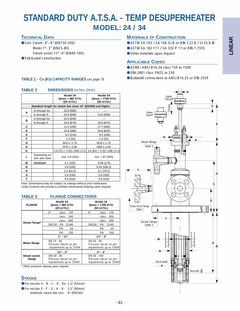
LIN
EAR
- 81 -
MATERIALS OF CONSTRUCTION
● ASTM SA 105 / SA 106 Gr.B or DIN C22.8 / St 35.8.III
● ASTM SA 182 F11 / SA 335 P 11 or DIN 1.7335
● Other materials upon request
APPLICABLE CODES
● ASME/ ANSI B16.34 class 150 to 1500
● DIN 2401 class PN25 to 250
● Buttweld connections to ANSI B16.25 or DIN 2559
STANDARD DUTY A.T.S.A. - TEMP DESUPERHEATERMODEL: 24 / 34
TECHNICAL DATA
● Size: Steam 6"- 8" (DN150-200)
Water 1"- 3" (DN25-80)Steam assist 11⁄2"- 4” (DN40-100)
● Fabricated construction
Valve“closed”
S
T
G
F
D
E
Valve“open”
Water flange
Table 3
Steam FlangeTable 3
Tack weld
Str
oke
Nozzles
HK
C
L
M
N
AB
P
Steam Assist FlangeTable 3
Model 24 Model 34Qmax = 883 ft3/hr Qmax = 1766 ft3/hr
(25 m3/hr.) (50 m3/hr.)
Standard length for steam line sizes 14" (DN350) and higher
AA through Dx 22.8 (580) —
E through K 23.6 (599) 23.6 (599)
BA through Dx 25.0 (636) —
E through K 26.6 (676) 26.6 (676)
C 11.4 (290) 17.7 (450)
D 15.6 (395) 24.6 (625)
E 8.3 (210) 9.2 (236)
F 1.3 (32) 1.3 (32)
G M12 x 1.75 M16 x 1.75
H M70 x 2.00 M90 x 2.00
K 2.8 (71) + 0 (0) /.008 (-0.2) 3.6 (91) + 0 (0) /.008 (-0.2)
LDepending on
min. 5.9 (150) min. 7.87 (200)size and class
M minimum 4.1 (105) 6.89 (175)
N 3.9 (100) 6.63 (168.3)
P 2.5 (64.0) 3.1 (78.0)
S 5.9 (150) 5.9 (150)
T 9.8 (250) 9.8 (250)
Note: Dimensions may be subject to change without prior notification. Leslie Controls will provide a certified dimensional drawing upon request.
Model 24 Model 34FLANGE Qmax = 883 ft3/hr Qmax = 1766 ft3/hr
(25 m3/hr.) (50 m3/hr.)
6" class 150 8" class 150class 300 class 300class 600 class 600
Steam flange*DN150 - PN 25/40 DN200 - PN 25/40
PN 64 PN 64PN 100 PN 100
1" - 11⁄2" 11⁄2" - 3"
DN 25 - 40 DN 40 - 80Water flange Pressure classes as per Pressure classes as per
requirements up to 1500# requirements up to 1500#
11⁄2" - 2" 2" - 4"Steam assist DN 40 - 50 DN 50 - 100
flange Pressure classes as per Pressure classes as per requirements up to 1500# requirements up to 1500#
STROKE● For nozzles A - B - C - D - Dx: 2.2" (55mm)
● For nozzles E - F - G - H - K: 3.5" (90mm) minimum steam line size: 8" (DN200)
TABLE 2 DIMENSIONS inches (mm)
TABLE 3 FLANGE CONNECTIONS
* Other pressure classes upon request.
TABLE 1 - Cv (Kv) CAPACITY RANGES see page 76
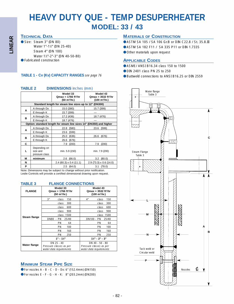
LIN
EAR
- 82 -
Model 33 Model 43Qmax = 1766 ft3/hr Qmax = 3532 ft3/hr
(50 m3/hr.) (100 m3/hr.)
Standard length for steam line sizes up to 12" (DN300)
AA through Dx 15.0 (380) 15.7 (399)
E through K 15.7 (399) —
BA through Dx 17.2 (436) 18.7 (476)
E through K 18.7 (476) —Option: standard length for steam line sizes 14" (DN350) and higher
AA through Dx 22.8 (580) 23.6 (599)
E through K 23.6 (599)
BA through Dx 25.0 (636) 26.6 (676)
E through K 26.6 (676)
C 7.9 (200) 7.9 (200)
Depending on L size and min. 5.9 (150) min. 7.9 (200)
pressure class
M minimum 2.6 (66.0) 3.2 (80.0)
N 2.4 (60.3) x 0.4 (11.1) 2.9 (73.3) x 0.6 (14.0)
P 2.5 (64.0) 3.1 (78.0)
Note: Dimensions may be subject to change without prior notification. Leslie Controls will provide a certified dimensional drawing upon request.
Model 33 Model 43FLANGE Qmax = 1766 ft3/hr Qmax = 3532 ft3/hr
(50 m3/hr.) (100 m3/hr.)
3" class 150 4" class 150class 300 class 300class 600 class 600class 900 class 900class 1500 class 1500
Steam flangeDN80 - PN 25/40 DN100 - PN 25/40
PN 64 PN 64PN 100 PN 100PN 160 PN 160PN 250 PN 250
1" - 11⁄2" 11⁄2" - 2" - 3"
DN 25 - 40 DN 40 - 50 - 80Water flange Pressure classes as per Pressure classes as per
water data requirements water data requirements
MINIMUM STEAM PIPE SIZE● For nozzles A - B - C - D - Dx: 6" (152.4mm) (DN150)
● For nozzles E - F - G - H - K: 8" (203.2mm) (DN200)
TABLE 2 DIMENSIONS inches (mm)
TABLE 3 FLANGE CONNECTIONS
MATERIALS OF CONSTRUCTION
● ASTM SA 105 / SA 106 Gr.B or DIN C22.8 / St. 35.8.III
● ASTM SA 182 F11 / SA 335 P11 or DIN 1.7335
● Other materials upon request
APPLICABLE CODES
● ASME/ ANSI B16.34 class 150 to 1500
● DIN 2401 class PN 25 to 250
● Buttweld connections to ANSI B16.25 or DIN 2559
HEAVY DUTY QUE - TEMP DESUPERHEATERMODEL: 33 / 43
TECHNICAL DATA
● Size: Steam 3" (DN 80)Water 1"-11⁄2" (DN 25-40)Steam 4” (DN 100)Water 11⁄2"-2"-3" (DN 40-50-80)
● Fabricated construction
Water flangeTable 3
Steam FlangeTable 3
Tack weld orCircular weld
Nozzles
•
•
B
C
L
M
N
A
P
TABLE 1 - Cv (Kv) CAPACITY RANGES see page 76
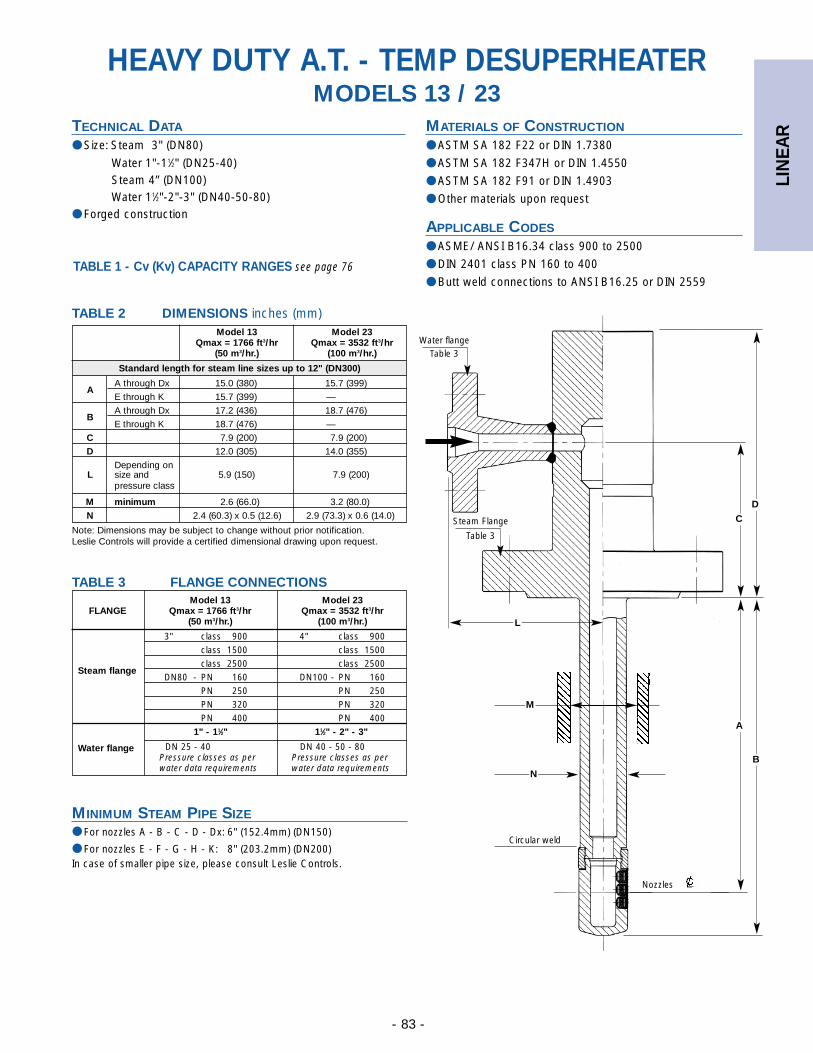
LIN
EAR
- 83 -
MATERIALS OF CONSTRUCTION
● ASTM SA 182 F22 or DIN 1.7380
● ASTM SA 182 F347H or DIN 1.4550
● ASTM SA 182 F91 or DIN 1.4903
● Other materials upon request
APPLICABLE CODES
● ASME/ ANSI B16.34 class 900 to 2500
● DIN 2401 class PN 160 to 400
● Butt weld connections to ANSI B16.25 or DIN 2559
HEAVY DUTY A.T. - TEMP DESUPERHEATERMODELS 13 / 23
TECHNICAL DATA
● Size: Steam 3" (DN80)
Water 1"-11⁄2" (DN25-40)Steam 4” (DN100)Water 11⁄2"-2"-3" (DN40-50-80)
● Forged construction
Water flangeTable 3
D
Steam Flange
Table 3
Circular weld
Nozzles
L
M
N
A
B
C
Model 13 Model 23Qmax = 1766 ft3/hr Qmax = 3532 ft3/hr
(50 m3/hr.) (100 m3/hr.)
Standard length for steam line sizes up to 12" (DN300)
AA through Dx 15.0 (380) 15.7 (399)
E through K 15.7 (399) —
BA through Dx 17.2 (436) 18.7 (476)
E through K 18.7 (476) —
C 7.9 (200) 7.9 (200)
D 12.0 (305) 14.0 (355)
Depending on L size and 5.9 (150) 7.9 (200)
pressure class
M minimum 2.6 (66.0) 3.2 (80.0)
N 2.4 (60.3) x 0.5 (12.6) 2.9 (73.3) x 0.6 (14.0)
Note: Dimensions may be subject to change without prior notification. Leslie Controls will provide a certified dimensional drawing upon request.
Model 13 Model 23FLANGE Qmax = 1766 ft3/hr Qmax = 3532 ft3/hr
(50 m3/hr.) (100 m3/hr.)
3" class 900 4" class 900class 1500 class 1500class 2500 class 2500
Steam flangeDN80 - PN 160 DN100 - PN 160
PN 250 PN 250PN 320 PN 320PN 400 PN 400
1" - 11⁄2" 11⁄2" - 2" - 3"
DN 25 - 40 DN 40 - 50 - 80Water flangePressure classes as per Pressure classes as per water data requirements water data requirements
MINIMUM STEAM PIPE SIZE● For nozzles A - B - C - D - Dx: 6" (152.4mm) (DN150)
● For nozzles E - F - G - H - K: 8" (203.2mm) (DN200)In case of smaller pipe size, please consult Leslie Controls.
TABLE 2 DIMENSIONS inches (mm)
TABLE 3 FLANGE CONNECTIONS
TABLE 1 - Cv (Kv) CAPACITY RANGES see page 76
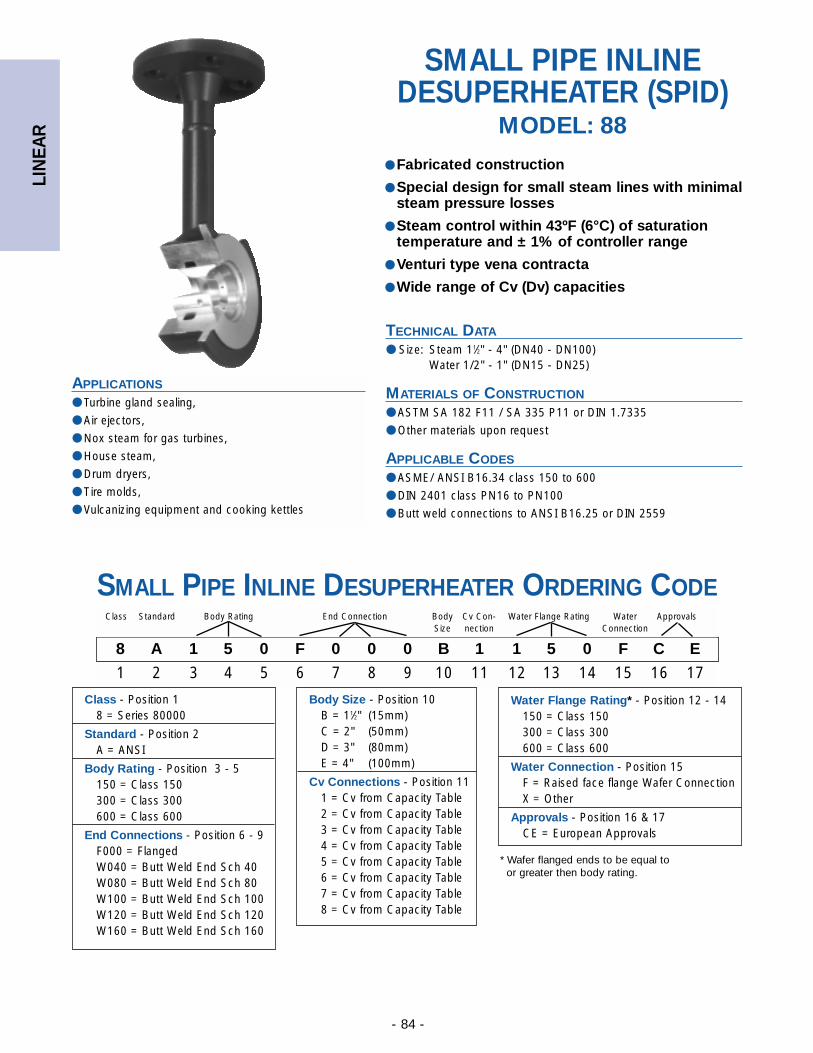
LIN
EAR
- 84 -
SMALL PIPE INLINEDESUPERHEATER (SPID)
MODEL: 88
TECHNICAL DATA
● Size: Steam 11⁄2" - 4" (DN40 - DN100)Water 1/2" - 1" (DN15 - DN25)
MATERIALS OF CONSTRUCTION
● ASTM SA 182 F11 / SA 335 P11 or DIN 1.7335
● Other materials upon request
APPLICABLE CODES
● ASME/ ANSI B16.34 class 150 to 600
● DIN 2401 class PN16 to PN100
● Butt weld connections to ANSI B16.25 or DIN 2559
● Fabricated construction
● Special design for small steam lines with minimalsteam pressure losses
● Steam control within 43ºF (6°C) of saturationtemperature and ± 1% of controller range
● Venturi type vena contracta
● Wide range of Cv (Dv) capacities
APPLICATIONS
● Turbine gland sealing,
● Air ejectors,
● Nox steam for gas turbines,
● House steam,
● Drum dryers,
● Tire molds,
● Vulcanizing equipment and cooking kettles
SMALL PIPE INLINE DESUPERHEATER ORDERING CODE
8 A 1 5 0 F 0 0 0 B 1 1 5 0 F C E
1 2 3 4 5 6 7 8 9 10 11 12 13 14 15 16 17
Class Standard Body Rating End Connection Body Cv Con- Water Flange Rating Water ApprovalsSize nection Connection
Body Size - Position 10B = 11⁄2" (15mm)C = 2" (50mm)D = 3" (80mm)E = 4" (100mm)
Cv Connections - Position 111 = Cv from Capacity Table2 = Cv from Capacity Table3 = Cv from Capacity Table4 = Cv from Capacity Table5 = Cv from Capacity Table6 = Cv from Capacity Table7 = Cv from Capacity Table8 = Cv from Capacity Table
Class - Position 18 = Series 80000
Standard - Position 2A = ANSI
Body Rating - Position 3 - 5150 = Class 150300 = Class 300600 = Class 600
End Connections - Position 6 - 9F000 = FlangedW040 = Butt Weld End Sch 40W080 = Butt Weld End Sch 80W100 = Butt Weld End Sch 100W120 = Butt Weld End Sch 120W160 = Butt Weld End Sch 160
Water Flange Rating* - Position 12 - 14150 = Class 150300 = Class 300600 = Class 600
Water Connection - Position 15F = Raised face flange Wafer ConnectionX = Other
Approvals - Position 16 & 17CE = European Approvals
* Wafer flanged ends to be equal to or greater then body rating.
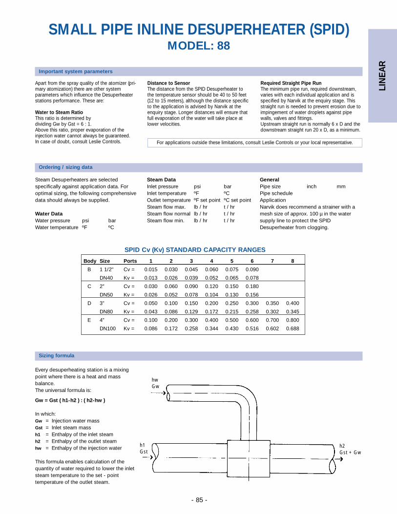
LIN
EAR
- 85 -
Apart from the spray quality of the atomizer (pri-mary atomization) there are other systemparameters which influence the Desuperheaterstations performance. These are:
Water to Steam RatioThis ratio is determined by dividing Gw by Gst = 6 : 1. Above this ratio, proper evaporation of theinjection water cannot always be guaranteed.In case of doubt, consult Leslie Controls.
Ordering / sizing data
Important system parameters
Distance to SensorThe distance from the SPID Desuperheater tothe temperature sensor should be 40 to 50 feet(12 to 15 meters), although the distance specificto the application is advised by Narvik at theenquiry stage. Longer distances will ensure thatfull evaporation of the water will take place atlower velocities.
Required Straight Pipe RunThe minimum pipe run, required downstream,varies with each individual application and isspecified by Narvik at the enquiry stage. Thisstraight run is needed to prevent erosion due toimpingement of water droplets against pipewalls, valves and fittings.Upstream straight run is normally 6 x D and thedownstream straight run 20 x D, as a minimum.
For applications outside these limitations, consult Leslie Controls or your local representative.
SMALL PIPE INLINE DESUPERHEATER (SPID)MODEL: 88
Steam Desuperheaters are selectedspecifically against application data. Foroptimal sizing, the following comprehensivedata should always be supplied.
Water DataWater pressure psi barWater temperature ºF ºC
Steam DataInlet pressure psi barInlet temperature ºF ºCOutlet temperature ºF set point ºC set point Steam flow max. lb / hr t / hrSteam flow normal lb / hr t / hrSteam flow min. lb / hr t / hr
GeneralPipe size inch mmPipe scheduleApplicationNarvik does recommend a strainer with amesh size of approx. 100 µ in the watersupply line to protect the SPIDDesuperheater from clogging.
Body Size Ports 1 2 3 4 5 6 7 8
B 1 1/2" Cv = 0.015 0.030 0.045 0.060 0.075 0.090
DN40 Kv = 0.013 0.026 0.039 0.052 0.065 0.078
C 2” Cv = 0.030 0.060 0.090 0.120 0.150 0.180
DN50 Kv = 0.026 0.052 0.078 0.104 0.130 0.156
D 3” Cv = 0.050 0.100 0.150 0.200 0.250 0.300 0.350 0.400
DN80 Kv = 0.043 0.086 0.129 0.172 0.215 0.258 0.302 0.345
E 4” Cv = 0.100 0.200 0.300 0.400 0.500 0.600 0.700 0.800
DN100 Kv = 0.086 0.172 0.258 0.344 0.430 0.516 0.602 0.688
SPID Cv (Kv) STANDARD CAPACITY RANGES
hwGw
Sizing formula
Every desuperheating station is a mixingpoint where there is a heat and massbalance.The universal formula is:
Gw = Gst ( h1-h2 ) : ( h2-hw )
In which:Gw = Injection water massGst = Inlet steam massh1 = Enthalpy of the inlet steamh2 = Enthalpy of the outlet steamhw = Enthalpy of the injection water
This formula enables calculation of thequantity of water required to lower the inletsteam temperature to the set - pointtemperature of the outlet steam.
h2Gst + Gw
h1Gst
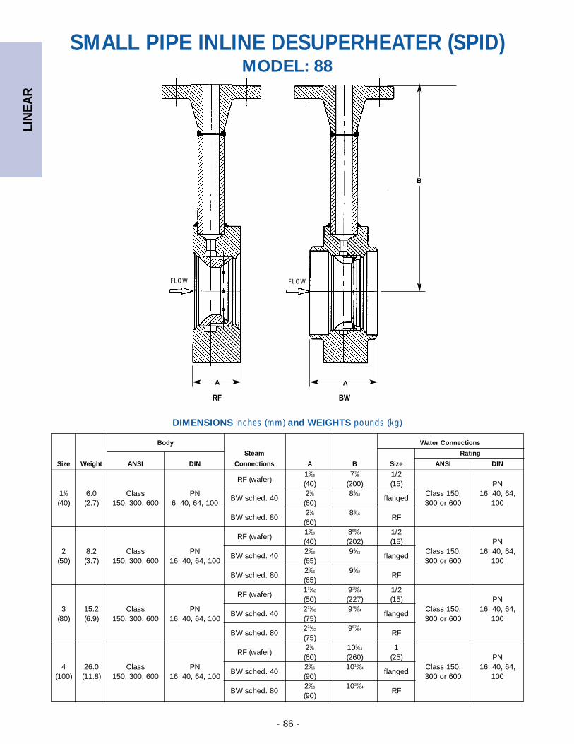
LIN
EAR
- 86 -
Body Water Connections
Steam Rating
Size Weight ANSI DIN Connections A B Size ANSI DIN
RF (wafer)19⁄16 77⁄8 1/2(40) (200) (15) PN
11⁄2 6.0 Class PNBW sched. 40
23⁄8 83⁄32flanged
Class 150, 16, 40, 64,(40) (2.7) 150, 300, 600 6, 40, 64, 100 (60) 300 or 600 100
BW sched. 8023⁄8 89⁄16
RF(60)
RF (wafer)19⁄16 855⁄64 1/2(40) (202) (15) PN
2 8.2 Class PNBW sched. 40
29⁄16 93⁄32flanged
Class 150, 16, 40, 64,(50) (3.7) 150, 300, 600 16, 40, 64, 100 (65) 300 or 600 100
BW sched. 8029⁄16 93⁄32
RF(65)
RF (wafer)131⁄32 929⁄64 1/2(50) (227) (15) PN
3 15.2 Class PNBW sched. 40
231⁄32 945⁄64flanged
Class 150, 16, 40, 64,(80) (6.9) 150, 300, 600 16, 40, 64, 100 (75) 300 or 600 100
BW sched. 80231⁄32 957⁄64
RF(75)
RF (wafer)23⁄8 103⁄64 1(60) (260) (25) PN
4 26.0 Class PNBW sched. 40
29⁄16 1019⁄64flanged
Class 150, 16, 40, 64,(100) (11.8) 150, 300, 600 16, 40, 64, 100 (90) 300 or 600 100
BW sched. 8029⁄16 1034⁄64
RF(90)
RF BW
FLOW
A
B
FLOW
A
SMALL PIPE INLINE DESUPERHEATER (SPID)MODEL: 88
DIMENSIONS inches (mm) and WEIGHTS pounds (kg)
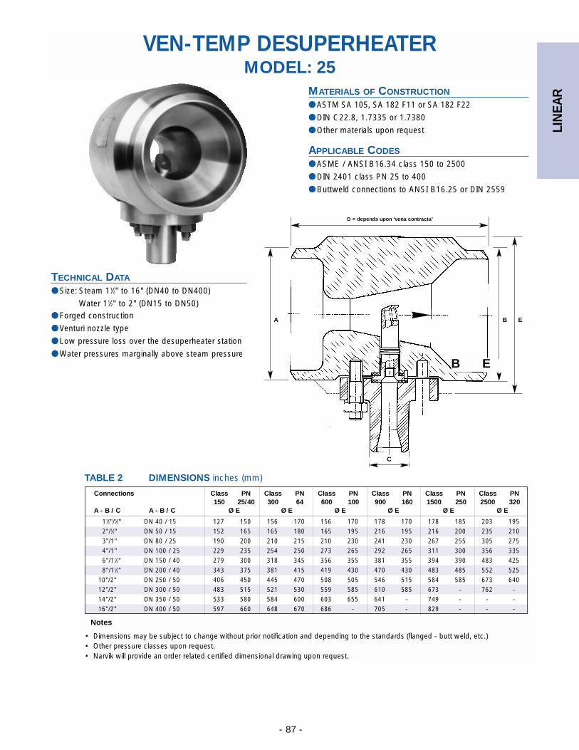
LIN
EAR
- 87 -
VEN-TEMP DESUPERHEATERMODEL: 25
TABLE 2 DIMENSIONS inches (mm)
MATERIALS OF CONSTRUCTION
● ASTM SA 105, SA 182 F11 or SA 182 F22
● DIN C22.8, 1.7335 or 1.7380
● Other materials upon request
APPLICABLE CODES
● ASME / ANSI B16.34 class 150 to 2500
● DIN 2401 class PN 25 to 400
● Buttweld connections to ANSI B16.25 or DIN 2559
TECHNICAL DATA
● Size: Steam 11⁄2" to 16" (DN40 to DN400)
Water 11⁄2" to 2" (DN15 to DN50)● Forged construction
● Venturi nozzle type
● Low pressure loss over the desuperheater station
● Water pressures marginally above steam pressure
D = depends upon ‘vena contracta’
A B E
C
B E
11⁄2"/1⁄2" DN 40 / 15 127 150 156 170 156 170 178 170 178 185 203 1952"/1⁄2" DN 50 / 15 152 165 165 180 165 195 216 195 216 200 235 2103"/1" DN 80 / 25 190 200 210 215 210 230 241 230 267 255 305 2754"/1" DN 100 / 25 229 235 254 250 273 265 292 265 311 300 356 3356"/11⁄2" DN 150 / 40 279 300 318 345 356 355 381 355 394 390 483 4258"/11⁄2" DN 200 / 40 343 375 381 415 419 430 470 430 483 485 552 525
10"/2" DN 250 / 50 406 450 445 470 508 505 546 515 584 585 673 64012"/2" DN 300 / 50 483 515 521 530 559 585 610 585 673 - 762 -14"/2" DN 350 / 50 533 580 584 600 603 655 641 - 749 - - -16"/2" DN 400 / 50 597 660 648 670 686 - 705 - 829 - - -
Notes
• Dimensions may be subject to change without prior notification and depending to the standards (flanged - butt weld, etc.)• Other pressure classes upon request.• Narvik will provide an order related certified dimensional drawing upon request.
Connections Class PN Class PN Class PN Class PN Class PN Class PN150 25/40 300 64 600 100 900 160 1500 250 2500 320
A - B / C A - B / C Ø E Ø E Ø E Ø E Ø E Ø E
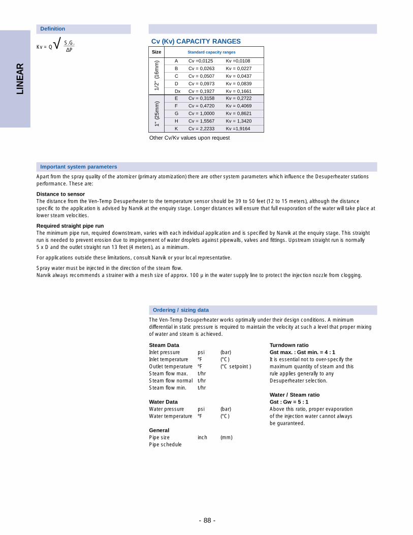
LIN
EAR
- 88 -
Size Standard capacity ranges
A Cv =0,0125 Kv =0,0108
B Cv = 0,0263 Kv = 0,0227
C Cv = 0,0507 Kv = 0,0437
D Cv = 0,0973 Kv = 0,0839
Dx Cv = 0,1927 Kv = 0,1661
E Cv = 0,3158 Kv = 0,2722
F Cv = 0,4720 Kv = 0,4069
G Cv = 1,0000 Kv = 0,8621
H Cv = 1,5567 Kv = 1,3420
K Cv = 2,2233 Kv =1,9164
Cv (Kv) CAPACITY RANGES
Definition
Kv = Q√ S.G.∆P
Important system parameters
Apart from the spray quality of the atomizer (primary atomization) there are other system parameters which influence the Desuperheater stationsperformance. These are:
Distance to sensorThe distance from the Ven-Temp Desuperheater to the temperature sensor should be 39 to 50 feet (12 to 15 meters), although the distancespecific to the application is advised by Narvik at the enquiry stage. Longer distances will ensure that full evaporation of the water will take place atlower steam velocities.
Required straight pipe run The minimum pipe run, required downstream, varies with each individual application and is specified by Narvik at the enquiry stage. This straightrun is needed to prevent erosion due to impingement of water droplets against pipewalls, valves and fittings. Upstream straight run is normally 5 x D and the outlet straight run 13 feet (4 meters), as a minimum.
For applications outside these limitations, consult Narvik or your local representative.
Spray water must be injected in the direction of the steam flow. Narvik always recommends a strainer with a mesh size of approx. 100 µ in the water supply line to protect the injection nozzle from clogging.
Steam DataInlet pressure psi (bar)Inlet temperature ºF (°C)Outlet temperature ºF (°C setpoint )Steam flow max. t/hrSteam flow normal t/hrSteam flow min. t/hr
Water DataWater pressure psi (bar)Water temperature ºF (°C)
GeneralPipe size inch (mm)Pipe schedule
Turndown ratioGst max. : Gst min. = 4 : 1It is essential not to over-specify the maximum quantity of steam and this rule applies generally to any Desuperheater selection.
Water / Steam ratioGst : Gw = 5 : 1Above this ratio, proper evaporation of the injection water cannot always be guaranteed.
Ordering / sizing data
The Ven-Temp Desuperheater works optimally under their design conditions. A minimumdifferential in static pressure is required to maintain the velocity at such a level that proper mixingof water and steam is achieved.
Other Cv/Kv values upon request
1" (2
5mm
)1/
2" (1
6mm
)
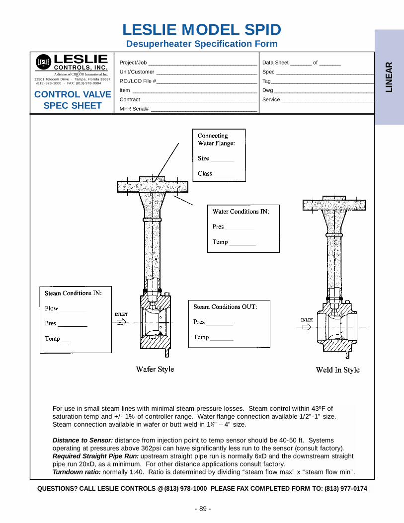
LIN
EAR
- 89 -
For use in small steam lines with minimal steam pressure losses. Steam control within 43ºF of saturation temp and +/- 1% of controller range. Water flange connection available 1/2”-1” size. Steam connection available in wafer or butt weld in 11⁄2” – 4” size.
Distance to Sensor: distance from injection point to temp sensor should be 40-50 ft. Systems operating at pressures above 362psi can have significantly less run to the sensor (consult factory).Required Straight Pipe Run: upstream straight pipe run is normally 6xD and the downstream straightpipe run 20xD, as a minimum. For other distance applications consult factory.Turndown ratio: normally 1:40. Ratio is determined by dividing “steam flow max” x “steam flow min”.
LESLIE MODEL SPIDDesuperheater Specification Form
12501 Telecom Drive · Tampa, Florida 33637(813) 978-1000 · FAX: (813)-978-0984
Project/Job _________________________________________ Data Sheet ________ of ________
Unit/Customer ______________________________________ Spec _____________________________________
P.O./LCO File #______________________________________ Tag_______________________________________
Item _______________________________________________ Dwg______________________________________
Contract____________________________________________ Service ___________________________________
MFR Serial# ________________________________________
CONTROL VALVE SPEC SHEET
QUESTIONS? CALL LESLIE CONTROLS @ (813) 978-1000 PLEASE FAX COMPLETED FORM TO: (813) 977-0174
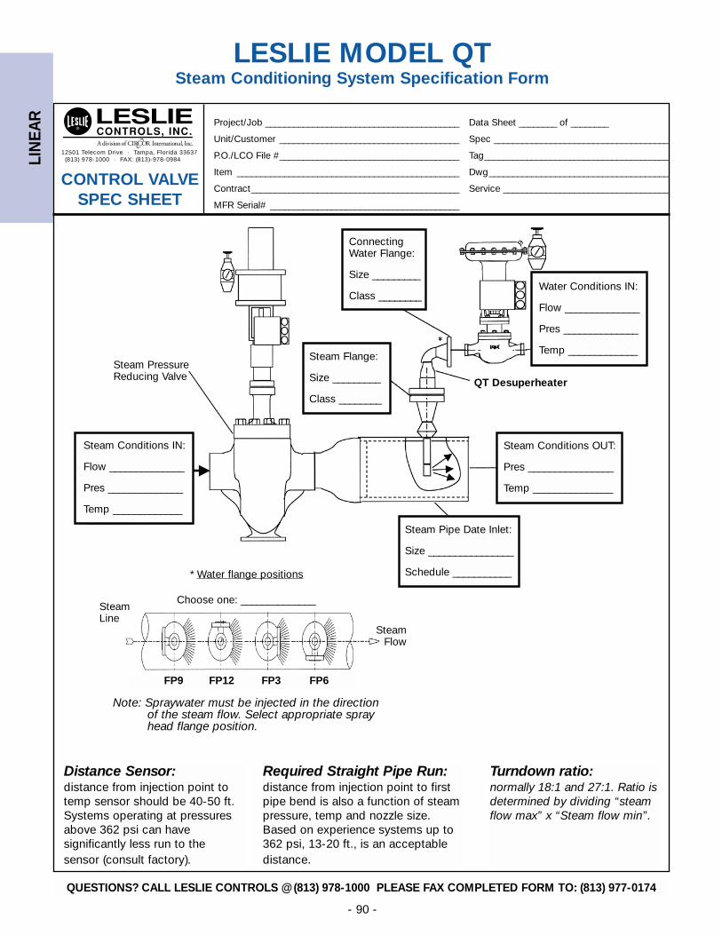
LIN
EAR
- 90 -
LESLIE MODEL QTSteam Conditioning System Specification Form
Steam Conditions OUT:
Pres ________________
Temp _______________
Steam Pipe Date Inlet:
Size ________________
Schedule ___________
Steam Conditions IN:
Flow ______________
Pres ______________
Temp _____________
Connecting Water Flange:
Size _________
Class ________
Steam Flange:
Size _________
Class ________
Water Conditions IN:
Flow ______________
Pres ______________
Temp _____________
* Water flange positions
Choose one: ______________
Note: Spraywater must be injected in the directionof the steam flow. Select appropriate sprayhead flange position.
SteamLine
SteamFlow
Steam PressureReducing Valve QT Desuperheater
Distance Sensor:distance from injection point totemp sensor should be 40-50 ft.Systems operating at pressuresabove 362 psi can have significantly less run to the sensor (consult factory).
Required Straight Pipe Run:distance from injection point to firstpipe bend is also a function of steampressure, temp and nozzle size.Based on experience systems up to362 psi, 13-20 ft., is an acceptabledistance.
Turndown ratio:normally 18:1 and 27:1. Ratio isdetermined by dividing “steamflow max” x “Steam flow min”.
FP9 FP12 FP3 FP6
12501 Telecom Drive · Tampa, Florida 33637(813) 978-1000 · FAX: (813)-978-0984
Project/Job _________________________________________ Data Sheet ________ of ________
Unit/Customer ______________________________________ Spec _____________________________________
P.O./LCO File #______________________________________ Tag_______________________________________
Item _______________________________________________ Dwg______________________________________
Contract____________________________________________ Service ___________________________________
MFR Serial# ________________________________________
CONTROL VALVE SPEC SHEET
QUESTIONS? CALL LESLIE CONTROLS @ (813) 978-1000 PLEASE FAX COMPLETED FORM TO: (813) 977-0174
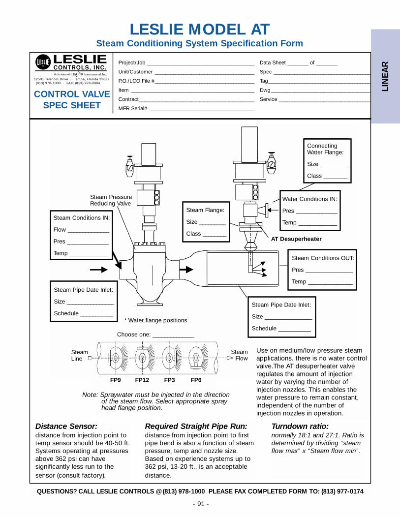
LIN
EAR
- 91 -
LESLIE MODEL ATSteam Conditioning System Specification Form
Steam Conditions IN:
Flow ______________
Pres ______________
Temp _____________
Water Conditions IN:
Pres ______________
Temp _____________
Steam Conditions OUT:
Pres ________________
Temp _______________
Steam Pipe Date Inlet:
Size ________________
Schedule ___________
Steam Pipe Date Inlet:
Size ________________
Schedule ___________
Steam Flange:
Size _________
Class ________
Connecting Water Flange:
Size _________
Class ________
* Water flange positions
Choose one: ______________
Note: Spraywater must be injected in the directionof the steam flow. Select appropriate sprayhead flange position.
SteamLine
SteamFlow
Steam PressureReducing Valve
AT Desuperheater
Use on medium/low pressure steamapplications. there is no water controlvalve.The AT desuperheater valve regulates the amount of injectionwater by varying the number of injection nozzles. This enables thewater pressure to remain constant,independent of the number of injection nozzles in operation.
Distance Sensor:distance from injection point totemp sensor should be 40-50 ft.Systems operating at pressuresabove 362 psi can have significantly less run to the sensor (consult factory).
Required Straight Pipe Run:distance from injection point to firstpipe bend is also a function of steampressure, temp and nozzle size.Based on experience systems up to362 psi, 13-20 ft., is an acceptabledistance.
Turndown ratio:normally 18:1 and 27:1. Ratio isdetermined by dividing “steamflow max” x “Steam flow min”.
FP9 FP12 FP3 FP6
12501 Telecom Drive · Tampa, Florida 33637(813) 978-1000 · FAX: (813)-978-0984
Project/Job _________________________________________ Data Sheet ________ of ________
Unit/Customer ______________________________________ Spec _____________________________________
P.O./LCO File #______________________________________ Tag_______________________________________
Item _______________________________________________ Dwg______________________________________
Contract____________________________________________ Service ___________________________________
MFR Serial# ________________________________________
CONTROL VALVE SPEC SHEET
QUESTIONS? CALL LESLIE CONTROLS @ (813) 978-1000 PLEASE FAX COMPLETED FORM TO: (813) 977-0174
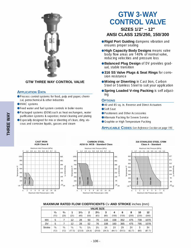
THR
EE W
AY
- 106 -
GTW THREE WAY CONTROL VALVE
APPLICATION DATA
● Process control systems for food, pulp and paper, chemi-cal, petrochemical & other industries
● HVAC systems
● Feed water and fuel system controls in boiler rooms
● Packaged systems (OEM) such as heat exchangers, waterpurification systems & vaporizer, metal cleaning and plating
● Especially designed for mix or diverting of clean, dirty, vis-cous and corrosive liquids, gasses and steam
GTW 3-WAY CONTROL VALVE
SIZES 1/2" – 12"ANSI CLASS 125/250, 150/300
● Rigid Port Guiding dampens vibration andensures proper seating
● High Capacity Body Designs means valvebody flow areas are 140% of normal valve,reducing velocities and pressure loss
● Balanced Plug Design of DV provides grad-ual, stable transition
● 316 SS Valve Plugs & Seat Rings for corro-sion resistance
● Mixing or Diverting in Cast Iron, CarbonSteel or Stainless Steel to suit your application
● Spring Loaded V-ring Packing is self adjust-ing
OPTIONS
● 40 and 85 sq. in. Reverse and Direct Actuators
● Soft Seat
● Positioners and Other Accessories
● Alternate Packing for Severe Service
● Graphite or High Temperature Packing
APPLICABLE CODES
C
lass
150
Cla
ss 3
000 0.7 1.4 2.1 2.8 3.5 4.1 4.8 5.5
800
700
600
500
400
300
200
100
0-20
1 2 3 4 5 6 7 80
427
371
315
260
204
149
93
38
-18-29
Temp
erature ºC
Tem
per
atur
e ºF
Maximum Inlet Pressure (psi x 100)
Maximum Inlet Pressure (psi x 100)
2 4 6 8 10 12 14 160
Tem
per
atur
e ºF
Temp
erature ºC
-29
565
482
398
315
232
149
65
-18
0 1.4 2.8 4.1 5.5 6.9 8.3 9.7 11
Cla
ss 1
50
Cla
ss 3
00
1050
900
750
600
450
300
150
0-20
C
lass
125
Temp
erature ºC
565
482
398
315
232
149
65
-18-29
0 1.4 2.8 4.1 5.5 6.9 8.3 9.7 11
Cla
ss 2
50
1050
900
750
600
450
300
150
0-20
Maximum Inlet Pressure (psi x 100)
2 4 6 8 10 12 14 160
Tem
per
atur
e ºF
Maximum Inlet Pressure (MPa) Maximum Inlet Pressure (MPa) Maximum Inlet Pressure (MPa)
VALVE SIZE1/2 3/4 1 11/2 2 21/2 3 4 6 8 10 12(15) (20) (25) (40) (50) (65) (80) (100) (150) (200) (250) (300)
MX 5 7 12 28 50 70 116 158 352 475 739 1070
DV 5 7 12 28 52 76 108 160 365 475 795 1078
Stroke 15⁄3215⁄32
11⁄1615⁄16 11⁄16 13⁄16 13⁄8 13⁄4 23⁄8 21⁄2 3 31⁄2
(12) (12) (17.5) (23.8) (26.6) (29.8) (34.5) (44.1) (59.5) (62.7) (80) (87.7)
MAXIMUM RATED FLOW COEFFICIENTS Cv AND STROKE inches (mm)
See Reference Section on page 195
CAST IRONA126 Class B
CARBON STEELA216 Gr. WCB - Standard Class
316 STAINLESS STEEL CF8MClass A - Standard
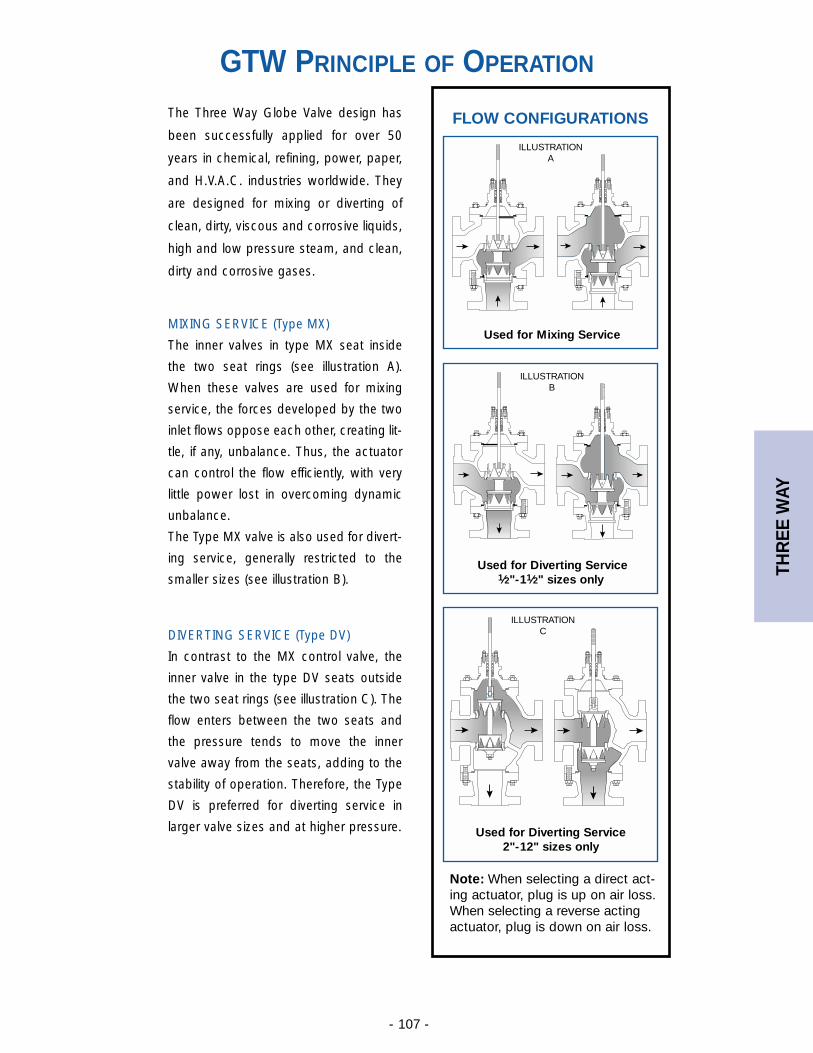
THR
EE W
AY
- 107 -
DIVERTING SERVICE (Type DV)
In contrast to the MX control valve, the
inner valve in the type DV seats outside
the two seat rings (see illustration C). The
flow enters between the two seats and
the pressure tends to move the inner
valve away from the seats, adding to the
stability of operation. Therefore, the Type
DV is preferred for diverting service in
larger valve sizes and at higher pressure.
MIXING SERVICE (Type MX)
The inner valves in type MX seat inside
the two seat rings (see illustration A).
When these valves are used for mixing
service, the forces developed by the two
inlet flows oppose each other, creating lit-
tle, if any, unbalance. Thus, the actuator
can control the flow efficiently, with very
little power lost in overcoming dynamic
unbalance.
The Type MX valve is also used for divert-
ing service, generally restricted to the
smaller sizes (see illustration B).
The Three Way Globe Valve design has
been successfully applied for over 50
years in chemical, refining, power, paper,
and H.V.A.C. industries worldwide. They
are designed for mixing or diverting of
clean, dirty, viscous and corrosive liquids,
high and low pressure steam, and clean,
dirty and corrosive gases.
GTW PRINCIPLE OF OPERATION
FLOW CONFIGURATIONS
Used for Mixing Service
Used for Diverting Service 1⁄2"-11⁄2" sizes only
Used for Diverting Service2"-12" sizes only
Note: When selecting a direct act-ing actuator, plug is up on air loss.When selecting a reverse actingactuator, plug is down on air loss.
ILLUSTRATIONA
ILLUSTRATIONB
ILLUSTRATIONC
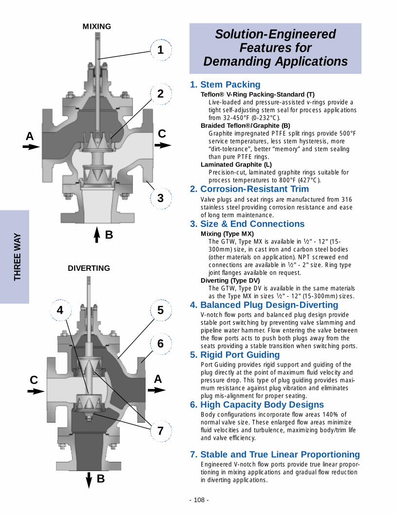
THR
EE W
AY
- 108 -
Solution-Engineered Features for
Demanding Applications
1. Stem PackingTeflon® V-Ring Packing-Standard (T)
Live-loaded and pressure-assisted v-rings provide atight self-adjusting stem seal for process applicationsfrom 32-450°F (0-232°C).
Braided Teflon®/Graphite (B)Graphite impregnated PTFE split rings provide 500°Fservice temperatures, less stem hysteresis, more “dirt-tolerance”, better “memory” and stem sealingthan pure PTFE rings.
Laminated Graphite (L)Precision-cut, laminated graphite rings suitable forprocess temperatures to 800°F (427°C).
2. Corrosion-Resistant TrimValve plugs and seat rings are manufactured from 316stainless steel providing corrosion resistance and ease of long term maintenance.
3. Size & End ConnectionsMixing (Type MX)
The GTW, Type MX is available in 1⁄2" - 12" (15-300mm) size, in cast iron and carbon steel bodies(other materials on application). NPT screwed endconnections are available in 1⁄2" - 2" size. Ring typejoint flanges available on request.
Diverting (Type DV)The GTW, Type DV is available in the same materialsas the Type MX in sizes 1⁄2" - 12" (15-300mm) sizes.
4. Balanced Plug Design-DivertingV-notch flow ports and balanced plug design providestable port switching by preventing valve slamming andpipeline water hammer. Flow entering the valve betweenthe flow ports acts to push both plugs away from theseats providing a stable transition when switching ports.
5. Rigid Port GuidingPort Guiding provides rigid support and guiding of theplug directly at the point of maximum fluid velocity andpressure drop. This type of plug guiding provides maxi-mum resistance against plug vibration and eliminatesplug mis-alignment for proper seating.
6. High Capacity Body DesignsBody configurations incorporate flow areas 140% of normal valve size. These enlarged flow areas minimizefluid velocities and turbulence, maximizing body/trim lifeand valve efficiency.
7. Stable and True Linear ProportioningEngineered V-notch flow ports provide true linear propor-tioning in mixing applications and gradual flow reductionin diverting applications.
1
2
3
4 5
7
6
MIXING
DIVERTING
A
A
B
B
C
C
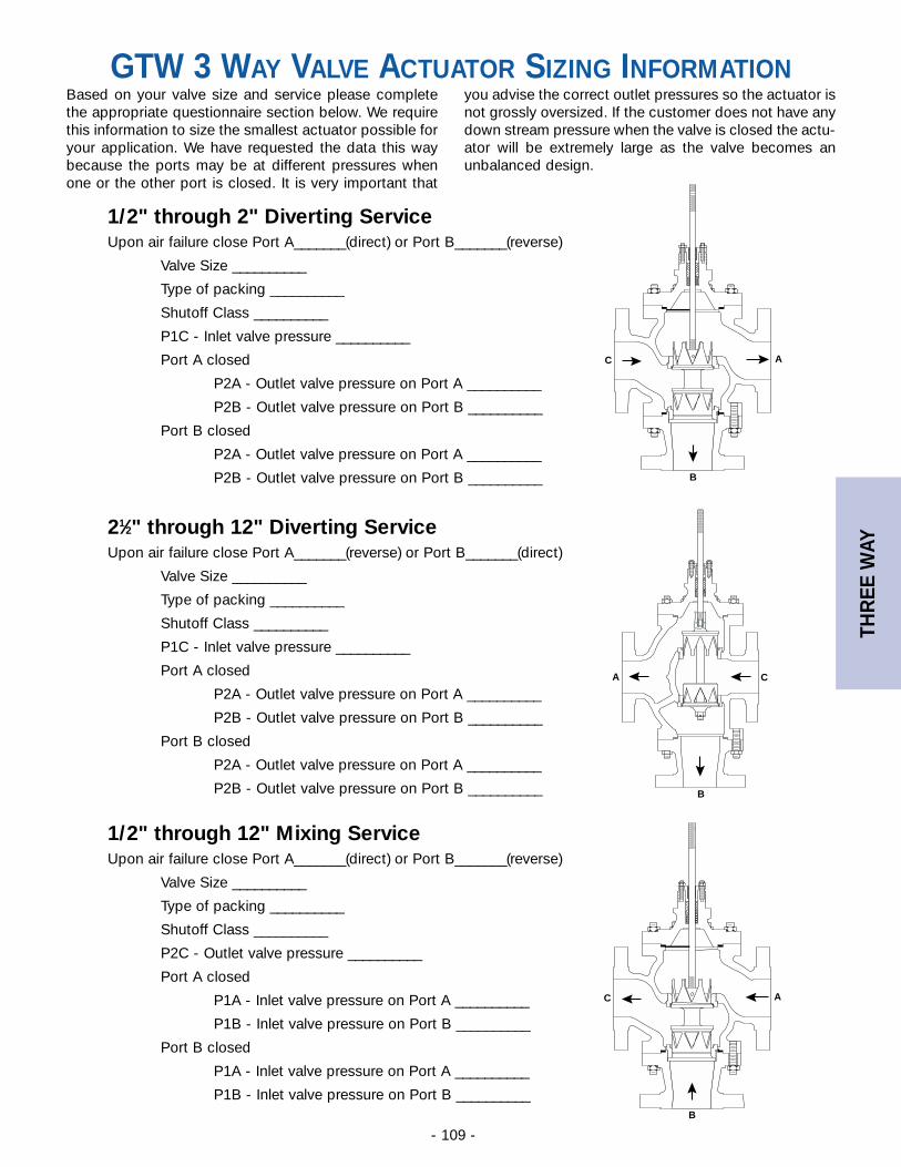
THR
EE W
AY
- 109 -
A
B
C
GTW 3 WAY VALVE ACTUATOR SIZING INFORMATIONBased on your valve size and service please completethe appropriate questionnaire section below. We requirethis information to size the smallest actuator possible foryour application. We have requested the data this waybecause the ports may be at different pressures whenone or the other port is closed. It is very important that
you advise the correct outlet pressures so the actuator isnot grossly oversized. If the customer does not have anydown stream pressure when the valve is closed the actu-ator will be extremely large as the valve becomes anunbalanced design.
1/2" through 2" Diverting ServiceUpon air failure close Port A_______(direct) or Port B_______(reverse)
Valve Size __________
Type of packing __________
Shutoff Class __________
P1C - Inlet valve pressure __________
Port A closed
P2A - Outlet valve pressure on Port A __________
P2B - Outlet valve pressure on Port B __________
Port B closed
P2A - Outlet valve pressure on Port A __________
P2B - Outlet valve pressure on Port B __________
21⁄2" through 12" Diverting ServiceUpon air failure close Port A_______(reverse) or Port B_______(direct)
Valve Size __________
Type of packing __________
Shutoff Class __________
P1C - Inlet valve pressure __________
Port A closed
P2A - Outlet valve pressure on Port A __________
P2B - Outlet valve pressure on Port B __________
Port B closed
P2A - Outlet valve pressure on Port A __________
P2B - Outlet valve pressure on Port B __________
1/2" through 12" Mixing ServiceUpon air failure close Port A_______(direct) or Port B_______(reverse)
Valve Size __________
Type of packing __________
Shutoff Class __________
P2C - Outlet valve pressure __________
Port A closed
P1A - Inlet valve pressure on Port A __________
P1B - Inlet valve pressure on Port B __________
Port B closed
P1A - Inlet valve pressure on Port A __________
P1B - Inlet valve pressure on Port B __________
A
B
C
A
B
C
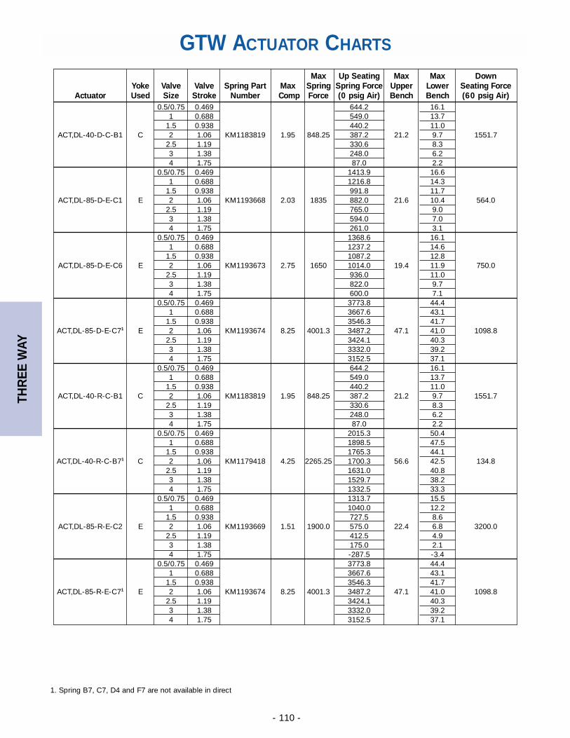
THR
EE W
AY
- 110 -
GTW ACTUATOR CHARTS
Max Up Seating Max Max DownYoke Valve Valve Spring Part Max Spring Spring Force Upper Lower Seating Force
Actuator Used Size Stroke Number Comp Force (0 psig Air) Bench Bench (60 psig Air)0.5/0.75 0.469 644.2 16.1
1 0.688 549.0 13.71.5 0.938 440.2 11.0
ACT,DL-40-D-C-B1 C 2 1.06 KM1183819 1.95 848.25 387.2 21.2 9.7 1551.72.5 1.19 330.6 8.33 1.38 248.0 6.24 1.75 87.0 2.2
0.5/0.75 0.469 1413.9 16.61 0.688 1216.8 14.3
1.5 0.938 991.8 11.7ACT,DL-85-D-E-C1 E 2 1.06 KM1193668 2.03 1835 882.0 21.6 10.4 564.0
2.5 1.19 765.0 9.03 1.38 594.0 7.04 1.75 261.0 3.1
0.5/0.75 0.469 1368.6 16.11 0.688 1237.2 14.6
1.5 0.938 1087.2 12.8ACT,DL-85-D-E-C6 E 2 1.06 KM1193673 2.75 1650 1014.0 19.4 11.9 750.0
2.5 1.19 936.0 11.03 1.38 822.0 9.74 1.75 600.0 7.1
0.5/0.75 0.469 3773.8 44.41 0.688 3667.6 43.1
1.5 0.938 3546.3 41.7ACT,DL-85-D-E-C71 E 2 1.06 KM1193674 8.25 4001.3 3487.2 47.1 41.0 1098.8
2.5 1.19 3424.1 40.33 1.38 3332.0 39.24 1.75 3152.5 37.1
0.5/0.75 0.469 644.2 16.11 0.688 549.0 13.7
1.5 0.938 440.2 11.0ACT,DL-40-R-C-B1 C 2 1.06 KM1183819 1.95 848.25 387.2 21.2 9.7 1551.7
2.5 1.19 330.6 8.33 1.38 248.0 6.24 1.75 87.0 2.2
0.5/0.75 0.469 2015.3 50.41 0.688 1898.5 47.5
1.5 0.938 1765.3 44.1ACT,DL-40-R-C-B71 C 2 1.06 KM1179418 4.25 2265.25 1700.3 56.6 42.5 134.8
2.5 1.19 1631.0 40.83 1.38 1529.7 38.24 1.75 1332.5 33.3
0.5/0.75 0.469 1313.7 15.51 0.688 1040.0 12.2
1.5 0.938 727.5 8.6ACT,DL-85-R-E-C2 E 2 1.06 KM1193669 1.51 1900.0 575.0 22.4 6.8 3200.0
2.5 1.19 412.5 4.93 1.38 175.0 2.14 1.75 -287.5 -3.4
0.5/0.75 0.469 3773.8 44.41 0.688 3667.6 43.1
1.5 0.938 3546.3 41.7ACT,DL-85-R-E-C71 E 2 1.06 KM1193674 8.25 4001.3 3487.2 47.1 41.0 1098.8
2.5 1.19 3424.1 40.33 1.38 3332.0 39.24 1.75 3152.5 37.1
1. Spring B7, C7, D4 and F7 are not available in direct
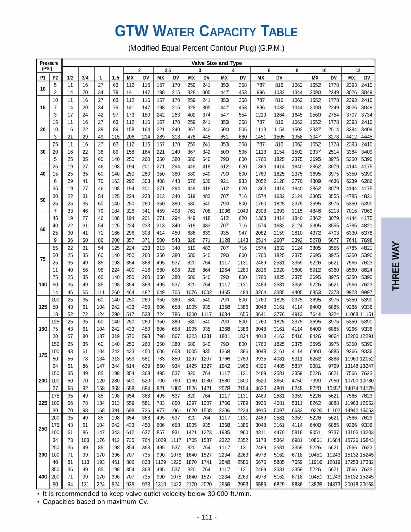
THR
EE W
AY
- 111 -
GTW WATER CAPACITY TABLE(Modified Equal Percent Contour Plug) (G.P.M.)
• It is recommended to keep valve outlet velocity below 30,000 ft./min.• Capacities based on maximum Cv.
Pressure Valve Size and Type(PSI) 2 2.5 3 4 6 8 10 12
P1 P2 1/2 3/4 1 1.5 MX DV MX DV MX DV MX DV MX DV MX DV MX DV
105 11 16 27 63 112 116 157 170 259 241 353 358 787 816 1062 1652 1778 2393 24102 14 20 34 79 141 147 198 215 328 305 447 453 996 1032 1344 2090 2249 3026 304910 11 16 27 63 112 116 157 170 259 241 353 358 787 816 1062 1652 1778 2393 2410
15 7 14 20 34 79 141 147 198 215 328 305 447 453 996 1032 1344 2090 2249 3026 30493 17 24 42 97 173 180 242 263 402 374 547 554 1219 1264 1645 2560 2754 3707 373415 11 16 27 63 112 116 157 170 259 241 353 358 787 816 1062 1652 1778 2393 2410
20 10 16 22 38 89 158 164 221 240 367 342 500 506 1113 1154 1502 2337 2514 3384 34093 21 29 49 115 206 214 289 313 478 445 651 660 1451 1505 1958 3047 3278 4412 444525 11 16 27 63 112 116 157 170 259 241 353 358 787 816 1062 1652 1778 2393 2410
30 20 16 22 38 89 158 164 221 240 367 342 500 506 1113 1154 1502 2337 2514 3384 34095 25 35 60 140 250 260 350 380 580 540 790 800 1760 1825 2375 3695 3975 5350 539025 19 27 46 108 194 201 271 294 449 418 612 620 1363 1414 1840 2862 3079 4144 4175
40 15 25 35 60 140 250 260 350 380 580 540 790 800 1760 1825 2375 3695 3975 5350 53906 29 41 70 163 292 303 408 443 676 630 921 933 2052 2128 2770 4309 4636 6239 628635 19 27 46 108 194 201 271 294 449 418 612 620 1363 1414 1840 2862 3079 4144 4175
5030 22 31 54 125 224 233 313 340 519 483 707 716 1574 1632 2124 3305 3555 4785 482125 25 35 60 140 250 260 350 380 580 540 790 800 1760 1825 2375 3695 3975 5350 53907 33 46 79 184 328 341 459 498 761 708 1036 1049 2308 2393 3115 4846 5213 7016 706945 19 27 46 108 194 201 271 294 449 418 612 620 1363 1414 1840 2862 3079 4144 4175
6040 22 31 54 125 224 233 313 340 519 483 707 716 1574 1632 2124 3305 3555 4785 482125 30 41 71 166 296 308 414 450 686 639 935 947 2082 2159 2810 4372 4703 6330 63789 36 50 86 200 357 371 500 543 828 771 1128 1143 2514 2607 3392 5278 5677 7641 769855 22 31 54 125 224 233 313 340 519 483 707 716 1574 1632 2124 3305 3555 4785 4821
7550 25 35 60 140 250 260 350 380 580 540 790 800 1760 1825 2375 3695 3975 5350 539025 35 49 85 198 354 368 495 537 820 764 1117 1131 2489 2581 3359 5226 5621 7566 762311 40 56 96 224 400 416 560 608 928 864 1264 1280 2816 2920 3800 5912 6360 8560 862475 25 35 60 140 250 260 350 380 580 540 790 800 1760 1825 2375 3695 3975 5350 5390
100 50 35 49 85 198 354 368 495 537 820 764 1117 1131 2489 2581 3359 5226 5621 7566 762314 46 65 111 260 464 482 649 705 1076 1002 1465 1484 3264 3385 4405 6853 7373 9923 9997
100 25 35 60 140 250 260 350 380 580 540 790 800 1760 1825 2375 3695 3975 5350 5390125 50 43 61 104 242 433 450 606 658 1005 935 1368 1386 3048 3161 4114 6400 6885 9266 9336
18 52 72 124 290 517 538 724 786 1200 1117 1634 1655 3641 3776 4913 7644 8224 11068 11151125 25 35 60 140 250 260 350 380 580 540 790 800 1760 1825 2375 3695 3975 5350 5390
150 75 43 61 104 242 433 450 606 658 1005 935 1368 1386 3048 3161 4114 6400 6885 9266 933620 57 80 137 319 570 593 798 867 1323 1231 1801 1824 4013 4162 5416 8426 9064 12200 12291
150 25 35 60 140 250 260 350 380 580 540 790 800 1760 1825 2375 3695 3975 5350 5390
175100 43 61 104 242 433 450 606 658 1005 935 1368 1386 3048 3161 4114 6400 6885 9266 933650 56 78 134 313 559 581 783 850 1297 1207 1766 1789 3935 4081 5311 8262 8888 11963 1205224 61 86 147 344 614 639 860 934 1425 1327 1942 1966 4325 4485 5837 9081 9769 13148 13247
150 35 49 85 198 354 368 495 537 820 764 1117 1131 2489 2581 3359 5226 5621 7566 7623200 100 50 70 120 280 500 520 700 760 1160 1080 1580 1600 3520 3650 4750 7390 7950 10700 10780
27 66 92 158 368 658 684 921 1000 1526 1421 2078 2104 4630 4801 6248 9720 10457 14074 14179175 35 49 85 198 354 368 495 537 820 764 1117 1131 2489 2581 3359 5226 5621 7566 7623
225 100 56 78 134 313 559 581 783 850 1297 1207 1766 1789 3935 4081 5311 8262 8888 11963 1205230 70 98 168 391 698 726 977 1061 1620 1508 2206 2234 4915 5097 6633 10320 11102 14942 15053
200 35 49 85 198 354 368 495 537 820 764 1117 1131 2489 2581 3359 5226 5621 7566 7623
250175 43 61 104 242 433 450 606 658 1005 935 1368 1386 3048 3161 4114 6400 6885 9266 9336100 61 86 147 343 612 637 857 931 1421 1323 1935 1960 4311 4470 5818 9051 9737 13105 1320334 73 103 176 412 735 764 1029 1117 1705 1587 2322 2352 5173 5364 6981 10861 11684 15726 15843
250 35 49 85 198 354 368 495 537 820 764 1117 1131 2489 2581 3359 5226 5621 7566 7623300 100 71 99 170 396 707 735 990 1075 1640 1527 2234 2263 4978 5162 6718 10451 11243 15132 15245
40 81 113 193 451 806 838 1129 1225 1870 1741 2548 2580 5676 5885 7659 11916 12819 17253 17382350 35 49 85 198 354 368 495 537 820 764 1117 1131 2489 2581 3359 5226 5621 7566 7623
400 200 71 99 170 396 707 735 990 1075 1640 1527 2234 2263 4978 5162 6718 10451 11243 15132 1524550 94 131 224 524 935 973 1310 1422 2170 2020 2956 2993 6585 6829 8886 13825 14873 20018 20168
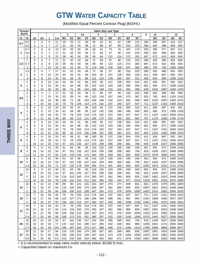
THR
EE W
AY
- 112 -
GTW WATER CAPACITY TABLE(Modified Equal Percent Contour Plug) (M3/Hr.)
• It is recommended to keep valve outlet velocity below 30,000 ft./min.• Capacities based on maximum Cv.
Pressure Valve Size and Type(M3/hr) 2 2.5 3 4 6 8 10 12
P1 P2 1/2 3/4 1 1.5 MX DV MX DV MX DV MX DV MX DV MX DV MX DV
0.70.5 2 3 5 11 19 20 27 29 45 42 61 62 136 141 184 286 307 414 4170.2 3 4 7 17 31 32 43 46 71 66 97 98 215 223 290 452 486 654 6590.7 2 3 6 13 24 25 33 36 55 51 75 76 167 173 225 350 377 507 511
1 0.5 3 4 7 17 31 32 43 46 71 66 97 98 215 223 290 452 486 654 659.2 4 5 9 22 39 40 54 59 90 84 122 124 272 282 367 572 615 828 8341 3 4 7 17 31 32 43 46 71 66 97 98 215 223 290 452 486 654 659
1.5 0.7 4 5 9 22 39 40 54 59 90 84 122 124 272 282 367 572 615 828 834.2 5 7 12 28 49 51 69 75 114 106 156 158 347 360 468 729 784 1055 10631.5 3 4 7 17 31 32 43 46 71 66 97 98 215 223 290 452 486 654 659
2 1 4 6 10 24 43 45 61 66 100 93 137 138 304 316 411 639 687 925 932.3 6 8 14 32 56 59 79 86 131 122 178 180 397 412 536 833 896 1206 12152 4 6 10 24 43 45 61 66 100 93 137 138 304 316 411 639 687 925 932
3 1 6 9 15 34 61 64 86 93 142 132 193 196 430 446 581 904 972 1309 1318.5 7 10 16 38 68 71 96 104 159 148 216 219 481 499 649 1010 1087 1463 14743 3 4 7 17 31 32 43 46 71 66 97 98 215 223 290 452 486 654 659
3.52 5 7 13 30 53 55 74 80 123 114 167 169 373 387 503 783 842 1133 11421 7 10 16 38 68 71 96 104 159 148 216 219 481 499 649 1010 1087 1463 1474.5 7 10 18 42 75 78 105 114 174 162 237 240 527 547 711 1107 1191 1603 16153 4 6 10 24 43 45 61 66 100 93 137 138 304 316 411 639 687 925 932
42 6 9 15 34 61 64 86 93 142 132 193 196 430 446 581 904 972 1309 13181 7 10 18 42 75 78 105 114 174 162 237 240 527 547 711 1107 1191 1603 1615.6 8 11 19 45 80 83 112 121 185 172 252 255 561 582 757 1178 1268 1706 17194 4 6 10 24 43 45 61 66 100 93 137 138 304 316 411 639 687 925 932
53 6 9 15 34 61 64 86 93 142 132 193 196 430 446 581 904 972 1309 13182 7 10 18 42 75 78 105 114 174 162 237 240 527 547 711 1107 1191 1603 1615.8 9 12 21 50 89 92 124 135 206 191 280 284 624 647 842 1310 1409 1896 19105 4 6 10 24 43 45 61 66 100 93 137 138 304 316 411 639 687 925 932
6 3 7 10 18 42 75 78 105 114 174 162 237 240 527 547 711 1107 1191 1603 16151 10 14 23 54 97 101 135 147 224 209 306 309 681 706 919 1429 1537 2069 20856 6 9 15 34 61 64 86 93 142 132 193 196 430 446 581 904 972 1309 1318
8 3 10 14 23 54 97 101 135 147 224 209 306 309 681 706 919 1429 1537 2069 20851.1 11 16 27 64 114 118 159 173 264 245 359 363 800 829 1079 1679 1806 2431 24498 6 9 15 34 61 64 86 93 142 132 193 196 430 446 581 904 972 1309 1318
10 5 10 14 23 54 97 101 135 147 224 209 306 309 681 706 919 1429 1537 2069 20851.4 13 18 30 71 127 132 178 193 294 274 401 406 893 926 1205 1874 2016 2714 273410 6 9 15 34 61 64 86 93 142 132 193 196 430 446 581 904 972 1309 1318
127 10 14 23 54 97 101 135 147 224 209 306 309 681 706 919 1429 1537 2069 20855 11 16 27 64 114 119 160 174 265 247 361 366 805 835 1087 1691 1819 2448 2466
1.7 14 19 33 78 139 144 194 211 322 300 439 444 977 1013 1318 2051 2206 2970 299210 9 12 21 48 86 90 121 131 201 187 273 277 609 631 822 1278 1375 1851 1864
14 7 11 16 27 64 114 119 160 174 265 247 361 366 805 835 1087 1691 1819 2448 24662 15 21 36 84 150 156 210 228 347 324 473 479 1054 1093 1423 2214 2382 3205 322912 7 10 18 42 75 78 105 114 174 162 237 240 527 547 711 1107 1191 1603 1615
15 7 12 17 29 68 122 127 171 186 284 264 386 391 861 893 1162 1808 1945 2617 26372 16 22 37 87 156 162 218 237 362 337 493 499 1098 1138 1481 2304 2479 3336 336114 7 10 18 42 75 78 105 114 174 162 237 240 527 547 711 1107 1191 1603 1615
1710 11 16 27 64 114 119 160 174 265 247 361 366 805 835 1087 1691 1819 2448 24665 15 21 36 84 150 156 210 228 347 324 473 479 1054 1093 1423 2214 2382 3205 3229
2.4 17 23 40 93 165 172 231 251 383 357 522 529 1163 1206 1570 2442 2627 3536 356215 10 14 23 54 97 101 135 147 224 209 306 309 681 706 919 1429 1537 2069 2085
20 10 14 19 33 77 137 142 191 208 317 295 432 438 963 998 1299 2021 2174 2926 29482.7 18 25 43 101 180 187 252 273 417 388 568 575 1266 1313 1709 2658 2860 3849 387720 11 16 27 64 114 119 160 174 265 247 361 366 805 835 1087 1691 1819 2448 2466
27 15 15 21 36 84 150 156 210 228 347 324 473 479 1054 1093 1423 2214 2382 3205 32293.5 21 29 50 117 210 218 293 319 486 453 662 671 1476 1530 1991 3098 3333 4486 4519
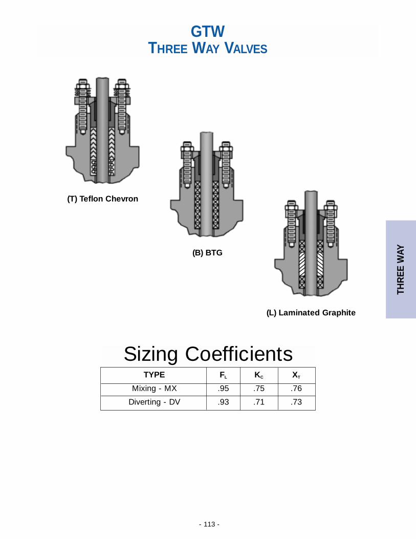
THR
EE W
AY
- 113 -
(L) Laminated Graphite
(T) Teflon Chevron
(B) BTG
GTWTHREE WAY VALVES
TYPE FL KC XT
Mixing - MX .95 .75 .76
Diverting - DV .93 .71 .73
Sizing Coefficients
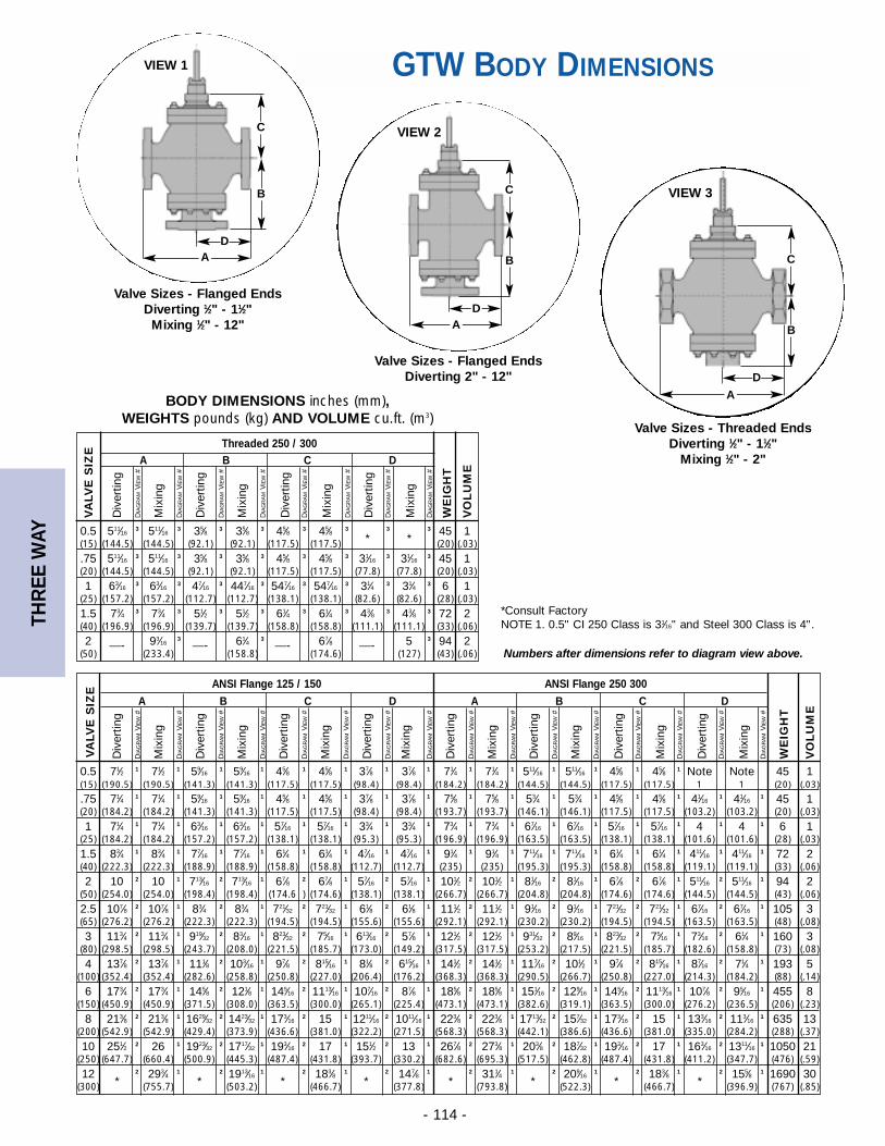
THR
EE W
AY
- 114 -
Valve Sizes - Flanged EndsDiverting 1⁄2" - 11⁄2"
Mixing 1⁄2" - 12"
Valve Sizes - Flanged EndsDiverting 2" - 12"
Valve Sizes - Threaded EndsDiverting 1⁄2" - 11⁄2"
Mixing 1⁄2" - 2"
GTW BODY DIMENSIONS
*Consult FactoryNOTE 1. 0.5" CI 250 Class is 31⁄16" and Steel 300 Class is 4".
BODY DIMENSIONS inches (mm), WEIGHTS pounds (kg) AND VOLUME cu.ft. (m3)
B
C
A
D
B
C
AD
B
C
AD
ANSI Flange 125 / 150 ANSI Flange 250 300
A B C D A B C D
0.5 71⁄2 1 71⁄2 1 59⁄161 59⁄16
1 45⁄8 1 45⁄8 1 37⁄8 1 37⁄8 1 71⁄4 1 71⁄4 1 511⁄161 511⁄16
1 45⁄8 1 45⁄8 1 Note Note 45 1(15) (190.5) (190.5) (141.3) (141.3) (117.5) (117.5) (98.4) (98.4) (184.2) (184.2) (144.5) (144.5) (117.5) (117.5) 1 1 (20) (.03)
.75 71⁄4 1 71⁄4 1 59⁄161 59⁄16
1 45⁄8 1 45⁄8 1 37⁄8 1 37⁄8 1 75⁄8 1 75⁄8 1 53⁄4 1 53⁄4 1 45⁄8 1 45⁄8 1 41⁄161 41⁄16
1 45 1(20) (184.2) (184.2) (141.3) (141.3) (117.5) (117.5) (98.4) (98.4) (193.7) (193.7) (146.1) (146.1) (117.5) (117.5) (103.2) (103.2) (20) (.03)
1 71⁄4 1 71⁄4 1 63⁄161 63⁄16
1 57⁄161 57⁄16
1 33⁄4 1 33⁄4 1 73⁄4 1 73⁄4 1 67⁄161 67⁄16
1 57⁄161 57⁄16
1 4 1 4 1 6 1(25) (184.2) (184.2) (157.2) (157.2) (138.1) (138.1) (95.3) (95.3) (196.9) (196.9) (163.5) (163.5) (138.1) (138.1) (101.6) (101.6) (28) (.03)
1.5 83⁄4 1 83⁄4 1 77⁄161 77⁄16
1 61⁄4 1 61⁄4 1 47⁄161 47⁄16
1 91⁄4 1 91⁄4 1 711⁄161 711⁄16
1 61⁄4 1 61⁄4 1 411⁄161 411⁄16
1 72 2(40) (222.3) (222.3) (188.9) (188.9) (158.8) (158.8) (112.7) (112.7) (235) (235) (195.3) (195.3) (158.8) (158.8) (119.1) (119.1) (33) (.06)
2 10 2 10 1 713⁄162 713⁄16
1 67⁄8 2 67⁄8 1 57⁄162 57⁄16
1 101⁄2 2 101⁄2 1 81⁄162 81⁄16
1 67⁄8 2 67⁄8 1 511⁄162 511⁄16
1 94 2(50) (254.0) (254.0) (198.4) (198.4) (174.6 ) (174.6) (138.1) (138.1) (266.7) (266.7) (204.8) (204.8) (174.6) (174.6) (144.5) (144.5) (43) (.06)
2.5 107⁄8 2 107⁄8 1 83⁄4 2 83⁄4 1 721⁄322 721⁄32
1 61⁄8 2 61⁄8 1 111⁄2 2 111⁄2 1 91⁄162 91⁄16
1 721⁄322 721⁄32
1 67⁄162 67⁄16
1 105 3(65) (276.2) (276.2) (222.3) (222.3) (194.5) (194.5) (155.6) (155.6) (292.1) (292.1) (230.2) (230.2) (194.5) (194.5) (163.5) (163.5) (48) (.08)
3 113⁄4 2 113⁄4 1 919⁄322 83⁄16
1 823⁄322 75⁄16
1 613⁄162 57⁄8 1 121⁄2 2 121⁄2 1 931⁄32
2 89⁄161 823⁄32
2 75⁄161 73⁄16
2 61⁄4 1 160 3(80) (298.5) (298.5) (243.7) (208.0) (221.5) (185.7) (173.0) (149.2) (317.5) (317.5) (253.2) (217.5) (221.5) (185.7) (182.6) (158.8) (73) (.08)
4 137⁄8 2 137⁄8 1 111⁄8 2 103⁄161 97⁄8 2 815⁄16
1 81⁄8 2 615⁄161 141⁄2 2 141⁄2 1 117⁄16
2 101⁄2 1 97⁄8 2 815⁄161 87⁄16
2 71⁄4 1 193 5(100) (352.4) (352.4) (282.6) (258.8) (250.8) (227.0) (206.4) (176.2) (368.3) (368.3) (290.5) (266.7) (250.8) (227.0) (214.3) (184.2) (88) (.14)
6 173⁄4 2 173⁄4 1 145⁄8 2 121⁄8 1 145⁄162 1113⁄16
1 107⁄162 87⁄8 1 185⁄8 2 185⁄8 1 151⁄16
2 129⁄161 145⁄16
2 1113⁄161 107⁄8 2 95⁄16
1 455 8(150) (450.9) (450.9) (371.5) (308.0) (363.5) (300.0) (265.1) (225.4) (473.1) (473.1) (382.6) (319.1) (363.5) (300.0) (276.2) (236.5) (206) (.23)
8 213⁄8 2 213⁄8 1 1629⁄322 1423⁄32
1 173⁄162 15 1 1211⁄16
2 1011⁄161 223⁄8 2 223⁄8 1 1713⁄32
2 157⁄321 173⁄16
2 15 1 133⁄162 113⁄16
1 635 13(200) (542.9) (542.9) (429.4) (373.9) (436.6) (381.0) (322.2) (271.5) (568.3) (568.3) (442.1) (386.6) (436.6) (381.0) (335.0) (284.2) (288) (.37)
10 251⁄2 2 26 1 1923⁄322 1717⁄32
1 193⁄162 17 1 151⁄2 2 13 1 267⁄8 2 273⁄8 1 203⁄8 2 187⁄32
1 193⁄162 17 1 163⁄16
2 1311⁄161 1050 21
(250) (647.7) (660.4) (500.9) (445.3) (487.4) (431.8) (393.7) (330.2) (682.6) (695.3) (517.5) (462.8) (487.4) (431.8) (411.2) (347.7) (476) (.59)
12*
2 293⁄4 1
*2 1913⁄16
1
*2 183⁄8 1
*2 147⁄8 1
*2 311⁄4 1
*2 209⁄16
1
*2 183⁄8 1
*2 155⁄8 1 1690 30
(300) (755.7) (503.2) (466.7) (377.8) (793.8) (522.3) (466.7) (396.9) (767) (.85)
Div
ertin
g
DIA
GR
AM
VIE
W#
Mix
ing
DIA
GR
AM
VIE
W#
Div
ertin
g
DIA
GR
AM
VIE
W#
Mix
ing
DIA
GR
AM
VIE
W#
Div
ertin
g
DIA
GR
AM
VIE
W#
Mix
ing
DIA
GR
AM
VIE
W#
Div
ertin
g
DIA
GR
AM
VIE
W#
Mix
ing
DIA
GR
AM
VIE
W#
Div
ertin
g
DIA
GR
AM
VIE
W#
Mix
ing
DIA
GR
AM
VIE
W#
Div
ertin
g
DIA
GR
AM
VIE
W#
Mix
ing
DIA
GR
AM
VIE
W#
Div
ertin
g
DIA
GR
AM
VIE
W#
Mix
ing
DIA
GR
AM
VIE
W#
Div
ertin
g
DIA
GR
AM
VIE
W#
Mix
ing
DIA
GR
AM
VIE
W#
WE
IGH
T
VO
LU
ME
VA
LVE
SIZ
E
Numbers after dimensions refer to diagram view above.
Threaded 250 / 300A B C D
0.5 511⁄163 511⁄16
3 35⁄8 3 35⁄8 3 45⁄8 3 45⁄8 3
*3
*3 45 1
(15) (144.5) (144.5) (92.1) (92.1) (117.5) (117.5) (20) (.03)
.75 511⁄163 511⁄16
3 35⁄8 3 35⁄8 3 45⁄8 3 45⁄8 3 31⁄163 31⁄16
3 45 1(20) (144.5) (144.5) (92.1) (92.1) (117.5) (117.5) (77.8) (77.8) (20) (.03)
1 63⁄163 63⁄16
3 47⁄163 447⁄16
3 547⁄163 547⁄16
3 31⁄4 3 31⁄4 3 6 1(25) (157.2) (157.2) (112.7) (112.7) (138.1) (138.1) (82.6) (82.6) (28) (.03)
1.5 73⁄4 3 73⁄4 3 51⁄2 3 51⁄2 3 61⁄4 3 61⁄4 3 43⁄8 3 43⁄8 3 72 2(40) (196.9) (196.9) (139.7) (139.7) (158.8) (158.8) (111.1) (111.1) (33) (.06)
2 —- 93⁄163
—- 61⁄4 3—- 67⁄8 —- 5 3 94 2
(50) (233.4) (158.8) (174.6) (127) (43) (.06)
Div
ertin
g
DIA
GR
AM
VIE
W#
Mix
ing
DIA
GR
AM
VIE
W#
Div
ertin
g
DIA
GR
AM
VIE
W#
Mix
ing
DIA
GR
AM
VIE
W#
Div
ertin
g
DIA
GR
AM
VIE
W#
Mix
ing
DIA
GR
AM
VIE
W#
Div
ertin
g
DIA
GR
AM
VIE
W#
Mix
ing
DIA
GR
AM
VIE
W#
WE
IGH
T
VO
LU
ME
VA
LVE
SIZ
E
VIEW 1
VIEW 2
VIEW 3
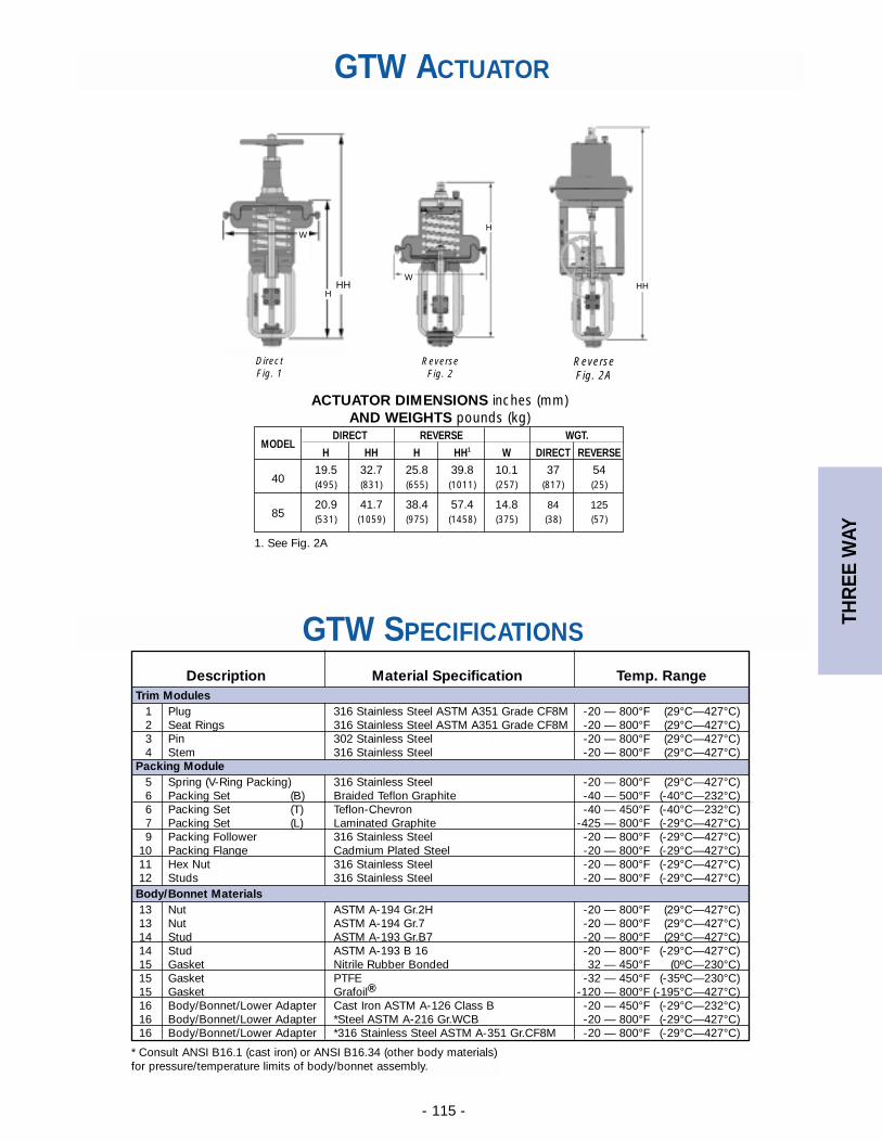
THR
EE W
AY
- 115 -
HH
ReverseFig. 2A
GTW SPECIFICATIONS
GTW ACTUATOR
ACTUATOR DIMENSIONS inches (mm)AND WEIGHTS pounds (kg)
HH
W
H
ReverseFig. 2
H
W
MODELDIRECT REVERSE WGT.
H HH H HH1 W DIRECT REVERSE
4019.5 32.7 25.8 39.8 10.1 37 54(495) (831) (655) (1011) (257) (817) (25)
8520.9 41.7 38.4 57.4 14.8 84 125(531) (1059) (975) (1458) (375) (38) (57)
Description Material Specification Temp. RangeTrim Modules
1 Plug 316 Stainless Steel ASTM A351 Grade CF8M -20 — 800°F (29°C—427°C)2 Seat Rings 316 Stainless Steel ASTM A351 Grade CF8M -20 — 800°F (29°C—427°C)3 Pin 302 Stainless Steel -20 — 800°F (29°C—427°C)4 Stem 316 Stainless Steel -20 — 800°F (29°C—427°C)
Packing Module 5 Spring (V-Ring Packing) 316 Stainless Steel -20 — 800°F (29°C—427°C)6 Packing Set (B) Braided Teflon Graphite -40 — 500°F (-40°C—232°C)6 Packing Set (T) Teflon-Chevron -40 — 450°F (-40°C—232°C)7 Packing Set (L) Laminated Graphite -425 — 800°F (-29°C—427°C)9 Packing Follower 316 Stainless Steel -20 — 800°F (-29°C—427°C)
10 Packing Flange Cadmium Plated Steel -20 — 800°F (-29°C—427°C)11 Hex Nut 316 Stainless Steel -20 — 800°F (-29°C—427°C)12 Studs 316 Stainless Steel -20 — 800°F (-29°C—427°C)
Body/Bonnet Materials13 Nut ASTM A-194 Gr.2H -20 — 800°F (29°C—427°C)13 Nut ASTM A-194 Gr.7 -20 — 800°F (29°C—427°C)14 Stud ASTM A-193 Gr.B7 -20 — 800°F (29°C—427°C)14 Stud ASTM A-193 B 16 -20 — 800°F (-29°C—427°C)15 Gasket Nitrile Rubber Bonded 32 — 450°F (0ºC—230°C)15 Gasket PTFE -32 — 450°F (-35ºC—230°C)15 Gasket Grafoil® -120 — 800°F (-195°C—427°C)16 Body/Bonnet/Lower Adapter Cast Iron ASTM A-126 Class B -20 — 450°F (-29°C—232°C)16 Body/Bonnet/Lower Adapter *Steel ASTM A-216 Gr.WCB -20 — 800°F (-29°C—427°C)16 Body/Bonnet/Lower Adapter *316 Stainless Steel ASTM A-351 Gr.CF8M -20 — 800°F (-29°C—427°C)
DirectFig. 1
1. See Fig. 2A
* Consult ANSI B16.1 (cast iron) or ANSI B16.34 (other body materials)for pressure/temperature limits of body/bonnet assembly.
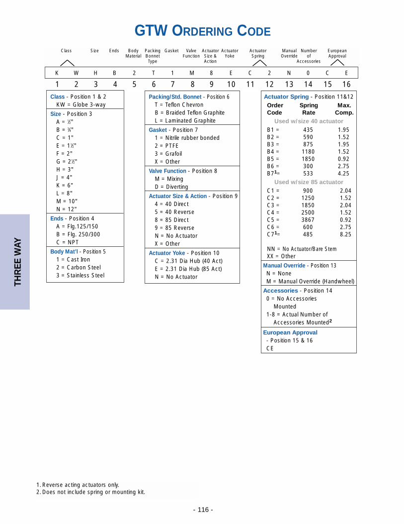
THR
EE W
AY
- 116 -
GTW ORDERING CODE
K W H B 2 T 1 M 8 E C 2 N 0 C E
1 2 3 4 5 6 7 8 9 10 11 12 13 14 15 16
Class Size Ends Body Packing Gasket Valve Actuator Actuator Actuator Manual Number EuropeanMaterial Bonnet Function Size & Yoke Spring Override of Approval
Type Action Accessories
Actuator Spring - Position 11&12Order Spring Max.Code Rate Comp.
Used w/size 40 actuatorB1 = 435 1.95B2 = 590 1.52B3 = 875 1.95B4 = 1180 1.52B5 = 1850 0.92B6 = 300 2.75B71= 533 4.25
Used w/size 85 actuatorC1 = 900 2.04C2 = 1250 1.52C3 = 1850 2.04C4 = 2500 1.52C5 = 3867 0.92C6 = 600 2.75C71= 485 8.25
NN = No Actuator/Bare StemXX = Other
Manual Override - Position 13N = NoneM = Manual Override (Handwheel)
Accessories - Position 140 = No Accessories
Mounted1-8 = Actual Number of
Accessories Mounted2
European Approval - Position 15 & 16CE
Packing/Std. Bonnet - Position 6T = Teflon ChevronB = Braided Teflon GraphiteL = Laminated Graphite
Gasket - Position 71 = Nitrile rubber bonded2 = PTFE3 = GrafoilX = Other
Valve Function - Position 8M = MixingD = Diverting
Actuator Size & Action - Position 94 = 40 Direct5 = 40 Reverse8 = 85 Direct9 = 85 ReverseN = No ActuatorX = Other
Actuator Yoke - Position 10C = 2.31 Dia Hub (40 Act)E = 2.31 Dia Hub (85 Act)N = No Actuator
Class - Position 1 & 2KW = Globe 3-way
Size - Position 3A = 1⁄2"B = 3⁄4"C = 1"E = 11⁄2"F = 2"G = 21⁄2"H = 3"J = 4"K = 6"L = 8"M = 10"N = 12"
Ends - Position 4A = Flg.125/150B = Flg. 250/300C = NPT
Body Mat’l - Position 51 = Cast Iron2 = Carbon Steel3 = Stainless Steel
1. Reverse acting actuators only.2. Does not include spring or mounting kit.
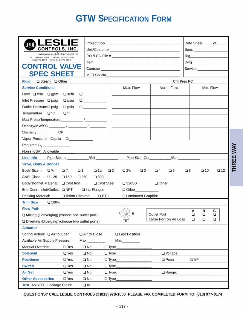
THR
EE W
AY
- 117 -
GTW SPECIFICATION FORM
12501 Telecom Drive · Tampa, Florida 33637(813) 978-1000 · FAX: (813)-978-0984
CONTROL VALVE SPEC SHEET
Project/Job _________________________________________ Data Sheet______of______
Unit/Customer_______________________________________ Spec ___________________
P.O./LCO File # ______________________________________ Tag_____________________
Item________________________________________________ Dwg____________________
Contract ____________________________________________ Service _________________
MFR Serial#_________________________________________
Fluid ❏ Steam ❏ Other Crit Pres PC
Service Conditions Max. Flow Norm. Flow Min. Flow
Flow ❏ #/hr ❏ gpm ❏ scfh ❏ _____________
Inlet Pressure ❏ psig ❏ psia ❏ _____________
Outlet Pressure ❏ psig ❏ psia ❏ _____________
Temperature ❏ °C ❏ °F ________________
Max Press/Temperature:____________ /____________
Density/MW/SG _________ / __________ / _________
Viscosity ___________ CP
Vapor Pressure ❏ psia ❏ _____________
Required Cv _______________
Noise (dBA) Allowable_________
Line Info Pipe Size In____________/Sch____________ Pipe Size Out____________/Sch____________
Valve, Body & Bonnet
Body Size in. ❏ 1/2 ❏ 3/4 ❏ 1 ❏ 11/2 ❏ 2 ❏ 21/2 ❏ 3 ❏ 4 ❏ 6 ❏ 8 ❏ 10 ❏ 12
ANSI Class ❏ 125 ❏ 150 ❏ 250 ❏ 300
Body/Bonnet Material: ❏ Cast Iron ❏ Cast Steel ❏ 316SS ❏ Other_____________
End Conn. Inlet/Outlet: ❏ NPT ❏ Int. Flanges ❏ Other_____________
Packing Material: ❏ Teflon Chevron ❏ BTG ❏ Laminated Graphite
Trim Size ❏ 100%
Flow Path
❏ Mixing (Converging) (choose one outlet port)
❏ Diverting (Diverging) (choose two outlet ports)
Actuator
Spring Action: ❏ Air to Open ❏ Air to Close ❏ Last Position
Available Air Supply Pressure: Max.__________ Min.__________
Manual Override: ❏ Yes ❏ No ❏ Type____________________
Solenoid ❏ Yes ❏ No ❏ Type____________________ ❏ Voltage_________________
Positioner ❏ Yes ❏ No ❏ Type____________________ ❏ Pneu ❏ I/P
Switch ❏ Yes ❏ No ❏ Type____________________
Air Set ❏ Yes ❏ No ❏ Type:___________________ ❏ Range:__________________
Other Accessories ❏ Yes ❏ No ❏ Type____________________
Test ANSI/FCI Leakage Class: ❏ IV
A B COutlet Port ❏ ❏ ❏
Close Port on Air Loss ❏ ❏ ❏
A
C
B
QUESTIONS? CALL LESLIE CONTROLS @ (813) 978-1000 PLEASE FAX COMPLETED FORM TO: (813) 977-0174
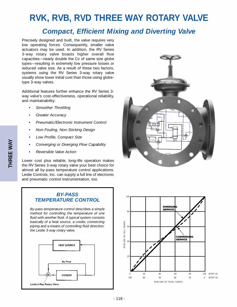
THR
EE W
AY
- 118 -
BY-PASS TEMPERATURE CONTROL
By-pass temperature control describes a simplemethod for controlling the temperature of onefluid with another fluid. A typical system consistsbasically of a heat source, a cooler, connectingpiping and a means of controlling fluid direction:the Leslie 3-way rotary valve.
Precisely designed and built, the valve requires verylow operating forces. Consequently, smaller valveactuators may be used. In addition, the RV Series 3-way rotary valve boasts higher overall flowcapacities—nearly double the Cv of same size globetypes—resulting in extremely low pressure losses orreduced valve size. As a result of these two factors,systems using the RV Series 3-way rotary valveusually show lower initial cost than those using globe-type 3-way valves.
Additional features further enhance the RV Series 3-way valve’s cost-effectiveness, operational reliability,and maintainability:
• Smoother Throttling
• Greater Accuracy
• Pneumatic/Electronic Instrument Control
• Non-Fouling, Non-Sticking Design
• Low Profile, Compact Size
• Converging or Diverging Flow Capability
• Reversible Valve Action
Lower cost plus reliable, long-life operation makesthe RV Series 3-way rotary valve your best choice foralmost all by-pass temperature control applications.Leslie Controls, Inc. can supply a full line of electronicand pneumatic control instrumentation, too.
Compact, Efficient Mixing and Diverting Valve
RVK, RVB, RVD THREE WAY ROTARY VALVE
DIVERGINGSERVICE
CONVERGINGSERVICE
PE
RC
EN
T O
F FU
LL T
RA
VE
L
PERCENT OF TOTAL TRAVEL
100
80
60
40
20
0 20 40 60 80 100 (PORT A)
100 80 60 40 20 0 (PORT B)
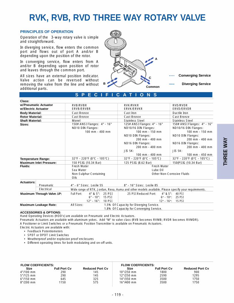
THR
EE W
AY
- 119 -
PRINCIPLES OF OPERATIONOperation of the 3-way rotary valve is simpleand straightforward.
In diverging service, flow enters the commonport and flows out of port A and/or Bdepending upon the position of the rotor.
In converging service, flow enters from Aand/or B depending upon position of rotorand leaves through the common port.
All sizes have an external position indicator.Valve action can be reversed withoutremoving the valve from the line and withoutadditional parts.
Class:w/Pneumatic Actuator RVB/RVBR RVK/RVKR RVD/RVDRw/Electric Actuator ERVB/ERVBR ERVK/ERVKR ERVD/ERVDRBody Material: Cast Bronze Cast Iron Ductile IronRotor Material: Cast Bronze Cast Bronze Cast BronzeShaft Material: Monel Stainless Steel Stainless SteelSizes: 150# ANSI Flanges: 4" - 16" 125# ANSI Flanges: 4" - 16" 150# ANSI Flanges: 4" - 16"
ND10 DIN Flanges: ND10/16 DIN Flanges: ND10/16 DIN Flanges:100 mm - 400 mm 100 mm - 150 mm 100 mm - 150 mm
ND10 DIN Flanges: ND10 DIN Flanges:200 mm - 400 mm 200 mm - 400 mm
ND16 DIN Flanges: ND16 DIN Flanges:200 mm - 400 mm 200 mm - 400 mm
JIS 5K: JIS 5K:100 mm - 400 mm 100 mm - 450 mm
Temperature Range: 32°F - 220°F (0°C - 105°C) 32°F - 220°F (0°C - 105°C) 32°F - 220°F (0°C - 105°C)Maximum Inlet Pressure: 150 PSIG (10.34 Bar) 125 PSIG (8.62 Bar) 150(PSIG (10.34 Bar)Fluids: Fresh Water Fresh Water
Sea Water Lube OilNon-Sulphur Containing Other Non-Corrosive FluidsOils
Actuators:Pneumatic 4" - 6" Sizes: Leslie 55 8" - 16" Sizes: Leslie 85Electrical Wide range of RTK, Jordan, Rexa, Auma and other models available. Please specify your requirements.
Maximum Through Valve ∆P: Full Port: 4" & 5": 25 PSI 25 PSI Reduced Port: 4" & 5": 40 PSI 6" - 10": 15 PSI 6" - 10": 25 PSI
12" - 16": 10 PSI 12" - 16": 15 PSIMaximum Leakage Rate: All Sizes: 1.5% Of Capacity for Diverging Service.
1.8% Of Capacity for Converging Service.ACCESSORIES & OPTIONS:Hand Operating Devices (HOD’s) are available on Pneumatic and Electric Actuators.Pneumatic Actuators are available with aluminum yokes. Add “M” to valve class (RVB becomes RVMB; RVDR becomes RVMDR).A Positioner or Limit Switches or a Pneumatic Position Transmitter is available on Pneumatic Actuators.Electric Actuators are available with:
• Feedback Potentiometers• SPDT or DPDT Limit Switches• Weatherproof and/or explosion proof enclosures• Different operating times for both modulating and on-off units.
---- Converging Service
—– Diverging Service
FLOW COEFFICIENTS:Size Full Port Cv Reduced Port Cv
4"/100 mm 290 1455"/125 mm 290 1456"/150 mm 645 3258"/200 mm 1150 575
FLOW COEFFICIENTS:Size Full Port Cv Reduced Port Cv
10"/250 mm 1800 90012"/250 mm 2590 129514"/350 mm 3500 175016"/400 mm 3500 1750
S P E C I F I C A T I O N S
A
BCommon
C
RVK, RVB, RVD THREE WAY ROTARY VALVE
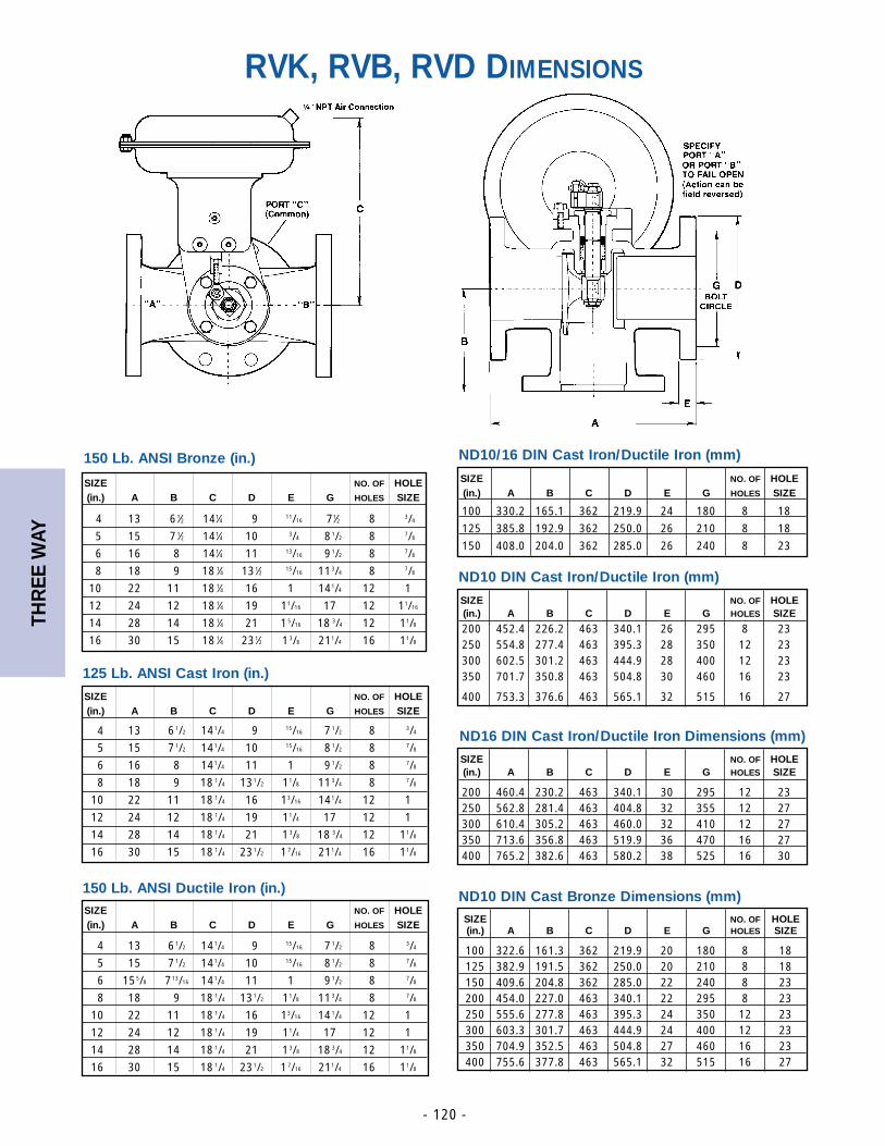
THR
EE W
AY
- 120 -
ND10/16 DIN Cast Iron/Ductile Iron (mm)
ND10 DIN Cast Iron/Ductile Iron (mm)
ND16 DIN Cast Iron/Ductile Iron Dimensions (mm)
ND10 DIN Cast Bronze Dimensions (mm)
SIZE NO. OF HOLE(in.) A B C D E G HOLES SIZE
100 330.2 165.1 362 219.9 24 180 8 18
125 385.8 192.9 362 250.0 26 210 8 18
150 408.0 204.0 362 285.0 26 240 8 23
SIZE NO. OF HOLE(in.) A B C D E G HOLES SIZE
200 452.4 226.2 463 340.1 26 295 8 23250 554.8 277.4 463 395.3 28 350 12 23300 602.5 301.2 463 444.9 28 400 12 23350 701.7 350.8 463 504.8 30 460 16 23
400 753.3 376.6 463 565.1 32 515 16 27SIZE NO. OF HOLE(in.) A B C D E G HOLES SIZE
04 13 061/2 141/4 09 015/16 071/2 08 03/4
05 15 071/2 141/4 10 015/16 081/2 08 07/8
06 16 08 141/4 11 1 091/2 08 07/8
08 18 09 18 1/4 131/2 11/8 113/4 08 07/8
10 22 11 18 1/4 16 13/16 141/4 12 1
12 24 12 18 1/4 19 11/4 17 12 1
14 28 14 18 1/4 21 13/8 18 3/4 12 11/8
16 30 15 18 1/4 231/2 17/16 211/4 16 11/8
150 Lb. ANSI Bronze (in.)
SIZE NO. OF HOLE(in.) A B C D E G HOLES SIZE
04 13 061⁄2 141⁄4 09 011/16 071⁄2 08 3/4
05 15 071⁄2 141⁄4 10 03/4 081/2 08 7/8
06 16 08 141⁄4 11 013/16 091/2 08 7/8
08 18 09 18 1⁄4 131⁄2 015/16 113/4 08 7/8
10 22 11 18 1⁄4 16 1 141/4 12 1
12 24 12 18 1⁄4 19 11/16 17 12 11/16
14 28 14 18 1⁄4 21 15/16 18 3/4 12 11/8
16 30 15 18 1⁄4 231⁄2 13/8 211/4 16 11/8
125 Lb. ANSI Cast Iron (in.)
150 Lb. ANSI Ductile Iron (in.)SIZE NO. OF HOLE(in.) A B C D E G HOLES SIZE
04 13 061/2 141/4 09 015/16 071/2 08 03/4
05 15 071/2 141/4 10 015/16 081/2 08 07/8
06 155/8 0713/16 141/4 11 1 091/2 08 07/8
08 18 09 18 1/4 131/2 11/8 113/4 08 07/8
10 22 11 18 1/4 16 13/16 141/4 12 1
12 24 12 18 1/4 19 11/4 17 12 1
14 28 14 18 1/4 21 13/8 18 3/4 12 11/8
16 30 15 18 1/4 231/2 17/16 211/4 16 11/8
RVK, RVB, RVD DIMENSIONS
SIZE NO. OF HOLE(in.) A B C D E G HOLES SIZE
200 460.4 230.2 463 340.1 30 295 12 23250 562.8 281.4 463 404.8 32 355 12 27300 610.4 305.2 463 460.0 32 410 12 27350 713.6 356.8 463 519.9 36 470 16 27400 765.2 382.6 463 580.2 38 525 16 30
SIZE NO. OF HOLE(in.) A B C D E G HOLES SIZE
100 322.6 161.3 362 219.9 20 180 8 18125 382.9 191.5 362 250.0 20 210 8 18150 409.6 204.8 362 285.0 22 240 8 23200 454.0 227.0 463 340.1 22 295 8 23250 555.6 277.8 463 395.3 24 350 12 23300 603.3 301.7 463 444.9 24 400 12 23350 704.9 352.5 463 504.8 27 460 16 23400 755.6 377.8 463 565.1 32 515 16 27
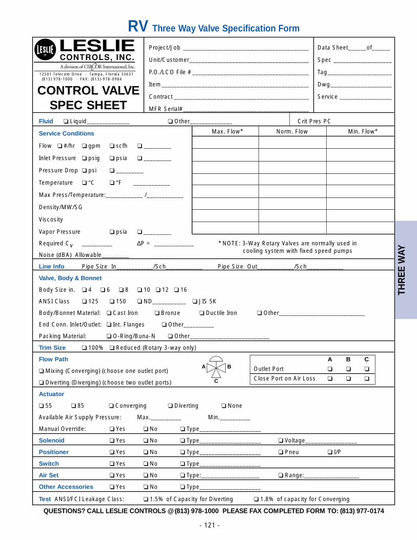
THR
EE W
AY
- 121 -
Project/Job _________________________________________ Data Sheet______of______
Unit/Customer_______________________________________ Spec ___________________
P.O./LCO File # ______________________________________ Tag_____________________
Item________________________________________________ Dwg____________________
Contract ____________________________________________ Service _________________
MFR Serial#_________________________________________
Fluid ❏ Liquid______________ ❏ Other______________ Crit Pres PC
Service Conditions Max. Flow* Norm. Flow Min. Flow*
Flow ❏ #/hr ❏ gpm ❏ scfh ❏ _________
Inlet Pressure ❏ psig ❏ psia ❏ _________
Pressure Drop ❏ psi ❏ _________
Temperature ❏ °C ❏ °F ____________
Max Press/Temperature:____________ /____________
Density/MW/SG
Viscosity
Vapor Pressure ❏ psia ❏ _________
Required Cv __________ ∆P = _____________ * NOTE: 3-Way Rotary Valves are normally used in
Noise (dBA) Allowable_________cooling system with fixed speed pumps
Line Info Pipe Size In____________/Sch____________ Pipe Size Out____________/Sch____________
Valve, Body & Bonnet
Body Size in. ❏ 4 ❏ 6 ❏ 8 ❏ 10 ❏ 12 ❏ 16
ANSI Class ❏ 125 ❏ 150 ❏ ND___________ ❏ JIS 5K
Body/Bonnet Material: ❏ Cast Iron ❏ Bronze ❏ Ductile Iron ❏ Other____________________________
End Conn. Inlet/Outlet: ❏ Int. Flanges ❏ Other__________
Packing Material: ❏ O-Ring/Buna-N ❏ Other__________________________
Trim Size ❏ 100% ❏ Reduced (Rotary 3-way only)
Flow Path
❏ Mixing (Converging) (choose one outlet port)
❏ Diverting (Diverging) (choose two outlet ports)
Actuator
❏ 55 ❏ 85 ❏ Converging ❏ Diverting ❏ None
Available Air Supply Pressure: Max.__________ Min.__________
Manual Override: ❏ Yes ❏ No ❏ Type____________________
Solenoid ❏ Yes ❏ No ❏ Type____________________ ❏ Voltage_________________
Positioner ❏ Yes ❏ No ❏ Type____________________ ❏ Pneu ❏ I/P
Switch ❏ Yes ❏ No ❏ Type____________________
Air Set ❏ Yes ❏ No ❏ Type:___________________ ❏ Range:__________________
Other Accessories ❏ Yes ❏ No ❏ Type____________________
Test ANSI/FCI Leakage Class: ❏ 1.5% of Capacity for Diverting ❏ 1.8% of capacity for Converging
12501 Telecom Drive · Tampa, Florida 33637(813) 978-1000 · FAX: (813)-978-0984
CONTROL VALVESPEC SHEET
A B C
Outlet Port ❏ ❏ ❏
Close Port on Air Loss ❏ ❏ ❏
A
C
B
RV Three Way Valve Specification Form
QUESTIONS? CALL LESLIE CONTROLS @ (813) 978-1000 PLEASE FAX COMPLETED FORM TO: (813) 977-0174
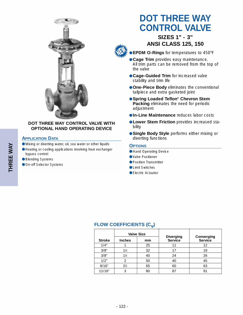
THR
EE W
AY
- 122 -
Valve SizeDiverging Converging
Stroke Inches mm Service Service1/4" 1 25 11 123/8" 11⁄4 32 17 193/8" 11⁄2 40 24 261/2" 2 50 40 459/16" 21⁄2 65 60 6311/16" 3 80 87 91
FLOW COEFFICIENTS (Cv)
DOT THREE WAYCONTROL VALVE
SIZES 1" - 3"ANSI CLASS 125, 150
● EPDM O-Rings for temperatures to 450ºF
● Cage Trim provides easy maintenance. All trim parts can be removed from the top ofthe valve
● Cage-Guided Trim for increased valve stability and trim life
● One-Piece Body eliminates the conventionaltailpiece and extra gasketed joint
● Spring Loaded Teflon® Chevron StemPacking eliminates the need for periodicadjustment
● In-Line Maintenance reduces labor costs
● Lower Stem Friction provides increased sta-bility
● Single Body Style performs either mixing ordiverting functions
OPTIONS
● Hand Operating Device
● Valve Positioner
● Position Transmitter
● Limit Switches
● Electric Actuator
APPLICATION DATA
● Mixing or diverting water, oil, sea water or other liquids
● Heating or cooling applications involving heat exchangerbypass control
● Blending Systems
● On-off Selector Systems
DOT THREE WAY CONTROL VALVE WITHOPTIONAL HAND OPERATING DEVICE
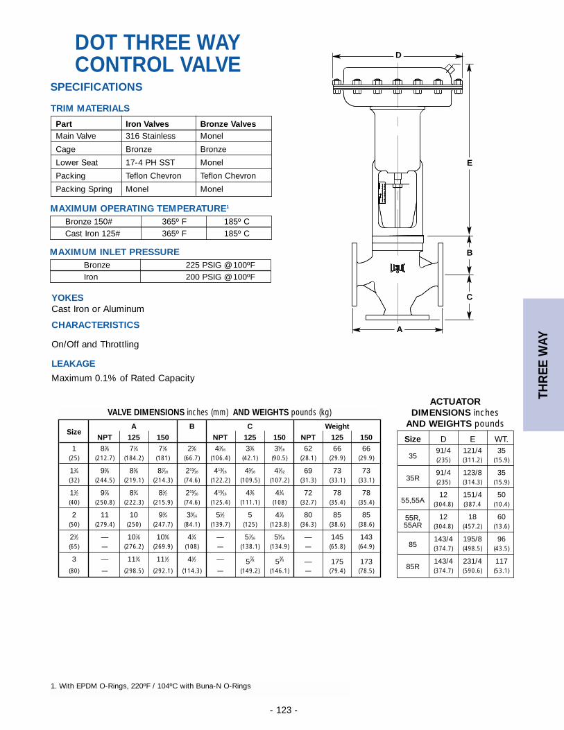
THR
EE W
AY
- 123 -
DOT THREE WAYCONTROL VALVE
SizeA B C Weight
NPT 125 150 NPT 125 150 NPT 125 150
1 83⁄8 71⁄4 71⁄8 25⁄8 43⁄16 35⁄8 39⁄16 62 66 66(25) (212.7) (184.2) (181) (66.7) (106.4) (42.1) (90.5) (28.1) (29.9) (29.9)
11⁄4 95⁄8 85⁄8 87⁄16 215⁄16 413⁄16 45⁄16 47⁄32 69 73 73(32) (244.5) (219.1) (214.3) (74.6) (122.2) (109.5) (107.2) (31.3) (33.1) (33.1)
11⁄2 97⁄8 83⁄4 81⁄2 215⁄16 415⁄16 43⁄8 41⁄4 72 78 78(40) (250.8) (222.3) (215.9) (74.6) (125.4) (111.1) (108) (32.7) (35.4) (35.4)
2 11 10 93⁄4 35⁄16 51⁄2 5 47⁄8 80 85 85(50) (279.4) (250) (247.7) (84.1) (139.7) (125) (123.8) (36.3) (38.6) (38.6)
21⁄2 — 107⁄8 105⁄8 41⁄4 — 57⁄16 55⁄16 — 145 143(65) — (276.2) (269.9) (108) — (138.1) (134.9) — (65.8) (64.9)
3 — 113⁄4 111⁄2 41⁄2 — 57⁄8 5
3⁄4 — 175 173(80) — (298.5) (292.1) (114.3) — (149.2) (146.1) — (79.4) (78.5)
VALVE DIMENSIONS inches (mm) AND WEIGHTS pounds (kg)
Size D E WT.
3591/4 121/4 35(235) (311.2) (15.9)
35R91/4 123/8 35(235) (314.3) (15.9)
55,55A12 151/4 50
(304.8) (387.4 (10.4)
55R, 12 18 6055AR (304.8) (457.2) (13.6)
85143/4 195/8 96(374.7) (498.5) (43.5)
85R143/4 231/4 117(374.7) (590.6) (53.1)
ACTUATOR DIMENSIONS inches
AND WEIGHTS pounds
A
D
E
B
C
SPECIFICATIONS
TRIM MATERIALS
MAXIMUM OPERATING TEMPERATURE1
MAXIMUM INLET PRESSURE
YOKESCast Iron or Aluminum
CHARACTERISTICS
On/Off and Throttling
LEAKAGE
Maximum 0.1% of Rated Capacity
Part Iron Valves Bronze ValvesMain Valve 316 Stainless Monel
Cage Bronze Bronze
Lower Seat 17-4 PH SST Monel
Packing Teflon Chevron Teflon Chevron
Packing Spring Monel Monel
Bronze 150# 365º F 185º CCast Iron 125# 365º F 185º C
Bronze 225 PSIG @ 100ºFIron 200 PSIG @ 100ºF
1. With EPDM O-Rings, 220ºF / 104ºC with Buna-N O-Rings
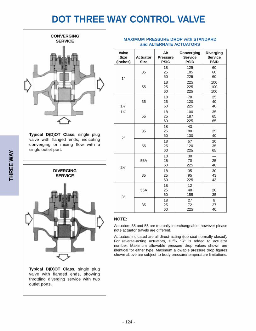
THR
EE W
AY
- 124 -
CONVERGINGSERVICE
Typical D(D)OT Class, single plugvalve with flanged ends, indicatingconverging or mixing flow with asingle outlet port.
DIVERGINGSERVICE
Typical D(D)OT Class, single plugvalve with flanged ends, showingthrottling diverging service with twooutlet ports.
MAXIMUM PRESSURE DROP with STANDARD and ALTERNATE ACTUATORS
NOTE:
Actuators 35 and 55 are mutually interchangeable; however pleasenote actuator travels are different.
Actuators indicated are all direct-acting (top seat normally closed).For reverse-acting actuators, suffix “R” is added to actuatornumber. Maximum allowable pressure drop values shown areidentical for either type. Maximum allowable pressure drop figuresshown above are subject to body pressure/temperature limitations.
Valve Air Converging DivergingSize Actuator Pressure Service Service
(Inches) Size PSIG PSID PSID
18 125 6035 25 185 60
60 225 601"18 225 100
55 25 225 10060 225 100
18 70 2535 25 120 40
11⁄4" 60 225 40
11⁄2" 18 100 3555 25 187 65
60 225 65
18 43 —35 25 80 25
60 130 402"
18 57 2055 25 120 35
60 225 65
18 30 —55A 25 70 25
60 225 4021⁄2"
18 35 3085 25 95 43
60 225 43
18 12 —55A 25 40 20
60 155 353"
18 27 885 25 72 27
60 225 40
DOT THREE WAY CONTROL VALVE
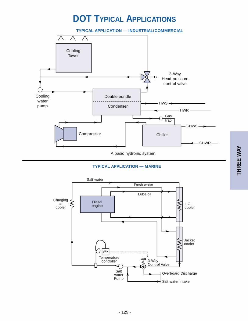
THR
EE W
AY
- 125 -
TYPICAL APPLICATION — INDUSTRIAL/COMMERCIAL
CoolingTower
Coolingwaterpump
Compressor
Double bundle
Condenser
Chiller
Gastrap
A basic hydronic system.
3-WayHead pressurecontrol valve
HWS
HWR
CHWS
CHWR
TYPICAL APPLICATION — MARINE
L.O.cooler
Jacketcooler
Overboard Discharge
Salt water intake
3-WayControl Valve
SaltwaterPump
Temperaturecontroller
Dieselengine
Lube oil
Fresh waterSalt water
Chargingair
cooler
DOT TYPICAL APPLICATIONS
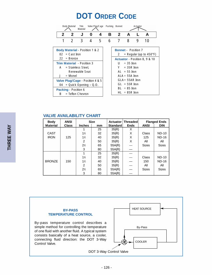
THR
EE W
AY
- 126 -
BY-PASSTEMPERATURE CONTROL
By-pass temperature control describes asimple method for controlling the temperatureof one fluid with another fluid. A typical systemconsists basically of a heat source, a cooler,connecting fluid direction: the DOT 3-WayControl Valve.
DOT 3-Way Control Valve
COOLER
By-Pass
HEAT SOURCE
DOT ORDER CODE
2 2 J 0 4 B 2 A L A
1 2 3 4 5 6 7 8 9 10
Body Material Trim Valve Plug/Cage Packing Bonnet ActuatorMaterial
Body Material - Position 1 & 202 = Cast Iron22 = Bronze
Trim Material - Position 3A = Stainless Steel,
Renewable SeatJ = Monel
Valve Plug/Cage - Position 4 & 504 = Quick Opening – Q.O.
Packing - Position 6 B = Teflon Chevron
Bonnet - Position 72 = Regular (up to 450°F)
Actuator - Position 8, 9 & 10U = 35 IronY = 35R IronAL = 55 IronALA = 55A IronGLA= 55AR IronGL = 55R IronBL = 85 IronHL = 85R Iron
Body ANSI Size Actuator Threaded Flanged EndsMaterial Class Inches mm Standard Ends ANSI DIN
1 25 35(R) XCAST 11⁄4 32 35(R) X Class ND-10IRON 125 11⁄2 40 35(R) X 125 ND-16
2 50 35(R) X All All21⁄2 65 55A(R) — Sizes Sizes3 80 55A(R) —1 25 35(R) —
11⁄4 32 35(R) — Class ND-10BRONZE 150 11⁄2 40 35(R) — 150 ND-16
2 50 35(R) — All All21⁄2 65 55A(R) — Sizes Sizes3 80 55A(R) —
VALVE AVAILABILITY CHART
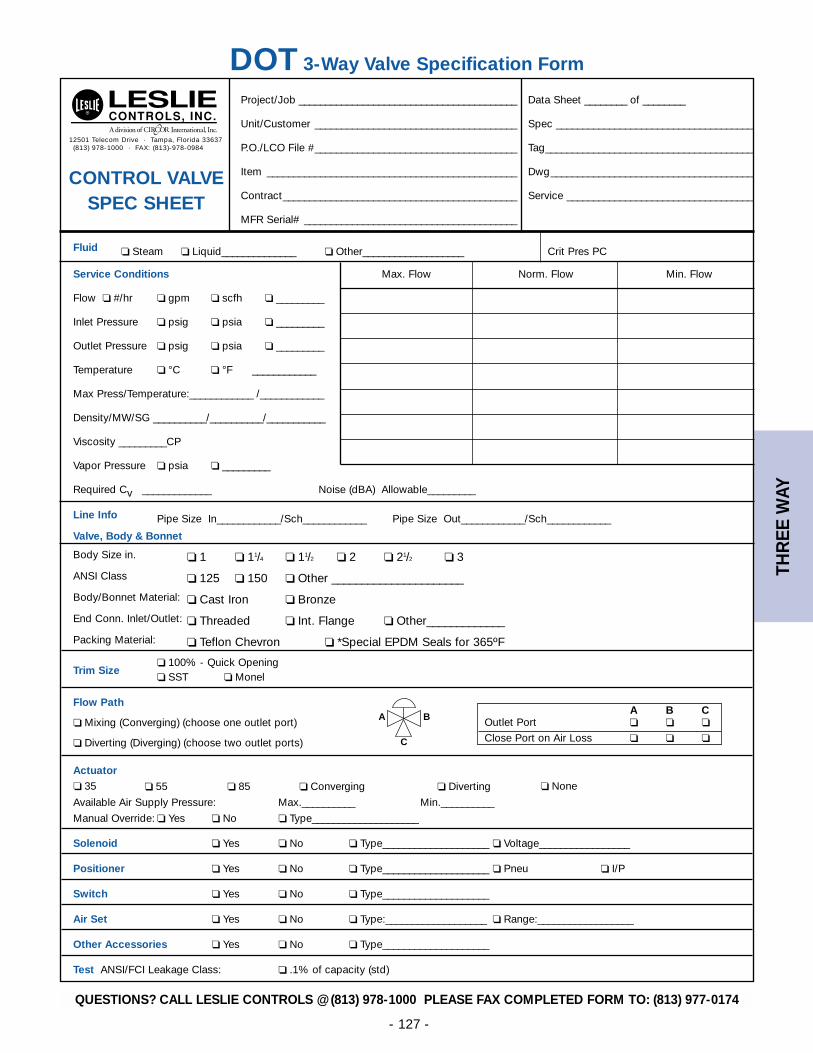
THR
EE W
AY
- 127 -
DOT 3-Way Valve Specification Form
12501 Telecom Drive · Tampa, Florida 33637(813) 978-1000 · FAX: (813)-978-0984
Project/Job _________________________________________ Data Sheet ________ of ________
Unit/Customer ______________________________________ Spec _____________________________________
P.O./LCO File #______________________________________ Tag_______________________________________
Item _______________________________________________ Dwg______________________________________
Contract____________________________________________ Service ___________________________________
MFR Serial# ________________________________________
Fluid ❏ Steam ❏ Liquid______________ ❏ Other___________________ Crit Pres PC
Service Conditions Max. Flow Norm. Flow Min. Flow
Flow ❏ #/hr ❏ gpm ❏ scfh ❏ _________
Inlet Pressure ❏ psig ❏ psia ❏ _________
Outlet Pressure ❏ psig ❏ psia ❏ _________
Temperature ❏ °C ❏ °F ____________
Max Press/Temperature:____________ /____________
Density/MW/SG __________/__________/___________
Viscosity _________CP
Vapor Pressure ❏ psia ❏ _________
Required Cv _____________ Noise (dBA) Allowable_________
Line Info Pipe Size In____________/Sch____________ Pipe Size Out____________/Sch____________
Valve, Body & Bonnet
Body Size in. ❏ 1 ❏ 11/4 ❏ 11/2 ❏ 2 ❏ 21/2 ❏ 3
ANSI Class ❏ 125 ❏ 150 ❏ Other ______________________
Body/Bonnet Material: ❏ Cast Iron ❏ Bronze
End Conn. Inlet/Outlet: ❏ Threaded ❏ Int. Flange ❏ Other_____________
Packing Material: ❏ Teflon Chevron ❏ *Special EPDM Seals for 365ºF
Trim Size❏ 100% - Quick Opening❏ SST ❏ Monel
Flow Path
❏ Mixing (Converging) (choose one outlet port)
❏ Diverting (Diverging) (choose two outlet ports)
Actuator❏ 35 ❏ 55 ❏ 85 ❏ Converging ❏ Diverting ❏ None
Available Air Supply Pressure: Max.__________ Min.__________
Manual Override: ❏ Yes ❏ No ❏ Type____________________
Solenoid ❏ Yes ❏ No ❏ Type____________________ ❏ Voltage_________________
Positioner ❏ Yes ❏ No ❏ Type____________________ ❏ Pneu ❏ I/P
Switch ❏ Yes ❏ No ❏ Type____________________
Air Set ❏ Yes ❏ No ❏ Type:___________________ ❏ Range:__________________
Other Accessories ❏ Yes ❏ No ❏ Type____________________
Test ANSI/FCI Leakage Class: ❏ .1% of capacity (std)
CONTROL VALVE SPEC SHEET
A B COutlet Port ❏ ❏ ❏
Close Port on Air Loss ❏ ❏ ❏
A
C
B
QUESTIONS? CALL LESLIE CONTROLS @ (813) 978-1000 PLEASE FAX COMPLETED FORM TO: (813) 977-0174
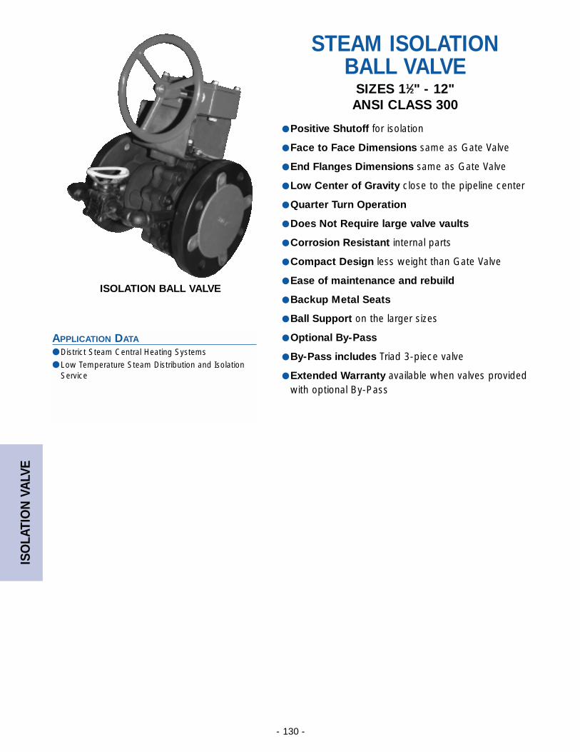
ISO
LATI
ON
VA
LVE
- 130 -
APPLICATION DATA
● District Steam Central Heating Systems
● Low Temperature Steam Distribution and IsolationService
STEAM ISOLATIONBALL VALVE
SIZES 11⁄2" - 12"ANSI CLASS 300
● Positive Shutoff for isolation
● Face to Face Dimensions same as Gate Valve
● End Flanges Dimensions same as Gate Valve
● Low Center of Gravity close to the pipeline center
● Quarter Turn Operation
● Does Not Require large valve vaults
● Corrosion Resistant internal parts
● Compact Design less weight than Gate Valve
● Ease of maintenance and rebuild
● Backup Metal Seats
● Ball Support on the larger sizes
● Optional By-Pass
● By-Pass includes Triad 3-piece valve
● Extended Warranty available when valves providedwith optional By-Pass
ISOLATION BALL VALVE
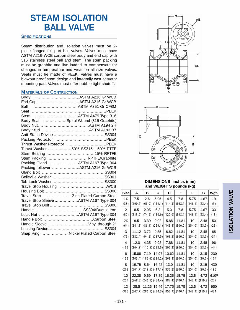
ISO
LATI
ON
VA
LVE
- 131 -
STEAM ISOLATIONBALL VALVE
SPECIFICATIONS
Steam distribution and isolation valves must be 2-piece flanged full port ball valves. Valves must haveASTM A216-WCB carbon steel body and end cap with316 stainless steel ball and stem. The stem packingmust be graphite and live loaded to compensate forchanges in temperature and wear on all size valves.Seats must be made of PEEK. Valves must have ablowout proof stem design and integrally cast actuatormounting pad. Valves must offer bubble tight shutoff.
MATERIALS OF CONTRUCTIONBody ……………………………ASTM A216 Gr WCBEnd Cap …………………………ASTM A216 Gr WCBBall ……………………………ASTM A351 Gr CF8MSeat …………………………………………………PEEKStem ……………………………ASTM A479 Type 316Body Seal ………………Spiral Wound (316 Graphite)Body Nut…………………………………ASTM A194 2HBody Stud ………………………………ASTM A193 B7Anti-Static Device …………………………………SS304Packing Protector …………………………………PEEKThrust Washer Protector …………………………PEEKThrust Washer ………………50% SS316 + 50% PTFEStem Bearing ………………………………15% RPTFEStem Packing …………………………RPTFE/GraphitePacking Gland …………………ASTM A167 Type 304Packing follower …………………ASTM A216 Gr WCBGland Bolt …………………………………………SS304Belleville Washer …………………………………SS301Tab Lock Washer …………………………………SS300Travel Stop Housing ………………………………WCBHousing Bolt ………………………………………SS300Travel Stop …………………Zinc Plated Carbon SteelTravel Stop Sleeve ………………ASTM A167 Type 304Travel Stop Bolt……………………………………SS300Handle ………………………………SS304/Ductile IronLock Nut …………………………ASTM A167 Type 304Handle Bolt…………………………………Carbon SteelHandle Sleeve …………………………Vinyl through 2"Locking Device ……………………………………SS304Snap Ring …………………Nickel Plated Carbon Steel
Size A B C D E F G Wgt.
11⁄2 7.5 2.6 5.95 4.5 7.8 5.75 1.67 19(38) (190.2) (66.0) (151.1) (114.3) (198.1) (146.1) (42.4) (9)
2 8.5 2.95 6.3 5.0 7.8 5.75 1.67 33(50) (215.9) (74.9) (160.0) (127.0) (198.1) (146.1) (42.4) (15)
21⁄2 9.5 3.39 9.02 5.88 11.81 10 2.48 50(64) (241.3) (86.1) (229.1) (149.4) (300.0) (254.0) (63.0) (23)
3 11.12 3.72 9.35 6.62 11.81 10 2.48 68(76) (282.4) (94.5) (237.5) (168.2) (300.0) (254.0) (63.0) (31)
4 12.0 4.35 9.98 7.88 11.81 10 2.48 96(102) (304.8) (110.5) (253.5) (200.2) (300.0) (254.0) (63.0) (44)
6 15.88 7.19 14.97 10.62 11.81 10 3.15 230(152) (403.4) (182.6) (380.2) (269.8) (300.0) (254.0) (80.0) (104)
8 19.75 8.64 16.42 13.0 11.81 10 3.15 430(203) (501.7) (219.5) (417.1) (330.2) (300.0) (254.0) (80.0) (195)
10 22.38 9.69 17.89 15.25 15.75 13.5 4.72 610()
(254) (568.5) (246.1) (454.4) (387.4) (400.1) (342.9) (119.9) (277)
12 25.5 11.26 19.46 17.75 15.75 13.5 4.72 950(305) (647.7) (286.1) (494.3) (450.9) (400.1) (342.9) (119.9) (431)
DIMENSIONS inches (mm) and WEIGHTS pounds (kg)
A
DO
EOG
C
B
F
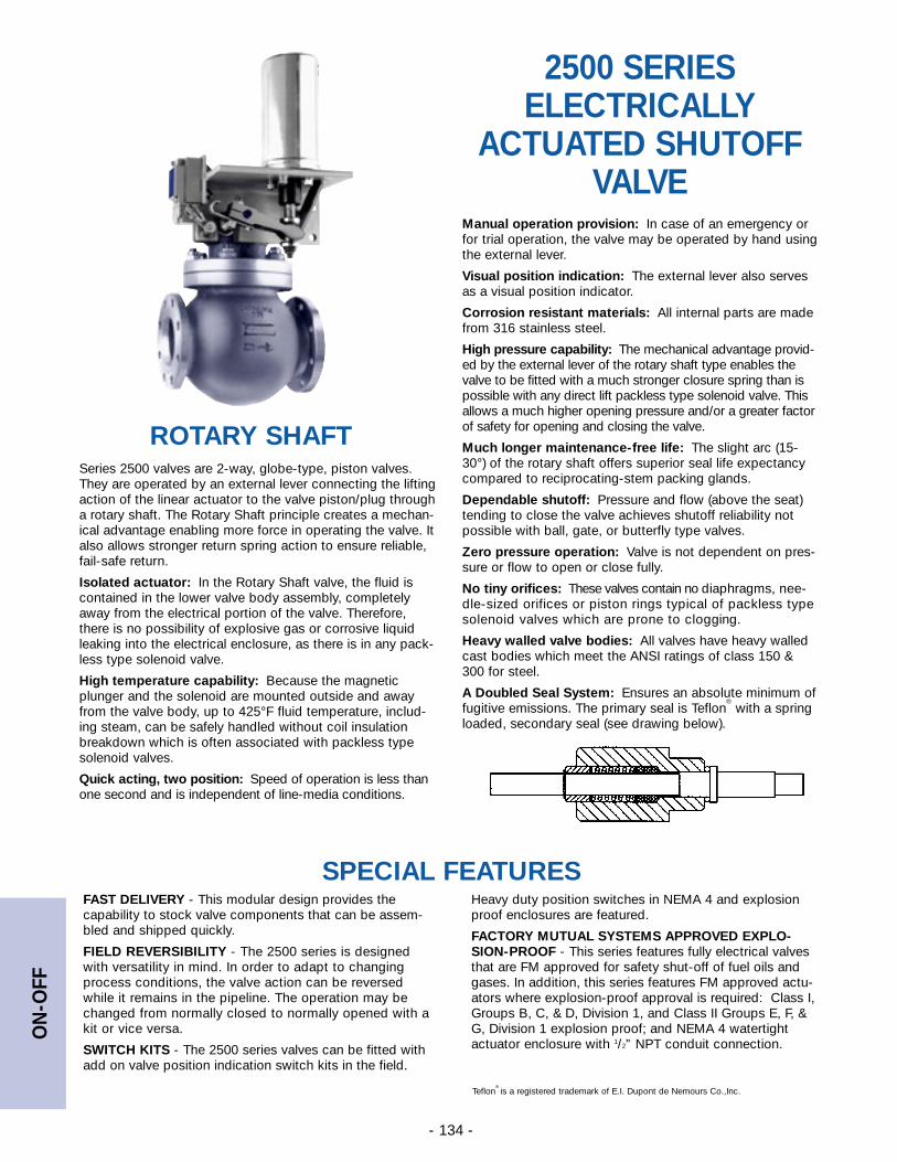
ON
-OFF
- 134 -
ROTARY SHAFT
FAST DELIVERY - This modular design provides thecapability to stock valve components that can be assem-bled and shipped quickly.
FIELD REVERSIBILITY - The 2500 series is designedwith versatility in mind. In order to adapt to changingprocess conditions, the valve action can be reversedwhile it remains in the pipeline. The operation may bechanged from normally closed to normally opened with akit or vice versa.
SWITCH KITS - The 2500 series valves can be fitted withadd on valve position indication switch kits in the field.
Heavy duty position switches in NEMA 4 and explosionproof enclosures are featured.
FACTORY MUTUAL SYSTEMS APPROVED EXPLO-SION-PROOF - This series features fully electrical valvesthat are FM approved for safety shut-off of fuel oils andgases. In addition, this series features FM approved actu-ators where explosion-proof approval is required: Class I,Groups B, C, & D, Division 1, and Class II Groups E, F, &G, Division 1 explosion proof; and NEMA 4 watertightactuator enclosure with 1/2” NPT conduit connection.
SPECIAL FEATURES
Teflon® is a registered trademark of E.I. Dupont de Nemours Co.,Inc.
2500 SERIESELECTRICALLY
ACTUATED SHUTOFFVALVE
Series 2500 valves are 2-way, globe-type, piston valves.They are operated by an external lever connecting the liftingaction of the linear actuator to the valve piston/plug througha rotary shaft. The Rotary Shaft principle creates a mechan-ical advantage enabling more force in operating the valve. Italso allows stronger return spring action to ensure reliable,fail-safe return.
Isolated actuator: In the Rotary Shaft valve, the fluid iscontained in the lower valve body assembly, completelyaway from the electrical portion of the valve. Therefore,there is no possibility of explosive gas or corrosive liquidleaking into the electrical enclosure, as there is in any pack-less type solenoid valve.
High temperature capability: Because the magneticplunger and the solenoid are mounted outside and awayfrom the valve body, up to 425°F fluid temperature, includ-ing steam, can be safely handled without coil insulationbreakdown which is often associated with packless typesolenoid valves.
Quick acting, two position: Speed of operation is less thanone second and is independent of line-media conditions.
Manual operation provision: In case of an emergency orfor trial operation, the valve may be operated by hand usingthe external lever.
Visual position indication: The external lever also servesas a visual position indicator.
Corrosion resistant materials: All internal parts are madefrom 316 stainless steel.
High pressure capability: The mechanical advantage provid-ed by the external lever of the rotary shaft type enables thevalve to be fitted with a much stronger closure spring than ispossible with any direct lift packless type solenoid valve. Thisallows a much higher opening pressure and/or a greater factorof safety for opening and closing the valve.
Much longer maintenance-free life: The slight arc (15-30°) of the rotary shaft offers superior seal life expectancycompared to reciprocating-stem packing glands.
Dependable shutoff: Pressure and flow (above the seat)tending to close the valve achieves shutoff reliability notpossible with ball, gate, or butterfly type valves.
Zero pressure operation: Valve is not dependent on pres-sure or flow to open or close fully.
No tiny orifices: These valves contain no diaphragms, nee-dle-sized orifices or piston rings typical of packless typesolenoid valves which are prone to clogging.
Heavy walled valve bodies: All valves have heavy walledcast bodies which meet the ANSI ratings of class 150 &300 for steel.
A Doubled Seal System: Ensures an absolute minimum offugitive emissions. The primary seal is Teflon
®with a spring
loaded, secondary seal (see drawing below).
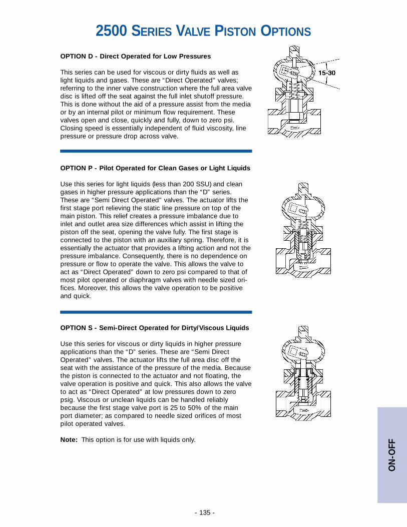
ON
-OFF
- 135 -
OPTION D - Direct Operated for Low Pressures
This series can be used for viscous or dirty fluids as well aslight liquids and gases. These are “Direct Operated” valves;referring to the inner valve construction where the full area valvedisc is lifted off the seat against the full inlet shutoff pressure.This is done without the aid of a pressure assist from the mediaor by an internal pilot or minimum flow requirement. Thesevalves open and close, quickly and fully, down to zero psi.Closing speed is essentially independent of fluid viscosity, linepressure or pressure drop across valve.
OPTION P - Pilot Operated for Clean Gases or Light Liquids
Use this series for light liquids (less than 200 SSU) and cleangases in higher pressure applications than the “D” series.These are “Semi Direct Operated” valves. The actuator lifts thefirst stage port relieving the static line pressure on top of themain piston. This relief creates a pressure imbalance due toinlet and outlet area size differences which assist in lifting thepiston off the seat, opening the valve fully. The first stage isconnected to the piston with an auxiliary spring. Therefore, it isessentially the actuator that provides a lifting action and not thepressure imbalance. Consequently, there is no dependence onpressure or flow to operate the valve. This allows the valve toact as “Direct Operated” down to zero psi compared to that ofmost pilot operated or diaphragm valves with needle sized ori-fices. Moreover, this allows the valve operation to be positiveand quick.
OPTION S - Semi-Direct Operated for Dirty/Viscous Liquids
Use this series for viscous or dirty liquids in higher pressureapplications than the “D” series. These are “Semi DirectOperated” valves. The actuator lifts the full area disc off theseat with the assistance of the pressure of the media. Becausethe piston is connected to the actuator and not floating, thevalve operation is positive and quick. This also allows the valveto act as “Direct Operated” at low pressures down to zeropsig. Viscous or unclean liquids can be handled reliablybecause the first stage valve port is 25 to 50% of the mainport diameter; as compared to needle sized orifices of mostpilot operated valves.
Note: This option is for use with liquids only.
2500 SERIES VALVE PISTON OPTIONS
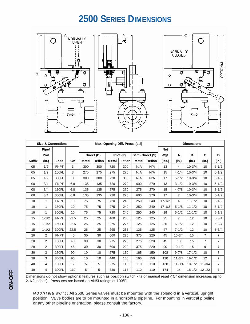
ON
-OFF
- 136 -
Size & Connections Max. Opening Diff. Press. (psi) Dimensions
Pipe/ Net
Port Direct (D) Pilot (P) Semi-Direct (S) Wgt. A B C D
Suffix (in.) Ends CV Metal Teflon Metal Teflon Metal Teflon (lbs.) (in.) (in.) (in.) (in.)
05 1/2 FNPT 3 300 300 720 300 N/A N/A 13 4 10-3/4 10 5-1/2
05 1/2 150FL 3 275 275 275 275 N/A N/A 15 4-1/4 10-3/4 10 5-1/2
05 1/2 300FL 3 300 300 720 300 N/A N/A 17 5-1/2 10-3/4 10 5-1/2
08 3/4 FNPT 6.8 135 135 720 270 600 270 13 3-1/2 10-3/4 10 5-1/2
08 3/4 150FL 6.8 135 135 275 270 275 270 15 4-7/8 10-3/4 10 5-1/2
08 3/4 300FL 6.8 135 135 720 270 600 270 17 7 10-3/4 10 5-1/2
10 1 FNPT 10 75 75 720 240 250 240 17-1/2 4 11-1/2 10 5-1/2
10 1 150FL 10 75 75 275 240 250 240 17-1/2 5-1/8 11-1/2 10 5-1/2
10 1 300FL 10 75 75 720 240 250 240 19 5-1/2 11-1/2 10 5-1/2
15 1-1/2 FNPT 22.5 25 25 400 285 125 125 25 7 12 10 5-3/4
15 1-1/2 150FL 22.5 25 25 275 275 125 125 26 6-1/2 12 10 5-3/4
15 1-1/2 300FL 22.5 25 25 295 285 125 125 47 7-1/2 12 10 5-3/4
20 2 FNPT 40 30 30 600 220 375 220 45 10-3/4 15 7 7
20 2 150FL 40 30 30 275 220 275 220 45 10 15 7 7
20 2 300FL 46 30 30 600 220 375 220 90 10-1/2 15 9 7
30 3 150FL 90 10 10 275 150 165 150 108 9-7/8 17-1/2 10 7
30 3 300FL 96 10 10 440 150 165 150 120 11-3/4 19-1/2 12 7
40 4 150FL 160 5 5 275 115 110 110 138 11-3/4 18-1/2 11-3/4 7
40 4 300FL 160 5 5 330 115 110 110 174 14 18-1/2 12-1/2 7
Dimensions do not show optional features such as position switch kits or manual reset (“C” dimension increases up to2-1/2 inches). Pressures are based on ANSI ratings at 100°F.
2500 SERIES DIMENSIONS
MOUNTING NOTE: All 2500 Series valves must be mounted with the solenoid in a vertical, uprightposition. Valve bodies are to be mounted in a horizontal pipeline. For mounting in vertical pipelineor any other pipeline orientation, please consult the factory.
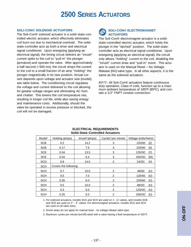
ON
-OFF
- 137 -
SOLI-CON® SOLENOID ACTUATORSThe Soli-Con® solenoid actuator is a solid-state-con-trolled electric actuator, which effectively eliminatescoil burn-out due to mechanical overload. The solid-state-controller acts as both a timer and electricalsignal conditioner. Upon energizing (applying anelectrical signal), the timing circuit delivers an “inrush”current spike to the coil to “pull-in” the plunger(armature) and operate the valve. After approximatelya half second (~500 ms), the circuit drops the currentto the coil to a small fraction of an amp “holding” theplunger magnetically in its new position. Actual cur-rent depends upon voltage and actuator size (model);see table below. The conditioning circuit regulatesthe voltage and current delivered to the coil allowingfor greater voltage ranges and eliminating AC humand chatter. This lowers the coil temperature rise,resulting in longer coil life, while also saving energyand maintenance costs. Additionally, should thevalve be operated in excess pressure or blocked, thecoil will not be damaged.
Model 1 Holding (amps) Inrush2 (amps) Cycles 3 per minute Voltage (volts/hertz)
SCB 0.2 14.2 3 120/60 (Z)
SCB 0.17 7.5 3 220/60 (X)
SCE 0.04 13.5 3 125/DC (Y)
SCE 0.04 6.4 3 250/DC (W)
SCG 0.8 14.0 2 24/DC (V)
SCH Covers the following:
SCH 0.7 10.0 2 48/60 (U)
SCH 0.5 7.0 2 120/60 (U)
SCH 0.35 6.0 2 220/60 (U)
SCH 0.5 10.0 2 48/DC (U)
SCH 0.3 6.0 2 125/DC (U)
SCH 0.25 5.0 2 250/DC (U)
2500 SERIES ACTUATORS
ELECTRICAL REQUIREMENTSSolid-State-Controlled Actuators
1. For solenoid actuators, models SCG and SCH are used on 1⁄2 - 11⁄2 valves, and models SCBand SCE are used on 2" - 4" valves. For electromagnet actuators, models SCG and SCHare used on all valve sizes.
2. Inrush amps do not apply for manual reset - no voltage release valve type.
3. Maximum cycles per minute (on/off) rated with a valve having a fluid temperature of 425°F.
SOLI-CON® ELECTROMAGNET ACTUATORS
The Soli-Con® electromagnet actuator is a solid-state-controlled electric actuator, which holds theplunger in the “latched” position. The solid-state-controller acts as electrical signal conditioner. Uponenergizing (applying an electrical signal), the circuitonly allows “holding” current to the coil, disabling the“inrush” current draw and “pull-in” event. This actu-ator is used on the Manual Reset – No VoltageRelease (NV) valve type. In all other aspects, it is thesame as the solenoid actuators.
NOTE: All Soli-Con® actuators feature continuousduty operation, Class H coils, function up to a maxi-mum ambient temperature of 185ºF (85ºC), and con-tain a 1/2” FNPT conduit connection.
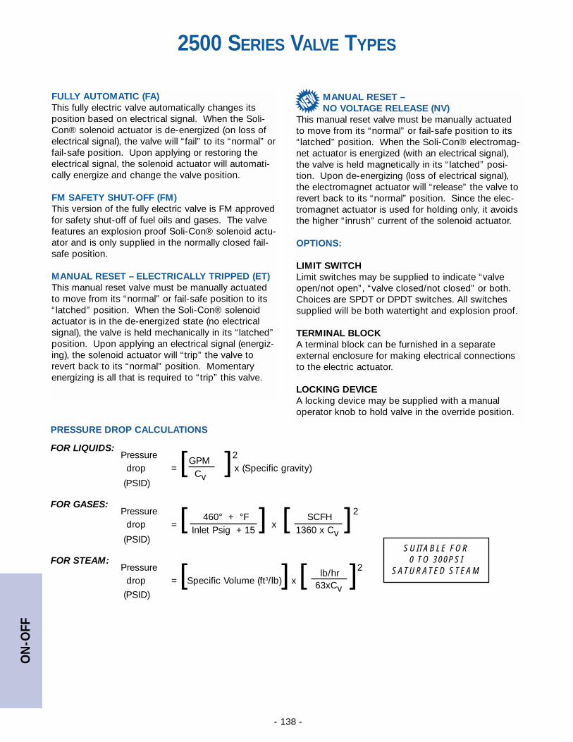
ON
-OFF
- 138 -
FULLY AUTOMATIC (FA)This fully electric valve automatically changes itsposition based on electrical signal. When the Soli-Con® solenoid actuator is de-energized (on loss ofelectrical signal), the valve will “fail” to its “normal” orfail-safe position. Upon applying or restoring theelectrical signal, the solenoid actuator will automati-cally energize and change the valve position.
FM SAFETY SHUT-OFF (FM)This version of the fully electric valve is FM approvedfor safety shut-off of fuel oils and gases. The valvefeatures an explosion proof Soli-Con® solenoid actu-ator and is only supplied in the normally closed fail-safe position.
MANUAL RESET – ELECTRICALLY TRIPPED (ET)This manual reset valve must be manually actuatedto move from its “normal” or fail-safe position to its“latched” position. When the Soli-Con® solenoidactuator is in the de-energized state (no electricalsignal), the valve is held mechanically in its “latched”position. Upon applying an electrical signal (energiz-ing), the solenoid actuator will “trip” the valve torevert back to its “normal” position. Momentaryenergizing is all that is required to “trip” this valve.
2500 SERIES VALVE TYPES
MANUAL RESET – NO VOLTAGE RELEASE (NV)
This manual reset valve must be manually actuatedto move from its “normal” or fail-safe position to its“latched” position. When the Soli-Con® electromag-net actuator is energized (with an electrical signal),the valve is held magnetically in its “latched” posi-tion. Upon de-energizing (loss of electrical signal),the electromagnet actuator will “release” the valve torevert back to its “normal” position. Since the elec-tromagnet actuator is used for holding only, it avoidsthe higher “inrush” current of the solenoid actuator.
OPTIONS:
LIMIT SWITCHLimit switches may be supplied to indicate “valveopen/not open”, “valve closed/not closed” or both.Choices are SPDT or DPDT switches. All switchessupplied will be both watertight and explosion proof.
TERMINAL BLOCKA terminal block can be furnished in a separateexternal enclosure for making electrical connectionsto the electric actuator.
LOCKING DEVICEA locking device may be supplied with a manualoperator knob to hold valve in the override position.
Pressure 2GPM
drop = [ ] x (Specific gravity)Cv
(PSID)
Pressure 2460° + °F SCFH
drop = [ ] x [ ]Inlet Psig + 15 1360 x Cv
(PSID)
Pressure 2lb/hr
drop = [Specific Volume (ft3/lb)] x [ ]63xCv(PSID)
FOR LIQUIDS:
FOR GASES:
FOR STEAM:
PRESSURE DROP CALCULATIONS
SUITABLE FOR0 TO 300PSI
SATURATED STEAM
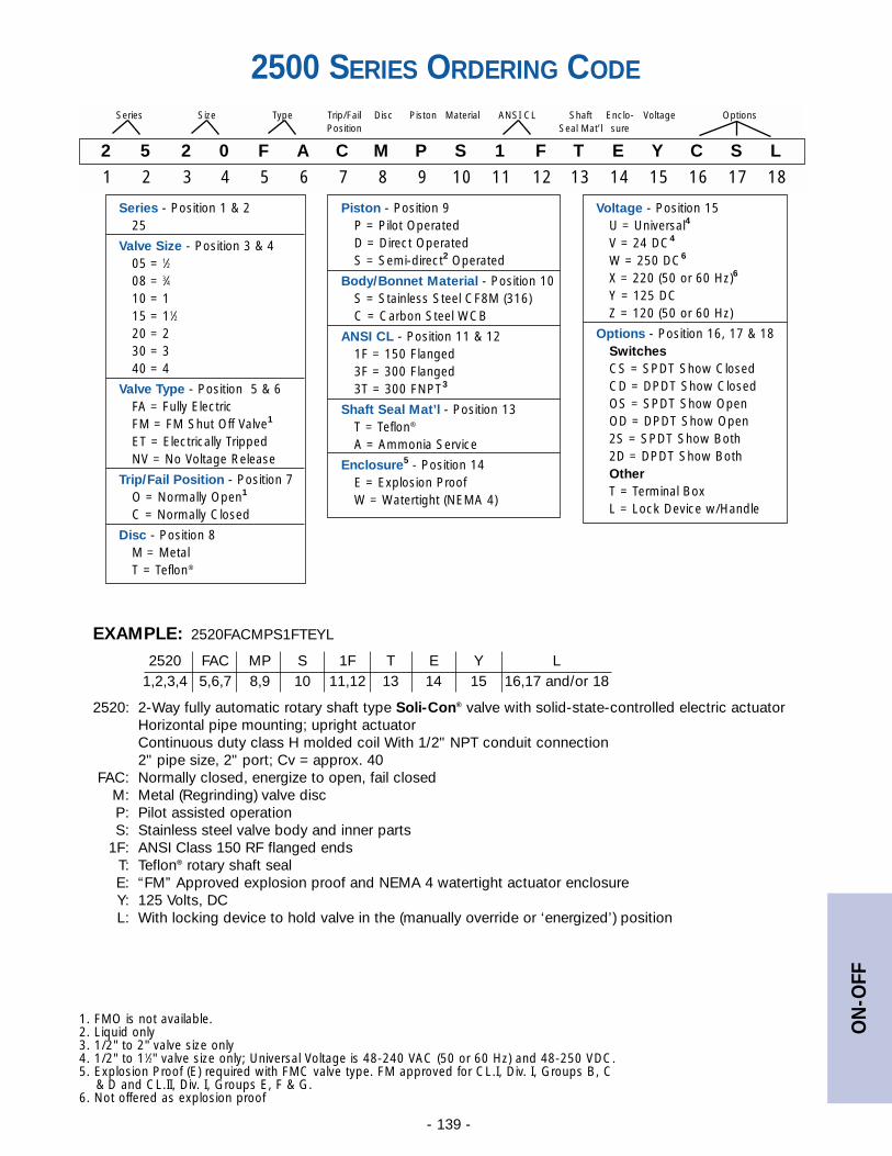
ON
-OFF
- 139 -
EXAMPLE: 2520FACMPS1FTEYL
2520 FAC MP S 1F T E Y L1,2,3,4 5,6,7 8,9 10 11,12 13 14 15 16,17 and/or 18
2520: 2-Way fully automatic rotary shaft type Soli-Con® valve with solid-state-controlled electric actuatorHorizontal pipe mounting; upright actuatorContinuous duty class H molded coil With 1/2" NPT conduit connection2" pipe size, 2" port; Cv = approx. 40
FAC: Normally closed, energize to open, fail closedM: Metal (Regrinding) valve discP: Pilot assisted operationS: Stainless steel valve body and inner parts
1F: ANSI Class 150 RF flanged endsT: Teflon® rotary shaft sealE: “FM” Approved explosion proof and NEMA 4 watertight actuator enclosureY: 125 Volts, DC L: With locking device to hold valve in the (manually override or ‘energized’) position
2500 SERIES ORDERING CODE
2 5 2 0 F A C M P S 1 F T E Y C S L
1 2 3 4 5 6 7 8 9 10 11 12 13 14 15 16 17 18
Series Size Type Trip/Fail Disc Piston Material ANSI CL Shaft Enclo- Voltage OptionsPosition Seal Mat’l sure
Piston - Position 9P = Pilot OperatedD = Direct OperatedS = Semi-direct2 Operated
Body/Bonnet Material - Position 10S = Stainless Steel CF8M (316)C = Carbon Steel WCB
ANSI CL - Position 11 & 121F = 150 Flanged3F = 300 Flanged3T = 300 FNPT3
Shaft Seal Mat’l - Position 13T = Teflon®
A = Ammonia Service
Enclosure5 - Position 14E = Explosion ProofW = Watertight (NEMA 4)
Series - Position 1 & 225
Valve Size - Position 3 & 405 = 1⁄208 = 3⁄410 = 115 = 11⁄220 = 230 = 340 = 4
Valve Type - Position 5 & 6FA = Fully ElectricFM = FM Shut Off Valve1
ET = Electrically TrippedNV = No Voltage Release
Trip/Fail Position - Position 7O = Normally Open1
C = Normally Closed
Disc - Position 8M = MetalT = Teflon®
1. FMO is not available.2. Liquid only3. 1/2" to 2" valve size only4. 1/2" to 11⁄2" valve size only; Universal Voltage is 48-240 VAC (50 or 60 Hz) and 48-250 VDC.5. Explosion Proof (E) required with FMC valve type. FM approved for CL.I, Div. I, Groups B, C
& D and CL.II, Div. I, Groups E, F & G.6. Not offered as explosion proof
Voltage - Position 15U = Universal4
V = 24 DC4
W = 250 DC6
X = 220 (50 or 60 Hz)6
Y = 125 DCZ = 120 (50 or 60 Hz)
Options - Position 16, 17 & 18SwitchesCS = SPDT Show ClosedCD = DPDT Show ClosedOS = SPDT Show OpenOD = DPDT Show Open2S = SPDT Show Both2D = DPDT Show BothOtherT = Terminal BoxL = Lock Device w/Handle
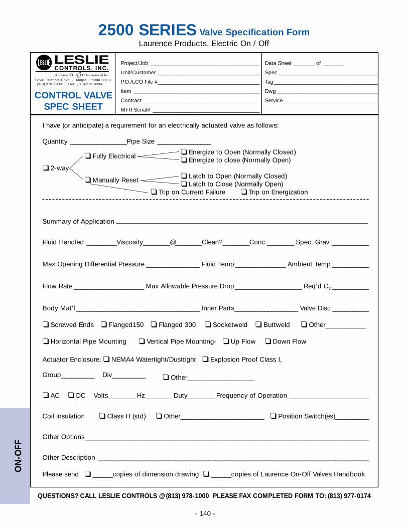
ON
-OFF
- 140 -
2500 SERIES Valve Specification FormLaurence Products, Electric On / Off
I have (or anticipate) a requirement for an electrically actuated valve as follows:
Quantity _________________Pipe Size ________________
❏ Fully Electrical❏ Energize to Open (Normally Closed)❏ Energize to close (Normally Open)
❏ 2-way
❏ Manually Reset❏ Latch to Open (Normally Closed)❏ Latch to Close (Normally Open)
❏ Trip on Current Failure ❏ Trip on Energization
Summary of Application
Fluid Handled _________Viscosity________@________Clean?________Conc.________ Spec. Grav. ___________
Max Opening Differential Pressure ________________ Fluid Temp _______________ Ambient Temp ___________
Flow Rate _____________________ Max Allowable Pressure Drop____________________ Req’d Cv ___________
Body Mat’l _____________________________________ Inner Parts___________________ Valve Disc ___________
❏ Screwed Ends ❏ Flanged150 ❏ Flanged 300 ❏ Socketweld ❏ Buttweld ❏ Other____________
❏ Horizontal Pipe Mounting ❏ Vertical Pipe Mounting- ❏ Up Flow ❏ Down Flow
Actuator Enclosure: ❏ NEMA4 Watertight/Dusttight ❏ Explosion Proof Class I,
Group__________ Div__________ ❏ Other____________________
❏ AC ❏ DC Volts________ Hz________ Duty________ Frequency of Operation ________________________
Coil Insulation ❏ Class H (std) ❏ Other_________________________ ❏ Position Switch(es)__________
Other Options_____________________________________________________________________________________
Other Description _________________________________________________________________________________
Please send ❏ ______copies of dimension drawing ❏ ______copies of Laurence On-Off Valves Handbook.
12501 Telecom Drive · Tampa, Florida 33637(813) 978-1000 · FAX: (813)-978-0984
Project/Job _________________________________________ Data Sheet ________ of ________
Unit/Customer ______________________________________ Spec _____________________________________
P.O./LCO File #______________________________________ Tag_______________________________________
Item _______________________________________________ Dwg______________________________________
Contract____________________________________________ Service ___________________________________
MFR Serial# ________________________________________
CONTROL VALVE SPEC SHEET
QUESTIONS? CALL LESLIE CONTROLS @ (813) 978-1000 PLEASE FAX COMPLETED FORM TO: (813) 977-0174
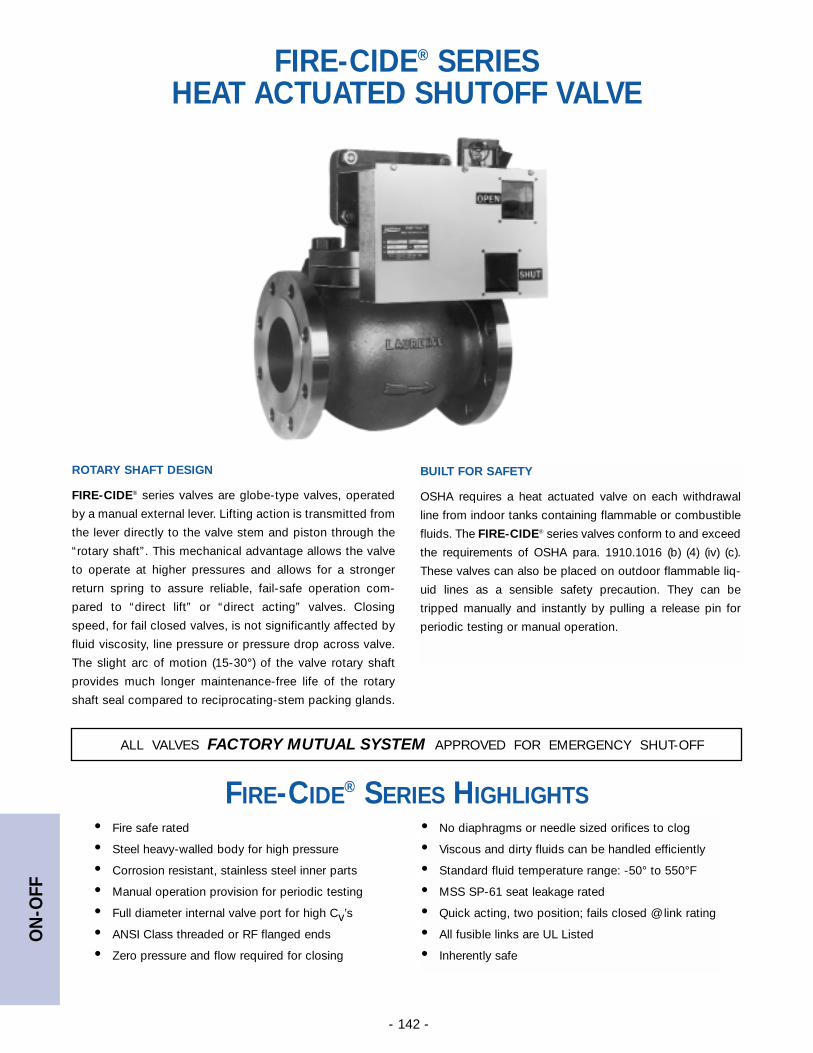
ON
-OFF
- 142 -
ALL VALVES FACTORY MUTUAL SYSTEM APPROVED FOR EMERGENCY SHUT-OFF
FIRE-CIDE® SERIES HEAT ACTUATED SHUTOFF VALVE
ROTARY SHAFT DESIGN
FIRE-CIDE® series valves are globe-type valves, operated
by a manual external lever. Lifting action is transmitted from
the lever directly to the valve stem and piston through the
“rotary shaft”. This mechanical advantage allows the valve
to operate at higher pressures and allows for a stronger
return spring to assure reliable, fail-safe operation com-
pared to “direct lift” or “direct acting” valves. Closing
speed, for fail closed valves, is not significantly affected by
fluid viscosity, line pressure or pressure drop across valve.
The slight arc of motion (15-30°) of the valve rotary shaft
provides much longer maintenance-free life of the rotary
shaft seal compared to reciprocating-stem packing glands.
• Fire safe rated
• Steel heavy-walled body for high pressure
• Corrosion resistant, stainless steel inner parts
• Manual operation provision for periodic testing
• Full diameter internal valve port for high Cv’s
• ANSI Class threaded or RF flanged ends
• Zero pressure and flow required for closing
FIRE-CIDE® SERIES HIGHLIGHTS• No diaphragms or needle sized orifices to clog
• Viscous and dirty fluids can be handled efficiently
• Standard fluid temperature range: -50° to 550°F
• MSS SP-61 seat leakage rated
• Quick acting, two position; fails closed @ link rating
• All fusible links are UL Listed
• Inherently safe
BUILT FOR SAFETY
OSHA requires a heat actuated valve on each withdrawal
line from indoor tanks containing flammable or combustible
fluids. The FIRE-CIDE® series valves conform to and exceed
the requirements of OSHA para. 1910.1016 (b) (4) (iv) (c).
These valves can also be placed on outdoor flammable liq-
uid lines as a sensible safety precaution. They can be
tripped manually and instantly by pulling a release pin for
periodic testing or manual operation.
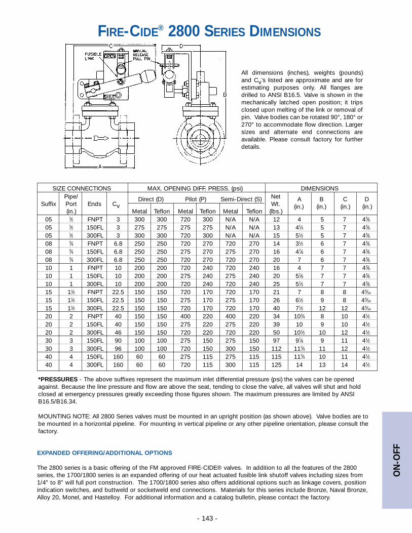
ON
-OFF
- 143 -
All dimensions (inches), weights (pounds)and Cv’s listed are approximate and are forestimating purposes only. All flanges aredrilled to ANSI B16.5. Valve is shown in themechanically latched open position; it tripsclosed upon melting of the link or removal ofpin. Valve bodies can be rotated 90°, 180° or270° to accommodate flow direction. Largersizes and alternate end connections areavailable. Please consult factory for furtherdetails.
*PRESSURES - The above suffixes represent the maximum inlet differential pressure (psi) the valves can be openedagainst. Because the line pressure and flow are above the seat, tending to close the valve, all valves will shut and holdclosed at emergency pressures greatly exceeding those figures shown. The maximum pressures are limited by ANSIB16.5/B16.34.
MOUNTING NOTE: All 2800 Series valves must be mounted in an upright position (as shown above). Valve bodies are tobe mounted in a horizontal pipeline. For mounting in vertical pipeline or any other pipeline orientation, please consult thefactory.
SIZE CONNECTIONS MAX. OPENING DIFF. PRESS. (psi) DIMENSIONSPipe/ NetDirect (D) Pilot (P) Semi-Direct (S) A B C D
Suffix Port Ends Cv Wt. (in.) (in.) (in.) (in.)(in.) Metal Teflon Metal Teflon Metal Teflon (lbs.)
05 1⁄2 FNPT 3 300 300 720 300 N/A N/A 12 4 5 7 43⁄805 1⁄2 150FL 3 275 275 275 275 N/A N/A 13 41⁄4 5 7 43⁄805 1⁄2 300FL 3 300 300 720 300 N/A N/A 15 51⁄2 5 7 43⁄808 3⁄4 FNPT 6.8 250 250 720 270 720 270 14 31⁄2 6 7 43⁄808 3⁄4 150FL 6.8 250 250 275 270 275 270 16 47⁄8 6 7 43⁄808 3⁄4 300FL 6.8 250 250 720 270 720 270 20 7 6 7 43⁄810 1 FNPT 10 200 200 720 240 720 240 16 4 7 7 43⁄810 1 150FL 10 200 200 275 240 275 240 20 51⁄8 7 7 43⁄810 1 300FL 10 200 200 720 240 720 240 25 51⁄2 7 7 43⁄815 11⁄2 FNPT 22.5 150 150 720 170 720 170 21 7 8 8 43⁄16
15 11⁄2 150FL 22.5 150 150 275 170 275 170 26 61⁄2 9 8 43⁄16
15 11⁄2 300FL 22.5 150 150 720 170 720 170 40 71⁄2 12 12 43⁄16
20 2 FNPT 40 150 150 400 220 400 220 34 103⁄4 8 10 41⁄220 2 150FL 40 150 150 275 220 275 220 39 10 9 10 41⁄220 2 300FL 46 150 150 720 220 720 220 50 101⁄2 10 12 41⁄230 3 150FL 90 100 100 275 150 275 150 97 97⁄8 9 11 41⁄230 3 300FL 96 100 100 720 150 300 150 112 113⁄4 11 12 41⁄240 4 150FL 160 60 60 275 115 275 115 115 113⁄4 10 11 41⁄240 4 300FL 160 60 60 720 115 300 115 125 14 13 14 41⁄2
FIRE-CIDE® 2800 SERIES DIMENSIONS
EXPANDED OFFERING/ADDITIONAL OPTIONS
The 2800 series is a basic offering of the FM approved FIRE-CIDE® valves. In addition to all the features of the 2800series, the 1700/1800 series is an expanded offering of our heat actuated fusible link shutoff valves including sizes from1/4" to 8" will full port construction. The 1700/1800 series also offers additional options such as linkage covers, positionindication switches, and buttweld or socketweld end connections. Materials for this series include Bronze, Naval Bronze,Alloy 20, Monel, and Hastelloy. For additional information and a catalog bulletin, please contact the factory.
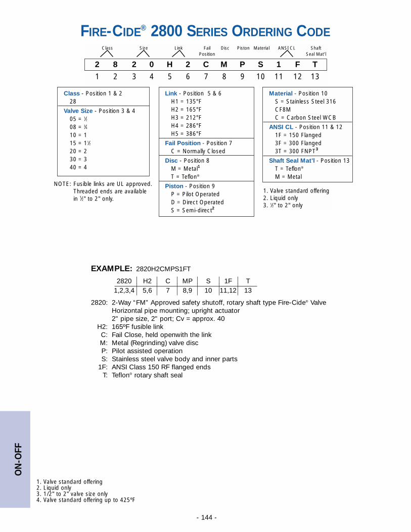
ON
-OFF
- 144 -
NOTE: Fusible links are UL approved.Threaded ends are available in 1⁄2" to 2" only.
FIRE-CIDE® 2800 SERIES ORDERING CODE
2 8 2 0 H 2 C M P S 1 F T
1 2 3 4 5 6 7 8 9 10 11 12 13
Class Size Link Fail Disc Piston Material ANSI CL ShaftPosition Seal Mat’l
Link - Position 5 & 6H1 = 135°FH2 = 165°FH3 = 212°FH4 = 286°FH5 = 386°F
Fail Position - Position 7C = Normally Closed
Disc - Position 8M = Metal1
T = Teflon®
Piston - Position 9P = Pilot OperatedD = Direct OperatedS = Semi-direct2
Class - Position 1 & 228
Valve Size - Position 3 & 405 = 1⁄208 = 3⁄410 = 115 = 11⁄220 = 230 = 340 = 4
Material - Position 10S = Stainless Steel 316CF8MC = Carbon Steel WCB
ANSI CL - Position 11 & 121F = 150 Flanged3F = 300 Flanged3T = 300 FNPT3
Shaft Seal Mat’l - Position 13T = Teflon®
M = Metal
1. Valve standard offering2. Liquid only3. 1⁄2" to 2" only
EXAMPLE: 2820H2CMPS1FT
2820 H2 C MP S 1F T1,2,3,4 5,6 7 8,9 10 11,12 13
2820: 2-Way “FM” Approved safety shutoff, rotary shaft type Fire-Cide® ValveHorizontal pipe mounting; upright actuator2" pipe size, 2" port; Cv = approx. 40
H2: 165ºF fusible linkC: Fail Close, held openwith the linkM: Metal (Regrinding) valve discP: Pilot assisted operationS: Stainless steel valve body and inner parts
1F: ANSI Class 150 RF flanged endsT: Teflon® rotary shaft seal
1. Valve standard offering2. Liquid only3. 1/2" to 2" valve size only4. Valve standard offering up to 425ºF
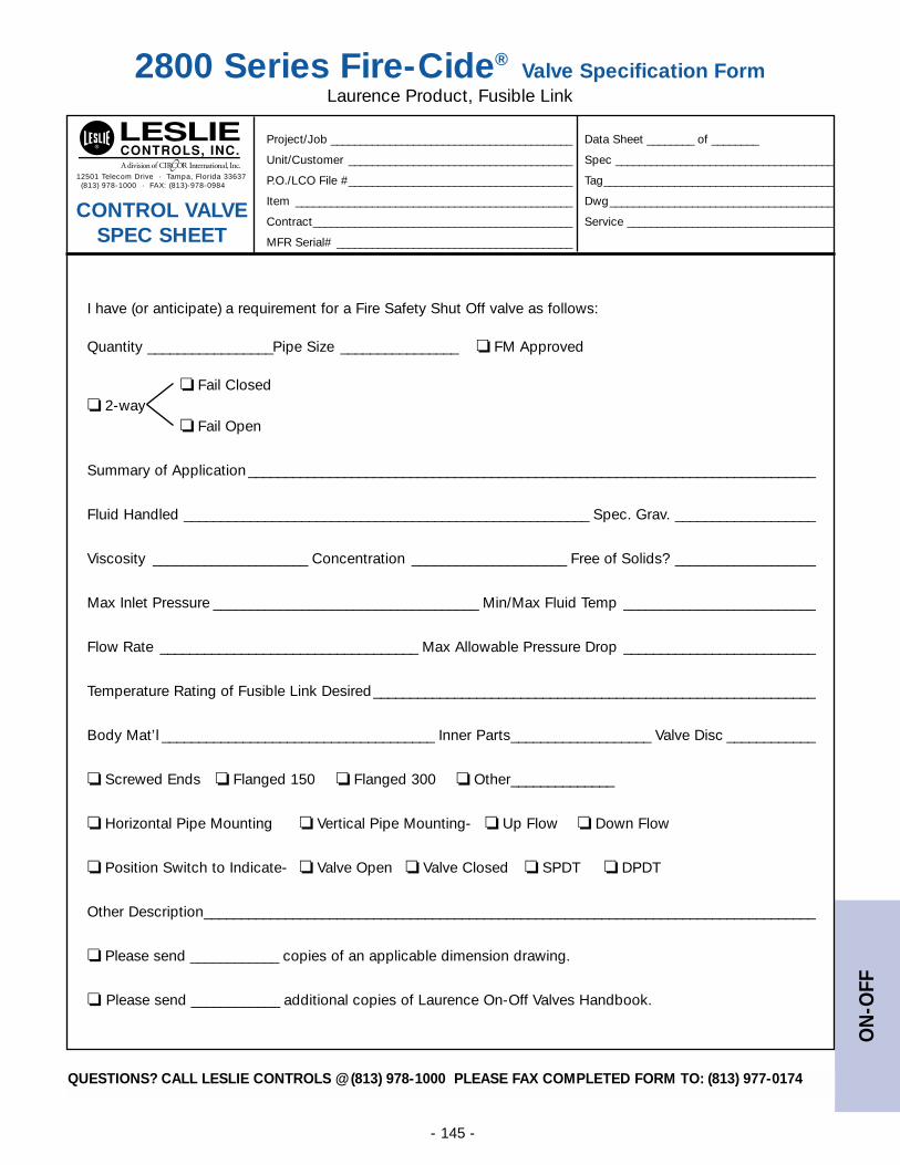
ON
-OFF
- 145 -
QUESTIONS? CALL LESLIE CONTROLS @ (813) 978-1000 PLEASE FAX COMPLETED FORM TO: (813) 977-0174
I have (or anticipate) a requirement for a Fire Safety Shut Off valve as follows:
Quantity _________________Pipe Size ________________ ❏ FM Approved
❏ Fail Closed❏ 2-way
❏ Fail Open
Summary of Application _____________________________________________________________________________
Fluid Handled _______________________________________________________ Spec. Grav. ___________________
Viscosity _____________________ Concentration _____________________ Free of Solids? ___________________
Max Inlet Pressure ____________________________________ Min/Max Fluid Temp __________________________
Flow Rate ___________________________________ Max Allowable Pressure Drop __________________________
Temperature Rating of Fusible Link Desired____________________________________________________________
Body Mat’l _____________________________________ Inner Parts___________________ Valve Disc ____________
❏ Screwed Ends ❏ Flanged 150 ❏ Flanged 300 ❏ Other______________
❏ Horizontal Pipe Mounting ❏ Vertical Pipe Mounting- ❏ Up Flow ❏ Down Flow
❏ Position Switch to Indicate- ❏ Valve Open ❏ Valve Closed ❏ SPDT ❏ DPDT
Other Description___________________________________________________________________________________
❏ Please send ____________ copies of an applicable dimension drawing.
❏ Please send ____________ additional copies of Laurence On-Off Valves Handbook.
2800 Series Fire-Cide®Valve Specification Form
Laurence Product, Fusible Link
12501 Telecom Drive · Tampa, Florida 33637(813) 978-1000 · FAX: (813)-978-0984
Project/Job _________________________________________ Data Sheet ________ of ________
Unit/Customer ______________________________________ Spec _____________________________________
P.O./LCO File #______________________________________ Tag_______________________________________
Item _______________________________________________ Dwg______________________________________
Contract____________________________________________ Service ___________________________________
MFR Serial# ________________________________________
CONTROL VALVE SPEC SHEET
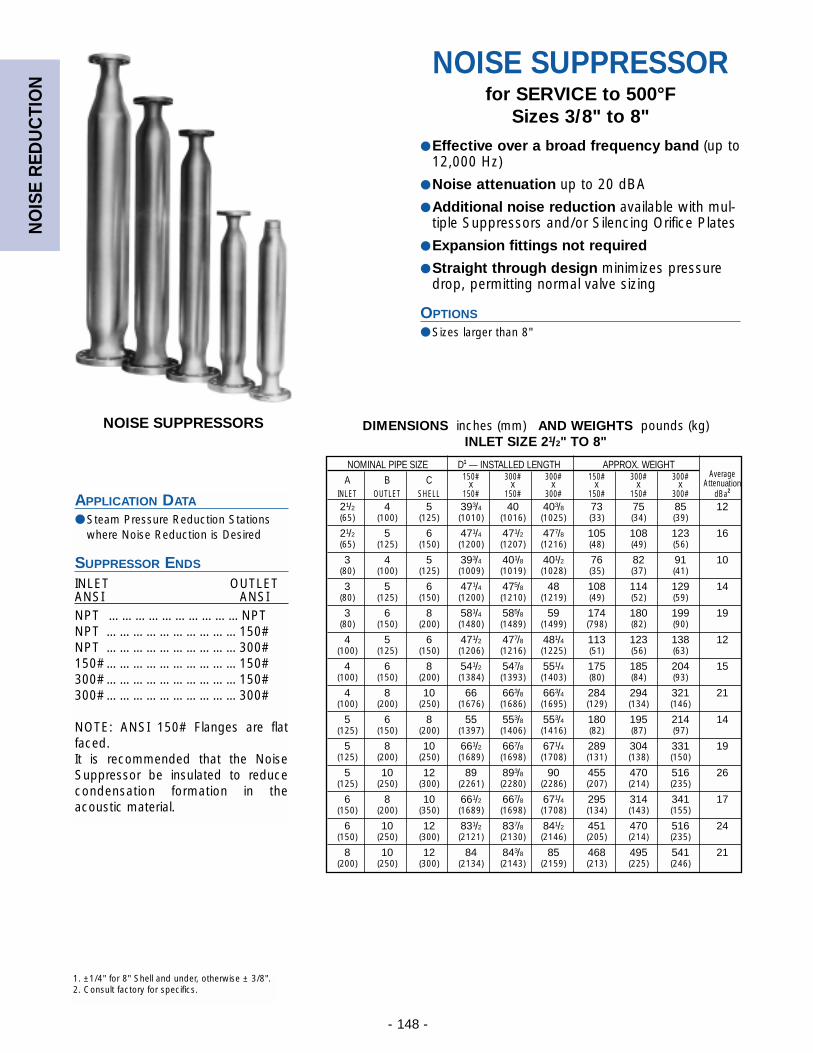
NO
ISE
RED
UC
TIO
N
- 148 -
NOISE SUPPRESSORfor SERVICE to 500°F
Sizes 3/8" to 8"
● Effective over a broad frequency band (up to12,000 Hz)
● Noise attenuation up to 20 dBA
● Additional noise reduction available with mul-tiple Suppressors and/or Silencing Orifice Plates
● Expansion fittings not required
● Straight through design minimizes pressuredrop, permitting normal valve sizing
OPTIONS
● Sizes larger than 8"
NOISE SUPPRESSORS
APPLICATION DATA
● Steam Pressure Reduction Stationswhere Noise Reduction is Desired
SUPPRESSOR ENDS
INLET OUTLETANSI ANSINPT …………………………NPTNPT …………………………150#NPT …………………………300#150# …………………………150#300# …………………………150#300# …………………………300#
NOTE: ANSI 150# Flanges are flatfaced.It is recommended that the NoiseSuppressor be insulated to reducecondensation formation in theacoustic material.
DIMENSIONS inches (mm) AND WEIGHTS pounds (kg)INLET SIZE 21/2" TO 8"
NOMINAL PIPE SIZE D1 — INSTALLED LENGTH APPROX. WEIGHT150# 300# 300# 150# 300# 300# Average
A B C x x x x x x AttenuationINLET OUTLET SHELL 150# 150# 300# 150# 150# 300# dBa2
21/2 4 5 393/4 40 403/8 73 75 85 12(65) (100) (125) (1010) (1016) (1025) (33) (34) (39)
21/2 5 6 471/4 471/2 477/8 105 108 123 16(65) (125) (150) (1200) (1207) (1216) (48) (49) (56)
3 4 5 393/4 401/8 401/2 76 82 91 10(80) (100) (125) (1009) (1019) (1028) (35) (37) (41)
3 5 6 471/4 475/8 48 108 114 129 14(80) (125) (150) (1200) (1210) (1219) (49) (52) (59)
3 6 8 581/4 585/8 59 174 180 199 19(80) (150) (200) (1480) (1489) (1499) (798) (82) (90)
4 5 6 471/2 477/8 481/4 113 123 138 12(100) (125) (150) (1206) (1216) (1225) (51) (56) (63)
4 6 8 541/2 547/8 551/4 175 185 204 15(100) (150) (200) (1384) (1393) (1403) (80) (84) (93)
4 8 10 66 663/8 663/4 284 294 321 21(100) (200) (250) (1676) (1686) (1695) (129) (134) (146)
5 6 8 55 553/8 553/4 180 195 214 14(125) (150) (200) (1397) (1406) (1416) (82) (87) (97)
5 8 10 661/2 667/8 671/4 289 304 331 19(125) (200) (250) (1689) (1698) (1708) (131) (138) (150)
5 10 12 89 893/8 90 455 470 516 26(125) (250) (300) (2261) (2280) (2286) (207) (214) (235)
6 8 10 661/2 667/8 671/4 295 314 341 17(150) (200) (350) (1689) (1698) (1708) (134) (143) (155)
6 10 12 831/2 837/8 841/2 451 470 516 24(150) (250) (300) (2121) (2130) (2146) (205) (214) (235)
8 10 12 84 843/8 85 468 495 541 21(200) (250) (300) (2134) (2143) (2159) (213) (225) (246)
1. ±1/4" for 8" Shell and under, otherwise ± 3/8".2. Consult factory for specifics.
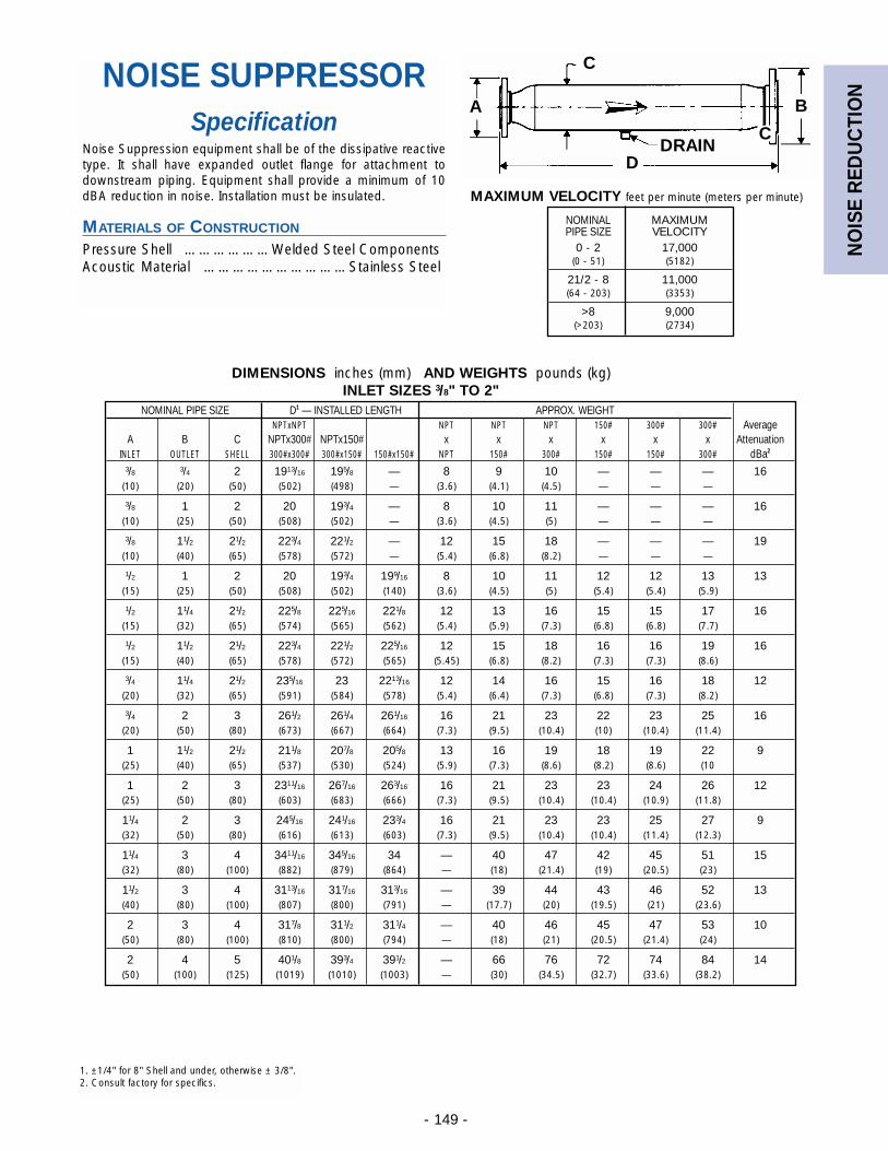
NO
ISE
RED
UC
TIO
N
- 149 -
NOISE SUPPRESSORSpecification
Noise Suppression equipment shall be of the dissipative reactivetype. It shall have expanded outlet flange for attachment todownstream piping. Equipment shall provide a minimum of 10dBA reduction in noise. Installation must be insulated.
MATERIALS OF CONSTRUCTION
Pressure Shell ………………Welded Steel ComponentsAcoustic Material …………………………Stainless Steel
C
A B
DDRAIN
C
MAXIMUM VELOCITY feet per minute (meters per minute)
NOMINAL MAXIMUM PIPE SIZE VELOCITY
0 - 2 17,000(0 - 51) (5182)
21/2 - 8 11,000(64 - 203) (3353)
>8 9,000(>203) (2734)
DIMENSIONS inches (mm) AND WEIGHTS pounds (kg)INLET SIZES 3/8" TO 2"
NOMINAL PIPE SIZE D1 — INSTALLED LENGTH APPROX. WEIGHTNPTxNPT NPT NPT NPT 150# 300# 300# Average
A B C NPTx300# NPTx150# x x x x x x AttenuationINLET OUTLET SHELL 300#x300# 300#x150# 150#x150# NPT 150# 300# 150# 150# 300# dBa2
3/8 3/4 2 1913/16 195/8 — 8 9 10 — — — 16(10) (20) (50) (502) (498) — (3.6) (4.1) (4.5) — — —
3/8 1 2 20 193/4 — 8 10 11 — — — 16(10) (25) (50) (508) (502) — (3.6) (4.5) (5) — — —
3/8 11/2 21/2 223/4 221/2 — 12 15 18 — — — 19(10) (40) (65) (578) (572) — (5.4) (6.8) (8.2) — — —
1/2 1 2 20 193/4 199/16 8 10 11 12 12 13 13(15) (25) (50) (508) (502) (140) (3.6) (4.5) (5) (5.4) (5.4) (5.9)
1/2 11/4 21/2 225/8 225/16 221/8 12 13 16 15 15 17 16(15) (32) (65) (574) (565) (562) (5.4) (5.9) (7.3) (6.8) (6.8) (7.7)
1/2 11/2 21/2 223/4 221/2 225/16 12 15 18 16 16 19 16(15) (40) (65) (578) (572) (565) (5.45) (6.8) (8.2) (7.3) (7.3) (8.6)
3/4 11/4 21/2 235/16 23 2213/16 12 14 16 15 16 18 12(20) (32) (65) (591) (584) (578) (5.4) (6.4) (7.3) (6.8) (7.3) (8.2)
3/4 2 3 261/2 261/4 261/16 16 21 23 22 23 25 16(20) (50) (80) (673) (667) (664) (7.3) (9.5) (10.4) (10) (10.4) (11.4)
1 11/2 21/2 211/8 207/8 205/8 13 16 19 18 19 22 9(25) (40) (65) (537) (530) (524) (5.9) (7.3) (8.6) (8.2) (8.6) (10
1 2 3 2311/16 267/16 263/16 16 21 23 23 24 26 12(25) (50) (80) (603) (683) (666) (7.3) (9.5) (10.4) (10.4) (10.9) (11.8)
11/4 2 3 245/16 241/16 233/4 16 21 23 23 25 27 9(32) (50) (80) (616) (613) (603) (7.3) (9.5) (10.4) (10.4) (11.4) (12.3)
11/4 3 4 3411/16 345/16 34 — 40 47 42 45 51 15(32) (80) (100) (882) (879) (864) — (18) (21.4) (19) (20.5) (23)
11/2 3 4 3113/16 317/16 313/16 — 39 44 43 46 52 13(40) (80) (100) (807) (800) (791) — (17.7) (20) (19.5) (21) (23.6)
2 3 4 317/8 311/2 311/4 — 40 46 45 47 53 10(50) (80) (100) (810) (800) (794) — (18) (21) (20.5) (21.4) (24)
2 4 5 401/8 393/4 391/2 — 66 76 72 74 84 14(50) (100) (125) (1019) (1010) (1003) — (30) (34.5) (32.7) (33.6) (38.2)
1. ±1/4" for 8" Shell and under, otherwise ± 3/8".2. Consult factory for specifics.
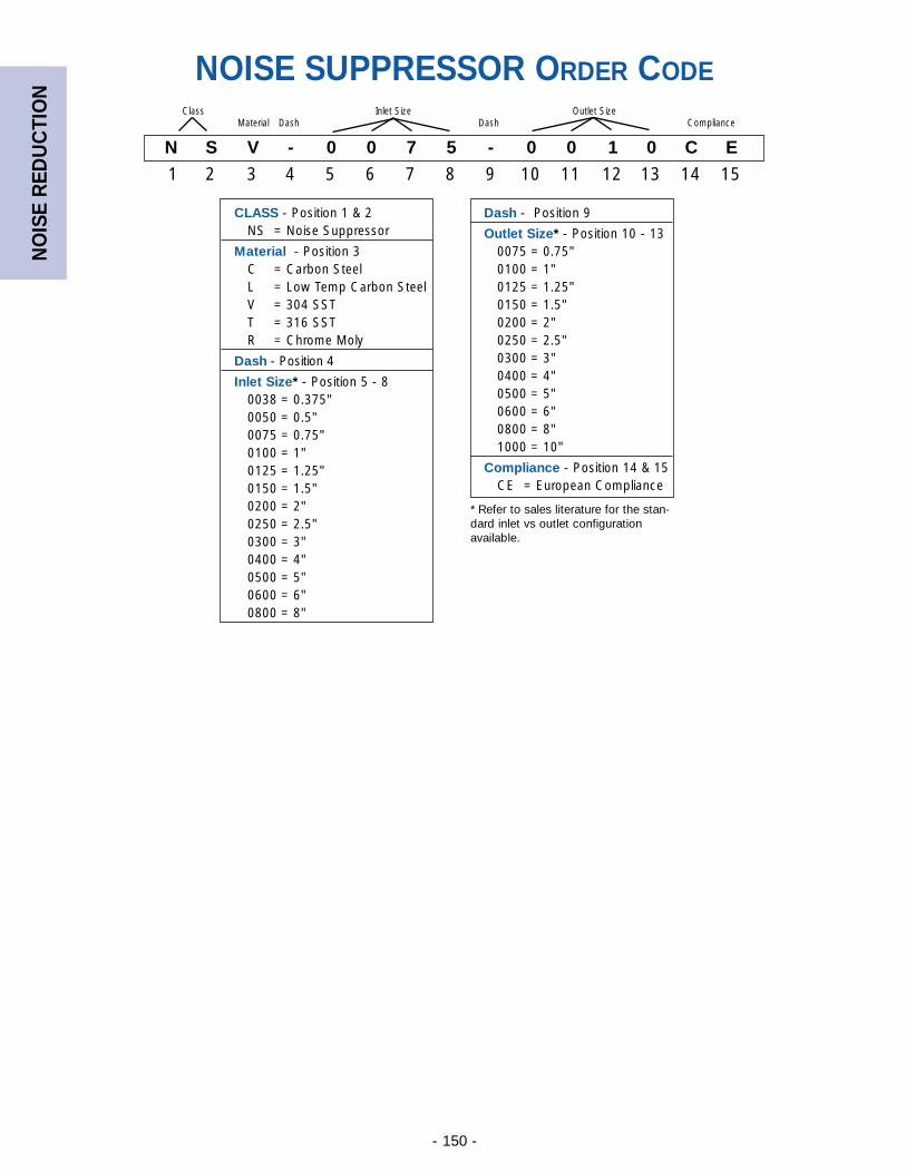
NO
ISE
RED
UC
TIO
N
- 150 -
NOISE SUPPRESSOR ORDER CODE
N S V - 0 0 7 5 - 0 0 1 0 C E
1 2 3 4 5 6 7 8 9 10 11 12 13 14 15
Class Inlet Size Outlet SizeMaterial Dash Dash Compliance
CLASS - Position 1 & 2NS = Noise Suppressor
Material - Position 3C = Carbon SteelL = Low Temp Carbon SteelV = 304 SSTT = 316 SSTR = Chrome Moly
Dash - Position 4
Inlet Size* - Position 5 - 8 0038 = 0.375"0050 = 0.5"0075 = 0.75"0100 = 1"0125 = 1.25"0150 = 1.5"0200 = 2"0250 = 2.5"0300 = 3"0400 = 4"0500 = 5"0600 = 6"0800 = 8"
Dash - Position 9
Outlet Size* - Position 10 - 130075 = 0.75"0100 = 1"0125 = 1.25"0150 = 1.5"0200 = 2"0250 = 2.5"0300 = 3"0400 = 4"0500 = 5"0600 = 6"0800 = 8"1000 = 10"
Compliance - Position 14 & 15CE = European Compliance
* Refer to sales literature for the stan-dard inlet vs outlet configurationavailable.

- 151 -
NOTES:
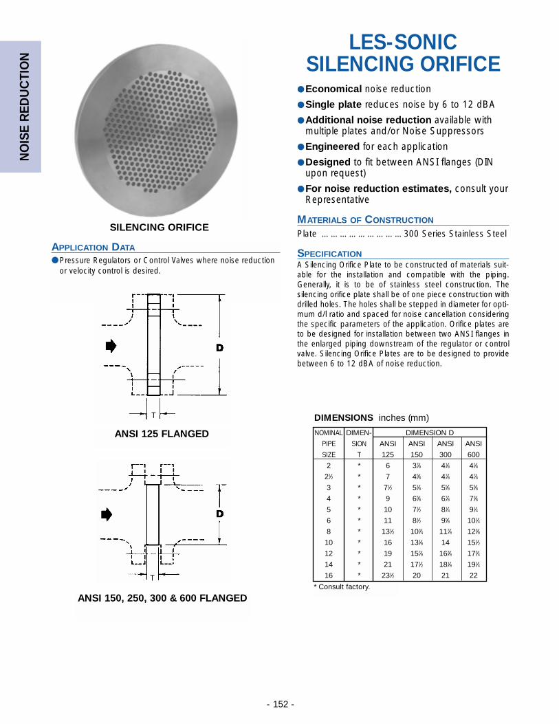
NO
ISE
RED
UC
TIO
N
- 152 -
SILENCING ORIFICE
APPLICATION DATA
● Pressure Regulators or Control Valves where noise reductionor velocity control is desired.
LES-SONICSILENCING ORIFICE
● Economical noise reduction
● Single plate reduces noise by 6 to 12 dBA
● Additional noise reduction available withmultiple plates and/or Noise Suppressors
● Engineered for each application
● Designed to fit between ANSI flanges (DINupon request)
● For noise reduction estimates, consult yourRepresentative
MATERIALS OF CONSTRUCTION
Plate ………………………300 Series Stainless Steel
SPECIFICATIONA Silencing Orifice Plate to be constructed of materials suit-able for the installation and compatible with the piping.Generally, it is to be of stainless steel construction. Thesilencing orifice plate shall be of one piece construction withdrilled holes. The holes shall be stepped in diameter for opti-mum d/l ratio and spaced for noise cancellation consideringthe specific parameters of the application. Orifice plates areto be designed for installation between two ANSI flanges inthe enlarged piping downstream of the regulator or controlvalve. Silencing Orifice Plates are to be designed to providebetween 6 to 12 dBA of noise reduction.
ANSI 125 FLANGED
ANSI 150, 250, 300 & 600 FLANGED
T
T
DIMENSIONS inches (mm)
NOMINAL DIMEN- DIMENSION D
PIPE SION ANSI ANSI ANSI ANSI
SIZE T 125 150 300 600
2 * 6 37⁄8 41⁄8 41⁄8
21⁄2 * 7 45⁄8 47⁄8 47⁄8
3 * 71⁄2 51⁄8 55⁄8 55⁄8
4 * 9 65⁄8 67⁄8 73⁄8
5 * 10 71⁄2 81⁄4 91⁄4
6 * 11 81⁄2 95⁄8 101⁄4
8 * 131⁄2 103⁄4 117⁄8 123⁄8
10 * 16 131⁄8 14 151⁄2
12 * 19 157⁄8 163⁄8 173⁄4
14 * 21 171⁄2 181⁄8 191⁄4
16 * 231⁄2 20 21 22
* Consult factory.
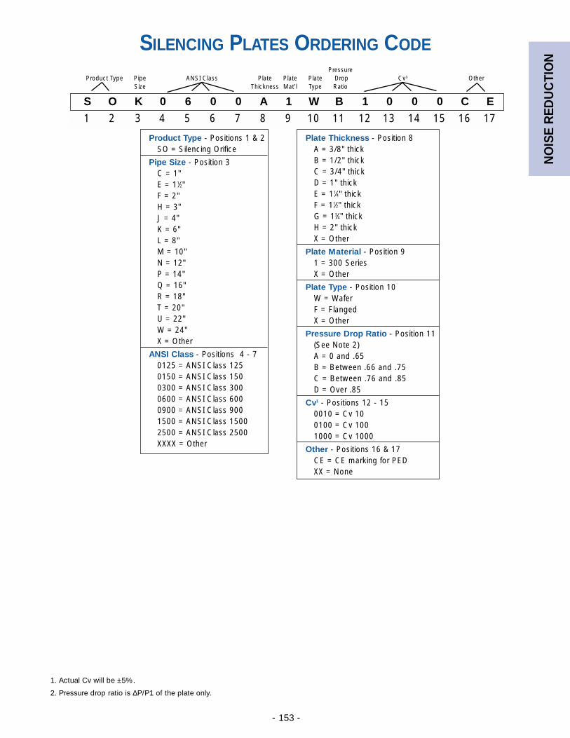
NO
ISE
RED
UC
TIO
N
- 153 -
SILENCING PLATES ORDERING CODE
S O K 0 6 0 0 A 1 W B 1 0 0 0 C E
1 2 3 4 5 6 7 8 9 10 11 12 13 14 15 16 17
PressureProduct Type Pipe ANSI Class Plate Plate Plate Drop Cv1 Other
Size Thickness Mat’l Type Ratio
Plate Thickness - Position 8A = 3/8" thickB = 1/2" thickC = 3/4" thickD = 1" thickE = 11⁄4" thickF = 11⁄2" thickG = 13⁄4" thickH = 2" thickX = Other
Plate Material - Position 91 = 300 SeriesX = Other
Plate Type - Position 10W = WaferF = FlangedX = Other
Pressure Drop Ratio - Position 11(See Note 2)A = 0 and .65B = Between .66 and .75C = Between .76 and .85D = Over .85
Cv1 - Positions 12 - 150010 = Cv 100100 = Cv 1001000 = Cv 1000
Other - Positions 16 & 17CE = CE marking for PEDXX = None
Product Type - Positions 1 & 2SO = Silencing Orifice
Pipe Size - Position 3C = 1"E = 11⁄2"F = 2"H = 3"J = 4"K = 6"L = 8"M = 10"N = 12"P = 14"Q = 16"R = 18"T = 20"U = 22"W = 24"X = Other
ANSI Class - Positions 4 - 70125 = ANSI Class 1250150 = ANSI Class 1500300 = ANSI Class 3000600 = ANSI Class 6000900 = ANSI Class 9001500 = ANSI Class 15002500 = ANSI Class 2500XXXX = Other
1. Actual Cv will be ±5%.
2. Pressure drop ratio is ∆P/P1 of the plate only.
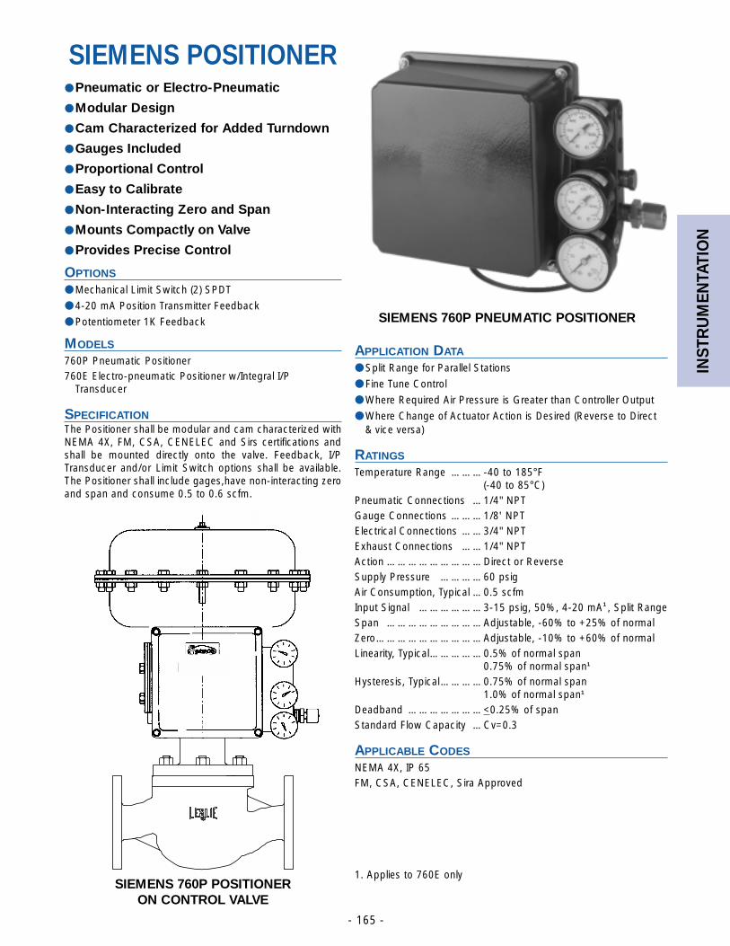
INST
RU
MEN
TATI
ON
- 165 -
SIEMENS 760P POSITIONERON CONTROL VALVE
SIEMENS 760P PNEUMATIC POSITIONER
APPLICATION DATA
● Split Range for Parallel Stations
● Fine Tune Control
● Where Required Air Pressure is Greater than Controller Output
● Where Change of Actuator Action is Desired (Reverse to Direct & vice versa)
RATINGS
Temperature Range ………-40 to 185°F(-40 to 85°C)
Pneumatic Connections …1/4" NPTGauge Connections ………1/8' NPTElectrical Connections ……3/4" NPTExhaust Connections ……1/4" NPTAction ………………………Direct or ReverseSupply Pressure …………60 psigAir Consumption, Typical …0.5 scfmInput Signal ………………3-15 psig, 50%, 4-20 mA1 , Split RangeSpan ………………………Adjustable, -60% to +25% of normalZero…………………………Adjustable, -10% to +60% of normalLinearity, Typical……………0.5% of normal span
0.75% of normal span1
Hysteresis, Typical…………0.75% of normal span1.0% of normal span1
Deadband …………………<0.25% of spanStandard Flow Capacity …Cv=0.3
APPLICABLE CODES
NEMA 4X, IP 65FM, CSA, CENELEC, Sira Approved
1. Applies to 760E only
SIEMENS POSITIONER● Pneumatic or Electro-Pneumatic
● Modular Design
● Cam Characterized for Added Turndown
● Gauges Included
● Proportional Control
● Easy to Calibrate
● Non-Interacting Zero and Span
● Mounts Compactly on Valve
● Provides Precise Control
OPTIONS
● Mechanical Limit Switch (2) SPDT
● 4-20 mA Position Transmitter Feedback
● Potentiometer 1K Feedback
MODELS
760P Pneumatic Positioner760E Electro-pneumatic Positioner w/Integral I/P
Transducer
SPECIFICATIONThe Positioner shall be modular and cam characterized withNEMA 4X, FM, CSA, CENELEC and Sirs certifications andshall be mounted directly onto the valve. Feedback, I/PTransducer and/or Limit Switch options shall be available.The Positioner shall include gages,have non-interacting zeroand span and consume 0.5 to 0.6 scfm.

INST
RU
MEN
TATI
ON
- 156 -
PMC-1 ELECTRO-PNEUMATIC CONTROLLER
APPLICATION DATA
● Process Control Systems Pressure/Temperature Control
● HVAC Systems
● Packaged Systems such as Water Purification, Vaporizers,Metal Cleaning, Plating, etc.
● Feed Water and Fuel System Controls in Boiler Rooms
● Ideal for Pressure Control
APPLICABLE CODES
NEMA 4 Enclosure
PMC-1 ELECTRO-PNEUMATIC
CONTROLLER● Simplified Installation eliminates need for
Positioner, I/P, External Power Supply &Instrument Quality Air
● No Air Consumption at Steady State
● Air Output 0 to Maximum Supply Pressure
● Loss of Power Reset
● Accuracy to ±0.5% of Span
● Easy to Read Digital Display
● Internal Power Supply for Transmitter
OPTIONS
● Pressure Transmitter
● RTD, Thermocouple and Transmitting Thermocouple
● Differential Pressure Transmitter
● Thermowell
MODELS
PMC-1—Electro-Pneumatic Controller PMC-1DA—Used for double acting ActuatorPMC-1M—For size 85 Actuator only
PMC SIMPLIFIESYOUR PRESSURE CONTROL SYSTEM
Control Valve
Air
I/PConverter
ElectronicController
4-20 mA
PowerSupply
Transmitter
Positioner
Conventional Electronic Control System
Air
Transmitter
4-20 mA
Control Valve
Leslie PMC System
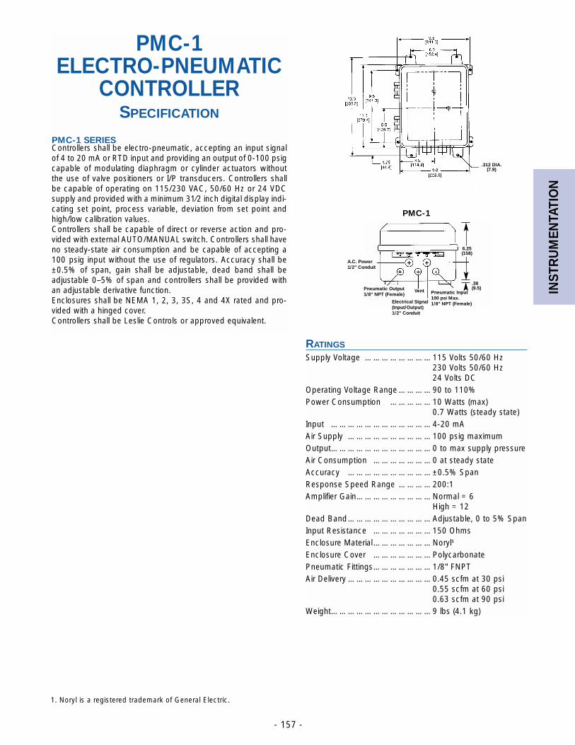
INST
RU
MEN
TATI
ON
- 157 -
PMC-1 ELECTRO-PNEUMATIC
CONTROLLERSPECIFICATION
PMC-1 SERIESControllers shall be electro-pneumatic, accepting an input signalof 4 to 20 mA or RTD input and providing an output of 0-100 psigcapable of modulating diaphragm or cylinder actuators withoutthe use of valve positioners or I/P transducers. Controllers shallbe capable of operating on 115/230 VAC, 50/60 Hz or 24 VDCsupply and provided with a minimum 31⁄2 inch digital display indi-cating set point, process variable, deviation from set point andhigh/low calibration values.Controllers shall be capable of direct or reverse action and pro-vided with external AUTO/MANUAL switch. Controllers shall haveno steady-state air consumption and be capable of accepting a100 psig input without the use of regulators. Accuracy shall be±0.5% of span, gain shall be adjustable, dead band shall beadjustable 0–5% of span and controllers shall be provided withan adjustable derivative function.Enclosures shall be NEMA 1, 2, 3, 3S, 4 and 4X rated and pro-vided with a hinged cover.Controllers shall be Leslie Controls or approved equivalent.
A.C. Power1/2" Conduit
Pneumatic Input 100 psi Max.1/8" NPT (Female)
VentPneumatic Output1/8" NPT (Female)
Electrical Signal(Input/Output)1/2" Conduit
.38(9.5)
6.25(158)
.312 DIA.(7.9)
RATINGS
Supply Voltage ……………………115 Volts 50/60 Hz230 Volts 50/60 Hz24 Volts DC
Operating Voltage Range …………90 to 110%Power Consumption ……………10 Watts (max)
0.7 Watts (steady state)Input ………………………………4-20 mAAir Supply …………………………100 psig maximumOutput………………………………0 to max supply pressureAir Consumption …………………0 at steady stateAccuracy …………………………±0.5% SpanResponse Speed Range …………200:1Amplifier Gain………………………Normal = 6
High = 12Dead Band…………………………Adjustable, 0 to 5% SpanInput Resistance …………………150 OhmsEnclosure Material…………………Noryl1
Enclosure Cover …………………PolycarbonatePneumatic Fittings…………………1/8" FNPTAir Delivery …………………………0.45 scfm at 30 psi
0.55 scfm at 60 psi0.63 scfm at 90 psi
Weight………………………………9 lbs (4.1 kg)
PMC-1
1. Noryl is a registered trademark of General Electric.

INST
RU
MEN
TATI
ON
- 158 -
The Indicating Pneumatic Pressure Controller isdesigned for performance and durability under rigorousoperating conditions.
FEATURES
• Compact Size
• High accuracy sensing element
• Easily adjusted control modes
• Easily changed control action
• High Capacity Pilot valve
• Low air consumption
• Push button restriction cleaner (optional)
• No plastic tubing (except direct set differential gap controller)
Fast response and highly stable control action are keyfeatures of this controller.
The controller has been engineered for compactness,and is constructed of materials that have been carefullyselected to give dependable service with a minimum ofmaintenance. Because of these features, the controller isespecially suitable for field-mounting and other types ofinstallations where a control record is not required.
LESLIE PNEUMATICS III
INDICATINGPNEUMATIC
CONTROLLERSPressure & Temperature
GENERAL SPECIFICATIONS
• Dimensions: 723⁄32" W x 715⁄16" H x 415⁄16" D (196 x 202 x 125mm)
• Case: Weatherproof, diecast aluminum case and gasketed door with plastic window, gray epoxy finishstandard
• Materials: All working parts - Stainless Steel, Diaphragms- neoprene, Feedback - Ni-Span-C
• Panel cutout: 73⁄16"W x 79⁄16"H (183x192mm) for controllerwithout M/A station. 2" (51mm) horizontal and 5" (127mm)vertical clearance required between adjacent panelmounted units.
• Mounting: Case is basically interchangeable for wall orflush-panel mounting. If required, can be furnished withbracket and U-bolts for mounting on 2" (51mm) pipe.
• Scale: Segmental with a 31⁄2" (83mm) calibrated length.Black figures on white background. Setpoint and meas-ured variable pointers are painted in fluorescent colors.
• Case connections: Pneumatic supply and output through1/4" (6.35mm) NPT female connections at bottom of case.Process variable through a 1/2" (12.7mm) NPT female fit-ting also at the bottom of the case.
• Weight: approximately 8 pounds (3.63kg)
OPTIONS (consult Factory for further information)
• Remote Setpoint - Pneumatically operated setpoint con-sists of a 3-15 psi capsular and a linkage that mechani-cally shifts the setpoint. Also included are adjustable highand low scale stops.
• External 2-Position Manual-Automatic Station - Usedfor transferring the pneumatic control of a process fromeither manual operation to automatic or automatic tomanual.
• 2330 Pneumatic Controller - Provides adjustable differ-ential gap pneumatic control of pressure, liquid level, flowor differential pressure.
• Differential-Pressure Element for level, flow andPressure Drop - Accurate, reliable sensor for Controllersand Transmitters under severe operating conditions andenvironments, easy installation and minimal maintenance
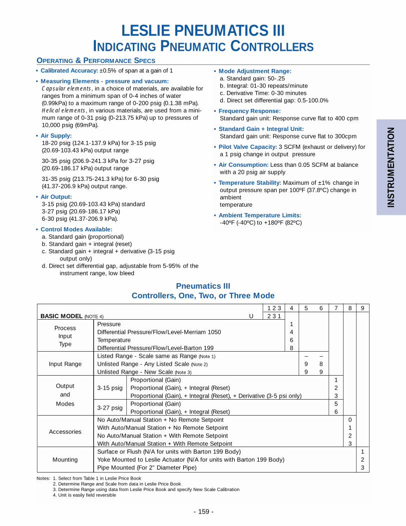
INST
RU
MEN
TATI
ON
- 159 -
LESLIE PNEUMATICS IIIINDICATING PNEUMATIC CONTROLLERS
OPERATING & PERFORMANCE SPECS
• Calibrated Accuracy: ±0.5% of span at a gain of 1
• Measuring Elements - pressure and vacuum: Capsular elements, in a choice of materials, are available forranges from a minimum span of 0-4 inches of water(0.99kPa) to a maximum range of 0-200 psig (0.1.38 mPa).Helical elements, in various materials, are used from a mini-mum range of 0-31 psig (0-213.75 kPa) up to pressures of10,000 psig (69mPa).
• Air Supply: 18-20 psig (124.1-137.9 kPa) for 3-15 psig (20.69-103.43 kPa) output range
30-35 psig (206.9-241.3 kPa for 3-27 psig (20.69-186.17 kPa) output range
31-35 psig (213.75-241.3 kPa) for 6-30 psig (41.37-206.9 kPa) output range.
• Air Output: 3-15 psig (20.69-103.43 kPa) standard 3-27 psig (20.69-186.17 kPa)6-30 psig (41.37-206.9 kPa).
• Control Modes Available: a. Standard gain (proportional)b. Standard gain + integral (reset)c. Standard gain + integral + derivative (3-15 psig
output only)d. Direct set differential gap, adjustable from 5-95% of the
instrument range, low bleed
• Mode Adjustment Range: a. Standard gain: 50-.25b. Integral: 01-30 repeats/minutec. Derivative Time: 0-30 minutesd. Direct set differential gap: 0.5-100.0%
• Frequency Response: Standard gain unit: Response curve flat to 400 cpm
• Standard Gain + Integral Unit: Standard gain unit: Response curve flat to 300cpm
• Pilot Valve Capacity: 3 SCFM (exhaust or delivery) fora 1 psig change in output pressure
• Air Consumption: Less than 0.05 SCFM at balancewith a 20 psig air supply
• Temperature Stability: Maximum of ±1% change inoutput pressure span per 100ºF (37.8ºC) change inambient temperature
• Ambient Temperature Limits: -40ºF (-40ºC) to +180ºF (82ºC)
1 2 3 4 5 6 7 8 9BASIC MODEL (NOTE 4) U 2 3 1
ProcessPressure 1
InputDifferential Pressure/Flow/Level-Merriam 1050 4
TypeTemperature 6Differential Pressure/Flow/Level-Barton 199 8Listed Range - Scale same as Range (Note 1) – –
Input Range Unlisted Range - Any Listed Scale (Note 2) 9 8Unlisted Range - New Scale (Note 3) 9 9
OutputProportional (Gain) 1
and3-15 psig Proportional (Gain), + Integral (Reset) 2
Proportional (Gain), + Integral (Reset), + Derivative (3-5 psi only) 3Modes
3-27 psigProportional (Gain) 5Proportional (Gain), + Integral (Reset) 6
No Auto/Manual Station + No Remote Setpoint 0
AccessoriesWith Auto/Manual Station + No Remote Setpoint 1No Auto/Manual Station + With Remote Setpoint 2With Auto/Manual Station + With Remote Setpoint 3Surface or Flush (N/A for units with Barton 199 Body) 1
Mounting Yoke Mounted to Leslie Actuator (N/A for units with Barton 199 Body) 2Pipe Mounted (For 2" Diameter Pipe) 3
Pneumatics IIIControllers, One, Two, or Three Mode
Notes: 1. Select from Table 1 in Leslie Price Book2. Determine Range and Scale from data in Leslie Price Book3. Determine Range using data from Leslie Price Book and specify New Scale Calibration4. Unit is easily field reversible
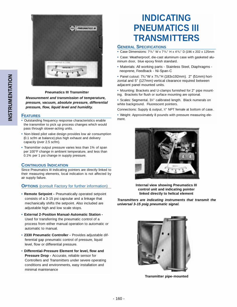
INST
RU
MEN
TATI
ON
- 160 -
Transmitters are indicating instruments that transmit theuniversal 3-15 psig pneumatic signal.
Pneumatics III Transmitter
Transmitter pipe-mounted
Internal view showing Pneumatics IIIcontrol unit and indicating pointerlinked directly to helical element
INDICATINGPNEUMATICS IIITRANSMITTERS
Measurement and transmission of temperature,pressure, vacuum, absolute pressure, differentialpressure, flow, liquid level and humidity.
GENERAL SPECIFICATIONS• Case Dimensions: 723⁄32" W x 715⁄16" H x 415⁄16" D (196 x 202 x 125mm
• Case: Weatherproof, die-cast aluminum case with gasketed alu-minum door, blue epoxy finish standard.
• Materials: All working parts - Stainless Steel, Diaphragms -neoprene, Feedback - Ni-Span-C
• Panel cutout: 73⁄16"W x 79⁄16"H (183x192mm). 2" (51mm) hori-zontal and 5" (127mm) vertical clearance required betweenadjacent panel mounted units.
• Mounting: Brackets and U-clamps furnished for 2" pipe mount-ing. Brackets for flush or surface mounting are optional.
• Scales: Segmental, 31⁄4" calibrated length. Black numerals onwhite background. Fluorescent pointers.
Connections: Supply & output, 1⁄4" NPT female at bottom of case.
• Weight: Approximately 8 pounds with pressure measuring ele-ment.
FEATURES• Outstanding frequency response characteristics enable
the transmitter to pick up process changes which wouldpass through slower-acting units.
• Non-bleed pilot valve design provides low air consumption(0.1 scfm at balance) plus high exhaust and deliverycapacity (over 2.5 scfm).
• Transmitter output pressure varies less than 1% of spanper 100°F change in ambient temperature, and less than0.1% per 1 psi change in supply pressure.
CONTINUOUS INDICATIONSince Pneumatics III indicating pointers are directly linked totheir measuring elements, local indication is not affected byair supply failure.
OPTIONS (consult Factory for further information)
• Remote Setpoint - Pneumatically operated setpointconsists of a 3-15 psi capsular and a linkage thatmechanically shifts the setpoint. Also included areadjustable high and low scale stops.
• External 2-Position Manual-Automatic Station -Used for transferring the pneumatic control of aprocess from either manual operation to automatic orautomatic to manual.
• 2330 Pneumatic Controller - Provides adjustable dif-ferential gap pneumatic control of pressure, liquidlevel, flow or differential pressure.
• Differential-Pressure Element for level, flow andPressure Drop - Accurate, reliable sensor forControllers and Transmitters under severe operatingconditions and environments, easy installation andminimal maintenance
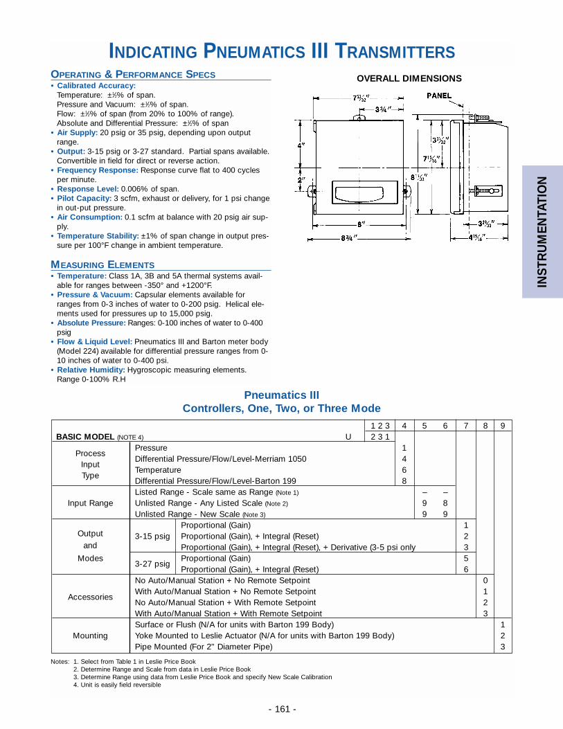
INST
RU
MEN
TATI
ON
- 161 -
OVERALL DIMENSIONS
1 2 3 4 5 6 7 8 9BASIC MODEL (NOTE 4) U 2 3 1
ProcessPressure 1
InputDifferential Pressure/Flow/Level-Merriam 1050 4
TypeTemperature 6Differential Pressure/Flow/Level-Barton 199 8Listed Range - Scale same as Range (Note 1) – –
Input Range Unlisted Range - Any Listed Scale (Note 2) 9 8Unlisted Range - New Scale (Note 3) 9 9
OutputProportional (Gain) 1
and3-15 psig Proportional (Gain), + Integral (Reset) 2
Proportional (Gain), + Integral (Reset), + Derivative (3-5 psi only 3Modes
3-27 psigProportional (Gain) 5Proportional (Gain), + Integral (Reset) 6
No Auto/Manual Station + No Remote Setpoint 0
AccessoriesWith Auto/Manual Station + No Remote Setpoint 1No Auto/Manual Station + With Remote Setpoint 2With Auto/Manual Station + With Remote Setpoint 3Surface or Flush (N/A for units with Barton 199 Body) 1
Mounting Yoke Mounted to Leslie Actuator (N/A for units with Barton 199 Body) 2Pipe Mounted (For 2" Diameter Pipe) 3
Pneumatics IIIControllers, One, Two, or Three Mode
Notes: 1. Select from Table 1 in Leslie Price Book2. Determine Range and Scale from data in Leslie Price Book3. Determine Range using data from Leslie Price Book and specify New Scale Calibration4. Unit is easily field reversible
INDICATING PNEUMATICS III TRANSMITTERSOPERATING & PERFORMANCE SPECS• Calibrated Accuracy:
Temperature: ±1⁄2% of span.Pressure and Vacuum: ±1⁄2% of span.Flow: ±1⁄2% of span (from 20% to 100% of range).Absolute and Differential Pressure: ±1⁄2% of span
• Air Supply: 20 psig or 35 psig, depending upon outputrange.
• Output: 3-15 psig or 3-27 standard. Partial spans available.Convertible in field for direct or reverse action.
• Frequency Response: Response curve flat to 400 cyclesper minute.
• Response Level: 0.006% of span.• Pilot Capacity: 3 scfm, exhaust or delivery, for 1 psi change
in out-put pressure.• Air Consumption: 0.1 scfm at balance with 20 psig air sup-
ply.• Temperature Stability: ±1% of span change in output pres-
sure per 100°F change in ambient temperature.
MEASURING ELEMENTS• Temperature: Class 1A, 3B and 5A thermal systems avail-
able for ranges between -350° and +1200°F.• Pressure & Vacuum: Capsular elements available for
ranges from 0-3 inches of water to 0-200 psig. Helical ele-ments used for pressures up to 15,000 psig.
• Absolute Pressure: Ranges: 0-100 inches of water to 0-400psig
• Flow & Liquid Level: Pneumatics III and Barton meter body(Model 224) available for differential pressure ranges from 0-10 inches of water to 0-400 psi.
• Relative Humidity: Hygroscopic measuring elements.Range 0-100% R.H
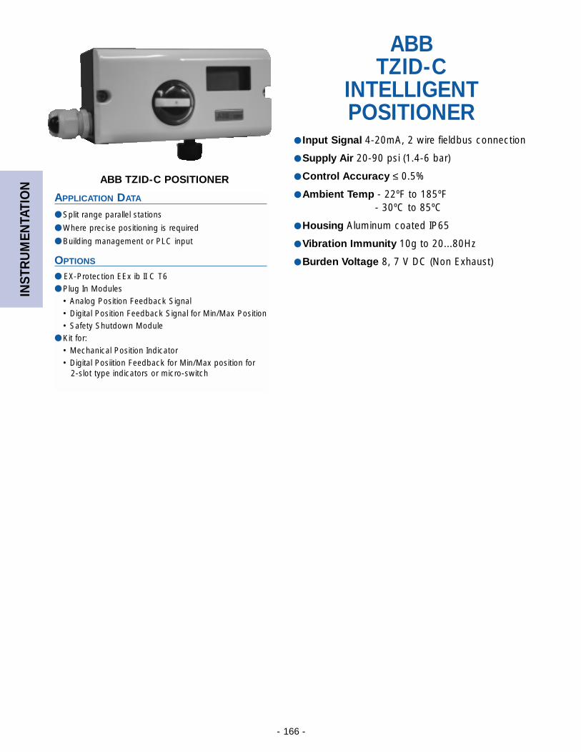
INST
RU
MEN
TATI
ON
- 166 -
ABB TZID-C POSITIONER
APPLICATION DATA
● Split range parallel stations
● Where precise positioning is required
● Building management or PLC input
OPTIONS
● EX-Protection EEx ib II C T6● Plug In Modules
• Analog Position Feedback Signal• Digital Position Feedback Signal for Min/Max Position• Safety Shutdown Module
● Kit for:• Mechanical Position Indicator• Digital Posiition Feedback for Min/Max position for
2-slot type indicators or micro-switch
ABB TZID-C
INTELLIGENT POSITIONER
● Input Signal 4-20mA, 2 wire fieldbus connection
● Supply Air 20-90 psi (1.4-6 bar)
● Control Accuracy ≤ 0.5%
● Ambient Temp - 22ºF to 185ºF- 30ºC to 85ºC
● Housing Aluminum coated IP65
● Vibration Immunity 10g to 20...80Hz
● Burden Voltage 8, 7 V DC (Non Exhaust)
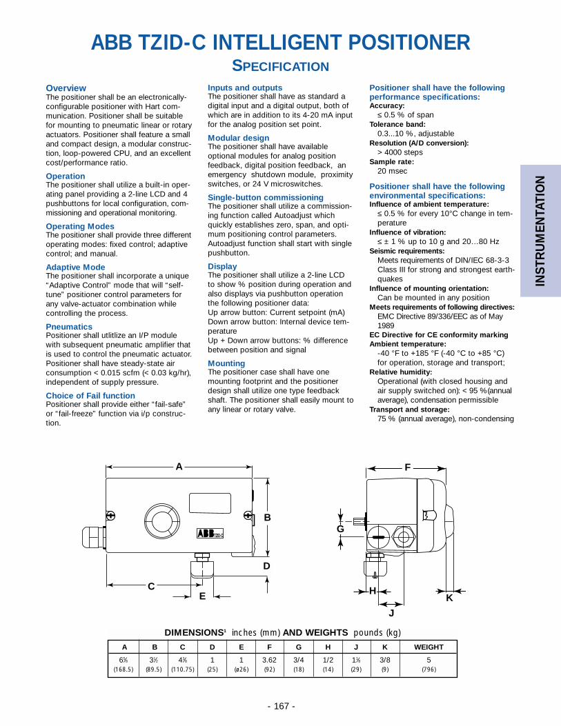
INST
RU
MEN
TATI
ON
- 167 -
ABB TZID-C INTELLIGENT POSITIONERSPECIFICATION
DIMENSIONS1 inches (mm) AND WEIGHTS pounds (kg)
A B C D E F G H J K WEIGHT
65⁄8 31⁄2 43⁄8 1 1 3.62 3/4 1/2 11⁄8 3/8 5(168.5) (89.5) (110.75) (25) (ø26) (92) (18) (14) (29) (9) (796)
OverviewThe positioner shall be an electronically-configurable positioner with Hart com-munication. Positioner shall be suitablefor mounting to pneumatic linear or rotaryactuators. Positioner shall feature a smalland compact design, a modular construc-tion, loop-powered CPU, and an excellentcost/performance ratio.
OperationThe positioner shall utilize a built-in oper-ating panel providing a 2-line LCD and 4pushbuttons for local configuration, com-missioning and operational monitoring.
Operating ModesThe positioner shall provide three differentoperating modes: fixed control; adaptivecontrol; and manual.
Adaptive ModeThe positioner shall incorporate a unique“Adaptive Control” mode that will “self-tune” positioner control parameters forany valve-actuator combination whilecontrolling the process.
PneumaticsPositioner shall utlitlize an I/P modulewith subsequent pneumatic amplifier thatis used to control the pneumatic actuator.Positioner shall have steady-state airconsumption < 0.015 scfm (< 0.03 kg/hr),independent of supply pressure.
Choice of Fail functionPositioner shall provide either “fail-safe”or “fail-freeze” function via i/p construc-tion.
Inputs and outputsThe positioner shall have as standard adigital input and a digital output, both ofwhich are in addition to its 4-20 mA inputfor the analog position set point.
Modular designThe positioner shall have availableoptional modules for analog positionfeedback, digital position feedback, anemergency shutdown module, proximityswitches, or 24 V microswitches.
Single-button commissioningThe positioner shall utilize a commission-ing function called Autoadjust whichquickly establishes zero, span, and opti-mum positioning control parameters.Autoadjust function shall start with singlepushbutton.
DisplayThe positioner shall utilize a 2-line LCDto show % position during operation andalso displays via pushbutton operationthe following positioner data:Up arrow button: Current setpoint (mA)Down arrow button: Internal device tem-peratureUp + Down arrow buttons: % differencebetween position and signal
MountingThe positioner case shall have onemounting footprint and the positionerdesign shall utilize one type feedbackshaft. The positioner shall easily mount toany linear or rotary valve.
A
B
C
D
E
F
H
G
K
J
Positioner shall have the followingperformance specifications:Accuracy:
≤ 0.5 % of spanTolerance band:
0.3...10 %, adjustableResolution (A/D conversion):
> 4000 stepsSample rate:
20 msec
Positioner shall have the followingenvironmental specifications:Influence of ambient temperature:
≤ 0.5 % for every 10°C change in tem-perature
Influence of vibration:≤ ± 1 % up to 10 g and 20…80 Hz
Seismic requirements:Meets requirements of DIN/IEC 68-3-3Class III for strong and strongest earth-quakes
Influence of mounting orientation:Can be mounted in any position
Meets requirements of following directives:EMC Directive 89/336/EEC as of May1989
EC Directive for CE conformity markingAmbient temperature:
-40 °F to +185 °F (-40 °C to +85 °C)for operation, storage and transport;
Relative humidity:Operational (with closed housing andair supply switched on): < 95 %(annualaverage), condensation permissible
Transport and storage:75 % (annual average), non-condensing
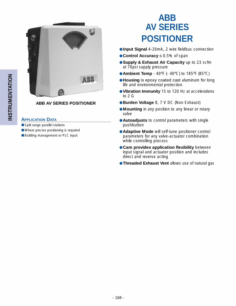
INST
RU
MEN
TATI
ON
- 168 -
ABB AV SERIES POSITIONER
APPLICATION DATA
● Split range parallel stations
● Where precise positioning is required
● Building management or PLC input
ABB AV SERIES
POSITIONER● Input Signal 4-20mA, 2 wire fieldbus connection
● Control Accuracy ≤ 0.5% of span
● Supply & Exhaust Air Capacity up to 23 scfmat 70psi supply pressure
● Ambient Temp - 40ºF (- 40ºC) to 185ºF (85ºC)
● Housing is epoxy coated cast aluminum for longlife and environmental protection
● Vibration Immunity 15 to 120 Hz at accelerationsto 2 G
● Burden Voltage 8, 7 V DC (Non Exhaust)
● Mounting in any position to any linear or rotaryvalve
● Autoadjusts to control parameters with singlepushbutton
● Adaptive Mode will self-tune positioner controlparameters for any valve-actuator combinationwhile controlling process
● Cam provides application flexibility betweeninput signal and actuator position and includesdirect and reverse acting
● Threaded Exhaust Vent allows use of natural gas
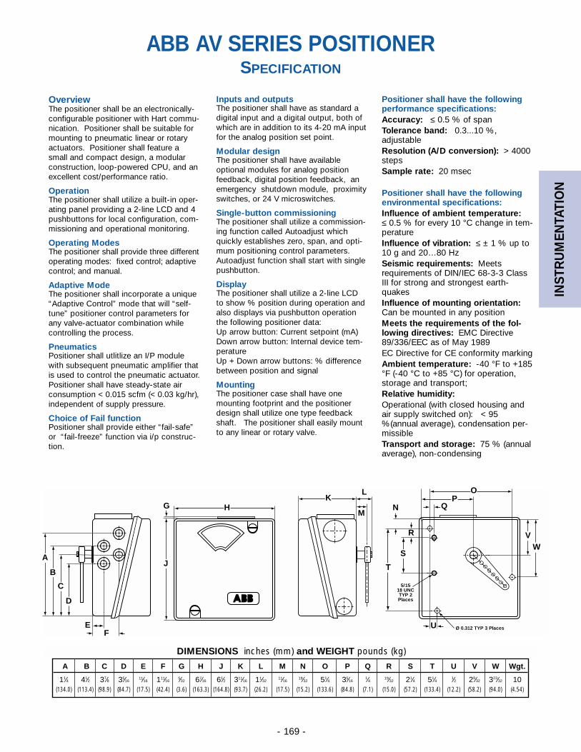
INST
RU
MEN
TATI
ON
- 169 -
ABB AV SERIES POSITIONERSPECIFICATION
DIMENSIONS inches (mm) and WEIGHT pounds (kg)
A B C D E F G H J K L M N O P Q R S T U V W Wgt.
11⁄4 41⁄2 37⁄8 35⁄1611⁄16 111⁄16
5⁄32 67⁄16 61⁄2 311⁄16 11⁄3211⁄16
19⁄32 51⁄4 35⁄161⁄4 19⁄32 21⁄4 51⁄4 1⁄2 29⁄32 323⁄32 10
(134.0) (113.4) (98.9) (84.7) (17.5) (42.4) (3.6) (163.3) (164.8) (93.7) (26.2) (17.5) (15.2) (133.6) (84.8) (7.1) (15.0) (57.2) (133.4) (12.2) (58.2) (94.0) (4.54)
OverviewThe positioner shall be an electronically-configurable positioner with Hart commu-nication. Positioner shall be suitable formounting to pneumatic linear or rotaryactuators. Positioner shall feature asmall and compact design, a modularconstruction, loop-powered CPU, and anexcellent cost/performance ratio.
OperationThe positioner shall utilize a built-in oper-ating panel providing a 2-line LCD and 4pushbuttons for local configuration, com-missioning and operational monitoring.
Operating ModesThe positioner shall provide three differentoperating modes: fixed control; adaptivecontrol; and manual.
Adaptive ModeThe positioner shall incorporate a unique“Adaptive Control” mode that will “self-tune” positioner control parameters forany valve-actuator combination whilecontrolling the process.
PneumaticsPositioner shall utlitlize an I/P modulewith subsequent pneumatic amplifier thatis used to control the pneumatic actuator.Positioner shall have steady-state airconsumption < 0.015 scfm (< 0.03 kg/hr),independent of supply pressure.
Choice of Fail functionPositioner shall provide either “fail-safe”or “fail-freeze” function via i/p construc-tion.
Inputs and outputsThe positioner shall have as standard adigital input and a digital output, both ofwhich are in addition to its 4-20 mA inputfor the analog position set point.
Modular designThe positioner shall have availableoptional modules for analog positionfeedback, digital position feedback, anemergency shutdown module, proximityswitches, or 24 V microswitches.
Single-button commissioningThe positioner shall utilize a commission-ing function called Autoadjust whichquickly establishes zero, span, and opti-mum positioning control parameters.Autoadjust function shall start with singlepushbutton.
DisplayThe positioner shall utilize a 2-line LCDto show % position during operation andalso displays via pushbutton operationthe following positioner data:Up arrow button: Current setpoint (mA)Down arrow button: Internal device tem-peratureUp + Down arrow buttons: % differencebetween position and signal
MountingThe positioner case shall have onemounting footprint and the positionerdesign shall utilize one type feedbackshaft. The positioner shall easily mountto any linear or rotary valve.
Positioner shall have the followingperformance specifications:Accuracy: ≤ 0.5 % of spanTolerance band: 0.3...10 %,adjustableResolution (A/D conversion): > 4000stepsSample rate: 20 msec
Positioner shall have the followingenvironmental specifications:Influence of ambient temperature: ≤ 0.5 % for every 10 °C change in tem-peratureInfluence of vibration: ≤ ± 1 % up to10 g and 20…80 HzSeismic requirements: Meetsrequirements of DIN/IEC 68-3-3 ClassIII for strong and strongest earth-quakesInfluence of mounting orientation:Can be mounted in any positionMeets the requirements of the fol-lowing directives: EMC Directive89/336/EEC as of May 1989EC Directive for CE conformity markingAmbient temperature: -40 °F to +185°F (-40 °C to +85 °C) for operation,storage and transport; Relative humidity: Operational (with closed housing andair supply switched on): < 95%(annual average), condensation per-missibleTransport and storage: 75 % (annualaverage), non-condensing
BBA
A
B
C
D
EF
HGK
J
L
M
OP
QN
T
S
R VW
U
5/1518 UNCTYP 2Places
Ø 0.312 TYP 3 Places
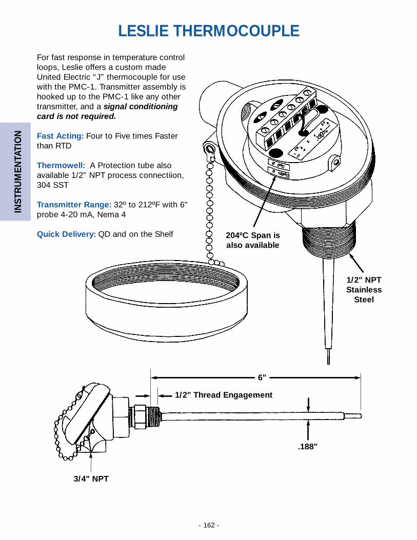
INST
RU
MEN
TATI
ON
- 162 -
LESLIE THERMOCOUPLE
1/2" Thread Engagement
3/4" NPT
6"
.188"
1/2" NPTStainless
Steel
204ºC Span isalso available
For fast response in temperature controlloops, Leslie offers a custom madeUnited Electric “J” thermocouple for usewith the PMC-1. Transmitter assembly ishooked up to the PMC-1 like any othertransmitter, and a signal conditioningcard is not required.
Fast Acting: Four to Five times Fasterthan RTD
Thermowell: A Protection tube alsoavailable 1/2" NPT process connectiion,304 SST
Transmitter Range: 32º to 212ºF with 6"probe 4-20 mA, Nema 4
Quick Delivery: QD and on the Shelf

INST
RU
MEN
TATI
ON
- 163 -
RTD RESISTANCE PROBE THERMOMETER
● 304 SS Closed End Probe measures temperature
● Varies Electrical Resistance in proportion to temperaturechanges
● Communicates Change in resistance to automated systems
OPTIONS
● 304 SST Thermowell
SPECIFICATION
The RTD shall have a 304 stainless steel closed end probe with a 1/2 inch NPT malewith hex fitting process connection. The RTD shall change resistance in proportion to achange in temperature and be capable of connecting to a device (such as a signal con-ditioning card) which can convert that resistance change to a standard 4-20 mA sig-nal.
MATERIALS OF CONSTRUCTION
Connector Head:………………………………………………NB 1 Cast IronProbe: ……………………………………………………304 SS Closed EndProcess Connection: …………………………1/2" NPT Male w/Hex fittingElectrical Connection:………………………………………1/2" NPT FemaleSheath Length ……………………………………………………51⁄2" or 111⁄2"Sheath Diameter ……………………………………………………………1⁄4"
RTD RESISTANCE PROBE THERMOMETER
APPLICATION DATA
● Building control systems
● Process control systems
● Systems utilizing the PMC Electro-Pneumatic Controller
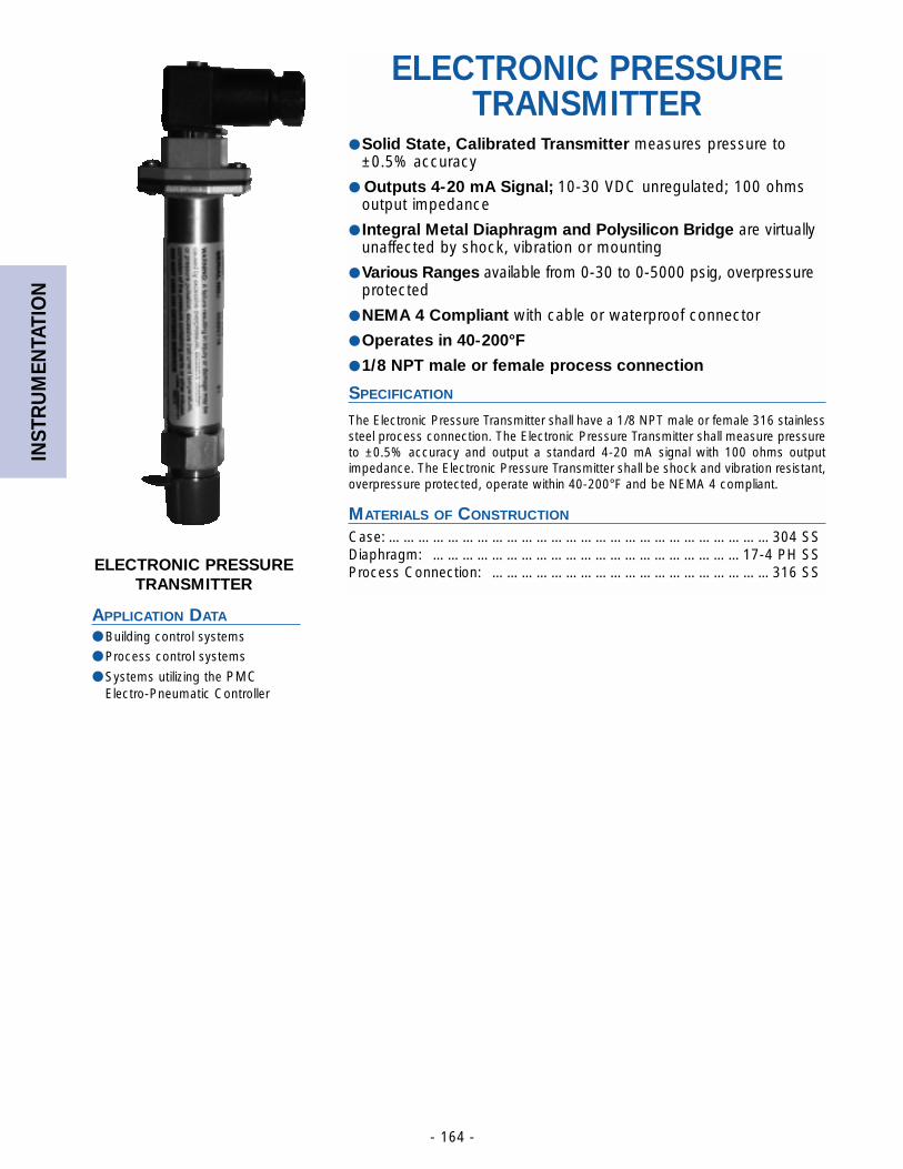
INST
RU
MEN
TATI
ON
- 164 -
ELECTRONIC PRESSURETRANSMITTER
APPLICATION DATA
● Building control systems
● Process control systems
● Systems utilizing the PMCElectro-Pneumatic Controller
ELECTRONIC PRESSURETRANSMITTER
● Solid State, Calibrated Transmitter measures pressure to±0.5% accuracy
● Outputs 4-20 mA Signal; 10-30 VDC unregulated; 100 ohmsoutput impedance
● Integral Metal Diaphragm and Polysilicon Bridge are virtuallyunaffected by shock, vibration or mounting
● Various Ranges available from 0-30 to 0-5000 psig, overpressureprotected
● NEMA 4 Compliant with cable or waterproof connector
● Operates in 40-200°F
● 1/8 NPT male or female process connection
SPECIFICATION
The Electronic Pressure Transmitter shall have a 1/8 NPT male or female 316 stainlesssteel process connection. The Electronic Pressure Transmitter shall measure pressureto ±0.5% accuracy and output a standard 4-20 mA signal with 100 ohms outputimpedance. The Electronic Pressure Transmitter shall be shock and vibration resistant,overpressure protected, operate within 40-200°F and be NEMA 4 compliant.
MATERIALS OF CONSTRUCTION
Case: ……………………………………………………………………304 SSDiaphragm: ………………………………………………………17-4 PH SSProcess Connection: …………………………………………………316 SS
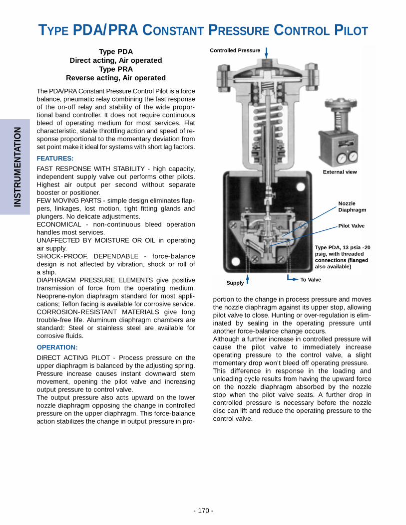
INST
RU
MEN
TATI
ON
- 170 -
Type PDADirect acting, Air operated
Type PRAReverse acting, Air operated
The PDA/PRA Constant Pressure Control Pilot is a forcebalance, pneumatic relay combining the fast responseof the on-off relay and stability of the wide propor-tional band controller. It does not require continuousbleed of operating medium for most services. Flatcharacteristic, stable throttling action and speed of re-sponse proportional to the momentary deviation fromset point make it ideal for systems with short lag factors.
FEATURES:
FAST RESPONSE WITH STABILITY - high capacity,independent supply valve out performs other pilots.Highest air output per second without separatebooster or positioner.FEW MOVING PARTS - simple design eliminates flap-pers, linkages, lost motion, tight fitting glands andplungers. No delicate adjustments.ECONOMICAL - non-continuous bleed operationhandles most services.UNAFFECTED BY MOISTURE OR OIL in operating air supply.SHOCK-PROOF, DEPENDABLE - force-balancedesign is not affected by vibration, shock or roll of a ship.DIAPHRAGM PRESSURE ELEMENTS give positive transmission of force from the operating medium.Neoprene-nylon diaphragm standard for most appli-cations; Teflon facing is available for corrosive service.CORROSION-RESISTANT MATERIALS give long trouble-free life. Aluminum diaphragm chambers arestandard: Steel or stainless steel are available for corrosive fluids.
OPERATION:
DIRECT ACTING PILOT - Process pressure on theupper diaphragm is balanced by the adjusting spring.Pressure increase causes instant downward stemmovement, opening the pilot valve and increasingoutput pressure to control valve.The output pressure also acts upward on the lowernozzle diaphragm opposing the change in controlledpressure on the upper diaphragm. This force-balanceaction stabilizes the change in output pressure in pro-
portion to the change in process pressure and movesthe nozzle diaphragm against its upper stop, allowingpilot valve to close. Hunting or over-regulation is elim-inated by sealing in the operating pressure untilanother force-balance change occurs.Although a further increase in controlled pressure willcause the pilot valve to immediately increaseoperating pressure to the control valve, a slightmomentary drop won’t bleed off operating pressure.This difference in response in the loading andunloading cycle results from having the upward forceon the nozzle diaphragm absorbed by the nozzle stop when the pilot valve seats. A further drop in controlled pressure is necessary before the nozzledisc can lift and reduce the operating pressure to thecontrol valve.
Controlled Pressure
External view
Type PDA, 13 psia -20psig, with threaded connections (flangedalso available)
NozzleDiaphragm
Pilot Valve
To ValveSupply
TYPE PDA/PRA CONSTANT PRESSURE CONTROL PILOT
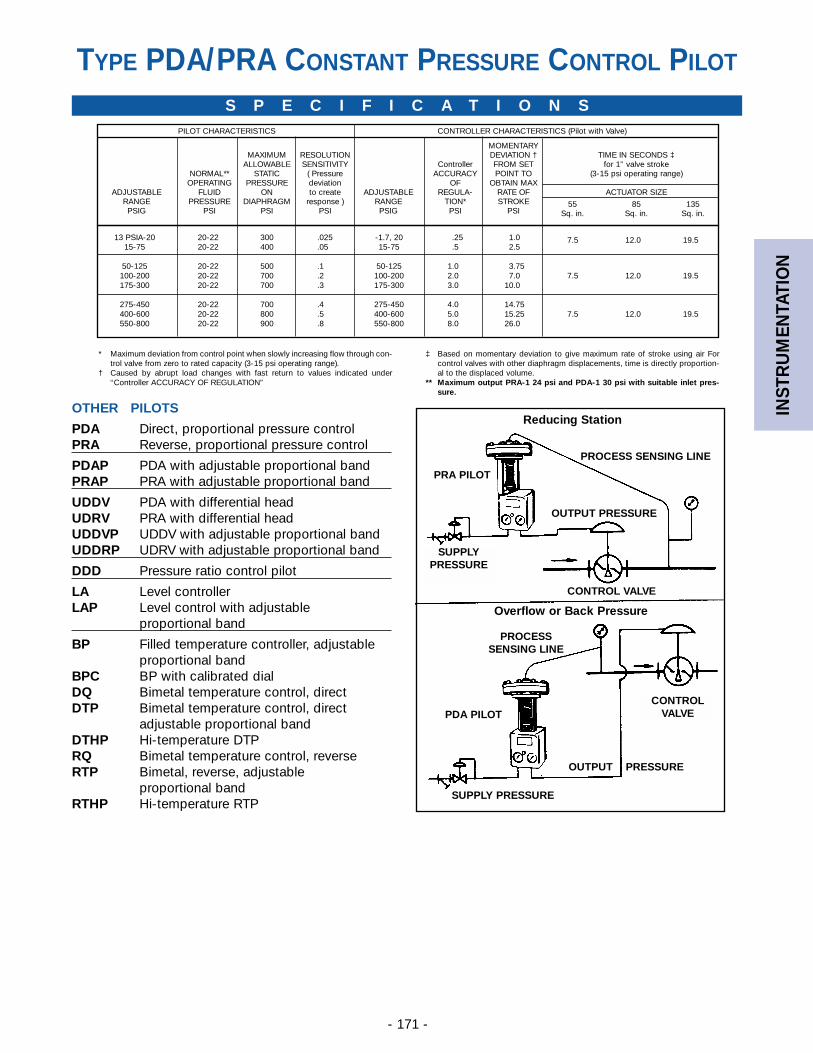
INST
RU
MEN
TATI
ON
- 171 -
* Maximum deviation from control point when slowly increasing flow through con-trol valve from zero to rated capacity (3-15 psi operating range).
† Caused by abrupt load changes with fast return to values indicated under“Controller ACCURACY OF REGULATION”
‡ Based on momentary deviation to give maximum rate of stroke using air Forcontrol valves with other diaphragm displacements, time is directly proportion-al to the displaced volume.
** Maximum output PRA-1 24 psi and PDA-1 30 psi with suitable inlet pres-sure.
13 PSIA-20 20-22 300 .025 -1.7, 20 0.25 01.0 7.5 12.0 19.515-75 20-22 400 .05 15-75 0.5 02.5
50-125 20-22 500 .1 50-125 1.0 03.75100-200 20-22 700 .2 100-200 2.0 07.0 7.5 12.0 19.5175-300 20-22 700 .3 175-300 3.0 10.0
275-450 20-22 700 .4 275-450 4.0 14.75400-600 20-22 800 .5 400-600 5.0 15.25 7.5 12.0 19.5550-800 20-22 900 .8 550-800 8.0 26.0
PILOT CHARACTERISTICS CONTROLLER CHARACTERISTICS (Pilot with Valve)
MOMENTARYMAXIMUM RESOLUTION DEVIATION † TIME IN SECONDS ‡
ALLOWABLE SENSITIVITY Controller FROM SET for 1” valve strokeNORMAL** STATIC ( Pressure ACCURACY POINT TO (3-15 psi operating range)
OPERATING PRESSURE deviation OF OBTAIN MAXADJUSTABLE FLUID ON to create ADJUSTABLE REGULA- RATE OF ACTUATOR SIZE
RANGE PRESSURE DIAPHRAGM response ) RANGE TION* STROKE 55 85 135PSIG PSI PSI PSI PSIG PSI PSI Sq. in. Sq. in. Sq. in.
S P E C I F I C A T I O N S
PROCESS SENSING LINE
OUTPUT PRESSURE
SUPPLYPRESSURE
PROCESSSENSING LINE
OUTPUT PRESSURE
SUPPLY PRESSURE
Reducing Station
PRA PILOT
CONTROL VALVE
Overflow or Back Pressure
CONTROLVALVEPDA PILOT
OTHER PILOTS
PDA Direct, proportional pressure controlPRA Reverse, proportional pressure control
PDAP PDA with adjustable proportional bandPRAP PRA with adjustable proportional band
UDDV PDA with differential headUDRV PRA with differential headUDDVP UDDV with adjustable proportional bandUDDRP UDRV with adjustable proportional band
DDD Pressure ratio control pilot
LA Level controllerLAP Level control with adjustable
proportional band
BP Filled temperature controller, adjustable proportional band
BPC BP with calibrated dialDQ Bimetal temperature control, directDTP Bimetal temperature control, direct
adjustable proportional bandDTHP Hi-temperature DTPRQ Bimetal temperature control, reverseRTP Bimetal, reverse, adjustable
proportional bandRTHP Hi-temperature RTP
TYPE PDA/PRA CONSTANT PRESSURE CONTROL PILOT
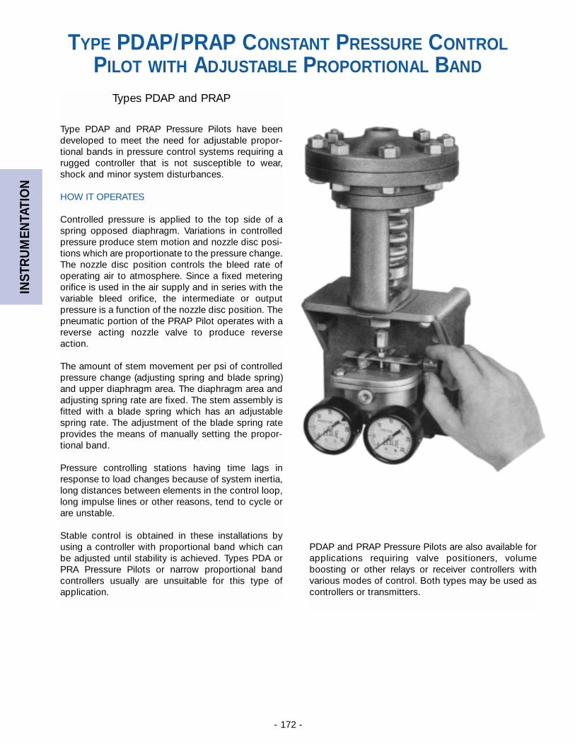
INST
RU
MEN
TATI
ON
- 172 -
Types PDAP and PRAP
Type PDAP and PRAP Pressure Pilots have beendeveloped to meet the need for adjustable propor-tional bands in pressure control systems requiring arugged controller that is not susceptible to wear,shock and minor system disturbances.
HOW IT OPERATES
Controlled pressure is applied to the top side of aspring opposed diaphragm. Variations in controlledpressure produce stem motion and nozzle disc posi-tions which are proportionate to the pressure change.The nozzle disc position controls the bleed rate ofoperating air to atmosphere. Since a fixed meteringorifice is used in the air supply and in series with thevariable bleed orifice, the intermediate or outputpressure is a function of the nozzle disc position. Thepneumatic portion of the PRAP Pilot operates with areverse acting nozzle valve to produce reverseaction.
The amount of stem movement per psi of controlledpressure change (adjusting spring and blade spring)and upper diaphragm area. The diaphragm area andadjusting spring rate are fixed. The stem assembly isfitted with a blade spring which has an adjustablespring rate. The adjustment of the blade spring rateprovides the means of manually setting the propor-tional band.
Pressure controlling stations having time lags inresponse to load changes because of system inertia,long distances between elements in the control loop,long impulse lines or other reasons, tend to cycle orare unstable.
Stable control is obtained in these installations byusing a controller with proportional band which canbe adjusted until stability is achieved. Types PDA orPRA Pressure Pilots or narrow proportional bandcontrollers usually are unsuitable for this type ofapplication.
PDAP and PRAP Pressure Pilots are also available forapplications requiring valve positioners, volumeboosting or other relays or receiver controllers withvarious modes of control. Both types may be used ascontrollers or transmitters.
TYPE PDAP/PRAP CONSTANT PRESSURE CONTROLPILOT WITH ADJUSTABLE PROPORTIONAL BAND
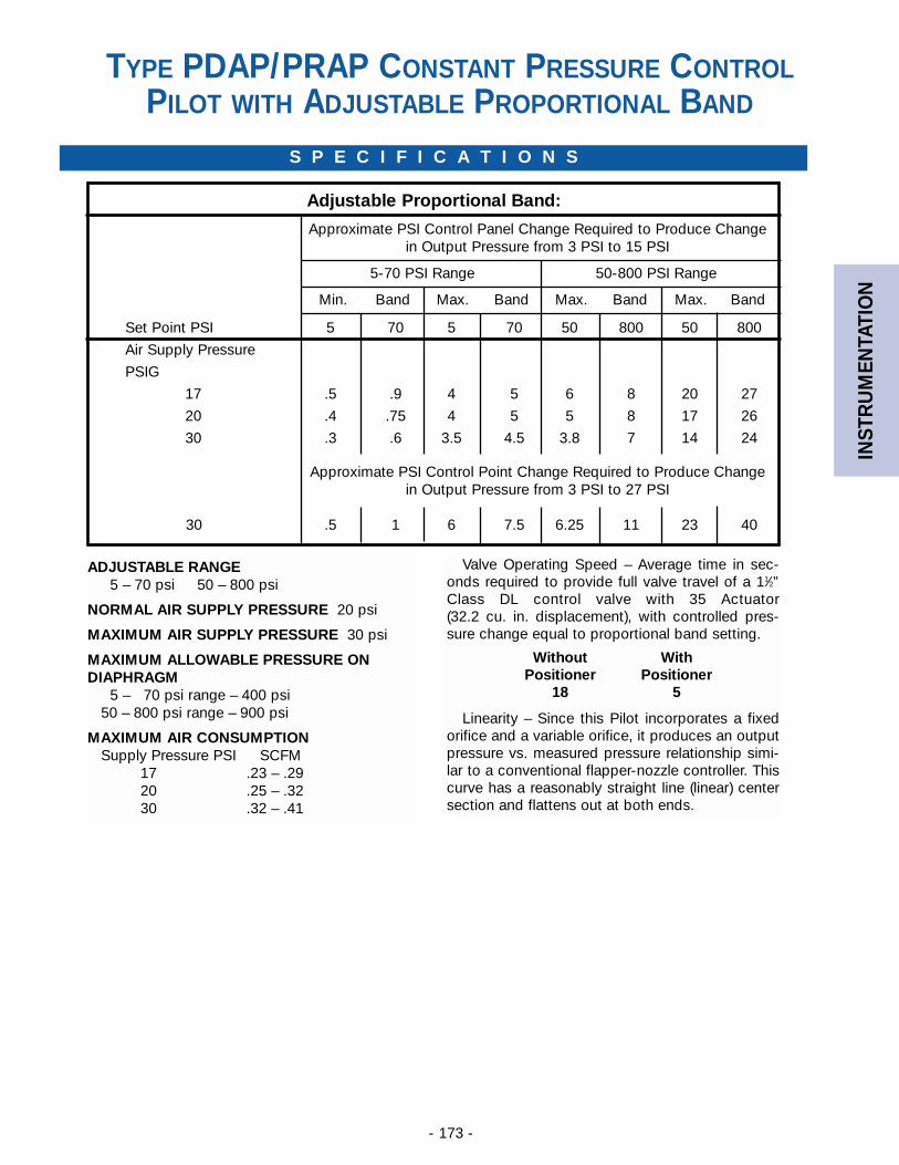
INST
RU
MEN
TATI
ON
- 173 -
S P E C I F I C A T I O N S
Adjustable Proportional Band:
Approximate PSI Control Panel Change Required to Produce Change in Output Pressure from 3 PSI to 15 PSI
5-70 PSI Range 50-800 PSI Range
Min. Band Max. Band Max. Band Max. Band
Set Point PSI 5 70 5 70 50 800 50 800
Air Supply Pressure
PSIG
17 .5 .9 4 5 6 8 20 27
20 .4 .75 4 5 5 8 17 26
30 .3 .6 3.5 4.5 3.8 7 14 24
Approximate PSI Control Point Change Required to Produce Change in Output Pressure from 3 PSI to 27 PSI
30 .5 1 6 7.5 6.25 11 23 40
ADJUSTABLE RANGE5 – 70 psi 50 – 800 psi
NORMAL AIR SUPPLY PRESSURE 20 psi
MAXIMUM AIR SUPPLY PRESSURE 30 psi
MAXIMUM ALLOWABLE PRESSURE ONDIAPHRAGM
5 – 70 psi range – 400 psi50 – 800 psi range – 900 psi
MAXIMUM AIR CONSUMPTIONSupply Pressure PSI SCFM
17 .23 – .2920 .25 – .3230 .32 – .41
Valve Operating Speed – Average time in sec-onds required to provide full valve travel of a 11⁄2”Class DL control valve with 35 Actuator (32.2 cu. in. displacement), with controlled pres-sure change equal to proportional band setting.
Without WithPositioner Positioner
18 5
Linearity – Since this Pilot incorporates a fixedorifice and a variable orifice, it produces an outputpressure vs. measured pressure relationship simi-lar to a conventional flapper-nozzle controller. Thiscurve has a reasonably straight line (linear) centersection and flattens out at both ends.
TYPE PDAP/PRAP CONSTANT PRESSURE CONTROLPILOT WITH ADJUSTABLE PROPORTIONAL BAND
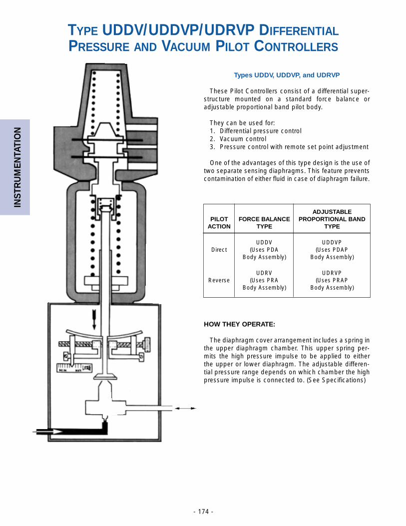
INST
RU
MEN
TATI
ON
- 174 -
Types UDDV, UDDVP, and UDRVP
These Pilot Controllers consist of a differential super-structure mounted on a standard force balance oradjustable proportional band pilot body.
They can be used for:1. Differential pressure control2. Vacuum control3. Pressure control with remote set point adjustment
One of the advantages of this type design is the use oftwo separate sensing diaphragms. This feature preventscontamination of either fluid in case of diaphragm failure.
HOW THEY OPERATE:
The diaphragm cover arrangement includes a spring inthe upper diaphragm chamber. This upper spring per-mits the high pressure impulse to be applied to eitherthe upper or lower diaphragm. The adjustable differen-tial pressure range depends on which chamber the highpressure impulse is connected to. (See Specifications)
ADJUSTABLEPILOT FORCE BALANCE PROPORTIONAL BAND
ACTION TYPE TYPE
UDDV UDDVPDirect (Uses PDA (Uses PDAP
Body Assembly) Body Assembly)
UDRV UDRVPReverse (Uses PRA (Uses PRAP
Body Assembly) Body Assembly)
TYPE UDDV/UDDVP/UDRVP DIFFERENTIALPRESSURE AND VACUUM PILOT CONTROLLERS
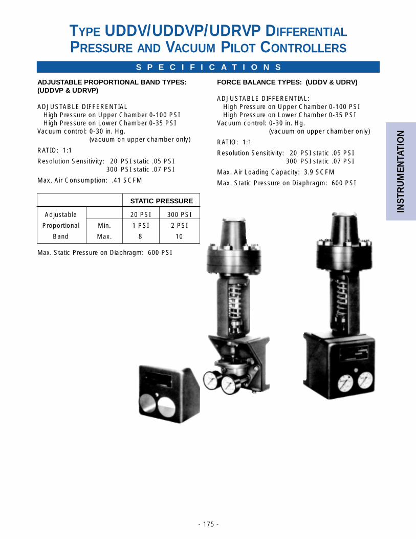
INST
RU
MEN
TATI
ON
- 175 -
S P E C I F I C A T I O N S
ADJUSTABLE PROPORTIONAL BAND TYPES:(UDDVP & UDRVP)
ADJUSTABLE DIFFERENTIALHigh Pressure on Upper Chamber 0-100 PSIHigh Pressure on Lower Chamber 0-35 PSI
Vacuum control: 0-30 in. Hg.(vacuum on upper chamber only)
RATIO: 1:1
Resolution Sensitivity: 20 PSI static .05 PSI300 PSI static .07 PSI
Max. Air Consumption: .41 SCFM
FORCE BALANCE TYPES: (UDDV & UDRV)
ADJUSTABLE DIFFERENTIAL:High Pressure on Upper Chamber 0-100 PSIHigh Pressure on Lower Chamber 0-35 PSI
Vacuum control: 0-30 in. Hg. (vacuum on upper chamber only)
RATIO: 1:1
Resolution Sensitivity: 20 PSI static .05 PSI300 PSI static .07 PSI
Max. Air Loading Capacity: 3.9 SCFM
Max. Static Pressure on Diaphragm: 600 PSI
STATIC PRESSURE
Adjustable 20 PSI 300 PSI
Proportional Min. 1 PSI 2 PSI
Band Max. 8 10
Max. Static Pressure on Diaphragm: 600 PSI
TYPE UDDV/UDDVP/UDRVP DIFFERENTIALPRESSURE AND VACUUM PILOT CONTROLLERS
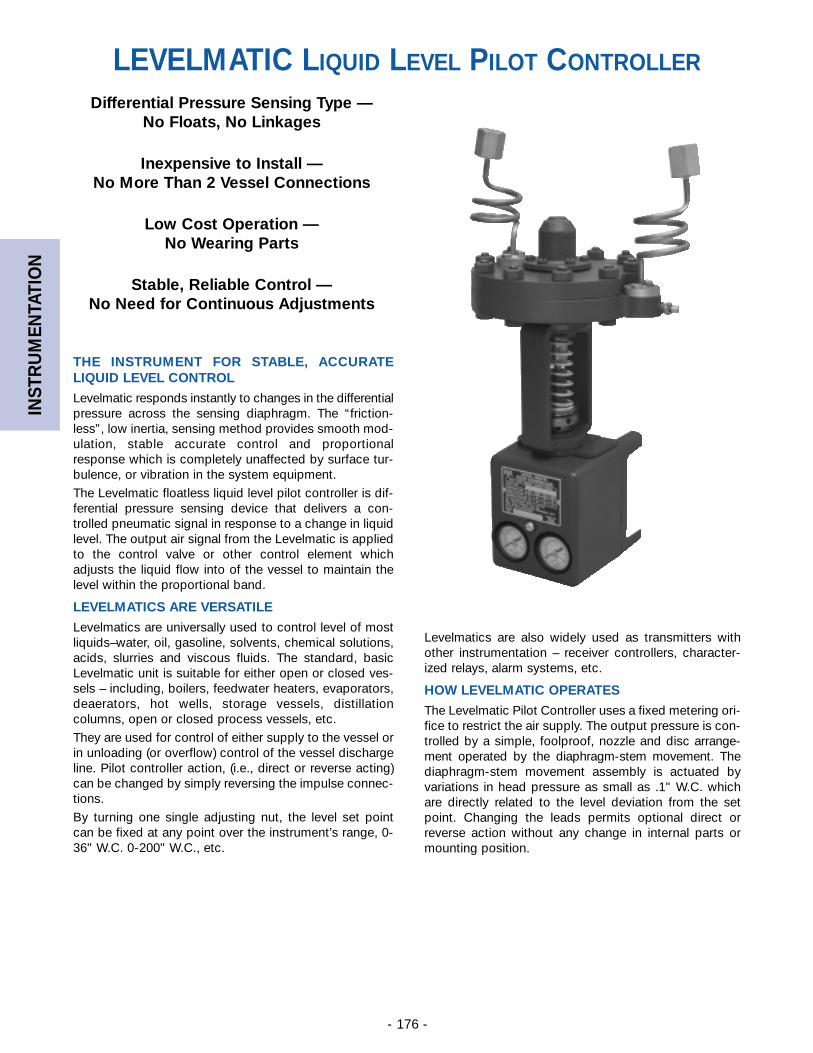
INST
RU
MEN
TATI
ON
- 176 -
Differential Pressure Sensing Type —No Floats, No Linkages
Inexpensive to Install —No More Than 2 Vessel Connections
Low Cost Operation —No Wearing Parts
Stable, Reliable Control — No Need for Continuous Adjustments
THE INSTRUMENT FOR STABLE, ACCURATE LIQUID LEVEL CONTROL
Levelmatic responds instantly to changes in the differentialpressure across the sensing diaphragm. The “friction-less”, low inertia, sensing method provides smooth mod-ulation, stable accurate control and proportionalresponse which is completely unaffected by surface tur-bulence, or vibration in the system equipment.
The Levelmatic floatless liquid level pilot controller is dif-ferential pressure sensing device that delivers a con-trolled pneumatic signal in response to a change in liquidlevel. The output air signal from the Levelmatic is appliedto the control valve or other control element whichadjusts the liquid flow into of the vessel to maintain thelevel within the proportional band.
LEVELMATICS ARE VERSATILE
Levelmatics are universally used to control level of mostliquids–water, oil, gasoline, solvents, chemical solutions,acids, slurries and viscous fluids. The standard, basicLevelmatic unit is suitable for either open or closed ves-sels – including, boilers, feedwater heaters, evaporators,deaerators, hot wells, storage vessels, distillationcolumns, open or closed process vessels, etc.
They are used for control of either supply to the vessel orin unloading (or overflow) control of the vessel dischargeline. Pilot controller action, (i.e., direct or reverse acting)can be changed by simply reversing the impulse connec-tions.
By turning one single adjusting nut, the level set pointcan be fixed at any point over the instrument’s range, 0-36" W.C. 0-200" W.C., etc.
Levelmatics are also widely used as transmitters withother instrumentation – receiver controllers, character-ized relays, alarm systems, etc.
HOW LEVELMATIC OPERATES
The Levelmatic Pilot Controller uses a fixed metering ori-fice to restrict the air supply. The output pressure is con-trolled by a simple, foolproof, nozzle and disc arrange-ment operated by the diaphragm-stem movement. Thediaphragm-stem movement assembly is actuated byvariations in head pressure as small as .1" W.C. whichare directly related to the level deviation from the setpoint. Changing the leads permits optional direct orreverse action without any change in internal parts ormounting position.
LEVELMATIC LIQUID LEVEL PILOT CONTROLLER
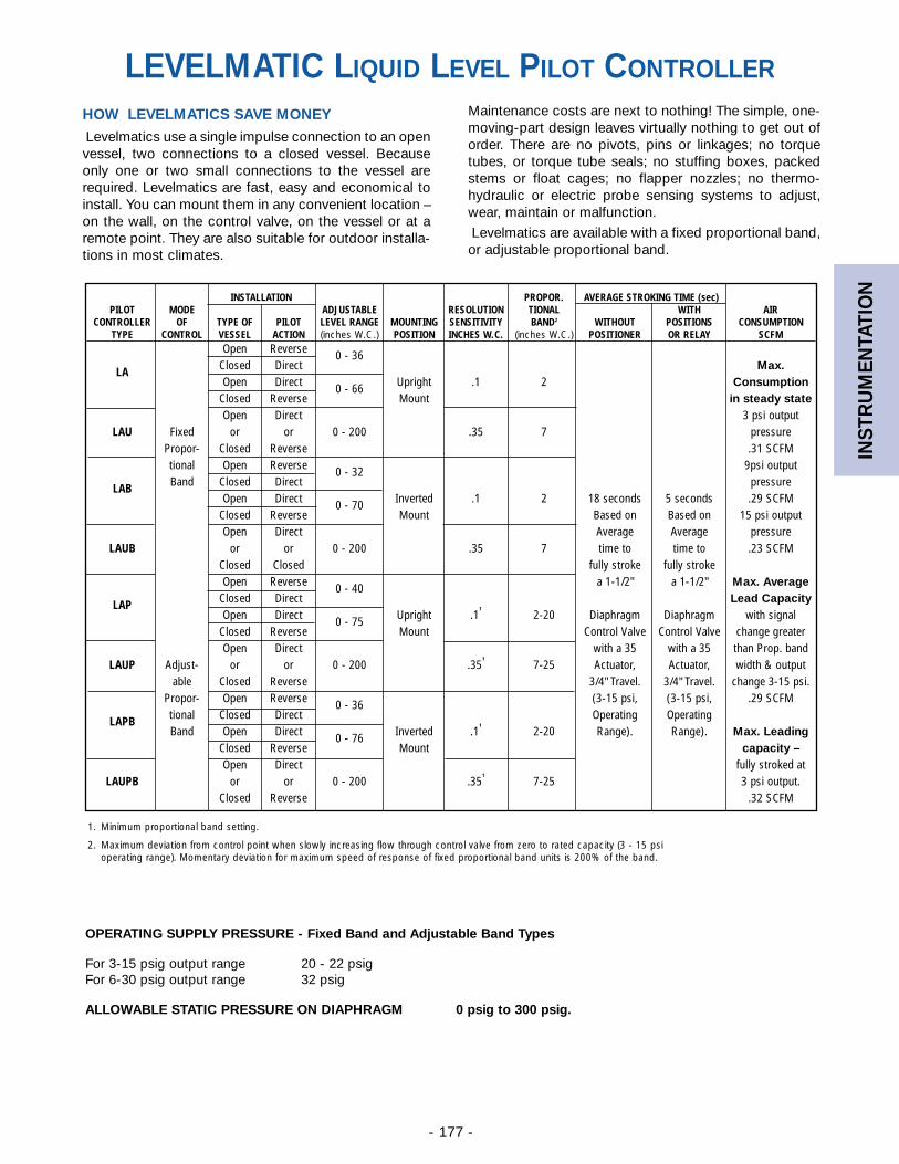
INST
RU
MEN
TATI
ON
- 177 -
INSTALLATION PROPOR. AVERAGE STROKING TIME (sec)PILOT MODE ADJUSTABLE RESOLUTION TIONAL WITH AIR
CONTROLLER OF TYPE OF PILOT LEVEL RANGE MOUNTING SENSITIVITY BAND2 WITHOUT POSITIONS CONSUMPTIONTYPE CONTROL VESSEL ACTION (inches W.C.) POSITION INCHES W.C. (inches W.C.) POSITIONER OR RELAY SCFM
Open ReverseClosed Direct
0 - 36Max.LA
Open Direct Upright .1 2 ConsumptionClosed Reverse
0 - 66Mount in steady state
Open Direct 3 psi outputLAU Fixed or or 0 - 200 .35 7 pressure
Propor- Closed Reverse .31 SCFMtional Open Reverse 9psi outputBand Closed Direct
0 - 32pressureLAB
Open Direct Inverted .1 2 18 seconds 5 seconds .29 SCFMClosed Reverse
0 - 70Mount Based on Based on 15 psi output
Open Direct Average Average pressureLAUB or or 0 - 200 .35 7 time to time to .23 SCFM
Closed Closed fully stroke fully strokeOpen Reverse a 1-1/2" a 1-1/2" Max. Average
Closed Direct0 - 40
Lead CapacityLAPOpen Direct Upright .1
1
2-20 Diaphragm Diaphragm with signalClosed Reverse
0 - 75Mount Control Valve Control Valve change greater
Open Direct with a 35 with a 35 than Prop. bandLAUP Adjust- or or 0 - 200 .35
1
7-25 Actuator, Actuator, width & outputable Closed Reverse 3/4" Travel. 3/4" Travel. change 3-15 psi.
Propor- Open Reverse (3-15 psi, (3-15 psi, .29 SCFMtional Closed Direct
0 - 36Operating OperatingLAPB
Band Open Direct Inverted .11
2-20 Range). Range). Max. LeadingClosed Reverse
0 - 76Mount capacity –
Open Direct fully stroked atLAUPB or or 0 - 200 .35
1
7-25 3 psi output.Closed Reverse .32 SCFM
HOW LEVELMATICS SAVE MONEY
Levelmatics use a single impulse connection to an openvessel, two connections to a closed vessel. Becauseonly one or two small connections to the vessel arerequired. Levelmatics are fast, easy and economical toinstall. You can mount them in any convenient location –on the wall, on the control valve, on the vessel or at aremote point. They are also suitable for outdoor installa-tions in most climates.
Maintenance costs are next to nothing! The simple, one-moving-part design leaves virtually nothing to get out oforder. There are no pivots, pins or linkages; no torquetubes, or torque tube seals; no stuffing boxes, packedstems or float cages; no flapper nozzles; no thermo-hydraulic or electric probe sensing systems to adjust,wear, maintain or malfunction.
Levelmatics are available with a fixed proportional band,or adjustable proportional band.
OPERATING SUPPLY PRESSURE - Fixed Band and Adjustable Band Types
For 3-15 psig output range 20 - 22 psigFor 6-30 psig output range 32 psig
ALLOWABLE STATIC PRESSURE ON DIAPHRAGM 0 psig to 300 psig.
1. Minimum proportional band setting.
2. Maximum deviation from control point when slowly increasing flow through control valve from zero to rated capacity (3 - 15 psioperating range). Momentary deviation for maximum speed of response of fixed proportional band units is 200% of the band.
LEVELMATIC LIQUID LEVEL PILOT CONTROLLER
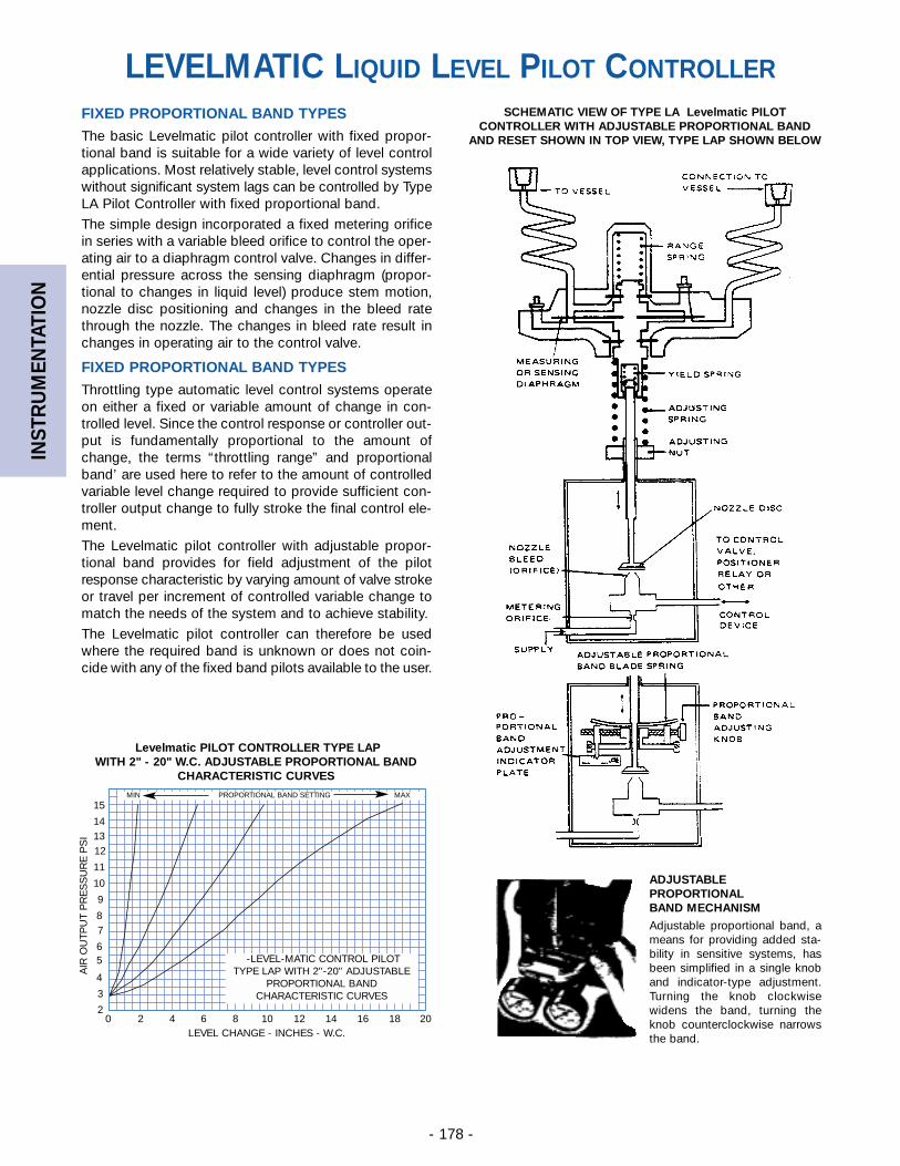
INST
RU
MEN
TATI
ON
- 178 -
FIXED PROPORTIONAL BAND TYPES
The basic Levelmatic pilot controller with fixed propor-tional band is suitable for a wide variety of level controlapplications. Most relatively stable, level control systemswithout significant system lags can be controlled by TypeLA Pilot Controller with fixed proportional band.
The simple design incorporated a fixed metering orificein series with a variable bleed orifice to control the oper-ating air to a diaphragm control valve. Changes in differ-ential pressure across the sensing diaphragm (propor-tional to changes in liquid level) produce stem motion,nozzle disc positioning and changes in the bleed ratethrough the nozzle. The changes in bleed rate result inchanges in operating air to the control valve.
FIXED PROPORTIONAL BAND TYPES
Throttling type automatic level control systems operateon either a fixed or variable amount of change in con-trolled level. Since the control response or controller out-put is fundamentally proportional to the amount ofchange, the terms “throttling range” and proportionalband’ are used here to refer to the amount of controlledvariable level change required to provide sufficient con-troller output change to fully stroke the final control ele-ment.
The Levelmatic pilot controller with adjustable propor-tional band provides for field adjustment of the pilotresponse characteristic by varying amount of valve strokeor travel per increment of controlled variable change tomatch the needs of the system and to achieve stability.
The Levelmatic pilot controller can therefore be usedwhere the required band is unknown or does not coin-cide with any of the fixed band pilots available to the user.
SCHEMATIC VIEW OF TYPE LA Levelmatic PILOTCONTROLLER WITH ADJUSTABLE PROPORTIONAL BAND
AND RESET SHOWN IN TOP VIEW, TYPE LAP SHOWN BELOW
Levelmatic PILOT CONTROLLER TYPE LAPWITH 2" - 20" W.C. ADJUSTABLE PROPORTIONAL BAND
CHARACTERISTIC CURVES
ADJUSTABLEPROPORTIONALBAND MECHANISM
Adjustable proportional band, ameans for providing added sta-bility in sensitive systems, hasbeen simplified in a single knoband indicator-type adjustment.Turning the knob clockwisewidens the band, turning theknob counterclockwise narrowsthe band.
0 2 4 6 8 10 12 14 16 18 202
3
4
56
78
9
10
11
121314
15
-LEVEL-MATIC CONTROL PILOTTYPE LAP WITH 2"-20" ADJUSTABLE
PROPORTIONAL BANDCHARACTERISTIC CURVES
LEVEL CHANGE - INCHES - W.C.
AIR
OU
TPU
T P
RE
SS
UR
E P
SI
MIN PROPORTIONAL BAND SETTING MAX
LEVELMATIC LIQUID LEVEL PILOT CONTROLLER
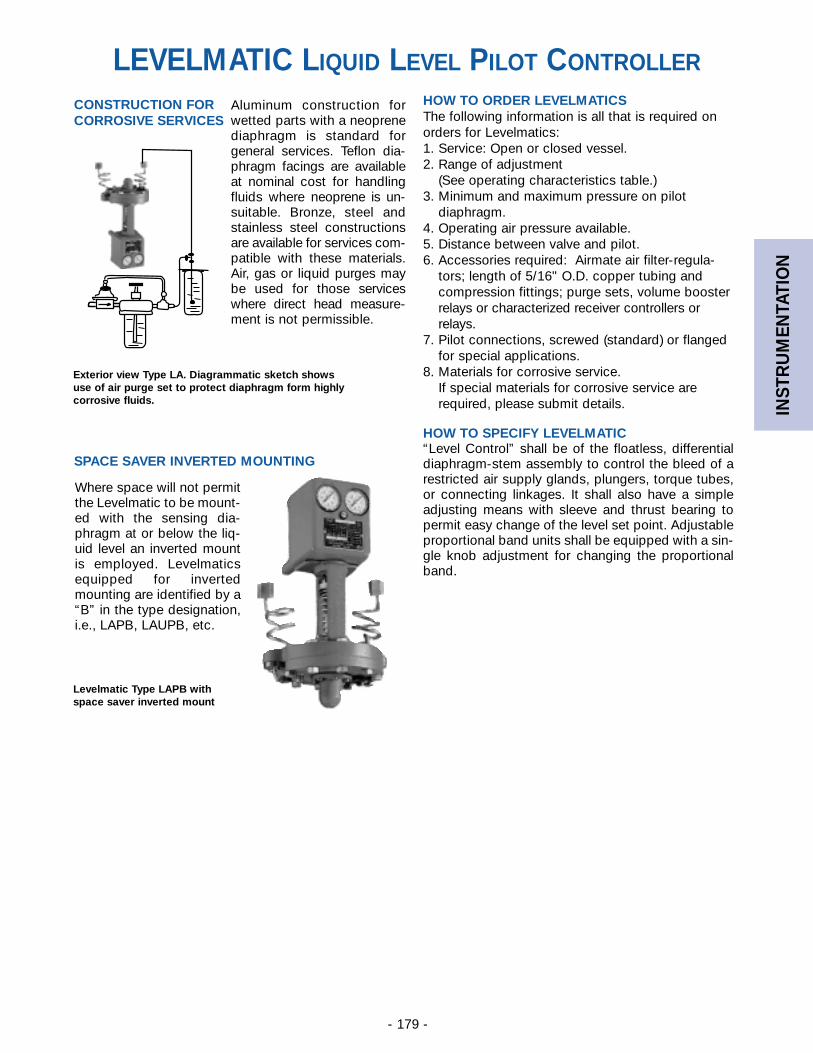
INST
RU
MEN
TATI
ON
- 179 -
Aluminum construction forwetted parts with a neoprenediaphragm is standard forgeneral services. Teflon dia-phragm facings are availableat nominal cost for handlingfluids where neoprene is un-suitable. Bronze, steel andstainless steel constructionsare available for services com-patible with these materials.Air, gas or liquid purges maybe used for those serviceswhere direct head measure-ment is not permissible.
CONSTRUCTION FORCORROSIVE SERVICES
Where space will not permitthe Levelmatic to be mount-ed with the sensing dia-phragm at or below the liq-uid level an inverted mountis employed. Levelmaticsequipped for invertedmounting are identified by a“B” in the type designation,i.e., LAPB, LAUPB, etc.
HOW TO ORDER LEVELMATICSThe following information is all that is required onorders for Levelmatics:1. Service: Open or closed vessel.2. Range of adjustment
(See operating characteristics table.)3. Minimum and maximum pressure on pilot
diaphragm.4. Operating air pressure available.5. Distance between valve and pilot.6. Accessories required: Airmate air filter-regula-
tors; length of 5/16" O.D. copper tubing andcompression fittings; purge sets, volume boosterrelays or characterized receiver controllers orrelays.
7. Pilot connections, screwed (standard) or flangedfor special applications.
8. Materials for corrosive service.If special materials for corrosive service are required, please submit details.
HOW TO SPECIFY LEVELMATIC“Level Control” shall be of the floatless, differentialdiaphragm-stem assembly to control the bleed of arestricted air supply glands, plungers, torque tubes,or connecting linkages. It shall also have a simpleadjusting means with sleeve and thrust bearing topermit easy change of the level set point. Adjustableproportional band units shall be equipped with a sin-gle knob adjustment for changing the proportionalband.
SPACE SAVER INVERTED MOUNTING
Exterior view Type LA. Diagrammatic sketch showsuse of air purge set to protect diaphragm form highlycorrosive fluids.
Levelmatic Type LAPB withspace saver inverted mount
LEVELMATIC LIQUID LEVEL PILOT CONTROLLER
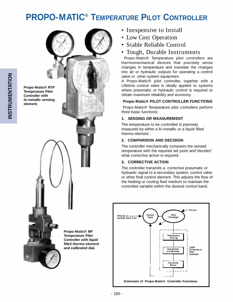
INST
RU
MEN
TATI
ON
- 180 -
• Inexpensive to Install• Low Cost Operation• Stable Reliable Control• Tough, Durable Instruments
Propo-Matic® Temperature pilot controllers arethermomechanical devices that precisely sensechanges in temperature and translate the changesinto air or hydraulic outputs for operating a controlvalve or other system equipment.A Propo-Matic® pilot controller, together with aLifetime control valve is ideally applied to systemswhere pneumatic or hydraulic control is required toobtain maximum reliability and economy.
Propo-Matic® PILOT CONTROLLER FUNCTIONS
Propo-Matic® Temperature pilot controllers performthree basic functions:
1. SENSING OR MEASUREMENT
The temperature to be controlled is preciselymeasured by either a bi-metallic or a liquid filledthermo-element.
2. COMPARISON AND DECISION
The controller mechanically compares the sensed temperature with the required set point and“decides”what corrective action is required.
3. CORRECTIVE ACTION
The controller transmits a corrective pneumatic orhydraulic signal to a secondary system, control valveor other final control element. This adjusts the flow ofthe heating or cooling fluid medium to maintain thecontrolled variable within the desired control band.
Propo-Matic® BPTemperature PilotController with liquidfilled thermo-elementand calibrated dial.
Schematic of Propo-Matic® Controller Functions.
Propo-Matic® RTPTemperature PilotController with bi-metallic sensingelement.
PROPO-MATIC® TEMPERATURE PILOT CONTROLLER
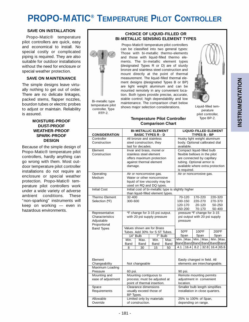
INST
RU
MEN
TATI
ON
- 181 -
BI-METALLIC ELEMENT LIQUID-FILLED ELEMENTCONSIDERATION BASIC TYPES R - D TYPES B - BPController All bronze and stainless Husky light weight aluminumConstruction steel construction, they body. Optional calibrated dial
last for decades. available.Element Invar and brass, monel or Compact liquid-filled bulbConstruction stainless steel element flexible bellows in the pilot
offers maximum protection are connected by capillaryagainst thermal element tubing. Optional armor isdamage. available where extra protection
is required.Operating Air or noncorrosive gas. Air or noncorrosive gas.Medium Water or other noncorrosive
liquid of low viscosity may beused on RQ and DQ types.
Initial Cost Initial cost of bi-metallic type is slightly higherthan liquid-filled element types.
Thermo Element 32-400 70-120 170-220 220-320Selection (ºF) 300-600 100-150 220-270 270-370
120-170 20-120 50-250150-200 70-170 50-400
Representative ºF change for 3-15 psi output. pressure ºF change for 3-15Characteristics with 20 psi supply pressure psi output with 20 psi supplyAdjustable pressureProportionalBand Types
Element Easily changed in field. AllChangeability Not changeable elements are interchangeable.Maximum LoadingPressure 60 psi. 90 psi.Mounting and Mounting contiguous to Remote mounting permitsease of adjustment process; must be adjusted at adjustment in convenient
point of thermal insertion. location.Space Clearance dimensions Smaller bulb length simplifiesRequirements usually exceed those of installation in close quarters.
BP Types.Allowable Limited only by materials 25% to 100% of Span,Override of construction. depending on range.
SAVE ON INSTALLATION
Propo-Matic® temperaturepilot controllers are quick, easyand economical to install. Nospecial costly or complicatedpiping is required. They are alsosuitable for outdoor installationswithout the need for enclosure orspecial weather protection.
SAVE ON MAINTENANCE
The simple designs leave virtu-ally nothing to get out of order.There are no delicate linkages,packed stems, flapper nozzles,bourdon tubes or electric probesto adjust or maintain. Reliabilityis assured.
MOISTURE-PROOFDUST-PROOF
WEATHER-PROOFSPARK-PROOF
DESIGN
Because of the simple design ofPropo-Matic® temperature pilotcontrollers, hardly anything cango wrong with them. Most out-door temperature pilot controllerinstallations do not require anenclosure or special weatherprotection. Propo-Matic® tem-perature pilot controllers workunder a wide variety of adverseambient conditions. These“non-sparking” instruments willkeep on working — even inhazardous environments.
Liquid-filled tem-perature
pilot controller,Type BP-2.
Bi-metallic typetemperature pilotcontroller, Type
RTP-2.
Temperature Pilot ControllerComparison Chart
Values shown are for BrassTubes. Add 30% for S ST Tubes.
14" Bulb 7" BulbMin. Max. Min. Max.Band Band Band Band
8 30 15 50
50ºF 100ºF 200ºFSpan Span Span
Min. Max. Min. Max. Min. Max.Band Band Band Band Band Band4.1 16.4 8.2 32.8 16.4 65.6
CHOICE OF LIQUID-FILLED ORBI-METALLIC SENSING ELEMENT TYPES
Propo-Matic® temperature pilot controllerscan be classified into two general types:Those with bi-metallic thermo-elementsand those with liquid-filled thermo ele-ments. The bi-metallic element types(designated Types R or D) are of sturdybronze and stainless steel construction andmount directly at the point of thermalmeasurement. The liquid-filled thermal ele-ment designs (designated Types B or BP)are light weight aluminum and can bemounted remotely in any convenient loca-tion. Both types provide precise, accurate,stable control; high dependability and lowmaintenance. The comparison chart belowshows major selection considerations.
PROPO-MATIC® TEMPERATURE PILOT CONTROLLER
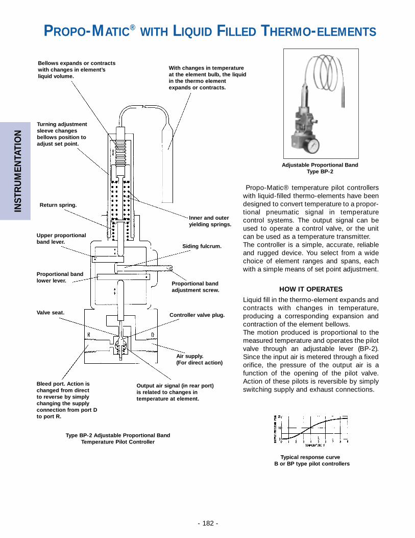
INST
RU
MEN
TATI
ON
- 182 -
Propo-Matic® temperature pilot controllerswith liquid-filled thermo-elements have beendesigned to convert temperature to a propor-tional pneumatic signal in temperaturecontrol systems. The output signal can beused to operate a control valve, or the unitcan be used as a temperature transmitter.The controller is a simple, accurate, reliableand rugged device. You select from a widechoice of element ranges and spans, eachwith a simple means of set point adjustment.
HOW IT OPERATES
Liquid fill in the thermo-element expands andcontracts with changes in temperature,producing a corresponding expansion andcontraction of the element bellows.The motion produced is proportional to themeasured temperature and operates the pilotvalve through an adjustable lever (BP-2).Since the input air is metered through a fixedorifice, the pressure of the output air is afunction of the opening of the pilot valve.Action of these pilots is reversible by simplyswitching supply and exhaust connections.
Adjustable Proportional BandType BP-2
Type BP-2 Adjustable Proportional BandTemperature Pilot Controller
Typical response curveB or BP type pilot controllers
Bellows expands or contractswith changes in element’sliquid volume.
Turning adjustmentsleeve changes bellows position toadjust set point.
Return spring.
Upper proportionalband lever.
Proportional bandlower lever.
Valve seat.
Bleed port. Action is changed from direct to reverse by simply changing the supply connection from port D to port R.
Output air signal (in rear port)is related to changes in temperature at element.
Inner and outeryielding springs.
With changes in temperatureat the element bulb, the liquidin the thermo elementexpands or contracts.
Siding fulcrum.
Proportional bandadjustment screw.
Controller valve plug.
Air supply.(For direct action)
PROPO-MATIC® WITH LIQUID FILLED THERMO-ELEMENTS
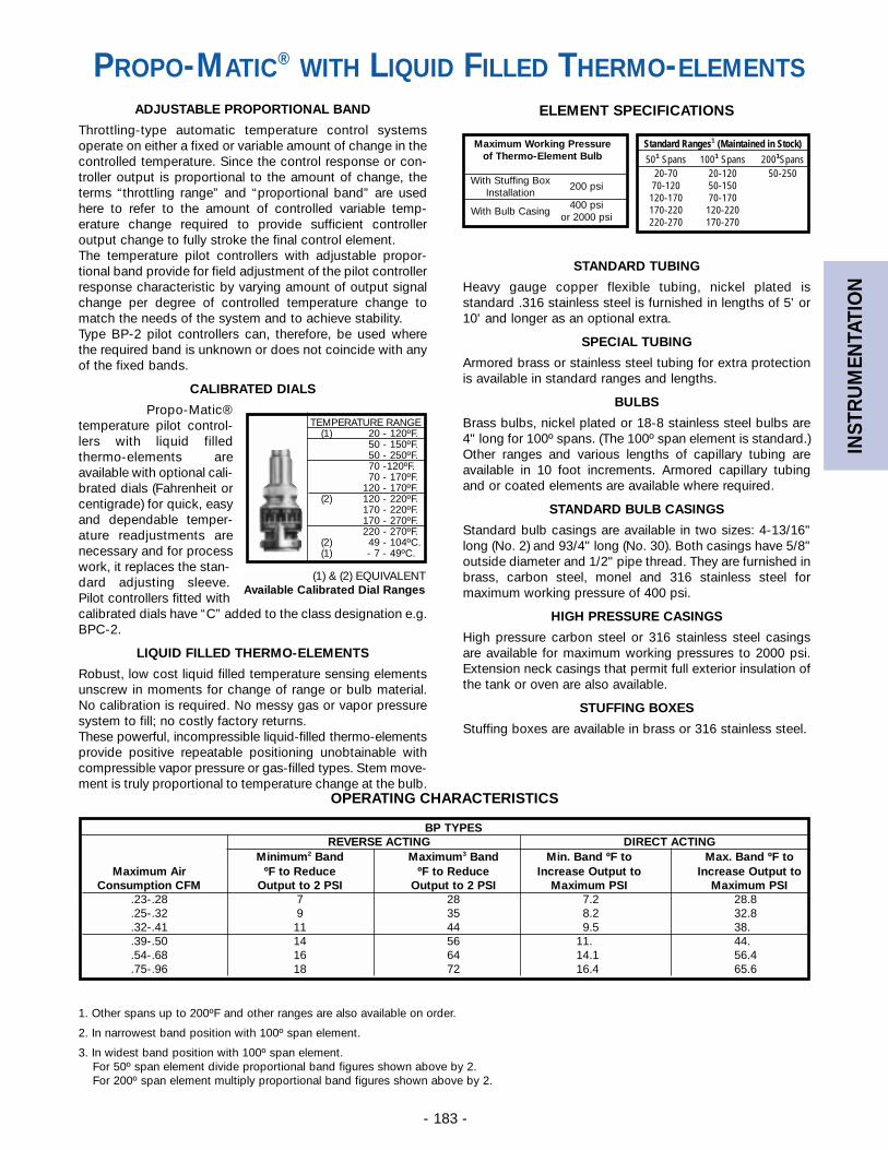
INST
RU
MEN
TATI
ON
- 183 -
ADJUSTABLE PROPORTIONAL BAND
Throttling-type automatic temperature control systemsoperate on either a fixed or variable amount of change in thecontrolled temperature. Since the control response or con-troller output is proportional to the amount of change, theterms “throttling range” and “proportional band” are usedhere to refer to the amount of controlled variable temp-erature change required to provide sufficient controlleroutput change to fully stroke the final control element.The temperature pilot controllers with adjustable propor-tional band provide for field adjustment of the pilot controllerresponse characteristic by varying amount of output signalchange per degree of controlled temperature change tomatch the needs of the system and to achieve stability.Type BP-2 pilot controllers can, therefore, be used wherethe required band is unknown or does not coincide with anyof the fixed bands.
CALIBRATED DIALS
Propo-Matic®temperature pilot control-lers with liquid filledthermo-elements areavailable with optional cali-brated dials (Fahrenheit orcentigrade) for quick, easyand dependable temper-ature readjustments arenecessary and for processwork, it replaces the stan-dard adjusting sleeve.Pilot controllers fitted withcalibrated dials have “C” added to the class designation e.g.BPC-2.
LIQUID FILLED THERMO-ELEMENTS
Robust, low cost liquid filled temperature sensing elementsunscrew in moments for change of range or bulb material.No calibration is required. No messy gas or vapor pressuresystem to fill; no costly factory returns.These powerful, incompressible liquid-filled thermo-elementsprovide positive repeatable positioning unobtainable withcompressible vapor pressure or gas-filled types. Stem move-ment is truly proportional to temperature change at the bulb.
STANDARD TUBING
Heavy gauge copper flexible tubing, nickel plated isstandard .316 stainless steel is furnished in lengths of 5' or10' and longer as an optional extra.
SPECIAL TUBING
Armored brass or stainless steel tubing for extra protectionis available in standard ranges and lengths.
BULBS
Brass bulbs, nickel plated or 18-8 stainless steel bulbs are4" long for 100º spans. (The 100º span element is standard.)Other ranges and various lengths of capillary tubing areavailable in 10 foot increments. Armored capillary tubingand or coated elements are available where required.
STANDARD BULB CASINGS
Standard bulb casings are available in two sizes: 4-13/16"long (No. 2) and 93/4" long (No. 30). Both casings have 5/8"outside diameter and 1/2" pipe thread. They are furnished inbrass, carbon steel, monel and 316 stainless steel formaximum working pressure of 400 psi.
HIGH PRESSURE CASINGS
High pressure carbon steel or 316 stainless steel casingsare available for maximum working pressures to 2000 psi.Extension neck casings that permit full exterior insulation ofthe tank or oven are also available.
STUFFING BOXES
Stuffing boxes are available in brass or 316 stainless steel.
BP TYPESREVERSE ACTING DIRECT ACTING
Minimum2 Band Maximum3 Band Min. Band ºF to Max. Band ºF toMaximum Air ºF to Reduce ºF to Reduce Increase Output to Increase Output to
Consumption CFM Output to 2 PSI Output to 2 PSI Maximum PSI Maximum PSI.23-.28 7 28 7.2 28.8.25-.32 9 35 8.2 32.8.32-.41 11 44 9.5 38..39-.50 14 56 11. 44..54-.68 16 64 14.1 56.4.75-.96 18 72 16.4 65.6
TEMPERATURE RANGE(1) 20 - 120ºF.
50 - 150ºF.50 - 250ºF.70 -120ºF.70 - 170ºF.
120 - 170ºF.(2) 120 - 220ºF.
170 - 220ºF.170 - 270ºF.220 - 270ºF.
(2) 49 - 104ºC.(1) - 7 - 49ºC.
(1) & (2) EQUIVALENTAvailable Calibrated Dial Ranges
1. Other spans up to 200ºF and other ranges are also available on order.
2. In narrowest band position with 100º span element.
3. In widest band position with 100º span element.For 50º span element divide proportional band figures shown above by 2.For 200º span element multiply proportional band figures shown above by 2.
OPERATING CHARACTERISTICS
ELEMENT SPECIFICATIONS
Maximum Working Pressureof Thermo-Element Bulb
With Stuffing Box 200 psiInstallation
400 psiWith Bulb Casing or 2000 psi
Standard Ranges1 (Maintained in Stock)501 Spans 1001 Spans 2001Spans
20-70 20-120 50-25070-120 50-150120-170 70-170170-220 120-220220-270 170-270
PROPO-MATIC® WITH LIQUID FILLED THERMO-ELEMENTS
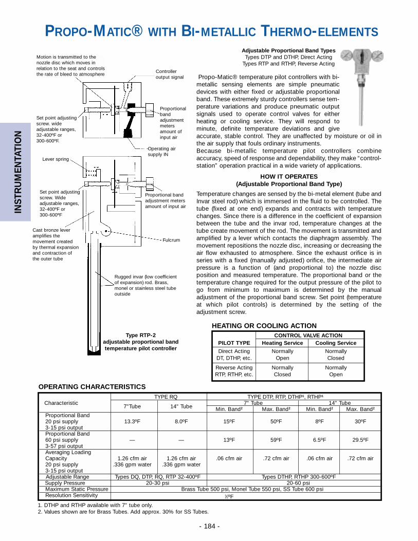
INST
RU
MEN
TATI
ON
- 184 -
TYPE RQ TYPE DTP, RTP, DTHP1, RTHP1
Characteristic 7" Tube 14" Tube7"Tube 14" Tube Min. Band2 Max. Band2 Min. Band2 Max. Band2
Proportional Band20 psi supply 13.3ºF 8.0ºF 15ºF 50ºF 8ºF 30ºF3-15 psi outputProportional Band60 psi supply — — 13ºF 59ºF 6.5ºF 29.5ºF3-57 psi outputAveraging LoadingCapacity 1.26 cfm air 1.26 cfm air .06 cfm air .72 cfm air .06 cfm air .72 cfm air20 psi supply .336 gpm water .336 gpm water3-15 psi outputAdjustable Range Types DQ, DTP, RQ, RTP 32-400ºF Types DTHP, RTHP 300-600ºFSupply Pressure 20-30 psi 20-60 psiMaximum Static Pressure Brass Tube 500 psi, Monel Tube 550 psi, SS Tube 600 psiResolution Sensitivity 1⁄2ºF
OPERATING CHARACTERISTICS
1. DTHP and RTHP available with 7" tube only.2. Values shown are for Brass Tubes. Add approx. 30% for SS Tubes.
Propo-Matic® temperature pilot controllers with bi-metallic sensing elements are simple pneumaticdevices with either fixed or adjustable proportionalband. These extremely sturdy controllers sense tem-perature variations and produce pneumatic outputsignals used to operate control valves for eitherheating or cooling service. They will respond tominute, definite temperature deviations and giveaccurate, stable control. They are unaffected by moisture or oil inthe air supply that fouls ordinary instruments.Because bi-metallic temperature pilot controllers combineaccuracy, speed of response and dependability, they make “control-station” operation practical in a wide variety of applications.
HOW IT OPERATES(Adjustable Proportional Band Type)
Temperature changes are sensed by the bi-metal element (tube andInvar steel rod) which is immersed in the fluid to be controlled. Thetube (fixed at one end) expands and contracts with temperaturechanges. Since there is a difference in the coefficient of expansionbetween the tube and the invar rod, temperature changes at thetube create movement of the rod. The movement is transmitted andamplified by a lever which contacts the diaphragm assembly. Themovement repositions the nozzle disc, increasing or decreasing theair flow exhausted to atmosphere. Since the exhaust orifice is inseries with a fixed (manually adjusted) orifice, the intermediate airpressure is a function of (and proportional to) the nozzle discposition and measured temperature. The proportional band or thetemperature change required for the output pressure of the pilot togo from minimum to maximum is determined by the manualadjustment of the proportional band screw. Set point (temperatureat which pilot controls) is determined by the setting of theadjustment screw.
Adjustable Proportional Band TypesTypes DTP and DTHP, Direct Acting
Types RTP and RTHP, Reverse Acting
HEATING OR COOLING ACTIONCONTROL VALVE ACTION
PILOT TYPE Heating Service Cooling Service
Direct Acting Normally NormallyDT, DTHP, etc. Open Closed
Reverse Acting Normally NormallyRTP, RTHP, etc. Closed Open
Controlleroutput signal
Operating airsupply IN
Proportional bandadjustment metersamount of input air
Fulcrum
Proportionalbandadjustmentmetersamount ofinput air
Rugged invar (low coefficientof expansion) rod. Brass,monel or stainless steel tubeoutside
Type RTP-2adjustable proportional bandtemperature pilot controller
Lever spring
Set point adjustingscrew. Wideadjustable ranges,32-400ºF or 300-600ºF
Cast bronze leveramplifies the movement created by thermal expansion and contraction of the outer tube
Set point adjustingscrew. wideadjustable ranges,32-400ºF or 300-600ºF.
Motion is transmitted to thenozzle disc which moves inrelation to the seat and controlsthe rate of bleed to atmosphere
PROPO-MATIC® WITH BI-METALLIC THERMO-ELEMENTS
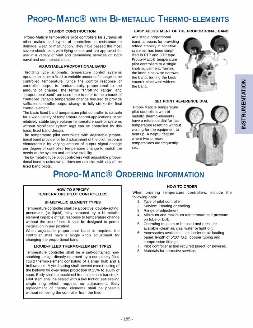
INST
RU
MEN
TATI
ON
- 185 -
STURDY CONSTRUCTION
Propo-Matic® temperature pilot controllers far surpass allother makes and types of controllers in resistance todamage, wear, or malfunction. They have passed the mostsevere shock tests with flying colors and are approved foruse in a variety of vital and demanding services on bothnaval and commercial ships.
ADJUSTABLE PROPORTIONAL BAND
Throttling type automatic temperature control systemsoperate on either a fixed or variable amount of change in thecontrolled temperature. Since the control response orcontroller output is fundamentally proportional to theamount of change, the terms “throttling range” and“proportional band” are used here to refer to the amount ofcontrolled variable temperature change required to providesufficient controller output change to fully stroke the finalcontrol element.The basic fixed band temperature pilot controller is suitablefor a wide variety of temperature control applications. Mostrelatively stable large volume temperature control systemswithout significant system lags can be controlled by thisbasic fixed band design.The temperature pilot controllers with adjustable propor-tional band provide for field adjustment of the pilot responsecharacteristic by varying amount of output signal changeper degree of controlled temperature change to match theneeds of the system and achieve stability.The bi-metallic type pilot controllers with adjustable propor-tional band is unknown or does not coincide with any of thefixed band pilots.
EASY ADJUSTMENT OF THE PROPORTIONAL BAND
Adjustable proportionalband, a means for providingadded stability in sensitivesystems, has been simpl-ified in RTP and DTP typePropo-Matic® temperaturepilot controllers to a singleknob adjustment. Turningthe knob clockwise narrowsthe band; turning the knobcounter-clockwise widensthe band.
SET POINT REFERENCE DIAL
Propo-Matic® temperaturepilot controllers with bi-metallic thermo-elementshave a reference dial for fasttemperature resetting withoutwaiting for the equipment toheat up. A helpful featurewhere two or moretemperatures are frequentlyset.
PROPO-MATIC® WITH BI-METALLIC THERMO-ELEMENTS
HOW TO SPECIFYTEMPERATURE PILOT CONTROLLERS
BI-METALLIC ELEMENT TYPES
Temperature controller shall be a positive, double-acting,pneumatic (or liquid) relay actuated by a bi-metallicelement capable of fast response to temperature changewithout the use of fins. It shall be designed to permitinstallation in any position.When adjustable proportional band is required thecontroller shall have a single knob adjustment forchanging the proportional band.
LIQUID-FILLED THERMO-ELEMENT TYPES
Temperature controller shall be a self-contained non-sparking design directly operated by a completely filledliquid thermo-element consisting of a small bulb and abellows unit. A yield spring shall prevent overstressing ofthe bellows for over-range protection of 25% to 100% ofspan. Body shall be machined from aluminum bar stock.Pilot stem shall be sealed with a low friction self-sealingsingle ring which requires no adjustment. Easyreplacement of thermo elements shall be possiblewithout removing the controller from the line.
HOW TO ORDER
When ordering temperature controllers, include thefollowing data:
1. Type of pilot controller.2. Service: Heating or cooling.3. Range of adjustment.4. Minimum and maximum temperature and pressure
on tube or bulb.5. Operating medium to be used and pressure
available (clean air, gas, water or light oil).6. Accessories available — air loader or air loading
panel; length of 5/16" O.D. copper tubing andcompression fittings.
7. Pilot controller action required (direct) or (reverse).8. Materials for corrosive services.
PROPO-MATIC® ORDERING INFORMATION
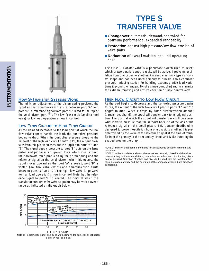
INST
RU
MEN
TATI
ON
- 186 -
HIGH FLOW CIRCUIT TO LOW FLOW CIRCUITAs the load begins to decrease and the controlled pressure beginsto rise, the output of the high flow circuit pilot to ports “C” and “E”begins to drop. When it drops by some predetermined amount(transfer deadband), the spool will transfer back to its original posi-tion. The point at which the spool will transfer back will be some-what lower in pressure than the setpoint because of the loss of thereference signal on the small piston. This transfer deadband isdesigned to prevent oscillation from one circuit to another. It is pre-determined by the value of the reference signal at the time of trans-fer from the primary to the secondary circuit and is illustrated by theshaded area on the graph.
NOTE 1: Transfer deadband is the same for all set points between minimum andmaximum.NOTE 2: In the installations shown, the valves are normally closed and the pilotsreverse acting. In these installations, normally open valves and direct acting pilotscannot be used. Selection of valves and pilots to be used with the transfer valvemust be made carefully and the operation of the complete cycle in both directionsconsidered.
The Class S Transfer Valve is a pneumatic switch used to selectwhich of two parallel control circuits will be active. It prevents oscil-lation from one circuit to another. It is usable in many types of con-trol loops and has been used primarily to provide a two-controllerpressure reducing station for handling extremely wide load varia-tions (beyond the rangeability of a single controller) and to minimizethe extreme throttling and erosive effect on a single control valve.
15
10
5
05 10 15 20 25 30
NOTE 1NEUTRAL ZONE
TRANSFER BACK TO PORT “A” TO PORT “B”(To low load valve)
MIN. SET POINT
PORT “C” TO PORT “D”
(Transfer to high load valve)
MAX. SET POINT
PORT “C” TO PORT “D”
(Transfer to high load valve)
SE
T P
OIN
TTYPE S
TRANSFER VALVE● Changeover automatic, demand-controlled for
optimum performance, expanded rangeability
● Protection against high pressure/low flow erosion ofvalve parts
● Reduction of overall maintenance and operatingcost
LOW FLOW CIRCUIT TO HIGH FLOW CIRCUITAs the demand increases to the load point at which the lowflow valve cannot handle the load, the controlled pressurebegins to drop. When the controlled pressure drops to thesetpoint of the high load circuit control pilot, the output pres-sure from this pilot increases and is supplied to ports “C” and“E”. The signal supply pressure to port “E” acts on the largepiston and produces an upward force which must exceedthe downward force produced by the piston spring and thereference signal on the small piston. When this occurs, thespool moves upward so that port “A” is sealed, port “B” isvented (low flow valve closes) and communication existsbetween ports “C” and “D”. The high flow valve (large valvefor high load operation) is now in control. Note that the refer-ence signal to port “F” is vented. The point at which thistransfer occurs (transfer valve setpoint) may be varied over arange as indicated on the graph below.
REFERENCE SIGNALNote 1: Transfer dead band. This band width remains the same for all set points
between min. and max.
HOW S-TRANSFER SYSTEMS WORKThe minimum adjustment of the piston spring positions thespool so that communication exists between port “A” andport “B”. A reference signal from port “B” is fed to the top ofthe small piston (port “F”). The low flow circuit (small controlvalve) for low load operation is now in control.
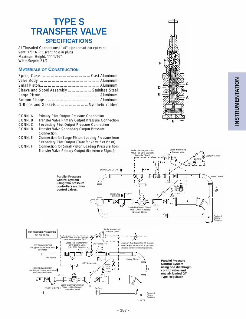
INST
RU
MEN
TATI
ON
- 187 -
Leslie Diaphragm ControlValve - 15-25% Capacity
Normally Closed
Leslie Diaphragm ControlValve - 100% Capacity
Normally Closed
Leslie interlockingTransfer Valve
FDB
A
CB
A
C
B
22 PSI
Leslie PRAPilot
Leslie PRA Pilot
LOW FLOW CIRCUIT
AF-2
AF-2
Sweep Elbow
ReducedSteamPressure
HIGH FLOWCIRCUIT
22 PSI
Parallel PressureControl Systemusing two pressurecontrollers and twocontrol valves.
Parallel PressureControl Systemusing one diaphragmcontrol valve andone air loaded GTType Regulator.
FOR REDUCED PRESSURES
BELOW 30 PSI
HIGH FLOW CIRCUITDiaphragm Control Valve with
Pressure Control Pilot
LOW FLOW CIRCUITGT type Control Valve with
air loader
Leslie interlockingTransfer Valve
CA
FDB
22 PSI
Leslie PRAPilot
AF-2
Sweep Elbow
ReducedSteamPressure
Leslie Diaphragm ControlValve -100% Capacity
Normally Closed
C
B
BC
A
1/2" Sched. 40
3/8" Sched. 40Leslie “No Maintenance”GPK Control Valve
(15 - 25% Capacity)
Needle Valve may be requiredto reduce speed of GPK
Leslie AF-2 air loader for GP ControlValve. Adjust as required to producedesired controlled steam pressure.
E
CA
E
By-Pass
Inlet Steam
= 5/16" O.D. Pipe
A
All Threaded Connections: 1/4" pipe thread except ventVent: 1/8" N.P.T. (vent hole in plug)Maximum Height: 1111/16"Width/Depth: 21/2
MATERIALS OF CONSTRUCTION
Spring Case ………………………………Cast AluminumValve Body ………………………………………AluminumSmall Piston………………………………………AluminumSleeve and Spool Assembly ………………Stainless SteelLarge Piston ……………………………………AluminumBottom Flange …………………………………AluminumO-Rings and Gaskets ……………………Synthetic rubber
A
E
C
F
D
B
CONN. A Primary Pilot Output Pressure ConnectionCONN. B Transfer Valve Primary Output Pressure ConnectionCONN. C Secondary Pilot Output Pressure ConnectionCONN. D Transfer Valve Secondary Output Pressure
ConnectionCONN. E Connection for Large Piston Loading Pressure from
Secondary Pilot Output (Transfer Valve Set Point)CONN. F Connection for Small Piston Loading Pressure from
Transfer Valve Primary Output (Reference Signal)
TYPE S TRANSFER VALVE
SPECIFICATIONS
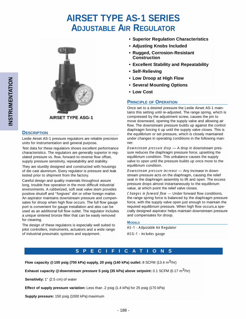
INST
RU
MEN
TATI
ON
- 188 -
• Superior Regulation Characteristics
• Adjusting Knobs Included
• Rugged, Corrosion-ResistantConstruction
• Excellent Stability and Repeatability
• Self-Relieving
• Low Droop at High Flow
• Several Mounting Options
• Low Cost
S P E C I F I C A T I O N S
Flow capacity @ 100 psig (700 kPa) supply, 20 psig (140 kPa) outlet: 8 SCFM (13.4 m3/hr)
Exhaust capacity @ downstream pressure 5 psig (35 kPa) above setpoint: 0.1 SCFM (0.17 m3/hr)
Sensitivity: 1” (2.5 cm) of water
Effect of supply pressure variation: Less than .2 psig (1.4 kPa) for 25 psig (170 kPa)
Supply pressure: 150 psig (1000 kPa) maximum
AIRSET TYPE AS-1 SERIESADJUSTABLE AIR REGULATOR
AIRSET TYPE ASG-1
DESCRIPTION
Leslie Airset AS-1 pressure regulators are reliable precisionunits for instrumentation and general purpose.
Test data for these regulators shows excellent performancecharacteristics. The regulators are generally superior in reg-ulated pressure vs. flow, forward-to-reverse flow offset,supply pressure sensitivity, repeatability and stability.
They are sturdily designed and constructed with housingsof die cast aluminum. Every regulator is pressure and leaktested prior to shipment from the factory.
Careful design and quality materials throughout assurelong, trouble free operation in the most difficult industrialenvironments. A rubberized, soft seat valve stem providespositive shutoff and “forgives” dirt or other foreign matter.An aspirator maintains downstream pressure and compen-sates for droop when high flow occurs. The full flow gaugeport is convenient for gauge installation and also can beused as an additional full flow outlet. The regulator includesa unique sintered bronze filter that can be easily removedfor cleaning.
The design of these regulators is especially well suited topilot controllers, instruments, actuators and a wide rangeof industrial pneumatic systems and equipment.
PRINCIPLE OF OPERATION
Once set to a desired pressure the Leslie Airset AS-1 main-tains this setting until re-adjusted. The range spring, which iscompressed by the adjustment screw, causes the pin tomove downward, opening the supply valve and allowing airflow. The downstream pressure builds up against the controldiaphragm forcing it up until the supply valve closes. This isthe equilibrium or set pressure, which is closely maintainedunder changes in operating conditions in the following man-ner:
Downstream pressure drop — A drop in downstream pres-sure reduces the diaphragm pressure force, upsetting theequilibrium condition. This unbalance causes the supplyvalve to open until the pressure builds up once more to theequilibrium condition.
Downstream pressure increase — Any increase in down-stream pressure acts on the diaphragm, causing the reliefseat in the diaphragm assembly to lift and open. The excesspressure drops almost instantaneously to the equilibriumvalue, at which point the relief valve closes.
Changes in forward flow — Under forward flow conditions,the range spring force is balanced by the diaphragm pressureforce, with the supply valve open just enough to maintain therequired equilibrium pressure. When high flow occurs,a spe-cially designed aspirator helps maintain downstream pressureand compensates for droop.
MODELS
AS-1 - Adjustable Air Regulator
ASG-1 - includes gauge
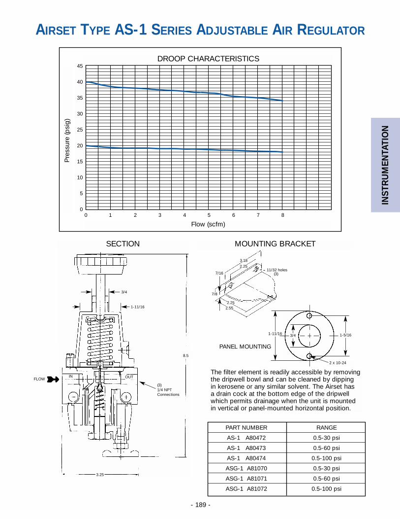
INST
RU
MEN
TATI
ON
- 189 -
DROOP CHARACTERISTICSP
ress
ure
(psi
g)45
40
35
30
25
20
15
10
5
00 1 2 3 4 5 6 7 8
Flow (scfm)
SECTION MOUNTING BRACKET
7/8
➼
7/16
2.25
2.252.55
3.18
11/32 holes(3)
The filter element is readily accessible by removingthe dripwell bowl and can be cleaned by dipping in kerosene or any similar solvent. The Airset has a drain cock at the bottom edge of the dripwellwhich permits drainage when the unit is mountedin vertical or panel-mounted horizontal position.
3/4
1-11/16
(3)1/4 NPTConnections
8.5
3.25
FLOWIN OUT
AIRSET TYPE AS-1 SERIES ADJUSTABLE AIR REGULATOR
PART NUMBER RANGE
AS-1 A80472 0.5-30 psi
AS-1 A80473 0.5-60 psi
AS-1 A80474 0.5-100 psi
ASG-1 A81070 0.5-30 psi
ASG-1 A81071 0.5-60 psi
ASG-1 A81072 0.5-100 psi
1-11/16 3/4 1-5/16
2 x 10-24
PANEL MOUNTING

INST
RU
MEN
TATI
ON
- 190 -
RELIEVING
Typical Air Loaderwith Aspirator
SE
T
PR
ES
SU
RE
P
SI
100 PSI INLET - 3 TO 95 RANGEDESIRED SET POINT - 29 PSI
1.2 1.0 0.8 .06 0.4 0.2 0 2 4 6 8 10 12 14 16 18 20 22 24 26
40
36
32
28
24
20
PANEL LOADERS
Basic air loader and flush gauges mounted onenameled aluminum plate suitable for flush orsurface console mounting. Optional air filteravailable, connected to air loader inlet connection.
AIRMATE® TYPE AFG-2AIR LOADERS AND PANELS
For Constant AirPressure Loading
How AIRMATE’S Patented Dual Aspirator ControlGives You Controlled Performance Over the EntireFlow Range:A comparison of capacity/regulation curves of otherleading air loaders with those of Airmate clearlydemonstrate Airmate’s superior performance. Airmateproduces a flatter curve and supplies and more accuratepressure regulation over a greater flow range duringperformance tests at flow rates from 0 to 40 scfm. Fromno flow to rated flow, deviations from the set point areinsignificant. Override and droop problems, common toordinary regulators, are eliminated.
PRESSURE AND TEMPERATURE RANGES
BASIC AIR LOADERSMaximum Inlet Pressure: 200 psiMaximum Temperature: 150°FReduces Pressure Ranges: 2 to 30 psi
3 to 60 psi30 to 150 psi1
Minimum Pressure Drop: 5 psiMaximum Ambient Temperature: 150°FSympathetic Variations: 65:12
Inlet and Outlet Connections: 1/4” NPTContinuous Bleed .04 SCFM
FILTERFiltration: Rated for 10 microns, maximumMaximum Pressure Drop at 50% fouled: 1/4 psiFilter Area: 4.3 sq. in.Rating of Filter Area to Normal Flow Area: 88:1Filter Bowl Capacity: 4.5 cu. in.
MATERIALS OF CONSTRUCTION
Basic Air Loaders ………………Die cast aluminum bodyand spring case
Filter ……………Die Cast aluminum bowl with drain cockFilter Material ………Phenolic resin-impregnated cellulose
1. For applications where accuracy of regulation is not critical, range may be extended to 10 to 150 psi.
2. The change in reduced pressure for an inlet pressure variation is inverse. A 65 psi increase in inletpressure will produce a 1 psi decrease in reduced pressure.
Typical Air Loaderwithout Aspirator
REDUCING
Leslie “Airmate” with PatentedDual Aspirator Control
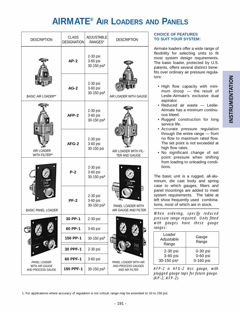
INST
RU
MEN
TATI
ON
- 191 -
CLASS ADJUSTABLEDESCRIPTION DESCRIPTION
DESIGNATION RANGES*
CHOICE OF FEATURESTO SUIT YOUR SYSTEM:
Airmate loaders offer a wide range offlexibility for selecting units to fitmost system design requirements.The basic loader, protected by U.S.patents, offers several distinct bene-fits over ordinary air pressure regula-tors:
• High flow capacity with mini-mum droop — the result ofLeslie-Airmate’s exclusive dualaspirator.
• Reduced air waste — Leslie-Airmate has a minimum continu-ous bleed.
• Rugged construction for longservice life.
• Accurate pressure regulationthrough the entire range — fromno flow to maximum rated flow.The set point is not exceeded athigh flow rates.
• No significant change of setpoint pressure when shiftingfrom loading to unloading condi-tions.
The basic unit is a rugged, all-alu-minum, die cast body and springcase to which gauges, filters andpanel mountings are added to meetsystem requirements. The table atleft show frequently used combina-tions, most of which are in stock.
When ordering, specify reducedpressure range required. Units fittedwith gauges have these gaugeranges:
AFP-2 is AFG-2 less gauge, withplugged gauge taps for future gauge.(AP-2, AFP-2).
LoaderGauge
AdjustableRange
Range
2-30 psi 0-30 psi3-60 psi 0-60 psi
30-150 psi1 0-160 psi
2-30 psi3-60 psi30-150 psi1
2-30 psi3-60 psi30-150 psi1
AP-2
AG-2
2-30 psi3-60 psi30-150 psi1
2-30 psi3-60 psi30-150 psi
2-30 psi3-60 psi30-150 psi1
2-30 psi3-60 psi30-150 psi1
AFP-2
AFG-2
P-2
PF-2
30 PP-1
60 PP-1
150 PP-1
30 PPF-1
2-30 psi
3-60 psi
30-150 psi1
2-30 psi
60 PPF-1 3-60 psi
150 PPF-1 30-150 psi1
BASIC AIR LOADER** AIR LOADER WITH GAUGE
AIR LOADERWITH FILTER**
AIR LOADER WITH FIL-TER AND GAUGE
BASIC PANEL LOADER
PANEL LOADERWITH AIR GAUGE
AND PROCESS GAUGE
PANEL LOADER WITHAIR GAUGE AND FILTER
PANEL LOADER WITH AIRAND PROCESS GAUGES
AND AIR FILTER
1. For applications where accuracy of regulation is not critical, range may be extended to 10 to 150 psi.
AIRMATE® AIR LOADERS AND PANELS
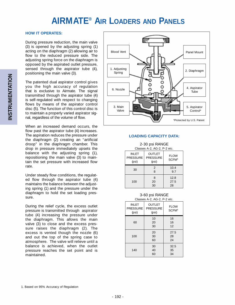
INST
RU
MEN
TATI
ON
- 192 -
HOW IT OPERATES:
During pressure reduction, the main valve(3) is opened by the adjusting spring (1)acting on the diaphragm (2) allowing air toflow to the reduced pressure side. Theadjusting spring force on the diaphragm isopposed by the aspirated outlet pressure,sensed through the aspirator tube (4),positioning the main valve (3).
The patented dual aspirator control givesyou the high accuracy of regulationthat is exclusive to Airmate. The signaltransmitted through the aspirator tube (4)is self-regulated with respect to changingflows by means of the aspirator controldisc (5). The function of this control disc isto maintain a properly varied aspirator sig-nal, regardless of the volume of flow.
When an increased demand occurs, theflow past the aspirator tube (4) increases.The aspiration reduces the pressure underthe diaphragm (2) creating an “artificialdroop” in the diaphragm chamber. Thisdrop in pressure immediately upsets thebalance with the adjusting spring (1),repositioning the main valve (3) to main-tain the set pressure with increased flowrate.
Under steady flow conditions, the regulat-ed flow through the aspirator tube (4)maintains the balance between the adjust-ing spring (1) and the pressure under thediaphragm to hold the set loading pres-sure.
During the relief cycle, the excess outletpressure is transmitted through aspiratortube (4) increasing the pressure underthe diaphragm. This allows the mainvalve (3) to close and the excess pres-sure raises the diaphragm (2). Theexcess is vented though the nozzle (6)and out the top of the spring case toatmosphere. The valve will relieve until abalance is achieved, when the outletpressure reaches the set point and ismaintained.
LOADING CAPACITY DATA:
INLET OUTLETFLOW
PRESSURE PRESSURESCFM1
(psi) (psi)
2 10.430
8 9.7
8 12.8100 20 27.5
30 28
2-30 psi RANGEClasses A-2, AG-2, P-2 etc.
INLET OUTLETFLOW
PRESSURE PRESSURESCFM1
(psi) (psi)
10 1660 20 16
30 12
20 27.5100 30 28
60 24
30 32.5140 40 35
60 34
3-60 psi RANGEClasses A-2, AG-2, P-2 etc.
1. Based on 95% Accuracy of Regulation
Blood Vent
1. AdjustingSpring
6. Nozzle
3. MainValve
Panel Mount
2. Diaphragm
4. AspiratorTube
5. Aspirator Control*
*Protected by U.S. Patent
AIRMATE® AIR LOADERS AND PANELS
- 194 -
REF
EREN
CE
GLOSSARY OF TERMS
Reprinted Courtesy Fluid Controls Institute ACCURACY OF REGULATION is the value of controlled variable (pressure, or differential pres-sure) expressed as a percentage of the set value (at minimum controllable flow) when with a con-stant supply pressure the flow through the regulator is increased from the minimum controllableflow to the rated capacity (also equal to 100% minus the offset (droop) %).
BACK PRESSURE REGULATOR—A device that controls and responds to change in its inletpressure.
BALANCED—A regulator style featuring a pressure balanced plug. May be single or double seat-ed.
DEAD BAND—The range through which the controlled variable can reverse direction without andobservable regulator response.
DIAPHRAGM ACTUATED REGULATOR—A regulator utilizing a diaphragm as the position actu-ator.
DIFFERENTIAL PRESSURE REGULATOR—A device that maintains a constant differential pres-sure between a reference pressure and the pressure of the controlled fluid.
DIRECT ACTION—A regulator that decreases its output as the measured variable increases.
DIRECT OPERATED—A regulator that uses a temperature thermal system to directly provide thepower to move the plug.
DRIFT—A change in set point over an extended period of time.
DROOP—See accuracy of regulation.
FLOW COEFFICIENT (Cv) is the regulator capacity in GPM of H2O at 20 degrees C with one PSIpressure drop at full rated travel. Refer to ISA S75.01 and S75.02 for Testing Procedures and SizingEquations.
MINIMUM CONTROLLABLE FLOW is the lowest flow at which a steady regulated condition ofthe controlled variable can be maintained.
PACKLESS—A construction that does not employ a dynamic seal isolating internal fluid fromambient or atmosphere.
PILOT OPERATED—A regulator that uses a temperature thermal system to power a pilot mech-anism which generates an amplified signal to position the plug of the regulator. The pilot may beinternal or external.
PRESSURE REDUCING REGULATOR—A device that controls and responds to changes in itsoutlet pressure.
PRESSURE REGULATOR—A self-operated device, either pilot or direct operated, in whichpower to position the valve closure member is provided by the pressure of the controlled variable.
PRESSURE TEMPERATURE—A dual function piloted regulator combining the control of bothtemperature and pressure. Control of pressure and temperature may be by a single pilot or multi-ple pilots. Pilot(s) may be internal or external or these functions in combination may be available.
PUMP PRESSURE REGULATOR—A device that controls the speed of a pump in response tochanges in pump discharge pressure.
REPEATABILITY—Ability to return to any defined point within stated limits of regulation within aspecified tolerance.
REVERSE ACTION—A regulator that increases its output as the measured variable increases.
TEMPERATURE REGULATOR—A self operated device in which the energy to position valve clo-sure member(s) is provided by changes of temperature energy of the controlled variable.
UNBALANCED—A regulator where the plug closure number is not pressure balanced. Generallya single regulator.
- 195 -
REF
EREN
CE
APPLICABLE INDUSTRY STANDARDS
All Leslie control valves are 100% factory tested andserialized. Leslie Controls’ quality assurance program isaccredited and certified to ISO 90011. All Leslie controlvalves are also designed, built and tested to meet the fol-lowing industry standards.
ANSI B1.20.1 Pipe Threads - Conforms to pipe threadrequirements.ANSI B16.1 Cast Iron Flanges and Flanged Fittings -Conforms to wall thickness, flange dimensions, materials,pressure/temperature ratings, markings and hydrostatictest requirements.ANSI B16.11 Socketweld Ends - Conforms to sock-etweld end requirements.ANSI B16.5 Pipe Flanges and Flanged Fittings -Conforms to flange thickness, diameter and drillingrequirements.ANSI B16.10 Face-To-Face Dimensions - Conforms to globe style control valve face-to-face dimension requirements.ANSI B16.25 Buttwelding Ends - Conforms to requirements of Schedule 40 or Schedule 80 pipe, without backing rings.ANSI B16.34 Valves, Flanged and Butt-weld - Integralflanged and BWE valve conforms to wall thickness, materials, pressure/temperature ratings, markings, andhydrostatic test requirements.ANSI B16.37 Hydrotesting of Control Valves - Conformsto hydrotesting requirements.ANSI/ISA 70-2 Control Valve Seat Leakage - Conformsto Class III, IV, and V shutoff requirements.ISA S75.01 Flow Equations for Sizing Control Valves.ISA S75.02 Control Valve Capacity Test Procedure -Conforms to flow capacity test procedure requirements.ISA S75.03 Uniform Face-To-Face Dimensions forFlanged Globe Style Control Valves - Conforms to face-to-face dimension requirements.ISA S75.12 Face-To-Face Dimensions for SocketweldEnd and Screwed End Globe Style Control Valves -Conforms to face-to-face dimension requirements.ISA S75.15 Face-To-Face Dimensions for Butt-weldEnd Globe Style Control Valves - Conforms to face-to-face dimension requirements.MSS SP25 Standard Marking System for Valves,Fittings, Flanges, and Unions - Conforms to markingrequirements for flanged, screwed and weld end fittings.MSS SP84 Steel Valves, Socketweld End and ThreadedEnd - Conforms to end connection requirements.
In addition, when required, control valves can bemanufactured and tested in compliance with:
CAN 3 Z299.3ANSI N45.2MIL-I-STD-45662MIL-I-45208B 31.1
1. Assessed and certified by ABS, Houston, Texas
INDUSTRY STANDARDS
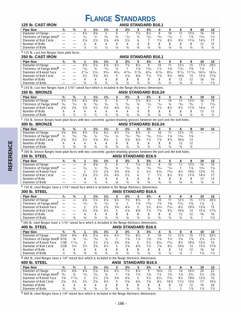
- 196 -
REF
EREN
CE
FLANGE STANDARDSPipe Size 1/2 3/4 1 11/4 11/2 2 21/2 3 31/2 4 5 6 8 10 12Diameter of Flange — — 41/4 45/8 5 6 7 71/2 81/2 9 10 11 131/2 16 19Thickness of Flange (min)a — — 7/16 1/2 9/16 5/8 11/16 3/4 13/16 15/16 15/16 1 11/8 13/16 11/4Diameter of Bolt Circle — — 31/8 31/2 37/8 43/4 51/2 6 7 71/2 81/2 91/2 113/4 141/4 17Number of Bolts — — 4 4 4 4 4 4 8 8 8 8 8 12 12Diameter of Bolts — — 1/2 1/2 1/2 5/8 5/8 5/8 5/8 5/8 3/4 3/4 3/4 7/8 7/8
a 125 lb. cast iron flanges have plain faces.
125 lb. CAST IRON ANSI STANDARD B16.1
Pipe Size 1/2 3/4 1 11/4 11/2 2 21/2 3 31/2 4 5 6 8 10 12Diameter of Flange 31/2 37/8 41/4 45/8 5 6 7 71/2 81/2 9 10 11 131/2 16 19Thickness of Flange (min)c 5/16 11/32 3/8 13/32 7/16 1/2 9/16 5/8 11/16 11/16 3/4 13/16 15/16 1 11/16
Diameter of Bolt Circle 23/8 23/4 31/8 31/2 37/8 43/4 51/2 6 7 71/2 81/2 91/2 113/4 141/4 17Number of Bolts 4 4 4 4 4 4 4 4 8 8 8 8 8 12 12Diameter of Bolts 1/2 1/2 1/2 1/2 1/2 5/8 5/8 5/8 5/8 5/8 3/4 3/4 3/4 7/8 7/8
c 150 lb. bronze flanges have plain faces with two concentric gasket-retaining grooves between the port and the bolt holes.
150 lb. BRONZE ANSI STANDARD B16.24
Pipe Size 1/2 3/4 1 11/4 11/2 2 21/2 3 31/2 4 5 6 8 10 12Diameter of Flange 33/4 45/8 47/8 51/4 61/2 61/2 71/2 81/4 9 10 11 121/2 15 — —Thickness of Flange (min)d 1/2 17/32 19/32 5/8 11/16 3/4 13/16 29/32 31/32 11/16 11/8 13/16 13/8Diameter of Bolt Circle 25/8 31/4 31/2 37/8 41/2 5 57/8 65/8 71/4 77/8 91/4 105/8 13Number of Bolts 4 4 4 4 4 8 8 8 8 8 8 12 12Diameter of Bolts 1/2 5/8 5/8 5/8 3/4 5/8 3/4 3/4 3/4 3/4 3/4 3/4 7/8
d 300 lb. bronze flanges have plain faces with two concentric gasket-retaining grooves between the port and the bolt holes.
300 lb. BRONZE ANSI STANDARD B16.24
Pipe Size 1/2 3/4 1 11/4 11/2 2 21/2 3 31/2 4 5 6 8 10 12Diameter of Flange — — 47/8 51/4 61/8 61/2 71/2 81/4 9 10 11 121/2 15 171/2 201/2Thickness of Flange (min)b — — 11/16 3/4 13/16 7/8 1 11/8 13/16 11/4 13/8 17/16 15/8 17/8 2Diameter of Raised Face — — 211/16 31/16 39/16 43/16 415/16 511/16 65/16 615/16 85/16 911/16 1115/16 141/16 167/16
Diameter of Bolt Circle — — 31/2 37/8 41/2 5 57/8 65/8 71/4 77/8 91/4 105/8 13 151/4 173/4Number of Bolts — — 4 4 4 8 8 8 8 8 8 12 12 16 16Diameter of Bolts — — 5/8 5/8 3/4 5/8 3/4 3/4 3/4 3/4 3/4 3/4 7/8 1 11/8
b 250 lb. cast iron flanges have a 1/16" raised face which is included in the flange thickness dimensions.
250 lb. CAST IRON ANSI STANDARD B16.1
Pipe Size 1/2 3/4 1 11/4 11/2 2 21/2 3 31/2 4 5 6 8 10 12Diameter of Flange — — 4 45/8 5 6 7 71/2 81/2 9 10 11 131/2 16 19Thickness of Flange (min)e — — 7/16 1/2 9/16 5/8 11/16 3/4 13/16 15/16 15/16 1 11/8 13/16 11/4Diameter of Raised Face — — 2 21/2 27/8 35/8 41/8 5 51/2 63/16 75/16 81/2 105/8 123/4 15Diameter of Bolt Circle — — 31/8 31/2 37/8 43/4 51/2 6 7 71/2 81/2 91/2 113/4 141/4 17Number of Bolts — — 4 4 4 4 4 4 8 8 8 8 8 12 12Diameter of Bolts — — 1/2 1/2 1/2 5/8 5/8 5/8 5/8 5/8 3/4 3/4 3/4 7/8 7/8
e 150 lb. steel flanges have a 1/16" raised face which is included in the flange thickness dimensions.
150 lb. STEEL ANSI STANDARD B16.5
Pipe Size 1/2 3/4 1 11/4 11/2 2 21/2 3 31/2 4 5 6 8 10 12Diameter of Flange — — 47/8 51/4 61/8 61/2 71/2 81/4 9 10 11 121/2 15 171/2 201/2Thickness of Flange (min)f — — 11/16 3/4 13/16 7/8 1 11/8 13/16 11/4 13/8 17/16 15/8 17/8 2Diameter of Raised Face — — 2 21/2 27/8 35/8 41/8 5 51/2 63/16 75/16 81/2 105/8 123/4 15Diameter of Bolt Circle — — 31/2 37/8 41/2 5 57/8 65/8 71/4 77/8 91/4 105/8 13 151/4 173/4Number of Bolts — — 4 4 4 8 8 8 8 8 8 12 12 16 16Diameter of Bolts — 5/8 5/8 3/4 5/8 3/4 3/4 3/4 3/4 3/4 3/4 3/4 7/8 1 11/8
f 300 lb. steel flanges have a 1/16" raised face which is included in the flange thickness dimensions.
300 lb. STEEL ANSI STANDARD B16.5
Pipe Size 1/2 3/4 1 11/4 11/2 2 21/2 3 31/2 4 5 6 8 10 12Diameter of Flange 33/4 45/8 47/8 51/4 61/8 61/2 71/2 81/4 9 10 11 121/2 15 171/2 201/2Thickness of Flange (min)g 9/16 5/8 11/16 13/16 7/8 1 11/8 11/4 13/8 13/8 11/2 15/8 17/8 21/8 21/4Diameter of Raised Face 1/38 111/16 2 21/2 27/8 35/8 41/8 5 51/2 63/16 75/16 81/2 105/8 123/4 15Diameter of Bolt Circle 25/8 31/4 31/2 37/8 41/2 5 57/8 65/8 71/4 77/8 91/4 105/8 13 151/4 173/4Number of Bolts 4 4 4 4 4 8 8 8 8 8 8 12 12 16 16Diameter of Bolts 1/2 5/8 5/8 5/8 3/4 5/8 3/4 3/4 7/8 7/8 7/8 7/8 1 11/8 11/4
g 400 lb. steel flanges have a 1/4" raised face which is included in the flange thickness dimensions.
400 lb. STEEL ANSI STANDARD B16.5
Pipe Size 1/2 3/4 1 11/4 11/2 2 21/2 3 31/2 4 5 6 8 10 12Diameter of Flange 33/4 45/8 47/8 51/4 61/8 61/2 71/2 81/4 9 103/4 13 14 161/2 20 22Thickness of Flange (min)h 9/16 5/8 11/16 13/16 7/8 1 11/8 11/4 13/8 11/2 13/4 17/8 23/16 21/2 25/8Diameter of Raised Face 13/8 111/16 2 21/2 27/8 35/8 41/8 5 51/2 63/16 75/16 81/2 105/8 123/4 15Diameter of Bolt Circle 25/8 31/4 31/2 37/8 41/2 5 57/8 65/8 71/4 81/2 101/2 111/2 133/4 17 191/4Number of Bolts 4 4 4 4 4 8 8 8 8 8 8 12 12 16 20Diameter of Bolts 1/2 5/8 5/8 5/8 3/4 5/8 3/4 3/4 7/8 7/8 1 1 11/8 11/4 11/4
h 600 lb. steel flanges have a 1/4" raised face which is included in the flange thickness dimensions.
600 lb. STEEL ANSI STANDARD B16.5
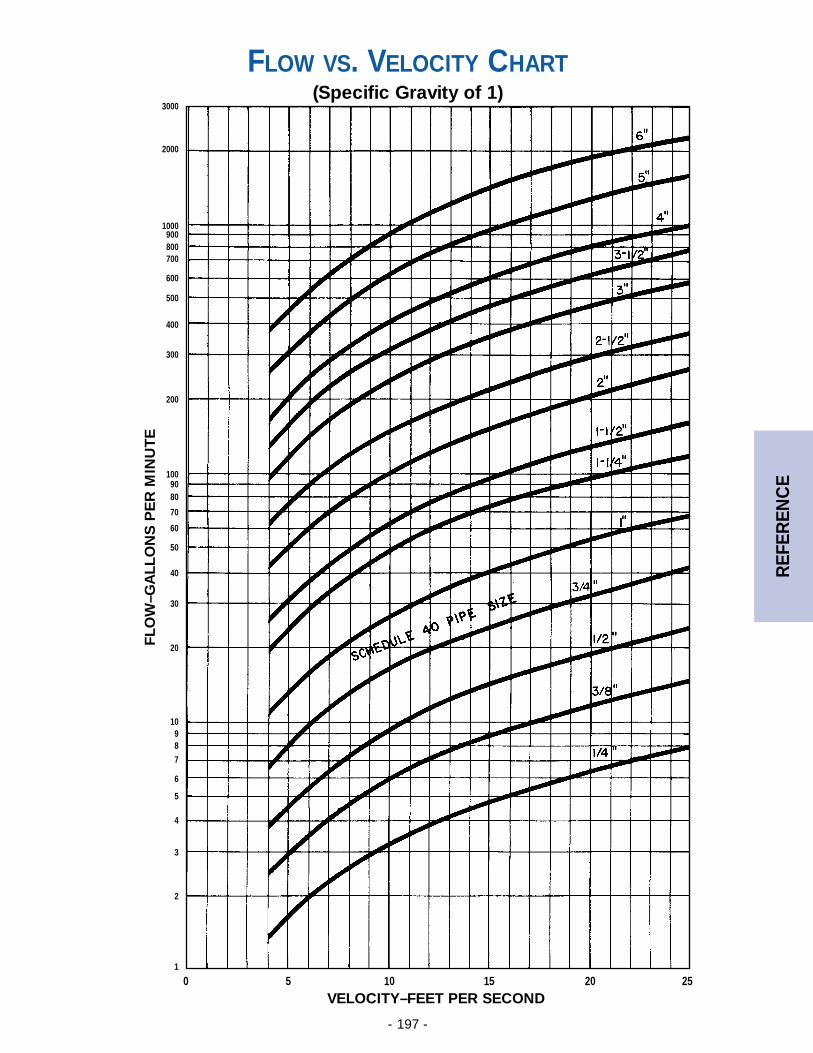
- 197 -
REF
EREN
CE
3000
2000
1000900800700
600
500
400
300
200
1009080
70
60
50
40
30
20
1098
7
6
5
4
3
2
1
0 5 10 15 20 25
FLOW VS. VELOCITY CHART(Specific Gravity of 1)
VELOCITY–FEET PER SECOND
FLO
W–G
ALL
ON
S P
ER
MIN
UT
E
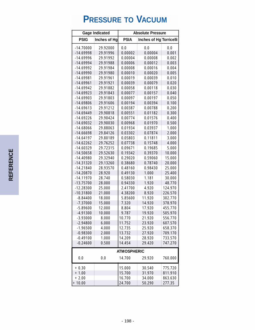
- 198 -
REF
EREN
CE
PRESSURE TO VACUUM
Gage Indicated Absolute Pressure
PSIG Inches of Hg PSIA Inches of Hg Torricelli
-14.70000 29.92000 0.0 0.0 0.0-14.69998 29.91996 0.00002 0.00004 0.001-14.69996 29.91992 0.00004 0.00008 0.002-14.69994 29.91988 0.00006 0.00012 0.003-14.69992 29.91984 0.00008 0.00016 0.004-14.69990 29.91980 0.00010 0.00020 0.005-14.69981 29.91961 0.00019 0.00039 0.010-14.69961 29.91921 0.00039 0.00079 0.020-14.69942 29.91882 0.00058 0.00118 0.030-14.69923 29.91843 0.00077 0.00157 0.040-14.69903 29.91803 0.00097 0.00197 0.050-14.69806 29.91606 0.00194 0.00394 0.100-14.69613 29.91212 0.00387 0.00788 0.200-14.69449 29.90818 0.00551 0.01182 0.300-14.69226 29.90424 0.00774 0.01576 0.400-14.69032 29.90030 0.00968 0.01970 0.500-14.68066 29.88063 0.01934 0.03937 1.000-14.66698 29.84126 0.03302 0.07874 2.000-14.64197 29.80189 0.05803 0.11811 3.000-14.62262 29.76252 0.07738 0.15748 4.000-14.60329 29.72315 0.09671 0.19685 5.000-14.50658 29.52630 0.19342 0.39370 10.000-14.40980 29.32940 0.29020 0.59060 15.000-14.31320 29.13260 0.38680 0.78740 20.000-14.21840 28.93570 0.48160 0.98430 25.000-14.20870 28.920 0.49130 1.000 25.400-14.11970 28.740 0.58030 1.181 30.000-13.75700 28.000 0.94330 1.920 48.770-12.28300 25.000 2.41700 4.920 124.970-10.31800 21.000 4.38200 8.920 226.570-8.84400 18.000 5.85600 11.920 302.770-7.37000 15.000 7.320 14.920 378.970-5.89600 12.000 8.804 17.920 455.770-4.91300 10.000 9.787 19.920 505.970-3.93000 8.000 10.770 21.920 556.770-2.94800 6.000 11.752 23.920 607.570-1.96500 4.000 12.735 25.920 658.370-0.98300 2.000 13.732 27.920 709.170-0.49100 1.000 14.209 28.920 733.570-0.24600 0.500 14.454 29.420 747.270
ATMOSPHERIC
0.0 0.0 14.700 29.920 760.000
+ 0.30 15.000 30.540 775.720+ 1.00 15.700 31.970 811.910+ 2.00 16.700 34.000 863.630
+ 10.00 24.700 50.290 277.35
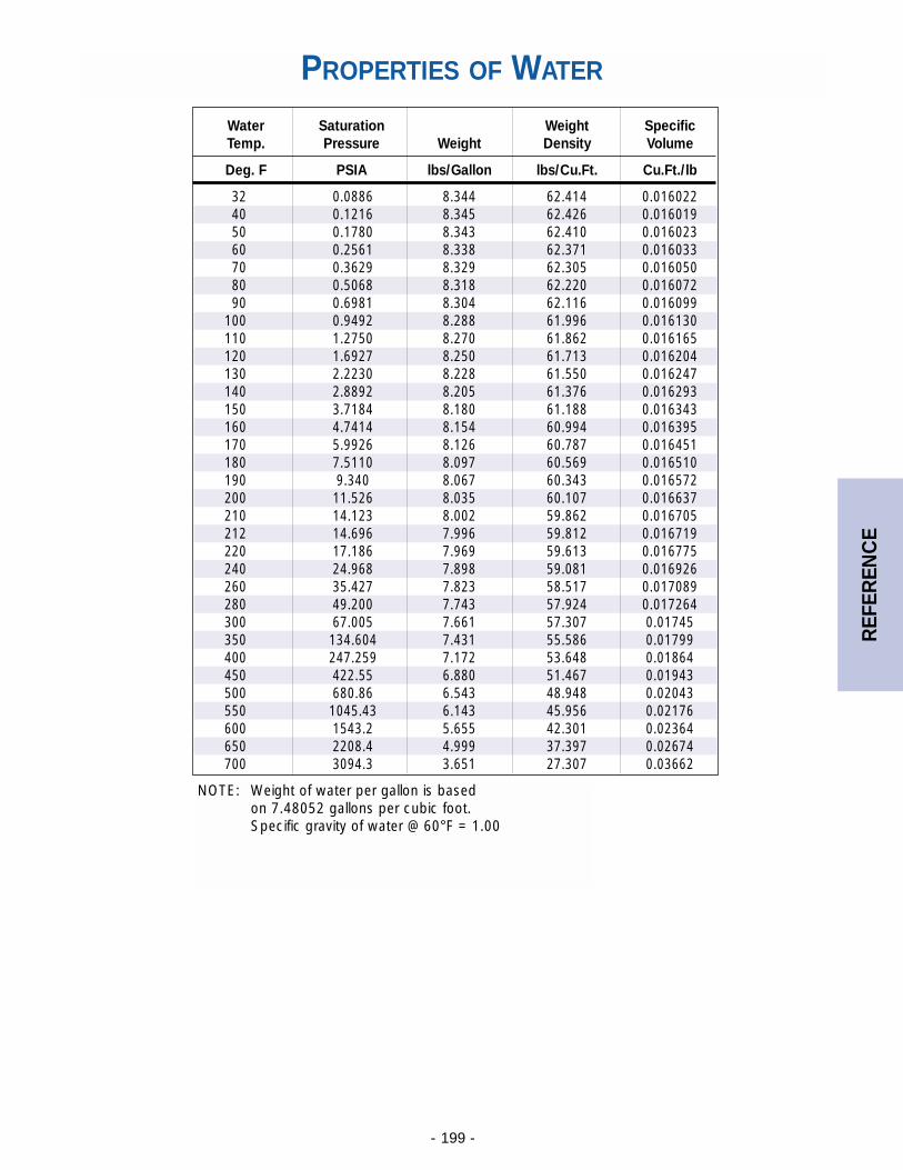
- 199 -
REF
EREN
CE
PROPERTIES OF WATER
Water Saturation Weight SpecificTemp. Pressure Weight Density Volume
Deg. F PSIA lbs/Gallon lbs/Cu.Ft. Cu.Ft./lb
32 0.0886 8.344 62.414 0.01602240 0.1216 8.345 62.426 0.01601950 0.1780 8.343 62.410 0.01602360 0.2561 8.338 62.371 0.01603370 0.3629 8.329 62.305 0.01605080 0.5068 8.318 62.220 0.01607290 0.6981 8.304 62.116 0.016099
100 0.9492 8.288 61.996 0.016130110 1.2750 8.270 61.862 0.016165120 1.6927 8.250 61.713 0.016204130 2.2230 8.228 61.550 0.016247140 2.8892 8.205 61.376 0.016293150 3.7184 8.180 61.188 0.016343160 4.7414 8.154 60.994 0.016395170 5.9926 8.126 60.787 0.016451180 7.5110 8.097 60.569 0.016510190 9.340 8.067 60.343 0.016572200 11.526 8.035 60.107 0.016637210 14.123 8.002 59.862 0.016705212 14.696 7.996 59.812 0.016719220 17.186 7.969 59.613 0.016775240 24.968 7.898 59.081 0.016926260 35.427 7.823 58.517 0.017089280 49.200 7.743 57.924 0.017264300 67.005 7.661 57.307 0.01745350 134.604 7.431 55.586 0.01799400 247.259 7.172 53.648 0.01864450 422.55 6.880 51.467 0.01943500 680.86 6.543 48.948 0.02043550 1045.43 6.143 45.956 0.02176600 1543.2 5.655 42.301 0.02364650 2208.4 4.999 37.397 0.02674700 3094.3 3.651 27.307 0.03662
NOTE: Weight of water per gallon is based on 7.48052 gallons per cubic foot.Specific gravity of water @ 60°F = 1.00
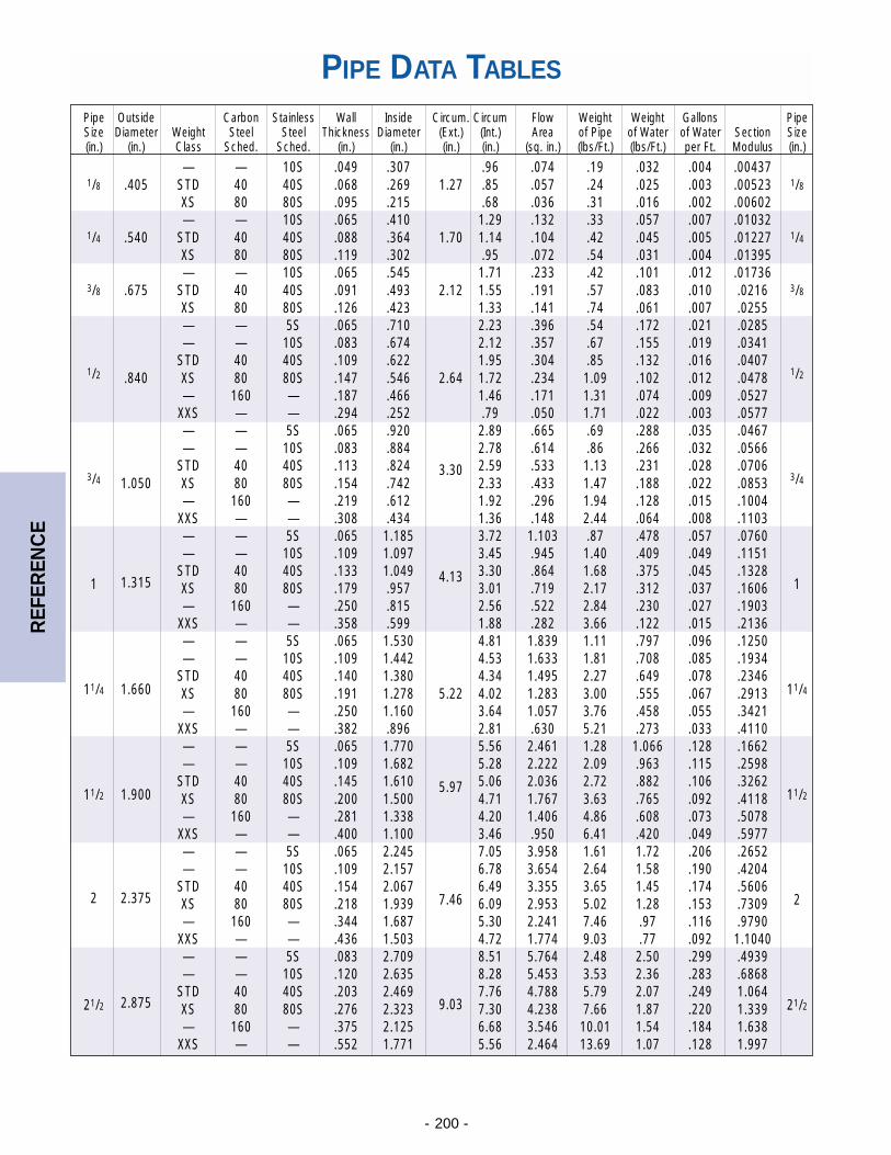
- 200 -
REF
EREN
CE
PIPE DATA TABLES
Pipe Outside Carbon Stainless Wall Inside Circum. Circum Flow Weight Weight Gallons PipeSize Diameter Weight Steel Steel Thickness Diameter (Ext.) (Int.) Area of Pipe of Water of Water Section Size(in.) (in.) Class Sched. Sched. (in.) (in.) (in.) (in.) (sq. in.) (lbs/Ft.) (lbs/Ft.) per Ft. Modulus (in.)
— — 10S .049 .307 .96 .074 .19 .032 .004 .004371/8 .405 STD 40 40S .068 .269 1.27 .85 .057 .24 .025 .003 .00523 1/8
XS 80 80S .095 .215 .68 .036 .31 .016 .002 .00602— — 10S .065 .410 1.29 .132 .33 .057 .007 .01032
1/4 .540 STD 40 40S .088 .364 1.70 1.14 .104 .42 .045 .005 .01227 1/4
XS 80 80S .119 .302 .95 .072 .54 .031 .004 .01395— — 10S .065 .545 1.71 .233 .42 .101 .012 .01736
3/8 .675 STD 40 40S .091 .493 2.12 1.55 .191 .57 .083 .010 .0216 3/8
XS 80 80S .126 .423 1.33 .141 .74 .061 .007 .0255— — 5S .065 .710 2.23 .396 .54 .172 .021 .0285— — 10S .083 .674 2.12 .357 .67 .155 .019 .0341
STD 40 40S .109 .622 1.95 .304 .85 .132 .016 .04071/2 .840 XS 80 80S .147 .546 2.64 1.72 .234 1.09 .102 .012 .0478 1/2
— 160 — .187 .466 1.46 .171 1.31 .074 .009 .0527XXS — — .294 .252 .79 .050 1.71 .022 .003 .0577— — 5S .065 .920 2.89 .665 .69 .288 .035 .0467— — 10S .083 .884 2.78 .614 .86 .266 .032 .0566
STD 40 40S .113 .824 3.30 2.59 .533 1.13 .231 .028 .07063/4 1.050 XS 80 80S .154 .742 2.33 .433 1.47 .188 .022 .0853 3/4
— 160 — .219 .612 1.92 .296 1.94 .128 .015 .1004XXS — — .308 .434 1.36 .148 2.44 .064 .008 .1103— — 5S .065 1.185 3.72 1.103 .87 .478 .057 .0760— — 10S .109 1.097 3.45 .945 1.40 .409 .049 .1151
STD 40 40S .133 1.049 4.13 3.30 .864 1.68 .375 .045 .13281 1.315 XS 80 80S .179 .957 3.01 .719 2.17 .312 .037 .1606 1
— 160 — .250 .815 2.56 .522 2.84 .230 .027 .1903XXS — — .358 .599 1.88 .282 3.66 .122 .015 .2136— — 5S .065 1.530 4.81 1.839 1.11 .797 .096 .1250— — 10S .109 1.442 4.53 1.633 1.81 .708 .085 .1934
STD 40 40S .140 1.380 4.34 1.495 2.27 .649 .078 .234611/4 1.660 XS 80 80S .191 1.278 5.22 4.02 1.283 3.00 .555 .067 .2913 11/4
— 160 — .250 1.160 3.64 1.057 3.76 .458 .055 .3421XXS — — .382 .896 2.81 .630 5.21 .273 .033 .4110— — 5S .065 1.770 5.56 2.461 1.28 1.066 .128 .1662— — 10S .109 1.682 5.28 2.222 2.09 .963 .115 .2598
STD 40 40S .145 1.610 5.97 5.06 2.036 2.72 .882 .106 .326211/2 1.900 XS 80 80S .200 1.500 4.71 1.767 3.63 .765 .092 .4118 11/2
— 160 — .281 1.338 4.20 1.406 4.86 .608 .073 .5078XXS — — .400 1.100 3.46 .950 6.41 .420 .049 .5977— — 5S .065 2.245 7.05 3.958 1.61 1.72 .206 .2652— — 10S .109 2.157 6.78 3.654 2.64 1.58 .190 .4204
STD 40 40S .154 2.067 6.49 3.355 3.65 1.45 .174 .56062 2.375 XS 80 80S .218 1.939 7.46 6.09 2.953 5.02 1.28 .153 .7309 2
— 160 — .344 1.687 5.30 2.241 7.46 .97 .116 .9790XXS — — .436 1.503 4.72 1.774 9.03 .77 .092 1.1040— — 5S .083 2.709 8.51 5.764 2.48 2.50 .299 .4939— — 10S .120 2.635 8.28 5.453 3.53 2.36 .283 .6868
STD 40 40S .203 2.469 7.76 4.788 5.79 2.07 .249 1.06421/2 2.875 XS 80 80S .276 2.323 9.03 7.30 4.238 7.66 1.87 .220 1.339 21/2
— 160 — .375 2.125 6.68 3.546 10.01 1.54 .184 1.638XXS — — .552 1.771 5.56 2.464 13.69 1.07 .128 1.997
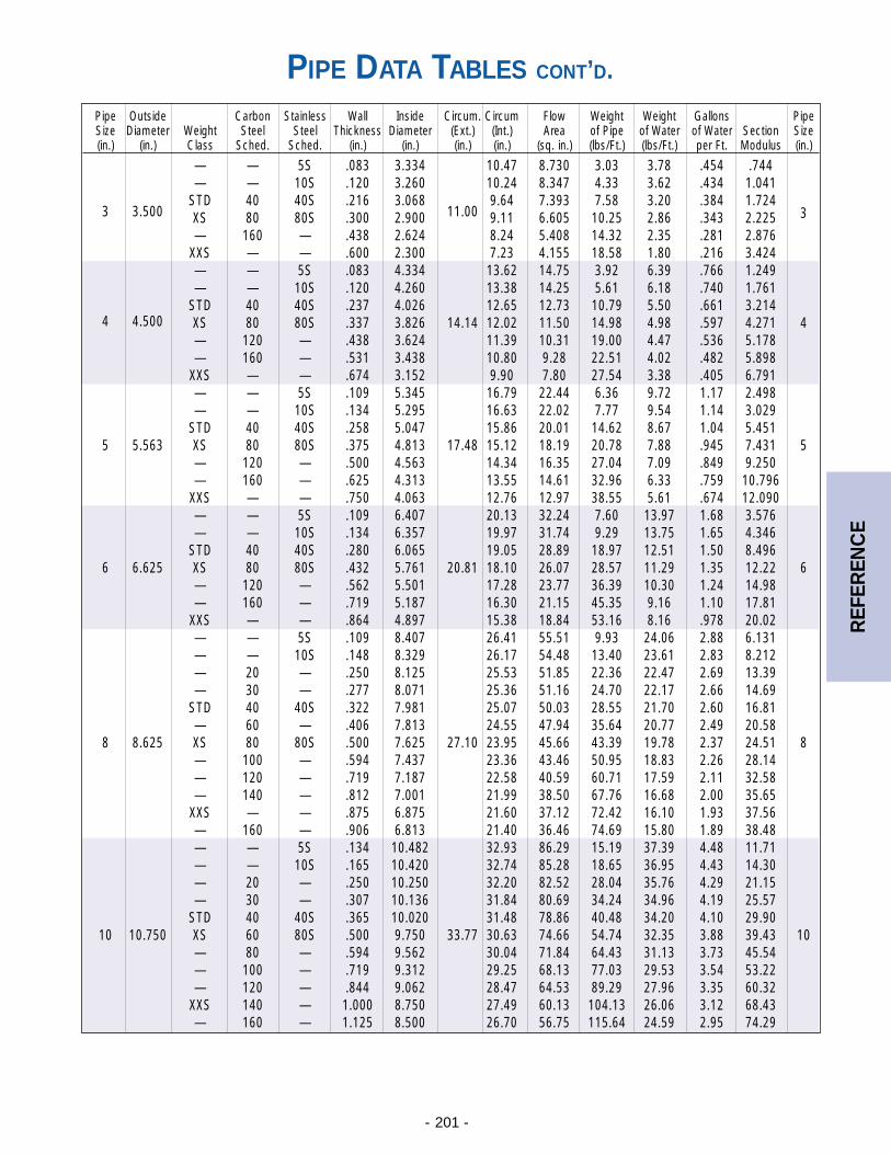
- 201 -
REF
EREN
CE
Pipe Outside Carbon Stainless Wall Inside Circum. Circum Flow Weight Weight Gallons PipeSize Diameter Weight Steel Steel Thickness Diameter (Ext.) (Int.) Area of Pipe of Water of Water Section Size(in.) (in.) Class Sched. Sched. (in.) (in.) (in.) (in.) (sq. in.) (lbs/Ft.) (lbs/Ft.) per Ft. Modulus (in.)
— — 5S .083 3.334 10.47 8.730 3.03 3.78 .454 .744— — 10S .120 3.260 10.24 8.347 4.33 3.62 .434 1.041
STD 40 40S .216 3.068 9.64 7.393 7.58 3.20 .384 1.7243 3.500 XS 80 80S .300 2.900 11.00 9.11 6.605 10.25 2.86 .343 2.225 3
— 160 — .438 2.624 8.24 5.408 14.32 2.35 .281 2.876XXS — — .600 2.300 7.23 4.155 18.58 1.80 .216 3.424— — 5S .083 4.334 13.62 14.75 3.92 6.39 .766 1.249— — 10S .120 4.260 13.38 14.25 5.61 6.18 .740 1.761
STD 40 40S .237 4.026 12.65 12.73 10.79 5.50 .661 3.2144 4.500 XS 80 80S .337 3.826 14.14 12.02 11.50 14.98 4.98 .597 4.271 4
— 120 — .438 3.624 11.39 10.31 19.00 4.47 .536 5.178— 160 — .531 3.438 10.80 9.28 22.51 4.02 .482 5.898
XXS — — .674 3.152 9.90 7.80 27.54 3.38 .405 6.791— — 5S .109 5.345 16.79 22.44 6.36 9.72 1.17 2.498— — 10S .134 5.295 16.63 22.02 7.77 9.54 1.14 3.029
STD 40 40S .258 5.047 15.86 20.01 14.62 8.67 1.04 5.4515 5.563 XS 80 80S .375 4.813 17.48 15.12 18.19 20.78 7.88 .945 7.431 5
— 120 — .500 4.563 14.34 16.35 27.04 7.09 .849 9.250— 160 — .625 4.313 13.55 14.61 32.96 6.33 .759 10.796
XXS — — .750 4.063 12.76 12.97 38.55 5.61 .674 12.090— — 5S .109 6.407 20.13 32.24 7.60 13.97 1.68 3.576— — 10S .134 6.357 19.97 31.74 9.29 13.75 1.65 4.346
STD 40 40S .280 6.065 19.05 28.89 18.97 12.51 1.50 8.4966 6.625 XS 80 80S .432 5.761 20.81 18.10 26.07 28.57 11.29 1.35 12.22 6
— 120 — .562 5.501 17.28 23.77 36.39 10.30 1.24 14.98— 160 — .719 5.187 16.30 21.15 45.35 9.16 1.10 17.81
XXS — — .864 4.897 15.38 18.84 53.16 8.16 .978 20.02— — 5S .109 8.407 26.41 55.51 9.93 24.06 2.88 6.131— — 10S .148 8.329 26.17 54.48 13.40 23.61 2.83 8.212— 20 — .250 8.125 25.53 51.85 22.36 22.47 2.69 13.39— 30 — .277 8.071 25.36 51.16 24.70 22.17 2.66 14.69
STD 40 40S .322 7.981 25.07 50.03 28.55 21.70 2.60 16.81— 60 — .406 7.813 24.55 47.94 35.64 20.77 2.49 20.58
8 8.625 XS 80 80S .500 7.625 27.10 23.95 45.66 43.39 19.78 2.37 24.51 8— 100 — .594 7.437 23.36 43.46 50.95 18.83 2.26 28.14— 120 — .719 7.187 22.58 40.59 60.71 17.59 2.11 32.58— 140 — .812 7.001 21.99 38.50 67.76 16.68 2.00 35.65
XXS — — .875 6.875 21.60 37.12 72.42 16.10 1.93 37.56— 160 — .906 6.813 21.40 36.46 74.69 15.80 1.89 38.48— — 5S .134 10.482 32.93 86.29 15.19 37.39 4.48 11.71— — 10S .165 10.420 32.74 85.28 18.65 36.95 4.43 14.30— 20 — .250 10.250 32.20 82.52 28.04 35.76 4.29 21.15— 30 — .307 10.136 31.84 80.69 34.24 34.96 4.19 25.57
STD 40 40S .365 10.020 31.48 78.86 40.48 34.20 4.10 29.9010 10.750 XS 60 80S .500 9.750 33.77 30.63 74.66 54.74 32.35 3.88 39.43 10
— 80 — .594 9.562 30.04 71.84 64.43 31.13 3.73 45.54— 100 — .719 9.312 29.25 68.13 77.03 29.53 3.54 53.22— 120 — .844 9.062 28.47 64.53 89.29 27.96 3.35 60.32
XXS 140 — 1.000 8.750 27.49 60.13 104.13 26.06 3.12 68.43— 160 — 1.125 8.500 26.70 56.75 115.64 24.59 2.95 74.29
PIPE DATA TABLES CONT’D.
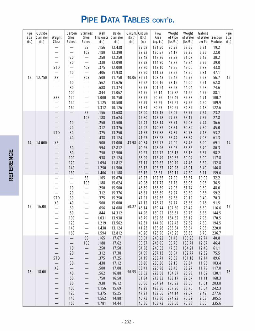
- 202 -
REF
EREN
CE
Pipe Outside Carbon Stainless Wall Inside Circum. Circum Flow Weight Weight Gallons PipeSize Diameter Weight Steel Steel Thickness Diameter (Ext.) (Int.) Area of Pipe of Water of Water Section Size(in.) (in.) Class Sched. Sched. (in.) (in.) (in.) (in.) (sq. in.) (lbs/Ft.) (lbs/Ft.) per Ft. Modulus (in.)
— — 5S .156 12.438 39.08 121.50 20.98 52.65 6.31 19.2— — 10S .180 12.390 38.92 120.57 24.17 52.25 6.26 22.0— 20 — .250 12.250 38.48 117.86 33.38 51.07 6.12 30.2— 30 — .330 12.090 37.98 114.80 43.77 49.74 5.96 39.0
STD — 40S .375 12.000 37.70 113.10 49.56 49.00 5.88 43.8— 40 — .406 11.938 37.50 111.93 53.52 48.50 5.81 47.1
12 12.750 XS — 80S .500 11.750 40.06 36.91 108.43 65.42 46.92 5.63 56.7 12— 60 — .562 11.626 36.52 106.16 73.15 46.00 5.51 62.8— 80 — .688 11.374 35.73 101.64 88.63 44.04 5.28 74.6— 100 — .844 11.062 34.75 96.14 107.32 41.66 4.99 88.1
XXS 120 — 1.000 10.750 33.77 90.76 125.49 39.33 4.71 100.7— 140 — 1.125 10.500 32.99 86.59 139.67 37.52 4.50 109.9— 160 — 1.312 10.126 31.81 80.53 160.27 34.89 4.18 122.6— — 5S .156 13.688 43.00 147.15 23.07 63.77 7.64 23.2— 10S .188 13.624 42.80 145.78 27.73 63.17 7.57 27.8— 10 — .250 13.500 42.41 143.14 36.71 62.03 7.44 36.6— 20 — .312 13.376 42.02 140.52 45.61 60.89 7.30 45.0
STD 30 — .375 13.250 41.63 137.88 54.57 59.75 7.16 53.2— 40 — .438 13.124 41.23 135.28 63.44 58.64 7.03 61.3
14 14.000 XS — — .500 13.000 43.98 40.84 132.73 72.09 57.46 6.90 69.1 14— 60 — .594 12.812 40.25 128.96 85.05 55.86 6.70 80.3— 80 — .750 12.500 39.27 122.72 106.13 53.18 6.37 98.2— 100 — .938 12.124 38.09 115.49 130.85 50.04 6.00 117.8— 120 — 1.094 11.812 37.11 109.62 150.79 47.45 5.69 132.8— 140 — 1.250 11.500 36.13 103.87 170.28 45.01 5.40 146.8— 160 — 1.406 11.188 35.15 98.31 189.11 42.60 5.11 159.6— — 5S .165 15.670 49.23 192.85 27.90 83.57 10.02 32.2— — 10S .188 15.624 49.08 191.72 31.75 83.08 9.96 36.5— 10 — .250 15.500 48.69 188.69 42.05 81.74 9.80 48.0— 20 — .312 15.376 48.31 185.69 52.27 80.50 9.65 59.2
STD 30 — .375 15.250 47.91 182.65 82.58 79.12 9.49 70.3XS 40 — .500 15.000 47.12 176.72 82.77 76.58 9.18 91.5
16 16.00 — 60 — .656 14.688 50.27 46.14 169.44 107.50 73.42 8.80 116.6 16
— 80 — .844 14.312 44.96 160.92 136.61 69.73 8.36 144.5— 100 — 1.031 13.938 43.79 152.58 164.82 66.12 7.93 170.5— 120 — 1.219 13.562 42.61 144.50 192.43 62.62 7.50 194.5— 140 — 1.438 13.124 41.23 135.28 233.64 58.64 7.03 220.0— 160 — 1.594 12.812 40.26 128.96 245.25 55.83 6.70 236.7— — 5S .165 17.67 55.51 245.22 31.43 106.26 12.74 40.8— — 10S .188 17.62 55.37 243.95 35.76 105.71 12.67 46.4— 10 — .250 17.50 54.98 240.53 47.39 104.21 12.49 61.1— 20 — .312 17.38 54.59 237.13 58.94 102.77 12.32 75.5
STD — — .375 17.25 54.19 233.71 70.59 101.18 12.14 89.6— 30 — .438 17.12 53.80 230.30 82.15 99.84 11.96 103.4XS — — .500 17.00 53.41 226.98 93.45 98.27 11.79 117.0
18 18.00 — 40 — .562 16.88 56.55 53.02 223.68 104.87 96.93 11.62 130.1 18
— 60 — .750 16.50 51.84 213.83 138.17 92.57 11.11 168.3— 80 — .938 16.12 50.66 204.24 170.92 88.50 10.61 203.8— 100 — 1.156 15.69 49.29 193.30 207.96 83.76 10.04 242.3— 120 — 1.375 15.25 47.91 182.66 244.14 79.07 9.49 277.6— 140 — 1.562 14.88 46.73 173.80 274.22 75.32 9.03 305.5— 160 — 1.781 14.44 45.36 163.72 308.50 70.88 8.50 335.6
PIPE DATA TABLES CONT’D.
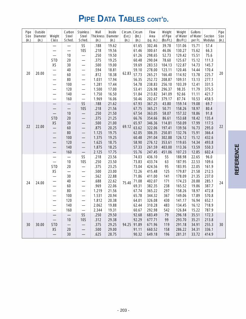
- 203 -
REF
EREN
CE
PIPE DATA TABLES CONT’D.
Pipe Outside Carbon Stainless Wall Inside Circum. Circum Flow Weight Weight Gallons PipeSize Diameter Weight Steel Steel Thickness Diameter (Ext.) (Int.) Area of Pipe of Water of Water Section Size(in.) (in.) Class Sched. Sched. (in.) (in.) (in.) (in.) (sq. in.) (lbs/Ft.) (lbs/Ft.) per Ft. Modulus (in.)
— — 5S .188 19.62 61.65 302.46 39.78 131.06 15.71 57.4— — 10S .218 19.56 61.46 300.61 46.06 130.27 15.62 66.3— 10 — .250 19.50 61.26 298.65 52.73 129.42 15.51 75.6
STD 20 — .375 19.25 60.48 290.04 78.60 125.67 15.12 111.3XS 30 — .500 19.00 59.69 283.53 104.13 122.87 14.73 145.7— 40 — .594 18.81 59.10 278.00 123.11 120.46 14.44 170.4
20 20.00 — 60 — .812 18.38 62.83 57.73 265.21 166.40 114.92 13.78 225.7 20
— 80 — 1.031 17.94 56.35 252.72 208.87 109.51 13.13 277.1— 100 — 1.281 17.44 54.78 238.83 256.10 103.39 12.41 331.5— 120 — 1.500 17.00 53.41 226.98 296.37 98.35 11.79 375.5— 140 — 1.750 16.50 51.84 213.82 341.09 92.66 11.11 421.7— 160 — 1.969 16.06 50.46 202.67 379.17 87.74 10.53 458.5— — 5S .188 21.62 67.93 367.25 43.80 159.14 19.08 69.7— — 10S .218 21.56 67.75 365.21 50.71 158.26 18.97 80.4— 10 — .250 21.50 67.54 363.05 58.07 157.32 18.86 91.8
STD 20 — .375 21.25 66.76 354.66 86.61 153.68 18.42 135.4XS 30 — .500 21.00 65.97 346.36 114.81 150.09 17.99 117.5
22 22.00 — 60 — .875 20.25 69.12 63.62 322.06 197.41 139.56 16.73 295.0 22
— 80 — 1.125 19.75 62.05 306.35 250.81 132.76 15.91 366.4— 100 — 1.375 19.25 60.48 291.04 302.88 126.12 15.12 432.6— 120 — 1.625 18.75 58.90 276.12 353.61 119.65 14.34 493.8— 140 — 1.875 18.25 57.33 261.59 403.00 113.36 13.59 550.3— 160 — 2.125 17.75 55.76 247.45 451.06 107.23 12.85 602.4— — 5S .218 23.56 74.03 436.10 55 188.98 22.65 96.0— 10 10S .250 23.50 73.83 433.74 63 187.95 22.53 109.6
STD 20 — .375 23.25 73.04 424.56 95 183.95 22.05 161.9XS — — .500 23.00 72.26 415.48 125 179.87 21.58 212.5— 30 — .562 22.88 71.86 411.00 141 178.09 21.35 237.0
24 24.00 — 40 — .688 22.62 75.40 71.08 402.07 171 174.23 20.88 285.1 24— 60 — .969 22.06 69.31 382.35 238 165.52 19.86 387.7— 80 — 1.219 21.56 67.74 365.22 297 158.26 18.97 472.8— 100 — 1.531 20.94 65.78 344.32 367 149.06 17.89 570.8— 120 — 1.812 20.38 64.01 326.08 430 141.17 16.94 652.1— 140 — 2.062 19.88 62.44 310.28 483 134.45 16.12 718.9— 160 — 2.344 19.31 60.67 292.98 542 126.84 15.22 787.9— — 5S .250 29.50 92.68 683.49 79 296.18 35.51 172.3— 10 10S .312 29.38 92.29 677.71 99 293.70 35.21 213.8
30 30.00 STD — — .375 29.25 94.25 91.89 671.96 119 291.18 34.91 255.3 30XS 20 — .500 29.00 91.11 660.52 158 286.22 34.31 336.1— 30 — .625 28.75 90.32 649.18 196 281.31 33.72 414.9
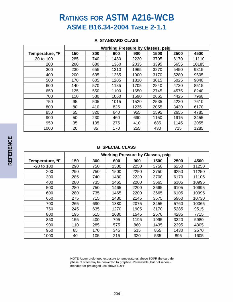
- 204 -
REF
EREN
CE
Working Pressure by Classes, psigTemperature, ºF 150 300 600 900 1500 2500 4500
-20 to 100 285 740 1480 2220 3705 6170 11110200 260 680 1360 2035 3395 5655 10185300 230 655 1310 1965 3270 5450 9815400 200 635 1265 1900 3170 5280 9505500 170 605 1205 1810 3015 5025 9040600 140 570 1135 1705 2840 4730 8515650 125 550 1100 1650 2745 4575 8240700 110 530 1060 1590 2665 4425 7960750 95 505 1015 1520 2535 4230 7610800 80 410 825 1235 2055 3430 6170850 65 320 640 955 1595 2655 4785900 50 230 460 690 1150 1915 3455950 35 135 275 410 685 1145 2055
1000 20 85 170 255 430 715 1285
RATINGS FOR ASTM A216-WCBASME B16.34-2004 TABLE 2-1.1
Working Pressure by Classes, psigTemperature, ºF 150 300 600 900 1500 2500 4500
-20 to 100 290 750 1500 2250 3750 6250 11250200 290 750 1500 2250 3750 6250 11250300 285 740 1480 2220 3700 6170 11105400 280 735 1465 2200 3665 6105 10995500 280 750 1465 2200 3665 6105 10995600 280 735 1465 2200 3665 6105 10995650 275 715 1430 2145 3575 5960 10730700 265 690 1380 2075 3455 5760 10365750 245 635 1270 1905 3170 5285 9515800 195 515 1030 1545 2570 4285 7715850 155 400 795 1195 1995 3320 5980900 110 285 575 860 1435 2395 4305950 65 170 345 515 855 1430 2570
1000 40 105 215 320 535 895 1605
B SPECIAL CLASS
A STANDARD CLASS
NOTE: Upon prolonged exposure to temperatures above 800ºF, the carbidephase of steel may be converted to graphite. Permissible, but not recom-mended for prolonged use above 800ºF.
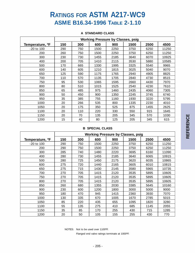
- 205 -
REF
EREN
CE
Working Pressure by Classes, psigTemperature, ºF 150 300 600 900 1500 2500 4500
-20 to 100 290 750 1500 2250 3750 6250 11250200 290 750 1500 2250 3750 6250 11250300 285 740 1480 2220 3695 6160 11090400 280 730 1455 2185 3640 6065 10915500 280 725 1450 2175 3620 6035 10865600 275 720 1440 2165 3605 6010 10815650 275 715 1430 2145 3580 5965 10735700 270 705 1415 2120 3535 5895 10605750 270 705 1415 2120 3535 5895 10605800 270 705 1415 2120 3535 5895 10605850 260 680 1355 2030 3385 5645 10160900 230 600 1200 1800 3000 5000 9000950 180 470 945 1415 2360 3930 7070
1000 130 335 670 1005 1670 2785 50151050 85 220 435 655 1095 1820 32801100 55 135 275 410 685 1145 20551150 35 85 170 255 430 715 12851200 20 50 105 155 255 430 770
Working Pressure by Classes, psigTemperature, ºF 150 300 600 900 1500 2500 4500
-20 to 100 290 750 1500 2250 3750 6250 11250200 260 750 1500 2250 3750 6250 11250300 230 730 1455 2185 3640 6070 10925400 200 705 1410 2115 3530 5880 10585500 170 665 1330 1995 3325 5540 9965600 140 605 1210 1815 3025 5040 9070650 125 590 1175 1765 2940 4905 8825700 110 570 1135 1705 2840 4730 8515750 95 530 1065 1595 2660 4430 7970800 80 510 1015 1525 2540 4230 7610850 65 485 975 1460 2435 4060 7305900 50 450 900 1350 2245 3745 6740950 35 385 755 1160 1930 3220 5795
1000 20 266 535 800 1335 2230 40101050 20 175 350 525 875 1455 26251100 20 110 220 330 550 915 16451150 20 70 135 205 345 570 10301200 15 40 80 125 205 345 615
RATINGS FOR ASTM A217-WC9ASME B16.34-1996 TABLE 2-1.10
A STANDARD CLASS
B SPECIAL CLASS
NOTES: Not to be used over 1100ºF.
Flanged end valve ratings terminate at 1000ºF.
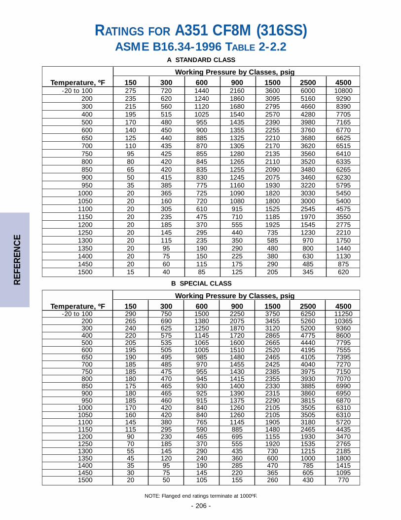
- 206 -
REF
EREN
CE
Working Pressure by Classes, psigTemperature, ºF 150 300 600 900 1500 2500 4500
-20 to 100 290 750 1500 2250 3750 6250 11250200 265 690 1380 2075 3455 5260 10365300 240 625 1250 1870 3120 5200 9360400 220 575 1145 1720 2865 4775 8600500 205 535 1065 1600 2665 4440 7795600 195 505 1005 1510 2520 4195 7555650 190 495 985 1480 2465 4105 7395700 185 485 970 1455 2425 4040 7270750 185 475 955 1430 2385 3975 7150800 180 470 945 1415 2355 3930 7070850 175 465 930 1400 2330 3885 6990900 180 465 925 1390 2315 3860 6950950 185 460 915 1375 2290 3815 6870
1000 170 420 840 1260 2105 3505 63101050 160 420 840 1260 2105 3505 63101100 145 380 765 1145 1905 3180 57201150 115 295 590 885 1480 2465 44351200 90 230 465 695 1155 1930 34701250 70 185 370 555 1920 1535 27651300 55 145 290 435 730 1215 21851350 45 120 240 360 600 1000 18001400 35 95 190 285 470 785 14151450 30 75 145 220 365 605 10951500 20 50 105 155 260 430 770
RATINGS FOR A351 CF8M (316SS)ASME B16.34-1996 TABLE 2-2.2
Working Pressure by Classes, psigTemperature, ºF 150 300 600 900 1500 2500 4500
-20 to 100 275 720 1440 2160 3600 6000 10800200 235 620 1240 1860 3095 5160 9290300 215 560 1120 1680 2795 4660 8390400 195 515 1025 1540 2570 4280 7705500 170 480 955 1435 2390 3980 7165600 140 450 900 1355 2255 3760 6770650 125 440 885 1325 2210 3680 6625700 110 435 870 1305 2170 3620 6515750 95 425 855 1280 2135 3560 6410800 80 420 845 1265 2110 3520 6335850 65 420 835 1255 2090 3480 6265900 50 415 830 1245 2075 3460 6230950 35 385 775 1160 1930 3220 5795
1000 20 365 725 1090 1820 3030 54501050 20 160 720 1080 1800 3000 54001100 20 305 610 915 1525 2545 45751150 20 235 475 710 1185 1970 35501200 20 185 370 555 1925 1545 27751250 20 145 295 440 735 1230 22101300 20 115 235 350 585 970 17501350 20 95 190 290 480 800 14401400 20 75 150 225 380 630 11301450 20 60 115 175 290 485 8751500 15 40 85 125 205 345 620
A STANDARD CLASS
B SPECIAL CLASS
NOTE: Flanged end ratings terminate at 1000ºF.
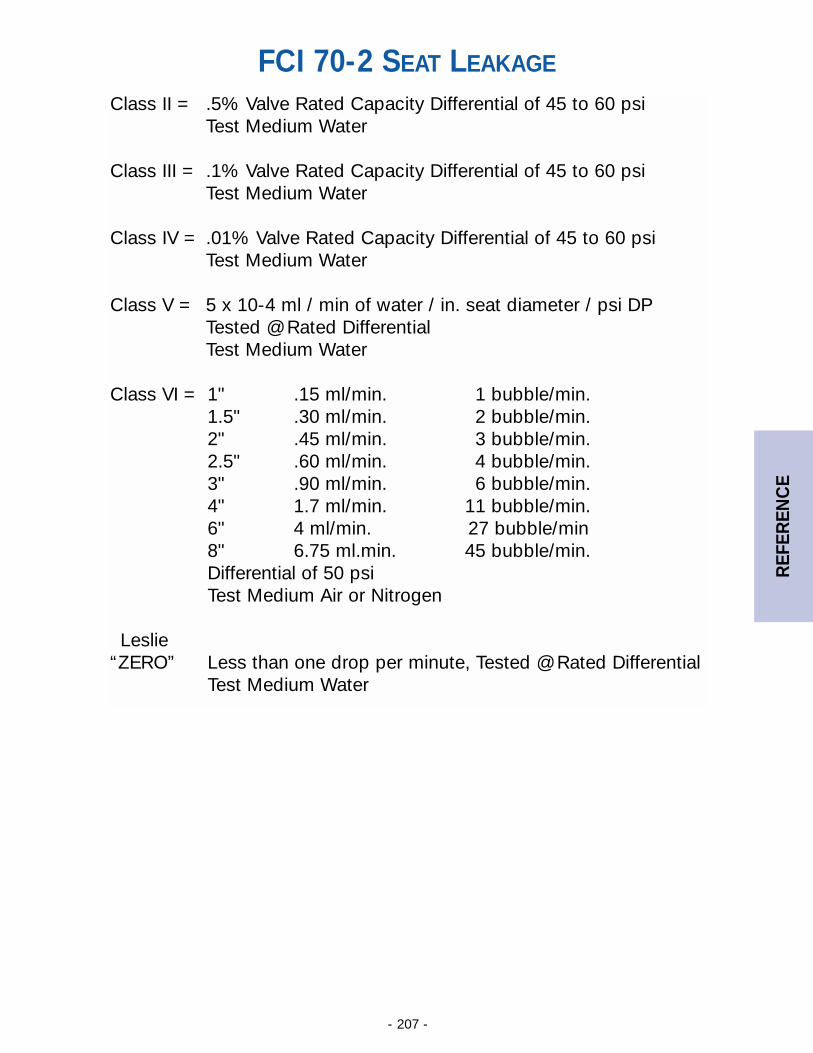
- 207 -
REF
EREN
CE
Class II = .5% Valve Rated Capacity Differential of 45 to 60 psiTest Medium Water
Class III = .1% Valve Rated Capacity Differential of 45 to 60 psiTest Medium Water
Class IV = .01% Valve Rated Capacity Differential of 45 to 60 psiTest Medium Water
Class V = 5 x 10⁻⁴ ml / min of water / in. seat diameter / psi DPTested @ Rated DifferentialTest Medium Water
Class VI = 1" .15 ml/min. 1 bubble/min.1.5" .30 ml/min. 2 bubble/min.2" .45 ml/min. 3 bubble/min.2.5" .60 ml/min. 4 bubble/min.3" .90 ml/min. 6 bubble/min.4" 1.7 ml/min. 11 bubble/min.6" 4 ml/min. 27 bubble/min8" 6.75 ml.min. 45 bubble/min.Differential of 50 psiTest Medium Air or Nitrogen
Leslie “ZERO” Less than one drop per minute, Tested @ Rated Differential
Test Medium Water
FCI 70-2 SEAT LEAKAGE
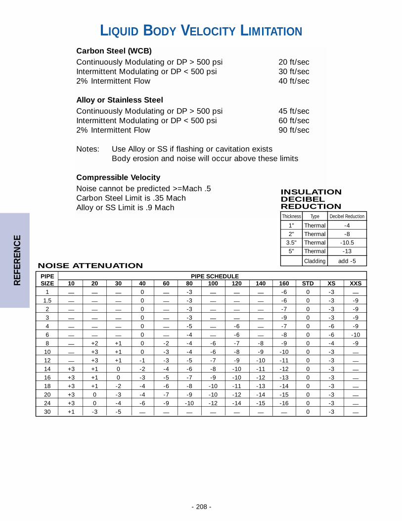
- 208 -
REF
EREN
CE
Carbon Steel (WCB)Continuously Modulating or DP > 500 psi 20 ft/secIntermittent Modulating or DP < 500 psi 30 ft/sec2% Intermittent Flow 40 ft/sec
Alloy or Stainless SteelContinuously Modulating or DP > 500 psi 45 ft/secIntermittent Modulating or DP < 500 psi 60 ft/sec2% Intermittent Flow 90 ft/sec
Notes: Use Alloy or SS if flashing or cavitation existsBody erosion and noise will occur above these limits
Compressible VelocityNoise cannot be predicted >=Mach .5Carbon Steel Limit is .35 MachAlloy or SS Limit is .9 Mach
NOISE ATTENUATION
INSULATION DECIBELREDUCTION
PIPE PIPE SCHEDULESIZE 10 20 30 40 60 80 100 120 140 160 STD XS XXS
1 — — — 0 — -3 — — — -6 0 -3 —1.5 — — — 0 — -3 — — — -6 0 -3 -92 — — — 0 — -3 — — — -7 0 -3 -93 — — — 0 — -3 — — — -9 0 -3 -94 — — — 0 — -5 — -6 — -7 0 -6 -96 — — — 0 — -4 — -6 — -8 0 -6 -108 — +2 +1 0 -2 -4 -6 -7 -8 -9 0 -4 -910 — +3 +1 0 -3 -4 -6 -8 -9 -10 0 -3 —12 — +3 +1 -1 -3 -5 -7 -9 -10 -11 0 -3 —14 +3 +1 0 -2 -4 -6 -8 -10 -11 -12 0 -3 —16 +3 +1 0 -3 -5 -7 -9 -10 -12 -13 0 -3 —18 +3 +1 -2 -4 -6 -8 -10 -11 -13 -14 0 -3 —20 +3 0 -3 -4 -7 -9 -10 -12 -14 -15 0 -3 —24 +3 0 -4 -6 -9 -10 -12 -14 -15 -16 0 -3 —30 +1 -3 -5 — — — — — — — 0 -3 —
Thickness Type Decibel Reduction
1" Thermal -42" Thermal -8
3.5" Thermal -10.55" Thermal -13
Cladding add -5
LIQUID BODY VELOCITY LIMITATION
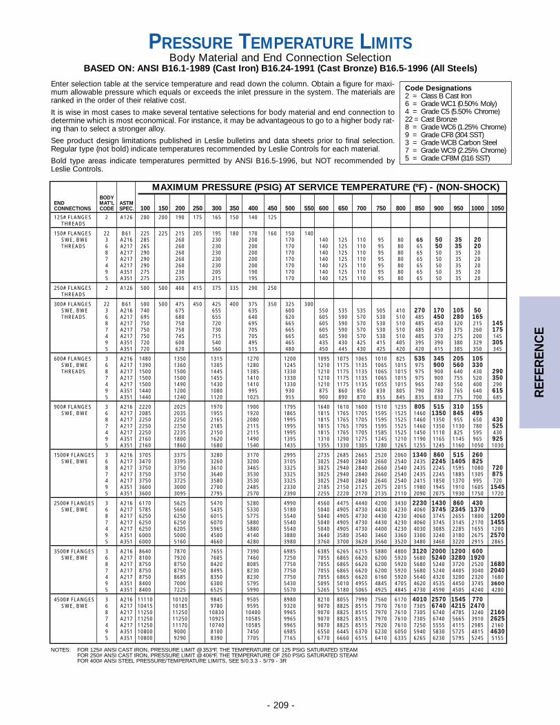
- 209 -
MAXIMUM PRESSURE (PSIG) AT SERVICE TEMPERATURE (ºF) - (NON-SHOCK)BODY
END MAT’L ASTMCONNECTIONS CODE SPEC. 100 150 200 250 300 350 400 450 500 550 600 650 700 750 800 850 900 950 1000 1050125# FLANGES 2 A126 200 200 190 175 165 150 140 125
THREADS
150# FLANGES 22 B61 225 225 215 205 195 180 170 160 150 140SWE, BWE 3 A216 285 260 230 200 170 140 125 110 95 80 65 50 35 20THREADS 6 A217 265 260 230 200 170 140 125 110 95 80 65 50 35 20
8 A217 290 260 230 200 170 140 125 110 95 80 65 50 35 207 A217 290 260 230 200 170 140 125 110 95 80 65 50 35 204 A217 290 260 230 200 170 140 125 110 95 80 65 50 35 209 A351 275 230 205 190 170 140 125 110 95 80 65 50 35 205 A351 275 235 215 195 170 140 125 110 95 80 65 50 35 20
250# FLANGES 2 A126 500 500 460 415 375 335 290 250THREADS
300# FLANGES 22 B61 500 500 475 450 425 400 375 350 325 300SWE, BWE 3 A216 740 675 655 635 600 550 535 535 505 410 270 170 105 50THREADS 6 A217 695 680 655 640 620 605 590 570 530 510 485 450 280 165
8 A217 750 750 720 695 665 605 590 570 530 510 485 450 320 215 1457 A217 750 750 730 705 665 605 590 570 530 510 485 450 375 260 1754 A217 750 745 715 705 665 605 590 570 530 510 485 370 275 200 1459 A351 720 600 540 495 465 435 430 425 415 405 395 390 380 329 3055 A351 720 620 560 515 480 450 445 430 425 420 420 415 385 350 345
600# FLANGES 3 A216 1480 1350 1315 1270 1200 1095 1075 1065 1010 825 535 345 205 105SWE, BWE 6 A217 1390 1360 1305 1280 1245 1210 1175 1135 1065 1015 975 900 560 330THREADS 8 A217 1500 1500 1445 1385 1330 1210 1175 1135 1065 1015 975 900 640 430 290
7 A217 1500 1500 1455 1410 1330 1210 1175 1135 1065 1015 975 900 755 520 3504 A217 1500 1490 1430 1410 1330 1210 1175 1135 1055 1015 965 740 550 400 2909 A351 1440 1200 1080 995 930 875 860 850 830 805 790 780 765 640 6155 A351 1440 1240 1120 1025 955 900 890 870 855 845 835 830 775 700 685
900# FLANGES 3 A216 2220 2025 1970 1900 1795 1640 1610 1600 1510 1235 805 515 310 155SWE, BWE 6 A217 2085 2035 1955 1920 1865 1815 1765 1705 1595 1525 1460 1350 845 495
8 A217 2250 2250 2165 2080 1995 1815 1765 1705 1595 1525 1460 1350 955 650 4307 A217 2250 2250 2185 2115 1995 1815 1765 1705 1595 1525 1460 1350 1130 780 5254 A217 2250 2235 2150 2115 1995 1815 1765 1705 1585 1525 1450 1110 825 595 4309 A351 2160 1800 1620 1490 1395 1310 1290 1275 1245 1210 1190 1165 1145 965 9255 A351 2160 1860 1680 1540 1435 1355 1330 1305 1280 1265 1255 1245 1160 1050 1030
1500# FLANGES 3 A216 3705 3375 3280 3170 2995 2735 2685 2665 2520 2060 1340 860 515 260SWE, BWE 6 A217 3470 3395 3260 3200 3105 3025 2940 2840 2660 2540 2435 2245 1405 825
8 A217 3750 3750 3610 3465 3325 3025 2940 2840 2660 2540 2435 2245 1595 1080 7207 A217 3750 3750 3640 3530 3325 3025 2940 2840 2660 2540 2435 2245 1885 1305 8754 A217 3750 3725 3580 3530 3325 3025 2940 2840 2640 2540 2415 1850 1370 995 7209 A351 3600 3000 2700 2485 2330 2185 2150 2125 2075 2015 1980 1945 1910 1605 15455 A351 3600 3095 2795 2570 2390 2255 2220 2170 2135 2110 2090 2075 1930 1750 1720
2500# FLANGES 3 A216 6170 5625 5470 5280 4990 4560 4475 4440 4200 3430 2230 1430 860 430SWE, BWE 6 A217 5785 5660 5435 5330 5180 5040 4905 4730 4430 4230 4060 3745 2345 1370
8 A217 6250 6250 6015 5775 5540 5040 4905 4730 4430 4230 4060 3745 2655 1800 12007 A217 6250 6250 6070 5880 5540 5040 4905 4730 4430 4230 4060 3745 3145 2170 14554 A217 6250 6205 5965 5880 5540 5040 4905 4730 4400 4230 4030 3085 2285 1655 12009 A351 6000 5000 4500 4140 3880 3640 3580 3540 3460 3360 3300 3240 3180 2675 25705 A351 6000 5160 4660 4280 3980 3760 3700 3620 3560 3520 3480 3460 3220 2915 2865
3500# FLANGES 3 A216 8640 7870 7655 7390 6985 6385 6265 6215 5880 4800 3120 2000 1200 600SWE, BWE 6 A217 8100 7920 7605 7460 7250 7055 6865 6620 6200 5920 5680 5240 3280 1920
8 A217 8750 8750 8420 8085 7750 7055 6865 6620 6200 5920 5680 5240 3720 2520 16807 A217 8750 8750 8495 8230 7750 7055 6865 6620 6200 5920 5680 5240 4405 3040 20404 A217 8750 8685 8350 8230 7750 7055 6865 6620 6160 5920 5640 4320 3200 2320 16809 A351 8400 7000 6300 5795 5430 5095 5010 4955 4845 4705 4620 4535 4450 3745 36005 A351 8400 7225 6525 5990 5570 5265 5180 5065 4925 4845 4730 4590 4505 4240 4200
4500# FLANGES 3 A216 11110 10120 9845 9505 8980 8210 8055 7990 7560 6170 4010 2570 1545 770SWE, BWE 6 A217 10415 10185 9780 9595 9320 9070 8825 8515 7970 7610 7305 6740 4215 2470
8 A217 11250 11250 10830 10400 9965 9070 8825 8515 7970 7610 7305 6740 4785 3240 21607 A217 11250 11250 10925 10585 9965 9070 8825 8515 7970 7610 7305 6740 5665 3910 26254 A217 11250 11170 10740 10585 9965 9070 8825 8515 7920 7610 7250 5555 4115 2985 21609 A351 10800 9000 8100 7450 6985 6550 6445 6370 6230 6050 5940 5830 5725 4815 46305 A351 10800 9290 8390 7705 7165 6770 6660 6515 6410 6335 6265 6230 5795 5245 5155
Body Material and End Connection SelectionBASED ON: ANSI B16.1-1989 (Cast Iron) B16.24-1991 (Cast Bronze) B16.5-1996 (All Steels)
Enter selection table at the service temperature and read down the column. Obtain a figure for maxi-mum allowable pressure which equals or exceeds the inlet pressure in the system. The materials areranked in the order of their relative cost.
It is wise in most cases to make several tentative selections for body material and end connection todetermine which is most economical. For instance, it may be advantageous to go to a higher body rat-ing than to select a stronger alloy.
See product design limitations published in Leslie bulletins and data sheets prior to final selection.Regular type (not bold) indicate temperatures recommended by Leslie Controls for each material.
Bold type areas indicate temperatures permitted by ANSI B16.5-1996, but NOT recommended byLeslie Controls.
Code Designations2 = Class B Cast Iron6 = Grade WC1 (0.50% Moly)4 = Grade C5 (5.50% Chrome)22 = Cast Bronze8 = Grade WC6 (1.25% Chrome)9 = Grade CF8 (304 SST)3 = Grade WCB Carbon Steel7 = Grade WC9 (2.25% Chrome)5 = Grade CF8M (316 SST)
NOTES: FOR 125# ANSI CAST IRON, PRESSURE LIMIT @ 353*F, THE TEMPERATURE OF 125 PSIG SATURATED STEAMFOR 250# ANSI CAST IRON, PRESSURE LIMIT @ 406*F, THE TEMPERATURE OF 250 PSIG SATURATED STEAMFOR 400# ANSI STEEL PRESSURE/TEMPERATURE LIMITS, SEE 5/0.3.3 - 5/79 - 3R
PRESSURE TEMPERATURE LIMITS
REF
EREN
CE
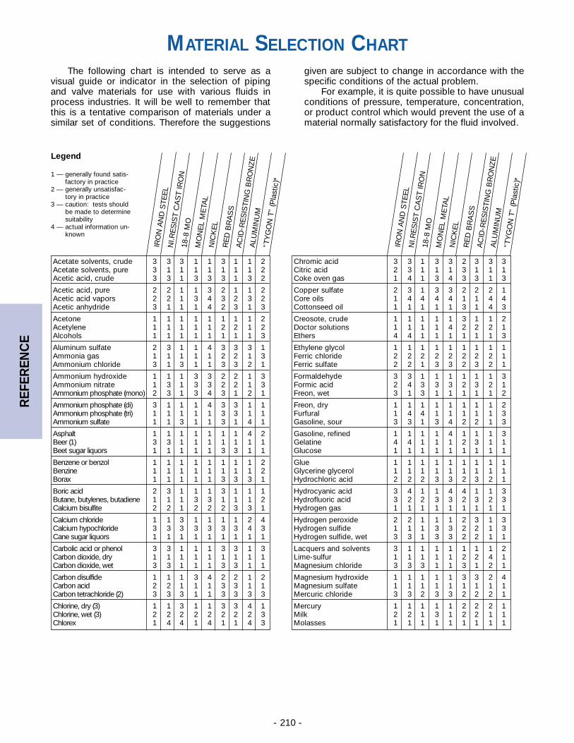
- 210 -
REF
EREN
CE
IRO
N A
ND
STE
EL
Acetate solvents, crude 3 3 3 1 1 3 1 1 2Acetate solvents, pure 3 1 1 1 1 1 1 1 2Acetic acid, crude 3 3 1 3 3 3 1 3 2
Acetic acid, pure 2 2 1 1 3 2 1 1 2Acetic acid vapors 2 2 1 3 4 3 2 3 2Acetic anhydride 3 1 1 1 4 2 3 1 3
Acetone 1 1 1 1 1 1 1 1 2Acetylene 1 1 1 1 1 2 2 1 2Alcohols 1 1 1 1 1 1 1 1 3
Aluminum sulfate 2 3 1 1 4 3 3 3 1Ammonia gas 1 1 1 1 1 2 2 1 3Ammonium chloride 3 1 3 1 1 3 3 2 1
Ammonium hydroxide 1 1 1 3 3 2 2 1 3Ammonium nitrate 1 3 1 3 3 2 2 1 3Ammonium phosphate (mono) 2 3 1 3 4 3 1 2 1
Ammonium phosphate (di) 3 1 1 1 4 3 3 1 1Ammonium phosphate (tri) 1 1 1 1 1 3 3 1 1Ammonium sulfate 1 1 3 1 1 3 1 4 1
Asphalt 1 1 1 1 1 1 1 4 2Beer (1) 3 3 1 1 1 1 1 1 1Beet sugar liquors 1 1 1 1 1 3 3 1 1
Benzene or benzol 1 1 1 1 1 1 1 1 2Benzine 1 1 1 1 1 1 1 1 2Borax 1 1 1 1 1 3 3 3 1
Boric acid 2 3 1 1 1 3 1 1 1Butane, butylenes, butadiene 1 1 1 3 3 1 1 1 2Calcium bisulfite 2 2 1 2 2 2 3 3 1
Calcium chloride 1 1 3 1 1 1 1 2 4Calcium hypochloride 3 3 3 3 3 3 3 4 3Cane sugar liquors 1 1 1 1 1 1 1 1 1
Carbolic acid or phenol 3 3 1 1 1 3 3 1 3Carbon dioxide, dry 1 1 1 1 1 1 1 1 1Carbon dioxide, wet 3 3 1 1 1 3 3 1 1
Carbon disulfide 1 1 1 3 4 2 2 1 2Carbon acid 2 2 1 1 1 3 3 1 1Carbon tetrachloride (2) 3 3 3 1 1 3 3 3 3
Chlorine, dry (3) 1 1 3 1 1 3 3 4 1Chlorine, wet (3) 2 2 2 2 2 2 2 2 3Chlorex 1 4 4 1 4 1 1 4 3
NI.R
ES
IST
CA
ST
IRO
N18
-8 M
OM
ON
EL
ME
TAL
RE
D B
RA
SS
NIC
KE
L
AC
ID-R
ES
ISTI
NG
BR
ON
ZE
ALU
MIN
UM
“TY
GO
N T
” (P
last
ic)*
IRO
N A
ND
STE
EL
Chromic acid 3 3 1 3 3 2 3 3 3Citric acid 2 3 1 1 1 3 1 1 1Coke oven gas 1 4 1 3 4 3 3 1 3
Copper sulfate 2 3 1 3 3 2 2 2 1Core oils 1 4 4 4 4 1 1 4 4Cottonseed oil 1 1 1 1 1 3 1 4 3
Creosote, crude 1 1 1 1 1 3 1 1 2Doctor solutions 1 1 1 1 4 2 2 2 1Ethers 4 4 1 1 1 1 1 1 3
Ethylene glycol 1 1 1 1 1 1 1 1 1Ferric chloride 2 2 2 2 2 2 2 2 1Ferric sulfate 2 2 1 3 3 2 3 2 1
Formaldehyde 3 3 1 1 1 1 1 1 3Formic acid 2 4 3 3 3 2 3 2 1Freon, wet 3 1 3 1 1 1 1 1 2
Freon, dry 1 1 1 1 1 1 1 1 2Furfural 1 4 4 1 1 1 1 1 3Gasoline, sour 3 3 1 3 4 2 2 1 3
Gasoline, refined 1 1 1 1 4 1 1 1 3Gelatine 4 4 1 1 1 2 3 1 1Glucose 1 1 1 1 1 1 1 1 1
Glue 1 1 1 1 1 1 1 1 1Glycerine glycerol 1 1 1 1 1 1 1 1 1Hydrochloric acid 2 2 2 3 3 2 3 2 1
Hydrocyanic acid 3 4 1 1 4 4 1 1 3Hydrofluoric acid 3 2 2 3 3 2 3 2 3Hydrogen gas 1 1 1 1 1 1 1 1 1
Hydrogen peroxide 2 2 1 1 1 2 3 1 3Hydrogen sulfide 1 1 1 3 3 2 2 1 3Hydrogen sulfide, wet 3 3 1 3 3 2 2 1 1
Lacquers and solvents 3 1 1 1 1 1 1 1 2Lime-sulfur 1 1 1 1 1 2 2 4 1Magnesium chloride 3 3 3 1 1 3 1 2 1
Magnesium hydroxide 1 1 1 1 1 3 3 2 4Magnesium sulfate 1 1 1 1 1 1 1 1 1Mercuric chloride 3 3 2 3 3 2 2 2 1
Mercury 1 1 1 1 1 2 2 2 1Milk 2 2 1 3 1 2 2 1 1Molasses 1 1 1 1 1 1 1 1 1
NI.R
ES
IST
CA
ST
IRO
N18
-8 M
OM
ON
EL
ME
TAL
RE
D B
RA
SS
NIC
KE
L
AC
ID-R
ES
ISTI
NG
BR
ON
ZE
ALU
MIN
UM
“TY
GO
N T
” (P
last
ic)*
Legend
1 — generally found satis-factory in practice
2 — generally unsatisfac-tory in practice
3 — caution: tests should be made to determinesuitability
4 — actual information un-known
MATERIAL SELECTION CHARTThe following chart is intended to serve as a
visual guide or indicator in the selection of pipingand valve materials for use with various fluids inprocess industries. It will be well to remember thatthis is a tentative comparison of materials under asimilar set of conditions. Therefore the suggestions
given are subject to change in accordance with thespecific conditions of the actual problem.
For example, it is quite possible to have unusualconditions of pressure, temperature, concentration,or product control which would prevent the use of amaterial normally satisfactory for the fluid involved.
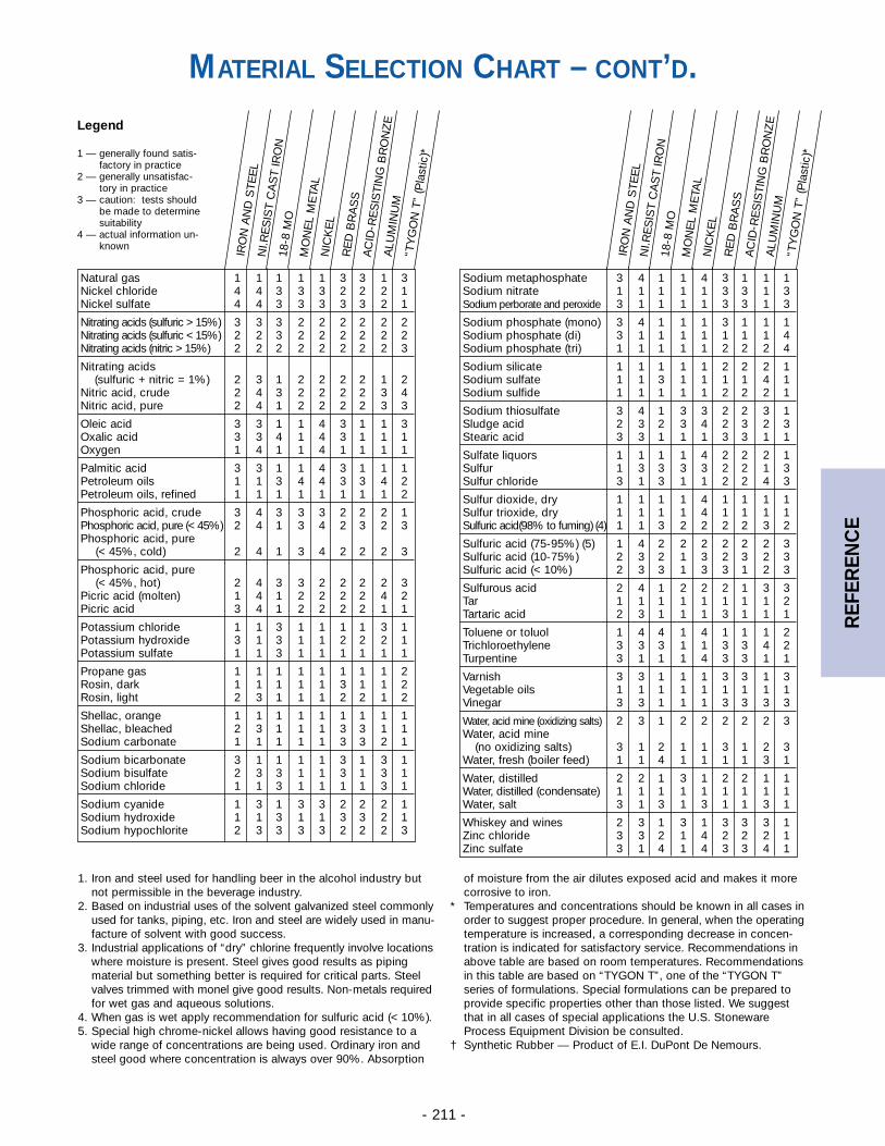
- 211 -
REF
EREN
CE
Legend
1 — generally found satis-factory in practice
2 — generally unsatisfac-tory in practice
3 — caution: tests should be made to determinesuitability
4 — actual information un-known
IRO
N A
ND
STE
EL
Natural gas 1 1 1 1 1 3 3 1 3Nickel chloride 4 4 3 3 3 2 2 2 1Nickel sulfate 4 4 3 3 3 3 3 2 1
Nitrating acids (sulfuric > 15%) 3 3 3 2 2 2 2 2 2Nitrating acids (sulfuric < 15%) 2 2 3 2 2 2 2 2 2Nitrating acids (nitric > 15%) 2 2 2 2 2 2 2 2 3
Nitrating acids(sulfuric + nitric = 1%) 2 3 1 2 2 2 2 1 2
Nitric acid, crude 2 4 3 2 2 2 2 3 4Nitric acid, pure 2 4 1 2 2 2 2 3 3
Oleic acid 3 3 1 1 4 3 1 1 3Oxalic acid 3 3 4 1 4 3 1 1 1Oxygen 1 4 1 1 4 1 1 1 1
Palmitic acid 3 3 1 1 4 3 1 1 1Petroleum oils 1 1 3 4 4 3 3 4 2Petroleum oils, refined 1 1 1 1 1 1 1 1 2
Phosphoric acid, crude 3 4 3 3 3 2 2 2 1Phosphoric acid, pure (< 45%) 2 4 1 3 4 2 3 2 3Phosphoric acid, pure
(< 45%, cold) 2 4 1 3 4 2 2 2 3
Phosphoric acid, pure(< 45%, hot) 2 4 3 3 2 2 2 2 3
Picric acid (molten) 1 4 1 2 2 2 2 4 2Picric acid 3 4 1 2 2 2 2 1 1
Potassium chloride 1 1 3 1 1 1 1 3 1Potassium hydroxide 3 1 3 1 1 2 2 2 1Potassium sulfate 1 1 3 1 1 1 1 1 1
Propane gas 1 1 1 1 1 1 1 1 2Rosin, dark 1 1 1 1 1 3 1 1 2Rosin, light 2 3 1 1 1 2 2 1 2
Shellac, orange 1 1 1 1 1 1 1 1 1Shellac, bleached 2 3 1 1 1 3 3 1 1Sodium carbonate 1 1 1 1 1 3 3 2 1
Sodium bicarbonate 3 1 1 1 1 3 1 3 1Sodium bisulfate 2 3 3 1 1 3 1 3 1Sodium chloride 1 1 3 1 1 1 1 3 1
Sodium cyanide 1 3 1 3 3 2 2 2 1Sodium hydroxide 1 1 3 1 1 3 3 2 1Sodium hypochlorite 2 3 3 3 3 2 2 2 3
NI.R
ES
IST
CA
ST
IRO
N18
-8 M
OM
ON
EL
ME
TAL
RE
D B
RA
SS
NIC
KE
L
AC
ID-R
ES
ISTI
NG
BR
ON
ZE
ALU
MIN
UM
“TY
GO
N T
” (P
last
ic)*
IRO
N A
ND
STE
EL
Sodium metaphosphate 3 4 1 1 4 3 1 1 1Sodium nitrate 1 1 1 1 1 3 3 1 3Sodium perborate and peroxide 3 1 1 1 1 3 3 1 3
Sodium phosphate (mono) 3 4 1 1 1 3 1 1 1Sodium phosphate (di) 3 1 1 1 1 1 1 1 4Sodium phosphate (tri) 1 1 1 1 1 2 2 2 4
Sodium silicate 1 1 1 1 1 2 2 2 1Sodium sulfate 1 1 3 1 1 1 1 4 1Sodium sulfide 1 1 1 1 1 2 2 2 1
Sodium thiosulfate 3 4 1 3 3 2 2 3 1Sludge acid 2 3 2 3 4 2 3 2 3Stearic acid 3 3 1 1 1 3 3 1 1
Sulfate liquors 1 1 1 1 4 2 2 2 1Sulfur 1 3 3 3 3 2 2 1 3Sulfur chloride 3 1 3 1 1 2 2 4 3
Sulfur dioxide, dry 1 1 1 1 4 1 1 1 1Sulfur trioxide, dry 1 1 1 1 4 1 1 1 1Sulfuric acid(98% to fuming) (4) 1 1 3 2 2 2 2 3 2
Sulfuric acid (75-95%) (5) 1 4 2 2 2 2 2 2 3Sulfuric acid (10-75%) 2 3 2 1 3 2 3 2 3Sulfuric acid (< 10%) 2 3 3 1 3 3 1 2 3
Sulfurous acid 2 4 1 2 2 2 1 3 3Tar 1 1 1 1 1 1 1 1 2Tartaric acid 2 3 1 1 1 3 1 1 1
Toluene or toluol 1 4 4 1 4 1 1 1 2Trichloroethylene 3 3 3 1 1 3 3 4 2Turpentine 3 1 1 1 4 3 3 1 1
Varnish 3 3 1 1 1 3 3 1 3Vegetable oils 1 1 1 1 1 1 1 1 1Vinegar 3 3 1 1 1 3 3 3 3
Water, acid mine (oxidizing salts) 2 3 1 2 2 2 2 2 3Water, acid mine
(no oxidizing salts) 3 1 2 1 1 3 1 2 3Water, fresh (boiler feed) 1 1 4 1 1 1 1 3 1
Water, distilled 2 2 1 3 1 2 2 1 1Water, distilled (condensate) 1 1 1 1 1 1 1 1 1Water, salt 3 1 3 1 3 1 1 3 1
Whiskey and wines 2 3 1 3 1 3 3 3 1Zinc chloride 3 3 2 1 4 2 2 2 1Zinc sulfate 3 1 4 1 4 3 3 4 1
NI.R
ES
IST
CA
ST
IRO
N18
-8 M
OM
ON
EL
ME
TAL
RE
D B
RA
SS
NIC
KE
L
AC
ID-R
ES
ISTI
NG
BR
ON
ZE
ALU
MIN
UM
“TY
GO
N T
” (P
last
ic)*
MATERIAL SELECTION CHART – CONT’D.
1. Iron and steel used for handling beer in the alcohol industry butnot permissible in the beverage industry.
2. Based on industrial uses of the solvent galvanized steel commonlyused for tanks, piping, etc. Iron and steel are widely used in manu-facture of solvent with good success.
3. Industrial applications of “dry” chlorine frequently involve locationswhere moisture is present. Steel gives good results as pipingmaterial but something better is required for critical parts. Steelvalves trimmed with monel give good results. Non-metals requiredfor wet gas and aqueous solutions.
4. When gas is wet apply recommendation for sulfuric acid (< 10%).5. Special high chrome-nickel allows having good resistance to a
wide range of concentrations are being used. Ordinary iron and steel good where concentration is always over 90%. Absorption
of moisture from the air dilutes exposed acid and makes it more corrosive to iron.
* Temperatures and concentrations should be known in all cases inorder to suggest proper procedure. In general, when the operatingtemperature is increased, a corresponding decrease in concen-tration is indicated for satisfactory service. Recommendations inabove table are based on room temperatures. Recommendationsin this table are based on “TYGON T”, one of the “TYGON T”series of formulations. Special formulations can be prepared toprovide specific properties other than those listed. We suggestthat in all cases of special applications the U.S. StonewareProcess Equipment Division be consulted.
† Synthetic Rubber — Product of E.I. DuPont De Nemours.
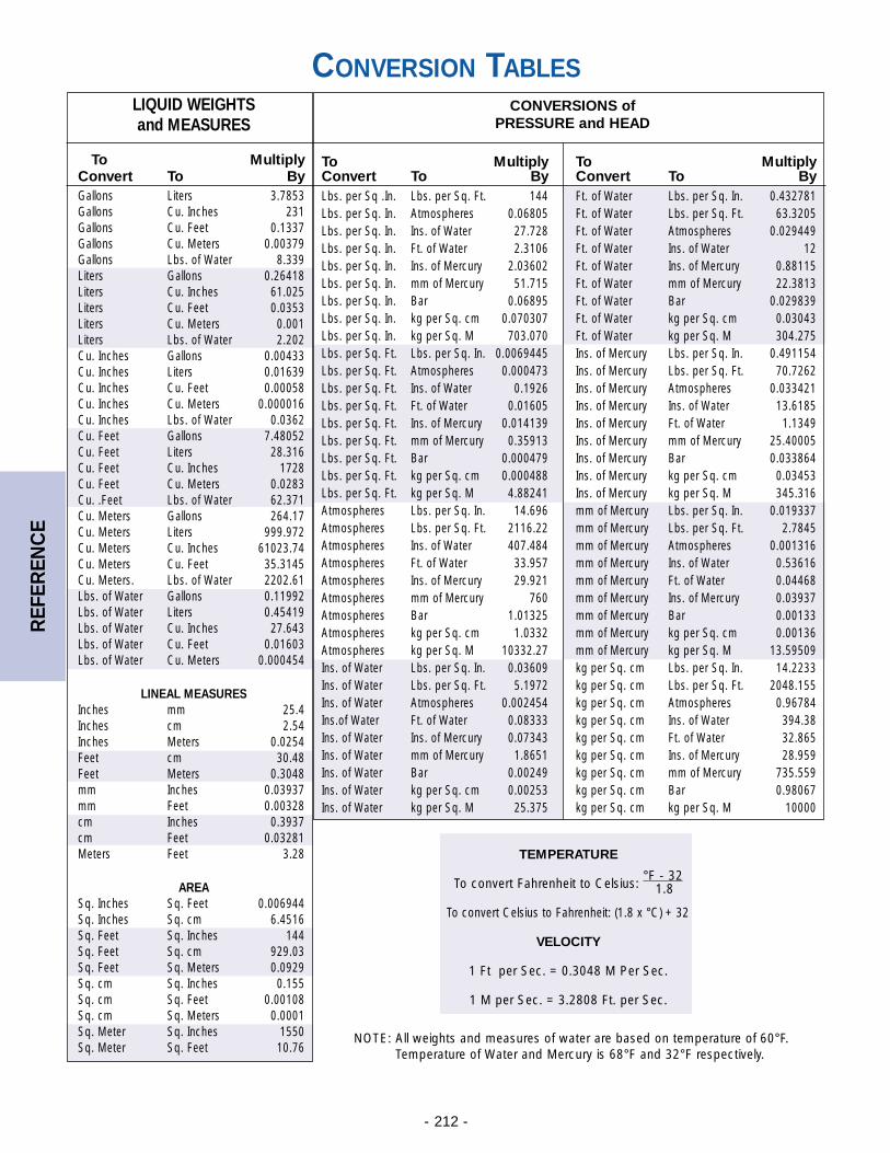
- 212 -
REF
EREN
CE
TEMPERATURE
To convert Fahrenheit to Celsius: °F - 32
1.8
To convert Celsius to Fahrenheit: (1.8 x °C) + 32
VELOCITY
1 Ft per Sec. = 0.3048 M Per Sec.
1 M per Sec. = 3.2808 Ft. per Sec.
CONVERSION TABLESLIQUID WEIGHTS and MEASURES
To MultiplyConvert To ByGallons Liters 3.7853Gallons Cu. Inches 231Gallons Cu. Feet 0.1337Gallons Cu. Meters 0.00379Gallons Lbs. of Water 8.339Liters Gallons 0.26418Liters Cu. Inches 61.025Liters Cu. Feet 0.0353Liters Cu. Meters 0.001Liters Lbs. of Water 2.202Cu. Inches Gallons 0.00433Cu. Inches Liters 0.01639Cu. Inches Cu. Feet 0.00058Cu. Inches Cu. Meters 0.000016Cu. Inches Lbs. of Water 0.0362Cu. Feet Gallons 7.48052Cu. Feet Liters 28.316Cu. Feet Cu. Inches 1728Cu. Feet Cu. Meters 0.0283Cu. .Feet Lbs. of Water 62.371Cu. Meters Gallons 264.17Cu. Meters Liters 999.972Cu. Meters Cu. Inches 61023.74Cu. Meters Cu. Feet 35.3145Cu. Meters. Lbs. of Water 2202.61Lbs. of Water Gallons 0.11992Lbs. of Water Liters 0.45419Lbs. of Water Cu. Inches 27.643Lbs. of Water Cu. Feet 0.01603Lbs. of Water Cu. Meters 0.000454
LINEAL MEASURESInches mm 25.4Inches cm 2.54Inches Meters 0.0254Feet cm 30.48Feet Meters 0.3048mm Inches 0.03937mm Feet 0.00328cm Inches 0.3937cm Feet 0.03281Meters Feet 3.28
AREASq. Inches Sq. Feet 0.006944Sq. Inches Sq. cm 6.4516Sq. Feet Sq. Inches 144Sq. Feet Sq. cm 929.03Sq. Feet Sq. Meters 0.0929Sq. cm Sq. Inches 0.155Sq. cm Sq. Feet 0.00108Sq. cm Sq. Meters 0.0001Sq. Meter Sq. Inches 1550Sq. Meter Sq. Feet 10.76
CONVERSIONS of PRESSURE and HEAD
To Multiply To MultiplyConvert To By Convert To ByLbs. per Sq .In. Lbs. per Sq. Ft. 144 Ft. of Water Lbs. per Sq. In. 0.432781Lbs. per Sq. In. Atmospheres 0.06805 Ft. of Water Lbs. per Sq. Ft. 63.3205Lbs. per Sq. In. Ins. of Water 27.728 Ft. of Water Atmospheres 0.029449Lbs. per Sq. In. Ft. of Water 2.3106 Ft. of Water Ins. of Water 12Lbs. per Sq. In. Ins. of Mercury 2.03602 Ft. of Water Ins. of Mercury 0.88115Lbs. per Sq. In. mm of Mercury 51.715 Ft. of Water mm of Mercury 22.3813Lbs. per Sq. In. Bar 0.06895 Ft. of Water Bar 0.029839Lbs. per Sq. In. kg per Sq. cm 0.070307 Ft. of Water kg per Sq. cm 0.03043Lbs. per Sq. In. kg per Sq. M 703.070 Ft. of Water kg per Sq. M 304.275Lbs. per Sq. Ft. Lbs. per Sq. In. 0.0069445 Ins. of Mercury Lbs. per Sq. In. 0.491154Lbs. per Sq. Ft. Atmospheres 0.000473 Ins. of Mercury Lbs. per Sq. Ft. 70.7262Lbs. per Sq. Ft. Ins. of Water 0.1926 Ins. of Mercury Atmospheres 0.033421Lbs. per Sq. Ft. Ft. of Water 0.01605 Ins. of Mercury Ins. of Water 13.6185Lbs. per Sq. Ft. Ins. of Mercury 0.014139 Ins. of Mercury Ft. of Water 1.1349Lbs. per Sq. Ft. mm of Mercury 0.35913 Ins. of Mercury mm of Mercury 25.40005Lbs. per Sq. Ft. Bar 0.000479 Ins. of Mercury Bar 0.033864Lbs. per Sq. Ft. kg per Sq. cm 0.000488 Ins. of Mercury kg per Sq. cm 0.03453Lbs. per Sq. Ft. kg per Sq. M 4.88241 Ins. of Mercury kg per Sq. M 345.316Atmospheres Lbs. per Sq. In. 14.696 mm of Mercury Lbs. per Sq. In. 0.019337Atmospheres Lbs. per Sq. Ft. 2116.22 mm of Mercury Lbs. per Sq. Ft. 2.7845Atmospheres Ins. of Water 407.484 mm of Mercury Atmospheres 0.001316Atmospheres Ft. of Water 33.957 mm of Mercury Ins. of Water 0.53616Atmospheres Ins. of Mercury 29.921 mm of Mercury Ft. of Water 0.04468Atmospheres mm of Mercury 760 mm of Mercury Ins. of Mercury 0.03937Atmospheres Bar 1.01325 mm of Mercury Bar 0.00133Atmospheres kg per Sq. cm 1.0332 mm of Mercury kg per Sq. cm 0.00136Atmospheres kg per Sq. M 10332.27 mm of Mercury kg per Sq. M 13.59509Ins. of Water Lbs. per Sq. In. 0.03609 kg per Sq. cm Lbs. per Sq. In. 14.2233Ins. of Water Lbs. per Sq. Ft. 5.1972 kg per Sq. cm Lbs. per Sq. Ft. 2048.155Ins. of Water Atmospheres 0.002454 kg per Sq. cm Atmospheres 0.96784Ins.of Water Ft. of Water 0.08333 kg per Sq. cm Ins. of Water 394.38Ins. of Water Ins. of Mercury 0.07343 kg per Sq. cm Ft. of Water 32.865Ins. of Water mm of Mercury 1.8651 kg per Sq. cm Ins. of Mercury 28.959Ins. of Water Bar 0.00249 kg per Sq. cm mm of Mercury 735.559Ins. of Water kg per Sq. cm 0.00253 kg per Sq. cm Bar 0.98067Ins. of Water kg per Sq. M 25.375 kg per Sq. cm kg per Sq. M 10000
NOTE: All weights and measures of water are based on temperature of 60°F.Temperature of Water and Mercury is 68°F and 32°F respectively.

- 213 -
REF
EREN
CE
NOTES:
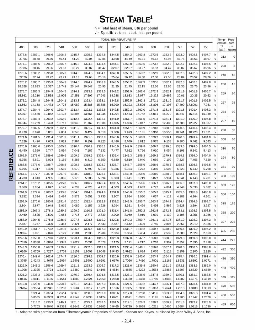
- 214 -
REF
EREN
CE
1. Adapted with permission from “Thermodynamic Properties of Steam”, Keenan and Keyes, published by John Wiley & Sons, Inc.
TOTAL TEMPERATURE, °F Temp- Pres-erature sure
480 500 520 540 560 580 600 620 640 660 680 700 720 740 750 °F psi(sat.) (gage)
1277.6 1287.1 1296.6 1306.2 1315.7 1325.3 1334.8 1344.5 1354.2 1363.8 1373.5 1383.2 1393.0 1402.8 1407.7 h37.96 38.78 39.60 40.41 41.23 42.04 42.86 43.68 44.49 45.31 46.12 46.94 47.75 48.56 48.97 v
212 0
1277.1 1286.6 1296.2 1305.7 1315.3 1324.8 1334.4 1344.1 1353.8 1363.5 1373.2 1382.9 1392.7 1402.6 1407.5 h27.86 28.46 29.06 29.67 30.27 30.87 31.47 32.07 32.67 33.27 33.87 34.47 35.07 35.67 35.96 v
228 5
1276.6 1286.2 1295.8 1305.3 1314.9 1324.5 1334.1 1343.8 1353.5 1363.2 1372.9 1382.6 1392.5 1402.3 1407.2 h22.26 22.74 23.22 23.71 24.19 24.68 25.16 25.64 26.12 26.60 27.08 27.56 28.04 28.52 28.76 v
240 10
1276.2 1285.7 1295.3 1304.9 1314.5 1324.2 1333.8 1343.5 1353.2 1362.9 1372.6 1382.4 1392.3 1402.1 1407.0 h18.528 18.933 19.337 19.741 20.144 20.547 20.95 21.35 21.75 22.15 22.56 22.96 23.36 23.76 23.96 v
250 15
1275.7 1285.3 1294.9 1304.5 1314.1 1323.8 1333.5 1343.2 1352.9 1362.6 1372.3 1382.1 1391.9 1401.8 1406.7 h15.862 16.210 16.558 16.905 17.251 17.597 17.943 18.288 18.633 18.977 19.322 19.666 20.01 20.35 20.52 v
259 20
1275.2 1284.8 1294.5 1304.1 1313.8 1323.4 1333.1 1342.8 1352.5 1362.3 1372.1 1381.9 1391.7 1401.6 1406.5 h13.862 14.168 14.473 14.778 15.082 15.385 15.688 15.990 16.293 16.595 16.896 17.198 17.499 17.8001 7.951 v
267 25
1274.7 1284.4 1294.0 1303.7 1313.4 1323.1 1332.8 1342.5 1352.2 1362.0 1371.8 1381.6 1391.5 1401.4 1406.3 h12.307 12.580 12.852 13.123 13.394 13.665 13.935 14.204 14.473 14.742 15.011 15.279 15.547 15.815 15.949 v
274 30
1273.7 1283.4 1293.2 1302.9 1312.6 1322.4 1332.1 1341.9 1351.7 1361.5 1371.3 1381.1 1391.0 1400.9 1405.8 h10.044 10.269 10.493 10.717 10.940 11.162 11.384 11.605 11.826 12.047 12.268 12.488 12.708 12.927 13.037 v
287 40
1272.7 1282.5 1292.3 1302.1 1311.9 1321.7 1331.5 1341.3 1351.1 1360.9 1370.8 1380.6 1390.5 1400.4 1405.4 h8.478 8.670 8.861 9.051 9.240 9.429 9.618 9.806 9.993 10.181 10.368 10.555 10.741 10.928 11.021 v
298 50
1271.6 1281.5 1291.4 1301.3 1311.1 1321.0 1330.8 1340.6 1350.5 1360.3 1370.2 1380.1 1390.0 1399.9 1404.9 h7.329 7.496 7.663 7.829 7.994 8.159 8.323 8.486 8.649 8.812 8.975 9.138 9.300 9.462 9.543 v
308 60
1270.6 1280.6 1290.5 1300.5 1310.4 1320.2 1330.1 1340.0 1349.9 1359.8 1369.7 1379.6 1389.6 1399.5 1404.5 h6.450 6.599 6.747 6.894 7.041 7.187 7.332 7.477 7.622 7.766 7.910 8.054 8.198 8.341 8.413 v
316 70
1269.5 1279.6 1289.6 1299.6 1309.6 1319.5 1329.4 1339.4 1349.3 1359.3 1369.2 1379.1 1389.1 1399.0 1404.0 h5.756 5.891 6.024 6.156 6.288 6.419 6.550 6.680 6.810 6.940 7.069 7.199 7.327 7.456 7.520 v
324 80
1268.5 1278.6 1288.7 1298.8 1308.8 1318.8 1328.7 1338.7 1348.7 1358.6 1368.6 1378.5 1388.5 1398.5 1403.5 h5.195 5.317 5.439 5.559 5.679 5.799 5.918 6.036 6.154 6.272 6.389 6.506 6.623 6.740 6.798 v
331 90
1267.4 1277.7 1287.8 1297.9 1308.0 1318.0 1328.1 1338.1 1348.0 1358.0 1368.0 1378.0 1388.1 1398.1 1403.1 h4.730 4.843 4.955 5.066 5.176 5.285 5.394 5.503 5.611 5.719 5.827 5.934 6.041 6.148 6.201 v
338 100
1264.7 1275.2 1285.5 1295.8 1306.0 1316.2 1326.4 1336.5 1346.6 1356.6 1366.7 1376.8 1386.9 1397.0 1402.0 h3.860 3.954 4.047 4.140 4.232 4.323 4.413 4.503 4.593 4.683 4.772 4.861 4.949 5.038 5.082 v
353 125
1261.9 1272.6 1283.2 1293.6 1304.0 1314.3 1324.6 1334.8 1345.0 1355.2 1365.3 1375.4 1385.6 1395.8 1400.8 h3.252 3.334 3.414 3.494 3.573 3.652 3.730 3.807 3.884 3.960 4.037 4.113 4.188 4.264 4.301 v
366 150
1259.0 1270.0 1280.8 1291.4 1302.0 1312.4 1322.8 1333.2 1343.5 1353.7 1363.9 1374.2 1384.4 1394.6 1399.7 h2.804 2.877 2.948 3.019 3.089 3.157 3.226 3.294 3.361 3.429 3.495 3.562 3.628 3.694 3.727 v
378 175
1256.0 1267.3 1278.3 1289.2 1299.9 1310.5 1321.0 1331.4 1341.8 1352.2 1362.5 1372.8 1383.1 1393.3 1398.5 h2.460 2.525 2.590 2.653 2.716 2.777 2.839 2.900 2.960 3.019 3.079 3.139 3.198 3.256 3.286 v
388 200
1253.0 1264.5 1275.8 1286.9 1297.8 1308.5 1319.2 1329.8 1340.3 1350.7 1361.1 1371.5 1381.9 1392.2 1397.3 h2.187 2.247 2.306 2.364 2.421 2.477 2.533 2.587 2.642 2.696 2.750 2.804 2.857 2.910 2.936 v
397 225
1249.9 1261.7 1273.2 1284.5 1295.6 1306.5 1317.3 1328.0 1338.7 1349.2 1359.7 1370.2 1380.6 1391.0 1396.2 h1.9654 2.021 2,076 2.129 2.181 2.233 2.284 2.334 2.384 2.434 2.483 2.532 2.580 2.629 2.653 v
406 250
1246.6 1258.8 1270.6 1282.1 1293.4 1304.5 1315.5 1326.3 1337.0 1347.7 1358.3 1368.8 1379.3 1389.8 1395.0 h1.7816 1.8338 1.8846 1.9342 1.9829 2.031 2.078 2.125 2.171 2.217 2.262 2.307 2.352 2.396 2.418 v
414 275
1243.3 1255.8 1267.9 1279.7 1291.2 1302.5 1313.6 1324.5 1335.4 1346.1 1356.8 1367.4 1378.0 1388.6 1393.8 h1.6266 1.6759 1.7237 1.7703 1.8159 1.8607 1.9048 1.9483 1.9912 2.034 2.076 2.118 2.159 2.200 2.220 v
422 300
1236.4 1249.6 1262.4 1274.7 1286.6 1298.2 1309.7 1320.9 1332.0 1343.0 1353.9 1364.7 1375.4 1386.1 1391.4 h1.3795 1.4243 1.4675 1.5094 1.5501 1.5900 1.6291 1.6676 1.7056 1.7430 1.7801 1.8168 1.8531 1.8892 1.9071 v
436 350
1229.0 1243.2 1256.6 1269.4 1281.8 1293.9 1305.7 1317.2 1328.6 1339.8 1350.9 1361.9 1372.8 1383.6 1389.0 h1.1908 1.2325 1.2724 1.3108 1.3480 1.3842 1.4196 1.4544 1.4885 1.5222 1.5554 1.5883 1.6207 1.6529 1.6689 v
448 400
1221.2 1236.3 1250.5 1264.0 1276.9 1289.4 1301.6 1313.5 1325.1 1336.5 1347.8 1359.0 1370.1 1381.1 1386.5 h1.0416 1.0811 1.1186 1.1544 1.1889 1.2224 1.2550 1.2868 1.3180 1.3488 1.3789 1.4088 1.4382 1.4675 1.4819 v
460 450
1212.8 1229.0 1244.0 1258.3 1271.8 1284.8 1297.3 1309.6 1321.5 1333.2 1344.7 1356.1 1367.3 1378.4 1384.0 h0.9204 0.9584 0.9941 1.0280 1.0604 1.0917 1.1221 1.1516 1.1805 1.2088 1.2367 1.2641 1.2913 1.3180 1.3313 v
470 500
1221.4 1237.4 1252.4 1266.5 1280.0 1293.0 1305.6 1317.8 1329.8 1341.6 1353.2 1364.6 1375.8 1381.4 h0.8565 0.8909 0.9234 0.9542 0.9838 1.0124 1.0401 1.0671 1.0935 1.1195 1.1449 1.1700 1.1947 1.2070 v
480 550
1213.2 1230.3 1246.1 1261.0 1275.1 1288.5 1301.5 1314.1 1326.3 1338.3 1350.2 1361.8 1373.2 1378.9 h0.7703 0.8040 0.8353 0.8649 0.8931 0.9203 0.9465 0.9720 0.9968 1.0211 1.0450 1.0684 1.0916 1.1030 v
489 600
STEAM TABLE1
h = Total heat of steam, Btu per poundv = Specific volume, cubic feet per pound
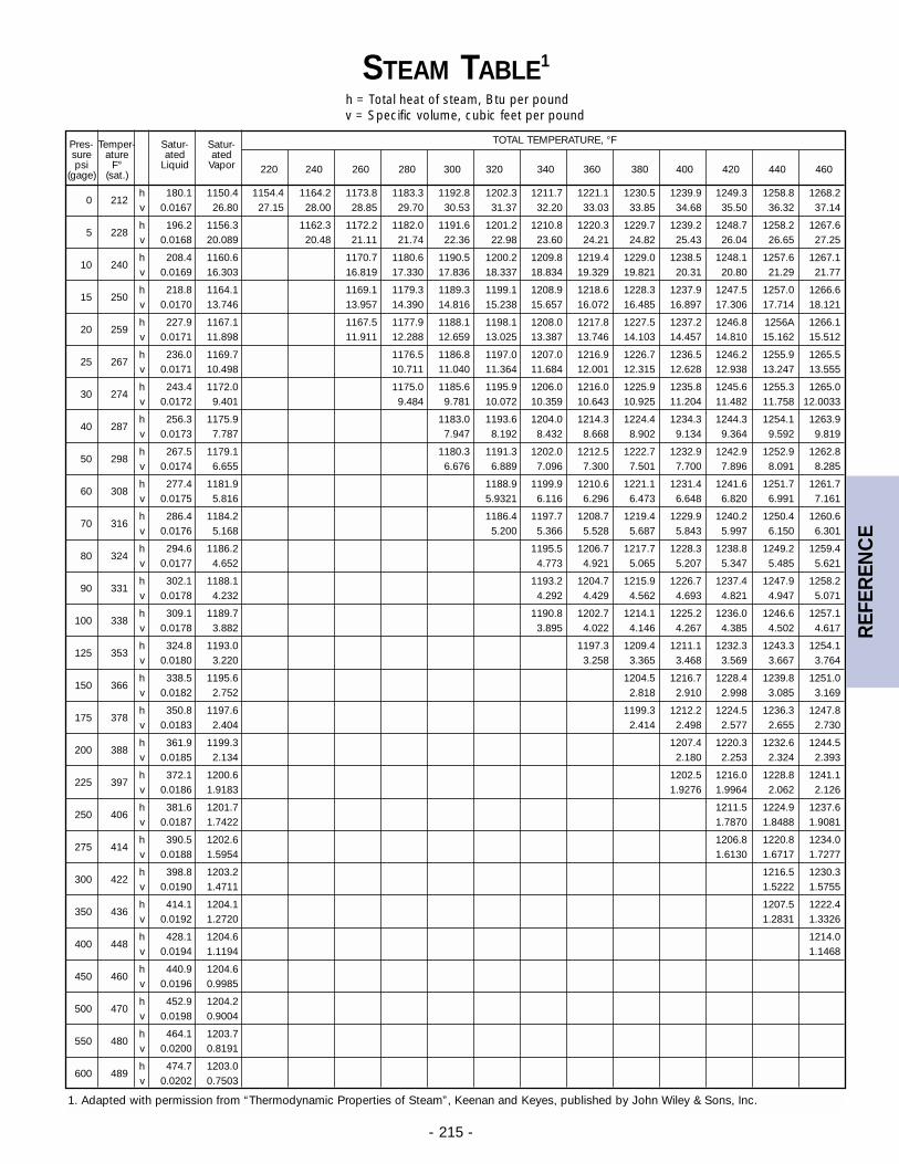
- 215 -
Pres- Temper- Satur- Satur- TOTAL TEMPERATURE, °Fsure ature ated atedpsi F° Liquid Vapor 220 240 260 280 300 320 340 360 380 400 420 440 460(gage) (sat.)
h 180.1 1150.4 1154.4 1164.2 1173.8 1183.3 1192.8 1202.3 1211.7 1221.1 1230.5 1239.9 1249.3 1258.8 1268.20 212
v 0.0167 26.80 27.15 28.00 28.85 29.70 30.53 31.37 32.20 33.03 33.85 34.68 35.50 36.32 37.14
h 196.2 1156.3 1162.3 1172.2 1182.0 1191.6 1201.2 1210.8 1220.3 1229.7 1239.2 1248.7 1258.2 1267.65 228
v 0.0168 20.089 20.48 21.11 21.74 22.36 22.98 23.60 24.21 24.82 25.43 26.04 26.65 27.25
h 208.4 1160.6 1170.7 1180.6 1190.5 1200.2 1209.8 1219.4 1229.0 1238.5 1248.1 1257.6 1267.110 240
v 0.0169 16.303 16.819 17.330 17.836 18.337 18.834 19.329 19.821 20.31 20.80 21.29 21.77
h 218.8 1164.1 1169.1 1179.3 1189.3 1199.1 1208.9 1218.6 1228.3 1237.9 1247.5 1257.0 1266.615 250
v 0.0170 13.746 13.957 14.390 14.816 15.238 15.657 16.072 16.485 16.897 17.306 17.714 18.121
h 227.9 1167.1 1167.5 1177.9 1188.1 1198.1 1208.0 1217.8 1227.5 1237.2 1246.8 1256A 1266.120 259
v 0.0171 11.898 11.911 12.288 12.659 13.025 13.387 13.746 14.103 14.457 14.810 15.162 15.512
h 236.0 1169.7 1176.5 1186.8 1197.0 1207.0 1216.9 1226.7 1236.5 1246.2 1255.9 1265.525 267
v 0.0171 10.498 10.711 11.040 11.364 11.684 12.001 12.315 12.628 12.938 13.247 13.555
h 243.4 1172.0 1175.0 1185.6 1195.9 1206.0 1216.0 1225.9 1235.8 1245.6 1255.3 1265.030 274
v 0.0172 9.401 9.484 9.781 10.072 10.359 10.643 10.925 11.204 11.482 11.758 12.0033
h 256.3 1175.9 1183.0 1193.6 1204.0 1214.3 1224.4 1234.3 1244.3 1254.1 1263.940 287
v 0.0173 7.787 7.947 8.192 8.432 8.668 8.902 9.134 9.364 9.592 9.819
h 267.5 1179.1 1180.3 1191.3 1202.0 1212.5 1222.7 1232.9 1242.9 1252.9 1262.850 298
v 0.0174 6.655 6.676 6.889 7.096 7.300 7.501 7.700 7.896 8.091 8.285
h 277.4 1181.9 1188.9 1199.9 1210.6 1221.1 1231.4 1241.6 1251.7 1261.760 308
v 0.0175 5.816 5.9321 6.116 6.296 6.473 6.648 6.820 6.991 7.161
h 286.4 1184.2 1186.4 1197.7 1208.7 1219.4 1229.9 1240.2 1250.4 1260.670 316
v 0.0176 5.168 5.200 5.366 5.528 5.687 5.843 5.997 6.150 6.301
h 294.6 1186.2 1195.5 1206.7 1217.7 1228.3 1238.8 1249.2 1259.480 324
v 0.0177 4.652 4.773 4.921 5.065 5.207 5.347 5.485 5.621
h 302.1 1188.1 1193.2 1204.7 1215.9 1226.7 1237.4 1247.9 1258.290 331
v 0.0178 4.232 4.292 4.429 4.562 4.693 4.821 4.947 5.071
h 309.1 1189.7 1190.8 1202.7 1214.1 1225.2 1236.0 1246.6 1257.1100 338
v 0.0178 3.882 3.895 4.022 4.146 4.267 4.385 4.502 4.617
h 324.8 1193.0 1197.3 1209.4 1211.1 1232.3 1243.3 1254.1125 353
v 0.0180 3.220 3.258 3.365 3.468 3.569 3.667 3.764
h 338.5 1195.6 1204.5 1216.7 1228.4 1239.8 1251.0150 366
v 0.0182 2.752 2.818 2.910 2.998 3.085 3.169
h 350.8 1197.6 1199.3 1212.2 1224.5 1236.3 1247.8175 378
v 0.0183 2.404 2.414 2.498 2.577 2.655 2.730
h 361.9 1199.3 1207.4 1220.3 1232.6 1244.5200 388
v 0.0185 2.134 2.180 2.253 2.324 2.393
h 372.1 1200.6 1202.5 1216.0 1228.8 1241.1225 397
v 0.0186 1.9183 1.9276 1.9964 2.062 2.126
h 381.6 1201.7 1211.5 1224.9 1237.6250 406
v 0.0187 1.7422 1.7870 1.8488 1.9081
h 390.5 1202.6 1206.8 1220.8 1234.0275 414
v 0.0188 1.5954 1.6130 1.6717 1.7277
h 398.8 1203.2 1216.5 1230.3300 422
v 0.0190 1.4711 1.5222 1.5755
h 414.1 1204.1 1207.5 1222.4350 436
v 0.0192 1.2720 1.2831 1.3326
h 428.1 1204.6 1214.0400 448
v 0.0194 1.1194 1.1468
h 440.9 1204.6450 460
v 0.0196 0.9985
h 452.9 1204.2500 470
v 0.0198 0.9004
h 464.1 1203.7550 480
v 0.0200 0.8191
h 474.7 1203.0600 489
v 0.0202 0.7503
STEAM TABLE1
h = Total heat of steam, Btu per poundv = Specific volume, cubic feet per pound
1. Adapted with permission from “Thermodynamic Properties of Steam”, Keenan and Keyes, published by John Wiley & Sons, Inc.
REF
EREN
CE


