Embed Size (px)
Citation preview
Cost-Function based Predictive Voltage Control ofTwo-Level Four-Leg Inverters using Two Step
Prediction Horizon for Standalone Power SystemsV. Yaramasu and B. Wu
Department of Electrical and Computer EngineeringRyerson University
Toronto, ON M5B 2K3 CanadaEmail: [email protected]
M. Rivera, J. Rodriguez and A. WilsonDepartment of Electronics Engineering
Universidad Tecnica Federico Santa MarıaValparaıso, 2390123 Chile
Email: [email protected]
Abstract—This paper presents a cost-function based predictivevoltage control strategy with a prediction horizon of two samplesto effectively control the output voltage of three-phase four-leg inverter used for the standalone power systems. The three-phase inverter with an additional leg is developed to deliversymmetrical sinusoidal three-phase voltages irrespective of thearbitrary consumer load profiles. The proposed controller usesthe discrete model of the inverter and RLC filter for two-step prediction of output voltage for each switching state ofthe inverter. The control method chooses a switching state thatminimizes the error between the output voltage and its reference.The proposed controller offers an excellent reference trackingwith less voltage harmonic distortion for balanced, unbalancedand nonlinear loading conditions. The feasibility of the proposedcontrol scheme has been verified by MATLAB/Simulink.
I. INTRODUCTION
The standalone power systems are an alternative solution topower-up remotely located consumers where the expansion ofelectrical grid is prohibitive and expensive. The hybrid powersystem combines two or more power generation units suchas photovoltaic (PV), solar thermal, wind energy conversionsystem (WECS), mini/micro hydro, fuel-cell and biomass andso on to overcome inherent limitations in either; and twoor more energy storage systems such as battery banks andflywheel to provide continuous and high-quality energy flowto the consumers [1]. The load could be a single home orseveral homes or large communities or islands. The otherexamples of standalone systems include satellite earth stations;broadcasting stations; military, medical and telecommunica-tion equipments; aircraft and ship power supply networks;and large scale computer systems. The voltage source inverterin standalone power system needs to provide symmetricaland robust three-phase sinusoidal voltages irrespective of thearbitrary consumer load profiles. In order to supply such loads,a three-phase four-wire system is used with the neutral pointaccomplished by an additional transformer or by the inverter.The three-phase inverter with an additional fourth (neutral)leg and output RLC filter is proved to be the best candidateto provide transformerless neutral connection and symmetricalsinusoidal voltages to the loads [2]–[5].
Three different output variables for four-leg converter suchas voltage, current or power can be controlled depending uponthe application. The current and power control techniquesare used for grid connected distributed generation [6], activepower filters [7], [8], active front-end rectifiers [9] and controlof two or more motors from an inverter [10]. The voltagecontrol technique is used for standalone distributed generation[11], uninterruptible power supplies (UPS) [12] and dynamicvoltage regulators [13]. The voltage control using hysteresisregulators [14]; open-loop feed forward controllers [15]; linearPID controllers in stationary (αβ0) [16], synchronous (qd0)[17], [18] and natural (abcn) [3] reference frame with externalvoltage and internal current control loops; and pole placementcontrollers [19], [20] are being analyzed before. The tuning ofPI controller is a trade-off between robustness and transientperformance and is very empirical. All these abstruse voltagecontrol techniques use even more complicated modulationstage in order to generate switching signals for the inverter.
Various carrier-less modulation schemes such as hysteresis[21], [22], flux vector [23] and selective harmonic elimination(SHE) [24]; and carried-based sinusoidal pulse width modula-tion (SPWM) [4], [5], [25]–[27] and three-dimensional spacevector modulation (3D-SVM) [28]–[31] methods are analyzedbefore. The hysteresis and flux vector techniques use compli-cated switching tables. The calculation of switching angles andtheir digital implementation for SHE is quite complex. Com-pared to the SPWM, 3D-SVM offers many advantages: gooddc-link utilization, lower switching frequency and minimumoutput distortion [28]. Despite its benefits, the 3D-SVM is verycomplicated, time consuming and non-intuitive for softwareand hardware implementation [26], [32].
The cost-function based finite control set model predictivecontrol (FCS-MPC) has found recent application in powerelectronics [33], [34]. This method appears as an attractivealternative to the classical control methods, due to its sim-ple concept, fast dynamic response, and easy inclusion ofnonlinearities & constraints in the design of controller [35].Moreover, this scheme does not require internal current controlloops and modulators and thus greatly reduces the complexity.
978-1-4577-1216-6/12/$26.00 ©2012 IEEE 128
+
+
PV Array
Wind Turbine
Gear Box PMSG
Flywheel Storage
DC PCCAC PCC
DC/DC Converter-1
DC/DC Converter-2AC/DC Converter-1
AC/DC Converter-2
4L-Inverter
DC Loads
AC Filter
Battery Banks
4
444
2
3 ∼ Linear
1 ∼ Linear
3 ∼ Non-Linear
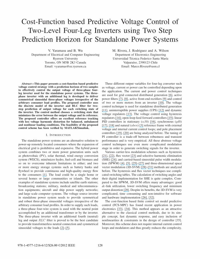
Figure 1. Standalone hybrid power system with four-leg inverter.
u
v
w
n
P
N
Rf Lf
Cf
vdc
vnN
vou
iu iou
AC Filter
Unknown Load
Su Sv Sw Sn
Su Sv Sw Sn
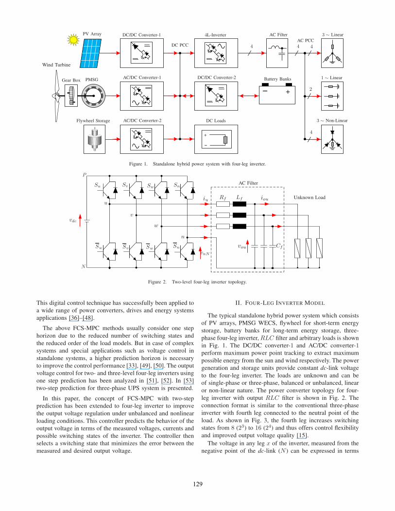
Figure 2. Two-level four-leg inverter topology.
This digital control technique has successfully been applied toa wide range of power converters, drives and energy systemsapplications [36]–[48].
The above FCS-MPC methods usually consider one stephorizon due to the reduced number of switching states andthe reduced order of the load models. But in case of complexsystems and special applications such as voltage control instandalone systems, a higher prediction horizon is necessaryto improve the control performance [33], [49], [50]. The outputvoltage control for two- and three-level four-leg inverters usingone step prediction has been analyzed in [51], [52]. In [53]two-step prediction for three-phase UPS system is presented.
In this paper, the concept of FCS-MPC with two-stepprediction has been extended to four-leg inverter to improvethe output voltage regulation under unbalanced and nonlinearloading conditions. This controller predicts the behavior of theoutput voltage in terms of the measured voltages, currents andpossible switching states of the inverter. The controller thenselects a switching state that minimizes the error between themeasured and desired output voltage.
II. FOUR-LEG INVERTER MODEL
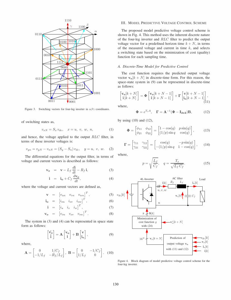
The typical standalone hybrid power system which consistsof PV arrays, PMSG WECS, flywheel for short-term energystorage, battery banks for long-term energy storage, three-phase four-leg inverter, RLC filter and arbitrary loads is shownin Fig. 1. The DC/DC converter-1 and AC/DC converter-1perform maximum power point tracking to extract maximumpossible energy from the sun and wind respectively. The powergeneration and storage units provide constant dc-link voltageto the four-leg inverter. The loads are unknown and can beof single-phase or three-phase, balanced or unbalanced, linearor non-linear nature. The power converter topology for four-leg inverter with output RLC filter is shown in Fig. 2. Theconnection format is similar to the conventional three-phaseinverter with fourth leg connected to the neutral point of theload. As shown in Fig. 3, the fourth leg increases switchingstates from 8 (23) to 16 (24) and thus offers control flexibilityand improved output voltage quality [15].
The voltage in any leg x of the inverter, measured from thenegative point of the dc-link (N ) can be expressed in terms
129
0000
0001
0010
0011
0100
0101
0110
0111
1000
1001
1010
1011
1100
1101
1110
1111
α
βγ
Figure 3. Switching vectors for four-leg inverter in αβγ coordinates.
of switching states as,
vxN = Sx vdc, x = u, v, w, n, (1)
and hence, the voltage applied to the output RLC filter, interms of these inverter voltages is:
vyn = vyN − vnN = (Sy − Sn) vdc, y = u, v, w. (2)
The differential equations for the output filter, in terms ofvoltage and current vectors is described as follows:
vo = v − Lfdi
dt−Rf i, (3)
i = io + Cfdvo
dt, (4)
where the voltage and current vectors are defined as,
v =[vun vvn vwn
]T, (5)
io =[iou iov iow
]T, (6)
i =[iu iv iw
]T, (7)
vo =[vou vov vow
]T. (8)
The system in (3) and (4) can be represented in space stateform as follows: [
vo
i
]= A
[vo
i
]+B
[vio
], (9)
where,
A =
[0 1/Cf
−1/Lf −Rf/Lf
], B =
[0 −1/Cf
1/Lf 0
]. (10)
III. MODEL PREDICTIVE VOLTAGE CONTROL SCHEME
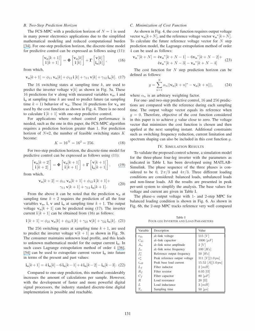
The proposed model predictive voltage control scheme isshown in Fig. 4. This method uses the inherent discrete natureof the four-leg inverter and RLC filter to predict the outputvoltage vector for a predefined horizon time k +N , in termsof the measured voltage and current in time k, and selectsa switching state based on the minimization of cost (quality)function for each sampling time.
A. Discrete-Time Model for Predictive Control
The cost function requires the predicted output voltagevector vo[k + N ] in discrete-time form. For this reason, thespace-state system in (9) can be represented in discrete-timeas follows:[
vo[k +N ]i [k +N ]
]= Φ
[vo[k +N − 1]i [k +N − 1]
]+ Γ
[v[k +N − 1]io[k +N − 1]
],
(11)where,
Φ = eTsA, Γ = A−1(Φ− I2x2)B, (12)
by using (10) and (12),
Φ =
[φ11 φ12
φ21 φ22
]=
[1− cos(q) p sin(q)(1/p) sin q cos(q)
], (13)
Γ =
[γ11 γ12γ21 γ22
]=
[cos(q) −p sin(q)
−(1/p) sin q 1− cos(q)
], (14)
where,
p =
√Lf
Cf, q =
Ts√Lf Cf
. (15)
4L-Inverter AC filter Load
u, v, w
n
Rf Lf
Cf
8
16N
vdc[k]
vdc[k]
vo[k]
io[k]i[k]
vo[k]
io[k]
i[k]
vo[k +N ]
v∗o [k +N ]
S[k]
Minimization ofcost function g
with (24)
Prediction of
output voltage vo
with (11) and (12)
Figure 4. Block diagram of model predictive voltage control scheme for thefour-leg inverter.
130
B. Two-Step Prediction Horizon
The FCS-MPC with a prediction horizon of N = 1 is usedin many power electronics applications due to the simplifiedmathematical modeling and reduced computational burden[34]. For one-step prediction horizon, the discrete-time modelfor predictive control can be expressed as follows using (11):[
vo[k + 1]i [k + 1]
]= Φ
[vo[k]i [k]
]+ Γ
[v[k]io[k]
], (16)
from which,
vo[k+1] = φ11 vo[k] +φ12 i [k]+ γ11 v[k] + γ12 io[k]. (17)
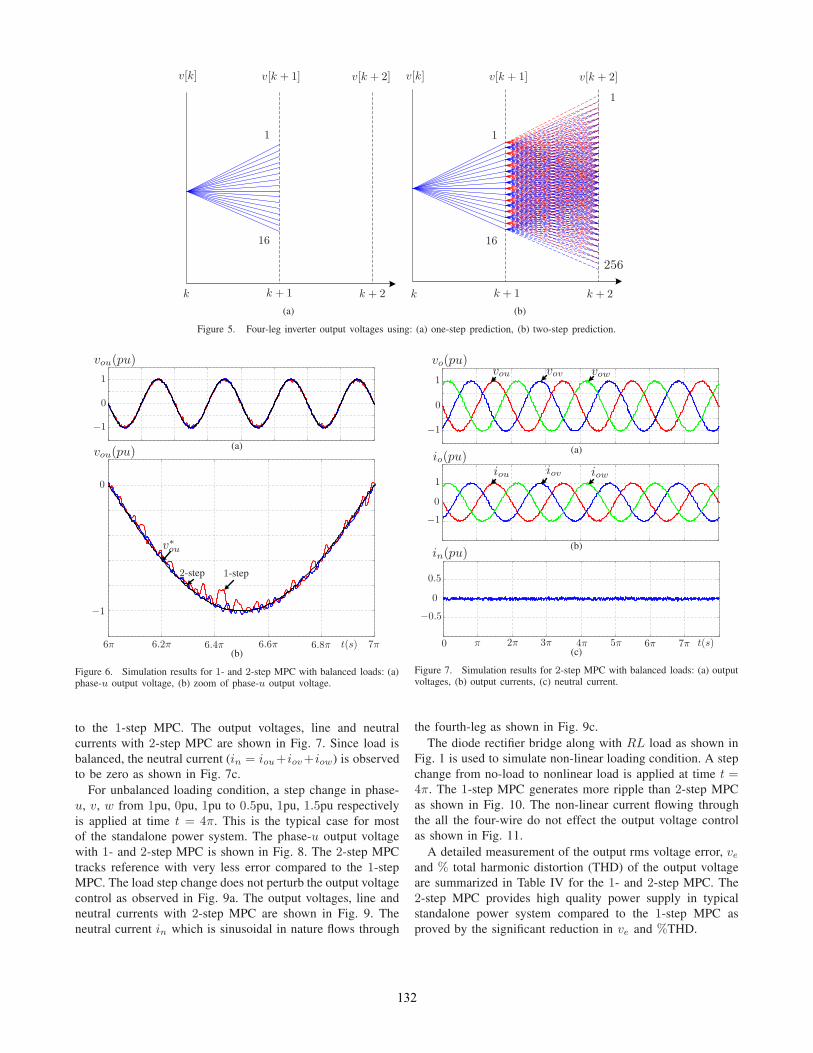
The 16 switching states at sampling time k, are used topredict the inverter voltage v[k] as shown in Fig. 5a. These16 predictions for v along with measured variables vo, i andio at sampling time k are used to predict future (at samplingtime k + 1) behavior of vo. These 16 predictions for vo areused by the cost function as shown in Fig. 4. There is no needto calculate i [k + 1] with one-step predictive control.
For applications where robust control performance isneeded, such as the one in this paper, the FCS-MPC algorithmrequires a prediction horizon greater than 1. For predictionhorizon of N=2, the number of feasible switching states Kbecome:
K = 16N = 162 = 256. (18)
For two-step prediction horizon, the discrete-time model forpredictive control can be expressed as follows using (11):[
vo[k + 2]i [k + 2]
]= Φ
[vo[k + 1]i [k + 1]
]+ Γ
[v[k + 1]io[k + 1]
], (19)
from which,
vo[k + 2] = φ11 vo[k + 1] + φ12 i [k + 1]+
γ11 v[k + 1] + γ12 io[k + 1].(20)
From the above it can be noted that the prediction vo atsampling time k + 2 requires the prediction of all the fourvariables vo, i, v and io at sampling time k + 1. The outputvoltage vo[k + 1] can be predicted using (17). The invertercurrent i [k + 1] can be obtained from (16) as follows:
i [k + 1] = φ21 vo[k] + φ22 i [k] + γ21 v[k] + γ22 io[k]. (21)
The 256 switching states at sampling time k + 1, are usedto predict the inverter voltage v[k + 1] as shown in Fig. 5b.The consumer maintains unknown load profile, and this leadsto unknown mathematical model for the output current io. Insuch cases Lagrange extrapolation method of order 4 [36],[54] can be used to extrapolate current vector io into futurein terms of the present and past values:
io[k+1] = 4 io[k]−6 io[k−1]+4 io[k−2]− io[k−3]. (22)
Compared to one-step prediction, this method considerablyincreases the amount of calculations per sample. However,with the development of faster and more powerful digitalsignal processors, the industry standard discrete-time digitalimplementation is possible and reachable.
C. Minimization of Cost Function
As shown in Fig. 4, the cost function requires output voltagevector vo[k+N ], and the reference voltage vector vo
∗[k+N ].To calculate the future reference voltage vector for N stepprediction model, the Lagrange extrapolation method of order4 can be used as follows:
vo∗[k +N ] = 4vo
∗[k +N − 1]− 6vo∗[k +N − 2]+
4vo∗[k +N − 3]− vo
∗[k +N − 4](23)
The cost function for N step prediction horizon can bedefined as follows:
g =
N∑n=1
αn||vo[k + n]∗ − vo[k + n]||, (24)
where αn is an arbitrary weighting factor.For one- and two-step predictive control, 16 and 256 predic-
tions are compared with the reference during each samplingtime. The output voltage vector equals its reference wheng = 0. Therefore, objective of the cost function consideredin this paper is to achieve g value close to zero. The voltagevector that minimizes the cost function is chosen and thenapplied at the next sampling instant. Additional constraintssuch as switching frequency reduction, current limitation andspectrum shaping can also be included in this cost function g.
IV. SIMULATION RESULTS
To validate the proposed control scheme, a simulation modelfor the three-phase four-leg inverter with the parameters asindicated in Table I, has been developed using MATLAB-Simulink. The phase sequence of the three phases is con-sidered to be 0, 2 π/3 and 4π/3. Three different loadingconditions are considered: balanced loads, unbalanced loadsand non-linear loads. All the results are presented in peakper-unit system to simplify the analysis. The base values forvoltage and current are given in Table I.
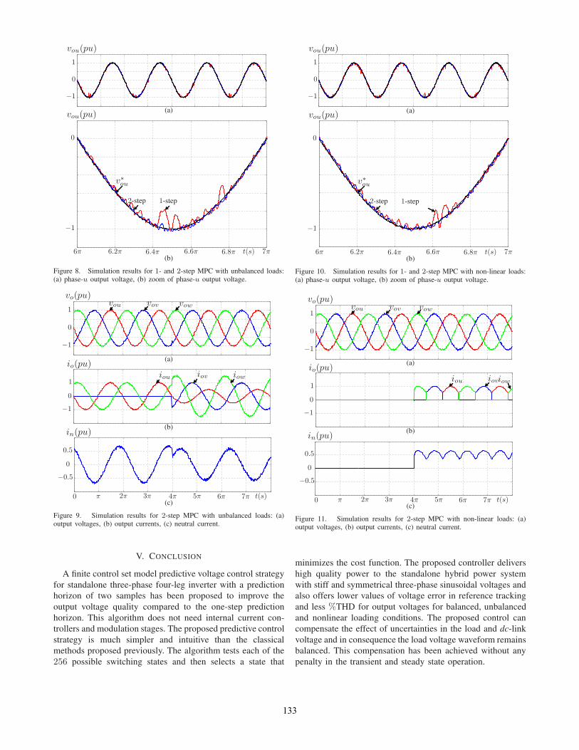
The phase-u output voltage with 1- and 2-step MPC forbalanced loading condition is shown in Fig. 6. As shown inFig. 6b, the 2-step MPC tracks reference very well compared
Table IFOUR-LEG INVERTER AND LOAD PARAMETERS
Variable Description Value
vdc dc-link voltage 515 [V ]
Cdc dc-link capacitor 1000 [μF ]
An dc-link noise amplitude 2 [V ]
fn dc-link noise frequency 100 [Hz]
f∗o Reference output frequency 50 [Hz]
v∗o Peak reference output voltage 311 [V ][1.0 pu]
ioB Peak base load current 15.52 [A][1.0 pu]
Lf Filter inductor 2 [mH]
Rf Filter resistor 0.05 [Ω]
Cf Filter capacitor 80 [μF ]
R Load resistance 20 [Ω]
L Load inductance 3 [mH]
Ts Sampling time 50 [μs]
131
v[k] v[k + 1] v[k + 2]
k k + 1 k + 2
1
16
(a)
v[k] v[k + 1] v[k + 2]
k k + 1 k + 2
1
1
16
256
(b)
Figure 5. Four-leg inverter output voltages using: (a) one-step prediction, (b) two-step prediction.
vou(pu)
1
−1
0
(a)vou(pu)
−1
0
v∗ou
1-step2-step
t(s)6π 6.2π 6.4π 6.6π 6.8π 7π(b)
Figure 6. Simulation results for 1- and 2-step MPC with balanced loads: (a)phase-u output voltage, (b) zoom of phase-u output voltage.
to the 1-step MPC. The output voltages, line and neutralcurrents with 2-step MPC are shown in Fig. 7. Since load isbalanced, the neutral current (in = iou+iov+iow) is observedto be zero as shown in Fig. 7c.
For unbalanced loading condition, a step change in phase-u, v, w from 1pu, 0pu, 1pu to 0.5pu, 1pu, 1.5pu respectivelyis applied at time t = 4π. This is the typical case for mostof the standalone power system. The phase-u output voltagewith 1- and 2-step MPC is shown in Fig. 8. The 2-step MPCtracks reference with very less error compared to the 1-stepMPC. The load step change does not perturb the output voltagecontrol as observed in Fig. 9a. The output voltages, line andneutral currents with 2-step MPC are shown in Fig. 9. Theneutral current in which is sinusoidal in nature flows through
vou vov vowvo(pu)
1
−1
0
(a)
iou iov iow
io(pu)
1
−1
0
(b)in(pu)
0.5
−0.5
0
0 π 2π 3π 4π 5π 6π 7π t(s)(c)
Figure 7. Simulation results for 2-step MPC with balanced loads: (a) outputvoltages, (b) output currents, (c) neutral current.
the fourth-leg as shown in Fig. 9c.The diode rectifier bridge along with RL load as shown in
Fig. 1 is used to simulate non-linear loading condition. A stepchange from no-load to nonlinear load is applied at time t =4π. The 1-step MPC generates more ripple than 2-step MPCas shown in Fig. 10. The non-linear current flowing throughthe all the four-wire do not effect the output voltage controlas shown in Fig. 11.
A detailed measurement of the output rms voltage error, veand % total harmonic distortion (THD) of the output voltageare summarized in Table IV for the 1- and 2-step MPC. The2-step MPC provides high quality power supply in typicalstandalone power system compared to the 1-step MPC asproved by the significant reduction in ve and %THD.
132
vou(pu)
1
−1
0
(a)vou(pu)
−1
0
v∗ou
1-step2-step
t(s)6π 6.2π 6.4π 6.6π 6.8π 7π(b)
Figure 8. Simulation results for 1- and 2-step MPC with unbalanced loads:(a) phase-u output voltage, (b) zoom of phase-u output voltage.
vou vov vowvo(pu)
1
−1
0
(a)
iou iov iow
io(pu)
1
−1
0
(b)in(pu)
0.5
−0.5
0
0 π 2π 3π 4π 5π 6π 7π t(s)(c)
Figure 9. Simulation results for 2-step MPC with unbalanced loads: (a)output voltages, (b) output currents, (c) neutral current.
V. CONCLUSION
A finite control set model predictive voltage control strategyfor standalone three-phase four-leg inverter with a predictionhorizon of two samples has been proposed to improve theoutput voltage quality compared to the one-step predictionhorizon. This algorithm does not need internal current con-trollers and modulation stages. The proposed predictive controlstrategy is much simpler and intuitive than the classicalmethods proposed previously. The algorithm tests each of the256 possible switching states and then selects a state that
vou(pu)
1
−1
0
(a)vou(pu)
−1
0
v∗ou
1-step2-step
t(s)6π 6.2π 6.4π 6.6π 6.8π 7π(b)
Figure 10. Simulation results for 1- and 2-step MPC with non-linear loads:(a) phase-u output voltage, (b) zoom of phase-u output voltage.
vou vov vowvo(pu)
1
−1
0
(a)
iou ioviow
io(pu)
1
−1
0
(b)in(pu)
0.5
−0.5
0
0 π 2π 3π 4π 5π 6π 7π t(s)(c)
Figure 11. Simulation results for 2-step MPC with non-linear loads: (a)output voltages, (b) output currents, (c) neutral current.
minimizes the cost function. The proposed controller delivershigh quality power to the standalone hybrid power systemwith stiff and symmetrical three-phase sinusoidal voltages andalso offers lower values of voltage error in reference trackingand less %THD for output voltages for balanced, unbalancedand nonlinear loading conditions. The proposed control cancompensate the effect of uncertainties in the load and dc-linkvoltage and in consequence the load voltage waveform remainsbalanced. This compensation has been achieved without anypenalty in the transient and steady state operation.
133
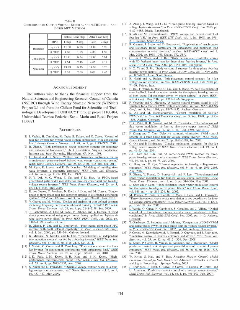
Table IICOMPARISON OF OUTPUT VOLTAGE ERROR ev AND %THD FOR 1- AND
2-STEP MPC METHODS.
Before Load Step After Load Step
MPC 1-step 2-step 1-step 2-step
Balanced ve (V ) 11.08 5.28 11.08 5.28
% THD 4.38 1.99 4.38 1.99
Unbalanced ve (V ) 11.41 5.54 12.00 5.57
% THD 4.54 2.15 4.85 2.12
Nonlinear ve (V ) 13.23 5.75 14.93 6.20
% THD 5.35 2.08 6.06 2.45
ACKNOWLEDGMENT
The authors wish to thank the financial support from theNatural Sciences and Engineering Research Council of Canada(NSERC) through Wind Energy Strategic Network (WESNet)Project 3.1 and from the Chilean Fund for Scientific and Tech-nological Development FONDECYT through project 1100404,Universidad Tecnica Federico Santa Maria and Basal ProjectFB0821.
REFERENCES
[1] I. Vechiu, H. Camblong, G. Tapia, B. Dakyo, and O. Curea, “Control offour leg inverter for hybrid power system applications with unbalancedload,” Energy Convers. Manage., vol. 48, no. 7, pp. 2119–2128, 2007.
[2] R. Zhang, “High performance power converter systems for nonlinearand unbalanced load/source,” Ph.D. dissertation, Virginia PolytechnicInstitute and State University, Blacksburg, VA, Nov. 1998.
[3] G. Kasal and B. Singh, “Voltage and frequency controllers for anasynchronous generator-based isolated wind energy conversion system,”IEEE Trans. Energy Convers., vol. 26, no. 2, pp. 402–416, Jun. 2011.
[4] M. Ryan, R. Lorenz, and R. De Doncker, “Modeling of multileg sine-wave inverters: a geometric approach,” IEEE Trans. Ind. Electron.,vol. 46, no. 6, pp. 1183–1191, Dec. 1999.
[5] N.-Y. Dai, M.-C. Wong, F. Ng, and Y.-D. Han, “A FPGA-basedgeneralized pulse width modulator for three-leg center-split and four-legvoltage source inverters,” IEEE Trans. Power Electron., vol. 23, no. 3,pp. 1472–1484, May 2008.
[6] E. dos Santos, C. Jacobina, N. Rocha, J. Dias, and M. Correa, “Single-phase to three-phase four-leg converter applied to distributed generationsystem,” IET Power Electron., vol. 3, no. 6, pp. 892–903, Nov. 2010.
[7] V. George and M. Mishra, “Design and analysis of user-defined constantswitching frequency current-control-based four-leg DSTATCOM,” IEEETrans. Power Electron., vol. 24, no. 9, pp. 2148–2158, Sep. 2009.
[8] T. Rachmildha, A. Llor, M. Fadel, P. Dahono, and Y. Haroen, “Hybriddirect power control using p-q-r power theory applied on 3-phase 4-wire active power filter,” in Proc. IEEE–PESC Conf., Jun. 2008, pp.1183–1189, Rhodes, Greece.
[9] R. Zhang, F. Lee, and D. Boroyevich, “Four-legged three-phase PFCrectifier with fault tolerant capability,” in Proc. IEEE–PESC Conf.,vol. 1, Jun. 2000, pp. 359–364, Galway, Ireland.
[10] K. Matsuse, N. Kezuka, and K. Oka, “Characteristics of independenttwo induction motor drives fed by a four-leg inverter,” IEEE Trans. Ind.Electron., vol. 47, no. 5, pp. 2125–2134, Oct. 2011.
[11] I. Vechiu, O. Curea, and H. Camblong, “Transient operation of a four-leg inverter for autonomous applications with unbalanced load,” IEEETrans. Power Electron., vol. 25, no. 2, pp. 399–407, Feb. 2010.
[12] J.-K. Park, J.-M. Kwon, E.-H. Kim, and B.-H. Kwon, “High-performance transformerless online UPS,” IEEE Trans. Ind. Electron.,vol. 55, no. 8, pp. 2943–2953, Aug. 2008.
[13] S. Naidu and D. Fernandes, “Dynamic voltage restorer based on a four-leg voltage source converter,” IET Gener. Transm. Distrib., vol. 3, no. 5,pp. 437–447, May 2009.
[14] X. Zhang, J. Wang, and C. Li, “Three-phase four-leg inverter based onvoltage hysteresis control,” in Proc. IEEE–ICECE Conf., Jun. 2010, pp.4482–4485, Dhaka, Bangladesh.
[15] S. Ali and M. Kazmierkowski, “PWM voltage and current control offour-leg VSI,” in Proc. IEEE–ISIE Conf., vol. 1, Jul. 1998, pp. 196–201, Pretoria, South Africa.
[16] R. Gannett, J. Sozio, and D. Boroyevich, “Application of synchronousand stationary frame controllers for unbalanced and nonlinear loadcompensation in 4-leg inverters,” in Proc. IEEE–APEC Conf., vol. 2,Mar. 2002, pp. 1038–1043, Dallas, TX, USA.
[17] C. Liu, F. Wang, and H. Bai, “High performance controller designwith PD feedback inner loop for three-phase four-leg inverter,” in Proc.IEEE–ICIEA Conf., May 2009, pp. 1057–1061, Singapore.
[18] H. Z. Yi and S. Jin, “Study on control strategy for three-phase four-leginverter power supply,” in Proc. IEEE–IECON Conf., vol. 1, Nov. 2004,pp. 805–809, Husan, South Korea.
[19] R. Nasiri and A. Radan, “Pole-placement control strategy for 4-legvoltage-source inverters,” in Proc. IEEE–PEDSTC Conf., Feb. 2010, pp.74–79, Tehran, Iran.
[20] H. Bai, F. Wang, D. Wang, C. Liu, and T. Wang, “A pole assignment ofstate feedback based on system matrix for three-phase four-leg inverterof high speed PM generator driven by micro-turbine,” in Proc. IEEE–ICIEA Conf., May 2009, pp. 1361–1366, Singapore.
[21] P. Verdelho and G. Marques, “A current control system based in αβ0variables for a four-leg PWM voltage converter,” in Proc. IEEE–IECONConf., vol. 3, Sep. 1998, pp. 1847–1852, Aachen, Germany.
[22] S. Ali and M. Kazmierkowski, “Current regulation of four-legPWM/VSI,” in Proc. IEEE–IECON Conf., vol. 3, Sep. 1998, pp. 1853–1858, Aachen, Germany.
[23] D. C. Patel, R. R. Sawant, and M. C. Chandorkar, “Three-dimensionalflux vector modulation of four-leg sine-wave output inverters,” IEEETrans. Ind. Electron., vol. 57, no. 4, pp. 1261–1269, Apr. 2010.
[24] F. Zhang and Y. Yan, “Selective harmonic elimination PWM controlscheme on a three-phase four-leg voltage source inverter,” IEEE Trans.Power Electron., vol. 24, no. 7, pp. 1682–1689, Jul. 2009.
[25] O. Ojo and P. Kshirsagar, “Concise modulation strategies for four-legvoltage source inverters,” IEEE Trans. Power Electron., vol. 19, no. 1,pp. 46–53, Jan. 2004.
[26] J.-H. Kim and S.-K. Sul, “A carrier-based PWM method for three-phase four-leg voltage source converters,” IEEE Trans. Power Electron.,vol. 19, no. 1, pp. 66–75, Jan. 2004.
[27] G. Dong and O. Ojo, “Current regulation in four-leg voltage-sourceconverters,” IEEE Trans. Ind. Electron., vol. 54, no. 4, pp. 2095–2105,Aug. 2007.
[28] R. Zhang, V. Prasad, D. Boroyevich, and F. Lee, “Three-dimensionalspace vector modulation for four-leg voltage-source converters,” IEEETrans. Power Electron., vol. 17, no. 3, pp. 314–326, May 2002.
[29] D. Shen and P. Lehn, “Fixed-frequency space-vector-modulation controlfor three-phase four-leg active power filters,” IET Electr. Power Appl.,vol. 149, no. 4, pp. 268–274, Jul. 2002.
[30] M. Perales, M. Prats, R. Portillo, J. Mora, J. Leon, and L. Franquelo,“Three-dimensional space vector modulation in abc coordinates for four-leg voltage source converters,” IEEE Power Electron. Lett., vol. 1, no. 4,pp. 104–109, Dec. 2003.
[31] I. Vechiu, O. Curea, H. Camblong, S. Ceballos, and J. Villate, “Digitalcontrol of a three-phase four-leg inverter under unbalanced voltageconditions,” in Proc. IEEE–EPE Conf., Sep. 2007, pp. 1–10, Aalborg,Denmark.
[32] T. Glasberger, Z. Peroutka, and J. Molnar, “Comparison of 3D-SVPWMand carrier-based PWM of three-phase four-leg voltage source inverter,”in Proc. IEEE–EPE Conf., Sep. 2007, pp. 1–9, Aalborg, Denmark.
[33] P. Cortes, M. Kazmierkowski, R. Kennel, D. Quevedo, and J. Rodriguez,“Predictive control in power electronics and drives,” IEEE Trans. Ind.Electron., vol. 55, no. 12, pp. 4312–4324, Dec. 2008.
[34] S. Kouro, P. Cortes, R. Vargas, U. Ammann, and J. Rodriguez, “Modelpredictive control - A simple and powerful method to control powerconverters,” IEEE Trans. Ind. Electron., vol. 56, no. 6, pp. 1826–1838,Jun. 2009.
[35] W. Kwon, S. Han, and S. Han, Receding Horizon Control: ModelPredictive Control for State Models, ser. Advanced Textbooks in Controland Signal Processing. Springer Verlag, 2005.
[36] J. Rodriguez, J. Pontt, C. Silva, P. Correa, P. Lezana, P. Cortes, andU. Ammann, “Predictive current control of a voltage source inverter,”IEEE Trans. Ind. Electron., vol. 54, no. 1, pp. 495–503, Feb. 2007.
134

[37] J. Rodriguez, J. Pontt, P. Correa, P. Lezana, and P. Cortes, “Predictivepower control of an AC/DC/AC converter,” in Proc. IEEE–IAS Annu.Meeting, vol. 2, Oct. 2005, pp. 934–939, Hong Kong.
[38] P. Cortes, G. Ortiz, J. Yuz, J. Rodriguez, S. Vazquez, and L. Franquelo,“Model predictive control of an inverter with output LC filter for UPSapplications,” IEEE Trans. Ind. Electron., vol. 56, no. 6, pp. 1875–1883,Jun. 2009.
[39] P. Cortes, J. Rodriguez, P. Antoniewicz, and M. Kazmierkowski, “Directpower control of an AFE using predictive control,” IEEE Trans. PowerElectron., vol. 23, no. 5, pp. 2516–2523, Sep. 2008.
[40] M. Rivera, J. Rodriguez, B. Wu, J. Espinoza, and C. Rojas, “Currentcontrol for an indirect matrix converter with filter resonance mitigation,”IEEE Trans. Ind. Electron., vol. 59, no. 1, pp. 71–79, Jan. 2012.
[41] M. Rivera, C. Rojas, J. Rodriguez, P. Wheeler, B. Wu, and J. Espinoza,“Predictive current control with input filter resonance mitigation for adirect matrix converter,” IEEE Trans. Power Electron., vol. 26, no. 10,pp. 2794–2803, Oct. 2011.
[42] M. Perez, J. Rodriguez, and A. Coccia, “Predictive current control in asingle phase PFC boost rectifier,” in Proc. IEEE–ICIT Conf., Feb. 2009,pp. 1–6, Gippsland, Australia.
[43] R. Vargas, P. Cortes, U. Ammann, J. Rodriguez, and J. Pontt, “Predictivecontrol of a three-phase neutral-point-clamped inverter,” IEEE Trans.Ind. Electron., vol. 54, no. 5, pp. 2697–2705, Oct. 2007.
[44] P. Cortes, A. Wilson, S. Kouro, J. Rodriguez, and H. Abu-Rub, “Modelpredictive control of multilevel cascaded H-bridge inverters,” IEEETrans. Ind. Electron., vol. 57, no. 8, pp. 2691–2699, Aug. 2010.
[45] P. Lezana, R. Aguilera, and D. Quevedo, “Model predictive control ofan asymmetric flying capacitor converter,” IEEE Trans. Ind. Electron.,vol. 56, no. 6, pp. 1839–1846, Jun. 2009.
[46] R. Vargas, U. Ammann, B. Hudoffsky, J. Rodriguez, and P. Wheeler,“Predictive torque control of an induction machine fed by a matrix con-
verter with reactive input power control,” IEEE Trans. Power Electron.,vol. 25, no. 6, pp. 1426–1438, June 2010.
[47] M. Rivera, J. Elizondo, M. Macias, O. Probst, O. Micheloud, J. Ro-driguez, C. Rojas, and A. Wilson, “Model predictive control of a doublyfed induction generator with an indirect matrix converter,” in Proc.IEEE–IECON Conf., Nov. 2010, pp. 2959–2965, Glendale, AZ, USA.
[48] S. Alepuz, S. Busquets-Monge, J. Bordonau, P. Cortes, J. Rodriguez, andR. Vargas, “Predictive current control of grid-connected neutral-point-clamped converters to meet low voltage ride-through requirements,” inProc. IEEE–PESC Conf., Jun. 2008, pp. 2423–2428, Rhodes, Greece.
[49] P. Correa, J. Rodriguez, I. Lizama, and D. Andler, “A predictive controlscheme for current-source rectifiers,” IEEE Trans. Ind. Electron., vol. 56,no. 5, pp. 1813–1815, May 2009.
[50] T. Geyer, “Generalized model predictive direct torque control: Longprediction horizons and minimization of switching losses,” in Proc.IEEE–CCC Conf., Dec. 2009, pp. 6799–6804, Shanghai, China.
[51] V. Yaramasu, J. Rodriguez, B. Wu, M. Rivera, A. Wilson, and C. Rojas,“A simple and effective solution for superior performance in two-levelfour-leg voltage source inverters: Predictive voltage control,” in Proc.IEEE–ISIE Conf., Jul. 2010, pp. 3127–3132, Bari, Italy.
[52] J. Rodriguez, B. Wu, M. Rivera, A. Wilson, V. Yaramasu, and C. Rojas,“Model predictive control of three-phase four-leg neutral-point-clampedinverters,” in Proc. IEEE–IPEC Conf., Jun. 2010, pp. 3112–3116,Sapporo, Japan.
[53] P. Cortes, J. Rodriguez, S. Vazquez, and L. Franquelo, “Predictive con-trol of a three-phase UPS inverter using two steps prediction horizon,”in Proc. IEEE–ICIT Conf., Mar. 2010, pp. 1283–1288, Vina del Mar,Chile.
[54] O. Kukrer, “Discrete-time current control of voltage-fed three-phasePWM inverters,” IEEE Trans. Power Electron., vol. 11, no. 2, pp. 260–269, Mar. 1996.
135