Embed Size (px)
Citation preview
1
High-function General-purpose InvertersRX2 Series
Save energy and maximize performance with versatile inverter• Triple rating: Normal Duty (ND), Low Duty (LD), and Very Low Duty (VLD)• PM motor control helps save energy• Safety function IEC 61800-5-2 "Safe Torque Off (STO)"
Conforms to machinery directive with ISO13849-1 (Category 4/PLe)• DriveProgramming allows simple sequence control without a PLC• EtherCAT communication using an optional communication unit provides
high-speed communication for running and stopping, monitoring operating status, and changing various settings
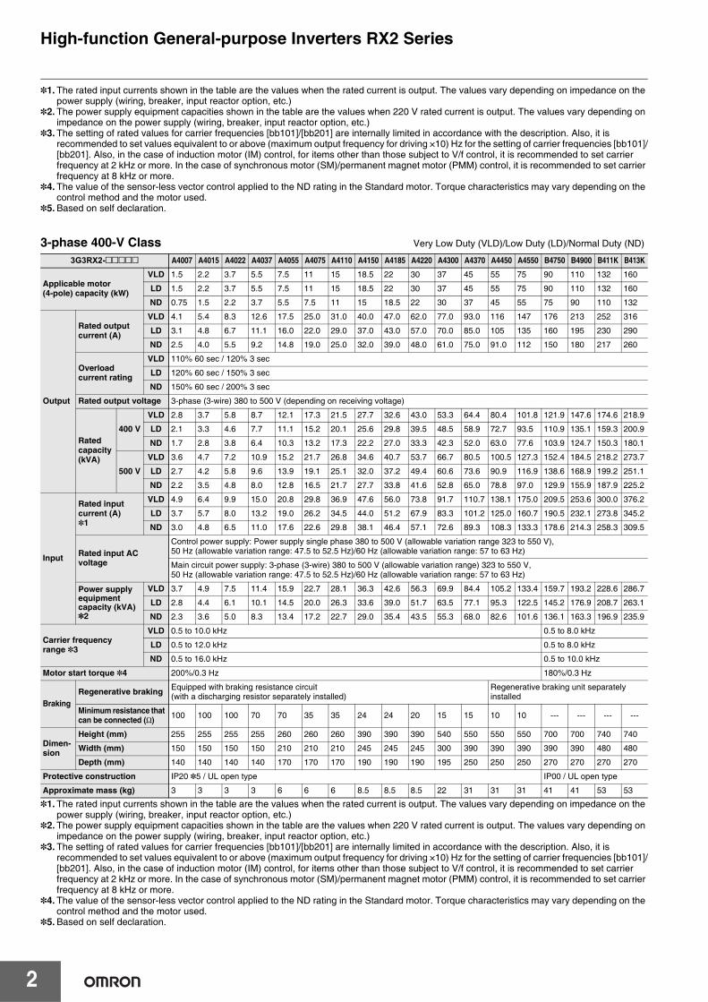
Performance SpecificationsInverter 3G3RX23-phase 200-V Class Very Low Duty (VLD)/Low Duty (LD)/Normal Duty (ND)
3G3RX2-A2@@@@@ A2004 A2007 A2015 A2022 A2037 A2055 A2075 A2110 A2150 A2185 A2220 A2300 A2370 A2450 A2550
Applicable motor(4-pole) capacity (kW)
VLD 0.75 1.5 2.2 3.7 5.5 7.5 11 15 18.5 22 30 37 45 55 75
LD 0.75 1.5 2.2 3.7 5.5 7.5 11 15 18.5 22 30 37 45 55 75
ND 0.4 0.75 1.5 2.2 3.7 5.5 7.5 11 15 18.5 22 30 37 45 55
Output
Rated output current (A)
VLD 4.4 8.0 10.4 15.6 22.8 33.0 46.0 60.0 80.0 93.0 124 153 185 229 295
LD 3.7 6.3 9.4 12.0 19.6 30.0 40.0 56.0 73.0 85.0 113 140 169 210 270
ND 3.2 5.0 8.0 11.0 17.5 25.0 32.0 46.0 64.0 76.0 95.0 122 146 182 220
Overload current rating
VLD 110% 60 sec / 120% 3 sec
LD 120% 60 sec / 150% 3 sec
ND 150% 60 sec / 200% 3 sec
Rated output voltage 3-phase (3-wire) 200 to 240 V (depending on receiving voltage)
Rated capacity (kVA)
200 VVLD 1.5 2.8 3.6 5.4 7.9 11.4 15.9 20.8 27.7 32.2 43.0 53.0 64.1 79.3 102.2
LD 1.3 2.2 3.3 4.2 6.8 10.4 13.9 19.4 25.3 29.4 39.1 48.5 58.5 72.7 93.5
ND 1.1 1.7 2.8 3.8 6.1 8.7 11.1 15.9 22.2 26.3 32.9 42.3 50.6 63.0 76.2
240 VVLD 1.8 3.3 4.3 6.5 9.5 13.7 19.1 24.9 33.3 38.7 51.5 63.6 76.9 95.2 122.6
LD 1.5 2.6 3.9 5.0 8.1 12.5 16.6 23.3 30.3 35.3 47.0 58.2 70.3 87.3 112.2
ND 1.3 2.1 3.3 4.6 7.3 10.4 13.3 19.1 26.6 31.6 39.5 50.7 60.7 75.7 91.5
Input
Rated input current (A) *1
VLD 5.2 9.5 12.4 18.6 27.1 39.3 54.8 71.4 95.2 110.7 147.6 182.1 220.2 272.6 351.2
LD 4.4 7.5 11.2 14.3 23.3 35.7 47.6 66.7 86.9 101.2 134.5 166.7 201.2 250.0 321.4
ND 3.8 6.0 9.5 13.1 20.8 29.8 38.1 54.8 76.2 90.5 113.1 145.2 173.8 216.7 261.9
Rated input AC voltage
Control power supply: Power supply single phase 200 to 240 V/allowable variation range 170 to 264 V, 50 Hz (allowable variation range: 47.5 to 52.5 Hz)/60 Hz (allowable variation range: 57 to 63 Hz)
Main circuit power supply: 3-phase (3-wire) 200 to 240 V/allowable variation range 170 to 264 V, 50 Hz (allowable variation range: 47.5 to 52.5 Hz)/60 Hz (allowable variation range: 57 to 63 Hz)
Power supply equipment capacity (kVA) *2
VLD 2.0 3.6 4.7 7.1 10.3 15.0 20.9 27.2 36.3 42.2 56.3 69.4 83.9 103.9 133.8
LD 1.7 2.9 4.3 5.4 8.9 13.6 18.1 25.4 33.1 38.6 51.3 63.5 76.7 95.3 122.5
ND 1.5 2.3 3.6 5.0 7.9 11.3 14.5 20.9 29.0 34.5 43.1 55.3 66.2 82.6 99.8
Carrier frequency operating range *3
VLD 0.5 to 10.0 kHz
LD 0.5 to 12.0 kHz
ND 0.5 to 16.0 kHz
Motor start torque *4 200%/0.3 Hz
BrakingRegenerative braking Equipped with BRD circuit (with a discharging resistor separately installed) Regenerative braking unit
separately installed
Minimum resistance that can be connected (Ω) 50 50 35 35 35 16 10 10 7.5 7.5 5 --- --- --- ---
Dimen- sion
Height (mm) 255 255 255 255 255 260 260 260 390 390 390 540 550 550 700
Width (mm) 150 150 150 150 150 210 210 210 245 245 245 300 390 390 480
Depth (mm) 140 140 140 140 140 170 170 170 190 190 190 195 250 250 250
Protective construction IP20 *5 / UL open type
Approximate mass (kg) 3 3 3 3 3 6 6 6 10 10 10 22 33 33 47
High-function General-purpose Inverters RX2 Series
2
*1. The rated input currents shown in the table are the values when the rated current is output. The values vary depending on impedance on the power supply (wiring, breaker, input reactor option, etc.)
*2. The power supply equipment capacities shown in the table are the values when 220 V rated current is output. The values vary depending on impedance on the power supply (wiring, breaker, input reactor option, etc.)
*3. The setting of rated values for carrier frequencies [bb101]/[bb201] are internally limited in accordance with the description. Also, it is recommended to set values equivalent to or above (maximum output frequency for driving ×10) Hz for the setting of carrier frequencies [bb101]/[bb201]. Also, in the case of induction motor (IM) control, for items other than those subject to V/f control, it is recommended to set carrier frequency at 2 kHz or more. In the case of synchronous motor (SM)/permanent magnet motor (PMM) control, it is recommended to set carrier frequency at 8 kHz or more.
*4. The value of the sensor-less vector control applied to the ND rating in the Standard motor. Torque characteristics may vary depending on the control method and the motor used.
*5. Based on self declaration.
3-phase 400-V Class Very Low Duty (VLD)/Low Duty (LD)/Normal Duty (ND)
*1. The rated input currents shown in the table are the values when the rated current is output. The values vary depending on impedance on the power supply (wiring, breaker, input reactor option, etc.)
*2. The power supply equipment capacities shown in the table are the values when 220 V rated current is output. The values vary depending on impedance on the power supply (wiring, breaker, input reactor option, etc.)
*3. The setting of rated values for carrier frequencies [bb101]/[bb201] are internally limited in accordance with the description. Also, it is recommended to set values equivalent to or above (maximum output frequency for driving ×10) Hz for the setting of carrier frequencies [bb101]/[bb201]. Also, in the case of induction motor (IM) control, for items other than those subject to V/f control, it is recommended to set carrier frequency at 2 kHz or more. In the case of synchronous motor (SM)/permanent magnet motor (PMM) control, it is recommended to set carrier frequency at 8 kHz or more.
*4. The value of the sensor-less vector control applied to the ND rating in the Standard motor. Torque characteristics may vary depending on the control method and the motor used.
*5. Based on self declaration.
3G3RX2-@@@@@ A4007 A4015 A4022 A4037 A4055 A4075 A4110 A4150 A4185 A4220 A4300 A4370 A4450 A4550 B4750 B4900 B411K B413K
Applicable motor (4-pole) capacity (kW)
VLD 1.5 2.2 3.7 5.5 7.5 11 15 18.5 22 30 37 45 55 75 90 110 132 160
LD 1.5 2.2 3.7 5.5 7.5 11 15 18.5 22 30 37 45 55 75 90 110 132 160
ND 0.75 1.5 2.2 3.7 5.5 7.5 11 15 18.5 22 30 37 45 55 75 90 110 132
Output
Rated output current (A)
VLD 4.1 5.4 8.3 12.6 17.5 25.0 31.0 40.0 47.0 62.0 77.0 93.0 116 147 176 213 252 316
LD 3.1 4.8 6.7 11.1 16.0 22.0 29.0 37.0 43.0 57.0 70.0 85.0 105 135 160 195 230 290
ND 2.5 4.0 5.5 9.2 14.8 19.0 25.0 32.0 39.0 48.0 61.0 75.0 91.0 112 150 180 217 260
Overload current rating
VLD 110% 60 sec / 120% 3 sec
LD 120% 60 sec / 150% 3 sec
ND 150% 60 sec / 200% 3 sec
Rated output voltage 3-phase (3-wire) 380 to 500 V (depending on receiving voltage)
Rated capacity (kVA)
400 V
VLD 2.8 3.7 5.8 8.7 12.1 17.3 21.5 27.7 32.6 43.0 53.3 64.4 80.4 101.8 121.9 147.6 174.6 218.9
LD 2.1 3.3 4.6 7.7 11.1 15.2 20.1 25.6 29.8 39.5 48.5 58.9 72.7 93.5 110.9 135.1 159.3 200.9
ND 1.7 2.8 3.8 6.4 10.3 13.2 17.3 22.2 27.0 33.3 42.3 52.0 63.0 77.6 103.9 124.7 150.3 180.1
500 V
VLD 3.6 4.7 7.2 10.9 15.2 21.7 26.8 34.6 40.7 53.7 66.7 80.5 100.5 127.3 152.4 184.5 218.2 273.7
LD 2.7 4.2 5.8 9.6 13.9 19.1 25.1 32.0 37.2 49.4 60.6 73.6 90.9 116.9 138.6 168.9 199.2 251.1
ND 2.2 3.5 4.8 8.0 12.8 16.5 21.7 27.7 33.8 41.6 52.8 65.0 78.8 97.0 129.9 155.9 187.9 225.2
Input
Rated input current (A) *1
VLD 4.9 6.4 9.9 15.0 20.8 29.8 36.9 47.6 56.0 73.8 91.7 110.7 138.1 175.0 209.5 253.6 300.0 376.2
LD 3.7 5.7 8.0 13.2 19.0 26.2 34.5 44.0 51.2 67.9 83.3 101.2 125.0 160.7 190.5 232.1 273.8 345.2
ND 3.0 4.8 6.5 11.0 17.6 22.6 29.8 38.1 46.4 57.1 72.6 89.3 108.3 133.3 178.6 214.3 258.3 309.5
Rated input AC voltage
Control power supply: Power supply single phase 380 to 500 V (allowable variation range 323 to 550 V), 50 Hz (allowable variation range: 47.5 to 52.5 Hz)/60 Hz (allowable variation range: 57 to 63 Hz)
Main circuit power supply: 3-phase (3-wire) 380 to 500 V (allowable variation range) 323 to 550 V, 50 Hz (allowable variation range: 47.5 to 52.5 Hz)/60 Hz (allowable variation range: 57 to 63 Hz)
Power supply equipment capacity (kVA) *2
VLD 3.7 4.9 7.5 11.4 15.9 22.7 28.1 36.3 42.6 56.3 69.9 84.4 105.2 133.4 159.7 193.2 228.6 286.7
LD 2.8 4.4 6.1 10.1 14.5 20.0 26.3 33.6 39.0 51.7 63.5 77.1 95.3 122.5 145.2 176.9 208.7 263.1
ND 2.3 3.6 5.0 8.3 13.4 17.2 22.7 29.0 35.4 43.5 55.3 68.0 82.6 101.6 136.1 163.3 196.9 235.9
Carrier frequency range *3
VLD 0.5 to 10.0 kHz 0.5 to 8.0 kHz
LD 0.5 to 12.0 kHz 0.5 to 8.0 kHz
ND 0.5 to 16.0 kHz 0.5 to 10.0 kHz
Motor start torque *4 200%/0.3 Hz 180%/0.3 Hz
BrakingRegenerative braking Equipped with braking resistance circuit
(with a discharging resistor separately installed)Regenerative braking unit separately installed
Minimum resistance that can be connected (Ω) 100 100 100 70 70 35 35 24 24 20 15 15 10 10 --- --- --- ---
Dimen- sion
Height (mm) 255 255 255 255 260 260 260 390 390 390 540 550 550 550 700 700 740 740
Width (mm) 150 150 150 150 210 210 210 245 245 245 300 390 390 390 390 390 480 480
Depth (mm) 140 140 140 140 170 170 170 190 190 190 195 250 250 250 270 270 270 270
Protective construction IP20 *5 / UL open type IP00 / UL open type
Approximate mass (kg) 3 3 3 3 6 6 6 8.5 8.5 8.5 22 31 31 31 41 41 53 53
High-function General-purpose Inverters RX2 Series
3
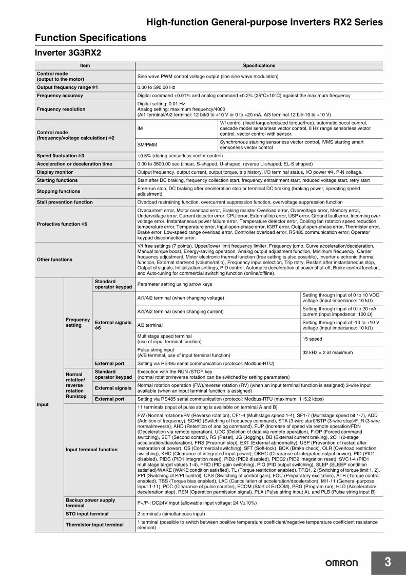
Function SpecificationsInverter 3G3RX2
Item Specifications
Control mode (output to the motor) Sine wave PWM control voltage output (line sine wave modulation)
Output frequency range *1 0.00 to 590.00 Hz
Frequency accuracy Digital command ±0.01% and analog command ±0.2% (25°C±10°C) against the maximum frequency
Frequency resolutionDigital setting: 0.01 HzAnalog setting: maximum frequency/4000(Ai1 terminal/Ai2 terminal: 12 bit/0 to +10 V or 0 to +20 mA, Ai3 terminal 12 bit/-10 to +10 V)
Control mode(frequency/voltage calculation) *2
IMV/f control (fixed torque/reduced torque/free), automatic boost control, cascade model sensorless vector control, 0 Hz range sensorless vector control, vector control with sensor.
SM/PMM Synchronous starting sensorless vector control, IVMS starting smart sensorless vector control
Speed fluctuation *3 ±0.5% (during sensorless vector control)
Acceleration or deceleration time 0.00 to 3600.00 sec (linear, S-shaped, U-shaped, reverse U-shaped, EL-S shaped)
Display monitor Output frequency, output current, output torque, trip history, I/O terminal status, I/O power *4, P-N voltage.
Starting functions Start after DC braking, frequency collection start, frequency entrainment start, reduced voltage start, retry start
Stopping functions Free-run stop, DC braking after deceleration stop or terminal DC braking (braking power, operating speed adjustment)
Stall prevention function Overload restraining function, overcurrent suppression function, overvoltage suppression function
Protective function *5
Overcurrent error, Motor overload error, Braking resister Overload error, Overvoltage error, Memory error, Undervoltage error, Current detector error, CPU error, External trip error, USP error, Ground fault error, Incoming over voltage error, Instantaneous power failure error, Temperature detector error, Cooling fan rotation speed reduction temperature error, Temperature error, Input open-phase error, IGBT error, Output open-phase error, Thermistor error, Brake error, Low-speed range overload error, Controller overload error, RS485 communication error, Operator keypad disconnection error.
Other functions
V/f free settings (7 points), Upper/lower limit frequency limiter, Frequency jump, Curve acceleration/deceleration, Manual torque boost, Energy-saving operation, Analog output adjustment function, Minimum frequency, Carrier frequency adjustment, Motor electronic thermal function (free setting is also possible), Inverter electronic thermal function, External start/end (volume/ratio), Frequency input selection, Trip retry, Restart after instantaneous stop, Output of signals, Initialization settings, PID control, Automatic deceleration at power shut-off, Brake control function, and Auto-tuning for commercial switching function (online/offline).
Input
Frequency setting
Standard operator keypad Parameter setting using arrow keys
External signals *6
Ai1/Ai2 terminal (when changing voltage) Setting through input of 0 to 10 VDC voltage (input impedance: 10 kΩ)
Ai1/Ai2 terminal (when changing current) Setting through input of 0 to 20 mA current (input impedance: 100 Ω)
Ai3 terminal Setting through input of -10 to +10 V voltage (input impedance: 10 kΩ)
Multistage speed terminal(use of input terminal function) 15 speed
Pulse string input(A/B terminal, use of input terminal function) 32 kHz × 2 at maximum
External port Setting via RS485 serial communication (protocol: Modbus-RTU)
Normal rotation/ reverse rotation Run/stop
Standard operator keypad
Execution with the RUN /STOP key(normal rotation/reverse rotation can be switched by setting parameters)
External signals Normal rotation operation (FW)/reverse rotation (RV) (when an input terminal function is assigned) 3-wire input available (when an input terminal function is assigned)
External port Setting via RS485 serial communication (protocol: Modbus-RTU (maximum: 115.2 kbps)
Input terminal function
11 terminals (input of pulse string is available on terminal A and B)
FW (Normal rotation)/RV (Reverse rotation), CF1-4 (Multistage speed 1-4), SF1-7 (Multistage speed bit 1-7), ADD (Addition of frequency), SCHG (Switching of frequency command), STA (3-wire start)/STP (3-wire stop)/F_R (3-wire normal/reverse), AHD (Retention of analog command), FUP (Increase of speed via remote operation/FDN (Deceleration via remote operation), UDC (Deletion of data via remote operation), F-OP (Forced command switching), SET (Second control), RS (Reset), JG (Jogging), DB (External current braking), 2CH (2-stage acceleration/deceleration), FRS (Free-run stop), EXT (External abnormality), USP (Prevention of restart after restoration of power), CS (Commercial switching), SFT (Soft-lock), BOK (Brake check), OLR (Overload restriction switching), KHC (Clearance of integrated input power), OKHC (Clearance of integrated output power), PID (PID1 disabled), PIDC (PID1 integration reset), PID2 (PID2 disabled), PIDC2 (PID2 integration reset), SVC1-4 (PID1 multistage target values 1-4), PRO (PID gain switching), PIO (PID output switching), SLEP (SLEEP condition satisfied)/WAKE (WAKE condition satisfied), TL (Torque restriction enabled), TRQ1, 2 (Switching of torque limit 1, 2), PPI (Switching of P/PI control), CAS (Switching of control gain), FOC (Preparatory excitation), ATR (Torque control enabled), TBS (Torque bias enabled), LAC (Cancellation of acceleration/deceleration), Mi1-11 (General-purpose input 1-11), PCC (Clearance of pulse counter), ECOM (Start of EzCOM), PRG (Program run), HLD (Acceleration/deceleration stop), REN (Operation permission signal), PLA (Pulse string input A), and PLB (Pulse string input B)
Backup power supply terminal P+/P-: DC24V input (allowable input voltage: 24 V±10%)
STO input terminal 2 terminals (simultaneous input)
Thermistor input terminal 1 terminal (possible to switch between positive temperature coefficient/negative temperature coefficient resistance element)
High-function General-purpose Inverters RX2 Series
4
*1. The output frequency range depend on the control and motor used. When running the inverter exceeding 60 Hz, check the maximum allowable frequency with the manufacturer of the motor.
*2. When the control mode is changed, unless the motor constant is appropriately configured, you cannot obtain the desired starting torque or the inverter may trip.
*3. The variable range of motor speed may vary depending on your system or the environment where the motor is used. Please contact us for details.
*4. Both the input power and output power are reference values, which are not appropriate for use in calculation of efficiency values, etc. To obtain an accurate value, use an external device.
*5. The IGBT error [E030] is generated by the protective function not only for short circuit protection but also when IGBT is damaged. Depending on the operating conditions of the inverter, the overcurrent error [E001] may occur, instead of the IGBT error.
*6. At the factory default setting, when voltage and current on Ai1/Ai2 terminal is changed using a switch, with input of voltage at 9.8 V and current at 19.8 mA, the maximum frequency is commanded. To change characteristics, make adjustments using the analog start/end function.
*7. The threshold for signal output varies depending on the motor to be combined with the inverter, parameter adjustment, etc.*8. The output data of analog voltage monitor and analog current monitor are reference values for connecting an analog meter. Due to the meter
to be connected and variation in analog output circuit, the maximum output value may slightly vary from 10 V or 20 mA. To change characteristics, make adjustments using the Ao1 adjustment and Ao2 adjustment functions. Some monitor data cannot be output.
*9. To enable the EMC filter, connect with a power supply grounded at a neutral point. Otherwise, the leakage current may increase.*10. Use the 400 V class inverter at an input voltage of 500 VAC or below. If input voltage exceeds 500 VAC due to fluctuation of power, use the
inverter at 40°C or lower ambient temperature.*11. The storage temperature is the temperature during transport.*12. To be in accordance with the testing method specified in JIS C 60068-2-6: 2010 (IEC 60068-2-6:2007)*13. When the inverter is used in a location at 1000 m or higher altitude, air pressure reduces approximately 1% every 100 m elevation. Perform
1% current der- ating and conduct evaluation for every 100 m elevation.*14. For insulation distance, comply with UL and CE standards*15. When a clock function is used, the optional battery (CR2032, 3 V) is required. When you purchase, this LCD operator does not come with the
battery.
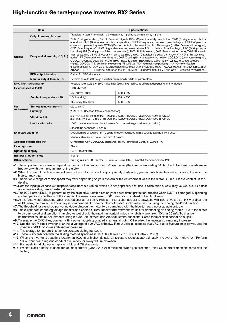
Output
Output terminal function Transistor output 5 terminal, 1a contact relay 1 point, 1c contact relay 1 point
RUN (During operation), FA1-5 (Reached signal), IRDY (Operation ready completion), FWR (During normal rotation operation), RVR (During reverse rotation operation), FREF (Frequency command operator keypad), REF (Operation command operator keypad), SETM (Second control under selection), AL (Alarm signal), MJA (Severe failure signal), OTQ (Over torque) *7, IP (During instantaneous power failure), UV (Under insufficient voltage), TRQ (During torque limitation), IPS (During power failure deceleration), RNT (RUN time over), ONT (Power on time over), THM (Electronic thermal warning), THC (Electronic thermal warning), WAC (Capacitor life advance notice), WAF (Fan life advance notice), FR (Operation command signal), OHF (Cooling fin heating advance notice), LOC/LOC2 (Low-current signal), OL/OL2 (Overload advance notice), BRK (Brake release), BER (Brake abnormality), ZS (Zero-speed detection signal), OD/OD2 (PID deviation excessive), FBV/FBV2 (PID feedback comparison), NDc (Communication disconnection), Ai1Dc/Ai2Dc/Ai3Dc (Analog disconnection Ai1/Ai2/Ai3), WCAi1/WCAi2/WCAi3 (Window comparator Ai1/Ai2/Ai3), LOG1-7 (Logical operation result 1-7), MO1-7 (General output 1-7), and OVS (Receiving overvoltage).
Relay and alarm relay (16, AL)
EDM output terminal Output for STO diagnosis
Monitor output terminal *8 Possible to output through selection from monitor data of parameters
EMC filter switching *9 Possible to enable the EMC noise filter (switching method is different depending on the model)
External access to PC USB Micro-B
Use environment
Ambient temperature *10
ND (normal duty) -10 to 50°C
LD (low duty) -10 to 45°C
VLD (very low duty) -10 to 40°C
Storage temperature *11 -20 to 65°C
Humidity 20-90%RH (location free of condensation)
Vibration *12 5.9 m/s2 (0.6 G) 10 to 55 Hz: 3G3RX2-A2004 to A2220 / 3G3RX2-A4007 to A4220 2.94 m/s2 (0.3 G) 10 to 55 Hz: 3G3RX2-A2300 to A2550 / 3G3RX2-A4300 to A413K
Use location *13 1000 m altitude or lower (location free from corrosive gas, oil mist, and dust)
Expected Life time
Smoothing capacitor 10 years
Designed life of cooling fan 10 years (models equipped with a cooling fan) free from dust
Memory element on the control circuit board
Applicable standards *14 Compliance with UL/cUL/CE standards, RCM, Functional Safety SIL3/PLe, KC
Painting color Black
Operating, display LCD Operator *15
Number of option slots 3 ports
Other options Braking resistor, AC reactor, DC reactor, noise filter, EtherCAT Communication, PG
Item Specifications
High-function General-purpose Inverters RX2 Series
5
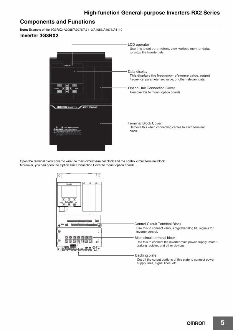
Components and FunctionsNote: Example of the 3G3RX2-A2055/A2075/A2110/A4055/A4075/A4110
Open the terminal block cover to wire the main circuit terminal block and the control circuit terminal block.Moreover, you can open the Option Unit Connection Cover to mount option boards.
LCD operator
Data display
Option Unit Connection Cover
Terminal Block Cover
Use this to set parameters, view various monitor data, run/stop the inverter, etc.
This displays the frequency reference value, output frequency, parameter set value, or other relevant data.
Remove this to mount option boards.
Remove this when connecting cables to each terminalblock.
Inverter 3G3RX2
Control Circuit Terminal BlockUse this to connect various digital/analog I/O signals for inverter control.
Backing plateCut off the cutout portions of this plate to connect power supply lines, signal lines, etc.
Main circuit terminal blockUse this to connect the inverter main power supply, motor, braking resistor, and other devices.
High-function General-purpose Inverters RX2 Series
6
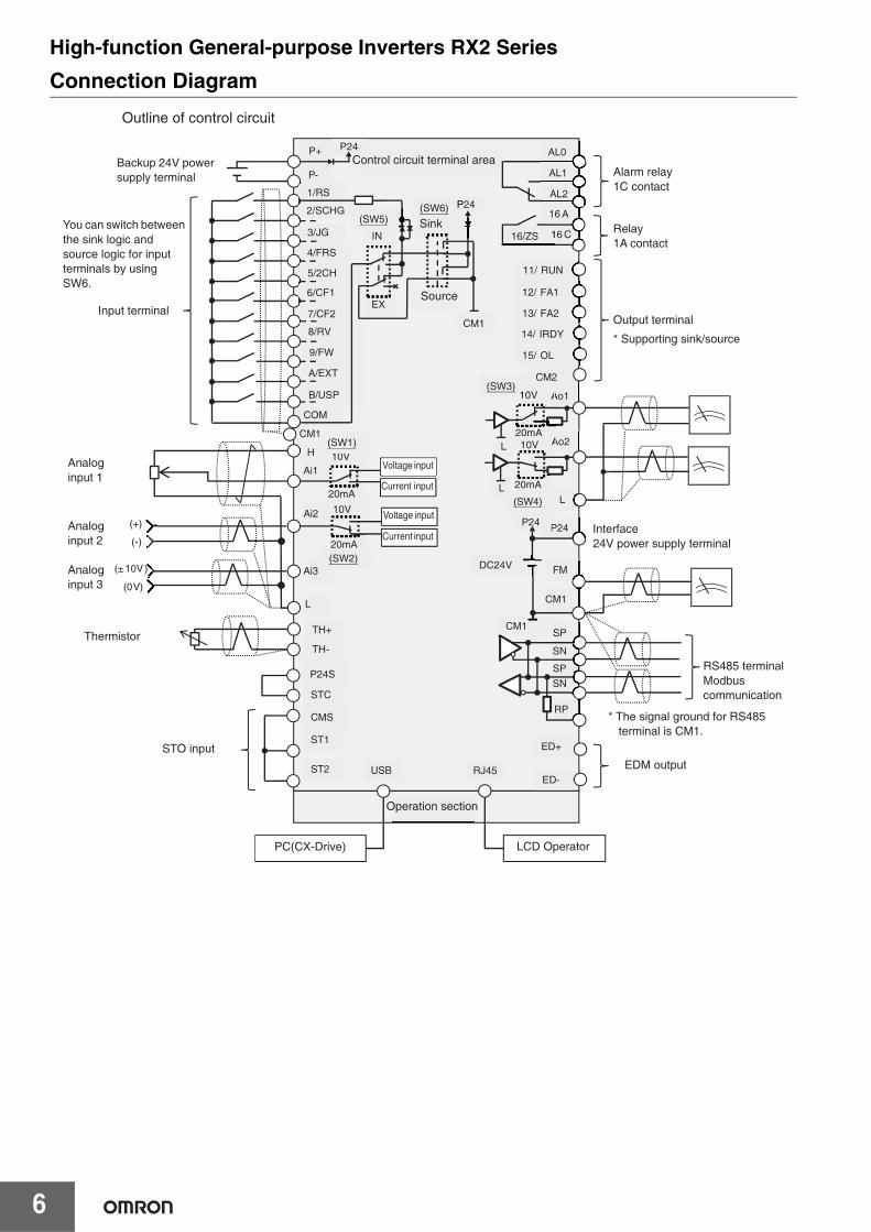
Connection DiagramOutline of control circuit
P+
P-
1/RS
2/SCHG
3/JG
4/FRS
5/2CH
6/CF1
7/CF2
8/RV
9/FW
A/EXT
B/USP
COM
P24
H
Ai1
Ai2
Ai3
L
(+)
(-)
(±10V)
(0V)
TH+
AL2
AL1
AL0
16 A
16 C
11/ RUN
12/ FA1
13/ FA2
14/ IRDY
15/ OL
CM2
FM
CM1
Ao1
Ao2L
SP
SN
SP
SN
RP
P24S
STC
CMS
ST1
ST2
ED+
ED-
TH-
LL
A10V
20mAAA
20mA10V
20mA
10V
10V
20mA
20mA
P24
SCM1
DC24V
P24
CM1
P24
IN
EX
(SW5)
P(SW6)
10V(SW1)
(SW2)
10(SW3)
(SW4)
116/ZS
USB RJ45
CM1
Backup 24V power supply terminal
Input terminal
Analoginput 1
Analoginput 2
Analoginput 3
Thermistor
STO input
LCD Operator
EDM output
* The signal ground for RS485 terminal is CM1.
RS485 terminal Modbus communication
Interface24V power supply terminal
Output terminal
* Supporting sink/source
Relay 1A contact
Alarm relay 1C contact
Control circuit terminal area
Sink
Source
Voltage input
Operation section
You can switch between the sink logic and source logic for input terminals by using SW6.
Current input
Voltage input
Current input
PC(CX-Drive)
High-function General-purpose Inverters RX2 Series
7
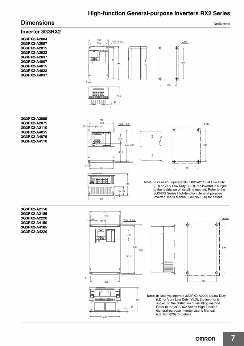
Dimensions (unit: mm)
Inverter 3G3RX2
130150
130
241
4-M5
241
255
Two, 6 dia.
6
47
3
140
3G3RX2-A20043G3RX2-A20073G3RX2-A20153G3RX2-A20223G3RX2-A20373G3RX2-A40073G3RX2-A40153G3RX2-A40223G3RX2-A4037
246
189
4-M6
(78)
149.2
189
1.5
203
170
70
246 260
7
Two, 7 dia.
210189
(78)22
3G3RX2-A20553G3RX2-A20753G3RX2-A21103G3RX2-A40553G3RX2-A40753G3RX2-A4110
Note: In case you operate 3G3RX2-A2110 at Low Duty (LD) or Very Low Duty (VLD), the inverter is subject to the restriction of installing method. Refer to the 3G3RX2 Series High-function General-purpose Inverter User’s Manual (Cat.No.I620) for details.
229
376
4-M6(78)
1.584
235
190
229
229
390376
7
(78)
271.7
Two, 7 dia.
245
42
3G3RX2-A2150 3G3RX2-A21853G3RX2-A22203G3RX2-A41503G3RX2-A41853G3RX2-A4220
Note: In case you operate 3G3RX2-A2220 at Low Duty (LD) or Very Low Duty (VLD), the inverter is subject to the restriction of installing method. Refer to the 3G3RX2 Series High-function General-purpose Inverter User’s Manual (Cat.No.I620) for details.
High-function General-purpose Inverters RX2 Series
8
4-M8
265
510
195
Two, 10 dia.
265
2.3
300
10
265
510 540
15
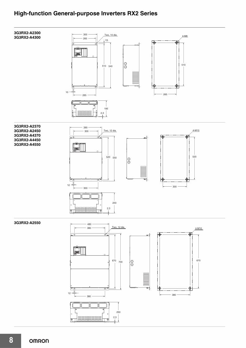
3G3RX2-A23003G3RX2-A4300
4-M10
520
300
550520
12300
Two, 12 dia.390
300
250
2.3
3G3RX2-A23703G3RX2-A24503G3RX2-A43703G3RX2-A44503G3RX2-A4550
4-M10
380
670
Two, 12 dia.
670 700
480
380
38012
250
2.3
3G3RX2-A2550

High-function General-purpose Inverters RX2 Series
9
2.3
4-M10
300
670
300
Two, 12 dia.
270
12
700670
390
300
3G3RX2-B47503G3RX2-B4900
2.3
710
380
4-M10Two, 12 dia.
740710
270
380
380
480
12
3G3RX2-B411K3G3RX2-B413K
High-function General-purpose Inverters RX2 Series
10
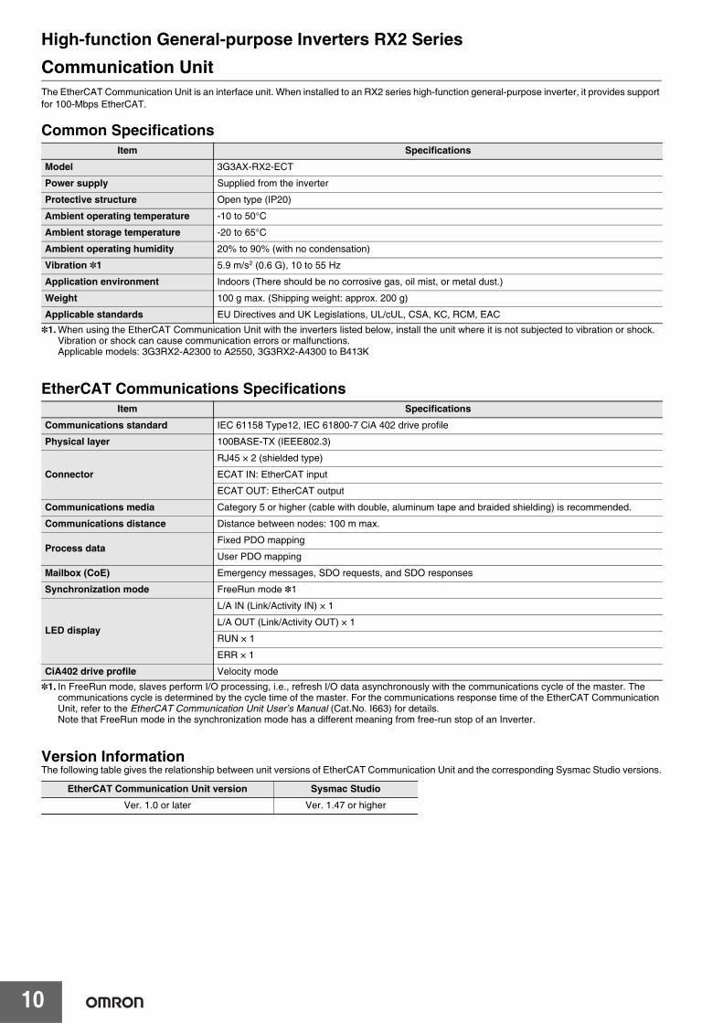
Communication UnitThe EtherCAT Communication Unit is an interface unit. When installed to an RX2 series high-function general-purpose inverter, it provides support for 100-Mbps EtherCAT.
Common Specifications
*1. When using the EtherCAT Communication Unit with the inverters listed below, install the unit where it is not subjected to vibration or shock. Vibration or shock can cause communication errors or malfunctions.Applicable models: 3G3RX2-A2300 to A2550, 3G3RX2-A4300 to B413K
EtherCAT Communications Specifications
*1. In FreeRun mode, slaves perform I/O processing, i.e., refresh I/O data asynchronously with the communications cycle of the master. The communications cycle is determined by the cycle time of the master. For the communications response time of the EtherCAT Communication Unit, refer to the EtherCAT Communication Unit User’s Manual (Cat.No. I663) for details.Note that FreeRun mode in the synchronization mode has a different meaning from free-run stop of an Inverter.
Version InformationThe following table gives the relationship between unit versions of EtherCAT Communication Unit and the corresponding Sysmac Studio versions.
Item Specifications
Model 3G3AX-RX2-ECT
Power supply Supplied from the inverter
Protective structure Open type (IP20)
Ambient operating temperature -10 to 50°C
Ambient storage temperature -20 to 65°C
Ambient operating humidity 20% to 90% (with no condensation)
Vibration *1 5.9 m/s2 (0.6 G), 10 to 55 Hz
Application environment Indoors (There should be no corrosive gas, oil mist, or metal dust.)
Weight 100 g max. (Shipping weight: approx. 200 g)
Applicable standards EU Directives and UK Legislations, UL/cUL, CSA, KC, RCM, EAC
Item Specifications
Communications standard IEC 61158 Type12, IEC 61800-7 CiA 402 drive profile
Physical layer 100BASE-TX (IEEE802.3)
Connector
RJ45 × 2 (shielded type)
ECAT IN: EtherCAT input
ECAT OUT: EtherCAT output
Communications media Category 5 or higher (cable with double, aluminum tape and braided shielding) is recommended.
Communications distance Distance between nodes: 100 m max.
Process data Fixed PDO mapping
User PDO mapping
Mailbox (CoE) Emergency messages, SDO requests, and SDO responses
Synchronization mode FreeRun mode *1
LED display
L/A IN (Link/Activity IN) × 1
L/A OUT (Link/Activity OUT) × 1
RUN × 1
ERR × 1
CiA402 drive profile Velocity mode
EtherCAT Communication Unit version Sysmac Studio
Ver. 1.0 or later Ver. 1.47 or higher
High-function General-purpose Inverters RX2 Series
11
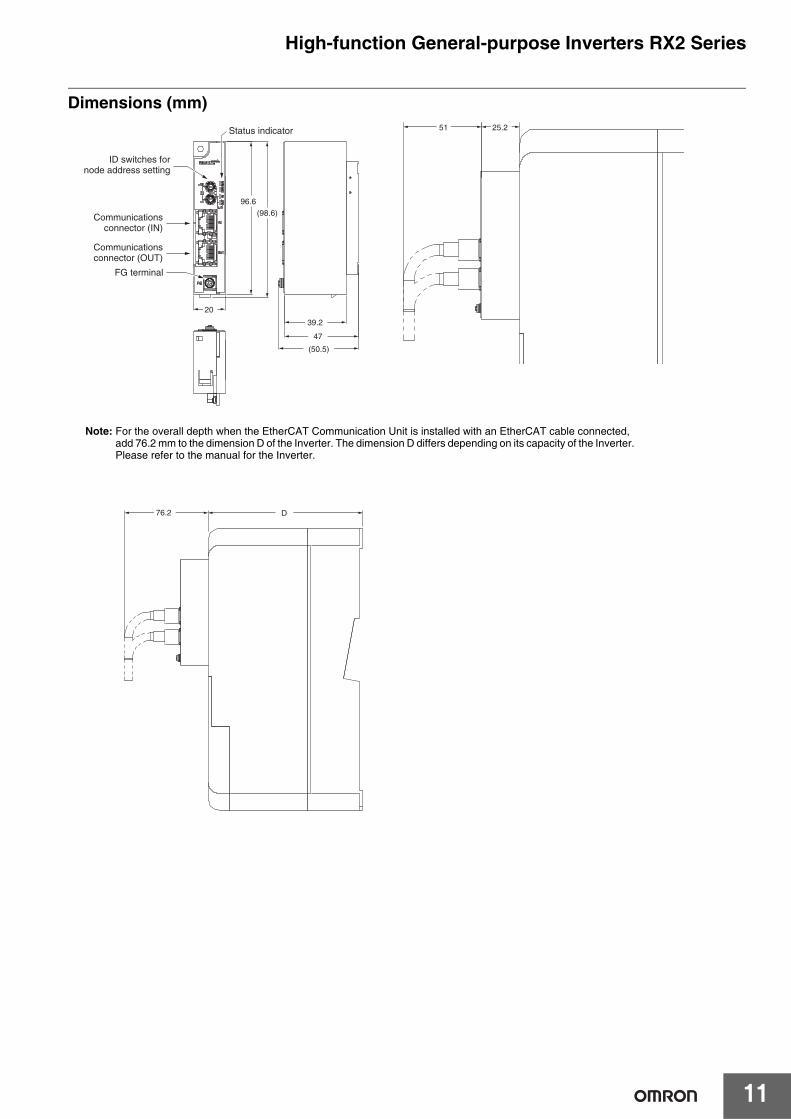
Dimensions (mm)
ID switches fornode address setting
FG terminal
Status indicator 51 25.2
(50.5)
(98.6)
39.2
47
20
96.6
Communicationsconnector (OUT)
Communicationsconnector (IN)
76.2 D
Note: For the overall depth when the EtherCAT Communication Unit is installed with an EtherCAT cable connected, add 76.2 mm to the dimension D of the Inverter. The dimension D differs depending on its capacity of the Inverter. Please refer to the manual for the Inverter.
High-function General-purpose Inverters RX2 Series
12
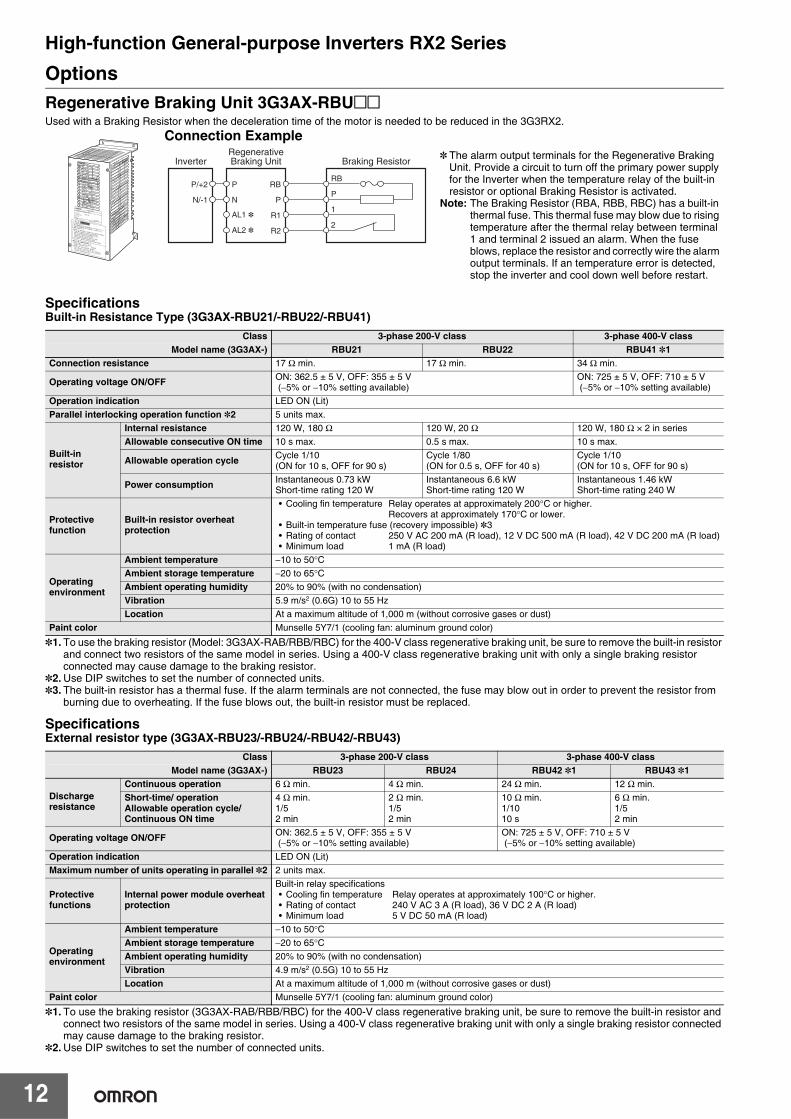
OptionsRegenerative Braking Unit 3G3AX-RBU@@Used with a Braking Resistor when the deceleration time of the motor is needed to be reduced in the 3G3RX2.
SpecificationsBuilt-in Resistance Type (3G3AX-RBU21/-RBU22/-RBU41)
*1. To use the braking resistor (Model: 3G3AX-RAB/RBB/RBC) for the 400-V class regenerative braking unit, be sure to remove the built-in resistor and connect two resistors of the same model in series. Using a 400-V class regenerative braking unit with only a single braking resistor connected may cause damage to the braking resistor.
*2. Use DIP switches to set the number of connected units.*3. The built-in resistor has a thermal fuse. If the alarm terminals are not connected, the fuse may blow out in order to prevent the resistor from
burning due to overheating. If the fuse blows out, the built-in resistor must be replaced.
SpecificationsExternal resistor type (3G3AX-RBU23/-RBU24/-RBU42/-RBU43)
*1. To use the braking resistor (3G3AX-RAB/RBB/RBC) for the 400-V class regenerative braking unit, be sure to remove the built-in resistor and connect two resistors of the same model in series. Using a 400-V class regenerative braking unit with only a single braking resistor connected may cause damage to the braking resistor.
*2. Use DIP switches to set the number of connected units.
Class 3-phase 200-V class 3-phase 400-V classModel name (3G3AX-) RBU21 RBU22 RBU41 *1
Connection resistance 17 Ω min. 17 Ω min. 34 Ω min.
Operating voltage ON/OFF ON: 362.5 ± 5 V, OFF: 355 ± 5 V (−5% or −10% setting available)
ON: 725 ± 5 V, OFF: 710 ± 5 V (−5% or −10% setting available)
Operation indication LED ON (Lit)Parallel interlocking operation function *2 5 units max.
Built-in resistor
Internal resistance 120 W, 180 Ω 120 W, 20 Ω 120 W, 180 Ω × 2 in seriesAllowable consecutive ON time 10 s max. 0.5 s max. 10 s max.
Allowable operation cycle Cycle 1/10(ON for 10 s, OFF for 90 s)
Cycle 1/80(ON for 0.5 s, OFF for 40 s)
Cycle 1/10(ON for 10 s, OFF for 90 s)
Power consumption Instantaneous 0.73 kWShort-time rating 120 W
Instantaneous 6.6 kWShort-time rating 120 W
Instantaneous 1.46 kWShort-time rating 240 W
Protectivefunction
Built-in resistor overheatprotection
• Cooling fin temperature Relay operates at approximately 200°C or higher.Recovers at approximately 170°C or lower.
• Built-in temperature fuse (recovery impossible) *3• Rating of contact 250 V AC 200 mA (R load), 12 V DC 500 mA (R load), 42 V DC 200 mA (R load)• Minimum load 1 mA (R load)
Operatingenvironment
Ambient temperature −10 to 50°CAmbient storage temperature −20 to 65°CAmbient operating humidity 20% to 90% (with no condensation)Vibration 5.9 m/s2 (0.6G) 10 to 55 HzLocation At a maximum altitude of 1,000 m (without corrosive gases or dust)
Paint color Munselle 5Y7/1 (cooling fan: aluminum ground color)
Class 3-phase 200-V class 3-phase 400-V classModel name (3G3AX-) RBU23 RBU24 RBU42 *1 RBU43 *1
Discharge resistance
Continuous operation 6 Ω min. 4 Ω min. 24 Ω min. 12 Ω min.Short-time/ operationAllowable operation cycle/Continuous ON time
4 Ω min.1/52 min
2 Ω min.1/52 min
10 Ω min.1/1010 s
6 Ω min.1/52 min
Operating voltage ON/OFF ON: 362.5 ± 5 V, OFF: 355 ± 5 V (−5% or −10% setting available)
ON: 725 ± 5 V, OFF: 710 ± 5 V (−5% or −10% setting available)
Operation indication LED ON (Lit)Maximum number of units operating in parallel *2 2 units max.
Protective functions
Internal power module overheat protection
Built-in relay specifications• Cooling fin temperature Relay operates at approximately 100°C or higher.• Rating of contact 240 V AC 3 A (R load), 36 V DC 2 A (R load)• Minimum load 5 V DC 50 mA (R load)
Operating environment
Ambient temperature −10 to 50°CAmbient storage temperature −20 to 65°CAmbient operating humidity 20% to 90% (with no condensation)Vibration 4.9 m/s2 (0.5G) 10 to 55 HzLocation At a maximum altitude of 1,000 m (without corrosive gases or dust)
Paint color Munselle 5Y7/1 (cooling fan: aluminum ground color)
Connection Example
InverterRegenerativeBraking Unit Braking Resistor
RB
P
AL1 *
AL2 *
P
N
RB
P1
2R1
R2
P/+2
N/-1
* The alarm output terminals for the Regenerative Braking Unit. Provide a circuit to turn off the primary power supply for the Inverter when the temperature relay of the built-in resistor or optional Braking Resistor is activated.
Note: The Braking Resistor (RBA, RBB, RBC) has a built-in thermal fuse. This thermal fuse may blow due to rising temperature after the thermal relay between terminal 1 and terminal 2 issued an alarm. When the fuse blows, replace the resistor and correctly wire the alarm output terminals. If an temperature error is detected, stop the inverter and cool down well before restart.
High-function General-purpose Inverters RX2 Series
13
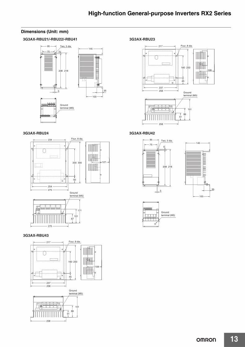
Dimensions (Unit: mm)
Groundterminal (M5)
234
200
50
67101
171
300
254
127
275
275
Four, 8 dia.
Groundterminal (M5)
217
109
237258
258
160
45
5186
151
250
Groundterminal (M5)
Four, 8 dia.
95145
35
100
5
755
208 218
Two, 5 dia.
Groundterminal (M5)
217
160
45
5186
151
250
237258
258
109
Groundterminal (M5)
Four, 8 dia.
95
5
100
35
1455
208 218
75
Two, 5 dia.
3G3AX-RBU21/-RBU22/-RBU41 3G3AX-RBU23
3G3AX-RBU24 3G3AX-RBU42
3G3AX-RBU43
High-function General-purpose Inverters RX2 Series
14
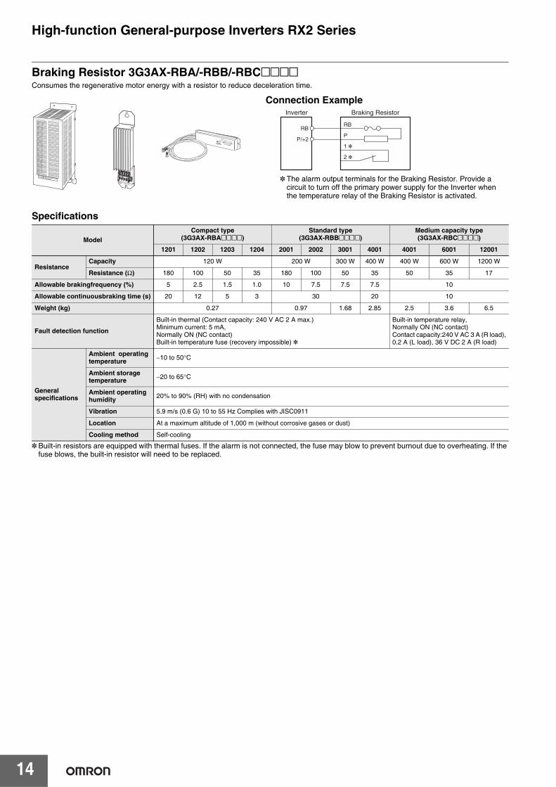
Braking Resistor 3G3AX-RBA/-RBB/-RBC@@@@Consumes the regenerative motor energy with a resistor to reduce deceleration time.
Specifications
* Built-in resistors are equipped with thermal fuses. If the alarm is not connected, the fuse may blow to prevent burnout due to overheating. If the fuse blows, the built-in resistor will need to be replaced.
ModelCompact type
(3G3AX-RBA@@@@)Standard type
(3G3AX-RBB@@@@)Medium capacity type(3G3AX-RBC@@@@)
1201 1202 1203 1204 2001 2002 3001 4001 4001 6001 12001
ResistanceCapacity 120 W 200 W 300 W 400 W 400 W 600 W 1200 W
Resistance (Ω) 180 100 50 35 180 100 50 35 50 35 17
Allowable brakingfrequency (%) 5 2.5 1.5 1.0 10 7.5 7.5 7.5 10
Allowable continuousbraking time (s) 20 12 5 3 30 20 10
Weight (kg) 0.27 0.97 1.68 2.85 2.5 3.6 6.5
Fault detection function
Built-in thermal (Contact capacity: 240 V AC 2 A max.)Minimum current: 5 mA, Normally ON (NC contact)Built-in temperature fuse (recovery impossible) *
Built-in temperature relay,Normally ON (NC contact)Contact capacity:240 V AC 3 A (R load),0.2 A (L load), 36 V DC 2 A (R load)
General specifications
Ambient operatingtemperature −10 to 50°C
Ambient storagetemperature −20 to 65°C
Ambient operatinghumidity 20% to 90% (RH) with no condensation
Vibration 5.9 m/s (0.6 G) 10 to 55 Hz Complies with JISC0911
Location At a maximum altitude of 1,000 m (without corrosive gases or dust)
Cooling method Self-cooling
Connection ExampleBraking Resistor
RB
P
1 *
2 *
Inverter
P/+2
RB
* The alarm output terminals for the Braking Resistor. Provide a circuit to turn off the primary power supply for the Inverter when the temperature relay of the Braking Resistor is activated.
High-function General-purpose Inverters RX2 Series
15
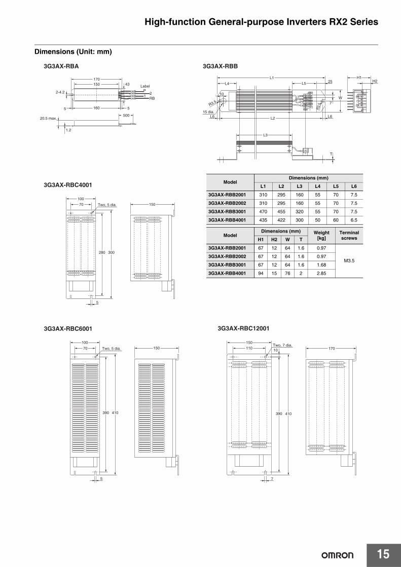
Dimensions (Unit: mm)
LabelP
21
RB
3G3AX-RBA 3G3AX-RBB
3G3AX-RBC4001
3G3AX-RBC120013G3AX-RBC6001
150
110
7
10 170
390 410390 410
100
70 150
150
280 300
5
5
100
70
500
1.2
20.5 max.
H1H2
L1
L4 L5 25
T
15 dia.
R3.5
10
L6
L3
L2 L6
R3.
5
W7
2-4.2
43170150
160 55
Two, 5 dia.
Two, 5 dia.Two, 7 dia.
ModelDimensions (mm)
L1 L2 L3 L4 L5 L6
3G3AX-RBB2001 310 295 160 55 70 7.5
3G3AX-RBB2002 310 295 160 55 70 7.5
3G3AX-RBB3001 470 455 320 55 70 7.5
3G3AX-RBB4001 435 422 300 50 60 6.5
ModelDimensions (mm) Weight
[kg]Terminal screwsH1 H2 W T
3G3AX-RBB2001 67 12 64 1.6 0.97
M3.53G3AX-RBB2002 67 12 64 1.6 0.97
3G3AX-RBB3001 67 12 64 1.6 1.68
3G3AX-RBB4001 94 15 76 2 2.85
High-function General-purpose Inverters RX2 Series
16
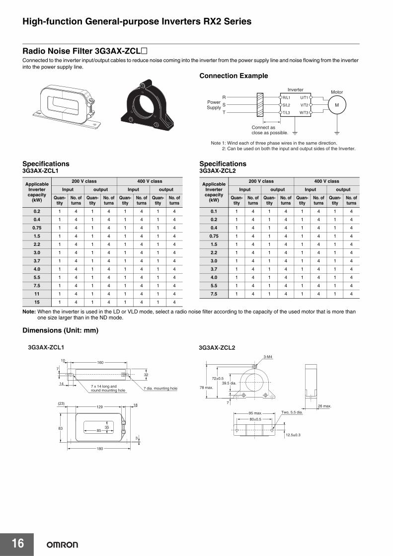
Radio Noise Filter 3G3AX-ZCL@Connected to the inverter input/output cables to reduce noise coming into the inverter from the power supply line and noise flowing from the inverter into the power supply line.
Specifications3G3AX-ZCL1
Specifications3G3AX-ZCL2
Note: When the inverter is used in the LD or VLD mode, select a radio noise filter according to the capacity of the used motor that is more than one size larger than in the ND mode.
Dimensions (Unit: mm)
Connection Example
R
S
T
M
Motor
PowerSupply
Connect asclose as possible.
Note 1: Wind each of three phase wires in the same direction.2: Can be used on both the input and output sides of the Inverter.
Inverter
U/T1
V/T2
W/T3
S/L2
T/L3
R/L1
ApplicableInvertercapacity
(kW)
200 V class 400 V class
Input output Input output
Quan-tity
No. ofturns
Quan-tity
No. ofturns
Quan-tity
No. ofturns
Quan-tity
No. ofturns
0.2 1 4 1 4 1 4 1 4
0.4 1 4 1 4 1 4 1 4
0.75 1 4 1 4 1 4 1 4
1.5 1 4 1 4 1 4 1 4
2.2 1 4 1 4 1 4 1 4
3.0 1 4 1 4 1 4 1 4
3.7 1 4 1 4 1 4 1 4
4.0 1 4 1 4 1 4 1 4
5.5 1 4 1 4 1 4 1 4
7.5 1 4 1 4 1 4 1 4
11 1 4 1 4 1 4 1 4
15 1 4 1 4 1 4 1 4
ApplicableInvertercapacity
(kW)
200 V class 400 V class
Input output Input output
Quan-tity
No. ofturns
Quan-tity
No. ofturns
Quan-tity
No. ofturns
Quan-tity
No. ofturns
0.1 1 4 1 4 1 4 1 4
0.2 1 4 1 4 1 4 1 4
0.4 1 4 1 4 1 4 1 4
0.75 1 4 1 4 1 4 1 4
1.5 1 4 1 4 1 4 1 4
2.2 1 4 1 4 1 4 1 4
3.0 1 4 1 4 1 4 1 4
3.7 1 4 1 4 1 4 1 4
4.0 1 4 1 4 1 4 1 4
5.5 1 4 1 4 1 4 1 4
7.5 1 4 1 4 1 4 1 4
160
3-M4
26 max.
95 max. Two, 5.5 dia.
80±0.5
18129
85
180
(23)
10
147 x 14 long and round mounting hole 7 dia. mounting hole
7
83 35
32
78 max.
12.5±0.3
39.5 dia.
7
72±0.5
3
3G3AX-ZCL1 3G3AX-ZCL2
High-function General-purpose Inverters RX2 Series
17
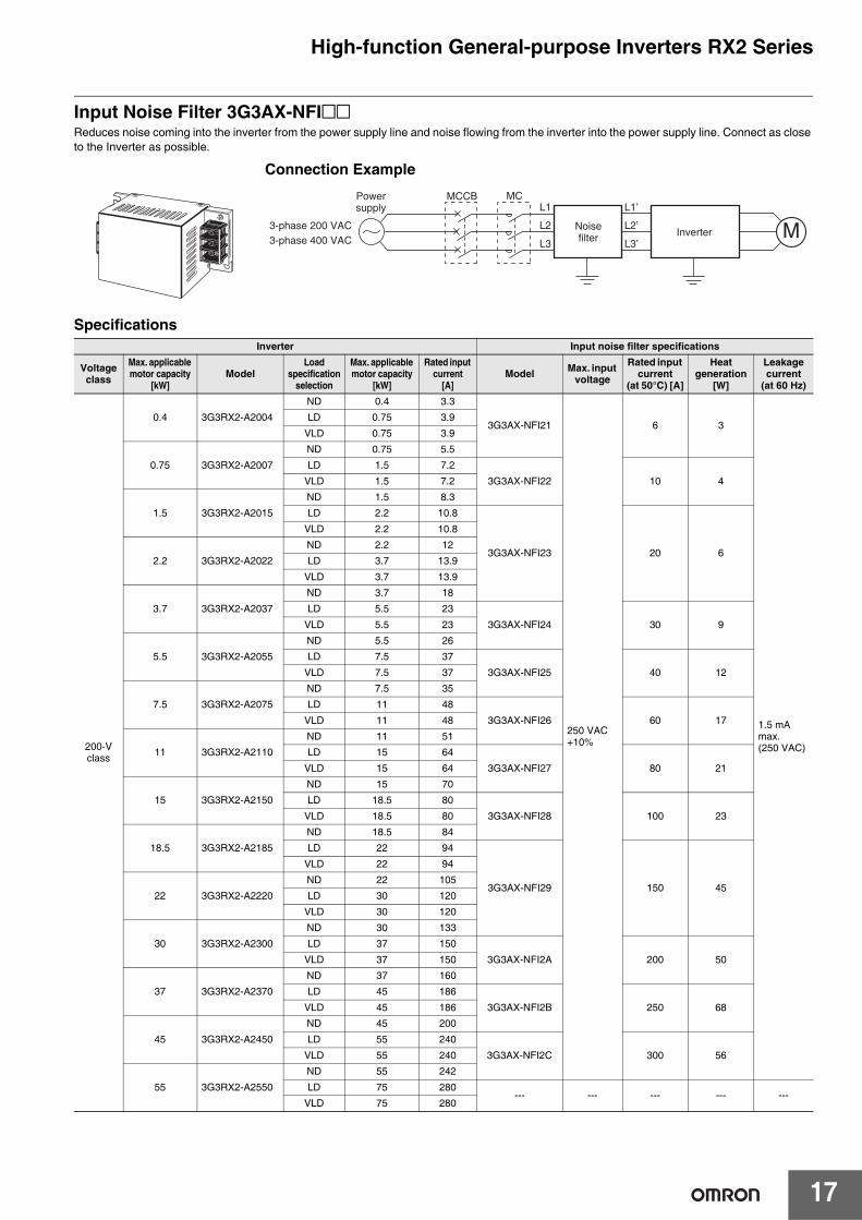
Input Noise Filter 3G3AX-NFI@@Reduces noise coming into the inverter from the power supply line and noise flowing from the inverter into the power supply line. Connect as close to the Inverter as possible.
SpecificationsInverter Input noise filter specifications
Voltageclass
Max. applicable motor capacity
[kW]Model
Load specification
selection
Max. applicable motor capacity
[kW]
Rated input current
[A]Model Max. input
voltage
Rated input current
(at 50°C) [A]
Heat generation
[W]
Leakage current
(at 60 Hz)
200-Vclass
0.4 3G3RX2-A2004
ND 0.4 3.3
3G3AX-NFI21
250 VAC+10%
6 3
1.5 mA max.(250 VAC)
LD 0.75 3.9
VLD 0.75 3.9
0.75 3G3RX2-A2007
ND 0.75 5.5
LD 1.5 7.2
3G3AX-NFI22 10 4VLD 1.5 7.2
1.5 3G3RX2-A2015
ND 1.5 8.3
LD 2.2 10.8
3G3AX-NFI23 20 6
VLD 2.2 10.8
2.2 3G3RX2-A2022
ND 2.2 12
LD 3.7 13.9
VLD 3.7 13.9
3.7 3G3RX2-A2037
ND 3.7 18
LD 5.5 23
3G3AX-NFI24 30 9VLD 5.5 23
5.5 3G3RX2-A2055
ND 5.5 26
LD 7.5 37
3G3AX-NFI25 40 12VLD 7.5 37
7.5 3G3RX2-A2075
ND 7.5 35
LD 11 48
3G3AX-NFI26 60 17VLD 11 48
11 3G3RX2-A2110
ND 11 51
LD 15 64
3G3AX-NFI27 80 21VLD 15 64
15 3G3RX2-A2150
ND 15 70
LD 18.5 80
3G3AX-NFI28 100 23VLD 18.5 80
18.5 3G3RX2-A2185
ND 18.5 84
LD 22 94
3G3AX-NFI29 150 45
VLD 22 94
22 3G3RX2-A2220
ND 22 105
LD 30 120
VLD 30 120
30 3G3RX2-A2300
ND 30 133
LD 37 150
3G3AX-NFI2A 200 50VLD 37 150
37 3G3RX2-A2370
ND 37 160
LD 45 186
3G3AX-NFI2B 250 68VLD 45 186
45 3G3RX2-A2450
ND 45 200
LD 55 240
3G3AX-NFI2C 300 56VLD 55 240
55 3G3RX2-A2550
ND 55 242
LD 75 280--- --- --- --- ---
VLD 75 280
Connection Example
MNoisefilter Inverter
3-phase 200 VAC3-phase 400 VAC
Powersupply
MCL1
L2
L3
L1’
L2’
L3’
MCCB

High-function General-purpose Inverters RX2 Series
18
400-Vclass
0.75 3G3RX2-A4007
ND 0.75 2.8
3G3AX-NFI41
480 VAC+10%
7 2
7.5 mA max.(480 VAC)
LD 1.5 4.3
VLD 1.5 4.3
1.5 3G3RX2-A4015
ND 1.5 4.2
LD 2.2 5.9
VLD 2.2 5.9
2.2 3G3RX2-A4022
ND 2.2 5.8
LD 3.7 8.1
3G3AX-NFI42 10 4VLD 3.7 8.1
3.7 3G3RX2-A4037
ND 3.7 9.8
LD 5.5 13.3
3G3AX-NFI43 20 6
VLD 5.5 13.3
5.5 3G3RX2-A4055
ND 5.5 15
LD 7.5 20
VLD 7.5 20
7.5 3G3RX2-A4075
ND 7.5 21
LD 11 24
3G3AX-NFI44 30 9VLD 11 24
11 3G3RX2-A4110
ND 11 28
LD 15 32
3G3AX-NFI45 40 12VLD 15 32
15 3G3RX2-A4150
ND 15 35
LD 18.5 41
3G3AX-NFI46 50 15VLD 18.5 41
18.5 3G3RX2-A4185
ND 18.5 42
LD 22 47
3G3AX-NFI47 60 17VLD 22 47
22 3G3RX2-A4220
ND 22 53
LD 30 63
3G3AX-NFI48 80 21VLD 30 63
30 3G3RX2-A4300
ND 30 64
LD 37 77
3G3AX-NFI49 100 23VLD 37 77
37 3G3RX2-A4370
ND 37 83
LD 45 94
3G3AX-NFI4A 150 45
VLD 45 94
45 3G3RX2-A4450
ND 45 100
LD 55 116
VLD 55 116
55 3G3RX2-A4550
ND 55 121
LD 75 149--- --- --- --- ---
VLD 75 149
Inverter Input noise filter specifications
Voltageclass
Max. applicable motor capacity
[kW]Model
Load specification
selection
Max. applicable motor capacity
[kW]
Rated input current
[A]Model Max. input
voltage
Rated input current
(at 50°C) [A]
Heat generation
[W]
Leakage current
(at 60 Hz)
High-function General-purpose Inverters RX2 Series
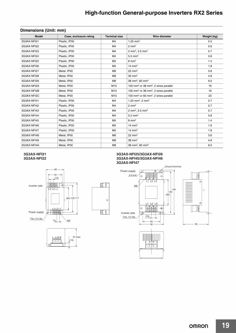
19
Dimensions (Unit: mm)Model Case, enclosure rating Terminal size Wire diameter Weight [kg]
3G3AX-NFI21 Plastic, IP00 M4 1.25 mm2 0.5
3G3AX-NFI22 Plastic, IP00 M4 2 mm2 0.6
3G3AX-NFI23 Plastic, IP00 M4 2 mm2, 3.5 mm2 0.7
3G3AX-NFI24 Plastic, IP00 M4 5.5 mm2 0.8
3G3AX-NFI25 Plastic, IP00 M5 8 mm2 1.4
3G3AX-NFI26 Plastic, IP00 M5 14 mm2 1.8
3G3AX-NFI27 Metal, IP00 M6 22 mm2 3.6
3G3AX-NFI28 Metal, IP00 M8 30 mm2 4.6
3G3AX-NFI29 Metal, IP00 M8 38 mm2, 60 mm2 9.0
3G3AX-NFI2A Metal, IP00 M10 100 mm2 or 38 mm2, 2 wires parallel 16
3G3AX-NFI2B Metal, IP00 M10 100 mm2 or 38 mm2, 2 wires parallel 16
3G3AX-NFI2C Metal, IP00 M10 150 mm2 or 60 mm2, 2 wires parallel 23
3G3AX-NFI41 Plastic, IP00 M4 1.25 mm2, 2 mm2 0.7
3G3AX-NFI42 Plastic, IP00 M4 2 mm2 0.7
3G3AX-NFI43 Plastic, IP00 M4 2 mm2, 3.5 mm2 0.7
3G3AX-NFI44 Plastic, IP00 M4 5.5 mm2 0.8
3G3AX-NFI45 Plastic, IP00 M5 8 mm2 1.4
3G3AX-NFI46 Plastic, IP00 M5 14 mm2 1.6
3G3AX-NFI47 Plastic, IP00 M5 14 mm2 1.8
3G3AX-NFI48 Metal, IP00 M6 22 mm2 3.6
3G3AX-NFI49 Metal, IP00 M8 38 mm2 4.6
3G3AX-NFI4A Metal, IP00 M8 38 mm2, 60 mm2 9.0
Inverter side
66
52(10)
L3' L2' L1'
L3 L2 L1
(84) 100 117
Two, 5.0 dia.10 M4
67 max.(15)
Power supply Inverter side
6590
(16)
L1' L2' L3'
L1 L2 L3
155165
Two, 4.5 dia.
M6
(95)
Power supply
Ground terminal
2-4.5×6
95
3G3AX-NFI213G3AX-NFI22
3G3AX-NFI25/3G3AX-NFI263G3AX-NFI45/3G3AX-NFI463G3AX-NFI47
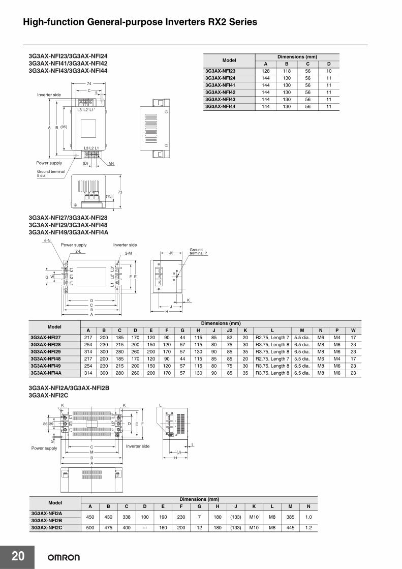
High-function General-purpose Inverters RX2 Series
20
Inverter side
Power supply
L3' L2' L1'
L3 L2 L1
(95)
74
(D)
5
M4
(15)73
C
BA
3G3AX-NFI23/3G3AX-NFI243G3AX-NFI41/3G3AX-NFI423G3AX-NFI43/3G3AX-NFI44
Ground terminal 5 dia.
ModelDimensions (mm)
A B C D3G3AX-NFI23 128 118 56 103G3AX-NFI24 144 130 56 113G3AX-NFI41 144 130 56 113G3AX-NFI42 144 130 56 113G3AX-NFI43 144 130 56 113G3AX-NFI44 144 130 56 11
Inverter side
A
6-N
G
Power supply
L1'
L2'
L3'L3 L2 L1
BCD
F EW
2-L 2-M
JH
J2
K
Ground terminal P
3G3AX-NFI27/3G3AX-NFI283G3AX-NFI29/3G3AX-NFI483G3AX-NFI49/3G3AX-NFI4A
ModelDimensions (mm)
A B C D E F G H J J2 K L M N P W3G3AX-NFI27 217 200 185 170 120 90 44 115 85 82 20 R2.75, Length 7 5.5 dia. M6 M4 173G3AX-NFI28 254 230 215 200 150 120 57 115 80 75 30 R3.75, Length 8 6.5 dia. M8 M6 233G3AX-NFI29 314 300 280 260 200 170 57 130 90 85 35 R3.75, Length 8 6.5 dia. M8 M6 233G3AX-NFI48 217 200 185 170 120 90 44 115 85 85 20 R2.75, Length 7 5.5 dia. M6 M4 173G3AX-NFI49 254 230 215 200 150 120 57 115 80 75 30 R3.75, Length 8 6.5 dia. M8 M6 233G3AX-NFI4A 314 300 280 260 200 170 57 130 90 85 35 R3.75, Length 8 6.5 dia. M8 M6 23
ModelDimensions (mm)
A B C D E F G H J K L M N3G3AX-NFI2A
450 430 338 100 190 230 7 180 (133) M10 M8 385 1.03G3AX-NFI2B3G3AX-NFI2C 500 475 400 --- 160 200 12 180 (133) M10 M8 445 1.2
Inverter side
A
G
Power supply
L1'
L2'
L3'L3 L2 L1
B
C
FE
M
H
K K L
t
(J)
D86 39
3G3AX-NFI2A/3G3AX-NFI2B3G3AX-NFI2C
High-function General-purpose Inverters RX2 Series
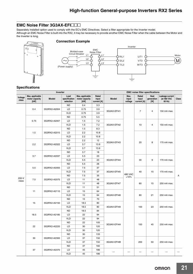
21
EMC Noise Filter 3G3AX-EFI@@@Separately installed option used to comply with the EC's EMC Directives. Select a filter appropriate for the Inverter model.Although an EMC Noise Filter is built into the RX2, it may be necessary to provide another EMC Noise Filter when the cable between the Motor andthe Inverter is long.
SpecificationsInverter EMC noise filter specifications
Voltage class
Max. applicable motor capacity
[kW]Model
Load specification
selection
Max. applicable motor capacity
[kW]
Rated input
current [A]Model
Max. input
voltage
Rated input
current [A]
Heat generation
[W]
Leakage current(at 480 VAC
60 Hz)Class
200-Vclass
0.4 3G3RX2-A2004
ND 0.4 3.3
3G3AX-EFI41
480 VAC+10%
7 4 150 mA max.
A
LD 0.75 3.9
VLD 0.75 3.9
0.75 3G3RX2-A2007
ND 0.75 5.5
LD 1.5 7.2
3G3AX-EFI42 10 4 150 mA max.VLD 1.5 7.2
1.5 3G3RX2-A2015
ND 1.5 8.3
LD 2.2 10.8
3G3AX-EFI43 20 8 170 mA max.
VLD 2.2 10.8
2.2 3G3RX2-A2022
ND 2.2 12
LD 3.7 13.9
VLD 3.7 13.9
3.7 3G3RX2-A2037
ND 3.7 18
LD 5.5 23
3G3AX-EFI44 30 9 170 mA max.VLD 5.5 23
5.5 3G3RX2-A2055
ND 5.5 26
LD 7.5 37
3G3AX-EFI45 40 15 170 mA max.VLD 7.5 37
7.5 3G3RX2-A2075
ND 7.5 35
LD 11 48
3G3AX-EFI47 60 15 250 mA max.VLD 11 48
11 3G3RX2-A2110
ND 11 51
LD 15 64
3G3AX-EFI48 80 21 250 mA max.VLD 15 64
15 3G3RX2-A2150
ND 15 70
LD 18.5 80
3G3AX-EFI49 100 23 250 mA max.VLD 18.5 80
18.5 3G3RX2-A2185
ND 18.5 84
LD 22 94
3G3AX-EFI4A 150 45 250 mA max.
VLD 22 94
22 3G3RX2-A2220
ND 22 105
LD 30 120
VLD 30 120
30 3G3RX2-A2300
ND 30 133
LD 37 150
3G3AX-EFI4B 200 50 250 mA max.VLD 37 150
37 3G3RX2-A2370
ND 37 160
LD 45 186--- --- --- --- --- ---
VLD 45 186
Connection Example
L1 L1'
L2'
L3'
L2
L3
R/L1
S/L2
T/L3
U/T1
V/T2
W/T3M
(Power supply)
EMCNoise FilterMolded-case
Circuit BreakerMotor
Inverter
High-function General-purpose Inverters RX2 Series
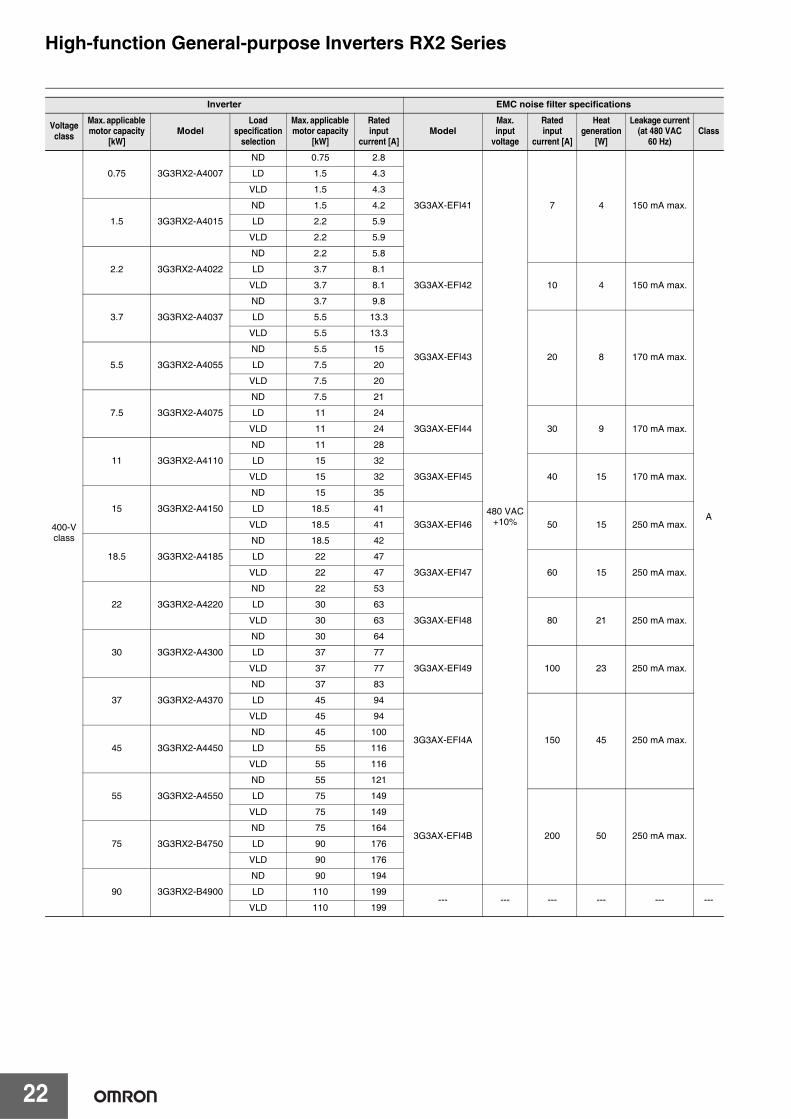
22
400-Vclass
0.75 3G3RX2-A4007
ND 0.75 2.8
3G3AX-EFI41
480 VAC+10%
7 4 150 mA max.
A
LD 1.5 4.3
VLD 1.5 4.3
1.5 3G3RX2-A4015
ND 1.5 4.2
LD 2.2 5.9
VLD 2.2 5.9
2.2 3G3RX2-A4022
ND 2.2 5.8
LD 3.7 8.1
3G3AX-EFI42 10 4 150 mA max.VLD 3.7 8.1
3.7 3G3RX2-A4037
ND 3.7 9.8
LD 5.5 13.3
3G3AX-EFI43 20 8 170 mA max.
VLD 5.5 13.3
5.5 3G3RX2-A4055
ND 5.5 15
LD 7.5 20
VLD 7.5 20
7.5 3G3RX2-A4075
ND 7.5 21
LD 11 24
3G3AX-EFI44 30 9 170 mA max.VLD 11 24
11 3G3RX2-A4110
ND 11 28
LD 15 32
3G3AX-EFI45 40 15 170 mA max.VLD 15 32
15 3G3RX2-A4150
ND 15 35
LD 18.5 41
3G3AX-EFI46 50 15 250 mA max.VLD 18.5 41
18.5 3G3RX2-A4185
ND 18.5 42
LD 22 47
3G3AX-EFI47 60 15 250 mA max.VLD 22 47
22 3G3RX2-A4220
ND 22 53
LD 30 63
3G3AX-EFI48 80 21 250 mA max.VLD 30 63
30 3G3RX2-A4300
ND 30 64
LD 37 77
3G3AX-EFI49 100 23 250 mA max.VLD 37 77
37 3G3RX2-A4370
ND 37 83
LD 45 94
3G3AX-EFI4A 150 45 250 mA max.
VLD 45 94
45 3G3RX2-A4450
ND 45 100
LD 55 116
VLD 55 116
55 3G3RX2-A4550
ND 55 121
LD 75 149
3G3AX-EFI4B 200 50 250 mA max.
VLD 75 149
75 3G3RX2-B4750
ND 75 164
LD 90 176
VLD 90 176
90 3G3RX2-B4900
ND 90 194
LD 110 199--- --- --- --- --- ---
VLD 110 199
Inverter EMC noise filter specifications
Voltage class
Max. applicable motor capacity
[kW]Model
Load specification
selection
Max. applicable motor capacity
[kW]
Rated input
current [A]Model
Max. input
voltage
Rated input
current [A]
Heat generation
[W]
Leakage current(at 480 VAC
60 Hz)Class
High-function General-purpose Inverters RX2 Series
23
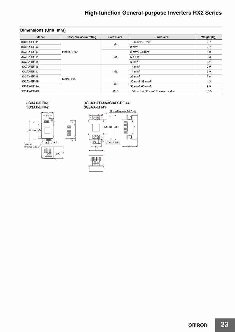
Dimensions (Unit: mm)Model Case, enclosure rating Screw size Wire size Weight [kg]
3G3AX-EFI41
Plastic, IP00
M41.25 mm2, 2 mm2 0.7
3G3AX-EFI42 2 mm2 0.7
3G3AX-EFI43
M5
2 mm2, 3.5 mm2 1.0
3G3AX-EFI44 5.5 mm2 1.3
3G3AX-EFI45 8 mm2 1.4
3G3AX-EFI46
Metal, IP00
M6
14 mm2 2.9
3G3AX-EFI47 14 mm2 3.0
3G3AX-EFI48 22 mm2 3.6
3G3AX-EFI49M8
30 mm2, 38 mm2 4.3
3G3AX-EFI4A 38 mm2, 60 mm2 9.0
3G3AX-EFI4B M10 100 mm2 or 38 mm2, 2 wires parallel 16.0
7456
144
73(15)
130 (95)
5
M411
(95) 155 165
(16)
65 95
90
3G3AX-EFI413G3AX-EFI42
3G3AX-EFI43/3G3AX-EFI443G3AX-EFI45
Ground terminal 2-4.5 x 6
Two, 4.5 dia.Groundterminal 5 dia.
High-function General-purpose Inverters RX2 Series
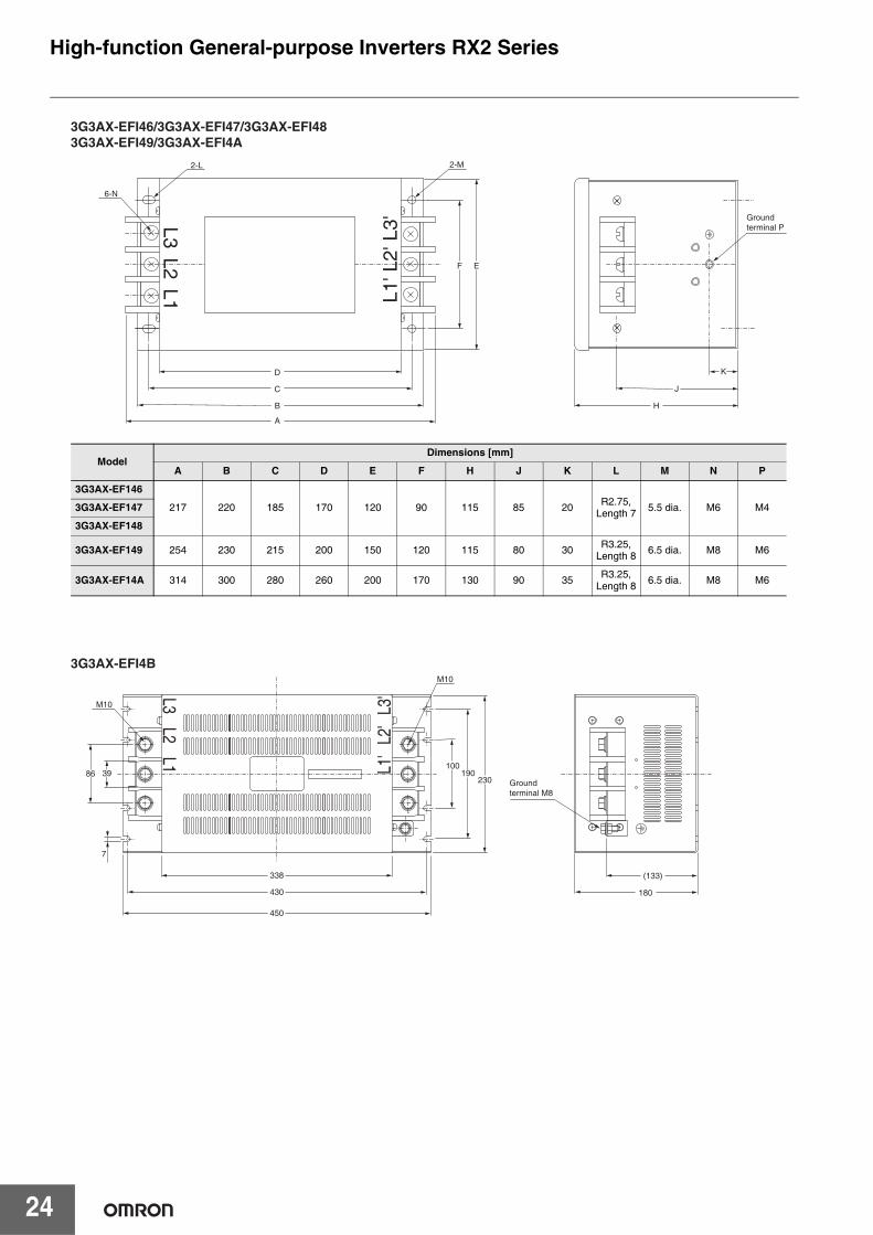
24
L3L2
L1
L3'
L2'
L1'
86100
190230
39
7
338
430
(133)
180
450
M10
M10
Ground terminal M8
3G3AX-EFI4B
L3L2
L1
L3'
L2'
L1'
F E
D
C J
K
HB
6-N
Ground terminal P
2-M
A
2-L
3G3AX-EFI46/3G3AX-EFI47/3G3AX-EFI483G3AX-EFI49/3G3AX-EFI4A
ModelDimensions [mm]
A B C D E F H J K L M N P
3G3AX-EF146
217 220 185 170 120 90 115 85 20 R2.75,Length 7 5.5 dia. M6 M43G3AX-EF147
3G3AX-EF148
3G3AX-EF149 254 230 215 200 150 120 115 80 30 R3.25,Length 8 6.5 dia. M8 M6
3G3AX-EF14A 314 300 280 260 200 170 130 90 35 R3.25,Length 8 6.5 dia. M8 M6
High-function General-purpose Inverters RX2 Series
25
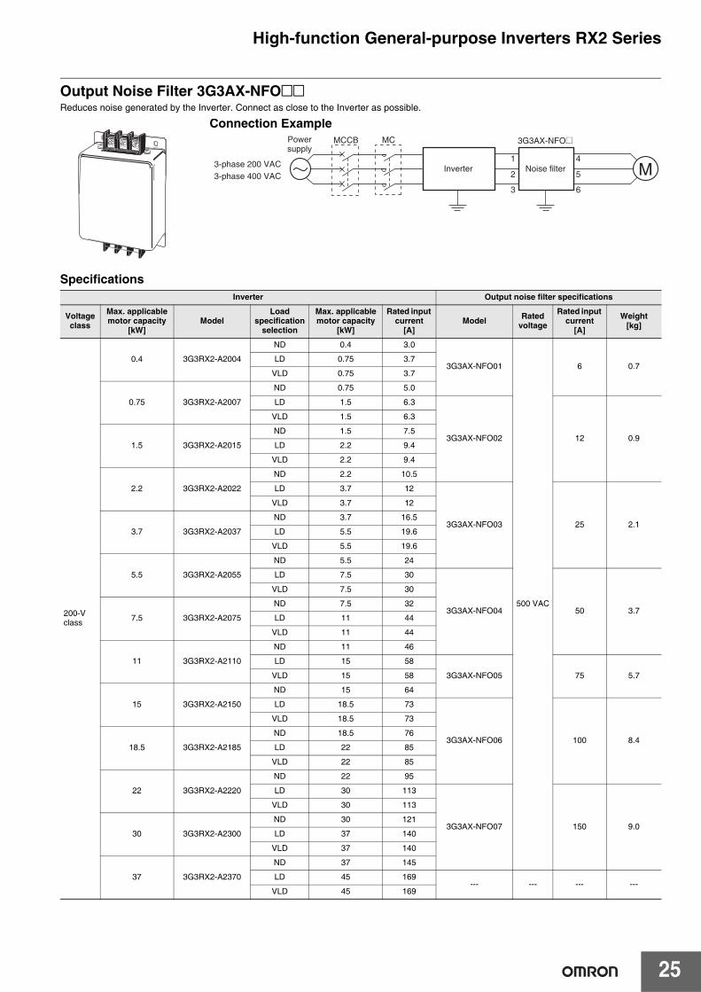
Output Noise Filter 3G3AX-NFO@@Reduces noise generated by the Inverter. Connect as close to the Inverter as possible.
SpecificationsInverter Output noise filter specifications
Voltageclass
Max. applicable motor capacity
[kW]Model
Load specification
selection
Max. applicable motor capacity
[kW]
Rated input current
[A]Model Rated
voltage
Rated input current
[A]
Weight [kg]
200-V class
0.4 3G3RX2-A2004
ND 0.4 3.0
3G3AX-NFO01
500 VAC
6 0.7LD 0.75 3.7
VLD 0.75 3.7
0.75 3G3RX2-A2007
ND 0.75 5.0
LD 1.5 6.3
3G3AX-NFO02 12 0.9
VLD 1.5 6.3
1.5 3G3RX2-A2015
ND 1.5 7.5
LD 2.2 9.4
VLD 2.2 9.4
2.2 3G3RX2-A2022
ND 2.2 10.5
LD 3.7 12
3G3AX-NFO03 25 2.1
VLD 3.7 12
3.7 3G3RX2-A2037
ND 3.7 16.5
LD 5.5 19.6
VLD 5.5 19.6
5.5 3G3RX2-A2055
ND 5.5 24
LD 7.5 30
3G3AX-NFO04 50 3.7
VLD 7.5 30
7.5 3G3RX2-A2075
ND 7.5 32
LD 11 44
VLD 11 44
11 3G3RX2-A2110
ND 11 46
LD 15 58
3G3AX-NFO05 75 5.7VLD 15 58
15 3G3RX2-A2150
ND 15 64
LD 18.5 73
3G3AX-NFO06 100 8.4
VLD 18.5 73
18.5 3G3RX2-A2185
ND 18.5 76
LD 22 85
VLD 22 85
22 3G3RX2-A2220
ND 22 95
LD 30 113
3G3AX-NFO07 150 9.0
VLD 30 113
30 3G3RX2-A2300
ND 30 121
LD 37 140
VLD 37 140
37 3G3RX2-A2370
ND 37 145
LD 45 169--- --- --- ---
VLD 45 169
Connection Example
M
3G3AX-NFO@
1
2
3
4
5
6
Inverter Noise filter3-phase 200 VAC3-phase 400 VAC
Powersupply
MCMCCB
High-function General-purpose Inverters RX2 Series
26
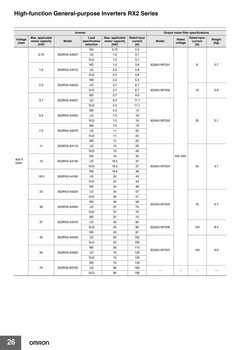
400-Vclass
0.75 3G3RX2-A4007
ND 0.75 2.5
3G3AX-NFO01
500 VAC
6 0.7
LD 1.5 3.1
VLD 1.5 3.1
1.5 3G3RX2-A4015
ND 1.5 3.8
LD 2.2 4.8
VLD 2.2 4.8
2.2 3G3RX2-A4022
ND 2.2 5.3
LD 3.7 6.7
3G3AX-NFO02 12 0.9VLD 3.7 6.7
3.7 3G3RX2-A4037
ND 3.7 9.0
LD 5.5 11.1
3G3AX-NFO03 25 2.1
VLD 5.5 11.1
5.5 3G3RX2-A4055
ND 5.5 14
LD 7.5 16
VLD 7.5 16
7.5 3G3RX2-A4075
ND 7.5 19
LD 11 22
VLD 11 22
11 3G3RX2-A4110
ND 11 25
LD 15 29
3G3AX-NFO04 50 3.7
VLD 15 29
15 3G3RX2-A4150
ND 15 32
LD 18.5 37
VLD 18.5 37
18.5 3G3RX2-A4185
ND 18.5 38
LD 22 43
VLD 22 43
22 3G3RX2-A4220
ND 22 48
LD 30 57
3G3AX-NFO05 75 5.7
VLD 30 57
30 3G3RX2-A4300
ND 30 58
LD 37 70
VLD 37 70
37 3G3RX2-A4370
ND 37 75
LD 45 85
3G3AX-NFO06 100 8.4VLD 45 85
45 3G3RX2-A4450
ND 45 91
LD 55 105
3G3AX-NFO07 150 9.0
VLD 55 105
55 3G3RX2-A4550
ND 55 112
LD 75 135
VLD 75 135
75 3G3RX2-B4750
ND 75 149
LD 90 160--- --- --- ---
VLD 90 160
Inverter Output noise filter specifications
Voltageclass
Max. applicable motor capacity
[kW]Model
Load specification
selection
Max. applicable motor capacity
[kW]
Rated input current
[A]Model Rated
voltage
Rated input current
[A]
Weight [kg]
High-function General-purpose Inverters RX2 Series
27
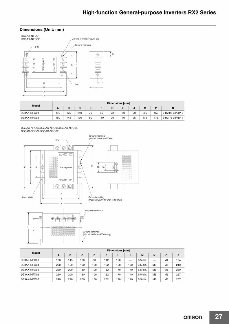
Dimensions (Unit: mm)
ModelDimensions [mm]
A B C E F G H J M P N
3G3AX-NFO01 140 125 110 70 95 22 50 20 4.5 156 2-R2.25 Length 6
3G3AX-NFO02 160 145 130 80 110 30 70 25 5.5 176 2-R2.75 Length 7
ModelDimensions [mm]
A B C E F H J M N O P
3G3AX-NFO03 160 145 130 80 112 120 --- 6.5 dia. --- M4 154
3G3AX-NFO04 200 180 160 100 162 150 120 6.5 dia. M5 M5 210
3G3AX-NFO05 220 200 180 100 182 170 140 6.5 dia. M6 M6 230
3G3AX-NFO06 220 200 180 100 182 170 140 6.5 dia. M8 M8 237
3G3AX-NFO07 240 220 200 150 202 170 140 6.5 dia. M8 M8 257
3G3AX-NFO013G3AX-NFO02
G
Nam
epla
te
JM4
Ground marking
Ground terminal Two, M dia.
2-N
12
3
4
IN OUT
56
E F
H
P
C
B
A
3G3AX-NFO03/3G3AX-NFO04/3G3AX-NFO053G3AX-NFO06/3G3AX-NFO07
Ground marking(Model: 3G3AX-NFO03)
Ground marking(Model: 3G3AX-NFO04 to NFO07)
30
Ground terminal N
Ground terminal(Model: 3G3AX-NFO03 only)
Four, M dia.
6-O
Nameplate
1 2 3
4
IN
OUT 5 6
C
B
A
EFP
JH
H 50
High-function General-purpose Inverters RX2 Series
28
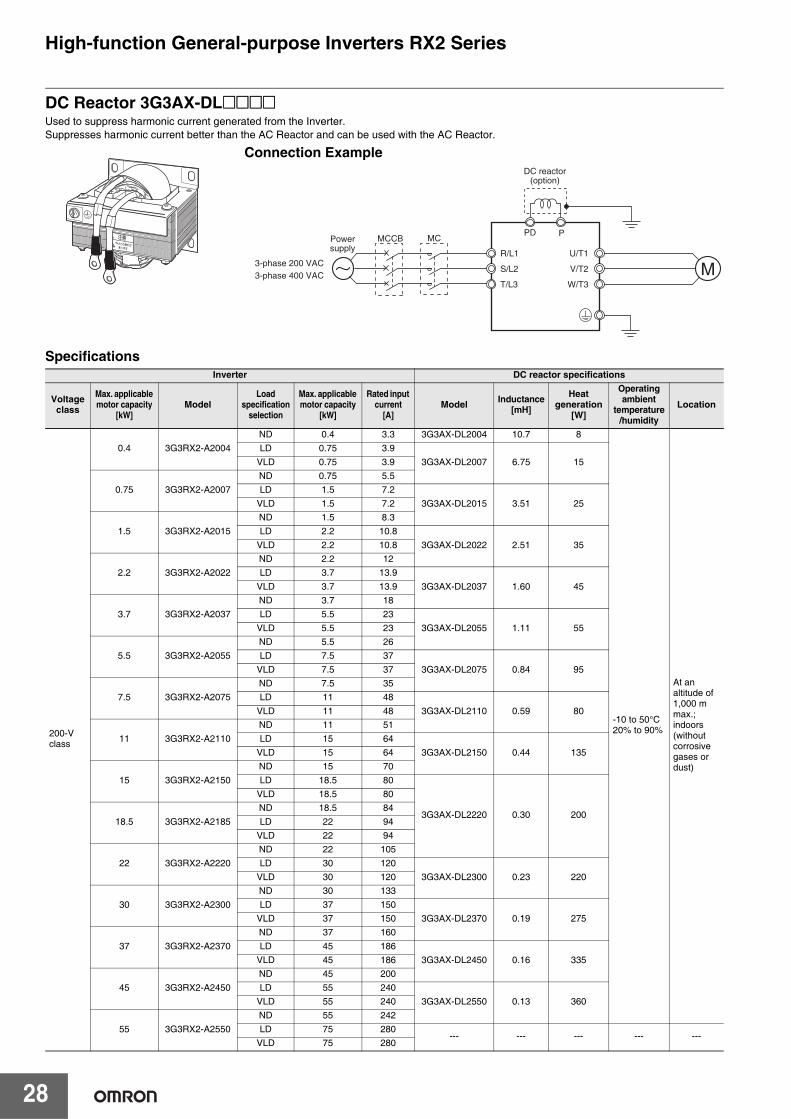
DC Reactor 3G3AX-DL@@@@Used to suppress harmonic current generated from the Inverter.Suppresses harmonic current better than the AC Reactor and can be used with the AC Reactor.
SpecificationsInverter DC reactor specifications
Voltageclass
Max. applicable motor capacity
[kW]Model
Load specification
selection
Max. applicable motor capacity
[kW]
Rated input current
[A]Model Inductance
[mH]
Heat generation
[W]
Operating ambient
temperature/humidity
Location
200-Vclass
0.4 3G3RX2-A2004ND 0.4 3.3 3G3AX-DL2004 10.7 8
-10 to 50°C20% to 90%
At an altitude of 1,000 m max.;indoors (without corrosive gases or dust)
LD 0.75 3.93G3AX-DL2007 6.75 15VLD 0.75 3.9
0.75 3G3RX2-A2007ND 0.75 5.5LD 1.5 7.2
3G3AX-DL2015 3.51 25VLD 1.5 7.2
1.5 3G3RX2-A2015ND 1.5 8.3LD 2.2 10.8
3G3AX-DL2022 2.51 35VLD 2.2 10.8
2.2 3G3RX2-A2022ND 2.2 12LD 3.7 13.9
3G3AX-DL2037 1.60 45VLD 3.7 13.9
3.7 3G3RX2-A2037ND 3.7 18LD 5.5 23
3G3AX-DL2055 1.11 55VLD 5.5 23
5.5 3G3RX2-A2055ND 5.5 26LD 7.5 37
3G3AX-DL2075 0.84 95VLD 7.5 37
7.5 3G3RX2-A2075ND 7.5 35LD 11 48
3G3AX-DL2110 0.59 80VLD 11 48
11 3G3RX2-A2110ND 11 51LD 15 64
3G3AX-DL2150 0.44 135VLD 15 64
15 3G3RX2-A2150ND 15 70LD 18.5 80
3G3AX-DL2220 0.30 200
VLD 18.5 80
18.5 3G3RX2-A2185ND 18.5 84LD 22 94
VLD 22 94
22 3G3RX2-A2220ND 22 105LD 30 120
3G3AX-DL2300 0.23 220VLD 30 120
30 3G3RX2-A2300ND 30 133LD 37 150
3G3AX-DL2370 0.19 275VLD 37 150
37 3G3RX2-A2370ND 37 160LD 45 186
3G3AX-DL2450 0.16 335VLD 45 186
45 3G3RX2-A2450ND 45 200LD 55 240
3G3AX-DL2550 0.13 360VLD 55 240
55 3G3RX2-A2550ND 55 242LD 75 280
--- --- --- --- ---VLD 75 280
Connection Example
M
DC reactor(option)
R/L1
S/L2
T/L3
U/T1
V/T2
W/T3
3-phase 200 VAC3-phase 400 VAC
Powersupply
MCMCCBPD P
High-function General-purpose Inverters RX2 Series
29
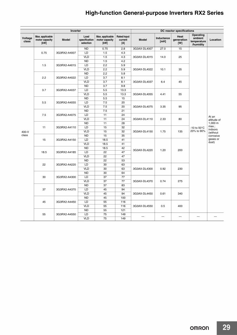
400-Vclass
0.75 3G3RX2-A4007ND 0.75 2.8 3G3AX-DL4007 27.0 15
-10 to 50°C20% to 90%
At an altitude of 1,000 m max.;indoors (without corrosive gases or dust)
LD 1.5 4.33G3AX-DL4015 14.0 25VLD 1.5 4.3
1.5 3G3RX2-A4015ND 1.5 4.2LD 2.2 5.9
3G3AX-DL4022 10.1 35VLD 2.2 5.9
2.2 3G3RX2-A4022ND 2.2 5.8LD 3.7 8.1
3G3AX-DL4037 6.4 45VLD 3.7 8.1
3.7 3G3RX2-A4037ND 3.7 9.8LD 5.5 13.3
3G3AX-DL4055 4.41 55VLD 5.5 13.3
5.5 3G3RX2-A4055ND 5.5 15LD 7.5 20
3G3AX-DL4075 3.35 95VLD 7.5 20
7.5 3G3RX2-A4075ND 7.5 21LD 11 24
3G3AX-DL4110 2.33 80VLD 11 24
11 3G3RX2-A4110ND 11 28LD 15 32
3G3AX-DL4150 1.75 135VLD 15 32
15 3G3RX2-A4150ND 15 35LD 18.5 41
3G3AX-DL4220 1.20 200
VLD 18.5 41
18.5 3G3RX2-A4185ND 18.5 42LD 22 47
VLD 22 47
22 3G3RX2-A4220ND 22 53LD 30 63
3G3AX-DL4300 0.92 230VLD 30 63
30 3G3RX2-A4300ND 30 64LD 37 77
3G3AX-DL4370 0.74 275VLD 37 77
37 3G3RX2-A4370ND 37 83LD 45 94
3G3AX-DL4450 0.61 340VLD 45 94
45 3G3RX2-A4450ND 45 100LD 55 116
3G3AX-DL4550 0.5 400VLD 55 116
55 3G3RX2-A4550ND 55 121LD 75 149
--- --- --- --- ---VLD 75 149
Inverter DC reactor specifications
Voltageclass
Max. applicable motor capacity
[kW]Model
Load specification
selection
Max. applicable motor capacity
[kW]
Rated input current
[A]Model Inductance
[mH]
Heat generation
[W]
Operating ambient
temperature/humidity
Location
High-function General-purpose Inverters RX2 Series
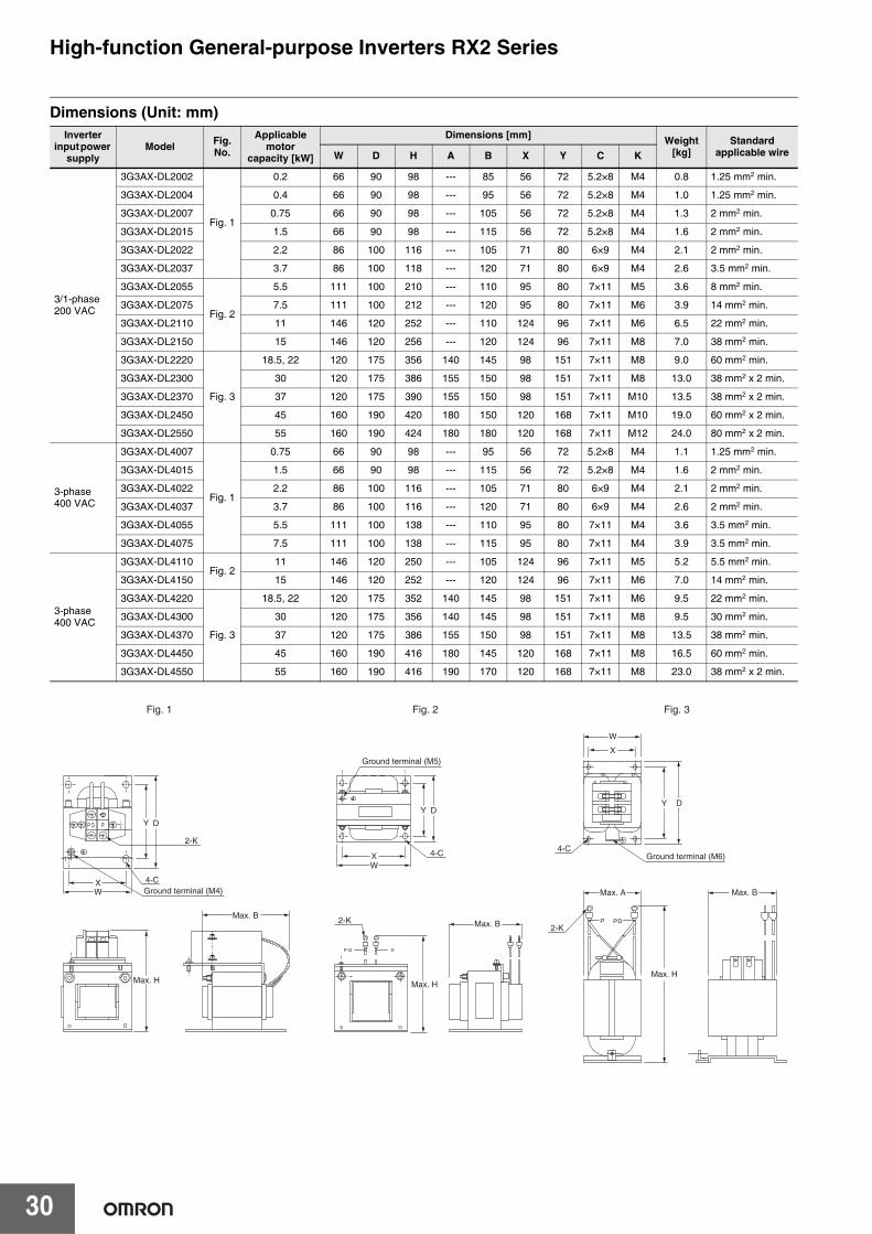
30
Dimensions (Unit: mm)Inverter
input power supply
Model Fig. No.
Applicable motor
capacity [kW]
Dimensions [mm] Weight[kg]
Standard applicable wireW D H A B X Y C K
3/1-phase200 VAC
3G3AX-DL2002
Fig. 1
0.2 66 90 98 --- 85 56 72 5.2×8 M4 0.8 1.25 mm2 min.
3G3AX-DL2004 0.4 66 90 98 --- 95 56 72 5.2×8 M4 1.0 1.25 mm2 min.
3G3AX-DL2007 0.75 66 90 98 --- 105 56 72 5.2×8 M4 1.3 2 mm2 min.
3G3AX-DL2015 1.5 66 90 98 --- 115 56 72 5.2×8 M4 1.6 2 mm2 min.
3G3AX-DL2022 2.2 86 100 116 --- 105 71 80 6×9 M4 2.1 2 mm2 min.
3G3AX-DL2037 3.7 86 100 118 --- 120 71 80 6×9 M4 2.6 3.5 mm2 min.
3G3AX-DL2055
Fig. 2
5.5 111 100 210 --- 110 95 80 7×11 M5 3.6 8 mm2 min.
3G3AX-DL2075 7.5 111 100 212 --- 120 95 80 7×11 M6 3.9 14 mm2 min.
3G3AX-DL2110 11 146 120 252 --- 110 124 96 7×11 M6 6.5 22 mm2 min.
3G3AX-DL2150 15 146 120 256 --- 120 124 96 7×11 M8 7.0 38 mm2 min.
3G3AX-DL2220
Fig. 3
18.5, 22 120 175 356 140 145 98 151 7×11 M8 9.0 60 mm2 min.
3G3AX-DL2300 30 120 175 386 155 150 98 151 7×11 M8 13.0 38 mm2 x 2 min.
3G3AX-DL2370 37 120 175 390 155 150 98 151 7×11 M10 13.5 38 mm2 x 2 min.
3G3AX-DL2450 45 160 190 420 180 150 120 168 7×11 M10 19.0 60 mm2 x 2 min.
3G3AX-DL2550 55 160 190 424 180 180 120 168 7×11 M12 24.0 80 mm2 x 2 min.
3-phase400 VAC
3G3AX-DL4007
Fig. 1
0.75 66 90 98 --- 95 56 72 5.2×8 M4 1.1 1.25 mm2 min.
3G3AX-DL4015 1.5 66 90 98 --- 115 56 72 5.2×8 M4 1.6 2 mm2 min.
3G3AX-DL4022 2.2 86 100 116 --- 105 71 80 6×9 M4 2.1 2 mm2 min.
3G3AX-DL4037 3.7 86 100 116 --- 120 71 80 6×9 M4 2.6 2 mm2 min.
3G3AX-DL4055 5.5 111 100 138 --- 110 95 80 7×11 M4 3.6 3.5 mm2 min.
3G3AX-DL4075 7.5 111 100 138 --- 115 95 80 7×11 M4 3.9 3.5 mm2 min.
3-phase400 VAC
3G3AX-DL4110Fig. 2
11 146 120 250 --- 105 124 96 7×11 M5 5.2 5.5 mm2 min.
3G3AX-DL4150 15 146 120 252 --- 120 124 96 7×11 M6 7.0 14 mm2 min.
3G3AX-DL4220
Fig. 3
18.5, 22 120 175 352 140 145 98 151 7×11 M6 9.5 22 mm2 min.
3G3AX-DL4300 30 120 175 356 140 145 98 151 7×11 M8 9.5 30 mm2 min.
3G3AX-DL4370 37 120 175 386 155 150 98 151 7×11 M8 13.5 38 mm2 min.
3G3AX-DL4450 45 160 190 416 180 145 120 168 7×11 M8 16.5 60 mm2 min.
3G3AX-DL4550 55 160 190 416 190 170 120 168 7×11 M8 23.0 38 mm2 x 2 min.
Fig. 1 Fig. 2 Fig. 3
Y
Y D
Max. H Max. H
D
2-K
W
4-C
Max. A Max. B
Max. H
2-K
X
Y D
Max. BMax. B2-K
WX
Ground terminal (M5)
Ground terminal (M6)4-C
X 4-CGround terminal (M4)W
High-function General-purpose Inverters RX2 Series
31
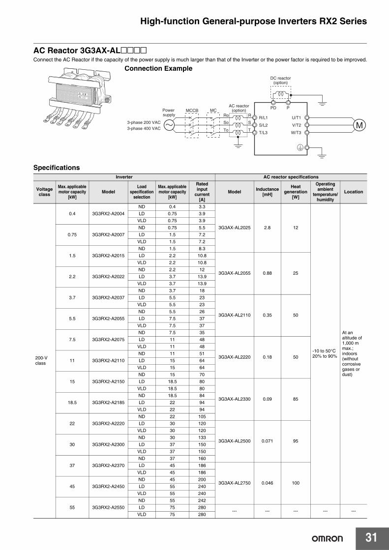
AC Reactor 3G3AX-AL@@@@Connect the AC Reactor if the capacity of the power supply is much larger than that of the Inverter or the power factor is required to be improved.
SpecificationsInverter AC reactor specifications
Voltage class
Max. applicable motor capacity
[kW]Model
Load specification
selection
Max. applicable motor capacity
[kW]
Rated input
current [A]
Model Inductance [mH]
Heat generation
[W]
Operating ambient
temperature/humidity
Location
200-Vclass
0.4 3G3RX2-A2004ND 0.4 3.3
3G3AX-AL2025 2.8 12
-10 to 50°C20% to 90%
At an altitude of 1,000 m max.; indoors (without corrosive gases or dust)
LD 0.75 3.9VLD 0.75 3.9
0.75 3G3RX2-A2007ND 0.75 5.5LD 1.5 7.2
VLD 1.5 7.2
1.5 3G3RX2-A2015ND 1.5 8.3LD 2.2 10.8
3G3AX-AL2055 0.88 25
VLD 2.2 10.8
2.2 3G3RX2-A2022ND 2.2 12LD 3.7 13.9
VLD 3.7 13.9
3.7 3G3RX2-A2037ND 3.7 18LD 5.5 23
3G3AX-AL2110 0.35 50
VLD 5.5 23
5.5 3G3RX2-A2055ND 5.5 26LD 7.5 37
VLD 7.5 37
7.5 3G3RX2-A2075ND 7.5 35LD 11 48
3G3AX-AL2220 0.18 50
VLD 11 48
11 3G3RX2-A2110ND 11 51LD 15 64
VLD 15 64
15 3G3RX2-A2150ND 15 70LD 18.5 80
3G3AX-AL2330 0.09 85
VLD 18.5 80
18.5 3G3RX2-A2185ND 18.5 84LD 22 94
VLD 22 94
22 3G3RX2-A2220ND 22 105LD 30 120
3G3AX-AL2500 0.071 95
VLD 30 120
30 3G3RX2-A2300ND 30 133LD 37 150
VLD 37 150
37 3G3RX2-A2370ND 37 160LD 45 186
3G3AX-AL2750 0.046 100
VLD 45 186
45 3G3RX2-A2450ND 45 200LD 55 240
VLD 55 240
55 3G3RX2-A2550ND 55 242LD 75 280
--- --- --- --- ---VLD 75 280
Connection Example
M
PD PAC reactor(option)
R/L1
S/L2
T/L3
U/T1
V/T2
W/T3
3-phase 200 VAC3-phase 400 VAC
Power supply
MCMCCBRo
So
To
R
S
T
DC reactor(option)
High-function General-purpose Inverters RX2 Series
32
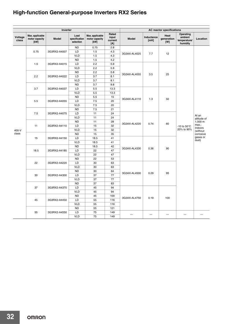
400-Vclass
0.75 3G3RX2-A4007ND 0.75 2.8
3G3AX-AL4025 7.7 12
-10 to 50°C20% to 90%
At an altitude of 1,000 m max.; indoors (without corrosive gases or dust)
LD 1.5 4.3
VLD 1.5 4.3
1.5 3G3RX2-A4015ND 1.5 4.2LD 2.2 5.9
3G3AX-AL4055 3.5 25
VLD 2.2 5.9
2.2 3G3RX2-A4022ND 2.2 5.8LD 3.7 8.1
VLD 3.7 8.1
3.7 3G3RX2-A4037ND 3.7 9.8LD 5.5 13.3
3G3AX-AL4110 1.3 50
VLD 5.5 13.3
5.5 3G3RX2-A4055ND 5.5 15LD 7.5 20
VLD 7.5 20
7.5 3G3RX2-A4075ND 7.5 21LD 11 24
3G3AX-AL4220 0.74 60
VLD 11 24
11 3G3RX2-A4110ND 11 28LD 15 32
VLD 15 32
15 3G3RX2-A4150ND 15 35LD 18.5 41
3G3AX-AL4330 0.36 90
VLD 18.5 41
18.5 3G3RX2-A4185
ND 18.5 42
LD 22 47VLD 22 47
22 3G3RX2-A4220
ND 22 53
LD 30 63
3G3AX-AL4500 0.29 95
VLD 30 63
30 3G3RX2-A4300
ND 30 64
LD 37 77VLD 37 77
37 3G3RX2-A4370
ND 37 83
LD 45 94
3G3AX-AL4750 0.19 100
VLD 45 94
45 3G3RX2-A4450
ND 45 100
LD 55 116VLD 55 116
55 3G3RX2-A4550
ND 55 121
LD 75 149--- --- --- --- ---
VLD 75 149
Inverter AC reactor specifications
Voltage class
Max. applicable motor capacity
[kW]Model
Load specification
selection
Max. applicable motor capacity
[kW]
Rated input
current [A]
Model Inductance [mH]
Heat generation
[W]
Operating ambient
temperature/humidity
Location
High-function General-purpose Inverters RX2 Series
33
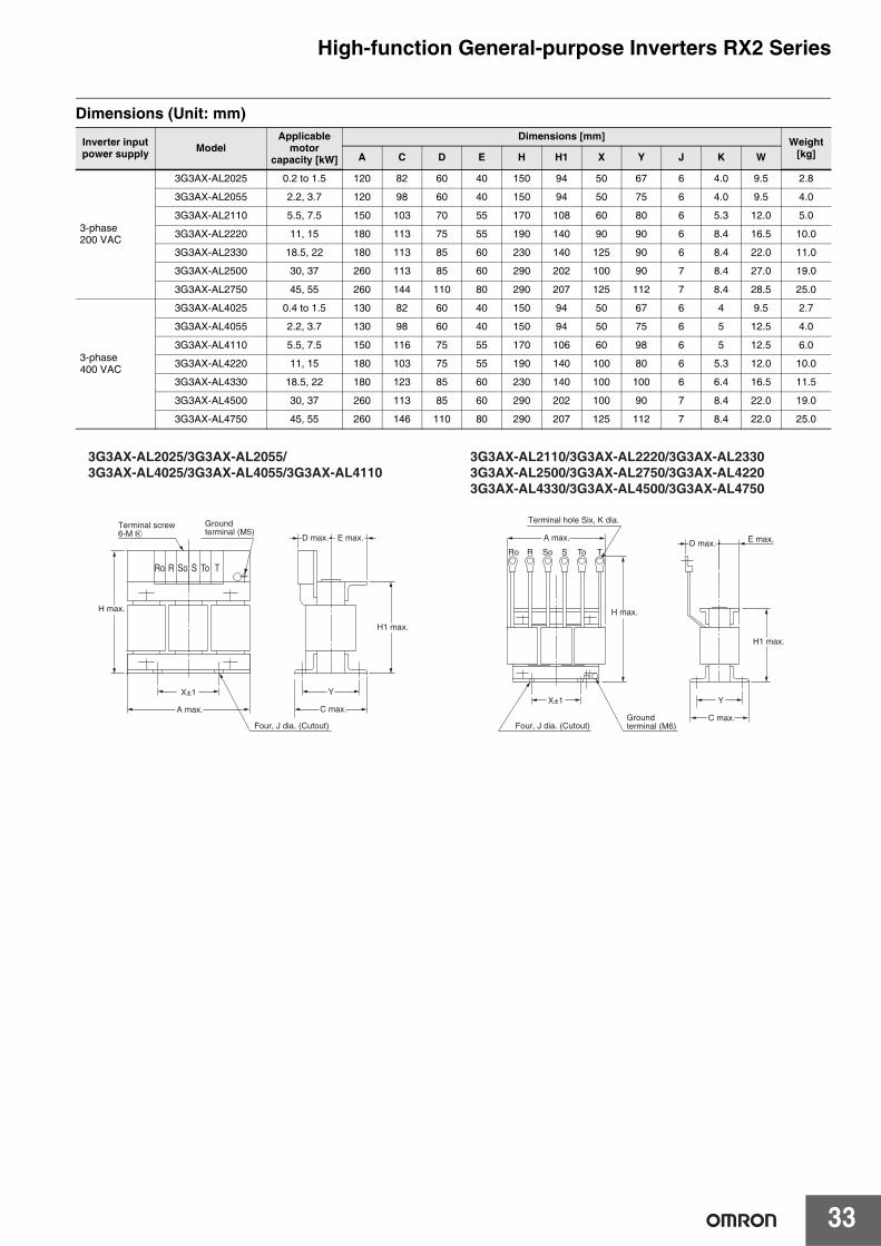
Dimensions (Unit: mm)
Inverter input power supply Model
Applicable motor
capacity [kW]
Dimensions [mm] Weight [kg]A C D E H H1 X Y J K W
3-phase200 VAC
3G3AX-AL2025 0.2 to 1.5 120 82 60 40 150 94 50 67 6 4.0 9.5 2.8
3G3AX-AL2055 2.2, 3.7 120 98 60 40 150 94 50 75 6 4.0 9.5 4.0
3G3AX-AL2110 5.5, 7.5 150 103 70 55 170 108 60 80 6 5.3 12.0 5.0
3G3AX-AL2220 11, 15 180 113 75 55 190 140 90 90 6 8.4 16.5 10.0
3G3AX-AL2330 18.5, 22 180 113 85 60 230 140 125 90 6 8.4 22.0 11.0
3G3AX-AL2500 30, 37 260 113 85 60 290 202 100 90 7 8.4 27.0 19.0
3G3AX-AL2750 45, 55 260 144 110 80 290 207 125 112 7 8.4 28.5 25.0
3-phase400 VAC
3G3AX-AL4025 0.4 to 1.5 130 82 60 40 150 94 50 67 6 4 9.5 2.7
3G3AX-AL4055 2.2, 3.7 130 98 60 40 150 94 50 75 6 5 12.5 4.0
3G3AX-AL4110 5.5, 7.5 150 116 75 55 170 106 60 98 6 5 12.5 6.0
3G3AX-AL4220 11, 15 180 103 75 55 190 140 100 80 6 5.3 12.0 10.0
3G3AX-AL4330 18.5, 22 180 123 85 60 230 140 100 100 6 6.4 16.5 11.5
3G3AX-AL4500 30, 37 260 113 85 60 290 202 100 90 7 8.4 22.0 19.0
3G3AX-AL4750 45, 55 260 146 110 80 290 207 125 112 7 8.4 22.0 25.0
A max.
D max.
H max.
H1 max.
X±1X±1
C max.
D max. E max. A max. E max.
Y
C max.
H max.
H1 max.
Y
R So S To TRo
Ro So ToR S T
3G3AX-AL2025/3G3AX-AL2055/3G3AX-AL4025/3G3AX-AL4055/3G3AX-AL4110
3G3AX-AL2110/3G3AX-AL2220/3G3AX-AL23303G3AX-AL2500/3G3AX-AL2750/3G3AX-AL42203G3AX-AL4330/3G3AX-AL4500/3G3AX-AL4750
Four, J dia. (Cutout)Ground terminal (M6)Four, J dia. (Cutout)
Terminal screw 6-M K
Terminal hole Six, K dia.Ground terminal (M5)
High-function General-purpose Inverters RX2 Series
34
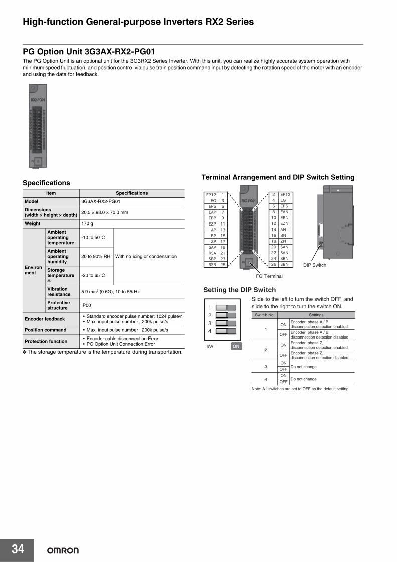
PG Option Unit 3G3AX-RX2-PG01The PG Option Unit is an optional unit for the 3G3RX2 Series Inverter. With this unit, you can realize highly accurate system operation with minimum speed fluctuation, and position control via pulse train position command input by detecting the rotation speed of the motor with an encoder and using the data for feedback.
Specifications
* The storage temperature is the temperature during transportation.
Terminal Arrangement and DIP Switch Setting
Item Specifications
Model 3G3AX-RX2-PG01
Dimensions(width × height × depth) 20.5 × 98.0 × 70.0 mm
Weight 170 g
Environment
Ambient operating temperature
-10 to 50°C
With no icing or condensationAmbient operatinghumidity
20 to 90% RH
Storage temperature *
-20 to 65°C
Vibration resistance 5.9 m/s2 (0.6G), 10 to 55 Hz
Protective structure IP00
Encoder feedback • Standard encoder pulse number: 1024 pulse/r• Max. input pulse number : 200k pulse/s
Position command • Max. input pulse number : 200k pulse/s
Protection function • Encoder cable disconnection Error• PG Option Unit Connection Error
Setting the DIP SwitchSlide to the left to turn the switch OFF, and slide to the right to turn the switch ON.
FG Terminal
DIP Switch
Note: All switches are set to OFF as the default setting.
Encoder phase A / B, disconnection detection enabled
OFF
Switch No. Settings
ON
Encoder phase A / B, disconnection detection disabledEncoder phase Z, disconnection detection enabled
OFF
ON
Encoder phase Z, disconnection detection disabled
Do not change
Do not change
OFF
ON
OFF
ON
1
3
2
4
High-function General-purpose Inverters RX2 Series
35
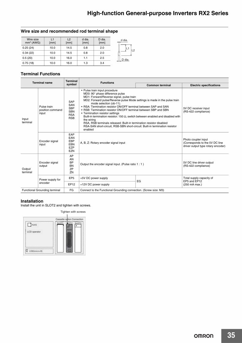
Wire size and recommended rod terminal shape
Terminal Functions
InstallationInstall the unit in SLOT2 and tighten with screws.
Terminal name Terminal symbol Functions
Common terminal Electric specifications
Input terminal
Pulse train position command input
SAPSANSBPSBNRSARSB
• Pulse train input procedure MD0: 90° phase difference pulseMD1: Forward/Reverse signal, pulse trainMD2: Forward pulse/Reverse pulse Mode settings is made in the pulse train
mode selection (ob-11).• RSA: Termination resistor ON/OFF terminal between SAP and SAN• RSB: Termination resistor ON/OFF terminal between SBP and SBN• Termination resistor settings
Built-in termination resistor: 150 Ω, switch between enabled and disabled with the wiring RSA, RSB terminals released: Built-in termination resistor disabled RSA-SAN short-circuit, RSB-SBN short-circuit: Built-in termination resistor enabled
5V DC receiver input(RS-422 compliance)
Encoder signal input
EAPEANEBPEBNEZPEZN
A, B, Z: Rotary encoder signal inputPhoto coupler input(Corresponds to the 5V DC line driver output type rotary encoder)
Output terminal
Encoder signal output
APANBPBNZPZN
Output the encoder signal input. (Pulse ratio 1 : 1 ) 5V DC line driver output(RS-422 compliance)
Power supply for encoder
EP5 +5V DC power supplyEG
Total supply capacity of EP5 and EP12(250 mA max.)EP12 +12V DC power supply
Functional Grounding terminal FG Connect to the Functional Grounding connection. (Screw size: M3)
d dia.
L1L2
D dia.
Wire sizemm2 (AWG)
L1[mm]
L2[mm]
d dia.[mm]
D dia.[mm]
0.25 (24) 10.0 14.5 0.8 2.0
0.34 (22) 10.0 14.5 0.8 2.0
0.5 (20) 10.0 16.0 1.1 2.5
0.75 (18) 10.0 16.0 1.3 3.4
Tighten with screws
Ordering Information
■System Configuration.....................................................................................37
■Interpreting Model Numbers ..........................................................................38
■Ordering Information
RX2 series Inverter Models .........................................................................39Related Options ...........................................................................................39Software.......................................................................................................55
■Overview of Inverter Selection .......................................................................56
■Related Manuals ............................................................................................60
Sysmac is a trademark or registered trademark of OMRON Corporation in Japan and other countries for OMRON factory automation products.Windows is either a registered trademark or trademark of Microsoft Corporation in the United States and/or other countries.EtherCAT® is a registered trademark and patented technology, licensed by Beckhoff Automation GmbH, Germany.Other company names and product names in this document are the trademarks or registered trademarks of their respective companies.The product photographs and figures that are used in this catalog may vary somewhat from the actual products.Microsoft product screen shot(s) reprinted with permission from Microsoft Corporation.Some images are used under license from Shutterstock.com.
37
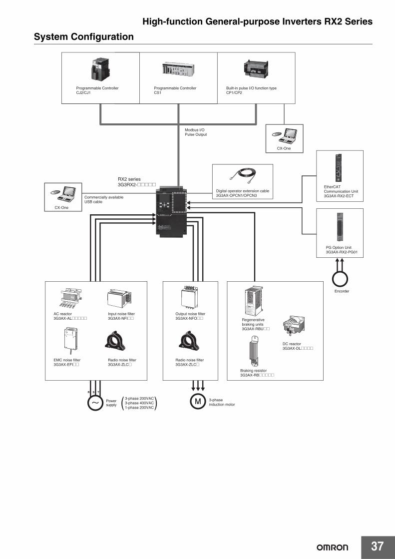
High-function General-purpose Inverters RX2 SeriesSystem Configuration
Programmable ControllerCJ2/CJ1
Digital operator extension cable3G3AX-OPCN1/OPCN3
Programmable ControllerCS1
Built-in pulse I/O function typeCP1/CP2
Modbus I/OPulse Output
CX-One
CX-One
Commercially available USB cable
RX2 series3G3RX2-@@@@@
EMC noise filter3G3AX-EFI@@
Radio noise filter3G3AX-ZLC@
Radio noise filter3G3AX-ZLC@
Output noise filter3G3AX-NFO@@
Input noise filter3G3AX-NFI@@
AC reactor3G3AX-AL@@@@@ Regenerative
braking units3G3AX-RBU@@
Braking resistor3G3AX-RB@@@@@
DC reactor3G3AX-DL@@@@
3-phaseinduction motor
Encorder
S R T
Powersupply
3-phase 200VAC3-phase 400VAC1-phase 200VAC)(
PG Option Unit3G3AX-RX2-PG01
EtherCAT Communication Unit3G3AX-RX2-ECT
38
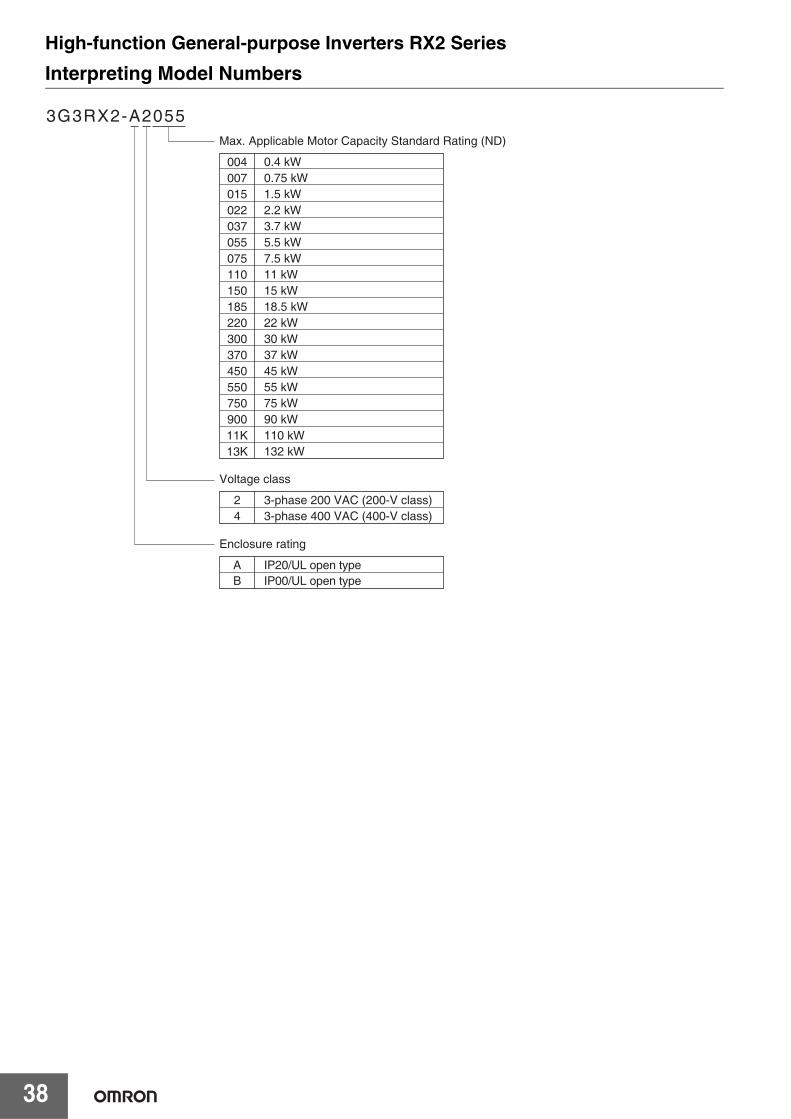
High-function General-purpose Inverters RX2 SeriesInterpreting Model Numbers
3G3RX2-A2055Max. Applicable Motor Capacity Standard Rating (ND)
00400701502203705507511015018522030037045055075090011K13K
0.4 kW0.75 kW1.5 kW2.2 kW3.7 kW5.5 kW7.5 kW11 kW15 kW18.5 kW22 kW30 kW37 kW45 kW55 kW75 kW90 kW110 kW132 kW
Voltage class
24
3-phase 200 VAC (200-V class)3-phase 400 VAC (400-V class)
Enclosure rating
A IP20/UL open typeB IP00/UL open type
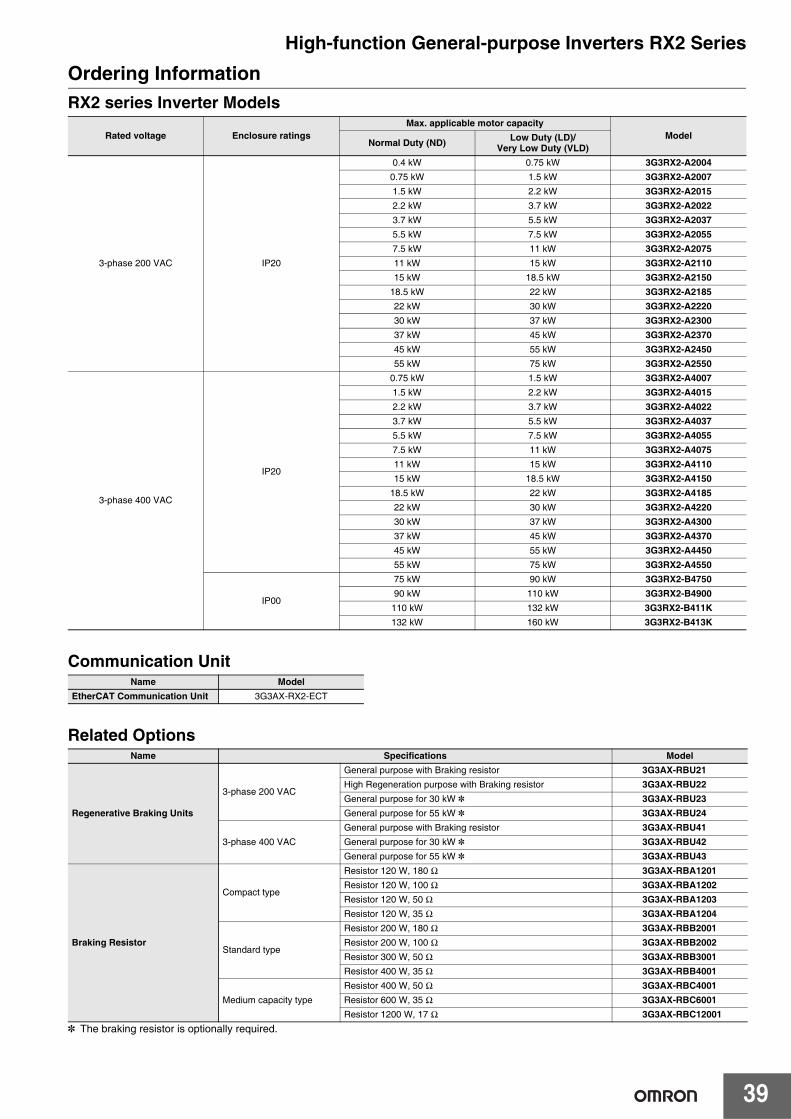
39
High-function General-purpose Inverters RX2 SeriesOrdering InformationRX2 series Inverter Models
Communication Unit
Related Options
* The braking resistor is optionally required.
Rated voltage Enclosure ratingsMax. applicable motor capacity
ModelNormal Duty (ND) Low Duty (LD)/
Very Low Duty (VLD)
3-phase 200 VAC IP20
0.4 kW 0.75 kW 3G3RX2-A20040.75 kW 1.5 kW 3G3RX2-A20071.5 kW 2.2 kW 3G3RX2-A20152.2 kW 3.7 kW 3G3RX2-A20223.7 kW 5.5 kW 3G3RX2-A20375.5 kW 7.5 kW 3G3RX2-A20557.5 kW 11 kW 3G3RX2-A207511 kW 15 kW 3G3RX2-A211015 kW 18.5 kW 3G3RX2-A2150
18.5 kW 22 kW 3G3RX2-A218522 kW 30 kW 3G3RX2-A222030 kW 37 kW 3G3RX2-A230037 kW 45 kW 3G3RX2-A237045 kW 55 kW 3G3RX2-A245055 kW 75 kW 3G3RX2-A2550
3-phase 400 VAC
IP20
0.75 kW 1.5 kW 3G3RX2-A40071.5 kW 2.2 kW 3G3RX2-A40152.2 kW 3.7 kW 3G3RX2-A40223.7 kW 5.5 kW 3G3RX2-A40375.5 kW 7.5 kW 3G3RX2-A40557.5 kW 11 kW 3G3RX2-A407511 kW 15 kW 3G3RX2-A411015 kW 18.5 kW 3G3RX2-A4150
18.5 kW 22 kW 3G3RX2-A418522 kW 30 kW 3G3RX2-A422030 kW 37 kW 3G3RX2-A430037 kW 45 kW 3G3RX2-A437045 kW 55 kW 3G3RX2-A445055 kW 75 kW 3G3RX2-A4550
IP00
75 kW 90 kW 3G3RX2-B475090 kW 110 kW 3G3RX2-B4900
110 kW 132 kW 3G3RX2-B411K132 kW 160 kW 3G3RX2-B413K
Name ModelEtherCAT Communication Unit 3G3AX-RX2-ECT
Name Specifications Model
Regenerative Braking Units
3-phase 200 VAC
General purpose with Braking resistor 3G3AX-RBU21High Regeneration purpose with Braking resistor 3G3AX-RBU22General purpose for 30 kW * 3G3AX-RBU23General purpose for 55 kW * 3G3AX-RBU24
3-phase 400 VAC
General purpose with Braking resistor 3G3AX-RBU41General purpose for 30 kW * 3G3AX-RBU42General purpose for 55 kW * 3G3AX-RBU43
Braking Resistor
Compact type
Resistor 120 W, 180 Ω 3G3AX-RBA1201Resistor 120 W, 100 Ω 3G3AX-RBA1202Resistor 120 W, 50 Ω 3G3AX-RBA1203Resistor 120 W, 35 Ω 3G3AX-RBA1204
Standard type
Resistor 200 W, 180 Ω 3G3AX-RBB2001Resistor 200 W, 100 Ω 3G3AX-RBB2002Resistor 300 W, 50 Ω 3G3AX-RBB3001Resistor 400 W, 35 Ω 3G3AX-RBB4001
Medium capacity type
Resistor 400 W, 50 Ω 3G3AX-RBC4001Resistor 600 W, 35 Ω 3G3AX-RBC6001Resistor 1200 W, 17 Ω 3G3AX-RBC12001
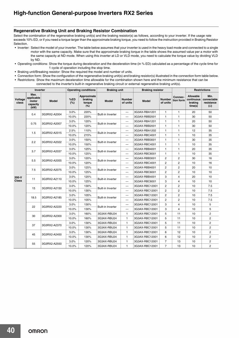
40
High-function General-purpose Inverters RX2 Series
Regenerative Braking Unit and Braking Resistor CombinationSelect the combination of the regenerative braking unit(s) and the braking resistor(s) as follows, according to your inverter. If the usage rate exceeds 10% ED, or if you need a torque larger than the approximate braking torque, you need to follow the instruction provided in Braking Resistor Selection.• Inverter: Select the model of your inverter. The table below assumes that your inverter is used in the heavy load mode and connected to a single
motor with the same capacity. Make sure that the approximate braking torque in the table shows the assumed value per a motor with the same capacity at ND mode. When using this inverter at LD or VLD mode, you need to calculate the torque value by dividing VLD by ND.
• Operating conditions: Show the torque during deceleration and the deceleration time (in % ED) calculated as a percentage of the cycle time for 1 cycle of operation including the stop time.
• Braking unit/Breaking resistor: Show the required the model and number of units.• Connection form: Show the configuration of the regenerative braking unit(s) and braking resistor(s) illustrated in the connection form table below.• Restrictions: Show the maximum deceleration time allowable for the combination shown here and the minimum resistance that can be
connected to the inverter's built-in regenerative braking circuit or external regenerative braking unit(s).
Inverter Operating conditions Braking unit Braking resistor
Connec-tion form
Restrictions
Voltageclass
Max.applicable
motorcapacity
(kW)
Model %ED(%)
Approximate braking torque(%)
Model Number of units Model Number
of units
Allowable continuous
braking time(s)
Min.connectable resistance
(Ω)
200-VClass
0.4 3G3RX2-A20043.0% 220%
Built-in Inverter--- 3G3AX-RBA1201 1 1 20 50
10.0% 220% --- 3G3AX-RBB2001 1 1 30 50
0.75 3G3RX2-A20073.0% 120%
Built-in Inverter--- 3G3AX-RBA1201 1 1 20 50
10.0% 120% --- 3G3AX-RBB2001 1 1 30 50
1.5 3G3RX2-A20152.5% 110%
Built-in Inverter--- 3G3AX-RBA1202 1 1 12 35
10.0% 215% --- 3G3AX-RBC4001 1 1 10 35
2.2 3G3RX2-A20223.0% 150%
Built-in Inverter--- 3G3AX-RBB3001 1 1 30 35
10.0% 150% --- 3G3AX-RBC4001 1 1 10 35
3.7 3G3RX2-A20373.0% 125%
Built-in Inverter--- 3G3AX-RBB4001 1 1 20 35
10.0% 125% --- 3G3AX-RBC6001 1 1 10 35
5.5 3G3RX2-A20553.0% 120%
Built-in Inverter--- 3G3AX-RBB3001 2 2 30 16
10.0% 120% --- 3G3AX-RBC4001 2 2 10 16
7.5 3G3RX2-A20753.0% 125%
Built-in Inverter--- 3G3AX-RBB4001 2 2 20 10
10.0% 125% --- 3G3AX-RBC6001 2 2 10 10
11 3G3RX2-A21103.0% 125%
Built-in Inverter--- 3G3AX-RBB4001 3 4 20 10
10.0% 125% --- 3G3AX-RBC6001 3 4 10 10
15 3G3RX2-A21503.0% 130%
Built-in Inverter--- 3G3AX-RBC12001 2 2 10 7.5
10.0% 130% --- 3G3AX-RBC12001 2 2 10 7.5
18.5 3G3RX2-A21853.0% 105%
Built-in Inverter--- 3G3AX-RBC12001 2 2 10 7.5
10.0% 105% --- 3G3AX-RBC12001 2 2 10 7.5
22 3G3RX2-A22203.0% 130%
Built-in Inverter--- 3G3AX-RBC12001 3 4 10 5
10.0% 130% --- 3G3AX-RBC12001 3 4 10 5
30 3G3RX2-A23003.0% 160% 3G3AX-RBU24 1 3G3AX-RBC12001 5 11 10 2
10.0% 160% 3G3AX-RBU24 1 3G3AX-RBC12001 5 11 10 2
37 3G3RX2-A23703.0% 130% 3G3AX-RBU24 1 3G3AX-RBC12001 5 11 10 2
10.0% 130% 3G3AX-RBU24 1 3G3AX-RBC12001 5 11 10 2
45 3G3RX2-A24503.0% 130% 3G3AX-RBU24 1 3G3AX-RBC12001 6 12 10 2
10.0% 130% 3G3AX-RBU24 1 3G3AX-RBC12001 6 12 10 2
55 3G3RX2-A25503.0% 120% 3G3AX-RBU24 1 3G3AX-RBC12001 7 13 10 2
10.0% 120% 3G3AX-RBU24 1 3G3AX-RBC12001 7 13 10 2
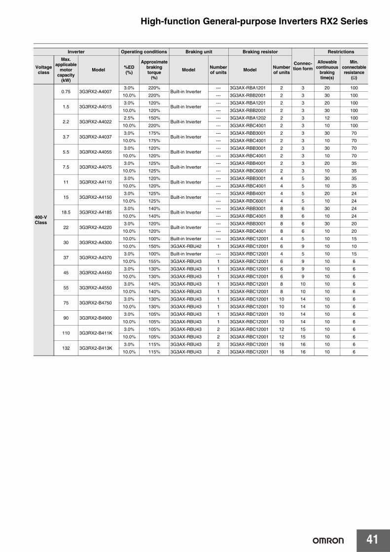
41
High-function General-purpose Inverters RX2 Series
400-VClass
0.75 3G3RX2-A40073.0% 220%
Built-in Inverter--- 3G3AX-RBA1201 2 3 20 100
10.0% 220% --- 3G3AX-RBB2001 2 3 30 100
1.5 3G3RX2-A40153.0% 120%
Built-in Inverter--- 3G3AX-RBA1201 2 3 20 100
10.0% 120% --- 3G3AX-RBB2001 2 3 30 100
2.2 3G3RX2-A40222.5% 150%
Built-in Inverter--- 3G3AX-RBA1202 2 3 12 100
10.0% 220% --- 3G3AX-RBC4001 2 3 10 100
3.7 3G3RX2-A40373.0% 175%
Built-in Inverter--- 3G3AX-RBB3001 2 3 30 70
10.0% 175% --- 3G3AX-RBC4001 2 3 10 70
5.5 3G3RX2-A40553.0% 120%
Built-in Inverter--- 3G3AX-RBB3001 2 3 30 70
10.0% 120% --- 3G3AX-RBC4001 2 3 10 70
7.5 3G3RX2-A40753.0% 125%
Built-in Inverter--- 3G3AX-RBB4001 2 3 20 35
10.0% 125% --- 3G3AX-RBC6001 2 3 10 35
11 3G3RX2-A41103.0% 120%
Built-in Inverter--- 3G3AX-RBB3001 4 5 30 35
10.0% 120% --- 3G3AX-RBC4001 4 5 10 35
15 3G3RX2-A41503.0% 125%
Built-in Inverter--- 3G3AX-RBB4001 4 5 20 24
10.0% 125% --- 3G3AX-RBC6001 4 5 10 24
18.5 3G3RX2-A41853.0% 140%
Built-in Inverter--- 3G3AX-RBB3001 8 6 30 24
10.0% 140% --- 3G3AX-RBC4001 8 6 10 24
22 3G3RX2-A42203.0% 120%
Built-in Inverter--- 3G3AX-RBB3001 8 6 30 20
10.0% 120% --- 3G3AX-RBC4001 8 6 10 20
30 3G3RX2-A430010.0% 100% Built-in Inverter --- 3G3AX-RBC12001 4 5 10 15
10.0% 150% 3G3AX-RBU42 1 3G3AX-RBC12001 6 9 10 10
37 3G3RX2-A43703.0% 100% Built-in Inverter --- 3G3AX-RBC12001 4 5 10 15
10.0% 155% 3G3AX-RBU43 1 3G3AX-RBC12001 6 9 10 6
45 3G3RX2-A44503.0% 130% 3G3AX-RBU43 1 3G3AX-RBC12001 6 9 10 6
10.0% 130% 3G3AX-RBU43 1 3G3AX-RBC12001 6 9 10 6
55 3G3RX2-A45503.0% 140% 3G3AX-RBU43 1 3G3AX-RBC12001 8 10 10 6
10.0% 140% 3G3AX-RBU43 1 3G3AX-RBC12001 8 10 10 6
75 3G3RX2-B47503.0% 130% 3G3AX-RBU43 1 3G3AX-RBC12001 10 14 10 6
10.0% 130% 3G3AX-RBU43 1 3G3AX-RBC12001 10 14 10 6
90 3G3RX2-B49003.0% 105% 3G3AX-RBU43 1 3G3AX-RBC12001 10 14 10 6
10.0% 105% 3G3AX-RBU43 1 3G3AX-RBC12001 10 14 10 6
110 3G3RX2-B411K3.0% 105% 3G3AX-RBU43 2 3G3AX-RBC12001 12 15 10 6
10.0% 105% 3G3AX-RBU43 2 3G3AX-RBC12001 12 15 10 6
132 3G3RX2-B413K3.0% 115% 3G3AX-RBU43 2 3G3AX-RBC12001 16 16 10 6
10.0% 115% 3G3AX-RBU43 2 3G3AX-RBC12001 16 16 10 6
Inverter Operating conditions Braking unit Braking resistor
Connec-tion form
Restrictions
Voltageclass
Max.applicable
motorcapacity
(kW)
Model %ED(%)
Approximate braking torque(%)
Model Number of units Model Number
of units
Allowable continuous
braking time(s)
Min.connectable resistance
(Ω)
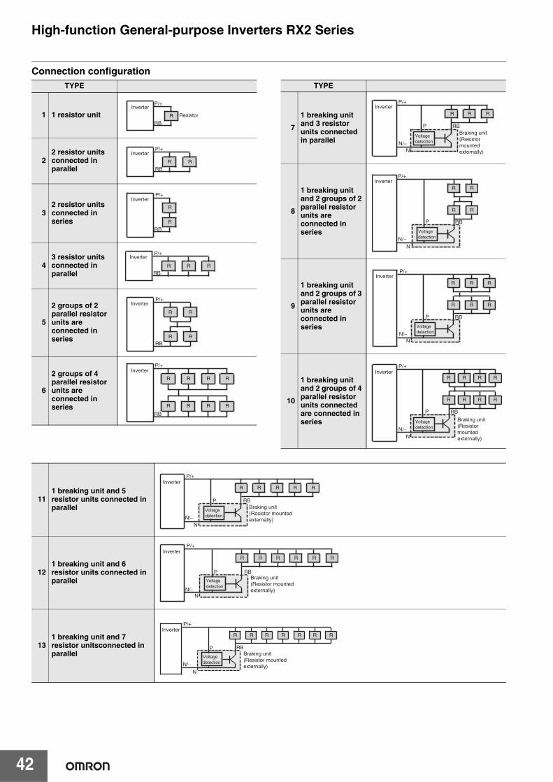
42
High-function General-purpose Inverters RX2 Series
Connection configurationTYPE
1 1 resistor unit
22 resistor unitsconnected inparallel
32 resistor unitsconnected inseries
43 resistor unitsconnected inparallel
5
2 groups of 2 parallel resistor units are connected in series
6
2 groups of 4 parallel resistor units are connected in series
P/+Inverter
Resistor
RBR
RB
P/+Inverter
R R
RBR
R
P/+Inverter
RB
P/+Inverter
R R R
RB
P/+Inverter
R R
R R
RB
R
R
R
R
R
R
R
R
P/+Inverter
TYPE
7
1 breaking unit and 3 resistor units connected in parallel
8
1 breaking unit and 2 groups of 2 parallel resistor units are connected in series
9
1 breaking unit and 2 groups of 3 parallel resistor units are connected in series
10
1 breaking unit and 2 groups of 4 parallel resistor units connected are connected in series
N
P/+Inverter
P RB
RRR
Braking unit(Resistor mountedexternally)
N/−Voltagedetection
N
R
R
R
R
P/+Inverter
P RB
N/−Voltagedetection
N
R
R
R
R
R
R
P/+Inverter
P RB
N/−Voltagedetection
N
RR
R
R
R
R
RR
P/+Inverter
P RB
Braking unit(Resistor mountedexternally)
N/−Voltagedetection
111 breaking unit and 5 resistor units connected in parallel
121 breaking unit and 6 resistor units connected in parallel
131 breaking unit and 7 resistor unitsconnected in parallel
N
P/+Inverter
P RB
R R R R R
Braking unit(Resistor mountedexternally)N/−
Voltagedetection
NN/−
P/+Inverter
P RB
R R R R R R
Braking unit(Resistor mountedexternally)
Voltagedetection
Braking unit(Resistor mountedexternally)
NN/−
P/+Inverter
Voltagedetection
R R R R R R R
P RB
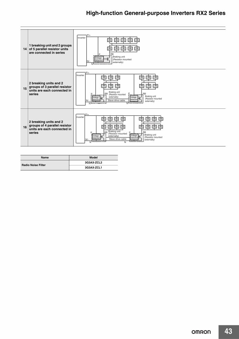
43
High-function General-purpose Inverters RX2 Series
141 breaking unit and 2 groups of 5 parallel resistor units are connected in series
15
2 breaking units and 2 groups of 3 parallel resistor units are each connected in series
16
2 breaking units and 2 groups of 4 parallel resistor units are each connected in series
Name Model
Radio Noise Filter3G3AX-ZCL2
3G3AX-ZCL1
N
RR RR
RR RR
R
R
P/+Inverter
P RBBraking unit(Resistor mountedexternally)N/−
Voltagedetection
N
R
R
R
R
R
R
N
R
R
R
R
R
R
P/+Inverter
Slave drive cable
P RB P RBBraking unit(Resistor mountedexternally)
Braking unit(Resistor mountedexternally)
N/−Voltagedetection
Voltagedetection
N
R
R
R
R
R
RR
R
N
R
R
R
R
R
RR
R
P/+Inverter
P RB P RBBraking unit(Resistor mountedexternally)
Braking unit(Resistor mountedexternally)
N/−Voltagedetection
Voltagedetection
Slave drive cable
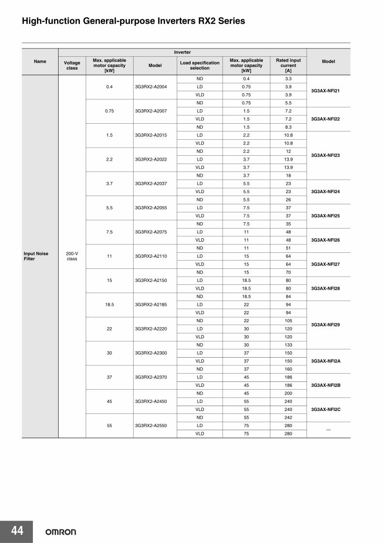
44
High-function General-purpose Inverters RX2 Series
Name
Inverter
ModelVoltage class
Max. applicable motor capacity
[kW]Model Load specification
selection
Max. applicable motor capacity
[kW]
Rated input current
[A]
Input Noise Filter
200-Vclass
0.4 3G3RX2-A2004
ND 0.4 3.3
3G3AX-NFI21LD 0.75 3.9
VLD 0.75 3.9
0.75 3G3RX2-A2007
ND 0.75 5.5
LD 1.5 7.2
3G3AX-NFI22VLD 1.5 7.2
1.5 3G3RX2-A2015
ND 1.5 8.3
LD 2.2 10.8
3G3AX-NFI23
VLD 2.2 10.8
2.2 3G3RX2-A2022
ND 2.2 12
LD 3.7 13.9
VLD 3.7 13.9
3.7 3G3RX2-A2037
ND 3.7 18
LD 5.5 23
3G3AX-NFI24VLD 5.5 23
5.5 3G3RX2-A2055
ND 5.5 26
LD 7.5 37
3G3AX-NFI25VLD 7.5 37
7.5 3G3RX2-A2075
ND 7.5 35
LD 11 48
3G3AX-NFI26VLD 11 48
11 3G3RX2-A2110
ND 11 51
LD 15 64
3G3AX-NFI27VLD 15 64
15 3G3RX2-A2150
ND 15 70
LD 18.5 80
3G3AX-NFI28VLD 18.5 80
18.5 3G3RX2-A2185
ND 18.5 84
LD 22 94
3G3AX-NFI29
VLD 22 94
22 3G3RX2-A2220
ND 22 105
LD 30 120
VLD 30 120
30 3G3RX2-A2300
ND 30 133
LD 37 150
3G3AX-NFI2AVLD 37 150
37 3G3RX2-A2370
ND 37 160
LD 45 186
3G3AX-NFI2BVLD 45 186
45 3G3RX2-A2450
ND 45 200
LD 55 240
3G3AX-NFI2CVLD 55 240
55 3G3RX2-A2550
ND 55 242
LD 75 280---
VLD 75 280
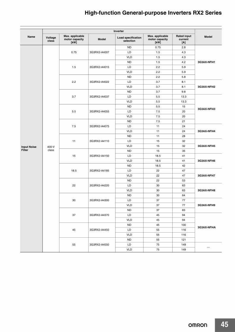
45
High-function General-purpose Inverters RX2 Series
Input Noise Filter
400-Vclass
0.75 3G3RX2-A4007
ND 0.75 2.8
3G3AX-NFI41
LD 1.5 4.3
VLD 1.5 4.3
1.5 3G3RX2-A4015
ND 1.5 4.2
LD 2.2 5.9
VLD 2.2 5.9
2.2 3G3RX2-A4022
ND 2.2 5.8
LD 3.7 8.1
3G3AX-NFI42VLD 3.7 8.1
3.7 3G3RX2-A4037
ND 3.7 9.8
LD 5.5 13.3
3G3AX-NFI43
VLD 5.5 13.3
5.5 3G3RX2-A4055
ND 5.5 15
LD 7.5 20
VLD 7.5 20
7.5 3G3RX2-A4075
ND 7.5 21
LD 11 24
3G3AX-NFI44VLD 11 24
11 3G3RX2-A4110
ND 11 28
LD 15 32
3G3AX-NFI45VLD 15 32
15 3G3RX2-A4150
ND 15 35
LD 18.5 41
3G3AX-NFI46VLD 18.5 41
18.5 3G3RX2-A4185
ND 18.5 42
LD 22 47
3G3AX-NFI47VLD 22 47
22 3G3RX2-A4220
ND 22 53
LD 30 63
3G3AX-NFI48VLD 30 63
30 3G3RX2-A4300
ND 30 64
LD 37 77
3G3AX-NFI49VLD 37 77
37 3G3RX2-A4370
ND 37 83
LD 45 94
3G3AX-NFI4A
VLD 45 94
45 3G3RX2-A4450
ND 45 100
LD 55 116
VLD 55 116
55 3G3RX2-A4550
ND 55 121
LD 75 149---
VLD 75 149
Name
Inverter
ModelVoltage class
Max. applicable motor capacity
[kW]Model Load specification
selection
Max. applicable motor capacity
[kW]
Rated input current
[A]
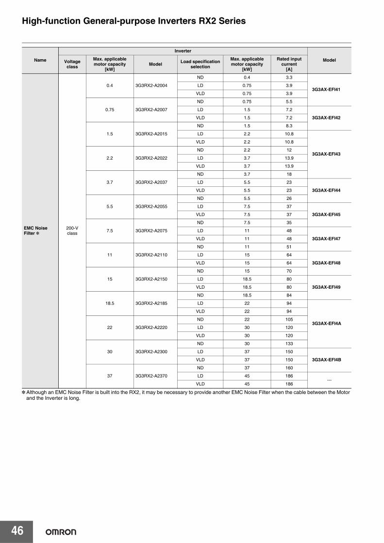
46
High-function General-purpose Inverters RX2 Series
EMC Noise Filter *
200-Vclass
0.4 3G3RX2-A2004
ND 0.4 3.3
3G3AX-EFI41LD 0.75 3.9
VLD 0.75 3.9
0.75 3G3RX2-A2007
ND 0.75 5.5
LD 1.5 7.2
3G3AX-EFI42VLD 1.5 7.2
1.5 3G3RX2-A2015
ND 1.5 8.3
LD 2.2 10.8
3G3AX-EFI43
VLD 2.2 10.8
2.2 3G3RX2-A2022
ND 2.2 12
LD 3.7 13.9
VLD 3.7 13.9
3.7 3G3RX2-A2037
ND 3.7 18
LD 5.5 23
3G3AX-EFI44VLD 5.5 23
5.5 3G3RX2-A2055
ND 5.5 26
LD 7.5 37
3G3AX-EFI45VLD 7.5 37
7.5 3G3RX2-A2075
ND 7.5 35
LD 11 48
3G3AX-EFI47VLD 11 48
11 3G3RX2-A2110
ND 11 51
LD 15 64
3G3AX-EFI48VLD 15 64
15 3G3RX2-A2150
ND 15 70
LD 18.5 80
3G3AX-EFI49VLD 18.5 80
18.5 3G3RX2-A2185
ND 18.5 84
LD 22 94
3G3AX-EFI4A
VLD 22 94
22 3G3RX2-A2220
ND 22 105
LD 30 120
VLD 30 120
30 3G3RX2-A2300
ND 30 133
LD 37 150
3G3AX-EFI4BVLD 37 150
37 3G3RX2-A2370
ND 37 160
LD 45 186---
VLD 45 186
Name
Inverter
ModelVoltage class
Max. applicable motor capacity
[kW]Model Load specification
selection
Max. applicable motor capacity
[kW]
Rated input current
[A]
* Although an EMC Noise Filter is built into the RX2, it may be necessary to provide another EMC Noise Filter when the cable between the Motor and the Inverter is long.
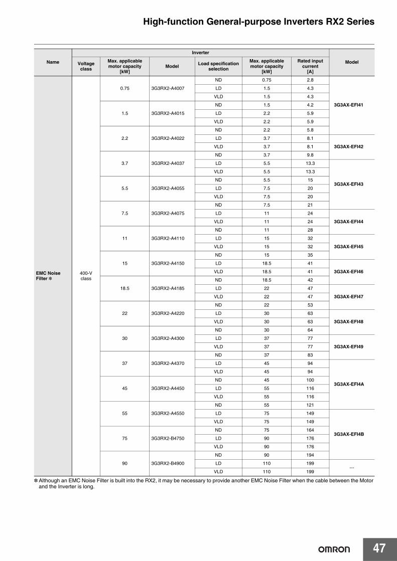
47
High-function General-purpose Inverters RX2 Series
EMC Noise Filter *
400-Vclass
0.75 3G3RX2-A4007
ND 0.75 2.8
3G3AX-EFI41
LD 1.5 4.3
VLD 1.5 4.3
1.5 3G3RX2-A4015
ND 1.5 4.2
LD 2.2 5.9
VLD 2.2 5.9
2.2 3G3RX2-A4022
ND 2.2 5.8
LD 3.7 8.1
3G3AX-EFI42VLD 3.7 8.1
3.7 3G3RX2-A4037
ND 3.7 9.8
LD 5.5 13.3
3G3AX-EFI43
VLD 5.5 13.3
5.5 3G3RX2-A4055
ND 5.5 15
LD 7.5 20
VLD 7.5 20
7.5 3G3RX2-A4075
ND 7.5 21
LD 11 24
3G3AX-EFI44VLD 11 24
11 3G3RX2-A4110
ND 11 28
LD 15 32
3G3AX-EFI45VLD 15 32
15 3G3RX2-A4150
ND 15 35
LD 18.5 41
3G3AX-EFI46VLD 18.5 41
18.5 3G3RX2-A4185
ND 18.5 42
LD 22 47
3G3AX-EFI47VLD 22 47
22 3G3RX2-A4220
ND 22 53
LD 30 63
3G3AX-EFI48VLD 30 63
30 3G3RX2-A4300
ND 30 64
LD 37 77
3G3AX-EFI49VLD 37 77
37 3G3RX2-A4370
ND 37 83
LD 45 94
3G3AX-EFI4A
VLD 45 94
45 3G3RX2-A4450
ND 45 100
LD 55 116
VLD 55 116
55 3G3RX2-A4550
ND 55 121
LD 75 149
3G3AX-EFI4B
VLD 75 149
75 3G3RX2-B4750
ND 75 164
LD 90 176
VLD 90 176
90 3G3RX2-B4900
ND 90 194
LD 110 199---
VLD 110 199
Name
Inverter
ModelVoltage class
Max. applicable motor capacity
[kW]Model Load specification
selection
Max. applicable motor capacity
[kW]
Rated input current
[A]
* Although an EMC Noise Filter is built into the RX2, it may be necessary to provide another EMC Noise Filter when the cable between the Motor and the Inverter is long.
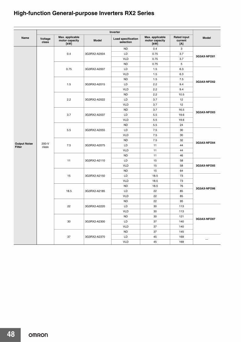
48
High-function General-purpose Inverters RX2 Series
Output Noise Filter
200-Vclass
0.4 3G3RX2-A2004
ND 0.4 3
3G3AX-NFO01LD 0.75 3.7
VLD 0.75 3.7
0.75 3G3RX2-A2007
ND 0.75 5
LD 1.5 6.3
3G3AX-NFO02
VLD 1.5 6.3
1.5 3G3RX2-A2015
ND 1.5 7.5
LD 2.2 9.4
VLD 2.2 9.4
2.2 3G3RX2-A2022
ND 2.2 10.5
LD 3.7 12
3G3AX-NFO03
VLD 3.7 12
3.7 3G3RX2-A2037
ND 3.7 16.5
LD 5.5 19.6
VLD 5.5 19.6
5.5 3G3RX2-A2055
ND 5.5 24
LD 7.5 30
3G3AX-NFO04
VLD 7.5 30
7.5 3G3RX2-A2075
ND 7.5 32
LD 11 44
VLD 11 44
11 3G3RX2-A2110
ND 11 46
LD 15 58
3G3AX-NFO05VLD 15 58
15 3G3RX2-A2150
ND 15 64
LD 18.5 73
3G3AX-NFO06
VLD 18.5 73
18.5 3G3RX2-A2185
ND 18.5 76
LD 22 85
VLD 22 85
22 3G3RX2-A2220
ND 22 95
LD 30 113
3G3AX-NFO07
VLD 30 113
30 3G3RX2-A2300
ND 30 121
LD 37 140
VLD 37 140
37 3G3RX2-A2370
ND 37 145
LD 45 169---
VLD 45 169
Name
Inverter
ModelVoltage class
Max. applicable motor capacity
[kW]Model Load specification
selection
Max. applicable motor capacity
[kW]
Rated input current
[A]
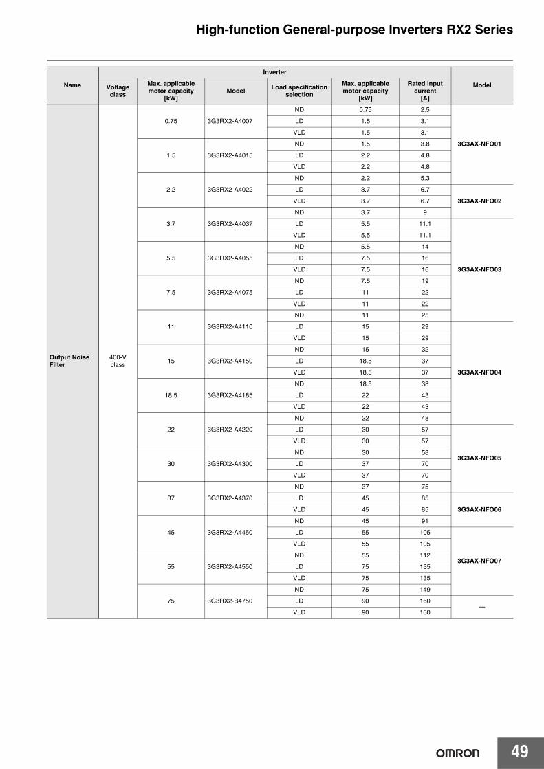
49
High-function General-purpose Inverters RX2 Series
Output Noise Filter
400-Vclass
0.75 3G3RX2-A4007
ND 0.75 2.5
3G3AX-NFO01
LD 1.5 3.1
VLD 1.5 3.1
1.5 3G3RX2-A4015
ND 1.5 3.8
LD 2.2 4.8
VLD 2.2 4.8
2.2 3G3RX2-A4022
ND 2.2 5.3
LD 3.7 6.7
3G3AX-NFO02VLD 3.7 6.7
3.7 3G3RX2-A4037
ND 3.7 9
LD 5.5 11.1
3G3AX-NFO03
VLD 5.5 11.1
5.5 3G3RX2-A4055
ND 5.5 14
LD 7.5 16
VLD 7.5 16
7.5 3G3RX2-A4075
ND 7.5 19
LD 11 22
VLD 11 22
11 3G3RX2-A4110
ND 11 25
LD 15 29
3G3AX-NFO04
VLD 15 29
15 3G3RX2-A4150
ND 15 32
LD 18.5 37
VLD 18.5 37
18.5 3G3RX2-A4185
ND 18.5 38
LD 22 43
VLD 22 43
22 3G3RX2-A4220
ND 22 48
LD 30 57
3G3AX-NFO05
VLD 30 57
30 3G3RX2-A4300
ND 30 58
LD 37 70
VLD 37 70
37 3G3RX2-A4370
ND 37 75
LD 45 85
3G3AX-NFO06VLD 45 85
45 3G3RX2-A4450
ND 45 91
LD 55 105
3G3AX-NFO07
VLD 55 105
55 3G3RX2-A4550
ND 55 112
LD 75 135
VLD 75 135
75 3G3RX2-B4750
ND 75 149
LD 90 160---
VLD 90 160
Name
Inverter
ModelVoltage class
Max. applicable motor capacity
[kW]Model Load specification
selection
Max. applicable motor capacity
[kW]
Rated input current
[A]
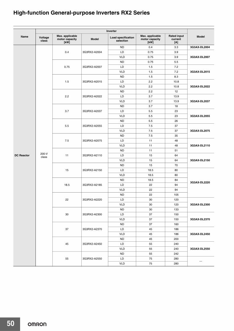
50
High-function General-purpose Inverters RX2 Series
DC Reactor 200-Vclass
0.4 3G3RX2-A2004
ND 0.4 3.3 3G3AX-DL2004
LD 0.75 3.9
3G3AX-DL2007VLD 0.75 3.9
0.75 3G3RX2-A2007
ND 0.75 5.5
LD 1.5 7.2
3G3AX-DL2015VLD 1.5 7.2
1.5 3G3RX2-A2015
ND 1.5 8.3
LD 2.2 10.8
3G3AX-DL2022VLD 2.2 10.8
2.2 3G3RX2-A2022
ND 2.2 12
LD 3.7 13.9
3G3AX-DL2037VLD 3.7 13.9
3.7 3G3RX2-A2037
ND 3.7 18
LD 5.5 23
3G3AX-DL2055VLD 5.5 23
5.5 3G3RX2-A2055
ND 5.5 26
LD 7.5 37
3G3AX-DL2075VLD 7.5 37
7.5 3G3RX2-A2075
ND 7.5 35
LD 11 48
3G3AX-DL2110VLD 11 48
11 3G3RX2-A2110
ND 11 51
LD 15 64
3G3AX-DL2150VLD 15 64
15 3G3RX2-A2150
ND 15 70
LD 18.5 80
3G3AX-DL2220
VLD 18.5 80
18.5 3G3RX2-A2185
ND 18.5 84
LD 22 94
VLD 22 94
22 3G3RX2-A2220
ND 22 105
LD 30 120
3G3AX-DL2300VLD 30 120
30 3G3RX2-A2300
ND 30 133
LD 37 150
3G3AX-DL2370VLD 37 150
37 3G3RX2-A2370
ND 37 160
LD 45 186
3G3AX-DL2450VLD 45 186
45 3G3RX2-A2450
ND 45 200
LD 55 240
3G3AX-DL2550VLD 55 240
55 3G3RX2-A2550
ND 55 242
LD 75 280---
VLD 75 280
Name
Inverter
ModelVoltage class
Max. applicable motor capacity
[kW]Model Load specification
selection
Max. applicable motor capacity
[kW]
Rated input current
[A]

51
High-function General-purpose Inverters RX2 Series
DC Reactor 400-Vclass
0.75 3G3RX2-A4007
ND 0.75 2.8 3G3AX-DL4007
LD 1.5 4.3
3G3AX-DL4015VLD 1.5 4.3
1.5 3G3RX2-A4015
ND 1.5 4.2
LD 2.2 5.9
3G3AX-DL4022VLD 2.2 5.9
2.2 3G3RX2-A4022
ND 2.2 5.8
LD 3.7 8.1
3G3AX-DL4037VLD 3.7 8.1
3.7 3G3RX2-A4037
ND 3.7 9.8
LD 5.5 13.3
3G3AX-DL4055VLD 5.5 13.3
5.5 3G3RX2-A4055
ND 5.5 15
LD 7.5 20
3G3AX-DL4075VLD 7.5 20
7.5 3G3RX2-A4075
ND 7.5 21
LD 11 24
3G3AX-DL4110VLD 11 24
11 3G3RX2-A4110
ND 11 28
LD 15 32
3G3AX-DL4150VLD 15 32
15 3G3RX2-A4150
ND 15 35
LD 18.5 41
3G3AX-DL4220
VLD 18.5 41
18.5 3G3RX2-A4185
ND 18.5 42
LD 22 47
VLD 22 47
22 3G3RX2-A4220
ND 22 53
LD 30 63
3G3AX-DL4300VLD 30 63
30 3G3RX2-A4300
ND 30 64
LD 37 77
3G3AX-DL4370VLD 37 77
37 3G3RX2-A4370
ND 37 83
LD 45 94
3G3AX-DL4450VLD 45 94
45 3G3RX2-A4450
ND 45 100
LD 55 116
3G3AX-DL4550VLD 55 116
55 3G3RX2-A4550
ND 55 121
LD 75 149---
VLD 75 149
Name
Inverter
ModelVoltage class
Max. applicable motor capacity
[kW]Model Load specification
selection
Max. applicable motor capacity
[kW]
Rated input current
[A]
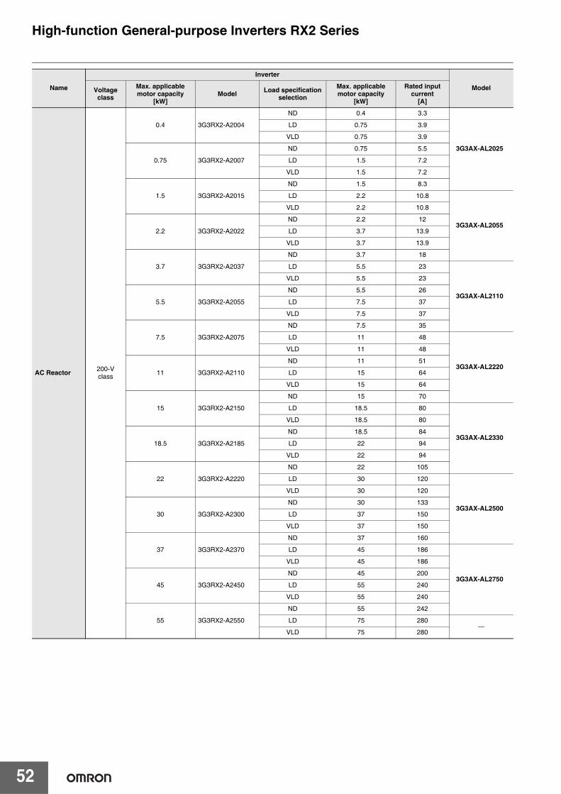
52
High-function General-purpose Inverters RX2 Series
AC Reactor 200-Vclass
0.4 3G3RX2-A2004
ND 0.4 3.3
3G3AX-AL2025
LD 0.75 3.9
VLD 0.75 3.9
0.75 3G3RX2-A2007
ND 0.75 5.5
LD 1.5 7.2
VLD 1.5 7.2
1.5 3G3RX2-A2015
ND 1.5 8.3
LD 2.2 10.8
3G3AX-AL2055
VLD 2.2 10.8
2.2 3G3RX2-A2022
ND 2.2 12
LD 3.7 13.9
VLD 3.7 13.9
3.7 3G3RX2-A2037
ND 3.7 18
LD 5.5 23
3G3AX-AL2110
VLD 5.5 23
5.5 3G3RX2-A2055
ND 5.5 26
LD 7.5 37
VLD 7.5 37
7.5 3G3RX2-A2075
ND 7.5 35
LD 11 48
3G3AX-AL2220
VLD 11 48
11 3G3RX2-A2110
ND 11 51
LD 15 64
VLD 15 64
15 3G3RX2-A2150
ND 15 70
LD 18.5 80
3G3AX-AL2330
VLD 18.5 80
18.5 3G3RX2-A2185
ND 18.5 84
LD 22 94
VLD 22 94
22 3G3RX2-A2220
ND 22 105
LD 30 120
3G3AX-AL2500
VLD 30 120
30 3G3RX2-A2300
ND 30 133
LD 37 150
VLD 37 150
37 3G3RX2-A2370
ND 37 160
LD 45 186
3G3AX-AL2750
VLD 45 186
45 3G3RX2-A2450
ND 45 200
LD 55 240
VLD 55 240
55 3G3RX2-A2550
ND 55 242
LD 75 280---
VLD 75 280
Name
Inverter
ModelVoltage class
Max. applicable motor capacity
[kW]Model Load specification
selection
Max. applicable motor capacity
[kW]
Rated input current
[A]

53
High-function General-purpose Inverters RX2 Series
AC Reactor 400-Vclass
0.75 3G3RX2-A4007
ND 0.75 2.8
3G3AX-AL4025LD 1.5 4.3
VLD 1.5 4.3
1.5 3G3RX2-A4015
ND 1.5 4.2
LD 2.2 5.9
3G3AX-AL4055
VLD 2.2 5.9
2.2 3G3RX2-A4022
ND 2.2 5.8
LD 3.7 8.1
VLD 3.7 8.1
3.7 3G3RX2-A4037
ND 3.7 9.8
LD 5.5 13.3
3G3AX-AL4110
VLD 5.5 13.3
5.5 3G3RX2-A4055
ND 5.5 15
LD 7.5 20
VLD 7.5 20
7.5 3G3RX2-A4075
ND 7.5 21
LD 11 24
3G3AX-AL4220
VLD 11 24
11 3G3RX2-A4110
ND 11 28
LD 15 32
VLD 15 32
15 3G3RX2-A4150
ND 15 35
LD 18.5 41
3G3AX-AL4330
VLD 18.5 41
18.5 3G3RX2-A4185
ND 18.5 42
LD 22 47
VLD 22 47
22 3G3RX2-A4220
ND 22 53
LD 30 63
3G3AX-AL4500
VLD 30 63
30 3G3RX2-A4300
ND 30 64
LD 37 77
VLD 37 77
37 3G3RX2-A4370
ND 37 83
LD 45 94
3G3AX-AL4750
VLD 45 94
45 3G3RX2-A4450
ND 45 100
LD 55 116
VLD 55 116
55 3G3RX2-A4550
ND 55 121
LD 75 149---
VLD 75 149
Name
Inverter
ModelVoltage class
Max. applicable motor capacity
[kW]Model Load specification
selection
Max. applicable motor capacity
[kW]
Rated input current
[A]
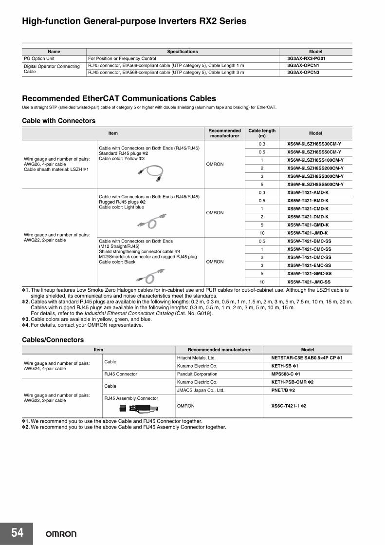
54
High-function General-purpose Inverters RX2 Series
Recommended EtherCAT Communications CablesUse a straight STP (shielded twisted-pair) cable of category 5 or higher with double shielding (aluminum tape and braiding) for EtherCAT.
Cable with Connectors
*1. The lineup features Low Smoke Zero Halogen cables for in-cabinet use and PUR cables for out-of-cabinet use. Although the LSZH cable is single shielded, its communications and noise characteristics meet the standards.
*2. Cables with standard RJ45 plugs are available in the following lengths: 0.2 m, 0.3 m, 0.5 m, 1 m, 1.5 m, 2 m, 3 m, 5 m, 7.5 m, 10 m, 15 m, 20 m.Cables with rugged RJ45 plugs are available in the following lengths: 0.3 m, 0.5 m, 1 m, 2 m, 3 m, 5 m, 10 m, 15 m.For details, refer to the Industrial Ethernet Connectors Catalog (Cat. No. G019).
*3. Cable colors are available in yellow, green, and blue.*4. For details, contact your OMRON representative.
Cables/Connectors
*1. We recommend you to use the above Cable and RJ45 Connector together.*2. We recommend you to use the above Cable and RJ45 Assembly Connector together.
Name Specifications ModelPG Option Unit For Position or Frequency Control 3G3AX-RX2-PG01
Digital Operator Connecting Cable
RJ45 connector, EIA568-compliant cable (UTP category 5), Cable Length 1 m 3G3AX-OPCN1RJ45 connector, EIA568-compliant cable (UTP category 5), Cable Length 3 m 3G3AX-OPCN3
Item Recommended manufacturer
Cable length (m) Model
Wire gauge and number of pairs: AWG26, 4-pair cableCable sheath material: LSZH *1
Cable with Connectors on Both Ends (RJ45/RJ45)Standard RJ45 plugs *2Cable color: Yellow *3
OMRON
0.3 XS6W-6LSZH8SS30CM-Y
0.5 XS6W-6LSZH8SS50CM-Y
1 XS6W-6LSZH8SS100CM-Y
2 XS6W-6LSZH8SS200CM-Y
3 XS6W-6LSZH8SS300CM-Y
5 XS6W-6LSZH8SS500CM-Y
Wire gauge and number of pairs: AWG22, 2-pair cable
Cable with Connectors on Both Ends (RJ45/RJ45)Rugged RJ45 plugs *2Cable color: Light blue
OMRON
0.3 XS5W-T421-AMD-K
0.5 XS5W-T421-BMD-K
1 XS5W-T421-CMD-K
2 XS5W-T421-DMD-K
5 XS5W-T421-GMD-K
10 XS5W-T421-JMD-K
Cable with Connectors on Both Ends (M12 Straight/RJ45)Shield strengthening connector cable *4M12/Smartclick connector and rugged RJ45 plugCable color: Black OMRON
0.5 XS5W-T421-BMC-SS
1 XS5W-T421-CMC-SS
2 XS5W-T421-DMC-SS
3 XS5W-T421-EMC-SS
5 XS5W-T421-GMC-SS
10 XS5W-T421-JMC-SS
Item Recommended manufacturer Model
Wire gauge and number of pairs: AWG24, 4-pair cable
CableHitachi Metals, Ltd. NETSTAR-C5E SAB0.5×4P CP *1
Kuramo Electric Co. KETH-SB *1
RJ45 Connector Panduit Corporation MPS588-C *1
Wire gauge and number of pairs: AWG22, 2-pair cable
CableKuramo Electric Co. KETH-PSB-OMR *2
JMACS Japan Co., Ltd. PNET/B *2
RJ45 Assembly Connector
OMRON XS6G-T421-1 *2
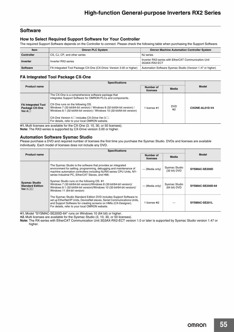
55
High-function General-purpose Inverters RX2 Series
Software
How to Select Required Support Software for Your ControllerThe required Support Software depends on the Controller to connect. Please check the following table when purchasing the Support Software.
FA Integrated Tool Package CX-One
*1.Multi licenses are available for the CX-One (3, 10, 30, or 50 licenses). Note: The RX2-series is supported by CX-Drive version 3.00 or higher.
Automation Software Sysmac StudioPlease purchase a DVD and required number of licenses the first time you purchase the Sysmac Studio. DVDs and licenses are available individually. Each model of licenses does not include any DVD.
*1.Model "SYSMAC-SE200D-64" runs on Windows 10 (64 bit) or higher.*2.Multi licenses are available for the Sysmac Studio (3, 10, 30, or 50 licenses).Note: The RX-series with EtherCAT Communication Unit 3G3AX-RX2-ECT version 1.0 or later is supported by Sysmac Studio version 1.47 or
higher.
Item Omron PLC System Omron Machine Automation Controller System
Controller CS, CJ, CP, and other series NJ series
Inverter Inverter RX2-seriesInverter RX2-series with EtherCAT Communication Unit 3G3AX-RX2-ECT
Software FA Integrated Tool Package CX-One (CX-Drive: Version 3.00 or higher) Automation Software Sysmac Studio (Version 1.47 or higher)
Product nameSpecifications
ModelNumber of licenses Media
FA Integrated ToolPackage CX-OneVer.4.@
The CX-One is a comprehensive software package thatintegrates Support Software for OMRON PLCs and components.
CX-One runs on the following OS.Windows 7 (32-bit/64-bit version) / Windows 8 (32-bit/64-bit version) / Windows 8.1 (32-bit/64-bit version) / Windows 10 (32-bit/64-bit version)
CX-One Version 4.@ includes CX-Drive [email protected] details, refer to your local OMRON website.
1 license *1 DVD*2 CXONE-AL01D-V4
Product nameSpecifications
ModelNumber of licenses Media
Sysmac StudioStandard EditionVer.1.@@
The Sysmac Studio is the software that provides an integrated environment for setting, programming, debugging and maintenance of machine automation controllers including NJ/NX-series CPU Units, NY-series Industrial PC, EtherCAT Slaves, and HMI.
Sysmac Studio runs on the following OS. *1Windows 7 (32-bit/64-bit version)/Windows 8 (32-bit/64-bit version)/Windows 8.1 (32-bit/64-bit version)/Windows 10 (32-bit/64-bit version)/Windows 11 (64-bit version)
The Sysmac Studio Standard Edition DVD includes Support Software to set up EtherNet/IP Units, DeviceNet slaves, Serial Communications Units, and Support Software for creating screens on HMIs (CX-Designer).For details, refer to your local OMRON website.
--- (Media only) Sysmac Studio(32 bit) DVD SYSMAC-SE200D
--- (Media only) Sysmac Studio(64 bit) DVD SYSMAC-SE200D-64
1 license *2 --- SYSMAC-SE201L
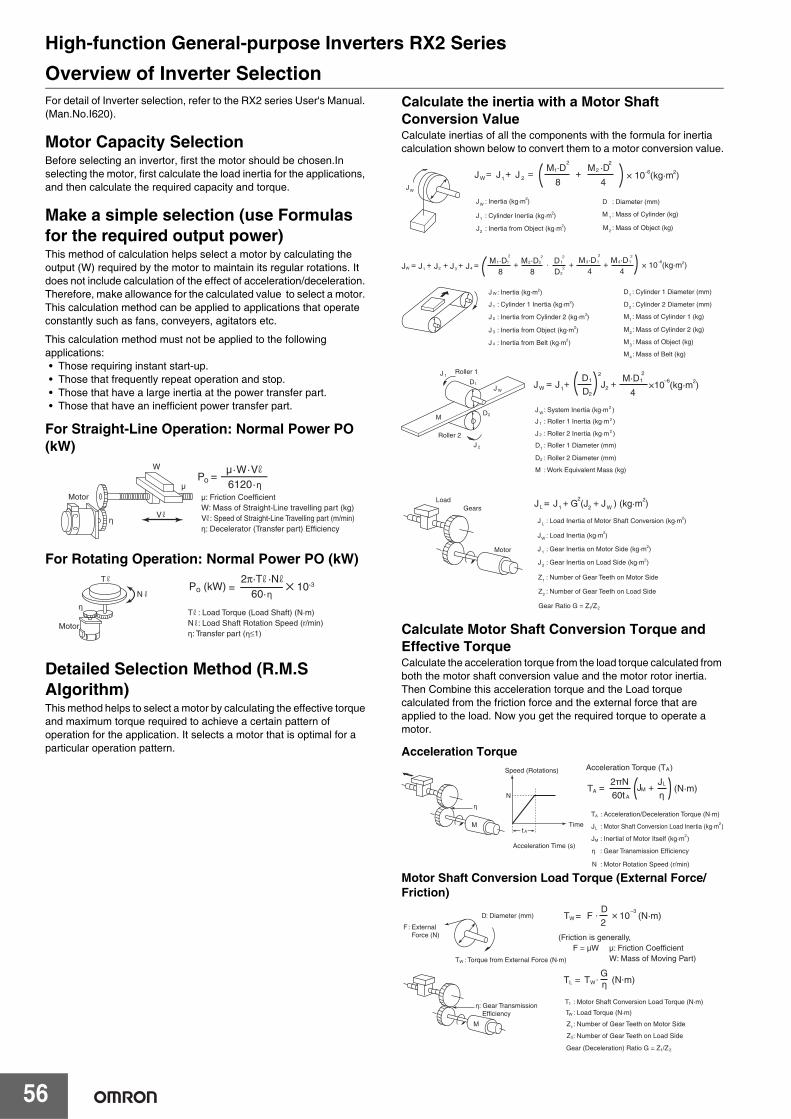
56
High-function General-purpose Inverters RX2 SeriesOverview of Inverter SelectionFor detail of Inverter selection, refer to the RX2 series User's Manual. (Man.No.I620).
Motor Capacity SelectionBefore selecting an invertor, first the motor should be chosen.In selecting the motor, first calculate the load inertia for the applications, and then calculate the required capacity and torque.
Make a simple selection (use Formulas for the required output power) This method of calculation helps select a motor by calculating the output (W) required by the motor to maintain its regular rotations. It does not include calculation of the effect of acceleration/deceleration. Therefore, make allowance for the calculated value to select a motor. This calculation method can be applied to applications that operate constantly such as fans, conveyers, agitators etc.
This calculation method must not be applied to the following applications:• Those requiring instant start-up.• Those that frequently repeat operation and stop.• Those that have a large inertia at the power transfer part.• Those that have an inefficient power transfer part.
For Straight-Line Operation: Normal Power PO (kW)
For Rotating Operation: Normal Power PO (kW)
Detailed Selection Method (R.M.S Algorithm)This method helps to select a motor by calculating the effective torque and maximum torque required to achieve a certain pattern of operation for the application. It selects a motor that is optimal for a particular operation pattern.
Calculate the inertia with a Motor Shaft Conversion ValueCalculate inertias of all the components with the formula for inertia calculation shown below to convert them to a motor conversion value.
Calculate Motor Shaft Conversion Torque and Effective TorqueCalculate the acceleration torque from the load torque calculated from both the motor shaft conversion value and the motor rotor inertia. Then Combine this acceleration torque and the Load torque calculated from the friction force and the external force that are applied to the load. Now you get the required torque to operate a motor.
Acceleration Torque
Motor Shaft Conversion Load Torque (External Force/Friction)
: Speed of Straight-Line Travelling part (m/min)
µ·W·V6120·η
Po =
Motor
η
W
V
µ
W: Mass of Straight-Line travelling part (kg)Vη: Decelerator (Transfer part) Efficiency
µ: Friction Coefficient
Motor
T
N
T : Load Torque (Load Shaft) (N·m)N : Load Shaft Rotation Speed (r/min)η: Transfer part (η≤1)
η60·η
=2π·T ·N
Po (kW) ✕ 10-3
JW
J JW 1 J 2= =
8 4+ × 10 (kg·m )
M ·D M ·D+ 1
2 2
–6 22
: Diameter (mm)D
: Mass of Cylinder (kg)M 1
: Inertia from Object (kg·m )J22
: Cylinder Inertia (kg·m )J12
: Mass of Object (kg)M2
: Inertia (kg·m )JW2
J JW 1 J2= + J3 J4++8 8 D
+ += ·M ·D M ·D D1 1
2
1
22
2 2
× 10 (kg·m )–6 22 2
4 4+M ·D M ·D3 1
2 24 1
: Inertia (kg·m )
: Cylinder 1 Inertia (kg·m )
: Inertia from Cylinder 2 (kg·m )
: Inertia from Object (kg·m )
: Inertia from Belt (kg·m )
J
J
J
J
J
2
2
2
2
2
2
1
W
3
4
: Cylinder 1 Diameter (mm)D1
: Cylinder 2 Diameter (mm)D2
: Mass of Cylinder 1 (kg)M1
: Mass of Cylinder 2 (kg)M2
: Mass of Object (kg)M3
: Mass of Belt (kg)M4
Roller 1
Roller 2
J
M
1
J W
J 2
D2
D1 J JW 1
1
2
J2=4
×10 (kg·m )M·D
+ +D
D 2 2–6 21
: System Inertia (kg·m )
: Roller 1 Inertia (kg·m )
: Work Equivalent Mass (kg)
: Roller 2 Inertia (kg·m )
: Roller 1 Diameter (mm)
: Roller 2 Diameter (mm)
J
J
M
J
D
D
2
2
W
2
1
2
1
2
LoadGears
Motor
J J G (J J ) (kg·m )L 1
2= +
2 W+ 2
1 2
: Gear Inertia on Motor Side (kg·m )J 1
: Number of Gear Teeth on Motor Side
Gear Ratio G = Z /Z
Z1
: Load Inertia of Motor Shaft Conversion (kg·m )J L2
: Gear Inertia on Load Side (kg·m )J 22
: Number of Gear Teeth on Load SideZ2
: Load Inertia (kg·m )J 2
2
W
: Motor Rotation Speed (r/min)N
: Acceleration/Deceleration Torque (N·m)T
: Inertial of Motor Itself (kg·m )JM2
A
: Motor Shaft Conversion Load Inertia (kg·m )JLA
A
2
T JAA
ML= + (N·m)
60t η2πN J
Acceleration Torque (T )
N
Acceleration Time (s)
Speed (Rotations)
Timet
η
η : Gear Transmission Efficiency
M
: Torque from External Force (N·m)TW
: Diameter (mm)D
: External Force (N)
F
(Friction is generally,F = µW µ: Friction Coefficient W: Mass of Moving Part)
T 10W–3
= F · × (N·m)2
D
T1
Z1
TW
2
η: Gear Transmission Efficiency
η
Z : Number of Gear Teeth on Load Side
M
TL W= T · (N·m)G
1 2Gear (Deceleration) Ratio G = Z /Z
: Motor Shaft Conversion Load Torque (N·m)
: Number of Gear Teeth on Motor Side
: Load Torque (N·m)
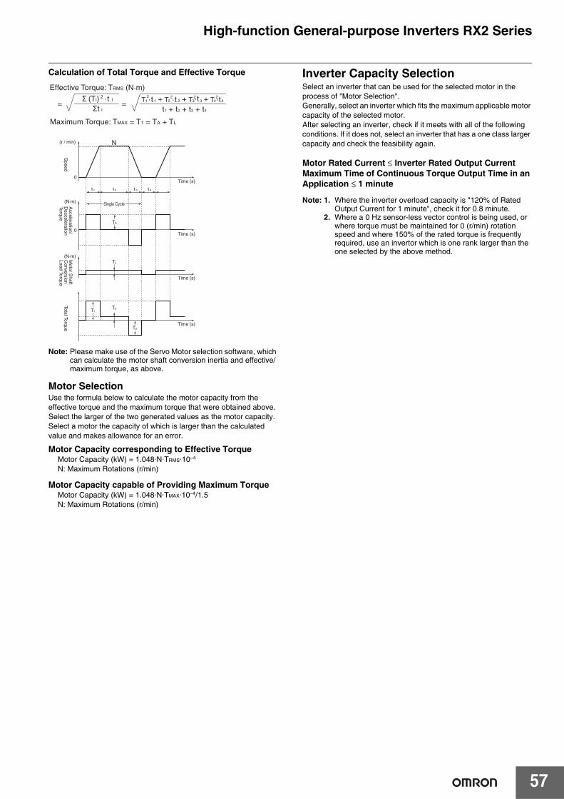
57
High-function General-purpose Inverters RX2 Series
Calculation of Total Torque and Effective Torque
Note: Please make use of the Servo Motor selection software, which can calculate the motor shaft conversion inertia and effective/maximum torque, as above.
Motor SelectionUse the formula below to calculate the motor capacity from the effective torque and the maximum torque that were obtained above.Select the larger of the two generated values as the motor capacity.Select a motor the capacity of which is larger than the calculated value and makes allowance for an error.
Motor Capacity corresponding to Effective TorqueMotor Capacity (kW) = 1.048·N·TRMS·10–4
N: Maximum Rotations (r/min)
Motor Capacity capable of Providing Maximum TorqueMotor Capacity (kW) = 1.048·N·TMAX·10–4/1.5N: Maximum Rotations (r/min)
Inverter Capacity SelectionSelect an inverter that can be used for the selected motor in the process of "Motor Selection". Generally, select an inverter which fits the maximum applicable motor capacity of the selected motor. After selecting an inverter, check if it meets with all of the following conditions. If it does not, select an inverter that has a one class larger capacity and check the feasibility again.
Motor Rated Current ≤ Inverter Rated Output CurrentMaximum Time of Continuous Torque Output Time in an Application ≤ 1 minute
Note: 1. Where the inverter overload capacity is "120% of Rated Output Current for 1 minute", check it for 0.8 minute.
2. Where a 0 Hz sensor-less vector control is being used, or where torque must be maintained for 0 (r/min) rotation speed and where 150% of the rated torque is frequently required, use an invertor which is one rank larger than the one selected by the above method.
(N·m)
(N·m)
Time (s)0
Single Cycle
0
T
Time (s)
Time (s)
Time (s)
A
t 1 t 2 t 3 t 4
TL
T2T1
T3
(r / min) N
Effective Torque: TRMS (N·m)
Σ (Ti) 2 ·t i
Σt i
Maximum Torque: TMAX = T1 = TA + TL
==t1 + t2 + t3 + t4
21 1T 2
2T·t 2·t 3·t+ 23T+ 4·t2
4T+
Speed
Acceleration/
Decceleration
Torque
Motor S
haft C
onversion Load Torque
Total Torque
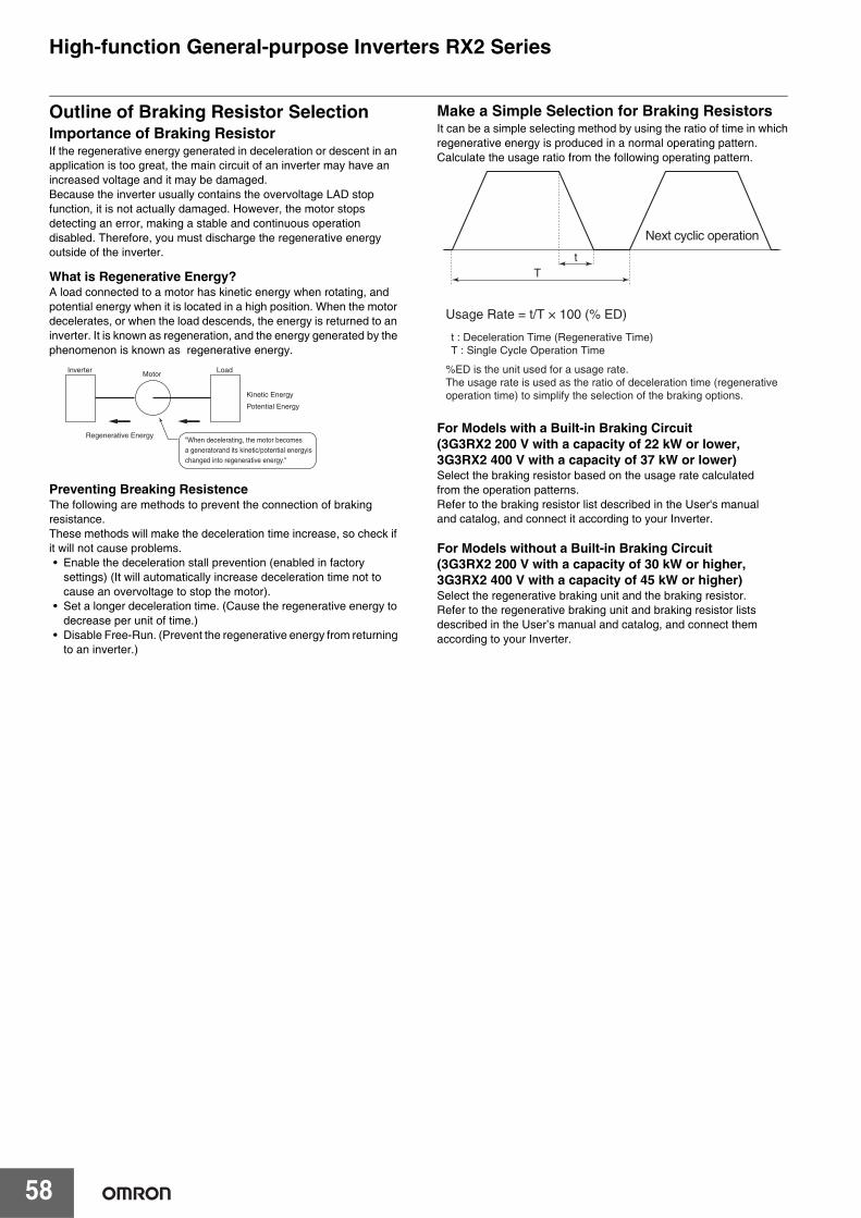
58
High-function General-purpose Inverters RX2 Series
Outline of Braking Resistor SelectionImportance of Braking ResistorIf the regenerative energy generated in deceleration or descent in an application is too great, the main circuit of an inverter may have an increased voltage and it may be damaged. Because the inverter usually contains the overvoltage LAD stop function, it is not actually damaged. However, the motor stops detecting an error, making a stable and continuous operation disabled. Therefore, you must discharge the regenerative energy outside of the inverter.
What is Regenerative Energy?A load connected to a motor has kinetic energy when rotating, and potential energy when it is located in a high position. When the motor decelerates, or when the load descends, the energy is returned to an inverter. It is known as regeneration, and the energy generated by the phenomenon is known as regenerative energy.
Preventing Breaking ResistenceThe following are methods to prevent the connection of braking resistance.These methods will make the deceleration time increase, so check if it will not cause problems.• Enable the deceleration stall prevention (enabled in factory
settings) (It will automatically increase deceleration time not to cause an overvoltage to stop the motor).
• Set a longer deceleration time. (Cause the regenerative energy to decrease per unit of time.)
• Disable Free-Run. (Prevent the regenerative energy from returning to an inverter.)
Make a Simple Selection for Braking ResistorsIt can be a simple selecting method by using the ratio of time in whichregenerative energy is produced in a normal operating pattern.Calculate the usage ratio from the following operating pattern.
For Models with a Built-in Braking Circuit (3G3RX2 200 V with a capacity of 22 kW or lower, 3G3RX2 400 V with a capacity of 37 kW or lower)Select the braking resistor based on the usage rate calculatedfrom the operation patterns.Refer to the braking resistor list described in the User's manualand catalog, and connect it according to your Inverter.
For Models without a Built-in Braking Circuit (3G3RX2 200 V with a capacity of 30 kW or higher, 3G3RX2 400 V with a capacity of 45 kW or higher)Select the regenerative braking unit and the braking resistor.Refer to the regenerative braking unit and braking resistor listsdescribed in the User’s manual and catalog, and connect themaccording to your Inverter.
Inverter Load
Regenerative Energy"When decelerating, the motor becomes a generatorand its kinetic/potential energyis changed into regenerative energy."
Kinetic Energy
Potential Energy
Motor
Usage Rate = t/T × 100 (% ED)
t : Deceleration Time (Regenerative Time)T : Single Cycle Operation Time
Next cyclic operation
Tt
%ED is the unit used for a usage rate. The usage rate is used as the ratio of deceleration time (regenerative operation time) to simplify the selection of the braking options.
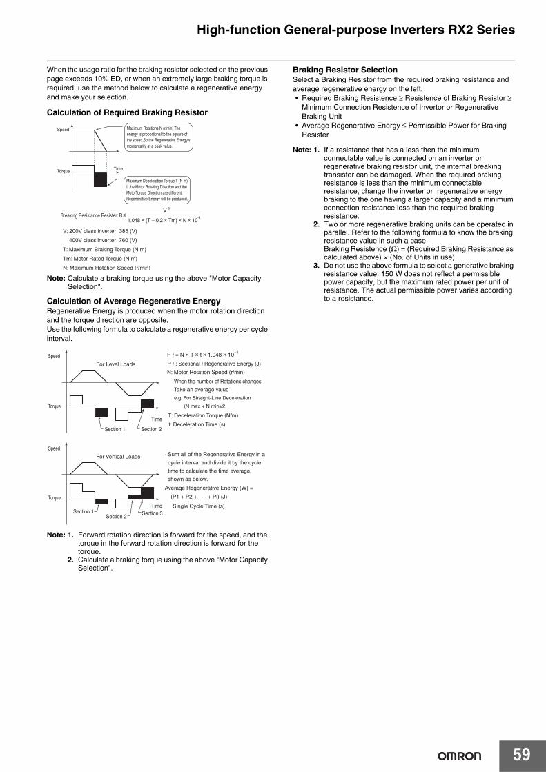
59
High-function General-purpose Inverters RX2 Series
When the usage ratio for the braking resistor selected on the previous page exceeds 10% ED, or when an extremely large braking torque is required, use the method below to calculate a regenerative energy and make your selection.
Calculation of Required Braking Resistor
Note: Calculate a braking torque using the above "Motor Capacity Selection".
Calculation of Average Regenerative EnergyRegenerative Energy is produced when the motor rotation direction and the torque direction are opposite.Use the following formula to calculate a regenerative energy per cycle interval.
Note: 1. Forward rotation direction is forward for the speed, and the torque in the forward rotation direction is forward for the torque.
2. Calculate a braking torque using the above "Motor Capacity Selection".
Braking Resistor SelectionSelect a Braking Resistor from the required braking resistance and average regenerative energy on the left.• Required Braking Resistence ≥ Resistence of Braking Resistor ≥
Minimum Connection Resistence of Invertor or Regenerative Braking Unit
• Average Regenerative Energy ≤ Permissible Power for Braking Resister
Note: 1. If a resistance that has a less then the minimum connectable value is connected on an inverter or regenerative braking resistor unit, the internal breaking transistor can be damaged. When the required braking resistance is less than the minimum connectable resistance, change the inverter or regenerative energy braking to the one having a larger capacity and a minimum connection resistance less than the required braking resistance.
2. Two or more regenerative braking units can be operated in parallel. Refer to the following formula to know the braking resistance value in such a case.Braking Resistence (Ω) = (Required Braking Resistance as calculated above) × (No. of Units in use)
3. Do not use the above formula to select a generative braking resistance value. 150 W does not reflect a permissible power capacity, but the maximum rated power per unit of resistance. The actual permissible power varies according to a resistance.
1.048 × (T – 0.2 × Tm) × N × 10
V: 200V class inverter 385 (V)
400V class inverter 760 (V)
T: Maximum Braking Torque (N·m)
Tm: Motor Rated Torque (N·m)
N: Maximum Rotation Speed (r/min)
Breaking Resistance Resister: R≤V
TimeTorque
Speed
-1
2
Maximum Deceleration Torque T (N·m) If the Motor Rotating Direction and the MotorTorque Direction are different, Regenerative Energy will be produced.
Maximum Rotations N (r/min) The energy is proportional to the square of the speed,So the Regenerative Energyis momentarily at a peak value.
P = N × T × t × 1.048 × 10
Time
Section 1
Section 1
Section 2
Section 2Section 3
Time
For Level Loads
For Vertical Loads
Torque
Torque
Speed
Speed
–1
When the number of Rotations changes
Take an average value
e.g. For Straight-Line Deceleration
(N max + N min)/2
N: Motor Rotation Speed (r/min)
t: Deceleration Time (s)
· Sum all of the Regenerative Energy in a
cycle interval and divide it by the cycle
time to calculate the time average,
shown as below.
Average Regenerative Energy (W) =
T: Deceleration Torque (N/m)
P : Sectional Regenerative Energy (J)
(P1 + P2 + · · · + Pi) (J)
Single Cycle Time (s)
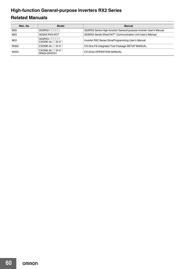
60
High-function General-purpose Inverters RX2 SeriesRelated Manuals
Man. No. Model Manual
I620 3G3RX2-@@@@@ 3G3RX2 Series High-function General-purpose Inverter User’s Manual
I663 3G3AX-RX2-ECT 3G3RX2 Series EtherCAT® Communication Unit User’s Manual
I622 3G3RX2-@@@@@CXONE-AL@@D-V@ Inverter RX2 Series DriveProgramming User’s Manual
W463 CXONE-AL@@D-V@ CX-One FA Integrated Tool Package SETUP MANUAL
W453 CXONE-AL@@D-V@WS02-DRVC01 CX-Drive OPERATION MANUAL
Terms and Conditions AgreementRead and understand this catalog.
Please read and understand this catalog before purchasing the products. Please consult your OMRON representative if you have any questions or comments.
Warranties.(a) Exclusive Warranty. Omron’s exclusive warranty is that the Products will be free from defects in materials and workmanship
for a period of twelve months from the date of sale by Omron (or such other period expressed in writing by Omron). Omron disclaims all other warranties, express or implied.
(b) Limitations. OMRON MAKES NO WARRANTY OR REPRESENTATION, EXPRESS OR IMPLIED, ABOUT NON-INFRINGEMENT, MERCHANTABILITY OR FITNESS FOR A PARTICULAR PURPOSE OF THE PRODUCTS. BUYER ACKNOWLEDGES THAT IT ALONE HAS DETERMINED THAT THE PRODUCTS WILL SUITABLY MEET THE REQUIREMENTS OF THEIR INTENDED USE.
Omron further disclaims all warranties and responsibility of any type for claims or expenses based on infringement by the Products or otherwise of any intellectual property right. (c) Buyer Remedy. Omron’s sole obligation hereunder shall be, at Omron’s election, to (i) replace (in the form originally shipped with Buyer responsible for labor charges for removal or replacement thereof) the non-complying Product, (ii) repair the non-complying Product, or (iii) repay or credit Buyer an amount equal to the purchase price of the non-complying Product; provided that in no event shall Omron be responsible for warranty, repair, indemnity or any other claims or expenses regarding the Products unless Omron’s analysis confirms that the Products were properly handled, stored, installed and maintained and not subject to contamination, abuse, misuse or inappropriate modification. Return of any Products by Buyer must be approved in writing by Omron before shipment. Omron Companies shall not be liable for the suitability or unsuitability or the results from the use of Products in combination with any electrical or electronic components, circuits, system assemblies or any other materials or substances or environments. Any advice, recommendations or information given orally or in writing, are not to be construed as an amendment or addition to the above warranty.
See http://www.omron.com/global/ or contact your Omron representative for published information.
Limitation on Liability; Etc.OMRON COMPANIES SHALL NOT BE LIABLE FOR SPECIAL, INDIRECT, INCIDENTAL, OR CONSEQUENTIAL DAMAGES, LOSS OF PROFITS OR PRODUCTION OR COMMERCIAL LOSS IN ANY WAY CONNECTED WITH THE PRODUCTS, WHETHER SUCH CLAIM IS BASED IN CONTRACT, WARRANTY, NEGLIGENCE OR STRICT LIABILITY.
Further, in no event shall liability of Omron Companies exceed the individual price of the Product on which liability is asserted.
Suitability of Use.Omron Companies shall not be responsible for conformity with any standards, codes or regulations which apply to the combination of the Product in the Buyer’s application or use of the Product. At Buyer’s request, Omron will provide applicable third party certification documents identifying ratings and limitations of use which apply to the Product. This information by itself is not sufficient for a complete determination of the suitability of the Product in combination with the end product, machine, system, or other application or use. Buyer shall be solely responsible for determining appropriateness of the particular Product with respect to Buyer’s application, product or system. Buyer shall take application responsibility in all cases.
NEVER USE THE PRODUCT FOR AN APPLICATION INVOLVING SERIOUS RISK TO LIFE OR PROPERTY OR IN LARGE QUANTITIES WITHOUT ENSURING THAT THE SYSTEM AS A WHOLE HAS BEEN DESIGNED TO ADDRESS THE RISKS, AND THAT THE OMRON PRODUCT(S) IS PROPERLY RATED AND INSTALLED FOR THE INTENDED USE WITHIN THE OVERALL EQUIPMENT OR SYSTEM.
Programmable Products.Omron Companies shall not be responsible for the user’s programming of a programmable Product, or any consequence thereof.
Performance Data.Data presented in Omron Company websites, catalogs and other materials is provided as a guide for the user in determining suitability and does not constitute a warranty. It may represent the result of Omron’s test conditions, and the user must correlate it to actual application requirements. Actual performance is subject to the Omron’s Warranty and Limitations of Liability.
Change in Specifications.Product specifications and accessories may be changed at any time based on improvements and other reasons. It is our practice to change part numbers when published ratings or features are changed, or when significant construction changes are made. However, some specifications of the Product may be changed without any notice. When in doubt, special part numbers may be assigned to fix or establish key specifications for your application. Please consult with your Omron’s representative at any time to confirm actual specifications of purchased Product.
Errors and Omissions.Information presented by Omron Companies has been checked and is believed to be accurate; however, no responsibility is assumed for clerical, typographical or proofreading errors or omissions.

Authorized Distributor:
In the interest of product improvement, specifications are subject to change without notice.
Cat. No. I921-E1-04 0522 (0319)
© OMRON Corporation 2019-2022 All Rights Reserved.
OMRON Corporation Industrial Automation Company
OMRON ELECTRONICS LLC2895 Greenspoint Parkway, Suite 200 Hoffman Estates, IL 60169 U.S.A.Tel: (1) 847-843-7900/Fax: (1) 847-843-7787
Regional HeadquartersOMRON EUROPE B.V.Wegalaan 67-69, 2132 JD HoofddorpThe NetherlandsTel: (31)2356-81-300/Fax: (31)2356-81-388
Contact: www.ia.omron.comKyoto, JAPAN
OMRON ASIA PACIFIC PTE. LTD.438B Alexandra Road, #08-01/02 Alexandra Technopark, Singapore 119968Tel: (65) 6835-3011/Fax: (65) 6835-2711
OMRON (CHINA) CO., LTD.Room 2211, Bank of China Tower, 200 Yin Cheng Zhong Road, PuDong New Area, Shanghai, 200120, ChinaTel: (86) 21-5037-2222/Fax: (86) 21-5037-2200
Note: Do not use this document to operate the Unit.
CSM_2_2


