Embed Size (px)
Citation preview
ISSN 1466-6790
www.cq-tv.comCQ
-TV
204
2003
November
Remote Control
Copyright © by the BATC CQ-TV 204 - November 2003 Page 3Page 2 CQ-TV 204 - November 2003 Copyright © by the BATC
Copyright © by the BATC CQ-TV 204 - November 2003 Page 3
Copyright © by the BATC and contributors.
Legal Niceties (the small print)E&OE. Whilst every care is taken in the production of this publication, the editor accepts no legal respon-sibility for the advice, data and opinions expressed. The BATC neither endorses nor is it responsible for the content of advertisements or the activities of those advertisers. No guarantee of accuracy is implied or given for the material herein. The BATC expressly disclaims all liability to any person in respect of anything and in respect of the consequences of anything done or omitted to be done wholly or partly in reliance upon the whole or any part of this magazine.As the regulations for the operation of radio frequency equipment vary in different countries, readers are advised to check that building or operating any piece of equipment described in CQ-TV will not contra-vene the rules that apply in their own country.The contents of this publication are covered by international copyright and must not be reproduced with-out permission, although an exception is made for not-for-profit publications (only) wishing to reprint short extracts or single articles and then only if acknowledgment is given to CQ-TV.Apart from any fair dealing for the purposes of published review, private study or research permitted under applicable copyright legislation, no part of this publication may be reproduced, stored in a retrieval system or transmitted in any form or by any means, electronic, mechanical, photocopy, recording or otherwise, without the prior permission of the publisher. All copyrights and trademarks mentioned in this publication are acknowledged and no infringement of the intellectual copyright of others is intended. Printed in Great Britain. ISSN 1466-6790.Notice to ContributorsAuthors are alone responsible for the content of their articles, including factual and legal accuracy, and opinions expressed by them may not reflect the editorial stance of the publication. Material submitted to CQ-TV should not infringe the copyright of other writers or bodies. Articles remain the copyright of their authors and following publication in CQ-TV, they may also appear on the BATC’s web site and CD-ROMs, also in other not-for-profit amateur publications. Contributions are accepted for publication on this basis alone.
Printed by Clipper Print Ltd., Unit 13, East Goscote Ind. Estate, East Goscote, Leicester, LE7 3XJ, England. Telephone: 0116 260 9909.
23cms ATV Repeater Map...................................................................................49AGAF at Ham Radio 2003 ..................................................................................52ATV Controller for Comtech Modules................................................................40A Personal View of Digital Television - part 7 ...................................................11A Warning about Foam........................................................................................56BATC Publications ..............................................................................................36Chairman’s Column ...............................................................................................5Circuit Notebook No. 83 .....................................................................................39Committee Contacts...............................................................................................4Contents .................................................................................................................3Contest news ........................................................................................................51CQ-TV Commercial Advertising Rates...............................................................66DATV Down Under - Part 2................................................................................37Deadlines..............................................................................................................56Digital Terrestrial Set Top Boxes for DATV ......................................................15Don’t Junk that VCR!..........................................................................................53Electronic CQ-TV................................................................................................56Front Panels .........................................................................................................33Index of Advertisers.............................................................................................66Infra-red Remote Control System........................................................................44In Retrospect ..........................................................................................................7Letters and Emails .................................................................................................6Lincoln Shortwave Club ATV Contest Report ....................................................50Members’ Services...............................................................................................36Satellite TV News................................................................................................21Subscription Rates ...............................................................................................20The BATC Open Day ............................................................................................8TV on the Air .......................................................................................................65TV Technology: “Brought to you in Living Colour” ..........................................57UK ATV Repeater List - September 2003...........................................................48Up, Up and Away! ...............................................................................................25Very Nearly Transparent ......................................................................................34Video Switcher using High Speed Op Amps .....................................................18
Contents
CQ
-TV
204

Page 4 CQ-TV 204 - November 2003 Copyright © by the BATC Copyright © by the BATC CQ-TV 204 - November 2003 Page 5
President: Mike Cox, CEng., FIEEE-mail: [email protected]
Chairman: Trevor Brown, G8CJSClub affairs, Videotape library, and Technical queries, especially relating to handbook projects. 14 Stairfoot Close, Adel, Leeds, LS16 8JR. Tel: 01132 670115. E-mail: [email protected]
General Secretary: Paul Marshall, G8MJWGeneral club correspondence and business. Library queries relating to the borrowing or donation of written material. Fern House, Church Road, Harby, Notts., NG23 7ED. Tel: 01522 703348. Email [email protected]
Hon. Treasurer: Brian Summers, G8GQSEnquiries regarding club finances, Donations, and constitutional enquiries. 9 Prior Croft Close, Camberley, Surrey, GU15 1DE. Tel: 01276 677879, Mobile077 4029 1191, Email: [email protected]
MembershipAnything to do with membership, including new applications, queries about new and existing membership, non-receipt of CQ-TV, subscriptions, membership records etc. Pat Hellen, The Villa, Plas Panteidal, Aberdyfi, Gwynedd, LL35 0RF, UK. Telephone 01654 767702. E-mail: [email protected]
Club Liaison: - And anything of a political nature, co-ordination of ATV repeater licences. Graham Shirville, G3VZV, The Hill Farm, Potsgrove, Milton Keynes, Bucks., MK17 9HF. Tel: 01525 290343. E-mail [email protected]
Contests: - Richard Parkes, G7MFO, 7 Main Street, Preston, Hull, HU12 8UB. Tel: 01482 898559. Email: [email protected]
CQ-TV Magazine: Editor Ian PawsonAnything for publication in CQ-TV, Articles, Review items, Letters to the editor, and other material except as below. 14 Lilac Avenue, Leicester, LE5 1FN, England. Tel: 0116 276 9425, Email: [email protected]
Photographs for the CQ-TV covers: - Please send any photographs by post, electronic images by email, to the editor at the above addresses.
TV on the Air: - Graham Hankins G8EMX, 17 Cottesbrook Road, Acocks Green, Birmingham, B27 6LE. Tel: 0121 706 7384
Satellite TV News: - Paul Holland G3TZO, Chatterton, Chapel Lane, Threapwood, Nr. Malpas, Cheshire, SY14 7AX. Tel: 01948 770429, Email: [email protected]
CQ-TV Advertising Manager: - Trevor Brown, 14 Stairfoot Close, Adel, Leeds, LS16 8JR. Tel: 01132 670115. Email: [email protected] Members adverts for inclusion in CQ-TV should be sent directly to the editor and the above address, either by post or e-mail.
CQ-TV Awards: - Bob Webb G8VBA, 78 Station Road, Rolleston on Dove, Burton on Trent, Staffs., DE13 9AB. Tel: 01283 814582
ExhibitionsGraham Hankins G8EMX, 17 Cottesbrook Road, Acocks Green, Birmingham, B27 6LE.Tel: 0121 706 7384 Email: [email protected]
Club SalesMembers Services: - PCB’s, components, camera tubes, accessories, etc. (NOT PUBLICATIONS). Peter Delaney, G8KZG, 6 East View Close, Wargrave, Berkshire, RG10 8BJ. Tel: 0118 940 3121. Email: [email protected]
Publications: - Handbooks, Back copies CQ-TV, and anything related to the supply of BATC publications. Paul Marshall, Fern House, Church Road, Harby, Notts., NG23 7ED, England. E-mail: [email protected]
CQ-TV and BATC web mastersAnything to do with the CQ-TV web site Email: [email protected] or for the BATCs web site. E-mail: [email protected]
Committee Contacts
Page 4 CQ-TV 204 - November 2003 Copyright © by the BATC Copyright © by the BATC CQ-TV 204 - November 2003 Page 5
By Trevor Brown
This year the Telford Amateur Radio Rally was held on the 31st August and the BATC committee
turned up in force to man the room we hired. The sun shone and the public turned up in droves. The setting of all the stands in amongst the historic aircraft was excellent. Brian Summers brought along a 30-year-old Marconi broadcast TV camera and set it up on the grass to attract passers by. Inside the room we played some of the more nostalgic ATV videotapes. We gave away back issues of CQ-TV complete with a membership application form. We answered questions from the public and I for one renewed a lot of old acquaintances.
This was an attempt at stemming the decline in membership we have seen in recent years. This does not mean that we are in danger of extinction, but lower numbers does not help in keeping costs down. We have fixed prices to pay for CQ-TV plate making, and the more people to share in these cost the more competitive we can keep the club subscription. Larger numbers also make advertising space in CQ-TV more attractive; it accounted for 16% of the printing and mailing cost of CQ-TV 203.
Technology is also on the move - this time its banking. The committee will have to update the processing of plastic cards. At the moment we use a hand swipe machine, and these are about to disappear. We will have to move to either PDQ or an ePDQ system. Plastic is becoming the preferred method of payment for subscriptions, particularly as this can be achieved on the Internet.
On a more “television”, front Richard Russell G4BAU (The designer of the BATC electronic test card) emailed me last month. Richard pointed out that it is over 20 years since his original design first appeared in the blue BATC handbook (Still available on the BATC CD). Richard has designed other test cards since then and his latest offering is now programmable from a PC. This unit comes ready built and looks like the ideal piece of kit for any TV station - amateur or otherwise. For more details see Richard’s advert on page 47
GB4FUN is about to be equipped with ATV. Carlos, the project co-ordinator,
has had this in mind for some time, but now it is about to become a reality. ATV is also on the agenda for the International Space Station. This time it’s SSTV as part of the ARISS project. SpaceCam1, as it’s called, will use a standard-looking web cam plugged into one of the astronaut’s laptops. FSTV is not possible, due to bandwidth limitations on the 440 MHz band, but a DATV system is under consideration for a future update.
Saturday September 27th, at 1030 UTC, saw Ben Jockert SM6CKU’s transmission on Sirius 2 of OH8K’s DXpedition to KP57AQ, filmed and edited by Johannes OH6HFX. This time the downlink was on 12,590.5 MHz with vertical polarisation. This was a change because the usual uplink was engaged on commercial work. Ben is working on a second uplink to avoid changes in the future. More information is available on Ben’s website www.Parabolic.se
2004 is a BGM year and we are about to enter the planning stage. Bletchley, although very popular, is not possible. We used one of their closed days for our past events, but alas these have all gone, as they have found fame on the big screen. Shuttleworth has been the home of late - it does have an excellent lecture room and grounds, but you may have other ideas, and why not - it’s your club. Any ideas will be welcome.
This issue, our letters prize just got better,
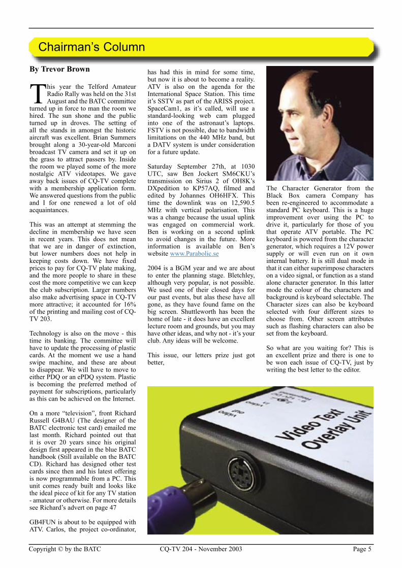
The Character Generator from the Black Box camera Company has been re-engineered to accommodate a standard PC keyboard. This is a huge improvement over using the PC to drive it, particularly for those of you that operate ATV portable. The PC keyboard is powered from the character generator, which requires a 12V power supply or will even run on it own internal battery. It is still dual mode in that it can either superimpose characters on a video signal, or function as a stand alone character generator. In this latter mode the colour of the characters and background is keyboard selectable. The Character sizes can also be keyboard selected with four different sizes to choose from. Other screen attributes such as flashing characters can also be set from the keyboard.
So what are you waiting for? This is an excellent prize and there is one to be won each issue of CQ-TV, just by writing the best letter to the editor.
Chairman’s Column
Page 6 CQ-TV 204 - November 2003 Copyright © by the BATC Copyright © by the BATC CQ-TV 204 - November 2003 Page 7
Letters and Emails
From: John Ransome [[email protected]] Sent: 22 September 2003 20:27 To: [email protected] Subject: Re Dicky Howett ‘Film into TV’ CQ-TV 203
Dear Ed,
Dicky Howett in his excellent article ‘Film into TV’ (CQ-TV 203) dismisses as a myth ‘that the movie business was, post war, dead afraid of television’. This statement may have been true of the USA but from my experience, the UK film industry was, at that time, very scared indeed!
I can recall, in the early 1950s, my uncle, E.A.R. ‘Kip’ Herren - then a rising executive in the Rank Organisation, fulminating at every opportunity about the dire effects of television on the newly rationalised British film industry. He would not have a television in his house and would dismiss anyone who wanted to talk about any tv programme as ‘an uncultured idiot’. This view seemed to be shared by many of his colleagues and, if my memory serves me correctly, eminated from the highest echelons of the Rank Organisation.
‘Kip’ Herren later became General Manager of Pinewood Film Studio and I can recall touring the set of the Bond Film ‘The Man with the Golden Gun’ twenty years later (1972?) and gleefully pointing out to him that three of the sound stages at Pinewood were being used for television productions!
My amusement was not allowed to last! I was reminded that the shooting of commercials and tv series was very much a ‘sideline to the main purpose’.
John Ransome G8LEO [email protected]
From: Steve Anderson [[email protected]]
Subject: SSTV.
Dear Ian,
I’m not quite sure how to express this....but I have spent a few hours this afternoon searching the Internet for SSTV related material. There was quite a lot, and the colour photos and the like were very impressive. But it’s all based on PCs and sound cards coupled to a commercially made transceiver. Doesn’t anyone actually build anything anymore?
I found it all quite depressing. Easy to do, but there is no individual input, no spirit, no stimulus, no effort. I guess it’s the ‘plug and play’ syndrome.
I assume this has also spilled into fast-scan ATV as well. I have been away from the amateur fields for some years, now I have the time to devote to the subject it appears that there’s little interest unless it has a PCI connector and a CD ROM with it (in a nice brightly packaged box).
Surely there must be those out there that want to be a little bit more creative (no pun intended) than just writing software. It takes time, effort, ingenuity and tenacity to create something hardware based. (I’m not running down those that do write software, myself included). But there must be a way to galvanize people into actually doing something.
Sorry to vent my spleen at this stage, but from what you have mentioned in previous e-mails I get the feeling that you would concur with me. It seems no wonder that hardware design engineers like me are in such high demand, it appears that no-one wants to get their hands dirty by actually touching a capacitor (perish the thought) or any other physical component.
I’m very tempted to write an article titled ‘The Way It Was And The Way It Should Be’.
OK, I’ll get down off my soap-box now, I do feel better!
However the article is brewing in my mind and might well come to fruition. (Would you consider publishing such an item? It might be a little controversial!).
Cheers, Steve.
Page 6 CQ-TV 204 - November 2003 Copyright © by the BATC Copyright © by the BATC CQ-TV 204 - November 2003 Page 7
From: Graham Shirville [[email protected]]Sent: 25 September 2003 11:23To: [email protected]: News from the RSGB
Hi Ian,
The RSGB have announced, in the October edition of Radcom, that they have disbanded all three spectrum committees with immediate effect.
The HF, VHF and Microwave committees have, for many years, been responsible for managing their own parts of the amateur spectrum and their responsibilities have included band planning and spectrum allocation. The RSGB had already disbanded the LAC ( Licensing Advisory Committee) which had been responsible for liaison with the RA about such matters.
With effect from the 1st January 2004, all these activities will become the responsibility of a new “Spectrum Forum” which will provide the leadership for the Society in this area and be able to work with the new telecommunications authority OFCOM. the Forum will have full responsibility for the frequency allocations, modes of operation and band planning from 136kHz to 76GHz
The RSGB have stated that that the Board “envisages that the change will make the work in this area more transparent to the membership and make it less cumbersome in dealing with outside agencies....”
Whilst the RSGB has been very obviously successful in progressing the very valuable work of the new licensing, morse tests, enlarged HF allocations and in the EMC area of power line communications, it seems to have found it more difficult to defend our bands at the higher frequencies that especially interest ATV operators.
As we have no exclusive or primary allocations in any of the amateur bands between 146MHz and 24GHz we need to be working very hard to ensure that we can continue to have access to the bands in between. The recent “ban” on any additional voice repeaters in the 432MHz band, the increasing difficulties on the 1.3GHz and the 2.3GHz bands, the forthcoming new high power wide area WLANS in the 5.6GHz band all bear witness to the risks and pressures that we face.
In their letters to the Chairmen of the existing Committees, the RSGB have stated their wish to ensure that the various interest groups remain well represented in the new spectrum forum. The BATC Committee have confirmed that they intend to ensure that the BATC will be represented on it as robustly as possible. Watch this space for more information in forthcoming issues and if you wish to discuss this matter or wish become more involved in this work please contact Graham Shirville G3VZV [email protected]
Dear Ian,
Can I advise readers that in my article “A Low Cost Caption Generator”, CQ-TV 201, that an error occurred in the component listing. SK1 should be a 6 pin mini DIN socket and not 8 pin as listed.
I would also like to thank all those builders who have complemented me on the unit’s performance.
As the project has been so well received I have had a further batch of PCBs manufactured, details are available on my website www.radio-kits.co.uk , or by email [email protected].
Regards, Steve Drury G6ALU
In Retrospect
Page 8 CQ-TV 204 - November 2003 Copyright © by the BATC Copyright © by the BATC CQ-TV 204 - November 2003 Page 9
The BATC Open Day
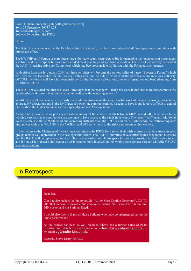
Well what an excellent day! I really enjoyed it. My camera worked all day long and
produced nice pictures for a camera that is almost 30 years old, lots of compliments there and only one “there are smaller ones in Dixons” - heathen. I spoke to lots of old friends and made a few new ones too.
For those of you who missed it, the Telford rally is quite a big one. It is held at the RAF Cosford Museum. I know this is a statement of the obvious, but the place is just littered with aeroplanes and engines! The main trading is done from 3 large hangers with the stalls mixed in between the museum exhibits, often with the stalls literally under an aircraft wing. Outside there is a long slope between the hangers and this is where large boot area is. All in all, the aircraft made a stunning and photogenic backdrop to the rally. The BATC had a room in the newly constructed central display and restaurant block where we had a steady flow of visitors passing though. Nice though our surroundings were, I suspect that not everyone there found us. I think that we need to do more promotioninal work next time.
Brian Summers
Time to unload the car, in my next life I think stamp collect-
ing would be thing to do, much easier on the back!
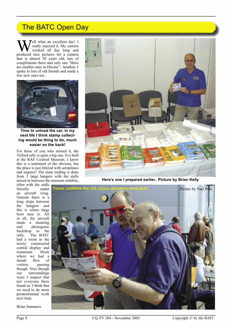
Here’s one I prepared earlier.. Picture by Brian Kelly
Picture by Paul PittsTrevor confirms the old colour decoders work best
Page 8 CQ-TV 204 - November 2003 Copyright © by the BATC Copyright © by the BATC CQ-TV 204 - November 2003 Page 9
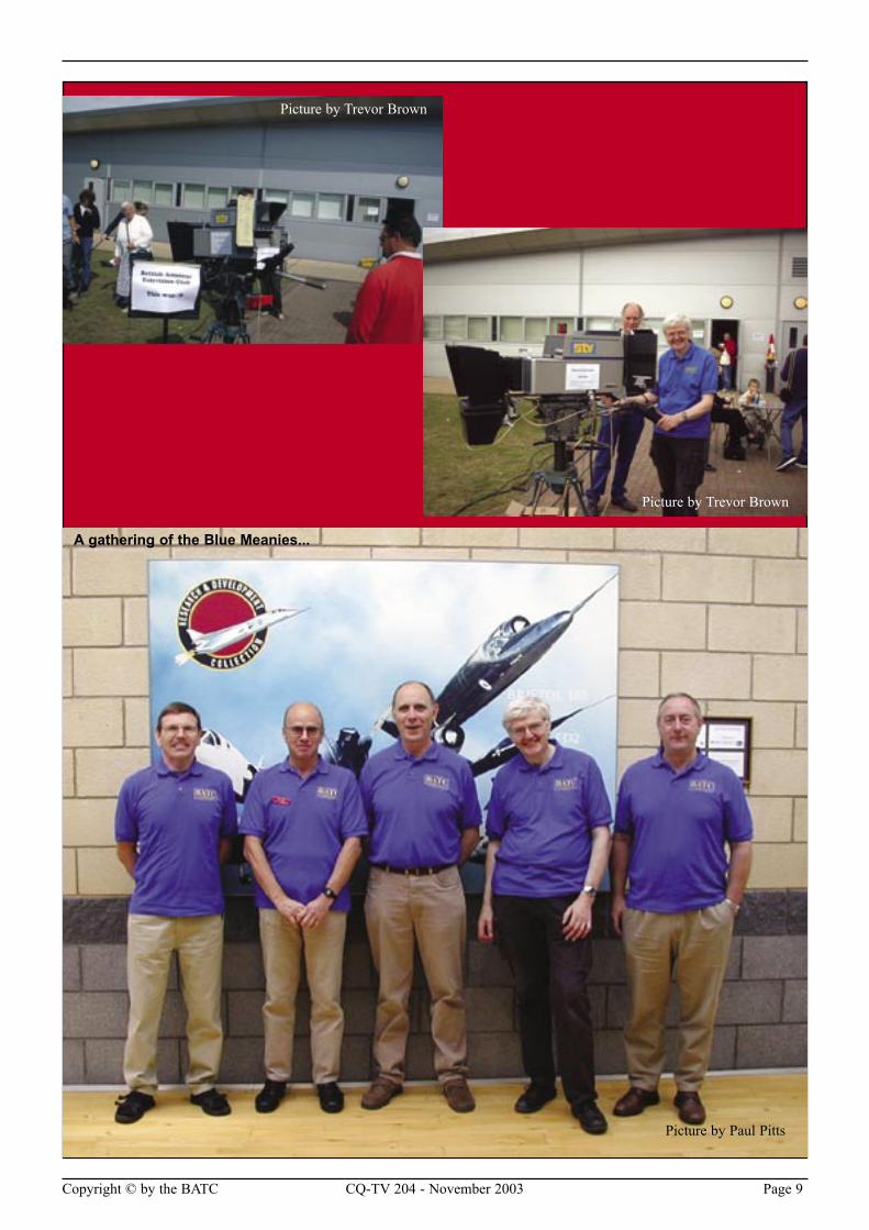
A gathering of the Blue Meanies...
Picture by Paul Pitts
Picture by Trevor Brown
Picture by Trevor Brown
Page 10 CQ-TV 204 - November 2003 Copyright © by the BATC Copyright © by the BATC CQ-TV 204 - November 2003 Page 11
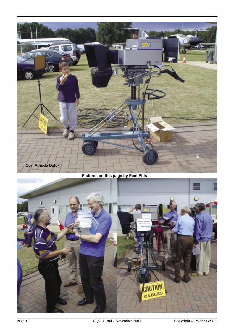
Pictures on this page by Paul Pitts
Cor! A nude Dalek
Page 10 CQ-TV 204 - November 2003 Copyright © by the BATC Copyright © by the BATC CQ-TV 204 - November 2003 Page 11
By Mike Cox
Over the past 7 editions of CQ-TV, you have had more or less of a stream of consciousness
from me describing the building of a practical vision mixer using digital techniques and with Serial Digital Interface [SDI] in and out of the box. The original specification was to replace the analogue component [YPbPr] switcher used for the IBC Info Channel.
The project is virtually finished, or as near finished as any project ever is. Note that it must be nearly there, as there is a technical manual for it. There are a few changes that have been made to improve performance, which will be described in the following paragraphs.
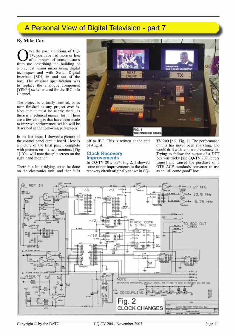
In the last issue, I showed a picture of the control panel circuit board. Here is a picture of the final panel, complete with pictures on the two monitors [Fig 1]. You will note the split screen on the right hand monitor.
There is a little tidying up to be done on the electronics unit, and then it is
off to IBC. This is written at the end of August.
Clock Recovery ImprovementsIn CQ-TV 201, p.34, Fig 2, I showed some minor improvements to the clock recovery circuit originally shown in CQ-
TV 200 [p.9, Fig. 1]. The performance of this has never been sparkling, and would drift with temperature somewhat. Trying to follow the output of a DTT box was tricky [see CQ-TV 202, letters pages] and caused the purchase of a GTH ACE standards converter to use as an ”all come good” box.
A Personal View of Digital Television - part 7
Page 12 CQ-TV 204 - November 2003 Copyright © by the BATC Copyright © by the BATC CQ-TV 204 - November 2003 Page 13
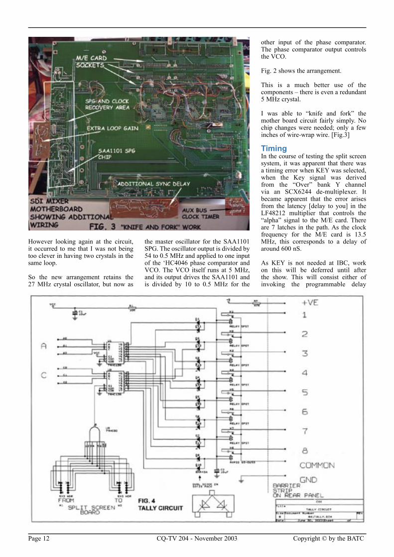
However looking again at the circuit, it occurred to me that I was not being too clever in having two crystals in the same loop.
So the new arrangement retains the 27 MHz crystal oscillator, but now as
the master oscillator for the SAA1101 SPG. The oscillator output is divided by 54 to 0.5 MHz and applied to one input of the ‘HC4046 phase comparator and VCO. The VCO itself runs at 5 MHz, and its output drives the SAA1101 and is divided by 10 to 0.5 MHz for the
other input of the phase comparator. The phase comparator output controls the VCO.
Fig. 2 shows the arrangement.
This is a much better use of the components – there is even a redundant 5 MHz crystal.
I was able to “knife and fork” the mother board circuit fairly simply. No chip changes were needed; only a few inches of wire-wrap wire. [Fig.3]
TimingIn the course of testing the split screen system, it was apparent that there was a timing error when KEY was selected, when the Key signal was derived from the “Over” bank Y channel via an SCX6244 de-multiplexer. It became apparent that the error arises from the latency [delay to you] in the LF48212 multiplier that controls the “alpha” signal to the M/E card. There are 7 latches in the path. As the clock frequency for the M/E card is 13.5 MHz, this corresponds to a delay of around 600 nS.
As KEY is not needed at IBC, work on this will be deferred until after the show. This will consist either of invoking the programmable delay
Page 12 CQ-TV 204 - November 2003 Copyright © by the BATC Copyright © by the BATC CQ-TV 204 - November 2003 Page 13
sections in the signal path LF48212s, or adding a suitable delay section in the 8 bit feeds to the three de-multiplexers for TX, NEXT EVENT and OVER banks. Such a device is the Fairchild TMC2111AR3C, 8 bit wide and programmable from 1 to 16 sections.
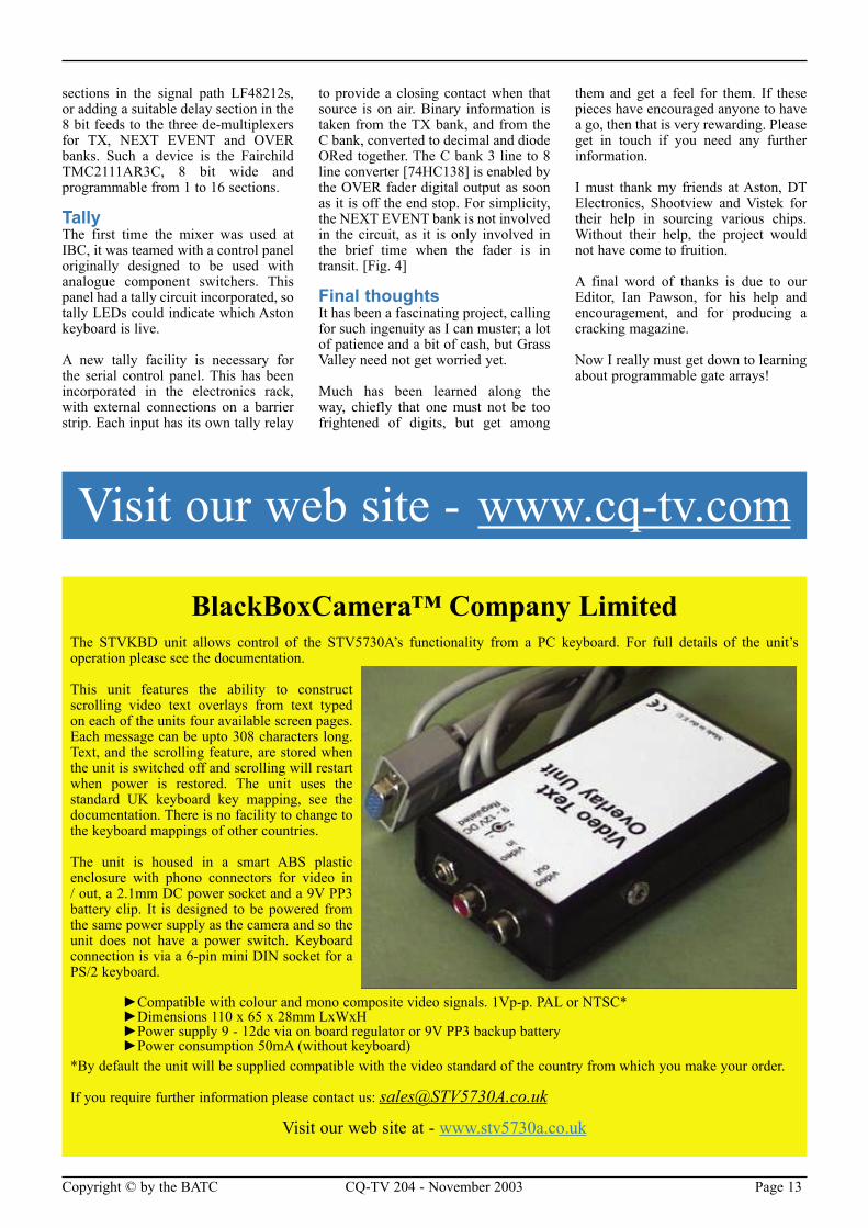
TallyThe first time the mixer was used at IBC, it was teamed with a control panel originally designed to be used with analogue component switchers. This panel had a tally circuit incorporated, so tally LEDs could indicate which Aston keyboard is live.
A new tally facility is necessary for the serial control panel. This has been incorporated in the electronics rack, with external connections on a barrier strip. Each input has its own tally relay
to provide a closing contact when that source is on air. Binary information is taken from the TX bank, and from the C bank, converted to decimal and diode ORed together. The C bank 3 line to 8 line converter [74HC138] is enabled by the OVER fader digital output as soon as it is off the end stop. For simplicity, the NEXT EVENT bank is not involved in the circuit, as it is only involved in the brief time when the fader is in transit. [Fig. 4]
Final thoughtsIt has been a fascinating project, calling for such ingenuity as I can muster; a lot of patience and a bit of cash, but Grass Valley need not get worried yet.
Much has been learned along the way, chiefly that one must not be too frightened of digits, but get among
them and get a feel for them. If these pieces have encouraged anyone to have a go, then that is very rewarding. Please get in touch if you need any further information.
I must thank my friends at Aston, DT Electronics, Shootview and Vistek for their help in sourcing various chips. Without their help, the project would not have come to fruition.
A final word of thanks is due to our Editor, Ian Pawson, for his help and encouragement, and for producing a cracking magazine.
Now I really must get down to learning about programmable gate arrays!
BlackBoxCamera™ Company LimitedThe STVKBD unit allows control of the STV5730A’s functionality from a PC keyboard. For full details of the unit’s operation please see the documentation.
This unit features the ability to construct scrolling video text overlays from text typed on each of the units four available screen pages. Each message can be upto 308 characters long. Text, and the scrolling feature, are stored when the unit is switched off and scrolling will restart when power is restored. The unit uses the standard UK keyboard key mapping, see the documentation. There is no facility to change to the keyboard mappings of other countries.
The unit is housed in a smart ABS plastic enclosure with phono connectors for video in / out, a 2.1mm DC power socket and a 9V PP3 battery clip. It is designed to be powered from the same power supply as the camera and so the unit does not have a power switch. Keyboard connection is via a 6-pin mini DIN socket for a PS/2 keyboard.
►Compatible with colour and mono composite video signals. 1Vp-p. PAL or NTSC* ►Dimensions 110 x 65 x 28mm LxWxH ►Power supply 9 - 12dc via on board regulator or 9V PP3 backup battery ►Power consumption 50mA (without keyboard) *By default the unit will be supplied compatible with the video standard of the country from which you make your order.
If you require further information please contact us: [email protected]
Visit our web site at - www.stv5730a.co.uk
Visit our web site - www.cq-tv.com

Page 14 CQ-TV 204 - November 2003 Copyright © by the BATC Copyright © by the BATC CQ-TV 204 - November 2003 Page 15
Severnside Television GroupOur 23cm aerials are specifically designed for ATV use, although they can be used for other modes as well. Wideband characteristics mean that you need only one aerial to cover the repeater input and output channels. Our famous wideband yagis come fully assembled in two versions:
38-ELEMENT HIGH-GAIN: 14dB gain, 1.8m long, £28.50 plus p&p.18-ELEMENT STANDARD: 10dB gain, 0.9m long, £15.00 plus p&p.Do not forget our 20-ELEMENT CONVERSION KIT, which converts your existing 18-element aerial to the full 38-element high-gain specification: £15.00 plus p&p.
Our aerials feature an SWR of less than 1.5:1 and are supplied with mast clamps suitable for masts up to 55mm diameter (mast poles are not supplied).
Postage and packing: £5.00 per aerial. (Postage to the UK only)Cheques, made payable to “SEVERNSIDE TELEVISION GROUP” should be sent to:
STG (ref CQ-TV), 3, Beechwood Drive, Penarth, Vale of Glamorgan, CF64 3RB.
G6NHG10GHz Horn polyester coated mild steel (20 dB) . . . . . . . .£2510GHz Horn Stainless Steel (20dB) . . . . . . . . . . . . . . . . . . .£322.4GHz spun aluminium Horn (14dB) with mast mounting bracket . . . . . . . . . . . . . . . . . . . . . . . . . . . . . . . . . . . . . . . . .£301.3GHz Alford Slot . . . . . . . . . . . . . . . . . . . . . . . . . . . . . . . .£602.4GHz Alford Slot . . . . . . . . . . . . . . . . . . . . . . . . . . . . . . . .£55Weather proof covers for Alford Slots . . . . . . . . . . . . . . . . .£12SMA to WG16 Feeds . . . . . . . . . . . . . . . . . . . . . . . . . . . . . .£23WG 16 Flanges . . . . . . . . . . . . . . . . . . . . . . . . . . . . . . . . . . . .£6WG16 to WG17 adapters . . . . . . . . . . . . . . . . . . . . . . . . . . . .£53cms slot antennas from . . . . . . . . . . . . . . . . . . . . . . . . . . . .£753cms filters from . . . . . . . . . . . . . . . . . . . . . . . . . . . . . . . . . .£60
For further information, contact:-S. Marshall, G6NHG,25 Carlcroft,Stonydelph,Tamworth,Staffs., B77 4DL.
Telephone 01827 897920. 7:30pm - 10pm weekdays.Email: [email protected]
HS Publications7 Epping Close, Derby, DE22 4HR.
Telephone: 01332 38 16 99Email: [email protected]
• DX-TV Converters
• VHF-UHF TV Aerials
• DX-TV Publications and Videos
• Amplifers - Filters - Hardware
• Technical Books
• BBC Test Card music CDs
• TV Clocks and Archive Publications
Send 3 First Class stamps for our latest cataloguePersonal callers by prior arrangement only please
Page 14 CQ-TV 204 - November 2003 Copyright © by the BATC Copyright © by the BATC CQ-TV 204 - November 2003 Page 15
By Ian F Bennett G6TVJ/D
Over the past year or so, I’ve conducted a number of experiments and trials
involving digital ATV. Essentially these were made possible by the ability to use a cheap domestic-type integrated receiver decoder (IRD). These tests were completed using the DVB-S digital satellite signal format. DVB-S capable receivers are very cheap and available for less than £100. DVB-S has proved to be a very robust signal format, but it is intended for use with good signal paths i.e. direct to and from a satellite transponder. DVB-T is a signal format specifically designed for use with terrestrial paths and exhibits robustness against the effects of multi-path propagation and reflections. DVB-T is an ideal format for DATV but, as with the DVB-S system, its success depends on the availability of suitable transmitting and receiving equipment. Transmitters are, of course, the really tricky bit but a German company called SR-Systems sells a DVB-S transmitter for sensible money. DVB-T transmitters using the complex COFDM modulation system are not currently available to amateurs, but in anticipation of such a transmitter eventually being provided, an affordable receiver is also needed.
The UK terrestrial digital TV system utilises set top boxes (STBs) to receive the “Free-view” broadcast service. These units in theory may receive any DVB-T format transmission - however there is a problem. The UK boxes are delivered virtually pre-programmed to search for the Free-view service, they cannot be manually configured to receive a single digital carrier (unless on a specific UHF channel frequency), such as a signal originated from an amateur transmitter. European DVB-T boxes are operationally different to UK boxes and potentially more flexible. The European specification is the same as for the UK but multiple countries’ frequency plans have to be catered for in a single box, and in Europe
additional TV frequencies exist known as the VHF Band III channels 5-13. I have found a couple of STBs which are intended for use in Europe; they differ from UK boxes in a fundamental way - they may be pre-programmed with a single carrier frequency allowing the reception of a single COFDM DATV signal.
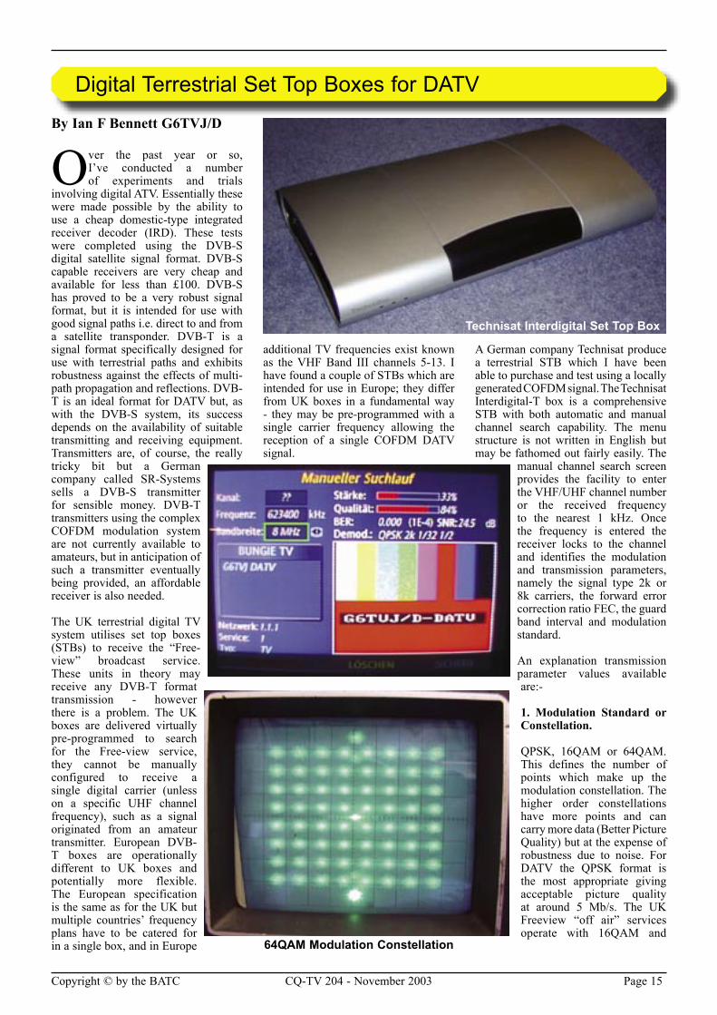
A German company Technisat produce a terrestrial STB which I have been able to purchase and test using a locally generated COFDM signal. The Technisat Interdigital-T box is a comprehensive STB with both automatic and manual channel search capability. The menu structure is not written in English but may be fathomed out fairly easily. The
manual channel search screen provides the facility to enter the VHF/UHF channel number or the received frequency to the nearest 1 kHz. Once the frequency is entered the receiver locks to the channel and identifies the modulation and transmission parameters, namely the signal type 2k or 8k carriers, the forward error correction ratio FEC, the guard band interval and modulation standard.
An explanation transmission parameter values available are:-
1. Modulation Standard or Constellation.
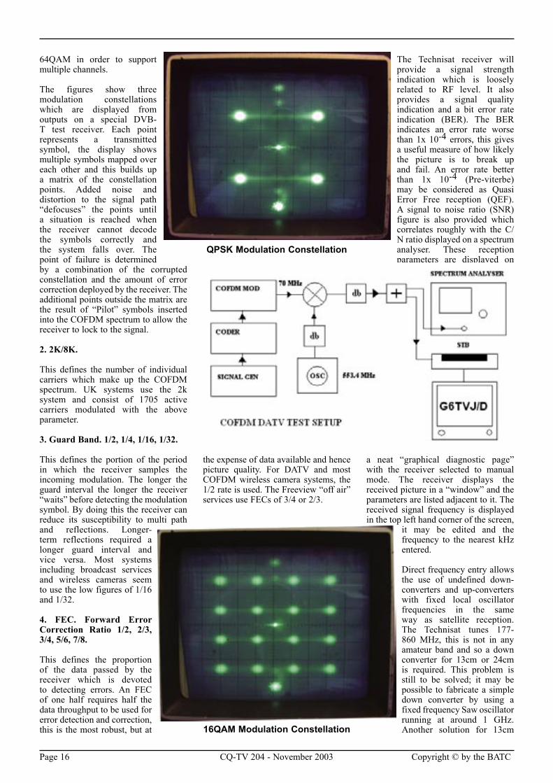
QPSK, 16QAM or 64QAM. This defines the number of points which make up the modulation constellation. The higher order constellations have more points and can carry more data (Better Picture Quality) but at the expense of robustness due to noise. For DATV the QPSK format is the most appropriate giving acceptable picture quality at around 5 Mb/s. The UK Freeview “off air” services operate with 16QAM and
Digital Terrestrial Set Top Boxes for DATV
64QAM Modulation Constellation
Technisat Interdigital Set Top Box
Page 16 CQ-TV 204 - November 2003 Copyright © by the BATC Copyright © by the BATC CQ-TV 204 - November 2003 Page 17
64QAM in order to support multiple channels.
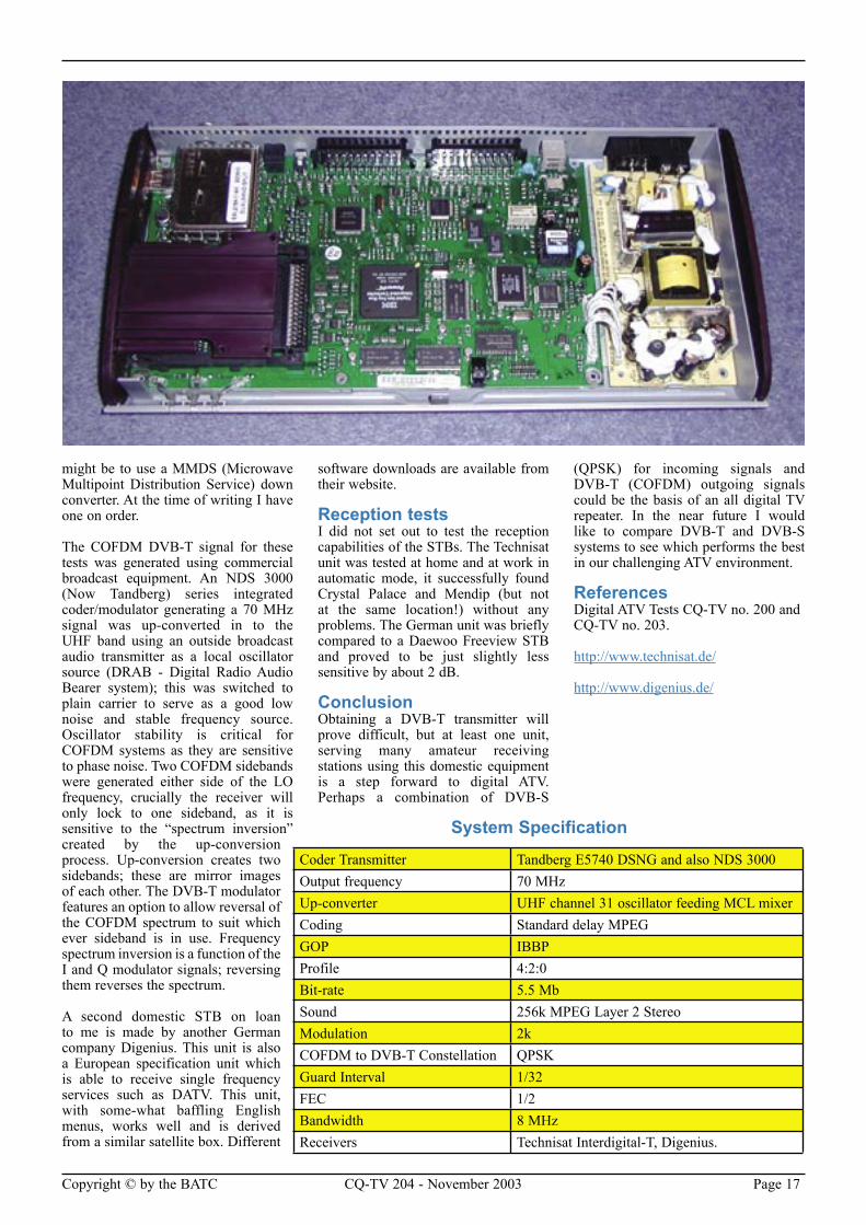
The figures show three modulation constellations which are displayed from outputs on a special DVB-T test receiver. Each point represents a transmitted symbol, the display shows multiple symbols mapped over each other and this builds up a matrix of the constellation points. Added noise and distortion to the signal path “defocuses” the points until a situation is reached when the receiver cannot decode the symbols correctly and the system falls over. The point of failure is determined by a combination of the corrupted constellation and the amount of error correction deployed by the receiver. The additional points outside the matrix are the result of “Pilot” symbols inserted into the COFDM spectrum to allow the receiver to lock to the signal.
2. 2K/8K.
This defines the number of individual carriers which make up the COFDM spectrum. UK systems use the 2k system and consist of 1705 active carriers modulated with the above parameter.
3. Guard Band. 1/2, 1/4, 1/16, 1/32.
This defines the portion of the period in which the receiver samples the incoming modulation. The longer the guard interval the longer the receiver “waits” before detecting the modulation symbol. By doing this the receiver can reduce its susceptibility to multi path and reflections. Longer-term reflections required a longer guard interval and vice versa. Most systems including broadcast services and wireless cameras seem to use the low figures of 1/16 and 1/32.
4. FEC. Forward Error Correction Ratio 1/2, 2/3, 3/4, 5/6, 7/8.
This defines the proportion of the data passed by the receiver which is devoted to detecting errors. An FEC of one half requires half the data throughput to be used for error detection and correction, this is the most robust, but at
the expense of data available and hence picture quality. For DATV and most COFDM wireless camera systems, the 1/2 rate is used. The Freeview “off air” services use FECs of 3/4 or 2/3.
The Technisat receiver will provide a signal strength indication which is loosely related to RF level. It also provides a signal quality indication and a bit error rate indication (BER). The BER indicates an error rate worse than 1x 10⁻⁴ errors, this gives a useful measure of how likely the picture is to break up and fail. An error rate better than 1x 10⁻⁴ (Pre-viterbe) may be considered as Quasi Error Free reception (QEF). A signal to noise ratio (SNR) figure is also provided which correlates roughly with the C/N ratio displayed on a spectrum analyser. These reception parameters are displayed on
a neat “graphical diagnostic page” with the receiver selected to manual mode. The receiver displays the received picture in a “window” and the parameters are listed adjacent to it. The received signal frequency is displayed in the top left hand corner of the screen,
it may be edited and the frequency to the nearest kHz entered.
Direct frequency entry allows the use of undefined down-converters and up-converters with fixed local oscillator frequencies in the same way as satellite reception. The Technisat tunes 177-860 MHz, this is not in any amateur band and so a down converter for 13cm or 24cm is required. This problem is still to be solved; it may be possible to fabricate a simple down converter by using a fixed frequency Saw oscillator running at around 1 GHz. Another solution for 13cm 16QAM Modulation Constellation
QPSK Modulation Constellation
Page 16 CQ-TV 204 - November 2003 Copyright © by the BATC Copyright © by the BATC CQ-TV 204 - November 2003 Page 17
might be to use a MMDS (Microwave Multipoint Distribution Service) down converter. At the time of writing I have one on order.
The COFDM DVB-T signal for these tests was generated using commercial broadcast equipment. An NDS 3000 (Now Tandberg) series integrated coder/modulator generating a 70 MHz signal was up-converted in to the UHF band using an outside broadcast audio transmitter as a local oscillator source (DRAB - Digital Radio Audio Bearer system); this was switched to plain carrier to serve as a good low noise and stable frequency source. Oscillator stability is critical for COFDM systems as they are sensitive to phase noise. Two COFDM sidebands were generated either side of the LO frequency, crucially the receiver will only lock to one sideband, as it is sensitive to the “spectrum inversion” created by the up-conversion process. Up-conversion creates two sidebands; these are mirror images of each other. The DVB-T modulator features an option to allow reversal of the COFDM spectrum to suit which ever sideband is in use. Frequency spectrum inversion is a function of the I and Q modulator signals; reversing them reverses the spectrum.
A second domestic STB on loan to me is made by another German company Digenius. This unit is also a European specification unit which is able to receive single frequency services such as DATV. This unit, with some-what baffling English menus, works well and is derived from a similar satellite box. Different
software downloads are available from their website.
Reception tests I did not set out to test the reception capabilities of the STBs. The Technisat unit was tested at home and at work in automatic mode, it successfully found Crystal Palace and Mendip (but not at the same location!) without any problems. The German unit was briefly compared to a Daewoo Freeview STB and proved to be just slightly less sensitive by about 2 dB.
ConclusionObtaining a DVB-T transmitter will prove difficult, but at least one unit, serving many amateur receiving stations using this domestic equipment is a step forward to digital ATV. Perhaps a combination of DVB-S
(QPSK) for incoming signals and DVB-T (COFDM) outgoing signals could be the basis of an all digital TV repeater. In the near future I would like to compare DVB-T and DVB-S systems to see which performs the best in our challenging ATV environment.
ReferencesDigital ATV Tests CQ-TV no. 200 and CQ-TV no. 203.
http://www.technisat.de/
http://www.digenius.de/
Coder Transmitter Tandberg E5740 DSNG and also NDS 3000Output frequency 70 MHz Up-converter UHF channel 31 oscillator feeding MCL mixer Coding Standard delay MPEG GOP IBBP Profile 4:2:0 Bit-rate 5.5 Mb Sound 256k MPEG Layer 2 StereoModulation 2k COFDM to DVB-T Constellation QPSK Guard Interval 1/32 FEC 1/2 Bandwidth 8 MHz Receivers Technisat Interdigital-T, Digenius.
System Specification
Page 18 CQ-TV 204 - November 2003 Copyright © by the BATC Copyright © by the BATC CQ-TV 204 - November 2003 Page 19
By Bruce Carter - High Speed Amplifier Applications
The advent of a new generation of high speed operational amplifiers with shutdown features has
opened many new applications. One of these is a high performance video switching system, suitable for conventional NTSC as well as high definition video.
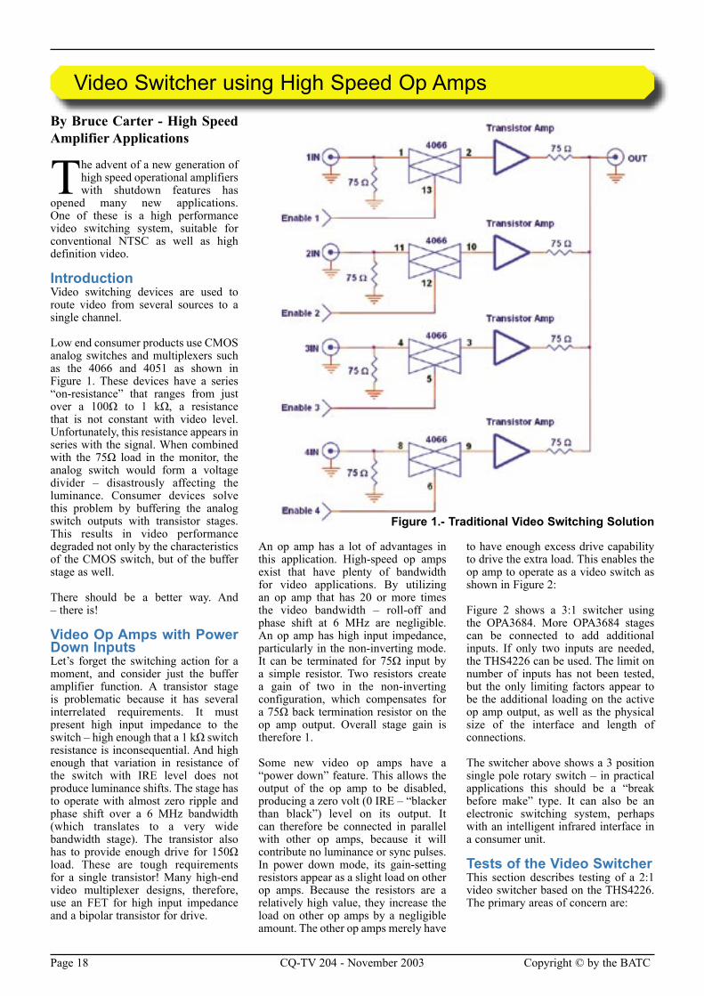
IntroductionVideo switching devices are used to route video from several sources to a single channel.
Low end consumer products use CMOS analog switches and multiplexers such as the 4066 and 4051 as shown in Figure 1. These devices have a series “on-resistance” that ranges from just over a 100Ω to 1 kΩ, a resistance that is not constant with video level. Unfortunately, this resistance appears in series with the signal. When combined with the 75Ω load in the monitor, the analog switch would form a voltage divider – disastrously affecting the luminance. Consumer devices solve this problem by buffering the analog switch outputs with transistor stages. This results in video performance degraded not only by the characteristics of the CMOS switch, but of the buffer stage as well.
There should be a better way. And – there is!
Video Op Amps with Power Down InputsLet’s forget the switching action for a moment, and consider just the buffer amplifier function. A transistor stage is problematic because it has several interrelated requirements. It must present high input impedance to the switch – high enough that a 1 kΩ switch resistance is inconsequential. And high enough that variation in resistance of the switch with IRE level does not produce luminance shifts. The stage has to operate with almost zero ripple and phase shift over a 6 MHz bandwidth (which translates to a very wide bandwidth stage). The transistor also has to provide enough drive for 150Ω load. These are tough requirements for a single transistor! Many high-end video multiplexer designs, therefore, use an FET for high input impedance and a bipolar transistor for drive.
An op amp has a lot of advantages in this application. High-speed op amps exist that have plenty of bandwidth for video applications. By utilizing an op amp that has 20 or more times the video bandwidth – roll-off and phase shift at 6 MHz are negligible. An op amp has high input impedance, particularly in the non-inverting mode. It can be terminated for 75Ω input by a simple resistor. Two resistors create a gain of two in the non-inverting configuration, which compensates for a 75Ω back termination resistor on the op amp output. Overall stage gain is therefore 1.
Some new video op amps have a “power down” feature. This allows the output of the op amp to be disabled, producing a zero volt (0 IRE – “blacker than black”) level on its output. It can therefore be connected in parallel with other op amps, because it will contribute no luminance or sync pulses. In power down mode, its gain-setting resistors appear as a slight load on other op amps. Because the resistors are a relatively high value, they increase the load on other op amps by a negligible amount. The other op amps merely have
to have enough excess drive capability to drive the extra load. This enables the op amp to operate as a video switch as shown in Figure 2:
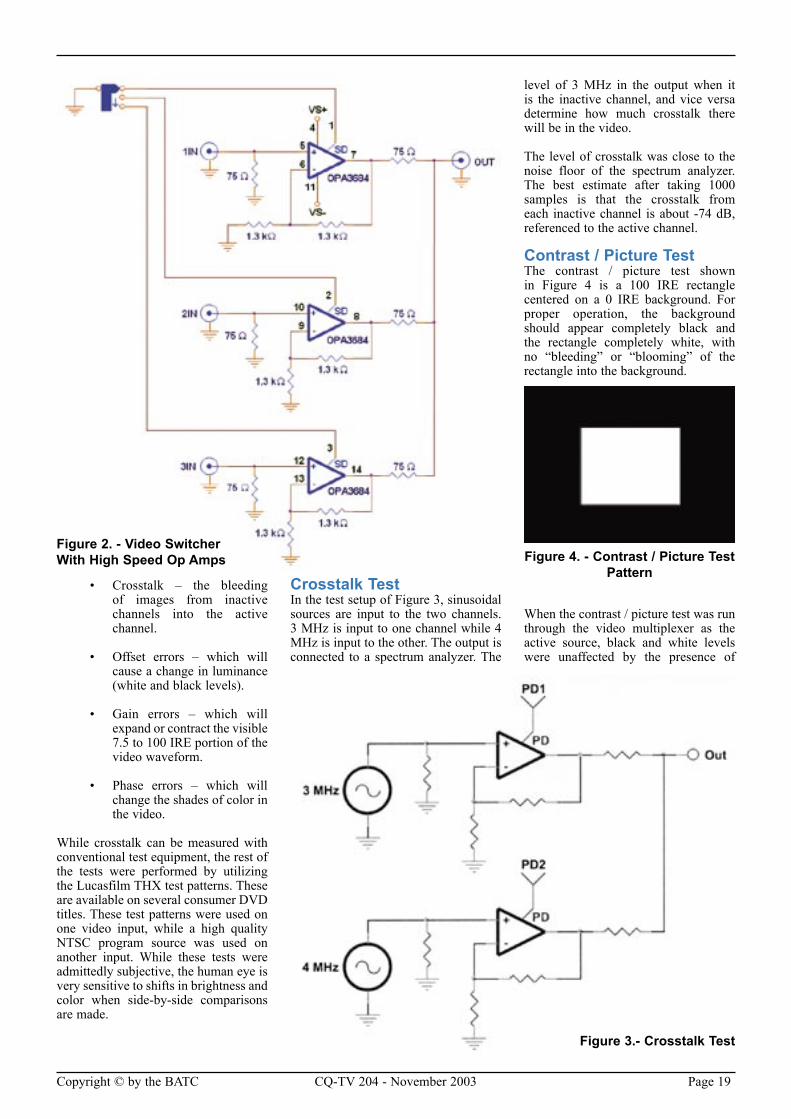
Figure 2 shows a 3:1 switcher using the OPA3684. More OPA3684 stages can be connected to add additional inputs. If only two inputs are needed, the THS4226 can be used. The limit on number of inputs has not been tested, but the only limiting factors appear to be the additional loading on the active op amp output, as well as the physical size of the interface and length of connections.
The switcher above shows a 3 position single pole rotary switch – in practical applications this should be a “break before make” type. It can also be an electronic switching system, perhaps with an intelligent infrared interface in a consumer unit.
Tests of the Video SwitcherThis section describes testing of a 2:1 video switcher based on the THS4226. The primary areas of concern are:
Video Switcher using High Speed Op Amps
Figure 1.- Traditional Video Switching Solution
Page 18 CQ-TV 204 - November 2003 Copyright © by the BATC Copyright © by the BATC CQ-TV 204 - November 2003 Page 19
• Crosstalk – the bleeding of images from inactive channels into the active channel.
• Offset errors – which will cause a change in luminance (white and black levels).
• Gain errors – which will expand or contract the visible 7.5 to 100 IRE portion of the video waveform.
• Phase errors – which will change the shades of color in the video.
While crosstalk can be measured with conventional test equipment, the rest of the tests were performed by utilizing the Lucasfilm THX test patterns. These are available on several consumer DVD titles. These test patterns were used on one video input, while a high quality NTSC program source was used on another input. While these tests were admittedly subjective, the human eye is very sensitive to shifts in brightness and color when side-by-side comparisons are made.
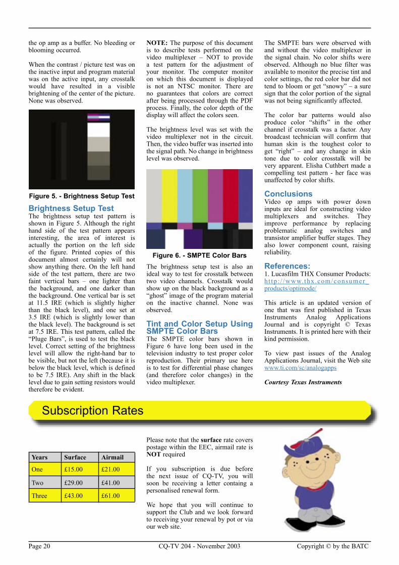
Crosstalk TestIn the test setup of Figure 3, sinusoidal sources are input to the two channels. 3 MHz is input to one channel while 4 MHz is input to the other. The output is connected to a spectrum analyzer. The
level of 3 MHz in the output when it is the inactive channel, and vice versa determine how much crosstalk there will be in the video.
The level of crosstalk was close to the noise floor of the spectrum analyzer. The best estimate after taking 1000 samples is that the crosstalk from each inactive channel is about -74 dB, referenced to the active channel.
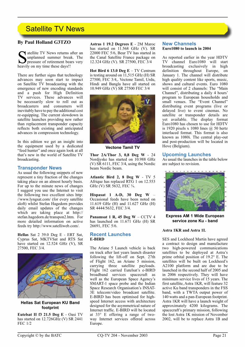
Contrast / Picture TestThe contrast / picture test shown in Figure 4 is a 100 IRE rectangle centered on a 0 IRE background. For proper operation, the background should appear completely black and the rectangle completely white, with no “bleeding” or “blooming” of the rectangle into the background.
When the contrast / picture test was run through the video multiplexer as the active source, black and white levels were unaffected by the presence of
Figure 2. - Video Switcher With High Speed Op Amps
Figure 3.- Crosstalk Test
Figure 4. - Contrast / Picture Test Pattern
Page 20 CQ-TV 204 - November 2003 Copyright © by the BATC Copyright © by the BATC CQ-TV 204 - November 2003 Page 21
the op amp as a buffer. No bleeding or blooming occurred.
When the contrast / picture test was on the inactive input and program material was on the active input, any crosstalk would have resulted in a visible brightening of the center of the picture. None was observed.
Brightness Setup TestThe brightness setup test pattern is shown in Figure 5. Although the right hand side of the test pattern appears interesting, the area of interest is actually the portion on the left side of the figure. Printed copies of this document almost certainly will not show anything there. On the left hand side of the test pattern, there are two faint vertical bars – one lighter than the background, and one darker than the background. One vertical bar is set at 11.5 IRE (which is slightly higher than the black level), and one set at 3.5 IRE (which is slightly lower than the black level). The background is set at 7.5 IRE. This test pattern, called the “Pluge Bars”, is used to test the black level. Correct setting of the brightness level will allow the right-hand bar to be visible, but not the left (because it is below the black level, which is defined to be 7.5 IRE). Any shift in the black level due to gain setting resistors would therefore be evident.
NOTE: The purpose of this document is to describe tests performed on the video multiplexer – NOT to provide a test pattern for the adjustment of your monitor. The computer monitor on which this document is displayed is not an NTSC monitor. There are no guarantees that colors are correct after being processed through the PDF process. Finally, the color depth of the display will affect the colors seen.
The brightness level was set with the video multiplexer not in the circuit. Then, the video buffer was inserted into the signal path. No change in brightness level was observed.
The brightness setup test is also an ideal way to test for crosstalk between two video channels. Crosstalk would show up on the black background as a “ghost” image of the program material on the inactive channel. None was observed.
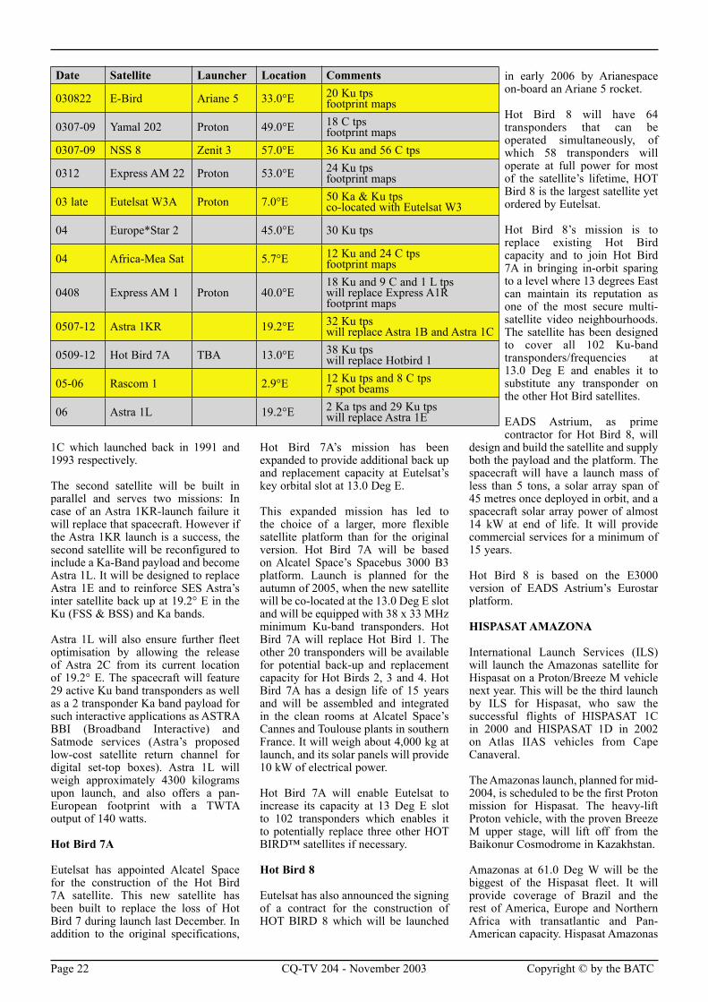
Tint and Color Setup Using SMPTE Color BarsThe SMPTE color bars shown in Figure 6 have long been used in the television industry to test proper color reproduction. Their primary use here is to test for differential phase changes (and therefore color changes) in the video multiplexer.
The SMPTE bars were observed with and without the video multiplexer in the signal chain. No color shifts were observed. Although no blue filter was available to monitor the precise tint and color settings, the red color bar did not tend to bloom or get “snowy” – a sure sign that the color portion of the signal was not being significantly affected.
The color bar patterns would also produce color “shifts” in the other channel if crosstalk was a factor. Any broadcast technician will confirm that human skin is the toughest color to get “right” – and any change in skin tone due to color crosstalk will be very apparent. Elisha Cuthbert made a compelling test pattern - her face was unaffected by color shifts.
ConclusionsVideo op amps with power down inputs are ideal for constructing video multiplexers and switches. They improve performance by replacing problematic analog switches and transistor amplifier buffer stages. They also lower component count, raising reliability.
References:1. Lucasfilm THX Consumer Products: h t tp : / /www.thx .com/consumer_products/optimode/
This article is an updated version of one that was first published in Texas Instruments Analog Applications Journal and is copyright © Texas Instruments. It is printed here with their kind permission.
To view past issues of the Analog Applications Journal, visit the Web site www.ti.com/sc/analogapps
Courtesy Texas Instruments
Figure 5. - Brightness Setup Test
Figure 6. - SMPTE Color Bars
Subscription Rates
Years Surface Airmail
One £15.00 £21.00
Two £29.00 £41.00
Three £43.00 £61.00
Please note that the surface rate covers postage within the EEC, airmail rate is NOT required
If you subscription is due before the next issue of CQ-TV, you will soon be receiving a letter containg a personalised renewal form.
We hope that you will continue to support the Club and we look forward to receiving your renewal by pot or via our web site.
Page 20 CQ-TV 204 - November 2003 Copyright © by the BATC Copyright © by the BATC CQ-TV 204 - November 2003 Page 21
By Paul Holland G3TZO
Satellite TV News returns after an unplanned summer break. The pressure of retirement bears very
heavily on my time these days!!
There are further signs that technology advances may soon start to impact on Satellite TV broadcasting with the emergence of new encoding standards and a push for High Definition TV services. These advances will be necessarily slow to roll out as broadcasters and consumers will inevitably have to pay the additional cost re-equipping. The current slowdown in satellite launches providing new rather than replacement transponder capacity reflects both existing and anticipated advances in compression technology.
In this edition we get an insight into the equipment used by a dedicated “feed hunter” and once again look at all that’s new in the world of Satellite TV broadcasting.
Transponder NewsAs usual the following snippets of new represent a tiny fraction of the changes taking place on an almost hourly basis. For up to the minute news of changes I suggest you use the Internet to visit the following two excellent sites http://www.lyngsat.com/ (for every satellite aloft) whilst Stefan Hagedorn provides daily email updates of the changes which are taking place at http://stefan.hagedorn.de/transpon2.htm. For more detailed information on active feeds try http://www.satelliweb.com/.
Hellas Sat 2 39.0 Deg E - ERT Sat, Cyprus Sat, MKTVSat and RTS Sat have started on 12.524 GHz (V), SR 27500, FEC 3/4.
Hellas Sat European KU Band footprint
Eutelsat II f3 21.5 Deg E - Oasi TV has started on 12.726GHz (V) SR 2441 FEC 1/2
Astras 1 19.2 Degrees E - 2M Maroc has started on 11.568 GHz (V). SR 22000 FEC 5/6, Beur TV has started in the Canal Satellite France package on 12.324 GHz (V). SR 27500, FEC 3/4
Hot Bird 6 13.0 Deg E – TV Centrum is testing around on 11,515 GHz (H) SR 27500, FEC 3/4,. Vectone Tamil, Urdu, Hindi and Bangla have all started on 10.949 GHz (V) SR 27500 FEC 3/4
Vectone Tamil TV
Thor 2A/Thor 3, 0,8 Deg W - 24 Nordjyske has started on 10.988 GHz (V) SR 6111, FEC 3/4, using the Nordic beam Nordic beam.
Atlantic Bird 2, 8 Deg W - TV 5 Afrique has replaced RTG 1 on 12.553 GHz (V) SR 5632, FEC 3⁄4.
Hispasat 1 A-D, 30 Deg W – Occasional feeds have been noted on 11.619 GHz (H) and 11.627 GHz (H) SR 4444/5632, FEC 3/4.
Panamsat 1 R, 45 Deg W – CCTV 4 has launched on 11.671 GHz (H) SR 26691, FEC 5/6.
Recent LaunchesE-BIRD
The Ariane 5 Launch vehicle is back on track after last years launch disaster following the lift-off on Sept. 27th of Flight 162, an Ariane 5 mission, carrying three satellite payloads. Flight 162 carried Eutelsat’s e-BIRD broadband services spacecraft as well as the European Space Agency’s SMART-1 space probe and the Indian Space Research Organisation’s INSAT-3E telecom/video broadcast satellite. E-BIRD has been optimised for high-speed Internet access with architecture designed for the asymmetrical nature of Internet traffic. E-BIRD will be located at 33° E offering a range of two-way Internet services offered across Europe.
New ChannelsEuro1080 to launch in 2004
As reported earlier in the year HDTV TV channel Euro1080 will start broadcasting exclusively in high definition throughout Europe, on January 1. The channel will distribute high quality content like sports, music, shows and cultural events. Euro 1080 will consist of 2 channels: The “Main Channel”, distributing a daily 4 hours’ program to European households and small venues. The “Event Channel” distributing event programs (live or delayed live) to event cinemas. No satellite or transponder details are yet available. The display format Euro1080 has chosen to use for HDTV is 1920 pixels x 1080 lines @ 50 hertz interlaced format. This format is also known as 1080i. The central play-out and post-production will be located in Hove (Belgium).
Upcoming LaunchesAs usual the launches in the table below are subject to revision.
Express AM 1 Wide European service zone Ku - band
Astra 1KR and Astra 1L
SES and Lockheed Martin have agreed a contract to design and manufacture two high-powered communications satellites to be deployed at Astra’s prime orbital position of 19.2° E. The satellites will be built on Lockheed’s A2100 platform and are due to be launched in the second half of 2005 and in 2006 respectively. They will have minimum service lives of 15 years. The first satellite, Astra 1KR, will feature 32 active Ku band transponders in the FSS band, with a TWTA output power of 140 watts and a pan-European footprint. Astra 1KR will have a launch weight of approximately 4200 kilograms. The spacecraft’s primary mission, following the lost Astra 1K mission of November 2002, will be to replace Astra 1B and
Satellite TV News
Page 22 CQ-TV 204 - November 2003 Copyright © by the BATC Copyright © by the BATC CQ-TV 204 - November 2003 Page 23
1C which launched back in 1991 and 1993 respectively.
The second satellite will be built in parallel and serves two missions: In case of an Astra 1KR-launch failure it will replace that spacecraft. However if the Astra 1KR launch is a success, the second satellite will be reconfigured to include a Ka-Band payload and become Astra 1L. It will be designed to replace Astra 1E and to reinforce SES Astra’s inter satellite back up at 19.2° E in the Ku (FSS & BSS) and Ka bands.
Astra 1L will also ensure further fleet optimisation by allowing the release of Astra 2C from its current location of 19.2° E. The spacecraft will feature 29 active Ku band transponders as well as a 2 transponder Ka band payload for such interactive applications as ASTRA BBI (Broadband Interactive) and Satmode services (Astra’s proposed low-cost satellite return channel for digital set-top boxes). Astra 1L will weigh approximately 4300 kilograms upon launch, and also offers a pan-European footprint with a TWTA output of 140 watts.
Hot Bird 7A
Eutelsat has appointed Alcatel Space for the construction of the Hot Bird 7A satellite. This new satellite has been built to replace the loss of Hot Bird 7 during launch last December. In addition to the original specifications,
Hot Bird 7A’s mission has been expanded to provide additional back up and replacement capacity at Eutelsat’s key orbital slot at 13.0 Deg E.
This expanded mission has led to the choice of a larger, more flexible satellite platform than for the original version. Hot Bird 7A will be based on Alcatel Space’s Spacebus 3000 B3 platform. Launch is planned for the autumn of 2005, when the new satellite will be co-located at the 13.0 Deg E slot and will be equipped with 38 x 33 MHz minimum Ku-band transponders. Hot Bird 7A will replace Hot Bird 1. The other 20 transponders will be available for potential back-up and replacement capacity for Hot Birds 2, 3 and 4. Hot Bird 7A has a design life of 15 years and will be assembled and integrated in the clean rooms at Alcatel Space’s Cannes and Toulouse plants in southern France. It will weigh about 4,000 kg at launch, and its solar panels will provide 10 kW of electrical power.
Hot Bird 7A will enable Eutelsat to increase its capacity at 13 Deg E slot to 102 transponders which enables it to potentially replace three other HOT BIRD™ satellites if necessary.
Hot Bird 8
Eutelsat has also announced the signing of a contract for the construction of HOT BIRD 8 which will be launched
in early 2006 by Arianespace on-board an Ariane 5 rocket.
Hot Bird 8 will have 64 transponders that can be operated simultaneously, of which 58 transponders will operate at full power for most of the satellite’s lifetime, HOT Bird 8 is the largest satellite yet ordered by Eutelsat.
Hot Bird 8’s mission is to replace existing Hot Bird capacity and to join Hot Bird 7A in bringing in-orbit sparing to a level where 13 degrees East can maintain its reputation as one of the most secure multi-satellite video neighbourhoods. The satellite has been designed to cover all 102 Ku-band transponders/frequencies at 13.0 Deg E and enables it to substitute any transponder on the other Hot Bird satellites.
EADS Astrium, as prime contractor for Hot Bird 8, will
design and build the satellite and supply both the payload and the platform. The spacecraft will have a launch mass of less than 5 tons, a solar array span of 45 metres once deployed in orbit, and a spacecraft solar array power of almost 14 kW at end of life. It will provide commercial services for a minimum of 15 years.
Hot Bird 8 is based on the E3000 version of EADS Astrium’s Eurostar platform.
HISPASAT AMAZONA
International Launch Services (ILS) will launch the Amazonas satellite for Hispasat on a Proton/Breeze M vehicle next year. This will be the third launch by ILS for Hispasat, who saw the successful flights of HISPASAT 1C in 2000 and HISPASAT 1D in 2002 on Atlas IIAS vehicles from Cape Canaveral.
The Amazonas launch, planned for mid-2004, is scheduled to be the first Proton mission for Hispasat. The heavy-lift Proton vehicle, with the proven Breeze M upper stage, will lift off from the Baikonur Cosmodrome in Kazakhstan.
Amazonas at 61.0 Deg W will be the biggest of the Hispasat fleet. It will provide coverage of Brazil and the rest of America, Europe and Northern Africa with transatlantic and Pan-American capacity. Hispasat Amazonas
Date Satellite Launcher Location Comments
030822 E-Bird Ariane 5 33.0°E 20 Ku tpsfootprint maps
0307-09 Yamal 202 Proton 49.0°E 18 C tpsfootprint maps
0307-09 NSS 8 Zenit 3 57.0°E 36 Ku and 56 C tps
0312 Express AM 22 Proton 53.0°E 24 Ku tpsfootprint maps
03 late Eutelsat W3A Proton 7.0°E 50 Ka & Ku tpsco-located with Eutelsat W3
04 Europe*Star 2 45.0°E 30 Ku tps
04 Africa-Mea Sat 5.7°E 12 Ku and 24 C tpsfootprint maps
0408 Express AM 1 Proton 40.0°E18 Ku and 9 C and 1 L tpswill replace Express A1Rfootprint maps
0507-12 Astra 1KR 19.2°E 32 Ku tpswill replace Astra 1B and Astra 1C
0509-12 Hot Bird 7A TBA 13.0°E 38 Ku tpswill replace Hotbird 1
05-06 Rascom 1 2.9°E 12 Ku tps and 8 C tps7 spot beams
06 Astra 1L 19.2°E 2 Ka tps and 29 Ku tpswill replace Astra 1E
Page 22 CQ-TV 204 - November 2003 Copyright © by the BATC Copyright © by the BATC CQ-TV 204 - November 2003 Page 23
will offer a wide range of services including the traditional satellite telecommunication services as well as content broadcasting, Internet access and broadband services.
The satellite is to be configured with 32 active transponders in Ku-band and 19 active transponders in C-band. The platform is the Eurostar 3000, which will have an operating life of 15 years and a total launching mass of approximately 4,600-kg.
TechnologyHDTV at IBC 2003
SES ASTRA demonstrated HDTV transmissions via Astra at 19.2° E during the IBC exhibition back in September. Two HDTV transmissions were demonstrated on 50-inch High Definition Plasma screens. One feed used MPEG-2 compression and showed high definition content of EURO1080, the first European HDTV channel.
The second feed used Windows Media 9 (WM9) technology to demonstrate a newer compression scheme that allows broadcasters to transmit HDTV content already at bit rates of about 6 - 8 Mbit/s, as opposed to the 15 - 18 Mbit/s currently required using the MPEG2 compression standard.
New H264 Codec
Back in February I reported on the emerging H.264 standard which it is claimed will deliver “DVD-quality” broadcasts with a 33 percent improvement over MPEG-4.
A new video codec for H264 is now being developed by the International Telecommunication Union (ITU) and the International Organisation for Standardisation (ISO.
The H.264 codec is claimed to be a significant improvement on both H.263 and MPEG4, and could have dramatic effects on the transmission of video. This could allow up to four times as many channels to be transmitted on digital TV systems. Its introduction in TV broadcasting will be dependant on the introduction of suitable set-top boxes or the upgrade of existing set top boxes to support the new standard.
From The Post BagAndrew Stringer, G1CWO, has written saying that he has a Scientific Atlanta B-MAC receiver for which he has been trying to get information. He says, “…..although the B-MAC part is virtually
useless, the receiver for PAL is excellent, and has a baseband output amongst other options. My problem is trying to control the front panel display. It will read in MHz when scanning, but does not allow saving of parameters, and on power up has a channel number/group displayed”. He wonders if any readers may be able to help. The receiver is a Scientific Atlanta B-MAC receiver, Cat No. PAL B BTV 2406 upxcx. He also has an aged PACE analogue receiver on which all the On Screen Displays have vanished as result of inadvertent button pushing on the remote. He queries if anybody know the access code to the factory lock, which may enable him to get back into the menus. Reply directly to Peter if you can help or I will pass any information on.
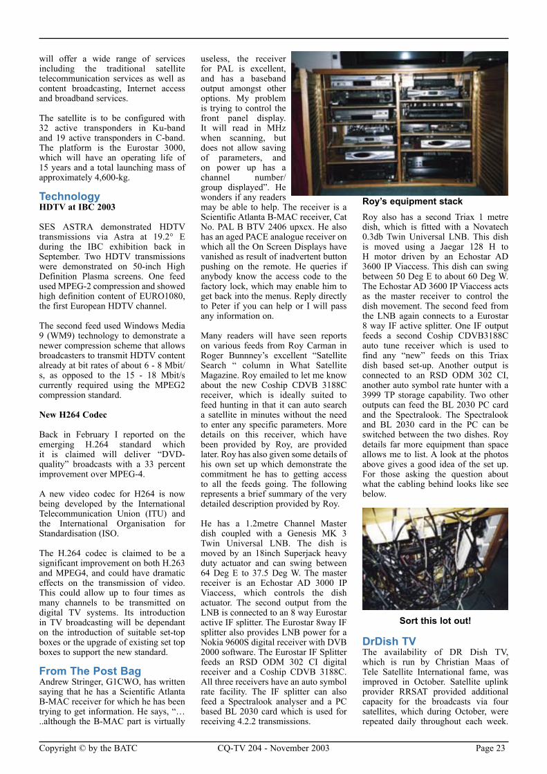
Many readers will have seen reports on various feeds from Roy Carman in Roger Bunnney’s excellent “Satellite Search “ column in What Satellite Magazine. Roy emailed to let me know about the new Coship CDVB 3188C receiver, which is ideally suited to feed hunting in that it can auto search a satellite in minutes without the need to enter any specific parameters. More details on this receiver, which have been provided by Roy, are provided later. Roy has also given some details of his own set up which demonstrate the commitment he has to getting access to all the feeds going. The following represents a brief summary of the very detailed description provided by Roy.
He has a 1.2metre Channel Master dish coupled with a Genesis MK 3 Twin Universal LNB. The dish is moved by an 18inch Superjack heavy duty actuator and can swing between 64 Deg E to 37.5 Deg W. The master receiver is an Echostar AD 3000 IP Viaccess, which controls the dish actuator. The second output from the LNB is connected to an 8 way Eurostar active IF splitter. The Eurostar 8way IF splitter also provides LNB power for a Nokia 9600S digital receiver with DVB 2000 software. The Eurostar IF Splitter feeds an RSD ODM 302 CI digital receiver and a Coship CDVB 3188C. All three receivers have an auto symbol rate facility. The IF splitter can also feed a Spectralook analyser and a PC based BL 2030 card which is used for receiving 4.2.2 transmissions.
Roy’s equipment stackRoy also has a second Triax 1 metre dish, which is fitted with a Novatech 0.3db Twin Universal LNB. This dish is moved using a Jaegar 128 H to H motor driven by an Echostar AD 3600 IP Viaccess. This dish can swing between 50 Deg E to about 60 Deg W. The Echostar AD 3600 IP Viaccess acts as the master receiver to control the dish movement. The second feed from the LNB again connects to a Eurostar 8 way IF active splitter. One IF output feeds a second Coship CDVB3188C auto tune receiver which is used to find any “new” feeds on this Triax dish based set-up. Another output is connected to an RSD ODM 302 CI, another auto symbol rate hunter with a 3999 TP storage capability. Two other outputs can feed the BL 2030 PC card and the Spectralook. The Spectralook and BL 2030 card in the PC can be switched between the two dishes. Roy details far more equipment than space allows me to list. A look at the photos above gives a good idea of the set up. For those asking the question about what the cabling behind looks like see below.
Sort this lot out!
DrDish TV The availability of DR Dish TV, which is run by Christian Maas of Tele Satellite International fame, was improved in October. Satellite uplink provider RRSAT provided additional capacity for the broadcasts via four satellites, which during October, were repeated daily throughout each week.
Page 24 CQ-TV 204 - November 2003 Copyright © by the BATC Copyright © by the BATC CQ-TV 204 - November 2003 Page 25
For each region as appropriate check out;
Asia, Africa and Australia: THAICOM 3, 78.5 Deg E, 3.672 GHz, (H), SR 13333, FEC 3/4.
Eastern Europe, Middle East and North Africa: I NTELSAT 707, 1 Deg W, 10.978 GHz, (V), SR 23000, FEC 2/3.
USA, Canada and South America: INTELSAT 907, 27.5 Deg (W), 3.732 GHz, (RHC), SR 14000, FEC 3/4.
TELSTAR 5, 97.0 Deg W, 12.177 GHz, (V), SR 23000, FEC 2/3.
The next scheduled broadcast in November will be on the 12th of the month between 1900-2200 CET. For more details visit www.drdish.tv.
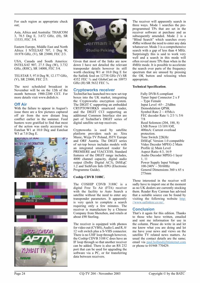
Off AirWith the failure to appear in August’s issue there are a few pictures captured off air from the now distant Iraq conflict earlier in the summer. Feed hunters were gratified to find that most of the action was easily accessed via Eutelsat W1 at 10.0 Deg and Eutelsat W3 at 7.0 Deg E.
Given that most of the links are now down I have not detailed the relevant transponder details however its still worth checking W1 at 10.0 Deg E for the Satlink feed on 12738 GHz (V) SR 4352 FEC 3⁄4 and GlobeCast on 10973 GHz (H) SR 5632 FEC 3⁄4.
Cryptoworks receiver TechniSat has launched two new set-top boxes into the UK market, integrating the Cryptoworks encryption system. The DIGIT C supporting an embedded CRYPTOWORKS smartcard reader, and the DIGIT CCI supporting an additional Common Interface slot are part of TechniSat’s DIGIT series of digital satellite set-top receivers.
Cryptoworks is used by satellite platform providers such as: Xtra Music, Wizja TV Poland, JSTV Europe and ORF Austria. The DIGIT series of set-top boxes includes models with an integrated smartcard reader for PREMIERE and VIACCESS. Standard features of the DIGIT range includes, 4000 channel capacity, digital audio output (Dolby Digital AC3), DiSEqC 1.2 and SiehFern Info EPG (Electronic Programme Guide).
Coship CDVB 3188C.
The COSHIP CDVB 3188C is a digital Free To Air (FTA) receiver with the facility to Auto Search a satellite without the need to enter any transponder parameters. It apparently is very quick to complete a search requiring only a few minutes. The receiver is manufacture by a Chinese Company from Shenzhen, and retails at about £90 Sterling.
The receiver is equipped with phonos for video out (CVBS), Audio L and R, 0/12 volt switch plus a S-VHS connector. There is no UHF loop through however, the Coship CDVB 3188 C does have an IF loop through so that another receiver can be added. There is also an RS 232 port that can be used for upgrading the software via a PC, or for transferring data between receivers.
The receiver will apparently search in three ways. Mode 1 searches the pre-programmed TPs that are set in the receiver software at purchase and as subsequently amended. Mode 2 is a “Blind Search” which searches every 4Mhz without the need to enter any data whatsoever. Mode 3 is a comprehensive search with a gap of less than 4 MHz. Surprisingly this is said to work very well and a search in this mode will often reveal more TPs than when in the 4MHz mode. It is possible to accelerate the search over parts of the frequency spectrum that are unused by pressing the OK button and releasing when appropriate.
Technical Specification.
Fully DVB-S compliantTuner Input Connector 2 x F – Type FemaleInput Level -65~ .25dBmDemodulation QPSKSymbol Rate 2 ~ 45Ms/sFEC decoder Rate 1⁄2 2/3 3⁄4 5/6 7/8Reed Solomon (204, 188, 8)LNB Power 13/18V/Off, 400mA: Current overload protection.Tone Switch 22KHzDiSEqC Version 1.0 compatibleVideo Decoder MPEG-2 Main Profile @ Main LevelAspect Ratio 4:3, 16:9Audio Decoder MPEG-1 layer 1, 11Power Supply Input Voltage 100-240V ~ 50/60HzGeneral Dimensions 360 x 65 x 275mm
Those interested in the receiver will sadly have to import one at the moment as no UK dealers are currently stocking them. Reader Roy Carman has advised that a suitable source can be found by visiting the following website http://www.satlinknz.co.nz/.
ConclusionThat’s it again for this edition. Thanks to those who have written, emailed and sent me information for use in the column. Please do write in and let me know what you are doing and let me have your news and views on the satellite TV related news matters. As usual the contact details are the same; email via [email protected] or phone to 01948 770429.

Page 24 CQ-TV 204 - November 2003 Copyright © by the BATC Copyright © by the BATC CQ-TV 204 - November 2003 Page 25
By Giles Read, G1MFG
Giles describes the construction and flights of two high-altitude balloon experiments carrying
2.4GHz TV transmitters up to the very edge of space.
How it all startedThe phone rang. “We want a balloon payload that will transmit TV pictures from ground level to 100,000 feet, maybe 100 miles down range. Are you interested in helping?”
What a question! Of course I was interested - that’s the sort of challenge I relish. The voice on the other end of the phone turned out to belong to Dr Ilya Eigenbrot, scientific communicator from Imperial College, London. He was speaking for Mike Jones of Film and Video Umbrella, who was working on behalf of the artist Simon Faithfull. Sounds complicated, but I found all the guys really easy to work with. Simon had a particular artistic requirement and after a few meetings and a lot of emails we hammered out a specification which would do what he wanted. We also decided to build two similar payloads rather than one, so that if one didn’t work well then we’d have a second to fall back on.
Building the payloadsThe only information I had about the balloon was that it had a lifting capacity of 2kg. That isn’t actually very much weight to play with, when you think that we’d be fitting batteries, a camera, and a transmitter into the weight limit. Weight was to be a determining factor in terms of what could and could not be flown.
The first step was to specify the RF link. It had already been determined that the operating frequency would be in the 2.4GHz band, on one of the JFMG-licensed programme making & special events channels. Conveniently, that is well within the range of unmodified G1MFG.com transmitters, amplifiers and receivers!
The expected flight profile was that the balloon would go more or less straight up for the first 20,000 feet or so and then encounter winds of around 100MPH which would carry it off. Fight duration would be about two or three hours, so the payload might be anything up to 200 miles away at
the end of the flight. Discussions with Ilya and his contacts in the Met Office indicated that the normal distance was actually nearer 100 miles, so I tried to figure out a suitable specification by examining the path characteristics.
We could assume that it would be line of sight and so the normal Free Space Path Loss calculations would apply.
For the purposes of the calculations I’d use a figure of 100 miles downrange (160km), and the operating frequency would be 2.5GHz.
• Free Space Path Loss = 32.5dB + 20 log (160 km) + 20 log (2500 MHz)
• FSPL = 144.5dB
• Receive sensitivity = -86dBm (typical for good quality on a G1MFG.com receiver)
• Link power + antenna gain required = 144.5 – 86 = 58.5dB
Using a G1MFG.com 24dBi gain receive antenna, we still need 34.5dB of gain relative to 1mW.
A 6W amplifier equates to about +38dBm, giving a margin of 3.5dB over the minimum requirement. This means that we could use a relatively
low gain transmit antenna for maximum coverage area.
Discussions with ANTEC (G8CKN) suggested that a hemispherical coverage with circular polarisation would be best. A suitable antenna was commissioned and constructed – an equal-angle spiral, to be precise. Circular polarisation, when received on a linearly polarised antenna, would result in a 3dB loss of signal but this would still leave a small margin.
So, at this point the transmit equipment was pretty much decided. A quick visit to my stock room indicated that a transmitter and 6W amplifier left plenty of weight over for batteries and a camera, so the project began in earnest.
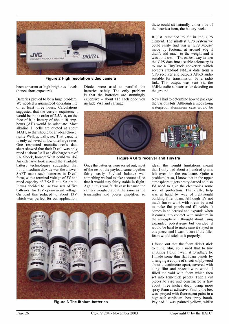
Simon particularly wanted to start with an image of his face, which would then shrink into insignificance as the camera was carried away on the balloon. After a false start with a cheap PCB camera we decided to use a high resolution JVC security camera as the main imaging element. We couldn’t decide exactly what focal length lens would be appropriate, so we compromised by getting a zoom lens. Consultation with the camera supplier suggested that a video drive lens would be the best method of iris control. We didn’t want to use an electronic iris because of the strobing effect which would have
Up, Up and Away!
Figure 1 Transmitter, amplifier and antenna
Page 26 CQ-TV 204 - November 2003 Copyright © by the BATC Copyright © by the BATC CQ-TV 204 - November 2003 Page 27
been apparent at high brightness levels (hence short exposure).
Batteries proved to be a huge problem. We needed a guaranteed operating life of at least three hours. Calculations suggested that the current requirement would be in the order of 2.5A so, on the face of it, a battery of about 10 amp-hours (AH) would be adequate. Most alkaline D cells are quoted at about 14AH, so that should be an ideal choice, right? Well, actually, no. That capacity is only achieved at low discharge rates. One respected manufacturer’s data sheet showed that their D cell was only rated at about 3AH at a discharge rate of 2A. Shock, horror! What could we do? An extensive look around the available battery technologies suggested that lithium sodium dioxide was the answer. SAFT make such batteries in D-cell form, with a terminal voltage of 3V and rated capacity of 7.5AH at 1.5A drain. It was decided to use two sets of five batteries, for 15V open-circuit voltage. On load this reduced to about 13V, which was perfect for our application.
Diodes were used to parallel the batteries safely. The only problem is that the batteries are stunningly expensive – about £15 each once you include VAT and carriage.
Once the batteries were sorted out, most of the rest of the payload came together fairly easily. Payload balance was something we had to take account of, so that it would stay fairly stable in flight. Again, this was fairly easy because the camera weighed about the same as the transmitter and power amplifier, so
these could sit naturally either side of the heaviest item, the battery pack.
It just remained to fit in the GPS element. The smallest GPS system we could easily find was a ‘GPS Mouse’ made by Fortuna: at around 80g it didn’t add much to the weight and it was quite small. The easiest way to turn the GPS data into useable telemetry is to use a TinyTrack converter, which accepts standard NMEA data from a GPS receiver and outputs APRS audio suitable for transmission by a radio link. This output was sent via the 6MHz audio subcarrier for decoding on the ground.
Now I had to determine how to package the various bits. Although a nice strong waterproof aluminium case would be
ideal, the weight limitations meant that I only had about a hundred grams left over for the enclosure. Quite a problem! Also, I knew that in the upper atmosphere it gets pretty darned cold so I’d need to give the electronics some sort of protection. Thankfully, help was at hand by way of lightweight building filler foam. Although it’s not much fun to work with it can be used to make flat panels and fill voids. It comes in an aerosol and expands when it comes into contact with moisture in the atmosphere. I thought about using expanded polystyrene but decided it would be hard to make sure it stayed in one piece, and I wasn’t sure if the filler foam would stick to it properly.
I found out that the foam didn’t stick to cling film, so I used that to line anything I didn’t want it to adhere to. I made some thin flat foam panels by arranging a couple of sheets of plywood about a centimetre apart, covered with cling film and spaced with wood. I filled the void with foam which then set into 1cm-thick panels. Then I cut pieces to size and constructed a tray about three inches deep, using more spray foam as adhesive. Finally the box was sprayed with fluorescent paint in a high-tech cardboard box spray booth. Payload 1 was painted yellow, whilst
Figure 2 High resolution video camera
Figure 3 The lithium batteries
Figure 4 GPS receiver and TinyTra
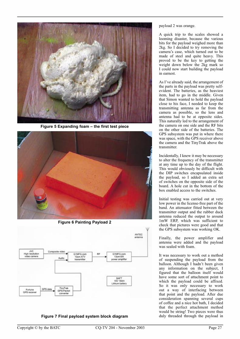
Page 26 CQ-TV 204 - November 2003 Copyright © by the BATC Copyright © by the BATC CQ-TV 204 - November 2003 Page 27
payload 2 was orange.
A quick trip to the scales showed a looming disaster, because the various bits for the payload weighed more than 2kg. So I decided to try removing the camera’s case, which turned out to be made of steel and quite heavy. This proved to be the key to getting the weight down below the 2kg mark so I could now start building the payload in earnest.
As I’ve already said, the arrangement of the parts in the payload was pretty self-evident. The batteries, as the heaviest item, had to go in the middle. Given that Simon wanted to hold the payload close to his face, I needed to keep the transmitting antenna as far from the camera as possible, so the lens and antenna had to be at opposite sides. This naturally led to the arrangement of the camera on one side and the RF bits on the other side of the batteries. The GPS subsystem was put in where there was space, with the GPS receiver above the camera and the TinyTrak above the transmitter.
Incidentally, I knew it may be necessary to alter the frequency of the transmitter at any time up to the day of the flight. This would obviously be difficult with the DIP switches encapsulated inside the payload, so I added an extra set of switches on the opposite side of the board. A hole cut in the bottom of the box enabled access to the switches.
Initial testing was carried out at very low power in the license-free part of the band. An attenuator fitted between the transmitter output and the rubber duck antenna reduced the output to around 1mW ERP, which was sufficient to check that pictures were good and that the GPS subsystem was working OK.
Finally, the power amplifier and antenna were added and the payload was sealed with foam.
It was necessary to work out a method of suspending the payload from the balloon. Although I hadn’t been given any information on the subject, I figured that the balloon itself would have some sort of attachment point to which the payload could be affixed. So it was only necessary to work out a way of interfacing between that point and the payload. After due consideration spanning several cups of coffee and a nice hot bath, I decided that the perfect attachment method would be string! Two pieces were thus duly threaded through the payload in
Figure 5 Expanding foam – the first test piece
Figure 6 Painting Payload 2
Figure 7 Final payload system block diagram
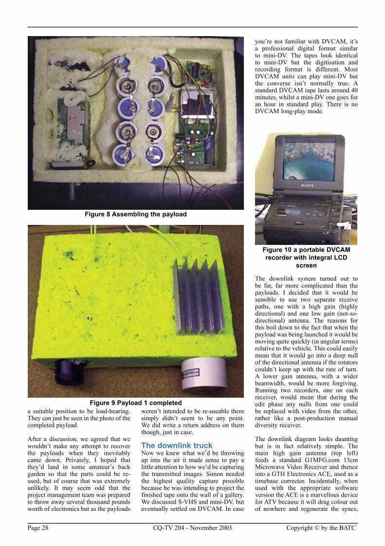
Page 28 CQ-TV 204 - November 2003 Copyright © by the BATC Copyright © by the BATC CQ-TV 204 - November 2003 Page 29
a suitable position to be load-bearing. They can just be seen in the photo of the completed payload.
After a discussion, we agreed that we wouldn’t make any attempt to recover the payloads when they inevitably came down. Privately, I hoped that they’d land in some amateur’s back garden so that the parts could be re-used, but of course that was extremely unlikely. It may seem odd that the project management team was prepared to throw away several thousand pounds worth of electronics but as the payloads
weren’t intended to be re-useable there simply didn’t seem to be any point. We did write a return address on them though, just in case.
The downlink truckNow we knew what we’d be throwing up into the air it made sense to pay a little attention to how we’d be capturing the transmitted images. Simon needed the highest quality capture possible because he was intending to project the finished tape onto the wall of a gallery. We discussed S-VHS and mini-DV, but eventually settled on DVCAM. In case
you’re not familiar with DVCAM, it’s a professional digital format similar to mini-DV. The tapes look identical to mini-DV but the digitisation and recording format is different. Most DVCAM units can play mini-DV but the converse isn’t normally true. A standard DVCAM tape lasts around 40 minutes, whilst a mini-DV one goes for an hour in standard play. There is no DVCAM long-play mode.
The downlink system turned out to be far, far more complicated than the payloads. I decided that it would be sensible to use two separate receive paths, one with a high gain (highly directional) and one low gain (not-so-directional) antenna. The reasons for this boil down to the fact that when the payload was being launched it would be moving quite quickly (in angular terms) relative to the vehicle. This could easily mean that it would go into a deep null of the directional antenna if the rotators couldn’t keep up with the rate of turn. A lower gain antenna, with a wider beamwidth, would be more forgiving. Running two recorders, one on each receiver, would mean that during the edit phase any nulls from one could be replaced with video from the other, rather like a post-production manual diversity receiver.
The downlink diagram looks daunting but is in fact relatively simple. The main high gain antenna (top left) feeds a standard G1MFG.com 13cm Microwave Video Receiver and thence into a GTH Electronics ACE, used as a timebase corrector. Incidentally, when used with the appropriate software version the ACE is a marvellous device for ATV because it will drag colour out of nowhere and regenerate the syncs,
Figure 8 Assembling the payload
Figure 9 Payload 1 completed
Figure 10 a portable DVCAM recorder with integral LCD
screen
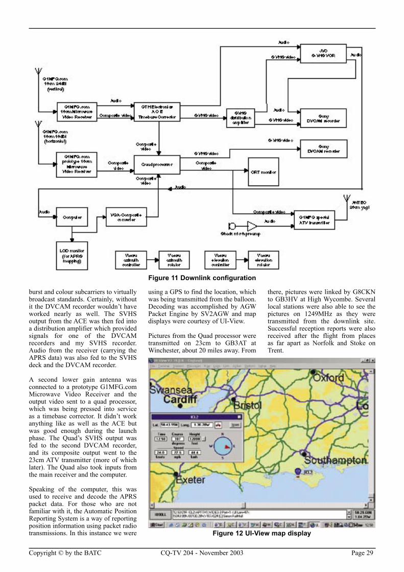
Page 28 CQ-TV 204 - November 2003 Copyright © by the BATC Copyright © by the BATC CQ-TV 204 - November 2003 Page 29
burst and colour subcarriers to virtually broadcast standards. Certainly, without it the DVCAM recorder wouldn’t have worked nearly as well. The SVHS output from the ACE was then fed into a distribution amplifier which provided signals for one of the DVCAM recorders and my SVHS recorder. Audio from the receiver (carrying the APRS data) was also fed to the SVHS deck and the DVCAM recorder.
A second lower gain antenna was connected to a prototype G1MFG.com Microwave Video Receiver and the output video sent to a quad processor, which was being pressed into service as a timebase corrector. It didn’t work anything like as well as the ACE but was good enough during the launch phase. The Quad’s SVHS output was fed to the second DVCAM recorder, and its composite output went to the 23cm ATV transmitter (more of which later). The Quad also took inputs from the main receiver and the computer.
Speaking of the computer, this was used to receive and decode the APRS packet data. For those who are not familiar with it, the Automatic Position Reporting System is a way of reporting position information using packet radio transmissions. In this instance we were
using a GPS to find the location, which was being transmitted from the balloon. Decoding was accomplished by AGW Packet Engine by SV2AGW and map displays were courtesy of UI-View.
Pictures from the Quad processor were transmitted on 23cm to GB3AT at Winchester, about 20 miles away. From
there, pictures were linked by G8CKN to GB3HV at High Wycombe. Several local stations were also able to see the pictures on 1249MHz as they were transmitted from the downlink site. Successful reception reports were also received after the flight from places as far apart as Norfolk and Stoke on Trent.
Figure 11 Downlink configuration
Figure 12 UI-View map display
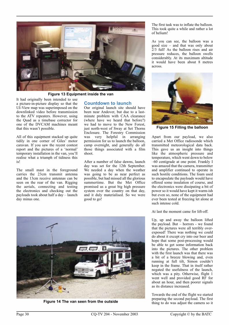
Page 30 CQ-TV 204 - November 2003 Copyright © by the BATC Copyright © by the BATC CQ-TV 204 - November 2003 Page 31
It had originally been intended to use a picture-in-picture display so that the UI-View map was superimposed on the downlinked video before transmission to the ATV repeaters. However, using the Quad as a timebase corrector for one of the DVCAM machines meant that this wasn’t possible.
All of this equipment stacked up quite tidily in one corner of Giles’ motor caravan. If you saw the recent contest report and the pictures of a ‘normal’ temporary installation in the van, you’ll realise what a triumph of tidiness this is!
The small mast in the foreground carries the 23cm transmit antenna and the 13cm receive antennas can be seen on the rear of the van. Rigging the aerials, connecting and testing the electronics and checking out the payloads took about half a day – launch day minus one.
Countdown to launchOur original launch site should have been near Andover, but due to a last-minute problem with CAA clearance (where have we heard that before?) we had to move to the New Forest, just north-west of Sway at Set Thorns Enclosure. The Forestry Commission was very helpful in arranging permission for us to launch the balloon, camp overnight, and generally do all those things associated with a film shoot.
After a number of false dawns, launch day was set for the 12th September. We needed a day when the weather was going to be as near perfect as possible, but had missed all the glorious summertime. But the Met Office promised us a great big high pressure system over the country on that day, and it duly materialised. So we were good to go!
The first task was to inflate the balloon. This took quite a while and rather a lot of helium!
As you can see, the balloon was a good size – and that was only about 2/3 full! As the balloon rises and air pressure reduces, the balloon swells considerably. At its maximum altitude it would have been about 8 metres across.
Apart from our payload, we also carried a Met Office radiosonde which transmitted meteorological data back. This gave us an insight into things like the atmospheric pressure and temperature, which went down to below –60 centigrade at one point. Frankly I was amazed that the camera, transmitter and amplifier continued to operate in such hostile conditions. The foam used to encapsulate the payloads would have offered some insulation of course, and the electronics were dissipating a bit of power so it would have kept it warm-ish but even so, none of the equipment had ever been tested at freezing let alone at such intense cold.
At last the moment came for lift-off.
Up, up and away the balloon lifted the payload. But – horrors - we found that the pictures were all terribly over-exposed! There was nothing we could do about it except cry into our beer and hope that some post-processing would be able to get some information back into the pictures. The other problem with the first launch was that there was a bit of a breeze blowing and, even running at full tilt, Simon couldn’t keep in the frame. That in itself rather negated the usefulness of the launch, which was a pity. Otherwise, flight 1 went well and provided good RF for about an hour, and then poorer signals as its distance increased.
Towards the end of the flight we started preparing the second payload. The first thing to do was adjust the camera so it Figure 14 The van seen from the outside
Figure 13 Equipment inside the van
Figure 15 Filling the balloon
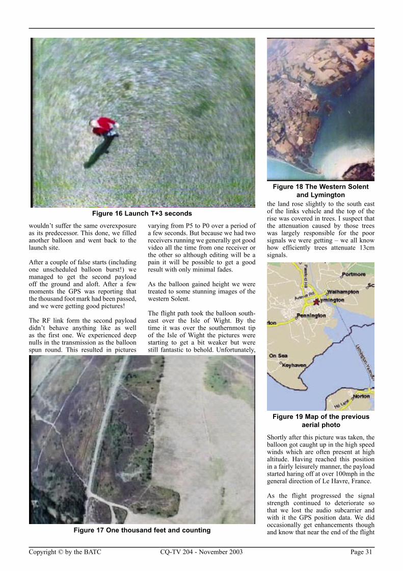
Page 30 CQ-TV 204 - November 2003 Copyright © by the BATC Copyright © by the BATC CQ-TV 204 - November 2003 Page 31
wouldn’t suffer the same overexposure as its predecessor. This done, we filled another balloon and went back to the launch site.
After a couple of false starts (including one unscheduled balloon burst!) we managed to get the second payload off the ground and aloft. After a few moments the GPS was reporting that the thousand foot mark had been passed, and we were getting good pictures!
The RF link form the second payload didn’t behave anything like as well as the first one. We experienced deep nulls in the transmission as the balloon spun round. This resulted in pictures
varying from P5 to P0 over a period of a few seconds. But because we had two receivers running we generally got good video all the time from one receiver or the other so although editing will be a pain it will be possible to get a good result with only minimal fades.
As the balloon gained height we were treated to some stunning images of the western Solent.
The flight path took the balloon south-east over the Isle of Wight. By the time it was over the southernmost tip of the Isle of Wight the pictures were starting to get a bit weaker but were still fantastic to behold. Unfortunately,
the land rose slightly to the south east of the links vehicle and the top of the rise was covered in trees. I suspect that the attenuation caused by those trees was largely responsible for the poor signals we were getting – we all know how efficiently trees attenuate 13cm signals.
Shortly after this picture was taken, the balloon got caught up in the high speed winds which are often present at high altitude. Having reached this position in a fairly leisurely manner, the payload started haring off at over 100mph in the general direction of Le Havre, France.
As the flight progressed the signal strength continued to deteriorate so that we lost the audio subcarrier and with it the GPS position data. We did occasionally get enhancements though and know that near the end of the flight
Figure 16 Launch T+3 seconds
Figure 17 One thousand feet and counting
Figure 18 The Western Solent and Lymington
Figure 19 Map of the previous aerial photo
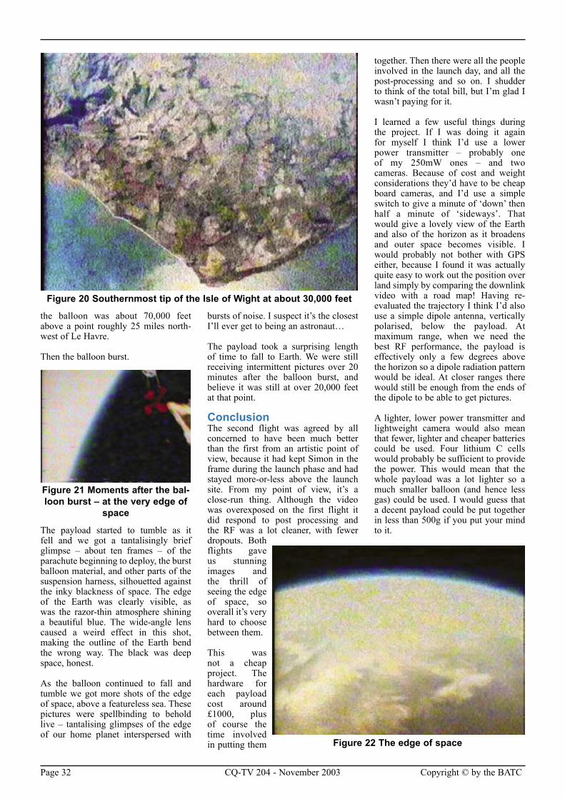
Page 32 CQ-TV 204 - November 2003 Copyright © by the BATC Copyright © by the BATC CQ-TV 204 - November 2003 Page 33
the balloon was about 70,000 feet above a point roughly 25 miles north-west of Le Havre.
Then the balloon burst.
The payload started to tumble as it fell and we got a tantalisingly brief glimpse – about ten frames – of the parachute beginning to deploy, the burst balloon material, and other parts of the suspension harness, silhouetted against the inky blackness of space. The edge of the Earth was clearly visible, as was the razor-thin atmosphere shining a beautiful blue. The wide-angle lens caused a weird effect in this shot, making the outline of the Earth bend the wrong way. The black was deep space, honest.
As the balloon continued to fall and tumble we got more shots of the edge of space, above a featureless sea. These pictures were spellbinding to behold live – tantalising glimpses of the edge of our home planet interspersed with
bursts of noise. I suspect it’s the closest I’ll ever get to being an astronaut…
The payload took a surprising length of time to fall to Earth. We were still receiving intermittent pictures over 20 minutes after the balloon burst, and believe it was still at over 20,000 feet at that point.
ConclusionThe second flight was agreed by all concerned to have been much better than the first from an artistic point of view, because it had kept Simon in the frame during the launch phase and had stayed more-or-less above the launch site. From my point of view, it’s a close-run thing. Although the video was overexposed on the first flight it did respond to post processing and the RF was a lot cleaner, with fewer dropouts. Both flights gave us stunning images and the thrill of seeing the edge of space, so overall it’s very hard to choose between them.
This was not a cheap project. The hardware for each payload cost around £1000, plus of course the time involved in putting them
together. Then there were all the people involved in the launch day, and all the post-processing and so on. I shudder to think of the total bill, but I’m glad I wasn’t paying for it.
I learned a few useful things during the project. If I was doing it again for myself I think I’d use a lower power transmitter – probably one of my 250mW ones – and two cameras. Because of cost and weight considerations they’d have to be cheap board cameras, and I’d use a simple switch to give a minute of ‘down’ then half a minute of ‘sideways’. That would give a lovely view of the Earth and also of the horizon as it broadens and outer space becomes visible. I would probably not bother with GPS either, because I found it was actually quite easy to work out the position over land simply by comparing the downlink video with a road map! Having re-evaluated the trajectory I think I’d also use a simple dipole antenna, vertically polarised, below the payload. At maximum range, when we need the best RF performance, the payload is effectively only a few degrees above the horizon so a dipole radiation pattern would be ideal. At closer ranges there would still be enough from the ends of the dipole to be able to get pictures.
A lighter, lower power transmitter and lightweight camera would also mean that fewer, lighter and cheaper batteries could be used. Four lithium C cells would probably be sufficient to provide the power. This would mean that the whole payload was a lot lighter so a much smaller balloon (and hence less gas) could be used. I would guess that a decent payload could be put together in less than 500g if you put your mind to it.
Figure 20 Southernmost tip of the Isle of Wight at about 30,000 feet
Figure 21 Moments after the bal-loon burst – at the very edge of
space
Figure 22 The edge of space
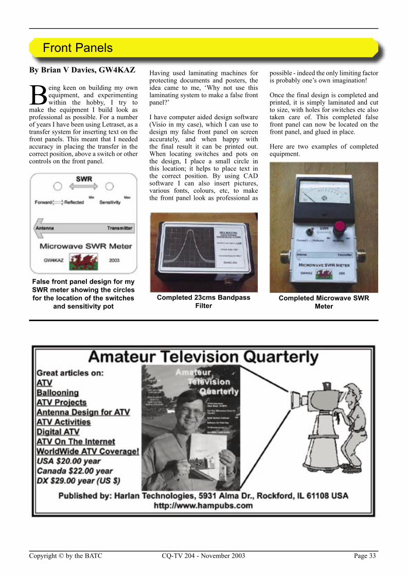
Page 32 CQ-TV 204 - November 2003 Copyright © by the BATC Copyright © by the BATC CQ-TV 204 - November 2003 Page 33
Front Panels
By Brian V Davies, GW4KAZ
Being keen on building my own equipment, and experimenting within the hobby, I try to
make the equipment I build look as professional as possible. For a number of years I have been using Letraset, as a transfer system for inserting text on the front panels. This meant that I needed accuracy in placing the transfer in the correct position, above a switch or other controls on the front panel.
Having used laminating machines for protecting documents and posters, the idea came to me, ‘Why not use this laminating system to make a false front panel?’
I have computer aided design software (Visio in my case), which I can use to design my false front panel on screen accurately, and when happy with the final result it can be printed out. When locating switches and pots on the design, I place a small circle in this location; it helps to place text in the correct position. By using CAD software I can also insert pictures, various fonts, colours, etc, to make the front panel look as professional as
possible - indeed the only limiting factor is probably one’s own imagination!
Once the final design is completed and printed, it is simply laminated and cut to size, with holes for switches etc also taken care of. This completed false front panel can now be located on the front panel, and glued in place.
Here are two examples of completed equipment.
False front panel design for my SWR meter showing the circles for the location of the switches
and sensitivity potCompleted 23cms Bandpass
FilterCompleted Microwave SWR
Meter
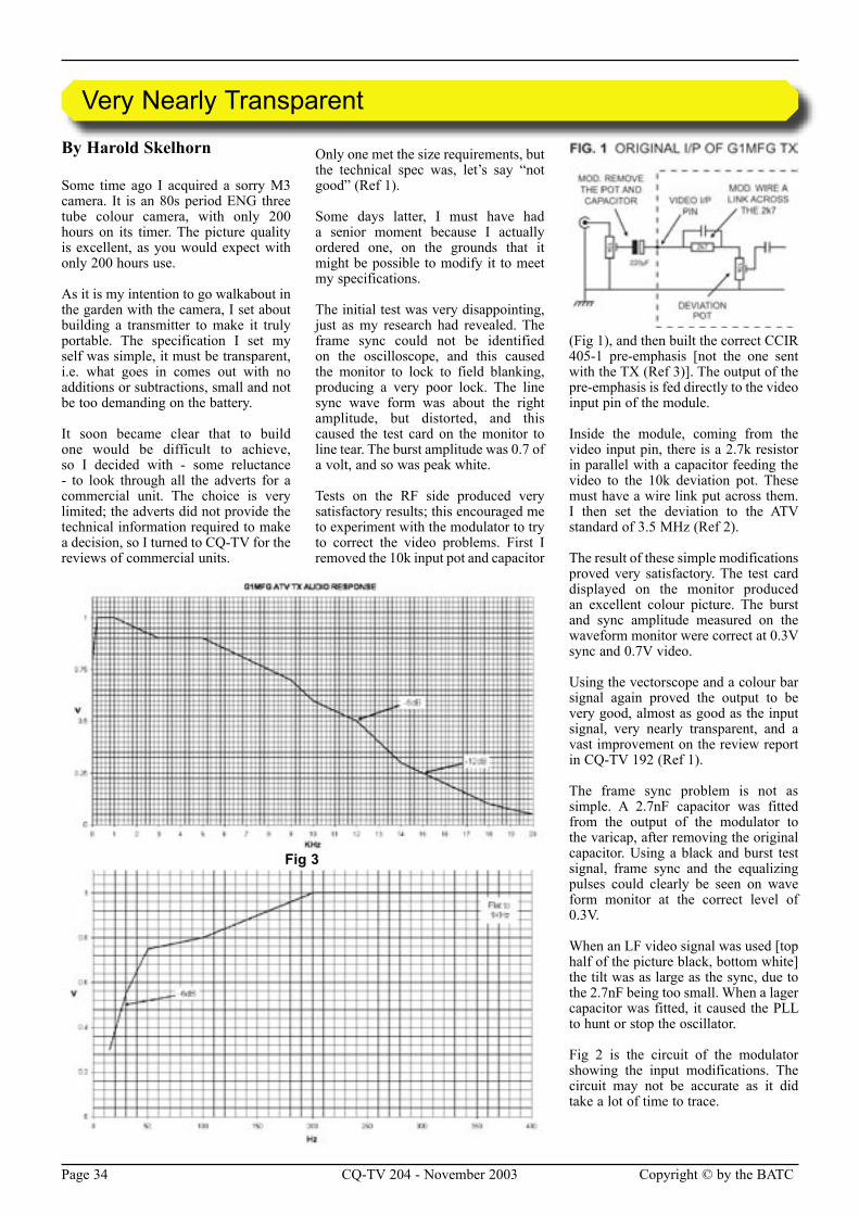
Page 34 CQ-TV 204 - November 2003 Copyright © by the BATC Copyright © by the BATC CQ-TV 204 - November 2003 Page 35
By Harold Skelhorn
Some time ago I acquired a sorry M3 camera. It is an 80s period ENG three tube colour camera, with only 200 hours on its timer. The picture quality is excellent, as you would expect with only 200 hours use.
As it is my intention to go walkabout in the garden with the camera, I set about building a transmitter to make it truly portable. The specification I set my self was simple, it must be transparent, i.e. what goes in comes out with no additions or subtractions, small and not be too demanding on the battery.
It soon became clear that to build one would be difficult to achieve, so I decided with - some reluctance - to look through all the adverts for a commercial unit. The choice is very limited; the adverts did not provide the technical information required to make a decision, so I turned to CQ-TV for the reviews of commercial units.
Only one met the size requirements, but the technical spec was, let’s say “not good” (Ref 1).
Some days latter, I must have had a senior moment because I actually ordered one, on the grounds that it might be possible to modify it to meet my specifications.
The initial test was very disappointing, just as my research had revealed. The frame sync could not be identified on the oscilloscope, and this caused the monitor to lock to field blanking, producing a very poor lock. The line sync wave form was about the right amplitude, but distorted, and this caused the test card on the monitor to line tear. The burst amplitude was 0.7 of a volt, and so was peak white.
Tests on the RF side produced very satisfactory results; this encouraged me to experiment with the modulator to try to correct the video problems. First I removed the 10k input pot and capacitor
(Fig 1), and then built the correct CCIR 405-1 pre-emphasis [not the one sent with the TX (Ref 3)]. The output of the pre-emphasis is fed directly to the video input pin of the module.
Inside the module, coming from the video input pin, there is a 2.7k resistor in parallel with a capacitor feeding the video to the 10k deviation pot. These must have a wire link put across them. I then set the deviation to the ATV standard of 3.5 MHz (Ref 2).
The result of these simple modifications proved very satisfactory. The test card displayed on the monitor produced an excellent colour picture. The burst and sync amplitude measured on the waveform monitor were correct at 0.3V sync and 0.7V video.
Using the vectorscope and a colour bar signal again proved the output to be very good, almost as good as the input signal, very nearly transparent, and a vast improvement on the review report in CQ-TV 192 (Ref 1).
The frame sync problem is not as simple. A 2.7nF capacitor was fitted from the output of the modulator to the varicap, after removing the original capacitor. Using a black and burst test signal, frame sync and the equalizing pulses could clearly be seen on wave form monitor at the correct level of 0.3V.
When an LF video signal was used [top half of the picture black, bottom white] the tilt was as large as the sync, due to the 2.7nF being too small. When a lager capacitor was fitted, it caused the PLL to hunt or stop the oscillator.
Fig 2 is the circuit of the modulator showing the input modifications. The circuit may not be accurate as it did take a lot of time to trace.
Very Nearly Transparent
Fig 3
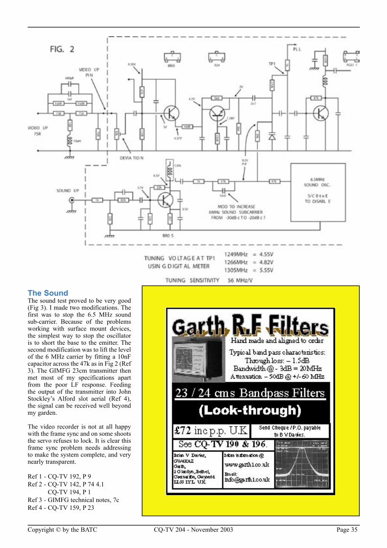
Page 34 CQ-TV 204 - November 2003 Copyright © by the BATC Copyright © by the BATC CQ-TV 204 - November 2003 Page 35
The SoundThe sound test proved to be very good (Fig 3). I made two modifications. The first was to stop the 6.5 MHz sound sub-carrier. Because of the problems working with surface mount devices, the simplest way to stop the oscillator is to short the base to the emitter. The second modification was to lift the level of the 6 MHz carrier by fitting a 10nF capacitor across the 47k as in Fig 2 (Ref 3). The GIMFG 23cm transmitter then met most of my specifications apart from the poor LF response. Feeding the output of the transmitter into John Stockley’s Alford slot aerial (Ref 4), the signal can be received well beyond my garden.
The video recorder is not at all happy with the frame sync and on some shoots the servo refuses to lock. It is clear this frame sync problem needs addressing to make the system complete, and very nearly transparent.
Ref 1 - CQ-TV 192, P 9Ref 2 - CQ-TV 142, P 74 4.1 CQ-TV 194, P 1Ref 3 - GIMFG technical notes, 7cRef 4 - CQ-TV 159, P 23
Page 36 CQ-TV 204 - November 2003 Copyright © by the BATC Copyright © by the BATC CQ-TV 204 - November 2003 Page 37
BATC Publications
Publication Each Qty Total
An Introduction To Amateur Television (225gm) . . . . . . . . . . . . . . . . . . . . . . . . . . . . . . . . . . . . £5.00 . . . . .......... . . ...........The latest handbook full of detailed information on how to set up your ATV station, plus lots of new video and RF construction projects.The Amateur TV Compendium (155gm) . . . . . . . . . . . . . . . . . . . . . . . . . . . . . . . . . . . . . . . . . . . £3.50 . . . . .......... . . ............The BATC handbook featuring construction articles on video units, 24cm and 3cm ATV, a Digital Frame Store, and much more.The Best of CQ-TV (150gm) . . . . . . . . . . . . . . . . . . . . . . . . . . . . . . . . . . . . . . . . . . . . . . . . . . . . £3.50 . . . . .......... . . ............A compilation of the best construction articles from CQ-TV’s 133 to 146CQ-TV Back Issues: . . . . . . . . . . . . . . . . . . . . . . . . . . . . . . . . . . . . . . . . . . . . . . . . . . . . . . . . . . £1.50 . . . . .......... . . ............The following issues are still available. Please circle those required: 142, 143, 144, 147, 150, 153, 154, 156, 158 159, 162, 163, 164, 166, 167, 168, 169, 170, 171, 173, 174, 175,176, 177,178, 179, 180, 181. 182, 183, 184, 185, 186, 187, 188,189, 190, 191, 192, 193, 194, 195, 196, 197, 198, 199, 200Special Offer: Any four of the above issues . . . . . . . . . . . . . . . . . . . . . . . . . . . . . . . . . . . . . . . . . £5.00 . . . . .......... . . ............201, 202, 203, 204 . . . . . . . . . . . . . . . . . . . . . . . . . . . . . . . . . . . . . . . . . . . . . . . . . . . . . . . . . . . . £3.75 . . . . .......... . . ............The BATC CD . . . . . . . . . . . . . . . . . . . . . . . . . . . . . . . . . . . . . . . . . . . . . . . . . . . . . . . . . . . . . . . £5.00 . . . . .......... . . ............
Total Goods and Postage - Amount Enclosed. £..……........
All prices in UK pounds (£) Each P&P Qty Total
Camera Tubes, Scan Coils, Bases & Lens Mounts3 . . . . . . . ONE INCH VIDICON BASE . . . . . . . . . . . . . . . . . . . . . . . . . . . . . . . . . . £1.20 . . £0.30 . . . . . .......... . . . . . . ..........4 . . . . . . . 2/3 INCH VIDICON BASE . . . . . . . . . . . . . . . . . . . . . . . . . . . . . . . . . . . £0.80 . . £0.30 . . . . . .......... . . . . . . ..........
VIDEO AND I2C CIRCUIT BOARDS/COMPONENTS 7 . . . . . . SYNC PULSE GENERATOR PCB . . . . . . . . . . . . . . . . . . . . . . . . . . . . . £14.00 . . £0.43 . . . . . .......... . . . . . ..........40 . . . . . . I2C CPU PCB . . . . . . . . . . . . . . . . . . . . . . . . . . . . . . . . . . . . . . . . £10.00 . . £0.43 . . . . . .......... . . . . . ..........41 . . . . . . I2C VDU PCB . . . . . . . . . . . . . . . . . . . . . . . . . . . . . . . . . . . . . . . . £10.00 . . £0.43 . . . . . .......... . . . . . ..........43 . . . . . . SAA5231 GENLOCK IC . . . . . . . . . . . . . . . . . . . . . . . . . . . . . . . . . . £8.80 . . £0.30 . . . . . .......... . . . . . ..........44 . . . . . . SAA5243PE TELETEXT IC . . . . . . . . . . . . . . . . . . . . . . . . . . . . . . . £14.70 . . £0.30 . . . . . .......... . . . . . ..........45 . . . . . . PCF8583 CLOCK IC . . . . . . . . . . . . . . . . . . . . . . . . . . . . . . . . . . . . . £7.00 . . £0.30 . . . . . .......... . . . . . ..........39 . . . . . . LM1881N SYNC SEPARATOR IC . . . . . . . . . . . . . . . . . . . . . . . . . . . . £3.50 . . £0.30 . . . . . .......... . . . . . ..........81 . . . . . . I2C 27256 EPROM . . . . . . . . . . . . . . . . . . . . . . . . . . . . . . . . . . . . . £9.70 . . £0.30 . . . . . .......... . . . . . ..........38 . . . . . . PCF8574P INPUT EXPANDER IC . . . . . . . . . . . . . . . . . . . . . . . . . . . . £4.70 . . £0.30 . . . . . .......... . . . . . ..........10 . . . . . . I2C RELAY PCB . . . . . . . . . . . . . . . . . . . . . . . . . . . . . . . . . . . . . . . . £6.50 . . £0.43 . . . . . .......... . . . . . .......... 9 . . . . . . PCF8574A INPUT EXPANDER IC . . . . . . . . . . . . . . . . . . . . . . . . . . . . £4.70 . . £0.43 . . . . . ......... . . . . . . ..........
RX, TX AND SSTV PCB’S AND GENERAL COMPONENTS47 . . . . . . 70CM UP CONVERTER PCB . . . . . . . . . . . . . . . . . . . . . . . . . . . . . . . £13.50 . . £0.43 . . . . . .......... . . . . . ..........50 . . . . . . 108.875 MHZ CRYSTAL . . . . . . . . . . . . . . . . . . . . . . . . . . . . . . . . . . . £8.20 . . £0.30 . . . . . .......... . . . . . ..........68 . . . . . . 4.433618MHZ CRYSTAL . . . . . . . . . . . . . . . . . . . . . . . . . . . . . . . . . . £3.25 . . £0.30 . . . . . .......... . . . . . ..........69 . . . . . . 5.0MHZ CRYSTAL . . . . . . . . . . . . . . . . . . . . . . . . . . . . . . . . . . . . . . . £3.25 . . £0.30 . . . . . .......... . . . . . ..........86 . . . . . . 24CM SOLID-STATE AMPLIFIER PCB . . . . . . . . . . . . . . . . . . . . . . . . . £10.50 . . £0.43 . . . . . …….. . . . . . . ……..
STATIONERY & STATION ACCESSORIES73 . . . . . . BATC BLUE DIAMOND CLUTCH PIN BADGE . . . . . . . . . . . . . . . . . . . . £1.75 . . £0.30 . . . . . .......... . . . . . ..........74 . . . . . . BATC CLOTH BADGE . . . . . . . . . . . . . . . . . . . . . . . . . . . . . . . . . . . . . £4.00 . . £0.30 . . . . . .......... . . . . . ..........75 . . . . . . BATC EQUIPMENT LABEL (6) . . . . . . . . . . . . . . . . . . . . . . . . . . . . . . . £0.25 . . £0.30 . . . . . .......... . . . . . ..........76 . . . . . . BATC SQUARE WINDSCREEN STICKER . . . . . . . . . . . . . . . . . . . . . . . . £0.10 . . £0.30 . . . . . .......... . . . . . . ..........78 . . . . . . BATC TEST CARD . . . . . . . . . . . . . . . . . . . . . . . . . . . . . . . . . . . . . . . £0.50 . . £0.43 . . . . . .......... . . . . . ..........79 . . . . . . BATC REPORTING CHART . . . . . . . . . . . . . . . . . . . . . . . . . . . . . . . . . £0.10 . . £0.43 . . . . . .......... . . . . . ..........
TOTAL GOODS AND POSTAGE - AMOUNT ENClosed £..……........
Members’ Services
PLEASE MAKE CHEQUES PAYABLE TO ‘BATC’.
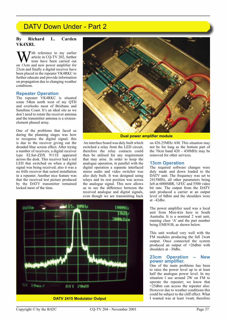
Page 36 CQ-TV 204 - November 2003 Copyright © by the BATC Copyright © by the BATC CQ-TV 204 - November 2003 Page 37
By Richard L. Carden VK4XRL
With reference to my earlier article in CQ-TV 202, further tests have been carried out
on 13cm and new power amplifier for 23cm and finally a digital receiver have been placed in the repeater VK4RKC to further educate and provide information on propagation due to changing weather conditions.
Repeater OperationThe repeater VK4RKC is situated some 54km north west of my QTH and overlooks most of Brisbane and Sunshine Coast. It’s an ideal site as we don’t need to rotate the receiver antenna and the transmitter antenna is a sixteen-element phased array.
One of the problems that faced us during the planning stages was how to recognise the digital signal; this is due to the receiver giving out the dreaded blue screen effect. After trying a number of receivers, a digital receiver type ELSat-ZDX 9111E appeared across the desk. This receiver had a red LED that switched on when a digital signal was being received; also it was a no frills receiver that suited installation in a repeater. Another nice feature was that the received test picture produced by the DATV transmitter remained locked most of the time.
An interface board was duly built which switched a relay from the LED circuit, therefore the relay contacts could then be utilised for any requirement that may arise. In order to keep the analogue operation, in parallel with the digital operation a separate interfaced stereo audio and video switcher was also duly built. It was designed using relays and its rest position was across the analogue signal. This now allows us to see the difference between the received analogue and digital signals, even though we are transmitting back
on 426.25MHz AM. This situation may not be for long as the bottom part of the 70cm band 420 – 430MHz may be removed for other services.
13cm OperationThe required software changes were duly made and down loaded to the DATV unit. The frequency was set to 2415MHz, all other parameters being left at 6000SBR, 3⁄4FEC and 5500 video bit rate. The output from the DATV unit produced a carrier at an output level of 0dbm and the shoulders were at –42dbc.
The power amplifier used was a local unit from Mini-kits here in South Australia. It is a nominal 2 watt unit, running class ‘A’ and the part number being EME91B, as shown below.
This unit worked very well with the FM modules producing the full 2watt output. Once connected the system produced an output of +26dbm with shoulders at –30dbc.
23cm Operation – New power amplifier.One of the main problems has been to raise the power level up to at least half the analogue power level. In my situation I use around 2W on FM to operate the repeater; we know that +25dbm can access the repeater also. However due to weather conditions this could be subject to the cliff effect. What I wanted was at least 1watt; therefore
DATV Down Under - Part 2
DATV 2415 Modulator Output
Dual power amplifier module
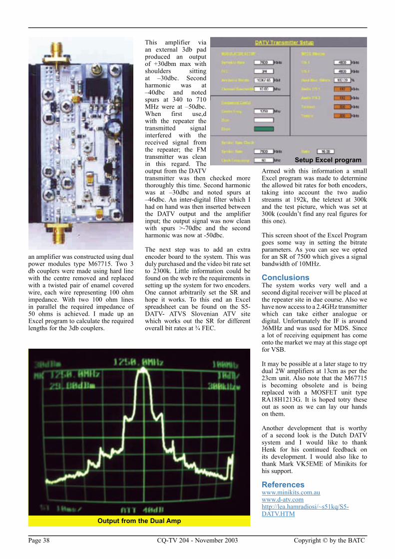
Page 38 CQ-TV 204 - November 2003 Copyright © by the BATC Copyright © by the BATC CQ-TV 204 - November 2003 Page 39
an amplifier was constructed using dual power modules type M67715. Two 3 db couplers were made using hard line with the centre removed and replaced with a twisted pair of enamel covered wire, each wire representing 100 ohm impedance. With two 100 ohm lines in parallel the required impedance of 50 ohms is achieved. I made up an Excel program to calculate the required lengths for the 3db couplers.
This amplifier via an external 3db pad produced an output of +30dbm max with shoulders sitting at –30dbc. Second harmonic was at –40dbc and noted spurs at 340 to 710 MHz were at –50dbc. When first use,d with the repeater the transmitted signal interfered with the received signal from the repeater; the FM transmitter was clean in this regard. The output from the DATV transmitter was then checked more thoroughly this time. Second harmonic was at –30dbc and noted spurs at –46dbc. An inter-digital filter which I had on hand was then inserted between the DATV output and the amplifier input; the output signal was now clean with spurs >-70dbc and the second harmonic was now at -50dbc.
The next step was to add an extra encoder board to the system. This was duly purchased and the video bit rate set to 2300k. Little information could be found on the web re the requirements in setting up the system for two encoders. One cannot arbitrarily set the SR and hope it works. To this end an Excel spreadsheet can be found on the S5-DATV- ATVS Slovenian ATV site which works out the SR for different overall bit rates at 3⁄4 FEC.
Armed with this information a small Excel program was made to determine the allowed bit rates for both encoders, taking into account the two audio streams at 192k, the teletext at 300k and the test picture, which was set at 300k (couldn’t find any real figures for this one).
This screen shoot of the Excel Program goes some way in setting the bitrate parameters. As you can see we opted for an SR of 7500 which gives a signal bandwidth of 10MHz.
ConclusionsThe system works very well and a second digital receiver will be placed at the repeater site in due course. Also we have now access to a 2.4GHz transmitter which can take either analogue or digital. Unfortunately the IF is around 36MHz and was used for MDS. Since a lot of receiving equipment has come onto the market we may at this stage opt for VSB.
It may be possible at a later stage to try dual 2W amplifiers at 13cm as per the 23cm unit. Also note that the M67715 is becoming obsolete and is being replaced with a MOSFET unit type RA18H1213G. It is hoped totry these out as soon as we can lay our hands on them.
Another development that is worthy of a second look is the Dutch DATV system and I would like to thank Henk for his continued feedback on its development. I would also like to thank Mark VK5EME of Minikits for his support.
Referenceswww.minikits.com.auwww.d-atv.comhttp://lea.hamradiosi/~s51kq/S5-DATV.HTM
Output from the Dual Amp
Setup Excel program
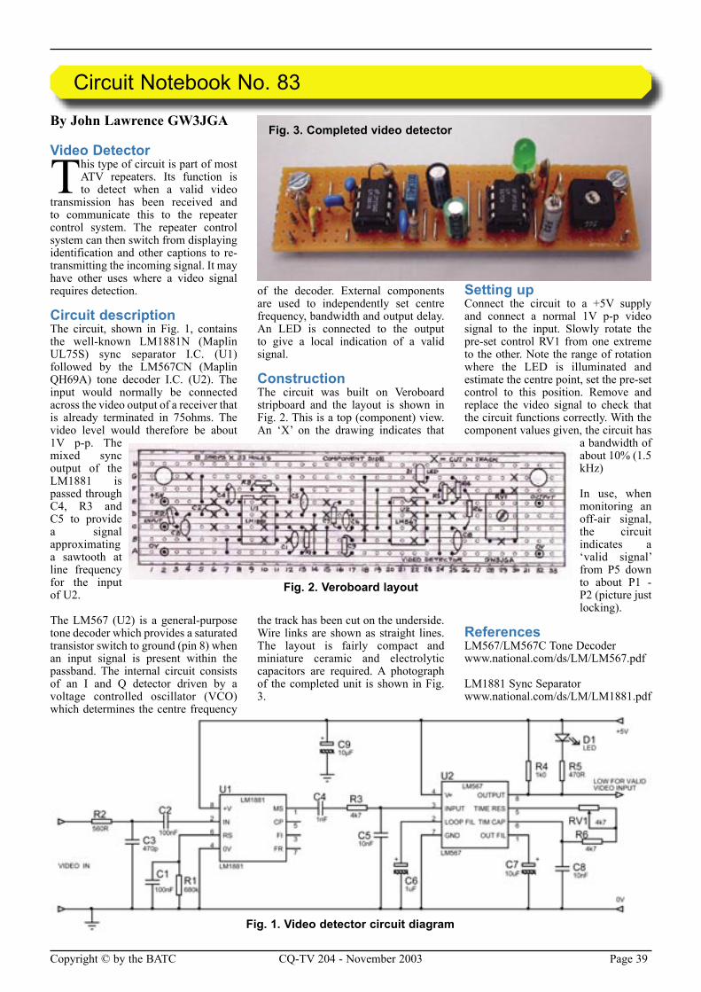
Page 38 CQ-TV 204 - November 2003 Copyright © by the BATC Copyright © by the BATC CQ-TV 204 - November 2003 Page 39
By John Lawrence GW3JGA
Video Detector
This type of circuit is part of most ATV repeaters. Its function is to detect when a valid video
transmission has been received and to communicate this to the repeater control system. The repeater control system can then switch from displaying identification and other captions to re-transmitting the incoming signal. It may have other uses where a video signal requires detection.
Circuit descriptionThe circuit, shown in Fig. 1, contains the well-known LM1881N (Maplin UL75S) sync separator I.C. (U1) followed by the LM567CN (Maplin QH69A) tone decoder I.C. (U2). The input would normally be connected across the video output of a receiver that is already terminated in 75ohms. The video level would therefore be about 1V p-p. The mixed sync output of the LM1881 is passed through C4, R3 and C5 to provide a signal approximating a sawtooth at line frequency for the input of U2.
The LM567 (U2) is a general-purpose tone decoder which provides a saturated transistor switch to ground (pin 8) when an input signal is present within the passband. The internal circuit consists of an I and Q detector driven by a voltage controlled oscillator (VCO) which determines the centre frequency
of the decoder. External components are used to independently set centre frequency, bandwidth and output delay. An LED is connected to the output to give a local indication of a valid signal.
ConstructionThe circuit was built on Veroboard stripboard and the layout is shown in Fig. 2. This is a top (component) view. An ‘X’ on the drawing indicates that
the track has been cut on the underside. Wire links are shown as straight lines. The layout is fairly compact and miniature ceramic and electrolytic capacitors are required. A photograph of the completed unit is shown in Fig. 3.
Setting upConnect the circuit to a +5V supply and connect a normal 1V p-p video signal to the input. Slowly rotate the pre-set control RV1 from one extreme to the other. Note the range of rotation where the LED is illuminated and estimate the centre point, set the pre-set control to this position. Remove and replace the video signal to check that the circuit functions correctly. With the component values given, the circuit has
a bandwidth of about 10% (1.5 kHz)
In use, when monitoring an off-air signal, the circuit indicates a ‘valid signal’ from P5 down to about P1 - P2 (picture just locking).
ReferencesLM567/LM567C Tone Decoder www.national.com/ds/LM/LM567.pdf
LM1881 Sync Separator www.national.com/ds/LM/LM1881.pdf
Circuit Notebook No. 83
Fig. 3. Completed video detector
Fig. 1. Video detector circuit diagram
Fig. 2. Veroboard layout
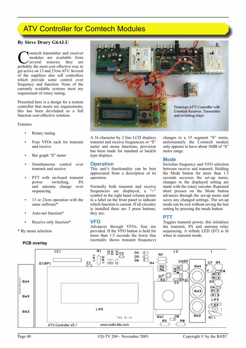
Page 40 CQ-TV 204 - November 2003 Copyright © by the BATC Copyright © by the BATC CQ-TV 204 - November 2003 Page 41
By Steve Drury G6ALU
Comtech transmitter and receiver modules are available from several sources; they are
probably the most cost effective way to get active on 13 and 23cm ATV. Several of the suppliers also sell controllers which provide some control over frequency and function. None of the currently available systems meet my requirement of rotary tuning.
Presented here is a design for a system controller that meets my requirements; this has been developed as a full function cost-effective solution.
Features
• Rotary tuning
• Four VFOs each for transmit and receive
• Bar graph “S” meter
• Simultaneous control over transmit and receive
• PTT with on-board transmit power switching, PA and antenna change over sequencing
• 13 or 23cm operation with the same software*
• Auto-net function*
• Receive only function*
* By menu selection
A 16 character by 2 line LCD displays transmit and receive frequencies or “S” meter and menu functions, provision has been made for standard or backlit type displays.
OperationThis unit’s functionality can be best appreciated from a description of its operation.
Normally both transmit and receive frequencies are displayed, a “>” symbol in the right hand column points to a label on the front panel to indicate which function is current. If all circuitry is installed there are 3 press buttons, they are:
VFOAdvances through VFOs, four are provided. If the VFO button is held for more than 1.5 seconds the lower line (normally shows transmit frequency)
changes to a 15 segment “S” meter, unfortunately the Comtech module only appears to have about 30dB of “S” meter range.
ModeSwitches frequency and VFO selection between receive and transmit. Holding the Mode button for more than 1.5 seconds accesses the set-up menu; changes to the displayed setting are made with the rotary encoder. Repeated short presses on the Mode button advances through the set-up menu and saves any changed settings. The set-up mode can be exit without saving the last setting by pressing the mode button.
PTTToggles transmit power; this initialises the transmit, PA and antenna relay sequencing. A telltale LED (D7) is lit when in transmit mode.
ATV Controller for Comtech Modules
PCB overlay
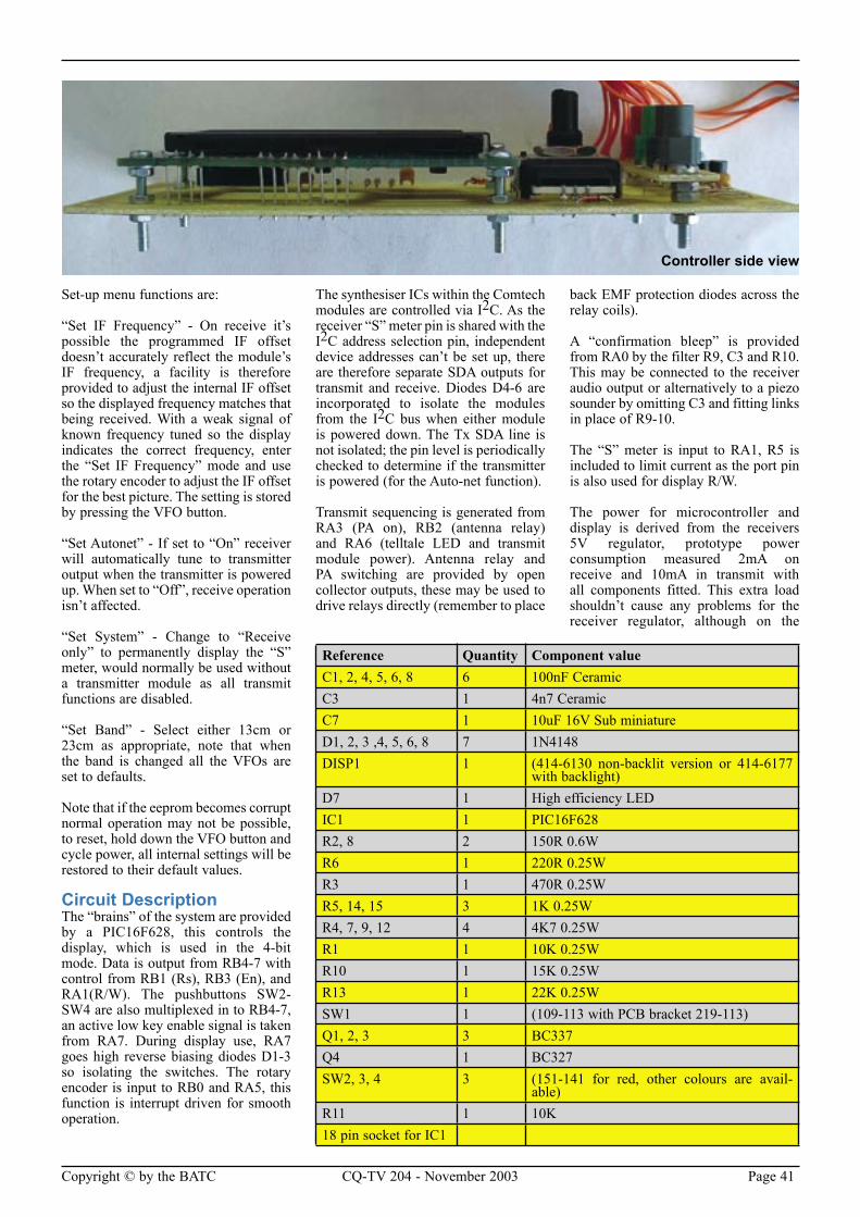
Page 40 CQ-TV 204 - November 2003 Copyright © by the BATC Copyright © by the BATC CQ-TV 204 - November 2003 Page 41
Set-up menu functions are:
“Set IF Frequency” - On receive it’s possible the programmed IF offset doesn’t accurately reflect the module’s IF frequency, a facility is therefore provided to adjust the internal IF offset so the displayed frequency matches that being received. With a weak signal of known frequency tuned so the display indicates the correct frequency, enter the “Set IF Frequency” mode and use the rotary encoder to adjust the IF offset for the best picture. The setting is stored by pressing the VFO button.
“Set Autonet” - If set to “On” receiver will automatically tune to transmitter output when the transmitter is powered up. When set to “Off”, receive operation isn’t affected.
“Set System” - Change to “Receive only” to permanently display the “S” meter, would normally be used without a transmitter module as all transmit functions are disabled.
“Set Band” - Select either 13cm or 23cm as appropriate, note that when the band is changed all the VFOs are set to defaults.
Note that if the eeprom becomes corrupt normal operation may not be possible, to reset, hold down the VFO button and cycle power, all internal settings will be restored to their default values.
Circuit DescriptionThe “brains” of the system are provided by a PIC16F628, this controls the display, which is used in the 4-bit mode. Data is output from RB4-7 with control from RB1 (Rs), RB3 (En), and RA1(R/W). The pushbuttons SW2-SW4 are also multiplexed in to RB4-7, an active low key enable signal is taken from RA7. During display use, RA7 goes high reverse biasing diodes D1-3 so isolating the switches. The rotary encoder is input to RB0 and RA5, this function is interrupt driven for smooth operation.
The synthesiser ICs within the Comtech modules are controlled via I2C. As the receiver “S” meter pin is shared with the I2C address selection pin, independent device addresses can’t be set up, there are therefore separate SDA outputs for transmit and receive. Diodes D4-6 are incorporated to isolate the modules from the I2C bus when either module is powered down. The Tx SDA line is not isolated; the pin level is periodically checked to determine if the transmitter is powered (for the Auto-net function).
Transmit sequencing is generated from RA3 (PA on), RB2 (antenna relay) and RA6 (telltale LED and transmit module power). Antenna relay and PA switching are provided by open collector outputs, these may be used to drive relays directly (remember to place
back EMF protection diodes across the relay coils).
A “confirmation bleep” is provided from RA0 by the filter R9, C3 and R10. This may be connected to the receiver audio output or alternatively to a piezo sounder by omitting C3 and fitting links in place of R9-10.
The “S” meter is input to RA1, R5 is included to limit current as the port pin is also used for display R/W.
The power for microcontroller and display is derived from the receivers 5V regulator, prototype power consumption measured 2mA on receive and 10mA in transmit with all components fitted. This extra load shouldn’t cause any problems for the receiver regulator, although on the
Reference Quantity Component valueC1, 2, 4, 5, 6, 8 6 100nF CeramicC3 1 4n7 CeramicC7 1 10uF 16V Sub miniatureD1, 2, 3 ,4, 5, 6, 8 7 1N4148DISP1 1 (414-6130 non-backlit version or 414-6177
with backlight)D7 1 High efficiency LEDIC1 1 PIC16F628R2, 8 2 150R 0.6WR6 1 220R 0.25WR3 1 470R 0.25WR5, 14, 15 3 1K 0.25WR4, 7, 9, 12 4 4K7 0.25WR1 1 10K 0.25WR10 1 15K 0.25WR13 1 22K 0.25WSW1 1 (109-113 with PCB bracket 219-113)Q1, 2, 3 3 BC337Q4 1 BC327SW2, 3, 4 3 (151-141 for red, other colours are avail-
able)R11 1 10K18 pin socket for IC1
Controller side view
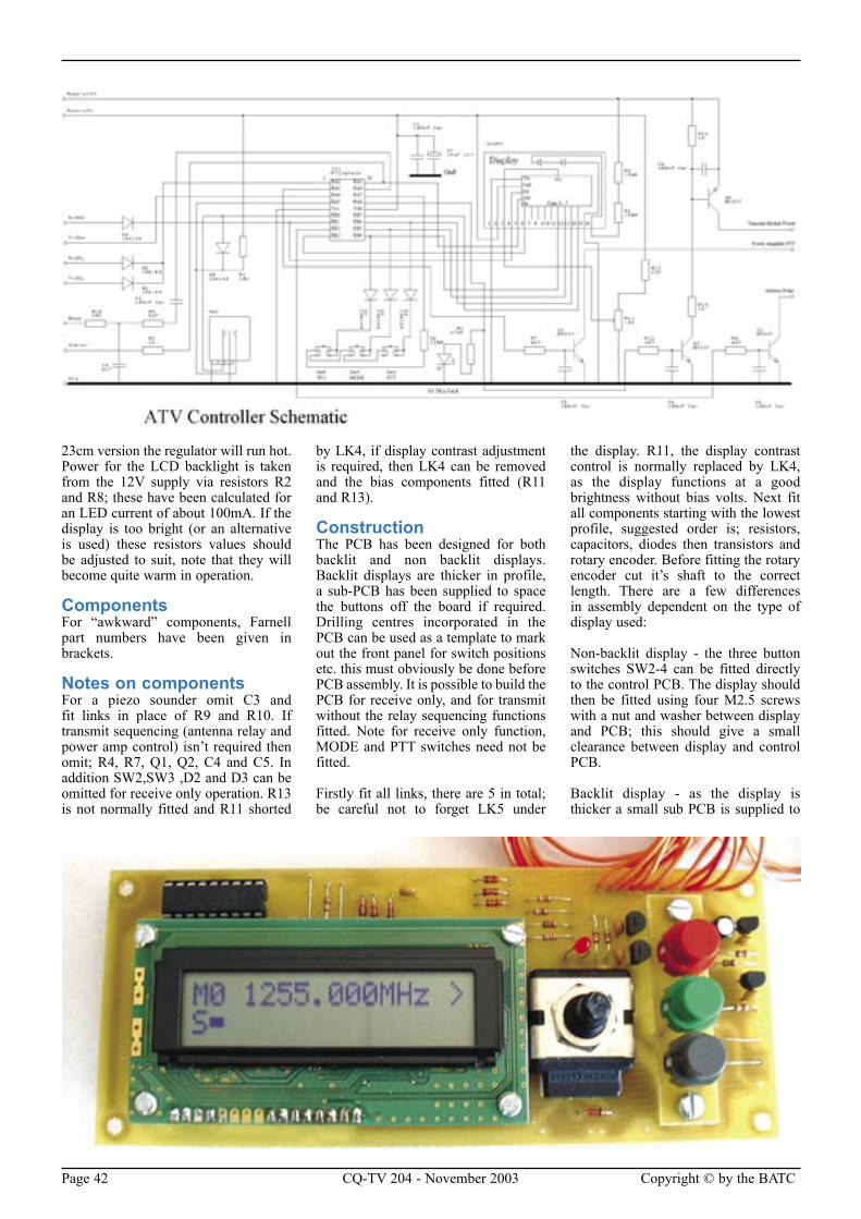
Page 42 CQ-TV 204 - November 2003 Copyright © by the BATC Copyright © by the BATC CQ-TV 204 - November 2003 Page 43
23cm version the regulator will run hot. Power for the LCD backlight is taken from the 12V supply via resistors R2 and R8; these have been calculated for an LED current of about 100mA. If the display is too bright (or an alternative is used) these resistors values should be adjusted to suit, note that they will become quite warm in operation.
ComponentsFor “awkward” components, Farnell part numbers have been given in brackets.
Notes on componentsFor a piezo sounder omit C3 and fit links in place of R9 and R10. If transmit sequencing (antenna relay and power amp control) isn’t required then omit; R4, R7, Q1, Q2, C4 and C5. In addition SW2,SW3 ,D2 and D3 can be omitted for receive only operation. R13 is not normally fitted and R11 shorted
by LK4, if display contrast adjustment is required, then LK4 can be removed and the bias components fitted (R11 and R13).
ConstructionThe PCB has been designed for both backlit and non backlit displays. Backlit displays are thicker in profile, a sub-PCB has been supplied to space the buttons off the board if required. Drilling centres incorporated in the PCB can be used as a template to mark out the front panel for switch positions etc. this must obviously be done before PCB assembly. It is possible to build the PCB for receive only, and for transmit without the relay sequencing functions fitted. Note for receive only function, MODE and PTT switches need not be fitted.
Firstly fit all links, there are 5 in total; be careful not to forget LK5 under
the display. R11, the display contrast control is normally replaced by LK4, as the display functions at a good brightness without bias volts. Next fit all components starting with the lowest profile, suggested order is; resistors, capacitors, diodes then transistors and rotary encoder. Before fitting the rotary encoder cut it’s shaft to the correct length. There are a few differences in assembly dependent on the type of display used:
Non-backlit display - the three button switches SW2-4 can be fitted directly to the control PCB. The display should then be fitted using four M2.5 screws with a nut and washer between display and PCB; this should give a small clearance between display and control PCB.
Backlit display - as the display is thicker a small sub PCB is supplied to
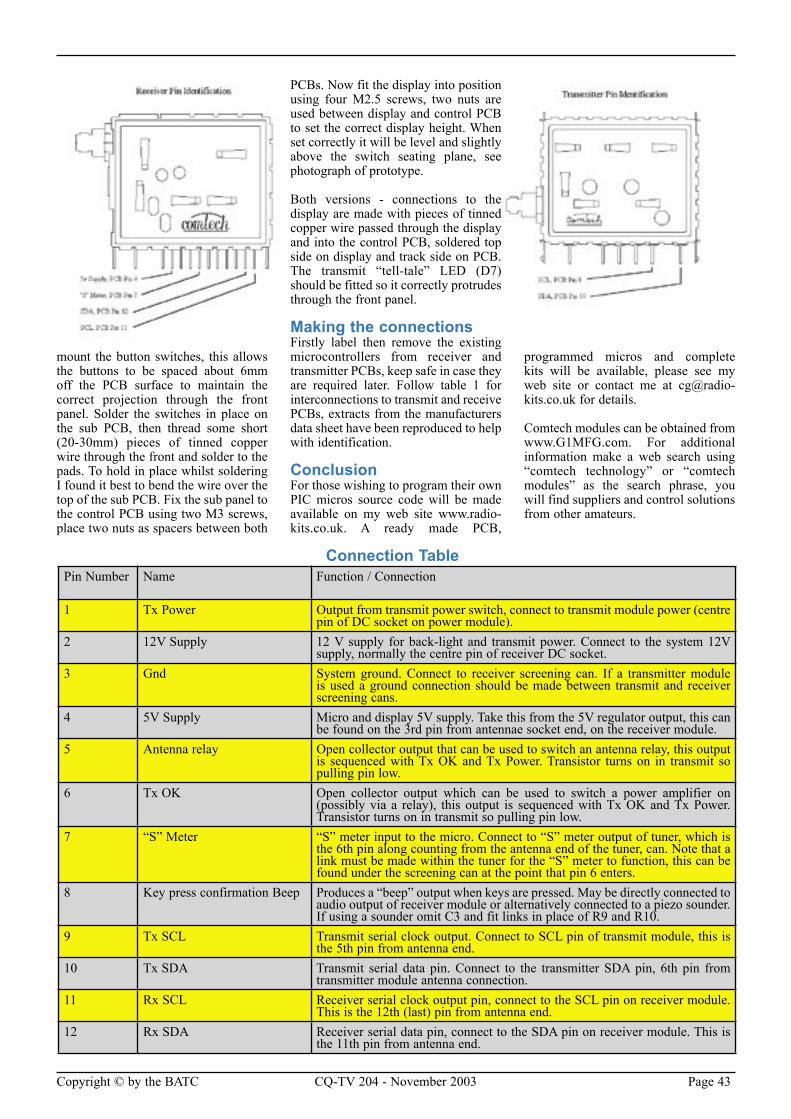
Page 42 CQ-TV 204 - November 2003 Copyright © by the BATC Copyright © by the BATC CQ-TV 204 - November 2003 Page 43
mount the button switches, this allows the buttons to be spaced about 6mm off the PCB surface to maintain the correct projection through the front panel. Solder the switches in place on the sub PCB, then thread some short (20-30mm) pieces of tinned copper wire through the front and solder to the pads. To hold in place whilst soldering I found it best to bend the wire over the top of the sub PCB. Fix the sub panel to the control PCB using two M3 screws, place two nuts as spacers between both
PCBs. Now fit the display into position using four M2.5 screws, two nuts are used between display and control PCB to set the correct display height. When set correctly it will be level and slightly above the switch seating plane, see photograph of prototype.
Both versions - connections to the display are made with pieces of tinned copper wire passed through the display and into the control PCB, soldered top side on display and track side on PCB. The transmit “tell-tale” LED (D7) should be fitted so it correctly protrudes through the front panel.
Making the connectionsFirstly label then remove the existing microcontrollers from receiver and transmitter PCBs, keep safe in case they are required later. Follow table 1 for interconnections to transmit and receive PCBs, extracts from the manufacturers data sheet have been reproduced to help with identification.
ConclusionFor those wishing to program their own PIC micros source code will be made available on my web site www.radio-kits.co.uk. A ready made PCB,
programmed micros and complete kits will be available, please see my web site or contact me at [email protected] for details.
Comtech modules can be obtained from www.G1MFG.com. For additional information make a web search using “comtech technology” or “comtech modules” as the search phrase, you will find suppliers and control solutions from other amateurs.
Pin Number Name Function / Connection
1 Tx Power Output from transmit power switch, connect to transmit module power (centre pin of DC socket on power module).
2 12V Supply 12 V supply for back-light and transmit power. Connect to the system 12V supply, normally the centre pin of receiver DC socket.
3 Gnd System ground. Connect to receiver screening can. If a transmitter module is used a ground connection should be made between transmit and receiver screening cans.
4 5V Supply Micro and display 5V supply. Take this from the 5V regulator output, this can be found on the 3rd pin from antennae socket end, on the receiver module.
5 Antenna relay Open collector output that can be used to switch an antenna relay, this output is sequenced with Tx OK and Tx Power. Transistor turns on in transmit so pulling pin low.
6 Tx OK Open collector output which can be used to switch a power amplifier on (possibly via a relay), this output is sequenced with Tx OK and Tx Power. Transistor turns on in transmit so pulling pin low.
7 “S” Meter “S” meter input to the micro. Connect to “S” meter output of tuner, which is the 6th pin along counting from the antenna end of the tuner, can. Note that a link must be made within the tuner for the “S” meter to function, this can be found under the screening can at the point that pin 6 enters.
8 Key press confirmation Beep Produces a “beep” output when keys are pressed. May be directly connected to audio output of receiver module or alternatively connected to a piezo sounder. If using a sounder omit C3 and fit links in place of R9 and R10.
9 Tx SCL Transmit serial clock output. Connect to SCL pin of transmit module, this is the 5th pin from antenna end.
10 Tx SDA Transmit serial data pin. Connect to the transmitter SDA pin, 6th pin from transmitter module antenna connection.
11 Rx SCL Receiver serial clock output pin, connect to the SCL pin on receiver module. This is the 12th (last) pin from antenna end.
12 Rx SDA Receiver serial data pin, connect to the SDA pin on receiver module. This is the 11th pin from antenna end.
Connection Table
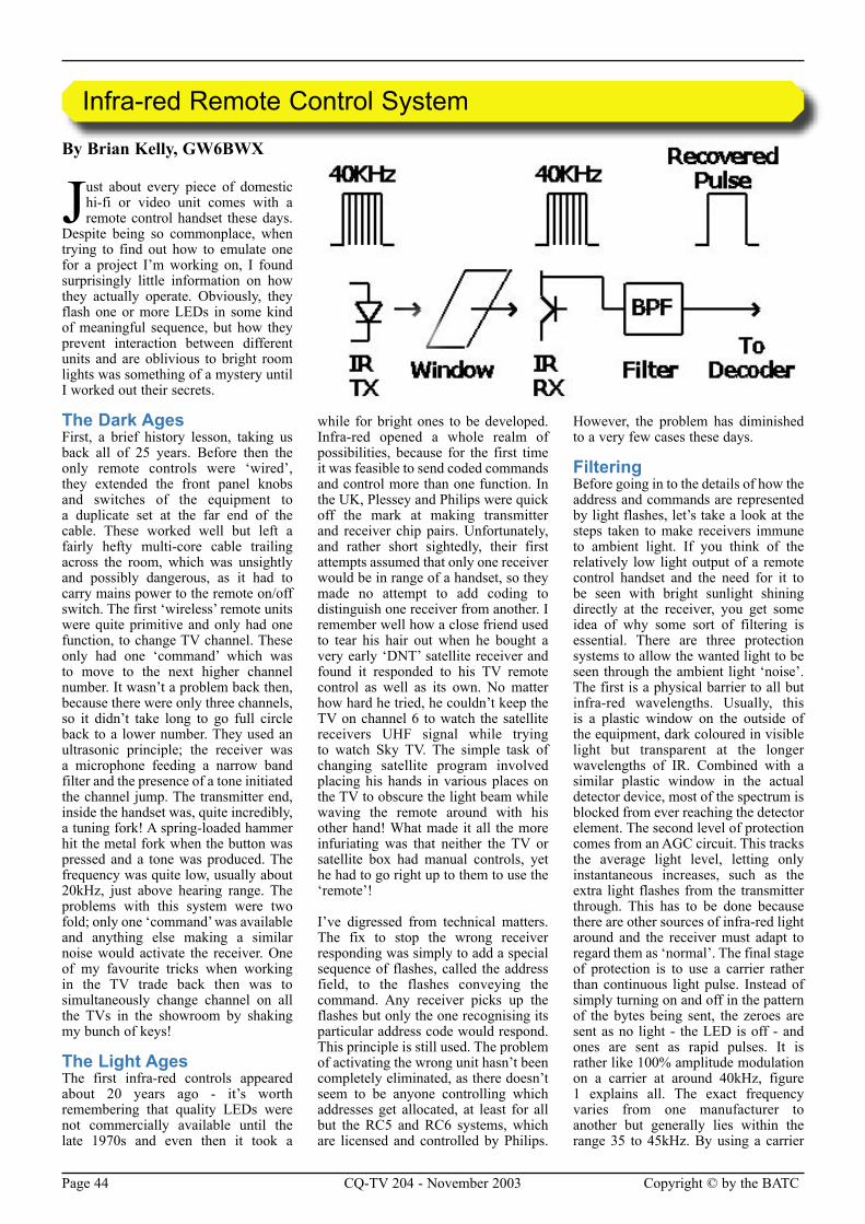
Page 44 CQ-TV 204 - November 2003 Copyright © by the BATC Copyright © by the BATC CQ-TV 204 - November 2003 Page 45
By Brian Kelly, GW6BWX
Just about every piece of domestic hi-fi or video unit comes with a remote control handset these days.
Despite being so commonplace, when trying to find out how to emulate one for a project I’m working on, I found surprisingly little information on how they actually operate. Obviously, they flash one or more LEDs in some kind of meaningful sequence, but how they prevent interaction between different units and are oblivious to bright room lights was something of a mystery until I worked out their secrets.
The Dark AgesFirst, a brief history lesson, taking us back all of 25 years. Before then the only remote controls were ‘wired’, they extended the front panel knobs and switches of the equipment to a duplicate set at the far end of the cable. These worked well but left a fairly hefty multi-core cable trailing across the room, which was unsightly and possibly dangerous, as it had to carry mains power to the remote on/off switch. The first ‘wireless’ remote units were quite primitive and only had one function, to change TV channel. These only had one ‘command’ which was to move to the next higher channel number. It wasn’t a problem back then, because there were only three channels, so it didn’t take long to go full circle back to a lower number. They used an ultrasonic principle; the receiver was a microphone feeding a narrow band filter and the presence of a tone initiated the channel jump. The transmitter end, inside the handset was, quite incredibly, a tuning fork! A spring-loaded hammer hit the metal fork when the button was pressed and a tone was produced. The frequency was quite low, usually about 20kHz, just above hearing range. The problems with this system were two fold; only one ‘command’ was available and anything else making a similar noise would activate the receiver. One of my favourite tricks when working in the TV trade back then was to simultaneously change channel on all the TVs in the showroom by shaking my bunch of keys!
The Light AgesThe first infra-red controls appeared about 20 years ago - it’s worth remembering that quality LEDs were not commercially available until the late 1970s and even then it took a
while for bright ones to be developed. Infra-red opened a whole realm of possibilities, because for the first time it was feasible to send coded commands and control more than one function. In the UK, Plessey and Philips were quick off the mark at making transmitter and receiver chip pairs. Unfortunately, and rather short sightedly, their first attempts assumed that only one receiver would be in range of a handset, so they made no attempt to add coding to distinguish one receiver from another. I remember well how a close friend used to tear his hair out when he bought a very early ‘DNT’ satellite receiver and found it responded to his TV remote control as well as its own. No matter how hard he tried, he couldn’t keep the TV on channel 6 to watch the satellite receivers UHF signal while trying to watch Sky TV. The simple task of changing satellite program involved placing his hands in various places on the TV to obscure the light beam while waving the remote around with his other hand! What made it all the more infuriating was that neither the TV or satellite box had manual controls, yet he had to go right up to them to use the ‘remote’!
I’ve digressed from technical matters. The fix to stop the wrong receiver responding was simply to add a special sequence of flashes, called the address field, to the flashes conveying the command. Any receiver picks up the flashes but only the one recognising its particular address code would respond. This principle is still used. The problem of activating the wrong unit hasn’t been completely eliminated, as there doesn’t seem to be anyone controlling which addresses get allocated, at least for all but the RC5 and RC6 systems, which are licensed and controlled by Philips.
However, the problem has diminished to a very few cases these days.
FilteringBefore going in to the details of how the address and commands are represented by light flashes, let’s take a look at the steps taken to make receivers immune to ambient light. If you think of the relatively low light output of a remote control handset and the need for it to be seen with bright sunlight shining directly at the receiver, you get some idea of why some sort of filtering is essential. There are three protection systems to allow the wanted light to be seen through the ambient light ‘noise’. The first is a physical barrier to all but infra-red wavelengths. Usually, this is a plastic window on the outside of the equipment, dark coloured in visible light but transparent at the longer wavelengths of IR. Combined with a similar plastic window in the actual detector device, most of the spectrum is blocked from ever reaching the detector element. The second level of protection comes from an AGC circuit. This tracks the average light level, letting only instantaneous increases, such as the extra light flashes from the transmitter through. This has to be done because there are other sources of infra-red light around and the receiver must adapt to regard them as ‘normal’. The final stage of protection is to use a carrier rather than continuous light pulse. Instead of simply turning on and off in the pattern of the bytes being sent, the zeroes are sent as no light - the LED is off - and ones are sent as rapid pulses. It is rather like 100% amplitude modulation on a carrier at around 40kHz, figure 1 explains all. The exact frequency varies from one manufacturer to another but generally lies within the range 35 to 45kHz. By using a carrier
Infra-red Remote Control System
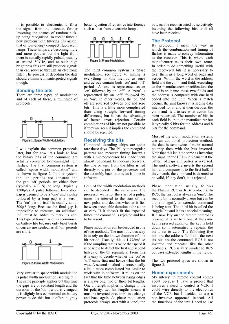
Page 44 CQ-TV 204 - November 2003 Copyright © by the BATC Copyright © by the BATC CQ-TV 204 - November 2003 Page 45
it is possible to electronically filter the signal from the detector, further lessening the chance of random pick-up being recognised. In recent times a new problem with filtering has arisen; that of low-energy compact fluorescent lamps. These lamps are becoming more and more popular but the light from them is actually rapidly pulsed, usually at around 50kHz, and at such high brightness this can still produce signals than can squeeze through an electronic filter. The process of decoding the data should eliminate misinterpreted signals though.
Sending the bitsThere are three types of modulation and of each of these, a multitude of protocols.
I will explain the common protocols later, but for now let’s look at how the binary bits of the command are actually converted to meaningful light flashes. The first common system is called “space width modulation” and is shown in figure 2. In this system, the ‘on’ periods are constant and the gap ‘off’ periods are either short (typically 400µS) or long (typically 1200µS). A pulse followed by a short gap is deemed to be a ‘one’ and a pulse followed by a long gap is a ‘zero’. The ‘on’ period itself is usually about 300µS long. Because the final gap is impossible to measure, an additional ‘on’ must be added to mark its end. This type of transmission is economical on battery life because only brief bursts of current are needed, as all ‘on’ periods are short.
Very similar to space width modulation is pulse width modulation, see figure 3. The same principle applies but this time the gaps are of constant length and the duration of the ‘on’ period is changed. It is slightly less economical on battery power to do this but it offers slightly
better rejection of repetitive interference such as that from electronic lamps.
The third common system is phase modulation, see figure 4. Timing is everything in this method as ones and zeroes contain both ‘on’ and ‘off’ periods. A ‘one’ is represented as an ‘on’ followed by an ‘off’. A ‘zero’ is represented by an ‘off’ followed by an ‘on’. In other words, the on and off are reversed between one and zero bits. This is a little more complicated than using straight forward timing differences, but it has the advantage of better error rejection. Certain combinations of bits are not possible so if they are seen it implies the command should be rejected.
Receiving the bitsCommand decoding chips are quite rare these days. The ability to recognise patterns and measure timing intervals with a microprocessor has made them almost redundant. In modern receivers, the one or zero from the filter is fed directly to a pin on the processor and the assembly back into bytes is done in software.
Both of the width modulation methods can be decoded in the same way. The processor waits for the start of a pulse, times the interval to the start of the next pulse and decides whether it lies between acceptable duration to be a one or zero. If it doesn’t fit the expected times, the command is rejected and has to be resent.
Phase modulation can be decoded in one of two methods. The most obvious way is to rely on the known duration of one bit period. Usually, this is 1.778mS so if the sampling rate is twice that speed it is possible to detect the first and second halves of the bit separately. From this it is easy to decide whether the ‘on’ or ‘off’ came first and hence what the bit was. A second method is conceptually a little more complicated but easier to work with in software. It relies on the fact that the time between rising edges is always one, two or three bit lengths. One bit length implies no change in the bit polarity, two bit lengths means it must be inverted three implies a change and back again. As phase modulation protocols always start with a ‘one’, the
byte can be reconstructed by selectively inverting the following bits until all have been received.
The ProtocolBy protocol, I mean the way in which the combination and timing of flashes is made to convey information to the receiver. This is where each manufacturer takes their own route. In order to do something useful with the recovered bits it is necessary to treat them as a long word of ones and zeroes. Within the word is the address field and the command field. According to the manufacturers specification, the word is split into these two fields and the address is compared with one hard coded into the unit. When a match occurs, the unit knows it is seeing data intended for it and it then decodes the command field to see what action has been requested. The number of bits in each field is up to the manufacturer but is typically 5 bits for the address and 8 bits for the command.
Most of the width modulation systems use an additional protection method; the data is sent twice, first in normal polarity then with the bits inverted. Note that this isn’t the same as inverting the signal to the LED - it means that the pattern of gaps and pulses is reversed. The unit’s software inverts the second half and compares it to the first half. If they match, the command is deemed to be valid, if they don’t, it is rejected.
Phase modulation usually follows the Philips RC5 or RC6 protocols. In RC5, the first bit is always a ‘one’. The second bit is normally a zero but can be a one to signify an extended command is being sent. The third bit is called the ‘toggle’ bit and it has a special meaning. If a new key on the remote control is pressed, it is set to a one, if the same key is pressed again, or the key is held down so it automatically repeats, the bit is set to zero. The following five bits are the address field and the next six bits are the command. RC5 is not inverted and repeated like the other protocols. RC6 is very similar to RC5 but uses extended lengths in the fields.
The two protocol types are shown in figure 5.
Home experimentsMy interest in remote control comes about because I have a project that involves a need to control a VCR. I could wire directly to the electronics of the VCR but I decided to use a non-invasive approach instead. All the functions of the unit I need to use
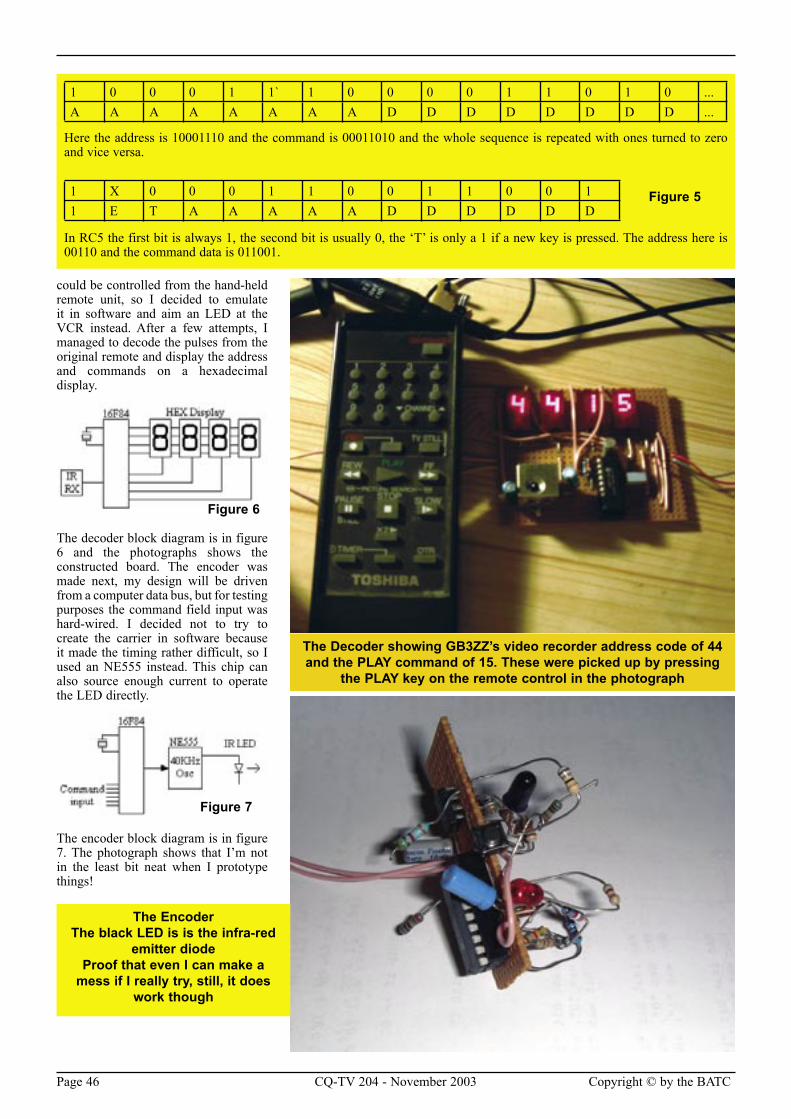
Page 46 CQ-TV 204 - November 2003 Copyright © by the BATC Copyright © by the BATC CQ-TV 204 - November 2003 Page 47
could be controlled from the hand-held remote unit, so I decided to emulate it in software and aim an LED at the VCR instead. After a few attempts, I managed to decode the pulses from the original remote and display the address and commands on a hexadecimal display.
The decoder block diagram is in figure 6 and the photographs shows the constructed board. The encoder was made next, my design will be driven from a computer data bus, but for testing purposes the command field input was hard-wired. I decided not to try to create the carrier in software because it made the timing rather difficult, so I used an NE555 instead. This chip can also source enough current to operate the LED directly.
The encoder block diagram is in figure 7. The photograph shows that I’m not in the least bit neat when I prototype things!
1 0 0 0 1 1` 1 0 0 0 0 1 1 0 1 0 ...A A A A A A A A D D D D D D D D ...
Here the address is 10001110 and the command is 00011010 and the whole sequence is repeated with ones turned to zero and vice versa.
1 X 0 0 0 1 1 0 0 1 1 0 0 11 E T A A A A A D D D D D D
In RC5 the first bit is always 1, the second bit is usually 0, the ‘T’ is only a 1 if a new key is pressed. The address here is 00110 and the command data is 011001.
Figure 5
Figure 6
Figure 7
The EncoderThe black LED is is the infra-red
emitter diodeProof that even I can make a
mess if I really try, still, it does work though
The Decoder showing GB3ZZ’s video recorder address code of 44 and the PLAY command of 15. These were picked up by pressing
the PLAY key on the remote control in the photograph
Page 46 CQ-TV 204 - November 2003 Copyright © by the BATC Copyright © by the BATC CQ-TV 204 - November 2003 Page 47
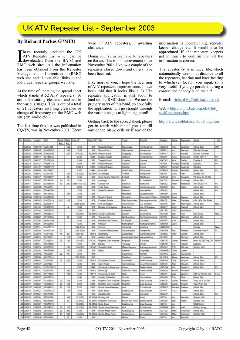
Page 48 CQ-TV 204 - November 2003 Copyright © by the BATC Copyright © by the BATC CQ-TV 204 - November 2003 Page 49
By Richard Parkes G7MFO
I have recently updated the UK ATV Repeater List which can be downloaded from the BATC and
RMC web sites. All the information has been obtained from the Repeater Management Committee (RMC) web site and if available, links to the individual repeater groups web site.
At the time of updating the spread sheet which stands at 52 ATV repeaters! 16 are still awaiting clearance and are in the various stages. This is out of a total of 21 repeaters awaiting clearance or change of frequency on the RMC web site (2m Audio etc.).
The last time this list was published in CQ-TV, was in November 2001. There
were 39 ATV repeaters, 3 awaiting clearance.
Doing your sums we have 36 repeaters on the air. This is no improvement since November 2001. I know a couple of the repeaters closed down and others have been licensed.
Like most of you, I hope the licensing of ATV repeaters improves soon. I have been told that it looks like a 24GHz repeater application is just about to land on the RMC door mat. We are the primary users of this band, so hopefully the application will go straight through the various stages at lightning speed!
Getting back to the spread sheet, please get in touch with me if you can fill any of the blank cells or if any of the
information is incorrect e.g. repeater keeper change etc. It would also be appreciated if the repeater keepers get in touch to confirm that all the information is correct.
The repeater list is an Excel file, which automatically works out distance to all the repeaters, bearing and back bearing to whichever locator you input, so is very useful if you go portable during a contest and nobody is on the air!
E-mail:- [email protected]
Web:- http://www.batc.org.uk/Club_stuff/repeaters.htm
http://www.coldal.org.uk/vetting.htm
UK ATV Repeater List - September 2003
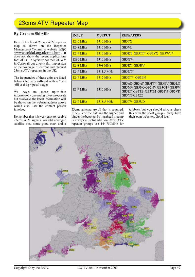
Page 48 CQ-TV 204 - November 2003 Copyright © by the BATC Copyright © by the BATC CQ-TV 204 - November 2003 Page 49
By Graham Shirville
Here is the latest 23cms ATV repeater map as shown on the Repeater Management Committee website http://www.coldal.org.uk/rmc.htm . It does not show the recent applications for GB3OT in Ayrshire nor the GB3WV in Cornwall but gives a fair impression of the coverage of current and planned 23cms ATV repeaters in the UK.
The frequencies of these units are listed below (the calls suffixed with a * are still at the proposal stage)
We have no more up-to-date information concerning these proposals but as always the latest information will be shown on the website address above which also lists the contact person involved.
Remember that it is very easy to receive 23cms ATV signals. An old analogue satellite box, some good coax and a
23cms antenna are all that is required. In terms of the antenna the higher and bigger the better and a masthead preamp is always a useful addition. Most ATV repeater groups use 144.750MHz for
talkback but you should always check this with the local group - many have their own websites. Good luck!
23cms ATV Repeater Map
INPUT OUTPUT REPEATERS
1246 MHz 1310 MHz GB3TX
1248 MHz 1310 MHz GB3VL
1249 MHz 1310 MHz GB3KT GB3TT* GB3VX GB3WV*
1280 MHz 1310 MHz GB3GW
1248 MHz 1308 MHz GB3EY GB3HV
1249 MHz 1311.5 MHz GB3UT*
1249 MHz 1312 MHz GB3CT* GB3EN
1249 MHz 1316 MHz
GB3AD GB3AT GB3FY* GB3GV GB3LO GB3MV GB3NQ GB3NV GB3OT* GB3PV GB3RT GB3TB GB3TM GB3TN GB3VR GB3YT GB3ZZ
1249 MHz 1318.5 MHz GB3TV GB3UD
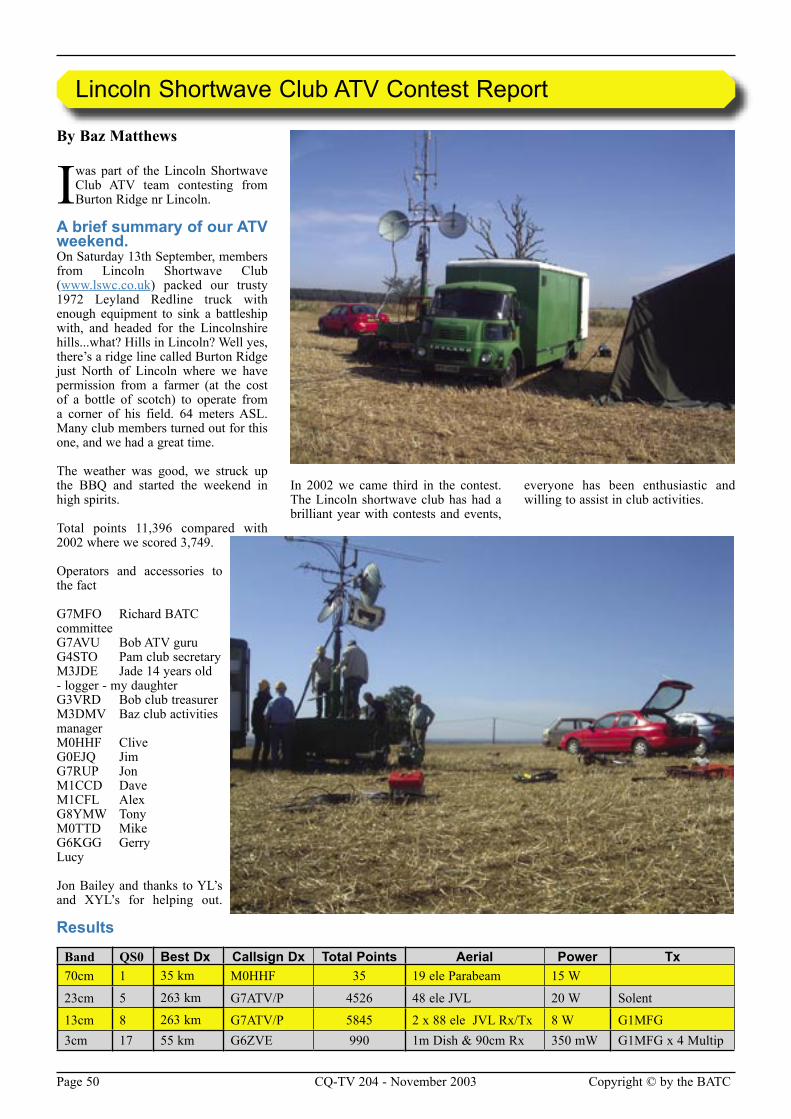
Page 50 CQ-TV 204 - November 2003 Copyright © by the BATC Copyright © by the BATC CQ-TV 204 - November 2003 Page 51
By Baz Matthews
I was part of the Lincoln Shortwave Club ATV team contesting from Burton Ridge nr Lincoln.
A brief summary of our ATV weekend.On Saturday 13th September, members from Lincoln Shortwave Club (www.lswc.co.uk) packed our trusty 1972 Leyland Redline truck with enough equipment to sink a battleship with, and headed for the Lincolnshire hills...what? Hills in Lincoln? Well yes, there’s a ridge line called Burton Ridge just North of Lincoln where we have permission from a farmer (at the cost of a bottle of scotch) to operate from a corner of his field. 64 meters ASL. Many club members turned out for this one, and we had a great time.
The weather was good, we struck up the BBQ and started the weekend in high spirits.
Total points 11,396 compared with 2002 where we scored 3,749.
Operators and accessories to the fact
G7MFO Richard BATC committeeG7AVU Bob ATV guruG4STO Pam club secretaryM3JDE Jade 14 years old - logger - my daughterG3VRD Bob club treasurerM3DMV Baz club activities managerM0HHF CliveG0EJQ JimG7RUP JonM1CCD DaveM1CFL AlexG8YMW TonyM0TTD MikeG6KGG GerryLucy
Jon Bailey and thanks to YL’s and XYL’s for helping out.
In 2002 we came third in the contest. The Lincoln shortwave club has had a brilliant year with contests and events,
everyone has been enthusiastic and willing to assist in club activities.
Lincoln Shortwave Club ATV Contest Report
Band QS0 Best Dx Callsign Dx Total Points Aerial Power Tx70cm 1 35 km M0HHF 35 19 ele Parabeam 15 W
23cm 5 263 km G7ATV/P 4526 48 ele JVL 20 W Solent
13cm 8 263 km G7ATV/P 5845 2 x 88 ele JVL Rx/Tx 8 W G1MFG3cm 17 55 km G6ZVE 990 1m Dish & 90cm Rx 350 mW G1MFG x 4 Multip
Results
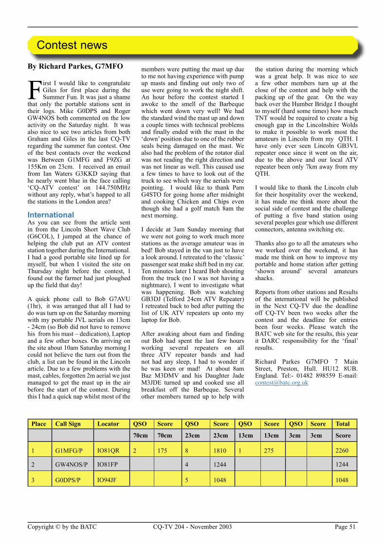
Page 50 CQ-TV 204 - November 2003 Copyright © by the BATC Copyright © by the BATC CQ-TV 204 - November 2003 Page 51
By Richard Parkes, G7MFO
First I would like to congratulate Giles for first place during the Summer Fun. It was just a shame
that only the portable stations sent in their logs. Mike G0DPS and Roger GW4NOS both commented on the low activity on the Saturday night. It was also nice to see two articles from both Graham and Giles in the last CQ-TV regarding the summer fun contest. One of the best contacts over the weekend was Between G1MFG and F9ZG at 155Km on 23cm. I received an email from Ian Waters G3KKD saying that he nearly went blue in the face calling ‘CQ-ATV contest’ on 144.750MHz without any reply, what’s happed to all the stations in the London area?
InternationalAs you can see from the article sent in from the Lincoln Short Wave Club (G6COL), I jumped at the chance of helping the club put an ATV contest station together during the International. I had a good portable site lined up for myself, but when I visited the site on Thursday night before the contest, I found out the farmer had just ploughed up the field that day!
A quick phone call to Bob G7AVU (1hr), it was arranged that all I had to do was turn up on the Saturday morning with my portable JVL aerials on 13cm - 24cm (so Bob did not have to remove his from his mast – dedication), Laptop and a few other boxes. On arriving on the site about 10am Saturday morning I could not believe the turn out from the club, a list can be found in the Lincoln article. Due to a few problems with the mast, cables, forgotten 2m aerial we just managed to get the mast up in the air before the start of the contest. During this I had a quick nap whilst most of the
members were putting the mast up due to me not having experience with pump up masts and finding out only two of use were going to work the night shift. An hour before the contest started I awoke to the smell of the Barbeque which went down very well! We had the standard wind the mast up and down a couple times with technical problems and finally ended with the mast in the ‘down’ position due to one of the rubber seals being damaged on the mast. We also had the problem of the rotator dial was not reading the right direction and was not linear as well. This caused use a few times to have to look out of the truck to see which way the aerials were pointing. I would like to thank Pam G4STO for going home after midnight and cooking Chicken and Chips even though she had a golf match 8am the next morning.
I decide at 3am Sunday morning that we were not going to work much more stations as the average amateur was in bed! Bob stayed in the van just to have a look around. I retreated to the ‘classic’ passenger seat make shift bed in my car. Ten minutes later I heard Bob shouting from the truck (no I was not having a nightmare), I went to investigate what was happening. Bob was watching GB3DJ (Telford 24cm ATV Repeater) I retreated back to bed after putting the list of UK ATV repeaters up onto my laptop for Bob.
After awaking about 6am and finding out Bob had spent the last few hours working several repeaters on all three ATV repeater bands and had not had any sleep, I had to wonder if he was keen or mad! At about 8am Baz M3DMV and his Daughter Jade M3JDE turned up and cooked use all breakfast off the Barbeque. Several other members turned up to help with
the station during the morning which was a great help. It was nice to see a few other members turn up at the close of the contest and help with the packing up of the gear. On the way back over the Humber Bridge I thought to myself (hard some times) how much TNT would be required to create a big enough gap in the Lincolnshire Wolds to make it possible to work most the amateurs in Lincoln from my QTH. I have only ever seen Lincoln GB3VL repeater once since it went on the air, due to the above and our local ATV repeater been only 7km away from my QTH.
I would like to thank the Lincoln club for their hospitality over the weekend, it has made me think more about the social side of contest and the challenge of putting a five band station using several peoples gear which use different connectors, antenna switching etc.
Thanks also go to all the amateurs who we worked over the weekend, it has made me think on how to improve my portable and home station after getting ‘shown around’ several amateurs shacks.
Reports from other stations and Results of the international will be published in the Next CQ-TV due the deadline off CQ-TV been two weeks after the contest and the deadline for entries been four weeks. Please watch the BATC web site for the results, this year it DARC responsibility for the ‘final’ results.
Richard Parkes G7MFO 7 Main Street, Preston, Hull. HU12 8UB. England. Tel:- 01482 898559 E-mail: [email protected]
Contest news
Place Call Sign Locator QSO Score QSO Score QSO Score QSO Score Total
70cm 70cm 23cm 23cm 13cm 13cm 3cm 3cm Score
1 G1MFG/P IO81QR 2 175 8 1810 1 275 2260
2 GW4NOS/P IO81FP 4 1244 1244
3 G0DPS/P IO94JF 5 1048 1048
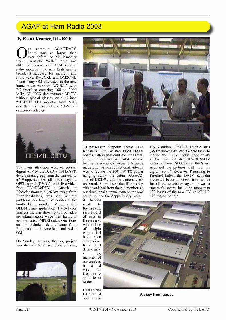
Page 52 CQ-TV 204 - November 2003 Copyright © by the BATC Copyright © by the BATC CQ-TV 204 - November 2003 Page 53
By Klaus Kramer, DL4KCK
Our common AGAF/DARC booth was as larger than ever before, so Mr. Kraemer
from “Deutsche Welle” radio was able to demonstrate DRM (digital radio mondial), the new high quality broadcast standard for medium and short wave. DM2CKB and DM2CMB found many OM interested in the new home made wobbler “WOB31” with PC interface covering 100 to 3000 MHz. DL4KCK demonstrated 3D-TV, without special glasses, on a 15 inch “3D-DTI” TFT monitor from VHS cassettes and live with a “NuView” camcorder adapter.
The main attraction was, of course, digital ATV by the DJ8DW and DJ8VR development group from the University of Wuppertal. On all three days, a QPSK signal (DVB-S) with live video from OE9/DL0DTV in Austria, at Pfaender mountain (26 km away from Friedrichshafen), was sent without problems to a large TV monitor at the booth. On a smaller TV set, a first OFDM demo application (DVB-T) for amateur use was shown with live video provoking people wave their hands to test the typical MPEG delay. Questions on the technical details came from European, north American and Asian OM.
On Sunday morning the big project was due - DATV live from a flying
10 passenger Zeppelin above Lake Konstanz. DJ8DW had fitted DATV boards, battery and ventilator into a small aluminium suitcase, and had it accepted by the aereonautical experts. A home made circular omnidirectional antenna was to radiate the 200 mW TX power hanging below the cabin. PA3HCZ, son of DJ8DW, did the camera work on board. Soon after takeoff the crisp video vanished from the big monitor, as our directional antenna team on the roof could not see the Zeppelin any more - it headed west to K o n s t a n z i n s t e a d of east to B r e g e n z , where line of sight w o u l d have been c e r t a i n . R e a l democracy - the majority of passengers h a d voted for K o n s t a n z and Isle of Mainau.
DJ3DY and DK5DF at our remote
DATV station OE9/DL0DTV in Austria (350 m above lake level) where lucky to receive the live Zeppelin video nearly all the time, and also HB9/DH6MAV in his van near St.Gallen at the Swiss Alps got the pictures well with his digital Sat-TV-Receiver. Returning to Friedrichshafen, the DATV Zeppelin presented beautiful views from above for all the spectators again. It was a successful event, including more than 120 issues of the new TV-AMATEUR 129 magazine sold.
AGAF at Ham Radio 2003
A view from above
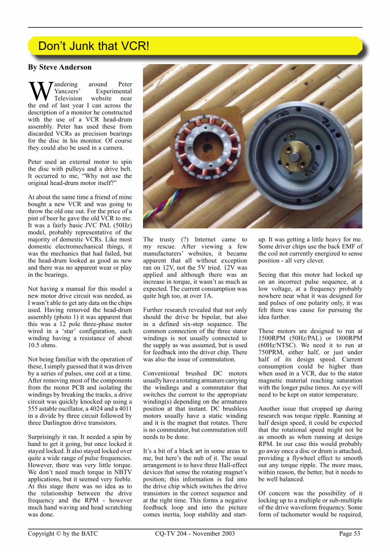
Page 52 CQ-TV 204 - November 2003 Copyright © by the BATC Copyright © by the BATC CQ-TV 204 - November 2003 Page 53
By Steve Anderson
Wandering around Peter Yanczers’ Experimental Television website near
the end of last year I can across the description of a monitor he constructed with the use of a VCR head-drum assembly. Peter has used these from discarded VCRs as precision bearings for the disc in his monitor. Of course they could also be used in a camera.
Peter used an external motor to spin the disc with pulleys and a drive belt. It occurred to me, “Why not use the original head-drum motor itself?”
At about the same time a friend of mine bought a new VCR and was going to throw the old one out. For the price of a pint of beer he gave the old VCR to me. It was a fairly basic JVC PAL (50Hz) model, probably representative of the majority of domestic VCRs. Like most domestic electromechanical things, it was the mechanics that had failed, but the head-drum looked as good as new and there was no apparent wear or play in the bearings.
Not having a manual for this model a new motor drive circuit was needed, as I wasn’t able to get any data on the chips used. Having removed the head-drum assembly (photo 1) it was apparent that this was a 12 pole three-phase motor wired in a ‘star’ configuration, each winding having a resistance of about 10.5 ohms.
Not being familiar with the operation of these, I simply guessed that it was driven by a series of pulses, one coil at a time. After removing most of the components from the motor PCB and isolating the windings by breaking the tracks, a drive circuit was quickly knocked up using a 555 astable oscillator, a 4024 and a 4011 in a divide by three circuit followed by three Darlington drive transistors.
Surprisingly it ran. It needed a spin by hand to get it going, but once locked it stayed locked. It also stayed locked over quite a wide range of pulse frequencies. However, there was very little torque. We don’t need much torque in NBTV applications, but it seemed very feeble. At this stage there was no idea as to the relationship between the drive frequency and the RPM - however much hand waving and head scratching was done.
The trusty (?) Internet came to my rescue. After viewing a few manufacturers’ websites, it became apparent that all without exception ran on 12V, not the 5V tried. 12V was applied and although there was an increase in torque, it wasn’t as much as expected. The current consumption was quite high too, at over 1A.
Further research revealed that not only should the drive be bipolar, but also in a defined six-step sequence. The common connection of the three stator windings is not usually connected to the supply as was assumed, but is used for feedback into the driver chip. There was also the issue of commutation.
Conventional brushed DC motors usually have a rotating armature carrying the windings and a commutator that switches the current to the appropriate winding(s) depending on the armatures position at that instant. DC brushless motors usually have a static winding and it is the magnet that rotates. There is no commutator, but commutation still needs to be done.
It’s a bit of a black art in some areas to me, but here’s the nub of it. The usual arrangement is to have three Hall-effect devices that sense the rotating magnet’s position; this information is fed into the drive chip which switches the drive transistors in the correct sequence and at the right time. This forms a negative feedback loop and into the picture comes inertia, loop stability and start-
up. It was getting a little heavy for me. Some driver chips use the back EMF of the coil not currently energized to sense position - all very clever.
Seeing that this motor had locked up on an incorrect pulse sequence, at a low voltage, at a frequency probably nowhere near what it was designed for and pulses of one polarity only, it was felt there was cause for pursuing the idea further.
These motors are designed to run at 1500RPM (50Hz/PAL) or 1800RPM (60Hz/NTSC). We need it to run at 750PRM, either half, or just under half of its design speed. Current consumption could be higher than when used in a VCR, due to the stator magnetic material reaching saturation with the longer pulse times. An eye will need to be kept on stator temperature.
Another issue that cropped up during research was torque ripple. Running at half design speed, it could be expected that the rotational speed might not be as smooth as when running at design RPM. In our case this would probably go away once a disc or drum is attached, providing a flywheel effect to smooth out any torque ripple. The more mass, within reason, the better, but it needs to be well balanced.
Of concern was the possibility of it locking up to a multiple or sub-multiple of the drive waveform frequency. Some form of tachometer would be required,
Don’t Junk that VCR!
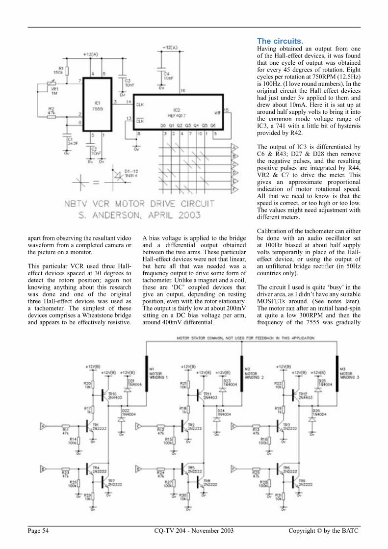
Page 54 CQ-TV 204 - November 2003 Copyright © by the BATC Copyright © by the BATC CQ-TV 204 - November 2003 Page 55
apart from observing the resultant video waveform from a completed camera or the picture on a monitor.
This particular VCR used three Hall-effect devices spaced at 30 degrees to detect the rotors position; again not knowing anything about this research was done and one of the original three Hall-effect devices was used as a tachometer. The simplest of these devices comprises a Wheatstone bridge and appears to be effectively resistive.
A bias voltage is applied to the bridge and a differential output obtained between the two arms. These particular Hall-effect devices were not that linear, but here all that was needed was a frequency output to drive some form of tachometer. Unlike a magnet and a coil, these are ‘DC’ coupled devices that give an output, depending on resting position, even with the rotor stationary. The output is fairly low at about 200mV sitting on a DC bias voltage per arm, around 400mV differential.
The circuits.Having obtained an output from one of the Hall-effect devices, it was found that one cycle of output was obtained for every 45 degrees of rotation. Eight cycles per rotation at 750RPM (12.5Hz) is 100Hz. (I love round numbers). In the original circuit the Hall effect devices had just under 3v applied to them and drew about 10mA. Here it is sat up at around half supply volts to bring it into the common mode voltage range of IC3, a 741 with a little bit of hystersis provided by R42.
The output of IC3 is differentiated by C6 & R43; D27 & D28 then remove the negative pulses, and the resulting positive pulses are integrated by R44, VR2 & C7 to drive the meter. This gives an approximate proportional indication of motor rotational speed. All that we need to know is that the speed is correct, or too high or too low. The values might need adjustment with different meters.
Calibration of the tachometer can either be done with an audio oscillator set at 100Hz biased at about half supply volts temporarily in place of the Hall-effect device, or using the output of an unfiltered bridge rectifier (in 50Hz countries only).
The circuit I used is quite ‘busy’ in the driver area, as I didn’t have any suitable MOSFETs around. (See notes later). The motor ran after an initial hand-spin at quite a low 300RPM and then the frequency of the 7555 was gradually
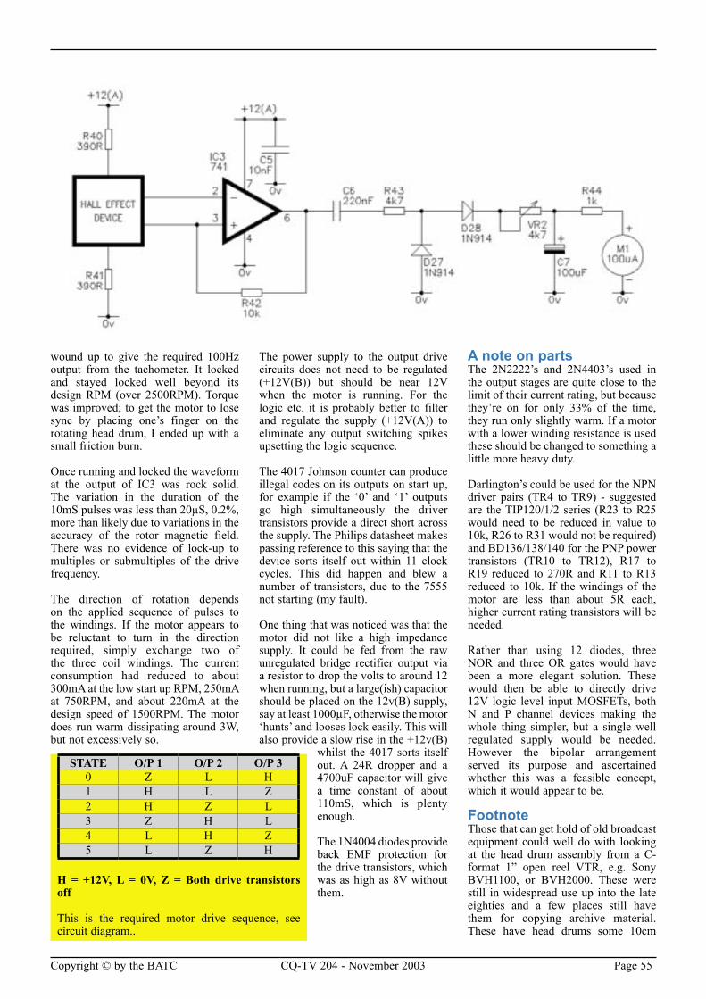
Page 54 CQ-TV 204 - November 2003 Copyright © by the BATC Copyright © by the BATC CQ-TV 204 - November 2003 Page 55
wound up to give the required 100Hz output from the tachometer. It locked and stayed locked well beyond its design RPM (over 2500RPM). Torque was improved; to get the motor to lose sync by placing one’s finger on the rotating head drum, I ended up with a small friction burn.
Once running and locked the waveform at the output of IC3 was rock solid. The variation in the duration of the 10mS pulses was less than 20µS, 0.2%, more than likely due to variations in the accuracy of the rotor magnetic field. There was no evidence of lock-up to multiples or submultiples of the drive frequency.
The direction of rotation depends on the applied sequence of pulses to the windings. If the motor appears to be reluctant to turn in the direction required, simply exchange two of the three coil windings. The current consumption had reduced to about 300mA at the low start up RPM, 250mA at 750RPM, and about 220mA at the design speed of 1500RPM. The motor does run warm dissipating around 3W, but not excessively so.
The power supply to the output drive circuits does not need to be regulated (+12V(B)) but should be near 12V when the motor is running. For the logic etc. it is probably better to filter and regulate the supply (+12V(A)) to eliminate any output switching spikes upsetting the logic sequence.
The 4017 Johnson counter can produce illegal codes on its outputs on start up, for example if the ‘0’ and ‘1’ outputs go high simultaneously the driver transistors provide a direct short across the supply. The Philips datasheet makes passing reference to this saying that the device sorts itself out within 11 clock cycles. This did happen and blew a number of transistors, due to the 7555 not starting (my fault).
One thing that was noticed was that the motor did not like a high impedance supply. It could be fed from the raw unregulated bridge rectifier output via a resistor to drop the volts to around 12 when running, but a large(ish) capacitor should be placed on the 12v(B) supply, say at least 1000µF, otherwise the motor ‘hunts’ and looses lock easily. This will also provide a slow rise in the +12v(B)
whilst the 4017 sorts itself out. A 24R dropper and a 4700uF capacitor will give a time constant of about 110mS, which is plenty enough.
The 1N4004 diodes provide back EMF protection for the drive transistors, which was as high as 8V without them.
A note on partsThe 2N2222’s and 2N4403’s used in the output stages are quite close to the limit of their current rating, but because they’re on for only 33% of the time, they run only slightly warm. If a motor with a lower winding resistance is used these should be changed to something a little more heavy duty.
Darlington’s could be used for the NPN driver pairs (TR4 to TR9) - suggested are the TIP120/1/2 series (R23 to R25 would need to be reduced in value to 10k, R26 to R31 would not be required) and BD136/138/140 for the PNP power transistors (TR10 to TR12), R17 to R19 reduced to 270R and R11 to R13 reduced to 10k. If the windings of the motor are less than about 5R each, higher current rating transistors will be needed.
Rather than using 12 diodes, three NOR and three OR gates would have been a more elegant solution. These would then be able to directly drive 12V logic level input MOSFETs, both N and P channel devices making the whole thing simpler, but a single well regulated supply would be needed. However the bipolar arrangement served its purpose and ascertained whether this was a feasible concept, which it would appear to be.
FootnoteThose that can get hold of old broadcast equipment could well do with looking at the head drum assembly from a C-format 1” open reel VTR, e.g. Sony BVH1100, or BVH2000. These were still in widespread use up into the late eighties and a few places still have them for copying archive material. These have head drums some 10cm
STATE O/P 1 O/P 2 O/P 30 Z L H1 H L Z2 H Z L3 Z H L4 L H Z5 L Z H
H = +12V, L = 0V, Z = Both drive transistors off
This is the required motor drive sequence, see circuit diagram..
Page 56 CQ-TV 204 - November 2003 Copyright © by the BATC Copyright © by the BATC CQ-TV 204 - November 2003 Page 57
(4”) or so in diameter with presumably equally beefy motors. Time to chat up your local TV station maintenance engineer.
Having done further research on DC brushless motors, I wish I hadn’t have removed the original components from the motor PCB. It is thought that with a few simple alterations to the existing VCR motor drive circuit, it could have
functioned in the manner we require. What has been done here is in effect to turn this motor into a synchronous one, however it is not self-starting. With sufficient patience this could be incorporated into a PLL, just as in the original application. When the next one comes along I will take a little more time. Updates will be given as and when that happens, but don’t hold your breath.
There are also a few 2-phase domestic VCR head-drum motors; Samsung as an instance make both the 3 and 2-phase varieties. DC brushless fans (as used in PCs’ for example) are generally 2-phase also, but are designed to run at higher RPM. Does someone else want to run with the 2-phase baton?
The author can be contacted at Email [email protected]
CQ-TV is published quarterly in February, May, August and November each year. The
deadlines for each issue are as follows: -
Please send your contributions in as soon as you can prior to this date.
Will all prospective contributors please be sure to read the ‘Notice
to Contributors’ on page 3 so that you understand the implications of submitting an article for publication.
If you have pictures that you want including in your article, then please send them, in the highest possible quality, as separate files.
Commercial adverts should be sent to Trevor Brown, the advertising manager, at 14 Stairfoot Close, Adel, Leeds, LS16 8JR. Tel: 01132 670115. Email: [email protected]. Members’ sales and wants should be sent to the Editor. Email: [email protected]
February 30th DecemberMay 30th March
August 30th JuneNovember 30th September.
Electronic CQ-TV
This quarter’s settings for access to the electronic versions at www.cq-tv.com/electronic are -
Username: amember Password: qpass
By Brian Summers
Recently I opened a small transit case, one that I had not opened for some time, only to find a
horrid sticky and corrosive mess instead of the nice soft foam lining. It seems that the foam sponge plastic material had under gone a transformation with the passage of time.
The sponge foam is or was the dark grey lightweight sort. A bit like you sometimes see filling cushions. I have
not had a problem (yet) with the dense hard foam you see in more professional packing and no doubt expensive use. I have had this happen on a previous occasion and have now resolved to go through the various packing cases and boxes that I have squirreled things away in. If you have some of this foam packing I can really recommend that you inspect it regularly, the consequences as I have found out is a real tacky mess. I wore disposable gloves to clear it up and wash the tools clean, fortunately the contents were only tools and not
part of my camera collection; I hate to think what the corrosive effects would have been on a lens!
The corrosion was obvious on the plated tool surfaces. If you can’t bring yourself to rip out, what seems to be perfectly good foam, at least wrap the content to protect them from the foam decay. The foam in question was probably 25 to 30 years old and I suspect there are a few more of these time bombs waiting to do their worst.
A Warning about Foam
Deadlines
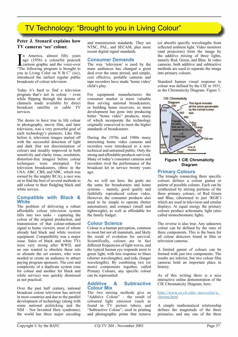
Page 56 CQ-TV 204 - November 2003 Copyright © by the BATC Copyright © by the BATC CQ-TV 204 - November 2003 Page 57
Peter J. Stonard explains how TV cameras ‘see’ colour.
In America, almost fifty years ago (1956) a colourful peacock cartoon graphic and the voice-over
“The following program is brought to you in Living Color on N B C” (sic), introduced the earliest regular public broadcasts of colour television.
Today it’s hard to find a television program that’s not in colour – even while flipping through the dozens of channels made available by direct broadcast satellite or cable TV services.
The desire to have true to life colour in photography, movie film, and later television, was a very powerful goal of each technology’s pioneers. Like film before it, television images started off with the successful detection of light and dark (but not discrimination of colour) and steadily improved in both sensitivity and clarity (tone, resolution, distortion-free images) before colour techniques were attempted. For television broadcasters, (three in the USA: ABC, CBS, and NBC, which was owned by the mighty RCA), a race was on to find the best of several methods to add colour to their fledgling black and white service.
Compatible with Black & WhiteThe problem of delivering a robust affordable colour television system falls into two tasks – capturing the colour of the original production, and transmission of that colour-enhanced signal to home viewers, most of whom already had black and white receiver equipment. Compatibility was a major issue. Sales of black and white TVs were very strong after WWII, and no one wanted to obsolete these sets or alienate the set owners, who were needed to create an audience to attract paying program sponsors. The cost and complexity of a duplicate system (one for colour and another for black and white service) was quickly dismissed as not practical.
Over the past half century, national broadcast colour television has arrived in most countries and due to the parallel development of technology (along with some national politicking and the NIH – Not Invented Here syndrome); the world has three major encoding
and transmission standards. They are NTSC, PAL, and SECAM, plus more recent digital signal standards.
Consumer DemandsThe way ‘television’ is used by the mass audiences has changed a great deal over the same period, and simple, cost effective, portable cameras and tape recorders have made ‘home video’ child’s play.
For equipment manufacturers the consumer market is more valuable than serving national broadcasters, or building home receivers, so more development has gone into producing better “home video” products, many of which incorporate the technology originally conceived to meet the higher standards of broadcasters.
During the 1970s and 1980s many interesting home video cameras and recorders were introduced to a non-technical and untrained public. Only the strong and affordable products survived. Many of today’s consumer cameras and recorders rival the performance of the broadcast kit in service twenty years ago.
As we will see here, the goals are the same for broadcasters and home systems – namely, good quality and faithfully reproduced colour video. However, the consumer products also need to be simple to operate (better automation); and compact (small and lightweight), as well as affordable for the family budget.
Colour ScienceColour is a human perception, common to most but not all mammals, and likely the result of evolution for survival. Scientifically, colours are in fact different frequencies of light waves, and the typical human eye responds most to green light, with less response to blues (shorter wavelengths), and reds, (longer wavelengths). By combining two (or more) components together, called Primary Colours, any specific colour can be represented.
Additive & Subtractive Colour Mix The two mixing methods give us “Additive Colour” - the result of coloured light emission (such as found in TV picture tubes), and “Subtractive Colour”, used in printing and photographic prints that remove
(or absorb) specific wavelengths from reflected ambient light. Video monitors (and projectors) form the image by the additive mixing of three lights, namely Red, Green, and Blue. In video cameras, both additive and subtractive methods are used to separate the image into primary colours.
Standard human visual response to colour was defined by the CIE in 1931, as the Chromaticity Diagram. Figure 1.
Figure 1 CIE Chromaticity Diagram
Primary ColoursThe triangle connecting three specific colours defines a colour gamut or palette of possible colours. Each can be synthesized by mixing portions of the three primary colours, of Red Green and Blue, (shortened to just ‘RGB’) which are used in television and similar displays. At equal energy the primary colours produce achromatic light (also called monochromatic light).
The reverse is also true. Any unknown colour can be defined by the ratio of three components. This is the basis for all colour detectors found in film or television cameras.
A limited gamut of colours can be formed with just two components. The results are inferior, but two colour film cameras hold an important place in history.
As of this writing there is a nice interactive online demonstration of the CIE Chromaticity Diagram, here:
http://www.cs.rit.edu/~ncs/color/a_chroma.html
A simple mathematical relationship defines the magnitude of the three primaries, and any one of the three
TV Technology: “Brought to you in Living Colour”
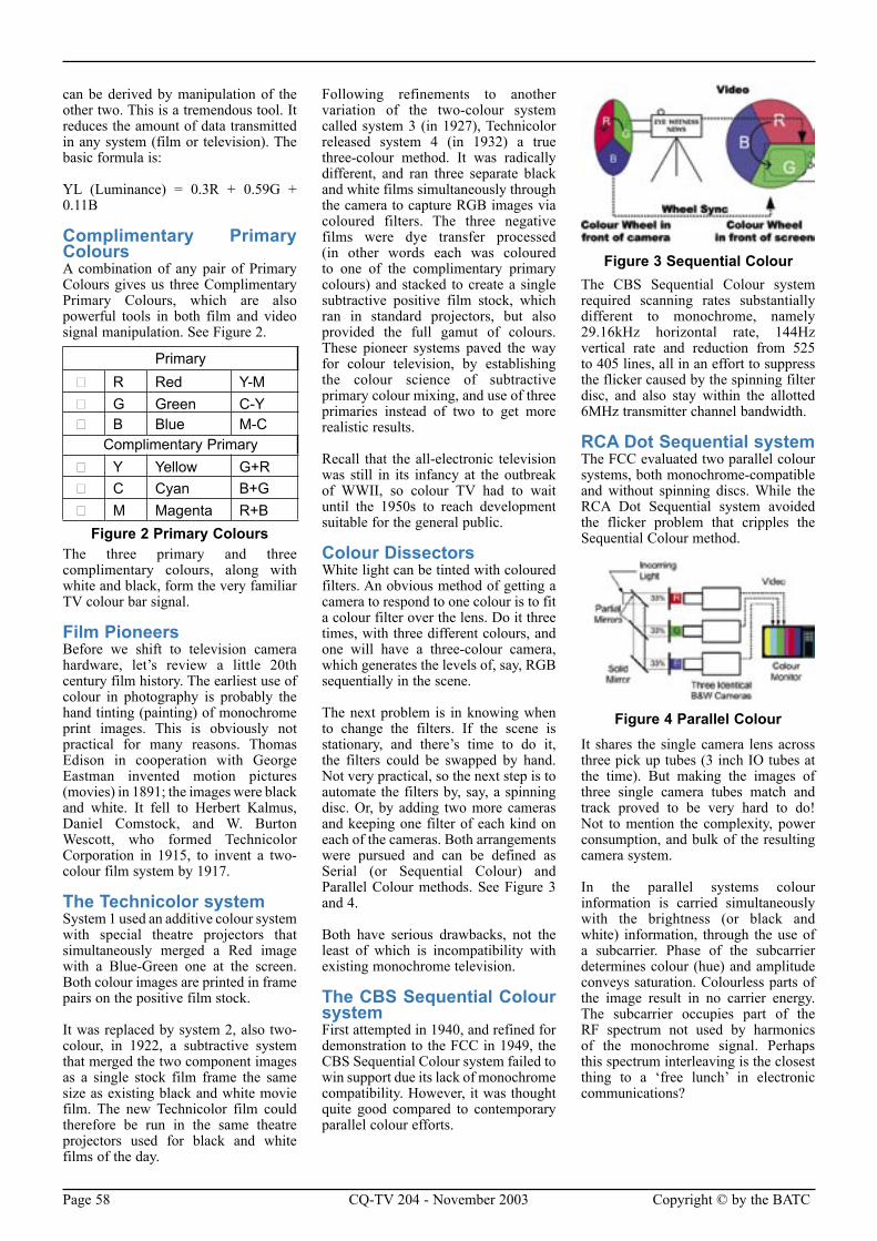
Page 58 CQ-TV 204 - November 2003 Copyright © by the BATC Copyright © by the BATC CQ-TV 204 - November 2003 Page 59
can be derived by manipulation of the other two. This is a tremendous tool. It reduces the amount of data transmitted in any system (film or television). The basic formula is:
YL (Luminance) = 0.3R + 0.59G + 0.11B
Complimentary Primary Colours A combination of any pair of Primary Colours gives us three Complimentary Primary Colours, which are also powerful tools in both film and video signal manipulation. See Figure 2.
Figure 2 Primary ColoursThe three primary and three complimentary colours, along with white and black, form the very familiar TV colour bar signal.
Film PioneersBefore we shift to television camera hardware, let’s review a little 20th century film history. The earliest use of colour in photography is probably the hand tinting (painting) of monochrome print images. This is obviously not practical for many reasons. Thomas Edison in cooperation with George Eastman invented motion pictures (movies) in 1891; the images were black and white. It fell to Herbert Kalmus, Daniel Comstock, and W. Burton Wescott, who formed Technicolor Corporation in 1915, to invent a two-colour film system by 1917.
The Technicolor systemSystem 1 used an additive colour system with special theatre projectors that simultaneously merged a Red image with a Blue-Green one at the screen. Both colour images are printed in frame pairs on the positive film stock.
It was replaced by system 2, also two-colour, in 1922, a subtractive system that merged the two component images as a single stock film frame the same size as existing black and white movie film. The new Technicolor film could therefore be run in the same theatre projectors used for black and white films of the day.
Following refinements to another variation of the two-colour system called system 3 (in 1927), Technicolor released system 4 (in 1932) a true three-colour method. It was radically different, and ran three separate black and white films simultaneously through the camera to capture RGB images via coloured filters. The three negative films were dye transfer processed (in other words each was coloured to one of the complimentary primary colours) and stacked to create a single subtractive positive film stock, which ran in standard projectors, but also provided the full gamut of colours. These pioneer systems paved the way for colour television, by establishing the colour science of subtractive primary colour mixing, and use of three primaries instead of two to get more realistic results.
Recall that the all-electronic television was still in its infancy at the outbreak of WWII, so colour TV had to wait until the 1950s to reach development suitable for the general public.
Colour DissectorsWhite light can be tinted with coloured filters. An obvious method of getting a camera to respond to one colour is to fit a colour filter over the lens. Do it three times, with three different colours, and one will have a three-colour camera, which generates the levels of, say, RGB sequentially in the scene.
The next problem is in knowing when to change the filters. If the scene is stationary, and there’s time to do it, the filters could be swapped by hand. Not very practical, so the next step is to automate the filters by, say, a spinning disc. Or, by adding two more cameras and keeping one filter of each kind on each of the cameras. Both arrangements were pursued and can be defined as Serial (or Sequential Colour) and Parallel Colour methods. See Figure 3 and 4.
Both have serious drawbacks, not the least of which is incompatibility with existing monochrome television.
The CBS Sequential Colour systemFirst attempted in 1940, and refined for demonstration to the FCC in 1949, the CBS Sequential Colour system failed to win support due its lack of monochrome compatibility. However, it was thought quite good compared to contemporary parallel colour efforts.
The CBS Sequential Colour system required scanning rates substantially different to monochrome, namely 29.16kHz horizontal rate, 144Hz vertical rate and reduction from 525 to 405 lines, all in an effort to suppress the flicker caused by the spinning filter disc, and also stay within the allotted 6MHz transmitter channel bandwidth.
RCA Dot Sequential system The FCC evaluated two parallel colour systems, both monochrome-compatible and without spinning discs. While the RCA Dot Sequential system avoided the flicker problem that cripples the Sequential Colour method.
Figure 4 Parallel ColourIt shares the single camera lens across three pick up tubes (3 inch IO tubes at the time). But making the images of three single camera tubes match and track proved to be very hard to do! Not to mention the complexity, power consumption, and bulk of the resulting camera system.
In the parallel systems colour information is carried simultaneously with the brightness (or black and white) information, through the use of a subcarrier. Phase of the subcarrier determines colour (hue) and amplitude conveys saturation. Colourless parts of the image result in no carrier energy. The subcarrier occupies part of the RF spectrum not used by harmonics of the monochrome signal. Perhaps this spectrum interleaving is the closest thing to a ‘free lunch’ in electronic communications?
Primary � R Red Y-M � G Green C-Y � B Blue M-C
Complimentary Primary � Y Yellow G+R � C Cyan B+G � M Magenta R+B
Figure 3 Sequential Colour
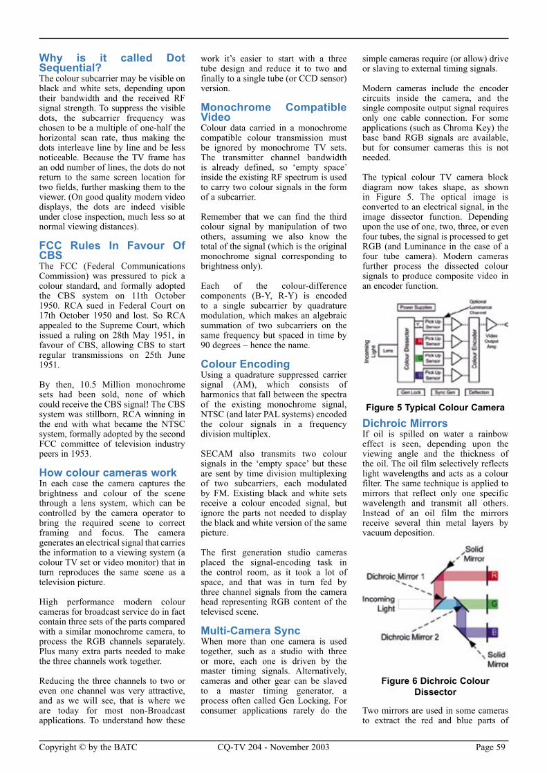
Page 58 CQ-TV 204 - November 2003 Copyright © by the BATC Copyright © by the BATC CQ-TV 204 - November 2003 Page 59
Why is it called Dot Sequential?The colour subcarrier may be visible on black and white sets, depending upon their bandwidth and the received RF signal strength. To suppress the visible dots, the subcarrier frequency was chosen to be a multiple of one-half the horizontal scan rate, thus making the dots interleave line by line and be less noticeable. Because the TV frame has an odd number of lines, the dots do not return to the same screen location for two fields, further masking them to the viewer. (On good quality modern video displays, the dots are indeed visible under close inspection, much less so at normal viewing distances).
FCC Rules In Favour Of CBSThe FCC (Federal Communications Commission) was pressured to pick a colour standard, and formally adopted the CBS system on 11th October 1950. RCA sued in Federal Court on 17th October 1950 and lost. So RCA appealed to the Supreme Court, which issued a ruling on 28th May 1951, in favour of CBS, allowing CBS to start regular transmissions on 25th June 1951.
By then, 10.5 Million monochrome sets had been sold, none of which could receive the CBS signal! The CBS system was stillborn, RCA winning in the end with what became the NTSC system, formally adopted by the second FCC committee of television industry peers in 1953.
How colour cameras work In each case the camera captures the brightness and colour of the scene through a lens system, which can be controlled by the camera operator to bring the required scene to correct framing and focus. The camera generates an electrical signal that carries the information to a viewing system (a colour TV set or video monitor) that in turn reproduces the same scene as a television picture.
High performance modern colour cameras for broadcast service do in fact contain three sets of the parts compared with a similar monochrome camera, to process the RGB channels separately. Plus many extra parts needed to make the three channels work together.
Reducing the three channels to two or even one channel was very attractive, and as we will see, that is where we are today for most non-Broadcast applications. To understand how these
work it’s easier to start with a three tube design and reduce it to two and finally to a single tube (or CCD sensor) version.
Monochrome Compatible Video Colour data carried in a monochrome compatible colour transmission must be ignored by monochrome TV sets. The transmitter channel bandwidth is already defined, so ‘empty space’ inside the existing RF spectrum is used to carry two colour signals in the form of a subcarrier.
Remember that we can find the third colour signal by manipulation of two others, assuming we also know the total of the signal (which is the original monochrome signal corresponding to brightness only).
Each of the colour-difference components (B-Y, R-Y) is encoded to a single subcarrier by quadrature modulation, which makes an algebraic summation of two subcarriers on the same frequency but spaced in time by 90 degrees – hence the name.
Colour EncodingUsing a quadrature suppressed carrier signal (AM), which consists of harmonics that fall between the spectra of the existing monochrome signal, NTSC (and later PAL systems) encoded the colour signals in a frequency division multiplex.
SECAM also transmits two colour signals in the ‘empty space’ but these are sent by time division multiplexing of two subcarriers, each modulated by FM. Existing black and white sets receive a colour encoded signal, but ignore the parts not needed to display the black and white version of the same picture.
The first generation studio cameras placed the signal-encoding task in the control room, as it took a lot of space, and that was in turn fed by three channel signals from the camera head representing RGB content of the televised scene.
Multi-Camera SyncWhen more than one camera is used together, such as a studio with three or more, each one is driven by the master timing signals. Alternatively, cameras and other gear can be slaved to a master timing generator, a process often called Gen Locking. For consumer applications rarely do the
simple cameras require (or allow) drive or slaving to external timing signals.
Modern cameras include the encoder circuits inside the camera, and the single composite output signal requires only one cable connection. For some applications (such as Chroma Key) the base band RGB signals are available, but for consumer cameras this is not needed.
The typical colour TV camera block diagram now takes shape, as shown in Figure 5. The optical image is converted to an electrical signal, in the image dissector function. Depending upon the use of one, two, three, or even four tubes, the signal is processed to get RGB (and Luminance in the case of a four tube camera). Modern cameras further process the dissected colour signals to produce composite video in an encoder function.
Figure 5 Typical Colour Camera
Dichroic MirrorsIf oil is spilled on water a rainbow effect is seen, depending upon the viewing angle and the thickness of the oil. The oil film selectively reflects light wavelengths and acts as a colour filter. The same technique is applied to mirrors that reflect only one specific wavelength and transmit all others. Instead of an oil film the mirrors receive several thin metal layers by vacuum deposition.
Figure 6 Dichroic Colour Dissector
Two mirrors are used in some cameras to extract the red and blue parts of
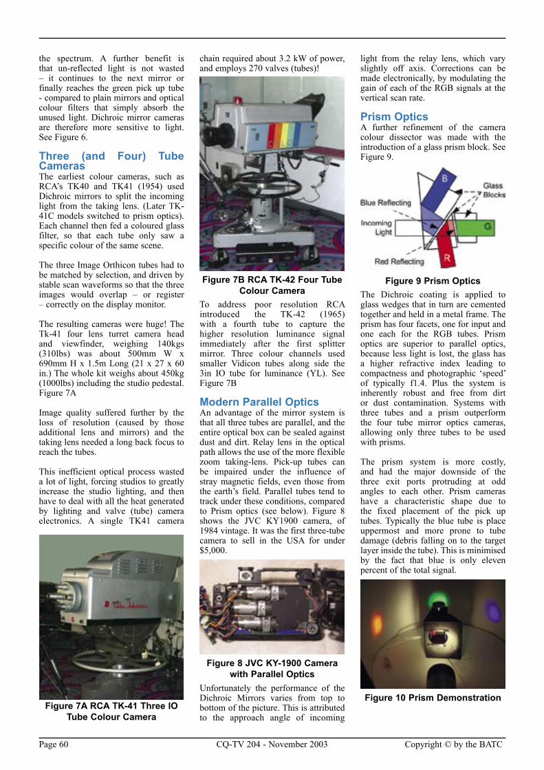
Page 60 CQ-TV 204 - November 2003 Copyright © by the BATC Copyright © by the BATC CQ-TV 204 - November 2003 Page 61
the spectrum. A further benefit is that un-reflected light is not wasted – it continues to the next mirror or finally reaches the green pick up tube - compared to plain mirrors and optical colour filters that simply absorb the unused light. Dichroic mirror cameras are therefore more sensitive to light. See Figure 6.
Three (and Four) Tube CamerasThe earliest colour cameras, such as RCA’s TK40 and TK41 (1954) used Dichroic mirrors to split the incoming light from the taking lens. (Later TK-41C models switched to prism optics). Each channel then fed a coloured glass filter, so that each tube only saw a specific colour of the same scene.
The three Image Orthicon tubes had to be matched by selection, and driven by stable scan waveforms so that the three images would overlap – or register – correctly on the display monitor.
The resulting cameras were huge! The Tk-41 four lens turret camera head and viewfinder, weighing 140kgs (310lbs) was about 500mm W x 690mm H x 1.5m Long (21 x 27 x 60 in.) The whole kit weighs about 450kg (1000lbs) including the studio pedestal. Figure 7A
Image quality suffered further by the loss of resolution (caused by those additional lens and mirrors) and the taking lens needed a long back focus to reach the tubes.
This inefficient optical process wasted a lot of light, forcing studios to greatly increase the studio lighting, and then have to deal with all the heat generated by lighting and valve (tube) camera electronics. A single TK41 camera
chain required about 3.2 kW of power, and employs 270 valves (tubes)!
Figure 7B RCA TK-42 Four Tube Colour Camera
To address poor resolution RCA introduced the TK-42 (1965) with a fourth tube to capture the higher resolution luminance signal immediately after the first splitter mirror. Three colour channels used smaller Vidicon tubes along side the 3in IO tube for luminance (YL). See Figure 7B
Modern Parallel OpticsAn advantage of the mirror system is that all three tubes are parallel, and the entire optical box can be sealed against dust and dirt. Relay lens in the optical path allows the use of the more flexible zoom taking-lens. Pick-up tubes can be impaired under the influence of stray magnetic fields, even those from the earth’s field. Parallel tubes tend to track under these conditions, compared to Prism optics (see below). Figure 8 shows the JVC KY1900 camera, of 1984 vintage. It was the first three-tube camera to sell in the USA for under $5,000.
Figure 8 JVC KY-1900 Camera with Parallel Optics
Unfortunately the performance of the Dichroic Mirrors varies from top to bottom of the picture. This is attributed to the approach angle of incoming
light from the relay lens, which vary slightly off axis. Corrections can be made electronically, by modulating the gain of each of the RGB signals at the vertical scan rate.
Prism OpticsA further refinement of the camera colour dissector was made with the introduction of a glass prism block. See Figure 9.
Figure 9 Prism OpticsThe Dichroic coating is applied to glass wedges that in turn are cemented together and held in a metal frame. The prism has four facets, one for input and one each for the RGB tubes. Prism optics are superior to parallel optics, because less light is lost, the glass has a higher refractive index leading to compactness and photographic ‘speed’ of typically f1.4. Plus the system is inherently robust and free from dirt or dust contamination. Systems with three tubes and a prism outperform the four tube mirror optics cameras, allowing only three tubes to be used with prisms.
The prism system is more costly, and had the major downside of the three exit ports protruding at odd angles to each other. Prism cameras have a characteristic shape due to the fixed placement of the pick up tubes. Typically the blue tube is place uppermost and more prone to tube damage (debris falling on to the target layer inside the tube). This is minimised by the fact that blue is only eleven percent of the total signal.
Figure 10 Prism DemonstrationFigure 7A RCA TK-41 Three IO
Tube Colour Camera
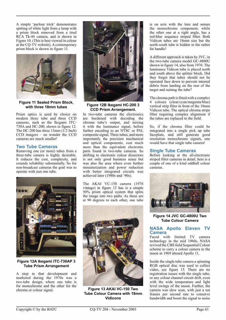
Page 60 CQ-TV 204 - November 2003 Copyright © by the BATC Copyright © by the BATC CQ-TV 204 - November 2003 Page 61
A simple ‘parlour trick’ demonstrates spitting of white light from a lamp with a prism block removed from a tired RCA Tk-44 camera, and is shown in Figure 10. (This is best viewed in colour at the CQ-TV website). A contemporary prism block is shown in figure 11.
Figure 11 Sealed Prism Block, with three 18mm tubes
Prism optics is used by choice on modern three tube and three CCD cameras, such as the Ikegami ITC-730A and HC-200, shown in figure 12. The HC-200 has three 13mm (1/2 Inch) CCD imagers – no wonder the CCD cameras are much smaller!
Two Tube CamerasRemoving one (or more) tubes from a three-tube camera is highly desirable. It reduces the cost, complexity, and extends reliability substantially. So for non-broadcast cameras the goal was to operate with just one tube.
Figure 12A Ikegami ITC-730AP 3 Tube Prism Arrangement
A step in that development and marketed during the 1970s was a two-tube design, where one tube is for monochrome and the other for the chroma or colour signal.
In two-tube cameras the electronics are burdened with decoding the chroma tube’s output, and mixing it with the luminance signal, before further encoding to an NTSC or PAL composite signal. Three tubes, and more importantly the precision mechanical and optical components, cost much more than the equivalent electronic parts found in two-tube cameras. So shifting to electronic colour dissectors is not only good business sense but was also the area where even further miniaturization and power reduction with better integrated circuits was achieved later (1980s and ‘90s).
The AKAI VC-150 camera (1976 vintage) in figure 13 has is a simple 50% prism optical system that splits the image into two paths. As these are at 90 degrees to each other, one tube
is on axis with the lens and senses the monochrome component, while the other one at a right angle, has a red-blue sequence striped filter. Both Vidicon tubes are 18mm size but the north-south tube is hidden in the rather fat handle!
A different approach is taken by JVC, in the two-tube camera model GC-4800U shown in figure 14, also from 1976. The luminance Vidicon tube is placed north and south above the splitter block. Did they forget that tubes should not be operated face down to prevent internal debris from landing on the rear of the target and ruining the tube?
The chroma path is fitted with a complex 4 colours (clear/cyan/magenta/blue) vertical strip filter in front of the 18mm Vidicon tube. The optical chroma stripe filter requiring complex alignment if the tubes are replaced in the field.
So, if the chroma filter could be integrated into a single pick up tube faceplate, and still generate good resolution monochrome signals, one would have that single tube camera!
Single Tube CamerasBefore looking at the all-electronic striped filter cameras in detail, here is a couple of one of a kind oddball colour cameras.
Figure 14 JVC GC-4800U Two Tube Colour Camera
NASA Apollo Eleven TV CameraFaced with limited TV camera technology in the mid 1960s, NASA revived the CBS field Sequential Colour scheme to carry a colour camera to the moon in 1969 aboard Apollo 11.
Inside the single tube camera a spinning RGB optical disc was used to collect video, see figure 15. There are no registration issues with the single tube, or any colour channel circuit drift, even with the wide temperature and light level swings of the moon. Further, the camera was slow scan, with just a ten frames per second rate to conserve bandwidth and boost the signal to noise
Figure 12B Ikegami HC-200 3 CCD Prism Arrangement.
Figure 13 AKAI VC-150 Two Tube Colour Camera with 18mm
Vidicons
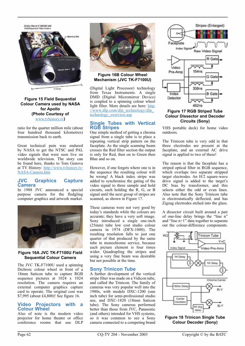
Page 62 CQ-TV 204 - November 2003 Copyright © by the BATC Copyright © by the BATC CQ-TV 204 - November 2003 Page 63
ratio for the quarter million mile (about four hundred thousand kilometres) transmission back to earth.
Great technical pain was endured by NASA to get the NTSC and PAL video signals that were seen live on worldwide television. The story can be found here, thanks to Tom Genova at TV History: http://www.tvhistory.tv/NASA-Camera.htm
JVC Graphics Capture CameraIn 1988 JVC announced a special purpose camera for the fledgling computer graphics and artwork market.
Figure 16A JVC TK-F7100U Field Sequential Colour Camera
The JVC TK-F7100U used a spinning Dichroic colour wheel in front of a 18mm Saticon tube to capture RGB sequence pictures at 1024 x 1024 resolution. The camera requires an external computer graphics capture card to operate. The original cost was $7,995 (about £4,800)! See figure 16.
Video Projectors with a Colour WheelAlso of note is the modern video projector for home theatre or office conference rooms that use DLP
(Digital Light Processor) technology from Texas Instruments. A single DMD (Digital Micromirror Device) is coupled to a spinning colour wheel light filter. More details are here: http://www.dlp.com/dlp_technology/dlp_technology_overview.asp
Single Tubes with Vertical RGB StripesOne simple method of getting a chroma signal from a single tube is to place a repeating vertical strip pattern on the faceplate. As the single scanning beam crosses the Red filter section the output is only for Red, then on to Green then Blue and so on.
However, if one forgets where one is in the sequence the resulting colour will be wrong! A black index stripe was added to synchronise the gating of the video signal to three sample and hold circuits, each holding the R, G, or B signal until the next group of stripes are scanned, as shown in Figure 17.
These cameras were not very good by today’s standards while the colours are accurate; they have a very soft image. Sony introduced a single one-inch (25mm) tube low cost studio colour camera in 1974 (DFX-1000). The resulting resolution falls to just one quarter of that produced by the same tube in monochrome service, because each picture element is four times wider. Quadrupling the stripes and using a very fine beam was desirable but not possible at the time.
Sony Trinicon TubeA further development of the vertical stripe filter was made on a Vidicon tube, and called the Trinicon. The family of cameras was very popular well into the 1980s, with models DXC-1200 (one inch tube) for semi-professional studio use, and DXC-1820 (18mm Saticon tube). The Sony cameras performed better than those from JVC, Panasonic (and others) intended for VHS systems, so it was common to see a Sony camera connected to a competing brand
VHS portable deck) for home video outdoors.
The Trinicon tube is very odd in that three electrodes are present at the faceplate, and an external AC drive signal is applied to two of these!
The reason is that the faceplate has a striped optical filter in RGB sequence, which overlaps two separate stripped target electrodes. An H/2 square-wave drive signal is added to the target’s DC bias by transformer, and this selects either the odd or even lines. Also note that the Sony Trinicon tube is electrostatically deflected, and has Zigzag electrodes etched into the glass.
A dissector circuit built around a pair of one-line delay brings the “line n” and “line n+1” data together to separate out the colour-difference components.
Figure 15 Field Sequential Colour Camera used by NASA
for Apollo(Photo Courtesy of
www.tvhistory.tv)
Figure 16B Colour Wheel Mechanism (JVC TK-F7100U)
Figure 17 RGB Striped Tube Colour Dissector and Decoder
Circuits (Sony)
Figure 18 Trinicon Single Tube Colour Decoder (Sony)
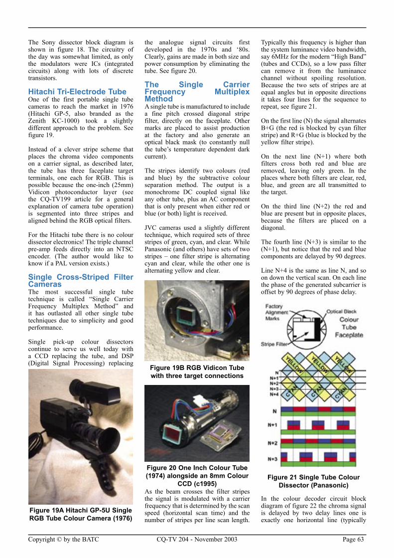
Page 62 CQ-TV 204 - November 2003 Copyright © by the BATC Copyright © by the BATC CQ-TV 204 - November 2003 Page 63
The Sony dissector block diagram is shown in figure 18. The circuitry of the day was somewhat limited, as only the modulators were ICs (integrated circuits) along with lots of discrete transistors.
Hitachi Tri-Electrode Tube One of the first portable single tube cameras to reach the market in 1976 (Hitachi GP-5, also branded as the Zenith KC-1000) took a slightly different approach to the problem. See figure 19.
Instead of a clever stripe scheme that places the chroma video components on a carrier signal, as described later, the tube has three faceplate target terminals, one each for RGB. This is possible because the one-inch (25mm) Vidicon photoconductor layer (see the CQ-TV199 article for a general explanation of camera tube operation) is segmented into three stripes and aligned behind the RGB optical filters.
For the Hitachi tube there is no colour dissector electronics! The triple channel pre-amp feeds directly into an NTSC encoder. (The author would like to know if a PAL version exists.)
Single Cross-Striped Filter CamerasThe most successful single tube technique is called “Single Carrier Frequency Multiplex Method” and it has outlasted all other single tube techniques due to simplicity and good performance.
Single pick-up colour dissectors continue to serve us well today with a CCD replacing the tube, and DSP (Digital Signal Processing) replacing
the analogue signal circuits first developed in the 1970s and ‘80s. Clearly, gains are made in both size and power consumption by eliminating the tube. See figure 20.
The Single Carrier Frequency Multiplex MethodA single tube is manufactured to include a fine pitch crossed diagonal stripe filter, directly on the faceplate. Other marks are placed to assist production at the factory and also generate an optical black mask (to constantly null the tube’s temperature dependent dark current).
The stripes identify two colours (red and blue) by the subtractive colour separation method. The output is a monochrome DC coupled signal like any other tube, plus an AC component that is only present when either red or blue (or both) light is received.
JVC cameras used a slightly different technique, which required sets of three stripes of green, cyan, and clear. While Panasonic (and others) have sets of two stripes – one filter stripe is alternating cyan and clear, while the other one is alternating yellow and clear.
Figure 19B RGB Vidicon Tube with three target connections
Figure 20 One Inch Colour Tube (1974) alongside an 8mm Colour
CCD (c1995)As the beam crosses the filter stripes the signal is modulated with a carrier frequency that is determined by the scan speed (horizontal scan time) and the number of stripes per line scan length.
Typically this frequency is higher than the system luminance video bandwidth, say 6MHz for the modern “High Band” (tubes and CCDs), so a low pass filter can remove it from the luminance channel without spoiling resolution. Because the two sets of stripes are at equal angles but in opposite directions it takes four lines for the sequence to repeat, see figure 21.
On the first line (N) the signal alternates B+G (the red is blocked by cyan filter stripe) and R+G (blue is blocked by the yellow filter stripe).
On the next line (N+1) where both filters cross both red and blue are removed, leaving only green. In the places where both filters are clear, red, blue, and green are all transmitted to the target.
On the third line (N+2) the red and blue are present but in opposite places, because the filters are placed on a diagonal.
The fourth line (N+3) is similar to the (N+1), but notice that the red and blue components are delayed by 90 degrees.
Line N+4 is the same as line N, and so on down the vertical scan. On each line the phase of the generated subcarrier is offset by 90 degrees of phase delay.
Figure 21 Single Tube Colour Dissector (Panasonic)
In the colour decoder circuit block diagram of figure 22 the chroma signal is delayed by two delay lines one is exactly one horizontal line (typically
Figure 19A Hitachi GP-5U Single RGB Tube Colour Camera (1976)
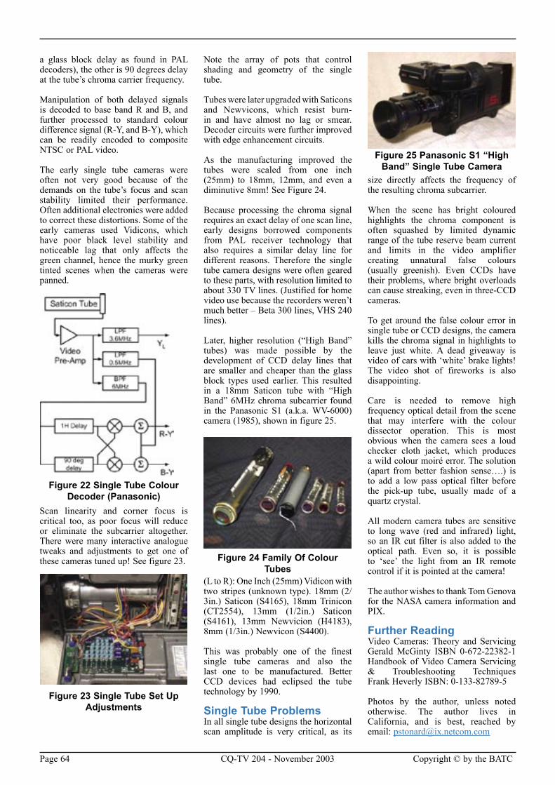
Page 64 CQ-TV 204 - November 2003 Copyright © by the BATC Copyright © by the BATC CQ-TV 204 - November 2003 Page 65
a glass block delay as found in PAL decoders), the other is 90 degrees delay at the tube’s chroma carrier frequency.
Manipulation of both delayed signals is decoded to base band R and B, and further processed to standard colour difference signal (R-Y, and B-Y), which can be readily encoded to composite NTSC or PAL video.
The early single tube cameras were often not very good because of the demands on the tube’s focus and scan stability limited their performance. Often additional electronics were added to correct these distortions. Some of the early cameras used Vidicons, which have poor black level stability and noticeable lag that only affects the green channel, hence the murky green tinted scenes when the cameras were panned.
Figure 22 Single Tube Colour Decoder (Panasonic)
Scan linearity and corner focus is critical too, as poor focus will reduce or eliminate the subcarrier altogether. There were many interactive analogue tweaks and adjustments to get one of these cameras tuned up! See figure 23.
Figure 23 Single Tube Set Up Adjustments
Note the array of pots that control shading and geometry of the single tube.
Tubes were later upgraded with Saticons and Newvicons, which resist burn-in and have almost no lag or smear. Decoder circuits were further improved with edge enhancement circuits.
As the manufacturing improved the tubes were scaled from one inch (25mm) to 18mm, 12mm, and even a diminutive 8mm! See Figure 24.
Because processing the chroma signal requires an exact delay of one scan line, early designs borrowed components from PAL receiver technology that also requires a similar delay line for different reasons. Therefore the single tube camera designs were often geared to these parts, with resolution limited to about 330 TV lines. (Justified for home video use because the recorders weren’t much better – Beta 300 lines, VHS 240 lines).
Later, higher resolution (“High Band” tubes) was made possible by the development of CCD delay lines that are smaller and cheaper than the glass block types used earlier. This resulted in a 18mm Saticon tube with “High Band” 6MHz chroma subcarrier found in the Panasonic S1 (a.k.a. WV-6000) camera (1985), shown in figure 25.
Figure 24 Family Of Colour Tubes
(L to R): One Inch (25mm) Vidicon with two stripes (unknown type). 18mm (2/3in.) Saticon (S4165), 18mm Trinicon (CT2554), 13mm (1/2in.) Saticon (S4161), 13mm Newvicion (H4183), 8mm (1/3in.) Newvicon (S4400).
This was probably one of the finest single tube cameras and also the last one to be manufactured. Better CCD devices had eclipsed the tube technology by 1990.
Single Tube ProblemsIn all single tube designs the horizontal scan amplitude is very critical, as its
size directly affects the frequency of the resulting chroma subcarrier.
When the scene has bright coloured highlights the chroma component is often squashed by limited dynamic range of the tube reserve beam current and limits in the video amplifier creating unnatural false colours (usually greenish). Even CCDs have their problems, where bright overloads can cause streaking, even in three-CCD cameras.
To get around the false colour error in single tube or CCD designs, the camera kills the chroma signal in highlights to leave just white. A dead giveaway is video of cars with ‘white’ brake lights! The video shot of fireworks is also disappointing.
Care is needed to remove high frequency optical detail from the scene that may interfere with the colour dissector operation. This is most obvious when the camera sees a loud checker cloth jacket, which produces a wild colour moiré error. The solution (apart from better fashion sense….) is to add a low pass optical filter before the pick-up tube, usually made of a quartz crystal.
All modern camera tubes are sensitive to long wave (red and infrared) light, so an IR cut filter is also added to the optical path. Even so, it is possible to ‘see’ the light from an IR remote control if it is pointed at the camera!
The author wishes to thank Tom Genova for the NASA camera information and PIX.
Further ReadingVideo Cameras: Theory and ServicingGerald McGinty ISBN 0-672-22382-1Handbook of Video Camera Servicing & Troubleshooting TechniquesFrank Heverly ISBN: 0-133-82789-5
Photos by the author, unless noted otherwise. The author lives in California, and is best, reached by email: [email protected]
Figure 25 Panasonic S1 “High Band” Single Tube Camera
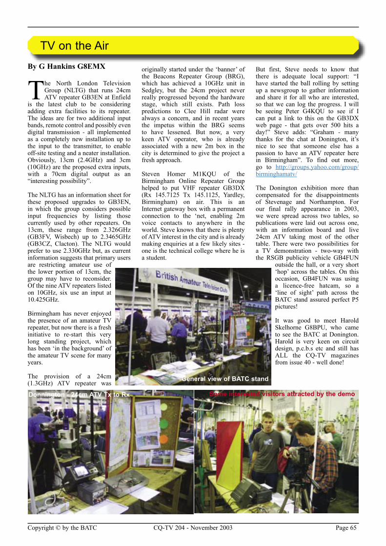
Page 64 CQ-TV 204 - November 2003 Copyright © by the BATC Copyright © by the BATC CQ-TV 204 - November 2003 Page 65
By G Hankins G8EMX
The North London Television Group (NLTG) that runs 24cm ATV repeater GB3EN at Enfield
is the latest club to be considering adding extra facilities to its repeater. The ideas are for two additional input bands, remote control and possibly even digital transmission - all implemented as a completely new installation up to the input to the transmitter, to enable off-site testing and a neater installation. Obviously, 13cm (2.4GHz) and 3cm (10GHz) are the proposed extra inputs, with a 70cm digital output as an “interesting possibility”.
The NLTG has an information sheet for these proposed upgrades to GB3EN, in which the group considers possible input frequencies by listing those currently used by other repeaters. On 13cm, these range from 2.326GHz (GB3FV, Wisbech) up to 2.3465GHz (GB3CZ, Clacton). The NLTG would prefer to use 2.330GHz but, as current information suggests that primary users are restricting amateur use of the lower portion of 13cm, the group may have to reconsider. Of the nine ATV repeaters listed on 10GHz, six use an input at 10.425GHz.
Birmingham has never enjoyed the presence of an amateur TV repeater, but now there is a fresh initiative to re-start this very long standing project, which has been ‘in the background’ of the amateur TV scene for many years.
The provision of a 24cm (1.3GHz) ATV repeater was
originally started under the ‘banner’ of the Beacons Repeater Group (BRG), which has achieved a 10GHz unit in Sedgley, but the 24cm project never really progressed beyond the hardware stage, which still exists. Path loss predictions to Clee Hill radar were always a concern, and in recent years the impetus within the BRG seems to have lessened. But now, a very keen ATV operator, who is already associated with a new 2m box in the city is determined to give the project a fresh approach.
Steven Homer M1KQU of the Birmingham Online Repeater Group helped to put VHF repeater GB3DX (Rx 145.7125 Tx 145.1125, Yardley, Birmingham) on air. This is an Internet gateway box with a permanent connection to the ‘net, enabling 2m voice contacts to anywhere in the world. Steve knows that there is plenty of ATV interest in the city and is already making enquiries at a few likely sites - one is the technical college where he is a student.
But first, Steve needs to know that there is adequate local support: “I have started the ball rolling by setting up a newsgroup to gather information and share it for all who are interested, so that we can log the progress. I will be seeing Peter G4KQU to see if I can put a link to this on the GB3DX web page - that gets over 500 hits a day!” Steve adds: “Graham - many thanks for the chat at Donington, it’s nice to see that someone else has a passion to have an ATV repeater here in Birmingham”. To find out more, go to http://groups.yahoo.com/group/birminghamatv/
The Donington exhibition more than compensated for the disappointments of Stevenage and Northampton. For our final rally appearance in 2003, we were spread across two tables, so publications were laid out across one, with an information board and live 24cm ATV taking most of the other table. There were two possibilities for a TV demonstration - two-way with the RSGB publicity vehicle GB4FUN
outside the hall, or a very short ‘hop’ across the tables. On this occasion, GB4FUN was using a licence-free hatcam, so a ‘line of sight’ path across the BATC stand assured perfect P5 pictures!
It was good to meet Harold Skelhorne G8BPU, who came to see the BATC at Donington. Harold is very keen on circuit design, p.c.b.s etc and still has ALL the CQ-TV magazines from issue 40 - well done!
TV on the Air
Some interested visitors attracted by the demoDonnington - 24cm ATV Tx to Rx
General view of BATC stand
Page 66 CQ-TV 204 - November 2003 Copyright © by the BATC
Amateur Television Quarterly .............................................................................33BATC Publications ..............................................................................................36BlackBoxCamera™ Company Limited...............................................................13CQ-TV Commercial Advertising Rates...............................................................34G1MFG..................................................................................................................2G1MFG................................................................................................................68G6NHG................................................................................................................14Garth RF Filters ...................................................................................................35HS Publications....................................................................................................13Members Services................................................................................................22R T Russel Test Card Generator ..........................................................................47Severnside Television Group ...............................................................................14
CQ-TV Commercial Advertising Rates
Size Mono Colour
Quarter page £50 £75
Half page £100 £150
Full page £150 £200
If you would like to advertise in CQ-TV, then please contact our advertising manager, Trevor Brown,
14 Stairfoot Close, Adel, Leeds, LS16 8JR, England. Telephone: +44 (0) 1132 670115. Email: [email protected]
Index of Advertisers
Silent Key: John Ashton G4NTSI have to report, with sincere regret, that on the 15th August John Ashton, G4NTS lost his very brave fight against cancer.
John became interested in Amateur Radio as a teenager in the early 60’s and later with Amateur Television. In fact he was one of the original members of BATC with membership No. 38. He was a passionate supporter of the BATC and did all he could to encourage others to join.
He was a Yorkshireman with a great sense of humour. Having lived in different places during his lifetime he is well remembered and respected by many Amateurs throughout the Country for his electronic design and construction abilities.
Wherever John and his wife Sue put down roots, John immediately became involved in the Amateur Television scene. He was a founder member of several ATV Repeater Groups including GB3WV and our GB3TB and we drew on his vast knowledge and experience when setting up the first 23cms ATV Repeater in Torbay.
During his last weeks, despite the seriousness of his illness, he was still planning the erection of a 10GHz Beacon.
All of us in the Torbay ATV Group pay our respects and say farewell to a great guy who honoured us with his friendship and great humour. He freely gave of his time and knowledge to help us and we owe him a great debt of gratitude.
Ken Harper GØEKH, Torbay Amateur Television Group
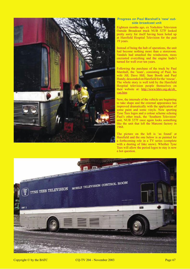
Page 66 CQ-TV 204 - November 2003 Copyright © by the BATC Copyright © by the BATC CQ-TV 204 - November 2003 Page 67
Progress on Paul Marshall’s ‘new’ out-side broadcast unit
Eighteen months ago, ex Yorkshire Television Outside Broadcast truck NUB 327F looked pretty sorry for itself having been holed up at Harefield Hospital Television for the past 19 years.
Instead of being the hub of operations, the unit had become nothing more than a storeroom. Vandals had smashed the windscreen, moss encrusted everything and the engine hadn’t turned for well over ten years.
Following the purchase of the truck by Paul Marshall, the ‘team’, consisting of Paul, his wife Jill, Dave Hill, Sam Booth and Paul Hundy, descended on Harefield for the ‘rescue’. The whole story is well told by the Harefield Hospital television people themselves on their website at: http://www.hhtv.org.uk/ob_van.htm
Now, the internals of the vehicle are beginning to take shape and the external appearance has improved dramatically with the application of some paint and some vinyls. Now sporting Tyne Tees logos and a colour scheme echoing Paul’s other truck, the ‘Southern Television’ unit, NUB 327F once again looks something like the unit that left the Marconi factory in 1968.
The picture on the left is ‘as found’ at Harefield and the one below is as painted for a forthcoming role in a TV series (complete with a dusting of fake snow). Whether Tyne Tees will allow the period logos to stay is now a hot question.
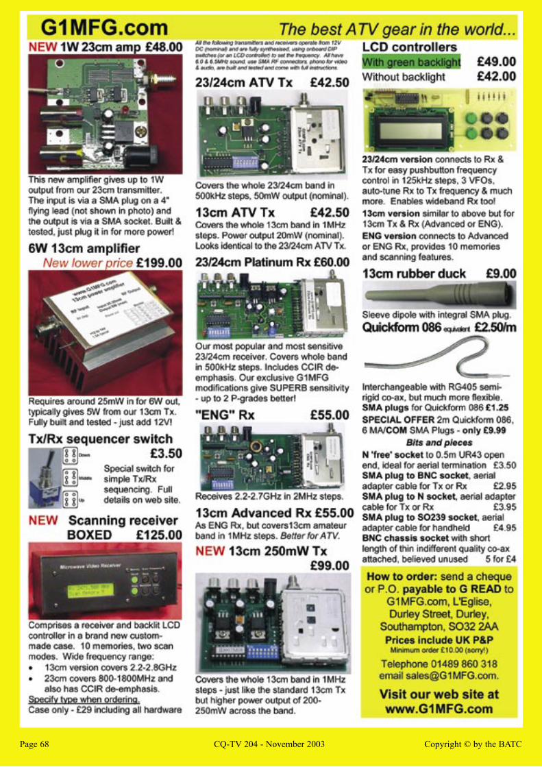
Page 68 CQ-TV 204 - November 2003 Copyright © by the BATCPage 68 CQ-TV 204 - November 2003 Copyright © by the BATC