Embed Size (px)
Citation preview

Contents
1997 by the BATC CQ-TV 178 Page 1
Contents
Contents............................................................................................ 1Committee Contacts.......................................................................... 2Editorial ............................................................................................ 4Dead Ducks and Forgotten Formats ................................................. 6List of French Amateur Television Repeaters,................................ 10The $70,000 ATV QSO, First Digital ATV.................................. 11LUXOR 180 Series TV as a Monitor ............................................. 14Members Services Sale ................................................................... 17A Slice of PYE................................................................................ 18Beyond TTL # 13............................................................................ 28ATV at GB4CDI............................................................................. 38UK Repeater Update....................................................................... 4013 cm Amateur Television.............................................................. 43Channel 5 Ghost Story.................................................................... 51How to get the Rally........................................................................ 53Pair start Amateur Television Channel. ......................................... 56Circuit Notebook No. 60................................................................. 57TV on the Air ................................................................................. 61Satellite TV News........................................................................... 65Slow Scan TV, an Overture............................................................ 76Post and News................................................................................. 86For Sale........................................................................................... 93Wanted............................................................................................ 96Index of Advertisers........................................................................ 96
CQ-TV is produced on a P6 Gateway 2000 PC computer system,using the Word for Windows word processing package. Thecamera ready artwork is produced on an Hewlet Packard LaserJet4 printer.
Edited by Ian Pawson with help from Trevor Brown, proof read byPeter Delaney. All rights reserved, all wrongs denied. 1997 bythe BATC.
Printed by Cramphorn Printers Ltd., 15c Paynes Lane, Rugby,England
Committee Contacts
Page 2 CQ-TV 178 1997 by the BATC
Committee Contacts
BATC Chairman Trevor Brown G8CJS
Club affairs, Video tape library, Technical queries, especially relating tohandbook projects. 14 Stairfoot Close, Adel, Leeds, LS16 8JR. Tel: 01132670115. E-mail: [email protected]
BATC General Secretary Paul Marshall G8MJW
General club correspondence and business. Library queries relating to theborrowing or donation of written material. Fern House, Church Road,Harby, Notts., NG23 7ED. Tel: 01522 703348. [email protected]
BATC Hon. Treasurer Brian Summers G8CQS
Enquiries regarding club finances, Donations, and constitutionalenquiries. 9 Prior Croft Close, Camberley, Surrey, GU15 1DE. Tel: 01276677879, Mobile 0850 014892
CQTV Magazine Editor Ian Pawson
Anything for publication in CQ-TV, Articles, Review items, Letters to theeditor, and other material except as below. 14 Lilac Avenue, Leicester,LE5 1FN, England. Email: [email protected]
Photographs for the CQ-TV covers:- Patrick White, Swyncombe, 8Kingswood Court, Maidenhead, Berkshire, SL6 1DD, England
TV on the Air:- Graham Hankins G8EMX, 11 Cottesbrook Road, AcocksGreen, Birmingham, B27 6LE. Tel: 0121 707 4337
Satellite TV News:- Paul Holland G3TZO, Chatterton, Chapel Lane,Threapwood, Nr. Malpas, Cheshire, SY14 7AX. Tel: 01948 770429,Email: [email protected]
CQ-TV Advertising Manager: Dave Hemingway, Ivanhoe, Glen Road,Hindhead, Surrey, GU26 6QE. Tel: 01428 604645
CQTV Awards:- Bob Webb G8VBA, 78 Station Road, Rolleston onDove, Burton on Trent, Staffs., DE13 9AB. Tel: 01283 814582
Committee Contacts
1997 by the BATC CQ-TV 178 Page 3
Exhibitions
Rally 97:- Mike Wooding G6IQM, 5 Ware Orchard, Barby, Nr. Rugby,CV33 8UF. Tel: 01788 890365, Fax: 01788 891883, Mobile: 0860 857434Email: [email protected]
Club Sales
Members Services:- PCB’s, components, camera tubes, accessories, etc.(NOT PUBLICATIONS). Peter Delaney G8KZG, 6 East View Close,Wargrave, Berkshire, RG10 8BJ. Tel: 0118 940 3121
Publications:- Handbooks, Back copies CQTV, and anything related tothe supply of BATC publications. PLEASE NOTE NEW ADDRESS:-
Paul Marshall, Fern House, Church Road, Harby, Notts., NG23 7ED,England. E-mail: [email protected]
Membership
Anything to do with membership, including new applications, queriesabout new and existing membership, non-receipt of CQ-TV, subscriptions,membership records, data protection act. Dave Lawton G0ANO,‘Grenehurst’, Pinewood Road, High Wycombe, Bucks., HP12 4DD. Tel:01494 528899. E-mail: [email protected]
Club Liaison:- And anything of a political nature, co-ordination of ATVrepeater licences. Graham Shirville G3VZV, The Hill Farm, Potsgrove,Milton Keynes, Bucks., MK17 9HF. Tel: 01525 290343. [email protected]
Contests:- Richard Guttridge G4YTV, Ivy House, Rise Road, Skirlaugh,Hull, HU11 5BH. Tel: 01964 562498
BATC BBS Sysop:- Brian Kelly GW6BWX, 12 Cotswold Way, Risca,Gwent, NP1 6QT. Tel: 01633 614376, BBS: 01633 614765.Email:[email protected]
Repeater Liaison:- General enquiries and repeater affiliation. GrahamHankins G8EMX, 11 Cottesbrook Road, Acocks Green, Birmingham, B276LE. Tel: 0121 707 4337

Editorial
Page 4 CQ-TV 178 1997 by the BATC
Editorial
Welcome to Ian’s first solo CQTV, unfortunately it’s the magazine withthe shortest lead time, as we try to get it to you before the BATC rally soas to give you all a timely reminder. The down side to this rally plug isthis issue closes about two weeks after CQTV 177 drops on your mat,hardly time to gather much copy. I asked Ian if I could do anything to helpand in return got stuck with the editorial, not being deterred by notknowing what is in the magazine, here goes.
Internet The club web site is growing and now has a complete copy ofCQTV 176 and CQTV 177 available for down loading. The files are inacrobat format, which compresses them and allows them to be available toa wide variety of computing platforms. A free copy of acrobat 3 reader isavailable from their linked web site. I hope by making CQTV available inthis way that it will expose what we do to a wider audience and swell ournumbers, which in turn will generate copy and keep printing andmembership costs down in the future. The down side is it is possible todownload CQTV and read it without being a member. Renewals will beclosely monitored to see if it is wise to continue this practice. Your viewsare always welcome on this, or any part of the clubs activity.
BBS The club web site does gather some interesting letters and is agood place to store club software. I have had requests to repeat all thesefeatures on the club BBS as everyone is not on the net. Brian Kelly theBBS sysops is thinking this over and I am sure would like to hear yourviews, at the club BBS.
CQTV Enough of all this electronic cyber communications and lets getback to ATV and paper communications tough, as it is on trees. I for oneam looking forward to reading this magazine, particularly as I have notseen it or angst over it in what can only be described as component form.If I have generated enough copy here to fill a page then Ian cannot includeany derogatory clip art as part of the page, fingers crossed. Sorry to spoilyour only enjoyment but I do not wield the axe anymore Ian, and hopefullythere is not enough space for you to depict my new role.
TREVOR BROWN G8CJS
BATC Chairman.

1997 by the BATC CQ-TV 178 Page 5
GB3XT Kits & Bits.GUNNMOD2 3cmsATV. TX. kit. Verypopular full feature Gunndiode TX. Complete withpre-tuned oscillator head.£30.00. PCB. kit lessoscillator £20.00
TVRO3 ATV TuneableIF/RX . kit. Fully featured750-1700MHz input.12vDC operation. Nosetting up or alignmentrequired. £50.00
24cms HIGH GAINLOW NOISEGASFET PRE-AMPkit. 40db gain 1db NF.with band pass helicalfiltering. 12-18vDC viacoax. £60.00
24cms ATV TX. kit. Fullspec 5ch max. 2W o/p.Filters for video & audio.12vDC. £125.00
3cms LNB’s. Brand newcircular input. Fit 38-40mm mounting. willmount directly on mostoffset satellite dishes.0.8db NF. 9.0GHz LO.£40.00
DTMF DECODERkit. Very high qualitydecoder IC. All o/p’sbuffered. Will directlydrive TTL/CMOS orrelays directly. Can beused to controlwhatever yourimagination thinks of.£12.00
All kits contain all board mounted components and full comprehensive instructions.
Prices are all inclusive of P&P etc. PCB’s are available assembled and tested at extracharge. SAE. (to take A4 paper) for further details.
Orders etc. to
Bob Platts G8OZP, 220 Rolleston Road, Burton Upon Trent, Staffs, DE13 0AY.Phone 01283 531443, 7-9pm on weekdays only please.

Dead Ducks and Forgotten Formats
Page 6 CQ-TV 178 1997 by the BATC
Dead Ducks and Forgotten Formats
Andy Emmerson takes you on a fast forward history of home video.
When did home video start? Easy question, difficult answer. Ask twopeople and you’ll get at least five answers, and if there’s confusion anddebate, it lies in the difference between availability and affordability. Lookat it this way... if you want to buy a giant-screen wide-format TV todaythere’s nothing stopping you – except an unbelievable price. But no-onecan deny they’re available now. And so it was with home video in theearly days; the price put them in the luxury bracket and they weredefinitely not mass-market products.
Today VHS is well-nigh the universal video recording format, simplybecause it’s affordable. Earlier domestic video systems weren’t and thatfactor alone was sufficient to ensure their rapid decline into obscurity,although it didn’t seem that way at the time.
The first true home video outfit was brought out by Sony in 1966 and itrejoiced in the memorable title of CV-2000. It appears that CV stood forConsumer Video, although Sony never used that name to brand thesystem. Observers loved it and when Sony launched the CV-2000recorder, noted hi-fi writer Gordon J. King named it ‘a Japanese miracle’.Sold complete with a dinky little 9"-screen portable television, it was aninstant hit with the press and other opinion formers.
Its price didn’t exactly translate into huge sales, though; the recorder andTV cost £365, whilst the camera, lens and tripod cost an additional £131.A portable recorder and lightweight camera together with sound andvision mixers were also available, but this was in an age when you pick upa brand new car for around £600. As a consumer product it was a failure,although a fair number of outfits were sold into industrial and educationaluse. Today these equipments are highly collectable and tapes recorded atthe time have yielded several lost television programme treasures.
The system worked reasonably well but the fact that it used open-reel tapesat a time when consumers were becoming used to cassette tapes andcartridges for audio was recognised as a weakness. Within five years aconsortium of Japanese manufacturers had collaborated to bring a new,cassette-based system to market. This they called U-Matic. It could recordcolour as well as black-and-white and it was very robust – virtually idiot-proof in fact. The equipment was heavy and extremely bulky, and like theCV-2000, it could record only one hour maximum. Systems were sold intothe consumer market in the USA but it was only for the well-to-do. Like a

Dead Ducks and Forgotten Formats
1997 by the BATC CQ-TV 178 Page 7
few other apparently dead ducks, U-Matic migrated rather thandisappeared. It ended up finding an unexpected niche in the professionalmarket, where it turned out ideal for training and promotional videoproductions, and the machines are only now starting to be replaced in abig way.
The first video recorder for the home using cassettes came in 1974, whenPhilips launched their model N1500 VCR or Video Cassette Recorder as‘a landmark in the history of television and the start of a revolution inhome entertainment’. Cost once again meant this machine was only forthe well-to-do; the recorder cost £388 in 1974 money, whilst blank tapescost £25 an hour. A succession of video machines and formats followed –Betamax in 1975, VHS in 1976, V2000 in 1981 – with no obvious winnerin sight for another decade.
Time will tell, they say, and for home video it already has told. VHS iswell-nigh universal now, and its higher-performance partner S-VHS hasmade little impact except with the enthusiasts who appreciate its 60 percent improved picture quality. Betamax, on the other hand, is nowregarded as a dead duck, although considering the number of Betamachines sold around the world over a period approaching two decades,‘flop’ is hardly the right word to use.
Even more, ‘Betamax’ has become the generic word for a video recorderin South America, just like many people call every vacuum cleaner here a‘Hoover’ and every ball-point pen a ‘Biro’. Today there are still manyvideo devotees who cherish their top of the line Beta machines, claimingbetter results than S-VHS, whilst the continuing sales of blank Beta-format tapes indicates there must be a mighty big population of humblerrecorders still used for time-shifting.
There were some interesting quarter-inch formats. Akai made a variety ofmono and colour open-reel video recorders, whilst the Funai/Technicolorminiature cassette system also had its brief period of success. And whatabout Pixelvision and the other kiddycam products? Fisher-Priceintroduced a children’s camcorder in the late 1980s that recorded black-and-white pictures on normal audio cassettes; it was called the PXL-2000and is already highly prized as a collector’s item. Tyco has a similarproduct on the market now; although picture quality is not as good, itmight yet turn out a good investment as a ‘modern antique’!
Finally a word about the video disc. As a home video device, this was theoldest format of all – after all, Baird had offered recordings ongramophone records in the 1930s. What’s more, Telefunken and Deccafooled with their TelDec system in the sixties. Later, growing affluence

Dead Ducks and Forgotten Formats
Page 8 CQ-TV 178 1997 by the BATC
and a perceived dissatisfaction with the sound and picture quality of VHStape led Philips, JVC and RCA to launch video disc products.
In Britain JVC’s VHD system aroused little interest except for someindustrial projects and only Laservision/LV (from Philips) andSelectavision/CED (from Hitachi, using the RCA system) came into thereckoning; it goes without saying that they were all mutually incompatibleand aroused little interest, particularly once new releases on disc dried up.
These early video discs cost the manufacturers dear; Philips weathered thestorm but RCA was bankrupted and had to sell out to Thomson of France.Format wars and regional releasing policies have always bedevilled videodisc systems... and look set to continue even now with the new DVDofferings. Truly those who ignore the lesson of history are condemned torelive it.
NOTE: Speaking personally, I am no longer collecting video tapemachines of the past but there are a growing number of enthusiasts whowould happily give these recorders a good home. If you are harbouring anancient reel-to-reel machine, please contact me and I’ll put you in touchwith a willing buyer.
DeadlineWill all contributors please note thatthe deadline for articles for CQ-TV179 is June 15th 1997. Please sendyour contributions in as soon as youcan prior to this date.
If you would like to contribute anarticle for publication in CQ-TV,then please send it to the editor,either by post, or preferably by email.If you don’t use a word processor,plain ASCII text is fine. Please seepage 2 for address details.

1997 by the BATC CQ-TV 178 Page 9
IMPROVE YOUR TV RECEPTIONSPECIAL DX GRID
Wideband UHF Grid with DirectorsFor receiving extra ITV programmes, or even Continental TV, thewideband UHF JJB/4 BILBOARD GRID provides the answer, Itsvideband response means that a single grid can be used to coverthe entire UHF spectrum,
The JJB/4 GRID is a special type of aerial consisting of FOURSTACKED DIPOLE assemblies which can provide improvedresults over a conventional ‘Yagi’ TV aerial. In some difficultreception areas where local signals are scattered and arrive atslightly different heights (with ghosting, signal imbalance, etc) theuse of a grid can improve results,
For even better results we can now supply this array with our ownunique add-on director assembly which provides further signalenhancement, A single grid is ideal even for Continental receptionin the UK during a tropospheric lift but two grids can bepositioned side-by-side for even higher gain; this also makes thesystem more directional,
The JJB/4 is ruggedly constructed and features a 16-elementreflector (not a mesh as found on other makes) providingexcellent front-to-back ratio characteristics,
JJB/4 WIDEBAND GRID + NS ADD-ON DIRECTORS (13.5db approx.).................. £34-95TWIN GRID (with add-on directors, stacking kit and combiner) ................................. £69-95SUPREME HI-GAIN LO-NGISE WIDEBAND UHF AMP (2SdB gain, 1,9dB noise) .......................................................................................... £23-95P1290 HI-CURRENT PSU FOR ABOVE................................................................... £15-95
UK POSTAGE & PACKING £5-00 PER AERIAL ORDER., OTHER ITENS UK P&PINCLUDED. EXPORT PRICES UPOW REQUEST.
Illustrated Catalogue of equipment & Publications only £0.75(refundable with the first order)
We can also manufacture aerials to your own design (one-off or multiples),
HS PUBLICATIONS7 Epping Close, Derby DE22 4HR, England
Tel: 01332 38 16 99

List of French Amateur Television Repeaters,
Page 10 CQ-TV 178 1997 by the BATC
List of French Amateur Television Repeaters,
January 1997
Information is given in the following order:
Location, callsign of repeater, Department, QRA locator, callsign ofkeeper, input frequency (MHz), output frequency (MHz)
1.CARLAT, F1ZDY, 15, JN14GV, F1ULK, 1255, 438.5
2. ROMANS, F5ZCH, 26, JN24NW, F8LZ, 1255, 438.5
3. EVREUX, F5ZBI, 27, JN09NA, F6GNJ, 1255, 438.5
4. NIMES, F5ZEI, 30, ???, F5AD, 1255, 438.5
5. CARTELEGUE, F1ZEC, 33, IN95QD, F1DZL, 1255, 438.5
6. TOURS, F5ZDD, 37, JN07FK, F6BRV, 1255, 438.5
7. GRENOBLE, FZ8TVB, 38, JN24NW, ???, 438.5, 1255
8. CHAMROUSSE, F5ZAR, 38, ???, F6BUH, 438.5, 1255 and vice versa
9. FIEFS, F1ZDM, 62, JO10DM, F1ESA, 1255, 438.5
10. MONTMORIN, F1ZDT, 63, JN15QQ, F1FY, 438.5, 1255
11. LYON Croix Rousse, FZ8TVD, 69, JN25KS, F1HMB, 1283.5, 1247.5
12. LYON Rilleux, FZ8TVA, 69, JN25KS, F1MHS, 438.5, 1255
13. LES MARCHES, F1ZEB, 73, ???, F1GCU, 1255, 438.5
14. LE HAVRE, F1ZDE, 76, JN09DO, F1EDM, 1255, 438.5
15. COISY, F1ZEA, 80, JN19DX, F1BPO, 1255, 438.5
16. No listing
17. MONTAUBAN, FZ5TVA, 82, JN03RX, F6DVW, 1255, 438.5 and
vice versa
18. FREJUS, F5ZDS, 83, JN33EF, JN33EF, F6FCE, 438.5, 1255
19. LA SEYNE SUR MER, F1ZDV, 83, JN23WC, F1FKE, 438.5, 1255
20. CLAMART, F1ZEG, 92, ???, F1HPR, 1255, 10450
21. AULNAY, F1ZIF, 93, ???, F1NSU, 10475, 1255
22. ROSNY SOUS BOIS, F1ZEH, 93, ???, F1LGC, 10450, 10485
23. CORMEILLES, F5ZDW, 95, JN18CX, F6ENB, 1255, 438.5
From information supplied by ANTA, the French national ATVassociation

The $70,000 ATV QSO, First Digital ATV
1997 by the BATC CQ-TV 178 Page 11
The $70,000 ATV QSO, First Digital ATV
By Ned Mountain NC4X
This is to all ATVers who have written about our digital MV tests. Wewill do an article as time permits, but here are some answers to thequestions you have asked. Time is extremely limited, so I will not becorresponding on it any more until we get an article written!
l The bandwidth of our first transmission was 2.7MHz. Modulation typewas QPSK and rate 1/2 error correction was used. If we had more poweravailable, we would have used higher data rates and higher bandwidth.These tests are next
2 The equipment is still way too expensive for hams. Each transmit systemcosts about $70,000, and the receivers are $3,000. This equipment is justnow making its way into professional broadcast applications. I think it willbe several years before we see prices anywhere near what we need for hamuse. But, we are doing this experimental work to show what can be donein the future. We are fortunate to have access to this equipment as it isbeing manufactured by our company. Anybody working for a televisionbroadcast station or network is very likely to see this type of equipmentshowing up in the satellite news gathering trucks during the next 12months.
3 Video quality should be as good as what you get over the DSS satellitesystem, which transmits each channel at data rates similar to what weused. We can set the equipment for any data rate between 2.5 and15Mbits/sec. Most broadcasters will use data rates in the 8Mbit/sec rangefor high quality transmissions. With digital ATV the picture is eitherperfect, or gone! In out first transmission, the picture was perfect, and wehad about 3dB of margin. At the 2.5Mbit/sec data rate, pictures are perfectfor normal.
ATV video. Higher data rates will insure perfect video under all motionconditions. In addition to transmitting the video, we also transmit 4channels of 15kHz audio and a 19.2 kbit/sec data channel.
4. Further experiments are planned in September using higher power andhigher data rates, and real antennas between the QTH of WD4MBK inAtlanta, and the two of us from various mountain tops in Georgia andNorth Carolina. Using digital ATV, we enjoy approximately 15 to 20dBadvantage over conventional VSB-AM transmissions. Thus, we expect to

The $70,000 ATV QSO, First Digital ATV
Page 12 CQ-TV 178 1997 by the BATC
easily communicate over paths that would be impossible using normalanalogue transmission.
[From ATV Quarterly, Autumn 1996]

1997 by the BATC CQ-TV 178 Page 13
Severnside Television Group
All of our 23 cm Aerials are specifically designed for ATV use - although they canbe used for other modes as well. Wideband characteristics mean that you need onlyone aerial to cover the repeater input and output channels. Our famous widebandyagis come fully assembled in two versions :
38 ELEMENT HIGH GAIN : 14 dB gain, 1.8 m long, £26.00 plus postage.18 ELEMENT STANDARD : 10 dB gain, 0.9 m long, £15.00 plus postage
Don’t forget our 20 ELEMENT CONVERSION KIT, which converts your existing18 element aerial to the full 38 element high gain specification : £13.00 plus postage.Our 23 cm TROUGH REFLECTOR is quite unique, combining 11dB gain withwide bandwidth and wide beamwidth. It’s also compact, just 0.55 m high, 0.35 mwide and 0.3 m deep. Supplied as a kit of predrilled and preformed parts. for easy“Screwdriver” assembly : £19.00 plus postage. All aerials feature an SWR of lessthan 1.5:1 and are supplied with mast clamps suitable for masts up to 55 mmdiameter. Mast poles shown are not supplied.
POSTAGE: £3.75 for one aerial, £5.00 for two or more. Telephone orders with cashon delivery: £2.75 supplement per order, Orders from outside of the UK - pleasewrite for carriage quotation.
CHEQUES payable to “SEVERNSIDE TELEVISION GROUP” and send to 18,Linnet Close, Patchway, Bristol BS12 5RN. Telephone ( evenings & weekends onlyplease ) 0117 969 8136. Please allow 28 days for delivery.

LUXOR 180 Series TV as a Monitor
Page 14 CQ-TV 178 1997 by the BATC
LUXOR 180 Series TV as a Monitor
By John Stockley, G8MNY
This TV series has a fully isolated chassis. Recognisable by its large metalframed vertical PCB across the back of the set, the TV’s were also badgedas LLOYD’S. Two main types were made, 26" & 14". Only one rareversion had video in & out, which used an extra internal PCB, externalbuffer amps & a connection box.
Here is a simpler way to add Video/Sound in & out that can be made onstrip PCB or just mounted ugly on the motherboard, as there is plenty ofroom track side. There are also two other modifications that could be doneto many TVs - one for extending the coverage to 70cms, and one for VCRfriendly slow line syncs, that helps keep in lock a noisy off air videowithout jagged VCR mode verticals.
The 26" model can also be made “S” input by the separating the Chromavideo feed, uplifting the luminance HF response & shorting out the coloursubcarrier luminance trap. Contact me if you need details of this mod.
Video In & OutFor Video work the chassis is safety earthed through 2 diodes & a resistor,to avoid hum loops, but keep connections static (& mains fault) safe. Themains lead may need changing to a 3 core.
On the 14" sets mount the input & output sockets 2x BNC video & 2xPhono audio on the earthed copper screening foil of the back, with theterm switch utilising the blanked off hole.
The video output is buffered with T5 from the 2Vp-p rail and matched to75 ohm with a 68 ohms in series with the 470µF blocking C. The externalvideo input is optionally terminated to permit daisy chain loop through,and amplified by a high input impedance 2 transistor amplifier T1 & T2that give the 2Vp-p video and negative video for the TV sync circuits.External Video mode switching is done by a 24v relay driven from a videodetector T3 & T4 feed after the video amp.
Audio input is just additive, but the TV Rx audio is muted by relayswitched 47k to ground on Sound FM IF IC TBA120 pin 13.

LUXOR 180 Series TV as a Monitor
1997 by the BATC CQ-TV 178 Page 15
Tune 435The UHF section on the tuner nearly covers this band, so with a slightnegative tuning voltage it does so easily. Cut the tuning track near XY01pin 3 and add the series diode. Make the -6v rail from rectifying the 55vline flyback pulse rail (only -7v swing) on resistor RS17 with a diode &cap. Apply the negative voltage to the tuner through a 1M resistor. This

LUXOR 180 Series TV as a Monitor
Page 16 CQ-TV 178 1997 by the BATC
ensures the tuning range is only offset by the few MHz needed. Re-tunethe push buttons and set up one (not VCR ch button 8!) to 70cms.
Slow VCRIf you receive a weak signal in VCR mode (Push button 8) the fast linePLL time constant will cause very disturbed verticals that degrade thepicture. However it is possible to keep most of the VCR mode ability tolock with a slow time constant provided the sync PLL time constant isswitched to fast mode during frame fly back, which is just after the VCRhead switch that causes the line phase change.
The circuit generates positive pulses from the frame output flyback swing,shapes the pulse with the diode & 0.1µF & applies it to the line timebasechip VCR pin through the 22k & 27k resistor. The filter cap C505 0.1µFneeds to be changed for 10nF to allow the pulse through. The value of the27k may need “selecting on test” depending on the chip sensitivity andframe height, so that the mode switching back to slow time constant is justat the top of the screen. If this is not right it shows up as a small kink inverticals. If it is not switched to fast mode for long enough it will not lockto a badly phase shifted recording.
This mod does not affect the VCR 8 button, that puts the set into VCRmode as usual.
BATC on the InternetThe URL (address) is:-
http://ourworld.compuserve.com/homepages/batc

Members Services Sale
1997 by the BATC CQ-TV 178 Page 17
Members Services Sale
One Day Only!The followingspecial offerswill ONLY beavailable at theBATC Rally onApril 27th - whilestocks last. Notonly are theresome greatbargains, yousave on the postand packing aswell!
Digital television is coming. If you want to experiment with this mode, wehave a few UVC3130 ics, that allow you to digitise a video signal, andalso to convert it back to analogue.
Normal price: £47.00. Sale price: £40.00, including data!
24cm receiver. Build a 2 input 24cm receiver, with video and audiooutputs. The through hole plated PCB, ASTEC AT2352 and the XR215phase lock loop IC are included in this package deal, with circuit diagram,layout plan and component list.
Normal price: £74.50. Sale price: £68.00
I2C project. This project allows a dedicated computer to control thestation, receive Teletext, generate test patterns, etc., but unlike othercomputers, the screen displays can be locked to your other picture sources.Other boards are available to expand this project, but this basic starterpackage comprises the I2C VDU PCB, I2C CPU PCB, the SAA5231genlock IC, the SAA5243 Teletext IC, the PCP8583 real time clock IC,the specially programmed EPROM - and we’ll throw in a 13.875MHzcrystal and the circuit and layout plans and a parts list!
Normal price: £64.90. Sale price: £60.00
Come early to be sure of obtaining what you want … or wait till after 2pmand you can have an extra 5% off the sale prices - IF there are any left!

A Slice of PYE
Page 18 CQ-TV 178 1997 by the BATC
A Slice of PYE
By Dicky Howett
Dicky Howett recalls the famous radio and television manufacturer PYELTD. He talks to retired Pye engineer and long time BATC member, IanWaters.
Today, little remains of theCambridge electronicscompany called Pye. In the1930’s, Pye Radio Ltd wasworld famous as amanufacturer of stylish radiosets, including the familiarart deco ‘Sunburst’ MMmodel of 1932. Also, Pyewas in the vanguard oftelevision development. Asearly as 1930 it established alaboratory to investigate thecommercial possibilities ofcathode ray tubes. This labeventually became thesubsidiary company,Cathodeon Ltd. By 1936,just in time for the openingof the BBC’s tvtransmissions, Pye had it’sfirst receivers in the shops.More models appeared astelevision slowly grew inpopularity. These included‘budget’ sets like the now extremely rare Pye 817 (1938) which had apicture measuring only 4 x 3 inches on a 5 inch tube.
Ian Waters joined Pye in 1948 at a time when the Company wasexpanding in many interesting directions. Ian recalls how he began hislong association with Pye.
“I entered Pye as a Radio Engineer-Apprentice. It was a five year stintwhich initially sent us round all the assembly shops for a three year tour.During the final two years, apprentices were supposed to go into the
Ian Waters demonstrates his fieldsequential colour disk.

A Slice of PYE
1997 by the BATC CQ-TV 178 Page 19
department of their choice to finish training. However in 1951, towardsthe end of my third year, the Company got a big order from the USA fortelevision cameras.”
Ian at that time was an enthusiastic television amateur and had built hisown television camera. Because of this practical experience, Pye decidedto pull Ian off the apprenticeship scheme and start him straight away as ajunior engineer on TV camera development, helping to fulfil that largeand lucrative American order. Ian discovered that because of a massiveexpansion of television in America, there was a dearth of suitable TVbroadcast equipment. As a consequence, a U.S. company called GeneralPrecision Laboratories Inc. was trawling Europe for useable kit. G.P.L.Inc. found Pye’s new Mk. III 3 inch image orthicon camera highly suitableand it shipped many channels back to the States, re-badging them in theprocess. Ian Water’s task was to help modify, to US line standards the MkIII.
“Actually, it was towards the end of the Second World War that Pye reallystarted to develop TV cameras and transmitters,” Ian remembers. “Whathappened was that the chap running Pye, C.0.Stanley announced hewished to diversify and gave two young Pye engineers John Brinkley and
The Pye MkIII 3 inch image orthicon camera. (1956)

A Slice of PYE
Page 20 CQ-TV 178 1997 by the BATC
John Edwards their heads. He asked them what they would most like todo. Brinkley chose to work on radio communications (which became PyeTelecommunications Ltd) and Edwards chose TV broadcasting.”
In 1946 a department was established at Pye to study the whole oftelevision broadcast equipment. An experimental studio was built andequipped with imported RCA 827 camera channels. These cameras usediconoscope image tubes. (An unusual feature of the RCA 827 camera wasthat it had a dual viewfinder. This showed not only an electronic imagebut superimposed, an optical image of a slightly wider view). Pye gainedmuch valuable experience from this studio.
In 1947 the department had advanced sufficiently to enable it to undertakethe design of a mobile o.b. unit which was built into the body of a Humbershooting brake. This unit contained two Iconoscope single-lens cameras

A Slice of PYE
1997 by the BATC CQ-TV 178 Page 21
and two wheeled mounts. Also crammed into the Humber was the visionand sound equipment, a link transmitter using sync. modulation (a newconcept which used the vision carrier for the sound signal) and anhydraulic aerial sticking out of the roof. This mobile unit travelled theContinent and the Middle East, introducing Pye as a serious contender inthe new and expanding world of television equipment manufacture. Pyealso exhibited this mobile unit at the 1947 British Industries Fair at EarlsCourt.
In 1949, combined with intensive work at Cathodeon, Pye produced it’sfirst broadcast quality camera, the (Mk.I) PHOTICON. The Pye Photiconwas an image iconoscope type camera with a four-lens turret and anelectronic viewfinder (cameramen at the time were used to framing anupside down optical image. They actually asked for the electronicviewfinder scans to be reversed! Pye wisely refused). The Photicon camerahad an image tube that was a distinct improvement over EMI’s existingSuper Emitron. Pye’s Photicon was much smaller (half the size) than theoriginal Super Emitron. Also the Photicon tube came ready potted withplaster of Paris in a sealed, quick-fit black box, complete with its scancoils and head amps. Just a few plugs and a screw secured the Photicon inplace, which was inserted on rails. Any replacement due to unit failure
Photo-electron stabilisation of an image iconoscope

A Slice of PYE
Page 22 CQ-TV 178 1997 by the BATC
could be achieved with great speed. This cost and time-saving advantageappealed to the BBC and they ordered immediately a new o.b. unit (MCR3) complete with three of the new Photicon cameras. This unit transmittedfor the first time on the 12th Feb. 1949. Ian Waters’ very junior engineernon-technical type contribution to this spanking new o.b. unit was to paintthe bottom of the scanner with Bitumastic underseal! (Outside broadcastvehicles became one of Pye’s most successful products. Over 150 unitswere sold throughout the world).
Also in 1949another Pyeinnovationarrived. Thiswas the ‘zoomlens’ which wasfitted to aPhoticoncamera. Thisexperimental2:1 zoom lens,(the first to bespecially madefor televisioncameras), wasdesigned by Dr.H.H. Hopkinsof the firm W.Watson and Sons, a Pye-owned company.
Later in 1952 an improvement of the Pye Photicon was suggested byRichard Theile, a German vacuum physicist working at Pye. At the timeall high velocity picture tubes such as the Photicon had shading problems.The picture displayed edge flare and uneven patches which varied inproportion to the level of illumination of the televised scene. This shadingwas due to spurious electrons bouncing around inside the tube. Also therewas an absence of a signal representing a black level.
Eventually, a solution to these problems was found in a process known asPhoto-Electron Stabilisation or P.E.S.tication. A (Mk.II) PESTICON tubewas constructed with an additional semitransparent photo-cathodesurrounding the storage plate plus two additional strip electrodes. Thephoto-cathode was illuminated by pea-bulbs attracting the spuriouselectrons. This improved the picture balance. Also the signals
A Pye Photicon image tube of 1949, ready potted foruse
A Slice of PYE
1997 by the BATC CQ-TV 178 Page 23
corresponding toblack areas nowhad a constantvalue and thus adefinite blacklevel outputsignal.
Ian Waters has astory about aPesticon.
“I was asked tomount anexhibition ofamateur TV at the1954 RadioSociety of Great Britain’s display in London. My home-made camera hada Photicon but it was getting a bit insensitive so I wandered over toCathodeon to scroungeanother tube. The testengineer gave me asub-standard rejecttube with a blemish onthe target. But thisparticular Photiconlooked a bit differentwith extra leads at theback. I was told toignore them and justuse the tube like anordinary Photicon. Idiscovered, of coursethat this was one of thenew Pesticon tubes. Isoon connected theextra leads and got thething workingperfectly with a goodblack level and nopicture shading. Onthe day of the RadioSociety exhibition everyone marvelled at the pictures from my cameraincluding two distinguished gentlemen who wandered over and expressed
The Pye Photicon Mk I (1948)
Rear end of a Pye Photicon MkI (1949)

A Slice of PYE
Page 24 CQ-TV 178 1997 by the BATC
great interest in my camera and it’s pictures. I recognised these two chapsat once because they were none other than D.C. Birkenshaw and R.H.Hammans, top BBC television engineers. Mr. Birkenshaw took off his hatto me and then immediately placed it over the lens. ‘Excuse me,’ he said,‘But that tube can’t be an Iconoscope and it can’t be a Photicon, because Ican see it’s got a black level!’ So I owned up. Anyway, the next day I wassummoned by Cathodeon’s technical director who was furious, wanting toknow why the BBC had phoned him to complain asking why it was thatCathodeon couldn’t supply Lime Grove with tubes that had a proper blacklevel, because they had seen such a tube working only the day before in ahome made amateur camera!”
Earlier, in 1949, Pye engineer Les Germany had visited the USA to reporton CBS’s colour television experiments. CBS’s colour system was theField Sequential System (adopted briefly in 1950 by the FCC as theofficial American colour system--and then quickly abandoned in 1951).Dr. Peter Goldmark had helped devise this purely mechanical coloursystem which consisted of a spinning three-colour disc (red green andblue) rotating quickly in front of an ordinary 3 inch image orthicon pick-up tube.
Ian Waters, “When Les Germany arrived back from the States he set upthis top secret department. Of course, all of us young lads were terriblykeen to know what was going on in that building with the painted-outwindows and guards on the doors. Then one day an old chap from ‘GoodsIn’ came down the yard with three large rolls of coloured gelatin under hisarm saying, ‘Where’s this bloke Germany? I’ve got something for him!”
All the secrecy was essential because Pye had an eye on possible lucrativemedical applications for colour television. Eventually, a 3 inch I.O. 405line camera with a spinning colour disc was built for use in an operatingtheatre. The camera was fitted into a streamlined white enamel case andmounted on the end of an adapted Mole Richardson microphone boom.Whilst the camera dangled above the operating table, the cameraman atthe other end had, mounted on the boom pram, mechanical controls forpan and tilt, plus a monitor. This camera (re-packaged without the micboom) was demonstrated at the 1949 Radio Olympia. Several 14 inch and17 inch spinning disc monitors were positioned around the stand andmembers of the public were ‘televised’ in colour. It caused a big stir.However, this relatively inexpensive colour system was not destined tolast. Apart from incompatibility with existing receivers, the majordrawbacks were tiresome flicker effects, lateral movement colour break-upand a field scanning rate (150Hz) requiring three times the normalbandwidth. Also from the receivers, the faint purring noise of the spinning

A Slice of PYE
1997 by the BATC CQ-TV 178 Page 25
colour disc could be heard. This might have proved distracting in the longterm. More alarmingly, a tv set actually disintegrated when somebodyturned it round when the disc was still at full spin. Despite these problems,Pye’s mechanical colour system had in 1953, another airing at theCoronation. Three cameras were positioned on top of the Home Officefrom whence they relayed views of the procession to several Londonhospitals, including Great Ormond Street.
“All this colour experimenting served a useful purpose”, adds Ian Waters.“Like the 30 line mechanical system, it was a dead duck, but at least itspurred people on into the right direction.”
Despite all those departed water fowl, Pye Ltd continued to earn a goodliving in the commercial world. In 1951 the previously mentioned Pye MkIII three inch image orthicon camera was launched. This camera provedan instant success and the BBC first operated the camera in November ofthat same year. Later, the Pye Mk III became the mainstay of CommercialTelevision, especially ATV who used them exclusively in their Londonstudios and o.b. fleet. The popular ATV show, ‘Sunday Night At TheLondon Palladium’ was shot using Mk. III’s.
A major feature of the Pye Mk III was the sheer automatic nature of it.Turret, focus and iris could all be controlled from the gallery. The cameracould also be supplied with a dedicated separate pan and tilt mechanism.Unfortunately, these automatic functions were perceived as a devilishmanagement scheme to do away altogether with the cameraman.Naturally, the various camera-craft unions objected. Eventually, despitethese reservations, over two hundred and fifty Pye Mk III camera channelswere sold world-wide. The camera finally ceased production in 1960.
But returning to 1956, after National Service Ian Waters moved up in thePye world. "I was put in charge of the Closed Circuit TV dept. Weconcentrated on supplying monitoring equipment to commerce and inparticular, the nuclear industry.
Before I left the department in 1960, I introduced the ‘Cambridge Station’which was a ‘cheap solution’ vidicon studio package which consisted oftwo cameras based on the Mk. IV industrial Staticon and a multiplexedtelecine/slide camera, all for educational or emerging country use
A new division at Pye was formed in 1960. This was Pye TVT Ltd.Previously the section had been called ‘Dept 24 Pye Ltd’ but by thebeginning of the nineteen sixties the section had expanded enormously.Thus Pye TVT Ltd became a separate entity within the group. (The ‘TVT’bit actually stood for nothing. Chairman C.O. Stanley was simply fond ofsnappy tags). Ian Waters became Chief Sales Engineer, advising and
A Slice of PYE
Page 26 CQ-TV 178 1997 by the BATC
providing television stations with telecine machines, transmitters, camerasand turn-key packages.
By 1960 new cameras on offer included the Pye Mk IV 3 inch I.O. whichhad a manual turret and an optional-extra periscopic viewfinder hood.Late in 1960 came the Pye Mk V 4½ inch 1.0. camera. This versatilemachine could run 405, 525, 625 and even 819 lines! It had a cone-shaped(and fully motorised again!) turret to allow long and short lenses to bemounted at an angle thus reducing the risk of cut off. ATV installed PyeMk V’s in its four new production studios at Elstree when the studioopened for business in 1960. Mk V’s were installed also at BBC RiversideStudios and the Television Theatre.
In 1963 the next new camera was the Pye Mk VI 4½ image orthicon. Thiscamera was produced to BBC specifications which included reverting yetagain to a manual turret. The Pye Mk VI was the last monochrome camerathat the BBC commissioned and it was used exclusively, prior to theintroduction of colour, in their o.b. fleet.
Pye’s final monochrome camera was the Mk VII introduced in 1965. Thiscompact camera, which made extensive use of transistors, was fitted witha detachable zoom lens. Later versions used a Plumbicon pick-up tube andthe zoom was incorporated within the camera body. The overall designconcept won an award and examples were exhibited at the Design Centrein London.
From the mid 1960’s onward, the Dutch company Philips supplied thedesigns for all Pye’s broadcast cameras (initially re-badged ‘Peto Scott’).The first Philips camera in UK broadcast use was the three-tubePlumbicon PC6O colour camera. This camera opened the BBC’s colourservice in July 1967 with tennis from Wimbledon. Visiting Americans atthe time commented that back in the States they hadn’t got pictures nearlyhalf so good!
Ian Waters moved from sales in 1971 to become Project ManagerTransmitters. He retired in 1992. “It’s difficult to judge by modernstandards how successful Pye was. The bread and butter was receivers.The chairman C.O. Stanley would set up little developments like tvtransmissions to soak up profits, rather than pay excess taxes. If we had agood idea, we knocked it up in the workshop and then put it on themarket. If it was a success then the world beat a path to your door. If itwas a failure, well, there was always the telly set sales to fall back on.Unfortunately, during the 1960’s telly set sales fell badly due to theuncertainty about 625 lines and colour. Nobody was buying newmonochrome sets in case they became obsolete. This hit profits and so on.

A Slice of PYE
1997 by the BATC CQ-TV 178 Page 27
Ultimately in 1967 Pye was bought by Philips Industries. Although thebroadcast side closed in 1986, Pye continues to supply innovations, albeiton a much reduced scale to the communications industry.”
An inside view of the GW3JGA (John Lawrence) lair.

Beyond TTL # 13
Page 28 CQ-TV 178 1997 by the BATC
Beyond TTL # 13
By Trevor Brown G8CJS, Bob Robson GW8AGI, Brian KellyGW6BWX
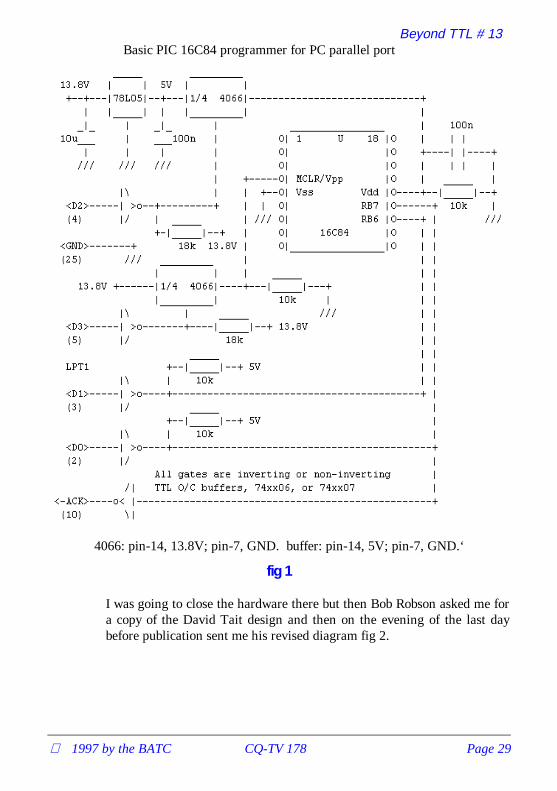
In the last issue I reproduced Derren Crome’s programmer for the PIC16C84. As an alternative in this issue, I would like to reproduce DavidTaits programmer. The design is a little more complex, but it has theadvantage of software which works with the MPASM assembler. Thesyntax for this assembler is different from the TASM assembler in the lastissue, but is more widely used. The MPASM assembler is available fromthe Microchip BBS ASM14000.ZIP and comes in two versions Windowsand non-Windows. I used the Windows version. It is front panel drivenand all you have to do is press the correct buttons with the mouse toassemble the PIC code. The assembler then generates the files required bythe programmer software.
The software to drive David Taits assembler is part of a file calledPIC84PGM.ZIP. Wen you unzip it there are five files - Readme (usefulnotes), PP.EXE (Runs the programmer) PP.BAS (some Q Basic sourcecode for the programmer) PP.C (some C source code for theprogrammer), and PP.ASC (Circuit diagram of the programmerhardware). I have reproduced the hardware diagram for the programmerin fig 1
The format is a little strange as it uses ASCII symbols to create a text filethat can be sent as e-mail and reproduced without any special graphicspackage. It does not have pin numbers for the chips so reference toappropriate data books is necessary before construction. One minor bug isthe reference to the open collector TTL buffers as 74xx06 and 74xx07.The 06 is an inverting buffer and the 07 is non inverting surely they cannot both work, the answer is they can both be made to work but thesoftware supplied assumes inverting TTL buffers. David covers this in hisfrequently asked questions file, where he states 7406, 74LS06, work fine.If you want to use non-inverting buffers then you will have to convert oneof the source code files. David also mentions that with hind sight he couldhave used the spare gate to drive an unused port bit and made thesoftware self configuring, but alas this is not a feature so stick to invertingbuffers. The final advantage to David Taits design is that it reads the codeand verifies that it has been programmed correctly.
Beyond TTL # 13
1997 by the BATC CQ-TV 178 Page 29
Basic PIC 16C84 programmer for PC parallel port
4066: pin-14, 13.8V; pin-7, GND. buffer: pin-14, 5V; pin-7, GND.‘
fig 1
I was going to close the hardware there but then Bob Robson asked me fora copy of the David Tait design and then on the evening of the last daybefore publication sent me his revised diagram fig 2.

Beyond TTL # 13
Page 30 CQ-TV 178 1997 by the BATC

Beyond TTL # 13
1997 by the BATC CQ-TV 178 Page 31
This programmer is adapted from a design by David Tate. Themodifications involve replacing the voltage switching elements. In Davidsdesign the switching was done with a 4066 analogue switch, but it was feltthat the ‘on’ resistance was too high to ensure the correct programmingvoltage. The adapted version uses 2 transistors as emitter followers. Inaddition the control program had to have a delay added to the ‘device online’ test as the response was too slow when the control PC was a ‘486 orPentium.
Referring to the circuit diagram:-
1) Power supplies.
The voltages are derived from a mains transformer. The rating is quite lowso the VA can be as low as 25. The rectified voltage is smoothed by C3,and is regulated to 13.4 Volts by IC3. The 12V regulator is ‘jacked up’ bythe two diodes in the common lead (do use an insulating pad if you mountthe regulators on a heat sink as NEITHER mounting tab is at groundpotential). The 5 Volt supply is regulated by a standard 7805 but with itscommon lead ‘jacked up’ by a diode. The purpose of this is to offset thebase/emitter drop in the switching transistor. The correct level of 5 voltsfor U1 is set by the forward current drop of D3.
2) Logic and voltage switching.
Unlike the programmer in CQTV 177 the voltage switching forprogramming is done under the control of the PC parallel port. The initialconditions are that all the data pins are at logic 1, so no voltages areapplied to the programming socket, as the two emitter follower bases areat zero volts. The first thing the control program does is to verify that theprogrammer is connected to its parallel port and switched on. It does thisby applying a 0 to data bit 0 feeding U1 pin 5. This puts a 1 onto U1 pin11 which pulls down the ACK line which the programme is monitoring.
Having decided that all is well the control program asks you a series ofquestions about the 16C84 you are using. The first is about the oscillatorcircuit on the board the PIC is to go on, then it checks the interruptrequirements and the start-up delay and code protection fuse. (I’ll go intothose questions later in this article).
Having satisfied itself about the answers you have given it (and assumingyou have inserted a device to be programmed into the socket) the programswitches on the supplies and happily begins to program the device. Shouldyou have forgotten to insert the PIC the program will soon come to agrinding halt as after it has programmed each location it checks what isthere (verify is the technical term !) and if the answer differs the program

Beyond TTL # 13
Page 32 CQ-TV 178 1997 by the BATC
halts and puts the address, required value and received value on to thescreen. Assuming all is well the programmer will take about 25 seconds toprogram the PIC. It doesn’t matter if you are only putting in 10 lines ofcode or 200 lines, the time to program is the same as it programmes alllocations, then carries out a full verification. Then it sets up the fuses forthe configuration you require.
How do you use it?I write my assembly files using a Wordstar program in a non documentarymode. The resulting ASM file is assembled using MPASM and, if theprogram has assembled correctly, I use David Taits programmingprogram. As there is, on my computer certainly, a lot of directorychanging I use a BATCH file to save time (and get it right every time!).This is one I use for the first PIC project I started.
cd\ws\picswscd\microsmpasm 16c55 \ws\picS\picproj.ASMtype \ws\pics\picproj.errcd programrpp1 -8S \ws\pics\picproj.hex
So what does it all mean? (Those of you who are familiar with theprocedure can nip off and help the wife with the dishes whilst I go throughthe process with the newcomers !)
The first line of the batch file changes to the Wordstar program directoryand the sub directory where the .ASM files are kept. The next line startsup Wordstar. (You then have to press N to edit a non documentary file,then select the file you are going to work on - in this case PICPROJ.ASM).When you have finished and exit Wordstar the batch file then changes tothe directory containing the MPASM files, then invokes the assemblerprogram. The assembler generates the HEX file for use by theprogrammer program, a LST file containing the full assembled listing andthe locations of all the variables used and, if necessary, an error file ERRcontaining all the errors found in the assembler process.
The batch file then types out any errors listed in the ERR file, and thengoes on to change directories once again for the programmer. If I have anyerrors listed on the screen by the ERR file, the programmer program hasto be aborted and the loop started again to correct the ASM file. Havinggot an error free assembled file you invoke the programming programPP1. In my batch file the line is:- PP1 -8S then the HEX file (in my case\WS\PICS\PICPROJ.HEX).

Beyond TTL # 13
1997 by the BATC CQ-TV 178 Page 33
The programmer program then checks that the interface is powered upand on line and asks you to enter the type of oscillator your PIC is going touse i.e. 0)= LP (low frequency crystal), 1)= XT - Crystal/Ceramicresonator (higher frequency), 2)= HS - 10 MHz crystal or 3)= RC -Resistor/capacitor. When you enter the required number the program asks-Enable watchdog timer (y/n) ?. The answer to this will depend on yourprogramme. The next question asked is - Enable Power-up timer (y/n) ?The answer for this is dependant on your programme requirements. Thefinal question the program asks you is - Protect code (y/n) ? During thedevelopment phase of the PIC programme answer N(o), with the finalversion you MAY want to prevent any other person obtaining yourwondrous program by reading the contents of the PIC so you would usethe Y(es) to this question.
Having answered all the questions the program tells you to insert the PICinto the programmer and to press any key. After you press the key there isno apparent action for about 20 seconds then the program informs you thatit is verifying the code in the micro, then tells you the fuse combination ithas set up in accordance with your instructions.
The moment of truth is now at hand and you can take the PIC and fit itinto your masterpiece and try out the program. What happens if it is notworking as you expect (that’s usually how my programs behave at first !).Don’t panic because help is at hand. A programme MPSIM is a simulatorprogram. Once this program is running you instruct it to load your errantfile (HEX) and then you can run it at full speed (GO) or single step (SS)through the program so that you can find where you sent it , which isusually not where you thought you had sent it !
Having found the error(s) in your program it’s back to the ASM file andround the loop once more, until the programme works as you want it.
On the BATC bulletin board in the BATC file area is a fileBATCPICS.ZIP which contains the MPASM, MPSIM and PP1 programs.Once downloaded and unzipped you will find text files associated witheach program which have the detailed instructions for operating them.Good Luck and Happy programming !!
All that remains is to get to grips with MPASM syntax and an example ofa flashing led programme that will illuminate LED’s connected to port Bas per fig 3. The display sweeps the LED’s Knight Rider fashion. Theprogramme was written by Brian Kelly and is reproduced with commentsbelow. The speed of the display sweep can be adjusted in software. (seecomments)

Beyond TTL # 13
Page 34 CQ-TV 178 1997 by the BATC

Beyond TTL # 13
1997 by the BATC CQ-TV 178 Page 35
; Demonstration of Microchip 16C84 for BATC.; Brian Kelly. 14th February 1997
; The next line tells the assembler which type of PIC is being used,; the default radix (number base) to use unless told otherwise and; how many columns to use in the program listing before wrapping text; to the next line.
list p=16C84, r=HEX, c=132
; Define the values to be associated with the register names and bit; names used later in the program. Whenever one of the names on the; left of ‘equ’ is encountered, the assembler substitutes the value; on the right. This is not essential as the values themselves could; be used but using meaningful names makes the program far easier to; read and understand. Capital letters have been used for pre-defined; registers, the remainder are used to store variables used in the; program.
RTCC equ 01 ;the real time clock/counter registerSTATUS equ 03 ;various status and control bitsPORT_B equ 06 ;port B, where the LEDs are connectedINTCON equ 0B ;bits for configuring the interruptsOPT_REG equ 01 ;processor options (in register bank 1)TRIS_B equ 06 ;port B pin direction controls (in bank 1pattern equ 0C ;the on/off pattern of the LEDSdirection equ 0D ;only bit 0 used to decide left/right
same equ 1 ;put result back where in source registerw equ 0 ;put result back in the working (W)registerC equ 0 ;bit number of the carry flag in STATUS
; The program counter (PCL), points to the next instruction to read and; is set to 000H on reset so the first instruction to be executed must; be there.; As the interrupt vector is at address 004H, not leaving much space; for code, we will start the program with a jump to an area where; there is more space.
initorg 000 ;tell assembler to start at 000
goto start ;the jump mentioned above.
; This is the interrupt routine. A jump to address 004 occurs whenever; an interrupt is generated. In this 84DEMO program, all the interrupts; are disabled except for the one caused by the RTCC overflowing; (reaching maximum count of FFH and rolling over to zero).
demoorg 004 ;move assembler to the interrupt vector
bcf INTCON,2 ;clear the interrupt bit so the chip;doesn’t immediately generate a new one;when interrupts are turned back on.
;as this point is reached at fixed time;intervals, use it to switch LEDs

Beyond TTL # 13
Page 36 CQ-TV 178 1997 by the BATC
displaymovf pattern,w ;use working register to carry patternmovwf PORT_B ;to port B
btfss direction,0 ;check which direction to shift.;skip next instruction if going right
goto left ;the left shift routine
rightbcf STATUS,C ;ensure carry=0 before shiftingrrf pattern,same ;shift the pattern one position rightbtfsc pattern,0 ;skip next inst if not fully at rightbcf direction,0 ;fully right so reverse directionretfie ;return from interrupt to main program
leftbcf STATUS,C ;ensure carry=0 before shiftingrlf pattern,same ;shift the pattern one position leftbtfsc pattern,7 ;skip next inst if not fully at leftbsf direction,0 ;fully left so reverse directionretfie ;return from interrupt to main program
; This is the part of the program entered when powered up or reset. It; initialises the processor and puts starting values in some registers.; After setting everything up it goes into a loop, waiting for; interrupts to occur.
startmovlw B’00100000’ ;select register page 1movwf STATUS
clrf TRIS_B ;set all port B pins to output mode
movlw B’10000111’movwf OPT_REG ;sets: pull-up on port B OFF
;RTCC counts internal clock;prescaler connected to RTCC;prescaler divides by 256;(other bits unimportant); change the "111" to alter sweep speed.
clrw ;clear the working registermovwf STATUS ;switch back to register page 0movwf direction ;set direction to LEFT (bit 0 = 0)
movlw B’00000001’ ;starting pattern for LEDSmovwf pattern
movlw B’10100000’movwf INTCON ;sets:global interrupts enabled
;RTIE enabled (RTCC roll over);(other bits disabled/cleared)
loopgoto loop ;wait here for interrupts.
end ;tell assembler there’s no more

1997 by the BATC CQ-TV 178 Page 37
RALLY 97Sunday April 27th
SPORTS CONNEXIONCOVENTRY
Doors open at 10.00 (09.30 for disabled)Entrance £1.00 & 50p for OAP and under 14
All the usual features of BATC rallies: over 200trading tables, Bring & Buy, large outdoor fleamarket, specialist more television displays, ex
broadcast vehicles, etc.
GB6ATV talk in on S22 and GB3CV (RB9)
Full refreshment facilities - licensed bar.
All enquiries: Mike Wooding G6IQMTel: 01788 890365 Fax: 01788 891883
email: [email protected]

ATV at GB4CDI
Page 38 CQ-TV 178 1997 by the BATC
ATV at GB4CDI
By John Stockley, G8MNY
This 4 yearly Scouting event took place at Camp Down International nearBiggin Hill in July 96. At the 1500 scout 9 day event this time as well asdemonstrations of a Crystal set, HF, VHF, UHF, Packet radio, DF huntingand aerial erection, we put on some ATV. Seven Hams ran the stationwith special inspiration for the Scouts from young Ruth G7UYR.
We had a small battery 70cm QRP Tx and camera that worked 100m or so(Ladies showers were less than that!) that was actually used todemonstrate ATV during the day when nobody was on.
The 24cm ATV system struggled to see GB3HV at High Wycombe (65km)although the path should have been ideal, but the trees in the local woodbeat our 63ft mast and a giant 65el loop Yagi. Over the days it becamequite obvious we could only see the repeater when the tops of the treeswere dry, and before the sap rose during the day.
However P5 pictures with sound were exchanged to John G3WFM inPotters Bar at 41km. The ground fell away in that direction with only afew trees. Also P5+ to Ian G4MLY’s 100watt station at 18km showed justhow good the pictures can be. These were contrasted by P2 to John G0PIAat 30km and P1 to Howard G8DXV at 18km both in Essex.
Amateur radio was only one of 33 activities laid on for the scouts, so theones that visited generally showed an interest, although this was oftenTroop (individual camp) leader driven. I have noticed with a few it wasthe ATV that excited them, being able to see who your are talking to, andthis had led them to work hard for the Communication Badge that wewere teaching at the event. This was no easy task as the badge is a fairway down the road to a NOVICE licence. Seven Scouts completed thebadge.
Please mention that you saw it in CQ-TVwhen responding to advertisers
1997 by the BATC CQ-TV 178 Page 39
VHF COMMUNICATIONSVHF COMMUNICATIONS magazine is published quarterly and isavailable from KM Publications, 5 Ware Orchard, Barby, Nr. Rugby, CV238UF, England.
Telephone: 44 (0) 1788 890365, Fax: 44 (0)1788 891883 Email: [email protected]
The 1997 subscription rate is £18.00 for cash or personal cheque (drawn on aUK bank, or bearing the name of a UK banking agent), postal orders orbankers draft made payable to VHF Communications. Payment may also bemade by any major credit card at £18.90. The subscription included surfacemail charges, airmail is extra at £6.50 per year (£6.85 by credit card). Themagazine is a MUST for the radio amateur and professional engineerinterested in VHF, UHF and Microwave working, containing, as it does,detailed construction articles for equipment operating in these bands.
Back Issues: special offer - enquire for detailsBinders to hold 12 issues ....................................£5.50Complete Index 1970 - 1995 ...............................£2.75
URL UK Site http://www.eolas.co.uk/ag/vhfcomm.htmURL USA Site http://clearlight.com/~vhfcomm

UK Repeater Update
Page 40 CQ-TV 178 1997 by the BATC
UK Repeater Update
from G3VZV dateline 28-Jan-1997
Headlines:-
• Two new 23cms ATV repeaters have the go-ahead from the RA
• New frequencies have been agreed for our 10Ghz repeaters
• Revised specifications for ATV repeaters “almost” ready!
A new application for an ATV repeater located at the BBC installation atNorth Hessary Tor was received last July from the group. The callsignapplied for is GB3WV and just before Christmas, the RA confirmed thatthey were happy for the licence to be issued. This box is going to be highup on Dartmoor and should have a considerable coverage. The contactperson is Tony Reynolds G8CEQ the group confirm that they hope to befully operational in a matter of weeks.
GB3AT near Southampton has also just been cleared and GB3KT in northeast Kent should also be approved within the next few weeks.
In June last year, the RA announced that they would be withdrawing the10,150 -10,300 from the amateur band in the UK. Unfortunately, our threeATV repeaters are located in precisely this section!
We have been in discussions with the Microwave Committee of the RSGBas the spectrum Committees are responsible for sorting out the variousband plans. As a result a new band plan has been agreed which stillretains three wideband repeater frequency pairs. The outputs are: 10040 -10065 - 10135 and the inputs 10315 - 10340 - 10425
The TG and XG groups have elected to use the 10135 output /10315 inputpair as these are the nearest to the existing pair. We hope that theirfrequency change applications will be processed before April 1st 1997when the band changes come into effect.
The BATC has been is discussion with the RSGB for over two years toagree an updated spec for FMATV in general and repeaters in particular.Many hours have been spent on this and much frustration has occurred.Finally however we now seem to be getting a set of proposed numbers thatcan be reviewed on technical basis. The most important need is to ensurethat there is no QRM from our units to the NATS rada’s which existwithin the 23cms band. The procedure for ensuring this has now beenused successfully for the ‘WV application mentioned above. A copy of this

UK Repeater Update
1997 by the BATC CQ-TV 178 Page 41
procedure is available from G3VZV and can also been downloaded on theInternet http://members.aol.com/rmgvet/rmg.htm The other majormatter is a definition of the bandwidth of the FMATV signal! Hopefullythis should be clarified shortly!
The three most recent editions of CQ-TV, and the 1997 magazines indexare available in electronic format in the Clubs web site. These can beviewed on-line with the Acrobat browser plug-in, or downloaded andviewed off-line. Please note that these files require version 3.0 or above ofthe Acrobat viewer. Note: They are not compatible with version 2.1. Both16bit and 32bit viewers are available from the Adobe web site. A suitablelink is provided from the Clubs web pages.

Page 42 CQ-TV 178 1997 by the BATC
DX-TV RECEIVER SYSTEMVariable vision IF bandwidthMulti-system sound
The D-100 ‘Super-X’ receiver provides multi-system sound reception plus reducedvision I.F. bandwidth feature to recover signals normally lost in the noise when usinga conventional I.F. bandwidth.
There are two outputs, one feeds a TV at channel 65 for vision, while another feedsan FM radio for sound. By simply matching the sound to the picture, multi-systemreception iis achieved, without the need for a special TV set.
DX-100 ‘SUPER-X’ CONVERTER............................................................£138-00
Illustrated Catalogue of Equipment & Publications only £0.75(refundable with the first order)
We can also manufacture aerials to your own design (one-off or multiples),
HS PUBLICATIONS7 Epping Close, Derby DE22 4HR, England
Tel: 01332 38 16 99
New ‘SUPER-X’ model now available, send SAE for more technical infonow.

13 cm Amateur Television
1997 by the BATC CQ-TV 178 Page 43
13 cm Amateur Television
By Ian F Bennett G6TVJ
Thirteen sems is probably one of the more obscure amateur bands in use inthe UK and is one of several that span the gap between the familiar 24cmand 3cm (10 GHz) bands. The amateur allocation starts at 2.310 GHz andextends to 2.45 GHz, this actually gives use quite a bit of room and allowsall modes of transmission including FM TV up to a maximum power of400w pep, a somewhat unlikely figure even with todays improvingmicrowave components available to amateurs. The band is moreextensively used in Europe and there are many TV repeaters using it as anoutput frequency, with 24cm as an input frequency. A couple of years agoI was fortunate enough to copy DBOTS P5 during portable operationwhile enjoying some quite astonishing lift conditions. DBOTS wasestimated to be as much as 600 km away.
Close to the amateur band and actually in it (We are secondary users)some other TV signals can sometimes be found. But wait I hear you cry,isn’t there another source of quite considerable microwave energy in thisband? The answer is of course yes, microwave ovens work on thisfrequency and even the best sealed units still radiate a sniff of power.Ovens can be a problem but as long as this spot ISM (industrial scientificand medical) frequency of 2.45 GHz is avoided things are not too bad,they do actually provide useful rough frequency markers and prove thesensitivity of one’s own equipment.
So why use the band at all when we have several other allocations for TV?I have personally found this band quite interesting as it exists adjacent toother professional frequency allocations. I have also acquired an LNBdevice which simplifies receiving these frequencies so I naturally decidedto develop a transmitter to work with it. It is also, in the light of changingamateur allocations, advisable to both use other allocations and developexpertise in them, in case we were to loose part or all of a band e.g.10GHz.
How to get onto the 13cm BandFirst thing we need is a receiver which tunes about 2.3 to 2.5 GHz. Thismay seem quite a tall order, but luckily by a quirk of fate a satellite bandactually exists near by. In addition to the familiar “KU” and “C” bands aband called "S" band has been used for satellite TV which covers 2.5 to2.7 GHz. The band is sometimes known as the “Arabsat” band, it is usedabroad as you might expect in the far east, but LNBs for this band can be

13 cm Amateur Television
Page 44 CQ-TV 178 1997 by the BATC
obtained in the UK if you look hard enough. We have been fortunate inobtaining several of these units, one belongs to the Severnside group andseveral other members have them including myself.
S band LNBs operate in a similar way to other types, they employ aconsiderable amount of low noise amplification to bring up the signal leveland then down convert its frequency using a high side local oscillatorrunning at 3.650 GHz. We have come across two types one made byCalifornia Amplifier and the other by Chaparral. They both exhibit verylow noise figures as good as any preamplifier and due to the high sidelocal oscillator will actually cover an input range from 2.7 GHz down to 2GHz and hence fully cover the 13cm amateur band. Nigel G7JZP has verykindly carried out a number of tests on these LNBs and found them both toperform quite well. The filleting inside the units is very wide so the gaindoes not drop of quickly outside their rated frequency range. Unlike otherLNBs the RF input is via a male “N” type allowing the connection ofcoaxial cable. The output connection is a standard “F” type connector andthe LNBs are powered up the coax from the receiver in the normal way.
There are other possibilities for receivers and down converters. CQTV no62 November 1992 carried an article for a simple down converter usingmmics (monolithic microwave integrated circuits). VHF communicationssometimes publishes articles on this band and there is also a Germanmagazine DUBUS which also has articles written in English. MainlineElectronics advertises a low noise preamp and a narrow band transverterfor 13cm. A transverter could be used as a TV transmitter.
AntennasJVL can supply loop yagis for this band and the designs for which havebeen published in various amateur publications. Tonna also supply anantenna centred on 2.330 GHz. It is a slightly odd beast, - basically astandard type Yagi with many director elements but the feed pointemploys an unusual waveguide type launcher with a probe inside. This isthe antenna I use and is available through Lowe Electronics for about £70.2.3 GHz is a frequency where dish type antennas start to become viable. Itought to be possible to construct a type of small dipole launcher and use itwith a largish dish say 1m in diameter. Unfortunately most coaxial cablesare starting to become quite lossy at these frequencies so lengths must bekept to a minimum. The LNBs have the advantage that they can be usedup at mast height and connected literally onto the antenna itself.Transmitters are best kept close to the antenna, I use a remotely keyedtransmitter in my loft space close to the antenna.

13 cm Amateur Television
1997 by the BATC CQ-TV 178 Page 45
Transmitters on this band can be a bit challenging technically particularlyas obtaining any significant level of power on this band seems to getexpensive quite quickly. I have seen designs published, and it may bepossible to get kits from abroad but I haven’t seen anything in thiscountry. CQTV no 160 again carries a design for a simple 13cm exciter. Ihave taken this design and added a synthesiser to it - this will be describedin more detail later. As mentioned earlier, tranverters are available fornarrow band operation. If it were possible to generate an FMTV IF on 144MHz then these devices could be used to form an upconverting transmittersimilar to the G6TVJ superhetrodyne 23cms transmitter published in P5 acouple of years ago.
ResultsThe results so far on this band have been quite good, certainly thereception of DBOTS from Germany is a personal best and quite aspectacular achievement if not helped by the location of Win Green nearShaftesbury which was about 900ft above sea level. Other terrestrialmicrowave signals from abroad were also copied up to P5, probably localcable feeds in some mountainous region somewhere. On a somewhat morelocal basis I have established a link to GlHIA’s QTH , both ways using thesynthesised exciter and a power amplifier providing a ‘hefty’ 900mW.Pictures were P5 in both directions, with some occasional interference,allowing duplex operation with GB3ZZ in the other direction. Some testswere also done from Tog Hill about 8 miles away with only the exciter and10mW, this still yielded a P5 picture when using the Tonna antennasdemonstrating the high sensitivity of the "S" band LNBs.
The autumn ATV contest proved to be quite successful on this band.G1HIA worked the contest station G7ATV/P both ways on 13 from homeand I established a one way contact P5 from Walbury Hill some 50 milesaway. This was good as the Severnside group was probably the only groupto operate a contest station on four TV bands.
The LNBs we have used do have one or two quirks. They seem to sufferbreakthrough from broadcast TV stations operating at UHF and also at theoutput IF frequency range. My 13cm Yagi points towards G1HIAs QTHonly a few degrees off GB3ZZ. ZZ breaks through P5 almost exactly werethe wanted IF exists, so some patterning is sometimes experienced . TheLNBs appear to ‘take off’ sometimes if not fed from a matched antennaand they also being designed for weak satellite signals easily can overload.One other point to note - due to the high side LO in the LNB when tuningup on the sat receiver you are actually tuning down the 2.5 GHz band.

13 cm Amateur Television
Page 46 CQ-TV 178 1997 by the BATC
A Synthesised Exciter for 13cmsThis is basically a development of the design found in CQTV No.160under the title 13cm the easy way. Well I don’t know about easy but theunit does work reasonably well. I have added a SP5070 Plessey synthesiserto the exciter to maintain the frequency and hopefully make findingsignals in this band simpler. I do like synthesised transmitters as theyremove one of many variables encountered when attempting to establishATV links for the first time. Antenna headings, receiver tuning andpossible obstacles in the path are quite enough without some doubt aboutthe exact TX frequency as well!
How it worksA voltage controlled oscillator operating at the transmitter outputfrequency is formed using a self oscillating mixer device, an AvantekMSF8685. The frequency of oscillation is determined by a trimmersoldered directly across the device which forms a tank circuit, theinductance of which is formed by the parasitic inductance of the trimmeritself. The frequency of oscillation is also determined by the power supplyvoltage to the device, which allows the oscillator to be modulated andtuned.
The output of the VCO is buffered and amplified by a standard MSA0485mmic device and then by a second mmic type MSA0585. These devicesare starting to struggle a bit at 2.3 GHz but this arrangement producesabout 10mW enough for a line of sight contact over a few miles.
Some RF energy is tapped off after the first amplifier and is fed to aSP5070 fixed modulus synthesiser chip. The SP5070 is basically a newerversion of the venerable old SP5060 found in many 23cm designs. The5070 is rated to 2.4 GHz so should be fine for the 13cm band. I didoriginally build the TX as an experiment to see if the device would workOK, which it did. The device is actually a standard DIL package (Asurface mount one is available) and I mounted it on standard fibreglassboard which is perhaps pushing one’s luck a bit at 2.3 GHz as mostcommercial designs would certainly be using PTFE board and surfacemount techniques at these frequencies. The TX frequency is produced at256 times a crystal reference frequency which the chip uses. I chose 2.330GHz which is OK for the antennas and is the official TV simplexfrequency (I think), which gives a crystal frequency of 9.101562 MHz.The crystal is a standard parallel resonant unit with a 30pf shunt capacity.Crystals can be ordered from various outlets without much bother.

13 cm Amateur Television
1997 by the BATC CQ-TV 178 Page 47

13 cm Amateur Television
Page 48 CQ-TV 178 1997 by the BATC
The SP5070 uses a simple op filter arrangement but care must be takenwith the values so that low frequency distortions do not result in the videosignal. The values I used work OK but are not ideal, but good solid P5pictures are possible with these values. Unfortunately the VCO exhibitsthe wrong frequency voltage characteristic, an increase in volts results in adrop in frequency. This is opposite to the output of the SP5070 so an op-amp inverter is used and the system should then lock up. There is howeveranother problem. When the TX is switched on the synthesiser initially seesno RF which causes the VCO volts to rise. As they are inverted the realVCO volts drop. The VCO volts are in fact its power supply so the devicedoes not oscillate perpetuating the problem. Not much good for thereceiving station sitting there patiently tuning up and down the bandlooking for you. The solution is to use a start up circuit. At switch on acapacitor charges up via the base of a transistor, which clamps the VCOvolts long enough to supply the VCO with power to start up. The capacitoreventually charges up and the VCO volts are allowed to float up and downand hence the synthesiser comes into lock.
Video modulation is applied to the VCO using the non inverting input ofthe op-amp. This results in the correct modulation sense for use with thehigh side local oscillators in the receive LNBs. This I believe is actuallynegative modulation - if positive mod is required another video invertercan be used. A standard pre-emphasis network is used at the video input tothe transmitter. The modulation sensitivity is quite good up to 6 or 7MHz/V being possible.
Sound can be added by using a subcarrier of an appropriate frequency. Iused a sound modulator down in the shack remote from the rest of thetransmitter by simply inserting the subcarrier onto the video near thecamera. I have found 200mV of subcarrier sufficient for quietening soundwith a reasonable video sig/noise. I have done quite a bit of work on tryingto perfect a synthesised sound modulator similar to the one in the G6TVJsuperhet TX, with varying results. Getting the correct audio pre-emphasisand hence a flat frequency response back out of a sat rx, is quite tricky.
ConstructionThe SHF construction is quite tricky and a PCB layout is shown. Doublesided board is used and one side is etched. Holes are drilled for the mmicsin order to sit them down neatly onto the board and keep their lead lengthsas short as possible. The pins on the SP5070 are cropped off and thedevice sat flush onto the board and the remains of the connectionssoldered down. Only the microwave components are critical the rest of thecomponents including the op-amps can be mounted as convenient. Theoutput connection can be an “N” type or SMA as long as sufficient

13 cm Amateur Television
1997 by the BATC CQ-TV 178 Page 49
grounding is employed to both sides of the PCB. The PCB must be housedin a metal box. I used an eddy box with a copper plate at the outputconnector as the board will not solder directly to the aluminium box.
There should be only one major adjustment to make and that is to set upthe VCO range. By monitoring the test point, the volts should rise up anddown as the trimmer is adjusted, care being needed as the trim tool affectsthe frequency. The VCO should be adjusted for about 10 volts. Whencorrectly operating the volts should be seen to vary as objects e.g. fingersare brought close to the VCO. Changing loads on the TX output will also"pull" the VCO a bit. A receiver can be used to further confirmsatisfactory operation - when using an “S” band LNB with an LO of3.650GHz it should produce an IF of 1.320GHz.
ResultsAs mentioned earlier the exciter alone managed about 8 miles inconjunction with the Tonna antennas. The arrangement with the VCO isnot very elegant but it does seem to start up and lock up reliably. I did trytuning the oscillator using a varactor diode but it seemed to drift a lot. Ihave seen a design for a transmitter VCO using BFR90/91/96 typetransistors but 2.3 GHz is only about an octave away from the transistors

13 cm Amateur Television
Page 50 CQ-TV 178 1997 by the BATC
fT of 5 GHz so problems might be experienced. The fT is the frequency atwhich a particular transistors frequency response has dropped so far thatthe device has only unity gain. Mimic devices intended for thesefrequencies are actually fabricated from transistors with fT of 25 GHz! Ihope soon to try out a MK2 exciter using a commercial VCO unit covering2.2 to 2.6 GHz. This exciter will also be synthesised using a better deviceand a prescaler chip.
BurnerI have builta poweramplifierfor 13cmsusing aspecialmicrowaveIC whichproducesabout900mW.The ICrequiresonly 5mWof drive soit workswell with aslightlypaddeddownoutputfrom theexciter.The ICcosts about£40 whichisn’t bad atthese frequencies. Plans for this PA will appear in a future P5 and perhapsCQ-TV as well.

Channel 5 Ghost Story
1997 by the BATC CQ-TV 178 Page 51
Channel 5 Ghost Story
By G8MNY
After seeing some of the recent test of CH5’s CROYDON TX at BeulahHill on channel 37, I investigated the weak signal and it’s ghost at mySouth Croydon QTH. The TX is scheduled as 250KW ERP some 6dBdown on the 4 services from the Crystal Palace Mast.
MeasurementsMy comparative signal strength measurements were done with a simplefairly flat response loop aerial as the normal group A aerial for this areawill have cut off by channel 37, a UHF signal meter, and stack ofattenuators. This showed the CH5 signal to be at least 26dB weaker thanthe others, and not the 6dB as published. This was later confirmed withmy home brew spectrum analyser. From CH5 contacts via Packet Radio allCH5 TX were supposed to be on full power!
GhostThe signal also had a severe but well defined ghost that defied myattempts to remove it. It was just over one of the five 10µS wide colourbars later, I guessed this delay to be about 12µS. This gives a reflectedpath of 12x300m = 3.6kM longer. I did a map plot traced on a large pieceof paper with my QTH and the Croydon TX site. Hammered in 2 nailsplaced at these focus points, then I was able to draw a ghost ellipse using apiece of string around these 2 nails but some 3.6kM to scale longer, byplacing a pencil inside the string and keeping it tight and drew the ellipse.This went right through the Crystal Palace mast, so I now knew that thiswas the cause. But why was it so strong? Beulah Hill mast does notproduce any detectable ghost on the other 4 Crystal Palace signals.
Rally AnswerAfter speaking to a broadcast engineer at Sandown Rally I had the answer.The French had objected to a main station on ch 37 as this would caseinterference to there existing TV service. So the Croydon TX aerials hadbeen designed to be 20dB down to the south eg. 1/100 of 250KW =2.5KW ERP.
This was the cause of the weak signal, and as the full power signal can hitthe Crystal Palace mast and reflect this is added to the weaker southsignal, making the ghost some 20dB stronger. This ghost move around in

Channel 5 Ghost Story
Page 52 CQ-TV 178 1997 by the BATC
and out of phase (positive & negative) as the 2 masts move relative to eachother in windy weather. The for most viewers the ghost can’t be removedwith different aerials as the masts are too close (2 deg apart my QTH).
DigitalThe TeletextP100 had a listof the CH5transmitterchannels, (alsoon page 1FF?)& P198 had astatus of theTeletextencoder,showing errorsetc. on some ofthe channels.No other pageswere found onthe testbroadcasts.This channelis supposed tobe the firstusing fullydigital TVlinks. Howeverunder therecent bad Wxthere waspicture break-up of theColour Barswith wronglittle squares(corruption onMPEG3 ?).
Also while checking UHF band with a spectrum analyser, I noticed 2Broadband square shaped signals on ch 28 & 34. These were both 50dBdown on the main CP signals, and may be DIGITAL TV testtransmissions!

How to get the Rally
1997 by the BATC CQ-TV 178 Page 53
How to get the Rally
The Sports Connexion lies approximately 3 miles south of Coventry citycentre and is at the junction of the A445 and the A423. It is within easyreach of the M1, M6, M40, M42 and M45. The major road links to andfrom Coventry and bypasses around the city make the location very easy toget to.
For those who wish overnight accommodation in the area the nearesthotel/motel is the Coventry Knight Hotel (01203 301585) which isapproximately 2 miles from the venue and is located at the junction of theA45 and the A445.
For those who wish to camp or caravan, as usual the site at the Bull andButcher (01203 301400) on the A445 1 mile south of the venue is ideal.The pub does excellent meals too - maybe I shall see you there on Saturdaynight? - min’s a pint of Kilkenny’s.
Coventry Amateur Radio Society will be providing the talk-in stationagain on S22 and GB3CV (RB9) using the special callsign GB6ATV.Many thanks to the GB3CV repeater group for allowing us to use therepeater again for this purpose.
There will be a specialist area available in the Banbury Room (adjacentthe bar) for anyone wishing to display ATV equipment. If you wish to dothis please contact me as shown below to book a table, these are free ofcharge and only available to members, trading from them will not bepermitted. Other specialist groups may also have displays in this area.
Finally, as ever, the usual plea for help. I have to admit that to some extentit actually worked last year! I shall be on site on Saturday from around1500 setting up the hall and from 0630 on Sunday morning. if you canspare an hour or two on either day please come and help. If you can helpon Saturday please phone me during the previous week or on my mobileon the Saturday, to confirm the time we can have access to the hall.Thanks in advance!
OK that’s it. I hope to see you ALL there. Please come and make yourselfknown to me and the rest of the Committee.
73 ... Mike
Tel: 01788 890365; Fax: 01788 891883; Mobile: 0468 925351;Email: [email protected]

How to get the Rally
Page 54 CQ-TV 178 1997 by the BATC

1997 by the BATC CQ-TV 178 Page 55

Pair start Amateur Television Channel.
Page 56 CQ-TV 178 1997 by the BATC
Pair start Amateur Television Channel.
By Geoff Lewis
Two Hamilton men have started their own TV channel. Bill Crawfordand Jerry Lewis are behind the fledgling Waikato Amateur Television thatuses a UHF frequency on channel 39. They have been sending homevideos, in colour, to each other from their homes on Sunday afternoons.
Now they have bigger plans. “At the moment we transmit things likefamily videos. Anyone with a Sky TV aerial can pick up ourtransmissions. However most won't as all the aerials are aimed at the Skyrepeater located to the east of Hamilton.
We are looking for a site for our repeater in the same area, which shouldallow many more to enjoy amateur television.” Mr Crawford says.
The channel has a huge future and there are plans to approach schools toexplain how it works.
The UHF system is also use by Waikato University's Static TV. At themoment, Mr Crawford and Mr Lewis, both members of the HamiltonAmateur Radio Club, use a line-of-sight transmission system with arepeater at the radio clubrooms in Seddon Rd.
And they use equipment that costs just a few hundred dollars.
Mr Crawford says compact modern electronics and falling equipmentcosts now makes high quality colour television transmissions readilyavailable.
Mr Crawford, now retired, spent much of his working life in the electricalindustry and as a trainee radio technician saw the first televisiontransmission in New Zealand between two Wellington hotels in the early1960s.
The Commerce Ministry monitors amateur television and the pair had toget an operator licence.
Interested people can call Mr Lewis on phone 847-5338.

Circuit Notebook No. 60
1997 by the BATC CQ-TV 178 Page 57
Circuit Notebook No. 60
By John Lawrence GW3JGA
Stepped Frequency Burst Generator for Television TestingThis design uses the recently publicised Maxim MAX038 High FrequencyWaveform Generator I.C. This device will generate square, triangle andsine-waves from low frequencies up to 20 MHz.
A useful test signal for testing video and television systems is a steppedfrequency sine wave burst signal which is repeated at line rate andincludes a line sync pulse to satisfy the requirements of the video circuitsunder test.
The circuit shown generates sine wave bursts of 1, 2, 3, 4, 5 and 6 MHzeach having a duration of 4us with 4us spacing, which is repeated on eachline. The peak to peak amplitude of each sine-wave burst is equal andextends from black level to peak white. The space between each burst is amid grey. The line sync pulse is 4us, a little shorter than the specifiedvalue of 4.7us.
Circuit OperationThe output from the 1 MHz packaged oscillator is divided down by the4520, a dual 4-bit binary divider, to provide the address and timing signalsto generate the TV line waveform. The 4051 analogue multiplexer isconnected to a potentiometer chain, fed from a reference voltage, toprovide a precise six step voltage staircase at its output.
This is fed, as a current, to the frequency control input of the MAX038 togenerate a sequence of six frequencies from 1 to 6 MHz. The 4067analogue demultiplexer provides sequential `logic 1’ outputs to controleach section of the 4066 analogue switch. This switches the appropriateD.C. levels from the potentiometer chain, on the right, and the sine wavesignals from the MAX038, to form the composite video waveform, asshown in Fig.2. The resultant signal is taken to the EL2020 videoamplifier to provide a 1v p-p video signal across a 75R terminated line.
The sine wave frequency output from the MAX038 has constantamplitude, but due to circuit layout and stray capacitances somecompensation is required between the output pin19 and the rest of thecircuit. In the prototype a 150 pF capacitor (selected on test) across the270 R resistor provides a flat frequency response giving equal sine waveamplitudes at all the output frequencies.

Circuit Notebook No. 60
Page 58 CQ-TV 178 1997 by the BATC
In use the test signal is applied to the 75 R input of the circuit orequipment under test and the output signal is viewed on an oscilloscopehaving an adequate bandwidth, say 15 MHz. The time base should be setto 10us/div. and synchronised by the line sync pulse. The resultant displayshows the response of the equipment at the various frequencies and makestesting and adjustment quick and easy.
Reference: MAXIM data sheet for MAX038. Maxim Integrated Products(UK) Ltd., 21C Horseshoe Park, Pangbourne, Reading, RG8 7JW. 0118-984 5255.
Fig. 2. Line Waveform Generation

Circuit Notebook No. 60
1997 by the BATC CQ-TV 178 Page 59
Fig. 1. Stepped Frequenct Burst Generator for Television Testing.
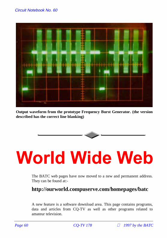
Circuit Notebook No. 60
Page 60 CQ-TV 178 1997 by the BATC
The BATC web pages have now moved to a new and permanent address.They can be found at:-
http://ourworld.compuserve.com/homepages/batc
A new feature is a software download area. This page contains programs,data and articles from CQ-TV as well as other programs related toamateur television.
Output waveform from the prototype Frequency Burst Generator. (the versiondescribed has the correct line blanking)

TV on the Air
1997 by the BATC CQ-TV 178 Page 61
TV on the Air
By Graham Hankins G8EMX.
Big news for UKAmateurTelevision is thattwo new 1.3GHzATV repeatershave been grantedapproval to go intoservice.
GB3WV is at aBBC transmittersite on Dartmoorand in an excitedphone call TonyReynolds G8CEQtold me: “GB3WVwas approved tostart service at the end of January and brings improved 24cm ATVfacilities into North Devon and Torbay. We have provided the repeaterwith three directional trough-reflector antennas which will be at a heightof 30m”.
Other regulars on 24cm ATV in the South West are Ken G4MPQ, DonGORQL, Mike G4XIX and Trevor G3ZYY.
Further east along the south coast (confused? You will be!) the SolentClub based in Southampton have at last received their licence for GB3ATand are looking to switch on at the end of February. Solent meet on thefirst and third Tuesdays of each month in the British Legion Club, ParkGate, Southampton from 7.3Opm.
All of which still leaves the poor old Kent Repeater Group waitingapproval for GB3KT. I gather that the Group recently held one of itsoccasional ‘At Home’ days, when stations take along their latest projectsto show off. There were test waveform generators, 10GHz systems, videomixers and of course the complete GB3KT project still waiting to belicensed. It seems that these meetings are the only way for most of thelocal ATVers to show off their ideas without a repeater.

TV on the Air
Page 62 CQ-TV 178 1997 by the BATC
All of the UK ATV Groups have been invited to provide displays at theBritish Amateur Television Club’s annual rally at the Sports Connexion atRyton, near Coventry on Sunday April 27.
Cookham RegattaATV doesn’t always need repeaters. Mike Sanders G8LES and JohnStockley G8MNY established a simplex video link on 1.3GHz for theCookham Regatta along a stretch of the River Thames. Amateur TV wasneeded because a tree-lined bank kept the commentator ‘blind’ for the first100m, but thanks to the video links he had something to describe over thepublic address system!
John describes what was involved: “We set up colour monitors and 24cmreceivers on the announcer's table. Two flatplate receive antennas werefixed fairly high, so that the transmitters could be anywhere up river. Mikeused a large Hi-band Super-VHS camcorder feeding a 1W transmitter andlong yagi, positioned where there was a gap in the trees so that he couldsee the start boat; I went further down the course with cheaper ccdcameras but still with only 1W of power”.
Needless to say over such a short path pictures were a clean, high qualityP5. Next time, perhaps, the Boat Race itself?
70cms reports?Anxious for some report of activity on 70cm, I packeted to Martin G7RTQin Warley, near Birmingham, who I knew had built a G4DYP 430MHzATV transmitter. Sure enough, Martin duly responded: “Hi Graham, Ihave added a few mods. to the G4DYP transmitter, but there does notseem to be anyone using the 70 cms band locally, unless I look at thewrong times!” (Sunday mornings from 11am and Tuesday evenings, Ialways thought? GJH.)
Right - what's new at this end; Ade G6KSN and I have set up a 3cms linkwhich is working very well, I am active every day between the hours of1800 - 0000 but even longer most times. 1’m operating on 10.470GHzwith two audio subcarriers, one on 7.02MHz and the other on 7.20MHz
We are also experimenting with a Hi Speed data link on another sub-carrier, 6.00MHz TX 6.5MHz RX, making the link full duplex. This isbeing run at 19200 Baud - we try to take it higher but then encountererrors. We have a distance of about 7km between each other and I'm usinga D.R.O. for transmit (a converted LNB), with an output around 1mW.The DRO feeds a 65mm dish with a gain of around 35dB giving an e.r.p.of around 4W”.

TV on the Air
1997 by the BATC CQ-TV 178 Page 63
Well, there must be many users of 70cm around; it would be great to beable to publish where they are and times of ’nets’. If you don’t want to takethe time and effort to write, just call my ansafone on 0121-707 4337; tellme whereabouts the ’net’ or regular activity operates, likely times and, ifyou can, usual callsigns.
Dutch NewsNow to the Netherlands where a 10GHz ATV repeater is being built, saysBernard PA3FZV: “Hello Graham. Hans PA3ETK and his ATV group areconstructing a fully featured 3cm repeater right now. At the end of Marcha 3cm beacon will be operational beaming north with an angle of 200degrees. Operation will be 24 hour using the callsign PA6ATV. A fewmonths later we hope to make the repeater fully operational”.
Any reception report of the beacon will be appreciated, either via the QSLbureau or packet to PA3FZV @ PI8WNO.#UTR.NLD.EU
Hans and his gang are well experienced with ATV, having previously putout 1.3GHz and 10GHz pictures from the 375m ‘Gerbrandy’ TV tower atIjaselstein near Utrecht. Even working in freezing windswept conditions
John Badger, G4YZO, of Badger Boards fame, receives the Leicester ATVrepeater at P4 at Barr Beacon, Birmingham.

TV on the Air
Page 64 CQ-TV 178 1997 by the BATC
the team achieved 20W on 24cm and an amazing e.r.p. of 800W at10GHz!
Down UnderMy stalwart scribe from Kiwi country, Michael Sheffield ZL1ABS, reportssome local problems: “The ZL1BQ repeater went low power during thestormy weather and power blackouts at the end of November". Wasn't itsupposed to be summer over there? The problem was tracked to a loss ofd.c. to the final amplifier due to a faulty fuse holder in the power supply.Opportunity was taken to fit the Mk.22 EPROM to give new pages on theTeletext video generator”.
Repeater Affiliation UpdateEarly in January all known repeater groups with ATV interests wereinvited to affiliate to the BATC. By the end of February, just under half ofthe current list had responded, and I am pleased to welcome theCambridge Repeater Group, who had held back from affiliation because of‘constitution’ concerns. My covering letter this year made clear thataffiliation ‘rules’ are very flexible, so Cambridge can now be added to thelist.
This time all Groups were canvassed for 10GHz linking. Willing to trialare 'DH, 'UD, 'HV (but a long haul to 'KT, comments John StockleyG8MNY!), 'RT, 'XT (plans already under way to 'DH) and 'VR. Goodfeedback, I think.
I normally end this with a “keep sending your ATV exploits and news tome” yet, letters by post are very infrequent. I've probably received only acouple, maybe three, since taking over TVOA. Most info comes fromtelephone calls or via the packet network. There is usually something inthe ‘ATV’ category on my local BBS. Yours too, probably. So now youknow!
Very late news: Silent Key in the Midlands, Geoffrey Hill G3DFL ofBearwood passed away from cancer in February. Geoff was very active onthe local ATV ‘net’ and will be missed on air by his many friends on 70and 24.
Graham Hankins G8EMX,11, Cottesbrook RoadAcocks Green, Birmingham, B27 6LE0121-707 4337or via packet to G8EMX @ GB7SOL.#29.GBR EU2
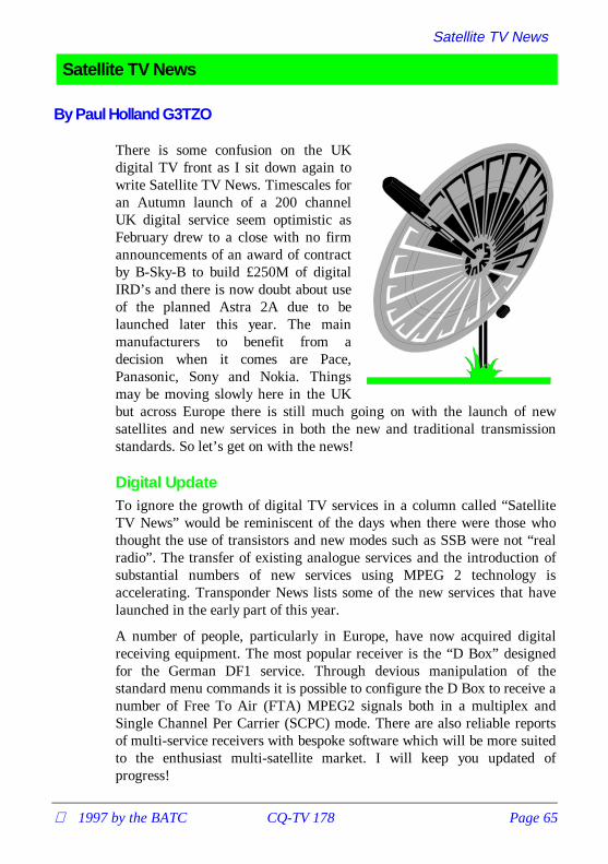
Satellite TV News
1997 by the BATC CQ-TV 178 Page 65
Satellite TV News
By Paul Holland G3TZO
There is some confusion on the UKdigital TV front as I sit down again towrite Satellite TV News. Timescales foran Autumn launch of a 200 channelUK digital service seem optimistic asFebruary drew to a close with no firmannouncements of an award of contractby B-Sky-B to build £250M of digitalIRD’s and there is now doubt about useof the planned Astra 2A due to belaunched later this year. The mainmanufacturers to benefit from adecision when it comes are Pace,Panasonic, Sony and Nokia. Thingsmay be moving slowly here in the UKbut across Europe there is still much going on with the launch of newsatellites and new services in both the new and traditional transmissionstandards. So let’s get on with the news!
Digital UpdateTo ignore the growth of digital TV services in a column called “SatelliteTV News” would be reminiscent of the days when there were those whothought the use of transistors and new modes such as SSB were not “realradio”. The transfer of existing analogue services and the introduction ofsubstantial numbers of new services using MPEG 2 technology isaccelerating. Transponder News lists some of the new services that havelaunched in the early part of this year.
A number of people, particularly in Europe, have now acquired digitalreceiving equipment. The most popular receiver is the “D Box” designedfor the German DF1 service. Through devious manipulation of thestandard menu commands it is possible to configure the D Box to receive anumber of Free To Air (FTA) MPEG2 signals both in a multiplex andSingle Channel Per Carrier (SCPC) mode. There are also reliable reportsof multi-service receivers with bespoke software which will be more suitedto the enthusiast multi-satellite market. I will keep you updated ofprogress!

Satellite TV News
Page 66 CQ-TV 178 1997 by the BATC
News that will surprise many is that BSkyB may be launching its digitalservice on the recently launched Astra 1F satellite, using 14 of thatsatellite’s 28 transponders instead of using Astra 2A which is planned forlaunch toward the end of this year. Astra 1F shares the 19 degrees Eastorbital position with the earlier 5 Astra satellites, where BSkyB’s existinganalogue channels are found. Astra 2A is due to be positioned 28 degreesEast. We will have to wait and see !
New ChannelsRadio Nordzee - Radio Noordzee Nationaal (RNN) plans to set up its owntelevision station under the name TV Noordzee. The station will be on airfor a couple of hours initially, with plans to expand later on. TV Noordzeeis hoping to share capacity with another broadcaster.
Animal Planet - Animal Planet, a new channel from the BBC andDiscovery, is close to launching in Europe. Initially a cable only service itwill move to satellite later this year and may launch as early as March orApril. The channel is already on the air in the United States (now onSatcom C4 on 4.000 GHz), with wildlife documentaries and drama shows.
Phoenix - German broadcaster ARD has announced that its special eventand documentary channel Phoenix will be launched on April 1. Initially itwill be distributed via DFS Kopernikus at 23.5 Deg E with a launch inanalogue on Hotbird 2 possible at some later date.
Polsat 2 - A sister channel for Polsat 1, cleverly called Polsat 2, was due tolaunch on 1st March for satellite and cable distribution. No transponderdetails are available at the time of writing.
Transponder NewsIntelsat 602 62.9 Deg E
From February, the Italian private TV channels Canale 5, Italia 1 and Rete4 ceased analogue broadcasting from here in favour of an MPEG2 servicevia Hot Bird 2. Parallel analogue transmissions on Intelsat 602 continueduntil February 19th. The digital service on Hot Bird 2 is aimed primarilyas a feed for terrestrial transmitters and regional TV centres and is notintended for DTH reception. All three channels can be found on 11.919GHz (V).
DFS-2 Kopernikus 28.5 Deg E
Test transmissions for the new Czech digital-package started on 8thJanuary. Prima TV, Cable + and 2 other domestic networks launched in

Satellite TV News
1997 by the BATC CQ-TV 178 Page 67
MPEG2 at 11.475 GHz (H) (SR 30000, FEC 3/4). The current analogueservice for both channels should have ceased by now.
Eutelsat 1 F5 21.5 Deg E (inclined orbit)
Its still worth checking here for the occasional news feed on 11.476 GHz(H).
Astra’s 1A, 1B, 1C, 1D, 1E, 1F 19.2 Deg E
There are now 185 digital TV channels across the Astra satellites formingpart of the various packages including the German DF1, Multichoice,Canal Satellite and Canal Espana. Canal Satellite has added morechannels to its service on ASTRA 1 E at Tp 78 11.973 GHz (V). TheMPEG 2 service is currently in the clear (SR 27500, FEC 3/4). Thechannels are; Canal +, Canal + Azul, Canal + Vende, Mosaico,Sportmania, Guia TV, Radios (5 radio-channels), Multimusica.
FilmNet 1 finally confirmed the end of its analogue service on Tp 1111.362 GHz (H) from 31 March. The rumoured successor here is Channel5 which was due to launch in April. FilmNet 1 is now only available viaTHOR, 0.8 degrees West.
MTV Networks Europe has announced plans to launch two new servicesin the UK. The first of the two networks, "MTV In The UK", will replacethe north European version of MTV Europe currently on Tp 15 and isexpected to begin operation during the summer. The second channel, "M2Music Television", will broadcast from the US and run commercial free onpan-European distribution. The “MTV In The UK” service is expected tobe in BSkyB’s multi channels package while M2 will be offered inBSkyB’s planned digital service.
Eutelsat II F3 16.0 Deg E
Duna TV may move to the Hotbird 3 satellite (13E) from its presenttransponder on Eutelsat II F3 and may be joined by the Hungarian TV2service when Hotbird 3 launches later this year. Both Duna TV and TV2are planned to be in unencrypted PAL.
TV Algeria has moved from transponder 11.678 GHz (H) to 11.095 GHz(V) (ex ART). ART Europe it’s now at 11.555 GHz (H) on a 24 hoursbasis.
Euro 7’s analogue service on 11.080 GHz (H) between 10.00 to 14.00 is toclose in favour of an extended service between 7.00 to 17.00 CET inMPEG 2. There is no information yet on transponder details.
Eutelsat’s II F1 & II F6 (Hot Bird 1) 13.0 Deg E

Satellite TV News
Page 68 CQ-TV 178 1997 by the BATC
The Greek Nethold/Multichoice package has started in MPEG-2 on11.823 GHz. The Arabesque package is testing on 12.015 GHz in MPEG-2. The AB Sat promo on 11.766 GHz has changed from super to widebeam.
Italy’s RAI 1, 2, and 3 are in clear MPEG-2 on Hot Bird 2 on 11.804GHz. The Vatican’s Tele Pace is also included in this package, and is now24 hours.
ART will start soon a digital-package as a part of Television par satelliteTPS France.
MCM Euromusique closed its analogue service 11.289 GHz (H) in favourof an MPEG2 encrypted service using the Viaccess system from the CanalSatellite package on ASTRA. The parameters will be SR 27500, FEC 3/4.
Eutelsat II F4 7.0 Deg E
The Italian hard core TV channel Satisfaction Club Television (SCT) mayjoin Telepiu’s digital package DSTV in favour of its current analoguefeed. Talks are currently underway between the two companies and ifsuccessful SCT would be the first adult channel offered to DSTVsubscribers. SCT is currently uplinked from Paris to Eutelsat IIF2 Tp 2111.163 GHz (V) in PAL and uses Ping Pong encryption.
Tele X 5.0 Deg E
TELE-X will soon enter an inclined orbit. Although this will have noaffect on receive sites in Scandinavia with small antennas it could affectlarger antennas with narrower beamwidth here in the UK. This controlleddrift will not exceed more then 0.8° p.a.. The end of the planned life isprogrammed for September 1997. Tele X will then be placed in thesatellite “junk-yard” which is 330km higher in orbit. The replacement forTele X is SIRIUS-2 (see launch news above).
Intelsat 702 1.0 Deg W, Thor 1 0.8 Deg W
Scandinavian Broadcast System (SBS) has announced that its newcommercial Danish TV channel, to be launched in March, will bebroadcast via the Thor 2A satellite. The new channel will be distributed inD2 Mac.
The Dutch music channel TMF, The Music Factory, is to start a Nordicversion from the 1.0 Deg W position but is likely to form part of a digitalpackage with no analogue feed.
Telecom 2B,2D 5.0 Deg W

Satellite TV News
1997 by the BATC CQ-TV 178 Page 69
France Telecom has finally broken its tradition with Telecom 2D in that itoperates in the FSS band rather than the usual Telecom Band of 12.5 -12.75 GHz. At the time of writing all the new transponders were carryingTest Cards in Secam with sound at 5.80 MHz.
Tp Pol Freq (GHz)K1 V 11.472K2 V 11.514K3 V 11.556K4 V 11.598K5 V 11.640K6 V 11.682K7 H 11.493K8 H 11.535K9 H 11.577K10 H 11.619K11 H 11.661
Telecom 2A 8.0 Deg W
There are reports that the French Canal+ and CineCinemas servicecurrently in D2MAC here will switch to encrypted MPEG II digitaldelivery from March 31st.
TDF1/2 18.8 Deg W
Canal + will close here at any time and will be offered to subscribers aspart of the digital Canal Satellite package on ASTRA. Subscribers arebeing offered a cheque for 500 FF or 250 FF reduction on a new digitalreceiver.
Hispasat 1A & 1B 30.0 Deg W
The Spanish Canal Sur channel closed its analogue service on 12.592 GHz(V) at the end of February. Telefonica has apparently leased thetransponder to another broadcaster. Canal Sur may re-appear according toTelefonica on Astra, probably as part of the Spanish digital package.
Intelsat 603 34.5 Deg W
Tara TV has started here on 11.158 GHz, in MPEG-2.
TDRS 4 41.0 Deg W
Due to the increasing inclination of the TDRS-4 orbit all DMX channelswere moved from TDRSS-4 to TDRSS-6 on 18th January.

Satellite TV News
Page 70 CQ-TV 178 1997 by the BATC
Receiving SCPC Signals in C BandThose of you with scanners such as the AOR8000 may already realise it ispossible to receive analogue SCPC telephony signals via satellites. Anyscanner tuning up to 1750 MHz is suitable for use in conjunction withyour satellite receiver.
In Europe most of the analogue telephony scpc-signals are in C band. Ku-band is mainly used for data-communications using V-SAT terminals.
A typical set-up is as follows;
1: Connect a signal splitter (DC isolator) between your LNB and satellitereceiver. The DC isolated port should be connected to the antenna input ofthe scanner.
2: Turn your antenna to INTELSAT 1° west and tune for a signal such asTV-Libya on 4.023 GHz (H) . Scan the range between 950 and 1450 MHzin narrow or wide FM mode on the scanner receiver. Check also thevertical polarisation at 4.023 GHz which will also produce interestingresults.
Other satellites worth checking include INTELSATs 601, 605 andARABSAT 1C.
Product NewsKeymaster VI - For those who are keen to keep their D2 Mac receptionup to date there are many options. One solution is the Keymaster VI whichuses a windows based programme to update cards using data acquiredfrom the Internet. The Keymaster VI programs single PIC cards, twin PICcards and the Multimac II cards in quadra format. It will also programwafer cards that are PIC based. A version to handle the full ISO commandspec & COP loading is due later in the year. Check their Web site athttp://www.ims-uk.com/keymaster or call 0181 508 3076.
Web NewsThanks to Selwyn Cathcart in New Zealand for dropping me a line abouthis site at http://www.nethomes.com/telsat/ which is well worth a visit.The site includes information on subjects such as feedhorntroubleshooting, actuators, antennas, cables and decoders and gives someuseful links to satellite and related software downloads.
Another useful site provides details of repairs for many of the popularmakes of satellite TV receivers in the UK. Check outhttp://elmswood.guernsey.net/sat.html

Satellite TV News
1997 by the BATC CQ-TV 178 Page 71
For those looking forward to Channel 5 engineers coming to retune their 3daisy chained satellite receivers and 2 VCRs will find solace at the newChannel 5 site which has a nifty programme allowing you to enter yourhome phone number and feeding back details of whether a re-tune isnecessary and whether you are in the primary service area. Checkhttp://www.channel5.co.uk/retune.html
Other sites worth a visit include;
SES (ASTRA) http://www.astra.lu/
NTL http://www.ntl.co.uk/index.htm
Lockheed Martin Corporationhttp://www.lmco.com/
and of course the best site on the web !
BT Broadcast Services http://www.vbs.bt.co.uk/
Digital ReceiversIn the last issue I reported on the Nokia DVB9500S also known as the “DBox” in Germany. I know that a number of people in the UK haveacquired the Pace DVR 500 receiver, which till now has been built forexport to a number of areas including the Far East, South Africa andEurope. Reports seem to indicate that this receiver is less flexible than theD Box, which has spawned almost a cult for people who have learned touse the control menu to re-programme the receiver in a way that wassurely never intended by Nokia.
For those considering the Pace receiver its basic specification is as follows;
• Electronic programme guide (EPG) for on screen channel information.
• Three digit, 7 segment LED display for visual numeric channelselection on unit.
• Full infra red remote control including favourite channel facility.
• Single LNB Digital tuner.
• Power consumption of 44 watts.
• High speed (up to 50Mb/s) digital output and RS232 serial link forinteraction with suitable personal computers.
• Four phono sockets for connection to external audio visual equipment.
• Conditional access (CA) module for use with a corresponding viewingcard.

Satellite TV News
Page 72 CQ-TV 178 1997 by the BATC
• On screen menus and signal strength meter.
• Video wall and video mosaic features for different views of suitabletransmissions.
• MPEG/DVB Musicam audio for CD quality stereo and radio sound.
My comments in the last issue still apply, in that there is still a highdegree of non-conformity between the different digital multiplexes. Checkwhat conditional access module is sold with the receiver and theavailability of the appropriate smart card. One European dealer stockingthe PACE receiver is Bakker Electronics BV Tel +31 (0)527 686 130 orFax : +31 (0)527 683 679. The price is currently Fl. 1595.
Anybody who has acquired a D Box and requires details of how tomanipulate the menu structure to receive a fairly broad range of what iscurrently available should write to me enclosing an SAE.
Launch NewsAriane 5 - The European Space Administration (ESA) has nowestablished a detailed timetable for operations leading up to Ariane flight502 following the disastrous failure of flight 501 last year. The 502campaign is scheduled to begin on Wednesday 9th April 1997 with thelaunch itself being planned for early July. Given these dates, the lastqualification launch of Ariane 503, managed by Arianespace, is nowscheduled for November 1997. Flight 502 will carry only an OSCARsatellite this time with no commercial payload - there’s confidence foryou .
Intersputnik-8 - The first Intersputnik-8 satellite will be placed in Orbitat 75°E late next year. The second Intersputnik-8 will be located at 16°Win mid 1999. The footprint in C-band from 75°E covers the whole of Asia,Europe and the Middle East. The Ku-band spot beams target India, south-east Asia, Australia and South Africa. From 16°W the C-band footprintwill cover North and South America, Europe, the Middle East and Africa.The Ku-band footprint will cover Central America, Argentina, Chile,Brazil and Europe.
The C Band payload will be 24 x 36 MHz transponders with an EIRP of37-49 dBW. The Ku band payload will be 16 x 54/72 MHz transponderswith an EIRP of 48-53 dBW.
Thor 2A - Thor 2A is delayed by the failure of an Atlas 2A launcher inJanuary and the subsequent enquiry to find a cause. Thor 2A will carry 15analogue or at least 75 digital TV channels and will co-locate with Thor 1at 1.0 Deg W.

Satellite TV News
1997 by the BATC CQ-TV 178 Page 73
The latest update for launches given in CQTV 176 is detailed below.
Satellite Date (all 1997) Position LauncherPanamsat 6 Mid April 43.0 Deg W ArianeThor 2A April/May 1.0 Deg W Delta IIHot Bird 3 July 13.0 Deg E TBAAstra 1G Jun 97 19.0 Deg E ProtonSirius 2 Jul 97 5.0 Deg E ArianeNilesat 1 End 7.0 Deg W ArianeAstra 2A 4th Qtr 28.2 Deg E ArianeIntelsat 804 Nov 21.5 Deg W ArianeHot Bird 4 Oct 97 13.0 Deg E ArianeEutelsat W24 Dec 10.0 Deg E Atlas
NilesatThe footprint for Nilesat due to launch later this year at 7.0 Deg W isshown below. Nilesat, manufactured by Matra Marconi Space will have 12x 100 watt transponders each with a bandwidth of 33 MHz and willdownlink between 11.7 and 12.5 GHz.
Sirius 2Sweden’s satellite position at 5 degrees East, currently the home of theSirius 1 and the ageing Tele-X satellites, will be getting a boost soon.General Electric’s Sirius 2 satellite is scheduled to be launched in July andwill carry 32 Ku band transponders. Half will be used for Scandinavianchannels, and GE will use the other half for its own new Pan-Europeanservice. When Sirius 2 is in orbit, it will carry 26 transponders between11.7 and 12.5 GHz, half of which will using the Nordic beam, the otherhalf a European beam. There will also be 6 transponders between 12.5 and12.75 GHz on a North/Central European beam. The European andScandinavian footprints are shown below.

Satellite TV News
Page 74 CQ-TV 178 1997 by the BATC

Satellite TV News
1997 by the BATC CQ-TV 178 Page 75
ConclusionThat’s it again for another edition of “Satellite TV News”. There was noPostbag this time as our deadline was only one week after most memberswill have received their copy of CQTV177. Any letters received will beheld over to the next issue when I will report on this years Cable &Satellite ‘97 held at Olympia in April and once again bring you all that’snew in the world of Satellite TV. All E-Mails [email protected].

Slow Scan TV, an Overture
Page 76 CQ-TV 178 1997 by the BATC
Slow Scan TV, an Overture
By John Langner WB2OSZ
This article is based ontext contained on John’sweb site, and isreproduced here with hiskind permission. Also,please note that rulesand frequencies apply inthe USA and notnecessarily anywhereelse ED
IntroductionSlow Scan Television hasbeen around for about 3decades but it never gotvery much attention. Thereason is that commercial equipment was very expensive and it was muchtoo complicated for most people to home-brew. The situation has changedradically in the last couple years. Rather than using expensive specialpurpose hardware, most of the newer systems are using personalcomputers to do most of the work. There is now a wide assortment of freesoftware that uses very simple interfaces and ready-to-use commercialsystems at affordable prices. New people are showing up on SSTVeveryday.
Although SSTV activity has exploded during the last couple years, it’sstill hard to find much modern information. The most recent SSTV [hardcopy] handbook published in the USA, that I know of, is now almost 20years old. Technology has changed quite a bit since then.
A very popular introductory book about Ham Radio (no names mentionedbut it’s available at Radio Shack) devotes only a few sentences to SSTVand describes it as 8 second black & white pictures. It’s been nearly allcolour pictures for many years.
The CQ 1994 Equipment Buyer’s Guide lists only two SSTV products andneither is manufactured anymore.
Some outdated and just plain wrong information keeps getting passed backand forth between various lists of SSTV equipment. A while back I sent

Slow Scan TV, an Overture
1997 by the BATC CQ-TV 178 Page 77
letters to 29 different suppliers asking about their SSTV and relatedproducts. This article contains condensed information from all the replies,magazine ads, newsletters and other sources of information.
Get Started at Little or No ExpenseYou don’t have to spend lots of money to get started with SSTV. You canreceive pictures with some free software and a trivial interface to getreceived audio into your computer.
This is what you will need:
Source of SSTV signals such as an HF SSB transceiver. IBM PCcompatible computer with at least:
‘386 or higher CPU. Colour VGA display. Spare serial port (COM1 orCOM2). A mouse is handy but not essential
A very simple interface to get audio into your computer. Use one of theseif you already have one or build your own with a few parts from your localRadio Shack store. More details are in the Home-brew chapter.
HAMCOM FAXCAP JVFAX (single op-amp version) SSC PC HFFacsimile AEA FAX
Next, find some free software such as JVFAX, VESTER, EZSSTV, orMSCAN.
Here are some places to look for software:
Internet ftp access:
ftp.ultranet.com: /pub/sstv oak.oakland.edu: /pub/hamradio/pc/digital/atvftp.cs.buffalo.edu: /pub/hamradio ftp.ucsd.edu: /hamradio/sstv
Telephone BBS:
ARRL BBS (203) 666 0578 ¨ ATV today BBS (319) 886 6020CompuServe, America On-line, GEnie, etc. have ham radio areas.
Stroll through the Photo GalleryThis section contains some typical SSTV images. All are genuine receivedoff the air and not retouched. These can be divided into 3 types:
Natural, Computer Generated, Composite
Natural ImagesThese are pictures of real things with little or no modification. Send apicture of yourself in the "shack," your friends, relatives, pets, new toys.

Slow Scan TV, an Overture
Page 78 CQ-TV 178 1997 by the BATC
These are usually produced by pointing a TV camera (camcorder) at thesubject and getting the image into a computer with a device called a framegrabber.
The images below are quarter size images reduced to 256 colours.
Computer Generated ImagesYou don’t need a TV camera to have fun with SSTV. Many people createinteresting images with paint programs.
Composite ImagesFinally, many people combine pictures of themselves and other natural orcomputer generated scenes for interesting effects. This is easy to do with

Slow Scan TV, an Overture
1997 by the BATC CQ-TV 178 Page 79
paint programs that allow cutting and pasting of arbitrarily shapedregions.
Frequently Asked Questions about SSTV
Why send pictures over the radio?The ancient Chinese proverb, "a picture is worth a thousand words," isjust as true today as it was thousands of years ago. Vision is our highestbandwidth sense and the primary source of information about the worldaround us. Material is easier to understand and more enjoyable whenimages accompany verbal descriptions.
Would you watch television with your eyes closed? Why not make yourham radio contacts more interesting by including pictures?
How much does it cost to get started?If you already have a voice transceiver and a computer, you can send andreceive pictures at zero cost or very close to it. If you’re impatient, skip tothe last question for details.

Slow Scan TV, an Overture
Page 80 CQ-TV 178 1997 by the BATC
How does SSTV differ from ATV?There are basically two methods used to send pictures over ham radio.Fast Scan TV is very similar to broadcast TV: full motion colour images.This requires a few megahertz of bandwidth so it is used only on UHF. Asingle transmission is wider than the entire 2 metre ham band.
The other method is Slow Scan TV: still images sent through voicetransceivers over a period of a few seconds to a couple minutes. Earlypictures were low resolution black and white. Now nearly all images arehigher resolution colour.
You’d expect the term Amateur Television to apply to both Fast Scan andSlow Scan but it generally means only Fast Scan TV.
What kinds of pictures are sent?Reviewing pictures saved during the last few weeks I found: Hams in theirshacks, lots of pet dogs, a frog, kangaroo, astronauts in the Space Shuttle(SSTV has been transmitted from some missions!!!), bridges, birds, ElvisPresley, rock formations, an old fashioned microphone wearing a SantaClaus hat, antique cars, flowers, children, Jupiter, a cow, someone playingbagpipes, many colourful butterflies, boats, and cartoon characters withpersonalised messages. Many SSTV’ers show off their artistic abilities bysending pictures they made with paint programs.
Will future Space Shuttle (SAREX) missions transmit SSTV?A few years ago there were only several thousand people with the facilitiesto receive SSTV images. The effort to transmit SSTV from a SpaceShuttle benefited very few people. Today, anyone with a VHF scanner, acomputer, and a few cheap parts can receive full colour SSTV images.Now, millions of people could benefit from these transmissions.
Contact the SAREX committee members with your thoughts on this topic.Tell them how you can help by donating equipment, educating your localclub members about SSTV, or setting up a Space Shuttle SSTVdemonstration at a school or shopping mall.
How is the image quality?There is a trade-off between image quality and time. At one extreme wehave low resolution (120 line) black and white images which take only 8seconds. At the other end we have the new Pasokon TV high resolution"P" modes with 16 million colours at 640 x 480 resolution which take upto 7 minutes. Most images these days are full colour 320 x 240 resolutiontaking almost 2 minutes to transmit.

Slow Scan TV, an Overture
1997 by the BATC CQ-TV 178 Page 81
What frequencies are used?Some countries are more restrictive, but in the U.S. SSTV can be usedanywhere voice is allowed. Traditionally, certain frequencies have beenused as meeting frequencies:
3.845, 3.857, 7.171, 14.230, 14.233, 21.340, 28.680, 145.5 MHz
20 metres is generally your best bet for finding activity. 80 metres is alsopopular.
What class of ham licence is required?If you are allowed to transmit voice, you are allowed to transmit SSTV onthe same frequencies. The one exception is the Novice/Technician 10metre segment.
Are there any nets?Saturdays at 15:00 and 18:00 UTC on 14.230 MHz.
Are there SSTV contests?There are the usual types of contests were participants try to make themaximum number of contacts in a certain amount of time.
There are also contests for the best pictures. The theme is usually thenearest holiday. For example, around Halloween there is a contest for thebest images with a Halloween subject matter. There are differentcategories for natural and computer generated images.
There is also an award for contacting at least 50 different countries withSSTV.
Is SSTV new or has it been around for a while?Amateur SSTV has been around since 1958.
Why do the magazines and handbooks ignore this fascinating mode?There were many articles in the early days when most people homebrewedtheir own equipment. In the 1970’s and 1980’s most people boughtcommercial equipment and exchanged pictures. Few people could affordthe expensive equipment and there really wasn’t much to write about.
In the last couple years, many new low cost SSTV systems have becomeavailable and tens of thousands of hams have discovered the fun of SSTVdespite the difficulty in finding information. Ham radio magazines inEurope and Japan constantly have articles on SSTV. I have no idea whythe American publishers continue to ignore it.

Slow Scan TV, an Overture
Page 82 CQ-TV 178 1997 by the BATC
How has equipment changed over the years?SSTV started out with surplus radar display tubes with very longpersistence ("P7") phosphors. This allowed an image to be painted on thescreen over a period of a few seconds.
When memory chips became affordable, scan converters became feasible.Scan converters translate one TV standard to another. In this case the scanconverter takes video from a TV camera (e.g. camcorder) and translates itfor SSTV transmission. In the other direction, it stores an SSTV image inmemory and allows it to be displayed on an ordinary TV set.
The latest trend is to use a personal computer, software, and an interfaceattached to your transceiver. This is much less expensive and much moreflexible.
What kinds of commercial equipment are available?There are basically two types: Dedicated scan converters and PC-basedsystems. The legendary Robot 1200C scan converter was discontinued in1992 but other new products such as the SUPERSCAN 2001 and TSC-70have moved in.
PC-based SSTV systems abound: Pasokon TV, SSTV Explorer, ViewPortVGA, MSCAN, and PC SSTV 5 all have their own hardware interfacethat connects the computer to a transceiver. Some Multi-mode TNC’s canhandle SSTV with optional software. You can even use a Sound Blasterwith the Slow Scan II software.
What are trade-offs between special purpose scan converters and PC-based systems?Dedicated scan converters offer some advantages: You plug in the cables,turn on the power, and they work. You don’t need a computer. They areexpensive.
Most people with scan converters use a computer anyhow, to store images,so why not use a low cost interface and let the computer do most of thework? This is also more flexible, new features are distributed by floppydisk instead of hardware changes. There are two major disadvantages.First, none of the current systems allow you to run SSTV concurrentlywith other applications. Second, there are occasional conflicts orincompatibilities when adding new hardware and software to a computersystem.
Although the single op-amp receive interface is popular due to itsextremely low cost, results aren’t that good under noisy conditions. Thosewho have run other systems, such as Viewport VGA or Pasokon TV, side-

Slow Scan TV, an Overture
1997 by the BATC CQ-TV 178 Page 83
by-side with the cheap interfaces consistently report that the systems withmore filtering and hardware demodulation perform much better with poorsignals.
Where do I plug in my TV camera?The dedicated scan converters all have video input but none of the currentPC-based systems do. Capturing an image from a TV camera, such as acamcorder, requires an extra device called a frame grabber. Of course,frame grabbers have many other uses besides SSTV and new models arecontinually being introduced by many manufacturers.
The bad news is that frame grabbers require a fair amount of high speedspecialised circuitry and memory. The good news is that prices aretumbling due to new technology and increased competition. A few yearsago you had to pay $600 for a decent frame grabber. Now less than $200.
What should I look out for when buying new or used equipment?There are many transmission modes in use. Make sure the system canreceive all the popular ones. If you were to pick up an old Robot 400(black & white only) system at a flea market, you’d be very disappointedto find out no one sends B&W pictures any more.
There is a wide variety in features, ease of use, documentation, price, andso on. Get on the air. Talk to people. Ask what they are using and howthey like it.
What plans are available for home-brewing?Magazine articles in the last couple years:
73 Amateur Radio Today -- August 1992. QST -- January 1993, QST –January 1994. Radio Fun -- February 1995
Is SSTV software available for the Macintosh?No, so stop asking. Someone, please tell me I’m wrong and I’ll publish thedetails here.
Are there any handbooks or newsletters dedicated to SSTV?There are only two modern SSTV handbooks:
Slow Scan Television Explainedby Mike Wooding G6IQM(1992 -- ISBN 0-9513779-3-0) (available from BATC Publications,though it is a bit ‘dated’ now. ED)
SSTV Handbook

Slow Scan TV, an Overture
Page 84 CQ-TV 178 1997 by the BATC
The primary author is JA6OAC (but the rest is hard to decipher because itis in Japanese.)
(1994 -- ISBN 4-7898-1011-9 C3055 P4500E)
The Internation Visual Communications Association (IVCA) has anewsletter in addition to its nets, contests, Dayton booth and otheractivities:
IVCAP.O. Box 140336Nashville, TN 37214
Where can I get more information on this fascinating mode?For a more detailed information package, send a large self-addressedstamped envelope with postage for 3 ounces (that’s currently 32 + 23 + 23= 78 cents in the U.S.) to:
John Langner WB2OSZ115 Stedman St. #AChelmsford, MA 01824-1823
How can I get started with little or no investment?Either dip into your junk box or take a few dollars to your local RadioShack store, and build the circuit in figure 1. This circuit simply takes thereceived audio, amplifies the signal, and sticks it into a status line of aserial port. Software measures the time between the zero crossings todetermine the frequency. The software converts these tones into images onthe screen.
The circuit shown below is the bare minimum.

Slow Scan TV, an Overture
1997 by the BATC CQ-TV 178 Page 85
U1 - top view (pins pointing away from you) 25 9 notch on this end J1 name pin pin and/or dot near pin 1 ---- --- ---
+----U----+ +-----+ | 1 8 | +----|--O | DTR 20 4audio from | | | | | | |receiver ----| |---+--------| 2 7 |----+ | | | | | | | | | C1 | +----| 3 6 |---------|--O | DSR 6 6 < | | | | | > | +--| 4 5 | | | R1 < | | +---------+ | | > | | | | < | +----------------------|--O | RTS 4 7 > | | | | | | |audio ground ------+---+------------------------|--O | GND 7 5 +-----+
Radio Shack part # $ ------- ----- U1 741 or similar op amp 276-007 0.79 R1 47K resistor 271-1342 0.39 C1 0.01 µF capacitor 272-131 0.49 J1 DB25S 276-1548 1.99 or DB9S connector 276-1538 1.29 - Shielded cable for audio ? ?
There are many other minor variations on this theme using diodes forreverse voltage protection, capacitors for power filtering, and transformersfor isolation. If you already have a HAMCOM, FAXCAP, SSC PC HFFacsimile, or AEA FAX demodulator they will all work with some andmaybe all the software mentioned here.
Next, find some free software such as EZ SSTV, GSH-PC, JVFAX,MSCAN, ProsKan, or VESTER. Here are some places to look:
These questions and answers were first published in the February 1995issue of Radio Fun and reused with permission.
Please mention that you saw it in CQ-TVwhen responding to advertisers

Post and News
Page 86 CQ-TV 178 1997 by the BATC
Post and News
Please send all correspondencefor Post and News to the CQ-TVEditor. Ian Pawson, 14 LilacAvenue, Leicester, LE5 1FN,England.
Tel: 0116 276 9425.
E-mail [email protected]
Members sales and wants, andtrade adverts should be sent tothe advertising manager,
Dave Hemingway, Ivanhoe, GlenRoad, Hindhead, Surrey, GU266QE. Tel: 01428 604645
Dear Trevor
Another note to let you all know that my web page has been updatedagain,
I have added another AVI file. This one is of the record reception 2 1/2years ago of the Hawaii ATV station KH6HME on 434 MHz in California.This was a span = of 2512 miles. This was received by KC6CCC. ThisAVI file is about 45 seconds and is about 2.3 MB. My web page is at:
http://web.io-online.com/users/forsberg/atv.htm
73, Bruce WB6IZG

Post and News
1997 by the BATC CQ-TV 178 Page 87
Dear Editor, congratulations on taking over the Editorship of CQTV Ihope you can bring a little humour to these pages than that last chap, hewas too dull for words.
I see also that you are the editor of the club web site, perhaps you couldhelp with a software problem I have been struggling with for a closefriend.
Last year he upgraded his MSGirlfriend Version 1.0 to MS Wifeversion 1.0 and found that it’s amemory hog, leaving very littlesystem resources for otherapplications. He is only now noticingthat Wife 1.0 is spawning Child-Processes which are furtherconsuming valuable resources. Nomention of this particular phenomenawas included in the product brochureor the documentation (typical of MS!),though other users have informedhim that this is to be expected due tothe nature of the application. Notonly that, Wife 1.0 installs itself suchthat it is always launched at systeminitialisation where it can monitor allother system activity. He’s findingthat some applications such asPokerNite 10.3, BeerBach 2.5 andPubNight 7.0 are no longer able torun in the system at all, crashing thesystem when selected (even thoughthey always ran fine before). Atinstallation, Wife 1.0 provides nooption as to the installation ofundesired Plug-ins such asMotherInLaw 55.8 and BrotherInLaw Beta release. Also, systemperformance seems to diminish with each passing day.
Some key features he would like to see in the upcoming release of Wife2.0.
1. A “Don’t Remind Me Again” button
2. A Minimise button
Any resemblance to theChairman is purelycoincidental (honest)

Post and News
Page 88 CQ-TV 178 1997 by the BATC
3. An install shield feature that allows Wife 2.0 to be installed with theoption to uninstall at any time without the loss of Cash and othersystem resources.
4. An option to run the network drive in ‘Promiscuous mode’ whichwould allow the system hardware probe feature to be much moreutilised.
I myself decided to avoid all of the headaches associated with Wife 1.0 bypurchasing Girlfriend 2.0. Even here, however, I found many problems.Apparently you cannot install Girlfriend 2.0 on top of Girlfriend 1.0.You must uninstall Girlfriend 1.0 first. Other users say this is a longstanding bug which I should have been aware of. Apparently the versionsof Girlfriend have conflicts over shared use of the I/O port. You thinkthey would have fixed such a stupid bug by now! To make matter worse,the uninstall program for Girlfriend 1.0 doesn’t work very well, leavingundesired traces of the application in the system. Another thing thatsucks -- all versions of Girlfriend continually pop up little annoyingmessages about the advantages of upgrading to Wife 1.0.
********* Bug Warning *********
Wife 1.0 has an undocumented bug. If you try to install MS Mistress 1.1before uninstalling Wife 1.0, Wife 1.0 will delete MS Money files beforedoing the uninstall itself. Then Ms Mistress 1.1 will refuse to install,claiming “Insufficient Resources”.
******* Bug Work-Around ********
To avoid the above bug, try installing MS Mistress 1.1 on a differentsystem and never run any file transfer applications such as LapLink 6.0.Also, beware of similar shareware applications that have been known tocarry viruses that may affect Wife 1.0. Another solution would be to runMS Mistress 1.1 via a UseNet provider under an anonymous login. Hereagain, beware of the viruses which can accidentally be downloaded fromthe UseNet.
My suggestion was delete Girlfriend 2.0!! What do you think??
TREVOR BROWN EX CQTV EDITOR

Post and News
1997 by the BATC CQ-TV 178 Page 89
EmailThe following item wereplucked from the Internetof sent to me directly asemail.
If you have any snippets ofnews of information, thenplease send them in to mymailbox.
At 03:38 PM 12/31/96 -0500, you wrote:
<<SNIP>>
Depends how much processing power you have available. Straighttranscoding to CCIR-601 gets you megabytes per second, MPEG-2 getsyou megabits per second, but with H.xxx video compression (chipsets andsoftware codecs are becoming widely available) you can get a watchablepicture at 56 kilobits, a decent one at 100 kilobits, and a poor butrecognizable one at under 30 kilobits. That translates to a bandwidthrequirement of 25 to 100 KHz, which is certainly possible for P3D.
Willie Smith [email protected] [email protected]
#define NII Information SuperCollider
PMFJI, but I am curious about the compression used in many of the Videoconferencing products available (AT&T for one). It seems that utilising asimilar compression scheme would be a good compromise betweenreasonably available hardware and data rate. Most of the systems I havedemoed seem to give "Senior V.P. Quality" full screen, full motion videoat rates from 3 ISDN lines (about 360KB I think). These systemsgracefully degrade to a useable, if jerky or smeared, picture all the waydown to about 64KB. As an ATVer I would be thrilled with the quality ofthe 2 line (240KB) pictures if they were coming off a remote repeater or,Wow, a satellite. If you can stuff 28.8 KB through an analog phone linerated for 3KHz bandwidth, doesn’t the technology exist to push the 240KBthrough say 30KHz of bandwidth? What is the actual bandwidth requiredfor 10 modems running 28.8 KB in parallel? I guess I am being prettynaieve somewhere.
Ron Sparks, [email protected] KC5ODM

Post and News
Page 90 CQ-TV 178 1997 by the BATC
Hi Ian.
The attached Jpeg image was digitised from my 3cms receiver. Its TonyG4CBW in Newcastle-under-Lyme through GB3XG, the 3cms repeaterjust south of Bristol. His signals were accessing the repeater for over anhour in the lift on January 14th. Distance from Tony to GB3XG is about175km.
Brian. Kelly.
I just thought that some of you in the TV broadcast industry would like tosee what Hams are doing in the TV area. Check out my web page whichshows what is happening with Amateur Television in the Southern CAarea.
http://web.io-online.com/users/forsberg/atv.htm
73, Bruce Forsberg WB6IZG

Post and News
1997 by the BATC CQ-TV 178 Page 91
Paul G8YYM raises some interesting points in his letter (CQ-TV 177) buthis statement regarding ‘non-licence bands in UK’ along with 2.4GHz isbased on misinformation, possibly from the article he mentions.
The frequencies 2400-2500MHz, along with various other bands, includean ‘Industrial, Scientific and Medical’ (ISM) allocation, in which varioustechnical and domestic apparatus can operate in a kind of ‘free for all’environment. Devices are supposed to be either very low-power or non-radiating but no guarantee is given against interference and Philips of allpeople should have expected problems from leaky microwave ovens.
Users do need a licence and it’s worth noting that there are very few bandsin this country on which no licence is required (and even in the case of49MHz walky-talkies, cordless phones and wireless door locks there isstill one communal licence, held by the Secretary of State for Trade andIndustry!).
Answering Paul’s questions, 2.4GHz amateur traffic can and does sufferQRM from microwave ovens. On ISM bands you can only use devicesagreed for use and so far I am not aware of any videosenders approved; theuse of ISM bands for telecommunications is expressly prohibited (UKTable of Radio Frequency Allocations, page 11). As for modifying satelliteequipment, I’ll leave that to the experts!
73, Andy G8PTH.
Well it got warm here yesterday in Michigan (45 degrees) so my friendJeff (N8QPJ) and myself tested out our new ATV kite. The kite is big, 13’wing span. This extra lift allows me to use a huge one pound battery packof nicads. (I know lithium batteries are lighter but I wanted to userechargeables). The one watt PC Electronics transmitter was attached toan “inverted v” dipole antenna which Tom supplied literature on. Forreception I used the now famous M2 egg beater antenna attached to mynew $194 Radio Shock 8mm VCR / 5" colour TV which someone fromH.A.T.S mentioned Radio Shock was blowing out (thanks). Because therewas only a few mile an hour wind we never got the kite up over threehundred feet but the video was great! It even made it P4 into my repeater.I like this kite idea because it’s really quick to setup. I don’t need rocketmotors, helium, etc. Jeff and I are giving a talk on ATV to The DetroitEdison club next week.
We will demonstrate a radio controlled car, and will show video tapes ofproject we’ve done which include an ATV aeroplane QSO, a pan/tilt ATV

Post and News
Page 92 CQ-TV 178 1997 by the BATC
balloon, two ATV rockets, and now even an ATV kite! Give it a trysometime!
- Chris N8UDK
Congratulations to Mike Henkoski (KC6CCC) and Bill Brown (WB8ELK)on a successful balloon launch on Feb 1, 1997. It went to almost 100,000feet and carried a colour camera and 2.4 GHz ATV FM transmitter. AnAVI file of part of the trip is available at my web page. It is 4.3 MB islength.
http://web.io-online.com/users/forsberg/atv.htm
73, Bruce WB6IZG
ATV Home Page: http://web.io-online.com/users/forsberg/atv.htm
Email: [email protected]
Cruising the Web I found an ATVer in Alameda, WA6ZJG, who has alive camera attached to his tower and which can be viewed in real time onthe Web! He has arrow controls on the screen where you can even rotatethe camera with your mouse! Of course after the command, it has to movethe camera, then re-download and compile a new JPG image for displayon the Web page, but it only takes a few minutes. Neat stuff! Check itout...
http://citynight.com/livecam.html
Tom
KC6TNB
Cristy Perera (4S5CP) wishes to hear from Sri Lankan members, inregarding establishing a Amateur Television club in Sri Lanka Tel:914011.

For Sale
1997 by the BATC CQ-TV 178 Page 93
Non trade advertisements are placed in this columnfree of charge to paid up members only. Pleasequote your membership number.Copy should be sent to:-D. Hemingway, Ivanhoe, Glen Road, Hindhead,
Surrey, GU26 6QE eMail: david [email protected]
For Sale
Amstrad SRX200’s Unidens and other useful early generation satellite TVreceivers and decoders from £10 + p&p, including Skyscans with integralpositioners. Contact:-Trevor Wiltshire G8AKA QTHR Tel 0118 9701163
Offers invited for Phillips V200, three vidicon tube video camera, cased,complete with cable reel/built in UHF modulator and PSU. Resolution 300horizontal, 400 vertical, zoom 8:1 Ken Domminney, 7, Chestnut Close,EASTBOURNE, BN22 0SZ. Tel. 01323 500174.
60’s viewfinder tube AW17-20 (from Marconi MKIV IO camera) nominalprice to good home: U-matic tapes 8x20 min small cassette, 2x60 minlarge cassette. £1.00 each. Buyer collects High Wycombe or ShepherdsBush. John Hoare, G3PJI, 4, Thrush Close, High Wycombe, Bucks,HP12 4RJ. Tel. 10494 522108.

For Sale
Page 94 CQ-TV 178 1997 by the BATC
BBC YEARBOOK 1951 Featuring ‘The White City Site’ Slightly frayedd/w VGC £8.
BBC HANDBOOK 1962 Plenty of pictures. VGC £5.
BBC HANDBOOK 1963 Good old black and white TV. VGC £5.
BBC HANDBOOK 1965 VGC £5.
BBC HANDBOOK 1966. VGC £5.
BBC HANDBOOK 1969 VGC £5.
BBC HANDBOOK 1972 VGC £5.
BBC HANDBOOK 1973. 50th. Anniversary Issue. VGC £5.
BBC Report and Handbook1986. Penultimate edition . VGC £4.
IBA Yearbook Television and Radio 1979 VGC £3.
IBA Yearbook Television and Radio 1981. Contents in VGC cover intactbut torn £2.
IBA Yearbook Television and Radio 1982 Contents in VGC back coverintact but torn £2.
The TELEVISION ANNUAL 1953. Edited by Keneth Baily. Superiorcollectable picture ands feature book about TV as it was. VGC. d/w. £8.
The TELEVISION ANNUAL 1955. Edited by Keneth Baily. Featuring‘All over the place’. Article about current (then) o.b.’s VGC d/w. £8.
The GIRL FILM AND TELEVISION ANNUAL 1963. Part of spinemissing. No d/w. However, very interesting pictures (inb colour) of theBBC’s 405 line colour test transmissions. Also, ob’s at the zoo and‘Supercar’. £1.
All books clean and intact. Postage £1.50 per book. Some are heavy!Contact Dicky Howett, 23, Micawber Way, Chelmsford Essex. Tel.01245 441811.

For Sale
1997 by the BATC CQ-TV 178 Page 95
Shack Sale:
30 foot ALTRON wind-up/tilt-over post-mounted Mast (a new groundpost will be required but this is standard-section steel and can bepurchased for app. UKP 25.00 from any steel stockholders)
The mast is complete with: Yaesu G400RC Rotator
5ele 6m Yagi
7ele 2m Yagi
16ele 70cm Yagi
22ele 23cm Quad-loop Yagi
48ele 23cm JVL Quad-loop Yagi
Total price: ...... UKP 250.00 buyer collects
SSB Electronics SP-2 2m GaAsFET Mast-head Pre-amplifier Gain20dB/Nf 0.9dB Max Power hard switched 500W ...... UKP 100.00
SSB Electronics SP-70 70cm GaAsFET Mast-head Pre-amplifier Gain20dB/Nf 0.8dB Max Power hard switched 500W ...... UKP 100.00
Parabolic 23cm GaAsFET Mast-head Pre-amplifier Gain <40dB/Nf 0.9dB(Rx only - no RF switching) Ideal for ATV use ...... UKP 75.00
Yaesu FT-790R unboxed complete with FL-7010 10W PA and mobilemount (slight fault on FM frequency step selection but otherwise worksOK) ...... UKP 250.00
Icom 290H/D 2m Multimode unboxed complete with mobile mount,perfect working order ...... UKP 300.00
Farnell 13.8V/20A PSU ...... UKP 50.00
23cm ATV Receive system: Amstrad converted TVRO Rx + Philipscolour monitor, ...... UKP 100.00
SSB Electronics 23cm 4-pole Interdigital Filter ...... UKP 75.00
Shipping at cost on any of the above. Prices somewhat negotiable!
Michael J Wooding G6IQM email: [email protected]
http://www.g6iqm.demon.co.uk/vhfcomm.htm
KM Publications, 5 Ware Orchard, Barby, Nr.Rugby, CV23 8UF, UKTel: (0)1788 890365 Fax: (0)1788 891883

Wanted
Page 96 CQ-TV 178 1997 by the BATC
Wanted
Wanted:- Loan or sale of service manual for EMI Encoder type 778/9/1PAL & NTSC. Manual for EME Aperture Corrector. Type 2113/1/.Equipment wanted :- Matrixing Unit type 2114. Colour Balance Panels,Remote Control Panels Type 2105. Headsets, Jack Plugs, PAL SPG to bein keeping with the EMI 2001. Any spares bits and pieces would be mostwelcome. Paul Hundy , 101, Goodway Rd., Gt Barr, Birmingham B448RS .Tel 0121 325 0615.
Wanted:- Ferguson SRA1-S for spares, Amstrad SRD600 and a remotecontrol for Bang and Olufson TV - Beovision 5500 - 7700 - 8800 seriesContact Mark Killingback, Threeways, Saxlingham Thorpe, NorwichNorfolk NR15 1VE Tel.01223 892062 (Evenings).
Index of Advertisers
BATC web pages ................................................................................... 60GB3XT Kits & Bits - Bob Platts .............................................................. 5HS Publications - Aerials......................................................................... 9HS Publications - Receiver..................................................................... 42Severnside Television Group ................................................................. 13VHF Communications ........................................................................... 39Worthing & Districe Video Repeater Group........................................... 55