Embed Size (px)
Citation preview
pre-ts con-g be-ction
r ofpo-
papermajor
n thethatnd 3)
de-tomo-
O. L. Cetin*Graduate Student
K. SaitouAssociate Professor
Dept. of Mechanical Engineering,University of Michigan,
Ann Arbor, MI 48109
Decomposition-Based AssemblySynthesis for StructuralModularityA method for modular design of structural products such as automotive bodies issented where two structural products are simultaneously decomposed to componensidering the structural performances of each structure and the component sharintween two structures. The problem is posed as an optimization to minimize the reduof structural strength due to the introduction of spot-weld joints and the numberedundant joints, while maximizing the manufacturability of the component and comnent sharing between two structures. As an extension to our previous work, thisfocuses on the simultaneous decomposition of two 3D beam-based structures. Theextensions include 1) a new, realistic definition of feasible joining angles based olocal geometry of joining components, 2) a component manufacturability evaluationeliminates the need of specifying the number of components prior to decomposition aa multi-objective optimization formulation that allows an effective exploration of traoffs among different criteria. A case study on the simplified, 3D beam models of autive bodies is presented to demonstrate the developed method.@DOI: 10.1115/1.1666890#
ic
n
a
n
s
e
r
n
ndec-ofpo-
ofal
ased
ofnnts
ng
od-
ithvari-
s’’
rod-b-
po-the
archex-then-
tond
to3
1 Introduction
Modularity is a tested and proven strategy in product desOne short description would be having products with identiinternal interfaces between components. The scope of the winterface includes the connection between components in futional, technology and physical domains. The interfaces betwcomponents are seen by many as the core issue of modularitythey must be standardized to allow the ability of the full exchanof components@1#.
Design for modularity is now in widespread use globally. Cmakers prefer designing many features of a family of cars atsame time, instead of one model at a time. Standardizing comnents and letting several variant products share these compowould save tooling costs and many related expenses@2–4#. De-veloping a complex product involves many activities and peoover a long period of time. Making use of modularity leads to tclustering of activities involved in the design process, so thatpotential group of activities might be scheduled simultaneouwhich enables simplification of project scheduling and manament @1#. As the identification of modules tremendously affecthe entire product development process, the strategy is usuapplicable in the early phases of the design process.
Many companies are also actively pursuing to replace theditional design process, where the translation of conceptualsigns into the final products to be manufactured has been accplished by iterations between design and manufacturing enginIn particular, design for manufacturability~DFM! and design forassembly~DFA! methodologies are utilized to implement thearly product design measures that can prevent manufacturingassembly problems and significantly simplify the production pcess. Most existing approaches generate redesign suggestiochanges to individual feature parameters, but because of the iactions among various portions of the design, it is often desirato propose a judiciously chosen combination of modificatio@5,6#.
*Current Research Associate Engineering Design Centre, Cambridge UniveUK.
Contributed by the Design Automation Committee for publication in the JOUR-NAL OF MECHANICAL DESIGN. Manuscript received July 2002; revised July 200Associate Editor: G. Fadel.
234 Õ Vol. 126, MARCH 2004 Copyright ©
gn.alordc-
eenandge
r-thepo-ents
plehethely,
ge-tsally
tra-de-om-ers.
eando-ns aster-blens
In this paper we introduce a method to combine the DFA aDFM concepts with the design for modularity process. The objtive is to identify the modules in the early development stagestructural products and optimally design the interfaces. Decomsition based assembly synthesis@7# is applied to search for thebasic building blocks of a product and determine the locationsjoints that will result in the minimum decrease in structurstrength. As an extension to our previous work@8,9#, this paperfocuses on the simultaneous decomposition two 3D beam-bstructures. The major extensions include 1! a new, realistic defi-nition of feasible joining angles based on the local geometryjoining components, 2! a component manufacturability evaluatiothat eliminates the need of specifying the number of componeprior to decomposition, and 3! a multi-objective optimization for-mulation that allows an effective exploration of trade-offs amodifferent criteria by generating a set ofParetooptimal solutions. Acase study on the simplified, 3D beam models of automotive bies is presented to demonstrate the developed method.
2 Previous WorkIn the design of a family of products, a shared subsystem w
common components and interfaces, based on which productants can be derived, is often referred to as aproduct platform, Onthe other hand, term ‘‘modular components’’ or simply ‘‘moduleare also used as common~often small, individual! componentssharable across the multiple product types in the context of puct family design. While a product platform implies a large susystem in a product consisting of multiple components~eg. boltsand nuts are not product platforms but they are modular comnents!, it is also termed as modules in the rest of the paper forsake of consistency.
Recently, there has been considerable increase in the resedirected towards modular design. Rather than providing anhaustive list of design for modularity, this section focuses onprevious work dealing with relatively complex applications ivolving mathematical optimizations. The reader should refer@8,9# for the previous work related to assembly synthesis astructural optimization. In the following, a classification similarthe one found in@10# is adopted:
rsity,
.
2004 by ASME Transactions of the ASME
e
r
my
s
p
ou
tEt
v
de
-
r
dn
u
dha
orw
an
ino
but
ign
els,theer,al
thodedtinggn
o
ts
eseatesingam
tion
ini-ti-iveintsntseen
is the
• Class I: Given product variants and modules to share, fithe module attributes~parameters associated with modulsuch as size and weight! that optimize the performances oeach product variant.
• Class II: Given product variants, simultaneously find thmodules to share and their attributes that optimize the permances of each product variant.
Note Class II problems, addressed in this paper, involve the dsions on which modules to share, and hence imposes considemore challenges than Class I problems.
Zugasti et al.@11# started with several predefined module altenatives and design variants. In this Class I formulation the optiproduct family can then be identified based on decision analand real options; modeling the risks and delayed decision benpresent during product development. Another example of Claformulation is reported by Nelson et al.@12#, where a multi-criteria optimization problem is formulated whose solution quatifies the performance degradation of product variants by comnent sharing. For each selection of modules to share,performance trade-offs between two product variants are resented as a Pareto curve. Several such Pareto curves are shoillustrate the effect of different module selections on the perfmances of the two product variants. While the optimal moddesign should be on one of these Pareto curves, exactly whichis the best is a question of performance as well as of other bness issues. Simpson et al.@13# focused on a slightly differenClass I application, introducing the Product Platform Conceptploration Method to design scalable modules and the resulproduct variants. The goal is to design a product that can betically leveraged for different market niches. Some parameterues in the modules are shared across given product variants, wother parameters can take different values within each provariant. A group of individually optimized products are comparwith the product variants with shared modules, and it is reporthat component sharing is achieved without a considerable losperformance.
Due to its complexity, there are a handful of past attemptsClass II problems. Fujita and Yoshida@10# presented an optimization method combining genetic, branch-and-bound and nonlinprogramming algorithms. In their multi-level technique, they fioptimize the module selection and similarity among differeproducts using genetic algorithm, then optimize the directionssimilarity on scale-based variety using branch-and-bound, annally optimize the module attributes as nonlinear programmiSimpson and D’Souza’s@14# presented a mixed-integer programming formulation of the single-stage design for modularity prolem where binary variables represents the selection of modwithin a product family and continuous variables specify paraeter values associated with each module. Fellini et al.@15# dis-cussed a similar approach where the binary variables for moselection is relaxed to a continuously differentiable function ttakes values in@0,1#, to allow the use of gradient-based optimiztion algorithms. Extending the work of Simpson et al.@13#, Mes-sac et al.@16# introduced a product family penalty function tsimultaneously maximize the performances of each design vaand minimize the variations in parameter values associatedchosen modules. Based on the decomposition-based assesynthesis method@7#, We presented a method to solve a Classproblem for structural products in 2D continuum models@8# and2D beam models@9#.
3 Modular Structural Component DesignThe modular structural component design problem addresse
this paper is posed as an optimization of the locations of jointsjoint types within two variants of a structural product. Consideriautomotive body applications, the locations and types of jointsselected to 1! minimize the reduction of structural strength duethe introduction of spot-weld joints in each structure, 2! minimizethe number of redundant joint in each structure, 3! maximize the
Journal of Mechanical Design
nds
f
efor-
eci-ably
r-alsis
efitss I
n-po-there-
wn tor-leone
usi-
x-ingver-al-hileuctd
teds in
for
earstntoffi-g.-b-les
m-
uleat-
iantith
mblyII
d inndg
areto
manufacturability of the components via stamping processeseach structure, and 4! maximize component sharing between twstructures.
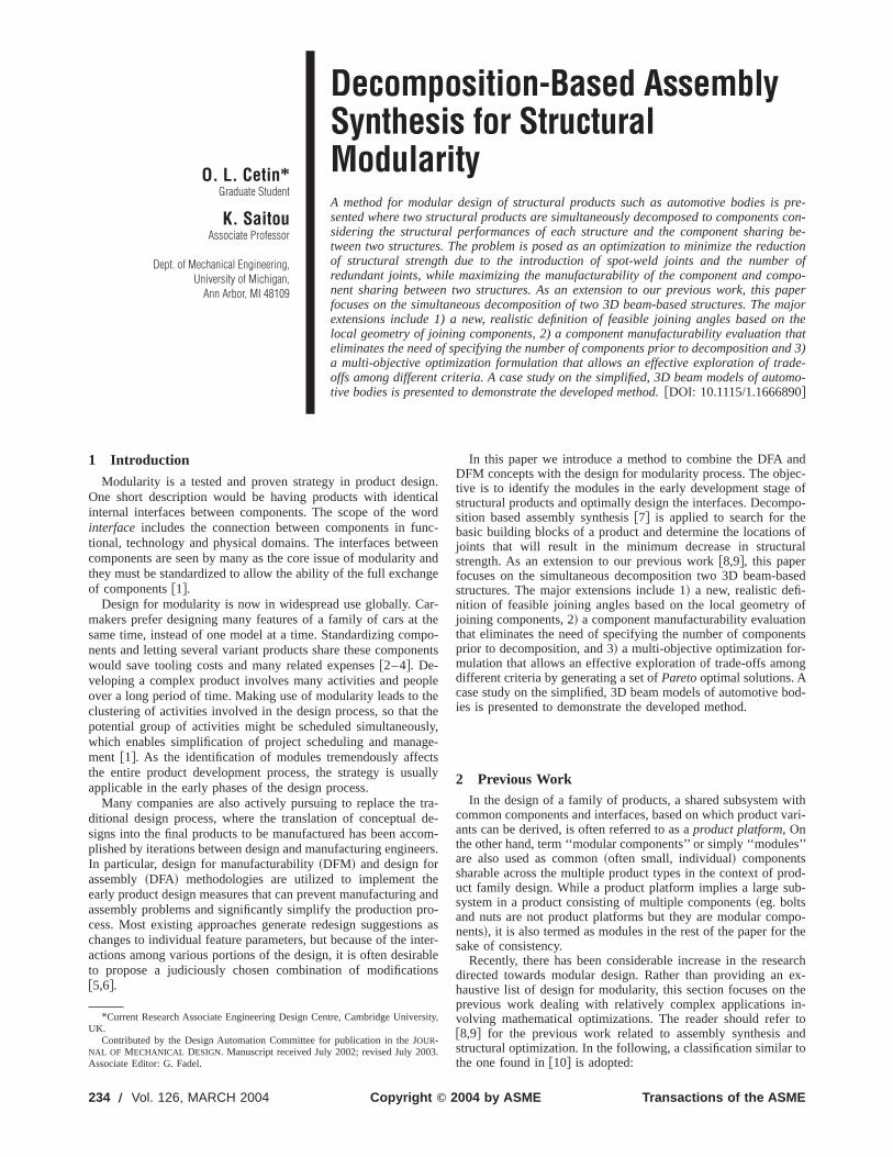
The variant structures are assumed to bear some similarityare distinct in the geometry and/or loading conditions. Figure 1~b!shows an example of two variant structures@9#, which are ob-tained with the beam-based topology optimization on the desdomain and boundary conditions shown in Fig. 1~a!. While thedeveloped method is tailored for 3D beam-based structure modwe will use these simple 2D structures to illustrate each step inmethod for the rest of this section. It should be noted, howevthat the product variants do not have to be topologically optimas seen in the case study in Sec. 4.
Based on the decomposition-based assembly synthesis me@7#, in the modular structural design problem two beam-basstructures are optimally decomposed into an assembly consisof multiple members with simpler geometries. Given two desivariants and the results of FEM analysis~stress distributionswithin structures! for desired loading conditions, there are twmain steps in the decomposition process:
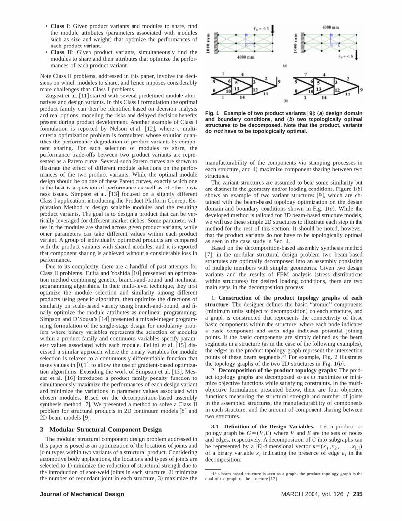
1. Construction of the product topology graphs of eachstructure: The designer defines the basic ‘‘atomic’’ componen~minimum units subject to decomposition! on each structure, anda graph is constructed that represents the connectivity of thbasic components within the structure, where each node indica basic component and each edge indicates potential joinpoints. If the basic components are simply defined as the besegments in a structure~as in the case of the following examples!,the edges in the product topology graph represent the intersecpoints of these beam segments.12 For example, Fig. 2 illustratesthe topology graphs of the two 2D structures in Fig. 1~b!.
2. Decomposition of the product topology graphs: The prod-uct topology graphs are decomposed so as to maximize or mmize objective functions while satisfying constraints. In the mulobjective formulation presented below, there are four objectfunctions measuring the structural strength and number of join the assembled structures, the manufacturability of componein each structure, and the amount of component sharing betwtwo structures.
3.1 Definition of the Design Variables. Let a product to-pology graph beG5(V,E) whereV andE are the sets of nodesand edges, respectively. A decomposition ofG into subgraphs canbe represented by auEu-dimensional vectorx5(x1 ,x2 , . . . ,xuEu)of a binary variablexi indicating the presence of edgeei in thedecomposition:
1If a beam-based structure is seen as a graph, the product topology graphdual of the graph of the structure@17#.
Fig. 1 Example of two product variants †9‡: „a… design domainand boundary conditions, and „b… two topologically optimalstructures to be decomposed. Note that the product, variantsdo not have to be topologically optimal.
MARCH 2004, Vol. 126 Õ 235
-
no
r
ld beo
ross
e
ible
hehen
the
de
sedro-duct
ly
xi5H 1 if edge ei exists in the decomposition
0 otherwise(1)
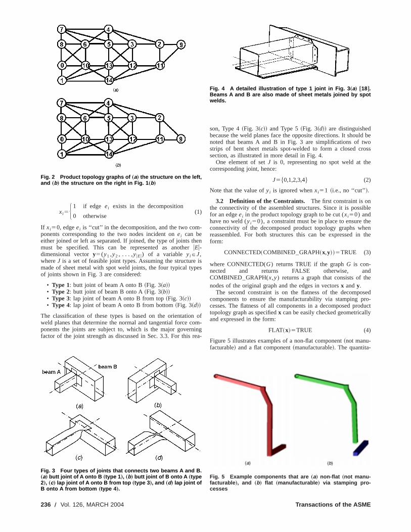
If xi50, edgeei is ‘‘cut’’ in the decomposition, and the two components corresponding to the two nodes incident onei can beeither joined or left as separated. If joined, the type of joints thmust be specified. This can be represented as anotheruEu-dimensional vectory5(y1 ,y2 , . . . ,yuEu) of a variable yiPJ,whereJ is a set of feasible joint types. Assuming the structuremade of sheet metal with spot weld joints, the four typical typof joints shown in Fig. 3 are considered:
• Type 1: butt joint of beam A onto B~Fig. 3~a!!• Type 2: butt joint of beam B onto A~Fig. 3~b!!• Type 3: lap joint of beam A onto B from top~Fig. 3~c!!• Type 4: lap joint of beam A onto B from bottom~Fig. 3~d!!
The classification of these types is based on the orientatioweld planes that determine the normal and tangential force cponents the joints are subject to, which is the major governfactor of the joint strength as discussed in Sec. 3.3. For this
Fig. 2 Product topology graphs of „a… the structure on the left,and „b… the structure on the right in Fig. 1 „b…
Fig. 3 Four types of joints that connects two beams A and B.„a… butt joint of A onto B „type 1 …, „b… butt joint of B onto A „type2…, „c… lap joint of A onto B from top „type 3 …, and „d… lap joint ofB onto A from bottom „type 4 ….
236 Õ Vol. 126, MARCH 2004
en
ises
ofm-
ingea-
son, Type 4~Fig. 3~c!! and Type 5~Fig. 3~d!! are distinguishedbecause the weld planes face the opposite directions. It shounoted that beams A and B in Fig. 3 are simplifications of twstrips of bent sheet metals spot-welded to form a closed csection, as illustrated in more detail in Fig. 4.
One element of setJ is 0, representing no spot weld at thcorresponding joint, hence:
J5$0,1,2,3,4% (2)
Note that the value ofyi is ignored whenxi51 ~i.e., no ‘‘cut’’!.
3.2 Definition of the Constraints. The first constraint is onthe connectivity of the assembled structures. Since it is possfor an edgeei in the product topology graph to be cut (xi50) andhave no weld (yi50), a constraint must be in place to ensure tconnectivity of the decomposed product topology graphs wreassembled. For both structures this can be expressed inform:
CONNECTED~COMBINED–GRAPH~x,y!!5TRUE (3)
where CONNECTED(G) returns TRUE if the graphG is con-nected and returns FALSE otherwise, anCOMBINED–GRAPH(x,y) returns a graph that consists of thnodes of the original graph and the edges in vectorsx andy.
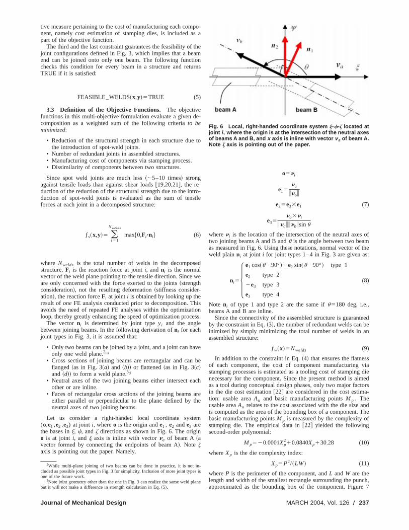
The second constraint is on the flatness of the decompocomponents to ensure the manufacturability via stamping pcesses. The flatness of all components in a decomposed protopology graph as specifiedx can be easily checked geometricaland expressed in the form:
FLAT~x!5TRUE (4)
Figure 5 illustrates examples of a non-flat component~not manu-facturable! and a flat component~manufacturable!. The quantita-
Fig. 4 A detailed illustration of type 1 joint in Fig. 3 „a… †18‡.Beams A and B are also made of sheet metals joined by spotwelds.
Fig. 5 Example components that are „a… non-flat „not manu-facturable …, and „b… flat „manufacturable … via stamping pro-cesses
Transactions of the ASME
i
ts
e
n
a
t
n
of
f the:
teeden
svia
g dieimedtorsa-
ndThef
ch,e 7
i
tive measure pertaining to the cost of manufacturing each comnent, namely cost estimation of stamping dies, is included apart of the objective function.
The third and the last constraint guarantees the feasibility ofjoint configurations defined in Fig. 3, which implies that a beaend can be joined onto only one beam. The following functchecks this condition for every beam in a structure and retuTRUE if it is satisfied:
FEASIBLE–WELDS~x,y!5TRUE (5)
3.3 Definition of the Objective Functions. The objectivefunctions in this multi-objective formulation evaluate a given dcomposition as a weighted sum of the following criteriato beminimized:
• Reduction of the structural strength in each structure duethe introduction of spot-weld joints.
• Number of redundant joints in assembled structures.• Manufacturing cost of components via stamping process.• Dissimilarity of components between two structures.
Since spot weld joints are much less~;5–10 times! strongagainst tensile loads than against shear loads@19,20,21#, the re-duction of the reduction of the structural strength due to the induction of spot-weld joints is evaluated as the sum of tenforces at each joint in a decomposed structure:
f s~x,y!5 (i 51
Nwelds
max$0,Fi "ni% (6)
where Nwelds is the total number of welds in the decomposstructure,Fi is the reaction force at jointi, andni is the normalvector of the weld plane pointing to the tensile direction. Sinceare only concerned with the force exerted to the joints~strengthconsideration!, not the resulting deformation~stiffness consider-ation!, the reaction forceFi at joint i is obtained by looking up theresult ofoneFE analysis conducted prior to decomposition. Thavoids the need of repeated FE analyses within the optimizaloop, thereby greatly enhancing the speed of optimization proc
The vectorni is determined by joint typeyi and the anglebetween joining beams. In the following derivation ofni for eachjoint types in Fig. 3, it is assumed that:
• Only two beams can be joined by a joint, and a joint can haonly one weld plane.2iii
• Cross sections of joining beams are rectangular and caflanged~as in Fig. 3~a! and ~b!! or flattened~as in Fig. 3~c!and ~d!! to form a weld plane.3d
• Neutral axes of the two joining beams either intersect eother or are inline.
• Faces of rectangular cross sections of the joining beamseither parallel or perpendicular to the plane defined byneutral axes of two joining beams.
Let us consider a right-handed local coordinate syst(o,e1 ,e2 ,e3) at joint i, whereo is the origin ande1 , e2 ande3 arethe bases inj, c, andz directions as shown in Fig. 6. The origio is at joint i, and j axis is inline with vectorna of beam A~avector formed by connecting the endpoints of beam A!. Note zaxis is pointing out the paper. Namely,
2While multi-plane joining of two beams can be done in practice, it is notcluded as possible joint types in Fig. 3 for simplicity. Inclusion of more joint typesone of the future work.
3Note joint geometry other than the one in Fig. 3 can realize the same weld pbut it will not make a difference in strength calculation in Eq.~5!.
Journal of Mechanical Design
po-s a
themonrns
e-
to
ro-ile
d
we
istioness.
ve
be
ch
arehe
em
o5ni
e15na
inoi
e25e33e1 (7)
e35no3ni
inaiinbisinu
whereni is the location of the intersection of the neutral axestwo joining beams A and B andu is the angle between two beamas measured in Fig. 6. Using these notations, normal vector oweld plainni at joint i for joint types 1–4 in Fig. 3 are given as
ni55e1 cos~u290°!1e2 sin~u290°! type 1
e2 type 2
2e3 type 3
e3 type 4
(8)
Note ni of type 1 and type 2 are the same ifu5180 deg, i.e.,beams A and B are inline.
Since the connectivity of the assembled structure is guaranby the constraint in Eq.~3!, the number of redundant welds can binimized by simply minimizing the total number of welds in aassembled structure:
f w~x!5Nwelds (9)
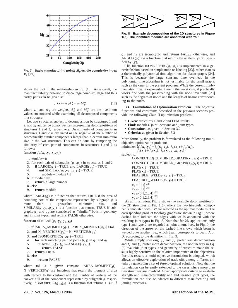
In addition to the constraint in Eq.~4! that ensures the flatnesof each component, the cost of component manufacturingstamping processes is estimated as a tooling cost of stampinnecessary for the component. Since the present method is aas a tool during conceptual design phases, only two major facin the die cost estimation@22# are considered in the cost estimtion: usable areaAu and basic manufacturing pointsM p . Theusable areaAu relates to the cost associated with the die size ais computed as the area of the bounding box of a component.basic manufacturing pointsM p is measured by the complexity ostamping die. The empirical data in@22# yielded the followingsecond-order polynomial:
M p520.0001Xp210.0840Xp130.28 (10)
whereXp is the die complexity index:
Xp5P2/~LW! (11)
whereP is the perimeter of the component, andL andW are thelength and width of the smallest rectangle surrounding the punapproximated as the bounding box of the component. Figur
n-is
lane
Fig. 6 Local, right-handed coordinate system j-c-z located atjoint i , where the origin is at the intersection of the neutral axesof beams A and B, and x axis is inline with vector v a of beam A.Note z axis is pointing out of the paper.
MARCH 2004, Vol. 126 Õ 237
h
eu
n-y
e
f
nd
thes
ple-lly
pond-
pro-
i-
of-
heerethelytheisor
q.re-es.chri-
thanatethend
shows the plot of the relationship in Eq.~10!. As a result, themanufacturability criterion to discourage complex, large and tcostly parts can be given as:
f c~x!5w1Au* 1w2M p* (12)
where w1 and w2 are weights,Au* and M p* are the maximumvalues encountered while examining all decomposed componin a structure.
Let two structures subject to decomposition be structures 12, andx1 andx2 be binary vectors representing decompositionsstructures 1 and 2, respectively. Dissimilarity of componentsstructures 1 and 2 is evaluated as the negative of the numbgeometrically similar components larger than a certain minimsize in the two structures. This can be done by comparingsimilarity of each pair of components in structures 1 and 2follows:function f m(x1 ,y1 ,x2 ,y2)
1. module502. for each pair of subgraphs (g1 ,g2) in structures 1 and 23. if LARGE(g1)5TRUE and LARGE(g2)5TRUE4. and SIMILAR( g1 ,y1 ,g2 ,y2)5TRUE5. module5module116. if module507. return a large number8. else9. return -module
where LARGE(g) is a function that returns TRUE if the area obounding box of the component represented by subgraphg ismore than a prescribed minimum size, aSIMILAR( g1 ,y1 ,g2y2) is a function that returns TRUE if subgraphsg1 and g2 are considered as ‘‘similar’’ both in geometrand in joint types, and returns FALSE otherwise:
function SIMILAR( g1 ,y1 ,g2 ,y2)
1. if uAREA–MOMENT(g1)2AREA–MOMENT(g2)u,tol2. and N–VERTICES(g1)5N–VERTICES(g2)3. and ISOMORPHIC(g1 ,g2)5TRUE4. for each matching pair of joints~i, j! in g1 andg25. if ANGLE((y1) i)! 5ANGLE((y2) j )6. return FALSE7. return TRUE8. else9. return FALSE
where tol is a given constant, AREA–MOMENT(g),N–VERTICES(g) are functions that return the moment of arwith respect to the centroid and the number of vertices ofconvex hull of the component represented by subgraphg, respec-tively, ISOMORPHIC(g1 ,g2) is a function that returns TRUE i
Fig. 7 Basic manufacturing points Mp vs. die complexity indexXp †21‡
238 Õ Vol. 126, MARCH 2004
us
ents
andofinr ofm
theas
f
d
athe
g1 and g2 are isomorphic and returns FALSE otherwise, aANGLE((y) i) is a function that returns the angle of jointi speci-fied by (y) i .
The function ISOMORPHIC(g1 ,g2) is implemented in a ge-neric fashion based on simple node re-labeling@23#, rather than asa theoretically polynomial-time algorithm for planar graphs@24#.This is because the large constant time overhead inpolynomial-time algorithm is not justifiable for the small graphsuch as the ones in the present problem. While the current immentation runs in exponential time in the worst case, it practicaworks fine with the prescreening with the node invariants@23#such as the degrees of nodes and the lengths of beams corresing to the nodes.
3.4 Formulation of Optimization Problem. The objectivefunctions and constraints described in the previous sectionsvide the following Class II optimization problem:
• Given: structures 1 and 2 and FEM results• Find: modules, joint locations and joint types• Constraints: as given in Section 3.2• Criteria : as given in Section 3.3
More formally, the problem is formulated as the following multobjective optimization problem:minimize: $f s(x1 ,y1)1 f s(x2 ,y2), f w(x1)1 f w(x2),
f c(x1)1 f c(x2), f m(x1 ,y1 ,x2 ,y2)%subject to:
CONNECTED(COMBINED–GRAPH(x1 ,y1))5TRUECONNECTED(COMBINED–GRAPH(x2 ,y2))5TRUEFLAT(x1)5TRUEFLAT(x2)5TRUEFEASIBLE–WELDS(x1 ,y1)5TRUEFEASIBLE–WELDS(x2 ,y2)5TRUE
x1P$0,1% uE1u
x2P$0,1% uE2u
y1P$0,1,2,3,4% uE1u
y2P$0,1,2,3,4% uE2u
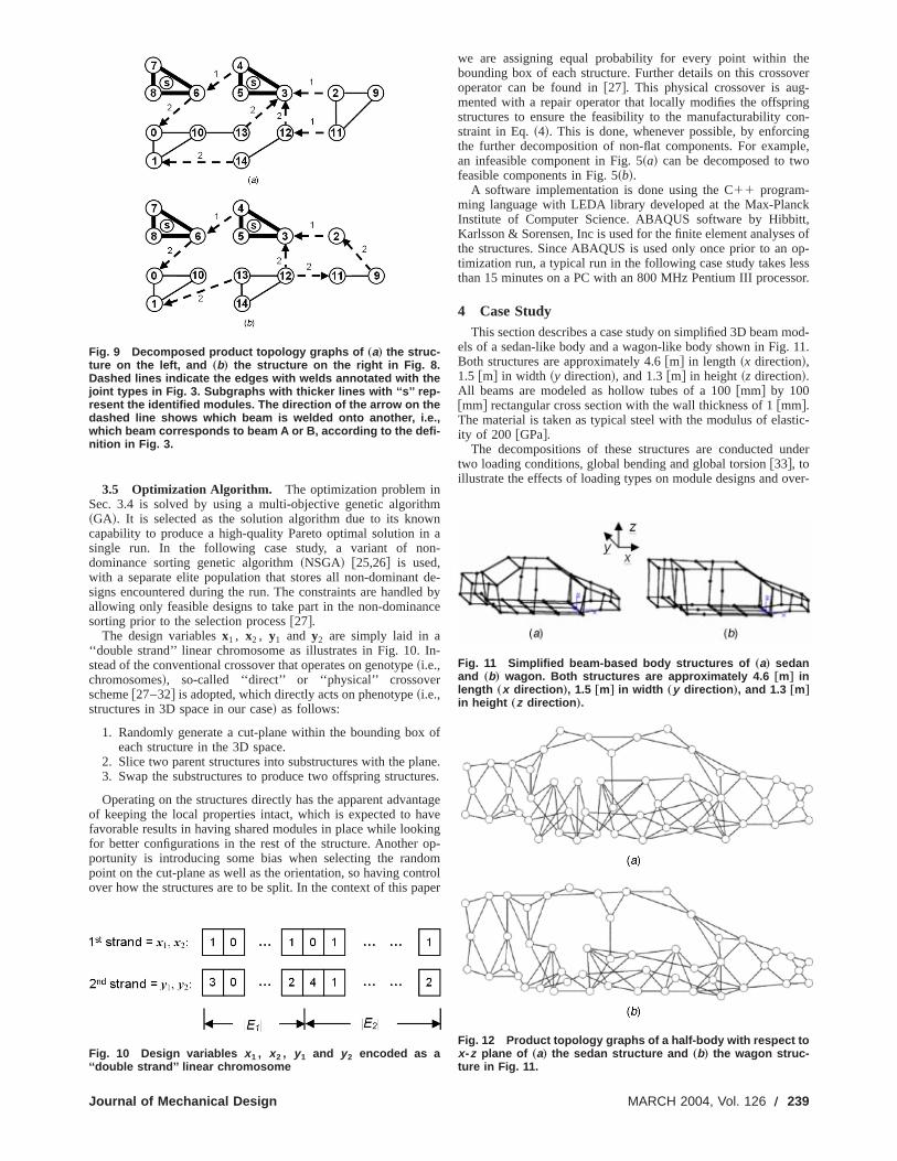
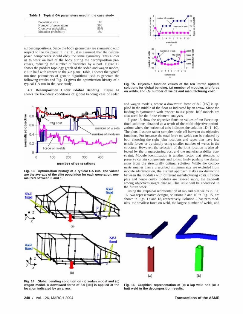
As an illustration, Fig. 8 shows the example decompositionthe 2D structures in Fig. 1~b!, where the two triangular components annotated with ‘‘s’’ are selected as the optimal modules. Tcorresponding product topology graphs are shown in Fig. 9, whdashed lines indicate the edges with welds annotated withresulting joint types in Fig. 3. Note that for 2D applications ontype 1 and type 2 are regarded as joint alternatives. In Fig. 9,direction of the arrow on the dashed line shows which beamwelded onto another, i.e., which beam corresponds to beam AB, according to the definition in Fig. 3.
While simply speaking,f s and f w prefer less decompositionand f c and f m prefer more decomposition, the nonlinearity in E~6! available joint types, and geometry of structure make thesults highly sensitive to the relative importance of the objectivFor this reason, a multi-objective formulation is adopted, whiallows an effective exploration of trade-offs among different cteria by generating a set ofParetooptimal solutions. Note that theformulation can be easily extended to the cases where moretwo structures are involved. Given appropriate criteria to evalustrength and manufacturability and and feasible joint types,formulation can also be adapted to different manufacturing ajoining processes.
Fig. 8 Example decomposition of the 2D structures in Figure1„b…. The identified modules are annotated with ‘‘s.’’
Transactions of the ASME
r
ever
gn-gle,
k,of
p-sr.
od-1.
ic-
der
er-
3.5 Optimization Algorithm. The optimization problem inSec. 3.4 is solved by using a multi-objective genetic algorith~GA!. It is selected as the solution algorithm due to its knowcapability to produce a high-quality Pareto optimal solution insingle run. In the following case study, a variant of nodominance sorting genetic algorithm~NSGA! @25,26# is used,with a separate elite population that stores all non-dominantsigns encountered during the run. The constraints are handleallowing only feasible designs to take part in the non-dominansorting prior to the selection process@27#.
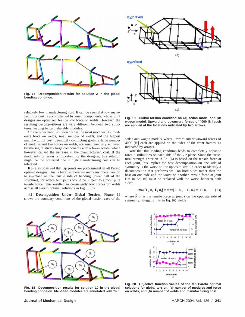
The design variablesx1 , x2 , y1 and y2 are simply laid in a‘‘double strand’’ linear chromosome as illustrates in Fig. 10. Istead of the conventional crossover that operates on genotype~i.e.,chromosomes!, so-called ‘‘direct’’ or ‘‘physical’’ crossoverscheme@27–32# is adopted, which directly acts on phenotype~i.e.,structures in 3D space in our case! as follows:
1. Randomly generate a cut-plane within the bounding boxeach structure in the 3D space.
2. Slice two parent structures into substructures with the pla3. Swap the substructures to produce two offspring structu
Operating on the structures directly has the apparent advanof keeping the local properties intact, which is expected to hafavorable results in having shared modules in place while lookfor better configurations in the rest of the structure. Another oportunity is introducing some bias when selecting the randpoint on the cut-plane as well as the orientation, so having conover how the structures are to be split. In the context of this pa
Fig. 9 Decomposed product topology graphs of „a… the struc-ture on the left, and „b… the structure on the right in Fig. 8.Dashed lines indicate the edges with welds annotated with thejoint types in Fig. 3. Subgraphs with thicker lines with ‘‘s’’ rep-resent the identified modules. The direction of the arrow on thedashed line shows which beam is welded onto another, i.e.,which beam corresponds to beam A or B, according to the defi-nition in Fig. 3.
Fig. 10 Design variables x 1 , x 2 , y 1 and y 2 encoded as a‘‘double strand’’ linear chromosome
Journal of Mechanical Design
mna
n-
de-d byce
n-
of
ne.es.
tageve
ingp-
omtrolper
we are assigning equal probability for every point within thbounding box of each structure. Further details on this crossooperator can be found in@27#. This physical crossover is aug-mented with a repair operator that locally modifies the offsprinstructures to ensure the feasibility to the manufacturability costraint in Eq.~4!. This is done, whenever possible, by enforcinthe further decomposition of non-flat components. For exampan infeasible component in Fig. 5~a! can be decomposed to twofeasible components in Fig. 5~b!.
A software implementation is done using the C11 program-ming language with LEDA library developed at the Max-PlancInstitute of Computer Science. ABAQUS software by HibbittKarlsson & Sorensen, Inc is used for the finite element analysesthe structures. Since ABAQUS is used only once prior to an otimization run, a typical run in the following case study takes lesthan 15 minutes on a PC with an 800 MHz Pentium III processo
4 Case StudyThis section describes a case study on simplified 3D beam m
els of a sedan-like body and a wagon-like body shown in Fig. 1Both structures are approximately 4.6@m# in length ~x direction!,1.5 @m# in width ~y direction!, and 1.3@m# in height~z direction!.All beams are modeled as hollow tubes of a 100@mm# by 100@mm# rectangular cross section with the wall thickness of 1@mm#.The material is taken as typical steel with the modulus of elastity of 200 @GPa#.
The decompositions of these structures are conducted untwo loading conditions, global bending and global torsion@33#, toillustrate the effects of loading types on module designs and ov
Fig. 11 Simplified beam-based body structures of „a… sedanand „b… wagon. Both structures are approximately 4.6 †m‡ inlength „x direction …, 1.5 †m‡ in width „y direction …, and 1.3 †m‡
in height „z direction ….
Fig. 12 Product topology graphs of a half-body with respect tox -z plane of „a… the sedan structure and „b… the wagon struc-ture in Fig. 11.
MARCH 2004, Vol. 126 Õ 239
l
the
op-i-
tived byowtheaf-on-to
signo-romtionm--offd in
ig.areod-and
all decompositions. Since the body geometries are symmetric wrespect to thex-z plane in Fig. 11, it is assumed that the decomposed components should obey the same symmetry. This alus to work on half of the body during the decomposition prcesses, reducing the number of variables by a half. Figureshows the product topology graph of the sedan and wagon mocut in half with respect to thex-zplane. Table 1 shows the typicarun-time parameters of genetic algorithms used to generatefollowing results and Fig. 13 gives the optimization history oftypical GA run in the case study.
4.1 Decomposition Under Global Bending. Figure 14shows the boundary conditions of global bending case of se
Fig. 13 Optimization history of a typical GA run. The valuesare the average of the elite population for each generation, nor-malized between 0 and 1.
Fig. 14 Global bending condition on „a… sedan model and „b…wagon model. A downward force of 8.0 †kN‡ is applied at thelocation indicated by an arrow.
Table 1 Typical GA parameters used in the case study
Population size 100Number of generations 500Crossover probability 90%Mutation probability 1%
240 Õ Vol. 126, MARCH 2004
ith-
owso-12
des,lthea
dan
and wagon models, where a downward force of 8.0@kN# is ap-plied in the middle of the floor as indicated by an arrow. Sinceloading is symmetric with respect tox-z plane, half models arealso used for the finite element analyses.
Figure 15 show the objective function values of ten Paretotimal solutions obtained as a result of the multi-objective optimzation, where the horizontal axis indicates the solution 1D~1–10!.The plots illustrate rather complex trade-off between the objecfunctions. For instance the total force on welds can be reduceboth choosing the right joint locations and types that have ltensile forces or by simply using smaller number of welds instructure. However, the selection of the joint location is alsofected by the manufacturing cost and the manufacturability cstraint. Module identification is another factor that attemptspreserve certain components and joints, likely pushing the deaway from the structurally optimal solution. While the compnents smaller than a prescribed minimum size are excluded fmodule identification, the current approach makes no distincbetween the modules with different manufacturing costs. If coplex and hence costly modules are favored more, the tradeamong objectives might change. This issue will be addressethe future work.
Using the graphical representation of lap and butt welds in F16, two representative designs, solutions 2 and 10 in Fig. 15,shown in Figs. 17 and 18, respectively. Solution 2 has zero mules, the smallest force on weld, the largest number of welds,
Fig. 15 Objective function values of the ten Pareto optimalsolutions for global bending. „a… number of modules and forceon welds, and „b… number of welds and manufacturing cost.
Fig. 16 Graphical representation of „a… a lap weld and „b… abutt weld in the decomposition results.
Transactions of the ASME
not
i
o
r
rl
s ofas
te
tofa
heint
th
relatively low manufacturing cost. It can be seen that low mafacturing cost is accomplished by small components, whose jdesigns are optimized for the low force on welds. However,resulting decompositions are very different between two strtures, leading to zero sharable modules.
On the other hand, solution 10 has the most modules~4!, mod-erate force on welds, small number of welds, and the highmanufacturing cost. Seemingly conflicting goals, a large numof modules and low forces on welds, are simultaneously achieby sharing relatively large components with a fewer welds, whhowever caused the increase in the manufacturing cost. Ifmodularity criterion is important for the designer, this solutimight be the preferred one if high manufacturing cost cantolerated.
It is also observed that lap joints are predominant in all Paroptimal designs. This is because there are many members pato x-y-plane on the tensile side of bending~lower half of thestructure!, for which butt joints would be subject to almost putensile force. This resulted in consistently low forces on weacross all Pareto optimal solutions in Fig. 15~a!.
4.2 Decomposition Under Global Torsion. Figure 19shows the boundary conditions of the global torsion case of
Fig. 17 Decomposition results for solution 2 in the globalbending condition.
Fig. 18 Decomposition results for solution 10 in the globalbending condition. Identified modules are annotated with ‘‘s.’’
Journal of Mechanical Design
u-intheuc-
estbervedchthenbe
etoallel
eds
the
sedan and wagon models, where upward and downward force4000 @N# each are applied on the sides of the front frames,indicated by arrows.
Note that this loading condition leads to completely opposiforce distributions on each side of thex-z plane. Since the struc-tural strength criterion in Eq.~6! is based on the tensile force aeach joint, this implies the best decomposition on one sidesymmetry is the worst on the opposite side. In order to identifydecomposition that performs well on both sides rather than tbest on one side and the worst on another, tensile force at joF"n in Eq. ~6! must be replaced with the worse between bosides:
max$Fi "ni ,Fi "ni%5max$Fi "ni ,2Fi "ni%5uFi "ni u (13)
where F"ni is the tensile force at jointi on the opposite side ofsymmetry. Plugging this in Eq.~6! yields
Fig. 19 Global torsion condition on „a… sedan model and „b…wagon model. Upward and downward forces of 4000 †N‡ eachare applied at the locations indicated by two arrows.
Fig. 20 Objective function values of the ten Pareto optimalsolutions for global torsion. „a… number of modules and forceon welds, and „b… number of welds and manufacturing cost.
MARCH 2004, Vol. 126 Õ 241
e
t
o
o
l
, thering
tobers
.
uraluctsthe
shar-iza-hentntlti-
go-findstivet so-nts.im-the-is
-x-lerger-bil-
canareelstheer,gralhs
buttheom-ble
ignm-tion.
uredndari-pli-
rityatu-n beer-ith
thanuntoandies,
forIt is
f s~x,y!5w1 (i 51
Nwelds
max$0,uFi "ni u%5w1 (i 51
Nwelds
uFi "ni u (14)
Equation~14! is used instead of Eq.~6! in the results given inFig. 20, where the objective function values of 10 Pareto optimsolutions are shown. Since forces normal to the mating planejoints, whether compressive or tensile, are added the total forcwelds, the Pareto optimal solutions have consistently higher fovalues than the ones for global bending. Since joints are almalways discouraged with the use of Eq.~14!, reducing the numberof welds seems the best solution to reduce the force on weHowever, the results in Fig. 20 shows no considerable reducof forces on welds is seen between solution 1~64 welds! andsolutions 2–10~75–76 welds!, which suggests the designer notconsider strength criterion as a priority in decision-making.
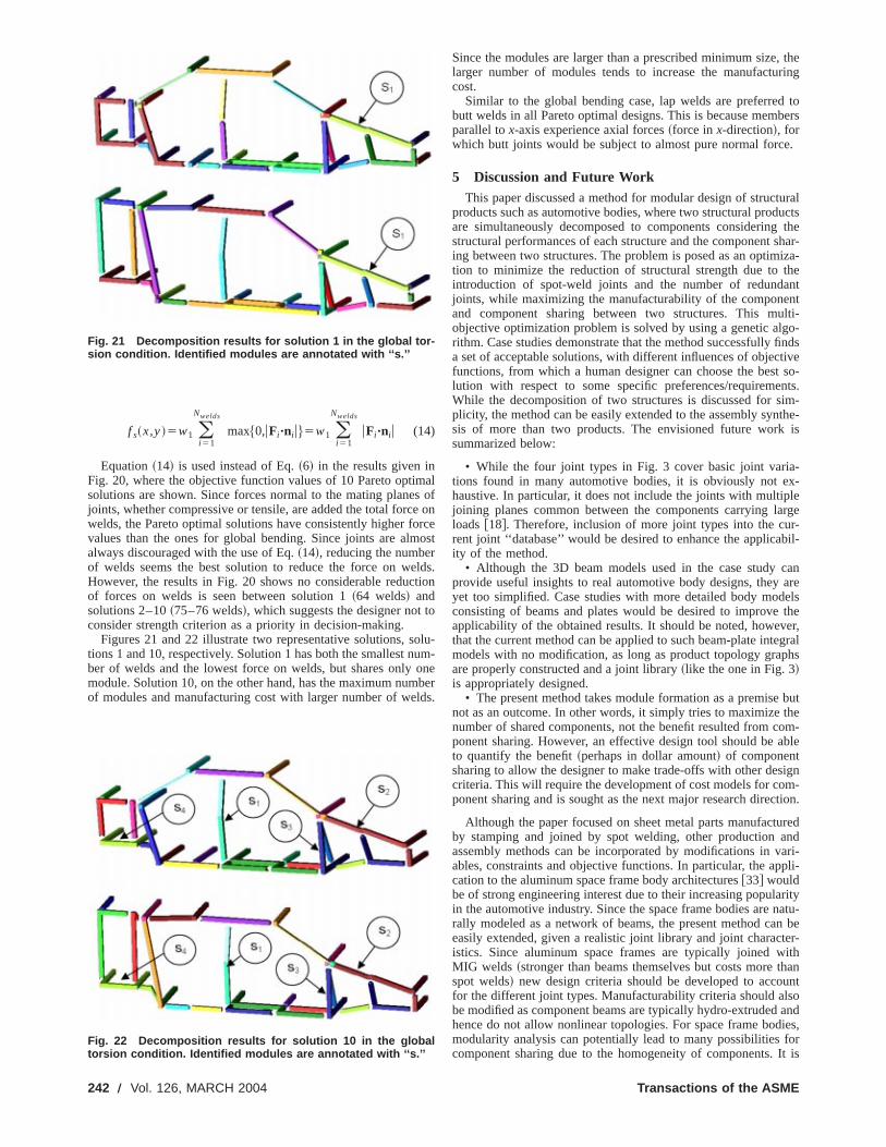
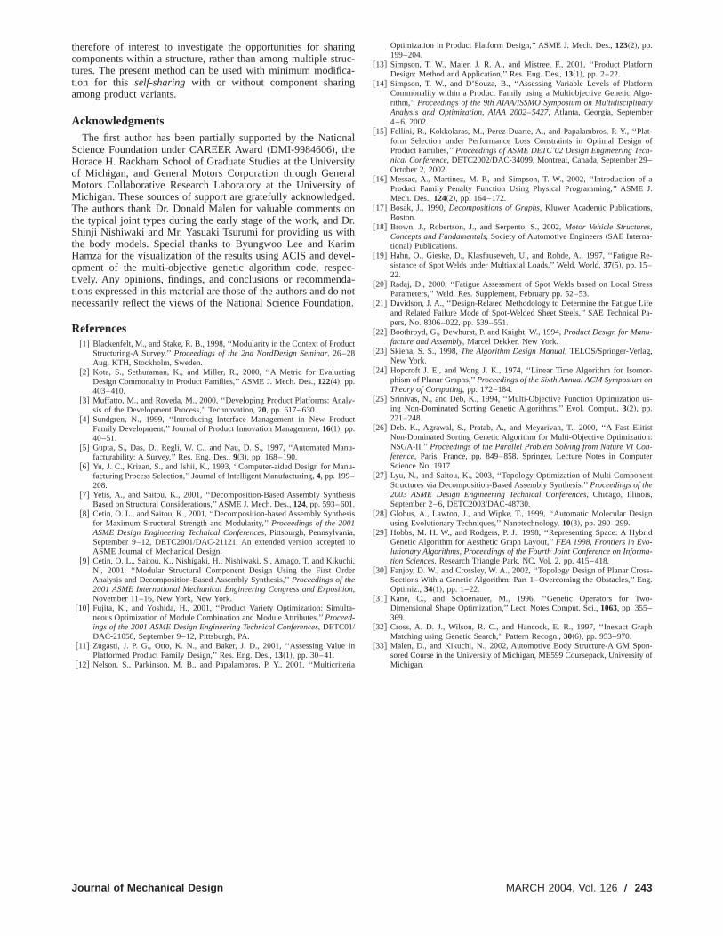
Figures 21 and 22 illustrate two representative solutions, stions 1 and 10, respectively. Solution 1 has both the smallest nber of welds and the lowest force on welds, but shares onlymodule. Solution 10, on the other hand, has the maximum numof modules and manufacturing cost with larger number of we
Fig. 21 Decomposition results for solution 1 in the global tor-sion condition. Identified modules are annotated with ‘‘s.’’
Fig. 22 Decomposition results for solution 10 in the globaltorsion condition. Identified modules are annotated with ‘‘s.’’
242 Õ Vol. 126, MARCH 2004
als of
onrceost
lds.tion
o
lu-um-neberds.
Since the modules are larger than a prescribed minimum sizelarger number of modules tends to increase the manufactucost.
Similar to the global bending case, lap welds are preferredbutt welds in all Pareto optimal designs. This is because memparallel tox-axis experience axial forces~force inx-direction!, forwhich butt joints would be subject to almost pure normal force
5 Discussion and Future WorkThis paper discussed a method for modular design of struct
products such as automotive bodies, where two structural prodare simultaneously decomposed to components consideringstructural performances of each structure and the componenting between two structures. The problem is posed as an optimtion to minimize the reduction of structural strength due to tintroduction of spot-weld joints and the number of redundajoints, while maximizing the manufacturability of the componeand component sharing between two structures. This muobjective optimization problem is solved by using a genetic alrithm. Case studies demonstrate that the method successfullya set of acceptable solutions, with different influences of objecfunctions, from which a human designer can choose the beslution with respect to some specific preferences/requiremeWhile the decomposition of two structures is discussed for splicity, the method can be easily extended to the assembly synsis of more than two products. The envisioned future worksummarized below:
• While the four joint types in Fig. 3 cover basic joint variations found in many automotive bodies, it is obviously not ehaustive. In particular, it does not include the joints with multipjoining planes common between the components carrying laloads@18#. Therefore, inclusion of more joint types into the curent joint ‘‘database’’ would be desired to enhance the applicaity of the method.
• Although the 3D beam models used in the case studyprovide useful insights to real automotive body designs, theyyet too simplified. Case studies with more detailed body modconsisting of beams and plates would be desired to improveapplicability of the obtained results. It should be noted, howevthat the current method can be applied to such beam-plate intemodels with no modification, as long as product topology grapare properly constructed and a joint library~like the one in Fig. 3!is appropriately designed.
• The present method takes module formation as a premisenot as an outcome. In other words, it simply tries to maximizenumber of shared components, not the benefit resulted from cponent sharing. However, an effective design tool should be ato quantify the benefit~perhaps in dollar amount! of componentsharing to allow the designer to make trade-offs with other descriteria. This will require the development of cost models for coponent sharing and is sought as the next major research direc
Although the paper focused on sheet metal parts manufactby stamping and joined by spot welding, other production aassembly methods can be incorporated by modifications in vables, constraints and objective functions. In particular, the apcation to the aluminum space frame body architectures@33# wouldbe of strong engineering interest due to their increasing populain the automotive industry. Since the space frame bodies are nrally modeled as a network of beams, the present method caeasily extended, given a realistic joint library and joint charactistics. Since aluminum space frames are typically joined wMIG welds ~stronger than beams themselves but costs morespot welds! new design criteria should be developed to accofor the different joint types. Manufacturability criteria should alsbe modified as component beams are typically hydro-extrudedhence do not allow nonlinear topologies. For space frame bodmodularity analysis can potentially lead to many possibilitiescomponent sharing due to the homogeneity of components.
Transactions of the ASME
r
r
Dhr
edoi
ly
u
n
e
,
i
a
rm
rmo-aryr
lat-of
h-9–
aJ.
Re-
tress
ifePa-
r-on
s-
ist:
n-uter
t
n
brid
a-
ss-ng.
o-
ph
n-of
therefore of interest to investigate the opportunities for sharcomponents within a structure, rather than among multiple sttures. The present method can be used with minimum modifition for this self-sharing with or without component sharingamong product variants.
AcknowledgmentsThe first author has been partially supported by the Natio
Science Foundation under CAREER Award~DMI-9984606!, theHorace H. Rackham School of Graduate Studies at the Univeof Michigan, and General Motors Corporation through GeneMotors Collaborative Research Laboratory at the UniversityMichigan. These sources of support are gratefully acknowledgThe authors thank Dr. Donald Malen for valuable commentsthe typical joint types during the early stage of the work, andShinji Nishiwaki and Mr. Yasuaki Tsurumi for providing us witthe body models. Special thanks to Byungwoo Lee and KaHamza for the visualization of the results using ACIS and devopment of the multi-objective genetic algorithm code, resptively. Any opinions, findings, and conclusions or recommentions expressed in this material are those of the authors and dnecessarily reflect the views of the National Science Foundat
References@1# Blackenfelt, M., and Stake, R. B., 1998, ‘‘Modularity in the Context of Produ
Structuring-A Survey,’’Proceedings of the 2nd NordDesign Seminar, 26–28Aug, KTH, Stockholm, Sweden.
@2# Kota, S., Sethuraman, K., and Miller, R., 2000, ‘‘A Metric for EvaluatinDesign Commonality in Product Families,’’ ASME J. Mech. Des.,122~4!, pp.403–410.
@3# Muffatto, M., and Roveda, M., 2000, ‘‘Developing Product Platforms: Anasis of the Development Process,’’ Technovation,20, pp. 617–630.
@4# Sundgren, N., 1999, ‘‘Introducing Interface Management in New ProdFamily Development,’’ Journal of Product Innovation Management,16~1!, pp.40–51.
@5# Gupta, S., Das, D., Regli, W. C., and Nau, D. S., 1997, ‘‘Automated Mafacturability: A Survey,’’ Res. Eng. Des.,9~3!, pp. 168–190.
@6# Yu, J. C., Krizan, S., and Ishii, K., 1993, ‘‘Computer-aided Design for Manfacturing Process Selection,’’ Journal of Intelligent Manufacturing,4, pp. 199–208.
@7# Yetis, A., and Saitou, K., 2001, ‘‘Decomposition-Based Assembly SyntheBased on Structural Considerations,’’ ASME J. Mech. Des.,124, pp. 593–601.
@8# Cetin, O. L., and Saitou, K., 2001, ‘‘Decomposition-based Assembly Synthfor Maximum Structural Strength and Modularity,’’Proceedings of the 2001ASME Design Engineering Technical Conferences, Pittsburgh, PennsylvaniaSeptember 9–12, DETC2001/DAC-21121. An extended version accepteASME Journal of Mechanical Design.
@9# Cetin, O. L., Saitou, K., Nishigaki, H., Nishiwaki, S., Amago, T. and KikuchN., 2001, ‘‘Modular Structural Component Design Using the First OrdAnalysis and Decomposition-Based Assembly Synthesis,’’Proceedings of the2001 ASME International Mechanical Engineering Congress and Exposit,November 11–16, New York, New York.
@10# Fujita, K., and Yoshida, H., 2001, ‘‘Product Variety Optimization: Simultneous Optimization of Module Combination and Module Attributes,’’Proceed-ings of the 2001 ASME Design Engineering Technical Conferences, DETC01/DAC-21058, September 9–12, Pittsburgh, PA.
@11# Zugasti, J. P. G., Otto, K. N., and Baker, J. D., 2001, ‘‘Assessing ValuePlatformed Product Family Design,’’ Res. Eng. Des.,13~1!, pp. 30–41.
@12# Nelson, S., Parkinson, M. B., and Papalambros, P. Y., 2001, ‘‘Multicrite
Journal of Mechanical Design
inguc-ca-
nal
sityralofed.onr.
imel-c-a-not
on.
ct
g
-
ct
u-
u-
sis
sis
d to
i,er
on
-
in
ria
Optimization in Product Platform Design,’’ ASME J. Mech. Des.,123~2!, pp.199–204.
@13# Simpson, T. W., Maier, J. R. A., and Mistree, F., 2001, ‘‘Product PlatfoDesign: Method and Application,’’ Res. Eng. Des.,13~1!, pp. 2–22.
@14# Simpson, T. W., and D’Souza, B., ‘‘Assessing Variable Levels of PlatfoCommonality within a Product Family using a Multiobjective Genetic Algrithm,’’ Proceedings of the 9th AIAA/ISSMO Symposium on MultidisciplinAnalysis and Optimization, AIAA 2002–5427, Atlanta, Georgia, Septembe4–6, 2002.
@15# Fellini, R., Kokkolaras, M., Perez-Duarte, A., and Papalambros, P. Y., ‘‘Pform Selection under Performance Loss Constraints in Optimal DesignProduct Families,’’Proceedings of ASME DETC’02 Design Engineering Tecnical Conference, DETC2002/DAC-34099, Montreal, Canada, September 2October 2, 2002.
@16# Messac, A., Martinez, M. P., and Simpson, T. W., 2002, ‘‘Introduction ofProduct Family Penalty Function Using Physical Programming,’’ ASMEMech. Des.,124~2!, pp. 164–172.
@17# Bosak, J., 1990,Decompositions of Graphs, Kluwer Academic Publications,Boston.
@18# Brown, J., Robertson, J., and Serpento, S., 2002,Motor Vehicle Structures,Concepts and Fundamentals, Society of Automotive Engineers~SAE Interna-tional! Publications.
@19# Hahn, O., Gieske, D., Klasfauseweh, U., and Rohde, A., 1997, ‘‘Fatiguesistance of Spot Welds under Multiaxial Loads,’’ Weld. World,37~5!, pp. 15–22.
@20# Radaj, D., 2000, ‘‘Fatigue Assessment of Spot Welds based on Local SParameters,’’ Weld. Res. Supplement, February pp. 52–53.
@21# Davidson, J. A., ‘‘Design-Related Methodology to Determine the Fatigue Land Related Failure Mode of Spot-Welded Sheet Steels,’’ SAE Technicalpers, No. 8306–022, pp. 539–551.
@22# Boothroyd, G., Dewhurst, P. and Knight, W., 1994,Product Design for Manu-facture and Assembly, Marcel Dekker, New York.
@23# Skiena, S. S., 1998,The Algorithm Design Manual, TELOS/Springer-Verlag,New York.
@24# Hopcroft J. E., and Wong J. K., 1974, ‘‘Linear Time Algorithm for Isomophism of Planar Graphs,’’Proceedings of the Sixth Annual ACM SymposiumTheory of Computing, pp. 172–184.
@25# Srinivas, N., and Deb, K., 1994, ‘‘Multi-Objective Function Optimization uing Non-Dominated Sorting Genetic Algorithms,’’ Evol. Comput.,3~2!, pp.221–248.
@26# Deb. K., Agrawal, S., Pratab, A., and Meyarivan, T., 2000, ‘‘A Fast ElitNon-Dominated Sorting Genetic Algorithm for Multi-Objective OptimizationNSGA-II,’’ Proceedings of the Parallel Problem Solving from Nature VI Coference, Paris, France, pp. 849–858. Springer, Lecture Notes in CompScience No. 1917.
@27# Lyu, N., and Saitou, K., 2003, ‘‘Topology Optimization of Multi-ComponenStructures via Decomposition-Based Assembly Synthesis,’’Proceedings of the2003 ASME Design Engineering Technical Conferences, Chicago, Illinois,September 2–6, DETC2003/DAC-48730.
@28# Globus, A., Lawton, J., and Wipke, T., 1999, ‘‘Automatic Molecular Desigusing Evolutionary Techniques,’’ Nanotechnology,10~3!, pp. 290–299.
@29# Hobbs, M. H. W., and Rodgers, P. J., 1998, ‘‘Representing Space: A HyGenetic Algorithm for Aesthetic Graph Layout,’’FEA 1998, Frontiers in Evo-lutionary Algorithms, Proceedings of the Fourth Joint Conference on Informtion Sciences, Research Triangle Park, NC, Vol. 2, pp. 415–418.
@30# Fanjoy, D. W., and Crossley, W. A., 2002, ‘‘Topology Design of Planar CroSections With a Genetic Algorithm: Part 1–Overcoming the Obstacles,’’ EOptimiz., 34~1!, pp. 1–22.
@31# Kane, C., and Schoenauer, M., 1996, ‘‘Genetic Operators for TwDimensional Shape Optimization,’’ Lect. Notes Comput. Sci.,1063, pp. 355–369.
@32# Cross, A. D. J., Wilson, R. C., and Hancock, E. R., 1997, ‘‘Inexact GraMatching using Genetic Search,’’ Pattern Recogn.,30~6!, pp. 953–970.
@33# Malen, D., and Kikuchi, N., 2002, Automotive Body Structure-A GM Sposored Course in the University of Michigan, ME599 Coursepack, UniversityMichigan.
MARCH 2004, Vol. 126 Õ 243


