Embed Size (px)
Citation preview

Simulink Models Are Also Software: ModularityAssessment
Yanja Dajsuren, Mark G. J. van den Brand, Alexander Serebrenik, Serguei RoubtsovEindhoven University of Technology
5612 AZ Eindhoven, The Netherlands{y.dajsuren | m.g.j.v.d.brand | a.serebrenik | s.roubtsov}@tue.nl
ABSTRACTIn automotive industry, more and more complex electronicsand software systems are being developed to enable the inno-vation and to decrease costs. Besides the complex multime-dia, comfort, and safety systems of conventional vehicles, au-tomotive companies are required to develop more and morecomplex engine, aftertreatment, and energy managementsystems for their (hybrid) electric vehicles to reduce fuelconsumption and harmful emissions. MATLAB/Simulinkis one of the most popular graphical modeling languagesand a simulation tool for validating and testing control soft-ware systems. Due to the increasing complexity and sizeof Simulink models of automotive software systems, it hasbecome a necessity to maintain the Simulink models.
In this paper, we defined metrics for assessing the modu-larity of Simulink models. A Java tool developed to measurethe defined metrics on Simulink models interfaces with a vi-sualization tool to facilitate the maintenance tasks of theSimulink models. The modularity metrics is furthermorevalidated in two phases. In the first phase, the modularitymeasurement is validated against the experts evaluation of asystem. In the second phase, we studied the relationship be-tween metric values and number of faults. We have observedthat high coupling metric values frequently correspond tonumber of faults. Modularity metrics will be extended toarchitectural quality metrics for automotive systems.
Categories and Subject DescriptorsD.2.8 [Software Engineering]: Metrics
General TermsMeasurement
Keywordsautomotive architectural quality; Simulink model; qualitymetrics; modularity
Permission to make digital or hard copies of all or part of this work forpersonal or classroom use is granted without fee provided that copies arenot made or distributed for profit or commercial advantage and that copiesbear this notice and the full citation on the first page. To copy otherwise, torepublish, to post on servers or to redistribute to lists, requires prior specificpermission and/or a fee.QoSA’13, June 17–21, 2013, Vancouver, BC, Canada.Copyright 2013 ACM 978-1-4503-2126-6/13/06 ...$15.00.
1. INTRODUCTIONAutomotive companies face strict fuel consumption de-
mands from the market and emission limits from legislations.Particularly, CO2 emission reduction is considered as thebiggest challenge for the automotive industry for the yearsto come [16]. This requirement necessitates major innova-tions, particularly in powertrain efficiency. The powertrainof an automotive vehicle is a set of components (e.g. the en-gine, transmission, drive shafts, differentials, and the drivewheels) that generates power and delivers it to the road sur-face. Increasing efficiency of the powertrain calls for develop-ment of new and more efficient energy managers, softwarecomponents determining the optimal use of the availablepower resources [49]. The fact that energy management,functionality so crucial for the modern vehicles, is delegatedto software is an indication of the immanence of softwarein the automotive world. Indeed, since the introduction ofsoftware in vehicles thirty years ago, the amount of softwarehas grown exponentially and nowadays is responsible for 50-70% of the total development costs of the electronics andsoftware systems[10]. Furthermore, given that the lifetimeof a vehicle is more than two or three decades [10], additionof the new functionality or fixing defects necessitate main-tainable and evolvable software.
Modularity is one of the key maintainability characteris-tics of the ISO/IEC SQuaRe quality standard [1]. Accordingto this standard, modularity is defined as a degree to which asystem or computer program is composed of discrete compo-nents such that a change to one component has minimal im-pact on other components [1]. For automotive software mod-ularity is recognized as being paramount [38] as changing orreusing non-modular software is very costly. Automotivesoftware is commonly being developed using model-baseddesign tools like Simulink and Stateflow1 together with au-tomatic code generation tools. Assessing quality of Simulinkmodels has become more important for automotive manu-facturers due to the increasing complexity of the models andstricter safety-related requirements [25]. Large automotiveSimulink models can consist of up to 15,000 building blocks,700 subsystems and 16 hierarchical levels [47]. Current qual-ity assessment techniques such as the Mathworks Automo-tive Advisory Board (MAAB) guidelines and Model Advisorfrom Mathworks focus mainly on configuration settings andguideline conformance rather than model quality [25]. Al-though there are plethora of source code quality analysistools available, methods for assessing quality of Simulinkmodels are still limited.
1http://www.mathworks.com/
99
In this paper, we study modularity of Simulink modelsby refining the Simulink metamodel and introducing modu-larity metrics. Furthermore, to facilitate application of theapproach by industry practitioners, we suggest visualisationof Simulink structure, dependency, and quality metrics usingthe SQuAVisiT tool [48].
The remainder of the paper is organized as follows. Sec-tion 2 introduces the modularity metrics for Simulink mod-els. Section 3 discusses the two phases of modularity met-rics evaluation. Section 4 elaborates the interfacing betweenour modularity tool and SQuAVisiT toolset to facilitate themaintenance task. Related work is addressed in Section 5.The final section concludes the paper and lists further stepsof our research.
2. SIMULINK MODULARITY METRICSSimulink is a visual modeling language and tool for devel-
oping, simulating and analyzing multidomain dynamic sys-tems.2 The metamodel of Simulink is presented in Figure 1.
Figure 1: Simulink metamodel (revised from [8]).
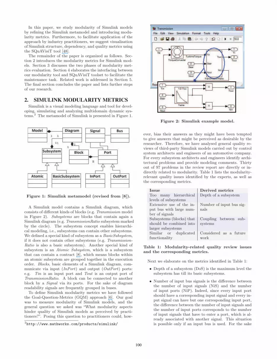
A Simulink model contains a Simulink diagram, whichconsists of different kinds of blocks (e.g. Transmission modelin Figure 2). Subsystems are blocks that contain again aSimulink diagram (e.g. TransmissionRatio subsystem markedby the circle). The subsystem concept enables hierarchi-cal modeling, i.e., subsystems can contain other subsystems.We defined a special kind of subsystem as a BasicSubsystem,if it does not contain other subsystems (e.g. Transmission-Ratio is also a basic subsystem). Another special kind ofsubsystem is an Atomic Subsystem, which is a subsystemthat can contain a contract [8], which means blocks withinan atomic subsystem are grouped together in the executionorder. Blocks, basic elements of a Simulink diagram, com-municate via input (InPort) and output (OutPort) ports:e.g. Tin is an input port and Tout is an output port ofTransmissionRatio. A block can be connected to anotherblock by a Signal via its ports. For the sake of diagramreadability signals are frequently grouped in buses.
To define Simulink modularity metrics we have followedthe Goal-Question-Metrics (GQM) approach [6]. Our goalwas to measure modularity of Simulink models, and thegeneral question we asked was “What modularity aspectshinder quality of Simulink models as perceived by practi-tioners?”. Posing this question to practitioners could, how-
2http://www.mathworks.com/products/simulink/
Figure 2: Simulink example model.
ever, bias their answers as they might have been temptedto give answers that might be perceived as desirable by theresearcher. Therefore, we have analysed general quality re-views of third-party Simulink models carried out by controlsystem architects and engineers of an automotive company.For every subsystem architects and engineers identify archi-tectural problems and provide modeling comments. Thirtyout of 97 problems in the review report are directly or in-directly related to modularity. Table 1 lists the modularity-relevant quality issues identified by the experts, as well asthe corresponding metrics.
Issue Derived metricsToo many hierarchicallevels of subsystems
Depth of a subsystem
Extensive use of the in-put bus with large num-ber of signals
Number of input bus sig-nals
Subsystems (blocks) thatshould be combined intolarger subsystems
Coupling between sub-systems
Similar or duplicatedfunctionality
Considered as a futurework
Table 1: Modularity-related quality review issuesand the corresponding metrics.
Next we elaborate on the metrics identified in Table 1:
• Depth of a subsystem (DoS) is the maximum level thesubsystem has till its basic subsystems.
• Number of input bus signals is the difference betweenthe number of input signals (NiS) and the numberof input ports (NiP). Indeed, since every input portshould have a corresponding input signal and every in-put signal can have but one corresponding input port,the difference between the number of input signals andthe number of input ports corresponds to the numberof input signals that have to enter a port, which is al-ready associated with another signal. This situationis possible only if an input bus is used. For the sake
100

Coupling metricsCBS Coupling Between SubsystemsDSC Degree of Subsystem CouplingNiP Number of input PortsNoP Number of output PortsNiS Number of input SignalsNoS Number of output SignalsCohesion metricsDoS Depth of a SubsystemNCS Number of Contained SubsystemsNBS Number of Basic Subsystems
Table 2: Modularity metrics for Simulink model.
of symmetry, we also measure the number of outputsignals (NoS) and the number of output ports (NoP).
• To measure coupling between subsystems (CBS) for agiven subsystem we count the number of subsystemscoupled to the subsystem, i.e., receiving input signalsfrom the subsystem or sending output signals to thesubsystem. CBS is close in spirit to Coupling BetweenObject classes [12], an object-oriented metrics refer-ring to total number of methods of a class, which usesmethods or instance variables of another class.
• In addition to CBS, we define Degree of SubsystemCoupling (DSC) to give additional weight to the out-put which imply more complexity: DSC = WiNis +WoNos, where Wi = 1, is weight of input dependen-cies, Wo = 2, is weight of output dependencies.
Furthermore, building on the long-standing tradition ofmodularity research in software engineering [36, 12, 43],we have decided to augment the metrics list in Table 1with those reflecting common software engineering guide-lines such as the number of connections between subsystemsshould be low (low coupling), system should contain similaror related functionalities (high cohesion) and communicationbetween subsystems should be limited (narrow interfaces).While coupling and interface granularity have already beenexplicitly addressed by the metrics in Table 1, to evaluatecohesion we include the Number of Contained Subsystems(NCS) at all hierarchical levels and the Number of BasicSubsystems (NBS). In Table 2, the summary of modular-ity metrics for Simulink models is provided. The interfacegranularity metrics are integrated into the coupling metrics.
3. METRICS TOOL AND EVALUATIONWe developed a Java tool to measure the defined met-
rics on Simulink models, since to our knowledge there is noother tool available. The tool uses a Java parser for SimulinkMDL files of the ConQAT open-source tool3, which is an in-tegrated toolkit for continuously monitoring quality charac-teristics of software systems. Our tool reads Simulink MDLfiles with the standard structural format and generates themetrics files with the list of subsystems and the respectivemodularity metrics. In the following sub-sections, we dis-cuss the results of the evaluations that were carried out intwo main phases.
3http://www.conqat.org/
3.1 Expert evaluationThe first part of the validation effort was based on the
expert evaluation. To this end we have randomly selecteda number subsystems of an industrial application and gotthem evaluated by the domain experts using a scale of 1 to10, 1 meaning worst and 10 meaning best modularity. Wehave opted for the 1–10 scale rather than more customaryfive- or seven-point Likert scales, since the 1–10 scale is theone used in Dutch schools and universities, and, hence, isfamiliar to the domain experts. The experts also providethe reasoning for the scores they give to the subsystems.
Results of the expert evaluation are summarized in Table 3(left). For confidentiality reasons we abbreviate the namesof the subsystems. Similarly, for privacy reasons we do notdisclose the names of the experts.
SubsystemExperts
ABC DEFEH 3 3 7 5 5 7ED 7 9 7 8 6 8SM 7 7 5 3 5 8IDA 9 8 7 7 7 8GS 7 6 7 7 6 8TP 9 8 7 8 8 8TS 3 7 1 7 7 7BTL 9 8 7 8 8 7CC 7 8 1 8 7 6TSCA 9 8 7 8 8 8TRC 7 8 5 7 8 3
Table 3: Expert review of selected subsystems of
the industrial application and the corresponding ˜T-
graph. Components missing from the ˜T-graph areincomparable.
We start by comparing the evaluation of different sub-systems. Traditionally, comparison of multiple groups fol-lows a two-step approach: first, a global null hypothesisis tested, and then multiple comparisons are used to testsub-hypotheses pertaining to each pair of groups. The firststep is commonly carried out by means of analysis of vari-ance (ANOVA) [21] or its non-parametric counterpart, theKruskal-Wallis one-way analysis of variance by ranks [22].The second step uses pairwise t-tests or their nonparametriccounterparts, Wilcoxon-Mann-Whitney tests [53], with Bon-ferroni correction [15, 46]. Unfortunately, the global test nullhypothesis may be rejected while none of the sub-hypothesesare rejected, or vice versa [20]. Moreover, simulation studiessuggest that the Wilcoxon-Mann-Whitney test is not robustto unequal population variances, especially in the unequalsample size case [54]. Therefore, one-step approaches arerequired: such an approach should produce confidence in-tervals which always lead to the same test decisions as themultiple comparisons. We have used the recently proposed
multiple contrast test procedure ˜T [27] in combination with
a ˜T-graph [50]. Using the ˜T-procedure for the “all pairs”(Tukey-type) contrast and 95% confidence level and inspect-
ing the corresponding ˜T-graph (Table 3 right) we can con-clude that the experts prefer BTL, TP and TSCA over EH
and TP and TSCA over TS. The ˜T-procedure does not re-veal consistent differences between the expert evaluations,i.e., one cannot argue that one of the experts consistently
101

gives higher/lower rankings than another one. Therefore,we do not exclude any of the evaluations.
We observe, however, that for individual subsystems theexpert ratings are not always consistent with each other: e.g.EH is ranked 3 by experts A and B and 7 by experts C andF. To get better insights in the reasons for this discrepancy,we have discussed it with the experts. Discussion revealedthat experts A, B and C interpreted modularity as coupling,while experts D, E and F interpreted modularity in terms ofcohesion. Thus as shown in Table 3, we grouped the expertsevaluation by coupling (A to C) and cohesion (D to F).
Before determining the relation between the coupling met-rics and expert evaluation, we carried out the Kendall’sτ correlation test [17] on the coupling-related metrics andidentified DSC as the statistically independent metric formeasuring coupling attribute. In Figure 3, a scatter plotof DSC values and an average experts’ evaluation based oncoupling (Exp) shows that there is a negative correlationbetween DSC and the expert evaluation. We calculated theKendall’s τ correlation coefficient to determine the strengthof the correlation and it is r = −0.641, which suggests astrong negative correlation. Therefore, high values of DSCindicate poor modularity according to experts evaluationbased on coupling. The subsystems BTL, TP and TSCAhave low DSC values and EH and TS have high DSC values.In the review comments of the domain experts, the list ofsubsystems with high coupling metrics values (high valuesof DSC) indeed identified as subsystems that are difficultto maintain due to big dependencies. There are, however,subsystems with the purpose of input processing thus scorehigh on coupling. Therefore, it is not necessary to take themetrics as absolute indicators of poor modularity but ratheran facilitator of the maintenance process.
5 10 15 20 25 30
45
67
8
DSC
Exp
Figure 3: Relation between expert evaluation andcoupling measurement.
We made the Kendall’s τ correlation analysis on the cohe-sion-related metrics to identify the statistically independentcohesion metrics. According to the analysis, NCS and NBShave positive correlation, r = 0.952. Therefore, we excludethe NBS metric. Regarding the correlation between NCS,
DSC NCS DoS NFDSC 1.000 0.597 0.569 0.549NCS 1.000 0.907 0.683DoS 1.000 0.705NF 1.000
Table 4: Kendall’s τ correlation analysis.
DoS and expert evaluation, there is no correlation betweenNCS and expert evaluation (r = −0.238). However, theKendall’s τ correlation coefficient, r = −0.279, suggestsa very weak negative correlation between DoS and expertevaluation – subsystems with lower depth of a subsystemvalues are evaluated good by the cohesion-related experts.In the review comments of the domain experts, the list ofsubsystems with high hierarchal level (more than 4 hierar-chal depths) identified as subsystems that are difficult tounderstand.
3.2 Metrics evaluationIn this evaluation phase, we carried out a correlation anal-
ysis to detect if there is a relation between modularity met-rics and the number of faults. A fault is an incorrect programstep, process, or data definition in a computer program [18].In this paper, we use the term fault, which exclude incorrectstep and process, but refers to an error in modeling or logicthat cause the system to malfunction or to produce incor-rect results. It is important to measure model defects tokeep control over the maintenance [7]. As stated earlier ourmain goal was to identify modularity aspects that hinderquality of Simulink models. By obtaining fault informationand analysing the relation of faults to modularity metrics,we aim to determine quality and furthermore predict a fault-proneness or a presence of faults.
We used the data collected from the second industrial ap-plication consisting of 41 subsystems, from which 20 sub-systems contain faults. Since there are a number of tiedvalues and establishing whether any modularity metric andthe number of faults are statistically dependent rather thanmeasuring the degree of the relationship between linear re-lated variables, we use the Kendall’s τ correlation test asused in Section 3.1. Table 4 shows the correlations betweenthe selected metrics and number of faults (NF).
The correlation coefficient infers the strength and direc-tion of the correlation meaning a positive correlation coef-ficient indicates a positive relation between the metrics anddefects and a negative correlation coefficient indicates a neg-ative relation. The significance points to a probability for acoincidence. We accept a common significance level of 0.05.As presented in Table 4, the all the metrics are positivelycorrelated with the number of faults. Based on this pre-liminary analysis, we can conclude that the high value ofhigher hierarchal levels may imply a more fault-prone sys-tem. This is in line with the studies from other programmingparadigms, which show that there is a strong correlation be-tween software maintenance effort and software metrics inthe procedural and object-oriented paradigms e.g. [29] [41].
4. VISUALIZATION TOOLAs the preliminary analyses concluded that the degree of a
subsystem coupling (DSC), number of contained subsystems(NCS), and depth of a subsystem (DoS) are key to assess
102

modularity of Simulink models, it is important to visual-ize these metrics in an efficient manner. For this purpose,we selected SQuAVisiT (Software Quality Assessment andVisualization Toolset) [48] as it is a flexible tool for visualsoftware analytics of multiple programming languages. TheSQuAVisiT is intended to support a software developmentteam (including developers and maintainers) for carrying outquality assurance and maintenance tasks in an efficient way.
Figure 4: SQuAVisiT extended quality radial viewof SolidSX tool5
In Figure 4, it visualizes the modularity and dependencyof the industrial application that we studied. (The subsys-tem names here and elsewhere are blurred up due to confi-dentiality reasons.) The radial view was first introduced byHolten [23] and extended in SolidSX [40] and the SQuAVisiTtoolset [42]. Subsystems of a Simulink model are illustratedas nested rectangles in the outer rings of the radial view. Therelations between (basic) subsystems, such as input and out-put signals, are shown as curved arrows in blue color. Thetool allows for zooming into the subsystems for more de-tailed views. The colors on subsystems are used to visualizevalues of modularity metrics. The green subsystems showthe modular and red ones show subsystems which requireattention for improving their modularity.
The modularity metrics are supported in the SQuAVisiTtool. Figure 4 demonstrates the visualization of softwarewith CBS (Coupling Between Subsystems) metric, whereCBS is selected in the right panel and CBS values for thesubsystems are shown in numbers and respective coloring.The grey rectangles represent Bus Selectors (forking bus sig-nals) and Bus Creators (merging signals into a bus signal).Figure 4 highlights not only subsystems with high coupling,but also shows subsystems which they depend upon, so thatthe developer can easily navigate and zoom into the depen-dencies of a particular outlier. This facilitates the signal
5http://www.solidsourceit.com/
tracing activity in Simulink and decreases the analysis timeto detect coupled subsystems.
Figure 5: SQuAVisiT quality treemap view.
An example treemap view of our industrial application asillustrated in Figure 5, it shows its structural nesting high-lighted with modularity measurements (green — modular,red — nonmodular). The advantage of this view is all thesubsystems and their sub-components are shown simultane-ously and it is easy for the architect to identify easily thesubsystems, which may require further inspection [40].
Figure 6: SQuAVisiT quality table view.
In Figure 6, we illustrate all the metric values of thesubsystems including the excluded metrics (NiP, NoP, NIS,NOS, and NBS). The table contains cells as pixel bars scaledand colored by metric values as first introduced by Rao et al.[39]. The first column displays the list of subsystems and therest of the columns list all the metric values and last columnlists the number of faults of the subsystems. Subsystemsare sorted by descending number of fault value. This canhelp the domain experts locate easily the most problematicsubsystems and their respective metric values.
103

5. RELATED WORKA quality model based on ISO/IEC 9126 standard for as-
sessing internal quality of Simulink models is introducedby W. Hu et al. [25]. Six quality sub-characteristics likeanalysability, changeability, stability, testability, understand-ability, and adaptability are selected for the quality modeltogether with respective metrics. However, modularity sub-characteristic and respective metrics are not explicitly ad-dressed by this quality model. A metric suite to identifythe most complex and instable parts of the system is intro-duced by Menkhaus and Andrich [32]. It measures McCabecyclomatic complexity, instability of blocks inspired by Mar-tin’s afferent and efferent connections between blocks (CBB)(based on the interaction of blocks with other blocks), andinstability of system accounting influences of the completesystem on a block. Although afferent and efferent connec-tions between blocks are used in the metrics of instability ofblocks, it is not directly related to modularity. The objectiveof this metric suite is to guide analysis team during the riskassessment of failure modes rather than providing insightinto improving modularity of the system or subsystem.
The Mathworks provide quality related tools like Model-ing Metric Tool [2] [24] and sldiagnostics [3] to quantitativelymeasure the content of a Simulink model (Stateflow model aswell) to improve the productivity and quality of model devel-opment (e.g. model size, complexity, and defect densities).Quality analysis metrics for measuring instability, abstract-ness, and complexity of Simulink models are introduced byOlszewska (Pl ↪aska) in [35] [34]. However, the modularitymetrics are not explicitly addressed by the MathWorks toolsand Olszewska’s metrics. Modularity metrics as part of soft-ware architecture metrics are introduced by Ahrens et al. [4].However, validation of the metrics is not provided.
Existing methods for measuring modularity are mostly in-tended for imperative and object-oriented (OO) software e.g.Li and Henry’s OO metrics that predict maintainability (i.e.the number of methods invocation s in a class’s implementa-tion, the number of abstract data types used in the measuredclass and defined in another class of the system) [29], Mar-tin’s OO design quality metrics [31, 44], Chidamber and Ke-merer’s metrics suite for OO design (i.e. weighted methodsper class, depth of inheritance, number of children, couplingbetween objects, response for a class, lack of cohesion ofmethods) [12], Lorenz and Kidd’s OO software metrics [30],and design quality metrics of OO software systems of Abreuet al. [9].
In our work we have proposed a series of modularity met-rics for Simulink subsystems. Since subsystems can be com-posed into larger ones, rather than evaluating the largerones directly, one could have inferred the metrics valuesof the larger subsystems by aggregating the correspondingmetric values of the subsystems composing them. This ap-proach would be related to the metrics aggregation problemas known in software maintenance. While the most com-mon aggregation technique, the mean, represents a centraltendency and as such is unreliable for heavily skewed dis-tributions, typical for software metrics [51], recently appliedto metrics aggregation econometric inequality indices [52,45] and threshold-based approaches [33] provide a promis-ing way to address this challenge. More profound study ofmetrics aggregation for Simulink models is considered as afuture work.
6. CONCLUSION AND FUTURE WORKDue to the increasing complexity and size of Simulink
models [19], it is important to assess its quality. In thispaper, we focused on the modularity aspects of Simulinkmodels and defined modularity metrics for Simulink mod-els following the Goal-Question-Metrics (GQM) approach.We defined a modularity metrics suit consisting of 9 cou-pling and cohesion-related metrics and validated it with ex-perts’ evaluation and preliminary statistical analysis. Weidentified three independent metrics (degree of subsystemcoupling, number of contained subsystems, and depth ofa subsystem) based on the statistical analysis and identi-fied a correlation between modularity metrics and numberof errors. We developed a tool to measure modularity ofthe Simulink models and visualized the quality aspects withSQuAVisiT toolset.
Although we did a preliminary analysis on defining a re-lation between modularity metrics and number of faults, itneeds to be explored further if the moderate correlation issatisfactory. This investigation can be compared to sourcecode or other graphical modeling languages. The benefit ofvisualizing using SQuAVisit needs to be investigated further.As identified in our previous research that connectors (sig-nals or dependencies) are not modeled as first-class objectsin automotive architecture description languages (ADLs) [13],it holds for MATLAB/Simulink modeling as well. Therefore,we will refine the modularity metrics related to connectorse.g. number of subsystems using a signal, unused signals of abus. The increasing complexity of Simulink models requiresa need of higher abstraction levels. Therefore, we believethat the metrics we defined here can be applied or extendedto architectural quality metrics for automotive systems [14].In addition, the modularity metrics should take into accountthe increasing number of subsystems and dependencies whenthe system evolves. This issue has been identified in theanalysis of high-cohesion/low-coupling metrics [5].
Modularity is one of the new quality sub-characteristicsof ISO/IEC SQuaRE quality standard and it is related toother quality (sub-)characteristics e.g. reusability, modifia-bility, and stability. In the expert evaluation, understand-ability is considered as one of the key related quality charac-teristic as well due to the Simulink visual modeling. There-fore, we plan to extend the proposed modularity metricswith the related quality (sub-)characteristics for Simulinkmodels. Once the quality metrics for the Simulink modelsfor the automotive domain is thoroughly validated, it can bemodified or extended further for other embedded domains.
As stated in Section 5, we also consider as future work in-vestigation of metrics aggregation techniques for Simulinkmodels. Finally, while in the current paper we have fo-cussed on one Simulink model, we intend to study changes inmodularity metrics during the system evolution, and inves-tigate the applicability of Lehman’s general software evo-lution laws [28] to evolution of Simulink models (cf. [11,26]). Should model repositories become available, we canaugment the evolutionary studies by repository mining tech-niques [37].
7. ACKNOWLEDGEMENTThe first three authors are supported by the Dutch Auto-
motive Innovation Programme (HTAS) project (HTASI10002).
104

8. REFERENCES
[1] ISO/IEC 25010:2011 Systems and softwareengineering - Systems and software QualityRequirements and Evaluation (SQuaRE) - System andsoftware quality models. http://www.iso.org/.
[2] The modeling metric tool. http://www.mathworks.com/matlabcentral/fileexchange/5574.
[3] The sldiagnostics tool. http://www.mathworks.nl/help/simulink/slref/sldiagnostics.html.
[4] D. Ahrens, A. Frey, A. Pfeiffer, and T. Bertram.Designing reusable and scalable software architecturesfor automotive embedded systems in driver assistance.Technical report, 2010.
[5] N. Anquetil and J. Laval. Legacy softwarerestructuring: Analyzing a concrete case. In CSMR,pages 279–286, 2011.
[6] V. R. Basili. Software modeling and measurement: thegoal/question/metric paradigm. Technical report,College Park, MD, USA, 1992.
[7] B. Boehm. Characteristics of Software Quality. TRWsoftware series / Systems Engineering and IntegrationDivision, TRW Systems Group. 1973.
[8] P. Bostrom, R. Gronblom, T. Huotari, and J. Wiik.An approach to contract-based verification of Simulinkmodels. Technical report, 2010.
[9] F. Brito e Abreu, Miguel Goulao, and R. Esteves.Toward the design quality evaluation ofobject-oriented software systems. In Proc. ofInternational Conference of Software Quality (QSIC),pages 44–57, 1995.
[10] M. Broy. Challenges in automotive softwareengineering. In Proc. of the International Conferenceon Software Engineering (ICSE), pages 33–42, NewYork, NY, USA, 2006. ACM.
[11] J. Businge, A. Serebrenik, and M. G. J. van denBrand. An empirical study of the evolution of Eclipsethird-party plug-ins. In Proc. of EVOL/IWPSE, pages63–72, 2010.
[12] S. Chidamber and C. Kemerer. A metrics suite forobject oriented design. Software Engineering, IEEETransactions on, 20(6):476 –493, 1994.
[13] Y. Dajsuren, M. G. J. van den Brand, andA. Serebrenik. Evolution mechanisms of automotivearchitecture description languages. In BENEVOL,pages 24–25, 2011.
[14] Y. Dajsuren, M. G. J. van den Brand, A. Serebrenik,and R. Huisman. Automotive ADLs: a study onenforcing consistency through multiple architecturallevels. In Proc. of Quality of Software Architectures(QoSA), pages 71–80. ACM, 2012.
[15] O. J. Dunn. Multiple comparisons among means.Journal of American Statistical Association, 56:52–64,1961.
[16] European Commission. Commission Regulation (EC)No 692/2008 of 18 July 2008 implementing andamending Regulation (EC) No 715/2007 of theEuropean Parliament and of the Council ontype-approval of motor vehicles with respect toemissions from light passenger and commercialvehicles (Euro 5 and Euro 6) and on access to vehiclerepair and maintenance information, 2008.
[17] A. Field. Discovering Statistics Using SPSS. SAGEPublications, 2005.
[18] W. A. Florac. Software Quality Measurement: AFramework for Counting Problems and Defects.Technical report, Software Engineering Institute, 1992.
[19] J. Friedman. MATLAB/Simulink for automotivesystems design. In Proc. of Design, Automation andTest in Europe (DATE), volume 1, pages 1 –2, 2006.
[20] K. R. Gabriel. Simultaneous test procedures—sometheory of multiple comparisons. The AnnalsMathematical Statistics, 40(1):224–250, 1969.
[21] R. Harris. ANOVA: An Analysis of Variance Primer.F.E. Peacock Publishers, 1994.
[22] M. Holander and D. A. Wolfe. Nonparametricstatistical methods. Wiley, 1973.
[23] D. Holten. Hierarchical edge bundles: Visualization ofadjacency relations in hierarchical data. IEEETransactions on Visualization and ComputerGraphics, 12(5):741–748, 2006.
[24] A. Hosagrahara and P. Smith. Measuring productivityand quality in model-based design. Technical report,2005.
[25] W. Hu, T. Loeffler, and J. Wegener. Quality modelbased on ISO/IEC 9126 for internal quality ofMATLAB/Simulink/Stateflow models. pages 325–330, 2012.
[26] A. Israeli and D. G. Feitelson. The linux kernel as acase study in software evolution. Journal of Systemsand Software, 83(3):485–501, 2010.
[27] F. Konietschke, L. A. Hothorn, and E. Brunner.Rank-based multiple test procedures and simultaneousconfidence intervals. Electronic Journal of Statistics,6:738–759, 2012.
[28] M. M. Lehman and L. A. Belady, editors. Programevolution: processes of software change. AcademicPress Professional, Inc., San Diego, CA, USA, 1985.
[29] W. Li and S. Henry. Object-oriented metrics thatpredict maintainability. Journal of Systems andSoftware, 23(2):111 – 122, 1993.
[30] M. Lorenz and J. Kidd. Object-oriented softwaremetrics: a practical guide. Prentice-Hall, Inc., UpperSaddle River, NJ, USA, 1994.
[31] R. Martin. OO Design Quality Metrics - An Analysisof Dependencies. In Workshop Pragmatic andTheoretical Directions in Object-Oriented SoftwareMetrics, 1994.
[32] G. Menkhaus and B. Andrich. Metric suite directingthe failure mode analysis of embedded softwaresystems. In ICEIS (3), pages 266–273, 2005.
[33] K. Mordal, N. Anquetil, J. Laval, A. Serebrenik,B. Vasilescu, and S. Ducasse. Software quality metricsaggregation in industry. Journal of Software:Evolution and Process, 2012.
[34] M. Olszewska (Pl ↪aska). Simulink-specific designquality metrics. Technical report, Turku, Finland,2011.
[35] M. Olszewska (Pl ↪aska), M. Huova, M. Walden,K. Sere, and M. Linjama. Quality analysis of simulinkmodels. In I. Schieferdecker and S. Goericke, editors,Software Quality Engineering. Proceedings of the
105

CONQUEST 2009., pages 223–240. dpunkt.verlagGmbH, 2009.
[36] D. L. Parnas. On the criteria to be used indecomposing systems into modules. Commun. ACM,15(12):1053–1058, 1972.
[37] W. Poncin, A. Serebrenik, and M. G. J. van denBrand. Process mining software repositories. InT. Mens, Y. Kanellopoulos, and A. Winter, editors,CSMR, pages 5–14. IEEE Computer Society, 2011.
[38] A. Pretschner, M. Broy, I. H. Kruger, and T. Stauner.Software engineering for automotive systems: Aroadmap. In Future of Software Engineering, pages55–71, Washington, DC, USA, 2007. IEEE ComputerSociety.
[39] R. Rao and S. K. Card. The table lens: merginggraphical and symbolic representations in aninteractive focus+context visualization for tabularinformation. In Conference Companion on HumanFactors in Computing Systems, CHI ’94, pages 222–,New York, NY, USA, 1994. ACM.
[40] D. Reniers, L. Voinea, and A. Telea. Visualexploration of program structure, dependencies andmetrics with solidsx. In VISSOFT, pages 1–4, 2011.
[41] H. Rombach. A controlled expeniment on the impactof software structure on maintainability. SoftwareEngineering, IEEE Transactions on, SE-13(3):344 –354, march 1987.
[42] S. Roubtsov, A. Telea, and D. Holten. Squavisit: Asoftware quality assessment and visualisation toolset.In Proceedings of the Seventh IEEE InternationalWorking Conference on Source Code Analysis andManipulation, SCAM ’07, pages 155–156, Washington,DC, USA, 2007. IEEE Computer Society.
[43] C. N. Sant’Anna. On the Modularity ofAspect-Oriented Design: A Concern-DrivenMeasurement Approach. PhD thesis, PontificalCatholic University of Rio de Janeiro, 2008.
[44] A. Serebrenik, S. A. Roubtsov, and M. G. J. van denBrand. Dn-based architecture assessment of Java opensource software systems. In ICPC, pages 198–207.IEEE Computer Society, 2009.
[45] A. Serebrenik and M. G. J. van den Brand. Theilindex for aggregation of software metrics values. InICSM, pages 1–9, 2010.
[46] D. J. Sheskin. Handbook of Parametric andNonparametric Statistical Procedures. Chapman &Hall, 4 edition, 2007.
[47] I. Sturmer and H. Pohlheim. Model quality assessmentin practice: How to measure and assess the quality ofsoftware models during the embedded softwaredevelopment process. In Embedded Real Time Softwareand Systems, 2012.
[48] M. G. J. van den Brand, S. Roubtsov, andA. Serebrenik. SQuAVisiT: A flexible tool for visualsoftware analytics. In Proceedings of the EuropeanConference on Software Maintenance andReengineering, pages 331–332, Washington, DC, USA,2009. IEEE Computer Society.
[49] V. van Reeven, T. Hofman, R. Huisman, andM. Steinbuch. Extending energy management inhybrid electric vehicles with explicit control of gear
shifting and start-stop. In American ControlConference (ACC), pages 521–526, 2012.
[50] B. Vasilescu, A. Serebrenik, M. Goeminne, andT. Mens. On the variation and specialisation ofworkload—a case study of the gnome ecosystemcommunity. Empirical Software Engineering, 2013.accepted.
[51] B. Vasilescu, A. Serebrenik, and M. G. J. van denBrand. By no means: a study on aggregating softwaremetrics. In Proceedings of the 2nd InternationalWorkshop on Emerging Trends in Software Metrics,WETSoM ’11, pages 23–26, New York, NY, USA,2011. ACM.
[52] B. Vasilescu, A. Serebrenik, and M. G. J. van denBrand. You can’t control the unfamiliar: A study onthe relations between aggregation techniques forsoftware metrics. In ICSM, pages 313–322, 2011.
[53] F. Wilcoxon. Individual comparisons by rankingmethods. Biometrics Bulletin, 1(6):80–83, 1945.
[54] D. W. Zimmerman and B. D. Zumbo. Parametricalternatives to the Student t test under violation ofnormality and homogeneity of variance. Perceptualand Motor Skills, 74(3(1)):835–844, 1992.
106


