Embed Size (px)
Citation preview
Dell|EMC AX4-5i iSCSI Storage Arrays
With Microsoft® Windows Server®
Failover Clusters
Hardware Installation andTroubleshooting Guide
w w w . d e l l . c o m | s u p p o r t . d e l l . c o m

Notes, Notices, and Cautions
NOTE: A NOTE indicates important information that helps you make better use of your computer.
NOTICE: A NOTICE indicates either potential damage to hardware or loss of data and tells you how to avoid the problem.
CAUTION: A CAUTION indicates a potential for property damage, personal injury, or death.
___________________
Information in this document is subject to change without notice.© 2008 Dell Inc. All rights reserved.
Reproduction in any manner whatsoever without the written permission of Dell Inc. is strictly forbidden.
Trademarks used in this text: Dell, the DELL logo, PowerEdge, PowerVault, and OpenManage are trademarks of Dell Inc.; Active Directory, Microsoft, Windows, Windows Server, and Windows NT are either trademarks or registered trademarks of Microsoft Corporation in the United States and/or other countries; EMC, Navisphere, and PowerPath are registered trademarks and MirrorView, SAN Copy, and SnapView are trademarks of EMC Corporation.
Other trademarks and trade names may be used in this document to refer to either the entities claiming the marks and names or their products. Dell Inc. disclaims any proprietary interest in trademarks and trade names other than its own.
April 2008 Rev A00
Contents
1 Introduction . . . . . . . . . . . . . . . . . . . . . . . . 5
Cluster Solution . . . . . . . . . . . . . . . . . . . . . . 6
Cluster Hardware Requirements . . . . . . . . . . . . . 6
Cluster Nodes. . . . . . . . . . . . . . . . . . . . . 7
Cluster Storage . . . . . . . . . . . . . . . . . . . . 8
NICs Dedicated to iSCSI . . . . . . . . . . . . . . . 9
Ethernet Switches Dedicated to iSCSI . . . . . . . . 9
Supported Cluster Configurations . . . . . . . . . . . . . 9
Direct-Attached Cluster . . . . . . . . . . . . . . . 9
iSCSI SAN-Attached Cluster . . . . . . . . . . . . 10
Other Documents You May Need . . . . . . . . . . . . 11
2 Cabling Your Cluster Hardware . . . . . . . . 13
Cabling the Mouse, Keyboard, and Monitor . . . . . . 13
Cabling the Power Supplies . . . . . . . . . . . . . . . 13
Cabling Your Cluster for Public and Private Networks . . . . . . . . . . . . . . . . . . . . 15
Cabling the Public Network . . . . . . . . . . . . 16
Cabling the Private Network . . . . . . . . . . . . 17
NIC Teaming . . . . . . . . . . . . . . . . . . . . 17
Cabling the Storage Systems . . . . . . . . . . . . . . 18
Cabling Storage for Your Direct-Attached Cluster . . . . . . . . . . . . . . 18
Cabling Storage for Your iSCSI SAN-Attached Cluster . . . . . . . . . . . . 20
Contents 3
3 Preparing Your Systems
for Clustering . . . . . . . . . . . . . . . . . . . . . 27
Cluster Configuration Overview . . . . . . . . . . . . . 27
Installation Overview . . . . . . . . . . . . . . . . . . 29
Installing the iSCSI NICs . . . . . . . . . . . . . . 30
Installing the Microsoft iSCSI Software Initiator . . . . . . . . . . . . . . . . . . 30
Modifying the TCP Registry Settings . . . . . . . . 31
Installing EMC® PowerPath® . . . . . . . . . . . 31
Configuring the Shared Storage System . . . . . . 32
Installing and Configuring a Failover Cluster . . . . 41
A Troubleshooting . . . . . . . . . . . . . . . . . . . 43
B Cluster Data Form . . . . . . . . . . . . . . . . . 49
C iSCSI Configuration Worksheet . . . . . . . 51
Index . . . . . . . . . . . . . . . . . . . . . . . . . . . . . . . 53
4 Contents
IntroductionA Dell™ Failover Cluster combines specific hardware and software components to provide enhanced availability for applications and services that run on your cluster. A Failover Cluster reduces the possibility of any single point of failure within the system that can cause the clustered applications or services to become unavailable. It is recommended that you use redundant components like servers, storage power supplies, connections between the nodes and the storage array(s), connections to client systems or other servers in a multi-tier enterprise application architecture in your cluster.
This document provides information and specific configuration tasks that enable you to configure your Failover Cluster with Dell|EMC AX4-5i Internet Small Computer System Interface (iSCSI) storage array(s).
For more information on deploying your cluster with Windows Server 2003 operating systems, see the Dell™ Failover Clusters with Microsoft Windows Server 2003 Installation and Troubleshooting Guide located on the Dell Support website at support.dell.com. For more information on deploying your cluster with Windows Server 2008 operating systems, see the Dell Failover Clusters with Microsoft Windows Server 2008 Installation and Troubleshooting Guide located on the Dell Support website at support.dell.com.
For a list of recommended operating systems, hardware components, and driver or firmware versions for your Failover Cluster, see the Dell Cluster Configuration Support Matrices located on the Dell High Availability Clustering website at www.dell.com/ha.
Introduction 5
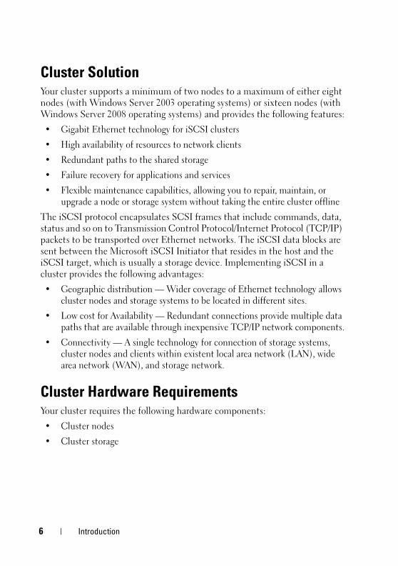
Cluster SolutionYour cluster supports a minimum of two nodes to a maximum of either eight nodes (with Windows Server 2003 operating systems) or sixteen nodes (with Windows Server 2008 operating systems) and provides the following features:
• Gigabit Ethernet technology for iSCSI clusters
• High availability of resources to network clients
• Redundant paths to the shared storage
• Failure recovery for applications and services
• Flexible maintenance capabilities, allowing you to repair, maintain, or upgrade a node or storage system without taking the entire cluster offline
The iSCSI protocol encapsulates SCSI frames that include commands, data, status and so on to Transmission Control Protocol/Internet Protocol (TCP/IP) packets to be transported over Ethernet networks. The iSCSI data blocks are sent between the Microsoft iSCSI Initiator that resides in the host and the iSCSI target, which is usually a storage device. Implementing iSCSI in a cluster provides the following advantages:
• Geographic distribution — Wider coverage of Ethernet technology allows cluster nodes and storage systems to be located in different sites.
• Low cost for Availability — Redundant connections provide multiple data paths that are available through inexpensive TCP/IP network components.
• Connectivity — A single technology for connection of storage systems, cluster nodes and clients within existent local area network (LAN), wide area network (WAN), and storage network.
Cluster Hardware RequirementsYour cluster requires the following hardware components:
• Cluster nodes
• Cluster storage
6 Introduction
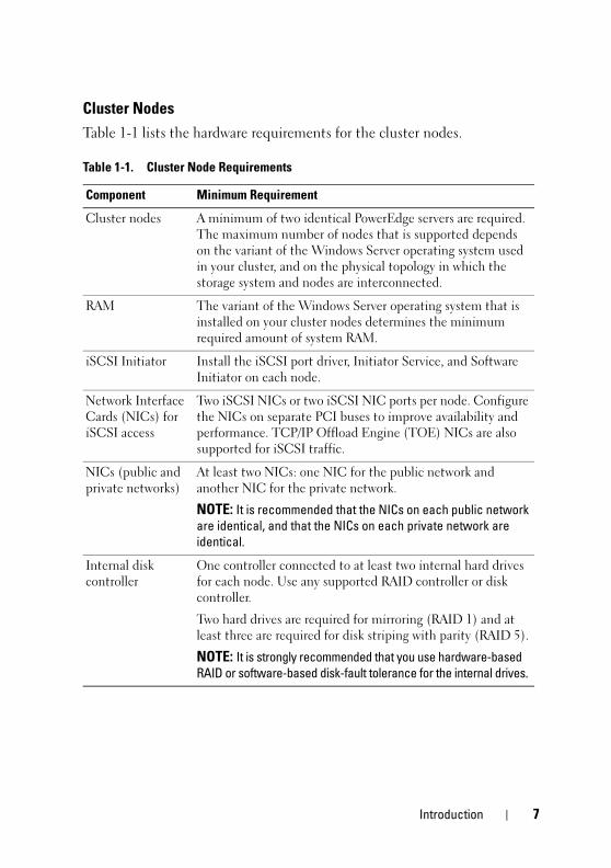
Cluster Nodes
Table 1-1 lists the hardware requirements for the cluster nodes.
Table 1-1. Cluster Node Requirements
Component Minimum Requirement
Cluster nodes A minimum of two identical PowerEdge servers are required. The maximum number of nodes that is supported depends on the variant of the Windows Server operating system used in your cluster, and on the physical topology in which the storage system and nodes are interconnected.
RAM The variant of the Windows Server operating system that is installed on your cluster nodes determines the minimum required amount of system RAM.
iSCSI Initiator Install the iSCSI port driver, Initiator Service, and Software Initiator on each node.
Network Interface Cards (NICs) for iSCSI access
Two iSCSI NICs or two iSCSI NIC ports per node. Configure the NICs on separate PCI buses to improve availability and performance. TCP/IP Offload Engine (TOE) NICs are also supported for iSCSI traffic.
NICs (public and private networks)
At least two NICs: one NIC for the public network and another NIC for the private network.
NOTE: It is recommended that the NICs on each public network are identical, and that the NICs on each private network are identical.
Internal disk controller
One controller connected to at least two internal hard drives for each node. Use any supported RAID controller or disk controller.
Two hard drives are required for mirroring (RAID 1) and at least three are required for disk striping with parity (RAID 5).
NOTE: It is strongly recommended that you use hardware-based RAID or software-based disk-fault tolerance for the internal drives.
Introduction 7
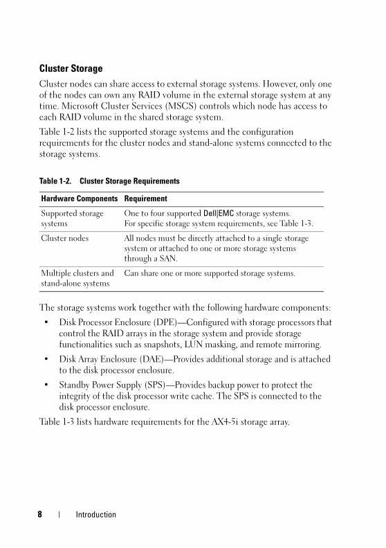
Cluster Storage
Cluster nodes can share access to external storage systems. However, only one of the nodes can own any RAID volume in the external storage system at any time. Microsoft Cluster Services (MSCS) controls which node has access to each RAID volume in the shared storage system.
Table 1-2 lists the supported storage systems and the configuration requirements for the cluster nodes and stand-alone systems connected to the storage systems.
The storage systems work together with the following hardware components:
• Disk Processor Enclosure (DPE)—Configured with storage processors that control the RAID arrays in the storage system and provide storage functionalities such as snapshots, LUN masking, and remote mirroring.
• Disk Array Enclosure (DAE)—Provides additional storage and is attached to the disk processor enclosure.
• Standby Power Supply (SPS)—Provides backup power to protect the integrity of the disk processor write cache. The SPS is connected to the disk processor enclosure.
Table 1-3 lists hardware requirements for the AX4-5i storage array.
Table 1-2. Cluster Storage Requirements
Hardware Components Requirement
Supported storage systems
One to four supported Dell|EMC storage systems. For specific storage system requirements, see Table 1-3.
Cluster nodes All nodes must be directly attached to a single storage system or attached to one or more storage systems through a SAN.
Multiple clusters and stand-alone systems
Can share one or more supported storage systems.
8 Introduction

NOTE: Ensure that the core software version running on the storage system is supported. For specific version requirements, see the Dell Cluster Configuration Support Matrices located on the Dell High Availability Cluster website at www.dell.com/ha.
NICs Dedicated to iSCSI
The NIC controlled by iSCSI Software Initiator acts as an I/O adapter to connect the system's expansion bus and the storage components. Failover Cluster solutions that are configured with the AX4-5i storage array require two iSCSI NICs or NIC ports in each PowerEdge system to provide redundant paths and load balance the I/O data transfer to the storage system.
Ethernet Switches Dedicated to iSCSI
The Gigabit switch for iSCSI access functions as a regular network switch that provides extension and dedicated interconnection between the node and the storage system(s).
Supported Cluster Configurations
Direct-Attached Cluster
In a direct-attached cluster, both nodes of the cluster are directly attached to a single storage system. In this configuration, the RAID controllers (or storage processors) on the storage systems are connected by cables directly to the iSCSI NIC ports in the nodes.
Figure 1-1 shows a basic direct-attached, single-cluster configuration.
Table 1-3. Dell|EMC Storage System Requirements
Processor Enclosure
Minimum Required Storage
Possible Storage Expansion
SPS
AX4-5i One DPE with at least 4 and up to 12 hard drives
Up to three DAE with a maximum of 12 hard drives each
1 (required) and 2 (optional)
Introduction 9
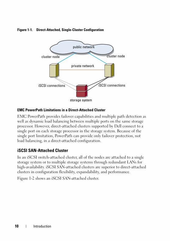
Figure 1-1. Direct-Attached, Single-Cluster Configuration
EMC PowerPath Limitations in a Direct-Attached Cluster
EMC PowerPath provides failover capabilities and multiple path detection as well as dynamic load balancing between multiple ports on the same storage processor. However, direct-attached clusters supported by Dell connect to a single port on each storage processor in the storage system. Because of the single port limitation, PowerPath can provide only failover protection, not load balancing, in a direct-attached configuration.
iSCSI SAN-Attached Cluster
In an iSCSI switch-attached cluster, all of the nodes are attached to a single storage system or to multiple storage systems through redundant LANs for high-availability. iSCSI SAN-attached clusters are superior to direct-attached clusters in configuration flexibility, expandability, and performance.
Figure 1-2 shows an iSCSI SAN-attached cluster.
cluster node
private network
public network
cluster node
storage system
iSCSI connectionsiSCSI connections
10 Introduction
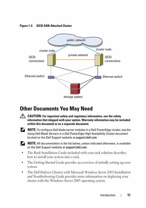
Figure 1-2. iSCSI SAN-Attached Cluster
Other Documents You May Need
CAUTION: For important safety and regulatory information, see the safety information that shipped with your system. Warranty information may be included within this document or as a separate document.
NOTE: To configure Dell blade server modules in a Dell PowerEdge cluster, see the Using Dell Blade Servers in a Dell PowerEdge High Availability Cluster document located on the Dell Support website at support.dell.com.
NOTE: All documentation in the list below, unless indicated otherwise, is available on the Dell Support website at support.dell.com.
• The Rack Installation Guide included with your rack solution describes how to install your system into a rack.
• The Getting Started Guide provides an overview of initially setting up your system.
• The Dell Failover Clusters with Microsoft Windows Server 2003 Installation and Troubleshooting Guide provides more information on deploying your cluster with the Windows Server 2003 operating system.
cluster node cluster node
private networkiSCSI connections
storage system
Ethernet switchEthernet switch
public network
iSCSI connections
Introduction 11
• The Dell Failover Clusters with Microsoft Windows Server 2008 Installation and Troubleshooting Guide provides more information on deploying your cluster with the Windows Server 2008 operating system.
• The Dell Cluster Configuration Support Matrices provides a list of recommended operating systems, hardware components, and driver or firmware versions for your Failover Cluster.
• Operating system documentation describes how to install (if necessary), configure, and use the operating system software.
• Documentation for any hardware and software components you purchased separately provides information to configure and install those options.
• The Dell PowerVault™ tape library documentation provides information for installing, troubleshooting, and upgrading the tape library.
• The EMC PowerPath documentation and Dell|EMC Storage Enclosure User’s Guides.
NOTE: Always read the updates first because they often supersede information in other documents.
• Release notes or readme files may be included to provide last-minute updates to the system or documentation, or advanced technical reference material intended for experienced users or technicians.
12 Introduction

Cabling Your Cluster Hardware NOTE: To configure Dell blade server modules in a Dell™ PowerEdge™ cluster, see
the Using Dell Blade Servers in a Dell PowerEdge High Availability Cluster document located on the Dell Support website at support.dell.com.
Cabling the Mouse, Keyboard, and MonitorWhen installing a cluster configuration in a rack, you must include a switch box to connect the mouse, keyboard, and monitor to the nodes. For instructions on cabling each node’s connections to the switch box, see the documentation included with your rack.
Cabling the Power SuppliesRefer to the documentation for each component in your cluster solution to ensure that the specific power requirements are satisfied.
The following guidelines are recommended to protect your cluster solution from power-related failures:
• For nodes with multiple power supplies, plug each power supply into a separate AC circuit.
• Use uninterruptible power supplies (UPS).
• For some environments, consider having backup generators and power from separate electrical substations.
Figure 2-1, and Figure 2-2 illustrate recommended methods for power cabling for a cluster solution consisting of two PowerEdge systems and two storage systems. To ensure redundancy, the primary power supplies of all the components are grouped onto one or two circuits and the redundant power supplies are grouped onto a different circuit.
Cabling Your Cluster Hardware 13
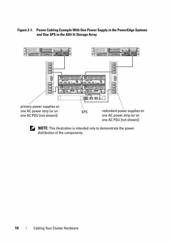
Figure 2-1. Power Cabling Example With One Power Supply in the PowerEdge Systems and One SPS in the AX4-5i Storage Array
redundant power supplies on one AC power strip (or on one AC PDU [not shown])
primary power supplies on one AC power strip (or on one AC PDU [not shown])
NOTE: This illustration is intended only to demonstrate the power distribution of the components.
SPS
14 Cabling Your Cluster Hardware
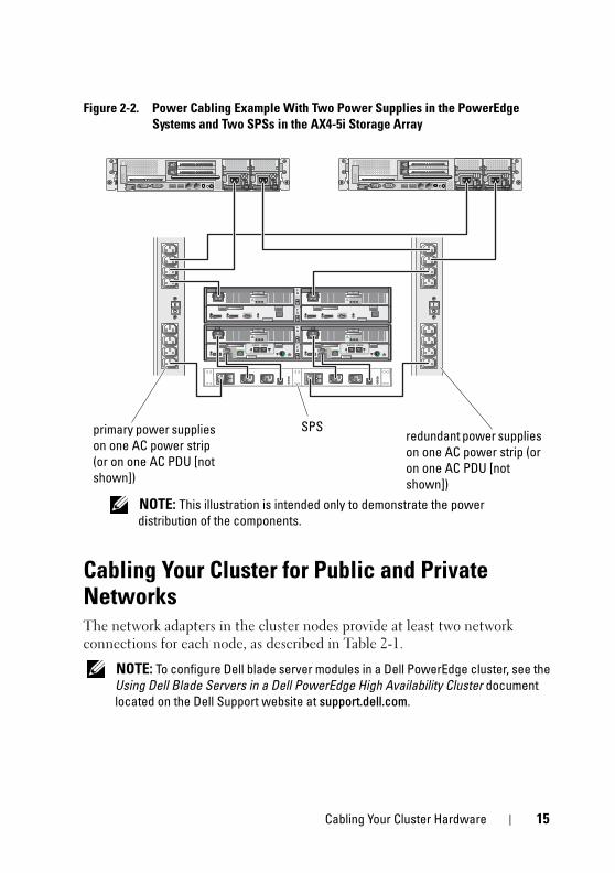
Figure 2-2. Power Cabling Example With Two Power Supplies in the PowerEdge Systems and Two SPSs in the AX4-5i Storage Array
Cabling Your Cluster for Public and Private NetworksThe network adapters in the cluster nodes provide at least two network connections for each node, as described in Table 2-1.
NOTE: To configure Dell blade server modules in a Dell PowerEdge cluster, see the Using Dell Blade Servers in a Dell PowerEdge High Availability Cluster document located on the Dell Support website at support.dell.com.
redundant power supplies on one AC power strip (or on one AC PDU [not shown])
NOTE: This illustration is intended only to demonstrate the power distribution of the components.
primary power supplies on one AC power strip (or on one AC PDU [not shown])
SPS
Cabling Your Cluster Hardware 15
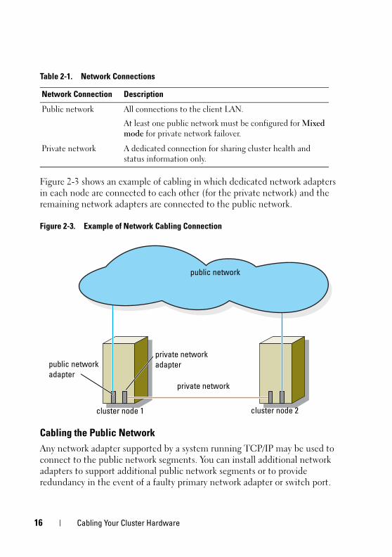
Figure 2-3 shows an example of cabling in which dedicated network adapters in each node are connected to each other (for the private network) and the remaining network adapters are connected to the public network.
Figure 2-3. Example of Network Cabling Connection
Cabling the Public Network
Any network adapter supported by a system running TCP/IP may be used to connect to the public network segments. You can install additional network adapters to support additional public network segments or to provide redundancy in the event of a faulty primary network adapter or switch port.
Table 2-1. Network Connections
Network Connection Description
Public network All connections to the client LAN.
At least one public network must be configured for Mixed
mode for private network failover.
Private network A dedicated connection for sharing cluster health and status information only.
cluster node 1 cluster node 2
public network
public network adapter
private network
private network adapter
16 Cabling Your Cluster Hardware
Cabling the Private Network
The private network connection to the nodes is provided by a different network adapter in each node. This network is used for intra-cluster communications. Table 2-2 describes three possible private network configurations.
NOTE: Throughout this document, the term Gigabit Ethernet refers to either Gigabit Ethernet or 10 Gigabit Ethernet.
Using Dual-Port Network Adapters
You can configure your cluster to use the public network as a failover for private network communications. If dual-port network adapters are used, do not use both ports simultaneously to support both the public and private networks.
NIC Teaming
NIC teaming combines two or more NICs to provide load balancing and fault tolerance. Your cluster supports NIC teaming, but only in a public network; NIC teaming is not supported in a private network and an iSCSI network.
You should use the same brand of NICs in a team, and you cannot mix brands of teaming drivers.
Table 2-2. Private Network Hardware Components and Connections
Method Hardware Components Connection
Network switch
Fast Ethernet or Gigabit Ethernet network adapters and switches
Connect standard Ethernet cables from the network adapters in the nodes to a Fast Ethernet or Gigabit Ethernet switch.
Point-to-Point Fast Ethernet (two-node clusters only)
Fast Ethernet network adapters
Connect a crossover Ethernet cable between the Fast Ethernet network adapters in both nodes.
Point-to-Point Gigabit Ethernet (two-node clusters only)
Copper Gigabit Ethernet network adapters
Connect a standard Ethernet cable between the Gigabit Ethernet network adapters in both nodes.
Cabling Your Cluster Hardware 17
Cabling the Storage SystemsThis section provides information for connecting your cluster to a storage system in a direct-attached configuration, or to one or more storage systems in an iSCSI SAN-attached configuration.
Connect the management port on each storage processor to the network where the management station resides on using an Ethernet network cable.
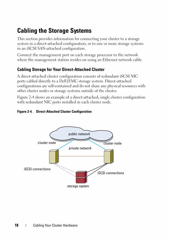
Cabling Storage for Your Direct-Attached Cluster
A direct-attached cluster configuration consists of redundant iSCSI NIC ports cabled directly to a Dell|EMC storage system. Direct-attached configurations are self-contained and do not share any physical resources with other cluster nodes or storage systems outside of the cluster.
Figure 2-4 shows an example of a direct-attached, single cluster configuration with redundant NIC ports installed in each cluster node.
Figure 2-4. Direct-Attached Cluster Configuration
cluster node
private network
public network
cluster node
storage system
iSCSI connectionsiSCSI connections
18 Cabling Your Cluster Hardware

Each cluster node attaches to the storage system using CAT5e or CAT6 LAN cables with RJ45 connectors that attach to Gigabit Ethernet NICs in the cluster nodes and the Gigabit iSCSI storage processor (SP) ports in the Dell|EMC storage system.
NOTE: The connections listed in this section are representative of one proven method of ensuring redundancy in the connections between the cluster nodes and the storage system. Other methods that achieve the same type of redundant connectivity may be acceptable.
Cabling a Two-Node Cluster to an AX4-5i Storage System
Figure 2-5 illustrates methods of cabling a two-node direct-attached cluster to an AX4-5i storage array.
1 Connect cluster node 1 to the storage system.
a Install a cable from cluster node 1 iSCSI NIC 0 (or NIC port 0) to SP-A iSCSI port 0.
b Install a cable from cluster node 1 iSCSI NIC 1 (or NIC port 1) to SP-B iSCSI port 0.
2 Connect cluster node 2 to the storage system.
a Install a cable from cluster node 2 iSCSI NIC 0 (or NIC port 0) to SP-A iSCSI port 1.
b Install a cable from cluster node 2 iSCSI NIC 1 (or NIC port 1) to SP-B iSCSI port 1.
NOTE: The cables are connected to the storage processor ports in sequential order for illustrative purposes. While the available ports in your storage system may vary, NIC 0 (or NIC port 0) and NIC 1 (or NIC port 1) must be connected to SP-A and SP-B, respectively.
Cabling Your Cluster Hardware 19
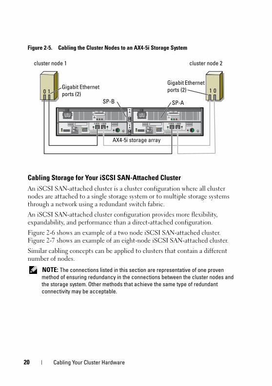
Figure 2-5. Cabling the Cluster Nodes to an AX4-5i Storage System
Cabling Storage for Your iSCSI SAN-Attached Cluster
An iSCSI SAN-attached cluster is a cluster configuration where all cluster nodes are attached to a single storage system or to multiple storage systems through a network using a redundant switch fabric.
An iSCSI SAN-attached cluster configuration provides more flexibility, expandability, and performance than a direct-attached configuration.
Figure 2-6 shows an example of a two node iSCSI SAN-attached cluster. Figure 2-7 shows an example of an eight-node iSCSI SAN-attached cluster.
Similar cabling concepts can be applied to clusters that contain a different number of nodes.
NOTE: The connections listed in this section are representative of one proven method of ensuring redundancy in the connections between the cluster nodes and the storage system. Other methods that achieve the same type of redundant connectivity may be acceptable.
cluster node 1 cluster node 2
0 1 1 0Gigabit Ethernet ports (2)
Gigabit Ethernet ports (2)
AX4-5i storage array
SP-B SP-A
20 Cabling Your Cluster Hardware
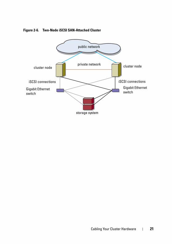
Figure 2-6. Two-Node iSCSI SAN-Attached Cluster
cluster node cluster nodeprivate network
iSCSI connections
storage system
Gigabit Ethernet switch
Gigabit Ethernet switch
public network
iSCSI connections
Cabling Your Cluster Hardware 21
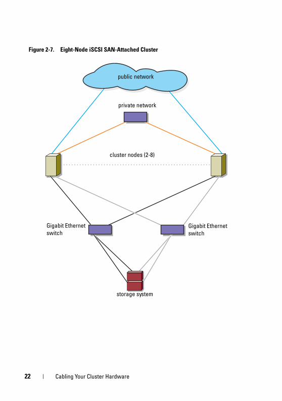
Figure 2-7. Eight-Node iSCSI SAN-Attached Cluster
public network
storage system
cluster nodes (2-8)
Gigabit Ethernet switch
Gigabit Ethernet switch
private network
22 Cabling Your Cluster Hardware
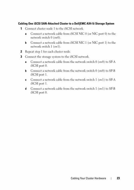
Cabling One iSCSI SAN-Attached Cluster to a Dell|EMC AX4-5i Storage System
1 Connect cluster node 1 to the iSCSI network.
a Connect a network cable from iSCSI NIC 0 (or NIC port 0) to the network switch 0 (sw0).
b Connect a network cable from iSCSI NIC 1 (or NIC port 1) to the network switch 1 (sw1).
2 Repeat step 1 for each cluster node.
3 Connect the storage system to the iSCSI network.
a Connect a network cable from the network switch 0 (sw0) to SP-A iSCSI port 0.
b Connect a network cable from the network switch 0 (sw0) to SP-B iSCSI port 1.
c Connect a network cable from the network switch 1 (sw1) to SP-A iSCSI port 1.
d Connect a network cable from the network switch 1 (sw1) to SP-B iSCSI port 0.
Cabling Your Cluster Hardware 23
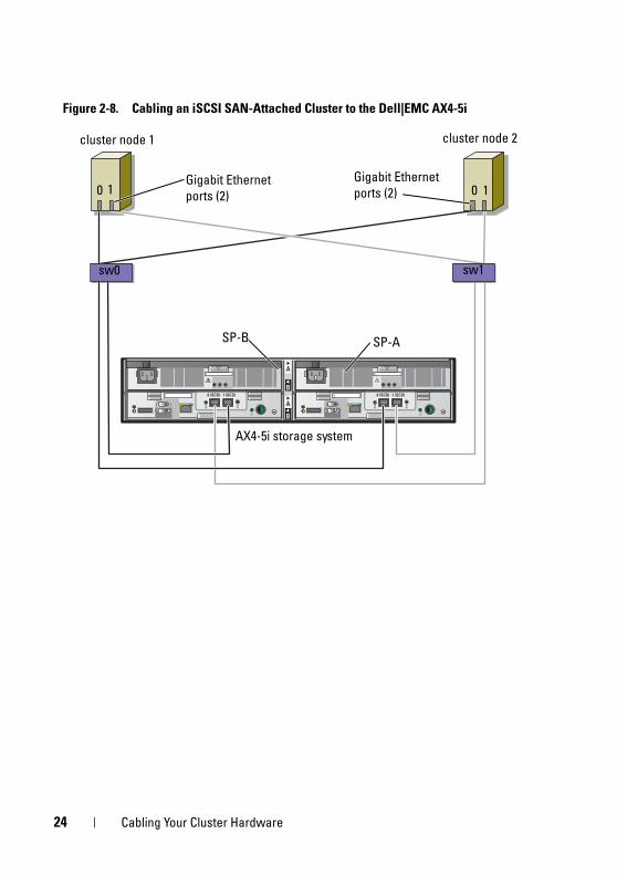
Figure 2-8. Cabling an iSCSI SAN-Attached Cluster to the Dell|EMC AX4-5i
sw0 sw1
cluster node 2cluster node 1
AX4-5i storage system
0 1 0 1Gigabit Ethernet ports (2)
Gigabit Ethernet ports (2)
SP-ASP-B
24 Cabling Your Cluster Hardware
Cabling Multiple iSCSI SAN-Attached Clusters to a Dell|EMC Storage System
To cable multiple clusters to the storage system, connect the cluster nodes to the appropriate iSCSI switches and then connect the iSCSI switches to the appropriate storage processors on the processor enclosure.
For rules and guidelines for iSCSI SAN-attached clusters, see the Dell Cluster Configuration Support Matrices located on the Dell High Availability Cluster website at www.dell.com/ha.
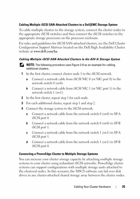
Cabling Multiple iSCSI SAN-Attached Clusters to the AX4-5i Storage System
NOTE: The following procedure uses Figure 2-8 as an example for cabling additional clusters.
1 In the first cluster, connect cluster node 1 to the iSCSI network.
a Connect a network cable from iSCSI NIC 0 (or NIC port 0) to the network switch 0 (sw0).
b Connect a network cable from iSCSI NIC 1 (or NIC port 1) to the network switch 1 (sw1).
2 In the first cluster, repeat step 1 for each node.
3 For each additional cluster, repeat step 1 and step 2.
4 Connect the storage system to the iSCSI network.
a Connect a network cable from the network switch 0 (sw0) to SP-A iSCSI port 0.
b Connect a network cable from the network switch 0 (sw0) to SP-B iSCSI port 1.
c Connect a network cable from the network switch 1 (sw1) to SP-A iSCSI port 1.
d Connect a network cable from the network switch 1 (sw1) to SP-B iSCSI port 0.
Connecting a PowerEdge Cluster to Multiple Storage Systems
You can increase your cluster storage capacity by attaching multiple storage systems to your cluster using redundant iSCSI networks. PowerEdge cluster systems can support configurations with multiple storage units attached to the clustered nodes. In this scenario, the MSCS software can fail over disk drives in any cluster-attached shared storage array between the cluster nodes.
Cabling Your Cluster Hardware 25
When attaching multiple storage systems with your cluster, the following rules apply:
• There is a maximum of four storage systems per cluster.
• The shared storage systems and firmware must be identical. Using dissimilar storage systems and firmware for your shared storage is not supported.
• MSCS is limited to 22 drive letters. Because drive letters A through D are reserved for local disks, a maximum of 22 drive letters (E to Z) can be used for your storage system disks.
• Windows Server 2003 and Windows Server 2008 support mount points, allowing greater than 22 drives per cluster. For more information, see Dell™ Failover Clusters With Microsoft® Windows Server® 2008 Installation and Troubleshooting Guide or Dell™ Failover Clusters With Microsoft® Windows Server® 2003 Installation and Troubleshooting Guide located on the Dell Support website at support.dell.com.
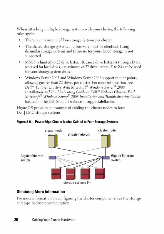
Figure 2-9 provides an example of cabling the cluster nodes to four Dell|EMC storage systems.
Figure 2-9. PowerEdge Cluster Nodes Cabled to Four Storage Systems
Obtaining More Information
For more information on configuring the cluster components, see the storage and tape backup documentation.
cluster nodecluster node
Gigabit Ethernet switch
storage systems (4)
private network
Gigabit Ethernet switch
26 Cabling Your Cluster Hardware
Preparing Your Systems for Clustering
CAUTION: Only trained service technicians are authorized to remove and access any of the components inside the system. For complete information about safety precautions, working inside the computer, and protecting against electrostatic discharge, see the safety information that shipped with your system.
Cluster Configuration Overview1 Ensure that your site can handle the cluster’s power requirements.
Contact your sales representative for information about your region's power requirements.
2 Install the systems, the shared storage array(s), and the interconnect switches (for example, in an equipment rack), and ensure that all the components are turned on.
NOTE: For more information on step 3 to step 7 and step 10 to step 13, see the "Preparing your systems for clustering" section of Dell Failover Clusters with Microsoft Windows Server 2003 Installation and Troubleshooting Guide or Dell Failover Clusters with Microsoft Windows Server 2008 Installation and Troubleshooting Guide located on the Dell Support website at support.dell.com.
3 Deploy the operating system (including any relevant service packs and hotfixes), network adapter drivers, and storage adapter drivers (including Multipath I/O (MPIO) drivers) on each cluster node. Depending on the deployment method that is used, it may be necessary to provide a network connection to successfully complete this step.
NOTE: To help in planning and deployment of your cluster, record the relevant cluster configuration information in the Cluster Data Form located at "Cluster Data Form" on page 49 and the iSCSI configuration information in the iSCSI Configuration Worksheet located at "iSCSI Configuration Worksheet" on page 51.
Preparing Your Systems for Clustering 27
4 Establish the physical network topology and the TCP/IP settings for network adapters on each cluster node to provide access to the cluster public and private networks.
5 Configure each cluster node as a member in the same Windows Active Directory Domain.
NOTE: You can configure the cluster nodes as Domain Controllers. For more information, see the “Selecting a Domain Model” section of Dell Failover Clusters with Microsoft Windows Server 2003 Installation and Troubleshooting Guide or Dell Failover Clusters with Microsoft Windows Server 2008 Installation and Troubleshooting Guide located on the Dell Support website at support.dell.com.
6 Establish the physical storage topology and any required storage network settings to provide connectivity between the storage array and the systems that you are configuring as cluster nodes. Configure the storage system(s) as described in your storage system documentation.
7 Use storage array management tools to create at least one logical unit number (LUN). The LUN is used as a cluster Quorum disk for Windows Server 2003 Failover cluster and as a Witness disk for Windows Server 2008 Failover cluster. Ensure that this LUN is presented to the systems that you are configuring as cluster nodes.
NOTE: For security reasons, it is recommended that you configure the LUN on a single node as mentioned in step 8 when you are setting up the cluster. Later, you can configure the LUN as mentioned in step 9 so that other nodes in the cluster can access it.
8 Select one of the systems and form a new failover cluster by configuring the cluster name, cluster management IP, and quorum resource. For more information, see "Preparing Your Systems for Clustering" on page 27.
NOTE: For Failover Clusters configured with Windows Server 2008, run the Cluster Validation Wizard to ensure that your system is ready to form the cluster.
9 Join the remaining node(s) to the failover cluster. For more information, see "Preparing Your Systems for Clustering" on page 27.
10 Configure roles for cluster networks. Take any network interfaces that are used for iSCSI storage (or for other purposes outside of the cluster) out of the control of the cluster.
28 Preparing Your Systems for Clustering
11 Test the failover capabilities of your new cluster.
NOTE: For Failover Clusters configured with Windows Server 2008, you can also use the Cluster Validation Wizard.
12 Configure highly-available applications and services on your Failover Cluster. Depending on your configuration, this may also require providing additional LUNs to the cluster or creating new cluster resource groups. Test the failover capabilities of the new resources.
13 Configure client systems to access the highly-available applications and services that are hosted on your failover cluster.
Installation OverviewEach cluster node in the Failover Cluster must have the same release, edition, service pack, and processor architecture of the Windows Server operating system installed. For example, all nodes in your cluster may be configured with the Windows Server 2003 R2, Enterprise x64 Edition operating system. If the operating system varies among nodes, it is not possible to configure a failover cluster successfully. It is recommended that you establish server roles prior to configuring a failover cluster, depending on the operating system configured on your cluster.
For a list of Dell PowerEdge systems, iSCSI NICs, recommended list of operating system variants, and specific driver and firmware revisions, see the Dell Cluster Configuration Support Matrices located on the Dell High Availability Cluster website at www.dell.com/ha.
For more information on deploying your cluster with Windows Server 2003 operating systems, see the Dell™ Failover Clusters with Microsoft Windows Server 2003 Installation and Troubleshooting Guide located on the Dell Support website at support.dell.com. For more information on deploying your cluster with Windows Server 2008 operating systems, see the Dell Failover Clusters with Microsoft Windows Server 2008 Installation and Troubleshooting Guide located on the Dell Support website at support.dell.com.
Preparing Your Systems for Clustering 29
The following sub-sections describe steps that enable you to establish communication between the cluster nodes and your shared Dell|EMC AX4-5i storage array, and to present disks from the storage array to the cluster. The following installation procedures are discussed in the subsequent sections:
• "Installing the iSCSI NICs" on page 30
• "Installing the Microsoft iSCSI Software Initiator" on page 30
• "Modifying the TCP Registry Settings" on page 31]
• "Installing EMC® PowerPath®" on page 31
• "Configuring the Shared Storage System" on page 32
• "Installing and Configuring a Failover Cluster" on page 41
Installing the iSCSI NICs
It is recommended that you install the latest supported version of the driver. If the NIC driver requires any service packs or hotfixes to be installed along with the operating system, install them at this time.
For information about supported NICs and drivers, see the Dell Cluster Configuration Support Matrices located on the Dell High Availability Cluster website at www.dell.com/ha.
Installing the Microsoft iSCSI Software Initiator
1 Use a web browser and go to the Microsoft Download Center website at www.microsoft.com/downloads.
2 Search for iscsi initiator.
3 Select and download the latest supported initiator software and related documentation for your operating system.
NOTE: For the latest supported Software Initiator version, see the Dell Cluster Configuration Support Matrices located on the Dell High Availability Cluster website at www.dell.com/ha.
4 Double-click the executable file. The installation wizard launches. In the Welcome screen, click Next.
5 In the following screens select the Initiator Service, Software Initiator, and Microsoft MPIO Multipathing Support for iSCSI options. Click Next to continue with the installation.
30 Preparing Your Systems for Clustering
6 Read and accept the license agreement and click Next to install the software.
7 At the completion screen, click Finish to complete the installation.
8 Select the Do not restart now option to reboot the system after modifying the TCP/IP registry settings in the section "Configuring the Shared Storage System" on page 32.
Modifying the TCP Registry Settings
To modify the TCP Registry:
1 Determine the IP addresses or the DHCP IP addresses that are used for iSCSI traffic.
2 Start the Registry Editor.
a Select Start→ Run.
b Type Regedit and click OK.
3 Locate and click the registry subkey at:
HKEY_LOCAL_MACHINE→ SYSTEM→ CurrentControlSet→ Services→ Tcpip→ Parameters→ Interfaces
4 Click each interface GUID associated with the iSCSI networks, and perform the following steps:
a Select Edit→ New→ DWORD value.
b Name the new value TcpAckFrequency.
c Assign a value of 1.
5 Exit the Registry Editor.
Installing EMC® PowerPath®
EMC PowerPath detects a failed storage path and automatically re-routes I/O through an alternate path. PowerPath also provides load balancing of data from the cluster node to the storage system. To install PowerPath:
1 Insert the PowerPath installation media in the CD/DVD drive.
2 On the Getting Started screen, go to the Installation section, and click the appropriate link for the operating system that is running on the node.
3 Select Run this program from its current location and click OK.
Preparing Your Systems for Clustering 31
4 In the Choose Language Setup screen, select the required language, and click OK.
5 In the Welcome window of the setup wizard, click Next.
6 In the CLARiiON AX-series window, select PowerPath and click Next. Follow the on-the-screen instructions to complete the installation.
7 Click Yes to reboot the system.
Configuring the Shared Storage System
To install and configure the Dell|EMC storage system in your cluster:
1 Install and use Navisphere Storage System Initialization Utility from a node or management station to initialize your AX4-5i storage system. During initialization, configure the network settings and create a user account to manage the AX4-5i storage system from the network.
2 If applicable, install the expansion pack using Navisphere Express.
3 Install the Navisphere Server Utility on each cluster node.
4 Configure the iSCSI Initiator on each cluster node.
5 Assign the virtual disks to the cluster nodes.
Installing the Navisphere Storage System Initialization Utility
The Navisphere Storage System Initialization Utility provides a user interface to initialize your AX4-5i storage system. Using the utility, you can configure the IP address, subnet mask, default gateway address for the storage system’s SPs, and assign user names and passwords for storage system access.
To install the software from the support media that is shipped with the storage system:
1 Insert the support media in the CD/DVD drive of the cluster node or the management station.
2 If prompted, select the language.
3 Click Install Products.
4 From the Install Products menu, click Navisphere Storage System Initialization Utility.
32 Preparing Your Systems for Clustering
5 Follow the on-screen instructions to complete the installation.
6 To initialize the storage system:
a From the cluster node or management station launch the Navisphere Storage System Initialization Utility that you installed. Go to Start→ Programs→ EMC→ Navisphere→ Navisphere Storage System Initialization.
b Read the license agreement, click I accept, and then click Next.
c From the Uninitialized Systems list, select the storage system to be initialized, and click Next.
d Follow the on-screen instructions to complete the initialization.
Installing the Expansion Pack Using Navisphere Express
Each storage system in the cluster is centrally managed by one host system (also called a management station) running EMC® Navisphere™ Express—a centralized storage management application used to configure Dell|EMC storage systems.
If you have an expansion pack option for the storage system and it has not been installed, install it at this time:
1 From the management host, open a web browser.
2 Enter the IP address of an SP in the storage system.
3 Log in to Navisphere Express with the username and password that you specified during the storage system initialization.
4 Go to System→ Navisphere Express navigation pane and click Software.
5 In the System Software window, click Upgrade Software.
6 Insert the expansion pack media into the CD/DVD drive on the host from which you are running Navisphere Express.
7 Browse the media for the expansion tier enabler software file (.ena file), and click Upgrade.
You can use Navisphere Express to perform tasks such as creating disk pools, binding the virtual disks, and downloading the firmware. Additionally, you can use Snapshot Management to capture point-in-time images of a virtual disk for backups or testing without affecting the contents of the source virtual disk. You can also use the SAN Copy feature in Navisphere Express to move data from the virtual disks on one storage system to the virtual disks on another storage system without using the host CPU cycles.
Preparing Your Systems for Clustering 33
Configuring the Navisphere Server Utility
The Navisphere Server Utility registers the cluster node NICs with the storage systems, allowing the nodes to access the cluster storage data. The tool is also used for cluster node maintenance procedures, such as:
• Updating the cluster node host name and/or IP address on the storage array
• Updating the file system information
• Adding, removing, or replacing a NIC
• Starting and stopping a snapshot
To install Navisphere Server Utility:
1 Log in to the Windows Server operating system as an administrator.
2 Insert the system support media into the cluster node.
3 If prompted, select the language.
4 From the Main Menu, click Install Products on Server.
5 From the Install Products menu, click Navisphere Server Utility.
6 Follow the on-screen instructions retaining all the default values to complete the installation.
34 Preparing Your Systems for Clustering
Configuring the iSCSI Initiator
Configuring the iSCSI Initiator using iSNS
iSNS includes an iSNS server component and iSNS client component. The iSNS server must reside within the IP storage network on a host or in the switch firmware. An iSNS client resides on both the iSCSI storage system and any iSCSI systems connected to the storage system. iSNS provides the following services:
• Name registration and discovery services – Targets and initiators register their attributes and addresses. After the targets and initiators register, they can obtain information about other initiators or targets.
NOTE: The iSCSI Initiator (usually a host server) converts blocks of SCSI commands and data into a format suitable for an IP network. The iSCSI Initiator is configured with a unique iSCSI name or Internet Qualified Name (IQN) in a PowerEdge system, allowing an administrator to identify and manage. For iSCSI access, the iSCSI Initiator assigns the same iSCSI name to all NICs in the PowerEdge system so they appear as one single initiator. However, each NIC is still identified by a unique IP address. The PowerEdge SE600Wi cluster solution supports NICs with Microsoft Software Initiator and does not support iSCSI HBAs. An iSCSI target (usually a storage device) receives iSCSI commands from the initiator. Each iSCSI target is identified by a unique IQN and each port on the storage array controller is identified by an IP address.
• State-change notification service – The iSNS server notifies relevant iSNS clients of network events that could affect their operational states such as storage resources going offline, domain membership change, and link failure in a network. These notifications let iSNS clients quickly adapt to changes in topology.
Preparing Your Systems for Clustering 35
• Discovery domains and login control service – Resources in a typical storage network are divided into manageable groups called discovery domains. Discovery domains help scale the storage network by reducing the number of unnecessary logins; each initiator only logins to a subset of targets which are within the domain. Each target can use Login Control to subordinate its access control policy to the iSNS server. Only initiators matching the required identification and authentication are allowed access by the target during session establishment.
• Open mapping of Fibre Channel and iSCSI devices – The iSNS database can store information about Fibre Channel and iSCSI devices and mappings between the two in a multi-protocol environment. The mapped information is then available to any authorized iSNS client.
When you start the storage system, the iSNS client on the storage system gathers all the storage-system iSCSI port information and stores it locally on the storage system. When you add a cluster node to the storage system iSNS configuration, Navisphere Express establishes a connection from the storage system to the iSNS server, and then registers the information stored on the storage system with the iSNS server.
For information about setting the iSNS service in your iSCSI storage network, see your Microsoft and EMC documentation.
NOTE: iSNS is supported only on systems running a Windows operating system in an iSCSI network configuration.
To configure iSNS client, login to Navisphere Express. For each iSNS server to which you want the storage system to connect:
1 In the Manage iSCSI window, click iSNS.
2 In the iSNS Servers window, click Add.
3 In the Add iSNS Servers dialog box, enter the IP address of the cluster node you are adding.
4 Click Apply to notify the SP iSCSI port information to the cluster node.
5 In the iSNS Servers dialog box, select the cluster node that you want to configure as the primary server and click Set Primary.
36 Preparing Your Systems for Clustering
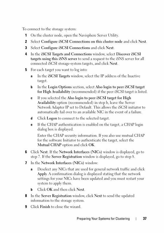
To connect to the storage system:
1 On the cluster node, open the Navisphere Server Utility.
2 Select Configure iSCSI Connections on this cluster node and click Next.
3 Select Configure iSCSI Connections and click Next.
4 In the iSCSI Targets and Connections window, select Discover iSCSI targets using this iSNS server to send a request to the iSNS server for all connected iSCSI storage-system targets, and click Next.
5 For each target you want to log into:
a In the iSCSI Targets window, select the IP address of the Inactive target.
b In the Login Options section, select Also login to peer iSCSI target for High Availability (recommended) if the peer iSCSI target is listed.
c If you selected the Also login to peer iSCSI target for High Availability option (recommended) in step b, leave the Server Network Adapter IP set to Default. This allows the iSCSI initiator to automatically fail over to an available NIC in the event of a failure.
d Click Logon to connect to the selected target.
e If the CHAP authentication is enabled on the target, a CHAP login dialog box is displayed.
Enter the CHAP security information. If you also use mutual CHAP for the software Initiator to authenticate the target, select the Mutual CHAP option and click OK.
6 Click Next. If the Network Interfaces (NICs) window is displayed, go to step 7. If the Server Registration window is displayed, go to step 8.
7 In the Network Interfaces (NICs) window:
a Deselect any NICs that are used for general network traffic and click Apply. A confirmation dialog is displayed stating that the network settings for your NICs have been updated and you must restart your system to apply them.
b Click OK and then click Next.
8 In the Server Registration window, click Next to send the updated information to the storage system.
9 Click Finish to close the wizard.
Preparing Your Systems for Clustering 37

Configuring the iSCSI Initiator without iSNS
On the cluster node:
1 Open the Navisphere Server Utility.
2 Select Configure iSCSI Connections on this cluster node and click Next.
3 Select Configure iSCSI Connections and click Next.
4 In the iSCSI Targets and Connections window, select one of the following options to discover the iSCSI target ports on the connected storage systems:
– Discover iSCSI targets on this subnet - Scans the current subnet for all connected iSCSI storage-system targets. The utility scans the subnet in the range from 1 to 255.
If CHAP authentication is enabled on all target ports on a storage system, you cannot discover the iSCSI target ports using a subnet scan. You must discover the targets using the target portal.
– Discover iSCSI targets for this target portal - Discovers targets known to the specified iSCSI SP data port.
5 Click Next.
6 For each target you want to log in to:
a In the iSCSI Targets window, select the IP address of the Inactive target.
b In the Login Options section, select Also login to peer iSCSI target for High Availability (recommended) if the peer iSCSI target is listed.
c If you selected Also login to peer iSCSI target for High Availability (recommended) in step b, leave the Server Network Adapter IP set to Default to allow the iSCSI initiator to automatically fail over to an available NIC in the event of a failure.
d Click Logon to connect to the selected target.
e If the CHAP authentication is enabled on the target, a CHAP login dialog box is displayed.
Enter the CHAP security information. If you also use mutual CHAP for the software Initiator to authenticate the target, select the Mutual CHAP option and click OK.
38 Preparing Your Systems for Clustering
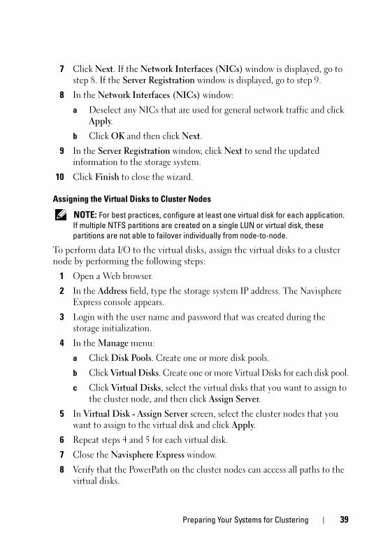
7 Click Next. If the Network Interfaces (NICs) window is displayed, go to step 8. If the Server Registration window is displayed, go to step 9.
8 In the Network Interfaces (NICs) window:
a Deselect any NICs that are used for general network traffic and click Apply.
b Click OK and then click Next.
9 In the Server Registration window, click Next to send the updated information to the storage system.
10 Click Finish to close the wizard.
Assigning the Virtual Disks to Cluster Nodes
NOTE: For best practices, configure at least one virtual disk for each application. If multiple NTFS partitions are created on a single LUN or virtual disk, these partitions are not able to failover individually from node-to-node.
To perform data I/O to the virtual disks, assign the virtual disks to a cluster node by performing the following steps:
1 Open a Web browser.
2 In the Address field, type the storage system IP address. The Navisphere Express console appears.
3 Login with the user name and password that was created during the storage initialization.
4 In the Manage menu:
a Click Disk Pools. Create one or more disk pools.
b Click Virtual Disks. Create one or more Virtual Disks for each disk pool.
c Click Virtual Disks, select the virtual disks that you want to assign to the cluster node, and then click Assign Server.
5 In Virtual Disk - Assign Server screen, select the cluster nodes that you want to assign to the virtual disk and click Apply.
6 Repeat steps 4 and 5 for each virtual disk.
7 Close the Navisphere Express window.
8 Verify that the PowerPath on the cluster nodes can access all paths to the virtual disks.
Preparing Your Systems for Clustering 39
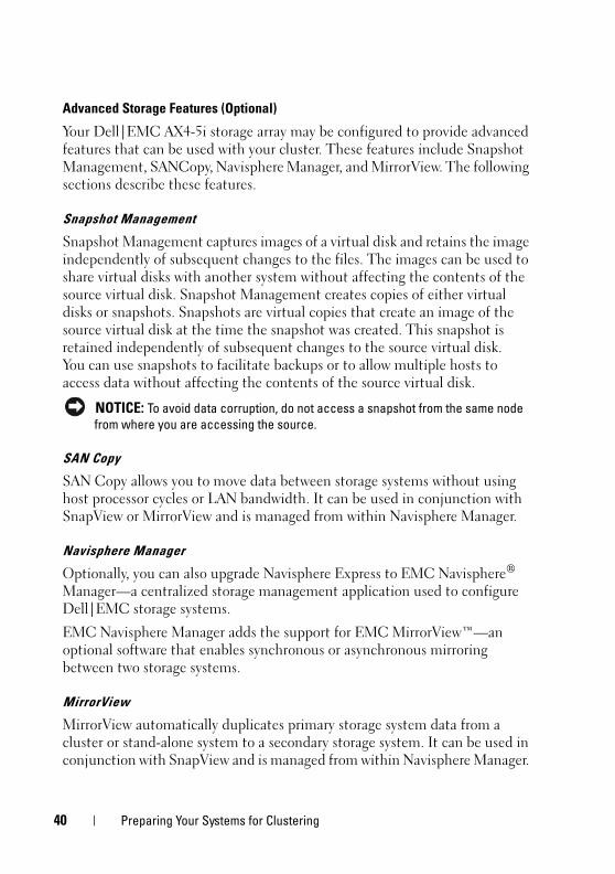
Advanced Storage Features (Optional)
Your Dell|EMC AX4-5i storage array may be configured to provide advanced features that can be used with your cluster. These features include Snapshot Management, SANCopy, Navisphere Manager, and MirrorView. The following sections describe these features.
Snapshot Management
Snapshot Management captures images of a virtual disk and retains the image independently of subsequent changes to the files. The images can be used to share virtual disks with another system without affecting the contents of the source virtual disk. Snapshot Management creates copies of either virtual disks or snapshots. Snapshots are virtual copies that create an image of the source virtual disk at the time the snapshot was created. This snapshot is retained independently of subsequent changes to the source virtual disk. You can use snapshots to facilitate backups or to allow multiple hosts to access data without affecting the contents of the source virtual disk.
NOTICE: To avoid data corruption, do not access a snapshot from the same node from where you are accessing the source.
SAN Copy
SAN Copy allows you to move data between storage systems without using host processor cycles or LAN bandwidth. It can be used in conjunction with SnapView or MirrorView and is managed from within Navisphere Manager.
Navisphere Manager
Optionally, you can also upgrade Navisphere Express to EMC Navisphere® Manager—a centralized storage management application used to configure Dell|EMC storage systems.
EMC Navisphere Manager adds the support for EMC MirrorView™—an optional software that enables synchronous or asynchronous mirroring between two storage systems.
MirrorView
MirrorView automatically duplicates primary storage system data from a cluster or stand-alone system to a secondary storage system. It can be used in conjunction with SnapView and is managed from within Navisphere Manager.
40 Preparing Your Systems for Clustering
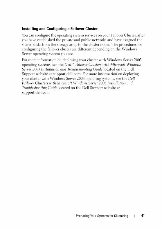
Installing and Configuring a Failover Cluster
You can configure the operating system services on your Failover Cluster, after you have established the private and public networks and have assigned the shared disks from the storage array to the cluster nodes. The procedures for configuring the failover cluster are different depending on the Windows Server operating system you use.
For more information on deploying your cluster with Windows Server 2003 operating systems, see the Dell™ Failover Clusters with Microsoft Windows Server 2003 Installation and Troubleshooting Guide located on the Dell Support website at support.dell.com. For more information on deploying your cluster with Windows Server 2008 operating systems, see the Dell Failover Clusters with Microsoft Windows Server 2008 Installation and Troubleshooting Guide located on the Dell Support website at support.dell.com.
Preparing Your Systems for Clustering 41

42 Preparing Your Systems for Clustering
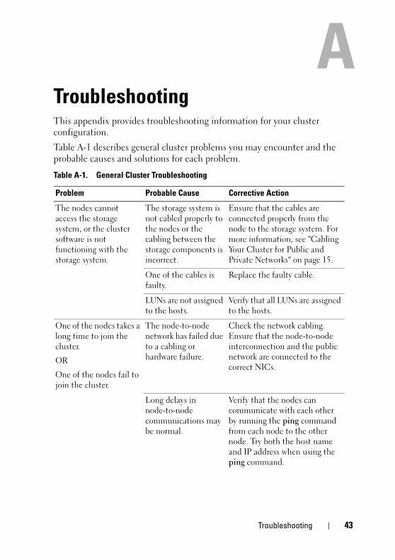
TroubleshootingThis appendix provides troubleshooting information for your cluster configuration.
Table A-1 describes general cluster problems you may encounter and the probable causes and solutions for each problem.
Table A-1. General Cluster Troubleshooting
Problem Probable Cause Corrective Action
The nodes cannot access the storage system, or the cluster software is not functioning with the storage system.
The storage system is not cabled properly to the nodes or the cabling between the storage components is incorrect.
Ensure that the cables are connected properly from the node to the storage system. For more information, see "Cabling Your Cluster for Public and Private Networks" on page 15.
One of the cables is faulty.
Replace the faulty cable.
LUNs are not assigned to the hosts.
Verify that all LUNs are assigned to the hosts.
One of the nodes takes a long time to join the cluster.
OR
One of the nodes fail to join the cluster.
The node-to-node network has failed due to a cabling or hardware failure.
Check the network cabling. Ensure that the node-to-node interconnection and the public network are connected to the correct NICs.
Long delays in node-to-node communications may be normal.
Verify that the nodes can communicate with each other by running the ping command from each node to the other node. Try both the host name and IP address when using the ping command.
Troubleshooting 43
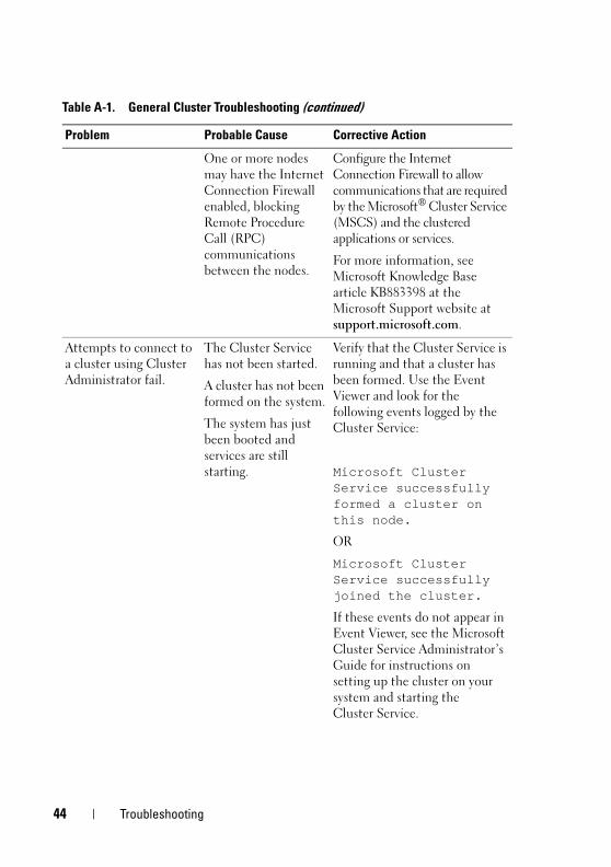
One or more nodes may have the Internet Connection Firewall enabled, blocking Remote Procedure Call (RPC) communications between the nodes.
Configure the Internet Connection Firewall to allow communications that are required by the Microsoft® Cluster Service (MSCS) and the clustered applications or services.
For more information, see Microsoft Knowledge Base article KB883398 at the Microsoft Support website at support.microsoft.com.
Attempts to connect to a cluster using Cluster Administrator fail.
The Cluster Service has not been started.
A cluster has not been formed on the system.
The system has just been booted and services are still starting.
Verify that the Cluster Service is running and that a cluster has been formed. Use the Event Viewer and look for the following events logged by the Cluster Service:
Microsoft Cluster Service successfully formed a cluster on this node.
OR
Microsoft Cluster Service successfully joined the cluster.
If these events do not appear in Event Viewer, see the Microsoft Cluster Service Administrator’s Guide for instructions on setting up the cluster on your system and starting the Cluster Service.
Table A-1. General Cluster Troubleshooting (continued)
Problem Probable Cause Corrective Action
44 Troubleshooting
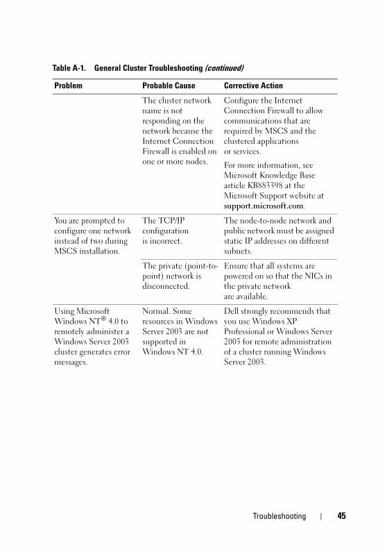
The cluster network name is not responding on the network because the Internet Connection Firewall is enabled on one or more nodes.
Configure the Internet Connection Firewall to allow communications that are required by MSCS and the clustered applications or services.
For more information, see Microsoft Knowledge Base article KB883398 at the Microsoft Support website at support.microsoft.com.
You are prompted to configure one network instead of two during MSCS installation.
The TCP/IP configuration is incorrect.
The node-to-node network and public network must be assigned static IP addresses on different subnets.
The private (point-to-point) network is disconnected.
Ensure that all systems are powered on so that the NICs in the private network are available.
Using Microsoft Windows NT® 4.0 to remotely administer a Windows Server 2003 cluster generates error messages.
Normal. Some resources in Windows Server 2003 are not supported in Windows NT 4.0.
Dell strongly recommends that you use Windows XP Professional or Windows Server 2003 for remote administration of a cluster running Windows Server 2003.
Table A-1. General Cluster Troubleshooting (continued)
Problem Probable Cause Corrective Action
Troubleshooting 45
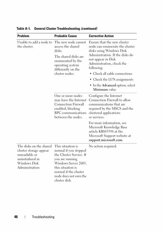
Unable to add a node to the cluster.
The new node cannot access the shared disks.
The shared disks are enumerated by the operating system differently on the cluster nodes.
Ensure that the new cluster node can enumerate the cluster disks using Windows Disk Administration. If the disks do not appear in Disk Administration, check the following:
• Check all cable connections
• Check the LUN assignments
• In the Advanced option, select Minimum value
One or more nodes may have the Internet Connection Firewall enabled, blocking RPC communications between the nodes.
Configure the Internet Connection Firewall to allow communications that are required by the MSCS and the clustered applications or services.
For more information, see Microsoft Knowledge Base article KB883398 at the Microsoft Support website at support.microsoft.com.
The disks on the shared cluster storage appear unreadable or uninitialized in Windows Disk Administration
This situation is normal if you stopped the Cluster Service. If you are running Windows Server 2003, this situation is normal if the cluster node does not own the cluster disk.
No action required.
Table A-1. General Cluster Troubleshooting (continued)
Problem Probable Cause Corrective Action
46 Troubleshooting
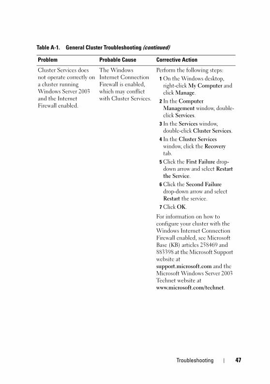
Cluster Services does not operate correctly on a cluster running Windows Server 2003 and the Internet Firewall enabled.
The Windows Internet Connection Firewall is enabled, which may conflict with Cluster Services.
Perform the following steps:
1 On the Windows desktop, right-click My Computer and click Manage.
2 In the Computer Management window, double-click Services.
3 In the Services window, double-click Cluster Services.
4 In the Cluster Services window, click the Recovery tab.
5 Click the First Failure drop-down arrow and select Restart the Service.
6 Click the Second Failure drop-down arrow and select Restart the service.
7 Click OK.
For information on how to configure your cluster with the Windows Internet Connection Firewall enabled, see Microsoft Base (KB) articles 258469 and 883398 at the Microsoft Support website at support.microsoft.com and the Microsoft Windows Server 2003 Technet website at www.microsoft.com/technet.
Table A-1. General Cluster Troubleshooting (continued)
Problem Probable Cause Corrective Action
Troubleshooting 47
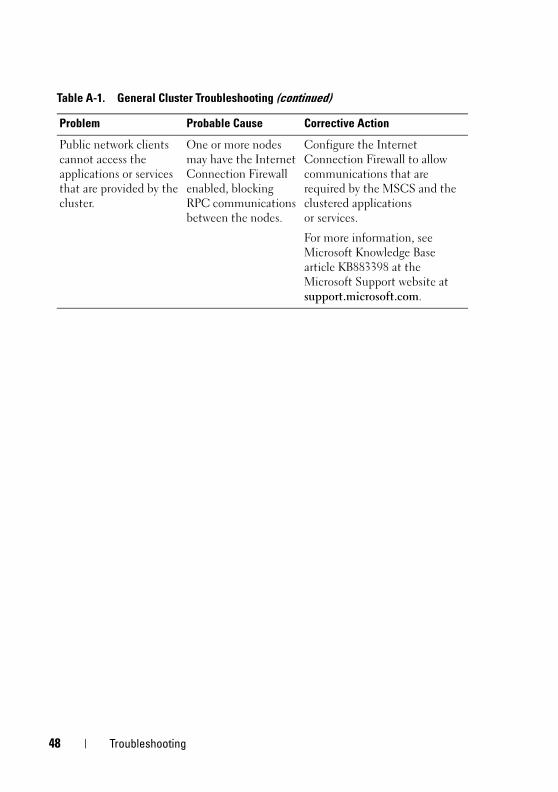
Public network clients cannot access the applications or services that are provided by the cluster.
One or more nodes may have the Internet Connection Firewall enabled, blocking RPC communications between the nodes.
Configure the Internet Connection Firewall to allow communications that are required by the MSCS and the clustered applications or services.
For more information, see Microsoft Knowledge Base article KB883398 at the Microsoft Support website at support.microsoft.com.
Table A-1. General Cluster Troubleshooting (continued)
Problem Probable Cause Corrective Action
48 Troubleshooting
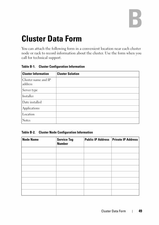
Cluster Data FormYou can attach the following form in a convenient location near each cluster node or rack to record information about the cluster. Use the form when you call for technical support.
Table B-1. Cluster Configuration Information
Cluster Information Cluster Solution
Cluster name and IP address
Server type
Installer
Date installed
Applications
Location
Notes
Table B-2. Cluster Node Configuration Information
Node Name Service Tag Number
Public IP Address Private IP Address
Cluster Data Form 49
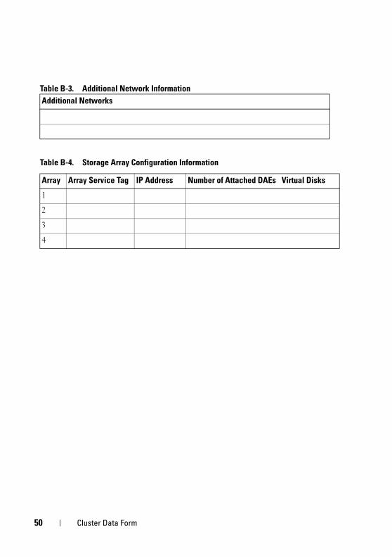
Table B-3. Additional Network Information
Additional Networks
Table B-4. Storage Array Configuration Information
Array Array Service Tag IP Address Number of Attached DAEs Virtual Disks
1
2
3
4
50 Cluster Data Form
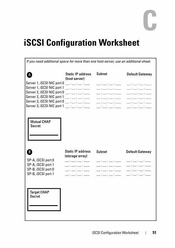
iSCSI Configuration Worksheet
If you need additional space for more than one host server, use an additional sheet.
A
Server 1, iSCSI NIC port 0Server 1, iSCSI NIC port 1Server 2, iSCSI NIC port 0Server 2, iSCSI NIC port 1Server 3, iSCSI NIC port 0Server 3, iSCSI NIC port 1
B
SP-A, iSCSI port 0SP-A, iSCSI port 1SP-B, iSCSI port 0SP-B, iSCSI port 1
__ . __ . __ . ___ __ . __ . __ . ___ __ . __ . __ . ___ __ . __ . __ . ___ __ . __ . __ . ___ __ . __ . __ . ___
__ . __ . __ . ___ __ . __ . __ . ___ __ . __ . __ . ___ __ . __ . __ . ___ __ . __ . __ . ___ __ . __ . __ . ___
Static IP address
(host server)
Subnet Default Gateway
Static IP address
(storage array)Subnet Default Gateway
__ . __ . __ . ___ __ . __ . __ . ___ __ . __ . __ . ___ __ . __ . __ . ___
__ . __ . __ . ___ __ . __ . __ . ___ __ . __ . __ . ___ __ . __ . __ . ___
__ . __ . __ . ___ __ . __ . __ . ___ __ . __ . __ . ___ __ . __ . __ . ___
__ . __ . __ . ___ __ . __ . __ . ___ __ . __ . __ . ___ __ . __ . __ . ___ __ . __ . __ . ___ __ . __ . __ . ___
Mutual CHAP Secret
Target CHAP Secret
iSCSI Configuration Worksheet 51

52 iSCSI Configuration Worksheet
Index
C
cable configurationscluster interconnect, 17for client networks, 16for mouse, keyboard, and
monitor, 13for power supplies, 13
clusteroptional configurations, 9
cluster configurationsconnecting to multiple shared
storage systems, 25connecting to one shared storage
system, 9direct-attached, 9, 18iSCSI SAN-attached, 10
cluster storagerequirements, 8
clusteringoverview, 5
D
Dell | EMC AX4-5iCabling a two-node cluster, 19
Dell|EMC AX4-5iCabling a two-node cluster, 19cabling the cluster nodes in an
iSCSI SAN-attached environment, 23
cabling to one iSCSI SAN-attached cluster, 23
configuring, 32installing, 32
direct-attached clusterabout, 18
I
iSCSIconfiguring the iSCSI NIC, 30
iSCSI SAN-attached clusterabout, 20configurations, 9
Index 53
K
keyboardcabling, 13
M
monitorcabling, 13
mousecabling, 13
MSCSinstalling and configuring, 41
N
network adapterscabling the private
network, 16-17cabling the public network, 16
O
operating systemWindows Server 2003, Enterprise
Editioninstalling, 29
P
power suppliescabling, 13
private networkcabling, 15, 17hardware components, 17hardware components and
connections, 17
public networkcabling, 15
T
troubleshootingconnecting to a cluster, 44shared storage subsystem, 43
W
warranty, 11
54 Index


