Embed Size (px)
Citation preview

actuators
Article
Design, 3D FEM Simulation and Prototyping of a PermanentMagnet Spherical Motor
Umut Yusuf Gündogar 1,2,* and Sibel Zorlu Partal 1
�����������������
Citation: Gündogar, U.Y.; Zorlu
Partal, S. Design, 3D FEM Simulation
and Prototyping of a Permanent
Magnet Spherical Motor. Actuators
2021, 10, 305. https://doi.org/
10.3390/act10110305
Academic Editor: Chien-Sheng Liu
Received: 28 October 2021
Accepted: 19 November 2021
Published: 21 November 2021
Publisher’s Note: MDPI stays neutral
with regard to jurisdictional claims in
published maps and institutional affil-
iations.
Copyright: © 2021 by the authors.
Licensee MDPI, Basel, Switzerland.
This article is an open access article
distributed under the terms and
conditions of the Creative Commons
Attribution (CC BY) license (https://
creativecommons.org/licenses/by/
4.0/).
1 Department of Electrical Engineering, Yildiz Technical University, Istanbul 34220, Turkey; [email protected] Numesys Inc., Istanbul 34758, Turkey* Correspondence: [email protected]
Abstract: In recent years, large tilt angles, uniform magnetic flux distributions, strong forces, andlarge torques for motors have increasingly become important for robotics, biomedical, and automotiveapplications that have multi-degrees of freedom (MDOFs) motion. Generally, one-degree of-freedommotors are applied in MDOF motion. These situations cause the systems to have very complex andlarge structures. In order to address these issues, a 2-DOF surface permanent magnet spherical motorwith a new mechanical design for the movement of the rotor with a large tilt angle of ±45◦ wasdesigned, simulated, produced and tested in this paper. The motor consisted of a 4-pole permanentmagnet rotor and a 3-block stator with 18 coils. In this study, the mechanical structure of the proposedspherical permanent magnet motor surrounded the rotor with two moving parts to move at a large tiltangle of ±45◦ without using any mechanical components such as spherical bearings, joint bearings,and bearing covers. Thus, the tilt angle, force, and torque values of the proposed motor have beenimproved according to MDOF motion motors using spherical bearings, bearing covers, or jointbearings in their mechanical structures in the literature. Ansys Maxwell software was used for thedesign and simulation of the motor. Three-dimensional (3D) finite element method (FEM) analysisand experimental studies were carried out on the force, torque, and magnetic flux density distributionof the motor. Then, simulation results and experimental results were compared to validate the 3DFEM simulations results.
Keywords: electrical machines; multi-degree of freedom; finite element method simulations
1. Introduction
In recent years, with the development of robotics, biomedical, and automotive indus-tries, the need for spherical motors, actuators, and manipulators that can perform motionwith multi-degrees of freedom (MDOFs) has increased. Therefore, researchers have carriedout studies on multi-axis motor designs with different structures and different operationalperformances, such as induction motors, ultrasonic motors, actuators, manipulators, andpermanent magnet motors.
Williams and Laithwaite designed an induction motor with a spherical stator [1–3].However, given the large dimensions of this induction motor, a new spherical motorwith a spherical rotor was designed [4,5]. A three-degree-of-freedom (DOF) sphericalmanipulator [6,7] and MDOF force characterization system of soft actuators [8], a sphericalactuator [9], and a fine motion wrist with six DOFs [10–12] were designed with largestructures. Spherical MDOF motors with sphere and shell stator and rotor structures weredesigned [13–20]. It has been observed sphere and shell rotor and stator motor designswere caused by mechanical loads and frictions between the rotor and the stator.
Based on the previous studies, MDOF motors and actuators studies have been car-ried out using spherical bearings, bearing covers, and joint bearings in their mechanicalstructures to reduce mechanical loads and frictions and to improve the tilt angle motion.
A spherical actuator of which the stator includes 24 coils with 2 layers, and the rotorincludes 8 permanent magnets and has a ±11◦ tilting angle by using bearings in the
Actuators 2021, 10, 305. https://doi.org/10.3390/act10110305 https://www.mdpi.com/journal/actuators

Actuators 2021, 10, 305 2 of 18
mechanical part. The outer stator radius of the actuator is 112.5 mm [21]. A sphericalmotor of which the rotor consists of 8-tiered-type permanent magnets, and a stator ofwhich the outer diameter is 250 mm consists of 21 slots and has ±11.5◦ tilting angle. Ajoint bearing is used in the center of the rotor to support MDOF motions [22]. A sphericalpermanent magnet motor was designed, and the torque of the 4-phase system of the motoraccording to the change of the pole pitch angles obtained is about 25 mN·m when thetilt angle is 22.5◦ and the rotating angle is 0◦. A spherical bearing is used to connect therotor to the motor [23]. A spherical motor which consists of eight permanent magnetsin the rotor and eight symmetrical coils in the stator was designed and verified by usingthree-dimensional (3D) finite element method (FEM) simulations. For the movement ofthe motor around the X-axis, Y-axis, and Z-axis, the coils rotating around the three axeshave 450, 450, and 250 turns, respectively. The resistance of each coil for rotating aroundthe X-axis and the Y-axis is 9.6 ohm, and the resistance of each coil for rotating aroundthe Z-axis is 6.5 ohm. Each coil is excited with a current of 0.25 A. Power consumptionwas considered for the design. A spherical bearing is used to connect the rotor and thestator. The spherical motor has a tilt angle of ±25◦ along the X- and Y-axes and that of±5◦ along the Z-axis. The average total torque output of the motor obtained is 7.98 mN·min movements with a ±25◦ tilt angle [24]. A three-DOF voice coil motor that consists ofa radially oriented ring magnet in the rotor and 16 coils in a stator was designed withthe illustration of the structure, working principle, and simulation studies of the motor.For the movements of the motor around the X-axis, Y-axis, and Z-axis, the coils aroundthese three axes have 500, 500, and 450 turns, respectively. Each coil is excited with acurrent of 1 A. Power consumption is considered for the electromagnetic structure design.A spherical bearing that is located at the center of the moving part is used to connect themoving and fixed parts. The proposed voice coil motor has a tilt angle of ±30◦ along theX- and Y-axes. The torque ranges of the motor obtained are between 14.08 mN·m and19.40 mN·m from 0◦ to 30◦ tilt angles along the X-axis [25]. A spherical actuator consists of16 permanent magnets in the rotor and 24 coils in the stator and has a ±37◦ tilting angleusing a spacer and a shaft in the mechanical part. The resistances of all the coils are set to2 ohm, and the loss obtained is 2 W [26]. A spherical joint that has a 1.08 N force for 2-DOFtilting movement was designed [27]. A spherical permanent magnets motor that has a tiltangle of ±30◦ along the X- and Y-axes and a rotation angle of ±360◦ along the Z-axis wasdesigned with 4 drum-type permanent magnets. The outer stator radius of the motor wasdesigned to be 90 mm. A shaft with a bearing cover is used in the mechanical design of themotor. The forces of the motor obtained are about 0.5 N in tilt movements and about 1 Nin rotation movements [28–31]. The other spherical actuator that consists of 8 permanentmagnets in the rotor and 16 air-cores coils in the stator was designed and has a ±11.5◦
tilting angle. The torque of the actuator obtained is 30.9 mN·m at ±11.5◦ tilting movementsusing a shaft component in the mechanical structure [32]. A three-DOF spherical motorwas proposed with types of drum, butterfly, layered and series permanent magnets. Thesupporting shaft and bearing cover are used to connect the rotor to the motor [33]. A modelconsisting of a doubly excited spherical motor that has a 2-part stator with 12 windings and4 permanent magnet rotors was investigated. A spherical bearing is used to connect therotor to the motor. Electromagnetic and structural simulations were performed according tothe motion capabilities of the spherical motor. After the simulations of the spherical motorwere completed, it was tested with the prepared prototype and designed drive circuit. Itwas found that it can successfully perform 8 different motions from the starting position tothe ±30◦ tilt motion position as revealed by the electromagnetic simulations [34,35].
In these studies, DOF motion motors and actuators were designed using sphericalbearings, bearing covers, and joint bearings in their mechanical structures to provide tiltingand rotational movement. However, it has been seen that the tilt motion capacities of thespherical bearings, bearing covers, and joint bearings are limited to the rotor movementsand tilt motion angles of the MDOF motors and actuators. Therefore, the limited tilt motionangle of the motor also affects the torque and force values.

Actuators 2021, 10, 305 3 of 18
From the previous studies in the literature, it has been observed that there is a need toimprove the tilt angle, force, torque, mechanical structure, and size of the motor for robotic,biomedical, and industrial applications that have MDOF motion. In order to address theseissues and contribute to applications with 2-DOF motion, a spherical-surface permanentmagnet motor with a 4-pole and 3-block stator having 18 coils has been designed andproduced in this study. The stator part of the motor has been designed with three blocks toensure the easy movement of the rotor in the mechanical structure with a large tilt angleand obtain higher torque and force values.
A new mechanical structure has been also designed for the proposed motor. Thismechanical design surrounds the rotor with two moving parts to provide the movement ofthe rotor in the X- and Y-axes at a large tilt angle of ±45◦ without using any mechanicalpart elements such as spherical bearings, joint bearings, and bearing covers. These movingparts have been connected to each other with pins and integrated into the base with twofixed parts from their sides.
Furthermore, the force and torque values of the proposed motor have been improvedthanks to the new mechanical structure compared to MDOF motion motors that usespherical bearings, bearing covers, or joint bearings in their mechanical structures.
3D simulations have been performed, before the motor was prototyped. The force,torque, and magnetic flux density of the motor have been obtained by 3D simulationswith Ansys Maxwell using the FEM [36]. Then, the motor has been produced, and theexperimental studies have been performed to obtain the magnetic flux density, force,and torque using a gaussmeter and a load cell. Finally, experimental studies have beencompared and validated with 3D FEM simulations results.
2. Design of the Spherical Permanent Magnet Motor2.1. Structure of the Motor
The design parameters and the sizing of a two-DOF spherical permanent magnetmotor were determined by using the results of the study given in [37]. In that study,27 different motor models were designed and simulated with different magnet materials,different magnet structures, and different stator–rotor structures. The spherical permanentmagnet motor model suggested in [37] was taken as a baseline model in this study.
The 2-DOF spherical permanent magnet motor consisted of a rotor, a stator, andmechanical parts. The rotor consisted of radially oriented surface magnets and movingparts. Steel 1010 that had a high saturation flux density of approximately 2 T was used inthe rotor. SmCo magnets were selected as the material of permanent magnets to providethe magnetic field of the rotor and have a residual magnetic flux density of 1.12 T. Thestator consisted of 18 coils with 3 separate blocks and 4 separator rings. N020 electricalsteel that had a low core loss of about 13 W/kg and a high electrical conductivity of1,851,852 Siemens/m was used in the stator. Stainless steel was used as a non-magneticmaterial for the mechanical parts and the separator rings of the motor. The separator ringsprevented the stator blocks from touching each other. The moving parts were connectedby pins. The moving and fixed parts were connected to each other by the fixed base parts,which were located near the rotor. The motor model which is shown in Figure 1 wasdesigned using Ansys Maxwell software.
2.2. Operating Principle of the Spherical Permanent Magnet Motor
The operating principle of the motor is based on the magnetic force generated bystator coils and permanent magnets. The same polarity of poles generates forces that pusheach other. The opposite polarity of poles produces magnetic forces that are pulled fromeach other. Thus, the magnetic forces generate a magnetic torque that allows the rotor tocomplete the motions around the X- and Y-axes.

Actuators 2021, 10, 305 4 of 18Actuators 2021, 10, 305 4 of 19
Figure 1. The design of the spherical permanent magnet motor.
The structure of the stator, rotor, and mechanical parts of the motor are shown in
Figure 2, and the design parameters of the motor model are listed in Table 1.
(a) Stator with coils (b) Separator rings and stator
blocks
(c) Rotor with permanent
magnets
(d) Fixed base and moving
parts (e) Housing and covers
Figure 2. Structures of the motor stator with coils (a), separator rings and stator blocks (b), the rotor
with permanent magnets (c), fixed base and moving parts (d), and a housing and covers (e).
Figure 1. The design of the spherical permanent magnet motor.
The structure of the stator, rotor, and mechanical parts of the motor are shown inFigure 2, and the design parameters of the motor model are listed in Table 1.
Actuators 2021, 10, 305 4 of 19
Figure 1. The design of the spherical permanent magnet motor.
The structure of the stator, rotor, and mechanical parts of the motor are shown in
Figure 2, and the design parameters of the motor model are listed in Table 1.
(a) Stator with coils (b) Separator rings and stator
blocks
(c) Rotor with permanent
magnets
(d) Fixed base and moving
parts (e) Housing and covers
Figure 2. Structures of the motor stator with coils (a), separator rings and stator blocks (b), the rotor
with permanent magnets (c), fixed base and moving parts (d), and a housing and covers (e).
Figure 2. Structures of the motor stator with coils (a), separator rings and stator blocks (b), the rotorwith permanent magnets (c), fixed base and moving parts (d), and a housing and covers (e).

Actuators 2021, 10, 305 5 of 18
Table 1. Design parameters of the motor.
Symbol Corresponding Parameter Dimension
Sod Stator’s outer diameter 157 mmSid Stator’s inner diameter 84 mmRod Rotor’s outer diameter 50.7 mmSRid Separator ring’s inner diameter of the stator 147 mmPMt Permanent magnet’s thickness 4.15 mmSRt Separator’s ring thickness 10.5 mmSt Stator’s thickness 9 mm
RPMl Rotor’s length 40 mmCl Connector’s length 12.5 mm
MPod Mechanical part’s outer diameter 71.5 mmTBCid Top and bottom cover’s inner diameter 100 mmTBCod Top and bottom covers’ outer diameter 167 mmHTBCl Housing and top-bottom cover’s length 79 mm
Hl Housing’s length 69 mmFBl Fixed base’s length 5 mm
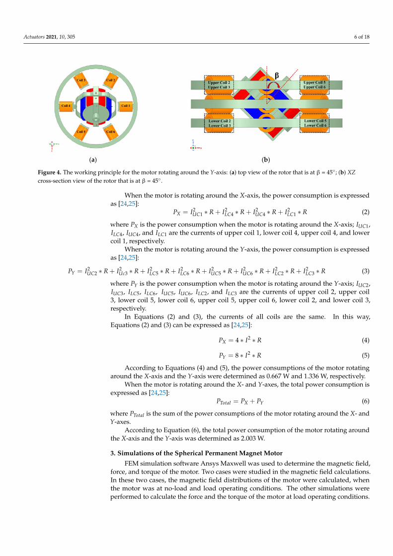
In this study, the tilt angles of the 2-DOF permanent magnet spherical motor aroundthe X-axis (α) and Y-axis (β) were ±45◦. As shown in Figure 3, when upper coil 1 and lowercoil 4 are both excited, S magnetic poles are produced. Similarly, upper coil 4 and lower coil1 are excited, and then, N magnetic poles are produced. Thus, the motor performs a motionaround the X-axis from 0◦ to 45◦. As shown in Figure 4, when upper coils 2–3 and lowercoils 5–6 are excited, N magnetic poles are produced. Similarly, upper coils 5–6 and lowercoils 2–3 are excited, and then, S magnetic poles are produced. Thus, the motor performsa motion around the Y-axis from 0◦ to 45◦. By changing the direction of the current, themotor can perform a motion in the reverse direction.
Actuators 2021, 10, 305 5 of 19
Table 1. Design parameters of the motor.
Symbol Corresponding Parameter Dimension
Sod Stator’s outer diameter 157 mm
Sid Stator’s inner diameter 84 mm
Rod Rotor’s outer diameter 50.7 mm
SRid Separator ring’s inner diameter of the stator 147 mm
PMt Permanent magnet’s thickness 4.15 mm
SRt Separator’s ring thickness 10.5 mm
St Stator’s thickness 9 mm
RPMl Rotor’s length 40 mm
Cl Connector’s length 12.5 mm
MPod Mechanical part’s outer diameter 71.5 mm
TBCid Top and bottom cover’s inner diameter 100 mm
TBCod Top and bottom covers’ outer diameter 167 mm
HTBCl Housing and top‐bottom cover’s length 79 mm
Hl Housing’s length 69 mm
FBl Fixed base’s length 5 mm
2.2. Operating Principle of the Spherical Permanent Magnet Motor
The operating principle of the motor is based on the magnetic force generated by
stator coils and permanent magnets. The same polarity of poles generates forces that push
each other. The opposite polarity of poles produces magnetic forces that are pulled from
each other. Thus, the magnetic forces generate a magnetic torque that allows the rotor to
complete the motions around the X‐ and Y‐axes.
In this study, the tilt angles of the 2‐DOF permanent magnet spherical motor around
the X‐axis (α) and Y‐axis (β) were ±45°. As shown in Figure 3, when upper coil 1 and lower
coil 4 are both excited, S magnetic poles are produced. Similarly, upper coil 4 and lower
coil 1 are excited, and then, N magnetic poles are produced. Thus, the motor performs a
motion around the X‐axis from 0° to 45°. As shown in Figure 4, when upper coils 2–3 and
lower coils 5–6 are excited, N magnetic poles are produced. Similarly, upper coils 5–6 and
lower coils 2–3 are excited, and then, S magnetic poles are produced. Thus, the motor
performs a motion around the Y‐axis from 0° to 45°. By changing the direction of the cur‐
rent, the motor can perform a motion in the reverse direction.
(a) (b)
Figure 3. The working principle for the motor rotating around the X‐axis: (a) top view of the rotor that is at α = 45°; (b) YZ
cross‐section view of the rotor that is at α = 45°. Figure 3. The working principle for the motor rotating around the X-axis: (a) top view of the rotor that is at α = 45◦; (b) YZcross-section view of the rotor that is at α = 45◦.
In addition, while the motor performs the movements around the X-and Y-axes, thepower consumption is considered for electrical design. The power consumption can beexpressed as [24,25]:
P = I ∗ V = I2 ∗ R, (1)
where I is the current of the coil; R is the resistance of the coil.The coils were excited with a current of 1 A for the movements of the motor around
the X-axis and the Y-axis. Each coil’s resistance was 0.167 ohm.
Actuators 2021, 10, 305 6 of 18Actuators 2021, 10, 305 6 of 19
(a) (b)
Figure 4. The working principle for the motor rotating around the Y‐axis: (a) top view of the rotor that is at β = 45°; (b) XZ
cross‐section view of the rotor that is at β = 45°.
In addition, while the motor performs the movements around the X‐and Y‐axes, the
power consumption is considered for electrical design. The power consumption can be
expressed as [24,25]:
𝑃 𝐼 ∗ 𝑉 𝐼 ∗ 𝑅, (1)
where 𝐼 is the current of the coil; 𝑅 is the resistance of the coil. The coils were excited with a current of 1 A for the movements of the motor around
the X‐axis and the Y‐axis. Each coil’s resistance was 0.167 ohm.
When the motor is rotating around the X‐axis, the power consumption is expressed
as [24,25]:
𝑃 𝐼 ∗ 𝑅 𝐼 ∗ 𝑅 𝐼 ∗ 𝑅 𝐼 ∗ 𝑅 (2)
where 𝑃 is the power consumption when the motor is rotating around the X‐axis; 𝐼 ,
𝐼 , 𝐼 , and 𝐼 are the currents of upper coil 1, lower coil 4, upper coil 4, and lower
coil 1, respectively.
When the motor is rotating around the Y‐axis, the power consumption is expressed
as [24,25]:
𝑃 𝐼 ∗ 𝑅 𝐼 ∗ 𝑅 𝐼 ∗ 𝑅 𝐼 ∗ 𝑅 𝐼 ∗ 𝑅 𝐼 ∗ 𝑅 𝐼 ∗ 𝑅 𝐼 ∗ 𝑅 (3)
where 𝑃 is the power consumption when the motor is rotating around the Y‐axis; 𝐼 ,
𝐼 , 𝐼 , 𝐼 , 𝐼 , 𝐼 , 𝐼 , and 𝐼 are the currents of upper coil 2, upper coil 3, lower
coil 5, lower coil 6, upper coil 5, upper coil 6, lower coil 2, and lower coil 3, respectively.
In Equations (2) and (3), the currents of all coils are the same. In this way, Equations
(2) and (3) can be expressed as [24,25]:
𝑃 4 ∗ 𝐼 ∗ 𝑅 (4)
𝑃 8 ∗ 𝐼 ∗ 𝑅 (5)
According to Equations (4) and (5), the power consumptions of the motor rotating
around the X‐axis and the Y‐axis were determined as 0.667 W and 1.336 W, respectively.
When the motor is rotating around the X‐ and Y‐axes, the total power consumption
is expressed as [24,25]:
𝑃 𝑃 𝑃 (6)
where 𝑃 is the sum of the power consumptions of the motor rotating around the X‐
and Y‐axes.
According to Equation (6), the total power consumption of the motor rotating around
the X‐axis and the Y‐axis was determined as 2.003 W.
Figure 4. The working principle for the motor rotating around the Y-axis: (a) top view of the rotor that is at β = 45◦; (b) XZcross-section view of the rotor that is at β = 45◦.
When the motor is rotating around the X-axis, the power consumption is expressedas [24,25]:
PX = I2UC1 ∗ R + I2
LC4 ∗ R + I2UC4 ∗ R + I2
LC1 ∗ R (2)
where PX is the power consumption when the motor is rotating around the X-axis; IUC1,ILC4, IUC4, and ILC1 are the currents of upper coil 1, lower coil 4, upper coil 4, and lowercoil 1, respectively.
When the motor is rotating around the Y-axis, the power consumption is expressedas [24,25]:
PY = I2UC2 ∗ R + I2
Uc3 ∗ R + I2LC5 ∗ R + I2
LC6 ∗ R + I2UC5 ∗ R + I2
UC6 ∗ R + I2LC2 ∗ R + I2
LC3 ∗ R (3)
where PY is the power consumption when the motor is rotating around the Y-axis; IUC2,IUC3, ILC5, ILC6, IUC5, IUC6, ILC2, and ILC3 are the currents of upper coil 2, upper coil3, lower coil 5, lower coil 6, upper coil 5, upper coil 6, lower coil 2, and lower coil 3,respectively.
In Equations (2) and (3), the currents of all coils are the same. In this way,Equations (2) and (3) can be expressed as [24,25]:
PX = 4 ∗ I2 ∗ R (4)
PY = 8 ∗ I2 ∗ R (5)
According to Equations (4) and (5), the power consumptions of the motor rotatingaround the X-axis and the Y-axis were determined as 0.667 W and 1.336 W, respectively.
When the motor is rotating around the X- and Y-axes, the total power consumption isexpressed as [24,25]:
PTotal = PX + PY (6)
where PTotal is the sum of the power consumptions of the motor rotating around the X- andY-axes.
According to Equation (6), the total power consumption of the motor rotating aroundthe X-axis and the Y-axis was determined as 2.003 W.
3. Simulations of the Spherical Permanent Magnet Motor
FEM simulation software Ansys Maxwell was used to determine the magnetic field,force, and torque of the motor. Two cases were studied in the magnetic field calculations.In these two cases, the magnetic field distributions of the motor were calculated, whenthe motor was at no-load and load operating conditions. The other simulations wereperformed to calculate the force and the torque of the motor at load operating conditions.

Actuators 2021, 10, 305 7 of 18
3.1. Magnetic Field of the Motor under No-Load Operating Conditions
In the first case, the magnetic field distributions of the rotor and the stator werecalculated, when the motor was at no-load. The rotor consisted of surface permanentmagnets and had four permanent magnets, two N poles and two S poles. The model of thepermanent magnet and the rotor is shown in Figure 5.
Actuators 2021, 10, 305 7 of 19
3. Simulations of the Spherical Permanent Magnet Motor
FEM simulation software Ansys Maxwell was used to determine the magnetic field,
force, and torque of the motor. Two cases were studied in the magnetic field calculations.
In these two cases, the magnetic field distributions of the motor were calculated, when the
motor was at no‐load and load operating conditions. The other simulations were per‐
formed to calculate the force and the torque of the motor at load operating conditions.
3.1. Magnetic Field of the Motor under No‐Load Operating Conditions
In the first case, the magnetic field distributions of the rotor and the stator were cal‐
culated, when the motor was at no‐load. The rotor consisted of surface permanent mag‐
nets and had four permanent magnets, two N poles and two S poles. The model of the
permanent magnet and the rotor is shown in Figure 5.
Figure 5. Model of surface permanent magnets and the rotor.
The flux density in a permanent magnet is composed of the flux in the air gap and
the intrinsic magnetic induction. The flux density in a permanent magnet can be expressed
as [15,36]:
𝐵 𝐵 𝜇 ∗ 𝐻 (7)
where 𝐵 is the flux density of the permanent magnet magnetization; 𝐵 is the intrinsic magnetic induction; 𝜇 is the vacuum permeability; 𝐻 is the magnetic field.
The residual magnetic flux density of a permanent magnet is expressed as [15,36]:
𝐵 𝜇 ∗ 𝜇 ∗ 𝐻 (8)
where 𝐵 is the residual magnetic flux density; 𝜇 is the relative permeability of the per‐
manent magnet; 𝐻 is the magnetic coercivity of the permanent magnet.
The material properties of the permanent magnet are given in Table 2.
Table 2. Material properties of the permanent magnet.
Parameter Value
Residual magnetic flux density 𝑩𝒓 1.12 T
Relative permeability of the permanent magnet 𝝁𝒓 1.08
Magnetic coercivity of the permanent magnet 𝑯𝒄 814.567 kA/m
The simulation results of the magnetic field distribution of the rotor and the stator
when the motor was at no‐load conditions are shown in Figure 6.
As can be seen from Figure 6, the distribution of the magnetic flux density was
smooth, when the motor was at no‐load conditions. Moreover, the average magnetic flux
density distribution in the stator was determined as 0.67 T. It was observed that the mag‐
netic flux vectors completed the circuit across the stator. The simulation results of the
magnetic field in the air gap when the motor was at no‐load conditions are shown in Fig‐
ure 7.
Figure 5. Model of surface permanent magnets and the rotor.
The flux density in a permanent magnet is composed of the flux in the air gap and theintrinsic magnetic induction. The flux density in a permanent magnet can be expressedas [15,36]:
B = Bi + µ0 ∗ H (7)
where B is the flux density of the permanent magnet magnetization; Bi is the intrinsicmagnetic induction; µ0 is the vacuum permeability; H is the magnetic field.
The residual magnetic flux density of a permanent magnet is expressed as [15,36]:
Br = µ0 ∗ µr ∗ Hc (8)
where Br is the residual magnetic flux density; µr is the relative permeability of the perma-nent magnet; Hc is the magnetic coercivity of the permanent magnet.
The material properties of the permanent magnet are given in Table 2.
Table 2. Material properties of the permanent magnet.
Parameter Value
Residual magnetic flux density (Br) 1.12 TRelative permeability of the permanent magnet (µr) 1.08Magnetic coercivity of the permanent magnet (Hc) 814.567 kA/m
The simulation results of the magnetic field distribution of the rotor and the statorwhen the motor was at no-load conditions are shown in Figure 6.
As can be seen from Figure 6, the distribution of the magnetic flux density was smooth,when the motor was at no-load conditions. Moreover, the average magnetic flux densitydistribution in the stator was determined as 0.67 T. It was observed that the magnetic fluxvectors completed the circuit across the stator. The simulation results of the magnetic fieldin the air gap when the motor was at no-load conditions are shown in Figure 7.
As shown in Figure 7, the magnetic flux density in the air gap was homogenouslydistributed. The average magnetic flux density obtained in the air gap was 0.237 T. It hasbeen seen that the magnetic flux density of the stator was due to the magnetic energy ofthe magnets in the rotor.
3.2. Magnetic Field of the Motor under Load Operating Conditions
In the second case, the magnetic field distributions of the motor for rotating aroundthe X-axis (α) and the Y-axis (β) from 0◦ to ±45◦ were calculated separately. For the

Actuators 2021, 10, 305 8 of 18
movements of the motor around the X-axis and the Y-axis, the coils were excited with acurrent of 1 A. Each of the coils in the stator consisted of 90 turns. Therefore, the coils wereexcited with 90 A turns of a magnetomotive force in the simulation. The magnetomotiveforce is expressed as [36]:
F = N ∗ I (9)
where F is the magnetomotive force, N is the number of turns of the coil, and I is the loadcurrent of the coil.
Actuators 2021, 10, 305 8 of 19
(a) (b)
Figure 6. Magnetic field distributions of the motor under no‐load conditions: (a) magnetic field vec‐
tors from the top view of the motor; (b) magnetic field distribution from the isometric view of the
motor.
(a) (b)
Figure 7. Magnetic field distributions in the air gap of the motor under no‐load conditions: (a) magnetic field distribution
in the air gap from the top view of the motor; (b) magnetic field distribution in the air gap of the motor.
As shown in Figure 7, the magnetic flux density in the air gap was homogenously
distributed. The average magnetic flux density obtained in the air gap was 0.237 T. It has
been seen that the magnetic flux density of the stator was due to the magnetic energy of
the magnets in the rotor.
3.2. Magnetic Field of the Motor under Load Operating Conditions
In the second case, the magnetic field distributions of the motor for rotating around
the X‐axis (α) and the Y‐axis (β) from 0° to ±45° were calculated separately. For the move‐
ments of the motor around the X‐axis and the Y‐axis, the coils were excited with a current
of 1 A. Each of the coils in the stator consisted of 90 turns. Therefore, the coils were excited
with 90 A turns of a magnetomotive force in the simulation. The magnetomotive force is
expressed as [36]:
𝐹 𝑁 ∗ 𝐼 (9)
where 𝐹 is the magnetomotive force, 𝑁 is the number of turns of the coil, and 𝐼 is the load current of the coil.
When the motor was at load operating conditions, the simulation results of the mag‐
netic field distributions of the motor at 0° and ±45° around the X‐axis (α) and the Y‐axis
(β) are shown in Figures 8 and 9, respectively.
Figure 6. Magnetic field distributions of the motor under no-load conditions: (a) magnetic field vectorsfrom the top view of the motor; (b) magnetic field distribution from the isometric view of the motor.
Actuators 2021, 10, 305 8 of 19
(a) (b)
Figure 6. Magnetic field distributions of the motor under no‐load conditions: (a) magnetic field vec‐
tors from the top view of the motor; (b) magnetic field distribution from the isometric view of the
motor.
(a) (b)
Figure 7. Magnetic field distributions in the air gap of the motor under no‐load conditions: (a) magnetic field distribution
in the air gap from the top view of the motor; (b) magnetic field distribution in the air gap of the motor.
As shown in Figure 7, the magnetic flux density in the air gap was homogenously
distributed. The average magnetic flux density obtained in the air gap was 0.237 T. It has
been seen that the magnetic flux density of the stator was due to the magnetic energy of
the magnets in the rotor.
3.2. Magnetic Field of the Motor under Load Operating Conditions
In the second case, the magnetic field distributions of the motor for rotating around
the X‐axis (α) and the Y‐axis (β) from 0° to ±45° were calculated separately. For the move‐
ments of the motor around the X‐axis and the Y‐axis, the coils were excited with a current
of 1 A. Each of the coils in the stator consisted of 90 turns. Therefore, the coils were excited
with 90 A turns of a magnetomotive force in the simulation. The magnetomotive force is
expressed as [36]:
𝐹 𝑁 ∗ 𝐼 (9)
where 𝐹 is the magnetomotive force, 𝑁 is the number of turns of the coil, and 𝐼 is the load current of the coil.
When the motor was at load operating conditions, the simulation results of the mag‐
netic field distributions of the motor at 0° and ±45° around the X‐axis (α) and the Y‐axis
(β) are shown in Figures 8 and 9, respectively.
Figure 7. Magnetic field distributions in the air gap of the motor under no-load conditions: (a) magnetic field distribution inthe air gap from the top view of the motor; (b) magnetic field distribution in the air gap of the motor.
When the motor was at load operating conditions, the simulation results of themagnetic field distributions of the motor at 0◦ and ±45◦ around the X-axis (α) and theY-axis (β) are shown in Figures 8 and 9, respectively.
As seen in Figures 8 and 9, the magnetic flux density distributions of the motor underload conditions were uniform. There was no problem with magnetic saturation at themotor. In addition, the average magnetic flux density in the stator was determined to beabout 1.1 T. When the motor was in a position of ±45◦ and rotated around the X-axis (α)and the Y-axis (β), it can be seen that the magnetic flux density increased as the rotor andstator approached each other. The simulation results of the magnetic field in the air gapwith the motor loaded are shown in Figure 10.

Actuators 2021, 10, 305 9 of 18Actuators 2021, 10, 305 9 of 19
(a) (b) (c)
Figure 8. Magnetic field distributions of the motor at loaded conditions rotating around the X‐axis:
(a) view of the motor that is at α = 0°; (b) view of the motor that is at α = +45°; (c) view of the motor
that is at α = −45°.
(a) (b) (c)
Figure 9. Magnetic field distributions of the motor at loaded conditions rotating around the Y‐axis:
(a) view of the motor that is at β = 0°; (b) view of the motor that is at β = +45°; (c) view of the motor
that is at β = –45°.
As seen in Figures 8 and 9, the magnetic flux density distributions of the motor under
load conditions were uniform. There was no problem with magnetic saturation at the mo‐
tor. In addition, the average magnetic flux density in the stator was determined to be
about 1.1 T. When the motor was in a position of ±45° and rotated around the X‐axis (α)
and the Y‐axis (β), it can be seen that the magnetic flux density increased as the rotor and
stator approached each other. The simulation results of the magnetic field in the air gap
with the motor loaded are shown in Figure 10.
(a) (b)
Figure 10. Magnetic flux density distributions in the air gap of the motor under loaded conditions rotating around the X‐
axis from α = 0° to α = ±45° (a) and rotating around the Y‐axis from β = 0° to β = ±45° (b).
As shown in Figure 10, when the motor was at loaded conditions, the maximum and
the average magnetic flux densities in the air gap obtained were 0.403 T and 0.283 T in the
X‐axis from α = 0° to α = ±45°, respectively. When the motor was at loaded conditions, the
Figure 8. Magnetic field distributions of the motor at loaded conditions rotating around the X-axis: (a) view of the motorthat is at α = 0◦; (b) view of the motor that is at α = +45◦; (c) view of the motor that is at α = −45◦.
Actuators 2021, 10, 305 9 of 19
(a) (b) (c)
Figure 8. Magnetic field distributions of the motor at loaded conditions rotating around the X‐axis:
(a) view of the motor that is at α = 0°; (b) view of the motor that is at α = +45°; (c) view of the motor
that is at α = −45°.
(a) (b) (c)
Figure 9. Magnetic field distributions of the motor at loaded conditions rotating around the Y‐axis:
(a) view of the motor that is at β = 0°; (b) view of the motor that is at β = +45°; (c) view of the motor
that is at β = –45°.
As seen in Figures 8 and 9, the magnetic flux density distributions of the motor under
load conditions were uniform. There was no problem with magnetic saturation at the mo‐
tor. In addition, the average magnetic flux density in the stator was determined to be
about 1.1 T. When the motor was in a position of ±45° and rotated around the X‐axis (α)
and the Y‐axis (β), it can be seen that the magnetic flux density increased as the rotor and
stator approached each other. The simulation results of the magnetic field in the air gap
with the motor loaded are shown in Figure 10.
(a) (b)
Figure 10. Magnetic flux density distributions in the air gap of the motor under loaded conditions rotating around the X‐
axis from α = 0° to α = ±45° (a) and rotating around the Y‐axis from β = 0° to β = ±45° (b).
As shown in Figure 10, when the motor was at loaded conditions, the maximum and
the average magnetic flux densities in the air gap obtained were 0.403 T and 0.283 T in the
X‐axis from α = 0° to α = ±45°, respectively. When the motor was at loaded conditions, the
Figure 9. Magnetic field distributions of the motor at loaded conditions rotating around the Y-axis: (a) view of the motorthat is at β = 0◦; (b) view of the motor that is at β = +45◦; (c) view of the motor that is at β = −45◦.
Actuators 2021, 10, 305 9 of 19
(a) (b) (c)
Figure 8. Magnetic field distributions of the motor at loaded conditions rotating around the X‐axis:
(a) view of the motor that is at α = 0°; (b) view of the motor that is at α = +45°; (c) view of the motor
that is at α = −45°.
(a) (b) (c)
Figure 9. Magnetic field distributions of the motor at loaded conditions rotating around the Y‐axis:
(a) view of the motor that is at β = 0°; (b) view of the motor that is at β = +45°; (c) view of the motor
that is at β = –45°.
As seen in Figures 8 and 9, the magnetic flux density distributions of the motor under
load conditions were uniform. There was no problem with magnetic saturation at the mo‐
tor. In addition, the average magnetic flux density in the stator was determined to be
about 1.1 T. When the motor was in a position of ±45° and rotated around the X‐axis (α)
and the Y‐axis (β), it can be seen that the magnetic flux density increased as the rotor and
stator approached each other. The simulation results of the magnetic field in the air gap
with the motor loaded are shown in Figure 10.
(a) (b)
Figure 10. Magnetic flux density distributions in the air gap of the motor under loaded conditions rotating around the X‐
axis from α = 0° to α = ±45° (a) and rotating around the Y‐axis from β = 0° to β = ±45° (b).
As shown in Figure 10, when the motor was at loaded conditions, the maximum and
the average magnetic flux densities in the air gap obtained were 0.403 T and 0.283 T in the
X‐axis from α = 0° to α = ±45°, respectively. When the motor was at loaded conditions, the
Figure 10. Magnetic flux density distributions in the air gap of the motor under loaded conditions rotating around theX-axis from α = 0◦ to α = ±45◦ (a) and rotating around the Y-axis from β = 0◦ to β = ±45◦ (b).
As shown in Figure 10, when the motor was at loaded conditions, the maximum andthe average magnetic flux densities in the air gap obtained were 0.403 T and 0.283 T in theX-axis from α = 0◦ to α = ±45◦, respectively. When the motor was at loaded conditions,the maximum and the average magnetic flux densities in the air gap obtained were 0.36 Tand 0.195 T in the Y-axis from β = 0◦ to β = ±45◦, respectively.
3.3. Force and Torque of the Spherical Permanent Magnet Motor
The force and the torque of the motor can be determined using Ansys Maxwell 3DFEM software. In the electromechanical system, the force and the torque are generated bymagnetic co-energy. The magnetic co-energy is expressed as [36]:
Wm =∫
Vol
(∫ H
0(B ∗ dH)
)dVol (10)

Actuators 2021, 10, 305 10 of 18
where Wm is the magnetic co-energy; H is the magnetic field; B is the magnetic flux density.Using the magnetic co-energy, the torque and the force are expressed as [36]:
T =
∣∣∣∣dW(θ, i)dθ
∣∣∣∣i=
∂
∂θ
[∫V
(∫ H
0B ∗ dH
)dV]
(11)
F =
∣∣∣∣dW(s, i)ds
∣∣∣∣i=
∂
∂s
[∫V
(∫ H
0B ∗ dH
)dV]
(12)
where T is the torque; F is the force; i is the current; θ is the rotating angle; s is the directionof the displacement.
In this way, the simulation results of the torque and the force of the motor from 0◦ to45◦, rotating around the X-axis (α) and the Y-axis (β), with the motor loaded condition, areshown in Figures 11 and 12, respectively.
Actuators 2021, 10, 305 10 of 19
maximum and the average magnetic flux densities in the air gap obtained were 0.36 T and
0.195 T in the Y‐axis from β = 0° to β = ±45°, respectively.
3.3. Force and Torque of the Spherical Permanent Magnet Motor
The force and the torque of the motor can be determined using Ansys Maxwell 3D
FEM software. In the electromechanical system, the force and the torque are generated by
magnetic co‐energy. The magnetic co‐energy is expressed as [36]:
𝑊 𝐵 ∗ 𝑑𝐻 𝑑𝑉𝑜𝑙 (10)
where 𝑊 is the magnetic co‐energy; 𝐻 is the magnetic field; 𝐵 is the magnetic flux den‐
sity.
Using the magnetic co‐energy, the torque and the force are expressed as [36]:
𝑇𝑑𝑊 𝜃, 𝑖
𝑑𝜃𝜕
𝜕𝜃𝐵 ∗ 𝑑𝐻 𝑑𝑉 (11)
𝐹𝑑𝑊 𝑠, 𝑖
𝑑𝑠𝜕
𝜕𝑠𝐵 ∗ 𝑑𝐻 𝑑𝑉 (12)
where 𝑇 is the torque; 𝐹 is the force; 𝑖 is the current; 𝜃 is the rotating angle; 𝑠 is the direction of the displacement.
In this way, the simulation results of the torque and the force of the motor from 0° to
45°, rotating around the X‐axis (α) and the Y‐axis (β), with the motor loaded condition,
are shown in Figures 11 and 12, respectively.
(a) (b)
Figure 11. Force values of the motor at the loaded condition rotating around the X‐axis from α = 0° to α = ±45° (a) and
rotating around the Y‐axis from β = 0° to β = ±45° (b).
(a) (b)
Figure 12. Torque values of the motor in the loaded condition rotating around the X‐axis from α = 0° to α = ±45° (a) and
rotating around the Y‐axis from β = 0° to β = ±45° (b).
As illustrated in Figures 11 and 12, when the results of the simulation were examined,
the average torque and force values obtained were 0.038 N∙m and 1.92 N in the movement
of the motor around the X‐axis, respectively. As can be seen in Figure 12, the average
Figure 11. Force values of the motor at the loaded condition rotating around the X-axis from α = 0◦ to α = ±45◦ (a) androtating around the Y-axis from β = 0◦ to β = ±45◦ (b).
Actuators 2021, 10, 305 10 of 19
maximum and the average magnetic flux densities in the air gap obtained were 0.36 T and
0.195 T in the Y‐axis from β = 0° to β = ±45°, respectively.
3.3. Force and Torque of the Spherical Permanent Magnet Motor
The force and the torque of the motor can be determined using Ansys Maxwell 3D
FEM software. In the electromechanical system, the force and the torque are generated by
magnetic co‐energy. The magnetic co‐energy is expressed as [36]:
𝑊 𝐵 ∗ 𝑑𝐻 𝑑𝑉𝑜𝑙 (10)
where 𝑊 is the magnetic co‐energy; 𝐻 is the magnetic field; 𝐵 is the magnetic flux den‐
sity.
Using the magnetic co‐energy, the torque and the force are expressed as [36]:
𝑇𝑑𝑊 𝜃, 𝑖
𝑑𝜃𝜕
𝜕𝜃𝐵 ∗ 𝑑𝐻 𝑑𝑉 (11)
𝐹𝑑𝑊 𝑠, 𝑖
𝑑𝑠𝜕
𝜕𝑠𝐵 ∗ 𝑑𝐻 𝑑𝑉 (12)
where 𝑇 is the torque; 𝐹 is the force; 𝑖 is the current; 𝜃 is the rotating angle; 𝑠 is the direction of the displacement.
In this way, the simulation results of the torque and the force of the motor from 0° to
45°, rotating around the X‐axis (α) and the Y‐axis (β), with the motor loaded condition,
are shown in Figures 11 and 12, respectively.
(a) (b)
Figure 11. Force values of the motor at the loaded condition rotating around the X‐axis from α = 0° to α = ±45° (a) and
rotating around the Y‐axis from β = 0° to β = ±45° (b).
(a) (b)
Figure 12. Torque values of the motor in the loaded condition rotating around the X‐axis from α = 0° to α = ±45° (a) and
rotating around the Y‐axis from β = 0° to β = ±45° (b).
As illustrated in Figures 11 and 12, when the results of the simulation were examined,
the average torque and force values obtained were 0.038 N∙m and 1.92 N in the movement
of the motor around the X‐axis, respectively. As can be seen in Figure 12, the average
Figure 12. Torque values of the motor in the loaded condition rotating around the X-axis from α = 0◦ to α = ±45◦ (a) androtating around the Y-axis from β = 0◦ to β = ±45◦ (b).
As illustrated in Figures 11 and 12, when the results of the simulation were examined,the average torque and force values obtained were 0.038 N·m and 1.92 N in the movementof the motor around the X-axis, respectively. As can be seen in Figure 12, the averagetorque and force values of the motor rotating around the Y-axis obtained were 0.027 N·mand 1.36 N, respectively.
4. Prototyping of the Spherical Permanent Magnet Motor4.1. Stator of the Spherical Permanent Magnet Motor
The stator of the 2-DOF permanent magnet motor consisted of 18 coils and3 separate blocks. Each of the coils consisted of 90 turns. N020 electrical steel was used formanufacturing the stator. The stator of the motor is shown in Figure 13.

Actuators 2021, 10, 305 11 of 18
Actuators 2021, 10, 305 11 of 19
torque and force values of the motor rotating around the Y‐axis obtained were 0.027 N∙m
and 1.36 N, respectively.
4. Prototyping of the Spherical Permanent Magnet Motor
4.1. Stator of the Spherical Permanent Magnet Motor
The stator of the 2‐DOF permanent magnet motor consisted of 18 coils and 3 separate
blocks. Each of the coils consisted of 90 turns. N020 electrical steel was used for manufac‐
turing the stator. The stator of the motor is shown in Figure 13.
Figure 13. Stator and coils of the motor.
4.2. Rotor of the Spherical Permanent Magnet Motor
The rotor had radially oriented surface magnets consisting of two N poles and two S
poles. Steel 1010 was used for manufacturing the rotor, and SmCo was chosen as the per‐
manent magnet material for the rotor. The rotor of the proposed motor is shown in Figure
14.
Figure 14. Rotor and permanent magnets of the motor.
4.3. Mechanical Parts of the Spherical Permanent Magnet Motor
The mechanical parts of the motor consisted of covers, moving parts, fixed parts, a
housing, and separator rings. There were 4 separator rings that prevented the stator blocks
from touching each other. The moving parts were fixed to the rotor and provided the
Figure 13. Stator and coils of the motor.
4.2. Rotor of the Spherical Permanent Magnet Motor
The rotor had radially oriented surface magnets consisting of two N poles and twoS poles. Steel 1010 was used for manufacturing the rotor, and SmCo was chosen as thepermanent magnet material for the rotor. The rotor of the proposed motor is shown inFigure 14.
Actuators 2021, 10, 305 11 of 19
torque and force values of the motor rotating around the Y‐axis obtained were 0.027 N∙m
and 1.36 N, respectively.
4. Prototyping of the Spherical Permanent Magnet Motor
4.1. Stator of the Spherical Permanent Magnet Motor
The stator of the 2‐DOF permanent magnet motor consisted of 18 coils and 3 separate
blocks. Each of the coils consisted of 90 turns. N020 electrical steel was used for manufac‐
turing the stator. The stator of the motor is shown in Figure 13.
Figure 13. Stator and coils of the motor.
4.2. Rotor of the Spherical Permanent Magnet Motor
The rotor had radially oriented surface magnets consisting of two N poles and two S
poles. Steel 1010 was used for manufacturing the rotor, and SmCo was chosen as the per‐
manent magnet material for the rotor. The rotor of the proposed motor is shown in Figure
14.
Figure 14. Rotor and permanent magnets of the motor.
4.3. Mechanical Parts of the Spherical Permanent Magnet Motor
The mechanical parts of the motor consisted of covers, moving parts, fixed parts, a
housing, and separator rings. There were 4 separator rings that prevented the stator blocks
from touching each other. The moving parts were fixed to the rotor and provided the
Figure 14. Rotor and permanent magnets of the motor.
4.3. Mechanical Parts of the Spherical Permanent Magnet Motor
The mechanical parts of the motor consisted of covers, moving parts, fixed parts, ahousing, and separator rings. There were 4 separator rings that prevented the stator blocksfrom touching each other. The moving parts were fixed to the rotor and provided themovement of the rotor in the X- and Y-axes. The material used for manufacturing thecovers, moving parts, fixed parts, housing, and separator rings was chosen to be stainlesssteel. All mechanical parts and the motor are shown in Figure 15.

Actuators 2021, 10, 305 12 of 18
Actuators 2021, 10, 305 12 of 19
movement of the rotor in the X‐ and Y‐axes. The material used for manufacturing the co‐
vers, moving parts, fixed parts, housing, and separator rings was chosen to be stainless
steel. All mechanical parts and the motor are shown in Figure 15.
(a) Housing and separator rings of motor (b) Covers of motor
(c) Moving parts with the rotor of the motor (d) Motor
Figure 15. Mechanical parts of motor: (a) the housing and the separator rings of motor; (b) the covers
of the motor; (c) the moving parts with the rotor of the motor; (d) the motor.
5. Testing of the Spherical Permanent Magnet Motor
5.1. Experimental Setup
Experimental studies on the magnetic flux density, force, and torque of the motor
were conducted to verify, and the experimental results were compared with the simula‐
tions results. The magnetic field in the air gap of the motor was measured with a gauss‐
meter at no‐load and load operating conditions. The forces were measured using a load
cell [6,15,38–40]. The measuring capacity of the load cell was 50 N. The load cell which
had an error sensitivity of 1% in force measurements was calibrated before the test. A
weight was placed in the load cell, and the calibration factor was determined. Before test‐
ing, the initial values in the load cell were determined, and then all tests were performed.
The force values were measured using the load cell and transferred to a computer with an
HX711 signal amplifier module. The torque values were also determined using the meas‐
ured forces with the force arm, which was positioned 0.02 m from the top to the center of
the rotor [6,15,38]. The experimental setup for measuring the magnetic flux density and
that for measuring the force and the torque of the motor are shown in Figures 16 and 17.
Figure 15. Mechanical parts of motor.
5. Testing of the Spherical Permanent Magnet Motor5.1. Experimental Setup
Experimental studies on the magnetic flux density, force, and torque of the motor wereconducted to verify, and the experimental results were compared with the simulationsresults. The magnetic field in the air gap of the motor was measured with a gaussme-ter at no-load and load operating conditions. The forces were measured using a loadcell [6,15,38–40]. The measuring capacity of the load cell was 50 N. The load cell which hadan error sensitivity of 1% in force measurements was calibrated before the test. A weightwas placed in the load cell, and the calibration factor was determined. Before testing, theinitial values in the load cell were determined, and then all tests were performed. The forcevalues were measured using the load cell and transferred to a computer with an HX711signal amplifier module. The torque values were also determined using the measuredforces with the force arm, which was positioned 0.02 m from the top to the center of therotor [6,15,38]. The experimental setup for measuring the magnetic flux density and thatfor measuring the force and the torque of the motor are shown in Figures 16 and 17.
Actuators 2021, 10, 305 13 of 19
Figure 16. The gaussmeter device and the motor for the measurements of magnetic flux density.
Figure 17. Experimental setup for the measurements of forces and torques.
5.2. Experimental Results of the Magnetic Flux Density in the Air Gap of the Motor at No‐Load
Conditions
Based on the results of the experimental studies and the simulation in the air gap, the
magnetic flux density in the air gap of the motor at no‐load conditions is shown in Figure 18.
Figure 18. Measured and simulation results of the magnetic flux density in the air gap of the motor
at no‐load conditions.
As can be seen from Figure 18, when the motor was at no‐load conditions, the meas‐
ured maximum magnetic flux density distribution in the air gap was obtained to be 0.29
T based on the experimental studies. When the simulation and experimental results were
examined, the average magnetic flux densities were obtained to be 0.237 T and 0.229 T in
the air gap of the motor, respectively. When these results were compared, it was seen that
the simulation results were as 97% accurate as the experimental results.
5.3. Experimental Results for Magnetic Flux Density in the Air Gap of the Motor at Load
Conditions
Figure 16. The gaussmeter device and the motor for the measurements of magnetic flux density.

Actuators 2021, 10, 305 13 of 18
Actuators 2021, 10, 305 13 of 19
Figure 16. The gaussmeter device and the motor for the measurements of magnetic flux density.
Figure 17. Experimental setup for the measurements of forces and torques.
5.2. Experimental Results of the Magnetic Flux Density in the Air Gap of the Motor at No‐Load
Conditions
Based on the results of the experimental studies and the simulation in the air gap, the
magnetic flux density in the air gap of the motor at no‐load conditions is shown in Figure 18.
Figure 18. Measured and simulation results of the magnetic flux density in the air gap of the motor
at no‐load conditions.
As can be seen from Figure 18, when the motor was at no‐load conditions, the meas‐
ured maximum magnetic flux density distribution in the air gap was obtained to be 0.29
T based on the experimental studies. When the simulation and experimental results were
examined, the average magnetic flux densities were obtained to be 0.237 T and 0.229 T in
the air gap of the motor, respectively. When these results were compared, it was seen that
the simulation results were as 97% accurate as the experimental results.
5.3. Experimental Results for Magnetic Flux Density in the Air Gap of the Motor at Load
Conditions
Figure 17. Experimental setup for the measurements of forces and torques.
5.2. Experimental Results of the Magnetic Flux Density in the Air Gap of the Motor at No-LoadConditions
Based on the results of the experimental studies and the simulation in the air gap,the magnetic flux density in the air gap of the motor at no-load conditions is shown inFigure 18.
Actuators 2021, 10, 305 13 of 19
Figure 16. The gaussmeter device and the motor for the measurements of magnetic flux density.
Figure 17. Experimental setup for the measurements of forces and torques.
5.2. Experimental Results of the Magnetic Flux Density in the Air Gap of the Motor at No‐Load
Conditions
Based on the results of the experimental studies and the simulation in the air gap, the
magnetic flux density in the air gap of the motor at no‐load conditions is shown in Figure 18.
Figure 18. Measured and simulation results of the magnetic flux density in the air gap of the motor
at no‐load conditions.
As can be seen from Figure 18, when the motor was at no‐load conditions, the meas‐
ured maximum magnetic flux density distribution in the air gap was obtained to be 0.29
T based on the experimental studies. When the simulation and experimental results were
examined, the average magnetic flux densities were obtained to be 0.237 T and 0.229 T in
the air gap of the motor, respectively. When these results were compared, it was seen that
the simulation results were as 97% accurate as the experimental results.
5.3. Experimental Results for Magnetic Flux Density in the Air Gap of the Motor at Load
Conditions
Figure 18. Measured and simulation results of the magnetic flux density in the air gap of the motorat no-load conditions.
As can be seen from Figure 18, when the motor was at no-load conditions, the mea-sured maximum magnetic flux density distribution in the air gap was obtained to be 0.29 Tbased on the experimental studies. When the simulation and experimental results wereexamined, the average magnetic flux densities were obtained to be 0.237 T and 0.229 T inthe air gap of the motor, respectively. When these results were compared, it was seen thatthe simulation results were as 97% accurate as the experimental results.
5.3. Experimental Results for Magnetic Flux Density in the Air Gap of the Motor atLoad Conditions
According to the results of the experimental studies and the simulations of the mag-netic flux density in the air gap of the motor from 0◦ to ±45◦ rotating around the X-axis (α)and the Y-axis (β) at load conditions are shown in Figure 19.
As seen in Figure 19, the experimental results of the maximum and average magneticflux densities in the air gap of the motor at load conditions were determined to be 0.4 T and0.256 T, respectively, in the X-axis from α = 0◦ to α = ±45◦. In addition, the experimentalresults for the maximum and average magnetic flux densities were obtained to be 0.33 Tand 0.158 T, respectively, at load conditions in the Y-axis from β = 0◦ to β = ±45◦. Whenwe compared the experimental results with the simulation results, it seemed that thesimulation result of the average magnetic flux density in the air gap was as 90% accuratefor the X-axis and as 81% accurate for the Y-axis as the experimental results.

Actuators 2021, 10, 305 14 of 18
Actuators 2021, 10, 305 14 of 19
According to the results of the experimental studies and the simulations of the mag‐
netic flux density in the air gap of the motor from 0° to ±45° rotating around the X‐axis (α)
and the Y‐axis (β) at load conditions are shown in Figure 19.
(a) (b)
Figure 19. Measured and simulation results of the magnetic flux density in the air gap of the motor rotating around the X‐
axis from α = 0° to α = ±45° (a) and rotating around the Y‐axis from β = 0° to β = ±45° (b).
As seen in Figure 19, the experimental results of the maximum and average magnetic
flux densities in the air gap of the motor at load conditions were determined to be 0.4 T
and 0.256 T, respectively, in the X‐axis from α = 0° to α = ±45°. In addition, the experi‐
mental results for the maximum and average magnetic flux densities were obtained to be
0.33 T and 0.158 T, respectively, at load conditions in the Y‐axis from β = 0° to β = ±45°.
When we compared the experimental results with the simulation results, it seemed that
the simulation result of the average magnetic flux density in the air gap was as 90% accu‐
rate for the X‐axis and as 81% accurate for the Y‐axis as the experimental results.
5.4. Experimental Results for the Force and the Torque of the Motor
Based on the results of the measurements and simulations, the force and the torque
of the motor from 0° to ±45° rotating around the X‐axis (α) and the Y‐axis (β) are shown
in Figures 20 and 21, respectively.
(a) (b)
Figure 20. Measured and simulation results for force values of motor rotating around X‐axis from α = 0° to α = ±45° (a)
and rotating around the Y‐axis from β = 0° to β = ±45° (b).
(a) (b)
Figure 21. Measured and simulation results for the torque values of the motor rotating around the X‐axis from α = 0° to α
= ±45° (a) rotating around the Y‐axis from β = 0° to β = ±45° (b).
Figure 19. Measured and simulation results of the magnetic flux density in the air gap of the motor rotating around theX-axis from α = 0◦ to α = ±45◦ (a) and rotating around the Y-axis from β = 0◦ to β = ±45◦ (b).
5.4. Experimental Results for the Force and the Torque of the Motor
Based on the results of the measurements and simulations, the force and the torque ofthe motor from 0◦ to ±45◦ rotating around the X-axis (α) and the Y-axis (β) are shown inFigures 20 and 21, respectively.
Actuators 2021, 10, 305 14 of 19
According to the results of the experimental studies and the simulations of the mag‐
netic flux density in the air gap of the motor from 0° to ±45° rotating around the X‐axis (α)
and the Y‐axis (β) at load conditions are shown in Figure 19.
(a) (b)
Figure 19. Measured and simulation results of the magnetic flux density in the air gap of the motor rotating around the X‐
axis from α = 0° to α = ±45° (a) and rotating around the Y‐axis from β = 0° to β = ±45° (b).
As seen in Figure 19, the experimental results of the maximum and average magnetic
flux densities in the air gap of the motor at load conditions were determined to be 0.4 T
and 0.256 T, respectively, in the X‐axis from α = 0° to α = ±45°. In addition, the experi‐
mental results for the maximum and average magnetic flux densities were obtained to be
0.33 T and 0.158 T, respectively, at load conditions in the Y‐axis from β = 0° to β = ±45°.
When we compared the experimental results with the simulation results, it seemed that
the simulation result of the average magnetic flux density in the air gap was as 90% accu‐
rate for the X‐axis and as 81% accurate for the Y‐axis as the experimental results.
5.4. Experimental Results for the Force and the Torque of the Motor
Based on the results of the measurements and simulations, the force and the torque
of the motor from 0° to ±45° rotating around the X‐axis (α) and the Y‐axis (β) are shown
in Figures 20 and 21, respectively.
(a) (b)
Figure 20. Measured and simulation results for force values of motor rotating around X‐axis from α = 0° to α = ±45° (a)
and rotating around the Y‐axis from β = 0° to β = ±45° (b).
(a) (b)
Figure 21. Measured and simulation results for the torque values of the motor rotating around the X‐axis from α = 0° to α
= ±45° (a) rotating around the Y‐axis from β = 0° to β = ±45° (b).
Figure 20. Measured and simulation results for force values of motor rotating around X-axis from α = 0◦ to α = ±45◦ (a)and rotating around the Y-axis from β = 0◦ to β = ±45◦ (b).
Actuators 2021, 10, 305 14 of 19
According to the results of the experimental studies and the simulations of the mag‐
netic flux density in the air gap of the motor from 0° to ±45° rotating around the X‐axis (α)
and the Y‐axis (β) at load conditions are shown in Figure 19.
(a) (b)
Figure 19. Measured and simulation results of the magnetic flux density in the air gap of the motor rotating around the X‐
axis from α = 0° to α = ±45° (a) and rotating around the Y‐axis from β = 0° to β = ±45° (b).
As seen in Figure 19, the experimental results of the maximum and average magnetic
flux densities in the air gap of the motor at load conditions were determined to be 0.4 T
and 0.256 T, respectively, in the X‐axis from α = 0° to α = ±45°. In addition, the experi‐
mental results for the maximum and average magnetic flux densities were obtained to be
0.33 T and 0.158 T, respectively, at load conditions in the Y‐axis from β = 0° to β = ±45°.
When we compared the experimental results with the simulation results, it seemed that
the simulation result of the average magnetic flux density in the air gap was as 90% accu‐
rate for the X‐axis and as 81% accurate for the Y‐axis as the experimental results.
5.4. Experimental Results for the Force and the Torque of the Motor
Based on the results of the measurements and simulations, the force and the torque
of the motor from 0° to ±45° rotating around the X‐axis (α) and the Y‐axis (β) are shown
in Figures 20 and 21, respectively.
(a) (b)
Figure 20. Measured and simulation results for force values of motor rotating around X‐axis from α = 0° to α = ±45° (a)
and rotating around the Y‐axis from β = 0° to β = ±45° (b).
(a) (b)
Figure 21. Measured and simulation results for the torque values of the motor rotating around the X‐axis from α = 0° to α
= ±45° (a) rotating around the Y‐axis from β = 0° to β = ±45° (b). Figure 21. Measured and simulation results for the torque values of the motor rotating around the X-axis from α = 0◦ toα = ±45◦ (a) rotating around the Y-axis from β = 0◦ to β = ±45◦ (b).
As illustrated in Figure 20, the average force results of the simulation and experimentsfor the motor rotating around the X-axis from 0◦ to ±45◦ obtained were 1.92 N and as 1.6 N,respectively. The average force results of the simulation and the experiments obtained were1.36 N and 1.17 N, respectively, when the motor rotated around the Y-axis. The averagetorque results of the simulation and the experiments for the motor rotating around theX-axis from 0◦ to ±45◦ were also determined to be 0.038 N·m and 0.032 N·m, respectively,as seen in Figure 21. The average torque results of the simulation and the experiments weredetermined to be 0.027 N·m and 0.0236 N·m, respectively, when the motor rotated aroundthe Y-axis.
6. Discussion
In this study, a surface permanent magnet 2-DOF spherical motor has been designed,manufactured and tested. First, the magnetic flux, force, and torque parameters of the

Actuators 2021, 10, 305 15 of 18
motor have been simulated using the Ansys Maxwell tool. Then, the experimental studieshave been carried out to validate the accuracy of the 3D FEM simulation results.
According to the experimental and simulation results, the magnetic flux densitiesunder no-load and load operating conditions of the motor were in good agreement witheach other. It is seen from the simulation results that the flux density was uniformlydistributed in the air gap of the motor. The magnetic flux density parameters were alsomeasured using a gaussmeter under both no-load and load conditions of the motor. It hasbeen observed from the experimental studies that there was no magnetic saturation on themotor. It has been seen that the simulated average magnetic flux density was 3% higherthan the experimental one at no-load operation conditions. Then, the maximum magneticflux density values were also obtained in the X-axis and the Y-axis from 0◦ to ±45◦ atload conditions. When the motor rotated around the X-axis, the maximum magnetic fluxdensity was 0.4 T. When the motor rotated around the Y-axis, the maximum magnetic fluxdensity was 0.33 T. The experimental results were 1% and 8% lower than the simulationresults for the X- and Y-axes, respectively.
In addition, the force and the torque of the motor have been obtained by experimentalstudies and compared with the simulation results. As a result, the average force valuesof the simulation and experimental studies for the motor rotating around the X-axisobtained were 1.92 N and 1.6 N, respectively. The average torque values of the simulationand experimental studies for the motor rotating around the X-axis were 0.038 N·m and0.032 N·m, respectively. The results of the average force and torque of the motor rotatingaround the X-axis from 0◦ to ±45◦ have been examined, and the experimental resultsobtained were approximately 17% lower than the simulation results. The average forcevalues of the simulation and experimental studies for the motor rotating around the Y-axisobtained were 1.36 N and 1.17 N, respectively. The average torque values of the simulationand experimental studies were 0.027 N·m and 0.0236 N·m, respectively in the movementof the motor rotating around the Y-axis. In addition, when the force and torque results forthis case were examined, it was seen that the experimental results were approximately 14%lower than the simulation results.
The difference between the simulated and experimental force and torque valuesis due to the mechanical forces and friction at the connection points that provided themotion of the motor. However, it is predicted that the values of the force and torque canbe significantly increased if the friction and mechanical loads are reduced around themechanical connection points.
Considering previous studies [23–25,27–32] which are similar according to the work-ing principle and structure of the motor with this study, it has been seen that the tilt anglemotion capacities of the spherical bearings, bearing covers, and joint bearings limited thetilt motion angles between ±11◦ and ±37◦ of the MDOF motion motors and actuators.In addition, the average torque values of MDOF motion motors and actuators were ob-tained for tilt movements in the range of 7.98–19.40 mN·m in these studies [24,25]. Theaverage force parameter has also been considered for the same studies and obtained for tiltmovements in the range of 0.5–1.08 N [27–31].
It has been observed that the tilt angle was limited in MDOF motion spherical motorsactuators using spherical bearings, bearing covers, and joint bearings for the mechanicalstructure. Thus, the limitation of the tilt angle also affects the force and torque values.
In this study, the mechanical structure of the prototyped motor was designed toimprove the tilt angle, which is different from the mechanical structures of MDOF motionmotors that consist of spherical bearings, joint bearings, or bearing covers in the literature.
Furthermore, the tilt angle of the prototyped motor of ±45◦ has been improved by21% compared to tilt angles between ±11◦ and ±37◦ of MDOF motion motors by usingspherical bearings, joint bearing, or bearing covers in their mechanical structures in theliterature. Thus, the average force values for the motor with a tilt angle of ±45◦ havebeen obtained for movements in the X- and Y-axes to be 1.6 N and 1.17 N, respectively.The average torque values have been also obtained for the X- and Y-axes to be 32 mN·m
Actuators 2021, 10, 305 16 of 18
and 23.6 mN·m, respectively. By increasing the tilt angle to ±45◦, the average force andtorque values of the prototyped motor obtained have been 29% and 43% higher than theMDOF motion motors that use spherical bearings, bearing covers, or joint bearings in theirmechanical structures, respectively.
Additionally, the size also has been considered in the design of the prototyped motor.The outer diameter of the stator was 157 mm to ensure that the rotor easily moved inthe new mechanical structure and achieved a large tilt angle of ±45◦. The stator outerdiameter has been found between 28 mm and 300 mm according to previous studies onMDOF motion motors and actuators [21,22,24,25,28,31] with the tilt motion angles between±11◦ and ±37◦. Power consumption has been also considered in this study. The powerconsumption of the proposed motor rotating around the X- and Y-axes with the tilt angleof ±45◦ was 2.003 W. The power consumption of the motor studied here seems to be lowerwithin acceptable levels compared to those of other similar motor designs [24–26].
Although the size and the power consumption of the proposed motor are within thesize and power consumption range of the previous studies on MDOF motion motors in theliterature, a larger tilt angle and higher force and torque values have been achieved in thisstudy.
7. Conclusions
A large tilt angle, a high torque, and a strong force values with a mechanical designare the most important features expected from MDOF motors. It has been observed thatthe inability to obtain high tilt angles depends not only on the electrical design of the motor,but also on the mechanical design of the motor that facilitates this movement. Therefore,both the electrical design and the mechanical structures of the motor have been designedby taking this case into account in this study.
A 2-DOF surface permanent magnet spherical motor that had a ±45◦ tilt angle aroundthe X-axis (α) and the Y-axis (β) has been designed, simulated and prototyped in thisstudy. The motor consisted of a 4-pole permanent magnet rotor and a 3-block stator with18 coils. Ansys Maxwell software has been used for the 3D FEM simulation of the motor todetermine the magnetic flux density, force, and torque. The simulated and experimentalstudies of the motor were compared for the motion around the X- and Y-axes from 0◦ to±45◦. In addition, a new mechanical structure of the proposed motor has been designedthat surrounded the rotor with two moving parts to provide the movement of the rotorin the X- and Y-axes at a large tilt angle of ±45◦ without using any mechanical partelements such as bearing covers, spherical bearings, and joint bearings. Furthermore, thehigher average force and torque values of the proposed motor with a tilt motion angle of±45◦ obtained were 1.4 N and 27.8 mN·m, respectively. The literature offers narrower tiltangles typically between ±11◦ and ±37◦ compared to our wider range of ±45◦. The forceparameters were in a lower range of 0.5–1.08 N, and the torque values were in a lowerrange of 7.98–19.40 mN·m, compared to our results for the movements of the motor.
The power consumption and the size of the motor have been also considered in thisstudy. The power consumption of the proposed motor rotating around the X- and Y-axeswith a tilt angle of ±45◦ was 2.003 W. The outer diameter of the stator was determined tobe 157 mm to ensure that the rotor rotated easily in the new mechanical structure with alarge tilt angle of ±45◦. It has been observed that the power consumption and the size ofthe proposed motor were within the size and the power consumption range of the previousstudies in the literature, while a larger tilt angle and higher force and torques values havebeen achieved in this study.
Consequently, the tilt angle, force and torque values of the prototype spherical perma-nent magnet motor which has a new mechanical structure have been improved when wecompared them to the MDOF motion motors that use spherical bearings, bearing covers,or joint bearings in their mechanical structures.
By using different materials and mechanical structures as a future work, the proposedmotor can be improved in terms of force, torque, and motion capability and find wider

Actuators 2021, 10, 305 17 of 18
applications in robotics, aerospace, automotive, and biomedical fields. In addition, thecoils in the center block of the stator were actually designed suitable for 3-DOF motioncapability. Thus, 3-DOF motion can also be obtained by developing a modified mechanicalstructure, so that it can be integrated into systems that require an even higher DOF.
Author Contributions: Conceptualization, U.Y.G. and S.Z.P.; methodology, U.Y.G. and S.Z.P.; soft-ware, U.Y.G.; validation, U.Y.G.; formal analysis, U.Y.G.; investigation, U.Y.G. and S.Z.P.; resources,U.Y.G. and S.Z.P.; writing—original draft preparation, U.Y.G.; writing—review and editing, S.Z.P.;visualization, U.Y.G. and S.Z.P.; supervision, S.Z.P. All authors have read and agreed to the publishedversion of the manuscript.
Funding: This research received no external funding.
Institutional Review Board Statement: Not applicable.
Informed Consent Statement: Not applicable.
Data Availability Statement: Not applicable.
Acknowledgments: The authors of this article would like to thank the companies FEMSAN ElectricMotors for the prototype of the motor; Numesys Inc. which is Ansys Elite Channel Partner for provid-ing the Ansys Maxwell software; Figes Engineering and ADVENS Engineering for the experimentaltests of the motor and all support during this study which is also based on the PhD thesis.
Conflicts of Interest: The authors declare no conflict of interest.
References1. Williams, F.; Laithwaite, E.; Piggot, L. Brushless variable speed induction motor. IEEE Proc. 1956, 2097U, 102–118.2. Williams, F.; Laithwaite, E.; Eastham, G.F. Development of design of spherical induction motor. IEEE Proc. 1959, 3036U, 471–484.
[CrossRef]3. Laithwaite, E. Design of spherical motors. Electr. Times 1960, 9, 921–925.4. Vachtsevanos, G.J.; Davey, K.; Lee, K.M. Development of a novel intelligent robotic manipulator. IEEE Control. Syst. Mag. 1987, 7,
9–15. [CrossRef]5. Vachtsevanos, G.J.; Davey, K.R. Spherical Motor Particularly Adapted for Robotics. US Patent 4739241, 19 April 1988.6. Diep, B.T.; Nguyen, N.D.; Tran, T.T.; Nguyen, Q.H. Design and experimental validation of a 3-DOF force feedback system
featuring spherical manipulator and magnetorheological actuators. Actuators 2020, 9, 19. [CrossRef]7. Li, X.; Bai, S.; Chen, W.; Liu, J. Torque modelling and current optimization of a spherical actuator built as an electromagnets
driven spherical parallel manipulator. In Proceedings of the 2017 IEEE International Conference on Cybernetics and IntelligentSystems (CIS) and IEEE Conference on Robotics, Automation and Mechatronics (RAM), Ningbo, China, 19–21 November 2017;pp. 626–631.
8. Joshi, S.; Paik, J. Multi-DoF force characterization of soft actuators. IEEE Robot. Autom. Lett. 2019, 4, 3679–3686. [CrossRef]9. Ahmadi, S.; Moghani, J.S.; Mirsalim, M. Simulation and analysis of a novel PM spherical 3-DOF actuator with E-shaped stator
and blade-shaped rotor structure. In Proceedings of the 2018 9th Annual Power Electronics, Drives Systems and TechnologiesConference (PEDSTC), Tehran, Iran, 13–15 February 2018; pp. 59–64.
10. Hollis, R.L.; Salcudean, S.; Allan, A.P. A six degree of freedom magnetically levitated variable compliance fine motion wrist. InProceedings of the 4th International Symposium on Robotics Research, Santa Cruz, CA, USA, 9–14 August 1987; MIT Press:Cambridge, MA, USA, 1988; pp. 65–73.
11. Salcudean, S.E.; Hollis, R.L. A magnetically levitated fine motion wrist: Kinematics, dynamics and control. In Proceedings of theIEEE International Conference on Robotics and Automation, Philadelphia, PA, USA, 24–29 April 1988; pp. 261–266.
12. Hollis, R.L.; Salcudean, S.E.; Allan, A.P. A six degree of freedom magnetically levitated variable compliance fine motion wrist:Design, modeling and control. IEEE Trans. Rob. Autom. 1991, 7, 320–332. [CrossRef]
13. Wang, J.; Wang, W.; Jewell, G.W.; Howe, D. A novel spherical permanent magnet actuator with three degrees-of-freedom. IEEETrans. Magn. 1998, 34, 2078–2080. [CrossRef]
14. Wang, J.; Jewell, G.W.; Howe, D. Analysis, design and control of a novel spherical permanent magnet actuator. Proc. IEEE Electr.Power Appl. 1998, 145, 61–71. [CrossRef]
15. Öner, Y. Computer Aided Three Dimensional Magnetic Analysis, Design and Application of a Permanent Magnet SphericalMotor. Ph.D. Thesis, University of Gazi, Ankara, Turkey, 2004.
16. Li, H.; Li, T. End-effect magnetic field analysis of the Halbach array permanent magnet spherical motor. IEEE Trans. Magn. 2018,54, 1–9. [CrossRef]
17. Lu, B.; Aoyagi, M. Examination of an outer-rotor-type multidegree-of-freedom spherical ultrasonic motor. In Proceedings of the2012 15th International Conference on Electrical Machines and Systems (ICEMS), Sapporo, Japan, 21–24 October 2012; pp. 1–5.
Actuators 2021, 10, 305 18 of 18
18. Li, Z.; Chen, Q.; Yue, F.; Zhang, Y. Modal analysis of electromagnetic resonance for multi-degree-of-freedom spherical motor. InProceedings of the 2018 21st International Conference on Electrical Machines and Systems (ICEMS), Jeju, Korea, 7–10 October2018; pp. 1847–1852.
19. Li, Z.; Chen, Q.; Wang, Q. Analysis of multi-physics coupling field of multi-degree-of-freedom permanent magnet sphericalmotor. IEEE Trans. Magn. 2019, 55, 1–5. [CrossRef]
20. Li, B.; Li, Z.; Li, G. Magnetic field model for permanent magnet spherical motor with double polyhedron structure. IEEE Trans.Magn. 2017, 53, 1–5. [CrossRef]
21. Yan, L.; Chen, I.-M.; Chee, K.L.; Yang, G.; Lin, W.; Lee, K.-M. Design and analysis of a permanent magnet spherical actuator. InProceedings of the 2005 IEEE/RSJ International Conference on Intelligent Robots and Systems, Edmonton, AB, Canada, 2–6August 2005; pp. 691–696.
22. Gan, L.; Pei, Y.; Chai, F. Tilting torque calculation of a novel tiered type permanent magnet spherical motor. IEEE Trans. Ind.Electron. 2020, 67, 421–431. [CrossRef]
23. Cho, S.; Lim, J.-S.; Oh, Y.J.; Jeong, G.; Kang, D.-W.; Lee, J. A study on output characteristics of the spherical multi-DOF motoraccording to the number of phases and pole pitch angles. IEEE Trans. Magn. 2018, 54, 1–5. [CrossRef]
24. Liu, C.-S.; Lin, Y.-H.; Yeh, C.-N. Analytical Investigation on Torque of Three-Degree-of-Freedom Electromagnetic Actuator forImage Stabilization. Appl. Sci. 2021, 11, 6872. [CrossRef]
25. Lin, Y.-H.; Liu, C.-S.; Yeh, C.-N. Design and Simulation of Novel 3-DOF Spherical Voice Coil Motor. Actuators 2021, 10, 155.[CrossRef]
26. Takahara, K.; Hirata, K.; Niguchi, N.; Nishiura, Y.; Sakaidani, Y. Experimental evaluation of the static characteristics of multi-degree-of-freedom spherical actuators. IEEE Trans. Magn. 2017, 53, 1–5.
27. Han, Y.M.; Choi, S.B. Force-feedback control of a spherical haptic device featuring an electrorheological fluid. Smart Mater.Structures 2006, 15, 1438–1446. [CrossRef]
28. Li, Z. Magnetic-field computation of a novel 3-DOF deflection-type PM motor with analytical and finite-element methods.Elektrotehniški Vestn. 2014, 81, 51–56.
29. Li, Z.; Zhang, L.; Lun, Q.; Jin, H. Optimal design of multi-DOF deflection type PM motor by response surface methodology. J.Electr. Eng. Technol. 2015, 10, 965–970. [CrossRef]
30. Li, Z.; Lun, Q.Q. Analysis of magnetic field and levitation force characteristics for 3-DOF deflection type PM motors. J. Chin. Inst.Eng. 2016, 39, 704–712. [CrossRef]
31. Li, Z.; Wang, Q. Levitation mechanism and improvements of 3-DOF deflection type PM actuator. IEEE Trans. Appl. Supercond.2016, 26, 1–5. [CrossRef]
32. El-Khalafawy, K.; El-Amary, N.H. Spherical actuator design and operation based on magnetic profile. In Proceedings of the 2017IEEE PES Asia-Pacific Power and Energy Engineering Conference (APPEEC), Bangalore, India, 8–10 November 2017; pp. 1–6.
33. Li, Z.; Yu, X.; Xue, Z.; Sun, H. Analysis of Magnetic Field and Torque Features of Improved Permanent Magnet Rotor DeflectionType Three-Degree-of-Freedom Motor. Energies 2020, 13, 2533. [CrossRef]
34. Gündogar, U.Y. Magnetics, Mechanical Analysis and Implementation of Double Excited Spherical Motor. Master’s Thesis,University of Pamukkale, Denizli, Turkey, 2015.
35. Gündogar, U.Y.; Zorlu Partal, S.; Öner, Y. 3D electromagnetic and structural analysis of a doubly excited spherical motor forrobotic applications. In Proceedings of the 2020 Innovations in Intelligent Systems and Applications Conference (ASYU), Istanbul,Turkey, 15–17 October 2020; pp. 1–8.
36. Ansys Maxwell 2021 R2; Ansys, Inc.: Canonsburg, PA, USA, 2021.37. Gündogar, U.Y.; Zorlu Partal, S. The effect of using different magnet structures and different magnet materials on the design of
the spherical motor. Eur. J. Sci. Technol. 2020, 19, 946–959.38. Wen, Y.; Li, G.; Wang, Q.; Tang, R.; Liu, Y.; Li, H. Investigation on the Measurement Method for Output Torque of a Spherical
Motor. Appl. Sci. 2020, 10, 2510. [CrossRef]39. Rossini, L.; Chételat, O.; Onillon, E.; Perriard, Y. Analytical and experimental investigation on the force and torque of a Reaction
Sphere for satellite attitude control. In Proceedings of the 2011 IEEE/ASME International Conference on Advanced IntelligentMechatronics (AIM), Budapest, Hungary, 3–7 July 2011; pp. 487–492.
40. Omura, M.; Shimono, T.; Fujimoto, Y. Development of semicircular tubular core-less linear motor and its motion control. IEEJTrans. Ind. Appl. 2015, 135, 246–257. [CrossRef]


