Embed Size (px)
Citation preview

4872 IEEE TRANSACTIONS ON INDUSTRIAL ELECTRONICS, VOL. 56, NO. 12, DECEMBER 2009
Design of an Analog Quasi-Steady-State NonlinearCurrent-Mode Controller for Single-Phase
Active Power FilterJaume Miret, Member, IEEE, Luis García de Vicuña, Miguel Castilla,
José Matas, and Josep M. Guerrero, Senior Member, IEEE
Abstract—The injection of sinusoidal current to an electricalgrid is nowadays possible with the use of active power filters(APFs). With quasi-steady-state (QSS) nonlinear controllers, thesepower filters provide low grid-current-harmonic content withsimple-control analog implementation. This paper focuses on thedesign of a QSS nonlinear controller for a single-phase APF.A complete analysis based on the sliding-mode-control theoryis given. From the analysis, a set of control-design guidelinesis presented to select the gains and parameters of the controlscheme. Selected experimental results are reported to validate thetheoretical design procedure.
Index Terms—Active power filter (APF), harmonics, powerquality, quasi steady-state (QSS) approach.
I. INTRODUCTION
W ITH THE increasing use of electronic equipment, spe-cial attention has been drawn to the impact that this
equipment has on ac power lines. The amount of harmoniccurrents flowing into the grid is growing rapidly due to pollutingloads. The use of passive filters can increase power quality,but they are a costly and bulky solution. Moreover, there is nopossibility of adjustment to correct harmonic currents producedby different loads.
Some power-grid-conditioning methods have been proposedin the literature to minimize harmonic distortion currents andto correct the power factor on the electric network [1]–[6].One of the most popular power-grid conditioners is the activepower filter (APF), with shunt connection [3]–[14] or seriesconnection with the load [15]. Several topologies are possible,including full-bridge voltage source inverter and full-bridgecurrent source inverter [16].
The main purpose of the shunt APF system is to supply theharmonics absorbed by the nonlinear load, in order to providethe grid current with a low harmonic content. To this end,
Manuscript received September 25, 2008; revised June 15, 2009. Firstpublished July 7, 2009; current version published November 6, 2009. This workwas supported by the Spanish Ministry of Science and Technology under GrantENE2006-15521-C03-01.
J. Miret, L. García de Vicuña, M. Castilla, and J. Matas are with the De-partment of Electronic Engineering, Technical University of Catalonia, 08800Vilanova i la Geltrú, Spain (e-mail: [email protected]; [email protected];[email protected]; [email protected]).
J. M. Guerrero is with the Department of Automatic Control Systems andComputer Engineering, Technical University of Catalonia, 08036 Barcelona,Spain (e-mail: [email protected]).
Digital Object Identifier 10.1109/TIE.2009.2026385
the control of APF systems has been widely studied in theliterature. The basic approach consists of two control loops.The outer voltage loop is responsible for capacitor-voltageregulation while the inner current loop performs the reference-current-signal tracking. For the reference-signal generation, adirect method consists of sensing the load current and extractingthe harmonic content. Then the filter current is used in the innercurrent loop to track the load-current harmonics [7], [11]. As analternative, an indirect method generates a sinusoidal referencesignal by means of grid-voltage sensing. In that case, the gridcurrent is forced to follow this sinusoidal signal and, thus, theload harmonics are indirectly given by the APF inductor current[8], [17]. The main advantages of this second approach are thatonly one low-bandwidth current sensor is required and fastertransient response is obtained [17], [18].
To improve the performance of the basic approaches, dif-ferent control solutions have been proposed. Recent workshave proposed digital implementations with time or frequency-domain mathematical representations [18]–[26]. These controlsolutions give high performance and flexible designs. However,fast digital signal processors are required to compute the com-plex mathematical calculations, yielding costly schemes.
Analog-control implementations have also been widely eval-uated in the literature [7]–[12]. The conventional controlconfiguration provides good performance at nominal grid con-ditions. However, in distorted grids, additional analog circuitryshould be necessary to maintain the expected features. Tosimplify the control circuitry, the quasi steady-state (QSS)approach has been successfully applied to switching convert-ers and particularly to shunt APFs [27]–[29]. The basic im-plementation uses an integrator with a reset signal which issynchronized with each switching cycle, in order to computethe duty ratio. The method is simple, but it loses the advantagesof past behavior in error correction caused by the integratorperiodic reset [30]. An improved QSS controller has beenrecently presented in [31]. This control scheme has superiorperformance characteristics due to its ability to maintain thepast behavior of the system. This feature is achieved throughthe use of an analog multiplexer and a bandpass filter instead ofthe reset integrator.
In this paper, we present a complete design-oriented studyfor the QSS nonlinear controller reported in [31]. The analysisis based on the sliding-mode-control theory. A set of designguidelines for the selection of the gain and parameters of the
0278-0046/$26.00 © 2009 IEEE
Authorized licensed use limited to: UNIVERSITAT POLITÈCNICA DE CATALUNYA. Downloaded on June 02,2010 at 07:21:01 UTC from IEEE Xplore. Restrictions apply.

MIRET et al.: QUASI-STEADY-STATE CONTROLLER FOR SINGLE-PHASE ACTIVE POWER FILTER 4873
Fig. 1. Shunt active power filter.
TABLE ISTATE OF SWITCHES AND CONTROL INPUT u
QSS controller is identified by means of the evaluation ofexistence, reaching, and stability conditions. In addition, theeffect of the bandpass-filter characteristics on the APF per-formance is analyzed. As a result, we propose a systematicprocedure for the design of the QSS controller. This procedureconstitutes the main contribution of this paper.
This paper is organized as follows. Section II reviews theanalog-control implementations for the shunt APF. Section IIIuses the sliding-mode-control theory to devise the QSS non-linear control configuration. Section IV presents some control-design guidelines. Section V corroborates the expected featuresof the proposed controller by means of selected experimentalresults. Also, a performance comparison with a reference APFcontroller is provided. Section VI presents the conclusion.
II. CONVENTIONAL INDIRECT CONTROL FOR
SINGLE-PHASE SHUNT APF
Fig. 1 shows a typical configuration of a full-bridge APFcircuit in parallel with both the grid and the nonlinear load. Forthe APF control, we adopt the basic bipolar modulation schemedue to its easy analog implementation. Table I sums up the stateof the switches and the definition of the control input u for thismodulation technique.
From Table I, the dynamic model of the APF circuit can beeasily expressed as
diLdt
=1L
(vs − rL · iL − vc · u) (1)
dvc
dt=
iLC
· u. (2)
Normally, the grid frequency is well below the switching fre-quency. Therefore, the variables of the aforementioned modelcan be considered nearly constant in one switching period.
Following this QSS approach [27]–[29], the relationship be-tween voltages vc and vs can be expressed as
vc
vs≈ 1
〈u〉 (3)
where 〈u〉 is the average value of the control variable u overone switching period. This simple expression will be used nextto derive the nonlinear control proposed in this paper.
Fig. 2 shows the control configuration for the shunt APFcircuit [10]. It consists of two control loops and a modulationscheme. The inner current loop is responsible for assuring thatthe grid current is remains sinusoidal and in phase with the gridvoltage vs. This control objective can be expressed as
is = i∗s = k · vs (4)
where i∗s is the reference current, and k is a slow-varyingvariable which accounts for the average power consumed bythe nonlinear load. Note that an analog multiplier is requiredfor the implementation of this control objective.
The value of k is given by an outer voltage loop, usually bymeans of a proportional–integral (PI) compensator of the volt-age error ev = v∗
c − vc. In common practice, the voltage vc isfiltered out through a low-pass filter with a cutoff frequency lessthan twice the grid frequency, in order to reduce the harmoniccontent of both the variable k and the reference current [8].
The last stage of the conventional indirect controller includesthe modulation scheme. From an analog implementation pointof view, an interesting sliding-mode modulation technique isgiven in [8]. A simple sliding surface is defined using the grid-current error
s = is − i∗s. (5)
The control law, which forces the grid current to track thereference signal, can be expressed as [8]
u ={
1, for s > 0−1, for s < 0.
(6)
Normally, a high-bandwidth current compensator is neces-sary in a conventional pulsewidth modulation scheme. Follow-ing this sliding-mode approach, the compensator of the innercurrent loop is not required.
The indirect sliding-mode control described here will beused as a reference control in the experimental performancecomparison provided in Section V.
III. QSS SLIDING-MODE CONTROLLER
The aim of this section is to derive a QSS sliding-mode con-troller which avoids the use of an analog multiplier in the outervoltage loop. Some details about the practical implementationof the proposed controller are also presented.
A. Derivation of Control Configuration
The QSS approach is considered here to obtain the output ofthe outer voltage loop i∗s. It is important to note that in steady
Authorized licensed use limited to: UNIVERSITAT POLITÈCNICA DE CATALUNYA. Downloaded on June 02,2010 at 07:21:01 UTC from IEEE Xplore. Restrictions apply.

4874 IEEE TRANSACTIONS ON INDUSTRIAL ELECTRONICS, VOL. 56, NO. 12, DECEMBER 2009
Fig. 2. Conventional indirect control for the single-phase APF circuit.
Fig. 3. Proposed QSS sliding-mode controller.
state, 〈u〉 is a nearly sinusoidal waveform, and the variables kand vc are slow-varying signals with respect to the switchingperiod. Substituting (3) into (4), the main control objective canbe alternatively expressed as
is ≈ k · vc · 〈u〉 = k1 · 〈u〉 (7)
where k1 is the output of the PI compensator of the error voltageev , i.e.,
k1 = kp (v∗c − vc) + ki
∫(v∗
c − vc) dt. (8)
Note that (7) gives the desired control objectives without sens-ing the grid voltage, but an analog multiplier is still required.
Because k1 is almost constant and a slow-varying signal, asecond approximation can be made; k1 · 〈u〉 ≈ 〈k1 · u〉, thatis, the product of two analog signals (k1 and 〈u〉) is replacedby the average value of the product of an analog signal (k1)and a discrete one (u). In that case, a bandpass filter and amultiplexer can be used to implement the reference current〈k1 · u〉 [31], eliminating the need for an analog multiplier inthe outer voltage loop
is = i∗s = 〈k1 · u〉. (9)
The bandpass filter used to obtain 〈k1 · u〉 must be tuned tothe grid frequency to reject all the current harmonics except thefundamental one.
B. Controller Implementation
Fig. 3 shows the implementation of the control objective(9) following a sliding-mode-control approach. The slidingsurface is easily derived by identifying (9) with the well-knownexistence condition s = 0
s = is − i∗s = is − 〈k1 · u〉. (10)
The characteristics of the bandpass filter have a significanteffect on the APF performance. The bandwidth should be smallenough to sufficiently attenuate the harmonic components ofthe reference current. However, a slow transient response withan important delay is obtained with a narrow bandpass filter. InSection V, a solution for this design tradeoff is given for theproposed controller.
In addition, the sensing of the grid voltage is not necessaryin the proposed controller, given that the reference currentproduces a sinusoidal waveform by means of the averaged valueof the control variable u, as shown in (3). In that case, the grid-voltage harmonics do not affect the generation of the referencethus reducing the grid-current total harmonic distortion (THD).This is an interesting property for an APF circuit, particularlyunder distorted grid condition.
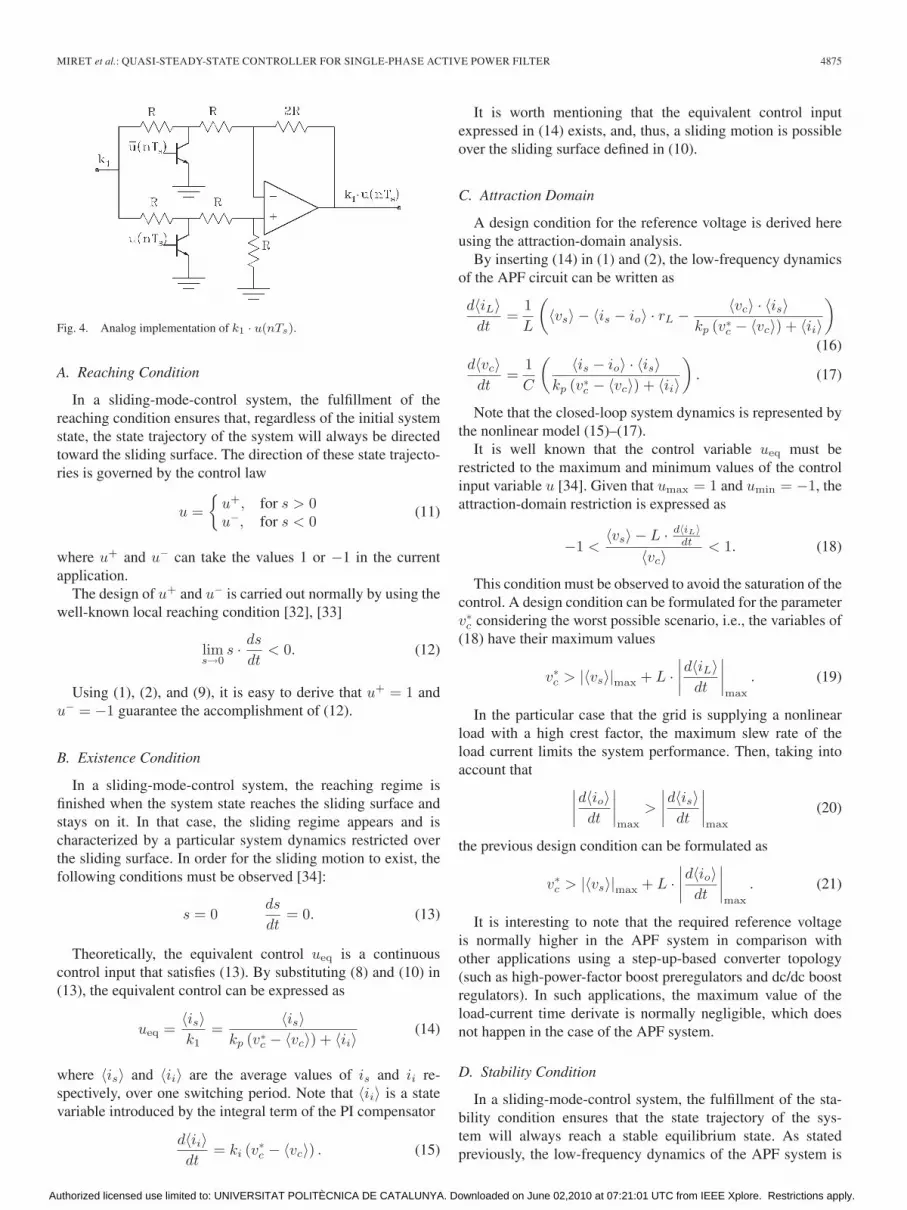
With the proposed controller, the switching frequency variesduring the grid period, due to the inherent behavior of thesliding-mode control. The maximum frequency is expected atzero-voltage crossing points and the minimum frequency isobtained at peak grid-voltage values. In the proposed controller,the maximum switching frequency fs,max is fixed by using aD flip-flop at the output of the comparator. A clock generatoroscillating at fclk forces that fs,max = fclk/2. The comple-mentary outputs of the flip-flop, u(nTs) and u(nTs), drive thepower switches. The signal u(nTs) indicates the sampled valueof the variable u(t) at the frequency fs,max(Ts = 1/fs,max).
Fig. 4 shows a possible implementation of the multiplexerbased on two bipolar transistors. The output of the circuit is thevoltage k1 · u(nTs).
IV. DESIGN OF PROPOSED CONTROLLER
This section presents some guidelines for the design of theproposed controller. The design is based on the sliding-mode-control theory. In particular, reaching, existence, and stabilityconditions will be examined.
Authorized licensed use limited to: UNIVERSITAT POLITÈCNICA DE CATALUNYA. Downloaded on June 02,2010 at 07:21:01 UTC from IEEE Xplore. Restrictions apply.
MIRET et al.: QUASI-STEADY-STATE CONTROLLER FOR SINGLE-PHASE ACTIVE POWER FILTER 4875
Fig. 4. Analog implementation of k1 · u(nTs).
A. Reaching Condition
In a sliding-mode-control system, the fulfillment of thereaching condition ensures that, regardless of the initial systemstate, the state trajectory of the system will always be directedtoward the sliding surface. The direction of these state trajecto-ries is governed by the control law
u ={
u+, for s > 0u−, for s < 0
(11)
where u+ and u− can take the values 1 or −1 in the currentapplication.
The design of u+ and u− is carried out normally by using thewell-known local reaching condition [32], [33]
lims→0
s · ds
dt< 0. (12)
Using (1), (2), and (9), it is easy to derive that u+ = 1 andu− = −1 guarantee the accomplishment of (12).
B. Existence Condition
In a sliding-mode-control system, the reaching regime isfinished when the system state reaches the sliding surface andstays on it. In that case, the sliding regime appears and ischaracterized by a particular system dynamics restricted overthe sliding surface. In order for the sliding motion to exist, thefollowing conditions must be observed [34]:
s = 0ds
dt= 0. (13)
Theoretically, the equivalent control ueq is a continuouscontrol input that satisfies (13). By substituting (8) and (10) in(13), the equivalent control can be expressed as
ueq =〈is〉k1
=〈is〉
kp (v∗c − 〈vc〉) + 〈ii〉
(14)
where 〈is〉 and 〈ii〉 are the average values of is and ii re-spectively, over one switching period. Note that 〈ii〉 is a statevariable introduced by the integral term of the PI compensator
d〈ii〉dt
= ki (v∗c − 〈vc〉) . (15)
It is worth mentioning that the equivalent control inputexpressed in (14) exists, and, thus, a sliding motion is possibleover the sliding surface defined in (10).
C. Attraction Domain
A design condition for the reference voltage is derived hereusing the attraction-domain analysis.
By inserting (14) in (1) and (2), the low-frequency dynamicsof the APF circuit can be written as
d〈iL〉dt
=1L
(〈vs〉 − 〈is − io〉 · rL − 〈vc〉 · 〈is〉
kp (v∗c − 〈vc〉) + 〈ii〉
)
(16)d〈vc〉dt
=1C
(〈is − io〉 · 〈is〉
kp (v∗c − 〈vc〉) + 〈ii〉
). (17)
Note that the closed-loop system dynamics is represented bythe nonlinear model (15)–(17).
It is well known that the control variable ueq must berestricted to the maximum and minimum values of the controlinput variable u [34]. Given that umax = 1 and umin = −1, theattraction-domain restriction is expressed as
−1 <〈vs〉 − L · d〈iL〉
dt
〈vc〉< 1. (18)
This condition must be observed to avoid the saturation of thecontrol. A design condition can be formulated for the parameterv∗
c considering the worst possible scenario, i.e., the variables of(18) have their maximum values
v∗c > |〈vs〉|max + L ·
∣∣∣∣d〈iL〉dt
∣∣∣∣max
. (19)
In the particular case that the grid is supplying a nonlinearload with a high crest factor, the maximum slew rate of theload current limits the system performance. Then, taking intoaccount that ∣∣∣∣d〈io〉dt
∣∣∣∣max
>
∣∣∣∣d〈is〉dt
∣∣∣∣max
(20)
the previous design condition can be formulated as
v∗c > |〈vs〉|max + L ·
∣∣∣∣d〈io〉dt
∣∣∣∣max
. (21)
It is interesting to note that the required reference voltageis normally higher in the APF system in comparison withother applications using a step-up-based converter topology(such as high-power-factor boost preregulators and dc/dc boostregulators). In such applications, the maximum value of theload-current time derivate is normally negligible, which doesnot happen in the case of the APF system.
D. Stability Condition
In a sliding-mode-control system, the fulfillment of the sta-bility condition ensures that the state trajectory of the sys-tem will always reach a stable equilibrium state. As statedpreviously, the low-frequency dynamics of the APF system is
Authorized licensed use limited to: UNIVERSITAT POLITÈCNICA DE CATALUNYA. Downloaded on June 02,2010 at 07:21:01 UTC from IEEE Xplore. Restrictions apply.

4876 IEEE TRANSACTIONS ON INDUSTRIAL ELECTRONICS, VOL. 56, NO. 12, DECEMBER 2009
expressed in (15)–(17) by a nonlinear description. The systemstability is then examined using a small-signal model. Usually,the small-signal model of the APF system considers only thedynamics of the capacitor voltage [7]. In this section, the wholenonlinear-model description is used in the small-signal-modelderivation to obtain a complete set of design conditions.
The variables of the nonlinear model (15)–(17) contain, ingeneral, dc and ac components. For the control design, only theac components with frequencies below the grid frequency havesignificant information. These components can be extractedby averaging the nonlinear model over one-half grid period[35], [36]. Thus, all the variables in the system model canbe represented as quiescent-averaged values plus their small-signal variations. Note that the small-signal variables havenonsinusoidal waveforms due to the low-frequency averagingprocess. The averaged variables can be expressed as
iL = IL + iL(t) (22)
vc =Vc + vc(t) (23)
ii = Ii + ii(t) (24)
vs =Vs + vs(t) (25)
is = Is + is(t) (26)
io = Io + io(t) (27)
io1 = Io1 + io1(t). (28)
Note that two load currents are defined in (27) and (28).The first one io is the current absorbed by the nonlinear load.The second one io1 is the first-harmonic component of io. Thecurrent io1 is introduced in the model by the averaging processof the product 〈is − io〉 · 〈is〉 expressed in (17). It should bementioned that the averaging of the product of a sinusoidalsignal 〈is〉 and a signal with a rich-harmonic content 〈is − io〉yields values that are different from zero only at the first-harmonic component (property of orthogonality).
By substituting (22)–(28) into (15)–(17) and averaging overone-half grid period, a model with quiescent and small acvariation variables is obtained
d(Is + is(t)
)dt
L −d
(Io + io(t)
)dt
L
= Vs + vs(t) − rL ·(Is + is(t) − Io − io(t)
)
−(Vc − vc(t)) ·
(Is + is(t)
)kp (v∗
c − Vc − vc(t)) + Ii + ii(t)(29)
d (Vc + vc(t))dt
=π2
8C
⎛⎝
(Is+ is(t)
)·(Is+ is(t)−Io1− io1(t)
)kp (v∗
c−Vc−vc(t))+Ii+ ii(t)
⎞⎠
(30)
d(Ii + ii(t)
)dt
= ki (v∗c − Vc − vc(t)) . (31)
TABLE IIPARAMETER VALUES OF APF CIRCUIT FOR EXPERIMENTAL TEST
Taking the quiescent values separately, the following steady-state relationships are deduced:
Ii =Vc · Is
Vs + rL · (Io − Is)=
v∗c · io1,rms
vs,rms + rL · (io,rms − io1,rms)
(32)
Is = Io1 =2 ·
√2
πio1,rms (33)
Vc = v∗c (34)
where vs,rms and io1,rms are the rms values of the grid voltageand load-current first harmonic, respectively (see Table II).
The small-signal closed-loop model of the variable vc is,finally, derived by inserting (32)–(34) into (29)–(31) and dis-regarding the second-order ac terms. In the Laplace domain,the model can be expressed as
(s3 + a2s2 + a1s + a0)vc(s) = f
(vs(s), io(s), io1(s)
)(35)
where
a2 =v∗
c + Ii · rL
Ii · L(36)
a1 =io1,rms
CL · I2i
(io1,rms + kp (vs,rms + rL(io,rms − io1,rms)))
(37)
a0 =ki · io1,rms
CL · I2i
(vs,rms + rL(io,rms − io1,rms)) . (38)
With the linear model (35) in mind, the stability analysisis performed using the well-known Routh’s–Hurwitz criterion.
Authorized licensed use limited to: UNIVERSITAT POLITÈCNICA DE CATALUNYA. Downloaded on June 02,2010 at 07:21:01 UTC from IEEE Xplore. Restrictions apply.

MIRET et al.: QUASI-STEADY-STATE CONTROLLER FOR SINGLE-PHASE ACTIVE POWER FILTER 4877
Fig. 5. Family of root-locus diagram. (a) kp = 0.64 for 0 < ki < 1000.(b) ki = 45 for 0.1 < kp < 1. Chosen locations for poles λ2 and λ3 areindicated by the large asterisks.
The stability limits of the gain parameters of the PI compensatorcan be expressed as the following stability condition:
kp > − io1,rms
vs,rms + rL(io,rms − io1,rms)(39)
0 < ki
<(v∗
c+Ii ·rL)·(io,rms+kp(vs,rms+rL(io,rms−io1,rms)))Ii ·L·(vs,rms+rL(io,rms−io1,rms))
.
(40)
An analysis of (35) through the representation of some root-locus diagrams gives additional information about the transientresponse of the system. Using the values shown in Table II,we observe that a negligible high-frequency real pole exists(λ1 at −6.7 · 1030 rad/s). Besides, neither kp nor ki have anynoticeable effects on this pole location.
Fig. 5 shows the root-locus diagram of the two remainderpoles, λ2 and λ3, under different values of the kp and ki
coefficients. The high-frequency pole λ1 is omitted in thisfigure. Note that there is a wide range of possible pole locations,so the desired transient response can be easily satisfied. Incommon practice, the bandwidth of the outer voltage loop mustbe sufficiently low to avoid an undesired harmonic content inthe grid current. Therefore, the PI compensator gains are set at
Fig. 6. (Top) Load current and grid voltage, and (bottom) load-current spec-trum with the nondistorted grid feeding an uncontrolled bridge rectifier.
kp = 0.64 and ki = 45 to achieve an equivalent second-orderdynamics with a damping factor of ξ = 0.707 and a naturalfrequency of ωn = 2π · 15.2 rad/s.
V. EXPERIMENTAL RESULTS
In this section, experimental results are provided to validatethe proposed control. A comparison with a reference controlleris also given.
A. Experimental Setup
An experimental prototype of the active filter was built usingfour insulated-gate bipolar transistor (IGBT) switches from aMitsubishi PM50RSK60 intelligent power module. Table IIlists the parameter values of both the APF circuit and the pro-posed controller. The maximum switching frequency is 18 kHzaccording to the limits expected for the IGBT switching charac-teristics. The power components have been designed using theguidelines reported in [8]. The design of the PI gain coefficientswas presented in the previous section. The remainder-controlparameters have been experimentally selected according to thefollowing criteria.
1) The value for v∗c must fulfill the design condition (21).
2) The cutoff frequency of the vc low-pass filter must beset at less than twice the grid frequency, to reduce theharmonic content of the reference current.
3) The bandpass-filter parameters must be selected accord-ing to the need to attenuate all the undesired currentharmonics and to guarantee a fast enough transient
Authorized licensed use limited to: UNIVERSITAT POLITÈCNICA DE CATALUNYA. Downloaded on June 02,2010 at 07:21:01 UTC from IEEE Xplore. Restrictions apply.

4878 IEEE TRANSACTIONS ON INDUSTRIAL ELECTRONICS, VOL. 56, NO. 12, DECEMBER 2009
Fig. 7. Nondistorted grid. (Top) Grid current and grid voltage. (Bottom) Grid-current spectra.
response. In the experimental setup, a simple second-order bandpass filter, with unity gain at resonant fre-quency, was used.
The utility grid feeds a nonlinear load, as shown in Fig. 1.The load is composed of a series resistance Rs, used to establishthe desired crest factor, a diode bridge, and a resistance Ro inparallel with a capacitor Co. Fig. 6 shows the load current iounder nondistorted grid and its spectrum.
The measured grid voltage (THD, calculated with respect tothe fundamental value of the signal) is 2%. The crest factorof the load current is 2.27, with a power factor of 0.73. TheTHD of the load current, considering up to the 21st-harmoniccomponent, is 83.92%.
B. Test Results
To evaluate the proposed controller, a performance compar-ison with a reference controller, described in [8], is carriedout. This reference controller has been described in detail inSection II. Fig. 7 shows the time waveforms of the experimentalgrid current and voltage when the active filter is governed by thereference and by the proposed control. As a prominent featureand due to the inherent characteristics of the bandpass filter,there is no noticeable phase deviation between the grid voltagevs and the grid current is when using both controls. Fig. 7also shows the measured spectra of the grid current with bothcontrollers. With the proposed controller, the grid-current THDdrops to 5.10%, providing a high reduction in the 3rd, 5th,7th, 9th, and 11th harmonics with respect to the load current
(see Fig. 6). When using the reference control, the grid currentTHD drops to 5.29%.
In practical applications, the grid-voltage waveform is nor-mally distorted. To compare the performance of both controllersin such a situation, a distorted grid voltage with an 8.92% THDhas been employed. Moreover, the measured load-current THDis 60.34%. In that case, the reference current i∗s has a significantharmonic content in the reference controller.
Fig. 8 shows the experimental grid-current waveforms usingboth the reference control and the proposed control. In this case,the reference control presents an unacceptable grid-current-harmonic distortion coming from the grid voltage, which isreplicated. As can be seen, the proposed control maintainsthe harmonic-rejection capability also when the grid volt-age is distorted. The nearly sinusoidal grid current is, ob-tained with the proposed control, shows that most of the loadcurrent harmonics have been compensated for successfully,see Fig. 8. The grid-current THD is 12.15% when testingthe reference control but it drops to only 6.11% with ourproposal.
Fig. 9 shows again the grid-current spectra but now with alarger frequency axis (up to 30 kHz). As can be seen, bothhigh-frequency spectra are very similar. Thus, the proposedcontroller achieves similar performance in these frequencyrange but with the benefit of simple-control implementation.
The dynamic performance of both controllers under step-load changes was evaluated and compared. Fig. 10 showsthe transient response of the grid current and the capacitorvoltage for the proposed controller. The load is changed from
Authorized licensed use limited to: UNIVERSITAT POLITÈCNICA DE CATALUNYA. Downloaded on June 02,2010 at 07:21:01 UTC from IEEE Xplore. Restrictions apply.

MIRET et al.: QUASI-STEADY-STATE CONTROLLER FOR SINGLE-PHASE ACTIVE POWER FILTER 4879
Fig. 8. Distorted grid. (Top) Grid current and grid voltage (top). (Bottom) Grid-current spectra.
Fig. 9. Distorted grid. Grid-current spectra.
no load to full load to evaluate the worst scenario. A goodtransient response is noticed with small deviation from the finalsteady-state value and low settling time. Although not shownhere, the reference controller presents a transient responsewith no appreciable differences with respect to the proposedcontroller.
Fig. 10. Response to load-step change from 0% to 100% using the proposedcontrol.
C. Discussion
The proposed controller is a simple low-cost analog solutionfor single-phase APF systems. The analog multiplier used inthe conventional control is substituted by a multiplexer and abandpass filter. Moreover, the sensing of the grid voltage is nolonger required. The performance of the APF system with the
Authorized licensed use limited to: UNIVERSITAT POLITÈCNICA DE CATALUNYA. Downloaded on June 02,2010 at 07:21:01 UTC from IEEE Xplore. Restrictions apply.

4880 IEEE TRANSACTIONS ON INDUSTRIAL ELECTRONICS, VOL. 56, NO. 12, DECEMBER 2009
proposed control is improved in relation to the performance ofthe conventional control. In fact, the THD of the grid currentis small, and it has low sensitivity to grid-voltage THD varia-tions. This interesting property could be attributed to the lowbandwidth of the bandpass filter which rejects all the unwantedharmonics.
The proposed control is particularly suitable for environ-ments in which the grid frequency presents small deviationsfrom its nominal value. Variations smaller than 2% of the nom-inal grid frequency (which is the normal situation in large gridsystems [37]) does not deteriorate significantly the performanceof the proposed APF system. In fact, a displacement powerfactor of 0.99 is measured when the frequency has a positive2% deviation. Moreover, the grid-current THD is unaffected inthis situation.
In environments in which high deviation in the utility gridfrequency is expected, the displacement power factor of theAPF system could be unacceptable. The reason for this per-formance deterioration is that the bandpass filter operates ata frequency different from its nominal resonance frequency,and, thus, a high phase deviation between the grid voltage andcurrent is produced.
VI. CONCLUSION
The injection of sinusoidal current to the electrical gridis nowadays possible with the use of APFs. With QSS non-linear controllers, these power filters provide low grid-current-harmonic content with simple-control analog implementation.This paper has been focused on the design of a QSS nonlinearcontroller for a single-phase APF. A complete analysis basedon the sliding-mode-control theory has been given. From theanalysis, a set of control-design guidelines were presented toselect the gains and parameters of the control scheme. Theperformance characteristics of the proposed controller wereevaluated experimentally and compared with the features of areference controller. In view of these results, we can concludethat the proposed controller offers low grid-current-harmoniccontent with low sensitivity to grid-voltage distortion.
REFERENCES
[1] H. Akagi, “Trends in active power line conditioners,” IEEE Trans. PowerElectron., vol. 9, no. 3, pp. 263–268, May 1994.
[2] H. Akagi, “Active harmonic filters,” Proc. IEEE, vol. 93, no. 12, pp. 2128–2141, Dec. 2005.
[3] M. El-Habrouk, M. K. Darwish, and P. Mehta, “A survey of active filtersand reactive power compensation techniques,” in Proc. IEE Conf. PowerElectron. Variable Speed Drives (Conf. Publ. No. 475), 2000, pp. 7–12.
[4] M. P. Kazmierkowski and L. Malesani, “Current control techniques forthree-phase voltage-source PWM converters: A survey,” IEEE Trans. Ind.Electron., vol. 45, no. 5, pp. 691–703, Oct. 1998.
[5] T. C. Green and J. H. Marks, “Control techniques for active power filters,”Proc. Inst. Elect. Eng.—Elect. Power Appl., vol. 152, no. 2, pp. 369–381,Mar. 2005.
[6] M. Cirrincione, M. Pucci, and G. Vitale, “A single-phase DG generationunit with shunt active power filter capability by adaptive neural filtering,”IEEE Trans. Ind. Electron., vol. 55, no. 5, pp. 2093–2110, May 2008.
[7] C. Y. Hsu and H. Y. Wu, “A new single-phase active power filter withreduced energy-storage capacity,” Proc. Inst. Elect. Eng.—Elect. PowerAppl., vol. 143, no. 1, pp. 25–30, Jan. 1996.
[8] D. A. Torrey and A. M. A. M. Al-Zamel, “Single-phase active powerfilters for multiple nonlinear loads,” IEEE Trans. Power Electron., vol. 10,no. 3, pp. 263–272, May 1995.
[9] F. Pottker and I. Barbi, “Power factor correction of non-linear loadsemploying a single phase active power filter: Control strategy, designmethodology and experimentation,” in Proc. IEEE PESC, St. Louis, MO,Jun. 22–27, 1997, pp. 412–417.
[10] J. C. Wu and H. L. Jou, “Simplified control method for the single-phaseactive power filter,” Proc. Inst. Elect. Eng.—Elect. Power Appl., vol. 143,no. 3, pp. 219–224, May 1996.
[11] H. Komurcugil and O. Kukrer, “A new control strategy for single-phaseshunt active power filters using a Lyapunov function,” IEEE Trans. Ind.Electron., vol. 53, no. 1, pp. 305–312, Feb. 2006.
[12] G. Escobar, P. R. Martinez, and J. Leyva-Ramos, “Analog circuitsto implement repetitive controllers with feedforward for harmoniccompensation,” IEEE Trans. Ind. Electron., vol. 55, no. 1, pp. 567–573,Feb. 2007.
[13] L. Asiminoaei, E. Aeloiza, N. Enjeti, and F. Blaabjerg, “Shunt active-power-filter topology based on parallel interleaved inverters,” IEEE Trans.Ind. Electron., vol. 55, no. 3, pp. 1175–1189, Mar. 2008.
[14] K. Gulez, A. A. Adam, and H. Pastaci, “Torque ripple and EMI noiseminimization in PMSM using active filter topology and field-orientedcontrol,” IEEE Trans. Ind. Electron., vol. 55, no. 1, pp. 251–257,Jan. 2008.
[15] S. Inoue, T. Shimizu, and K. Wada, “Control methods and compensationcharacteristics of a series active filter for a neutral conductor,” IEEE Trans.Ind. Electron., vol. 54, no. 1, pp. 433–440, Feb. 2007.
[16] M. Salo and H. Tuusa, “A novel open-loop control method for a current-source active power filter,” IEEE Trans. Ind. Electron., vol. 50, no. 2,pp. 313–321, Apr. 2003.
[17] B. N. Singh, “Sliding mode control technique for indirect currentcontrolled active filter,” in Proc. IEEE Region 5, Annu. Tech. Conf.,New Orleans, LA, Apr. 2003, pp. 51–58.
[18] P. Mattavelli and F. Pinhabel, “Repetitive-based control for selective har-monic compensation in active power filters,” IEEE Trans. Ind. Electron.,vol. 51, no. 5, pp. 118–124, Oct. 2004.
[19] R. Grino, R. Cardoner, R. Costa-Castello, and E. Fossas, “Digital repet-itive control of a three-phase four-wire shunt active filter,” IEEE Trans.Ind. Electron., vol. 54, no. 3, pp. 1495–1503, Jun. 2007.
[20] B.-R. Lin and Y.-C. Lee, “Three-phase power quality compensator underthe unbalanced sources and nonlinear loads,” IEEE Trans. Ind. Electron.,vol. 51, no. 5, pp. 1009–1017, Oct. 2004.
[21] M. Cichowlas, M. Malinowski, M. P. Kazmierkowski,D. L. Sobczuk, P. Rodriguez, and J. Pou, “Active filtering functionof three-phase PWM boost rectifier under different line voltageconditions,” IEEE Trans. Ind. Electron., vol. 52, no. 2, pp. 410–419,Apr. 2005.
[22] T. Ohnishi and M. Hojo, “AC line voltage harmonics compensator withexcessive current control,” IEEE Trans. Ind. Electron., vol. 50, no. 6,pp. 1126–1133, Dec. 2003.
[23] I. Etxeberria-Otadui, A. López de Heredia, H. Gaztañaga, S. Bacha, andR. Reyero, “A single synchronous frame hybrid (SSFH) multifrequencycontroller for power active filters,” IEEE Trans. Ind. Electron., vol. 53,no. 5, pp. 1640–1648, Oct. 2006.
[24] B. M. Han, B. Y. Bae, and S. J. Ovaska, “Reference signal generator foractive power filters using improved adaptive predictive filter,” IEEE Trans.Ind. Electron., vol. 52, no. 2, pp. 576–584, Apr. 2005.
[25] K. Shyu, M. Yang, Y. Chen, and Y. Lin, “Model reference adaptive controldesign for a shunt active-power-filter system,” IEEE Trans. Ind. Electron.,vol. 55, no. 1, pp. 97–106, Jan. 2008.
[26] Z. Shu, Y. Guo, and J. Lian, “Steady-state and dynamic study of activepower filter with efficient FPGA-based control algorithm,” IEEE Trans.Ind. Electron., vol. 55, no. 4, pp. 1527–1536, Apr. 2008.
[27] K. M. Smedley and S. Cuk, “One-cycle control of switching converters,”in Proc. IEEE Power Electron. Spec. Conf., 1991, pp. 1173–1180.
[28] G. Chen and K. M. Smedley, “Steady-state and dynamic study of one-cycle-controlled three-phase power-factor correction,” IEEE Trans. Ind.Electron., vol. 52, no. 2, pp. 355–362, Apr. 2005.
[29] C. Quiao, T. Jin, and K. Y. Smedley, “One-cycle control of three-phaseactive power filter with vector operation,” IEEE Trans. Ind. Electron.,vol. 51, no. 2, pp. 455–463, Apr. 2004.
[30] P. Midya, P. T. Krein, and M. F. Greuel, “Sensorless current modecontrol—An observer-based technique for DC–DC converters,” IEEETrans. Power Electron., vol. 16, no. 4, pp. 522–526, Jul. 2001.
[31] J. Miret, L. Garcia de Vicuña, M. Castilla, J. Cruz, and M. Guerrero,“A simple sliding mode control of an active power filter,” in Proc. IEEEPower Electron. Spec. Conf., 2004, pp. 1052–1056.
[32] P. Mattavelli, L. Rossetto, and G. Spiazzi, “Small-signal analysis ofDC–DC converters with sliding mode control,” IEEE Trans. Power Elec-tron., vol. 12, no. 1, pp. 96–102, Jan. 1997.
Authorized licensed use limited to: UNIVERSITAT POLITÈCNICA DE CATALUNYA. Downloaded on June 02,2010 at 07:21:01 UTC from IEEE Xplore. Restrictions apply.

MIRET et al.: QUASI-STEADY-STATE CONTROLLER FOR SINGLE-PHASE ACTIVE POWER FILTER 4881
[33] H. de Battista and R. J. Mantz, “Harmonic series compensators in powersystems: Their control via sliding mode,” IEEE Trans. Control Syst.Technol., vol. 8, no. 6, pp. 939–947, Nov. 2000.
[34] R. A. DeCarlo, S. H. Zak, and G. P. Matthews, “Variable structure controlof nonlinear multivariable systems: A tutorial,” Proc. IEEE, vol. 76, no. 3,pp. 212–232, Mar. 1988.
[35] K. Mahabir, G. Verghese, J. Thottuvelil, and A. Heyman, “Linear averagedand sampled data models for large signal control of high power factorAC–DC converters,” in Proc. IEEE PESC, 1990, pp. 372–381.
[36] R. Ridley, “Average small-signal analysis of the boost power factor correc-tion circuit,” in Proc. Virginia Power Electron. Center Semin., Blacksburg,VA, Sep. 1989, pp. 108–120.
[37] S. J. Ovaska and O. Vainio, “Evolutionary-programming-based optimiza-tion of reduced-rank adaptive filters for reference generation in activepower filters,” IEEE Trans. Ind. Electron., vol. 51, no. 4, pp. 910–916,Aug. 2004.
Jaume Miret (M’01) received the B.S. degree intelecommunications and the M.S. and Ph.D. de-grees in electronics from the Technical University ofCatalonia, Barcelona, Spain, in 1992, 1999, and2005, respectively.
Since 1993, he has been an Assistant Profes-sor with the Department of Electronic Engineering,Technical University of Catalonia, Vilanova i laGeltrú, Spain, where he teaches courses on digi-tal design and circuit theory. His research interestsinclude dc–ac converters, active power filters, and
digital control.
Luis García de Vicuña received the Ingenierode Telecomunicación and Dr.Ing. degrees from theTechnical University of Catalonia, Barcelona, Spain,in 1980 and 1990, respectively, and the Dr.Sci. de-gree from the Université Paul Sabatier, Toulouse,France, in 1992.
From 1980 to 1982, he was an Engineer with acontrol applications company. He is currently an As-sociate Professor with the Department of ElectronicEngineering, Technical University of Catalonia,Vilanova i la Geltrú, Spain, where he teaches courses
on power electronics. His research interests include power-electronics model-ing, simulation and control, active power filtering, and high-power-factor ac/dcconversion.
Miguel Castilla received the B.S., M.S., and Ph.D.degrees in telecommunication engineering from theTechnical University of Catalonia, Barcelona, Spain,in 1988, 1995, and 1998, respectively.
Since 2002, he has been an Associate Profes-sor with the Department of Electronic Engineering,Technical University of Catalonia, Vilanova i laGeltrú, Spain, where he teaches courses on analogcircuits and power electronics. His research interestsare in the areas of power electronics, nonlinear con-trol, and renewable-energy systems.
José Matas received the B.S., M.S., and Ph.D. de-grees in telecommunications engineering from theTechnical University of Catalonia, Barcelona, Spain,in 1988, 1996, and 2003, respectively.
From 1988 to 1990, he was an Engineer with aconsumer electronics company. Since 1990, he hasbeen an Associate Professor with the Departmentof Electronic Engineering, Technical University ofCatalonia, Vilanova i la Geltrú, Spain. His researchinterests include power-factor-correction circuits, ac-tive power filters, uninterruptible power systems,
distributed power systems, and nonlinear control.
Josep M. Guerrero (S’01–M’04–SM’08) receivedthe B.S. degree in telecommunications engineering,the M.S. degree in electronics engineering, and thePh.D. degree in power electronics from the TechnicalUniversity of Catalonia, Barcelona, Spain, in 1997,2000, and 2003, respectively.
He is an Associate Professor with the Depart-ment of Automatic Control Systems and ComputerEngineering, Technical University of Catalonia,Barcelona, where he currently teaches courses ondigital signal processing, field-programmable gate
arrays, microprocessors, and renewable energy. Since 2004, he has been respon-sible for the Renewable Energy Laboratory, Escola Industrial de Barcelona,Barcelona. His research interests include photovoltaics, wind-energy conver-sion, uninterruptible power supplies, storage energy systems, and microgrids.
Dr. Guerrero is the Editor-in-Chief of the International Journal of IntegratedEnergy Systems. He is also an Associate Editor for the IEEE TRANSACTIONS
ON INDUSTRIAL ELECTRONICS, the IEEE TRANSACTIONS ON POWER
ELECTRONICS, the International Journal of Power Electronics, and the Inter-national Journal of Industrial Electronics and Drives.
Authorized licensed use limited to: UNIVERSITAT POLITÈCNICA DE CATALUNYA. Downloaded on June 02,2010 at 07:21:01 UTC from IEEE Xplore. Restrictions apply.