Embed Size (px)
Citation preview

Design of an Electromagnetic Suspension and Regenerative Braking System for Electricity Generation
Zibusiso Jila Dube and Mufaro Kanganga
Department of Industrial and Mechatronics Engineering University of Zimbabwe
[email protected], [email protected]; [email protected]
Loice Gudukeya and Nita Inderlal Sukdeo Quality and Operations Management Department
PhD in Engineering Management [email protected], [email protected], [email protected]
Abstract
This research aim was to design an electromagnetic suspension and regenerative braking system for power generation. It looks at ways in which the heat dissipated into the environment from the brakes and suspension can be reused by converting it into another form of electrical energy stored in batteries. My research findings indicate how the braking efficiencies vary with a number of factors. These include road geography (slopes), braking velocities and traffic volumes. The results of this research then helped to narrow down which types of road geography would lead to an optimum amount of energy being recovered. Journals of past researches on the topic were reviewed in order to help determine how best to design a system that will integrate regenerative braking and the electromagnetic suspension. Calculations on determining the optimum braking force needed were done which has led to the final chosen concept. This project focused on Electrical Vehicles. Keywords Electric vehicles, power generation, electromagnetic suspension and regenerative braking system 1. Introduction In the case of brakes or suspensions, kinetic energy is often released as heat. Friction brakes, which convert kinetic energy to heat, are used in the majority of automobiles. This basically means that when you apply the brakes, a lot of energy is released as heat (Lakshmi, 2017). Regenerative braking is the conversion of kinetic energy generated during braking into a form that can be used right away or stored till later. For most convectional vehicles, the majority of the Kinetic energy converted during friction braking, between the brake pads & wheels turns into heat which then gets emitted unused into the environment as waste but not when driving a hybrid model or electrical vehicle. Using electric motors, a portion of Kinetic energy can be recovered for reuse. This means using a regenerative braking system, all the Kinetic energy that would have been lost can partially be put right back into the battery. Every automotive suspension has two goals: passenger comfort and vehicle control. Electromagnetic suspension is a system that converts vehicle bump into electrical energy. Its primary function is to reduce effects of vibrations and irregularities on roads. This is achieved with the help of shock absorbers that emit vibrational energy in the form of heat. This heat is the one that this project aims to harvest and convert into electrical power that can then charge the battery. This research proposes a design of a system where the heat lost in the suspension system and brakes combined is extracted, converted into a usable form of electrical energy which can charge batteries. In 1967, the American Motor Car Company (AMC) created an electrical energy regeneration brake for their concept electric car, the AMC Amitron. Toyota was the first car manufacturer to commercialize RBS technology in their Prius series hybrid cars (Clark, et al,.2011). Since then there has been an evolution in the regenerative braking systems. Modern
Proceedings of the International Conference on Industrial Engineering and Operations Management Nsukka, Nigeria, 5 - 7 April, 2022
IEOM Society International 1604

hybrid cars and EVs make use of an electrical engine to power the car which makes applying regenerative braking very simple and efficient. ZERA launched the first electric car to accelerate adoption of clean energy, it is in sync with Zimbabwe’s aspirations of a modernized and mechanised country by 2030. The intent to adopt more electric cars in the country means the need to charge those cars grows. This is a great opportunity to invest in the design of the electromagnetic suspension and the regenerative braking system as it solves the problem of not having enough charging ports by utilizing the wasted energy in order to charge the car batteries. The major issue is the battery time and the need to reduce the frequency in charging. The amount of energy wasted by braking and suspension system coupled by shorter charging intervals is as a result of convectional braking. ZERA launched the first electric car to accelerate adoption of clean energy in Zimbabwe. Introduction of more electric cars means a lot of energy is wasted as a result of braking and suspension systems. 1.1. Objectives The objective was to design a mechanical system that harvests and utilizes the energy lost during regenerative braking and in the electromagnetic suspension system combined as a result of linear motion and vibration. This was achieved through the design an energy optimization system that will integrate energy from regenerative braking and electromagnetic suspension, determination the optimum amount of braking force needed for maximum energy, analysis of maximum energy recovered due to road irregularities and braking and the design a system that is not only efficient but affordable. 2. Literature Review Regenerative braking is used in cars with electric motors, such as electric automobiles and hybrid electric vehicles. When an electric motor rotates in one direction, it converts electrical energy into mechanical energy that may be used to perform tasks such as spinning the wheels of a car, but when it rotates in the opposite direction, it becomes an electric generator. (Unnewehr & Nasar, 1982). There are two types of regenerative braking which are serial and parallel regenerative braking. Serial regenerative braking combines a friction-based adaptive braking system with a regenerative braking system that converts electrical energy to the electric motors and batteries as part of an integrated control strategy. A friction-based and a regenerative braking system work together without the need of an appropriate control in the parallel braking system. Suspensions are catergorised into their construction and ways of energy generation. Examples based on paths of generation are piezoelectric, hydraulic, pneumatic, electromagnetic and hybrid [hydraulic + electromagnetic]. BEVs [battery electric vehicles], PHEVs [plug-in hybrid electrical vehicles], and HEVs [hybrid electrical vehicles] are the three primary kinds of electric vehicles, which are characterized by the amount to which electricity is employed as an energy source. HEVs use both an electric motor and fuel to power them. The Battery is charged as the vehicle runs on gas. PHEVs are plugged in in order to recharge the battery. They are similar to the convectional hybrids. BEVs are powered 100% by battery and an electric motor. (Plugndrive, 2021).
Figure 1. Types of EVs (source: www.nspower.ca)
A research was done by Salinas and Cajamarca (2021) which was an analysis of regenerative braking efficiency in an electric vehicle through experimental tests. The main significant values were initial and final braking velocities and the weight of the vehicle. Three routes were investigated which had different types of road geography, slopes, and
Proceedings of the International Conference on Industrial Engineering and Operations Management Nsukka, Nigeria, 5 - 7 April, 2022
IEOM Society International 1605

looked at how initial braking speeds had an impact on the variability of the obtained efficiencies. Due to the general above-mentioned parameters tested, the average efficiency in the specific sample for route 1 was 23%, indicating that the brake pedal was not utilized frequently. Due to the high vehicle flow, low driving speeds, and heavy use of the brake pedal on route 2, the figures fluctuated. As a result, the regenerative system's efficiency improved, and the efficiency tended to stabilize, resulting in increased energy recovery. The efficiency of Route 3 varied depending on the road terrain, typical braking velocities, and traffic volume. With a maximum value of 77 percent, the average efficiency was 22 percent (Table 1, table 2 and table 3).
Table 1. Route 1
SPEED (km/h) RECOVERY BRAKING ENERGY Em (J)
ENERGY LOSS OF BRAKING Eb (J)
EFFICIENCY (%)
9 3053.40 409842.90 0.07 44 6930.63 19275.92 36 74 444720 55819.86 79
Table 2. Route 2
SPEED (km/h) RECOVERY BRAKING ENERGY Em (J)
ENERGY LOSS OF BRAKING Eb (J)
EFFICIENCY (%)
9 111.72 8261.11 1.35 22 6346.10 17210.64 37 44 8030.25 10326.39 78
Table 3. Route 3
SPEED (km/h) RECOVERY BRAKING ENERGY Em (J)
ENERGY LOSS OF BRAKING Eb (J)
EFFICIENCY (%)
9 346.96 569041.39 0.06 22 1748.81 4818.98 36 52 34224 44059.25 78 Each route's regenerative braking efficiency is demonstrated to be dependent on the amount of energy lost and recovered by the vehicle. Table 4 for route two values showed that there was an improvement by the extended use of the brake pedal even though its velocity values were lower due to intense traffic. As there is no need for a large power demand, energy consumption is reduced. A lack of significant alterations in the route favored energy recovery and high efficiency. Due to the geology of the road, high power when overcoming slopes, and modest usage of the brake pedal, the vehicle had a large energy loss compared to route 2, resulting in lower recovery compared to route 2.
2.1 Factors limiting the braking power generated during regenerative braking
i. Braking power is limited by the charging power limit of the battery pack. This limit depends on the chemical composition (battery type) and this changed with temperature.
ii. When a car is moving slowly, the kinetic energy is low enough such that very little energy is put back into the battery as the car comes to a stop. In most cases the small amount of energy generated as the car slows down does not even cover the fixed losses in the inverter and motor.
iii. Additional charge from regenerative braking would cause the voltage of a full battery to rise above safe level, the motor controller unit will limit regen torque in this case.
2.2 Efficiency calculations
Proceedings of the International Conference on Industrial Engineering and Operations Management Nsukka, Nigeria, 5 - 7 April, 2022
IEOM Society International 1606
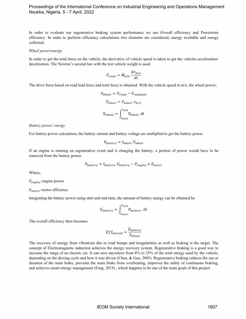
In order to evaluate our regenerative braking system performance we use Overall efficiency and Powertrain efficiency. In order to perform efficiency calculations two elements are considered; energy available and energy collected.
Wheel power/energy
In order to get the total force on the vehicle, the derivative of vehicle speed is taken to get the vehicles acceleration/ deceleration. The Newton’s second law with the test vehicle weight is used.
𝐹𝐹𝑇𝑇𝑇𝑇𝑇𝑇𝑇𝑇𝑇𝑇 = 𝑀𝑀𝑣𝑣𝑣𝑣ℎ .𝑑𝑑𝑑𝑑𝑚𝑚/𝑠𝑠
𝑑𝑑𝑑𝑑
The drive force based on road load force and total force is obtained. With the vehicle speed in m/s, the wheel power;
𝐹𝐹𝑊𝑊ℎ𝑣𝑣𝑣𝑣𝑇𝑇 = 𝐹𝐹𝑇𝑇𝑇𝑇𝑇𝑇𝑇𝑇𝑇𝑇 − 𝐹𝐹𝑟𝑟𝑇𝑇𝑇𝑇𝑟𝑟𝑇𝑇𝑇𝑇𝑇𝑇𝑟𝑟
𝑃𝑃𝑤𝑤ℎ𝑣𝑣𝑣𝑣𝑇𝑇 = 𝐹𝐹𝑤𝑤ℎ𝑣𝑣𝑣𝑣𝑇𝑇 . 𝑑𝑑𝑚𝑚/𝑠𝑠
Ewheel = � Pwheeltend
tstart. dt
Battery power/ energy
For battery power calculation, the battery current and battery voltage are multiplied to get the battery power.
𝑃𝑃𝑏𝑏𝑇𝑇𝑇𝑇𝑇𝑇𝑣𝑣𝑟𝑟𝑏𝑏 = 𝐼𝐼𝑤𝑤ℎ𝑣𝑣𝑣𝑣𝑇𝑇 .𝑉𝑉𝑤𝑤ℎ𝑣𝑣𝑣𝑣𝑇𝑇
If an engine is running on regenerative event and is charging the battery, a portion of power would have to be removed from the battery power.
𝑃𝑃𝑏𝑏𝑇𝑇𝑇𝑇𝑇𝑇𝑣𝑣𝑟𝑟𝑏𝑏 = 𝐼𝐼𝑏𝑏𝑇𝑇𝑇𝑇𝑇𝑇𝑣𝑣𝑟𝑟𝑏𝑏 .𝑉𝑉𝑏𝑏𝑇𝑇𝑇𝑇𝑇𝑇𝑣𝑣𝑟𝑟𝑏𝑏 − 𝑃𝑃𝑣𝑣𝑒𝑒𝑒𝑒𝑒𝑒𝑒𝑒𝑣𝑣 × 𝐸𝐸𝑚𝑚𝑇𝑇𝑇𝑇𝑇𝑇𝑟𝑟
Where;
𝑃𝑃𝑣𝑣𝑒𝑒𝑒𝑒𝑒𝑒𝑒𝑒𝑣𝑣-engine power
𝐸𝐸𝑚𝑚𝑇𝑇𝑇𝑇𝑇𝑇𝑟𝑟-motor efficiency
Integrating the battery power using start and end time, the amount of battery energy can be obtained by
𝐸𝐸𝑏𝑏𝑇𝑇𝑇𝑇𝑇𝑇𝑣𝑣𝑟𝑟𝑏𝑏 = � 𝑃𝑃𝑏𝑏𝑇𝑇𝑇𝑇𝑇𝑇𝑣𝑣𝑟𝑟𝑏𝑏𝑇𝑇𝑒𝑒𝑒𝑒𝑒𝑒
𝑇𝑇𝑠𝑠𝑠𝑠𝑠𝑠𝑠𝑠𝑠𝑠.𝑑𝑑𝑑𝑑
The overall efficiency then becomes
𝐸𝐸𝐸𝐸𝐸𝐸𝑂𝑂𝑣𝑣𝑣𝑣𝑟𝑟𝑇𝑇𝑇𝑇𝑇𝑇 =𝐸𝐸𝑏𝑏𝑇𝑇𝑇𝑇𝑇𝑇𝑣𝑣𝑟𝑟𝑏𝑏𝐸𝐸𝑊𝑊ℎ𝑣𝑣𝑣𝑣𝑇𝑇
The recovery of energy from vibrations due to road bumps and irregularities as well as braking is the target. The concept of Electromagnetic induction achieves the energy recovery system. Regenerative braking is a good way to increase the range of an electric car. It can save anywhere from 8% to 25% of the total energy used by the vehicle, depending on the driving cycle and how it was driven (Chen, & Guo, 2005). Regenerative braking reduces the use or duration of the main brake, prevents the main brake from overheating, improves the safety of continuous braking, and achieves smart energy management (Feng, 2019) , which happens to be one of the main goals of this project.
Proceedings of the International Conference on Industrial Engineering and Operations Management Nsukka, Nigeria, 5 - 7 April, 2022
IEOM Society International 1607

3. Methods 3.1. Literature Review Through the use of credible sources online, textbooks, articles and researches that have been done prior on the topic of Regenerative braking systems and electromagnetic suspension systems, the researcher conducted a theoretical study to obtain a better understanding of the topic, in order to understand the current system being used, learn its advantages and be able to improve it by making use of authentic articles online and from the library.
Existing models of electromagnetic suspension systems and regenerative braking systems were revealed throughout the project as a foundation of the intended design which aims to improve on the current existing ideas. With the use of reputable articles on the internet and library visit, that is how the information was obtained to aid in the best way to combine the two systems. Concepts were generated and compared against each other according to design criteria and requirements towards the selection of the final desired design.
3.2. Design Procedure The researcher made use of software like AutoCAD and Solid works for the modelling and simulation of the final design. Cost analysis was done for all the designs. Data collection and data analysis was done with aid of existing models and the use of credible research sources online and in the library.
Three possible solutions were prepared and analysis so as to be able to select the best possible solution was done. The generation of concept ideas were generated taking into account cost, customer’s needs, components to be used and general size.
3.3. Selection of Best Concept, Design Analysis and Optimization A decision matrix was prepared in order to choose the best concept from the three possible solutions. The chosen solution was analysed and designed to meet the objectives and requirements of chosen solution. The working principle of three possible techniques was analysed to come up with the matrix.
3.4. Expansion of The Concept Research of the current advancements in electromagnetic suspensions and regenerative braking systems was taken into account. Innovation using research techniques like the internet and currently published books and journals were all taken into consideration mainly focusing on the experimental details and the numerical analysis.
3.5. Detailed Design Calculations, Drawings and Analysis Calculations were brought down, from the braking torque necessary for optimum energy harvest as well as the braking force required to achieve an optimum result. Other frictional forces caused by the motor due to the torque produced were also considered. AutoCAD was used for the detailed drawings of the three options. Due to the wide scope of different motors used, different designs amongst other components, the decision matrix was used to choose the best concept.
3.6. Evaluation and Analysis Feasibility Analysis The design of the regenerative braking system and electromagnetic suspension was expected to increase efficiency of existing models. The outcome was expected to come up with advancements of the existing systems. The drawings and modelling proved to be the best for the expected prediction of the result.
Economic Analysis A breakdown of the cost budget of the components needed was done. The costing took into consideration the manufacturing costs, cost of design, cost of assembly, cost of parts and all manufacturing processes to be done.
3.7. Development of Chosen Solution The development of the optimum chosen concept was done. Actual drawings were made using the CAD software. The entire design was exploded and each component analyzed in order to fulfil the major aim and objectives of the project. The full structure of the regenerative braking system was drawn which shows all connections.
Proceedings of the International Conference on Industrial Engineering and Operations Management Nsukka, Nigeria, 5 - 7 April, 2022
IEOM Society International 1608

Figure 2- Regenerative braking mechanism and electromagnetic suspension assembly with disc braking mechanism
The regenerative braking system is connected to a rotating disc in the wheel system with electric motors attached to it (Figure 2). A connecting mechanism joins the spring system, shock absorber and the magnets which are the foundation of the electromagnetism concept in the suspension. The energy generated by these two concepts combined is then used to charge the battery and other features in the electrical vehicle that need electric energy. This model does not make use of the braking drum and friction lining but rather the metal disc is used to achieve the desired results.
Working concept This concept makes use of a regenerative braking system where motors are attached to a disc brake. When the brakes are applied the motors touch the surface/lining of the brake and automatically run thus harvesting the heat energy, changing it into electrical energy and making use of connecting cables to transfer that energy to the batteries.
The electric motor is engaged when an electric current is sent through it. When an external force is applied to engage the motor, it acts like a generator, creating electricity. When the motor rotates in one way, electric energy is transformed to mechanical energy, which is utilized to accelerate the vehicle; when the motor rotates in the opposite direction, the inverse is true (motor runs in the opposite direction performing functions of a generator). The generator then converts mechanical energy into electrical energy, allowing the rotational force that turns the electric motors to be more easily achieved. With the regenerative resistance of the electric motors, this results in the regeneration of electric energy for storage in batteries and a reduction in vehicle speed. The electromagnets found in the suspension system, facilitates the concept of electromagnetism that way harvesting energy from the suspension and combining it with the energy from the regenerative braking system to then charge the battery.
The electromagnetic suspension system turns all types of vehicle bumps into electricity, including linear motion and vibration. The energy is absorbed without being converted into electrical energy by the shock absorber enclosed within the casing and spring system. To generate electricity from this motion, the electromagnetic principle is applied. A metal shaft, spring, magnet coils, base with screws, and joints make up the shock absorber. Cylindrical supports are utilized to reduce friction and provide a smooth generation process. The spring is precisely fitted to obtain the appropriate motion and magnet overlap, allowing electricity to be generated using the electromagnetism principle. The electromagnetic suspension system is used to generate smart electricity.
Proceedings of the International Conference on Industrial Engineering and Operations Management Nsukka, Nigeria, 5 - 7 April, 2022
IEOM Society International 1609

Components used
Figure 3. Exploded view of chosen concept
1. Shaft made of metal (Figure 3)
2. Spring
3. The inner rod
4. Magnets
5. Coils made of copper
6. The foundation of the frame
7. Joints and screws
8. Dc motors
9. Linking mechanism
10. Metal disc
Advantages 1. Free energy generation
2. Low maintenance
3. Energy conservation
Modifications To avoid a problem of overheating on the motor, routine maintenance is to be done that way temperature and performance for signs of overheating or deterioration can be observed and fixed on time. In order to alert the owner of the vehicle if there is overheating, a thermostat is to be placed on the surface of the motor. Motors generally need
Proceedings of the International Conference on Industrial Engineering and Operations Management Nsukka, Nigeria, 5 - 7 April, 2022
IEOM Society International 1610

room to breathe to perform at their optimal therefore, small fans are to be placed on the sides of the motor which will carry away heat from the surface of the motor.
Additional features 1. Voltage regulator
The device contains a voltage regulator linked to the motor to prevent overheating or burning of the motor. When the motor is under low load, less work has to be done, resulting in less voltage being permitted to go to the motor. As a result, the amount of voltage allowed to reach the motor is proportional to the load. This prevents the motor from overworking or consuming too much energy when there is no load, while also increasing the amount of energy used when there is more load.
2. Sensors A number of sensors are used with various parts of the electromagnetic suspension framework to make it keen and quick responsive. These sensors sense the ride's requirements and send signals to the vehicle's ECU (electronic control unit) to control the suspension as needed, and they are in charge of the electromagnetic suspension framework's strength. 4. Results and Discussion The regenerative braking system is designed so as to utilize the mechanical energy which is usually dissipated when brakes are applied. It converts the mechanical energy into electrical energy which is used to charge the battery and other components in the vehicle that need the energy. The design was mainly focused not on heavy duty vehicles but vehicles with respect to a certain weight. Hence if the mechanism applied and design procedures here are done on vehicles larger or smaller, the same concept will work the same only if the parameters are adjusted in accordance to the size of hat particular vehicle (Table 4 and table 5).
Table 4. list of parameters to be used PARAMETER VALUE Vehicle mass 1500kg DC motor speed 1800rpm Approximate diameter of a vehicle wheel 20.823inches=0.5289042m 4.1. Brake calculations
Table 5. Disc brake standard measurements
Rotor disc dimension 240mm Rotor disc material Carbon ceramic matrix Pad brake area 2000𝑚𝑚𝑚𝑚2 Pad brake material Asbestos Coefficient of friction (wet) 0.07-0.13 Coefficient of friction ( dry) 0.3-0.5 Maximum temperature 350°C Maximum pressure 1MPa
Proceedings of the International Conference on Industrial Engineering and Operations Management Nsukka, Nigeria, 5 - 7 April, 2022
IEOM Society International 1611

Figure 4. Braking system Tangential force between brake pad and motor (𝐹𝐹𝑇𝑇) Where: 𝜇𝜇-coefficient of friction 𝑃𝑃𝑚𝑚𝑇𝑇𝑚𝑚 –maximum pressure A –pad brake area
𝐹𝐹𝑇𝑇 = 0.5 𝑥𝑥 �106
2 𝑥𝑥 2000 𝑥𝑥 10−6 � = 500𝑁𝑁
NB: Total force is the tangential force between the pad and rotor in the outer and the inner face. Since the material is the same that means the tangential force in the inner face is the same as the tangential force in the outer face (Figure 4). Brake torque (𝑇𝑇𝑏𝑏) Assumption: the coefficient of friction between the inner face and outer face is equal
𝑇𝑇𝑏𝑏 = 𝐹𝐹𝑇𝑇(𝑇𝑇𝑇𝑇𝑇𝑇𝑇𝑇𝑇𝑇) 𝑥𝑥 𝑅𝑅
𝑇𝑇𝑏𝑏 = (500 + 500)𝑥𝑥 (120 𝑥𝑥 10−3) = 120𝑁𝑁𝑚𝑚 4.2. Choosing the right motor to use Let: L-load of the vehicle g -acceleration due to gravity (9.81m/s) [For the calculation of rpm for a motor, the frequency in hertz is multiplied by 60(for the number of seconds in a minute) also multiplied by 2 for the negative and positive cycles in a cycle. Solution is then divided by the number of poles the motor has.] Assuming a motor of approximately 60Hz frequency is used with 4poles.
𝑁𝑁 = 60 × 60 × 2
4= 1800𝑟𝑟𝑟𝑟𝑚𝑚
Proceedings of the International Conference on Industrial Engineering and Operations Management Nsukka, Nigeria, 5 - 7 April, 2022
IEOM Society International 1612

𝑇𝑇 = (1500𝑥𝑥9.81)𝑥𝑥 �0.5289042
2� = 3891.412652𝑁𝑁𝑚𝑚
Power needed for the motor to move the system
𝑃𝑃 =2 𝑥𝑥 𝜋𝜋 𝑥𝑥 1800 𝑥𝑥 3891.412652
60= 733514.0039𝑊𝑊𝑊𝑊𝑑𝑑𝑑𝑑𝑊𝑊
P=983.6583129horsepower NB: therefore a 984 horsepower brushless DC motor is the best choice considering cost and efficiency. A DC motor of that horsepower can also be used though the advantages of an induction motor outweigh those of the DC motor. 4.3. Spring design
Figure 5. Helical spring Let: D = Mean diameter of the spring coil d = Diameter of the spring wire n = Number of active coils G = Modulus of rigidity for the spring material W = Axial load on the spring τ = Maximum shear stress induced in the wire C = spring index = D/d p = Pitch of the coils δ = Deflection of the spring, as a result of an axial load W Since the spring does not support the full load of the car but rather a certain mass. Assumption made is that the spring is subjected to approximately 60kg (588.6N) which will be used in design calculations (Figure 5). Table 6. Values of allowable shear stress, modulus of elasticity and modulus of rigidity for various spring materials MATERIAL ALLOWABLE
SHEAR STRESS (MPa)
MODULUS OF RIGIDITY (G)
MODULUS OF ELASTICITY (E)
SEVERE SERVICE
AVERAGE SERVICE
LIGHT SERVICE
1. Carbon steel
Proceedings of the International Conference on Industrial Engineering and Operations Management Nsukka, Nigeria, 5 - 7 April, 2022
IEOM Society International 1613

a) Up to 2.125mm
b) 2.125-4.625mm
c) 4.625-8mm d) 8-13.25mm e) 13.25-
24.25mm f) 24.25-38mm
420 385 336 294 252 224
525 483 420 364 315 280
651 595 525 455 392 350
2. Music wire 392 490 612 3. Oil
tempered wire
336 420 525
4. Hard drawn spring wire
240 350 437.5
5. Stainless steel wire
280 350 437.5 70 196
6. Nonel metal 196 245 306 44 105 7. Phosphor
bronze 196 245 306 44 105
8. brass 140 175 219 35 100 Making use of carbon steel, the modulus of rigidity is therefore 80kN/mm2 and 210kN/mm2 for modulus of elasticity
𝑀𝑀𝑀𝑀𝑊𝑊𝑀𝑀 𝑊𝑊𝑊𝑊𝑟𝑟𝑀𝑀 𝐷𝐷𝑊𝑊𝑊𝑊𝑚𝑚𝑀𝑀𝑑𝑑𝑀𝑀𝑟𝑟(𝐷𝐷) = 𝑊𝑊𝑀𝑀𝑀𝑀𝑀𝑀𝑟𝑟 𝑑𝑑𝑊𝑊𝑊𝑊𝑚𝑚𝑀𝑀𝑑𝑑𝑀𝑀𝑟𝑟 + 𝑑𝑑 𝑚𝑚𝑚𝑚 Assuming wire diameter of standard wire gauge (SWG) 5.9mm and inner diameter 50mm
𝑀𝑀 = 9.6 = 10𝑑𝑑𝑡𝑡𝑟𝑟𝑀𝑀𝑊𝑊 Since spring is grounded on both ends n = 10 + 2 = 12 effective turns Assuming the free length is 70mm, the pitch is
𝐿𝐿𝐹𝐹 = 𝑀𝑀𝑟𝑟 + 2𝑑𝑑
𝑟𝑟 =(𝐿𝐿𝐹𝐹 − 2𝑑𝑑)
𝑀𝑀=
(70 − 2𝑥𝑥5.9)12
= 4.85𝑚𝑚𝑚𝑚
Assuming maximum deflection is 70mm, the deflection load will be
𝜏𝜏𝑒𝑒𝑒𝑒𝑟𝑟 =𝐾𝐾8𝑊𝑊𝑊𝑊𝜋𝜋𝑑𝑑2
= �4𝑊𝑊 − 14𝑊𝑊 − 4
+0.615𝑊𝑊
� 𝑥𝑥8𝑊𝑊𝑊𝑊𝜋𝜋𝑑𝑑2
= �4(8.97) − 14(8.97) − 4
+0.6158.97
� �8𝑥𝑥476.86𝑥𝑥8.97
𝜋𝜋𝑥𝑥5.92�
𝜏𝜏𝑒𝑒𝑒𝑒𝑟𝑟 = 363.8𝑀𝑀𝑃𝑃𝑊𝑊 Surging which is the application of many cycles on load per second at a frequency higher than natural frequency of spring causes unequal deflections and propagation of waves and resonance resulting in spring failure (Table 6). In order to avoid this failure, springs of frequency higher than the frequency of loading are to be used. Where spring frequency is to be given by
80 210
Proceedings of the International Conference on Industrial Engineering and Operations Management Nsukka, Nigeria, 5 - 7 April, 2022
IEOM Society International 1614
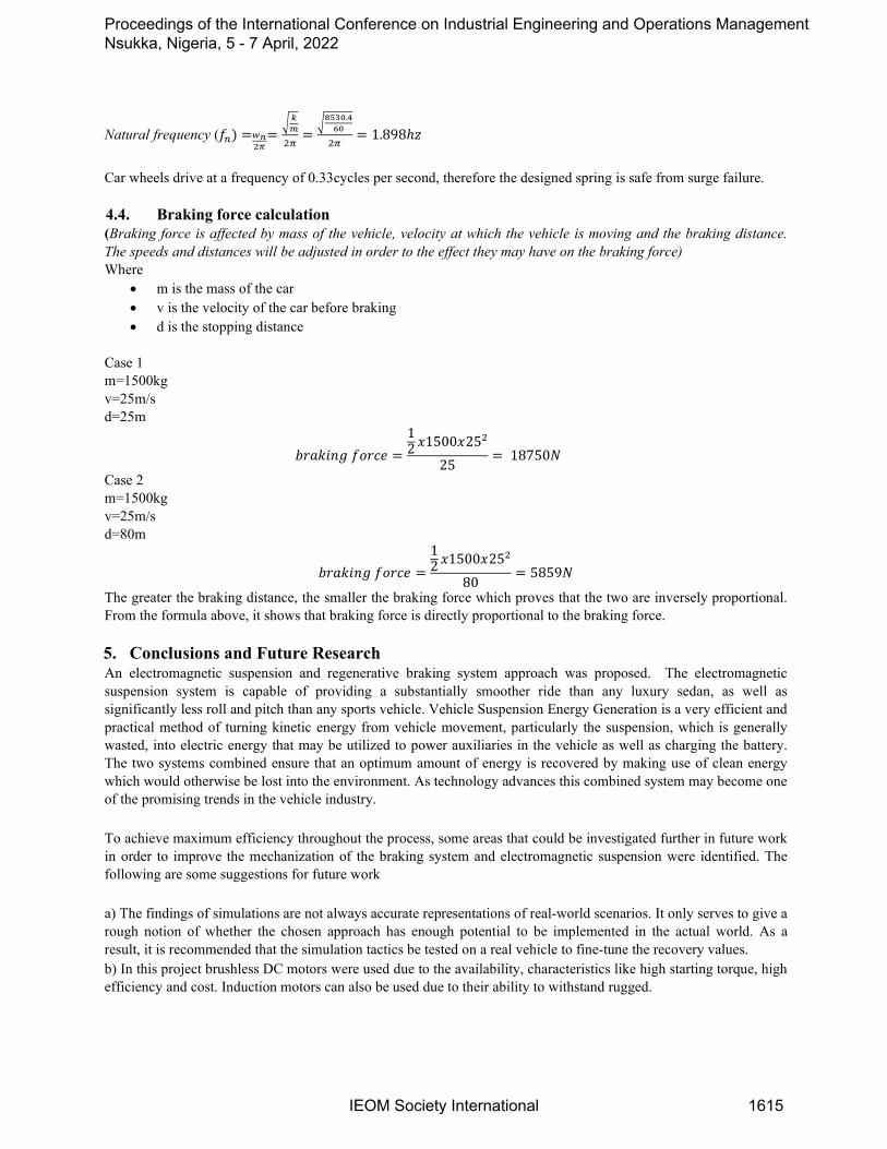
Natural frequency (𝐸𝐸𝑒𝑒) =𝑤𝑤𝑒𝑒2𝜋𝜋
=�𝑘𝑘𝑚𝑚
2𝜋𝜋=
�8530.460
2𝜋𝜋= 1.898ℎ𝑧𝑧
Car wheels drive at a frequency of 0.33cycles per second, therefore the designed spring is safe from surge failure. 4.4. Braking force calculation (Braking force is affected by mass of the vehicle, velocity at which the vehicle is moving and the braking distance. The speeds and distances will be adjusted in order to the effect they may have on the braking force) Where
• m is the mass of the car • v is the velocity of the car before braking • d is the stopping distance
Case 1 m=1500kg v=25m/s d=25m
𝑏𝑏𝑟𝑟𝑊𝑊𝑏𝑏𝑊𝑊𝑀𝑀𝑏𝑏 𝐸𝐸𝑜𝑜𝑟𝑟𝑜𝑜𝑀𝑀 =12 𝑥𝑥1500𝑥𝑥252
25= 18750𝑁𝑁
Case 2 m=1500kg v=25m/s d=80m
𝑏𝑏𝑟𝑟𝑊𝑊𝑏𝑏𝑊𝑊𝑀𝑀𝑏𝑏 𝐸𝐸𝑜𝑜𝑟𝑟𝑜𝑜𝑀𝑀 =12 𝑥𝑥1500𝑥𝑥252
80= 5859𝑁𝑁
The greater the braking distance, the smaller the braking force which proves that the two are inversely proportional. From the formula above, it shows that braking force is directly proportional to the braking force. 5. Conclusions and Future Research An electromagnetic suspension and regenerative braking system approach was proposed. The electromagnetic suspension system is capable of providing a substantially smoother ride than any luxury sedan, as well as significantly less roll and pitch than any sports vehicle. Vehicle Suspension Energy Generation is a very efficient and practical method of turning kinetic energy from vehicle movement, particularly the suspension, which is generally wasted, into electric energy that may be utilized to power auxiliaries in the vehicle as well as charging the battery. The two systems combined ensure that an optimum amount of energy is recovered by making use of clean energy which would otherwise be lost into the environment. As technology advances this combined system may become one of the promising trends in the vehicle industry. To achieve maximum efficiency throughout the process, some areas that could be investigated further in future work in order to improve the mechanization of the braking system and electromagnetic suspension were identified. The following are some suggestions for future work a) The findings of simulations are not always accurate representations of real-world scenarios. It only serves to give a rough notion of whether the chosen approach has enough potential to be implemented in the actual world. As a result, it is recommended that the simulation tactics be tested on a real vehicle to fine-tune the recovery values. b) In this project brushless DC motors were used due to the availability, characteristics like high starting torque, high efficiency and cost. Induction motors can also be used due to their ability to withstand rugged.
Proceedings of the International Conference on Industrial Engineering and Operations Management Nsukka, Nigeria, 5 - 7 April, 2022
IEOM Society International 1615

References Chen, H., & Guo, KConstrained H∞ control of active suspensions: An LMI approach. IEEE Transactions on Control Systems Technology, 13(3), 4121, 2005.
https://doi.org/10.1109/TCST.2004.841661 Clark W. W. and Cooke G., 2011. Global Energy Innovation: Why America Must Lead. Praeger, 2011. Feng, J., Tian,as Z., Cui, J., Zhou, F., “Downhill Safety Assistant Driving System for Battery Electrical Vehicles on
Mountain Roads,” SAE Technical Paper 2019-01-2129, Accessed at: https://doi.org/10.4271/2019-01-2129, 2021.
Lakshmi N. D.,. “Energy Efficient Electric Vehicle Using Regenerative Braking System,” International Journal of Advance Research, Ideas and Innovations in Technology 3, 155, 2017
Plugndrive, Types of Electrical Vehicles. https://ev.plugndrive.ca/. Accessed 23 September 2021. Unnewehr, L.E and Nasar, S.A.,. Electrical Vehicle Technology. Rahul UttamraoPatil, Dr. S.S.Gawade, “Design and
static magnetic analysis of electromagnetic regenerative Shock absorber” 1982 Biographies Zibusiso Jila Dube is a student in the department of Industrial and Mechatronics Engineering at the University of Zimbabwe. Loice Gudukeya is a Senior Lecturer and Head of Industrial and Mechatronics Engineering Department at the University of Zimbabwe. She is also a Senior Research Associate in the Faculty of Engineering and the Built Environment at the University of Johannesburg in South Africa. She attained her PhD in Engineering Management at the University of Johannesburg, in 2018, and her Master’s Degree in Renewable Energy at the University of Zimbabwe in 2012 and her Honours Degree in Industrial and Manufacturing Engineering at NUST (Bulawayo, Zimbabwe) in 2004. Nita Inderlal Sukdeo is the Head of Department of Quality and Operations Management at the University of Johannesburg Mufaro Kanganga is a lecturer at the University of Zimbabwe in the Industrial and Mechatronics Engineering Department. Mufaro is a Ph.D. student at University of Pretoria, researching advanced technologies like additive manufacturing. She attained her Master of Engineering in Manufacturing Systems and Operations Management and her Bachelor of Engineering in Industrial and Manufacturing at NUST (Bulawayo, Zimbabwe) in 2019 and 2017 respectively.
Proceedings of the International Conference on Industrial Engineering and Operations Management Nsukka, Nigeria, 5 - 7 April, 2022
IEOM Society International 1616


