Embed Size (px)
Citation preview

Journal Identification = CHERD Article Identification = 689 Date: June 6, 2011 Time: 11:21 am
Do
IBa
b
c
d
e
1
SiTwsaretgtda
cd
0d
chemical engineering research and design 8 9 ( 2 0 1 1 ) 1155–1167
Contents lists available at ScienceDirect
Chemical Engineering Research and Design
j o ur nal homepage: www.elsev ier .com/ locate /cherd
esigning four-product dividing wall columns for separationf a multicomponent aromatics mixture
. Dejanovic a, Lj. Matijasevic a, I.J. Halvorsenb, S. Skogestadc, H. Jansend,. Kaibeld, Z. Olujic e,∗
University of Zagreb, Faculty of Chemical Engineering and Technology, HR-10000 Zagreb, CroatiaSintef ICT, Applied Cybernetics, 7465 Trondheim, NorwayNorwegian University of Science and Technology (NTNU), Department of Chemical Engineering, 7491 Trondheim, NorwayJulius Montz GmbH, PO Box 530, 40705 Hilden, GermanyDelft University of Technology, Process & Energy Laboratory, 2628 CA Delft, The Netherlands
a b s t r a c t
Preliminary evaluations using a simple but reliable short-cut method indicated that a 15 component aromatics
mixture can be separated very efficiently into four fractions according to the given product specifications employing
either a single or a multiple partition wall dividing wall column (DWC). The obtained results have been used to initiate
rigorous simulations, to determine the number of stages required in different sections, as well as to obtain internal
flows of vapour and liquid necessary for dimensioning and adequate cost estimation for two design alternatives.
Based on the comparison of total annualised costs it appears that a multi-partition wall configuration that maximizes
energy efficiency is a more attractive option for implementation in aromatics processing plants than more practical
single partition wall configuration.
© 2011 The Institution of Chemical Engineers. Published by Elsevier B.V. All rights reserved.
Keywords: Distillation; Energy saving; Dividing wall column; Thermal coupling
however is a challenge for dimensioning because a proper
. Introduction
eparation by distillation is responsible for a large fraction ofmmense amount of energy consumed in process industries.herefore distillation operations became a major concernithin sustainability challenge, i.e. a primary target of energy
aving efforts in industrially developed countries (Humphreynd Keller, 1997). Being by far the most widely used sepa-ation process in industrial practice, utilizing largest scalequipment, distillation is both most energy and most capi-al intensive process technology. Driven by global industrialrowth it tends to grow in both number and size of applica-ions (Olujic et al., 2009). Hence the present day challenge is toesign distillation systems that at the same time are sustain-ble and economically feasible.
Most promising in this respect are so-called dividing wallolumns (DWC). DWC is in essence a fully thermally coupled
istillation sequence, with one condenser and one reboiler∗ Corresponding author. Tel.: +31 15 278 66 74.E-mail address: [email protected] (Z. Olujic).Received 1 November 2010; Received in revised form 12 January 2011;
263-8762/$ – see front matter © 2011 The Institution of Chemical Engioi:10.1016/j.cherd.2011.01.016
regardless of the number of products, packed into a singleshell, by means of one or more longitudinal partition walls.This configuration minimizes entropy of mixing formationsimply by avoiding effectively internal re-mixing of streams.Its special feature is that it is the only known large scaleprocessing intensification example, where both capital andenergy expenses can be reduced, with additional benefit ofreduction of required installation space.
So far, only single-partition wall DWCs have found wideapplication in practice (Olujic et al., 2009; Asprion and Kaibel,2010; Dejanovic et al., 2010a). However, by adopting non-welded partition wall technology it became possible, not onlyto expand the application window for three products columnsbut also to think of implementing four and more productsseparations in one DWC. This implies installation of severalpartition walls in off-centre positions and in parallel, which
Accepted 22 January 2011
distribution of vapour immediately below the partition wall
neers. Published by Elsevier B.V. All rights reserved.

Journal Identification = CHERD Article Identification = 689 Date: June 6, 2011 Time: 11:21 am
1156 chemical engineering research and design 8 9 ( 2 0 1 1 ) 1155–1167
Table 1 – Feed and product streams base case data.
Stream Property
Platformate C5-C6 BRC Toluene Heavies
Temperature (◦C) 37.0 40.0 115.3 111.1 163.6Pressure (bar) 3.01 2.70 3.17 1.01 1.56Flow rate (kmol/h) 343.0 97.8 47.1 86.5 111.6Flow rate (t/h) 31.73 7.16 4.16 7.86 15.55Mass fractionn-Butane 0.019 0.086 – – –i-Pentane 0.064 0.284 – – –n-Pentane 0.045 0.201 – – –2-Methylpentane 0.080 0.351 0.010 – –n-Hexane 0.043 0.066 0.210 – –Benzene 0.086 0.013 0.629 – –3-Metylhexane 0.020 – 0.151 0.002 –Toluene 0.247 – – 0.984 0.001Ethylbenzene 0.035 – – 0.006 0.086p-Xylene 0.042 – – 0.003 0.107m-Xylene 0.122 – – 0.005 0.307o-Xylene 0.055 – – – 0.140m-Ethyltoluene 0.047 – – – 0.1201-3-5-Trimethylbenzene 0.077 – – – 0.197
–
tions studies (see Dejanovic et al., 2010a), the former enables
A, B, C, D
A
B
C
D
1-4-Diethylbenzene 0.017
has to be ensured during the design phase by arranging thepressure drop of each partitioned section accordingly.
In this paper, we show a comparison of a properlydimensioned single-partition wall column for obtaining fourproducts with a three-partition wall column. As indicated inconceptual design stage and confirmed by rigorous simula-tions in present work, the latter maximizes the energy savinggain with respect to conventional three columns sequence.However such a complex internal DWC configuration has notbeen attempted yet in industrial practice. As it will be demon-strated later on, in present case a multiple-partition-wall DWCappears to be an industrially viable option.
2. Base case design
The existing aromatics plant in a petroleum refinery is used toremove as much benzene as possible, as a heart cut, from theplatforming process reactor effluent stream (31.73 t/h, 3.01 bar,37 ◦C, slightly under-cooled liquid, i.e. q = 1.064) that contains40 components. For the purposes of this study, these have beenlumped together accordingly into a representative 15 compo-nents mixture. The separation by distillation is performed ina conventional two-column direct sequence, producing C5–C6
gasoline with less than 1.5 mass% benzene, benzene rich cut(BRC) with 68 mass% benzene content, and heavy platformate,consisting mostly of toluene and heavier aromatics, withless than 0.5 mass% benzene. This three-product sequencewas successfully simulated using ChemCAD (Dejanovic et al.,2010b).
In order to acquire a base-case design for a four-productsequence, a third column was added to effect separation of atoluene rich (>98 mass%) stream from ethylbenzene and heav-ier components. Thus the separation is performed accordingto the arrangement shown in Fig. 1, which is regarding energyrequirement similar to equivalent direct sequence. It can beeasily implemented, simply by adding the 3rd column, with-out changing the operation of the existing sequence. Product
stream compositions obtained by simulation of this three-column configuration are shown in Table 1.– – 0.043
3. 4-p DWC modelling and evaluation
3.1. Alternative 4-p DWC configurations
Two feasible options for a 4-product dividing wall column (4-pDWC) are shown schematically in Fig. 2a and b. Fig. 2a shows aso-called Kaibel configuration (Kaibel, 1987; Olujic et al., 2009)employing one partition wall, and Fig. 2b shows a so calledfully extended Petlyuk configuration, that employs multiplepartitions walls. The former implies having two and the latterone three sections in parallel. According to various simula-
Fig. 1 – Base case configuration.

Journal Identification = CHERD Article Identification = 689 Date: June 6, 2011 Time: 11:21 am
chemical engineering research and design 8 9 ( 2 0 1 1 ) 1155–1167 1157
Fig. 2 – Schematic illustration of two alternative four-product DWCs: Kaibel column – (“2-4”) and the fully extended Petlyuk(
afia
iweip
“2-3-4”) configurations.
significant energy saving with respect to conventional con-guration, which however is well below that achievable with
fully extended counterpart.However, the only known application so far of a 4-p DWC
s the simpler, Kaibel type column, with one partition wall,ith longitudinal sections in off-centre position (see Olujic
t al., 2009), which was adopted because of practical reasons,
.e. its simpler design, construction and operation. The com-lexity, i.e. design, operation and control related uncertaintiesFig. 3 – Simple column sequences used
seems to be the main reason that multiple partition wall con-figurations, which maximize energy saving, have not yet beenattempted in industrial practice.
An objective of this paper is to demonstrate that designof internal configuration of a complex DWC is something thatcan be done with certainty, and that column dimensioning canbe performed with some confidence for applications utilising
columns equipped with structured packings, using the pub-lic domain knowledge. Namely, well established and highlyfor detailed simulation of a DWC.

Journal Identification = CHERD Article Identification = 689 Date: June 6, 2011 Time: 11:21 am
1158 chemical engineering research and design 8 9 ( 2 0 1 1 ) 1155–1167
Fig. 4 – Partitioned part of a DWC represented as aprefractionator column coupled with two two-productcolumns, resembling base case configuration shown inFig. 1.
Fig. 5 – V-min diagram for “2-4” configuration.
Table 2 – Calculation initialisation data required byV-min diagram method.
Tag Component zi Ki Product
A n-Butane 0.0308 6.2768 DB i-Pentane 0.0821 3.3869 DC n-Pentane 0.0581 2.8330 DD 2-Methylpentane 0.0863 1.6298 DE n-Hexane 0.0456 1.3261 DF Benzene 0.1013 0.9417 S1
G 3-Metylhexane 0.0187 0.7347 S1
H Toluene 0.2484 0.4154 S2
I Ethylbenzene 0.0306 0.2032 BJ p-Xylene 0.0370 0.1888 BK m-Xylene 0.1062 0.1851 BL o-Xylene 0.0477 0.1637 BM m-Ethyltoluene 0.0363 0.0962 BN 1-3-5-Trimethylbenzene 0.0595 0.0841 BO 1-4-Diethylbenzene 0.0114 0.0478 B
q = 1.0641 (slightly sub-cooled feed!).
and elaborated in detail in recent publications by Halvorsen
practical non-welded partition wall technology, described ingreater detail elsewhere (Kaibel et al., 2007; Olujic et al., 2009;Dejanovic et al., 2010a), allows assembling multiple partition
wall configurations without additional difficulties.Table 3 – Characteristic points of the V-min diagram shown in
Section Split Specified
Recoveries
C1 PG/H r(I,D) = 0.01 r(E,B) = 0.C2.1 PE/F r(H,D) = 0.05 r(E,B) = 0.C2.2 PH/I r(I,D) = 0.01 r(G,B) = 0
Table 4 – Characteristic points of the V-min diagram shown in
Section Split Specified
Recoveries
C1 PE/I r(I,D) = 0.01 r(E,B) = 0.01C2.1 PE/H r(H,D) = 0.01 r(E,B) = 0.01C2.2 PG/I r(I,D) = 0.01 r(G,B) = 0.01C3.1 PE/F r(F,D) = 0.05 r(E,B) = 0.05C3.2 PG/H r(H,D) = 0.01 r(G,B) = 0.01C3.3 PH/I r(I,D) = 0.01 r(G,B) = 0.01
Two alternative configurations can be simulated usingfacilities available in commercial software packages byemploying corresponding thermodynamically equivalentsequences of simple columns. These are shown schematicallyin Fig. 3a and b, respectively. In case of “2-4” configura-tion, a prefractionator column delivers two products as feedstreams to a four product column, and the “2-3-4” configu-ration consists of a two products prefractionator feeding amiddle column delivering three product streams as feeds forthe main, four products column. According to Fig. 2a and b,respectively, former requires 13, while the latter requires 22parameters to be fully defined, i.e. to allow performance sim-ulation using models suitable for this purpose. This impliesdealing with computational difficulties, which however couldbe avoided by employing a robust, design-oriented short-cutmethod to generate reliable estimates of governing variablesfor initialization of detailed calculations.
3.2. Short-cut modelling approach
According to a most recent state of the art review (Dejanovicet al., 2010a), the so called V-min diagram method, introduced
and Skogestad (2003a,b,c) represents a universal engineering
Fig. 5.
Calculated
VT/F D/F N Nf
01 0.76 0.4252 75 3805 1.28 0.3057 100 50.01 1.28 0.6693 68 35
Fig. 8.
Calculated
VT/F D/F N Nf
0.51 0.4063 28 14 0.56 0.3545 43 22
0.65 0.4851 35 18 1.06 0.3057 100 50
0.76 0.4252 75 38 1.13 0.6693 68 35

Journal Identification = CHERD Article Identification = 689 Date: June 6, 2011 Time: 11:21 am
chemical engineering research and design 8 9 ( 2 0 1 1 ) 1155–1167 1159
459.7572.8
178.492.7281.3480.2
260.7116.6 178.4
439.1336.2
219.6
343 .0
113.2
RL=0.347
RV=0.624
Liquid
Vapo ur
102.9
41.2
V/B = 4.06 1
L/D = 3.26 7 D
S1
B
178.4178.4
85.7 S2
Fig. 6 – Mass balance for “2-4” configuration, with all internal vapour and liquid flows and splits according to V-mindiagram.
ttcbbhwmcoi
aemmaaamc
ca(eciiIfbcipt
gfa
V/F) all other properties are completely determined, such asall component recoveries and product compositions.
C1
C2.1
C2.2
F
C3.1
C3.2
C3.3
D
S2
B
S1
Fig. 7 – Partitioned part of a DWC according to “2-3-4”
ool that enables thorough and accurate assessment of poten-ial for minimization of energy requirement of fully thermallyoupled distillation columns. This rather simple method isased on assumptions of constant molar flows, infinite num-er of stages, and constant relative volatilities, and thereforeolds for (near) ideal zeotropic mixtures. It relies on Under-ood’s equations utilised to estimate the value of theoreticalinimum boil-up ratio, outgoing from the thermodynamic
ondition (q) and composition (z) of the feed and the K-valuesr equilibrium constants of each component for given operat-
ng conditions.The real power of the V-min diagram is that it contains
ll necessary information to calculate the overall minimumnergy requirement and all the internal flow rates for an opti-ally operated extended Petlyuk arrangement for an arbitraryulticomponent feed and any number of products (Halvorsen
nd Skogestad, 2003c). Here, Halvorsen and Skogestad havelso shown that an optimally operated generalized Petlyukrrangement results in the lowest overall vapour flow require-ent for any distillation configuration when we consider
onstant pressure and no external heat integration.We would generally anticipate that we would need to cal-
ulate the minimum energy for each succeeding column by new column computation, but Halvorsen and Skogestad2003b) showed that the properties determining minimumnergy in each sub-column can be found from the previousolumn. This practically means that regardless the complex-ty of a situation, the V-min diagram containing all necessarynformation can be constructed based on feed data only.mportantly, this simple method that in original graphicalorm provides direct insight into the optimal separationsehaviour in fully thermally coupled column arrangementsan be easily translated into analytical form and implementednto a commercial process simulator, as it was done in presentaper to generate reliable initial guesses for rigorous simula-ions.
The composition of the feed considered in this study isiven in Table 2, with component K-values corresponding to
eed stage conditions, and component grouping according toctual product specifications. For convenience, each compo-nent is represented by a letter according to alphabetic order.Distillate and bottoms stream are represented by commonsymbols D and B, while S1 and S2 denote molar flow rates oflighter and heavier side product, respectively.
The basic entity of the V-min diagram is a simple two-product distillation column at constant pressure with a givenmulticomponent feed (F), which at steady state implies twodegrees of freedom in operation. There are several possibili-ties in this respect, however using the ratio of molar flow ratesof internal vapour and the feed (V/F) and the ratio of molarflow rates of distillate product and the feed (D/F) appeared tobe most appropriate choice. Namely, for each given pair (D/F,
configuration, with three sections of main columnsuperimposed on that representing “2-4” configuration.

Journal Identification = CHERD Article Identification = 689 Date: June 6, 2011 Time: 11:21 am
1160 chemical engineering research and design 8 9 ( 2 0 1 1 ) 1155–1167
Fig. 8 – V-min diagram for “2-3-4” configuration.
3.2.1. V-min diagram for “2-4” configurationThe base case configuration shown in Fig. 1, consisting of aprefractionator and two final columns can be used to serve asbasis to construct a V-min diagram. For convenience this situ-ation is shown schematically in Fig. 4, with three independentcolumns represented as sections C1, C2.1 and C2.2 i.e. the pre-fractionator, upper and lower column sections of a 4-p DWCshown in Fig. 2a. To ensure continuity, the upper and lowersections are connected via N2,3 section, which is effectivelyoperating at total reflux (L = V), without any net-transport ofcomponents, acting as a means for heat exchange betweenthese two sections. The key components for the split (S1/S2) inthe prefractionator are G/H, i.e. 3-methylhexane/toluene, andfor splits (D/S1) and (S2/B) in respectively C2.1 and C2.2 are E/F(n-hexane/benzene), and H/I (toluene/ethyl benzene).
As is the case for a full Petlyuk arrangement (“2-3-4”arrangement), the overall vapour flow requirement for a “2-
4” configuration is determined by the highest peak in theV-min diagram, shown in Fig. 5. For “2-4” configuration case,Fig. 9 – Mass balance of “2-3-4” configuration with all intern
the required boilup however does not correspond to the onerequired for most difficult binary separation of the feed,because prefractionator is not operated at the preferred split,performing a sharp G/H split instead. This leads to increasedenergy requirements for E/F and H/I splits, which can be seenas higher V/F values compared to those of “2-3-4” configura-tion shown also in Fig. 5. The detailed analytical procedure isgiven by Halvorsen and Skogestad (2006).
If we subtract (1 − q)F, which is negative (slightly sub-cooledliquid, i.e. q = 1.0641), from the value of highest peak in thediagram we will find that the required boilup is Vmin/F = 1.34.Each sections vapour flow and net top product flow can befound directly as a difference between the peaks and knots inthe V-min diagram. Note that the values of D and V are takendirectly from the diagram, and other flows follow from simplemass balance expressions: L = V − D, Lb = L + qF, Vb = V − (1 − q)F,B = F − D. Table 3 contains relevant specifications and out-comes.
A summary of the complete mass balance of “2-4” configu-ration is shown schematically in Fig. 6, indicating all internalvapour and liquid flows as obtained using V-min diagram.Given liquid and vapour splits represent fraction of respec-tively descending liquid and ascending vapour going to theprefractionator column side.
3.2.2. V-min diagram for “2-3-4” configurationInternal layout of a DWC with “2-3-4” configuration is shownschematically in Fig. 7. Table 4 contains relevant data forcharacteristic points in V-min diagram shown in Fig. 8. Firstcolumn shows the section, i.e. corresponding binary column,performing split indicated in second column, while the thirdcolumn contains given specifications. The key components forthe C1 section, i.e. prefractionator column are n-hexane (E) as
light, and ethylbenzene (I) as heavy key, respectively, and soon. As indicated in third and fourth column in Table 4, for allal vapour and liquid flows according to V-min diagram.
Journal Identification = CHERD Article Identification = 689 Date: June 6, 2011 Time: 11:21 am
chemical engineering research and design 8 9 ( 2 0 1 1 ) 1155–1167 1161
Fig. 10 – Schematic illustration of flow resistances in thepartitioned part of a “2-3-4” DWC.
sFtat
pucttwef
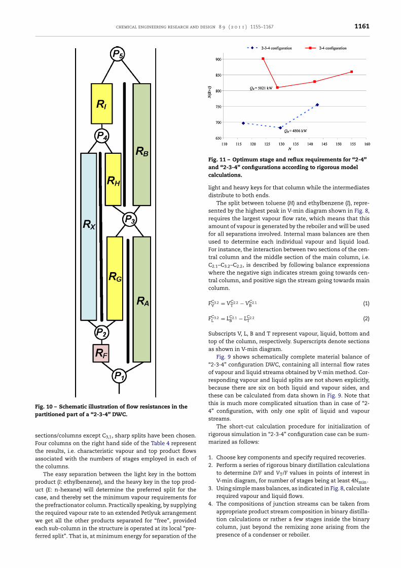
Fig. 11 – Optimum stage and reflux requirements for “2-4”and “2-3-4” configurations according to rigorous model
column, just beyond the remixing zone arising from the
ections/columns except C3,1, sharp splits have been chosen.our columns on the right hand side of the Table 4 representhe results, i.e. characteristic vapour and top product flowsssociated with the numbers of stages employed in each ofhe columns.
The easy separation between the light key in the bottomroduct (I: ethylbenzene), and the heavy key in the top prod-ct (E: n-hexane) will determine the preferred split for thease, and thereby set the minimum vapour requirements forhe prefractionator column. Practically speaking, by supplyinghe required vapour rate to an extended Petlyuk arrangemente get all the other products separated for “free”, provided
ach sub-column in the structure is operated at its local “pre-
erred split”. That is, at minimum energy for separation of thecalculations.
light and heavy keys for that column while the intermediatesdistribute to both ends.
The split between toluene (H) and ethylbenzene (I), repre-sented by the highest peak in V-min diagram shown in Fig. 8,requires the largest vapour flow rate, which means that thisamount of vapour is generated by the reboiler and will be usedfor all separations involved. Internal mass balances are thenused to determine each individual vapour and liquid load.For instance, the interaction between two sections of the cen-tral column and the middle section of the main column, i.e.C2.1–C3.2–C2.2, is described by following balance expressionswhere the negative sign indicates stream going towards cen-tral column, and positive sign the stream going towards maincolumn.
FC3.2V = VC2.2
T − VC2.1B (1)
FC3.2L = LC2.1
B − LC2.2T (2)
Subscripts V, L, B and T represent vapour, liquid, bottom andtop of the column, respectively. Superscripts denote sectionsas shown in V-min diagram.
Fig. 9 shows schematically complete material balance of“2-3-4” configuration DWC, containing all internal flow ratesof vapour and liquid streams obtained by V-min method. Cor-responding vapour and liquid splits are not shown explicitly,because there are six on both liquid and vapour sides, andthese can be calculated from data shown in Fig. 9. Note thatthis is much more complicated situation than in case of “2-4” configuration, with only one split of liquid and vapourstreams.
The short-cut calculation procedure for initialization ofrigorous simulation in “2-3-4” configuration case can be sum-marized as follows:
1. Choose key components and specify required recoveries.2. Perform a series of rigorous binary distillation calculations
to determine D/F and VT/F values in points of interest inV-min diagram, for number of stages being at least 4Nmin.
3. Using simple mass balances, as indicated in Fig. 8, calculaterequired vapour and liquid flows.
4. The compositions of junction streams can be taken fromappropriate product stream composition in binary distilla-tion calculations or rather a few stages inside the binary
presence of a condenser or reboiler.

Journal Identification = CHERD Article Identification = 689 Date: June 6, 2011 Time: 11:21 am
1162 chemical engineering research and design 8 9 ( 2 0 1 1 ) 1155–1167
557.4656.52,1
552.9651.9
324.3 174.1 324 .3 371.32,21,1
363.7316.7133.3279.3
315. 6 318.02,3
289.5287.1
287.1 203.02,4a508.4311.5287.21,2a 203.1
542.1345.1
287.2 203.1345.7 2,4b542.7
1,2b 193.0277.1546.0346.4
746.7633.92,5a
734.9618.3
615.0 731.12,5b
604.1 716.9
N=20
N=19
N=10
N=11
N=17
N=18
N=22
N=22
N=15
N=15
44.6
343.0
L/D = 5 .628
86.5
99.1
112 .8V/B = 5.345
w(tol uene)=9 8.1%
w(benz ene)=70.9%
QR =5821 kW
Q C=-50 55 kW
w(benze ne)=1 .3%
w(tol uene)=0 .06%
Fig. 12 – Mass balance of “2-4” configuration with all internal vapour and liquid flows according to rigorous model.
It should be noted that use of commercial process sim-ulator for short-cut simulation of “2-4” configuration is notso straightforward. This case cannot be modelled as a seriesof binary distillation calculations of the same feed, becauseprefractionator column is not operated at a preferred split,causing higher energy use in subsequent sections. A way ofperforming simulations is to use the base case configurationin Fig. 1, but with liquid fractions of the feed into the finaltwo columns set to the effective liquid fraction of the ther-mal coupling. This will give an artificial superheated feed tothe upper column and an artificial sub-cooled feed to the lowercolumn giving the same flow changes at the junctions as in thefully thermally coupled “2-4” configuration in Fig. 3. However,this may in some cases give convergence problems becausethe artificial temperatures may become close to critical
values.Table 5 – Comparison of energy requirements of studied seque
Base case
Shortcut methodVmin/F 2.21
Relative savings in reboiler duty (%) –
Rigorous methodTotal QR, [MW] 10.03
Total QR/F [MW/t] 0.324
Relative savings in reboiler duty (%) –
3.3. Detailed modelling approach
Sequences used for simulation of proposed configurations areshown in Fig. 3. All sections’ stage numbers were initially setat effectively infinite values (>4Nmin). Side stream flows rateswere initially set according to the material balance. Refluxratio was adjusted to keep top and bottom products’ puritiesat specified levels, and boil-up ratio was set to provide neces-sary vapour flow from the reboiler, as calculated from V-mindiagram. Initial values of vapour and liquid split ratios werealso set as calculated from V-min diagram, and then tuned inorder to keep heavy key and light key recoveries in section’stop and bottom respectively, below 0.01.
The actual number of stages was then found using fol-
lowing procedure. Keeping boil-up ratio constant, number ofstages in each section was gradually reduced, to the valuesnces, estimated using shortcut and detailed methods.
“2-4” “2-3-4”
1.34 1.1139.4 49.8
5.82 4.810.183 0.152
42.0 52.0

Journal Identification = CHERD Article Identification = 689 Date: June 6, 2011 Time: 11:21 am
chemical engineering research and design 8 9 ( 2 0 1 1 ) 1155–1167 1163
Table 6 – Comparison of conventional and two DWC designs.
Configuration Conventional “2-4” “2-3-4”
Column C1 C2 C3
Shell tangent to tangent height (m) 40.5 39.5 39.5 63.8 60.4Shell diameter (m) 2.0 2.0 1.8 2.2 2.1Top pressure (bar) 1.70 2.70 1.01 2.2 2.2Pressure drop (bar) 0.313 0.272 0.244 0.150 0.137Reboiler duty (MW) 3.76 3.12 3.15 5.82 4.81Total reboiler duty (MW) 10.03 5.82 4.81Number of stages/trays 40/61 38/59 38/59 129/– 130/–Number of packed beds – – – 10 (7) 13 (10)Number of distributors – – – 10 (7) 11 (8)Number of liquid catchers – – – 8 (5) 9 (6)Number of support grids – – – 10 (7) 13 (10)
Note: Numbers in parentheses indicate devices placed in partitioned part of the column.
wrkwd
mai
s
12
3
4
3
Dopad
fi
here product purities were still not compromised. Then,eboiler specification was changed to automatically adjust toeep bottom product purity. Number of stages in each sectionas proportionally reduced, and split ratios tuned to achieveesired side product purities.
Effectively, optimization has been performed by graduallyinimizing (in each step) the product of the number of stages
nd the reflux ratio: N(R + 1), which represents a good approx-mation of total annualized costs.
Detailed calculation is effectively done following theseteps:
. Chose appropriate conventional column sequence.
. Use values from V-min diagram, including stage number,for initialization.
. Keeping product purities at specified levels, using splitratios to minimize reboiler duty.
. Gradually reduce number of stages, repeating step 3, untilmin(N(R + 1)) is achieved.
.4. Dimensioning
ividing wall columns can be equipped with trays, randomr structured packing, same as conventional columns, buteculiarities, i.e. essential details associated with hydraulicsnd consequently dimensioning of these columns are notescribed in open literature.
The basis for dimensioning is a converged column pro-le obtained by rigorous column steady-state simulation. This
Table 7 – Equipment and utilities cost, and total annualised cos
Configuration Conventional
Equipped with Sieve trays
Total equipment costs ($)Shell 1,819,996
Internals 768,276
Reboiler 561,294
Condenser 637,547
Total 3,787,113
Savings –
Operating costs ($/year)Cooling 577,257
Heating 986,355
Total 1,563,612
Savings –
TAC ($/year) 1,942,323
Savings –
effectively means that liquid and vapour flows and prop-erties are known for every column stage. In conventionalcolumn design, the dimensioning has to ensure stable col-umn performance with regards to liquid and vapour loads. InDWCs, dimensioning has one additional purpose, and that isto ensure desired vapour split below the partition wall. Unlikeliquid split, which can be set precisely by an external device,vapour split ratio is self-adjusting and is set by the govern-ing pressure drops across different column sections. In otherwords, in order to be able to precisely tune the vapour split, thedesigner needs to be able to accurately predict and manipulateaccordingly the pressure drop of column sections separated bythe partition wall. In conjunction with the fixed liquid split, thepressure drop depends on the type and size of internals used.If a bed, sized to ensure given separation, does not generatesufficient pressure drop to ensure required vapour split, addi-tional pressure drop can be arranged for instance by adjustingthe free area of liquid distributors and/or catchers accord-ingly.
The “2-4” configuration appeared to be rather simple inthis respect. Additional challenges are associated with presentattempt to evaluate feasibility of a multiple-partition wallcolumn, which means going beyond the limits of practicalexperience of J. Montz GmbH, the pioneer in this field amongequipment manufacturers, which was involved with designand delivery of more than 90 packed DWCs so far.
Fig. 10 shows schematically flow resistances as encoun-
tered in the partitioned part of a “2-3-4” configuration DWC. Int (TAC) for “2-4” and “2-3-4” configurations.
“2-4” “2-3-4”Structured packings Structured packings
1,015,543 924,8831,358,112 1,441,898
393,578 336,353264,245 272,759
3,031,478 2,975,89320.0% 21.4%
108,103 86,632752,127 620,980860,230 707,612
45.0% 54.7%1,163,378 1,005,201
40.1% 48.2%

Journal Identification = CHERD Article Identification = 689 Date: June 6, 2011 Time: 11:21 am
1164 chemical engineering research and design 8 9 ( 2 0 1 1 ) 1155–1167
514.4 414.9
2,1
516 .4 416. 8
1,1
2,4
1,2
3,1
3,6a
3,6b
494.0 606. 4
493.6 605.1
492.7 603.9
472.3 584. 7
160.6
145.6
55.7
40.7
162.2
186.5
400.2
424.6
178.3
173.4
83.3
78.4
265.7
276.5
457 .4
468 .2
3,3
3,4
3,5
324. 6
316. 9
274.9
267.7
241. 3
225. 4
248.4
232.5
225.3
216.0
146.0
136.6
3,2337.8
325.5
333.2
320.0
2,2
2,3
10.7
10.5
20.6
20.5
82.9
77.7
36.5
31.3
44.6
86.5
N=18
N=15N=7
N=20
N=28
N=27
N=10
N=12
N=15
N=9
N=19
N=21
N=21
L/D = 4.170 99.5
343 .0
112.4V/B = 4.202
w(toluene) =98.4%
w(benzene)=70 .9%
Q R =4806 k W
QC=-4038 k W
w(benzene)=1.3%
w(toluene) =0.06%
Fig. 13 – Mass balance of “2-3-4” configuration with all internal vapour and liquid flows according to rigorous model.
order to arrive at required vapour splits, following conditionsmust be satisfied:
�pRF + �pRG = �pRA (3)
�pRH + �pRI = �pRB (4)
�pRX = �pRG + �pRH (5)
In present case, with pronounced differences in the num-ber of stages and flow rates of phases in parallel sectionsof the column, different types and sizes of J. Montz cor-rugated metal sheet structured packings of series B1 havebeen considered to provide enough flexibility in this respect.Two basic structured packing area sizes were considered asappropriate for this case, 250 and 350 m2/m3, respectively, inconjunction with different corrugation inclination angles aswell as designs, i.e. M and MN. For the same specific geo-metric area, using a packing with 60◦ instead of common45◦ means a nearly factor three drop in the pressure drop,and a 30% higher capacity, at the expense of some 20% lossof efficiency (Olujic et al., 2002). Packings of series M havea long smooth bend at the end of the corrugations, whichreduces the pressure drop and increases the capacity accord-ingly.
If this packing is used at vapour loads below the loadingpoint then some 10% loss of efficiency should be accounted
for with respect to standard version of the same specificgeometric area. MN series combines a shorter smooth bendwith a decreased corrugation inclination angle, generat-ing additional pressure drop due to increased interactionof crossing vapour streams, which however translates intomore efficiency, while preserving a rather high capacity.More detailed information on the performance characteristicsof this new generation, high performance Montz struc-tured packings can be found elsewhere, e.g. Olujic et al.(2010).
The dimensioning procedure for a packed DWC can bedescribed as following:
1. Choose packing type.2. Calculate required packing height in each section via HETP.3. Find critical vapour load and use it to determine overall
column diameter.4. Adjust wall positions, until calculated pressure drop in
all sections is below 3 mbar/m. If that is not achievable,increase overall column diameter.
5. Choose internals, using liquid loads for guidelines. Usechimney tray for side-stream draw-offs, regardless of liquidload.
6. Adjust free areas of collectors in divided section, to achieveequal calculated pressure drops, ensuring required vapour
splits. If that is not achievable, adjust wall position, andrepeat calculations.
Journal Identification = CHERD Article Identification = 689 Date: June 6, 2011 Time: 11:21 am
chemical engineering research and design 8 9 ( 2 0 1 1 ) 1155–1167 1165
3
Siccpcrcdpttt2
cchvfom1eTp
adbc(ttf
capsic1a
h(
4
Tr“1c
Dtep4
.5. Cost estimation
imilar to conventional columns, total DWC costs can be splitnto cost of shell, packings and auxiliary internals. The pur-hased cost of sieve trays, packings, liquid distributors, liquidatchers and packing support grids has been provided for theurpose of this and similar studies by J. Montz. The purchasedost of structured packings is based on the specific geomet-ic area per unit volume, and for the present case, the baseost of standard packing with an area of 250 m2/m3, indepen-ent of the type, is US$ 2000/m3. For larger geometric areaacking considered in this study (350 m2/m3) this value needso be multiplied by factor 1.4 corresponding to the ratio ofwo specific geometric areas. The base unit purchased cost forhe liquid distributor is US$ 4000/m2, for liquid catcher US$000/m2, and for packing support grid US$ 800/m2.
Compared to conventional columns, the equipment relatedosts of a DWC are somewhat higher. For instance, the pur-hased cost of internals and packings placed in a DWC isigher because it includes partition walls and additional pro-isions needed to get packings and related internals readyor installation. For single-partition wall with sections placedff-centre the design complexity cost factor is 1.2 while for aulti-partition wall section of a DWC this value is higher, i.e.
.3, with respect to conventional column. Purchased cost ofquipment is multiplied by factor 2 to arrive at installed cost.hese particular values are considered reasonable for presenturposes.
Installed column shell costs for conventional tray columnsnd DWCs as well as reboilers and condensers have beenetermined using well established correlations from Douglasook (1988), expressed in SI units. The estimated installedosts have been updated using Marshall & Swift Index for 2009Chemical Engineering, 2010). The purchased cost for sieverays as employed in design of three columns of the conven-ional configuration is US$ 600/m2 and to obtain installed costactor 3 is employed.
For the sake of simplicity, the operating costs are in presentase taken to be that of the utilities, i.e. the heating mediumnd the cooling water. Since the bottoms temperature inresent case is well above that of low and medium pres-ure steam, the same heating medium (furnace using fuel oil)s considered as in actual aromatics plant for conventionalolumns. The utilities prices adopted for this study are: US$30/tonne for fuel oil, and US$ 0.03/tonne for cooling water,nd 13$/tonne for steam.
Total annualized cost (TAC) is based on 8322 operatingours per year and 10% of installed costs, assuming a plant
financial) life time of 10 years.
. Results and discussion
he curves representing various stage and reflux requirementelations for main column side of configurations “2-4” and2-3-4” are shown in Fig. 11, indicating respectively 129 and30 equilibrium stages as optimum values. The reboiler dutiesorresponding to these points are also shown.
Energy requirements of conventional and two alternativeWC configurations are compared in Table 5. Interestingly,
he rigorously estimated, reboiler duty based energy savings,xpressed in percents, do not differ practically from those
redicted by the short-cut method. Simpler design, i.e. “2-” configuration ensures around 42% saving compared toconventional three-column configuration, while the savingachievable with complex design, i.e. ‘2-3-4” configuration, isaround 52%. In other words, “2-3-4” configuration requiresonly one half of the energy to achieve the same separationas conventional configuration.
Compared to simpler “2-4” configuration, the thermo-dynamically optimal “2-3-4” configuration column requires17.4% less energy for the same goal. This may be considerednot attractive enough to move users to consider accepting therisks associated with building and operation of such a complexcolumn. However, in present case this means an additionalenergy saving of 1 MW, and this number indicates a poten-tially higher financial benefit with respect to that expectedfrom simpler single-partition wall configuration.
The optimized number of stages and corresponding inletand outlet vapour and liquid mass flow rates for all beds intwo configurations are summarized in Figs. 12 and 13, respec-tively. Compositions of product streams in all configurationssatisfy requirements of the base-case situation, as indicatedin Table 1. Namely, C5–C6 stream must contain less than1.3 mass% benzene, and toluene stream more than 98.0 mass%toluene. Owing to the fact that approximate calculations havebeen performed with a relatively larger number of stages, boththe reflux and boil-up ratios generated by detailed calculations(an optimised, i.e. minimised number of stages) are signifi-cantly higher. This implies larger internal liquid and vapourflows and these are, as expected, relatively larger for singlepartition wall configuration than for maximally energy effi-cient multiple-partition wall configuration. Consequently, thelatter should require smaller column dimensions and conse-quently lower capital cost.
The liquid and vapour flow rates for the top and bottom ofeach bed, together with belonging physical properties, servedas basis for column dimensioning. In both cases the bottomsection with highest vapour and liquid loads was taken asbasis for determination of the shell diameter. This in bothcases appeared to be large enough to accommodate parallelsections, containing where necessary appropriate sizes andtypes of structured packing as well as liquid collecting devices,with free area chosen within given range to tune the pres-sure drop. Estimation of the pressure drop of various sizes andtypes of Montz packings used in conjunction with state of theart narrow trough liquid distributors and collectors was per-formed using methods that will be described in details in aforthcoming publication.
Detailed drawings of two columns are shown in Fig. 14,indicating relative size of packed beds in different sectionsas well as the type of liquid collector used. In general forspecific liquid loads above 20 m3/m2 h a chimney type col-lector was used as well as for the draw-off of side products.Two beds in central section are rather narrow and practicallyrectangular, and with three beds in parallel above and belowthe side-draw-off a rather large fraction of walls is involved.Nevertheless, by combining in each layer conventional liquidscrappers with robust ones that also ensure fixing of the par-tition wall between two packed beds, bypassing of liquid andvapour, which is a serious concern, could be minimised.
Main column dimensions and the number of beds, dis-tributors, collector and packing support grids contained inconventional and partitioned parts (numbers in parentheses)of “2-4” and “2-3-4” DWC are summarised in Table 6. Forcomparison, main dimensions of the three columns of the
conventional configuration, designed as tray columns are alsoshown in Table 6.
Journal Identification = CHERD Article Identification = 689 Date: June 6, 2011 Time: 11:21 am
1166 chemical engineering research and design 8 9 ( 2 0 1 1 ) 1155–1167
Fig. 14 – Detailed drawings of single (“2-4”) and multiple(“2-3-4”) partition wall DWCs. (numbers indicate individualbeds as given in Figs 12 and 13, respectively).
The shells of two DWCs are taller but make roughly onlyone half of total height of three columns from conventionalsequence. Diameters of both DWCs are slightly larger, and thereduced energy requirement of complex “2-3-4” configuration,i.e. reduced internal vapour flow rate, results in a somewhatsmaller diameter. Due to a more compact arrangement of the
partitioned part, the complex DWC is also shorter than thesingle partition wall “2-4” configuration column.As shown in Table 7, compared to conventional, threecolumns configuration, capital cost of two compact dividingwall columns is approximately 20% lower, which is a lesspronounced saving than usually experienced with conven-tional three-product DWCs. This however is mainly due to costenhancement factors adopted to account for additional manu-facturing and construction/installation complexity associatedwith single and multi-partition, off-centre wall DWCs con-figurations. Owing to a rather pronounced operating costreduction, i.e. 45.0% and 54.7% for respectively “2-4” and 2-3-4” configuration, the corresponding savings expressed on TACbasis are quite large, i.e. 40.1% and 48.1%.
Regarding the fact that the operating (energy) cost of the “2-3-4” configuration is 17.7% lower, compared to that of the “2-4”configuration, which results in a 13.6% lower TAC, it appearsthat complex, multi-partition wall configuration is an attrac-tive option for present case.
Regarding the control aspects of four product columns,which however is not within the scope of the present paper,one should note that so far only one DWC with “2-4” configura-tion has been realized in industrial practice (Kaibel et al., 2007;Olujic et al., 2009; Dejanovic et al., 2010a). For such a columnStrandberg et al. (2010) have shown a feasible control strategybased on controlling four temperatures by manipulating theliquid split and the three upper product flow rates while boilupand vapour split are kept constant. It is reasonable to extendthis strategy to the full “2-3-4” column. This however is sub-ject of an ongoing research effort at NTNU under supervisionof two of the co-authors of the present paper, which will beaddressed soon in extension of their previous work along thisline.
5. Conclusions
An energy efficient alternative has been proposed for recov-ery of essential fractions in a refinery aromatics complex.Three columns configuration has been replaced by one DWCfor obtaining four products. Two options, one with a single lon-gitudinal partition wall, with some sections off-centre, and amultiple-partition wall column containing three sections inparallel have been worked out using rigorous simulations ini-tiated using the values of governing variables estimated usingan established short-cut method.
V-min diagram proved to be a simple and effective toolfor identification and conceptual design of internal, minimumenergy requirement configuration of a multi-product DWC, aswell as for reliable initialization of detailed (rigorous) calcula-tions.
Detailed calculation method adopted, in conjunction witha simple empirical objective function for design optimal-ity indication, allows easy determination of the stage andreflux requirement of a complex DWC. The dimension-ing method developed for standard, three-product columnsappeared to be an effective tool for design and assessmentof cost-effectiveness of alternative internal configurationsof four-product multiple partition wall DWC equipped withstructured packings.
The simulation studies indicated a strikingly large energysaving potential compared to conventional configuration,resulting in a 40.1% and 48.2% lower TAC for single- and mul-tiple partition wall DWC, respectively. This means that morecomplex, multiple-partition wall column is a more attractive
option for industrial implementation, but due to its construc-tional complexity it may appear impractical.
Journal Identification = CHERD Article Identification = 689 Date: June 6, 2011 Time: 11:21 am
chemical engineering research and design 8 9 ( 2 0 1 1 ) 1155–1167 1167
tfimow
ptao(bs
A
Tmp
R
A
C
D
D
Regarding the scale of this and similar applications, addi-ional 17.7% saving in operating costs translates into largenancial benefits. Therefore in present and similar cases thereay be a strong incentive to put more effort and resources into
vercoming potential barriers and making multiple-partitionall DWC configurations industrially viable.
Thanks to the availability of proven non-welded, self-fixingartition wall structured packing technology, multiple par-ition wall configurations could be realized in practice. If itppears that control of the complex DWCs (subject of anngoing research effort at NTNU) will not be too demanding
impractical), than the barriers other than technical need toe overcome to enable practical implementation of this highlyustainable distillation column technology.
cknowledgement
he authors would like to thank INA Refinery Sisak, Croatia,ember of MOL Group for providing actual plant data for the
urposes of this study.
eferences
sprion, N., Kaibel, G., 2010. Dividing wall columns:fundamentals and recent advances. Chem. Eng. Process. 49,139–146.
hemical Engineering, 2010. Economic Indicators, February, p. 50,www.che.com.
ejanovic, I., Matijasevic, Lj., Olujic, Z., 2010a. Dividing wallcolumn – a breakthrough towards sustainable distilling.Chem. Eng. Process. 49, 559–580.
ejanovic, I., Matijasevic, Lj., Jansen, H., Olujic, Z., 2010b. Dividingwall column application to a platformate splitter – a casestudy, 20th European Symposium on Computer Aided Process
Engineering, In: Pierucci, S., Buzzi Ferraris, G. (eds), Elsevier,2010, pp. 655–660.Douglas, J.M., 1988. Conceptual Design of Chemical Processes.McGraw-Hill.
Halvorsen, I.J., Skogestad, S., 2003a. Minimum energyconsumption in multicomponent distillation. 1. Vmin diagramfor a two-product column. Ind. Eng. Chem. Res. 42, 596–604.
Halvorsen, I.J., Skogestad, S., 2003b. Minimum energyconsumption in multicomponent distillation. 2.Three-product Petlyuk arrangements. Ind. Eng. Chem. Res. 42,605–615.
Halvorsen, I.J., Skogestad, S., 2003c. Minimum energyconsumption in multicomponent distillation. 3. More thanthree products and generalized Petlyuk arrangements. Ind.Eng. Chem. Res. 42, 616–629.
Halvorsen, I.J., Skogestad, S., 2006. Minimum energy for thefour-product Kaibel-column. In: AIChE Annual Meeting , SanFrancisco (paper 216d), November 12–17, 2006.
Humphrey, J.L., Keller II, G.E., 1997. Separation ProcessTechnology. McGraw-Hill, New York.
Kaibel, G., 1987. Distillation columns with vertical partitions.Chem. Eng. Technol. 10, 92–98.
Kaibel, B., Jansen, H., Rietfort, T., Zich, E., Olujic, Z., 2007. Unfixedwall: the key to a breakthrough in dividing wall columntechnology. In: Proceedings of Distillation Topical Conference,AIChE Spring National Meeting , Houston, Texas, USA, 22–27April, pp. 29–41.
Olujic, Z., Seibert, A.F., Fair, J.R., 2002. Influence of corrugationgeometry on the performance of structured packings: anexperimental study. Chem. Eng. Process. 39, 335–342.
Olujic, Z., Jödecke, M., Shilkin, A., Schuch, G., Kaibel, B., 2009.Equipment improvement trends in distillation. Chem. Eng.Process. 48, 1089–1104.
Olujic, Z., Rietfort, T., Jansen, H., Kaibel, B., Zich, E., Ruffert, G.,Zielke, T., 2010. Maximizing the performance of corrugatedsheet structured packings. In: Proceedings of Distillation andAbsorption 2010 , Eindhoven, The Netherlands, pp.605–610.
Strandberg, J., Skogestad, S., Halvorsen, I.J., 2010. Practical control
of dividing wall columns. In: Proceedings of Distillation andAbsorption 2010 , Eindhoven, The Netherlands, pp. 527–532.