Embed Size (px)
Citation preview

polymers
Article
Development of Inorganic Particle-Filled Polypropylene/HighDensity Polyethylene Membranes via Multilayer Co-Extrusionand Stretching
Pilar Castejón , Marcelo Antunes and David Arencón *
�����������������
Citation: Castejón, P.; Antunes, M.;
Arencón, D. Development of
Inorganic Particle-Filled
Polypropylene/High Density
Polyethylene Membranes via
Multilayer Co-Extrusion and
Stretching. Polymers 2021, 13, 306.
https://doi.org/10.3390/polym
13020306
Received: 29 December 2020
Accepted: 13 January 2021
Published: 19 January 2021
Publisher’s Note: MDPI stays neutral
with regard to jurisdictional claims in
published maps and institutional affil-
iations.
Copyright: © 2021 by the authors.
Licensee MDPI, Basel, Switzerland.
This article is an open access article
distributed under the terms and
conditions of the Creative Commons
Attribution (CC BY) license (https://
creativecommons.org/licenses/by/
4.0/).
Poly2 Group, Department of Materials Science and Engineering, Universitat Politècnica de Catalunya (UPCBarcelonaTech), ESEIAAT, C/Colom 11, E-08222 Terrassa, Spain; [email protected] (P.C.);[email protected] (M.A.)* Correspondence: [email protected]; Tel.: +34-93-739-8056
Abstract: This work is made to ascertain the effects of mineral fillers, namely calcium carbonate andtalc, on the morphology and properties of multilayer polypropylene (PP)/high-density polyethylene(HDPE) porous membranes. Multilayer membranes were prepared using the three-stage Melt-Extrusion, Annealing and Uniaxial Stretching (MEAUS) process. The orientation of PP’s crystallinephase was affected by both the flow-induced crystallization and the heterogeneous nucleationpromoted by the fillers. A synergistic effect was observed in the filled samples due to the generationof pores after the stretching-induced lamellae separation and the debonding of mineral fillers fromthe polymeric matrix. The fillers increased the porous surface, leading to an increase of permeanceto air, being this effect more marked at higher filler contents. Talc showed a higher efficiency tocreate porous surfaces when compared to calcium carbonate. The thermal stability of the membranesincreased with filler addition, as well as their stiffness and strength.
Keywords: particle-filled multilayer membranes; co-extrusion; annealing; uniaxial stretching
1. Introduction
Polymeric porous membranes have attracted much interest as separators in differentapplications due to their wide range of chemical and physical characteristics, low rawmaterial cost and great number of available manufacturing processes. Recently, dry stretchmethods have been developed to reduce solvent consumption and waste generation. Voidnucleation and growth can occur by four different mechanisms in the stretched samples:interface separation between immiscible polymer blends, stress-induced polymorphictransitions in crystalline polymers, debonding of particle/matrix interfaces in mineralparticle-filled polymers and separation of crystalline lamellar structure after uniaxialstretching [1–7].
The three-stage Melt-Extrusion, Annealing and Uniaxial Stretching (MEAUS) processfor producing porous membranes is a solvent-free process based on the stretching ofsemicrystalline polymer films. This method involves three consecutive stages: (a) filmextrusion, where the polymer is melt-extruded under appropriate conditions to achieve astacked lamellar morphology, commonly known as row-nucleated structure, resulting fromstress-induced crystallization; (b) thermal annealing to achieve a near-perfect crystallinephase and lamellar thickening; and (c) uniaxial stretching, where the films are highlydeformed along the machine direction, first at room temperature to generate pores andthen at a high temperature to enlarge pore size by increasing lamellar separation. Followingthis last stretching step, a heat-setting stage is applied to maintain the dimensional stabilityof the resulting membranes, avoiding shrinkage and keeping the mean pore size constant.The significance of the morphological characteristics and the state of crystal orientationof the extruded precursor films on the final pore structure of the membranes have beenhighlighted in many studies [6–14].
Polymers 2021, 13, 306. https://doi.org/10.3390/polym13020306 https://www.mdpi.com/journal/polymers
Polymers 2021, 13, 306 2 of 15
Polyolefin microporous membranes are commonly used in lithium-ion batteries ascommercial separators placed between the anode and the cathode. Usually, commercialbattery separators are made from polyolefins such as polyethylene (PE) or polypropylene(PP). These materials have been commonly employed to produce microporous membranesusing a wet phase inversion process or a dry-stretch process, including the MEAUS process.To increase the battery cycle performance and safety, PE and PP have been combinedto form trilayer PP/PE/PP separators. This kind of separator possesses a shutdownmechanism, where the intermediate PE layer with a low melting temperature closes thepores and stops ion flow through the cell when a lithium-ion battery is overcharged, and theexternal PP layers, having a higher melting temperature, provide the required dimensionaland mechanical stability [15,16]. Finally, some characteristics of these types of separators,such as dimensional, thermal and mechanical stability, wettability to the electrolyte, as wellas pore morphology and permeability, have been shown to be enhanced with the additionof a certain amount of fillers or with polymer or ceramic coatings [17,18].
Some authors have investigated the formation of multilayer microporous membranesof PP and PE using a multilayer co-extrusion process [15,16]. According to Tabatabaeiet al. [15], due to the interface and the lower crystalline orientation achieved duringthe cast-film extrusion stage, trilayer microporous membranes of PP and high-densitypolyethylene (HDPE) showed a lower permeability to water vapor than the respectivemonolayer membranes. The authors observed a good adhesion between PP and HDPE inthe porous multilayer membrane, which they related to a transcrystallization zone formedaround the interface.
Organic and inorganic fillers are usually added to thermoplastics to reduce cost andenhance material characteristics. A common method for forming porous membranes con-siders the delamination of inorganic fillers from the polymer matrix. Some authors haveinvestigated the formation of microporous membranes with filled PP using a stretchingmethod, including our previous study [19]. Nakamura [4] and Nago [5] prepared microp-orous PP films containing calcium carbonate (CaCO3) particles by extrusion and biaxialstretching, and established a relationship between the size of the particles and the porousstructure. Research shows that, with decreasing filler size, low tortuosity factor, highporosity and small pore size are obtained. It is known that mineral fillers can change thehydrophilic surface characteristics, enhance the mechanical and thermal stability of mem-branes and have a direct influence on the generated porous structure, as most fillers havesome crystal nucleation ability during semicrystalline polymer cooling, especially in thecase of PP [20–25]. However, experimental results have shown that it is sometimes difficultto achieve said nucleation because of the weak interfacial interactions between particlesand the polymer matrix. Inorganic surface modification using coupling agents has beenshown to prevent agglomeration and promote particle dispersion during processing [26].
With all these considerations in mind, this study focuses on the production of thinmultilayer membranes composed of HDPE as mid layer and blends of PP and inorganicfillers, namely calcium carbonate and talc, as outer layers. We hypothesized that thesefillers, commonly employed in the industry to enhance some characteristics of polymers,would lead to changes in the crystalline structure, thermal stability and mechanical andpermeance properties of the porous membranes. The influence of annealing and uniaxialstretching is also investigated.
2. Materials and Methods2.1. Materials and Composite Compounding
Commercial grades of PP homopolymer, Isplen PP020 G3E, from Repsol (Madrid,Spain), and HDPE, HDPE KT 1000 UE, from Dow (Midland, MI, USA), were used. Bothmaterials display a characteristic linear-like molecular architecture. Isplen PP020 G3E has amelt flow index of 0.9 dg/min (measured at 230 ◦C and 2.16 kg according to ISO 1133 [27]),a Vicat softening temperature of 151 ◦C (ISO 306, method A [28]) and a yield strength of34 MPa (ISO 527-2 [29]). HDPE KT 1000 UE has a melt flow index of 8.0 dg/min (measured
Polymers 2021, 13, 306 3 of 15
at 190 ◦C and 2.16 kg according to ISO 1133), a Vicat softening temperature of 131 ◦C(ISO 306, method A) and a yield strength of 29 MPa (ISO 527-2).
Two different commercial mineral fillers were added to the outer layers of PP. Byone hand, a ultramicronized calcium carbonate, Microcarb 95T, from Reverté Minerals(Barcelona, Spain), surface-treated with MgCO3, Fe2O3 and amino groups. This calciumcarbonate has an average particle size (D98) of 4 µm; by the other hand, an untreated talc,Mistrocell M90, from Imerys Talc (Paris, France), with a micro-lamellar morphology andan average particle size (D98) of 3.3 µm. Both fillers have a Brunauer–Emmett–Teller (BET)surface area of 13.0 m2·g−1.
PP composites were compounded with different weight percentages of filler, namely0, 5 and 10 wt%. These compounds were obtained using a co-rotating twin-screw extruderCollin Kneter 25 × 36D (Dr. Collin, Maitenbeth, Germany), with screw length/diameterrelation of 36. The extrusion temperature profile from the hopper to the die ranged from140 to 230 ◦C. The melt was extruded through a circular die with a diameter of 3 mm,cooled in a water bath (water kept at room temperature) and pelletized.
2.2. Production of Trilayer Membranes2.2.1. Co-Extrusion of Trilayer Precursor Films
Trilayer precursor films (PP/HDPE/PP layer configuration) were extruded usinga lab-scale three-layer co-extrusion line (Teach-Line Collin, E20T and E16T, Dr. Collin,Maitenbeth, Germany) equipped with a rectangular die having a width of 100 mm anda gap opening of 1.9 mm. The trilayer configuration was PP (with or without filler) asouter layers and HDPE as the mid layer. The co-extrusion adapter and co-extrusion diewere set at 230 ◦C during extrusion. At the exit of the die, slit-open air knives were usedto supply air (5 bar) to both sides of the film to achieve fast cooling. Simultaneously, thefilm underwent uniaxial stretching along the machine direction orientation (MDO) usingcalendaring rolls kept at controlled temperature (room temperature). The draw ratio waskept at 70 in order to obtain a precursor film having a nominal thickness of 30 µm. Thefollowing codes will be used in the manuscript: “PP” or “neat PP” to refer to outer layers ofthe trilayer membranes without filler; “PP-5C” and “PP-10C” will account for outer layerswith 5 and 10 wt% of CaCO3; and “PP-5T” and “PP-10T” will denote outer layers with 5and 10 wt% of talc.
2.2.2. Annealing and Uniaxial Stretching
Rectangular samples were directly cut from the extruded precursor films with a lengthof 100 mm and width of 60 mm, to be annealed (without any external stress) at twodifferent temperatures, 120 and 130 ◦C, using an air-circulating oven, for 15 min. Theannealed precursor films were then tightened in two grips in a tensile configuration foruniaxial stretching along the MDO using a universal testing machine SUN 2500 (Galdabini,Cardano al Campo, Italy) equipped with a climatic chamber. They were firstly stretched atroom temperature (cold stage) and secondly at 125 ◦C (hot stage). A stretching speed of50 mm·min−1 and 35% of stretching were applied during the cold stretching step; duringthe second step, multilayer films were stretched at 10 mm·min−1 up to 230% of stretching.Once the test was finished and before relieving the films from the imposed stress, all ofthem were kept at the same hot stretching temperature for 90 s to stabilize the porousstructure. The obtained membranes had a nominal thickness of 16–18 µm.
2.3. Characterization2.3.1. Orientation and Microstructural Changes of the Crystalline Phase
For the assessment of the orientation of the crystalline phase of non-annealed and an-nealed precursor films, a Fourier-transform infrared (FTIR) spectrometer Perkin Elmer 1000(PerkinElmer, Waltham, MA, USA), with a spectral resolution of 1 cm−1 under polarized
Polymers 2021, 13, 306 4 of 15
beam, was used. A minimum of three samples were tested. The IR spectra were recordedwithin the range 600–4000 cm−1. Herman’s orientation function (F) is expressed as:
F = (D − 1)/(D + 2) (1)
where the dichroic ratio, D, is the ratio of two absorption values in the two orthogonaldirections, parallel (A0) and perpendicular (A90) to the reference axis MDO:
D = A0/A90 (2)
For PP, the crystalline orientation function (Fc) of non-annealed and annealed precur-sor films was determined using the absorption at the wavelength of 998 cm−1, attributed tothe c-axis crystalline phase. For HDPE, the c-axis orientation function (Fc) was determinedusing the orthogonal equation:
Fa + Fb + Fc = 0 (3)
where Fa and Fb are the a-axis and b-axis of the unit crystal cell at the absorption wavelengthof 730 cm−1 and 720 cm−1, respectively [15].
Differential scanning calorimetry was employed to analyze changes in the endothermicsignals due to microstructural changes of both PP and HDPE layers from the annealedprecursor films to the membranes. A DSC Q2000 calorimeter (TA instruments, New Castle,DE, USA) was employed. Samples with a mass of 6–8 mg were heated from 30 to 200 ◦Cat 10 ◦C·min−1. To assess about the nucleating efficiency of fillers on the crystallizationof PP, the filled samples were heated to 200 ◦C for 5 min to erase any thermal history andsubsequently cooled down to 30 ◦C at 10 ◦C·min−1.
2.3.2. Pore Morphology
A scanning electron microscope JSM-5610 (JEOL, Akishima, Japan) operating at 2 kVwas employed to examine the trilayer membranes surfaces and cross-sections. The sampleswere first coated with a thin layer of gold in an argon atmosphere using a SCD005 SputterCoater (BalTec, Pfäffikon, Switzerland). An image analysis program, OmniMet (Buehler,Lake Bluff, IL, USA), was used to obtain values of the pore density and porous areaassuming a circular-like porous geometry.
An etching method was employed to observe the crystal arrangement of the membranecross-section. The samples were dissolved in a 0.7 wt% solution of potassium permanganatein concentrated sulfuric acid. The potassium permanganate was slowly added to thesulfuric acid and the mixture was stirred efficiently with a magnetic stirrer until all thepermanganate was dissolved. At the end of the reaction time, samples were washedfollowing the process described by Olley and Basset [30].
The Brunauer–Emmett–Teller (BET) analysis was used for evaluating the surfacearea of the trilayer membranes, using a Tristar 3000 automated gas adsorption analyzer(Micromeritics Instrument Corporation, Norcross, GA, USA). It comprises two majorstages: first, it is necessary to transform a physisorption isotherm into the BET plot andfrom it derive a value of the monolayer capacity (nm). The BET equation is conventionallyexpressed in the following linear form:
ppo
n(1− ppo)=
1nmC
+C − 1nmC
(ppo
)(4)
where n is the specific amount adsorbed at the relative pressure p/po, nm is the mono-layercapacity and C is a constant. Then, in the second stage, the calculation of the BET areafrom nm is made by adopting an appropriate value of the molecular cross-sectional area,σm, occupied by the adsorbate molecule in the monolayer [31].
as = nm NA σm/m (5)

Polymers 2021, 13, 306 5 of 15
where as is the BET surface area, NA is Avogadro’s constant and m is the weight of theadsorbate. The method for mesopore size analysis of the trilayer membrane was proposedby Barrett, Joyner and Halenda (BJH) and can be found in [32].
2.3.3. Permeance to Air
The permeance to air of the trilayer membranes was measured using a Gurley den-simeter (Lorentzen & Wettre, Kista, Sweden). The permeance to air was calculated bydividing 135.5 into the time necessary for a settled volume (100 mL) of air to pass throughthe sample with a fixed area (0.79 cm2) under a pressure of 0.02 MPa, according to ISO5636-5 [33]. Longer time values correspond to low air permeances, usually a consequenceof a long and tortuous path for air transportation through the pores.
2.3.4. Thermal Stability
Thermogravimetric analysis (TGA) of the trilayer membranes was carried out toevaluate the thermal stability of the membranes using a TGA/DSC 1 (Mettler Toledo,Columbus, OH, USA). Samples with a mass of 8.0 mg were heated from 40 to 700 ◦C at aheating rate of 10 ◦C·min−1. All tests were performed under a nitrogen atmosphere with aconstant gas flow of 30 mL·min−1.
2.3.5. Tensile Behavior
The mechanical properties of the annealed precursor films and membranes wereobtained in tensile mode along MDO. Tensile tests were performed in a universal tensilemachine SUN 2500 (Galdabini, Cardano al Campo, Italy) using a 1 kN load cell and a videoextensometer OS-65D (Mintron, Taipei, Taiwan). Samples were cut with the dimensionsestablished in ISO 527-3 [34]. Tensile strength and strain at break were obtained from tensiletests performed on five samples at room temperature at a crosshead speed of 50 mm·min−1,whereas for Young’s modulus the crosshead speed was set at 1 mm·min−1.
3. Results3.1. Influence of Annealing on the Crystalline Orientation of PP’s Outer Layers
After extrusion, thermal annealing is normally used to promote further structuralrearrangement and obtain a more thermodynamically stable crystal structure with reducedirregularities and increased lamellar orientation and thickness [7,8,12]. FTIR measurementscarried out in the precursor films allowed to determine the evolution of the crystallinephase orientation as a function of annealing temperature and filler content for both PPand HDPE (see values of the crystalline orientation function, Fc, presented in Table 1).As can be seen, annealing promoted an increase in the crystalline orientation function,with small differences being found with increasing annealing temperature. For furthermembrane production, an annealing temperature of 130 ◦C was selected, as a higher valueof the crystalline orientation factor accounts for a more arranged row-lamellar crystallinestructure, necessary before the final uniaxial stretching step [8].
3.2. Influence of Filler Addition on the Crystalline Orientation of PP’s Outer Layers
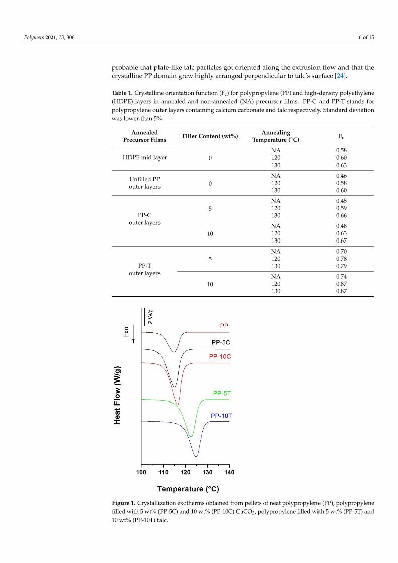
The outer PP-filled layers showed a higher crystalline orientation (see values in Table 1)than those reported in the monolayer films characterized in our previous work, even ifannealed at a higher temperature (140 ◦C) [19]. It has been reported that the nucleationactivity of these fillers in various composites affects the crystallization kinetics and finalorientation of polymer molecules under high stresses [22–24]. It can be observed in Figure 1that CaCO3 had a weak nucleation effect on PP’s crystallization when compared to talc [23].The combination of the high aspect ratio and the plate-like shape of talc particles provideda higher nucleating effect and an increase in crystalline orientation.
It was also noticed that the crystalline phase orientation increased with augmentingfiller content for both types of fillers. This effect was more marked when using talc. It is
Polymers 2021, 13, 306 6 of 15
probable that plate-like talc particles got oriented along the extrusion flow and that thecrystalline PP domain grew highly arranged perpendicular to talc’s surface [24].
Table 1. Crystalline orientation function (Fc) for polypropylene (PP) and high-density polyethylene(HDPE) layers in annealed and non-annealed (NA) precursor films. PP-C and PP-T stands forpolypropylene outer layers containing calcium carbonate and talc respectively. Standard deviationwas lower than 5%.
AnnealedPrecursor Films Filler Content (wt%) Annealing
Temperature (◦C) Fc
HDPE mid layer 0NA 0.58120 0.60130 0.63
Unfilled PPouter layers 0
NA 0.46120 0.58130 0.60
PP-Couter layers
5NA 0.45120 0.59130 0.66
10NA 0.48120 0.63130 0.67
PP-Touter layers
5NA 0.70120 0.78130 0.79
10NA 0.74120 0.87130 0.87
Figure 1. Crystallization exotherms obtained from pellets of neat polypropylene (PP), polypropylenefilled with 5 wt% (PP-5C) and 10 wt% (PP-10C) CaCO3, polypropylene filled with 5 wt% (PP-5T) and10 wt% (PP-10T) talc.
Polymers 2021, 13, 306 7 of 15
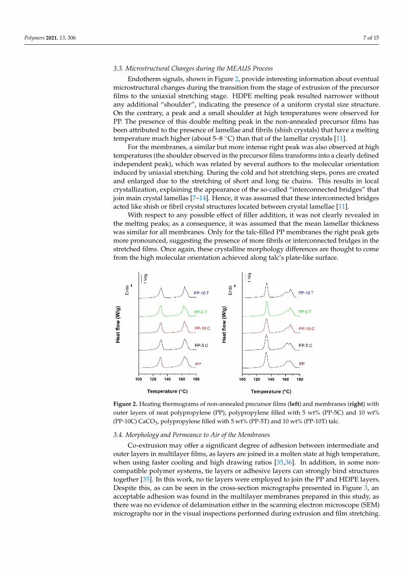
3.3. Microstructural Changes during the MEAUS Process
Endotherm signals, shown in Figure 2, provide interesting information about eventualmicrostructural changes during the transition from the stage of extrusion of the precursorfilms to the uniaxial stretching stage. HDPE melting peak resulted narrower withoutany additional “shoulder”, indicating the presence of a uniform crystal size structure.On the contrary, a peak and a small shoulder at high temperatures were observed forPP. The presence of this double melting peak in the non-annealed precursor films hasbeen attributed to the presence of lamellae and fibrils (shish crystals) that have a meltingtemperature much higher (about 5–8 ◦C) than that of the lamellar crystals [11].
For the membranes, a similar but more intense right peak was also observed at hightemperatures (the shoulder observed in the precursor films transforms into a clearly definedindependent peak), which was related by several authors to the molecular orientationinduced by uniaxial stretching. During the cold and hot stretching steps, pores are createdand enlarged due to the stretching of short and long tie chains. This results in localcrystallization, explaining the appearance of the so-called “interconnected bridges” thatjoin main crystal lamellas [7–14]. Hence, it was assumed that these interconnected bridgesacted like shish or fibril crystal structures located between crystal lamellae [11].
With respect to any possible effect of filler addition, it was not clearly revealed inthe melting peaks; as a consequence, it was assumed that the mean lamellar thicknesswas similar for all membranes. Only for the talc-filled PP membranes the right peak getsmore pronounced, suggesting the presence of more fibrils or interconnected bridges in thestretched films. Once again, these crystalline morphology differences are thought to comefrom the high molecular orientation achieved along talc’s plate-like surface.
Figure 2. Heating thermograms of non-annealed precursor films (left) and membranes (right) withouter layers of neat polypropylene (PP), polypropylene filled with 5 wt% (PP-5C) and 10 wt%(PP-10C) CaCO3, polypropylene filled with 5 wt% (PP-5T) and 10 wt% (PP-10T) talc.
3.4. Morphology and Permeance to Air of the Membranes
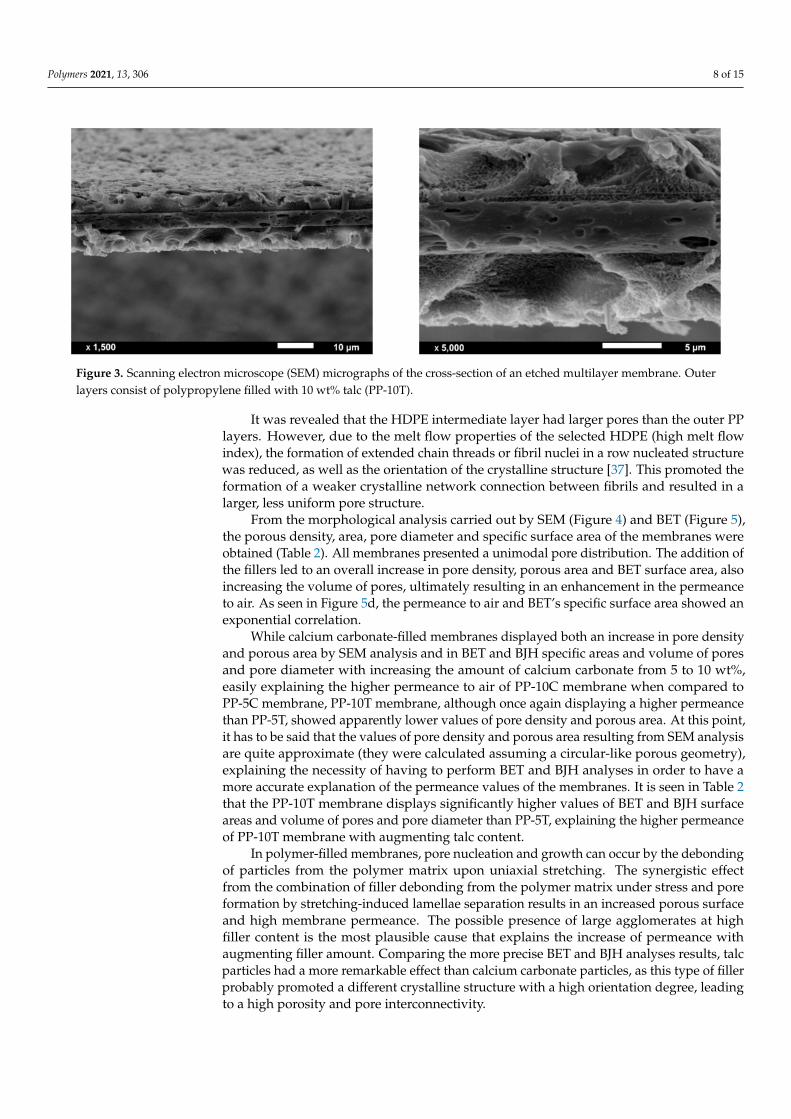
Co-extrusion may offer a significant degree of adhesion between intermediate andouter layers in multilayer films, as layers are joined in a molten state at high temperature,when using faster cooling and high drawing ratios [35,36]. In addition, in some non-compatible polymer systems, tie layers or adhesive layers can strongly bind structurestogether [35]. In this work, no tie layers were employed to join the PP and HDPE layers.Despite this, as can be seen in the cross-section micrographs presented in Figure 3, anacceptable adhesion was found in the multilayer membranes prepared in this study, asthere was no evidence of delamination either in the scanning electron microscope (SEM)micrographs nor in the visual inspections performed during extrusion and film stretching.
Polymers 2021, 13, 306 8 of 15
Figure 3. Scanning electron microscope (SEM) micrographs of the cross-section of an etched multilayer membrane. Outerlayers consist of polypropylene filled with 10 wt% talc (PP-10T).
It was revealed that the HDPE intermediate layer had larger pores than the outer PPlayers. However, due to the melt flow properties of the selected HDPE (high melt flowindex), the formation of extended chain threads or fibril nuclei in a row nucleated structurewas reduced, as well as the orientation of the crystalline structure [37]. This promoted theformation of a weaker crystalline network connection between fibrils and resulted in alarger, less uniform pore structure.
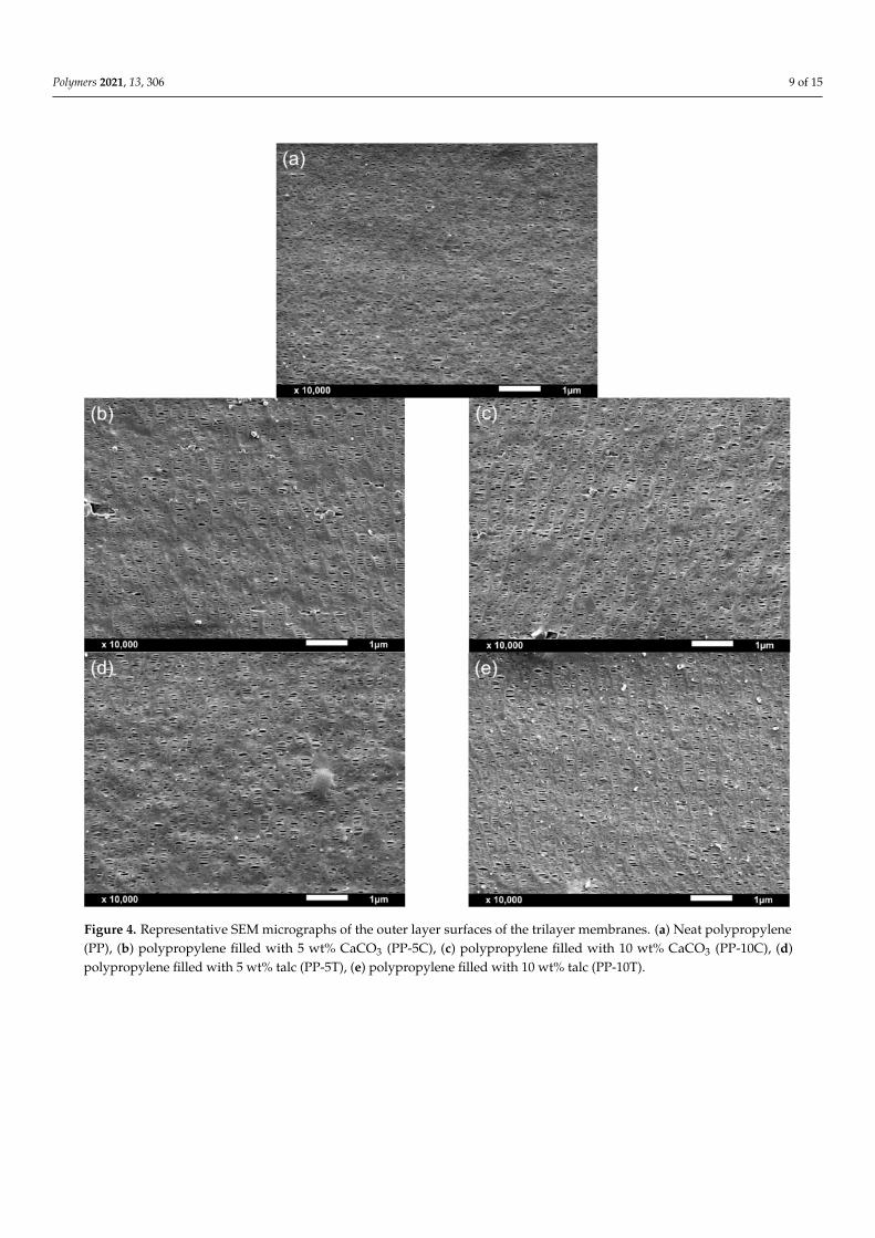
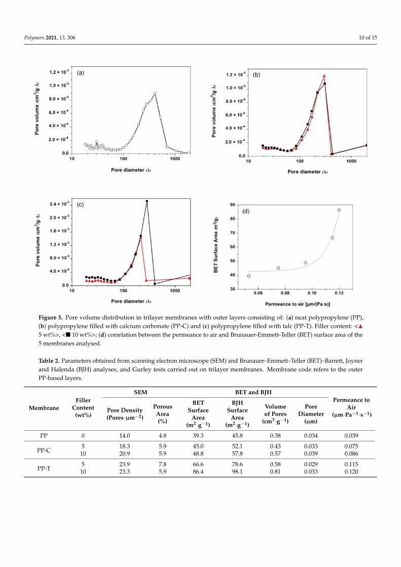
From the morphological analysis carried out by SEM (Figure 4) and BET (Figure 5),the porous density, area, pore diameter and specific surface area of the membranes wereobtained (Table 2). All membranes presented a unimodal pore distribution. The addition ofthe fillers led to an overall increase in pore density, porous area and BET surface area, alsoincreasing the volume of pores, ultimately resulting in an enhancement in the permeanceto air. As seen in Figure 5d, the permeance to air and BET’s specific surface area showed anexponential correlation.
While calcium carbonate-filled membranes displayed both an increase in pore densityand porous area by SEM analysis and in BET and BJH specific areas and volume of poresand pore diameter with increasing the amount of calcium carbonate from 5 to 10 wt%,easily explaining the higher permeance to air of PP-10C membrane when compared toPP-5C membrane, PP-10T membrane, although once again displaying a higher permeancethan PP-5T, showed apparently lower values of pore density and porous area. At this point,it has to be said that the values of pore density and porous area resulting from SEM analysisare quite approximate (they were calculated assuming a circular-like porous geometry),explaining the necessity of having to perform BET and BJH analyses in order to have amore accurate explanation of the permeance values of the membranes. It is seen in Table 2that the PP-10T membrane displays significantly higher values of BET and BJH surfaceareas and volume of pores and pore diameter than PP-5T, explaining the higher permeanceof PP-10T membrane with augmenting talc content.
In polymer-filled membranes, pore nucleation and growth can occur by the debondingof particles from the polymer matrix upon uniaxial stretching. The synergistic effectfrom the combination of filler debonding from the polymer matrix under stress and poreformation by stretching-induced lamellae separation results in an increased porous surfaceand high membrane permeance. The possible presence of large agglomerates at highfiller content is the most plausible cause that explains the increase of permeance withaugmenting filler amount. Comparing the more precise BET and BJH analyses results, talcparticles had a more remarkable effect than calcium carbonate particles, as this type of fillerprobably promoted a different crystalline structure with a high orientation degree, leadingto a high porosity and pore interconnectivity.
Polymers 2021, 13, 306 9 of 15
Figure 4. Representative SEM micrographs of the outer layer surfaces of the trilayer membranes. (a) Neat polypropylene(PP), (b) polypropylene filled with 5 wt% CaCO3 (PP-5C), (c) polypropylene filled with 10 wt% CaCO3 (PP-10C), (d)polypropylene filled with 5 wt% talc (PP-5T), (e) polypropylene filled with 10 wt% talc (PP-10T).
Polymers 2021, 13, 306 10 of 15
Figure 5. Pore volume distribution in trilayer membranes with outer layers consisting of: (a) neat polypropylene (PP),(b) polypropylene filled with calcium carbonate (PP-C) and (c) polypropylene filled with talc (PP-T). Filler content: <N5 wt%>, <� 10 wt%>; (d) correlation between the permeance to air and Brunauer-Emmett-Teller (BET) surface area of the5 membranes analysed.
Table 2. Parameters obtained from scanning electron microscope (SEM) and Brunauer–Emmett–Teller (BET)–Barrett, Joynerand Halenda (BJH) analyses, and Gurley tests carried out on trilayer membranes. Membrane code refers to the outerPP-based layers.
MembraneFiller
Content(wt%)
SEM BET and BJHPermeance to
Air(µm·Pa−1·s−1)
Pore Density(Pores·µm−2)
PorousArea(%)
BETSurface
Area(m2·g−1)
BJHSurface
Area(m2·g−1)
Volumeof Pores
(cm3·g−1)
PoreDiameter
(µm)
PP 0 14.0 4.8 39.3 45.8 0.38 0.034 0.039
PP-C5 18.3 5.9 45.0 52.1 0.43 0.033 0.075
10 20.9 5.9 48.8 57.8 0.57 0.039 0.086
PP-T5 23.9 7.8 66.6 78.6 0.58 0.029 0.115
10 23.3 5.9 86.4 98.1 0.81 0.033 0.120
Polymers 2021, 13, 306 11 of 15
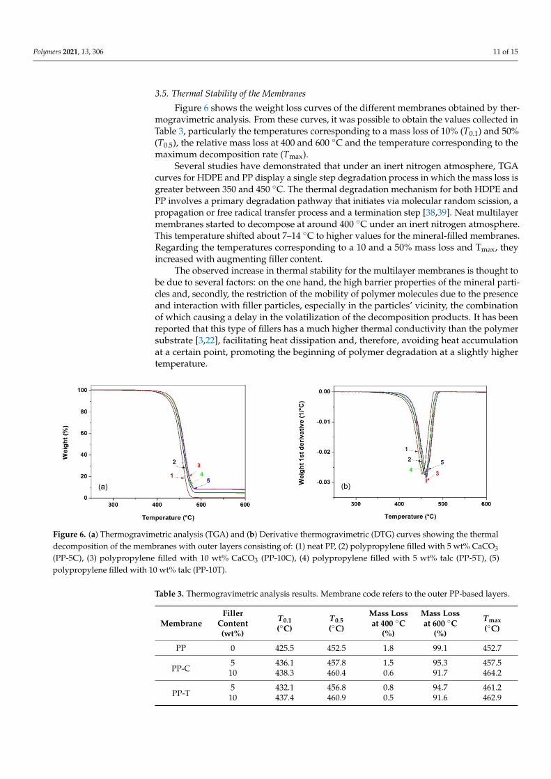
3.5. Thermal Stability of the Membranes
Figure 6 shows the weight loss curves of the different membranes obtained by ther-mogravimetric analysis. From these curves, it was possible to obtain the values collected inTable 3, particularly the temperatures corresponding to a mass loss of 10% (T0.1) and 50%(T0.5), the relative mass loss at 400 and 600 ◦C and the temperature corresponding to themaximum decomposition rate (Tmax).
Several studies have demonstrated that under an inert nitrogen atmosphere, TGAcurves for HDPE and PP display a single step degradation process in which the mass loss isgreater between 350 and 450 ◦C. The thermal degradation mechanism for both HDPE andPP involves a primary degradation pathway that initiates via molecular random scission, apropagation or free radical transfer process and a termination step [38,39]. Neat multilayermembranes started to decompose at around 400 ◦C under an inert nitrogen atmosphere.This temperature shifted about 7–14 ◦C to higher values for the mineral-filled membranes.Regarding the temperatures corresponding to a 10 and a 50% mass loss and Tmax, theyincreased with augmenting filler content.
The observed increase in thermal stability for the multilayer membranes is thought tobe due to several factors: on the one hand, the high barrier properties of the mineral parti-cles and, secondly, the restriction of the mobility of polymer molecules due to the presenceand interaction with filler particles, especially in the particles’ vicinity, the combinationof which causing a delay in the volatilization of the decomposition products. It has beenreported that this type of fillers has a much higher thermal conductivity than the polymersubstrate [3,22], facilitating heat dissipation and, therefore, avoiding heat accumulationat a certain point, promoting the beginning of polymer degradation at a slightly highertemperature.
Figure 6. (a) Thermogravimetric analysis (TGA) and (b) Derivative thermogravimetric (DTG) curves showing the thermaldecomposition of the membranes with outer layers consisting of: (1) neat PP, (2) polypropylene filled with 5 wt% CaCO3
(PP-5C), (3) polypropylene filled with 10 wt% CaCO3 (PP-10C), (4) polypropylene filled with 5 wt% talc (PP-5T), (5)polypropylene filled with 10 wt% talc (PP-10T).
Table 3. Thermogravimetric analysis results. Membrane code refers to the outer PP-based layers.
MembraneFiller
Content(wt%)
T0.1(◦C)
T0.5(◦C)
Mass Lossat 400 ◦C
(%)
Mass Lossat 600 ◦C
(%)
Tmax(◦C)
PP 0 425.5 452.5 1.8 99.1 452.7
PP-C5 436.1 457.8 1.5 95.3 457.510 438.3 460.4 0.6 91.7 464.2
PP-T5 432.1 456.8 0.8 94.7 461.210 437.4 460.9 0.5 91.6 462.9
Polymers 2021, 13, 306 12 of 15
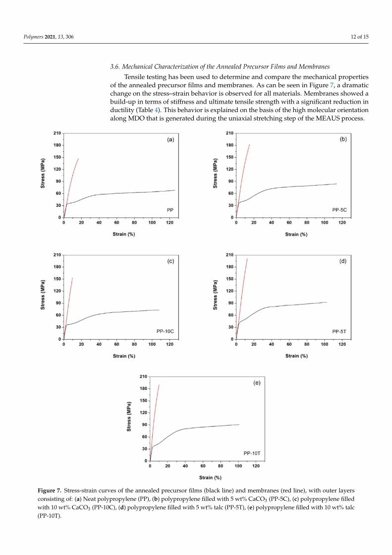
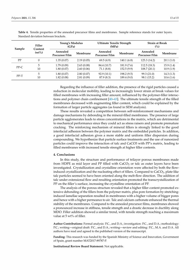
3.6. Mechanical Characterization of the Annealed Precursor Films and Membranes
Tensile testing has been used to determine and compare the mechanical propertiesof the annealed precursor films and membranes. As can be seen in Figure 7, a dramaticchange on the stress–strain behavior is observed for all materials. Membranes showed abuild-up in terms of stiffness and ultimate tensile strength with a significant reduction inductility (Table 4). This behavior is explained on the basis of the high molecular orientationalong MDO that is generated during the uniaxial stretching step of the MEAUS process.
Figure 7. Stress-strain curves of the annealed precursor films (black line) and membranes (red line), with outer layersconsisting of: (a) Neat polypropylene (PP), (b) polypropylene filled with 5 wt% CaCO3 (PP-5C), (c) polypropylene filledwith 10 wt% CaCO3 (PP-10C), (d) polypropylene filled with 5 wt% talc (PP-5T), (e) polypropylene filled with 10 wt% talc(PP-10T).
Polymers 2021, 13, 306 13 of 15
Table 4. Tensile properties of the annealed precursor films and membranes. Sample reference stands for outer layers.Standard deviation between brackets.
SampleFiller
Content(wt%)
Young’s Modulus(GPa)
Ultimate Tensile Strength(MPa)
Strain at Break(%)
AnnealedPrecursor Film Membrane Annealed
Precursor Film Membrane AnnealedPrecursor Film Membrane
PP 0 1.35 (0.07) 2.19 (0.05) 69.5 (4.9) 140.1 (6.8) 125.3 (14.2) 20.1 (1.0)
PP-C5 1.79 (0.09) 2.63 (0.08) 84.4 (10.7) 181.9 (7.6) 112.5 (18.3) 15.9 (1.4)
10 1.80 (0.07) 2.60 (0.06) 71.1 (8.8) 152.5 (9.9) 108.7 (20.1) 10.9 (1.9)
PP-T5 1.80 (0.07) 2.80 (0.07) 92.9 (10.1) 198.2 (9.5) 99.3 (21.0) 14.3 (1.3)
10 1.82 (0.08) 2.81 (0.09) 87.9 (8.3) 189.4 (9.0) 98.1 (15.2) 10.6 (1.6)
Regarding the influence of filler addition, the presence of the rigid particles caused areduction in molecular mobility, leading to increasingly lower strain at break values forfilled membranes with increasing filler amount, influenced by the polymer-filler interac-tions and polymer chain confinement [40–43]. The ultimate tensile strength of the filledmembranes decreased with augmenting filler content, which could be explained by theformation of larger particle aggregates (as found in SEM analysis).
These results revealed a competition between self-reinforcement mechanisms anddamage mechanisms by debonding in the mineral-filled membranes. The presence of largeparticle agglomerates leads to stress concentrations in the matrix, which are detrimentalto mechanical performance since they could act as stress raisers and promote prematurecracking. The reinforcing mechanism of mineral fillers is strongly linked to the goodinterfacial adhesion between the polymer matrix and the embedded particles. In addition,a good interfacial adhesion gives a more stable and uniform filler dispersion duringcompounding. We hypothesize that particle surface treatments and the use of nanosizedparticles could improve the interaction of talc and CaCO3 with PP’s matrix, leading tofilled membranes with increased tensile strength at higher filler contents.
4. Conclusions
In this study, the structure and performance of trilayer porous membranes madefrom HDPE as mid layer and PP filled with CaCO3 or talc as outer layers have beeninvestigated. Crystallization and crystalline orientation were affected by both the flow-induced crystallization and the nucleating effect of fillers. Compared to CaCO3, plate-liketalc particles seemed to have been oriented along the melt-flow direction. The addition oftalc under extensional flow and resulting orientation promoted the transcrystallization ofPP on the filler’s surface, increasing the crystalline orientation of PP.
The analysis of the porous structure revealed that a higher filler content promoted ex-tensive debonding of the fillers from the polymer matrix, plus pore formation by stretching-induced lamellae separation resulted in membranes with a higher volume of bigger poresand hence with a higher permeance to air. Talc and calcium carbonate enhanced the thermalstability of the membranes. Compared to the annealed precursor films, membranes showeda pronounced increase in stiffness, tensile strength and a drastic decrease in ductility alongMDO. Filler addition showed a similar trend, with tensile strength reaching a maximumvalue at 5 wt% of filler.
Author Contributions: Formal analysis: P.C., and D.A.; investigation: P.C., and D.A.; methodology:P.C.; writing—original draft: P.C., and D.A.; writing—review and editing: P.C., M.A. and D.A. Allauthors have read and agreed to the published version of the manuscript.
Funding: This research was funded by the Spanish Ministry of Science and Innovation, Governmentof Spain, grant number MAT2017-89787-P.
Institutional Review Board Statement: Not applicable.
Polymers 2021, 13, 306 14 of 15
Informed Consent Statement: Not applicable.
Data Availability Statement: The data presented in this study are available on request from thecorresponding author.
Conflicts of Interest: The authors declare no conflict of interest.
References1. Baker, R.W. Membrane Technology and Applications, 3rd ed.; John Wiley & Sons Ltd.: West Sussex, UK, 2012; pp. 1–132.2. Offord, G.T.; Armstrong, S.R.; Freeman, B.D.; Baer, E.; Hiltner, A.; Swinnea, J.S.; Paul, D.R. Porosity enhancement in β nucleated
isotactic polypropylene stretched films by thermal annealing. Polymer 2013, 54, 2577–2589. [CrossRef]3. Chrissafis, K.; Bikiaris, D. Can nanoparticles really enhance thermal stability of polymers? Part I: An overview on thermal
decomposition of addition polymers. Thermochim. Acta 2011, 523, 1–24. [CrossRef]4. Nakamura, S.; Kaneko, S.; Mizutani, Y. Microporous polypropylene sheets containing CaCO3 filler. J. Appl. Polym. Sci. 1993, 49,
143–150. [CrossRef]5. Nago, S.; Mizutani, Y. Microporous polypropylene sheets containing CaCO3 filler: Effects of stretching ratio and removing CaCO3
filler. J. Appl. Polym. Sci. 1998, 68, 1543–1553. [CrossRef]6. Xiong, B.; Kang, J.; Chen, R.; Men, Y. Initiation of cavitation upon drawing of pre-oriented polypropylene film: In situ SAXS and
WAXD studies. Polymer 2017, 128, 57–64. [CrossRef]7. Sadeghi, F.; Ajji, A.; Carreau, P.J. Analysis of microporous membranes obtained from polypropylene films by stretching. J. Membr.
Sci. 2007, 292, 62–71. [CrossRef]8. Tabatabaei, S.H.; Carreau, P.J.; Ajji, A. Effect of processing on the crystalline orientation, morphology, and mechanical properties
of polypropylene cast films and microporous membrane formation. Polymer 2009, 50, 4228–4240. [CrossRef]9. Xiande, C.; Ruijie, X.; Jiayi, X.; Yuanfei, L.; Caihong, L.; Liangbin, L. The study of room-temperature stretching of annealed
polypropylene cast film with row-nucleated crystalline structure. Polymer 2016, 94, 31–42. [CrossRef]10. Zeng, F.; Xu, R.; Ye, L.; Xiong, B.; Kang, J.; Xiang, M.; Hao, Z. Effects of Heat Setting on the Morphology and Performance of
Polypropylene Separator for Lithium Ion Batteries. Ind. Eng. Chem. Res. 2019, 58, 2217–2224. [CrossRef]11. Tabatabaei, S.H.; Carreau, P.J.; Ajji, A. Structure and properties of MDO stretched polypropylene. Polymer 2009, 50, 3981–3989.
[CrossRef]12. Saffar, A.; Carreau, P.J.; Ajji, A.; Kamal, M.R. The impact of new crystalline lamellae formation during annealing on the properties
of polypropylene based films and membranes. Polymer 2014, 55, 3156–3167. [CrossRef]13. Saffar, A.; Carreau, P.J.; Ajji, A.; Kamal, M.R. Influence of stretching on the performance of polypropylene-based microporous
membranes. Ind. Eng. Chem. Res. 2014, 53, 14014–14021. [CrossRef]14. Lin, Y.; Meng, L.; Wu, L.; Li, X.; Chen, X.; Zhang, Q.; Li, L. A semi-quantitative deformation model for pore formation in isotactic
polypropylene microporous membrane. Polymer 2015, 80, 214–227. [CrossRef]15. Tabatabaei, S.H.; Carreau, P.J.; Ajji, A. Microporous membranes obtained from PP/HDPE multilayer films by stretching. J. Membr.
Sci. 2009, 345, 148–159. [CrossRef]16. Li, Y.; Pu, H.; Wei, Y. Polypropylene/polyethylene multilayer separators with enhanced thermal stability for lithium-ion battery
via multilayer coextrusion. Electrochim. Acta 2018, 264, 140–149. [CrossRef]17. Arora, P.; Zhang, Z. Battery separators. Chem. Rev. 2004, 104, 4419–4462. [CrossRef]18. Xiong, B.; Chen, R.; Zeng, F.; Kang, J.; Men, Y. Thermal shrinkage and microscopic shutdown mechanism of polypropylene
separator for lithium-ion battery: In-situ ultra-small angle X-ray scattering study. J. Membr. Sci. 2018, 545, 213–220. [CrossRef]19. Castejón, P.; Habibi, K.; Saffar, A.; Ajji, A.; Martínez, A.B.; Arencón, D. Polypropylene-based porous membranes: Influence of
polymer composition, extrusion draw ratio and uniaxial strain. Polymers 2017, 10, 33. [CrossRef]20. Audet, E.; Mighri, F.; Rodrigue, D.; Ajji, A. Effect of Biaxial Stretching Temperature and Gas Diffusion Expansion on Cellular
Morphology of PP/CaCO3 and PP/talc Cellular Films. Cell. Polym. 2015, 34, 233–248. [CrossRef]21. Armstrong, S.R.; Offord, G.T.; Paul, D.R.; Freeman, B.D.; Hiltner, A.; Baer, E. Co-extruded polymeric films for gas separation
membranes. J. Appl. Polym. Sci. 2014, 131, 39765. [CrossRef]22. Qiu, F.; Wang, M.; Hao, Y.; Guo, S. The effect of talc orientation and transcrystallization on mechanical properties and thermal
stability of the polypropylene/talc composites. Compos. Part A Appl. Sci. Manuf. 2014, 58, 7–15. [CrossRef]23. Wang, B.; Wang, Q.; Li, L. Morphology and properties of highly talc- and CaCO3-filled poly (vinyl alcohol) composites prepared
by melt processing. J. Appl. Polym. Sci. 2013, 130, 3050–3057. [CrossRef]24. Fiorentino, B.; Fulchiron, R.; Duchet-Rumeau, J.; Bounor-Legaré, V.; Majesté, J.C. Controlled shear-induced molecular orientation
and crystallization in polypropylene/talc microcomposites–Effects of the talc nature. Polymer 2013, 54, 2764–2775. [CrossRef]25. Jang, K.S. Mineral filler effect on the mechanics and flame retardancy of polycarbonate composites: Talc and kaolin. e-Polymers
2016, 16, 379–386. [CrossRef]26. Kamal, M.; Sharma, C.S.; Upadhyaya, P.; Verma, V.; Pandey, K.N.; Kumar, V.; Agrawal, D.D. Calcium carbonate (CaCO3)
nanoparticle filled polypropylene: Effect of particle Surface treatment on mechanical, thermal, and morphological performance ofcomposites. J. Appl. Polym. Sci. 2012, 124, 2649–2656. [CrossRef]
Polymers 2021, 13, 306 15 of 15
27. ISO. ISO 1133. Plastics—Determination of the Melt Mass-Flow Rate (MFR) and the Melt Volume-Flow Rate (MVR) of Thermoplastics;International Organization for Standardization: Geneva, Switzerland, 2005.
28. ISO. ISO 306. Plastics—Determination of Vicat Softening Temperature; International Organization for Standardization: Geneva,Switzerland, 2004.
29. ISO. ISO 527-2. Plastics—Determination of Tensile Properties—Part 2: Test Conditions for Moulding and Extrusion Plastics; InternationalOrganization for Standardization: Geneva, Switzerland, 2012.
30. Olley, R.H.; Bassett, D.C. An improved permanganic etchant for polyolefines. Polymer 1982, 23, 1707–1710. [CrossRef]31. Brunauer, S.; Emmett, P.H.; Teller, E. Adsorption of gases in multimolecular layers. J. Am. Chem. Soc. 1938, 60, 309–319. [CrossRef]32. Thommes, M.; Kaneko, K.; Neimark, A.V.; Olivier, J.P.; Rodriguez-Reinoso, F.; Rouquerol, J.; Sing, K.S. Physisorption of gases,
with special reference to the evaluation of surface area and pore size distribution (IUPAC Technical Report). Pure Appl. Chem.2015, 87, 1051–1069. [CrossRef]
33. ISO. ISO 5636-5. Paper and Board—Determination of Air Permeance (Medium Range)—Part 5: Gurley Method; International Organiza-tion for Standardization: Geneva, Switzerland, 2013.
34. ISO. ISO 527-3. Plastics—Determination of Tensile Properties—Part 3: Test Conditions for Films and Sheets; International Organizationfor Standardization: Geneva, Switzerland, 2018.
35. Giles, H.F., Jr.; Mount, E.M., III; Wagner, J.R., Jr. Extrusion: The Definitive Processing Guide and Handbook; William Andrew, Inc.:Norwich, NY, USA, 2004; pp. 437–499.
36. Song, J.; Bringuier, A.; Kobayashi, S.; Baker, A.M.; Macosko, C.W. Adhesion between polyethylenes and different types ofpolypropylenes. Polym, J. 2012, 44, 939–945. [CrossRef]
37. Zhang, X.M.; Elkoun, S.; Ajji, A.; Huneault, M.A. Oriented structure and anisotropy properties of polymer blown films: HDPE,LLDPE and LDPE. Polymer 2004, 45, 217–229. [CrossRef]
38. Martínez, M.C.; Benavente, R.; Gómez-Elvira, J.M. Molecular weight dependence and stereoselective chain cleavage during theearly stages of the isotactic polypropylene pyrolysis. Polym. Degrad. Stab. 2017, 143, 26–34. [CrossRef]
39. Rychlý, J.; Matisová-Rychlá, L.; Csmorová, K.; Janigová, I. Non-isothermal thermogravimetry, differential scanning calorimetryand chemiluminiscence in degradation of polyethylene, polypropylene, polystyrene and poly(methyl methacrylate). Polym.Degrad. Stab. 2011, 96, 1573–1581. [CrossRef]
40. Jancar, J.; Fekete, E.; Hornsby, P.R.; Jancar, J.; Pukánszky, B.; Rothon, R.N. (Eds.) Mineral. Fillers in Thermoplastics I: Raw Materialsand Processing; Springer: Berlin/Heidelberg, Germany, 1999; pp. 67–155.
41. Drioli, E.; Giorno, L. Comprehensive Membrane Science and Engineering; Elsevier: Waltham, MA, USA, 2010; Volume 1, pp. 65–85.42. Swallowe, G.M. Mechanical Properties and Testing of Polymers: An A–Z Reference; Springer Science & Business Media: Leicestershire,
UK, 2013; Volume 3, pp. 214–249.43. Lin, Y.; Chen, H.; Chan, C.M.; Wu, J. Effects of coating amount and particle concentration on the impact toughness of
polypropylene/CaCO3 nanocomposites. Eur. Polym. J. 2011, 47, 294–304. [CrossRef]


